Component Systems for Lighting Applications
564
Lamps OLEDs LED Components Ballasts Transformers Control Gear Units Ignitors Power Switches Capacitors Lampholders Starter Holders Terminal Blocks Accessories Component Systems for Lighting Applications 2012/2013 | www.vossloh-schwabe.com
-
Upload
khangminh22 -
Category
Documents
-
view
0 -
download
0
Transcript of Component Systems for Lighting Applications

LampsOLEDsLED ComponentsBallastsTransformersControl Gear UnitsIgnitorsPower SwitchesCapacitorsLampholdersStarter HoldersTerminal BlocksAccessories
Component Systems for Lighting Applications
2012/2013 | www.vossloh-schwabe.com

Vossloh-Schwabe is not merely a manufacturer of top-quality componentsfor the lighting industry, but above all makes a competent and innovativecontribution to setting market trends.
Featuring a future-proof component structure that already now satisfiesboth the requirements of energy-efficient lighting and European standards,VS' unique product range includes magnetic and electronic ballasts,state-of-the-art control systems (Lixos or DALI), LED lighting systems andmatching operating devices.
Employing in excess of 1,000 people in more than 20 countries, Vossloh-Schwabe is represented all over the world. As a subsidiary of theJapanese Panasonic Group, VS can draw on extensive resources for R&Das well as for international expansion activities. A highly motivated work-force, comprehensive market knowledge, profound industry expertise aswell as eco-awareness and environmental responsibility show Vossloh-Schwabe to be a reliable partner for the provision of optimum andcost-effective lighting solutions.
Vossloh-Schwabe's dedication to delivering superior quality is reflected inits ISO 9001 certification.
Vossloh-Schwabe is ready to embark on a collaborative journey into aneconomically illuminated future.
2 www.vossloh-schwabe.com
Vossloh-Schwabe
LIGHT TECHNOLOGYPRODUCTS

Sagrada Família, Barcelona
As different as each of the façades of the Sagrada Família are, they dohave something in common: each is supremely symbolic. Rather thanmerely enclose space with walls, Gaudi intended his buildings to tellstories and be an experience in themselves. Gaudi's vision is now slowlybeing put into practice along with a number of additional modernelements, for instance the decision to use innovative lighting technologyin the form of LED spots to perfectly set off the basilica's sacral symbolism.
The interior of the basilica, which has already been completed, soars upto an enormous vault supported by stone columns that branch off at theceiling to form a lace-like canopy. At present these columns are fitted witha total of 40 luminaires, which in turn are equipped with daylight-whiteLED modules and matching control gear made by Vossloh-Schwabe.
Interior photos: José TióConsulting and luminaire design: Anoche Iluminación ArquitectónicaGlass artist: D. Fita
LiCS – The DALI Light Management System
More than ever before, present-day light management is expected to beflexible, save energy and be convenient to operate. The new all-roundsystem made by Vossloh-Schwabe, consisting of a light controller, sensor,extender and push buttons, can be programmed without needing a PCor overriding bus system. Instead, the entire lighting system is configuredusing the controller's integrated display screen and rotary push key.
The DALI-based system can be used to control a max. of 64 luminaires,or luminaire groups, 6 independently configurable standard buttonsand up to 16 MultiSensors using a single controller. By connecting anextender, the lighting system can then be extended by up to 64 luminairesper extender. The controller can be mounted on a 35-mm mounting rail.The wireless version of the controller (LW) substantially reduces theinstallation work required during refurbishment and with that also reducesinstallation costs. Up to 16 wireless modules can be connected, eachwith 4 independently configurable radio buttons.
Thanks to the VS LiCS system, the energy consumed by a warehouse(1,320 m², ceiling height of 7 m) can be almost halved from approx.20,500 kWh p.a. down to 11,500 kWh p.a. by installing 169 luminaires1x 49 W, a DALI-compliant electronic ballast and MultiSensors. Creatingluminaire groups as well as positioning light- and motion-activated Multi-Sensors additionally provide the comfort and convenience of optimumlight –any time you need it. If the sensor fails to register any movement,LiCS will switch the lighting system off, either in its entirety or only incertain sections, or dim it down to the specified minimum value. Thisremoves the need to switch the lighting system on and off manually.
www.vossloh-schwabe.com 3
Sagrada Família Warehouse

Lamps 6–7Premier S Metal Halide Lamps 7
OLED and LED Components 8–99OLEDs 9Technical details on OLED 10–13Constant current system 18–53LEDSpots 54–6024 V CA system 61–7024 V standard system 71–89Electronic converter for LED modules 12 V 90–91Technical details on LED technology 92–99
Ballasts for Discharge Lamps 100–141Electronic ballasts, accessories 102–111
Dimmable electronic ballasts 110–111Control gear units for HS and HI lamps 112–118Electromagnetic ballasts 119–141
for HS and HI lamps 119–130for HM and HI lamps 131–134for SDW-T/-TF lamps 135for power reduction 136–141
Ignitors and Accessoriesfor Discharge Lamps 142–162Electronic superimposed ignitors 144–152Pulse ignitors 153–154Instant restrike ignitors 155–156Electronic power switches 157Electronic superimposed ignitorswith power switch 158Switch units for electronic operating deviceswith 1–10 V interface 159Start-up switches 160–161Electronic discharge units 162
Lampholders for Discharge Lamps 164–183E27 lampholders 166–168E40 lampholders 169–171G8.5 lampholders 171GX8.5 lampholders, accessories 172GU8.5 lampholders 172GU6.5 lampholders 173PGJ5 lampholders 174GX10 lampholders 175GY9.5 lampholders 175G12, GX12-1, PG12-1, PG12-2 lampholders 176–177RX7s lampholders 177–180Fc2 lampholders 181–182K12x30s lampholders 182K12s-7 support 183
Technical Detailsfor Discharge Lamps 184–225
Electronic Ballasts for TC and T Lamps 226–256For compact fluorescent lamps 228–244
ELXs – Warm start 228ELXc – Warm start – Linear 229ELXd – Dimmable – Linear 230–231ELXc – Warm start – Compact 232–239ELXd – Dimmable – Compact 240–244
For tubular fluorescent lamps 245–255ELXs – Warm start 245ELXc – Warm start – Linear 246–249ELXc EffectLine – Warm start 250–251ELXd – Dimmable – Linear 252–254ELXe – Instant start – Linear 255
Accessories fordimmable electronic built-in ballasts 256
Electromagnetic Ballastsfor TC and T Lamps 258–280For compact fluorescent lamps 260–272
Standard ballasts 260–264Super-thin ballasts 265–268Slim ballasts 269–270Ballasts 120 V, 60 Hz 271Operating units 120 V, 60 Hz 272
For tubular fluorescent lamps 273–280Standard ballasts 273–275Super-thin ballasts 276–277Slim ballasts 277–278Ballasts 120 V, 60 Hz 279Operating units 120 V, 60 Hz 280
Lampholders and Accessoriesfor TC Lamps 282–304G24, GX24 lampholders 284–2912G7 lampholders 2922G8 lampholders 293G23 lampholders 293–296GR8, GR10q, GRY10q-3, GRZ10d,GRZ10t lampholders 296–2972G10 lampholders 2972G11/2GX11 lampholders 298–299Accessories 300–302GX53-1 lampholders, accessories 303–304
Lampholders and Accessoriesfor T Lamps 306–337G5 lampholders, accessories 308–312G5 twin lampholder 313G5 lampholders,degree of protection IP54/IP65/IP67 313–3142GX13 lampholders, accessories 315G13 push-through lampholders 316–318G13 push-fit lampholders 319–321G13 push-fit twin lampholders, accessories 322–323G13 built-in lampholders 323–327G13 surface-mounted lampholders 327–328Accessories for T8 and T12 lamps 328–330
4 www.vossloh-schwabe.com
Contents
1
2
3
3
3
3
4
4
4
4

Lampholders and Accessoriesfor T Lamps 306–337G13 lampholders, degree of protectionIP54/IP65/IP67, accessories 331–335G10q lampholders, accessories 336W4.3x8.5d surface-mounted lampholder 337
Starter Holders and Terminal Blocks,Accessories 338–349Starter holders, accessories 340–343Terminal blocks, accessories 344–348Built-in rocker switches 349
Technical Detailsfor Fluorescent Lamps 350–379
Transformers for Low-voltageHalogen Incandescent Lamps 380–395Independent electronic converters 382–386With DALI interface 386Electronic built-in converters 387–389Potentiometer and dimmers 390Electromagnetic safety transformers 391–395
Lampholders for Low-voltageHalogen Incandescent Lamps 396–407G4, GZ4, G5.3, GX5.3, G6.35,GY6.35 lampholders, accessories 398–399G4 lampholders, GZ4 lamp connectors 400–402Lampholders with separate mountingspring for GU4 lamps 402–403GX5.3 lamp connectors 403–404GU5.3 lampholders 404Lampholders with separate mounting springfor GU5.3 lamps 405–406G6.35, GY6.35 lampholders,GZ6.35 lamp connectors 406G53 lamp connectors 407B15d, BA15d lampholders 407
Lampholders for Mains VoltageHalogen Incandescent Lamps 407–417B15d, BA15d lampholders 407G9 lampholders, accessories 408–410GU10, GZ10 lampholders, accessories 410–412R7s thermoplastic lampholders 412R7s ceramic lampholders 412–414R7s metal lampholders 415Connection boxes 416Connectors 417
Lampholders for General-serviceIncandescent and Retrofit Lamps 418–456E14 thermoplastic lampholders, one-pieceand cover caps 420–424E27 renovation kit lampholders 425E14 thermoplastic lampholders, three-piece 425–427E14 porcelain lampholders, one-piece 428
Lampholders for General-serviceIncandescent and Retrofit Lamps 418–456E14 metal lampholders, three-piece 428–429E14 thermoplastic rocker switch lampholders 429–430E14 lampholder for emergency lighting 430E27 thermoplastic lampholders, one-pieceand cover caps 431–435E27 table lamp set 436E27 renovation kit lampholders 436E27 thermoplastic lampholders, three-piece 437–439E27 porcelain lampholders 440–442E27 metal lampholders, three-piece 442–443E27 thermoplastic pull-switch lampholders 443–444E27 metal pull-switch lampholders 445E27 thermoplastic rocker switch lampholders 446E27 thermoplastic rotary switch lampholders 447E27 festoon lampholders 447–448B22d lampholders, accessories 448–449Accessories for E14, E27 and B22d lampholders 450–455E40 porcelain lampholders 456
Technical Detailsfor Incandescent Lamps 457–471
Lighting Control Systems forIndoor Applications 472–480Light Controller L/LW and S 476–477Extender 478Sensors 479Accessories 480Technical details for lighting control systemsfor indoor applications 481–487
Lighting Control Systems forOutdoor Applications 488–497Light Controller – iLC and iPC 492–493Data concentrator – iDC 494Lux meter – iLUX 495Software – iCT 496Intelligent luminaire information centre– iLIC 496Light Controller – iMCU 497
Emergency Lighting Modules 498–501With self-diagnosis function 500–501Technical details for emergency lighting modules 502–508
Parallel capacitors 510–524Parallel capacitors 512–515Technical details for parallel capacitors 516–524
Components for UL Market 526–532For discharge lamps 528–530For fluorescent lamps 530–532
General Technical Details 533–543General Technical Details 534–540Glossary 541–543Table of reference numbers, approval marks 544–561
www.vossloh-schwabe.com 5
5
5
6
6
7
8
9
10
4
4
4
5
5
5
5

A NEW GENERATIONOF HI LAMPSPanasonic has redefined the standard in retail lighting with its new 35 Wand 70 W Premier S ceramic discharge lamps.
The lamp is characterised by an extremely high CRI value of morethan Ra 96, a high degree of luminous efficiency (100 lm/W) as wellas near constant luminous flux (luminous flux = 80% at up to 12,000operating hours).
The lamp's "triple envelope" technology protects the lamp bulb andtherefore removes the need to fit luminaires with a front cover since thereis no danger of any glass shards falling out should the lamp shatter. Nextto facilitating even slimmer luminaire designs, the enclosed bulb alsoincreases easeof maintenance and cost-effectiveness since there is noneed to remove or replace a glass cover when lamps are exchanged.
Photometric quality, cost-effectiveness, safety factors and ease ofinstallation are all key criteria when it comes to luminaire design –and all of these criteria are fully satisfied by the Premier S lamp.
6 www.vossloh-schwabe.com
Lamps
DISCHARGE LAMPS
Triple-envelope technologyEnclosed bulb prevents glass shards from falling outshould the lamp shatter
Highly convenient and low-cost maintenanceCoverless design enables easy lamp replacement
Minimal drop in luminous fluxResults in long service life at nearly constant light quality
High CRI value (Ra 93 / Ra 96)Especially in the red spectral range
High degree of luminous efficiency (100 lm/W)Due to perfectly matched system components

Premier S Metal Halide Lamps35 W and 70 W ceramic discharge lampsfor open and closed luminairesColour temperature: warm white (3000 K)or cool white (4200 K)Colour rendering level: 1ALamp base: "twist & lock" GU8.5 baseOperation only with suitable electronic ballasts (see page 103)Suitable lampholders see page 172UV filter technology
Nominal Base Type Ref. No. Output Colour Colour Luminous Luminous CRI Average Burning position
output consumption temperature flux* efficiency survival lamp life
W W K lm lm/W Ra hrs.
35 GU8.5 CPS 35W 3000K 546075 39 warm white 3000 3300 85 93 15,000 free
35 GU8.5 CPS 35W 4200K 546076 39 cool white 4200 3300 85 96 15,000 free
70 GU8.5 CPS 70W 3000K 546077 73 warm white 3000 7300 100 93 15,000 free
70 GU8.5 CPS 70W 4200K 546078 73 cool white 4200 7300 100 96 18,000 free
* Lumen maintenance: > 80% @ 12,000 hrs
www.vossloh-schwabe.com 7
newLamps
10
9
8
7
6
5
4
3
2
1
max. 22
51.5
±1.0
appro
x.30
4.8
±0.5
max.92
95.2
±2.5
Ø20.5±0.5
Premier S 35 W
max. 22
51.5
±1.0
max.92
95.2
±2.5
Ø20.5±0.5
appro
x.30
6±0.5
Premier S 70 W

OLED STANDS FORFEEL-GOOD LIGHTINGOLEDs are made of very thin organic semi-conductor layers that,when the power is switched on, radiate the kind of uniform diffused lightknown from indirect lighting. In addition, OLEDs are already moreenergy-efficient than halogen lamps.
The potential and application options of OLED technology areextensive. OLEDs are lightweight, thin and will in future also beavailable in transparent versions, thus opening up numerous furtherdesign possibilities.
Dimmable via a 1–10 V interface or PWM signal, VS OLEDs areadditionally characterised by optimum values in terms of luminance,efficiency, colour rendering and service life. The extremely thin basepart ensures easy mounting and quick replacement of OLED panels.
Typical applications• High-quality luminaires for effect lighting• Decorative indoor lighting• Orientation lighting• Illuminated signs
8 www.vossloh-schwabe.com
OLED – Organic Light Emitting Diodes
ORGANICLIGHT
OLED features• Diffused, glare-free and large-area light radiation with
a high colour rendering index (CRI)• Extremely thin design and low weight• Dimmable via a 1–10 V interface or a PWM signal• Contain neither mercury nor any other hazardous
substances• UV- and IR-free• No additional cooling needed

OLEDsBuilt-in light modulesThese square-shaped OLED modules feature a highCRI value for brilliant colours, are suitable for indooruse and are characterised by a very flat design.OLED modules are available in three white tones.Thanks to the base part, the modules are easy toattach and replace.
Technical notesOLED module dimensions (WxHxD): 102x95x8.9 mmInput voltage: 24 V DC ±10%Operating current range over the service life:
117–188 mA ±15%Power consumption range over the service life:
2.8–4.5 W ±15%Ambient temperature ta: 5 to 35 °CMax. casing temperature at the tc point
tc1 max. 70 °Ctc2 max. 57 °C
Humidity range: 45 to 85%Luminance: 3000 cd/m²Luminance uniformity: � 50%Colour rendering index (CRI) Ra: � 90Luminous flux: 48 lmService life L70: 10,000 hrsWeight: 100 gOLED panel incl. base partType: PEW-OM 80x80 3000KRef. No.: 186223 colour temperature: 3000 KType: PEW-OM 80x80 4000KRef. No.: 186247 colour temperature: 4000 KType: PEW-OM 80x80 5000KRef. No.: 186248 colour temperature: 5000 K
www.vossloh-schwabe.com 9
newOLED – Organic Light Emitting Diodes
10
9
8
7
6
5
4
3
2
1
OLED Panel part + Base part
t 2c t 1c
t 1c
t 2c
Base part95
±0.5
66
±0.3
30±0.228.1±0.2
102±0.5
90
OLE
DP
anel
6x Ø3.2 Mounting Hole3 395
4.4
102
Dimensions required to replace the OLED Panel part
97 OLED Panel
80 Light Emitting Range
8.9
±0.6
new
new
new

OLED modules for indoor use
Brought to you by the company Panasonic, VS OLED modules consist of two parts:• OLED panel The OLED panel is the actual light source of the module. To protect it from the weather and
mechanical stress, the panel is enclosed in a casing, whose design enables simple lampexchange.
• Base part The base part serves to hold the OLED panel in place and contains a voltage/currentconverter that exactly meets the needs of the respective OLED panel, which goes to ensureoptimum operation of the module.Apart from the supply connections, the base part also features the connections needed todim the OLED module. The PWM input can be addressed using the colour controllers of theVS DigiLED CA series, which are suitable for easy integration into DALI/DMX systems.
The intelligent design of the connections also makes it easy to combine OLED and LED technologies.
Installation Instructions for OLED ModulesInstructions for mounting and installing OLED modules
Mandatory regulations
DIN VDE 0100 Erection of low-voltage installations
EN 60598-1 Luminaires – part 1: general requirements and tests
EN 61347-1 Lamp control gear – part 1: general and safety requirements
EN 61347-2-11 Control gear – part 2-11: particular requirements for miscellaneous electronic circuits usedwith luminaires
EN 55015 Limits and methods of measurement of radio disturbance characteristics of electrical lightingand similar equipment
EN 61000-3-2 Electromagnetic compatibility (EMC) – part 3-2: limits – limits for harmonic currentemissions (equipment input current up to and including 16 A per phase)
EN 61000-3-3 Electromagnetic compatibility (EMC) – part 3-3: limits – limitation of voltage fluctuationsand flicker in low-voltage circuits (equipment input current up to and including 16 A perphase)
EN 61547 For general lighting purposes – EMC immunity requirements
EN 62471 Photo-biological safety of lamps and lamp systems
10 www.vossloh-schwabe.com
Technical Details – OLED – Organic Light Emitting Diodes

Mechanical mounting of OLED modules
Surface Solid, flat surface
Installation locationOLED modules are approved only for installation in indoor luminaires.OLED modules need to be shielded from humidity and heat.
Fastening M3 screws
Installation locationAny
Further handling information
• OLED modules and their various components must not be subjected to undue mechanical stress:– OLED modules must not be stacked on top of one another;– OLED modules must not be handled as bulk cargo;– Shear forces or pressure stress must be avoided when handling the base part, the terminals and
especially the OLED panels.• Standard ESD (electrostatic discharge) prevention measures need to be taken when handling
and installing OLED modules; electrostatic discharge can damage OLEDs.• Never use an OLED panel with a broken or damaged surface.• To attach the base part, please use the two central holes or the four corner holes.• OLED modules are not tested for resistance to vibrations. When installing the module for respective
applications, please ensure the luminaire design guarantees the OLED panel cannot fall out.• The module must be disconnected from the power supply prior to replacing the OLED panel.• The maximum temperature at the tc point must not be exceeded to ensure fault-free operation of
the module.• The modules can produce audible noise. Please test noise development in the individual luminaire.• Poor terminal connections can cause flashovers, which in unfavourable cases can cause a fire.
Please ensure all leads are contacted properly.• This product is not protected against water, moisture or dust. If destined for use in applications subject
to higher degrees of moisture or dust, OLED modules must be installed in a casing with a suitabledegree of protection.
• Before any work is carried out on OLED modules, they must be disconnected from the power supply.Ignoring this instruction can result in damage, and can activate the module's protective functions.
www.vossloh-schwabe.com 11
Technical Details – OLED – Organic Light Emitting Diodes
10
9
8
7
6
5
4
3
2
1Ø5.8
2.15

Electrical installation
Push-in terminals The terminals can be used with rigid conductors (AWG22).
Wiring • See the diagram for wiring instructions
• Please use the wiring guides to ensure proper wiring.• Ensure that no leads are squashed or pinched by the OLED panel.• Avoid criss-crossing leads.• Heed lead polarity.• After proper terminal connection, please tug gently on the lead (using no more
than 15 N of force) to ensure a good electrical connection.• To undo the connection, pull on the lead. Do not use the base part again afterwards.• Two signal types can be used for dimming purposes:
– PWM signal: please use a PWM generator of the following specifications:PWM frequency: 122 Hz to 1 kHzAmplitude: 8 to 24 V
– 1–10 V interface: in acc. with EN 60929• Further wiring instructions can be found under wiring layout on page 13
Protective functions
EOL behaviour When an OLED panel nears the end of its service life, the electronics in the base part reducethe current flowing through the panel, which causes the OLED to flicker. This is a sign that theOLED panel needs to be replaced.
No-load protectionIf an OLED panel is removed during operation or if the base part is operated without apanel, the electronics will immediately turn the base part off. To reset, the base part must bebriefly disconnected from the power supply.
Thermal behaviour
The service life of an OLED panel is decisively influenced by its operating temperature.To ensure the longest possible service life of an OLED module, balanced thermal management must be takeninto account when designing the luminaire.
Maximum operating temperatures
Measuring points Max. temperature
tc1 (centre of the attachment panel of the base part) 70 °C
tc2 (centre of the top surface of the OLED panel) 57 °C
12 www.vossloh-schwabe.com
Technical Details – OLED – Organic Light Emitting Diodes
Wiring Retainers
min
.95.5
min. 105

Wiring LayoutsConnection of OLED modules (without a dimming function)
Connection of OLED modules with a dimming function
Connection of OLED modules and LED modules (without a dimming function)
www.vossloh-schwabe.com 13
Technical Details – OLED – Organic Light Emitting Diodes
10
9
8
7
6
5
4
3
2
1
+-
DC24V
DC24V
DC24V
DC24V
PWM
PWM
PWM
PWM
1–10 V
1–10 V
1–10 V
1–10 V
+
+
+
+
+
+
+
+
-
-
-
-
-
-
-
-
+
+
+
+
+
+
+
+
-
-
-
-
-
-
-
-
DC24V
DC24V
DC24V
DC24V
PWM
PWM
PWM
PWM
1–10 V
1–10 V
1–10 V
1–10 V
+
+
+
+
+
+
+
+
-
-
-
-
-
-
-
-
+
+
+
+
+
+
+
+
-
-
-
-
-
-
-
-
DC24V
DC24V
DC24V
DC24V
PWM
PWM
PWM
PWM
1–10 V
1–10 V
1–10 V
1–10 V
+
+
+
+
+
+
+
+
-
-
-
-
-
-
-
-
+
+
+
+
+
+
+
+
-
-
-
-
-
-
-
-
230
V~
24
VD
C
DigiLED Manual CA( : 186136)Ref. No.
DigiLED DALI CA*( : 186138)Ref. No.
DigiLED Push CA( : 186144)Ref. No.
DigiLED DMX CA( : 186153)Ref. No.
-+
+RGBW-
24V
(The connections are different dependingon the control module.)
or PWMgenerator
+-
or1–10 Vdimmer
PWM generatorOutput frequency: 122 Hz–1 KHzVoltage output U : 8–24 VOUT
The total number of OLED modules depends on the outputrating of the driver.
*Pull-up-resistance (4.7 k )Ùwhen usingDigiLED DALI CA
*Pull-up-resistance (4.7 k )when usingDigiLED DALI CA
Ù
Converter LEDLine EDX
Max. 10 OLED modules per row
Max. 10 OLED modules per row
Max. 10 OLED modules per row
Max. 10 OLED modules per row
DigiLED Control Modules
LEDLine EDXe 120
LEDLine EDXe 170
( : 186129)
( : 186103 – B )( : 186104 I )( : 186105 IP67)
Ref. No.
(Ref. No.: 186218 – Built-in)(Ref. No.: 186219 – Independent)
Ref. No. uilt-inuRef. No. – ndependentRef. No. –
(Ref. No.: 186131 – Built-in)(Ref. No.: 186132 – Independent)(Ref. No.: 186133 – IP67)
LEDLine EDXe 150
LEDLine EDXe 1130
R
R
230
V~
24
VD
C
Converter LEDLine EDX
Max. 10 OLED modules per row
The number of LED modules depends on the module type.
LEDLine EDXe 120
LEDLine EDXe 170
( : 186129)
( : 186103 – B )( : 186104 I )( : 186105 IP67)
Ref. No.
(Ref. No.: 186218 – Built-in)(Ref. No.: 186219 – Independent)
Ref. No. uilt-inRef. No. – ndependentRef. No. –
(Ref. No.: 186131 – Built-in)(Ref. No.: 186132 – Independent)(Ref. No.: 186133 – IP67)
LEDLine EDXe 150
LEDLine EDXe 1130
OLED and LED modules can be operated in combination. However, LED modules cannot beincluded in rows of OLEDs that are connected in series. Combined OLED/LED systems must beconnected in parallel, as shown above. The total number of OLED and LED modules is dependenton the power consumption of the modules as well as the output rating of the driver.
DC24V
PWM
1–10 V+
+
-
-
+
+
-
- DC24V
PWM
1–10 V+
+
-
-
+
+
-
- DC24V
PWM
1–10 V+
+
-
-
+
+
-
-+-
-
230
V~
24
VD
C
Converter LEDLine EDX
Max. 10 OLED modules per row
LEDLine EDXe 120
LEDLine EDXe 170
( : 186129)
( : 186103 – B )( : 186104 I )( : 186105 IP67)
Ref. No.
(Ref. No.: 186218 – Built-in)(Ref. No.: 186219 – Independent)
Ref. No. uilt-inRef. No. – ndependentRef. No. –
(Ref. No.: 186131 – Built-in(Ref. No.: 186132 – Independent)(Ref. No.: 186133 – IP67)
LEDLine EDXe 150
LEDLine EDXe 1130
DC24V
DC24V
PWM
PWM
1–10 V
1–10 V
+
+
+
+
-
-
-
-
+
+
+
+
-
-
-
-
DC24V
DC24V
PWM
PWM
1–10 V
1–10 V
+
+
+
+
-
-
-
-
+
+
+
+
-
-
-
-
DC24V
DC24V
PWM
PWM
1–10 V
1–10 V
+
+
+
+
-
-
-
-
+
+
+
+
-
-
-
-
+-
The total number of OLED modules depends on the output rating of the driver.
Max. 10 OLED modules per row

SYSTEMS AND COMPONENTSFOR LIGHTING APPLICATIONSWITH LEDS
Thanks to the characteristics and advantages of LED modules overconventional light sources, there is almost no limit to the ways in whichLED modules can be used, and new applications are being found on acontinuous basis.
The usefulness of LED modules stretches from architecture and furnituredesign right through to creating atmospheric lighting in homes, shops,bars and restaurants. LED modules can be integrated into existing lightingsystems or integrated into the respective application as a separate lightsource.
Vossloh-Schwabe develops and manufactures LED modules in differentperformance classes and shapes on the basis of COB and SMDtechnology.
The DigiLED series makes a high-performance range of colour-controlmodules for polychromatic control of LED modules using RGB technologyavailable to users. The digital technology and user-friendly interfacesguarantee LED lighting is simple to use.
Vossloh-Schwabe's high-quality electronic LED control gear, which isavailable in various performance classes and designs, is designed tosupply power to voltage- and constant-current-operated LED applications.
Vossloh-Schwabe's range of LED lighting systems and components isrounded off by connection components for integrating LED modules intolighting applications. Different joining elements to match the individualLED modules guarantee simple, low-cost and soldering-free assembly.
14 www.vossloh-schwabe.com
Components for LED Applications
LED MODULES,OPERATING DEVICESAND CONNECTINGTECHNOLOGY

System overview 16–17
Constant-current system 18–53LUGA Line – Linear LED COB modules and accessories 20–21HighPerformance (COB) 22–23LED SMD modules for retail environments 24–25LUGA Shop – LED COB modules for retail environments 26–27LED roadway light ME/S 28–30LED modules SMD/COB 10,000 lm 31PowerEmitter XP and XML 32–33TriplePowerEmitter XP with optics and heat sink 34–35LED modules XP – Line, Spot and Mini 36–38LED modules Spot XP with optics and heat sink 39LED modulesHC – Line, Spot and Mini 40–41PowerOptics3 for XP and XML modules 42–43PowerOptics for XP modules 44Reflectores for PowerEmitter XP modules 45Heat sinks for LED modules XP and XML 45LED constant-current drivers 46–53
LEDSpots 54–60LEDSpots XP/XML with heat sink and frames 55–57LEDSpots reflector XP with heat sink and frames 58–59LEDSpots EffectLine XP/XML with heat sink and frames 60
24 V CA system 61–70High Power 24 V CA modules XP Mono and RGB 62–63LEDLine Flex RGB2 CA Indoor 64LEDLine Flex RGB2 CA Outdoor 65Colour control modules – DigiLED CA 66–68LED connection technology for 24 CA system 69Wiring layout High Power 70
24 V standard system 71–89LEDLine Flex SMD monochrom/RGB and High Brightness 72–73LEDLine Flex SMD Outdoor monochrom and RGB 74–75LEDLine (COB) 76–77LEDLine (SMD) 78LED connection technology LEDLine (SMD) 79Colour control module – DigiLED 80–81LED connection technology 82–83Typical RGB wiring layout 84LightThile 85Thermally conductive adhesive transfer tapes and thermal tapes for LED modules 86–87Electronic converters for LED modules 24 V 88–89
Electronic converter for LED modules 12 V 90–91
Technical details for LED applications 92–99General technical details 533–540Glossary 541–543
www.vossloh-schwabe.com 15
10
9
8
7
6
5
4
3
2
1
2 Components for LED Applications

LED System Overview by Application Fields
16 www.vossloh-schwabe.com
Components for LED Applications
Roadway Light ME/S
PowerEmitter XP/XML
LUGA Linear
High Power 24 V CAXP Mono / RGB
SMD Shop
LED modules
LED modules
LED modules
LED modules
LED modules
LED constant current drivers350 mA, 42 W400/700 mA, 150 W | IP67, 70/150 W
LED constant current drivers350 mA, 15 W350 mA, 75 W
LED converter150, 170, 1130/24 V170, 1130 IP67/24 V
LED colour controlDigiLED RF CADigiLED Push CA
LED constant current drivers700 mA, 40 W | 1050 mA, 60 WDALI: 700 mA, 40 W | 1050 mA, 40 W
Roadway Light ME/S Linear
TriplePowerEmitter XP
HighPerformance Standard
LEDLine Flex SMD OutdoorMono / RGB
LUGA Shop2000/3000/4000/5500 lm
Roadway Light ME/S 2x2
Line XP | Spot XP | Mini XP
Line XP-E/XP-G
LEDLine COB
LEDSpot XP/XMLwith heat sink
LED constant current drivers350 mA, 8/11/42 W | 500 mA, 16 W700 mA, 17 W | 1050 mA, 20 W
STRE
ETA
RCH
ITEC
TURE
OFF
ICE
RESI
DEN
TIA
L
SHO
P
LUGA 7000/10000 lmLUGA 7000/10000 lm
SMD 7000/10000 lm

System Overview for Voltage Driven LED Modules
System Overview for Current Driven LED Modules
www.vossloh-schwabe.com 17
Components for LED Applications
10
9
8
7
6
5
4
3
2
1
LEDLine RGB/Mono
Flood RGB/MonoTriple RGB/Mono
LED Modules Colour Control Modules Electronic Converters
Standard System
24 V DC – High Power and Low Power CA System CA System 24 V DC
12 V DC
24 V DC – Standard System
LEDLine Flex RGB In-/Outdoor
LEDLine Flex SMD RGB/Mono
LEDLine SMD
LEDLine COB 150/300
LEDLine Flex High Brightness
LEDLine Flex Outdoor
DigiLED Mono CA
DigiLED RF CA
DigiLED Manual CA
DigiLED DALI CA
DigiLED Wireless IR CA
DigiLED DMX CA
DigiLED Push CA
Active Slave
Passive Slave
Passive Slave PCB
High Power Slaves
DigiLED Manual
DigiLED DMX
DigiLED Wireless IR
DigiLED SlaveDigiLED DALI DigiLED 1–10 V
DigiLED RFDigiLED MonoDigiLED Push
LEDLine EDXe 12020 W
LEDLine EDXe 17070 W
LEDLine EDXe 15050 W
LEDLine EDXe 170 IP6770 W
LEDLine EDXe 1130130 W
LEDLine EDXe 1130 IP67130 W
LEDLine EDXe 13030 W
LEDLine EDXe 11212 W
LEDLine EDXe 17070 W
PowerEmitter XML
350–1050 mA 350–700 mA 350–500 mA 350 mA 350 mA
500 mA
700 mA 700 mA
700 mA
1050 mA
HighPerformance Standard
HighPerformance StandardTriplePowerEmitter XP-E
Spot XP-C
Mini XP-C
LUGA Shop
LEDLine ECXe 350 mA – 42 W
LEDLine ECXe 350 mA – 11 W
LEDLine ECXe 350 mA – 75 W
LEDLine ECXe 400/700 mA – 150 W
LEDLine ECXe 700 mA – 40 W
LEDLine ECXe 500 mA – 16 W
LEDLine ECXe 1050 mA – 60 W
LEDLine ECXe 700 mA – 17 W
LEDLine ECXe 1050 mA – 20 W
Line XP-C
LEDLine ECXe 350 mA – 8 W
PowerEmitter XP-C
PowerEmitter XP-E
LEDLine ECXd 700 mA – 34 W
LEDLine ECXd 700 mA DALI
LUGA Line
LEDLine ECXd 1050 mA DALI – 60 W
LEDLine ECXe 350 mA – 15 WMini XP-E / HC
Spot XP-E / HC
Line XP-E / HC
SMD Modules Shop
PowerEmitter XP-G
Line XP-G
Spot XP-G
Mini XP-G
LUGA Shop 5,500 lm LED Roadway Light MS/E, ME/S – Linear
LED Modules Constant Current Drivers
LUGA 7,000/10,000 lm

The LED modules dealt with in this chapter are constant-current-operated, built-in modules whose circuit board does not feature itsown power-supply electronics. Circular and linear modules featuringvarious chip types are available.
Ensuring constant-current control of LED modules benefits permanentoperation, efficiency (lm/Watt) and the service life of LEDs. Constant-current control is particularly important for high-performance LEDs, asa module brightness of up to 10,000 lm can be achieved.
Various brightness levels can be set by selecting the requisite operatingcurrent (350 mA, 500 mA, 700 mA, 1050 mA). In this regard, the maxi-mum admissible current must never be exceeded and heat developmentmust be monitored.
Typical applications• Installation in luminaires for general lighting purposes• Residential lighting• Reading lamps and spots• Entertainment• Retail lighting• Architectural lighting• Street lighting
18 www.vossloh-schwabe.com
Constant-current System
LED MODULES,CONSTANTCURRENT DRIVERSAND ACCESSORIES
The specifications contained in this catalogue can changedue to technical innovations. Any such changes will bemade without separate notification.
Please read the safety and installation instructions on theindividual products as well as further technical informationprovided in the extensive product descriptions atwww.vossloh-schwabe.com.

Constant-current LED modulesfor all applications
Vossloh-Schwabe's constant-current-operated LED modules arecharacterised by their extreme efficiency, long service life and colourbrilliance. The extensive range of different designs and brightnesslevels results in a multitude of application options.
Whether they are used for indoor or outdoor applications: VS LEDmodules can be found as a decorative and functional lightingsource in offices, homes, buildings and on our streets.They are:• highly efficient,• characterised by a high CRI and• extremely versatile.
Constant-current driverfor current-operated LED modules
To ensure safe operation of LEDs that are connected in series,the operating current must be kept at a constant value by the ballast.
It is recommended to operate all high-performance LED modulesin combination with an external constant-current driver.
To ensure the same current flows through every LED, high-performanceLEDs can only be connected in series. For each respective application,the source of the constant-current must be selected to ensure therequired current and sufficient voltage are supplied to the LED modules.The number of LED modules that can be connected to control gearis dependent on the forward bias of the respective modules.
www.vossloh-schwabe.com 19
10
9
8
7
6
5
4
3
2
1

LUGA LineBuilt-in PCB lighting modulesThe linear LED COB modules produce a very highlumen output. The flat, impact- and vibration-proofmodules are available in warm white and neutralwhite; they can also be seamlessly connected(no gaps).
The ceramic PCB ensures optimum thermalmanagement. Thanks to producing a homogeneouslight field without any discernible individual light points,these LED modules are ideal for use in reflectors inluminaires constructed for T5 and T8 lamps.
Technical notes LED moduleDimensions: 280x15 mmOn-board push terminal systemAllowed operating temperature at tc point:
–20 to 65 °CUse of external LED constant-current drivers requiredCeramic PCB for optimum thermal managementColour rendering index Ra: min. 80Colour accuracy initially: 3 SDCM per BIN;after 50,000 hrs. operating time: 4 SDCM per BINESD protection class 2Minimum order quantity: 60 pcs.
Technical notes fixing unitHolder material: thermo-conductive resinLead exit: lateral or base wiringWhen joining linear modules to form rows,a minimum clearance of 1 mm between theassembly groups must be observed.Accessories such as a cover, diffuser andreflector can be made available on request.
Typical applicationsOffice lightingShop DesignT5/T8 replacement as built-in moduleFurniture lighting
20 www.vossloh-schwabe.com
newComponents for LED Applications
280±0.2
15±0.1
2.3
±0.1 1.4
±0.1
1±0.0
51.5
±0.5
25±0.1 25±0.1tc
A
280
23,2
4,5
B
280
25,2
23,2
6 4,5
2,2
220
5
D
90°
60°
30°
I (cd/klm)
225
300
150
75
C0 – C180 C90 – C270
300±2 50±2 22±2Feed In: 548081 PCB-PCB: 548082 Terminal: 548083
280±0,2280±0,2
Connection example
280
220
40
31
4,5 4
,5
23,2
Ø4,5 (M4)C

Type Ref. No. Fixing Colour Current Voltage DC (V) Correlated CRI Luminous Radiation angle* Drawing Weight Power
colour Ra flux* (lm) °
mA min. typ. max. temperature* (K) min. typ. min. typ. min. typ. max. g W
LUGA Line
DML62EL30/L 548135 — warm white 350 18.6 19.8 21 3000 –150/+80 80 84 500 550 110 120 130 A 16.0 6
DML62EW/L 548136 — neutral white 350 18.6 19.8 21 4000 –230/+130 80 84 540 600 110 120 130 A 16.0 6
Fixing unit incl. LUGA Line module
DML62EL30/L 89300 549258 Built-in warm white 350 18.6 19.8 21 3000 –150/+80 80 84 500 550 110 120 130 B 39.3 6
DML62EW/L 896300 549259 Built-in neutral white 350 18.6 19.8 21 4000 –230/+130 80 84 540 600 110 120 130 B 39.3 6
DML62EL30/L 89301 549260 Screw warm white 350 18.6 19.8 21 3000 –150/+80 80 84 500 550 110 120 130 C 40.2 6
DML62EW/L 89301 549261 Screw neutral white 350 18.6 19.8 21 4000 –230/+130 80 84 540 600 110 120 130 C 40.2 6
DML62EL30/L 89302 549262 Slide-in warm white 350 18.6 19.8 21 3000 –150/+80 80 84 500 550 110 120 130 D 39.2 6
DML62EW/L 89302 549263 Slide-in neutral white 350 18.6 19.8 21 4000 –230/+130 80 84 540 600 110 120 130 D 39.2 6
* Measurement tolerance of colour accuracy: + 7% |Emission data tc = 65 °C
Accessories for LUGA Line Modules
Feed-in connectorFeed in connector for power supplyColour: – black
+ whiteMax. permissible current: 1.5 ANumber of strands: 2(Strand diameter: 0.09 mm²/AWG28)Type: WU-VB-010Ref. No.: 548081
PCB–PCB connectorMax. permissible current: 1.5 AType: WU-VB-011Ref. No.: 548082
End connectorType: WU-VB-012Ref. No.: 548083
Thermally conductive adhesive tapesDimensions: 278x13 mmRef. No.: 548179
www.vossloh-schwabe.com 21
newComponents for LED Applications
10
9
8
7
6
5
4
3
2
1
Cable (+); white, AWG28 (7x0,127mm)
Cable (-); white, AWG28 (7x0,127mm)
300±2
Cable; white
Cable; white
41±2
Cable; white
22±2
new
new
new
new
newnew
newnew
newnew
newnew

HighPerformance(COB)Built-in PCB lighting modulesThe HighPerformance modules have a very high lumenoutput. The modules have a low mounting height andare resistant against shock and vibrations.
By ensuring high light-point density COB technologycan be used to produce brightly and homogeneouslyilluminated surfaces.
Technical notesLinear modules: � 12x300 mm with 6 W or 12 WSquare modules:20x20 mm – 1.2 W35x35 mm – 2.5 W50x50 mm – 5 WOperating temperature at tc point: –20 to 70 °CExternal LED constant-current drivers requiredMinimum order quantity: 100 pcs.
Typical applicationsArchitectural lightingMarking paths, stairs, etc.Furniture lightingLight advertisingEntertainment, shop design
22 www.vossloh-schwabe.com
Components for LED Applications
90°
60°
30°250
150
50
I (cd/klm)
6,8
tc
Ø2,10
307
7
12
294
WU-M-291-W, WU-M-292-W
27,520
tc
16,4
11,6
16,4
20
Ø2,1
6,8
WU-M-293-W
Ø 2,1
42,5
35
31
tc
35
31
12
6,8
WU-M-294-W
Ø 2,1
tc
57,5
50
46
50
46
12
6,8
WU-M-295-W

HighPerformance (COB)
Type Ref. No. Colour Number of Current Voltage Colour temperature Typ. luminous flux* Radiation Power
light points angle
mA V K lm ° W
Line modules
WU-M-291-W-3200K 532638 warm white 60 350 17 3200 320 140 6
WU-M-291-W-4200K 532639 neutral white 60 350 17 4200 400 140 6
WU-M-291-W-5400K 526742 neutral white 60 350 17 5400 400 140 6
WU-M-291-W-6500K 532640 cool white 60 350 17 6500 360 140 6
WU-M-292-W-3200K 532641 warm white 60 700 17 3200 580 140 12
WU-M-292-W-4200K 532642 neutral white 60 700 17 4200 720 140 12
WU-M-292-W-5400K 526743 neutral white 60 700 17 5400 720 140 12
WU-M-292-W-6500K 532643 cool white 60 700 17 6500 650 140 12
Square modules
WU-M-293-W-3200K 532645 warm white 12 350 3.5 3200 60 140 1.2
WU-M-293-W-4200K 532646 neutral white 12 350 3.5 4200 75 140 1.2
WU-M-293-W-5400K 526744 neutral white 12 350 3.5 5400 75 140 1.2
WU-M-293-W-6500K 532647 cool white 12 350 3.5 6500 70 140 1.2
WU-M-294-W-3200K 532648 warm white 12 350 7 3200 115 140 2.5
WU-M-294-W-4200K 532649 neutral white 12 350 7 4200 145 140 2.5
WU-M-294-W-5400K 526745 neutral white 12 350 7 5400 145 140 2.5
WU-M-294-W-6500K 532650 cool white 12 350 7 6500 130 140 2.5
WU-M-295-W-3200K 534395 warm white 12 350 14 3200 240 140 5
WU-M-295-W-4200K 534396 neutral white 12 350 14 4200 300 140 5
WU-M-295-W-5400K 526746 neutral white 12 350 14 5400 300 140 5
WU-M-295-W-6500K 534397 cool white 12 350 14 6500 270 140 5
* Emission data at tc = 40 °C
HighPerformance connection cableConnection cable for all HighPerformance modulesPVC-freeColour: white and blackNumber of strands: 2 (strand diameter: 0.25 mm²)Minimum bend radius: 12 mm
www.vossloh-schwabe.com 23
Components for LED Applications
10
9
8
7
6
5
4
3
2
1
Length: 300 mmRef. No.: 533318 PCB connector with
ferrules on bare end of coreRef. No.: 533366 PCB connector
on both sidesLength: 700 mmRef. No.: 534095 PCB connector with
ferrules on bare end of core

LED Modules SMD forRetail EnvironmentsBuilt-in lighting modulesThese LED modules are used in the most diverseareas of retail application – from shop windows,through refrigerated counters right up to mobilefood units at markets.
To ensure safe operation, the modules may only beoperated using different constant-current convertersat a maximum of 700 mA or a maximum of 1050 mA.Sufficient cooling must be ensured. LED SMDmodules are available in white and warm white;pre-assembled connectors enable low-cost andsolder-free terminal connections.
Technical notesDimensions: Ø 56x6 mm andØ 50x6 mm (WU-M-403)On-board push-in connectorCasing material: PETFixing pillars: Ø 3.4 mmTemperature fail-safe circuit:
activation temperature tc � 105 °C12 V DC interface for active cooling element:
I = 120 mA, temperature-dependent rotationspeed control (except WU-M-403)
Use of external LED constant-current drivers requiredColour rendering index Ra: typ. 80ESD protection class 2Minimum order quantity: 100 pcs.
Typical applicationsIntegration in• Reflector luminaires• Flat surface-mounting luminaires• Cladding illumination• Suspended luminaire with external control gearFor use in• Shop design• Furniture lighting• Stairway and corridor illumination
24 www.vossloh-schwabe.com
newComponents for LED Applications
tc
Ø49.5
6
31.5 80°
37
3x1
20°
Ø32.4
Ø3.4
R21
WU-M-403
Cooling element connector
tc
Ø56
6
31.5 80°
37
3x1
20°
Ø32.4
Ø3.4
R21
WU-M-404
Cooling element connector
tc
Ø56
6
31.5 80°
3x1
20°
Ø32.4
Ø3.4
R21
37
WU-M-405
90°
60°
30°
I (cd/klm)
255
340
170
85
XPE modules
90°
60°
30°
I (cd/klm)
250
350
150
50
NV modules

LED Modules SMD for Retail Environments
Type Ref. No. Colour Correlated CRI Luminous flux* (lm) Typ. power consumption Typ. radiation
colour temperature Ra at 700 mA at 1050 mA 700 mA 1050 mA angle*
K typ. min. typ. min. typ. W W °
LED modules Ø 50 mm – XP
WU-M-403-XP-2700K W1 545185 warm white 2700 –120/+175 80 1300 1400 not allowed 27.7 not allowed 110
WU-M-403-XP-3000K W1 545187 warm white 3000 –130/+220 80 1400 1500 not allowed 27.7 not allowed 110
WU-M-403-XP-4000K W1 545189 neutral white 4000 –300/+260 80 1400 1500 not allowed 27.7 not allowed 110
WU-M-403-XP-4000K W2 545680 neutral white 4000 –300/+260 80 1600 1700 not allowed 27.7 not allowed 110
LED modules Ø 50 mm – NV
WU-M-403-NV-2700K W1 546283 warm white 2700 –120/+175 80 2072 2220 2800 3000 27.6 44.1 115
WU-M-403-NV-3000K W1 546271 warm white 3000 –130/+220 80 2220 2405 3000 3250 27.6 44.1 115
WU-M-403-NV-4000K W1 546284 neutral white 4000 –300/+260 80 2220 2405 3000 3250 27.6 44.1 115
LED modules Ø 56 mm
WU-M-404-NV-2700K W1 546285 warm white 2700 –120/+175 80 2072 2220 2800 3000 32.2 51.5 125
WU-M-404-NV-3000K W1 546272 warm white 3000 –130/+220 80 2220 2405 3000 3250 32.2 51.5 125
WU-M-404-NV-4000K W1 546286 neutral white 4000 –300/+260 80 2220 2405 3000 3250 32.2 51.5 125
WU-M-405-NV-2700K W1 546287 warm white 2700 –120/+175 80 2405 2590 3250 3500 36.8 58.8 125
WU-M-405-NV-3000K W1 546273 warm white 3000 –130/+220 80 2590 2775 3500 3750 36.8 58.8 125
WU-M-405-NV-4000K W1 546288 neutral white 4000 –300/+260 80 2590 2775 3500 3750 36.8 58.8 125
* Measurement tolerance of luminous flux: ± 7% | Emission data at tc = 65 °C
Conection cable for cooling elementFor connection of an active cooling elementType: WU-VB-009-300 mmRef. No.: 545356
www.vossloh-schwabe.com 25
newComponents for LED Applications
10
9
8
7
6
5
4
3
2
1
–, AWG26, schwarz/black
+, AWG26, weiß/white
newnewnewnew
newnewnew
newnewnewnewnewnew
new

LUGA Shop2000/3000/4000 lmBuilt-in lighting modulesThese LED modules are suitable for use in all retailareas – from shop windows, through refrigeratedcounters right up to mobile food units at markets.
The COB technology on the ceramic PCBguarantees excellent light quality in combinationwith a very long service life. The stable casingprotects the PCB from mechanical stress andensures high compatibility with numerous reflectorsand cooling solutions.
VS LED COB modules are available in varioustones of white (2700 K, 3000 K, 4000 K). Plug-inconnectors enable simple, low-cost and solder-freeterminal connections.
Technical notesDimensions: Ø 50 mmOn-board push-in connectorCasing material: PETAllowed operating temperature at tc point:
–25 to 85 °CFixing pillars: Ø 3.2 mmTemperature fail-safe circuit:
activation temperature tc � 105 °CUse of external LED constant-current drivers requiredColour rendering index Ra: typ. 82Colour accuracy initially: 3 SDCM per BIN;after 50,000 hrs operating time: 4 SDCM per BINESD protection class 2Minimum order quantity: 100 pcs.
Type Ref. No. Colour Correlated colour Luminous flux* (lm) at Typ. CRI**
temperature 350 mA (Pel = 15 W) 700 mA (Pel = 30.7 W) 1050 mA (Pel = 46.8 W) radiation angle Ra
K min. typ. min. typ. min. typ. ° typ.
WU-M-431-2700K 548381 warm white 2700 –75/+125 1468 1600 2666 2908 3519 3825 120 82
WU-M-431-3000K 548382 warm white 3000 –75/+165 1509 1681 2736 3070 3605 4006 120 82
WU-M431-4000K 548383 neutral white 4000 –215/+185 1559 1732 2834 3150 3719 4140 120 82
WU-M-432-2700K 548384 warm white 2700 –75/+125 927 1018 1648 1793 not allowed not allowed 120 82
WU-M-432-3000K 548385 warm white 3000 –75/+165 958 1079 1687 1884 not allowed not allowed 120 82
WU-M-432-4000K 548386 neutral white 4000 –215/+185 998 1109 1745 1947 not allowed not allowed 120 82
Preliminary data
* Measurement tolerance of luminous flux: ± 7% | Emission data at tc = 65 °C
** CRI Ra > 90 on request
26 www.vossloh-schwabe.com
newComponents for LED Applications
3x1
20°
Ø3,2
tc
26
,6
LESØ22
1235
7
Ø50
WU-M-431
3x1
20°
Ø3,2
tc
26
,6LESØ16
1235
7
Ø50
WU-M-432
90°
60°
30°
I (cd/klm)
270
360
180
90
Typical applicationsIntegration in• Reflector luminaires (20/35 W HIT replacement)• Flat surface-mounting luminaires• Cladding illumination• Suspended luminaire with external control gearFor use in• Shop design• Furniture lighting• Stairway and corridor illumination
newnewnewnewnewnew

LUGA Shop5500 lmBuilt-in lighting modulesThese LED modules are suitable for use in all retailareas – from shop windows, through refrigeratedcounters right up to mobile food units at markets.
The COB technology on the ceramic PCBguarantees excellent light quality in combinationwith a very long service life. The stable casingprotects the PCB from mechanical stress andensures high compatibility with numerous reflectorsand cooling solutions.
VS LED COB modules are available in varioustones of white (2700 K, 3000 K, 4000 K). Plug-inconnectors enable simple, low-cost and solder-freeterminal connections.
Typical applicationsIntegration in• Reflector luminaires (50/70 W HIT replacement)• Flat surface-mounting luminaires• Cladding illumination• Suspended luminaire with external control gearFor use in• Shop design• Furniture lighting• Stairway and corridor illumination
Technical notesDimensions: Ø 46.6 x 45.5 mmOn-board push-in connectorCasing material: PETAllowed operating temperature at tc point:
–0 to 85 °CFixing pillars: Ø 3.2 mmTemperature fail-safe circuit:
activation temperature tc � 105 °CUse of external LED constant-current drivers requiredColour rendering index Ra: typ. 82Colour accuracy initially: 3 SDCM per BIN;after 50,000 hrs operating time: 4 SDCM per BINESD protection class 2Minimum order quantity: 100 pcs.
Type Ref. No. Colour Correlated colour Luminous flux (lm) at* Typ. CRI**
temperature 700 mA (Pel = 35.3 W) 1050 mA (Pel = 55.3 W) radiation angle Ra
K min. typ. min. typ. ° typ.
WU-M-437-2700K 548826 warm white 2700 –75/+125 3524 3838 4809 5234 120 82
WU-M-437-3000K 548827 warm white 3000 –75/+165 3615 4020 4928 5481 120 82
WU-M-437-4000K 548828 neutral white 4000 –215/+185 3737 4152 5096 5669 120 82
Preliminary data
* Measurement tolerance of luminous flux: ± 7% | Emission data at tc = 65 °C
** CRI Ra > 90 on request
www.vossloh-schwabe.com 27
newComponents for LED Applications
10
9
8
7
6
5
4
3
2
1
90°
60°
30°
I (cd/klm)
270
360
180
90
newnewnew
45.546.6
5.6 7
.35
38.2
0
31
34.7
90°
tc
38.3Ø31
Ø3.2
LESØ29

LED Roadway LightME/SBuilt-in lighting modulesThese LED modules are suitable for standard-compliantstreet lighting in accordance with EN 13201.
The combination of a robust aluminium base andthe IP67 degree of protection enables a simpler,modular luminaire design. The optics attachmentsguarantee optimum illumination given an installationratio of 4.5 : 1 (distance between luminaire poles tothe height of the luminaire pole).
The VS ECXd 700/150 W LED driver enablespower reduction via phase inversion.
The modules are available in three white tonesand are both impact- and vibration-proof.
Technical notesDimensions incl. optics (LxWxH): 120x120x16 mmEncapsulated for outdoor applications with degree
of proteciton IP6716 high-efficient High Power LEDs, serial connectedPre-assembled leads, length: 500 mm
2 leads: + (red); – (blue) for luminairesof protection class II3 leads: + (red); – (blue); earth (green/yellow)for luminaires of protection class I
Allowed operating temperature at tc pointat IF = 700 mA: –20 to 70 °C
Use of external LED constant-current driversrequiredDesign for optimum thermal managementColour rendering index Ra: > 80ESD protection class 2Surge protection: 4 kVMinimum order quantity: 60 pcs.
Typical applicationsIntegration in outdoor luminairesStreet lighting for class ME and S (acc. EN 13201)
Type Ref. No. Ref. No. Colour Correlated Luminous flux * (lm) at Spacing CRI
Number of Number of colour 400 mA 700 mA 1050 mA pole distance
leads: leads: temperature Pel = 18 W Pel = 35 W Pel = 56.6 W to pole height
2 3 K min. typ. min. typ. min. typ. Ra
WU-M-425-WW 547230 547233 warm white 3000 –130/+220 1540 1700 2450 2700 3300 3630 4.5:1 asymmetric > 80
WU-M-425-NW 547229 547232 neutral white 4000 –300/+260 1700 1875 2700 2950 3630 3960 4.5:1 asymmetric > 80
WU-M-425-CW 547228 547231 cool white 5000 –255/+310 1700 1875 2700 2950 3630 3960 4.5:1 asymmetric > 80
WU-M-425-CW-LOWCRI 549056 549057 cool white 5000 –400/+600 2020 2185 3235 3485 4325 4660 4.5:1 asymmetric ~ 70
* Measurement tolerance of luminous flux: ± 7% | Emission data at tc = 65 °C
28 www.vossloh-schwabe.com
newComponents for LED Applications
90°
60°
30°
I (cd/klm)
435
580
290
145
0°/180°
90°
60°
30°
I (cd/klm)
435
580
290
145
90°/270°
120
12
0
16
10.5
0°
7.5
3.5
117
30 30 30
270°
180°
tc
30
30
30
Ø4.
2(8x
)60
60
110
110
newnewnewnew

LED Roadway LightME/S LinearBuilt-in lighting modulesThese LED modules are suitable for standard-compliant street lighting in accordance withEN 13201.
The combination of a robust base and the IP67degree of protection enables a simpler, modularluminaire design. The optics attachments guaranteeoptimum illumination given an installation ratio of4.5 : 1 (distance between luminaire poles tothe height of the luminaire pole).
The VS ECXd 700/150 W LED driver enablespower reduction via phase inversion.
The modules are available in three white tonesand are both impact- and vibration-proof.
Technical notesDimensions incl. Optics (LxWxH): 240x60x16 mmEncapsulated for outdoor applications with degree
of proteciton IP6716 high-efficient High Power LEDs, serial connectedPre-assembled leads, length: 500 mm
2 leads: + (red); – (blue) for luminairesof protection class II
Allowed operating temperature at tc pointat IF = 700 mA: –20 to 70 °C
Use of external LED constant-current driversrequiredDesign for optimum thermal managementColour rendering index Ra: > 80ESD protection class 2Surge protection: 4 kVMinimum order quantity: 60 pcs.
Typical applicationsIntegration in outdoor luminairesStreet lighting for class ME and S (acc. EN 13201)
Type Ref. No. Colour Correlated colour Luminous flux* (lm) Spacing CRI
temperature* 400 mA 700 mA 1050 mA pole distance
(Pel = 18 W) (Pel = 35 W) (Pel = 56.6 W) to pole height
K min. typ. min. typ. min. typ. Ra
Modules with optics crosswise
WU-M-438-WW 548568 warm white 3000 –130/+220 1540 1700 2450 2700 3300 3630 4.5:1 asymmetric > 80
WU-M-438-NW 548567 neutral white 4000 –300/+260 1700 1875 2700 2950 3630 3960 4.5:1 asymmetric > 80
WU-M-438-CW 548566 cool white 5000 –255/+310 1700 1875 2700 2950 3630 3960 4.5:1 asymmetric > 80
WU-M-438-CW-LOWCRI 549145 cool white 5000 –400/+600 2020 2185 3235 3485 4325 4660 4.5:1 asymmetric ~70
Modules with optics lengthwise
WU-M-438WW 548506 warm white 3000 –130/+220 1540 1700 2450 2700 3300 3630 4.5:1 asymmetric > 80
WU-M-438-NW 548505 neutral white 4000 –300/+260 1700 1875 2700 2950 3630 3960 4.5:1 asymmetric > 80
WU-M-438CW 548504 cool white 5000 –255/+310 1700 1875 2700 2950 3630 3960 4.5:1 asymmetric > 80
WU-M-438-CW-LOWCRI 549146 cool white 5000 –400/+600 2020 2185 3235 3485 4325 4660 4.5:1 asymmetric ~ 70
* Measurement tolerance of luminous flux: ± 7% | Emission data at tc = 65 °C
www.vossloh-schwabe.com 29
newComponents for LED Applications
10
9
8
7
6
5
4
3
2
1
90°
60°
30°
I (cd/klm)
435
580
290
145
0°/180°
90°
60°
30°
I (cd/klm)
435
580
290
145
90°/270°
WU-M-438 cross
WU-M-438 length
new
newnewnew
newnewnewnew

LED Roadway LightME 2x2 LEDsBuilt-in lighting modulesThese LED modules are suitable for standard-compliantstreet lighting in accordance with EN 13201.
Using differing numbers of modules enables flexibleand simple implementation of different lumenpackages for the various lighting classes (ME1–ME6).
Technical NotesDimensions incl. Optics (LxWxH): 60x65x14.5 mmLED built-in module for luminaires4 high-efficient High Power LEDsLEDs on the module are serial connectedPre-assembled with two WAGO push-in terminalsESD protection class 2
Typical applicationsIntegration in outdoor luminairesStreet lighting for class ME (acc. EN 13201)
Type Ref. No. Colour Correlated Luminous flux* (lm) Spacing CRI
colour temperature 400 mA 700 mA 1050 mA pole distance
K min. typ. min. typ. min. typ. to pole height Ra
WU-M-444-WW-LOW-CRI 549341 warm white 3000 –130/+220 450 480 700 750 910 970 4.5:1 asymmetric > 65
WU-M-444-NW-LOW-CRI 549340 neutral white 4000 –255/+310 490 530 790 850 1075 1150 4.5:1 asymmetric > 65
WU-M-444-CW-LOW-CRI 549339 cool white 5000 –400/+600 490 530 790 850 1075 1150 4.5:1 asymmetric > 65
* Measurement tolerance of luminous flux: ±7%
30 www.vossloh-schwabe.com
newComponents for LED Applications
newnewnew
60
3.2tc
Ø3.2
65
10
.1 1.6
47.5
Ø3.2
61
.8
90°
60°
30°
I (cd/klm)
435
580
290
145
90°/270°
90°
60°
30°
I (cd/klm)
435
580
290
145
0°/180°

LED ModulesSMD/COB 10,000 lmBuilt-in light modulesThe 10,000 lm LED modules are suitable for useboth in street lighting as well as high-bay andindustrial lighting.
Technical NotesDimensions (LxWxH): 108 x44 x 6 mm, Weight: 25 gLED module is operated at high voltage (up to 155 V).Push-in terminals (WAGO 2060 Series)LEDs on the module are serial connectedReverse polarity protection (up to 450 V)Thermal overheat protection by power reduction ofthe LED module (reduced to 15 LEDs in operationat tc = 94 °C).Reset after restart, ESD protection class 2Surge protection: 3 kVNTC-resister for external driver feedback of moduletemperature
Type Ref. No. Number Colour Correlated colour Luminous flux* (lm) CRI
of LEDs temperature 400 mA 700 mA
K min. typ. min. typ. Ra
LED modules with 27 LEDs (Pel = 31.6 W) (Pel = 55.3 W)
WU-M-433-27 548728 27 warm white 3000 –130/+220 3320 3540 4650 4950 > 70
WU-M-433-27 548729 27 neutral white 4000 –300/+260 4040 4350 5970 6430 > 70
WU-M-433-27 548730 27 cold white 5000 –255/+310 4040 4350 5970 6430 > 70
LED modules with 42 LEDs (Pel = 49.2 W) (Pel = 93.1 W)
WU-M-433-42 548731 42 warm white 3000 –130/+220 5160 5500 7230 7710 > 70
WU-M-433-42 548732 42 neutral white 4000 –300/+260 6290 6770 9280 10000 > 70
WU-M-433-42 548733 42 cold white 5000 –255/+310 6290 6770 9280 10000 > 70
Type Ref. No. Colour Correlated colour temperature Typ. luminous flux* at 700 mA CRI LES-type
K lm Ra
on request on request neutral white 3000 7500 80 square
on request on request neutral white 4000 10000 80 round
Preliminary data
www.vossloh-schwabe.com 31
newComponents for LED Applications
10
9
8
7
6
5
4
3
2
1
WU-M-433
LUGA modules COB 7,000/10,000 lm
newnewnew
newnewnew
newnew
I (cd/klm)90°
60°
30°
225
340
170
85
WU-M-433
25.753
6
44
–+
NT
C
6
30
1.5108
Ø3.4(4x)
tc

PowerEmitterXP and XMLBuilt-in PCB lighting modulesThanks to the use of highly efficient LEDs, PowerEmittermodules guarantee an extremely high lumen outputof up to 731 lm at max. 1050 mA.
The modules can be safely operated with variousconstant-current converters (350 mA, 500 mA,700 mA, 1050 mA). Sufficient cooling must beensured.
Cables have to be soldered onto the solder padsof PowerEmitter modules, which are available in white,neutral white and warm white, to enable terminalconnections to be made. The colours of red, greenand blue can be made available on request.
To enable the creation of unique light solutions, VS alsoprovides PowerOptics attachments with a variety ofradiation angle characteristics (see pages 42 and 43).
Technical notesPCB diameter: 30 mmAllowed operating temperature at tc point:
–20 to 60 °C for PowerEmitter XP–20 to 65 °C for PowerEmitter XML
Use of external LED constant-current drivers requiredFR4-PCB with thermal ducts (PowerEmitter XP)or aluminium PCB (PowerEmitter XML)for optimum thermal managementColour rendering index:
white Ra = 75, warm white Ra = 80ESD protection class 2Minimum order quantity: 144 pcs.
Typical applicationsIntegration in luminairesArchitectural lightingMarking paths, stairs, etc.Furniture lightingLight advertisingEntertainment, shop design
32 www.vossloh-schwabe.com
newComponents for LED Applications
90°
60°
30°
I (cd/klm)
225
300
150
75
XP-G
90°
60°
30°
I (cd/klm)
255
340
170
85
XP-E
90°
60°
30°
I (cd/klm)
255
340
170
85
XP-C
Ø2.2
Ø3.2
23.5
tc
24
8,6 30
PowerEmitter XP
Ø3.2
34.5
tc
24
30
PowerEmitter XML
90°
60°
30°
I (cd/klm)
255
340
170
85
XML

PowerEmitter XP
Type Ref. No. Colour Correlated Luminous flux* (lm) at Radiation
colour temperature 350 mA 500 mA 700 mA 1050 mA angle
(Pel = 1.2 W) (Pel = 1.75 W) (Pel = 2.4 W) (Pel = 3.5 W)
K min. typ. min. typ. min. typ. min. typ. °
PowerEmitter XP-C
WU-M-421-XPC-WW 546676 warm white 2870...3200 67.2 80.6 87.4 104.8 not allowed not allowed 110
WU-M-421-XPC-NW 546671 neutral white 3700...4260 73.9 87.4 96.1 113.6 not allowed not allowed 110
WU-M-421-XPC-CW 546673 white 5650...6950 100.0 114.0 130.0 148.2 not allowed not allowed 110
PowerEmitter XP-E
WU-M-421-XPE-WW 546684 warm white 2870...3200 80.6 93.9 104.8 122.1 137.0 159.6 not allowed 115
WU-M-421-XPE-NW 546685 neutral white 3700...4260 93.9 107.0 122.1 139.1 159.6 181.9 not allowed 115
WU-M-421-XPE-CW 546680 white 5650...6950 107.0 122.0 139.1 158.6 181.9 207.4 not allowed 115
PowerEmitter XP-G
WU-M-421-XPG-WW 546688 warm white 2870...3200 100.0 114.0 140.0 159.6 180.0 205.2 250.0 250.0 125
WU-M-421-XPG-NW 546687 neutral white 3700...4260 107.0 122.0 149.8 170.8 192.6 219.6 267.5 267.5 125
WU-M-421-XPG-CW 546686 white 5300...7050 122.0 139.0 170.8 194.6 219.6 250.2 305.0 347.5 125
* Measurement tolerance of luminous flux: ± 7% | Emission data at tj = 25 °C
PowerEmitter XML
Type Ref. No. Colour Correlated Luminous flux * (lm) at Radiation
colour temperature 350 mA 500 mA 700 mA 1050 mA angle
(Pel = 4 W) (Pel = 6 W) (Pel = 9.3 W) (Pel = 12.7 W)
K min. typ. min. typ. min. typ. min. typ. °
PowerEmitter XML
WU-M-424-27K 548032 warm white 2650...2790 260 300 325 375 442 510 560 645 115
WU-M-424-30K 548031 warm white 2950...3125 280 320 350 400 476 544 602 688 115
WU-M-424-40K 548030 neutral white 3835...4110 300 340 375 425 510 578 645 731 115
* Measurement tolerance of luminous flux: ± 7% | Emission data at tj = 85 °C
www.vossloh-schwabe.com 33
newComponents for LED Applications
10
9
8
7
6
5
4
3
2
1
newnewnew
newnewnew
newnewnew
newnewnew

TriplePowerEmitter XPBuilt-in PCB lighting modulesThanks to the use of highly efficient LEDs,TriplePowerEmitter modules guarantee an extremelyhigh lumen output of up to 560 lm at max. 700 mA.
The modules can be safely operated with variousconstant-current drivers (350 mA, 500 mA or700 mA). Sufficient cooling must be ensured.
The TriplePowerEmitter modules are available inwhite, neutral white and warm white.
The modules are available without an opticalattachment or with a fixed 10°, 15°, 20° or 40°optical attachment to enable the creation ofdifferent lighting scenes.
Technical notesPCB diameter: 45 mmAllowed operating temperature at tc point:
–20 to 65 °CUse of external LED constant-current drivers requiredAluminium PCB for optimum thermal managementColour rendering index:
white Ra = 75, warm white Ra = 80ESD protection class 2Minimum order quantity: 120 pcs.
Additional technical notesfor LED modules with heat sinkHeat sink material: thermoconductive resinPre-assembled leads: Cu tinned, stranded conductors
AWG22, PVC-insulation, length: 300 mmWeight: 90 gUnit: 40 pcs.
Typical applicationsIntegration in luminairesArchitectural lightingMarking paths, stairs, etcFurniture lightingLight advertisingEntertainment, shop design
34 www.vossloh-schwabe.com
newComponents for LED Applications
9Ø3.2
3.5
1.5
38
45
Ø25
Ø45
Ø25
9
Module without optics
9Ø3.2
38
50
3.5
13.3
Ø45
Ø25
9
Module with optics
90°
60°
30°
I (cd/klm)
4500
6000
3000
1500
20°
90°
60°
30°
I (cd/klm)
18000
24000
12000
6000
10°
90°
60°
30°
I (cd/klm)
255
340
170
85
Without optics
90°
60°
30°
I (cd/klm)
1500
2000
1000
500
40°
90°
60°
30°
I (cd/klm)
2100
2800
1400
700
30°
Ø50
Ø46
37,516,9
TriplePowerEmitter XP with optics and heat sink

TriplePowerEmitter XP
Type Ref. No. Colour Correlated Luminous flux* (lm) at Radiation angle
colour temperature 350 mA 500 mA 700 mA
(Pel = 3.36 W) (Pel = 4.95 W) (Pel = 7.14 W)
K min. typ. min. typ. min. typ. °
Without optics
WU-M-422-XPE-WW 546733 warm white 2870...3200 241.8 281.7 314.3 366.2 411.1 478.9 115
WU-M-422-XPE-NW 546727 neutral white 3700...4260 281.7 321.0 366.2 417.3 478.9 545.7 115
WU-M-422-XPE-CW 546729 cool white 5650...6950 321.0 366.0 417.3 475.8 545.7 622.2 115
TriplePowerEmitter XP 10°
WU-M-422-XPE-WW-10° 546741 warm white 2870...3200 217.6 253.5 282.9 329.6 370.0 431.0 10
WU-M-422-XPE-NW-10° 546736 neutral white 3700...4260 253.5 288.9 329.6 375.6 431.0 491.1 10
WU-M-422-XPE-CW-10° 546735 cool white 5650...6950 288.9 329.4 375.6 428.2 491.1 560.0 10
TriplePowerEmitter XP 20°
WU-M-422-XPE-WW-20° 546749 warm white 2870...3200 217.6 253.5 282.9 329.6 370.0 431.0 20
WU-M-422-XPE-NW-20° 546750 neutral white 3700...4260 253.5 288.9 329.6 375.6 431.0 491.1 20
WU-M-422-XPE-CW-20° 546748 cool white 5650...6950 288.9 329.4 375.6 428.2 491.1 560.0 20
TriplePowerEmitter XP 30°
WU-M-422-XPE-WW-30° 548090 warm white 2870...3200 217.6 253.5 282.9 329.6 370.0 431.0 30
WU-M-422-XPE-NW-30° 548089 neutral white 3700...4260 253.5 288.9 329.6 375.6 431.0 491.1 30
WU-M-422-XPE-CW-30° 548088 cool white 5650...6950 288.9 329.4 375.6 428.2 491.1 560.0 30
TriplePowerEmitter XP 40°
WU-M-422-XPE-WW-40° 546757 warm white 2870...3200 217.6 253.5 282.9 329.6 370.0 431.0 40
WU-M-422-XPE-NW-40° 546756 neutral white 3700...4260 253.5 288.9 329.6 375.6 431.0 491.1 40
WU-M-422-XPE-CW-40° 546755 cool white 5650...6950 288.9 329.4 375.6 428.2 491.1 560.0 40
* Measurement tolerance of luminous flux: ± 7% | Emission data at tj = 25 °C
TriplePowerEmitter XP with Optics and Heat Sink
Type Description Ref. No. Colour Correlated Luminous flux* (lm) at Radiation angle
colour temperature 350 mA 500 mA 700 mA
Pel = 3.36 W Pel = 4.95 W Pel = 7.14 W
K min. typ. min. typ. min. typ. °
TripleEmitter XP 10°
LR3W XPE 3000K min P4 548875 warm white 2870...3200 217.6 253.5 282.9 329.6 370.0 431.0 10
LR3W XPE 4000K min Q2 548879 neutral white 3700...4260 236.0 261.9 306.8 340.3 401.2 445.0 10
LR3W XPE 6300K min Q4 548883 cool white 5650...6950 270.0 298.4 351.0 387.8 459.0 507.2 10
TripleEmitter XP 20°
LR3W XPE 3000K min P4 548874 warm white 2870...3200 217.6 253.5 282.9 329.6 370.0 431.0 20
LR3W XPE 4000K min Q2 548878 neutral white 3700...4260 236.0 261.9 306.8 340.3 401.2 445.0 20
LR3W XPE 6300K min Q4 548882 cool white 5650...6950 270.0 298.4 351.0 387.8 459.0 507.2 20
TripleEmitter XP 30°
LR3W XPE 3000K min P4 548873 warm white 2870...3200 217.6 253.5 282.9 329.6 370.0 431.0 30
LR3W XPE 4000K min Q2 548877 neutral white 3700...4260 236.0 261.9 306.8 340.3 401.2 445.0 30
LR3W XPE 6300K min Q4 548881 cool white 5650...6950 270.0 298.4 351.0 387.8 459.0 507.2 30
TripleEmitter XP 40°
LR3W XPE 3000K min P4 548872 warm white 2870...3200 217.6 253.5 282.9 329.6 370.0 431.0 40
LR3W XPE 4000K min Q2 548876 neutral white 3700...4260 236.0 261.9 306.8 340.3 401.2 445.0 40
LR3W XPE 6300K min Q4 548880 cool white 5650...6950 270.0 298.4 351.0 387.8 459.0 507.2 40
* Measurement tolerance of luminous flux: ± 7% | Emission data at tj = 25 °C
www.vossloh-schwabe.com 35
newComponents for LED Applications
10
9
8
7
6
5
4
3
2
1
newnewnew
newnewnew
newnewnew
newnewnew
newnewnew
newnewnew
newnewnew
newnewnew
newnewnew

LED Modules XPLine XP / Spot XP / Mini XPBuilt-in PCB lighting modulesThe Line XP, Spot XP and Mini XP modules areavailable with various highly efficient LED arraysand cover a wide range of applications in thefield of general lighting.
Depending on the respective LED array the modulesoperate with a constant-current of 350 to 1050 mA.Care must be taken to ensure adequate cooling tosuit the respective module's power input. Availablein white and warm white, the modules are designedfor cost-effective and solder-free connection usingpre-assembled cables.
To enable the creation of unique light solutions(for street lighting for example), VS also providesoptics attachments with a variety of radiationangle characteristics (see pages 42–44).
Technical notesDimensionsLine XP: 200x15 mmSpot XP: Ø 45 mmMini XP: 50x10 mmPre-assembled with 2 leadsAllowed operating temperature at tc point:
–20 to 80 °C for XP-C/XP-E–20 to 70 °C for XP-G
Use of external LED constant-current drivers requiredAluminium PCB for optimum thermal managementColour rendering index:
white Ra = 75, warm white Ra = 80ESD protection class 2Minimum order quantity: 100 pcs.
Typical applicationsIntegration in luminairesArchitectural lightingMarking paths, stairs, etc.Furniture lightingLight advertisingShop designStreet lighting
36 www.vossloh-schwabe.com
newComponents for LED Applications
Line XP
Spot XP Mini XP
90°
60°
30°
I (cd/klm)
225
300
150
75
XP-G
90°
60°
30°
I (cd/klm)
255
340
170
85
XP-E
90°
60°
30°
I (cd/klm)
255
340
170
85
XP-C

LED Modules XP – Line, Spot, Mini
Type Ref. No. Colour Correlated Brightness Luminous flux* at Radiation
colour temp. bin 350 mA 500 mA 700 mA 1050 mA angle
K lm lm lm lm °
Line XPC – Line XPE – Line XPG (Pel = 9.6 W) (Pel = 14 W) (Pel = 19.6 W) (Pel = 29.4 W)
WU-M-392-XPC-WW 543872 warm white 2720...3040 N4 496.0... 537.6 644.8... 698.6 not allowed not allowed 110
WU-M-392-XPC-WW 543873 warm white 2720...3040 P2 537.6... 591.2 698.9... 768.6 not allowed not allowed 110
WU-M-392-XPC-WW 543874 warm white 2720...3040 P3 591.2... 644.8 768.6... 838.2 not allowed not allowed 110
WU-M-392-XPC-W 543871 white 5650...6950 Q2 699.2... 751.2 909.0... 976.6 not allowed not allowed 110
WU-M-392-XPC-W 543541 white 5650...6950 Q3 751.2... 800.0 976.6...1040.0 not allowed not allowed 110
WU-M-392-XPC-W 544673 white 5650...6950 Q4 800.0... 856.0 1040.0...1112.8 not allowed not allowed 110
WU-M-392-XPC-W 544674 white 5650...6950 Q5 856.0... 912.0 1112.8...1185.6 not allowed not allowed 110
WU-M-392-XPE-WW 543886 warm white 2720...3040 P3 591.2... 644.8 768.6... 838.2 1005.0...1096.2 not allowed 115
WU-M-392-XPE-WW 542809 warm white 2720...3040 P4 644.8... 699.2 838.2... 909.0 1096.2...1188.6 not allowed 115
WU-M-392-XPE-WW 543887 warm white 2720...3040 Q2 699.2... 751.2 909.0... 976.6 1188.6...1277.0 not allowed 115
WU-M-392-XPE-WW 544679 warm white 2720...3040 Q3 751.2... 800.0 976.6...1040.0 1277.0...1360.0 not allowed 115
WU-M-392-XPE-W 543883 white 5650...6950 Q4 800.0... 856.0 1040.0...1112.8 1360.0...1455.2 not allowed 115
WU-M-392-XPE-W 543884 white 5650...6950 Q5 856.0... 912.0 1112.8...1185.6 1455.2...1550.4 not allowed 115
WU-M-392-XPE-W 543531 white 5650...6950 R2 912.0... 976.0 1185.6...1268.8 1550.4...1659.2 not allowed 115
WU-M-392-XPE-W 543885 white 5650...6950 R3 976.0...1040.0 1268.8...1352.0 1659.2...1768.0 not allowed 115
WU-M-392-XPG-WW 544682 warm white 2720...3040 Q4 800.0... 856.0 1120.0...1198.4 1440.0...1540.8 2000.0...2140.0 125
WU-M-392-XPG-WW 544683 warm white 2720...3040 Q5 856.0... 912.0 1198.4...1276.8 1540.8...1641.4 2140.0...2280.0 125
WU-M-392-XPG-W 543543 white 5300...7050 R4 1040.0...1112.0 1456.0...1556.8 1872.0...2001.6 2600.0...2780.0 125
WU-M-392-XPG-W 543898 white 5300...7050 R5 1112.0...1184.0 1556.8...1657.6 2001.6...2131.2 2780.0...2960.0 125
Spot XPC – Spot XPE – Spot XPG (Pel = 4.8 W) (Pel = 7 W) (Pel = 9.8 W) (Pel = 14.7 W)
WU-M-393-XPC-WW 543876 warm white 2720...3040 N4 248.0... 268.8 322.4... 349.4 not allowed not allowed 110
WU-M-393-XPC-WW 543877 warm white 2720...3040 P2 268.8... 295.6 349.4... 384.3 not allowed not allowed 110
WU-M-393-XPC-WW 543878 warm white 2720...3040 P3 295.6... 322.4 384.3... 419.1 not allowed not allowed 110
WU-M-393-XPC-W 543875 white 5650...6950 Q2 349.6... 375.6 454.5... 488.3 not allowed not allowed 110
WU-M-393-XPC-W 543539 white 5650...6950 Q3 375.6... 400.0 488.3... 520.0 not allowed not allowed 110
WU-M-393-XPC-W 544675 white 5650...6950 Q4 400.0... 428.0 520.0... 556.4 not allowed not allowed 110
WU-M-393-XPC-W 544676 white 5650...6950 Q5 428.0... 456.0 556.4... 592.8 not allowed not allowed 110
WU-M-393-XPE-WW 543891 warm white 2720...3040 P3 295.6... 322.4 384.3... 419.1 502.5... 548.1 not allowed 115
WU-M-393-XPE-WW 542810 warm white 2720...3040 P4 322.4... 349.6 419.1... 454.5 548.1... 594.3 not allowed 115
WU-M-393-XPE-WW 543892 warm white 2720...3040 Q2 349.6... 375.6 454.5... 488.3 594.3... 638.5 not allowed 115
WU-M-393-XPE-WW 544680 warm white 2720...3040 Q3 375.6... 400.0 488.3... 520.0 638.5... 680.0 not allowed 115
WU-M-393-XPE-W 543888 white 5650...6950 Q4 400.0... 428.0 520.0... 556.4 680.0... 727.6 not allowed 115
WU-M-393-XPE-W 543889 white 5650...6950 Q5 428.0... 456.0 556.4... 592.8 727.6... 775.2 not allowed 115
WU-M-393-XPE-W 543533 white 5650...6950 R2 456.0... 488.0 592.8... 634.4 775.2... 829.6 not allowed 115
WU-M-393-XPE-W 543890 white 5650...6950 R3 488.0... 520.0 634.4... 676.0 829.6... 884.0 not allowed 115
WU-M-393-XPG-WW 544684 warm white 2720...3040 Q4 400.0... 428.0 560.0... 599.2 720.0... 770.4 770.4...1000.0 125
WU-M-392-XPG-WW 544685 warm white 2720...3040 Q5 428.0... 456.0 599.2... 638.4 770.4... 820.8 820.8...1070.0 125
WU-M-393-XPG-W 543545 white 5300...7050 R4 520.0... 556.0 728.0... 778.4 936.0...1000.8 1300.0...1390.0 125
WU-M-393-XPG-W 543899 white 5300...7050 R5 556.0... 592.0 778.4... 828.8 1000.8...1065.6 1390.0...1480.0 125
Mini XPC – Mini XPE – Mini XPG (Pel = 4.8 W) (Pel = 7 W) (Pel = 9.8 W) (Pel = 14.7 W)
WU-M-394-XPC-WW 543880 warm white 2720...3040 N4 248.0... 268.8 322.4... 349.4 not allowed not allowed 110
WU-M-394-XPC-WW 543881 warm white 2720...3040 P2 268.8... 295.6 349.4... 384.3 not allowed not allowed 110
WU-M-394-XPC-WW 543882 warm white 2720...3040 P3 295.6... 322.4 384.3... 419.1 not allowed not allowed 110
WU-M-394-XPC-W 543879 white 5650...6950 Q2 349.6... 375.6 454.5... 488.3 not allowed not allowed 110
WU-M-394-XPC-W 543537 white 5650...6950 Q3 375.6... 400.0 488.3... 520.0 not allowed not allowed 110
WU-M-394-XPC-W 544677 white 5650...6950 Q4 400.0... 428.0 520.0... 556.4 not allowed not allowed 110
WU-M-394-XPC-W 544678 white 5650...6950 Q5 428.0... 456.0 556.4... 592.8 not allowed not allowed 110
* Measurement tolerance of luminous flux: ± 7% | Emission data at tj = 25 °C
www.vossloh-schwabe.com 37
newComponents for LED Applications
10
9
8
7
6
5
4
3
2
1
newnew
new
newnew
newnew
new
newnew
newnew

LED Modules XP – Line, Spot, Mini
Type Ref. No. Colour Correlated Brightness Luminous flux* at Radiation
colour temp. bin 350 mA 500 mA 700 mA 1050 mA angle
K lm lm lm lm °
Mini XPC – Mini XPE – Mini XPG (Pel = 4.8 W) (Pel = 7 W) (Pel = 9.8 W) (Pel = 14.7 W)
WU-M-394-XPE-WW 543896 warm white 2720...3040 P3 295.6... 322.4 384.3... 419.1 502.5... 548.1 not allowed 115
WU-M-394-XPE-WW 542811 warm white 2720...3040 P4 322.4... 349.6 419.1... 454.5 548.1... 594.3 not allowed 115
WU-M-394-XPE-WW 543897 warm white 2720...3040 Q2 349.6... 375.6 454.5... 488.3 594.3... 638.5 not allowed 115
WU-M-394-XPE-WW 544681 warm white 2720...3040 Q3 375.6... 400.0 488.3... 520.0 638.5... 680.0 not allowed 115
WU-M-394-XPE-W 543893 white 5650...6950 Q4 400.0... 428.0 520.0... 556.4 680.0... 727.6 not allowed 115
WU-M-394-XPE-W 543894 white 5650...6950 Q5 428.0... 456.0 556.4... 592.8 727.6... 775.2 not allowed 115
WU-M-394-XPE-W 543535 white 5650...6950 R2 456.0... 488.0 592.8... 634.4 775.2... 829.6 not allowed 115
WU-M-394-XPE-W 543895 white 5650...6950 R3 488.0... 520.0 634.4... 676.0 829.6... 884.0 not allowed 115
WU-M-394-XPG-WW 544686 warm white 2720...3040 Q4 400.0... 428.0 560.0... 599.2 720.0... 770.4 770.4...1000.0 125
WU-M-394-XPG-WW 544687 warm white 2720...3040 Q5 428.0... 456.0 599.2... 638.4 770.4... 820.8 820.8...1070.0 125
WU-M-394-XPG-W 543900 white 5300...7050 R4 520.0... 556.0 728.0... 778.4 936.0...1000.8 1300.0...1390.0 125
WU-M-394-XPG-W 543901 white 5300...7050 R5 556.0... 592.0 778.4... 828.8 1000.8...1065.6 1390.0...1480.0 125
* Measurement tolerance of luminous flux: ± 7% | Emission data at tj = 25 °C
38 www.vossloh-schwabe.com
newComponents for LED Applications
new
newnew

Modules Spot XPwith Optics and Heat SinkAdditional technical notesfor LED modules with heat sinkHeat sink material: thermoconductive resinPre-assembled leads: Cu tinned, stranded conductors
AWG22, PVC-insulation, length: 300 mmAllowed operating temperature at tc point:
–20 to 80 °CWeight: 90 gUnit: 40 pcs.
Typical applicationsIntegration in luminairesArchitectural lightingMarking paths, stairs, etc.Furniture lightingLight advertisingShop designStreet lighting
Type Description Ref. No. Colour Correlated Luminous flux* (lm) at Radiation angle
colour temperature 350 mA 500 mA 700 mA
(Pel = 4.48 W) (Pel = 6.6 W) (Pel = 9.52 W)
K min. typ. min. typ. min. typ. °
LEDSpot modules XP 4 10°
LR4W XPE 3000K min P4 547790 warm white 2870...3200 290.2 327.6 377.2 425.9 493.3 556.9 10
LR4W XPE 4000K min Q2 548864 neutral white 3700...4260 314.6 349.2 409.0 453.7 534.9 593.3 10
LR4W XPE 6300K min Q4 547798 cool white 5650...6950 360.0 397.8 468.0 517.1 612.0 676.3 10
LEDSpot modules XP 4 20°
LR4W XPE 3000K min P4 547789 warm white 2870...3200 290.2 327.6 377.2 425.9 493.3 556.9 20
LR4W XPE 4000K min Q2 547940 neutral white 3700...4260 314.6 349.2 409.0 453.7 534.9 593.3 20
LR4W XPE 6300K min Q4 547797 cool white 5650...6950 360.0 397.8 468.0 517.1 612.0 676.3 20
LEDSpot modules XP 4 30°
LR4W XPE 3000K min P4 547788 warm white 2870...3200 290.2 327.6 377.2 425.9 493.3 556.9 30
LR4W XPE 4000K min Q2 548863 neutral white 3700...4260 314.6 349.2 409.0 453.7 534.9 593.3 30
LR4W XPE 6300K min Q4 547796 cool white 5650...6950 360.0 397.8 468.0 517.1 612.0 676.3 30
LEDSpot modules XP 4 40°
LR4W XPE 3000K min P4 547726 warm white 2870...3200 290.2 327.6 377.2 425.9 493.3 556.9 40
LR4W XPE 4000K min Q2 547837 neutral white 3700...4260 314.6 349.2 409.0 453.7 534.9 593.3 40
LR4W XPE 6300K min Q4 547795 cool white 5650...6950 360.0 397.8 468.0 517.1 612.0 676.3 40
* Measurement tolerance of luminous flux: ± 7% | Emission data at tj = 25 °C
www.vossloh-schwabe.com 39
newComponents for LED Applications
10
9
8
7
6
5
4
3
2
1
12,8 37,5
Ø50
Ø46
LED Spot XP with optics and heat sink
newnewnew
newnewnew
newnewnew
newnewnew
90°
60°
30°
I (cd/klm)
1500
2000
1000
500
40°
90°
60°
30°
I (cd/klm)
2100
2800
1400
700
30°
90°
60°
30°
I (cd/klm)
4500
6000
3000
1500
20°
90°
60°
30°
I (cd/klm)
12800
16400
8200
4100
10°

LED Modules HCLine HC / Spot HC / Mini HCBuilt-in PCB lighting modulesThe high colour rendering index of up to Ra = 92and high efficiency values of typically 75 lm/Wof Line HC, Spot HC and Mini HC modules clearlyset them apart from the competition and makethem ideal for shop and interior lighting.
These HC modules (HC = high colour renderingindex) operate with a constant-current of between350 and 700 mA. Care must be taken to ensuresuitable cooling for the respective module's powerinput.
Available in warm white, the modules are designedfor cost-effective and solder-free connection usingpre-assembled cables. To enable the creationof unique light solutions, VS also provides opticsattachments with a variety of radiation anglecharacteristics (see page 43).
Technical notesDimensionsLine HC: 200x15 mmSpot HC: Ø 45 mmMini HC: 50x10 mmPre-assembled with 2 leadsAllowed operating temperature at tc point:
–20 to 75 °CUse of external LED constant-current drivers requiredAluminium PCB for optimum thermal managementESD protection class 2
Typical applicationsIntegration in luminairesArchitectural lightingShop designShowcase lightingMarking paths, stairs, etc.Furniture lightingLight advertising
40 www.vossloh-schwabe.com
newComponents for LED Applications
Line HC
Spot HC Mini HC
90°
60°
30°
I (cd/klm)
270
360
180
90

LED Modules HC – Line, Spot, Mini
Type Ref. No. Colour Correlated Bright- Luminous flux* at Radiation CRI
colour temperature ness 350 mA 500 mA 700 mA angle* Ra
K bin lm lm lm ° typ.
Line HC (Pel = 9.6 W) (Pel = 14 W) (Pel = 19.6 W)
WU-M-395-WW-H3 542812 warm white 2850...3200 C140 616.0...682.0 806.4... 892.8 1120.0...1240.0 120 85
WU-M-395-WW-H3 543902 warm white 2850...3200 C155 682.0...748.0 892.8... 979.2 1240.0...1360.0 120 85
WU-M-395-WW-H3 543903 warm white 2850...3200 C170 748.0...814.0 979.2...1065.6 1360.0...1480.0 120 85
WU-M-395-WW-H3 543904 warm white 2850...3200 C185 814.0...880.0 1065.6...1152.0 1480.0...1600.0 120 85
WU-M-395-WW-H1 545007 warm white 2850...3200 B06 480.0...560.0 — — 120 92
WU-M-395-WW-H1 545008 warm white 2850...3200 B07 560.0...640.0 — — 120 92
WU-M-395-WW-H1 545009 warm white 2850...3200 B08 640.0...720.0 — — 120 92
WU-M-395-WW-H1 545010 warm white 2850...3200 B09 720.0...800.0 — — 120 92
Spot HC (Pel = 4.8 W) (Pel = 7 W) (Pel = 9.8 W)
WU-M-396-WW-H3 542813 warm white 2850...3200 C140 308.0...341.0 403.2... 446.4 560.0... 620.0 120 85
WU-M-396-WW-H3 543905 warm white 2850...3200 C155 341.0...374.0 446.4... 489.6 620.0... 680.0 120 85
WU-M-396-WW-H3 543906 warm white 2850...3200 C170 374.0...407.0 489.6... 532.8 680.0... 740.0 120 85
WU-M-396-WW-H3 543907 warm white 2850...3200 C185 407.0...440.0 532.8... 576.0 740.0... 800.0 120 85
WU-M-396-WW-H1 545011 warm white 2850...3200 B06 240.0...280.0 — — 120 92
WU-M-396-WW-H1 545012 warm white 2850...3200 B07 280.0...320.0 — — 120 92
WU-M-396-WW-H1 545013 warm white 2850...3200 B08 320.0...360.0 — — 120 92
WU-M-396-WW-H1 545015 warm white 2850...3200 B09 360.0...400.0 — — 120 92
Mini HC (Pel = 4.8 W) (Pel = 7 W) (Pel = 9.8 W)
WU-M-397-WW-H3 542814 warm white 2850...3200 C140 308.0...341.0 403.2... 446.4 560.0... 620.0 120 85
WU-M-397-WW-H3 543908 warm white 2850...3200 C155 341.0...374.0 446.4... 489.6 620.0... 680.0 120 85
WU-M-397-WW-H3 543909 warm white 2850...3200 C170 374.0...407.0 489.6... 532.8 680.0... 740.0 120 85
WU-M-397-WW-H3 543910 warm white 2850...3200 C185 407.0...440.0 532.8... 576.0 740.0... 800.0 120 85
WU-M-397-WW-H1 545016 warm white 2850...3200 B06 240.0...280.0 — — 120 92
WU-M-397-WW-H1 545017 warm white 2850...3200 B07 280.0...320.0 — — 120 92
WU-M-397-WW-H1 545018 warm white 2850...3200 B08 320.0...360.0 — — 120 92
WU-M-397-WW-H1 545019 warm white 2850...3200 B09 360.0...400.0 — — 120 92
* Measurement tolerance of luminous flux: ± 7% | Emission data at tj = 25 °C
www.vossloh-schwabe.com 41
newComponents for LED Applications
10
9
8
7
6
5
4
3
2
1
newnewnewnew
newnewnewnew
newnewnewnew

PowerOptics3 for XP ModulesPowerOptics3 were specially developed tosupplement VS PowerEmitter making it possible forusers to put unique lighting solutions into practice.Use of high-grade optical PMMA enables highefficiency factors of up to 90%.
To guarantee easy mounting, the PowerOptics3modules are backed with self-adhesive tape.However, depending on the type of application andambient conditions, the PowerOptics3 module mayrequire additional fixing to ensure secure mounting.
Light distribution curves PowerOptics3
Type Ref. No. Radiation angle* Drawing Dimensions* (mm)
° diameter/module height
Optics for VS PowerEmitter XP
PowerOptics3 547716 8 A 26/14.6
PowerOptics3 547717 16 A 26/14.6
PowerOptics3 547718 26 A 26/14.6
PowerOptics3 547719 45 A 26/14.6
PowerOptics3 548868 8 B 35/14.6
PowerOptics3 548869 16 B 35/14.6
PowerOptics3 548870 26 B 35/14.6
PowerOptics3 548871 45 B 35/14.6
* The values mentioned above represent only statistical variables on account of the complex manufacturing process of light emitting diodes.
The values do not necessarily correspond exactly to the actual parameters of every single product which can vary from the typical specification.
42 www.vossloh-schwabe.com
newComponents for LED Applications
Ø35
16,4
3
21
,6
8,6
1,4
14,45
B
Ø26
8,6
21
,6
3
16,4
14,45
A
90°
60°
30°
I (cd/klm)
4800
9600
14400
8°
90°
60°
30°
I (cd/klm)
13000
6500
1000
16°
90°
60°
30°1400
700
100
I (cd/klm)
45°
90°
60°
30°5000
2500
1000
I (cd/klm)
26°
PowerOptics3 – Ø 26 mm
PowerOptics3 – Ø 35 mm
newnewnewnewnewnewnewnew

PowerOptics for XP and HC ModulesFor Line and Spot modulesVarious attachable optics are available for the Lineand Spot modules of the XP and HC series toenable different radiation characteristics andillumination levels.
VS PowerOptics are made of PMMA, a material ofhigh optical efficiency, and therefore achieveefficiencies of up to 92%.
The optics are available in various radiation anglesand are easily attached to the modules usingself-adhesive tape. Depending on the type ofapplication or the expected ambient conditions, itmay be necessary to supplement this method offastening to ensure the optics are securely mounted.
Light distribution curves
Type Ref. No. Radiation angle* Dimensions* (mm)
° diameter x height / width x depth x height
Optics for Line and Spot modules of XP series
PowerOptics XP 11° 543422 11 16.1 x 10.1
PowerOptics XP 13° diff 543423 12 16.1 x 10.1
PowerOptics XP 30° 543424 30 16.1 x 10.1
PowerOptics XP 40° 543425 40 16.1 x 10.1
PowerOpticsStrada A XP 544036 100 x 20 19.6 x 15.4 x 10.5
PowerOpticsStrada B XP 544038 116 x 44 20.0 x 15.5 x 5.3
Optics for Line and Spot modules of HC series
PowerOptics HC 14° 544031 14 16.1 x 10.1
PowerOptics HC 18° diff 544032 18 16.1 x 10.1
PowerOptics HC 32° 544033 32 16.1 x 10.1
PowerOptics HC 42° 544034 42 16.1 x 10.1
PowerOptics HC 63° 544035 63 16.1 x 10.1
* On account of the complex manufacturing process of the modules the above values only represent statistical variables.
The values do not necessarily correspond exactly to the actual parameters of every single product which can vary from the typical specification.
www.vossloh-schwabe.com 43
Components for LED Applications
10
9
8
7
6
5
4
3
2
1
PowerOptics XP
PowerOptics HC
90°
60°
30°
I (cd/klm)
12500
18000
7000
1500
XP11°
90°
60°
30°
I (cd/klm)
7200
9600
4800
2400
XP13°
90°
60°
30°
I (cd/klm)
1800
2400
1200
600
XP30°
90°
60°
30°
I (cd/klm)
1350
1800
900
450
XP40°
90°
60°
30°
I (cd/klm)
825
1100
550
275
Strada A XP
90°
60°
30°
I (cd/klm)
325
500
250
125
Strada B XP
90°
60°
30°
I (cd/klm)
600
800
400
200
HC63°
90°
60°
30°
I (cd/klm)
1025
1500
750
375
HC42°
90°
60°
30°
I (cd/klm)
1350
1800
900
450
HC32°
90°
60°
30°
I (cd/klm)
3300
4400
2200
1100
HC18°
90°
60°
30°
I (cd/klm)
6000
8000
4000
2000
HC14°
C0–C180
90°
270°
0°180°C90–C270

PowerOptics for XP ModulesFor TriplePowerEmitter and Spot modulesVarious attachable optics are available forTriplePowerEmitter and the Spot modules of the XPseries to enable different radiation characteristics andillumination levels.
VS PowerOptics are made of PMMA, a material ofhigh optical efficiency, and therefore achieveefficiencies of up to 92%
FixingPowerOptics 3 XP: with gluePowerOptics 4 XP: by self tapping screw 2.9 mm x H
(H = 6.8 mm + A + B)
Light distribution curves PowerOptics 3XP
Light distribution curves PowerOptics 4XP
Type Ref. No. Radiation angle* Dimensions* (mm)
° diameter x height
Optics for TriplePowerEmitter XP modules
PowerOptics 3XP 10° 547591 10 50 x 11.6
PowerOptics 3XP 20° 547589 20 50 x 11.6
PowerOptics 3XP 30° 547587 30 50 x 11.6
PowerOptics 3XP 40° 547510 40 50 x 11.6
Optics for Spot XP modules
PowerOptics 4XP 10° 547592 10 50 x 11.4
PowerOptics 4XP 20° 547590 20 50 x 11.4
PowerOptics 4XP 30° 547588 30 50 x 11.4
PowerOptics 4XP 40° 547511 40 50 x 11.4
* On account of the complex manufacturing process of the modules the above values only represent statistical variables.
The values do not necessarily correspond exactly to the actual parameters of every single product which can vary from the typical specification.
44 www.vossloh-schwabe.com
newComponents for LED Applications
PowerOptics 3XP
PowerOptics 4XP
Ø24,9
Ø34
Ø50
2
1,211,2
2,4530° 30°
Ø50
35
16,6
2,45
11,4
16,6
A B
6,8
Fixing
newnewnewnew
newnewnewnew
90°
60°
30°
I (cd/klm)
4500
6000
3000
1500
3XP 20°
90°
60°
30°
I (cd/klm)
18000
24000
12000
6000
3XP 10°
90°
60°
30°
I (cd/klm)
1500
2000
1000
500
3XP 40°
90°
60°
30°
I (cd/klm)
2100
2800
1400
700
3XP 30°
90°
60°
30°
I (cd/klm)
1500
2000
1000
500
4XP 40°
90°
60°
30°
I (cd/klm)
2100
2800
1400
700
4XP 30°
90°
60°
30°
I (cd/klm)
4500
6000
3000
1500
4XP 20°
90°
60°
30°
I (cd/klm)
12800
16400
8200
4100
4XP 10°

Reflectors for PowerEmitter XP modulesReflectors generate a high efficiency, round spot withhomogeneous light distributionMaterial: PC, with reflective aluminium coatingThe reflectors are available in two various radiationangles and are easily attached to the modules usingself-adhesive tape.Depending on the type of application or the expectedambient conditions, it may be necessary to supplementthis method of fastening to ensure the reflectors aresecurely mounted.Ref. No.: 548781 20°Ref. No.: 546370 45°
Heat Sinks for LED Modules XP and XMLUnder no circumstances may LEDSpots ever be coveredby insulation material or similar. Air ventilation must be ensured.
Heat sinks for PowerEmitterXP and XML modulesFor LED modules with one XP LED up to 700 mAFor LED modules with one XML LED up to 350 mAMaterial: thermoconductive resinDimensions: (Ø x depth): 32.4 x 20 mm / 48 x 12.8 mmFixing: with screwsWeight: 16.4 gUnit: 250 pcs.Ref. No.: 548739 drawing/photo ARef. No.: 544804 drawing/photo B
Heat sink for TriplePowerEmitterand Spot XPFor LED modules up to 700 mAMaterial: thermoconductive resinDimensions: (Ø x depth): 46x 37.5 mmFixing: with screwsWeight: 51 gUnit: 225 pcs.Ref. No.: 544805
www.vossloh-schwabe.com 45
newComponents for LED Applications
10
9
8
7
6
5
4
3
2
13,7
3,7
8,6
8,6
2,8
3,65
Ø1,4 4
2,0
5
2,5
37,5
4
3
Ø46
42
8 24
Ø3,2
Ø48
1,510
12,8
28
B
Ø6,45
19
24
4,4
16,5
20
Ø32,4
Ø3,213,8
15,8
A
newnew
newnew
new

LED ConstantCurrent DriversThe electronic stabilised power supplies ECXe areoptimised to drive VS High Power LED modules.Primary side switching only. Before connecting LEDmodules ensure that the power supplier is isolated.
Mains voltage: 220–240 V ±10%Mains frequency: 0 Hz, 50–60 HzElectronic short-circuit protectionOverload protectionProtection against "no load" operationDegree of protection: IP20, protection class IISELV-equivalentPower factor: 0.6Screw terminals: 2.5 mm²Quantity of screw terminals:
1x2-poles primary1x2-poles secondary
With integrated cord grip(except 186180 and 186175)Service life time: 50,000 hrs
permanent operation when maximumtemperature tcmax. at tc point will not beexceeded;failure rate: < 0.2% per 1,000 hrs
Additional technical details350 mA / 42 W – 186175Mains frequency: 50–60 HzProtection class IPower factor: 0.97Quantity of push-in terminals:
1x2-poles + earth terminal primary1x2-poles secondary
The electronic constant-current source is protectedagainst transient main peaks up to 3 kV (betweenL and N) and up to 4 kV (between L, N and PE).When using ECXe 350mA/42W together withLED modules in luminaires care must be taken toensure safety according to EN 60598.
Max. Type Ref. No. Mains current Output current Voltage Ambient Casing Drawing Weight
output output temperature ta temperature tcW mA mA V °C °C g
Dimensions: 65x30.7x21.5 mm
8 ECXe 350mA/8W 186180 60/65 350 +5% 2–24 –20 to 50 80 A 33
Dimensions: 128x37x28 mm
11 ECXe 350mA/11W 186157 122/117 350 ±5% 2–32 –20 to 50 70 B 71
16 ECXe 500mA/16W 186158 160/155 500 ±5% 2–32 –20 to 50 75 B 71
17 ECXe 700mA/17W 186159 188/178 700 ±5% 2–25 –20 to 50 70 B 71
20 ECXe 1050mA/20W 186160 210/202 1050 ±5% 2–19 –20 to 45 70 B 71
Dimensions: 187x60x36 mm
42 ECXe 350mA/42W 186175 210/190 350 ±5% 40–115 –30 to 60 65 C 270
46 www.vossloh-schwabe.com
Components for LED Applications
111117128
28
28
37
4,2
B
65 30,7
3,5 (4)57,5
3,2
3,2
21,5
23
(3,8
5)
3,8
5
A
36
25,5
2,5
4,5
4,5
4,5
60
178
187
143
170
C
The converters (except ECXe 350mA/42W) are designed for DC-operation (mains frequency: 0 Hz) and can be used for emergencypower supplies.

LED ConstantCurrent Drivers700 mA / 40 W and 1050 mA / 60 WThe electronic constant-current drivers are optimisedto drive VS HighPower LED modules.Primary side switching only. Before connecting LEDmodules ensure that the power supplier isdisconnected from mains.
Mains voltage: 220–240 V ±10%Mains frequency: 0 Hz, 50–60 HzElectronic short-circuit protectionOverload and overtemperature protectionProtection against "no load" operationDegree of proteciton: IP20For luminaires of protection class ISELV-equivalentPower factor: 0.98Efficiency: > 0.88Push-in terminals: 0.2–1.5 mm²Quantity of push-in terminals:
6x1-poles terminal primary (L, N, PE)2x1-poles secondary
Service life time: 50,000 hrspermanent operation when maximumtemperature tcmax. at tc point will not beexceeded;failure rate: < 0.2% per 1,000 hrs
Max. Type Ref. No. Voltage Mains current Output Voltage Max. voltage 12 V Ambient Casing Weight
output 0 Hz, current DC output DC without interface temperature temperature
50/60 Hz load DC ta tcW V mA mA V (V) (2 W) °C °C g
Dimensions: 110x75x30 mm
40 ECXe 700mA/40W 186200 176/264 250/160 700 ±5% 20–57 60 no –20 to 60 75 210
220/240 200/180
40 ECXe 700mA/40W on request 176/264 250/160 700 ±5% 20–57 60 yes –20 to 60 75 210
220/240 200/180
60 ECXe 1050mA/60W 186198 176/264 391/261 1050 ±5% 20–58 60 no –20 to 60 80 226
220/240 308/286
60 ECXe 1050mA/60W on request 176/264 391/261 1050 ±5% 20–58 60 yes –20 to 60 80 226
220/240 308/286
With cord grip — dimensions: 170.5x83x32 mm
40 ECXe 700mA/40W 186201 176/264 250/160 700 ±5% 20–57 60 no –20 to 60 75 257
220/240 200/240
40 ECXe 700mA/40W on request 176/264 250/160 700 ±5% 20–57 60 yes –20 to 60 75 257
220/240 200/240
60 ECXe 1050mA/60W 186199 176/264 391/261 1050 ±5% 20–58 60 no –20 to 50 80 273
220/240 308/286
60 ECXe 1050mA/60W on request 176/264 391/261 1050 ±5% 20–58 60 yes –20 to 50 80 273
220/240 308/286
www.vossloh-schwabe.com 47
newComponents for LED Applications
10
9
8
7
6
5
4
3
2
1
64
(5,5
)
4,2
110
4,2
(5,5)995,53
0
23
4,2
(5,5)995,5
5,5
(20
)
75
45
10
163
4,2
Ø4,2
32
3
83
170.5
With cord grip
new
new
new
new
new
new
new
new
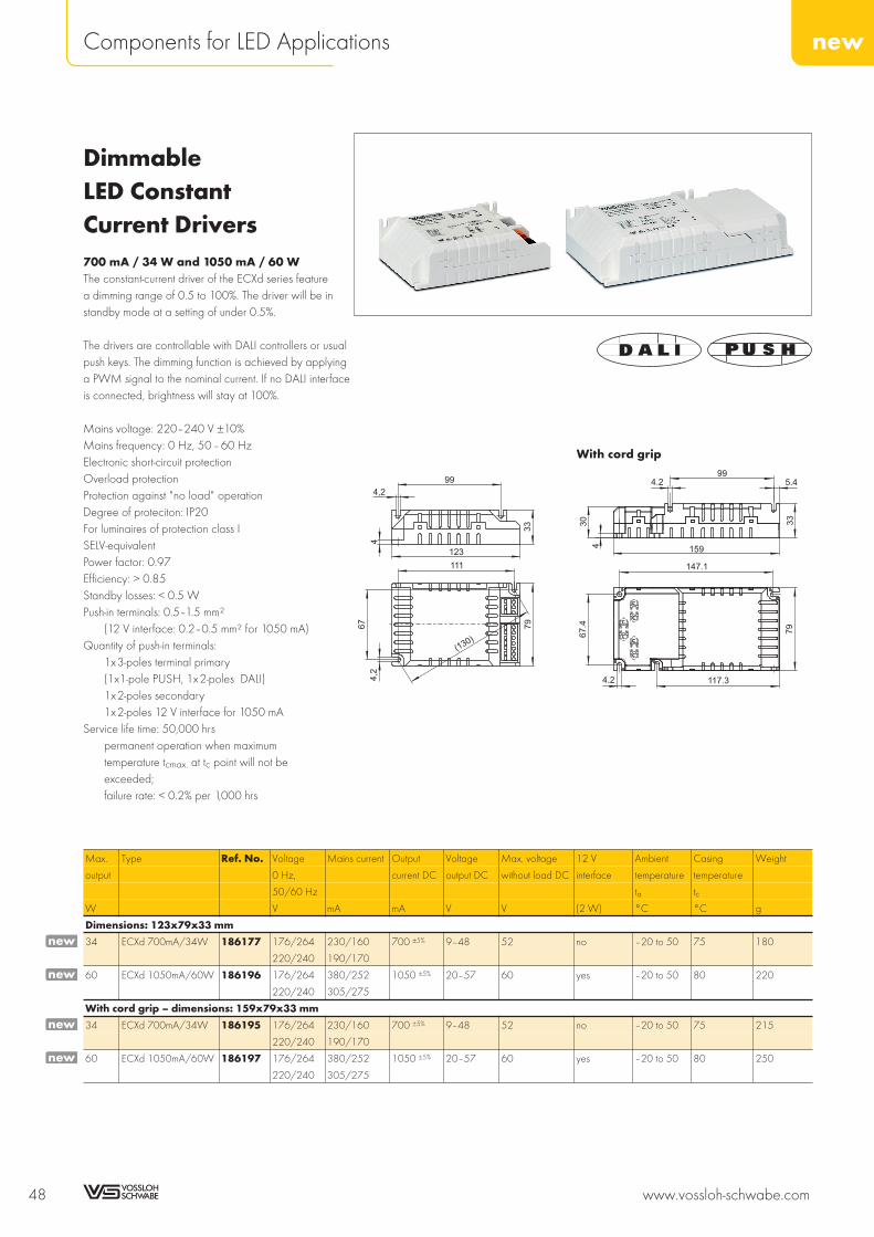
DimmableLED ConstantCurrent Drivers700 mA / 34 W and 1050 mA / 60 WThe constant-current driver of the ECXd series featurea dimming range of 0.5 to 100%. The driver will be instandby mode at a setting of under 0.5%.
The drivers are controllable with DALI controllers or usualpush keys. The dimming function is achieved by applyinga PWM signal to the nominal current. If no DALI interfaceis connected, brightness will stay at 100%.
Mains voltage: 220–240 V ±10%Mains frequency: 0 Hz, 50–60 HzElectronic short-circuit protectionOverload protectionProtection against "no load" operationDegree of proteciton: IP20For luminaires of protection class ISELV-equivalentPower factor: 0.97Efficiency: > 0.85Standby losses: < 0.5 WPush-in terminals: 0.5–1.5 mm²
(12 V interface: 0.2–0.5 mm² for 1050 mA)Quantity of push-in terminals:
1x3-poles terminal primary(1x1-pole PUSH, 1x2-poles DALI)1x2-poles secondary1x2-poles 12 V interface for 1050 mA
Service life time: 50,000 hrspermanent operation when maximumtemperature tcmax. at tc point will not beexceeded;failure rate: < 0.2% per 1,000 hrs
Max. Type Ref. No. Voltage Mains current Output Voltage Max. voltage 12 V Ambient Casing Weight
output 0 Hz, current DC output DC without load DC interface temperature temperature
50/60 Hz ta tcW V mA mA V V (2 W) °C °C g
Dimensions: 123x79x33 mm
34 ECXd 700mA/34W 186177 176/264 230/160 700 ±5% 9–48 52 no –20 to 50 75 180
220/240 190/170
60 ECXd 1050mA/60W 186196 176/264 380/252 1050 ±5% 20–57 60 yes –20 to 50 80 220
220/240 305/275
With cord grip – dimensions: 159x79x33 mm
34 ECXd 700mA/34W 186195 176/264 230/160 700 ±5% 9–48 52 no –20 to 50 75 215
220/240 190/170
60 ECXd 1050mA/60W 186197 176/264 380/252 1050 ±5% 20–57 60 yes –20 to 50 80 250
220/240 305/275
48 www.vossloh-schwabe.com
newComponents for LED Applications
4,2
67
111
79
(130)
123
33
4
4,2
99
4.2
67.4
117.3
79
147.1
159
33
4
30
4.299
5.4
With cord grip
new
new
new
new

Adjustable andDimmable LEDConstant-currentDrivers350, 500, 600, 700 mA / 40 WThe constant-current drivers of the ECXd series featurea dimming range of 0.5 to 100%.The dial can be used set the nominal current to 350 mA,500 mA, 600 mA or 700 mA. The dimming function isachieved by the use of a PWM signal.If no 1–10 V interface is connected, brightness will stayat 100%.The LEDs are thermally protected by the driver's NTCinterface, which ensures the current will be reducedwhen a critical temperature is reached.
Mains voltage: 220–240 V ±10%Mains frequency: 50–60 HzElectronic short-circuit protectionOverload protectionProtection against "no load" operationDegree of proteciton: IP20For luminaires of protection class I and IISELV-equivalentPower factor: 0.95Efficiency: > 0.80Push-in terminals: 0.5–1.5 mm²Quantity of push-in terminals:
1x2-poles primary1x2-poles 1–10 V1x2-poles secondary1x2-poles NTC connection
Service life time: 50,000 hrspermanent operation when maximum temperaturetcmax. at tc point will not be exceeded;failure rate: < 0.2% per 1,000 hrs
Max. Type Ref. No. Voltage Mains current Output current Voltage Max. voltage Ambient Casing Weight
output DC output DC without load DC temperature temperature
50/60 Hz ta tcW V mA mA V V °C °C g
Dimensions: 103.6x67x31 mm
40 ECXd 700mA/40W 186206 220/240 215/195 350 +5/–10% 20–57 60 –20 to 50 80 190
500 +5/–10% –20 to 50
600 +5/–10% –20 to 50
700 +5/–10% –20 to 45
With cord grip – dimensions: 140x67x31 mm
40 ECXd 700mA/40W 186207 220/240 215/195 350 +5/–10% 20–57 60 –20 to 50 80 220
500 +5/–10% –20 to 50
600 +5/–10% –20 to 50
700 +5/–10% –20 to 45
Preliminary data
www.vossloh-schwabe.com 49
newComponents for LED Applications
10
9
8
7
6
5
4
3
2
1
new
new
67
58
(110)
44.2
4.184
31
31
103.6
94
1–10V
4.5 99
57.4
4.5
130
4.5
67
3
28
4.2
84
31
140
With cord grip
NTC of LED module 220 kΩ
R (kΩ) Nominal current (%)
20.7 100
17.3 60
14.6 0 (off)
Adjustment Nominal current
mA
1 350
2 500
3 600
4 700

Adjustable andDimmable LEDConstant-currentDrivers800, 900, 1050, 1200 mA / 68 WThe constant-current drivers of the ECXd series featurea dimming range of 1to 100%.The dial can be used set the nominal current to 800 mA,900 mA, 1050 mA or 1200 mA. The dimming function isachieved by the use of a PWM signal.If no 1–10 V interface is connected, brightness will stayat 100%.
The LEDs are thermally protected by the driver's NTCinterface, which ensures the current will be reducedwhen a critical temperature is reached.
Mains voltage: 220–240 V ±10%Mains frequency: 0 Hz, 50–60 HzElectronic short-circuit protectionOverload protectionProtection against "no load" operationDegree of proteciton: IP20For luminaires of protection class I and IISELV-equivalent, power factor: 0.97Efficiency: > 0.85Push-in terminals: 0.5–1.5 mm²Quantity of push-in terminals:
1x2-poles primary1x2-poles 1–10V1x2-poles secondary1x2-poles NTC connection
Service life time: 50,000 hrspermanent operation when maximum temperaturetcmax. at tc point will not be exceeded;failure rate: < 0.2% per 1,000 hrs
Max. Type Ref. No. Voltage Mains current Output current Voltage output Max. voltage Ambient Casing Weight
output 0 Hz, DC DC without load DC temperature temperature
50/60 Hz ta tcW V mA mA V V °C °C g
Dimensions: 123x79x33 mm
68 ECXd 1200mA/68W on request 176/264 365/340 800 +5/–10% 20–57 60 50 80 260
220/240 435/290 900 +5/–10% 20–57 60 50 80 260
1050 +5/–10% 20–57 60 50 80 260
1200 +5/–10% 20–57 60 50 80 260
With cord grip – dimensions: 159x79x33 mm
68 ECXd 1200mA/68W on request 176/264 365/340 800 +5/–10% 20–57 60 50 80 300
220/240 435/290 900 +5/–10% 20–57 60 50 80 300
1050 +5/–10% 20–57 60 50 80 300
1200 +5/–10% 20–57 60 50 80 300
Preliminary data
50 www.vossloh-schwabe.com
newComponents for LED Applications
1–10V67
(130)
79
33
44.2
4.299
111
123
4.2
67.4
117.3
79
147.1
159
33
4
30
4.299
5.4
With cord grip
NTC of LED module 220 kΩ
R (kΩ) Nominal current (%)
20.7 100
17.3 60
14.6 0 (off)
Adjustment Nominal current
mA
1 800
2 900
3 1050
4 1200
new
new

Dimmable LEDConstant-currentDrivers1400 mA / 65 WThe constant-current drivers of the ECXd seriesfeatures a dimming range of 1to 100%.The dimming function is achieved by the use ofa PWM signal.If no 1–10 V interface is connected, brightness willstay at 100%.The LEDs are thermally protected by the driver's NTCinterface, which ensures the current is reduced whena critical temperature is reached.
Mains voltage: 220–240 V ±10%Mains frequency: 0 Hz, 50–60 HzElectronic short-circuit protectionOverload protectionProtection against "no load" operationDegree of proteciton: IP20For luminaires of protection class I and IISELV-equivalentPower factor: 0.95Efficiency: > 0.85Push-in terminals: 0.5–1.5 mm²Quantity of push-in terminals:
1x2-poles primary1x2-poles 1–10 V1x2-poles secondary1x2-poles NTC connection
Service life time: 50,000 hrspermanent operation when maximum temperaturetcmax. at tc point will not be exceeded;failure rate: < 0.2% per 1,000 hrs
Max. Type Ref. No. Mains voltage Mains Current Voltage Max. voltage Ambient Casing Weight
output 0 Hz, current output DC output DC without load DC temperature temperature
50/60 Hz ta tcW V mA mA V V °C °C g
Dimensions: 123x79x33 mm
65 ECXd 1400mA/65 W 186208 176/264 430/280 1400 +5/–10% 20–47 50 50 80 260
220/240 360/340
With cord grip – dimensions: 159x79x33 mm
65 ECXd 1400mA/65 W 186209 176/264 430/280 1400 +5/–10% 20–47 50 50 80 300
220/240 360/340
Preliminary data
www.vossloh-schwabe.com 51
newComponents for LED Applications
10
9
8
7
6
5
4
3
2
1
new
new
NTC on LED module 220 kΩ
R (kΩ) Nominal current (%)
20.7 100
17.3 60
14.6 0 (off)
1–10V
4.2
67.4
117.3
79
147.1
159
33
4
30
4.299
5.4
With cord grip
4,2
67
111
79
(130)
123
33
4
4,2
99

LED Constant-currentDrivers400, 700 mA / 150 WVS' electronic constant-current sources are designedfor use in street lighting systems. They provide a simplepower-reduction option by connecting a further phase,which makes it possible to switch between 400 mAand 700 mA.
Mains voltage: 220–277 V ±10%Mains frequency: 50–60 HzElectronic short-circuit protectionOverload and overtemperature protectionProtection against "no load" operationDegree of proteciton: IP20 or IP67For luminaires of protection class IPower factor: 0.95Efficiency: > 0.9Service life time: 50,000 hrs
permanent operation when maximum temperaturetcmax. at tc point will not be exceeded;failure rate: < 0.2% per 1,000 hrs
IP20 driverPush-in terminals: 0.5–2.5 mm²Quantity of push-in terminals:
5x1-poles terminal primary2x1-poles secondary
IP67 driverPre-assembled connection leads:
Primary: 5x1 mm², length: 200 mmSecondary: 2x1.5 mm², length: 200 mm
Max. Type Ref. No. Voltage Mains current Output Voltage Max. Voltage Ambient Casing Weight
output 50/60 Hz current DC output DC without load DC temperature temperature
ta tcW V mA mA V V °C °C g
IP20 – dimensions: 240x60x40 mm
150 ECXe 700.023 186202 220–277 735–585 700 +5%/–10% 48–215 445 –40 to 60 75 440
400 +5%/–10% 48–375
IP67 – dimensions: 268x71.6x51 mm
150 ECXe 700.023 186203 220–277 735–585 700 +5%/–10% 48–215 445 –40 to 60 75 560
400 +5%/–10% 48–375
52 www.vossloh-schwabe.com
newComponents for LED Applications
Additional technical features
The electronic converters are protected against transient main peaksup to 3 kV (between L and N) and up to 4 kV (between L, N and PE).
240
2257,5 (7,5)
60
40
5,5
5,5
IP20
275
225 51
79,1
65
30
45
237
IP67
new
new

LED Constant-currentDrivers Linear350 mA/75 W, 350 mA/15 WVS' linear LED constant-current drivers are designedfor use in office and retail lighting. The linear designis particularly suitable for luminaire concepts toreplace T5/T8 fluorescent lamps with LEDs.
Mains voltage: 220–240 V ±10%Mains frequency: 0/50–60 HzElectronic short-circuit protectionOverload protectionProtection against "no load" operationDegree of proteciton: IP20SELV (ECXe 350mA/15W)Service life time: 50,000 hrs
permanent operation when maximum temperaturetcmax. at tc point will not be exceeded;failure rate: < 0.2% per 1,000 hrs
Max. Type Ref. No. Mains voltage Mains Current Voltage Max. voltage Ambient Casing Weight
output 0 Hz, current output DC output DC without load DC temperature temperature
50/60 Hz ta tcW V mA mA V V °C °C g
Casing: M10
75 ECXe 350mA/75W 186226 176/264 350 350 +5/–10% 90–215 420 –20 to 50 75 215
220/240
Casing: M10 with DALI interface
75 ECXd 350mA/75W 186227 176/264 350 350 +5/–10% 90–215 420 –20 to 50 75 215
220/240
Casing: K21
15 ECXe 350mA/15W 186229 176/264 140 350 +5/–10% 2–40 42 –20 to 50 80 49
220/240
Preliminary data
www.vossloh-schwabe.com 53
newComponents for LED Applications
10
9
8
7
6
5
4
3
2
1
18
4,4
21
141,7
146,7
K21
4,2
21
4,2
30
4,2
4,2
350
350
359
M10
new
new
new

THE PERFECT REPLACEMENTConvenient LED technology
As the perfect replacement for low-voltage halogen lamps, the new LEDmodules made by VS are ideal for use in furniture, false ceilings as wellas cooker hoods.
These LED modules are available with high-power LEDs and semi-transparent optics attachments. The circular or square metal frame isavailable in a white, silver, matt silver or gold finish. Furthermore, flexiblesnap-in fasteners make it extremely easy and quick to exchange halogenspots, which are still in widespread use.
The package is rounded off by a matching LED driver housed in acompact VS LiteLine transformer casing plus a set of cables with pre-assembled plugs for connecting up to two LED modules.
54 www.vossloh-schwabe.com
LEDSpots
FOR RESIDENTIALAND FURNITURELIGHTING

LEDSpot XP/XML withHeat Sink – Roundor Square FrameFor cut-out: Ø 56 mmLEDSpot with one LED and with heat sinkfor optimum thermal managementMetal frame, round or square: steelRadiation angle: 60°Leads: Cu tinned, stranded conductors AWG22,
PVC insulation, lengths: 250 mmSnap-in clips for easy installation
for luminaire sheets (type LCH-002 and -008)for ceilings (type LCH-004 and -009)
Degree of protection: IP40Unit: 90 pcs. type LCH-002, LCH-008Unit: 40 pcs. type LCH-004, LCH-009
Typical applicationsIntegration in luminairesArchitectural lightingMarking paths, stairs, etc.Furniture lightingLight advertisingEntertainment, shop design
www.vossloh-schwabe.com 55
newComponents for LED Applications
10
9
8
7
6
5
4
3
2
1
56±0,2
10,5
±0,2
58±0,2
tc
0,5
-1
4,7
18
Ø67
A
Ø67
56±0.2
tc4,7
20
B
58±0,2
T pointc
10,5
±0,2
4,60,5
-1
18
56±0,2
72
C
Operating Service Lifeat ambient temperature ta = 25 °C
Current Operating service life
mA (lumen maintenance at 70%)
350 50,000 hrs XP-E/40,000 hrs XML
500 50,000 hrs
700 40,000 hrs
90°
60°
30°
I (cd/klm)
855
1140
570
285
T pointc
72
21,2
3,6
Ø56±0,2
D

LEDSpot XP/XML with Heat Sink – Round Frame
Type Description Ref. No. Colour Correlated Luminous flux* (lm) at Frame Drawing
colour temperature 350 mA 500 mA 700 mA colour
K min. typ. min. typ. min. typ.
LEDSpot XP at junction temperature tj=25 °C Pel = 1.12 W Pel = 1.65 W Pel = 2.38 W
LCH-002 XPE 3000K min Q3 548898 warm white 2870...3200 79.8 88.0 103.7 114.4 135.7 149.6 silver A
LCH-002 XPE 3000K min Q3 548899 warm white 2870...3200 79.8 88.0 103.7 114.4 135.7 149.6 silver mat A
LCH-002 XPE 3000K min Q3 548900 warm white 2870...3200 79.8 88.0 103.7 114.4 135.7 149.6 gold A
LCH-002 XPE 3000K min Q3 548901 warm white 2870...3200 79.8 88.0 103.7 114.4 135.7 149.6 white A
LCH-004 XPE 3000K min Q3 548886 warm white 2870...3200 79.8 88.0 103.7 114.4 135.7 149.6 silver B
LCH-004 XPE 3000K min Q3 548887 warm white 2870...3200 79.8 88.0 103.7 114.4 135.7 149.6 silver mat B
LCH-004 XPE 3000K min Q3 548888 warm white 2870...3200 79.8 88.0 103.7 114.4 135.7 149.6 gold B
LCH-004 XPE 3000K min Q3 548889 warm white 2870...3200 79.8 88.0 103.7 114.4 135.7 149.6 white B
LCH-002 XPE 4500K min Q4 548902 neutral white 4250...4750 85.0 93.9 110.5 122.1 144.5 159.6 silver A
LCH-002 XPE 4500K min Q4 548903 neutral white 4250...4750 85.0 93.9 110.5 122.1 144.5 159.6 silver mat A
LCH-002 XPE 4500K min Q4 548904 neutral white 4250...4750 85.0 93.9 110.5 122.1 144.5 159.6 gold A
LCH-002 XPE 4500K min Q4 548905 neutral white 4250...4750 85.0 93.9 110.5 122.1 144.5 159.6 white A
LCH-004 XPE 4500K min Q4 547838 neutral white 4250...4750 85.0 93.9 110.5 122.1 144.5 159.6 silver B
LCH-004 XPE 4500K min Q4 548891 neutral white 4250...4750 85.0 93.9 110.5 122.1 144.5 159.6 silver mat B
LCH-004 XPE 4500K min Q4 548892 neutral white 4250...4750 85.0 93.9 110.5 122.1 144.5 159.6 gold B
LCH-004 XPE 4500K min Q4 548893 neutral white 4250...4750 85.0 93.9 110.5 122.1 144.5 159.6 white B
LCH-002 XPE 6300K min R2 548906 cool white 5650...6950 96.9 107.1 126.0 139.2 164.7 182.1 silver A
LCH-002 XPE 6300K min R2 548907 cool white 5650...6950 96.9 107.1 126.0 139.2 164.7 182.1 silver mat A
LCH-002 XPE 6300K min R2 548908 cool white 5650...6950 96.9 107.1 126.0 139.2 164.7 182.1 gold A
LCH-002 XPE 6300K min R2 548909 cool white 5650...6950 96.9 107.1 126.0 139.2 164.7 182.1 white A
LCH-004 XPE 6300K min R2 548894 cool white 5650...6950 96.9 107.1 126.0 139.2 164.7 182.1 silver B
LCH-004 XPE 6300K min R2 548895 cool white 5650...6950 96.9 107.1 126.0 139.2 164.7 182.1 silver mat B
LCH-004 XPE 6300K min R2 548896 cool white 5650...6950 96.9 107.1 126.0 139.2 164.7 182.1 gold B
LCH-004 XPE 6300K min R2 548897 cool white 5650...6950 96.9 107.1 126.0 139.2 164.7 182.1 white B
LEDSpot XML at junction temperature tj=85 °C Pel = 4 W – –
LCH-002 XML 3000K min T6 548912 warm white 2950...3125 238.0 255.0 not allowed not allowed silver A
LCH-002 XML 3000K min T6 548913 warm white 2950...3125 238.0 255.0 not allowed not allowed silver mat A
LCH-002 XML 3000K min T6 548914 warm white 2950...3125 238.0 255.0 not allowed not allowed gold A
LCH-002 XML 3000K min T6 548915 warm white 2950...3125 238.0 255.0 not allowed not allowed white A
LCH-004 XML 3000K min T6 548920 warm white 2950...3125 238.0 255.0 not allowed not allowed silver B
LCH-004 XML 3000K min T6 548921 warm white 2950...3125 238.0 255.0 not allowed not allowed silver mat B
LCH-004 XML 3000K min T6 548922 warm white 2950...3125 238.0 255.0 not allowed not allowed gold B
LCH-004 XML 3000K min T6 548923 warm white 2950...3125 238.0 255.0 not allowed not allowed white B
LCH-002 XML 4000K min U2 548916 neutral white 3835...4110 255.0 272.0 not allowed not allowed silver A
LCH-002 XML 4000K min U2 548917 neutral white 3835...4110 255.0 272.0 not allowed not allowed silver mat A
LCH-002 XML 4000K min U2 548918 neutral white 3835...4110 255.0 272.0 not allowed not allowed gold A
LCH-002 XML 4000K min U2 548919 neutral white 3835...4110 255.0 272.0 not allowed not allowed white A
LCH-004 XML 4000K min U2 548924 neutral white 3835...4110 255.0 272.0 not allowed not allowed silver B
LCH-004 XML 4000K min U2 548925 neutral white 3835...4110 255.0 272.0 not allowed not allowed silver mat B
LCH-004 XML 4000K min U2 548926 neutral white 3835...4110 255.0 272.0 not allowed not allowed gold B
LCH-004 XML 4000K min U2 548927 neutral white 3835...4110 255.0 272.0 not allowed not allowed white B
* Measurement tolerance of luminous flux: ± 7% | Emission data at tj = 25 °C
56 www.vossloh-schwabe.com
newComponents for LED Applications
newnewnewnewnewnewnewnewnewnewnewnewnewnewnewnewnewnewnewnewnewnewnewnew
newnewnewnewnewnewnewnewnewnewnewnewnewnewnewnew

LEDSpot XP/XML with Heat Sink – Square Frame
Type Description Ref. No. Colour Correlated Luminous flux* (lm) at Frame Drawing
colour temperature 350 mA 500 mA 700 mA colour
K min. typ. min. typ. min. typ.
LEDSpot XP at junction temperature tj=25 °C Pel = 1.12 W Pel = 1.65 W Pel = 2.38 W
LCH-008 XPE 3000K min Q3 548363 warm white 2870...3200 79.8 88.0 103.7 114.4 135.7 149.6 silver C
LCH-008 XPE 3000K min Q3 548364 warm white 2870...3200 79.8 88.0 103.7 114.4 135.7 149.6 silver mat C
LCH-008 XPE 3000K min Q3 548368 warm white 2870...3200 79.8 88.0 103.7 114.4 135.7 149.6 gold C
LCH-008 XPE 3000K min Q3 548366 warm white 2870...3200 79.8 88.0 103.7 114.4 135.7 149.6 white C
LCH-009 XPE 3000K min Q3 548418 warm white 2870...3200 79.8 88.0 103.7 114.4 135.7 149.6 silver D
LCH-009 XPE 3000K min Q3 548419 warm white 2870...3200 79.8 88.0 103.7 114.4 135.7 149.6 silver mat D
LCH-009 XPE 3000K min Q3 548428 warm white 2870...3200 79.8 88.0 103.7 114.4 135.7 149.6 gold D
LCH-009 XPE 3000K min Q3 548424 warm white 2870...3200 79.8 88.0 103.7 114.4 135.7 149.6 white D
LCH-008 XPE 4500K min Q4 548369 neutral white 4250...4750 85.0 93.9 110.5 122.1 144.5 159.6 silver C
LCH-008 XPE 4500K min Q4 548370 neutral white 4250...4750 85.0 93.9 110.5 122.1 144.5 159.6 silver mat C
LCH-008 XPE 4500K min Q4 548374 neutral white 4250...4750 85.0 93.9 110.5 122.1 144.5 159.6 gold C
LCH-008 XPE 4500K min Q4 548372 neutral white 4250...4750 85.0 93.9 110.5 122.1 144.5 159.6 white C
LCH-009 XPE 4500K min Q4 548429 neutral white 4250...4750 85.0 93.9 110.5 122.1 144.5 159.6 silver D
LCH-009 XPE 4500K min Q4 548430 neutral white 4250...4750 85.0 93.9 110.5 122.1 144.5 159.6 silver mat D
LCH-009 XPE 4500K min Q4 548434 neutral white 4250...4750 85.0 93.9 110.5 122.1 144.5 159.6 gold D
LCH-009 XPE 4500K min Q4 548432 neutral white 4250...4750 85.0 93.9 110.5 122.1 144.5 159.6 white D
LCH-008 XPE 6300K min R2 548375 cool white 5650...6950 96.9 107.1 126.0 139.2 164.7 182.1 silver C
LCH-008 XPE 6300K min R2 548376 cool white 5650...6950 96.9 107.1 126.0 139.2 164.7 182.1 silver mat C
LCH-008 XPE 6300K min R2 548380 cool white 5650...6950 96.9 107.1 126.0 139.2 164.7 182.1 gold C
LCH-008 XPE 6300K min R2 548378 cool white 5650...6950 96.9 107.1 126.0 139.2 164.7 182.1 white C
LCH-009 XPE 6300K min R2 548435 cool white 5650...6950 96.9 107.1 126.0 139.2 164.7 182.1 silver D
LCH-009 XPE 6300K min R2 548436 cool white 5650...6950 96.9 107.1 126.0 139.2 164.7 182.1 silver mat D
LCH-009 XPE 6300K min R2 548440 cool white 5650...6950 96.9 107.1 126.0 139.2 164.7 182.1 gold D
LCH-009 XPE 6300K min R2 548438 cool white 5650...6950 96.9 107.1 126.0 139.2 164.7 182.1 white D
LEDSpot XML at junction temperature tj=85 °C Pel = 4 W – –
LCH-008 XML 3000K min T6 549828 warm white 2950...3125 238.0 255.0 not allowed not allowed silver C
LCH-008 XML 3000K min T6 548929 warm white 2950...3125 238.0 255.0 not allowed not allowed silver mat C
LCH-008 XML 3000K min T6 548930 warm white 2950...3125 238.0 255.0 not allowed not allowed gold C
LCH-008 XML 3000K min T6 548931 warm white 2950...3125 238.0 255.0 not allowed not allowed white C
LCH-009 XML 3000K min T6 548936 warm white 2950...3125 238.0 255.0 not allowed not allowed silver D
LCH-009 XML 3000K min T6 548937 warm white 2950...3125 238.0 255.0 not allowed not allowed silver mat D
LCH-009 XML 3000K min T6 548938 warm white 2950...3125 238.0 255.0 not allowed not allowed gold D
LCH-009 XML 3000K min T6 548939 warm white 2950...3125 238.0 255.0 not allowed not allowed white D
LCH-008 XML 4000K min U2 548932 neutral white 3835...4110 255.0 272.0 not allowed not allowed silver C
LCH-008 XML 4000K min U2 548933 neutral white 3835...4110 255.0 272.0 not allowed not allowed silver mat C
LCH-008 XML 4000K min U2 548934 neutral white 3835...4110 255.0 272.0 not allowed not allowed gold C
LCH-008 XML 4000K min U2 548935 neutral white 3835...4110 255.0 272.0 not allowed not allowed white C
LCH-009 XML 4000K min U2 548940 neutral white 3835...4110 255.0 272.0 not allowed not allowed silver D
LCH-009 XML 4000K min U2 548941 neutral white 3835...4110 255.0 272.0 not allowed not allowed silver mat D
LCH-009 XML 4000K min U2 548942 neutral white 3835...4110 255.0 272.0 not allowed not allowed gold D
LCH-009 XML 4000K min U2 548943 neutral white 3835...4110 255.0 272.0 not allowed not allowed white D
* Measurement tolerance of luminous flux: ± 7% | Emission data at tj = 25 °C
www.vossloh-schwabe.com 57
newComponents for LED Applications
10
9
8
7
6
5
4
3
2
1
newnewnewnewnewnewnewnewnewnewnewnewnewnewnewnewnewnewnewnewnewnewnewnew
newnewnewnewnewnewnewnewnewnewnewnewnewnewnewnew

LEDSpot Reflector XPwith Heat SinkFor cut-out: Ø 56 mmLEDSpot with one LED and with heat sinkfor optimum thermal managementReflector with glass diffuserMetal frame, round: steelLeads: Cu tinned, stranded conductors AWG22,
PVC insulation, lengths: 250 mmSnap-in clips for easy installation
for luminaire sheets (type LCH-006)for ceilings (type LCH-007)
Degree of protection: IP40Unit: 90 pcs. type LCH-006Unit: 40 pcs. type LCH-007
Typical applicationsIntegration in luminairesArchitectural lightingMarking paths, stairs, etc.Furniture lightingLight advertisingEntertainment, shop design
58 www.vossloh-schwabe.com
newComponents for LED Applications
Ø68,6
Ø56±0,2
tc
1,2
21
B
Ø68,6
0,5
-1
10,5
±0,2
Ø56±0.2
58±0,2
tc
21
1,2
A
Operating service lifeat ambient temperature ta = 25 °C
Current Operating service life
mA (lumen maintenance at 70%)
350 50,000 hrs
500 50,000 hrs
700 40,000 hrs

LEDSpot Reflector XP with Heat Sink
Type Description Ref. No. Colour Correlated Luminous flux* (lm) at Radiation Frame Drawing
colour 350 mA 500 mA 700 mA angle colour
temperature Pel = 1.12 W Pel = 1.65 W Pel = 2.38 W
K min. typ. min. typ. min. typ. °
LEDSpot Reflector XP at junction temperature tj=25 °C – radiation angle 20°
LCH-006 XPE 3000K min Q3 548769 warm white 2870...3200 79.8 88.0 103.7 114.4 135.7 149.6 20 silver A
LCH-006 XPE 3000K min Q3 548770 warm white 2870...3200 79.8 88.0 103.7 114.4 135.7 149.6 20 silver mat A
LCH-006 XPE 3000K min Q3 548774 warm white 2870...3200 79.8 88.0 103.7 114.4 135.7 149.6 20 gold A
LCH-006 XPE 3000K min Q3 548772 warm white 2870...3200 79.8 88.0 103.7 114.4 135.7 149.6 20 white A
LCH-007 XPE 3000K min Q3 548794 warm white 2870...3200 79.8 88.0 103.7 114.4 135.7 149.6 20 silver B
LCH-007 XPE 3000K min Q3 548795 warm white 2870...3200 79.8 88.0 103.7 114.4 135.7 149.6 20 silver mat B
LCH-007 XPE 3000K min Q3 548799 warm white 2870...3200 79.8 88.0 103.7 114.4 135.7 149.6 20 gold B
LCH-007 XPE 3000K min Q3 548797 warm white 2870...3200 79.8 88.0 103.7 114.4 135.7 149.6 20 white B
LCH-006 XPE 4500K min Q4 548944 neutral white 4250...4750 85.0 93.9 110.5 122.1 144.5 159.6 20 silver A
LCH-006 XPE 4500K min Q4 548945 neutral white 4250...4750 85.0 93.9 110.5 122.1 144.5 159.6 20 silver mat A
LCH-006 XPE 4500K min Q4 548946 neutral white 4250...4750 85.0 93.9 110.5 122.1 144.5 159.6 20 gold A
LCH-006 XPE 4500K min Q4 548947 neutral white 4250...4750 85.0 93.9 110.5 122.1 144.5 159.6 20 white A
LCH-007 XPE 4500K min Q4 548952 neutral white 4250...4750 85.0 93.9 110.5 122.1 144.5 159.6 20 silver B
LCH-007 XPE 4500K min Q4 548953 neutral white 4250...4750 85.0 93.9 110.5 122.1 144.5 159.6 20 silver mat B
LCH-007 XPE 4500K min Q4 548954 neutral white 4250...4750 85.0 93.9 110.5 122.1 144.5 159.6 20 gold B
LCH-007 XPE 4500K min Q4 548955 neutral white 4250...4750 85.0 93.9 110.5 122.1 144.5 159.6 20 white B
LCH-006 XPE 6300K min R2 548775 cool white 5450...6950 96.9 107.1 126.0 139.2 164.7 182.1 20 silver A
LCH-006 XPE 6300K min R2 548776 cool white 5450...6950 96.9 107.1 126.0 139.2 164.7 182.1 20 silver mat A
LCH-006 XPE 6300K min R2 548780 cool white 5450...6950 96.9 107.1 126.0 139.2 164.7 182.1 20 gold A
LCH-006 XPE 6300K min R2 548778 cool white 5450...6950 96.9 107.1 126.0 139.2 164.7 182.1 20 white A
LCH-007 XPE 6300K min R2 548800 cool white 5450...6950 96.9 107.1 126.0 139.2 164.7 182.1 20 silver B
LCH-007 XPE 6300K min R2 548801 cool white 5450...6950 96.9 107.1 126.0 139.2 164.7 182.1 20 silver mat B
LCH-007 XPE 6300K min R2 548805 cool white 5450...6950 96.9 107.1 126.0 139.2 164.7 182.1 20 gold B
LCH-007 XPE 6300K min R2 548803 cool white 5450...6950 96.9 107.1 126.0 139.2 164.7 182.1 20 white B
LEDSpot Reflector XP at junction temperature tj=25 °C – radiation angle 50°
LCH-006 XPE 3000K min Q3 548782 warm white 2870...3200 79.8 88.0 103.7 114.4 135.7 149.6 50 silver A
LCH-006 XPE 3000K min Q3 548783 warm white 2870...3200 79.8 88.0 103.7 114.4 135.7 149.6 50 silver mat A
LCH-006 XPE 3000K min Q3 548787 warm white 2870...3200 79.8 88.0 103.7 114.4 135.7 149.6 50 gold A
LCH-006 XPE 3000K min Q3 548785 warm white 2870...3200 79.8 88.0 103.7 114.4 135.7 149.6 50 white A
LCH-007 XPE 3000K min Q3 548806 warm white 2870...3200 79.8 88.0 103.7 114.4 135.7 149.6 50 silver B
LCH-007 XPE 3000K min Q3 548807 warm white 2870...3200 79.8 88.0 103.7 114.4 135.7 149.6 50 silver mat B
LCH-007 XPE 3000K min Q3 548811 warm white 2870...3200 79.8 88.0 103.7 114.4 135.7 149.6 50 gold B
LCH-007 XPE 3000K min Q3 548809 warm white 2870...3200 79.8 88.0 103.7 114.4 135.7 149.6 50 white B
LCH-006 XPE 4500K min Q4 548948 neutral white 4250...4750 85.0 93.9 110.5 122.1 144.5 159.6 50 silver A
LCH-006 XPE 4500K min Q4 548949 neutral white 4250...4750 85.0 93.9 110.5 122.1 144.5 159.6 50 silver mat A
LCH-006 XPE 4500K min Q4 548950 neutral white 4250...4750 85.0 93.9 110.5 122.1 144.5 159.6 50 gold A
LCH-006 XPE 4500K min Q4 548951 neutral white 4250...4750 85.0 93.9 110.5 122.1 144.5 159.6 50 white A
LCH-007 XPE 4500K min Q4 548956 neutral white 4250...4750 85.0 93.9 110.5 122.1 144.5 159.6 50 silver B
LCH-007 XPE 4500K min Q4 548957 neutral white 4250...4750 85.0 93.9 110.5 122.1 144.5 159.6 50 silver mat B
LCH-007 XPE 4500K min Q4 548958 neutral white 4250...4750 85.0 93.9 110.5 122.1 144.5 159.6 50 gold B
LCH-007 XPE 4500K min Q4 548959 neutral white 4250...4750 85.0 93.9 110.5 122.1 144.5 159.6 50 white B
LCH-006 XPE 6300K min R2 548788 cool white 5450...6950 96.9 107.1 126.0 139.2 164.7 182.1 50 silver A
LCH-006 XPE 6300K min R2 548789 cool white 5450...6950 96.9 107.1 126.0 139.2 164.7 182.1 50 silver mat A
LCH-006 XPE 6300K min R2 548793 cool white 5450...6950 96.9 107.1 126.0 139.2 164.7 182.1 50 gold A
LCH-006 XPE 6300K min R2 548791 cool white 5450...6950 96.9 107.1 126.0 139.2 164.7 182.1 50 white A
LCH-007 XPE 6300K min R2 548812 cool white 5450...6950 96.9 107.1 126.0 139.2 164.7 182.1 50 silver B
LCH-007 XPE 6300K min R2 548813 cool white 5450...6950 96.9 107.1 126.0 139.2 164.7 182.1 50 silver mat B
LCH-007 XPE 6300K min R2 548817 cool white 5450...6950 96.9 107.1 126.0 139.2 164.7 182.1 50 gold B
LCH-007 XPE 6300K min R2 548815 cool white 5450...6950 96.9 107.1 126.0 139.2 164.7 182.1 50 white B
* Measurement tolerance of luminous flux: ± 7% | Emission data at tj = 25 °C
www.vossloh-schwabe.com 59
newComponents for LED Applications
10
9
8
7
6
5
4
3
2
1
newnewnewnewnewnewnewnewnewnewnewnewnewnewnewnewnewnewnewnewnewnewnewnew
newnewnewnewnewnewnewnewnewnewnewnewnewnewnewnewnewnewnewnewnewnewnewnew

LEDSpot EffectLine XP/XMLwith Heat SinkFor cut-out: Ø 37 mmLEDSpot with one LED and with heat sinkfor optimum thermal managementMetal frame, round or square: steel, silverLeads: Cu tinned, stranded conductors AWG22,
PVC insulation, lengths: 250 mmSnap-in clips for easy installationfor ceilingsUnit: 45 pcs.
Typical applicationsIntegration in luminairesArchitectural lightingMarking paths, stairs, etc.Furniture lightingLight advertisingEntertainment, shop design
Type Description Ref. No. Colour Correlated Luminous flux* (lm) at Radiation Drawing
colour temperature 350 mA 500 mA 700 mA angle
K min. typ. min. typ. min. typ. °
LEDSpot EffectLine XP at junction temperature tj=25 °C Pel = 1.12 W Pel = 1.65 W Pel = 2.38 W
LCH010 XPE 3000K min Q3 548964 warm white 2870...3200 84.5 93.2 109.9 121.1 163.7 158.4 26 A
LCH010 XPE 3000K min Q3 548960 warm white 2870...3200 84.5 93.2 109.9 121.1 163.7 158.4 45 A
LCH010 XPE 4500K min Q4 548965 neutral white 4250...4750 90.0 99.4 117.0 129.3 153.0 169.0 26 A
LCH010 XPE 4500K min Q4 548961 neutral white 4250...4750 90.0 99.4 117.0 129.3 153.0 169.0 45 A
LCH011 XPE 3000K min Q3 548966 warm white 2870...3200 84.5 93.2 109.9 121.1 163.7 158.4 26 B
LCH011 XPE 3000K min Q3 548962 warm white 2870...3200 84.5 93.2 109.9 121.1 163.7 158.4 45 B
LCH011 XPE 4500K min Q4 548967 neutral white 4250...4750 90.0 99.4 117.0 129.3 153.0 169.0 26 B
LCH011 XPE 4500K min Q4 548963 neutral white 4250...4750 90.0 99.4 117.0 129.3 153.0 169.0 45 B
LEDSpot EffectLine XML at junction temperature tj=85 °C Pel = 4 W – –
LCH010 XML 3000K min T6 548974 warm white 2950...3125 252.0 270.0 not allowed not allowed 26 A
LCH010 XML 3000K min T6 548970 warm white 2950...3125 252.0 270.0 not allowed not allowed 45 A
LCH010 XML 4000K min U2 548975 neutral white 3835...4110 270.0 288.0 not allowed not allowed 26 A
LCH010 XML 4000K min U2 548971 neutral white 3835...4110 270.0 288.0 not allowed not allowed 45 A
LCH011 XML 3000K min T6 548976 warm white 2950...3125 252.0 270.0 not allowed not allowed 26 B
LCH011 XML 3000K min T6 548972 warm white 2950...3125 252.0 270.0 not allowed not allowed 45 B
LCH011 XML 4000K min U2 548977 neutral white 3835...4110 270.0 288.0 not allowed not allowed 26 B
LCH011 XML 4000K min U2 548973 neutral white 3835...4110 270.0 288.0 not allowed not allowed 45 B
* Measurement tolerance of luminous flux: ± 7% | Emission data at tj = 25 °C
60 www.vossloh-schwabe.com
newComponents for LED Applications
41
0,5
Ø50
Ø37
A
41
0,5
50
Ø37
50
B
Operating service lifeat ambient temperature ta = 25 °C
Current Operating service life
mA (lumen maintenance at 70%)
350 50,000 hrs XP-E/40,000 hrs XML
500 50,000 hrs
700 40,000 hrs
newnewnewnewnewnewnewnew
newnewnewnewnewnewnewnew
90°
60°
30°1400
700
100
I (cd/klm)
45°
90°
60°
30°5000
2500
1000
I (cd/klm)
26°

With its high-power 24 V system, Vossloh-Schwabe is responding to thetrend towards market harmonisation and simplification of LED controltechnology.
The modules are operated at 24 V DC and constant-current control of350 mA min. is effected on the circuit board. The module is connectedusing on-board push-in terminals and matching connecting cables. Thisenables modular and highly flexible LED systems.
The RGB system is based on the "common anode" principle.The DigiLED CA series permits the operation of high-power RGBmodules and low-power modules of "common anode" design.
Typical applications• General lighting• Architectural lighting• Lighting of complex structures• Entertainment• Shop design
www.vossloh-schwabe.com 61
The specifications contained in this catalogue can changedue to technical innovations. Any such changes will bemade without separate notification.
Please read the safety and installation instructions on theindividual products as well as further technical informationprovided in the extensive product descriptions atwww.vossloh-schwabe.com.
High Power 24 V CA System
24 V CA MODULES,COLOUR CONTROLAND CONNECTIONTECHNOLOGY

High Power 24 V CAModulesMono and RGBBuilt-in PCB lighting modulesThe High Power 24 V CA modules are available inwhite and warm white or RGB with a very highluminous flux.
The round design with 3 or 10 High Power LEDs isparticularly suitable for installation in luminaires andspots. The linear design with 6 LEDs is, for instance,suitable for wall-washing and linear luminaires, etc.
To enable easy understanding of the system, themodules are operated at 24 V DC. Constant-currentcontrol of the LEDs is on the circuit board. Contactsare made using an on-board push terminal withmatching connection cables.
Additional suitable dimming modules (DigiLED CAseries) and optics attachments (s. pages 42 and 43)are available to create individual lighting solutions.
Technical notesTriple WU-M-440: Ø 66 mm, 3 LEDsLine WU-M-441: 300x26 mm, 6 LEDsFlood WU-M-442: Ø 110 mm, 10 LEDsAllowed operating temperature at tc point:
–10 to 85 °CAluminium PCBFor improved thermal management VS recommendsan additional cooling element, which is suitable forthe application.Colour rendering index: > 80Increased ESD protectionVoltage supply: 24 V DCMinimum order quantity: 50 pcs.
Typical applicationsGeneral lightingArchitectural lightingEntertainment, shop designDecorative lightingLight advertising
62 www.vossloh-schwabe.com
Components for LED Applications
90°
60°
30°
I (cd/klm)
250
350
150
50
Mono
90°
60°
30°
I (cd/klm)
255
340
170
85
RGB
66±0.5
16 23.3
X1
Tc
25
23.3
25
2
7.2
5
Ø3.2
Ø3.2
Ø3.2
16
Triple
26
26
7.2
5 2
Tc88±0.5 Ø
3,1Ø3,1
124±0.5
300±0.5
(5x50=250)
Line
3xØ3.2
52
39.5
45.33
Tc
45.33
14
110
5
10
2
26
RGB Flood

High Power 24 V CA Modules – Mono
Type Ref. No. Colour Number Inrush current* Nominal current* Colour temperature* Typ. luminous flux* (lm) Radiation Max. power*
of LEDs A A K min. typ. angle* (°) W
Mono Triple
WU-M-440-WW 548520 warm white 3 0.86 0.42 3000 –130/+220 565 610 115 10
WU-M-440-NW 548519 neutral white 3 0.86 0.42 4000 –300/+260 565 610 115 10
Mono Line
WU-M-441-WW 548523 warm white 6 1.66 0.83 3000 –130/+220 1130 1220 115 20
WU-M-441-NW 548522 neutral white 6 1.66 0.83 4000 –300/+260 1130 1220 115 20
Mono Flood
WU-M-442-WW 548526 warm white 10 1.10 1.10 3000 –130/+220 1900 1550 115 20
WU-M-442-NW 548525 neutral white 10 1.10 1.10 4000 –300/+260 1900 1550 115 20
* Measurement tolerance of luminous flux: ± 7% | Emission data at tj = 25 °C
High Power 24 V CA Modules – RGB
Type Ref. No. Colour Number Inrush current* Nominal Dom. wavelength (mm) Typ. luminous flux* (lm) Radiation Max. power*
of LEDs A current* (A) red green blue red green blue angle* (°) W
RGB Triple
WU-M-440-RGB 548518 RGB 3 0.54 0.22 620–630 520–535 465–485 60 115 40 130 5
RGB Line
WU-M-441-RGB 548521 RGB 6 1.10 0.65 620–630 520–535 465–485 180 315 115 130 15
RGB Flood
WU-M-442-RGB 548524 RGB 10 1.40 1.10 620–630 520–535 465–485 215 500 135 130 25
* Measurement tolerance of luminous flux: ± 7% | Emission data at tj = 25 °C
www.vossloh-schwabe.com 63
Components for LED Applications
10
9
8
7
6
5
4
3
2
1

LEDLine Flex RGB2CA IndoorBuilt-in PCB lighting modulesThe LEDLine Flex RGB2 CA is a "common anode"design variant. This permits the user to operatehigh-power RGB modules together with the newFlex RGB2 CA.
The LEDLine Flex RGB2 CA is fitted with SMD LEDson a flexible printed circuit board of only approx.0.15 mm thickness. Even the most complex structurescan be illuminated thanks to the use of an extremelypliable foil. LEDLine Flex SMD can be separated intosegments of 171 mm without loss of function.This product is available in continuous lengths of4.104 m. Installation is achieved via double-sidedadhesive tape affixed to the rear of the PCB.
Technical notes
Allowed operating temperature at tc point:–25 to 70 °C
Wide radiation angle (110°)Voltage supply: 24 V DCPower consumption per step (171 mm): 2.4 WEach SMD contains 3 LED-Chips
in the colours red, green and blue
Typical applicationsArchitectural lightingLighting of complex structuresEntertainment, shop designMarking paths, stairs, etc.Furniture lightingLight advertising
Type Ref. No. Colour Current* Dom. wavelength* Typ. luminous flux* Radiation Max. power*
A nm lm angle* W
red green blue red green blue red green blue ° red green blue
WU-M-266-RGB2-CA 536052 RGB 0.48 0.96 0.96 624 528 467 528 853 193 110 11.5 23 23
* The values mentioned above represent only statistical variables on account of the complex manufacturing process of light emitting diodes.
The values do not necessarily correspond exactly to the actual parameters of every single product, which can vary from the typical specifications.
64 www.vossloh-schwabe.com
Components for LED Applications
0,4
10
8,55
17,1 tc
171
2,9
90°
60°
30°
I (cd/klm)
50
350
200
Dimensions of LEDLine Flex SMD
LxW SMDs Single Length SMDs
mm pcs. steps mm pcs.
4104x10 240 24 171 10

LEDLine Flex RGB2CA OutdoorBuilt-in PCB lighting modulesThe LEDLine Flex RGB2 CA Outdoor is an extremelyflexible linear module for applications with highmoisture or dust burden conditions. Due to the flexibleand compact design, the illumination of complexstructures and flat designs can be realised. The IP67protected LEDLine Flex RGB2 CA Outdoor is availablein 3 different lengths (see below). The installation isachieved via double-sided adhesive tape affixed tothe rear of the PCB.
The colour blend of LEDLine Flex RGB2 CA Outdoorcan be adjusted using DigiLED control modules. Toincrease the number of LED modules DigiLED-Slavecan be used.
Technical notesDimensions of PCB: 171x10 mm,855x10 mm, 1710x10 mmEncapsulated dimensions (see drawing)PCB 171 mm: A = 177±5 mmPCB 855 mm: A = 861±5 mmPCB 1710 mm: A = 1716±5 mmDegree of protection: IP67Allowed operating temperature at tc point:
–20 to 50 °CAllowed handling temperature:
10 to 50 °CMinimum bend radius: 50 mm,flexible in longitudinal direction onlyPre-assembled with 4 wires on both endsVoltage supply: 24 V DC
Typical applicationsLighting of complex structureswith high moisture or dust burdenOutdoor marking of paths, stairs, etc.Outdoor light advertisingOutdoor entertainment, shop designArchitectural lightingOutdoor border lighting
Type Ref. No. Colour Number Current* Dom. wavelength* Typ. luminous Radiation Max. power*
of SMDs A nm flux* (lm) angle* W
WU-M-266- red green blue red green blue red green blue ° red green blue
RGB2-CA-Outdoor 171mm 545420 RGB 10 0.02 0.04 0.04 624 528 467 22 36 8 110 0.48 0.96 0.96
RGB2-CA-Outdoor 855mm 545421 RGB 50 0.10 0.20 0.20 624 528 467 110 180 40 110 2.40 4.80 4.80
RGB2-CA-Outdoor 1710mm 545422 RGB 100 0.20 0.40 0.40 624 528 467 220 360 80 110 4.80 9.60 9.60
* The values mentioned above represent only statistical variables on account of the complex manufacturing process of light emitting diodes.
The values do not necessarily correspond exactly to the actual parameters of every single product, which can vary from the typical specifications.
www.vossloh-schwabe.com 65
Components for LED Applications
10
9
8
7
6
5
4
3
2
1
90°
60°
30°
I (cd/klm)
50
350
200
200±10
A
tc
200±10
12
±0.5
6+1.5
–0.0

Colour Control Modules – DigiLED CAThe DigiLED CA series is based on a system designthat combines simplicity, flexibility and reliability. TheDigiLED CA series is suitable for operating both high-power RGB CA modules and low-power RGB CAmodules.In the simplest case, a keypad enables manual colourcontrol. In addition to custom colour control, it is alsopossible to call up pre-set colour programs forexample colour sequences.
The CA series of VS colour control modules areavailable with both a manual operating padand a DALI interface or "PUSH" or DMX variant.
Furthermore the DigiLED Mono is available.The DigiLED Mono enables the dimming ofsingle-colour (e. g. white) LED modules.
Technical notesDimensions: 93x58x29 mmAmbient temperature ta: –20 to 45 °COperating voltage: 24 V DCMax. current on the supply line: 5 AConnectors: push-in terminals: 0.25–1.5 mm²,
grid: 3.5 mmAll DigiLED not suitable for the US market
DigiLED Manual CAColour controls via key pads (6 keys)Individual colour control or selection ofpre-set programstc = 55 °C max.Max. current per control channel: 1.25 AType: WU-ST-001-Digi-manuell-CARef. No.: 186136
DigiLED DALI CADigital colour controls via DALI light managementtc = 60 °C max.Max. current per control channel: 1.25 AType: WU-ST-004-Digi-DALI-CARef. No.: 186138
DigiLED DMX CADigital colour controls via DMX light managementtc = 60 °C max.Max. current per control channel: 1.25 AType: WU-ST-003-Digi-DMX-CARef. No.: 186153
DigiLED IR CAColour adjustment by a portable remote controlCall up of pre-adjusted setting possibleData transfer via infra-redtc = 55 °C max.Max. current per control channel: 1.25 AType: WU-ST-005-Digi-IR-CARef. No.: 186154
66 www.vossloh-schwabe.com
Components for LED Applications
DigiLED Manual CA
93
29
58
48.5
4.2
4.2
83.5
74
DigiLED DALI CA
DigiLED DMX CA
DigiLED IR CA
93
29
58
48.5
4.2
4.2
83.5
74
93
29
58
48.5
4.2
4.2
83.5
74
93
29
58
48.5
4.2
4.2
83.5
74

DigiLED RF CAEasy operation possible via radio frequency (RF)and a keypad with 7 buttons. The operation viaradio frequency (RF) enables a flexible installation.Optical "line of sight" or cables are not necessarydue to RF operation.Dimensions: 93x58x29 mmAmbient temperature ta: –20 to 45 °COperating voltage: 24 V DCMax. current per control channel: 1.25 AType: WU-ST-012-DigiLED-RF CARef. No.: 186181
WalltransmitterRequired to activate the programsin the DigiLED RFDimensions: 86x86x15 mmColour: whiteType: WU-ST-009-WalltransmitterRef. No.: 536843
DigiLED Push CAColour adjustment by separate push buttonPermits retrieval of pre-set programstc = 55 °C max.Max. current per control channel: 1.25 AType: WU-ST-006-DigiLED-Push CARef. No.: 186144
DigiLED Mono CAFor dimming of single-colour LED modulesDimming via 1–10 V interface or externalPWM signaltc = 55 °C max.Max. current per control channel: 5 AType: WU-ST-010-DigiLED-Mono CARef. No.: 186155
DigiLED Slave CAIncrease of the system performancefor 24 V CA LED built-in systemSignal amplification on channels RGB(W)tc = 65 °C max.Max. current per control channel per slave: 1.25Type: WU-ST-002-DigiLED-Slave CARef. No.: 186142
www.vossloh-schwabe.com 67
Components for LED Applications
10
9
8
7
6
5
4
3
2
1
DigiLED Push CA
4 1
(3)
75
83
3.2
30
19
15
697 (7)
83 30
19
4 1
(3)
75
3.2
697 (7)
15
DigiLED Mono CA
DigiLED RF CA
Walltransmitter
86
86
15
DigiLED Slave CA
93
29
58
48.5
4.2
4.2
83.5
74

Passive Slave CAIncrease of the system performancefor 24 V CA LED built-in systemNo signal amplification on channels RGB(W)tc = 65 °C max.Type: WU-ST-011-Passive-Slave CARef. No.: 186172
Passive Slave PCB CAPCB for increase of the system performancefor 24 V CA LED built-in systemWithout casingNo signal amplification on channels RGB(W)tc = 65 °C max.Type: WU-VB-004-Slave-PCB CARef. No.: 186140
Table 1: Terminal connection
Pole Colour coding Function Max. current-carrying Colour coding
capacity System flatband cable
1 red supply line for LED built-in modules (+24 V) 5 A blue
2 orange PMW signal line for channel 1 1.25 A grey
3 green PMW signal line for channel 2 1.25 A grey
4 blue PMW signal line for channel 3 1.25 A grey
5 light grey PMW signal line for channel 4 1.25 A grey
6 black supply line for LED built-in modules (GND) 5 A grey
68 www.vossloh-schwabe.com
Components for LED Applications
Passive Slave CA
Passive Slave PCB CA
56
48
14.7
36
43
Ø 3.2

LED Connection Technology for 24 V CA SystemVarious connection methods like flatband cables,feed in cables, PCB distributors and slaves can beused to effect electrical connections between LEDassembly modules and DigiLED CA colour controlunits.
Flatband and feed-in cables are designed to ensurethat LED built-in modules can be connected to aDigiLED CA colour control unit or a PCB distributoror slave board up to the maximum current-carryingcapacity specified in Table 1 on page 68.
When setting up a 24 V CA system,it must be ensured that the minimumsupply voltage stated in the data sheetsof the LED built-in modules is attainedthrough the combination of leadlengths.
Flatband system cablesFor reverse-polarity protected connections between LEDbuilt-in modules and/or groups and for connection toPCB distributors. The six-strand flatband cable is fittedwith pre-assembled connectors that plug directly in tothe sockets of the LED built-in modules and PCBdistributors.Type: WU-VB-002-HP-20mmRef. No.: 539476 cable length: 20 mmType: WU-VB-002-HP-100mmRef. No.: 539475 cable length: 100 mmFlatband extension cableType: WU-VB-008-HP-extension-400mmRef. No.: 543187 cable length: 400 mm
Feed-in cableFor connecting LED built-in modules and groups toa DigiLED CA colour control unit or slave board. Thereverse-polarity protected connector attached to thefeed in cable is plugged on the LED built-in module.The other side of the cable is then connected to theslave board or DigiLED CA colour control unit whileensuring correct polarity (colour coding)Type: WU-VB-002-HP-Feed-in-500mmRef. No.: 535900 cable length: 500 mm
Feed-in cable MonoFor reverse polarity protected connection betweenmonochromatic LED built-in modules and 24 V voltagesupply. The dimming function is not supported.Type: WU-VB-006-HP-Feed-in-500mm monoRef. No.: 542267 cable length: 500 mm
PCB distributorFor connecting up to four LED built-in modules orgroups to a DigiLED CA colour control unit or slaveboard. The maximum current-carrying capacity percontact is 5 A on the input side (terminal) and asdetailed in Table 1 (page 68) on the output side(connector). A standard six-strand conductor(e.g. LIYY 6X0.75 mm²) and up to four flatbandcables can be used.Type: WU-VB-003-DistriPCB CARef. No.: 186141
www.vossloh-schwabe.com 69
Components for LED Applications
10
9
8
7
6
5
4
3
2
1
500-
12.7
3
+5
56
45.5
Ø 3.2
33
27.5
14.7
500-+5
12.7
320100
±2
±212.7
3
400±5
312.7

Wiring Layout High PowerThe diagram shows the typical wiring layout of theHigh Power RGB CA system.
The DigiLED CA series colour control modules canbe used to operate both VS high-power LED modulesand VS low-power LED modules if these are CAdesign variants.
70 www.vossloh-schwabe.com
Components for LED Applications
High PowerSlave PCBRef. No. 186140
230
V~
24
VD
C
Converter LEDLine EDX
LEDLine EDXe 120
LEDLine EDXe 170
( No.: 186129)
( No.: 186103 – Built-in)( No.: 186104 Independent)( No.: 186105 IP67)
Ref.
(Ref. No.: 186218 – Built-in)(Ref. No.: 186219 – Independent)
Ref.Ref. –Ref. –
(Ref. No.: 186131 – Built-in)(Ref. No.: 186132 – Independent)(Ref. No.: 186133 – IP67)
LEDLine EDXe 150
LEDLine EDXe 1130
Converter LEDLine EDX
230
V~
24
VD
C
Converter LEDLine EDX
230
V~
24
VD
C
Slave 2
Slave 1
DigiLED Control Modules
DigiLED Manual CA(Ref. No.: 186136)
DigiLED DALI CA(Ref. No.: 186138)
DigiLED Push CA(Ref. No.: 186144)
DigiLED DMX CA(Ref. No.: 186153)
-+
+RGBW-
24V
High Power PCB-PCB ConnectorRef. No. 539476 (20mm)Ref. No. 539475 (100mm)
Commercial control cable:LIYY or 2x Y-OZ
RGB Line
RGB Triple
RGB Flood
High Power DistributorRef. No. 186141
-WBGR+
RGB Line
RGB Triple
RGB Flood
High Power DistributorRef. No. 186141
-WBGR+
RGB Line
RGB Triple
RGB Flood
High Power DistributorRef. No. 186141
-WBGR+
(The connections are differentdepending on the control module)
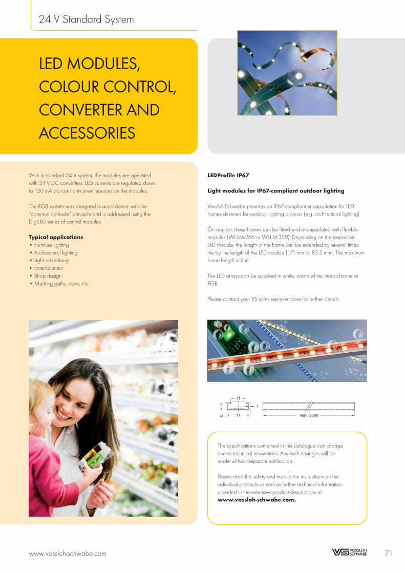
With a standard 24 V system, the modules are operatedwith 24 V DC converters. LED currents are regulated downto 120 mA via constant-current sources on the modules.
The RGB system was designed in accordance with the"common cathode" principle and is addressed using theDigiLED series of control modules.
Typical applications• Furniture lighting• Architectural lighting• Light advertising• Entertainment• Shop design• Marking paths, stairs, etc.
LEDProfile IP67
Light modules for IP67-compliant outdoor lighting
Vossloh-Schwabe provides an IP67-compliant encapsulation for LEDframes destined for outdoor lighting projects (e.g. architectural lighting).
On request, these frames can be fitted and encapsulated with flexiblemodules (WU-M-266 or WU-M-359). Depending on the respectiveLED module, the length of the frame can be extended by several timesthe by the length of the LED module (171 mm or 85.5 mm). The maximumframe length is 2 m.
The LED arrays can be supplied in white, warm white, monochrome orRGB.
Please contact your VS sales representative for further details.
www.vossloh-schwabe.com 71
24 V Standard System
The specifications contained in this catalogue can changedue to technical innovations. Any such changes will bemade without separate notification.
Please read the safety and installation instructions on theindividual products as well as further technical informationprovided in the extensive product descriptions atwww.vossloh-schwabe.com.
LED MODULES,COLOUR CONTROL,CONVERTER ANDACCESSORIES
max. 200017

LEDLine Flex SMDmonochrom/RGB andHigh BrightnessBuilt-in PCB lighting modulesThe LEDLine Flex SMD is fitted with SMD LEDs on aflexible printed circuit board of only approx. 0.15 mmthickness. Even the most complex structures can beilluminated thanks to the use of an extremely pliablefoil. LEDLine Flex SMD can be separated intosegments of different lengths (see table) without lossof function. This product is available in continuouslengths of up to nearly 10 m or 4.1 m for RGB and5 m for High Brightness. Installation is achieved viadouble-sided adhesive tape affixed to the rear ofthe PCB.
The entire LEDLine Flex SMD RGB (power consumptionof 4.1 m: 57.5 W) can be driven by a 70 W powersupply. To increase the numberof LED modulesDigiLED-Slave can be used.
Technical notes
Allowed operating temperature at tc point:–25 to 70 °C0 to 85 °C (for High Brightness)
Wide radiation angle (120°),for RGB modules (110°)
Voltage supply: 24 V DC
Additional technical notesfor RGB modulesPower consumption per step (171 mm): 2.4 WEach SMD contains 3 LED-chips
in the colours red, green and blue
Typical applicationsLighting of complex structuresMarking paths, stairs, etc.Furniture lightingLight advertisingEntertainment, shop designArchitectural lighting
72 www.vossloh-schwabe.com
newComponents for LED Applications
90°
60°
30°
I (cd/klm)
350
200
50
WU-M-266-SO, -SY, -SB, -SG
90°
60°
30°350
200
50
WU-M-266-W
+
– –
+24V+
– –
+24V
tc17,1
85,5
1,8
10
0,4
2,6
WU-M-266-W2, -W3, -WW, -WW2
tc
171
19
10
0,4
2,6
2,4
++
–– ––
+24V+24V
WU-M-266-SO, -SY
0,4
10
17,1
85,5
tc
2,6
2,5
+24V+
– –
+24V+
– –
WU-M-266-SB, -SG
0,4
10
8,55
17,1 tc
171
2,9
WU-M-266-RGB, -RGB2
90°
60°
30°
I (cd/klm)
50
350
200
WU-M-266-RGB
90°
60°
30°
I (cd/klm)
50
350
200
High Brightness
34242.75
10
0.3
52.6
5
hier nicht teilbar / not divisible at this point
Transistor
HB2: WU-M-359-SO, -SY
171
10
2.6
50.3
5
28.5
HB1: WU-M-359-W, -WW, -WW-H1, -SB, -SG
Dimensions of LEDLine Flex SMD
Colour LxW SMDs Single Length SMDs
mm pcs. steps mm pcs.
white 9918x10 580 116 85.5 5
green 9918x10 580 116 85.5 5
blue 9918x10 580 116 85.5 5
red 9918x10 522 58 171 9
yellow 9918x10 522 58 171 9
RGB 4104x10 240 24 171 10
HB1 4959x10 174 29 171 6
HB2 4788x10 112 14 342 8

LEDLine Flex SMD monochrome
Type Ref. No. Colour Number of Current* Dom. wavelength* (nm) Typ. luminous flux* Radiation angle* Power*
SMDs A Colour temperature* (K) lm ° W
WU-M-266-SO 528790 red 522 1.3 625 750 120 31
WU-M-266-SG 528788 green 580 2.6 530 650 120 62
WU-M-266-SB 528786 blue 580 2.6 470 300 120 62
WU-M-266-SY 528792 yellow 522 1.3 590 840 120 31
WU-M-266-WW 529512 warm white 580 2.6 2800 K 1300 120 62
WU-M-266-WW2 534428 warm white 580 2.6 2800 K 1700 120 62
WU-M-266-W2 529524 white 580 2.6 5000 K 2400 120 62
WU-M-266-W3 536051 white 580 2.6 5000 K 3200 120 62
* The values mentioned above represent only statistical variables on account of the complex manufacturing process of light emitting diodes.
The values do not necessarily correspond exactly to the actual parameters of every single product, which can vary from the typical specifications.
LEDLine Flex SMD RGB
Type Ref. No. Colour Current* Dom. wavelength* Typ. luminous flux* Radiation Max. power*
A nm lm angle* W
red green blue red green blue red green blue ° red green blue
WU-M-266-RGB2 534496 RGB 0.48 0.96 0.96 624 528 467 528 853 193 110 11.5 23 23
* The values mentioned above represent only statistical variables on account of the complex manufacturing process of light emitting diodes.
The values do not necessarily correspond exactly to the actual parameters of every single product, which can vary from the typical specifications.
LEDLine Flex SMD High Brightness
Type Ref. No. Colour Number of Current* Dom. wavelength* (nm) CRI Typ. luminous flux* Radiation angle* Power*
SMDs A Colour temperature* (K) Ra lm ° W
WU-M-359-SO 535951 red 112 1.8 625 — 840 120 44
WU-M-359-SY 542731 yellow 112 1.8 592 — 1100 120 44
WU-M-359-SG 535950 green 174 3.8 530 — 2300 120 92
WU-M-359-SB 535949 blue 174 3.8 470 — 640 120 92
WU-M-359-WW 535948 warm white 174 3.8 2800 K 75 2600 120 92
WU-M-359-WW-H1 543666 warm white 174 3.8 2800 K 92 2200 120 92
WU-M-359-W 538111 white 174 3.8 5000 K 70 3250 120 92
* The values mentioned above represent only statistical variables on account of the complex manufacturing process of light emitting diodes.
The values do not necessarily correspond exactly to the actual parameters of every single product, which can vary from the typical specifications.
www.vossloh-schwabe.com 73
newComponents for LED Applications
10
9
8
7
6
5
4
3
2
1
newnewnewnew

LEDLine Flex SMDOutdoormonochrome andRGBBuilt-in PCB lighting modulesThe LEDLine Flex SMD Outdoor is an extremelyflexible linear module for applications with highmoisture or dust burden conditions. Due to the flexibleand compact design, the illumination of complexstructures and flat designs can be realised. The IP67protected LEDLine Flex SMD Outdoor is available in3 different lengths (see below). The installation isachieved via double-sided adhesive tape affixedto the rear of the PCB.
The colour blend of LEDLine Flex SMD Outdoor RGBcan be adjusted using DigiLED control modules. Toincrease the number of LED modules DigiLED-Slavecan be used.
Technical notesDimensions of PCB: 171x10 mm,855x10 mm, 1710x10 mmEncapsulated dimensions (see drawing)PCB 171 mm: A = 177 mm+3/–6
PCB 855 mm: A = 861 mm+3/–6
PCB 1710 mm: A = 1716 mm+4/–6
Degree of protection: IP67Allowed operating temperature at tc point:
–20 to 50 °CAllowed handling temperature:
10 to 50 °CMinimum bend radius: 50 mm,flexible in longitudinal direction onlyPre-assembled with 2 wires or 4 wiresfor RGB modules on both endVoltage supply: 24 V DC
Typical applicationsLighting of complex structureswith high moisture or dust burdenOutdoor marking paths, stairs, etc.Outdoor light advertisingOutdoor entertainment, shop designArchitectural lightingOutdoor border lighting
74 www.vossloh-schwabe.com
Components for LED Applications
90°
60°
30°
I (cd/klm)
350
200
50
WU-M-266-SO, -SY, -SB, -SG
90°
60°
30°350
200
50
WU-M-266-W
90°
60°
30°
I (cd/klm)
50
350
200
WU-M-266-RGB
A
tctc
6±0.5
13±0.5
20±0.5
20±0.5
3±0.5
200.00±0.5
LEDLine Flex Outdoor monochrome
200±10
A
tc
200±10
12
±0.5
6+1.5
–0.0
LEDLine Flex Outdoor RGB

LEDLine Flex SMD Outdoor monochrome
Type Ref. No. Colour Number of Current* Dom. wavelength* (nm) Luminous flux* Radiation Power*
SMDs Colour temperature* (K) angle*
mA lm ° W
WU-M-266-SO-Outdoor 171mm 545411 red 9 22 625 13 120 0.528
WU-M-266-SO-Outdoor 855mm 545412 red 45 110 625 65 120 2.640
WU-M-266-SO-Outdoor 1710mm 545413 red 90 220 625 130 120 5.280
WU-M-266-SG-Outdoor 171mm 545408 green 10 44 530 11 120 1.056
WU-M-266-SG-Outdoor 855mm 545409 green 50 220 530 55 120 5.280
WU-M-266-SG-Outdoor 1710mm 545410 green 100 440 530 110 120 10.560
WU-M-266-SB-Outdoor 171mm 545392 blue 10 44 470 5 120 1.056
WU-M-266-SB-Outdoor 855mm 545406 blue 50 220 470 25 120 5.280
WU-M-266-SB-Outdoor 1710mm 545407 blue 100 440 470 50 120 10.560
WU-M-266-SY-Outdoor 171mm 545414 yellow 9 22 590 15 120 0.528
WU-M-266-SY-Outdoor 855mm 545415 yellow 45 110 590 75 120 2.640
WU-M-266-SY-Outdoor 1710mm 545416 yellow 90 220 590 150 120 5.280
WU-M-266-WW2-Outdoor 171mm 545389 warm white 10 44 2800 K 30 120 1.056
WU-M-266-WW2-Outdoor 855mm 545390 warm white 50 220 2800 K 150 120 5.280
WU-M-266-WW2-Outdoor 1710mm 545391 warm white 100 440 2800 K 300 120 10.560
WU-M-266-W2-Outdoor 171mm 545383 white 10 44 5000 K 23 120 1.056
WU-M-266-W2-Outdoor 855mm 545384 white 50 220 5000 K 112 120 5.280
WU-M-266-W2-Outdoor 1710mm 545385 white 100 440 5000 K 224 120 10.560
WU-M-266-W3-Outdoor 171mm 545386 white 10 44 6600 K 38 120 1.056
WU-M-266-W3-Outdoor 855mm 545387 white 50 220 6600 K 190 120 5.280
WU-M-266-W3-Outdoor 1710mm 545388 white 100 440 6600 K 380 120 10.560
* The values mentioned above represent only statistical variables on account of the complex manufacturing process of light emitting diodes.
The values do not necessarily correspond exactly to the actual parameters of every single product, which can vary from the typical specifications.
LEDLine Flex SMD Outdoor RGB
Type Ref. No. Colour Number Dom. wavelength* Max. luminous flux* Radiation Max. power*
of SMD nm lm angle* W
red green blue red green blue ° red green blue
WU-M-266-RGB2-Outdoor 171mm 545417 RGB 10 624 528 467 22 36 8 110 0.48 0.96 0.96
WU-M-266-RGB2-Outdoor 855mm 545418 RGB 50 624 528 467 110 180 40 110 2.40 4.80 4.80
WU-M-266-RGB2-Outdoor 1710mm 545419 RGB 100 624 528 467 220 360 80 110 4.80 9.60 9.60
* The values mentioned above represent only statistical variables on account of the complex manufacturing process of light emitting diodes.
The values do not necessarily correspond exactly to the actual parameters of every single product, which can vary from the typical specifications.
Recommended connectorMoisture-resistant, gel-filled connectorStrand diameter: 0.4–0.9 mmRef. No.: 534992
www.vossloh-schwabe.com 75
Components for LED Applications
10
9
8
7
6
5
4
3
2
1
5.8
17.6
12.4
2.0
8

LEDLine (COB)Built-in PCB lighting modulesThe universal LEDLine is based on COB (Chip-on-Board) technology. Owing to its homogeneous lightdistribution, it can be used for high-quality indooraccent and decorative lighting purposes.
Many other fields of application present themselvesin combination with VS LighTiles. Using commerciallyavailable flatband cables, the LEDLine modules canbe directly connected without leaving visible joins.The modules can be operated by VS systemconverters and controllers.
Technical notesLEDLine 150: � 150x10 mm (LxW)LEDLine 300: � 300x10 mm (LxW)LED-chips are driven by constant-current sourcesAllowed operating temperature at tc point:
–20 to 70 °CWide radiation angle (170°) due toChip-on-Board technologyVoltage supply: 24 V DC
Typical applicationsMarking paths, stairs, etc.Furniture lightingLight advertisingEntertainment, shop designArchitectural lighting
Connecting technologyLED connecting technology for these modulesyou will find on pages 82 and 83.
76 www.vossloh-schwabe.com
Components for LED Applications
90°
60°
30°250
150
50
I (cd/klm)
150
104
tc
1,5 9,2
10
WU-M-306, WU-M-311, WU-M-314
299,5
253,5
1,5 9,2
10
tc
WU-M-305, WU-M-310, WU-M-313

LEDLine (COB)
Type Ref. No. Colour Number of Current* Dom. wavelength* (nm) Luminous Radiation Power* Max. number
LEDs Colour temperature* (K) flux* angle* of modules**
mA lm ° W pcs.
LEDLine 150 (COB)
WU-M-306-RGB 527656 RGB 30 100 R 625 G 535 B 470 33 170 2.4 24
WU-M-306-SO 527657 red 10 20 625 12 170 0.48 48
WU-M-306-SG 527658 green 10 40 535 15 170 0.96 24
WU-M-306-SB 527659 blue 10 40 470 5 170 0.96 24
WU-M-306-SY 527660 yellow 10 20 590 15 170 0.48 48
WU-M-306-W-3200K 528472 warm white 10 40 3200 K 12 170 0.96 24
WU-M-306-W-4200K 528473 neutral white 10 40 4200 K 15 170 0.96 24
WU-M-306-W-5400K 527661 neutral white 10 40 5400 K 15 170 0.96 24
WU-M-306-W-6500K 528474 cool white 10 40 6500 K 14 170 0.96 24
WU-M-314-SOSOSO 528850 red 30 60 625 35 170 1.44 48
WU-M-311-SGSGSG 528855 green 30 120 535 43 170 2.88 24
WU-M-311-SBSBSB 528856 blue 30 120 470 15 170 2.88 24
WU-M-314-SYSYSY 528908 yellow 30 60 590 40 170 1.44 48
WU-M-311-WWW-3200K 528852 warm white 30 120 3200 K 36 170 2.88 24
WU-M-311-WWW-4200K 528853 neutral white 30 120 4200 K 45 170 2.88 24
WU-M-311-WWW-5400K 528851 neutral white 30 120 5400 K 45 170 2.88 24
WU-M-311-WWW-6500K 528854 cool white 30 120 6500 K 41 170 2.88 24
LEDLine 300 (COB)
WU-M-305-RGB 527649 RGB 60 200 R 625 G 535 B 470 65 170 4.8 12
WU-M-305-SO 527650 red 20 40 625 25 170 0.96 24
WU-M-305-SG 527651 green 20 80 535 29 170 1.92 12
WU-M-305-SB 527652 blue 20 80 470 10 170 1.92 12
WU-M-305-SY 527653 yellow 20 40 590 30 170 0.96 24
WU-M-305-W-3200K 528478 warm white 20 80 3200 K 24 170 1.92 12
WU-M-305-W-4200K 528479 neutral white 20 80 4200 K 30 170 1.92 12
WU-M-305-W-5400K 527655 neutral white 20 80 5400 K 30 170 1.92 12
WU-M-305-W-6500K 528480 cool white 20 80 6500 K 27 170 1.92 12
WU-M-313-SOSOSO 528843 red 60 120 625 70 170 2.88 24
WU-M-310-SGSGSG 528848 green 60 240 535 86 170 5.76 12
WU-M-310-SBSBSB 528849 blue 60 240 470 30 170 5.76 12
WU-M-313-SYSYSY 528907 yellow 60 120 590 80 170 2.88 24
WU-M-310-WWW-3200K 528845 warm white 60 240 3200 K 72 170 5.76 12
WU-M-310-WWW-4200K 528846 neutral white 60 240 4200 K 90 170 5.76 12
WU-M-310-WWW-5400K 528844 neutral white 60 240 5400 K 90 170 5.76 12
WU-M-310-WWW-6500K 528847 cool white 60 240 6500 K 81 170 5.76 12
* The values mentioned above represent only statistical variables on account of the complex manufacturing process of light emitting diodes.
The values do not necessarily correspond exactly to the actual parameters of every single product, which can vary from the typical specifications.
** By the use of the DigiLED-Slave the quantity of modules can be increased further.
www.vossloh-schwabe.com 77
Components for LED Applications
10
9
8
7
6
5
4
3
2
1

LEDLine (SMD)Built-in PCB lighting modulesThis universal lighting strip can be used for indoordecorative and accent lighting, like for instancemarking paths and contours. Owing to its low heightand extra-flat connectors, it is particularly suited tofurniture installations. LEDLine modules can be bentinto a quarter-circle and can be either adhesive-or screw-mounted. LEDLine can be operated by VSsystem components.
Technical notesSMDs are driven by constant-current sourcesWide radiation angle (120°)Voltage supply: 24 V DCMinimum order quantity: 54 pcs.
Type Ref. No. Number of SMDs Current* Typ. colour temperature* Typ. luminous flux* Max. power* Max. quantity of modules
pcs. mA K lm W pcs.
LEDLine 420 (SMD)
WU-M-225 W-48 warm white 526151 48 160 2900 140 3.84 6
WU-M-225 W-48 cool white 525873 48 160 4700 198 3.84 6
* The values mentioned above represent only statistical variables on account of the complex manufacturing process of light emitting diodes.
The values do not necessarily correspond exactly to the actual parameters of every single product, which can vary from the typical specifications.
78 www.vossloh-schwabe.com
Components for LED Applications
90°
60°
30°350
200
50
WU-M-225
10
6,7
5
105 105 105 105Ø3,1
26,25
8,75
26,257 x 52,5 = 367,5
(420)
Lighting module divisible in length of 105 mm!

LED Connecting Technology – LEDLine (SMD)Leads, push terminals and mountingLEDLine SMD modules can be contacted solderfreeusing a special connecting cable system. Modulescan be connected in straight or angled alignment.
Connecting cable for LEDLine (SMD)Colour: whiteNumber of strands: 2(Strand diameter: 0.25 mm²)Ref. No.: 506492 length: 500 mmRef. No.: 507848 length: 1000 mm
Extension cable for LEDLine (SMD)Colour: whiteNumber of strands: 2(Strand diameter: 0.25 mm²)Length: 500 mmRef. No.: 507967
www.vossloh-schwabe.com 79
Components for LED Applications
10
9
8
7
6
5
4
3
2
1

Colour Control Modules – DigiLEDThe DigiLED module enables three-channel (RGB)colour control. In addition, it can be used for indepen-dent brightness control of three single-colour LEDmodules. In the simplest case, a keypad enablesmanual colour control. However, next to customcolour control, it is also possible to call up pre-setcolour programs like for instance colour sequences.
The load circuits of the DigiLED modules areelectronically protected against overload, overheatingand short-circuiting. The input circuit is additionallyprotected by a safety fuse.
Technical notesDimensions: 93x58x29 mmAmbient temperature ta: 0 to 45 °C
(DigiLED DALI ta: –20 to 40 °C)Operating voltage: 12–30 V DCMax. current via LED module: 1 A per conductorShort-circuit protection: electronicOverload and temperature protection: reversibleConnector: VS system connectorAll DigiLED not for the US market
DigiLED ManualColour controls via key pads (6 keys) withinterface for control via external signal lineIndividual colour control or selection ofpre-set programsType: WU-ST-DigiLED-manuellRef. No.: 509377
DigiLED DALIThe DigiLED DALI modules enables three-channel(RGB) colour control. In addition, it can be usedfor independent brightness control of three single-colourLED modules. The DigiLED DALI module offers threeaddressable 16 bit outputs and can be controlledusing all DALI-compatible control devices.Type: WU-ST-DigiLED-DALI-3CHRef. No.: 529620
DigiLED DMXDigital colour controls via DMX light managementType: WU-ST-DigiLED-DMX-2Ref. No.: 509378
DigiLED Wireless IRColour adjustment by a portable remote controlCall up of pre-adjusted setting possible datatransfer via infra-redType: WU-ST-DigiLED-Wireless IRRef. No.: 508621
80 www.vossloh-schwabe.com
Components for LED Applications
DigiLED DMX
DigiLED Manual4,2
48,5
83,5
(96)
58
93
29
4
74
4,2
DigiLED DALI
DigiLED IR
4,2
48,5
83,5
(96)
58
93
29
4
74
4,2
4,2
48,5
83,5
(96)
58
93
29
4
74
4,2
4,2
48,5
83,5
(96)
58
93
29
4
74
4,2

DigiLED SlaveIncrease of the system performanceColour control over upstreamed DigiLEDCombination with all DigiLED variants possibleType: WU-ST-DigiLED-SlaveRef. No.: 507222
DigiLED 1–10 VColour control by 1–10 V interfaceCommercial control elements can be connectedType: WU-ST-DigiLED-1–10 VRef. No.: 505781
Manual controllerDimmer with low-voltage interface 1–10 VWith push-button change-over switchStud 4 mm, for installation in flushtype boxeswith 55 mm dia.Without cover plate: 67x67x51 mmRef. No.: 172778Cover plate with rotary knob: 80x80x9 mmColour: whiteRef. No.: 172775
DigiLED PushColour control by separate push-buttonPermits retrieval of pre-set programsType: WU-ST-006-DigiLED-PushRef. No.: 186143
DigiLED RFEasy operation possible via radio frequency (RF)and a keypad with 7 buttons. The operation viaradio frequency (RF) enables a flexible installation.Optical "line of sight" or cables are not necessarydue to RF operation.Type: WU-ST-008-DigiLED-RFRef. No.: 536842
WalltransmitterRequired to activate the programsin the DigiLED RFDimensions: 86x86x15 mmColour: whiteType: WU-ST-009-WalltransmitterRef. No.: 536843
www.vossloh-schwabe.com 81
Components for LED Applications
10
9
8
7
6
5
4
3
2
1
DigiLED Push
4 1
(3)
75
83
3.2
30
19
15
697 (7)
DigiLED 1–10 VDigiLED Slave
Manual Controller
1 2 3 4
67
67
80
Ø 50
Ø 38
Ø 50
Ø 4
M10x0,75
32
32
12
7 912
80
Max.
Fuse
DigiLED RF
Walltransmitter
86
86
15
4,2
48,5
83,5
(96)
58
93
29
4
74
4,2

LED Connecting TechnologyLeads, push terminals and mountingLEDLine COB components from VS can be wired bythe use of commercial 6-strand flatband cable. Thusan easy, flexible and economical installation ispossible.
The user can cut the leads to length on locationand mount push terminals based on IDC technology.
Flatband cableColour: greyNumber of strands: 6Wire according to AWG28(Strand diameter: 0.09 mm2)Load capacity: 1.2 A/strandWidth: 7.3 mm, thickness: 1 mmType: WU-VB-KB-6x28-grauRef. No.: 505222 length: 100 mPush connector on both sidesRef. No.: 507609 length: 60 mmRef. No.: 507610 length: 150 mm
Push connectorsMaterial: PBT GFThe push connector forms a connecting error proofsnap in connection between lead and LED systemcomponents. The connection with the cable is assuredby IDC contacts. As the push connector can bemounted in any part of the lead a very flexible systemtopology is possible.Type: WU-VB-BU-6Ref. No.: 507051 assembled for customer
specified applicationRef. No.: 505219 not assembled
Pre-assembled flatband cablesApart from individually pre-assembled cables,Vossloh-Schwabe also provides various inexpensivestandard cable lengths for simple wiring of theDigiLED-to-LEDLine COB interface.Ref. No.: 534401 for 4 modulesRef. No.: 534402 for 8 modulesRef. No.: 534403 for 12 modules
Crimping toolFor WU-VB-BU-6To process and mount flatband cablesRef. No.: 506835
LineClip for LEDLine modulesSupport for linear modules with 10 mm widthRef. No.: 507775
82 www.vossloh-schwabe.com
Components for LED Applications
Screened flatband cableColour: greyNumber of strands: 6Connecting cable: spacing 1.27 mm screenedfor augmented EMC requirementsLength: 100 mRef. No.: 506854
Intensity +/–
On/OffMemory
Programmode
Programroutinevelocity
Input
exte
rnal
sw
itch
Outp
utto
LE
Dm
odule
Supply
voltage
+– 24V
1 m Feed-in
1 m Feed-in
1 m Feed-in
300 mm
1. Module
1. Module
1. Module 2. Module 3. Module 4. Module
300 mm 300 mm 300 mm
8. Module
12. Module
534401
534402
534403

LED Connecting TechnologyPCB distributorsThe distribution boards of VS' LED system aredesigned to enable a variety of easy and flexiblewiring layouts.
Coupling adapter monoTo connect monochrome light modules to standardinstallation technologyNot suitable for connection of modules in RGB systemsType: WU-VB-KM-1-1Ref. No.: 506066
Coupling adaptersTo extend pre-equipped connection leadsType: WU-VB-KP-1-1Ref. No.: 505217
DistributorsDistributors enable the secondary lead of the controlcomponent to be extended (four-way) to form four leads.In addition, the possibility exists of connecting externalcomponents (e.g. LEDLine Flex SMD RGB) via afurther-lead using conventional screw terminal.Type: WU-VB-VT-1-4Ref. No.: 504964
3 channel splitterSplitter for operating three single-colour LED modulesusing a three-channel control device.Type: WU-VB-SP-1-3Ref. No.: 505218
www.vossloh-schwabe.com 83
Components for LED Applications
10
9
8
7
6
5
4
3
2
1

Typical RGB Wiring LayoutThe diagram shows the typical wiring layout of the LED modules in conjunction with VS 24 V converters,colour control modules (DigiLED) and distributors (e.g.: four-way distributor Ref. No. 504964).
84 www.vossloh-schwabe.com
Components for LED Applications
DigiLED Slave (Ref. No.: 507222)
6 strandssystem wire
3 Channel Splitter(Ref. No.: 505218)
Distributor(Ref. No.: 504964)
RGB coupling adapters(Ref. No.: 505217)
LEDLine Mono
LE
DLin
eR
GB
LE
DLin
eR
GB
LE
DLin
eR
GB
LE
DLin
eFle
xS
MD
RG
B
LE
DLin
eR
GB
(The connections are differentdepending on the control module)
DigiLED Control Modules
Converters LEDLine EDX
230V
~
24V
DC
LEDLine EDXe 120
LEDLine EDXe 170
( : 186129)
( : 186103 - Built-in)( : 186104 - Independent)( : 186105 - IP67)
Ref. No.
(Ref. No.: 186218 - Built-in)(Ref. No.: 186219 - Independent)
Ref. No.Ref. No.Ref. No.
(Ref. No.: 186131 - Built-in)(Ref. No.: 186132 - Independent)(Ref. No.: 186133 - IP67)
LEDLine EDXe 150
LEDLine EDXe 1130
Digitales Steuermodulfür LED-Module
Typ: WU-ST-DigiLED SlaveArt.-Nr. 507222.02Made in Germany
PRI: 12–30Vabhängig vomLED-Modul
SEC = PRImax. 3x1Ata = 0° bis 45°C
Steuer-EingangLED-Module1 + Kanal Rot2 + Kanal Grün3 + Kanal Blau4 Masse
AusgangLED-Module1 + Kanal Rot2 + Kanal Grün3 + Kanal Blau4 Masse
Spannungs-versorgung
+
–
tc
DigiLED Ref. No.
...
...
... DMX-2 509378
...
...
...
...
Manual 509377
DALI 529620
1-10V 505781
Push 186143
wireless IR 508621
RF 536842

LighTileLighting modulesLighTiles consist of a laser-engraved, edge-lit acrylicsubstrate.
The LighTiles need to be equipped with extra-flat,COB technology-based LEDLine modules, wherebythe RGB versions enable LighTiles to be configuredin any desired light colour.
Depending on the required light output, betweenone and all four sides of the LighTiles can be edge-lit.
LighTiles are ideal for ceiling or wall-mounted accentor decorative lighting, but are also suitable forfunctional lighting needs, e.g. for illuminatedadvertisements, information panels and emergencyexit signs.
The reference numbers quoted below refer to theacrylic LighTiles with a custom-fitted and assembledaluminium frame only. The LEDLine PCBs must beordered separately to suit the given assembly.
Type Ref. No. Weight Dimensions of the acrylic substrate Dimensions incl. frame
kg Length (mm) Width (mm) Length (mm) Width (mm)
WU-LT-300x300 505170 1.6 300 300 330 330
WU-LT-600x300 534025 2.5 600 300 630 330
WU-LT-600x600 505183 5.2 600 600 630 630
WU-LT-900x600 505185 7.6 900 600 930 630
WU-LT-900x900 505192 13.0 900 900 930 930
As standard with laser-engraved pattern in clear acrylic panel. White diffuse acrylic panel available on request.
www.vossloh-schwabe.com 85
Components for LED Applications
10
9
8
7
6
5
4
3
2
1
21.3
8.35 10.6+0.3
2.35
5.5
3.1
1.8
11.7+0.3
3.7+0.3
17
+0.3
9.8
+0.3
8+0.3
15
+0.3
23
1.5
Frame

ThermallyConductive AdhesiveTransfer Tapesfor LED Modules3MTM type 8810 andBergquist Bond-Ply® 100
Thermally Conductive Adhesive Transfer Tapes aredesigned to provide a preferential heat-transfer pathbetween heat-generating components and heat-sinksor other cooling devices.
These tapes are tacky pressure sensitive adhesivesloaded with thermally conductive ceramic fillers thatdo not require a heat cure cycle to form an excellentbond to many substrates. Only pressure is needed toform an excellent bond and thermal interface.
The specialized chemistry renders them modestly softand able to wet to many surfaces, allowing them toconform well to non-flat substrates, provide highadhesion, and act as a good thermal interface.
The specialized acrylic chemistry of the tapes providesfor excellent thermal stability of the base polymer.The thermally conductive tapes are provided ona silicone treated polyester release liner for easeof handling and die cutting. The tapes offer excellentadhesive performance with good wetting and flowonto many substrate surfaces.
Depending on the type of application and/or theexpected ambient conditions, the modules must beadditionally secured to ensure optimum fixing.
For detailed information and appli-cation guidelines see 3M or Bergquistdatasheet for thermally conductiveadhesive transfer taper (8805; 8810;8815; 8820; www.3m.comor Bergquist Bond-Ply® 100;www.bergquistcompany.com).
Type Ref. No. Size Tape thickness Liner thickness Thermal conductive Rth For VS LED modules
mm mm μm K/W
For round LED modules
Adhesive pad Ø28 536248 Ø28 0.25 37.5–30 1.0 PowerEmitter
Adhesive pad Ø43 536977 Ø43 0.20 76 0.5 TriplePowerEmitter Ø45mm, Ø50mm
Adhesive pad Ø63 539625 Ø63 0.25 37.5–50 0.5 High Power 24V RGB Triple
Adhesive pad Ø107 539624 Ø107 0.25 37.5–50 0.1 High Power 24V RGB Flood
For square LED modules
Adhesive pad 19x19 529158 19x19 0.25 37.5–50 1.4 WU-M-293
Adhesive pad 34x34 529155 34x34 0.25 37.5–50 0.5 WU-M-294
Adhesive pad 49x49 529157 49x49 0.25 37.5–50 0.3 WU-M-295, TriplePowerEmitter Ø50mm
For linear LED modules
Adhesive pad 278x13 548179 278x13 0.25 35.5–50 0.3 LUGA Line
Adhesive pad 306x11 529156 306x11 0.25 37.5–50 0.3 WU-M-291, WU-M-292
Adhesive pad 320x35 533815 320x35 0.20 76 0.1 LEDLine High Power
Adhesive pad 297x23 539626 297x23 0.25 37.5–50 0.1 High Power 24V RGB Line
This technical information for 3M™ Thermally Conductive Adhesive Transfer Tape 8810 or Bergquist Bond-Ply® 100 should be considered representative
or typical only and should not be used for specification purposes.
86 www.vossloh-schwabe.com
newComponents for LED Applications
new

Thermal Tapes for LED Modules
Thermal conductive graphite tapeFor modules for shop designThermal resistance: Rth 0.04 K/WType: Thermal tape Ø 48 mm GraphiteRef. No.: 545689
Thermal conductive tapeFor LED modules ME/S (see page 28)Type: Thermal tape 54x54 mmRef. No.: 548252
www.vossloh-schwabe.com 87
newComponents for LED Applications
10
9
8
7
6
5
4
3
2
1
new
new

Electronic Converters for LED Modules 24 VIf LED modules are used that are connected inparallel, the voltage-stabilising system is activated.The advantages include easy extendibility andsystem safety on account of the low voltage.
The electronic converters made by Vossloh-Schwabeguarantee a broad output range at a voltage of24 V. Typical areas of application are architecturaland general lighting, the replacement of halogenlamps as well as furniture lighting.
Devices with the particularly high IP67degree of protection are designed foruse in outdoor applications.
General technical notesShort-circuit protection: electronicOverload and temperature protection: reversibleProtection against "no load" operationProtection class I (EDXe 120: protection class II)
Max. Type Ref. No. Mains voltage Voltage Mains Output Ambient Casing Power Drawing/ With cord Weight
output 50, 60 Hz output current current temperature ta temperature tc factor photo grip
W V V mA A °C °C g
0.1–20 EDXe 120 186129 220–240 24 ±0.5 230/210 0.85 –20 to 45 75 0.5 A — 155
0.0–50 EDXe 150/24 V 186218 220–240 24 ±0.72 260/235 0.0–2.1 –40 to 45 70 0.97 B — 290
0.0–50 EDXe 150/24 V 186219 220–240 24 ±0.72 260/235 0.0–2.1 –40 to 45 70 0.97 C yes 320
0.0–70 EDXe 170/24 V 186103 220–240 24 ±0.48 360/310 0.0–2.9 –20 to 45 70 0.97 B — 340
0.0–70 EDXe 170/24 V 186104 220–240 24 ±0.48 360/310 0.0–2.9 –20 to 45 70 0.97 C yes 360
0.0–130 EDXe 1130/24 V 186131 220–240 24 ±0.48 640/585 0.0–5.4 –20 to 45 75 0.98 B — 370
0.0–130 EDXe 1130/24 V 186132 220–240 24 ±0.48 640/585 0.0–5.4 –20 to 45 75 0.98 C yes 390
Degree of protection: IP67
0.0–70 EDXe 170/24 V IP67 186105 220–240 24 ±0.48 360/330 0.0–2.9 –20 to 45 70 0.97 D — 515
0.0–130 EDXe 1130/24 V IP67 186133 220–240 24 ±0.48 640/585 0.0–5.4 –20 to 45 70 0.97 D — 545
Converter EDXe 120Degree of protection: IP20, SELV-equivalentDimensionse (LxWxH): 182x42x18 mm(Drawing: A)Connections/leads:
prim.: mains connection cable, length: 1.48 msec.: screw terminals 1.5 mm²
Ref. No.: 186129
88 www.vossloh-schwabe.com
newComponents for LED Applications
182
18
42
4,5
172
1,5
A
newnew
A – EDXe 120

Converters EDXe 150, 170 and 1130/24VDegree of protection: IP20, SELVPush-in terminals with push button:
2.5 mm² solid lead
Without cord gripDimensions (LxWxH): 187x60x36 mmFixing centres: 178 mm (drawing: B)Type: EDXe 150/24 VRef. No.: 186218 output: 0–50 WDimensions (LxWxH): 200x61x49 mmFixing centres: 191 mm (drawing: B)Type: EDXe 170/24 VRef. No.: 186103 output: 0–70 WType: EDXe 1130/24 VRef. No.: 186131 output: 0–130 W
With cord gripCord grip approved for mains leads:
H03W-F 3X0.75 mm² or NYM 3X1,5 mm²Cord grip approved fo routput leads:
SIHY-Cu 4X1 mm² or SIHSI-Cu 4X1 mm²Dimensions (LxWxH): 224x60x36 mmFixing centres: 210 mm (drawing: C)Type: EDXe 150/24 VRef. No.: 186219 output: 0–50 WDimensions (LxWxH): 245x61x49 mmFixing centres: 231 mm (drawing: C)Type: EDXe 170/24 VRef. No.: 186104 output: 0–70 WType: EDXe 1130/24 VRef. No.: 186132 output: 0–130 W
Converter EDXe 170 IP67/24 VDegree of protection: casing IP67, SELVDimensions (LxWxH): 268x71.6x51 mmFixing centres: 235 mm (drawing: D)Pre-assembled connection:
prim.: 3X1 mm², H05RN-F, length: 500 mmsec.: 2X2 mm², S07RN-F, length: 500 mm
Ref. No.: 186105 output: 0–70 W
Converter EDXe 1130 IP67/24 VDegree of protection: casing IP67, SELVDimensions (LxWxH): 268x71.6x51 mmFixing centres: 235 mm (drawing: D)Pre-assembled connection:
prim.: 3X1 mm², H05RN-F, length: 500 mmsec.: 2X2 mm², S07RN-F, length: 500 mm
Ref. No.: 186133 output: 0–130 W
www.vossloh-schwabe.com 89
newComponents for LED Applications
10
9
8
7
6
5
4
3
2
1
D – EDXe 170 IP67 / EDXe 1130 IP67
B and C – EDXe 150 / EDXe 170 / EDXe 1130
36
/49
25,5
/30,5
2,5
4,5
4,5
4,5
60
/61
178/191
187/200
143/158
170/183
B
60
/61
36
/49
45
/46
4,5
24
/27
7,54,5
4,5
2,5
210/231
224/245
C – with cord grip
268
225
235
51
30
45
65,6
71,6
D
new
new

Electronic Converters for LED Modules 12 VIf LED modules are used that are connected inparallel, the voltage-stabilising system is activated.The advantages include easy extendibility andsystem safety on account of the low voltage.
The electronic converters made by Vossloh-Schwabeguarantee a broad output range at a voltage of12 V. Typical areas of application are architecturaland general lighting, the replacement of halogenlamps as well as furniture lighting.
Devices with the particularly high IP67degree of protection are designed foruse in outdoor applications.
General technical notesShort-circuit protection: electronicOverload and temperature protection: reversibleProtection against "no load" operationProtection class I (EDXe 112: protection class II)
Max. Type Ref. No. Mains voltage Voltage Mains Output Ambient Casing Power Drawing With cord Weight
power 50, 60 Hz output current current temperature ta temperature tc factor Photo grip
W V V mA A °C °C g
0.1–12 EDXe 112 186204 220–240 12 ±0.6 120 1 –20 to 50 75 0.57 A — 60
0.0–50 EDXe 150/12 V 186216 220–240 12.1 ±0.24 260/230 0.0–4.2 –40 to 45 70 0.97 B — 375
0.0–50 EDXe 150/12 V 186217 220–240 12.1 ±0.24 250/240 0.0–4.2 –40 to 45 70 0.97 C yes 425
0.0–70 EDXe 170/12 V 186112 220–240 12.1 ±0.24 365/335 0.0–5.8 –20 to 45 70 0.97 B — 340
0.0–70 EDXe 170/12 V 186113 220–240 12.1 ±0.24 365/335 0.0–5.8 –20 to 45 70 0.97 C yes 360
Degree of protection: IP67
0.0–70 EDXe 170/12 V IP67 186114 220–240 12.1 ±0.24 365/335 0.0–5.8 –20 to 45 70 0.97 D — 515
Converter EDXe 112/12 VDegree of protection: IP20, SELV-equivalentDimensions (LxWxH): 103.5x36x22 mmFixing centres: 92 mm (drawing: A)Prim. and sec. connections:
each with 2 x 2.5 mm² screw terminalsRef. No.: 186204
90 www.vossloh-schwabe.com
newComponents for LED Applications
newnew
A
A – EDXe 112
new
new

Converters EDXe 150 and 170/12VDegree of protection: IP20, SELVPush-in terminals with push button:
2.5 mm² solid lead
Without cord gripDimensions (LxWxH): 187x60x36 mmFixing centres: 178 mm (drawing: B)Type: EDXe 150/12 VRef. No.: 186216 output: 0–50 WDimensions (LxWxH): 210x61x49 mmFixing centres: 191 mm (drawing: B)Type: EDXe 170/12 VRef. No.: 186112 output: 0–70 W
With cord gripCord grip approved for mains leads:
H03W-F 3X0.75 mm² or NYM 3X1.5 mm²Cord grip approved fo routput leads:
SIHY-Cu 4X1 mm² or SIHSI-Cu 4X1 mm²Dimensions (LxWxH): 224x60x36 mmFixing centres: 210 mm (drawing: C)Type: EDXe 150/12 VRef. No.: 186217 output: 0–50 WDimensions (LxWxH): 245x61x49 mmFixing centres: 231 mm (drawing: C)Type: EDXe 170/12 VRef. No.: 186113 output: 0–70 W
Converter EDXe 170 IP67/12 VDegree of protection: casing IP67, SELVDimensions (LxWxH): 268x71.6x51 mmFixing centres: 235 mm (drawing: D)Pre-assembled connection:
prim.: 3X1 mm², H05RN-F, length: 500 mmsec.: 2X2 mm², S07RN-F, length: 500 mm
Ref. No.: 186114 output: 0–70 W
www.vossloh-schwabe.com 91
newComponents for LED Applications
10
9
8
7
6
5
4
3
2
1
B and C – EDXe 150 / EDXe 170
EDXe 170 IP67
new
new
268
225
235
51
30
45
65,6
71,6
D
36
/49
25,5
/30,5
2,5
4,5
4,5
4,5
60
/61
178/191
187/200
143/158
170/183
B
60
/61
36
/49
45
/46
4,5
24
/27
7,54,5
4,5
2,5
210/231
224/245
C – with cord grip

General information on LED technology 92–99CIE chromaticity chart 95Assembly instructions – LED components 96–98Assembly and safety information for LEDSpots and LED modules with heat sink 98–99
General technical details 533–540
Glossary 541–543
92 www.vossloh-schwabe.com
Technical Details
2 Components for LED Applications
10
9
8
7
6
5
4
3
2
1

General information on LED technology
Thanks to the constant developmental progress made in LED semiconductor technology, the fields of applicationfor LEDs are growing continuously. Mood and architectural lighting, for instance, are already benefiting from thesaturated colours of and possibilities afforded by RGB colour control. Ever higher light efficiency levels at highercurrents are making white LEDs increasingly attractive for general lighting. Among others, further decisive advan-tages are great longevity, low energy consumption, neither UV or IR radiation nor any hazardous substances.
The key basis of modern optoelectronics is the availability of high-performance LEDs in the three primary coloursred, green and blue as well as white and warm white. By assembling these on circuit boards and in combina-tion with converters and control systems, lighting systems can be created for the most diverse areas of use.
Vossloh-Schwabe's production of LED modules is based on tried-and-tested COB and SMD technology. Thismakes it possible to design modules in various dimensions and performance classes. COB (Chip On Board)technology enables super-flat designs with very high chip densities. SMD (Surface Mounted Device Techno-logy) enables convenient, quick and simultaneous assembly of LED and electronics devices.
Working principle of light emitting diodes (LEDs)
An LED semiconductor chip is a semiconductor component that is made up of two differently doped crystal-layers, one of which positive (p) and the other negative (n). Light is emitted at the depletion-layer pn boundaryfor a current flow in forward direction.
An LED converts applied electric energy into visible electromagnetic radiation. The construction and doping ofa semiconductor depends on the desired wavelength λ (colour), which can only be monochromatic (red,orange, yellow, green or blue). Colour blends are created by varying the number of LEDs in the individualcolours. By adding certain converter materials, LEDs can also produce white and warm white light. This type oflight generation using a semiconductor is generally referred to as luminescence, i.e. the generation of cold lightwhose rays contain no warmth and are emitted without infrared (IR).
Semiconductor materials for LED chips
Irrespective of the specific model, an LED always consists of the following components: leadframe, LED chipand contacting using conductive adhesive and bonding.While the leadframe can be made of a PCB or ceramics, plastics and other materials, the LED chips aremounted on a die-cut reflector (cathode) using conductive adhesive to achieve higher light intensities witha focused beam of light. The anode is connected using bonding wire.The optical viewing angle (�) of an LED is determined by the geometry of the casing including reflector and theposition of the chip within the casing.Small in size and highly resistant against mechanical impact/stress, LEDs are an ideal component for lightingapplications. Special modular solutions are also available for applications involving differing ambient conditions(humidity, ambient temperature, etc.).
www.vossloh-schwabe.com 93
Technical Details – Components for LED Applications
10
9
8
7
6
5
4
3
2
1
Anode (+)
Cathode (–)
Substrate,transparent
n
p
Emitted light
Reflecting rear contact
Cross-sectional DetailCross-section of an LED semi-conductor chipLight emission at the pn depletion layer

Visible light within the electromagnetic spectrum
Visible light only accounts for a small part of the electromagnetic spectrum. The part of the electromagneticspectrum that is visible for humans ranges from ultraviolet (λ = 380 nm) to dark red (λ = 780 nm).
Light sensitivity of the human eye
By day, the maximum light sensitivity (Km) of the human eye for green is at λ = 555 nm and drops toλ = 510 nm by night. Light sensitivity falls off sharply for both higher and lower wavelengths and only totals1% of day vision for blue at λ = 430 nm and dark red at λ = 720 nm. Thus, in order for the human eye toperceive light of these wavelengths at the same intensity as yellow-green light, its luminance LV needs tobe 100 times greater.
Service life of LEDs
The service life of an LED is determined by various factors:
• the degradation rate of the semiconductor material and the encapsulation material• the applied operating current IF• the ambient temperature ta during operation and• the thermal resistance
The term degradation describes the decrease in brightness of an LED chip as a result of the applied forwardcurrent during normal operation. Given normal operating conditions (ta = 25°C at IF = 10–30 mA), LEDs willprovide a service life of up to 100,000 operating hours (typically 50,000 hours for High Power applications),after which time the brightness of the LED will have dropped to 70% of its original value.
94 www.vossloh-schwabe.com
Technical Details – Components for LED Applications
4
4 -3 -6 -9 -11
6 8 10 12 14 16 18
Frequency
Medium wave Micro waves Infrared Ultraviolet X rays
Short waveTV
Wavelength
f in Hz
� in nm
10
10 10 10 10 103* 3* 10 3* 3*
10
30 0,3
780 nm 380 nm Gammaradiation
Visible spectrum
Cosmicradiation
10 10 10 10 10 10
Degree ofspectral light sensitivity
Rela
tive
spec
tral
sens
itivi
ty
Wavelength in nm
Day visionNight vision
1
0.8
0.6
0.4
0.2
0350 450 550 650 750

LED efficiency
In theory, the internal efficiency of an LED chip is 90%, meaning that 90% of the applied electrical energyis converted into visible light at the pn junction layer.
However, a part of the light emitted at the pn junction layer cannot pass through the semiconductor structureand it remains a major technological challenge to optimise the coupling of light out of the chip with the helpof innovative designs. These processes determine the external degree of LED efficiency, which denotes themagnitude of visible output that can pass through the semiconductor structure when, for instance, 1 W ofelectrical power is applied to an LED.
Colour design with LEDs
CIE Chromaticity Chart (CIE 1931 according to DIN 5033)
The CIE chromaticity triangle (standardised CIE 1931 chromaticity chart according to DIN 5033) makes itpossible to precisely plot the colours of light sources and objects using two standardised (and previouslygauged) chromaticity coordinates, the x and y values. Every point in this chart represents the chromaticitylocation of a certain chroma. Colours of the same chromaticity only differ from each other in terms of theirintensity (colour saturation). The so-called "no-colour point" (white, grey and black, depending on brightness)is situated in the middle of the chart at x = 0.33 and y = 0.33.
The boundary of the chromaticity chart is made up of the gamut of spectral colours from 380 nm (blue-violet)to 780 nm (dark red) and the so-called purple boundary. As a result of additive mixing of two or more colouredlight sources the chromaticity coordinates are always along a direct line between the starting coordinates.
www.vossloh-schwabe.com 95
Technical Details – Components for LED Applications
10
9
8
7
6
5
4
3
2
1

When using LED lighting, different colours can be created using additive colour mixing (RGB) or by transformingthe wavelengths a diode emits by adding a luminescent material in a manner similar to fluorescent lamps. In thecase of additive colour mixing/control, appropriate control devices are used to adjust the brightness of the indi-vidual LED colours (RGB) to create the desired light colour.
LED system components• LED light modules• LED operating devices• LED control modules• LED connection technology
When selecting LED components, it is important to take account of their technical specifications, especially withregard to voltage range, current and temperature. VS provides a large range of components for the variousareas that all go to build a perfectly matched system. The technical specifications of the various componentscan be found on the product pages. All VS LED operating devices work with a safety extra-low voltage (SELV)or SELV equivalent on the output side.
Assembly Instructions for LEDsFor mounting and installing LED components
Mandatory regulations
DIN VDE 0100 Erection of low voltage installations
EN 60598-1 Luminaires – part 1: general requirements and tests
EN 60838-2-2 Miscellaneous lampholders – part 2-2: particular requirements –connectors for LED-modules
EN 61347-1 Lamp controlgear – part 1: general and safety requirements
EN 61347-2-11 Controlgear – part 2-11: particular requirements for miscellaneous electroniccircuits used with luminaires
EN 61347-2-13 Lamp controlgear – part 2-13: particular requirements for DC or AC suppliedelectronic controlgear for LED modules
EN 62031 LED modules for general lighting – safety specifications
EN 62384 DC or AC supplied control gear for LED modules – performance requirements
EN 55015 Limits and methods of measurement of radio disturbance characteristicsof electrical lighting and similar equipment
EN 61000-3-2 Electromagnetic compatibility (EMC) – part 3-2: limits – limits forharmonic current emissions (equipment input current = 16 A per phase)
EN 61000-3-3 Electromagnetic compatibility (EMC) – part 3-3: limits – limitation of voltage fluctuationsand flicker (equipment input current = 16 A per phase)
EN 61547 Equipment for general lighting purposes – EMC immunity requirements
EN 62471 Photobiological safety of lamps and lamp systems
96 www.vossloh-schwabe.com
Technical Details – Components for LED Applications

Mechanical mounting of LED operating devices
Surface Solid, flat surface for good heat discharge required.Avoid mounting protruding surfaces.
Mounting locationConverters must be protected against moisture and heat.
Installation in external luminairesLuminaire requires water protection rate of = 4 (e.g. IP54).
Heat transfer If the converter is destined for installation in a luminaire, sufficient heat transfer must beensured between the converter and the luminaire casing. Converters should be mountedwith the greatest possible clearance to sources of heat.During operation, the temperature measured at the tc point of the convertermust not exceed the specified maximum value.
Additional mounting instructions for independent LED operating devices
Mounting position Any
Clearance Min. of 0.10 m from walls, ceilings, insulationMin. of 0.10 m from other electronic ballastsMin. of 0.25 m from sources of heat (LEDs or other lamps)
Surface Solid; device must not be allowed to sink into insulation materials
Safety information for LED modules
Warning The installation of LED modules may only be undertaken by qualified staff. Installation mustbe conducted at zero potential after disconnection from the line. Modules can have sharpedges or corners. Please take special care during installation to avoid injury. The High Power24 V Triple, Line and Flood, the HighPerformance, Power Emitter, TriplePowerEmitter, LEDLineHigh Power, XP and HC Line Spot and Mini modules can get hot. Please provide warningnotices at the luminaire body if necessary.
Assembly and handling information for LED modules
LED modules and all PCB components must not be subjected to undue mechanical stress:• LED modules must not be handled as bulk cargo.• Shear and pressure stress must be avoided on SMD LEDs and the grouting material of COB LEDs
during assembly and handling.
The circuit path must not be damaged or interrupted. We recommend using clips or plastic screws forinstallation purposes to avoid short circuits and damage to the modules.
The LED modules are not protected against short-circuiting, overloading or overheating. The use ofVossloh-Schwabe electronic power supply units is therefore absolutely essential. Using other power supplyunits is not recommended. Please ensure you choose the correct electronic power supply unit for themodule in question and that the respective output parameters (current, voltage, wattage) are correct(see www.vossloh-schwabe.com).
Please ensure standard ESD (electrostatic discharge) protection measures are employed when handlingand installing LED modules. Electrostatic discharge can damage LEDs.
Please ensure the correct polarity of the leads prior to commissioning. Reversed polarity can destroythe modules.
www.vossloh-schwabe.com 97
Technical Details – Components for LED Applications
10
9
8
7
6
5
4
3
2
1

The modules are not protected against dust or moisture (except LEDLine Flex SMD Outdoor). When LEDmodules are operated in unduly moist or dusty environments, care must be taken to ensure each module is builtinto a protective casing in compliance with the correct IP classification or provided with corrosion protection.Damage caused by moisture and/or corrosion will not be recognised as a material or manufacturing defect.
To ensure smooth module operation, care must be taken that module temperatures at the tc point neverexceed the maximum values stipulated in the data on catalogue pages.
Due to the numerous installation options and differing operating conditions, no precise installation guidelinescan be provided that will ensure the maximum temperature values are never exceeded. In principle, the HighPower 24 V Triple, Line and Flood, the HighPerformance, PowerEmitter, TriplePowerEmitter, LEDLine High Power,XP and HC Line, Spot and Mini can be mounted on a flat metal surface that must, however, provide a largeenough surface area to ensure the generated heat can be dissipated to the surroundings.
Please ensure adhesive pads or other products with adhesive areas (LEDLine Flex SMD, LEDLine Flex SMDOutdoor) are only used on dry and clean surfaces that are free of grease, oil, silicone and dirt particles. Owingto the varying application options and different types of surface as well as ambient conditions, VS accepts noliability for the quality of the adhesive bond achieved when mounting these products.
Assembly and safety information for LEDSpots and LED modules with heat sink
Installation and maintenance must always be performed by a qualified fitter in accordance with relevantlegislation. The following instructions must be strictly observed. Vossloh-Schwabe Deutschland GmbHaccepts no liability for any possible inaccuracies during installation, any non-compliance with theseinstructions or for any possible omissions in this publication.
In addition, Vossloh-Schwabe Deutschland GmbH reserves the right to make modifications at any time andwithout prior notification. This data sheet is an integral part of the equipment and its safety devices andshould therefore be kept in a safe place for easy reference. The equipment must always be disconnectedfrom the mains prior to undertaking any maintenance work. The safety instructions on the type plate of thecomponents must be strictly observed.Safe operation is only possible by the use of external constant-current sources.Power supply units must be used for operation, in which the following protective measures are ensured:• Short-circuit protection• Overload protection• Overheating protection• SELV equiv. (Safety Extra Low Voltage)
Please ensure the correct polarity of the leads prior to commissioning. Reversed polarity can destroy themodules.
The maximum output of the power supply must be observed.
ESD (electrostatic discharge) protection measures must be observed when handling and installing the LEDmodules.
The modules are not protected against dust or moisture. When modules are operated in unduly moist ordusty environments, care must be taken to ensure each module is built into a protective casing in compliancewith the correct IP classification or provided with corrosion protection. Damage caused by moisture and/orcorrosion will not be recognised as a material or manufacturing defect.
Under no circumstances may LED modules ever be covered by insulation material or similar. Air ventilationmust be ensured.
For optimal load of used constant-current driver the LEDSpots can only be connected in series. The quantityof LEDSpots is limited by the sum of forward voltage and the capacity of used constant-current driver. Underno circumstances may the sum of the forward bias exceed 60 V DC.
A parallel connection of the modules is not allowed.
98 www.vossloh-schwabe.com
Technical Details – Components for LED Applications

Tests have shown the following chemicals to be harmful to LEDs used on the modules. It is recommendednot to use the under-mentioned chemicals anywhere in an LED system. The fumes from even small amountsof these chemicals may damage the LEDs.• Chemicals that might outgas aromatic hydrocarbons (e.g., toluene, benzene, xylene)• Methyl acetate or ethyl acetate (i.e., nail polish remover)• Cyanoacrylates (i.e., "Superglue")• Glycol ethers
(including Radio Shack®, Precision Electronics Cleaner – dipropylene glycol monomethyl ether)• Formaldehyde or butadiene (including Ashland PLIOBOND® adhesive)• Dymax 984-LVUF conformal coating• Loctite Sumo glue• Gorilla glue• Clorox bleach• Clorox Clean-Up cleaner spray• Loctite 384 adhesive• Loctite 7387 activator• Loctite 242 threadlocker
Photobiological safety of lamps and lamp systems; German version EN 62471:2008 General lighting:exempt group
www.vossloh-schwabe.com 99
Technical Details – Components for LED Applications
10
9
8
7
6
5
4
3
2
1

ELECTRONIC AND ELECTRO-MAGNETIC OPERATING DEVICESFor high-pressure sodium lamps (HS), metal halide lamps(HI) and mercury vapour lamps (HM)
Electronic ballastsModern discharge lamps operate very efficiently in combination withelectronic ballasts. The numerous advantages of using electronic ballaststo operate high-pressure discharge lamps are listed in more detail on theproduct pages.
With the help of temperature and service-life tests, VS electronic ballastsguarantee a high degree of reliability. The quality of the electronicballasts is ensured by continuous in-circuit tests and function tests likeburn-in tests.
Magnetic ballastsThe electrical specifications of VS' range of ballasts comply with lamp-specific requirements. Vossloh-Schwabe attaches great importance toensuring the impedance value of electromagnetic ballasts is kept withinparticularly narrow tolerances. This advantage, which is achieved byindividual adjustment of the air gap during the automated production andtesting process of every ballast, decisively contributes to optimising lightoutput, light colour and service life of discharge lamps.
The range includes ballasts with variable voltage tapping points andvarying degrees of inherent heating as well as encapsulated devices.
100 www.vossloh-schwabe.com
Ballasts for Discharge Lamps
ELECTRONIC ANDELECTROMAGNETIC

For high-pressure sodium lamps (HS), metal halide lamps (HI) and mercury vapour lamps (HM)
Electronic ballasts, accessories 102–111Dimmable electronic ballasts 110–111
Control gear units for HS and HI lamps 112–118
Electromagnetic ballasts 119–141for HS and HI lamps 119–130for HM and HI lamps 131–134for SDW-T/-TF lamps 135for power reduction 136–141
Technical details for discharge lamps 184–225General technical details 533–540Glossary 541–543
www.vossloh-schwabe.com 101
10
9
8
7
6
5
4
3
2
1
3 Ballasts for Discharge Lamps

CompactElectronic Ballastsfor HI Lamps20 and 35 WShape: K35
Casing: heat-resistant polyamide,encapsulated with polyurethane(EHXc 35G.327 B and EHXc 35G.327 I)For ceramic discharge tube lamps (C-HI)Power factor: > 0.9Operation frequency: 135 HzPush-in terminals: 0.5–1.5 mm²Constant power consumptionProtection against "no load" operationFor luminaires of protection class I and IIDegree of protection: IP20Permissible load capacity: 120 pFRFI-suppressedFixing brackets for screws M4for base mountingNo flickering of defective lamps
Lamp Electronic ballast System
Output Type Base Power con- Type Ref. No. Voltage AC Mains Energy Ambient Casing Ignition Weight Output
sumption 50, 60 Hz current efficiency temperature temperature voltage
W W V –10%+6% A ta (°C) tc (°C) kV g W
Electronic built-in ballasts
20 HI GU6.5, G8.5, GX8.5, 1 x 20 EHXc 20.329 B 188991 220–240 0.11 A2 –15 to 60 max. 75 2–4 130 23
GX10
35 HI GU6.5, G8.5, GX8.5, 1 x 39 EHXc 35G.327 B 188993 220–240 0.2 A2 –15 to 45 max. 80 2–4 180 43.5
GX10, G12
Independent electronic ballasts with cord grip
20 HI GU6.5, G8.5, GX8.5, 1 x 20 EHXc 20.329 I 188992 220–240 0.11 A2 –15 to 60 max. 75 2–4 145 23
GX10
35 HI GU6.5, G8.5, GX8.5, 1 x 39 EHXc 35G.327 I 188994 220–240 0.2 A2 –15 to 45 max. 80 2–4 195 43.5
GX10, G12
Circuit diagrams see page 190
102 www.vossloh-schwabe.com
newBallasts for Discharge Lamps
(5)
1
(3.5
)
41
4.5
4.5
4.5
4.5 117.5
127
31.5
50
K35 with cord grip
31.5
41.5
4.5
(4)
4.5
50
96
874.5 (4.5)
K35
new
new
new
new

Electronic Ballastsfor HI Lamps35, 50 and 70 WShape: M3/K34
Casing: aluminium (M3),heat-resistant polycarbonate (K34)For ceramic discharge tube lamps (C-HI)Power factor: � 0.95Ignition voltage: max. 5 kVOperation frequency: 173 HzPush-in terminals with push-button: 0.75–2.5 mm²Total harmonic distortion: < 10%Temperature protectionConstant power consumptionProtection against "no load" operationFor luminaires of protection class I (metal casing)For luminaires of protection class I and II(plastic casing)Degree of protection: IP20Permissible load capacity: 20–120 pFRFI-suppressedFixing brackets for screws M4for base mountingNo flickering of defective lamps
Lamp Electronic ballast System
Output Type Base Power con- Type Ref. No. Voltage AC Mains Energy Ambient Casing Weight Output
sumption 50, 60 Hz current efficiency temperature temperature
W W V ±10% A ta (°C) tc (°C) g W
Electronic built-in ballast (with cap)
35 HI GU6.5, G8.5, GU8.5, 1 x 39 EHXc 35.325 183033 220–240 0.20–0.18 A2 –20 to 65 max. 80 220 43
GX8.5, G12, E27
50 HI G8.5, G12 1 x 50 EHXc 50.358 183028* 220–240 0.26–0.24 A2 –20 to 60 max. 80 220 55
70 HI G8.5, GU8.5, GX8.5, G12, 1 x 73 EHXc 70.326 183036 220–240 0.36–0.34 A2 –20 to 55 max. 80 220 80
PG12-2, E27, RX7s
Built-in PCB – Electronic built-in ballasts (without cap)
35 HI GU6.5, G8.5, GU8.5, 1 x 39 EHXc 35.325 183034 220–240 0.20–0.18 A2 –20 to 65 max. 80 180 43
GX8.5, G12, E27
50 HI G8.5, G12 1 x 50 EHXc 50.358 183030* 220–240 0.26–0.24 A2 –20 to 60 max. 80 180 55
70 HI G8.5, GU8.5, GX8.5, G12, 1 x 73 EHXc 70.326 183037 220–240 0.36–0.34 A2 –20 to 55 max. 80 180 80
PG12-2, E27, RX7s
Independent electronic ballasts with cord grip
35 HI GU6.5, G8.5, GU8.5, 1 x 39 EHXc 35.325 183035 220–240 0.20–0.18 A2 –20 to 65 max. 75 260 43
GX8.5, G12, E27
50 HI G8.5, G12 1 x 50 EHXc 50.358 183029* 220–240 0.26–0.24 A2 –20 to 60 max. 70 260 55
70 HI G8.5, GU8.5, GX8.5, G12, 1 x 73 EHXc 70.326 183038 220–240 0.36–0.34 A2 –20 to 55 max. 75 260 80
PG12-2, E27, RX7s
Circuit diagrams see page 190
* In development
www.vossloh-schwabe.com 103
newBallasts for Discharge Lamps
10
9
8
7
6
5
4
3
2
1
108995
4,2
27.3
73
64
4,5
M3 built-in PCB
163
4,2Ø4,2
32
3
83
170.5
K34 with cord grip
M3 K34
tc
tc point definition
new
new
new
64
(5,5
)
4,2
110
4,2
(5,5)995,5
30
23
4,2
(5,5)995,5
5,5
(20)
75
45
10
M3

Electronic Ballastsfor HI Lamps35 and 70 WShape: M3 EffectLine
Casing: heat-resistant polycarbonateFor ceramic discharge tube lamps (C-HI)Power factor: � 0.95Ignition voltage: max. 5 kVOperation frequency: 173 HzPush-in terminals with push-button: 0.5–1.5 mm²Total harmonic distortion: < 10%Temperature protectionConstant power consumptionProtection against "no load" operationFor luminaires of protection class I and IIDegree of protection: IP20Permissible load capacity: 20–120 pFRFI-suppressedLife-time at tc max. = 30,000 hrsFixing brackets for screws M4for base mounting
Lamp Electronic ballast System
Output Type Base Power con- Type Ref. No. Voltage AC Mains Energy Ambient Casing Weight Output
sumption 50, 60 Hz current efficiency temperature temperature
W W V ±10% A ta (°C) tc (°C) g W
35 HI GU6.5, G8.5, GU8.5, 1 x 39 EHXe 35.356 183026* 220–240 0.20–0.18 A2 –15 to 65 max. 80 220 43
GX8.5, G12, E27
70 HI G8.5, GU8.5, GX8.5, 1 x 73 EHXe 70.357 183027* 220–240 0.36–0.34 A2 –15 to 50 max. 80 220 80
G12, PG12-2, E27, RX7s
Circuit diagrams see page 190
* In development
104 www.vossloh-schwabe.com
newBallasts for Discharge Lamps
5.5 (5.5)
4.2
110
99
4.2
5.5 (5.5)
9932
25
10.2
(5.5
)
4.2
64
5.5
75
(32.1
)32.7
M3 EffectLine
new
new

IndependentElectronic Ballastsfor HI Lamps35, 50 and 70 WShape: K36
Casing: heat-resistant polycarbonateEasy connection by plug-in connector
primary: GST18 1-coded/blackwith lockingsecondary: ST18 0-coded
For ceramic discharge tube lamps (C-HI)Power factor: 0.95Ignition voltage: max. 5 kVOperation frequency: 173 HzTotal harmonic distortion: < 10%Temperature protectionConstant power consumptionProtection against "no load" operationFor luminaires of protection class I and IIDegree of protection: IP20Permissible load capacity: 20–120 pFRFI-suppressedFixing brackets for screws M4for base mounting
Lamp Electronic ballast System
Output Type Base Power con- Type Ref. No. Voltage AC Mains Energy Ambient Casing Weight Output
sumption 50, 60 Hz current efficiency temperature temperature
W W V ±10% A ta (°C) tc (°C) g W
35 HI GU6.5, G8.5, GU8.5, 1 x 39 EHXc 35.339 188919 220–240 0.20–0.18 A2 –20 to 55 max. 75 250 43
GX8.5, G12, E27
50 HI G8.5, G12 1 x 50 EHXc 50.359 183031* 220–240 0.26–0.24 A2 –20 to 55 max. 75 250 55
70 HI G8.5, GU8.5, GX8.5, 1 x 73 EHXc 70.340 188920 220–240 0.36–0.34 A2 –20 to 50 max. 75 250 80
G12, PG12-2, E27, RX7s
Circuit diagrams see page 190
* In development
www.vossloh-schwabe.com 105
newBallasts for Discharge Lamps
10
9
8
7
6
5
4
3
2
1
Additional technical features
The electronic ballast is protected against transient mains peaks up to 2.5 kV.
Overheating protection with VS thermal cut-out system with automaticreset which evaluates the temperature of the ballast.
At lamp operation voltage of > 120 V the electronic ballast will switch itself off.120V
new
(6,5
)
Ø4,2
77
32
149,5
138 (5)6,5
64
6,54,2
K36

Electronic Ballastsfor HI Lamps2 x 35 and 2 x 70 WShape: K32
Casing: heat-resistant polycarbonateFor ceramic discharge tube lamps (C-HI)Power factor: 0.98Ignition voltage: max. 5 kVOperation frequency: 176 HzPush-in terminals with push-button: 0.75–2.5 mm²Total harmonic distortion: < 10%Temperature protection: a lamp is switched offin the event of overheatingConstant power consumptionProtection against "no load" operationFor luminaires of protection class I and IIDegree of protection: IP20Permissible load capacity: 20–100 pFRFI-suppressedFixing brackets for screws M4for base mountingSeparate ignition channels enableindependent lamp operation
Lamp Electronic ballast System
Output Type Base Power con- Type Ref. No. Voltage AC Mains Energy- Ambient Casing Weight Output
sumption 50, 60 Hz current efficiency temperature temperature
W W V –10%+6% A ta (°C) tc (°C) g W
Electronic built-in ballasts
2x35 HI GU6.5, G8.5, GU8.5, GX8.5, 2 x 39 EHXc 235.316 188223 220–240 0.4–0.36 A2 –25 to 50 max. 80 405 86
G12, E27
2x70 HI G8.5, GU8.5, GX8.5, G12, 2 x 73 EHXc 270.317 188224 220–240 0.74–0.68 A2 –25 to 45 max. 80 440 160
PG12-2, E27, RX7s
Independent electronic ballasts with cord grip
2x35 HI GU6.5, G8.5, GU8.5, GX8.5, 2 x 39 EHXc 235.316 188455 220–240 0.4–0.36 A2 –25 to 50 max. 80 455 86
G12, E27
2x70 HI G8.5, GU8.5, GX8.5, G12, 2 x 73 EHXc 270.317 188456 220–240 0.74–0.68 A2 –25 to 45 max. 80 490 160
PG12-2, E27, RX7s
Circuit diagrams see page190
106 www.vossloh-schwabe.com
Ballasts for Discharge Lamps
190
3,6
37
174
89
70(18
5)
K32
224
3,6
37
4,5
210
70
89(217)
K32 with cord grip

Cord Grip forElectronic Built-inBallastsFor shape K31 and K32
By using the cord grip electronic built-in ballastsfor metal halide lamps become independentballasts.Material: heat-resistant polycarbonateFor use with electronic built-in ballastswith casing K31 and K32For mains leads:
H03VV-F 3X0.75 or NYM 3X1.5 mm²For lamp leads: SIHY-Cu 3X1 mm²
or SIHSI-Cu 3X1 mm²Weight: 50 gUnit: 20 pcs.By turning the cable clamp by 180°the lead diameter can be reduced to 5 mm.Ref. No.: 188080
www.vossloh-schwabe.com 107
Ballasts for Discharge Lamps
10
9
8
7
6
5
4
3
2
1

Electronic Ballastsfor HI Lamps100 and 150 WShape: M36/K31/K38
Casing: aluminium (M36),heat-resistant polycarbonate (K31, K38)For ceramic discharge tube lamps (C-HI)Power factor: 0.98Ignition voltage: max. 5 kVOperation frequency: 170 HzPush-in terminals with push-button: 0.75–2.5 mm²Total harmonic distortion: < 10%Temperature protectionConstant power consumptionProtection against "no load" operationFor luminaires of protection class I and IIDegree of protection: IP20Permissible load capacity: 20–240 pFRFI-suppressedFixing brackets for screws M4for base mounting
108 www.vossloh-schwabe.com
newBallasts for Discharge Lamps
151.6
134
(151.2
)
(8)9.6
3.6
36.8
70
4.5
88.8
K31
186
36.8
88.8
3.6
70
4.5
172
(184)
K31 with cord grip
K31
75
138,5 (5,5)5,5
4,2
149,5
(6)
4,2
1385,5
30
23
5,5
64
(5,5
)
4,2
M36
3,5
83
210
(7,5)
202,54
(41,5
)41,5
Ø4,2
32
4,2
3
8 194,5
K38
M36 K38

Electronic Ballasts for HI Lamps 100 and 150 WShape: M36 and K31, K38
Lamp Electronic ballast System
Output Type Base Power con- Type Ref. No. Voltage AC Mains Energy Ambient Casing Casing Weight Output
sumption 50, 60 Hz current efficiency temperature temperature
W W V ±10% A ta (°C) tc (°C) g W
Electronic built-in ballasts
100 HI G12, E40 1 x 100 EHXc 100.353 183000* 220–240 0.49–0.45 A2 –20 to 50 max. 75 M36 306 108
150 HI G12, PGX12-2, 1 x 147 EHXc 150G.334 183046 220–240 0.73–0.67 A2 –20 to 45 max. 85 K31 540 160
E27, E40, RX7s
Independent electronic ballasts with cord grip
100 HI G12, E40 1 x 100 EHXc 100.353 183001* 220–240 0.49–0.45 A2 –20 to 45 max. 75 K38 350 108
150 HI G12, PGX12-2, 1 x 147 EHXc 150G.334 183047 220–240 0.73–0.67 A2 –20 to 45 max. 85 K31 582 160
E27, E40, RX7s
Circuit diagrams see page 190
* In development
www.vossloh-schwabe.com 109
newBallasts for Discharge Lamps
10
9
8
7
6
5
4
3
2
1
new
new

Dimmable ElectronicBuilt-in Ballastsfor HI and HS Lamps50–250 WShape: K40/K41 and M42
For dimmable metal halide lamps anddimmable high pressure sodium lampsCasing: aluminium (M42),heat-resistant polycarbonate (K40/K41)Dimming range: acc. to lamp specificationCommunication protocols: DALI or MidNightFor use with open- or closed-loop control unitsSuitable MidNight Controller 186240 (for installationin the distribution board) or 186241 (as a mobilecontroller) is available on request.Power factor: > 0.98Ignition voltage: max. 4.5 kVOperation frequency: 81 HzPush-in terminals with push-button: 0,75–2,5 mm²Total harmonic distortion: < 6%Temperature protectionConstant power consumptionProtection against "no load" operationFor luminaires of protection class I and IIDegree of protection: IP20Permissible load capacity: 250 pFRFI-suppressedFixing brackets for screws M4 for base mountingCompatible with IEC 62386 (DALI version)
Lamp Electronic ballast System
Output Type Base** Power con- Type Ref. No. Voltage AC Mains Energy- Ambient Casing Casing Weight Output
sumption 50, 60 Hz current efficiency temperature temperature
W W V ±10% A ta (°C) tc (°C) g W
DALI – Casing K40, K41 and M42
50 HI/HS G8.5, G12, E27 1 x 50 EHXd 50.360 183048* 220–240 0.26–0.23 A2 –25 to 65 max. 80 K40 380 56
70 HI/HS G8.5, GU8.5, GX8.5, 1 x 70 EHXd 70.361 183049* 220–240 0.35–0.32 A2 –25 to 60 max. 80 K40 380 79
G12, PG12-2, E27, RX7s
100 HI/HS G12, E40 1 x 100 EHXd 100.362 183050* 220–240 0.50–0.46 A2 –25 to 60 max. 75 K41 520 107
150 HI/HS G12, G22, PGX12-2, 1 x 150 EHXd 150.363 183051* 220–240 0.75–0.69 A2 –25 to 50 max. 75 K41 520 161
Fc2, E27, E40, RX7s
250 HI/HS Fc2, E40, RX7s 1 x 250 EHXd 250.364 183052* 220–240 1.22–1.12 A2 –25 to 45 max. 65 M42 930 267
MidNight – Casing K40, K41 and M42
50 HI/HS G8.5, G12, E27 1 x 50 EHXd 50.365 M 183053* 220–240 0.26–0.23 A2 –25 to 65 max. 80 K40 380 56
70 HI/HS G8.5, GU8.5, GX8.5, 1 x 70 EHXd 70.366 M 183054* 220–240 0.35–0.32 A2 –25 to 60 max. 80 K40 380 79
G12, PG12-2, E27, RX7s
100 HI/HS G12, E40 1 x 100 EHXd 100.367 M 183055* 220–240 0.50–0.46 A2 –25 to 60 max. 75 K41 520 107
150 HI/HS G12, G22, PGX12-2, 1 x 150 EHXd 150.368 M 183056* 220–240 0.75–0.69 A2 –25 to 50 max. 75 K41 520 161
Fc2, E27, E40, RX7s
250 HI/HS Fc2, E40, RX7s 1 x 250 EHXd 250.369 M 183057* 220–240 1.22–1.12 A2 –25 to 45 max. 65 M42 930 267
Circuit diagrams see page 190
* In development | ** Please ensure that lamps are only dimmed if specified as "dimmable" by the manufacturer.
110 www.vossloh-schwabe.com
newBallasts for Discharge Lamps
newnew
newnew
new
newnew
newnew
186.4
173
70
4.5
87
59
M42
new
89146/187
134/174
44/4
5
72
4.5
K40/K41

IndependentDimmable ElectronicBallasts IP65 for HIand HS Lamps50–250 WShape: M43/M44 and M45
For dimmable metal halide lamps and dimmablehigh pressure sodium lampsCasing: aluminiumDimming range: acc. to lamp specificationCommunication protocols: DALI or MidNightFor use with open- or closed-loop control unitsSuitable MidNight Controller 186240 (for installationin the distribution board) or 186241 (as a mobilecontroller) is available on request.Power factor: > 0.98, Ignition voltage: max. 4.5 kVOperation frequency: 81 HzLeads: Mains: H05VV-F 3X1.5 mm²
DALI: YSLY-0Z 2X0.75 mm²Lamp: X-SIHF 2X1.5 mm²Lead lengths: 60 cm
Total harmonic distortion: < 6%Temperature protectionConstant power consumptionProtection against "no load" operationFor luminaires of protection class I and IIDegree of protection: IP65Permissible load capacity: 250 pFRFI-suppressed, Fixing brackets for screws M4 for basemounting, Compatible with IEC 62386 (DALI version)
Lamp Electronic ballast System
Output Type Base** Power con- Type Ref. No. Voltage AC Mains Energy- Ambient Casing Casing Weight Output
sumption 50, 60 Hz current efficiency temperature temperature
W W V ±10% A ta (°C) tc (°C) g W
DALI – Casing M43, M44 and M45
50 HI/HS G8.5, G12, E27 1 x 50 EHXd 50.360 183060* 220–240 0.26–0.23 A2 –25 to 65 max. 80 M43 1000 56
70 HI/HS G8.5, GU8.5, GX8.5, 1 x 70 EHXd 70.361 183061* 220–240 0.35–0.32 A2 –25 to 60 max. 80 M43 1000 79
G12, PG12-2, E27, RX7s
100 HI/HS G12, E40 1 x 100 EHXd 100.362 183062* 220–240 0.50–0.46 A2 –25 to 60 max. 75 M44 1200 107
150 HI/HS G12, G22, PGX12-2, 1 x 150 EHXd 150.363 183063* 220–240 0.75–0.69 A2 –25 to 50 max. 75 M44 1200 161
Fc2, E27, E40, RX7s
250 HI/HS Fc2, E40, RX7s 1 x 250 EHXd 250.364 183064* 220–240 1.22–1.12 A2 –25 to 50 max. 65 M45 1500 267
MidNight – Casing M43, M44 and M45
50 HI/HS G8.5, G12 1 x 50 EHXd 50.365 M 183065* 220–240 0.26–0.23 A2 –25 to 65 max. 80 M43 1000 56
70 HI/HS G8.5, GU8.5, GX8.5, 1 x 70 EHXd 70.366 M 183066* 220–240 0.35–0.32 A2 –25 to 60 max. 80 M43 1000 79
G12, PG12-2, E27, RX7s
100 HI/HS G8.5, G12, E27 1 x 100 EHXd 100.367 M 183067* 220–240 0.50–0.46 A2 –25 to 60 max. 75 M44 1200 107
150 HI/HS G12, G22, PGX12-2, 1 x 150 EHXd 150.368 M 183068* 220–240 0.75–0.69 A2 –25 to 50 max. 75 M44 1200 161
Fc2, E27, E40, RX7s
250 HI/HS Fc2, E40, RX7s 1 x 250 EHXd 250.369 M 183069* 220–240 1.22–1.12 A2 –25 to 50 max. 65 M45 1500 267
Circuit diagrams see page 190
* In development | ** Please ensure that lamps are only dimmed if specified as "dimmable" by the manufacturer.
www.vossloh-schwabe.com 111
newBallasts for Discharge Lamps
10
9
8
7
6
5
4
3
2
1
newnew
newnew
new
newnew
newnew
194/229
54
95
101
101
9
4.5
4.5
80
176/211
M43/M44
70.3
229
102
102
95.2
980
4.5
4.5
211
M45
new

Control Gear Unitsfor HS and HILamps 35 to 150 WCompact plastic casingShape: 64x72 mm
For high pressure sodium lamps (HS),metal halide lamps (HI)and ceramic discharge lamps (C-HI)Compact control gear unit with ballast withpatented, intelligent thermal cut-out withautomatic reset (which evaluates the temperatureand current of the ballast), digital timer ignitor withIPP++ technology and compensation capacitorwith thermal fuseAs individual components no longer needto be wired, there is a significant reductionin assembly time and costs.Protection class IIDegree of protection: IP40Permissible load capacity: 20–1000 pFLead length to the lamp: max. 10 mtw 130Push-in terminals: 0.5–2.5 mm²Cord grips for mains and lamp leadsFurther outputs and voltages on request
Lamp Control gear unit
Output Type Current Type Ref. No. Voltage AC Mains current a b Weight ta Power factor Energy efficiency*
W A V, Hz A mm mm kg °C λ
230 V, 50 Hz
35 HS, HI 0.53 VNaHJ 35PZTG.568 536199 230, 50 0.210 175 166 1.32 55 0.92 EEI=A3
70 HS, HI 0.98 VNaHJ 70PZTG.566 535657 230, 50 0.380 175 166 1.32 45 0.91 EEI=A3
100 HS, HI 1.20 VNaHJ 100PZTG.571 536200 230, 50 0.560 214 205 1.85 45 0.85 EEI=A3
150 HS, HI 1.80 VNaHJ 150PZTG.567 535695 230, 50 0.720 214 205 2.25 45 0.91 EEI=A3
240 V, 50 Hz
35 HS, HI 0.53 VNaHJ 35PZTG.568 536201 240, 50 0.210 175 166 1.32 55 0.94 EEI=A3
70 HS, HI 0.98 VNaHJ 70PZTG.566 536202 240, 50 0.370 175 166 1.32 40 0.94 EEI=A3
100 HS, HI 1.20 VNaHJ 100PZTG.571 536203 240, 50 0.560 214 205 1.85 40 0.86 EEI=A3
150 HS, HI 1.80 VNaHJ 150PZTG.567 536204 240, 50 0.730 214 205 2.25 40 0.91 EEI=A3
220 V, 60 Hz
35 HS, HI 0.53 VNaHJ 35PZTG.574 536205 220, 60 0.220 175 166 1.32 60 0.98 EEI=A3
70 HS, HI 0.98 VNaHJ 70PZTG.575 536207 220, 60 0.370 175 166 1.32 50 0.97 EEI=A3
150 HS, HI 1.80 VNaHJ 150PZTG.576 536209 220, 60 0.800 214 205 2.25 45 0.98 EEI=A3
* Step 2: EEI = A3, minimum EU energy efficiency requirements as of 2012 | Step 3: A2, minimum EU energy efficiency requirements as of 2017
112 www.vossloh-schwabe.com
Ballasts for Discharge Lamps

Control Gear Unitsfor HS and HILamps 35 to 150 WCompact plastic casing withintegrated GST18 connector (red)Shape: 64 x 72 mm
For high pressure sodium lamps (HS),metal halide lamps (HI)and ceramic discharge lamps (C-HI)Compact control gear unit with ballast withpatented, intelligent thermal cut-out withautomatic reset (which evaluates the temperatureand current of the ballast), digital timer ignitor withIPP++ technology and compensation capacitorWith integrated GST18 connectorAs individual components no longer needto be wired, there is a significant reductionin assembly time and costs.Protection class IIDegree of protection: IP40Permissible load capacity: 20–1000 pFLead length to the lamp: max. 10 mtw 130Push-in terminals: 0.5–2.5 mm2
Cord grip for mains leadFurther outputs and voltages on request
Lamp Control gear unit
Output Type Current Type Ref. No. Voltage AC Mains current a b Weight ta Power factor Energy efficiency*
W A V, Hz A mm mm kg °C λ
230 V, 50 Hz
35 HS, HI 0.53 VNaHJ 35PZTG.568 536210 230, 50 0.210 175 166 1.32 55 0.92 EEI=A3
70 HS, HI 0.98 VNaHJ 70PZTG.566 536211 230, 50 0.380 175 166 1.32 45 0.91 EEI=A3
150 HS, HI 1.80 VNaHJ 150PZTG.567 536213 230, 50 0.720 214 205 2.25 45 0.91 EEI=A3
240 V, 50 Hz
35 HS, HI 0.53 VNaHJ 35PZTG.568 536214 240, 50 0.210 175 166 1.32 55 0.94 EEI=A3
70 HS, HI 0.98 VNaHJ 70PZTG.566 536215 240, 50 0.370 175 166 1.32 40 0.94 EEI=A3
150 HS, HI 1.80 VNaHJ 150PZTG.567 536216 240, 50 0.730 214 205 2.25 40 0.91 EEI=A3
220 V, 60 Hz
35 HS, HI 0.53 VNaHJ 35PZTG.574 536217 220, 60 0.220 175 166 1.32 60 0.98 EEI=A3
70 HS, HI 0.98 VNaHJ 70PZTG.575 536218 220, 60 0.370 175 166 1.32 50 0.97 EEI=A3
150 HS, HI 1.80 VNaHJ 150PZTG.576 536219 220, 60 0.800 214 205 2.25 45 0.98 EEI=A3
* Step 2: EEI = A3, minimum EU energy efficiency requirements as of 2012 | Step 3: A2, minimum EU energy efficiency requirements as of 2017
www.vossloh-schwabe.com 113
Ballasts for Discharge Lamps
10
9
8
7
6
5
4
3
2
1

Control GearUnits IP65 forHS and HI Lamps35 to 150 WEncapsulated unit incompact plastic casingShape: 61x72 mm
For high pressure sodium lamps (HS),metal halide lamps (HI)and ceramic discharge lamps (C-HI)Compact control gear unit with ballast withpatented, intelligent thermal cut-out withautomatic reset (which evaluates the temperatureand current of the ballast), digital timer ignitor withIPP++ technology and compensation capacitorwith thermal fuseAs individual components no longer needto be wired, there is a significant reductionin assembly time and costs.Protection class IIDegree of protection: IP65Permissible load capacity: 20–1000 pFLead length to the lamp: max. 10 mtw 130
Lamp Control gear unit
Output Type Current Type Ref. No. Voltage Mains current a b Weight ta Power factor Energy efficiency*
W A V, Hz A mm mm kg °C λ
230 V, 50 Hz
35 HS, HI 0.53 VNaHJ 35PZTG.050 533391 230, 50 0.240 222 214 1.95 60 0.96 EEI=A3
50 HS 0.76 VNaH 50PZTG.058 543733 230, 50 0.290 222 214 1.95 60 0.94 EEI=A3
70 HS, HI 0.98 VNaHJ 70PZTG.051 533392 230, 50 0.370 222 214 1.95 50 0.97 EEI=A3
100 HS, HI 1.20 VNaHJ 100PZTG.078 533393 230, 50 0.560 249 240 2.25 55 0.90 EEI=A3
150 HS, HI 1.80 VNaHJ 150PZTG.052 533394 230, 50 0.740 249 240 2.75 50 0.94 EEI=A3
240 V, 50 Hz
35 HS, HI 0.53 VNaHJ 35PZTG.053 534107 240, 50 0.240 222 214 1.95 60 0.96 EEI=A3
70 HS, HI 0.98 VNaHJ 70PZTG.054 534109 240, 50 0.370 222 214 1.95 50 0.97 EEI=A3
150 HS, HI 1.80 VNaHJ 150PZTG.055 534115 240, 50 0.730 249 240 2.75 50 0.95 EEI=A3
220 V, 60 Hz
35 HS, HI 0.53 VNaHJ 35PZTG.041 534122 220, 60 0.220 222 214 1.95 70 0.98 EEI=A3
70 HS, HI 0.98 VNaHJ 70PZTG.067 534111 220, 60 0.370 222 214 1.95 50 0.97 EEI=A3
150 HS, HI 1.80 VNaHJ 150PZTG.068 534117 220, 60 0.800 249 240 2.25 45 0.98 EEI=A3
* Step 2: EEI = A3, minimum EU energy efficiency requirements as of 2012 | Step 3: A2, minimum EU energy efficiency requirements as of 2017
114 www.vossloh-schwabe.com
Ballasts for Discharge Lamps
400 mm Lead length

Control Gear Unitsfor HS andHI Lamps250 and 400 WShape: 76x91 mm
For high pressure sodium lamps (HS),metal halide lamps (HI) andceramic discharge lamps (C-HI)Fully wired slim, weather-proof control gear unitwith ballast with thermal cut-out with automatic reset,capacitor, timer ignitor and connection terminalSuitable for installation in or on pylonsFrontal cable feed using a PG thread fittingFront access to terminalsScrew-fixed end capScrew terminals: 0.75–2.5 mm²For luminaires of protection class IDegree of protection: IP54Permissible load capacity: 20–1000 pFDistance to the lamp: max. 10 mtw 130With connection for protective earth conductor
Lamp Control gear unit
Output Type Current Mains current Type Ref. No. Voltage AC L L1 Weight Power factor Energy efficiency*
W A A V, Hz mm mm kg λ
250 HS, HI 3.0 1.3 VNaHJ 250PZT.745 531476 230, 50 322 302 4.30 > 0.94 A2
400 HS, HI 4.45 2.0 VNaHJ 400PZT.743 531475 230, 50 357 337 5.62 > 0.91 A2
* Step 2: EEI = A3, minimum EU energy efficiency requirements as of 2012 | Step 3: A2, minimum EU energy efficiency requirements as of 2017
www.vossloh-schwabe.com 115
Ballasts for Discharge Lamps
10
9
8
7
6
5
4
3
2
1

Ballast Unitsfor HS and HI Lamps600 to 2000 WShape: 114x116 mm
For high-pressure sodium vapour lamps (HS)and metal halide lamps (HI)Slim, weather-proof ballast unit fully wired withballast, capacitor and connection terminalSuitable for installation in or on pylonsWith connection for protective earth conductorFrontal cable feed using a PG thread fittingFront access to terminals or fusesOptional additional third PG connection for mainsfeed-through wiringScrew-fixed end capDiverse mounting options using an assembly plate or railScrew terminals: 0.75–10 mm²For luminaires of protection class Itw 130
Degree of protection: IP54
Lamp Ballast unit
Output Type Current Mains current Type Ref. No. Voltage AC L L1 L2 Weight Power factor Energy efficiency*
W A A V, Hz mm mm mm kg λ
600 HS 6.2 3.1 VNaH 600.02 531182 230–240, 50 452 375 335 9.6 > 0.90 A2
1000 HS 10.3 5.0 VNaHJ 1000.61 531472 230–240, 50 487 410 370 11.6 > 0.90 A2
HI 9.5 4.9 A2
2000 HI 8.8 5.7 VJ 2000.05 531193 380–400, 50 570 500 460 15.2 > 0.90 A2
2000 HI 10.3 6.0 VJD 2000.63 531474 380–400, 50 627 550 510 20.2 > 0.90 A2
* Step 2: EEI = A3, minimum EU energy efficiency requirements as of 2012 | Step 3: A2, minimum EU energy efficiency requirements as of 2017
Degree of protection: IP65Fully encapsulated ballast unit with leads
Lamp Ballast unit
Output Type Current Mains current Type Ref. No. Voltage AC L L1 L2 Weight Power factor Energy efficiency*
W A A V, Hz mm mm mm kg λ
1000 HS 10.3 5.0 VNaHJ 1000.61 531480 220, 50 487 410 370 11.6 > 0.90 A2
HI 9.5 4.9 A2
2000 HI 10.3 6.0 VJD 2000.63 531481 380, 50 627 550 510 20.2 > 0.90 A2
* Step 2: EEI = A3, minimum EU energy efficiency requirements as of 2012 | Step 3: A2, minimum EU energy efficiency requirements as of 2017
116 www.vossloh-schwabe.com
newBallasts for Discharge Lamps
new
Ø12,5
PG 16
L2 22,5 (40)
30L130
60ca. 27
L
Ø8
-15
Option
114
40
ca.116
Ø148
new

CompactAssembly Kits forHS and HI Lamps35 to 150 WBallast shape: 53x66 mm
For high pressure sodium lamps (HS),metal halide lamps (HI)and ceramic discharge lamps (C-HI)Compact assembly kit with ballast with orwithout patented, intelligent thermal cut-outwith automatic reset (which evaluates thetemperature and current of the ballast), super-imposed ignitor and compensation capacitorWith luminaire terminal block:
screw terminal 0.75–2.5 mm²With earth terminalPermissible load capacity: 20–100 pFLead length to the lamp: max. 1.5 mtw 130On request:
Further outputs and voltagesWith digital timer ignitorFor pulse ignition system
Lamp Assembly kit
Output Type Current Type Ref. No. Voltage AC Mains Temperature a b c d Weight Power Energy
current protection factor efficiency*
W A V, Hz A mm mm mm mm kg λ
230 V, 50 Hz
35 HS, HI 0.53 PKNaHJ 35.008 546797 230, 50 0.22 yes 117 86 108 54 1.2 > 0.90 EEI=A3
50 HS 0.76 PKNaH 50PZT.992 543378 230, 50 0.30 yes 117 86 111 59 1.4 > 0.90 EEI=A3
70 HS, HI 0.98 PKNaHJ 70.128 538675 230, 50 0.37 yes 117 86 111 59 1.4 > 0.90 EEI=A3
538685 no EEI=A3
100 HS, HI 1.20 PKNaHJ 100.941 538676 230, 50 0.56 yes 117 86 111 59 1.6 > 0.90 EEI=A3
538686 no EEI=A3
150 HS, HI 1.80 PKNaHJ 150.620 538677 230, 50 0.74 yes 151 120 115 63 2.2 > 0.90 EEI=A3
538687 no EEI=A3
220 V, 60 Hz
35 HS, HI 0.53 PKNaHJ 35.008 547285 220, 60 0.23 yes 117 86 108 54 1.2 > 0.90 EEI=A3
543401 no
70 HS, HI 0.98 PKNaHJ 70.653 547287 220, 60 0.37 yes 117 86 111 59 1.4 > 0.90 EEI=A3
538680 no
100 HS, HI 1.20 PKNaHJ 100.271 538681 220, 60 0.56 no 117 86 111 59 1.6 > 0.90 EEI=A3
150 HS, HI 1.80 PKNaHJ 150.679 538682 220, 60 0.74 no 151 120 115 63 2.2 > 0.90 EEI=A3
220/240 V, 60 Hz
100 HS, HI 1.20 PKNaHJ 100.345 543295 220/240, 60 0.60 no 117 86 111 60 1.6 > 0.90 EEI=A3
150 HS, HI 1.80 PKNaHJ 150.301 543299 220/240, 60 0.80 no 151 120 115 63 2.2 > 0.90 EEI=A3
* Step 2: EEI = A3, minimum EU energy efficiency requirements as of 2012 | Step 3: A2, minimum EU energy efficiency requirements as of 2017
www.vossloh-schwabe.com 117
newBallasts for Discharge Lamps
10
9
8
7
6
5
4
3
2
1
As individual components no longerneed to be wired, there is a significantreduction in assembly time and costs.
Especially suitable for change of lamptechnology from HM to HS.
new
new
new

CompactAssembly Kits forHS and HI Lamps250 and 400 WBallast shape: 71x75 mm
For high pressure sodium lamps (HS),metal halide lamps (HI)and ceramic discharge lamps (C-HI)Compact assembly kit with ballast with orwithout thermal cut-out with automatic reset,superimposed ignitor and compensationcapacitorWith luminaire terminal block:
screw terminal 0.75–2.5 mm²With earth terminalPermissible load capacity: 20–100 pFLead length to the lamp: max. 1.5 mtw 130On request:
Further outputs and voltagesWith digital timer ignitorFor pulse ignition system
Lamp Assembly kit
Output Type Current Type Ref. No. Voltage AC Mains Temperature a b c d Weight Power Energy
current protection kg factor efficiency*
W A V, Hz A mm mm mm mm kg λ
230 V, 50 Hz
250 HS, HI 3.00 PKNaHJ 250.741 538678 230, 50 1.20 yes 141 110 128 73 3.2 > 0.90 A2
538688 no A2
400 HS, HI 4.45 PKNaHJ 400.743 538679 230, 50 1.80 yes 171 140 129 73 5.2 > 0.90 A2
538689 no A2
220 V, 60 Hz
250 HS, HI 3.00 PKNaHJ 250.742 538683 220, 60 1.20 no 141 110 126 71 3.2 > 0.90 A2
400 HS, HI 4.45 PKNaHJ 400.744 538684 220, 60 1.80 no 171 140 129 71 5.2 > 0.90 A2
* Step 2: EEI = A3, minimum EU energy efficiency requirements as of 2012 | Step 3: A2, minimum EU energy efficiency requirements as of 2017
118 www.vossloh-schwabe.com
Ballasts for Discharge Lamps
As individual components nolonger need to be wired, there isa significant reduction in assemblytime and costs.
Especially suitable for change oflamp technology from HM to HS.

Standard Ballastsfor HS and HILamps 35 to 70 WShape: 53x66 mm
For high pressure sodium lamps (HS),metal halide lamps (HI) andceramic discharge lamps (C-HI)Vacuum-impregnated with polyester resinScrew terminals: 0.5–2.5 mm²Protection class Itw 130Ballasts for pulse ignition system on request
Lamp Ballast Capacitor
Output Type Current Type Ref. No. Voltage AC a b c Weight Δt Power factor Energy CP INW A V, Hz mm mm mm kg K λ efficiency* μF A
35 HS, HI 0.53 NaHJ 35.485 526517 220/230, 50 108 86 28 0.91 60 0.40 EEI=A3 6 0.22/0.21
35 HS, HI 0.53 NaHJ 35.485 161367 230/240, 50 108 86 28 0.91 60 0.40 EEI=A3 6 0.22/0.21
35 HS, HI 0.53 NaHJ 35.638 161371 220, 60 108 86 28 0.91 50 0.41 EEI=A3 5 0.23
50 HS 0.76 NaH 50.486 161379 230/240, 50 108 86 36 1.07 65 0.37 EEI=A3 8 0.30/0.29
50 HS 0.76 NaH 50.654 161399 220, 60 108 86 28 0.91 60 0.36 EEI=A3 8 0.31
50 HS 0.76 NaHJ 70/50.157 160613 230, 50 108 86 42 1.23 55 0.37 EEI=A3 8 0.30
70 HS, HI 0.98 70 0.37 EEI=A3 12 0.38
70 HS, HI 0.98 NaHJ 70.300 174961 220, 50 108 86 36 1.07 75 0.40 EEI=A3 12 0.40
70 HS, HI 0.98 NaHJ 70.128 533568 230, 50 108 86 36 1.07 70 0.36 EEI=A3 12 0.38
70 HS, HI 0.98 NaHJ 70.228 547860 230, 50 108 86 36 1.07 75 0.36 EEI=A3 12 0.38
70 HS, HI 0.98 NaHJ 70.128 539434 230/240, 50 108 86 36 1.07 70/75 0.36 EEI=A3 12 0.38/0.37
70 HS, HI 0.98 NaHJ 70.158 161662 240, 50 108 86 42 1.23 70 0.36 EEI=A3 12 0.37
70 HS, HI 0.98 NaHJ 70.128 538407 240, 50 108 86 36 1.07 75 0.37 EEI=A3 12 0.37
70 HS, HI 0.98 NaHJ 70.653 161392 220, 60 108 86 36 1.07 60 0.42 EEI=A3 10 0.40
* Step 2: EEI = A3, minimum EU energy efficiency requirements as of 2012 | Step 3: A2, minimum EU energy efficiency requirements as of 2017
www.vossloh-schwabe.com 119
newBallasts for Discharge Lamps
10
9
8
7
6
5
4
3
2
1
new

Standard Ballasts for HS and HI Lamps70 to 250 WShape: 53x66 mm
Lamp Ballast Capacitor
Output Type Current Type Ref. No. Voltage AC a b c Weight Δt Power factor Energy CP INW A V, Hz mm mm mm kg K λ efficiency* μF A
70 HS, HI 0.98 NaHJ 100/70.703 161469 230, 50 145 120 55 1.55 60 0.37 EEI=A3 12 0.38
100 HS, HI 1.20 70 0.43 EEI=A3 12 0.55
70 HS, HI 0.98 NaHJ 100/70.519 161158 230/240, 50 145 120 75 2.03 50 0.36 A2 12 0.38/0.37
100 HS, HI 1.20 60 0.42 EEI=A3 12 0.55/0.53
70 HS, HI 0.98 NaHJ 100/70.709 161471 220, 60 145 120 55 1.55 50 0.39 EEI=A3 10 0.40
100 HS, HI 1.20 60 0.44 EEI=A3 10 0.57
100 HS, HI 1.20 NaHJ 100.126 507671 220, 50 108 86 42 1.24 75 0.44 EEI=A3 12 0.55
100 HS, HI 1.20 NaHJ 100.941 161707 230/240, 50 108 86 42 1.24 75/80 0.42 EEI=A3 12 0.55/0.53
100 HS, HI 1.20 NaHJ 100.271 530195 220, 60 108 86 42 1.24 75 0.45 EEI=A3 10 0.57
100 HS, HI 1.20 NaHJ 150/100.973 169591 230, 50 145 120 75 2.03 55 0.41 A2 12 0.55
150 HS, HI 1.80 75 0.41 EEI=A3 20 0.77
150 HS, HI 1.80 NaHJ 150.159 533602 220, 50 145 120 64 1.80 75 0.41 EEI=A3 20 0.80
150 HS, HI 1.80 NaHJ 150.620 533565 230, 50 145 120 64 1.80 70 0.40 EEI=A3 20 0.77
150 HS, HI 1.80 NaHJ 150.620 534540 240, 50 145 120 64 1.80 75 0.40 EEI=A3 20 0.74
150 HS, HI 1.80 NaHJ 150.679 526196 220, 60 145 120 55 1.55 75 0.44 EEI=A3 16 0.80
150 HS, HI 1.80 NaHJ 150.679 537793 220, 60 117 92 55 1.55 75 0.44 EEI=A3 16 0.80
250 HS, HI 3.00 NaHJ 250.204 529087 220, 50 160 135 95 2.50 80 0.42 EEI=A3 32 1.32
250 HS, HI 3.00 NaHJ 250.160 160597 220, 50 180 155 110 2.84 75 0.41 EEI=A3 32 1.32
250 HS, HI 3.00 NaHJ 250.915 161686 230, 50 180 155 110 2.84 80 0.40 EEI=A3 32 1.26
250 HS, HI 3.00 NaHJ 250.340 504109 230/240, 50 180 155 110 2.84 80 0.39 EEI=A3 32 1.26/1.21
250 HS, HI 3.00 NaHJ 250.340 178177 240, 50 180 155 110 2.84 80 0.39 EEI=A3 32 1.21
250 HS, HI 3.00 NaHJ 250.163 529072 220, 60 160 135 95 2.50 70 0.42 A2 25 1.35
250 HS, HI 3.00 NaHJ 250.163 160604 220, 60 180 155 95 2.50 70 0.42 A2 25 1.35
* Step 2: EEI = A3, minimum EU energy efficiency requirements as of 2012 | Step 3: A2, minimum EU energy efficiency requirements as of 2017
120 www.vossloh-schwabe.com
Ballasts for Discharge Lamps

Ballasts withThermal Cut-outfor HS andHI Lamps35 to 150 WShape: 53x66 mm
For high pressure sodium lamps (HS),metal halide lamps (HI) andceramic discharge lamps (C-HI)Vacuum-impregnated with polyester resinWith VS-patented, intelligent temperature switchwith automatic reset (evaluates thetemperature and current of the ballast)Protection class Itw 130Ballasts for pulse ignition system on request
Lamp Ballast Capacitor
Output Type Current Type Ref. No. Voltage AC Drawing a b c Weight Δt Power factor Energy CP INW A V, Hz mm mm mm kg K λ efficiency* μF A
Push-in terminals: 0.5–1.5 mm²
35 HS, HI 0.53 NaHJ 35.209 543737 230/240, 50 A 108 86 36 1.07 35 0.36 A2 6 0.22
35 HS, HI 0.53 NaHJ 35.485 506122 230/240, 50 A 108 86 28 0.91 60 0.40 EEI=A3 6 0.22/0.21
35 HS, HI 0.53 NaHJ 35.638 509170 220, 60 A 108 86 28 0.91 50 0.41 EEI=A3 5 0.23
50 HS 0.76 NaH 50.206 543738 230, 50 A 108 86 48 1.39 45 0.35 A2 8 0.30
50 HS 0.76 NaHJ 70/50.157 507341 230, 50 A 108 86 42 1.23 55 0.37 EEI=A3 8 0.30
70 HS, HI 0.98 70 0.37 EEI=A3 12 0.38
50 HS 0.76 NaHJ 70/50.520 538361 230, 50 A 117 92 55 1.55 45 0.36 EEI=A3 8 0.30
70 HS, HI 0.98 55 0.36 EEI=A3 12 0.38
70 HS, HI 0.98 NaHJ 70.128 535191 230, 50 A 108 86 36 1.07 70 0.36 EEI=A3 12 0.38
70 HS, HI 0.98 NaHJ 70.226 543741 230, 50 A 108 86 48 1.39 50 0.37 A2 12 0.38
70 HS, HI 0.98 NaHJ 70.128 533572 230/240, 50 A 108 86 36 1.07 70/75 0.36 EEI=A3 12 0.38/0.37
70 HS, HI 0.98 NaHJ 70.653 509169 220, 60 A 108 86 36 1.07 60 0.42 EEI=A3 10 0.40
70 HS, HI 0.98 NaHJ 100/70.703 507342 230, 50 A 145 120 55 1.55 60 0.37 EEI=A3 12 0.38
100 HS, HI 1.20 70 0.43 EEI=A3 12 0.55
100 HS, HI 1.20 NaHJ 100.213 543739 230, 50 A 117 92 55 1.55 55 0.41 A2 12 0.55
100 HS, HI 1.20 NaHJ 100.670 506120 230/240, 50 A 117 92 55 1.55 70 0.42 EEI=A3 12 0.55/0.53
100 HS, HI 1.20 NaHJ 100.941 539492 230/240, 50 A 108 86 42 1.23 75/80 0.42 EEI=A3 12 0.55/0.53
100 HS, HI 1.20 NaHJ 150/100.973 507343 230, 50 A 145 120 75 2.02 55 0.41 A2 12 0.55
150 HS, HI 1.80 75 0.41 EEI=A3 20 0.57
150 HS, HI 1.80 NaHJ 150.620 535216 230, 50 A 145 120 64 1.80 70 0.40 EEI=A3 20 0.77
150 HS, HI 1.80 NaHJ 150.620 538543 230/240, 50 A 145 120 64 1.80 70/75 0.40 EEI=A3 20 0.77/0.74
150 HS, HI 1,80 NaHJ 150.355 509100 230/240, 50 A 145 120 75 2.02 65 0.39 EEI=A3 20 0.77/0.74
150 HS, HI 1.80 NaHJ 150.679 509171 220, 60 A 145 120 75 2.02 65 0.42 EEI=A3 16 0.80
* Step 2: EEI = A3, minimum EU energy efficiency requirements as of 2012 | Step 3: A2, minimum EU energy efficiency requirements as of 2017
www.vossloh-schwabe.com 121
newBallasts for Discharge Lamps
10
9
8
7
6
5
4
3
2
1
8
b
c
66
53
a
6.3
7
A Push-in terminals: 0.5–1.5 mm²
7 8
c
b
a
53
66
6,3
B Screw terminals: 0.5–2.5 mm²
new

Ballasts with Thermal Cut-out forHS and HI Lamps 35 to 250 WShape: 53x66 mm
Lamp Ballast Capacitor
Output Type Current Type Ref. No. Voltage AC Drawing a b c Weight Δt Power factor Energy CP INW A V, Hz mm mm mm kg K λ efficiency* μF A
Screw terminals: 0.5–2.5 mm²
35 HS, HI 0.53 NaHJ 35.485 503010 230/240, 50 B 108 86 28 0.91 60 0.40 EEI=A3 6 0.22/0.21
35 HS 0.53 NaH 50/35.797 539515 230, 50 B 108 86 36 1.07 45 0.40 EEI=A3 6 0.22
50 HS 0.76 70 0.37 EEI=A3 8 0.30
50 HS 0.76 NaH 50.486 507498 230/240, 50 B 108 86 36 1.07 65 0.37 EEI=A3 8 0.30
50 HS 0.76 NaHJ 70/50.695 507697 230/240, 50 B 108 86 48 1.39 50 0.37 EEI=A3 8 0.30/0.29
70 HS, HI 0.98 . 70 0.37 EEI=A3 12 0.38/0.37
70 HS, HI 0.98 NaHJ 70.128 536582 230, 50 B 108 86 36 1.07 70 0.36 EEI=A3 12 0.38
70 HS, HI 0.98 NaHJ 70.158 169722 230/240, 50 B 108 86 42 1.23 70 0.36 EEI=A3 12 0.38/0.37
70 HS, HI 0.98 NaHJ 70.128 538830 230/240, 50 B 108 86 36 1.07 70/75 0.36 EEI=A3 12 0.38/0.37
70 HS, HI 0.98 NaHJ 70.158 546817 240, 50 B 108 86 42 1.23 70 0.36 EEI=A3 12 0.37
70 HS, HI 0.98 NaHJ 100/70.703 504131 230, 50 B 117 92 55 1.55 60 0.37 EEI=A3 12 0.38
100 HS, HI 1.20 . 70 0.43 EEI=A3 12 0.55
100 HS, HI 1.20 NaHJ 100.941 543349 230, 50 B 108 86 42 1.23 75 0.42 EEI=A3 12 0.55
100 HS, HI 1.20 NaHJ 100.941 502799 230/240, 50 B 108 86 42 1.23 75/80 0.42 EEI=A3 12 0.55/0.53
100 HS, HI 1.20 NaHJ 150/100.973 504135 230, 50 B 145 120 75 2.02 55 0.41 A2 12 0.55
150 HS, HI 1.80 75 0.41 EEI=A3 20 0.77
150 HS, HI 1.80 NaHJ 150.355 539270 220, 50 B 145 120 75 2.02 65 0.39 EEI=A3 20 0.80
150 HS, HI 1.80 NaHJ 150.620 536593 230, 50 B 145 120 64 1.80 70 0.40 EEI=A3 20 0.77
150 HS, HI 1.80 NaHJ 150.995 169721 230/240, 50 B 145 120 75 2.02 70 0.40 EEI=A3 20 0.77/0.74
150 HS, HI 1,80 NaHJ 150.620 538831 230/240, 50 B 145 120 64 1.80 70/75 0.40 EEI=A3 20 0.77/0.74
150 HS, HI 1.80 NaHJ 150.620 537763 240, 50 B 130 105 64 1.80 75 0.40 EEI=A3 20 0.74
150 HS, HI 1.80 NaHJ 150.679 526616 220, 60 B 145 120 75 2.02 65 0.42 EEI=A3 16 0.80
250 HS, HI 3.00 NaHJ 250.915 505054 230, 50 B 180 155 110 2.84 80 0.40 EEI=A3 32 1.26
250 HS, HI 3.00 NaHJ 250.340 542349 230/240, 50 B 180 155 110 2.84 80 0.39 EEI=A3 32 1.26
250 HS, HI 3.00 NaHJ 250.340 508723 240, 50 B 180 155 110 2.84 80 0.39 EEI=A3 32 1.26
* Step 2: EEI = A3, minimum EU energy efficiency requirements as of 2012 | Step 3: A2, minimum EU energy efficiency requirements as of 2017
122 www.vossloh-schwabe.com
newBallasts for Discharge Lamps
new
new

Compact Ballastsfor HS andHI Lamps35 to 150 WShape: 53x66 mm
For high pressure sodium lamps (HS),metal halide lamps (HI) andceramic discharge lamps (C-HI)Vacuum-impregnated with polyester resinPush-in terminals: 0.5–1 mm²IDC terminals for leads H05V-U 0.5Protection class IBallasts with screw terminals on request
Lamp Ballast Capacitor
Output Type Current Type Ref. No. Voltage AC a b c Weight Δt tw Power Energy CP INfactor efficiency*
W A V, Hz mm mm mm kg K °C λ μF A
35 HS, HI 0.53 NaHJ 35.485 538807 230/240, 50 80 67 29 0.91 60 130 0.40 EEI=A3 6 0.22/0.21
70 HS, HI 0.98 NaHJ 70.128 538810 230, 50 80 67 37 1.06 70 130 0.36 EEI=A3 12 0.38
70 HS, HI 0.98 NaHJ 70.128 538823 230/240, 50 80 67 37 1.06 70/75 130 0.36 EEI=A3 12 0.38/0.37
70 HS, HI 0.98 NaHJ 70.653 538828 220, 60 80 67 37 1.06 60 130 0.42 EEI=A3 10 0.40
150 HS, HI 1.80 NaHJ 150.620 538834 230, 50 107 94 65 1.80 70 130 0.40 EEI=A3 20 0.77
150 HS, HI 1.80 NaHJ 150.625 538843 240, 50 107 94 65 1.80 75 130 0.40 EEI=A3 20 0.74
150 HS, HI 1.80 NaHJ 150.679 542557 220, 60 107 94 65 1.80 75 130 0.44 EEI=A3 16 0.80
* Step 2: EEI = A3, minimum EU energy efficiency requirements as of 2012 | Step 3: A2, minimum EU energy efficiency requirements as of 2017
With Thermal Cut-outThermal cut-out with automatic reset
Lamp Ballast Capacitor
Output Type Current Type Ref. No. Voltage AC a b c Weight Δt tw Power Energy CP INfactor efficiency*
W A V, Hz mm mm mm kg K °C λ μF A
35 HS, HI 0.53 NaHJ 35.485 538258 230/240, 50 80 67 29 0.91 60 130 0.40 EEI=A3 6 0.22/0.21
70 HS, HI 0.98 NaHJ 70.128 538189 230/240, 50 80 67 37 1.06 70/75 130 0.36 EEI=A3 12 0.38/0.37
70 HS, HI 0.98 NaHJ 70.128 539223 230/240, 50 80 67 37 1.06 70/75 140 0.36 EEI=A3 12 0.38/0.37
70 HS, HI 0.98 NaHJ 70.653 538537 220, 60 80 67 37 1.06 60 130 0.42 EEI=A3 10 0.40
100 HS, HI 1.20 NaHJ 100.581 539081 230/240, 50 107 94 65 1.80 60 130 0.42 EEI=A3 12 0.55/0.53
150 HS, HI 1.80 NaHJ 150.159 548260 220, 50 107 94 65 1.80 75 130 0.41 EEI=A3 20 0.77
150 HS, HI 1.80 NaHJ 150.620 538262 230, 50 107 94 65 1.80 70 130 0.40 EEI=A3 20 0.77
150 HS, HI 1.80 NaHJ 150.620 539306 230, 50 107 94 65 1.80 70 140 0.40 EEI=A3 20 0.77
150 HS, HI 1.80 NaHJ 150.620 538264 240, 50 107 94 65 1.80 75 130 0.40 EEI=A3 20 0.74
150 HS, HI 1.80 NaHJ 150.620 539286 240, 50 107 94 65 1.80 75 140 0.40 EEI=A3 20 0.74
150 HS, HI 1.80 NaHJ 150.679 539311 220, 60 107 94 65 1.80 75 130 0.44 EEI=A3 16 0.80
* Step 2: EEI = A3, minimum EU energy efficiency requirements as of 2012 | Step 3: A2, minimum EU energy efficiency requirements as of 2017
www.vossloh-schwabe.com 123
newBallasts for Discharge Lamps
10
9
8
7
6
5
4
3
2
1
new

Ballasts withThermal Cut-out forHS and HI Lamps35 to 150 W,Protection Class IIEncapsulated ballast incompact plastic casingShape: 61x72 mm
For high pressure sodium lamps (HS),metal halide lamps (HI) andceramic discharge lamps (C-HI)With cable holderThermal cut-out with automatic resetScrew terminals: 0.5–2.5 mm²Protection class lltw 130
Lamp Ballast Capacitor
Output Type Current Type Ref. No. Voltage AC a b Weight Δt Power factor Energy efficiency* CP INW A V, Hz mm mm kg K λ μF A
35 HS 0.53 NaHZ 50/35.797 539609 230, 50 134 125 1.60 45 0.40 EEI=A3 6 0.22
50 HS 0.76 70 0.37 EEI=A3 8 0.30
50 HS 0.76 NaHJZ 70/50.520 533395 230, 50 134 125 1.60 45 0.36 EEI=A3 8 0.30
70 HS, HI 0.98 65 0.36 EEI=A3 12 0.38
70 HS, HI 0.98 NaHJZ 100/70.519 533396 230, 50 161 152 2.10 45 0.36 EEI=A3 12 0.38
100 HS, HI 1.20 60 0.42 EEI=A3 12 0.55
100 HS, HI 1.20 NaHJZ 150/100.466 533398 230, 50 161 152 2.30 45 0.41 A2 12 0.85
150 HS, HI 1.80 70 0.39 EEI=A3 20 0.77
* Step 2: EEI = A3, minimum EU energy efficiency requirements as of 2012 | Step 3: A2, minimum EU energy efficiency requirements as of 2017
124 www.vossloh-schwabe.com
Ballasts for Discharge Lamps

Ballasts forHS and HI Lamps150 to 400 WShape: 71x75 mm
For high pressure sodium lamps (HS),metal halide lamps (HI) andceramic discharge lamps (C-HI)Vacuum-impregnated with polyester resinScrew terminals: 0.75–2.5 mm²Protection class Itw 130Ballasts for pulse ignition system on request
Lamp Ballast Capacitor
Output Type Current Type Ref. No. Voltage AC a b c Weight Δt Power factor Energy efficiency* CP INW A V, Hz mm mm mm kg K λ μF A
250 HS, HI 3.00 NaHJ 250.741 536147 220, 50 135 115 68 2.85 70 0.42 A2 32 1.35
250 HS, HI 3.00 NaHJ 250.741 536148 230, 50 135 115 68 2.85 75 0.40 A2 32 1.30
250 HS, HI 3.00 NaHJ 250.741 536149 240, 50 135 115 68 2.85 75 0.39 A2 32 1.25
250 HS, HI 3.00 NaHJ 250.742 536150 220, 60 135 115 68 2.85 70 0.42 A2 25 1.40
400 HS, HI 4.45 NaHJ 400.743 536142 220, 50 165 145 103 4.1 70 0.45 A2 45 2.10
400 HS, HI 4.45 NaHJ 400.743 535142 230, 50 165 145 103 4.1 75 0.44 A2 45 2.00
400 HS, HI 4.45 NaHJ 400.743 536143 240, 50 165 145 103 4.1 75 0.40 A2 45 1.85
400 HS, HI 4.45 NaHJ 400.744 536144 220, 60 165 145 103 4.1 70 0.44 A2 40 2.05
* Step 2: EEI = A3, minimum EU energy efficiency requirements as of 2012 | Step 3: A2, minimum EU energy efficiency requirements as of 2017
With Thermal Cut-outThermal cut-out with automatic reset
Lamp Ballast Capacitor
Output Type Current Type Ref. No. Voltage AC a b c Weight Δt Power factor Energy efficiency* CP INW A V, Hz mm mm mm kg K λ μF A
150 HS, HI 1.80 NaHJ 150.216 543740 230, 50 135 115 68 2.85 45 0.40 A2 20 0.77
250 HS, HI 3.00 NaHJ 250.741 539274 220, 50 135 115 68 2.85 70 0.42 A2 32 1.35
250 HS, HI 3.00 NaHJ 250.741 544210 230, 50 135 115 68 2.85 65 0.40 A2 32 1.30
250 HS, HI 3.00 NaHJ 250.741 536151 230, 50 135 115 68 2.85 75 0.40 A2 32 1.30
250 HS, HI 3.00 NaHJ 250.741 537726 230/240, 50 135 115 68 2.85 75 0.40 A2 32 1.30/1.25
250 HS, HI 3.00 NaHJ 250.741 536152 240, 50 135 115 68 2.85 75 0.39 A2 32 1.25
400 HS, HI 4.45 NaHJ 400.743 548259 220, 50 165 145 103 4.1 70 0.44 A2 45 2.10
400 HS, HI 4.45 NaHJ 400.743 536145 230, 50 165 145 103 4.1 75 0.44 A2 45 2.00
400 HS, HI 4.45 NaHJ 400.743 538204 230, 50 165 145 103 4.1 65 0.41 A2 45 2.00
400 HS, HI 4.45 NaHJ 400.743 539209 230/240, 50 165 145 103 4.1 75 0.41 A2 45 2.00/1.85
400 HS, HI 4.45 NaHJ 400.743 543986 240, 50 165 145 103 4.1 70 0.40 A2 45 1.85
400 HS, HI 4.45 NaHJ 400.743 536146 240, 50 165 145 103 4.1 75 0.40 A2 45 1.85
400 HS, HI 4.45 NaHJ 400.744 538620 220, 60 165 145 103 4.1 70 0.44 A2 40 2.05
* Step 2: EEI = A3, minimum EU energy efficiency requirements as of 2012 | Step 3: A2, minimum EU energy efficiency requirements as of 2017
www.vossloh-schwabe.com 125
newBallasts for Discharge Lamps
10
9
8
7
6
5
4
3
2
1
new
new
new

Ballasts forHS and HI Lamps250 to 600 WShape: 92x102 mm
For high pressure sodium lamps (HS),metal halide lamps (HI) andceramic discharge lamps (C-HI)Vacuum-impregnated with polyester resinScrew terminals: 0.75–2.5 mm²Protection class Itw 130Ballasts for pulse ignition system on request
Lamp Ballast Capacitor
Output Type Current Type Ref. No. Voltage AC a b c Weight Δt Power factor Energy efficiency* CP INW A V, Hz mm mm mm kg K μF A
250 HS, HI 3.00 NaHJ 250.003 179743 220, 50 133 120 44 3.53 70 0.41 EEI=A3 32 1.32
250 HS, HI 3.00 NaHJ 250.727 178771 230, 50 133 120 44 3.53 70 0.39 EEI=A3 32 1.26
250 HS, HI 3.00 NaHJ 250.727 500976 240, 50 133 120 44 3.53 70 0.39 EEI=A3 32 1.21
250 HS, HI 3.00 NaHJ 250.011 500401 220, 60 133 120 44 3.53 65 0.43 A2 25 1.35
400 HS, HI 4.45 NaHJ 400.006 179740 220, 50 148 135 68 5.20 70 0.44 A2 45 2.00
400 HS, HI 4.45 NaHJ 400.006 178790 230, 50 148 135 68 5.20 70 0.44 A2 45 1.95
400 HS, HI 4.45 NaHJ 400.737 500402 240, 50 148 135 68 5.20 75 0.43 A2 45 1.90
400 HS, HI 4.45 NaHJ 400.012 500403 220, 60 148 135 68 5.20 70 0.44 A2 40 2.00
400 HI 3.50 J 400.027 505782 230/240, 50 148 135 68 5.20 60 0.45 A2 35 1.64/1.59
600 HS 6.20 NaH 600.010 179742 220, 50 173 160 96 6.80 70 0.44 A2 65 2.90
600 HS 6.20 NaH 600.005 533484 230/240, 50 173 160 96 6.80 70 0.44 A2 65 2.90/2.85
600 HS 6.20 NaH 600.140 529560 220, 60 173 160 96 6.80 65 0.46 A2 55 3.00
* Step 2: EEI = A3, minimum EU energy efficiency requirements as of 2012 | Step 3: A2, minimum EU energy efficiency requirements as of 2017
With Thermal Cut-outThermal cut-out with automatic reset
Lamp Ballast Capacitor
Output Type Current Type Ref. No. Voltage AC a b c Weight t Power factor Energy efficiency* CP INW A V, Hz mm mm mm kg K λ μF A
250 HS, HI 3.00 NaHJ 250.727 500969 230/240, 50 133 120 44 3.53 70 0.39 EEI=A3 32 1.26/1.21
250 HS, HI 3.00 NaHJ 250.011 508744 220, 60 133 120 44 3.46 65 0.43 A2 25 1.35
400 HS, HI 4.45 NaHJ 400.737 179424 230/240, 50 148 135 68 5.20 70/75 0.43 A2 45 1.95/1.90
400 HI 3.50 J 400.027 509613 230/240, 50 148 135 68 5.20 60 0.45 A2 35 1.64/1.59
400 HS, HI 4.45 NaHJ 400.012 508741 220, 60 148 135 68 5.20 70 0.44 A2 40 2.00
600 HS 6.20 NaH 600.005 179454 230/240, 50 173 160 96 6.80 70 0.44 A2 65 2.90/2.85
* Step 2: EEI = A3, minimum EU energy efficiency requirements as of 2012 | Step 3: A2, minimum EU energy efficiency requirements as of 2017
126 www.vossloh-schwabe.com
Ballasts for Discharge Lamps
6,5
75
a
b
c 92
28,5
28,5
81 102

EncapsulatedBallasts withThermal Cut-out forHS and HI Lamps250 and 400 WShape: 100x113 mm
For high pressure sodium lamps (HS)and metal halide lamps (HI)Encapsulated with PUR electrical resin,suitable for aggressive environments,e.g. humid roomsScrew terminals: 0.75–2.5 mm²Thermal cut-out with automatic resetFor luminaires of protection class ll(luminaire design to ensure 8 mm minimumclearance around terminals)tw 130
Lamp Ballast Capacitor
Output Type Current Type Ref. No. Voltage AC a b Weight Δt Power factor Energy efficiency* CP INW A V, Hz mm mm kg K λ μF A
250 HS, HI 3.00 NaHJ 250G.533 507721 230/240, 50 143 120 4.90 55 0.39 A2 32 1.26/1.21
400 HS, HI 4.45 NaHJ 400G.191 508130 230/240, 50 158 135 5.25 70 0.43 A2 45 1.95/1.90
* Step 2: EEI = A3, minimum EU energy efficiency requirements as of 2012 | Step 3: A2, minimum EU energy efficiency requirements as of 2017
www.vossloh-schwabe.com 127
Ballasts for Discharge Lamps
10
9
8
7
6
5
4
3
2
1

Ballasts forHS and HI Lamps1000 WShape: 92x102 mm
For high pressure sodium lamps (HS)and metal halide lamps (HI)Vacuum-impregnated with polyester resinScrew terminals: 0.75–2.5 mm²Protection class Itw 130Ballasts for pulse ignition system on request
Lamp Ballast Capacitor
Output Type Current Type Ref. No. Voltage AC a b c Weight Δt Power factor Energy efficiency* CP INW A V, Hz mm mm mm kg K λ μF A
1000 HS 10.30 NaHJ 1000.089 534487 220, 50 203 188 124 8.90 80 0.47 A2 100 5.1
HI 9.50 70 0.51 A2 85 5.0
1000 HS 10.30 NaHJ 1000.089 539212 220/230, 50 203 188 124 8.90 80 0.45 A2 100 5.1
HI 9.50 70 0.49 A2 85 5.0
1000 HS 10.30 NaHJ 1000.089 528548 230, 50 203 188 124 8.90 80 0.45 A2 100 5.1
HI 9.50 70 0.49 A2 85 5.0
1000 HS 10.30 NaHJ 1000.089 544787 230/240, 50 203 188 124 8.90 85 0.45 A2 100 5.1
HI 9.50 70 0.46 A2 85 5.0
1000 HS 10.30 NaHJ 1000.089 536140 240, 50 203 188 124 8.90 85 0.42 A2 100 4.8
HI 9.50 75 0.46 A2 85 4.9
1000 HS 10.30 NaHJ 1000.089 528536 220, 60 203 188 124 8.90 75 0.46 A2 100 5.1
HI 9.50 60 0.50 A2 85 5.0
* Step 2: EEI = A3, minimum EU energy efficiency requirements as of 2012 | Step 3: A2, minimum EU energy efficiency requirements as of 2017
128 www.vossloh-schwabe.com
newBallasts for Discharge Lamps
92±1
6,5
5,5
78,5
78,5
188
203
43 ±0,5
102
+1
-0,2
124+1,2-0,6
18,5
18,5
5,5
Ø
new

Ballasts forHI Lampsup to 2500 WShape: 150x155 mm
For metal halide lamps (HI)Vacuum impregnated with polyester resinScrew terminals: 0.75–4 mm²For luminaires of protection class Itw 130
Lamp Ballast Capacitor
Output Type Current Type Ref. No. Voltage AC a b c Weight Δt Power factor Energy efficiency* CP INW A V, Hz mm mm mm kg K λ μF A
2000 HI 8.8 J 2000.44 531007 380/400, 50 125 125 150 13.7 75 0.62 A2 37 6
2000 HI 8.8 J 2000.35 531010 380/400/415, 50 125 150 150 14.0 75 0.58 A2 37 6
2000 HI 10.3/11.3 JD 2000.33 531009 380/400, 50 125 150 175 17.5 80 0.53 A2 60 6
2000 HI 10.3/11.3 JD 2000.36 531011 380/400/415, 50 125 150 175 17.5 80 0.50 A2 60 6
2000 HI 10.3/11.3 JD 2000.58 531465 380, 60 125 150 150 14.0 70 0.53 A2 60 6
2000 HI 12.2 JD 2000II.67 548721 380/400, 50 125 150 175 17.5 80 0.43 A2 85 6
2000 HI 16.5 JD 2000I.48 531448 220/230, 50 125 150 175 17.5 80 0.57 A2 125 10.5
2000 HI 16.5 JD 2000I.60 531467 230, 60 125 150 175 17.5 80 0.57 A2 125 10
For HI lamps (Short Arc Lamps) 1200 and 2500 W
1200 HI 13.8 J 1200.37 531013 208, 60 125 150 150 14.0 — 0.40 A2 150 6
230/245, 50 A2
2500 HI 25.6 J 2500.38 531014 208, 60 125 150 175 17.7 — 0.44 A2 260 12.3
230/245, 50 A2
* Step 2: EEI = A3, minimum EU energy efficiency requirements as of 2012 | Step 3: A2, minimum EU energy efficiency requirements as of 2017
www.vossloh-schwabe.com 129
newBallasts for Discharge Lamps
10
9
8
7
6
5
4
3
2
1
For Short Arc Lamps
new
a
c
b
150
7
155

EncapsulatedBallasts forHS Lamps 1000 Wand HI Lamps1000 and 2000 WShape: 108x114 mm
For high-pressure sodium vapour lamps (HS)and metal halide lamps (HI)Corrosion-proof due to fully encapsulationof the ballast in an aluminium casingSpecifically designed for installation in pylonsDiverse mounting optionsScrew terminals: 0.75–10 mm²For luminaires of protection class Itw 130With connection for protective earth conductor
Lamp Ballast Capacitor
Output Type Current Type Ref. No. Voltage AC L L1 Weight Δt Power factor Energy efficiency* CP INW A V, Hz mm mm kg K λ μF A
1000 HS 10.3 NaH 1000G.46 531018 230/240, 50 216 185 10.3 65 0.44 A2 100 5.1
1000 HI 9.5 J 1000G.41 531017 230/240, 50 216 185 10.2 70 0.48 A2 85 5.1
2000 HI 10.3 J 2000G.40 531024 380/400, 50 313 290 19.7 70 0.50 A2 60 6
2000 HI 8.8 J 2000G.42 531021 360/380/400, 50 261 235 13.8 90 0.62 A2 37 6
* Step 2: EEI = A3, minimum EU energy efficiency requirements as of 2012 | Step 3: A2, minimum EU energy efficiency requirements as of 2017
130 www.vossloh-schwabe.com
Ballasts for Discharge Lamps
114
108
Ø150
23
L
8
6,5
75
5L17

Ballasts forHM and HI Lamps50 to 400 WShape: 53x66 mm
For mercury vapour lamps (HM) andmetal halide lamps (HI) with ignition voltage 1 kVVacuum-impregnated with polyester resinScrew terminals: 0.5–2.5 mm²Protection class Itw 130
Lamp Ballast Capacitor
Output Type Current Type Ref. No. Voltage AC a b c Weight Δt Power factor Energy efficiency* CP INW A V, Hz mm mm mm kg K λ μF A
50 HM 0.61 Q 50.501 167100 220, 50 108 86 28 0.91 55 0.44 EEI=A3 7 0.28
50 HM 0.61 Q 50.550 167213 230, 50 108 86 28 0.91 55 0.44 EEI=A3 7 0.27
50 HM 0.61 Q 50.508 167125 240, 50 108 86 28 0.91 65 0.42 EEI=A3 7 0.26
50 HM 0.61 Q 50.535 167185 220, 60 108 86 28 0.91 50 0.44 EEI=A3 6 0.28
50 HM 0.61 Q 80/50.596 167311 230, 50 108 86 28 0.91 55 0.43 EEI=A3 7 0.27
80 HM 0.80 70 0.51 EEI=A3 8 0.41
50 HM 0.61 Q 80/50.592 167306 220, 60 108 86 28 0.91 50 0.44 EEI=A3 6 0.28
80 HM 0.80 60 0.53 EEI=A3 7 0.43
80 HM 0.80 Q 80.587 167302 220, 50 108 86 28 0.91 65 0.52 EEI=A3 8 0.43
80 HM 0.80 Q 80.588 167304 230, 50 108 86 28 0.91 70 0.51 EEI=A3 8 0.41
80 HM 0.80 Q 80.510 167132 240, 50 108 86 36 1.07 60 0.48 EEI=A3 8 0.40
80 HM 0.80 Q 80.584 167299 220, 60 108 86 28 0.91 55 0.51 EEI=A3 7 0.43
80 HM 0.80 Q 125/80.611 167326 230, 50 108 86 42 1.23 50 0.49 EEI=A3 8 0.41
125 HM 1.15 70 0.54 EEI=A3 10 0.60
80 HM 0.80 Q 125/80.511 167136 240, 50 108 86 48 1.39 50 0.48 EEI=A3 8 0.40
125 HM 1.15 70 0.52 EEI=A3 10 0.58
125 HM 1.15 Q 125.549 169947 220, 50 108 86 36 1.07 70 0.56 EEI=A3 10 0.63
125 HM 1.15 Q 125.568 167263 230, 50 108 86 36 1.07 75 0.54 EEI=A3 10 0.60
125 HM 1.15 Q 125.512 167140 240, 50 108 86 48 1.39 65 0.51 EEI=A3 10 0.58
125 HM 1.15 Q 125.598 502818 220, 60 108 86 36 1.07 60 0.57 EEI=A3 10 0.65
250 HM 2.13 Q 250.513 167144** 220, 50 145 120 75 2.10 75 0.58 EEI=A3 18 1.26
250 HM 2.13 Q 250.528 167367** 230, 50 145 120 75 2.10 75 0.56 EEI=A3 18 1.20
250 HM 2.13 Q 250.703 507256** 240, 50 145 120 75 2.10 75 0.53 EEI=A3 18 1.15
250 HM 2.13 Q 250.606 533705** 220, 60 145 120 64 1.80 70 0.58 A2 15 1.30
400 HM 3.25 Q 400.616 528236** 220, 50 160 135 95 2.50 80 0.60 EEI=A3 25 2.00
400 HM 3.25 Q 400.561 167250** 220, 50 180 155 110 2.88 75 0.60 A2 25 2.00
400 HM 3.25 Q 400.612 167330** 230, 50 180 155 110 2.88 75 0.56 EEI=A3 25 1.90
400 HM 3.25 Q 400.669 167374** 240, 50 180 155 110 2.88 75 0.54 EEI=A3 25 1.85
400 HM 3.25 Q 400.613 167335** 220, 60 180 155 110 2.88 65 0.60 EEI=A3 25 2.00
400 HM 3.25 Q 400.613 508245** 220, 60 180 155 95 2.50 75 0.60 EEI=A3 25 2.00
* Step 2: EEI = A3, minimum EU energy efficiency requirements as of 2012 | Step 3: A2, minimum EU energy efficiency requirements as of 2017
** Suitable for metal halide lamps (HI) with ignition voltage 1 kV in combination with pulse ignitor PZI 1000/1 K (see page 154)
www.vossloh-schwabe.com 131
newBallasts for Discharge Lamps
10
9
8
7
6
5
4
3
2
1
new
new

Ballasts withThermal Cut-outfor HM Lamps50 to 125 W,Protection Class IIEncapsulated ballast incompact plastic casingShape: 61x72 mm
For mercury vapour lamps (HM)With cable holderThermal cut-out with automatic resetScrew terminals: 0.5–2.5 mm²Protection class lltw 130
Lamp Ballast Capacitor
Output Type Current Type Ref. No. Voltage AC a b Weight Δt Power factor Energy efficiency* CP INW A V, Hz mm mm kg K λ μF A
50 HM 0.61 QZ 80/50.551 533399 230, 50 134 125 1.2 50 0.43 EEI=A3 7 0.27
80 HM 0.80 65 0.51 EEI=A3 8 0.41
80 HM 0.80 QZ 125/80.553 533400 230, 50 134 125 1.6 45 0.50 EEI=A3 8 0.41
125 HM 1.15 60 0.53 EEI=A3 10 0.60
* Step 2: EEI = A3, minimum EU energy efficiency requirements as of 2012 | Step 3: A2, minimum EU energy efficiency requirements as of 2017
132 www.vossloh-schwabe.com
Ballasts for Discharge Lamps

Ballasts forHM and HI Lamps250 and 400 WShape: 71x75 mm
For mercury vapour lamps (HM) andmetal halide lamps (HI) with ignition voltage 1 kVVacuum-impregnated with polyester resinScrew terminals: 0.75–2.5 mm²Protection class Itw 130
Lamp Ballast Capacitor
Output Type Current Type Ref. No. Voltage AC a b c Weight Δt Power factor Energy efficiency* CP INW A V, Hz mm mm mm kg K λ μF A
250 HM 2.13 Q 250.800 536260** 230/240, 50 135 115 68 2.85 55 0.53 EEI=A3 18 1.3
400 HM 3.25 Q 400.715 537869** 220, 50 135 115 68 2.85 70 0.59 A2 25 2.0
400 HM 3.25 Q 400.801 536258** 230, 50 135 115 68 2.85 75 0.58 EEI=A3 25 2.0
400 HM 3.25 Q 400.801 538034** 230, 50 135 115 68 2.85 65 0.58 EEI=A3 25 2.0
400 HM 3.25 Q 400.801 537703** 230/240, 50 135 115 68 2.85 75 0.58 EEI=A3 25 2.0/1.85
400 HM 3.25 Q 400.732 537873** 220, 60 135 115 68 2.85 70 0.59 A2 25 2.0
* Step 2: EEI = A3, minimum EU energy efficiency requirements as of 2012 | Step 3: A2, minimum EU energy efficiency requirements as of 2017
** Suitable for metal halide lamps (HI) with ignition voltage 1 kV in combination with pulse ignitor PZI 1000/1 K (see page 154)
With Thermal Cut-outThermal cut-out with automatic reset
Lamp Ballast Capacitor
Output Type Current Type Ref. No. Voltage AC a b c Weight Δt Power factor Energy efficiency* CP INW A V, Hz mm mm mm kg K λ μF A
250 HM 2.13 Q 250.800 536261** 230/240, 50 135 115 68 2.85 55 0.53 EEI=A3 18 1.3
400 HM 3.25 Q 400.801 536259** 230, 50 135 115 68 2.85 75 0.58 EEI=A3 25 2.0
* Step 2: EEI = A3, minimum EU energy efficiency requirements as of 2012 | Step 3: A2, minimum EU energy efficiency requirements as of 2017
** Suitable for metal halide lamps (HI) with ignition voltage 1 kV in combination with pulse ignitor PZI 1000/1 K (see page 154)
www.vossloh-schwabe.com 133
Ballasts for Discharge Lamps
10
9
8
7
6
5
4
3
2
1

Ballasts forHM and HI Lamps250 to 1000 WShape: 92x102 mm
For mercury vapour lamps (HM) andmetal halide lamps (HI) with ignition voltage 1 kVVacuum-impregnated with polyester resinScrew terminals: 0.75–2.5 mm²Protection class Itw 130
Lamp Ballast Capacitor
Output Type Current Type Ref. No. Voltage AC a b c Weight Δt Power factor Energy efficiency* CP INW A V, Hz mm mm mm kg K λ μF A
250 HM 2.13 Q 250.417 504467** 230/240, 50 133 120 44 3.53 50 0.52 EEI=A3 18 1.20
400 HM 3.25 Q 400.001 504474** 230/240, 50 133 120 44 3.53 65 0.56 EEI=A3 25 1.80
700 HM 5.40 Q 700.035 528521 230/240, 50 173 160 96 6.90 60 0.56 EEI=A3 40 3.40
1000 HM 7.50 Q 1000.097 537103** 220, 50 173 160 96 6.90 75 0.61 EEI=A3 60 4.80
1000 HM 7.50 Q 1000.096 538540** 230, 50 173 160 96 6.90 65 0.60 EEI=A3 60 4.80
1000 HM 7.50 Q 1000.096 528761** 230, 50 173 160 96 6.90 65 0.60 EEI=A3 60 4.80
1000 HM 7.50 Q 1000.145 528886** 240, 50 173 160 96 6.90 75 0.58 EEI=A3 60 4.60
1000 HM 7.50 Q 1000.311 526715** 220, 60 173 160 96 6.90 70 0.61 EEI=A3 50 5.00
* Step 2: EEI = A3, minimum EU energy efficiency requirements as of 2012 | Step 3: A2, minimum EU energy efficiency requirements as of 2017
** Suitable for metal halide lamps (HI) with ignition voltage 1 kV in combination with pulse ignitor PZI 1000/1 K (see page 154)
With Thermal Cut-outThermal cut-out with automatic reset
Lamp Ballast Capacitor
Output Type Current Type Ref. No. Voltage AC a b c Weight Δt Power factor Energy efficiency* CP INW A V, Hz mm mm mm kg K λ μF A
250 HM 2.13 Q 250.417 508746** 230/240, 50 133 120 44 3.53 50 0.52 EEI=A3 18 1.20
400 HM 3.25 Q 400.001 505002** 230/240, 50 133 120 44 3.53 65 0.56 EEI=A3 25 1.80
* Step 2: EEI = A3, minimum EU energy efficiency requirements as of 2012 | Step 3: A2, minimum EU energy efficiency requirements as of 2017
** Suitable for metal halide lamps (HI) with ignition voltage 1 kV in combination with pulse ignitor PZI 1000/1 K (see page 154)
134 www.vossloh-schwabe.com
Ballasts for Discharge Lamps
6,5
75
a
b
c 92
28,5
28,5
81 102

Ballasts forSDW-T/-TF Lamps35, 50 and 100 WShape: 53x66 mm
These ballasts are only intended foroperation with high-pressure sodium lampsSDW-T/SDW-TF (Philips)An additional control unit is necessaryVacuum-impregnated with polyester resinPush-in terminals: 0.5–1.5 mm²Protection class Itw 130
Lamp Ballast Capacitor
Output Type Current Type Ref. No. Voltage AC a b c Weight Δt Power factor Energy efficiency* CP INW A V, Hz mm mm mm kg K λ μF A
35 SDW-T/-TF 0.48 NaH 35II.538 161692 230, 50 108 86 28 0.91 50 0.40 EEI=A3 6 0.22
50 SDW-T/-TF 0.76 NaH 50II.539 161682 230, 50 108 86 36 1.07 55 0.40 EEI=A3 9 0.30
100 SDW-T/-TF 1.35 NaH 100II.918 161688 230, 50 108 86 48 1.39 75 0.40 EEI=A3 12 0.55
* Step 2: EEI = A3, minimum EU energy efficiency requirements as of 2012 | Step 3: A2, minimum EU energy efficiency requirements as of 2017
With Thermal Cut-outThermal cut-out with automatic reset
Lamp Ballast Capacitor
Output Type Current Type Ref. No. Voltage AC a b c Weight Δt Power factor Energy efficiency* CP INW A V, Hz mm mm mm kg K λ μF A
50 SDW-T/-TF 0.76 NaH 50II.539 520998 230, 50 108 86 36 1.07 55 0.40 EEI=A3 9 0.30
100 SDW-T/-TF 1.35 NaH 100II.918 520935 230, 50 108 86 48 1.39 75 0.40 EEI=A3 12 0.55
* Step 2: EEI = A3, minimum EU energy efficiency requirements as of 2012 | Step 3: A2, minimum EU energy efficiency requirements as of 2017
www.vossloh-schwabe.com 135
Ballasts for Discharge Lamps
10
9
8
7
6
5
4
3
2
1

CompactPower ReductionKits for HS Lamps50 to 150 WBallast shape: 53x66 mm
For high pressure sodium lamps (HS)Compact power reduction kit with ballast with orwithout patented, intelligent thermal cut-out with auto-matic reset (which evaluates the temperature andcurrent of the ballast), ignitor, power switch andcompensation capacitorWith luminaire terminal block:
screw terminal 0.75–2.5 mm²With earth terminalPermissible load capacity: 20–100 pFLead length to the lamp: max. 1.5 mtw 130Further outputs and voltages on requestWith digital timer ignitor on request
Lamp Power reduction kit
Output Type Current Type Ref. No. Voltage Mains Temperature a b c c1 d Weight Power Energy
AC current protection factor efficiency*
V, Hz A mm mm mm mm mm kg λ
Power reduction without control phase – Intelligent power switch PR 12 K LC (Light Control)
70/40% HS 0.98 PRKUNaH 70/40%.525 543384 220, 50 0.38 no 117 86 151 76 60 1.5 > 0.90 EEI=A3
100/40% HS 1.20 PRKUNaH 100/40%.522 543388 220, 50 0.56 no 123 92 151 76 60 1.7 > 0.90 EEI=A3
150/40% HS 1.80 PRKUNaH 150/40%.142 543385 220, 50 0.77 no 151 120 154 79 60 2.3 > 0.90 EEI=A3
50/40% HS 0.76 PRKUNaH 50/40%.021 544760 230, 50 0.30 yes 117 86 151 76 56 1.5 > 0.90 EEI=A3
70/40% HS 0.98 PRKUNaH 70/40%.525 543742 230, 50 0.38 yes 117 86 151 76 60 1.5 > 0.90 EEI=A3
100/40% HS 1.20 PRKUNaH 100/40%.522 543743 230, 50 0.55 yes 123 92 151 76 60 1.7 > 0.90 EEI=A3
150/40% HS 1.80 PRKUNaH 150/40%.142 543744 230, 50 0.77 yes 151 120 154 79 60 2.3 > 0.90 EEI=A3
Power reduction without control phase – Power switch PR 12 KD with selectable switching time
70/40% HS 0.98 PRKUNaH 70/40%.525 539328 220, 50 0.38 no 117 86 151 76 60 1.5 > 0.90 EEI=A3
100/40% HS 1.20 PRKUNaH 100/40%.522 539330 220, 50 0.56 no 123 92 151 76 60 1.7 > 0.90 EEI=A3
150/40% HS 1.80 PRKUNaH 150/40%.142 539332 220, 50 0.77 no 151 120 154 79 60 2.3 > 0.90 EEI=A3
70/40% HS 0.98 PRKUNaH 70/40%.525 538690 230, 50 0.38 yes 117 86 151 76 60 1.5 > 0.90 EEI=A3
100/40% HS 1.20 PRKUNaH 100/40%.522 538691 230, 50 0.56 yes 123 92 151 76 60 1.7 > 0.90 EEI=A3
150/40% HS 1.80 PRKUNaH 150/40%.142 538692 230, 50 0.77 yes 151 120 154 79 60 2.3 > 0.90 EEI=A3
70/40% HS 0.98 PRKUNaH 70/40%.525 538700 220, 60 0.38 no 117 86 151 76 60 1.5 > 0.90 EEI=A3
100/40% HS 1.20 PRKUNaH 100/40%.522 538701 220, 60 0.56 no 123 92 151 76 60 1.7 > 0.90 EEI=A3
150/40% HS 1.80 PRKUNaH 150/40%.142 538702 220, 60 0.77 no 151 120 154 79 60 2.3 > 0.90 EEI=A3
Power reduction with control phase – Power switch PU 12 K
70/40% HS 0.98 PRKUNaH 70/40%.525 539329 220, 50 0.38 no 117 86 151 76 56 1.5 > 0.90 EEI=A3
100/40% HS 1.20 PRKUNaH 100/40%.522 539331 220, 50 0.56 no 123 92 151 76 56 1.7 > 0.90 EEI=A3
150/40% HS 1.80 PRKUNaH 150/40%.142 539333 220, 50 0.77 no 151 120 154 79 56 2.3 > 0.90 EEI=A3
70/40% HS 0.98 PRKUNaH 70/40%.525 538695 230, 50 0.38 yes 117 86 151 76 56 1.5 > 0.90 EEI=A3
100/40% HS 1.20 PRKUNaH 100/40%.522 538696 230, 50 0.56 yes 123 92 151 76 56 1.7 > 0.90 EEI=A3
150/40% HS 1.80 PRKUNaH 150/40%.142 538697 230, 50 0.77 yes 151 120 154 79 56 2.3 > 0.90 EEI=A3
70/40% HS 0.98 PRKUNaH 70/40%.525 538705 220, 60 0.38 no 117 86 151 76 56 1.5 > 0.90 EEI=A3
100/40% HS 1.20 PRKUNaH 100/40%.522 538706 220, 60 0.56 no 123 92 151 76 56 1.7 > 0.90 EEI=A3
150/40% HS 1.80 PRKUNaH 150/40%.142 538707 220, 60 0.77 no 151 120 154 79 56 2.3 > 0.90 EEI=A3
* Step 2: EEI = A3, minimum EU energy efficiency requirements as of 2012 | Step 3: A2, minimum EU energy efficiency requirements as of 2017
136 www.vossloh-schwabe.com
newBallasts for Discharge Lamps
As individual components no longerneed to be wired, there is a significantreduction in assembly time and costs.
new

CompactPower ReductionKits for HS Lamps250 and 400 WBallast shape: 71x75 mm
For high pressure sodium lamps (HS)Compact power reduction kit with ballastwith or without thermal cut-out with automaticreset, superimposed ignitor, power switch andcompensation capacitorWith luminaire terminal block:
screw terminal 0.75–2.5 mm²With earth terminalPermissible load capacity: 20–100 pFLead length to the lamp: max. 1.5 mtw 130Further outputs and voltages on requestWith digital timer ignitor on request
Lamp Power reduction kit
Output Type Current Type Ref. No. Voltage Mains Temperature a b c c1 d Weight Power Energy
AC current protection factor efficiency*
W A V, Hz A mm mm mm mm mm kg λ
Power reduction without control phase – Intelligent power switch PR 12 K LC (Light Control)
250/40% HS 3.00 PRKUNaH 250/40%.936 543386 220, 50 1.26 no 141 110 171 91 71 3.3 > 0.90 EEI=A3
400/40% HS 4.45 PRKUNaH 400/40%.906 543389 220, 50 1.95 no 171 140 171 91 71 5.3 > 0.90 A2
250/40% HS 3.00 PRKUNaH 250/40%.936 543745 230, 50 1.26 yes 141 110 171 91 71 3.3 > 0.90 EEI=A3
400/40% HS 4.45 PRKUNaH 400/40%.906 543746 230, 50 1.95 yes 171 140 171 91 71 5.3 > 0.90 A2
Power reduction without control phase – Power switch PR 12 KD with selectable switching time
250/40% HS 3.00 PRKUNaH 250/40%.758 546585 220, 50 1.26 no 171 140 171 91 71 5.3 > 0.90 EEI=A3
250/40% HS 3.00 PRKUNaH 250/40%.936 539334 220, 50 1.26 no 141 110 171 91 71 3.3 > 0.90 EEI=A3
400/40% HS 4.45 PRKUNaH 400/40%.906 539335 220, 50 1.95 no 171 140 171 91 71 5.3 > 0.90 A2
250/40% HS 3.00 PRKUNaH 250/40%.936 538693 230, 50 1.26 yes 141 110 171 91 71 3.3 > 0.90 EEI=A3
400/40% HS 4.45 PRKUNaH 400/40%.906 538694 230, 50 1.95 yes 171 140 171 91 71 5.3 > 0.90 A2
250/40% HS 3.00 PRKUNaH 250/40%.983 538703 220, 60 1.26 no 141 110 165 86 71 3.3 > 0.90 EEI=A3
400/40% HS 4.45 PRKUNaH 400/40%.937 538704 220, 60 1.95 no 171 140 171 91 71 5.3 > 0.90 A2
Power reduction with control phase – Power switch PU 12 K
250/40% HS 3.00 PRKUNaH 250/40%.936 539336 220, 50 1.26 no 141 110 171 91 71 3.3 > 0.90 EEI=A3
400/40% HS 4.45 PRKUNaH 400/40%.906 539337 220, 50 1.95 no 171 140 171 91 71 5.3 > 0.90 A2
250/40% HS 3.00 PRKUNaH 250/40%.936 538698 230, 50 1.26 yes 141 110 171 91 71 3.3 > 0.90 EEI=A3
400/40% HS 4.45 PRKUNaH 400/40%.906 538699 230, 50 1.95 yes 171 140 171 91 71 5.3 > 0.90 A2
250/40% HS 3.00 PRKUNaH 250/40%.983 538708 220, 60 1.26 no 141 110 165 86 71 3.3 > 0.90 EEI=A3
400/40% HS 4.45 PRKUNaH 400/40%.937 538709 220, 60 1.95 no 171 140 171 91 71 5.3 > 0.90 A2
* Step 2: EEI = A3, minimum EU energy efficiency requirements as of 2012 | Step 3: A2, minimum EU energy efficiency requirements as of 2017
www.vossloh-schwabe.com 137
newBallasts for Discharge Lamps
10
9
8
7
6
5
4
3
2
1
As individual componentsno longer need to be wired,there is a significant reductionin assembly time and costs.
new

Ballasts forPower Reductionof HS Lamps70 to 250 WShape: 53x66 mm
For high pressure sodium lamps (HS)Vacuum-impregnated with polyester resinScrew terminals: 0.5–2.5 mm²Protection class Itw 130
Lamp Ballast Capacitor
Output Current Type Ref. No. Voltage AC a b c Weight Δt Power factor Energy efficiency* CP INW A V, Hz mm mm mm kg K λ μF A
70 (42) 0.98 UNaH 70/40%.501 534128 220, 50 108 86 42 1.23 65 0.39 EEI=A3 12 0.40
70 (42) 0.98 UNaH 70/40%.525 535348 230, 50 108 86 42 1.23 70 0.38 EEI=A3 12 0.38
70 (42) 0.98 UNaH 70/40%.691 161460 220, 60 108 86 48 1.39 60 0.42 EEI=A3 10 0.40
100 (60) 1.20 UNaH 100/40%.452 533947 220, 50 117 92 55 1.52 65 0.43 EEI=A3 12 0.55
100 (60) 1.20 UNaH 100/40%.522 535347 230, 50 117 92 55 1.52 70 0.42 EEI=A3 12 0.55
100 (60) 1.20 NaHJ 100/70.709 161471 220, 60 145 120 55 1.55 60/50 0.44 EEI=A3 10 0.57
150 (90) 1.80 UNaH 150/40%.453 533948 220, 50 145 120 75 2.03 75 0.42 EEI=A3 20 0.80
150 (90) 1.80 UNaH 150/40%.142 535333 230, 50 145 120 75 2.03 75 0.40 EEI=A3 20 0.77
150 (90) 1.80 UNaH 150/40%.717 161475 220, 60 145 120 75 2.03 70 0.44 EEI=A3 20 0.77
250 (150) 3.00 UNaH 250/40%.454 533949 220, 50 180 155 110 2.88 80 0.42 EEI=A3 32 1.32
250 (150) 3.00 UNaH 250/40%.983 169892 220, 60 145 120 75 2.03 75 0.40 EEI=A3 32 1.32
* Step 2: EEI = A3, minimum EU energy efficiency requirements as of 2012 | Step 3: A2, minimum EU energy efficiency requirements as of 2017
138 www.vossloh-schwabe.com
newBallasts for Discharge Lamps
new

Ballasts withThermal Cut-out forPower Reductionof HS Lamps50 to 150 WShape: 53x66 mm
For high pressure sodium lamps (HS)Vacuum-impregnated with polyester resinThermal cut-out with automatic resetProtection class Itw 130
Lamp Ballast Capacitor
Output Current Type Ref. No. Voltage AC a b c Drawing Weight Δt Power factor Energy CP INW A V, Hz mm mm mm kg K λ efficiency* μF A
With push-in terminals: 0.5–1.5 mm²
70 (42) 0.98 UNaH 70/40%.525 544728 230, 50 108 86 42 A 1.23 70 0.38 EEI=A3 12 0.38
100 (60) 1.20 UNaH 100/40%.522 544730 230, 50 117 92 55 A 1.55 70 0.42 EEI=A3 12 0.55
150 (90) 1.80 UNaH 150/40%.142 544729 230, 50 145 120 75 A 2.10 75 0.40 EEI=A3 20 0.77
150 (101) 1.80 UNaH 150/100.722 539050 230/240, 50 160 135 95 A 2.50 65/50 0.41 EEI=A3 20 0.77
150 (101) 1.80 UNaH 150/100.722 507627 230/240, 50 180 155 95 A 2.50 65/50 0.41 EEI=A3 20 0.77
With screw terminals: 0.5–2.5 mm²
50 (33) 0.76 NaH 50/35.797 539515 230, 50 108 86 36 B 1.07 70/45 0.37 EEI=A3 6 0.22
70 (44) 0.98 NaHJ 70/50.695 503136 230, 50 108 86 48 B 1.34 70/50 0.37 EEI=A3 12 0.38
100 (64) 1.20 NaHJ 100/70.703 504131 230, 50 117 92 55 B 1.55 70/60 0.43 EEI=A3 12 0.55
150 (101) 1.80 NaHJ 150/100.973 504135 230, 50 145 120 75 B 2.10 75/55 0.41 EEI=A3 20 0.77
* Step 2: EEI = A3, minimum EU energy efficiency requirements as of 2012 | Step 3: A2, minimum EU energy efficiency requirements as of 2017
www.vossloh-schwabe.com 139
newBallasts for Discharge Lamps
10
9
8
7
6
5
4
3
2
1
STL
B Screw terminals: 0.5–2.5 mm²
8
b
c
66
53
a6.3
7
A Push-in terminals: 0.5–1.5 mm²
newnewnewnew

Ballasts withThermal Cut-out forPower Reductionof HS Lamps70 to 150 W,Protection Class IIEncapsulated ballast incompact plastic casingShape: 61x72 mm
For high pressure sodium lamps (HS)With cable holderThermal cut-out with automatic resetScrew terminals: 0.5–2.5 mm²Protection class lltw 130
Lamp Ballast Capacitor
Output Type Current Type Ref. No. Voltage AC a b Weight Δt Power factor Energy CP INW A V, Hz mm mm kg K λ efficiency* μF A
70 (44) HS 0.98 NaHJZ 70/50.520 533395 230, 50 134 125 1.60 65/45 0.36 EEI=A3 12 0.38
100 (64) HS 1.20 NaHJZ 100/70.519 533396 230, 50 161 152 2.10 60/45 0.42 EEI=A3 12 0.55
150 (101) HS 1.80 NaHJZ 150/100.466 533398 230, 50 161 152 2.30 70/45 0.39 EEI=A3 20 0.77
* Step 2: EEI = A3, minimum EU energy efficiency requirements as of 2012 | Step 3: A2, minimum EU energy efficiency requirements as of 2017
140 www.vossloh-schwabe.com
Ballasts for Discharge Lamps

Ballasts forPower Reductionof HS Lamps250 to 600 WShape: 71x75 mmShape: 92x102 mm
For high pressure sodium lamps (HS)Vacuum-impregnated with polyester resinScrew terminals: 0.75–2.5 mm²Protection class Itw 130
Lamp Ballast Capacitor
Output Type Current Type Ref. No. Voltage Drawing a b c Weight Δt Power Energy CP INAC factor efficiency*
W A V, Hz mm mm mm kg K λ μF A
250 (150) HS 3.00 UNaH 250/40%.746 539283 220, 50 A 135 115 68 2.85 75 0.42 EEI=A3 32 1.35
250 (150) HS 3.00 UNaH 250/40%.936 543747 230, 50 A 135 115 68 2.85 75 0.40 EEI=A3 32 1.30
250 (150) HS 3.00 UNaH 250/40%.747 539517 220, 60 A 135 115 68 2.85 75 0.42 EEI=A3 25 1.40
400 (240) HS 4.45 UNaH 400/40%.892 538592 220, 50 A 165 145 103 4.13 75 0.44 A2 45 2.10
400 (240) HS 4.45 UNaH 400/40%.906 543748 230, 50 A 165 145 103 4.13 75 0.42 A2 45 2.00
400 (240) HS 4.45 UNaH 400/40%.937 538715 220, 60 A 165 145 103 4.13 75 0.44 A2 40 2.05
* Step 2: EEI = A3, minimum EU energy efficiency requirements as of 2012 | Step 3: A2, minimum EU energy efficiency requirements as of 2017
With Thermal Cut-outThermal cut-out with automatic reset
Lamp Ballast Capacitor
Output Type Current Type Ref. No. Voltage AC Drawing a b c Weight Δt Power Energy CP INfactor efficiency*
W A V, Hz mm mm mm kg K λ μF A
250 (150) HS 3.00 UNaH 250/40%.936 538711 230, 50 A 135 115 68 2.85 75 0.40 EEI=A3 32 1.30
400 (240) HS 4.45 UNaH 400/40%.906 538710 230, 50 A 165 145 103 4.13 75 0.42 A2 45 2.00
600 (360) HS 6.20 UNaH 600/40%.060 539384 230/240, 50 B 173 160 108 6.80 75 0.44 A2 75 2.80
* Step 2: EEI = A3, minimum EU energy efficiency requirements as of 2012 | Step 3: A2, minimum EU energy efficiency requirements as of 2017
www.vossloh-schwabe.com 141
Ballasts for Discharge Lamps
10
9
8
7
6
5
4
3
2
1
A
STL 6,5
75
a
b
c 92
28,5
28,5
81 102
B

ELECTRONIC IGNITORSSuperimposed ignitorsSuperimposed ignitors work independently of ballasts and generatedefined ignition pulses during every half-wave within the stipulatedvoltage ranges. As the mains frequency only plays a subordinate role,these systems work equally well at 50 Hz and 60 Hz.
Superimposed ignitors should be mounted near the lampholder. Theclearance needed between the ignitor and the lamp is determined by therespective maximum load capacitance, which is specified for each ignitorin the technical details. The capacitive load of the cable is dependent onits physical properties and wiring layout; this value usually rangesbetween 70–100 pF per metre.
Pulse ignitorsAs pulse ignitors use the winding of an inductive ballast to generate therequisite pulse voltage, such ballasts must be designed to withstand thesehigh ignition voltages.
Instant restrike ignitorsInstant restrike ignitors are a special type of ignitor for high-pressuredischarge lamps. In comparison to superimposed and pulse ignitors,instant restrike ignitors have a very specified field of application.However, safety-relevant lighting systems, e.g. in power plants, stadiums,but also in television studios, make instant re-ignition of hot high-pressuredischarge lamps necessary.
On the following pages, Vossloh-Schwabe presents an extensiverange of ignitors for all areas of application.
142 www.vossloh-schwabe.com
Ignitors and Accessories for Discharge Lamps
SUPERIMPOSED,PULSE ANDINSTANT RESTRIKE

Electronic superimposed ignitors 144–152
Pulse ignitors 153–154
Instant restrike ignitors 155–156
Electronic power switches 157
Electronic superimposed ignitors with power switch 158
Switch units for electronic operating devices with 1–10 V interface 159
Start-up switches 160–161
Electronic discharge units 162
Technical details for discharge lamps 184–225General technical details 533–540Glossary 541–543
www.vossloh-schwabe.com 143
10
9
8
7
6
5
4
3
2
1
3 Ignitors and Accessories for Discharge Lamps

ElectronicSuperimposedIgnitorsfor HS Lampsup to 70 WStandard version or with automatic switch-offFor high pressure sodium lamps (HS) andceramic discharge lamps C-HI-TT/ET with base E27Phasing of the ignition voltage:60–90 °el and 240–270 °elMax. permitted casing temperature: 105 °CFastening: male nipple with pre-assembledwasher and nutFor luminaires of protection class I and II
Type Ref. No. Voltage AC Max. Internal Inherent Ignition Load Switch-off time Casing Weight
50–60 Hz lamp loss heating voltage capacity d (Ø) a b c
V A W K kV pF sec./Hz mm mm mm mm g
Aluminium casing (Al) with screw terminals: 0.75–4 mm²
Z 70 S 140413 220–240 2 < 0.6 < 5 1.8–2.3 20–200 — 35 76 — — 135
Plastic casing (PC) with screw terminals: 0.75–4 mm²
Z 70 K 140481 220–240 2 < 0.6 < 5 1.8–2.3 20–200 — — 78 34 27 125
Z 70 K D20 141580* 220–240 2 < 0.6 < 5 1.8–2.3 20–200 1216/50–60 — 80 34 30 145
Plastic casing (PC) with push-in terminals: 0.5–2.5 mm²
Z 70 K 142320 220–240 2 < 0.6 < 5 1.8–2.3 20–200 — — 81 34 27 125
Z 70 K D20 142330* 220–240 2 < 0.6 < 5 1.8–2.3 20–200 1216/50–60 — 83 34 30 145
* With IPP technology
144 www.vossloh-schwabe.com
Ignitors and Accessories for Discharge Lamps
a 10
Ød
M8
Al casing
a 10
c
27
M8
b
PC casing – K
a 10 c
M8
b
PC casing – with push-in terminals
a 10 29
M8
b
PC casing – K D20

ElectronicSuperimposedIgnitorsfor HS Lamps70 (DE) to 250 Wand HI Lamps35 to 250 WStandard version or with automatic switch-offFor high pressure sodium lamps (HS),metal halide lamps (HI) andceramic discharge lamps (C-HI)Phasing of the ignition voltage:60–90 °el and 240–270 °elMax. permitted casing temperature: 105 °CFastening: male nipple with pre-assembledwasher and nutFor luminaires of protection class I and II
Type Ref. No. Voltage AC Max. Internal Inherent Ignition Load Switch-off time Casing Weight
50–60 Hz lamp current loss heating voltage capacity d (Ø) a b c
V A W K kV pF sec./Hz mm mm mm mm g
Aluminium casing (Al) with screw terminals: 0.75–4 mm²
Z 250 S 140425 220–240 3.5 < 1.8 < 20 4–5 20–100 — 35 76 — — 140
Plastic casing (PC) with screw terminals: 0.75–4 mm²
Z 250 K 140489 220–240 3.5 < 1.8 < 20 4–5 20–100 — — 78 34 27 130
Z 250 K D20 141581* 220–240 3.5 < 1.8 < 20 4–5 20–100 1216/50–60 — 80 34 30 145
Plastic casing (PC) with push-in terminals: 0.5–2.5 mm²
Z 250 K 142340 220–240 3.5 < 1.8 < 20 4–5 20–100 — — 81 34 27 130
Z 250 K D20* 142350* 220–240 3.5 < 1.8 < 20 4–5 20–100 1216/50–60 — 83 34 30 145
* With IPP technology
www.vossloh-schwabe.com 145
Ignitors and Accessories for Discharge Lamps
10
9
8
7
6
5
4
3
2
1
a 10
Ød
M8
Al casing
a 10
c
27
M8
b
PC casing – K
a 10 cM
8
b
PC casing – with push-in terminals
a 10 29
M8
b
PC casing – K D20

ElectronicSuperimposedIgnitorsfor HS Lamps70 (DE) to 400 Wand HI Lamps35 to 400 WStandard version or with automatic switch-offFor high pressure sodium lamps (HS),metal halide lamps (HI) andceramic discharge lamps (C-HI)Phasing of the ignition voltage:60–90 °el and 240–270 °elMax. permitted casing temperature: 105 °CScrew terminals: 0.75–4 mm²Fastening: male nipple with pre-assembledwasher and nutFor luminaires of protection class I and II
Type Ref. No. Voltage AC Max. Internal Inherent Ignition Load Switch-off time Casing Weight
50–60 Hz lamp current loss heating voltage capacity d (Ø) a b c
V A W K kV pF sec./Hz mm mm mm mm g
Aluminium casing (Al)
Z 400 S 140427 220–240 5 < 3 < 25 4–5 20–100 — 45 76 — — 250
Z 400 S D20 141583* 220–240 5 < 3 < 25 4–5 20–100 1216/50–60 45 90 — — 280
* With IPP technology
146 www.vossloh-schwabe.com
Ignitors and Accessories for Discharge Lamps
a 10
M8
Ød
Al casing

ElectronicSuperimposedIgnitorsfor HS Lamps70 (DE) to 400 Wand HI Lamps35 to 400 WStandard version or with automatic switch-offCompact shapeFor high pressure sodium lamps (HS),metal halide lamps (HI) andceramic discharge lamps (C-HI)Ignition voltage: 4–5 kVPhasing of the ignition voltage:60–90 °el and 240–270 °elMax. permitted casing temperature: 105 °CFastening: male nipple with pre-assembledwasher and nutFor luminaires of protection class I and IIFor luminaires of protection class I(140594, 147707)
Type Ref. No. Voltage AC Max. Internal Inherent Ignition Load Switch-off time Casing Weight
50–60 Hz lamp current loss heating voltage capacity d (Ø) a b c
V A W K kV pF sec./Hz mm mm mm mm g
Aluminium casing (Al) with screw terminals: 0.75–4 mm²
Z 400 M 140594 220–240 5 < 3 < 35 4–5 20–50 — 35 76 — — 140
Z 400 M VS-Power 147707** 220–240 5 < 3 < 35 4–5 20–50 — 35 76 — — 140
Z 400 M S 140693 220–240 5 < 3 < 35 4–5 20–50 — 35 76 — — 140
Plastic casing (PC) with screw terminals: 0.75–4 mm²
Z 400 M K 140597 220–240 5 < 3 < 35 4–5 20–50 — — 78 34 27 130
Z 400 M K VS-Power 142897** 220–240 5 < 3 < 35 4–5 20–50 — — 78 34 27 130
Z 400 M K D20 141582* 220–240 5 < 3 < 35 4–5 20–50 1216/50–60 — 80 34 30 145
Plastic casing (PC) with push-in terminals: 0.5–2.5 mm²
Z 400 M K 142360 220–240 5 < 3 < 35 4–5 20–50 — — 81 34 27 130
Z 400 M K VS-Power 142361** 220–240 5 < 3 < 35 4–5 20–50 — — 81 34 27 130
Z 400 M K D20 142370* 220–240 5 < 3 < 35 4–5 20–50 1216/50–60 — 83 34 30 145
Recommended for outdoor lighting* With IPP technology** Not suitable for C-HI lamps
www.vossloh-schwabe.com 147
Ignitors and Accessories for Discharge Lamps
10
9
8
7
6
5
4
3
2
1
a 10
Ød
M8
Al casing
a 10
c
27
M8
b
PC casing – K
a 10 cM
8
b
PC casing – with push-in terminals
a 10 29
M8
b
PC casing – K D20

ElectronicSuperimposedIgnitorsfor HS Lamps600 and 750 WStandard versionFor high pressure sodium lamps (HS)Phasing of the ignition voltage:60–90 °el and 240–270 °elMax. permitted casing temperature: 105 °CScrew terminals: 0.75–4 mm²Fastening: male nipple with pre-assembledwasher and nutFor luminaires of protection class I and II
Type Ref. No. Voltage AC Max. Internal Inherent Ignition Load Switch-off time Casing Weight
50–60 Hz lamp current loss heating voltage capacity d (Ø) a b c
V A W K kV pF sec./Hz mm mm mm mm g
Aluminium casing (Al)
Z 750 S 146990 220–240 8 < 3 < 20 4–5 20–100 — 50 90 — — 360
148 www.vossloh-schwabe.com
Ignitors and Accessories for Discharge Lamps
a 10
M8
Ød
Al casing

ElectronicSuperimposedIgnitorsfor HS andHI Lamps250 to 1000 WStandard version or with automatic switch-offFor high pressure sodium lamps (HS)and metal halide lamps (HI)Phasing of the ignition voltage:60–90 °el and 240–270 °elMax. permitted casing temperature: 105 °CScrew terminals: 0.75–2.5 mm²
(Z 1000 S: 0.75–4 mm²)Fastening: male nipple with pre-assembledwasher and nutFor luminaires of protection class I and II
Type Ref. No. Voltage AC Max. Internal Inherent Ignition Load Switch-off time Casing Weight
50–60 Hz lamp current loss heating voltage capacity d (Ø) a b c
V A W K kV pF sec./Hz mm mm mm mm g
Aluminium casing (Al)
Z 1000 S 140430 220–240 12 < 6 < 35 4–5 20–100 — 50 80 — — 340
Z 1000 TOP 140607** 220–240 12 < 6 < 35 4–5 20–100 — — 85 85 60 520
Z 1000 S D20 141584* 220–240 12 < 6 < 35 4–5 20–100 1216/50–60 50 89 — — 340
* With IPP technology** For flange-mounting with gasket for degree of protection IP55
www.vossloh-schwabe.com 149
Ignitors and Accessories for Discharge Lamps
10
9
8
7
6
5
4
3
2
1
a 10
M8
Ød
Al casing
Ø 5,5
85
85
60
69 5,5
69
Z 1000 TOP
a 10
M8
Ød
Al casing – D20

ElectronicSuperimposedIgnitors for HS andHI Lampsup to 1000 WStandard versionFor high pressure sodium lamps (HS)and metal halide lamps (HI)For long lead lengthsMax. permitted casing temperature: 105 °CScrew terminals: 0.75–2.5 mm²Fastening: male nipple with pre-assembledwasher and nut
For HS and HI lamps 150 to 1000 WPhasing of the ignition voltage: 60–90 °elFor luminaires of protection class I
Type Ref. No. Voltage AC Max. Internal Inherent Ignition Load Switch-off time Casing Weight
50–60 Hz lamp current loss heating voltage capacity d (Ø) a b c
V A W K kV pF sec./Hz mm mm mm mm g
Aluminium casing (Al)
Z 1000 L 140471* 220–240 12 < 6 < 35 4–5 20–2000 — 50 97 — — 340
* Not suitable for HI lamps types NDL, WDL or for HS lamps types S, de-Luxe, Comfort or similar
For HS lamps 600 to 1000 W/400 Vand HI lamps 1000 W/400 VPhasing of the ignition voltage:60–90 °el and 240–270 °elFor luminaires of protection class I and II
Type Ref. No. Voltage AC Max. Internal Inherent Ignition Load Switch-off time Casing Weight
50–60 Hz lamp current loss heating voltage capacity d (Ø) a b c
V A W K kV pF sec./Hz mm mm mm mm g
Aluminium casing (Al)
Z 1000 S/400 V 140496 380–415 6 < 3.3 < 28 4–5 20–2000 — 45 100 — — 295
150 www.vossloh-schwabe.com
Ignitors and Accessories for Discharge Lamps
a 10
M8
Ød
Al casing

ElectronicSuperimposedIgnitors forProjection Lampsup to 1200 WStandard versionFor high-pressure discharge lampsPhasing of the ignition voltage:60–90 °el and 240–270 °elMax. permitted casing temperature: 105 °CScrew terminals: 0.75–2.5 mm²Fastening: male nipple with pre-assembledwasher and nutFor luminaires of protection class I
Type Ref. No. Voltage AC Max. Internal Inherent Ignition Load Switch-off time Casing Weight
50–60 Hz lamp current loss heating voltage capacity d (Ø) a b c
V A W K kV pF sec./Hz mm mm mm mm g
Aluminium casing (Al)
Z 1200/2.5 140608* 220–240 15 < 7.5 < 40 2–2.5 20–200 — 50 87 — — 330
Z 1200/9 140609** 220–240 15 < 10 < 40 7–8 20–50 — 50 135 — — 650
* For lamps, e.g. HSR, MSR, SN
** For lamps, e.g. HMI, HTI, CDI, RSI, CSR
www.vossloh-schwabe.com 151
Ignitors and Accessories for Discharge Lamps
10
9
8
7
6
5
4
3
2
1
a 10M
8
Ød
Al casing

ElectronicSuperimposedIgnitorsfor HI Lampsup to 3500 WStandard versionFor metal halide lamps (HI)Phasing of the ignition voltage:60–90 °el and 240–270 °elMax. permitted casing temperature: 105 °CScrew terminals: 0.75–2.5 mm²Fastening: male nipple with pre-assembledwasher and nutFor luminaires of protection class I and II
Type Ref. No. Voltage AC Max. Internal Inherent Ignition Load Switch-off Drawing Casing Weight
50–60 Hz lamp current loss heating voltage capacity time d (Ø) a b c
V A W K kV pF sec./Hz mm mm mm mm g
Aluminium casing (Al)
Z 2000 S 140432 220–240 20 < 6 < 30 4–5 20–100 — A 65 96 — — 640
Z 2000 S/400 V 140497 380–415 12 < 5 < 32 4–5 20–2000 — B 50 98 — — 340
Z 3500 S/400 V 140499 380–415 20 < 7 < 35 4–5 20–100 — B 65 96 — — 650
152 www.vossloh-schwabe.com
Ignitors and Accessories for Discharge Lamps
a 12Ø
d
M12
A
a 10
Ød
M8
B

Pulse Ignitorsfor HS andHI Lampsup to 1000 WWith automatic switch-offFor high pressure sodium lamps (HS),metal halide lamps (HI) andceramic discharge lamps (C-HI)Max. permitted casing temperature: 95 °CScrew terminals: 0.75–2.5 mm²Fastening: male nipple with pre-assembledwasher and nutFor luminaires of protection class IThis pulse ignitor is only for use with ballasts thathave a dedicated tapping, as this determines thesize of the ignition voltage.
For HS lamps 50 to 1000 W,HI lamps 35 to 1000 W and C-HI lamps 35 to 400 W
Type Ref. No. Voltage AC Number of Ignition Load Programmed Casing Weight
50–60 Hz ignition pulses voltage capacity switch-off time a b c
V per mains period kV pF sec./Hz mm mm mm g
Plastic casing (PC)
PZ 1000 K D20 142784* 220–240 ±10%� 2 1.8–2.3/4–5 20–1000 1216/50–60 74 34 27 100
With IPP technology
* Suitable ballasts (type: NaHJ...PZT) are available on request
For HS lamps 600 to 1000 W/400 Vand HI lamps 1000 W/400 V
Type Ref. No. Voltage AC Number of Ignition Load Programmed Casing Weight
50–60 Hz ignition pulses voltage capacity switch-off time d (Ø) a b c
V per mains period kV pF sec./Hz mm mm mm mm g
Aluminium casing (Al)
PZ 1000/400 V A5 142783* 380–420 � 1 4–5 20–800 300/50 40 80 — — 155
* Suitable ballasts (type: NaHJ...PZT) are available on request
www.vossloh-schwabe.com 153
Ignitors and Accessories for Discharge Lamps
10
9
8
7
6
5
4
3
2
1
a 10
Ød
M8
Al casing
a 10 c
b
M8
PC casing

Pulse Ignitors for HS Lamps50 to 1000 WStandard versionFor standard high pressure sodium lamps (HS)Max. permitted casing temperature: 95 °CScrew terminals: 0.5–1.5 mm²Fastening: male nipple with pre-assembledwasher and nutFor luminaires of protection class I
Type Ref. No. Voltage AC Number of Ignition Load Programmed Casing Weight
50–60 Hz ignition pulses voltage capacity switch-off time d (Ø) a b c
V per mains period kV pF sec. mm mm mm mm g
Plastic casing (PC)
PZS 1000 K 140613 220–240 approx. 1/sec. approx. 4 20–4000 — — 50 28 27 50
Not suitable for HS lamps types Plus, Super, XL, HO
Suitable ballasts (type: NaH...P) are available on request
Pulse Ignitors for HI Lamps250 to 2000 W, Ignition Voltage up to 1 kVStandard versionFor metal halide lamps (HI)with ignition voltage of 0.9 kVMax. permitted casing temperature: 95 °CScrew terminals: 0.5–2.5 mm²Fastening: male nipple with pre-assembledwasher and nutFor luminaires of protection class I
Type Ref. No. Voltage AC Number of Ignition Load Programmed Casing Weight
50–60 Hz ignition pulses voltage capacity switch-off time a b c
V per mains period kV pF sec. mm mm mm g
Plastic casing (PC)
PZI 1000/1 K 140617 220–240 � 1 0.7–0.9 max. 10000 — 57 28 27 50
Suitable ballasts see page 131, 133 und 134
154 www.vossloh-schwabe.com
Ignitors and Accessories for Discharge Lamps
a 10 c
b
M8
a 10
M8
b
c

Instant RestrikeIgnitors forHigh-pressureDischarge Lampsup to 600 WFor high pressure sodium lamps (HS),metal halide lamps (HI), ceramic dischargelamps (C-HI) and projection lamps inaccordance with the lamp table shown belowFor installation as a symmetric ignition device(whereby the ignition voltage is split equallyover both lamp electrodes)For installation in luminaires of protection class IMax. permitted ambient temperature ta: 60 °CMains connection: screw terminal 3-poles,
0.75–2.5 mm²Lamp connection: screw terminal 0.75–2.5 mm²
for circuit 1 and 2Fastening: 2 mounting slots for screws M4Material: plastic casing made of ABS
CAUTIONDefective lamps must be replaced immediately
Type Ref. No. Voltage AC Max. Internal Inherent Ignition Ignition Load Casing Weight
50–60 Hz lamp current loss heating voltage* time capacity a b c
V A W K kV sec. pF mm mm mm g
HZ 600 K 147790 230 ±10% 8 < 4 < 10 20–35 approx. 6 5–30 247 66 47 1000
* Depending on the respective circuit; the ignition voltage is split equally over both lamp electrodes
Lamp table
Circuit 1 Circuit 2
Lamp type Base VS lampholder type Catalogue page Lamp type Base VS lampholder type
CDM-TD 70 W RX7s 306 180 HBO 50 W SFa8-2 —
HCI-TS 70 W RX7s 306 180 MSR 125 HR GZX9.5 —
HI 70 W (DE) RX7s 306 180 HBO 200 W SFc10-4 —
HS 70 W (DE) RX7s 306 180 HBO 200 W SFc10-4 —
RCI-TS 70 W RX7s 306 180 MSR 200 HR GZX9.5 —
HS 150 W (DE) RX7s 306 180 HTI 250 W FaX1.5 —
HMI 200 W X515 — HMI 400 W/SE GZZ9.5 —
HMI 200 W/X GZY9.5 — HMP 400 W FaX1.5 —
MSI 200 W GZY9.5 — HTI 400 W FaX1.5 —
RSI 200 W X515 — RSI 400 W GZX9.5 —
HS 250 W (DE) Fc2 025 181–182 HBO 500 W SFcY13-5 —
HS 400 W (DE) Fc2 025 181–182 HMP 575 W SFc10-4 / G22 — / in preparation
MSR 400 HR GZZ9.5 — HMI 575 W SFc10-4 —
MSI 575 W SFc10 — RSI 575 W G22 in preparation
MSR 575 HR G22 in preparation HTI 600 W FaX1.5 —
www.vossloh-schwabe.com 155
Ignitors and Accessories for Discharge Lamps
10
9
8
7
6
5
4
3
2
1
BLN
b
c
a
BALLAST
LAMP
C
N
L
INSTANTRESTRIKEIGNITOR
N
L
B
N
L
a
b
b
a
LH1LH1
LH1LH2
SWITCH
Circuit 1
BALLAST
LAMP
C
N
L
INSTANTRESTRIKEIGNITOR
N
L
B
N
L
a
b
b
a
LH1LH1
LH1LH2
SWITCH
Circuit 2

Instant RestrikeIgnitors forHigh-pressureDischarge Lamps1000 W/230 Vand 2000 W/400 VFor high pressure sodium lamps (HS), metal halidelamps (HI), ceramic discharge lamps (C-HI) inaccordance with the lamp table shown belowFor installation as a symmetric ignition device(whereby the ignition voltage is split equallyover both lamp electrodes)Degree of protection: IP65For installation in luminaires of protection class IMax. permitted ambient temperature ta: 60 °CMains connection: screw terminal 3-poles,max. 4 mm²Earth connection: screw terminal max. 4 mm²Lamp connection: screw terminal max. 4 mm²Fastening: 4 holes Ø 6.3 mm in the base of casingMaterial: casing made of fibreglass-reinforcedpolyester
CAUTIONDefective lamps must be replaced immediately
Type Ref. No. Voltage AC Max. Internal Inherent Ignition Ignition Load Casing Weight
50–60 Hz lamp current loss heating voltage* time capacity a b c
V A W K kV sec. pF mm mm mm g
HZ 1000 K 147791 230 ±10% 12 < 5 < 10 36 approx. 6 5–50 218 120 92 3745
HZ 2000 K/400 V 147793 400 ±10% 12 < 5 < 10 36 approx. 6 5–30 218 120 92 3745
* The ignition voltage is split equally over both lamp electrodes
Lamp table HZ 1000 K
Lamp type Lamp manufacturer Base VS lampholder type Catalogue page Lamp type Base VS lampholder type Catalogue page
CDM-TD 150 W Philips RX7s 306 180 HI 400 W (DE) Fc2 025 181–182
HCI-TS 150 W Osram RX7s 306 180 HS 400 W (DE) Fc2 025 181–182
HI 150 W (DE) RX7s 306 180 HI 1000 W (DE) Fc2 025 181–182
HS 150 W (DE) RX7s 306 180 HS 1000 W (DE) Cable, K12s-7 211 183
HI 250 W (DE) Fc2 025 181–182 — — — —
HS 250 W (DE) Fc2 025 181–182 — — — —
Lamp table HZ 2000 K/400 V
Lamp type Base VS lampholder type Catalogue page Note
HI 2000 W (DE) Cable, K12s-7 211 183 not suitable for HRI-TS 2000 W/N/L, HQI-TS 2000 W/N/L
156 www.vossloh-schwabe.com
Ignitors and Accessories for Discharge Lamps
50
c
50
b
40
40
270
a
204
82
BALLAST
LAMP
C
N
LINSTANT
RESTRIKEIGNITOR
N
L
B LH1
LH2
SWITCH
PE
Circuit diagram HZ 1000 K/230V
BALLAST
LAMP
L2 (L3, L1)
L1 (L2, L3)INSTANT
RESTRIKEIGNITOR
1
2
3 LH1
LH2
SWITCH
PE
CN
Circuit diagram HZ 2000 K/400 V

ElectronicPower Switchesfor HS Lampsup to 600 Wand HM Lampsup to 700 WFor high pressure sodium lamps (HS)and mercury vapour lamps (HM)For power reduction by using ballastswith multiple voltage tapping andsuperimposed ignitorsCasing: PCMax. permitted casing temperature tc: 80 °CScrew terminals: 0.75–2.5 mm²Fastening: male nipple with pre-assembledwasher and nutFor luminaires of protection class I and IICircuit diagrams for power reductionsee pages 201–202.
Type Ref. No. Voltage AC Max. contact Inherent Integrated Control phase Casing Weight
current heating delay for power reduction a b c
V, Hz A λ K switching (circuitry logic) mm mm mm g
Power reduction with control phase
PU 12 K 140621 230, 50 / 220, 60 8/0.5 12/1 < 25 — disconnect or connect 74 34 27 100
PU 120 K 140622* 230, 50 / 220, 60 8/0.5 12/1 < 10 327 sec. disconnect 74 34 27 100
PU 121 K 140623* 230, 50 / 220, 60 8/0.5 12/1 < 25 327 sec. connect 74 34 27 100
Power reduction without control phase
PR 12 K LC 142170** 220–230 ±10%, 50 8/0.5 12/1 < 12 selectable without control phase 76 34 31 100
220 ±10%, 60
PR 12 K D 142150*** 220–230 ±10%, 50 8/0.5 12/1 < 12 selectable without control phase 76 34 31 100
220 ±10%, 60
* For full-load lamp start
** Time of power-reduced operation selectable, starting point of switching-time changes automatically to suit constantly changing day-night cycles
***Power reduction after a constant switching-time (delay switching);
swichting-time selectable: 3 | 3.5 | 4 | 4.5 | 5 | 5.5 | 6 hrs at 50 Hz
www.vossloh-schwabe.com 157
Ignitors and Accessories for Discharge Lamps
10
9
8
7
6
5
4
3
2
1
Advantages of PR 12 K LC• intelligent, auto-adaptive concept• eliminates the time-consuming task of continually adjusting the times
of power-reduced operation to suit constantly changing day-night cycles• removes the need for making adjustments due to daylight-saving times• easy programming via dial• no additional control line necessary• optimal suitable for the supplementary integration into existing luminaires• suitable for luminaires of protection class I and II
a 10 c
b
M8
PU 12 K/PR 12 KD/PR 12 K LC
a 10 c
b
M8
PU 121 K
a 10 c
b
M8
PU 120 K

ElectronicSuperimposedIgnitors withPower Switchfor HS Lamps50 to 250 WFor ignition and power reduction ofhigh pressure sodium lamps (HS)Casing: PCControl voltage: 230 V ±10%Response/cut-out voltage: 170–198 VPhasing of the ignition voltage:60–90 °el and 240–270 °elMax. permitted casing temperature tc: 80 °CPush-in terminals: 0.75–1.5 mm²Fastening: male nipple with pre-assembledwasher and nutFor luminaires of protection class I and II
Applicable for positive switch logic allowing for terminalpin assignment of power switch• Full load lamp start is guaranteed• Switching to power reduced operation
after delay time of approx. 5 min.
Type Ref. No. Voltage AC Max. Number of Internal Inherent Ignition Load Programmed Casing Weight
lamp ignition pulses loss heating voltage capacity switch-off time a b c
current per mains
V, Hz A period W K kV pF sec./Hz mm mm mm g
HS lamps 50 and 70 W
ZPU 70 K D20 142098 230, 50/220, 60 2 4 < 2 < 15 1.8–2.3 20–200 1216/50–60 96 50 32 240
HS lamps 70 (DE) to 250 W
ZPU 250 K D20 142099 230, 50/220, 60 3 6 < 2 < 15 4–5 20–50 1216/50–60 96 50 32 240
Circuit diagrams see page 202
158 www.vossloh-schwabe.com
Ignitors and Accessories for Discharge Lamps
ca 10
M10
b

Switch Units for Electronic Operating Deviceswith 1–10 V InterfaceVossloh-Schwabe's switch units are designed toenable one-step power reduction of lamps (FL, CFL,LED, HS, HI and C-HI) with the help of the respectiveelectronic ballast or converter.
To this end, the switch units utilises the 1–10 V inter-face of the control gear unit. The switch unit is mainlyintended for outdoor luminaires in systems with orwithout a control phase.
Shape: 56x28x27 mmCasing: PCScrew terminals: 0.75–2.5 mm²Max. permissible casing temperature tc: 80 °CMin. permissible ambient temperature ta: –30 °CFastening: plastic male nipple with pre-assembledwasher and nut
Type Ref. No. Control voltage LST Externally (on site) connected resistor (Rext.) Self-heating Weight
V, 50/60 Hz kΩ (min. 0.1 W) K g
For lighting systems with control phase
SU 1–10 V K 149992 220–240 V ±10% 1–70 < 10 50
For lighting systems without control phase
PR 1–10 V K LC 149993 — 1–70 < 10 50
www.vossloh-schwabe.com 159
newIgnitors and Accessories for Discharge Lamps
10
9
8
7
6
5
4
3
2
1
46 10
M8
28
27
Power reduction SU 1–10 V K for lightingsystems featuring an LST control phaseThe switch unit employs a positive switching toreduce power, i.e. power is reduced when thecontrol phase is switched off (LST = 0 V).The 1–10 V interface of the electronic ballast isaddressed at the moment that power reduction iseffected.
Power reduction PR 1–10 V K LC forlighting systems without a control phaseThis switch unit can be used to effect power reductionin lighting systems that do not feature a control phase.
The 1–10 V interface is addressed on the basis ofthe fundamental operating principle used by Vossloh-Schwabe's PR 12 K LC power switch (details ofwhich can be made available on request). Thispower switch is capable of determining the startingtime of reduced-power operation over the measuredoperating time of a lighting system. As a result, it is nolonger necessary to spend valuable time modifyingthe power-reduction unit to suit the continuallychanging day-night cycle; changing the clocks in linewith daylight saving measures in the summer andwinter is equally unnecessary. The 1–10 V interfaceof the electronic ballast is addressed as soon as thesystem is switched to reduced power.
new
new
L
N
LST
EVG / EB
SU
1–10V
R ext.
–+
LAMP
Circuit diagram SU 1–10 V K
LAMP
L
N
EVG / EB
PR
1–10V
R ext.
–
+
Circuit diagram PR 1–10 V K LC

Start-up Switches forHS and HI Lamps 35 to 1000 Wand HM Lamps 50 to 700 WTo bridge a phase of darkness during the starting-up period of high-pressuredischarge lamps and also after a brief interruption of the power supply untilthe high-pressure discharge lamps are restarted
For mercury vapour lamps (HM),high-pressure sodium lamps (HS),metal halide lamps (HI) andceramic discharge lamps (C-HI)For HS, HI and C-HI lamps only if usedtogether with a superimposed ignitorNominal voltage/frequency:
220–230 V ± 10%/50–60 Hz240 V ± 10%/50 Hz
Max. permitted casing temperature tc: 85 °CScrew terminals: 0.75–2.5 mm²Fastening: male nipple with pre-assembledwasher and nutMax. wattage of incandescent lamp: 1000 WAutomatic switch-off at 60% of the dischargelamp's luminous flux
During the ignition and start-up period, the start-upswitch activates an incandescent lamp to provide abasic level of lighting. After a brief interruption in thesupply voltage during the re-ignition of the dischargelamp, the integrated control electronics also bridgesthe phase of darkness by switching on the auxilliarylighting. The incandescent lamp is automaticallyswitched off when the discharge lamp has achieveda sufficient luminous flux (approx. 60%).
AS 1000 KCasing: PCWeight: 100 gInternal loss: < 0.8 WInherent heating: < 10 KType: AS 1000 KRef. No.: 140627
The time diagram shows some typical switchingexamples of a luminaire equipped with a high-pressure discharge lamp, incandescent lamp andstart-up switch AS 1000 K.
160 www.vossloh-schwabe.com
Ignitors and Accessories for Discharge Lamps
74 27
34
M8
UMains
Luminousflux HID lamp
UIncand. lamp
230 V
0
230 V
100 %
0
0
Power supply interruption Power supply interruption
Incandescent lampswitched on
Incandescent lampswitched on
Incandescent lampswitched on
60 %
Circuit for HM lamps Circuit for HS and HI lamps

AS 1000 K A10Specially for using with electronicballasts or pulse ignitors for high-pressure discharge lampsCasing: PCDelayed switching: 655 sec. (50 Hz)For luminaires of protection class I and IIMax. contact current: 6 A at λ 0.5, 10 A at λ 1Internal loss: < 1 WInherent heating: < 12 KWeight: 100 gType: AS 1000 K A10Ref. No.: 141193
The time diagram shows some typical switchingexamples of a luminaire equipped with a high-pressure discharge lamp, incandescent lamp andstart-up switch AS 1000 K A10.
www.vossloh-schwabe.com 161
Ignitors and Accessories for Discharge Lamps
10
9
8
7
6
5
4
3
2
1
230 V
0
UL
230 V
0
UA
Brief power supply interruption
Incandescent lamp switched on Incandescent lamp switched on
UMains
UHID lamp
74 27
34
M8
Circuit with electronic ballast
A L N N A L
L
N N A L N N N A
AS 1000 K A10 PZ 1000 K D20

Electronic Discharge Unitsfor Parallel Connected Capacitors 0.1 to 100 μFOn luminaires with parallel compensation anddesigned for plug connection to the mains supply,the plugs retain their charge for a relatively longtime after disconnection from the power supply.The discharge resistors built into the compensa-tion capacitor are designed for stationary lampsand when disconnected from the mains permit avoltage reduction to 50 V after 1 minute at theearliest.
According to European standard EN 60598-1,the compensation capacitor on mobile lampsmust be discharged to 34 V within 1 second.Until now so-called discharge chokes built likeconventional ballasts have been used for thispurpose. These conventional discharge chokesare connected in parallel to the compensationcapacitor and after disconnection from the powersupply rapidly discharge the capacitor owing totheir low ohmic resistance.
In their rated operating conditions, conventionaldischarge chokes exhibit a considerable inductivereactance which diminishes the effect of the com-pensation capacitor particularly if it has a lowcapacitance.
Furthermore, conventional discharge chokes causeconsiderable losses and feature high weight.
With the aid of the electronic dischargeunit CE 50, it is possible to discharge acapacitor with a capacitance of up to100 μF to 34 V within 1 second, i.e.within the time specified in EN 60598-1.
Thanks to its high reliability, low inherent losses,small dimensions and low weight, the CE 50represents an inexpensive solution to the problemof capacitor discharge.
CE 50All electronic, wear resistant switching elementCasing: aluminiumNominal voltage: 34–264 VNominal frequency: 50–60 HzInternal loss: < 0.5 WInherent heating: < 6 KMax. permitted casing temperature: 95 °CPush-in terminals: 1 mm²Fastening: male nipple with pre-assembled washerand nutWeight: 40 gType: CE 50Ref. No.: 140537
162 www.vossloh-schwabe.com
Ignitors and Accessories for Discharge Lamps
UN
t< 1s
45 10
Ø25
M8

www.vossloh-schwabe.com 163
Ignitors and Accessories for Discharge Lamps
10
9
8
7
6
5
4
3
2
1

THE RIGHT MATERIAL MIXSPELLS A DECISIVE ADVANTAGEThe lampholders presented in this chapter are designed for high-pressuredischarge lamps, for which high ignition voltages and high startingcurrents are characteristic. High temperatures can also occur with higherlamp outputs.
Vossloh-Schwabe therefore attaches great importance to ensuringcasings, contacts and cables are made of high-grade materials.
Owing to the high ignition voltages, these lampholders are alsogoverned by stricter requirements regarding creepage and airclearance distances.
When operating high-pressure discharge lamps with E27 and E40 Edisonbases, care must be taken to ensure that the respective lampholders areapproved for use with discharge lamps. Lampholders that are suitable inthis respect are marked with "5 kV".
Lampholders with E26 and E39 bases and UL-approved wiring can befound under www.unvlt.com.
164 www.vossloh-schwabe.com
Lampholders for Discharge Lamps
THERMOPLASTICSAND PORCELAIN

E27 lampholders 166–168
E40 lampholders 169–171
G8.5 lampholders 171
GX8.5 lampholders, accessories 172
GU8.5 lampholders 172
GU6.5 lampholders 173
PGJ5 lampholders 174
GX10 lampholders 175
GY9.5 lampholders 175
G12, GX12-1, PG12-1, PG12-2 lampholders 176–177
RX7s lampholders 177–180
Fc2 lampholders 181–182
K12x30s lampholders 182
K12s-7 support 183
Technical details for discharge lamps 184–225General technical details 533–540Glossary 541–543
www.vossloh-schwabe.com 165
10
9
8
7
6
5
4
3
2
1
3 Lampholders for Discharge Lamps

E27 LampholdersFor discharge lamps with base E27
E27 lampholders, for cover caps (see p. 433–435)Profiled shape, external thread 40x2.5 IEC 60399Nominal rating: 4/250/5 kVPush-in twin terminals: 0.5–2.5 mm²Fixing holes for screws M3Rear fixing holes for self-tapping screwsacc. to ISO 1481/7049-ST3.9-C/FWeight: 15/16.5 g, unit: 500 pcs.Type: 64719Ref. No.: 505721 PET GF, black, T210Ref. No.: 505720 LCP, black, T270
E27 lampholders, for cover caps (see p. 433–435)Profiled shape, plainNominal rating: 4/250/5 kVPush-in twin terminals: 0.5–2.5 mm²Fixing holes for screws M3Rear fixing holes for self-tapping screwsacc. to ISO 1481/7049-ST3.9-C/FWeight: 15 g, unit: 500 pcs.Type: 64770Ref. No.: 505389 PET GF, black, T210Ref. No.: 505014 LCP, black, T270
E27 lampholdersCasing: PPS, black, T230Nominal rating: 4/500/5 kVScrew terminals: 0.5–2.5 mm²Spring loaded central contactFixing holes for screws M4 and M5Weight: 35/35.4 g, unit: 250 pcs.Type: 62150Ref. No.: 108718Type: 62151 with lamp safety catchRef. No.: 108719
E27 lampholdersCasing: porcelain, white, T210Nominal rating: 4/250/5 kVScrew terminals: 0.5–2.5 mm²Spring loaded central contactOblong holes for screws M4Weight: 65/67.7 g, unit: 200 pcs.Type: 62600Ref. No.: 102635Type: 62601 with lamp safety catchRef. No.: 102637
166 www.vossloh-schwabe.com
Lampholders for Discharge Lamps
46,8
43,8
1,2
37,5ø
31,5
18
28,6ø
7
1
40ø x2,515
8,4 8,4
4
10,3
8
1
17
26,8
38,2ø
10,3
46
4,9
41,9
24
18

E27 lampholderCasing: porcelain, white, T210Nominal rating: 4/250/5 kVScrew terminals: 0.5–2.5 mm²Spring loaded central contactThreaded bushes for screws M3Weight: 69.3 g, unit: 200 pcs.Type: 62622Ref. No.: 108416
E27 lampholdersCasing: porcelain, white, T210Nominal rating: 4/250/5 kVScrew terminals: 0.5–2.5 mm²Spring loaded central contactOblong holes for screws M4, length max. 15 mmWeight: 106.8/103.9 g, unit: 100 pcs.Type: 62104Ref. No.: 102615Type: 62105 with lamp safety catchRef. No.: 102617
E27 lampholdersCasing: porcelain, white, T210Nominal rating: 4/250/5 kVScrew terminals: 0.5–2.5 mm²Spring loaded central contactFixing bracket with slot for screws M5Weight: 113 g, unit: 100 pcs.Type: 62110Ref. No.: 106585Type: 62111 with lamp safety catchRef. No.: 109568
E27 lampholdersCasing: porcelain, white, T270Nominal rating: 4/250/5 kVScrew terminals: 0.5–2.5 mm²Spring loaded central contactFixing oblong holes for screws M4Weight: 60.6 g, unit: 200 pcs.Type: 62050Ref. No.: 102599Type: 62010 with lamp safety catch (with spring)Ref. No.: 102577Type: 62009 with lamp safety catch (with crushing)Ref. No.: 544605
E27 lampholderCasing: porcelain, white, T270Nominal rating: 4/250/5 kVScrew terminals: 0.5–2.5 mm²Spring loaded central contactFastening bushes for screws M3Weight: 66.3 g, unit: 200 pcs.Type: 62015Ref. No.: 102582
www.vossloh-schwabe.com 167
newLampholders for Discharge Lamps
10
9
8
7
6
5
4
3
2
1
new

E27 lampholder, one-pieceMaterial: porcelain, white, T270Nominal rating: 4/250/5 kVScrew terminals: 0.5–2.5 mm²Spring loaded central contactFixing oblong holes for screws M4Weight: 60.5 g, unit: 200 pcs.Type: 62070Ref. No.: 543304
E27 lampholderMaterial: porcelain, white, T270Nominal rating: 4/250/5 kVScrew terminals: 0.5–2.5 mm²With lateral fixing flange,tilt angle: 15°Spring loaded central contactFixing hole for screw M4Weight: 67.6 g, unit: 200 pcs.Type: 62415Ref. No.: 543414
E27 lampholder, for cover caps (see page 435)Casing: porcelain, white, T270Nominal rating: 4/250/5 kVScrew terminals: 0.5–2.5 mm²Spring loaded central contactFixing oblong holes for screws M4Weight: 66.5 g, unit: 150 pcs.Type: 62310Ref. No.: 102624
E27 lampholderFor cover caps type 80010, 97735and 97742 (see page 441)Casing: porcelain, white, T270Nominal rating: 4/250/5 kVScrew terminals: 0.5–2.5 mm²Spring loaded central contactFixing oblong holes for screw M4Weight: 66.5 g, unit: 200 pcs.Type: 62370Ref. No.: 543303
168 www.vossloh-schwabe.com
newLampholders for Discharge Lamps
new

E40 LampholdersFor discharge lamps with base E40
Nominal rating: 18/500/5 kVScrew terminals: 1.5–4 mm²Spring loaded central contact
E40 lampholdersCasing: PPS, black, T240Oblong holes for screws M5Weight: 111.7/112.1 g, unit: 40 pcs.Type: 12600/12601Ref. No.: 400913Ref. No.: 400914 with lamp safety catchWith steel threadRef. No.: 533428Ref. No.: 533429 with lamp safety catch
E40 lampholdersCasing: PPS, black, T240Fixing bracket with slots for screws M5Weight: 122.3/122.7 g, unit: 40 pcs.Type: 12610/12611Ref. No.: 400915Ref. No.: 400916 with lamp safety catchWith steel threadRef. No.: 533430Ref. No.: 533431 with lamp safety catch
E40 lampholdersCasing: PPS, black, T240Fixing bracket with tapped fixing holes M5Weight: 122.9/123.3 g, unit: 40 pcs.Type: 12614/12612Ref. No.: 400917Ref. No.: 400918 with lamp safety catchWith steel threadRef. No.: 536220Ref. No.: 533432 with lamp safety catch
E40 lampholdersCasing: porcelain, white, T270Oblong holes for screws M5Weight: 224/229.3 g, unit : 48 pcs.Type: 12800/12801Ref. No.: 108208Ref. No.: 107780 with lamp safety catchWith steel threadRef. No.: 532602Ref. No.: 532603 with lamp safety catch
www.vossloh-schwabe.com 169
Lampholders for Discharge Lamps
10
9
8
7
6
5
4
3
2
1

E40 lampholdersCasing: porcelain, white, T270Fixing bracket with slots for screws M5Weight: 252.3/243 g, unit : 48 pcs.Type: 12810/12811Ref. No.: 108374Ref. No.: 108375 with lamp safety catchWith steel threadRef. No.: 532604Ref. No.: 532605 with lamp safety catch
E40 lampholdersCasing: porcelain, white, T270Fixing bracket with tapped fixing holes M5With lamp safety catchWeight: 252.8 g, unit: 48 pcs.Type: 12812Ref. No.: 108373With steel threadRef. No.: 532606
E40 lampholdersCasing: porcelain, white, T270Oblong holes for screws M5Weight: 220 g, unit: 48 pcs.Type: 12500/12501Ref. No.: 533950Ref. No.: 533951 with lamp safety catch
E40 lampholdersCasing: porcelain, white, T270Fixing bracket with slots for screws M5Weight: 240 g, unit: 48 pcs.Type: 12510/12511Ref. No.: 533952Ref. No.: 533953 with lamp safety catch
E40 lampholdersOnly for lamps with base E40/E45Casing: porcelain, white, T270Oblong holes for screws M5Weight: 206 g, unit: 50 pcs.Type: 12900/12901Ref. No.: 528252Ref. No.: 528958 with lamp safety catch
170 www.vossloh-schwabe.com
Lampholders for Discharge Lamps

E40 lampholdersOnly for lamps with base E40/E45Casing: porcelain, white, T270Fixing bracket with slots for screws M5Weight: 217 g, unit: 50 pcs.Type: 12910/12911Ref. No.: 528253Ref. No.: 528254 with lamp safety catch
G8.5 LampholdersFor discharge lamps with base G8.5
Nominal rating: 2/500/5 kVMultipoint contacts: CuNiZnFixing holes for screws M3
G8.5 lampholdersPush-in terminals for stranded conductorswith ferrule bare end of cores Ø 1.4–1.8 mmType: 33600 casing: LCP, black, T270Weight: 5 g, unit: 1000 pcs.Ref. No.: 502394Type: 33650 casing: ceramic, T300Weight: 12.6 g, unit: 150 pcs.Ref. No.: 526018
G8.5 lampholderCasing: ceramic, T300Welded leads: Cu tinned, stranded conductors 1 mm²,
Si-insulation max. Ø 3.6 mm, length: 300 mmWeight: 26.4 g, unit: 100 pcs.Type: 33671Ref. No.: 535631
www.vossloh-schwabe.com 171
Lampholders for Discharge Lamps
10
9
8
7
6
5
4
3
2
1

GX8.5 Lampholders, AccessoriesFor discharge lamps with base GX8.5
GX8.5 lampholdersCasing: LCP, cover material: LCP, T270Nominal rating: 2/500/5kVPush-in terminals for stranded conductorswith ferrule bare end of cores Ø 1.8 mmWeight: 11.9/12.6, unit: 50 pcs.Type: 34650/34651Ref. No.: 547807 fixing holes for screws M3Ref. No.: 547808 threaded bushes M3
Cover cap for GX8.5 lampholders type 346For luminaires of protection class IIMaterial: LCP, blackWeight: 5.4 g, unit: 50 pcs.Type: 97685Ref. No.: 532521
GU8.5 LampholdersFor discharge lamps with base GU8.5
GU8.5 lampholderCasing: ceramic, cover plate: LCPT250, nominal rating: 2/250/5 kVWelded leads: Cu tinned, stranded conductors
1 mm², Si-insulation, white, length: 300 mmFixing holes for screws M3Weight: 38 g, unit: 25 pcs.Type:. 34700Ref. No.: 544895
GU8.5 lampholdersCasing: ceramic, cover plate: LCPT250, nominal rating: 2/250/5 kVWelded leads: Cu tinned, stranded conductors
1 mm², Si-insulation, white, length: 300 mmIdentical mounting hole layout and lamp focuslike for G12 lampholder type 42200/10 offeran effortless interchangeability of both lamptechnologies.Weight: 51 g, unit: 25 pcs.Type: 34720/34730Ref. No.: 544896 threaded bushes M3Ref. No.: 546161 fixing holes for screws M3
172 www.vossloh-schwabe.com
newLampholders for Discharge Lamps
newnew
new
newnew

GU6.5 LampholdersFor discharge lamps with base GU6.5
Suitable for luminaries of protection class IICasing: ceramic, cover: PPS, T250Nominal rating: 2/250/5 kVLeads: Cu nickel-plated, stranded conductors 0.75 mm²,
double PTFE-insulation, length: 250 mm
GU6.5 lampholdersWeight: 13.8 g, unit: 100 pcs.Type: 34510 fixing holes for screws M3Ref. No.: 533957Type: 34511 threaded bushes for screws M3Ref. No.: 534220
GU6.5 lampholderFixing holes for screws M3Identical mounting hole layout and lamp focusof the PGJ5 lampholder 34120 offer an effortlessinterchangeability of both lamp technologies.Weight: 15 g, unit: 100 pcs.Type: 34520Ref. No.: 539497
www.vossloh-schwabe.com 173
Lampholders for Discharge Lamps
10
9
8
7
6
5
4
3
2
1

PGJ5 LampholdersFor discharge lamps with base PGJ5
Nominal rating: 2/300/2.5 kVFixing holes for screws M3
PGJ5 lampholders with cover plateCasing: ceramic, cover plate: LCP, T270Leads: Cu nickel-pIated, stranded conductors
0.75 mm², PTFE-insulation, length: 250 mmWeight: 9.2 g, unit: 100 pcs.Type: 34105/34106Ref. No.: 534080 lateral lead exitRef. No.: 534081 central lead exit
PGJ5 lampholders with cover plateSuitable for luminaires protection class IICasing: ceramic, cover plate: LCP, T270Leads: Cu nickel-pIated, stranded conductors
0.75 mm², double PTFE-insulation, length: 250 mmWeight: 10.6 g, unit: 100 pcs.Type: 34110/34111Ref. No.: 534016 lateral lead exitRef. No.: 534017 central lead exit
PGJ5 lampholder with cover plateSuitable for luminaires protection class IICasing: ceramic, cover plate: LCP, T270Leads: Cu nickel-pIated, stranded conductors
0.75 mm², double PTFE-insulation, length: 250 mmIdentical mounting hole layout and lamp focus likefor GU6.5 lampholder 34520 offer an effortlessinterchangeability of both lamp technologies.Weight: 11.5 g, unit: 100 pcs., type: 34120Ref. No.: 534979
PGJ5 lampholders with cover plateSuitable for luminaires protection class IICasing: ceramic, cover plate: mica, T270Leads: Cu nickel-pIated, stranded conductors
0.75 mm², double PTFE-insulation, length: 250 mmWeight: 10.8 g, unit: 100 pcs.Type: 34150/34151Ref. No.: 536428 lateral lead exitRef. No.: 536429 central lead exit
174 www.vossloh-schwabe.com
Lampholders for Discharge Lamps

GX10 LampholdersFor discharge lamps with base GX10
GX10 lampholder, for luminaires of protection class IICasing: PPS, black, T240, nominal rating: 2/250/5 kVPush-in twin terminals for stranded conductorswith ferrule bare end of cores max. Ø 1.8 mmFixing holes for screws M3Weight: 9 g, unit: 100 pcs.. Type: 31400Ref. No.: 509356
GX10 lampholder, for luminaires of protection class IICasing: steatite, cover plate: PPST240, nominal rating: 2/500/5 kVPush-in terminals for stranded conductorswith ferrule bare end of cores Ø 1.5–1.8 mmFor leads with outer diameter: max. 3 mmFixing holes for screws M3Weight: 14 g, unit: 100 pcs.Type: 31500Ref. No.: 536469
GX10 lampholder, for luminaires of protection class IICasing: steatite, cover plate: PPST240, nominal rating: 2/500/5 kVWelded leads: Cu nickel-pIated, stranded conductors
0.75 mm², double PTFE-insulation, length: 250 mmFixing holes for screws M3Weight: 23.3 g, unit: 100 pcs.Type: 31530Ref. No.: 543267
GY9.5 LampholdersFor discharge lamps with base GY9.5
GY9.5 lampholderCasing: ceramic, cover plate: PPS, blackT240, nominal rating: 10/500/5 kV, contacts: NiLeads: Cu tinned, stranded conductors
5 kV: 1 mm², Si-insulation max. Ø 3.6 mm,length: 300 mm and Cu tinned,stranded conductors 0.75 mm², Si-insulation,length: 300 mm
Fixing holes for screws M3Weight: 48 g, unit: 150 pcs.Type: 37001Ref. No.: 533663
www.vossloh-schwabe.com 175
Lampholders for Discharge Lamps
10
9
8
7
6
5
4
3
2
1

G12, GX12-1, PG12-1, PG12-2 LampholdersFor discharge lamps with base G12, GX12 and PG12
G12 lampholdersCasing: ceramic, cover plate: LCPT250, nominal rating: 5/500/5 kVContacts: CrNiPush-in terminals for leads withferrule bare end of cores max. Ø 1.8 mmWeight: 30.7 g, unit: 25 pcs.Type: 42200/ 42210Ref. No.: 535750 fixing holes Ø 4.2 mmRef. No.: 535751 threaded bushes M3
G12 lampholdersCasing: ceramicT250, nominal rating: 5/500/5 kVContacts: CrNiWelded leads: Cu tinned, stranded conductors 1 mm²
Si-insulation, white, length: 300 mmWeight: 43/52 g, unit: 25 pcs.Type: 42222/42242Ref. No.: 535755 cover plate: LCPRef. No.: 543643 cover plate: ceramic
G12 lampholderCasing: LCP, blackT250, nominal rating: 2/500/5 kVContacts: CrNiPush-in terminals for leads withferrule bare end of cores max. Ø 1.8 mmFor tinned lead ends: 0.5–1 mm²Fixing holes for screws M4Weight: 13.6 g, unit: 250 pcs.Type: 42000Ref. No.: 509213
GX12-1 lampholderCasing: ceramic, cover plate: PPS, blackT220, nominal rating: 2/500/5 kV, contacts: NiWelded leads: Cu tinned, stranded conductors
5 kV: 1 mm², Si-insulation, white,N: 0.75 mm², Si-insulation, brown,length: 300 mm
Fixing holes for screws M4Weight: 58.5 g, unit: 25 pcs.Type: 41900Ref. No.: 507656
176 www.vossloh-schwabe.com
Lampholders for Discharge Lamps
41
30
Ø4,4
Ø35
10
17,3
30,1

GX12-1 lampholderCasing: LCP, blackT250, nominal rating: 2/500/5 kVContacts: CrNiPush-in terminals for leads withferrule on bare end of core max. Ø 1.8 mmor for tinned lead ends: 0.5–1 mm²Fixing holes for screws M4Weight: 13.6 g, unit: 50 pcs.Type: 42100Ref. No.: 509214
PG12-1 lampholderCasing: PPS, black, T220Nominal rating: 4/500/5 kV, contacts: CrNiPush-in terminals for leads withferrule on bare end of core max. Ø 1.8 mmor for tinned lead ends: 0.5–1 mm²Fixing holes for screws M4Weight: 20.2 g, unit: 100 pcs.Type: 31981Ref. No.: 505030
PG12-1 lampholderFor cover caps (see p. 433–435)Casing: PPS, black, T220Nominal rating: 4/500/5 kV, contacts: CrNiPush-in terminals for leads withferrule on bare end of core max. Ø 1.8 mmor for tinned lead ends: 0.5–1 mm²Fixing holes for screws M3Weight: 23 g, unit: 100 pcs.Type: 31980Ref. No.: 505029
RX7s LampholdersIf the central hole on the bracket is used for fixing ithas to be ensured by an additional support within theluminaire that the bracket cannot be deformed. If thelampholders are used for lamps with ignition voltagemax. 20 kV the luminaire manufacturer is responsiblefor sufficient creepage distances and clearances.
Remark on lampholders type
323 and 343:
The luminaire design must ensure protection fromelectric shock as well as sufficient creepagedistances and clearances from live parts on theback of lampholder.
Type 343:With doubled insulated leadssuitable for luminaires of protectionclass II
RX7s lampholdersContact pin: Ni, nominal rating: 2/500/5 kVLead: Cu tinned, stranded conductors 1 mm²,
Si-insulation max. Ø 3.6 mm, length: 300 mmFixing holes for screws M4Weight: 23.3/20.1 g, unit: 25 pcs.Type: 31662/31672 PPS, black, T220Ref. No.: 107065 lead exit rightRef. No.: 107066 lead exit leftType: 31695/31696 LCP, black, T270Ref. No.: 504416 lead exit rightRef. No.: 504669 lead exit left
www.vossloh-schwabe.com 177
Lampholders for Discharge Lamps
10
9
8
7
6
5
4
3
2
1
33
17
3,247,4
35
23,6
4,3ø
38ø
3,5
ø
5
31
15
16
47,4
24
38
ø
26
4,2
24
36
Z-14 20
Ø4,5
18
8
30
5
13,35
31

RX7s lampholderCasing: PPS, black, T220Contact pin: Cu, silver bulbNominal rating: 2/250/5 kVLead: Cu tinned, stranded conductors 1 mm²,
Si-insulation max. Ø 3.6 mm, length: 200 mmWith screw M4Weight: 14 g, unit: 300 pcs.Type: 34301Ref. No.: 509117
RX7s lampholderCasing: PPS, black, T220Contact pin: Cu, silver bulbNominal rating: 2/250/5 kVLeads: Cu tinned, stranded conductors 1 mm²,
Si-insulation max. Ø 3.6 mm, length: 200 mmOblong holes for screws M4Central hole for screw M4Other bracket versions on requestWeight: 43.8 g, unit: 200 pcs.Type: 34311 contact distance 114.2 mmRef. No.: 529841
RX7s lampholderCasing: PPS, black, T220Contact pin: Cu, silver bulbNominal rating: 2/250/5 kVLeads: Cu tinned, stranded conductors 1 mm²,
Si-insulation max. Ø 3.6 mm, length: 200 mmOblong holes for screws M4Central tapped hole M4Weight: 47.5 g, unit: 200 pcs.Type: 34326 contact distance: 132 mmRef. No.: 529845
Partly enclosed RX7s lampholderCasing: ceramic, T350Contact pin: Cu, silver bulbNominal rating: 4/1000/5 kVLead: Cu tinned, stranded conductors 1 mm²,
Si-insulation max. Ø 3.6 mm, length: 200 mmFixing screw M4Weight: 26.2 g, unit: 300 pcs.Type: 32301Ref. No.: 100913
Partly enclosed RX7s lampholderCasing: ceramic, T350Contact pin: Cu, silver bulbNominal rating: 4/1000/5 kVLeads: Cu tinned, stranded conductors 1 mm²,
Si-insulation max. Ø 3.6 mm, length: 200 mmOblong holes for screws M4Central hole for screw M4Weight: 74.8 g, unit: 200 pcs.Type: 32311 contact distance: 114.2 mmRef. No.: 100921
178 www.vossloh-schwabe.com
Lampholders for Discharge Lamps
15
24,5
1,5
0,8
Z – 22,212,3
158,8
23
40
M49,5
65

Partly enclosed RX7s lampholderCasing: ceramic, T350Contact pin: Cu, silver bulbNominal rating: 4/1000/5 kVLeads: Cu tinned, stranded conductors 1 mm²,
Si-insulation max. Ø 3.6 mm, length: 200 mmOblong holes for screws M4Central tapped holes M4Weight: 76 g, unit: 200 pcs.Type: 32321 contact distance: 114.2 mmRef. No.: 100922
Partly enclosed RX7s lampholderCasing: ceramic, T350Contact pin: Cu, silver bulbNominal rating: 4/1000/5 kVLeads: Cu tinned, stranded conductors 1 mm²,
Si-insulation max. Ø 3.6 mm, length: 200 mmOblong holes for screws M4Central hole for screw M4Weight: 74 g, unit: 200 pcs.Type: 32341 contact distance: 114.2 mmRef. No.: 100932
Partly enclosed RX7s lampholderCasing: ceramic, T350Contact pin: Cu, silver bulbNominal rating: 4/1000/5 kVLeads: Cu tinned, stranded conductors 1 mm²,
Si-insulation max. Ø 3.6 mm, length: 200 mmOblong holes for screws M4Central hole for screw M5Weight: 75.5 g, unit: 200 pcs.Type: 32361 contact distance: 114.2 mmRef. No.: 100934
Partly enclosed RX7s lampholderCasing: ceramic, T350Contact pin: Cu, silver bulbNominal rating: 4/1000/5 kVLeads: Cu tinned, stranded conductors 1 mm²,
Si-insulation max. Ø 3.6 mm, length: 200 mmOblong holes for screws M4Central hole for screw M5Weight: 76.4 g, unit: 200 pcs.Type: 32381 contact distance: 114.2 mmRef. No.: 100937
Partly enclosed RX7s lampholderCasing: ceramic, T350Contact pin: Cu, silver bulbNominal rating: 4/1000/5 kVLeads: Cu tinned, stranded conductors 1 mm²,
Si-insulation max. Ø 3.6 mm, length: 200 mmOblong holes for screws M4Central tapped hole M4Weight: 78.3 g, unit: 200 pcs.Type: 32326 contact distance: 132 mmRef. No.: 100925
www.vossloh-schwabe.com 179
Lampholders for Discharge Lamps
10
9
8
7
6
5
4
3
2
1

Partly enclosed RX7s lampholderCasing: ceramic, T350Contact pin: Cu, silver bulbNominal rating: 4/1000/5 kVLeads: Cu tinned, stranded conductors 1 mm²,
Si-insulation max. Ø 3.6 mm, length: 200 mmOblong holes for screws M4Central hole for screw M5Weight: 77.6 g, unit: 200 pcs.Type: 32330 contact distance: 132 mmRef. No.: 100928
Partly enclosed RX7s lampholderCasing: ceramic, T350Contact pin: Cu, silver bulbNominal rating: 4/1000/5 kVLeads: Cu tinned, stranded conductors 1 mm²,
Si-insulation max. Ø 3.6 mm, length: 200 mmOblong holes for screws M4Central hole for screw M5Weight: 75.7 g, unit: 200 pcs.Type: 32336 contact distance: 132 mmRef. No.: 100931
Protection caps for RX7s lampholdersFor push-fit onto lampholders type 323Protection against electrical shockon the rear side of the lampholderLampholders with assembled protection capon requestWeight: 0.7/0.6 g, unit: 1000 pcs.Type: 97528Ref. No.: 507592 LCP, naturalRef. No.: 507593 PET, white
RX7s lampholderCasing: ceramic, T250Contact pin: NiNominal rating: 10/500/5 kVLead: Cu tinned, stranded conductors 1 mm²,
Si-insulation max. Ø 3.6 mm, length: 300 mmFixing holes for screws M4Weight: 72 g, unit: 25 pcs.Type: 30602Ref. No.: 100723
RX7s lampholderCasing: ceramic, T250, contact pin: NiNominal rating: 10/500/20 kVLead: Cu tinned, stranded conductors 1 mm²,
Si-insulation with spun glass filler Ø 7 mm,for ignition voltage: max. 20 kV,length: 1000 mm
Fixing holes for screws M4Weight: 120 g, unit: 25 pcs.Type: 30620Ref. No.: 100741
180 www.vossloh-schwabe.com
Lampholders for Discharge Lamps
30,8
15,8
10,3
9,5 8,9 16,5
149 (150W)
149 (70W)
34,5
34
30
Ø4,5
Ø7,5
25
35
45
8,9 16,5
149 (150W)
149 (70W)
34,5
Ø7,5
25
35
45
30,8
15,8
10,3
9,5
34
30
Ø4,5

Fc2 LampholdersFor discharge lamps with base Fc2
If the lampholders are used for lamps withignition voltage max. 20 kV the luminaire manu-facturer is responsible for sufficient creepagedistances and clearances.
Fc2 lampholderCasing: ceramic, T250Nominal rating: 10/500/5 kVContacts: NiLead: Cu tinned, stranded conductors 1 mm²,
Si-insulation max. Ø 3.6 mm, length: 300 mmFixing holes for screws M4Weight: 100 g, unit: 200 pcs.Type: 02500Ref. No.: 108937
Fc2 lampholderCasing: ceramic, T250Nominal rating: 10/250/5 kV, contacts: NiLead: Cu tinned, stranded conductors 1 mm²,
Si-insulation max. Ø 3.6 mm, length: 300 mmFixing screws M4, captiveWeight: 102 g, unit: 25 pcs.Type: 02574 rigid fixingRef. No.: 100096
Fc2 lampholderCasing: ceramic, T250Nominal rating: 10/250/5 kV, contacts: NiLead: Cu tinned, stranded conductors 1 mm²,
Si-insulation max. Ø 3.6 mm, length: 300 mmFixing screws M4, captiveWeight: 102 g, unit: 25 pcs.Type: 02575 adjustable fixingRef. No.: 100098
Fc2 lampholderCasing: ceramic, T250Nominal rating: 10/250/20 kV, contacts: NiLead: Cu tinned, stranded conductors 1mm²,
Si-insulation with spun glass filler Ø 7 mm,for ignition voltage: max. 20 kV,length: 500 mm
Fixing screws M4, captiveWeight: 120 g, unit: 25 pcs.Type: 02525 rigid fixingRef. No.: 100082
www.vossloh-schwabe.com 181
Lampholders for Discharge Lamps
10
9
8
7
6
5
4
3
2
1

Fc2 lampholderCasing: ceramic, T250Nominal rating: 10/250/20 kV, contacts: NiLead: Cu tinned, stranded conductors 1 mm²,
Si-insulation with spun glass filler Ø 7 mm,for ignition voltage: max. 20 kV,length: 500 mm
Fixing screws M4, captiveWeight: 120 g, unit: 25 pcs.Type: 02543 adjustable fixingRef. No.: 100086
Lamp safety catchFor push-fit onto the lampholders 100082,100086, 100096 and 100098Casing: ceramicSpring: stainless steelWeight: 21 g, unit: 50 pcs.Type: 86037Ref. No.: 103818
K12x30s LampholdersFor discharge lamps with base K12x30s
K12x30s lampholdersSuitable for luminaires of protection class IICasing: LCP, black, T150Nominal rating: 4/500/3 kVContacts: CuSn6, silver platedLeads: Cu tinned, stranded conductors 1 mm²
Si-insulation, doubled insulatedRear recess M4, wrench size 7Rear and bottom fixing holes for screws M5Weight: 75.9/61.5 g, unit: 100 pcs.Type: 13010Ref. No.: 532430 lead length: 705 mmRef. No.: 532431 lead length: 155 mm
182 www.vossloh-schwabe.com
Lampholders for Discharge Lamps

K12s-7 SupportFor metal halide lamps 1000 and 2000 WType Osram HQI TS and Radium HRI TS
The luminaire design must ensure protectionfrom electric shock as well as sufficient creepageand clearance distances.
K12s-7 supportCable connection on cable lug for lead0.75–2.5 mm²Casing: ceramic, T300Support: stainless steel, heat-resistantOblong holes for screws M5Weight: 70 g, unit: 25 pcs.Type: 21100Ref. No.: 107677
www.vossloh-schwabe.com 183
Lampholders for Discharge Lamps
10
9
8
7
6
5
4
3
2
1

Electronic ballasts 185Assembly instructions for mounting and installing 186–190Circuit diagrams 191
Electromagnetic ballasts 191Power reduction 191–192Assembly instructions for mounting and installing 196–199
Electromagnetic control gear units 193Assembly instructions for mounting and installing 193–196
Circuit diagrams – Electromagnetic ballasts 200–202
Lampholders for high-pressure sodium lamps 203–204
Ignitors 204–206Assembly instructions for mounting and installing 207–209
Power switches 210–212
Switch units 212–213
Lamp table 214–224
Energy efficiency classification 255
General technical details 533–540
Glossary 541–543
184 www.vossloh-schwabe.com
Technical Details
3 Components for Discharge Lamps
10
9
8
7
6
5
4
3
2
1

If the electrical current through a discharge lamp is increased, a discharge channel with very high luminousefficiency is created in the discharge chamber. Luminous flux and light output increase substantially. The internalpressure of the discharge chamber rises and attains between 1 and 10 bar – these are so-called high-pressuredischarge lamps or simply discharge lamps. The light output and colour rendition of high-pressure lamps varyconsiderably depending on the lamp family.
Discharge lamps can only be operated with ballasts. Ignitors are additionally required for sodium lamps andmetal halide lamps. Furthermore, to compensate blind current when using magnetic ballasts, compensationcapacitors must be fitted. The lampholders enable the lamp to be fixed in the luminaire and ensure simpleexchange of lamps at the end of their service life.
As well as stabilising the lamp's operating point, ballasts also influence the lamp's output and luminous flux,the system's light output, the service life of the lamps as well as the colour temperature of the light.
The following chapters provide technical information regarding VS components for• High-pressure sodium lamps (HS lamps)• Metal halide lamps (HI lamps)• Metal halide lamps with a ceramic discharge tube (C-HI lamps)• Mercury vapour lamps (HM lamps)• Low-pressure sodium lamps (LS lamps)
Electromagnetic or electronic ballasts can be used for high-pressure discharge lamps. Unlike with fluorescentlamps, lamp efficiency is not decisively altered by the use of electronic ballasts. In contrast, electronic ballastslead to a reduction of the inherent losses and thus to an increase in system efficiency. In addition, electronicballasts ensure gentle lamp operation, which increases the lamp's service life.
Independent electronic and electromagnetic ballasts have also been developed, which in the form of controlgear units then provide special advantages during application.
Electronic Ballasts for HI and C-HI LampsElectronic ballasts are fitted with all the components required to operate discharge lamps.Furthermore, they safely shut down lamps at the end of their service life to prevent high temperatures from beinggenerated within the luminaires that could influence the service life of the luminaires and components.
By adding a strain-relief module, VS electronic built-in ballasts turn into independent operating devices that can,for instance, be used as a power unit and can also be installed in intermediate ceilings in this form.
MidNight – Multi-Step Dimming
The MidNight concept is based on independent dimmable ballasts that can be locally or remotelyprogrammed to any desired dimming scenario.
The simplicity of MidNight makes it a most innovative solution for street lighting as there is no need to installcomplex systems.
The remote reconfiguration capabilities allow for various dimming scenarios before leaving the production site,or at any given time after installation at the site.
www.vossloh-schwabe.com 185
Technical Details – Components for Discharge Lamps
10
9
8
7
6
5
4
3
2
1

DALIThe EHXd-DALI provides advanced functionality and makes it the perfect fit for current and future indoor andstreet lighting applications.
Standardisation Ballasts fully comply with the new DALI IEC 62386 standard.
Extensive protocol (optional)Advanced control and monitoring commands that comply with Part X.203 of the DALI standard.
Various DALI devicesCompliance with all standard DALI controllers and device as well as all Lonmark® DALI devices.
Super-low communication-noise mechanismYears of working with various DALI nodes in the market have positioned the EHXd-DALI as adevice that causes one of the lowest degrees of communication interference.
Up-to-date and debuggedBallast firmware can be upgraded remotely (using the DALI terminals).
Assembly Instructions for Electronic BallastsAssembly instructions for mounting and installing electronic ballastsfor high-pressure discharge lamps
Mandatory regulations
DIN VDE 0100 Erection of low voltage installations
EN 60598-1 Luminaires – part 1: general requirements and tests
EN 61347-1 Operating devices for lamps – part 1: general and safety requirements
EN 61347-2-12 Control gear for lamps; part 2-12: Particular requirements for d.c. or a.c. supplied electronicballasts for discharge lamps (excluding fluorescent lamps)
EN 55015 Limits and methods of measurement of radio disturbance characteristics of electrical lightingand similar equipment
EN 61000-3-2 Electromagnetic Compatibility (EMC) – part 3: maximum values – main section part 2:maximum values for mains harmonics (device input current up to and including 16 A per conductor)
EN 61547 Installations for general lighting purposes – EMC immunity requirements
Descriptions of VS EBs for discharge lamps
The type designations for VS HID ballasts all follow the same pattern, as follows:
EHXc 70 .326
Electronic ballast for HID lamps Wattage Serial number
186 www.vossloh-schwabe.com
Technical Details – Components for Discharge Lamps

Mechanical mounting
Surface Firm, flat surface required to ensure good heat transfer. Avoid mounting on protruding surfaces.
Mounting locationElectronic ballasts must be protected against moisture and heat. Installation in outdoor luminaires:water protection rate of > 4 (e.g. IP54 required).
Fastening Using M4 screws in the designated holes
Heat transfer If the ballast is destined for installation in a luminaire, sufficient heat transfer must be ensured betweenthe electronic ballast and the luminaire casing. Electronic ballasts should be mounted with the greatestpossible clearance to heat sources or lamps. During operation, the temperature measure at theballast's tc point must not exceed the specified maximum value.
Supplement for independent electronic ballasts
Mounting position Any
Clearance Min. of 0.10 m from walls, ceilings and insulationMin. of 0.10 m from further electronic ballastsMin. of 0.25 m from sources of heat (lamp)
Surface Solid; EB must not be allowed to sink into insulation materials
Technical specifications
Type Operating voltage Protective Mean service Power Temperature Possible no. of VS devices/automatic cut-out type
range conductor life*** factor protection* B (10A) B (16A) C (10A) C (16A)
AC: 220 V...240 V mA hrs. λ
Standard EB
EHXc 20.329 +6 –10% � 0.5 50,000 (tc 75 °C) > 0.9 yes 11 18 18 30
EHXc 35.325 ±10% � 0.5 32,000 (tc 85 °C) � 0.95 yes** 7 12 12 20
(183033;183034) 40,000 (tc 80 °C)
50,000 (tc 75 °C)
EHXc 35.325 ±10% � 0.5 32,000 (tc 80 °C) � 0.95 yes 7 12 12 20
(183035) 40,000 (tc 75 °C)
50,000 (tc 70 °C)
EHXc 35G.327 +6 –10% � 0.5 30,000 (tc 80 °C) > 0.95 yes 7 12 12 20
EHXc 35.339 ±10% � 0.5 50,000 (tc 70 °C) � 0.95 yes 7 12 12 20
EHXe 35.356 ±10% � 0.5 30,000 (tc 80 °C) � 0.95 yes 7 12 12 20
EHXc 235.316 +6 –10% � 0.5 50,000 (tc 70 °C) > 0.98 yes 7 12 12 20
EHXc 50.358 ±10% � 0.5 40,000 (tc 80 °C) > 0.95 yes** 7 12 12 20
EHXc 50.359 ±10% � 0.5 30,000 (tc 75 °C) > 0.95 yes 7 12 12 20
EHXc 70.326 ±10% � 0.5 32,000 (tc 80 °C) � 0.95 yes** 7 12 12 20
(183036; 183037) 40,000 (tc 75 °C)
50,000 (tc 70 °C)
EHXc 70.326 ±10% � 0.5 26,000 (tc 75 °C) � 0.95 yes 7 12 12 20
(183038) 40,000 (tc 65 °C)
50,000 (tc 60 °C)
EHXc 70.340 ±10% � 0.5 30,000 (tc 80 °C) > 0.95 yes 7 12 12 20
50,000 (tc 70 °C)
EHXe 70.357 ±10% � 0.5 30,000 (tc 75 °C) � 0.95 yes 7 12 12 20
EHXc 270.317 +6 –10% � 0.5 50,000 (tc 70 °C) > 0.98 yes 4 7 7 12
EHXc 100.353 ±10% < 2 50,000 (tc 70 °C) > 0.95 yes 4 6 6 11
EHXc 150G.334 +6 –10% � 0,5 50,000 (tc 75 °C) > 0.98 yes 5 8 8 14
* The devices are fitted with a temperature switch to protect against impermissible overheating.Once the device has cooled down, it is switched on again. It may prove necessary to briefly dis- and then reconnect the device to the mains voltage.
** The temperature protection inside the luminaire must be checked when using devices without a cap.***To achieve the mean service life, the max. temperature (tc max.) at the tc point must not be exceeded; failure rate = 0.2% per 1000 hrs
www.vossloh-schwabe.com 187
Technical Details – Components for Discharge Lamps
10
9
8
7
6
5
4
3
2
1

Type Operating voltage Protective Mean service Power Temperature Possible no. of VS devices/automatic cut-out type
range conductor life*** factor protection* B (10A) B (16A) C (10A) C (16A)
AC: 220 V...240 V mA hrs. λ
Dimmable DALI EB
EHXd 50.360 ±10% � 0.5 50,000 (tc 80 °C) � 0.98 yes 30 47 30 47
EHXd 70.361 ±10% � 0.5 50,000 (tc 80 °C) � 0.98 yes 22 35 22 35
EHXd 100.362 ±10% � 0.5 50,000 (tc 75 °C) � 0.98 yes 15 24 15 24
EHXd 150.363 ±10% � 0.5 50,000 (tc 75 °C) � 0.98 yes 10 16 10 16
EHXd 250.364 ±10% � 0.5 50,000 (tc 65 °C) � 0.98 yes 6 10 6 10
Dimmable MidNight EB
EHXd 50.365 M ±10% � 0.5 50,000 (tc 80 °C) � 0.98 yes 30 47 30 47
EHXd 70.366 M ±10% � 0.5 50,000 (tc 80 °C) � 0.98 yes 22 35 22 35
EHXd 100.367 M ±10% � 0.5 50,000 (tc 75 °C) � 0.98 yes 15 24 15 24
EHXd 150.368 M ±10% � 0.5 50,000 (tc 75 °C) � 0.98 yes 10 16 10 16
EHXd 250.369 M ±10% � 0.5 50,000 (tc 65 °C) � 0.98 yes 6 10 6 10
* The devices are fitted with a temperature switch to protect against impermissible overheating.Once the device has cooled down, it is switched on again. It may prove necessary to briefly dis- and then reconnect the device to the mains voltage.
** The temperature protection inside the luminaire must be checked when using devices without a cap.***To achieve the mean service life, the max. temperature (tc max.) at the tc point must not be exceeded; failure rate = 0.2% per 1000 hrs
Product features
Shutdown of defective lampsIn the event of a lamp failing to ignite or of a lamp with an increased operating voltage (endof the lamp's service life), the electronic ballast will switch off after a defined period of time(< 20 minutes). The ballast will also shut down if the lamp fails to attain its specified rated output.The ballast can be reset by disconnecting and then reconnecting the mains voltage. The ballastmust always be disconnected from the mains prior to changing a lamp.
EOL Effect In high-pressure discharge lamps, the EOL effect manifests itself in a change of the lamp's voltage.These changes can, for instance, occur due to unsealed parts of the burner or the rectifier effect. Anautomatic EOL cut-out prevents safety risks at the end of the service life of high-pressure dischargelamps. EOL tests are conducted to check the behaviour of electronic ballasts at the end of a lamp'sservice life. The EOL cut-out stops the lamp base overheating at the end of a lamp's service life.
Short-circuit resistanceThe ballast outputs (to the lamp) are short-circuit-proof. Short-circuits between the lamp connectionand the casing (earth conductor) will destroy the ballast.
Temperature protectionTo prevent excess temperatures, some ballasts are fitted with temperature protection. A ballast willrestart after it has cooled down. It might be necessary to briefly interrupt the supply voltage. Thetable on page 187/188 contains a list of temperature-protected devices.
Transient mains peak protectionValues are in compliance with EN 61547 (interference immunity).
Electrical installation
Wiring • The wiring between the mains, electronic ballast and lamp must comply with the respectivecircuit diagram. Note: the luminaire casing (metal) must be connected to the earth conductor.
• The electronic ballast must be earthed using a toothed washer or similar (protection class I,compliance with RFI/BCI standards).
• To ensure compliance with RFI suppression limits, mains conductors should not be wired parallelto lamp conductors and maximum clearance should be ensured.
• After the installation of electronic ballasts, luminaires must be tested to ensure compliance withmaximum values laid down in EN 55015.
188 www.vossloh-schwabe.com
Technical Details – Components for Discharge Lamps

It is permissible to connect the protective conductor of the ballast by attaching the ballast tometal conductors that are connected to the protective conductor. In doing so, care must betaken to ensure the protective conductor is contacted in accordance with EN 60598. If,however, a ballast is fitted with a connection terminal for a protective conductor withoutthrough-wiring and if this is to be used to connect the protective conductor, this connectionterminal may only be used for the ballast itself.
Push-in terminals The used terminals can be connected using rigid or flexible conductors with a section of0.75–2.5 mm² (K35 ballasts: 0.5–1.5 mm²). The stripped conductor length is 10–11 mm(K35 ballasts: 8.5–9.5 mm, K40/41 and M42/M45 ballasts: 5–6 mm ) for terminalgrid 3.5 mm. Conductors must not be tin-plated.
Error current Impulse-resistant leak-current protection must be installed. Distribute the luminaires to phasesL1, L2 and L3; install tri-phase FI switches. If permissible, install FI switches with 30 mA leakcurrent; connect no more than 15 luminaires as FI switches can be triggered at half the leakcurrent value.
Tri-phase connection of luminaires with EB• Prior to operating newly installed lighting systems: check the mains voltage is appropriate
to the electronic ballast's mains voltage range (AC, DC).• The N-type conductor must be properly connected to all luminaires or ballasts.• Conductors can only be connected or disconnected if the ballast is disconnected from the
mains. Attention: N-type conductors must never be disconnected individually or as the firstelement.
• Insulation resistance test: from L to PE (L and N must not be connected)• The neutral conductor must be reconnected after completion of the test.
Electromagnetic Compatibility (EMC)Vossloh-Schwabe's electronic ballast range was developed in accordance with valid EMCstandards (interference, interference immunity and mains harmonics) and specially designedto ensure safe compliance with the limiting values. It is assumed that any remarks regardingconductor wiring and conductor length in the instructions for installing electronic ballastsin luminaires or for independent ballasts will be observed.
Compensation Luminaires with electronic ballasts do not need compensation (power factor � 0.95).
Selection of automatic cut-outs
Dimensioning automatic cut-outsHigh transient currents occur when an EB is switched on because the capacitors have toload. Lamp ignition occurs almost simultaneously.This also causes a simultaneous highdemand for power. These high currents when the system is switched on put a strain on theautomatic conductor cut-outs, which must be selected and dimensioned to suit.
Release reaction The release reaction of the automatic conductor cut-outs comply with VDE 0641, part 11,for B, C characteristics.
No. of electronic ballasts (see table on page 187/188)The maximum number of VS ballasts applies to cases where the devices are switched onsimultaneously. Specifications apply to single-pole fuses. The number of permissible ballastsmust be reduced by 20% for multi-pole fuses. The considered circuit impedance equals400 mΩ (approx. 20 m [2.5 mm²] of conductor from the power supply to the distributor anda further 15 m to the luminaire). Doubling circuit impedance to 800 mΩ increases thepossible number of ballasts by 10%.
www.vossloh-schwabe.com 189
Technical Details – Components for Discharge Lamps
10
9
8
7
6
5
4
3
2
1

Additional information
Information on the installation of electronic ballasts for optimising EMC. To ensure good radio interferencesuppression and the greatest possible operating safety, the following points should be observed when installingelectronic ballasts:
• Conductors between the EB and the lamp (HF conductors) must be kept short (reductionof electromagnetic interference).
• Mains and lamp conductors must be kept separate and if possible should not be laidin parallel to one another. The distance between HF and mains conductors should be aslarge as possible, ideally > 5 cm. (This prevents the induction of interference betweenthe mains and lamp conductors.)
• The mains conductor within the luminaire must be kept short (to reduce the inductionof interference).
• Devices must be properly earthed. EBs require secure contacts to the luminaire casingor must be earthed using a PE connection. This PE connection should be effected using anindependent conductor to achieve better dissipation of the leak current. EMC improvesat frequencies greater than 30 MHz.
• The mains conductor must not be laid too close to the EB or the lamp (this is especiallyimportant in the event of through-wiring).
• Mains and lamp conductors must not be crossed. Should this be impossible to avoid,conductors should be crossed at right angles to one another if at all possible.
• Should conductors be wired through metal parts, such conductors must always beadditionally shielded (e.g. with an insulating sleeve or grommet).
Temperature Reference point temperature tcThe safe operation of electronic ballasts is dependent on the maximum permissible tem-perature not being exceeded at the measuring point. Vossloh-Schwabe has determined acasing temperature measuring point – tc max. – on all EB casings. To avoid shortening theservice life or diminishing operating safety, the stipulated maximum temperature must not beexceeded at this tc point. This point is determined by testing the converter during normal,IEC-standardised operation at the specified ambient temperature (ta), which is also indicatedon the type plate. As both the design-related ambient temperature and the ballast's inherentheat, as determined by the installed load, are subject to great variation, the casingtemperature should be tested at the tc point under real installation conditions.
Ambient temperature taThe ambient temperature – as specified on every EB – denotes the permissible temperaturerange within the luminaire.
Reliability and service lifeIf the max. temperature at the tc reference point (as specified on the type plate and the tech-nical documentation of the ballast) is not exceeded, the defined service life can be expectedto be achieved, assuming a switching cycle of 165 minutes on and 15 minutes off. See tableon page 187/188 for service life details.
190 www.vossloh-schwabe.com
Technical Details – Components for Discharge Lamps

Circuit diagrams for metal halide lamps (HI) andhigh-pressure sodium lamps (HS) with electronic ballasts (EB)
Electromagnetic Ballastsfor Discharge LampsElectromagnetic ballasts for HI and HS Lamps
As the lamp manufacturer's reference values regarding lamp current and voltage are generally identical formetal halide (HI) and high-pressure sodium lamps (HS) of the same lamp wattage and the impedance valuesrequired for the ballast are also identical, the same ballasts can frequently be used for both lamp types. Itshould be remembered that HI lamps react sensitively to impedance deviations from the rated value withappreciable colour changes. Vossloh-Schwabe ballasts therefore comply with the lamp's narrower tolerances.Moreover, ballasts remain below the maximum peak DC value for HI lamps. This value is not specified for HSlamps; instead, the maximum stated start-up current must not be exceeded.
In order to keep the temperature of the luminaires and the electrical values of the lamps within tolerable limits,the impedance of the ballasts must remain constant over the entire service life. A so-called service life test(test of thermal durability) provides proof of this requirement having been met.
HI and HS lamps constitute a special case in terms of thermal testing. In rare cases, a safety risk can occur atthe end of the service life of lamps fitted with external bulbs. The safety risk is caused by the so-called lamprectifier effect, which can lead to overheating of ballasts, ignitors, lampholders and conductors and cantherefore destroy the luminaire. Against this background, the luminaire standard EN 60598-1 "luminaires;part 1: general requirements and tests" has been supplemented by tests concerning this safety risk. As a result,since 1 September 2002, it has been illegal to market luminaires that do not comply with the new regulations.This means luminaires need to be fitted with thermal protection that prevents a luminaire from overheating in theevent of this malfunction.
In this respect, it is recommended to use VS ballasts with temperatureswitches that have already been tested using this circuit.
www.vossloh-schwabe.com 191
Technical Details – Components for Discharge Lamps
10
9
8
7
6
5
4
3
2
1
DUT
UND
DUT Device under TestD Diode, 100A, 600VR Resistor, 0...200
(1/2 lamp output)U 110% of rated
supply voltageN
R
Test circuit for thermally pro-tected ballasts

Electromagnetic ballasts for HM lamps
Even in the event of major mains fluctuations (92–106% of the rated voltage), the ballast must not fall short ofthe no-load voltage specified by the lamp manufacturer nor exceed a fixed short-circuit current. The start-upcurrent must be high enough to ensure that at least 90% of the lamp's operating voltage is achieved within15 minutes.
Power reduction with HS and HM lamps
The lamp wattage can be reduced by operating the ballast at a higher impedance value, higher than the ratedvalue. The lamp manufacturer's specifications must be observed in doing so to avoid shortening the lamp'sservice life. The lamps should be started at the ballast's rated impedance and only switched down to reducedoperation after a period of at least five minutes.The impedance value can be altered by using an additional ballast (high-effort option) or by using a switch-able ballast (low-cost option). These ballast models can be switched using either a modern, time-controlledelectronic power reduction switch, which is equipped with an additional control conductor (230 V), or a powerreduction switch with a constant incentive rate setting (no control conductor).
The construction of power reduction switches with control conductors differs according to the selected increasein impedance.
Power reduction with switchable ballasts
Ballast type Tested with Mains voltage System output 100% Reduced system output Reduced luminous flux
W W % % (approx. values)
U-NaHJ 70/40% HS 70 230, 50 83 50 60 55
U-NaH 100/40% HS 100 230, 50 114 67 58 55
U-NaH 150/40% HS 150 230, 50 160 98 61 55
U-NaH 250/40% HS 250 230, 50 271 150 55 50
U-NaH 400/250.805 HS 400 230, 50 421 253 60 50
Q 80/50.596 HM 80 230, 50 90 55 61 55
Q 125/80.611 HM 125 230, 50 134 89 65 55
U-Q 250/150.438 HM 250 230, 50 274 164 60 55
U-Q 400/250.437 HM 400 230, 50 422 267 65 55
Example: Osram lamp, type NAV, HQL
Start-up switches
As high-pressure lamps operate with a start-up phase, the lamp's full luminous flux will only be reached aftercompletion of this start-up period. In the event of disconnection from the mains, this start-up phase is dependenton the lamp's temperature. If an additional source of light is desired or required for this start-up period forsafety-relevant applications, it is possible to switch on an auxiliary lamp with the help of a start-up switch.There are two types of start-up switches:• AS 1000 K for superimposed ignition systems. This switch monitors the lamp's operating voltage. If this
is below a defined value (approx. 60% of the lamp's luminous flux), an auxiliary lamp is switched on.• AS 1000 K A10 for pulse ignition systems and electronic ballasts.
This model switches the auxiliary lamp off after a defined period of time (10 minutes), after whichthe high-pressure lamp will have reached the desired illumination level.
Lamp family Typical start-up time Typical restart time
(mains interruption at lamp operating temperature)
HS 3 min. 5 min.
HI / C-HI 3 min. 10 min.
HM 4–5 min. 4–5 min.
LS 10 min. 5 min.
192 www.vossloh-schwabe.com
Technical Details – Components for Discharge Lamps
3 BN LpLST N
PW 12 K
L
N
1 2
LST
Z
Switching to reduced powerusing additional impedance(second ballast)
213
PU 120 KZ
B Lp NN STL
Pmin
Pmax
L
NLST
L
Switching to reduced powerusing a switchable ballast(ballast with tapping points)

Control Gear Units forHigh-pressure Discharge LampsWith electromagnetic ballasts
Control gear units with electromagnetic ballasts for high-pressure sodium lamps (HS), metal halide lamps (HI)and metal halide lamps with a ceramic discharge tube (C-HI) are fitted with all the components needed toensure safe normal operation. Apart from a ballast, control gear units also contain a digital timer ignitor withIPP++ technology (Intelligent-Pulse-Pause-Mode), a compensation capacitor and a temperature switch withautomatic reset. As all these components form a matched system, they create optimum operating conditionsfor lamps and small models. These compact control gear units remove the need for separate installation andwiring of individual components, thus considerably reducing assembly time.
Mandatory regulations
DIN VDE 0100 Erection of low voltage installations
EN 60598-1 Luminaires – part 1: general requirements and tests
EN 61347-1 Operating devices for lamps – part 1: general and safety requirements
EN 61347-2-1 Control gear for lamps; part 2-1: special requirements for ignitors(other than glow starters)
EN 61347-2-9 Control gear for lamps; part 2-9: special requirements for ballastsfor discharge lamps (except fluorescent lamps)
EN 60923 Ballasts for discharge lamps – performance requirements
EN 60927 Operating devices for lamps; ignitors (glow starters); performance requirements
EN 61048 Operating devices for lamps – capacitors for fluorescent lamp circuits andother discharge lamp circuits; general and safety requirements
EN 61049 Operating devices for lamps – capacitors for fluorescent lamp circuits andother discharge lamp circuits; performance requirements
EN 55015 Limits and methods of measurement of radio disturbance characteristicsof electrical lighting and similar equipment
EN 61000-3-2 Electromagnetic Compatibility (EMC) – part 3:maximum values – main section part 2: maximum values for mains harmonics(device input current up to and including 16 A per conductor)
EN 61547 Installations for general lighting purposes – EMC immunity requirements
www.vossloh-schwabe.com 193
Technical Details – Components for Discharge Lamps
10
9
8
7
6
5
4
3
2
1

Technical specifications
Operating voltage rangeControl gear units can be operated at the specified mains voltage within a tolerance rangeof ± 10% for HS/HI lamps and ± 3% for C-HI lamps.
Leak current � 0.1 mA
Compensation/power factorParallel-compensated control gear units with a power factor of λ < 0.9 (λ < 0.85 for 100 W)
Degree of protectionIP40, IP65IP54 for aluminium casing
Protection class Independent, protection class II control gear units (plastic casing)Independent, protection class I control gear units (aluminium casing)
Max. ambient temperatureSee ta value on the type plate of the control gear unit
Lead length to lampMax. 10 m
"F" designation Suitable for mounting on surfaces of normal flammability
Mechanical mounting
Mounting positionAny position using the mounting tabs
Clearance Min. of 0.20 m from walls, ceilings and insulationMin. of 0.20 m from further control gear unitsMin. of 0.25 m from sources of heat (lamp)
Surface Solid; control gear unit must not be allowed to sink into insulation materials
Electromagnetic compatibility (EMC)
Interference Interference voltage measurements only have to be taken at the connection terminals forluminaires with electromagnetic control gear units as these systems operate with lampvoltages of under 100 Hz. These low-frequency interference voltages are generally notcritical with high-pressure discharge lamps with electromagnetic control gear units.
Interference immunityThanks to the robust design and choice of materials, electromagnetic control gear unitsprovide a high degree of interference immunity and are not impaired by normal mainspower interference.
Mains HarmonicsAfter every zero crossing of the lamp current, discharge lamps experience a re-ignitionpeak as the lamps go out for a brief (imperceptible) moment. These re-ignition peaks ofdischarge lamps generate mains harmonics that are smoothed by the ballast's impedance.VS electromagnetic control gear units all comply with the stipulated maximum values.
194 www.vossloh-schwabe.com
Technical Details – Components for Discharge Lamps

Selection of automatic cut-outs for VS control gear units
Dimensioning automatic cut-outsWhen a control gear unit is switched on, high transient current peaks occur due to thesmoothing capacitor having to load. The lamps are ignited almost simultaneously, which alsocauses energy consumption peaks. These high system switch-on currents put a strain on theautomatic conductor cut-outs, which must be selected and dimensioned to suit.
Release reaction The release reaction of the automatic conductor cut-outs comply with VDE 0641, part 11,for B and C characteristics.
No. of control gear unitsThe following values are meant as guidelines only and may vary depending on therespective lighting system. The specified maximum number applies to the number of devicesthat can be switched on simultaneously. Specifications apply to single-pole fuses; usingmulti-pole fuses reduces the maximum number by 20%. The considered circuit impedanceequals 400 mΩ (approx. 20 m [2.5 mm²] of conductor from the power supply to thedistributor and a further 15 m to the luminaire). Doubling circuit impedance to 800 mΩincreases the possible number of control gear units by 10%.
Type of control gear unit Type of automatic cut-out
B (10 A) B (16 A) C (10 A) C (16 A)
VNaHJ 35PZT 7 12 12 20
VNaHJ 70PZT 7 12 12 20
VNaHJ 100PZT 6 10 10 16
VNaHJ 150PZT 5 8 8 14
VNaHJ 250PZT 3 5 5 7
VNaHJ 400PZT 2 4 3 5
Safety functions
Shutdown of defective lampsIn the event of a lamp failing to ignite the control gear unit will automatically shut downafter a preset safety period. The programmed switch off time prevents flickering at the endof the lamp's service life. The control gear unit can be reset after shut down and lampchanging by disconnecting and then reconnecting the mains voltage.
Temperature protectionTo protect against impermissible excess temperatures, the devices are fitted with atemperature fuse.
Protection against installation and wiring errorsThe integrated IPP++ function will prevent the power unit from making any attempt to startthe lamp in the event of an installation or wiring error and also if the neutral conductor isdislodged within the existing mains voltage network (three-phase supply network). Shouldthe nominal supply voltage be connected, the power unit will begin starting the lampimmediately.
Reliability and service life
The control gear units can be expected to provide a service life of 50,000 operating hours provided that theassembly instructions are observed and the maximum tw value of the ballast is not exceeded. Failure rate:< 0.1%/1,000 hrs
www.vossloh-schwabe.com 195
Technical Details – Components for Discharge Lamps
10
9
8
7
6
5
4
3
2
1

Electrical installation
Connection terminalsTerminals can be contacted with rigid or flexible conductors• Rigid conductors: max. 2.5 mm²• Flexible conductors: max. 2.5 mm²• Stripped lead length: 10–11 mm• Conductors must not be tin-plated
Connection leadsAdmissible diameter 7–9 mmThe suitability of luminaire conductors and cables for use within luminaires with ignitiondevices must be checked in accordance with luminaire standard EN 60598-1 10.2.2.In general, all silicone and standard PVC cables meet these requirements.
Wiring The wiring between the supply mains, control gear unit and lamp must be in accordancewith the circuit diagram shown on the type plate.Note: luminaire casing (metal) must be connected to the protective earth conductor.
Assembly Instructions forElectromagnetic BallastsFor mounting and installing electromagnetic ballasts for high-pressure discharge lamps
Mandatory regulations
DIN VDE 0100 Erection of low voltage installations
EN 60598-1 Luminaires – part 1: general requirements and tests
EN 61347-1 Operating devices for lamps – part 1: general and safety requirements
EN 61347-2-9 Operating devices for lamps; part 2-9: special requirements for ballasts fordischarge lamps (except fluorescent lamps)
EN 60923 Ballasts for discharge lamps – performance requirements
EN 55015 Maximum values and methods of measurement for RFI suppression inelectrical lighting installations and similar electrical appliances
EN 61000-3-2 Electromagnetic Compatibility (EMC) – part 3:maximum values – main section part 2: maximum values for mains harmonics(device input current up to and including 16 A per conductor)
EN 61547 Installations for general lighting purposes – EMC immunity requirements
196 www.vossloh-schwabe.com
Technical Details – Components for Discharge Lamps
Technical specifications
Operating voltage rangeThe ballasts can be operated at the specified mains voltage withina tolerance range of ±10% for HS/HI and HM lamps and ±3% for C-HI lamps.
Leak current � 0.1 mA
Compensation/power factorInductive ballasts: λ � 0.5Parallel-compensated ballasts: λ � 0.85
Mechanical mounting
Mounting positionAny
Mounting locationBallasts are designed for installation in luminaires or comparable devices.Independent ballasts do not need to be installed in a casing.
Fastening Preferably using M4 to M6 screws, depending on the size of the ballast.Encapsulated ballasts may only be used with flat-headed screws (M5), underlaid with awasher (DIN 9021). (Tightening torque � 2 Nm)
Temperature The winding temperature tw must be checked during operation and must not exceed thespecified maximum value. It must be tested by using the standardised method of measuringresistance. The Δt marking on the type plate is a measure of the ballast's inherent heatingand thus of its power loss. The lower this value is the lower the power loss of the ballast.This value is determined using standardised measuring regulations and constitutes abenchmark for comparing ballasts of the same design for selection purposes.
Electromagnetic compatibility (EMC)
Interference Interference voltage measurements have to be taken at the connection terminals forluminaires with electromagnetic ballasts as these are systems that operate with lamp voltagesof under 100 Hz. These low-frequency interference voltages are generally not critical withhigh-pressure discharge lamps with electromagnetic ballasts.
Interference immunityThanks to the robust design and choice of materials, electromagnetic ballasts provide a highdegree of interference immunity and are not impaired by normal mains power interference.
Mains Harmonics After every zero crossing of the lamp current, discharge lamps experience a re-ignition peakas the lamps go out for a brief (imperceptible) moment. These re-ignition peaks of dischargelamps generate mains harmonics that are smoothed by the ballast's impedance. VS electro-magnetic ballasts all comply with the stipulated maximum values.
Selection of automatic cut-outs for VS electromagnetic ballasts
Dimensioning automatic cut-outsWhen a ballast is switched on, high transient current peaks occur due to parasitecapacitances that can accumulate with the number of luminaires. These high systemswitch-on currents put a strain on the automatic conductor cut-outs. For this reason, onlysurge-current-proof automatic cut-outs should be used for lighting systems.
www.vossloh-schwabe.com 197
Technical Details – Components for Discharge Lamps
10
9
8
7
6
5
4
3
2
1

Release reaction The release reaction of the automatic conductor cut-outs comply with VDE 0641, part 11, for B and C characteristics.
No. of ballasts The following values are meant as guidelines only and may vary depending on the respective lighting system.The maximum number of VS ballasts applies to cases where the devices are switched on simultaneously. Specifications apply to single-pole fuses. The number of permissible ballasts must be reduced by 20% for multi-pole fuses. The considered circuit impedance equals400 mΩ (approx. 20 m of [2.5 m²] conductor from the power supply to the distributor and a further 15 m to the luminaire). Doublingcircuit impedance to 800 mΩ increases the possible number of ballasts by 10%. The values quoted in the following tables are guidelinesand can be affected by system-specific factors.
Possible number of ballasts connected to automatic cut-outs with or without compensation
Lamp data CP Max. number of ballasts connected to automatic cut-outs – without compensation / with compensation
C10 C13 C16 C20 C25 B10 B13 B16 B20 B25
W V μF without with without with without with without with without with without with without with without with without with without with
Mercury vapour lamps (HM)
50 230 7 10 19 13 25 15 31 18 39 23 49 8 10 11 12 13 15 16 18 20 23
80 230 8 6 12 7 15 9 19 11 24 14 30 6 6 8 7 10 9 12 11 15 14
125 230 10 4 7 5 9 7 12 7 15 9 19 4 4 5 5 7 6 9 7 10 9
250 230 18 2 4 3 5 3 6 3 7 4 9 2 2 3 2 3 3 4 3 5 4
400 230 25 1 2 1 3 2 4 2 5 2 6 1 1 1 1 2 22 3 2 3 2
700 230 40 — 1 — 1 1 2 1 2 1 3 1 — 1 — 1 1 1 1 2 1
1000 230 60 — 1 — 1 — 1 1 2 1 2 — — — — 1 — 1 1 1 1
Metal halide lamps (HI)
35 230 6 11 22 14 29 18 36 23 45 29 50 9 11 12 14 15 18 18 23 23 27
70 230 12 7 12 9 15 11 18 14 23 17 29 5 8 6 10 8 13 9 16 12 20
100 230 12 6 10 7 13 9 16 11 20 14 25 4 7 5 9 6 11 8 14 10 17
150 230 20 4 7 5 9 6 11 7 14 9 17 2 5 3 6 4 8 5 10 6 12
250 230 32 2 5 2 6 3 7 4 9 5 11 1 3 1 4 2 5 3 6 4 8
400 230 35 2 3 2 4 3 5 4 7 5 8 1 2 1 3 2 4 2 5 3 6
1000 230 85 — 1 — 1 1 1 1 3 1 3 — — — — — 1 1 1 1 2
2000 380 60 — 1 — 1 — 2 — 2 — 3 — — — — — 1 — 1 — 2
2000 380 37 — — — — — 1 — 1 — 2 — — — — — — — 1 — 1
3500 380 100 — — — — — — — — — — — — — — — — — — — —
High pressure sodium vapour lamps (HS)
35 230 6 11 22 14 29 18 36 23 45 29 50 9 11 12 14 15 18 18 23 23 27
50 230 10 9 16 11 20 14 24 18 31 22 38 6 11 8 14 10 17 13 22 16 27
70 230 12 7 12 9 15 11 18 14 23 17 29 5 8 6 10 8 13 10 16 12 20
100 230 12 6 10 7 13 9 16 11 20 14 25 4 7 5 9 6 11 8 14 10 17
150 230 20 4 7 5 9 6 11 7 14 9 17 2 5 3 6 4 8 5 10 7 12
250 230 36 2 5 2 6 3 7 4 9 5 11 1 3 1 4 2 5 3 6 4 8
400 230 45 1 3 1 3 2 4 3 5 4 7 1 2 1 2 1 3 2 4 2 5
600 230 60 1 2 1 2 1 2 2 3 2 4 — 1 — 1 1 2 2 2 2 3
1000 230 100 1 1 1 1 1 1 1 2 2 3 — — — — — 1 1 1 1 2
Safety functions
The VS range includes ballasts with an integrated temperature switch that safely disconnects the lamp from the power supply if the lamp should developthe rectifier effect towards the end of its service life. The cut-out behaviour of the temperature switch is influenced by the luminaire construction. The luminairemanufacturer is responsible for checking the factory settings of the temperature switch in accordance with EN 60598-1 Section 12.5. VS can adjust thetemperature switch to the appropriate cut-out temperature to suit requirements.
Reliability and service life
Provided the maximum winding temperature is not exceeded, the ballasts can be expected to yield a service life of 100,000 operating hours.Failure rate < 0.025 %/1,000 hrs
198 www.vossloh-schwabe.com
Technical Details – Components for Discharge Lamps

Electrical installation
Push-in terminals Terminals can be contacted with rigid conductors up to a maximum of 1.5 mm².
Screw terminals • Terminals can be contacted with rigid or flexible conductors with ferrules on bare endof core
• Conductor cross-sections are determined by the terminals and can vary according totype 0.5–1.5 mm² / 0.75–2.5 mm² / 1.5–2.5 mm²
• Stripped lead length: 8–9 mm• Conductors must not be tin-plated• Max. tightening torque 0.5 Nm
Wiring The wiring between the power supply, ballast and lamp must be in accordance withthe respective circuit diagram (see pages 200–201).
Components High-pressure discharge lamps must only be fitted with components that are rated towithstand the respective ignition voltage.
www.vossloh-schwabe.com 199
Technical Details – Components for Discharge Lamps
10
9
8
7
6
5
4
3
2
1

Circuit diagrams for high-pressure sodium lamps (HS) and metal halide lamps (HI)
200 www.vossloh-schwabe.com
Technical Details – Components for Discharge Lamps
63
SDW-T lamps
64
HS lamps with internal ignitor (ballasts withtwo alternative voltage tapping points)
65
Superimposed ignition of HS and HI lampswith three alternative power tapping points
66
Superimposed ignition of HS and HI lampswith polyphase power systems
A L N N
59
Start-up switch for HI lamps, ignition voltage 0.9 kV
A L
L
N N
60
Start-up switch for standard HS lamps
A L N N N A
AS 1000 K A10 PZ 1000 K D20
61
Start-up switch for HS and HI lamp
AS 1000 K
62
Start-up switch for HS and HI lamps
56
Pulse ignition of HI lamps, ignition voltage 0.9 kV
N A
PZ 1000 K D20
58
Pulse ignition for HS and HI lamps
PZS
55
Pulse ignition of standard HS lamps
54
Superimposed ignition of HS and HI lamps(ballasts with two alternative voltage andpower tapping points)
53
Superimposed ignition of HS and HI lamps(ballasts with two alternative power tapping points)
50
Superimposed ignition of HS and HI lamps
51
Superimposed ignition of HS and HI lamps(ballasts with two alternative voltage tapping points)
52
Superimposed ignition of HS and HI lamps(ballasts with three alternative voltage tapping points)

Circuit diagrams for mercury vapour lamps (HM)
Power reduction of mercury vapour lamps (HM lamps)LST connectable to L1, L2 and L3
www.vossloh-schwabe.com 201
Technical Details – Components for Discharge Lamps
10
9
8
7
6
5
4
3
2
167
HM lamps
68
HM lamps (ballasts withtwo alternative voltage tapping points)
69
HM lamps (ballasts withtwo alternative power tapping points)
70
HM lamps (ballasts with two alternative voltageand power tapping points apiece)
71
Start-up switch for HM lamps with auxiliary lamp
213
PU 121 K
L
N
N STL
STL
Pmin
Pmax
93
Connected control phase (LST = 230 V)with ballasts with two tapping points
L
Pmax
Pmin
LST
LSTN
N
L
PU 120 K
3 1 2
92
Disconnected control phase (LST = 0 V)with ballasts with two tapping points
213
PU 12 K
L
N
N STL
STL
Pmax
94
Disconnected control phase (LST = 0 V)with ballasts with two tapping points
Pmax
LN
N
L
PR 12 K LCPR 12 K D
3 1 2
97
Electronic power reduction without control phase
LST
N
213
PU 120 K
N STL
Pmax
L
L
96
Disconnected control phase (LST = 0 V)with two ballasts connected in parallel
Pmax
LST
LSTN
N
L
PU 12 K
3 1 2
95
Connected control phase (LST = 230 V)with ballasts with two tapping points
PU
98
Ballasts with two tapping points andtwo voltage tapping points (LST = 0 V or LST > 0 V)

Power reduction of high-pressure sodium lamps (HS lamps) – superimposed ignition systemLST connectable to L1, L2 or L3
202 www.vossloh-schwabe.com
Technical Details – Components for Discharge Lamps
Pmax
Pmin
LSTN NLpB
ZPU 121 K
3 1 2
STL
L
N
81
Connected control phase (LST = 230 V)with ballasts with two tapping points
213
PU 120 K
L
N
Z
B Lp NN STL
STL
Pmin
Pmax
L
80
Disconnected control phase (LST = 0 V)with ballasts with two tapping point
Pmax
LSTN NLpB
ZPU 12 K
3 1 2
L
NSTL
82
Disconnected control phase (LST = 0 V)with ballasts with two tapping points
213
PR 12 K LCPR 12 K D
L
N
Z
B Lp NN L
Pmax
85
Electronic power reduction without control phase
ST
213
PU 120 K Z
B Lp NN STL
Pmax
L
L
N
L
84
Disconnected control phase (LST = 0 V)with main ballast and additional inductance
213
PU 12 K Z
B Lp NN STL
Pmax
L
STL
N
83
Connected control phase (LST = 230 V)with ballasts with two tapping points
STL
86
Ballast with two tapping points and twovoltage tapping points (LST = 0 V or LST > 0 V)
2 NN
ZPU...D20
1 ST PLL L
L
STL
N
89
Disconnected control phase (LST = 0 V)with ballasts with two tapping points

Lampholders for High-pressure DischargeLampsMetal halide and high-pressure sodium lamps feature extremely different bases, which include RX7s, Fc2, G8.5,GX8.5, GU8.5, GX10, G12, GX12, PG12, PGJ5, GU6.5, E27 and E40, depending on whether the lamp issingle- or double-ended. All lampholders are subject to the same typical conditions found with discharge lamps:high ignition voltages and temperatures. The high start-up currents deserve particular attention in lampholderdesign. This is also reflected by the insulation materials, which are usually solid ceramics or heat-resistant plastic(e.g. PPS – polyphenylene sulphide). Depending on the lamp's requirements (voltage, current, temperature,etc.), silver, nickel and copper alloys with thick nickel coatings are used as conductors. The luminaire regulationEN 60598-1 (VDE 0711 part 1), defines the safety requirements with regard to ignition voltages in connectionwith creepage and air clearance distances. Special care must be taken to ensure that lampholders are appro-ved for discharge lamps when using high-pressure lamps with E27 and E40 Edison bases. Lampholders thatare suitable for this purpose are marked with a maximum value of "5 kV" and comply with the increasedcreepage and air clearance distances specified by the lampholder requirements in EN 60238 (VDE 0616part 1). The lampholder regulations governing special lampholders, EN 60838-1 (VDE 0616 part 5), applyanalogously to all other base systems. The high ignition voltage pulses also place special demands on theconductors. In practice, silicone-insulated conductors with an outer diameter of 3.6 mm have proved to besuitable for discharge lamps. Silicone-insulated conductors with a glass-silk lining with a diameter of 7 mmshould be used for lamps with an instant hot restart (20 kV) function.
When connecting lampholders to push-in terminals of ballasts, the diameter of the conductor and the lengthof the stripped cables must be taken into account to ensure correct operation of the installed components. Tothis end, Vossloh-Schwabe can make additional versions available with compacted cable ends as further op-tions.
When using compacted cable ends, the reduction of the cable diameter at the end of the cable must betaken into account, which means that the respective ballast push-in terminal has to be capable of takingthe next-smaller cable diameter (see table with examples).
When using screw terminals to connect a ballast, it is recommended to use a ferrules on the bare end of core.
Cable cross-section Push-in terminal range on the ballast when using compacted cable ends
mm² mm²
0.75 � 0.5
1 � 0.75
Bases for the most commonly used HI and HS lamps
www.vossloh-schwabe.com 203
Technical Details – Components for Discharge Lamps
10
9
8
7
6
5
4
3
2
1VS lampholders for the ULmarket and UL approvedleads are available for allcommon lamp types.
Further information can befound at www.unvlt.com.
G8.5
Fc2RX7s E27 E40/45 E40/80x50E40/41
G12 PG12-1 PG12-2GX10GX8.5 GX12
PGJ5
GY9.5 GU6.5 GU8.5
10+1
Compacted cable ends
Ferrule on bare end of core

Bases for the most commonly used HM lamps
Edison bases are predominantly used for mercury vapour lamps (HM)
IgnitorsIgnition voltages for high-pressure sodium lamps (HS) and metal halide lamps (HI)
The ignition voltage of HS and HI lamps is determined by the respective lamp technology as well as thecreepage and air clearance distances of the base-lampholder system. High-pressure sodium lamps of 35,50 and 70 W with an E27 base are ignited with a voltage of between 1.8 and 2.3 kV. All other high-pressurelamps of the sodium and metal halide families require an ignition voltage of between 4 and 5 kV (except forspecial lamps and lamps with base PGJ5).
Superimposed ignitors
Superimposed ignitors work independently of ballasts and generate defined ignition pulses within the voltageranges of 220–240 V ±10% and 380–415 V ±10%. As the mains frequency only plays a minor role, thesesystems work equally well at 50 Hz and 60 Hz. In accordance with the lamp manufacturer's specifications,pulses or clusters of pulses of defined width and height are generated in every half wave. Although lampcurrent flows through superimposed ignitors, they only cause low losses in relation to the system's powerconsumption. The maximum ambient temperature can be calculated by subtracting the ignitor's self-heating,which is caused by the inherent losses, from the specified maximum casing temperature (tc).
Superimposed ignitors should be mounted near the lampholder. The clearance needed between the ignitorand the lamp is determined by the respective maximum load capacitance, which is specified for each ignitorin the technical specifications. The capacitive load of the cable is dependent on its physical properties andwiring layout; this value usually ranges between 70 pF and 100 pF per metre. The casing temperature mustnot fall below –30 °C and must not exceed the maximum value specified on the device.
Pulse ignitors
Pulse ignitors use the winding of an inductive ballast to generate the pulse voltage needed to ignite high-pressure discharge lamps. For that reason, ballasts must be designed to withstand these high ignition voltages.In this respect, special attention is paid to the insulation as well as the creepage and air clearance distances.As pulse ignition systems generate high-energy pulses, they are also suitable in the event of longer conductordistances between ignitor and lamp. State-of-the-art ignitors feature electronic circuitry. Depending on theirdesign and the technical requirements, the simplest solution is to connect pulse ignitors in parallel with thelamp. Further models make partial use of the winding of a ballast, which will either feature multiple tappingpoints for voltage selection or special tapping points for pulse operation.
204 www.vossloh-schwabe.com
Technical Details – Components for Discharge Lamps
L1
N
VG
Circuit principle of asuperimposed ignitor
L
N
VG
Circuit principle ofa pulse ignitor
E27 E40/41 E40/45 E40/80x50

VS ignitors provide the following advantages:
• fully electronic construction• compact design• large nominal voltage range• large output range• low self-heating• minimal power loss• low noise• long service life• high electrical safety due to high-quality
components (e.g. approved capacitors)
• highly heat-resistant (max. permissible casingtemperature tc: 105°C for superimposed ignitorsand 95°C for pulse ignitors)
• highly fire-resistant potting compound(certified according to EN 60926 and UL 94-V0)
• environmentally compatible potting compound(waste key No. 57110)
Product range
Vossloh-Schwabe's product range covers superimposed and pulse ignitors in standard models and withautomatic cut-outs. Superimposed ignitors with automatic cut-outs are available with various cut-out times andignition voltage pulse mechanisms (A and D). In this respect, D-series ignitors featuring the intelligent pulse-pause mode (IPP) are the best solution in terms of ignition reliability and switching off defective lamps.
Electronic ignitors with integrated cut-outs capture data on ignition behaviour during the ignition process.These data, e.g. regarding ignition frequency or failure, serve to identify ageing lamps and to ensure the ignitionprocess is reliably switched off after a defined period of time at the end of the lamp's service life or in theevent of defective lamps. This reduces the negative consequences associated with defective lamps.
Superimposed and Pulse Ignitorswith Automatic Cut-outIgnitors with IPP technology and extended cut-out – D series
After connection to mains voltage, D series ignitors generate ignition voltage pulses that are controlled andif necessary switched off by the ignitor in accordance with the lamp's operating state, lamp recognitionand the safe burning time. If the safe burning time is not attained after three consecutive ignition attempts,pulse generation will cease.
Appropriately programmed microprocessors enable these performance featuresof ignitors with IPP technology (Intelligent Pulse-Pause Mode) and extended cut-outs.
Z ... D20/PZ ... D20 for HS, HI and C-HI lamps
programmed cut-out time: 1,216 seconds
Ignitors with IPP technology and extended cut-outs are available up to an output of 1,000 W.
www.vossloh-schwabe.com 205
Technical Details – Components for Discharge Lamps
10
9
8
7
6
5
4
3
2
1

Programmed cut-out function of VS ignitors
Ignitors with automatic cut-out – A series
After connection to mains voltage, A series ignitors supply a continuous stream of ignition voltage pulses untilthe lamp has ignited or the predefined cut-out time (sum of all ignition periods) has been reached if the lampfails to ignite.
PZ ... A5 for HSI lamps
programmed cut-out time: ca. 300 seconds
Pulse ignition systems – overview of technical specifications
For HS, HI and C-HI lamps – PZ 1000 K D20for high-pressure sodium lamps (HS) 50–1000 W,metal halide lamps (HI) 35–1000 W andfor ceramic discharge tube lamps (C-HI) 35–400 WIgnition voltage: 1.8–2.3 kV or 4–5 kVNo. of pulses: 2 per mains periodLoad capacitance: 20–1000 pFIgnitors with automatic cut-out and IPP technologySuitable ballast types: NaHJ ... PZT with special winding tapping point,whose position is determined by the magnitude of the ignition voltage
For HS lamps – PZS 1000 Kfor standard high-pressure sodium lamps (HS) 50–1000 WNot suitable for discharge lamp models SUPER, PLUS, XL, etc.Ignition voltage: approx. 4 kVNo. of pulses: 1 per secondLoad capacitance: 20–4000 pFSuitable ballast types:NaH ... P with winding tapping point(20 V voltage difference)
For HI lamps – PZI 1000/1 Kfor metal halide lamps (HI)with an ignition voltage up to 0.9 kVNo. of pulses: 1 per mains periodLoad capacitance: max. 10,000 pFSuitable ballast models: Q...
206 www.vossloh-schwabe.com
Technical Details – Components for Discharge Lamps
A
L
N
N
PZ 1000 K D20
C
L
N
N32
(220
V)
(240
V)
PZS 1000 K
C
L
N
NB
PZI 1000/1 KC
Time
D20
A5

Assembly Instructions for IgnitorsFor mounting and installing ignitors
Mandatory regulations
DIN VDE 0100 Erection of low voltage installations
EN 60598-1 Luminaires – part 1: general requirements and tests
EN 61347-1 Operating devices for lamps – part 1: general and safety requirements
EN 61347-2-1 Control gear for lamps; part 2-1: special requirements for ignitors (other than glow starters)
EN 60927 Control gear for lamps; ignitors (other than glow starters); performance requirements
EN 55015 Maximum values and methods of measurement for RFI suppression in electrical lightinginstallations and similar electrical appliances
EN 61000-3-2 Electromagnetic Compatibility (EMC) – part 3:maximum values – main section part 2: maximum values for mains harmonics(device input current up to and including 16 A per conductor)
EN 61547 Installations for general lighting purposes – EMC immunity requirements
Technical specifications
Operating voltage rangeIgnitors can be operated at the specified mains voltage within a tolerance range of ±10%.
Max. casing temperature tcA maximum casing temperature tc of 105°C or 95°C is specified for superimposed ignitorsand pulse ignitors, respectively. Tests carried out during operation must ensure this maximumvalue is not exceeded. Selecting an ignitor for higher lamp currents can reduce self-heatingand thus also the temperature at the tc measuring point. Details regarding self-heating canbe found in the following table. The temperature structure in the luminaires is negativelyinfluenced by ageing lamps.
Minimum ambient temperature taThe minimum ambient temperature ta for all superimposed and pulse ignitors is –30 °C.Ignitors for use in applications with special requirements to the ambient temperature (forexample –40 °C) are available on request.
www.vossloh-schwabe.com 207
Technical Details – Components for Discharge Lamps
10
9
8
7
6
5
4
3
2
1

Superimposed ignitors – Technical specifications
Voltage Ignitor type Max.
lamp
current
Power
loss
Inherent
heating
Ignition
voltage
Max.
load
capacity
Max.
conductor
length between
ignitor and
lamp*
Connection terminals
(mm²)
Casing
material
Dimensions
(dia. x L or
L x W x H)
length without
threaded stud
V/Hz A W K kV pF m Screw Push-in mm
220–240/
50–60
Z 70 S 2 < 0.6 < 5 1.8–2.3 200 2 0.75–4 — Al Ø35 x 76
Z 70 K 2 < 0.6 < 5 1.8–2.3 200 2 0.75–4 — PC 78 x 34 x 27
— 0.5–2.5 81 x 34 x 27
Z 70 K D20 2 < 0.6 < 5 1.8–2.3 200 2 0.75–4 — PC 80 x 34 x 30
— 0.5–2.5 83 x 34 x 30
Z 250 S 3.5 < 1.8 < 20 4.0–5.0 100 1 0.75–4 — Al Ø35 x 76
Z 250 K 3.5 < 1.8 < 20 4.0–5.0 100 1 0.75–4 — PC 78 x 34 x 27
— 0.5–2.5 81 x 34 x 27
Z 250 K D20 3.5 < 1.8 < 20 4.0–5.0 100 1 0.75–4 — PC 80 x 34 x 30
— 0.5–2.5 83 x 34 x 30
Z 400 S 5 < 3.0 < 25 4.0–5.0 100 1 0.75–4 — Al Ø45 x 76
Z 400 M
Z 400 M VS-Power
Z 400 M S
5 < 3.0 < 35 4.0–5.0 50 0.5 0.75–4 — Al Ø35 x 76
Z 400 M K 5 < 3,0 < 35 4,0–5,0 50 0,5 0,75–4 — PC 78 x 34 x 27
— 0.5–2.5 81 x 34 x 27
Z 400 M K VS-Power 5 < 3,0 < 35 4,0–5,0 50 0,5 0,75–4 — PC 78 x 34 x 27
— 0.5–2.5 81 x 34 x 27
Z 400 S D20 5 < 3.0 < 25 4.0–5.0 100 1 0.75–4 — Al Ø45 x 90
Z 400 M K D20 5 < 3.0 < 35 4.0–5.0 50 0.5 0.75–4 — PC 80 x 34 x 30
— 0.5–2.5 83 x 34 x 30
Z 750 S 8 < 3.0 < 20 4.0–5.0 100 1 0.75–2.5 — Al Ø50 x 90
Z 1000 S
Z 1000 TOP
12 < 6.0 < 35 4.0–5.0 100 1 0.75–2.5 — Al Ø50 x 80
85 x 85 x 60
Z 1000 S D20 12 < 6.0 < 35 4.0–5.0 100 1 0.75–2.5 — Al Ø50 x 89
Z 1000 L 12 < 6.0 < 35 4.0–5.0 2000 20 0.75–2.5 — Al Ø50 x 97
Z 1200/2,5 15 < 7.5 < 40 2.0–2.5 200 2 0.75–2.5 — Al Ø50 x 87
Z 1200/9 15 < 10.0 < 40 7.0–8.0 50 0.5 0.75–2.5 — Al Ø50 x 135
Z 2000 S 20 < 6.0 < 30 4.0–5.0 100 1 0.75–2.5 — Al Ø65 x 96
380–420/
50–60
Z 1000 S/400V 6 < 3.3 < 28 4.0–5.0 2000 20 0.75–2.5 — Al Ø45 x 100
Z 2000 S/400V 12 < 5.0 < 32 4.0–5.0 2000 20 0.75–2.5 — Al Ø50 x 98
Z 3500 S/400V 20 < 7.0 < 35 4.0–5.0 100 1 0.75–2.5 — Al Ø65 x 96
* With a conductor of, for instance, 100 pF per m (3x2.5 mm²)
Pulse ignitors – Technical specifications
Nominal voltage/
frequency
Pulse ignitor type Casing
temperature
tc
Ignition
voltage
Max.
load
capacity
Max. conductor
length between
ignitor and lamp*
Connection
screw
terminals
Casing
material
Dimensions
(dia. x L or L x W x H)
length without threadedstud
V/Hz °C kV pF m mm² mm
220–240/50–60 PZS 1000 K 95 approx. 4 4000 40 0.5–1.5 PC 50 x 28 x 27
220–240/50–60 PZ 1000 K D20 95 1.8–2.3/
4.0–5.0
1000 10 0.75–2.5 PC 74 x 34 x 27
220–240/50–60 PZI 1000/1 K 95 0.7–0.9 10000 100 0.5–2.5 PC 57 x 28 x 27
380–420/50–60 PZ 1000/400 V A5 95 4.0–5.0 800 8 0.75–2.5 Al Ø40 x 80
* With a conductor of, for instance, 100 pF per m (3x2.5 mm²) – wiring must be taken into consideration
208 www.vossloh-schwabe.com
Technical Details – Components for Discharge Lamps

Mechanical mounting
Mounting position Any
Mounting locationIgnitors are designed for installation in luminaires or comparable constructions. Ignitors must be protectedagainst radiation of direct lamp heat by appropriate installation.
Clearance from lampThe clearance needed between ignitor and lamp is determined by the load capacitance of the conductors andby the type of ignitor pulses. The table on page 208 gives details of the clearance needed for a typical 3-phase leadwith a cross-section of 2.5 mm² per conductor.
Casing materials Unmarked in the type description: aluminium; marked "K": polycarbonate
Fastening Via threaded stud M8x10 (Z 2000 S, Z 3500 S/400 V: M12x12)
Dimensions The table on page 208 provides details of ignitor dimensions.
Electromagnetic compatibility (EMC)
Interference Ignitors only generate interference due to the high ignition voltages during lamp ignition. This is classified as clickinterference and is not evaluated in lighting technology. However, as this interference occurs continuously in the eventof old lamps that fail to ignite, operators of lighting systems are legally obliged to exchange such lamps.
Interference immunityOwing to their design and the materials used, VS ignitors are characterised by high interference immunity and complywith the specified maximum values.
Mains harmonics Are not observed during lamp ignition. VS ignitors meet the requirements.
Reliability and service life
The service life of an ignitor is dependent on strict compliance with the casing temperature tc during operation. As the ignitors are only subjectedto loads during high-voltage lamp ignition, a service life of 10 years can be expected provided the tc values are not exceeded. Failure rate:< 0.04%/1,000 hrs
Electrical installation
Connection terminalsIgnitors feature screw or push-in terminals. For screw terminals a maximum torque value of 0.8 Nm must not be exceeded whenconnecting the conductor. Push-in terminals are for rigid conductors with a cross section of 0.5–2.5 mm² or respective flexibleconductors with ferrule bare end of cores. Stripped lead ends of 8–9 mm are required. Tinned lead ends are not permitted.The permissible conductor cross-sections can be seen in the table on page 208.
Wiring The ignitors must be wired between ballast and lamp in accordance with the circuit diagrams on pages 200–202.The load capacitances of the wiring must also be taken into account. Distances to lamps should be kept as short as possible.
www.vossloh-schwabe.com 209
Technical Details – Components for Discharge Lamps
10
9
8
7
6
5
4
3
2
1

Power switches for street lighting
In view of the drive to cut public spending on energy and also in the light of environmental policies to protect resources, reducing the power consumptionof high-pressure discharge lamps is becoming increasingly important.
Power reduction is possible on high-pressure sodium vapour and mercury vapour lamps and is realised with the aid of electronic actuators or by switchingthe inductance in the luminaire itself with the aid of power switches.
Provided that the lamp still emits an acceptable minimum of light output and uniformity, these lamps can be used to reduce the lighting level of outdoorlighting systems during off-peak traffic periods (e.g. in accordance with DIN 5044 for street lighting).In conjunction with the appropriate ballasts, the VSpower switches constitute a perfect all-round solution for power switching purposes. This VS system has been approved by leading lamp manufacturers.
Power switch PR 12 K LC – Power reduction without control line
The new VS PR 12 K LC power switch is capable of setting the period of power-reduced operation based on the measured burning time of a lighting system.This eliminates the time-consuming task of continually adjusting the times of power-reduced operation to suit constantly changing day-night cycles; it alsoremoves the need for making adjustments due to daylight-saving times and is thus suitable for use worldwide (regionally independent).
Function
The intelligent PR 12 K LC power switch does not require a control line to reduce lamp output; it uses the tapping of the ballast. Thanks to an integratedmicroprocessor, the PR 12 K LC power switch can measure the burning time of the luminaire. This value is then compared to data stored on the chip andused to set the time at which the luminaire will switch over to power-reduced operation. The luminaire will be operated at reduced power for a minimumof six hours (reduced by approx. 40% of the lamp's nominal rating at 50% of luminous flux). This period of power reduction can be extended to amaximum of 10 hours.
Setting periods of power-reduced operation
The power switch is delivered in its default setting – i.e. the dial is set to 'Test (Code 0)'. After the luminaire has been installed, the desired power reductiontime must be set using the dial on the power switch. The power-reduction period can be set to a minimum of six hours and can be extended by up to twohours in both directions (i.e. earlier or later). This results in a maximum power-reduction period of 10 hours.
The dial enables the following settings:
Dial settings t1 Basic power t2 Total power
Position Timings Hours reduction period (hrs) Hours reduction time (hrs)
0 Test Factory setting: 5 seconds on full load, followed by power reduction
1 0/0 0 6 0 6
2 0/1 0 6 1 7
3 0/2 0 6 2 8
4 0.5/0 0.5 6 0 6.5
5 0.5/1 0.5 6 1 7.5
6 0.5/2 0.5 6 2 8.5
7 1/0 1 6 0 7
8 1/1 1 6 1 8
9 1/2 1 6 2 9
A 1.5/0 1.5 6 0 7.5
B 1.5/1 1.5 6 1 8.5
C 1.5/2 1.5 6 2 9.5
D 2/0 2 6 0 8
E 2/1 2 6 1 9
F 2/2 2 6 2 10* Voltage range 210–275 V ** Voltage range 250–315 V
210 www.vossloh-schwabe.com
Technical Details – Components for Discharge Lamps
09/09
1/01/00,5/20,5/2
0,5/10,5/1
0,5/00,5/0
0/20/2
0/10/10/00/02/22/2
2/12/1
2/02/0
1,5/21,5/2
1,5/11,5/1
1,5/01,5/01/21/2
TestTest
t1t1
t2t2
1/11/1
t /t1 2t /t1 2
6h6h
PR 12 K LCPR 12 K LCPowerswitchPowerswitch
80 °C80 °C
33 22 NN11 LL
Lamp (Ign.)Lamp (Ign.)
ttcc
LL
NN
Made in GermanyMade in Germany
1 N3 2 L1 N3 2 L
Ref. No. 142170220- 230V/50Hz or220V/ 60HzPL max. 600WTa 70°C
Ref. No. 142170220- 230V/50Hz or220V/ 60HzPL max. 600WTa 70°C
00 11
33EE
DD
FF
99
22
BB
77665544CC
88AA
1/01/00,5/20,5/2
0,5/10,5/1
0,5/00,5/0
0/20/2
0/10/10/00/02/22/2
2/12/1
2/02/0
1,5/21,5/2
1,5/11,5/1
1,5/01,5/01/21/2
TestTest
1/11/1
00 11
33EE
DD
FF
99
22
BB
77665544CC
88AA
1/01/00,5/20,5/2
0,5/10,5/1
0,5/00,5/0
0/20/2
0/10/10/00/02/22/2
2/12/1
2/02/0
1,5/21,5/2
1,5/11,5/1
1,5/01,5/01/21/2
TestTest
1/11/1
00 11
33EE
DD
FF
99
22
BB
77665544CC
88AA

Determining operating/power reduction periods
• The dial is set to the desired period of power reduction, e.g. to position 1 (0/0), which corresponds to apower-reduction period of six hours.
• In the first night, the luminaire is activated by the twilight switch (e.g. at 20:30 hours) and will operate atits nominal rating. After four hours (default setting), the luminaire will be switched down by 40% of the lampoutput by the power switch and will then remain in power-reduced operation until the twilight switch turnsthe system off (e.g. at 06:30 hours).
• During this time, the power switch will measure the entire burning time of the lamp (10 hours in our example).• The power switch then compares the measured burning period with values stored on the microprocessor.
The integrated comparative values of the power switch form the basis for the starting point of power-reducedoperation for the following night. The "new" starting time will then be stored by the power switch until thefollowing night.
• In the second night, the lighting system – controlled by the twilight switch and thus dependent on theday/night cycle of the respective region and the time of year – will be activated (and deactivated) ata slightly different time as compared to the first night (either earlier or later, depending on the season)
• With the dial set to position 1, the power switch will thus activate the six-hour period of power-reduced operation after two hours, as per our example, and will then revert to nominal operation beforethe twilight switch finally sends the signal to switch the lighting system off.
• During the night, the power switch will again measure the entire burning time, compare this value with thestored values and then reset the starting time for power-reduced operation.
• The period of power-reduced operation can be adjusted by changing the dial setting. This period canbe extended in both directions (i.e. earlier or later) as detailed in the table on page 210.
• If the dial is, for instance, set to 9 (1/2) this will produce a total period of power-reduced operation of9 hours (1+6+2). As a result, power-reduced operation will begin one hour earlier than the value deter-mined the night before would ordinarily prescribe and will then extend the minimum period of power-reduced operation by two hours.
• If, in very rare cases, the total burning period of the lighting system should remain under six hours per night,the power switch will activate power-reduced operation after 15 minutes of nominal operation and stay inpower-reduced mode until the lighting system is switched off. Switching diagram for power reduced operation.
Switching diagram for power reduced operation
Deactivating reduced-power operation for the night
The functional scope of the PR 12 K LC power switch has been extended with an extra function that permits theoperator to deactivate reduced-power operation of the lighting system for a single night. The function can beuseful for local festivities or events (e.g. town fêtes) during which it would not be appropriate to operate thelocal street lighting system at reduced power for safety reasons.
The power switch can be easily programmed to operate the lighting system at normal (i.e. 100%) power for theimmediately following night cycle. The power switch is programmed by briefly switching the lighting system onfor a period of min. 60 and max. 90 seconds during the day of the event and then switching it off again. Theintelligent power switch recognises this command and sets the usual reduced-power operation to zero. Thepower switch can be successively programmed in this manner as many days in a row as necessary. For everynight the lighting system is to be operated at normal (100%) power, the lighting system will have to be switchedon for a period of min. 60 and max. 90 seconds during the day. The lighting system will be operated at normal(100%) power in the respective night following day-time activation of the extra function.
www.vossloh-schwabe.com 211
Technical Details – Components for Discharge Lamps
10
9
8
7
6
5
4
3
2
1
Pmax.
Pmin.
0 V
Reduced Power(Basic time 6 hrs.)
Expandable Power Reduction ( + 6 hrs. + t )2t1
t1
ON OFF
t2

The power switch does not need to be reprogrammed to return to power-reduced operation of the lightingsystem. The power switch will automatically return to its original (power-reducing) program if the lighting systemis not switched on during the day for a period of min. 60 and max. 90 seconds.
Before testing the extra function, it is important to ensure that the power switch has been in operation for atleast one night cycle. Only then will the "learning cycle" start that is required to perform the basic function.After that, the extra function can be activated as described above.
Luminaire testing
The 'Test (Code 0)' dial setting on the power switch is used for luminaire testing during production as well asfor direct function tests for "subsequent" installation in the lighting system. After the luminaire is switched on, thelamp is first operated at its nominal rating. After only five seconds, the system will be switched over to power-reduced operation, which will produce a visible change even though the lamp will not yet have attained its fulloutput.
Maintenance work on the lighting system
Maintenance work that requires the lighting system to be switched on for a period of less than two hours willnot influence the settings of power switch PR 12 K LC.Should the lighting system need to be switched on for more than two hours during maintenance work, thePR 12 K LC power switch will activate power-reduced operation after 15 minutes of nominal operation in thefollowing night and will then start to re-measure the total burning time of the lighting system. To determine thestarting time of power-reduced operation for subsequent nights, the power switch will again use the storedcomparative values.
Switch UnitsFor power reduction using electronic ballasts with a 1–10 V interface
Suitable for a broad range of lamps
Vossloh-Schwabe's switch units are designed to enable one-step power reduction of lamps (FL, CFL, LED,HS, HI and C-HI) with the help of the respective electronic ballast or converter. To this end, the switchunits utilises the 1–10 V interface of the control gear unit. The switch unit is mainly intended for outdoorluminaires in systems with or without a control phase.
Discharge lamps may only be operated at reduced power if they have been expressly approved for thispurpose by the manufacturer. In addition, the unit can also be used to dim tubular and compact fluorescentlamps as well as LEDs.
The 1–10 V interface is addressed via an external circuit at the output of the switch unit using a suitablydimensioned resistor. The type of resistor and circuitry are selected by the luminaire manufacturer to suitthe desired degree of power reduction.The switch unit satisfies the provisions of DIN EN 61347 and is suitable for use in outdoor luminaires ofprotection classes I and II.
212 www.vossloh-schwabe.com
Technical Details – Components for Discharge Lamps

Function PR 1–10 V K LC
The intelligent PR 1–10 V K LC switch unit does not require a control line to reduce lamp output.
Thanks to an integrated microprocessor, the PR 1–10 V K LC switch unit can measure the burning time of theluminaire. This value is then compared to data stored on the chip and used to set the time at which the luminairewill switch over to power-reduced operation.
The luminaire will be operated at reduced power for a minimum of six hours (reduced by approx. 40% of thelamp's nominal rating at 50% of luminous flux). This period of power reduction can be extended to a maximumof 10 hours.
Setting periods of power-reduced operation for PR 1–10 V K LC
The PR 1–10 V K LC switch unit is delivered in its default setting – i.e. the dial is set to 'Test (Code 0)'.After the luminaire has been installed, the desired power reduction time must be set using the dial on the switchunit. The power-reduction period can be set to a minimum of six hours and can be extended by up to two hoursin both directions (i.e. earlier or later). This results in a maximum power-reduction period of 10 hours.
The dial enables the following settings:
Dial Settings t1 Basic power t2 Total power
Position Timings Hours reduction period (hrs) Hours reduction time (hrs)
0 Test Factory setting: 5 seconds on full load, followed by power reduction
1 0/0 0 6 0 6
2 0/1 0 6 1 7
3 0/2 0 6 2 8
4 0.5/0 0.5 6 0 6.5
5 0.5/1 0.5 6 1 7.5
6 0.5/2 0.5 6 2 8.5
7 1/0 1 6 0 7
8 1/1 1 6 1 8
9 1/2 1 6 2 9
A 1.5/0 1.5 6 0 7.5
B 1.5/1 1.5 6 1 8.5
C 1.5/2 1.5 6 2 9.5
D 2/0 2 6 0 8
E 2/1 2 6 1 9
F 2/2 2 6 2 10
Circuit diagrams for switch units
www.vossloh-schwabe.com 213
Technical Details – Components for Discharge Lamps
10
9
8
7
6
5
4
3
2
1
8 9 10 11 12 11
Ref. No. 149993220-240 V/50-60 Hz
-N
PR 1-10V K LC
LeistungsumschalterPowerswitch
Made in Germany
+
+
PR
N
N
L
L
-
L
tc = 80°C
+
-
R ext.
1-10V
1/00,5/2
0,5/1
0,5/0
0/2
0/10/02/2
2/1
2/0
1,5/2
1,5/1
1,5/01/2
Test
t1
t2
1/1
t /t1 2t /t1 2
6h6h
0 1
3E
D
F
9
2
B
7654C
8A
Night
L
N
LST
EVG / EB
SU
1–10V
R ext.
–+
LAMP
SU 1–10 V K
LAMP
L
N
EVG / EB
PR
1–10V
R ext.
–
+
PR 1–10 V K LC

Lamp Table for Discharge LampsHigh-pressure sodium lamps (HS lamps)
Manufacturer Designation Base Lamp Superimposed ignition system Pulse ignition system Instant restrike ignition system Control EB
current Ignitor Ballast Ignitor Ballast Ignitor Ballast gear unit
Lamp output 35 W
Philips SDW-T PG12-1 0.48 ignitor/
stabiliser
NaH 35II — — — — — —
Sylvania SHP-S...CO/E E27 0.53 Z 70… NaHJ 35 PZ 1000KD20 NaHJ 35PZT — — — —
Lamp output 50 W
GE LU… E27 0.76 Z 70… NaH 50 PZ 1000KD20 — — — — EHXd 50
GE LU...XO E27 0.76 Z 70… NaH 50 PZ 1000KD20 — — — — EHXd 50
GE LU...SBY E27 0.76 Z 70… NaH 50 PZ 1000KD20 — — — — EHXd 50
Iwasaki NH.../HV/… E27 0.76 Z 70… NaH 50 PZ 1000KD20 — — — — EHXd 50
Narva NA E27 0.76 Z 70… NaH 50 PZ 1000KD20 — — — — EHXd 50
Narva NA…-D E27 0.76 Z 70… NaH 50 PZ 1000KD20 — — — — EHXd 50
Osram NAV-E .../E E27 0.76 Z 70… NaH 50 PZ 1000KD20 — — — — EHXd 50
Osram NAV-E...4Y E27 0.76 Z 70… NaH 50 PZ 1000KD20 — — — — EHXd 50
Osram NAV-T...Super 4Y E27 0.76 Z 70… NaH 50 PZ 1000KD20 — — — — EHXd 50
Philips SDW-T PG12-1 0.78 ignitor/
stabiliser
NaH 50II — — — — — —
Philips SON...Hg free E27 0.76 Z 70… NaH 50 PZ 1000KD20 — — — — EHXd 50
Philips SON...Pro E27 0.76 Z 70… NaH 50 PZ 1000KD20 — — — — EHXd 50
Philips SON-T...Plus E27 0.76 Z 70… NaH 50 PZ 1000KD20 — — — — EHXd 50
Radium RNP E27 0.76 Z 70… NaH 50 PZ 1000KD20 — — — — EHXd 50
Sylvania SHP-S E27 0.76 Z 70… NaH 50 PZ 1000KD20 — — — — EHXd 50
Sylvania SHP-TS E27 0.76 Z 70… NaH 50 PZ 1000KD20 — — — — EHXd 50
Lamp output 70 W
BLV HST-SE E27 0.98 Z 70… NaHJ 70 PZ 1000KD20 NaHJ 70PZT — — VNaHJ 70 EHXd 70
GE LU E27 0.98 Z 70… NaHJ 70 PZ 1000KD20 NaHJ 70PZT — — VNaHJ 70 EHXd 70
GE LU...RFL E27 0.98 Z 70… NaHJ 70 PZ 1000KD20 NaHJ 70PZT — — VNaHJ 70 EHXd 70
GE LU...SBY E27 0.98 Z 70… NaHJ 70 PZ 1000KD20 NaHJ 70PZT — — VNaHJ 70 EHXd 70
GE LU...XO E27 0.98 Z 70… NaHJ 70 PZ 1000KD20 NaHJ 70PZT — — VNaHJ 70 EHXd 70
Iwasaki NH.../HV/… E27 0.98 Z 70… NaHJ 70 PZ 1000KD20 NaHJ 70PZT — — VNaHJ 70 EHXd 70
Narva NA. E27 0.98 Z 70… NaHJ 70 PZ 1000KD20 NaHJ 70PZT — — VNaHJ 70 EHXd 70
Narva NA...-D E27 0.98 Z 70… NaHJ 70 PZ 1000KD20 NaHJ 70PZT — — VNaHJ 70 EHXd 70
Osram NAV-E.../E E27 0.98 Z 70… NaHJ 70 PZ 1000KD20 NaHJ 70PZT — — VNaHJ 70 EHXd 70
Osram NAV-E...4Y E27 0.98 Z 70… NaHJ 70 PZ 1000KD20 NaHJ 70PZT — — VNaHJ 70 EHXd 70
Osram NAV-T E27 0.98 Z 70… NaHJ 70 PZ 1000KD20 NaHJ 70PZT — — VNaHJ 70 EHXd 70
Osram NAV-T...4Y E27 0.98 Z 70… NaHJ 70 PZ 1000KD20 NaHJ 70PZT — — VNaHJ 70 EHXd 70
Osram NAV-T...Super 4Y E27 0.98 Z 70… NaHJ 70 PZ 1000KD20 NaHJ 70PZT — — VNaHJ 70 EHXd 70
Osram NAV-TS...Super 4Y RX7s 0.98 Z 400… NaHJ 70 PZ 1000KD20 NaHJ 70PZT HZ 600K NaHJ 70 VNaHJ 70 EHXd 70
Philips SON...Hg free E27 0.98 Z 70… NaHJ 70 PZ 1000KD20 NaHJ 70PZT — — VNaHJ 70 EHXd 70
Philips SON...Pro E27 0.98 Z 70… NaHJ 70 PZ 1000KD20 NaHJ 70PZT — — VNaHJ 70 EHXd 70
Philips SON-T...Plus E27 0.98 Z 70… NaHJ 70 PZ 1000KD20 NaHJ 70PZT — — VNaHJ 70 EHXd 70
Philips SON-T...Pro E27 0.98 Z 70… NaHJ 70 PZ 1000KD20 NaHJ 70PZT — — VNaHJ 70 EHXd 70
Radium RNP-E E27 0.98 Z 70… NaHJ 70 PZ 1000KD20 NaHJ 70PZT — — VNaHJ 70 EHXd 70
Radium RNP-T E27 0.98 Z 70… NaHJ 70 PZ 1000KD20 NaHJ 70PZT — — VNaHJ 70 EHXd 70
Radium RNP-TS RX7s 0.98 Z 400… NaHJ 70 PZ 1000KD20 NaHJ 70PZT HZ 600K NaHJ 70 VNaHJ 70 EHXd 70
Sylvania SHP E27 0.98 Z 70… NaHJ 70 PZ 1000KD20 NaHJ 70PZT — — VNaHJ 70 EHXd 70
Sylvania SHP-T E27 0.98 Z 70… NaHJ 70 PZ 1000KD20 NaHJ 70PZT — — VNaHJ 70 EHXd 70
Sylvania SHP-TS E27 0.98 Z 70… NaHJ 70 PZ 1000KD20 NaHJ 70PZT — — VNaHJ 70 EHXd 70
Sylvania SHP.../CO-E E27 0.98 Z 70… NaHJ 70 PZ 1000KD20 NaHJ 70PZT — — VNaHJ 70 EHXd 70
Sylvania SHP-S E27 0.98 Z 70… NaHJ 70 PZ 1000KD20 NaHJ 70PZT — — VNaHJ 70 EHXd 70
Lamp output 100 W
BLV HST-SE E40 1.20 Z 250…, Z 400… NaHJ 100 PZ 1000KD20 NaHJ 100PZT — — VNaHJ 100 EHXd 100
GE LU E40 1.20 Z 250…, Z 400… NaHJ 100 PZ 1000KD20 NaHJ 100PZT — — VNaHJ 100 EHXd 100
GE LU...SBY E40 1.20 Z 250…, Z 400… NaHJ 100 PZ 1000KD20 NaHJ 100PZT — — VNaHJ 100 EHXd 100
GE LU...XO E40 1.20 Z 250…, Z 400… NaHJ 100 PZ 1000KD20 NaHJ 100PZT — — VNaHJ 100 EHXd 100
Iwasaki NH...F E40 1.20 Z 250…, Z 400… NaHJ 100 PZ 1000KD20 NaHJ 100PZT — — VNaHJ 100 EHXd 100
Iwasaki NHT...F E40 1.20 Z 250…, Z 400… NaHJ 100 PZ 1000KD20 NaHJ 100PZT — — VNaHJ 100 EHXd 100
Narva NA. E40 1.20 Z 250…, Z 400… NaHJ 100 PZ 1000KD20 NaHJ 100PZT — — VNaHJ 100 EHXd 100
Narva NA…-D E40 1.20 Z 250…, Z 400… NaHJ 100 PZ 1000KD20 NaHJ 100PZT — — VNaHJ 100 EHXd 100
Osram NAV-E E40 1.20 Z 250…, Z 400… NaHJ 100 PZ 1000KD20 NaHJ 100PZT — — VNaHJ 100 EHXd 100
Osram NAV-E...Super 4Y E40 1.20 Z 250…, Z 400… NaHJ 100 PZ 1000KD20 NaHJ 100PZT — — VNaHJ 100 EHXd 100
Osram NAV-T E40 1.20 Z 250…, Z 400… NaHJ 100 PZ 1000KD20 NaHJ 100PZT — — VNaHJ 100 EHXd 100
214 www.vossloh-schwabe.com
Technical Details – Components for Discharge Lamps

Lamp Table for Discharge LampsHigh-pressure sodium lamps (HS lamps)
Manufacturer Designation Base Lamp Superimposed ignition system Pulse ignition system Instant restrike ignition system Control EB
current Ignitor Ballast Ignitor Ballast Ignitor Ballast gear unit
Lamp output 100 W
Osram NAV-T...Super 4Y E40 1.20 Z 250…, Z 400… NaHJ 100 PZ 1000KD20 NaHJ 100PZT — — VNaHJ 100 EHXd 100
Philips SDW-T PG12-1 1.30 ignitor/
stabiliser
NaH 100II — — — — — —
Philips SON...Plus E40 1.20 Z 250…, Z 400… NaHJ 100 PZ 1000KD20 NaHJ 100PZT — — VNaHJ 100 EHXd 100
Philips SON...Pro E40 1.20 Z 250…, Z 400… NaHJ 100 PZ 1000KD20 NaHJ 100PZT — — VNaHJ 100 EHXd 100
Philips SON-T...Hg free E40 1.20 Z 250…, Z 400… NaHJ 100 PZ 1000KD20 NaHJ 100PZT — — VNaHJ 100 EHXd 100
Philips SON-T...Plus E40 1.20 Z 250…, Z 400… NaHJ 100 PZ 1000KD20 NaHJ 100PZT — — VNaHJ 100 EHXd 100
Philips SON-T...Pro E40 1.20 Z 250…, Z 400… NaHJ 100 PZ 1000KD20 NaHJ 100PZT — — VNaHJ 100 EHXd 100
Radium RNP-E E40 1.20 Z 250…, Z 400… NaHJ 100 PZ 1000KD20 NaHJ 100PZT — — VNaHJ 100 EHXd 100
Radium RNP-T E40 1.20 Z 250…, Z 400… NaHJ 100 PZ 1000KD20 NaHJ 100PZT — — VNaHJ 100 EHXd 100
Sylvania SHP-S E40 1.20 Z 250…, Z 400… NaHJ 100 PZ 1000KD20 NaHJ 100PZT — — VNaHJ 100 EHXd 100
Sylvania SHP-T E40 1.20 Z 250…, Z 400… NaHJ 100 PZ 1000KD20 NaHJ 100PZT — — VNaHJ 100 EHXd 100
Sylvania SHP-TS E40 1.20 Z 250…, Z 400… NaHJ 100 PZ 1000KD20 NaHJ 100PZT — — VNaHJ 100 EHXd 100
Lamp output 150 W
BLV HST-DE Fc2 1.80 Z 250…, Z 400… NaHJ 150 PZ 1000KD20 NaHJ 150PZT HZ 600K NaHJ 150 VNaHJ 150 EHXd 150
BLV HST-DE RX7s 1.80 Z 250…, Z 400… NaHJ 150 PZ 1000KD20 NaHJ 150PZT HZ 600K NaHJ 150 VNaHJ 150 EHXd 150
BLV HST-SE E40 1.80 Z 250…, Z 400… NaHJ 150 PZ 1000KD20 NaHJ 150PZT — — VNaHJ 150 EHXd 150
GE LU E40 1.80 Z 250…, Z 400… NaHJ 150 PZ 1000KD20 NaHJ 150PZT — — VNaHJ 150 EHXd 150
GE LU...SBY E40 1.80 Z 250…, Z 400… NaHJ 150 PZ 1000KD20 NaHJ 150PZT — — VNaHJ 150 EHXd 150
GE LU...XO E40 1.80 Z 250…, Z 400… NaHJ 150 PZ 1000KD20 NaHJ 150PZT — — VNaHJ 150 EHXd 150
Iwasaki NH E40 1.80 Z 250…, Z 400… NaHJ 150 PZ 1000KD20 NaHJ 150PZT — — VNaHJ 150 EHXd 150
Iwasaki NHT E40 1.80 Z 250…, Z 400… NaHJ 150 PZ 1000KD20 NaHJ 150PZT — — VNaHJ 150 EHXd 150
Narva NA E40 1.80 Z 250…, Z 400… NaHJ 150 PZ 1000KD20 NaHJ 150PZT — — VNaHJ 150 EHXd 150
Narva NA…-D E40 1.80 Z 250…, Z 400… NaHJ 150 PZ 1000KD20 NaHJ 150PZT — — VNaHJ 150 EHXd 150
Osram NAV-E E40 1.80 Z 250…, Z 400… NaHJ 150 PZ 1000KD20 NaHJ 150PZT — — VNaHJ 150 EHXd 150
Osram NAV-E...4Y E40 1.80 Z 250…, Z 400… NaHJ 150 PZ 1000KD20 NaHJ 150PZT — — VNaHJ 150 EHXd 150
Osram NAV-E...Super 4Y E40 1.80 Z 250…, Z 400… NaHJ 150 PZ 1000KD20 NaHJ 150PZT — — VNaHJ 150 EHXd 150
Osram NAV-T E40 1.80 Z 250…, Z 400… NaHJ 150 PZ 1000KD20 NaHJ 150PZT — — VNaHJ 150 EHXd 150
Osram NAV-T...4Y E40 1.80 Z 250…, Z 400… NaHJ 150 PZ 1000KD20 NaHJ 150PZT — — VNaHJ 150 EHXd 150
Osram NAV-T...Super 4Y E40 1.80 Z 250…, Z 400… NaHJ 150 PZ 1000KD20 NaHJ 150PZT — — VNaHJ 150 EHXd 150
Osram NAV-TS...Super 4Y RX7s 1.80 Z 250…, Z 400… NaHJ 150 PZ 1000KD20 NaHJ 150PZT HZ 600K NaHJ 150 VNaHJ 150 EHXd 150
Philips SON...Hg free E40 1.80 Z 250…, Z 400… NaHJ 150 PZ 1000KD20 NaHJ 150PZT — — VNaHJ 150 EHXd 150
Philips SON...Plus E40 1.80 Z 250…, Z 400… NaHJ 150 PZ 1000KD20 NaHJ 150PZT — — VNaHJ 150 EHXd 150
Philips SON...Pro E40 1.80 Z 250…, Z 400… NaHJ 150 PZ 1000KD20 NaHJ 150PZT — — VNaHJ 150 EHXd 150
Philips SON...Comfort Pro E40 1.82 Z 250…, Z 400… NaHJ 150 PZ 1000KD20 NaHJ 150PZT — — VNaHJ 150 EHXd 150
Philips SON-T...Hg free E40 1.80 Z 250…, Z 400… NaHJ 150 PZ 1000KD20 NaHJ 150PZT — — VNaHJ 150 EHXd 150
Philips SON-T...Plus E40 1.80 Z 250…, Z 400… NaHJ 150 PZ 1000KD20 NaHJ 150PZT — — VNaHJ 150 EHXd 150
Philips SON-T...Pro E40 1.80 Z 250…, Z 400… NaHJ 150 PZ 1000KD20 NaHJ 150PZT — — VNaHJ 150 EHXd 150
Philips SON-T...Comfort Pro E40 1.80 Z 250…, Z 400… NaHJ 150 PZ 1000KD20 NaHJ 150PZT — — VNaHJ 150 EHXd 150
Radium RNP-E E40 1.80 Z 250…, Z 400… NaHJ 150 PZ 1000KD20 NaHJ 150PZT — — VNaHJ 150 EHXd 150
Radium RNP-T E40 1.80 Z 250…, Z 400… NaHJ 150 PZ 1000KD20 NaHJ 150PZT — — VNaHJ 150 EHXd 150
Radium RNP-TS RX7s 1.80 Z 250…, Z 400… NaHJ 150 PZ 1000KD20 NaHJ 150PZT HZ 600K NaHJ 150 VNaHJ 150 EHXd 150
Sylvania SHP-S E40 1.80 Z 250…, Z 400… NaHJ 150 PZ 1000KD20 NaHJ 150PZT — — VNaHJ 150 EHXd 150
Sylvania SHP-T E40 1.80 Z 250…, Z 400… NaHJ 150 PZ 1000KD20 NaHJ 150PZT — — VNaHJ 150 EHXd 150
Sylvania SHP-TS E40 1.80 Z 250…, Z 400… NaHJ 150 PZ 1000KD20 NaHJ 150PZT — — VNaHJ 150 EHXd 150
Lamp output 250 W
BLV HST-DE RX7s 3.00 Z 250…, Z 400… NaHJ 250 PZ 1000KD20 NaHJ 250PZT HZ 600K NaHJ 250 VNaHJ 250 EHXd 250
BLV HST-SE E40 3.00 Z 250…, Z 400… NaHJ 250 PZ 1000KD20 NaHJ 250PZT — — VNaHJ 250 EHXd 250
GE LU E40 3.00 Z 250…, Z 400… NaHJ 250 PZ 1000KD20 NaHJ 250PZT — — VNaHJ 250 EHXd 250
GE LU...SBY E40 3.00 Z 250…, Z 400… NaHJ 250 PZ 1000KD20 NaHJ 250PZT — — VNaHJ 250 EHXd 250
GE LU...TD RX7s 2.95 Z 250…, Z 400… NaHJ 250 PZ 1000KD20 NaHJ 250PZT HZ 600K NaHJ 250 VNaHJ 250 EHXd 250
GE LU...XO E40 2.95 Z 250…, Z 400… NaHJ 250 PZ 1000KD20 NaHJ 250PZT — — VNaHJ 250 EHXd 250
Iwasaki NH E40 3.00 Z 250…, Z 400… NaHJ 250 PZ 1000KD20 NaHJ 250PZT — — VNaHJ 250 EHXd 250
Iwasaki NHT E40 3.00 Z 250…, Z 400… NaHJ 250 PZ 1000KD20 NaHJ 250PZT — — VNaHJ 250 EHXd 250
Narva NA E40 3.00 Z 250…, Z 400… NaHJ 250 PZ 1000KD20 NaHJ 250PZT — — VNaHJ 250 EHXd 250
Narva NA…-D E40 3.00 Z 250…, Z 400… NaHJ 250 PZ 1000KD20 NaHJ 250PZT — — VNaHJ 250 EHXd 250
Osram NAV-E E40 3.00 Z 250…, Z 400… NaHJ 250 PZ 1000KD20 NaHJ 250PZT — — VNaHJ 250 EHXd 250
Osram NAV-E...4Y E40 3.00 Z 250…, Z 400… NaHJ 250 PZ 1000KD20 NaHJ 250PZT — — VNaHJ 250 EHXd 250
Osram NAV-E...Super 4Y E40 3.00 Z 250…, Z 400… NaHJ 250 PZ 1000KD20 NaHJ 250PZT — — VNaHJ 250 EHXd 250
Osram NAV-T E40 3.00 Z 250…, Z 400… NaHJ 250 PZ 1000KD20 NaHJ 250PZT — — VNaHJ 250 EHXd 250
www.vossloh-schwabe.com 215
Technical Details – Components for Discharge Lamps
10
9
8
7
6
5
4
3
2
1

Lamp Table for Discharge LampsHigh-pressure sodium lamps (HS lamps)
Manufacturer Designation Base Lamp Superimposed ignition system Pulse ignition system Instant restrike ignition system Control EB
current Ignitor Ballast Ignitor Ballast Ignitor Ballast gear unit
Lamp output 250 W
Osram NAV-T...4Y E40 3.00 Z 250…, Z 400… NaHJ 250 PZ 1000KD20 NaHJ 250PZT — — VNaHJ 250 EHXd 250
Osram NAV-T...Super 4Y E40 3.00 Z 250…, Z 400… NaHJ 250 PZ 1000KD20 NaHJ 250PZT — — VNaHJ 250 EHXd 250
Osram NAV-TS RX7s 3.00 Z 250…, Z 400… NaHJ 250 PZ 1000KD20 NaHJ 250PZT HZ 600K NaHJ 250 VNaHJ 250 EHXd 250
Philips SON...Hg free E40 3.00 Z 250…, Z 400… NaHJ 250 PZ 1000KD20 NaHJ 250PZT — — VNaHJ 250 EHXd 250
Philips SON...Plus E40 3.00 Z 250…, Z 400… NaHJ 250 PZ 1000KD20 NaHJ 250PZT — — VNaHJ 250 EHXd 250
Philips SON...Pro E40 3.00 Z 250…, Z 400… NaHJ 250 PZ 1000KD20 NaHJ 250PZT — — VNaHJ 250 EHXd 250
Philips SON...Comfort Pro E40 3.00 Z 250…, Z 400… NaHJ 250 PZ 1000KD20 NaHJ 250PZT — — VNaHJ 250 EHXd 250
Philips SON-T...Hg free E40 3.00 Z 250…, Z 400… NaHJ 250 PZ 1000KD20 NaHJ 250PZT — — VNaHJ 250 EHXd 250
Philips SON-T...Plus E40 3.00 Z 250…, Z 400… NaHJ 250 PZ 1000KD20 NaHJ 250PZT — — VNaHJ 250 EHXd 250
Philips SON-T...Pro E40 3.00 Z 250…, Z 400… NaHJ 250 PZ 1000KD20 NaHJ 250PZT — — VNaHJ 250 EHXd 250
Philips SON-T...Comfort Pro E40 3.00 Z 250…, Z 400… NaHJ 250 PZ 1000KD20 NaHJ 250PZT — — VNaHJ 250 EHXd 250
Radium RNP-E E40 3.00 Z 250…, Z 400… NaHJ 250 PZ 1000KD20 NaHJ 250PZT — — VNaHJ 250 EHXd 250
Radium RNP-T E40 3.00 Z 250…, Z 400… NaHJ 250 PZ 1000KD20 NaHJ 250PZT — — VNaHJ 250 EHXd 250
Sylvania SHP E40 3.00 Z 250…, Z 400… NaHJ 250 PZ 1000KD20 NaHJ 250PZT — — VNaHJ 250 EHXd 250
Sylvania SHP-T E40 3.00 Z 250…, Z 400… NaHJ 250 PZ 1000KD20 NaHJ 250PZT — — VNaHJ 250 EHXd 250
Sylvania SHP-S E40 2.95 Z 250…, Z 400… NaHJ 250 PZ 1000KD20 NaHJ 250PZT — — VNaHJ 250 EHXd 250
Sylvania SHP-TS E40 2.95 Z 250…, Z 400… NaHJ 250 PZ 1000KD20 NaHJ 250PZT — — VNaHJ 250 EHXd 250
Lamp output 400 W
BLV HST-DE RX7s 4.40 Z 400…, Z 1000… NaHJ 400 PZ 1000KD20 NaHJ 400PZT HZ 600K NaHJ 400 VNaHJ 400 —
BLV HST-SE E40 4.40 Z 400…, Z 1000… NaHJ 400 PZ 1000KD20 NaHJ 400PZT — — VNaHJ 400 —
GE LU E40 4.60 Z 400…, Z 1000… NaHJ 400 PZ 1000KD20 NaHJ 400PZT — — VNaHJ 400 —
GE LU...PSL E40 4.30 Z 400…, Z 1000… NaHJ 400 PZ 1000KD20 NaHJ 400PZT — — VNaHJ 400 —
GE LU...SBY E40 4.45 Z 400…, Z 1000… NaHJ 400 PZ 1000KD20 NaHJ 400PZT — — VNaHJ 400 —
GE LU...TD RX7s 4.40 Z 400…, Z 1000… NaHJ 400 PZ 1000KD20 NaHJ 400PZT HZ 600K NaHJ 400 VNaHJ 400 —
GE LU...XO E40 4.50 Z 400…, Z 1000… NaHJ 400 PZ 1000KD20 NaHJ 400PZT — — VNaHJ 400 —
Iwasaki NH E40 4.60 Z 400…, Z 1000… NaHJ 400 PZ 1000KD20 NaHJ 400PZT — — VNaHJ 400 —
Iwasaki NHT E40 4.60 Z 400…, Z 1000… NaHJ 400 PZ 1000KD20 NaHJ 400PZT — — VNaHJ 400 —
Narva NA E40 4.45 Z 400…, Z 1000… NaHJ 400 PZ 1000KD20 NaHJ 400PZT — — VNaHJ 400 —
Narva NA…-D E40 4.45 Z 400…, Z 1000… NaHJ 400 PZ 1000KD20 NaHJ 400PZT — — VNaHJ 400 —
Narva NA…-S E40 4.45 Z 400…, Z 1000… NaHJ 400 PZ 1000KD20 NaHJ 400PZT — — VNaHJ 400 —
Osram NAV-E E40 4.45 Z 400…, Z 1000… NaHJ 400 PZ 1000KD20 NaHJ 400PZT — — VNaHJ 400 —
Osram NAV-E...4Y E40 4.45 Z 400…, Z 1000… NaHJ 400 PZ 1000KD20 NaHJ 400PZT — — VNaHJ 400 —
Osram NAV-E...Super 4Y E40 4.40 Z 400…, Z 1000… NaHJ 400 PZ 1000KD20 NaHJ 400PZT — — VNaHJ 400 —
Osram NAV-T E40 4.40 Z 400…, Z 1000… NaHJ 400 PZ 1000KD20 NaHJ 400PZT — — VNaHJ 400 —
Osram NAV-T...4Y E40 4.40 Z 400…, Z 1000… NaHJ 400 PZ 1000KD20 NaHJ 400PZT — — VNaHJ 400 —
Osram NAV-T...Super 4Y E40 4.40 Z 400…, Z 1000… NaHJ 400 PZ 1000KD20 NaHJ 400PZT — — VNaHJ 400 —
Osram NAV-TS RX7s 4.40 Z 400…, Z 1000… NaHJ 400 PZ 1000KD20 NaHJ 400PZT HZ 600K NaHJ 400 VNaHJ 400 —
Osram Plantastar E40 4.40 Z 400…, Z 1000… NaHJ 400 PZ 1000KD20 NaHJ 400PZT — — VNaHJ 400 —
Philips SON...Hg free E40 4.50 Z 400…, Z 1000… NaHJ 400 PZ 1000KD20 NaHJ 400PZT — — VNaHJ 400 —
Philips SON...Plus E40 4.50 Z 400…, Z 1000… NaHJ 400 PZ 1000KD20 NaHJ 400PZT — — VNaHJ 400 —
Philips SON...Pro E40 4.45 Z 400…, Z 1000… NaHJ 400 PZ 1000KD20 NaHJ 400PZT — — VNaHJ 400 —
Philips SON...Comfort Pro E40 4.60 Z 400…, Z 1000… NaHJ 400 PZ 1000KD20 NaHJ 400PZT — — VNaHJ 400 —
Philips SON-T...Agro E40 4.13 Z 400…, Z 1000… NaHJ 400 PZ 1000KD20 NaHJ 400PZT — — VNaHJ 400 —
Philips SON-T... Green Power E40 4.23 Z 400…, Z 1000… NaHJ 400 PZ 1000KD20 NaHJ 400PZT — — VNaHJ 400 —
Philips SON-T...Hg free E40 4.60 Z 400…, Z 1000… NaHJ 400 PZ 1000KD20 NaHJ 400PZT — — VNaHJ 400 —
Philips SON-T...Plus E40 4.50 Z 400…, Z 1000… NaHJ 400 PZ 1000KD20 NaHJ 400PZT — — VNaHJ 400 —
Philips SON-T...Pro E40 4.60 Z 400…, Z 1000… NaHJ 400 PZ 1000KD20 NaHJ 400PZT — — VNaHJ 400 —
Philips SON-T...Comfort Pro E40 4.45 Z 400…, Z 1000… NaHJ 400 PZ 1000KD20 NaHJ 400PZT — — VNaHJ 400 —
Radium RNP-E E40 4.60 Z 400…, Z 1000… NaHJ 400 PZ 1000KD20 NaHJ 400PZT — — VNaHJ 400 —
Radium RNP-T E40 4.60 Z 400…, Z 1000… NaHJ 400 PZ 1000KD20 NaHJ 400PZT — — VNaHJ 400 —
Sylvania SHP E40 4.60 Z 400…, Z 1000… NaHJ 400 PZ 1000KD20 NaHJ 400PZT — — VNaHJ 400 —
Sylvania SHP-S E40 4.50 Z 400…, Z 1000… NaHJ 400 PZ 1000KD20 NaHJ 400PZT — — VNaHJ 400 —
Sylvania SHP-TS E40 4.50 Z 400…, Z 1000… NaHJ 400 PZ 1000KD20 NaHJ 400PZT — — VNaHJ 400 —
Sylvania SHP-TS...Gro-Lux E40 4.00 Z 400…, Z 1000… NaHJ 400 PZ 1000KD20 NaHJ 400PZT — — VNaHJ 400 —
Lamp output 600 W
GE LU...PSL E40 6.00 Z 750… NaH 600 PZ 1000KD20 NaH 600PZT — — VNaH 600 —
GE LU...XO E40 6.00 Z 750… NaH 600 PZ 1000KD20 NaH 600PZT — — VNaH 600 —
GE LU 400V/600W PSL E40 3.60 Z 1000/400V NaH 600/400V PZ 1000/400V A5 NaH 600PZT/400V — — — —
Narva NA E40 6.20 Z 750… NaH 600 PZ 1000KD20 NaH 600PZT — — VNaH 600 —
Narva NA…-S E40 6.20 Z 750… NaH 600 PZ 1000KD20 NaH 600PZT — — VNaH 600 —
216 www.vossloh-schwabe.com
Technical Details – Components for Discharge Lamps

Lamp Table for Discharge LampsHigh-pressure sodium lamps (HS lamps)
Manufacturer Designation Base Lamp Superimposed ignition system Pulse ignition system Instant restrike ignition system Control EB
current Ignitor Ballast Ignitor Ballast Ignitor Ballast gear unit
Lamp output 600 W
Osram NAV-T….Super 4Y E40 6.20 Z 750… NaH 600 PZ 1000KD20 NaH 600PZT — — VNaH 600 —
Osram Plantastar 600 E40 6.20 Z 750… NaH 600 PZ 1000KD20 NaH 600PZT — — VNaH 600 —
Philips SON-T...Plus E40 5.80 Z 750… NaH 600 PZ 1000KD20 NaH 600PZT — — VNaH 600 —
Philips SON-T... Green Power E40 6.30 Z 750… NaH 600 PZ 1000KD20 NaH 600PZT — — VNaH 600 —
Philips SON-T 600W/400V
Green Power
E40 3.62 Z 1000/400V NaH 600/400V PZ 1000/
400V A5
NaH 600PZT/
400V
— — — —
Philips SON-T 600W
EL 400V Green Power*
E40 2.93–2.24 — — — — — — — —
Radium RNP-T E40 6.20 Z 750… NaH 600 PZ 1000KD20 NaH 600PZT — — VNaH 600 —
Sylvania SHP-TS E40 5.90 Z 750… NaH 600 PZ 1000KD20 NaH 600PZT — — VNaH 600 —
Sylvania SHP-TS...Gro-Lux E40 5.50 Z 750… NaH 600 PZ 1000KD20 NaH 600PZT — — VNaH 600 —
Lamp output 750 W
GE LU...PSL E40 7.00 Z 750… NaH 750 PZ 1000KD20 NaH 750/600PZT — — — —
GE LU 400V/750W PSL E40 4.40 Z 1000/400V NaH 750/400V PZ 1000/400V A5 NaHJ 750PZT — — — —
Lamp output 1000 W
GE LU...T E40 10.60 Z 1000… NaH 1000,NaHJD 1000
PZ 1000KD20 — — — — —
GE LU...D E40 10.30 Z 1000… NaH 1000,NaHJD 1000
PZ 1000KD20 — — — — —
GE LU...TD RX7s 10.30 Z 1000… NaH 1000,NaHJD 1000
PZ 1000KD20 — — — — —
Iwasaki NH E40 10.30 Z 1000… NaH 1000,NaHJD 1000
PZ 1000KD20 — — — — —
Iwasaki NHT E40 10.30 Z 1000… NaH 1000,NaHJD 1000
PZ 1000KD20 — — — — —
Narva NA E40 10.60 Z 1000… NaH 1000,NaHJD 1000
PZ 1000KD20 — — — — —
Narva NA…-D E40 10.60 Z 1000… NaH 1000,NaHJD 1000
PZ 1000KD20 — — — — —
Narva NAT-VEG 1000/400V E40 5.70 Z 1000/400V,
Z 2000/400V
— PZ 1000/
400V A5
— — — — —
Osram NAV-E E40 10.30 Z 1000… NaH 1000,NaHJD 1000
PZ 1000KD20 — — — — —
Osram NAV-T E40 10.30 Z 1000… NaH 1000,NaHJD 1000
PZ 1000KD20 — — — — —
Philips SON...Pro E40 10.30 Z 1000… NaH 1000,NaHJD 1000
PZ 1000KD20 — — — — —
Philips SON-T...Pro E40 10.60 Z 1000… NaH 1000,NaHJD 1000
PZ 1000KD20 — — — — —
Philips SON-T 1000W EL
400V Green Power**
Wire 4–3.17 — — — — — — — —
Radium RNP-E E40 10.30 Z 1000… NaH 1000,NaHJD 1000
PZ 1000KD20 — — — — —
Radium RNP-T E40 10.30 Z 1000… NaH 1000,NaHJD 1000
PZ 1000KD20 — — — — —
Sylvania SHP-T E40 10.60 Z 1000… NaH 1000,NaHJD 1000
PZ 1000KD20 — — — — —
Sylvania SHP-T...SBY E40 10.60 Z 1000… NaH 1000,NaHJD 1000
PZ 1000KD20 — — — — —
* Voltage range 210–275 V ** Voltage range 250–315 V
www.vossloh-schwabe.com 217
Technical Details – Components for Discharge Lamps
10
9
8
7
6
5
4
3
2
1

Lamp Table for Discharge LampsMetal halide lamps (HI lamps)
Manufacturer Designation Base Lamp Superimposed ignition system Pulse ignition system Instant restrike ignition system Control EB
current Ignitor Ballast Ignitor Ballast Ignitor Ballast gear unit
Lamp output 70 W
BLV HIE E27 0.90 Z 250…, Z 400… NaHJ 70 PZ 1000KD20 NaHJ 70PZT — — VNaHJ 70 EHXc 70
BLV HIE-P E27 0.90 Z 250…, Z 400… NaHJ 70 PZ 1000KD20 NaHJ 70PZT — — VNaHJ 70 EHXc 70
BLV HIT G12 0.90 Z 250…, Z 400… NaHJ 70 PZ 1000KD20 NaHJ 70PZT — — VNaHJ 70 EHXc 70
BLV HIT-DE RX7s 0.90 Z 250…, Z 400… NaHJ 70 PZ 1000KD20 NaHJ 70PZT — — VNaHJ 70 EHXc 70
GE ARC G12 0.95 Z 250…, Z 400… NaHJ 70 PZ 1000KD20 NaHJ 70PZT — — VNaHJ 70 EHXc 70
GE ARC Rx7s 0.95 Z 250…, Z 400… NaHJ 70 PZ 1000KD20 NaHJ 70PZT HZ 600K NaHJ 70 VNaHJ 70 EHXc 70
Iwasaki M E27 1.00 Z 250…, Z 400… NaHJ 70 PZ 1000KD20 NaHJ 70PZT — — VNaHJ 70 EHXc 70
Iwasaki MT E27 1.00 Z 70… NaHJ 70 PZ 1000KD20 NaHJ 70PZT — — VNaHJ 70 EHXc 70
Iwasaki MT G8.5 1.00 Z 250…, Z 400… NaHJ 70 PZ 1000KD20 NaHJ 70PZT — — VNaHJ 70 EHXc 70
Iwasaki MT G12 1.00 Z 250…, Z 400… NaHJ 70 PZ 1000KD20 NaHJ 70PZT — — VNaHJ 70 EHXc 70
Narva NC… E27; G12 0.90 Z 250…, Z 400… NaHJ 70 PZ 1000KD20 NaHJ 70PZT — — VNaHJ 70 EHXc 70
Narva NC… RX7s 0.90 Z 250…, Z 400… NaHJ 70 PZ 1000KD20 NaHJ 70PZT HZ 600K NaHJ 70 VNaHJ 70 EHXc 70
Osram HQI-E E27 0.95–1.00 Z 250…, Z 400… NaHJ 70 PZ 1000KD20 NaHJ 70PZT — — VNaHJ 70 EHXc 70
Osram HQI-T G12 1.00 Z 250…, Z 400… NaHJ 70 PZ 1000KD20 NaHJ 70PZT — — VNaHJ 70 EHXc 70
Osram HQI-TS RX7s 1.00 Z 250…, Z 400… NaHJ 70 PZ 1000KD20 NaHJ 70PZT HZ 600K NaHJ 70 VNaHJ 70 EHXc 70
Philips MHN-TD RX7s 1.00 Z 250…, Z 400… NaHJ 70 PZ 1000KD20 NaHJ 70PZT HZ 600K NaHJ 70 VNaHJ 70 EHXc 70
Philips MHW-TD RX7s 1.00 Z 250…, Z 400… NaHJ 70 PZ 1000KD20 NaHJ 70PZT HZ 600K NaHJ 70 VNaHJ 70 EHXc 70
Radium HRI-E E27 0.95 Z 250…, Z 400… NaHJ 70 PZ 1000KD20 NaHJ 70PZT — — VNaHJ 70 EHXc 70
Radium HRI-T G12 1.00 Z 250…, Z 400… NaHJ 70 PZ 1000KD20 NaHJ 70PZT — — VNaHJ 70 EHXc 70
Radium HRI-TS RX7s 1.00 Z 250…, Z 400… NaHJ 70 PZ 1000KD20 NaHJ 70PZT HZ 600K NaHJ 70 VNaHJ 70 EHXc 70
Sylvania HSI-MP E27 1.00 Z 250…, Z 400… NaHJ 70 PZ 1000KD20 NaHJ 70PZT — — VNaHJ 70 EHXc 70
Sylvania HSI-T G12 0.95 Z 250…, Z 400… NaHJ 70 PZ 1000KD20 NaHJ 70PZT — — VNaHJ 70 EHXc 70
Sylvania HSI-TD RX7s 0.98 Z 250…, Z 400… NaHJ 70 PZ 1000KD20 NaHJ 70PZT HZ 600K NaHJ 70 VNaHJ 70 EHXc 70
Venture HIE E27 0.90 Z 250…, Z 400… NaHJ 70 PZ 1000KD20 NaHJ 70PZT — — VNaHJ 70 EHXc 70
Venture HIPE E27 0.90 Z 250…, Z 400… NaHJ 70 PZ 1000KD20 NaHJ 70PZT — — VNaHJ 70 EHXc 70
Venture HIT E27 0.90 Z 250…, Z 400… NaHJ 70 PZ 1000KD20 NaHJ 70PZT — — VNaHJ 70 EHXc 70
Venture HIT G12 0.90 Z 250…, Z 400… NaHJ 70 PZ 1000KD20 NaHJ 70PZT — — VNaHJ 70 EHXc 70
Venture MH-DE RX7s 1.00 Z 250…, Z 400… NaHJ 70 PZ 1000KD20 NaHJ 70PZT — — VNaHJ 70 EHXc 70
Lamp output 100 W
BLV HIE E27 1.20 Z 250…, Z 400… NaHJ 100 PZ 1000KD20 NaHJ 100PZT — — VNaHJ 100 —
BLV HIE-P E27 1.20 Z 250…, Z 400… NaHJ 100 PZ 1000KD20 NaHJ 100PZT — — VNaHJ 100 —
Narva NC… E27; E40 1.10 Z 250…, Z 400… NaHJ 100 PZ 1000KD20 NaHJ 100PZT — — VNaHJ 100 —
Osram HQI-E E27 1.10 Z 250…, Z 400… NaHJ 100 PZ 1000KD20 NaHJ 100PZT — — VNaHJ 100 —
Radium HRI-E E27 1.10 Z 250…, Z 400… NaHJ 100 PZ 1000KD20 NaHJ 100PZT — — VNaHJ 100 —
Sylvania HSI-MP E27 1.15 Z 250…, Z 400… NaHJ 100 PZ 1000KD20 NaHJ 100PZT — — VNaHJ 100 —
Venture HIE E27 1.10 Z 250…, Z 400… NaHJ 100 PZ 1000KD20 NaHJ 100PZT — — VNaHJ 100 —
Venture HIPE E27; E40 1.10 Z 250…, Z 400… NaHJ 100 PZ 1000KD20 NaHJ 100PZT — — VNaHJ 100 —
Venture HIT E27; E40 1.10 Z 250…, Z 400… NaHJ 100 PZ 1000KD20 NaHJ 100PZT — — VNaHJ 100 —
Lamp output 150 W
BLV HIE E27 1.80 Z 250…, Z 400… NaHJ 150 PZ 1000KD20 NaHJ 150PZT — — VNaHJ 150 EHXc 150
BLV HIE-P E27 1.80 Z 250…, Z 400… NaHJ 150 PZ 1000KD20 NaHJ 150PZT — — VNaHJ 150 EHXc 150
BLV HIT G12; E27; E40 1.80 Z 250…, Z 400… NaHJ 150 PZ 1000KD20 NaHJ 150PZT — — VNaHJ 150 EHXc 150
BLV HIT-DE RX7s-24 1.80 Z 250…, Z 400… NaHJ 150 PZ 1000KD20 NaHJ 150PZT HZ 1000K NaHJ 150 VNaHJ 150 EHXc 150
GE ARC G12 1.80 Z 250…, Z 400… NaHJ 150 PZ 1000KD20 NaHJ 150PZT — — VNaHJ 150 EHXc 150
GE ARC RX7s-24 1.80 Z 250…, Z 400… NaHJ 150 PZ 1000KD20 NaHJ 150PZT HZ 1000K NaHJ 150 VNaHJ 150 EHXc 150
Iwasaki M E27 1.90 Z 250…, Z 400… NaHJ 150 PZ 1000KD20 NaHJ 150PZT — — VNaHJ 150 EHXc 150
Iwasaki MT E27 1.90 Z 250…, Z 400… NaHJ 150 PZ 1000KD20 NaHJ 150PZT — — VNaHJ 150 EHXc 150
Iwasaki MT G12 1.90 Z 250…, Z 400… NaHJ 150 PZ 1000KD20 NaHJ 150PZT — — VNaHJ 150 EHXc 150
Iwasaki MTD RX7s 1.90 Z 250…, Z 400… NaHJ 150 PZ 1000KD20 NaHJ 150PZT HZ 1000K NaHJ 150 VNaHJ 150 EHXc 150
Narva NC… E27; E40; G12 1.80 Z 250…, Z 400… NaHJ 150 PZ 1000KD20 NaHJ 150PZT — — VNaHJ 150 EHXc 150
Narva NC… RX7s 1.80 Z 250…, Z 400… NaHJ 150 PZ 1000KD20 NaHJ 150PZT HZ 1000K NaHJ 150 VNaHJ 150 EHXc 150
Osram HQI-E E27 1.80 Z 250…, Z 400… NaHJ 150 PZ 1000KD20 NaHJ 150PZT — — VNaHJ 150 EHXc 150
Osram HQI-R connector 1.80 Z 250…, Z 400… NaHJ 150 PZ 1000KD20 NaHJ 150PZT — — VNaHJ 150 —
Osram HQI-T G12 1.80 Z 250…, Z 400… NaHJ 150 PZ 1000KD20 NaHJ 150PZT — — VNaHJ 150 EHXc 150
Osram HQI-TS RX7s-24 1.80 Z 250…, Z 400… NaHJ 150 PZ 1000KD20 NaHJ 150PZT HZ 1000K NaHJ 150 VNaHJ 150 EHXc 150
Philips MHN-TD RX7s 1.80 Z 250…, Z 400… NaHJ 150 PZ 1000KD20 NaHJ 150PZT HZ 1000K NaHJ 150 VNaHJ 150 EHXc 150
Philips MHW-TD RX7s 1.80 Z 250…, Z 400… NaHJ 150 PZ 1000KD20 NaHJ 150PZT HZ 1000K NaHJ 150 VNaHJ 150 EHXc 150
Radium HRI-E E27 1.80 Z 250…, Z 400… NaHJ 150 PZ 1000KD20 NaHJ 150PZT — — VNaHJ 150 EHXc 150
Radium HRI-T G12 1.80 Z 250…, Z 400… NaHJ 150 PZ 1000KD20 NaHJ 150PZT — — VNaHJ 150 EHXc 150
Radium HRI-TS RX7s 1.80 Z 250…, Z 400… NaHJ 150 PZ 1000KD20 NaHJ 150PZT HZ 1000K NaHJ 150 VNaHJ 150 EHXc 150
218 www.vossloh-schwabe.com
Technical Details – Components for Discharge Lamps

Lamp Table for Discharge LampsMetal halide lamps (HI lamps)
Manufacturer Designation Base Lamp Superimposed ignition system Pulse ignition system Instant restrike ignition system Control EB
current Ignitor Ballast Ignitor Ballast Ignitor Ballast gear unit
Lamp output 150 W
Sylvania HSI-MP E27 1.80 Z 250…, Z 400… NaHJ 150 PZ 1000KD20 NaHJ 150PZT — — VNaHJ 150 EHXc 150
Sylvania HSI-T G12 1.80 Z 250…, Z 400… NaHJ 150 PZ 1000KD20 NaHJ 150PZT — — VNaHJ 150 EHXc 150
Sylvania HSI-TD RX7s 1.80 Z 250…, Z 400… NaHJ 150 PZ 1000KD20 NaHJ 150PZT HZ 1000K NaHJ 150 VNaHJ 150 EHXc 150
Venture HIE E27 1.80 Z 250…, Z 400… NaHJ 150 PZ 1000KD20 NaHJ 150PZT — — VNaHJ 150 EHXc 150
Venture HIPE E27; E40 1.80 Z 250…, Z 400… NaHJ 150 PZ 1000KD20 NaHJ 150PZT — — VNaHJ 150 EHXc 150
Venture HIT E27; E40 1.80 Z 250…, Z 400… NaHJ 150 PZ 1000KD20 NaHJ 150PZT — — VNaHJ 150 EHXc 150
Venture HIT G12 1.80 Z 250…, Z 400… NaHJ 150 PZ 1000KD20 NaHJ 150PZT — — VNaHJ 150 EHXc 150
Venture MH-DE RX7s 1.80 Z 250…, Z 400… NaHJ 150 PZ 1000KD20 NaHJ 150PZT HZ 1000K NaHJ 150 VNaHJ 150 EHXc 150
Lamp output 250 W
BLV HIE E40 3.00 Z 250…, Z 400… NaHJ 250 PZ 1000KD20 NaHJ 250PZT — — VNaHJ 250 —
BLV HIT E40 3.00 Z 250…, Z 400… NaHJ 250 PZ 1000KD20 NaHJ 250PZT — — VNaHJ 250 —
BLV HIT-DE Fc2 3.00 Z 250…, Z 400… NaHJ 250 PZ 1000KD20 NaHJ 250PZT HZ 1000K NaHJ 250 VNaHJ 250 —
GE ARC250/T E40 2.75 Z 250…, Z 400… NaHJ 250 PZ 1000KD20 NaHJ 250PZT — — VNaHJ 250 —
GE ARC250/TD Fc2 3.00 Z 250…, Z 400… NaHJ 250 PZ 1000KD20 NaHJ 250PZT HZ 1000K NaHJ 250 VNaHJ 250 —
Narva NC… E40 2.15 Z 250…, Z 400… NaHJ 250 PZ 1000KD20 NaHJ 250PZT — — VNaHJ 250 —
Narva NC…-P E40 2.15 — — PZI 1000/1 Q 250 — — — —
Osram HQI-E E40 3.00 Z 250…, Z 400… NaHJ 250 PZ 1000KD20 NaHJ 250PZT — — VNaHJ 250 —
Osram HQI-E/P E40 3.00 Z 250…, Z 400… NaHJ 250 PZ 1000KD20 NaHJ 250PZT — — VNaHJ 250 —
Osram HQI-T E40 3.00 Z 250…, Z 400… NaHJ 250 PZ 1000KD20 NaHJ 250PZT — — VNaHJ 250 —
Osram HQI-TS Fc2 3.00 Z 250…, Z 400… NaHJ 250 PZ 1000KD20 NaHJ 250PZT HZ 1000K NaHJ 250 VNaHJ 250 —
Philips HPI Plus E40 2.20 — — PZI 1000/1 Q 250 — — — —
Philips HPI-T E40 2.15 — — PZI 1000/1 Q 250 — — — —
Philips MHN-TD Fc2 3.00 Z 250…, Z 400… NaHJ 250 PZ 1000KD20 NaHJ 250PZT — — VNaHJ 250 —
Radium HRI-E E40 3.00 Z 250…, Z 400… NaHJ 250 PZ 1000KD20 NaHJ 250PZT — — VNaHJ 250 —
Radium HRI-T E40 3.00 Z 250…, Z 400… NaHJ 250 PZ 1000KD20 NaHJ 250PZT — — VNaHJ 250 —
Radium HRI-TS Fc2 3.00 Z 250…, Z 400… NaHJ 250 PZ 1000KD20 NaHJ 250PZT HZ 1000K NaHJ 250 VNaHJ 250 —
Sylvania HSI-HX E40 2.10 — — PZI 1000/1 Q 250 — — — —
Sylvania HSI-T E40 3.00 Z 250…, Z 400… NaHJ 250 PZ 1000KD20 NaHJ 250PZT — — VNaHJ 250 —
Sylvania HSI-TD Fc2 3.00 Z 250…, Z 400… NaHJ 250 PZ 1000KD20 NaHJ 250PZT HZ 1000K NaHJ 250 VNaHJ 250 —
Sylvania HSI-THX E40 2.10 — — PZI 1000/1 Q 250 — — — —
Sylvania HSI-TSX E40 2.90 Z 250…, Z 400… NaHJ 250 PZ 1000KD20 NaHJ 250PZT — — VNaHJ 250 —
Sylvania HSI-SX E40 2.90 Z 250…, Z 400… NaHJ 250 PZ 1000KD20 NaHJ 250PZT — — VNaHJ 250 —
Venture HIE E40 3.10 Z 250…, Z 400… NaHJ 250 PZ 1000KD20 NaHJ 250PZT — — VNaHJ 250 —
Venture HIPE E40 3.10 Z 250…, Z 400… NaHJ 250 PZ 1000KD20 NaHJ 250PZT — — VNaHJ 250 —
Venture HIT E40 3.10 Z 250…, Z 400… NaHJ 250 PZ 1000KD20 NaHJ 250PZT — — VNaHJ 250 —
Venture HIT…EURO E40 2.10 — — PZI 1000/1 Q 250 — — — —
Venture MH-DE Fc2 3.10 Z 250…, Z 400… NaHJ 250 PZ 1000KD20 NaHJ 250PZT HZ 1000K NaHJ 250 VNaHJ 250 —
Lamp output 400 W
BLV HIE E40 4.00 Z 400…, Z 1000… NaHJ 400 PZ 1000KD20 NaHJ 400PZT — — VNaHJ 400 —
BLV HIT E40 4.00 Z 400…, Z 1000… NaHJ 400 PZ 1000KD20 NaHJ 400PZT — — VNaHJ 400 —
GE ARC400/T E40 4.35 Z 400…, Z 1000… NaHJ 400 PZ 1000KD20 NaHJ 400PZT — — VNaHJ 400 —
Narva NC… E40 3.25 Z 400…, Z 1000… NaHJ 400 PZ 1000KD20 NaHJ 400PZT — — VNaHJ 400 —
Narva NC…-P E40 3.25 — — PZI 1000/1 Q 400 — — — —
Osram HQI-E E40 3.50 Z 400…, Z 1000… NaHJ 400 PZ 1000KD20 NaHJ 400PZT — — VNaHJ 400 —
Osram HQI-E/P E40 3.50 Z 400…, Z 1000… NaHJ 400 PZ 1000KD20 NaHJ 400PZT — — VNaHJ 400 —
Osram HQI-T E40 3.60 Z 400…, Z 1000… NaHJ 400 PZ 1000KD20 NaHJ 400PZT — — VNaHJ 400 —
Osram HQI-TS Fc2 3.60 Z 400…, Z 1000… NaHJ 400 PZ 1000KD20 NaHJ 400PZT HZ 1000K NaHJ 400 VNaHJ 400 —
Philips HPI-T E40 3.40 — — PZI 1000/1 Q 400 — — — —
Philips MH-T E40 3.40 Z 400…, Z 1000… NaHJ 400 PZ 1000KD20 NaHJ 400PZT — — VNaHJ 400 —
Radium HRI-BT E40 4.00 Z 400…, Z 1000… NaHJ 400 PZ 1000KD20 NaHJ 400PZT — — VNaHJ 400 —
Radium HRI-E E40 4.60 Z 400…, Z 1000… NaHJ 400 PZ 1000KD20 NaHJ 400PZT — — VNaHJ 400 —
Radium HRI-T E40 4.60 Z 400…, Z 1000… NaHJ 400 PZ 1000KD20 NaHJ 400PZT — — VNaHJ 400 —
Radium HRI-TS Fc2 4.10 Z 400…, Z 1000… NaHJ 400 PZ 1000KD20 NaHJ 400PZT HZ 1000K NaHJ 400 VNaHJ 400 —
Sylvania HSI-HX E40 3.40 — — PZI 1000/1 Q 400 — — — —
Sylvania HSI-T E40 4.00 Z 400…, Z 1000… NaHJ 400 PZ 1000KD20 NaHJ 400PZT — — VNaHJ 400 —
Sylvania HSI-THX E40 3.40 — — PZI 1000/1 Q 400 — — — —
Sylvania HSI-TSX E40 4.40 Z 400…, Z 1000… NaHJ 400 PZ 1000KD20 NaHJ 400PZT — — VNaHJ 400 —
Sylvania HSI-SX E40 4.40 Z 400…, Z 1000… NaHJ 400 PZ 1000KD20 NaHJ 400PZT — — VNaHJ 400 —
Venture HIE E40 3.20 Z 400…, Z 1000… NaHJ 400 PZ 1000KD20 NaHJ 400PZT — — VNaHJ 400 —
Venture HIPE E40 3.20 Z 400…, Z 1000… NaHJ 400 PZ 1000KD20 NaHJ 400PZT — — VNaHJ 400 —
www.vossloh-schwabe.com 219
Technical Details – Components for Discharge Lamps
10
9
8
7
6
5
4
3
2
1

Lamp Table for Discharge LampsMetal halide lamps (HI lamps)
Manufacturer Designation Base Lamp Superimposed ignition system Pulse ignition system Instant restrike ignition system Control EB
current Ignitor Ballast Ignitor Ballast Ignitor Ballast gear unit
Lamp output 400 W
Venture HIT E40 3.20 Z 400…, Z 1000… NaHJ 400 PZ 1000KD20 NaHJ 400PZT — — VNaHJ 400 —
Venture HIT …EURO E40 3.20 — — PZI 1000/1 Q 400 — — — —
Lamp output 600 W
Osram HQI-TM G22 6.10 Z1000 NaH 600 PZ 1000KD20 NaH 600PZT — — VNaH 600 —
Radium HRI-TM G22 6.10 Z1000 NaH 600 PZ 1000KD20 NaH 600PZT — — VNaH 600 —
Lamp output 1000 W
BLV HIT E40 9.50 Z 1000…, Z 2000 NaHJ 1000 PZ 1000KD20 — — — — —
GE SPL 1000 E40 9.50 Z 1000…, Z 2000 NaHJ 1000 PZ 1000KD20 — — — — —
Narva NC… E40 8.25 Z 1000…, Z 2000 NaHJ 1000 PZ 1000KD20 — — — — —
Narva NC…-P E40 8.25 — — PZI 1000/1 Q 1000 — — — —
Narva NCT…/400V E40 4.80 Z 1000/400V;Z 2000/400V
NaHJ 1000 — — — — — —
Osram HQI-TM G22 9,50 Z 1000 NaHJ 1000 PZ 1000KD20
Osram HQI-E E40 9.50 Z 1000…, Z 2000 NaHJ 1000 PZ 1000KD20 — — — — —
Osram HQI-T E40 9.50 Z 1000…, Z 2000 NaHJ 1000 PZ 1000KD20 — — — — —
Osram HQI-TS cables 9.60 Z 1000…, Z 2000 NaHJ 1000 PZ 1000KD20 — HZ 1000K NaHJ 1000 — —
Philips HPI-T E40 8.25 — — PZI 1000/1 Q 1000 — — — —
Philips MHN-LA cables 9.30 Z 1000…, Z 2000 NaHJ 1000 PZ 1000KD20 — HZ 1000K NaHJ 1000 — —
Radium HRI-T E40 9.50 Z 1000…, Z 2000 NaHJ 1000 PZ 1000KD20 — — — — —
Radium HRI-TM G22 9.50 Z 1000 NaHJ 1000 PZ 1000KD20
Radium HRI-TS cables 9.60 Z 1000…, Z 2000 NaHJ 1000 PZ 1000KD20 — HZ 1000K NaHJ 1000 — —
Sylvania HSI-THX E40 8.25 — — PZI 1000/1 Q 1000 — — — —
Venture HIT E40 9.15 Z 1000…, Z 2000 NaHJ1000 PZ 1000KD20 — — — — —
Venture MBIL RX7s 4.40 Z 2000/400V — — — HZ 2000K/400V
— — —
Lamp output 2000 W
GE SPL 2000/T E40 10.30 Z 2000/400V JD 2000 — — — — — —
Osram HQI-T/D E40 10.30 Z 2000/400V JD 2000 — — — — — —
Osram HQI-T…SN/380V
E40 8.80 — — – QJ 2000 — — — —
Osram HQI-TS cables 11.30 Z 2000/400V JD 2000 — — HZ 2000K/400V
JD 2000 — —
Osram HQI-TS cables 12.2 Z 2000/400V JD 2000II/12.2 — — — — — —
Philips HPI-T 220V E40 16.50 — — PZI 1000/1 JD 2000 I — — — —
Philips HPI-T 380V E40 9.10 — – QJ 2000 — — — —
Philips MHN-LA cables 9.6–10.3 Z 2000/400V JD 2000 — — HZ 2000K/400V
JD 2000 — —
Philips MHN-SA X830R 11.30 Z 2000/400V JD 2000 — — HZ 2000K/400V
JD 2000 — —
Philips MHN-SB400V
cables 11.30 Z 2000/400V JD 2000 — — — — — —
Radium HRI-T 230V E40 16.50(2x8.25)
— — PZI 1000/1 JD 2000 I — — — —
Radium HRI-T/D E40 10.30 Z 2000/400V JD 2000
Radium HRI-TS E40 10.30 Z 2000/400V JD 2000 — — — — — —
Radium HRI-TS cables 11.30 Z 2000/400V JD 2000 — — HZ 2000K/400V*
JD 2000 — —
Sylvania HSI-T E40 9.00 Z 2000/400V JD 2000 — — — — — —
Sylvania HSI-TD cables 11.30 Z 2000/400V JD 2000 — — HZ 2000K/400V
JD 2000 — —
Venture MH cables 10.30 Z 2000 JD 2000 — — — — — —
Venture MBIL RX7s 10.30 Z 2000 JD 2000 — — — — — —
Lamp output 3500 W
Radium HRI-T E40 18.00 Z 3500/400V JD 3500 — — — — — —
Radium HRI-TS cables 18.00 Z 3500/400V JD 3500 — — — — — —
* Not suitable HRI-TS 2000W/N/L; HQI-TS 2000W/N/L
220 www.vossloh-schwabe.com
Technical Details – Components for Discharge Lamps

Lamp Table for Discharge LampsCeramic discharge tube lamps (C-HI)
Manufacturer Designation Base Lamp Superimposed ignition system Pulse ignition system Instant restrike ignition system Control EB
current Ignitor* Ballast Ignitor Ballast Ignitor Ballast gear unit
Lamp output 20 W
GE CMH20MR16 GX10 0.21 — — — — — — — EHXc 20
GE CMH20PAR E27 0.23 — — — — — — — EHXc 20
GE CMH20T G12 0.23 — — — — — — — EHXc 20
GE CMH20T GU6.5 0.21 — — — — — — — EHXc 20
GE CMH20TC G8.5 0.23 — — — — — — — EHXc 20
GE CMH20TC G12 0.23 — — — — — — — EHXc 20
Osram HCI-PAR E27 0.22 — — — — — — — EHXc 20
Osram HCI-R111 GX8.5 0.22 — — — — — — — EHXc 20
Osram HCI-TF GU6.5 0.22 — — — — — — — EHXc 20G.329
Osram HCI-TC G8.5 0.22 — — — — — — — EHXc 20G.329
Philips CDM-TM PGJ5 0.22 — — — — — — — —
Philips CDM-R GX10 0.22 — — — — — — — EHXc 20G.329
Radium RCC-TC G8.5 0.22 — — — — — — — EHXc 20G.329
Lamp output 35 W
BLV C-HIT G12 0.50 Z 250…, Z 400… NaHJ 35 PZ 1000KD20 NaHJ 35PZT — — VNaHJ 35 EHXc 35
GE CMH35PAR E27 0.50 Z 250…, Z 400… NaHJ 35 PZ 1000KD20 NaHJ 35PZT — — VNaHJ 35 EHXc 35
GE CMH35T G12 0.50 Z 250…, Z 400… NaHJ 35 PZ 1000KD20 NaHJ 35PZT — — VNaHJ 35 EHXc 35
GE CMH35TC G8.5 0.50 Z 250…, Z 400… NaHJ 35 PZ 1000KD20 NaHJ 35PZT — — VNaHJ 35 EHXc 35
Osram HCI-E/P E27 0.50 Z 250…, Z 400… NaHJ 35 PZ 1000KD20 NaHJ 35PZT — — VNaHJ 35 EHXc 35
Osram HCI-PAR E27 0.50 Z 250…, Z 400… NaHJ 35 PZ 1000KD20 NaHJ 35PZT — — VNaHJ 35 EHXc 35
Osram HCI-R111 GX8.5 0.50 Z 250…, Z 400… NaHJ 35 PZ 1000KD20 NaHJ 35PZT — — VNaHJ 35 EHXc 35
Osram HCI-T G12 0.50 Z 250…, Z 400… NaHJ 35 PZ 1000KD20 NaHJ 35PZT — — VNaHJ 35 EHXc 35
Osram HCI-TC G8.5 0.50 Z 250…, Z 400… NaHJ 35 PZ 1000KD20 NaHJ 35PZT — — VNaHJ 35 EHXc 35
Osram HCI-TF GU6.5 0.50 Z 250…, Z 400… NaHJ 35 PZ 1000KD20 NaHJ 35PZT — — VNaHJ 35 EHXc 35
Panasonic CPS 35 W GU8.5 0.44 — — — — — — — EHXc 35
Philips CDM-R E27 0.53 Z 250…, Z 400… NaHJ 35 PZ 1000KD20 NaHJ 35PZT — — VNaHJ 35 EHXc 35
Philips CDM-R111 GX8.5 0.53 Z 250…, Z 400… NaHJ 35 PZ 1000KD20 NaHJ 35PZT — — VNaHJ 35 EHXc 35
Philips CDM-T G12 0.53 Z 250…, Z 400… NaHJ 35 PZ 1000KD20 NaHJ 35PZT — — VNaHJ 35 EHXc 35
Philips CDM-TC G8.5 0.53 Z 250…, Z 400… NaHJ 35 PZ 1000KD20 NaHJ 35PZT — — VNaHJ 35 EHXc 35
Philips CDM-R GX10 0,53 Z 250…, Z 400… NaHJ 35 PZ 1000KD20 NaHJ 35PZT — — — EHXc 35G
Radium RCC-PAR E27 0.50 Z 250…, Z 400… NaHJ 35 PZ 1000KD20 NaHJ 35PZT — — VNaHJ 35 EHXc 35
Radium RCC-T G12 0.50 Z 250…, Z 400… NaHJ 35 PZ 1000KD20 NaHJ 35PZT — — VNaHJ 35 EHXc 35
Radium RCC-TC G8.5 0.50 Z 250…, Z 400… NaHJ 35 PZ 1000KD20 NaHJ 35PZT — — VNaHJ 35 EHXc 35
Sylvania CMI-T G12 0.53 Z 250…, Z 400… NaHJ 35 PZ 1000KD20 NaHJ 35PZT — — VNaHJ 35 EHXc 35
Sylvania CMI-TC G8.5 0.53 Z 250…, Z 400… NaHJ 35 PZ 1000KD20 NaHJ 35PZT — — VNaHJ 35 EHXc 35
Venture CMH35/T G12 0.50 Z 250…, Z 400… NaHJ 35 PZ 1000KD20 NaHJ 35PZT — — VNaHJ 35 EHXc 35
Venture CMH35/TC G8.5 0.50 Z 250…, Z 400… NaHJ 35 PZ 1000KD20 NaHJ 35PZT — — VNaHJ 35 EHXc 35
Lamp output 50 W
Philips CDM-TC Elite G8.5 0,59 Z 70… NaH 50 — — — — VNaH 50 EHXc 50
Philips CDM-T Elite G12 0,57 Z 70… NaH 50 — — — — VNaH 50 EHXc 50
Lamp output 70 W
BLV C-HIT G12 0.98 Z 250…, Z 400… NaHJ 70 PZ 1000KD20 NaHJ 70PZT — — VNaHJ 70 EHXc 70
BLV C-HIT-DE RX7s 0.90 Z 250…, Z 400… NaHJ 70 PZ 1000KD20 NaHJ 70PZT — — VNaHJ 70 EHXc 70
GE CMH70E E27 0.98 Z 250…, Z 400… NaHJ 70 PZ 1000KD20 NaHJ 70PZT — — VNaHJ 70 EHXc 70
GE CMH70PAR E27 0.98 Z 250…, Z 400… NaHJ 70 PZ 1000KD20 NaHJ 70PZT — — VNaHJ 70 EHXc 70
GE CMH70T G12 0.98 Z 250…, Z 400… NaHJ 70 PZ 1000KD20 NaHJ 70PZT — — VNaHJ 70 EHXc 70
GE CMH70TC G8.5 0.98 Z 250…, Z 400… NaHJ 70 PZ 1000KD20 NaHJ 70PZT — — VNaHJ 70 EHXc 70
GE CMH70TD Rx7s 0.98 Z 250…, Z 400… NaHJ 70 PZ 1000KD20 NaHJ 70PZT — — VNaHJ 70 EHXc 70
GE CMH70TT E27 0.98 Z 70… NaHJ 70 PZ 1000KD20 NaHJ 70PZT — — VNaHJ 70 EHXc 70
Osram HCI-E/P E27 0.98 Z 250…, Z 400… NaHJ 70 PZ 1000KD20 NaHJ 70PZT — — VNaHJ 70 EHXc 70
Osram HCI-PAR E27 0.97 Z 250…, Z 400… NaHJ 70 PZ 1000KD20 NaHJ 70PZT — — VNaHJ 70 EHXc 70
Osram HCI-R111 GX8.5 0.98 Z 250…, Z 400… NaHJ 70 PZ 1000KD20 NaHJ 70PZT — — VNaHJ 70 EHXc 70
Osram HCI-T G12 0.96 Z 250…, Z 400… NaHJ 70 PZ 1000KD20 NaHJ 70PZT — — VNaHJ 70 EHXc 70
Osram HCI-T/P E27 0.98 Z 250…, Z 400… NaHJ 70 PZ 1000KD20 NaHJ 70PZT — — VNaHJ 70 EHXc 70
Osram HCI-TC G8.5 0.96 Z 250…, Z 400… NaHJ 70 PZ 1000KD20 NaHJ 70PZT — — VNaHJ 70 EHXc 70
Osram HCI-TS RX7s 0.95 Z 250…, Z 400… NaHJ 70 PZ 1000KD20 NaHJ 70PZT HZ 600K NaHJ 70 VNaHJ 70 EHXc 70
Osram HCI-TT E27 0.92 Z 70… NaHJ 70 PZ 1000KD20 NaHJ 70PZT — — VNaHJ 70 EHXc 70
Panasonic CPS 70 W GU8.5 0.86 — — — — — — — EHXc 70
Philips CDO-ET E27 0.98 Z 70… NaHJ 70 PZ 1000KD20 NaHJ 70PZT — — VNaHJ 70 EHXc 70
Philips CDO-TT E27 1.00 Z 70… NaHJ 70 PZ 1000KD20 NaHJ 70PZT — — VNaHJ 70 EHXc 70
www.vossloh-schwabe.com 221
Technical Details – Components for Discharge Lamps
10
9
8
7
6
5
4
3
2
1

Lamp Table for Discharge LampsCeramic discharge tube lamps (C-HI)
Manufacturer Designation Base Lamp Superimposed ignition system Pulse ignition system Instant restrike ignition system Control EB
current Ignitor* Ballast Ignitor Ballast Ignitor Ballast gear unit
Lamp output 70 W
Philips CDM-R E27 0.97 Z 250…, Z 400… NaHJ 70 PZ 1000KD20 NaHJ 70PZT — — VNaHJ 70 EHXc 70
Philips CDM-R111 GX8.5 0.97 Z 250…, Z 400… NaHJ 70 PZ 1000KD20 NaHJ 70PZT — — VNaHJ 70 EHXc 70
Philips CDM-T G12 0.98 Z 250…, Z 400… NaHJ 70 PZ 1000KD20 NaHJ 70PZT — — VNaHJ 70 EHXc 70
Philips CDM-TC G8.5 0.98 Z 250…, Z 400… NaHJ 70 PZ 1000KD20 NaHJ 70PZT — — VNaHJ 70 EHXc 70
Philips CDM-TD RX7s 0.97 Z 250…, Z 400… NaHJ 70 PZ 1000KD20 NaHJ 70PZT HZ 600K NaHJ 70 VNaHJ 70 EHXc 70
Philips CDM-TP PG12-2 0.98 Z 250…, Z 400… NaHJ 70 PZ 1000KD20 NaHJ 70PZT — — VNaHJ 70 —
Radium RCC-PAR E27 0.98 Z 250…, Z 400… NaHJ 70 PZ 1000KD20 NaHJ 70PZT — — VNaHJ 70 EHXc 70
Radium RCC-T G12 0.96 Z 250…, Z 400… NaHJ 70 PZ 1000KD20 NaHJ 70PZT — — VNaHJ 70 EHXc 70
Radium RCC-TC G8.5 0.96 Z 250…, Z 400… NaHJ 70 PZ 1000KD20 NaHJ 70PZT — — VNaHJ 70 EHXc 70
Radium RCC-TS RX7s 0.98 Z 250…, Z 400… NaHJ 70 PZ 1000KD20 NaHJ 70PZT HZ 600K NaHJ 70 VNaHJ 70 EHXc 70
Sylvania CMI-T G12 0.98 Z 250…, Z 400… NaHJ 70 PZ 1000KD20 NaHJ 70PZT — — VNaHJ 70 EHXc 70
Sylvania CMI-TC G8.5 0.98 Z 250…, Z 400… NaHJ 70 PZ 1000KD20 NaHJ 70PZT — — VNaHJ 70 EHXc 70
Sylvania CMI-TD RX7s 0.98 Z 250…, Z 400… NaHJ 70 PZ 1000KD20 NaHJ 70PZT — — VNaHJ 70 EHXc 70
Venture CMH70/T G12 0.98 Z 250…, Z 400… NaHJ 70 PZ 1000KD20 NaHJ 70PZT — — VNaHJ 70 EHXc 70
Venture CMH70/TC G8.5 0.98 Z 250…, Z 400… NaHJ 70 PZ 1000KD20 NaHJ 70PZT — — VNaHJ 70 EHXc 70
Venture CMH70/TD RX7s 0.98 Z 250…, Z 400… NaHJ 70 PZ 1000KD20 NaHJ 70PZT — — VNaHJ 70 EHXc 70
Venture CMH70/TT E27 0.98 Z 70… NaHJ 70 PZ 1000KD20 NaHJ 70PZT — — VNaHJ 70 EHXc 70
Lamp output 100 W
GE CMH100PAR E26 1.10 Z 250…, Z 400… NaHJ 100 PZ 1000KD20 NaHJ 100PZT — — VNaHJ 100 —
GE LUCALOX XO E40 1.11 Z 250…, Z 400… NaHJ 100 PZ 1000KD20 NaHJ 100PZT — — VNaHJ 100 EHXc 100
Osram HCI-E/P E27 1.20 Z 250…, Z 400… NaHJ 100 PZ 1000KD20 NaHJ 100PZT — — VNaHJ 100 —
Osram HCI-T/P E27 1.20 Z 250…, Z 400… NaHJ 100 PZ 1000KD20 NaHJ 100PZT — — VNaHJ 100 —
Osram HCI-T G12 1.10 Z 250…, Z 400… NaHJ 100 PZ 1000KD20 NaHJ 100PZT — — VNaHJ 100 EHXc 100
Philips CDO-ET E40 1.20 Z 250…, Z 400… NaHJ 100 PZ 1000KD20 NaHJ 100PZT — — VNaHJ 100 —
Philips CDO-TT E40 1.20 Z 250…, Z 400… NaHJ 100 PZ 1000KD20 NaHJ 100PZT — — VNaHJ 100 —
Philips CDM-T Elite G12 1.14 Z 250…, Z 400… NaHJ 100 PZ 1000KD20 NaHJ 100PZT — — VNaHJ 100 EHXc 100
Lamp output 150 W
BLV C-HIT G12 1.85 Z 250…, Z 400… NaHJ 150 PZ 1000KD20 NaHJ 150PZT — — VNaHJ 150 EHXc 150
BLV C-HIT-DE RX7s-24 1.80 Z 250…, Z 400… NaHJ 150 PZ 1000KD20 NaHJ 150PZT — — VNaHJ 150 —
GE CMH150T G12 1.85 Z 250…, Z 400… NaHJ 150 PZ 1000KD20 NaHJ 150PZT — — VNaHJ 150 EHXc 150
GE CMH150TD RX7s 1.80 Z 250…, Z 400… NaHJ 150 PZ 1000KD20 NaHJ 150PZT — — VNaHJ 150 EHXc 150
Osram HCI-E/P E27 1.80 Z 250…, Z 400… NaHJ 150 PZ 1000KD20 NaHJ 150PZT — — VNaHJ 150 EHXc 150
Osram HCI-T G12 1.80 Z 250…, Z 400… NaHJ 150 PZ 1000KD20 NaHJ 150PZT — — VNaHJ 150 EHXc 150
Osram HCI-T/P E27 1.80 Z 250…, Z 400… NaHJ 150 PZ 1000KD20 NaHJ 150PZT — — VNaHJ 150 EHXc 150
Osram HCI-TS RX7s-24 1.80 Z 250…, Z 400… NaHJ 150 PZ 1000KD20 NaHJ 150PZT HZ 1000K NaHJ 150 VNaHJ 150 —
Osram HCI-TT E40 1.80 Z 250…, Z 400… NaHJ 150 PZ 1000KD20 NaHJ 150PZT — — VNaHJ 150 EHXc 150
Philips CDO-ET E40 1.80 Z 250…, Z 400… NaHJ 150 PZ 1000KD20 NaHJ 150PZT — — VNaHJ 150 EHXc 150
Philips CDO-TT E40 1.80 Z 250…, Z 400… NaHJ 150 PZ 1000KD20 NaHJ 150PZT — — VNaHJ 150 EHXc 150
Philips CDM-T G12 1.80–1.90 Z 250…, Z 400… NaHJ 150 PZ 1000KD20 NaHJ 150PZT — — VNaHJ 150 EHXc 150
Philips CDM-TD RX7s 1.80 Z 250…, Z 400… NaHJ 150 PZ 1000KD20 NaHJ 150PZT HZ 1000K NaHJ 150 VNaHJ 150 EHXc 150
Philips CDM-TP PGX12-2 1.80 Z 250…, Z 400… NaHJ 150 PZ 1000KD20 NaHJ 150PZT — — VNaHJ 150 EHXc 150
Radium RCC-T G12 1.80 Z 250…, Z 400… NaHJ 150 PZ 1000KD20 NaHJ 150PZT HZ 1000K NaHJ 150 VNaHJ 150 EHXc 150
Radium RCC-TS RX7s 1.80 Z 250…, Z 400… NaHJ 150 PZ 1000KD20 NaHJ 150PZT — — VNaHJ 150 EHXc 150
Sylvania CMI-T G12 1.82 Z 250…, Z 400… NaHJ 150 PZ 1000KD20 NaHJ 150PZT — — VNaHJ 150 EHXc 150
Sylvania CMI-TD RX7s-24 1.82 Z 250…, Z 400… NaHJ 150 PZ 1000KD20 NaHJ 150PZT — — VNaHJ 150 —
Venture CMH150/T G12 1.85 Z 250…, Z 400… NaHJ 150 PZ 1000KD20 NaHJ 150PZT — — VNaHJ 150 EHXc 150
Venture CMH150/TD RX7s 1.80 Z 250…, Z 400… NaHJ 150 PZ 1000KD20 NaHJ 150PZT — — VNaHJ 150 EHXc 150
Lamp output 250 W
GE CMH250E E40 2.70 Z 250…, Z 400… NaHJ 250 PZ 1000KD20 NaHJ 250PZT — — VNaHJ 250 —
GE CMH250P E40 2.70 Z 250…, Z 400… NaHJ 250 PZ 1000KD20 NaHJ 250PZT — — VNaHJ 250 —
GE CMH-TT E40 2.90 Z 250…, Z 400… NaHJ 250 PZ 1000KD20 NaHJ 250PZT — — VNaHJ 250 —
Osram HCI-E E40 2.90 Z 250…, Z 400… NaHJ 250 PZ 1000KD20 NaHJ 250PZT — — VNaHJ 250 —
Osram HCI-TC E40 2.90 Z 250…, Z 400… NaHJ 250 PZ 1000KD20 NaHJ 250PZT — — VNaHJ 250 —
Osram HCI-TM G22 2.90 Z 250…, Z 400… NaHJ 250 PZ 1000KD20 NaHJ 250PZT HZ 1000K NaHJ 250 VNaHJ 250 —
Osram HCI-TS E40; Fc2 3.00 Z 250…, Z 400… NaHJ 250 PZ 1000KD20 NaHJ 250PZT HZ 1000K NaHJ 250 VNaHJ 250 —
Philips CDO-TT E40 3.00 Z 250…, Z 400… NaHJ 250 PZ 1000KD20 NaHJ 250PZT — — VNaHJ 250 —
Philips CDM-T G12 3.00 Z 250…, Z 400… NaHJ 250 PZ 1000KD20 NaHJ 250PZT — — VNaHJ 250 —
Radium RCC-E E40 2.90 Z 250…, Z 400… NaHJ 250 PZ 1000KD20 NaHJ 250PZT — — VNaHJ 250 —
Radium RCC-T E40 2.80 Z 250…, Z 400… NaHJ 250 PZ 1000KD20 NaHJ 250PZT — — VNaHJ 250 —
222 www.vossloh-schwabe.com
Technical Details – Components for Discharge Lamps

Lamp Table for Discharge LampsCeramic discharge tube lamps (C-HI)
Manufacturer Designation Base Lamp Superimposed ignition system Pulse ignition system Instant restrike ignition system Control EB
current Ignitor* Ballast Ignitor Ballast Ignitor Ballast gear unit
Lamp output 250 W
Radium RCC-TM G22 2.90 Z 250…, Z 400… NaHJ 250 PZ 1000KD20 NaHJ 250PZT HZ 1000K NaHJ 250 VNaHJ 250 —
Radium RCC-TS Fc2 3.00 Z 250…, Z 400… NaHJ 250 PZ 1000KD20 NaHJ 250PZT HZ 1000K NaHJ 250 VNaHJ 250 —
Lamp output 400 W
GE CMHTT E40 4.60 Z 400M…, Z 400… NaHJ 400 PZ 1000KD20 NaHJ 400PZT — — VNaHJ 400 —
Osram HCI-TM G22 4.45 Z 400M…, Z 400… NaHJ 400 PZ 1000KD20 NaHJ 400PZT — — VNaHJ 400 —
* Z 400 M VS power ignitor is not suitable for C-HI lamps
www.vossloh-schwabe.com 223
Technical Details – Components for Discharge Lamps
10
9
8
7
6
5
4
3
2
1

Lamp Table for Discharge LampsMercury vapour lamps (HM lamps)
Manufacturer Designation Base Current Operating devices Capacitor
Ballasts (ignitor not required) at 50 Hz
Lamp output 50 W
GE H 50 E27, B22d 0.62 Q 50, Q 80/50 7 μF
Iwasaki HF 50 PD E27 0.62 Q 50, Q 80/50 7 μF
Narva NF 50 E27 0.62 Q 50, Q 80/50 7 μF
Osram HQL 50 E27 0.62 Q 50, Q 80/50 7 μF
Philips HPL 50 E27 0.62 Q 50, Q 80/50 7 μF
Radium HRL 50 E27 0.62 Q 50, Q 80/50 7 μF
Sylvania HSL 50 E27 0.62 Q 50, Q 80/50 7 μF
Lamp output 80 W
GE H 80 E27, B22d-3* 0.80 Q 80, Q 80/50, Q 125/80 8 μF
Iwasaki HF 80 PD E27 0.80 Q 80, Q 80/50, Q 125/80 8 μF
Narva NF 80 E27 0.80 Q 80, Q 80/50, Q 125/80 8 μF
Osram HQL 80 E27 0.80 Q 80, Q 80/50, Q 125/80 8 μF
Philips HPL 80 E27 0.80 Q 80, Q 80/50, Q 125/80 8 μF
Radium HRL 80 E27 0.80 Q 80, Q 80/50, Q 125/80 8 μF
Sylvania HSL 80 E27 0.80 Q 80, Q 80/50, Q 125/80 8 μF
Lamp output 125 W
GE H 125 E27, B22d-3* 1.15 Q 125, Q 125/80 10 μF
Iwasaki HF 125 PD E27 1.15 Q 125, Q 125/80 10 μF
Narva NF 125 E27 1.15 Q 125, Q 125/80 10 μF
Osram HQL 125 E27, E40 1.15 Q 125, Q 125/80 10 μF
Philips HPL 125 E27 1.15 Q 125, Q 125/80 10 μF
Radium HRL 125 E27 1.15 Q 125, Q 125/80 10 μF
Sylvania HSL 125 E27, B22d-3* 1.15 Q 125, Q 125/80 10 μF
Lamp output 250 W
GE H 250 E40 2.15 Q 250, U-Q 250/150 18 μF
Iwasaki HF 250 PD E40 2.15 Q 250, U-Q 250/150 18 μF
Narva NF 250 E40 2.15 Q 250, U-Q 250/150 18 μF
Osram HQL 250 E40 2.15 Q 250, U-Q 250/150 18 μF
Philips HPL 250 E40 2.15 Q 250, U-Q 250/150 18 μF
Radium HRL 250 E40 2.15 Q 250, U-Q 250/150 18 μF
Sylvania HSL 250 E40 2.15 Q 250, U-Q 250/150 18 μF
Lamp output 400 W
GE H 400 E40 3.25 Q 400, U-Q 400/250 25 μF
Iwasaki HF 400 PD E40 3.25 Q 400, U-Q 400/250 25 μF
Narva NF 400 E40 3.25 Q 400, U-Q 400/250 25 μF
Osram HQL 400 E40 3.25 Q 400, U-Q 400/250 25 μF
Philips HPL 400 E40 3.25 Q 400, U-Q 400/250 25 μF
Radium HRL 400 E40 3.25 Q 400, U-Q 400/250 25 μF
Sylvania HSL 400 E40 3.25 Q 400, U-Q 400/250 25 μF
Lamp output 700 W
GE H 700 E40 5.45 Q 700 40 μF
Iwasaki HF 700 PD E40 5.40 Q 700 40 μF
Narva NF 700 E40 5.40 Q 700 40 μF
Osram HQL 700 E40 5.40 Q 700 40 μF
Philips HPL 700 E40 5.40 Q 700 40 μF
Radium HRL 700 E40 5.40 Q 700 40 μF
Sylvania HSL 700 E40 5.40 Q 700 40 μF
Lamp output 1000 W
GE H 1000 E40 7.50 Q 1000 60 μF
Iwasaki HF 1000 PD E40 7.50 Q 1000 60 μF
Narva NF 1000 E40 7.50 Q 1000 60 μF
Osram HQL 1000 E40 7.50 Q 1000 60 μF
Philips HPL 1000 E40 7.50 Q 1000 60 μF
Radium HRL 1000 E40 7.50 Q 1000 60 μF
Sylvania HSL 1000 E40 7.50 Q 1000 60 μF
* The VS range does not include a lampholder for base B22d-3
224 www.vossloh-schwabe.com
Technical Details – Components for Discharge Lamps

Energy efficiency classification
The commission's regulation (EC) No. 245/2009 dated 18 March 2009 implementing Directive2005/32/EC of the European Parliament and of the Council with regard to defining ecodesign requirementsfor fluorescent lamps without integrated ballast, high-pressure discharge lamps and for ballasts and luminairesneeded for their operation, and repealing Directive 2000/55/EC of the European Parliament and of theCouncil (official title), has created a legal framework in the EU that defines fundamental requirements foroperating efficient lighting technology products.
Although the Regulation predominantly applies to general lighting, it is also product-orientated and thusindependent of any specific application. The efficiency and performance requirements (specifications governingperformance features) apply to fluorescent lamps without integrated ballast, high-pressure discharge lamps aswell as ballasts and luminaires needed to operate these lamps. A brief overview of the requirements governinghigh-pressure discharge lamps is provided in the following table (excerpt from the CELMA guide).
www.vossloh-schwabe.com 225
Technical Details – Components for Discharge Lamps
10
9
8
7
6
5
4
3
2
1
Stage Requirements governing
1
13.04.2010
Ballasts • No special requirements
Interim Stage
13.09.2010
Luminaires • After 18 months: technical information must be made available, both online andin luminaire documentation (for luminaires > 2,000 Lumens)
2
13.04.2012
Ballasts • Introduction of minimum energy-efficiency index values for HID ballasts and their labelling:
P < 30 W – η � 65%
30 < P < 75 W – η � 75%
75 < P < 105 W – η � 80%
105 < P < 405 W – η � 85%
P > 405 W – η � 90%
• HID ballasts to be labelled: EEI=A3
Luminaires • Luminaire designs must permit the integration of 3rd-stage ballasts.Exception: luminaires > IP4X
at the latest by
13.04.2014
Revision of the regulation
Technological progress as well as the sum of the experience gained during the implementationof the Regulatio be taken into oconsideration during the revision process.
3
13.04.2017
Ballasts • Minimum energy-efficiency index values will be raised:
P < 30 W – η � 78%
30 < P < 75 W – η � 85%
75 < P < 105 W – η � 87%
105 < P < 405 W – η � 90%
P > 405 W – η � 92%
• HID ballasts to be labelled: A2
Luminaires • All luminaire designs must permit the integration of 3rd-stage ballasts.

ELECTRONIC BALLASTSOperating fluorescent lamps with electronic ballasts yields numerousadvantages with regard to efficiency and convenience. Further detailsare provided on the respective product pages and the technicalappendix.
The brightness of fluorescent lamps can also be regulated with the helpof dimmable electronic ballasts. Adjusting lamp wattage leads to afurther reduction of energy consumption and of the associated costs.The corresponding ELXd units from Vossloh-Schwabe enable conven-tional 1–10 V control units to be connected via a bipolar 1–10 Vdimmer interface.
Moreover, Vossloh-Schwabe's product range also contains electronicballasts that can be dimmed using conventional light sensors or polarity-independent dimmer interfaces via DALI-compatible control units. Bothinterfaces (1–10 V and DALI) were developed in accordance withEN 60929. Under consideration of the maximum current of the respec-tive control unit, it is also possible to operate several electronic ballasts inparallel.
226 www.vossloh-schwabe.com
Electronic Ballasts for TC and T Lamps
WARM START,DIMMABLE ANDINSTANT START

Electronic ballasts for compact fluorescent lamps 228–244ELXs – Warm start 228ELXc – Warm start – Linear casing shape 229ELXd – Dimmable – Linear casing shape 230–231ELXc – Warm start – Compact casing shape 232–239ELXd – Dimmable – Compact casing shape 240–244
Electronic ballasts for tubular fluorescent lamps 245–255ELXs – Warm start 245ELXc – Warm start – Linear casing shape 246–249ELXc EffectLine – Warm start 250–251ELXd – Dimmable – Linear casing shape 252–254ELXe – Instant start – Linear casing shape 255
Accessories for dimmable electronic built-in ballasts 256
Technical details for fluorescent lamps 350–379General technical details 533–540Glossary 541–543
www.vossloh-schwabe.com 227
10
9
8
7
6
5
4
3
2
1
4 Electronic Ballasts for TC and T Lamps

ELXs – Warm Startfor CompactFluorescent LampsElectronic built-in ballastsCasing: heat-resistant polyamidePower factor: approx. 0.6
(depending on the lamp output)DC voltage operation: 198–264 VPush-in terminals with push-button: 0.5–1.5 mm²RFI-suppressedFor luminaires of protection class I and IIDegree of protection: IP20Fixing slots for screws M4For lighting systems withhigh switching frequency (> 5/day)EOL shut down approvedacc. to EN 61347 Test 2
Lamp Electronic ballast System
Output Type Base Power con- Type Ref. No. Voltage AC Energy Ambient Casing Casing Output
sumption 50, 60 Hz efficiency temperature temperature
W W V±10% ta (°C) tc (°C) W
5 TC-SEL 2G7 1 x 5.0 ELXs 116.900 188661 220–240 A3 –15 to 55 max. 75 K20 6.1
ELXs 116.903 188662 220–240 A3 –15 to 55 max. 75 K21 6.1
7 TC-SEL 2G7 1 x 6.4 ELXs 116.900 188661 220–240 A2 –15 to 55 max. 75 K20 7.5
ELXs 116.903 188662 220–240 A2 –15 to 55 max. 75 K21 7.5
9 TC-SEL 2G7 1 x 8.0 ELXs 116.900 188661 220–240 A2 –15 to 55 max. 75 K20 8.8
ELXs 116.903 188662 220–240 A2 –15 to 55 max. 75 K21 8.8
10 TC-DEL G24q-1 1 x 9.3 ELXs 116.900 188661 220–240 A2 –15 to 55 max. 75 K20 10.2
TC-DD GR10q 1 x 9.3 ELXs 116.900 188661 220–240 A2 –15 to 55 max. 75 K20 10.3
TC-DEL G24q-1 1 x 9.3 ELXs 116.903 188662 220–240 A2 –15 to 55 max. 75 K21 10.2
TC-DD GR10q 1 x 9.3 ELXs 116.903 188662 220–240 A2 –15 to 55 max. 75 K21 10.3
11 TC-SEL 2G7 1 x 10.8 ELXs 116.900 188661 220–240 A2 –15 to 55 max. 75 K20 11.8
ELXs 116.903 188662 220–240 A2 –15 to 55 max. 75 K21 11.8
13 TC-DEL/-TEL G24q-1/GX24q-1 1 x 12.5 ELXs 121.901 188663 220–240 A2 –15 to 55 max. 80 K20 15.5
ELXs 121.904 188664 220–240 A2 –15 to 55 max. 80 K21 15.5
16 TC-DD GR10q 1 x 13.2 ELXs 116.900 188661 220–240 A3 –15 to 55 max. 75 K20 15.1
ELXs 116.903 188662 220–240 A3 –15 to 55 max. 75 K21 15.1
18 TC-DEL/-TEL G24q-2/GX24q-2 1 x 15.3 ELXs 121.901 188663 220–240 A2 –15 to 55 max. 80 K20 16.9
ELXs 121.904 188664 220–240 A2 –15 to 55 max. 80 K21 16.9
TC-F/-L 2G10/2G11 1 x 16.0 ELXs 124.902 188665 220–240 A2 –15 to 55 max. 85 K20 17.9
ELXs 124.905 188666 220–240 A2 –15 to 55 max. 85 K21 17.9
22 T-R5 2GX13 1 x 19.1 ELXs 124.902 188665 220–240 A2 –15 to 55 max. 85 K20 21.2
ELXs 124.905 188666 220–240 A2 –15 to 55 max. 85 K21 21.2
24 TC-F/-L 2G10/2G11 1 x 20.0 ELXs 124.902 188665 220–240 A2 –15 to 55 max. 85 K20 21.4
ELXs 124.905 188666 220–240 A2 –15 to 55 max. 85 K21 21.4
1 x 20.8 ELXs 126.906 188667 220–240 A2 –15 to 55 max. 85 K20 22.9
ELXs 126.907 188668 220–240 A2 –15 to 55 max. 85 K21 22.9
26 TC-DEL/-TEL G24q-3/GX24q-3 1 x 21.5 ELXs 126.906 188667 220–240 A2 –15 to 55 max. 85 K20 23.4
ELXs 126.907 188668 220–240 A2 –15 to 55 max. 85 K21 23.4
Circuit diagrams see pages 362–365
228 www.vossloh-schwabe.com
Electronic Ballasts for TC and T Lamps
80
18
41
75
K20
18
4,4
21
141,7
146,7
K21
T5 TC BUILT-IN 1–10 V
T8 INDEPENDENT DALI/PUSH

ELXc – Warm Start for TC-F, TC-L LampsElectronic built-in ballastsCasing: metalPower factor: > 0.96DC voltage
for operation: 176–264 Vfor ignition: 198–264 V(ELXc 180.866, 280.538: DC voltagecannot be reduced to 176 V)
Push-in terminals: 0.5–1 mm²For the automatic luminaire wiring:IDC terminals for leads H05V-U 0.5RFI-suppressedFor luminaires of protection class IDegree of protection: IP20For lighting systems withhigh switching frequency (> 5/day)EOL shut down approved acc. to EN 61347 Test 2
Lamp Electronic ballast System
Output Type Base Power con- Type Ref. No. Voltage AC Energy Ambient Casing Casing Output Luminous
sumption 50, 60 Hz efficiency temperature temperature factor
W W V±10% ta (°C) tc (°C) W %
18 TC-F/-L 2G10/2G11 1 x 16.0 ELXc 140.862 188140 220–240 A2 –15 to 55 max. 70 M10 19.0 109.0
2x18 TC-F/-L 2G10/2G11 2 x 16.0 ELXc 240.863 188616 220–240 A2 BAT –15 to 55 max. 70 M10 35.0 105.3
24 TC-F/-L 2G10/2G11 1 x 22.0 ELXc 140.862 188140 220–240 A2 BAT –15 to 55 max. 70 M10 27.0 109.0
2x24 TC-F/-L 2G10/2G11 2 x 22.0 ELXc 240.863 188616 220–240 A2 BAT –15 to 55 max. 70 M10 51.0 106.8
36 TC-F/-L 2G10/2G11 1 x 32.0 ELXc 140.862 188140 220–240 A2 –15 to 55 max. 70 M10 35.0 101.0
2x36 TC-F/-L 2G10/2G11 2 x 32.0 ELXc 240.863 188616 220–240 A2 BAT –15 to 55 max. 70 M10 71.0 98.7
40 TC-L 2G11 1 x 40.0 ELXc 140.862 188140 220–240 A2 –15 to 55 max. 70 M10 46.0 104.0
2x40 TC-L 2G11 2 x 40.0 ELXc 240.863 188616 220–240 A2 BAT –15 to 55 max. 70 M10 89.0 103.6
55 TC-L 2G11 1 x 55.0 ELXc 180.866 188144 220–240 A2 BAT –15 to 55 max. 70 M10 62.0 107.3
2x55 TC-L 2G11 2 x 50.0 ELXc 254.865 188618 220–240 A2 BAT –15 to 50 max. 70 M10 112.0 92.9
2 x 55.0 ELXc 280.538 188619 220–240 A2 BAT –15 to 50 max. 70 M11 120.0 100.0
80 TC-L 2G11 1 x 80.0 ELXc 180.866 188144 220–240 A2 BAT –15 to 55 max. 70 M10 87.0 97.6
2x80 TC-L 2G11 2 x 80.0 ELXc 280.538 188619 220–240 A2 BAT –15 to 50 max. 70 M11 175.0 100.0
Circuit diagrams see pages 362–365
www.vossloh-schwabe.com 229
Electronic Ballasts for TC and T Lamps
10
9
8
7
6
5
4
3
2
1
4,2
21
4,2
30
350/412
4,2
4,2
350/412
350/412
359/425
M10/M11
T5 TC BUILT-IN 1–10 V
T8 INDEPENDENT DALI/PUSH

ELXd – Dimmable for TC-F, TC-L LampsElectronic built-in ballastsCasing: metalDimming range:approx. 1–100% of lamp powerPower factor: � 0.95 at 100% operationDC voltage
for operation: 154–276 V (M22, M23, M24)for operation: 176–264 V (M9)for ignition: 198–264 V
Push-in terminals: 0.5–1 mm²For the automatic luminaire wiring:IDC terminals for leads H05V-U 0.5RFI-suppressedFor luminaires of protection class IDegree of protection: IP20Fixing holes for screws M4for lateral or base mountingFor lighting systems withhigh switching frequency (> 5/day)EOL shut down approved acc. to EN 61347 Test 2
230 www.vossloh-schwabe.com
Electronic Ballasts for TC and T Lamps
359
28,5
350
4,2
4,2
30,4
M9
349,5 1(3,75)
40
214,1
4,1
4,75
360
3505
Ø4,1
Ø4,1
(5)
M23
5
4
21
350/415
8
Ø4,2
Ø4,2
30
4,2
350/415360/423
M22/M24

ELXd – Dimmable 1–10 V for TC-F, TC-L lamps
Control voltage: DC 1–10 Vacc. to EN 60929 with earth leakage current 0.5 mA(protected if connected to mains voltage)For use with open- or closed-loop control units
Lamp Electronic ballast System
Output Type Base Power con- Type Ref. No. Voltage AC Energie Ambient Casing Casing Output Luminous
sumption 50, 60 Hz efficiency temperature temperature factor
W W V±10% ta (°C) tc (°C) W %
18 TC-F/-L 2G10/2G11 1 x 16.0 ELXd 118.718 188873 220–240 EEI=A1 10 to 50 max. 70 M9 18.0 94.0
2x18 TC-F/-L 2G10/2G11 2 x 16.0 ELXd 218.719 188874 220–240 EEI=A1 10 to 50 max. 70 M9 36.0 90.6
24 TC-F/-L 2G10/2G11 1 x 22.0 ELXd 118.718 188873 220–240 EEI=A1 10 to 50 max. 70 M9 27.0 96.6
1 x 23.0 ELXd 124.607 188336 220–240 A1 BAT 10 to 50 max. 75 M22 26.0 100.0
2x24 TC-F/-L 2G10/2G11 2 x 22.0 ELXd 218.719 188874 220–240 EEI=A1 10 to 50 max. 70 M9 52.0 100.8
2 x 23.0 ELXd 224.608 188337 220–240 A1 BAT 10 to 50 max. 75 M24 49.0 100.0
3x24 TC-F/-L 2G10/2G11 3 x 24.0 ELXd 324.623 188597 220–240 A1 BAT 10 to 50 max. 75 M23 73.4 100.0
4x24 TC-F/-L 2G10/2G11 4 x 24.0 ELXd 424.624 188598 220–240 A1 BAT 10 to 50 max. 75 M23 97.6 100.0
36 TC-F/-L 2G10/2G11 1 x 32.0 ELXd 136.720 188875 220–240 A1 BAT 10 to 50 max. 70 M9 37.3 93.5
2x36 TC-F/-L 2G10/2G11 2 x 32.0 ELXd 236.721 188876 220–240 EEI=A1 10 to 50 max. 70 M9 72.0 92.6
40 TC-L 2G11 1 x 38.0 ELXd 139.609 188338 220–240 A1 BAT 10 to 50 max. 75 M22 42.0 100.0
2x40 TC-L 2G11 2 x 38.0 ELXd 239.610 188339 220–240 A1 BAT 10 to 50 max. 75 M24 82.0 100.0
55 TC-L 2G11 1 x 51.0 ELXd 158.722 188877 220–240 EEI=A1 10 to 50 max. 70 M9 56.0 92.5
1 x 54.0 ELXd 154.611 188340 220–240 A1 BAT 10 to 50 max. 75 M22 59.0 100.0
2x55 TC-L 2G11 2 x 54.0 ELXd 254.612 188341 220–240 A1 BAT 10 to 50 max. 75 M24 115.0 100.0
80 TC-L 2G11 1 x 80.0 ELXd 180.613 188342 220–240 A1 BAT 10 to 50 max. 75 M22 88.0 100.0
Circuit diagrams see pages 362–365
ELXd – Dimmable with push key or DALI for TC-F, TC-L lamps
Complete implementation of the DALI-standard:addressable, memory store for scenes and groups,revertive information communication, physical andRND-selection, standardized lamp characteristicLow-power design ensures very low standbypower consumptionstandby power consumption: � 0.2 W
Lamp Electronic ballast System
Output Type Base Power con- Type Ref. No. Voltage AC Energie Ambient Casing Casing Output Luminous
sumption 50, 60 Hz efficiency temperature temperature factor
W W V±10% ta (°C) tc (°C) W %
18 TC-F/-L 2G10/2G11 1 x 16.0 ELXd 118.615 188344 220–240 A1 BAT 10 to 50 max. 75 M22 19.0 100.0
2x18 TC-F/-L 2G10/2G11 2 x 16.0 ELXd 218.616 188345 220–240 A1 BAT 10 to 50 max. 75 M24 37.0 100.0
24 TC-F/-L 2G10/2G11 1 x 23.0 ELXd 124.600 188329 220–240 A1 BAT 10 to 50 max. 75 M22 26.0 100.0
2x24 TC-F/-L 2G10/2G11 2 x 23.0 ELXd 224.601 188330 220–240 A1 BAT 10 to 50 max. 75 M24 49.0 100.0
3x24 TC-F/-L 2G10/2G11 3 x 23.0 ELXd 324.626 188600 220–240 A1 BAT 10 to 50 max. 75 M23 73.4 100.0
4x24 TC-F/-L 2G10/2G11 4 x 23.0 ELXd 424.628 188602 220–240 A1 BAT 10 to 50 max. 75 M23 97.6 100.0
36 TC-F/-L 2G10/2G11 1 x 32.0 ELXd 136.617 188346 220–240 A1 BAT 10 to 50 max. 75 M22 36.0 100.0
2x36 TC-F/-L 2G10/2G11 2 x 32.0 ELXd 236.618 188347 220–240 A1 BAT 10 to 50 max. 75 M24 69.0 100.0
40 TC-L 2G11 1 x 38.0 ELXd 139.602 188331 220–240 A1 BAT 10 to 50 max. 75 M22 42.0 100.0
2x40 TC-L 2G11 2 x 38.0 ELXd 239.621 188350 220–240 A1 BAT 10 to 50 max. 75 M24 82.0 100.0
55 TC-L 2G11 1 x 54.0 ELXd 154.603 188332 220–240 A1 BAT 10 to 50 max. 75 M22 59.0 100.0
2x55 TC-L 2G11 2 x 54.0 ELXd 254.604 188333 220–240 A1 BAT 10 to 50 max. 75 M24 115.0 100.0
80 TC-L 2G11 1 x 80.0 ELXd 180.605 188334 220–240 A1 BAT 10 to 50 max. 75 M22 88.0 100.0
Circuit diagrams see pages 362–365
www.vossloh-schwabe.com 231
Electronic Ballasts for TC and T Lamps
10
9
8
7
6
5
4
3
2
1T5 TC BUILT-IN 1–10 V
T8 INDEPENDENT DALI/PUSH
T5 TC BUILT-IN 1–10 V
T8 INDEPENDENT DALI/PUSH

ELXc – Warm Start for Compact Fluorescent LampsElectronic ballastsCasing: heat-resistant polyamide (K2, K3)or heat-resistant polycarbonate (K1, K4)DC voltage
for operation: 176–264 Vfor ignition: 198–264 V(ELXc 242.837: DC voltage cannotbe reduced to 176 V)
Power factor: > 0.96 (K1: 0.9)Push-in terminals with push-button: 0.5–1.5 mm²RFI-suppressedConstant power consumptionFor luminaires of protection class I and IIDegree of protection: IP20Fixing brackets for screws M4for lateral or base mounting
For lighting systems withhigh switching frequency (> 5/day)EOL shut down approved acc. toEN 61347 Test 2
Electronic built-in ballasts
232 www.vossloh-schwabe.com
Electronic Ballasts for TC and T Lamps
4,2
48,5
83,5
(96)
58
93
29
4
74
4,2
K1
4,2
58
94
67
(110)
103
31
83,5
4,2
4
K24,2
67
111
79
(130)
123
33
44,2
99
K3
4,2
90
146
102
(171
)
158
4
4,2
134
38
K4
134
4,2
158
38
4
146
90
4,2
(171
)
102
K4+ with venting slits

Independent electronic ballasts
www.vossloh-schwabe.com 233
Electronic Ballasts for TC and T Lamps
10
9
8
7
6
5
4
3
2
1
4,5 99
57,4
4,5
130
4,5
67
3
28
4,2
83,5
31
140
K2 with cord grip
4,5
90
183
146
10
2
195
2,5
28
4,5
134
5,5
38
K4 with cord grip
183
146,5
10
2
195
38
4,5
134
5,5
K4+ with cord grip and venting slits
4.2
67.4
117.3
79
147.1
159
33
4
30
4.299
5.4
K3 with cord grip
31
57,6
67
4,2
103,6
93,85,3
K2.1 with cord grip

ELXc – Warm start for compact fluorescent lampsBuilt-in ballasts
ELXc 213.870, 218.871, 142.872,242.837, 155.378 have a second earth terminalto ground the luminaires for example
Lamp Electronic ballast System
Output Type Base Power con- Type Ref. No. Voltage AC Energie Ambient Casing Casing Output Luminous
sumption 50, 60 Hz efficiency temperature temperature factor
W W V±10% ta (°C) tc (°C) W %
5 TC-SEL 2G7 1 x 5.0 ELXc 113.392 188454 220–240 A2 –20 to 55 max. 65 K1 6.5 100.0
7 TC-SEL 2G7 1 x 6.5 ELXc 113.392 188454 220–240 A2 –20 to 55 max. 65 K1 8.0 100.0
9 TC-SEL 2G7 1 x 8.0 ELXc 113.392 188454 220–240 A2 BAT –20 to 55 max. 65 K1 10.0 100.0
ELXc 213.870 188698 220–240 A2 BAT –20 to 50 max. 65 K2 10.7 102.9
2x9 TC-SEL 2G7 2 x 8.0 ELXc 213.870 188698 220–240 A2 BAT –20 to 50 max. 65 K2 19.4 102.9
10 TC-DEL G24q-1 1 x 9.5 ELXc 113.392 188454 220–240 A2 BAT –20 to 55 max. 65 K1 11.5 106.0
ELXc 213.870 188698 220–240 A2 BAT –20 to 50 max. 65 K2 10.9 99.2
2x10 TC-DEL G24q-1 2 x 9.5 ELXc 213.870 188698 220–240 A2 BAT –20 to 50 max. 65 K2 20.5 98.8
11 TC-SEL 2G7 1 x 11.0 ELXc 113.392 188454 220–240 A2 BAT –20 to 55 max. 65 K1 13.5 100.0
ELXc 213.870 188698 220–240 A2 BAT –20 to 50 max. 65 K2 14.7 110.1
2x11 TC-SEL 2G7 2 x 11.0 ELXc 213.870 188698 220–240 A2 BAT –20 to 50 max. 65 K2 27.9 116.1
13 TC-DEL/-TEL G24q-1/GX24q-1 1 x 12.5 ELXc 113.392 188454 220–240 A2 BAT –20 to 55 max. 65 K1 15.0 100.0
ELXc 213.870 188698 220–240 A2 BAT –20 to 50 max. 65 K2 15.0 102.9
2x13 TC-DEL/-TEL G24q-1/GX24q-1 2 x 12.5 ELXc 213.870 188698 220–240 A2 BAT –20 to 50 max. 65 K2 28.1 110.9
14 TC-TEL GR14q-1 1 x 14.8 ELXc 217.873 188760 220–240 A2 BAT –20 to 50 max. 65 K2 18.0 100.0
2x14 TC-TEL GR14q-1 2 x 14.8 ELXc 217.873 188760 220–240 A2 BAT –20 to 50 max. 65 K2 34.0 102.0
17 TC-TEL GR14q-1 1 x 18.4 ELXc 217.873 188760 220–240 A2 BAT –20 to 50 max. 65 K2 22.0 99.0
2x17 TC-TEL GR14q-1 2 x 18.4 ELXc 217.873 188760 220–240 A2 BAT –20 to 50 max. 65 K2 41.5 102.0
18 TC-DEL/-TEL G24q-2/GX24q-2 1 x 16.5 ELXc 218.871 188699 220–240 A2 BAT –20 to 50 max. 65 K2 21.0 104.8
TC-F/-L 2G10/2G11 1 x 16.0 ELXc 142.872 188700 220–240 A2 BAT –20 to 50 max. 65 K2 18.0 102.0
2x18 TC-DEL/-TEL G24q-2/GX24q-2 2 x 16.5 ELXc 218.871 188699 220–240 A2 BAT –20 to 50 max. 65 K2 38.0 100.7
TC-F/-L 2G10/2G11 2 x 16.0 ELXc 242.837 188643 220–240 A2 BAT –20 to 50 max. 65 K3 35.0 104.3
ELXc 142.872 188700 220–240 A2 BAT –20 to 50 max. 65 K2 34.0 98.0
22 T-R5 2GX13 1 x 22.0 ELXc 142.872 188700 220–240 A2 BAT –20 to 50 max. 65 K2 26.0 103.0
ELXc 128.869 188589 220–240 A2 BAT –20 to 50 max. 70 K2 25.0 96.7
22+40 T-R5 2GX13 1 x 22+40 ELXc 242.837 188643 220–240 A2 BAT –20 to 50 max. 65 K3 68.0 100.0
2x22 T-R5 2GX13 2 x 22.0 ELXc 242.837 188643 220–240 A2 BAT –20 to 50 max. 65 K3 48.5 105.8
24 TC-F/-L 2G10/2G11 1 x 22.0 ELXc 142.872 188700 220–240 A2 BAT –20 to 50 max. 65 K2 27.0 105.0
1 x 22.5 ELXc 128.869 188589 220–240 A2 BAT –20 to 50 max. 70 K2 25.0 95.8
2x24 TC-F/-L 2G10/2G11 2 x 22.0 ELXc 242.837 188643 220–240 A2 BAT –20 to 50 max. 65 K3 48.5 106.2
ELXc 142.872 188700 220–240 A2 BAT –20 to 50 max. 65 K2 47.0 102.0
26 TC-DEL/-TEL G24q-3/GX24q-3 1 x 24.0 ELXc 142.872 188700 220–240 A2 BAT –20 to 50 max. 65 K2 26.0 104.0
2x26 TC-DEL/-TEL G24q-3/GX24q-3 2 x 24.0 ELXc 242.837 188643 220–240 A2 BAT –20 to 50 max. 65 K3 53.0 106.1
ELXc 257.836 188132 220–240 A2 BAT –20 to 50 max. 70 K4 52.0 106.2
ELXc 142.872 188700 220–240 A2 BAT –20 to 50 max. 65 K2 53.0 105.0
Circuit diagrams see pages 362–365
234 www.vossloh-schwabe.com
Electronic Ballasts for TC and T Lamps
T5 TC BUILT-IN 1–10 V
T8 INDEPENDENT DALI/PUSH

ELXc – Warm start for compact fluorescent lampsBuilt-in ballasts
ELXc 213.870, 218.871, 142.872,242.837, 155.378 have a second earth terminalto ground the luminaires for example
Lamp Electronic ballast System
Output Type Base Power con- Type Ref. No. Voltage AC Energie Ambient Casing Casing Output Luminous
sumption 50, 60 Hz efficiency temperature temperature factor
W W V±10% ta (°C) tc (°C) W %
28 TC-DD GR10q 1 x 26.0 ELXc 128.869 188589 220–240 A2 BAT –20 to 50 max. 70 K2 32.0 98.1
32 TC-TEL GX24q-3 1 x 32.0 ELXc 142.872 188700 220–240 A2 BAT –20 to 50 max. 65 K2 33.0 102.0
2x32 TC-TEL GX24q-3 2 x 32.0 ELXc 242.837 188643 220–240 A2 BAT –20 to 50 max. 65 K3 70.5 104.8
ELXc 257.836 188132 220–240 A2 BAT –20 to 50 max. 70 K4 70.0 109.4
36 TC-F/-L 2G10/2G11 1 x 32.0 ELXc 142.872 188700 220–240 A2 BAT –20 to 50 max. 65 K2 34.0 105.0
2x36 TC-F/-L 2G10/2G11 2 x 32.0 ELXc 242.837 188643 220–240 A2 BAT –20 to 50 max. 65 K3 70.5 101.8
38 TC-DD GR10q 1 x 36.0 ELXc 142.872 188700 220–240 A2 BAT –20 to 50 max. 65 K2 38.0 95.0
2x38 TC-DD GR10q 2 x 36.0 ELXc 242.837 188643 220–240 A2 BAT –20 to 50 max. 65 K3 79.2 101.3
40 TC-L 2G11 1 x 40.0 ELXc 142.872 188700 220–240 A2 BAT –20 to 50 max. 65 K2 43.0 99.0
T-R5 2GX13 1 x 40.0 ELXc 142.872 188700 220–240 A2 BAT –20 to 50 max. 65 K2 41.0 96.0
2x40 TC-L 2G11 2 x 40.0 ELXc 242.837 188643 220–240 A2 BAT –20 to 50 max. 65 K3 88.0 101.3
T-R5 2GX13 2 x 40.0 ELXc 242.837 188643 220–240 A2 BAT –20 to 50 max. 65 K3 88.0 101.1
42 TC-TEL GX24q-4 1 x 42.0 ELXc 142.872 188700 220–240 A2 BAT –20 to 50 max. 65 K2 45.0 99.0
2x42 TC-TEL GX24q-4 2 x 43.0 ELXc 242.837 188643 220–240 A2 BAT –20 to 50 max. 65 K3 94.5 100.6
ELXc 257.836 188132 220–240 A2 BAT –20 to 50 max. 70 K4 94.0 104.9
55 TC-L 2G11 1 x 55.6 ELXc 155.378 188680 220–240 A2 BAT –20 to 50 max. 70 K3 60.0 102.4
T-R5 2GX13 1 x 55.6 ELXc 155.378 188680 220–240 A2 BAT –20 to 50 max. 70 K3 60.0 101.2
57 TC-TEL GX24q-5 1 x 57.0 ELXc 170.833 188682 220–240 A2 BAT –20 to 50 max. 65 K3 63.0 105.0
2x57 TC-TEL GX24q-5 2 x 57.5 ELXc 257.836 188132 220–240 A2 BAT –20 to 50 max. 70 K4 130.0 100.0
60 TC-TEL 2G8-1 1 x 63.0 ELXc 120.838 188238 220–240 A2 BAT –20 to 60 max. 70 K4+ 70.0 106.1
T-R5 2GX13 1 x 60.6 ELXc 155.378 188680 220–240 A2 –20 to 50 max. 70 K3 66.0 109.5
2x60 TC-TEL 2G8-1 2 x 63.0 ELXc 120.838 188238 220–240 A2 BAT –20 to 60 max. 70 K4+ 139.0 100.0
70 TC-TEL GX24q-6 1 x 70.0 ELXc 170.833 188682 220–240 A2 BAT –20 to 50 max. 65 K3 77.0 110.0
80 TC-L 2G11 1 x 80.5 ELXc 155.378 188680 220–240 A2 BAT –20 to 50 max. 70 K3 88.0 101.3
85 TC-TEL 2G8-1 1 x 87.0 ELXc 120.838 188238 220–240 A2 BAT –20 to 60 max. 70 K4+ 96.0 100.0
120 TC-TEL 2G8-1 1 x 122.0 ELXc 120.838 188238 220–240 A2 –20 to 60 max. 70 K4+ 134.0 100.0
Circuit diagrams see pages 362–365
www.vossloh-schwabe.com 235
Electronic Ballasts for TC and T Lamps
10
9
8
7
6
5
4
3
2
1T5 TC BUILT-IN 1–10 V
T8 INDEPENDENT DALI/PUSH

ELXc – Warm start for compact fluorescent lamps – Independent ballasts
For ELXc 257.836 aloop-through of the mains supply is possibleELXc 213.870, 218.871, 142.872,242.837, 155.378 have a second earth terminalto ground the luminaires
Lamp Electronic ballast System
Output Type Base Power con- Type Ref. No. Voltage AC Energy Ambient Casing Casing Output Luminous
sumption 50, 60 Hz efficiency temperature temperature factor
W W V±10% ta (°C) tc (°C) W %
9 TC-SEL 2G7 1 x 8.0 ELXc 213.870 188712 220–240 A2 BAT –20 to 50 max. 65 K2 10.7 102.9
2x9 TC-SEL 2G7 2 x 8.0 ELXc 213.870 188712 220–240 A2 BAT –20 to 50 max. 65 K2 19.4 102.9
10 TC-DEL G24q-1 1 x 9.5 ELXc 213.870 188712 220–240 A2 BAT –20 to 50 max. 65 K2 10.9 99.2
2x10 TC-DEL G24q-1 2 x 9.5 ELXc 213.870 188712 220–240 A2 BAT –20 to 50 max. 65 K2 20.5 98.8
11 TC-SEL 2G7 1 x 11.0 ELXc 213.870 188712 220–240 A2 BAT –20 to 50 max. 65 K2 14.7 110.1
2x11 TC-SEL 2G7 2 x 11.0 ELXc 213.870 188712 220–240 A2 BAT –20 to 50 max. 65 K2 27.9 116.1
13 TC-DEL/-TEL G24q-1/GX24q-1 1 x 12.5 ELXc 213.870 188712 220–240 A2 BAT –20 to 50 max. 65 K2 15.0 102.9
2x13 TC-DEL/-TEL G24q-1/GX24q-1 2 x 12.5 ELXc 213.870 188712 220–240 A2 BAT –20 to 50 max. 65 K2 28.1 110.9
14 TC-TEL GR14q-1 1 x 14.8 ELXc 217.873 188761 220–240 A2 BAT –20 to 50 max. 65 K2 18.0 100.0
2x14 TC-TEL GR14q-1 2 x 14.8 ELXc 217.873 188761 220–240 A2 BAT –20 to 50 max. 65 K2 34.0 102.0
17 TC-TEL GR14q-1 1 x 18.4 ELXc 217.873 188761 220–240 A2 BAT –20 to 50 max. 65 K2 22.0 99.0
2x17 TC-TEL GR14q-1 2 x 18.4 ELXc 217.873 188761 220–240 A2 BAT –20 to 50 max. 65 K2 41.5 102.0
18 TC-DEL/-TEL G24q-2/GX24q-2 1 x 16.5 ELXc 218.871 188713 220–240 A2 BAT –20 to 50 max. 65 K2 21.0 104.8
TC-F/-L 2G10/2G11 1 x 16.0 ELXc 142.872 188714 220–240 A2 BAT –20 to 50 max. 65 K2 18.0 102.0
2x18 TC-DEL/-TEL G24q-2/GX24q-2 2 x 16.5 ELXc 218.871 188713 220–240 A2 BAT –20 to 50 max. 65 K2 38.0 100.7
TC-F/-L 2G10/2G11 2 x 16.0 ELXc 242.837 188687 220–240 A2 BAT –20 to 50 max. 65 K3 35.0 104.3
ELXc 142.872 188714 220–240 A2 BAT –20 to 50 max. 65 K2 34.0 98.0
22 T-R5 2GX13 1 x 22.0 ELXc 142.872 188714 220–240 A2 BAT –20 to 50 max. 65 K2 26.0 103.0
ELXc 128.869 188590 220–240 A2 BAT –20 to 50 max. 70 K2 25.0 96.7
22+40 T-R5 2GX13 1 x 22+40 ELXc 242.837 188687 220–240 A2 BAT –20 to 50 max. 65 K3 68.0 100.0
2x22 T-R5 2GX13 2 x 22.0 ELXc 242.837 188687 220–240 A2 BAT –20 to 50 max. 65 K3 48.5 105.8
24 TC-F/-L 2G10/2G11 1 x 22.0 ELXc 142.872 188714 220–240 A2 BAT –20 to 50 max. 65 K2 27.0 105.0
TC-F/-L 2G10/2G11 1 x 22.5 ELXc 128.869 188590 220–240 A2 –20 to 50 max. 70 K2 25.0 95.8
2x24 TC-F/-L 2G10/2G11 2 x 22.0 ELXc 242.837 188687 220–240 A2 BAT –20 to 50 max. 65 K3 48.5 106.2
ELXc 142.872 188714 220–240 A2 BAT –20 to 50 max. 65 K2 47.0 102.0
26 TC-DEL/-TEL G24q-3/GX24q-3 1 x 24.0 ELXc 142.872 188714 220–240 A2 BAT –20 to 50 max. 65 K2 26.0 104.0
2x26 TC-DEL/-TEL G24q-3/GX24q-3 2 x 24.0 ELXc 242.837 188687 220–240 A2 BAT –20 to 50 max. 65 K3 53.0 106.1
ELXc 257.836 188400 220–240 A2 BAT –20 to 50 max. 70 K4 52.0 106.2
ELXc 142.872 188714 220–240 A2 BAT –20 to 50 max. 65 K2 53.0 105.0
Circuit diagrams see pages 362–365
236 www.vossloh-schwabe.com
Electronic Ballasts for TC and T Lamps
T5 TC BUILT-IN 1–10 V
T8 INDEPENDENT DALI/PUSH

ELXc – Compact warm start for compact fluorescent lamps – Independent ballasts
For ELXc 257.836 aloop-through of the mains supply is possibleELXc 213.870, 218.871, 142.872,242.837, 155.378 have a second earth terminalto ground the luminaires for example
Lamp Electronic ballast System
Output Type Base Power con- Type Ref. No. Voltage AC Energy Ambient Casing Casing Output Luminous
sumption 50, 60 Hz efficiency temperature temperature factor
W W V±10% ta (°C) tc (°C) W %
28 TC-DD GR10q 1 x 26.0 ELXc 128.869 188590 220–240 A2 BAT –20 to 50 max. 70 K2 32.0 98.1
32 TC-TEL GX24q-3 1 x 32.0 ELXc 142.872 188714 220–240 A2 BAT –20 to 50 max. 65 K2 33.0 102.0
2x32 TC-TEL GX24q-3 2 x 32.0 ELXc 242.837 188687 220–240 A2 BAT –20 to 50 max. 65 K3 70.5 104.8
ELXc 257.836 188400 220–240 A2 BAT –20 to 50 max. 70 K4 70.0 109.4
36 TC-F/-L 2G10/2G11 1 x 32.0 ELXc 142.872 188714 220–240 A2 BAT –20 to 50 max. 65 K2 34.0 105.0
2x36 TC-F/-L 2G10/2G11 2 x 32.0 ELXc 242.837 188687 220–240 A2 BAT –20 to 50 max. 65 K3 70.5 101.8
38 TC-DD GR10q 1 x 36.0 ELXc 142.872 188714 220–240 A2 BAT –20 to 50 max. 65 K2 38.0 95.0
2x38 TC-DD GR10q 2 x 36.0 ELXc 242.837 188687 220–240 A2 BAT –20 to 50 max. 65 K3 79.2 101.3
40 TC-L 2G11 1 x 40.0 ELXc 142.872 188714 220–240 A2 BAT –20 to 50 max. 65 K2 43.0 99.0
T-R5 2GX13 1 x 40.0 ELXc 142.872 188714 220–240 A2 BAT –20 to 50 max. 65 K2 41.0 96.0
2x40 TC-L 2G11 2 x 40.0 ELXc 242.837 188687 220–240 A2 BAT –20 to 50 max. 65 K3 88.0 101.3
T-R5 2GX13 2 x 40.0 ELXc 242.837 188687 220–240 A2 BAT –20 to 50 max. 65 K3 88.0 101.1
42 TC-TEL GX24q-4 1 x 42.0 ELXc 142.872 188714 220–240 A2 BAT –20 to 50 max. 65 K2 45.0 99.0
2x42 TC-TEL GX24q-4 2 x 43.0 ELXc 242.837 188687 220–240 A2 BAT –20 to 50 max. 65 K3 94.5 100.6
ELXc 257.836 188400 220–240 A2 BAT –20 to 50 max. 70 K4 94.0 104.9
55 TC-L 2G11 1 x 55.6 ELXc 155.378 188681 220–240 A2 BAT –20 to 50 max. 70 K3 60.0 102.4
T-R5 2GX13 1 x 55.6 ELXc 155.378 188681 220–240 A2 BAT –20 to 50 max. 70 K3 60.0 101.2
57 TC-TEL GX24q-5 1 x 57.0 ELXc 170.833 188683 220–240 A2 BAT –20 to 50 max. 65 K3 63.0 105.0
2x57 TC-TEL GX24q-5 2 x 57.0 ELXc 257.836 188400 220–240 A2 BAT –20 to 50 max. 70 K4 130.0 100.0
60 TC-TEL 2G8-1 1 x 63.0 ELXc 120.838 188273 220–240 A2 BAT –20 to 60 max. 70 K4+ 70.0 106.1
T-R5 2GX13 1 x 60.6 ELXc 155.378 188681 220–240 A2 –20 to 50 max. 70 K3 66.0 109.5
2x60 TC-TEL 2G8-1 2 x 63.0 ELXc 120.838 188273 220–240 A2 BAT –20 to 60 max. 70 K4+ 139.0 100.0
70 TC-TEL GX24q-6 1 x 70.0 ELXc 170.833 188683 220–240 A2 BAT –20 to 50 max. 65 K3 77.0 110.0
80 TC-L 2G11 1 x 80.5 ELXc 155.378 188681 220–240 A2 BAT –20 to 50 max. 70 K3 88.0 101.3
85 TC-TEL 2G8-1 1 x 87.0 ELXc 120.838 188273 220–240 A2 BAT –20 to 60 max. 70 K4+ 96.0 100.0
120 TC-TEL 2G8-1 1 x 122.0 ELXc 120.838 188273 220–240 A2 –20 to 60 max. 70 K4+ 134.0 100.0
Circuit diagrams see pages 362–365
ELXc EffectLineWarm start for compact fluorescent lamps – Independent ballasts
Lamp Electronic ballast System
Output Type Base Power con- Type Ref. No. Voltage AC Energy Ambient Casing Casing Output Luminous
sumption 50, 60 Hz efficiency temperature temperature factor
W W V±10% ta (°C) tc (°C) W %
26 TC-DEL/-TEL G24q-3/GX24q-3 1 x 24.0 ELXc 226.878 183040 220–240 A2 BAT –20 to 55 75 K2.1 27.0 105.0
2x26 TC-DEL/-TEL G24q-3/GX24q-3 2 x 24.0 ELXc 226.878 183040 220–240 A2 BAT –20 to 55 75 K2.1 49.5 100.0
Circuit diagrams see pages 362–365
www.vossloh-schwabe.com 237
newElectronic Ballasts for TC and T Lamps
10
9
8
7
6
5
4
3
2
1
newnew
T5 TC BUILT-IN 1–10 V
T8 INDEPENDENT DALI/PUSH
T5 TC BUILT-IN 1–10 V
T8 INDEPENDENT DALI/PUSH

ELXc – Warm Startfor CompactFluorescent LampsIndependent electronic ballastsCasing: heat-resistant polyamide (K3)Power factor: > 0.96DC voltage
for operation: 176–264 Vfor ignition: 198–264 V
Push-in terminals with push-button: 0.5–1.5 mm²Mains and earth through-wiringon primary side is possibleExisting terminals: 2xL; 2xN; 3xPERFI-suppressedConstant power consumptionFor luminaires of protection class I and IIDegree of protection: IP20Fixing brackets for screws M4for lateral or base mountingFor lighting systems withhigh switching frequency (> 5/day)EOL shut down approved acc. to EN 61347 Test 2
Lamp Electronic ballast System
Output Type Base Power con- Type Ref. No. Voltage AC Energy Ambient Casing Casing Output Luminous
sumption 50, 60 Hz efficiency temperature temperature factor
W W V±10% ta (°C) tc (°C) W %
9 TC-SEL 2G7 1 x 8.0 ELXc 213.874 188886 220–240 A2 BAT –20 to 50 max. 65 K3 10.7 102.9
2x9 TC-SEL 2G7 2 x 8.0 ELXc 213.874 188886 220–240 A2 BAT –20 to 50 max. 65 K3 19.4 102.9
10 TC-DEL G24q-1 1 x 9.5 ELXc 213.874 188886 220–240 A2 BAT –20 to 50 max. 65 K3 10.9 99.2
2x10 TC-DEL G24q-1 2 x 9.5 ELXc 213.874 188886 220–240 A2 BAT –20 to 50 max. 65 K3 20.5 98.8
11 TC-SEL 2G7 1 x 11.0 ELXc 213.874 188886 220–240 A2 BAT –20 to 50 max. 65 K3 14.7 110.1
2x11 TC-SEL 2G7 2 x 11.0 ELXc 213.874 188886 220–240 A2 BAT –20 to 50 max. 65 K3 27.9 116.1
13 TC-DEL/-TEL G24q-1/GX24q-1 1 x 12.5 ELXc 213.874 188886 220–240 A2 BAT –20 to 50 max. 65 K3 15.0 102.9
2x13 TC-DEL/-TEL G24q-1/GX24q-1 2 x 12.5 ELXc 213.874 188886 220–240 A2 BAT –20 to 50 max. 65 K3 28.1 110.9
18 TC-DEL/-TEL G24q-2/GX24q-2 1 x 16.5 ELXc 218.875 188887 220–240 A2 BAT –20 to 50 max. 65 K3 21.0 104.8
TC-F/-L 2G10/2G11 1 x 16.0 ELXc 142.876 188888 220–240 A2 BAT –20 to 50 max. 65 K3 18.0 102.0
2x18 TC-DEL/-TEL G24q-2/GX24q-2 2 x 16.5 ELXc 218.875 188887 220–240 A2 BAT –20 to 50 max. 65 K3 38.0 100.7
TC-F/-L 2G10/2G11 2 x 16.0 ELXc 242.877 188889 220–240 A2 –20 to 50 max. 65 K3 35.0 104.3
ELXc 142.876 188888 220–240 A2 BAT –20 to 50 max. 65 K3 34.0 98.0
22 T-R5 2GX13 1 x 22.0 ELXc 142.876 188888 220–240 A2 BAT –20 to 50 max. 65 K3 26.0 103.0
22+40 T-R5 2GX13 1 x 22+40 ELXc 242.877 188889 220–240 A2 –20 to 50 max. 65 K3 68.0 100.0
2x22 T-R5 2GX13 2 x 22.0 ELXc 242.877 188889 220–240 A2 –20 to 50 max. 65 K3 48.5 105.8
24 TC-F/-L 2G10/2G11 1 x 22.0 ELXc 142.876 188888 220–240 A2 BAT –20 to 50 max. 65 K3 27.0 105.0
2x24 TC-F/-L 2G10/2G11 2 x 22.0 ELXc 242.877 188889 220–240 A2 BAT –20 to 50 max. 65 K3 48.5 106.2
ELXc 142.876 188888 220–240 A2 BAT –20 to 50 max. 65 K3 47.0 102.0
Circuit diagrams see pages 362–365
238 www.vossloh-schwabe.com
Electronic Ballasts for TC and T Lamps
4.2
67.4
117.379
147.1
159
33
4
30
4.299
5.4
K3 with cord grip
T5 TC BUILT-IN 1–10 V
T8 INDEPENDENT DALI/PUSH

ELXc – Warm start for compact fluorescent lamps – Independent ballasts
Lamp Electronic ballast System
Output Type Base Power con- Type Ref. No. Voltage AC Energy Ambient Casing Casing Output Luminous
sumption 50, 60 Hz efficiency temperature temperature factor
W W V±10% ta (°C) tc (°C) W %
26 TC-DEL/-TEL G24q-3/GX24q-3 1 x 24.0 ELXc 142.876 188888 220–240 A2 –20 to 50 max. 65 K3 26.0 104.0
2x26 TC-DEL/-TEL G24q-3/GX24q-3 2 x 24.0 ELXc 242.877 188889 220–240 A2 –20 to 50 max. 65 K3 53.0 106.1
ELXc 142.876 188888 220–240 A2 –20 to 50 max. 65 K3 53.0 105.0
32 TC-TEL GX24q-3 1 x 32.0 ELXc 142.876 188888 220–240 A2 –20 to 50 max. 65 K3 33.0 102.0
2x32 TC-TEL GX24q-3 2 x 32.0 ELXc 242.877 188889 220–240 A2 –20 to 50 max. 65 K3 70.5 104.8
36 TC-F/-L 2G10/2G11 1 x 32.0 ELXc 142.876 188888 220–240 A2 BAT –20 to 50 max. 65 K3 34.0 105.0
2x36 TC-F/-L 2G10/2G11 2 x 32.0 ELXc 242.877 188889 220–240 A2 BAT –20 to 50 max. 65 K3 70.5 101.8
38 TC-DD GR10q 1 x 36.0 ELXc 142.876 188888 220–240 A2 –20 to 50 max. 65 K3 38.0 95.0
2x38 TC-DD GR10q 2 x 36.0 ELXc 242.877 188889 220–240 A2 BAT –20 to 50 max. 65 K3 79.2 101.3
40 TC-L 2G11 1 x 40.0 ELXc 142.876 188888 220–240 A2 –20 to 50 max. 65 K3 43.0 99.0
T-R5 2GX13 1 x 40.0 ELXc 142.876 188888 220–240 A2 –20 to 50 max. 65 K3 41.0 96.0
2x40 TC-L 2G11 2 x 40.0 ELXc 242.877 188889 220–240 A2 –20 to 50 max. 65 K3 88.0 101.3
T-R5 2GX13 2 x 40.0 ELXc 242.877 188889 220–240 A2 –20 to 50 max. 65 K3 88.0 101.1
42 TC-TEL GX24q-4 1 x 42.0 ELXc 142.876 188888 220–240 A2 –20 to 50 max. 65 K3 45.0 99.0
2x42 TC-TEL GX24q-4 2 x 43.0 ELXc 242.877 188889 220–240 A2 –20 to 50 max. 65 K3 94.5 100.6
Circuit diagrams see pages 362–365
www.vossloh-schwabe.com 239
Electronic Ballasts for TC and T Lamps
10
9
8
7
6
5
4
3
2
1T5 TC BUILT-IN 1–10 V
T8 INDEPENDENT DALI/PUSH

ELXd – Dimmable for TC-DEL, TC-TEL LampsElectronic ballastsCasing: heat-resistant polycarbonateDimming range:approx. 3–100% of lamp powerPush-in terminals with push-button: 0.5–1.5 mm²RFI-suppressed
Degree of protection: IP20For luminaires of protection class IFixing brackets for screws M4for lateral or base mountingFor lighting systems withhigh switching frequency (> 5/day)
EOL shut down approvedacc. to EN 61347 Test 2
Electronic built-in ballasts
240 www.vossloh-schwabe.com
Electronic Ballasts for TC and T Lamps
4,2
90
146
102
(171
)
158
4
4,2
134
38
K4
4,2
58
94
67
(110)
103
31
83,5
4,2
4
K2
134
4,2
158
38
4
146
90
4,2
(171
)
102
K4+ with venting slits
4,2
67
111
79
(130)
123
33
4
4,2
99K3

ELXd – Dimmable for TC-DEL, TC-TEL Lamps
Independent electronic ballasts
www.vossloh-schwabe.com 241
Electronic Ballasts for TC and T Lamps
10
9
8
7
6
5
4
3
2
1
4,5 99
57,4
4,5130
4,5
67
3
28
4,2
83,5
31
140
K2 with cord grip
4,5
90
183
146
102
195
2,5
28
4,5
134
5,5
38
K4 with cord grip
183
90
1464,5
102
195
38
2,5
28
4,5
134
5,5
K4+ with cord grip and venting slits
4.2
67.4
117.3
79
147.1
159
33
4
30
4.299
5.4
K3 with cord grip

ELXd – Dimmable 1–10 V for TC-DEL, TC-TEL lamps
Electronic built-in ballastsCasing: K3, K4 and K4+ with venting slitsControl voltage: DC 1–10 V acc. toEN 60929 with earth leakage current 0.5 mA(protected if connected to mains voltage)For use with open- or closed-loop control unitsPower factor: 0.98 at 100% operation
DC voltagefor operation: 176–264 Vfor ignition: 198–264 V
Lamp Electronic ballast System
Output Type Base Power con- Type Ref. No. Voltage AC Energy Ambient Casing Casing Output Luminous
sumption 50, 60 Hz efficiency temperature temperature factor
W W V±10% ta (°C) tc (°C) W %
18 TC-DEL/-TEL G24q-2/GX24q-2 1 x 16.5 ELXd 118.802 188564 220–240 A1 BAT 5 to 55 max. 70 K3 21.0 100.0
2x18 TC-DEL/-TEL G24q-2/GX24q-2 2 x 16.5 ELXd 218.803 188549 220–240 A1 BAT 5 to 55 max. 70 K4 38.0 100.0
26 TC-DEL/-TEL G24q-3/GX24q-3 1 x 24.0 ELXd 142.806 188565 220–240 A1 BAT 10 to 50 max. 70 K3 27.0 100.0
2x26 TC-DEL/-TEL G24q-3/GX24q-3 2 x 24.0 ELXd 242.807 188550 220–240 A1 BAT 10 to 50 max. 70 K4 53.0 100.0
ELXd 226.801 188431 220–240 A1 BAT 10 to 50 max. 70 K3 54.0 100.0
32 TC-TEL GX24q-3 1 x 32.0 ELXd 142.806 188565 220–240 A1 BAT 10 to 50 max. 70 K3 36.0 100.0
2x32 TC-TEL GX24q-3 2 x 32.0 ELXd 242.807 188550 220–240 A1 BAT 10 to 50 max. 70 K4 71.0 100.0
42 TC-TEL GX24q-4 1 x 43.0 ELXd 142.806 188565 220–240 A1 BAT 10 to 50 max. 70 K3 46.0 100.0
2x42 TC-TEL GX24q-4 2 x 43.0 ELXd 242.807 188550 220–240 A1 BAT 10 to 50 max. 70 K4 92.0 100.0
57 TC-TEL GX24q-5 1 x 57.0 ELXd 170.808 188276 220–240 A1 BAT 10 to 55 max. 60 K4+ 62.0 100.0
70 TC-TEL GX24q-6 1 x 70.0 ELXd 170.808 188276 220–240 A1 BAT 10 to 55 max. 60 K4+ 77.0 100.0
Circuit diagrams see pages 362–365
ELXd – Dimmable 1–10 V for TC-DEL, TC-TEL lamps
Independent electronic ballastsCasing with cord grip: K3, K4 andK4+ with venting slitsControl voltage: DC 1–10 V acc. toEN 60929 with earth leakage current 0.5 mA(protected if connected to mains voltage)For use with open- or closed-loop control unitsPower factor: 0.98 at 100% operation
DC voltagefor operation: 176–264 Vfor ignition: 198–264 V
Lamp Electronic ballast System
Output Type Base Power con- Type Ref. No. Voltage AC Energy Ambient Casing Casing Output Luminous
sumption 50, 60 Hz efficiency temperature temperature factor
W W V±10% ta (°C) tc (°C) W %
18 TC-DEL/-TEL G24q-2/GX24q-2 1 x 16.5 ELXd 118.802 188694 220–240 A1 BAT 5 to 55 max. 70 K3 21.0 100.0
2x18 TC-DEL/-TEL G24q-2/GX24q-2 2 x 16.5 ELXd 218.803 188696 220–240 A1 BAT 5 to 55 max. 70 K4 38.0 100.0
26 TC-DEL/-TEL G24q-3/GX24q-3 1 x 24.0 ELXd 142.806 188695 220–240 A1 BAT 10 to 50 max. 70 K3 27.0 100.0
2x26 TC-DEL/-TEL G24q-3/GX24q-3 2 x 24.0 ELXd 242.807 188697 220–240 A1 BAT 10 to 50 max. 70 K4 53.0 100.0
ELXd 226.801 188490 220–240 A1 BAT 10 to 50 max. 70 K3 54.0 100.0
32 TC-TEL GX24q-3 1 x 32.0 ELXd 142.806 188695 220–240 A1 BAT 10 to 50 max. 70 K3 36.0 100.0
2x32 TC-TEL GX24q-3 2 x 32.0 ELXd 242.807 188697 220–240 A1 BAT 10 to 50 max. 70 K4 71.0 100.0
42 TC-TEL GX24q-4 1 x 43.0 ELXd 142.806 188695 220–240 A1 BAT 10 to 50 max. 70 K3 46.0 100.0
2x42 TC-TEL GX24q-4 2 x 43.0 ELXd 242.807 188697 220–240 A1 BAT 10 to 50 max. 70 K4 92.0 100.0
57 TC-TEL GX24q-5 1 x 57.0 ELXd 170.808 188495 220–240 A1 BAT 10 to 55 max. 60 K4+ 62.0 100.0
70 TC-TEL GX24q-6 1 x 70.0 ELXd 170.808 188495 220–240 A1 BAT 10 to 55 max. 60 K4+ 77.0 100.0
Circuit diagrams see pages 362–365
242 www.vossloh-schwabe.com
Electronic Ballasts for TC and T Lamps
T5 TC BUILT-IN 1–10 V
T8 INDEPENDENT DALI/PUSH
T5 TC BUILT-IN 1–10 V
T8 INDEPENDENT DALI/PUSH

ELXd – Dimmable with push key or DALI for TC-DEL, TC-TEL lamps
Electronic built-in ballastsPUSH: dimmable with usual push key
and sensorDALI: poles are not polarity sensitive
(protected if connected to mains voltage)for use with DALI compatible control units
Automatic restart after lamp has been changedPower factor: > 0.95 at 100% operationDC voltage
for operation: 176–264 Vfor ignition: 198–264 V
standby power consumption: � 0.5 WComplete implementation of the DALI-standard:addressable, memory store for scenes and groups,revertive information communication, physical andRND-selection, standardized lamp characteristicLow-power design ensures very low standbypower consumptionCompatible with IEC 62386
Lamp Electronic ballast System
Output Type Base Power con- Type Ref. No. Voltage AC Energy Ambient Casing Casing Output Luminous
sumption 50, 60 Hz efficiency temperature temperature factor
W W V±10% ta (°C) tc (°C) W %
14 TC-TEL GR14q-1 1 x 16.7 ELXd 117.715 188864 220–240 A1 BAT 10 to 50 max. 65 K2 18.0 103.8
2x14 TC-TEL GR14q-1 2 x 14.0 ELXd 217.717 188866 220–240 A1 BAT 10 to 60 max. 70 K3 33.8 95.9
17 TC-TEL GR14q-1 1 x 20.0 ELXd 117.715 188864 220–240 A1 BAT 10 to 50 max. 65 K2 22.0 105.3
2x17 TC-TEL GR14q-1 2 x 17.0 ELXd 217.717 188866 220–240 A1 BAT 10 to 60 max. 70 K3 40.7 95.2
18 TC-DEL/-TEL G24q-2/GX24q-2 1 x 16.5 ELXd 118.705 188952 220–240 A1 BAT 10 to 50 max. 65 K2 20.2 105.5
2x18 TC-DEL/-TEL G24q-2/GX24q-2 2 x 18.0 ELXd 218.707 188954 220–240 A1 BAT 10 to 50 max. 70 K3 40.0 100.1
26 TC-DEL/-TEL G24q-3/GX24q-3 1 x 25.0 ELXd 142.709 188923 220–240 A1 BAT 10 to 50 max. 65 K2 27.5 106.8
2x26 TC-DEL/-TEL G24q-3/GX24q-3 2 x 24.0 ELXd 242.711 188974 220–240 A1 BAT 10 to 50 max. 70 K3 56.0 97.9
32 TC-TEL GX24q-3 1 x 32.0 ELXd 142.709 188923 220–240 A1 BAT 10 to 50 max. 65 K2 34.5 106.3
2x32 TC-TEL GX24q-3 2 x 32.0 ELXd 242.711 188974 220–240 A1 BAT 10 to 50 max. 70 K3 69.0 97.6
42 TC-TEL GX24q-4 1 x 42.0 ELXd 142.709 188923 220–240 A1 BAT 10 to 50 max. 65 K2 45.0 103.8
2x42 TC-TEL GX24q-4 2 x 42.0 ELXd 242.711 188974 220–240 A1 BAT 10 to 50 max. 70 K3 90.0 99.1
Circuit diagrams see pages 362–365
www.vossloh-schwabe.com 243
newElectronic Ballasts for TC and T Lamps
10
9
8
7
6
5
4
3
2
1
newnew
new
new
new
T5 TC BUILT-IN 1–10 V
T8 INDEPENDENT DALI/PUSH

ELXd – Dimmable with push key or DALI for TC-DEL, TC-TEL lamps
Independent electronic ballastsPUSH: dimmable with usual push key
and sensorDALI: poles are not polarity sensitive
(protected if connected to mains voltage)for use with DALI compatible control units
Automatic restart after lamp has been changedPower factor: > 0.95 at 100% operationDC voltage
for operation: 176–264 Vfor ignition: 198–264 V
standby power consumption: � 0.5 WComplete implementation of the DALI-standard:addressable, memory store for scenes and groups,revertive information communication, physical andRND-selection, standardized lamp characteristicLow-power design ensures very low standbypower consumptionCompatible with IEC 62386
Lamp Electronic ballast System
Output Type Base Power con- Type Ref. No. Voltage AC Energy Ambient Casing Casing Output Luminous
sumption 50, 60 Hz efficiency temperature temperature factor
W W V±10% ta (°C) tc (°C) W %
14 TC-TEL GR14q-1 1 x 16.7 ELXd 117.715 188865 220–240 A1BAT 10 to 50 max. 65 K2 18.0 103.8
2x14 TC-TEL GR14q-1 2 x 14.0 ELXd 217.717 188867 220–240 A1BAT 10 to 60 max. 70 K3 33.8 95.9
17 TC-TEL GR14q-1 1 x 20.0 ELXd 117.715 188865 220–240 A1BAT 10 to 50 max. 65 K2 22.0 105.3
2x17 TC-TEL GR14q-1 2 x 17.0 ELXd 217.717 188867 220–240 A1BAT 10 to 60 max. 70 K3 40.7 95.2
18 TC-DEL/-TEL G24q-2/GX24q-2 1 x 16.5 ELXd 118.705 188953 220–240 A1BAT 10 to 50 max. 65 K2 20.2 105.5
2x18 TC-DEL/-TEL G24q-2/GX24q-2 2 x 18.0 ELXd 218.707 188955 220–240 A1BAT 10 to 60 max. 70 K3 40.0 100.1
26 TC-DEL/-TEL G24q-3/GX24q-3 1 x 25.0 ELXd 142.709 188924 220–240 A1BAT 10 to 50 max. 65 K2 27.5 106.3
2x26 TC-DEL/-TEL G24q-3/GX24q-3 2 x 24.0 ELXd 242.711 188975 220–240 A1BAT 10 to 50 max. 70 K3 56.0 97.9
32 TC-TEL GX24q-3 1 x 32.0 ELXd 142.709 188924 220–240 A1BAT 10 to 50 max. 65 K2 34.8 106.3
2x32 TC-TEL GX24q-3 2 x 32.0 ELXd 242.711 188975 220–240 A1BAT 10 to 50 max. 70 K3 69.0 97.6
42 TC-TEL GX24q-4 1 x 42.0 ELXd 142.709 188924 220–240 A1BAT 10 to 50 max. 65 K2 45.0 103.8
2x42 TC-TEL GX24q-4 2 x 42.0 ELXd 242.711 188975 220–240 A1BAT 10 to 50 max. 70 K3 90.0 99.1
Circuit diagrams see pages 362–365
244 www.vossloh-schwabe.com
newElectronic Ballasts for TC and T Lamps
newnew
new
new
new
T5 TC BUILT-IN 1–10 V
T8 INDEPENDENT DALI/PUSH

ELXs – Warm Startfor T5 andT8 LampsElectronic built-in ballastsCasing: heat-resistant polyamidePower factor: approx. 0.6
(depending on the lamp output)DC voltage operation: 198–264 VPush-in terminals with push-button: 0.5–1.5 mm²RFI-suppressedFor luminaires of protection class I and IIDegree of protection: IP20Fixing slots for screws M4For lighting systems withhigh switching frequency (> 5/day)EOL shut down approvedacc. to EN 61347 Test 2
Lamp Electronic ballast System
Output Type Base Power con- Type Ref. No. Voltage AC Energy Ambient Casing Casing Output
sumption 50, 60 Hz efficiency temperature temperature
W W V±10% ta (°C) tc (°C) W
4 T5 G5 1 x 4.6 ELXs 116.900 188661 220–240 A3 –15 to 55 max. 75 K20 5.9
1 x 4.6 ELXs 116.903 188662 220–240 A3 –15 to 55 max. 75 K21 5.9
6 T5 G5 1 x 6.0 ELXs 116.900 188661 220–240 A2 –15 to 55 max. 75 K20 7.5
1 x 6.0 ELXs 116.903 188662 220–240 A2 –15 to 55 max. 75 K21 7.5
8 T5 G5 1 x 7.1 ELXs 116.900 188661 220–240 A2 –15 to 55 max. 75 K20 8.6
1 x 7.1 ELXs 116.903 188662 220–240 A2 –15 to 55 max. 75 K21 8.6
13 T5 G5 1 x 12.0 ELXs 116.900 188661 220–240 A2 –15 to 55 max. 75 K20 13.1
1 x 12.0 ELXs 116.903 188662 220–240 A2 –15 to 55 max. 75 K21 13.1
14 T5 G5 1 x 14.1 ELXs 121.901 188663 220–240 A2 –15 to 55 max. 80 K20 16.3
1 x 14.1 ELXs 121.904 188664 220–240 A2 –15 to 55 max. 80 K21 16.3
T8 G13 1 x 13.5 ELXs 124.902 188665 220–240 A2 –15 to 55 max. 85 K20 16.2
1 x 13.5 ELXs 124.905 188666 220–240 A2 –15 to 55 max. 85 K21 16.2
15 T8 G13 1 x 14.1 ELXs 124.902 188665 220–240 A2 –15 to 55 max. 85 K20 17.6
1 x 14.1 ELXs 124.905 188666 220–240 A2 –15 to 55 max. 85 K21 17.6
16 T8 G13 1 x 12.0 ELXs 116.900 188661 220–240 A2 –15 to 55 max. 75 K20 13.4
1 x 12.0 ELXs 116.903 188662 220–240 A2 –15 to 55 max. 75 K21 13.4
18 T8 G13 1 x 15.9 ELXs 124.902 188665 220–240 A2 –15 to 55 max. 85 K20 18.5
1 x 15.9 ELXs 124.905 188666 220–240 A2 –15 to 55 max. 85 K21 18.5
21 T5 G5 1 x 19.1 ELXs 121.901 188663 220–240 A2 –15 to 55 max. 80 K20 21.8
1 x 19.1 ELXs 121.904 188664 220–240 A2 –15 to 55 max. 80 K21 21.8
24 T5 G5 1 x 20.1 ELXs 124.902 188665 220–240 A2 –15 to 55 max. 85 K20 21.5
1 x 20.1 ELXs 124.905 188666 220–240 A2 –15 to 55 max. 85 K21 21.5
Circuit diagrams see pages 362–365
www.vossloh-schwabe.com 245
Electronic Ballasts for TC and T Lamps
10
9
8
7
6
5
4
3
2
1
80
18
41
75
K20
18
4,4
21
141,7
146,7
K21
T5 TC BUILT-IN 1–10 V
T8 INDEPENDENT DALI/PUSH

ELXc – Warm Start for T5 and T8 LampsElectronic built-in ballastsCasing: heat-resistant polycarbonate (K9, K10)or metal (M8, M9, M10, M11, M22, M24)Power factor: � 0.95RFI-suppressedFor luminaires of protection class I (metal casing)For luminaires of protection class I and II(plastic casing)
Degree of protection: IP20For lighting systems withhigh switching frequency (> 5/day)
246 www.vossloh-schwabe.com
Electronic Ballasts for TC and T Lamps
4,2
4,2
28,5
30,4
350
359
K9
425
28,5
4,2
5,5 415
4,2
40
K10

ELXc – Warm Start for T5 and T8 Lamps
www.vossloh-schwabe.com 247
Electronic Ballasts for TC and T Lamps
10
9
8
7
6
5
4
3
2
1
Ø4,25
220
4,2
5
40,6
Ø4,25
230
217
28
4,2
5
M8
359
28,5
350
4,2
4,2
30,4
M9
4,2
21
4,2
30
350/412
4,2
4,2
350/412
350/412
359/425
M10/M11
5
4
21
350/415
8
Ø4,2
Ø4,2
30
4,2
350/415360/423
M22/M24
30
4,2
4,2
4,2
11,5
4,2
20,9
(8)
(8)
217
217
230
5
5
M6

ELXc – Warm start for T5 lampswith automatic lamp detectionDC voltage
for operation: 176–276 Vfor ignition: 198–264 V
Push-in terminals: 0.5–1 mm²For the automatic luminaire wiring:IDC terminals for leads H05V-U 0.5
EOL shut down approvedacc. to EN 61347 Test 2Automatic lamp detection (T5 HO/HE)Optimum pre-heating of the filament ensureslamps can be ignited within 1 second.
Lamp Electronic ballast System
Output Type Base Power con- Type Ref. No. Voltage AC Energy Ambient Casing Casing Output Luminous
sumption 50, 60 Hz efficiency temperature temperature factor
W W V±10% ta (°C) tc (°C) W %
14 T5 G5 1 x 14.0 ELXc 139.632 188945 220–240 A2 BAT –20 to 50 max. 75 M22 16.0 100.0
2x14 T5 G5 2 x 14.0 ELXc 239.635 188948 220–240 A2 BAT –20 to 50 max. 75 M22 31.0 100.0
21 T5 G5 1 x 21.0 ELXc 139.632 188945 220–240 A2 BAT –20 to 50 max. 75 M22 24.0 100.0
2x21 T5 G5 2 x 20.5 ELXc 239.635 188948 220–240 A2 BAT –20 to 50 max. 75 M22 45.0 100.0
24 T5 G5 1 x 23.0 ELXc 139.632 188945 220–240 A2 BAT –20 to 50 max. 75 M22 26.0 100.0
2x24 T5 G5 2 x 23.0 ELXc 239.635 188948 220–240 A2 BAT –20 to 50 max. 75 M22 50.0 100.0
28 T5 G5 1 x 28.0 ELXc 154.633 188946 220–240 A2 BAT –20 to 50 max. 75 M22 32.0 100.0
2x28 T5 G5 2 x 28.0 ELXc 254.636 188949 220–240 A2 BAT –20 to 50 max. 75 M22 61.0 100.0
35 T5 G5 1 x 35.0 ELXc 154.633 188946 220–240 A2 BAT –20 to 50 max. 75 M22 38.0 100.0
1 x 35.0 ELXc 180.634 188947 220–240 A2 BAT –20 to 50 max. 75 M22 38.0 100.0
2x35 T5 G5 2 x 35.0 ELXc 254.636 188949 220–240 A2 BAT –20 to 50 max. 75 M22 76.0 100.0
2 x 35.0 ELXc 280.637 188950 220–240 A2 BAT –20 to 50 max. 75 M24 75.0 100.0
39 T5 G5 1 x 38.0 ELXc 139.632 188945 220–240 A2 BAT –20 to 50 max. 75 M22 41.0 100.0
2x39 T5 G5 2 x 38.0 ELXc 239.635 188948 220–240 A2 BAT –20 to 50 max. 75 M22 81.0 100.0
49 T5 G5 1 x 49.0 ELXc 154.633 188946 220–240 A2 BAT –20 to 50 max. 75 M22 53.0 100.0
1 x 49.0 ELXc 180.634 188947 220–240 A2 BAT –20 to 50 max. 75 M22 53.0 100.0
2x49 T5 G5 2 x 49.0 ELXc 254.636 188949 220–240 A2 BAT –20 to 50 max. 75 M22 105.0 100.0
2 x 49.0 ELXc 280.637 188950 220–240 A2 BAT –20 to 50 max. 75 M24 104.0 100.0
54 T5 G5 1 x 54.0 ELXc 154.633 188946 220–240 A2 BAT –20 to 50 max. 75 M22 58.0 100.0
2x54 T5 G5 2 x 54.0 ELXc 254.636 188949 220–240 A2 BAT –20 to 50 max. 75 M22 115.0 100.0
80 T5 G5 1 x 80.0 ELXc 180.634 188947 220–240 A2 BAT –20 to 50 max. 75 M22 85.0 100.0
2x80 T5 G5 2 x 80.0 ELXc 280.637 188950 220–240 A2 BAT –20 to 50 max. 75 M24 165.0 100.0
Circuit diagrams see pages 362–365
248 www.vossloh-schwabe.com
Electromagnetic Ballasts for TC and T Lamps
T5 TC BUILT-IN 1–10 V
T8 INDEPENDENT DALI/PUSH

ELXc – Warm startDC voltage
for operation: 176–264 Vfor ignition: 198–264 V(ELXc 135.856, 235.857, 149.858, 154.864,180.866, 270.206; 280.538:DC voltage cannot be reduced to 176 V)
Push-in terminals: 0.5–1 mm²
For the automatic luminaire wiring:IDC terminals for leads H05V-U 0.5EOL shut down approvedacc. to EN 61347 Test 2 (for T5)EOL shut down (for T8)
Lamp Electronic ballast System
Output Type Base Power con- Type Ref. No. Voltage AC Energy Ambient Casing Casing Output Luminous
sumption 50, 60 Hz efficiency temperature temperature factor
W W V±10% ta (°C) tc (°C) W %
T5 lamps – Casing: M8, M10 and M11
14 T5 G5 1 x 14.0 ELXc 135.856 188093 220–240 A2 BAT –15 to 55 max. 70 M10 17.0 110.7
2x14 T5 G5 2 x 14.0 ELXc 235.857 188094 220–240 A2 BAT –15 to 55 max. 70 M10 33.4 107.0
3x14 T5 G5 3 x 14.0 ELXc 414.868 188438 220–240 A2 BAT –15 to 55 max. 70 M8 48.0 105.4
4x14 T5 G5 4 x 14.0 ELXc 414.868 188438 220–240 A2 BAT –15 to 55 max. 70 M8 63.0 102.3
21 T5 G5 1 x 21.0 ELXc 135.856 188093 220–240 A2 BAT –15 to 55 max. 70 M10 24.0 107.4
2x21 T5 G5 2 x 21.0 ELXc 235.857 188094 220–240 A2 BAT –15 to 55 max. 70 M10 50.2 110.6
24 T5 G5 1 x 22.5 ELXc 140.862 188140 220–240 A2 BAT –15 to 55 max. 70 M10 27.0 114.0
2x24 T5 G5 2 x 22.5 ELXc 240.863 188616 220–240 A2 BAT –15 to 55 max. 70 M10 51.0 107.4
3x24 T5 G5 3 x 21.5 ELXc 424.223 183039 220–240 A2 BAT –15 to 55 max. 75 M8 76.0 98.2
4x24 T5 G5 4 x 21.5 ELXc 424.223 183039 220–240 A2 BAT –15 to 50 max. 75 M8 96.5 98.4
28 T5 G5 1 x 28.0 ELXc 135.856 188093 220–240 A2 BAT –15 to 55 max. 70 M10 32.0 104.9
2x28 T5 G5 2 x 28.0 ELXc 235.857 188094 220–240 A2 BAT –15 to 55 max. 70 M10 60.6 106.2
35 T5 G5 1 x 35.0 ELXc 135.856 188093 220–240 A2 BAT –15 to 55 max. 70 M10 39.5 102.7
2x35 T5 G5 2 x 35.0 ELXc 235.857 188094 220–240 A2 BAT –15 to 55 max. 70 M10 74.5 102.5
39 T5 G5 1 x 38.0 ELXc 140.862 188140 220–240 A2 BAT –15 to 55 max. 70 M10 43.0 107.0
2x39 T5 G5 2 x 38.0 ELXc 240.863 188616 220–240 A2 BAT –15 to 55 max. 70 M10 82.0 97.9
49 T5 G5 1 x 49.0 ELXc 149.858 188095 220–240 A2 BAT –15 to 55 max. 70 M10 54.0 102.5
2x49 T5 G5 2 x 49.0 ELXc 249.859 188617 220–240 A2 BAT –15 to 50 max. 70 M10 113.0 106.6
54 T5 G5 1 x 54.0 ELXc 154.864 188142 220–240 A2 BAT –15 to 55 max. 70 M10 59.0 101.1
2x54 T5 G5 2 x 54.0 ELXc 254.865 188618 220–240 A2 BAT –15 to 50 max. 70 M10 119.0 106.0
80 T5 G5 1 x 80.0 ELXc 180.866 188144 220–240 A2 BAT –15 to 55 max. 70 M10 87.0 97.6
2x80 T5 G5 2 x 80.0 ELXc 280.538 188619 220–240 A2 BAT –15 to 50 max. 70 M11 175.0 97.2
T8 lamps – Casing: K9, M8 and M9
18 T8 G13 1 x 16.0 ELXc 136.200 188314 220–240 A2 BAT –20 to 55 max. 70 K9 19.5 106.0
2x18 T8 G13 2 x 16.0 ELXc 236.202 188316 220–240 A2 BAT –20 to 55 max. 70 K9 38.0 104.3
3x18 T8 G13 3 x 16.0 ELXc 418.204 188744 220–240 A2 BAT –15 to 55 max. 70 M8 56.0 100.8
4x18 T8 G13 4 x 16.0 ELXc 418.204 188744 220–240 A2 BAT –15 to 55 max. 70 M8 71.5 98.9
36 T8 G13 1 x 32.0 ELXc 136.200 188314 220–240 A2 BAT –20 to 55 max. 70 K9 34.5 96.5
2x36 T8 G13 2 x 32.0 ELXc 236.202 188316 220–240 A2 BAT –20 to 55 max. 70 K9 72.0 98.3
3x36 T8 G13 3 x 32.0 ELXc 336.214 188595 220–240 A2 BAT –15 to 50 max. 65 M8 105.0 99.4
58 T8 G13 1 x 50.0 ELXc 158.201 188315 220–240 A2 BAT –20 to 55 max. 70 K9 55.0 100.9
2x58 T8 G13 2 x 50.0 ELXc 258.203 188317 220–240 A2 BAT –20 to 50 max. 75 K9 107.0 101.0
70 T8 G13 1 x 60.0 ELXc 170.205 188319 220–240 A2 BAT –20 to 55 max. 70 M9 67.8 104.3
2x70 T8 G13 2 x 60.0 ELXc 270.206 188320 220–240 A2 BAT –20 to 50 max. 65 M9 131.0 104.3
Circuit diagrams see pages 362–365
www.vossloh-schwabe.com 249
newElectronic Ballasts for TC and T Lamps
10
9
8
7
6
5
4
3
2
1
newnew
T5 TC BUILT-IN 1–10 V
T8 INDEPENDENT DALI/PUSH

ELXc EffectLine – Warm startWarm start for T5 and T8 lamps – Casing: M6, M8 and M10
DC voltagefor operation: 176–264 Vfor ignition: 198–264 V(not possible for T8)
Push-in terminals with push-button: 0.5–1.5 mm²
EOL shut down approvedacc. to EN 61347 Test 2 (for T5)EOL shut down (for T8)
Lamp Electronic ballast System
Output Type Base Power con- Type Ref. No. Voltage AC Energy Ambient Casing Casing Output Luminous
sumption 50, 60 Hz efficiency temperature temperature factor
W W V±10% ta (°C) tc (°C) W %
T5 lamps – Casing: M6 and M10
14 T5 G5 1 x 14.3 ELXc 135.220 188921 220–240 A2 BAT –15 to 55 max. 70 M6 17.0 104.8
2x14 T5 G5 2 x 14.3 ELXc 235.221 188922 220–240 A2 BAT –15 to 55 max. 70 M10 34.5 101.9
21 T5 G5 1 x 20.4 ELXc 135.220 188921 220–240 A2 BAT –15 to 55 max. 70 M6 23.3 106.9
2x21 T5 G5 2 x 21.4 ELXc 235.221 188922 220–240 A2 BAT –15 to 55 max. 70 M10 48.3 104.9
28 T5 G5 1 x 26.7 ELXc 135.220 188921 220–240 A2 BAT –15 to 55 max. 70 M6 29.9 107.5
2x28 T5 G5 2 x 28.7 ELXc 235.221 188922 220–240 A2 BAT –15 to 55 max. 70 M10 62.1 109.0
35 T5 G5 1 x 32.6 ELXc 135.220 188921 220–240 A2 BAT –15 to 55 max. 70 M6 36.5 103.0
2x35 T5 G5 2 x 35.6 ELXc 235.221 188922 220–240 A2 BAT –15 to 55 max. 70 M10 78.2 100.8
T8 lamps – Casing: M8
18 T8 G13 1 x 16.0 ELXc 136.207 188704 220–240 A2 BAT –20 to 55 max. 60 M8 18.4 105.0
2x18 T8 G13 2 x 16.0 ELXc 236.208 188705 220–240 A2 BAT –20 to 50 max. 60 M8 35.2 106.0
36 T8 G13 1 x 32.0 ELXc 136.207 188704 220–240 A2 BAT –20 to 55 max. 60 M8 35.4 97.0
2x36 T8 G13 2 x 32.0 ELXc 236.208 188705 220–240 A2 BAT –20 to 50 max. 60 M8 69.7 98.0
58 T8 G13 1 x 50.0 ELXc 158.209 188706 220–240 A2 BAT –20 to 50 max. 60 M8 52.6 106.0
2x58 T8 G13 2 x 50.0 ELXc 258.210 188707 220–240 A2 –20 to 50 max. 65 M8 109.9 105.0
Circuit diagrams see pages 362–365
Warm start for T8 lamps – Casing: M8
For the automatic luminaire wiring:IDC terminals for leads H05V-U 0.5EOL shut down
Lamp Electronic ballast System
Output Type Base Power con- Type Ref. No. Voltage AC Energy Ambient Casing Casing Output Luminous
sumption 50, 60 Hz efficiency temperature temperature factor
W W V±10% ta (°C) tc (°C) W %
18 T8 G13 1 x 16.0 ELXc 136.207 188708 220–240 A2 BAT –20 to 55 max. 60 M8 18.4 105.0
2x18 T8 G13 2 x 16.0 ELXc 236.208 188709 220–240 A2 BAT –20 to 50 max. 60 M8 35.2 106.0
36 T8 G13 1 x 32.0 ELXc 136.207 188708 220–240 A2 BAT –20 to 55 max. 60 M8 35.4 97.0
2x36 T8 G13 2 x 32.0 ELXc 236.208 188709 220–240 A2 BAT –20 to 50 max. 60 M8 69.7 98.0
58 T8 G13 1 x 50.0 ELXc 158.209 188710 220–240 A2 BAT –20 to 50 max. 60 M8 52.6 106.0
2x58 T8 G13 2 x 50.0 ELXc 258.210 188711 220–240 A2 –20 to 50 max. 65 M8 109.9 105.0
Circuit diagrams see pages 362–365
250 www.vossloh-schwabe.com
newElectronic Ballasts for TC and T Lamps
new
newnew
newnewnewnewnew
T5 TC BUILT-IN 1–10 V
T8 INDEPENDENT DALI/PUSH
T5 TC BUILT-IN 1–10 V
T8 INDEPENDENT DALI/PUSH

ELXc EffectLine II – Warm startWarm start for T8 lamps – Casing: M8
DC voltagefor operation: 176–264 V(DC voltage can be reduced to 176 V for 2 hours)for ignition: 198–264 V
IDC terminals: 0.5–1 mm²For the automatic luminaire wiring:IDC/push-in terminals for leads H05V-U 0.5EOL 2 shut down
Lamp Electronic ballast System
Output Type Base Power con- Type Ref. No. Voltage AC Energy Ambient Casing Casing Output Luminous
sumption 50, 60 Hz efficiency temperature temperature factor
W W V±10% ta (°C) tc (°C) W %
18 T8 G13 1 x 16.0 ELXc 136.216 188868 220–240 A2 BAT –20 to 55 max. 65 M8 19.8 105.7
2x18 T8 G13 2 x 16.0 ELXc 236.217 188869 220–240 A2 BAT –20 to 60 max. 70 M8 38.0 101.6
36 T8 G13 1 x 32.0 ELXc 136.216 188868 220–240 A2 BAT –20 to 55 max. 65 M8 34.4 97.5
2x36 T8 G13 2 x 32.0 ELXc 236.217 188869 220–240 A2 BAT –20 to 60 max. 70 M8 71.9 110.6
58 T8 G13 1 x 50.0 ELXc 158.218 188870 220–240 A2 BAT –20 to 60 max. 65 M8 56.0 100.8
2x58 T8 G13 2 x 50.0 ELXc 258.219 188871 220–240 A2 –20 to 55 max. 70 M8 110.0 101.0
Circuit diagrams see pages 362–365
Warm start for T8 lamps – Casing: M8
DC voltagefor operation: 176–264 V(DC voltage can be reduced to 176 V for 2 hours)for ignition: 198–264 V
Push-in terminals with push-button: 0.5–1.5 mm²EOL 2 shut down
Lamp Electronic ballast System
Output Type Base Power con- Type Ref. No. Voltage AC Energy Ambient Casing Casing Output Luminous
sumption 50, 60 Hz efficiency temperature temperature factor
W W V±10% ta (°C) tc (°C) W %
18 T8 G13 1 x 16.0 ELXc 136.216 188912 220–240 A2 BAT –20 to 55 max. 65 M8 19.8 105.7
2x18 T8 G13 2 x 16.0 ELXc 136.217 188913 220–240 A2 BAT –20 to 60 max. 60 M8 38.0 101.6
36 T8 G13 1 x 32.0 ELXc 136.216 188912 220–240 A2 BAT –20 to 55 max. 65 M8 34.4 97.5
2x36 T8 G13 2 x 32.0 ELXc 236.217 188913 220–240 A2 BAT –20 to 60 max. 70 M8 71.9 110.6
58 T8 G13 1 x 50.0 ELXc 158.218 188914 220–240 A2 BAT –20 to 60 max. 65 M8 56.0 100.8
2x58 T8 G13 2 x 50.0 ELXc 258.219 188915 220–240 A2 –20 to 50 max. 70 M8 110.0 101.0
Circuit diagrams see pages 362–365
www.vossloh-schwabe.com 251
Electronic Ballasts for TC and T Lamps
10
9
8
7
6
5
4
3
2
1
T5 TC BUILT-IN 1–10 V
T8 INDEPENDENT DALI/PUSH
T5 TC BUILT-IN 1–10 V
T8 INDEPENDENT DALI/PUSH

ELXd – Dimmable forT5 and T8 LampsElectronic built-in ballastsCasing: metalPower factor: � 0.95 at 100% operationDC voltage
for operation: 154–276 V (M22, M23, M24)for operation: 176–264 V (M9)for ignition: 198–264 V
For the automatic luminaire wiring:IDC terminals for leads H05V-U 0.5RFI-suppressedFor luminaires of protection class IDegree of protection: IP20For lighting systems withhigh switching frequency (> 5/day)Suitable for use in luminaires for emergencylighting systems acc. to VDE 0108
252 www.vossloh-schwabe.com
Electronic Ballasts for TC and T Lamps
349,5 1(3,75)
40
214,1
4,1
4,75
360
3505
Ø4,1
Ø4,1
(5)
M23
5
4
21
350/415
8
Ø4,2
Ø4,2
30
4,2
350/415360/423
M22/M24
359
28,5
350
4,2
4,2
30,4
M9
4,2
21
4,2
30
350/412
4,2
4,2
350/412
350/412
359/425
M10

ELXd – Dimmable 1–10 VDimming range:approx. 1–100% of lamp powerControl voltage: DC 1–10 V acc. to EN 60929with earth leakage current 0.6 mA(protected if connected to mains voltage)
For use with open- or closed-loop control unitsPush-in terminals: 0.5–1 mm²EOL shut down approvedacc. to EN 61347 Test 2 (for T5)EOL 2 shut down (for T8)
Lamp Electronic ballast System
Output Type Base Power con- Type Ref. No. Voltage AC Energy Ambient Casing Casing Output Luminous
sumption 50, 60 Hz efficiency temperature temperature factor
W W V±10% ta (°C) tc (°C) W %
T5 lamps – Casing: M10, M22, M23 and M24
14 T5 G5 1 x 14.0 ELXd 135.823 188717 220–240 A1 BAT 10 to 55 max. 65 M10 17.0 99.5
ELXd 124.607 188336 220–240 A1 BAT 10 to 50 max. 75 M22 16.0 100.0
2x14 T5 G5 2 x 14.0 ELXd 224.608 188337 220–240 A1 BAT 10 to 50 max. 75 M24 31.0 100.0
3x14 T5 G5 3 x 14.0 ELXd 324.623 188597 220–240 A1 BAT 10 to 50 max. 75 M23 45.3 100.0
4x14 T5 G5 4 x 14.0 ELXd 424.624 188598 220–240 A1 BAT 10 to 50 max. 75 M23 60.4 100.0
21 T5 G5 1 x 21.0 ELXd 135.823 188717 220–240 A1 BAT 10 to 55 max. 65 M10 24.0 99.0
ELXd 139.609 188338 220–240 A1 BAT 10 to 50 max. 75 M22 23.0 100.0
2x21 T5 G5 2 x 21.0 ELXd 239.610 188339 220–240 A1 BAT 10 to 50 max. 75 M24 45.0 100.0
24 T5 G5 1 x 23.0 ELXd 124.607 188336 220–240 A1 BAT 10 to 50 max. 75 M22 26.0 100.0
2x24 T5 G5 2 x 23.0 ELXd 224.608 188337 220–240 A1 BAT 10 to 50 max. 75 M24 50.0 100.0
3x24 T5 G5 3 x 23.0 ELXd 324.623 188597 220–240 A1 BAT 10 to 50 max. 75 M23 73.4 100.0
4x24 T5 G5 4 x 23.0 ELXd 424.624 188598 220–240 A1 BAT 10 to 50 max. 75 M23 97.6 100.0
28 T5 G5 1 x 28.0 ELXd 135.823 188717 220–240 A1 BAT 10 to 55 max. 65 M10 32.0 98.6
ELXd 154.611 188340 220–240 A1 BAT 10 to 50 max. 75 M22 31.0 100.0
2x28 T5 G5 2 x 28.0 ELXd 254.612 188341 220–240 A1 BAT 10 to 50 max. 75 M24 61.0 100.0
35 T5 G5 1 x 35,0 ELXd 135.823 188717 220–240 A1 BAT 10 to 55 max. 65 M10 38,0 95.0
ELXd 180.613 188342 220–240 A1 BAT 10 to 50 max. 75 M22 38.0 100.0
2x35 T5 G5 2 x 35.0 ELXd 249.614 188343 220–240 A1 BAT 10 to 50 max. 75 M24 75.0 100.0
ELXd 280.630 188604 220–240 A1 BAT 10 to 50 max. 75 M24 75.0 100.0
39 T5 G5 1 x 38.0 ELXd 139.609 188338 220–240 A1 BAT 10 to 50 max. 75 M22 42.0 100.0
2x39 T5 G5 2 x 38.0 ELXd 239.610 188339 220–240 A1 BAT 10 to 50 max. 75 M24 82.0 100.0
49 T5 G5 1 x 49.0 ELXd 180.613 188342 220–240 A1 BAT 10 to 50 max. 75 M22 54.0 100.0
2x49 T5 G5 2 x 49.0 ELXd 249.614 188343 220–240 A1 BAT 10 to 50 max. 75 M24 104.0 100.0
ELXd 280.630 188604 220–240 A1 BAT 10 to 50 max. 75 M24 104.0 100.0
54 T5 G5 1 x 54.0 ELXd 154.611 188340 220–240 A1 BAT 10 to 50 max. 75 M22 59.0 100.0
2x54 T5 G5 2 x 54.0 ELXd 254.612 188341 220–240 A1 BAT 10 to 50 max. 75 M24 115.0 100.0
80 T5 G5 1 x 80.0 ELXd 180.613 188342 220–240 A1 BAT 10 to 50 max. 75 M22 88.0 100.0
2x80 T5 G5 2 x 80.0 ELXd 280.630 188604 220–240 A1 BAT 10 to 50 max. 75 M24 165.0 100.0
T8 lamps – Casing: M9 and M23
18 T8 G13 1 x 16.0 ELXd 118.718 188873 220–240 EEI=A1 10 to 50 max. 70 M9 21.0 102.1
2x18 T8 G13 2 x 16.0 ELXd 218.719 188874 220–240 EEI=A1 10 to 50 max. 70 M9 41.5 104.6
3x18 T8 G13 3 x 16.0 ELXd 318.622 188596 220–240 A1 BAT –20 to 50 max. 75 M23 53.6 100.0
4x18 T8 G13 4 x 16.0 ELXd 418.625 188599 220–240 A1 BAT –20 to 50 max. 75 M23 69.3 100.0
36 T8 G13 1 x 32.0 ELXd 136.720 188875 220–240 A1 BAT 10 to 50 max. 70 M9 37.3 101.6
2x36 T8 G13 2 x 32.0 ELXd 236.721 188876 220–240 EEI=A1 10 to 50 max. 70 M9 72.0 98.9
58 T8 G13 1 x 50.0 ELXd 158.722 188877 220–240 EEI=A1 10 to 50 max. 70 M9 55.0 101.3
2x58 T8 G13 2 x 50.0 ELXd 258.723 188878 220–240 EEI=A1 10 to 50 max. 75 M9 109.0 96.5
Circuit diagrams see pages 362–365
www.vossloh-schwabe.com 253
Electronic Ballasts for TC and T Lamps
10
9
8
7
6
5
4
3
2
1
T5 TC BUILT-IN 1–10 V
T8 INDEPENDENT DALI/PUSH

ELXd – Dimmable with push key or DALIDimming range:approx. 1–100% of lamp powerPUSH: dimmable with usual push keyDALI: poles are not polarity sensitive
(protected if connected to mains voltage)for use with DALI compatible control units
Push-in terminals: 0.5–1 mm²EOL shut down approvedacc. to EN 61347 Test 2 (for T5)EOL 2 shut down (for T8)standby power consumption: � 0.2 W
Complete implementation of the DALI-standard:addressable, memory store for scenes and groups,revertive information communication, physical andRND-selection, standardized lamp characteristicLow-power design ensures very low standbypower consumptionCompatible with IEC 62386
Lamp Electronic ballast System
Output Type Base Power con- Type Ref. No. Voltage AC Energy Ambient Casing Casing Output Luminous
sumption 50, 60 Hz efficiency temperature temperature factor
W W V±10% ta (°C) tc (°C) W %
T5 lamps – Casing: M22, M23 and M24
14 T5 G5 1 x 14.0 ELXd 124.600 188329 220–240 A1 BAT 10 to 50 max. 75 M22 16.0 100.0
2x14 T5 G5 2 x 14.0 ELXd 224.601 188330 220–240 A1 BAT 10 to 50 max. 75 M24 31.0 100.0
3x14 T5 G5 3 x 14.0 ELXd 324.626 188600 220–240 A1 BAT 10 to 50 max. 75 M23 45.3 100.0
4x14 T5 G5 4 x 14.0 ELXd 424.628 188602 220–240 A1 BAT 10 to 50 max. 75 M23 60.4 100.0
21 T5 G5 1 x 21.0 ELXd 139.602 188331 220–240 A1 BAT 10 to 50 max. 75 M22 23.0 100.0
2x21 T5 G5 2 x 21.0 ELXd 239.621 188350 220–240 A1 BAT 10 to 50 max. 75 M24 45.0 100.0
24 T5 G5 1 x 23.0 ELXd 124.600 188329 220–240 A1 BAT 10 to 50 max. 75 M22 26.0 100.0
2x24 T5 G5 2 x 23.0 ELXd 224.601 188330 220–240 A1 BAT 10 to 50 max. 75 M24 50.0 100.0
3x24 T5 G5 3 x 23.0 ELXd 324.626 188600 220–240 A1 BAT 10 to 50 max. 75 M23 73.4 100.0
4x24 T5 G5 4 x 23.0 ELXd 424.628 188602 220–240 A1 BAT 10 to 50 max. 75 M23 97.6 100.0
28 T5 G5 1 x 28.0 ELXd 154.603 188332 220–240 A1 BAT 10 to 50 max. 75 M22 31.0 100.0
2x28 T5 G5 2 x 28.0 ELXd 254.604 188333 220–240 A1 BAT 10 to 50 max. 75 M24 61.0 100.0
35 T5 G5 1 x 35.0 ELXd 180.605 188334 220–240 A1 BAT 10 to 50 max. 75 M22 38.0 100.0
2x35 T5 G5 2 x 35.0 ELXd 249.606 188335 220–240 A1 BAT 10 to 50 max. 75 M24 75.0 100.0
39 T5 G5 1 x 38.0 ELXd 139.602 188331 220–240 A1 BAT 10 to 50 max. 75 M22 42.0 100.0
2x39 T5 G5 2 x 38.0 ELXd 239.621 188350 220–240 A1 BAT 10 to 50 max. 75 M24 82.0 100.0
49 T5 G5 1 x 49.0 ELXd 180.605 188334 220–240 A1 BAT 10 to 50 max. 75 M22 54.0 100.0
2x49 T5 G5 2 x 49.0 ELXd 249.606 188335 220–240 A1 BAT 10 to 50 max. 75 M24 104.0 100.0
54 T5 G5 1 x 54.0 ELXd 154.603 188332 220–240 A1 BAT 10 to 50 max. 75 M22 59.0 100.0
2x54 T5 G5 2 x 54.0 ELXd 254.604 188333 220–240 A1 BAT 10 to 50 max. 75 M24 115.0 100.0
80 T5 G5 1 x 80.0 ELXd 180.605 188334 220–240 A1 BAT 10 to 50 max. 75 M22 88.0 100.0
2x80 T5 G5 2 x 80.0 ELXd 280.631 188605 220–240 A1 BAT 10 to 50 max. 75 M24 165.0 100.0
T8 lamps – Casing: M22, M23 and M24
18 T8 G13 1 x 16.0 ELXd 118.615 188344 220–240 A1 BAT –20 to 50 max. 75 M22 19.0 100.0
2x18 T8 G13 2 x 16.0 ELXd 218.616 188345 220–240 A1 BAT –20 to 50 max. 75 M24 37.0 100.0
3x18 T8 G13 1 x 16.0 ELXd 318.627 188601 220–240 A1 BAT –20 to 50 max. 75 M23 53.6 100.0
4x18 T8 G13 2 x 16.0 ELXd 418.629 188603 220–240 A1 BAT –20 to 50 max. 75 M23 69.3 100.0
36 T8 G13 1 x 32.0 ELXd 136.617 188346 220–240 A1 BAT –20 to 50 max. 75 M22 36.0 100.0
2x36 T8 G13 2 x 32.0 ELXd 236.618 188347 220–240 A1 BAT –20 to 50 max. 75 M24 69.0 100.0
58 T8 G13 1 x 50.0 ELXd 158.619 188348 220–240 A1 BAT –20 to 50 max. 75 M22 56.0 100.0
2x58 T8 G13 2 x 50.0 ELXd 258.620 188349 220–240 A1 BAT –20 to 50 max. 75 M24 108.0 100.0
Circuit diagrams see pages 362–365
254 www.vossloh-schwabe.com
Electronic Ballasts for TC and T Lamps
T5 TC BUILT-IN 1–10 V
T8 INDEPENDENT DALI/PUSH

ELXe – Instant Start for T8 LampsElectronic built-in ballastsCasing: heat-resistant polycarbonate (K9)or metal (M8)Power factor: 0.98DC voltage operation: 198–264 VPush-in terminals: 0.5–1 mm²For the automatic luminaire wiring:IDC terminals for leads H05V-U 0.5RFI-suppressedFor luminaires of protection class I and IIDegree of protection: IP20For lighting systems withlow switching frequency (< 5/day)
Lamp Electronic ballast System
Output Type Base Power con- Type Ref. No. Voltage AC Energy Ambient Casing Casing Output Luminous
sumption 50, 60 Hz efficiency temperature temperature factor
W W V±10% ta (°C) tc (°C) W %
15 T8 G13 1 x 13.0 ELXe 218.526 188136 220–240 A2 BAT –20 to 50 max. 60 K9 14.5 100.0
2x15 T8 G13 2 x 13.0 ELXe 218.526 188136 220–240 A2 BAT –20 to 50 max. 60 K9 29.0 100.0
18 T8 G13 1 x 16.0 ELXe 218.526 188136 220–240 A2 BAT –20 to 50 max. 60 K9 18.0 100.0
2x18 T8 G13 2 x 16.0 ELXe 218.526 188136 220–240 A2 BAT –20 to 50 max. 60 K9 34.0 102.3
4x18 T8 G13 4 x 17.0 ELXe 418.215 188660 220–240 A2 BAT –10 to 55 max. 65 M8 68.0 98.2
30 T8 G13 1 x 30.0 ELXe 238.527 188137 220–240 A2 –20 to 50 max. 60 K9 31.0 100.0
2x30 T8 G13 2 x 30.0 ELXe 238.527 188137 220–240 A2 –20 to 50 max. 60 K9 62.0 100.0
36 T8 G13 1 x 32.0 ELXe 238.527 188137 220–240 A2 BAT –20 to 50 max. 60 K9 35.0 100.0
2x36 T8 G13 2 x 32.0 ELXe 238.527 188137 220–240 A2 BAT –20 to 50 max. 60 K9 68.5 99.4
38 T8 G13 1 x 34.0 ELXe 238.527 188137 220–240 A2 BAT –20 to 50 max. 60 K9 35.0 100.0
2x38 T8 G13 2 x 34.0 ELXe 238.527 188137 220–240 A2 BAT –20 to 50 max. 60 K9 70.0 101.3
58 T8 G13 1 x 52.0 ELXe 258.222 188130 220–240 A2 BAT –20 to 50 max. 60 K9 54.0 100.0
2x58 T8 G13 2 x 52.0 ELXe 258.222 188130 220–240 A2 BAT –20 to 50 max. 60 K9 108.0 100.0
Circuit diagrams see pages 362–365
www.vossloh-schwabe.com 255
Electronic Ballasts for TC and T Lamps
10
9
8
7
6
5
4
3
2
1
4,2
4,2
28,5
30,4
350
359
K9
Ø4,25
220
4,2
5
40,6
Ø4,25
230
217
28
4,2
5
M8
T5 TC BUILT-IN 1–10 V
T8 INDEPENDENT DALI/PUSH

Accessories for Dimmable Electronic Ballasts
Manual controllerDimmer for EB with low-voltage interface 1–10 VDimensions: 67x67x51 mmPush-button change-over switch with stud 4 mmfor installation in flushtype boxes with Ø 55 mmMax. 50 EBs per dimmerWeight: 60/30 g, unit: 25 pcs.Without cover plateRef. No.: 172778Cover plate with rotary knobDimensions: 80x80x9 mmRef. No.: 172775 white
Light sensorConstant light control with clampfastening for fluorescent lamps T8 (T26)and compact fluorescent lampsDimensions: 33.5x40x96 mmWith connection lead: 2x0.24 mm²Length: 800 mmMax. 50 EBs per light sensorWeight: 55 g, unit: 60 pcs.Ref. No.: 172776
Multi sensorDimensions: 58.5x70.5x42 mmWith the sensor the lighting can be kepton a pre-defined levelWith integrated motion detectorMax. 50 EBs per multi sensorWeight: 125 g, unit: 25 pcs.Ref. No.: 172777
256 www.vossloh-schwabe.com
Electronic Ballasts for TC and T Lamps
70,5
58,5 42
33 8
1
58 1
414
25
25
4,5
8
17–32 21–36
Ø 26 mm Ø 16 mm
1 2 3 4
67
67
80
Ø 50
Ø 38
Ø 50
Ø 4
M10x0,75
32
32
12
7 912
80
Max.
Fuse
83 13
28
33,5
46 13
83
Lamp

www.vossloh-schwabe.com 257
Electronic Ballasts for TC and T Lamps
10
9
8
7
6
5
4
3
2
1

ELECTROMAGNETIC BALLASTSThe following chapter presents Vossloh-Schwabe's broad range ofelectromagnetic ballasts for compact fluorescent lamps and tubularfluorescent lamps. The variety of available performance properties andshapes satisfies the most diverse design requirements.
Vossloh-Schwabe's electromagnetic ballasts are characterized byextremely tight impedance-value tolerances, which are achieved by indi-vidual adjustment of the air gap during the automated production andtesting process of the ballasts. This optimises both light output as well asthe service life of fluorescent lamps.
258 www.vossloh-schwabe.com
Electromagnetic Ballasts for TC and T Lamps
RELIABLE ANDDURABLE

Electromagnetic ballasts for compact fluorescent lamps 260–272Standard ballasts 260–264Super-thin ballasts 265–268Slim ballasts 269–270Ballasts 120 V, 60 Hz 271Operating units 120 V, 60 Hz 272
Electromagnetic ballasts for tubular fluorescent lamps 273–280Standard ballasts 273–275Super-thin ballasts 276–277Slim ballasts 277–278Ballasts 120 V, 60 Hz 279Operating units 120 V, 60 Hz 280
Technical details for fluorescent lamps 350–379General technical details 533–540Glossary 541–543
www.vossloh-schwabe.com 259
10
9
8
7
6
5
4
3
2
1
4 Electromagnetic Ballasts for TC and T Lamps

Standard Ballasts5–16 W, 230 VFor compact fluorescent lampsShape: 28x41 mm
Vacuum-impregnated with polyester resinPush-in terminal for leads: 0.5–1 mm²For the automatic luminaire wiring:IDC terminals for leads H05V-U 0.5tw 130Protection class I
Lamp Ballast Capacitor
Output Type Base Current Type Ref. No. Voltage a b c Weight Δt/Δtan. Energy CP Current
efficiency*
W mA V, Hz mm mm mm kg K μF mA
230 V, 50 Hz
5 TC-S G23 180 L 7/9/11.307 163694 230, 50 85 75 34 0.32 60/85 B2 2.0 50
2x5 TC-S G23 180 LN 13.805 169647 230, 50 85 75 34 0.32 50/85 B1 2.0 70
LN 13.313 163711 230, 50 85 75 34 0.32 55/80 B2 2.0 70
7 TC-S G23 175 L 7/9/11.307 163694 230, 50 85 75 34 0.32 60/85 B2 2.0 50
2x7 TC-S G23 160 LN 13.805 169647 230, 50 85 75 34 0.32 50/85 B1 2.0 70
LN 13.313 163711 230, 50 85 75 34 0.32 55/80 B2 2.0 70
9 TC-S G23 170 L 7/9/11.307 163694 230, 50 85 75 34 0.32 60/85 B1 2.0 60
2x9 TC-S G23 140 LN 13.805 169647 230, 50 85 75 34 0.32 50/85 B1 2.0 70
LN 13.313 163711 230, 50 85 75 34 0.32 55/80 B2 2.0 80
10 TC-D G24d-1 190 LN 13.805 169647 230, 50 85 75 34 0.32 50/85 B1 2.0 70
LN 13.313 163711 230, 50 85 75 34 0.32 55/80 B2 2.0 70
TC-DD GR10q 180 LN 13.805 169647 230, 50 85 75 34 0.32 50/85 B1 2.0 70
LN 13.313 163711 230, 50 85 75 34 0.32 55/80 B2 2.0 70
11 TC-S G23 155 L 7/9/11.307 163694 230, 50 85 75 34 0.32 60/85 B1 2.0 80
13 TC-D/TC-T G24d-1/GX24d-1 175 LN 13.805 169647 230, 50 85 75 34 0.32 50/85 B1 2.0 80
LN 13.313 163711 230, 50 85 75 34 0.32 55/80 B2 2.0 80
16 TC-DD GR8/GR10q 195 LN 16.316 163730 230, 50 85 75 34 0.32 60/125 B1 2.0 100
* Energy efficiency: EEI=B2 and EEI=B1, valid until 2017
260 www.vossloh-schwabe.com
Electromagnetic Ballasts for TC and T Lamps
28
41+1
c
b
a
5

Standard Ballasts5–16 W, 240/220 VFor compact fluorescent lampsShape: 28x41 mm
Lamp Ballast Capacitor
Output Type Base Current Type Ref. No. Voltage a b c Weight Δt/Δtan. Energy CP Current
efficiency*
W mA V, Hz mm mm mm kg K μF mA
240 V, 50 Hz
5 TC-S G23 180 L 7/9/11.411 164335 240, 50 85 75 34 0.32 60/85 B2 2.0 50
2x5 TC-S G23 180 LN 13.413 164342 240, 50 85 75 34 0.32 60/90 B2 2.0 70
7 TC-S G23 175 L 7/9/11.411 164335 240, 50 85 75 34 0.32 60/85 B2 2.0 50
2x7 TC-S G23 160 LN 13.413 164342 240, 50 85 75 34 0.32 60/90 B2 2.0 70
9 TC-S G23 170 L 7/9/11.411 164335 240, 50 85 75 34 0.32 60/85 B1 2.0 60
2x9 TC-S G23 140 LN 13.413 164342 240, 50 85 75 34 0.32 60/90 B2 2.0 80
10 TC-D G24d-1 190 LN 13.413 164342 240, 50 85 75 34 0.32 60/90 B2 2.0 70
TC-DD GR10q 180 LN 13.413 164342 240, 50 85 75 34 0.32 60/90 B2 2.0 70
11 TC-S G23 155 L 7/9/11.411 164335 240, 50 85 75 34 0.32 60/85 B1 2.0 80
13 TC-D/TC-T G24d-1/GX24d-1 175 LN 13.413 164342 240, 50 85 75 34 0.32 60/90 B1 2.0 80
16 TC-DD GR8/GR10q 195 LN 16.417 164358 240, 50 85 75 34 0.32 60/130 B1 2.0 100
220 V, 60 Hz
5 TC-S G23 180 L 7/9/11.207 163305 220, 60 85 75 34 0.32 35/65 — 2.0 70
2x5 TC-S G23 180 L 13.210 520992 220, 60 85 75 34 0.32 45/80 — 2.0 90
7 TC-S G23 175 L 7/9/11.207 163305 220, 60 85 75 34 0.32 35/65 — 2.0 70
2x7 TC-S G23 160 L 13.210 520992 220, 60 85 75 34 0.32 45/80 — 2.0 90
9 TC-S G23 170 L 7/9/11.207 163305 220, 60 85 75 34 0.32 35/65 — 2.0 70
2x9 TC-S G23 140 L 13.210 520992 220, 60 85 75 34 0.32 45/80 — 2.0 90
10 TC-D G24d-1 190 L 13.210 520992 220, 60 85 75 34 0.32 45/80 — 2.0 80
TC-DD GR10q 180 L 13.210 520992 220, 60 85 75 34 0.32 45/80 — 2.0 80
11 TC-S G23 155 L 7/9/11.207 163305 220, 60 85 75 34 0.32 35/65 — 2.0 80
13 TC-D/TC-T G24d-1/GX24d-1 165 L 13.210 520992 220, 60 85 75 34 0.32 45/80 — 2.0 110
* Energy efficiency: EEI=B2 and EEI=B1, valid until 2017
www.vossloh-schwabe.com 261
newElectromagnetic Ballasts for TC and T Lamps
10
9
8
7
6
5
4
3
2
1
newnewnewnewnewnewnew
new
newnewnewnewnewnewnewnewnewnew
newnewnewnewnewnewnewnewnewnew
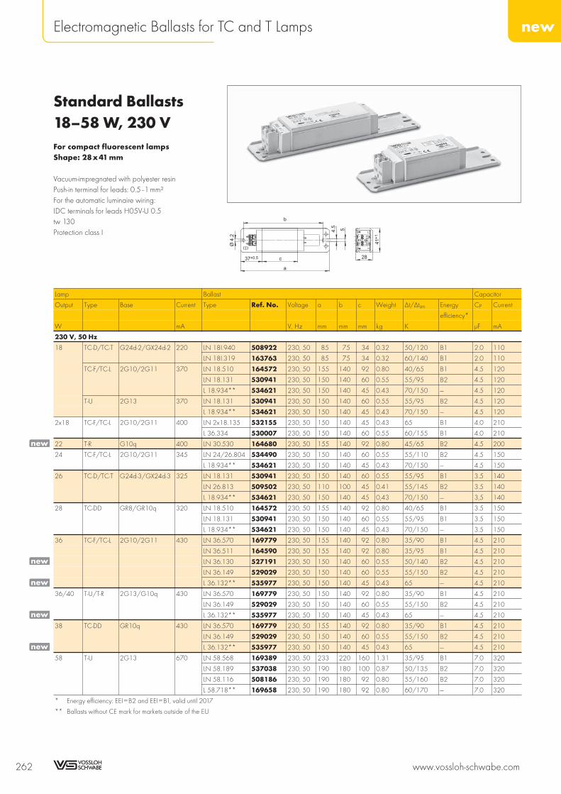
Standard Ballasts18–58 W, 230 VFor compact fluorescent lampsShape: 28x41 mm
Vacuum-impregnated with polyester resinPush-in terminal for leads: 0.5–1 mm²For the automatic luminaire wiring:IDC terminals for leads H05V-U 0.5tw 130Protection class I
Lamp Ballast Capacitor
Output Type Base Current Type Ref. No. Voltage a b c Weight Δt/Δtan. Energy CP Current
efficiency*
W mA V, Hz mm mm mm kg K μF mA
230 V, 50 Hz
18 TC-D/TC-T G24d-2/GX24d-2 220 LN 18I.940 508922 230, 50 85 75 34 0.32 50/120 B1 2.0 110
LN 18I.319 163763 230, 50 85 75 34 0.32 60/140 B1 2.0 110
TC-F/TC-L 2G10/2G11 370 LN 18.510 164572 230, 50 155 140 92 0.80 40/65 B1 4.5 120
LN 18.131 530941 230, 50 150 140 60 0.55 55/95 B2 4.5 120
L 18.934** 534621 230, 50 150 140 45 0.43 70/150 — 4.5 120
T-U 2G13 370 LN 18.131 530941 230, 50 150 140 60 0.55 55/95 B2 4.5 120
L 18.934** 534621 230, 50 150 140 45 0.43 70/150 — 4.5 120
2x18 TC-F/TC-L 2G10/2G11 400 LN 2x18.135 532155 230, 50 150 140 45 0.43 65 B1 4.0 210
L 36.334 530007 230, 50 150 140 60 0.55 60/155 B1 4.0 210
22 T-R G10q 400 LN 30.530 164680 230, 50 155 140 92 0.80 45/65 B2 4.5 200
24 TC-F/TC-L 2G10/2G11 345 LN 24/26.804 534490 230, 50 150 140 60 0.55 55/110 B2 4.5 150
L 18.934** 534621 230, 50 150 140 45 0.43 70/150 — 4.5 150
26 TC-D/TC-T G24d-3/GX24d-3 325 LN 18.131 530941 230, 50 150 140 60 0.55 55/95 B1 3.5 140
LN 26.813 509502 230, 50 110 100 45 0.41 55/145 B2 3.5 140
L 18.934** 534621 230, 50 150 140 45 0,43 70/150 — 3,5 140
28 TC-DD GR8/GR10q 320 LN 18.510 164572 230, 50 155 140 92 0.80 40/65 B1 3.5 150
LN 18.131 530941 230, 50 150 140 60 0.55 55/95 B1 3.5 150
L 18.934** 534621 230, 50 150 140 45 0.43 70/150 — 3.5 150
36 TC-F/TC-L 2G10/2G11 430 LN 36.570 169779 230, 50 155 140 92 0.80 35/90 B1 4.5 210
LN 36.511 164590 230, 50 155 140 92 0.80 35/95 B1 4.5 210
LN 36.130 527191 230, 50 150 140 60 0.55 50/140 B2 4.5 210
LN 36.149 529029 230, 50 150 140 60 0.55 55/150 B2 4.5 210
L 36.132** 535977 230, 50 150 140 45 0.43 65 — 4.5 210
36/40 T-U/T-R 2G13/G10q 430 LN 36.570 169779 230, 50 150 140 92 0.80 35/90 B1 4.5 210
LN 36.149 529029 230, 50 150 140 60 0.55 55/150 B2 4.5 210
L 36.132** 535977 230, 50 150 140 45 0.43 65 — 4.5 210
38 TC-DD GR10q 430 LN 36.570 169779 230, 50 155 140 92 0.80 35/90 B1 4.5 210
LN 36.149 529029 230, 50 150 140 60 0.55 55/150 B2 4.5 210
L 36.132** 535977 230, 50 150 140 45 0.43 65 — 4.5 210
58 T-U 2G13 670 LN 58.568 169389 230, 50 233 220 160 1.31 35/95 B1 7.0 320
LN 58.189 537038 230, 50 190 180 100 0.87 50/135 B2 7.0 320
LN 58.116 508186 230, 50 190 180 92 0.80 55/160 B2 7.0 320
L 58.718** 169658 230, 50 190 180 92 0.80 60/170 — 7.0 320
* Energy efficiency: EEI=B2 and EEI=B1, valid until 2017
** Ballasts without CE mark for markets outside of the EU
262 www.vossloh-schwabe.com
newElectromagnetic Ballasts for TC and T Lamps
28
41+1
37+0.5 c
b
4.5
Ø4.2
5
a
new
new
new
new
new

Standard Ballasts18–58 W, 240 VFor compact fluorescent lampsShape: 28x41 mm
Lamp Ballast Capacitor
Output Type Base Current Type Ref. No. Voltage a b c Weight Δt/Δtan. Energy CP Current
efficiency*
W mA V, Hz mm mm mm kg K μF mA
240 V, 50 Hz
18 TC-D/TC-T G24d-2/GX24d-2 220 LN 18I.418 164353 240, 50 85 75 34 0.28 60/130 B1 2.0 110
TC-F/TC-L 2G10/2G11 370 LN 18.507 164566 240, 50 155 140 92 0.80 35/60 B1 4.5 120
LN 18.162 533043 240, 50 150 140 60 0.55 60/110 B2 4.5 120
L 18.936** 534627 240, 50 150 140 45 0.43 70/140 — 4.5 120
T-U 2G13 370 LN 18.507 164566 240, 50 155 140 92 0.80 35/60 B1 4.5 120
LN 18.162 533043 240, 50 150 140 60 0.55 60/110 B2 4.5 120
L 18.936** 534627 240, 50 150 140 45 0.43 70/140 — 4.5 120
2x18 TC-F/TC-L 2G10/2G11 400 LN 2x18.135 535778 240, 50 150 140 45 0.43 65 B1 4.0 210
L 36/40.443 530008 240, 50 150 140 60 0.55 65/155 B1 4.0 210
LN 36.201 527196 240, 50 150 140 60 0.55 55/140 B1 4.0 210
LN 36.505 164555 240, 50 155 140 92 0.80 40/95 B1 4.0 210
21 TC-DD GR10q 260 LN 21.293 547145 240, 50 105 95 45 0,41 55 B1 3,0 120
24 TC-F/TC-L 2G10/2G11 345 LN 18.507 164566 240, 50 155 140 92 0.80 35/60 B1 4.5 150
LN 18.162 533043 240, 50 150 140 60 0.55 60/110 B2 4.5 150
L 18.936** 534627 240, 50 150 140 45 0.43 70/140 — 4.5 150
26 TC-D/TC-T G24d-3/GX24d-3 325 LN 18.162 533043 240, 50 150 140 60 0.55 60/110 B1 4.5 150
LN 26.238 545405 240, 50 105 95 45 0.41 55/145 B2 3.5 140
28 TC-DD GR8/GR10q 320 LN 18.162 533043 240, 50 150 140 60 0.55 60/110 B1 3.5 150
L 18.936** 534627 240, 50 150 140 45 0.43 70/140 — 3.5 150
32 T-R G10q 450 LN 36.505 164555 240, 50 155 140 92 0.80 40/95 B1 4.0 220
36 TC-F/TC-L 2G10/2G11 430 LN 36.505 164555 240, 50 155 140 92 0.80 40/95 B1 4.5 210
LN 36.201 527196 240, 50 155 140 60 0.55 55/140 B2 4.5 210
L 36/40.443** 164438 240, 50 150 140 60 0.55 65/155 — 4.5 210
36/40 T-U/T-R 2G13/G10q 430 LN 36.505 164555 240, 50 155 140 92 0.80 40/95 B1 4.5 210
LN 36.201 527196 240, 50 150 140 60 0.55 55/140 B2 4.5 210
L 36/40.443** 164438 240, 50 150 140 60 0.55 65/155 — 4.5 210
38 TC-DD GR10q 430 LN 36.201 527196 240, 50 150 140 60 0.55 55/140 B2 4.5 210
L 36/40.443** 164438 240, 50 150 140 60 0.55 65/155 — 4.5 210
58 T-U 2G13 670 LN 58.506 164560 240, 50 233 220 160 1.31 35/85 B1 7.0 320
LN 58.190 537056 240, 50 190 180 100 0.87 50/150 B2 7.0 320
LN 58.722 534252 240, 50 190 180 92 0.80 60/180 B2 7.0 320
* Energy efficiency: EEI=B2 and EEI=B1, valid until 2017
** Ballasts without CE mark for markets outside of the EU
www.vossloh-schwabe.com 263
newElectromagnetic Ballasts for TC and T Lamps
10
9
8
7
6
5
4
3
2
1
new
new
new

Standard Ballasts18–58 W, 220 VFor compact fluorescent lampsShape: 28x41 mm
Lamp Ballast Capacitor
Output Type Base Current Type Ref. No. Voltage a b c Weight Δt/Δtan. Energy CP Current
efficiency*
W mA V, Hz mm mm mm kg K μF mA
220 V, 50 Hz
18 TC-F/TC-L 2G10/2G11 370 L18.933 534624 220,50 150 140 45 0.43 70/160 — 4.5 120
T-U 2G13 370 L18.933 534624 220,50 150 140 45 0.43 70/160 — 4.5 120
2x18 TC-F/TC-L 2G10/2G11 400 L 36.158 530252 220,50 150 140 45 0.43 65 — 4.0 210
24 TC-F/TC-L 2G10/2G11 345 L18.933 534624 220,50 150 140 45 0.43 70/160 — 4.5 150
26 TC-D/TC-T G24d-3/GX24d-3 325 L18.933 534624 220,50 150 140 45 0.43 70/160 — 3.5 140
28 TC-DD GR8/GR10q 320 L18.933 534624 220,50 150 140 45 0.43 70/160 — 3.5 150
36 TC-F/TC-L 2G10/2G11 430 L 36.158 530252 220,50 150 140 45 0.43 65 — 4.5 210
36/40 T-U/T-R 2G13/G10q 430 L 36.158 530252 220,50 150 140 45 0.43 65 — 4.5 210
38 TC-DD GR10q 430 L 36.158 530252 220,50 150 140 45 0.43 65 — 4.5 210
58 T-U 2G13 670 L 58.625 164828 220,50 190 180 92 0.80 55/155 — 7.0 320
220 V, 60 Hz
18 TC-D/TC-T G24d-2/GX24d-2 220 L 18I.602 164779 220, 60 85 75 34 0.32 45/110 — 2.0 110
TC-F/TC-L 2G10/2G11 370 L 18.121 532149 220, 60 110 100 45 0.42 65/145 — 4.0 150
L 18.121 528582 220, 60 150 140 45 0.43 65/145 — 4.0 150
L 18.249 538801 220, 60 150 140 34 0.32 75/140 — 4.0 150
T-U 2G13 370 L 18.121 532149 220, 60 110 100 45 0.42 65/145 — 4.0 150
L 18.121 528582 220, 60 150 140 45 0.43 65/145 — 4.0 150
L 18.249 538801 220, 60 150 140 34 0.32 75/140 — 4.0 150
2x18 TC-F/TC-L 2G10/2G11 400 L 36.120 509373 220, 60 150 140 45 0.43 60/170 — 4.0 210
24 TC-F/TC-L 2G10/2G11 345 L 18.121 532149 220, 60 110 100 45 0.42 65/145 — 4.0 190
L 18.121 528582 220, 60 150 140 45 0.43 65/145 — 4.0 190
L 18.249 538801 220, 60 150 140 34 0.32 75/140 — 4.0 190
26 TC-D/TC-T G24d-3/GX24d-3 325 L 18.121 532149 220, 60 110 100 45 0.42 65/145 — 3.0 160
L 18.121 528582 220, 60 150 140 45 0.43 65/145 — 3.0 160
L 18.249 538801 220, 60 150 140 34 0.32 75/140 — 3.0 160
28 TC-DD GR8/GR10q 320 L 18.121 532149 220, 60 110 100 45 0.42 65/145 — 3.0 155
L 18.249 538801 220, 60 150 140 34 0.32 75/140 — 3.0 155
36 TC-F/TC-L 2G10/2G11 430 L 36.120 509373 220, 60 150 140 45 0.43 60/170 — 4.0 210
36/40 T-U/T-R 2G13/G10q 430 L 36.120 509373 220, 60 150 140 45 0.43 60/170 — 4.0 220
38 TC-DD GR10q 430 L 36.120 509373 220, 60 150 140 45 0.43 60/170 — 4.0 220
58 T-U 2G13 670 L 58.657 164870 220, 60 195 180 92 0.80 55/140 — 6.0 320
* Energy efficiency: EEI=B2 and EEI=B1, valid until 2017
264 www.vossloh-schwabe.com
newElectromagnetic Ballasts for TC and T Lamps
newnewnewnewnewnewnewnewnewnew
new
new
new
new

Super-thin Ballasts5–40 W, 230 VFor compact fluorescent lampsShape: 18x41 mm
Vacuum-impregnated with polyester resinPush-in terminal for leads: 0.5–1.5 mm²With earth screwtw 130Protection class I
Lamp Ballast Capacitor
Output Type Base Current Type Ref. No. Voltage a b c Weight Δt/Δtan. Energy CP Current
efficiency*
W mA V, Hz mm mm mm kg K μF mA
230 V, 50 Hz
5 TC-S G23 180 L 7/9/11.141 163052 230, 50 155 140 58 0.37 50/80 B2 2.0 50
2x5 TC-S G23 180 LN 13.143 163071 230, 50 155 140 58 0.37 45/70 B2 2.0 70
7 TC-S G23 175 L 7/9/11.141 163052 230, 50 155 140 58 0.37 50/80 B2 2.0 50
2x7 TC-S G23 160 LN 13.143 163071 230, 50 155 140 58 0.37 45/70 B2 2.0 70
9 TC-S G23 170 L 7/9/11.141 163052 230, 50 155 140 58 0.37 50/80 B2 2.0 60
2x9 TC-S G23 140 LN 13.143 163071 230, 50 155 140 58 0.37 45/70 B2 2.0 80
10 TC-D G24d-1 190 LN 13.143 163071 230, 50 155 140 58 0.37 45/70 B2 2.0 70
TC-DD GR10q 180 LN 13.143 163071 230, 50 155 140 58 0.37 45/70 B2 2.0 70
11 TC-S G23 155 L 7/9/11.141 163052 230, 50 155 140 58 0.37 50/80 B2 2.0 80
13 TC-D/TC-T G24d-1/GX24d-1 175 LN 13.143 163071 230, 50 155 140 58 0.37 45/70 B2 2.0 80
16 TC-DD GR8/GR10q 195 LN 16.145 163084 230, 50 155 140 58 0.37 50/110 B2 2.0 100
18 TC-D G24d-2/GX24d-2 220 LN 18I.147 163102 230, 50 155 140 58 0.37 55/110 B2 2.0 110
TC-F/TC-L 2G10/2G11 370 LN 18.220 526592 230, 50 195 180 116 0.70 55/80 B2 4.5 120
T-U 2G13 370 LN 18.220 526592 230, 50 195 180 116 0.70 55/80 B2 4.5 120
2x18 TC-F/TC-L 2G10/2G11 400 LN 36.221 526593 230, 50 195 180 116 0.70 50/125 B2 4.0 210
24 TC-F/TC-L 2G10/2G11 345 LN 18.220 526592 230, 50 195 180 116 0.70 55/80 B2 4.5 150
26 TC-D/TC-T G24d-3/GX24d-3 325 LN 18.220 526592 230, 50 195 180 116 0.70 55/80 B1 3.5 140
28 TC-DD GR8/GR10q 320 LN 18.220 526592 230, 50 195 180 116 0.70 55/80 B1 3.5 150
36 TC-F/TC-L 2G10/2G11 430 LN 36.221 526593 230, 50 195 180 116 0.70 50/125 B2 4.5 210
36/40 T-U/T-R 2G13/G10q 430 LN 36.221 526593 230, 50 195 180 116 0.70 50/125 B2 4.5 220
38 TC-DD GR10q 430 LN 36.221 526593 230, 50 195 180 116 0.70 50/125 B2 4.5 210
* Energy efficiency: EEI=B2 and EEI=B1, valid until 2017
www.vossloh-schwabe.com 265
Electromagnetic Ballasts for TC and T Lamps
10
9
8
7
6
5
4
3
2
1

Super-thin Ballasts 5–40 W, 240/220 VFor compact fluorescent lampsShape: 18x41 mm
Lamp Ballast Capacitor
Output Type Base Current Type Ref. No. Voltage a b c Weight Δt/Δtan. Energy CP Current
efficiency*
W mA V, Hz mm mm mm kg K μF mA
240 V, 50 Hz
2x5 TC-S G23 180 L 13.111 162966 240, 50 155 140 58 0.37 55/85 B2 2.0 70
7 TC-S G23 175 L 7/9/11.110 162958 240, 50 155 140 58 0.37 55/80 B2 2.0 50
2x7 TC-S G23 160 L 13.111 162966 240, 50 155 140 58 0.37 55/85 B2 2.0 70
9 TC-S G23 170 L 7/9/11.110 162958 240, 50 155 140 58 0.37 55/80 B2 2.0 60
2x9 TC-S G23 140 L 13.111 162966 240, 50 155 140 58 0.37 55/85 B2 2.0 80
10 TC-D G24d-1 190 L 13.111 162966 240, 50 155 140 58 0.37 55/85 B2 2.0 70
TC-DD GR10q 180 L 13.111 162966 240, 50 155 140 58 0.37 55/85 B2 2.0 70
11 TC-S G23 155 L 7/9/11.110 162958 240, 50 155 140 58 0.37 55/80 B2 2.0 80
13 TC-D/TC-T G24d-1/GX24d-1 175 L 13.111 162966 240, 50 155 140 58 0.37 55/85 B2 2.0 80
16 TC-DD GR8/GR10q 195 L 16.113 162976 240, 50 155 140 58 0.37 45/110 B2 2.0 100
18 TC-D/TC-T G24d-2/GX24d-2 220 L 18I.132 163031 240, 50 155 140 58 0.37 70/140 B2 2.0 110
TC-F/TC-L 2G10/2G11 370 LN 18.121 529272 240, 50 195 180 116 0.64 50/85 B2 2.0 110
T-U 2G13 370 LN 18.121 529272 240, 50 195 180 116 0.64 50/85 B2 4.5 120
2x18 TC-F/TC-L 2G10/2G11 400 LN 36.124 529273 240, 50 195 180 116 0.64 55/140 B2 4.0 210
24 TC-F/TC-L 2G10/2G11 345 LN 18.121 529272 240, 50 195 180 116 0.64 50/85 B2 4.5 150
26 TC-D/TC-T G24d-3/GX24d-3 325 LN 18.121 529272 240, 50 195 180 116 0.64 50/85 B1 3.5 140
28 TC-DD GR8/GR10q 320 LN 18.121 529272 240, 50 195 180 116 0.64 50/85 B1 3.5 150
36 TC-F/TC-L 2G10/2G11 430 LN 36.124 529273 240, 50 195 180 116 0.64 55/140 B2 4.5 210
36/40 T-U/T-R 2G13/G10q 430 LN 36.124 529273 240, 50 195 180 116 0.64 55/140 B2 4.5 210
38 TC-DD GR8/GR10q 430 LN 36.124 529273 240, 50 195 180 116 0.64 55/140 B2 4.5 210
220 V, 60 Hz
5 TC-S G23 180 L 7/9/11.134 163041 220, 60 155 140 58 0.37 45/65 — 2.0 70
2x5 TC-S G23 180 L 13.164 163162 220, 60 155 140 58 0.37 40/80 — 2.0 90
7 TC-S G23 175 L 7/9/11.134 163041 220, 60 155 140 58 0.37 45/65 — 2.0 70
2x7 TC-S G23 160 L 13.164 163162 220, 60 155 140 58 0.37 40/80 — 2.0 90
9 TC-S G23 170 L 7/9/11.134 163041 220, 60 155 140 58 0.37 45/65 — 2.0 70
2x9 TC-S G23 140 L 13.164 163162 220, 60 155 140 58 0.37 40/80 — 2.0 90
10 TC-D G24d-1 190 L 13.164 163162 220, 60 155 140 58 0.37 40/80 — 2.0 80
11 TC-S G23 155 L 7/9/11.134 163041 220, 60 155 140 58 0.37 45/65 — 2.0 80
13 TC-D/TC-T G24d-1/GX24d-1 175 L 13.164 163162 220, 60 155 140 58 0.37 40/80 — 2.0 110
16 TC-DD GR8/GR10q 195 L 16.202 163235 220, 60 155 140 58 0.37 45/110 — 2.0 100
18 TC-F/TC-L 2G10/2G11 370 L 18.140 163045 220, 60 195 180 116 0.64 55/80 — 4.0 150
T-U 2G13 370 L 18.140 163045 220, 60 195 180 116 0.64 55/80 — 4.0 150
2x18 TC-F/TC-L 2G10/2G11 400 L 36.188 163218 220, 60 195 180 116 0.64 45/110 — 4.0 210
24 TC-F/TC-L 2G10/2G11 345 L 18.140 163045 220, 60 195 180 116 0.64 55/80 — 4.0 190
26 TC-D/TC-T G24d-3/GX24d-3 325 L 18.140 163045 220, 60 195 180 116 0.64 55/80 — 3.0 160
28 TC-DD GR8/GR10q 320 L 18.140 163045 220, 60 195 180 116 0.64 55/80 — 3.0 155
36 TC-F/TC-L 2G10/2G11 430 L 36.188 163218 220, 60 195 180 116 0.64 45/110 — 4.0 210
36/40 T-U/T-R 2G13/G10q 430 L 36.188 163218 220, 60 195 180 116 0.64 45/110 — 4.0 220
38 TC-DD GR10q 430 L 36.188 163218 220, 60 195 180 116 0.64 45/110 — 4.0 220
* Energy efficiency: EEI=B2 and EEI=B1, valid until 2017
266 www.vossloh-schwabe.com
Electromagnetic Ballasts for TC and T Lamps

Super-thin Ballastswith Pre-MountedLampholder 5–26 W230/240/220 VFor compact fluorescent lampsShape: 18x41 mm
Vacuum-impregnated with polyester resinPush-in terminals: 0.5–1.5 mm²With earth screwWith groove for reflector attachmenttw 130Protection class I
www.vossloh-schwabe.com 267
Electromagnetic Ballasts for TC and T Lamps
10
9
8
7
6
5
4
3
2
1
A
B
C

Super-thin Ballasts with Pre-Mounted Lampholder5–26 W, 230/240/220 V
Lamp Ballast Capacitor
Output Type Base Current Type Ref. No. Voltage Drawing a b c Weight Δt/Δtan. Energy CP Current
efficiency*
W mA V, Hz mm mm mm kg K μF mA
230 V, 50 Hz
5 TC-S G23 180 L 7/9/11.141 163148 230, 50 A 155 140 58 0.37 50/80 B2 2.0 50
2x5 TC-S G23 180 LN 13.143 163207 230, 50 B 155 140 58 0.37 45/70 B2 2.0 70
7 TC-S G23 175 L 7/9/11.141 163148 230, 50 A 155 140 58 0.37 50/80 B2 2.0 50
2x7 TC-S G23 160 LN 13.143 163207 230, 50 B 155 140 58 0.37 45/70 B2 2.0 70
9 TC-S G23 170 L 7/9/11.141 163148 230, 50 A 155 140 58 0.37 50/80 B2 2.0 60
2x9 TC-S G23 140 LN 13.143 163207 230, 50 B 155 140 58 0.37 45/70 B2 2.0 80
10 TC-D G24d-1 190 LN 13.143 163157 230, 50 C 155 140 58 0.37 45/70 B2 2.0 70
11 TC-S G23 155 L 7/9/11.141 163148 230, 50 A 155 140 58 0.37 50/80 B2 2.0 80
13 TC-D G24d-1 175 LN 13.143 163157 230, 50 C 155 140 58 0.37 45/70 B2 2.0 80
18 TC-D G24d-2 220 LN 18I.147 163170 230, 50 C 155 140 58 0.37 55/110 B2 2.0 110
26 TC-D G24d-3 325 LN 18.220 526591 230, 50 C 215 200 116 0.64 55/80 B1 3.5 140
LN 18.146 163180 230, 50 C 215 200 116 0.64 60/95 B2 3.5 140
240 V, 50 Hz
5 TC-S G23 180 L 7/9/11.110 163007 240, 50 A 155 140 58 0.37 55/80 B2 2.0 50
2x5 TC-S G23 180 L 13.111 163212 240, 50 B 155 140 58 0.37 55/85 B2 2.0 70
7 TC-S G23 175 L 7/9/11.110 163007 240, 50 A 155 140 58 0.37 55/80 B2 2.0 50
2x7 TC-S G23 160 L 13.111 163212 240, 50 B 155 140 58 0.37 55/85 B2 2.0 70
9 TC-S G23 170 L 7/9/11.110 163007 240, 50 A 155 140 58 0.37 55/80 B2 2.0 60
2x9 TC-S G23 140 L 13.111 163212 240, 50 B 155 140 58 0.37 55/85 B2 2.0 80
10 TC-D G24d-1 190 L 13.111 163016 240, 50 C 155 140 58 0.37 55/85 B2 2.0 70
11 TC-S G23 155 L 7/9/11.110 163007 240, 50 A 155 140 58 0.37 55/80 B2 2.0 80
13 TC-D G24d-1 175 L 13.111 163016 240, 50 C 155 140 58 0.37 55/85 B2 2.0 80
18 TC-D G24d-2 220 L 18I.132 163033 240, 50 C 155 140 58 0.37 70/140 B2 2.0 110
26 TC-D G24d-3 325 L 18.114 163024 240, 50 C 215 200 116 0.64 60/90 B2 3.5 140
220 V, 60 Hz
5 TC-S G23 180 L 7/9/11.134 163036 220, 60 A 155 140 58 0.37 45/65 — 2.0 70
2x5 TC-S G23 180 L 13.164 178627 220, 60 B 155 140 58 0.37 40/80 — 2.0 90
7 TC-S G23 175 L 7/9/11.134 163036 220, 60 A 155 140 58 0.37 45/65 — 2.0 70
2x7 TC-S G23 160 L 13.164 178627 220, 60 B 155 140 58 0.37 40/80 — 2.0 90
9 TC-S G23 170 L 7/9/11.134 163036 220, 60 A 155 140 58 0.37 45/65 — 2.0 70
2x9 TC-S G23 140 L 13.164 178627 220, 60 B 155 140 58 0.37 40/80 — 2.0 90
10 TC-D G24d-1 190 L 13.164 163189 220, 60 C 155 140 58 0.37 40/80 — 2.0 80
11 TC-S G23 155 L 7/9/11.134 163036 220, 60 A 155 140 58 0.37 45/65 — 2.0 80
13 TC-D G24d-1 165 L 13.164 163189 220, 60 C 155 140 58 0.37 40/80 — 2.0 80
* Energy efficiency: EEI=B2 and EEI=B1, valid until 2017
268 www.vossloh-schwabe.com
Electromagnetic Ballasts for TC and T Lamps

Slim Ballasts5–40 W, 230 VFor compact fluorescent lampsShape: 28x28 mm
Vacuum-impregnated with polyester resinPush-in terminal for leads: 0.5–1 mm²For the automatic luminaire wiring:IDC terminals for leads H05V-U 0.5tw 130Protection class I
Lamp Ballast Capacitor
Output Type Base Current Type Ref. No. Voltage a b c Weight Δt/Δtan. Energy CP Current
efficiency*
W mA V, Hz mm mm mm kg K μF mA
230 V, 50 Hz
5 TC-S G23 180 L 7/9/11.131 179409 230, 50 130 120 52 0.34 50/70 B2 2.0 50
2x5 TC-S G23 180 LN 13.134 179466 230, 50 130 120 52 0.34 50/80 B2 2.0 70
7 TC-S G23 175 L 7/9/11.131 179409 230, 50 130 120 52 0.34 50/70 B2 2.0 50
2x7 TC-S G23 160 LN 13.134 179466 230, 50 130 120 52 0,34 50/80 B2 2.0 70
9 TC-S G23 170 L 7/9/11.131 179409 230, 50 130 120 52 0.34 50/70 B1 2.0 60
2x9 TC-S G23 140 LN 13.134 179466 230, 50 130 120 52 0.34 50/80 B2 2.0 80
10 TC-D G24d-1 190 LN 13.134 179466 230, 50 130 120 52 0.34 50/80 B2 2.0 70
TC-DD GR10q 180 LN 13.134 179466 230, 50 130 120 52 0.34 50/80 B2 2.0 70
11 TC-S G23 155 L 7/9/11.131 179409 230, 50 130 120 52 0.34 50/70 B1 2.0 80
13 TC-D/TC-T G24d-1/GX24d-1 175 LN 13.134 179466 230, 50 130 120 52 0.34 50/80 B2 2.0 80
16 TC-DD GR8/GR10q 195 LN 16.135 505607 230, 50 130 120 52 0.34 50/125 B2 2.0 100
18 TC-D/TC-T G24d-2/GX24d-2 220 LN 18I.130 179231 230, 50 130 120 52 0.34 55/125 B1 2.0 110
TC-F/TC-L 2G10/2G11 370 LN 18.127 526596 230, 50 190 180 120 0.70 45/80 B2 4.5 120
T-U 2G13 370 LN 18.127 526596 230, 50 190 180 120 0.70 45/80 B2 4.5 190
2x18 TC-F/TC-L 2G10/2G11 400 LN 36.172 526597 230, 50 190 180 120 0.70 50/130 B2 4.0 210
24 TC-F/TC-L 2G10/2G11 345 LN 18.127 526596 230, 50 190 180 120 0.70 45/80 B2 4.5 150
26 TC-D/TC-T G24d-3/GX24d-3 325 LN 18.127 526596 230, 50 190 180 120 0.70 45/80 B1 3.5 140
28 TC-DD GR8/GR10q 320 LN 18.127 526596 230, 50 190 180 120 0.70 45/80 B1 3.5 155
36 TC-F/TC-L 2G10/2G11 430 LN 36.172 526597 230, 50 190 180 120 0.70 50/130 B2 4.5 210
36/40 T-U/T-R 2G13/G10q 430 LN 36.172 526597 230, 50 190 180 120 0.70 50/130 B2 4.0 210
38 TC-DD GR10q 430 LN 36.172 526597 230, 50 190 180 120 0.70 50/130 B2 4.5 210
* Energy efficiency: EEI=B2 and EEI=B1, valid until 2017
www.vossloh-schwabe.com 269
Electromagnetic Ballasts for TC and T Lamps
10
9
8
7
6
5
4
3
2
1
4.5
28.0
+1
28
4.5
c
b
a

Slim Ballasts 5–58 W, 240/220 VFor compact fluorescent lampsShape: 28x28 mm
Lamp Ballast Capacitor
Output Type Base Current Type Ref. No. Voltage a b c Weight Δt/Δtan. Energy CP Current
efficiency*
W mA V, Hz mm mm mm kg K μF mA
240 V, 50 Hz
5 TC-S G23 180 L 7/9/11.137 505609 240, 50 130 120 52 0.34 50/70 B2 2.0 50
2x5 TC-S G23 180 L 13.129 179258 240, 50 130 120 52 0.34 55/80 B2 2.0 70
7 TC-S G23 175 L 7/9/11.137 505609 240, 50 130 120 52 0.34 50/70 B2 2.0 50
2x7 TC-S G23 160 L 13.129 179258 240, 50 130 120 52 0.34 55/80 B2 2.0 70
9 TC-S G23 170 L 7/9/11.137 505609 240, 50 130 120 52 0.34 50/70 B1 2.0 60
2x9 TC-S G23 140 L 13.129 179258 240, 50 130 120 52 0.34 55/80 B2 2.0 80
10 TC-D G24d-1 190 L 13.129 179258 240, 50 130 120 52 0.34 55/80 B2 2.0 70
TC-DD GR10q 180 L 13.129 179258 240, 50 130 120 52 0.34 55/80 B2 2.0 70
11 TC-S G23 155 L 7/9/11.137 505609 240, 50 130 120 52 0.34 50/70 B1 2.0 80
13 TC-D/TC-T G24d-1/GX24d-1 175 L 13.129 179258 240, 50 130 120 52 0.34 55/80 B2 2.0 80
16 TC-DD GR8/GR10q 195 LN 16.146 505629 240, 50 130 120 52 0.34 55/125 B2 2.0 100
18 TC-D/TC-T G24d-2/GX24d-2 220 LN 18I.147 505630 240, 50 130 120 52 0.34 60/120 B2 2.0 110
TC-F/TC-L 2G10/2G11 370 LN 18.173 529066 240, 50 190 180 120 0.70 45/80 B2 4.5 120
T-U 2G13 370 LN 18.173 529066 240, 50 190 180 120 0.70 45/80 B2 4.5 190
2x18 TC-F/TC-L 2G10/2G11 400 LN 36.174 529071 240, 50 190 180 120 0.70 50/135 B2 4.0 210
24 TC-F/TC-L 2G10/2G11 345 LN 18.173 529066 240, 50 190 180 120 0.70 45/80 B2 4.5 150
26 TC-D/TC-T G24d-3/GX24d-3 325 LN 18.173 529066 240, 50 190 180 120 0.70 45/80 B1 3.5 140
28 TC-DD GR8/GR10q 320 LN 18.173 529066 240, 50 190 180 120 0.70 45/80 B1 3.5 150
36 TC-F/TC-L 2G10/2G11 430 LN 36.174 529071 240, 50 190 180 120 0.70 50/135 B2 4.5 210
36/40 T-U/T-R 2G13/G10q 430 LN 36.174 529071 240, 50 190 180 120 0.70 50/135 B2 4.5 210
38 TC-DD GR10q 430 LN 36.174 529071 240, 50 190 180 120 0.70 50/135 B2 4.5 210
220 V, 60 Hz
5 TC-S G23 180 L 7/9/11.138 505610 220, 60 130 120 52 0.34 50/70 — 2.0 70
2x5 TC-S G23 180 L 13.136 505608 220, 60 130 120 52 0.34 50/80 — 2.0 90
7 TC-S G23 175 L 7/9/11.138 505610 220, 60 130 120 52 0.34 50/70 — 2.0 70
2x7 TC-S G23 160 L 13.136 505608 220, 60 130 120 52 0.34 50/80 — 2.0 90
9 TC-S G23 170 L 7/9/11.138 505610 220, 60 130 120 52 0.34 50/70 — 2.0 70
2x9 TC-S G23 140 L 13.136 505608 220, 60 130 120 52 0.34 50/80 — 2.0 90
10 TC-D G24d-1 190 L 13.136 505608 220, 60 130 120 52 0.34 50/80 — 2.0 80
TC-DD GR10q 180 L 13.136 505608 220, 60 130 120 52 0.34 50/80 — 2.0 80
11 TC-S G23 155 L 7/9/11.138 505610 220, 60 130 120 52 0.34 50/70 — 2.0 80
13 TC-D/TC-T G24d-1/GX24d-1 165 L 13.136 505608 220, 60 130 120 52 0.34 50/80 — 2.0 110
16 TC-DD GR8/GR10q 195 LN 16.188 539981 220, 60 150 140 52 0.34 55/110 — 2.0 100
18 TC-F/TC-L 2G10/2G11 370 L 20.148 505768 220, 60 150 140 102 0.60 55/85 — 4.0 150
T-U 2G13 370 L 20.148 505768 220, 60 150 140 102 0.60 55/85 — 4.0 150
2x18 TC-F/TC-L 2G10/2G11 400 L 36.126 170009 220, 60 150 140 102 0.60 55/125 — 4.0 210
24 TC-F/TC-L 2G10/2G11 345 L 20.148 505768 220, 60 150 140 102 0.60 55/85 — 4.0 190
26 TC-D/TC-T G24d-3/GX24d-3 325 L 20.148 505768 220, 60 150 140 102 0.60 55/85 — 3.0 160
28 TC-DD GR8/GR10q 320 L 20.148 505768 220, 60 150 140 102 0.60 55/85 — 3.0 155
36 TC-F/TC-L 2G10/2G11 430 L 36.126 170009 220, 60 150 140 102 0.60 55/125 — 4.0 210
36/40 T-U/T-R 2G13/G10q 430 L 36.126 170009 220, 60 150 140 102 0.60 55/125 — 4.0 210
38 TC-DD GR10q 430 L 36.126 170009 220, 60 150 140 102 0.60 55/125 — 4.0 220
58 T-U 2G13 670 L 58/65.149 507213 220, 60 230 220 178 1.00 60/140 — 6.0 320
* Energy efficiency: EEI=B2 and EEI=B1, valid until 2017
270 www.vossloh-schwabe.com
Electromagnetic Ballasts for TC and T Lamps

Ballasts5–20 W120 V/60 HzFor compact fluorescent lampsShape: 28x41 mm
Vacuum-impregnated with polyester resinPush-in terminal for leads: 0.5–1 mm²For the automatic luminaire wiring:IDC terminals for leads H05V-U 0.5tw 130Protection class I
Lamp Ballast Capacitor
Output Type Base Current Type Ref. No. Voltage a b c Weight Δt/Δtan. CP Current
W mA V, Hz mm mm mm kg K μF mA
120 V, 60 Hz
5 TC-S G23 180 L 7/9.209 163318 120, 60 85 75 34 0.32 25/40 3.0 90
7 TC-S G23 175 L 7/9.209 163318 120, 60 85 75 34 0.32 25/40 3.0 90
9 TC-S G23 170 L 7/9.209 163318 120, 60 85 75 34 0.32 25/40 3.0 90
18 TC-F/TC-L 2G10/2G11 370 L 20.122 163256 120, 60 85 75 34 0.32 35/80 5.0 150
20 T-U 2G13 370 L 20.122 163256 120, 60 85 75 34 0.32 35/80 5.0 190
www.vossloh-schwabe.com 271
newElectromagnetic Ballasts for TC and T Lamps
10
9
8
7
6
5
4
3
2
128
41+1
c
b
a
5
newnew

Operating Units5–40 W120 V/60 HzFor compact fluorescent lampsShape: 33x41 mm
Vacuum-impregnated with polyester resinPush-in terminal for leads: 0.5–1.5 mm²For the automatic luminaire wiring:IDC terminals for leads H05V-U 0.5tw 130Protection class I
These units are a combination of transformers/ballasts (high-reactance transformers) whichsupply the lamp with the necessary operatingvoltage. For these units a usual starter(220–240 V) is necessary.
Lamp Ballast Capacitor
Output Type Base Current Type Ref. No. Voltage a b c Weight Δt/Δtan. CP Current
W mA V, Hz mm mm mm kg K μF mA
120 V, 60 Hz
2x5 TC-S G23 180 SL 13.331 169496 120, 60 125 110 40 0.47 50/80 8.0 150
2x7 TC-S G23 160 SL 13.331 169496 120, 60 125 110 40 0.47 50/80 7.0 170
2x9 TC-S G23 145 SL 13.331 169496 120, 60 125 110 40 0.47 50/80 7.0 165
10 TC-D G24d-1 190 SL 13.331 169496 120, 60 125 110 40 0.47 50/80 8.0 150
13 TC-D/TC-T G24d-1/GX24d-1 165 SL 13.331 169496 120, 60 125 110 40 0.47 50/80 7.0 170
18 TC-D/TC-T G24d-2/GX24d-2 220 SL 18I.334 169727 120, 60 125 110 40 0.47 45/95 7.0 280
2x18 TC-F/TC-L 2G10/2G11 410 SL 36.342 506405 120, 60 155 140 65 0.71 75/175 16.0 430
24 TC-F/TC-L 2G10/2G11 340 SL 24.335 168108 120, 60 155 140 65 0.71 55/120 12.0 350
26 TC-D/TC-T G24d-3/GX24d-3 315 SL 24.335 168108 120, 60 155 140 65 0.71 55/120 12.0 310
28 TC-DD GR8/GR10q 325 SL 24.335 168108 120, 60 155 140 65 0.71 55/120 12.0 320
36 TC-F/TC-L 2G10/2G11 410 SL 36.342 506405 120, 60 155 140 65 0.71 75/175 16.0 440
36/40 T-U/T-R 2G13/G10q 410 SL 36.342 506405 120, 60 155 140 65 0.71 75/175 16.0 470
38 TC-DD GR10q 410 SL 36.342 506405 120, 60 155 140 65 0.71 75/175 16.0 460
272 www.vossloh-schwabe.com
Electromagnetic Ballasts for TC and T Lamps

Standard Ballasts4–13 W230/240/220 VFor fluorescent lampsShape: 28x41 mm
Vacuum-impregnated with polyester resinPush-in terminal for leads: 0.5–1 mm²For the automatic luminaire wiring:IDC terminals for leads H05V-U 0.5tw 130Protection class I
Lamp Ballast Capacitor
Output Type Base Current Type Ref. No. Voltage a b c Weight Δt/Δtan. Energy CP Current
efficiency*
W mA V, Hz mm mm mm kg K μF mA
230 V, 50 Hz
4 T5 (T16) G5 170 L 4/6/8.304 163683 230, 50 85 75 34 0.32 55/85 B2 2.0 40
2x4 T5 (T16) G5 155 L 4/6/8.304 163683 230, 50 85 75 34 0.32 55/85 B1 2.0 50
6 T5 (T16) G5 160 L 4/6/8.304 163683 230, 50 85 75 34 0.32 55/85 B1 2.0 50
2x6 T5 (T16) G5 175 LN 13.313 163711 230, 50 85 75 34 0.32 55/80 B1 2.0 65
8 T5 (T16) G5 145 L 4/6/8.304 163683 230, 50 85 75 34 0.32 55/85 B1 2.0 60
2x8 T5 (T16) G5 155 LN 13.313 163711 230, 50 85 75 34 0.32 55/80 B1 2.0 85
13 T5 (T16) G5 165 LN 13.313 163711 230, 50 85 75 34 0.32 55/80 B1 2.0 80
240 V, 50 Hz
4 T5 (T16) G5 170 L 4/6/8.404 164326 240, 50 85 75 34 0.32 55/80 B2 2.0 40
2x4 T5 (T16) G5 155 L 4/6/8.404 164326 240, 50 85 75 34 0.32 55/80 B1 2.0 50
6 T5 (T16) G5 160 L 4/6/8.404 164326 240, 50 85 75 34 0.32 55/80 B1 2.0 50
2x6 T5 (T16) G5 175 LN 13.413 164342 240, 50 85 75 34 0.32 60/90 B1 2.0 65
8 T5 (T16) G5 145 L 4/6/8.404 164326 240, 50 85 75 34 0.32 55/80 B1 2.0 60
2x8 T5 (T16) G5 155 LN 13.413 164342 240, 50 85 75 34 0.32 60/90 B1 2.0 85
13 T5 (T16) G5 165 LN 13.413 164342 240, 50 85 75 34 0.32 60/90 B1 2.0 80
220 V, 60 Hz
4 T5 (T16) G5 170 L 4/6/8.218 532644 220, 60 85 75 34 0.32 60/80 — 2.0 40
2x4 T5 (T16) G5 155 L 4/6/8.218 532644 220, 60 85 75 34 0.32 60/80 — 2.0 50
6 T5 (T16) G5 160 L 4/6/8.218 532644 220, 60 85 75 34 0.32 60/80 — 2.0 50
2x6 T5 (T16) G5 175 L 13.210 520992 220, 60 85 75 34 0.32 45/80 — 2.0 65
8 T5 (T16) G5 145 L 4/6/8.218 532644 220, 60 85 75 34 0.32 60/80 — 2.0 60
2x8 T5 (T16) G5 155 L 13.210 520992 220, 60 85 75 34 0.32 45/80 — 2.0 85
13 T5 (T16) G5 165 L 13.210 520992 220, 60 85 75 34 0.32 45/80 — 2.0 80
* Energy efficiency: EEI=B2 and EEI=B1, valid until 2017
www.vossloh-schwabe.com 273
newElectromagnetic Ballasts for TC and T Lamps
10
9
8
7
6
5
4
3
2
128
41+1
c
b
a
5
newnewnew
new
newnewnew
new
new
newnew

Standard Ballasts14–65 W, 230 VFor fluorescent lampsShape: 28x41 mm
Vacuum-impregnated with polyester resinPush-in terminal for leads: 0.5–1 mm²For the automatic luminaire wiring:IDC terminals for leads H05V-U 0.5tw 130Protection class I
Lamp Ballast Capacitor
Output Type Base Current Type Ref. No. Voltage a b c Weight Δt/Δtan. Energy CP Current
efficiency*
W mA V, Hz mm mm mm kg K μF mA
230 V, 50 Hz
14 T8 (T26) G13 395 LN 18.510 164572 230, 50 155 140 92 0.80 40/65 B2 4.5 150
15 T8 (T26) G13 310 LN 15.329 163861 230, 50 150 140 60 0.55 50/80 B2 3.5 120
2x15 T8 (T26) G13 340 LN 30.801 169645 230, 50 150 140 60 0.55 55/110 B2 4.0 185
L 30.347** 164033 230, 50 150 140 60 0.55 60/150 — 4.0 185
16 T8 (T26) G13 200 LN 16.316 163730 230, 50 85 75 34 0.32 60/125 B1 2.0 90
18/20 T8 (T26)/T12 (T38) G13 370 LN 18.510 164572 230, 50 155 140 92 0.80 40/65 B1 4.5 120
LN 18.131 530941 230, 50 150 140 60 0.55 55/95 B2 4.5 120
L 18.934** 534621 230, 50 150 140 45 0.43 70/150 — 4.5 120
2x18/20 T8 (T26)/T12 (T38) G13 400 LN 2x18.135 532155 230, 50 150 140 45 0.43 65 B1 4.0 210
L 36.334 530007 230, 50 150 140 60 0.55 60/155 B1 4.0 210
25 T12 (T38) G13 290 L 25.346 164013 230, 50 150 140 60 0.55 45/80 B1 3.5 130
30 T8 (T26) G13 365 LN 30.801 169645 230, 50 150 140 60 0.55 55/110 B2 4.5 180
36-1 T8 (T26) G13 556 L 36I.342 538072 230, 50 195 180 100 0.87 50/120 B2 6.5 250
36/40 T8 (T26)/T12 (T38) G13 430 LN 36.570 169779 230, 50 155 140 92 0.80 35/90 B1 4.5 210
LN 36.511 164590 230, 50 155 140 92 0.80 35/95 B1 4.5 210
LN 36.130 527191 230, 50 150 140 60 0,55 50/140 B2 4.5 210
LN 36.149 529029 230, 50 150 140 60 0.55 55/150 B2 4.5 210
L 36.132** 535977 230, 50 150 140 45 0.43 65 — 4.5 210
38 T8 (T26) G13 430 LN 36.570 169779 230, 50 155 140 92 0.80 35/90 B1 4.5 210
LN 36.511 164590 230, 50 155 140 92 0.80 35/95 B1 4.5 210
LN 36.149 529029 230, 50 150 140 60 0.55 55/150 B2 4.5 210
L 36.132** 535977 230, 50 150 140 45 0.43 65 — 4.5 210
58/65 T8 (T26)/T12 (T38) G13 670 LN 58.568 169389 230, 50 233 220 160 1.31 35/95 B1 7.0 320
LN 58.189 537038 230, 50 190 180 100 0.87 50/125 B2 7.0 320
LN 58.116 508186 230, 50 190 180 92 0.80 55/160 B2 7.0 320
L 58.718** 169658 230, 50 190 180 92 0.80 60/170 — 7.0 320
* Energy efficiency: EEI=B2 and EEI=B1, valid until 2017
** Ballasts without CE mark for markets outside of the EU
274 www.vossloh-schwabe.com
newElectromagnetic Ballasts for TC and T Lamps
28
41+1
37+0.5 c
b
4.5
Ø4.2
5
a
new
new
new

Standard Ballasts15–75 W, 240/220 VFor fluorescent lampsShape: 28x41 mm
Lamp Ballast Capacitor
Output Type Base Current Type Ref. No. Voltage a b c Weight Δt/Δtan. Energy CP Current
efficiency*
W mA V, Hz mm mm mm kg K μF mA
240 V, 50 Hz
2x15 T8 (T26) G13 340 LN 30.806 533067 240, 50 150 140 60 0.55 55/130 B2 4.0 185
16 T8 (T26) G13 200 LN 16.417 164358 240, 50 85 75 34 0.32 60/130 B1 2.0 90
18/20 T8 (T26)/T12 (T38) G13 370 LN 18.507 164566 240, 50 155 140 92 0.80 35/60 B1 4.5 120
LN 18.162 533043 240, 50 150 140 60 0.55 60/110 B2 4.5 120
L 18.936** 534627 240, 50 150 140 45 0.43 70/140 — 4.5 120
2x18/20 T8 (T26)/T12 (T38) G13 400 LN 2x18.135 535778 240, 50 150 140 45 0.43 65 B1 4.0 210
L 36/40.443 530008 240, 50 150 140 60 0.55 65/155 B1 4.0 210
LN 36.201 527196 240, 50 150 140 60 0.55 55/140 B1 4.0 210
LN 36.505 164555 240, 50 155 140 92 0.80 40/95 B1 4.0 210
30 T8 (T26) G13 365 LN 30.806 533067 240, 50 150 140 60 0.55 55/130 B2 4.5 180
36/40 T8 (T26)/T12 (T38) G13 430 LN 36.505 164555 240, 50 155 140 92 0.80 40/95 B1 4.5 210
LN 36.201 527196 240, 50 150 140 60 0.55 55/140 B2 4.5 210
L 36/40.443** 164438 240, 50 150 140 60 0.55 65/155 — 4.5 210
38 T8 (T26) G13 430 LN 36.505 164555 240, 50 155 140 92 0.80 40/95 B1 4.5 210
LN 36.201 527196 240, 50 150 140 60 0.55 55/140 B2 4.5 210
L 36/40.443** 164438 240, 50 150 140 60 0.55 65/155 — 4.5 210
58/65 T8 (T26)/T12 (T38) G13 670 LN 58.506 164560 240, 50 233 220 160 1.31 35/85 B1 7.0 320
LN 58.190 537056 240, 50 190 180 100 0.87 50/150 B2 7.0 320
LN 58.722 534252 240, 50 190 180 92 0.80 60/180 B2 7.0 320
70/75 T8 (T26)/T12 (T38) G13 670 LN 75.170 538603 240, 50 190 180 100 0.87 55/160 B2 6.0 320
220 V, 50 Hz
18/20 T8 (T26)/T12 (T38) G13 370 L 18.933 534624 220, 50 150 140 45 0.43 70/160 — 4.5 120
2x18/20 T8 (T26)/T12 (T38) G13 430 L 36.158 530252 220, 50 150 140 45 0.43 65 — 4.0 210
36/40 T8 (T26)/T12 (T38) G13 430 L 36.158 530252 220, 50 150 140 45 0.43 65 — 4.5 210
38 T8 (T26) G13 430 L 36.158 530252 220, 50 150 140 45 0.43 65 — 4.5 210
58/65 T8 (T26)/T12 (T38) G13 670 L 58.625 164828 220, 50 190 180 92 0.80 55/155 — 7.0 320
220 V, 60 Hz
15 T8 (T26) G13 310 L 15.007 537744 220, 60 150 140 45 0.43 55/80 — 3.0 120
2x15 T8 (T26) G13 350 L 30.006 537750 220, 60 150 140 45 0.43 60/120 — 4.0 185
18/20 T8 (T26)/T12 (T38) G13 370 L 18.121 532149 220, 60 110 100 45 0.42 65/145 — 4.0 190
L 18.121 528582 220, 60 150 140 45 0.43 65/145 – 4.0 190
L 18.149 538801 220, 60 150 140 34 0.32 75/140 — 4.0 190
2x18/20 T8 (T26)/T12 (T38) G13 430 L 36.120 509373 220, 60 150 140 45 0.43 60/170 — 4.0 220
30 T8 (T26) G13 365 L 30.006 537750 220, 60 150 140 45 0.43 60/120 — 4.0 180
36/40 T8 (T26)/T12 (T38) G13 430 L 36.120 509373 220, 60 150 140 45 0.43 60/170 — 4.0 220
38 T8 (T26) G13 430 L 36.120 509373 220, 60 150 140 45 0.43 60/170 — 4.0 230
58/65 T8 (T26)/T12 (T38) G13 670 L 58.657 164870 220, 60 195 180 92 0.80 55/140 — 6.0 320
* Energy efficiency: EEI=B2 and EEI=B1, valid until 2017
** Ballasts without CE mark for markets outside of the EU
www.vossloh-schwabe.com 275
newElectromagnetic Ballasts for TC and T Lamps
10
9
8
7
6
5
4
3
2
1
newnewnew
new
new
new
new

Super-thin Ballasts4–40 W230/240 VFor fluorescent lampsShape: 18x41 mm
Vacuum-impregnated with polyester resinPush-in terminal for leads: 0.5–1.5 mm²With earth screwtw 130Protection class I
Lamp Ballast Capacitor
Output Type Base Current Type Ref. No. Voltage a b c Weight Δt/Δtan. Energy CP Current
efficiency*
W mA V, Hz mm mm mm kg K μF mA
230 V, 50 Hz
4 T5 (T16) G5 170 L 4/6/8.142 163062 230, 50 155 140 58 0.37 45/65 B2 2.0 40
2x4 T5 (T16) G5 155 L 4/6/8.142 163062 230, 50 155 140 58 0.37 45/65 B2 2.0 50
6 T5 (T16) G5 160 L 4/6/8.142 163062 230, 50 155 140 58 0.37 45/65 B2 2.0 50
2x6 T5 (T16) G5 175 LN 13.143 163071 230, 50 155 140 58 0.37 45/70 B2 2.0 65
8 T5 (T16) G5 145 L 4/6/8.142 163062 230, 50 155 140 58 0.37 45/65 B1 2.0 60
2x8 T5 (T16) G5 155 LN 13.143 163071 230, 50 155 140 58 0.37 45/70 B2 2.0 85
13 T5 (T16) G5 165 LN 13.143 163071 230, 50 155 140 58 0.37 45/70 B2 2.0 80
15 T8 (T26) G13 310 LN 15.144 526594 230, 50 195 180 116 0.64 45/80 B2 3.5 120
2x15 T8 (T26) G13 340 LN 30.148 525809 230, 50 195 180 116 0.64 45/95 B2 4.0 185
16 T8 (T26) G13 200 LN 16.145 163084 230, 50 155 140 58 0.37 50/110 B2 2.0 90
18/20 T8 (T26)/T12 (T38) G13 370 LN 18.220 526592 230, 50 195 180 116 0.70 55/80 B2 4.5 120
2x18/20 T8 (T26)/T12 (T38) G13 400 LN 36.221 526593 230, 50 195 180 116 0.70 50/125 B2 4.0 210
30 T8 (T26) G13 365 LN 30.148 525809 230, 50 195 180 116 0.64 45/95 B2 4.5 180
36/40 T8 (T26)/T12 (T38) G13 430 LN 36.221 526593 230, 50 195 180 116 0.70 50/125 B2 4.5 210
38 T8 (T26) G13 430 LN 36.221 526593 230, 50 195 180 116 0.70 50/125 B2 4.5 210
240 V, 50 Hz
4 T5 (T16) G5 170 L 4/6/8.109 169414 240, 50 155 140 58 0.37 55/75 B2 2.0 40
2x4 T5 (T16) G5 155 L 4/6/8.109 169414 240, 50 155 140 58 0.37 55/75 B2 2.0 50
6 T5 (T16) G5 160 L 4/6/8.109 169414 240, 50 155 140 58 0.37 55/75 B2 2.0 50
2x6 T5 (T16) G5 175 L 13.111 162966 240, 50 155 140 58 0.37 55/85 B2 2.0 65
8 T5 (T16) G5 145 L 4/6/8.109 169414 240, 50 155 140 58 0.37 55/75 B1 2.0 60
2x8 T5 (T16) G5 155 L 13.111 162966 240, 50 155 140 58 0.37 55/85 B2 2.0 85
13 T5 (T16) G5 165 L 13.111 162966 240, 50 155 140 58 0.37 55/85 B2 2.0 80
15 T8 (T26) G13 310 LN 15.119 529268 240, 50 195 180 116 0.64 50/70 B2 3.5 120
2x15 T8 (T26) G13 340 LN 30.120 529269 240, 50 195 180 116 0.64 50/100 B2 4.0 185
16 T8 (T26) G13 200 L 16.113 162976 240, 50 155 140 58 0.37 45/110 B2 2.0 90
18 T8 (T26)/T12 (T38) G13 370 LN 18.121 529272 240, 50 195 180 116 0.64 50/85 B2 4.5 120
2x18/20 T8 (T26)/T12 (T38) G13 400 LN 36.124 529273 240, 50 195 180 116 0.64 55/140 B2 4.0 210
30 T8 (T26) G13 365 LN 30.120 529269 240, 50 195 180 116 0.64 50/100 B2 4.5 180
36/40 T8 (T26)/T12 (T38) G13 430 LN 36.124 529273 240, 50 195 180 116 0.64 55/140 B2 4.5 210
38 T8 (T26) G13 430 LN 36.124 529273 240, 50 195 180 116 0.64 55/140 B2 4.5 210
* Energy efficiency: EEI=B2 and EEI=B1, valid until 2017
276 www.vossloh-schwabe.com
Electromagnetic Ballasts for TC and T Lamps

Super-thin Ballasts 6–40 W, 220 VFor fluorescent lampsShape: 18x41 mm
Lamp Ballast Capacitor
Output Type Base Current Type Ref. No. Voltage a b c Weight Δt/Δtan. Energy CP Current
efficiency*
W mA V, Hz mm mm mm kg K μF mA
220 V, 60 Hz
2x6 T5 (T16) G5 175 L 13.164 163162 220, 60 155 140 58 0.37 40/80 — 2.0 65
2x8 T5 (T16) G5 155 L 13.164 163162 220, 60 155 140 58 0.37 40/80 — 2.0 85
13 T5 (T16) G5 165 L 13.164 163162 220, 60 155 140 58 0.37 40/80 — 2.0 80
15 T8 (T26) G13 310 L 15.201 163234 220, 60 195 180 116 0.64 50/80 — 3.0 120
16 T8 (T26) G13 200 L 16.202 163235 220, 60 155 140 58 0.37 45/110 — 2.0 90
18/20 T8 (T26)/T12 (T38) G13 370 L 18.140 163045 220, 60 195 180 116 0.64 55/80 — 4.0 190
2x18/20 T8 (T26)/T12 (T38) G13 400 L 36.188 163218 220, 60 195 180 116 0.64 45/110 — 4.0 210
36/40 T8 (T26)/T12 (T38) G13 430 L 36.188 163218 220, 60 195 180 116 0.64 45/110 — 4.0 220
38 T8 (T26) G13 430 L 36.188 163218 220, 60 195 180 116 0.64 45/110 — 4.0 230
* Energy efficiency: EEI=B2 and EEI=B1, valid until 2017
Slim Ballasts 4–65 W230/240/220 VFor fluorescent lampsShape: 28x28 mm
Vacuum-impregnated with polyester resinPush-in terminal for leads: 0.5–1 mm²For the automatic luminaire wiring:IDC terminals for leads H05V-U 0.5tw 130Protection class I
Lamp Ballast Capacitor
Output Type Base Current Type Ref. No. Voltage a b c Weight Δt/Δtan. Energy CP Current
efficiency*
W mA V, Hz mm mm mm kg K μF mA
230 V, 50 Hz
4 T5 (T16) G5 170 L 4/6/8.132 505712 230, 50 130 120 52 0.34 50/70 B2 2.0 40
2x4 T5 (T16) G5 155 L 4/6/8.132 505712 230, 50 130 120 52 0.34 50/70 B2 2.0 50
6 T5 (T16) G5 160 L 4/6/8.132 505712 230, 50 130 120 52 0.34 50/70 B2 2.0 50
2x6 T5 (T16) G5 175 LN 13.134 179466 230, 50 130 120 52 0.34 50/80 B2 2.0 65
* Energy efficiency: EEI=B2 and EEI=B1, valid until 2017
www.vossloh-schwabe.com 277
Electromagnetic Ballasts for TC and T Lamps
10
9
8
7
6
5
4
3
2
1
4.5
28.0
+1
28
4.5
c
b
a

Slim Ballasts 4–65 W, 230/240/220 VFor fluorescent lampsShape: 28x28 mm
Lamp Ballast Capacitor
Output Type Base Current Type Ref. No. Voltage a b c Weight Δt/Δtan. Energy CP Current
efficiency*
W mA V, Hz mm mm mm kg K μF mA
230 V, 50 Hz
8 T5 (T16) G5 145 L 4/6/8.132 505712 230, 50 130 120 52 0.34 50/70 B1 2.0 60
2x8 T5 (T16) G5 155 LN 13.134 179466 230, 50 130 120 52 0.34 50/80 B2 2.0 85
10 T8 (T26) G13 170 LN 10.145 505628 230, 50 130 120 52 0.34 50/80 B2 2.0 75
13 T5 (T16) G5 165 LN 13.134 179466 230, 50 130 120 52 0.34 50/80 B2 2.0 80
15 T8 (T26) G13 310 L 15.107 162860 230, 50 150 140 102 0.60 50/80 B2 3.5 120
2x15 T8 (T26) G13 340 LN 30.128 526595 230, 50 190 180 120 0.70 45/85 B2 4.0 185
16 T8 (T26) G13 200 LN 16.135 505607 230, 50 130 120 52 0.34 50/125 B2 2.0 90
18/20 T8 (T26)/T12 (T38) G13 370 LN 18.127 526596 230, 50 190 180 120 0.70 45/80 B2 4.5 120
2x18/20 T8 (T26)/T12 (T38) G13 400 LN 36.172 526597 230, 50 190 180 120 0.70 50/130 B2 4.0 210
30 T8 (T26) G13 365 LN 30.128 526595 230, 50 190 180 120 0.70 45/85 B2 4.5 180
36/40 T8 (T26)/T12 (T38) G13 430 LN 36.172 526597 230, 50 190 180 120 0.70 50/130 B2 4.5 210
38 T8 (T26) G13 430 LN 36.172 526597 230, 50 190 180 120 0.70 50/130 B2 4.5 210
58/65 T8 (T26)/T12 (T38) G13 670 LN 58TD.120** 529685 230, 50 190 180 120 0.70 30/100 B2 7.0 320
240 V, 50 Hz
4 T5 (T16) G5 170 L 4/6/8.133 179414 240, 50 130 120 52 0.34 50/70 B2 2.0 40
2x4 T5 (T16) G5 155 L 4/6/8.133 179414 240, 50 130 120 52 0.34 50/70 B2 2.0 50
6 T5 (T16) G5 160 L 4/6/8.133 179414 240, 50 130 120 52 0.34 50/70 B1 2.0 50
2x6 T5 (T16) G5 175 L 13.129 179258 240, 50 130 120 52 0.34 55/80 B2 2.0 65
8 T5 (T16) G5 145 L 4/6/8.133 179414 240, 50 130 120 52 0.34 50/70 B1 2.0 60
2x8 T5 (T16) G5 155 L 13.129 179258 240, 50 130 120 52 0.34 55/80 B2 2.0 85
13 T5 (T16) G5 165 L 13.129 179258 240, 50 130 120 52 0.34 55/80 B2 2.0 80
15 T8 (T26) G13 310 LN 15.116 528753 240, 50 150 140 102 0.60 50/80 B2 3.5 120
2x15 T8 (T26) G13 340 LN 30.117 528755 240, 50 150 140 102 0.60 55/125 B2 4.0 185
LN 30.117 529632 240, 50 190 180 102 0.60 55/125 B2 4.0 185
16 T8 (T26) G13 200 LN 16.146 505629 240, 50 130 120 52 0.34 55/125 B2 2.0 90
18 T8 (T26) G13 200 LN 18.173 529066 240, 50 190 180 120 0.70 45/80 B2 4.5 120
2x18/20 T8 (T26)/T12 (T38) G13 400 LN 36.174 529071 240, 50 190 180 120 0.70 50/135 B2 4.0 210
30 T8 (T26) G13 365 LN 30.117 528755 240, 50 150 140 102 0.60 55/125 B2 4.5 180
LN 30.117 529632 240, 50 190 180 102 0.60 55/125 B2 4,.5 180
36/40 T8 (T26)/T12 (T38) G13 430 LN 36.174 529071 240, 50 190 180 120 0.70 50/135 B2 4.5 210
38 T8 (T26) G13 430 LN 36.174 529071 240, 50 190 180 120 0.70 50/135 B2 4.5 210
58 T8 (T26)/T12 (T38) G13 670 LN 58TD.175** 529689 240, 50 190 180 120 0.70 35/110 B2 7.0 320
220 V, 60 Hz
4 T5 (T16) G5 170 L 4/6/8.493 539614 220, 60 130 120 52 0.34 45/60 — 2.0 40
2x4 T5 (T16) G5 155 L 4/6/8.493 539614 220, 60 130 120 52 0.34 45/60 — 2.0 50
6 T5 (T16) G5 160 L 4/6/8.493 539614 220, 60 130 120 52 0.34 45/60 — 2.0 50
2x6 T5 (T16) G5 175 L 13.136 505608 220, 60 130 120 52 0.34 50/80 — 2.0 65
8 T5 (T16) G5 145 L 4/6/8.493 539614 220, 60 130 120 52 0.34 45/60 — 2.0 60
2x8 T5 (T16) G5 155 L 13.136 505608 220, 60 130 120 52 0.34 50/80 — 2.0 85
13 T5 (T16) G5 165 L 13.136 505608 220, 60 130 120 52 0.34 50/80 — 2.0 80
16 T8 (T26) G13 200 LN 16.188 539981 220, 60 150 140 52 0.34 55/110 — 2.0 90
18/20 T8 (T26)/T12 (T38) G13 370 L 20.148 505768 220, 60 150 140 102 0.60 55/85 — 4.0 120
2x18/20 T8 (T26)/T12 (T38) G13 400 L 36.126 170009 220, 60 150 140 102 0.60 55/125 — 4.0 210
36/40 T8 (T26)/T12 (T38) G13 430 L 36.126 170009 220, 60 150 140 102 0.60 55/125 — 4.0 210
38 T8 (T26) G13 430 L 36.126 170009 220, 60 150 140 102 0.60 55/125 — 4.0 210
58/65 T8 (T26)/T12 (T38) G13 670 L 58/65.149 507213 220, 60 230 220 178 1.00 60/140 — 6.0 320
* Energy efficiency: EEI=B2 and EEI=B1, valid until 2017
** TD = halfchoke (two ballasts per lamp are necessary)
278 www.vossloh-schwabe.com
Electromagnetic Ballasts for TC and T Lamps

Ballasts14–20 W120 V/60 HzFor fluorescent lampsShape: 28x41 mm
Vacuum-impregnated with polyester resinPush-in terminal for leads: 0.5–1 mm²For the automatic luminaire wiring:IDC terminals for leads H05V-U 0.5tw 130Protection class I
Lamp Ballast Capacitor
Output Type Base Current Type Ref. No. Voltage a b c Weight Δt/Δtan. CP Current
W mA V, Hz mm mm mm kg K μF mA
120 V, 60 Hz
14 T8 (T26) G13 395 L 14.139 170117 120, 60 85 75 34 0.32 55/90 7.0 175
15 T8 (T26) G13 350 L 15.308 163702 120, 60 85 75 34 0.32 35/65 7.0 170
18/20 T8 (T26)/T12 (T38) G13 370 L 20.122 163256 120, 60 85 75 34 0.32 35/80 5.0 190
www.vossloh-schwabe.com 279
newElectromagnetic Ballasts for TC and T Lamps
10
9
8
7
6
5
4
3
2
128
41+1
c
b
a
5
new

Operating Units6–40 W120 V/60 HzFor fluorescent lampsShape: 33x41 mm
Vacuum-impregnated with polyester resinPush-in terminal for leads: 0.5–1.5 mm²For the automatic luminaire wiring:IDC terminals for leads H05V-U 0.5tw 130Protection class I
These units are a combination of transformers/ballasts (high-reactance transformers) whichsupply the lamp with the necessary operatingvoltage. For these units a usual starter(220–240 V) is necessary.
Lamp Ballast Capacitor
Output Type Base Current Type Ref. No. Voltage a b c Weight Δt/Δtan. CP Current
W mA V, Hz mm mm mm kg K μF mA
120 V, 60 Hz
2x6 T5 (T16) G5 155 SL 13.331 169496 120, 60 125 110 40 0.47 50/80 7.0 160
2x8 T5 (T16) G5 155 SL 13.331 169496 120, 60 125 110 40 0.47 50/80 7.0 165
13 T5 (T16) G5 165 SL 13.331 169496 120, 60 125 110 40 0.47 50/80 7.0 170
2x15 T8 (T26) G13 330 SL 30.315 160374 120, 60 155 140 80 0.86 45/110 12.0 340
2x18 T8 (T26) G13 370 SL 36.342 506405 120, 60 155 140 65 0.71 75/175 16.0 400
2x20 T12 (T38) G13 370 SL 40.333 169546 120, 60 155 140 65 0.71 55/155 16.0 400
30 T8 (T26) G13 365 SL 30.315 160374 120, 60 155 140 80 0.86 45/110 12.0 350
36 T8 (T26) G13 430 SL 36.342 506405 120, 60 155 140 65 0.71 75/175 16.0 410
38 T8 (T26) G13 430 SL 36.342 506405 120, 60 155 140 65 0.71 75/175 16.0 430
40 T12 (T38) G13 430 SL 40.333 169546 120, 60 155 140 65 0.71 55/155 16.0 420
280 www.vossloh-schwabe.com
Electromagnetic Ballasts for TC and T Lamps

www.vossloh-schwabe.com 281
Electromagnetic Ballasts for TC and T Lamps
10
9
8
7
6
5
4
3
2
1

VS LAMPHOLDERS FOR COMPACTFLUORESCENT LAMPSVossloh-Schwabe provides a broad range of lampholders for single-ended compact fluorescent lamps, with regard to which the numerousfixing methods make just about any luminaire design possible.
As compact fluorescent lamps generate considerably less heat in com-parison to incandescent lamps, the advantages provided by thermo-plastics can be fully utilized for lampholder design.
Almost all VS lampholders for compact fluorescent lamps are madeof thermoplastic PBT and therefore bear the T marking T140, whichrefers to the maximum base temperature in accordance with EN 61199(VDE 0715 T9). The use of this highly heat-resistant material was born ofclose cooperation between Vossloh-Schwabe and the world's leadinglamp manufacturers that also use PBT for producing lamp bases. Inconnection with fatigue-resistant, stainless steel lamp mounting springs,harmonizing the casing material ensures a permanent and secure lampfit.
282 www.vossloh-schwabe.com
Lampholders and Accessories for TC Lamps
COMPACT ANDVERSATILE

G24, GX24 lampholders 284–291
2G7 lampholders 292
2G8 lampholders 293
G23 lampholders 293–296
GR8, GR10q, GRY10q-3, GRZ10d, GRZ10t lampholders 296–297
2G10 lampholders 297
2G11/2GX11 lampholders 298–299
Accessories 300–302
GX53-1 lampholders, accessories 303–304
Technical details for fluorescent lamps 350–379General technical details 533–540Glossary 541–543
www.vossloh-schwabe.com 283
10
9
8
7
6
5
4
3
2
1
4 Lampholders and Accessories for TC Lamps

G24, GX24 LampholdersFor single-ended compact fluorescent lamps TC-D, TC-T, TC-DEL, TC-TEL
The drawings and photos contained in this chapteronly show lampholders for lamps with base G24q-1.Further drawings of lamp bases can be found onpage 373.
When mounting the lampholder it has to beconsidered that the TC-T and TC-TEL lamp iswider than the lampholder. When using thecentral hole for mounting additional depressionsfor anti-rotation pips have to be provided.
G24, GX24 lampholdersPlain casingCasing: PBT GF, white, T140Nominal rating: 2/500Push-in twin terminals: 0.5–1 mm² (lamp circuit)In addition for G24q, GX24q lampholders:push-in terminals: 0.5–1 mm² (starter circuit)Rear fixing holes for self-tapping screwsacc. to ISO 1481/7049-ST4.2-C/FFront fixing holes for screws M3Central fixing hole for screw M3Rotation stopFor cover caps (see p. 433–435)
Type Ref. No. Base Lamp Output (W) Weight (g) Unit (pcs.)
71501 527735 G24d-1/GX24d-1 TC-D/TC-T 10, 13 / 13 13 500
71502 527736 G24d-2/GX24d-2 TC-D/TC-T 18 / 18 13 500
71503 527737 G24d-3/GX24d-3 TC-D/TC-T 26 / 26 13 500
71511 527739 G24q-1/GX24q-1 TC-DEL/TC-TEL 10, 13 / 13 14.5 500
71512 527740 G24q-2/GX24q-2 TC-DEL/TC-TEL 18 / 18 14.5 500
71513 527741 G24q-3/GX24q-3 TC-DEL/TC-TEL 26 / 26, 32 14.5 500
71519 527745 GX24q-3/-4* TC-TEL 26, 32 / 42 14.5 500
71514 527742 GX24q-4 TC-TEL 42 14.5 500
71515 527743 GX24q-5 TC-TEL 57 15.1 500
71516 527744 GX24q-6 TC-TEL 70 15.1 500
* Lampholder 527745 may only be used in luminaires that are operated with electronic ballasts that have been certified according to
the applicable standards and that cover the luminaire performance range of 26, 32 and 42 W.
284 www.vossloh-schwabe.com
Lampholders and Accessories for TC Lamps
Ø 388,5
4
3
1,5
1,5
5
27,2
32,5
Ø3,4
Ø3,4
Ø34,6
5
32,2
18
8,4
34,5
3
26,5
31,5
16
24

G24, GX24 lampholdersExternal thread 40x2.5 IEC 60399Casing: PBT GF, white, T140Nominal rating: 2/500Push-in twin terminals: 0.5–1 mm² (lamp circuit)In addition for G24q, GX24q lampholders:push-in terminals: 0.5–1 mm² (starter circuit)Rear fixing holes for self-tapping screwsacc. to ISO 1481/7049-ST4.2-C/FFront fixing holes for screws M3Central fixing hole for screw M3Rotation stopFor cover caps (see p. 433–435)For screw rings (see p. 451)
Type Ref. No. Base Lamp Output (W) Weight (g) Unit (pcs.)
71001 527502 G24d-1/GX24d-1 TC-D/TC-T 10, 13 / 13 12.7 500
71002 527503 G24d-2/GX24d-2 TC-D/TC-T 18 / 18 12.7 500
71003 527504 G24d-3/GX24d-3 TC-D/TC-T 26 / 26 12.7 500
71011 527506 G24q-1/GX24q-1 TC-DEL/TC-TEL 10, 13 / 13 15.2 500
71012 527507 G24q-2/GX24q-2 TC-DEL/TC-TEL 18 / 18 15.2 500
71013 527508 G24q-3/GX24q-3 TC-DEL/TC-TEL 26 / 26, 32 15.2 500
71019 527512 GX24q-3/-4* TC-TEL 26, 32 / 42 15.2 500
71014 527509 GX24q-4 TC-TEL 42 15.2 500
71015 527510 GX24q-5 TC-TEL 57 15.8 500
71016 527511 GX24q-6 TC-TEL 70 15.8 500
* Lampholder 527512 may only be used in luminaires that are operated with electronic ballasts that have been certified according to
the applicable standards and that cover the luminaire performance range of 26, 32 and 42 W.
G24, GX24 lampholdersExternal thread 40x2.5 IEC 60399Casing: PBT GF, white T140Nominal rating: 2/500Push-in twin terminals: 0.5–1 mm² (lamp circuit)In addition for G24q, GX24q lampholders:push-in terminals: 0.5–1 mm² (starter circuit)Front fixing holes for screws M3Central fixing hole for screw M3Rotation stopFor cover caps (see p. 433–435)For screw rings (see p. 451)
Type Ref. No. Base Lamp Output (W) Weight (g) Unit (pcs.)
35812 101410 G24d-1/GX24d-1 TC-D/TC-T 10, 13 / 13 18 500
35842 106262 G24d-2/GX24d-2 TC-D/TC-T 18 / 18 18 500
35862 101448 G24d-3/GX24d-3 TC-D/TC-T 26 / 26 18 500
35912 106912 G24q-1/GX24q-1 TC-DEL/TC-TEL 10, 13 / 13 19.5 500
35942 502555 G24q-2/GX24q-2 TC-DEL/TC-TEL 18 / 18 19.5 500
35962 502556 G24q-3/GX24q-3 TC-DEL/TC-TEL 26 / 26, 32 19.5 500
www.vossloh-schwabe.com 285
Lampholders and Accessories for TC Lamps
10
9
8
7
6
5
4
3
2
1Ø 40 x 2,5
8,5
4
3
1,5
1,5
5
27,2
32,5
Ø3,4
Ø3,4
Ø34,6
5
32,2
18
8,4
3
26,5
31,5
16
24

G24, GX24 lampholdersProfiled shapeCasing: PBT GF, white, T140Nominal rating: 2/500Push-in twin terminals: 0.5–1 mm² (lamp circuit)In addition for G24q, GX24q lampholders:push-in terminals: 0.5–1 mm² (starter circuit)Central fixing hole for screw M3Rotation stop
Type Ref. No. Base Lamp Output (W) Weight (g) Unit (pcs.)
71101 527529 G24d-1/GX24d-1 TC-D/TC-T 10, 13 / 13 8.5 500
71102 527530 G24d-2/GX24d-2 TC-D/TC-T 18 / 18 8.5 500
71103 527531 G24d-3/GX24d-3 TC-D/TC-T 26 / 26 8.5 500
71111 527533 G24q-1/GX24q-1 TC-DEL/TC-TEL 10, 13 / 13 10.9 500
71112 527534 G24q-2/GX24q-2 TC-DEL/TC-TEL 18 / 18 10.9 500
71113 527535 G24q-3/GX24q-3 TC-DEL/TC-TEL 26 / 26, 32 10.9 500
71119 527539 GX24q-3/-4* TC-TEL 26, 32 / 42 10.9 500
71114 527536 GX24q-4 TC-TEL 42 10.9 500
71115 527537 GX24q-5 TC-TEL 57 11.1 500
71116 527538 GX24q-6 TC-TEL 70 11.1 500
* Lampholder 527539 may only be used in luminaires that are operated with electronic ballasts that have been certified according to
the applicable standards and that cover the luminaire performance range of 26, 32 and 42 W.
G24, GX24 push-fit lampholdersLamp position: 45°Casing: PBT GF, white, T140Nominal rating: 2/500Push-in twin terminals: 0.5–1 mm² (lamp circuit)In addition for G24q, GX24q lampholders:push-in terminals: 0.5–1 mm² (starter circuit)Push-fit foot for cut-out 10x20 mmfor wall thickness 0.6–1 mmFoot with facility for cable routing
Type Ref. No. Base Lamp Output (W) Weight (g) Unit (pcs.)
71301 527585 G24d-1/GX24d-1 TC-D/TC-T 10, 13 / 13 10.2 500
71302 527586 G24d-2/GX24d-2 TC-D/TC-T 18 / 18 10.2 500
71303 527587 G24d-3/GX24d-3 TC-D/TC-T 26 / 26 10.2 500
71311 527589 G24q-1/GX24q-1 TC-DEL/TC-TEL 10, 13 / 13 12.1 500
71312 527590 G24q-2/GX24q-2 TC-DEL/TC-TEL 18 / 18 12.1 500
71313 527591 G24q-3/GX24q-3 TC-DEL/TC-TEL 26 / 26, 32 12.1 500
71319 527596 GX24q-3/-4* TC-TEL 26, 32 / 42 12.1 500
71314 527592 GX24q-4 TC-TEL 42 12.1 500
71315 527594 GX24q-5 TC-TEL 57 12.6 500
71316 527595 GX24q-6 TC-TEL 70 12.6 500
* Lampholder 527596 may only be used in luminaires that are operated with electronic ballasts that have been certified according to
the applicable standards and that cover the luminaire performance range of 26, 32 and 42 W.
286 www.vossloh-schwabe.com
Lampholders and Accessories for TC Lamps
3
18
32,2
Ø3,4
1,5
1,5
34,5
32,5
27,2
Ø 38 24,7
30
15
10 – 0,3
20
–0,5
1030
45°
5
0,6
–1
24

G24 push-fit lampholdersLamp position: 45°Casing: PBT GF, white, T140Nominal rating: 2/500Push-in twin terminals: 0.5–1 mm² (lamp circuit)In addition for G24q lampholders:push-in terminals: 0.5–1 mm² (starter circuit)Split pins for wall thickness up to 1.2 mm
Type Ref. No. Base Lamp Output (W) Weight (g) Unit (pcs.)
35814 106893 G24d-1 TC-D 10, 13 14.3 500
35844 107617 G24d-2 TC-D 18 14.3 500
35864 107618 G24d-3 TC-D 26 14.3 500
35914 107861 G24q-1 TC-DEL 10, 13 15 500
35944 108575 G24q-2 TC-DEL 18 15 500
35964 108576 G24q-3 TC-DEL 26 15 500
G24, GX24 push-fit lampholdersCasing: PBT GF, white, T140Nominal rating: 2/500Push-in twin terminals: 0.5–1 mm² (lamp circuit)In addition for G24q, GX24q lampholders:push-in terminals: 0.5–1 mm² (starter circuit)Push-fit foot for cut-out 10x20 mmfor wall thickness 0.6–1 mmFoot with facility for cable routing
Type Ref. No. Base Lamp Output (W) Weight (g) Unit (pcs.)
71801 528029 G24d-1/GX24d-1 TC-D/TC-T 10, 13 / 13 10.2 500
71802 528030 G24d-2/GX24d-2 TC-D/TC-T 18 / 18 10.2 500
71803 528031 G24d-3/GX24d-3 TC-D/TC-T 26 / 26 10.2 500
71811 528033 G24q-1/GX24q-1 TC-DEL/TC-TEL 10, 13 / 13 12.1 500
71812 528034 G24q-2/GX24q-2 TC-DEL/TC-TEL 18 / 18 12.1 500
71813 528035 G24q-3/GX24q-3 TC-DEL/TC-TEL 26 / 26, 32 12.1 500
71819 528039 GX24q-3/-4* TC-TEL 26, 32 / 42 12.1 500
71814 528036 GX24q-4 TC-TEL 42 12.1 500
71815 528037 GX24q-5 TC-TEL 57 12.7 500
71816 528038 GX24q-6 TC-TEL 70 12.7 500
* Lampholder 528039 may only be used in luminaires that are operated with electronic ballasts that have been certified according to
the applicable standards and that cover the luminaire performance range of 26, 32 and 42 W.
www.vossloh-schwabe.com 287
Lampholders and Accessories for TC Lamps
10
9
8
7
6
5
4
3
2
1
30
24,7
20
–0,5
10 – 0,3
15
10
0,6
–1
5
37,1
21
30
34,5

G24, GX24 surface-mounted lampholdersCasing: PBT GF, white, T140, Nominal rating: 2/500Push-in twin terminals: 0.5–1 mm² (lamp circuit)In addition for G24q, GX24q lampholders:push-in terminals: 0.5–1 mm² (starter circuit)Base fixing holes for self-tapping screwsacc. to ISO 1481/7049-ST4.2-C/FBase oblong holes for screws M4Rear fixing holes for self-tapping screwsacc. to ISO 1481/7049-ST2.9-C/Fand ST4.2-C/FFront fixing holes for screws M3
Type Ref. No. Base Lamp Output (W) Weight (g) Unit (pcs.)
71701 527790 G24d-1/GX24d-1 TC-D/TC-T 10, 13 / 13 13.2 500
71702 527791 G24d-2/GX24d-2 TC-D/TC-T 18 / 18 13.2 500
71703 527792 G24d-3/GX24d-3 TC-D/TC-T 26 / 26 13.2 500
71711 527794 G24q-1/GX24q-1 TC-DEL/TC-TEL 10, 13 / 13 15.2 500
71712 527795 G24q-2/GX24q-2 TC-DEL/TC-TEL 18 / 18 15.2 500
71713 527796 G24q-3/GX24q-3 TC-DEL/TC-TEL 26 / 26, 32 15.2 500
71719 527800 GX24q-3/-4* TC-TEL 26, 32 / 42 15.2 500
71714 527797 GX24q-4 TC-TEL 42 15.2 500
71715 527798 GX24q-5 TC-TEL 57 15.8 500
71716 527799 GX24q-6 TC-TEL 70 15.8 500
* Lampholder 527800 may only be used in luminaires that are operated with electronic ballasts that have been certified according to
the applicable standards and that cover the luminaire performance range of 26, 32 and 42 W.
G24, GX24 surface-mounted lampholdersCasing: PBT GF, white, T140Nominal rating: 2/500Push-in twin terminals: 0.5–1 mm² (lamp circuit)In addition for G24q, GX24q lampholders:push-in terminals: 0.5–1 mm² (starter circuit)Front fixing holes for screws M3
Type Ref. No. Base Lamp Output (W) Weight (g) Unit (pcs.)
71201 527556 G24d-1/GX24d-1 TC-D/TC-T 10, 13 / 13 12 500
71202 527557 G24d-2/GX24d-2 TC-D/TC-T 18 / 18 12 500
71203 527558 G24d-3/GX24d-3 TC-D/TC-T 26 / 26 12 500
71211 527560 G24q-1/GX24q-1 TC-DEL/TC-TEL 10, 13 / 13 12.9 500
71212 527561 G24q-2/GX24q-2 TC-DEL/TC-TEL 18 / 18 12.9 500
71213 527562 G24q-3/GX24q-3 TC-DEL/TC-TEL 26 / 26, 32 12.9 500
71219 527566 GX24q-3/-4* TC-TEL 26, 32 / 42 12.9 500
71214 527563 GX24q-4 TC-TEL 42 12.9 500
71215 527564 GX24q-5 TC-TEL 57 13.5 500
71216 527565 GX24q-6 TC-TEL 70 13.5 500
* Lampholder 527566 may only be used in luminaires that are operated with electronic ballasts that have been certified according to
the applicable standards and that cover the luminaire performance range of 26, 32 and 42 W.
288 www.vossloh-schwabe.com
Lampholders and Accessories for TC Lamps
30,4
23
24
4,5
5,5 7
14,5
35,7
23
34,5
Ø 3,4
37,1
21
26
8
12
2,5
6,2
11,5
20,6
34,5
28,7
34
31,5
33,4
35
Ø3,8
25,4
5

G24, GX24 push-fit lampholdersCasing: PBT GF, white, T140Nominal rating: 2/500Push-in twin terminals: 0.5–1 mm² (lamp circuit)In addition for G24q, GX24q lampholders:push-in terminals: 0.5–1 mm² (starter circuit)Base split pins for wall thickness 0.8–1.7 mm
Type Ref. No. Base Lamp Output (W) Weight (g) Unit (pcs.)
71601 527762 G24d-1/GX24d-1 TC-D/TC-T 10, 13 / 13 10.5 500
71602 527763 G24d-2/GX24d-2 TC-D/TC-T 18 / 18 10.5 500
71603 527764 G24d-3/GX24d-3 TC-D/TC-T 26 / 26 10.5 500
71611 527766 G24q-1/GX24q-1 TC-DEL/TC-TEL 10, 13 / 13 12 500
71612 527768 G24q-2/GX24q-2 TC-DEL/TC-TEL 18 / 18 12 500
71613 527769 G24q-3/GX24q-3 TC-DEL/TC-TEL 26 / 26, 32 12 500
71619 527773 GX24q-3/-4* TC-TEL 26, 32 / 42 12 500
71614 527770 GX24q-4 TC-TEL 42 12 500
71615 527771 GX24q-5 TC-TEL 57 12.6 500
71616 527772 GX24q-6 TC-TEL 70 12.6 500
* Lampholder 527773 may only be used in luminaires that are operated with electronic ballasts that have been certified according to
the applicable standards and that cover the luminaire performance range of 26, 32 and 42W.
G24, GX24 push-fit lampholdersCasing: PBT GF, white, T140Nominal rating: 2/500Push-in twin terminals: 0.5–1 mm² (lamp circuit)In addition for G24q, GX24q lampholders:push-in terminals: 0.5–1 mm² (starter circuit)Base split pins for wall thickness 0.8–1.7 mm
Type Ref. No. Base Lamp Output (W) Weight (g) Unit (pcs.)
72201 530458 G24d-1/GX24d-1 TC-D/TC-T 10, 13 / 13 10.5 500
72202 530459 G24d-2/GX24d-2 TC-D/TC-T 18 / 18 10.5 500
72203 530460 G24d-3/GX24d-3 TC-D/TC-T 26 / 26 10.5 500
72211 530462 G24q-1/GX24q-1 TC-DEL/TC-TEL 10, 13 / 13 12 500
72212 530463 G24q-2/GX24q-2 TC-DEL/TC-TEL 18 / 18 12 500
72213 530464 G24q-3/GX24q-3 TC-DEL/TC-TEL 26 / 26, 32 12 500
72219 530468 GX24q-3/-4* TC-TEL 26, 32 / 42 12 500
72214 530465 GX24q-4 TC-TEL 42 12 500
72215 530466 GX24q-5 TC-TEL 57 12.6 500
72216 530467 GX24q-6 TC-TEL 70 12.6 500
* Lampholder 530468 may only be used in luminaires that are operated with electronic ballasts that have been certified according to
the applicable standards and that cover the luminaire performance range of 26, 32 and 42W.
www.vossloh-schwabe.com 289
Lampholders and Accessories for TC Lamps
10
9
8
7
6
5
4
3
2
1
34,5
Ø 4,8 + 0,1
25,4 ± 0,1
34,5
Ø 4,8 + 0,1
20,6 ± 0,1

G24, GX24 push-fit lampholdersCasing: PBT GF, white, T140Nominal rating: 2/500Push-in twin terminals: 0.5–1 mm² (lamp circuit)In addition for G24q, GX24q lampholders:push-in terminals: 0.5–1 mm² (starter circuit)Rear split pins for wall thickness 0.8–1.7 mmWidth of split pin: 6.5 mm
Type Ref. No. Base Lamp Output (W) Weight (g) Unit (pcs.)
72001 528089 G24d-1/GX24d-1 TC-D/TC-T 10, 13 / 13 10.4 500
72002 528090 G24d-2/GX24d-2 TC-D/TC-T 18 / 18 10.4 500
72003 528091 G24d-3/GX24d-3 TC-D/TC-T 26 / 26 10.4 500
72011 528093 G24q-1/GX24q-1 TC-DEL/TC-TEL 10, 13 / 13 12.3 500
72012 528094 G24q-2/GX24q-2 TC-DEL/TC-TEL 18 / 18 12.3 500
72013 528095 G24q-3/GX24q-3 TC-DEL/TC-TEL 26 / 26, 32 12.3 500
72019 528099 GX24q-3/-4* TC-TEL 26, 32 / 42 12.3 500
72014 528096 GX24q-4 TC-TEL 42 12.3 500
72015 528097 GX24q-5 TC-TEL 57 12.9 500
72016 528098 GX24q-6 TC-TEL 70 12.9 500
* Lampholder 528099 may only be used in luminaires that are operated with electronic ballasts that have been certified according to
the applicable standards and that cover the luminaire performance range of 26, 32 and 42 W.
G24, GX24 push-fit lampholdersCasing: PBT GF, white, T140Nominal rating: 2/500Push-in twin terminals: 0.5–1 mm² (lamp circuit)In addition for G24q, GX24q lampholders:push-in terminals: 0.5–1 mm² (starter circuit)Rear split pins for wall thickness 0.8–1.7 mmWidth of split pin: 4.5 mm
Type Ref. No. Base Lamp Output (W) Weight (g) Unit (pcs.)
72101 528116 G24d-1/GX24d-1 TC-D/TC-T 10, 13 / 13 10.4 500
72102 528117 G24d-2/GX24d-2 TC-D/TC-T 18 / 18 10.4 500
72103 528118 G24d-3/GX24d-3 TC-D/TC-T 26 / 26 10.4 500
72111 528120 G24q-1/GX24q-1 TC-DEL/TC-TEL 10, 13 / 13 12.3 500
72112 528121 G24q-2/GX24q-2 TC-DEL/TC-TEL 18 / 18 12.3 500
72113 528122 G24q-3/GX24q-3 TC-DEL/TC-TEL 26 / 26, 32 12.3 500
72119 528126 GX24q-3/-4* TC-TEL 26, 32 / 42 12.3 500
72114 528123 GX24q-4 TC-TEL 42 12.3 500
72115 528124 GX24q-5 TC-TEL 57 12.9 500
72116 528125 GX24q-6 TC-TEL 70 12.9 500
* Lampholder 528126 may only be used in luminaires that are operated with electronic ballasts that have been certified according to
the applicable standards and that cover the luminaire performance range of 26, 32 and 42 W.
290 www.vossloh-schwabe.com
Lampholders and Accessories for TC Lamps
35,5 + 0,1_
9 + 0,1_
6,8
+0,1
_ 1,6 + 0,1_
1,4
+0,1
_
3,5
30,6
32,2
35,9
0,8
–1,7
34,5
35,5 + 0,1_
1,6 + 0,1_
9 + 0,1
4,8
+0,1
_
1,4
+0,1
_
3,5
30,6
32,2
35,9
0,8
–1,7
34,5

G24, GX24 rotary lock lampholdersExternal thread 40x2.5 IEC 60399Casing: PBT GF, white, T120Nominal rating: 1/500Push-in twin terminals: 0.5–0.75 mm² (lamp circuit)Push-in terminals: 0.5–0.75 mm² (starter circuit)Front fixing holes for screws M3For screw rings (see p. 451)
Type Ref. No. Base Lamp Output (W) Weight (g) Unit (pcs.)
45940 507993 G24q-2/GX24q-2 TC-DEL/TC-TEL 18 / 18 20.2 500
45960 507994 G24q-3/GX24q-3 TC-DEL/TC-TEL 26 / 26, 32 20.2 500
45930 507992 G24q-3/GX24q-3/-4* TC-DEL/TC-TEL 26 / 26, 32 / 42 20.2 500
45980 507995 GX24q-4 TC-TEL 42 20.2 500
* Lampholder 507992 may only be used in luminaires that are operated with electronic ballasts that have been certified according to
the applicable standards and that cover the luminaire performance range of 26, 32 and 42 W.
GX24q-5 rotary lock lampholderfor TC-TEL lamps 57 WPlain casingCasing: PPS, black, T150Nominal rating: 1/500Push-in twin terminals: 0.5–0.75 mm² (lamp circuit)Push-in terminals: 0.5–0.75 mm² (starter circuit)Front fixing holes for screws M3Weight: 28 g, unit: 500 pcs.Type: 45990Ref. No.: 508159
www.vossloh-schwabe.com 291
Lampholders and Accessories for TC Lamps
10
9
8
7
6
5
4
3
2
14,6
6,4
4,9
14,8
15,7
14,825
30
5,5
28,8
27,58°
37
25,5
Ø40x2,5
34
21
4,6
6,4
4,9
15,7
14,8 14,8
4,3
6
25,5
31
28,8
27,58°
37
25,5
Ø40x2,5
12
43

2G7 LampholdersFor single-ended compact fluorescent lamps TC-SEL
2G7 push-fit lampholderCasing: PBT GF, white, T140, nominal rating: 2/250Push-in twin terminals: 0.5–1 mm² (lamp circuit)Push-in terminals: 0.5–1 mm² (starter circuit)Rear fixing hole for self-tapping screwacc. to ISO 1481/7049-ST4.2-C/FFront fixing holes for screws M3Locking of the lampholder by a 15° turnWeight: 13.7 g, unit: 500 pcs.Type: 35610Ref. No.: 109235
2G7 push-fit lampholderCasing: PBT GF, white, T140Nominal rating: 2/250Push-in twin terminals: 0.5–1 mm² (lamp circuit)Push-in terminals: 0.5–1 mm² (starter circuit)Push-fit foot for cut-out 10x20 mmfor wall thickness 0.6–1 mmWeight: 18 g, unit: 500 pcs.Type: 35613Ref. No.: 500574
2G7 surface-mounted lampholderCasing: PBT GF, white, T140, nominal rating: 2/250Push-in twin terminals: 0.5–1 mm² (lamp circuit)Push-in terminals: 0.5–1 mm² (starter circuit)Fixing holes for screws M4Lateral and rear fixing holes for self-tappingscrews acc. to ISO 1481/7049-ST4.2-C/FFront fixing holes for screws M3Weight: 18.1 g, unit: 500 pcs.Type: 35611Ref. No.: 109238
2G7 surface-mounted lampholderCasing: PBT GF, white, T140Nominal rating: 2/250Push-in twin terminals: 0.5–1 mm² (lamp circuit)Push-in terminals: 0.5–1 mm² (starter circuit)Rear fixing holes for self-tapping screwsacc. to ISO 1481/7049-ST4.2-C/FFront fixing holes for screws M3Weight: 14 g, unit: 500 pcs.Type: 35612Ref. No.: 109240
292 www.vossloh-schwabe.com
Lampholders and Accessories for TC Lamps

2G8 LampholderFor single-ended compact fluorescent lamps TC-TEL
2G8 surface-mounted lampholderCasing: PBT GF, white, T140Nominal rating: 2/500Push-in twin terminals: 0.5–1 mm² (lamp circuit)Push-in terminals: 0.5–1 mm² (preheat circuit)Rear fixing holes for self-tapping screwsacc. to ISO 1481/7049-ST4.2-C/FFront fixing holes for screws M3Weight: 19.6 g, unit: 250 pcs.Type: 59000Ref. No.: 526755
G23 LampholdersFor single-ended compact fluorescent lamps TC-S
If the central hole is used for mounting,make sure there is no risk of rotation.
G23 surface-mounted lampholderCasing: PBT GF, white, T140Nominal rating: 2/250Push-in twin terminals: 0.5–1 mm²Rear fixing holes for self-tapping screwsacc. to ISO 1481/7049-ST2.9-C/FCentral fixing hole for screw M3Weight: 11.6 g, unit: 500 pcs.Type: 35002Ref. No.: 101290
G23 lampholderCasing: PBT GF, white, T140Nominal rating: 2/250Push-in twin terminals: 0.5–1 mm²Front and rear fixing holes for self-tappingscrews acc. to ISO 1481/7049-ST2.9-C/FCentral fixing hole for screw M3Weight: 9 g, unit: 500 pcs.Type: 35003Ref. No.: 101294
www.vossloh-schwabe.com 293
Lampholders and Accessories for TC Lamps
10
9
8
7
6
5
4
3
2
1

G23 push-fit lampholderCasing: PBT GF, white, T140Nominal rating: 2/250Push-in twin terminals: 0.5–1 mm²Split pins for wall thickness up to 1.2 mmCentral fixing hole for screw M3Weight: 12 g, unit: 500 pcs.Type: 35004Ref. No.: 101298
G23 surface-mounted lampholderCasing: PBT GF, white, T140Nominal rating: 2/250Push-in twin terminals: 0.5–1 mm²Fixing holes for screws M4Central fixing hole for screw M3Weight: 12.4 g, unit: 500 pcs.Type: 35006Ref. No.: 101306
G23 lampholderFor push-fit on trackCasing: PBT GF, white, T140, nominal rating: 2/250Push-in twin terminals: 0.5–1 mm²Lateral fixing holes for self-tapping screwsacc. to ISO 1481/7049-ST2.9-C/FFixing holes for screws M4Central fixing hole for screw M3Weight: 14 g, unit: 500 pcs.Type: 35007Ref. No.: 101310
G23 surface-mounted lampholderCasing: PBT GF, white, T140Nominal rating: 2/250Push-in twin terminals: 0.5–1 mm²Fixing holes for screws M4Central fixing hole for screw M3Weight: 11.1 g, unit: 500 pcs.Type: 35008Ref. No.: 101314
G23 lampholder, for cover caps (see p. 433–435)External thread 40x2.5 IEC 60399Casing: PBT GF, white, T140, nominal rating: 2/250Push-in twin terminals: 0.5–1 mm²Central fixing hole for screw M3When using the central hole for mountingadditional depressions for anti-rotation pipshave to be provided.For screw rings (see p. 451)Weight: 16.3 g, unit: 500 pcs.Type: 35010Ref. No.: 101320
294 www.vossloh-schwabe.com
Lampholders and Accessories for TC Lamps

G23 lampholderCasing: PBT GF, white, T140Nominal rating: 2/250Push-in twin terminals: 0.5–1 mm²Lateral pivots for bracket 105820 (see p. 300)Central fixing hole for screw M3Weight: 11 g, unit: 500 pcs.Type: 35011Ref. No.: 101324
G23 surface-mounted lampholderCasing: PBT GF, white, T140Nominal rating: 2/250Push-in twin terminals: 0.5–1 mm²Front fixing holes for screws M3Rear fixing holes for self-tapping screwsacc. to ISO 1481/7049-ST4.2-C/FWeight: 11.9 g, unit: 500 pcs.Type: 35012Ref. No.: 108898
G23 push-fit lampholderCasing: PBT GF, white, T140Nominal rating: 2/250Push-in twin terminals: 0.5–1 mm²Push-fit foot for wall thickness 0.8–1.3 mmCentral fixing hole for screw M3Weight: 11 g, unit: 500 pcs.Type: 35051Ref. No.: 101344
G23 push-fit lampholderCasing: PBT GF, white, T140Nominal rating: 2/250Push-in twin terminals: 0.5–1 mm²Front split pins for wall thickness 0.8–1.3 mmCentral fixing hole for screw M3Weight: 12 g, unit: 500 pcs.Type: 35052Ref. No.: 101346
G23 lampholderCasing: PBT GF, white, T140Nominal rating: 2/250Push-in terminals: 0.5–1 mm²Central fixing hole for screw M3Particularly suitable for narrow mounting(e.g. for insertion into tube systems)Weight: 8 g, unit: 500 pcs.Type: 35201Ref. No.: 101364
www.vossloh-schwabe.com 295
Lampholders and Accessories for TC Lamps
10
9
8
7
6
5
4
3
2
1
31,5
17,5
0,8
–1,3
10
–1,3
32,8
15
15
27,2
30
20 – 0,5
34,7
35,2 + 0,1
13,3
20
max.1
5
34,7
31
1,5
27,2 32,8
3
0,8
–1,3
Ø 3,4
34
31
+0,1
20,8
+0,1
22
+0,1
5,5 + 0,1
14,2 + 0,1
_
_
_
_ __

G23 lampholderCasing: PBT GF, white, T140Nominal rating: 2/250Push-in terminals: 0.5–1 mm²Central fixing hole for screw M3Particularly suitable for narrow mounting(e.g. for insertion into tube systems)Weight: 8.2 g, unit: 500 pcs.Type: 35202Ref. No.: 101367
GR8, GR10q, GRY10q-3,GRZ10d, GRZ10t LampholdersFor single-ended compact fluorescent lamps TC-DD
GR8 push-fit lampholderCasing: PC, whiteNominal rating: 2/250Base and front push-in terminals: 0.5–1 mm²Fixing clips for wall thickness up to 1 mmWeight: 5.4 g, unit: 500 pcs.Type: 35100Ref. No.: 101358
GR10q push-fit lampholderCasing: PC, white, T110Nominal rating: 2/250Base push-in terminals: 0.5–1 mm²Base fixing clip for wall thickness 0.6–1 mmWeight: 6.2 g, unit: 1000 pcs.Type: 35500Ref. No.: 108927
GR10q push-fit lampholderCasing: PC, white, T110Nominal rating: 2/250Base push-in terminals: 0.5–1 mm²Base split pins for wall thickness 0.6–1 mmWeight: 6.2 g, unit: 1000 pcs.Type: 35510Ref. No.: 108928
296 www.vossloh-schwabe.com
Lampholders and Accessories for TC Lamps

GR10q push-fit lampholderMaterial: PBT, white, T110Nominal rating: 2/250Lateral push-in terminals: 0.5–1 mm²Base fixing clip for wall thickness 0.6–1 mmWeight: 7.2 g, unit: 1000 pcs.Type: 35530Ref. No.: 108932
GR10q push-fit lampholderMaterial: PBT, white, T110Nominal rating: 2/250Lateral push-in terminals: 0.5–1 mm²Base split pins for wall thickness 0.6–1 mmWeight: 7.2 g, unit: 1000 pcs.Type: 35540Ref. No.: 108933
GR10q surface-mounted lampholderMaterial: PBT, white, T110Nominal rating: 2/250Lateral push-in terminals: 0.5–1 mm²Fastening slots for screws M3Weight: 7.4 g, unit: 1000 pcs.Type: 35550Ref. No.: 108934
2G10 LampholdersFor single-ended compact fluorescent lamps TC-F
2G10 surface-mounted lampholder, with lamp lockCasing: PBT GF, white, T140, nominal rating: 2/250Push-in twin terminals: 0.5–1 mm²Lateral lamp insertionFront fixing holes for cheese-head screws M3Rear fixing holes for self-tapping screwsacc. to ISO 1481/7049-ST4.2-C/FBase fixing holes for screws M4Weight: 25.5 g, unit: 250 pcs.Type: 36300Ref. No.: 101521
www.vossloh-schwabe.com 297
Lampholders and Accessories for TC Lamps
10
9
8
7
6
5
4
3
2
1

2G11/2GX11 LampholdersFor single-ended compact fluorescent lamps TC-L
2G11 surface-mounted lampholderCasing: PBT GF, white, T140, nominal rating: 2/500Push-in twin terminals: 0.5–1 mm² (lamp circuit)Push-in terminals: 0.5–1 mm² (starter circuit)Lateral pivots for bracket 105824 (see p. 300)Base fixing holes for screws M4Rear fixing holes for self-tapping screwsacc. to ISO 1481/7049-ST4.2-C/FFront fixing holes for screws M3Weight: 13.7 g, unit: 500 pcs.Type: 36050Ref. No.: 101485
2G11 surface-mounted lampholderCasing: PBT GF, white, T140, nominal rating: 2/500Push-in twin terminals: 0.5–1 mm² (lamp circuit)Push-in terminals: 0.5–1 mm² (starter circuit)Lateral pivots for bracket 105824 (see p. 300)Rear fixing holes for self-tapping screwsacc. to ISO 1481/7049-ST4.2-C/FFront fixing holes for screws M3Weight: 12.7 g, unit: 500 pcs.Type: 36051Ref. No.: 101489
2GX11 surface-mounted lampholderCasing: PBT GF, white, T140, nominal rating: 2/500Push-in twin terminals: 0.5–1 mm² (lamp circuit)Push-in terminals: 0.5–1 mm² (starter circuit)Lateral pivots for bracket 105824 (see p. 300)Base fixing holes for screws M4Rear fixing holes for self-tapping screwsacc. to ISO 1481/7049-ST4.2-C/FFront fixing holes for screws M3Weight: 13.7 g, unit: 500 pcs.Type: 36020Ref. No.: 546609
2GX11 surface-mounted lampholderCasing: PBT GF, white, T140, nominal rating: 2/500Push-in twin terminals: 0.5–1 mm² (lamp circuit)Push-in terminals: 0.5–1 mm² (starter circuit)Lateral pivots for bracket 105824 (see p. 300)Rear fixing holes for self-tapping screwsacc. to ISO 1481/7049-ST4.2-C/FFront fixing holes for screws M3Weight: 12.7 g, unit: 500 pcs.Type: 36021Ref. No.: 546612
298 www.vossloh-schwabe.com
newLampholders and Accessories for TC Lamps
new
new

2G11 push-fit lampholderCasing: PBT GF, white, T140, nominal rating: 2/500Push-in twin terminals: 0.5–1 mm² (lamp circuit)Push-in terminals: 0.5–1 mm² (starter circuit)Lamp position: verticalRear fixing holes for self-tapping screwsacc. to ISO 1481/7049-ST4.2-C/FFront fixing holes for screws M3Weight: 14.3 g, unit: 500 pcs.Type: 36052Ref. No.: 101491
2G11 push-fit lampholderCasing: PBT GF, white, T140, nominal rating: 2/500Push-in twin terminals: 0.5–1 mm² (lamp circuit)Push-in terminals: 0.5–1 mm² (starter circuit)Rear fixing holes for self-tapping screwsacc. to ISO 1481/7049-ST4.2-C/FFront fixing holes for screws M3Option for base wiringWeight: 14.1 g, unit: 500 pcs.Type: 36053Ref. No.: 101493
2G11 push-fit lampholderFor the automatic luminaire wiringCasing: PBT GF, white, T140Nominal rating: 2/250IDC terminals for leads H05V-U 0.5The lampholder is wired in its horizontal positionbefore being brought into its vertical service position,to assist lamp changes, it can be swiveled by 25°Weight: 12 g, unit: 500 pcs.Type: 36010Ref. No.: 500105
2G11 built-in lampholderFor the automatic luminaire wiringCasing: PBT GF, white, T140Nominal rating: 2/250IDC terminals for leads H05V-U 0.5Front and rear split pinsfor wall thickness up to 1.2 mmWeight: 10.5 g, unit: 500 pcs.Type: 36011Ref. No.: 500106
www.vossloh-schwabe.com 299
Lampholders and Accessories for TC Lamps
10
9
8
7
6
5
4
3
2
1
only for frontsplit pin mounting
wiring position

AccessoriesFor single-ended compact fluorescent lamps
The luminaire manufacturer is responsiblefor the right choice of accessories.Cover caps for G24/GX24 lampholders(see p. 433–435)
BracketFor G23 lampholder 101324 (see p. 295)To swivel the lampholder when changing the lampMaterial: PC, whiteOblong holes for screws M4Weight: 3.1 g, unit: 500 pcs.Type: 97515Ref. No.: 105820
BracketFor 2G11 lampholders 101485 and 101489(see p. 298)To swivel the lampholder when changing the lampMaterial: PC, whiteOblong holes for screws M4Base fixing holes for self-tapping screwsacc. to ISO 1481/7049-ST2.9-C/FWeight: 3.7 g, unit: 500 pcs.Type: 97516Ref. No.: 105824
Lamp support for TC-D, TC-DEL lampsMaterial: PC, white, UV-stabilisedLamp position: 45°Fixing foot with slot for screw M3.5Weight: 1.5 g, unit: 500 pcs.Type: 97031Ref. No.: 105448
Lamp supports for TC-S, TC-SEL lampsHeight adjustable H: 17.5/20.5/23.5 mmPush-fit foot for cut-out Ø 5.5 mmfor wall thickness up to 1 mmWeight: 0.4/0.8/0.8 g, unit : 500 pcs.Type: 35060Ref. No.: 105775 foot, PC, whiteRef. No.: 105776 bracket, PC, crystal-clear,
UV-stabilisedRef. No.: 106416 bracket, PC, white,
UV-stabilised
300 www.vossloh-schwabe.com
Lampholders and Accessories for TC Lamps

Lamp supports for TC-S, TC-SEL lampsHeight adjustable H: 27.5/30.5/33.5 mmPush-fit foot for cut-out Ø 5.5 mmfor wall thickness up to 1 mmWeight: 0.7/0.8/0.8 g, unit : 500 pcs.Type: 35061Ref. No.: 105931 foot, PC, whiteRef. No.: 105776 bracket, PC, crystal-clear,
UV-stabilisedRef. No.: 106416 bracket, PC, white,
UV-stabilised
Lamp supports for TC-L lampsHeight adjustable H: 21/24/27 mmPush-fit foot for cut-out Ø 5.5 mmfor wall thickness up to 1 mmWeight: 0.4/1.3/1.1 g, unit: 500 pcs.Type: 35760Ref. No.: 105775 foot, PC, whiteRef. No.: 105777 bracket, PC, crystal-clear,
UV-stabilisedRef. No.: 106417 bracket, PC, white,
UV-stabilised
Lamp supports for TC-L lampsHeight adjustable H: 31/34/37 mmPush-fit foot for cut-out Ø 5.5 mmfor wall thickness up to 1 mmWeight: 0.7/1.3/1.1 g, unit: 500 pcs.Type: 35761Ref. No.: 105931 foot, PC, whiteRef. No.: 105777 bracket, PC, crystal-clear,
UV-stabilisedRef. No.: 106417 bracket, PC, white,
UV-stabilised
Lamp supports for TC-S, TC-SEL lampsMaterial: stainless steelWeight: 1.3 g, unit: 500 pcs.Type: 93056 push-fit foot for Ø 5.5 mmRef. No.: 509522Type: 93057 push-fit foot for 8.5x10.5 mmRef. No.: 509521
Lamp supports for TC-F, TC-L lampsMaterial: stainless steelWeight: 1.5 g, unit: 500 pcs.Type: 93058 push-fit foot for Ø 5.5 mmRef. No.: 509520Type: 93059 push-fit foot for 8.5x10.5 mmRef. No.: 509519
www.vossloh-schwabe.com 301
Lampholders and Accessories for TC Lamps
10
9
8
7
6
5
4
3
2
1
30,5
~17,5
10,85
3,9
0,6
-1
14
Ø5,5+0,1
8,5
+0,1
10,5+0,1
35
~21
10,85
3,9
0,6
-1
Ø5,5+0,1
8,5
+0,1
10,5+0,1
14
30,8 3,8
11
5,5 +0,1ø
1m
ax.
8,5
4,3
H
5,5 +0,1ø
1m
ax.
11
3,841
4,3
9,5
H

Lamp supports for TC-F, TC-L lampsFor wall thickness 0.6–1 mmMaterial: PC, white, UV-stabilisedWeight: 1.3 g, unit: 500 pcs.Type: 97638 push-fit foot for Ø 5.5 mmRef. No.: 105981
Lamp support for TC-L lampsMaterial: PC, white, UV-stabilisedPush-fit foot for cut-out Ø 5.5 mmfor wall thickness up to 1 mmWeight: 0.7 g, unit: 500 pcs.Type: 36060Ref. No.: 108878
Lamp support for TC-L lampsMaterial: PC, crystal-clear, UV-stabilisedLockableBase split pins for wall thickness 0.6–1 mmWeight: 4 g, unit: 500 pcs.Type: 36061Ref. No.: 101497
302 www.vossloh-schwabe.com
Lampholders and Accessories for TC Lamps

GX53-1 Lampholders, AccessoriesFor single-ended compact fluorescent lamps with integrated ballasts
GX53-1 lampholderCasing: PC, white, T100, nominal rating: 2/250Push-in terminals for through-wiring
for single-core leads: 0.5–1 mm²for stranded leads:0.75 mm², tinned lead ends
Fixing holes for screws M3Weight: 12.8 g, unit: 200 pcs.Type: 11000Ref. No.: 530878
GX53-1 lampholderFixing springs for installation into furniture panelsCasing: PC, white, T100, nominal rating: 2/250Push-in terminals for through-wiring
for single-core leads: 0.5–1 mm²for stranded leads:0.75 mm², tinned lead ends
Cut-out: Ø 78+0.2 mmWeight: 13.2 g, unit: 200 pcs.Type: 11010Ref. No.: 530879
Cord grip/cover plate for GX53-1 lampholdersFor leads H03VVH2-F 2X0.75, tinned lead endsFor luminaires of protection class IIMaterial: PC, whiteWeight: 1.6 g, unit: 200 pcs.Type: 97278Ref. No.: 504939
Surface-mounted installation ringFor wood or furniture panelsMaterial: PC, whiteWeight: 10.4 g, unit: 100 pcs.Type: 97277Ref. No.: 504938
www.vossloh-schwabe.com 303
Lampholders and Accessories for TC Lamps
10
9
8
7
6
5
4
3
2
1
13
Ø100
Ø77,5
9,8

Surface-mounted installation ring, flatFor built-in into furniture panelsMaterial: PC, whiteWeight: 2.1 g, unit: 200 pcs.Type: 97272Ref. No.: 504933
Surface-mounted installation ring, highFor built-in into furniture panelsMaterial: PC, whiteWeight: 5.7 g, unit: 100 pcs.Type: 97281Ref. No.: 505118
Surface-mounted installation ringFor built-in into furniture panelsMaterial: PC, transparentWeight: 12.5 g, unit: 100 pcs.Type: 97280Ref. No.: 505003
304 www.vossloh-schwabe.com
Lampholders and Accessories for TC Lamps
84,5
ø
77,5
ø
1
2
77,5
ø
84,5
ø
15,2
1
13
2
Ø77,5
Ø100

www.vossloh-schwabe.com 305
Lampholders and Accessories for TC Lamps
10
9
8
7
6
5
4
3
2
1

VS LAMPHOLDERS FOR DOUBLE-ENDED FLUORESCENT LAMPSVossloh-Schwabe's comprehensive range of lampholders for double-ended fluorescent lamps covers all major fixing methods. Push-through,push-fit and built-in lampholders with split pins or catches are availablejust as models with screw and push fittings.
High-grade materials for the contacts and thermoplastics for the casingsguarantee reliable contacts and a long service life of the components.
Special G13 lampholders for the USA and Canada can be found underwww.unvlt.com.
306 www.vossloh-schwabe.com
Lampholders and Accessories for T Lamps
LAMPHOLDERS FORT5, T8, T12 AND T2LAMPS

G5 lampholders 308–315G5 lampholders, accessories 308–312G5 twin lampholder 313G5 lampholders, degree of protection IP54/IP65/IP67 313–3142GX13 lampholders, accessories 315
G13 lampholders 316–336G13 push-through lampholders 316–318G13 push-fit lampholders 319–321G13 push-fit twin lampholders, accessories 322–323G13 built-in lampholders 323–327G13 surface-mounted lampholders 327–328Accessories for T8 and T12 lamps 328–330G13 lampholders, degree of protection IP54/IP65/IP67, accessories 331–335G10q lampholders, accessories 336
W4.3x8.5d lampholders 337
Technical details for fluorescent lamps 350–379General technical details 533–540Glossary 541–543
www.vossloh-schwabe.com 307
10
9
8
7
6
5
4
3
2
1
4 Lampholders and Accessories for T Lamps

G5 Lampholders, AccessoriesFor fluorescent lamps T5 (T16)
Max. permitted temperature Tm
on the rear side of the lampholder: 110 °C
G5 push-through/surface-mounted lampholderLamp axis push-through lampholder: 13.2 mmLamp axis surface-mounted lampholder: 15.2 mmCasing: PC, white, T110Nominal rating: 2/500Push-in terminals: 0.5–1 mm²Lateral fixing clips for wall thickness 0.5–1.5 mmFixing slot for screw M3Weight: 3.2 g, unit: 1000 pcs.Type: 09105Ref. No.: 100305
G5 built-in lampholderCasing: PC, white, T110Nominal rating: 2/500Push-in terminals: 0.5–1 mm²Rear split pins for wall thickness up to 1.2 mmWeight: 2.6 g, unit: 1000 pcs.Type: 09205Ref. No.: 100310
G5 built-in/push-fit lampholderLamp axis: 12 mmCasing: PC, white, T110Nominal rating: 2/500Push-in terminals: 0.5–1 mm²Rear split pins for wall thickness up to 1.2 mmBase split pins for wall thickness up to 1 mmWeight: 2.9 g, unit: 1000 pcs.Type: 09210Ref. No.: 106455
G5 push-through lampholdersFor the automatic luminaire wiringCasing: PBT GF, white, frontplate: PC, whiteRotor: PBT GF, white, T140, lamp axis: 15 mmNominal rating: 2/500IDC terminals for leads H05V-U 0.5Lateral fixing clips for wall thickness 0.5–1.5 mmWeight: 5 g, unit: 1000 pcs.Type: 09420/ 09421Ref. No.: 532377 with stopRef. No.: 532378 without stop
308 www.vossloh-schwabe.com
Lampholders and Accessories for T Lamps
22,5
19 9,3
3,3
169,7 + 0,2
A – 1
19 9,3
max. 1,2
3,1
Ø 3,2 + 0,1
~ 19,5
19
A + 13,8
Ø 3,2 + 0,1
3,1
9,3
max. 1,2
2,4
Ø 3,2 + 0,1
19,5 ± 0,1

G5 push-through lampholdersFor the automatic luminaire wiringCasing: PBT GF, white, frontplate: PC, whiteRotor: PBT GF, white, T140, lamp axis: 20 mmNominal rating: 2/500IDC terminals for leads H05V-U 0.5Lateral fixing clips for wall thickness 0.5–1.5 mmWeight: 5.6 g, unit: 1000 pcs.Type: 09422/09423Ref. No.: 532379 with stopRef. No.: 532380 without stop
G5 push-fit lampholderFor the automatic luminaire wiringLamp axis: 18 mmCasing: PC, white, rotor: PBT GF, white, T130Nominal rating: 2/500IDC terminals for leads H05V-U 0.5Lateral push-in twin terminals: 0.5–1 mm²Weight: 5.5 g, unit: 1000 pcs.Type: 09900Ref. No.: 534644
G5 built-in lampholdersFor the automatic luminaire wiringCasing: PC, white, rotor: PBT GF, white, T130Nominal rating: 2/500IDC terminals for leads H05V-U 0.5Rear split pins for wall thickness up to 1.2 mmWeight: 3.7/4.1 g, unit: 1000 pcs.Type: 09145Ref. No.: 501533Type: 09146 with spring adjustmentRef. No.: 501534
G5 built-in lampholderCasing: PBT GF, white, rotor: PBT GF, whiteT140, nominal rating: 2/500Push-in twin terminals: 0.5–1 mm²Lateral fixing clipsWeight: 2.8 g, unit: 1000 pcs.Type: 09404Ref. No.: 505732
G5 built-in lampholdersCasing: PBT GF, white, rotor: PBT GF, whiteT140, nominal rating: 2/500Push-in twin terminals: 0.5–1 mm²Rear split pins for wall thickness up to 1.2 mmWeight: 2.9/3.3 g, unit: 1000 pcs.Type: 09405Ref. No.: 505733Type: 09406 with spring adjustmentRef. No.: 505734
www.vossloh-schwabe.com 309
Lampholders and Accessories for T Lamps
10
9
8
7
6
5
4
3
2
1
20,5
11,5
10,8
19
9,3
3,5
6,9
11,5
19
12,2
9,3
max.1,2
Ø3,8+0,1
20±0,1
~27,6
15,1
13,5-2
19 9,3
22,8 A – 27
Ø 3,8 + 0,1
27

G5 built-in lampholderLampholder thickness: 12.5 mmCasing: PBT GF, white, rotor: PBT GF, whiteT140, nominal rating: 2/500Push-in twin terminals: 0.5–1 mm²Rear split pins for wall thickness up to 1 mmWeight: 3 g, unit: 1000 pcs.Type: 09407Ref. No.: 508590
G5 built-in lampholdersCasing: PBT GF, white, rotor: PBT GF, whiteT140, nominal rating: 2/500Push-in twin terminals: 0.5–1 mm²Rear split pins for wall thickness up to 1.2 mmWeight: 2.9/3.2 g, unit: 1000 pcs.Type: 09415Ref. No.: 505735Type: 09416 with spring adjustmentRef. No.: 505736
G5 push-through lampholdersLamp axis: 15 mmCasing: PBT GF, white, rotor: PBT GF, whiteT140, nominal rating: 2/500Push-in twin terminals: 0.5–1 mm²Lateral fixing clips for wall thickness 0.5–1.5 mmWeight: 3.5/3.4 g, unit: 1000 pcs.Type: 09420/09421Ref. No.: 505737 with stopRef. No.: 505739 without stop
G5 push-through lampholdersLamp axis: 20 mmCasing: PBT GF, white, rotor: PBT GF, whiteT140, nominal rating: 2/500Push-in twin terminals: 0.5–1 mm²Lateral fixing clips for wall thickness 0.5–1.5 mmWeight: 4.1 g, unit: 1000 pcs.Type: 09432/09433Ref. No.: 545933 with stopRef. No.: 545935 without stop
G5 push-through lampholdersLamp axis: 25 mmCasing: PBT GF, white, rotor: PBT GF, whiteT140, nominal rating: 2/500Push-in twin terminals: 0.5–1 mm²Lateral fixing clips for wall thickness 0.5–1.5 mmWeight: 4.5 g, unit: 1000 pcs.Type: 09434/09435Ref. No.: 545937 with stopRef. No.: 545939 without stop
310 www.vossloh-schwabe.com
newLampholders and Accessories for T Lamps
newnew
newnew
11,5
19
13,3
9,3
max.1,2
~24,9
16,3
13,5-2
10±
0,3
18±
0,1
Ø3,2+0,1
11,5
19
15,212,5
max.1
Ø3,8+0,1
20±0,1

G5 push-through lampholdersLamp axis: 35 mmCasing: PBT GF, white, rotor: PBT GF, whiteT140, nominal rating: 2/500Push-in twin terminals: 0.5–1 mm²Lateral fixing clips for wall thickness 0.5–1.5 mmWeight: 4.6 g, unit: 1000 pcs.Type: 09426/09427Ref. No.: 505745 with stopRef. No.: 505746 without stop
G5 push-fit lampholderLamp axis: 14 mmCasing: PBT GF, white, rotor: PBT GF, whiteT140, nominal rating: 2/500Push-in twin terminals: 0.5–1 mm²Rear fixing clips for wall thickness 0.6–1 mmBase or lateral wiringWeight: 3.3 g, unit: 1000 pcs.Type: 09440Ref. No.: 505747
G5 push-fit lampholderLamp axis: 18 mmCasing: PBT GF, white, rotor: PBT GF, whiteT140, nominal rating: 2/500Push-in twin terminals: 0.5–1 mm²Rear fixing clips for wall thickness 0.6–1 mmBase or lateral wiringWeight: 3.9 g, unit: 1000 pcs.Type: 09446Ref. No.: 545894
G5 push-fit lampholderLamp axis: 23 mmCasing: PBT GF, white, rotor: PBT GF, whiteT140, nominal rating: 2/500Push-in twin terminals: 0.5–1 mm²Rear fixing clips for wall thickness 0.6–1 mmBase or lateral wiringWeight: 4.2 g, unit: 1000 pcs.Type: 09447Ref. No.: 545896
G5 push-fit lampholderLamp axis: 15 mmCasing: PBT GF, white, rotor: PBT GF, whiteT140, nominal rating: 2/500Push-in twin terminals: 0.5–1 mm²Base split pins for wall thickness 0.6–1 mmWeight: 3.4 g, unit: 1000 pcs.Type: 09450Ref. No.: 505750
www.vossloh-schwabe.com 311
newLampholders and Accessories for T Lamps
10
9
8
7
6
5
4
3
2
1
new
new
19
14
3,6
20
11,3
9,3
88°
0,6
-1
0,9
13,919,5
+0,2
9,7+0,2
A-1
19
15
4,1
9,3
88°
16,1
19,25 0,6
-1
Ø3,7+0,1
13,2
±0,1
A-13,6

G5 push-fit lampholderLamp axis: 11.8 mmCasing: PBT GF, white, rotor: PBT GF, whiteT140, nominal rating: 2/500Push-in twin terminals: 0.5–1 mm²Base split pins for wall thickness up to 1 mmLateral wiringWeight: 3.1 g, unit: 1000 pcs.Type: 09460Ref. No.: 505751
G5 built-in/push-fit lampholderLamp axis: 11.8 mmCasing: PBT GF, white, rotor: PBT GF, whiteT140, nominal rating: 2/500Push-in twin terminals: 0.5–1 mm²Rear split pins for wall thickness up to 1.2 mmBase split pins for wall thickness up to 1 mmLateral wiringWeight: 3.2 g, unit: 1000 pcs.Type: 09465Ref. No.: 508314
G5 lampholderFor push-fit onto the lampCasing: PBT GF, white, T130Nominal rating: 2/500Push-in twin terminals: 0.5–1 mm²Pin support for reliable contactLamp support 109685 (see below)Weight: 3.7 g, unit: 1000 pcs.Type: 09170Ref. No.: 109686
Lamp support for lamps Ø 16 mmMaterial: zinc-coated polished steelFixing hole for screw M3.5Weight: 1.3 g, unit: 1000 pcs.Type: 94088Ref. No.: 109685
Lamp support for lamps Ø 16 mmMaterial: PC, white, UV-stabilisedPush-fit foot for cut-out Ø 5.5 mmWeight: 1 g, unit: 500 pcs.Type: 84001Ref. No.: 500757
312 www.vossloh-schwabe.com
Lampholders and Accessories for T Lamps
19
max.1
11,8
2,8
~19,5
9,3
max.1,2
2,4
4
25,1
10±
0,3
18±
0,1
Ø3,2+0,1
Ø3,2+0,1
19,5±0,1
A+13,8
19
max.1
11,8
2,8
~19,5
9,3
2,4
25,1
Ø3,2+0,1
19,5±0,1
A+13,8

G5 Twin LampholderFor fluorescent lamps T5 (T16)
Max. permitted temperature Tm
on the rear side of the lampholder: 110 °C
G5 built-in lampholderCasing: PBT GF, white, rotor: PBT GF, whiteT140, nominal rating: 2/500Push-in twin terminals: 0.5–1 mm²Lateral fixing clipsWeight: 2.8 g, unit: 1000 pcs.Type: 09404Ref. No.: 505732
Push-fit bracketFor two G5 built-in lampholders 505732Material: PC, whiteLamp axis: 20 mmDistance between two lamp axes: 24 mmPush-fit foot for wall thickness 0.5–1 mmWeight: 3.5 g, unit: 1000 pcs.Type: 97677Ref. No.: 507562
G5 Lampholders, Degree of Protection IP54/IP65/IP67For fluorescent lamps T5 (T16)For luminaires of protection class I and II
Lampholders protected against dust andsplashing water (IP54)Lampholders protected against dust andjet of water (IP65)Dust and watertight lampholders (IP67)
Pin support for reliable contactWith spring adjustmentMax. permitted temperature Tm
on the rear side of the lampholder: 110 °C
G5 push-fit lampholder for metal casingCasing: PC, white, interior part: PBT GFT140, nominal rating: 2/500Push-in twin terminals: 0.5–1 mm²Push-fit foot for wall thickness: 1.4–2 mmWeight: 11.3 g, unit: 250 pcs.Type: 84101 system 153Ref. No.: 529832
www.vossloh-schwabe.com 313
Lampholders and Accessories for T Lamps
10
9
8
7
6
5
4
3
2
1
20,511,5
10,8
19
9,3
3,5
6,9
1
45,3
25,2
A – 4
13,3 + 0,2
15,5
30,6
5
18,5
10,5
25,5
+0,2
0.6
–1
20
3,6
24

G5 push-fit lampholder for plastic casingCasing: PC, white, interior part: PBT GFT140, nominal rating: 2/500Push-in twin terminals: 0.5–1 mm²Push-fit foot for wall thickness: 0.4–1 mmWeight: 11.6 g, unit: 250 pcs.Type: 84104 system 154Ref. No.: 530535
Foot gaskets for systems 153 and 154Weight: 0.5/0.7/0.7 gUnit: 1000 pcs.Type: 98002 degree of protection IP67Ref. No.: 108947 material: PE foamType: 98087 degree of protection IP67Ref. No.: 503773 material: EPDM, blackType: 98003 degree of protection IP54Ref. No.: 108266 material: EPDM, black
G5 push-fit lampholderCasing: PC, white, interior part: PBT GFT140, nominal rating: 2/500Push-in twin terminals: 0.5–1 mm²Push-fit foot for wall thickness: 1.4–2 mmWeight: 12.7 g, unit: 250 pcs.Type: 84108 system 151Ref. No.: 534073
Foot gaskets for system 151Weight: 1/1.1/1.1 gUnit: 1000 pcs.Type: 98004 degree of protection IP65Ref. No.: 108267 material: cellular rubber,
blackType: 98011 degree of protection IP67Ref. No.: 504078 material: silicone, transparentType: 98008 degree of protection IP67Ref. No.: 546254 profiled foot gasket,
material: EPDM, black
Screw ring for systems 151, 153 and 154Ring: PBT GF, white, gasket: siliconeWeight: 11.8 g, unit: 250 pcs.Type: 84103Ref. No.: 529836
314 www.vossloh-schwabe.com
newLampholders and Accessories for T Lamps
19,5
31,9
new

2GX13 Lampholders, AccessoriesFor fluorescent lamps T-R5 (T-R16)
2GX13 push-fit lampholderLamp axis: 15 mmCasing: PC, white, T110Nominal rating: 2/500Push-in terminals: 0.5–1 mm²Base push-fit studs forwall thickness up to 1.2 mmWeight: 10 g, unit: 500 pcs.Type: 58110Ref. No.: 546656
2GX13 surface-mounted lampholderLamp axis: 15 mmCasing: PC, white, T110Nominal rating: 2/500Push-in terminals: 0.5–1 mm²Rear fixing holes for self-tapping screwsacc. to ISO 1481/7049-ST2.9-C/FLateral fixing holes for screws M3Weight: 10.6 g, unit: 500 pcs.Type: 58100Ref. No.: 546655
Lamp support for lamps Ø 16 mmMaterial: PC, white, UV-stabilisedFixing hole for screw M3Fixing hole for self-tapping screwacc. to ISO 1481/7049-ST4.2-C/FWeight: 1 g, unit: 500 pcs.Type: 84000Ref. No.: 109532
Lamp support for lamps Ø 16 mmMaterial: PC, white, UV-stabilisedPush-fit foot for cut-out Ø 5.5 mmWeight: 1 g, unit: 500 pcs.Type: 84001Ref. No.: 500757
www.vossloh-schwabe.com 315
newLampholders and Accessories for T Lamps
10
9
8
7
6
5
4
3
2
1
new
new

G13 Push-through LampholdersFor fluorescent lamps T8 (T26), T12 (T38)
Lampholders with integrated starter holder havepush-in twin terminals for the lamp circuit andpush-in terminals for the the starter circuit.Pin support for reliable contactMax. permitted temperature Tm
on the rear side of the lampholder: 110 °C
G13 push-through lampholders for lamps T8 and T12Lamp axis: 23 mmCasing: PC, white, frontplate: PBT GF, whiteT140, nominal rating: 2/500Push-in terminals: 0.5–1 mm²Lateral fixing clips for wall thickness 0.4–2 mmWeight: 6 g, unit: 1000 pcs.Type: 27700/27701Ref. No.: 109330 with stopRef. No.: 109331 without stop
G13 Rotoclic push-through lampholdersfor lamps T8 and T12Lamp axis: 23 mmCasing: PC, white, frontplate: PBT GF, whiteT140, nominal rating: 2/500Push-in terminals: 0.5–1 mm²Lateral fixing clips for wall thickness 0.4–2 mmWeight: 6.8 g, unit: 1000 pcs.Type: 27700/27701Ref. No.: 546641 with stopRef. No.: 546642 without stop
G13 push-through lampholders for lamps T8With starter attachmentLamp axis: 23 mmCasing: PC, white, frontplate: PBT GF, whiteT140, nominal rating: 2/500Push-in terminals: 0.5–1 mm²Lateral fixing clips for wall thickness 0.4–2 mmWeight: 10.4 g, unit: 500 pcs.Type: 27800/27801Ref. No.: 109332 with stopRef. No.: 109335 without stop
G13 Rotoclic push-through lampholdersfor lamps T8, with starter attachmentLamp axis: 23 mmCasing: PC, white, frontplate: PBT GF, whiteT140, nominal rating: 2/500Push-in terminals: 0.5–1 mm²Lateral fixing clips for wall thickness 0.4–2 mmWeight: 10.4 g, unit: 500 pcs.Type: 27800/27801Ref. No.: 546647 with stopRef. No.: 546648 without stop
316 www.vossloh-schwabe.com
newStarter Holders and Terminal Blocks, Accessories
newnew
newnew

G13 push-through lampholders for lamps T8Lamp axis: 16 mmCasing: PC, white, frontplate: PBT GF, whiteT140, nominal rating: 2/500Push-in terminals: 0.5–1 mm²Lateral fixing clips for wall thickness 0.4–2 mmWeight: 4.6/4.4 g, unit: 1000 pcs.Type: 29300/29301Ref. No.: 509134 with stopRef. No.: 509135 without stop
G13 push-through lampholders for lamps T8 and T12With starter attachmentLamp axis: 22.5 mmCasing: PC, white, rotor: PBT, whiteT130, nominal rating: 2/500Push-in terminals: 0.5–1 mm²Lateral fixing clips for wall thickness 0.6–2 mmWeight: 9.5 g, unit: 500 pcs.Type: 27820/27821Ref. No.: 100579 with stopRef. No.: 100581 without stop
G13 push-through lampholders for lamps T8 and T12Lamp axis: 31 mmCasing: PC, white, frontplate: PBT GF, whiteT140, nominal rating: 2/500Push-in terminals: 0.5–1 mm²Lateral fixing clips for wall thickness 0.4–2 mmWeight: 7.8 g, unit: 1000 pcs.Type: 28500/28501Ref. No.: 109338 with stopRef. No.: 109339 without stop
G13 push-through lampholders for lamps T8 and T12With starter attachmentLamp axis: 31 mmCasing: PC, white, frontplate: PBT GF, whiteT140, nominal rating: 2/500Push-in terminals: 0.5–1 mm²Lateral fixing clips for wall thickness 0.4–2 mmWeight: 10.3/10.1 g, unit: 500 pcs.Type: 28600/28601Ref. No.: 109340 with stopRef. No.: 109341 without stop
G13 push-through lampholders for lamps T8 and T12Lamp axis: 31 mmCasing: PC, white, rotor: PBT GF, whiteT130, nominal rating: 2/500Push-in terminals: 0.5–1 mm²Lateral fixing clips for wall thickness 0.6–2 mmWeight: 9.6 g, unit: 500 pcs.Type: 28740/28741Ref. No.: 542983 with stopRef. No.: 542984 without stop
www.vossloh-schwabe.com 317
Lampholders and Accessories for T Lamps
10
9
8
7
6
5
4
3
2
188
9+0,20,4
-220,5
8,7 7,9'0,1
16
2,3
29
25
25,5
+0,2
Ø\C
2;4
,5-0
,2
A-1
A-1

G13 push-through lampholders for lamps T8 and T12Lamp axis: 31 mmCasing: PC, white, rotor: PBT, whiteT130, nominal rating: 2/500Push-in terminals: 0.5–1 mm²Lateral fixing clips for wall thickness 0.6–2 mmWeight: 9.9 g, unit: 1000 pcs.Type: 28500/28501Ref. No.: 100591 with stopRef. No.: 100593 without stop
G13 push-through lampholders for lamps T8 and T12For the automatic luminaire wiringLamp axis: 23 mmCasing: PC, white, frontplate: PBT GF, whiteT140, nominal rating: 2/500IDC terminals for leads H05V-U 0.5Lateral fixing clips for wall thickness 0.4–2 mmWeight: 7.7/7.5 g, unit: 1000 pcs.Type: 27780/27781Ref. No.: 526019 with stopRef. No.: 526020 without stop
G13 push-through lampholders for lamps T8 and T12For the automatic luminaire wiringLamp axis: 31 mmCasing: PC, white, frontplate: PBT GF, whiteT140, nominal rating: 2/500IDC terminals for leads H05V-U 0.5Lateral fixing clips for wall thickness 0.4–2 mmWeight: 8.8/8.6 g, unit: 1000 pcs.Type: 28580/28581Ref. No.: 526021 with stopRef. No.: 526022 without stop
318 www.vossloh-schwabe.com
Lampholders and Accessories for T Lamps
25
88°
8,7
23,8
23
12,1
25,5
+0,2
6,7+0,1
A-4
A-4
13,3+0,2
Ø4,5
-0,2
0,4
-2
29
_
8,7 _6,7+0,1
13,3+0,2
A-4
A-4
88°
23,8
Ø4,5
-0,2
25,5
+0,2
0,4
-212,1
31
29
25

G13 Push-fit LampholdersFor fluorescent lamps T8 (T26), T12 (T38)
Lampholders with integrated starter holderare equipped with big rotor and havepush-in twin terminals for the lamp circuit andpush-in terminals for the the starter circuit.Pin support for reliable contact
Casing: PC, white, frontplate/rotor: PBT GF, whiteMax. permitted temperature Tm
on the rear side of the lampholder: 110 °CT-Marking acc. to IECIP50 version: push-fit foot with gasket
G13 Rotoclic push-fit lampholders for lamps T8 and T12T140, nominal rating: 2/500, suitable for Top TestLateral push-in terminals: 0.5–1 mm²Push-fit foot for luminaire cut-out 13.3x25.5 mmwith wall thickness 0.6–1 mmLampholder foot/luminaire: IP40 (537135: IP50)Weight: 5.9/5.9/6/6 g, unit: 1000 pcs.Type: 24100/24110/24170/24150Ref. No.: 537132 lamp axis H: 25 mmRef. No.: 537135 lamp axis H: 25 mm, IP50Ref. No.: 537150 lamp axis H: 21 mmRef. No.: 537144 lamp axis H: 18 mm
G13 push-fit lampholders with starter attachmentfor lamps T8 and T12, lamp axis H: 25 mmT130, nominal rating: 2/500Lateral push-in terminals: 0.5–1 mm²Push-fit foot for luminaire cut-out 13.3x25.5 mmwith wall thickness 0.6–1 mmLampholder foot/luminaire: IP40 (100540: IP50)Weight: 10.4/12 g, unit: 1000/500 pcs.Type: 27200/27201Ref. No.: 100536 IP40Ref. No.: 100540 IP50
G13 Rotoclic push-fit lampholders for lamps T8 and T12T140, nominal rating: 2/500, suitable for Top TestLateral push-in terminals: 0.5–1 mm²Push-fit foot for luminaire cut-out 10x20 mmwith wall thickness 0.6–1 mmLampholder foot/luminaire: IP40Weight: 5.7/6 g, unit: 1000 pcs.Type: 24120/24160Ref. No.: 537138 lamp axis H: 25 mmRef. No.: 537147 lamp axis H: 21 mm
G13 push-fit lampholders for lamps T8Lamp axis: 18 mmT130, nominal rating: 2/500Push-in terminals: 0.5–1 mm²Push-fit feet for luminaire cut-out 13.3x25.5 mmwith wall thickness 0.7 mmWeight: 6 g, unit: 1000 pcs.Type: 27151Ref. No.: 100532
www.vossloh-schwabe.com 319
Lampholders and Accessories for T Lamps
10
9
8
7
6
5
4
3
2
1

G13 Rotoclic push-fit lampholders for lamps T8T140, nominal rating: 2/500Base push-in terminals: 0.5–1 mm²Base split pins for wall thickness up to 1.2 mmLampholder foot/luminaire: IP40Weight: 5.9/5.7 g, unit: 1000 pcs.Type: 24360/24350Ref. No.: 537155 lamp axis H: 30 mmRef. No.: 537153 lamp axis H: 23.5 mm
G13 Rotoclic push-fit lampholders for lamps T8T140, nominal rating: 2/500Suitable for Top TestLateral push-in terminals: 0.5–1 mm²Base split pins for wall thickness up to 1.2 mmLampholder foot/luminaire: IP40Weight: 6/5.8/5.3 g, unit: 1000 pcs.Type: 23360/23350/23370Ref. No.: 537160 lamp axis H: 30 mmRef. No.: 537157 lamp axis H: 23.5 mmRef. No.: 539128 lamp axis H: 18 mm
G13 push-fit lampholders with starter attachmentfor lamps T8T130, nominal rating: 2/250Base push-in terminals: 0.5–1 mm²Base split pins for wall thickness up to 1.2 mmLampholder foot/luminaire: IP40Weight: 9.7/9.5 g, unit: 1000 pcs.Type: 27460/27450Ref. No.: 100559 lamp axis H: 30 mmRef. No.: 100557 lamp axis H: 23.5 mm
G13 push-fit lampholders for lamps T8 and T12Lamp axis H: 25 mmT130, nominal rating: 2/500Base push-in terminals: 0.5–1 mm²Push-fit foot for luminaire cut-out 13.3x25.5 mmwith wall thickness 0.5–1 mmLampholder foot/luminaire: IP40Weight: 5/11 g, unit: 500 pcs.Type: 28100/28200Ref. No.: 100585Ref. No.: 100588 with starter attachment
320 www.vossloh-schwabe.com
Lampholders and Accessories for T Lamps

G13 push-fit lampholder for lamps T8For the automatic luminaire wiringLamp axis: 21 mmT130, nominal rating: 2/250IDC terminals for leads H05V-U 0.5Base split pins for wall thickness up to 1 mmThe lampholder is wired in its horizontal positionbefore being brought into its vertical service positionWeight: 6.7 g, unit: 1000 pcs.Type: 48230Ref. No.: 108730
G13 push-fit lampholder for lamps T8For the automatic luminaire wiringLamp axis: 31 mmT130, nominal rating: 2/500IDC terminals for leads H05V-U 0.5Base split pins for wall thickness up to 1 mmWeight: 7.2 g, unit: 1000 pcs.Type: 28310Ref. No.: 506007
G13 push-fit lampholder for lamps T8For the automatic luminaire wiringLamp axis: 26.5 mmT130, nominal rating: 2/500IDC terminals for leads H05V-U 0.5Base split pins for wall thickness up to 1 mmWeight: 7.1 g, unit: 1000 pcs.Type: 28315Ref. No.: 504202
G13 push-fit lampholder for lamps T8For the automatic luminaire wiringLamp axis: 31 mmT130, nominal rating: 2/500IDC terminals for leads H05V-U 0.5Lateral push-in twin terminals: 0.5–1 mm²Base split pins for wall thickness up to 1 mmFront cable holder for up to 3 individual conductorsWeight: 8 g, unit: 1000 pcs.Type: 28330Ref. No.: 508423
G13 push-fit lampholdersLamp axis: 25 mmT130, nominal rating: 5/500Lateral and base push-in terminals: 0.5–1 mm²Push-fit foot for luminaire cut-out 10x20 mmfor wall thickness 0.4–1 mmWeight: 6/8.5 g, unit: 500 pcs.Type: 28921/28920Ref. No.: 108438 for lamps T8 and T12Ref. No.: 108437 for lamps T8
with starter attachment
www.vossloh-schwabe.com 321
Lampholders and Accessories for T Lamps
10
9
8
7
6
5
4
3
2
1
Wiring position

G13 Push-fit Twin Lampholders, AccessoriesFor fluorescent lamps T8 (T26), T12 (T38)
Casing: PC, white, rotor: PBT GF, whitePin support for reliable contactMax. permitted temperature Tm
on the rear side of the lampholder: 110 °C
G13 twin lampholder for lamps T8Lamp axis: 22 mmDistance between two lamp axes: 50 mmT130, nominal rating: 2/500Base wiringPush-in terminals: 0.5–1 mm²Push-fit foot for wall thickness 1 mmWeight: 14 g, unit: 400 pcs.Type: 22900Ref. No.: 108984
G13 twin lampholders for lamps T8 and T12Lamp axis: 25 mmDistance between two lamp axes: 76 mmT130, nominal rating: 2/500Base push-in twin terminals: 0.5–1 mm² (lamp circuit)Base push-in terminals: 0.5–1 mm² (starter circuit)Push-fit foot for wall thickness 0.6–1 mmWeight: 21 g, unit: 200/500 pcs.Type: 22604/22602 without starter attachmentRef. No.: 108816 with stopRef. No.: 100487 without stopType: 22600/22601 with starter attachmentRef. No.: 100484 with stopRef. No.: 100486 without stop
G13 twin lampholders for lamps T8 and T12Lamp axis: 31.5 mmDistance between two lamp axes: 76 mmT130, nominal rating: 2/500For wiring inserts 108777/108778and 545261/545262Weight: 17 g, unit: 250 pcs.Type: 22800/22801Ref. No.: 108773 with starter attachmentRef. No.: 108775 without starter attachment
Wiring inserts with push-fit footFor G13 twin lampholders 108773/108775Material: PC, whitePush-in terminals: 0.5 mm²For the automatic luminaire wiring:IDC terminals for leads H05V-U 0.5Weight: 5.3 g, unit: 500 pcs.Type: 22850/22851Ref. No.: 108777 with stopRef. No.: 108778 without stop
322 www.vossloh-schwabe.com
Lampholders and Accessories for T Lamps

Wiring inserts with push-fit footFor G13 twin lampholders 108773/108775Material: PC, whitePush-in terminals: 0.5–1 mm²Weight: 4.4 g, unit: 500 pcs.Type: 22860/22861Ref. No.: 545261 with stopRef. No.: 545262 without stop
G13 Built-in LampholdersFor fluorescent lamps T8 (T26), T12 (T38)
Lampholders with integrated starter holderare equipped with big rotor and havepush-in twin terminals for the lamp circuit andpush-in terminals for the the starter circuit.Pin support for reliable contact(except for type 485)
Casing: PC, white, frontplate/rotor: PBT GF, whiteMax. permitted temperature Tm
on the rear side of the lampholder: 110 °CT-Marking acc. to IEC
G13 built-in lampholders for lamps T8 and T12Lampholder thickness: 13 mmT140, nominal rating: 2/500Push-in terminals: 0.5–1 mm²Rear split pins for wall thickness up to 1.2 mmWeight: 4.6/5.4 g, unit: 1000 pcs.Type: 47105/47106Ref. No.: 509152Ref. No.: 509154 with spring adjustment
G13 built-in lampholders for lamps T8 and T12Lampholder thickness: 9.5 mmT140, nominal rating: 2/500Push-in terminals: 0.5–1 mm²Rear split pins for wall thickness up to 1.2 mmWeight: 4.4/5.1 g, unit: 1000 pcs.Type: 47505/47506Ref. No.: 509162Ref. No.: 509164 with spring adjustment
G13 built-in lampholder for lamps T8 and T12Lampholder thickness: 10.5 mmT140, nominal rating: 2/500Push-in terminals: 0.5–1 mm²Weight: 4.6 g, unit: 1000 pcs.Type: 47304Ref. No.: 509156
www.vossloh-schwabe.com 323
newLampholders and Accessories for T Lamps
10
9
8
7
6
5
4
3
2
1
3,5
10,5
7,5
1415
26
25
newnew

G13 Rotoclic built-in lampholders for lamps T8 and T12T140, nominal rating: 2/500Base push-in terminals: 0.5–1 mm²Fixing holes Ø 3.2 mmWeight: 5 g, unit: 1000 pcs.Type: 49100/49500Ref. No.: 537165 lampholder thickness: 13 mmRef. No.: 537173 lampholder thickness: 9.5 mm
G13 built-in lampholders with spring adjustmentfor lamps T8 and T12T130, nominal rating: 2/500Base push-in terminals: 0.5–1 mm²Fixing holes for screws M3Weight: 6/5.5 g, unit: 1000 pcs.Type: 47102/47502Ref. No.: 101681 lampholder thickness: 13 mmRef. No.: 101740 lampholder thickness: 9.5 mm
G13 Rotoclic built-in lampholders for lamps T8 and T12T140, nominal rating: 2/500Lateral push-in terminals: 0.5–1 mm²Suitable for Top TestFixing holes Ø 3.2 mmWeight: 5/4.7 g, unit: 1000 pcs.Type: 59100/59500Ref. No.: 537181 lampholder thickness: 13 mmRef. No.: 537205 lampholder thickness: 9.5 mm
G13 built-in lampholders with starter attachmentfor lamps T8 and T12T130, nominal rating: 2/500Base push-in terminals: 0.5–1 mm²Fixing holes for screws M3Weight: 8.7/10.3/8 g, unit: 1000 pcs.Type: 47200/47402 lampholder thickness: 13 mmRef. No.: 101706Ref. No.: 101708 with spring adjustmentType: 47600 lampholder thickness: 9,5 mmRef. No.: 101765
G13 Rotoclic built-in lampholders for lamps T8 and T12T140, nominal rating: 2/500Base push-in terminals: 0.5–1 mm²Rear split pins for wall thickness up to 1.2 mmWeight: 5.1/5.9/5/5.5 g, unit : 1000 pcs.Type: 49105/49106 lampholder thickness: 13 mmBest.-Nr.: 537166Best.-Nr.: 537167 with spring adjustmentType: 49505/49506 lampholder thickness: 9.5 mmBest.-Nr.: 537174Best.-Nr.: 537175 with spring adjustment
324 www.vossloh-schwabe.com
Lampholders and Accessories for T Lamps

G13 Rotoclic built-in lampholders for lamps T8 and T12T140, nominal rating: 2/500Lateral push-in terminals: 0.5–1 mm², suitable for Top TestRear split pins for wall thickness up to 1.2 mmWeight: 5.1/5.9/5/5.5 g, unit : 1000 pcs.Type: 59105/59106 lampholder thickness: 13 mmRef. No.: 537182Ref. No.: 537183 with spring adjustmentType: 59505/59506 lampholder thickness: 9.5 mmRef. No.: 537206Ref. No.: 537207 with spring adjustment
G13 built-in lampholders with starter attachmentfor lamps T8 and T12, T130, nominal rating: 2/500Base push-in terminals: 0.5–1 mm²Rear split pins for wall thickness up to 1.2 mmWeight: 9/9.5/8/8.5 g, unit: 1000 pcs.Type: 47205/47206 lampholder thickness: 13 mmRef. No.: 101712Ref. No.: 101716 with spring adjustmentType: 47605/47606 lampholder thickness: 9.5 mmRef. No.: 101769Ref. No.: 101773 with spring adjustment
G13 built-in lampholders for lamps T8For the automatic luminaire wiringT130Nominal rating: 2/500, lampholder thickness:10.5 mm, IDC terminals for leads H05V-U 0.5Rear split pins for wall thickness up to 1.2 mmWeight: 5/5.5 g, unit: 1000 pcs.Type: 48205/48206Ref. No.: 507133Ref. No.: 507134 with spring adjustment
G13 built-in lampholder for lamps T8 and T12Lampholder thickness: 10.7 mmT130Nominal rating: 2/500Push-in terminals: 0.5–1 mm²Lateral fixing clipsWeight: 4.7 g, unit: 1000 pcs.Type: 47504Ref. No.: 101745
G13 lampholderFor push-fitting onto lamps T12Lampholder thickness: 9.5 mmCasing: PC, white, T110Front cover plate: PBT GF, whiteNominal rating: 2/250Push-in terminals: 0.5–1 mm²Fixing holes for screws M3Weight: 10.5 g, unit: 1000 pcs.Type: 47700Ref. No.: 101781
www.vossloh-schwabe.com 325
Lampholders and Accessories for T Lamps
10
9
8
7
6
5
4
3
2
1
Fixing holes Fixing holes for theautomatic wiring

G13 lampholderFor push-fitting onto lamps T8Lampholder thickness: 9.5 mmCasing: PC, white, T110Front cover plate: PBT GF, whiteNominal rating: 2/500Push-in terminals: 0.5–1 mm²Fixing hole for screw M3Weight: 5.3 g, unit: 1000 pcs.Type: 47900Ref. No.: 101784
G13 lampholder with starter attachmentFor push-fitting onto lamps T8Lampholder thickness: 9.5 mmCasing: PC, white, T110Front cover plate: PBT GF, whiteNominal rating: 2/250Push-in terminals: 0.5–1 mm²Fixing hole for screw M3Weight: 8.1 g, unit: 1000 pcs.Type: 47920Ref. No.: 101785
Endbox with integrated G13 lampholderfor lamps T8 and T12For recessed luminaires in modular ceilingsT130, nominal rating: 2/500Push-in terminals: 0.5–0.75 mm², single-coreFor the automatic luminaire wiring:IDC terminals for leads H05V-U 0.5Clip fixing for wall thickness up to 1 mmWeight: 20.8 g, unit: 200 pcs.Type: 48300Ref. No.: 109487
G13 built-in lampholder with lamp lockfor lamps T8 and T12Contacts on both sidesCasing: PBT GF, white, T130, nominal rating: 2/500Screw terminals: 0.5–2.5 mm²Fixing holes for screws M3Weight: 12.9/18 g, unit: 500 pcs.Type: 46100/46101Ref. No.: 101643Ref. No.: 101647 with spring adjustment
G13 built-in lampholders for lamps T8 and T12Casing: PC, white, T110Nominal rating: 2/500Screw terminals: 0.5–2.5 mm²Fixing holes for screws M35 rotation stopsWeight: 9/10.6 g, unit: 1000 pcs.Type: 48500/48501Ref. No.: 101787Ref. No.: 101789 with spring adjustment
326 www.vossloh-schwabe.com
Lampholders and Accessories for T Lamps

G13 built-in lampholder with spring adjustmentfor lamps T8 and T12Contacts on both sidesCasing: PBT GF, white, T130Nominal rating: 2/500Screw terminals: 0.5–2.5 mm²Fixing holes for screws M3Front lamp insertionWeight: 14 g, unit: 500 pcs.Type: 49401Ref. No.: 101812
G13 Surface-mounted LampholdersFor fluorescent lamps T8 (T26), T12 (T38)
Pin support for reliable contact(except for type 485)Max. permitted temperature Tm
on the rear side of the lampholder: 110 °C
G13 surface-mounted lampholder for lamps T8 and T12Lamp axis: 25.5 mmCasing: PC, white, rotor: PBT GF, white, T130Nominal rating: 2/500Push-in twin terminals: 0.5–1 mm²Fixing hole: Ø 3.8 mmWeight: 7.2 g, unit: 500 pcs.Type: 27722Ref. No.: 100572
G13 surface-mounted lampholder with starter attachmentfor lamps T8 and T12Lamp axis: 25.5 mmCasing: PC, white, rotor: PBT GF, white, T130Nominal rating: 2/500Push-in twin terminals: 0.5–1 mm²Fixing hole: Ø 3.8 mmWeight: 9.5 g, unit: 500 pcs.Type: 27822Ref. No.: 100583
G13 surface-mounted lampholder for lamps T8Lamp axis: 17 mmCasing: PC, white, rotor: PBT GF, white, T130Nominal rating: 2/250Push-in twin terminals: 0.5–1 mm²Fixing hole for self-tapping screwacc. to ISO 1481/7049-ST3.5-C/FWeight: 5.4 g, unit: 1000 pcs.Type: 27356Ref. No.: 100551
www.vossloh-schwabe.com 327
Lampholders and Accessories for T Lamps
10
9
8
7
6
5
4
3
2
1

G13 surface-mounted lampholders with lamp lockfor lamps T8 and T12, lamp axis: 25 mmContacts on both sidesCasing: PBT GF, white, T130Screw terminals: 0.5–2.5 mm², nominal rating: 2/500Bracket: zinc-coated polished steelFixing slots for screws M4Weight: 35/36 g, unit: 500 pcs.Type: 46102/46103Ref. No.: 101651Ref. No.: 101655 with spring adjustment
G13 surface-mounted lampholdersfor lamps T8 and T12Lamp axis: 25 mm, casing: PC, white, T110Screw terminals: 0.5–2.5 mm², nominal rating: 2/500Bracket: zinc-coated polished steelFixing slots for screws M45 rotation stopsWeight: 26/28.1 g, unit: 500 pcs.Type: 48502/48503Ref. No.: 101791Ref. No.: 101793 with spring adjustment
AccessoriesFor lampholders for fluorescent lamps T8 (T26), T12 (T38)
The luminaire manufacturer is responsible forthe right choice of accessories.
Lamp supportsFixing hole for screw M4Weight: 4.3/6.8 g, unit: 500 pcs.Type: 20400 for lamps T8Ref. No.: 100442 material: zinc-coated
polished steelType: 20401 for lamps T12Ref. No.: 100444 material: CrNi-steel
Lamp supports for lamps T8Material: PC, crystal-clearFixing hole for screw M4Weight: 2 g, unit: 1000 pcs.Type: 20501Ref. No.: 100448
328 www.vossloh-schwabe.com
Lampholders and Accessories for T Lamps

Push-fit bracketFor G13 built-in lampholder 537174, 537206(see p. 324–325) and starter holder 101627and 109792 (see p. 341–342), material: PC, whiteLamp axis optional: 46/51/56 mmor 43 mm (lateral lamp insertion)Push-fit foot for wall thickness 0.5–1 mmOption for lateral or base wiringWeight: 5.3 g, unit: 1000 pcs.Type: 97532Ref. No.: 105843
Push-fit bracketFor G13 built-in lampholder 537181, 537166, 537174(see p. 324), 537206 and 507133 (see p. 325)Material: PC, greyLamp axis optional: 33/40/46/51/56or 43 mm (lateral lamp insertion)Push-fit foot for wall thickness 0.5–1 mmWeight: 6 g, unit: 1000 pcs.Type: 97044Ref. No.: 108780
Foot gasket for degree of protection IP50For push-fit bracket 108780Material: EPDM, blackWeight: 0.7 gType: 98003Ref. No.: 108266
Push-fit bracket, rightFor G13 built-in lampholders 101769, 537174and 537206 (see p. 324–325)Material: PC, whiteLamp axis optional: 25/45 mm, distancebetween two lamp axes optional: 30/35 mmPush-fit foot for wall thickness 0.5–1 mmOption for lateral or base wiringWeight: 6.6 g, unit: 1000 pcs.Type: 97533Ref. No.: 105845
Push-fit bracket, leftFor G13 built-in lampholders 537174, 537206(see p. 324–325)Material: PC, whiteLamp axis optional: 25/45 mm, distancebetween two lamp axes optional: 30/35 mmPush-fit foot for wall thickness 0.5–1 mmOption for lateral or base wiringWeight: 6.7 g, unit: 1000 pcs.Type: 97534Ref. No.: 105847
www.vossloh-schwabe.com 329
Lampholders and Accessories for T Lamps
10
9
8
7
6
5
4
3
2
1

Cable holderMaterial: PA, whitePush-fit foot for cut-out Ø 4 mmfor wall thickness 0.6–1.2 mmWeight: 0.2 g, unit: 5000 pcs.Type: 97147Ref. No.: 109086
Cable holderFor the automatic luminaire wiringand manual wiringMaterial: PC, whiteDegree of protection IP50Weight: 0.5 g, unit: 5000 pcs.Type: 97117Ref. No.: 108845
Cable holderFor the automatic luminaire wiringand manual wiringMaterial: PA, whiteWeight: 2.1 g, unit: 7500 pcs.Type: 0607Ref. No.: 159968
330 www.vossloh-schwabe.com
Lampholders and Accessories for T Lamps

G13 Lampholders, Degree of Protection IP54For fluorescent lamps T8 (T26), T12 (T38)For luminaires of protection class I and II
Lampholders protected against dust andsplashing water (IP54)To convert luminaires from IP20 to IP54Pin support for reliable contactWith spring adjustment
Max. permitted temperature Tm
on the rear side of the lampholder: 110 °C
G13 push-fit lampholder for lamps T8/T12Casing: PC, white, interior part: PBT GF, whiteRotor: PBT GF, white, T140Nominal rating: 2/500Push-in terminals: 0.5–1 mm²Fixing clips for wall thickness 0.7 mmScrew rings see page 335Weight: 17.1 g, unit: 500 pcs.Type: 84171 system 161Ref. No.: 107957
G13 push-fit twin lampholder for lamps T8/T12Casing: PC, white, interior part: PBT GF, whiteRotor: PBT GF, white, T140Nominal rating: 2/500Push-in terminals: 0.5–1 mm²Fixing clips for wall thickness 0.7 mmScrew rings see page 335Weight: 33.6 g, unit: 250 pcs.Type: 84173 system 162Ref. No.: 107959
Food gasket for degree of protection IP54For lampholder systems 161, 162Material: EPDM, blackWeight: 0.7 gType: 98003Ref. No.: 108266
www.vossloh-schwabe.com 331
Lampholders and Accessories for T Lamps
10
9
8
7
6
5
4
3
2
1

G13 Lampholders, Degree of Protection IP65/IP67For fluorescent lamps T8 (T26), T12 (T38)For luminaires of protection class I and II
Lampholders protected against dust andjet of water (IP65)Dust and watertight lampholders (IP67)Pin support for reliable contactwith spring adjustment
Max. permitted temperature Tm
on the rear side of the lampholder: 110 °C
G13 push-fit lampholders for lamps T8/T12Casing: PC, interior part: PBT GFRotor: PBT GF, white, T140Nominal rating: 2/500Push-in terminals: 0.5–1 mm²Fixing clips for wall thickness 1.4–2 mmScrew rings see page 335Weight: 17.3 g, unit: 500 pcs.Type: 84172 system 163Ref. No.: 107958 casing whiteRef. No.: 108666 casing grey
G13 push-fit twin lampholders for lamps T8/T12Casing: PC, interior part: PBT GFRotor: PBT GF, white, T140Nominal rating: 2/500Push-in terminals: 0.5–1 mm²Fixing clips for wall thickness 1.4–2 mmScrew rings see page 335Weight: 34.2 g, unit: 250 pcs.Type: 84174 system 164Ref. No.: 107960 casing whiteRef. No.: 108669 casing grey
G13 push-fit lampholders for lamps T8/T12Casing: PC, interior part: PBT GF, T140Nominal rating: 2/500Push-in terminals: 0.5–1 mm²Fixing clips for wall thickness 1.4–2 mmWith slot insertionScrew rings see page 335Weight: 14.5 g, unit: 250 pcs.Type: 84175 system 165Ref. No.: 108608 casing whiteRef. No.: 108614 casing grey
Foot gasketsFor lampholder systems 163, 164, 165Weight: 1/1.1 gFor degree of protection IP65Material: cellular rubberType: 98004Ref. No.: 108267For degree of protection IP67Material: silicone, transparentType: 98011Ref. No.: 504078
332 www.vossloh-schwabe.com
Lampholders and Accessories for T Lamps

Profiled foot gasketFor degree of protection IP67For lampholder systems 163, 164, 165Material: EPDM, blackWeight: 1.1 g, unit: 1000 pcs.Type: 98008Ref. No.: 546254
G13 lampholder for lamps T8/T12Casing: PC, interior part: PBT GF, T140Nominal rating: 2/500With slot insertionFor wiring insert 108819Screw rings see page 335Weight: 15.1 g, unit: 500 pcs.Type: 84180 system 167Ref. No.: 108948 casing white
G13 twin lampholder for lamps T8/T12Casing: PC, interior part: PBT GF, T140Nominal rating: 2/500With slot insertionFor wiring insert 108819Screw rings see page 335Weight: 30.6 g, unit: 250 pcs.Type: 84181 system 168Ref. No.: 108994 casing white
Wiring insert with push-fit footFor lampholder systems 167, 168Material: PC, greyPush-in terminals: 0.5 mm²For the automatic luminaire wiring:IDC terminals for leads H05V-U 0.5Push-fit foot for wall thickness 1.4–2 mmWeight: 5.1 g, unit: 500 pcs.Type: 22852Ref. No.: 108819
Foot gasket for degree of protection IP67For lampholder systems 167, 168Material: PE foamWeight: 0.5 gType: 98002Ref. No.: 108947
www.vossloh-schwabe.com 333
newLampholders and Accessories for T Lamps
10
9
8
7
6
5
4
3
2
1new

Foot gasket, profiled shapeFor degree of protection IP67For lampholder systems 167, 168Material: EPDM, blackWeight: 0.7 g, unit: 1000 pcs.Type: 98087Ref. No.: 503773
G13 lampholder for lamps T8/T12Casing: PC, white, interior part: PBT GF, T140Nominal rating: 2/500Screw fixing foot with tapped holes M4Screw rings see page 335With slot insertionWeight: 14 g, unit: 250 pcs.Type: 84105 system 152Ref. No.: 521123
Foot gasket for degree of protection IP65/IP67For lampholder system 152Material: EPDM, blackWeight: 1.4 g, unit: 1000 pcs.Type: 98085Ref. No.: 106094
334 www.vossloh-schwabe.com
Lampholders and Accessories for T Lamps
ø46,5
34
M4
8
ø4,5±0,1
A+6
5±0,1
24±0,1
~ø10
34
21 6,5
19,5
31,9

Screw Rings for G13 Lampholders,Degree of Protection IP54, IP65, IP67For lampholder systems 152, 161, 162, 163, 164, 165, 167, 168
Screw ringsRing: PBT GF, gasket: siliconeWeight: 17/20 g, unit: 500/250 pcs.Type: 84122 for lamps T8Ref. No.: 103710 whiteRef. No.: 103709 greyType: 84123 for lamps T12 orfor lamps T8 with protection tube Ø 38 mmRef. No.: 103712 whiteRef. No.: 103711 grey
Screw rings with heat dissipatorFor lamps T8 withplastic protection tube Ø 38 mmRing: PBT GFGasket: silicone, shell: aluminiumWeight: 40 g, unit: 250 pcs.Type: 84154Ref. No.: 103744 whiteRef. No.: 103743 grey
Screw ringsFor protection tube Ø 50 mmRing: PBT GFGasket: EPDMWeight: 43.8 g, unit: 125 pcs.Type: 84159 not suitable for system 152Ref. No.: 103750 whiteRef. No.: 103749 grey
www.vossloh-schwabe.com 335
Lampholders and Accessories for T Lamps
10
9
8
7
6
5
4
3
2
1

G10q Lampholders, AccessoriesFor fluorescent lamps T-R
G10q push-fit lampholderCasing: PC, white, T110Spring bracket Ø 32 mm: CrNi-steelNominal rating: 2/500Push-in terminals: 0.5–1 mm²Lamp axis: 23 mmPush-fit foot for wall thickness up to 1.2 mmWeight: 8.4 g, unit: 500 pcs.Type: 40100Ref. No.: 101528
Lamp support for T-R lampsFor lampholder 101528Material: PC, whiteSpring bracket Ø 32 mm: CrNi-steelLamp axis: 23 mmPush-fit foot for wall thickness up to 1.2 mmWeight: 4.4 g, unit: 500 pcs.Type: 40150Ref. No.: 101532
G10q surface-mounted lampholderCasing: PC, white, T110Spring bracket Ø 32 mm: CrNi-steelNominal rating: 2/250Connection leads: H05V2-U 1X0.75,
max. 105 °C, length: 270 mmLamp axis: 35 mmFixing plates with tapped holes M4Weight: 25 g, unit: 250 pcs.Type: 58016Ref. No.: 102409
Lamp support for T-R lampsFor lampholder 102409Material: PC, whiteSpring bracket Ø 32 mm: CrNi-steelLamp axis: 35 mmFixing plates with tapped holes M4Weight: 8 g, unit: 500 pcs.Type: 58001Ref. No.: 102407
336 www.vossloh-schwabe.com
Lampholders and Accessories for T Lamps

W4.3x8.5d Surface-mounted LampholderFor fluorescent lamps T2 (T7)
W4.3x8.5d surface-mounted lampholderCasing: PC, white, T110Nominal rating: 2/250Leads: H05V-K 1X0.5 max. 90 °C,
length: 450 mm, ferrules on bare end of coreFixing hole: Ø 2.6 mmSpring-mounted insert for reliable contactWeight: 10.3 g, unit: 500 pcs.Type: 09000Ref. No.: 107536
www.vossloh-schwabe.com 337
Lampholders and Accessories for T Lamps
10
9
8
7
6
5
4
3
2
1

STARTER HOLDERS ANDTERMINAL BLOCKS,ACCESSORIESVossloh-Schwabe provides a comprehensive range of miscellaneousaccessories for operating fluorescent lamps.
Starter holdersStarters are needed for lamp circuits operated with electromagneticballasts. VS provides a number of starter holders with various designs forthis purpose. Almost all starter holders are made of polycarbonate andqualify for a T110 temperature rating.
Terminal blocksFurthermore, Vossloh-Schwabe's product range also includes connectionterminals, some of which feature the VDE-approved IDC method in addi-tion to the well-known and installation-friendly push-in connectors. Theconnection terminals therefore make it possible to automate luminairewiring and thus wire up several terminals using a single cable.
The range is rounded off by built-in rocker switches.
338 www.vossloh-schwabe.com
Starter Holders and Terminal Blocks, Accessories
OPTIMUMSTART WITHCOMPONENTSMADE BY VS

Starter holders, accessories 340–343
Terminal blocks, accessories 344–348
Built-in rocker switches 349
Technical details for fluorescent lamps 350–379General technical details 533–540Glossary 541–543
www.vossloh-schwabe.com 339
10
9
8
7
6
5
4
3
2
1
4 Starter Holders and Terminal Blocks, Accessories

Starter Holders, AccessoriesFor starters acc. to DIN VDE 0712 part 101,IEC 60155
Starter holders with central studs, suitable for luminairesof protection class II, are available on request.
Starter holderMaterial: PC, whiteT110, nominal rating: 2/250Push-in terminals: 0.5–1 mm²Rear split pins for wall thickness up to 1.2 mmWeight: 2.1 g, unit: 1000 pcs.Type: 02113Ref. No.: 535131
Starter holderMaterial: PC, whiteT110, nominal rating: 2/250Push-in terminals: 0.5–1 mm², single-coreFront and rear split pins for wall thicknessup to 1.2 mmRear of starter holder/luminaire: IP40Weight: 2.8 g, unit: 1000 pcs.Type: 02110Ref. No.: 109784
Starter holderMaterial: PC, whiteT110, nominal rating: 2/250Push-in terminals: 0.5–1 mm²Rear split pins for wall thickness up to 1.2 mmLateral split pins for wall thickness up to 1.25 mmRear of starter holder/luminaire: IP40Weight: 3.7 g, unit: 1000 pcs.Type: 02120Ref. No.: 100064
Starter holderMaterial: PC, whiteT110, nominal rating: 2/250Push-in terminals: 0.5–1 mm²Fixing holes for screws M3Weight: 3.8 g, unit: 1000 pcs.Type: 02150Ref. No.: 100069
340 www.vossloh-schwabe.com
Starter Holders and Terminal Blocks, Accessories
23,2
10,65
max. 1,2
4
7,1
Ø 4,2 + 0,1

Starter holderMaterial: PC, whiteT110, nominal rating: 2/250Push-in terminals: 0.5–1 mm²Front split pins, flatfor wall thickness 0.6–1 mmWeight: 3.1 g, unit: 1000 pcs.Type: 02170Ref. No.: 106818
Starter holderMaterial: PC, whiteT110, nominal rating: 2/250Push-in terminals: 0.5–1 mm²Rear split pins for wall thickness up to 1.2 mmRear of starter holder/luminaire: IP40Weight: 3.3 g, unit: 1000 pcs.Type: 43000Ref. No.: 101627
Starter holderMaterial: PC, whiteT110, nominal rating: 2/250Push-in terminals: 0.5–1 mm²Lateral split pins for wall thickness up to 1 mmRear of starter holder/luminaire: IP40Weight: 3.4 g, unit: 1000 pcs.Type: 43010Ref. No.: 101629
Starter holderMaterial: PC, whiteT110, nominal rating: 2/250Push-in terminals: 0.5–1 mm²Rear and lateral split pinsfor wall thickness up to 1 mmRear of starter holder/luminaire: IP40Weight: 3.5 g, unit: 1000 pcs.Type: 43020Ref. No.: 108671
Starter holderMaterial: PC, whiteT110, nominal rating: 2/250Push-in terminals: 0.5–1 mm²Fixing holes for screws M3Weight: 3.7 g, unit: 1000 pcs.Type: 43100Ref. No.: 101631
www.vossloh-schwabe.com 341
Starter Holders and Terminal Blocks, Accessories
10
9
8
7
6
5
4
3
2
1

Starter holderMaterial: PC, whiteT110, nominal rating: 2/250Push-in terminals: 0.5–1 mm², single-coreLateral split pins for wall thickness up to 1 mmRear of starter holder/luminaire: IP40Weight: 3.7 g, unit: 1000 pcs.Type: 43200Ref. No.: 109790
Starter holderMaterial: PC, whiteT110, nominal rating: 2/250Push-in terminals: 0.5–1 mm², single-coreRear split pins for wall thickness up to 1.2 mmLateral split pins for wall thickness up to 1 mmRear of starter holder/luminaire: IP40Weight: 3.7 g, unit: 1000 pcs.Type: 43210Ref. No.: 109792
Starter holder with integrated extension pieceMaterial: PC, whiteT110, nominal rating: 2/250Push-in terminals: 0.5–1 mm²Front split pins for wall thickness up to 0.8 mmWeight: 5.4 g, unit: 1000 pcs.Type: 43300Ref. No.: 101636
Starter holder with integrated extension pieceMaterial: PC, whiteFor the automatic luminaire wiringT110, nominal rating: 2/250IDC terminals for leads H05V-U 0.5Front split pins for wall thickness up to 1 mmWeight: 5.4 g, unit: 1000 pcs.Type: 43500Ref. No.: 108454
Starter holderMaterial: PC, whiteFor the automatic luminaire wiringT110, nominal rating: 2/250IDC terminals for leads H05V-U 0.5Rear split pins for wall thickness up to 1 mmWeight: 3.2 g, unit: 1000 pcs.Type: 43510Ref. No.: 107723
342 www.vossloh-schwabe.com
Starter Holders and Terminal Blocks, Accessories
19,5 ±0,13,2+0,1
ø
1,153,15
1,2max.
9,6
7,1
1,8
15,7
19,5 ±0,1
3,2+0,1
ø
19
24,5 1
max
.
23,9

Starter holderMaterial: PC, whiteT110, nominal rating: 2/250Push-in terminals: 0.5–1 mm²For the automatic luminaire wiring:IDC terminals for leads H05V-U 0.5Rear split pins for wall thickness up to 1 mmWeight: 3 g, unit: 1000 pcs.Type: 43520Ref. No.: 530079
Starter holderMaterial: PA, whiteT110, nominal rating: 2/250For the automatic luminaire wiring:IDC terminals for leads H05V-U 0.5Lateral split pins for wall thickness up to 1 mmWeight: 3 g, unit: 1000 pcs.Type: 43410Ref. No.: 107445
Extension pieceFor front clip-in fixing into luminaire metal sheetsFor use with starter holder 109784 (see p. 340)For screw caps type 97065Material: PC, whiteWeight: 3.5 g, unit: 500 pcs.Type: 97064Ref. No.: 105482
Screw caps for degree of protection IP54/IP65/IP67For extension piece 105482Material: PPGasket: EPDM cellular rubberWeight: 3.2/4/3.2/0.3 g, unit : 500 pcs.Type: 97065 screw capRef. No.: 105483 whiteRef. No.: 109575 greyRef. No.: 105484 blackType: 98086 gasketRef. No.: 106095
www.vossloh-schwabe.com 343
Starter Holders and Terminal Blocks, Accessories
10
9
8
7
6
5
4
3
2
1
Cut-out for wall thickness0.7–1.2 mm
Cut-out for wall thickness1.5–2 mm
35,4
29,4
5
max.1
8
20±0,1
Ø3,8+0,1
13

Terminal Blocks, AccessoriesSuitable only for solid conductors on the secondary connection
Terminal blocksCasing: PC, white, T85Nominal rating: 450 VPrimary connection with release button:
push-in twin terminals 0.5–2.5 mm²/16 ASecondary connection:
push-in twin terminals 0.5–1.5 mm²/16 Aand 0.5–2.5 mm²/16 A
Connection for X2 RFI-suppression capacitor:0.5–0.75 mm², capacitor's pins must beinsulated (stripped lead ends: 8+1 mm)
For the automatic luminaire wiring:IDC terminals for leads H05V-U 0.5/6 A
Base split pins for wall thickness 0.6–1 mm
Type Ref. No. Number of poles Earth-contact connection Mark Weight (g) Unit (pcs.)
41500 533312 3-poles not earthed N, L2, L1 9.2 500
41510 533313 3-poles earth spike N, PE, L1 9.4 500
41520 533314 3-poles earth strap M4 N, PE, L1 10 500
41530 534948 3-poles earth finger N, PE, L1 10 500
41540 533315 5-poles not earthed L3, L2, L4, N, L1 15.1 500
41550 533316 5-poles earth spike L3, L2, PE, N, L1 15.3 500
41560 533317 5-poles earth strap M4 L3, L2, PE, N, L1 16 500
41570 534954 5-poles earth finger L3, L2, PE, N, L1 16 500
Push-in cord gripFor terminal blocks type 415For leads with insulation max. Ø 10.5 mmConductor fixed with self-tapping screwsacc. to ISO 1481/7049-ST2.9-C/FMaterial: PA, whiteWeight: 2.2 g, unit: 500 pcs.Type: 97734Ref. No.: 535474
344 www.vossloh-schwabe.com
Starter Holders and Terminal Blocks, Accessories

Terminal blocksCasing: PC, white, T85Nominal rating: 450 VPrimary connection:
screw terminals 2.5 mm²Secondary connection:
push-in twin terminals 1.5 mm²(with IDC contacts: 1 mm²)push-in terminal 0.5 mm²
For the automatic luminaire wiring:IDC terminals for leads H05V-U 0.5
Base split pins for wall thickness 0.6–1.2 mm
Type Ref. No. IDC Number of poles Earth-contact connection Weight (g) Unit (pcs.)
40660 543793 no 3-poles not earthed 5.7 1000
40662 543795 no 3-poles earth strap M4 8.4 1000
40666 543800 no 3-poles earth finger 8.3 1000
40661 543794 yes 3-poles not earthed 6 1000
40663 543796 yes 3-poles earth strap M4 8.7 1000
40667 547801 yes 3-poles earth finger 8.6 1000
Terminal blocks with fuse holderMaterial: PC, white, T70nominal rating: 250 VPrimary connection: screw terminals 2.5 mm²Secondary connection:
push-in twin terminals 1.5 mm²(with IDC contacts: 1 mm²)push-in terminal 0.5 mm²
For the automatic luminaire wiring:IDC terminals for leads H05V-U 0.5
With retaining clip for fuses 5x20 mmWith integrated fuse on requestBase split pins for wall thickness 0.6–1.2 mm
Type Ref. No. IDC Number of poles Earth-contact connection Weight (g) Unit (pcs.)
40670 543802 no 3-poles not earthed 8.7 1000
40672 543805 no 3-poles earth strap M4 11.5 1000
40676 543809 no 3-poles earth finger 14.1 1000
40671 543803 yes 3-poles not earthed 9.0 1000
40673 543806 yes 3-poles earth strap M4 11.8 1000
40677 543810 yes 3-poles earth finger 14.4 1000
Terminal blocksMaterial: PC, white, T85, nominal rating: 400 VPrimary connection: screw terminals 2.5 mm²Secondary connection:
push-in twin terminals 1.5 mm²push-in terminal 0.5 mm²
Fixing holes for screws M3Weight: 7.7/10.6 g, unit: 1000 pcs.Type: 40650/40651Ref. No.: 533860Ref. No.: 533861 with earth strap for screw M4
www.vossloh-schwabe.com 345
Starter Holders and Terminal Blocks, Accessories
10
9
8
7
6
5
4
3
2
1

Terminal blocks with fuse holderMaterial: PC, white, T70, nominal rating: 250 VPrimary connection: screw terminals 2.5 mm²Secondary connection:
push-in twin terminals 1.5 mm²push-in terminal 0.5 mm²
Fixing holes for screws M3Weight: 11.2/14.1 g, unit: 1000 pcs.Type: 40655/40656Ref. No.: 533865Ref. No.: 533866 with earth strap for screw M4
Terminal blocksCasing: PC, grey, T85Nominal rating: 450 VPrimary connection:
screw terminals 2.5 mm²Secondary connection:
push-in twin terminal 1.5 mm²(with IDC contacts: 1 mm²)push-in terminal 0.5 mm²
For the automatic luminaire wiring:IDC terminals for leads H05V-U 0.5
Base split pins for wall thickness 0.6–1.2 mm
Type Ref. No. IDC Number of poles Earth-contact connection Weight (g) Unit (pcs.)
40560 543770 no 3-poles not earthed 8 1000
40562 543772 no 3-poles earth strap M4 8.7 1000
40566 543777 no 3-poles earth finger 8.8 1000
40561 543771 yes 3-poles not earthed 8.3 1000
40563 543773 yes 3-poles earth strap M4 9 1000
40567 543778 yes 3-poles earth finger 9.1 1000
Terminal blocks with fuse holderMaterial: PBT, grey, T70Nominal rating: 250 VPrimary connection: screw terminals 2.5 mm²Secondary connection:
push-in twin terminals 1.5 mm²(with IDC contacts: 1 mm²)push-in terminal 0.5 mm²
For the automatic luminaire wiring:IDC terminals for leads H05V-U 0.5
With retaining clip for fuses 6x25 mmWith integrated fuse on requestBase split pins for wall thickness 0.6–1.2 mm
Type Ref. No. IDC Number of poles Earth-contact connection Weight (g) Unit (pcs.)
40570 543781 no 3-poles not earthed 11 500
40572 543783 no 3-poles earth strap M4 11.7 500
40576 543787 no 3-poles earth finger 11.8 500
40571 543782 yes 3-poles not earthed 11.3 500
40573 543784 yes 3-poles earth strap M4 12 500
40577 543788 yes 3-poles earth finger 12.1 500
346 www.vossloh-schwabe.com
Starter Holders and Terminal Blocks, Accessories

Terminal blocks (modular system)Casing: PC, white, T85Nominal rating: 450 VPrimary connection:
screw terminals 2.5 mm²Secondary connection:
push-in twin terminals 1 mm²For the automatic luminaire wiring:
IDC terminals for leads H05V-U 0.5
Type Ref. No. Number of poles With earth strap Weight (g) Unit (pcs.)
40505 526709 1-pole no 3.4 2000
40520 526711 4-poles no 14.6 500
40521 526712 4-poles yes 14.9 500
If required, the number of available lines (i.e. poles) can be extended by simply linking up the requisite number of luminaire terminal blocks.
Terminal blocks (modular system)Casing: PBT, white, T70Nominal rating: 250 VPrimary connection:
screw terminals 2.5 mm²Secondary connection:
push-in twin terminals 1 mm²For the automatic luminaire wiring:
IDC terminals for leads H05V-U 0.5With retaining clip for fuses 6x25 mmWith integrated fuse on request
Type Ref. No. Number of poles With earth strap Weight (g) Unit (pcs.)
40506 526710 1-pole no 9 1000
40530 526713 4-poles no 22.3 500
40531 526714 4-poles yes 22.6 500
If required, the number of available lines (i.e. poles) can be extended by simply linking up the requisite number of luminaire terminal blocks.
www.vossloh-schwabe.com 347
Starter Holders and Terminal Blocks, Accessories
10
9
8
7
6
5
4
3
2
10,4-1
3,2522,7
0,4
27,55
32,3 6
Ø4,3
33,75
17±0,1
Ø3,8±0,1
Ø3,8±0,1
10±0,1
20±0,1
Ø3,8±0,1
20±0,1
0,4
27,8 0,4-1
22,7 3,25
48
42,3
6
Ø4,3
30,75
Ø3,8±0,1
17±0,1
Ø3,5±0,1
10±0,1
20±0,1
Ø3,8±0,1
20±0,1

Terminal blocksCasing: PC, white, T95Nominal rating: 16/250Primary and secondary connectionwith release button:
push-in twin terminals 0.5–2.5 mm²push-in terminals 0.5–0.75 mm²
Fixing holes for screws M3Base split pins
Type Ref. No. Number of poles Earth-contact connection Mark Weight (g) Unit (pcs.)
40710 509534 3-poles earth spike N PE L 13.2 500
40711 530829 3-poles with earth strap M4 N PE L 14.8 500
40712 529596 3-poles not earthed N PE L 13 500
40730 509535 5-poles earth spike L3 N PE L1 L2 17.4 500
40731 530831 5-poles with earth strap M4 L3 N PE L1 L2 19 500
Push-in cord gripFor terminal blocks type 407For leads with insulation Ø 9.5–12.5 mmConductor fixed with screwsMaterial: PC, whiteWeight: 6.2 g, unit: 500 pcs.Type: 80016Ref. No.: 525893
Terminal blocksCasing: PA, whitePrimary and secondary connection:screw terminals
Type Ref. No. Number of poles Nominal rating Cconnection T-Marking Weight Unit
primary/secondary g pcs.
41600 537484 2-poles 24 A / 450 V 0.5–2.5 mm² T85 5.2 2000
41600 544000 2-poles 24 A / 450 V 0.5–2.5 mm² T180 5.6 2000
41663 542503 3-poles 24 A / 450 V 0.5–2.5 mm² T110 5.3 2000
41672 544011 12-poles 24 A / 450 V 0.5–2.5 mm² T110 21.3 2000
348 www.vossloh-schwabe.com
Starter Holders and Terminal Blocks, Accessories

Built-in Rocker Switches
Built-in rocker switch 1-poleFor cut-out 16x26 mmCasing: PC, white, T100Contact pillar and rocker: PBT, whiteTerminal: nichrome steelNominal rating: 6(2)/250~Push-in terminals: 0.5–1 mm²Lateral fixing clips for wall thickness 0.6–1 mmWeight: 7.2 g, unit: 500 pcs.Type: 20200Ref. No.: 100437
www.vossloh-schwabe.com 349
Starter Holders and Terminal Blocks, Accessories
10
9
8
7
6
5
4
3
2
1

Electronic ballasts 351–352Assembly instructions for mounting and installing – Electronic ballasts 352–359DALI system information 359–361Circuit diagrams – Electronic ballasts 362–365
Electromagnetic ballasts 366Assembly instructions for mounting and installing – Electromagnetic ballasts 367–370Circuit diagrams – Electromagnetic ballasts 370
Connection terminals 371
Lampholders for fluorescent lamps 372
Lamp table 373–375
Energy efficiency classification 376–378
Key to lamp designations 379
General technical details 533–540Glossary 541–543
350 www.vossloh-schwabe.com
Technical Details
4 Components for Fluorescent Lamps
10
9
8
7
6
5
4
3
2
1

Ballasts for fluorescent lamps
The operation of a fluorescent lamp depends on a ballast that stabilises the lamp's preheat current afterconnection to the mains and, in conjunction with the starter, also supplies the required lamp ignition voltageafter preheating. After ignition, the ballast then serves to limit the lamp current. As fluorescent lamps are charac-terised by a negative characteristic current-voltage curve, lamp current stabilisation is essential with regard toboth the lamp's stable operation and a long service life, which is also dependent on compliance with thestarting conditions (preheat current and ignition voltage). Unfavourable starting conditions cause damage tothe electrodes every time the lamp is started and thus reduce the lamp's service life. Furthermore, care shouldbe taken to prevent crossdischarge in the electrode area during preheating, which also shortens lamp servicelife.
Electromagnetic (inductive) ballasts have to be operated in conjunction with starters for lamp ignition andcapacitors for blind current compensation. In addition, capacitors for RFI suppression will also be required forcertain circuits. Electronic ballasts do not require any additional components.
Electronic ballasts (EB)VS electronic ballasts are designed for mains voltages of 220 V to 240 V (exceptions are devices for the NorthAmerican market where the nominal mains voltage is 127 V or 277 V) and are used to operate fluorescentlamps at high frequencies. The lamps are ignited with an internally generated ignition voltage, thereby removingthe need for an external starter. The power factor (λ) > 0.95 also removes the need for compensation, unlikewith electromagnetic ballasts. The only exceptions are low-output ELXs models, which attain a power factorof 0.6. Luminaires fitted with electronic ballasts are characterised by low energy consumption as they drawsubstantially less system power than conventional, inductive applications. This is firstly because the lampconsumes less power to achieve the same luminous flux and secondly because the internal loss of an electronicballast only amounts to approx. 8% to 10% of the lamp's output. Furthermore, thanks to their modern circuitry,the power input of VS electronic ballasts remains constant even in the event of mains voltage fluctuations, thusensuring permanently low energy consumption.
VS electronic ballasts permit a broad range of applications. For instance, the VS product range includes manyballast types for multiple lamp operation. These ballasts reduce installation and component costs and thusenable particularly efficient luminaires. Twin-lamp electronic ballasts permit so-called master-slave operation.The lamps of two single-lamp luminaires are operated by a twin-lamp electronic ballast that is built into theso-called master luminaire. The lamp of the slave luminaire is electrically connected to the electronic ballast.
Multi-lamp electronic ballasts also provide an interesting advantage in that several lamps of different ratingscan be connected. Electronic ballasts of this kind simplify storage and logistics.
www.vossloh-schwabe.com 351
Technical Details – Components for Fluorescent Lamps
10
9
8
7
6
5
4
3
2
1

The use of electronic ballasts makes a lighting system both more convenient and efficient to operate:• reduced power consumption (up to 30%) at undiminished light output• 50% longer service life• stabilised lamp output• overvoltage protection• no stroboscopic effect• flicker-free lamp start• no need for a starter or capacitor• low wiring effort• no radiated electromagnetic interference• low self-heating due to minimal power loss• automatic shutdown of defective lamps• automatic restart once the lamp has been changed (except ELXe series)
Vossloh-Schwabe electronic ballasts are developed on the basis of the latest technological and componentstandards and are produced using state-of-the-art technology, whereby consideration is taken of our customers'quality standards in our quality assurance system.
Assembly Instructions for Electronic BallastsFor mounting and installing of electronic ballasts for fluorescent lamps
Mandatory regulations
EN 61347-1 Lamp controlgear – part 1: general and safety requirements
EN 61347-2-3 Lamp controlgear – part 2-3: particular requirements for a.c. suppliedelectronic ballasts for fluorescent lamps
EN 60929 AC-supplied electronic ballasts for tubular fluorescent lamps
DIN VDE 0100 Erection of low voltage installations
EN 60598-1 Luminaires – part 1: general requirements and tests
EN 61000-3-2 Electromagnetic compatibility (EMC) – part 3:maximum values – main section part 2: maximum values for mains harmonics(device input current up to and including 16 A per conductor)
EN 55015 Maximum values and methods of measurement for RFI suppressionin electrical lighting installations and similar electrical appliances
EN 61547 Installations for general lighting purposes – EMC immunity requirements
352 www.vossloh-schwabe.com
Technical Details – Components for Fluorescent Lamps

Descriptions of VS electronic ballasts (EBs)
ELXs ballastsThe family of ELXs ballasts forms a perfect alternative to magnetic ballasts. ELXs ballasts have the same fixinghole centres as standard electromagnetic ballasts. The lamp is ignited after a preheating time (warm start) of1.5 seconds. These ballasts are dimensioned to take system outputs (lamp output plus power loss of theelectronic ballast) of up to 25 W. The power factor of these ballasts amounts to approx. 0.6. The averageservice life of these ballasts totals 30,000 hours with a failure rate of � 0.2% per 1,000 operating hours.
ELXe ballasts (instant start)With this ballast family, the lamps ignite immediately after connection to the mains by applying an ignitionvoltage of max. 1,500 V to the gas discharge path of the lamp. The ignition time totals approx. 0.5 seconds.As this puts a severe strain on the electrodes, the realistic number of lamp starts is limited to max. 10,000ignitions up to the end of the lamp's service life. For that reason, ELXe ballasts should only be used forapplications demanding fewer than five lamp ignitions per day (e.g. in production sites, warehouses ordepartment stores). The power factor of this device is approx. 0.98. As there is no need for preheating, ELXeballasts usually require one connection per electrode for lamp operation. This makes them suitable for use inexplosion protected luminaires. In addition, they are very energy-efficient as there are no lamp electrode losses.The average service life of these ballasts totals 50,000 hours with a failure rate of � 0.2% per 1,000 operatinghours.
ELXc ballasts (warm start)In contrast to the ELXs series, ELXc ballasts have a power factor of better than 0.95 and cover the completecapacity range.ELXc ballasts ensure the lamp is started following a defined lamp electrode preheating period of approx.1–2.5 seconds using a fixed ignition voltage. This particularly gentle lamp start makes over 20,000 lamp startspossible. ELXc ballasts should be used for applications with high switching frequencies (e.g. hotels or offices)where energy savings as well as low maintenance costs are desired. The average service life of these ballaststotals 50,000 hours (for EffectLine ballasts of first generation: 40,000 hrs.) with a failure rate of � 0.2% per1,000 operating hours.
ELXd ballasts (dimmable)These are warm start ballasts with an additional dimming function that is controlled via an interface fitted to theballast. The interface of these ballasts can be either analogue (1–10 Volt) or digital (DALI; PUSH); the interfaceenables lighting to be ideally adjusted to suit the given need. Control components can also be used as longas they comply with the respective standard (Annex to IEC/EN 60929). The power factor for these ballasts is> 0.95 at 100% lamp operation. When using ELXd ballasts in a lighting system, an energy saving of 75% canbe achieved if, for instance, the control inputs of the ballasts are coupled with movement detectors and lightsensors. The average service life of these ballasts totals 50,000 hours with a failure rate of � 0.2% per 1,000operating hours.
To guarantee trouble-free operation and a long service life of the various types of electronic ballast, attentionshould be paid to the regulations and mounting instructions (page 354–359). In addition, the installationinstructions for lighting systems must be observed when installing luminaires with electronic ballasts.
Mounting and installation instructions can be obtained from Vossloh-Schwabe on request or can be foundonline at www.vossloh-schwabe.com.
www.vossloh-schwabe.com 353
Technical Details – Components for Fluorescent Lamps
10
9
8
7
6
5
4
3
2
1

Mechanical mounting
Surface Solid, flat surface for good heat dissipation required.Avoid mounting on protruding surfaces.
Mounting locationElectronic ballasts must be protected against moisture and heat.Installation in external luminaires: water protection rate of � 4(e.g. IP54 required)
Fastening With M4 screws in the designated holes
Heat transfer If the ballast is destined for installation in a luminaire, sufficient heat transfer must be ensuredbetween the ballast and the luminaire casing.Electronic ballasts should be mounted with the greatest possible clearance to heat sourcesor lamps. During operation, the temperature measured at the tc point of the ballast must notexceed the specified maximum value.
Supplement for independent electronic ballasts
Mounting position Any
Clearance Min. of 0.10 m from walls, ceilings, insulationMin. of 0.10 m from other electronic ballastsMin. of 0.25 m from sources of heat (lamp)
Surface Solid; device must not be allowed to sink into insulation materials
Technical specifications
Operating voltage rangeAC: 220 to 240 V (±10%)DC: please observe the specifications on the individual product pages
Ignition time ELXe ballasts t < 0.5 seconds (instant start)
Preheat time ELXc, ELXs and ELXd ballasts t = 0.5 or 1.5 to 2.5 seconds (warm start)
Leak current � 0.5 mA per electronic ballast
Product features
Overheating VS EBs for fluorescent lamps are not protected against overheating
Overvoltage protectionAC: up to 48 hours at UNAC = 320 V and up to 2 hours at UNAC = 350 VDC: no disorders occur with input voltages of up to UNDC 285 V. UNDC voltagesin excess of 288 V destroy the ballast.
Shutdown of defective lampsDuring starting operation, the electronic ballast will detect whether a lamp is connected. Ifno lamp is present, the ballast will cancel the starting operation. Deactivated lamps orinterrupted electrodes are detected and lead to the high-frequency supply being switchedoff after an unsuccessful ignition attempt. Changing a lamp during operation will lead to thehigh-frequency supply being switched off.
354 www.vossloh-schwabe.com
Technical Details – Components for Fluorescent Lamps

EOL effect Up to now, it has not been possible to conclusively reproduce the end-of-life effect underlaboratory conditions. However, it can be qualitatively described for fluorescent lamps asfollows: when the emitter material of the cathode (i.e. the filament in conventional bi-pinlamps) has been fully consumed or has otherwise lost its emitting power, the emission ofelectrons is hampered, which leads to a voltage drop at the cathode. Frequent cold startsaccelerate active emitter loss.
Operating a lamp with a constant current (an electronic ballasts (EB) provides a near-constant current) results in high dissipation losses that also cause the lamp base andlampholder to heat up and can even cause damage to both. This is often referred to asthe EOL effect; from an electrical point of view, this is manifested in the so-called "partialrectifier effect".
The EOL cut-out ensures that a ballast is safely switched off and the lamp base does notoverheat at the end of a lamp's service life.
EN 61347-2-3 (A1:2004) describes three possible tests.The first are now in widespread use and are described in more detail here.The third test is not conducted at VS.1. EOL Test 1 (61347-2-3:2000 + A1:2004 + A2:2006 17.2)
Asymmetric pulse test2. EOL Test 2 (61347-2-3:2000 + A1:2004 + A2:2006 17.3)
Asymmetric power test3. EOL Test 3 (61347-2-3:2000 + A1:2004 + A2:2006 17.4)
Exposed filament test
The first two tests attempt to simulate the rectifier effect:• Test 1 pulse switching of rectifing effect• Test 2 by applying a DC voltage that is constantly higher than required by the lamp.
VS EBs are capable of suitably assessing the altered voltage signal in comparison to normaloperation so as to meet EOL requirements.
Protection against transient mains peaksValues are in compliance with EN 61547 (interference immunity)(1 kV for AC and 0.5 kV for DC and control conductors).
Electrical installation
Wiring The wiring between the mains, electronic ballast and lamp must comply with the respectivecircuit diagram. Note: with ELXe models, one side of the lamp electrode is never connectedto the electronic ballast.The electronic ballast must be earthed using a toothed washer or similar (protection class I,ignition help, compliance with RFI/BCI standards).To ensure compliance with RFI-suppression limits, mains conductors should not be wired inparallel to high-frequency carrying lamp conductors; maximum clearance should be ensuredand all conductors marked with an * must be kept short. As a general rule, a maximumconductor length should not be exceeded when using conventional conductors (see tableon page 363–365 for precise details). Luminaire must be tested for compliance with the RFIsuppression limits stipulated by EN 55015.
Conductors must not exceed 3 m in length in the event of master-slave operation.
Dimmable electronic ballasts are unsuitable for master/slave operation.
www.vossloh-schwabe.com 355
Technical Details – Components for Fluorescent Lamps
10
9
8
7
6
5
4
3
2
1

Through-wiring of mains voltageELXc 257.836 (188400) devices permit through-wiring of mains voltageThe following list specifies the maximum No. of devices that may be connectedto the first device:• 2 x 57 W = max. 3 devices• 2 x 42 W = max. 4 devices• 2 x 32 W = max. 5 devices• 2 x 26 W = max. 7 devices
Mains power can be through-wired with the following devices:• ELXc 213.874: max. 39 devices• ELXc 218.875: max. 31 devices• ELXc 142.876: max. 23 devices• ELXc 242.877: max. 11 devicesThe number of devices always refers to maximum-load operation. In addition, the maximumnumber of devices per installed automatic fuse must be strictly observed.
It is permissible to connect the protective conductor of the ballast by attaching the ballast tometal conductors that are connected to the protective conductor. In doing so, care must betaken to ensure the protective conductor is contacted in accordance with EN 60598. If,however, a ballast is fitted with a connection terminal for a protective conductor withoutthrough-wiring and if this is to be used to connect the protective conductor, this connectionterminal may only be used for the ballast itself.
Cord grip EBs with cord grip can be used with the following conductors, for instance:
Connection terminals for automatic luminaire wiring (ALF connections)• Use copper (not stranded) wire• Rquired diameter for push-in connection 0.5–1 mm²• Stripped lead length 8–9 mm• Required diameter for IDC 0.5 mm², max. Ø 2 mm including insulation, no wire stripping
required; mounting requires a special tool
Push-in terminals The integrated terminals can be used with flexible or rigid leads with a crosssection of0.5–1.5 mm². The stripped lead length ranges between 8.5–9.5 mm for a 3.5 mmterminal grid.
Error current Impulse-resistant leak-current protection must be installed. Distribute the luminaires to phasesL1, L2 and L3; install tri-phase FI switches. If permissible, install FI switches with 30 mA leakcurrent; connect no more than 15 luminaires as FI switches can be triggered at half the leakcurrent value.
Tri-phase connection of luminaires with EB• Prior to operating newly installed lighting systems: check the mains voltage is
appropriate to the electronic ballast's mains voltage range (AC, DC).• The N-type conductor must be properly connected to all luminaires or ballasts.• Conductors can only be connected or disconnected if the ballast is
disconnected from the mains. Attention: N-type conductors must never bedisconnected individually or as the first element.
• Insulation resistance test: from L to PE (L and N must not be connected)• The neutral conductor must be reconnected after completion of the test.
356 www.vossloh-schwabe.com
Technical Details – Components for Fluorescent Lamps
Designation Lead type
Mains lead H03VV-F 3X0.75 mm² or NYM 3X1.5 mm²
Control lead H03VV-F 2X0.5 mm²
Mains and control lead in one lead H03VV-F 5X0.75 mm²
Lamp lead H05VV-F 4X1 mm² or 5X1 mm²

Power factor/compensationLuminaires with electronic ballasts do not require compensation:power factor � 0.95 (ELXc 113.392: power factor � 0.9).For ELXc ballast models 116.900, 116.903, 117.908, 121.901, 121.904, 124.902,124.905, 126.906 and 126.907: power factor � 0.6.
Selection of automatic cut-outs
Dimensioning automatic cut-outsHigh transient currents occur when an EB is switched on because the capacitors have toload. Lamp ignition occurs almost simultaneously. This also causes a simultaneous highdemand for power. These high currents when the system is switched on put a strain on theautomatic conductor cut-outs, which must be selected and dimensioned to suit.
Release reaction The release reaction of the automatic conductor cut-outs comply with VDE 0641, part 11,for B and C characteristics.
No. of electronic ballasts (see the table on pages 363–365)The maximum number of VS ballasts applies to cases where the devices are switched onsimultaneously. Specifications apply to single-pole fuses. The number of permissible ballastsmust be reduced by 20% for multi-pole fuses. The considered circuit impedance equals400 mΩ (approx. 20 m of conductor [2.5 m²] from the power supply to the distributor anda further 15 m to the luminaire). Doubling circuit impedance to 800 mΩ increases thepossible number of ballasts by 10%.
EB output voltage Electronic ballasts bear the information "UOUT" on their type plates. All subsequentlyconnected components must be designed for this EB output voltage. When using T5 lamps,any components connected to the output side of the EB must be approved for a voltageof � 430 V (especially lampholders). This also applies to dimmable T5 EBs.
Lamps and dimmed operationFor lighting systems with dimmable electronic ballasts, Vossloh-Schwabe recommends thatfluorescent lamps always be replaced as a full complement to maintain uniform lightinglevels and colour impressions. New lamps must be burnt in at maximum brightness forapprox. 100 hours.Without restrictions, VS electronic ballasts can be used to operate ECO T5 fluorsecentlamps (except for with types ELXc 135.856 and ELXc 235.857) and T8 fluorescent lamps.A two-lamp dimmable electronic ballast can only be used with lamps of a single lampmanufacturer. The following EBs are restricted in their suitability for dimmer operation ofamalgam lamps: ELXd 118.802, 218.803, 142.806, 242.807.
Dimming interfaceDC 1–10 V according to EN 60929 with power source 0.5 mA (protected in the event ofmains voltage connection); designed to enable connection of control and regulation units.Dimming range: 3–100% of lamp power
DALI (Digital Addressable Lighting Interface) dimming interfacePolarity reversible dimmer interface – protected in accordance with EN 60929 given mainsvoltage supply – for connecting control devices that work according to the standard digitalprotocol. Dimming range: 1–100% of the lamp's rating
Potential interference with IR systemsOperating lamps at frequencies of 20 to 50 kHz can cause interference with infraresystems (remote controls, sound transmission, personal pager systems). Countermeasures:optical filters, switching to infrared systems with higher carrier frequencies (over 400 kHz).
www.vossloh-schwabe.com 357
Technical Details – Components for Fluorescent Lamps
10
9
8
7
6
5
4
3
2
1

Electromagnetic Compatibility (EMC)Vossloh-Schwabe's electronic ballast range was developed in accordance with valid EMCstandards (interference, interference immunity and mains harmonics) and specially designedto ensure safe compliance with the limiting values.It is assumed that that any remarks regarding conductor wiring and conductor length in theinstructions for installing electronic ballasts in luminaires or for independent ballasts will beobserved.
Vossloh-Schwabe electronic ballasts are also tested in commercially available luminaires inaddition to the CISPR 30 sample luminaires.
• ELXs devices: The ELXs device family was developed for system ratings of � 25 W onthe basis of the limiting values prescribed for this in EN 61000-3-2. Vossloh-Schwabe'sELXs devices all bear the VDE EMC mark and comply with the limiting values laid downby EN 61000-3-2.It is possible to use several ELXs ballasts in a luminaire if a separate connection terminalis available for each lamp circuit.
Mains harmonics: the maximum values laid down in EN 61547 (Interference Immunity)are satisfied.
Additional information
Information on the installation of electronic ballasts for optimising EMCTo ensure good radio interference suppression and the greatest possible operating safety,the following points should be observed when installing electronic ballasts:• Conductors between the EB and the lamp (HF conductors) must be kept short (reduction
of electromagnetic interference). High-potential lamp conductors must be kept as short aspossible, in particular with tubular lamps. Lamp conductors of this kind are labelled withan * in the wiring diagram on the type plate (see page 363–365).
• Mains and lamp conductors must be kept separate and if possible should not be laid inparallel to one another. The distance between HF and mains conductors should be aslarge as possible, ideally > 5 cm. (This prevents the induction of interference between themains and lamp conductors.)
• The mains conductor within the luminaire must be kept short (to reduce the induction ofinterference).
• Devices must be properly earthed. EBs require secure contacts to the luminaire casing ormust be earthed using a PE connection. This PE connection should be effected using anindependent conductor to achieve better dissipation of the leak current. EMC improves atfrequencies greater than 30 MHz.
• The mains conductor must not be laid too close to the EB or the lamp (this is especiallyimportant in the event of through-wiring).
• Mains and lamp conductors must not be crossed. Should this be impossible to avoid,conductors should be crossed at right angles to one another to avoid inducing inter-ference between mains and HF conductors.
• Should conductors be wired through metal parts, such conductors must always beadditionally shielded (e.g. with an insulating sleeve or grommet).
Temperature Reference point temperature tcThe safe operation of electronic ballasts is dependent on the maximum permissibletemperature not being exceeded at the measuring point. Vossloh-Schwabe has determineda casing temperature measuring point – tc max. – on all EB casings. To avoid shortening theservice life or diminishing operating safety, the stipulated maximum temperature must not beexceeded at this tc point. This point is determined by testing the convertor during normal,IEC-standardised operation at the specified ambient temperature (ta), which is also indicatedon the type plate. As both the design-related ambient temperature and the ballast's inherentheat, as determined by the installed load, are subject to great variation, the casing tempera-ture should be tested at the tc point under real installation conditions.
358 www.vossloh-schwabe.com
Technical Details – Components for Fluorescent Lamps

Ambient temperature taThe ambient temperature – as specified on every EB – denotes the permissible temperaturerange within the luminaire.
Reliability and service lifeIf the max. temperature at the tc reference point (as specified on the type plate and the tech-nical documentation of the ballast) is not exceeded, the defined service life can be expectedto be achieved, assuming a switching cycle of 165 minutes on and 15 minutes off.See page 353 for service life details regarding the various electronic ballast families.
Emergency lightingAll Vossloh-Schwabe EBs that are suitable for DC voltage operation can be used in emer-gency lighting systems. Consideration must, however, be taken of system requirements.
VS Dimmable Electronic BallastsVossloh-Schwabe's range of electronic ballasts is rounded off by dimmable ballasts for fluorescent lampsThe standardised interfaces "1–10 V" and "DALI" are used for this purpose. Coupled with sensors, electronicballasts fitted with a "1–10 V" interface make it easy to create intelligent luminaires and room lighting systems,whereby the luminaires are "programmed" via the wiring to the control units, i.e. via the hardware.
The digital interface "DALI" (Digital Addressable Lighting Interface) constitutes a further development of the"1–10 V" analogue interface. This digital interface was jointly developed by leading manufacturers ofelectronic ballasts in order to create a uniform standard for the lighting industry. The uniform interface andtelegram definition dictates the function of a DALI operating device or DALI consumer and ensures exchange-ability of operating devices made by various manufacturers.
Each VS DALI ballast is additionally fitted with the so-called PUSH function. The data input DA (DALI & PUSH)is used as a control input for both signal structures, with the exception of devices featuring separate inputs.When used as a DALI ballast, control is effected via the DALI protocol; when used as a PUSH ballast, controlis effected via a push key and is achieved via current flow times of differing duration.
Due to the working principle involved, dimming compact fluorescent lamps causes a negligible dropin colour temperature. However, sudden larger changes in the dimmer setting can temporarily causegreater variation in colour temperature. The dimmer function is optimised to minimise this subjective visualchange in colour temperature when the dimmer setting is suddenly subjected to larger change.
VS DALI electronic ballasts are characterised by the following performance feature• Two-strand, potential-free, polarity-independent control input• Dimmer curve analogue to the light sensitivity of the human eye• Addressing options: total system, group-wise or individually• Scene memory• Feedback in the event of defective lamps
These features ensure a number of advantages for lighting systems• No group wiring needed• Each DALI ballast can be individually addressed• No need for scene memory modules• Synchronised scene transitions• Operating devices provide reports on lamp status• Simple integration into facility management systems
www.vossloh-schwabe.com 359
Technical Details – Components for Fluorescent Lamps
10
9
8
7
6
5
4
3
2
1
DALI and PUSH must not beused at the same time!
Switching mains voltage tothe DALI conductors withina DALI system will lead tothe destruction of both theDALI power supply and theDALI master!
VS DALI electronic ballastsprovide the convenience ofa bus system that is botheasy to install and operate.
1–10V
PUSH function characteristic• Just one key for dimming and ON/OFF• Polarity- and phase-independent control• Control input with large working voltage range• Suitable for multi-layer control• Fully DC-compatible – no functional restrictions during DC operation• After disconnection from the primary voltage the ballast will reproduce the last stored lighting level• Soft start• Automatic recognition of DALI and PUSH signals
PUSH operating voltage ranges during control signal input
EB type ELXd 117.715, ELXd 217.717, ELXd 118.705, ELXd 218.707, All other DALI/PUSH ballasts
ELXd 142.709, ELXd 242.711
AC 220–240 V ±10% 10–230 V
DC 198–264 V —
Failing to observe these working voltage ranges can lead to non-recognition of the signals; exceeding the
maximum voltages can lead to the destruction of the data inputs.
PUSH control signals (key activation)
Short push (80 ms < t < 460 ms) (0 ms < t < 500 ms)
Is used to switch between ON/OFF lighting states. After the device is switched on, the last selected lighting level is
restored and the next dimming direction will be upwards.
Long push (460 ms < t < 10 s) (500 ms < t < �)
Is used to dim upwards or downwards; a long push will change the dimming direction. Thus, a long push will
reverse the dimming direction until the upper or lower limit is reached. If the light was off, a long push will switch
iit on and the dimmer will start at the lowest light intensity.
Push to synchronise (t > 10 s) long – short – long
Light is dimmed to the preset factory level and the next
dimming direction will be upwards.
Starting situation: luminaires are switched off.
The "long – short – long" combination first switches the
lamp on, then off and finally on again, after which it gets
gradually brighter. The EBs will be synchronised again
after this procedure.
Synchronisation Any 1-key dimmer that does not feature a central control module (as each ballast will have its own controls)
can develop asynchronous behaviour (e.g. children might play with the key). The system will then be out of sync,
i.e. some lamps will be on, others off or the dimming direction will differ from lamp to lamp.
Two methods of synchronisation can be used:
• Push the key for more than 10 seconds, after which
the light will be dimmed to a preset level and the next
dimming direction will be upwards.
• Start with a long push of the key so that all lamps are
switched on. Follow with a short push to turn the
system off. The system will now be resynchronised.
360 www.vossloh-schwabe.com
Technical Details – Components for Fluorescent Lamps

Wiring examples for PUSH function
Note Not permissible: N-type conductors must not be used as PUSH potentials for multi-phasesystems. Example: if the PUSH key is not activated, the series connection of the internalresistors of the DA inputs will approach the delta voltage of 400 V (voltage between L2and L3) (Fig. 1).
General information on PUSH and DALI
Mains voltage and interface conductors must not be wired in parallel to the lamp conductors so as to avoidcapacitive bridging of the mains filter.
If more than one device is operated with a single key during PUSH operation, asynchronous behaviour canoccur, which will require manual resynchronisation using the method described. Should this be unacceptable,a DALI control module will have to be used instead. It is recommended not to control more than four devicesusing a single key.
When using dimmable devices, new lamps should generally be burnt in for at least 100 hours at full brightnessbefore they are dimmed. This process can become necessary again should the lamps be physically relocated0(e.g. transport).
After initial operation of a DALI system (address assignment, luminaire allocation, group formation, scenesettings) it is recommended to disconnect the primary voltage of the DALI control units at the circuit breakerfor at least 3 seconds and then to reconnect it. The devices will detect this disconnection from the mains andstore the settings.
DALI devices with a PUSH function must be operated with a control module (DALI control module or key padwith PUSH function). DALI devices with a PUSH function must not be operated with an open or bridgedDALI/PUSH input.
To ensure the ballast does not distort and misinterpret signals when operated in PUSH mode, connected PUSHbuttons must not feature a control lamp.
www.vossloh-schwabe.com 361
Technical Details – Components for Fluorescent Lamps
10
9
8
7
6
5
4
3
2
1
LN
da
PEELXd
LN
daPE ELXd
L1L2L3NPEPUSH
L1L2L3NPEPUSH
L1 L2L3 NPE PUSH
PUSH
key
da
daDALI & PUSH
DALI & PUSH
Fig. 1N conductor must not be used as a PUSHpotential
LN
da
PEELXd
L1L2L3NPEPUSH
PUSH
key
L1 L2L3 NPE PUSH
L1L2L3NPEPUSH
LNPE ELXd
PUSH
key
PUSH
key
da
dada DALI & PUSH
DALI & PUSH
Fig. 2Standard application for T5 and T8 lamps
LN
PUSH
PEELXd
L1L2L3NPEPUSH
PUSH
key
L1 L2L3 NPE PUSH
L1L2L3NPEPUSH
LNPE ELXd
PUSH
key
PUSH
key
PUSH
Fig. 3Standard application for TC lamps

Circuit diagrams for Vossloh-Schwabe electronic ballasts
The circuit diagrams shown here are wiring examples for Vossloh-Schwabe electronic ballasts, whereby the number and configurationof the contacts differ. See the table on page 363–365 for details.
EB 1 lamp 2 lamps 3 lamps 4 lamps
ELXd
Linear ballast shape*
Compact ballast shape
ELXc
ELXe
ELXs
* ELXc devices can also be wired under observation of the circuit diagram on the ballast.
362 www.vossloh-schwabe.com
Technical Details – Components for Fluorescent Lamps
1234567
1234567
10
1112131415
987654321
10
1112131415
987654321
123456
12345678
1234
1234567
1234567
1234567
1110
98 7
654321
1110
98 7
654321
123456
1234567
12345678
1234
123456
1234567
1234567
1
3
2
12
34

Explanation of circuit diagrams for Vossloh-Schwabe electronic ballasts (see page 362)
Electronic ballasts Lamp Electronic ballasts Max. lead length Operation Output THD Possible quantity of
Ref. No. Type Quantity Terminals hot* cold frequency voltage EB/automatic cut-outs
1 2 3 4 5 6 7 8 9 10 11 12 13 14 15 UOUT B B C C
(m/pf) (m/pf) kHz V % (10A) (16A) (10A) (16A)
ELXc
183039 ELXc 424.223 3 x* x* — x x x x — — x x — — — — 1/100 2/200 46 360 < 10 7 12 12 20
4 x* x* — x x x x x x x x — — — — 1/100 2/200 46 360 < 10 7 12 12 20
183040 ELXc 226.878 1 x x — — x* x* — — — — — — — — — 1/100 1.5/150 45 300 < 10 11 18 18 30
2 x x x x x* x* — — — — — — — — — 1/100 1.5/150 45 300 < 10 11 18 18 30
188093 ELXc 135.856 1 x* x* x x — — — — — — — — — — — 1/100 2/200 44 330 < 10 11 18 18 30
188094 ELXc 235.857 2 x* x* x x x x* x* — — — — — — — — 1/100 2/200 45 330 < 10 9 15 15 25
183039 ELXc 424.223 1 x* x* x x — — — — — — — — — — — 1/100 2/200 28 330 < 10 11 18 18 30
188132 ELXc 257.836 2 x* x* x x x x* x* — — — — — — — — 1/100 1.5/150 47 350 < 10 7 12 12 20
188140 ELXc 140.862 1 x* x* x x — — — — — — — — — — — 1/100 2/200 45 250 < 10 11 18 18 30
188142 ELXc 154.864 1 x* x* x x — — — — — — — — — — — 1/100 2/200 34 300 < 10 9 15 15 25
188144 ELXc 180.866 1 x* x* x x — — — — — — — — — — — 1/100 2/200 45 300 < 10 9 15 15 25
188238 ELXc 120.838 1 x x — — — x* x* — — — — — — — — 1/100 1.5/150 53 420 < 10 7 12 12 20
2 x x x — x x* x* — — — — — — — — 1/100 1.5/150 53 420 < 10 7 12 12 20
188273 ELXc 120.838 1 x x — — — x* x* — — — — — — — — 1/100 1.5/150 53 420 < 10 7 12 12 20
2 x x x — x x* x* — — — — — — — — 1/100 1.5/150 53 420 < 10 7 12 12 20
188314 ELXc 136.200 1 x x — — — x* x* — — — — — — — — 1/100 2/200 48 330 < 10 11 18 18 30
188315 ELXc 158.201 1 x x — — — x* x* — — — — — — — — 1/100 2/200 36 300 < 10 9 15 15 25
188316 ELXc 236.202 2 x x x — x x* x* — — — — — — — — 1/100 2/200 48 430 < 10 11 18 18 30
188317 ELXc 258.203 2 x x x — x x* x* — — — — — — — — 1/100 2/200 36 300 < 10 7 12 12 20
188319 ELXc 170.205 1 x x — — — x* x* — — — — — — — — 1/100 2/200 37 380 < 10 11 18 18 30
188320 ELXc 270.206 2 x x x — x x* x* — — — — — — — — 1/100 2/200 51 380 < 10 6 11 11 18
188400 ELXc 257.836 2 x* x* x x x x* x* — — — — — — — — 1/100 1.5/150 47 350 < 10 7 12 12 20
188438 ELXc 414.868 3 x* x* — x x x x — — x x — — — — 1/100 2/200 45 400 < 10 7 12 12 20
4 x* x* — x x x x x x x x — — — — 1/100 2/200 45 400 < 10 7 12 12 20
188454 ELXc 113.392 1 x x x* x* — — — — — — — — — — — 1/100 1.5/150 44 350 16 50 80 50 80
188589 ELXc 128.869 1 x* x* x x — — — — — — — — — — — 1/100 1.5/150 54 450 < 10 11 18 18 30
188590 ELXc 128.869 1 x* x* x x — — — — — — — — — — — 1/100 1.5/150 54 450 < 10 11 18 18 30
188595 ELXc 336.214 3 x x x x x x x* x* — — — — — — — 1/100 2/200 70 370 < 10 6 11 11 18
188616 ELXc 240.863 2 x* x* x — x x x — — — — — — — — 1/100 2/200 46 360 < 15 7 12 12 20
188617 ELXc 249.859 2 x* x* x x x x* x* — — — — — — — — 1/100 2/200 43 480 < 10 7 12 12 20
188618 ELXc 254.865 2 x* x* x — x x x — — — — — — — — 1/100 2/200 43 390 < 10 7 12 12 20
188619 ELXc 280.538 2 x* x* x x x x* x* — — — — — — — — 1/100 2/200 50 420 < 10 — 10 — 10
188643 ELXc 242.837 2 x x x x x* x* — — — — — — — — — 1/100 1.5/150 43 440 < 15 7 12 12 20
188680 ELXc 155.378 1 x x x* x* — — — — — — — — — — — 1/100 1.5/150 47 250 < 15 7 12 12 20
188681 ELXc 155.378 1 x x x* x* — — — — — — — — — — — 1/100 1.5/150 47 250 < 15 7 12 12 20
188682 ELXc 170.833 1 x* x* — — — x x — — — — — — — — 1/100 1.5/150 44 350 < 10 7 12 12 20
188683 ELXc 170.833 1 x* x* — — — x x — — — — — — — — 1/100 1.5/150 44 350 < 10 7 12 12 20
188687 ELXc 242.837 2 x x x x x* x* — — — — — — — — — 1/100 1.5/150 43 440 < 15 7 12 12 20
188698 ELXc 213.870 1 x x — — x* x* — — — — — — — — — 1/100 1.5/150 42 250 < 20 11 18 18 30
2 x x x x x* x* — — — — — — — — — 1/100 1.5/150 42 250 < 20 11 18 18 30
188699 ELXc 218.871 1 x x — — x* x* — — — — — — — — — 1/100 1.5/150 35 350 < 12 11 18 18 30
2 x x x x x* x* — — — — — — — — — 1/100 1.5/150 35 350 < 12 11 18 18 30
188700 ELXc 142.872 1 x x — — x* x* — — — — — — — — — 1/100 1.5/150 44 480 < 15 11 18 18 30
2 x x x x x* x* — — — — — — — — — 1/100 1.5/150 44 480 < 15 11 18 18 30
188704 ELXc 136.207 1 x x — — x* x* — — — — — — — — — — — 48 350 < 20 11 18 18 30
188705 ELXc 236.208 2 x x x x x* x* — — — — — — — — — — — 45 250 < 20 11 18 18 30
188706 ELXc 158.209 1 x x — — x* x* — — — — — — — — — — — 33 250 < 20 9 15 15 25
188707 ELXc 258.210 2 x x x x x* x* — — — — — — — — — — — 48 350 < 20 7 12 12 19
188708 ELXc 136.207 1 x x — — x* x* — — — — — — — — — — — 48 350 < 20 11 18 18 30
188709 ELXc 236.208 2 x x x x x* x* — — — — — — — — — — — 45 250 < 20 11 18 18 30
188710 ELXc 158.209 1 x x — — x* x* — — — — — — — — — — — 33 250 < 20 9 15 15 25
188711 ELXc 258.210 2 x x x x x* x* — — — — — — — — — — — 48 350 < 20 7 12 12 19
188712 ELXc 213.870 1 x x — — x* x* — — — — — — — — — 1/100 1.5/150 42 250 < 20 11 18 18 30
2 x x x x x* x* — — — — — — — — — 1/100 1.5/150 42 250 < 20 11 18 18 30
188713 ELXc 218.871 1 x x — — x* x* — — — — — — — — — 1/100 1.5/150 35 350 < 12 11 18 18 30
2 x x x x x* x* — — — — — — — — — 1/100 1.5/150 35 350 < 12 11 18 18 30
188714 ELXc 142.872 1 x x — — x* x* — — — — — — — — — 1/100 1.5/150 44 480 < 15 11 18 18 30
2 x x x x x* x* — — — — — — — — — 1/100 1.5/150 44 480 < 15 11 18 18 30
188744 ELXc 418.204 3 x* x* — x x x x — — x x — — — — 1/100 2/200 44 480 < 10 7 12 12 20
4 x* x* — x x x x x x x x — — — — 1/100 2/200 44 480 < 10 7 12 12 20
www.vossloh-schwabe.com 363
Technical Details – Components for Fluorescent Lamps
10
9
8
7
6
5
4
3
2
1

Electronic ballasts Lamp Electronic ballasts Max. lead length Operation Output THD Possible quantity of
Ref. No. Type Quantity Terminals hot* cold frequency voltage EB/automatic cut-outs
1 2 3 4 5 6 7 8 9 10 11 12 13 14 15 UOUT B B C C
(m/pf) (m/pf) kHz V % (10A) (16A) (10A) (16A)
ELXc
188760 ELXc 217.873 1 x x — — x* x* — — — — — — — — — 1/75 1.5/100 48 470 < 10 7 12 12 20
2 x x x x x* x* — — — — — — — — — 1/75 1.5/100 48 430 < 10 17 28 28 46
188761 ELXc 217.873 1 x x — — x* x* — — — — — — — — — 1/75 1.5/100 48 430 < 20 17 28 28 46
2 x x x x x* x* — — — — — — — — — 1/75 1.5/100 48 430 < 10 17 28 28 46
188868 ELXc 136.216 1 x x — — x* x* — — — — — — — — — 1/75 1.5/100 47.5 430 < 20 17 28 28 46
188869 ELXc 236.217 2 x* x* x x x* x* — — — — — — — — — 1/75 1.5/100 45 430 < 10 8 13 13 21
188870 ELXc 158.218 1 x x — — x* x* — — — — — — — — — 1/75 1.5/100 34 430 < 10 12 19 19 31
188871 ELXc 258.219 2 x* x* x x x* x* — — — — — — — — — 1/75 1.5/100 52 430 < 10 8 13 13 21
188886 ELXc 213.874 1 x x — — x* x* — — — — — — — — — 1/75 1.5/100 44 250 < 10 11 18 18 30
2 x x x x x* x* — — — — — — — — — 1/75 1.5/100 44 250 < 10 11 18 18 30
188887 ELXc 218.875 1 x x — — x* x* — — — — — — — — — 1/75 1.5/100 37 350 < 10 11 18 18 30
2 x x x x x* x* — — — — — — — — — 1/75 1.5/100 37 350 < 10 11 18 18 30
188888 ELXc 142.876 1 x x — — x* x* — — — — — — — — — 1/75 1.5/100 44 480 < 10 11 18 18 30
2 x x x x x* x* — — — — — — — — — 1/75 1.5/100 44 480 < 10 11 18 18 30
188889 ELXc 242.877 1 x x — — x* x* — — — — — — — — — 1/75 1.5/100 45 480 < 10 7 12 12 20
2 x x x x x* x* — — — — — — — — — 1/75 1.5/100 45 480 < 10 7 12 12 20
188912 ELXc 136.216 1 x x — — x* x* — — — — — — — — — 1/75 1.5/100 47.5 430 < 20 17 28 28 46
188913 ELXc 236.217 2 x* x* x x x* x* — — — — — — — — — 1/75 1.5/100 45 430 < 10 17 28 28 46
188914 ELXc 158.218 1 x x — — x* x* — — — — — — — — — 1/75 1.5/100 34 430 < 10 17 28 28 46
188915 ELXc 258.219 2 x* x* x x x* x* — — — — — — — — — 1/75 1.5/100 52 430 < 10 17 28 28 46
188921 ELXc 135.220 1 x* x* x x — — — — — — — — — — — 1/100 2/150 41 300 < 10 11 18 18 30
188922 ELXc 235.221 2 x x x x x x* x* — — — — — — — — 1/100 2/150 41 300 <10 11 18 18 30
188945 ELXc 139.632 1 x x x* x* — — — — — — — — — — — 1/75 2/150 42–85 330 < 15 17 28 29 47
188946 ELXc 149.633 1 x x x* x* — — — — — — — — — — — 1/75 2/150 42–85 330 < 10 17 28 29 47
188947 ELXc 180.634 1 x x x* x* — — — — — — — — — — — 1/75 2/150 42–85 330 < 10 8 13 13 22
188948 ELXc 239.635 2 x x x x* x* x* x* — — — — — — — — 1/75 2/150 42–85 330 < 10 8 13 13 22
188949 ELXc 249.636 2 x x x x* x* x* x* — — — — — — — — 1/75 2/150 42–85 330 < 7 8 13 13 22
188950 ELXc 280.637 2 x x x x* x* x* x* — — — — — — — — 1/75 2/150 45–70 330 < 10 5 9 9 15
ELXd
188276 ELXd 170.808 1 x* x* x x — — — — — — — — — — — 0.5/50 0.75/75 50–90 470 < 10 7 12 12 20
188329 ELXd 124.600 1 x x — — — x* x* — — — — — — — — 1/100 1.5/150 76–120 430 < 10 17 28 28 46
188330 ELXd 224.601 2 x x x x* x* x* x* — — — — — — — — 1/100 1.5/150 53–120 430 < 10 17 28 28 46
188331 ELXd 139.602 1 x x — — — x* x* — — — — — — — — 1/100 1.5/150 85–120 430 < 10 17 28 28 46
188332 ELXd 154.603 1 x x — — — x* x* — — — — — — — — 1/100 1.5/150 83–120 430 < 10 17 28 28 46
188333 ELXd 254.604 2 x x x x* x* x* x* — — — — — — — — 1/100 1.5/150 44–120 430 < 10 8 13 13 21
188334 ELXd 180.605 1 x x — — — x* x* — — — — — — — — 1/100 1.5/150 91–120 430 < 10 12 19 19 31
188335 ELXd 249.606 2 x x x x* x* x* x* — — — — — — — — 1/100 1.5/150 44–120 430 < 10 8 13 13 21
188336 ELXd 124.607 1 x x — — — x* x* — — — — — — — — 1/100 1.5/150 76–120 430 < 10 17 28 28 46
188337 ELXd 224.608 2 x x x x* x* x* x* — — — — — — — — 1/100 1.5/150 53–120 430 < 10 17 28 28 46
188338 ELXd 139.609 1 x x — — — x* x* — — — — — — — — 1/100 1.5/150 85–120 430 < 10 17 28 28 46
188339 ELXd 239.610 2 x x x x* x* x* x* — — — — — — — — 1/100 1.5/150 53–120 430 < 10 17 28 28 46
188340 ELXd 154.611 1 x x — — — x* x* — — — — — — — — 1/100 1.5/150 83–120 430 < 10 17 28 28 46
188341 ELXd 254.612 2 x x x x* x* x* x* — — — — — — — — 1/100 1.5/150 44–120 430 < 10 8 13 13 21
188342 ELXd 180.613 1 x x — — — x* x* — — — — — — — — 1/100 1.5/150 91–120 430 < 10 12 19 19 31
188343 ELXd 249.614 2 x x x x* x* x* x* — — — — — — — — 1/100 1.5/150 44–120 430 < 10 8 13 13 21
188344 ELXd 118.615 1 x x — — — x* x* — — — — — — — — 1/100 1.5/150 51–120 300 < 10 17 28 28 46
188345 ELXd 218.616 2 x x x x* x* x* x* — — — — — — — — 1/100 1.5/150 51–120 300 < 10 12 19 19 31
188346 ELXd 136.617 1 x x — — — x* x* — — — — — — — — 1/100 1.5/150 48–120 430 < 10 17 28 28 46
188347 ELXd 236.618 2 x x x x* x* x* x* — — — — — — — — 1/100 1.5/150 48–120 430 < 10 17 28 28 46
188348 ELXd 158.619 1 x x — — — x* x* — — — — — — — — 1/100 1.5/150 46–120 430 < 10 17 28 28 46
188349 ELXd 258.620 2 x x x x* x* x* x* — — — — — — — — 1/100 1.5/150 46–120 430 < 10 8 13 13 21
188350 ELXd 239.621 2 x x x x* x* x* x* — — — — — — — — 1/100 1.5/150 53–120 430 < 10 17 28 28 46
188431 ELXd 226.801 2 x x x x x* x* — — — — — — — — — 0.5/50 0.75/75 50–90 470 < 10 7 12 12 20
188490 ELXd 226.801 2 x x x x x* x* — — — — — — — — — 0.5/50 0.75/75 50–90 470 < 10 7 12 12 20
188495 ELXd 170.808 1 x* x* x x — — — — — — — — — — — 0.5/50 0.75/75 50–90 470 < 10 7 12 12 20
188549 ELXd 218.803 2 x* x* x x x x* x* — — — — — — — — 0.5/50 0.75/75 60–99 300 < 10 11 18 18 30
188550 ELXd 242.807 2 x* x* x x x x* x* — — — — — — — — 0.5/50 0.75/75 45–95 400 < 10 7 12 12 20
188564 ELXd 118.802 1 x x — — x* x* — — — — — — — — — 0.5/50 0.75/75 60–105 400 < 10 11 18 18 30
188565 ELXd 142.806 1 x x — — x* x* — — — — — — — — — 0.5/50 0.75/75 40–95 400 < 10 11 18 18 30
188596 ELXd 318.622 3 — x* x* x* x* x* x* — — — — x* x* x* x* 0.5/50 — 45–120 430 < 10 17 28 28 46
188597 ELXd 324.623 3 — x* x* x* x* x* x* — — — — x* x* x* x* 0.5/50 — 67–120 430 < 10 8 13 13 21
188598 ELXd 424.624 4 — x* x* x* x* x* x* x* x* — — x* x* x* x* 0.5/50 — 45–120 430 < 10 8 13 13 21
188599 ELXd 418.625 4 — x* x* x* x* x* x* x* x* — — x* x* x* x* 0.5/50 — 45–120 430 < 10 12 19 19 31
188600 ELXd 324.626 3 — x* x* x* x* x* x* — — — — x* x* x* x* 0.5/50 — 67–120 430 < 10 8 13 13 21
364 www.vossloh-schwabe.com
Technical Details – Components for Fluorescent Lamps

Electronic ballasts Lamp Electronic ballasts Max. lead length Operation Output THD Possible quantity of
Ref. No. Type Quantity Terminals hot* cold frequency voltage EB/automatic cut-outs
1 2 3 4 5 6 7 8 9 10 11 12 13 14 15 UOUT B B C C
(m/pf) (m/pf) kHz V % (10A) (16A) (10A) (16A)
ELXd
188601 ELXd 318.627 3 — x* x* x* x* x* x* — — — — x* x* x* x* 0.5/50 — 45–120 430 < 10 17 28 28 46
188602 ELXd 424.628 4 — x* x* x* x* x* x* x* x* — — x* x* x* x* 0.5/50 — 45–120 430 < 10 8 13 13 21
188603 ELXd 418.629 4 — x* x* x* x* x* x* x* x* — — x* x* x* x* 0.5/50 — 45–120 430 < 10 12 19 19 31
188604 ELXd 280.630 2 x x x x* x* x* x* — — — — — — — — 1/100 1.5/150 44–120 430 < 10 5 9 9 15
188605 ELXd 280.631 2 x x x x* x* x* x* — — — — — — — — 1/100 1.5/150 44–120 430 < 10 5 9 9 15
188694 ELXd 118.802 1 x x — — x* x* — — — — — — — — — 0.5/50 0.75/75 60–105 400 < 10 11 18 18 30
188695 ELXd 142.806 1 x x — — x* x* — — — — — — — — — 0.5/50 0.75/75 40–95 400 < 10 11 18 18 30
188696 ELXd 218.803 2 x* x* x x x x* x* — — — — — — — — 0.5/50 0.75/75 60–99 300 < 10 11 18 18 30
188697 ELXd 242.807 2 x* x* x x x x* x* — — — — — — — — 0.5/50 0.75/75 45–95 400 < 10 7 12 12 20
188717 ELXd 135.823 1 x* x* x x — — — — — — — — — — — 1.0/75 1.5/100 45 420 < 10 30 50 30 50
188864 ELXd 117.715 1 — — x* x* x* x* — — — — — — — — — 0.5/50 1.5/150 47–80 400 < 10 10 15 15 25
188865 ELXd 117.715 1 — — x* x* x* x* — — — — — — — — — 0.5/50 1.5/150 47–80 400 < 10 10 15 15 25
188866 ELXd 217.717 2 x* x* x* x* x* x* x* — — — — — — — — 0.5/50 1.5/150 34–94 250 < 10 11 18 18 30
188867 ELXd 217.717 2 x* x* x* x* x* x* x* — — — — — — — — 0.5/50 0.5/50 34–94 250 < 10 11 18 18 30
188873 ELXd 118.718 1 x* x* x x — — — — — — — — — — — 1.5/150 2.0/200 55–113 300 < 5 15 24 25 40
188874 ELXd 218.719 2 x* x* x x x x* x* — — — — — — — — 1.5/150 2.0/200 42–114 400 < 5 17 27 28 46
188875 ELXd 136.720 1 x* x* x x — — — — — — — — — — — 1.5/100 2.0/200 47–105 300 < 5 15 24 25 40
188876 ELXd 236.721 2 x* x* x x x x* x* — — — — — — — — 1.5/100 2.0/200 42–107 400 < 5 17 27 27 44
188877 ELXd 158.722 1 x* x* x x — — — — — — — — — — — 1.5/100 2.0/200 47–105 300 < 8 15 24 25 40
188878 ELXd 258.723 2 x* x* x x x x* x* — — — — — — — — 1.5/150 2.0/200 45–110 400 < 10 11 18 19 31
188923 ELXd 142.709 1 — — x* x* x* x* — — — — — — — — — 0.5/50 0.5/50 41–104 400 < 10 8 12 12 20
188924 ELXd 142.709 1 — — x* x* x* x* — — — — — — — — — 0.5/50 0.5/50 41–104 400 < 10 8 12 12 20
188952 ELXd 118.705 1 — — x* x* x* x* — — — — — — — — — 0.5/50 0.5/50 47 250 < 10 13 20 21 34
188953 ELXd 118.705 1 — — x* x* x* x* — — — — — — — — — 0.5/50 0.5/50 47 250 < 10 13 20 21 34
188954 ELXd 218.707 2 x* x* x* x* x* x* x* — — — — — — — — 0.5/50 0.5/50 41 250 < 10 12 20 21 33
188955 ELXd 218.707 2 x* x* x* x* x* x* x* — — — — — — — — 0.5/50 0.5/50 41 250 < 10 12 20 21 33
188974 ELXd 242.711 2 x* x* x* x* x* x* x* — — — — — — — — 0.5/50 0.5/50 40 250 < 10 12 20 21 33
188975 ELXd 242.711 2 x* x* x x* x* x* — — — — — — — — — 0.5/50 0.5/50 40 250 < 10 12 20 21 33
ELXe
188130 ELXe 258.222 1 — x — — — x* — — — — — — — — 1/100 2/200 35 330 < 10 7 12 12 20
2 — x x — — x* — — — — — — — — — 1/100 2/200 35 330 < 10 7 12 12 20
188136 ELXe 218.526 1 — x — — — x* — — — — — — — — — 1/100 2/200 29 250 < 10 11 18 18 30
2 — x x — — x* — — — — — — — — — 1/100 2/200 29 250 < 10 11 18 18 30
188137 ELXe 238.527 1 — x — — — x* — — — — — — — — — 1/100 2/200 26 350 < 10 7 12 12 20
2 — x x — — x* — — — — — — — — — 1/100 2/200 26 350 < 10 7 12 12 20
188660 ELXe 418.215 4 x* x* x — — — — — — — — — — — — 1/100 1.5/150 26.5 480 < 20 7 12 12 19
ELXs
188661 ELXs 116.900 1 x* x* x x — — — — — — — — — — — 1/100 2/150 43 250 — 27 43 44 72
188662 ELXs 116.903 1 x x x* x* — — — — — — — — — — — 1/100 2/150 43 250 — 27 43 44 72
188663 ELXs 121.901 1 x* x* x x — — — — — — — — — — — 1/100 2/150 40 250 — 54 86 88 148
188664 ELXs 121.904 1 x x x* x* — — — — — — — — — — — 1/100 2/150 40 250 — 54 86 88 148
188665 ELXs 124.902 1 x* x* x x — — — — — — — — — — — 1/100 2/150 47 250 — 54 86 88 148
188666 ELXs 124.905 1 x x x* x* — — — — — — — — — — — 1/100 2/150 47 250 — 54 86 88 148
188667 ELXs 126.906 1 x* x* x x — — — — — — — — — — — 1/100 2/150 42 250 — 27 43 44 72
188668 ELXs 126.907 1 x x x* x* — — — — — — — — — — — 1/100 2/150 42 250 — 27 43 44 72
188934 ELXs 117.908 1 x* x* x x — — — — — — — — — — — 1/100 2/200 45 250 — 60 95 97 163
www.vossloh-schwabe.com 365
Technical Details – Components for Fluorescent Lamps
10
9
8
7
6
5
4
3
2
1

Electromagnetic ballastsElectromagnetic (inductive) ballasts are active components that in conjunction with starters preheat the lampelectrodes, supply the ignition voltage and stabilise lamp currents during operation. Series or parallelcapacitors are required to compensate blind current.
For installation in luminaires, consideration must be taken of the mains voltage and mains frequency, thedimensions and maximum thermal values as well as any potential noise generation. To fulfil these specialrequirements, Vossloh-Schwabe provides a large variety of different ballasts.
VS magnetic ballasts have been optimised with regard to their magnetic fields and loads so that usually so thatnoise cannot usually be perceived. However, the luminaire design can cause magnetic vibrations to affect largeareas. When designing luminaires, it might therefore be necessary to fit a concertina section or grooves toprevent vibrations from spreading and thus from noise being generated.
The service life of an inductive ballast is mainly determined by the material chosen for the winding insulation.The maximum winding temperature denotes the temperature (tw) that the insulation will withstand for a period of10 years given continuous operation under rated conditions. This maximum winding temperature must not beexceeded in real conditions to ensure the ballast can achieve its full service life. The winding temperature of theballast that is measured in the luminaire is made up of the ambient temperature of the luminaire, the thermalconditions within the luminaire and the power loss of the ballast. The Δt marking on the ballast type plateprovides a measure of the power loss of the ballast. In addition to this, the power loss of ballast-lamp circuits ismeasured in accordance with EN 50294. This test method forms the basis for the CELMA energy classificationof ballasts and is also applied in European Regulation 245/2009/EG "Definition of eco-design requirementsregarding fluorescent lamps without an integrated ballast, high-pressure discharge lamps as well as ballasts andluminaires in their operation and the invalidation of Directive 2000/55/EC" (see pages 376–378 for furtherdetails).
As a result of their design features, inductive ballasts cause leak current that is discharged via the earthconductor of the luminaire. The maximum permissible leak current for protection class I luminaires is 1 mA, avalue of which all Vossloh-Schwabe electronic ballasts fall clearly short. Values of max. 0.1 mA are measuredper electromagnetic ballast. However, as these values accumulate with the number of installed ballasts, thisshould be taken into account when dimensioning the F1 protective switch.
Starters for fluorescent lamps
As mentioned above, the operation of fluorescent lamps also requires starters in addition to ballasts. Adistinction is made between glow starters, which are also available with automatic cut-outs, and electronicstarters. The correct choice of voltage and power range is crucial. Starters are available for 220–240 Vand for 110–127 V mains voltage. The latter are also required for twin-lamp operation (e.g. 2x18 W at 230 V).
Operating SL-series VS ballasts (100–127 V) depends on the use of a 220–240 V starter as these operatingdevices are high-reactance transformers that supply higher voltages to the lamp. Starters should only be usedwith starter contacts with a hardness value of at least HB 100.
366 www.vossloh-schwabe.com
Technical Details – Components for Fluorescent Lamps

Assembly Instructions forElectromagnetic BallastsFor mounting and installing of electromagnetic ballasts for fluorescent lamps
Mandatory regulations
DIN VDE 0100 Erection of low voltage installations
EN 60598-1 Luminaires – part 1: general requirements and tests
EN 61347-1 Operating devices for lamps – part 1: general and safety requirements
EN 61347-2-8 Operating devices for lamps – part 2-8: special requirements for ballastsfor fluorescent lamps
EN 60921 Ballasts for fluorescent tube lamps – performance requirements
EN 50294 Methods for measuring the total input power of ballast-lamp circuits
EN 55015 Maximum values and methods of measurement for RFI suppressionin electrical lighting installations and similar electrical appliances
EN 61000-3-2 Electromagnetic Compatibility (EMC) – part 3:maximum values – main section part 2: maximum values for mains harmonics(device input current up to and including 16 A per conductor)
EN 61547 Installations for general lighting purposes – EMC immunity requirements
Technical specifications
Operating voltage rangeVS ballasts can be operated at the specified mains voltage within a tolerance rangeof ±10%
Leak current � 0.1 mA per ballast
Error current Impulse-resistant leak-current protection must be installed. Distribute the luminaires to phasesL1, L2 and L3; install tri-phase FI switches. If permissible, install FI switches with 30 mA leakcurrent; connect no more than 15 luminaires as FI switches can be triggered at half the leakcurrent value.
Power factor Inductive ballasts: λ � 0.5Parallel-compensated ballasts: λ � 0.85
Compensation VS recommends the use of parallel capacitors owing to their technical advantages andpower balance.
Possible interference with IR systemsAre not known to occur
www.vossloh-schwabe.com 367
Technical Details – Components for Fluorescent Lamps
10
9
8
7
6
5
4
3
2
1

Mechanical mounting
Mounting positionAny
Mounting locationBallasts are designed for installation in luminaires or comparable devices.Independent ballasts do not need to be installed in a casing.
Fastening Preferably using screws Ø 4 mm
Maximum temperaturesThe stipulated winding temperature (tw 130, tw 140 and tw 150, respectively) must not beexceeded during normal operation. The corresponding maximum values (232°C, 248°Cand 264°C, respectively) must be observed during anomalous operation. These values mustbe checked by measuring resistance during operation.
Temperature increaseThe lamp current flowing through the ballast generates a power loss that leads to anincrease in winding temperature. The Δt values for normal and abnormal operation providea measure of this temperature increase. The Δt values are ascertained using standardisedconnections for measurement and are provided on the ballast type plate in Kelvin.
Example: Δt = 55 K/140 K:The first Δt value indicates the temperature increase for normal operation at the lamp'soperating current. The second value, 140 K in this case, denotes the temperature increaseof the winding that results from the current that flows when the lamp's discharge path isshort-circuited. The current that flows in this state is the preheat current through the lamp'selectrodes.
Electromagnetic compatibility (EMC)
Interference Interference voltage measurements have to be taken at the connection terminals forluminaires with magnetic ballasts as these are systems that operate with lamp voltages ofunder 100 Hz. These low-frequency interference voltages are generally not critical withmagnetic ballasts.
Interference immunityThanks to the robust design and choice of materials, magnetic ballasts provide a highdegree of interference immunity and are not impaired by admissible mains powerinterference.
Mains Harmonics After every zero crossing of the lamp current, fluorescent lamps experience a re-ignitionpeak as the lamps go out for a brief (imperceptible) moment. These re-ignition peaksgenerate mains harmonics that are smoothed by the ballast's impedance. The right design,i.e. determining the operating point of the magnetic ballast, ensures mains harmonics arelimited to the maximum values permitted by EN 61000-3-2. VS electromagnetic ballasts allcomply with the stipulated maximum values.
368 www.vossloh-schwabe.com
Technical Details – Components for Fluorescent Lamps

Selection of automatic cut-outs for VS electromagnetic ballasts
Dimensioning automatic cut-outsWhen a ballast is switched on, high transient current peaks occur due to parasitecapacitances that can accumulate with the number of luminaires. These high systemswitch-on currents put a strain on the automatic conductor cut-outs. For this reason,only surge-current-proof automatic cut-outs should be used for lighting systems.
Release reaction The release reaction of the automatic conductor cut-outs comply with VDE 0641, part 11,for B and C characteristics.
No. of ballasts The following values are meant as guidelines only and may vary depending on therespective lighting system. The maximum number of VS ballasts applies to cases where thedevices are switched on simultaneously. Specifications apply to single-pole fuses. Thenumber of permissible ballasts must be reduced by 20% for multi-pole fuses. The consideredcircuit impedance equals 400 mΩ (approx. 20 m of [2.5 m²] conductor from the powersupply to the distributor and a further 15 m to the luminaire). Doubling circuit impedanceto 800 mΩ increases the possible number of ballasts by 10%. The values quoted in thefollowing tables are guidelines and can be affected by system-specific factors.
Possible number of ballasts connected to automatic cut-outs for compact fluorescent lamps(single lamp operation)
Lamp output 10 A (B) 16 A (B)
W Inductive Parallel compensation Inductive Parallel compensation
5/7/8/9/10/11/13 50 90 80 130
18 (TC-L) 27 32 43 51
18 (TC-D) 40 65 65 110
24 25 32 40 51
26 27 32 43 51
36 23 32 37 51
Possible number of ballasts connected to automatic cut-outs for tubularand U-shaped fluorescent lamps (single lamp operation)
Lamp output 10 A (B) 16 A (B)
W Inductive Parallel compensation Inductive Parallel compensation
4/6/8/10 50 90 80 130
13 45 80 70 115
15/18/20 27 32 43 51
30/36/38/40 23 32 37 51
58/65 15 20 22 32
70 13 18 20 30
Reliability and service life
Provided the specified maximum values for the winding temperature are complied with, a service life of10 years can be expected. Failure rate: � 0.025%/1,000 hours.
www.vossloh-schwabe.com 369
Technical Details – Components for Fluorescent Lamps
10
9
8
7
6
5
4
3
2
1

Electrical installation
Connection terminals (combination terminals)• Use copper (not stranded) wire• Required diameter for push-in connection 0.5–1 mm²• Stripped lead length 8 mm• Required cross-section for IDC zone 0.5 mm²; max. Ø 2 mm including
Insulation, no wire stripping required; mounting requires a special tool
Push-in terminals The integrated terminals can only be used with rigid leads.Rigid leads: 0.5–1.5 mm². The stripped lead length totals 8 mm.
Wiring The wiring between the mains, ballasts and lamps must comply with therespective circuit diagram.
Circuit diagrams for the operation of fluorescent lampswith Vossloh-Schwabe electromagnetic ballasts
370 www.vossloh-schwabe.com
Technical Details – Components for Fluorescent Lamps
Inductive single circuit
Inductive tandem circuit
Parallel-compensated single circuit
Parallel-compensated tandem circuit
Parallel-compensated single circuit withhigh-reactance transformer
Parallel-compensated tandem circuit withhigh-reactance transformer

Connection terminalsIn the interest of ensuring firm contacts and long component service life, Vossloh-Schwabe uses only top-qualitymaterials for plastic or metal parts during the production of connection terminals. These quality features applyto both Vossloh-Schwabe's luminaire connection terminals as well as to the terminals fitted to ballasts andlampholders.
Notes on connection terminals on electronic ballastsVossloh-Schwabe electronic ballasts are fitted with installation-friendly push-in connectors. In addition, manymodels for linear fluorescent lamps are also available with IDC terminals (for solid conductors 0.5 mm²) andsupplementary push-in terminals (for solid conductors 0.5–1 mm²), stripped length 8–9 mm. IDC terminalspermit automated luminaire wiring and testing using the ALF system and are thus particularly efficient.
Notes on connection terminals on electromagnetic ballastsStandard issue Vossloh-Schwabe electromagnetic ballasts are fitted with installation-friendly IDC/push-interminals (combination terminals) or push-in terminals. The terminals are designed for use with solid conductorswith cross-sections of 0.5–1 mm² (combination terminals) or up to 1.5 mm² (push-in terminals) and are approvedfor current loads of up to 6 A (combination terminal) and 16 A (push-in terminal). The lead stripping length totals7–9 mm for push-in terminals; leads do not need to be stripped for IDC terminals.On request, many ballasts can also be provided with screw terminals (current load up to 16 A) for conductorcross-sections of 0.5 to 2.5 mm².
Notes on connection terminals on lampholdersVossloh-Schwabe usually equips lampholders for T and TC lamps as well as starter lampholders withinstallation-friendly push-in terminals for solid conductors of 0.5–1 mm². Most lampholders are fitted with twinpush-in terminals and thus permit through-wiring. The required lead stripping length amounts to 8–9 mm forall types.
IDC terminalsIn order to fully exploit the vast potential for rationalisation offered by automated wiring and testing with the ALFsystem, a totally new component family was developed that is equipped with the VDE-tested IDC terminaltechnology. This technology has already been used very successfully on a large scale in other branches ofindustry. This connection technology dispenses with the stripping of conductors that is required for the push-in,screw or crimping methods. The tried-and-tested IDC terminal technology has created the foundation forefficient automation as it ensures both high connection quality and rapid contacting. Components equipped inthis fashion make it possible to through-wire several terminals with a single conductor. This constitutes a furthereconomic advantage as it significantly reduces the required conductor lengths. Furthermore, this designprinciple makes it possible to use adapters to simply and reliably make electrical contact from above for aVDE-compatible final luminaire inspection.
www.vossloh-schwabe.com 371
Technical Details – Components for Fluorescent Lamps
10
9
8
7
6
5
4
3
2
1

Lampholders for Fluorescent LampsLampholders for compact fluorescent lampsVossloh-Schwabe produces the majority of lampholders for TC lamps using PBT, a thermoplastic material. Thishighly heat-resistant material is responsible for the T140 temperature rating. Leading lamp manufacturers alsouse PBT for the lamp bases they produce. This material harmonisation in conjunction with fatigue-free, stainlesssteel lamp mounting springs ensures a permanently secure lamp fit.
Lampholders for double-ended fluorescent lampsVS lampholders for T lamps are characterised by a number of technical features that guarantee a high degreeof reliability and safety. The heat-resistant PBT rotor with which most VS lampholders are fitted is a recognisedtrademark. In addition to the lampholders with the field-tested large rotor, VS also provides a new generationof lampholders featuring innovative "Rotoclic" rotor technology. This new VS technology constitutes a furthermilestone in the development of highly heat-resistant rotor systems.
Among the special features of this new technology is a T140 temperature rating thanks to a front plate madeentirely of PBT as well as a clearly audible click when the lamp is inserted or replaced. As a result, the motionof turning the lamp from "replacement" to "operating" position is aided acoustically.
In addition to this, VS produces a further series of lampholders with a rotor-like function, whose front plates arealso made of highly heat-resistant PBT and have similarly been given a T140 temperature rating.
The maximum permissible temperature at the back of all lampholders is Tm 110 °C. Another key featurecommon to all VS lampholders is a highly effective support for the lamp pin that reliably prevents any base pindeflection, even with older lamps, and guarantees a durable and firm contact.
Push-through lampholdersPush-through lampholders are inserted from below through a cut-out in the luminaire casing and are secured bylateral catches. This type of lampholder is frequently used in luminaires on which the lampholder remains visiblefrom the outside, e.g. in so-called strip lighting. The electrical leads are laid beneath the sheet metal level.Luminaire directive EN 60598-1 Para. 8.2 must be observed with regard to the luminaire.
Push-fit lampholdersThis lampholder type, which is frequently found in surface-mounted ceiling and built-in luminaires, is pushed intothe luminaire casing from above. The lampholder foot should protrude by no more than 4 mm to match theusual height of the spacing cams in the luminaire casing. These lampholders are mostly wired above theluminaire casing to the side of the lampholder. However, there are also lampholders on which the wiring runsthrough the lampholder foot, with the leads laid beneath the luminaire casing.
Built-in lampholdersThis design is also predominantly used for recessed ceiling and surface-mounted luminaires. However, unlikepush-fit lampholders, built-in lampholders are usually fitted at the ends of the luminaire boxes. In addition to theusual fixing with split pins attached to the rear, there are also countless versions with fixing clips, push-fit studs orscrew-in holes, which are also available with spring-loaded length compensation. Built-in lampholders offer lumi-naire designers a wealth of scope regarding the choice of lamp position in relation to the reflector. This enablesgreat variation in light distribution as the lampholder does not dictate the distance of the centre of the lamp fromthe metal casing.
Surface-mounted lampholdersThe fastening system of surface-mounted lampholders usually consists of screws or rivets above a fixing level,along which the wiring is also laid. As this type of installation is usually too costly nowadays for large unitnumbers, these lampholders are used almost exclusively for special applications, e.g. displays or illuminatedadvertisements.
VS lampholders for the UL market and UL approved leads are available for all commonlamp types. Further information can be found at www.unvlt.com.
372 www.vossloh-schwabe.com
Technical Details – Components for Fluorescent Lamps

Lamp Table – Fluorescent LampsLamp type/lamp base Base Output (W) Max. length (C) acc. to IEC
G24q-1 1013
95130
G24q-2 18 140
G24q-3 26 160
GX24q-1 13 90
GX24q-2 18 110
GX24q-3 2632
130145
GX24q-4 42 155
GX24q-5 57 191
GX24q-6 70 219
G24d-1 81013
73*95
130
G24d-2 18 140
G24d-3 26 160
GX24d-1 13 90
GX24d-2 18 110
GX24d-3 26 130
G23 57911
85115145215
2G7 579
11
85115145215
2G8-1 6085
120
167208285
A B C D
GR14q-1 1417
99.7121.7
120142
126.6148.6
41*41*
A B
GR8 1628
138205
141207
GR10q 1016212838
92138138205205
95141141207207
GRY10q-3 55 205 205*
GRZ10d 18 137 141*
GRZ10t 30 202 206*
2G10 182436
122165217
2G11 18243436405580
225320533*415535535565
*not included in IEC standard (non-committal specifications)
www.vossloh-schwabe.com 373
Technical Details – Components for Fluorescent Lamps
10
9
8
7
6
5
4
3
2
1G24q-1 -3-2TC-DEL
C
GX24q-1 -2 -3 -4TC-TEL -5 -6
C
C
G24d-1 -3-2TC-D
C
GX24d-1 -2 -3TC-T
C
G23TC-S
C
2G7TC-SEL
C
2G8-1TC-TEL
A
B
C
D
GR14q-1TC-TEL
GR8
TC-DD
GRY10q-3GR10q GRZ10tGRZ10d
B
A
C
2G10TC-F
C
2G11TC-L

Lamp Table – Fluorescent LampsLamp type/lamp base Base Output (W) Ø D (mm) Length A/C (mm) acc. to IEC 60081/
60901 (for circular lamps B)
GX53-1 79
W4.3x8.5d 68
1113
7777
219.3320.9422.5524.1
G5 468
1314202124252832343539454950547380
1616161616161616161616161616161616161616
135.9212.1288.3516.9549.0549.0849.0549.0
1149.01149.01449.0849.0
1449.0849.0
1449.01449.01449.01149.01449.01449.0
G13 10141516161820*1
233032333436363850515870
26262626262626262626262626262626262626
470.0*²360.0*²437.4589.8720.0*²589.8438.0*²970.0*²894.6
1199.41149.01047.0*²1199.4970.0*²
1047.01500.01500.01500.01763.8
G13 20253040657580*1
8585*1
100100*1
115125140140*1
160*1
38383838383838383838383838383838
589.8970.0894.6
1199.41500.01763.81500.02374.31763.82374.31800.0*²1200.0*²2374.31500.0*²1800.0*²1800.0*²
*1 UV solarium lamps*² Not included in IEC standard
(non-committal specifications)
374 www.vossloh-schwabe.com
Technical Details – Components for Fluorescent Lamps
GX53-1
D
C
W4.3T2 (T7)
D
A
G13T8 (T26)
D
A
G13T12 (T38)
D
A

Lamp Table – Fluorescent LampsLamp type/lamp base Base Output (W) Ø D (mm) A (mm)
2GX13 22405560
16161616
230.0305.0305.0379.0
G10q 22324060
29292930
215.9304.8406.4408.8*
2G13-92 183658
262626
304*566, 601*566, 759*
* Not yet included in IEC standard(non-committal specifications)
Tube lengths of plastic and glass protective tube
Ø D (mm) Length L (mm)
38±0.5 L = A–20±1
50±0.8 L = A–30±1
www.vossloh-schwabe.com 375
Technical Details – Components for Fluorescent Lamps
10
9
8
7
6
5
4
3
2
1
D
L
2GX13
T-R5 (T-R16)
AD
T-R
G10q
A
D
2G13 T-U
A
D
D

Energy efficiency classification
The commission's regulation (EC) No. 245/2009 dated 18 March 2009 implementing Directive2005/32/EC of the European Parliament and of the Council with regard to defining ecodesign requirementsfor fluorescent lamps without integrated ballast, high-pressure discharge lamps and for ballasts and luminairesneeded for their operation, and repealing Directive 2000/55/EC of the European Parliament and of theCouncil (official title), has created a legal framework in the EU that defines fundamental requirements foroperating efficient lighting technology products.
Although the Regulation predominantly applies to general lighting, it is also product-orientated and thusindependent of any specific application. The efficiency and performance requirements (specifications governingperformance features) apply to fluorescent lamps without integrated ballast, high-pressure discharge lamps aswell as ballasts and luminaires needed to operate these lamps. A brief overview of the requirements governingfluorescent lamps is provided in the following table (excerpt from the CELMA guide).
376 www.vossloh-schwabe.com
Technical Details – Components for Fluorescent Lamps
Stage Requirements governing
1
13.04.2010
Ballasts • Non-dimmable ballasts: minimum EEI = B2
• Dimmable ballasts: minimum EEI = A1
• Standby losses � 1 W
• Non-dimmable ballasts for new lamps not designed for use with existing ballasts: minimum EEI = A3
• Ballasts must be labelled (for instance: EEI = A2)
Interim stage
13.09.2010
Luminaires • Luminaire standby losses = sum of ballast limiting values (No. of installed ballasts)
• After 18 months: technical information must be made available, both online and in luminaire documentation
(for luminaires > 2,000 Lumens).
2
13.04.2012
Ballasts • Standby losses � 0.5 W
Luminaires • Luminaire standby losses = sum of ballast limiting values (No. of installed ballasts)
• Luminaire designs must permit integration of 3rd-stage ballasts. Exceptions: luminaires > IP4X
at the latest by
13.04.2014
Revision of the regulation
Technological progress as well as the sum of the experience gained during the implementation of the Regulation
will be taken into consideration during the revision process.
3
13.04.2017
Ballasts • New ballast limiting values calculated using specified formula (see page 378)
• That constitutes a ban on EEI = A3, B1 and B2 ballasts (magnetic ballasts can only be produced for higher lamp ratings –
permitted classes are A2, A2 BAT and only A1 BAT for dimmable ballasts)
• Ballasts labels shortened to A2, A2 BAT or A1 BAT ("EEI =" will be dropped; this means labelled ballasts can be clearly dated.
Luminaires • All luminaire designs must permit the integration of 3rd-stage ballasts.

Energy efficiency classification
The following table taken from Regulation 245/2009/EC provides an overview of (1st- and 2nd-stage)ballast requirements, ordered according to efficiency values:
Lamp data Ballast efficiency (PLamp/PInput)
Type Nominal ILCOS-Code Typical rating (non-dimmable ballasts)
output 50 Hz HF A2 BAT A2 A3 B1 B2
W W W % % % % %
T8 15 FD-15-E-G13-26/450 15 13.5 87.8 84.4 75.0 67.9 62.0
18 FD-18-E-G13-26/600 18 16 87.7 84.2 76.2 71.3 65.8
30 FD-30-E-G13-26/900 30 24 82.1 77.4 72.7 79.2 75.0
36 FD-36-E-G13-26/1200 36 32 91.4 88.9 84.2 83.4 79.5
38 FD-38-E-G13-26/1050 38.5 32 87.7 84.2 80.0 84.1 80.4
58 FD-58-E-G13-26/1500 58 50 93.0 90.9 84.7 86.1 82.2
70 FD-70-E-G13-26/1800 69.5 60 90.9 88.2 83.3 86.3 83.1
TC-L 18 FSD-18-E-2G11 18 16 87.7 84.2 76.2 71.3 65.8
24 FSD-24-E-2G11 24 22 90.7 88.0 81.5 76.0 71.3
36 FSD-36-E-2G11 36 32 91.4 88.9 84.2 83.4 79.5
TC-F 18 FSS-18-E-2G10 18 16 87.7 84.2 76.2 71.3 65.8
24 FSS-24-E-2G10 24 22 90.7 88.0 81.5 76.0 71.3
36 FSS-36-E-2G10 36 32 91.4 88.9 84.2 83.4 79.5
TC-D/
TC-DE
10 FSQ-10-E-G24q=1
FSQ-10-I-G24d=1
10 9.5 89.4 86.4 73.1 67.9 59.4
13 FSQ-13-E-G24q=1
FSQ-13-I-G24d=1
13 12.5 91.7 89.3 78.1 72.6 65.0
18 FSQ-18-E-G24q=2
FSQ-18-I-G24d=2
18 16.5 89.8 86.8 78.6 71.3 65.8
26 FSQ-26-E-G24q=3
FSQ-26-I-G24d=3
26 24 91.4 88.9 82.8 77.2 72.6
TC-T/
TC-TE
13 FSM-13-E-GX24q=1
FSM-13-I-GX24d=1
13 12.5 91.7 89.3 78.1 72.6 65.0
18 FSM-18-E-GX24q=2
FSM-18-I-GX24d=2
18 16.5 89.8 86.8 78.6 71.3 65.8
26 FSM-26-E-GX24q=3
FSM-26-I-GX24d=3
26.5 24 91.4 88.9 82.8 77.5 73.0
TC-DD/
TC-DDE
10 FSS-10-E-GR10q
FSS-10-L/P/H-GR10q
10.5 9.5 86.4 82.6 70.4 68.8 60.5
16 FSS-16-E-GR10q
FSS-16-I-GR10q
FSS-10-L/P/H-GR10q
16 15 87.0 83.3 75.0 72.4 66.1
21 FSS-21-E-GR10q
FSS-21-I-GR10q
FSS-21-L/P/H-GR10q
21 19 89.4 86.4 79.2 73.9 68.8
28 FSS-28-E-GR10q
FSS-28-I-GR10q
FSS-28-L/P/L-GR10q
28 26 89.7 86.7 81.3 78.2 73.9
38 FSS-38-E-GR10q
FSS-38-L/P/L-GR10q
38.5 36 92.3 90.0 85.7 84.1 80.4
TC 5 FSD-5-I-G23 FSD-5-E-2G7 5.4 5 72.7 66.7 58.8 49.3 41.4
7 FSD-7-I-G23 FSD-7-E-2G7 7.1 6.5 77.6 72.2 65.0 55.7 47.8
9 FSD-9-I-G23 FSD-9-E-2G7 8.7 8 78.0 72.7 66.7 60.3 52.6
11 FSD-11-I-G23 FSD-11-E-2G7 11.8 11 83.0 78.6 73.3 66.7 59.6
T5 4 FD-4-E-G5-16/150 4.5 3.6 64.9 58.1 50.0 45.0 37.2
6 FD-6-E-G5-16/225 6 5.4 71.3 65.1 58.1 51.8 43.8
8 FD-8-E-G5-16/300 7.1 7.5 69.9 63.6 58.6 48.9 42.7
13 FD-13-E-G5-16/525 13 12.8 84.2 80.0 75.3 72.6 65.0
T9-C 22 FSC-22-E-G10q-29/200 22 19 89.4 86.4 79.2 74.6 69.7
32 FSC-32-E-G10q-29/300 32 30 88.9 85.7 81.1 80.0 76.0
40 FSC-40-E-G10q-29/400 40 32 89.5 86.5 82.1 82.6 79.2
www.vossloh-schwabe.com 377
Technical Details – Components for Fluorescent Lamps
10
9
8
7
6
5
4
3
2
1Lamp types
T8
TC-L
TC-F
TC-D/TC-DE
TC-T/TC-TE
TC-DD/TC-DDE
TC
T5

Lamp data Ballast efficiency (PLamp/PInput)
Type Nominal ILCOS-Code Typical rating (non-dimmable ballasts)
output 50 Hz HF A2 BAT A2 A3 B1 B2
W W W % % % % %
T2 6 FDH-6-L/P-W4.3x8.5d-7/220 5 72.7 66.7 58.8 — —
8 FDH-8-L/P-W4.3x8.5d-7/320 7.8 76.5 70.9 65.0 — —
11 FDH-11-L/P-W4.3x8.5d-7/420 10.8 81.8 77.1 72.0 — —
13 FDH-13-L/P-W4.3x8.5d-7/520 13.3 84.7 80.6 76.0 — —
21 FDH-21-L/P-W4.3x8.5d-7 21 88.9 85.7 79.2 — —
23 FDH-23-L/P-W4.3x8.5d-7 23 89.8 86.8 80.7 — —
T5-E 14 FDH-14-L/P-G5-16/550 13.7 84.7 80.6 72.1 — —
21 FDH-21-L/P-G5-16/850 20.7 89.3 86.3 79.6 — —
24 FDH-24-L/P-G5-16/550 22.5 89.6 86.5 80.4 — —
28 FDH-28-L/P-G5-16/1150 27.8 89.8 86.9 81.8 — —
35 FDH-35-L/P-G5-16/1450 34.7 91.5 89.0 82.6 — —
39 FDH-39-L/P-G5-16/850 38 91.0 88.4 82.6 — —
49 FDH-49-L/P-G5-16/1450 49.3 91.6 89.2 84.6 — —
54 FDH-54-L/P-G5-16/1150 53.8 92.0 89.7 85.4 — —
80 FDH-80-L/P-G5-16/1150 80 93.0 90.9 87.0 — —
95 FDH-95-L/P-G5-16/1150 95 92.7 90.5 84.1 — —
120 FDH-120-L/P-G5-16/1450 120 92.5 90.2 84.5 — —
T5-C 22 FSCH-22-L/P-2GX13-16/225 22.3 88.1 84.8 78.8 — —
40 FSCH-40-L/P-2GX13-16/300 39.9 91.4 88.9 83.3 — —
55 FSCH-55-L/P-2GX13-16/300 55 92.4 90.2 84.6 — —
60 FSCH-60-L/P-2GX13-16/375 60 93.0 90.9 85.7 — —
TC-LE 40 FSDH-40-L/P-2G11 40 91.4 88.9 83.3 — —
55 FSDH-55-L/P-2G11 55 92.4 90.2 84.6 — —
80 FSDH-80-L/P-2G11 80 93.0 90.9 87.0 — —
TC-TE 32 FSMH-32-L/P-GX24q=3 32 91.4 88.9 82.1 — —
42 FSMH-42-L/P-GX24q=4 43 93.5 91.5 86.0 — —
57 FSM6H-57-L/P-GX24q=5
FSM8H-57-L/P-GX24q=5
56 91.4 88.9 83.6 — —
70 FSM6H-70-L/P-GX24q=6
FSM8H-70-L/P-GX24q=6
70 93.0 90.9 85.4 — —
60 FSM6H-60-L/P-2G8=1 63 92.3 90.0 84.0 — —
62 FSM8H-62-L/P-2G8=2 62 92.2 89.9 83.8 — —
82 FSM8H-82-L/P-2G8=2 82 92.4 90.1 83.7 — —
85 FSM6H-85-L/P-2G8=1 87 92.8 90.6 84.5 — —
120 FSM6H-120-L/P-2G8=1
FSM8H-120-L/P-2G8=1
122 92.6 90.4 84.7 — —
TC-DD 55 FSSH-55-L/P-GR10q 55 92.4 90.2 84.6 — —
At the very latest, the following energy efficiency formula for ballasts will be introduced to coincidewith the 3rd stage:
If PLamp � 5 W EBbFL = 0.71If 5 W < PLamp < 100 W EBbFL = PLamp/(2*sqrt(PLamp/36)+38/36*PLamp +1)If PLamp � 100 W EBbFL = 0.91
The following limiting values must be observed:
η Ballast Energy efficiency classes
� EBbFL A2 and A1BAT
� 1–0.75*(1–EBbFL) A2 BAT
The graph illustrates the difference between Classes A2, A1 BAT and A2 BAT(BAT = best available technology).
378 www.vossloh-schwabe.com
Technical Details – Components for Fluorescent Lamps
Lamp types
T9-C
T2
T5-E
T5-C
TC-LE
TC-TE
TC-DD
0.95
0.90
0.85
0.80
0.75
0.700
P (W)Lamp
η Bal
last
20 40 60 80 100 120
A2 BAT
A2 (EBb )A1 BAT
FL

Key to lamp designations
TC-S Tube Compact-Single
TC-SEL Tube Compact-Single Electronic
TC-D Tube Compact-Double
TC-DEL Tube Compact-Double Electronic
TC-T Tube Compact-Triple
TC-TEL Tube Compact-Triple Electronic
TC-Q Tube Compact-Quad
TC-QEL Tube Compact-Quad Electronic
TC-DD Tube Compact-Double D-Shape
TC-L Tube Compact-Long
TC-F Tube Compact-Flat
T2 (T7) Tube Ø 2/8" (7 mm)
T5 (T16) Tube Ø 5/8" (16 mm)
T8 (T26) Tube Ø 8/8" (26 mm)
T12 (T38) Tube Ø 12/8" (38 mm)
T-U Tube, U-Shape
T-R Tube, Ring-Shape
T-R5 (T-R16) Tube, Ring-Shape Ø 5/8" (16 mm)
www.vossloh-schwabe.com 379
Technical Details – Components for Fluorescent Lamps
10
9
8
7
6
5
4
3
2
1

FOR LOW-VOLTAGE HALOGENINCANDESCENT LAMPSThe operating voltage of low-voltage halogen lamps is normally 12 V(6 and 24 V are also used for special applications). As a result, trans-formers are required in order to connect such lamps to the normal mainssupply within buildings, whereby international requirements governingbuilding installations specify that safety transformers or converters (electro-nic transformers) be exclusively used for such purposes nowadays. Thesedevices are designed in such a way as to prevent both personal injuryand the outbreak of fire should the lighting system malfunction.
Electronic convertersThe following chapter provides an overview of the VS range of electronicconverters that feature a whole range of advantages: light and compact,superior efficiency (approx. 95%), short-circuit protection, integrated over-heating and overload protection, soft start for longer lamp life, broadpart-load range and dimmability.
Electromagnetic safety transformersThe following chapter also provides an overview of Vossloh- Schwabe'srange of electromagnetic transformers. The range is split into protectionclass II transformers and protection class I built-in transformers whoseultra-flat design make them particularly user-friendly. Lamp brightness canbe regulated using conventional phase dimmers for low-voltage halogenlamps.
380 www.vossloh-schwabe.com
Transformers for Low-voltage Halogen Incandescent Lamps
ELECTRONICAND ELECTRO-MAGNETICTRANSFORMERS

Independent electronic converters 382–386With DALI interface 386
Electronic built-in converters 387–389
Potentiometer and dimmers 390
Electromagnetic safety transformers 391–395
Technical details for incandescent lamps 457–471General technical details 533–540Glossary 541–543
www.vossloh-schwabe.com 381
10
9
8
7
6
5
4
3
2
1
5 Transformers for Low-voltage Halogen Incandescent Lamps

IndependentElectronicConverters – LiteLineElectronic safety convertersfor low-voltage halogen incandescent lamps 12 VCasing: heat-resistant polyamideMains frequency: 50–60 HzProtection against "no load" operationProtection against short-circuit:electronic switch-off with automatic restartElectronically controlled overloadand temperature protectionSuitable for installation in furnitureand on combustible surfacesPower factor: > 0.95Efficiency: � 94%Dimming: optional with phase-cutting leading-
edge or phase-cutting trailing-edge dimmer(EST 35/12.650: only phase-cuttingtrailing-edge dimmer)
Screw terminals: 2.5 mm²(EST 60/12.635 primary: 4 mm²)
Quantity of screw terminals:1x2-poles primary1x2-poles secondary
With integrated cord gripProtection class IISELV-equivalentDegree of protection: IP20RFI-suppressed
Type Ref. No. Capacity Voltage (V) Nominal current Ambient Casing Drawing Weight
range (W) prim. (±10%) sec. A temperature ta (°C) temperature tc (°C) g
Dimensions: 22x36x103.5 mm
EST 60/12.635 186173 10–60 220–240 10.2–12 0.258–0.260 –20 to 45 max. 85 A 70
Dimensions: 28x37x128 mm
EST 35/12.650 186081 5–35 230–240 11.4–11.8 0.152–0.158 –20 to 60 max. 70 B 80
EST 70/12.380 186072 20–70 230–240 11.3–11.7 0.30–0.31 –20 to 45 max. 70 B 85
EST 105/12.381 186077 20–105 230–240 11.2–11.7 0.435–0.445 –20 to 40 max. 85 B 95
Dimensions: 33x37x185 mm
EST 150/12.622 186098 50–150 230–240 11.2–11.6 0.595–0.605 –20 to 45 max. 85 C 175
382 www.vossloh-schwabe.com
Transformers for Low-voltage Halogen Incandescent Lamps
B
C
A

Independent,Super-thin ElectronicConverters – FlatLineElectronic safety convertersfor low-voltage halogen incandescent lamps 12 VCasing: heat-resistant polyamideMains frequency: 50–60 HzProtection against "no load" operationProtection against short-circuit:electronic switch-off with automatic restartElectronically controlled overloadand temperature protectionSuitable for installation in furnitureand on combustible surfacesPower factor: 0.98Efficiency: 95%Dimming: with phase-cutting trailing-edge dimmerScrew terminals: 2.5 mm²Quantity of screw terminals:
1x2-poles primary1x2-poles secondary
With integrated cord gripProtection class IISELVDegree of protection: IP20RFI-suppressed
Type Ref. No. Capacity range Voltage (V) Nominal Ambient Casing Drawing Weight
W prim. (±10%) sec. current (A) temperature ta (°C) temperature tc (°C) g
Dimensions: 16x42x182 mm
EST 60/12.388 179792 10–60 230 11.5 0.25 –20 to 50 max. 70 A 100
Dimensions: 18x42x182 mm
EST 120/12.389 179793 20–120 230 11.5 0.50 –20 to 40 max. 70 B 125
www.vossloh-schwabe.com 383
Transformers for Low-voltage Halogen Incandescent Lamps
10
9
8
7
6
5
4
3
2
1
A
B

IndependentElectronicConverters – TopLineElectronic safety converters forlow-voltage halogen incandescent lamps 12 VCasing: heat-resistant polyamideMains frequency: 50–60 HzProtection against "no load" operationProtection against short-circuit:electronic switch-off with automatic restartElectronically controlled overloadand temperature protectionSuitable for installation in furnitureand on combustible surfacesPower factor: � 0.98Efficiency: � 94%Dimming: optional with phase-cutting leading-edge or phase-cutting trailing-edge dimmerScrew terminals: 2.5 mm²
(EST 200/12.649: 4 mm²)Quantity of screw terminals:
2x2-poles primary3x2-poles secondary
With integrated cord gripProtection class IISELV-equivalentDegree of protection: IP20RFI-suppressedTime saving mounting due toclick-in endcaps
Type Ref. No. Capacity Voltage (V) Nominal current Ambient Casing Drawing Weight
range (W) prim. (±10%) sec. A temperature ta (°C) temperature tc (°C) g
Dimensions: 31.5x42x175 mm
EST 70/12.643 186117 20–70 230–240 11.3–11.8 0.305–0.310 –20 to 55 max. 75 A 145
EST 105/12.644 186118 20–105 230–240 11.3–11.8 0.430–0.440 –20 to 55 max. 75 A 165
Dimensions: 41x42x215 mm
EST 150/12.645 186119 50–150 230–240 11.3–11.9 0.615–0.630 –20 to 55 max. 75 B 230
EST 200/12.649 186068 35–200 230/240 11.3/11.7 0.81/0.86 –20 to 45 max. 70 B 280
384 www.vossloh-schwabe.com
Transformers for Low-voltage Halogen Incandescent Lamps
A
B

IndependentElectronicConverters – DiscLineElectronic safety convertersfor low-voltage halogen incandescent lamps 12 VCasing: heat-resistant polycarbonateMains frequency: 50–60 HzProtection against "no load" operationProtection against short-circuit:electronic switch-off with automatic restartThermal cut-out with automatic resetSuitable for installation in furnitureand on combustible surfacesPower factor: 0.98Efficiency: 95%Dimming: with phase-cutting trailing-edge dimmerPrimary lead: 2x0.75 mm²,
PVC-insulation, length: 100+30 mmSecondary lead: 0.75 mm²,
PVC-insulation, length: 150 mmSecondary lead length: max. 2 mProtection class IISELVDegree of protection: IP20RFI-suppressed
Type Ref. No. Capacity range Voltage (V) Nominal current Ambient Casing Drawing Weight
W prim. (±10%) sec. A temperature ta (°C) temperature tc (°C) g
Dimensions: Ø 53x22.2 mm
EST 70/12.601 186005 20–70 230 11.5 0.30 –20 to 35 max. 75 A 70
Dimensions: Ø 70x22.2 mm
EST 105/12.602 186007 35–105 230 11.5 0.43 –20 to 35 max. 70 B 100
www.vossloh-schwabe.com 385
Transformers for Low-voltage Halogen Incandescent Lamps
10
9
8
7
6
5
4
3
2
1
ø53
22,2
12V
A
22,2
ø70
12V
B

DimmableIndependentElectronicConvertersElectronic safety convertersfor low-voltage halogen incandescent lamps 12 VCasing: heat-resistant polyamideDimming range:approx. 1–100% of lamp powerDALI: poles are not polarity sensitive
(protected if connected to mainsvoltage), for use with DALI compatiblecontrol units
Low standby power consumption (< 1 W)Mains frequency: 50–60 HzProtection against "no load" operationProtection against short-circuit:electronic switch-off with automatic restartElectronically controlled overloadand temperature protectionSuitable for installation in furnitureand on combustible surfacesPower factor: 0.98 at 100% operationEfficiency: 94%Screw terminals: 2.5 mm²Quantity of screw terminals:
1x2-poles primary1x2-poles DALI2x2-poles secondary(ESTd 150/12.661: 3x2-poles secondary)
With integrated cord gripProtection class IISELV-equivalentDegree of protection: IP20RFI-suppressed
Type Ref. No. Capacity Voltage (V) Nominal current Ambient Casing Drawing Weight
range (W) prim. (±10%) sec. A temperature ta (°C) temperature tc (°C) g
Dimensions: 33x37x185 mm
ESTd 70/12.660 186115 20–70 230–240 11.3–11.8 0.299–0.306 –20 to 50 70 A 110
ESTd 105/12.662 186121 20–105 230–240 11.2–11.7 0.440–0.455 –20 to 45 75 A 130
Dimensions: 41x42x215 mm
ESTd 150/12.661 186116 50–150 230–240 11.2–11.6 0.595–0.605 –20 to 45 70 B 230
386 www.vossloh-schwabe.com
Transformers for Low-voltage Halogen Incandescent Lamps
A
B

Electronic Built-inConverters – CapLineElectronic built-in safety convertersfor low-voltage halogen incandescent lamps 12 VCasing: heat-resistant polyamide,encapsulated with polyester resinFor installation in plaster depth boxes:Ø 60 mm, height 65 mmDimensions: 30x50.5x61.5 mmMains frequency: 50–60 HzProtection against "no load" operationPrimary and secondary leads:
stranded conductors 1 mm², Si-insulation,Ø external: 2 mm, length: 170 mm
Protection against short-circuit:electronic switch-off with automatic restartThermal cut-out with automatic resetSuitable for installation in furnitureand on combustible surfacesPower factor: 0.98Efficiency: 94%Dimming: with phase-cutting trailing-edge dimmerSELVDegree of protection: IP54RFI-suppressed
Type Ref. No. Capacity Voltage (V) Nominal Ambient temperature ta Casing temperature tc Weight
range (W) prim. (±10%) sec. current (A) °C °C g
EST 75/12G.302 162400 20–75 230 11.5 0.32 –20 to 60 max. 85 200
www.vossloh-schwabe.com 387
Transformers for Low-voltage Halogen Incandescent Lamps
10
9
8
7
6
5
4
3
2
1

Electronic Built-inConverters – BoardLineElectronic built-in safety convertersfor low-voltage halogen incandescent lamps 12 VMains frequency: 50–60 HzProtection against "no load" operationProtection against short-circuit:electronic switch-off with automatic restartThermal cut-out with automatic reset
(EST 70/12.380 and EST 105/12.381:electronically controlled overloadand temperature protection)
Power factor: 0.98Dimming: optional with phase-cutting leading-
edge or phase-cutting trailing-edge dimmer(EST 60/12.304: only phase-cuttingtrailing-edge dimmer)
Screw terminals: 2.5 mm²(EST 60/12.304 screw terminals: 4 mm²)
Fixing hole: Ø 4 mm (EST 60/12.304)SELV-equivalentRFI-suppressed
Electronic converter Maximum temperature
Type Ref. No. Capacity Voltage (V) Nominal Efficiency Drawing Weight Power Transformer Y-Capacitor
range current transistor
W prim. (±10%) sec. A % g t/tan (°C) t/tan (°C) t/tan (°C)
Dimensions: 25x49x56 mm
EST 60/12.304 162396 20–60 230 11.5 0.26 94 A 70 90/110 110/120 < 110/110
Dimensions: 23x33x96 mm
EST 70/12.380 186074 20–70 230–240 11.3–11.7 0.30–0.31 95 B 65 95/105 95/115 < 100/110
EST 105/12.381 186079 20–105 230–240 11.3–11.7 0.43–0.44 95 B 75 115/125 130/150 < 105/115
388 www.vossloh-schwabe.com
Transformers for Low-voltage Halogen Incandescent Lamps
2556,0
4,2
4,2
49,0
2
A
95,75 22,8
33
B

Electronic Built-inConverters – TwinLineWith potentiometer connection(3.3 MΩ ±10%)
Electronic safety built-in convertersfor low-voltage halogen incandescent lamps 12 VCasing: heat-resistant polyamideMains frequency: 50–60 HzProtection against "no load" operationProtection against short-circuit:electronic switch-off with automatic restartThermal cut-out with automatic resetSuitable for installation in furnitureand on combustible surfacesPower factor: 0.98Efficiency: � 94%Dimming: potentiometer (3.3 MΩ ±10%)
or phase-cutting trailing-edge dimmerScrew terminals: 4 mm²Quantity of screw terminals:
1x2-poles primary1x2-poles secondary1x2-poles potentiometer connection
Fastening: male nipple M8SELV (70 W)SELV-equivalent (105 W)Degree of protection: IP20RFI-suppressed
Type Ref. No. Capacity Voltage (V) Nominal Ambient Casing Drawing Weight
range current temperature ta temperature tcW prim. (±10%) sec. A °C °C g
Dimensions: 28.5x51.5x74 mm
EST 70/12.618 186032 20–70 230–240 11.3–11.8 0.30–0.31 –20 to 45 max. 70/70 W A 105
max. 75/60 W
max. 80/20–50 W
Dimensions: 28.5x51.5x99.5 mm
EST 105/12.619 186033 20–105 230–240 11.3–11.7 0.43–0.44 –20 to 45 max. 75 B 140
www.vossloh-schwabe.com 389
Transformers for Low-voltage Halogen Incandescent Lamps
10
9
8
7
6
5
4
3
2
1A
B

PotentiometerFor brightness control of low-voltagehalogen incandescent lamps with electronicbuilt-in safety transformers with potentiometerconnection (3.3 MΩ ±10%)Pressure or rotary switchfor switching on/off and brightness regulationSoldered leads: stranded conductors 0.75 mm²,
Si-insulation, Ø external: 2 mm, length: 150 mmWeight: 15 gUnit: 14 pcs.Ref. No.: 186050
Dimmers for Electronic ConvertersPhase-cutting trailing-edge dimmerDimmer without cover plateDimensions: 67x67x51 mmPush-button change-over switch with stud 4 mm,for installation in flushtype boxes with Ø 55 mmOutput: 10–350 WWeight: 60 gUnit: 25 pcs.Ref. No.: 172773
Phase-cutting leading-edge dimmerDimmer without cover plateDimensions: 67x67x51 mmPush-button change-over switch with stud 4 mm,for installation in flushtype boxes with Ø 55 mmOutput: 15–500 WWeight: 60 gUnit: 25 pcs.Ref. No.: 172774
Cover plate with rotary knobDimensions: 80x80x9 mmColour: whiteWeight: 30 gUnit: 10 pcs.Ref. No.: 172775
390 www.vossloh-schwabe.com
Transformers for Low-voltage Halogen Incandescent Lamps
Ø 4
40
M10x0,75
8
1 2 3 4
67
67
80
Ø 50
Ø 38
Ø 50
Ø 4
M10x0,75
32
32
12
7 912
80
Max.
Fuse

Super-thinElectromagneticBuilt-in TransformersShape: 28x41 mm
Electromagnetic safety transformersfor low-voltage halogen incandescent lamps 12 VVacuum-impregnated with polyester resinScrew terminals: 0.5–2.5 mm²Protection class IFor these transformers without thermal cut-out,a slow-acting fuse should be installed in thewiring on site
Safety transformers Primary fuse
Type Ref. No. Capacity range 50, 60 Hz Ambient Drawing a b c Weight
W V prim. V sec. temperature ta (°C) mm mm mm kg AT
220 V/50, 60 Hz
STr 50/12.207 500843 35–50 220 11.5 40/B A 175 165 83 0.73 0.250
230 V/50, 60 Hz
STr 20/12.306 161781 15–20 230 11.5 60/B A 155 140 63 0.55 0.125
STr 50/12.301 161757 35–50 230 11.5 50/B A 195 180 92 0.80 0.250
STr 50/12.342 507181 35–50 230 11.5 40/B A 175 165 83 0.73 0.250
STr 60/12.338 179604 40–60 230 11.5 50/F A 195 180 92 0.80 0.315
STr 105/12.311 170002 60–105 230 11.5 30/F B 240 230 160 1.33 0.500
240 V/50, 60 Hz
STr 50/12.401 169830 35–50 240 11.5 45/B A 195 180 92 0.80 0.250
STr 50/12.422 502592 35–50 240 11.5 40/B A 175 165 83 0.73 0.250
STr 105/12.406 169125 60–105 240 11.5 50/H B 240 230 160 1.33 0.500
127 V/60 Hz
STr 50/12.109 525791 35–50 127 11.5 40/F A 155 140 63 0.55 0.500
www.vossloh-schwabe.com 391
newTransformers for Low-voltage Halogen Incandescent Lamps
10
9
8
7
6
5
4
3
2
1
4,5 4
,5
41
B
4,2 4,5
41+1
28
A
new

Super-thinElectromagneticBuilt-in Transformerswith Thermal Cut-outShape: 28x41 mm
Electromagnetic safety transformersfor low-voltage halogen incandescent lamps 12 VVacuum-impregnated with polyester resinScrew terminals: 0.5–2.5 mm²Protection class ITemperature switch with self-holding protectionagainst overheating,no primary fuse necessary
Type Ref. No. Capacity range 50, 60 Hz Ambient Drawing a b c Weight
W V prim. V sec. temperature ta (°C) mm mm mm kg
230 V/50, 60 Hz
STr 20/12.306 161860 15–20 230 11.5 60/B A 155 140 63 0.55
STr 50/12.337 179444 35–50 230 11.5 50/F A 175 165 83 0.73
STr 50/12.301 170091 35–50 230 11.5 50/B A 195 180 92 0.80
STr 60/12.338 179608 40–60 230 11.5 50/F A 195 180 92 0.80
STr 105/12.311 169747 60–105 230 11.5 45/F B 240 230 160 1.33
240 V/50, 60 Hz
STr 50/12.401 169748 35–50 240 11.5 45/B A 195 180 92 0.80
STr 105/12.406 161935 60–105 240 11.5 50/H B 240 230 160 1.33
127 V/60 Hz
STr 50/12.109 537403 35–50 127 11.5 40/F A 155 140 63 0.55
392 www.vossloh-schwabe.com
Transformers for Low-voltage Halogen Incandescent Lamps
4,5 4
,5
41
B
4,2 4,5
41+1
28
A

ElectromagneticBuilt-in Transformers,Protection Class IIShape: 38x49.6 mm
Electromagnetic safety transformersfor low-voltage halogen incandescent lamps 12 VCasing: polycarbonateencapsulated with PUR electrical resinWith self-holding thermal cut-outScrew terminals: 2.5 mm2
With integrated cord gripSuitable for installation in furnitureand on combustible surfacesDegree of protection: IP20
Type Ref. No. Capacity range 50, 60 Hz Ambient a b Weight
W V prim. V sec. temperature ta (°C) mm mm kg
STr 50/12G.301 161827 35–50 230 11.5 30/B 204 196 0.90
STr 60/12G.303 161830 40–60 230 11.5 30/B 204 196 1.10
STr 100/12G.311 161816 60–100 230 11.5 25/B 255 245 1.50
www.vossloh-schwabe.com 393
Transformers for Low-voltage Halogen Incandescent Lamps
10
9
8
7
6
5
4
3
2
1
b
a
Ø55
4,2
4,2
38
49
,6

CompactElectromagneticTransformers70–300 WShape: 96x70 mm
Built-in electromagnetic safety transformersfor low-voltage halogen incandescent lamps 12 VFully encapsulated transformer in a plastic casingMains frequency: 50–60 HzBuilt-in primary fuse and temperature switchScrew terminals:
primary 0.75–2.5 mm2
secondary up to 10 mm2
Degree of protection: IP20Protection class IISuitable for installation in furnitureand on combustible surfaces
Type Ref. No. Capacity range Voltage AC Ambient temperature ta L L1 Weight
V –10%+6%
W prim. sec. °C mm mm kg
230 V/50, 60 Hz
STr 200/12.02 531101 70–200 230 12 40 200 145 3.3
STr 300/12.13 531102 150–300 230 12 40 230 175 4.6
240 V/50, 60 Hz
STr 300/12.50 531109 150–300 240 12 40 230 175 4.6
394 www.vossloh-schwabe.com
Transformers for Low-voltage Halogen Incandescent Lamps
L
4,5
4,5
75
64
4,5
70
18
15
13
5L15
96
Ø11
0
PRI
200VA min. 4 mm , max. 10 mm2 2
300VA min. 6 mm , max. 10 mm2 2
SEC
Circuit diagram

CompactElectromagneticTransformers70–400 WDimensions: 110x77 mm
Built-in electromagnetic safety transformers forlow-voltage halogen incandescent lamps 12 V and 24 VFully encapsulated transformer in analuminium casingMains frequency: 50–60 HzBuilt-in reversible device protectionand temperature switchScrew terminals:
primary 0.75–2.5 mm2
secondary up to 10 mm2
Degree of protection: IP20Protection class IISuitable for installation in furnitureand on combustible surfacesSimple installation thanks to mounting aid
Type Ref. No. Capacity range Voltage AC Ambient temperature ta L L1 Casing colour Weight
V –10%+6%
W prim. sec. °C mm mm kg
STr 200/12.05 531091 70–200 230 12 45 195 165 black 3.6
STr 200/12.01 531098 70–200 230 12 45 195 165 white 3.6
STr 200/24.20 531093 70–200 230 24 45 195 165 black 3.6
STr 300/12.11 531092 150–300 230 12 35 240 210 black 5.4
STr 300/12.12 531099 150–300 230 12 35 240 210 white 5.4
STr 300/24.01 531094 150–300 230 24 35 240 210 black 5.4
STr 400/12.01 531090 250–400 230 12 25 290 260 black 5.7
STr 400/12.02 531097 250–400 230 12 25 290 260 white 5.7
www.vossloh-schwabe.com 395
Transformers for Low-voltage Halogen Incandescent Lamps
10
9
8
7
6
5
4
3
2
1
min. 6 mm²
max. 10 mm²
SECPRI
Circuit diagram
7771
6110
L1
L
20 ca. 11
44

LAMPHOLDERS FOR HALOGENINCANDESCENT LAMPSAs the tungsten-halogen cycle and the high lamp current can cause veryhigh temperatures when operating low-voltage halogen lamps, closeattention must be paid to the luminaire's thermal conditions and compon-ents must be made of high-grade materials.
VS lampholders for low-voltage halogen lampsThe following chapter contains Vossloh-Schwabe's comprehensiverange of connection elements, lampholders and accessories for safeand reliable installation in accordance with the latest regulations anddevelopments.
VS lampholders for mains voltage halogen lampsThe following chapter contains Vossloh-Schwabe's comprehensiverange of lampholders for single-ended halogen lamps (GU/GZ10and G9 bases), lampholders for bayonet lamps (B15d and B22d bases)as well as lampholders for double-ended tubular lamps (R7s base).
396 www.vossloh-schwabe.com
Lampholders for Halogen Incandescent Lamps
LOW- AND MAINSVOLTAGELAMPHOLDERS

Lampholders for low-voltage halogen incandescent lamps 398–407G4, GZ4, G5.3, GX5.3, G6.35, GY6.35 lampholders, accessories 398–399G4 lampholders, GZ4 lamp connectors 400–402Lampholders with separate mounting spring for GU4 lamps 402–403GX5.3 lamp connectors 403–404GU5.3 lampholders 404Lampholders with separate mounting spring for GU5.3 lamps 405–406G6.35, GY6.35 lampholders, GZ6.35 lamp connectors 406G53 lamp connectors 407B15d, BA15d lampholders 407
Lampholders for mains voltage halogen incandescent lamps 407–417B15d, BA15d lampholders 407G9 lampholders, accessories 408–410GU10, GZ10 lampholders, accessories 410–412R7s thermoplastic lampholders 412R7s ceramic lampholders 412–414R7s metal lampholders 415Connection boxes 416Connectors 417
Technical details for incandescent lamps 457–471General technical details 533–540Glossary 541–543
www.vossloh-schwabe.com 397
10
9
8
7
6
5
4
3
2
1
5 Lampholders for Halogen Incandescent Lamps

G4, GZ4, G5.3, GX5.3, G6.35, GY6.35 Lampholders,AccessoriesFor low-voltage halogen incandescent lamps
The lampholders listed in this chapter permit theuse of lamps with different bases. It is importantto ensure that under no circumstances a lamp
with a smaller pin diameter is usedif a lamp with a larger pin diameterhas already been used.
G/GZ4, G/GX5.3, G/GY6.35 lampholderCasing: LCP, natural, T270Nominal rating: 8/24 (for G4/GZ4 lamps: 4/24)Multipoint contacts: CuNiZnPush-in terminals for stranded conductorswith ferrule on bare end of core Ø 1.4–1.8 mmFixing holes for screws M3Weight: 2.4 g, unit: 1000 pcs.Type: 33300Ref. No.: 109547
Cover capsFor push-fit onto lampholders type 333External thread 20.8x2Material: LCP, naturalMoulded thread: M10x1Weight: 3.8 g, unit: 1000 pcs.Type: 97255Ref. No.: 109548
Screw ringsFor components with external thread 20.8x2Weight: 1.7/1.4 g, unit: 1000 pcs.Type: 97257Ref. No.: 109550 PPS, blackRef. No.: 507490 LCP, natural
G/GZ4, G/GX5.3, G/GY6.35 lampholderCasing: LCP, natural, T270Nominal rating: 8/24 (for G4/GZ4 lamps: 4/24)Multipoint contacts: CuNiZnPush-in terminals for stranded conductorswith ferrule on bare end of core Ø 1.4–1.8 mmFixing holes for screws M3Weight: 2.6 g, unit: 1000 pcs.Type: 33400Ref. No.: 109674
398 www.vossloh-schwabe.com
Lampholders for Halogen Incandescent Lamps
Ø17
11,5
35°
Ø3,3
5,7
7,2
5
9
10M
x1 15,1
20,8
øx2
22

G/GZ4, G/GX5.3, G/GY6.35 lampholderCasing: steatite, T270Nominal rating: 8/24 (for G4/GZ4 lamps: 4/24)Multipoint contacts: CuNiZnPush-in terminals for stranded conductorswith ferrule on bare end of core Ø 1.4–1.8 mmFixing holes for screws M4Weight: 3.4 g, unit: 1000 pcs.Type: 32210Ref. No.: 543530
G/GZ4, G/GX5.3, G/GY6.35 lampholderCasing: ceramic, cover plate: micaT350Nominal rating: 10/24Contacts: NiLeads: Cu nickel-plated, stranded conductors
0.75 mm², PTFE-insulation, length: 140 mmFixing holes for screws M3Weight: 6.8 g, unit: 500 pcs.Type: 32400Ref. No.: 100939
G/GZ4, G/GX5.3, G/GY6.35 lampholderCasing: ceramic, cover plate: micaT300Nominal rating: 10/24Multipoint contacts: CuNiZnLeads: Cu nickel-plated, stranded conductors
0.75 mm², PTFE-insulation, length: 140 mmFixing holes for screws M3Weight: 7.1 g, unit: 1000 pcs.Type: 32700Ref. No.: 101258
G/GZ4, G/GX5.3, G/GY6.35 lampholderCasing: ceramic, cover plate: micaT300, nominal rating: 10/24Multipoint contacts: CuNiZnLeads: Cu nickel-plated, stranded conductors
0.75 mm², PTFE-insulation, length: 140 mmFixing plate: zinc-coated polished steelFixing holes for screws M3Weight: 8.8 g, unit: 1000 pcs.Type: 32720Ref. No.: 101274
G/GZ4, G/GX5.3, G/GY6.35 lampholderCasing: ceramic, cover plate: micaT300, nominal rating: 10/24Multipoint contacts: CuNiZnLeads: Cu nickel-plated, stranded conductors
0.75 mm², PTFE-insulation, length: 140 mmFixing bracket: zinc-coated polished steelFixing holes for screws M3Weight: 9.3 g, unit: 1000 pcs.Type: 32730Ref. No.: 101275
www.vossloh-schwabe.com 399
Lampholders for Halogen Incandescent Lamps
10
9
8
7
6
5
4
3
2
1

G4 Lampholders, GZ4 Lamp ConnectorsFor low-voltage halogen incandescent lamps
G4 lampholder, GZ4 lamp connectorCasing: PPS, black, T240Nominal rating: 4/24, multipoint contacts: steelLeads: Cu tinned, stranded conductors 0.75 mm2,
Si-insulation, length: 140 mmOption for lateral wiringLampholder height: 16 mmFixing holes for screws M3Weight: 5.7 g, unit: 1000 pcs.Type: 30400Ref. No.: 530024
G4 lampholder, GZ4 lamp connectorCasing: PPS, black, T240Nominal rating: 4/24, multipoint contacts: steelLeads: Cu tinned, stranded conductors 0.75 mm²,
Si-insulation, length: 140 mmLampholder height: 12.8 mmFixing holes for screws M3Weight: 5.5 g, unit: 1000 pcs.Type: 30450Ref. No.: 530025
G4 lampholder, GZ4 lamp connectorCasing: PPS, black, T240Nominal rating: 4/24, multipoint contacts: steelLeads: Cu tinned, stranded conductors 0.75 mm²,
Si-insulation, length: 140 mmOption for lateral wiringLampholder height: 16 mmFor push-fit onto the lampWeight: 5.3 g, unit: 1000 pcs.Type: 30460Ref. No.: 530026
G4 lampholder, GZ4 lamp connectorCasing: PPS, black, T240Nominal rating: 4/24, multipoint contacts: steelLeads: Cu tinned, stranded conductors 0.75 mm²,
Si-insulation, length: 140 mmOption for lateral and base wiringLampholder height: 12.8 mmFor push-fit onto the lampWeight: 5.1 g, unit: 1000 pcs.Type: 30465Ref. No.: 530027
400 www.vossloh-schwabe.com
Lampholders for Halogen Incandescent Lamps
8,226
13,5
20
16
3
5,6 2,3 4
7
Ø3,4
8,226
13,5
20
12,8
3
5,6 2,3 4
7
Ø3,4
13,5
33
7
16
8
2,3
3,2
3,5
3,5
8
713,5
2,3
3
3
12,8

G4 lampholdersFor push-fit into lampholder support 535267T240Nominal rating: 2/50Multipoint contacts: CuNiZnPush-in terminals for stranded conductorswith ferrule on bare end of core Ø 1.4–1.8 mmWeight: 1.5/1.6 g, unit: 1000 pcs.Type: 30800Ref. No.: 535146 material: LCPRef. No.: 535263 material: PPS
Lampholder support for G4 lampholders type 30800Material: polyamideBase split pins for wall thickness 0.6 mmWeight: 0.8 g, unit: 500 pcs.Type: 95300Ref. No.: 535267
G4 lampholdersCasing: PPS, black, T200Nominal rating: 2/24Contacts: NiPush-in terminals for stranded conductorswith ferrule on bare end of core max. Ø 1.8 mmWeight: 4.4/5 g, unit: 1000 pcs.Type: 32800 holes for screws M3Ref. No.: 106248Type: 32820 threaded bushes M3Ref. No.: 106249
G4 lampholderCasing: PPS, black, T200Nominal rating: 2/24Multipoint contacts: CuNiZnLeads: Cu tinned, stranded conductors 0.75 mm²,
Si-insulation brown/blue, length: 140 mmPush-in fixingWeight: 4.4 g, unit: 1000 pcs.Type: 30485Ref. No.: 535988
G4 clip-in tube lampholderWith earth contactCasing: PPS, black, T200Nominal rating: 2/24Multipoint contacts: CuNiZnLead: Cu tinned, stranded conductors 0.75 mm²,
Si-insulation blue, length: 140 mmPush-in fixingWeight: 2.7 g, unit: 1000 pcs.Type: 30471Ref. No.: 108449
www.vossloh-schwabe.com 401
Lampholders for Halogen Incandescent Lamps
10
9
8
7
6
5
4
3
2
1

G4 clip-in tube lampholderWith integrated cable holder for Teflon conductorCasing: PPS, black, T200Nominal rating: 2/24Multipoint contacts: CuNiZnLeads: Cu tinned, stranded conductors 0.61 mm²,
FEP-insulation brown/blue, length: 140 mmPush-in fixingWeight: 8.1 g, unit: 1000 pcs.Type: 30470Ref. No.: 520865
G4 lampholderCasing: PPS, black, T240Nominal rating: 4/24Multipoint contacts: steelLeads: Cu tinned, stranded conductors 0.75 mm²,
Si-insulation, length: 140 mmFor push-fit onto the lampWeight: 4.7 g, unit: 1000 pcs.Type: 34000Ref. No.: 507105
Lampholders with Separate Mounting Springfor GU4 LampsFor low-voltage halogen incandescent lamps
G/GZ4, G/GX5.3, G/GY6.35 lampholderCasing: LCP, natural, T270Nominal rating: 8/24 (for G4/GZ4 lamps: 4/24)Multipoint contacts: CuNiZnPush-in terminals for stranded conductorswith ferrule on bare end of core Ø 1.4–1.8 mmFixing holes for screws M3For cover cap (see p. 398)Weight: 2.4 g, unit: 1000 pcs.Type: 33300Ref. No.: 109547
G/GZ4, G/GX5.3, G/GY6.35 lampholderCasing: steatite, T270Nominal rating: 8/24 (for G4/GZ4 lamps: 4/24)Multipoint contacts: CuNiZnPush-in terminals for stranded conductorswith ferrule on bare end of core Ø 1.4–1.8 mmFixing holes for screws M4Weight: 3.4 g, unit: 1000 pcs.Type: 32210Ref. No.: 543530
402 www.vossloh-schwabe.com
Lampholders for Halogen Incandescent Lamps
1,8
19
Ø7,7+0,1Ø8,8
Ø17
11,5
35°
Ø3,3
5,7
7,2
5
9

GU4 mounting spring for lampMaterial: stainless steelFor push-fit onto lampholders type 333 and 32210Weight: 0.8 g, unit: 1000 pcs.Type: 94095Ref. No.: 109553
G/GZ4-, G/GX5.3, G/GY6.35 lampholderCasing: ceramic, cover plate: micaT350Nominal rating: 10/24Contacts: NiLeads: Cu nickel-plated, stranded conductors
0.75 mm², PTFE-insulation, length: 140 mmFixing holes for screws M3Weight: 6.8 g, unit: 500 pcs.Type: 32400Ref. No.: 100939
GU4 mounting spring for lampMaterial: stainless steelThe mounting spring has to be fastenedto the lampholder 100939.The luminaire manufacturer is responsiblefor the attachment.Weight: 1.6 g, unit: 1000 pcs.Type: 94071Ref. No.: 108678
GX5.3 Lamp ConnectorsFor low-voltage halogen incandescent lamps
GX5.3 lamp connectorCasing: ceramic, cover plate: micaT300, nominal rating: 10/24Multipoint contacts: NiLeads: Cu nickel-plated, stranded conductors
1 mm², PTFE-insulation, length: 145 mmFixing holes for screws M3Weight: 13.3 g, unit: 1000 pcs.Type: 32020Ref. No.: 400548
www.vossloh-schwabe.com 403
Lampholders for Halogen Incandescent Lamps
10
9
8
7
6
5
4
3
2
115,2
8,2
18,2ø

GX5.3 lamp connectorCasing: ceramic, cover plate: micaT300, nominal rating: 10/24Multipoint contacts: NiLeads: Cu nickel-plated, stranded conductors
0.75 mm², PTFE-insulation, length: 135 mmWeight: 12 g, unit: 500 pcs.Type: 32100Ref. No.: 100877
GX5.3 lamp connectorsCasing: ceramic, cover plate: micaT300, nominal rating: 10/24Multipoint contacts: NiLeads: Cu nickel-plated, stranded conductors
0.75 mm², PTFE-insulation, length: 140 mmWeight: 7.8/8.5 g, unit: 500 pcs.Type: 32600 holes for screws M3Ref. No.: 101162Type: 32620 threaded bushes M3Ref. No.: 101207
GU5.3 LampholdersFor low-voltage halogen incandescent lamps
GU5.3 lampholderCasing: ceramic, cover plate: micaT350, nominal rating: 10/24Contacts: NiLeads: Cu nickel-plated, stranded conductors
0.75 mm², PTFE-insulation, length: 140 mmFixing holes for screws ST2.9Mounting spring for lamp: stainless steelWeight: 9.1 g, unit: 1000 pcs.Type: 32480Ref. No.: 106457
GU5.3 lampholdersCasing: ceramic, cover plate: micaT300, nominal rating: 10/24, multipoint contacts: NiLeads: Cu nickel-plated, stranded conductors
0.75 mm², PTFE-insulation, length: 140 mmMounting spring for lamp: stainless steelWeight: 11/12 g, unit: 500 pcs.Type: 32680 holes for screws M3Ref. No.: 101248Type: 32690 threaded bushes M3Ref. No.: 101253
404 www.vossloh-schwabe.com
Lampholders for Halogen Incandescent Lamps
18,5
Ø3,2
Ø17
12
9 7 9,5
M3
30°

Lampholders with Separate Mounting Springfor GU5.3 LampsFor low-voltage halogen incandescent lamps
G/GZ4, G/GX5.3, G/GY6.35 lampholderCasing: LCP, natural, T270Nominal rating: 8/24 (for G4/GZ4 lamps: 4/24)Multipoint contacts: CuNiZnPush-in terminals for stranded conductorswith ferrule on bare end of core Ø 1.4–1.8 mmFixing holes for screws M3For cover cap (see p. 398)Weight: 2.4 g, unit: 1000 pcs.Type: 33300Ref. No.: 109547
G/GZ4, G/GX5.3, G/GY6.35 lampholderCasing: steatite, T270Nominal rating: 8/24 (for G4/GZ4 lamps: 4/24)Multipoint contacts: CuNiZnPush-in terminals for stranded conductorswith ferrule on bare end of core Ø 1.4–1.8 mmFixing holes for screws M4Weight: 3.4 g, unit: 1000 pcs.Type: 32210Ref. No. 543530
GU5.3 mounting spring for lampMaterial: stainless steelFor push-fit onto lampholders type 333 and 32210Weight: 1.1 g, unit: 1000 pcs.Type: 94096Ref. No.: 109554
G/GZ4, G/GX5.3, G/GY6.35 lampholderCasing: ceramic, cover plate: micaT350Nominal rating: 10/24Contacts: NiLeads: Cu nickel-plated, stranded conductors
0.75 mm², PTFE-insulation, length: 140 mmFixing holes for screws M3Weight: 6.8 g, unit: 500 pcs.Type: 32400Ref. No.: 100939
www.vossloh-schwabe.com 405
Lampholders for Halogen Incandescent Lamps
10
9
8
7
6
5
4
3
2
1
Ø17
11,5
35°
Ø3,3
5,7
7,2
5
9

GU5.3 mounting spring for lampMaterial: stainless steelThe mounting spring has to be fastenedto the lampholder 100939.The luminaire manufacturer is responsiblefor the attachment.Weight: 2 g, unit: 1000 pcs.Type: 94060Ref. No.: 106256
G6.35, GY6.35 Lampholders, GZ6.35 Lamp ConnectorsFor low-voltage halogen incandescent lamps
G/GY6.35 lampholder, GZ6.35 lamp connectorCasing: ceramic, cover plate: micaT300, nominal rating: 10/24Multipoint contacts: NiLeads: Cu nickel-plated, stranded conductors
0.75 mm², PTFE-insulation, length: 140 mmFixing holes for screws M3Lamp fixing holes: diagonalWeight: 11 g, unit: 500 pcs.Type: 30300Ref. No.: 100662
G/GY6.35 lampholder, GZ6.35 lamp connectorCasing: ceramic, cover plate: micaT300, nominal rating: 10/24Multipoint contacts: NiLeads: Cu nickel-plated, stranded conductors
0.75 mm², PTFE-insulation, length: 140 mmFixing holes for screws M3Lamp fixing holes: axialWeight: 12 g, unit: 500 pcs.Type: 30350Ref. No.: 108674
406 www.vossloh-schwabe.com
Lampholders for Halogen Incandescent Lamps

G53 Lamp ConnectorsFor low-voltage halogen incandescent lamps
G53 lamp connectorCasing: PPS, blackNominal rating: 10/24Contacts: CuNiZnLead: Cu tinned, stranded conductors 0.75 mm²,
Si-insulation, length: 140 mm
Fixing hole for screw M4Lead exit: lateralWeight: 4.4 g, unit: 1000 pcs.Type: 33100Ref. No.: 107694
B15d, BA15d LampholdersFor low-voltage and mains voltage halogen incandescent lamps
One-piece contact pins with screw terminalsto reduce voltage drop.When using lampholders without cap it has tobe ensured protection from electric shock as wellas sufficient creepage distances and clearancesfrom live parts on the back of lampholders.
B15d, BA15d lampholdersCasing with fixing flange: zinc-coated polished steelInsert: ceramic, T230Nominal rating: 8/250Fixing holes for screws M3Weight: 15/16 g, unit: 500 pcs.Type: 78100Ref. No.: 102923Type: 78101 with earth terminalRef. No.: 102925
B15d, BA15d lampholderCasing: zinc-coated polished steelInsert: ceramic, T230, nominal rating: 8/250With earth terminalCover cap: PBT GF, max. 180 °CExternal thread 28x2 IEC 60399For E14 metal screw ringsWeight: 17/11.5 g, unit: 500 pcs.Type: 78201Ref. No.: 106513 insertRef. No.: 106583 cap M10x1
www.vossloh-schwabe.com 407
Lampholders for Halogen Incandescent Lamps
10
9
8
7
6
5
4
3
2
1

G9 Lampholders, AccessoriesFor mains voltage halogen incandescent lamps
For luminaires of protection class II
G9 lampholderCasing: ceramic, cover plate: LCP, naturalT300, nominal rating: 2/250Push-in twin terminals for stranded conductorswith ferrule on bare end of core Ø 1.4–1.8 mmWeight: 7.5 g, unit: 1000 pcs.Type: 33800Ref. No.: 509357
G9 lampholderCasing: ceramic, T300, nominal rating: 2/250Leads: Cu nickel-plated, stranded conductors
0.75 mm2, double PTFE-insulation,length: 180 mm
Weight: 12.8 g, unit: 1000 pcs.Type: 33906Ref. No.: 532610
Metal bracket with nippleFor G9 lampholders type 338/339Material: zinc-coated steelFemale nipple: M10x1Weight: 7.8 g, unit: 1000 pcs.Type: 94455Ref. No.: 520880
Metal bracketsFor G9 lampholders type 338/339Material: zinc-coated steelFixing holes for screws M3Weight: 1.5/3.5 g, unit: 1000 pcs.Type: 94457Ref. No.: 520882Type: 80280 with bracket 90°Ref. No.: 521010
408 www.vossloh-schwabe.com
Lampholders for Halogen Incandescent Lamps
14,2
Ø17,8
14,2
12
10,9
16
168
,1
25,6 13
4,5
Ø17,8
13
8,2
10,5
13,5
25,6
16
11
3,2
23 10,5
10,7
7,7
25,6
11,5
~25,6
~16
Ø18
Ø3,5
Ø6,6
Ø3,1
~16

Cover cap for G9 lampholders type 338/339Material: LCPExternal thread 20.8x2Moulded thread: M10x1Weight: 3.2 g, unit: 1000 pcs.Type: 97760Ref. No.: 525583
G9 lampholder with external thread 20.8 x 2Casing: steatite, T300Nominal rating: 2/250For luminaires of protection class IIPush-in twin terminals for stranded conductorswith ferrule on bare end of core Ø 1.5–1.8 mmFixing holes for screws M3Weight: 14.5 g, unit: 500 pcs.Type: 33890Ref. No.: 535610
G9 lampholders with external thread 20.8x2Casing: LCP, nominal rating: 2/250Push-in terminals for stranded conductorswith ferrule on bare end of core Ø 1.4–1.8 mmFixing holes for screws M2.5Bayonet fixing for cover capsWeight: 8.6/8.2/6 g, unit: 1000 pcs.Type: 33700/33710Ref. No.: 506398 insert: ceramic, natural, T300Ref. No.: 507470 insert: ceramic, natural, T270Ref. No.: 508306 insert: LCP, natural, T270
Screw ringsFor components with external thread 20.8x2Weight: 1.7/1.4 g, unit: 1000 pcs.Type: 97257Ref. No.: 109550 PPS, blackRef. No.: 507490 LCP, natural
Metal screw ringsFor components with external thread 20.8x2Material: zinc-coated polished steelWeight: 1.6/2 g, unit: 1000 pcs.Type: 93034 Ø 27 mm, height : 7 mmRef. No.: 509110Type: 93035 Ø 27 mm, height : 11 mmRef. No.: 509118
www.vossloh-schwabe.com 409
newLampholders for Halogen Incandescent Lamps
10
9
8
7
6
5
4
3
2
1
new
19,1 10,7
22,1
20,2
Ø20,8
x2
14
60°
Ø27
Ø20,8x2
11
Ø27
7
Ø20,8x2

G9 lampholderCasing: ceramic, cover plate: LCP, naturalT270, nominal rating: 2/250Push-in twin terminals for stranded conductorswith ferrule on bare end of core Ø 1.4–1.8 mmFixing holes for screws M3Weight: 14.4 g, unit: 1000 pcs.Type: 33500Ref. No.: 502004
Cover caps for G9 lampholder 502004Material: LCP, naturalExternal thread 28x2 IEC 60399Fixing holes for screws M3Weight: 8.7/4.6 g, unit: 1000 pcs.Type: 83310 female nipple: M10x1Ref. No.: 505951Type: 97268 moulded thread: M10x1Ref. No.: 501942
Screw ringFor components with external thread 28x2Material: PPS, blackØ 34 mm, height: 7.5 mmWeight: 1.9 g, unit: 1000 pcs.Type: 05202Ref. No.: 502503
GU10, GZ10 Lampholders, AccessoriesFor mains voltage halogen incandescent lamps
GU10, GZ10 lampholdersCasing: LCP, natural, T270, nominal rating: 2/250Push-in twin terminals for stranded conductorswith ferrule on bare end of core Ø 1.4–1.8 mmFixing holes for screws M3Weight: 7 g, unit: 1000 pcs.Type: 31000/31010Ref. No.: 108979 GU10, GZ10 lampholderRef. No.: 109007 GU10 lampholder
410 www.vossloh-schwabe.com
Lampholders for Halogen Incandescent Lamps

GU10, GZ10 lampholdersFor luminaires of protection class IICasing: LCP, natural, T270, nominal rating: 2/250Push-in twin terminals for stranded conductorswith ferrule on bare end of core Ø 1.4–1.8 mmFixing holes for screws M3Weight: 8 g, unit: 1000 pcs.Type: 31020/31030Ref. No.: 502111 GU10, GZ10 lampholderRef. No.: 502112 GU10 lampholder
Cover cap for GU10, GZ10 lampholders type 310Material: PA GF, blackMoulded thread: M10x1Fixing holes for screws M3Weight: 3.4 g, unit: 1000 pcs.Type: 97244Ref. No.: 109411
Cover cap for lampholders 502111/502112External thread 32x2Material: LCP, naturalMoulded thread: M10x1Weight: 6 g, unit: 1000 pcs.Type: 97320Ref. No.: 502064
Screw ringFor components with external thread 32x2Ø 38.9 mm, height: 7.5 mmMaterial: PPS, blackWeight: 2.3 g, unit: 1000 pcs.Type: 97282Ref. No.: 502416
GU10, GZ10 lampholdersCasing: steatite, cover plate: PPST240, nominal rating: 2/250Push-in terminals for stranded conductorswith ferrule on bare end of core Ø 1.5–1.8 mmFixing holes for screws M3Weight: 13.6/14 g, unit: 500 pcs.Type: 31755/31705Ref. No.: 535034 GU10, GZ10 lampholderRef. No.: 535032 GU10 lampholder
www.vossloh-schwabe.com 411
Lampholders for Halogen Incandescent Lamps
10
9
8
7
6
5
4
3
2
1

Cover caps for lampholders type 315/317Material: PBT GFFront fixing holes for self-tappingscrews acc. to ISO 1481/7049-ST2.9-C/FCord grip: twist and block (for single-core leads)Rear lead exit: max. Ø 2.5 mmWeight: 6.9 g, unit: 500 pcs.Type: 97765Ref. No.: 536164 blackRef. No.: 543615 grey
R7s Thermoplastic LampholdersFor mains voltage halogen incandescent lamps
R7s lampholdersCasing: LCP, black, T270Contact pin: Ni, nominal rating: 2/250Lead: Cu nickel-plated, stranded conductors
0.75 mm², PTFE-insulation, length: 300 mmFixing holes for screws M4Weight: 15.5 g, unit: 25 pcs.Type: 31690 lead exit rightRef. No.: 504296Type: 31691 lead exit leftRef. No.: 504297
R7s Ceramic LampholdersFor mains voltage halogen incandescent lamps
The luminaire design must ensure protection fromelectric shock as well as sufficient creepagedistances and clearances from live parts on theback of lampholder.
If the central hole on the bracket is used forfixing there must be a support within the luminaireto ensure that the bracket cannot be deformed.
Partly enclosed R7s lampholderCasing: ceramic, T350Contact pin: Cu, silver bulbNominal rating: 8/250Leads: Cu nickel-plated, stranded conductors
0.75 mm², PTFE-insulation, length: 200 mmWith fixing screw M4Weight: 25.4 g, unit: 400 pcs.Type: 32300Ref. No.: 100912
412 www.vossloh-schwabe.com
Lampholders for Halogen Incandescent Lamps
26
4,2
36
24
Z-14 20
Ø4,5 8
18
30
5
13,3531

Partly enclosed R7s lampholderCasing: ceramic, T350Contact pin: Cu, silver bulbNominal rating: 8/250Leads: Cu nickel-plated, stranded conductors
0.75 mm², PTFE-insulation, length: 200 mmOblong holes for screws M3/M4Central hole for screw M4Weight: 59.3 g, unit: 200 pcs.Type: 32390 contact distance: 74.9 mmRef. No.: 107213
Partly enclosed R7s lampholderCasing: ceramic, T350Contact pin: Cu, silver bulbNominal rating: 8/250Leads: Cu nickel-plated, stranded conductors
0.75 mm², PTFE-insulation, length: 200 mmOblong holes for screws M3/M4Central hole for screw M4Weight: 61 g, unit: 200 pcs.Type: 32391 contact distance: 74.9 mmRef. No.: 107214
Partly enclosed R7s lampholderCasing: ceramic, T350Contact pin: Cu, silver bulbNominal rating: 8/250Leads: Cu nickel-plated, stranded conductors
0.75 mm², PTFE-insulation, length: 200 mmOblong holes for screws M3/M4Central hole for screw M4Weight: 61.3 g, unit: 200 pcs.Type: 32395 contact distance: 74.9 mmRef. No.: 107215
Partly enclosed R7s lampholderCasing: ceramic, T350Contact pin: Cu, silver bulbNominal rating: 8/250Leads: Cu nickel-plated, stranded conductors
0.75 mm², PTFE-insulation, length: 200 mmOblong holes for screws M4Central hole for screw M4Weight: 64.9 g, unit: 200 pcs.Type: 32310 contact distance: 114.2 mmRef. No.: 107195
Partly enclosed R7s lampholderCasing: ceramic, T350Contact pin: Cu, silver bulbNominal rating: 8/250Leads: Cu nickel-plated, stranded conductors
0.75 mm², PTFE-insulation, length: 200 mmOblong holes for screws M4Central threaded bush M4Weight: 66.5 g, unit: 200 pcs.Type: 32320 contact distance: 114.2 mmRef. No.: 107194
www.vossloh-schwabe.com 413
Lampholders for Halogen Incandescent Lamps
10
9
8
7
6
5
4
3
2
1

Partly enclosed R7s lampholderCasing: ceramic, T350Contact pin: Cu, silver bulbNominal rating: 8/250Leads: Cu nickel-plated, stranded conductors
0.75 mm², PTFE-insulation, length: 200 mmOblong holes for screws M4Central hole for screw M4Weight: 65.4 g, unit: 200 pcs.Type: 32340 contact distance: 114.2 mmRef. No.: 107193
Partly enclosed R7s lampholderCasing: ceramic, T350Contact pin: Cu, silver bulbNominal rating: 8/250Leads: Cu nickel-plated, stranded conductors
0.75 mm², PTFE-insulation, length: 200 mmOblong holes for screws M4Central hole for screw M5Weight: 66.7 g, unit: 200 pcs.Type: 32360 contact distance: 114.2 mmRef. No.: 107192
Partly enclosed R7s lampholderCasing: ceramic, T350Contact pin: Cu, silver bulbNominal rating: 8/250Leads: Cu nickel-plated, stranded conductors
0.75 mm², PTFE-insulation, length: 200 mmOblong holes for screws M4Central hole for screw M5Weight: 71.3 g, unit: 200 pcs.Type: 32380 contact distance: 114.2 mmRef. No.: 109497
Protection cap for R7s lampholdersFor push-fit onto lampholders type 323Protection against electrical shockon the rear side of the lampholderLampholder with assembled protection cap on requestMaterial: LCP, naturalWeight: 0.7 g, unit: 1000 pcs.Type: 97528Ref. No.: 507592
414 www.vossloh-schwabe.com
Lampholders for Halogen Incandescent Lamps

R7s Metal LampholdersFor mains voltage halogen incandescent lamps
R7s lampholderCasing: Al, T300, contact pin: NiNominal rating: 10/250Lead: Cu nickel-plated, stranded conductors
0.75 mm², PTFE-insulation, length: 300 mmFixing flangeFixing holes for screws M4Weight: 21 g, unit: 50 pcs.Type: 30023Ref. No.: 100616
R7s lampholderCasing: Al, T300, contact pin: Cu, silver bulbNominal rating: 10/250Lead: Cu nickel-plated, stranded conductors
1 mm², PTFE-insulation, length: 300 mmFixing flangeFixing holes for screws M3Weight: 15.7 g, unit: 1000 pcs.Type: 30523Ref. No.: 100710
R7s lampholderCasing: Al, T300, contact pin: Cu, silver bulbNominal rating: 10/250Lead: Cu nickel-plated, stranded conductors
1 mm², PTFE-insulation, length: 350 mmFixing bracketFixing holes for screws M4Weight: 24.8 g, unit: 500 pcs.Type: 30550Ref. No.: 100720
www.vossloh-schwabe.com 415
Lampholders for Halogen Incandescent Lamps
10
9
8
7
6
5
4
3
2
1

Connection BoxesFor connecting downlights in false ceilingsaccording to standardsThe luminaire manufaturer is responsible forthe right choice of accessories.
Connection boxMaterial: PC, blackSplit pins for wall thickness 0.5–1.5 mmWith integrated 2-pole terminal block andcontact bushings: 2.5 mm²With cord gripWeight: 18 g, unit: 500 pcs.Type: 85007Ref. No.: 108940
Connection boxesMaterial: PA, blackWith integrated 2-pole terminal block for leadswith cross-section: 0.5–2.5 mm²Cord grip on primary side for leads
H03VV-F/H05VV-F (Ø 5–7 mm) andsingle-core Ø 3–7 mm
Cord grip on secondary side forsingle-core Teflon leads up to Ø 3 mmand single-core PVC leads up to Ø 2.2 mm
Weight: 21.8/20.1 g, unit: 500 pcs.Type: 85011/85012 plastic bracketwith locking screwRef. No.: 543048 12 VRef. No.: 543049 230 VType: 85013/85014 for fixing screwRef. No.: 543053 12 VRef. No.: 543054 230 V
Connection boxesWith plastic bracket with locking screwMaterial: PA, blackWith integrated 3-pole terminal block for leadswith cross-section: 0.75–4 mm²Cord grip on primary side for leads Ø 2.5–11 mmCord grip on secondary side for
single-core Teflon leads up to Ø 1.8 mmand single-core PVC leads up to Ø 2.2 mm
Weight: 28.7 g, unit: 500 pcs.Type: 85015/85016Ref. No.: 543058 12 VRef. No.: 543059 230 V
416 www.vossloh-schwabe.com
Lampholders for Halogen Incandescent Lamps
Application examplesfor connection box

ConnectorsModular system for various assembly optionsConnectors can be delivered pre-assembledwith lampholder and lead assemblies
Male and female plugNominal rating: 7/600For cable: 0.3–0.9 mm²For crimping on the end of leadMaterial: brass, tinnedWeight: 0.1 g, unit: 5000 pcs.Type: 93088 male plugRef. No.: 505251Type: 93089 female plugRef. No.: 506807
Male and female casingFor male and female plugFor push-fit assemblyMaterial: PA, naturalWeight: 0.8/1 g, unit: 2500 pcs.Type: 97355 male casingRef. No.: 509295 UL94V-0Ref. No.: 508562 UL94V-2Type: 97356 female casingRef. No.: 509296 UL94V-0Ref. No.: 508563 UL94V-2
www.vossloh-schwabe.com 417
Lampholders for Halogen Incandescent Lamps
10
9
8
7
6
5
4
3
2
1
19
11
Ø1,7
19,3
11
Ø1,7
Ø1
23,7
9,8
11,2
5,6
23,7
14,4
9,8
5,6

LAMPHOLDERS FOR GENERAL-SERVICE INCANDESCENT ANDRETROFIT LAMPSThe general-service light bulb owes its name to its bulbous shape, whichhas remained almost unchanged to this day. The tungsten filament con-tained within the bulb's glass shell, in which there used to be a vacuumbut which is nowadays more usually filled with an inert gas, begins toglow as electricity is passed through it. Despite the considerable techni-cal progress that has been made, the typical disadvantages associatedwith light bulbs still remain. For instance, incandescent lamps mainlyradiate heat with no more than 5–10% light output and have a servicelife of approx. 1000 operating hours.
As a result of energy-efficiency regulations in the various regions of theworld, the use of all-purpose incandescent lamps has been limited oreven banned. Nonetheless, thanks to the many different shapes andsurfaces of lamp bulbs, all-purpose incandescent lamps still have a firmplace in decorative residential lighting applications and are often animportant feature of luminaire designs. Retrofit lamps that comply withenergy-efficiency regulations are increasingly being used as a replace-ment for all-purpose incandescent lamps and use the same lampholdersystems found with E12/E14, E26/E27, E39/E40, B15d and B22dbases.
VS lampholders for general-service incandescent andretrofit lampsDepending on the operating conditions, lampholders can be made ofthermoplastics, metal or porcelain. Metal lampholders are most oftenused for high-grade decorative luminaires. In accordance with protectionclass I, metal lampholders must be included in the measures taken toearth the luminaire.
Due to their heat resistance, Edison lampholders made of porcelain arefrequently used for higher-output lamps. Classic lampholder materials likemetal and porcelain are increasingly being displaced by modernthermoplastics.
418 www.vossloh-schwabe.com
Lampholders for General-service Incandescent and Retrofit Lamps
LAMPHOLDERS MADEOF THERMOPLAS-TICS, METAL ANDPORCELAIN

E14 lampholders 420–430E14 thermoplastic lampholders, one-piece and cover caps 420–424E14 table lamp set 425E14 thermoplastic lampholders, three-piece 425–427E14 porcelain lampholders, one-piece 428E14 metal lampholders, three-piece 428–429E14 thermoplastic rocker switch lampholders 429–430E14 lampholder for emergency lighting 430
E27 lampholders 431–448E27 thermoplastic lampholders, one-piece and cover caps 431–435E27 table lamp set 436E27 renovation kit lampholders 436E27 thermoplastic lampholders, three-piece 437–439E27 porcelain lampholders 440–442E27 metal lampholders, three-piece 442–443E27 thermoplastic pull-switch lampholders 443–444E27 metal pull-switch lampholders 445E27 thermoplastic rocker switch lampholders 446E27 thermoplastic rotary switch lampholders 447E27 festoon lampholders 447–448
B22d lampholders, accessories 448–449
Accessories for E14, E27 and B22d lampholders 450–455
E40 porcelain lampholders 456
Technical details for incandescent lamps 457–471General technical details 533–540Glossary 541–543
www.vossloh-schwabe.com 419
10
9
8
7
6
5
4
3
2
1
5 Lampholders for General-service Incandescent and Retrofit Lamps

E14 Thermoplastic Lampholders, One-pieceFor incandescent lamps with base E14
E14 lampholders with temperature markingT180 on request.Brass-finished versions are available on request.
E14 lampholders, for cover capsPlain casingCasing: PET GF, T210, nominal rating: 2/250Push-in twin terminals: 0.5–1.5 mm²Rear fixing holes for self-tapping screwsacc. to ISO 1481/7049-ST2.9-C/FWeight: 11.3/11.4 g, unit: 1000 pcs.Type: 64001Ref. No.: 109384 whiteRef. No.: 109383 black
E14 lampholders, for cover capsExternal thread 28x2 IEC 60399Casing: PET GF, T210, nominal rating: 2/250Push-in twin terminals: 0.5–1.5 mm²Rear fixing holes for self-tapping screwsacc. to ISO 1481/7049-ST2.9-C/FWeight: 12.5/12.2 g, unit: 1000 pcs.Type: 64101Ref. No.: 109387 whiteRef. No.: 109386 black
E14 lampholders, for cover capsExternal thread 28x2 IEC 60399, with flangeCasing: PET GF, T210, nominal rating: 2/250Push-in twin terminals: 0.5–1.5 mm²Rear fixing holes for self-tapping screwsacc. to ISO 1481/7049-ST2.9-C/FWeight: 12.7 g, unit: 1000 pcs.Type: 64201Ref. No.: 503924 whiteRef. No.: 503923 black
E14 lampholders, for cover capsProfiled shape, short external thread 28x2 IEC 60399Casing: PET GF, T210, Nominal rating: 2/250Push-in twin terminals: 0.5–1.5 mm²Rear fixing holes for self-tapping screwsacc. to ISO 1481/7049-ST2.9-C/FWeight: 8.5/8.4 g, unit: 1000 pcs.Type: 64370Ref. No.: 546456 whiteRef. No.: 546454 black
420 www.vossloh-schwabe.com
Lampholders for General-service Incandescent and Retrofit Lamps
21
15,5
13,6
14,5
26,6ø
5,5
14
17
8,4
8,3
4,5
42
44,5
17
28ø x2
4,5
14,5
8,3
13,6
8,4
15,5
21
5,5
14
42
44,5
14,5
14
8,3
13,6
28ø x2
26,6ø
36ø 15,5
21
8,4
17
4,5 5,5
24,5
44,5
42

E14 lampholdersProfiled shape, short external thread 28x2 IEC 60399Casing: PET GF, T210, nominal rating: 2/250Push-in twin terminals: 0.5–1.5 mm²For clipping-inWeight: 6.6/6.8 g, unit: 1000 pcs.Type: 64360Ref. No.: 506247 whiteRef. No.: 506249 black
E14 lampholdersProfiled shape, nominal rating: 2/250Push-in twin terminals: 0.5–1.5 mm²Lateral push-fit foot for cut-out 10x20 mmfor wall thickness 0.6–1.3 mmTilt of lamp axis: 6°For cover cap 503579 (see p. 421)Weight: 9.1/9.2 g, unit: 1000 pcs.Type: 64307Ref. No.: 108983 PBT GF, white, T180Ref. No.: 509263 PET GF, natural, T210
E14 lampholderProfiled shapeCasing: PET GF, white, T210Nominal rating: 2/250Push-in twin terminals: 0.5–1.5 mm²For insertion, clipping-in or bayonet fixingfor plastic cut-out: Ø 27.5 mmwith wall thickness: 2.5 mmWeight: 7.1 g, unit: 1000 pcs.Type: 64308Ref. No.: 533820
Cover CapsFor E14 thermoplastic lampholders, one-piece
Brass-finished versions are available on request.
Cover cap for lampholders type 64307For luminaires of protection class IIMaterial: PP, whiteWeight: 2.4 g, unit: 1000 pcs.Type: 97322Ref. No.: 503579
www.vossloh-schwabe.com 421
newLampholders for General-service Incandescent and Retrofit Lamps
10
9
8
7
6
5
4
3
2
1
Ø27
30
46,2
17,8
~24,7
51,1
6,2
6°
~3,5
0,6
-1,3
20-0,5
10-0
,3
24,5
43
11,8
411,5
Ø24
Ø28x2
8
14,6
16,7
R6
5,5
10
20
4
24,5
19,5
17,5
22,3
new

Cover capsMaterial: PA GFFemale nipple: M10x1Weight: 7.6/8.8 g, unit: 1000 pcs.Type: 85075Ref. No.: 109110 whiteRef. No.: 109112 black
Cover capsMaterial: PA GFMoulded thread: M10x1Rotation stop: externalWeight: 2.7 g, unit: 1000 pcs.Type: 97636Ref. No.: 109676 whiteRef. No.: 109677 black
Cover capsMaterial: PA GFMoulded thread: M10x1Rotation stop: externalWith locking screwWeight: 3 g, unit: 1000 pcs.Type: 85076Ref. No.: 400818 whiteRef. No.: 400817 black
Cover capsHeight: 19 mmMaterial: PA GFMoulded thread: M10x1Rotation stop: externalWeight: 3.2/3.1 g, unit: 1000 pcs.Type: 97705Ref. No.: 520733 whiteRef. No.: 520734 black
Cover capsHeight: 19 mmMaterial: PA GFMoulded thread: M10x1Rotation stop: externalWith locking screwWeight: 3.6/3.5 g, unit: 1000 pcs.Type: 85074Ref. No.: 520735 whiteRef. No.: 520736 black
422 www.vossloh-schwabe.com
Lampholders for General-service Incandescent and Retrofit Lamps
1,9
19,5
M10x1
6
Ø16
Ø26,6

Cover capsMaterial: PA GFRound hole: Ø 10.5 mmRotation stop: internal and externalWeight: 4.3 g, unit: 1000 pcs.Type: 97666Ref. No.: 109119 whiteRef. No.: 109120 black
Cover capsMaterial: PA GFProfiled hole: Ø 10.5x8.6 mmFixing holes for screws M3Weight: 4.4/4.3 g, unit: 1000 pcs.Type: 97635Ref. No.: 109122 whiteRef. No.: 109123 black
Cover capMaterial: PA GFProfiled hole: Ø 10.4 mmRotation stop: internal and externalWeight: 4 g, unit: 1000 pcs.Type: 97697Ref. No.: 109126 black
Cover capsHeight: 19 mmMaterial: PA GFProfiled hole: Ø 10.4 mmRotation stop: internal and externalWeight: 2.7 g, unit: 1000 pcs.Type: 97708Ref. No.: 520759 whiteRef. No.: 520760 black
Cover capsWith pegWith integrated cord gripFor leads H03VVH2-F 2X0.75Material: PA GFWeight: 4.2/4.3 g, unit: 1000 pcs.Type: 97000Ref. No.: 503457 whiteRef. No.: 503458 black
www.vossloh-schwabe.com 423
Lampholders for General-service Incandescent and Retrofit Lamps
10
9
8
7
6
5
4
3
2
1
6,3
19,5
4
12,3
Ø15,6
R1
Ø10,4
Ø26,6
26,6ø
20
14,5
9±0,1
ø
22 min.

Cover capWith male nipple: M10x1With rotation stopWith integrated cord gripFor leads H03VVH2-F 2X0.75Material: PA GF, whiteWeight: 4.1 g, unit: 1000 pcs.Type: 97037Ref. No.: 508067
Cover capExternal thread 28x2 IEC 60399With integrated cord gripFor leads H03VVH2-F 2X0.75Material: PA GF, naturalWeight: 5.5 g, unit: 1000 pcs.Type: 97427Ref. No.: 509340
Cover capLateral push-fit foot for cut-out 10x20 mmFor luminaires of protection class IIMaterial: PA GF, whiteWeight: 4.3 g, unit: 1000 pcs.Type: 97745Ref. No.: 546006
Cover capWith central positioning studMaterial: PA GFFixing holes for countersunk screws Ø 3 mmWeight: 3 g, unit: 1000 pcs.Type: 91522Ref. No.: 535357
424 www.vossloh-schwabe.com
newLampholders for General-service Incandescent and Retrofit Lamps
16
M10x1
3,5
14,5 Ø26,6
14,5
±0,1
10,5±0,1
4,5±0,1
26
331,8
8,4
Ø34,8
Ø28x2
new

Table Lamp SetFor E14 lampholders, one-piece
For E14 lampholders type 64001 (s. p. 420)For glass with hole: Ø 40–45 mmMaterial: PA
Fixing insert for cover cap 534089For glass with hole: Ø 40–45 mm,wall thickness: 3–10 mmWeight: 6.9 g, unit: 500 pcs.Type: 97658Ref. No.: 534087 natural
Screw ring for fixing insertExternal thread 38x2.5Weight: 3.4 g, unit: 500 pcs.Type: 97701Ref. No.: 534088 natural
Cover cap for E14 lampholdersSuitable for fixing insert 534087With cord grip for lead H03VVH2-FWeight: 3.4 g, unit: 1000 pcs.Type: 97692Ref. No.: 534089 white
E14 Thermoplastic Lampholders,Three-pieceFor incandescent lamps with base E14
Nominal rating: 2/250Temperature marking: T190Brass-finished versions are available on request.
InsertsMaterial: PET GF, blackCasing lockWeight: 3.9/3.2 g, unit: 1000 pcs.Type: 81095 screw terminals: 0.5–2.5 mm²Ref. No.: 103424Type: 81096 push-in twin terminals: 0.5–1.5 mm²Ref. No.: 107716
www.vossloh-schwabe.com 425
Lampholders for General-service Incandescent and Retrofit Lamps
10
9
8
7
6
5
4
3
2
1

Plain casingsMaterial: PET GFWeight: 9/8.5 g, unit: 1000 pcs.Type: 81093Ref. No.: 103415 whiteRef. No.: 103414 black
Threaded casings 28x2 IEC 60399Material: PET GFWeight: 9.8/9.6 g, unit: 1000 pcs.Type: 81109Ref. No.: 103431 whiteRef. No.: 103430 black
Threaded casings 28x2 IEC 60399With flangeMaterial: PET GFWeight: 10.6/10.4 g, unit: 1000 pcs.Type: 81120Ref. No.: 103443 whiteRef. No.: 103442 black
CapsMaterial: PA GFFemale nipple: M10x1Height: 13.7 mmWeight: 6.9/7.2 g, unit: 1000 pcs.Type: 81002Ref. No.: 109102 whiteRef. No.: 109103 black
CapsMaterial: PA GFFemale nipple: M10x1Height: 18.7 mmWeight: 7/7.3 g, unit: 1000 pcs.Type: 81024Ref. No.: 109805 whiteRef. No.: 109145 black
426 www.vossloh-schwabe.com
Lampholders for General-service Incandescent and Retrofit Lamps

CapsMaterial: PA GFMoulded thread: M10x1Rotation stop: externalHeight: 13.7 mmWeight: 3.3/3.7 g, unit: 1000 pcs.Type: 96159Ref. No.: 109095 whiteRef. No.: 109084 black
CapsMaterial: PA GFMoulded thread: M10x1Rotation stop: externalHeight: 18.7 mmWeight: 3.6/3.9 g, unit: 1000 pcs.Type: 96211Ref. No.: 109149 whiteRef. No.: 109150 black
CapsMaterial: PA GFMoulded thread: M10x1Rotation stop: externalWith locking screwHeight: 13.7 mmWeight: 3.7/4 g, unit: 1000 pcs.Type: 81130Ref. No.: 109041 whiteRef. No.: 109054 black
CapsMaterial: PA GFMoulded thread: M10x1Rotation stop: externalWith locking screwHeight: 18.7 mmWeight: 3.9/4.3 g, unit: 1000 pcs.Type: 81132Ref. No.: 109152 whiteRef. No.: 109153 black
CapsMaterial: PA GFRound hole: Ø 10.5 mmRotation stop: internalHeight: 13.7 mmWeight: 3.3 g, unit: 1000 pcs.Type: 96004Ref. No.: 508352 whiteRef. No.: 508353 black
www.vossloh-schwabe.com 427
Lampholders for General-service Incandescent and Retrofit Lamps
10
9
8
7
6
5
4
3
2
1
16
ø
61,9
10M
x1
26,4ø13,7

E14 Porcelain Lampholders, One-pieceFor incandescent lamps with base E14
E14 lampholder, one-pieceMaterial: porcelain, white, T270Nominal rating: 2/250Screw terminals: 0.5–2.5 mm²With lateral fixing flangeFixing oblong hole for screw M4Weight: 57 g, unit: 250 pcs.Type: 51020Ref. No.: 543419
E14 lampholders, one-pieceMaterial: porcelain, white, T270Nominal rating: 2/250Screw terminals: 0.5–2.5 mm²Fixing bracket with tapped holes for screws M3Weight: 62/63 g, unit: 250 pcs.Type: 51021/51022Ref. No.: 543420Ref. No.: 543421 with earth terminal
E14 Metal Lampholders, Three-pieceFor incandescent lamps with base E14
Nominal rating: 2/250Temperature marking: T190/T240Type: 513 plain casingType: 514 threaded casing 28x2
InsertMaterial: porcelain, whiteCasing lockScrew terminals: 0.5–2.5 mm²Weight: 10.3 g, unit: 500 pcs.Type: 81020Ref. No.: 107944
428 www.vossloh-schwabe.com
Lampholders for General-service Incandescent and Retrofit Lamps

Plain casingsMaterial: zinc-coated polished steelWeight: 14.3/14.2/18.3/18.2 gUnit: 500 pcs.Type: 81019 insulating threaded ring: duroplastic, T190Ref. No.: 103359 chrome-finishRef. No.: 103360 brass-finishType: 81018 insulating threaded ring: steatite, T240Ref. No.: 507049 chrome-finishRef. No.: 507050 brass-finish
Threaded casings 28x2 IEC 60399Material: zinc-coated polished steelWeight: 14.4/14.4/18.9/18.9 gUnit: 500 pcs.Type: 81022 insulating threaded ring: duroplastic, T190Ref. No.: 103365 chrome-finishRef. No.: 103366 brass-finishType: 81017 insulating threaded ring: steatite, T240Ref. No.: 507052 chrome-finishRef. No.: 507053 brass-finish
CapsMaterial: zinc-coated polished steelFemale nipple: M10x1Weight: 7.2/7.1/7.9/7.8 gUnit: 500 pcs.Type: 80006Ref. No.: 102946 chrome-finishRef. No.: 102947 brass-finishType: 80003 with earth terminalRef. No.: 102938 chrome-finishRef. No.: 102939 brass-finish
E14 Thermoplastic Rocker SwitchLampholdersFor incandescent lamps with base E14
Nominal rating: 2/250Temperature marking: T160
Suitable casings see page 426:Type: 81093 plain casingType: 81109 threaded casing 28x2Type: 81120 threaded casing 28x2, with flange
Inserts with switchMaterial: PET GFScrew terminals: 0.5–2.5 mm²Weight: 7.9 g, unit: 1000 pcs.Type: 83141Ref. No.: 537087 switch, whiteRef. No.: 537088 switch, black
www.vossloh-schwabe.com 429
Lampholders for General-service Incandescent and Retrofit Lamps
10
9
8
7
6
5
4
3
2
1

CapsMaterial: PET GFMoulded thread: M10x1with locking screwWeight: 9.9 g, unit: 1000 pcs.Type: 81100Ref. No.: 537079 whiteRef. No.: 537080 black
E14 Lampholder for Emergency LightingFor incandescent lamps with base E14
E14 lampholder, nominal rating: 2/250For emergency lighting acc. toDIN VDE 0711 part 2-22/EN 60598-2-22Casing: FS 181 SG, whiteScrew terminals: max. 10 mm²With cord grip for leads max. Ø 7.5 mm,after turn of cord grip for leads max. Ø 12 mm"Green dot" sticker enclosedWeight: 49 g, unit: 200 pcs.Type: 52001Ref. No.: 101910
430 www.vossloh-schwabe.com
Lampholders for General-service Incandescent and Retrofit Lamps

E27 Thermoplastic Lampholders, One-pieceFor incandescent lamps with base E27
E27 lampholders with temperature markingT180 on request.Brass-finished versions are available on request.
E27 lampholders, for cover capsPlain casingCasing: PET GF, T210Nominal rating: 4/250Push-in twin terminals: 0.5–2.5 mm²Fixing holes for screws M4Weight: 17.4 g, unit: 500 pcs.Type: 64401Ref. No.: 108936 whiteRef. No.: 500810 black
E27 lampholders, for cover capsExternal thread 40x2.5 IEC 60399Casing: PET GF, T210Nominal rating: 4/250Push-in twin terminals: 0.5–2.5 mm²Fixing holes for screws M4Weight: 19.1/18.8 g, unit: 500 pcs.Type: 64501Ref. No.: 108965 whiteRef. No.: 109429 black
E27 lampholders, for cover capsExternal thread 40x2.5 IEC 60399, with flangeCasing: PET GF, T210Nominal rating: 4/250Push-in twin terminals: 0.5–2.5 mm²Fixing holes for screws M4Weight: 21.4 g, unit: 500 pcs.Type: 64601Ref. No.: 501358 whiteRef. No.: 501356 black
E27 lampholders, for cover capsProfiled shape, external thread 40x2.5 IEC 60399Casing: PET GF, T210, nominal rating: 4/250Push-in twin terminals: 0.5–2.5 mm²Fixing holes for screws M3Rear fixing holes for self-tapping screwsacc. to ISO 1481/7049-ST3.9-C/FWeight: 14.8/14.9 g, unit: 500 pcs.Type: 64719Ref. No.: 504303 whiteRef. No.: 504302 black
www.vossloh-schwabe.com 431
Lampholders for General-service Incandescent and Retrofit Lamps
10
9
8
7
6
5
4
3
2
1
46,8
43,8
1,2
37,5ø
31,5
18
28,6ø
7
1
40ø x2,5
15
8,4 8,4
4
10,3

E27 lampholders, for cover capsProfiled shape, external thread 40x2.5 IEC 60399Casing: PET GF, T210, nominal rating: 4/250Push-in twin terminals: 0.5–2.5 mm²Fixing holes for screws M3Rear fixing holes for self-tapping screwsacc. to ISO 1481/7049-ST3.9-C/FWeight: 11.4/11.3 g, unit: 500 pcs.Type: 64775Ref. No.: 506255 whiteRef. No.: 506257 black
E27 lampholdersProfiled shape, plain, nominal rating: 4/250Screw terminals: 0.5–2.5 mm²Fixing holes for screws M3Rear fixing holes for self-tapping screwsacc. to ISO 1481/7049-ST3.9-C/FWeight: 11.7/11.5/13 g, unit: 500 pcs.Type: 64785Ref. No.: 506263 PET GF, white, T210Ref. No.: 506265 PET GF, black, T210Ref. No.: 506267 LCP, natural, T270
E27 lampholdersFor cover caps type 97545/80023 (see p. 434)Profiled shape, plain, nominal rating: 4/250Push-in twin terminals: 0.5–2.5 mm²Fixing holes for screws M3Rear fixing holes for self-tapping screwsacc. to ISO 1481/7049-ST3.9-C/FWeight: 11.5/14.9 g, unit: 500 pcs.Type: 64770Ref. No.: 108953 PET GF, natural, T210Ref. No.: 109838 LCP, natural, T270
E27 lampholderFor luminaires of protection class IIProfiled shape, plainCasing: PET GF, white, T210Nominal rating: 4/250Screw terminals: 0.5–2.5 mm²Lateral fixing hole for screw M4Tilt of lamp axis: 3°Weight: 15.2 g, unit: 500 pcs.Type: 64781Ref. No.: 503041
E27 lampholdersProfiled shape, plainCasing: PET GF, T210Nominal rating: 4/250Push-in twin terminals: 0.5–2.5 mm²Lateral fixing hole for screw M4Tilt of lamp axis: 3°Weight: 13.3 g, unit: 500 pcs.Type: 64740Ref. No.: 108747 whiteRef. No.: 529599 natural
432 www.vossloh-schwabe.com
Lampholders for General-service Incandescent and Retrofit Lamps
8,4
46,8
43,8
1
37,5ø
28,4ø
6
1
4
31,5
18
8,4
15
940ø x2,5
10,3
7
1,5
38,6ø
26,6ø
8,49,5
45,3
46,8
18
18
8
1
17
26,8
38,2ø
10,3
46
4,9
41,9
24
18
6,4
16
16,2
20,7
18,4
5,2
4,2
13
2,5
37,6ø
6,2
17
46,1
3°
38,2ø
17
6,2 4,2
13
16
5,2
20,1 18,4
20,7
6,4
2,5
49
52,5
3°

E27 lampholderProfiled shape, external thread 40x2.5 IEC 60399Casing: PET GF, natural, T210, nominal rating: 4/250Push-in twin terminals: 0.5–2.5 mm²Lateral push-fit foot for cut-out 10x20 mmFixing clips for wall thickness 0.4–1 mmTilt of lamp axis: 12°For cover cap 504615 (see below)Weight: 14.7 g, unit: 500 pcs.Type: 64741Ref. No.: 108758
Cover CapsFor E27 thermoplastic lampholders, one-pieceand for B22d thermoplastic lampholders
Cover cap for lampholder 108758 (see above)For luminaires of protection class IIMaterial: PA GF, whiteWeight: 2.7 g, unit: 500 pcs.Type: 97321Ref. No.: 504615
Protection caps for E27 lampholders withbracket with earth connection 400772 (s. p. 452)For lampholder type 64770/64785 (s. p. 432)For luminaires of protection class IIMaterial: PA GF, naturalWeight: 4.8 g, unit: 500 pcs.Type: 97497Ref. No.: 526886Type: 97498 fixing hole: Ø 10 mmRef. No.: 529464
Cover capsMaterial: PA GFFemale nipple: M10x1Weight: 9.6/9.9 g, unit: 500 pcs.Type: 85070Ref. No.: 109077 whiteRef. No.: 109092 black
www.vossloh-schwabe.com 433
Lampholders for General-service Incandescent and Retrofit Lamps
10
9
8
7
6
5
4
3
2
1
11,7
11,9
40x2,5ø
10,4-
28,6~
20-0,510-0
,3
23,83,2
9,5
49,5
20,6
12°
13
24,8
25,5
34,6

Cover capsMaterial: PA GFMoulded thread: M10x1Cross groove for rotation stop: externalWeight: 4.4/4.6 g, unit: 500 pcs.Type: 97665Ref. No.: 109679 whiteRef. No.: 109680 black
Cover capsMaterial: PA GFMoulded thread: M10x1Cross groove for rotation stop: externalWith lateral holeWeight: 4/4.6 g, unit: 500 pcs.Type: 97664Ref. No.: 109795 whiteRef. No.: 109794 black
Cover capsMaterial: PA GFMoulded thread: M10x1Cross groove for rotation stop: externalWith locking screwWeight: 4.7/4.9 g, unit: 500 pcs.Type: 85077Ref. No.: 400819 whiteRef. No.: 400820 black
Cover capsFor E27 lampholders type 64770Material: PA GF, blackMoulded thread: M10x1Cross groove for rotation stop: externalWeight: 3.1/3.4 g, unit: 500 pcs.Type: 97545Ref. No.: 532390Type: 80023 with locking screwRef. No.: 532391
Cover capsMaterial: PA GFProfiled hole: Ø 10.4 mmRotation stop: internal and externalWeight: 5.7/5.9 g, unit: 500 pcs.Type: 97698Ref. No.: 109560 whiteRef. No.: 109184 black
434 www.vossloh-schwabe.com
Lampholders for General-service Incandescent and Retrofit Lamps
17,5
6,3
Ø37,9
Ø15,6
Ø10,4
R1
4
12,3

Cover capsMaterial: PA GFRound hole: Ø 10.5 mmRotation stop: externalFixing holes for screws M4Weight: 5.4/5.5 g, unit: 500 pcs.Type: 97511Ref. No.: 109045 whiteRef. No.: 109062 black
Cover capsConical shapeMaterial: PA GFMoulded thread: M10x1Cross groove for rotation stop: externalWeight: 8.9/8.8 g, unit: 500 pcs.Type: 97260Ref. No.: 109555 whiteRef. No.: 109556 black
Cover capsConical shapeMaterial: PA GFWith integrated cord gripFor leads H03VV-F 2X0.5 orH03VV-F 2X0.75Weight: 10.6/10.5 g, unit: 500 pcs.Type: 83282Ref. No.: 109159 whiteRef. No.: 109462 black
Cover cap for lampholder 102624 (see p. 440)With cord grip for self-tapping screwsacc. to ISO 1481/7049-ST2.9-C/FCord grip for luminaires of protection class IIMaterial: PA GF, blackWeight: 12.5/2.2 g, unit: 500 pcs.Type: 96206 cover capRef. No.: 107178Type: 96242 cord gripRef. No.: 107177
Cover capsMaterial: PA GFWith integrated cord gripFor leads H03VV-F 2X0.5 orH03VV-F 2X0.75Weight: 6.6/5.8 g, unit: 500 pcs.Type: 83283Ref. No.: 504769 whiteRef. No.: 507075 black
www.vossloh-schwabe.com 435
Lampholders for General-service Incandescent and Retrofit Lamps
10
9
8
7
6
5
4
3
2
1
17,5
1,910
Mx1
56,5
ø
12,5ø
16ø
6
37,9
ø
36
17,5

Table Lamp SetFor E27 lampholders, one-piece
For E27 lampholders type 64401 (s. p. 431)For glass with hole: Ø 40–45 mmMaterial: PA
Fixing insert for cover cap 534090For glass with hole: Ø 40–45 mm,wall thickness: 3–10 mmWeight: 6.9 g, unit: 500 pcs.Type: 97658Ref. No.: 534087 natural
Screw ring for fixing insertExternal thread 38x2.5Weight: 3.4 g, unit: 500 pcs.Type: 97701Ref. No.: 534088 natural
Cover cap for E27 lampholdersSuitable for fixing insert 534087With cord grip for lead H03VVH2-FWeight: 5.4 g, unit: 500 pcs.Type: 97700Ref. No.: 534090 white
E27 Renovation Kit LampholdersFor incandescent lamps with base E27
E27 renovation kit lampholders with suspensionProfiled shaped lampholder 64770 – T180Cover cap with cord grip 532394Nominal rating: 4/250Lead: Cu, stranded conductors 0.75 mm²,
double PVC-insulation, length: 150 mmWeight: 25.8/26.2 g, unit : 150 pcs.Type: 64770Ref. No.: 532399 black, with screw terminalRef. No.: 533991 black, with push-in terminal
436 www.vossloh-schwabe.com
Lampholders for General-service Incandescent and Retrofit Lamps
~230

E27 Thermoplastic Lampholders,Three-pieceFor incandescent lamps with base E27
Nominal rating: 4/250Temperature marking: T190Brass-finished versions are available on request.
InsertsMaterial: PET GF, blackCasing lockWeight: 5.7/6.1 g, unit: 500 pcs.Type: 83285 push-in terminals: 0.5–1.5 mm²Ref. No.: 103643Type: 83011 screw terminals: 0.5–2.5 mm²Ref. No.: 103520
Plain casingsMaterial: PET GFWeight: 14.5/14.3 g, unit: 500 pcs.Type: 83000Ref. No.: 103468 whiteRef. No.: 103467 black
Threaded casings 40x2.5 IEC 60399Material: PET GFWeight: 17/16.1 g, unit: 500 pcs.Type: 83002Ref. No.: 103484 whiteRef. No.: 103483 black
Threaded casings 40x2.5 IEC 60399With flangeMaterial: PET GFWeight: 16.7/17 g, unit: 500 pcs.Type: 83173Ref. No.: 103570 whiteRef. No.: 103569 black
www.vossloh-schwabe.com 437
Lampholders for General-service Incandescent and Retrofit Lamps
10
9
8
7
6
5
4
3
2
1

CapsMaterial: PA GFProfiled hole: Ø 10.5x8.6 mmFixing holes for screws M4Height: 13.8 mmWeight: 5.6/6 g, unit: 500 pcs.Type: 96148Ref. No.: 109188 whiteRef. No.: 109187 black
CapsMaterial: PA GFFemale nipple: M10x1Height: 17 mmWeight: 9.8/10.1 g, unit: 500 pcs.Type: 83007Ref. No.: 109052 whiteRef. No.: 109039 black
Caps with earth terminalMaterial: PA GFFemale nipple: M10x1Height: 17 mmWeight: 10.7/11 g, unit: 500 pcs.Type: 83035Ref. No.: 109098 whiteRef. No.: 109099 black
CapsMaterial: PA GFMoulded thread: M10x1Rotation stop: externalHeight: 17 mmWeight: 6.7/7 g, unit: 500 pcs.Type: 96147Ref. No.: 109195 whiteRef. No.: 109196 black
CapsMaterial: PA GFMoulded thread: M10x1Rotation stop: externalWith locking screwHeight: 17 mmWeight: 7.1/7.3 g, unit: 500 pcs.Type: 83293Ref. No.: 109087 whiteRef. No.: 109074 black
438 www.vossloh-schwabe.com
Lampholders for General-service Incandescent and Retrofit Lamps

CapsMaterial: PA GFRound hole: Ø 10.5 mmRotation stop: internal and externalHeight: 17 mmWeight: 5.9/6.6 g, unit: 500 pcs.Type: 96154Ref. No.: 109190 whiteRef. No.: 109191 black
CapsMaterial: PA GFProfiled hole: Ø 10.3 mmRotation stop: internal and externalHeight: 17 mmWeight: 5.9/6.6 g, unit: 500 pcs.Type: 96124Ref. No.: 109559 whiteRef. No.: 109512 black
CapsConical shapeMaterial: PA GFFemale nipple: M10x1Height: 19.2 mmWeight: 14.2/15.2 g, unit: 500 pcs.Type: 83274Ref. No.: 109081 whiteRef. No.: 109093 black
CapsConical shapeMaterial: PA GFRound hole: Ø 10.5 mmRotation stop: internalHeight: 19.2 mmWeight: 10.4/10.6 g, unit: 500 pcs.Type: 96172Ref. No.: 109060 whiteRef. No.: 109044 black
www.vossloh-schwabe.com 439
Lampholders for General-service Incandescent and Retrofit Lamps
10
9
8
7
6
5
4
3
2
1

E27 Porcelain LampholdersFor incandescent lamps with base E27
E27 lampholders, one-pieceMaterial: porcelain, white, T270Nominal rating: 4/250/5 kVScrew terminals: 0.5–2.5 mm²Spring loaded central contactFixing oblong holes for screws M4Weight: 60.6 g, unit: 250 pcs.Type: 62050Ref. No.: 102599Type: 62010 with lamp safety catch (with spring)Ref. No.: 102577Type: 62009 with lamp safety catch (with crushing)Ref. No.: 544605
E27 lampholder, one-pieceMaterial: porcelain, white, T270Nominal rating: 4/250/5 kVScrew terminals: 0.5–2.5 mm²Spring loaded central contactFixing pillars for screws M3Weight: 66.3 g, unit: 250 pcs.Type: 62015Ref. No.: 102582
E27 lampholder, one-pieceMaterial: porcelain, white, T270Nominal rating: 4/250/5 kVScrew terminals: 0.5–2.5 mm²Spring loaded central contactFixing oblong holes for screws M4Weight: 60.5 g, unit: 200 pcs.Type: 62070Ref. No.: 543304
E27 lampholder, one-pieceMaterial: porcelain, white, T270Nominal rating: 4/250/5 kVScrew terminals: 0.5–2.5 mm²With lateral fixing flange,tilt angle: 15°Spring loaded central contactFixing hole for screw M4Weight: 67.6 g, unit: 200 pcs.Type: 62415Ref. No.: 543414
440 www.vossloh-schwabe.com
newLampholders for General-service Incandescent and Retrofit Lamps
new
new

E27 lampholder, one-piece, for cover caps (see p. 435)Material: porcelain, white, T270Nominal rating: 4/250/5 kVScrew terminals: 0.5–2.5 mm²Spring loaded central contactFixing oblong holes for screws M4Weight: 66.5 g, unit: 250 pcs.Type: 62310Ref. No.: 102624
E27 lampholderFor cover caps type 80010, 97735 and 97742(see below)Material: porcelain, white, T270Nominal rating: 4/250/5 kVScrew terminals: 0.5–2.5 mm²Spring loaded central contactFixing holes for screw M4Weight: 66.5 g, unit: 250 pcs.Type: 62370Ref. No.: 543303
Cover caps for lampholder 543303Material: PA GFWeight: 12.5/12.5/10/10 g, unit: 500 pcs.Type: 97735 moulded thread: M10x1,without locking screwRef. No.: 536445 blackRef. No.: 536446 whiteType: 97742 moulded thread: M10x1,with lateral hole, without locking screwRef. No.: 535247 blackType: 80010 female nipple: G3/8ARef. No.: 535694 white
E27 lampholder, three-pieceMaterial: porcelain, white, T240, nominalrating: 4/250, screw terminals: 0.5–2.5 mm²Weight: 116/125/116/125/121.7/130.7 gUnit: 25 pcs.Type: 62061 female nipple: M10x1Ref. No.: 535684Ref. No.: 535685 with earth screwType: 62062 female nipple: M13x1Ref. No.: 536451Ref. No.: 536452 with earth screwType: 62063 female nipple: G3/8ARef. No.: 534832Ref. No.: 534833 with earth screw
www.vossloh-schwabe.com 441
Lampholders for General-service Incandescent and Retrofit Lamps
10
9
8
7
6
5
4
3
2
1

E27 lampholder, two-pieceWith screws for assemblingMaterial: porcelain, white, T210Nominal rating: 4/500Screw terminals: 0.5–2.5 mm²Fixing holes for screw M4Weight: 122 g, unit: 10 pcs.Type: 62700Ref. No.: 534835
E27 Metal Lampholders, Three-pieceFor incandescent lamps with base E27
Nominal rating: 4/250Type: 670 plain casingType: 671 threaded casing 40x2.5Temperature marking: T240
InsertsMaterial: porcelain, whiteScrew terminals: 0.5–2.5 mm²Spring loaded central contact, casing lockWeight: 22.8/23.3 g, unit : 500 pcs.Type: 83221Ref. No.: 103595Type: 83223 with earth terminalRef. No.: 103597
Plain casingsMaterial: zinc-coated polished steelWeight: 23.5/22.9/27.1/27.1gUnit: 500 pcs.Type: 83218 insulating threaded ring: PPSRef. No.: 103582 chrome-finishRef. No.: 103583 brass-finishType: 83226 insulating threaded ring: steatiteRef. No.: 504640 chrome-finishRef. No.: 504641 brass-finish
Threaded casings 40x2.5 IEC 60399Material: zinc-coated polished steelWeight: 24/23.1/27.3/27.6 gUnit: 500 pcs.Type: 83219 insulating threaded ring: PPSRef. No.: 103590 chrome-finishRef. No.: 103591 brass-finishType: 83227 insulating threaded ring: steatiteRef. No.: 504643 chrome-finishRef. No.: 504644 brass-finish
442 www.vossloh-schwabe.com
Lampholders for General-service Incandescent and Retrofit Lamps

CapsMaterial: zinc-coated polished steelFemale nipple: M10x1Weight: 10.6/10.8/11.4/11.3 gUnit: 500 pcs.Type: 80342Ref. No.: 103020 chrome-finishRef. No.: 103021 brass-finishType: 80343 with earth terminalRef. No.: 103026 chrome-finishRef. No.: 103027 brass-finish
CapsMaterial: zinc-coated polished steelFemale nipple: M10x1With lateral hole: Ø 7 mmWeight: 10/10/11/11 g, unit: 500 pcs.Type: 80345Ref. No.: 103031 chrome-finishRef. No.: 103032 brass-finishType: 80353 with earth terminalRef. No.: 103042 chrome-finishRef. No.: 103043 brass-finish
E27 Thermoplastic Pull-switchLampholdersFor incandescent lamps with base E27
Nominal rating: 2/250Type: 65300 plain casing, with pull cordType: 65308 plain casing, with draw chain
Type: 65400 threaded casing 40x2.5,with pull cordType: 65408 threaded casing 40x2.5,with draw chain
Insert with pull cordMaterial: PET GF, blackScrew terminals: 0.5–2.5 mm²Length of cord: 250 mmWeight: 12.3 g, unit: 500 pcs.Type: 83146Ref. No.: 507802End button for pull cord, material: PS, whiteWeight: 0.8 g, unit: 500 pcs.Type: 96010Ref. No.: 105144
Insert for brass chainMaterial: PET GF, blackScrew terminals: 0.5–2.5 mm²Weight: 11.7 g, unit: 500 pcs.Type: 83147Ref. No.: 507803Draw chain with end buttonMaterial: brass, length of chain: 85 mmWeight: 3.9 g, unit: 500 pcs.Type: 94304Ref. No.: 104928
www.vossloh-schwabe.com 443
Lampholders for General-service Incandescent and Retrofit Lamps
10
9
8
7
6
5
4
3
2
1

Plain casingsMaterial: PET GFWeight: 11.7 g, unit: 500 pcs.Type: 96033Ref. No.: 105179 whiteRef. No.: 109280 black
Threaded casings 40x2.5 IEC 60399Material: PET GFWeight: 9.3 g, unit: 500 pcs.Type: 96034Ref. No.: 105185 whiteRef. No.: 109281 black
CapsMaterial: PET GFFemale nipple: M10x1Weight: 19.8/19.4 g, unit: 500 pcs.Type: 83258Ref. No.: 109282 whiteRef. No.: 109283 black
Flange ringsFor pull-switch lampholders type 654Material: PA GFØ 60 mm, height: 6.5 mmWeight: 3/3.1 g, unit: 500 pcs.Type: 08400Ref. No.: 501351 whiteRef. No.: 501352 black
444 www.vossloh-schwabe.com
Lampholders for General-service Incandescent and Retrofit Lamps
6,5 60ø
2
1
35,7ø
39ø

E27 Metal Pull-switch LampholdersFor incandescent lamps with base E27
Nominal rating: 2/250Type: 55204 plain casing, with pull cordType: 55203 plain casing, with draw chainType: 55304 threaded casing 40x2.5, with pull cordType: 55303 threaded casing 40x2.5, with draw chain
Insert with pull cordMaterial: porcelain, whiteScrew terminals: 0.5–2.5 mm²Length of cord: 250 mm, casing lockWeight: 28 g, unit: 500 pcs.Type: 83006Ref. No.: 103504End button for pull cord, material: PS, whiteWeight: 0.8 g, unit: 500 pcs.Type: 96010Ref. No.: 105144
Insert for brass chainMaterial: porcelain, whiteScrew terminals: 0.5–2.5 mm²Weight: 29.4 g, unit: 500 pcs.Type: 83008Ref. No.: 103515Draw chain with end buttonMaterial: brass, length of chain: 85 mmWeight: 3.9 g, unit: 500 pcs.Type: 94304Ref. No.: 104928
CasingsMaterial: brass, passivatedInsulating threaded ring: PPSWeight: 21.5/22.7 g, unit: 500 pcs.Type: 83218 plain casingRef. No.: 103587Type: 83219 threaded casing 40x2.5Ref. No.: 103594
Cap with earth terminalMaterial: brass, passivatedFemale nipple: M10x1With insulating insertWeight: 20 g, unit: 500 pcs.Type: 80014Ref. No.: 102956
www.vossloh-schwabe.com 445
Lampholders for General-service Incandescent and Retrofit Lamps
10
9
8
7
6
5
4
3
2
1

E27 Thermoplastic Rocker SwitchLampholdersFor incandescent lamps with base E27
Nominal rating: 2/250Temperature marking: T180Suitable casings see page 437:Type: 83000 plain casingType: 83002 threaded casing 40x2.5Type: 83173 threaded casing 40x2.5, with flange
Inserts with switchMaterial: PET GF, whiteScrew terminals: 0.5–2.5 mm²Weight: 11/11.1 g, unit: 500 pcs.Type: 83015Ref. No.: 107331 switch, whiteRef. No.: 107096 switch, black
CapsMaterial: PA GFFemale nipple: M10x1Weight: 14.2/14.7 g, unit: 500 pcs.Type: 83260Ref. No.: 109198 whiteRef. No.: 109199 black
CapsMaterial: PA GFProfiled hole: Ø 10.4 mmRotation stop: internal and externalWeight: 8.2/10.4 g, unit: 500 pcs.Type: 96229Ref. No.: 109200 whiteRef. No.: 109201 black
446 www.vossloh-schwabe.com
Lampholders for General-service Incandescent and Retrofit Lamps
6,3
37,3
Ø15,6
Ø10,4
4
12,3
Ø38
R1

E27 Thermoplastic Rotary SwitchLampholdersFor incandescent lamps with base E27
Nominal rating: 2/250Temperature marking: T180Suitable casings see page 437:Type: 83000 plain casingType: 83002 threaded casing 40x2.5Type: 83173 threaded casing 40x2.5, with flange
Insert with rotary switchMaterial: PET GF, whiteScrew terminals: 0.5–2.5 mm²Weight: 19.2 g, unit: 500 pcs.Type: 83001Ref. No.: 506943
Caps for E27 rotary switch lampholderMaterial: PA GFFemale nipple: M10x1Weight: 14.7/15.1 g, unit: 500 pcs.Type: 83005Ref. No.: 507177 whiteRef. No.: 507178 black
E27 Festoon LampholdersFor lighting chains of protection class II
Degree of protection: IP44Type: 64710/11The lampholders may only be operated with thelamp pointing downwards and with a gasket.
E27 festoon lampholderFor lamps max. 40 WMaterial: PBT GF, blackNominal rating: 4/250Blade contactsfor festoon lead H05RN H2-F 2X1.5To be used only with protection capWeight: 13.8 g, unit: 500 pcs.Type: 83297Ref. No.: 109158
www.vossloh-schwabe.com 447
Lampholders for General-service Incandescent and Retrofit Lamps
10
9
8
7
6
5
4
3
2
1

Protection capFor E27 festoon lampholdersMaterial: PA GF, blackWith ready-fitted stainless screwsWeight: 6.3 g, unit: 500 pcs.Type: 83300 with non-removable screwsRef. No.: 109243
Protection capFor E27 festoon lampholdersMaterial: PA GF, blackWith ready-fitted stainless screwsFixing holes for screws M4Weight: 7.2 g, unit: 500 pcs.Type: 83301 with non-removable screwsRef. No.: 502515
GasketFor E27 festoon lampholdersMaterial: siliconeWeight: 4 g, unit: 500 pcs.Type: 98006Ref. No.: 106817
B22d Lampholders, AccessoriesFor mains voltage halogen incandescent lamps
B22d lampholdersFor cover caps (see p. 433–435)Nominal rating: 2/250Push-in twin terminals: 0.5–1.5 mm²Fixing holes for self-tapping screwsacc. to ISO 1481/7049-ST3.9-C/FWeight: 12.7/12.3 g, unit: 500 pcs.Type: 64800Ref. No.: 108748 PET GF, T180, whiteRef. No.: 544621 PET GF, T210, white
448 www.vossloh-schwabe.com
newLampholders for General-service Incandescent and Retrofit Lamps
10,2
6
13,2
ø34,4
3
13,2
6
10,2
ø4,3
ø34,4
9
55
46
new

Plain casingFor B22d lampholders type 64800For cover caps (see p. 433–435)Threaded casing on requestMaterial: PA GF, whiteWeight: 14.5 g, unit: 500 pcs.Type: 96021Ref. No.: 504749
B22d lampholderWith protection flangeFor cover caps type 80010, 97735and 97742 (see below)Casing: porcelain, white, T240Nominal rating: 2/250Screw terminals: 0.5–2.5 mm²Fixing holes for screws M3Weight: 84.7 g, unit: 150 pcs.Type: 64900Ref. No.: 535673
B22d lampholderCasing: porcelain, white, T240Nominal rating: 2/250Screw terminals: 0.5–2.5 mm²Lateral fixing bracketTilt angle: 15°Fixing hole for screws M4Weight: 70 g, unit: 150 pcs.Type: 64940Ref. No.: 535674
Cover caps for lampholder 535673Material: PA GFWeight: 12.5/12.5/10/10 g, unit: 500 pcs.Type: 97735 moulded thread: M10x1,without locking screwRef. No.: 536445 blackRef. No.: 536446 whiteType: 97742 moulded thread: M10x1,with lateral hole, without locking screwRef. No.: 535247 blackType: 80010 female nipple: G3/8ARef. No.: 535694 white
www.vossloh-schwabe.com 449
Lampholders for General-service Incandescent and Retrofit Lamps
10
9
8
7
6
5
4
3
2
1

AccessoriesFor E14, E27 lampholders, one-piece and three-pieceand B22d lampholders
The luminaire manufacturer is responsible forthe right choice of accessories.Brass-finished versions are available on request.
Plastic screw ringsFor E14 lampholderswith external thread 28x2 IEC 60399Weight: 3.6/3.2/1.8/1.6 g, unit: 1000 pcs.Type: 03210 Ø 43 mm, height: 15 mmRef. No.: 100125 PET GF, whiteRef. No.: 109162 PA GF, blackType: 05202 Ø 34 mm, height : 7.5 mmRef. No.: 107154 PET GF, whiteRef. No.: 109166 PA GF, black
Metal screw ringFor E14 lampholderswith external thread 28x2 IEC 60399Material: zinc-coated polished steel, chrome-finishØ 40 mm, height: 12 mmWeight: 4.3 g, unit: 500 pcs.Type: 06700Ref. No.: 100194
Metal screw ring with flangeFor E14 lampholderswith external thread 28x2 IEC 60399Material: zinc-coated polished steel, chrome-finishImprinted: max. 40 WWith leaf springsFor glass with hole: Ø 34–42 mmWeight: 11 g, unit: 500 pcs.Type: 17400Ref. No.: 100417
Metal screw ring with flangeFor E14 lampholderswith external thread 28x2 IEC 60399Material: zinc-coated polished steel, chrome-finishWith basket springsFor glass with hole: Ø 38–41 mmWeight: 12.3 g, unit: 500 pcs.Type: 17803Ref. No.: 108847
450 www.vossloh-schwabe.com
Lampholders for General-service Incandescent and Retrofit Lamps
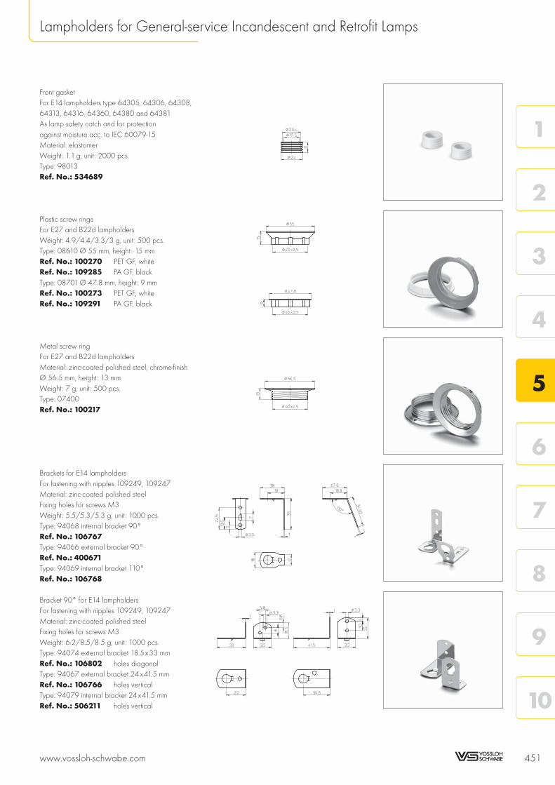
Front gasketFor E14 lampholders type 64305, 64306, 64308,64313, 64316, 64360, 64380 and 64381As lamp safety catch and for protectionagainst moisture acc. to IEC 60079-15Material: elastomerWeight: 1.1 g, unit: 2000 pcs.Type: 98013Ref. No.: 534689
Plastic screw ringsFor E27 and B22d lampholdersWeight: 4.9/4.4/3.3/3 g, unit : 500 pcs.Type: 08610 Ø 55 mm, height: 15 mmRef. No.: 100270 PET GF, whiteRef. No.: 109285 PA GF, blackType: 08701 Ø 47.8 mm, height: 9 mmRef. No.: 100273 PET GF, whiteRef. No.: 109291 PA GF, black
Metal screw ringFor E27 and B22d lampholdersMaterial: zinc-coated polished steel, chrome-finishØ 56.5 mm, height: 13 mmWeight: 7 g, unit: 500 pcs.Type: 07400Ref. No.: 100217
Brackets for E14 lampholdersFor fastening with nipples 109249, 109247Material: zinc-coated polished steelFixing holes for screws M3Weight: 5.5/5.3/5.3 g, unit : 1000 pcs.Type: 94068 internal bracket 90°Ref. No.: 106767Type: 94066 external bracket 90°Ref. No.: 400671Type: 94069 internal bracket 110°Ref. No.: 106768
Bracket 90° for E14 lampholdersFor fastening with nipples 109249, 109247Material: zinc-coated polished steelFixing holes for screws M3Weight: 6.2/8.5/8.5 g, unit : 1000 pcs.Type: 94074 external bracket 18.5x33 mmRef. No.: 106802 holes diagonalType: 94067 external bracket 24x41.5 mmRef. No.: 106766 holes verticalType: 94079 internal bracket 24x41.5 mmRef. No.: 506211 holes vertical
www.vossloh-schwabe.com 451
Lampholders for General-service Incandescent and Retrofit Lamps
10
9
8
7
6
5
4
3
2
1

U-shaped clipsFor E27 lampholders, one-pieceMaterial: zinc-coated polished steel, chrome-finishFor wall thickness: 0.5–2 mmWeight: 3.7/4.3 g, unit: 2500 pcs.Type: 94435Ref. No.: 109621Type: 80433 with earth terminalRef. No.: 103087
Base clipsFor E14 and E27 lampholders, one-pieceMaterial: zinc-coated polished steel, chrome-finishFor wall thickness: 0.8–1.5 mmWeight: 3.3/4 g, unit: 2500 pcs.Type: 94436Ref. No.: 109622Type: 80474 with earth terminal(without drawing)Ref. No.: 400699
Brackets: 90°, 12.5x47.1 mmFor E14 and E27 lampholders, one-pieceMaterial: zinc-coated polished steel, chrome-finishFixing hole for screw M5Weight: 5.6/4.8 g, unit: 500 pcs.Type: 80475 with earth terminalRef. No.: 400779Type: 94444Ref. No.: 401536
Brackets: 100°, 22.9x36.6 mmFor E14 and E27 lampholders, one-pieceMaterial: zinc-coated polished steel, chrome-finishFixing holes for self-tapping screwsacc. to ISO 1481/7049-ST2.9-C/FTapped hole M4Weight: 5.5/4.6 g, unit: 1000 pcs.Type: 80476 with earth terminalRef. No.: 400772Type: 94438Ref. No.: 401549
Fixing bracketFor E14 and E27 lampholders, one-pieceMaterial: zinc-coated polished steel, chrome-finishWith slots for screws M4Weight: 4.6 g, unit: 1000 pcs.Type: 94450Ref. No.: 106829
452 www.vossloh-schwabe.com
Lampholders for General-service Incandescent and Retrofit Lamps
8
9 +0,1
49,5
23
4ø
18
39
±0,2
36 ±0,2ø
3,4
5~
0,8
47,1
1,5
12,5
33
8
Ø4
18
5
Ø5,3
4ø
6,7
5
4M
18
8
1,5
22,9
2,6ø22,5
36,6
413,5
100°

Fixing bracket: 90°, 21x40 mmFor E14 and E27 lampholders, one-pieceMaterial: zinc-coated polished steel, chrome-finishFixing holes for screws M3Weight: 5.2 g, unit: 1000 pcs.Type: 94448Ref. No.: 537628
Fixing bracket: 8°For E27 thermoplastic lampholderstype 64719 (see p. 431) and for B22dthermoplastic lampholders type 648 (see p. 448)For clicking-on onto the lampholderMaterial: PA, whiteOblong hole for screw M4Weight: 1.9 g, unit: 500 pcs.Type: 97194Ref. No.: 108956
Fixing brackets: 8°, 14.5x39 mmFor E27 thermoplastic lampholders, one-pieceMaterial: PET GF, whiteWith cable holderOblong hole for screw M4Weight: 3/3.6 g, unit: 1000 pcs.Type: 97750 fixing holes: Ø 4 mmRef. No.: 109725Type: 97752 fixing holes for self-tappingscrews acc. to ISO 1481/7049-ST3.9-C/FRef. No.: 109728
Fixing brackets: 8°, 14.4x39 mmFor E27 thermoplastic lampholders, one-pieceMaterial: PET GF, whiteOblong hole for screw M4Weight: 1.9/4.3 g, unit: 1000 pcs.Type: 97159 fixing holes: Ø 4 mmRef. No.: 108304Type: 97755 fixing holes for self-tappingscrews acc. to ISO 1481/7049-ST3.9-C/FRef. No.: 400732
Fixing bracket: 8°, 20x44.4 mmFor E27 thermoplastic lampholders, one-pieceMaterial: PET GF, whiteFixing holes: Ø 4 mmWith cable holderOblong hole for screw M4Weight: 3.7 g, unit: 1000 pcs.Type: 97754Ref. No.: 401970
www.vossloh-schwabe.com 453
Lampholders for General-service Incandescent and Retrofit Lamps
10
9
8
7
6
5
4
3
2
1
39
2,54
8
1,2
14,5
4,5
24
32
12
1,5
4
6,8
2,5
20,5
4,53
9
3,2ø4ø
8°
3,2ø4ø
8
11
4,5
1,6
3,1
1,2
3
9
14,4
25
39
8
1,6
3,15,9
8°
20
9
12
9
15,6
8
4ø
15,8
4,5
25
5,4
44,4
23,8
2,55
1,7
3,2
16,2
/15,7
±0,1
kon.
12,5
/12,3
±0,1
kon.
8±0,1
10,1
5/9
,65+0,1
kon.
12,15±0,05
5 ±0,1
8°

NipplesFor E14 cover caps with moulded thread: M10x1Cross groove for rotation stop: externalFor E27 caps (see p. 438–439), for fasteningof brackets 106766 and 106802 (see p. 451)Material: PA, whiteMale nipple: M10x1, with hexagon flangeWeight: 0.5 g, unit: 1000 pcs.Type: 09700/09703/09708Ref. No.: 538089 length: 15 mmRef. No.: 109249 length: 10 mmRef. No.: 109247 length: 7 mm
Locking nut for thread M10x1Material: PA GFWeight: 0.9 g, unit: 1000 pcs.Type: 97267Ref. No.: 507797 whiteRef. No.: 507798 black
Cord grip with insulating socketFor E14 and E27 lampholdersMaterial: PA, naturalFor luminaires of protection class IIFor leads H03VVH2-F 2X0.75Weight: 0.6 g, unit: 1000 pcs.Type: 97632Ref. No.: 534097
Cable gripsFor leads: H03VV-FMaterial: PAMale nipple: M10x1, length: 10 mmWith locking screwWeight: 0.6 g, unit: 1000 pcs.Type: 09701Ref. No.: 543640 whiteRef. No.: 543641 black
Cable gripsFor leads H03VV-F and H03VVH2-F 2X0.5or 2X0.75Material: PAMale nipple: M10x1, length: 11 mmWith locking screwWeight: 1.6/1.5 g, unit: 1000 pcs.Type: 09701Ref. No.: 109248 whiteRef. No.: 109253 black
454 www.vossloh-schwabe.com
Lampholders for General-service Incandescent and Retrofit Lamps

Cord gripFor E14 lampholders, three-piece,with cap height: 19 mmFor leads H03VVH2-FMaterial: PA, transparentWeight: 0.6 g, unit: 1000 pcs.Type: 09501Ref. No.: 106948
Cord gripFor E27 lampholders, three-piece (without switch)For leads H03VVH2-FWeight: 0.9 g, unit: 1000 pcs.Type: 09502Ref. No.: 106949 PA, transparentInsulating socketMaterial: PA, transparentWeight: 0.5 g, unit: 1000 pcs.Type: 09705Ref. No.: 109592
Cord gripsFor leads H03VV-F 2X0.5 orH03VV-F 2X0.75Material: PAWeight: 0.9/0.8/1.7/1.6 g, unit: 1000 pcs.Type: 09606 cord gripsRef. No.: 506026 whiteRef. No.: 506027 blackType: 96160 screw capsRef. No.: 109318 whiteRef. No.: 109317 black
Cord gripsFor leads H03VV-F 2X0.5 orH03VV-F 2X0.75Material: PA, male nipple: M10x1Weight: 1/0.9/1.7/1.6 g, unit: 1000 pcs.Type: 09607 cord gripsRef. No.: 506024 whiteRef. No.: 506020 blackType: 96160 screw capsRef. No.: 109318 whiteRef. No.: 109317 black
Insulating socket for E14 lampholdersMaterial: PA, transparentWeight: 1 g, unit: 1000 pcs.Type: 09704Ref. No.: 109600
www.vossloh-schwabe.com 455
Lampholders for General-service Incandescent and Retrofit Lamps
10
9
8
7
6
5
4
3
2
1
18,5
Ø7
Ø14,8
18,5
Ø14,8

E40 Porcelain LampholdersFor incandescent lamps with base E40
Nominal rating: 18/500/5 kVScrew terminals: 1.5–4 mm²Spring loaded central contact
E40 lampholdersMaterial: porcelain, white, T270Oblong holes for screws M5Weight: 224/229.3/224/229.3 gUnit: 48 pcs.Type: 12800/12801Ref. No.: 108208Ref. No.: 107780 with lamp safety catchWith steel threadRef. No.: 532602Ref. No.: 532603 with lamp safety catch
E40 lampholdersMaterial: porcelain, white, T270Fixing bracket with slots for screws M5Weight: 252.3/243/252.3/243 gUnit: 48 pcs.Type: 12810/12811Ref. No.: 108374Ref. No.: 108375 with lamp safety catchWith steel threadRef. No.: 532604Ref. No.: 532605 with lamp safety catch
E40 lampholdersMaterial: porcelain, white, T270Fixing bracket with tapped holesfor screws M5With lamp safety catchWeight: 252.8 g, unit: 48 pcs.Type: 12812Ref. No.: 108373With steel threadRef. No.: 532606
456 www.vossloh-schwabe.com
Lampholders for General-service Incandescent and Retrofit Lamps

Transformers and converters for low-voltage halogen lamps 458Dimmability of VS transformers and VS converters 459
Electronic converters 459Assembly instructions – Electronic converters 460–464DALI information 464
Electromagnetic transformers 465Assembly instructions – Electromagnetic transformers 466–468Conductors for low-voltage halogen installations 468–469
Lampholders for incandescent lamps 469–470
General technical details 533–540
Glossary 541–543
www.vossloh-schwabe.com 457
10
9
8
7
6
5
4
3
2
1
5 Components for Incandescent and Retrofit Lamps
Technical Details

Transformers and converters for low-voltage halogen lamps
Operating low-voltage halogen lamps depends on operating devices that transform the usual mains voltage of230 V to under 24 V. Safety transformers, of either electromagnetic or electronic (converter) design, have beenin almost exclusive use for several years now. The type plate of electromagnetic transformers bears the symbolfor safety transformers in accordance with VDE 0570, corresponding to EN 61558. Electronic converters aremarked with the sign for Safety Extra-Low Voltage (SELV), which indicates that the product is an isolating conver-ter whose secondary output is safe to touch even during no-load operation.
All Vossloh-Schwabe transformers are safety transformers, i.e. isolation transformers for supplying SELV (safety ex-tra-low voltage) and PELV (protection extra-low voltage) circuits. With such systems, the voltage must not exceeda value of 50 V AC or 120 V DC (smoothed) between the conductors or a conductor and the earth conductorof a circuit that is separated from the mains by a safety transformer. The specified values apply for protected(non-touchable) voltages; 25 V AC and 60 V DC (smoothed) apply for exposed (touchable) voltages.
Depending on their design features to protect against touchable live parts, transformers and converters fall intoone of two protection classes. Operating devices of protection class I are base-insulated and have a protectiveearth conductor connection terminal that must be connected to the protective earth conductor for safetyreasons. Isolating transformers and converters of protection class II are equipped with double or reinforcedinsulation that protects against dangerous casing currents; these operating devices are solely available asindependent operating devices (also see page 538; Protection Classes of Luminaires and Operating Devices).
Electronic converters can also be fitted with a functional earth terminal that must be connected to a functionalearth to ensure compliance with EMC requirements. In addition, some electronic converters are designed insuch a way that neither a protective earth conductor nor a functional earth needs to be connected.
Operating devices can also be differentiated according to the way they are used. Built-in transformers have tobe installed in a permanent casing, e.g. a luminaire. In contrast, so-called independent transformers and conver-ters can be operated independently of a luminaire. These are often found in ceiling installations; in order to pre-vent possible noise development, isolation transformers must be mounted in such a way as to avoid vibrationtransmission.
Transformers or converters bearing the MM mark can be mounted on surfaces of unknown flammability, whichcan be the case when mounting these devices on wooden furniture elements. Such devices comply with thetemperature requirements of VDE 0710, part 14, of < 95°C during normal and < 115°C during abnormaloperation.
Converters are labelled with a tc point. The stipulated temperature (e.g. 75°C) must not be exceeded when in-stalled so that the service life of the converter is not shortened. The temperature quoted in the triangle (e.g. 110)denotes that the surface of the converter must never (even in the event of a defect) exceed this temperature.
458 www.vossloh-schwabe.com
Technical Details – Components for Incandescent and Retrofit Lamps
Independent operating device
t = 75 °CcMeasuring point for maximumpermissible casing temperature
Protection class II
Temperature-protected converter(in this case < 110 °C)
Furniture installationNormal operation < 95 °CAbnormal operation < 115 °C
Safety Extra Low Voltage
110
SELV
Safety transformer
If the maximum value of 130 °Cis not exceeded, the luminairedoes not have to be tested inaccordance with conditions.F
Protection symbols

Dimmability of VS transformers and VS converters
Electromagnetic VS transformers can be controlled using phase-cutting leading-edge dimmers. These dimmers"cut" the sinusoidal mains voltage in the negative and positive half wave at an angle in the ascending portionof this sinusoidal half wave. The higher the angle is set at the dimmer controls, the lower the effective value ofthe voltage and hence the lamp's output.
Electronic VS converters can be controlled using phase-cutting trailing-edge dimmers. In this case, a semicon-ductor ensures the predefined descending portion of the sinusoidal half wave is clipped, i.e. the voltage isreduced in reverse mode. Again, higher the angle is set at the dimmer controls, the lower the effective valueof the voltage and hence the lamp's output.
Converters of the LiteLine (EST 70/12.380, EST 105/12.381, EST 150/12.622 and EST 60/12.635)and TopLine (EST 70/12.643, EST 105/12.644, EST 150/12.645 and EST 200/12.649) families can beoperated using conventional phase-cutting trailing-edge and phase-cutting leading-edge dimmers.
Furthermore, TwinLine converters feature a separate potentiometer connection for direct regulation of lampvoltage and thus of its brightness.
VS DALI converters (Digital Addressable Lighting Interface) can be controlled via the DALI interface; dimmeroperation (whether phase-cutting leading- or trailing-edge) is not possible.
Electronic ConvertersThe safe operation of electronic converters is dependent on the maximum permissible temperature not beingexceeded at the measuring point. Vossloh-Schwabe has determined a casing temperature measuring point– tc max. – on all converter casings. To avoid shortening the service life or diminishing operating safety, thestipulated maximum temperature must not be exceeded at this tc point. This point is determined by testing theconverter during normal, IEC-standardised operation at the specified max. ambient temperature (ta), which isalso indicated on the type plate. As both the design-related ambient temperature and the converter's inherentheat generation, as determined by the installed load, are subject to great variation, the casing temperatureshould be tested at the converter's tc point under real installation conditions.
Temperature-protected converters feature a further protection symbol, namely a triangle containing themaximum temperature. This symbol certifies that the stipulated surface temperature of the device casing willnot be exceed during any operating state or in the event of a defect.
Vossloh-Schwabe electronic converters are tested in accordance with EN 61347. Function tests are carried outin accordance with EN 61047. VS converters can be operated without causing any inadmissible system reac-tions as all devices comply with EN 61000-3-2 on the limitation of mains harmonics. They also meet the EMCrequirements of EN 61547. These devices are thus also protected against mains surges (as defined in thestandard) that can be caused by, for instance, inductive ballasts during combined operation of fluorescent andlow-voltage halogen lamps.
In addition, all devices comply with the RFI requirements of EN 55015. As the highly effective integrated filtercan only limit the unit's own interference, the secondary conductor should be kept to under 2 metres in lengthso as to avoid RFI interference in the lighting system.
www.vossloh-schwabe.com 459
Technical Details – Components for Incandescent and Retrofit Lamps
10
9
8
7
6
5
4
3
2
1CL,
Dimmable using phase-cuttingleading-edge or trailing-edgedimmers
L
Dimmable using phase-cuttingleading-edge dimmers
U, I
U, I
t
t
Working principle of a phase-cutting leading-edge dimmer
� = Ignition angleλ = Operating angleU = VoltageI = Current
Working principle of a phase-cutting trailing-edge dimmer
C
Dimmable using phase-cuttingtrailing-edge dimmers

Assembly Instruction forElectronic ConvertersFor mounting and installing electronic converters for low-voltage halogen lamps
Mandatory regulations
DIN VDE 0100 Erection of low voltage installations
EN 60598-1 Luminaires – part 1: general requirements and tests
EN 61000-3-2 Electromagnetic compatibility (EMC) – part 3:maximum values – main section part 2: maximum values for mains harmonics(device input current up to and including 16 A per conductor)
EN 55015 Maximum values and methods of measurement for RFI suppressionin electrical lighting installations and similar electrical appliances
EN 61547 Installations for general lighting purposes – EMC immunity requirements
EN 61347-1 Operating devices for lamps – part 1: general and safety requirements
EN 61347-2-2 Operating devices for lamps – part 2-2: special requirements for DC- orAC-powered electronic converters for incandescent lamps
EN 61047 DC- or AC-powered electronic converters for incandescent lamps –performance requirements
Designations for VS converters
Designations for electronic converters are first listed by the name of the product family, which in each case re-flects the visible product properties. The type designation should be read as follows:
EST 60 /12 .388
Electronic safety transformer Max. wattage Lamp voltage Serial number
Mechanical mounting
Mounting position Any
Clearance Min. of 0.1 m from walls, ceilings, insulation; min. of 0.1 m from other electronic converters;min. of 0.25 m from sources of heat (lamp)
Surface Solid; device must not be allowed to sink into insulation materials
Mounting locationIn dry rooms or in luminaires, cases, casings or similar in the instanceof built-in converters
Fastening Independent converters: using screws, Ø 4 mmBuilt-in converters: fix M8 nut on the threaded stud
Heat transfer If the electronic converter is destined for installation in a luminaire, sufficient heat transfer mustbe ensured between the converter and the luminaire casing. During operation, the tc pointmust not exceed the specified value.
460 www.vossloh-schwabe.com
Technical Details – Components for Incandescent and Retrofit Lamps

Technical specifications
Type Operating
voltage
range AC
Dimmability Temperature
protection
Through-
wiring4
Type of automatic cut-out and
number of possible VS devices
Unsuitable for
DC operation
Phasecutting
trailing edge1
Phasecutting
leading edge1
Max. potentio-
meter 3.3 MΩ
DALI Thermal
cut-out²
Electronic
control³
Converter
quantity
B (10A) B (16A) C (10A) C (16A)
FlatLine EST 60/12.388 230 x x — 35 56 35 56
EST 120/12.389 230 x x — 18 29 18 29
LiteLine EST 35/12.650 230–240 x x — 55 85 55 85
EST 70/12.380 230–240 x x x — 28 45 28 45
EST 105/12.381 230–240 x x x — 20 32 20 32
EST 150/12.622 230–240 x x x — 14 23 14 23
...Mini EST 60/12.635 220–240 x x x — 35 56 35 56
TopLine EST 70/12.643 230–240 x x x 7 29 47 29 47
EST 105/12.644 230–240 x x x 7 20 32 20 32
EST 150/12.645 230–240 x x x 5 14 22 14 22
EST 200/12.649 230–240 x x x 5 11 18 11 18
DiscLine EST 70/12.601 230 x x — 30 49 30 49
EST 105/12.602 230 x x — 21 34 21 34
TwinLine EST 70/12.618 230–240 x x x — 29 47 29 47
EST 105/12.619 230–240 x x x — 20 32 20 32
CapLine EST 75/12G.302 230 x x — 28 45 28 45
BoardLine EST 60/12.304 230 x x — 34 55 34 55
EST 70/12.380 230–240 x x x — 28 45 28 45
EST 105/12.381 230–240 x x x — 20 32 20 32
DALI ESTd 70/12.660 230–240 x x — 28 45 28 45
ESTd 105/12.662 230–240 x x — 14 22 14 22
ESTd 150/12.661 230–240 x x — 11 18 11 181 The dimmer is connected to the primary side between mains and converter.
It is possible to connect several converters to one dimmer (whereby the dimmer's minimum and maximum load must be observed).The dimmer-converter system should be subjected to function and noise development tests prior to installation.
² In the event of overheating, the protective temperature switch turns the converter off. Once the converter has cooled down, it is automatically switched on again.³ The rating is decreased electronically in the event of overheating.4 Distributed secondary leads are only permitted on non-metallic surfaces (RFI suppression)
Properties of electronic converters
Overheating Protection against overheating is provided by a temperature switch or an electronic controller (see table above).
Short-circuit The converter will be electronically disconnected in the event of a short-circuit at the output; once the short-circuit has been eliminated,the converter will switch on again automatically.
Overload Minor overloads (< 50%) will trigger the temperature switch against overheating; major overloads (> 50%) will trigger the same reactionas for short-circuit. The ESTd 70/12.660, ESTd 105/12.662 and ESTd 150/12.661 converter models are fitted with integrated cut-outmechanisms in accordance with the DALI standard EN 62386-204.
Should any of the above-mentioned safety functions be triggered, disconnect the converter from the powersupply, then find and eliminate the cause of the problem.
Protection against transient mains peaksValues compliant with EN 61547 (immunity)
www.vossloh-schwabe.com 461
Technical Details – Components for Incandescent and Retrofit Lamps
10
9
8
7
6
5
4
3
2
1

Electrical installation
Conductors Primary conductor cross-section: min. 0.75 mm²Secondary conductor cross-section: min. 0,75 mm² for 50 W output andmin. 1 mm² for 100 W output
Stripping
Converter 60/12.388, 60/12.635, 70/12.643, 35/12.650,
120/12.389 70/12.618, 105/12.644, 70/12.380,
105/12.619 150/12.645, 105/12.381,
200/12.649 150/12.622,
70/12.660,
105/12.662
150/12.661
Type of lead H03-VVH2-F 2X0.75 All usual types NYM 2X1.5; NYM 3X1.5 after H03-VVH2-F 2X0.75
H05-VVH2-F 2X0.75 of lead up to breaking open the marked plastic H05-VVH2-F 2X0.75
H03-VV-F 2X0.75 4 mm² parts in the cover over the H03-VV-F 2X0.75
H05-VV-F 2X0.75 terminal area of the transformer H05-VV-F 2X0.75
Lead
preparation
The cables/cords of converter models EST 70/12.601, EST 70/12.618, EST 105/12.602 and
EST 105/12.619 must be protected against tension and compression during mounting.
Connections Screw terminals: max. initial torque of 0.4 Nm must not be exceeded
Secondary length Min. 0.25 m (clearance to lamp), max. 2 m (RFI protection)
Secondary wiring Min. 0.1 m clearance from the mains (RFI protection)
Star wiring Twist single-wire or lead wires narrowly; silicone-insulated leadsare recommended
Parallel connectionSecondary-side parallel connection is inadmissible
Feed-through of the mains voltageSee table on page 461Distributed secondary leads are only permitted on non-metallic surfaces(RFI suppression)
Selection of automatic cut-outs for VS converters
Dimensioning automatic cut-outsHigh transient mains current pulses occur when a converter is switched on becausethe capacitor has to load. As the lamps ignite almost simultaneously, this also createsa high power drain. The high currents that occur when the system is switched on puta strain on the automatic conductor cut-outs, which must be selected and dimensionedto suit.
Release reaction Release reaction of automatic cut-outs in accordance with VDE 0641, Part 11; for B and Ccharacteristics. The values provided in the table on page 461 are meant as guidelines onlyand may vary depending on the respective lighting system.
No. of converters The maximum number of VS converters (see table on page 461) applies to cases wherethe devices are switched on simultaneously. Specifications apply to single-pole fuses. Thenumber of permissible ballasts must be reduced by 20% for multi-pole fuses. The consideredcircuit impedance equals 400 mΩ (approx. 20 m [2.5 m²] of conductor from the powersupply to the distributor and a further 15 m to the luminaire).
462 www.vossloh-schwabe.com
Technical Details – Components for Incandescent and Retrofit Lamps
6–8
max.16
7–10
max.20
6–8
max.12

Dimmability of electronic converters
Dimmed operationVS converters can be operated with phase-cutting trailing-edge dimmers. Some converterscan additionally be operated with phase-cutting leading-edge dimmers (see table onpage 461). The dimmer is connected to the primary side between mains and converter. It ispossible to connect several converters to one dimmer (whereby the dimmer's minimum andmaximum load must be observed). The dimmer-converter system should be subjected tofunction and noise development tests prior to installation.
Converter TwinLine models EST 70/12.618 and EST 105/12.619 can be dimmed usinga potentiometer of 3.3 MΩ max.Converter DALI models ESTd 70/12.660, ESTd 105/12.662 and ESTd 150/12.661 canbe dimmed using the DALI interface; operation with leading- or trailing-edge dimmers is notpossible.
Electromagnetic compatibility (EMC)
Mains HarmonicsMaximum values are observed in accordance with EN 61000-3-2.
Interference The requirements of EN 55015 must be met for luminaires with converters for operatinglow-voltage halogen lamps.Vossloh-Schwabe converters are designed and manufactured to ensure these requirementsare satisfied provided the installation instructions regarding the interference voltage at theconnection terminals and electromagnetic interference fields up to 300 MHz are observed.
Additional information
Wiring To ensure good radio interference suppression and the greatest possible operating safety,the following points should be observed when installing electronic converters:• Conductors between the EST and the lamp (HF conductors) must be kept short
(reduction of electromagnetic interference).• Mains and lamp conductors must be kept separate and if possible should not be laid in
parallel to one another. The distance between HF conductors and mains conductorsshould be as large as possible, ideally > 5 cm. (This prevents the induction of interferencebetween the mains and lamp conductors).
• The mains conductor within the luminaire must be kept short (to reduce the inductionof interference).
• The mains conductor must not be laid too close to the EST (this is especially importantin the event of through-wiring).
• Mains and lamp conductors must not be crossed. Should this be impossible to avoid,conductors should be crossed at right angles to one another (to avoid inducing inter-ference between mains and HF conductors).
• Should conductors be wired through metal parts, such conductors must alwaysbe additionally shielded (e.g. with an insulating sleeve or grommet).
Temperature Reference point temperature tcThe safe operation of electronic converters is dependent on the maximum permissibletemperature not being exceeded at the measuring point. Vossloh-Schwabe has determineda casing temperature measuring point – tc max. – on all converter casings. To avoidshortening the service life or diminishing operating safety, the stipulated maximumtemperature must not be exceeded at this tc point. This point is determined by testing theconverter during normal, IEC-standardised operation at the specified ambient temperature(ta), which is also indicated on the type plate. As both the design-related ambienttemperature and the converter's inherent heat, as determined by the installed load, aresubject to great variation, the casing temperature should be tested at the tc point underreal installation conditions.
www.vossloh-schwabe.com 463
Technical Details – Components for Incandescent and Retrofit Lamps
10
9
8
7
6
5
4
3
2
1

Ambient temperature taThe ambient temperature – as specified on every converter – denotes thepermissible temperature range within the luminaire or at the place of installation.
Reliability Service life of 50,000 hrs at reference point temperature tc, whereby a switching cycle of165 minutes on and 15 minutes off is assumed. Failure rate: � 0.2%/1,000 hrsIn order to achieve the average service life, the maximum temperature(tc max.) must not be exceeded at the tc point.
Emergency lightingVS electronic converters cannot be used for emergency lighting purposes as they areunsuitable for DC voltage operation.
System Description of VS DALIElectronic ConvertersVossloh-Schwabe's EST range is rounded off by dimmable converters with a digital interface for low-voltagehalogen lamps. The standardised DALI protocol EN 62386-204 (Digital Addressable Lighting Interface) is usedfor this purpose.
VS DALI converters include the following features:• potential-free, polarity-independent control input• dimming curve analogue to the light sensitivity of the human eye• addressing options: total system, group-wise or individually• scene memory• feedback in the event of defective lamps
These features ensure a number of advantages for lighting systems:• no group wiring needed• each DALI converter can be individually addressed• no need for scene memory modules• synchronised scene transitions• operating devices provide reports on lamp status• simple integration into facility management systems
General Information on DALI
Mains voltage and interface conductors must not be wired in parallel to the lamp conductors so as to avoidcapacitive bridging of the mains filter.
After initial operation of a DALI system (address assignment, luminaire allocation, group formation, scenesettings) it is recommended to disconnect the primary voltage of the DALI operating devices at the circuitbreaker for at least 3 seconds and then to reconnect it. The devices will detect this disconnection from themains and store the settings.
464 www.vossloh-schwabe.com
Technical Details – Components for Incandescent and Retrofit Lamps
VS DALI converters offerthe convenience of a bussystem that is both easyto install and operate.
Switching the mainsvoltage to the DALIconductors within a DALIsystem will lead to thedestruction of both theDALI power supply andthe DALI master!

Electromagnetic TransformersOwing to the low internal impedance of electromagnetic transformers, high currents can occur in the event of ashort-circuit on the secondary side, which can lead to the transformer being destroyed. For this reason, IEC61558-1 differentiates between three types of transformer:
Transformers without short-circuit resistanceThese transformers require external protection to prevent excessive temperatures being generated.
At Vossloh-Schwabe, these transformers are marked with the symbol "not short-circuit proof safety transformer".To protect against current overload during overload or short-circuit operation, Vossloh-Schwabe recommendsinstalling a fuse on the primary side. As an aid to the user, the rating of this fuse is stated on the type plate inaccordance with IEC 60127. The installed primary-side fuse should be easily accessible so that it can bereadily replaced at any time.
Transformers with (limited) short-circuit resistanceThese transformers feature a safety device that prevents excessive temperatures being generated.
Electromagnetic transformers with thermal cut-outs afford a limited degree of short-circuit resistance and do notneed to be additionally fused. VS safety transformers of limited short-circuit resistance are designed to safely cutout in the event of overload or short-circuit, but not to restart automatically after cooling off. The transformer mustfirst be disconnected from the mains (i.e. switched off and on) before it can be restarted. The thermal cut-outsare dimensioned to ensure that the maximum permissible winding temperature of 225°C (transformers of ther-mal class B) or 240°C (F) or 260°C (H) is not exceeded in the event of overload or short-circuit.
Transformers with (unlimited) short-circuit resistanceThese transformers are designed to ensure that fixed maximum temperatures are not exceeded in the event ofoverload or short-circuit.
This type of safety transformer is not in common use within the lighting industry due to the relatively large dimen-sions it needs to meet the overload and short-circuit requirements.
All transformers will function perfectly and meet the requirements of the standard after the overload or short-circuit has been eliminated.
In addition to the above, there are also so-called failsafe transformers that are rendered permanentlyinoperative in the event of improper use, but do not pose a threat to the user or the surroundings.Vossloh-Schwabe does not provide this type of isolation transformer.
All Vossloh-Schwabe transformers are tested for compliance with the safety requirements of European standardEN 61558 regarding creepage and air clearance distances, the winding temperature and the maximumpermissible ambient temperature (ta).
EN 61558 specifies five insulation classes for electromagnetic transformers; respective testing temperatures andtimes are assigned to these classes. Due to the quality of the insulation materials used by Vossloh-Schwabe, VStransformers are only available in the three highest insulation classes B (120°C), F (140°C) and H (165°C).In this case, the quoted temperature refers to the maximum permissible winding temperature during permanentoperation.
As luminaire casings made of plastic or sheet metal will discharge heat to varying degrees and becausetransformer installation conditions can differ, a transformer's winding temperature must be tested within theluminaire. The measured values will show whether the maximum temperature corresponds to the transformer'sinsulation class.
On request, Vossloh-Schwabe can carry out such luminaire tests to assess built-in components.
www.vossloh-schwabe.com 465
Technical Details – Components for Incandescent and Retrofit Lamps
10
9
8
7
6
5
4
3
2
1
t 65a
0.25 AT
Thermal cut-out(reset after disconnectionfrom the mains)
X
O
Transformer's maximum per-missible ambient temperature
Limited short-circuit proofsafety transformer
Rated fuse value
Non short-circuit proofsafety transformer
Protection symbols

Assembly Instruction forElectromagnetic TransformersFor mounting and installing electromagnetic transformersfor low-voltage halogen lamps
Mandatory regulations
DIN VDE 0100 Erection of low voltage installations
EN 60598-1 Luminaires – part 1: general requirements and tests
EN 61558-1 Safety of transformers, power supply units and similar – part 1:general requirements and tests
EN 61558-2-6 Safety of transformers, power supply units and similar – part 2-6:special requirements for safety transformers for general use
EN 61000-3-2 Electromagnetic compatibility (EMC) – part 3:maximum values – main section part 2: maximum values for mains harmonics(device input current up to and including 16 A per conductor)
EN 55015 Maximum values and testing methods for radio disturbance of electrical lighting facilities andsimilar electrical equipment
EN 61547 Installations for general lighting purposes – EMC immunity requirements
Technical specifications
Mains voltage rangeVS safety transformers can be operated at the specified mains voltage withina tolerance range of ±10%
Leak current � 0.1 mA per safety transformer
Power factor λ � 0.85
Compensation Not required
466 www.vossloh-schwabe.com
Technical Details – Components for Incandescent and Retrofit Lamps

Mechanical mounting
Mounting positionAny
Mounting locationSafety transformers are designed for installation in luminaires or comparabledevices. Independent safety transformers do not need to be built into a casing.
Fastening Preferably using screws, Ø 4 mm
Insulation classes and maximum temperaturesIn accordance with EN 61558, safety transformers are assigned to insulation classes on thebasis of the insulation materials used (also called insulation material classes for this reason) inthe transformers. These insulation classes also prescribe respective maximum winding tempe-ratures that must not be exceeded during normal operation or in the event of overload orshort-circuit.
Compliance with the maximum winding temperatures is tested by measuring the resistance ofthe transformer's copper winding.
Insulation classes for safety transformers in accordance with EN 61558-1
A E B F H
Max. winding temperature (1.06 UN) 100 °C 115 °C 120 °C 140 °C 165 °C
during normal operation
Max. winding temperature in the event 200 °C 215 °C 225 °C 240 °C 260 °C
of overload or short-circuit
Electromagnetic compatibility (EMC)
Interference Interference voltage measurements do not have to be taken for luminaires with magneticsafety transformers for operating low-voltage halogen lamps as these are systems with lampvoltages of under 100 Hz and it is assumed that such systems do not cause interference.
Interference immunityThanks to the robust design and choice of materials, magnetic safety transformers providea high degree of interference immunity and are not impaired by admissible mains powerinterference.
Mains harmonicsOwing to the Ohmic resistance characteristics of low-voltage halogen lamps and the lowdegree of distortion caused by magnetic transformers, mains harmonics remain low.
Safety functions of VS transformers
Load Transformer features
Unprotected (OS) With self-locking temperature protection (TS)
Overheating Is not recorded Protection is provided by the
built-in thermal switchShort-circuit Protection must be provided
by devices fitted in the luminaire
(fuse or thermal switch)
Overload
www.vossloh-schwabe.com 467
Technical Details – Components for Incandescent and Retrofit Lamps
10
9
8
7
6
5
4
3
2
1
Should one of the safetyfunctions be triggered,the transformer must bedisconnected from themains, the cause of thefault found and theneliminated.

Dimmer operation
VS safety transformers can be controlled using progressively adjustable phase-cutting leading-edge dimmers forlow-voltage halogen lamps.
Reliability and service life
VS safety transformers are designed for a long service life. Provided the specified maximum values for the win-ding temperature are complied with during operation, a service life of 10 years can be expected. Failure rate:< 0.025%/1,000 hrs
Electrical installation
Conductors Primary conductor cross-section: min. 0.75 m²,secondary conductor cross-section: min. 0.75 m² for 50 W outputand a min. of 1 mm² for 100 W output
Connections Terminal screws: max. torque of 0.5 Nm must not be exceeded
Parallel connectionParallel connection is admissible on the primary side, but is inadmissible onthe secondary side
Conductors for low-voltage halogen installations
As the high temperatures associated with the operation of low-voltage halogen lamps place severe demandson lampholder conductors, a skilful combination of conductor and insulation is essential. Tin-plated copper con-ductors with silicone insulation are recommended for temperatures of up to 180°C at the cable's conductor;nickel-plated copper cables with polytetrafluoroethylene (PTFE) sheathing are recommended for temperatures ofup to 250°C. Welded connections ensure the most effective heat discharge. Control measurements should becarried out if other connection types are used, e.g. crimping or plug connectors. To prevent the risk of additionalheat generation, the maximum permissible current load must be observed when dimensioning the conductorcross-section. When using electromagnetic transformers, the conductor resistance causes a relatively large volt-age drop. This drop in voltage is always associated with a reduction of luminous flux. For instance, an 11% dropin voltage will lead to a 30% drop in luminous flux. For this reason, care should be taken to ensure secondaryconductors are kept as short as possible and conductor cross-sections are adequately dimensioned whenwiring luminaires. Nevertheless, transformers should not be mounted too near the light source (> 25 cm clear-ance if possible) to prevent the heat generated by the lamp from raising the ambient temperature above thecritical level for a transformer.
As electronic converters operate at high frequencies, consideration must be taken of the skin effect, i.e. the dis-placement of the electrons from the middle of the conductor to its surface. As a result, the full cross-section of theconductor is no longer used, resistance increases and thus leads to a greater drop in voltage. In addition, ACresistance, which is caused by feed line inductance, can result in an even greater voltage drop. It is thereforerecommended that lamp conductors be laid closely parallel or twisted together.
Voltage losses (V) with a two-metre secondary conductor
Working frequency Load Cross-section/Voltage drop
W 0.75 mm² 1 mm² 1.5 mm²
50 Hz (electromagnetic transformers) 50 0,38 V 0.29 V 0.2 V
any wiring layout 100 0.74 V 0.56 V 0.39 V
40 kHz (electronic converters) 50 1.4 V 1.25 V 1.2 V
any wiring layout (loops) 100 3.3 V 3.1 V 3 V
40 kHz (electronic converters) 50 0.5 V 0.45 V 0.35 V
wires twisted together or closely parallel 100 1.2 V 1 V 0.85 V
468 www.vossloh-schwabe.com
Technical Details – Components for Incandescent and Retrofit Lamps
Conductor Contacts

Conductors for installations with halogen lamps
All conductors must be selected to suit the luminaire conditions (see table) in terms of material, cross-section andinsulation. Testing these conductors under worst case conditions is essential as the commonly occurring hightemperatures considerably reduce the conductivity of the conductor and hence its current-carrying capacity.
Insulation Conductor Cross-section Mains voltage Max. temperature
Material mm² V °C
SI Cu tin-plated (Cu vz) 0.75 300 180
FEP Cu tin-plated (Cu vz) 0.75 300 180
PTFE Cu nickel-plated (Cu vn) 0.75 500 250
PTFE Cu nickel-plated (Cu vn) 1 500 250
PTFE Ni 1 500 250
PTFE Ni 1.5 500 250
LampholdersFor low-voltage halogen lamps
With the exception of B15d bases, the low-voltage sector is dominated by pin bases, which are fitted with avariety of different pin distances and diameters. Apart from classic lampholders that ensure both the electricalcontact and the correct positioning of the lamp, connection elements are also available. These components aresolely responsible for establishing electrical contact and are used in cases where, for instance, the regulationsdemand that the lamp be attached to its reflector (e.g. cold-light reflector lamps with GZ4 and GX5.3 bases).Extremely high temperatures are also generated when operating low-voltage halogen lamps as a result of thetungsten-halogen cycle and high lamp currents. In addition, the respective luminaires are often of very compactdesign, which leads to heat accumulation and thus to high internal temperatures. The materials the lampholderis made of thus play a vital role for the luminaire's operating safety and the lamp's service life. In addition totried-and-tested materials – ceramics for casings and mica for covers – ever more frequent use is being madeof highly heat-resistant plastics like LCP (liquid crystal polymer for e.g. G4, GU4, GX5.3, GU5.3 and GY6.35lampholders) and PPS (polyphenylene sulphide for G4 lampholders). Plastic lampholders provide clear advan-tages: narrow dimensional tolerances, no material fractures, low weight and clip-attachment options.
The type of contact also plays an important role. Conventional contacts are only attached to one side of thelamp pin. In contrast, additional contact points – known as multipoint contacts – lead to a reduction of currentdensity at the point of transition from the lamp pins to the lampholder contact and with that to a decreasein temperature. These contacts provide the further advantage of ensuring superior heat dissipation from thelamp pins to the conductor. The temperature advantage of multipoint contacts in defined conditions (includingwelded-on conductors) can amount to as much as 100 °C. In extremely rare cases, due to the high internalpressure in the bulb, it is possible for the lamp to shatter. For reasons of fire prevention (high temperature of theglass bulb), the lamp's components must be prevented from falling out. Enclosed luminaires meet these require-ments. Open luminaires, however, may only be operated using lamps with enclosed bulbs or low-pressurelamps. Lamps of this kind are suitably marked with pictograms on the lamp's packaging and in the lamp manu-facturer's documentation. Lamps marked with pictogram No. 1 are suitable for use with open luminaires,whereas those marked with pictogram No. 2 may only be used in enclosed luminaires.
Lampholders for low-voltage halogen lamps are equipped with mounted cables or with plug-type connectors.In addition to the various lampholders contained in the catalogue, further lampholder models with various cablelengths and of various qualities as well as lampholders with plug-connected cables can be made available onrequest.
www.vossloh-schwabe.com 469
Technical Details – Components for Incandescent and Retrofit Lamps
10
9
8
7
6
5
4
3
2
1
1 2
VS lampholders forthe UL market and ULapproved leads areavailable for all commonlamp types.
Further information can befound at www.unvlt.com.

Bases of the most widely used low-voltage halogen lamps
Lampholders for mains voltage halogen lamps
A major factor in lampholder design is the lamp temperature, which is determined by the tungstenhalogencycle, high lamp current and high wattages. Lampholder casings can be made of ceramics, metal or the evermore popular highly heat-resistant thermoplastics like PET (polyethyleneterephthalate), PPS (polyphenylenesulphide) and LCP (liquid crystal polymer). The most suitable contact materials for these temperatures are nickel,copper-nickel alloys or copper materials with sufficiently thick nickel coatings. For tubular lamps (R7s base), thestandard IEC 60061-2 7005-53 prescribes the respective contact pressure of lampholder contact materials.
Although halogen lamps offer twice the service life of general-purpose light bulbs, this can only be fully realisedif luminaire manufacturers observe the recommended maximum temperatures at the lamp's pinch point. There isusually a welded-on molybdenum plate at the pinch point where the lamp base pins join the lamp filament.Lamp manufacturers ascertain the pinch temperature at this point, which is generally located within the lamp'squartz glass, using specially prepared measuring lamps. The pinch temperature is a critical thermal referencepoint which must not be exceeded within the luminaire.
The bases of the most widely used mains voltage incandescent lamps
470 www.vossloh-schwabe.com
Technical Details – Components for Incandescent and Retrofit Lamps
GU5.3GU4 GZ4G4 GX5.3
G6.35 GY6.35 GZ6.35 B15dG53
E14/E12 E40/E39E27/E26R7s
B15d B22dGU10 GZ10
G9
VS lampholders for the ULmarket and UL approvedleads are available for allcommon lamp types.
Further information can befound at www.unvlt.com.

www.vossloh-schwabe.com 471
Technical Details – Components for Incandescent and Retrofit Lamps
10
9
8
7
6
5
4
3
2
1

INTELLIGENT INDOOR LIGHTINGIn addition to easily modifiable rooms, modern society particularlyneeds flexible lighting systems – a requirement that can only be satisfiedwith the help of intelligent and versatile solutions that suit the given pur-pose. Furthermore, where possible cost-intensive refurbishment measuresshould be avoided.
The VS LiCS Indoor System enables individual control of single luminaires,e.g. using sensors or conventional push buttons. If required, the systemcan be easily reconfigured without requiring rebuilding measures.
Typical applications• Offices, industrial spaces and warehouses• Supermarkets• Public buildings (e.g. schools and hospitals)• Stairwells and hallways• Sanitary facilities
472 www.vossloh-schwabe.com
Lighting Control System for Indoor Applications
DALI LIGHTCONTROL GEARAND ACCESSORIES
• Adjustment of lighting levels to suit human needs• Energy savings and cost reductions• More convenience thanks to automation
LiCS Indoor System overview 474–475
DALI light control gears 476–477Light Controller L/LW 476Light Controller S 477
Extender 478
Sensors 479
Accessories 480
Technical details for lighting control system for indoor 481–487General technical details 533–540Glossary 541–543
www.vossloh-schwabe.com 473
10
9
8
7
6
5
4
3
2
1
6 Lighting Control System for Indoor Applications

Overview of the LiCS Indoor SystemThis new generation of Vossloh-Schwabe lightingcontrol gear was designed for indoor applicationsand combines the convenience of a light managementsystem with the ability to reap substantial energysavings by ensuring targeted use of light.
These VS lighting control devices are light managementsystems that require neither a PC nor an overriding bussystem to control and regulate a lighting system. Theequipment works with the standardised DALI protocoland complies with all currently valid parts of the DALIstandard, IEC 62386.
The system can be commissioned without needing anyadditional equipment, with configuration undertakenusing the controller. To this end, the controller is fittedwith a corresponding user interface, which enableseasy system configuration and adjustment.
474 www.vossloh-schwabe.com
newLighting Control System for Indoor Applications

Overview of the LiCS Indoor System
Product matrix Light Controller L Light Controller LW Light Controller S Light Controller XS
for integration into the for integration into the distribution for independent operation
distribution board board – EnOcean wireless version
Sensors(motion and brightness)
Extender
Accessories max. 6 buttons(mains voltage-compatible)
antenna (magnetic-base or screw-base);max. 6 buttons (mains voltage-compatible); EnOcean wirelessmodules (max. 16 pcs.)
button(mains voltage-compatible)
button(mains voltage-compatible)
Functions Light Controller L Light Controller LW Light Controller S Light Controller XS
Control options single, group, broadcast single, group, broadcast broadcast broadcast
No. of groups max. 16 max. 16 — —
No. of EBs max. 64 max. 64 max. 64 max. 10
No. of sensors max. 16 max. 16 max. 16 max. 1
Motion detection(automatic and semi-automatic)
� � � �
Constant light control � � � �
Scene settings � � — —
Push function � � � �
ON/OFF function � � � �
Stairwell function (timer) � � � �
System analysis software � � — —
Password protection � � — —
Minimising standby losses � � — —
Menu navigation in German, English, French,Italian, Spanish
German, English, French,Italian, Spanish
— —
Configuration using rotary push key and screen rotary push key and screen dip switch dip switch
www.vossloh-schwabe.com 475
newLighting Control System for Indoor Applications
10
9
8
7
6
5
4
3
2
1

Light Controller L/LWFor installation in a distribution boardThis light control gear is designed for installationin a distribution board.
Technical notesConfiguration interface: display screen
and rotary push key (on the controller)Ambient temperature ta: 5 to 50 °CPush-in terminals with push-button: 0.5–1.5 mm²Degree of protection: IP20, Protection class: IRFI-suppressedThe MultiSensors are connected directlyto the DALI busNo. of DALI ballasts: max. 64 pcs.No. of MultiSensors: max. 16 pcs.
ConnectionsMains connection: 220–240 V AC, 50–60 Hz,
max. power consumption 9 W1 DALI bus to 3 pairs of terminals: max. current on DALI
bus = 200 mA (see the respective data sheet forcurrent consumption of individual components)As a standard DALI bus is not SELV-compliant, theDALI cable must be rated for mains voltage.The DALI bus features reversible electronic overloadand short-circuit protection.
6 independently configurable push button inputs:cables must be rated for mains voltage;220–240 V AC, 50–60 Hz
1 closing relay contact to 2 pairs of terminals(can be reconfigured as an opener):
Minimising standby lossesAntenna jack (only Light Controller LW):radio signal with a frequency of 868 MHz
FunctionsAutomatic and semi-automatic motion detection,constant light control, scene settings, push function,ON/OFF function, stairwell function (timer), systemanalysis software, password protection, controloptions (broadcast, single and group), softwarelanguages: German, English, French, Spanish, Italian
LightController LDimensions (LxWxH): 126x90x68 mm, 7hp (horizontal pitches)Weight: 250 gRef. No.: 186189
LightController LWSuitable for wireless operation with EnOceanNo. of wireless modules: 16 pcs.Antenna needed (see p. 480)Dimensions (LxWxH): 126x90x68 mm, 7hp (horizontal pitches)Weight: 250 gRef. No.: 186190
476 www.vossloh-schwabe.com
newLighting Control System for Indoor Applications
93,2
90
48,5 6
8
126
new
new

Light Controller SFor independent operationThese light control devices are suitable forindependent operation (e.g. in false ceilings).
Technical notesConfiguration interface: dip switch (on the device)Ambient temperature ta: 0 to 50 °CMax. casing temperature tc: 65 °CScrew terminals: 0.75–2.5 mm²Degree of protection: IP20, Protection class: IIRFI-suppressedThe MultiSensors are connected directly to the DALI busNo. of DALI ballasts: max. 64 pcs.No. of MultiSensors: max. 16 pcs.
ConnectionsMains connection: 220–240 V AC/DC, 0/50–60 Hz,
max. power consumption 6.5 W1 DALI bus: max. current on DALI bus = 200 mA
(see the respective data sheet for currentconsumption of individual components)As a standard DALI bus is not SELV-compliant,the DALI cable must be rated for mains voltage.The DALI bus features reversible electronic overloadand short-circuit protection.
1 configurable push button input:cables must be rated for mains voltage;220–240 V AC/DC, 0/50–60 Hz
FunctionsAutomatic and semi-automatic motion detection,constant light control, push function, ON/OFF function,stairwell function (timer), control option (broadcast)
LightController SDimensions (LxWxH): 175x42x31.5 mmWeight: 150 gRef. No.: 186210
www.vossloh-schwabe.com 477
newLighting Control System for Indoor Applications
10
9
8
7
6
5
4
3
2
1
new

ExtenderTo extend LiCS Indoor System
An extender enables the maximum number of DALI-compliant control gear units within a standard DALIsystem to be increased.
This means the DALI extender is installed andaddressed in instead of the ballast. At the extenderoutput, up to 64 DALI ballasts can then be connect-ed, which will all respond in the same way to therespective input signal.
The extender for DALI systems can only be used incombination with a DALI controller. When DALIcommands are received, the extender behaves justlike a DALI-compliant ballast for fluorescent lamps.
Technical notesConfiguration interface: via a DALI controllerAmbient temperature ta: 0 to 50 °CMax. casing temperature tc: 65 °CScrew terminals: 0.75–2.5 mm²Degree of protection: IP20, Protection class IIRFI-suppressed
ConnectionsMains connection: 220–240 V AC/DC, 0/50–60 HzMax. power consumption: 6.5 WFor DALI signals in acc. with IEC 62386DALI current consumption: 2 mA1 DALI bus to 3 terminal pairs: max. current on the
DALI bus = 200 mA (see the respective data sheetfor current consumption values of the individualcomponents)As a standard DALI bus is not SELV-compliant,the DALI cable must be rated for mains voltage.The DALI bus features reversible electronicoverload and short-circuit protection.
FunctionsConnection of up to 64 ballasts to a single DALI address
ExtenderTo extend DALI-controlled lighting systemsDimensions (LxWxH): 175x42x31.5 mmWeight: 150 gRef. No.: 186194
478 www.vossloh-schwabe.com
newLighting Control System for Indoor Applications
new
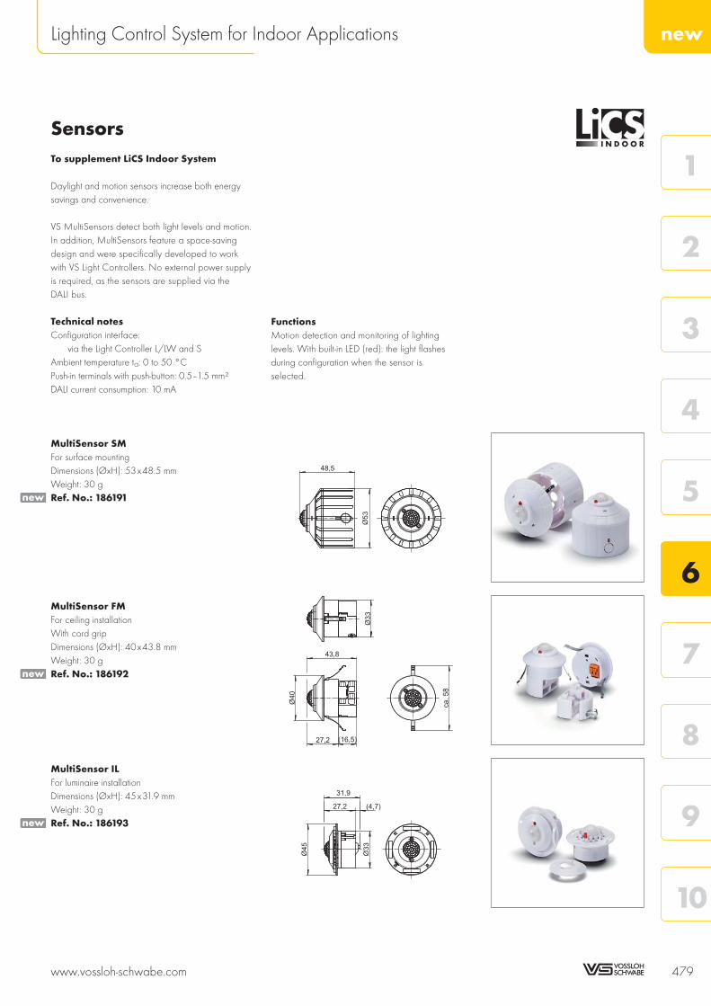
SensorsTo supplement LiCS Indoor System
Daylight and motion sensors increase both energysavings and convenience.
VS MultiSensors detect both light levels and motion.In addition, MultiSensors feature a space-savingdesign and were specifically developed to workwith VS Light Controllers. No external power supplyis required, as the sensors are supplied via theDALI bus.
Technical notesConfiguration interface:
via the Light Controller L/LW and SAmbient temperature ta: 0 to 50 °CPush-in terminals with push-button: 0.5–1.5 mm²DALI current consumption: 10 mA
MultiSensor SMFor surface mountingDimensions (ØxH): 53x48.5 mmWeight: 30 gRef. No.: 186191
MultiSensor FMFor ceiling installationWith cord gripDimensions (ØxH): 40x43.8 mmWeight: 30 gRef. No.: 186192
MultiSensor ILFor luminaire installationDimensions (ØxH): 45x31.9 mmWeight: 30 gRef. No.: 186193
www.vossloh-schwabe.com 479
newLighting Control System for Indoor Applications
10
9
8
7
6
5
4
3
2
1
48,5
Ø53
Ø40
ca.58
Ø33
(16,5)
43,8
27,2
Ø45
Ø33
(4,7)
31,9
27,2
new
new
new
FunctionsMotion detection and monitoring of lightinglevels. With built-in LED (red): the light flashesduring configuration when the sensor isselected.

AccessoriesTo supplement LiCS Indoor System
To ensure faultless wireless operation, an antennamust be connected that is set to the respective frequency.
When fitting the antenna, care must be taken thatit is not shielded by metal objects, e.g. steel cabinets,radiators, ventilation shafts etc., to ensure optimumsignal reception.
The requisite antenna is provided by Vossloh-Schwabein two models: the screw-base model comes witha detachable connection cable, while the magnetic-base model is fitted with a non-detachableconnection cable.
Magnetic-base antenna with connection cableAntenna dimensions (ØxH): 29x88 mmCable diameter: Ø 6 mm, length: 2.5 mMin. bending radius of the cable: 50 mmImpedance: 50 ΩCapacity: 10 W pulsedAmbient temperature ta: –40 to 80 °CStorage temperature: –40 to 80 °CDegree of protection: IP66Weight: 62 gRef. No.: 186211
Screw-base antennaAntenna dimensions (ØxH): 33x89 mmImpedance: 50 ΩCapacity: 8 W pulsedAmbient temperature ta: –40 to 70 °CStorage temperature: –40 to 80 °CDegree of protection: IP66Weight: 41 gRef. No.: 186212
Connection cable for the screw-base antennaCable diameter: Ø 6 mm, length: 1.5 mMin. bending radius of the cable 50 mmWeight: 66 gRef. No.: 186213
480 www.vossloh-schwabe.com
newLighting Control System for Indoor Applications
~90
2500
62±2 27±0,1 10,5
+0,5
-0,1
Ø14
new
new
new

Light Controller L/LW 482–484Assembly instructions 482Circuit diagrams 483
Light Controller S 483–484Assembly instructions 483Circuit diagrams 484
Extender 485–486Assembly instructions 485Circuit diagrams 486
Sensors 486–487Assembly instructions 486Circuit diagrams 483–486
General technical details 533–540
Glossary 541–543
www.vossloh-schwabe.com 481
10
9
8
7
6
5
4
3
2
1
6 Lighting Control System for Indoor Applications
Technical Details

General safety information• LiCS products may only be installed and commissioned by authorised and fully
qualified staff.• These instructions must be carefully read before installing and commissioning the system,
as this is the only way to ensure safe and correct handling.• Before any work is carried out on the equipment, it must be disconnected from the mains.• All valid safety and accident-prevention regulations must be observed.• The products should never be inexpertly opened as this poses lethal danger due
to electrical shock. Repairs may only be undertaken by the manufacturer.• On no account may the DALI control line be used to carry mains voltage or any
other external voltage as this can destroy individual system components.
Light Controller L/LWInstallation • In a distribution board on a 35-mm mounting rail in acc. with DIN 43880;
required installation space: 7 hp (horizontal pitches) (126 mm)• The controller must be installed so the display screen is in the upper left corner.• Hook the light controller over the upper edge of the rail using the two mounting notches.
Then carefully press the controller onto the lower part of the rail until the mounting springon the controller snaps into place over the rail. If required, use a screwdriver to help youwith the spring.
Removal To remove the controller from the mounting rail, use a screwdriver to loosen the spring andease the controller over the rail flange from the bottom.
Installation instructions• Conductor cross-section for all terminals: 0.5–1.5 mm² for rigid or flexible conductors• Cable preparation (see right)• To protect the equipment, a 10 A or 16 A, Type B automatic circuit breaker must be fitted.• Push button inputs 1–6: cables must be rated for mains voltage;
max. cable length = 100 m.• As a standard DALI bus is not SELV-compliant, the DALI cable must be rated for mains
voltage.• A max. of 64 DALI ballasts and/or DALI extenders in aggregate can be connected
as well as up to 16 MultiSensors, which in total must not exceed 200 mA.The exact number of components can be found in the manual.
• The power supply and the DALI line can be laid in a single cable provided the cabledoes not exceed a maximum length of 100 m, e.g. using 5 x1.5 mm².
• Three electrically connected DALI outputs make it easier to connect DALI control gear.Please observe the maximum lengths of the DALI bus during installation:
• The relay contact is a potential-free closing contact. The current load of the relay contactmust not exceed an Ohmic load of Imax. = 3 A. When using the standby contact, anadditional external power relay should be used.
• Although both models of the Light Controller (L/LW) feature an antenna-connection jack(located top right on the front), only the jack on the LW model is functional.This is where the antenna is connected to enable wireless operation (EnOcean) of theLight Controller LW.
482 www.vossloh-schwabe.com
Technical Details – Lighting Control System for Indoor Applications
1.5 mm² 1 mm² 0.75 mm² 0.5 mm²
6.2 Ω max. 300 m 180 m 130 m 80 m
0.5–1.5 mm²
8.5–9.5

Additional information• To ensure faultless wireless operation, an antenna must be connected that is set to the
respective frequency. This antenna is not included in the scope of delivery.• Please refer to the manual at www.vossloh-schwabe.com/en/home/services
for exact instructions on how to configure the system using the controller.• The outputs of different controllers must not be connected with each other.• To ensure safe operation of the controller, the maximum ambient temperature must not
be exceeded.
Circuit diagram of Light Controller L/LW
Light Controller SInstallation • Independent installation, e.g. in false ceilings
• Easy and time-saving installation thanks to end caps that snap into place without needingtools.
• Clearance: min. 0.1 m to walls, ceilings, insulation and other electronic devices;min. 0.25 m to sources of heat (e.g. lamps)
• Surface: solid, must not let the controller sink into insulation material• Fastening: using 4-mm screws
Installation instructions• Conductor cross-section for all terminals: 0.75–2.5 mm²• Cable preparation (see right)• Screw terminals: max. tightening torque = 0.4 Nm• A standard DALI bus only features basic insulation. All DALI cables must be rated for
mains voltage.• A max. of 64 DALI ballasts and/or DALI extenders in aggregate can be connected
as well as up to 16 MultiSensors, which in total must not exceed 200 mA.The exact number of components can be found in the manual.
• The power supply and the DALI line can be laid in a single cable provided the cabledoes not exceed a maximum length of 100 m, e.g. using NYM 5 x1.5 mm².Please observe the maximum lengths of the DALI bus during installation:
• Push button inputs: cables must be rated for mains power; maximum 100 m.
www.vossloh-schwabe.com 483
Technical Details – Lighting Control System for Indoor Applications
10
9
8
7
6
5
4
3
2
1
7–10
max.20
1.5 mm² 1 mm² 0.75 mm² 0.5 mm²
6.2 Ω max. 300 m 180 m 130 m 80 m

Additional information• The outputs of several light controllers (S model) must not be connected with each other.• All control gear that is connected to the output of the DALI Light Controller S is
synchronously operated in "broadcast" mode; the DALI ballasts are not addressed.• To ensure safe operation of the Light Controller (S model), the maximum casing
temperature at the measuring point (tc) must not be exceeded.• Please refer to the manual at www.vossloh-schwabe.com/en/home/services
for exact instructions on how to configure the system using the controller.
Circuit diagram of Light Controller S
Technical Details Light Controllers
Light Controller L LW S
Ref. No. 186189 186190 186210
Supply voltage 220–240 V AC, 50–60 Hz 220–240 V AC/DC, 0/50–60 Hz
Power consumption 9 W 6.5 W
Ambient temperature ta 5 to 50 °C 0 to 50 °C
DALI output (da+–) max. 200 mA current drain
No. of DALI ballasts max. 64 pcs. per Controller (expandable with the Extender)
No. of MultiSensors max. 16 pcs.
RF input — Antenna for a receptionrange of 868 MHz
—
Wireless module — All radio buttons withPTM radio sensors by
EnOcean with 868 MHz
—
No. of wireless modules — max. 16 pcs.with up to 4 buttons
—
Relay (outputs a1, a2) 250 V, max. 3 A ohmic load —
Push inputs 1–6 220–240 V AC, 50–60 Hz 220–240 V AC/DC, 0/50–60 Hz
Degree of protection IP20
Protection class I II
Weight 250 g 150 g
CE requirements EMC in acc. with EN 61547, RFI in acc. with EN 55015,Safety in acc. with EN 61347-2-11
484 www.vossloh-schwabe.com
Technical Details – Lighting Control System for Indoor Applications

ExtenderInstallation • Independent installation, e.g. in false ceilings
• Easy and time-saving installation due to end caps that snap into place withoutneeding tools
• Clearance: min. 0.1 m to walls, ceilings, insulation and to other electronic devices;min. 0.25 m to sources of heat (e.g. lamps)
• Surface: solid, must not permit the extender to sink into insulation material• Fastening: using 4-mm screws
Installation instructions• Cross-section of primary/secondary conductor: 0.75–2.5 mm²• Cable preparation (see right)• Screw terminals: max. tightening torque = 0.4 Nm• Length of the secondary bus cable: max. 300 m• A standard DALI bus only features basic insulation. All DALI cables must be rated
for mains voltage.• The power supply and the DALI line can be laid in a single cable (max. 100 m).• Mains power cables and DALI cables should not be laid directly parallel to lamp cables
(min. clearance = 0.25 m).• A maximum of 64 DALI ballasts and/or DALI extenders in total can be connected as
well as up to 16 MultiSensors.
Additional information• The extender can only be operated if connected to a DALI control unit. Please refer to
the respective operating instructions for information on the control unit.• The DALI extender is integrated into the DALI system using the "random address"
assignment method.• Three electrically connected DALI outputs make it easier to connect DALI ballasts.
A maximum of 64 DALI ballasts and/or DALI extenders in total can be connected.• The outputs of several extenders must not be connected with each other.• All control gear that is connected to the output of the DALI Extender is synchronously
operated in "broadcast" mode; the output side is not addressed.• To ensure safe operation of the Light Controller S, the maximum casing temperature at
the measuring point (tc) must not be exceeded.
Technical details
Extender
Ref. No. 186194
Supply voltage 220–240 V AC/DC, 0/50–60 Hz
Power consumption 6.5 W
Control input DALI in. acc. with IEC 62386-102/-201
DALI output max. 64 pcs. DALI EBs or max. 200 mA (expandable with the Extender)
Ambient temperature ta 0 to 50 °C
Casing temperature tc max. 65 °C
Degree of protection IP20
Protection class II
Weight 150 g
CE requirements EMC in acc. with EN 61547, RFI in acc. with EN 55015,Safety in acc. with EN 61347-2-11
www.vossloh-schwabe.com 485
Technical Details – Lighting Control System for Indoor Applications
10
9
8
7
6
5
4
3
2
1
7–10
max.20

Circuit diagram of the Extender
SensorsInstallation SM (Surface Mounted)
Prepare the cable accordingly and thread it through the back plate of the sensor at the sideor from behind. Attach the back plate in the selected position using the two screws provided,then connect the cable to the sensor. Use two fingers to lightly press the springs of the sensorcover together and allow to lock into place along the guide rails inside the sensor's bottomface (see Fig. 1).
FM (Flush Mounted), with or without cord gripPrepare the cable, connect to the sensor and attach cord grip if appropriate. Use twofingers to lightly press the sensor together and allow to lock into place in the pre-drilledhole (35 mm) in the selected position (see Fig. 2).
IL (In Luminaire)Heed the dimension of the drilling template when inserting the sensor in the metal plate,which is 0.5–1 mm thick. Allow the sensor to lock into place in the precisely pre-drilled holein the metal plate. Allow the sensor cover ring to lock into place from the other side in therecesses provided (see Fig. 3).
Installation instructions• Conductor cross-section of all terminals: 0.5–1.5 mm² for both rigid and flexible
conductors• Preparation of the sensor cables (see right)• As a standard DALI bus is not SELV-compliant, cables must be rated for mains voltage.• The power supply and the DALI line can be laid in a single cable provided the cable
does not exceed a maximum length of 100 m, e.g. using NYM 5 x1.5 mm².Please observe the maximum lengths of the DALI bus during installation:
486 www.vossloh-schwabe.com
Technical Details – Lighting Control System for Indoor Applications
1.5 mm² 1 mm² 0.75 mm² 0.5 mm²
6.2 Ω max. 300 m 180 m 130 m 80 m
8.5–9.5
Without cord grip
8.5–9.5
max. 17.5
With cord grip
«click»
«click»Fig. 1
Fig. 2
Fig. 3
.
.
.

Additional information• VS MultiSensors can only be operated in combination with a VS Light Controller from
the LiCS indoor range.• Please refer to the controller manual for exact instructions on how to configure the sensor.• To ensure safe operation of the sensors, the maximum permitted ambient temperature
must not be exceeded.• The sensor must be positioned to ensure its reception range is not obstructed by objects,
furniture, etc.• See Fig. 4 for the sensor range.
The height specified in Fig. 4 is a reference value. For other and specifically greaterheights, it may be necessary to test the sensitivity of the sensors on site as the sensitivityof the motion sensor decreases the higher up it is mounted.
Technical details
MultiSensor SM FM IL
Ref. No. 186191 186192 186193
Control input DALI in acc. with IEC 62386
DALI current consumption 10 mA
Ambient temperature ta 0 to 50 °C
Casing temperature tc max. 50°C
Degree of protection IP20
Protection class II
Weight 30 g
CE requirement Safety in acc. with EN 61347-2-11
Circuit diagram of the sensors
See the circuit diagrams of the Light Controllers on pages 483 and 484.
www.vossloh-schwabe.com 487
Technical Details – Lighting Control System for Indoor Applications
10
9
8
7
6
5
4
3
2
1Fig. 4

ECO-FRIENDLY ANDCOST-SAVING LIGHTINGThe lighting solutions provided by Vossloh-Schwabe ensure thatlocal authorities everywhere can save energy, achieve sustainablecost reductions and at the same time make a valuable contributionto reducing CO2 output. Using various lighting situations as examples,energy savings of 30%–50% can be achieved if efficient technologyis used in the right place.
This chapter presents Vossloh-Schwabe's newly developed lightcontrol systems for street lighting and lighting systems in the vicinityof buildings.
Luminaires operated in combination with magnetic and dimmableelectronic ballasts that feature a 1–10 V or DALI interface can bemonitored and controlled using these products. The system is suitablefor both new installations as well as classic retrofits.
Without exception, all LiCS outdoor products can rightfully claimto provide the most efficient and most flexible control solutions foroutdoor lighting. Vossloh-Schwabe's light management systems enablecentralised control of individual luminaires with the advantage of aconstant online link and the ability to monitor the lighting system.Lighting systems for which flexibility and efficiency are key, but thatdo not require an online connection, can benefit from the samesavings potential by using the intelligent multifunctional controllerunits (iMCUs) in offline mode.
Typical applications• General lighting in public spaces• Lighting in the vicinity of buildings• Lighting in tunnels• Lighting for sports' venues• Industrial lighting
488 www.vossloh-schwabe.com
Lighting Control System for Outdoor Applications
ELECTRONICCONTROL OF OUT-DOOR LIGHTING

Intelligent light control for outdoor applications 490
System overview 491
Network-capable products 492–495iLC – intelligent luminaire controller (built-in) 492–493iPC – intelligent post controller (built-in) 493iDC – intelligent data concentrator 494iLUX – intelligent lux meter with a power line carrier interface 495
Software 496iCT – intelligent configuration software 496iLIC – intelligent luminaire information centre 496
Non network-capable products 497iMCU – intelligent multifunctional controller unit 497
General technical details 533–540
Glossary 541–543
SensorsFurther sensors for the LiCS outdoor system are currently being developed.Please contact your VS representative for further details. The VS website atwww.vossloh-schwabe.com also provides information on the currentsituation.
MidNight ControllerFurther controllers for the LiCS outdoor system are currently being developed.Please contact your VS representative for further details. The VS website atwww.vossloh-schwabe.com also provides information on the currentsituation.
www.vossloh-schwabe.com 489
10
9
8
7
6
5
4
3
2
1
6 Lighting Control System for Outdoor Applications

Intelligent Light Control for Outdoor ApplicationsPower line carrier (PLC) technology enables bidirec-tional data transmission via the 230-V supply voltage.Without requiring additional wiring it is thereforepossible to connect these light controllers to forma powerful network using either a lighting cable ora commonly available network cable in almost anyenvironment. Data are measured with a high degreeof precision at every controller connected to thenetwork and, if required, automatically amplified.As a result, length restrictions make no difference.Vossloh-Schwabe's LiCS Outdoor system is basedon this tried-and-tested technology, which has alreadyproved itself millions of times in the most diverseapplications and fields.
Vossloh-Schwabe's LiCS Outdoor system makes itpossible to dim individual luminaires or entireluminaire groups. Depending on the requirements,the degree to which the lighting level is dimmed canbe sensor-controlled or can comply with a presetlevel; the burn-in periods of discharge lampscan also be taken into consideration.A lighting system that provides light as requiredtherefore results in further savings potential.Thanks to the system's convenient remote monitoringfunctions, it is possible to optimise maintenanceprocesses as well as better plan maintenance workand budget for it in more detail.
Overview of functionsIndependent functions form an integral part of the LiCS Outdoor controller and are common to all products.The parameters of these functions can be (re)set at any time by the customer using various tools or via thepower line carrier network.
490 www.vossloh-schwabe.com
newLighting Control System for Outdoor Applications
MFF (Maintenance Factor Function)Maintenance factor function: reduction of the degreeto which the luminous flux decreases over the servicelife of the light source.
BBT (Burn-in Block Time)Configurable dimmer block during the burn-in periodof conventional light sources (can be deactivated).
DPC (Delayed Switching for Pedestrian Crossing)The lighting is switched off after a short delay orswitched on more quickly in the vicinity of pedestriancrossings
DOO (Dimmed ON/OFF)The lighting system is switched on or off in a dimmedstate; also, dimmed changeover between dimminglevels with configurable time sequences
ISD (Intelligent Switching Time Dimming)Intelligent, timer-controlled periods of dimmed light.
LST (Control input)Control input with configurable behaviour and effecton the DALI/1-10 V output or the relay's two-waycontact.
RCR (Ripple Control Receiver)Sound frequency reception module for typical soundfrequencies of 100 Hz to 1.7 kHz; TFR protocols onrequest.

Overview of the LiCS Outdoor System
Product matrix Network-capable Non network-capable
Software iLIC iSITE —
Data concentrator iDC
• GPRS
• IP
• FO-MM
• FO-SM
iMICO or iCTT
Controller iLC (for installation in luminaires)
iPC (for installation in the luminaire pole)
iRFS (controller)
iMCU (controller)
EHXd (electronic ballasts)
iRFS (controller)
iMCU Light Controller
for independent operation
iRFS (controller)
Sensors iLUX (lux meter) / iRAS (radar sensor) iRAS (radar sensor) iRAS (radar sensor)
iRFS (wireless bridge)
Operating unit iSCT (tablet)
iCTI (hand-held operating device)
— —
The technical documentation for the iMICO and iCTT MidNight controllers as well as the associated iSITE software can be found online atwww.vossloh-schwabe.com.Please contact your VS representative for further details.
Expansion Options for the LiCS Outdoor System
www.vossloh-schwabe.com 491
newLighting Control System for Outdoor Applications
10
9
8
7
6
5
4
3
2
1
ControlleriLCiPC
ControlleriMCU
ControlleriMCU
Data concentratoriDC
Mobile or stationarymasteriMICO or iCTT
Control cablesSensor (iRAS)Wireless bridge (iRFS)
Centralised controland monitoringiLIC and iCT
Centralised control andpartial configurationiSITE
1
2
3SensoriLUX
EBEHXd
CO
MM
UN
ICA
TIO
ND
IREC
TIO
N
CO
MM
UN
ICA
TIO
ND
IREC
TIO
N

Light Control Gear for Outdoor LuminairesVossloh-Schwabe's outdoor light control gear workswith power-line-carrier communication using theC/B CENELEC band. Thanks to the integratedfunctions, they can be used as independent controlcomponents or be integrated into a light manage-ment system to centrally monitor and regulateindividual luminaires.
The LiCS outdoor system enables control of lumi-naires operated with magnetic ballasts (low-lostballast and low-loss ballast ECO) as well asluminaires with up to four dimmable electronicballasts with a 1–10 V or DALI interface.
The product is suitable both for new installationsas well as for classic retrofits. The particularly flatdesign of the controller enables installation in almostall luminaires, especially luminaires featuring LEDtechnology.
Control input LST can be used for a control phase, a motion detector, a key switch, a light sensoror, if operated independently, to receive simple protocols. Please contact your VS representativefor further details.
The controller is integrated into a LON power-line-carrier light management system that requiresa network connection to a central module (iDC). Communication via power line carrier occursin accordance with standardised directives EN 14908-1, EN 14908-3 and the Lonmark® OLCprofile (outdoor luminaire controller profile).
Installation and integration requires further products that are supplied in accordance with customerspecifications. Once installed in a light management system, the controller delivers various per-formance data and status reports independently of the connected ballast. The following calibratedperformance data are available within a tolerance of 1%: voltage, current, power factor, energyconsumption, lighting hours and temperature. Limits must be defined for each measured value,which are then monitored in the controller with a report being transmitted to the master system iflimits are exceeded. As a result, the controller itself already intelligently monitors the luminaire.
iLC – intelligentLuminaire Controller(built-in)This light controller was developed for installationin a luminaire. Without requiring additional wiring,it can be integrated into a light management system.
Technical notesDimensions (LxWxH): 93x58x30 mmControl output: DALI or 1–10 V for max. 4 EBs,Short-circuit-proofBistable relay output: closing contact, controloutput ECO ballast: 10 mA for powerreduction relaysConnection terminals: 0.5–1.5 mm²Operating temperature: –25 to 85 °CBetriebstemperatur: –25 to 80 °CHumidity: non-condensingDegree of protection: IP20, protection class I
Galvanic isolationThe electronic ballast does not feature potentialisolation between input and output: as soon asthe electronic ballast is connected to the controller,the control input of the electronic ballast is notpotential-free.
Type Ref. No. Voltage AC Power consumption Control input LST Switching output Switching current Weight
V, Hz W V V A (λ = 0.8) g
iLC 186233 90–230, 50 < 1,2 230 230 4 100
492 www.vossloh-schwabe.com
newLighting Control System for Outdoor Applications
iLC – intelligent Luminaire Controller (built-in)
4,2
48,5
83,5
(96)
58
93
29
4
74
4,2
Typical applicationsLighting for public spacesLighting in the vicinity of buildingsLighting for tunnels
DPC MFF ISD DOO
BBT LST RCR
new
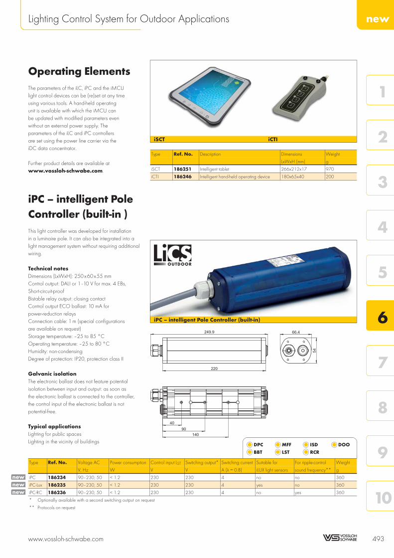
Operating ElementsThe parameters of the iLC, iPC and the iMCUlight control devices can be (re)set at any timeusing various tools. A hand-held operatingunit is available with which the iMCU canbe updated with modified parameters evenwithout an external power supply. Theparameters of the iLC and iPC controllersare set using the power line carrier via theiDC data concentrator.
Further product details are available atwww.vossloh-schwabe.com.
iPC – intelligent PoleController (built-in )This light controller was developed for installationin a luminaire pole. It can also be integrated into alight management system without requiring additionalwiring.
Technical notesDimensions (LxWxH): 250x60x55 mmControl output: DALI or 1–10 V for max. 4 EBs,Short-circuit-proofBistable relay output: closing contactControl output ECO ballast: 10 mA forpower-reduction relaysConnection cable: 1 m (special configurationsare available on request)Storage temperature: –25 to 85 °COperating temperature: –25 to 80 °CHumidity: non-condensingDegree of protection: IP20, protection class II
Galvanic isolationThe electronic ballast does not feature potentialisolation between input and output: as soon asthe electronic ballast is connected to the controller,the control input of the electronic ballast is notpotential-free.
Typical applicationsLighting for public spacesLighting in the vicinity of buildings
Type Ref. No. Voltage AC Power consumption Control input LST Switching output* Switching current Suitable for For ripple-control Weight
V, Hz W V V A (λ = 0.8) iLUX light sensors sound frequency** g
iPC 186234 90–230, 50 < 1.2 230 230 4 no no 360
iPC-Lux 186235 90–230, 50 < 1.2 230 230 4 yes no 360
iPC-RC 186236 90–230, 50 < 1.2 230 230 4 no yes 360
* Optionally available with a second switching output on request
** Protocols on request
www.vossloh-schwabe.com 493
newLighting Control System for Outdoor Applications
10
9
8
7
6
5
4
3
2
1
iPC – intelligent Pole Controller (built-in)
249.9
140
90
40
220
66.4
54
Type Ref. No. Description Dimensions Weight
LxWxH (mm) g
iSCT 186251 Intelligent tablet 266x212x17 970
iCTI 186246 Intelligent hand-held operating device 180x65x40 200
DPC MFF ISD DOO
BBT LST RCR
iSCT iCTI
newnewnew

For ripple-control iDC – intelligent Data ConcentratorThe iDC forms the master of the light managementsystem and functions as the central connectioninterface to the software of the master system. Theproduct can be programmed and also featuresapplication programs that are perfect for controllinglighting systems.
The following functions are an integral part of theproduct: timer programs, monitoring of limit valuesplus alarm function and alarm transmission, dataconversion, data logging and email client.
Fitted with various interfaces such as S0 for counterregistration, the M bus for remote counter reading orthe MOD bus for extended sensor and actuatingfunctions, the iDC can adapt to suit almost anycontrol task.
The iDC also provides a very well documented,web-based XML/SOAP interface or an optionallyavailable OPC driver (open process control) to theSCADA (Supervisory Control and Data Acquisition)system. This makes it possible to integrate the iDCalso into any BA (Building Automation) or controlsystem.
The iLIC software was specifically developed toenable control of the iDC. Various extension optionsare available to suit common communication require-ments: GPRS, IP (CAT5), Fibre optic (FO) SingleMode, Fibre optic (FO) Multi Mode, and optionallyalso WLAN on request.
Technical notesDimensions (BxWxT): 280x230x112 mmMaterial: aluminium AlSi12 (Fe)Drill holes for cables:
2 PG metric fittings (25x1.5 mm)2 PG metric fittings (32x1.5 mm)1 PG metric fittings (20x1.5 mm)
Interfaces for power line carriersInputs: 2 x 30 V DC digital inputs
Optionally extendable using a cut-offrelay for 230 V AC2 impulse-counter inputs typical of S0
Outputs: 2 relay outputs 230 V AC; 10 AEthernet port 10/100BaseT, auto-selecting,RS232 interface for GSM/GPRS modem
LON power line carrier communication:Protocols: in acc. with ANSI CEA 709.1 /
EN 14908-1 on the supply voltage(tri/single phase)
Transmission: in acc. with ANSI CEA 709.3 /EN 14908-3
IP communication: XML / SOAP, http, FTP, UDPFME antenna connection: maleStorage temperature: –25 to 85 °COperating temperature: –25 to 60 °CHumidity: non-condensingDegree of protection: IP65, protection class I
Special featuresThe product can be commissioned using the VS iCT tool.
Type Ref. No. Voltage AC Average power consumption Transmission mode Weight
V, Hz VA VA g
iDC-GPRS 186230 230±10%, 50±1% standby 7VA 12 4400
iDC-IP 186237 230±10%, 50±1% standby 7VA 12 4400
iDC-FO-MM 186238 230±10%, 50±1% standby 7VA 12 4400
iDC-FO-SM 186239 230±10%, 50±1% standby 7VA 12 4400
494 www.vossloh-schwabe.com
newLighting Control System for Outdoor Applications
iDC – Data Concentrator
230
10,1280
111
38
ca. 27
35
75
70
31
56
54
34
53
newnewnewnew

iLUX – intelligent Lux Meter with a Power-Line-Carrier InterfaceThe high-quality light sensor, upgraded with a specialvariant of the iPC controller for installation in the lumi-naire pole, directly measures and delivers digital lightmetrics in lux to a light management system for thepurpose of lighting control.
Lighting systems operated with or without a lightmanagement system can be switched on or off at aspecific lux value via internal relays. The measuredlux values can then be transmitted to the lightingsystem via the power line. Depending on the respec-tive lighting level required in each case, it is thereforepossible to independently control luminaires indifferent areas, e.g. at major and minor roads,pedestrian crossings and in parks.
The compact sensor can be fixed to the luminairepole or a wall using the enclosed mounting bracket.
Technical notesDimensions (LxWxH: 165x165x104 mmSensor casing: aluminium with a PC cover,Sensor unit protected by opal glassConnection cable to the controller: 10 m(special configurations available on request)Storage temperature: –25 to 85 °COperating temperature: –25 to 80 °CHumidity: non-condensingDegree of protection: IP65Weight of mounting bracket: 300 gFor details on the casing and connections ofthe iPC controller (intended for installation inluminaire poles), see page 493
Typical applicationsLighting for public spacesLighting in the vicinity of buildings
Type Ref. No. Note Weight
g
iLUX 186231 Use only in combination with iPC-LUX (Ref. No.: 186235) 1000
www.vossloh-schwabe.com 495
newLighting Control System for Outdoor Applications
10
9
8
7
6
5
4
3
2
1
iLUX – Light sensor
160
135
75,3
76 5
9,5
25
new

iCT – intelligent Configuration SoftwareFor outdoor luminaire control
The software was specifically developed to integrateiLC or iPC luminaire controllers in the iDC. This enablesquick and convenient installation of all controllers innetwork segments. Commissioning can also be com-pleted quickly by using an optional barcode scannerto read the unique barcode identification numberprinted on each controller. The parameters of thecontrollers of the individual luminaires as well as lumi-naire groups can be set in accordance with the OLCLonmark® profile. The software is available only incombination with the iDC, the intelligent dataconcentrator.Ref. No.: 186242
iLIC – intelligent Luminaire Information CentreFor outdoor luminaire control
The luminaire information centre is the central controlinstrument of a light management system. All connect-ed luminaires can be controlled, monitored anddisplayed using a web-based server application.
The server-based software supports both Windowsand Linux operating systems. Firefox or Internet Ex-plorer are the frontend applications to operate, con-trol or display the light management system. Thefollowing actions can be controlled via the software:• Switching individual luminaires on or off ahead
of defined luminaire groups• Defining the most diverse timer settings• Evaluation and display of the lighting system
status depending on various types of errormessage
• Evaluation of energy consumption at individualluminaire and luminaire-group level
• Graphic display of all acquired data over time(voltage, current, power, temperature, powerfactor, lighting hours, ...)
Based on the software design, the lighting systemdisplays information as a tree-like structure showingcity, suburb, street, luminaire or can be broken downaccording to other criteria. The multi-client softwarealso makes it possible to restrict rights and functionsfor different people or groups of people dependingon their level of authorisation.
As the software is a wholly web-based application,system maintenance can be carried out via the web(global) or can be restricted to just the companyusing its LAN network, all depending on the systemstructure. Numerous users can access the system atthe same time. Optional interfaces are also availableto connect to other asset management systems.
Ref. No.: 186243
496 www.vossloh-schwabe.com
newLighting Control System for Outdoor Applications
System requirements• Server: state-of-the-art• RAM: 4GB HD: 2TB• CPU: min. Dual Core,
depending on the scopeof the project
• Operating system: XT,Windows 7, Linux, Distribution,VM operation is possible
• Data security: min. RAID 1,recommended RAID 5
new
new

iMCU – intelligent Multifunctional Controller UnitFor outdoor luminaire control
This light controller unit was specifically designedfor independent operation to enable control of streetlighting or lighting close to buildings.
The unit is suitable for use with luminaires operatedwith magnetic ballasts (low-loss ballasts and low-lossballasts ECO) as well as with dimmable electronicballasts that support a 1–10 V or DALI interface.
The product is suitable both for new installations aswell as for classic retrofits. The controller's particularlycompact design facilitates installation in almost anyluminaire, especially luminaires with LED technology.
Depending on the given task, the product canreplace one or more individual products. It alsoenables control of conventional magnetic ballastswith coil tapping points without needing any othercomponents. The control input LST can be used toconnect a control phase, a motion detector, a keyswitch or a light sensor, but can also be used toreceive simple data protocols.
Operating unitsThe parameters of the iMCU can be (re)set at anytime using various tools. A simple hand-held unit(which does not require an additional power supply)is available with which the installed controller can beupdated with modified parameters (see page 493).
Alternatively, a Windows-basedprogram can be used that providesextended functions for stationary appli-cations. To suit the specific requirementsof the OEM market, the controller canbe supplied with software protectionmechanisms. Please contact us directlyfor further information.
Technical notesDimensions (LxWxH): 83x30x19 mmControl output: DALI or 1–10 V for max. 1 EB,short-circuit-proofRelay contacts: potential-free (input, opener,closing contact)Connection terminals: 0.5–1.5 mm²Storage temperature: –25 to 85 °COperating temperature: –25 to 80 °CHumidity: non-condensingDegree of protection: IP20, protection class I
Galvanic isolationThe electronic ballast does not feature potentialisolation between input and output: as soon asthe electronic ballast is connected to the controller,the control input of the electronic ballast is notpotential-free.
Typical applicationsStreet lighting or lighting in the vicinity of buildings
Type Ref. No. Voltage AC Power consumption Control input LST Switching current Weight
V, Hz mW V A (λ = 0.8) g
iMCU 186232 220–230, 50 < 500 230 4 30
www.vossloh-schwabe.com 497
newLighting Control System for Outdoor Applications
10
9
8
7
6
5
4
3
2
1
4 1
(3)
75
83
3.2
30
19
15
697 (7)
iMCU
DPC MFF ISD DOO
BBT LST RCR
new

EMERGENCY LIGHTINGEmergency lighting systems spring to life any time normal artificial lightingsystems fail. Emergency lighting is designed to ensure that work can con-tinue without risk, that staff can safely leave any workplaces involvingspecial hazards and that there is sufficient lighting to illuminate rescuepaths/routes as well as to avoid panic situations.
As power cuts result in a risk to safety, legislation has been enacted inthe form of the Health and Safety at Work Directive (Europe) and theHealth and Safety at Work Acts of the individual European countries(e.g. Germany), all of which stipulate that emergency lighting must beprovided. The requirements placed on emergency lighting installed inplaces of public assembly and public buildings are governed bysupplementary directives and laws.
Vossloh-Schwabe's emergency lighting units are designed for usewith T5, T8 and compact fluorescent lamps and can be operated withelectromagnetic or electronic ballasts.
VS emergency lighting units are suitable for both continuous and standbycircuits with a nominal operating period of 1 or 3 hours.
498 www.vossloh-schwabe.com
Emergency Lighting Modules for TC and T Lamps
6–80 WEMERGENCYLIGHTINGMODULES

Emergency lighting modules with self-diagnosis function 500–501
Technical details for emergency lighting modules 502–508General technical details 533–540Glossary 541–543
www.vossloh-schwabe.com 499
10
9
8
7
6
5
4
3
2
1
7 Emergency Lighting Modules for TC and T Lamps

Emergency LightingModules 6 to 80 Wwith Self-DiagnosisFunctionEMXs – Emergency lighting modules
For one-, two-, three- or four-lamp operationwith standard and dimmable electronic ormagnetic ballastsEB phase is switched off during emergencyoperationShort circuit protectionRoHS-compliant (excluding rechargeable batteries)5-pin technology and therefore EMC-complianteven during emergency operationSuitable for protection class IEN 61347-1, EN 61347-2-7Suitable for systems in accordance withVDE 0108 or EN 50172Not suitable for lamps with an integratedstarterCyclic charging of the NiMH battery is micro-processor controlled, which can extend batterylife by up to 30%Dimensions (LxWxH): 210x31.4x21.5 mmFixing hole distance: 205.5 mmNominal voltage: 230 V ±10%, 50–60 HzAmbient temperature ta: 0 to 50 °CUnit: 25 pcs.
These VS emergency lighting modules include anautomatic self-diagnosis feature that performsa two-minute function test of the device, the lampand the battery every seven days.In addition, the operating period is tested every12 months with subsequent battery reactivation.
Optical status display• Red LED, flashing intermittently:
defective lamp. The status display will bereset approx. one minute after the fault hasbeen rectified.
• White LED, not illuminated:if connected to the power supply, the LEDmust turn green after a maximum of five minutes.If not, the device either has no voltage supplyor the emergency lighting module is defective.
• Red LED, permanently flashing:battery capacity is too low or the batterysupply line has been interrupted.
• Green LED: fully functional.
500 www.vossloh-schwabe.com
Emergency Lighting Modules for TC and T Lamps
21,5
210
205,5
31,4
4,5
Emergency lighting module
red wire 0.5 mm /AWG20total length = 250 mm
2JST-EHconnector
2 contacts crimped on the wiresJST: SEH-001T-P0.6Lwith housing JST: EHR-2
red incircuit 2
black incircuit 1
ØD
ØD
ØD
black wire 0.5 mm /AWG20total length = 250 mm, NiCd
200 mm, NiMH
2
protective plastic coveron both sides
L
L 200
180
red
black
ca. 80
250
Rechargeable battery
black
black
450
5.5
redred
green
green
LED

Emergency Lighting Modules 6 to 80 Wwith Self-Diagnosis FunctionEMXs – Emergency lighting modules
Type Ref. No. Ref. No. Nominal operating Rechargeable Dimensions LxD (Ø) Test function Weight Weight
Module Battery period battery type of battery module battery
hrs. mm g g
EMXs 180.000 188792 188823 1 4.8V 1.8Ah NiCd 1 / 190 x 23 automatic 160 200
EMXs 180.001 188793 188824 3 4.8V 4.5Ah NiCd 1 / 240 x 33 automatic 160 490
EMXs 180.002 188794 188825 1 4.8V 1.8Ah NiMH 1 / 200 x 17 automatic 160 140
EMXs 180.003 188795 188826 3 4.8V 4.5Ah NiMH 2 / 450 x 19 automatic 160 320
Circuit diagrams see page 506–508
Holders for Rechargeable Batteries forEmergency Lighting ModulesMaterial: PC (188828: PBT)Type: Rechargeable Battery Holder
Ref. No. For rechargeable Dimensions (mm)
battery type a b c d e f
188827 4.8V 1.8Ah NiCd 35.0 18.0 26.3 26.7 13.0 5.5
188828 4.8V 4.5Ah NiCd 39.0 32.2 36.2 37.3 12.4 6.0
188829 4.8V 1.8Ah NiMH 22.5 15.0 22.8 22.5 8.0 4.0
188829 4.8V 4.5Ah NiMH 22.5 15.0 22.8 22.5 8.0 4.0
It is recommended to use two holders per rechargeable batteryto ensure optimum hold.
Table of suitable lamp types
Lamp type Lamp nominal output
W
T8 15, 18, 32, 36, 58, 70
T5 HE 14, 21, 28, 35
T5 HO 24, 39, 49, 54, 80
T5 6, 8, 13
T-R5 (T-R16) 22, 40, 55, 60
T-R (T29-R) 22, 32, 40
TC-L/TC-F 18, 24, 36, 40, 55, 80
TC-DEL 10, 13, 18, 26
TC-TEL 13, 18, 26, 32, 42, 57, 70
TC-SEL 7, 9, 11
TC-DD (2D) 10, 16, 21, 28, 38, 55
www.vossloh-schwabe.com 501
Emergency Lighting Modules for TC and T Lamps
10
9
8
7
6
5
4
3
2
1
a
f
b
ce
Ød
Luminous flux factor of lamps during emergency operation
Lamp nominal output Luminous flux factor*
W %
6 43.0
8 32.0
18 13.0
28 9.0
32 7.0
35 7.0
36 7.0
49 4.7
54 4.3
55 4.7
58 5.2
70 4.3
80 3.7
* Theoretically defined reference values at 25°C ambient temperature

Assembly instructions for emergency lighting modules 502–509Electrical installation 502–504Emergency lighting module display 505Circuit diagrams 506–508
General technical details 533–540
Glossary 541–543
502 www.vossloh-schwabe.com
Technical Details
7 Emergency Lighting Modules for TC and T Lamps
10
9
8
7
6
5
4
3
2
1

Emergency lighting modules are designed for operation with 6 to 80 W, 4-pin fluorescent lamps.Luminaires with integrated emergency lighting modules can be operated using a continuous or standby circuit.
Technical specifications EMXs emergency lighting modules
Permissible mains voltage 230 V ±10%
Permissible mains frequency 50–60 Hz
Power consumption with standby circuit 3 W
Nominal period of operation 1 to 3 hours, depending on the type of rechargeable battery
Batteries NiCd or NiMH
Ambient temperature 0* to 50°C
Charging time 24 hrs
Protection class 1
Degree of protection IP20
Certification CENELEC
Tested in accordance with EN 61347-2-7
Suitable for systems compliant with VDE 0108 / EN 50172
Casing Metal (zinc-plated)
Installation outside the luminaire Permissible lead length between the emergency lighting module and the lamp must not exceed two metres.
Luminous flux factors during emergency operation See the table on page 501, values apply to 25 °C ambient temperature.
* Ignition in progress; the values of the colour rendering index and the luminous flux factor may deviate.
Assembly Instructions for Emergency Lighting ModulesFor mounting and installing of emergency lighting modules
If the emergency lighting module is integrated in the luminaire, the LED and battery have to be wired separately, i.e. not in parallel with the mains or lamp.Emergency lighting modules must be fixed in a suitable spot within the luminaire (4-mm bore holes for mounting).In the interest of maximising battery capacity and service life, care must be taken to ensure the battery is positioned at the coolest part of the luminaire.The ambient temperature of the battery must not exceed 50 °C. Emergency lighting modules must not be mounted on surfaces that ignite, melt or undergosome other thermal change at a temperature of 60 °C. Moreover, emergency lighting modules must not be operated in explosion-endangered enclosedspaces.
Electrical installationThe respective ordinances and standards valid at the place of operation must be observed for installation purposes. Emergency lighting modules andluminaires must only be installed by trained staff. Operating voltages exceed 50 V. Caution: potentially fatal hazard!
Prior to first operation of emergency luminaires, all covers must be attached. Furthermore, care must be taken to ensure that the supply voltage complieswith the specifications on the type plate and the protective conductor is connected.
1. Fuse2. Light switch3. Room lighting4. Emergency luminaires
Emergency luminaires must be connected to a direct phase to enable mains monitoring and ensure constant charge retention. This phase must be connectedto the group fuse of the regular room luminaire. Emergency luminaires are generally delivered with uncharged batteries and must be connected to the mainsfor at least 48 hours to be fully functional or for approx. 10 minutes for mains operation in the case of a continuous circuit.
www.vossloh-schwabe.com 503
Technical Details – Emergency Lighting Modules for TC and T Lamps
10
9
8
7
6
5
4
3
2
1
1
2 3
4

Additional information for optimising EMCInformation on the installation of electronic ballasts for optimising EMC
To ensure good radio interference suppression and the greatest possible operating safety,the following points should be observed when installing electronic ballasts:• Conductors between the EB and the lamp (HF conductors) must be kept short
(reduction of electromagnetic interference). High-potential lamp conductors mustbe kept as short as possible, in particular with tubular lamps.Lamp conductors of this kind are labelled with an * in the wiring diagram onthe type plate.
• Mains and lamp conductors must be kept separate and if possible should notbe laid in parallel to one another. The distance between HF and mainsconductors should be as large as possible, ideally > 5 cm.(This prevents the induction of interference between the mains and lamp conductors.)
• The mains conductor within the luminaire must be kept short (to reduce theinduction of interference).
• Devices must be properly earthed. EBs require secure contacts to the luminairecasing or must be earthed using a PE connection. This PE connection should beeffected using an independent conductor to achieve better dissipation of theleak current. EMC improves at frequencies greater than 30 MHz.
• The mains conductor must not be laid too close to the EB or the lamp (this isespecially important in the event of through-wiring).
• Mains and lamp conductors must not be crossed. Should this be impossible to avoid,conductors should be crossed at right angles to one another to avoid inducinginterference between mains and HF conductors.
• Should conductors be wired through metal parts, such conductors must alwaysbe additionally shielded (e.g. with an insulating sleeve or grommet).
Maintenance With regard to system maintenance and control, care must be taken to ensure compliancewith any ordinances and standards governing emergency lighting at the place of installation.Prior to opening lamp covers, the following procedure must be observed:
1. Disconnect luminaires from the mains voltage.2. Remove cover.3. Disconnect battery from the emergency lighting module (disconnect the plug).
VS recommends connecting control LEDs to be visible on the outside of emergencyluminaires to enable simple and regular control of emergency luminaires andemergency lighting modules.
Changing batteriesBatteries need to be replaced if the operating period of luminaires falls short of 60 minutes inthe case of 1-hour operation and 180 minutes for 3-hour operation, respectively. Emergencylighting modules have a status display for this purpose.Spent batteries must be replaced with the manufacturer's original batteries only. Furthermore,the polarity of the batteries must be strictly observed. The battery supply lines of the emer-gency lighting module are marked as follows:red = +; black = –
504 www.vossloh-schwabe.com
Technical Details – Emergency Lighting Modules for TC and T Lamps

Emergency lighting module displayNormal operation is indicated by a green LED. During emergency operation or for as longas the battery remains fully discharged, the LED is off (i.e. does not glow). The LED will flashred if the battery is missing or not properly connected.
Automatic test of emergency lighting modulesIn the case of emergency luminaires with emergency lighting modules, the operationalreadiness of the device, the lamp and the battery is tested automatically every seven days.In addition, battery capacity is measured during a simulated loss of mains power every 12months.The first capacity test will be carried out seven days following initial installation or any repairwork. The LED must be checked after the first self-test. A green LED indicates all is in workingorder, any other display indicates a problem.The device features a two-colour LED display to indicate that the emergency luminaire isready for use.
Optical status display
Notes Vossloh-Schwabe accepts no liability for any direct, indirect or incidental damage caused byputting a device to any improper use, i.e. any use not expressly permitted by VS. Similarly,Vossloh-Schwabe accepts no liability for third-party claims arising from putting a device toany improper use, i.e. any use not expressly permitted by VS. Emergency lighting modulesmust not be opened or modified in any way. The components of emergency lighting modulesmust be replaced with original parts only.Should emergency lighting modules be damaged in a way that suggests it cannot be opera-ted safely, the luminaires or emergency lighting modules, respectively, must not be operated.VS reserves the right to make changes to diagrams, weights, tables of dimensions or othersuch details included in the catalogue or instructions for use without prior notice if such chan-ges prove to be necessary or are made as a result of technological progress. VS emergencylighting modules are patent protected.Any act of producing counterfeit VS products will be prosecuted according to criminal andcivil law.
Caution! Emergency lighting modules from VS must not be operated with amalgam lamps.
www.vossloh-schwabe.com 505
Technical Details – Emergency Lighting Modules for TC and T Lamps
10
9
8
7
6
5
4
3
2
1
LED
LED
LED
LED keine Störung / no fault / pas de défaut /sin fallos / nessu difetto
Emergency luminaires merely require regular visual inspection of the status display (LED)
and the luminaire itself.
Red LED, flashing intermittently During initial operation, a lamp recognition test is first carried
out. Prior to and during this test, the LED will be red and flash
intermittently.
White LED, not illuminated If connected to mains power, the LED must turn green after
a maximum of five minutes. If not, the device has no mains
voltage or the emergency lighting module is defective.
Red LED, continuous flashing Battery capacity is too low or the battery supply line has been
interrupted. The warning light will go off again as soon as the
problem has been rectified.
Green LED Fully functional.

Circuit DiagramsFor VS emergency lighting modulesNotes for wiring:• The distance between mains lead and lead 8 should be as large as possible• Leads 2/4/6/8 must be kept short
Circuit diagrams – 1-lamp operation
506 www.vossloh-schwabe.com
Technical Details – Emergency Lighting Modules for TC and T Lamps
PE 1
1
2
2
345678
EMXs
ElectromagneticBallast
Battery
NLB
LLS
+–
S
1-lamp operationwith electromagnetic ballast
PE 12345678
EMXs
Battery
N
L
+–
1-lamp operationwithout electronic or electromagneticballast (continuous circuits)
PE 1234567
ELXe
PE 12345678
EMXs
Battery
NLB
LLS
+–
1-lamp operation – Instant startwith electronic ballast ELXe
PE
PE
1
1
2
2
3
3
4
4
5678
EMXs
ELXs
Battery
NLB
LLS
+–
1-lamp operation – Warm startwith electronic ballast ELXs
PE 1
**
234567
ELXd / ELXc
PE 12345678
EMXsNLB
LLS
+–
*nur bei dimmbaren Vorschaltgeräten/only with dimmable ballasts/juste avec ballastsgraduables/solo con alimentatori dimmerabili/sólo con reactancia regulable
Battery
1-lamp operation – Dimming / Warm startwith electronic ballast ELXd / ELXc

Circuit diagrams – 2-lamp operation
Circuit diagrams – 3-lamp operation
www.vossloh-schwabe.com 507
Technical Details – Emergency Lighting Modules for TC and T Lamps
10
9
8
7
6
5
4
3
2
1
Battery
1
1
2
2
345678
EMXs
ElectromagneticBallast
PENLB
LLS
+–
S
S
2-lamp operationwith electromagnetic ballast
PE
PE
1
1
2
2
3
3
4
4
5
5
6
6
7
7
8
EMXs
ELXc
Battery
NLB
LLS
+–
2-lamp operation – Warm startwith electronic ballast ELXc
PE 123
567
ELXe
4
PE 12345678
EMXs
Battery
NLB
LLS
+–
2-lamp operation – Instant startwith electronic ballast ELXe
PE
PE
DADA
1
1
2
2
3
3
4
4
5
5
6
67
8
8
EMXs
ELXd
Battery
NLB
LLS
+–
7
2-lamp operation – Dimmingwith electronic ballast ELXd
PE
PE
1
1
*
2
2
3
3
4
4
5
5
6
6
7
7
8
EMXs
ELXd / ELXc
Battery
NLB
LLS
+–
*
*nur bei dimmbaren Vorschaltgeräten/only withdimmable ballasts/juste avec ballasts graduables/solo con alimentatori dimmerabili/sólo conreactancia regulable
2-lamp operation – Dimming / Warm startwith electronic ballast ELXd / ELXc
PE
DADA
1234567
ELXd
PE 12345678
EMXsNLB
LLS
+–Battery
2-lamp operation – Dimmingwith electronic ballast ELXd
PE
PE
1
1
2
2
3
3
4
4
5
5
6
6
7
7
8
8
EMXs
ELXc
Battery
NLB
LLS
+–
3-lamp operation – Warm startwith electronic ballast ELXc
PE
PE
1
1
2
2
3
3
4
411
5
510
6
69
7
78
8
EMXs
ELXc
Battery
NLB
LLS
+–
3-lamp operation – Warm startwith electronic ballast ELXc

Circuit diagrams – 3-lamp operation
Circuit diagrams – 4-lamp operation
508 www.vossloh-schwabe.com
Technical Details – Emergency Lighting Modules for TC and T Lamps
PE
PE
111098
1
1
2
2
3
3
4
4
5
5
6
6
7
7
8
EMXs
ELXc
Battery
NLB
LLS
+–
4-lamp operation – Warm startwith electronic ballast ELXc
PE
PEDADA1112131415
1
1
2
2
3
3
4
4
5
5
6
6
7
789
10
8
EMXs
ELXd
Battery
NLB
LLS
+–
4-lamp operation – Dimmingwith electronic ballast ELXd
PE
PE
1
1
2
2
3
3
4
4
5
5
6
6
7
7
8
EMXs
ELXe
Battery
NLB
LLS
+–
4-lamp operation – Instant startwith electronic ballast ELXe
PE 1234567
ELXe
PE 12345678
EMXs
Battery
NLB
LLS
+–
3-lamp operation – Instant startwith electronic ballast ELXe
PEDADA1112131415
12345678
109
ELXd
PE 12345678
EMXs
Battery
NLB
LLS
+–
3-lamp operation – Dimmingwith electronic ballast ELXd

www.vossloh-schwabe.com 509
Technical Details – Emergency Lighting Modules for TC and T Lamps
10
9
8
7
6
5
4
3
2
1

PARALLEL CAPACITORSCapacitors are designed to compensate inductive reactive current ofdischarge lamps in 50/60 Hz networks when operated with electro-magnetic ballasts. As required by utility companies, capacitors serve tocompensate the reactive current generated by the respective ballast.A power factor of λ � 0.9 is achieved.
In addition, capacitors can also be used to compensate or generatephase displacements. Careful selection of the raw materials as well asspecial thermal treatment of the capacitor coil guarantee a long service-life and stable capacitance.
510 www.vossloh-schwabe.com
Parallel Capacitors
SYSTEM-OPTIMISINGCOMPENSATION

Parallel capacitors 512–515
Technical details for parallel capacitors 516–524General technical details 533–540Glossary 541–543
www.vossloh-schwabe.com 511
10
9
8
7
6
5
4
3
2
1
8 Parallel Capacitors

Parallel ConnectedCapacitors withBreak-actionMechanismCapacitors type B
Casing: aluminiumFilling material: based on vegetable oilFastening: male nipplewith nut and washer includedDischarge resistanceOverpressure protectionOn request further capacities or connectors
512 www.vossloh-schwabe.com
Parallel Capacitors
A Push-in twin terminals 0.5–1 mm² B Double spade connector 6.3x0.8 acc. to IEC 61210

Parallel Connected Capacitorswith Break-action MechanismCapacitors type B
Ref. No. Capacity Temperature range Drawing Ø (D) Length (L) Male nipple/ Weight Unit
μF °C mm mm length (mm) g pcs.
250 V, 50/60 Hz
536378 2.0 –40 to 100 A 25 63 M8x10 85 100
536379 4.0 –40 to 100 A 25 63 M8x10 85 100
536380 6.0 –40 to 100 A 25 63 M8x10 85 100
536381 8.0 –40 to 100 A 25 78 M8x10 90 100
536382 10.0 –40 to 100 A 30 78 M8x10 95 100
536383 12.0 –40 to 100 A 30 78 M8x10 95 100
536384 13.0 –40 to 100 A 30 78 M8x10 95 100
536385 16.0 –40 to 100 A 35 78 M8x10 100 81
536386 18.0 –40 to 100 A 35 78 M8x10 100 81
536387 20.0 –40 to 100 A 35 78 M8x10 100 81
536388 25.0 –40 to 100 A 40 78 M8x10 110 64
536389 30.0 –40 to 100 A 35 103 M8x10 115 81
536390 32.0 –40 to 100 A 35 103 M8x10 115 81
536391 35.0 –40 to 100 A 40 103 M8x10 130 64
536392 40.0 –40 to 100 A 40 103 M8x10 130 64
536393 45.0 –40 to 100 A 40 103 M8x10 130 64
536394 50.0 –40 to 100 A 45 103 M8x10 160 49
536395 55.0 –40 to 100 A 45 103 M8x10 160 49
536396 60.0 –40 to 100 A 45 103 M8x10 200 49
380–450 V, 50/60 Hz
536397 13.0 –40 to 85 A 35 103 M8x10 115 81
536398 18.0 –40 to 85 A 40 103 M8x10 130 64
536399 28.0 –40 to 85 A 45 103 M8x10 130 49
536400 32.0 –40 to 85 A 45 103 M8x10 130 49
536401 37.0 –40 to 85 A 50 103 M12x12 220 36
536402 50.0 –40 to 85 A 55 103 M12x12 240 36
536403 55.0 –40 to 85 B 50 128 M12x12 250 36
536404 60.0 –40 to 85 B 55 128 M12x12 250 36
536405 85.0 –40 to 85 B 60 138 M12x12 300 36
www.vossloh-schwabe.com 513
Parallel Capacitors
10
9
8
7
6
5
4
3
2
1

Parallel ConnectedCapacitors250 V, 50/60 HzCapacitors type A
Casing: plastics, white or aluminiumFastening: male nipplewith nut and washer includedDischarge resistanceOptional: thermal cut-out,European wide patentOn request with alternative capacities,connection terminals, mounting options,casing materials or with a thermal fuseas well as versions with IDC terminal forthe automatic luminaire wiring
Ref. No. Capacity Temperature range Ø (D) Length (L) Male nipple/ Push-in Weight Unit
μF °C mm mm length (mm) twin terminals g pcs.
Plastic casing
500296 2.0 –40 to 85 25 57 M8x10 0.5–1 mm² 22 530
500299 2.5 –40 to 85 25 57 M8x10 0.5–1 mm² 22 530
500300 3.0 –40 to 85 25 57 M8x10 0.5–1 mm² 22 530
500301 3.5 –40 to 85 25 57 M8x10 0.5–1 mm² 22 530
500302 4.0 –40 to 85 25 70 M8x10 0.5–1 mm² 29 450
500303 4.5 –40 to 85 25 70 M8x10 0.5–1 mm² 29 450
500304 5.0 –40 to 85 25 70 M8x10 0.5–1 mm² 29 450
500305 6.0 –40 to 85 25 70 M8x10 0.5–1 mm² 29 450
506495 7.0 –40 to 85 30 70 M8x10 0.5–1 mm² 35 320
502783 8.0 –40 to 85 30 70 M8x10 0.5–1 mm² 35 320
504147 9.0 –40 to 85 30 70 M8x10 0.5–1 mm² 37 72
508667 10.0 –40 to 85 30 70 M8x10 0.5–1 mm² 39 320
506366 12.0 –40 to 85 30 94 M8x10 0.5–1 mm² 43 260
508468 15.0 –40 to 85 30 94 M8x10 0.5–1 mm² 43 260
508668 16.0 –40 to 85 30 94 M8x10 0.5–1 mm² 48 260
500315 18.0 –40 to 85 35 94 M8x10 0.5–1.5 mm² 55 190
500316 20.0 –40 to 85 35 94 M8x10 0.5–1.5 mm² 62 190
500317 25.0 –40 to 85 40 94 M8x10 0.5–1.5 mm² 66 80
500318 30.0 –40 to 85 40 94 M8x10 0.5–1.5 mm² 72 100
Aluminium casing
500319 32.0 –40 to 85 35 135 M8x10 0.5–1.5 mm² 70 50
500320 35.0 –40 to 85 40 135 M8x10 0.5–1.5 mm² 135 36
500321 40.0 –40 to 85 40 135 M8x10 0.5–1.5 mm² 139 36
536406 45.0 –40 to 85 40 135 M8x10 0.5–1.5 mm² 139 36
500322 50.0 –40 to 85 45 135 M8x10 0.5–1.5 mm² 154 32
500323 55.0 –40 to 85 45 135 M8x10 0.5–1.5 mm² 159 32
514 www.vossloh-schwabe.com
Parallel Capacitors
8M
10+1
D+1
L±213+1

Parallel ConnectedCapacitorswith Leads250 V, 50/60 HzCapacitors type A
Casing: plastics, whiteFastening: male nipplewith nut and washer includedDischarge resistanceFixing centres: 20 mmOptional: thermal cut-out,European wide patentOn request with alternative capacities,connection terminals, mounting options,casing materials or with a thermal fuseas well as versions with IDC terminalfor the automatic luminaire wiring
Ref. No. Capacity Temperature range Ø (D) Length (L) Male nipple/ Lead length Weight Unit
μF °C mm mm length (mm) mm g pcs.
Plastic casing
526169 4.0 –25 to 85 28 54 M8x10 250 32 350
526170 6.0 –40 to 85 25 70 M8x10 250 32 320
526171 8.0 –40 to 85 35 57 M8x10 250 35 220
529665 10.0 –40 to 85 30 70 M8x10 200 40 280
536742 12.0 –25 to 85 36 67 M8x10 150 47 120
529666 16.0 –25 to 85 36 92 M8x10 200 52 120
536741 20.0 –40 to 85 35 95 M8x10 150 63 160
508484 25.0 –25 to 85 40 70 M8x10 250 72 80
536743 30.0 –25 to 85 40 92 M8x10 150 82 80
528554 35.0 –25 to 85 45 94.5 M8x10 250 85 60
536813 40.0 –25 to 85 45 94.5 M8x10 400 85 60
528555 45.0 –25 to 85 50 94.5 M8x10 250 90 50
www.vossloh-schwabe.com 515
Parallel Capacitors
10
9
8
7
6
5
4
3
2
1
M8
10
9
94.5 ±1 400 –10+20
±2
45±0.5

Idle current compensation 517
Parallel compensation 518
MPP capacitor technology 518–520
Assembly instructions – Capacitors 521–522
Capacitor tables 523–524
General technical details 533–540
Glossary 541–543
516 www.vossloh-schwabe.com
Technical Details
8 Capacitors for Fluorescent and Discharge Lamps
10
9
8
7
6
5
4
3
2
1

Compensation of idle current
When using magnetic ballasts a phase shift occurs between the mains voltage and the current drawn. Thisphase shift is expressed by the power factor λ, which generally ranges between a value of 0.3 and 0.7 withinductive circuits.
As a result of this phase shift, idle current, which does not boost the efficiency of the lighting unit, is also takenup from the power supply network in addition to real power. Power utility companies therefore require anincrease of the power factor to values of over 0.85 for systems exceeding a certain rating (usually upwardsof 250 W per external conductor).
Compensation capacitors are used to counteract idle current (by increasing the power factor) and can beconnected either in parallel or in series.
Thanks to a power factor of approx. 0.95, electronic ballasts do not need to be operated with compensationcapacitors.
Compensation using series capacitors
Series compensation employs a so-called dual circuit (two fluorescent lamp circuits connected in parallel),whereby the capacitor, which is connected in a branch of the circuit, over compensates the inductive idlecurrent to such an extent that it covers the idle current of both ballasts. This type of circuit is only used withfluorescent lamps. As series capacitors are dimensioned for nominal-voltage and ballast tolerances, the lampin the capacitor branch of the dual circuit operates with a higher current and thus also with a higher rating.Apart from differences in lamp brightness, the power loss in the circuit branch with the capacitor will also begreater.
An advantage of the dual circuit is that it prevents the radiated light from flickering.
The higher current in the so-called capacitive lamp circuit causes an up to 14% increase in lamp rating anda reduction of the lamp service life by as much as 20%. This goes hand in hand with substantial technical,ecological and economic disadvantages.
Series capacitors have to meet very high technical requirements to suit various aspects like temperature,nominal voltage, tolerances of the capacitance values, etc.
As defined by EC directive 2000/55/EC (European Standard EN 50294 governing the measurementof total power consumption), a series capacitor is considered to be a part of the ballast. If the system ratingof the capacitive circuit containing the lamps and ballasts is then determined in line with the above definition,rating increases of up to 14% will become apparent in comparison to operation without a series capacitor.Experience has shown that this increased power consumption often means devices fall in the directive's"banned" category. It is therefore strongly advised that due consideration be given to the elevated powerconsumption values common to using series capacitors for compensation purposes.
www.vossloh-schwabe.com 517
Technical Details – Capacitors for Fluorescent and Discharge Lamps
10
9
8
7
6
5
4
3
2
1
Series compensation in a branch of thedual circuit with a series capacitor, magneticballasts and starters

Parallel compensation
During parallel compensation, each lamp circuit is assigned to a capacitor connected in parallel to the mains.Only one capacitor providing sufficient capacitance is needed for luminaires with several lamps. Parallelcompensation does not affect current flow through a discharge lamp. The requirements placed on parallelcapacitors are clearly lower than those for series capacitors.
However, parallel compensation can be subject to limitations when using audio-frequency ripple controlpulses if the system operates with a connected rating of over 5 kVA and ripple control frequencies of over300 Hz are used. The respective power utility company should be consulted for advice in such cases.
Parallel compensation is used in fluorescent lamp and high-pressure discharge lamp circuits.
As parallel compensation offers substantial advantages, this has become the accepted methodin the last few years.
Metallised polypropylene film capacitors
Metallised polypropylene film capacitors are designed to compensate the inductive idle current drawn bydischarge lamps (fluorescent lamps, high-pressure mercury vapour lamps, high-pressure sodium vapour lampsand metal halide lamps with a ceramic discharge tube) in 50 Hz/60 Hz grids. All Vossloh-Schwabecompensation capacitors for luminaires feature a metallised polypropylene film dielectric. Compensationcapacitors help to increase the power factor to values of over λ 0.85 as required by power utility companies.
Construction of metallised polypropylene film capacitors
VS MPP capacitors contain a low-loss metallised polypropylene film dielectric, which is produced by depositinga thin layer of zinc and aluminium or pure aluminium vapour onto one side of the polypropylene film. The con-tacts at either end of the capacitor coil are created by spraying on a layer of metal and thus guarantee a highcurrent-carrying capacity as well as a low-inductive connection between the terminals and the coils.
All capacitors with a nominal voltage upwards of 280 V are filled with oil or resin after the coils have beeninserted and then hermetically sealed. This protects the coils from environmental influences and reduces partialdischarge, which contributes to a long service life and stable capacitance. The effects of partial discharge onlyplay a minor role for capacitors with a nominal voltage of under 280 V so that these devices do not need tobe filled.
518 www.vossloh-schwabe.com
Technical Details – Capacitors for Fluorescent and Discharge Lamps
Parallel compensationof a fluorescent lamp circuit
Parallel compensation of a high-pressuredischarge lamp circuit with a superimposedignitor
Parallel compensation of a high-pressuredischarge lamp circuit with a pulse ignitor

Hermetically sealed, filled capacitors with an overpressure contact breaker should always be used in criticalambient conditions (high humidity, aggressive atmospheres, high temperatures), if the workload and powersupply conditions are unknown as well as in situations that demand increased attention to safety.
VS MPP capacitors feature a self-healing dielectric. In the event of a dielectric breakdown in the coil (shortcircuit), the metal coating vaporises around the breakdown site owing to the high temperature of the transientarc that is produced. Owing to the excess pressure generated during such a breakdown, the metal vapour ispushed outwards away from the centre of the site within the space of just a few microseconds. This creates acoating-free corona around the breakdown site that completely isolates it and means the capacitor remainsfully functional during a dielectric breakdown.
The self-healing properties of a capacitor can decrease with time and with constant overloading. This bears therisk of a non-healing breakdown with a permanent short circuit. Therefore self-healing must not be confused withfailsafe.
Compensation capacitors are divided into two type families (A and B) in accordance with IEC 61048 A2.
• Type A capacitors defined:"Self-healing parallel capacitors; without an (overpressure) contact breaker in the event of failure".They are referred to as unsecured capacitors.
• Type B capacitors defined:"Self-healing capacitors for series connection in lighting circuits or self-healing parallelcapacitors; with an (overpressure) contact breaker in the event of failure".These are referred to as hermetically sealed, secured capacitors.
In accordance with the standard, the discharge resistor of both capacitor families must becapable of reducing capacitor voltage to a value of under 50 V in the space of 60 seconds afterdisconnection from the mains.
Capacitors without a contact breaker, unsecured,Type A capacitors in accordance with IEC 61048 A2
IEC 61048 A2-compliant Type A capacitors are self-healing and require no short-circuit protection for normaloperation.
Type A capacitors are not fitted with a specific failsafe mechanism as prescribed by the standards forType B capacitors. Nevertheless, the requirements laid down in the standard for Type A capacitors, especiallywith regard to temperature and service life tests, are designed to ensure a sufficient degree of device safetyand availability provided the device was correctly installed and operated under calculableand known ambient operating conditions.
Even so, in very rare cases these capacitors can still develop erratic behaviour due to overloadingor at the end of the device's service life.
For that reason, Type A capacitors should only be integrated into luminaires for operation in ambient conditionsthat are uncritical with regard to flammable materials. Luminaires should feature protection against secondarydamage inside and outside the luminaire in the event of a defect.
www.vossloh-schwabe.com 519
Technical Details – Capacitors for Fluorescent and Discharge Lamps
10
9
8
7
6
5
4
3
2
1

Temperature-protected capacitors are a further development of Type A capacitors and are fitted with a thermalfuse that is triggered by overheating as a result of electrical or thermal overloading. They are tested in accor-dance with IEC 61048 A2 and comply with Type A requirements. Excess temperatures cause the two wire endsof the element inside the fuse to melt into bead shapes that are fully isolated from each other by specialinsulation.
In 99% of all the rare cases of critical capacitor failure, this failure is preceded by a gradual increase in theloss factor, which leads to an increase in the winding temperature and thus triggers the thermal fuse.
Vossloh-Schwabe recommends that preference be given to Type A capacitors with a thermal fuse as a matterof course for reasons of safety.
Type A capacitors predominantly feature a plastic casing.
Capacitors with a contact breaker,secured Type B capacitors in accordance with IEC 61048 A2
Self-healing capacitors do not require short-circuit protection for normal operation as they automaticallyregenerate after a dielectric breakdown. However, as a result of frequent self-healing caused by overloading(voltage, current, temperature) or towards the end of the capacitor's service life, overpressure can build upinside the capacitor (due to the decomposition products of the vaporised polypropylene).
In order to prevent the capacitor casing from exploding in such cases, hermetically sealed capacitors inaccordance with IEC 61048 A2 (Type B capacitors) are fitted with an overpressure contact breaker. Ifexcess pressure builds up within these capacitors, e.g. due to undue thermal loading or excessive voltagesor at the end of the capacitor's service life, a concertina section opens out that causes the casing to expandlengthways. As a result, the wire contacts rupture at a predetermined breaking point, which irreversiblyinterrupts the current (contact breaker).
This type of overpressure-protected capacitor with a contact breaker is also referred to as a flame- andexplosion-proof capacitor with a break-action mechanism.
Type B capacitors with a contact breaker are available in an aluminium casing.
520 www.vossloh-schwabe.com
Technical Details – Capacitors for Fluorescent and Discharge Lamps
Special compoundCasing
Thermal element

Assembly Instructions for CapacitorsFor mounting and installing compensation capacitors
Mandatory regulations
DIN VDE 0100 Erection of low voltage installations
EN 60598 Luminaires – part 1: General requirements and tests
EN 55015 Maximum values and testing methods for radio disturbance of electrical lightingfacilities and similar electrical equipment
EN 61000-3-2 Electromagnetic Compatibility (EMC) – part 3:maximum values – main section part 2: maximum values for mains harmonics(ballast input current up to and including 16 A per conductor)
EN 61048 Operating devices for lamps – capacitors for fluorescent lamp circuits andother discharge lamp circuits; general and safety requirements
EN 61049 Operating devices for lamps – capacitors for fluorescent lamp circuits andother discharge lamp circuits; performance requirements
Mechanical mounting
Fastening Base screw (permissible torque):• M8x10 – 5 Nm (aluminium casing)• M8x10 – 2.2 Nm (plastic casing)
Mounting locationAnyCapacitors fitted with overpressure protection require clearance of at least 10 mm above thecontacts so ensure the casing can expand unhindered if the contact breaker is triggered.
Heat transfer Capacitors should be mounted with the greatest possible clearance to heat sources orlamps. During operation, the temperature measured at the tc point must not exceedthe specified maximum value.
tc point The tc point is defined as an arbitrary point on the surface of the capacitor, which is notspecifically marked.
UV Radiation Capacitors should not be installed in an unprotected manner directly next to any sourcesof light, heat radiation or convection (ballasts, lamps, heating elements, etc.) as both hightemperatures and constant exposure to UV radiation can lead to premature ageing. Incombination with high temperatures, UV radiation or other substances and influencingfactors, chemicals such as ozone and chlorine can lead to accelerated ageing and materialembrittlement.
Thermal load All capacitor casings are made of flame-retardant materials. However, the potting material,oils and the winding material are flammable and consideration must be taken of this factduring installation. The thermal load of an MKP capacitor is approx. 40 MJ/kg.
www.vossloh-schwabe.com 521
Technical Details – Capacitors for Fluorescent and Discharge Lamps
10
9
8
7
6
5
4
3
2
1

Safety functions
Type A capacitors are not fitted with any special protective functions in case of defect.Temperature-protected capacitors are a further development of Type A capacitors andfeature a thermal fuse that is triggered by excess temperatures and disconnects thecapacitor from the mains.
Type B capacitors are fitted with an overpressure contact breaker in case of defects at the end ofthe capacitor's service life.
Connection Parallel capacitors for fluorescent lamps:• Casing diameter 25–30 mm: push-in terminals for 0.5–1 mm² conductors
and IDC terminals for H05V-U 0.5 conductors• Casing diameter > 30 mm: push-in terminals for 0.5–1 mm² conductors
Parallel capacitors for high-pressure lamps:• Casing diameter 25–30 mm: push-in terminals for 0.5–1 mm² conductors
and IDC terminals for H05V-U 0.5 conductors• Casing diameter > 30 mm: push-in terminals for 0.5–1.5 mm² conductors
Reliability and service life
Provided the max. specified voltage and current loads, temperature, humidity and mains harmonics values areobserved,• approx. 50,000 hours for overpressure-protected parallel capacitors• approx. 30,000 hours for parallel capacitors without overpressure
protection in a plastic or aluminium casingA 3–10% decrease in capacitance must be expected in the course of the capacitor's service life.Failure rate: 1‰ per 1,000 operating hours when maximum voltage, current and temperature values are notexceeded.
Electrical installation
Nominal voltage 250 V, 50/60 Hz; 280 V, 50/60 Hz; 450 V, 50/60 Hz(dependent on type)
Capacitance tolerance±10% (±5% dependent on type)
Temperature range–25/–40 °C to +85/+100 °C (dependent on type, details see product page)
Optional thermal fuse
Relative humidity Class F for Type B capacitors: 75% annual mean, 95% peak value on 30 daysClass G for Type A capacitors: 65% annual mean, 85% peak value on 30 days
Condensation Impermissible
522 www.vossloh-schwabe.com
Technical Details – Capacitors for Fluorescent and Discharge Lamps

Capacitors for fluorescent lamp circuits
Lamp Parallel compensation capacitor (μF ±10% at 250 V) Series compensation capacitor (μF ±4%)
Output Type 220–240 V/50 Hz 220–230 V/60 Hz 220 V/50 Hz 230 V/50 Hz 220 V/60 Hz
W μF μF μF μF μF
4 T 2** 2** — — —
6 T 2** 2** — — —
8 T 2** 2** — — —
10 T 2 2 — — —
13 T 2 2 — — —
14 T 4.5 4.5 — — —
15 T 3.5 or 4* 3 or 4* — — —
16 T 2 2 — — —
18 T 4.5 or 4* 4** 2.9/440 V 2.8/480 V 2.4/440 V
20 T 4.5 or 4* 4** 2.9/440 V 2.8/480 V 2.4/440 V
23 T 3.5 3 — — —
25 T 3.5 3 — 2.3/450 V —
30 T 4.5 4 3/420 V 2.9/450 V —
36 T 4.5 4 3.6/420 V 3.4/450 V 3/420 V
36-1m T 6.5 — — — —
38 T 4.5 4 — — —
40 T 4.5 4 3.6/420 V 3.4/450 V 3/420 V
42 T 6.5 — — — —
58 T 7 6 5.7/450 V 5.3/450 V 4.8/420 V
65 T 7 6 5.7/450 V 5.3/450 V 4.8/420 V
70 T 6 — — — —
75 T 6 — — — —
80 T 9 8 — 7.2/420 V —
85 T 8 6.5 — 8.4/420 V —
100 T 10 9 — — —
115 T 18 16 — — —
140 T 14 14 — — —
160 T 14 14 — — —
16 T-U 2 2 — — —
18/20 T-U 4.5 or 4* 4** 2.9/440 V 2.8/480 V 2.4/440 V
36/40 T-U 4.5 4 3.6/420 V 3.4/450 V 3/420 V
58/65 T-U 7 6 — — —
22 T-R 5 4.5 — 3.2/440 V —
32 T-R 5 4.5 — 3.4/450 V —
40 T-R 4.5 4 3.6/420 V 3.4/450 V 3/420 V
5/7/9/11 TC-S 2** 2** — — —
10 TC-D/TC-T 2 2 — — —
13 TC-D/TC-T 2 2 — — —
18 TC-D/TC-T 2 2 — — —
26 TC-D/TC-T 3.5 3 — — —
10 TC-DD 2 2 — — —
16 TC-DD 2 2 — — —
21 TC-DD 3 3 — — —
28 TC-DD 3.5 3 — — —
38 TC-DD 4.5 4 — — —
18 TC-L/TC-F 4.5 or 4* 4** — — —
24 TC-L/TC-F 4.5 4 — — —
34 TC-L/TC-F 4.5 4 — — —
36 TC-L/TC-F 4.5 4 — — —
*) Two lamps connected to a ballast in series **) Applies to one lamp connected to a ballast or two lamps connected in series
www.vossloh-schwabe.com 523
Technical Details – Capacitors for Fluorescent and Discharge Lamps
10
9
8
7
6
5
4
3
2
1

Capacitors for
Lamp Compensation capacitor (μF ±10%)
Output Type 220/230/240/252 V 220 V 380/400/420 V, 380 V/60 Hz
W 50 Hz (μF) 60 Hz (μF) 50 Hz (μF) 60 Hz (μF)
high-pressure mercury vapour lamp circuits
50 HM 7 6
80 HM 8 7
125 HM 10 10
250 HM 18 15
400 HM 25 25
700 HM 40 35
1000 HM 60 50
high-pressure sodium vapour lamp circuits
35 HS 6 5
50 HS 8 8
70 HS 12 10
100 HS 12 10
150 HS 20 16
250 HS 32 25
400 HS 45 40
600 HS 65 55 25 20
750 HS 70 60 25 25
1000 HS 100 85
metal halide lamp circuits
35 HI 6 5
70 HI 12 10
100 HI 12 10
150 HI 20 16
250 HI 32 25
400 HI 35/45 35/45
1000 HI 85 75
2000 HI 125 125
2000 HI 37 37
2000 HI 60 60
2000 HI 60 60
2000 HI 100 100
Capacitors for low-pressure discharge lamp circuits
Lamp Compensation capacitor (μF ±10%)
Output Type 230 V/50 Hz
W μF
35 LS 20
55 LS 20
90 LS 26
135 LS 40
180 LS 40
524 www.vossloh-schwabe.com
Technical Details – Capacitors for Fluorescent and Discharge Lamps

www.vossloh-schwabe.com 525
Technical Details – Capacitors for Fluorescent and Discharge Lamps
10
9
8
7
6
5
4
3
2
1

At the beginning of 2010, the US American sales office, Vossloh-Schwabe Inc., was merged with Universal Lighting Technologies, Inc.,a further Panasonic subsidiary.
This merger has enabled Universal Lighting Technologies – as the USA'ssecond-largest manufacturer of ballasts – to expand its product rangewith electronic ballasts for discharge lamps, a very extensive line of lamp-holders for all common lamp types as well as an outstanding suite of LEDmodules.
The entire range of ULT and VS products for the NAFTA market canbe found at www.unvlt.com. Your usual contact partners will naturallycontinue to be available.
The merger of these two Panasonic subsidiaries has given rise to majorsynergies with regard to innovation and market presence.
The extensive range of electronic ballasts for the UL market goes fromstandard products right up to dimmable ballasts for all common fluores-cent lamps. Micro, Mini, Square and Standard electronic ballasts arealso available for 20 W to 150 W high-pressure discharge lamps.
Available in numerous models that permit a wide variety of installationoptions, these low-loss products are characterised by a high degree ofreliability and low internal losses.
VS lampholders for the UL market are available for all common lamptypes. The following pages serve to give you some idea of the highlyextensive product range.
Further information can be found at www.unvlt.com.
526 www.vossloh-schwabe.com
Components for the UL Market
LIGHTINGTECHNOLOGYCOMPONENTS FORTHE UL MARKET

The Universal® and Triad® brands stand for continuously improved tech-nologies and innovations that can reduce energy costs by up to 40%.
Universal® products are characterised by advanced design in the fieldsof linear electromagnetic ballasts for fluorescent lamps, discharge lampsand advertising technology.
Triad® provides a complete range of products to dim compact fluores-cent lamps and linear electronic ballasts for fluorescent lamps.
www.vossloh-schwabe.com 527
Nashville, TN 372215Phone: 615-316-5100www.unvlt.com
Linear Fluorescent BallastsEnergy Management & Controllable Lighting Electronic & Magnetic HID Ballasts
Sign Ballasts Compact Fluorescent Ballasts

E39 Porcelain LampholdersFor discharge lamps with base E39 / Mogul base
Screw terminals: max. 16–12 AWG, solid conductor
E39 lampholdersCasing: porcelain, whiteNominal rating: 2000 W/600 V/6 kV pulse ratingCylindric shapeScrew shell: brass, nickel-platedCentral contact: brass, nickel-platedSpring loaded central contactScrew terminals: 18–14 AWGFixing distance: 35 mm (1.378")Thread measured in inches No. 8-32 UNC (ISO)Weight: 190 g, unit: 50 pcs.Type: 12870/12876Ref. No.: 109014Ref. No.: 109518 with lamp safety catch
PGJ5 LampholdersFor single-ended discharge lamps
Additional lead lengths and types on request
PGJ5 lampholderCasing: ceramic, cover plate: LCPNominal rating: 2 A/250 V/2.5 kV pulse ratingLeads: Cu nickel-plated, stranded conductors
18 AWG, PTFE-insulation, transparent,length: 305 mm (12")
Fixing holes for screws M3 (#4)Weight: 10.8 g, unit: 100 pcs.Type: 34155Ref. No.: 538629 lateral lead exit
528 www.vossloh-schwabe.com
Components for the UL Market
E199586
E105519

GU6.5 LampholdersFor single-ended discharge lamps
Additional lead lengths and types on request
GU6.5 lampholdersCasing: ceramic, cover plate: PPSNominal rating: 2 A/250 V/5 kV pulse ratingLeads: Cu nickel-plated, stranded conductors 18 AWG,
PTFE-insulation, length: 305 mm (12")Weight: 20 g, unit: 100 pcs.Type: 34515 fixing holes for screws M3 (#4)Ref. No.: 534218Type: 34516 threaded bushes for screws M3 (#4)Ref. No.: 534219
GU6.5 lampholdersCasing: ceramic, cover plate: PPSNominal rating: 2 A/250 V/5 kV pulse ratingLeads: Cu nickel-plated, stranded conductors 18 AWG,
PTFE-insulation, length: 305 mm (12")Weight: 20 g, unit: 100 pcs.Type: 34525 dia. 22 mmRef. No.: 535783
GX10 LampholdersFor single-ended discharge lamps
GX10 lampholderCasing: steatite, cover plate: PPSNominal rating: 2/500/5 kVLeads: Cu nickel-pIated, stranded conductors
18AWG, PTFE insulation, length: 305 mm (12")Weight: 25 g, unit: 100 pcs.Type: 31550Ref. No.: 543153
www.vossloh-schwabe.com 529
Components for the UL Market
10
9
8
7
6
5
4
3
2
1
new
E105519
pending
new
E105519

G12 LampholdersFor single-ended discharge lamps
Additional lead lengths and types on request
G12 lampholdersCasing: ceramic, cover plate: PPS, blackNominal rating: 660 W/600 V/5 kV pulse ratingContacts: NiLeads: 18 AWG, SF-2Fixing holes for screws M4 (#8)Weight: 56/144 g, unit: 25 pcs.Type: 31936Ref. No.: 108257 lead length: 460 mm (18")Ref. No.: 526211 lead length: 1525 mm (60")
Slide-on Lampholders for Lamps T8, T12Twist and lock lampholders for fluorescent lamps T8 and T12 / Medium Bi-Pin
Nominal rating: 660 W/600 VAll products in this chapter carry a T ratingof T140 acc. to IEC standards
Slide-on lampholders for lamps T8 and T12Lamp axis: 23 mm (0.906")Push-in twin terminals: 18 AWG, solid conductoror stranded conductor, tinnedSlide slots for wall thickness0.5–0.8 mm (0.020–0.031")Weight: 7 g, unit: 1000 pcs.Type: 29150/29155Ref. No.: 545858Ref. No.: 545852 internally shunted
530 www.vossloh-schwabe.com
Components for the UL Market new
E105519
newnew
E110363

G13 Push-through Lampholders for T8, T12 LampsLampholders for fluorescent lamps T8 and T12 / Medium Bi-Pin
Nominal rating: 660 W/600 VPush-in twin terminals: 18 AWG, solid orstranded conductors, tinnedLateral fixing clips for wall thickness 0.4–2 mm(0.016"–0.079")
All products in this chapter carry a T ratingof T140 acc. to IEC standards
G13 push-through lampholders for lamps T8, T12Pin support for reliable contactLamp axis: 16 mm (0.630")Weight: 4.7/4.5 g, unit: 1000 pcs.Type: 29300 with stopRef. No.: 509134Type: 29301 without stopRef. No.: 509135
G13 push-through lampholders for lamps T8, T12Pin support for reliable contactLamp axis: 23 mm (0.906")Weight: 6.6 g, unit: 1000 pcs.Type: 29100/29125 with stopRef. No.: 545845Ref. No.: 545840 internally shuntedType: 29101/29126 without stopRef. No.: 545849Ref. No.: 545842 internally shunted
G13 push-through lampholders for lamps T8, T12Pin support for reliable contactLamp axis: 31 mm (1.220")Weight: 7.8 g, unit: 1000 pcs.Type: 28700/28725 with stopRef. No.: 109342Ref. No.: 109376 internally shuntedType: 28701/28726 without stopRef. No.: 109343Ref. No.: 109377 internally shunted
www.vossloh-schwabe.com 531
Components for the UL Market
10
9
8
7
6
5
4
3
2
1
new
newnew
newnew
E110363
E110363
E110363

G5 LampholdersLampholders for fluorescent lamps with base G5
G5 push-through lampholdersLamp axis: 20 mm (0.787")Casing: PBT GF, white, rotor: PBT GF, whiteT140, nominal rating: 2/500Push-in twin terminals: 0,5–1 mm² (18 AWG)Lateral fixing clips for wall thickness 0.5–1.5 mm
(0.020"–0.059")Weight: 4.1 g, unit: 1000 pcs.Type: 09432/09433Ref. No.: 545933 with stopRef. No.: 545935 without stop
G5 push-through lampholdersLamp axis: 25 mm (0.984")Casing: PBT GF, white, rotor: PBT GF, whiteT140, nominal rating: 2/500Push-in twin terminals: 0.5–1 mm² (18 AWG)Lateral fixing clips for wall thickness 0.5–1.5 mm
(0.020"–0.059")Weight: 4.5 g, unit: 1000 pcs.Type: 09434/09435Ref. No.: 545937 with stopRef. No.: 545939 without stop
G5 push-through lampholdersLamp axis: 15 mm (0.591")Casing: PBT GF, white, rotor: PBT GF, whiteT140, nominal rating: 2/500Push-in twin terminals: 0.5–1 mm² (18 AWG)Lateral fixing clips for wall thickness 0.5–1.5 mm
(0.020"–0.059")Weight: 3.5/3.4 g, unit: 1000 pcs.Type: 09420/09421Ref. No.: 505737 with stopRef. No.: 505739 without stop
532 www.vossloh-schwabe.com
Components for the UL Market new
E110363
E110363
newnew
newnew
E110363

General technical details 533–540Product development and product certification 534–535CE mark 535–536Climate and environmental protection 537Protection classes of luminaires and operating devices 538Operating devices with double or reinforced insulation for installation in protection class II luminaires 538Protection classes of luminaires and operating devices 539Selection of components, materials and dimensions 539Impulse voltage categories for lampholders 540Torque to be applied to screws 540
Glossary 541–543
www.vossloh-schwabe.com 533
10
9
8
7
6
5
4
3
2
1
10 General Technical Details
Technical Details

Product development and product certification
The increasingly converging world and the global markets that are being created are both placing new designdemands on the sector and its technologies. Against this background, standardisation – both on a regional andinternational scale – is becoming more and more important in positioning new technologies and innovationson the market. Standardisation ensures the necessary degree of safety, reliability, exchangeability and cost-effectiveness.
Vossloh-Schwabe products have been developed and produced on the basis of technical innovations, interna-tionally and regionally applicable standards and valid environmental regulations for more than 90 years. Inthis respect, we already take account of integrated components and materials, production methods and techno-logies, comprehensive environmental aspects as well as a product's energy efficiency during the developmentphase. An important entrepreneurial goal in all these years has been and continues to be to create lightingcomponents that satisfy the requirements of our customers with regard to safety, function, longevity and cost-effectiveness.
In addition to observing valid, state-of-the-art standards, we also take consideration of the recommendationsof industrial associations when developing new products.
In addition to undergoing internal production approval tests, mass-produced devices are also submitted tonational and international testing institutes for certification. The applicable testing and assessment regulationsof the testing institutes are subject to international variation. The marks of conformity shown here are thereforenot valid for all the products featured in the catalogue. You will find an overview of the approval marks forthe products presented in the catalogue from page 544 on. On request, we will gladly provide informationabout all of the existing approvals. You can also find test certificates in our online catalogue atwww.vossloh-schwabe.com.
As the international IEC (International Electrotechnical Commission) standards for lighting technology are alsoadopted by the European Institute for Standardisation CENELEC (Comité Européen de NormalisationElectrotechnique), the European standards (EN) therefore contain the same requirements. In rare cases,national deviations are permitted. The certification (third-party testing) of VS catalogue products in accordancewith EN standards is documented by the ENEC mark.
The ENEC mark (European Norms of Electrical Certification) was created in Europe as a uniform certificationmark for electrotechnical products. The ENEC Agreement currently governs the following product groups:
• luminaires • noise filters• luminaire components • safety transformers• energy-saving lamps • tools• IT equipment • consumer electronic• connection terminals, clips • batteries• capacitors • domestic appliance• couplers mobile tools• switches for household appliances • IT products
There are plans to include further electrical equipment in the ENEC Agreement.
534 www.vossloh-schwabe.com
General Technical Details
PSQUALITY MARK
E NE C
CER
TIF
ICA
TIO
NDE CONFIRMATION DE LA FA
B
RIC
AC
ION

The certification of products is also expanded to include non-European manufacturers. However, certificationtesting for lighting equipment must be carried out by an ENEC testing institute in Europe.
At present, a total of 27 testing houses in 22 countries are signatories of the ENEC agreement (see table).Obtaining an ENEC mark for luminaire components like ballasts and ignitors also includes having the productassessed in accordance with the standards governing safety and function. Certification must be based on theEN standards listed in the Agreement.The mark documents that the product not only complies with the appli-cable standards, but also that ongoing production is monitored by inspectors from a testing institute and that themanufacturer operates an effective quality assurance system in accordance with the ISO 9000 standard suite(International Standards Organisation). ISO deals with the standardisation of non-electrotechnical products.
The ENEC mark is displayed with the identification number and often the logo of the testing institute, as follows:
Identification No. Testing Institute Identification No. Testing Institute
01 AENOR – Spain 16 SGS Fimko – Finland
02 SGS – Belgium 17 NEMKO – Norway
03 IMQ – Italy 18 TRI MEEI – Hungary
04 CERTIF – Portugal 19 ITCL – United Kingdom
05 DEKRA – Netherlands 20 ASTA – United Kingdom
06 NSAI – Ireland 21 EZÚ – Czech Republic
07 SNCH – Luxembourg 22 SIQ – Slovenia
08 LCIE – France 23 TSE – Turkey
09 ELOT – Greece 24 TRLPTÜV – Germany
10 VDE – Germany 25 TÜV SÜD PS – Germany
11 ÖVE – Austria 26 not currently issued
12 BSI – United Kingdom 27 not currently issued
13 Electrosuisse – Switzerland 28 SEP – BBJ – Poland
14 Intertek SEMKO – Sweden 29 not currently issued
15 UL Int'I DEMKO – Denmark 30 PREDOM – OBR – Poland
Apart from a product's safety and performance certification, a further useful selection aid is to have a product'selectromagnetic compatibility (EMC) tested by an independent test institute, particularly in the case of electro-nic ballasts. If the product passes the EMC test, an additional test mark is awarded, for instance the VDE EMCmark of the VDE test and certification institute in Offenbach. The EMC certifications for control gears are helpfulfor the EMC luminaire certification and could reduce time and cost for the luminaire certification.
CE mark
EC Directives form the basis for a common European domestic market without any trade restrictions. Anyproducts that are destined for the European market have to meet the requirements of all directives that applyto the product in question. Compliance with the directives is documented by the CE mark on the product orin the technical documents.
This CE mark is therefore not a mark of compliance with standards (test certificate) of a testing institute, likethe ENEC mark is, and can therefore not be issued by a testing institute. The CE mark must be printed on theproduct, the packaging or both and is not directed at the consumer, but at supervisory authorities.
www.vossloh-schwabe.com 535
General Technical Details
10
9
8
7
6
5
4
3
2
1

The following table contains a list of key EC Directives governing lighting:
347/2010 Change of commission regulation No. 245/2009
859/2009 Change of commission regulation No. 244/2009
2009/125/EG Setting of ecodesign requirements for energy-related products (ErP). This directive supersedes directive 2005/32/EC.
The new directive was extended and now includes all energy-consuming products. Regulations 244 and 245 remain unaffected by this change.
245/2009/EG Definition of eco-design requirements regarding fluorescent lamps without an integrated ballast, high-pressure discharge lamps as well as ballasts
and luminaires in their operation and the invalidation of Directive 2000/55/EC of the European Parliament and Council.
244/2009/EG Definition of eco-design requirements regarding household lamps with non-directional light.
1907/2006 Specifications governing the registration, evaluation, authorisation and description of chemicals:
REACH (Registration, Evaluation, Authorisation and Restriction of Chemical Substances)
2006/95/EG Electrical equipment designed for use within certain voltage limits (Low Voltage Directive).
2006/32/EG Energy end-use efficiency and energy services – ES Directive (Energy Service); national laws must take effect by 17.05.2008.
2006/25/EG Directive on the minimum health and safety requirements regarding the exposure of workers arising from physical agents (artificial optical radiation)
2005/32/EG Eco-design requirements for energy-using products – EuP directive (Energy using Products).
2005/20/EG Directive regarding packaging
2004/108/EG Directive on the approximation of the laws of the Member States relating to electromagnetic compatibility; national laws had to take effect
by 20.01.2007. Applicable to new products since 20.07.2007.
2004/40/EG Directive on the minimum health and safety requirements regarding the exposure to the risks arising from physical agents (electromagnetic fields)
2004/12/EG Directive on packaging
2003/66/EG Directive on energy labelling of household electrical refrigerators, freezers and lamps
2002/96/EG Old electrical and electronic devices; effective since 13.08.2005; does not fall under the CE mark directive
2002/91/EG Total energy efficiency of buildings; effective since 04.01.2006; does not fall under the CE mark directive
2001/95/EG Directive on general product safety
1998/11/EG Energy rating of household lamps; effective since 14.06.1999
1994/62/EG Directive on packaging
93/68/EWG CE marking directive
89/336/EWG Directive on the approximation of the laws of the Member States relating to electromagnetic compatibility; effective since 30.06.1991;
still applicable to old products (i.e. manufactured prior to the date of the directive) up to 20.07.2009.
Manufacturers are obliged to keep conformity declarations as well as test and production documentation readyfor presentation.
The documents must be retained for a period of 10 years after the product was last marketed.
Vossloh-Schwabe operating devices all bear the CE mark; the respective conformity declaration and productiondocumentation are available for inspection. As a consequence, all luminaires that are equipped with properlyinstalled VS components and for which the assembly instructions were observed meet the legal requirements.
536 www.vossloh-schwabe.com
General Technical Details

Climate and environmental protection
The European Union adopted a number of EU Directives that are designed to reduce the CO2 output.Essentially, these objectives can be grouped into three categories:
• requirements placed on new products,• requirements placed on buildings and• revision of existing installations.
The requirements placed on new products are governed by the ErP framework directive (Energy-related Products) together with the so-called implementation directive, which envisage the setting of specialenergy requirements for lamps (minimum lm/W requirements), operating devices (minimum efficiency ratings)and luminaires (minimum energy efficiency requirements) for all lighting technologies. The directive on energyefficiency requirements regarding ballasts for fluorescent lamps is integrated into the implementation directive.
The requirements for buildings (EPBD: Energy Performance of Buildings) are specify targets for the maximumpermissible primary output of lighting. In so doing, a calculation method is employed that will stipulate the per-missible maximum electrical output values of the lighting system using a reference procedure.
With regard to the revision of existing installations the EU member states are called upon to set up nationalaction plans (Energy Service Directive) that show which measures can be used to achieve the targetedCO2 reductions.
In addition to the climate protection requirements, a number of directives were also produced to cover wastereduction and recycling, specifically the WEEE (Waste of Electrical and Electronic Equipment) and RoHS(Restriction of the use of certain Hazardous Substances) directives. These directives regulate the disposal andreduction of waste and the use of hazardous substances.
As a result of the REACH system (Registration, Evaluation, Authorisation and Restriction of ChemicalSubstances) only registered chemical substances can now be brought onto the market. The principle is: nodata, no market.
As operating devices and lampholders are constituent parts of luminaires, these components are to be disposedof along with the luminaire; separate disposal is not provided for.
www.vossloh-schwabe.com 537
General Technical Details
10
9
8
7
6
5
4
3
2
1

Protection classes of luminaires and operating devices
The electric shock protection that luminaires and control gears are fitted with provides dual protection, whichprevents any danger in the event of a technical defect.
Luminaires and operating devices of protection class I provide protection against electrical shock solelyusing the base insulation and the safe connection of all exposed conductive parts to an earth conductor.Thus, should the base insulation fail, no exposed conductive parts can become live.
Luminaires and operating devices of protection class II provide protection against electrical shock usingboth the base insulation and an additional or reinforced insulation. Protection class II products do not featurea connection to a protective earth conductor. The mounting conditions do not ensure any additional degree ofprotection, either.
In special cases with Protection Class II luminaires, it can be permissible to connect a protectiveconductor or a function protection conductor, as follows:
• for EMC reasons – in such cases, it can be necessary to connect a function protectionconductor to remain within EMC limiting values. The component manufacturer's specificationsregarding the individual operating devices must be observed during the construction of theluminaire. If an operating device is marked as containing a function protection conductor, thecreepage and air clearance distances of the operating device connection must comply withthe requirements of protection class II (reinforced or additional insulation);
• as an ignition aid for lamps – connecting a function protection conductor can benecessary as a capacitive ignition aid for lamps. In such cases the creepage and air clearancedistances around the ignition aid within the luminaire and the function protection conductorconnection terminal have to comply with the requirements of protection class II (reinforced oradditional insulation). The ignition behaviour of a lamp should be agreed with the manufacturerin these cases;
• when wiring the protective conductor from the luminaire to another device. This is aninstallation point of the protective conductor and creepage and air clearances must comply withthe respective requirements laid down in the luminaire standard as well as any requirementsregarding reinforced or additional insulation.
Operating devices with double or reinforced insulation for installation in protectionclass II luminaires
Protection class II specifications have to be met by the luminaire along with its installed operating device.Both protection class I and class II ballasts can be installed. The design of the luminaire must be adaptedto suit. This means that if a protection class I ballast is installed in a protection class II luminaire, the designof the luminaire has to be correspondingly sophisticated to ensure the creepage and air clearance distancescan be met. On the other hand, using a protection class II ballast, only available as an independent ballastnowadays, will in most cases result in a need for too much technical effort and thus in high costs. Against thisbackground, the standards contain special requirements for ballasts destined for installation in protectionclass II luminaires.
These "double or reinforced insulation ballasts" and respective protection class II lampholderspermit technically and cost-effective construction of protection class II luminaires.
Protection class III luminaires provide protection against electrical shock by using Safety Extra Low Voltage(SELV). Luminaires of protection class III are not permitted to generate higher voltages than the Safety Extra LowVoltage (SELV).
538 www.vossloh-schwabe.com
General Technical Details
Protection class II
Connection terminalfor the protectiveearth conductorProtection class I
Connection of the functionprotection conductor(will drop in future)
General symbol foran earth connection
Protection class III
Ballasts with double orreinforced insulation

Protection classes of luminaires and operating devices
IEC 60529 (EN 60529) defines protection classes for enclosures of casings. The IP Code (InternationalProtection Code) describes the level of protection provided against accidental contact and penetration byforeign bodies as well as protection against water. The first number stands for protection against foreignbodies, the second stands for protection against water. These specifications are important with particularregard to built-in or mounted luminaires as the provisions governing protection against accidental contactprovide the basis for the insulation system for components and conductors (also see luminaire standardEN 60598-1).
To comply with the IP requirements, the installation instructions supplied by the luminaire and/or operatingdevice manufacturer(s) must be observed.
Number 1st Number 2nd Number
Protection againstcontact
Protection againstforeign bodies
Protection against water
0 No protection No protection No protection
1 Protected against contactwith the back of the hand
Protected against solid foreignbodies Ø � 50 mm
Protected against vertically dripping water
2 Protected against fingercontact
Protected against solid foreignbodies Ø � 12 mm
Protected against diagonally drippingwater (angle of 15° from above)
3 Protected against contactwith tools
Protected against solid foreignbodies Ø � 2.5 mm
Protected against diagonal water sprayup to an angle of 60° from above
4 Protected against contactwith wire
Protected against solid foreignbodies Ø � 1 mm
Protected against water splashes fromany direction
5 Protected against contactwith wire
Protected against dust Protected against jets of water
6 Protected against contactwith wire
Dust-tight Protected against strong jets of water
7 – – Protected against temporary immersionin water
8 – – Protected against permanent submersionin water. Specific testing conditions mustbe agreed, especially with regard to high-pressure cleaning equipment.
9 – – For high-pressure cleaning IPx9in accordance with DIN 4005
If any components like ballasts or conductors of built-in or mounted luminaires (e.g. wall-mounted luminaires)are accessible to accidental contact, they must comply with the requirements of the two safety levels stipulatedfor these components. Luminaire construction must be in line with these conditions, which can mean that, forinstance, conductors have to feature additional or reinforced insulation.
For lampholders the compliance with the two safety levels is proved by conducting a special voltage test.
Selection of components, materials and dimensions
The documentation provided by Vossloh-Schwabe is carefully researched. Technical advice is given to thebest of our knowledge. The details on the product or the type plate are binding in every case.
Any manipulation of VS products or product packaging is illegal and violates registered trademark rights.Manipulations can negatively influence or destroy technical properties and can possibly result in secondarydamage. Vossloh-Schwabe does not accept any liability for manipulated products and cannot be heldresponsible for any secondary damage.
Manufacturers of luminaires and lighting systems remain responsible for the selection of suitable luminairecomponents, e.g. operating devices and lampholders, and component materials just as for their safe andcorrect installation in line with luminaire and system set-up regulations.
www.vossloh-schwabe.com 539
General Technical Details
10
9
8
7
6
5
4
3
2
1

Particular attention should be paid to the following:• temperature measurements and temperature limits• compliance with creepage and air clearance distances and insulation thicknesses• selection of components to suit their operating conditions and degree of strain
(e.g. voltage, current, mechanical loading, UV radiation)• protection against contact and safe protective earth conductor connections• resistance to corrosion
The product drawings without tolerances are contained in this catalogue only feature nominal dimensions.For space and simplicity reasons, the full dimensions and particularly the associated tolerances cannot beshown. For detailed information resp. details of luminaire design, please request our in-depth dimensionalassembly drawings.
All VS products comply with the relevant standards and are developed and produced using the latesttechnological expertise.
To ensure safe luminaire production we do not recommend reusing dismantled lampholders.
Impulse voltage categories for lampholders
Lampholder Standard Impulse voltage category
E14: 250 V / 2 A 2
E27: 250/500 V / 4 A IEC 60238 / VDE 0616-1 2
E40 2
Starters: 250 V / 2 A IEC 60400 / VDE 0616-3 2
Fluorescent lamps 250 V / 500 V / 2 A IEC 60400 / VDE 0616-3 2
Halogen lamps and other lamps IEC 60838-1 / VDE 0616-5 2
Bayonet fitting IEC 61184 / VDE 0616-2 2
Torques for screws
With regard to lampholders secured with screws, we recommend using a torque of around 80% of the valuestipulated in DIN EN 60598-1
Nominal diameter of the screw's outside thread Torque (Nm) for screws with a head in acc.
mm with DIN EN 60598-1
to 2.8 0.40
< 2.8 to 3.0 0.50
< 3.0 to 3.2 0.60
< 3.2 to 3.5 0.80
< 3.6 to 4.1 1.20
< 4.1 to 4.7 1.80
< 4.7 to 5.3 2.00
< 5.3 to 6.0 2.50
540 www.vossloh-schwabe.com
General Technical Details

A type, B typecapacitors
The requirements of the safety standard for capacitors differentiates between capacitor types; A type capacitors stand for plastic can capacitors;B type capacitors stand for aluminium can capacitors.
AG DALI International working group under the umbrella of ZVEI (the German Electrical and Electronic Manufacturers' Association) in support of DALI(Digital Addressable Lighting Interface).
Analogue interface1–10 V
Bipolar interface of dimmable operating devices with a built-in constant current source.
Average service life Specified service life of electronic operating devices with a failure rate per unit of time.
Ballast Device that is connected in between the voltage supply and one or more discharge lamps and serves the purpose of igniting the lamps andlimiting lamp current during operation.
Ballast-Lumen Factor(luminous flux factor ofa ballast)
The ratio of luminous flux emitted by a reference lamp when operated with a particular production ballast to the luminous flux emitted by thesame lamp when operated with its reference ballast.
Capacitive circuit(series compensation)
Circuit of an inductive ballast with a capacitor connected in series.
CE Mark European regulation governing all products that are introduced to the market. Products must comply with the respective EC directives.
CELMA Association of European component and luminaire manufacturers (Committee of E.E.C. Luminaires Components Manufacturers Associations).
CENELEC European committee for electronic standardisation (Comité Européen de Normalisation Electrotechnique).
CISPR International special commission for radio interference (Comité International Spécial des Perturbations Radioélectriques).
Colour rendering index(CRI) Ra
Index to determine the degree of deviation from a viewed body colour (with 8 standardised test colours) under a given type of lighting.Ra = 100 denotes a light source that causes no distortion of any colour. Lower Ra values denote light sources with less positive colour renditionproperties.
Compensated circuit(parallel compensation)
Circuit of an inductive ballast with a capacitor between phase and neutral conductor.
Compensationcapacitors
The power factor can be increased to a value of 0.9–0.98 by using compensation capacitors.
Conformity declaration Documentation for an operating device or a luminaire regarding compliance with European directives; this documentation is for submissionto national supervisory authorities (e.g. regulation authority for telecommunications and post (Reg. TP) or trade supervisory authorities).
Convertors Electronic convertor (electronic conversion of mains voltage in extra-low voltage) to generate operating voltage for low-voltage halogen lamps.
Creepage and airclearance distances
Regulation minimum distances between voltage-carrying components of different polarity or between voltage-carrying components andthe accessible casing surfaces (air clearance: shortest distance through air; creepage distance: shortest distance across a surface).
Cross discharge Discharge in the lamp electrode region during preheating.
DALI Digital interface for controlling dimmable electronic operating devices (Digital Addressable Lighting Interface).
Δt Increase in the winding temperature during the operation of a ballast (the ballast is mounted on 75 mm high wooden blocks and its temperatureis measured at an ambient temperature of 25 °C).
Δtan Temperature increase during short-circuit operation (e.g. defective starter, defective lamp).
DIAL German institute for applied lighting technology (Deutsches Institut für Angewandte Lichttechnik), Lüdenscheid, Germany.
DKE German electrotechnical commission of the DIN and VDE.
EC directives Regulations (laws) of the European Community that have to be transposed into national laws within a prescribed period of time.
Efficiency Ratio of power output in relation to power input.
ELC European Lamp Companies Federation
EMC Electromagnetic compatibility
EMF Electromagnetic fields
ENEC agreement Agreement between the European testing institutes for issuing the European test mark.
ENEC mark Marking for a device that complies with the European standards and that was tested by a testing institute that is a part of the ENEC agreement(European Norms of Electrical Certification).
Energy classification EEI CELMA system to determine energy classes for ballasts for fluorescent lamps (Energy Efficency Index).
Error current Current that is caused by a fault in the insulation of a device or via creepage or air clearance distances.
Error current protectionswitch
Evaluates the magnitude of the error current and switches the circuit off if a predefined maximum value is reached.
Feed-through of mainsvoltage
The possibility of connecting two lamps to a single terminal so that an electrical connection can be made to another device.
FELV Functional extra-low voltage without adequate protection from accidental contact with higher voltages in other parts of the same circuit.
FEP capacitors Flame- and explosion-proof capacitors with a contact breaker.
FGL Promotion Society for Good Lighting (Fördergemeinschaft Gutes Licht – ZVEI).
Function protectionconductor
It may be necessary to connect a "function protection conductor" to ensure compliance with the EMC requirements or as a starting aid forlamps; VS operating devices are suitably marked.
IDC terminal
(alf terminal)
IDC-type connection terminal (Insulation Displacement Connection) for automatic luminaire fabrication (ALF terminal).
IEC International Electrotechnical Commission
ILCOS lamp designationsystem
International IEC marking system for lamps.
Illuminance EV Illuminance (Ev) is the total luminous flux (Φ) incident on a horizontal, vertical or angled illuminated surface (per unit area). The unit is lux[lx=lm/m²], with luminous flux in [lm] and area in [m²]. Illuminance Ev forms the basis for all lighting calculations and designs.
Impedance Impedance is a conductor's apparent resistance to an alternating current.
IMQ Italian institute for quality marking; at the same time, the mark of conformity with standards (Istituto Italiano del Marchio di Qualitá).
www.vossloh-schwabe.com 541
Technical Details – Glossary
10
9
8
7
6
5
4
3
2
1

Independent lampoperation
Possibility of operating a single lamp with a multi-lamp operating device after the other lamps have failed.
Independent operatingdevice
Operating device that does not have to be installed in a casing; the safety regulations are fulfilled by the operating device itself.
Inductance Inductance establishes the connection between the current and the magnetic flux caused by it in a conductor arrangement after taking accountof all design and material fluctuations.
Inductive circuit Operation of a fluorescent lamp with a ballast without a capacitor.
Interference Interference signals emitted by operating devices via the mains voltage or the air.
Interference immunity Property of an operating device to remain fully functional despite interference emitted by other operating devices.
IP numbers Code system for marking the protection level of an operating device or a luminaire against moisture or foreign bodies entering(the first figure stands for foreign bodies and the second for moisture).
IPP technology Generating the ignition voltage required for high-pressure lamps using the special intelligent pulse pause technology.
LBS lamp designationSystem
Marking system for lamps, established for Europe.
Leak current Current of an operating device or a luminaire that is discharged via the potential compensation conductor (earth conductor).
Light colour Perceived colour of the light radiated by a lamp.
LED-light engine Functional unit consisting of an LED module and control gear. The LED light module and the control gear can be used separatelyin two different casings or combined as a single unit.
LED (light emtting diode) Solid state device embodying a p-n junction, emtting optical radiation when excited by an electric current.
LED module Unit supplied as a light source. In addition to one or more LED's it may contain other components,e.g. optical, electrical, mechanical and/or electronic.
Light intensitydistribution curve
Represents the spatial distribution of the light intensity of light sources.
LiTG German Association for Lighting Technology (Deutsche Lichttechnische Gesellschaft)
Luminance L Luminance L is the luminous intensity density of an area that emits or reflects light with a certain emission angle. The unit of luminance L is [cd/m²]and is the photo-technical measure that corresponds to the subjective perception of the level of brightness of a light source or an object, whileluminous flux Φ, luminous intensity I and illuminance E are not visible, i.e. not sensed by the human eye. Light only becomes visible when it hits anobject that it is either reflected by or penetrates in a diffused manner. Objects of different levels of brightness therefore only seem to be darker orbrighter at same illuminance because they reflect the light differently.
Luminous efficiency /efficiency
Ratio of luminous flux to power input (lm/W).
Luminous flux Φ(photon radiation)
Luminous flux Φ is the radiated/emitted light power in lumen [lm] of a light source, a unit of measurement for the number of light photons emittedin all directions. Luminous flux is the photometrical light output perceived by the human eye.
Luminous intensity I Luminous intensity I in [cd] is decisive for characterising of a source of light and is defined as a quotient of the emitted luminous flux Φ and theradiated area of the solid angle Ω. Luminous intensity I is thus the focused luminous flux Φ within the radiated solid angle Ω. Today's LEDs canreach a luminous intensity of more than I=10 cd. The luminous intensity value depends on the viewing angle, i.e. the luminous intensity of an LEDchip in a 30° reflector will be higher than that of an identical LED chip in a 60° reflector. This is because a 60° reflector results in the sameluminous flux Φ having to illuminate a larger area.
Mains harmonics Mains current distortions by higher-frequency currents.
Master/slave circuit Operating several lamps in different luminaires with one ballast.
μF Unit of capacitance (microfarad)
MPP capacitors Metallised polypropylene film dielectric capacitors.
Parallel-compensatedcircuits
Circuit of an inductive ballast with a capacitor between phase and neutral conductor (connected in parallel to the lamp circuit).
Part load range Variable load range up to the maximum rated load.
PELV Protective extra-low voltage with adequate protection from accidental contact with higher voltages in other parts of the same circuit.
Phase-cutting leading-edge control
In accordance with the defined angle, voltage regions are suppressed of the positive and negative sinusoidal oscillations of the mains voltage inan upwards direction starting with the voltage zero crossing.
Pinch temperature This is measured at a defined point of the lamp base; the permissible maximum values are internationally determined.
Polyester resinimpregnation
High-grade vacuum impregnation with polyester resin.
Power factor Ratio of true power to apparent power (total power). Lambda (λ) expresses the power factor for non-sinusoidal currents and voltages. In con-trast, cos � (phi) expresses the power factor for sinusoidal currents or voltages.
Pulse Ignition Generation of the ignition voltage for high-pressure lamps with the help of ballasts (ballast insulation must match the ignition voltage).
PUSH Key-operated bipolar interface of VS electronic ballasts for controlling the brightness of connected lamps.
Reference ballast Special ballast that is either inductive for lamps operated with mains voltage or ohmic for lamps operated at high frequencies. Reference ballastsare designed to deliver comparable values for testing ballasts, selecting reference lamps and testing mass-produced lamps under standardisedconditions.
Reference lamp When used in combination with a suitable reference ballast, reference lamps provide key electrical data that are close to the target values laiddown in the lamp standards.
Safety transformer Isolation transformer for supplying circuits with safety extra-low voltages.
SELV Safety extra-low voltage.
Short-circuit-proof Short-circuit-proof operating devices do not pose a safety risk if a short-circuit occurs at the output of the operating device; a difference is madebetween operating devices offering limited and unlimited protection against short-circuit; in the case of operating devices with limited short-circuitprotection, an additional mechanism has to be installed.
542 www.vossloh-schwabe.com
Technical Details – Glossary

Solid angle Ω Solid angle Ω is the area within a sphere that is pervaded by the light emitted by a light source. The steradian (sr) is the unit of measure for solidangle, whereby 1sr = 65.5°. This describes a cone with its peak in the light source and a beam spread angle of 65.5°. A whole solid angle isexpressed as sr = 12.56 sr.
Standards VS products comply with the regulations of the following European standards:• Electronic ballasts for fluorescent lamps: EN 61347-1, EN 61347-2-3, EN 60929, EN 55015, EN 61547,
EN 61000-3-2, IEC 62493• Electronic ballasts for high-pressure discharge lamps: EN 61347-1, EN 61347-2-12, EN 55015, EN 61547,
EN 61000-3-2, IEC 62493• Electronic convertors: EN 61347-1, EN 61347-2-2, EN 61047, EN 55015, EN 61547, EN 61000-3-2, IEC 62493• Electromagnetic ballasts: EN 61347-1, EN 61347-2-8, EN 61347-2-9, EN 60921, EN 60923, EN 50294,
EN 55015, EN 61547, EN 61000-3-2, IEC 62493• Electromagnetic transformers: EN 61558-1, EN 61558-2-6, EN 55015, EN 61547, EN 61000-3-2, IEC 62493• Ignitors: EN 61347-1, EN 61347-2, EN 60927, EN 55015, EN 61547, EN 61000-3-2• Capacitors: EN 61048, EN 61049• Lampholders: EN 60238, EN 60400, EN 60838-1, EN 61184, EN 60399• Digital control inputs of operating devices: IEC 62386• LED: IEC 62031, IEC 61347-1, IEC 61347-2-13, IEC 62384, IEC 61231, IEC TR 61341, IEC 60838-2-2, IEC 62471(-1),
EC 62471-2• EMC/EMF: EN 55015, EN 61547, EN 61000-3-2, IEC 62493
Stroboscopic effect Optical illusion whereby objects appear either to be moving or stationary in contrast to their actual state when illuminated by periodicallyalternating light.
Superimposed ignition Generation of the ignition voltage required for high-pressure lamps by the ignitor independent of the ballast (superimposed over the mainsvoltage).
System powerconsumption
Total power input of lamp and operating device (in watt).
T rating Rated value of the lampholder's maximum operating temperature (e.g. T130).
ta Ambient temperature
Tandem circuit Series connection of two fluorescent lamps using a single ballast.
tc Maximum operating temperature of the casing at the marked measuring point.
Temperature details The temperature details on our VS ballasts are always maximum values; these are based on the maximum voltage values givenon the type plate.
Thermal classes Classification of transformers according to the degree of heat resistance offered by the insulation materials.
Thermal cut-out Protection from overheating due to abnormal lamp conditions (rectifier effect, short-circuit and overload), with automatic restart after cooling.
Transient mainsovervoltages
Voltage peaks that briefly occur and are superimposed over the mains voltage.
Tungsten-halogen cycle In the outer, cooler part of the lamp, the halogen combines with the tungsten vapour released by the filament to form a tungsten-halogenmolecule which then decomposes and deposits the tungsten on the filament.
tw Maximum permissible winding temperature.
UL, UL approval Underwriters' Laboratories Inc., USA; US conformity mark for safety.
VDE mark Safety mark on the basis of the German safety standard for electrical equipment; tested by the VDE-PZI (Verband Deutscher Elektrotechniker –Prüf- und Zertifizierungsinstitut).
Winding temperature Temperature of the copper winding in a magnetic ballast; the change in winding temperature is measured using the change of theresistance of the copper winding.
Zhaga Global industrial consortium that has taken on the task of standardising the interfaces needed for LED light engines.
ZVEI Central association of the electrotechnical and electronics industry in Germany (Zentralverband Elektrotechnik- und Elektronikindustrie e.V.).
www.vossloh-schwabe.com 543
Technical Details – Glossary
10
9
8
7
6
5
4
3
2
1

Ref. No. Type Page Approval100064 02120 340 1,3100069 02150 340 1,3,33100082 02525 181 1100086 02543 182 1100096 02574 181 1100098 02575 181 1100125 03210 450 —100194 06700 450 —100217 07400 451 —100270 08610 451 —100273 08701 451 —100305 09105 308 1,3100310 09205 308 1,3100417 17400 450 —100437 20200 349 1100442 20400 328 —100444 20401 328 —100448 20501 328 —100484 22600 322 1,3,33100486 22601 322 1,3,33100487 22602 322 1,3,33100532 27151 319 1,3100536 27200 319 1,3100540 27201 319 1,3100551 27356 327 1,3100557 27450 320 1,3,33100559 27460 320 1,3100572 27722 327 1,3100579 27820 317 1,3,33100581 27821 317 1,3100583 27822 327 1,3100585 28100 320 1,3,33100588 28200 320 1,3,33100591 28500 318 1,3,33100593 28501 318 1,3,33100616 30023 415 1100662 30300 406 1100710 30523 415 1100720 30550 415 1100723 30602 180 1100741 30620 180 1100877 32100 404 1100912 32300 412 1100913 32301 178 1100921 32311 178 1100922 32321 179 1100925 32326 179 1100928 32330 180 1100931 32336 180 1100932 32341 179 1100934 32361 179 1100937 32381 179 1100939 32400 399, 403, 405 1101162 32600 404 1101207 32620 404 1101248 32680 404 1101253 32690 404 1101258 32700 399 1101274 32720 399 1101275 32730 399 1101290 35002 293 1,3,33101294 35003 293 1,3,33101298 35004 294 1,3,33101306 35006 294 1,3,33101310 35007 294 1,3,33101314 35008 294 1,3101320 35010 294 1,3,33101324 35011 295 1,3,33101344 35051 295 1,3,33101346 35052 295 1,3
Ref. No. Type Page Approval101358 35100 296 15,3101364 35201 295 1,3,33101367 35202 296 1,3,33101410 35812 285 1,3101448 35862 285 1,3101485 36050 298 1,3,33101489 36051 298 1,3,33101491 36052 299 1,3,33101493 36053 299 1,3101497 36061 302 —101521 36300 297 1,3101528 40100 336 1,3101532 40150 336 —101627 43000 341 1,3,33101629 43010 341 1,3101631 43100 341 1,3101636 43300 342 1,3,33101643 46100 326 1,3101647 46101 326 1,3101651 46102 328 1,3101655 46103 328 1,3101681 47102 324 1,3101706 47200 324 1,3101708 47202 324 1,3101712 47205 325 1,3101716 47206 325 1,3101740 47502 324 1,3101745 47504 325 1,3101765 47600 324 1,3101769 47605 325 1,3101773 47606 325 1,3101781 47700 325 1,3101784 47900 326 1,3,33101785 47920 326 1,33101787 48500 326 1,3101789 48501 326 1,3101791 48502 328 1,3101793 48503 328 1,3101812 49401 327 1101910 52001 430 1102407 58001 336 —102409 58016 336 1,3102577 62010 44, 167 1102582 62015 44, 167 1102599 62050 44, 167 1102615 62104 167 1102617 62105 167 1102624 62310 168, 441 1102635 62600 166 1102637 62601 166 1102923 78100 407 1,3102925 78101 407 1,3102938 80003 429 —102939 80003 429 —102946 80006 429 —102947 80006 429 —102956 80014 445 —103020 80342 443 —103021 80342 443 —103026 80343 443 —103027 80343 443 —103031 80345 443 —103032 80345 443 —103042 80353 443 —103043 80353 443 —103087 80433 452 —103359 81019 429 —103360 81019 429 —103365 81022 429 —103366 81022 429 —
544 www.vossloh-schwabe.com
Reference Numbers
14
17
7
ENECapplied1a
VDEapplied14a
1
15
3
5
13
19
25B
28
31
33
34
32
35
13a
CER
TIF
ICA
TIO
NDE CONFIRMATION DE LA FA
B
RIC
AC
ION
SVC
INTERTEK
KEMA

Ref. No. Type Page Approval103414 81093 426 —103415 81093 426 —103424 81095 425 1,33103430 81109 426 —103431 81109 426 —103442 81120 426 —103443 81120 426 —103467 83000 437 —103468 83000 437 —103483 83002 437 —103484 83002 437 —103504 83006 445 1103515 83008 445 1103520 83011 437 1,33103569 83173 437 —103570 83173 437 —103582 83218 442 —103583 83218 442 —103587 83218 445 —103590 83219 442 —103591 83219 442 —103594 83219 445 —103595 83221 442 1103597 83223 442 1103643 83285 437 1,33103709 84122 335 —103710 84122 335 —103711 84123 335 —103712 84123 335 —103743 84154 335 —103744 84154 335 —103749 84159 335 —103750 84159 335 —103818 86037 182 —104928 94304 443, 445 —105144 96010 443, 445 —105179 96033 444 —105185 96034 444 —105448 97031 300 —105482 97064 343 —105483 97065 343 —105484 97065 343 —105775 35060 300, 301 —105776 35060 300, 301 —105777 35760 301 —105820 97515 300 —105824 97516 300 —105843 97532 329 —105845 97533 329 —105847 97534 329 —105931 35061 301 —105981 97638 302 —106094 98085 334 —106095 98086 343 —106248 32800 401 1,34106249 32820 401 1,34106256 94060 406 —106262 35842 285 1,3106416 35060 300, 301 —106417 35760 301 —106455 09210 308 1,3106457 32480 404 1106513 78201 407 1,34106583 78201 407 1,34106585 62110 167 1106766 94067 451 —106767 94068 451 —106768 94069 451 —106802 94074 451 —106817 98006 448 —
Ref. No. Type Page Approval106818 02170 341 1,3106829 94450 452 —106893 35814 287 1,3106912 35912 285 1,3106948 09501 455 —106949 09502 455 —107065 31662 177 1107066 31672 177 1107096 83015 446 1107154 05202 450 —107177 96242 435 —107178 96206 435 —107192 32360 414 1107193 32340 414 1107194 32320 413 1107195 32310 413 1107213 32390 413 1107214 32391 413 1107215 32395 413 1107331 83015 446 1107445 43410 343 1107536 09000 337 1,3107617 35844 287 1,3107618 35864 287 1,3107677 21100 183 34107694 33100 407 —107716 81096 425 1,33107723 43510 342 1107780 12801 169, 456 1107861 35914 287 1,3107944 81020 428 1107957 84171 331 1107958 84172 332 1,3107959 84173 331 1107960 84174 332 1,3108208 12800 169, 456 1108257 31936 530 3108266 98003 314, 329, 331 —108267 98004 314, 332 —108304 97159 453 —108373 12812 170, 456 1108374 12810 170, 456 1108375 12811 170, 456 1108416 62622 167 1108437 28920 321 1,3108438 28921 321 1,3108449 30471 401 1108454 43500 342 1108575 35944 287 1,3108576 35964 287 1,3108608 84175 332 1,3108614 84175 332 1,3108666 84172 332 1,3108669 84174 332 1,3108671 43020 341 1,3108674 30350 406 1108678 94071 403 —108718 62150 166 1108719 62151 166 1108730 48230 321 1108747 64740 432 1,33108748 64800 448 1108758 64741 433 1,33108773 22800 322 1108775 22801 322 1108777 22850 322 1108778 22851 322 1108780 97044 329 —108816 22604 322 1,3108819 22852 333 1
www.vossloh-schwabe.com 545
Reference Numbers
10
9
8
7
6
5
4
3
2
1
14
17
7
ENECapplied1a
VDEapplied14a
1
15
3
5
13
19
25B
28
31
33
34
32
35
13a
CER
TIF
ICA
TIO
NDE CONFIRMATION DE LA FA
B
RIC
AC
ION
SVC
INTERTEK
KEMA

Ref. No. Type Page Approval108845 97117 330 —108847 17803 450 —108878 36060 302 —108898 35012 295 1,3,33108927 35500 296 1,3108928 35510 296 1,3108932 35530 297 1,3108933 35540 297 1,3108934 35550 297 1,3108936 64401 431 1,33108937 02500 181 1108940 85007 416 —108947 98002 314, 333 —108948 84180 333 1108953 64770 432 1,33108956 97194 453 —108965 64501 431 1,33108979 31000 410 1,34108983 64307 421 1,33108984 22900 322 1108994 84181 333 1109007 31010 410 1,34109014 12870 528 3109039 83007 438 —109041 81130 427 —109044 96172 439 —109045 97511 435 —109052 83007 438 —109054 81130 427 —109060 96172 439 —109062 97511 435 —109074 83293 438 —109077 85070 433 —109081 83274 439 —109084 96159 427 —109086 97147 330 —109087 83293 438 —109092 85070 433 —109093 83274 439 —109095 96159 427 —109098 83035 438 —109099 83035 438 —109102 81002 426 —109103 81002 426 —109110 85075 422 —109112 85075 422 —109119 97666 423 —109120 97666 423 —109122 97635 423 —109123 97635 423 —109126 97697 423 —109145 81024 426 —109149 96211 427 —109150 96211 427 —109152 81132 427 —109153 81132 427 —109158 83297 447 1109159 83282 435 —109162 03210 450 —109166 05202 450 —109184 97698 434 —109187 96148 438 —109188 96148 438 —109190 96154 439 —109191 96154 439 —109195 96147 438 —109196 96147 438 —109198 83260 446 —109199 83260 446 —109200 96229 446 —
Ref. No. Type Page Approval109201 96229 446 —109235 35610 292 1,3109238 35611 292 1,3109240 35612 292 1,3109243 83300 448 —109247 09708 454 —109248 09701 454 —109249 09703 454 —109253 09701 454 —109280 96033 444 —109281 96034 444 —109282 83258 444 —109283 83258 444 —109285 08610 451 —109291 08701 451 —109317 96160 455 —109318 96160 455 —109330 27700 316 1,3,33109331 27701 316 1,3,33109332 27800 316 1,3109335 27801 316 1,3109338 28500 317 1,3,33109339 28501 317 1,3,33109340 28600 317 1,3,33109341 28601 317 1,3,33109342 28700 531 1,3109343 28701 531 1,3109376 28725 531 1,3109377 28726 531 1,3109383 64001 420 1,33109384 64001 420 1,33109386 64101 420 1,33109387 64101 420 1,33109411 97244 411 —109429 64501 431 1,33109462 83282 435 —109487 48300 326 1109497 32380 414 1109512 96124 439 —109518 12876 528 3109532 84000 315 —109547 33300 398, 402, 405 1,34109548 97255 398 —109550 97257 398, 409 —109553 94095 403 —109554 94096 405 —109555 97260 435 —109556 97260 435 —109559 96124 439 —109560 97698 434 —109568 62111 167 1109575 97065 343 —109592 09705 455 —109600 09704 455 —109621 94435 452 —109622 94436 452 —109674 33400 398 1,34109676 97636 422 —109677 97636 422 —109679 97665 434 —109680 97665 434 —109685 94088 312 —109686 09170 312 1,3109725 97750 453 —109728 97752 453 —109784 02110 340 1,3,33109790 43200 342 1,3109792 43210 342 1,3,33109794 97664 434 —109795 97664 434 —
546 www.vossloh-schwabe.com
Reference Numbers
14
17
7
ENECapplied1a
VDEapplied14a
1
15
3
5
13
19
25B
28
31
33
34
32
35
13a
CER
TIF
ICA
TIO
NDE CONFIRMATION DE LA FA
B
RIC
AC
ION
SVC
INTERTEK
KEMA

Ref. No. Type Page Approval109805 81024 426 —109838 64770 432 —140413 Z 70 S 144 14140425 Z 250 S 145 14140427 Z 400 S 146 14140430 Z 1000 S 149 14140432 Z 2000 S 152 —140471 Z 1000 L 150 —140481 Z 70 K 144 14140489 Z 250 K 145 14140496 Z 1000 S/400 V 150 14140497 Z 2000 S/400 V 152 14140499 Z 3500 S/400 V 152 —140537 CE 50 162 —140594 Z 400 M 147 14140597 Z 400 M K 147 14140607 Z 1000 TOP 149 14140608 Z 1200/2,5 151 —140609 Z 1200/9 151 —140613 PZS 1000 K 154 14140617 PZI 1000/1 K 154 14140621 PU 12 K 157 14140622 PU 120 K 157 14140623 PU 121 K 157 —140627 AS 1000 K 160 —140693 Z 400 M S 147 14141193 AS 1000 K A10 161 —141580 Z 70 K D20 144 14141581 Z 250 K D20 145 14141582 Z 400 M K D20 147 14141583 Z 400 S D20 146 14141584 Z 1000 S D20 149 14142098 ZPU 70 K D20 158 14142099 ZPU 250 K D20 158 14142150 PR 12 K D 157 14142170 PR 12 K LC 157 14142320 Z 70 K 144 14142330 Z 70 K D20 144 14142340 Z 250 K 145 14142350 Z 250 K D20 145 14142360 Z 400 M K 147 14142361 Z 400 M K VS-Power 147 14142370 Z 400 M K D20 147 14142783 PZ 1000/400 V A5 153 14142784 PZ 1000 K D20 153 14142897 Z 400 M K VS-Power 147 14146990 Z 750 S 148 14147707 Z 400 M VS-Power 147 14147790 HZ 600 K 155 —147791 HZ 1000 K 156 —147793 HZ 2000 K/400 V 156 —149992 SU 1–10 V K 159 —149993 PR 1–10 V K LC 159 —159968 0607 330 —160374 SL 30.315 280 —160597 NaHJ 250.160 120 1,19,31160604 NaHJ 250.163 120 —160613 NaHJ 70/50.157 119 1161158 NaHJ 100/70.519 120 1161367 NaHJ 35.485 119 1161371 NaHJ 35.638 119 —161379 NaH 50.486 119 1161392 NaHJ 70.653 119 —161399 NaH 50.654 119 —161460 UNaH 70/40%.691 138 —161469 NaHJ 100/70.703 120 1161471 NaHJ 100/70.709 120, 138 —161475 UNaH 150/40%.717 138 —161662 NaHJ 70.158 119 1161682 NaH 50II.539 135 —
Ref. No. Type Page Approval161686 NaHJ 250.915 120 1,31,32161688 NaH 100II.918 135 14161692 NaH 35II.538 135 —161707 NaHJ 100.941 120 1161757 STr 50/12.301 391 14,19161781 STr 20/12.306 391 14,19161816 STr 100/12G.311 393 14161827 STr 50/12G.301 393 14161830 STr 60/12G.303 393 14161860 STr 20/12.306 392 14,19161935 STr 105/12.406 392 —162396 EST 60/12.304 388 14162400 EST 75/12G.302 387 14162860 L 15.107 278 1162958 L 7/9/11.110 266 1162966 L 13.111 266, 276 1162976 L 16.113 266, 276 —163007 L 7/9/11.110 268 1163016 L 13.111 268 1163024 L 18.114 268 1163031 L 18I.132 266 —163033 L 18I.132 268 —163036 L 7/9/11.134 268 —163041 L 7/9/11.134 266 34163045 L 18.140 266, 277 —163052 L 7/9/11.141 265 1,19,31163062 L 4/6/8.142 276 1163071 LN 13.143 265, 276 1,19,31163084 LN 16.145 265, 276 1163102 LN 18I.147 265 1,19,31163148 L 7/9/11.141 268 1,19163157 LN 13.143 268 1,19163162 L 13.164 266, 277 —163170 LN 18I.147 268 1,19163180 LN 18.146 268 1,19163189 L 13.164 268 —163207 LN 13.143 268 1,19163212 L 13.111 268 1163218 L 36.188 266, 277 —163234 L 15.201 277 —163235 L 16.202 266, 277 —163256 L 20.122 271, 279 34163305 L 7/9/11.207 261 —163318 L 7/9.209 271 34163683 L 4/6/8.304 273 1,19,25163694 L 7/9/11.307 260 1,19,25,31163702 L 15.308 279 34,35163711 LN 13.313 260, 273 1,19,25,31163730 LN 16.316 260, 274 1,25163763 LN 18I.319 262 1,19,25,31163861 LN 15.329 274 1,25164013 L 25.346 274 1164033 L 30.347 274 19,25,31164326 L 4/6/8.404 273 1164335 L 7/9/11.411 261 1164342 LN 13.413 261, 273 1164353 LN 18I.418 263 1164358 LN 16.417 261, 275 1164438 L 36/40.443 263, 275 1164555 LN 36.505 263, 275 1164560 LN 58.506 263, 275 1164566 LN 18.507 263, 275 1164572 LN 18.510 262, 274 1164590 LN 36.511 262, 274 1164680 LN 30.530 262 —164779 L 18I.602 264 —164828 L 58.625 264, 275 —164870 L 58.657 264, 275 —167100 Q 50.501 131 1167125 Q 50.508 131 1
www.vossloh-schwabe.com 547
Reference Numbers
10
9
8
7
6
5
4
3
2
1
14
17
7
ENECapplied1a
VDEapplied14a
1
15
3
5
13
19
25B
28
31
33
34
32
35
13a
CER
TIF
ICA
TIO
NDE CONFIRMATION DE LA FA
B
RIC
AC
ION
SVC
INTERTEK
KEMA

Ref. No. Type Page Approval167132 Q 80.510 131 1167136 Q 125/80.511 131 1167140 Q 125.512 131 1167144 Q 250.513 131 1,19,31167185 Q 50.535 131 —167213 Q 50.550 131 1,32167250 Q 400.561 131 1,19,31167263 Q 125.568 131 1,19,31,32167299 Q 80.584 131 —167302 Q 80.587 131 19167304 Q 80.588 131 1,19,31,32167306 Q 80/50.592 131 —167311 Q 80/50.596 131 1167326 Q 125/80.611 131 1167330 Q 400.612 131 1,19,31,32167335 Q 400.613 131 —167367 Q 250.528 131 1,19,31,32167374 Q 400.669 131 1168108 SL 24.335 272 —169125 STr 105/12.406 391 —169389 LN 58.568 262, 274 1169414 L 4/6/8.109 276 —169496 SL 13.331 272 —169546 SL 40.333 280 —169591 NaHJ 150/100.973 120 1169645 LN 30.801 274 1169647 LN 13.805 260 1169658 L 58.718 262, 274 1169721 NaHJ 150.995 122 1,32169722 NaHJ 70.158 122 1,32169727 SL 18I.334 272 —169747 STr 105/12.311 392 15,19,31169748 STr 50/12.401 392 —169779 LN 36.570 262, 274 1169830 STr 50/12.401 391 —169892 UNaH 250/40%.983 138 —169947 Q 125.549 131 1,19170002 STr 105/12.311 391 15,19,31170009 L 36.126 270, 278 —170091 STr 50/12.301 392 14,19170117 L 14.139 279 —172773 Phase-cutting trailing-edge dimmer 390 —172774 Phase-cutting leading-edge dimmer 390 —172775 Cover plate 81, 256, 390 —172776 Light sensor 256 —172777 Multi sensor 256 —172778 Manual controller 81, 256 —174961 NaHJ 70.300 119 1,31178177 NaHJ 250.340 120 1178627 L 13.164 268 —178771 NaHJ 250.727 126 1,19,32178790 NaHJ 400.006 126 1,31,32179231 LN 18I.130 269 1179258 L 13.129 270, 278 1179409 L 7/9/11.131 269 1179414 L 4/6/8.133 278 1179424 NaHJ 400.737 126 1,19,31,32179444 STr 50/12.337 392 —179454 NaH 600.005 126 1,19179466 LN 13.134 269, 277, 278 1179604 STr 60/12.338 391 —179608 STr 60/12.338 392 —179740 NaHJ 400.006 126 1,31,19179742 NaH 600.010 126 1179743 NaHJ 250.003 126 1179792 EST 60/12.388 383 1,14,28179793 EST 120/12.389 383 1,14,28183000 EHXc 100.353 109 1,14,28183001 EHXc 100.353 109 1,14,28183026 EHXe 35.356 104 14,28
Ref. No. Type Page Approval183027 EHXe 70.357 104 14,28183028 EHXc 50.358 103 1,14,28183029 EHXc 50.358 103 1,14,28183030 EHXc 50.358 103 1,14,28183031 EHXc 50.359 105 1,14,28183033 EHXc 35.325 103 1,14,28183034 EHXc 35.325 103 1,14,28183035 EHXc 35.325 103 1,14,28183036 EHXc 70.326 103 1,14,28183037 EHXc 70.326 103 1,14,28183038 EHXc 70.326 103 1,14,28183039 ELXc 424.223 249 1,14,28183040 ELXc 226.878 237 1,14,28183046 EHXc 150G.334 109 1,14,28183047 EHXc 150G.334 109 1,14,28183048 EHXd 50.360 110 14,28183049 EHXd 70.361 110 14,28183050 EHXd 100.362 110 14,28183051 EHXd 150.363 110 14,28183052 EHXd 250.364 110 14,28183053 EHXd 50.365 M 110 14,28183054 EHXd 70.366 M 110 14,28183055 EHXd 100.367 M 110 14,28183056 EHXd 150.368 M 110 14,28183057 EHXd 250.369 M 110 14,28183060 EHXd 50.360 111 14,28183061 EHXd 70.361 111 14,28183062 EHXd 100.362 111 14,28183063 EHXd 150.363 111 14,28183064 EHXd 250.364 111 14,28183065 EHXd 50.365 M 111 14,28183066 EHXd 70.366 M 111 14,28183067 EHXd 100.367 M 111 14,28183068 EHXd 150.368 M 111 14,28183069 EHXd 250.369 M 111 14,28186005 EST 70/12.601 385 1,14,28186007 EST 105/12.602 385 1,14,28186032 EST 70/12.618 389 1,14,28186033 EST 105/12.619 389 1,14,28186050 Potentiometer 390 —186068 EST 200/12.649 384 1,13,28186072 EST 70/12.380 382 1,14,28186074 EST 70/12.380 388 1,14,28186077 EST 105/12.381 382 1,14,28186079 EST 105/12.381 388 1,14,28186081 EST 35/12.650 382 1,14,28186098 EST 150/12.622 382 1,14,28186103 EDXe 170/24 V 88, 89 14186104 EDXe 170/24 V 88, 89 14186105 EDXe 170/24 V IP67 88, 89 14186112 EDXe 170/12 V 90, 91 13186113 EDXe 170/12 V 90, 91 13186114 EDXe 170/12 V IP67 90, 91 13186115 ESTd 70/12.660 386 1,14,28186116 ESTd 150/12.661 386 1,14,28186117 EST 70/12.643 384 1,14,28186118 EST 105/12.644 384 1,14,28186119 EST 150/12.645 384 1,14,28186121 ESTd 105/12.662 386 1,14,28186129 EDXe 120 88 14186131 EDXe 1130/24 V 88, 89 13186132 EDXe 1130/24 V 88, 89 13186133 EDXe 1130/24 V IP67 88, 89 13186136 WU-ST-001-Digi-manuell-CA 66 —186138 WU-ST-004-Digi-DALI-CA 66 1,14186140 WU-VB-004-Slave-PCB CA 68 —186141 WU-VB-003-DistriPCB CA 69 —186142 WU-ST-002-DigiLED-Slave CA 67 —186143 WU-ST-006-DigiLED-Push 81 —186144 WU-ST-006-DigiLED-Push CA 67 —
548 www.vossloh-schwabe.com
Reference Numbers
14
17
7
ENECapplied1a
VDEapplied14a
1
15
3
5
13
19
25B
28
31
33
34
32
35
13a
CER
TIF
ICA
TIO
NDE CONFIRMATION DE LA FA
B
RIC
AC
ION
SVC
INTERTEK
KEMA

Ref. No. Type Page Approval186153 WU-ST-003-Digi-DMX-CA 66 —186154 WU-ST-005-Digi-IR-CA 66 —186155 WU-ST-010-DigiLED-Mono CA 67 —186157 ECXe 350mA/11W 46 1,14,28186158 ECXe 500mA/16W 46 1,14,28186159 ECXe 700mA/17W 46 1,14,28186160 ECXe 1050mA/20W 46 1,14,28186172 WU-ST-011-Passive-Slave CA 68 —186173 EST 60/12.635 382 13186175 ECXe 350mA/42W 46 1,14186177 ECXd 700mA/34W 48 1,14,28186180 ECXe 350mA/8W 46 1,14,28186181 WU-ST-012-DigiLED-RF CA 67 —186189 Light Controller L 476 —186190 Light Controller LW 476 —186191 MultiSensor SM 479 —186192 MultiSensor FM 479 —186193 MultiSensor IL 479 —186194 Extender 478 —186195 ECXd 700mA/34W 48 1,14,28186196 ECXd 1050mA/60W 48 1,14,28186197 ECXd 1050mA/60W 48 1,14,28186198 ECXe 1050mA/60W 47 1,14,28186199 ECXe 1050mA/60W 47 1,14,28186200 ECXe 700mA/40W 47 1,14,28186201 ECXe 700mA/40W 47 1,14,28186202 ECXe 700mA/400mA 52 1,14,28186203 ECXe 700mA/400mA 52 1,14,28186204 EDXe 112 90 1,13a186206 ECXd 700mA/40W 49 1,14,28186207 ECXd 700mA/40W 49 1,14,28186208 ECXd 1400mA/65W 51 1,14,28186209 ECXd 1400mA/65W 51 1,14,28186210 Light Controller S 477 —186211 Magnetic-base antenna 480 —186212 Screw-base antenna 480 —186213 Connection cable 480 —186216 EDXe 150/12 V 90, 91 13,13a186217 EDXe 150/12 V 90, 91 13,13a186218 EDXe 150/24 V 88, 89 13,13a186219 EDXe 150/24 V 88, 89 13,13a186223 PEW-OM 80x80 3000K 9 —186226 ECXe 350mA/75W 53 1,14,28186227 ECXd 350mA/75W 53 1,14,28186229 ECXe 350mA/15W 53 1,13186230 iDC-GPRS 494 —186231 iLUX 495 —186232 iMCU 497 —186233 iLC 492 —186234 iPC 493 —186235 iPC-Lux 493 —186236 iPC-RC 493 —186237 iDC-IP 494 —186238 iDC-FO-MM 494 —186239 iDC-FO-SM 494 —186242 iCT 496 —186243 iLIC 496 —186246 iCTI 493 —186247 PEW-OM 80x80 4000K 9 —186248 PEW-OM 80x80 5000K 9 —186251 iTAB 493 —188080 Cord grip 107 —188093 ELXc 135.856 249 1,14,28188094 ELXc 235.857 249 1,14,28188095 ELXc 149.858 249 1,14,28188130 ELXe 258.222 255 1,14188132 ELXc 257.836 234, 235 1,14,28188136 ELXe 218.526 255 1,14188137 ELXe 238.527 255 1,14188140 ELXc 140.862 229, 249 1,14,28
Ref. No. Type Page Approval188142 ELXc 154.864 249 1,14,28188144 ELXc 180.866 229, 249 1,14,28188223 EHXc 235.316 106 1,14,28188224 EHXc 270.317 106 1,14,28188238 ELXc 120.838 235 1,14,28188273 ELXc 120.838 237 1,14,28188276 ELXd 170.808 242 1,14,28188314 ELXc 136.200 249 1,14,28188315 ELXc 158.201 249 1,14,28188316 ELXc 236.202 249 1,14,28188317 ELXc 258.203 249 1,14,28188319 ELXc 170.205 249 1,14,28188320 ELXc 270.206 249 1,14,28188329 ELXd 124.600 231, 254 1,14,28188330 ELXd 224.601 231, 254 1,14,28188331 ELXd 139.602 231, 254 1,14,28188332 ELXd 154.603 231, 254 1,14,28188333 ELXd 254.604 231, 254 1,14,28188334 ELXd 180.605 231, 254 1,14,28188335 ELXd 249.606 254 1,14,28188336 ELXd 124.607 231, 253 1,14,28188337 ELXd 224.608 231, 253 1,14,28188338 ELXd 139.609 231, 253 1,14,28188339 ELXd 239.610 231, 253 1,14,28188340 ELXd 154.611 231, 253 1,14,28188341 ELXd 254.612 231, 253 1,14,28188342 ELXd 180.613 231, 253 1,14,28188343 ELXd 249.614 253 1,14,28188344 ELXd 118.615 231, 254 1,14,28188345 ELXd 218.616 231, 254 1,14,28188346 ELXd 136.617 231, 254 1,14,28188347 ELXd 236.618 231, 254 1,14,28188348 ELXd 158.619 254 1,14,28188349 ELXd 258.620 254 1,14,28188350 ELXd 239.621 231, 254 1,14,28188400 ELXc 257.836 236, 237 1,14,28188431 ELXd 226.801 242 14,28188438 ELXc 414.868 249 1,14,28188454 ELXc 113.392 234 1,14,28188455 EHXc 235.316 106 1,14,28188456 EHXc 270.317 106 1,14,28188490 ELXd 226.801 242 14,28188495 ELXd 170.808 242 1,14,28188549 ELXd 218.803 242 1,14,28188550 ELXd 242.807 242 1,14,28188564 ELXd 118.802 242 1,14,28188565 ELXd 142.806 242 1,14,28188589 ELXc 128.869 234, 235 1,14,28188590 ELXc 128.869 236, 237 1,14,28188595 ELXc 336.214 249 1,14,28188596 ELXd 318.622 253 1,14,28188597 ELXd 324.623 231, 253 1,14,28188598 ELXd 424.624 231, 253 1,14,28188599 ELXd 418.625 253 1,14,28188600 ELXd 324.626 231, 254 1,14,28188601 ELXd 318.627 254 1,14,28188602 ELXd 424.628 231, 254 1,14,28188603 ELXd 418.629 254 1,14,28188604 ELXd 280.630 253 1,14,28188605 ELXd 280.631 254 1,14,28188616 ELXc 240.863 229, 249 1,14,28188617 ELXc 249.859 249 1,14,28188618 ELXc 254.865 229, 249 1,14,28188619 ELXc 280.538 229, 249 1,14,28188643 ELXc 242.837 234, 235 1,14,28188660 ELXe 418.215 255 —188661 ELXs 116.900 228, 245 14,28188662 ELXs 116.903 228, 245 14,28188663 ELXs 121.901 228, 245 14,28188664 ELXs 121.904 228, 245 14,28
www.vossloh-schwabe.com 549
Reference Numbers
10
9
8
7
6
5
4
3
2
1
14
17
7
ENECapplied1a
VDEapplied14a
1
15
3
5
13
19
25B
28
31
33
34
32
35
13a
CER
TIF
ICA
TIO
NDE CONFIRMATION DE LA FA
B
RIC
AC
ION
SVC
INTERTEK
KEMA

Ref. No. Type Page Approval188665 ELXs 124.902 228, 245 14,28188666 ELXs 124.905 228, 245 14,28188667 ELXs 126.906 228 14,28188668 ELXs 126.907 228 14,28188680 ELXc 155.378 235 1,14,28188681 ELXc 155.378 237 1,14,28188682 ELXc 170.833 235 1,14,28188683 ELXc 170.833 237 1,14,28188687 ELXc 242.837 236, 237 1,14,28188694 ELXd 118.802 242 1,14,28188695 ELXd 142.806 242 1,14,28188696 ELXd 218.803 242 1,14,28188697 ELXd 242.807 242 1,14,28188698 ELXc 213.870 234 1,14,28188699 ELXc 218.871 234 1,14,28188700 ELXc 142.872 234, 235 1,14,28188704 ELXc 136.207 250 14188705 ELXc 236.208 250 14188706 ELXc 158.209 250 14188707 ELXc 258.210 250 14188708 ELXc 136.207 250 14188709 ELXc 236.208 250 14188710 ELXc 158.209 250 14188711 ELXc 258.210 250 14188712 ELXc 213.870 236 1,14,28188713 ELXc 218.871 236 1,14,28188714 ELXc 142.872 236, 237 1,14,28188717 ELXd 135.823 253 1,14,28188744 ELXc 418.204 249 1,14,28188760 ELXc 217.873 234 1,14,28188761 ELXc 217.873 236 1,14,28188792 EMXs 180.000 501 13188793 EMXs 180.001 501 13188794 EMXs 180.002 501 13188795 EMXs 180.003 501 13188823 EMXs 180.000 501 —188824 EMXs 180.001 501 —188825 EMXs 180.002 501 —188826 EMXs 180.003 501 —188827 Battery holder 501 —188828 Battery holder 501 —188829 Battery holder 501 —188864 ELXd 117.715 243 1,14,28188865 ELXd 117.715 244 1,14,28188866 ELXd 217.717 243 1,14,28188867 ELXd 217.717 244 1,14,28188868 ELXc 136.216 251 1,14,28188869 ELXc 236.217 251 1,14,28188870 ELXc 158.218 251 1,14,28188871 ELXc 258.219 251 1,14,28188873 ELXd 118.718 231, 253 1,14,28188874 ELXd 218.719 231, 253 1,14,28188875 ELXd 136.720 231, 253 1,14,28188876 ELXd 236.721 231, 253 1,14,28188877 ELXd 158.722 231, 253 1,14,28188878 ELXd 258.723 253 1,14,28188886 ELXc 213.874 238 1,14,28188887 ELXc 218.875 238 1,14,28188888 ELXc 142.876 238, 239 1,14,28188889 ELXc 242.877 238, 239 1,14,28188912 ELXc 136.216 251 1,14,28188913 ELXc 236.217 251 1,14,28188914 ELXc 158.218 251 1,14,28188915 ELXc 258.219 251 1,14,28188919 EHXc 35.339 105 1,14,28188920 EHXc 70.340 105 1,14,28188921 ELXc 135.220 250 14,28188922 ELXc 235.221 250 14,28188923 ELXd 142.709 243 1,14,28188924 ELXd 142.709 244 1,14,28
Ref. No. Type Page Approval188945 ELXc 139.632 248 1,14,28188946 ELXc 154.633 248 1,14,28188947 ELXc 180.634 248 1,14,28188948 ELXc 239.635 248 1,14,28188949 ELXc 254.636 248 1,14,28188950 ELXc 280.637 248 1,14,28188952 ELXd 118.705 243 1,14,28188953 ELXd 118.705 244 1,14,28188954 ELXd 218.707 243 1,14,28188955 ELXd 218.707 244 1,14,28188974 ELXd 242.711 243 1,14,28188975 ELXd 242.711 244 1,14,28188991 EHXc 20.329 B 102 1,14,28188992 EHXc 20.329 I 102 1,14,28188993 EHXc 35G.327 B 102 1,14,28188994 EHXc 35G.327 I 102 1,14,28400548 32020 403 1400671 94066 451 —400699 80474 452 —400732 97755 453 —400772 80476 452 —400779 80475 452 —400817 85076 422 —400818 85076 422 —400819 85077 434 —400820 85077 434 —400913 12600 169 1400914 12601 169 1400915 12610 169 1400916 12611 169 1400917 12614 169 1400918 12612 169 1401536 94444 452 —401549 94438 452 —401970 97754 453 —500105 36010 299 1500106 36011 299 1500296 Capacitor 514 1500299 Capacitor 514 1500300 Capacitor 514 1500301 Capacitor 514 1500302 Capacitor 514 1500303 Capacitor 514 1500304 Capacitor 514 1500305 Capacitor 514 1500315 Capacitor 514 1500316 Capacitor 514 1500317 Capacitor 514 1500318 Capacitor 514 1500319 Capacitor 514 1500320 Capacitor 514 1500321 Capacitor 514 1500322 Capacitor 514 1500323 Capacitor 514 —500401 NaHJ 250.011 126 —500402 NaHJ 400.737 126 1500403 NaHJ 400.012 126 1500574 35613 292 1,3500757 84001 312, 315 —500810 64401 431 1,33500843 STr 50/12.207 391 —500969 NaHJ 250.727 126 1,19500976 NaHJ 250.727 126 1,19501351 08400 444 —501352 08400 444 —501356 64601 431 1,33501358 64601 431 1,33501533 09145 309 1501534 09146 309 1501942 97268 410 —
550 www.vossloh-schwabe.com
Reference Numbers
14
17
7
ENECapplied1a
VDEapplied14a
1
15
3
5
13
19
25B
28
31
33
34
32
35
13a
CER
TIF
ICA
TIO
NDE CONFIRMATION DE LA FA
B
RIC
AC
ION
SVC
INTERTEK
KEMA

Ref. No. Type Page Approval502004 33500 410 1,34502064 97320 411 —502111 31020 411 1,34502112 31030 411 1,34502394 33600 171 1502416 97282 411 —502503 05202 410 —502515 83301 448 —502555 35942 285 1,3502556 35962 285 1,3502592 STr 50/12.422 391 —502783 Capacitor 514 1502799 NaHJ 100.941 122 1502818 Q 125.598 131 —503010 NaHJ 35.485 122 1,32503041 64781 432 1,33503136 NaHJ 70/50.695 139 1503457 97000 423 5503458 97000 423 5503579 97322 421 —503773 98087 314, 334 —503923 64201 420 1,33503924 64201 420 1,33504078 98011 314, 332 —504109 NaHJ 250.340 120 1504131 NaHJ 100/70.703 122, 139 1504135 NaHJ 150/100.973 122, 139 1504147 Capacitor 514 —504202 28315 321 1504296 31690 412 1504297 31691 412 1504302 64719 431 1,33504303 64719 431 1,33504416 31695 177 1504467 Q 250.417 134 1,32504474 Q 400.001 134 1,32504615 97321 433 —504640 83226 442 —504641 83226 442 —504643 83227 442 —504644 83227 442 —504669 31696 177 1504749 96021 449 —504769 83283 435 —504933 97272 304 —504938 97277 303 —504939 97278 303 —504964 WU-VB-VT-1-4 83 —505002 Q 400.001 134 1505003 97280 304 —505014 64770 166 1505029 31980 177 1505030 31981 177 1505054 NaHJ 250.915 122 1,31,32505118 97281 304 —505170 WU-LT-300x300 85 —505183 WU-LT-600x600 85 —505185 WU-LT-900x600 85 —505192 WU-LT-900x900 85 —505217 WU-VB-KP-1-1 83 —505218 WU-VB-SP-1-3 83 —505219 WU-VB-BU-6 82 —505222 WU-VB-KB-6x28-grau 82 —505251 93088 417 —505389 64770 166 1,33505607 LN 16.135 269, 278 1505608 L 13.136 270, 278 —505609 L 7/9/11.137 270 1505610 L 7/9/11.138 270 —505628 LN 10.145 278 1
Ref. No. Type Page Approval505629 LN 16.146 270, 278 —505630 LN 18I.147 270 —505712 L 4/6/8.132 277, 278 1505720 64719 166 1505721 64719 166 1505732 09404 309, 313 1,3505733 09405 309 1,3,33505734 09406 309 1,3,33505735 09415 310 1,3,33505736 09416 310 1,3,33505737 09420 310, 532 1,3,33505739 09421 310, 532 1,3505745 09426 311 1,3,33505746 09427 311 1,3,33505747 09440 311 1,3505750 09450 311 1,3,33505751 09460 312 1,3,33505768 L 20.148 270, 278 —505781 WU-ST-DigiLED-1–10 V 81 —505782 J 400.027 126 1505951 83310 410 —506007 28310 321 1,33506020 09607 455 17506024 09607 455 17506026 96155 455 —506027 96155 455 —506066 WU-VB-KM-1-1 83 —506120 NaHJ 100.670 121 1,19506122 NaHJ 35.485 121 1,32506211 94079 451 —506247 64360 421 1,33506249 64360 421 1,33506255 64775 432 1,33506257 64775 432 1,33506263 64785 432 1,33506265 64785 432 1,33506267 64785 432 1,33506366 Capacitor 514 1506398 33700 409 1,34506405 SL 36.342 28, 272 —506492 Connection cable 79 —506495 Capacitor 514 1506807 93089 417 —506835 Crimping tool 82 —506854 Flatband cable 82 —506943 83001 447 1,33507049 81018 429 —507050 81018 429 —507051 WU-VB-BU-6 82 —507052 81017 429 —507053 81017 429 —507075 83283 435 —507105 34000 402 1507133 48205 325 1507134 48206 325 1507177 83005 447 —507178 83005 447 —507181 STr 50/12.342 391 —507213 L 58/65.149 270, 278 —507222 WU-ST-DigiLED-Slave 81 —507256 Q 250.703 131 1507341 NaHJ 70/50.157 121 1507342 NaHJ 100/70.703 121 1507343 NaHJ 150/100.973 121 1507470 33710 409 1,34507490 97257 398, 409 —507498 NaH 50.486 122 1507562 97677 313 —507592 97528 180, 414 —507593 97528 180 —
www.vossloh-schwabe.com 551
Reference Numbers
10
9
8
7
6
5
4
3
2
1
14
17
7
ENECapplied1a
VDEapplied14a
1
15
3
5
13
19
25B
28
31
33
34
32
35
13a
CER
TIF
ICA
TIO
NDE CONFIRMATION DE LA FA
B
RIC
AC
ION
SVC
INTERTEK
KEMA

Ref. No. Type Page Approval507609 WU-VB-KB-6x28-grau 82 —507610 WU-VB-KB-6x28-grau 82 —507627 UNaH 150/100.722 139 1507656 41900 176 1507671 NaHJ 100.126 120 1,19507697 NaHJ 70/50.695 122 1507721 NaHJ 250G.533 127 1507775 LineClip 82 —507797 97267 454 —507798 97267 454 —507802 83146 443 1507803 83147 443 1507848 Connection cable 79 —507967 Extension cable 79 —507992 45930 291 14507993 45940 291 14507994 45960 291 14507995 45980 291 14508067 97037 424 5508130 NaHJ 400G.191 127 1508159 45990 291 14508186 LN 58.116 262, 274 1508245 Q 400.613 131 —508306 33710 409 1,34508314 09465 312 1,3508352 96004 427 —508353 96004 427 —508423 28330 321 1508468 Capacitor 514 1508484 Capacitor 515 1508562 97355 417 —508563 97356 417 —508590 09407 310 1,3508621 WU-ST-DigiLED-Wireless IR 80 —508667 Capacitor 514 1508668 Capacitor 514 1508723 NaHJ 250.340 122 1508741 NaHJ 400.012 126 1508744 NaHJ 250.011 126 —508746 Q 250.417 134 1508922 LN 18I.940 262 1509100 NaHJ 150.355 121 1,19,31509110 93034 409 —509117 34301 178 1509118 93035 409 —509134 29300 317, 531 1,3,33509135 29301 317, 531 1,3,33509152 47105 323 1,3,33509154 47106 323 1,3,33509156 47304 323 1,3,33509162 47505 323 1,3,33509164 47506 323 1,3,33509169 NaHJ 70.653 121 —509170 NaHJ 35.638 121 —509171 NaHJ 150.679 121 —509213 42000 176 1,3509214 42100 177 1,3509263 64307 421 1,33509295 97355 417 15509296 97356 417 15509340 97427 424 —509356 31400 175 1,34509357 33800 408 1,34509373 L 36.120 264, 275 —509377 WU-ST-DigiLED-manuell 80 —509378 WU-ST-DigiLED-DMX-2 80 —509502 LN 26.813 262 1,31509519 93059 301 —509520 93058 301 —509521 93057 301 —
Ref. No. Type Page Approval509522 93056 301 —509534 40710 348 1509535 40730 348 1509613 J 400.027 126 1520733 97705 422 —520734 97705 422 —520735 85074 422 —520736 85074 422 —520759 97708 423 —520760 97708 423 —520865 30470 402 1,34520880 94455 408 —520882 94457 408 —520935 NaH 100II.918 135 14520992 L 13.210 261, 273 —520998 NaH 50II.539 135 —521010 80280 408 —521123 84105 334 1525583 97760 409 —525791 STr 50/12.109 391 —525809 LN 30.148 276 1525873 WU-M-225 W-48 cool white 78 —525893 80016 348 —526018 33650 171 1,34526019 27780 318 1526020 27781 318 1526021 28580 318 1526022 28581 318 1526151 WU-M-225 W-48 warm white 78 —526169 Capacitor 515 1526170 Capacitor 515 1526171 Capacitor 515 1526196 NaHJ 150.679 120 —526211 31936 530 3526517 NaHJ 35.485 119 1526591 LN 18.220 268 1526592 LN 18.220 265, 276 1526593 LN 36.221 265, 276 1526594 LN 15.144 276 1526595 LN 30.128 278 1526596 LN 18.127 269, 278 1526597 LN 36.172 269, 278 1,19526616 NaHJ 150.679 122 —526709 40505 347 1526710 40506 347 7526711 40520 347 1526712 40521 347 1526713 40530 347 7526714 40531 347 7526715 Q 1000.311 134 —526742 WU-M-291-W-5400K 23 —526743 WU-M-292-W-5400K 23 —526744 WU-M-293-W-5400K 23 —526745 WU-M-294-W-5400K 23 —526746 WU-M-295-W-5400K 23 —526755 59000 293 1,3526886 97497 433 —527191 LN 36.130 262, 274 1527196 LN 36.201 263, 275 1527502 71001 285 1,3,33527503 71002 285 1,3,33527504 71003 285 1,3,33527506 71011 285 1,3,33527507 71012 285 1,3,33527508 71013 285 1,3,33527509 71014 285 1,3,33527510 71015 285 1,3527511 71016 285 1,3527512 71019 285 1,3,33527529 71101 286 1,3,33
552 www.vossloh-schwabe.com
Reference Numbers
14
17
7
ENECapplied1a
VDEapplied14a
1
15
3
5
13
19
25B
28
31
33
34
32
35
13a
CER
TIF
ICA
TIO
NDE CONFIRMATION DE LA FA
B
RIC
AC
ION
SVC
INTERTEK
KEMA

Ref. No. Type Page Approval527530 71102 286 1,3,33527531 71103 286 1,3,33527533 71111 286 1,3,33527534 71112 286 1,3,33527535 71113 286 1,3,33527536 71114 286 1,3,33527537 71115 286 1,3527538 71116 286 1,3527539 71119 286 1,3,33527556 71201 288 1,3,33527557 71202 288 1,3,33527558 71203 288 1,3,33527560 71211 288 1,3,33527561 71212 288 1,3,33527562 71213 288 1,3,33527563 71214 288 1,3,33527564 71215 288 1,3527565 71216 288 1,3527566 71219 288 1,3,33527585 71301 286 1,3,33527586 71302 286 1,3,33527587 71303 286 1,3,33527589 71311 286 1,3,33527590 71312 286 1,3,33527591 71313 286 1,3,33527592 71314 286 1,3,33527594 71315 286 1,3527595 71316 286 1,3527596 71319 286 1,3,33527649 WU-M-305-RGB 77 —527650 WU-M-305-SO 77 —527651 WU-M-305-SG 77 —527652 WU-M-305-SB 77 —527653 WU-M-305-SY 77 —527655 WU-M-305-W-5400K 77 —527656 WU-M-306-RGB 77 —527657 WU-M-306-SO 77 —527658 WU-M-306-SG 77 —527659 WU-M-306-SB 77 —527660 WU-M-306-SY 77 —527661 WU-M-306-W-5400K 77 —527735 71501 284 1,3,33527736 71502 284 1,3,33527737 71503 284 1,3,33527739 71511 284 1,3,33527740 71512 284 1,3,33527741 71513 284 1,3,33527742 71514 284 1,3,33527743 71515 284 1,3527744 71516 284 1,3527745 71519 284 1,3,33527762 71601 289 1,3,33527763 71602 289 1,3,33527764 71603 289 1,3,33527766 71611 289 1,3,33527768 71612 289 1,3,33527769 71613 289 1,3,33527770 71614 289 1,3,33527771 71615 289 1,3527772 71616 289 1,3527773 71619 289 1,3,33527790 71701 288 1,3,33527791 71702 288 1,3,33527792 71703 288 1,3,33527794 71711 288 1,3,33527795 71712 288 1,3,33527796 71713 288 1,3,33527797 71714 288 1,3,33527798 71715 288 1,3527799 71716 288 1,3
Ref. No. Type Page Approval527800 71719 288 1,3,33528029 71801 287 1,3,33528030 71802 287 1,3,33528031 71803 287 1,3,33528033 71811 287 1,3,33528034 71812 287 1,3,33528035 71813 287 1,3,33528036 71814 287 1,3,33528037 71815 287 1,3528038 71816 287 1,3528039 71819 287 1,3,33528089 72001 290 1,3,33528090 72002 290 1,3,33528091 72003 290 1,3,33528093 72011 290 1,3,33528094 72012 290 1,3,33528095 72013 290 1,3,33528096 72014 290 1,3,33528097 72015 290 1,3528098 72016 290 1,3528099 72019 290 1,3,33528116 72101 290 1,3,33528117 72102 290 1,3,33528118 72103 290 1,3,33528120 72111 290 1,3,33528121 72112 290 1,3,33528122 72113 290 1,3,33528123 72114 290 1,3,33528124 72115 290 1,3528125 72116 290 1,3528126 72119 290 1,3,33528236 Q 400.616 131 1,19528252 12900 170 15528253 12910 171 15528254 12911 171 15528472 WU-M-306-W-3200K 77 —528473 WU-M-306-W-4200K 77 —528474 WU-M-306-W-6500K 77 —528478 WU-M-305-W-3200K 77 —528479 WU-M-305-W-4200K 77 —528480 WU-M-305-W-6500K 77 —528521 Q 700.035 134 —528536 NaHJ 1000.089 128 1528548 NaHJ 1000.089 128 1528554 Capacitor 515 1528555 Capacitor 515 1528582 L 18.121 264, 275 1528753 LN 15.116 278 1528755 LN 30.117 278 —528761 Q 1000.096 134 1528786 WU-M-266-SB 73 —528788 WU-M-266-SG 73 —528790 WU-M-266-SO 73 —528792 WU-M-266-SY 73 —528843 WU-M-313-SOSOSO 77 —528844 WU-M-310-WWW-5400K 77 —528845 WU-M-310-WWW-3200K 77 —528846 WU-M-310-WWW-4200K 77 —528847 WU-M-310-WWW-6500K 77 —528848 WU-M-310-SGSGSG 77 —528849 WU-M-310-SBSBSB 77 —528850 WU-M-314-SOSOSO 77 —528851 WU-M-311-WWW-5400K 77 —528852 WU-M-311-WWW-3200K 77 —528853 WU-M-311-WWW-4200K 77 —528854 WU-M-311-WWW-6500K 77 —528855 WU-M-311-SGSGSG 77 —528856 WU-M-311-SBSBSB 77 —528886 Q 1000.145 134 1528907 WU-M-313-SYSYSY 77 —
www.vossloh-schwabe.com 553
Reference Numbers
10
9
8
7
6
5
4
3
2
1
14
17
7
ENECapplied1a
VDEapplied14a
1
15
3
5
13
19
25B
28
31
33
34
32
35
13a
CER
TIF
ICA
TIO
NDE CONFIRMATION DE LA FA
B
RIC
AC
ION
SVC
INTERTEK
KEMA

Ref. No. Type Page Approval528908 WU-M-314-SYSYSY 77 —528958 12901 170 15529029 LN 36.149 262, 274 1529066 LN 18.173 270, 278 1529071 LN 36.174 270, 278 1529072 NaHJ 250.163 120 —529087 NaHJ 250.204 120 1,19529155 Adhesive pad 34x34 86 —529156 Adhesive pad 306x11 86 —529157 Adhesive pad 49x49 86 —529158 Adhesive pad 19x19 86 —529268 LN 15.119 276 1529269 LN 30.120 276 1529272 LN 18.121 266, 276 1529273 LN 36.124 266, 276 —529464 97498 433 —529512 WU-M-266-WW 73 —529524 WU-M-266-W2 73 —529560 NaH 600.140 126 —529596 40712 348 1529599 64740 432 1,33529620 WU-ST-DigiLED-DALI-3CH 80 1,14529632 LN 30.117 278 —529665 Capacitor 515 1529666 Capacitor 515 1529685 LN 58TD.120 278 1529689 LN 58TD.175 278 1529832 84101 313 1,3529836 84103 314 —529841 34311 178 1529845 34326 178 1530007 L 36.334 262, 274 1,19,25,31530008 L 36/40.443 263, 275 1530024 30400 400 1530025 30450 400 1530026 30460 400 1530027 30465 400 1530079 43520 343 1530195 NaHJ 100.271 120 —530252 L 36.158 264, 275 14530458 72201 289 1,3,33530459 72202 289 1,3,33530460 72203 289 1,3,33530462 72211 289 1,3,33530463 72212 289 1,3,33530464 72213 289 1,3,33530465 72214 289 1,3,33530466 72215 289 1,3530467 72216 289 1,3530468 72219 289 1,3,33530535 84104 314 1,3530829 40711 348 1530831 40731 348 1530878 11000 303 1,3,33530879 11010 303 1,3,33530941 LN 18.131 262, 274 1531007 J 2000.44 129 —531009 JD 2000.33 129 —531010 J 2000.35 129 —531011 JD 2000.36 129 —531013 J 1200.37 129 —531014 J 2500.38 129 —531017 J 1000G.41 130 —531018 NaH 1000G.46 130 —531021 J 2000G.42 130 —531024 J 2000G.40 130 —531090 STr 400/12.01 395 —531091 STr 200/12.05 395 —531092 STr 300/12.11 395 —531093 STr 200/24.20 395 —
Ref. No. Type Page Approval531094 STr 300/24.01 395 —531097 STr 400/12.02 395 —531098 STr 200/12.01 395 —531099 STr 300/12.12 395 —531101 STr 200/12.02 394 —531102 STr 300/12.13 394 —531109 STr 300/12.50 394 —531182 VNaH 600.02 116 —531193 VJ 2000.05 116 —531448 JD 2000I.48 129 —531465 JD 2000.58 129 —531467 JD 2000I.60 129 —531472 VNaHJ 1000.61 116 —531474 VJD 2000.63 116 —531475 VNaHJ 400PZT.743 115 —531476 VNaHJ 250PZT.745 115 —531480 VNaHJ 1000.61 116 —531481 VJD 2000.63 116 —532149 L 18.121 264, 275 1532155 LN 2x18.135 262, 274 1532377 09420 308 1a532378 09421 308 1a532379 09422 309 1a532380 09423 309 1a532390 97545 434 —532391 80023 434, 436 —532399 64770 436 —532430 13010 182 —532431 13010 182 —532521 97685 172 —532602 12800 169, 456 1532603 12801 169, 456 1532604 12810 170, 456 1532605 12811 170, 456 1532606 12812 170, 456 1532610 33906 408 1532638 WU-M-291-W-3200K 23 —532639 WU-M-291-W-4200K 23 —532640 WU-M-291-W-6500K 23 —532641 WU-M-292-W-3200K 23 —532642 WU-M-292-W-4200K 23 —532643 WU-M-292-W-6500K 23 —532644 L 4/6/8.218 273 —532645 WU-M-293-W-3200K 23 —532646 WU-M-293-W-4200K 23 —532647 WU-M-293-W-6500K 23 —532648 WU-M-294-W-3200K 23 —532649 WU-M-294-W-4200K 23 —532650 WU-M-294-W-6500K 23 —533043 LN 18.162 263, 275 1533067 LN 30.806 275 —533312 41500 344 1533313 41510 344 1533314 41520 344 1533315 41540 344 1533316 41550 344 1533317 41560 344 1533318 Connection cable 23 —533366 Connection cable 23 —533391 VNaHJ 35PZTG.050 114 1533392 VNaHJ 70PZTG.051 114 1533393 VNaHJ 100PZTG.078 114 —533394 VNaHJ 150PZTG.052 114 1533395 NaHJZ 70/50.520 14, 124 1533396 NaHJZ 100/70.519 14, 124 1533398 NaHJZ 150/100.466 14, 124 1533399 QZ 80/50.551 132 —533400 QZ 125/80.553 132 —533428 12600 169 1533429 12601 169 1
554 www.vossloh-schwabe.com
Reference Numbers
14
17
7
ENECapplied1a
VDEapplied14a
1
15
3
5
13
19
25B
28
31
33
34
32
35
13a
CER
TIF
ICA
TIO
NDE CONFIRMATION DE LA FA
B
RIC
AC
ION
SVC
INTERTEK
KEMA

Ref. No. Type Page Approval533430 12610 169 1533431 12611 169 1533432 12612 169 1533484 NaH 600.005 126 1,19533565 NaHJ 150.620 120 1533568 NaHJ 70.128 119 1533572 NaHJ 70.128 121 1533602 NaHJ 150.159 120 1,19533663 37001 175 1533705 Q 250.606 131 —533815 Adhesive pad 320x35 86 —533820 64308 421 1,33533860 40650 345 1533861 40651 345 1533865 40655 346 1533866 40656 346 1533947 UNaH 100/40%.452 138 —533948 UNaH 150/40%.453 138 —533949 UNaH 250/40%.454 138 —533950 12500 170 1533951 12501 170 1533952 12510 170 1533953 12511 170 1533957 34510 173 1534016 34110 174 1534017 34111 174 1534025 WU-LT-600x300 85 —534073 84108 314 1,3534080 34105 174 1534081 34106 174 1534087 97658 425, 436 17534088 97701 425, 436 —534089 97692 425 17534090 97700 436 17534095 Connection cable 23 —534097 97632 454 17534107 VNaHJ 35PZTG.053 114 1534109 VNaHJ 70PZTG.054 114 1534111 VNaHJ 70PZTG.067 114 —534115 VNaHJ 150PZTG.055 114 1534117 VNaHJ 150PZTG.068 114 —534122 VNaHJ 35PZTG.041 114 —534128 UNaH 70/40%.501 138 —534218 34515 529 34534219 34516 529 34534220 34511 173 1534252 LN 58.722 263, 275 1534395 WU-M-295-W-3200K 23 —534396 WU-M-295-W-4200K 23 —534397 WU-M-295-W-6500K 23 —534401 Flatband cable 82 —534402 Flatband cable 82 —534403 Flatband cable 82 —534428 WU-M-266-WW2 73 —534487 NaHJ 1000.089 128 1534490 LN 24/26.804 262 1534496 WU-M-266-RGB2 73 —534540 NaHJ 150.620 120 1534621 L 18.934 262, 274 —534624 L18.933 264, 275 —534627 L 18.936 263, 275 —534644 9900 309 1534689 98013 451 —534832 62063 441 1534833 62063 441 1534835 62700 442 1534948 41530 344 1534954 41570 344 1534979 34120 174 1534992 Moisture-resistant connector 75 —
Ref. No. Type Page Approval535032 31705 411 1535034 31755 411 1535131 02113 340 1535142 NaHJ 400.743 125 1535146 30800 401 1535191 NaHJ 70.128 121 1535216 NaHJ 150.620 121 1535247 97742 441, 449 —535263 30800 401 1535267 95300 401 —535333 UNaH 150/40%.142 138 —535347 UNaH 100/40%.522 138 —535348 UNaH 70/40%.525 138 —535357 91522 424 —535474 97734 344 17535610 33890 409 1,34535631 33671 171 1535657 VNaHJ 70PZTG.566 112 1535673 64900 449 —535674 64940 449 —535684 62061 441 1535685 62061 441 1535694 80010 441, 449 —535695 VNaHJ 150PZTG.567 112 1535750 42200 176 1535751 42210 176 1535755 42222 176 1535778 LN 2x18.135 263, 275 1535783 34525 529 34535900 WU-VB-002-HP-Feed-in-500mm 69 —535948 WU-M-359-WW 73 —535949 WU-M-359-SB 73 —535950 WU-M-359-SG 73 —535951 WU-M-359-SO 73 —535977 L 36.132 262, 274 14535988 30485 401 1536051 WU-M-266-W3 73 —536052 WU-M-266-RGB2-CA 64 —536140 NaHJ 1000.089 128 1536142 NaHJ 400.743 125 1536143 NaHJ 400.743 125 1536144 NaHJ 400.744 125 —536145 NaHJ 400.743 125 1536146 NaHJ 400.743 125 1536147 NaHJ 250.741 125 1536148 NaHJ 250.741 125 1536149 NaHJ 250.741 125 1536150 NaHJ 250.742 125 —536151 NaHJ 250.741 125 1536152 NaHJ 250.741 125 1536164 97765 412 —536199 VNaHJ 35PZTG.568 112 1536200 VNaHJ 100PZTG.571 112 —536201 VNaHJ 35PZTG.568 112 1536202 VNaHJ 70PZTG.566 112 1536203 VNaHJ 100PZTG.571 112 —536204 VNaHJ 150PZTG.567 112 1536205 VNaHJ 35PZTG.574 112 —536207 VNaHJ 70PZTG.575 112 —536209 VNaHJ 150PZTG.576 112 —536210 VNaHJ 35PZTG.568 113 1536211 VNaHJ 70PZTG.566 113 1536213 VNaHJ 150PZTG.567 113 1536214 VNaHJ 35PZTG.568 113 1536215 VNaHJ 70PZTG.566 113 1536216 VNaHJ 150PZTG.567 113 1536217 VNaHJ 35PZTG.574 113 —536218 VNaHJ 70PZTG.575 113 —536219 VNaHJ 150PZTG.576 113 —536220 12614 169 1
www.vossloh-schwabe.com 555
Reference Numbers
10
9
8
7
6
5
4
3
2
1
14
17
7
ENECapplied1a
VDEapplied14a
1
15
3
5
13
19
25B
28
31
33
34
32
35
13a
CER
TIF
ICA
TIO
NDE CONFIRMATION DE LA FA
B
RIC
AC
ION
SVC
INTERTEK
KEMA

Ref. No. Type Page Approval536248 Adhesive pad Ø28 86 —536258 Q 400.801 133 1536259 Q 400.801 133 1536260 Q 250.800 133 1536261 Q 250.800 133 1536378 Capacitor 513 1536379 Capacitor 513 1536380 Capacitor 513 1536381 Capacitor 513 1536382 Capacitor 513 1536383 Capacitor 513 1536384 Capacitor 513 1536385 Capacitor 513 1536386 Capacitor 513 1536387 Capacitor 513 1536388 Capacitor 513 1536389 Capacitor 513 1536390 Capacitor 513 1536391 Capacitor 513 1536392 Capacitor 513 1536393 Capacitor 513 1536394 Capacitor 513 1536395 Capacitor 513 1536396 Capacitor 513 1536397 Capacitor 513 1536398 Capacitor 513 1536399 Capacitor 513 1536400 Capacitor 513 1536401 Capacitor 513 1536402 Capacitor 513 1536403 Capacitor 513 1536404 Capacitor 513 1536405 Capacitor 513 1536406 Capacitor 514 —536428 34150 174 1536429 34151 174 1536445 97735 441, 449 —536446 97735 441, 449 —536451 62062 441 1536452 62062 441 1536469 31500 175 1536582 NaHJ 70.128 122 1536593 NaHJ 150.620 122 1536741 Capacitor 515 1536742 Capacitor 515 1536743 Capacitor 515 1536813 Capacitor 515 1536842 WU-ST-008-DigiLED-RF 81 —536843 WU-ST-009-Walltransmitter 67, 81 —536977 Adhesive pad Ø43 86 —537038 LN 58.189 262, 274 1537056 LN 58.190 263, 275 1537079 81100 430 —537080 81100 430 —537087 83141 429 1537088 83141 429 1537103 Q 1000.097 134 19537132 24100 319 1,3537135 24110 319 1,3537138 24120 319 1,3537144 24150 319 1,3537147 24160 319 1,3537150 24170 319 1,3537153 24350 320 1,3537155 24360 320 1,3537157 23350 320 1,3537160 23360 320 1,3537165 49100 324 1,3537166 49105 324 1,3537167 49106 324 1,3
Ref. No. Type Page Approval537173 49500 324 1,3537174 49505 324 1,3537175 49506 324 1,3537181 59100 324 1,3537182 59105 325 1,3537183 59106 325 1,3537205 59500 324 1,3537206 59505 325 1,3537207 59506 325 1,3537403 STr 50/12.109 392 —537484 41600 348 1537628 94448 453 —537703 Q 400.801 133 1537726 NaHJ 250.741 125 1537744 L 15.007 275 —537750 L 30.006 275 —537763 NaHJ 150.620 122 1537793 NaHJ 150.679 120 —537869 Q 400.715 133 —537873 Q 400.732 133 —538034 Q 400.801 133 1538072 L 36I.342 274 1538089 09700 454 —538111 WU-M-359-W 73 —538189 NaHJ 70.128 123 1538204 NaHJ 400.743 125 1538258 NaHJ 35.485 123 1538262 NaHJ 150.620 123 1538264 NaHJ 150.620 123 1538361 NaHJ 70/50.520 121 1538407 NaHJ 70.128 119 1538537 NaHJ 70.653 123 —538540 Q 1000.096 134 1538543 NaHJ 150.620 121 1538592 UNaH 400/40%.892 141 —538603 LN 75.170 275 1538620 NaHJ 400.744 125 —538629 34155 528 34538675 PKNaHJ 70.128 117 —538676 PKNaHJ 100.941 117 —538677 PKNaHJ 150.620 117 —538678 PKNaHJ 250.741 118 —538679 PKNaHJ 400.743 118 —538680 PKNaHJ 70.653 117 —538681 PKNaHJ 100.271 117 —538682 PKNaHJ 150.679 117 —538683 PKNaHJ 250.742 118 —538684 PKNaHJ 400.744 118 —538685 PKNaHJ 70.128 117 —538686 PKNaHJ 100.941 117 —538687 PKNaHJ 150.620 117 —538688 PKNaHJ 250.741 118 —538689 PKNaHJ 400.743 118 —538690 PRKUNaH 70/40%.525 136 —538691 PRKUNaH 100/40%.522 136 —538692 PRKUNaH 150/40%.142 136 —538693 PRKUNaH 250/40%.936 137 —538694 PRKUNaH 400/40%.906 137 —538695 PRKUNaH 70/40%.525 136 —538696 PRKUNaH 100/40%.522 136 —538697 PRKUNaH 150/40%.142 136 —538698 PRKUNaH 250/40%.936 137 —538699 PRKUNaH 400/40%.906 137 —538700 PRKUNaH 70/40%.525 136 —538701 PRKUNaH 100/40%.522 136 —538702 PRKUNaH 150/40%.142 136 —538703 PRKUNaH 250/40%.983 137 —538704 PRKUNaH 400/40%.937 137 —538705 PRKUNaH 70/40%.525 136 —538706 PRKUNaH 100/40%.522 136 —
556 www.vossloh-schwabe.com
Reference Numbers
14
17
7
ENECapplied1a
VDEapplied14a
1
15
3
5
13
19
25B
28
31
33
34
32
35
13a
CER
TIF
ICA
TIO
NDE CONFIRMATION DE LA FA
B
RIC
AC
ION
SVC
INTERTEK
KEMA

Ref. No. Type Page Approval538707 PRKUNaH 150/40%.142 136 —538708 PRKUNaH 250/40%.983 137 —538709 PRKUNaH 400/40%.937 137 —538710 UNaH 400/40%.906 141 1538711 UNaH 250/40%.936 141 1538715 UNaH 400/40%.937 141 —538801 L 18.249 264, 275 14538807 NaHJ 35.485 123 1538810 NaHJ 70.128 123 1538823 NaHJ 70.128 123 1538828 NaHJ 70.653 123 —538830 NaHJ 70.128 122 1538831 NaHJ 150.620 122 1538834 NaHJ 150.620 123 1538843 NaHJ 150.625 123 1539050 UNaH 150/100.722 139 1539081 NaHJ 100.581 123 1539128 23370 320 1,3539209 NaHJ 400.743 125 1539212 NaHJ 1000.089 128 1539223 NaHJ 70.128 123 1539270 NaHJ 150.355 122 1,19,31539274 NaHJ 250.741 125 1539283 UNaH 250/40%.746 141 —539286 NaHJ 150.620 123 1539306 NaHJ 150.620 123 1539311 NaHJ 150.679 123 —539328 PRKUNaH 70/40%.525 136 —539329 PRKUNaH 70/40%.525 136 —539330 PRKUNaH 100/40%.522 136 —539331 PRKUNaH 100/40%.522 136 —539332 PRKUNaH 150/40%.142 136 —539333 PRKUNaH 150/40%.142 136 —539334 PRKUNaH 250/40%.936 137 —539335 PRKUNaH 400/40%.906 137 —539336 PRKUNaH 250/40%.936 137 —539337 PRKUNaH 400/40%.906 137 —539384 UNaH 600/40%.060 141 —539434 NaHJ 70.128 119 1539475 WU-VB-002-HP-100mm 69 —539476 WU-VB-002-HP-20mm 69 —539492 NaHJ 100.941 121 1539497 34520 173 1539515 NaH 50/35.797 122, 139 1539517 UNaH 250/40%.747 141 —539609 NaHZ 50/35.797 124 1539614 L 4/6/8.493 278 —539624 Adhesive pad Ø107 86 —539625 Adhesive pad Ø63 86 —539626 Adhesive pad 297x23 86 —539981 LN 16.188 270, 278 —542267 WU-VB-006-HP-Feed-in-500mm mono 69 —542349 NaHJ 250.340 122 1542503 41663 348 1542557 NaHJ 150.679 123 —542731 WU-M-359-SY 73 —542809 WU-M-392-XPE-WW 37 14542810 WU-M-393-XPE-WW 37 14542811 WU-M-394-XPE-WW 38 14542812 WU-M-395-WW-H3 41 14542813 WU-M-396-WW-H3 41 14542814 WU-M-397-WW-H3 41 14542983 28740 317 1a542984 28741 317 1a543048 85011 416 —543049 85012 416 —543053 85013 416 —543054 85014 416 —543058 85015 416 —543059 85016 416 —
Ref. No. Type Page Approval543153 31550 529 1,3543187 WU-VB-008-HP-extension-400mm 69 —543267 31530 175 1543295 PKNaHJ 100.345 117 —543299 PKNaHJ 150.301 117 —543303 62370 168, 441 1543304 62070 44, 168 1543349 NaHJ 100.941 122 1543378 PKNaH 50PZT.992 117 —543384 PRKUNaH 70/40%.525 136 —543385 PRKUNaH 150/40%.142 136 —543386 PRKUNaH 250/40%.936 137 —543388 PRKUNaH 100/40%.522 136 —543389 PRKUNaH 400/40%.906 137 —543401 PKNaHJ 35.008 117 —543414 62415 44, 168 —543419 51020 428 1543420 51021 428 1543421 51022 428 1543422 PowerOptics XP 11° 43 —543423 PowerOptics XP 13° diff 43 —543424 PowerOptics XP 30° 43 —543425 PowerOptics XP 40° 43 —543530 32210 399, 402, 405 1543531 WU-M-392-XPE-W 37 14543533 WU-M-393-XPE-W 37 14543535 WU-M-394-XPE-W 38 14543537 WU-M-394-XPC-W 37 14543539 WU-M-393-XPC-W 37 14543541 WU-M-392-XPC-W 37 14543543 WU-M-392-XPG-W 37 14543545 WU-M-393-XPG-W 37 14543615 97765 412 —543640 09701 454 —543641 09701 454 —543643 42242 176 1543666 WU-M-359-WW-H1 73543733 VNaH 50PZTG.058 114 —543737 NaHJ 35.209 121 1543738 NaH 50.206 121 1543739 NaHJ 100.213 121 1543740 NaHJ 150.216 125 1543741 NaHJ 70.226 121 1543742 PRKUNaH 70/40%.525 136 —543743 PRKUNaH 100/40%.522 136 —543744 PRKUNaH 150/40%.142 136 —543745 PRKUNaH 250/40%.936 137 —543746 PRKUNaH 400/40%.906 137 —543747 UNaH 250/40%.936 141 1543748 UNaH 400/40%.906 141 1543770 40560 346 1543771 40561 346 1543772 40562 346 1543773 40563 346 1543777 40566 346 1543778 40567 346 1543781 40570 346 1543782 40571 346 1543783 40572 346 1543784 40573 346 1543787 40576 346 1543788 40577 346 1543793 40660 345 1543794 40661 345 1543795 40662 345 1543796 40663 345 1543800 40666 345 1543801 40667 345 1543802 40670 345 1543803 40671 345 1
www.vossloh-schwabe.com 557
Reference Numbers
10
9
8
7
6
5
4
3
2
1
14
17
7
ENECapplied1a
VDEapplied14a
1
15
3
5
13
19
25B
28
31
33
34
32
35
13a
CER
TIF
ICA
TIO
NDE CONFIRMATION DE LA FA
B
RIC
AC
ION
SVC
INTERTEK
KEMA

Ref. No. Type Page Approval543805 40672 345 1543806 40673 345 1543809 40676 345 1543810 40677 345 1543871 WU-M-392-XPC-W 37 14543872 WU-M-392-XPC-WW 37 14543873 WU-M-392-XPC-WW 37 14543874 WU-M-392-XPC-WW 37 14543875 WU-M-393-XPC-W 37 14543876 WU-M-393-XPC-WW 37 14543877 WU-M-393-XPC-WW 37 14543878 WU-M-393-XPC-WW 37 14543879 WU-M-394-XPC-W 37 14543880 WU-M-394-XPC-WW 37 14543881 WU-M-394-XPC-WW 37 14543882 WU-M-394-XPC-WW 37 14543883 WU-M-392-XPE-W 37 14543884 WU-M-392-XPE-W 37 14543885 WU-M-392-XPE-W 37 14543886 WU-M-392-XPE-WW 37 14543887 WU-M-392-XPE-WW 37 14543888 WU-M-393-XPE-W 37 14543889 WU-M-393-XPE-W 37 14543890 WU-M-393-XPE-W 37 14543891 WU-M-393-XPE-WW 37 14543892 WU-M-393-XPE-WW 37 14543893 WU-M-394-XPE-W 38 14543894 WU-M-394-XPE-W 38 14543895 WU-M-394-XPE-W 38 14543896 WU-M-394-XPE-WW 38 14543897 WU-M-394-XPE-WW 38 14543898 WU-M-392-XPG-W 37 14543899 WU-M-393-XPG-W 37 14543900 WU-M-394-XPG-W 38 14543901 WU-M-394-XPG-W 38 14543902 WU-M-395-WW-H3 41 —543903 WU-M-395-WW-H3 41 —543904 WU-M-395-WW-H3 41 —543905 WU-M-396-WW-H3 41 —543906 WU-M-396-WW-H3 41 —543907 WU-M-396-WW-H3 41 —543908 WU-M-397-WW-H3 41 —543909 WU-M-397-WW-H3 41 —543910 WU-M-397-WW-H3 41 —543986 NaHJ 400.743 125 1544000 41600 348 1544011 41672 348 1544031 PowerOptics HC 14° 43 —544032 PowerOptics HC 18° diff 43 —544033 PowerOptics HC 32° 43 —544034 PowerOptics HC 42° 43 —544035 PowerOptics HC 63° 43 —544036 PowerOpticsStrada A XP 43 —544038 PowerOpticsStrada B XP 43 —544210 NaHJ 250.741 125 1544605 62009 440 1544621 64800 448 —544673 WU-M-392-XPC-W 37 14544674 WU-M-392-XPC-W 37 14544675 WU-M-393-XPC-W 37 14544676 WU-M-393-XPC-W 37 14544677 WU-M-394-XPC-W 37 14544678 WU-M-394-XPC-W 37 14544679 WU-M-392-XPE-WW 37 14544680 WU-M-393-XPE-WW 37 14544681 WU-M-394-XPE-WW 38 14544682 WU-M-392-XPG-WW 37 14544683 WU-M-392-XPG-WW 37 14544684 WU-M-393-XPG-WW 37 14544685 WU-M-393-XPG-WW 37 14
Ref. No. Type Page Approval544686 WU-M-394-XPG-WW 38 14544687 WU-M-394-XPG-WW 38 14544728 UNaH 70/40%.525 139 —544729 UNaH 150/40%.142 139 —544730 UNaH 100/40%.522 139 —544760 PRKUNaH 50/40%.021 136 —544787 NaHJ 1000.089 128 1544804 Kühlkörper 45 —544805 Kühlkörper 45 —544895 34700 172 1a544896 34720 172 1a545007 WU-M-395-WW-H1 41 —545008 WU-M-395-WW-H1 41 —545009 WU-M-395-WW-H1 41 —545010 WU-M-395-WW-H1 41 —545011 WU-M-396-WW-H1 41 —545012 WU-M-396-WW-H1 41 —545013 WU-M-396-WW-H1 41 —545015 WU-M-396-WW-H1 41 —545016 WU-M-397-WW-H1 41 —545017 WU-M-397-WW-H1 41 —545018 WU-M-397-WW-H1 41 —545019 WU-M-397-WW-H1 41 —545185 WU-M-403-XP-2700K W1 25 14545187 WU-M-403-XP-3000K W1 25 14545189 WU-M-403-XP-4000K W1 25 14545261 22860 323 1a545262 22861 323 1a545356 WU-VB-009-300 25 —545383 WU-M-266-W2-Outdoor 171mm 75 —545384 WU-M-266-W2-Outdoor 855mm 75 —545385 WU-M-266-W2-Outdoor 1710mm 75 —545386 WU-M-266-W3-Outdoor 171mm 75 —545387 WU-M-266-W3-Outdoor 855mm 75 —545388 WU-M-266-W3-Outdoor 1710mm 75 —545389 WU-M-266-WW2-Outdoor 171mm 75 —545390 WU-M-266-WW2-Outdoor 855mm 75 —545391 WU-M-266-WW2-Outdoor 1710mm 75 —545392 WU-M-266-SB-Outdoor 171mm 75 —545405 LN 26.238 263 1545406 WU-M-266-SB-Outdoor 855mm 75 —545407 WU-M-266-SB-Outdoor 1710mm 75 —545408 WU-M-266-SG-Outdoor 171mm 75 —545409 WU-M-266-SG-Outdoor 855mm 75 —545410 WU-M-266-SG-Outdoor 1710mm 75 —545411 WU-M-266-SO-Outdoor 171mm 75 —545412 WU-M-266-SO-Outdoor 855mm 75 —545413 WU-M-266-SO-Outdoor 1710mm 75 —545414 WU-M-266-SY-Outdoor 171mm 75 —545415 WU-M-266-SY-Outdoor 855mm 75 —545416 WU-M-266-SY-Outdoor 1710mm 75 —545417 WU-M-266-RGB2-Outdoor 171mm 75 —545418 WU-M-266-RGB2-Outdoor 855mm 75 —545419 WU-M-266-RGB2-Outdoor 1710mm 75 —545420 WU-M-266-RGB2-CA-Outdoor171mm 65 —545421 WU-M-266-RGB2-CA-Outdoor855mm 65 —545422 WU-M-266-RGB2-CA-Outdoor1710mm 65 —545680 WU-M-403-XP-4000K W2 25 14545689 Thermal tape Ø 48 mm Graphite 87 —545840 29125 531 1,3545842 29126 531 1,3545845 29100 531 1,3545849 29101 531 1,3545852 29155 530 1,3545858 29150 530 1,3545894 09446 311 1a545896 09447 311 1a545933 09432 310, 532 1a545935 09433 310, 532 1a545937 09434 310, 532 1a
558 www.vossloh-schwabe.com
Reference Numbers
14
17
7
ENECapplied1a
VDEapplied14a
1
15
3
5
13
19
25B
28
31
33
34
32
35
13a
CER
TIF
ICA
TIO
NDE CONFIRMATION DE LA FA
B
RIC
AC
ION
SVC
INTERTEK
KEMA

Ref. No. Type Page Approval545939 09435 310, 532 1a546006 97745 424 —546075 CPS 35W 3000K 7 —546076 CPS 35W 4200K 7 —546077 CPS 70W 3000K 7 —546078 CPS 70W 4200K 7 —546088 WU-M-422-XPE-CW-30° 35 —546089 WU-M-422-XPE-NW-30° 35 —546090 WU-M-422-XPE-WW-30° 35 —546161 34730 172 1a546254 98008 314, 333 —546271 WU-M-403-NV-3000K W1 25 14546272 WU-M-404-NV-3000K W1 25 14546273 WU-M-405-NV-3000K W1 25 14546283 WU-M-403-NV-2700K W1 25 14546284 WU-M-403-NV-4000K W1 25 14546285 WU-M-404-NV-2700K W1 25 14546286 WU-M-404-NV-4000K W1 25 14546287 WU-M-405-NV-2700K W1 25 14546288 WU-M-405-NV-4000K W1 25 14546370 Reflector 45 —546454 64370 420 —546456 64370 420 —546585 PRKUNaH 250/40%.758 137 —546609 36020 298 1a546612 36021 298 1a546641 27700 316 1,3546642 27701 316 1,3546647 27800 316 1,3546648 27801 316 1,3546655 58100 315 1a546656 58110 315 1a546671 WU-M-421-XPC-NW 33 —546673 WU-M-421-XPC-CW 33 —546676 WU-M-421-XPC-WW 33 —546680 WU-M-421-XPE-CW 33 —546684 WU-M-421-XPE-WW 33 —546685 WU-M-421-XPE-NW 33 —546686 WU-M-421-XPG-CW 33 —546687 WU-M-421-XPG-NW 33 —546688 WU-M-421-XPG-WW 33 —546727 WU-M-422-XPE-NW 35 —546729 WU-M-422-XPE-CW 35 —546733 WU-M-422-XPE-WW 35 —546735 WU-M-422-XPE-CW-10° 35 —546736 WU-M-422-XPE-NW-10° 35 —546741 WU-M-422-XPE-WW-10° 35 —546748 WU-M-422-XPE-CW-20° 35 —546749 WU-M-422-XPE-WW-20° 35 —546750 WU-M-422-XPE-NW-20° 35 —546755 WU-M-422-XPE-CW-40° 35 —546756 WU-M-422-XPE-NW-40° 35 —546757 WU-M-422-XPE-WW-40° 35 —546797 PKNaHJ 35.008 117 —546817 NaHJ 70.158 122 —547145 LN 21.293 263 —547228 WU-M-425-CW 28 14a547229 WU-M-425-NW 28 14a547230 WU-M-425-WW 28 14a547231 WU-M-425-CW 28 14a547232 WU-M-425-NW 28 14a547233 WU-M-425-WW 28 14a547285 PKNaHJ 35.008 117 —547287 PKNaHJ 70.653 117 —547510 PowerOptics 3XP 40° 44 —547511 PowerOptics 4XP 40° 44 —547587 PowerOptics 3XP 30° 44 —547588 PowerOptics 4XP 30° 44 —547589 PowerOptics 3XP 20° 44 —547590 PowerOptics 4XP 20° 44 —
Ref. No. Type Page Approval547591 PowerOptics 3XP 10° 44 —547592 PowerOptics 4XP 10° 44 —547716 PowerOptics3 42 —547717 PowerOptics3 42 —547718 PowerOptics3 42 —547719 PowerOptics3 42 —547726 LR4W XPE 3000K min P4 39 —547788 LR4W XPE 3000K min P4 39 —547789 LR4W XPE 3000K min P4 39 —547790 LR4W XPE 3000K min P4 39 —547795 LR4W XPE 6300K min Q4 39 —547796 LR4W XPE 6300K min Q4 39 —547797 LR4W XPE 6300K min Q4 39 —547798 LR4W XPE 6300K min Q4 39 —547807 34650 172 1a547808 34651 172 1a547837 LR4W XPE 4000K min Q2 39 —547838 LCH-004 XPE 4500K min Q4 56 —547860 NaHJ 70.228 119 —547940 LR4W XPE 4000K min Q2 39 —548030 WU-M-424-40K 33 —548031 WU-M-424-30K 33 —548032 WU-M-424-27K 33 —548081 WU-VB-010 21 —548082 WU-VB-011 21 —548083 WU-VB-012 21 —548135 DML62EL30/L 21 —548136 DML62EW/L 21 —548179 Conductive adhesive tapes 21, 86 —548252 Thermal tape 54x54 mm 87 —548259 NaHJ 400.743 125 1548260 NaHJ 150.159 123 1,19548363 LCH-008 XPE 3000K min Q3 57 —548364 LCH-008 XPE 3000K min Q3 57 —548366 LCH-008 XPE 3000K min Q3 57 —548368 LCH-008 XPE 3000K min Q3 57 —548369 LCH-008 XPE 4500K min Q4 57 —548370 LCH-008 XPE 4500K min Q4 57 —548372 LCH-008 XPE 4500K min Q4 57 —548374 LCH-008 XPE 4500K min Q4 57 —548375 LCH-008 XPE 6300K min R2 57 —548376 LCH-008 XPE 6300K min R2 57 —548378 LCH-008 XPE 6300K min R2 57 —548380 LCH-008 XPE 6300K min R2 57 —548381 WU-M-431-2700K 26 14a548382 WU-M-431-3000K 26 14a548383 WU-M431-4000K 26 14a548384 WU-M-432-2700K 26 14a548385 WU-M-432-3000K 26 14a548386 WU-M-432-4000K 26 14a548418 LCH-009 XPE 3000K min Q3 57 —548419 LCH-009 XPE 3000K min Q3 57 —548424 LCH-009 XPE 3000K min Q3 57 —548428 LCH-009 XPE 3000K min Q3 57 —548429 LCH-009 XPE 4500K min Q4 57 —548430 LCH-009 XPE 4500K min Q4 57 —548432 LCH-009 XPE 4500K min Q4 57 —548434 LCH-009 XPE 4500K min Q4 57 —548435 LCH-009 XPE 6300K min R2 57 —548436 LCH-009 XPE 6300K min R2 57 —548438 LCH-009 XPE 6300K min R2 57 —548440 LCH-009 XPE 6300K min R2 57 —548504 WU-M-438CW 29 —548505 WU-M-438-NW 29 —548506 WU-M-438WW 29 —548518 WU-M-440-RGB 63 —548519 WU-M-440-NW 63 —548520 WU-M-440-WW 63 —548521 WU-M-441-RGB 63 —548522 WU-M-441-NW 63 —
www.vossloh-schwabe.com 559
Reference Numbers
10
9
8
7
6
5
4
3
2
1
14
17
7
ENECapplied1a
VDEapplied14a
1
15
3
5
13
19
25B
28
31
33
34
32
35
13a
CER
TIF
ICA
TIO
NDE CONFIRMATION DE LA FA
B
RIC
AC
ION
SVC
INTERTEK
KEMA

Ref. No. Type Page Approval548523 WU-M-441-WW 63 —548524 WU-M-442-RGB 63 —548525 WU-M-442-NW 63 —548526 WU-M-442-WW 63 —548566 WU-M-438-CW 29 —548567 WU-M-438-NW 29 —548568 WU-M-438-WW 29 —548721 JD 2000II.67 129 —548728 WU-M-438-6KLM 31 —548729 WU-M-438-6KLM 31 —548730 WU-M-438-6KLM 31 —548731 WU-M-438-10KLM 31 —548732 WU-M-438-10KLM 31 —548733 WU-M-438-10KLM 31 —548739 Heat sink 45 —548769 LCH-006 XPE 3000K min Q3 59 —548770 LCH-006 XPE 3000K min Q3 59 —548772 LCH-006 XPE 3000K min Q3 59 —548774 LCH-006 XPE 3000K min Q3 59 —548775 LCH-006 XPE 6300K min R2 59 —548776 LCH-006 XPE 6300K min R2 59 —548778 LCH-006 XPE 6300K min R2 59 —548780 LCH-006 XPE 6300K min R2 59 —548781 Reflector 45 —548782 LCH-006 XPE 3000K min Q3 59 —548783 LCH-006 XPE 3000K min Q3 59 —548785 LCH-006 XPE 3000K min Q3 59 —548787 LCH-006 XPE 3000K min Q3 59 —548788 LCH-006 XPE 6300K min R2 59 —548789 LCH-006 XPE 6300K min R2 59 —548791 LCH-006 XPE 6300K min R2 59 —548793 LCH-006 XPE 6300K min R2 59 —548794 LCH-007 XPE 3000K min Q3 59 —548795 LCH-007 XPE 3000K min Q3 59 —548797 LCH-007 XPE 3000K min Q3 59 —548799 LCH-007 XPE 3000K min Q3 59 —548800 LCH-007 XPE 6300K min R2 59 —548801 LCH-007 XPE 6300K min R2 59 —548803 LCH-007 XPE 6300K min R2 59 —548805 LCH-007 XPE 6300K min R2 59 —548806 LCH-007 XPE 3000K min Q3 59 —548807 LCH-007 XPE 3000K min Q3 59 —548809 LCH-007 XPE 3000K min Q3 59 —548811 LCH-007 XPE 3000K min Q3 59 —548812 LCH-007 XPE 6300K min R2 59 —548813 LCH-007 XPE 6300K min R2 59 —548815 LCH-007 XPE 6300K min R2 59 —548817 LCH-007 XPE 6300K min R2 59 —548826 WU-M-437-2700K 27 —548827 WU-M-437-3000K 27 —548828 WU-M-437-4000K 27 —548863 LR4W XPE 4000K min Q2 39 —548864 LR4W XPE 4000K min Q2 39 —548868 PowerOptics3 42 —548869 PowerOptics3 42 —548870 PowerOptics3 42 —548871 PowerOptics3 42 —548872 LR3W XPE 3000K min P4 35 —548873 LR3W XPE 3000K min P4 35 —548874 LR3W XPE 3000K min P4 35 —548875 LR3W XPE 3000K min P4 35 —548876 LR3W XPE 4000K min Q2 35 —548877 LR3W XPE 4000K min Q2 35 —548878 LR3W XPE 4000K min Q2 35 —548879 LR3W XPE 4000K min Q2 35 —548880 LR3W XPE 6300K min Q4 35 —548881 LR3W XPE 6300K min Q4 35 —548882 LR3W XPE 6300K min Q4 35 —548883 LR3W XPE 6300K min Q4 35 —548886 LCH-004 XPE 3000K min Q3 56 —
Ref. No. Type Page Approval548887 LCH-004 XPE 3000K min Q3 56 —548888 LCH-004 XPE 3000K min Q3 56 —548889 LCH-004 XPE 3000K min Q3 56 —548891 LCH-004 XPE 4500K min Q4 56 —548892 LCH-004 XPE 4500K min Q4 56 —548893 LCH-004 XPE 4500K min Q4 56 —548894 LCH-004 XPE 6300K min R2 56 —548895 LCH-004 XPE 6300K min R2 56 —548896 LCH-004 XPE 6300K min R2 56 —548897 LCH-004 XPE 6300K min R2 56 —548898 LCH-002 XPE 3000K min Q3 56 —548899 LCH-002 XPE 3000K min Q3 56 —548900 LCH-002 XPE 3000K min Q3 56 —548901 LCH-002 XPE 3000K min Q3 56 —548902 LCH-002 XPE 4500K min Q4 56 —548903 LCH-002 XPE 4500K min Q4 56 —548904 LCH-002 XPE 4500K min Q4 56 —548905 LCH-002 XPE 4500K min Q4 56 —548906 LCH-002 XPE 6300K min R2 56 —548907 LCH-002 XPE 6300K min R2 56 —548908 LCH-002 XPE 6300K min R2 56 —548909 LCH-002 XPE 6300K min R2 56 —548912 LCH-002 XML 3000K min T6 56 —548913 LCH-002 XML 3000K min T6 56 —548914 LCH-002 XML 3000K min T6 56 —548915 LCH-002 XML 3000K min T6 56 —548916 LCH-002 XML 4000K min U2 56 —548917 LCH-002 XML 4000K min U2 56 —548918 LCH-002 XML 4000K min U2 56 —548919 LCH-002 XML 4000K min U2 56 —548920 LCH-004 XML 3000K min T6 56 —548921 LCH-004 XML 3000K min T6 56 —548922 LCH-004 XML 3000K min T6 56 —548923 LCH-004 XML 3000K min T6 56 —548924 LCH-004 XML 4000K min U2 56 —548925 LCH-004 XML 4000K min U2 56 —548926 LCH-004 XML 4000K min U2 56 —548927 LCH-004 XML 4000K min U2 56 —548929 LCH-008 XML 3000K min T6 57 —548930 LCH-008 XML 3000K min T6 57 —548931 LCH-008 XML 3000K min T6 57 —548932 LCH-008 XML 4000K min U2 57 —548933 LCH-008 XML 4000K min U2 57 —548934 LCH-008 XML 4000K min U2 57 —548935 LCH-008 XML 4000K min U2 57 —548936 LCH-009 XML 3000K min T6 57 —548937 LCH-009 XML 3000K min T6 57 —548938 LCH-009 XML 3000K min T6 57 —548939 LCH-009 XML 3000K min T6 57 —548940 LCH-009 XML 4000K min U2 57 —548941 LCH-009 XML 4000K min U2 57 —548942 LCH-009 XML 4000K min U2 57 —548943 LCH-009 XML 4000K min U2 57 —548944 LCH-006 XPE 4500K min Q4 59 —548945 LCH-006 XPE 4500K min Q4 59 —548946 LCH-006 XPE 4500K min Q4 59 —548947 LCH-006 XPE 4500K min Q4 59 —548948 LCH-006 XPE 4500K min Q4 59 —548949 LCH-006 XPE 4500K min Q4 59 —548950 LCH-006 XPE 4500K min Q4 59 —548951 LCH-006 XPE 4500K min Q4 59 —548952 LCH-007 XPE 4500K min Q4 59 —548953 LCH-007 XPE 4500K min Q4 59 —548954 LCH-007 XPE 4500K min Q4 59 —548955 LCH-007 XPE 4500K min Q4 59 —548956 LCH-007 XPE 4500K min Q4 59 —548957 LCH-007 XPE 4500K min Q4 59 —548958 LCH-007 XPE 4500K min Q4 59 —548959 LCH-007 XPE 4500K min Q4 59 —548960 LCH010 XPE 3000K min Q3 60 —
560 www.vossloh-schwabe.com
Reference Numbers
14
17
7
ENECapplied1a
VDEapplied14a
1
15
3
5
13
19
25B
28
31
33
34
32
35
13a
CER
TIF
ICA
TIO
NDE CONFIRMATION DE LA FA
B
RIC
AC
ION
SVC
INTERTEK
KEMA

Ref. No. Type Page Approval548961 LCH010 XPE 4500K min Q4 60 —548962 LCH011 XPE 3000K min Q3 60 —548963 LCH011 XPE 4500K min Q4 60 —548964 LCH010 XPE 3000K min Q3 60 —548965 LCH010 XPE 4500K min Q4 60 —548966 LCH011 XPE 3000K min Q3 60 —548967 LCH011 XPE 4500K min Q4 60 —548970 LCH010 XML 3000K min T6 60 —548971 LCH010 XML 4000K min U2 60 —548972 LCH011 XML 3000K min T6 60 —548973 LCH011 XML 4000K min U2 60 —548974 LCH010 XML 3000K min T6 60 —548975 LCH010 XML 4000K min U2 60 —548976 LCH011 XML 3000K min T6 60 —548977 LCH011 XML 4000K min U2 60 —549056 WU-M-425-CW-LOWCRI 28 14a549057 WU-M-425-CW-LOWCRI 28 14a549145 WU-M-438-CW-LOWCRI 29 —549146 WU-M-438-CW-LOWCRI 29 —549258 DML62EL30/L 89300 21 —549259 DML62EW/L 896300 21 —549260 DML62EL30/L 89301 21 —549261 DML62EW/L 89301 21 —549262 DML62EL30/L 89302 21 —549263 DML62EW/L 89302 21 —549828 LCH-008 XML 3000K min T6 57 —
www.vossloh-schwabe.com 561
Reference Numbers
10
9
8
7
6
5
4
3
2
1
14
17
7
ENECapplied1a
VDEapplied14a
1
15
3
5
13
19
25B
28
31
33
34
32
35
13a
CER
TIF
ICA
TIO
NDE CONFIRMATION DE LA FA
B
RIC
AC
ION
SVC
INTERTEK
KEMA

Subsidiaries Address Phone / Fax / EmailVossloh-Schwabe Deutschland GmbH P.O. Box 28 69 Phone: +49/(0)2351/10 10Germany, Benelux, Great Britain, Ireland, D-58478 Lüdenscheid, Germany Fax: +49/(0)2351/10 12 17Austria, Switzerland, Scandinavia, Turkey [email protected] Branch Office Sydney Phone: +61/(0)2/88 43 07 00Vossloh-Schwabe Deutschland GmbH 3A Lenton Place Fax: +61/(0)2/88 43 07 77
North Rocks, N.S.W. 2151, Australia [email protected] Wiselogic International Center Phone: +86/21/62 18 55 99Vossloh-Schwabe Electrical Appliances Room 1602, #66 North Shannxi Road Fax: +86/21/62 67 07 81Trading (Shanghai) Co., Ltd. Shanghai, P.C. 200041/China [email protected] Europe Sales Office East Europe Phone: +420/235 30 03 58Vossloh-Schwabe Deutschland GmbH Na Radosti 184 Fax: +420/235 31 22 61
155 21 Prague 5 - Zlicín, Czech Republic [email protected] ZI.-Nord Phone: +33/(0)389/20 12 12Vossloh-Schwabe France S.a.r.l. 20, rue A. Kiener Fax: +33/(0)389/24 18 65
68016 Colmar, France [email protected] Kong Flat A & B, 26/F., West Gate Tower Phone: +852/28779688Vossloh-Schwabe Hong Kong Ltd. 7 Wing Hong Street, Cheung Sha Wan Fax: +852/28779933
Kowloon, Hong Kong [email protected] Sales Office Hungary Mobil: +36/30/298 43 00Vossloh-Schwabe Deutschland GmbH Árpád utca 27 Fax: +36/1/270 12 62
H-1161 Budapest, Hungary [email protected], Greece Via Strada S. Martino 15 Phone: +39/0547/9 81 11Vossloh-Schwabe Italia S.p.A. 47027 Sarsina/Forlí, Italy Fax: +39/0547/9 82 60
[email protected] #602 Olympia Center Building Phone: +82/2/62 04 87 81/4Vossloh-Schwabe Korea 828-10, Yeoksam-Dong, Gangnam-Gu Fax: +82/2/62 04 87 85
Seoul 135-935, Korea [email protected] Zealand Branch Office Auckland Phone: +64/(0)9/265 11 10Vossloh-Schwabe Deutschland GmbH Unit 2 / 54 Lady Ruby Drive Fax: +64/(0)9/265 11 20
East Tamaki, Auckland, New Zealand [email protected], Baltic States Sales Office Poland Phone: +48/(0)12/3 57 23 23Vossloh-Schwabe Deutschland GmbH ul. Zaporoska 6/5 Fax: +48/(0)12/2 62 03 26
PL 30-389 Kraków, Poland [email protected], Bosnia-Herzegovina, Bulgaria, Kosovo, Sales Office Belgrad/Serbia Phone: +381/63/286 330Croatia, Macedonia, Montenegro, Slovenia Danila Lekica 1 Fax: +381/63/286 330Vossloh-Schwabe Deutschland GmbH 11000 Belgrade, Serbia [email protected] Vertex, 33 Ubi Avenue 3 Phone: +65/62 75 75 33Vossloh-Schwabe Pte. Ltd. Lobby A #06-72 Fax: +65/62 75 76 33
Singapore 408868 [email protected] Africa Branch Office Johannesburg Phone: +27/11/31 44 340Vossloh-Schwabe Deutschland GmbH 154, Lechwe Avenue, Corporate Park Fax: +27/11/31 45 287
Midrand 1685, South Africa [email protected], South America, Portugal Venezuela 105, 5º - A Phone: +34/93/481 70 70Vossloh-Schwabe Ibérica, S.L. 08019 Barcelona, Spain Fax: +34/93/481 70 71
[email protected] Taiwan Branch Phone: +886/(0)2/25 68 36 22Vossloh-Schwabe Pte. Ltd. 9. FL-2, No. 80 Fax: +886/(0)2/25 68 36 20
Sung Chiang Road, Taipei, Taiwan [email protected] 3rd Floor (Unit 1) BUI Building 1 Phone: +66/(0)2/63 473 11Vossloh-Schwabe Trading Ltd. 175–177 Soi Anumarnratchathon 1 Fax: +66/(0)2/63 473 13
Surawong Road, Kwaeng Suriyawongse [email protected] Bangrak, Bangkok 10500, Thailand
Tunisia Rue de l'énergie, BP. 299 Phone: +216/1/38 49 00Vossloh-Schwabe Tunisie S.A. Zone Industrielle de Ben Arous 2013 Fax: +216/71/38 49 90
Tunis, Tunisia [email protected], Canada, Mexico 26 Century Blvd. Phone: +1/615/31 65 100Universal™ Lighting Technologies Nashville, TN 37214-3683, USA Fax: +1/615/31 65 205
562 www.vossloh-schwabe.com
Subsidiaries

Distributors Address Phone / Fax / EmailBelgium Golden Hope Straat 35b Phone: +32/2/344 34 34Huppertz NV-SA 1620 Drogenbos, Belgium Fax: +32/2/344 34 30
[email protected] Vasil Levski Street, No 20 Phone: +359/(0)618/64 909HIT Ltd. 5139 Parvomaitsi, Bulgaria Fax: +359/(0)618/64 929
[email protected] Syv Holmevej 3 Phone: +45/4618/66 44Scanlouvers A/S 4130 Viby Sj., Denmark Fax: +45/4618/67 12
[email protected] 55, Al Gomhoria St. Phone: +202/2/58 800 22Egyptian German Electrical Supplies Comp. Azbakia, Cairo, Egypt Fax: +202/2/59 141 88Germany An der Wachsfabrik 3a Phone: +49/(0)2236/966 310Arnold Houben GmbH 50996 Cologne, Germany Fax: +49/(0)2236/966 319Distributor für den Elektro-Großhandel [email protected] 141 Amol Road Phone: +98/111/328 39 11Sepehr Afrooz Saba Trading, Inc. Babol, Iran Fax: +98/111/328 39 24
[email protected] Salah Ad-deen Str. 164, 182 Phone: +962/6/46 46 666Hassan Minwer Est. P.O. Box 182651 Fax: +962/6/46 43 746Jabal Al-Hussein 11118 Amman, Jordan [email protected] Argonweg 15 Phone: +31/36/53 650 55L. Michels 1362 AA Almere Stad-West Fax: +31/36/52 925 85Technische Handelsonderneming B.V. Netherlands [email protected] Sagmyra 2 A Phone: +47/38/003636Lyskomponenter AS 4624 KristiansandBal, Norway Fax: +47/23/501283
[email protected] Empreendimento Urbiportral, Armazém 3 Phone: +351/21/91 511 75Vabeldi-Comercio de Iluminação, Lda. Zona Industrial da Abrunheira Fax: +351/21/91 520 63
2710-089 Sintra, Portugal [email protected] Budila str., 12, ap. 4B4, Sector 2 Mobile: +40/744278096Patrascoiu Consulting SRL 024095 Bucharest, Romania Phone/Fax: +40/21/6107437
[email protected] 87, Dmitrovskoje Shosse Phone: +7/(0)495/77 50 100Terna-Lainer 127238 Moscow, Russia Fax: +7/(0)495/50 298 76
[email protected] Arabia P.O. Box 42005 Phone: +966/1/29 17 855Ultra Light 11541 Riyadh, Saudi Arabia Fax: +966/1/29 13 597
[email protected] Hamragårdsvägen 37 Phone: +46/(0)31/70 600 70Candelux AB 43951 Åsa, Sweden Fax: +46/(0)31/70 600 72
[email protected], Liechtenstein Weidstrasse 16 Phone: +41/71/42 42 525Max Hauri AG 9220 Bischofszell, Switzerland Fax: +41/71/42 42 590
[email protected] Arab Emirates P.O. Box 17590 Phone: +971/4/88 12 599VS-Gulf FZCO Jebel Ali Free Zone, Dubai, U.A.E. Fax: +971/4/88 12 170
www.vossloh-schwabe.com 563
Distributors

Hohe Steinert 8 · 58509 Lüdenscheid · GermanyPhone +49/23 51/10 10 · Fax +49/23 51/10 12 17
www.vossloh-schwabe.com
All rights reserved © Vossloh-SchwabePhotos: istockphoto.com; shutterstock.com
Specifications are subject to change without notice
Vossloh-Schwabe Deutschland GmbH
Whenever an electric light goes on aroundthe world, Vossloh-Schwabe is likely to havemade a key contribution to ensuring thateverything works at the flick of a switch.
Headquartered in Germany, Vossloh-Schwabe has been a member of the globalPanasonic group since 2002 and counts asa technology leader within the lighting sec-tor. Top-quality, high-performance productsform the basis of the company's success.
Whether cost-effective standard compon-ents or tailor-made product developmentsare needed, Vossloh-Schwabe can satisfyeven the most diverse market and customerrequirements. Vossloh-Schwabe's extensiveproduct portfolio covers all lighting com-ponents: electronic and magnetic ballasts,lampholders, state-of-the-art control systems(LiCS), LED systems with matching controlgear units as well as OLEDs.
VS Main Catalogue GB 2012