
Real-time eye feature tracking from a video image sequence using Kalman filter
10
1568 IEEE TRANSACTIONS ON SYSTEMS, MAN, AND CYBERNETICS, VOL 25, NO. 12, DECEMBER 1995 Eye Feature Tracking from a Sequence Using Kalman Filter Xangdong Xie, Raghavan Sudhakar, Senior Member, IEEE, and Hanqi Zhuang, Senior Member, IEEE Abstract-Eye movement analysis is of importance in clinical studies and in research. Monitoring eye movements using video cameras has the advantage of being nonintrusive, inexpensive, and automated. The main objective of this paper is to propose an efficient approach for real-time eye feature tracking from a sequence of eye images. To this end, first we formulate a dynamic model for eye feature tracking, which relates the measurements from the eye images to the tracking parameters. In our model, the center of the iris is chosen as the tracking parameter vector and the gray level centroid of the eye is chosen as the measurement vector. In our procedure for evaluating the gray level centroid, the preprocessing step such as edge detection and curve fitting need to be performed only for the first frame of the image sequence. A discrete Kalman filter is then constructed for the recursive estimation of the eye features, while taking into account the measurement noise. Experimental results are presented to demonstrate the accuracy aspects and the real-time applicability of the proposed approach. I. INTRODUCTION ESEARCHERS and practitioners in psychology, edu- cation, clinical and basic medicine, and opthalmology widely use measurements from human eyeblink and eye move- ments [ 11-[3]. Application areas include human factors re- search, human performance evaluation, and man-machine interface. Developmental study of human infants and analyzing the respondent oculomotor condition for revealing covert mental states are two such examples. Human eye movement dynamics exhibit a range of different behaviors, such as saccades, fixation, smooth tracking motions, and miniature movements. Saccadic eye movements are the rapid conjugate movements by which one changes fixation from one point to another voluntarily. Pursuit, or smooth tracking, movements are conjugate eye movements used to track slowly moving visual targets. Miniature movements are generally less than 1 degree in amplitude and occur during attempted steady fixation on a target [l]. Over the past twenty years many computer-based systems have been developed for the study of eye movements. It basically consists of two stages, namely, tracking the eye features [4]-[lo] and analyzing the pattern of eye dynamics [ 111-[ 151. Eye feature tracking usually refers to the estimation of the eye pointing direction, either within the eye socket, or with respect to some scene being viewed. The primary techniques for determining eye pointing direction are: a) cornea reflection method in which the differing light reflection Manuscript received October 10, 1993; revised September 19, 1994. The authors are with the Robotics Center and Department of Electrical Engineering, Florida Atlantic University, Boca Raton, FL 3343 1 USA. IEEE Log Number 9414490. factors of sclera and cornea are obtained using fixed optical sensors, and b) electro oculography (EOG) in which the small potential difference between cornea and retina is measured using electrodes attached to eyes. Once the eye pointing direction is determined, various algorithms and estimation techniques are often used to quantify and distinguish between the different types of eye movements. This paper deals only with eye tracking. Generally, techniques for eye movement tracking can be classified into: 1) those that measure the eye position relative to the head, such as the EOG approach, and 2) those that measure the orientation of the eye in space such as cornea reflection method or the video-based method proposed in this paper. Methods from the first category usually require some attachment to the head and may be intrusive. On the other hand, methods from the second category require compensation of head movements. Some of the reported work are briefly reviewed below. In the instrument designed by Meachant et al. [6], a single light source is used to produce a cornea reflection on the pupil. The problem of obtaining net eye motion with respect to the scene is solved through the tracking of two differ- ent motions with eye position and head position separately. Sheena’s method [7] for extraction of eye features uses a conventional horizontal television scan across the pupil and cornea reflection. Special techniques are devised to enhance the reliability of detection of eye features. Nakamura et al. [8] presented the design of a sophisticated system for real-time eye movement monitoring by measuring eye movements with an eye-mark recorder and head movements using a camera set on subjects’ head. The camera coordinates and rotations are determined using a simple static geometrical model (relative orientation method) which in turn is used to compensate for the head movements. Myers et al. [9] reported the design of a microcomputer-based eye monitor which uses an internal model to track eye movements. The specially designed eye monitor hardware receives the video signals from the camera which captures an eye image illuminated by an infrared light source. Yuille et al. [lo] proposed a method for detecting and tracking features of faces using deformable templates. The method makes use of the gray level information contained in the static eye image. The method requires relatively large computational effort. Automated systems that provide accurate measurement of eye dynamics activity are available commercially, but their high cost and intrusive operation have made them less at- tractive to most researchers and practitioners. In recent years, 0018-9472/9.5$04.00 0 199.5 E E E
-
Upload
independent -
Category
Documents
-
view
1 -
download
0
Transcript of Real-time eye feature tracking from a video image sequence using Kalman filter

1568 IEEE TRANSACTIONS ON SYSTEMS, MAN, AND CYBERNETICS, VOL 25, NO. 12, DECEMBER 1995
Eye Feature Tracking from a Sequence Using Kalman Filter
Xangdong Xie, Raghavan Sudhakar, Senior Member, IEEE, and Hanqi Zhuang, Senior Member, IEEE
Abstract-Eye movement analysis is of importance in clinical studies and in research. Monitoring eye movements using video cameras has the advantage of being nonintrusive, inexpensive, and automated. The main objective of this paper is to propose an efficient approach for real-time eye feature tracking from a sequence of eye images. To this end, first we formulate a dynamic model for eye feature tracking, which relates the measurements from the eye images to the tracking parameters. In our model, the center of the iris is chosen as the tracking parameter vector and the gray level centroid of the eye is chosen as the measurement vector. In our procedure for evaluating the gray level centroid, the preprocessing step such as edge detection and curve fitting need to be performed only for the first frame of the image sequence. A discrete Kalman filter is then constructed for the recursive estimation of the eye features, while taking into account the measurement noise. Experimental results are presented to demonstrate the accuracy aspects and the real-time applicability of the proposed approach.
I. INTRODUCTION
ESEARCHERS and practitioners in psychology, edu- cation, clinical and basic medicine, and opthalmology
widely use measurements from human eyeblink and eye move- ments [ 11-[3]. Application areas include human factors re- search, human performance evaluation, and man-machine interface. Developmental study of human infants and analyzing the respondent oculomotor condition for revealing covert mental states are two such examples.
Human eye movement dynamics exhibit a range of different behaviors, such as saccades, fixation, smooth tracking motions, and miniature movements. Saccadic eye movements are the rapid conjugate movements by which one changes fixation from one point to another voluntarily. Pursuit, or smooth tracking, movements are conjugate eye movements used to track slowly moving visual targets. Miniature movements are generally less than 1 degree in amplitude and occur during attempted steady fixation on a target [l].
Over the past twenty years many computer-based systems have been developed for the study of eye movements. It basically consists of two stages, namely, tracking the eye features [4]-[lo] and analyzing the pattern of eye dynamics [ 111-[ 151. Eye feature tracking usually refers to the estimation of the eye pointing direction, either within the eye socket, or with respect to some scene being viewed. The primary techniques for determining eye pointing direction are: a) cornea reflection method in which the differing light reflection
Manuscript received October 10, 1993; revised September 19, 1994. The authors are with the Robotics Center and Department of Electrical
Engineering, Florida Atlantic University, Boca Raton, FL 3343 1 USA. IEEE Log Number 9414490.
factors of sclera and cornea are obtained using fixed optical sensors, and b) electro oculography (EOG) in which the small potential difference between cornea and retina is measured using electrodes attached to eyes. Once the eye pointing direction is determined, various algorithms and estimation techniques are often used to quantify and distinguish between the different types of eye movements. This paper deals only with eye tracking.
Generally, techniques for eye movement tracking can be classified into: 1) those that measure the eye position relative to the head, such as the EOG approach, and 2) those that measure the orientation of the eye in space such as cornea reflection method or the video-based method proposed in this paper. Methods from the first category usually require some attachment to the head and may be intrusive. On the other hand, methods from the second category require compensation of head movements. Some of the reported work are briefly reviewed below.
In the instrument designed by Meachant et al. [6], a single light source is used to produce a cornea reflection on the pupil. The problem of obtaining net eye motion with respect to the scene is solved through the tracking of two differ- ent motions with eye position and head position separately. Sheena’s method [7] for extraction of eye features uses a conventional horizontal television scan across the pupil and cornea reflection. Special techniques are devised to enhance the reliability of detection of eye features. Nakamura et al. [8] presented the design of a sophisticated system for real-time eye movement monitoring by measuring eye movements with an eye-mark recorder and head movements using a camera set on subjects’ head. The camera coordinates and rotations are determined using a simple static geometrical model (relative orientation method) which in turn is used to compensate for the head movements. Myers et al. [9] reported the design of a microcomputer-based eye monitor which uses an internal model to track eye movements. The specially designed eye monitor hardware receives the video signals from the camera which captures an eye image illuminated by an infrared light source. Yuille et al. [lo] proposed a method for detecting and tracking features of faces using deformable templates. The method makes use of the gray level information contained in the static eye image. The method requires relatively large computational effort.
Automated systems that provide accurate measurement of eye dynamics activity are available commercially, but their high cost and intrusive operation have made them less at- tractive to most researchers and practitioners. In recent years,
0018-9472/9.5$04.00 0 199.5 E E E

XIE et al.: REAL-TIME EYE FEATURE TRACKING FROM A VIDEO IMAGE SEQUENCE 1569
the advances of image processing hardware and software have made it possible to develop a low cost, nonintrusive, and automated system to be used in quantilying the eye measurement from video recordings of human faces.
The main objective of this paper is to propose an approach for real-time eye feature tracking from a sequence of eye im- ages. To this end, we formulate an efficient dynimic model of the eye which is incrementally modified framevvise, using the gray level information of the eye image sequence. This image- based method is different from the traditionally intrusive eye movement measuring system and is implemented using an inexpensive PC, fitted with a commercial-grade video camera and image frame grabber. The inputs to system are either video tape images or on-line images taken by camera and these images are digitized by image grabber for subsequent computer processing.
If the camera is perfectly stationary with respect to the head, the measuring data are sufficient to de;cribe the eye movement; otherwise, the head position with respect to the camera must also be measured to ensure the accuracy of the tracking. Usually head movements are much slower than eye movements, and can be compensated using another tracking scheme for the head position at a slower rate. This topic is being pursued in our current research.
A variety of computational methods, such as least-squares, maximum likelihood, and minimum variance estimation [ 161, can be used to solve the tracking problem. The use of Kalman filter algorithm, a recursive minimum variance estimator, is advantageous for the dynamic measuring of the eye features since it provides the following advantages. As the Kalman filter is a recursive procedure, it requires minimum amount of storage for the past samples. It provides an efficient mechanism for modeling slowly time-varying noisy systems. Also, the accuracy of estimation can be assessed by monitoring the error covariance. The Kalman filtering technique was applied by Sauter et al. [15] for classifying the time profile of eye movements.
The remainder of the paper is organized ass follows. The problem to be addressed is outlined in Section 11. A tracking model is constructed in Section 111. The linearized measure- ment equations are derived in Section IV. h u e s related to the Kalman filter implementation are addressed in Section V. Section VI provides experiment details of eye tracking to demonstrate the accuracy aspects and the real-time applicabil- ity of the proposed approach. The paper ends with concluding remarks.
11. PROBLEM STATEMENT The problem at hand is to track the position of the eye
from a sequence of eye images. We choose the position (center) of the iris as an appropriate tracking parameter vector. The iris is normally visible and clearly distinguishable from the other parts of the eye and is the basis for the normal visual assessment of eye movements. Eye movements can be indirectly measured from the eye image by using the brightness information of the dark iris and the white sclera. This motivates us to select the gray level centroid of the whole eye as the
measurement. When the iris moves, the gray level centroid will shift correspondingly. Notice that the centroid can be measured from the eye image without using the information about the current position of the iris.
The problem is thus reduced to the tracking of the center of the iris by measuring the gray level centroid of the eye from a sequence of eye images. As a first step to solve this problem, a mathematical model, which relates the measurements (the centroid) to the tracking parameters (the center of the iris), is needed.
111. FORMULATION OF THE TRACKING MODEL
In this section, we formulate a tracking model by exploit- ing the geometrical relationship between measurements and tracking parameters. We first assume that the location of the eye remain unchanged during the span of the analyzed image sequences. The effect of slow head movements can be compensated by a separate tracking scheme. We start with the construction of the gray level centroid for the whole eye region. Recall that the definition of the centroid for an area A with a density function p(x, y) is
The gray level centroid of the whole eye region can thus be written as
(1) eye region - eye region
c I, Zk = ; Y k =
4 eye region eye region
where (xi, y,) is the location of a pixel in the eye region, I, is the brightness value of this pixel and the summations are made in the eye region for the kth image. Notice that in our procedure for evaluating the gray level centroid, the preprocessing step such as edge detection and curve fitting need to be performed only for the first frame of the image sequence.
In order to relate the measurements to the tracking param- eters, we consider a simplified geometrical model of the eye (illustrated in Fig. 1). The iris is represented by a circle and the upper and lower eyelids are represented by two parabolas. Parts of the iris are cut by the upper and lower eyelids. We assume that the parameters of the parabolas and the radius of the circle are preestimated and remain unchanged during tracking. The notations for different regions of the eye are also illustrated in Fig. 1 and are explained in Table I.
The dark region D has an average brightness value ID and the white region W has an average brightness value Iw.
We define two coordinate systems for the computation of the gray level centroid (shown in Fig. 2). The fixed coordinate system is X O Y and the moving coordinate system is X‘O’Y’ with the origin at the center of the iris. In order to simplify the computation, we formulate the equation of the gray level

1570 IEEE TRANSACTIONS ON SYSTEMS, MAN, AND CYBERNETICS, VOL. 25, NO. 12, DECEMBER 1995
Upper eyelid coordinate system takes the following form:
TABLE I - 1 x‘ dx‘ dy’] ) NOTATIONS FOR THE REGIONS OF THE EYE
= 1 M { ( ID - I w ) j x‘ dx‘ dy‘ + Iw[ x‘ dz‘ d y ‘ )
D
(7)
where M is the total mass of the region E and is calculated as
M = IDAD + IwAw =IDAD + Iw(AE - A D ) =IwAE + ( ID - Iw)AD =IwAE + (10 - Iw) (Ac - AU - AL) =Iw[$ * 2 b ( ~ + e)] + ( ID - Iw)[TT*~ - AU - All (8)
where A E , AD, Aw, AU and AL are areas of the eye, dark, white, upper bow and lower bow regions, respectively.
of the gray level centroid of the eye region. That is, A similar expression can be obtained for the y comp x’
X’O’Y’. simplified as
centroid based on the moving X’O‘Y’ coordinate system and then translate the calculated quantity back to the X O Y coordinate system. The translation between the two coordinate systems is defined as
D
x = 2 ’ + x c (2) y =Y’ + Ye. (3)
Similarly, The equations of the circle and parabolas in the moving
coordinate system are given as follows:
Using the transforms given in (2) and (3) together with (7) 2 ‘ 2 + y‘2 = r2 (4)
through (1 l), the measurement equations base coordinate system are written as y’ = --ye + a - A(.’ + z,)~
y’ = -ye - c + “(XI + x,)~ (lower parabola) (6) -
(Upper parabola) (5) b2
b2 = fi(x,, yC) = & { Iw[ x’ dx’ dy’ + ( Iw - ID)
where a, b,c and r are assumed to be known from the preprocessing stage.
Based on the setup of the coordinate systems, the x com- ponent of the gray level centroid of the eye in the moving

XIE et al.: REAL-TIME EYE FEATURE TRACKING FROM A ’VIDEO IMAGE SEQUENCE 1571
To evaluate integrals ssU x’ dx’ dy’, SS, 1.’ dx‘ dy’, ss, y’ dx’ dy’, and ssr y’ dx’ dy’in (12) and (13), we have to determine the regions U and L.
The upper bow region U is formed by the circle and the upper parabola (see Fig. 1). Once the intersection points of the circle and parabola are known, we can determine the upper bow region by integration. The detailed procedure to obtain the intersection points of the circle and parabola is given in Appendix A.
After performing the procedure given in Appendix A, we obtain two qualified intersection points F’y (51, y1) and PF(z2,yz). Using the same procedure to the circle and the lower parabola, we can obtain another pair of intersection points for the lower bow region L , if present.
For convenience, we define the integrals in (12) and (13) as
J I =j x‘ dx‘ dy’ ; J2 = y‘ d d dy‘;
E E
J3 = 1 x’ dx‘ dy’ 54 = y’ dx’ dy‘ ;
U U
Once the exact intersection points are obtained, the areas Au and AL of the upper and lower bow regions can be calculated by integration. The derivations of the areas AU and AL and integrals J1 to J6 are provided in Appendix B.
Using the above notations, we obtain the following mea- surement model
This model links the measurements to the tracking param- eters. The total mass M of the region E and integrals 51 to J6 are functions of the tracking parameters (x,, ye). Notice that the measurement model is a nonlinear fumction of these parameters.
Iv. LINEARIZATION OF THE MEASUREMENT MODEL
Since the measurement model obtained in the last section is nonlinear, it is computationally expensive to solve the tracking parameters directly from the model for real-time applications. We assume that the movement of the eye is simall during one image frame interval, which is reasonable for tracking pursuit movements. Based on this assumption, a linearized model can be obtained by using the first order Taylor series expansion of
the model given in (14) and (15) about the point (xco,yco), which is the estimated iris center from the previous image frame. That is,
Y = f Z ( ~ c 0 , Y c a ) + (2 , - 5,,)- Z C O + (ye - yco)- ax, YC, 2 I 5 c o af2 I -
where
The derivative terms in (18) through (21) can be obtained by differentiating integrals 51 to J6 with respect to 2, and yc, respectively, (see Appendix C). The above linearized model will be used as the measurement equations in the Kalman filter, for tracking smooth pursuit.
V. KALMAN FILTER IMPLEMENTATION
A. The Discrete Kalman Filter A variety of computational methods can be used to solve
the tracking parameters from (16) and (17) [16], [17]. Among these, the Kalman filtering method has the following ad- vantages. First, it is a computationally efficient recursive procedure requiring minimum amount of storage for the past samples. It embodies the information about the system and measurement noise in its model. It can also effectively deal with time varying signals. The results of the previous step is used to predict the current states. Further, the accuracy of the estimation can be assessed by monitoring the error covariance.

1572 IEEE TRANSACTIONS ON SYSTEMS, MAN, AND CYBERNETICS, VOL. 25, NO. 12, DECEMBER 1995
Finally, a priori knowledge about the system can be readily incorporated into the Kalman filter.
The eye feature tracking problem using the Kalman filter is formulated as follows. Let the state vector be S = [ 3. Based on the assumption that the eye movement is small during each frame interval, the system equation can be modeled as
(24) sk+l = s k f wk
where IC is the frame index and wk is assumed to be Gaussian white noise with zero mean, i.e., W k N N ( 0 , Qk).
The measurement equation of the Kalman filter is modeled as
z k H k S k + v k (25) -
where z k = [ 5 k - E k ] is the modified measurement vector, HI, = [ 2: Et] is the measurement matrix and the measure- ments are corrupted by additive zero mean white Gaussian noise, i.e. VI, N N(0, Rk), The components of H , E , and F are given in (18) through (23).
Following the notations in [16], the a priori state estimate for the time update is
Y k - F k
(26) A-
Sk+l = s k
and the a priori state error covariance matrix is
where the Kalman gain matrix is
For the measurement update, the a posterior error covari- ance matrix is
and the a posterior state estimate is
&+I = ;i +I -k Kk+l(zk+l - Hk+lsi+i). (30)
The initial conditions of the Kalman filter are obtained from the feature extraction phase, as explained in Section VI, using the deformable template approach [lo], [20].
The following issues are addressed while applying the Kalman filter algorithm.
1) The measurement equation is linearized under the as- sumption of small eye movements. For handling sac- cadic motions, the frame rate required has to be much higher than 30 framesh, which requires special cameras. If the over-sampling factor is sufficiently high, lineariza- tion is justifiable and the present algorithm will work, provided that the computation can be performed in the frame time. For sampling rates marginally above the Nyquist rate, the extended Kalman filter [ 161 is expected to provide accurate tracking. For lower sampling rates, the extended Kalman filter may track the average values of eye motion parameters, but the details of saccadic motions may be lost.
2) For the system equation in (24), we have chosen the simple "random-walk" model of the eye movements. If the pattern of eye movements has some regularity (such as back and forth movements), a higher order system model may be more appropriate. However, with a higher order model, one needs to estimate the model parameters on-line, which may be computationally demanding.
B. Error Covariances The update equations require the a priori knowledge of
the covariance matrices Q k and R k . Q k depends on the uncertainty in xc and y,. Assuming that their dependence can be neglected, Q k will be a 2 x 2 diagonal matrix. The diagonal elements represent the maximum anticipated errors in each direction.
The measurements obtained from the images are corrupted by additive noise, sensor distortion, spatial digitization and linearization errors. To facilitate a quantitative description of the measurement quality, we consider only two major error sources that contribute to the noise covariance matrix R (for simplicity, the subscript k is dropped in the following formulation).
1) ?%e error contributed by the variations of brightness values in the dark and white regions: In the measurement equations, only the average brightness values are used and the spatial variations are ignored. The I(: and y components of the error variances due to the changes in the brightness values are given below:
where ID , IW are the average brightness values in the dark and white regions and CJ;, o& are the variances of the brightness values in the dark and white regions. The covariance matrix for this type of errors can thus be written as follows:
2) The error introduced by the first order approximation of measurement equations: Here, we assume that the corre- lation among the elements of the measurement noise V k due to the first order approximation is negligible. Hence the corresponding covariance matrix can be represented as
(33)
where

XIE et al.: REAL-TIME EYE FEATURE TRACKING FROM A VIDEO IMAGE SEQUENCE 1573
where
and
etc. The total measurement error covariance matrix is
R = R' + R". (36)
C. Estimation of the Error Bound
Because of the presence of random noise in the data, the quality of the estimation has to be assesseld statistically. The Cramer-Rao bound [16] provides a lower bound for the expected errors of an unbiased estimator. With Graussian noise, the Cramer-Rao bound takes a simpler form:
E[(s - q s - ;)TI = Pg >_ L-l
L = HTR-'H + QY1
(37)
where
(38)
The induced norm of the inverse information matrix is used where Qs is the state covariance matrix.
as a measure of the error bound. That is,
(39)
where Amax((L-l)T(L-l)) denotes the largest eigenvalue of ( L - y ( L - 1 ) .
Let M be the estimated parameter error
M = (S - 2)(s - 2 ) T . (40)
The induced norm of the parameter error covariance matrix is used as a measure of the estimated parameter error. That is,
where A,,, ( M T M ) denotes the largest eigenv,alue of MT M .
VI. EXPERIMENTAL STUDIES
The experiments for eye feature tracking were performed on a real, facial image sequence. The measuring system consists of a 33 MHz 486 personal computer, an image grabber (512 x 480 resolution and 256 gray llevels) with its user interface software, an image monitor, and a consumer- grade video camera (meeting the industry-standard RS- 170 specifications). The experiments were perfonmed under the natural illumination with the subject sitting in front of the camera and following a slowly moving target. The images were sampled at the rate of 30 frames per second and then digitized by the image grabber. In the preprocessing stage, the facial image is binarized based on a threshold derived from gray level histogram and a binary search algorithm [181, [19] is used to locate an eye window that covers the whole eye (about 75 pixels by 45 pixels) shown in Fig. 3. The localization
Fig. 3. The image sequence of the tracked eye for the first experiment.
of eye windows is only performed once for the first frame of the image sequence and takes about two seconds. Further processing is confined to the image within the eye window. The tracking of the eye features is implemented based on the model developed in Section I11 using a Kalman filter.
The initial conditions of the Kalman filter are obtained through a feature extraction phase using the deformable tem- plate approach [lo], [20]. This template is characterized by the three parameters (xc, yc, T ) corresponding to the iris circle and the six parameters ( z e , y e , a , b , c and 8) corresponding to the two parabolas (here (x,,y,) is the center of the eye and 19 is the orientation of the eye). An energy function is defined in terms of these parameters to account for the brightness and geometrical characteristics of the eye image while imposing constraints on the parameters. Based on the gray level eye image and its edge detected version, the required eye parameters are then estimated by minimizing the energy function. After the feature extraction step, the center of the iris is used as the initial conditions and parameters a, b , c and r are used to evaluate the measurement equations. This step needs to be performed only for the first frame of the image sequence and takes about ten seconds.
Two experiments for tracking the center of the iris were performed on the identified window in the preprocessing step to demonstrate the algorithm. In the first experiment the iris moved to the right eye corner from its normal gaze position, and in the second one the iris moved to the left eye corner. The image sequences for the first and second experiments, shown in Figs. 3 and 4, are 75 pixel by 45 pixel eye windows, identified in the preprocessing stage. It can be seen from these figures that the tracking results are close to the results obtained by visual estimation. The variances of the tracking parameters during tracking are plotted in Fig. 5. It can be observed that only a few recursive operations are needed to reduce the error variances to small values. The norm of the Cramer-Rao bound versus the norm of the parameter error covariance is provided in Table 11. The tracking accuracy is approximately 0.25 pixel based on the norm of the error covariance. The total computer processing time for one frame, except the initial frame, is about 25 ms. Thus, with a faster personal computer the proposed algorithm can be employed for real-time applications.
VII. CONCLUSIONS
The problem of eye feature tracking has been addressed in this paper. This is a prerequisite to most methods for analyzing eye dynamics. The center of the iris is chosen as the tracking parameter vector and the gray level centroid of the eye region is chosen as the measurement vector. Based on the geometry of the eye, a model is created to relate

1574 IEEE TRANSACTIONS ON SYSTEMS, MAN, AND CYBERNETICS, VOL. 25, NO. 12, DECEMBER 1995
Norm of the Cramer-Rao bound ~ ~ L ~ ' ~ ~ 2 Norm of the parameter error covmance ihq2
Fig. 4. The image sequence of the tracked eye for the second experiment.
1st expenment 2nd experiment 0 13 0 10
0 25 0 22
0.26,
P I I 0.3, 1
O o L - - - ; - 7 i o 0.05 wo (c) ( 4
Fig. 5. The vanances of the estimation error for the first and second experiments. (a) The error variance of the parameter x, in the first experiment. (b) The error variance of the parameter yc in the first expenment. (c) The error variance of the parameter zc in the second expenment. (d) The error variance of the parameter yc in the second expenment.
TABLE I1 THE CRAMER-RAO B o w VERSUS THE PARAMETER ERROR COVARIANCE
The major bottleneck of our low-cost-video-based system in handling saccadic motions is video rate of 30 framesls, which is much lower than the sampling rate required for capturing such motions. If the image sequence is sufficiently oversam- pled, linearization is justifiable and the present algorithm will work, provided that the computation can be performed in the frame time. For sampling rates marginally above the Nyquist rate, the extended Kalman filter is expected to provide accurate tracking. For lower sampling rates, the extended Kalman filter may track the average values of eye motion p arameters, but the details of saccadic motions may be lost.
APPENDIX A AN ALGORITHM TO OBTAIN INTERSECTION
POFTTS OF A CIRCLE AND PARABOLAS
The following procedure is used to obtain the two intersec- tion points of the circle and the upper parabola. Note that the computation is carried out in the moving coordinate system X'O'Y' and the prime ' is dropped in this section to simplify the representation.
1) From the given parabolic representation of the upper and lower eyelids in the moving coordinate system,
Y = -Yc + a - a(. + 2 , ) 2 (A 1 4 b2
the measurements to the tracking parameters. The resultant nonlinear measurement equations are linearized to reduce the computational complexity. A Kalman filter was employed to perform the tracking.
The proposed method needs only a simple, inexpensive hardware setup without the need of any special equipments. Further, the Kalman filter estimation algorithm requires rela- tively simple preprocessing procedures, and uses a low-order but effective mathematical model. This results in a low-cost system with increased automation and nonintrusiveness.
The experimental results show that the proposed method can be successfully applied to smooth pursuit eye movements. The results are comparable with those of visual estimation. It is demonstrated that the proposed approach is suitable for real- time applications as the algorithm can be processed within 25 ms for one image frame. It may be noted that the initialization procedure using the deformable template approach takes about ten seconds. The proposed algorithm in the present form does not address the issue of compensating head movements. Head movements are normally much slower than eye movements, and can be compensated using another tracking scheme for the head position at a slower rate. A hybrid scheme employing two tracking algorithms is being developed and will be reported later.
find two eye comers, Po(z0,yo) and P4(24,y4), by computing the intersection points of the two parabolas.
2) Interpolate 3 points, PI(LCZ, y l ) , 4 ( 2 2 , y2) and Ps(rcg, ys), in the even span of the II: coordinate for the upper parabola (see Fig. 6).
3) Link each pair of points, Pi-1 and P,, with a line
y = k , z + m , ( i = 1 , 2 , 3 , 4 ) (A21
where
m, = y, - k , ~ , . (A41 4) For each line, find the intersection points of this line and
circle, i.e. find the roots of the equations
2 + y2 =r2 y=k,rc+m, ( i = 1 , 2 , 3 , 4 ) .
Solving the above equations, we obtain the roots

XIE et ai.: REAL-TIME EYE FEATURE TRACKING FROM A VIDEO IMAGE SEQUENCE 1575
(B 1)
Fig. 6. The parabola approximately represented by 4 lines.
Check the x and y components of the roots. If they are real numbers, this root is put into irhe root pool. Otherwise, they are excluded from the root pool, since no intersection exists. Assume that there are totally 1 possible intersection points (7'1, to E ) . Arrange these points in the order of x coordinate value from small to large. If I is equal to zero, there are no intersection points. 'The procedure is terminated here. Two clusters are formed in the root pool. The left and right intersection points belong to the two clusters respectively. Which cluster a root belong to depends on the distances from this root to the two extreme roots. Thus, first assign TI to group V;,Ti to group V2. For remaining points, classify them to either VI or V2 according to the distance in th,e z direction from this point to TI or Tl. That is, if the distance Jt;-TlJ, < JT;-TlJ,, classify this point to Q; otherwise, classify it to V2. For each point in VI, compute the error distance from this point to the corresponding point in the parabola with the same x coordinate, i.e.,
e, = Iyy - yr1 i E GI
where y r is the y component of the point im the parabola. Pick the point Pi with the smallest error distance as
the approximate left intersection point of' the circle and the parabola. Based on the approximate intersection point obtained, 1-D search algorithm is employed to find the exact left intersection point Pr of the circle and the parabola.
10) Use the same scheme in (8) and (9) to group V, to find the right intersection point P;.
APPENDIX B AREAS Au, AL AND INTEGRALS 51 TO J6
The areas AU and AL of the upper and lower bow regions can be calculated by the following integration.
dz' dy' = (yc - u)(xF - xy ) Au = U
+ %[x," + XJ3 - (x," + xc)3] 3b
The integrals 51 and 52 are computed in the region E , which is assumed unchanged for all the frames.
The other integrals J3 to J6 are computed in the upper and lower bow regions and the regions of integration are changed from frame to frame.
ri- J4
a(" - yc) [(x," + xc)3 - (xy + x c ) 3 ] + 3b2
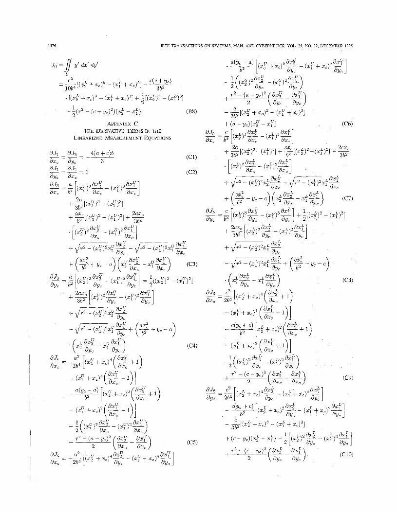
1516 IEEE TRANSACTIONS ON SYSTEMS, MAN, AND CYBERNETICS, VOL. 25, NO. 12, DECEMBER 1995
J6 = 1 y’ dx’ dy‘ L
c2 L c(c + Yc) = - 4 X 2 + xCl5 - (xf + 4 5 1 - ___
. [(xk + z,)~ - (xf + G ) ~ ] + ,[(x33 - (zf)3]
- -(? - ( e + yc)2)(xf - xf).
l o b 4 3b2 1
+ 2 - _ (B 8) 3;2 K.,” + 5 J 3 - (.P + d31 1
2
APPENDIX C + ( a - Yc)(.,” - (C6) THE DERIVATIVE E m s ET THE
LINEARIZED MEASUREMENT EQUATIONS

XIE et al.: REAL-TIME EYE FEATURE TRACKING FROM A VIDEO IMAGE SEQUENCE 1577
Also, the derivative terms dx,/dx,and dz,/dy, in (Cl) through (c10) are calculated by differentiating (A5) and (A6) with respect to x, and y,, respectively; they are
[16] F. L. Lewis, Optimal Estimation. New York Wiley, 1986. [I71 R. G. Brown and p. y. c. Hwang, zntroduction to Random Signals and
Applied Kalman Filtering. [18] X. Xie, R. Sndhakar, and H. Zhuang, “Estimation of eye features from
New York Wiley, 1992.
facial images.” in Proc. 4th Annu. Conf Recent Advances Robot.. Boca -mil& Raton, FLY 1991, pp. 73-80.
Recognition, vol. 26, no. 8, 1993. (c11) [19] -, “Corner detection by a cost minimization approach,” Pattem 4; f
dz, 1 + k p [20] -, “On improving eye feature extraction using deformable tem-
plates,” Pattern Recognition, vol. 27, no. 6, 1994. [21] X. Xie, “Automatic extraction and tracking of eye features from facial
image sequences,’’ Ph.D. dissertation, Florida Atlantic University, Boca Raton, FL, Aug. 1994.
* (c12) dz; 1 dy, 1 + - - - - ( k ; f
ACKNOWLEDGMENT The authors would like to express their sincere gratitude
toward the reviewers for their constructive criticisms and helpful suggestions.
REFERENCES
[l] L. R. Young and D. Sheena, “Survey of eye movement recording methods,” Behav. Res. Methods Znst., vol. 7, no. 5, pp. 397429, 1975.
[2] M. Nixon, “Eye spacing measurement for facial recognition,” SPZE Applicat. Digital Image Processing VIZI, vol. 575, pp 279-285, 1985.
[3] R. F. Olivio and M. C. Thompson, “Monitoring animals’ movements using digitized video images,” Behav. Res. Methods Inst., vol. 20, no. 5, pp. 485-490, 1988.
[4] D. Sheena and J. Borah, “Compensation for some second order effects
I71
I81
[91
to improve eye position measurement,’’ in Eye Movements: Cognition and Visual Perception, D. F. Fisher, R. A. Monty, and J. W. Senders, Eds. Hillsdale, NJ: Lawrence Erlbanm, 1981. R. Kliegl and R. K. Olson, “Reduction and calibration of eye monitor data,” Behav. Res. Methods Inst., vol. 13, no. 2, pp. ‘115-120, 1981. J. Merchant, R. Morrissette, and J. I. Porterfield, “Remote measurement of eye direction allowing subject motion offer one cubic foot of space,” ZEEE Trans. Biomed. Eng., vol. BME-21, no. 4, pp. 309-317, 1974. D. Sheene, "Pattern-recognition techniques for extraction of features of the eye from a conventional television scan,” i.n Eye Movements and Psychological Processes, R. A. Monty and J. W. Senders, Eds. Hillsdale, NJ: Lawrence Erlbaum, 1976. G. A. Myers, K. R. Sherman, and L. Stark, “Eye monitor, microcomputer-based instrument uses an intemal model to track the eye,” ZEEE Computer, pp. 14-21, Mar. 1991. H. Nakamura, H. Kobayashi, K. Taya, and S. Ishigami, “Design of eye movement monitoring system for practical environment,” in Proc. SPZE, San Jose, 1991, pp. 226-238. A. L. Yuille, P. W. Hallinan, and D. S. Cohen, “Feature extraction from faces using deformable templates,” Znt. J. Comp. Vision, vol. 8, no. 2,
R. W. Baloh, L. Langhoffer, V. Honrubia, and R. D. Yee, ‘‘On-line analysis of eye movements using a digital computer,” Aviat., Space, Environ. Med., vol. 51, pp. 563-567, 1980. G. R. Barnes, “A procedure for the analysis of nystagmus and other eye movements,” Aviat., Space, Environ. Med., vol. 53, no. 7, pp. 676-682, 1982. R. Kliegl, “Automated and interactiive analysis of eye fixation data in reading,” Behav. Res. Methods, Inst., vol. 13, no. 2, pp. 115-120, 1981. J. R. Tole and L. R. Young, “Digital filters for sa(xade and fixation detection,” in Eye Movements: Cognition and Visual Perception, D. F. Fisher, R. A. Monty, and J. W. Senders, Eds. Hillsdale, NJ: Lawrence Erlbaum, 1981. D. Sauter, B. J. Martin, N. Di. Renzo, and C. Vornscheid, “Analysis of eye tracking movements using innovations generated by a Kalman filter,” Med. Biol. Eng. Comput., vol. 29, pp. 63-69, 1991.
pp. 99-111, 1992.
research interests includi Dr. Xie is a member
Xangdong Xie received the B.S. and M.S. degrees in electrical engineering from Shanghai University of Technology, China, in 1982 and 1984, respec- tively, and the Ph.D. degree in electrical engineering from Florida Atlantic University in 1994.
He joined Shanghai Robotics Research Institute, China, from 1982-1990, working on research and development of industrial robots. From 1990-1994, he was a Research Assistant in the Robotics Center of Florida Atlantic University while pursuing the Ph.D. degree in electrical engineering at FAU. His
e robotics, computer vision and image processing. of Phi Kappa Phi.
Raghavan Sudhakar (M’87-SM’93) received the B.Sc. (Eng.) degree in electronics and communi- caiton engineering from the University of Kerala, Trivand”, India, in 1973, the M.Tech. degree in radar and communication engineering from the In- dian Institute of Technology, Madras, India, in 1977, and the Ph.D. degree for research on digital signal processing from the Indian Institute of Technology, New Delhi, India, in 1982.
He joined KELTRON, Kerala, Trivandrum, In- dia, in 1973. From 1982-1983 he was with the
University of Rhode Island, Kingston. Since August 1983 he has been with the Florida Atlantic University, Boca Raton, currently as Professor in Electrical Engineering. His research interests are in signal processing, digital communication and computer vision.
Dr. Sudhakar is a Professional Engineer in the State of Florida.
Hanqi Zhuang (S’88-M’89-SM’93) received the B.S. degree in engineering from Shanghai Uni- versity of Technology in 1982, and the M.S. and Ph.D. degrees in electrical engineering from Florida Atlantic University in 1986 and 1989, respectively.
Since December 1989, he has been a faculty member in the Department of Electrical Engineer- ing, where he is now an Associate Professor. His current research interests include robotics, laser and optics, computer vision and image processing.
Tan Beta Pi. Dr. Zhnang is a member of Phi Kappa Phi and