Scale-up of a continuous-jet hydrate reactor for CO2 ocean sequestration
Upload
khangminh22Category
view
0download
0
Catalysts 2019, 9, 262; doi:10.3390/catal9030262 www.mdpi.com/journal/catalysts
Review
Reactor Selection for Effective Continuous
Biocatalytic Production of Pharmaceuticals
Rowan M. Lindeque and John M. Woodley *
Department of Chemical and Biochemical Engineering, Technical University of Denmark,
2800 Kgs. Lyngby, Denmark; [email protected]
* Correspondence: [email protected]; Tel.: +45-4525-2885
Received: 14 February 2019; Accepted: 08 March 2019; Published: 14 March 2019
Abstract: Enzyme catalyzed reactions are rapidly becoming an invaluable tool for the synthesis of
many active pharmaceutical ingredients. These reactions are commonly performed in batch, but
continuous biocatalysis is gaining interest in industry because it would allow seamless integration
of chemical and enzymatic reaction steps. However, because this is an emerging field, little attention
has been paid towards the suitability of different reactor types for continuous biocatalytic reactions.
Two types of continuous flow reactor are possible: continuous stirred tank and continuous plug-
flow. These reactor types differ in a number of ways, but in this contribution, we focus on residence
time distribution and how enzyme kinetics are affected by the unique mass balance of each reactor.
For the first time, we present a tool to facilitate reactor selection for continuous biocatalytic
production of pharmaceuticals. From this analysis, it was found that plug-flow reactors should
generally be the system of choice. However, there are particular cases where they may need to be
coupled with a continuous stirred tank reactor or replaced entirely by a series of continuous stirred
tank reactors, which can approximate plug-flow behavior. This systematic approach should
accelerate the implementation of biocatalysis for continuous pharmaceutical production.
Keywords: continuous process; enzyme; residence time distribution; kinetics; reactor selection;
biocatalysis; flow chemistry
1. Introduction
As the pharmaceutical industry moves towards flow chemistry [1], the real advantage of
continuous manufacturing is that common (and even standardized) technologies will start to be used
for development and ultimately production. For example, production can use scaled-out versions of
the identical tubular reactors which were run in the laboratory. The use of such common technologies,
will enable enormous savings to be made in development time, meaning that processes can be
implemented more quickly, and products launched into the market earlier. These are major drivers
in virtually all pharmaceutical companies and so the field has grown considerably in recent years.
The complementary field of biocatalysis has also grown tremendously in the last decade. This has
been fueled firstly by protein engineering developments [2–5],which allow the individual tuning of
catalytic properties of enzymes, and secondly by the ability to operate cascades of enzymes [6–8]
under similar conditions. Additionally, biocatalysis offers the possibility of cutting the number of
process steps [9]. Many in the biocatalysis field therefore believe it timely to investigate flow
biocatalysis [10,11], not least because this enables the smooth integration of chemical and biocatalytic
methods together in continuous processes [12,13]. Indeed, this special issue is testament to the interest
in this field. There are already some superb examples of flow biocatalysis both in the area of enzyme
characterization and property measurements [14,15], as well as development and production [16,17].
Nevertheless, an often-cited challenge is that biocatalytic reactions in general are rather slow

Catalysts 2019, 9, 262 2 of 17
(compared to their chemical counterparts) and thereby the use of flow technology is hard to justify.
In reality, the arguments for flow technology are perhaps a little different for enzymes and, in this
brief review, we will discuss the issue of reactor selection, in order to capitalize upon the benefits of
both flow technology and biocatalysis. Downstream unit operations are not included in this
discussion.
2. Reactor Types
Figure 1 shows schematic diagrams of the three ideal reactor types, namely the batch stirred tank
reactor (BSTR), the continuous stirred tank reactor (CSTR) and the continuous plug-flow reactor
(CPFR). The characteristics of these reactors have been described in extensive detail elsewhere [18]
and will therefore be only briefly summarized here.
CS
Time
CS
Time
CS
Length
(a)
(b)
(c)
X∙CS0 + KM∙ln(1/1-X) = kcat∙E∙t/V
X∙CS0 + KM∙ln(1/1-X) = kcat∙E/Q
X∙CS0 + KM∙(X/1-X) = kcat∙E/Q
Figure 1. Reactor schematics, substrate concentration (CS) profiles and design equations for: (a) batch
stirred tank reactor (BSTR), (b) continuous stirred tank reactor (CSTR) and (c) continuous plug-flow
reactor (CPFR).
The design equations for each of the reactors in Figure 1 can be used to determine the
concentration of enzyme (E) required to achieve a desired fractional conversion of substrate (X) for a
given initial or feed substrate concentration (CS0). In a BSTR, the time of reaction (t) and reaction
volume (V) are also required, whilst for CSTRs and CPFRs the volumetric flowrate through the
reactor (Q) is needed. KM is the affinity constant of the enzyme towards the substrate and kcat is its
turnover number.
In a BSTR, the mechanically stirred vessel is first filled with substrate and enzyme, to initiate the
reaction, after which no material is removed until the reaction is stopped. BSTRs are well-mixed
reactors, meaning that concentrations are the same regardless of location within the reactor. Typical
enzyme kinetics follow Michaelis–Menten behavior, where rate is independent of substrate (zero
order) at high concentrations but becomes proportional to the amount of substrate (first order) at
lower concentrations, with a transition in between. This means that in a BSTR the substrate is initially
consumed quickly, whilst later in the reaction, as it enters the first order regime, the reaction rate
slows, as illustrated by the substrate concentration profile in Figure 1a. However, given sufficient
time in the reactor, complete conversion can be achieved, provided the equilibrium is favorable.
Catalysts 2019, 9, 262 3 of 17
BSTRs are commonly used for biocatalytic reactions [19,20] due to their simplicity and flexibility. For
instance, substrate concentrations can be kept below toxic or inhibitory levels by adopting a fed-batch
approach [21,22] where substrate is fed to the reactor, resulting in a reaction volume that increases
with time. Additionally, pH changes caused by the biocatalytic reaction can be neutralized through
the addition of an acid or base to maintain the optimal pH of the enzyme.
The design of a CSTR is similar to that of a BSTR, except that material is continuously added to,
and removed from, the reactor such that the working volume remains constant. In this case, the
biocatalyst must either be fed continuously to the reactor (to make up for loss of catalyst in the
effluent) or it must be retained within the reactor by immobilization and/or partially permeable
membranes. Like BSTRs, CSTRs are well-mixed and so the reactor contents and effluent are
homogenous. However, since there must be enough substrate in the reactor to achieve an adequate
reaction rate, the effluent will always contain some substrate and so full substrate conversion is not
possible [23]. This trade-off between reaction rate and conversion is an important characteristic of
CSTRs. Furthermore, since the reactor contents are homogenous, the substrate concentration, and
subsequently the reaction rate, throughout the reactor remain constant with respect to time, as shown
in the profile in Figure 1b.
In a CPFR, reactants are pumped into a long tubular reactor where, unlike stirred tanks, material
flowing through does not mix with any material flowing ahead of it, or behind it. This results in
concentration gradients over the length of the reactor, identical to the concentration gradients over
time in a BSTR. Therefore, if the reactor is sufficiently long, the substrate can be fully converted. For
this reason, in Figure 1c the concentration profile is given with respect to length, since the time
material spends in a CPFR is simply a function of the reactor length and volumetric flowrate.
Although it is possible to operate a CPFR with a soluble catalyst, biocatalysts are typically
immobilized onto the reactor wall or on particles of a carrier material, which are then packed into a
tube to form a continuous packed-bed reactor (CPBR) [24] that exhibits plug-flow behavior. However,
this can potentially introduce mass transfer limitations and large pressure drops over the reactor [25].
3. Batch vs. Continuous
There are many considerations which need to be evaluated when selecting the type of reactor to
use. However, even for simple single product reactions in a single liquid phase, two considerations
which are always of relevance are the residence time distribution (RTD) and the kinetics of the
enzyme catalyzed reaction. BSTRs and CPFRs have identical kinetic behavior and both afford good
control over RTDs. Consequently, it would appear that there is little motivation to invest in the shift
from batch operation to continuous since both give the same result. However, much research has
highlighted the benefits of continuous biocatalysis over batch processing, for both production as well
as research and development, and these are summarized in Figure 2 [26–28]. Nonetheless, it has also
been shown that, for single-phase homogenous reactions, the differences in performance between
batch and continuous reactors at the laboratory scale are negligible [29]. Therefore, in such instances,
shifting from batch to continuous would appear to be a time-consuming and resource-intensive
process that yields few improvements. But, at production scales, where mixing and heat transfer in
large batch reactors are less efficient, shifting to continuous operation could be beneficial.
Additionally, steady-state operation of a continuous reactor affords simpler control and greater
consistency than a dynamic batch process at large scales.
Catalysts 2019, 9, 262 4 of 17
Advantages of continuous biocatalysis
Improved mass transfer
Pressurized operation for
gas/liquid reactions
Reduced variability
Automation and less
downtime
Integration of process
analytical technology
(PAT)
In-line purification
Figure 2. Benefits of shifting towards flow biocatalysis.
Moreover, active pharmaceutical ingredients (APIs) are often the products of numerous reaction
steps. Some of these reaction steps, especially those involving optically active compounds, may be
biocatalytic, but many reactions are still more efficient using chemical catalysts. Chemocatalytic
reactions are frequently operated continuously to benefit from rapid mixing and heat transfer [30],
particularly in the case of exothermic reactions, or to avoid the storage of unstable or toxic
intermediates. Therefore, when selecting a reactor for a biocatalytic reaction that has to be integrated
into a combined chemo/biocatalytic reaction sequence [31–33], opting for a continuous approach may
be more practical, potentially allowing for end-to-end manufacturing that could even include
downstream processing and formulation [34]. For this reason, it may also make more sense to use
continuous reactors for research and development in the pharmaceutical industry, as it simplifies the
transition to production scale through the process of scale-out, reducing time-to-market.
Finally, continuous operation is generally more efficient than batch operation, which is plagued
with lengthy start-up and shutdown times, before and after each reaction, and mandatory downtimes
as the reactors need to be routinely cleaned. Of course, there are still some cases where BSTRs may
be the most appropriate reactor to use. For instance, if the reaction rates of an enzyme are very low,
then continuous operation in a CPFR would require very low flowrates or an impractically long
reactor. In such a case, it would be beneficial to simply run the reaction in a BSTR for a long period
of time until the reaction reaches completion. However, even in such cases where BSTRs are in use it
is still possible to gain some of the benefits of flow chemistry, by simulating continuous behavior. For
example, this could be done by operating three BSTRs in parallel, but with each at a different stage
in the process (i.e., start-up, operation, shutdown), termed pseudo-continuous operation.
4. Residence Time Distribution
Residence time defines the length of time material is in a reactor. For an ideal BSTR it is simply
the time from the addition of the final reagent (usually biocatalyst) to the quenching time of the
reaction. In other words, all material is in the reactor for the same length of time and can be said to
have a defined residence time. If this time is sufficiently long, then all the reactant will have been
converted to product. Therefore, in the production of APIs, batch reactors have frequently been used
simply because complete conversion was achievable. Moreover, if some substrate remains at the end
of the reaction, more catalyst can be added to complete the conversion. This flexibility is very
attractive. Even in cases where the equilibrium prevents complete conversion of substrate to product,
all material has an identical residence time and thereby the reaction mixture has a defined conversion.
For more complex reactions (with multiple reactants, products or phases) this is critical, because
otherwise what might leave the reactor is a variable mixture of compounds that complicates

Catalysts 2019, 9, 262 5 of 17
downstream processing. Small-molecule APIs are complex, and their production is strictly regulated
(e.g., by the Federal Drug Administration or European Medicines Agency). For this reason, there is a
demand for precision chemistry in the pharmaceutical industry to achieve high product quality in a
reproducible manner, ensuring the safety of the patient. It is for this reason that enzymes are
particularly attractive due to their high selectivity [35], compared to most conventional catalysts,
which minimizes by-product formation. Additionally, they operate at mild conditions [36] which also
greatly reduces the occurrence of spontaneous degradation of reactants, intermediates or products.
This allows for the precise production of APIs with simpler downstream processing steps. However,
to truly capitalize upon this, the reactor should also give a precise residence time. In other words, a
precision catalyst used in a precision reactor. In this way the benefit of flow biocatalysis becomes
clear.
Residence time is an important characteristic of any reactor. It is desirable to have a well-defined
residence time for accurate control of reactions. In an ideal CPFR, where no back-mixing occurs,
material exits the reactor in the same order as it enters with a single residence time (τ) which can
easily be calculated from the volume of the reactor and the volumetric flowrate, as follows:
τ =V
Q (1)
The ideal BSTR and CPFR are the only two cases where a reactor has a single residence time. For
all other reactor types and configurations, multiple residence times exist and so residence times are
typically expressed as a function of time, known as the residence time distribution. For instance, the
RTD of the ideal BSTR (or ideal CPFR) is represented mathematically by the following Dirac delta
function, shown graphically in Figure 3:
E(t) = δ(t − τ) (2)
Feed
Injection Detection
Effluent
CS
Time
Ideal pulse injection Ideal response
CS
Time
0 τ
Figure 3. Response of a CPFR to a pulse injection under ideal conditions.
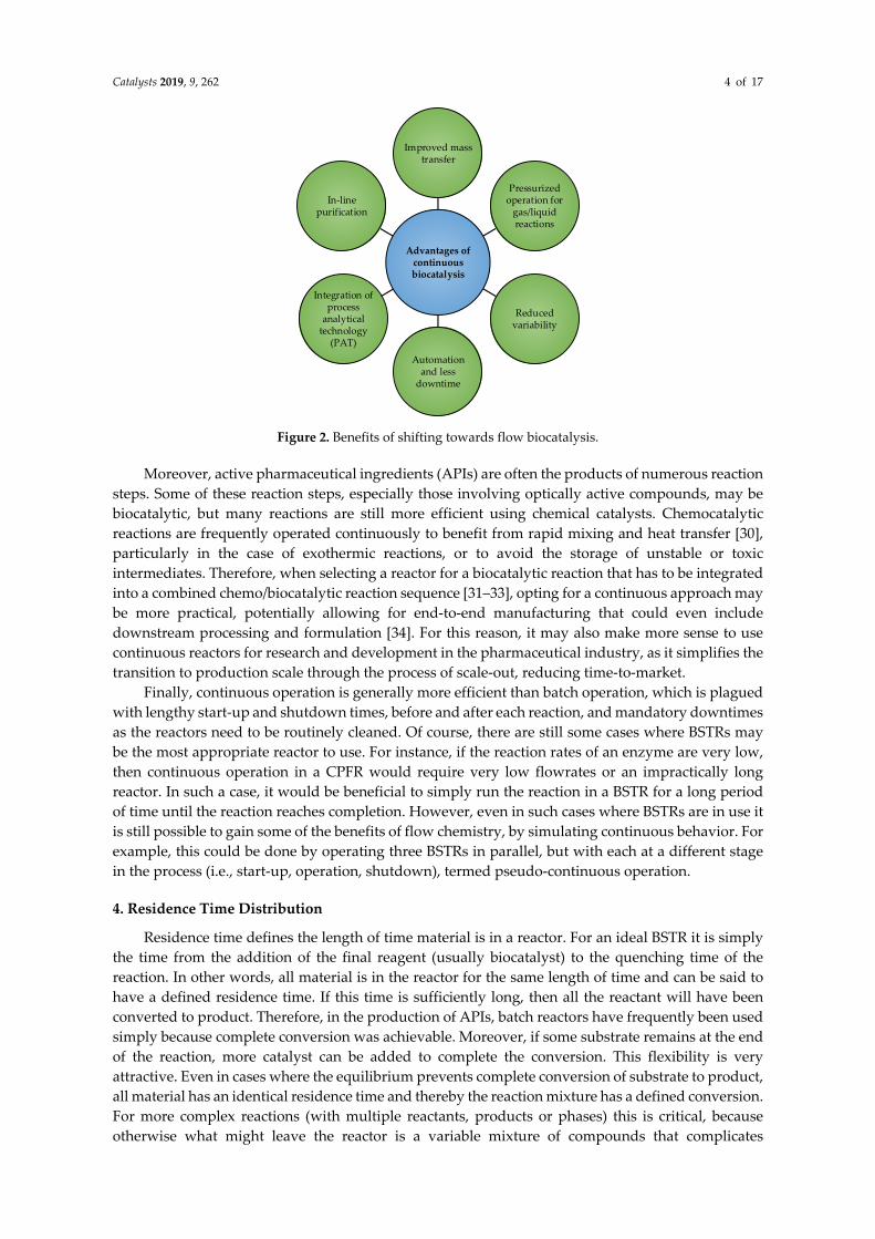
In an ideal CSTR it is assumed that mixing is complete and instantaneous, such that the
composition of the entire reactor volume and the reactor outlet are homogenous. As a result, some of
the feed molecules exit the reactor immediately, since fluid is constantly being removed at the outlet,
whilst others remain in the reactor almost indefinitely. Therefore, the RTD can be represented by an
exponential decay function (Equation (3)), illustrated in Figure 4, although the mean residence time
can still be calculated using Equation (1).
E(t) =1
τe�
��� � (3)
Catalysts 2019, 9, 262 6 of 17
Feed
Injection Detection
Effluent
Time
Ideal pulse injection Ideal response
CS
Time
0
CS
Figure 4. Response of a CSTR to a pulse injection under ideal conditions.
5. Enzyme Kinetics
Enzyme kinetics are often modeled using the basic Michaelis–Menten equation, shown below.
Modified versions of this equation also exist to describe more complex systems, such as those with
substrate or product inhibition, or multiple substrates or products.
v =V���C�K� + C�
(4)
V��� = k���E (5)
Equation (4) relates the reaction rate (v) to the substrate concentration. The maximum rate of the
enzyme reaction (Vmax) is dependent on the turnover number of the enzyme and its concentration.
The affinity constant of the enzyme towards a specific substrate, KM, corresponds to the substrate
concentration at which the initial rate will be half of the maximum rate. Therefore, to achieve the
maximum rate of an enzymatic reaction, the substrate concentration must be sufficiently high
(relative to its KM) that the rate equation approximates the following zero order form:
C� ≫ K�
v ≈ V��� = k���E (6)
If an enzyme has a very high affinity towards a particular substrate, characterized by a very low
KM, the maximum rate of the enzymatic reaction can still be achieved at low substrate concentrations.
This is a highly desirable scenario because it means that the enzyme can likely be used effectively
regardless of reactor type. This can be illustrated by dividing the design equation of a CSTR
(Figure 1b) with that of a CPFR (Figure 1c) to determine the ratio of enzyme concentrations
(ECSTR/ECPFR) required to reach a desired fractional conversion, plotted in Figure 5. It can be seen that,
to reach high fractional conversions, much higher enzyme concentrations are required in a CSTR than
a CPFR unless the substrate concentration in the feed is a few orders of magnitude higher than the
affinity constant of the enzyme. For this reason, protein engineering efforts should be focused on
increasing the affinity of enzymes towards industrially attractive molecules [37,38]. In the meantime,
however, enzymes generally have low affinities towards pharmaceutical intermediates due to their
complex, non-native structures. Therefore, for pharmaceutical production in particular, the choice of
reactor can greatly affect the reaction rates that can be achieved in a biocatalytic reaction.

Catalysts 2019, 9, 262 7 of 17
CS0/KM = 1
CS0/KM = 10
CS0/KM = 100
Figure 5. Enzyme concentrations required in a CSTR vs. a CPFR to achieve a desired fractional
conversion of substrate.
For instance, in a CSTR, substrate is fed into a much larger, well-mixed volume. This means the
reaction takes place at a single, constant substrate concentration far more dilute than that of the feed,
resulting in reduced rates throughout the reactor. In contrast, the substrate concentration in a CPFR
is equal to that of the feed at the inlet, where the enzyme can operate closer to its maximum rate, and
progressively decreases across the length of the reactor, as does the reaction rate. This is typically a
more effective way of using the catalyst. As expressed earlier, this kinetic behavior is identical to that
of a biocatalytic reaction in a BSTR [18].
Enzyme inhibition by substrate or product is also very important to consider when selecting a
reactor for biocatalysis. On the one hand, if the enzyme is inhibited by high concentrations of the
substrate, the substrate dilution that occurs in a CSTR may be desirable, whereas the high initial
substrate concentration in a CPFR could have a negative impact. On the other hand, if the enzyme is
inhibited by the product, operating in a CSTR is undesirable as the homogeneity guarantees
inhibition throughout the reactor unless a much larger, more dilute reaction volume is used, which
would increase capital costs as well as the cost of downstream processing. Conversely, in a BSTR
product inhibition would only become problematic towards the end of the reaction. Likewise, in a
CPFR the rate would only be severely inhibited towards the end of the reactor, whilst maintaining a
smaller, more concentrated and cost-effective volume. The concentrations of substrate and product
throughout the reactor also influence the thermodynamic equilibrium of the reaction, but this has
been discussed in detail elsewhere [39].
The difference in capital costs between a CSTR and CPFR is best demonstrated with an example.
One of the most successful instances where a biocatalytic reaction has been implemented in the
pharmaceutical industry is the use of a highly engineered transaminase in the production of
sitagliptin [40]. The kinetic parameters of this enzyme have not been published. However, another
transaminase from Halomonas elongata (HEWT), which has been characterized, was recently used for
the continuous production of amines at laboratory scale [41]. The turnover number of this enzyme
was found to be 0.094 s−1, and its KM values were 2.57 mM and 0.56 mM towards (S)-1-
phenylethylamine (amino donor) and pyruvate (amino acceptor), respectively, for the production of
acetophenone at 25 °C [42]. Due to the high affinity of the enzyme towards pyruvate, it will be
assumed that pyruvate is supplied in sufficient excess such that the reaction rate is only dependent
on the concentration of (S)-1-phenylethylamine, according to Equation (4). Equation (7) shows how
the Michaelis–Menten expression can be transformed into a function of the fractional conversion,
where FS0 is the inlet molar flowrate of substrate.
v =k���E
F��Q
(1 − X)
K� +F��Q
(1 − X) (7)
A typical industrial enzyme concentration of 1 g/L has been assumed as well as a desired annual
production target of 100 kg, with a final product concentration of 10 g/L. Figure 6 shows the
Levenspiel plot for this reaction, which can be used to determine the reactor volume required to
0
5
10
15
20
0 0.2 0.4 0.6 0.8 1
EC
ST
R/E
CP
FR
X

Catalysts 2019, 9, 262 8 of 17
achieve a desired conversion in a continuous reactor with these conditions [43]. For a CSTR, the
required volume is equal to the area of a rectangle with a height of FS0/v and a width of X, whereas
for a CPFR, the required volume is the area under the curve. It is clear from Figure 6 that a similar
volume would be required for both reactors to achieve most fractional conversions. In fact, only 2.5 L
more volume would be required in a CSTR than a CPFR to achieve 80% substrate conversion.
However, in most biocatalytic reactions the only difference between the substrate and product is a
single functional group, which can make separating them extremely challenging. Therefore, to avoid
adding more complexity to the downstream process it is best to aim for complete conversion of the
substrate and this is where the gap between the CSTR and the CPFR becomes apparent. From
Figure 6, it can be calculated that, to achieve 99% substrate conversion, a CPFR with a volume of 38 L
would be sufficient, but a CSTR would require a volume of 134 L, nearly 4 times larger. This problem
becomes significantly worse if a conversion of 99.9% is desired, a perfectly common target in the
pharmaceutical industry, in which case a CSTR would require 23 times more volume than a CPFR,
greatly increasing capital and downstream processing costs.
Figure 6. Levenspiel plot for the production of acetophenone from (S)-1-phenylethylamine and
pyruvate by an amine transaminase from Halomonas elongata (HEWT).
6. pH Control and Multiphase Systems
Much of the previous discussion has shown that CPFRs are generally better suited for
continuous biocatalytic production of pharmaceuticals than CSTRs. Nevertheless, CPFRs and CPBRs
do have some limitations that may preclude their use with certain systems. For instance, although
residence time and temperature are easily controlled in these reactors, control of pH across the length
of the reactor is often more challenging due to the concentration gradients that arise from the lack of
mixing [44]. To overcome this problem, engineered enzymes that can tolerate the range of pH
expected to occur across the reactor would be required. Alternatively, the effluent from the CPFR can
be recycled through a CSTR where acid or base can be added to adjust the pH back to the optimal
value, as illustrated in Figure 7. Here, the well-mixed behavior of a CSTR is extremely beneficial to
quickly counteract pH changes. Another possibility is to operate multiple shorter CPFRs in series
since the performance will be the same as a single long CPFR. This allows additional pH adjustments
to be made in between CPFRs, as shown in Figure 8. This configuration could also allow intermediate
substrate feeding to avoid substrate inhibition.
0
50
100
150
0 0.2 0.4 0.6 0.8 1
FS
0/v
(L
)
X
Catalysts 2019, 9, 262 9 of 17
+ -
Base
pH
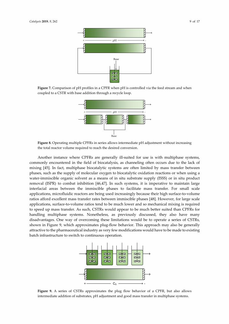
Figure 7. Comparison of pH profiles in a CPFR when pH is controlled via the feed stream and when
coupled to a CSTR with base addition through a recycle loop.
+ -pH
Base
Figure 8. Operating multiple CPFRs in series allows intermediate pH adjustment without increasing
the total reactor volume required to reach the desired conversion.
Another instance where CPFRs are generally ill-suited for use is with multiphase systems,
commonly encountered in the field of biocatalysis, as channeling often occurs due to the lack of
mixing [45]. In fact, multiphase biocatalytic systems are often limited by mass transfer between
phases, such as the supply of molecular oxygen to biocatalytic oxidation reactions or when using a
water-immiscible organic solvent as a means of in situ substrate supply (ISSS) or in situ product
removal (ISPR) to combat inhibition [46,47]. In such systems, it is imperative to maintain large
interfacial areas between the immiscible phases to facilitate mass transfer. For small scale
applications, microfluidic reactors are being used increasingly because their high surface-to-volume
ratios afford excellent mass transfer rates between immiscible phases [48]. However, for large scale
applications, surface-to-volume ratios tend to be much lower and so mechanical mixing is required
to speed up mass transfer. As such, CSTRs would appear to be much better suited than CPFRs for
handling multiphase systems. Nonetheless, as previously discussed, they also have many
disadvantages. One way of overcoming these limitations would be to operate a series of CSTRs,
shown in Figure 9, which approximates plug-flow behavior. This approach may also be generally
attractive to the pharmaceutical industry as very few modifications would have to be made to existing
batch infrastructure to switch to continuous operation.
+ -CS
Figure 9. A series of CSTRs approximates the plug flow behavior of a CPFR, but also allows
intermediate addition of substrates, pH adjustment and good mass transfer in multiphase systems.
Catalysts 2019, 9, 262 10 of 17
7. Reactor Selection
The analyses of reactor configurations in Sections 4–6 are established, even if not widely
discussed in the scientific literature. However, we have also taken inspiration from this to develop a
reactor selection tool, so that for the first time, decisions about continuous biocatalytic reactors can
be made on a rational basis. To effectively use this tool, a number of prerequisites should be satisfied,
namely that the enzyme of interest has been characterized, the operating conditions (temperature,
pH, co-solvents etc.) have been set and the enzyme has been shown to be stable at these conditions
for a sufficient duration, which is case dependent. Additionally, it is recommended that the main
limitations of the enzyme [49] are identified and its performance is compared with relevant economic
targets [50], but this is outside the scope of this article.
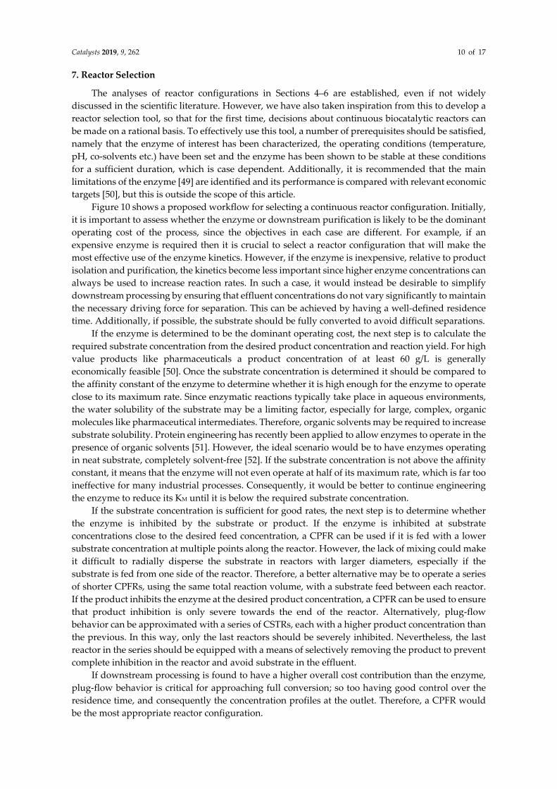
Figure 10 shows a proposed workflow for selecting a continuous reactor configuration. Initially,
it is important to assess whether the enzyme or downstream purification is likely to be the dominant
operating cost of the process, since the objectives in each case are different. For example, if an
expensive enzyme is required then it is crucial to select a reactor configuration that will make the
most effective use of the enzyme kinetics. However, if the enzyme is inexpensive, relative to product
isolation and purification, the kinetics become less important since higher enzyme concentrations can
always be used to increase reaction rates. In such a case, it would instead be desirable to simplify
downstream processing by ensuring that effluent concentrations do not vary significantly to maintain
the necessary driving force for separation. This can be achieved by having a well-defined residence
time. Additionally, if possible, the substrate should be fully converted to avoid difficult separations.
If the enzyme is determined to be the dominant operating cost, the next step is to calculate the
required substrate concentration from the desired product concentration and reaction yield. For high
value products like pharmaceuticals a product concentration of at least 60 g/L is generally
economically feasible [50]. Once the substrate concentration is determined it should be compared to
the affinity constant of the enzyme to determine whether it is high enough for the enzyme to operate
close to its maximum rate. Since enzymatic reactions typically take place in aqueous environments,
the water solubility of the substrate may be a limiting factor, especially for large, complex, organic
molecules like pharmaceutical intermediates. Therefore, organic solvents may be required to increase
substrate solubility. Protein engineering has recently been applied to allow enzymes to operate in the
presence of organic solvents [51]. However, the ideal scenario would be to have enzymes operating
in neat substrate, completely solvent-free [52]. If the substrate concentration is not above the affinity
constant, it means that the enzyme will not even operate at half of its maximum rate, which is far too
ineffective for many industrial processes. Consequently, it would be better to continue engineering
the enzyme to reduce its KM until it is below the required substrate concentration.
If the substrate concentration is sufficient for good rates, the next step is to determine whether
the enzyme is inhibited by the substrate or product. If the enzyme is inhibited at substrate
concentrations close to the desired feed concentration, a CPFR can be used if it is fed with a lower
substrate concentration at multiple points along the reactor. However, the lack of mixing could make
it difficult to radially disperse the substrate in reactors with larger diameters, especially if the
substrate is fed from one side of the reactor. Therefore, a better alternative may be to operate a series
of shorter CPFRs, using the same total reaction volume, with a substrate feed between each reactor.
If the product inhibits the enzyme at the desired product concentration, a CPFR can be used to ensure
that product inhibition is only severe towards the end of the reactor. Alternatively, plug-flow
behavior can be approximated with a series of CSTRs, each with a higher product concentration than
the previous. In this way, only the last reactors should be severely inhibited. Nevertheless, the last
reactor in the series should be equipped with a means of selectively removing the product to prevent
complete inhibition in the reactor and avoid substrate in the effluent.
If downstream processing is found to have a higher overall cost contribution than the enzyme,
plug-flow behavior is critical for approaching full conversion; so too having good control over the
residence time, and consequently the concentration profiles at the outlet. Therefore, a CPFR would
be the most appropriate reactor configuration.

Catalysts 2019, 9, 262 11 of 17
Finally, the need for pH control and/or multiple phases should be considered. In both of these
cases, good mixing is required to neutralize pH changes or generate high interfacial areas between
phases. For multiphase reactions, a series of CSTRs should be used to approximate plug-flow
behavior while still allowing sufficient dispersion of the phases. This configuration would also be
beneficial for pH control because it provides multiple acid/base feed points. Alternatively, a CPFR
can be coupled with a recycle loop through a CSTR where pH can be controlled, although the
presence of a recycle complicates the process.
8. Immobilization
Due to the high cost of enzymes, it is desirable to recycle them for continuous operation,
provided they are stable enough for repeated use. Isolation of the enzyme downstream of the reactor,
using selectively permeable membranes, is one possibility, but introduces an additional unit
operation and further complexity to the process. A better alternative is to retain the enzyme within
the reactor. This can be done by placing membranes at the reactor outlet, however, fouling of the
membrane and concentration polarization are likely to become problematic [53]. For this reason, the
most common method of retaining enzymes within a reactor is by binding them to larger carrier
particles that are easier to separate from the reactor effluent than the soluble enzyme. Recently, the
use of paramagnetic nanoparticles as supports has received much attention due to their high specific
surface areas and simple retention within the reactor by a magnetic field [54]. Numerous methods
and support materials have been described for the immobilization of a wide variety of enzymes [55].
Depending on the support material used, immobilization can improve the stability of an enzyme
towards harsher operating conditions, such as elevated temperatures or the presence of organic co-
solvents [56–58], since bonds are formed between the enzyme and the support. However, in some
cases, these bonds, particularly strong covalent bonds, may prevent the enzyme from adopting a
more stable conformation or one that is required to catalyze the desired reaction and so,
immobilization of an enzyme can also negatively affect its stability or activity [59,60]. Physical
adsorption is an alternative for immobilizing enzymes without forming such strong bonds [61] but
this makes it easier for the enzyme to leach off the support during reactor operation. Affinity
immobilization, whereby enzymes are engineered to contain specific tags [62] that bind very
selectively to ligands on specialized support materials, minimizes leaching and maintains the
flexibility of the enzyme so that activity loss is reduced. This method of immobilization also ensures
that only the desired enzyme binds to the support instead of other proteins or impurities that may be
present in crude cell extracts.
In stirred tank reactors, whether they are operated in batch or continuously, the use of
immobilized biocatalysts is often limited because the catalyst loading in the reactor is restricted to
about 10% (v,v), compared to 60% (v,v) in a CPBR [18]. This is because the shear forces from stirring
[63] may break apart the carrier material, making the biocatalyst difficult to separate from the reaction
media and potentially contaminating the effluent. Loss of biocatalyst in the effluent may also reduce
the productivity of a CSTR. Cross-linked enzyme aggregates (CLEAs) [64] are a more suitable form
of immobilization for use in stirred tank reactors [65,66] due to their smaller size compared to typical
carrier-bound biocatalysts.
Although immobilization has proven to be advantageous in some cases, it is important to
recognize that the support and immobilization process add additional cost to the biocatalyst and this
should always be taken into consideration when assessing the feasibility of a process. Furthermore,
although most immobilization supports allow for high protein loadings due to their large specific
surface areas, internal diffusion limitations frequently make such high loadings ineffective [67,68].
As a result, immobilization often limits the amount of enzyme that can be loaded into a reactor,
compared to soluble enzymes. Nevertheless, as protein expression and engineering continue to
improve, the costs of enzymes may decrease until eventually it becomes feasible to utilize soluble
enzymes in continuous processes [69–71]. This would be especially attractive for the pharmaceutical
industry, where the high value of the products can help offset the cost of the biocatalyst, to simplify
Catalysts 2019, 9, 262 12 of 17
production and downstream processing. Additionally, the enzyme would only need to be stable at
the desired operating conditions for the length of the residence time in the reactor.
Determine which is the dominant operating cost;
the enzyme or downstream processing
EnzymeDownstream
processing
Calculate required substrate concentration
(CS) from desired product concentration (g/L) and
yield (gproduct/gsubstrate)
CS >> KM
NoEnzyme requires further engineering before
industrial implementation
Yes
Is the enzyme inhibited by substrate?
series CPFRs
YesIs the enzyme inhibited by
product?
Yes
series CSTRs with ISPR
CPFR
No No
High substrate conversion and narrow residence time
distribution required
CPFR
pH control required?
CPFR + CSTR recycle
series CSTRs
v
CS
KM
multi-feed CPFR
Multiple phases required?
series CSTRs
Figure 10. Workflow for selection of continuous biocatalytic reactor configurations.
Catalysts 2019, 9, 262 13 of 17
9. Outlook
In this review, some important criteria have been investigated to assist reactor selection for
continuous biocatalytic pharmaceutical production and a novel selection tool is presented. We have
shown that many reactor configurations, using only the ideal CSTR and CPFR, are possible to ensure
effective enzyme use, overcome inhibitory effects, simplify downstream processing, operate with
multiple phases or control operating conditions like pH, depending on the major limitations of a
given system. Nevertheless, there are other important factors that have yet to be considered, such as:
Regeneration and retention of expensive cofactors in a continuous reactor;
Cost-effective and benign methods for retaining enzymes to reduce their overall cost
contributions;
The need for metrics to evaluate and compare different continuous biocatalytic systems;
Effective downstream unit operations for continuous product isolation and purification.
Future efforts will need to be directed towards these aspects and eventually be used to update
the selection tool presented here.
Author Contributions: The methodology presented here was conceptualized by R.M.L. and J.M.W.; the original
draft was prepared by R.M.L., reviewed and edited by J.M.W.
Funding: This research received no external funding.
Conflicts of Interest: The authors declare no conflicts of interest.
Nomenclature
Symbol Definition Unit
CS Substrate concentration mol L−1
CS0 Initial or inlet substrate concentration mol L−1
X Fractional substrate conversion -
t Reaction time s
V Reactor volume L
Q Volumetric flowrate L s−1
KM Substrate affinity constant mol L−1
kcat Enzyme turnover number s−1
τ Residence time s
FS0 Inlet molar flowrate of substrate mol s−1
References
1. Porta, R.; Benaglia, M.; Puglisi, A. Flow Chemistry: Recent Developments in the Synthesis of
Pharmaceutical Products. Org. Proc. Res. Dev. 2015, 20, 2–25, doi:10.1021/acs.oprd.5b00325.
2. Bornscheuer, U.T.; Huisman, G.W.; Kazlauskas, R.J.; Lutz, S.; Moore, J.C.; Robins, K. Engineering the third
wave of biocatalysis. Nature 2012, 485, 185–194, doi:10.1038/nature11117.
3. Strohmeier, G.A.; Pichler, H.; May, O.; Gruber-Khadjawi, M. Application of designed enzymes in organic
synthesis. Chem. Rev. 2011, 111, 4141–4164, doi:10.1021/cr100386u.
4. Ghislieri, D.; Green, A.P.; Pontini, M.; Willies, S.C.; Rowles, I.; Frank, A.; Grogan, G.; Turner, N.J.
Engineering an enantioselective amine oxidase for the synthesis of pharmaceutical building blocks and
alkaloid natural products. J. Am. Chem. Soc. 2013, 135, 10863–10869, doi:10.1021/ja4051235.
5. Arnold, F.H. Directed Evolution: Bringing New Chemistry to Life. Angew. Chem. Int. Ed. 2018, 57, 4143–
4148, doi:10.1002/anie.201708408.
6. Ricca, E.; Brucher, B.; Schrittwieser, J.H. Multi-Enzymatic Cascade Reactions: Overview and Perspectives.
Adv. Synth. Catal. 2011, 353, 2239–2262, doi:10.1002/adsc.201100256.
7. Chuaboon, L.; Wongate, T.; Punthong, P.; Kiattisewee, C.; Lawan, N.; Hsu, C.; Lin, C.; Bornscheuer, U.T.;
Chaiyen, P. One-Pot Bioconversion of L-Arabinose to L-Ribulose in an Enzymatic Cascade. Angew. Chem.
2019, 10, doi:10.1002/anie.201814219.
Catalysts 2019, 9, 262 14 of 17
8. Aumala, V.; Mollerup, F.; Jurak, E.; Blume, F.; Karppi, J.; Koistinen, A.; Schuiten, E.; Voss, M.; Bornscheuer,
U.; Deska, J.; et al. Biocatalytic production of amino-carbohydrates through oxidoreductase and
transaminase cascades. ChemSusChem 2018, doi:10.1002/cssc.201802580.
9. Ma, S.K.; Gruber, J.; Davis, C.; Newman, L.; Gray, D.; Wang, A.; Grate, J.; Huisman, G.W.; Sheldon, R.A. A
green-by-design biocatalytic process for atorvastatin intermediate. Green Chem. 2010, 12, 81–86,
doi:10.1039/b919115c.
10. Tamborini, L.; Fernandes, P.; Paradisi, F.; Molinari, F. Flow Bioreactors as Complementary Tools for
Biocatalytic Process Intensification. Trends Biotechnol. 2018, 36, 73–88, doi:10.1016/j.tibtech.2017.09.005.
11. Jones, E.; McClean, K.; Housden, S.; Gasparini, G.; Archer, I. Biocatalytic oxidase: Batch to continuous.
Chem. Eng. Res. Des. 2012, 90, 726–731, doi:10.1016/j.cherd.2012.01.018.
12. Rudroff, F.; Mihovilovic, M.D.; Gröger, H.; Snajdrova, R.; Iding, H.; Bornscheuer, U.T. Opportunities and
challenges for combining chemo- and biocatalysis. Nat. Catal. 2018, 1, 12–22, doi:10.1038/s41929-017-0010-
4.
13. Dawood, A.W.H.; Bassut, J.; de Souza, R.; Bornscheuer, U.T. Combination of the Suzuki-Miyaura Cross-
Coupling Reaction with Engineered Transaminases. Chem. Eur. J. 2018, 24, 16009–16013,
doi:10.1002/chem.201804366.
14. Ringborg, R.H.; Pedersen, A.T.; Woodley, J.M. Automated Determination of Oxygen-Dependent Enzyme
Kinetics in a Tube-in-Tube Flow Reactor. ChemCatChem 2017, 9, 3285–3288, doi:10.1002/cctc.201700811.
15. Bolivar, J.M.; Eisl, I.; Nidetzky, B. Advanced characterization of immobilized enzymes as heterogeneous
biocatalysts. Catal. Today 2015, 259, 66–80, doi:10.1016/j.cattod.2015.05.004.
16. Andrade, L.H.; Kroutil, W.; Jamison, T.F. Continuous flow synthesis of chiral amines in organic solvents:
Immobilization of E. coli cells containing both omega-transaminase and PLP. Org. Lett. 2014, 16, 6092–6095,
doi:10.1021/ol502712v.
17. Gasparini, G.; Archer, I.; Jones, E.; Ashe, R. Scaling Up Biocatalysis Reactions in Flow Reactors. Org. Process
Res. Dev. 2012, 16, 1013–1016, doi:10.1021/op2003612.
18. Woodley, J.M. Scale-Up and Development of Enzyme-Based Processes for Large-Scale Synthesis
Applications. In Science of Synthesis: Biocatalysis in Organic Synthesis; Faber, K., Fessner, W.D., Turner, N.J.,
Eds.; Thieme: Stuttgart, Germany, 2015; Volume 3, pp. 515–546.
19. Zhou, X.; Lü, S.; Xu, Y.; Mo, Y.; Yu, S. Improving the performance of cell biocatalysis and the productivity
of xylonic acid using a compressed oxygen supply. Biochem. Eng. J. 2015, 93, 196–199,
doi:10.1016/j.bej.2014.10.014.
20. Dennewald, D.; Hortsch, R.; Weuster-Botz, D. Evaluation of parallel milliliter-scale stirred-tank bioreactors
for the study of biphasic whole-cell biocatalysis with ionic liquids. J. Biotechnol. 2012, 157, 253–257,
doi:10.1016/j.jbiotec.2011.10.008.
21. Zhang, J.; Fang, X.; Zhu, X.-L.; Li, Y.; Xu, H.-P.; Zhao, B.-F.; Chen, L.; Zhang, X.-D. Microbial lipid
production by the oleaginous yeast Cryptococcus curvatus O3 grown in fed-batch culture. Biomass
Bioenergy 2011, 35, 1906–1911, doi:10.1016/j.biombioe.2011.01.024.
22. Gomes, N.; Teixeira, J.A.; Belo, I. Fed-batch versus batch cultures of Yarrowia lipolytica for gamma-
decalactone production from methyl ricinoleate. Biotechnol. Lett. 2012, 34, 649–654, doi:10.1007/s10529-011-
0824-0.
23. Lima-Ramos, J.; Neto, W.; Woodley, J.M. Engineering of Biocatalysts and Biocatalytic Processes. Top. Catal.
2014, 57, 301–320, doi:10.1007/s11244-013-0185-0.
24. Tran, D.-T.; Chen, C.-L.; Chang, J.-S. Continuous biodiesel conversion via enzymatic transesterification
catalyzed by immobilized Burkholderia lipase in a packed-bed bioreactor. Appl. Energ. 2016, 168, 340–350,
doi:10.1016/j.apenergy.2016.01.082.
25. Xu, Y.; Nordblad, M.; Woodley, J.M. A two-stage enzymatic ethanol-based biodiesel production in a packed
bed reactor. J. Biotechnol. 2012, 162, 407–414, doi:10.1016/j.jbiotec.2012.05.017.
26. Mohr, S.; Fisher, K.; Scrutton, N.S.; Goddard, N.J.; Fielden, P.R. Continuous two-phase flow miniaturised
bioreactor for monitoring anaerobic biocatalysis by pentaerythritol tetranitrate reductase. Lab A Chip 2010,
10, 1929–1936, doi:10.1039/c003561k.
27. Britton, J.; Raston, C.L.; Weiss, G.A. Rapid protein immobilization for thin film continuous flow
biocatalysis. Chem. Commun. 2016, 52, 10159–10162, doi:10.1039/c6cc04210d.

Catalysts 2019, 9, 262 15 of 17
28. Pedersen, A.T.; de Carvalho, T.M.; Sutherland, E.; Rehn, G.; Ashe, R.; Woodley, J.M. Characterization of a
Continuous Agitated Cell Reactor for Oxygen Dependent Biocatalysis. Biotechnol. Bioeng. 2017, 114, 1222–
1230, doi:10.1002/bit.26267.
29. Valera, F.E.; Quaranta, M.; Moran, A.; Blacker, J.; Armstrong, A.; Cabral, J.T.; Blackmond, D.G. The flow’s
the thing... or is it? Assessing the merits of homogeneous reactions in flask and flow. Angew. Chem. 2010,
49, 2478–2485, doi:10.1002/anie.200906095.
30. Wegner, J.; Ceylan, S.; Kirschning, A. Ten key issues in modern flow chemistry. Chem. Commun. 2011, 47,
4583–4592, doi:10.1039/c0cc05060a.
31. Yuryev, R.; Strompen, S.; Liese, A. Coupled chemo(enzymatic) reactions in continuous flow. Beilstein J. Org.
Chem. 2011, 7, 1449–1467, doi:10.3762/bjoc.7.169.
32. Morales, M.; Dapsens, P.Y.; Giovinazzo, I.; Witte, J.; Mondelli, C.; Papadokonstantakis, S.; Hungerbühler,
K.; Pérez-Ramírez, J. Environmental and economic assessment of lactic acid production from glycerol using
cascade bio- and chemocatalysis. Energy Environ. Sci. 2015, 8, 558–567, doi:10.1039/c4ee03352c.
33. Groger, H.; Hummel, W. Combining the ‘two worlds’ of chemocatalysis and biocatalysis towards multi-
step one-pot processes in aqueous media. Curr. Opin. Chem. Biol. 2014, 19, 171–179,
doi:10.1016/j.cbpa.2014.03.002.
34. Adamo, A.; Beingessner, R.L.; Behnam, M.; Chen, J.; Jamison, T.F.; Jensen, K.F.; Monbaliu, J.M.; Myerson,
A.S.; Revalor, E.M.; Snead, D.R., et al. On-demand continuous-flow production of pharmaceuticals in a
compact, reconfigurable system. Science 2016, 352, 61–67, doi:10.1126/science.aaf1337.
35. Wohlgemuth, R. Biocatalysis-key to sustainable industrial chemistry. Curr. Opin. Biotechnol. 2010, 21, 713–
724, doi:10.1016/j.copbio.2010.09.016.
36. Bordeaux, M.; Galarneau, A.; Fajula, F.; Drone, J. A regioselective biocatalyst for alkane activation under
mild conditions. Angew. Chem. 2011, 123, 2123–2127, doi:10.1002/anie.201005597.
37. Woodley, J.M. Protein engineering of enzymes for process applications. Curr. Opin. Chem. Biol. 2013, 17,
310–316, doi:10.1016/j.cbpa.2013.03.017.
38. Woodley, J.M. Integrating protein engineering with process design for biocatalysis. Phil. Trans. R. Soc. A
2017, 376, doi:10.1098/rsta.2017.0062.
39. Abu, R.; Woodley, J.M. Application of Enzyme Coupling Reactions to Shift Thermodynamically Limited
Biocatalytic Reactions. ChemCatChem 2015, 7, 3094–3105, doi:10.1002/cctc.201500603.
40. Savile, C.K.; Janey, J.M.; Mundorff, E.C.; Moore, J.C.; Tam, S.; Jarvis, W.R.; Colbeck, J.C.; Krebber, A.; Fleitz,
F.J.; Brands, J.; et al. Biocatalytic Asymmetric Synthesis of Chiral Amines from Ketones Applied to
Sitagliptin Manufacture. Science 2010, 329, 305–309, doi:10.1126/science.1188934.
41. Planchestainer, M.; Contente, M.L.; Cassidy, J.; Molinari, F.; Tamborini, L.; Paradisi, F. Continuous flow
biocatalysis: Production and in-line purification of amines by immobilised transaminase from Halomonas
elongata. Green Chem. 2017, 19, 372–375, doi:10.1039/c6gc01780k.
42. Cerioli, L.; Planchestainer, M.; Cassidy, J.; Tessaro, D.; Paradisi, F. Characterization of a novel amine
transaminase from Halomonas elongata. J. Molec. Catal. B Enzym. 2015, 120, 141–150,
doi:10.1016/j.molcatb.2015.07.009.
43. Rakmai, J.; Cheirsilp, B. Continuous production of β-cyclodextrin by cyclodextrin glycosyltransferase
immobilized in mixed gel beads: Comparative study in continuous stirred tank reactor and packed bed
reactor. Biochem. Eng. J. 2016, 105, 107–113, doi:10.1016/j.bej.2015.09.011.
44. Tufvesson, P.; Fu, W.; Jensen, J.S.; Woodley, J.M. Process considerations for the scale-up and
implementation of biocatalysis. Food Bioprod. Process. 2010, 88, 3–11, doi:10.1016/j.fbp.2010.01.003.
45. Xue, R.; Woodley, J.M. Process technology for multi-enzymatic reaction systems. Bioresour. Technol. 2012,
115, 183–195, doi:10.1016/j.biortech.2012.03.033.
46. Schmolzer, K.; Madje, K.; Nidetzky, B.; Kratzer, R. Bioprocess design guided by in situ substrate supply
and product removal: Process intensification for synthesis of (S)-1-(2-chlorophenyl)ethanol. Bioresour.
Technol. 2012, 108, 216–223, doi:10.1016/j.biortech.2012.01.009.
47. Gruber, P.; Marques, M.P.C.; O’Sullivan, B.; Baganz, F.; Wohlgemuth, R.; Szita, N. Conscious coupling: The
challenges and opportunities of cascading enzymatic microreactors. Biotechnol. J. 2017, 12,
doi:10.1002/biot.201700030.
48. Karande, R.; Schmid, A.; Buehler, K. Miniaturizing Biocatalysis: Enzyme-Catalyzed Reactions in an
Aqueous/Organic Segmented Flow Capillary Microreactor. Adv. Synth. Catal. 2011, 353, 2511–2521,
doi:10.1002/adcs.201100394.

Catalysts 2019, 9, 262 16 of 17
49. Nordblad, M.; Gomes, M.D.; Meissner, M.P.; Ramesh, H.; Woodley, J.M. Scoping Biocatalyst Performance
Using Reaction Trajectory Analysis. Org. Proc. Res. Dev. 2018, 22, 1101–1114, doi:10.1021/acs.oprd.8b00119.
50. Lima-Ramos, J.; Tufvesson, P.; Woodley, J.M. Application of environmental and economic metrics to guide
the development of biocatalytic processes. Green Process Synth 2014, 3, doi:10.1515/gps-2013-0094.
51. Doukyu, N.; Ogino, H. Organic solvent-tolerant enzymes. Biochem. Eng. J. 2010, 48, 270–282,
doi:10.1016/j.bej.2009.09.009.
52. Lee, A.; Chaibakhsh, N.; Rahman, M.B.A.; Basri, M.; Tejo, B.A. Optimized enzymatic synthesis of levulinate
ester in solvent-free system. Ind. Crop. Prod. 2010, 32, 246–251, doi:10.1016/j.indcrop.2010.04.022.
53. Luo, J.; Morthensen, S.T.; Meyer, A.S.; Pinelo, M. Filtration behavior of casein glycomacropeptide (CGMP)
in an enzymatic membrane reactor: Fouling control by membrane selection and threshold flux operation.
J. Membr. Sci. 2014, 469, 127–139, doi:10.1016/j.memsci.2014.06.024.
54. Bezerra, R.M.; Neto, D.M.A.; Galvão, W.S.; Rios, N.S.; Carvalho, A.C.L.d.M.; Correa, M.A.; Bohn, F.;
Fernandez-Lafuente, R.; Fechine, P.B.A.; de Mattos, M.C.; et al. Design of a lipase-nano particle biocatalysts
and its use in the kinetic resolution of medicament precursors. Biochem. Eng. J. 2017, 125, 104–115,
doi:10.1016/j.bej.2017.05.024.
55. Sheldon, R.A.; van Pelt, S. Enzyme immobilisation in biocatalysis: Why, what and how. Chem. Soc. Rev.
2013, 42, 6223–6235, doi:10.1039/c3cs60075k.
56. Popat, A.; Hartono, S.B.; Stahr, F.; Liu, J.; Qiao, S.Z.; Qing Max Lu, G. Mesoporous silica nanoparticles for
bioadsorption, enzyme immobilisation, and delivery carriers. Nanoscale 2011, 3, 2801–2818,
doi:10.1039/c1nr10224a.
57. Palomo, J.M.; Munoz, G.; Fernandez-Lorente, G.; Mateo, C.; Fernandez-Lafuente, R.; Guisan, J.M.
Interfacial adsorption of lipases on very hydrophobic support (octadecyl–Sepabeads): Immobilization,
hyperactivation and stabilization of the open form of lipases. J. Mol. Catal. B Enzym. 2002, 19–20, 279–286,
doi:10.1016/S1381-1177(02)00178-9.
58. Rios, N.S.; Pinheiro, M.P.; dos Santos, J.C.; Fonseca, T.D.; Lima, L.D.; de Mattos, M.C.; Freire, D.M.; da Silva
Júnior, I.J.; Rodríguez-Aguado, E.; Goncalves, L.R. Strategies of covalent immobilization of a recombinant
Candida antarctica lipase B on pore-expanded SBA-15 and its application in the kinetic resolution of (R,S)-
Phenylethyl acetate. J. Mol. Catal. B Enzym. 2016, 133, 246–258, doi:10.1016/j.molcatb.2016.08.009.
59. Magner, E. Immobilisation of enzymes on mesoporous silicate materials. Chem. Soc. Rev. 2013, 42, 6213–
6222, doi:10.1039/c2cs35450k.
60. Manoel, E.A.; Dos Santos, J.C.; Freire, D.M.; Rueda, N.; Fernandez-Lafuente, R. Immobilization of lipases
on hydrophobic supports involves the open form of the enzyme. Enzym. Microb. Technol. 2015, 71, 53–57,
doi:10.1016/j.enzmictec.2015.02.001.
61. Jesionowski, T.; Zdarta, J.; Krajewska, B. Enzyme immobilization by adsorption: A review. Adsorption 2014,
20, 801–821, doi:10.1007/s10450-014-9623-y.
62. Matosevic, S.; Lye, G.J.; Baganz, F. Immobilised enzyme microreactor for screening of multi-step
bioconversions: Characterisation of a de novo transketolase-omega-transaminase pathway to synthesise
chiral amino alcohols. J. Biotechnol. 2011, 155, 320–329, doi:10.1016/j.jbiotec.2011.07.017.
63. Nunes, M.A.; Rosa, M.E.; Fernandes, P.C.; Ribeiro, M.H. Operational stability of naringinase PVA lens-
shaped microparticles in batch stirred reactors and mini packed bed reactors-one step closer to industry.
Bioresour. Technol. 2014, 164, 362–370, doi:10.1016/j.biortech.2014.04.108.
64. Sheldon, R.A. Cross-Linked Enzyme Aggregates as Industrial Biocatalysts. Org. Proc. Res. Dev. 2011, 15,
213–223, doi:10.1021/op100289f.
65. Xu, D.Y.; Yang, Z. Cross-linked tyrosinase aggregates for elimination of phenolic compounds from
wastewater. Chemosphere 2013, 92, 391–398, doi:10.1016/j.chemosphere.2012.12.076.
66. Xu, D.-Y.; Chen, J.-Y.; Yang, Z. Use of cross-linked tyrosinase aggregates as catalyst for synthesis of l-
DOPA. Biochem. Eng. J. 2012, 63, 88–94, doi:10.1016/j.bej.2011.11.009.
67. Lage, F.A.; Bassi, J.J.; Corradini, M.C.; Todero, L.M.; Luiz, J.H.; Mendes, A.A. Preparation of a biocatalyst
via physical adsorption of lipase from Thermomyces lanuginosus on hydrophobic support to catalyze
biolubricant synthesis by esterification reaction in a solvent-free system. Enzym. Microb. Technol. 2016, 84,
56–67, doi:10.1016/j.enzmictec.2015.12.007.
68. Manoel, E.A.; Ribeiro, M.F.P.; dos Santos, J.C.S.; Coelho, M.A.Z.; Simas, A.B.C.; Fernandez-Lafuente, R.;
Freire, D.M.G. Accurel MP 1000 as a support for the immobilization of lipase from Burkholderia cepacia:

Catalysts 2019, 9, 262 17 of 17
Application to the kinetic resolution of myo -inositol derivatives. Process Biochem. 2015, 50, 1557–1564,
doi:10.1016/j.procbio.2015.06.023.
69. Kazi, F.K.; Fortman, J.A.; Anex, R.P.; Hsu, D.D.; Aden, A.; Dutta, A.; Kothandaraman, G. Techno-economic
comparison of process technologies for biochemical ethanol production from corn stover. Fuel 2010, 89,
S20-S28, doi:10.1016/j.fuel.2010.01.001.
70. Li, S.; Yang, X.; Yang, S.; Zhu, M.; Wang, X. Technology prospecting on enzymes: Application, marketing
and engineering. Comput. Struct. Biotechnol. J. 2012, 2, e201209017, doi:10.5936/csbj.201209017.
71. Chapman, J.; Ismail, A.; Dinu, C. Industrial Applications of Enzymes: Recent Advances, Techniques, and
Outlooks. Catalysts 2018, 8, 238, doi:10.3390/catal8060238.
© 2019 by the authors. Licensee MDPI, Basel, Switzerland. This article is an open access
article distributed under the terms and conditions of the Creative Commons Attribution
(CC BY) license (http://creativecommons.org/licenses/by/4.0/).
Copyright © 2022 FDOKUMEN