
RAVENNA - LAWO
47
Networking Guide RAVENNA Version: 1.0/3 Edition: 19 September 2015
-
Upload
khangminh22 -
Category
Documents
-
view
0 -
download
0
Transcript of RAVENNA - LAWO

Networking Guide
RAVENNA
Version: 1.0/3
Edition: 19 September 2015

Copyright
All rights reserved. Permission to reprint or electronically reproduce any document or graphic in whole orin part for any reason is expressly prohibited, unless prior written consent is obtained from the Lawo AG.
All trademarks and registered trademarks belong to their respective owners. It cannot be guaranteed thatall product names, products, trademarks, requisitions, regulations, guidelines, specifications and norms
are free from trade mark rights of third parties.
All entries in this document have been thoroughly checked; however no guarantee for correctness can begiven. Lawo AG cannot be held responsible for any misleading or incorrect information provided throughout
this manual.
Lawo AG reserves the right to change specifications at any time without notice.
© Lawo AG, 2015

Table of Contents
RAVENNA Networking Guide V1.0/3 3
Table of Contents
Welcome 4
Data Network Requirements 5
Selecting Components 6
Network Switch Configuration 12
Appendices 40
Glossary 45

RAVENNA Networking GuideV1.0/34
Welcome
Welcome
Welcome to RAVENNA, Lawo's preferred solution for real-time audio distribution in IP-based networkenvironments.
About this Manual
This manual describes the data network requirements which must be supported if you wish to stream audioacross an IP network using RAVENNA. Topics include general prerequisites, selecting components and networkswitch configuration. We recommend that you read this document carefully before purchasing or installingcomponents intended for use with RAVENNA.
Other useful documents include the:
· RAVENNA for crystal User Guide
· RAVENNA for sapphire User Guide
· RAVENNA for mc2/Nova73 User Guide - more specific details about how RAVENNA is implementedwithin these products.
Look out for the following symbols which indicate:
Notes - points of clarification. Tips - useful tips and short cuts.
Warnings
Alert you when an action should always be observed.
Lawo User Registration
For access to the Download-Center and to receive regular product updates, please register atwww.lawo.com/user-registration.

RAVENNA Networking Guide V1.0/3 5
Data Network Requirements
Data Network RequirementsRAVENNA streaming requires proper configuration and management of the data network. This means that allnetwork components (routers and switches) must support the following requirements. All are common datanetworking features. However, they are not supported by every network switch.
Please DO NOT attempt to connect RAVENNA streaming nodes using an unknown or unqualifying IP network. Ifyou do so, correct streaming operation cannot be guaranteed.
Essential Requirements
To qualify for RAVENNA streaming, all network components MUST support:
· Multicast addressing - as opposed to unicast, with:
o IGMPv2 Snooping - with an active Querier. Fast/Immediate Leave is also highly recommended.
o Port Filtering - streaming ports must be open to Avahi/Bonjour and Ember+ services (to allow for
automatic node detection and stream announcement).
· IPv4 protocol - as opposed to IPv6.
· QoS - the use of DSCP values, otherwise known as Diffserv, is highly recommended. In Lawo'sRAVENNA devices, the following DSCP values are implemented:
o DSCP 56 (C7) = PTP clock signals.
o DSCP 46 (EF) = RAVENNA media streams.
o DSCP 0 (BE) = all other network traffic.
· No Green Ethernet/EEE/Power Saving- any Energy Efficient Ethernet (EEE), Green Ethernet or powersaving features must be disabled, as these can interfere with RAVENNA's clock signals and real-timebuffering.
· No Jumbo Frames - any options for Jumbo Frames should be disabled.
· PTP - for mc2/Nova73 installations, Synchronization requires a PTP master clock source. As a result, allnetwork components must be PTP-aware.
When configuring the network, it is also important that all streaming nodes reside within a single broadcastdomain (i.e. within the same IP address range and subnet). This is necessary to support automatic streamannouncement.
Recommendations
The following are also highly recommended:
· Switch Configuration - a managed switch will allow you to easily monitor and adjust settings such asthe IGMP, QoS and Port filtering features described above.
· Gigabit Ethernet - a Gigabit Ethernet switch operating at 1000 Mbit/s will significantly improve thenetwork's bandwidth and performance when compared to Fast Ethernet (100 Mbit/s) or Standard Ethernet(10 Mbit/s).
· No Network Address Translation (NAT) or Firewalls - NAT and Firewalls should be avoided as theycan result in long and unpredictable delays.

RAVENNA Networking GuideV1.0/36
Selecting Components
Selecting Components
This section deals with choosing the right components for your RAVENNA network including cables, switchesand SFP modules (for fibre optic conversion):
· Cables
· Switches
· SFPs (Fibre Optic Conversion)

RAVENNA Networking Guide V1.0/3 7
Selecting ComponentsCables
Cables
All of Lawo's RAVENNA devices support copper Ethernet cabling (see below). In addition, some devices supportoptical fibre ports by fitting one of the Lawo-certified SFP modules.
Copper Connections
Choose an Ethernet cable and connector that meets the following specification:
· Cable Type: CAT 5 or better (CAT 5e/6/7); straight (1:1) or crossedEthernet cable.
· Connector Type: RJ45.
· Network Speed: 1000, 100 and 10 Base-TX LAN speeds are supported;1000 Base-TX (Gigabit Ethernet) is recommended.
· Cable Length: up to 100m.
Cable Quality & Distance
The CAT5, CAT5e, CAT6 and CAT7 standards specify that these cables can transmit data up to 100m. However,in practice, the reliability of Gigabit Ethernet transmission over longer distances will vary according to the cablequality and its termination. You should check the manufacturer's specifications for the maximum cablingdistance, and also the quality of terminations using a CAT5e cable checker - an inaccurate termination will notachieve the maximum transmission performance.
If the cabling distance is to exceed say 70m, then a rugged solid-conductor cable, as opposed to stranded cable,is recommended )(see below). For distances longer than 100m, you should convert to fibre optic, see SFPs.
In addition, if the installation environment is prone to electromagnetic interference, you should choose STP(Shielded Twisted Pair) cables, as opposed to UTP (Unshielded Twisted Pair). Note that STP cables requirecompatible connectors (for proper grounding).
Solid-conductor vs Stranded Cables
Two cable types are supported by the CAT 5/5e/6/7 specifications:
· Solid-conductor cable uses a single solid wire per conductor and, therefore, creates a more rigidproduct. It is ideal for fixed installations and provides reliable long distance transmission (up to 100m).
· Stranded cable uses multiple wires wrapped around each other in each conductor and, therefore,creates a more flexible product. It is ideal for shorter patch cables, but is less reliable over long distance.

RAVENNA Networking GuideV1.0/38
Selecting ComponentsSFPs (Fibre Optic Conversion)
SFPs (Fibre Optic Conversion)
For network connections over long distances (> 100m), you should use optical fibre cables and connectors.
The 981/61 RAVENNA IO card (for Lawo's mc2 consoles and Nova73 router) offers connections on optical fibre byfitting one of the Lawo-certified SFP modules:
The Lawo-certified SFPs include multi-mode and single-mode fibre, supporting a choice of maximum cable
lengths. Please refer to the "RAVENNA for mc2/Nova73 User Guide" for details.
All other Lawo RAVENNA IO cards require an external media converter (copper to fibre).
Many network switches also support fibre optic connection via SFP or GBIC modules; please check the switchmanufacturer's specifications for details.
You should close any unused optical connectors, with a protection plug, to avoid performancedegradation by dust or dirt.

RAVENNA Networking Guide V1.0/3 9
Selecting ComponentsSwitches
Switches
In order to create a RAVENNA network you will need a Layer 2 switch, or switches, that meet the followingrequirements:
1. Transmission Speed = Gigbit Ethernet
A Gigabit Ethernet switch operating at 1000 Mbit/s is recommended, as opposed to Fast (100 Mbit/s) or Standard(10 Mbit/s) Ethernet.
2. Synchronization = PTP-Aware
In mc2/Nova73 systems, synchronisation of the RAVENNA streaming network requires a PTP master clocksource. In the current release, this takes the form of a specially configured DALLIS sync frame which convertsincoming Wordclock, from the master sync reference, to PTP.
In other Lawo systems, you should consider installing a PTP Grandmaster. Currently, Lawo recommends usingMeinberg clock generators.
As a result, you will require a PTP-aware switch with this feature enabled.
In smaller RAVENNA streaming networks using crystal, sapphire or JADE, it is possible for nodes tosync to an incoming stream. In this instance, a PTP Grandmaster is not required, and non-PTPswitches may be implemented. Please see "RAVENNA for crystal" or "RAVENNA for sapphire/Nova17" for more details.
3. Capacity (Non-blocking) = dependent on number of RAVENNA nodes & bandwidth requirements
The capacity of the switch will depend on the number of RAVENNA nodes and their bandwidth requirements. It isbest to choose a non-blocking switch, where all ports are capable of simultaneous Gigbit transfer. This can bedetermined by the switch capacity and number of ports - for example, if a switch has 10 ports, then its capacityshould be at least 20 Gbps (Gigabits per second), to cater for 1Gb Input and Output transmissions per port.
If long distance connections are required, then you should choose a switch that supports fibre opticmodules.
4. Energy Efficient Ethernet (EEE) or Power Saving = OFF
It is important that any EEE, Green Ethernet or power saving features can be disabled, as these can interfere withRAVENNA's clock signals and real-time buffering.
5. Addressing = Multicast, with IGMPv2
The switch must support multicast addressing. This means that packets sent from a single device can bereceived by multiple nodes at the same time (i.e. one to many). This differs from a unicast data network wheredata packets are addressed to a single receiving node (i.e. one to one).
The switch should also support IGMPv2 Snooping with an active Querier and Fast or Immediate leave. IGMPQuerying/Snooping is a technique used by network switches to control the forwarding of Multicast data packets.A switch with IGMP Querying/Snooping will forward Multicast data packets only to the ports that are members ofthe Multicast group. Whereas, a switch without IGMP Querying/Snooping will broadcast Multicast data to all of itsoutput ports. As a result, the volume of Multicast traffic will be significantly reduced if a network switch supportsIGMP Querying/Snooping.

RAVENNA Networking GuideV1.0/310
Selecting ComponentsSwitches
6. Quality of Service (QoS) = DiffServ
The switch should support DSCP values, otherwise known as Diffserv.
In data networks, a QoS (Quality of Service) setup is used to prioritise different types of network data. So, forexample, RAVENNA timing information and audio streams MUST take priority over all other types of networktraffic (e.g. control data, file transfers, web browsing, etc.). In Lawo's RAVENNA devices, DSCP (DifferentiatedServices Code Point) values are implemented (this system is known as DiffServ). The default DSCP values areDSCP 56 (C7) = PTP clock signals; DSCP 46 (EF) = RAVENNA media streams; DSCP 0 (BE) = all othernetwork traffic. You should check that your network switch is configured to support and prioritise the correctDSCP classes, and that the default values have not been altered.
7. Port Filtering = Ports must be open to Avahi/Bonjour and Ember+ services
Streaming ports must be open to Avahi/Bonjour and Ember+ services to allow for automatic node detection andstream announcement.
8. Configuration = Managed Switch (recommended)
A managed switch can be remotely configured, usually from a service computer running a browser-basedinterface. This will allow you to easily monitor and adjust the settings described above. See Network SwitchConfiguration for more details.
If you are creating a network with multiple switches, then it may be helpful to choose switches fromthe same manufacturer and/or the same model. This will allow you to copy the switch configurationfrom one device to another.

RAVENNA Networking Guide V1.0/3 11
Selecting ComponentsSwitches
Evaluated Network Switches
The following network switches have been evaluated by Lawo. This list is from working and proven setups, and issubject to change at any time.
Note that the only switch recommended for professional audio and/or video installation, at this time, is the Arista7150S.
PTP-Aware Switches (recommended)
· Arista 7150S - www.arista.com/en/products/7150-series
Other PTP-Aware Switches (we have experience of)
· Extreme Networks X460 Gen2 - www.extremenetworks.com/product/summit-x460-series
· Cisco Nexus 3000 family - www.cisco.com/c/en/us/products/switches/nexus-3000-series-switches
· Hirschmann Mach 104 family - www.e-catalog.beldensolutions.com
· ARG stagebox switch - www.arg.co.uk/network-products/stagebox-html
· Juniper (latest firmware Beta)
Example configuration files are available for some of the above. Note that these should be used as examples only,as some parameters must be adopted for the individual situation. Please contact your local Lawo representativeor email [email protected].
Other Switches (we have experience of)
· Small Business 300 and 500 series
· Catalyst 3750-X

RAVENNA Networking GuideV1.0/312
Network Switch Configuration
Network Switch Configuration
This section provides an example configuration of a network switch. We will use a CISCO SG300 series switch todemonstrate the procedures and options. This is a managed network switch that allows remote configuration froma browser-based interface. Note that the CISCO switches are non-PTP aware, and therefore you should also referto the Arista 7150S topic for an example of the PTP-aware switch options.
If you are using a different manufacturer's switch, then the user interface and its terminology may differ. Pleaserefer to the switch documentation to help locate (and configure) the equivalent options.
You should configure the network switch first, before connecting the RAVENNA-enabled devices.
Note that our example configures the switch for a single vLAN (virtual Local Area Network). However, if thenetwork is large or the switch is to be used for other devices (Control System, Service ports, company network,etc.), then it is a good idea to divide the network traffic by creating separate vLANs. This will avoid unnecessarypacket transfers between different types of device and make the network more stable. Please refer to your switchdocumentation for more details.
All RAVENNA streaming interfaces must connect to the same vLAN.

RAVENNA Networking Guide V1.0/3 13
Network Switch ConfigurationFirst Steps
First Steps
The first steps are to establish a connection between the network switch and your computer, and download andinstall the latest switch software.
To do this, you will need to know the IP address of the network switch. If the IP address is unknown, or the switchhas been used for a previous application, then you should reset the switch to its factory default settings and begina new configuration from scratch. For the purposes of this illustration, we will assume that the switch IP settingsare as follows:
· IP Address = 192.168.101.254
· Subnet Mask = 255.255.255.0
· Default Gateway = left blank
1. Before connecting you should download the latest firmware release for the network switch onto yourcomputer - for example:
2. It is also recommended to use a TFTP server tool such as Tftpd64 (or Tftpd32 for 32-bit windowssystems), for the file transfers. This can be downloaded from http://tftpd32.jounin.net/.

RAVENNA Networking GuideV1.0/314
Network Switch ConfigurationFirst Steps
3. Next, connect your computer's Ethernet port directly to one of the 10/100/1000 Ethernet ports on theswitch front panel using a standard network cable (CAT 5 or above):
4. Adjust the TCP/IP settings for your computer’s Network Interface Card (NIC) - the following screenshotsdemonstrate how to do this on a PC running Windows 7/8:
The Subnet Mask should be identical to that of the port you are connecting to, in our example 255.255.255.0.
The IP address must be unique, and set within the same range as that of the port you are connecting to (i.e.thefirst three fields must match). For example, to connect to a network switch which has an IP address of192.168.101.254, you could set your computer's IP address to 192.168.101.67.

RAVENNA Networking Guide V1.0/3 15
Network Switch ConfigurationFirst Steps
5. Now start a browser session, by opening your web browser software, and entering the IP address of theswitch into the URL field - in our example, 192.168.101.254 - the browser connects and the login screenappears (in our example, behind our TCP/IP configuration):
If the login screen does not appear, then check the following:
· URL Address - this must match the IP address of the network switch.
· Physical network connection - between the computer's Network Interface Card and the switch.
· TCP/IP configuration - check the TCP/IP settings entered in step 2. If the login screen still does notappear, then run a PING test to check your network communication.
· Firewall or Antivirus Software - some software may interfere with web browser communication. Trydisabling your Firewall and/or Antivirus to eliminate them as the cause of the problem.
For further assistance, consult your switch documentation.

RAVENNA Networking GuideV1.0/316
Network Switch ConfigurationFirst Steps
6. At the login screen, enter the Username and Password and click on Log in.
The default Username and Password for CISCO switches is CISCO.
If you do not know the Username and/or Password, then you will need to perform a factory reset.
7. If the Username and Password have not been altered (from the defaults), then you may be asked toenter a new password.
Once the login (and password changes) are complete, the Getting Started (Home) page for the switchconfiguration appears:
8. Use the tabs on the left to select the different pages of switch settings. For full details, you shouldconsult the CISCO switch documentation. Here we will focus on the settings and options which must beadjusted to support a RAVENNA streaming network. If an option is not mentioned, then it should be left at itsdefault setting.
Before proceeding, it is recommended that you first install any new firmware.

RAVENNA Networking Guide V1.0/3 17
Network Switch ConfigurationInstalling New Firmware
Installing New Firmware
To install the new firmware, it is recommended you use an TFTP server tool, such as Tftpd64, rather than thebrowser interface as this is a more reliable method of performing file transfers.
1. Start the TFTP server tool and adjust the settings as shown below - this will bind the TFTP server to yourcomputer's IP address (e.g. 192.168.101.67) and prepare it for the file transfer:
Global Settings TFTP Settings
2. Select Browse and choose the firmware update file which you downloaded earlier.

RAVENNA Networking GuideV1.0/318
Network Switch ConfigurationInstalling New Firmware
3. Leave the TFTP server tool running and, on the CISCO switch GUI select Administration -> FileManagement -> Upgrade/Backup Firmware. Then adjust the following settings:
· Transfer Method = via TFTP
· Save Action = Upgrade
· File Type = Firmware image
· TFTP Server Destination = By IP address (Version 4)
· TFTP Server IP Address/Name = enter the IP address of your TFTP server (in our example192.168.101.67).
· Source File Type = the firmware version filename
The complete setup should look like this:

RAVENNA Networking Guide V1.0/3 19
Network Switch ConfigurationInstalling New Firmware
4. Select Apply to begin the file transfer - you will see the upload in progress:

RAVENNA Networking GuideV1.0/320
Network Switch ConfigurationInstalling New Firmware
5. After a successful upload, the following screen appears:
6. Click on the active image link to make the firmware image active, and then Reboot the switch:

RAVENNA Networking Guide V1.0/3 21
Network Switch ConfigurationEditing and Saving Changes
Editing and Saving Changes
Before looking at the individual settings, it is important to understand that most network switches support both aRunning and Startup configuration. When you make an update, it is saved in the Running configuration. On boot-up, the Startup configuration is loaded. Therefore, to make permanent changes, you must remember to savechanges to the Startup configuration. For our CISCO switch, this works as follows:
Firstly, whenever you Apply a parameter change, the Save icon (in the headline bar) starts to flash - thisindicates that you have made a change to the Running configuration:
You can continue to Apply changes to the Running configuration for as long as you wish - the Save iconcontinues to flash. This allows you to make multiple parameter changes before updating the Startup configuration.
Note that if you reboot the switch at this stage, the Running configuration settings are lost, and the switch revertsto its Startup configuration.
To save the changes permanently, you must copy the Running configuration to the Startup configuration asfollows:
1. Click on the flashing Save icon, or select Administration -> File Managerment -> Copy/SaveConfiguration, to open the copy/save page.
2. Select the Running configuration as the Source File Name and the Startup configuration as theDestination File Name.

RAVENNA Networking GuideV1.0/322
Network Switch ConfigurationEditing and Saving Changes
3. Click Apply and then OK to confirm the operation:
When the copy is complete, you will see the following confirmation:

RAVENNA Networking Guide V1.0/3 23
Network Switch ConfigurationNo Jumbo Frames
No Jumbo Frames
RAVENNA streaming cannot support Jumbo Frames, and therefore, this option should be disabled:

RAVENNA Networking GuideV1.0/324
Network Switch ConfigurationNo Green Ethernet / EEE / Power Saving
No Green Ethernet / EEE / Power Saving
It is important that any Energy Efficient Ethernet (EEE), otherwise known an Green Ethernet, or power savingfeatures are disabled, as these can interfere with RAVENNA's clock signals and real-time buffering:

RAVENNA Networking Guide V1.0/3 25
Network Switch ConfigurationSpanning Tree - Rapid & Filtering
Spanning Tree - Rapid & Filtering
The Spanning Tree State should be Enabled, with the STP status set to Rapid STP and BPDU Handling toFiltering (as opposed to Flooding):

RAVENNA Networking GuideV1.0/326
Network Switch ConfigurationMulticast (with IGMP Snooping & Port Filtering)
Multicast (with IGMP Snooping & Port Filtering)
RAVENNA streaming uses IPv4 multicast (as opposed to unicast). It also requires IGMPv2 snooping to beenabled, and ports to be filtered (to prevent the forwarding of unwanted network traffic). This requires a number ofsettings to be adjusted:
1. Bridge Multicast Filtering Status should be Enabled.
In a multicast network, packets sent from a single device can be received by multiple nodes at the same time(i.e. one to many). The Forwarding Method can be left as the MAC Group Address. You would use the IPGroup Address options if the switch has been configured for multiple vLANs.

RAVENNA Networking Guide V1.0/3 27
Network Switch ConfigurationMulticast (with IGMP Snooping & Port Filtering)
2. Under IPv4 Multicast Configuration, IGMP Snooping should be enabled - tick the global Enable optionsbeside IGMP Snooping Status and IGMP Querier Status. This enables IGMP Snooping for all configuredvLAN ports (in our example, there is a single vLAN):

RAVENNA Networking GuideV1.0/328
Network Switch ConfigurationMulticast (with IGMP Snooping & Port Filtering)
3. Select the Edit button beside the relevant vLAN entry in the IGMP Snooping Table to edit the IGMPQuerier settings - a dialogue box opens:
IGMP Snooping Status - tick Enable.
IGMP Snooping is a technique used by network switches to control the forwarding of Multicast data packets. Aswitch with IGMP Snooping will forward Multicast data packets only to the ports that are members of theMulticast group. (Whereas, a switch without IGMP Snooping will broadcast Multicast data to all of its outputports.) As a result, the volume of Multicast traffic will be significantly reduced if a network switch supports IGMP.
MRouter Ports Auto Learn - tick Enable and enter the recommended Default values (e.g. Query Robustness= 2, Query Interval = 125, etc.)
If your network contains multiple switches, you will need to configure Multicast router ports to allow Multicasttraffic and IGMP messages to be transmitted to other switches. This is achieved by enabling the MRouter PortsAuto Learn options above. Once auto learning is enabled, no special multicast router port settings are required.
Immediate Leave - tick Enable.
This option allows the switch to determine when an output port has left a Multicast group. If the option is notenabled, then Multicast traffic can flood the output port continuously. Note that in other switches, this option maybe known as Fast Leave.
IGMP Querier Status - tick Enable and set the Querier Source IP Address to either Auto or a specific IPaddress (see note below).
IGMP Querier version - select IGMPv2.
Multicast networks require an active querier to request the IGMP messages. There should be onlyone active IGMP Querier in the network; if the IGMP Querier Status is set to Auto, then the querierwill be determined automatically. However, if you are using other switches (not in Auto mode), thenyou must make sure that there is only one querier and enter the IP address of the Querier switch.Otherwise, multiple IGMP messages will be sent.

RAVENNA Networking Guide V1.0/3 29
Network Switch ConfigurationMulticast (with IGMP Snooping & Port Filtering)
4. Under IPv6 Multicast Configuration, similar settings should be adjusted for MLD Snooping:

RAVENNA Networking GuideV1.0/330
Network Switch ConfigurationMulticast (with IGMP Snooping & Port Filtering)
The next three steps will reduce unwanted network traffic by not forwarding any unwanted or unregisteredMulticast traffic (i.e. packets that do not belong to a Multicast group)
5. Under Multicast Router Port, all ports should be set to None:
6. Under Forward All, all ports should be set to None:

RAVENNA Networking Guide V1.0/3 31
Network Switch ConfigurationMulticast (with IGMP Snooping & Port Filtering)
7. Under Unregistered Multicast, change all ports from Forwarding to Filtering:

RAVENNA Networking GuideV1.0/332
Network Switch ConfigurationQuality of Service (QoS)
Quality of Service (QoS)
A Quality of Service (QoS) setup is used to prioritise different types of network data. So, for example, RAVENNAtiming information and audio streams MUST take priority over all other types of network traffic.In Lawo'sRAVENNA devices, the following DSCP classes are implemented. By prioritising these classes within the switchconfiguration, in the order shown below, you can ensure that PTP clock, and then RAVENNA media streamsalways take priority:
· DSCP 56 (C7) = PTP clock signals.
· DSCP 46 (EF) = RAVENNA media streams.
· DSCP 0 (BE) = all other network traffic.
On the CISCO switch interface, the important parameters are shown below.
1. Select Quality of Service -> QoS Properties and set the QoS Mode to Advanced to enable the QoSsetup:

RAVENNA Networking Guide V1.0/3 33
Network Switch ConfigurationQuality of Service (QoS)
2. Set the QoS Queue options to Strict Priority:
RAVENNA Networking GuideV1.0/334
Network Switch ConfigurationQuality of Service (QoS)
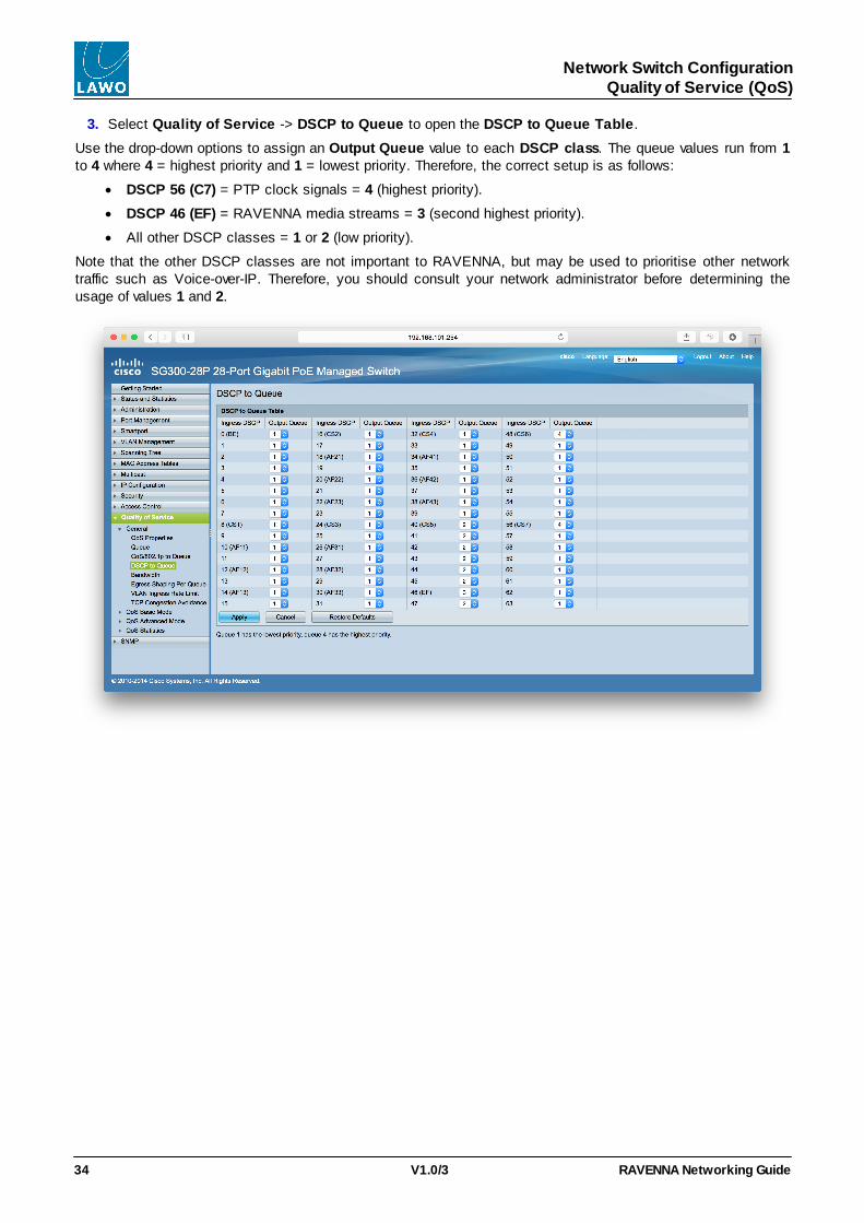
3. Select Quality of Service -> DSCP to Queue to open the DSCP to Queue Table.
Use the drop-down options to assign an Output Queue value to each DSCP class. The queue values run from 1to 4 where 4 = highest priority and 1 = lowest priority. Therefore, the correct setup is as follows:
· DSCP 56 (C7) = PTP clock signals = 4 (highest priority).
· DSCP 46 (EF) = RAVENNA media streams = 3 (second highest priority).
· All other DSCP classes = 1 or 2 (low priority).
Note that the other DSCP classes are not important to RAVENNA, but may be used to prioritise other networktraffic such as Voice-over-IP. Therefore, you should consult your network administrator before determining theusage of values 1 and 2.

RAVENNA Networking Guide V1.0/3 35
Network Switch ConfigurationQuality of Service (QoS)
4. Select QoS Advanced Mode -> Global Settings and set the Trust Mode = DSCP. This will ensure thatthe QoS uses the DSCP table values (entered in step 3):

RAVENNA Networking GuideV1.0/336
Network Switch ConfigurationSaving Changes
Saving Changes
When all changes have been made, remember to copy the Running configuration to the Startup configuration:

RAVENNA Networking Guide V1.0/3 37
Network Switch ConfigurationCopying Settings to another Network Switch
Copying Settings to another Network Switch
If you are creating a network with multiple switches, you can copy your final settings to another switch as follows:
1. Connect your service computer to the source switch.
2. Start the TFTP server tool and adjust the following settings:
· Current Directory - choose the directory where the TFTP backup files will be stored.
· Server interfaces - select the Network Interface Card (on your computer) which is connected to theCISCO switch. In our example, this is the NIC using the IP address of 192.168.1.101:

RAVENNA Networking GuideV1.0/338
Network Switch ConfigurationCopying Settings to another Network Switch
3. Leave the TFTP server tool running and select Administration -> Download/Backup Configuration on theCISCO switch GUI. Then adjust the following settings:
· Transfer Method = via TFTP
· Save Action = Backup
· TFTP Server Destination = By IP address (Version 4)
· TFTP Server IP Address/Name = enter the IP address of your TFTP server (this is the IP address of theServer interface selected in step 2 - in our example 192.168.1.101).
· Source File Type = Running configuration
· Destination File Name = enter a suitable file name - in our example, test.
4. Click on Apply - the current Running configuration is saved to the TFTP file. The file will be named test andis located in the directory selected on the TFTP server (during step 2).
5. Now connect your computer to the destination switch and repeat a similar procedure, but this time selectDownload as the Save Action (during step 3). The TFTP file will be downloaded from your computer to theswitch. The switch must then be rebooted.
Note that the switch should be disconnected from the rest of the network as the file will reset its IP address. (Ifboth the source and destination switches are connected to the network, then you will have an IP conflict.)
6. Reset the IP address of the destination switch, using the Administration -> Management Interface ->IPv4 Interface page.
7. Repeat steps 5 & 6 for the other switches in the RAVENNA network.

RAVENNA Networking Guide V1.0/3 39
Network Switch ConfigurationArista 7150S Example of PTP-aware Switch Configuration
Arista 7150S Example of PTP-aware Switch Configuration
In mc2/Nova73 systems, synchronisation of the RAVENNA streaming network requires a PTP master clocksource. In the current release, this takes the form of a specially configured DALLIS sync frame which convertsincoming Wordclock, from the master sync reference, to PTP.
In other Lawo systems, you should consider installing a PTP Grandmaster. Currently, Lawo recommends usingMeinberg clock generators.
As a result, you will require a PTP-aware switch with PTP enabled.
Below is an excerpt from the raw configuration file of a correctly configured Arista 7150S.
Here you can see that the PTP mode is enabled as "e2etransparent" (end-to-end transparent). You can also seethe IP address of the PTP master, and that each Ethernet interface is PTP-enabled:

RAVENNA Networking GuideV1.0/340
Appendices
Appendices
The following appendices cover additional information you may find useful:
· Running a PING Test
· The OSI Reference Model
· RAVENNA Streaming: a User's View

RAVENNA Networking Guide V1.0/3 41
AppendicesRunning a PING Test
Running a PING Test
The simplest way to check whether you have a valid network connection is run a PING test:
The PING command is a built-in Windows and Mac function, that allows you to test whether you have a validnetwork connection to and from any networked device.
1. Make sure that your computer is connected to the correct network port, and that you have configured theTCP/IP settings of your computer's network interface card.
2. On a Windows 7 PC, type cmd into the "Search programs and files" field under the Start menu andpress Enter.
This opens the DOS command prompt window:
Alternatively, on a Mac, open the Terminal program (found in the Applications -> Utilities folder).
3. On both platforms, perform the ping test as follows:
Type ping xxx.xxx.xxx.xx (where xx.. is the IP address of the device you are trying to connect to) and pressEnter.
For example, to test the connection to a mc256 control system (using its default IP address), you would type:
ping 192.168.102.56
Your computer will now try to establish communication...

RAVENNA Networking GuideV1.0/342
AppendicesRunning a PING Test
Ø Ping Test Fail
If the ping test fails, then the request will time out, and you will not receive any successful packets:
There is something wrong with your network configuration, so check the network connections, and TCP/IPsettings again. Or contact your network administrator.
Ø Ping Test Success
If the ping test is successful, then the result will show that the Sent packets have been successfully Received:
This confirms that the network communication is working. If you still cannot connect, then something on yourcomputer is blocking the network connection. Try disabling any firewall and/or antivirus software.

RAVENNA Networking Guide V1.0/3 43
AppendicesThe OSI Reference Model
The OSI Reference Model
The OSI (Open System Interconnection) Reference Model is a conceptual model that describes how differentdevices on a data network communicate with each other. Within the data networking industry, you will often findcomponents described according to the "layers" of the model - for example, a Layer 2 switch or Layer 3 router.The model is divided into seven layers:
Layer 1 is the Physical layer used for the connection - it describes the cable type (e.g. CAT 5 or fibre),connector type (e.g. RJ45), transmission speed (e.g. 1000BASE-TX), etc.
Layer 2 is the Data Link layer which describes the protocols required to transfer data between devices within thesame LAN. For example, this would describe your computer's network interface card or a Network Switch. Layer2 provides basic error correction and point-to-point communication, but is not yet IP. The most commonly usedData Link layer protocol is Ethernet.
Layer 3 is the Network layer which provides the functions and procedures to transfer data from one source inone network to a destination in different network. Network Routers operate at this layer and communicate via IP(Internet protocol).
Layers 4 to 7 are the application and protocol-based layers.
The first three layers are the most important for Audio-over-IP.

RAVENNA Networking GuideV1.0/344
AppendicesRAVENNA Streaming: a User's View
RAVENNA Streaming: a User's View
While the OSI reference model provides a technician's view of RAVENNA technology, this can be simplified intothe following end-user's view:
Layer 1 is the Audio Transport which is handled by the data network.
Layer 2 is the Virtual Patching which is handled in the background by the Zone Controller.
Layer 3 is the Signal Handling. In mc2/Nova73 systems, this is performed from the console or mxGUI via theSignal List display. In crystal and sapphire/Nova17, signal routing is usually defined by the zirkon configuration.
Layer 4 represents any automated or scripted applications which, in turn, control each of the lower layers.Examples of application in this layer are VisConNavigator and a VSM control system.

RAVENNA Networking Guide V1.0/3 45
Glossary
Glossary
1000 Base-T
1000 Base-SX
1000 Base-LX
Used in data networks to describe the Ethernet standard. The standard defines thenetwork speed, cable type and length.
For example, 1000 Base-T is a standard for Gigabit Ethernet over copper wiring. The1000 refers to the network speed (1000 Mbit/s), while the Base-T refers to the cabletype and length of connection (e.g. twisted pair CAT5, CAT5e, CAT6, CAT7, up to100m).
Other common Ethernet standards include 100 Base-TX (Fast Ethernet, twisted pairCAT 5, up to 100m), 1000 Base-SX (Gigabit Ethernet, multi-mode fibre, 220-550metres), 1000 Base-LX10 (Gigabit Ethernet, single-mode fibre, up to 10km), etc.
AoIP Audio-over-IP
Avahi A data network service (similar to Bonjour) that allows devices to publish and discovernodes running on a Local Area Network. Avahi is an example of a zeroconf (zero-configuration) networking implementation. Other zeroconf systems include Bonjour(licensed by Apple).
Buffer Size The buffer size sets the amount of data stored (in memory) before each data packet istransmitted or played out. In an audio system, the smaller the buffer size, the lowerthe latency, but the more susceptible to drop-outs.
COMi.MX The name of Lawo's RAVENNA processing hardware device. The COMi.MX forms asub component of most of Lawo's RAVENNA IO cards.
DALLIS Digital and Line Level Interface System.
The name of Lawo's configurable IO device. Each DALLIS frame can be fitted with acombination of plug-in IO cards (analogue, AES, MADI, RAVENNA, GPIO, etc.).
DHCP Dynamic Host Configuration Protocol
Commonly used in data networks to dynamically allocate IP addresses from a centralserver.
DSCP Differentiated Services Code Point
DSCP values are used within computer networks to classify and manage differenttypes of network traffic. For example, to provide low-latency for critical network trafficsuch as media streaming, while providing best-effort services to non-critical servicessuch as web traffic or file transfers. The default DSCP value for RAVENNA streams is46 (=EF); and for PTP is 56 (=CS7).
Ember+ A non-proprietary TCP/IP interface protocol. An Ember+ provider can "publish"parameters which may then be used by an Ember+ consumer. For example, todisplay information or enable control from a remote device.
Fast Leave An option often supported by IGMP network switches, which allows the switch todetermine when an output port has left a Multicast group. If this option is not enabled,then Multicast traffic can flood the output port continuously. See IGMP.
HPET High Precision Event Timer
A high precision clock reference provided by your PC. It is required for properRAVENNA timing with a JADE PC.
HTTP Hypertext Transfer Protocol
A networking protocol/URL address, commonly used to exchange or transfer webpages, email, etc.
IGMP Internet Group Management Protocol
A communications protocol used by adjacent switches/routers on a network toestablish Multicast group memberships.

RAVENNA Networking GuideV1.0/346
Glossary
IGMP Querying/Snooping is a technique used by network switches to control theforwarding of Multicast data packets. A switch with IGMP Querying/Snooping willforward Multicast data packets only to the ports that are members of the Multicastgroup. Whereas, a switch without IGMP Querying/Snooping will broadcast Multicastdata to all of its output ports. As a result, the volume of Multicast traffic will besignificantly reduced if a network switch supports IGMP Querying/Snooping.
IP Address Internet Protocol address.
All devices connected to a data network must have a unique IP address. In IPv4, a 32-bit number is used and a typical address looks like this: 192.168.101.240. In IPv6, a128-bit number is used. In the current RAVENNA release, IPv6 is not supported.
In IPv4, subnets are used to divide the IP address range. For example, a subnet maskof 255.255.255.0 effectively filters the first three fields of the address. So, providing thesubnet masks match, a device with an IP address = 192.168.101.xxx cancommunicate with another device using an IP address = 192.168.101.xxx (where xxxis a unique number between 1 and 254) without any further configuration or routing.Note that an IPv4 address range runs from 0 to 255. However, .0 is usually reserved foruse as a gateway and .255 as a broadcast address (by network switches). Therefore,it is a good idea to avoid these numbers.
IPv4 Internet Protocol Version 4 - see IP Address.
IPv6 Internet Protocol Version 6 - see IP Address.
LAN Local Area Network
A data network that interconnects devices within a small geographic area (e.g. ahome, school or office building). LANs differ from WANs (Wide Area Networks) in thatthey do not require leased telecommunications lines (i.e. there is no need for anexternal service provider).
Latency The amount of time delay between an audio signal entering and emerging from asystem.
Layer 2/3 See Network Switch.
Multicast In a multicast data network, data is copied and distributed by the network switch/router. This means that packets sent from a single device can be received by multiplenodes at the same time (i.e. one to many). This differs from a unicast data networkwhere data packets are addressed to a single receiving node (i.e. one to one).
Network Router See Network Switch.
Network Switch A device used in data networks to interconnect multiple nodes. A Layer 2 networkswitch conforms to the OSI Layer 2 model, meaning that they can handle the physicaland data link layers (i.e. cabling and basic packet transmission). This differs from aLayer 3 network router which also handles the network layer (i.e. it can redirectnetwork packets).
NIC Network Interface Card
A computer interface that connects to external network devices.
Nova73 A stand alone routing matrix with networking capabilities; this is a large matrix related
to the mc2 series of Lawo consoles.
PTP Precision Time Protocol.
An ultra-precise, Synchronization method used in data networks. The PTPv2 protocolcan be used as the sync reference for all RAVENNA devices in a network.
QoS Quality of Service
The QoS defines the overall performance of a computer network. Several factors areconsidered: error rates, bandwidth, throughput, transmission delay, availability, jitter,etc. See also DSCP.

RAVENNA Networking Guide V1.0/3 47
Glossary
RAVENNA A real-time, network-synchronised Audio over IP protocol.
RAVENNA offers real-time distribution of audio and other media content within IP-based network environments.
Remote MNOPL The remote control protocol RemoteMNOPL is a LAN based client-server network byteorder protocol to enable third party systems to control Lawo’s digital mixing consolesor standalone routers.
RTP Real-time Transport Protocol
A networking protocol that defines a standard packet format for delivering audio andvideo over data networks.
RTCP Real-time Transport Control Protocol
Works in conjunction with RTP. While RTP carries the media streams (audio andvideo), RTCP is used to monitor the transmission statistics and Quality of Service(QoS).
RTSP Real-time Transport Streaming Protocol
A networking protocol/URL address, commonly used in establishing point-to-pointmedia sessions.
Sample Rate The speed at which the Processing of the system takes samples respective to valuesfrom a continuous, analogue audio signal to make a discrete, digital one. Forexample, when running at 48kHz, incoming analogue audio is sampled at a rate of48000 values per second.
SFP Small Form-factor Pluggable transceiver.
A hot-pluggable device which can be used to offer a choice of connection methods -e.g. multi-mode fibre, single-mode fibre, etc.
SIP Session Initiation Protocol
A networking protocol/URL address, commonly used within Voice-over-IP systems.
Subnet See IP Address.
TDM Time-Division Multiplexing
A common method of transporting signals via a point-to-point connection. In Lawodevices, TDM is used internally to transport audio along the backplane - e.g. from a IOor DSP card to the routing matrix, and vice versa.
TTL Time to Live
A mechanism that limits the lifespan of data within a computer network, in order toprevent data packets from circulating indefinitely.
UDP User Datagram Protocol
A simple connection-less networking protocol which is often used in real-timeapplications due to its low latency. UDP is suitable for purposes where error checkingand correction are either not necessary or performed in the application.
URL Uniform Resource Locator
A networking term for specifying the location of a resource on a computer network.URL types include http, rtsp and sip.
vLAN virtual Local Area Network
A tool supported by some network switches/routers to separate network traffic"virtually" when connected to the same physical LAN.
WAN Wide Area Network
A data network that covers a broad area (e.g. linking regional, national or internationalboundaries) using leased telecommunications lines (i.e. supported by a servicecontract from an external provider).


![M. David, "I dittici 'cuspidati' e gli strumenti della propaganda di Stato nel Mediterraneo del V secolo", in Felix Ravenna, CLVII-CLX, 2001-2004 [2010], pp. 35-55.](https://static.fdokumen.com/doc/165x107/6335ecafcd4bf2402c0b4abc/m-david-i-dittici-cuspidati-e-gli-strumenti-della-propaganda-di-stato-nel-mediterraneo.jpg)

