Radiological validation of a fluoroscopic guided technique for femoral implant positioning during...
10
1 23 !" #$%& #& '( ) *+" !" # $! %%
-
Upload
independent -
Category
Documents
-
view
0 -
download
0
Transcript of Radiological validation of a fluoroscopic guided technique for femoral implant positioning during...

1 23
��������� ��������������������� ���������������������������������������� �!"�#��$�%&#���&��' �� ()�����*����+"��� ����������
��������� ������������������������������������������������������������������������������������
���������� �������������������� ����������������������������������������� �!��"��� ��#�$���!������%% ��

1 23
Your article is protected by copyright andall rights are held exclusively by Springer-Verlag Berlin Heidelberg. This e-offprint isfor personal use only and shall not be self-archived in electronic repositories. If youwish to self-archive your work, please use theaccepted author’s version for posting to yourown website or your institution’s repository.You may further deposit the accepted author’sversion on a funder’s repository at a funder’srequest, provided it is not made publiclyavailable until 12 months after publication.

ORIGINAL PAPER
Radiological validation of a fluoroscopic guided techniquefor femoral implant positioning during hip resurfacing
Philippe Chiron & Régis Pailhé & Nicolas Reina &
David Ancelin & Akash Sharma & Laurent Maubisson &
Jean-Michel Laffosse
Received: 29 October 2012 /Accepted: 4 January 2013 /Published online: 29 January 2013# Springer-Verlag Berlin Heidelberg 2013
AbstractPurpose The positioning of the femoral cup in hipresurfacing is essential for the survival of the implant.We described a technique in 2005 to position the femoralcup guided by fluoroscopy independent of the approach per-formed. The main objectives were to study the positioning ofthe femoral components of the implant and the accuracy of thetechnique.Methods Between 2003 and 2011 we conducted a prospec-tive study of 160 consecutive hip resurfacings all operatedwith this fluoroscopic-guided technique. Three independentobservers performed a radiographic analysis at thepre-operative planning stage and on postoperative radio-graphs using OsiriX software. The statistical analysis wasbased on comparison of two groups by Student’s t test.Results The entire implant was positioned in valgus, with anaverage of 7.816° valgus (p <0.001). All implants were posi-tioned in neutral or anteverted with a mean of 1.98°(p <0.001). The risk of malpositioning on the antero-posteriorplane was less than 1.41° with p <0.019. The risk of profilepositioning error was lower than 0.80° with p <0.047.
Conclusion This study validates a technique of femoralimplant positioning for resurfacing. It is simple, preciseand independent of the approach performed.
Introduction
Correct positioning of the femoral implant in hip resur-facing arthroplasty is essential for the survival of a hipreplacement and for good functional results. An excessof varus or valgus position can cause femoral head fracture[1, 2]. Depending on the series, this type of complica-tion varies from 0 % to 17 % [3]. We described atechnique in 2005 [4] for positioning the femoral cupguided by fluoroscopy and independent of the surgicalapproach chosen.
Our null hypothesis stated that with our technique offemoral implant positioning, we could reproducibly andaccurately put the femoral implants in the position chosenduring the pre-operative planning.
To test this hypothesis, we defined two main objectives—to determine the correct positioning of the femoral implantand to study the accuracy of the technique to reproduce thepre-operative planning.
Material and methods
Material
Institutional review board approval was obtained prior to theinitiation of the study.
Between 2003 and 2011 we conducted a single centreprospective study on 160 cases of hip resurfacing (BHR®Smith&Nephew,Memphis, Tennessee and Durom®Zimmer,Warsaw, Indiana) performed consecutively.
P. Chiron :R. Pailhé :N. Reina :D. Ancelin : L. Maubisson :J.-M. LaffosseThe Service de Chirurgie Orthopédique et de Traumatologie,Centre Hospitalier Universitaire de Rangueil, Toulouse, France
R. Pailhé :A. SharmaThe Royal Orthopaedic Hospital, Birmingham, UK
R. Pailhé (*)Service de Chirurgie Orthopédique, Hôpital Rangueil, 1,avenue du Pr Jean Poulhès, TSA 50032,31059 Toulouse Cedex, Francee-mail: [email protected]
R. Pailhée-mail: [email protected]
International Orthopaedics (SICOT) (2013) 37:361–368DOI 10.1007/s00264-013-1777-9
Author's personal copy

Our inclusion criteria were: patients with primary orsecondary osteoarthritis, regardless of aetiology, orosteonecrosis of a volume less than 30 % of the femoralhead, age <65 years for men and <60 years for womenwithout major morphological abnormalities of the upper endof the femur or acetabulum, good bone quality, absence ofhistory of allergy to nickel. Women of childbearing agewere excluded.
The average age of patients at surgery was 46.8 years ±7.2 years with a minimum age of 37 years and maximum60 years. Patients were predominantly males with a 95 %male dominance and a ratio of 20 to one.
Etiological distribution showed 76.8 % (123 patients) werecoxa-arthrosis cases: primitive in 58.6 % (72 patients), sec-ondary to epiphysiolysis in 27.6 % (34 patients), secondary tofemoro-acetabular impingement in 13.8 % (17 patients), andaseptic osteonecrosis of the femoral head in 23.2 % of cases(37 patients).
Surgical technique
Planning was made according to the following criteria: animplant should be in valgus < 10°, its stem parallel to thelongitudinal trabecular system, and it should avoid notchingthe supero-lateral neck. It should be centred in the neck onfrog-leg views. The correct positioning of the femoral cup wasassessed on an antero-posterior pelvis radiograph with a fem-oral internal rotation of 10° and on a lateral radiograph of hipwith 45° of flexion, 45° of abduction, and 30° of externalrotation [5]. The axis of the stem corresponded to the axis ofthe guide pin. The entry point on the of the upper end side ofthe femur was identified in relation to the position of the lessertrochanter (high - medium - low). The exit point of the pin atthe top of the head was also identified.
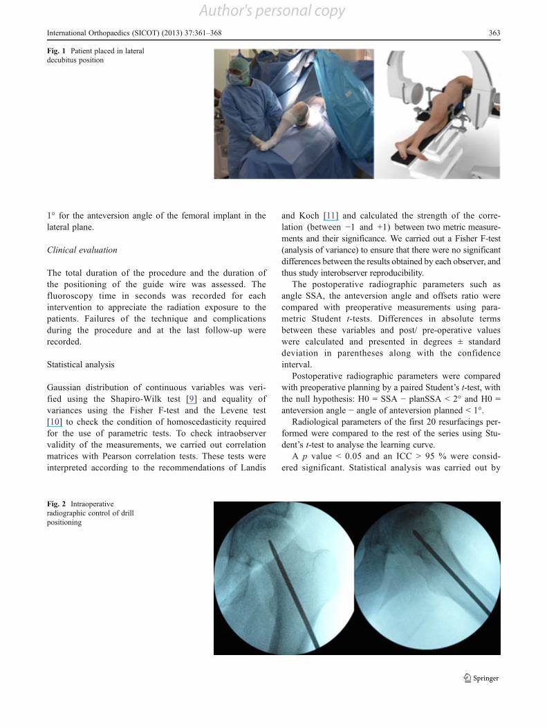
On a technical aspect, the patient in the operating room wasplaced in a lateral position, with the image intensifier posi-tioned perpendicular to the patient from above. In this config-uration, it was possible to obtain a radiograph of the hip withinternal rotation of 10° and a position of 45° flexion, 45°abduction, and 30° external rotation without moving the imageintensifier (Figs. 1 and 2). The entry point of the pin wasmarked using a metallic marker and an image intensifier. A1 cm skin incision was made 2 cm below the point marked forthe insertion of the pin in the centre of the femur in theanteroposterior plane. The soft tissues were bluntly dissecteduntil the femur was exposed. An oblique hole was drilled in theaxis of the neck with a 4.5-mm diameter drill. This drill wasdirected, under the control of successive radiographs (Fig. 2),until the subchondral bone of the head was breached. The drillwas then removed and replaced with a single guide pin. Guidedby this pin, a canulated drill corresponding to the diameter ofthe guide bar was used. This allowed the drill to guide a tunnelin the desired axis. Breaching of the subchondral bone and
cartilage was the endpoint and was performed under imageintensifier.
Whichever approach was used, we found it possible afterthe hip was dislocated to position the guide bar and to finishthe preparation of the femoral head with the appropriatereamers and jigs without the need for an image intensifier.
In our series, we used a minimally invasive anterolateralapproach which preserved both the muscles and vascularityof the femoral head.
Methods
Radiographic evaluation
Three independent observers performed double-blinded, ran-domized analysis of the radiographs at an interval oftwo weeks. All radiological parameters were studied usingOsiriX software (OsiriX, Switzerland) [6] after calibration onanteroposterior digital pelvic radiographs with the hip in 20°internal rotation and on lateral hip radiographs such as thefrog-leg 45/45/30 view [5]. Conforming with strict qualitycriteria was required, and this was verified before any hipmeasurements were performed, since even a minimal changein rotation leads to major differences in measurement [7].
On pre-operative radiographs and planned radiographsthe following parameters were studied: the neck-shaft angle(NSA), the planned stem-shaft angle (planSSA), and theplanned anteversion angle of the implant stem in relation tothe axis of the neck.
On postoperative radiographs, the following parameterswere studied: the stem-shaft angle (SSA); superior andinferior offset, which ratio was used to evaluate anteriorcentring of the implant; the anteversion angle of the implantstem in relation to the axis of the neck; anterior and posterioroffset, of which the ratio was used to evaluate the lateralcentring of the implant; the presence of supero-lateral notch-ing of the femoral neck; and leg length discrepancies withthe tear drop line method [8] (Figs. 3 and 4).
To verify our null hypothesis, we defined two mainobjectives. The first one was to assess the correct position-ing of the femoral implants according to the followingcriteria: the implant positioned in valgus (<10°) (not invarus), the stem parallel to the longitudinal trabeculae andwithout notching of the supero-lateral cortices of the femo-ral neck. The leg-length discrepancy should be less than5 mm. It should also be centred in the axis of the neck on afrog-leg lateral view.
The second objective was to study the accuracy of thetechnique which was defined by a difference in positioningof the femoral implant compared to preoperative planningon lateral and antero-posterior (AP) radiographs; it shouldbe less than a 2° angle for the SSA angle which evaluatedthe orientation of the implant in the AP plane, and less than
362 International Orthopaedics (SICOT) (2013) 37:361–368
Author's personal copy
1° for the anteversion angle of the femoral implant in thelateral plane.
Clinical evaluation
The total duration of the procedure and the duration ofthe positioning of the guide wire was assessed. Thefluoroscopy time in seconds was recorded for eachintervention to appreciate the radiation exposure to thepatients. Failures of the technique and complicationsduring the procedure and at the last follow-up wererecorded.
Statistical analysis
Gaussian distribution of continuous variables was veri-fied using the Shapiro-Wilk test [9] and equality ofvariances using the Fisher F-test and the Levene test[10] to check the condition of homoscedasticity requiredfor the use of parametric tests. To check intraobservervalidity of the measurements, we carried out correlationmatrices with Pearson correlation tests. These tests wereinterpreted according to the recommendations of Landis
and Koch [11] and calculated the strength of the corre-lation (between !1 and +1) between two metric measure-ments and their significance. We carried out a Fisher F-test(analysis of variance) to ensure that there were no significantdifferences between the results obtained by each observer, andthus study interobserver reproducibility.
The postoperative radiographic parameters such asangle SSA, the anteversion angle and offsets ratio werecompared with preoperative measurements using para-metric Student t-tests. Differences in absolute termsbetween these variables and post/ pre-operative valueswere calculated and presented in degrees ± standarddeviation in parentheses along with the confidenceinterval.
Postoperative radiographic parameters were comparedwith preoperative planning by a paired Student’s t-test, withthe null hypothesis: H0 = SSA ! planSSA < 2° and H0 =anteversion angle ! angle of anteversion planned < 1°.
Radiological parameters of the first 20 resurfacings per-formed were compared to the rest of the series using Stu-dent’s t-test to analyse the learning curve.
A p value < 0.05 and an ICC > 95 % were consid-ered significant. Statistical analysis was carried out by
Fig. 1 Patient placed in lateraldecubitus position
Fig. 2 Intraoperativeradiographic control of drillpositioning
International Orthopaedics (SICOT) (2013) 37:361–368 363
Author's personal copy
an independent statistician using EXCEL (Microsoft Inc,Redmond, WA) and SPSS software (SPSS Inc, Chicago, IL).
Results
Positioning of the femoral implant
In comparison to the preoperative neck-shaft angle NSA, the valueof the angle of the implant stem-shaft postoperative SSA showedan increase of 7.816° ± 4.85 (5.29–10.34; p <0.001). All theimplants were positioned in valgus and always inferior than 11°.
The anteversion angle of the implant relative to the axisof the neck averaged 1.98° ± 1.68 (1.43–2.55; p <0.001). All
implants were positioned in neutral or anteverted with aminimum angle of 0° and 5° max.
The ratio of vertical offset averaged 0.90 ± 0.44(0.76–1.05; p <0.001). The horizontal offset ratio aver-aged 0.92 ± 0.28 (0.82–1.01; p <0.001). None of theimplants demonstrated supero-lateral notching of thefemoral neck. Mean lengthening was 1.5 mm (!6, 8.5)(p <0.001).
Accuracy of the technique
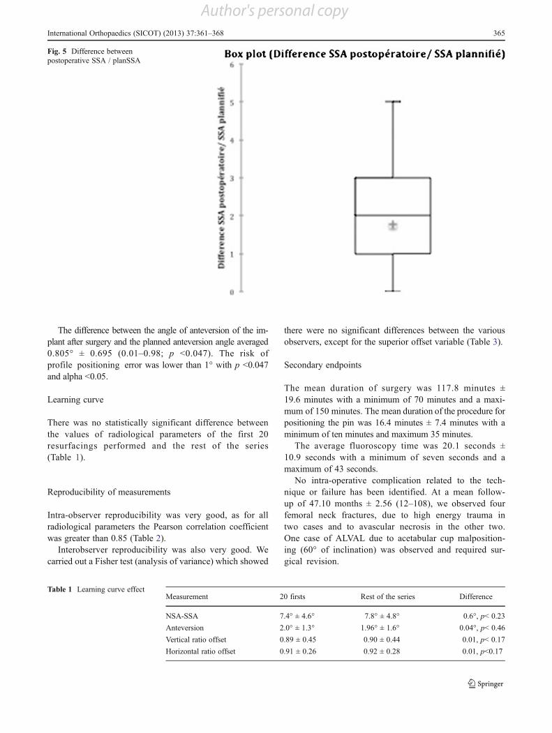
Comparison between the measurements of the postoperativeangle SSA and SSA planned angle showed a mean differenceof 1.41° ± 1.3 (0.12–1.87; p <0.019; Fig. 5).
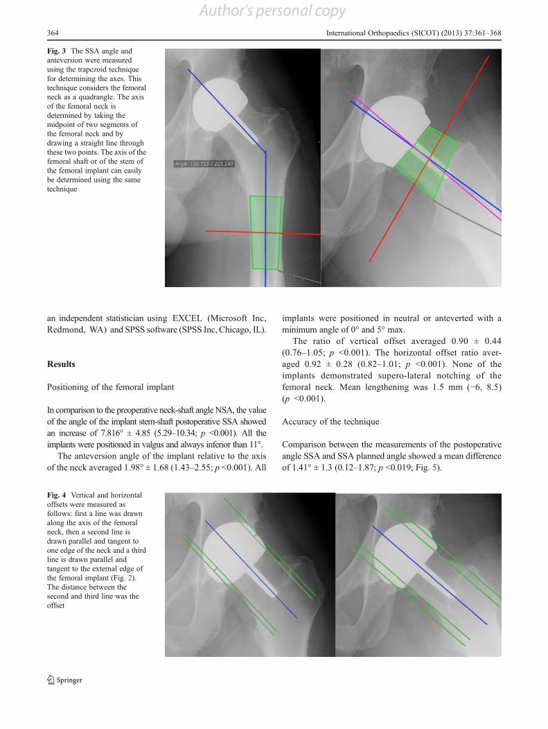
Fig. 3 The SSA angle andanteversion were measuredusing the trapezoid techniquefor determining the axes. Thistechnique considers the femoralneck as a quadrangle. The axisof the femoral neck isdetermined by taking themidpoint of two segments ofthe femoral neck and bydrawing a straight line throughthese two points. The axis of thefemoral shaft or of the stem ofthe femoral implant can easilybe determined using the sametechnique
Fig. 4 Vertical and horizontaloffsets were measured asfollows: first a line was drawnalong the axis of the femoralneck, then a second line isdrawn parallel and tangent toone edge of the neck and a thirdline is drawn parallel andtangent to the external edge ofthe femoral implant (Fig. 2).The distance between thesecond and third line was theoffset
364 International Orthopaedics (SICOT) (2013) 37:361–368
Author's personal copy
The difference between the angle of anteversion of the im-plant after surgery and the planned anteversion angle averaged0.805° ± 0.695 (0.01–0.98; p <0.047). The risk ofprofile positioning error was lower than 1° with p <0.047and alpha <0.05.
Learning curve
There was no statistically significant difference betweenthe values of radiological parameters of the first 20resurfacings performed and the rest of the series(Table 1).
Reproducibility of measurements
Intra-observer reproducibility was very good, as for allradiological parameters the Pearson correlation coefficientwas greater than 0.85 (Table 2).
Interobserver reproducibility was also very good. Wecarried out a Fisher test (analysis of variance) which showed
there were no significant differences between the variousobservers, except for the superior offset variable (Table 3).
Secondary endpoints
The mean duration of surgery was 117.8 minutes ±19.6 minutes with a minimum of 70 minutes and a maxi-mum of 150 minutes. The mean duration of the procedure forpositioning the pin was 16.4 minutes ± 7.4 minutes with aminimum of ten minutes and maximum 35 minutes.
The average fluoroscopy time was 20.1 seconds ±10.9 seconds with a minimum of seven seconds and amaximum of 43 seconds.
No intra-operative complication related to the tech-nique or failure has been identified. At a mean follow-up of 47.10 months ± 2.56 (12–108), we observed fourfemoral neck fractures, due to high energy trauma intwo cases and to avascular necrosis in the other two.One case of ALVAL due to acetabular cup malposition-ing (60° of inclination) was observed and required sur-gical revision.
Fig. 5 Difference betweenpostoperative SSA / planSSA
Table 1 Learning curve effectMeasurement 20 firsts Rest of the series Difference
NSA-SSA 7.4° ± 4.6° 7.8° ± 4.8° 0.6°, p< 0.23
Anteversion 2.0° ± 1.3° 1.96° ± 1.6° 0.04°, p< 0.46
Vertical ratio offset 0.89 ± 0.45 0.90 ± 0.44 0.01, p< 0.17
Horizontal ratio offset 0.91 ± 0.26 0.92 ± 0.28 0.01, p<0.17
International Orthopaedics (SICOT) (2013) 37:361–368 365
Author's personal copy

Discussion
Our series statistically confirms and allows us to validate theaccuracy and reliability of the technique for placement ofthe femoral implants. The results of this study also highlightthe excellent intra-observer reproducibility and interobserv-er measurement of radiographic parameters to assess thepositioning of a resurfacing implant. Indeed intraobserverreproducibility for the Spearman correlation coefficient r
was whatever the parameters studied and whatever the ob-server averaged 0.913 (0.754 min – max 0.993). The inter-observer study by analysis of variance highlighted excellentreproducibility since no significant difference could bedetected except for the measurement of superior offset.
Furthermore, this study did not assess the intra and inter-operator reproducibility. However, the results did includethe learning curve of this technique. The results of the first20 resurfacings were compared to the rest of the series and
Table 2 Intraobserver reproducibility measured by Pearson’s correlation coefficient and the corresponding P value
Observer Parameter SSA Offset > Offset < Anteversion Anterior offset Posterior offset
Obs 1 r 0.991** 0.872** 0.976** 0.993** 0.594 0.943**
P 0.000 0.000 0.000 0.000 0.054 0.000
Obs 2 r 0.965** 0.754** 0.965** 0.942** 0.923** 0.975**
P 0.000 0.007 0.000 0.000 0.000 0.000
Obs 3 r 0.951** 0.963** 0.877** 0.827** 0.948** 0.972**
P 0.000 0.000 0.000 0.002 0.000 0.000
Mean r 0.969 0.863 0.939 0.920 0.821 0.963
* Significant result
Table 3 Interobserver reproducibility measured by analysis of variance using the Fisher F-test
Observer Measure Femoral implantdiameter (mm)
SSA Offset > Offset < Anteversion Anterior offset Posterior offset
First analysis
Observer 1 Mean 47.273 141.648 0.531 0.591 7.436 0.597 0.707
Standard deviation 2.87 4.89 0.08 0.18 5.71 0.16 0.23
Observer 2 Mean 47.273 141.011 0.667 0.655 8.551 0.659 0.770
Standard deviation 2.87 4.83 0.18 0.24 5.26 0.22 0.24
Observer 3 Mean 47.273 142.556 0.459 0.560 6.928 0.579 0.581
Standard deviation 2.87 5.08 0.12 0.16 3.04 0.15 0.14
Total Mean 47.273 141.738 0.552 0.602 7.638 0.612 0.686
Standard deviation 2.78 4.82 0.16 0.20 4.71 0.18 0.22
F 0.000 0.272 6.938 0.673 0.327 0.595 2.318
P 1.000 0.763 0.003 0.518 0.724 0.558 0.116
Significance ns ns sig. ns ns ns ns
Second analysis
Observer 1 Mean 47.273 141.869 0.551 0.603 7.161 0.544 0.800
Standard deviation 2.87 4.59 0.09 0.19 5.25 0.22 0.32
Observer 2 Mean 47.273 141.982 0.582 0.625 7.975 0.663 0.769
Standard deviation 2.87 4.71 0.13 0.19 4.73 0.28 0.26
Observer 3 Mean 47.273 142.759 0.447 0.579 6.032 0.620 0.679
Standard deviation 2.87 5.03 0.13 0.15 3.63 0.20 0.19
Total Mean 47.273 142.203 0.526 0.602 7.056 0.609 0.749
Standard deviation 2.78 4.65 0.13 0.18 4.52 0.23 0.26
F 0.000 0.113 3.700 0.179 0.497 0.720 0.644
P 1.000 0.893 0.037 0.837 0.613 0.495 0.532
Significance ns ns sig. ns ns ns ns
ns not significant, sig. significant
366 International Orthopaedics (SICOT) (2013) 37:361–368
Author's personal copy

showed no statistically significant difference. In other words,even when the operator was untrained, this technique gavereliable and reproducible results. These results are encouragedby those of Hurst and Millett [12].
The assessment of positioning of the implant on usingradiographs could be criticised; nonetheless, Olsen reportedgood intra and interobserver reproducibility when measur-ing the SSA angle [13]. In fact, a three-dimensional CTevaluation would have been of preference to assess preciselythe correct positioning of implants. However, because of thestringent radiological quality criteria selected, we had aradiological analysis with very good intra and interobserverreproducibility.
In our series we chose to position the femoral implants invalgus parallel to the longitudinal axis of the trabeculae.Many studies have confirmed the importance of this forimplant positioning [14, 15]. In an anatomical and biome-chanical study, Freeman et al. [16] highlighted that thecompressive strength of the femoral head depends on themedial trabecular system which runs through the head atapproximately 20° to the vertical plane. Long et al. [17]conducted a finite element analysis of the effects of femoralimplant positioning, which found a significant decrease inthe risk of loosening and fracture, with valgus positioning ofthe implants. In addition to those ex-vivo studies, manyclinical studies have shown the importance for the futureof the resurfaced hip in accordance with the valgus posi-tioning of femoral implant and absence of supero lateralfemoral neck notching [1, 15, 18]. The correct positioningis essential but remains a difficult task even for experiencedsurgeons [19].
Many techniques have been developed to shorten thelearning curve for surgeons and improve the ease and accu-racy of femoral implant placement [20]. The work done onmany navigation systems “free image” or systems-based onCT tend to show a decrease in the learning curve and a betterpositioning of the implants. Seyler, in a study comparing theaccuracy of implantation of femoral components based onthe experience of the surgeon, found an average accuracycompared to the planned angle SSA of 0.9–1.5 ° (p <0.17)[21]. Ganapathi et al. found a difference of position withnavigation less than 1° compared to planning in a retrospec-tive study comparing 51 hips operated with navigation and88 by the conventional technique [22]. These results arecomparable to those of our technique and in some caseseven better.
Our technique has the advantage of positioning the fem-oral implant without influencing the surgical approach to hipresurfacing. Indeed, even if Myers et al. [23] and McBrydeet al. [24] suggest that the surgical approach slightly modi-fies the position of the femoral implant and survival, it is vitalfor the surgeon to preserve the vascularity of the femoral headand neck [25].
Conclusion
This study validates a technique for resurfacing femoralimplant positioning which is simple, accurate, independentof the approach, and does not require heavy physicallogistics.
Conflict of interest None.
References
1. De Haan R, Campbell PA, Su EP, De Smet KA (2008) Revision ofmetal-on-metal resurfacing arthroplasty of the hip: the influence ofmalpositioning of the components. J Bone Joint Surg Br 90(9):1158–1163
2. Kim PR, Beaulé PE, Laflamme GY, Dunbar M (2008) Causes ofearly failure in a multicenter clinical trial of hip resurfacing. JArthroplast 23(6 Suppl 1):44–49
3. Pailhé R, Sharma A, Reina N, Cavaignac E, Chiron P, Laffosse J-M(2012) Hip resurfacing: a systematic review of literature. Int Orthop36(12):2399–2410
4. Chiron P (2005) Use of a guide wire in hip resurfacing arthro-plasty. Osteologie 14(suppl 2):65–67
5. Cavaignac E, Chiron P, Espié A, Reina N, Lepage B, Laffosse J-M(2012) Experimental study of an original radiographic view fordiagnosis of cam-type anterior femoroacetabular impingement. IntOrthop 36(9):1783–1788
6. Rosset A, Spadola L, Ratib O (2004) OsiriX: an open-sourcesoftware for navigating in multidimensional DICOM images. JDigit Imaging 17(3):205–216
7. Tannast M, Zheng G, Anderegg C, Burckhardt K, Langlotz F,Ganz R, Siebenrock KA (2005) Tilt and rotation correction ofacetabular version on pelvic radiographs. Clin Orthop Relat Res438:182–190
8. Sayed-Noor ASA, Hugo AA, Sjödén GOG, Wretenberg PP (2009)Leg length discrepancy in total hip arthroplasty: comparison of twomethods of measurement. CORD Conf Proc 33(5):1189–1193
9. Royston P (1991) Estimating departure from normality. Stat Med10(8):1283–1293
10. Won S, Morris N, Lu Q, Elston RC (2009) Choosing an optimalmethod to combine P-values. Stat Med 28(11):1537–1553
11. Landis JR, Koch GG (1977) The measurement of observer agree-ment for categorical data. Biometrics 33(1):159–174
12. Hurst JM, Millett PJ (2010) A simple and reliable technique forplacing the femoral neck guide pin in hip resurfacing arthroplasty.J Arthroplast 25(5):832–834
13. Olsen M, Gamble P, Chiu M, Tumia N, Boyle RA, Schemitsch EH(2010) Assessment of accuracy and reliability in preoperativetemplating for hip resurfacing arthroplasty. J Arthroplast 25(3):445–449
14. Beaulé PE, Lee JL, Le Duff MJ, Amstutz HC, Ebramzadeh E(2004) Orientation of the femoral component in surface arthro-plasty of the hip. A biomechanical and clinical analysis. J BoneJoint Surg Am 86-A(9):2015–2021
15. Richards CJ, Giannitsios D, Huk OL, Zukor DJ, Steffen T, AntoniouJ (2008) Risk of periprosthetic femoral neck fracture after hip resur-facing arthroplasty: valgus compared with anatomic alignment. Abiomechanical and clinical analysis. J Bone Joint Surg Am 90(Supplement 3):96–101
International Orthopaedics (SICOT) (2013) 37:361–368 367
Author's personal copy

16. Freeman MA (1978) Some anatomical and mechanical consider-ations relevant to the surface replacement of the femoral head. ClinOrthop Relat Res 134:19–24
17. Long JP, Bartel DL (2006) Surgical variables affect the me-chanics of a hip resurfacing system. Clin Orthop Relat Res453:115–122
18. Laffosse JM, Aubin K, Lavigne M, Roy A, Vendittoli PA (2011)Radiographic changes of the femoral neck after total hip resurfacing.Orthop Traumatol Surg Res 97(3):229–240
19. Steffen R-T, Foguet PR, Krikler SJ, Gundle R, Beard DJ, MurrayDW (2009) Femoral neck fractures after hip resurfacing. J Arthro-plast 24(4):614–619
20. Witjes S, Smolders JMH, Beaulé PE, Pasker P, van Susante JLC(2009) Learning from the learning curve in total hip resurfacing: aradiographic analysis. Arch Orthop Trauma Surg 129(10):1293–1299
21. Seyler TM, Lai LP, Sprinkle DI, Ward WG, Jinnah RH (2008)Does computer-assisted surgery improve accuracy and decreasethe Learning curve in hip resurfacing? A radiographic analysis. JBone Joint Surg Am 90(Supplement 3):71–80
22. Ganapathi M, Vendittoli P-A, Lavigne M, Günther K-P (2009)Femoral component positioning in hip resurfacing with and with-out navigation. Clin Orthop Relat Res 467(5):1341–1347
23. Myers GJC, Morgan D, Mcbryde CW, O’Dwyer K (2009) Doessurgical approach influence component positioning with Birming-ham hip resurfacing? Int Orthop 33(1):59–63
24. McBryde CW, Revell MP, Thomas AM, Treacy RB, Pynsent PB(2008) The influence of surgical approach on outcome in Birminghamhip resurfacing. Clin Orthop Relat Res 466(4):920–926
25. Hananouchi T, Nishii T, Lee SB, OhzonoK, YoshikawaH, SuganoN(2009) The vascular network in the femoral head and neck after hipresurfacing. J Arthroplast 25(1):146–151
368 International Orthopaedics (SICOT) (2013) 37:361–368
Author's personal copy