radiative capture of polarized neutrons by aluminium and ...
65
JULY 1979 RADIATIVE CAPTURE OF POLARIZED NEUTRONS BY ALUMINIUM AND MANGANESE NUCLEI BY P.P.J. DELHEIJ
-
Upload
khangminh22 -
Category
Documents
-
view
5 -
download
0
Transcript of radiative capture of polarized neutrons by aluminium and ...

JULY 1979
RADIATIVE CAPTURE OF POLARIZED NEUTRONS BY ALUMINIUM AND MANGANESE NUCLEI
BY
P.P.J. DELHEIJ

ECN dots not assume any liability with respect
to the use of, or for damages resulting from
the use of any information, apparatus, method
or process disclosed in this document.
Netherlands Energy Research Foundation ECN
P.O. Box 1
1755 ZG Petten (NHI
The Netherlands
Telephone (0)2246 - 6:62
Telex 57211

JULV1t7»
RADIATIVE CAPTURE OF POLARIZED NEUTRONS
BY ALUMINIUM AND MANGANESE NUCLEI
P.P.J. DCLHEIJ

Delheij, P.P.J. ECM-62
RADIATIVE CAPTURE OF POLARIZED NEUTRONS BY ALUMINIUM AND MANGANESE
NUCLEI.
Petten, ECN-FOM Nuclear Structure Gro-tp, Netherlands Energy Research
Foundation ECN. 1979, July.
59 pages, 18 figures, 6 tables.
The angular distribution of the intensity is calculated for primary
and secondary gamma-rays eaitted after polarized neutron capture in
a polarized target. Also the circular polarization is derived for
capture of polarized neutrons by unoriented nuclei. Interference be
tween the reaction channels and all possible dipole/quadrupole mixing
is taken into account. Some aspects of p-wave capture and s-p inter
ference are discussed. The results of these calculations are applied
to the experiments on aluminium and manganese. In the nuclear orien
tation experiment with aluminium a "brute force" polarized target
was used. For five levels in 28A1 the spin *alue could be determined
uniquely. No evidence for significant M2/E1 mixing is found. A ferro
magnetic MnSb sample was used to polarize the manganese nuclei.
Unique spin values are assigned to 13 states in 56Mn. The magnetic
hyperfine field on the Mn nuclei is determined to be negative.
Keywords:
POLARIZED TARGETS MULTIPOLE TRANSITIONS
CAPTURE ALUMINIUM 27 TARGET
GAMMA RADIATION ALUMINIUM 28
ORIENTED NUCLEI MANGANESE 55 TARGET
ANGULAR DISTRIBUTION MANGANESE 56
SPIN NEUTRON REACTIONS

- 1 -
CONTENTS
INTRODUCTION
ÏBSË.
CHAPTER I ANGULAR DISTRIBUTIONS JF GAMMA RADIATION EMITTED
AFTER CAPTURE OF PCÏ.ARIZED NEUTRONS 7
1. Introduction 7
2. The density matrix and efficiency matrix 8
3. Pure s-wave capture 10
4. Pure p-wave capture 17
5. Remarks on interference between s- and p-wave
capture 20
6. Conclusions 22
CHAPTER II A STUDY OF THE 27Xl(n,y)28Al and 2 7A1 V'',Y)28A1
REACTIONS
1. Introduction
2. Angular distributions
3. Experimental arrangements
4. Analysis
5. Discussion
6. Conclusions
23
23
24
26
31
35
40
55. >56. CHAPTER III A STUDY OF THE ^ n ( n , y ) Mn and Mn(n,Y) Mn
REACTIONS 42
1. Introduction 42
2. Experiments 42
3. Results in terms of the decay scheme and jpins 51
4. The hyperfine field on Mn nuclei in the
compound MnSb 56
5. Conclusions 56
SUMMARY 58

- 3 -
Introduction
The study of interactions between neutrons and nuclei is an extensive
subject, of which the radiative capture forms only a small part.
However, thermal neutrcns are captured alaost exclusively in s-states,
and therefore the angular momentum characteristics of this reaction are
quite simple. So, the utilization of thermal neutrons offers definite
advantages, in particular as regards the spin assignments to the nuclear
levels that are populated in the radiative decay.
A further simplification of the angular momentum analysis of the (n,y)
reaction is provided by the method of polarizing the neutrons, the
nuclei or both and by detecting the degree of gamma-ray circular
polarization. This fundamental advantage may in many cases off-set the
practical disadvantages associated with a more complicated experimental
arrangement and with lower counting statistics. But the recent development
of large-volume Ge(Li)-detectors has, besides the energy-analysis, also 3 4
improved the statistics considerably. The introduction of He- He
dilution refrigerators for sample coding and of superconducting coils
for sample magnetization (to polarize the nuclei) has removed some
of the limitations of earlier experiments. More advanced cryogenic
techniques have extended the possibilities for useful experiments, in
particular as regards the introduction of "brute-force" polarization
of atomic nuclei. It has become possible, as described in this thesis,
to combine the method of neutron polarization with the technique of
"brute-force" polarization.
A schematic view of the set-up used for these experiments is given in
fig. 1. The neutron beam, emerging from the reactor, is diffracted
horizontally over 37 by Bragg-reflection in a vertically magnetized
Heussler single crystal (Cu?MnAl). Since the nuclear and magnetic scat
tering amplitudes interfere coherently, tht scattered mono-energetic
beam is polarized in the vertical direction.
The neutron polarization can be reversed by a radio-frequency spin
flipper. This device works according to the principle of transverse
nuclear magnetic resonance.
The beam passes through a titanium foil, which is mounted in front of
the sample.

- 5 -
In the nuclear orientation set-up angular distributions have been
measured with a "brute-force" polarized aluminium sample and a ferro
magnetic manganese compound (MnSb).
Additional information on the angular momenta involved in the (n,y)
reaction is obtained by determining the degree of circular polarization
of the gamma-radiation that is emitted after polarized neutron capture
in unpolarized nuclei. A schematic view of the set-up is shown in
fig. 2. The neutrons, which emerge from the reactor, are totally reflected
by the magnetized Co-Fe mirror system only if their spin is parallel
to the m£_netization. The reflecting system contains two sets of focussing
mirrors which make a small angle with each other. This construction
prevents direct transmission of the neutrons.
By means of a set of twisted coils (1 m long) the neutron spins are turned
over +90 or -90° from the vertical direction into the horizontal plane,
while they remain perpendicular to the propagation direction. The polariza
tion of the captured neutrons defines the circular polarization of the
emitted gamma-radiation.
rntcnm
MS I »c I
^
*H
*>%
MS Mirror System NS Neutron Spin
STC Spin Turning Coils T Target ^ A RHTntndur AnoJyzer M: Magnetization
BSBoam Stop Ge(Li) Garmaniun detector
PS-Photon-Spin
Fig. 2. Schematic view of the circular polarization set-up. The full and dashed arrows indicate the two directions of the neutron polarization behind the STC, to which the photon spin is related directly.

- 6 -
The transmission of polarized gamma-radiation through magnetized Materials
is determined by the compton cross-section, which contains a polarization
dependent part. The degree of circular polarization is measured with the
aid of magnetized permendur cylinders. By reversing the neutron polar
ization and consequently the gamma-ray polarization a difference in
intensity of the gamma-rays is measured by the germanium detectors
behind the two analyzers. This difference is directly related to the
degree of circular polarization of the gamma-radiation. Also with this
set-up measurements on aluminium and manganese have been performed.
It may be noted that for the calculation of the angular distribution
coefficients in the next chapters, the choice of the z-axis in the
frame of reference is essential. It should be emphasized that this
choice differs for the two set-ups that are described here. In the
nuclear orientation experiment the z-axis is defined parallel to the
external magnetic field which polarizes the nuclei. For the determina
tion of the circular polarization the z-axis points in the direction
of the magnetization in the permendur analyzers.
At present, these experiments yield a wealth of experimental data
compared with earlier measurements, in particular with respect to the
number of accessible nuclear states. Moreover, the spin assignments in
the earlier work have become questionable in view of the important
observation that the two reactionchannels with different spin may
interfere coherently. This effect remained unnoticed until 1973.
In the first chapter an introduction to the calculation of the angular
distribution coefficients is given. These are applied in chapter 2 to
the analysis of the experimental results on aluminium. The last chapter
contains a discussion of the experiments with manganese.

- 7 -
CHAPTER I
ANGULAR DISTRIBUTIONS OF GAMMA RADIATION EMITTED AFTER CAPTURE OF
POLARIZED NEUTRONS
1. Introduction
Spins can be assigned to nuclear levels by aeans of capture gamma ray
experiments with polarized neutrons
Directional intensity distributions of gamma radiation fro* oriented
nuclei (NO) are calculated. Also the angular dependence of the gamma-
ray circular polarization (CP) from unpolarized samples is investigated.
With respect to ref. 1 an extension is reported here in which, for
s-wave capture, multipole adaixture is included for both reaction
channels c « t + 1/2 (fig. 1), where t is the spin of the target nucleus
and r the channel spin. Mixed multipole radiation and channel spin inter
ference is also treated for secondary gamma-rays.
For p-wave capture the influence of the orbital angular momentum on
the angular distributions is investigated. Although the latter is hardly
observed in case of thermal neutron capture, in section 5 the effects
of s-wave and p-wave interference are considered . This concerns
transitions with impure parity.
The monograph of Ferguson provides the general basis for the calculation
of the angular distributions of radiation from states with impure
spin and/or parity. For convenience some of the basic concepts are
shortly repeated in the next see*ion, in order to define the symbols
used in the present context.
c=Ub
I.
- 7=Uc
h
f=M«T
Fig. 1. Angular momenta, involved in the (n,y) reaction.

- 8 -
2. The density —tri» «ad the efficiency —tri»
The angular distribution function W for nuclear reactions is generally
obtained by suaning the products of the probability density and the
detection efficiency over all substates (ref. 2, ch. 2)
W • Tr[pe]. (2.1)
Mere o and c are the density matrix and efficiency matrix and the
trace operator Tr sua» over all diagonal elements of the product
matrix. For an impure state •, characterised by the sets of quantum
numbers A and A', a density matrix element is defined by:
<A|p|A«> - C<A|*><#|A'>]average (2.2)
If the quantum numbers are the angular momenta a and a', the calculations
are simplified by a transformation to a spherical basis, in which the
irreducible tensorial sets are defined:
p,_„ (aa«) - E (-)a'"V (am .a'-m .|k.c)<amJp|a'm .> (2.3) t 4* 4» « 1 3 'kK
a a
ek|c ( a a ' ) - E ( - ) * " " a ' ( a m a , a ' - m , |kic)<aa | c | a ' a , > . (2 .4 ) m m '
a a
Here m is the projection of a on the z-axis, which is usually chosen
in either the direction of the detector, or along the propagation of
the beam or in the polarization direction. Under a rotation R of the
coordinate axes the tensors are transformed by means of the Wigner D
matrices:
pk<'<aa'>^DïK'<R",> V ( a a'>- (2-5>
The capture of neutrons with intrinsic and orbital angular momenta
s and 1 by a target with spin t and the subsequent emission of gamma
radiations with multipolarities L and M is schematically shown in fig. I.
The following vector relations are valid:

- 9 -
8 + ï » b (beam)
-• -• ->•
b • t « c (channel)
c + L « x (intermediate state)
ï + H - 1 (final state).
Then the angular distiibution function can be written as:
Z Pk „ < « ' ) P t r OH') P. „ (LL') x KfKf TTM TL
x e* (ff') e? r (MM') e* (LL'). (2.6) *f f TTM TL
The summation will be specified below. (Because of the normalization
all factors 4it finally cancel in this text and will therefore be
omitted throughout). The statistical tensors are expressed step by 2)
step in terms of the tensors of the incoming particles . These
reflect the state in which the system is prepared initially. The
efficiency tensors c.(LL') of the gamma radiation contain a factor
J {S0+S3+(-)d(SQ-S3)} with d - L + L' + ir + ir' - k. Here ir, IT' take
the values 0 or 1 depending on the electric or magnetic character of
the multipole components L and L' respectively. This factor reflects
the absolute sensitivity of the detector for an intensity or a degree
of circular polarization» and must be inferred from a calibration. This
quantity is omitted from further consideration. So the Stokes parameters
S~ and S. can be arbitrarily set equal to unity. A first simplification
of (2.6) is possible because the recoiling nuclei are not detected:
Vf (££,)-1 W 6 " " (2,7)
where f - /2f+J".
It should be noted that the angular momentum characterization of the
reaction channel c may be impure. This will giv* rise to interference
effects in the angular distribution coefficients.

- 10 -
3. Pure 3-wave capture
Capture of s-wave neutrons means 1 • 0 so p. 0>b') * p (ss'). D O s s
It is assumed that the neutrons are polarized perpendicular to the
propagation direction and that this direction is coincident with the
axis of nuclear polarization. This direction is denoted as the z-axis.
So the system is utationally symmetric and therefore only tensor
components with K * 0 occur, which can be expressed in terms of
orientation parameters (ref. 3). Regarding the gamma transitions only
dipole and quadrupole radiation are considered. If the gamma radiation
is detected in an arbitrary direction, the frame of reference must be
rotated so that the final z-axis is coincident with the direction of
the detector. The Wigner D matrices, which accomplish this rotational
transformation»can be reduced here to Legendre polynomials P. (cos 6).
3i2i_Primar2_radiation
Considered is the gamma radiation emitted directly after che capture
process. The angular distribution can then be written as:
_ . ft s c i H T p k Q(tt) pfc 0(ss) (k 0,k0|k 0 ) ( c r ( c ' r k t k U s c»[ x
t s lk k k J t s c
li-K i, C U / T „ T I „ I . i t . \ tit / . ^ ', x (-1) c ** c WdeL'c'jik) LL'(-r "'(Ll,L'-l|kc0) x
x <c | | s | t><c , | | s j t>*<i |L| | c><i|L'||c'>*Pk (cos 9) . (3.1) c
The summation is over k , k , k , c,c', L, L' with s • 1/2, L • 1,2, t D C
L' - 1,2, c « t + s, c' - t • s, |L-L'|sk SL+L', Osfc «52t, 0*kgS2s
Ik -k |sk £k +k and k +k +k even, ' t s ' c t s t s c
The orientation parameters f. are substituted ' for the statistical
tensors p, n, with f_ - J and f "f, (k • J). The summation is carried kO 0 n k s
out partially, giving the A-coefficients:

A; 10
>t»1
y,
/
»
y
C—I
/
\ /
/
\
1*2,—,
1
/ i A«4
\
\
i«r--..
* i
c -^
IC—11 — 2
/
*'* 4**
' M
- W
1 . •
S
0
- .V
(C—H— I
M
- 1 . ^ * — • — • —
I'J
. V5 ,
W
'"'
Fig. 2. The angular distribution coefficients for pure dipole radiation from a target with apin t = 5/2. The parameter A^ is related to the circular polarization experiment^ and the other parameters give the intensity distribution in the nuclear orientation experiment. The full (dashed) curves indicate constructive (destructive) interference as a function of the fraction (a) of a gamma transition that originates from the reaction channel with the highest spin value.

r-\
. i — •
•"*-"•
,-v, , t

* •

- 13c -
o * L •
5
• i ' Ir."
i

- IM -
or-*-.

Q •
O -.

I_.
rs-
IT"
!^v^3^^i
5- .. .^ ^"S-
U y
13d -

- 16 -
W(NO) - A £ ° + i j 1 f , fn • a\l f , fn • 7? f2 • A j 3 f 3 f n ) F 2 (cos8)
+ (X43 Vn + *T f4 + K5 Vn)P4 (cOS 9)* ° ' 2 )
W(CP) - AJ5° • A ° fn P^cos 6 ) . (3.3)
In practice terms containing f. may be neglected for k>2.
In the X-coefficients the following continuous parameters will be intro
duced:
<t+s s|t> - _ <i|L-2 s|t> L <i|L»I
t-s> . _ <i|L»2|| t*s> t-s> H <i L»1 t+s>
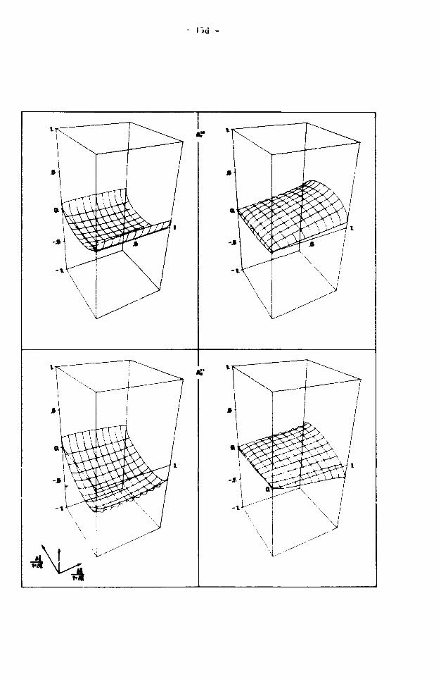
kskt ~kskt -00 In fig. 2 soae examples of the normalized coefficients A, «A. /Afl
are given as a function of:
2 o » (t*1)n - for — s n s - and «.-«„-O.
t+(t+l)n L H
In fig. 3 the behaviour of some coefficients is shown for a • 0.5 and
Ó., 6 as free parameters. 1* H
3.2. Secondary radiation
The distribution coefficients are calculated for gamma-rays originating
from levels that are populated by only one primary transition.
2 2r - fC s c 1 M - E p 0(«)p k Q(ss)(k 0,k 0|k 0)(2)'(8
,)Vk t s c x t s *k k k '
t s c
x (-)L"C_iW(cic'i;Lkc)(i)2 (-)f"M"i W(MiM'i;fkc) x
x MM» (-)M "' (MI,M'-
- 17 -
The summation is over k , k , k , c, c', L, M, M* with s • 1/2, L * 1,2, t s c
c « t+s, c' * t+s, M - 1,2, M' - 1,2, |M-M'|sk <M+M', 0<k s2t, Osk <2s, Ik -k |<k <k +k and k + k + k even,
s ' ' t s' c t s t s c After an analogous transcription as carried out for primaries the result
is identical in terms of A-coefficients. Furthermore the numerical values ~00 11
of A. and A are the same. The other A-coefficients behave completely
different. In fig. 2 some examples are given for all mixing parameters
zero. In fig. 4 the multipole mixings of the secondary transition
°s <f|L-l u *- '".5.
-T— and one of the primary components are varied for
A. Pure p-wave capture
For p-wave capture an additional angular momentum appears in the formula,
namely the orbital angular momentum 1 of the neutrons. Firstly 1 and s
are coupled. Thus the intrinsic and orbital angular momenta are combined
in the statistical tensors of the beam. With these new tensors the
above used procedure is carried out again.
According to ref. 2 the statistical tensors for a beam of spinless
particles can be written as:
Pk 0 (11') - 11' (-)1' (10,1'Olk^). (4.1)
A beam of particles with intrinsic spin can be then described by:
Pk K (bb') - Z pk K (ss) (10,l'o|k10)(k10,kgKs|kbKb) x b b k k. s s
s 1
rl s b 1» f1 s D I x (-)1 11' bb' k.k il' s b'k (A.2.)
\ k V 1 s b
This implies a choice of the z-axis along the propagation direction of
the beam. It is assumed that the neutrons are polarized perpendicular
to the beam and this direction is chosen as x-axis (fig. 5).
Because p-wave capture through only one reaction channel (1»1') is
considered, two situations can be distinguished with respect to the
nuclear orbital in which the neutrons are captured:
p .„-capture (i.e. b-b'-l/2) and p_,„-capture (*'.e. b»b'-3/2).
18 -
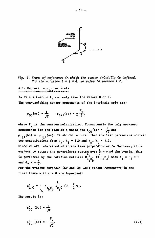
Fig. 5. Frame of reference in which the system initially is defined. For the notation 9 = $ = i t we refer to section 4.2.
4.1. Capture in p . -orbitals
In this situation k. can only take the values 0 or I.
The non-vanishing tensor components of the intrinsic spin are:
'00 (ss) - -!- P, + 1(ss) - i - p
where P is the neutron polarization. Consequently the only non-zero x 1
components for the beam as a whole are Pnf.(bb) » -jm and
p .(bb) • -p (ss). It should be noted that the last parameters contain
two contributions from k , k, » 1,0 and k , k, » 1,2.
s i ' s i Since we are interested in intensities perpendicular to the beam, it is easiest to rotate the co-ordinate system over x around the y-axis. This
kb 2
is performed by the rotation matrices D , (e 9.C.) with 9. • 9- * 0 ir b b
'2 ~ " 2* For the present purposes (CP and NO) only tensor components in the final frame with K • 0 are important:
and 6,
V0 D
The result is:
»óo (bb) J_ /I
P'10 (bb) x (4.3)
- 19 -
For s-wave neutrons p..(1/2) * -ym would hold. So it appears in this
capture process that the polarization of the total angular momentum of
the beam is opposite to that of the intrinsic spin.
4.2. Capture in p. ..-orbitals
With the same approach as in section 4.1 for b • b' » 3/2 the following
tensor components can be formed in the original frame of reference:
P0Q (bb) - p0() (ss) p0{) (11) (...) ^4.4a)
pi+i (bb) - p i + .
( s s ) p o o ( n ) ( — >
+ P1+l (ss) p 2 Q (11) (...) (4.4b)
P2+] (bb) - p 1 + J (ss) p 2 Q (11) (...) (4.4c)
P2Q (bb) - p Q 0 (ss) p 2 Q (II) (...) (4.4d)
P3+, (bb) « pJ + J (ss) p2() (11) (...) (4.4e)
The dots (...) denote products of Clebsch-Gordan and Wigner 9-j symbols.
Because of the rotation over •=• around the y-axis the components p.
and p_ . do not contribute to the distribution. Compared with p. . -capture
p?f) (bb) is a new term which is independent of the polarization of
the intrinsic neutron spin. It reflects the intensity distribution with
respect to the beam axis for unpolarized p-vave capture. ~02
Consequently a new term B. has to be added to the formulas (3.2) and
(3.3).
W(NO) - A?0 + B?2 + X'1 f,f + ... (4.5) (J i u I n
W(CP) - A°° • B?2 • A»0 f • ... (4.6) o i in
In the direction of the neutron polarization (9 • j , $ • 0) for target
spin t • 5/2 an explicit calculation has been carried out for the

- 20 -
coefficients A and A. .
It follows that their values are a factor 1.2 larger for p. ..-capture
(spin i • 0 or 5) than for s.,--capture (spin i « 1 or 4). No channel
spin interference occurs for these extreme spin values.
5. Remarks on interference between s- and p-wave capture
The frame of reference is chosen as in section 4. Now tensor parameters
for the beam with mixed orbital angular momenta (1^1') occur:
p00 ( 1 1> , , 1
10 " ' P_
20 P,A (ID ^ (SS) * * f
where 1 - 1,2, 1' « 1,2 and s - 1/2.
A list of all possible tensor components is given in table 1 with their
constituent terms. If only the intensity and circular polarization are
considered [only p' (bb') in an arbitrary direction],the transformation
under a rotation is given by the spherical harmonics:
pk0 (bb'> " I \K (bb?) C <e*>'
The explicit rotational properties are listed in the fourth column of
table 1.
The interference between s- and p-wave neutrons shows up in the terms
numbered 2, 4 and 7 in the first column. Under the assumption that no
parity violation occurs in the gamma transitions these terms contribute
to the intensity distribution for odd k and to the circular polarization
distribution for even k. Consequently from term 2 follows an intensity
asymmetry with respect to the propagation direction of the neutrons.
For the products of reduced matrix elements in the terms 4 and 7 the real
and imaginary part must be considered separately. Since in term 4 the
factor p. (SS)(10,1K|1K)K sin 8 has opposite signs for K • 1 and K • -I,
the real part vanishes but the imaginary part gives an intensity
asymmetry for ( 9 ^ 0 , <f> + 0) if the neutron polarization is reversed.
From an analogous consideration it follows that for term 7 the imaginary
part vanishes and the real part gives a contribution to the circular
polarization for (6 + 0, 6 ^ T , $ + •*•).

Tabel 1: Statistical tensors for polarized s- and p-wave neutrons.
n
\
2
3
4
5
6
7
8
9
PkK
PQ0(bb)
P , 0 ( b b ' )
P , + 1 ( b b ' )
P 2 0 (bb ' )
P 2 l , ( b b ' )
P 3 ± 1 ( b b ' )
const i tuent
parameters
rotat ion
propert ies
= P 0 0 ( l l ) p Q 0 ( s s ) ( 0 0 , 0 0 | 0 0 ) x . . . x 1 x
» p . _ ( l l ' ) p ( s s ) ( 1 0 , 0 0 | 1 0 ) x . . . x cos e x
» P 0 0 ( l l ) P 1 + , ( S S ) ( 0 0 , 1 _ + 1 ' 1+_1) x . . . x _ + s i n 8 exp(+i<t>) x
+ p J 0 ( l l ' ) p ( s s ) (10,^+11 HI) x . . . x _+ s in 8 exp(+i<tO x
• P 2 0 ( l l ) p ( s s ) ( 2 0 , m 11+J) x . . . x _ + s in 6 exp(+i<fr) x
- P20<11) p Q 0 ( s s ) ( 2 0 , 0 0 | 2 0 ) x . . . x (3 c o s 2 6 - l ) x
- p . - d l ' ) p (ss)(IO,!_+! |2+1) x . . .x _+ s in e cos 6 exp(+i*) x
+ p „ A ( l l ) p _ , ( s s ) ( 2 0 , l + 1 |2+1) x . . . x + s i n 6 cos 6 exp(+i*) x
» P 2 0 ( l l ) P J + j ( s s ) ( 2 0 , I + l | 3 + I ) x . - . x + ^ s i n 6(5 c o s 2 6 - l ) e x p ( + i * ) x
reduced
matrix elements
<i |L|j o A < c | | t | b '>*<b ' | | l ' | s > * < i
ti
i i
ii
II
II
i t
II
II
|L| | C><C| | t | b x b | | l | s >
l\J
1

- 22 -
6. Conclusions
In the past several authors had to interpret* their experimental
circular polarization data by including multipole mixing ' , assuming
that only one reaction channel was involved. This restriction is removed.
It will be demonstrated in chapter 2 that, as a result, the previously 28
reported E2/MI mixing ratio for the ground state transition in Al should
be refuted . So far no significant M2/E1 multipole admixture has been
found in primary transitions.
The effect of s-vave and p-wave interference is treated because this
may affect the results in ref. 4 that are obtained from parity non-
conserving experiments with polarized neutrons. But this influence can
only arise from the imaginary part of the transition probability. For
thermal neutron capture the real part is usually much larger. This can
be determined by measuring, perpendicular to the neutron beam, the circular
polarization of gamma rays that are emitted after capture of neutrons
with a polarization along the beam axis.
References
1) J.J. Bosman and H. Postma, Nucl. Instr. Meth, U£ (1978) 331.
2) A.J. Ferguson, Angular Correlation Methods in Gamma-Ray Spectroscopy,
(North-Holland Publ. Co., Amsterdam, 1965).
3) H.A. Tolhoek and J.A.H. Cox, Physica J£ (I953) 101.
4) Yu.G. Abov, O.N. Ermakov and P.A. Krupchitsky, Soviet Phys. JETP
38 (1974) 870.
Yu.G. Abov, H.M. Danilov, O.N. Ermakov, I.L. Karpikhin,
V.K. Rissukhin and A.M. Skornyakov, Soviet J. Nucl. Phys. j£ (1973)
670.
5) F. Stecker-Rasmussen, K. Abrahams and J. Kopecky, Nucl. Phys.
A181 (1972) 225.
6) A.M.J. Spits and J. Kopecky, Nucl. Phys. A264 (1975) 63.
7) This thesis, chapter 2.

- 23 -
CHAPTER II
27-* -»• 28 27 -»• •*• ?R A STUDY OF THE Al(n,Y) Al AND Al(n,y) Al REACTIONS
1. Introduction
28 1 Levels of the odd-odd nuclide Al have been studied by neutron capture as well as by charged particle reactions. For a few transitions
3) the degree of gamna-ray circular polarization has been determined.
Parities and transferred orbital angular momenta have been obtained
from (d,p) and ( He,p) experiments. By means of the (3,a) reaction
the natural or unnatural character of the parity has been measured.
Lifetimes have been determined by application of the Doppler shift 7) 8)
attenuation method to the (d,p-y) reaction . Shell model calculations
have only reproduced the positive parity states below 2 MeV excitation
energy.
In the present investigation brute-force polarization was used for the
first time as a new stage in the continuous development of nuclear
orientation applied to neutron capture gamma-ray spectroscopy.
The target was natural aluminium. To perform such an experiment it
is important to use as high a magnetic field as possible. The magnet
system of the equipment at the High Flux Reactor in Petten is able to
produce fields up to 5 T. However, depolarization of the neutron beam
at the entrance and the exit of the cryogenic system so far prohibited
to use the magnet above 2.7 T. By improving the guide-field system it
is now possible to apply the maximum field strength. This has made it
useful to measure the gamma-ray anisotropics after capture of polarized 27
neutrons by polarized Al nuclei at a temperature of 35 mK.
In addition, another experiment was carried out to determine the degree
of circular polarization of gamma transitions after capture of polarized
neutrons by unoriented aluminium nuclei.
From these reported experiments angular distribution coefficients could
be determined for a large series of gamma-rays, some of them coming
directly from the capturing state, others being intermediate transitions. 28
In total characteristics of 43 transitions and 22 levels in Al could
be studied.

- 24 -
2. Angular distributions
In the past «any authors have treated the intensity and polarization
angular distribution of gamma-rvys emitted by ensembles of oriented
nuclei . The case of gamma radiation following directly after
neutron capture has also been studied in detail, including interference
effects between reaction channels with different spins . Very little
experimental work has been performed on secondary transitions and then
only for situations with one spin value for capture ' . This work
is now extended by including intermediate gamma-rays with interference
effects between the reaction amplitudes.
Ic=2.3
27 28 Fig. 1. Spins involved in the Al'nty) At reaction.
For the experiments with aluminium only s-wave capture will be considered.
In fig. I the usual sequence of primary and secondary transitions with
the spin notations of the various levels are given. Consequently the
angular distribution function can be written as:
W(9) -AJJ° • AJ' fj(S) f,(It) + [A" f,(S) £,(1^ • A°* f2(It)
• AJ3 fj(s) f 3 u t ) ] , *2 ( c o s e ) » (2.1)
where 8 denotes the angle with respect to the orientation axis,
and f.(S), fv(If.) a r c the orientation parameters of the neutron
beam and the target respectively. It should be noted at this point that H I
the A. term in eq. (2.1) is identical for primary as well as for
secondary or any other intermittant transition if the initial level
is populated by only a single cascade.

C — !
"--
~ ~ ^ l - - 2
^ n
t—i
>ü y
E . II<«V)
D °
Q-DS9
!
e
4 1
«! IC—II —?
P
^ I.*-
IC—U—3
V - - ^ -
4 1
• r
A\
.H
:J4J
f}
!•?
I C - 1 1 - 1
'•tfl
L)
I C - I I — 1
t ' i l l
I-J
Flflr. 2, Some experimental values of the angular distribution coefficient from the Al(n,y) At reaction are compared with the theoretical surves as a function of the relative contribution (a) of the reaction channels. The errors in a are obtained from a X"• analysis. The full (dashed) lines indicate constructive ^destructive) interference. Here C •*• I refers to primary, and (C+)I •> If to secondary transitions.

- 26 -
The tern betveen brackets is strongly dependent on the position of the
transition; it includes effects due to undetected gamma-rays preceding
tbe one under consideration. If brute-force polarization is applied,
it is not necessary to take tens into account depending on f^CI^i
which is extremely small compared to f.(I ). Only in some cases fod»)
may be of interest.
The angular dependence of the circular polarization P of gamma radiation
emitted by unoriented nuclei after capture of polarized neutrons is
given by:
P (8) - AJ° + A ] ° fj(S) cos 9. (2.2)
Again the preceding unobserved gamma transitions may influence the ~J0
coefficient A strongly.
The A parameters depend on the capture cross section and the partial ~00
radiation widths of the transitions. Dividing them by AQ gives the
normalized coefficients:
k k k k A ' 2 _ r I 2.-00 (2 3 )
\ " \ /A0 * ( }
To elucidate the interference effects in primary and secondary transitions,
the relevant parameters are shown in fig» 2 for target spin 5/2 as a function
of a, the fraction of a transition originating from the reaction channel
with spin 3. Explicit formulae of the A-coefficients are derived in
chapter 1. It is obvious that the interference effects become smaller
for secondary gamma-rays compared to the preceding primary transitions.
3. Experimental arrangements
A detailed description of the equipment used for the nuclear orientation
experiment can be found in ref. 17. A sample with dimensions 3
22 x 22 x 30 mm was cut from a single crystal of aluminium. A single
crystal was chosen because of its high purity. In order to reduce
possible eddy current heating in the target, five cuts perpendicular to
the neutron beam were made with a fine saw. In the top of the sample
a threaded hole was drilled to facilitate a direct and stiff connection

- 27 -
with the mixing chamber of the He- Me dilution refrigerator which was
basically the same as described in ref. 20.
The target was irradiated by a Bragg reflected neutron beam. During
the time of the reported experiment the neutron diffraction set-up 29)
contained a set of Heussler crystals of the composition Cu MnAl with 3
dimensions 20 x 20 x 7 mm . With the existing fixed diffraction angle
of 37 the first order diffracted neutrons had an energy of 17.5 meV.
However, a considerabl' amount of second order neutrons of 70 meV reduced
the neutron beam polarization from close to 100Z to about 65%. A r.f.
spin-flip device wee used to reverse the polarization of the first
order neutrons; the s>ins of the second order neutrons rotate over
only 90 and hence for our purpose, may be considered as fully depolarized.
The guide-field system, which keeps the neutrons polarized between the
diffraction set-up and the low temperature equipment , has been
extended. Especially the region close to the magnet is crucial since
the fringing field tends to depolarize the neutrons.
In addition to the system, described in ref. 21, another set of weak-
iron rings (14 cm long, 8 cm and 10 cm inner and outer diameter) was
installed, adjacent to the former ones, to remove the field reversal
region away from the neutron beam.
Even with the central field of the magnet at its maximum value (5 T),
it was possible to run the magnet without a noticeable reduction of
neutron polarization.
3 Gamma-ray spectra were recorded with two 50 cm Ge(Li) detectors, one
located in the direction 9 - 0 and the other at 8 « 90 with respect
to the orientation axis.
The temperature of the sample was about 35 mK and the heat-load
prevented to reach a lower temperature. The degree of polarization of 27 Al was of the order of 10% at this temperature. In addition spectra
were accumulated at A K, thus with essentially unoriented nuclei.
3i2i_Circular_£olarization_feX£eriment
A description of the experimental arrangement can be found in ref. 3.
Larger gamma-ray polarimeters were installed, consisting of cylinders
of permendur, 8 cm long and 6 cm in diameter. They were magnetized
with the aid of simple coils wound from thin copper tape. The direction
of neutron polarization was switched every 100 a with the aid of twisted
00 CM
ftxW?
- S
4x10*
ï IXIO3-
O
- 1 •
- 2<
- 3 -
- 4 -
amo*-
TÜ(n. >flu 8-0 t f - t l
wW**VfW^fv^
•trl
* * . - * « W ""in**"*'
' *T *'.£* •"*!•» J ' «6»' ^ ^ , • ^ » * S "
«••»»»*
25 ao 38 4 0 4 5 5.0
^#wVMy^ > »wV^%ir*Ki|#-*'*v-t*. ~ * » ~ w W ^ jrft»*.*K. *
'KW 11-11
Mil M
*?b *<*»
i OA e.o • 8 7.0
— 1 — »
E>«W«
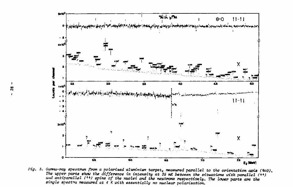
Fig*. 3. Gamma-ray spectrum from a polarized aluminium target, measured parallel to the orientation axis (0=0), The upper parts show the difference in intensity at 35 mK between the situations with parallel (+*) and antiparallel (+*) spins of the nuclei and the neutrons respectively. The lower parts are the single spect*>a measured at 4 K with essentially no nuclear polarization.
5X10*
' , I , , " A K n . ^ , e = 9 0 | f . , ,
- 9-
-10
3*»*-
2
1 -
UW*-
1 -
2
3
4
3X10*
J
W*1. S fe^l^fe " ^ =5 . v - - ^ _ „ v . •o?"1 ?Sli'
,*& • — » —
29 — i —
ao - 1 — as - i —
4.0 — I — 45
- 1 — 90
° - * < > ^ ^ ^ ^ *** II
,*W.VlM<»*vlv>»<*J>**-A' •
IxS
J.
M i l
»« »* f « > T r t , • * „ ^ ? « i S5 . « .» .' % * ?£* .?•*
?Sr«> — i — 99
— I — «0
— I —
u — I — 7.0
~ i — 7.9
Ek(NtaV)
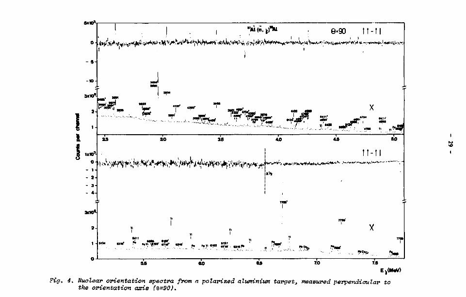
Fig. 4. Nuclear orientation spectra from a •polarized aluminium target, measured perpendicular to the orientation axis (Q=90).
ISJ

I 1 I
4
3
0
• a-
«mo*
10
• <
• <
4 .
2 •
4 .
0
WxlO*
^ i V ! . ^ ^
OtftafwiM fljMctrain •>»(«. y*i
>4-
x
Sum spectrum
X •"f"]*»1 « i t
i t
,'•?• ÜT 1Ï - •^5" 4J6
— I - -
80
>*vt
Diffofortoo •p#etfufn
,••. J"j 'i^Vv-'-'-TV.^ U . V * Y * H V . A V ^ f c ^ ' v
M i l
Sum apactrum
•"•.a • » * ' • » * > ? ~°e
&a «o i
as - 1 — 7.0
~ i — 7.S EjSMtf)
Fly. £. Circular polarization spectrum from an aluminium targett irradiated by polarised neutrons. The sign of the effect corresponds with the eign of the circular polarization.

- 31 -
guide field coils. Spectra were accumulated on magnetic disk for the two
directions of polarization.
4. Analysis
4.l^_Nuclgar_orientation
The spectra, measured parallel and perpendicular to the orientation
axis, are shown in fig. 3 and fig. 4; these spectiu were obtained by
summing 25 runs, each of one day length. The unnormalized intensities
1(6) were obtained by fitting a skewed gaussian curve to the gamma-ray
peaks.
Using eq. (2.1) and eq. (2.3) the relative intensity difference e(8)
of the spectra obtained with a polarized neutron beam and an oriented
target, with respect to the unpolarized situation, is given by:
W . (6) - W (8) .,
•»» - p « (.7—*'£,<sw unp
CAJ1 f1(S)f,(It) + A°2 i2Ut>3 ?2 (cos 8). (4.1)
The intensities of the unpolarized spectra I (6) must be carefully
normalized to the intensities I , (8). This was performed with the aid pol
of the strong Ti-lines at 6.76, 6.42, 1.59 and 1.38 MeV from a thin
titanium foil, placed in front of the aluminium target. Then the relative
difference e(9) is related to the measured intensities by:
W . (6) I , (8)
unp N unp
where C„ is the normalization constant.
N
The values of the orientation parameters i\(It) and f o ( 0 can be
calculated from the temperature of the target. This temperature was
monitored with th« aid of a carbon Speer resistor attached to the
mixing chamber, and with the nuclear orientation thermometers CoCo 54
and MnPe mounted to the bottom side of the sample. These temperature
measurements are mutually consistent within the experimental errors.
The neutron polarization of the initial beam was measured to be 0.65.
From the experimental differences e(9), measured for the polarization
- 32 -
of the neutron beam and target parallel and antiparallel respectively,
at the two angles 9 = 0 and 9 • 90 , it is possible to arrive at
values for A , A and A , which are given in table 1. As an illustration
the data for some levels are shown in fig. 2.
4i2i_Circular_golarization
In fig. 5 the sum and differer •: of the circular polarization spectra,
recorded for 6 = 0 and 6 = 180 , are displayed for one detector. To
determine the peak contents the following procedure was used.
For each peak a skewed gattssian curve was fitted to the sum of the
spectra. Then a fit was performed to the difference of those spectra
while the tailing, the f.w.h.m. and the position of the peaks were taken
over from the sum spectrum. This approach is allowed if the peak para
meters in both spectra are equal within the errors, as was checked to be
the case. In this way the errors in the asymmetries originating from the
fitting procedure, are suppressed appreciably.
32 The 5.42 MeV (1/2^3/2) transition of the S(n,y) reaction was employed
in a separate run for calibration purposes. This determines the only
free parameter in the formula which gives the energy dependence of the 22)
sensitivity for circular polarization of the polanmeter . The 23)
usefulness of this technique has been proved in earlier experiments
The resulting A values are listed in table 1.
2 4i3i_Method_of_^_-anal^sis
2 . . . The spin assignments are based on a X -analysis in which the measured
values (table 1) were compared with the theoretical coefficients as a
function of the free parameter a. If the feeding of a level occurs via
one gamma transition only, which is the case for all negative parity 28
states in Al above 3 MeV, also the available data from the deexciting 2
gamma-rays are included in the same x -calculation. This is permitted
since the feeding is within the errors equal to, or exceeds the de-
exciting intensity. Because also intensities do*., to 0.02% have been
claimed it is very improbable that important side feedings of those
levels are missed.
The errors in a are obtained from the relation ' :

- 33 -
Table 1: Angular distribution coefficients for gamna transitions in Al
E X (keV)
0
31
972
1014
1623 C )
2139
2273
3296
3465
3591
3876
3936
4691
4765
E Y (keV)
7725
7695
941
2131 b )
1014
983
1623
1592
6102
2139
2108
5586
2273 b )
4428
3465
4260
3591
2577
4133
3876
2256
3850
3790
4691
4660
3034
4765
4734
2626
2960
A11 n u
-0.89 +
0.43
-0.39
1.07
-0.08
-0.06
-0.10
0.05
-0.05
-0.66
-0.64
0.47
0.18
0.02
0.58
0.67
-0.05
0.16
-0.05
-0.96
-0.16
-0.54
1.42
0.31
0.56
C.32
-0.27
-0.87
-0.21
-1.21
0.11
0.21
0.64
0.76
0.17
0.22
0.20
0.51
0.31
0.22
0.19
0.62
0.31
0.49
0.12
0.13
O.II
0.21
0.10
0.34
0.90
0.31
0.74
0.13
0.23
0.13
0.47
0.16
0.29
0.19
"z i.
-0.31 +
0.44
-0.76
0.15
0.27
0.02
0.24
-0.26
-0.42
-0.73
-0.02
1.31
-0.02
0.66
0.20
0.16
-0.22
-0.53
0.04
-0.11
0.46
-0.57
-0.78
-0.69
0.41
0.04
0.22
0.02
-0.14
0.17
0.11
0.29
0.61
0.99
0.20
0.25
0.22
0.76
0.41
0.27
0.18
0.84
0.36
0.68
0.14
0.14
0.13
0.29
0.12
0.34
0.88
0.38
0.86
0.17
0.29
0.16
0.55
0.17
0.39
0.20
A 0 2 A2
0.0 +
-0.5
2.8
-0.2
-0.7
-0.4
0.6
-0.6
0.5
-0.4
0.0
-0.5
-0.3
a)
0.5
0.9
0.9
1.0
0.8
0.6
0.7
0.6
0.6
0.7
0.8
0.8
0.8
*!° 1
0.85 +
0.78
-0.31
0.64
0.61
-0.48
0.15
-0.56
-0.07
-0.32
0.19
0.56
-0.30
0.39
-0.10
-0.15
0.03
0.07
0.10
0.23
0.07
0.05
0.09
0.05
0.17
0.12
0.07
0.11
0.06
0.34
0.06
0.06

- 34 -
Table 1: Continued
E X (keV)
4903
5134
5443
5742
5798
5861
6200
6316
E Y (keV)
4903
2822
5134
2591
5411
3302
2283
1982
1927
1864
1525
6316
1409
A11 Ao
0.27 + 0.38
0.63 0.14
0.59 0.24
0.79 0.16
-0.24 0.76
-0.73 0.33
-1.16 0.20
-0.23 0.34
-0.14 0.28
1.32 0.65
0.22 0.30
0.64 0.19
0.91 0.21
A11 A2
0.18 + 0.53
0.21 0.16
-0.46 0.28
-0.74 0.21
0.46 1.11
-0.05 0.36
0.24 0.21
-0.03 0.44
0.62 0.35
0.31 0.83
-0.66 0.31
-0.29 0.22
0.22 0.19
02 a) A2
-1.0 + 0.7
-0.4 1.0
-1.6 1.0
-1.3 1.0
-0.4 1.0
1.8 0.7
A10 Al
0.31 + 0.12
0.33 0.09
0.02 0.16
0.00 0.37
0.87 0.13
a) Only values with errors ^ 1.0 are considered.
b) Doubts exist where this transition should be placed in the level
scheme (see ref. 19).
c) Unresolved doublet at E - 1.62 MeV.

- 35 -
2 2
Here XL1v determines the error interval, X^TM *S t n e «minimum value of
the x -distribution, F is called the statistical F- or Fisher function,
and n is the number of degrees of freedom.
5. Discussion of the results
Spin values have been excluded if their probability in the present
analysis is less than 0.1Z. For a probability less than 5Z the values
are placed between brackets. The final conclusions about the spin 25)
values, obtained from a combination of the known data and the
present work, are listed in table 2 and shown in fig. 6.
The intensity weighted contribution of the reaction channel with spin 3
to the capture process is EI a /EI « 0.47. The summation EI over the Y Y Y Y
primary transitions adds up to 83% of the total capture strength.
The ground state
From the reported experiments spin 3 is concluded. This is in agreement
with (d,p) and (d,ot) reaction experiments ; spin 3 is also strongly
suggested by a (6,Y) circular polarization correlation measurement
The deviation of the circular polarization parameter A. by more than 3) 5 standard deviations from the earlier obtained value 0.68 + 0.02 is
not fully understood. An underestimation of the error or a contribution
of the unpolarized aluminium background gamma radiation may be the cause.
A comparison for other transitions is not possible because of the lack
of accuracy in the earlier experiment.
Since the statistics is very good for this transition, a search for
uiultipole mixing is carried out. If quadrupole radiation is only
allowed to occur in the reaction channel with spin 2, which gives the 2
strongest contribution, the multi-dimensional x 'analysis yields
o - 0.15 + O.n* and 6_ - 0.00 • 0.14. Taking mixing in both channels
into account, the result is ct • 0.15 + 0.08, 6, • 0.0 +0.3 and
6, - 0.0 + 0.6.

- 36 -
no Table 2: Channel spin mixing ratios and spins in * Al
E X keV
0
31
1014
1623
2139
3296
3465
3591
3876
3S36
4691
4765
4903
5134
5443
5742
5798
5861
6200
6316
a) a
c 0.15+0.02
c 0.99+0.03
0.54+0.08 c )
0.53+0.11 c )
0.21+0.08 d )
1.00+0.13 e )
1.00
d 0.56+0.05
d 0.20+0.15
1.0 +0.5
d 0.82+0.05
0.00+0.01
d 0.12+0.03
d 0.85+0.12
1.0
1.00+0.05
0.50+0.17
J* b)
literature
3+
2+
3+
2+(3+)
+ 2
3*
4~
3~
2"
2+
(2,3)"
1
2"
3"
(1,2)"
(0-2)"
J
present work
3
2 (3)
2,3(1,4) e )
2(3) e )
2,3,4(1)
4
3
2,3
2,3,4
3
2
3
(3)
(4)
3
2,3,(1)
2,3(1,4)
2,(3)
2,3,4
3(2,4)
(4)
final conclusion
+ 3
2+
3+
2+(3+)
2+
+ 3
4~
3"
2~
2+
3"
2~
2",4"
3"
2"d")
2,30,4)
2~
2,3,4
3(2,4)
(4) 1

- 37 -
Table 2: Continued
a) Constructive and destructive interference are indicated by c and d
respectively.
The value a - c 0.99 + 0.03 denotes the regions c 0.96 -»• c 1.00 and
d 1.00 -»• d 0.98 since the values at « = c 1.00 and a * d 1.00 are
b) See ref. 25.
c) This a value is an average for all feeding cascades obtained from
100% of the de-excitation.
d) This a value is an average for all feeding cascades obtained from
93% of the de-excitation.
e) Obtained from the primary transition to this level.

- 38
Vi
tl?
6316 6200
5742
5442
5134
4903 4765 4691
3936 3976
3591 3465
3296
2139
1014 972
31
'AUn
- r
!
_!!_
5£
8 8!
m
"Al Fig. 6. Partial decay scheme of *'°Al.
(4) 3(24
hm nu
r r r-
?
rirj
£
- 39 -
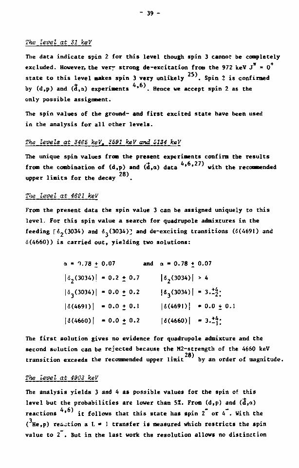
The level at 31 keV
The data indicate spin 2 for this level though spin 3 cannor be completely
excluded. However, the very strong de-excitation from the 972 keV J = 0 25)
state to this level makes spin 3 very unlikely . Spin 2 is confirmed
by (d,p) and (d,a) experiments * . Hence we accept spin 2 as the
only possible assignment.
The spin values of the ground- and first excited state have been used
in the analysis for all other levels.
The levels at 3465 keV* 3591 keV and 5134 keV
The unique spin values from the present experiments confirm the results
.P) 28)
from the combination of (d,p) and (d,ct) data ' ' with the recommended
upper limits for the decay
The level at 4691 keV
From the present data the spin value 3 can be assigned uniquely to this
level. For this spin value a search for quadrupole admixtures in the
feeding [6_(3034) and 6.(3034)] and de-exciting transitions (6(4691) and
6(4660)) is carried out, yielding two solutions:
a - 0.78 + 0.07 and a - 0.78 + 0.07
|62(3034)l - 0.2 + 0.7 |fi2(3034)| > 4
|63(3034)| - 0.0 + 0.2 |«3(3034)| - 3.1^
|6(469I)| - 0 . 0 + 0 . 1 |6(469I)| -0.0 +0.1
|5(4660)| -0.0 + 0.2 |<5(4660)| - 3.14;
The first solution gives no evidence for quadrupole admixture and the
second solution can be rejected because the M2-strength of the 4660 keV 28)
transition exceeds the recommended upper limit by an order of magnitude.
The level at 4903 keV
The analysis yields 3 and 4 as possible values for the spin of this
level but the probabilities are lower than 51. From (d,p) and (d,a) 4 6) -
reactions ' it follows that this state has spin 2 or 4 . With the 3 . . . ( He,p) reaction a L * 1 transfer is measured which restricts the spin value to 2 . But in the last work the resolution allows no distinction

- 40 -
between the levels at 4903 keV and 4928 keV. Therefore doubts about the
spin of the 4903 keV level seem justified.
The level at 6316 keV
The only possible spin value is 4 but the probability is again lower
than 5%. According to ref. I and ref. 2 an appreciable part of the feeding
is missed. This may strongly influence the distribution of the 6316 keV
transition.
6. Conclusion
In a completely model-independent way and without any a priori assumptions 28
it is possible to assign five spin values uniquely to levels in Al.
Furthermore several restrictions on the spin values are obtained. In
addition» the fractions of the gamma-ray transitions are determined which
originate from the reaction channels with spin 2 and 3.
Both channels contribute about equally to the total capture cross section.
No significant quadrupole admixture has been found in the present
investigation.
References
1) A.F.H. Ishaq, A.H. Colebrander and T.J. Kennett, Can. J. Phys.
50 (1972) 2845.
2) R. Hardell, S.O. Idetjarn and H. Ahlgren, Nucl. Phys. A126 (1969)
392.
3) F. Stecher-Rasmussen, K. Abrahams and J. Kopecky, Nucl. Phys.
A181 (1972) 225.
4) T.P.G. Carola and J.G. v.d. Baan, Nucl. Phys. A173 (1971) 414.
5) R.R. Betts, H.T. Fortune and D.J. Pullen, Phys. Rev. C £ (1974) 589.
6) D.O. Boerma, W. Griiebler, V. König, P.A. Schmelzbach and R. Risler,
Nucl. Phys. A270 (1976) 15.
7) F.A. El-Akad, S, Backe, T. Holtbekk, F. Ingebretsen and J. Rek»tad,
Nucl. Phys. A283 (1977) 12.
8) F. Meurders, P.W.M. Glaudemans, J.F.A. van Hienen and G.A. Timmer,
Z. Physik A276 (1976) 113.
F.E.H. van Eijkern, thesis (1976) State University Utrecht.

- 41 -
9) H.A. Tolhoek and J.A.M. Cox, Physica ^8 (1952) 357.
10) K. Alder, Helv. Phys. Acta 25 (1952) 235.
11) H.A. Tolhoek and J.A.M. Cox, Physica _19. (1953) 101.
12) J.A.M. Cox and S.R. de Groot, Physica \± (1953) 683.
13) Chr.D. Hartogh, H.A. Tolhoek and S.R. de Groot, Physica 20 (1954)
1310.
14) S.R. de Groot, H.A. Tolhoek and W.J. Huiskamp, in Alpha-, Beta-
and Ganma Ray Spectroscopy, ed. K. Siegbahn, vol. 2 (Morth-Holland
Publ. Comp., Amsterdam, 1974) p. 1199.
15) A.J. Ferguson, Angular Correlation Methods in Gamma Ray spectroscopy
(North-Holland Publ. Comp., Amsterdam 1965).
16) R.D. Gill, Gamma Ray Angular Correlations (Academic Press,
New York 1975).
17) J.J. Bosman and H. Postma, Nucl. Instr. Meth. _U8 (1978) 331.
18) H. Postma and E.R. Reddingius, Physica 34 (1967) 541.
19) H. Postma and J.F.M. Potters, Physica 45 (1969) 559.
20) J. Mellema and H. Postma, Nucl. Phys. A154 (1970) 385.
21) J.J. Bosman, thesis (1976) State University Leiden.
22) H. Schopper, Nucl. Instr. _3 (1958) 158.
23) J. Kopecky, private communication.
24) A.N. James, P.J. Twin and P.A. Butter, Nucl. Instr. Meth. 115
(1974) 105.
25) P.M. Endt and C. v.d. Leun, Nucl. Phys A310 (1978) 1.
26) L.G. Mann and S.D. Bloom, Phys. Rev. J^9 (1965) B540.
27) P.G. Ikossi, A.M. McDonald and J.A. Kuehner, Nucl. Phys. A297
(1978) 1.
28) P.M. Endt and C. v.d. Leun, Nucl. Phys A235 (1974) 27.
29) A. Delapalme, J. Schweizer, G. Couderchon and R. Perrier de la Bathie,
Nucl. Instr. Meth. 95 (1971) 589.

- 42 -
CHAPTER III
A STUDY OF THE 55Mn(n,y)56Mn AND 55Mn(n,7)56«n REACTIONS
I. Introduction
56. About two hundred levels in Mn have been established by means of neutron 1,2)
capture gamma-ray spectroscopy . Gamma-ray anisotropics from
neutron capture in an aligned target yielded several restrictions on 3) the spin values . Such restrictions also followed from experiments on
the degree of circular polarization of gamma-rays, emitted after polarized 4) neutron capture . Parities have been obtained from the orbital angular
3 momentum transfer in the (d,p), ( He.p) and (d,a) reactions.
In the present investigation 65 gamma-ray transitions were studied by
polarized neutron capture in polarized nuclei and by measuring the degree
of circular polarization after capture of polarized neutrons in an
unpolarized target. In order to define the symbols, various possibilities
for the spins that are involved in s-wave neutron capture are shown in
fig. 1.
Ic=2.3
c c eg
Fig. 1. Spins involved in the Mn(n,y) Mn reaction.
2. Experiments
The experimental procedure and the analysis are in general described in
chapter 2. Therefore only details, specific for the present work on
manganese,will be given here.

- 43 -
2.I. Nuclear orientation
As a target material MnSb was chosen for two reasons: firstly it is
ferromagnetic and secondly the radiative capture of neutrons in anti
mony does not contaminate the gamma-ray spectra. A polycristalline
cylindrical sample of MnSb (22 mm in diameter and 13 mm thick) was cooled
to about 40 mK. Thermal contact was achieved with a copper ring (13 mm
wide, 1 mm wall thickness) clamped around the target with Apiezon-N grease
between the sample and the copper.
The NiAs structure of the sample was verified by x-ray diffraction.
The derived lattice parameters a • 4.127(1)A and c - 5.785(2)A are in
good agreement with ref. 5 and ref. 6.
It has been found previously that at 77 R the magnetization of a small
MnSb single crystal is saturated in magnetic fields larger than 0.3 T.
Hence, it may be assumed that at 40 mK and for fields of a few tesla the
electron spin polarization is almost complete. However, it was found that
with the maximum field of 5 T still some depolarization of the neutrons
occured. It should be noted that the polarization of the transmitted beam
is very sensitive co small deviations from perfect magnetization, as
follows from the theoretical considerations in ref. 12.
As a result the polarization of the neutron beam was reduced from 0.65
to about 0.50. The temperature was monitored with a crlibrated carbon
Speer resistor attached to the mixing chamber and with the nuclear
orientation thermometers CoCo and MnFe attached to the bottom side
of the sample. These measurements indicated internally consistently a
temperature of 40 mK.
The magnetic hyperfine field is measured to be 24.5 T on the Mn nuclei 8)
in MnSb . As will be shown below, the sign of this field is negative.
After subtracting the external field of 5 T a nuclear polarization of
0.27 at 40 mK is calculated in good agreement with the capture gamma-ray
results reported furtheron in this chapter.
With the neutron counter, positioned "down-stream" behind the target* a
transmission effect
T N +N
was measured to change from -0.013 to +0.002 if the sample was cooled
We thank dr. B. Knook of the Kamerlingh Onnes Laboratory in Leiden for the preparation of the MnSb sample.

A i W t "**tn(n, jl^Mn e*o
* \^^/,AA^V^VW^N\VA
• IA
I J
4-
»
2 —
lilO*
a-
^ ' M , . , V W Is.W*' A55^=«^^-f^fe^.'
M
0- i-v**» jtff^Mr^fi^*^/^»^
11-11
x w
A#T \ , ...X
44 so
1 1-1 1
"-y^ "rt»»Li ' •** Il J» I ' J I H T " S'
t *J V tam
X
A ?VlT SA • 0 &S 7.0 E t OMA
spectra measured at 4 K with essentially no nuclear polarization

-1.1P-
4x«F
"On (n, |/*Mn e=9o
, ^ 4 ^ ^
w\u " ^ v u VA UW J^JögÖL ^L^Srid^J^ fi X
E)(MtoV)
Fig-, 3. Nuclear orientation spectra from a polarized manganese target, measured perpendicular to the orientation axis (8=90J.
2x10*
1 "j different* apactrum
"MndS.^rMn
"| dlffaranca apactrum ( f i
2x10'- ,•
1-5 J u rn «pactrum
* -5! a. fi 1.5x10*-
/ i . _ _ , ' P°°*A«io«" MM 5«3 s l l r
-/ V
4.0 45 5.0
.5
0-
- . 5 -
- 1
15x10*
1.
.5
0
'W*>'V /^rv^wv^^^^ # ^ ^ W V W l^p*^\^^A , ^ - A M "
diffstonc* spectrum \ ;"V v * J y'
tan A
• •04
>' ' A.
uu' I Tim- ' raw' , I i fl ; ' M M
' i I • ; / ' " • • » • f , «t04,J , J <J \ - v__ 71 I WO'
L „ A « W
mm apactnan
55 ao — i —
&5 — T 7.0
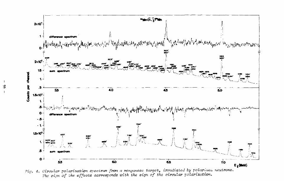
Fin. 4. Circular polarization spectrum from a manganese target, irradiated by polarizeu neutrons. The sign of the effects corresponds with the sign of the circular polarization.
EiWWfl

Table 1: Angular distribution coefficients for gamma transitions in Mn
E
(keV)
0
26
110
212
341
486
716
1166
1240
1509
E
(keV)
7270
7244
7160
7058
212
6929
314
6783
459
354
274
271
231
6429
6104
6031
5761
A
-0.83
-0.87
-1.03
0.71
-0.10
0.33
-0.55
-0.93
-0.32
-0.9
-0.92
-0.99
0.4
11 lo
+ 0.16
0.09
0.10
0.10
0.07
0.11
0.08
0.16
0.17
0.9
0.15
0.15
0.6
A
-0.16
0.33
-0.34
0.10
0.11
-0.83
-0.03
-0.25
-0.23
-0.1
0.82
-0.48
0.5
11 2
± 0.29
0.07
0.08
0.11
0.08
0.18
0.09
0.28
0.19
0.6
0.12
0.21
0.9
A
-0.6
-0.7
0.8
0.5
0.5
0.1
1.2
-0.5
-0.5
-3.3
-0.3
02 L2
+ 0.7
0.3
0.3
0.3
0.3
0.5
0.4
0.6
0.7
1.0
0.6
A02 A2 ref. 3
-0.06 + 0.14
-0.93 0.09
0.93 0.11
0.16 0.07
0.51 0.05
-0.21 0.13
0.04 0.08
0.82 0.11
0.8 0.5
0.38 0.05
0.6 0.5
0.93 0.21
-0.21 0.23
A10
0.29 +
0.051
-0.50
-0.44
0.80
-0.01
-0.5
-0.55
1.4
0.8
0.04
0.011
0.03
0.03
0.07
0.05
0.3
0.06
0.4
0.4
A10 Al ref. 4
0.40 + 0.05
0.04 0.02
-0.46 0.04
-0.45 0.04
0.56 0.08
0.04 0.08
-0.23 0.19
-0.55 0.11
-0.2 0.3
0.67 0.11

Table 1: Continued
(keV)
1743
1833
-
1866
2016
2071
2089
2202
2235
2255
2300
E Y (keV)
5527
5437
5433
5404
5254
5199
2045
5182
2063
5068
2177
5036
5015
4970
A11 A0
-0.09
-1.0
0.6
-0.1
-0.8
-0.70
-0.70
-1.14
-1.01
-0.98
-0.3
-0.54
+ 0.10
0.6
0.5
0.5
0.3
0.13
0.10
0.17
0.12
0.29
0.3
0.09
A11 A2
0.72
0.0
0.5
0.03
0.08
0.10
-0.39
0.2
0.9
-0.45
+ 0.15
0.8
0.5
0.16
0.10
0.23
0.16
0.3
0.4
0.08
A02 A2
-0.6 + 0.5
-0.5 0.6
-0.5 0.4
0.3 0.7
0.1 0.4
-0.4 0.9
0.05 0.29
A02 A2 ref. 3
-0.78 + 0.10
>0.1 0.4
-1.3 0.4
-0.03 0.10
0.93 0.18
0.04 0.07
A
0.70
-1.2
-0.40
-0.8
-0.63
-0.08
-0.19
-0.59
1.00
1.02
-0.3
10 1
+ 0.05
0.3
0.21
0.3
0.20
0.13
0.03
0.06
0.23
0.08
0.6
A10 Al ref. 4
0.56 + 0.04
f-0.02 0.17
-0.57 0.20
-0.3 0.2
-0.1 0.07
-0.32 0.07
1.0 0.2
0.81 0.06

Table 1: Continued
E X (k«V)
2321
2362
2395
2441
2545
2626
2704
2720
2824
3002
3047
3291
E Y (keV)
4949
2321
2295
2211
4908
4875
4829
2331
4725
4644
4567
4551
4446
4269
4223
3979
A11 A0
0.8 + 0.4
-0.3 0.6
-1.17 0.23
-0.93 0.22
0.3 0.5
-1.07 0.24
-1.18 0.17
-0.57 0.23
-1.1 0.4
-1.01 0.19
0.04 0.27
-0.9 0.5
-0.6 0.3
A11 A2
0.6 • 0.8
0.2 1.0
0.44 0.23
0.20 0.27
1.6 0.9
0.4 0.5
-0.01 0.27
0.1 -0.4
-0.4 0.9
-0.10 0.26
0.4 0.5
0.1 0.9
-0.9 0.6
A02
2
0.2 + 0.7
-1.5 0.7
-0.2 1.0
-0.2 0.9
-0.2 0.7
-1.3 0.6
A02 A2 ref. 3
-1.5 + 0.4
0.26 0.23
0.44 0.22
A ; ° I
-0.25 + 0.09
0.68 0.21
0.96 0.30
0.46 0.13
-0.13 0.07
0.17 0.24
-0.33 0.09
0.15 0.20
0.04 0.27
0.4 0.4
0.4 0.4
1.2 0.5
A!° i
ref. 4
-0.06 • 0.19
-0.15 0.09
-0.63 0.19
0.04 0.13

Table 1: Continued
E X (keV)
3455
3628
3689
3771
3861
4841
-
E > (keV)
3815
3642
3627
3581
3499
3409
4841
2090
A " Ao
-0.5 + 0.4
-0.51 0.26
-0.2 0.5
-0.5 0.5
0.2 0.3
-0.89 0.12
-0.6 0.4
A H
A2
0.1 + 0.7
-0.6 0.4
1.2 1.0
-0.7 0.8
0.4 0.?
0.36 0.14
0.1 0.7
A02 A2
-0.7 0.5
A02 A2 ref. 3
10 A«
0.8 + 0.8
-0.6 0.4
-0.03 0.07
-0.41 0.24
A10 Al ref. 4

- 51 -
from 4 K to 40 mK. Here N..(N ) is the count rate obtained for (anti) TT tt
parallel spins of the neutrons and nuclei.
As a consequence it follows that the neutron flux, integrated over the
sample, is different for these two situations. It is shown in chapter 2
that the gamma-ray anisotropics e(6) are related to the measured intensities
by: W .(9) - W (9) I ,(e)
e(9) = _E°1 H22 PQl , K ' W (9) CHI (9) '•
unp N unp
Here the normalization constant CN is determined with the aid of the
strong Ti-lines at 6.76, 6.42, 1.59 and 1.38 MeV from a titanium foil
placed in front of the MnSb sample. But to this constant C„ a different N
correction must be applied for parallel and antiparallel spins because
of the transmission effect: i n(e) if+(e)
S t ( 6 ) = C UI (6) ' ' and eT* ( 9 ) " C,XI (9) - '• TT unp ++ unp
in which C, » C„ and C,,» (1+6)C„. It was measured that 60 percent of TT N T+ N
the neutrons is removed from the beam by the sample. Herewith the value
of 6 can be calculated from the transmission effect.
The spectra measure parallel (9-0°) and perpendicular (9"90 ; to the
orientation axis are shown in fig. 2 and fig. 3. Taking all these
considerations into account it is possible to derive the values for
A , A and A_ , listed in table 1, from the experimental data.
2i2i_Circular_golarization
With a sample of 20 g manganese flakes contained in a thin walled
aluminium cylinder the same experimental procedure was followed as has
been described in chapter 2. In fig. 4 the sum and difference of the
circular polarization spectra, recorded for 9-0 and 9-180 are dis
played. The resulting values for A. are given in table 1.
3. Results in terms of the decay scheme and spins
3iili_Gamma;rax_s£ectrosco£y_
In general fair agreement is observed between the previously found 1 2 3) gamma-ray energies and intensies ' ' and the present work.
However, a remarkable feature in the low energy spectra is the weakness
of the gamma-rays transitions of 2017 keV and 2024 keV.

- 52 -
20O.7
Fig. 5. The strongest gamut-ray transitions near 2 MeV from neutron
capture by manganese.
In cable 2 the intensit ies , claimed in ref. 1, are compared with the
present work after a calibration on the 2045 keV transition.
Table 2: Some gamma-ray intensities of transitions near 2 MeV
E Y
(keV)
1988
2017
2024
2045
2063
2090
I I Y Y ref. 1 and ref. 2 this work photons per 100 captures
2.74
3.36
1.11
2.10
1.41
0.94
1.11
0.20
0.09
(2.10 calibration)
1.34
0.87
If the gamma lines at 2017 keV and 2024 keV belong to Mn, they are at
least a factor 10 weaker than claimed previously.
02 In table I the A- values of
listed together with their present values and the values for A''and A''
In table I the A, values of ref. 3 and the A. values of ref. 4 are ' 11 . JI

53 -
7
If possible» the weighted average was used in the present x -analysis
unless otherwise stated below. Spin values are excluded in this
analysis if their probability is less than 0.1Z. The results are given
in table 3.
For probabilities less than 5Z the values are placed between brackets.
The intensity-weighted contribution of the reaction channel with siin 3
to the capture cross-section is EI a 111 • 0.29. The summation £1 over y y y y
the nrimary transitions adds up to 67Z of the total capture strength.
If the assigned spins froa ref.3 and ref. 4 are compared with the present
ones, it should be kept in mind that before 1973 the possibility of co
herent interference between the reaction amplitudes with different channel
spin has been disregarded. Moreover the early assignments are partly based 9)
on resonance (n,y) experiments , from which the relative contribution
of those amplitudes (a-values) has been derived.
These predictions of the spin admixtures are reasonably good, as shown
in table 3, but have led to one erroneous conclusion.
The levels at E = 0, 26, 110, 341, 486, 1166 and 1743 keV
From the data of the primary transitions the following unique spin
values are assigned respectively: 3, 2, 1, 3, 3, 1, 2.
The level at E„ = 212 keV x
The analysis of the data for the primary transition yields spin 4 if 10 2
the A values are not averaged. Otherwise the x value does not reach
the 5Z limit. This may be caused by a small admixture of a transition
to the 215 keV level which cannot be resolved from the main transition.
The level at E = 2255 keV x 2
Taking all available data into account, no solution in the x -analysis
could be obtained for this level. Omitting the previously determination
A value results in a unique spin value 3. The a value, derived by
Auchampaugh and the A value that was measured by Stecher-Rasmussen
et.al. have formerly led to an assignment of spin 2 for this level.
However, this conclusion is untenable in view of our new and more
extended data on the A-coefficients.
- 54 -
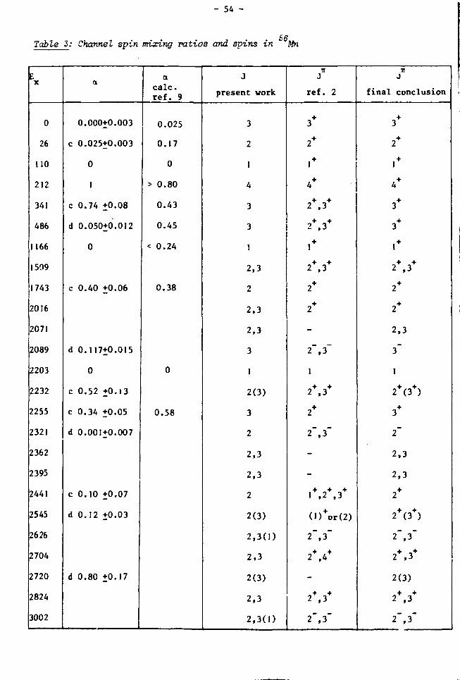
Table 3: Channel spin mixing ratios and spins in " Mn
E X
0
26
110
212
341
486
1166
1509
1743
2016
2071
2089
2203
2232
2255
2321
2362
2395
2441
2545
2626
2704
2720
2824
3002
a
0.000+0.003
c 0.025+0.003
0
1
c 0.74 +0.08
d 0.050+0.012
0
c 0.40 +0.06
d 0.117+0.015
0
c 0.52 +0.13
c 0.34 +0.05
d 0.001+0.007
c 0.10 +0.07
d 0.12 +0.03
d 0.80 +0.17
a calc. ref. 9
0.025
0.17
0
> 0.80
0.43
0.45
< 0.24
0.38
0
0.58
J
present work
3
2
1
4
3
3
1
2,3
2
2,3
2,3
3
1
2(3)
3
2
2,3
2,3
2
2(3)
2,3(1)
2,3
2(3)
2,3
2,3(1)
•n J
ref. 2
3+
2+
1 +
4+
2+,3+
2+,3+
1 +
2+,3+
2+
2+
-
2~,3~
1
2+,3+
2+
2~,3"
-
-
1+,2+,3*
(D+or(2)
2~,3~
2+,4+
-
2+,3+
2",3"
J
final conclusion
+ 3
2+
1 +
4+
3+
3+
1 +
2+,3+
2+
2+
2,3
3~
1
2+(3+)
3+
2~
2,3
2,3
2+
2+(3+)
2",3"
2+,3*
2(3)
2+,3+
2", 3"
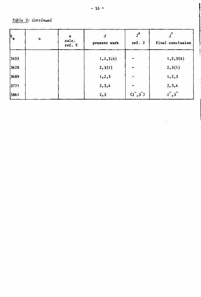
- 55 -
Table 3: Continued
E X
3455
3628
3689
3771
3861
a a
calc. ref. S
J
present work
1,2,3(4)
2,3(1)
1,2,3
2,3,4
2,3
J*
ref. 2
-
-
-
-
(2~,3~)
TT J
final conclusion
1,2,3(4)
2,3(1)
1,2,3
2,3,4
2", 3"

- 56 -
The levels at Ex = 2089, 2203, 2321 and 2441 keV
The spin values 3, I, 2 and 2 respectively were obtained by conbining
the data of the primary and secondary transitions.
The level at £. = 2704 keV x
With the previous A and A values ' the x -analysis yielded no
spin with a probability higher than 5Z. Disregarding those data results
in an assignment 2,3,
4. The hyperfine field on Mn nuclei in the compound MnSb
From 0-decay of Cr the spin value of the 110 keV level was established
as 1 and therefore a primary dipole transition to this level pro
ceeds only through the reaction channel with spin I„ « 2. In such a case
the capture cross-section is larger for antiparallel than for parallel
polarized nuclei and neutrons. Since the direction of the external
magnetic field and the neutron polarization are known, the negative sign
of the hyperfine field on the Mn nuclei in MnSb can be extracted directly
from the gamma-ray intensities. This agrees with the negative sign in
MnBi, which has also a NiAs structure n ) . The result is understood in
view of the predominating contribution of the polarized core electrons
to the hyperfine field in these manganese compounds.
5. Conclusions
56 Spin values could uniquely be assigned to 13 levels in Mn. Several
restrictions were obtained for other states. For 16 primary transitions
the relative contribution of the reaction channel with spin 3 could
be determined. Finally the sign of the magnetic hyperfine field at the
Mn nuclei was established as being negative in MnSb.
References
1) A.H. Colenbrander and T.J. Kennett, Can. J. Fhys. 5J3 (1975) 236.
2) Nuclear Data Sheets, 20 (1977).
3) J. Mellema and H. Postma, Nucl. Phys. AI54 (1970) 385.
4) F, Stecher-Rasmussen, J. Kopecky, K. Abrahams and W. Ratynski,
Nucl. Phys. A181 (1972) 250.
5) I. Teramoto and A.M.J.G. van Run, J. Phys. Chem. Solids 29_ (1968)
347.
6) W.J. Takei, D.E. Cox and G. Shirane, Fhys. Rev. J29 (1963) 2008.

- 57 -
7) H. Ido, J. Phys. Soc. Japan 25 (1968) 625.
8) J. Bouwma and C. Haas, Phys. Stat. Sol. B56 (1973) 299.
9) G.F. Auchaapaugh, UCRL-50504 (1968) Lawrence Livermore Laboratory.
10) B.J. Dropesky, A.W. Schardt and T.T. Schuil, Nucl. Phys. J^ (I960)
357.
11) T. Hihara and Y. Koi, J. Phys. Cos. Japan 29 (1970) 343.
12) 0. Halpern and T. Holstein, Phys. Rev. 59 (1941) 960.

- 58 -
This investigation treats the angular dependence of the intensity and
of the circular polarization of gamma-radiation, that is emitted after
capture of polarized neutrons by polarized and unpolarized targets•
In chapter I we have discussed the interference effects between the
(n,y)-reaction amplitudes with different channel spin, in particular now
this effect propagates into the secondary gamma-ray transitions. Also, the
angular distribution coefficients are calculated in case mixing of di-
pole and quadrupole radiation occurs. Further, we have indicated how
the influence of p-wave capture stay be taken into account.
In the next chapter the first successful (n,y) experiment with brute-force
polarized nuclei is described.
The nuclear orientation experiments on aluminium yield the values of
the angular distribution coefficients of primary and secondary gamma-ray
transitions. By a measurement of the degree of circular polarization an
additional coefficient is obtained. The values of these coefficients
depend on the spin of the excited level in the final nucleus and on the
parameter a which denotes Cue fraction of a gamma-ray transition that
originates from the reaction channel with the highest possible spin. 2
By a x -analysis five spin values are assigned uniquely and several
ct-values are determined.
Many experiments have been carried out on nuclides in the s-d shell
region. But only very recently some spin values are assigned to negative 28
parity states in Al between 3 and 5 MeV excitation energy by combining
the results from (d,p) and (a,a) work with lifetime measurements. No
discrepancies occur with the present investigation.
In our analysis we have taken into account that the angular distribution
coefficients depend on the tnultipolarity of the gamma-ray transitions. So the
previously determined E2/M1 mixing ratio of the ground state transition
can be rejected. To give an impression of the attainable accuracy, upper
limits are set on the quadrupole admixture in the feeding and depopulating
transitions of the 469) keV level.
In chapter 3 the results of chapter I are applied to the experiments on
manganese. The degree of circular polarization of the gamma Tddiation
was determined with the (n,y) reaction and unpolarized nuclei. For the
nuclear orientation experiment a ferromagnetic MnSb sample was used to

- 59 -
polarize the manganese nuclei. The values for the A-coefficients re
sulting from these measurements lead to a-values and unique spin
assignments for thirteen nuclear states in Mn.
For the spin assignments to four of these states information from
secondary transitions has been used. The previously assigned spin value
2 for the 5015 keV level is to be discarded in view of the present
experimental results which lead to the value 3.