Polarized electromagnetic radiation from spatially correlated sources

Polarized light imaging with a hand-held cameraJessica C. Ramella-Romana,b, Ken Leec, Scott A. Prahla,b,c, Steven L. Jacquesa,b,c
aOregon Medical Laser Center, Providence St. Vincent Medical Center, Portland, OR, USAbDepartment of Electrical and Computer Engineering, OGI School of Science and Engineering,
Oregon Health and Science University, Portland, OR USAcDepartment of Dermatology, Oregon Health and Science University, Portland, OR USA
ABSTRACT
Polarized light imaging can facilitate clinical mapping of skin cancer margins and can potentially guide clinical excision.A real-time hand-held polarized-light system was built to image skin lesions in the clinic.The system consisted of two 8-bit CCD cameras (Camera 1 and Camera 2) mounted on two sides of a polarizing beam-splitter. A polarized light source was mounted on the camera assembly and illuminated the patient's skin. Light waspolarized parallel to the source-patient-camera plane. The light, reflected from the patient, was collected with anobjective lens mounted on the beam splitter and divided into a horizontal (H) and vertical (V) component. The Hcomponent was collected by Camera 1, and the V component was collected by Camera 2. A new image was generatedbased on the polarization ratio (H - V)/(H + V) and displayed. This image was sensitive to the superficial skin layer andsome early clinical examples are presented.A web version of this paper is available at the following web site: optics.sgu.ru/SFM/2002/internet/Jessica/.
Keywords: Polarization, imaging, melanoma.
1. INTRODUCTION
The polarization status of a beam of light propagating through light-scattering media such as biological tissues, microsphere solutions, or an atmosphere with particulate, can be altered either by scattering events or by birefringentproperties of the media1 .So a light beam traveling through the superficial layers of the skin will have its polarizationstatus changed by the local birefringent matrix of collagen fibers. Since skin cancer often arises in the dermis where itdisrupts the natural order of the collagen matrix, polarized light imaging can be used to detect cancer.A schematic of a prototype polarization camera is shown below in Figure 1.
Figure 1:Set up of the polarized camera

The incident light is linearly polarized parallel to the scattering plane (the source-tissue-camera plane). An optical flatenforces a uniform skin/glass interface and reflects glare away from the camera.The polarized scattered light and the diffusely randomly polarized scattered light reach the camera after passing througha linear polarizer that can be oriented parallel (Horizontal) or perpendicular (Vertical) to the scattering plane.
Polarization Mathematics:After the images, Horizontal and Vertical, are acquired they are algebraically combined to yield a “Polarization Image”using equation 1.1:
Polarization Image = H - VH + V
(1.1)
The melanin pigmentation acts as a neutral density filter and attenuates both the superficial and deeply penetrating lightequally. If tm is the attenuation due to this layer then the polarization image may be decomposed into its fundamentalcomponents as shown in equation 1.2:
Polarization Image =s × tm × (Hsuperficial + Hdeep ) - s × t m ×Vdeeps × tm × (Hsuperficial + H deep) + s × tm × Vdeep
(1.2)
Where s is the light source distribution. This equation shows how by normalizing by (H+V), we can completely cancelthe effect of the source and superficial pigmentation. The polarization of the light reaching the deep layers of the skin iscompletely randomized, and when back scattered into the camera its effect is equally distributed in the Horizontal andVertical images. The light is cancelled in the numerator, and the resulting image is given by equation 1.3:
Polarization Image =Hsuperficial
Hsuperficial + Hdeep + Vdeep(1.3)
This equation shows how the polarization image is sensitive to superficially back scattered light.The first prototype of the polarized light camera was built using a 16-bit CCD camera (Roper Scientific, NJ, USA), twopolarizers (Coherent Ealing Electro Optics Ltd., Watford, England) and a Xenon lamp (Oriel, Stratford, CT). Thepolarizers were rotated by hand to collect the H and V images using IPLab imaging software. The polarized image wasreconstructed using Matlab.2
When used in the clinic the camera was attached to a balanced arm with a universal joint to allow for positioning on thepatient's affected areas.It was evident, after the initial clinical testing, that a much smaller device was preferred. In particular we decided todesign a smaller and completely automatic camera that could display the polarized image results in real time.The new hand-held polarized camera was designed using a polarizing beam splitter cube, two CCD cameras, and oneobjective lens.The polarizing beam splitter cube split the image into its Horizontal and Vertical polarized components. Two imagescould be collected simultaneously: Camera 1 collected the Horizontal image and Camera 2 collected the Vertical image.The polarized image given by equation 1.1 was calculated programmatically.
2. MATERIALS AND METHODS
The hand-held prototype of the polarized camera is shown in Figure 2. The spherical casing, used to protect the innerparts, was chosen for its ergonomic characteristics. The sphere diameter was 10 cm, small and light enough to feelcomfortable in a user's hand. The polarized light source was constructed with three ultra bright white LED mounted onan acrylic support. The LEDs were battery powered by three AA batteries that were stored in a compartment in the

bottom of the sphere. LED light was polarized parallel to the source, sample, and detector plane with a sheet polarizer.The light source assembly was oriented at an angle ~30 degree to the objective lens axis to avoid the glare coming backinto the camera.
Figure 2: The clinical hand-held polarization system, spherical casing protects the main components: a polarizing beam-splitter cubeand two web cameras.
A fixed distance between the imaging plane and the cameras was maintained using an acrylic support. The acrylicsupport was also used as a mount for a glass cover slip that was used as an optical flat. During camera operation theglass cover slip was in contact with the skin and a drop of water was used to achieve index matching
Figure 3: the inner components of a polarization camera are a polarizing beam-splitter cube, and 2 web-cameras.

An objective lens (PL 4/0.1) was used as the imaging lens, the field of view was approximately 5x5 mm.The inner part of the hand-held polarization system is visible in Figure 3, it is composed of a broadband polarizing beamsplitter cube ( Melles Griot, Carlsbad, CA, USA ) with 0.01 nominal extinction, two USB Quickcam Pro 3000 Web-Cameras (Logitech Inc., Fremont, CA, USA) and a custom made Delrin box that encased the beam splitter cube andsupported the two cameras in fixed positions.The polarization image was calculated by the software in real time and displayed on the screen (Right window), togetherwith the Horizontal image (Left). Image size was 400 by 400 pixels. Maximum frame rate for this image size was 6.5frames/sec. The frame rate could be improved decreasing the image size, using 250 x 250 pixels as the image increasedthe frame rate to 15 frames/sec.The color CCD cameras collected images composed of Red, Green, and Blue images. These three images generatedthree polarized RGB images that could be displayed on the screen during collection. This provided crude spectroscopicinformation of skin lesions. The software allows the user to average multiple pictures before displaying the results onscreen. This operation was implemented to limit small movement artifacts. Up to 20 images could be averaged.
2.1 Polarized system performance tests
The camera consists of a 1/4" color CCD (640x480 pixels), the CCD chip is mounted on a small, circa 4 by 3 cm, controlboard, which is an ideal size for a small portable package.The original camera round case was removed, as well as the original imaging lens, to facilitate mounting the camera onthe polarizing beam splitter cube. A few test were performed to assess the quality of the cameras and the polarizingoptics.
2.1.1 Dark noise over time: this test was done to determine if camera dark noise increased over time. The test wasperformed with the camera software shutter off, and an acquisition time > 0. The test was performed in the dark, andimages were captured at increasing time intervals. Camera streaming was interrupted only during image acquisition.The test was run for two hours, we expect to use the camera in patient observations for much shorter times. Thecaptured images were processed using Matlab and results are shown in Figure 4. The process consisted in calculatingthe mean and standard deviation for all of the 400 x 400 = 16000 image pixels, for the three (RGB) images. The Bchannel dark noise is noticeably higher than the R and G, but the general trend of noise is quite flat. The fact that thedark noise does not increase over time allows us to subtract it from the image programmatically.
Figure 4: Test on the camera dark noise drift over time, the three curves show the mean and standard deviation of a dark image. Thethree curves represent the red, green and blue images.

2.1.2 Camera repeatability: this test was performed to establish the pixel count variation during multiple acquisitions.Our target was a checkerboard; two main regions are visible on the board dark/black squares and white/bright squares.A group of 20 images of the checkerboard was captured over a 10 minutes period. The variability from image to imagewas analyzed using Matlab. 20 different pixel locations were chosen on the images. For every pixel location the meanand standard deviation among the 20 images was calculated, and it is shown in Figure 5. The inset in the plot shows thatthe standard deviation from a pixel population average is less than 3 counts.
Figure 5: Test on web-cameras repeatability, the image-to-image variation was tested for 20 subsequent captured images, thevariation, visible in the plot inset, was less than 3 counts.
Figure 6 shows histograms of all the collected points for all three channels. Three pixel values populations are visible:the black squares (~ 100 counts), the white squares (~ 200 counts), and the bordering lines between dark and whitesquares (~150 counts). This graph shows how the light variation across the imaging field was less than 20 counts.Concluding that our field of view is uniformly illuminated.

Figure 6: The polarized illumination varied across the field of view. The histograms above show three main areas on the imagedcheckerboard. Points collected on black squares had pixel intensity around 100 counts, points collected on white squares were ~ 200
counts and bordering lines ~ 150 counts. For all three regions, the pixel variation was ~ 20 counts, this demonstrates that theillumination across the field of view was reasonably uniform.
2.1.3 Polarization optics tests: we tested the performance of all the polarizing elements in transmission mode. Thelight source was positioned in front of the hand-held camera. The sheet polarizer axis was aligned with the beam splitterhorizontal axis. The orientation of the sheet polarizer axis was then increased in intervals of 20 degrees. At each angletwo images were collected: one with Camera 1 (Horizontal) and one with Camera 2 (Vertical).
Figure 7: Analysis of polarizing optical component, Malus’ law was reconstructed rotating the source polarizer 20 degrees at the timeand capturing images with the horizontal and vertical camera. The plot show the mean and standard deviation of a Region Of Interest
in the image. The chosen ROI was the central 100 x 100 pixels.

The transmitted light beam filled most of the cameras field of view. The pixel intensity counts of the central 100 x 100pixels were selected to eliminate any beam shape artifact. Dark noise was subtracted from every imageImages were then normalized by the maximum transmittance image. The mean and standard deviation of the resultingvalues are plotted in Figure 7.
3. THE POLARIZING HAND-HELD CAMERA SOFTWARE
The hand-held polarized light camera controlling software was written in C. The software was develop using theQuickTime SDK (Software Development Kit)3,4. QT is a system-level code package on most computers that supportmultimedia tasks. When the code runs, it calls QT to create and show movies. The software was developed on aMacintosh platform.
3.1 Software description:
1. Initialization2. Generate a dialog box to establish file name in case of save3. Create 2 windows, use the left window for the polarization image and the right window for the Horizontal
image4. Initialize Sequence Grabbers for camera 1 and 25. Generate a dialog Box for camera 1, let the user modify camera parameters as Gain, Shutter, window
orientation.a. .For camera 2 the user needs to flip the window horizontal to correct for the beam splitter mirror effect.
6. Event Loopa. If the s key is pressed: save currently displayed images in PICT format, without asking the userb. If the 1 to 5 keys are pressed: average 1 to 5 images, if the 0 key is pressed average 20 imagesc. If mouse click on left window: switch in between R,G,B channels.d. If mouse click on right window: switch camera off.e. If no key is pressed: work on current frames.
7. Decompress a sequence of frames8. Get R,G,B values for every pixel for camera 1 and 29. Average frames if necessary10. Reconstruct the polarized image calculating Pol for every pixel11. If Pol is negative or equal to 0, set Pol to 0.000112. Copy pixel values for the Polarized and for Horizontal image back to window 1 and 2.13. Return14. END
4. RESULTS
We show here some preliminary images of skin features and lesions collected with the hand-held polarized camera. Theimage on the left is the polarized green image in grayscale. The green image was the most clear among the threeacquired images, this is due to the CCD camera high sensitivity to green wavelengths. On the right hand-side we showthe horizontally polarized image in gray-scale format, both image contrasts were enhanced using the Photoshop auto-balance feature.Four different skin features are shown: a Tattoo, a Mole, a Freckle, and a Melanoma.
4.1 A tattooImage of a tattoo is shown in Figure 8, the dark areas in the right Horizontally polarized image are the tattoo. In thepolarized images the tattoo becomes white, while the surrounding areas are gray. This behavior is confirmed by similartests using the 16-bit CCD camera. We believe that the ink particles, that constitute the tattoo, act as small mirrors,reflecting polarized light directly into the camera with the original status of polarization preserved. White correspondsto a degree of polarization = 1, fully maintained. The darker the image becomes the lower the degree of polarization.

Figure 8: Image of a tattoo; on the left we show the polarized image on the right the Horizontal image.
4.2 A moleThe polarized image enhances the superficial features of the skin. In the polarized image: wrinkles, air follicles, and themole structure, are very clear, especially compared to the normal image on the right. In the polarized image, the moleappears white and has interesting three-dimensional features.
Figure 9: Image of a mole; on the left we show the polarized image on the right the Horizontal image.
4.3 A freckleA freckle disappears to the polarized camera. As described in equation 1.2, the melanosomes pigmentation effect visiblein the normal image and is cancelled in the polarized image since it effects both the Horizontal and Vertical images.
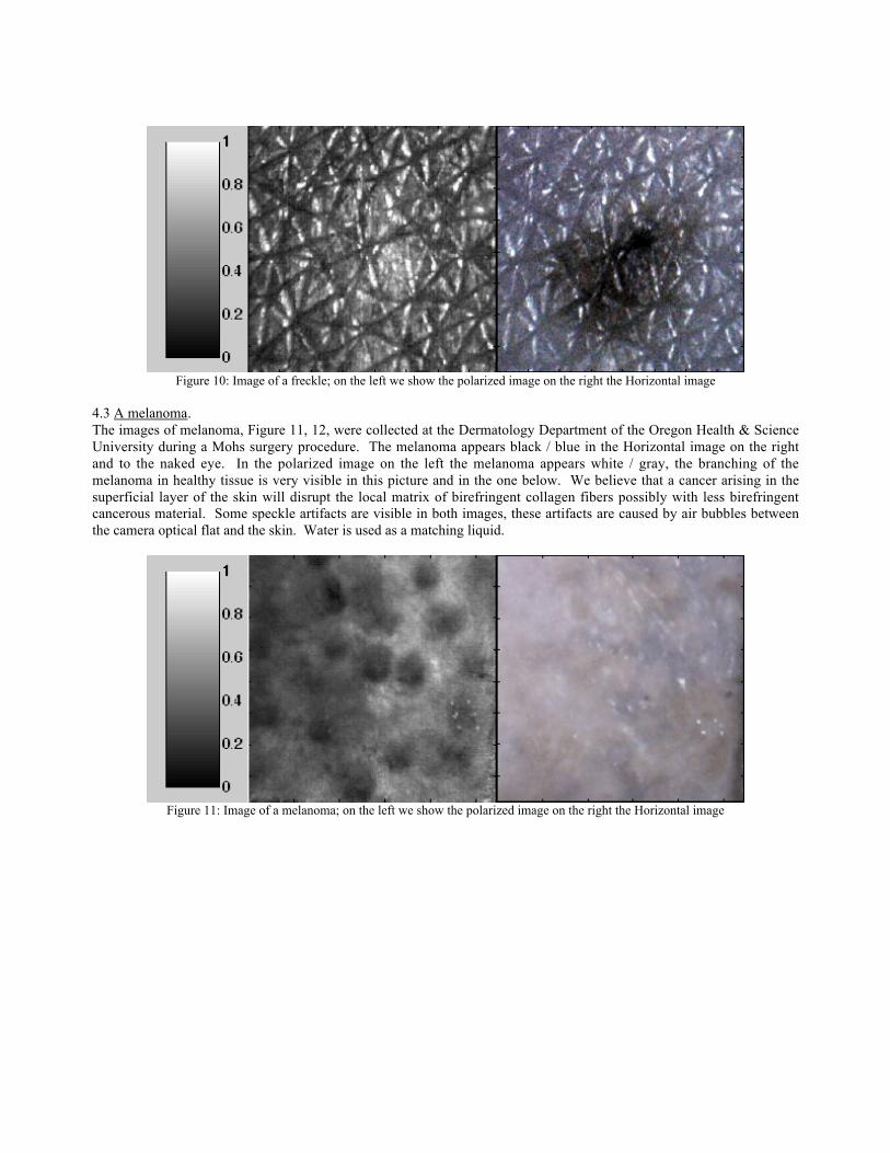
Figure 10: Image of a freckle; on the left we show the polarized image on the right the Horizontal image
4.3 A melanoma.The images of melanoma, Figure 11, 12, were collected at the Dermatology Department of the Oregon Health & ScienceUniversity during a Mohs surgery procedure. The melanoma appears black / blue in the Horizontal image on the rightand to the naked eye. In the polarized image on the left the melanoma appears white / gray, the branching of themelanoma in healthy tissue is very visible in this picture and in the one below. We believe that a cancer arising in thesuperficial layer of the skin will disrupt the local matrix of birefringent collagen fibers possibly with less birefringentcancerous material. Some speckle artifacts are visible in both images, these artifacts are caused by air bubbles betweenthe camera optical flat and the skin. Water is used as a matching liquid.
Figure 11: Image of a melanoma; on the left we show the polarized image on the right the Horizontal image

Figure 12: Image of a melanoma in situ; on the left we show the polarized image on the right the Horizontal image
5. CONCLUSIONS
We built a hand-held polarized light system that can acquire images of skin lesions in real-time. The hand-held system issmall, can fit in the physician's hand, and can perform real-time acquisition using a custom-made software. Earlyclinical work is encouraging: results are comparable those obtained with a much more expensive and bulky system builtwith a high quality 16-bit camera5.
6. REFERENCES
1. C. Brosseau, Fundamentals of Polarized Light: a Statistical Optics Approach, Whiley, New York (1988)2. S. L. Jacques, J. R. Roman, and Ken Lee, "Imaging superficial tissue with polarized light", Lasers Surg. Med.
26,119-129, (2000)3. developer.apple.com4. G. Towner, Discovering Quicktime, Morgan Kauffman, San Francisco (1999)5. Steven L. Jacques, Jessica C. Ramella-Roman, and Ken Lee, "Imaging skin pathology with polarized light", Journal
of Biomedical Optics. Vol. 7, No. 3, 329-340 (2002)
Copyright © 2022 FDOKUMEN