Dual Polarized Radiometers RPG-DPR-XXX Applications ...
8
Dual Polarized Radiometers DPR Series RPG‐DPR‐XXX RPG‐MWR‐DPR‐TN03‐2012‐09 Page 1 / 8 www.radiometer‐physics.de Radiometer Physics GmbH +49 2225‐99981‐0 Birkenmaarstrasse 10 info@radiometer‐physics.de 53340 Meckenheim, Germany 2012‐09‐21 radiometer‐support@radiometer‐physics.de Applications Soil moisture measurements Rain observations Discrimination of Cloud Liquid (LWC) and Rain Liquid (LWR) Accurate LWP measurements during rain events Cloud physics and structure LWP (Liquid Water Path) IWV (Integrated Water Vapour) Full sky IWV / LWP mapping Cloud coverage Features Brightness temperature (TB=TB v ‐TB h ) and polarisation difference (PD=TB v ‐TB h ) at multiple frequencies, at the same time and same viewing direction Multiple frequencies: the X (in RPG‐XCH‐DP) typically stands for 4 channels: two frequencies, typically 21.0 (or 18.7) and 36.5 GHz 6 channels: 10.7 / 21.0 (18.7) / 36.5 GHz 8 channels: 6.925 / 10.7 / 21.0 (18.7) / 36.5 GHz All frequencies from 1.4, 6.9, up to 90, 150, 225, 350 GHz, and more All microwave channels measured in parallel High temporal resolution (1 second), spatial resolution (6° HPBW) IWV (integrated water vapour) and LWP (integrated cloud liquid) full sky maps (350 points) within 10 minutes Determination of cloud coverage and monitoring of abrupt changes in the 3D humidity field Distinguishes between cloud liquid water and rain liquid. Precise determination of total liquid water content (LWP) Covers all rain rate events (depending on model), light rain <2 mm/h up to 50 mm/h Immune to RF interference below reception bands (e.g. radio transmitters, mobile phones etc.), direct detection receiver layout Purely passive operation, no internal oscillators or other RF sources Extremely short calibration cycles (sky tipping, 2 minutes), complete internal auto‐calibration systems including noise sources (noise switching, gain calibration) and Dicke switches (system noise temperature calibration) Internal data file backup system Rain protection of microwave windows Modular design allows for later frequency extensions (4 frequencies maximum)
-
Upload
khangminh22 -
Category
Documents
-
view
1 -
download
0
Transcript of Dual Polarized Radiometers RPG-DPR-XXX Applications ...

Dual Polarized Radiometers DPR Series
RPG‐DPR‐XXX
RPG‐MWR‐DPR‐TN03‐2012‐09 Page 1 / 8 www.radiometer‐physics.de Radiometer Physics GmbH +49 2225‐99981‐0 Birkenmaarstrasse 10 info@radiometer‐physics.de 53340 Meckenheim, Germany 2012‐09‐21 radiometer‐support@radiometer‐physics.de
Applications
Soil moisture measurements
Rain observations
Discrimination of Cloud Liquid (LWC) and
Rain Liquid (LWR)
Accurate LWP measurements during rain
events
Cloud physics and structure LWP (Liquid
Water Path)
IWV (Integrated Water Vapour)
Full sky IWV / LWP mapping
Cloud coverage
Features
Brightness temperature (TB=TBv‐TBh) and polarisation difference (PD=TBv‐TBh) at multiple frequencies, at the same time and same viewing direction
Multiple frequencies: the X (in RPG‐XCH‐DP) typically stands for 4 channels: two frequencies, typically 21.0 (or 18.7) and 36.5 GHz 6 channels: 10.7 / 21.0 (18.7) / 36.5 GHz 8 channels: 6.925 / 10.7 / 21.0 (18.7) / 36.5 GHz All frequencies from 1.4, 6.9, up to 90, 150, 225, 350 GHz, and more
All microwave channels measured in parallel High temporal resolution (1 second), spatial resolution (6° HPBW) IWV (integrated water vapour) and LWP (integrated cloud liquid) full sky maps (350 points) within 10 minutes
Determination of cloud coverage and monitoring of abrupt changes in the 3D humidity field
Distinguishes between cloud liquid water and rain liquid. Precise determination of total liquid water content (LWP)
Covers all rain rate events (depending on model), light rain <2 mm/h up to 50 mm/h Immune to RF interference below reception bands (e.g. radio transmitters, mobile phones etc.), direct detection receiver layout
Purely passive operation, no internal oscillators or other RF sources Extremely short calibration cycles (sky tipping, 2 minutes), complete internal auto‐calibration systems including noise sources (noise switching, gain calibration) and Dicke switches (system noise temperature calibration)
Internal data file backup system Rain protection of microwave windows Modular design allows for later frequency extensions (4 frequencies maximum)

Dual Polarized Radiometers DPR Series
RPG‐DPR‐XXX
RPG‐MWR‐DPR‐TN03‐2012‐09 Page 2 / 8 www.radiometer‐physics.de Radiometer Physics GmbH +49 2225‐99981‐0 Birkenmaarstrasse 10 info@radiometer‐physics.de 53340 Meckenheim, Germany 2012‐09‐21 radiometer‐support@radiometer‐physics.de
Introduction
The RPG‐XCH‐DP is a 2/3/4 frequency, dual polarisation radiometer with direct detection receivers and complete auto‐calibration frontends. The system requires no external calibration targets and performs sky tippings for absolute calibration purposes. The system is split into different frequency modules which are grouped on top of a precision elevation / azimuth positioner. Therefore the antennas can reach every point in the sky and complicated scanning schemes, including full sky LWP / IWV maps are possible. One of the key features is the measurement of polarisation difference (PD) during rain events under e.g. 30° elevation angle. Falling droplets are flattened due to the air resistance from below and nearly form an ellipsoid with long axis along the horizontal direction. Therefore the emission of falling droplets is more pronounced in the horizontal polarisation compared to the vertical. This allows for the separation of cloud liquid (perfectly round droplets, approx. 20 µm in diameter) and rain liquid. Without taking the polarisation difference into account, a radiometer overestimates the total liquid water content during rain by assuming that the brightness temperature signal is all generated by small cloud droplets. The small cloud droplets produce a much lower sky temperature than the bigger rain droplets, even with the same amount of liquid water. Therefore the rain droplet contribution to the sky temperature is relatively large while their contribution to the total liquid is smaller.
Highlights
Zenith Sky Observations When observing the sky in zenith direction, polarization splitting should be zero, even if clouds are passing the field of view. Falling rain droplets are vertically flattened, but this cannot be seen in zenith direction.
Fig. 1 Brightness Temperature time series (two frequencies, dual polarization).
36.5 GHz (H/V)
18.7 GHz (H/V)

Dual Polarized Radiometers DPR Series
RPG‐DPR‐XXX
RPG‐MWR‐DPR‐TN03‐2012‐09 Page 3 / 8 www.radiometer‐physics.de Radiometer Physics GmbH +49 2225‐99981‐0 Birkenmaarstrasse 10 info@radiometer‐physics.de 53340 Meckenheim, Germany 2012‐09‐21 radiometer‐support@radiometer‐physics.de
Fig. 2 Polarization difference (PD=TBv‐TBh) time series for clear sky.
Polarization effects due to falling rain droplets have to be observed under lower elevation angles (e.g. 30°). Therefore, by directing the radiometer to zenith, the polarization difference between V and H should vanish. Fig.1 shows the TBs observed for a cloudy atmosphere and Fig.2 is the polarization difference.
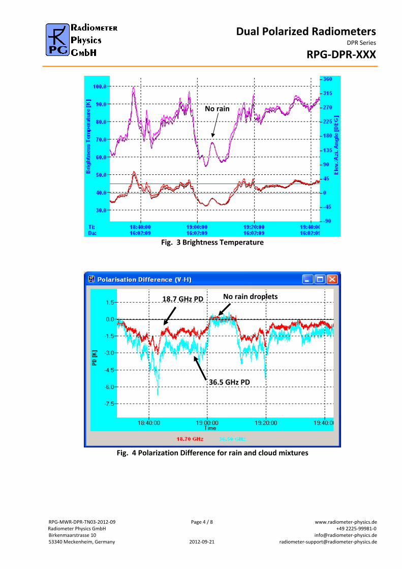
Observations under Low Elevation Angles The following measurements were performed at 30° elevation angle, observing a raining atmosphere (rain rate 5mm/h). The polarization splitting is very obvious but immediately drops down to zero, when the rain pauses. As expected, the 36.5 GHz channels respond much more sensitively to the liquid water and the polarization difference is more exaggerated. The 36.5 GHz channels are used for light rain detection while the 18.7 GHz channels cover the strong rain events with rain rates above 20‐30 mm/h when the 36.5 GHz channels are starting to saturate. Fig.3 shows the retrieval outputs for the Tb time series above. LWR is the liquid water content of the rain droplets, LWC denotes the cloud liquid and LWP is the total liquid water amount. The three time series are consistent even though the three quantities have been derived by three independent retrieval algorithms, one for each product.
Dual Polarized Radiometers DPR Series
RPG‐DPR‐XXX
RPG‐MWR‐DPR‐TN03‐2012‐09 Page 4 / 8 www.radiometer‐physics.de Radiometer Physics GmbH +49 2225‐99981‐0 Birkenmaarstrasse 10 info@radiometer‐physics.de 53340 Meckenheim, Germany 2012‐09‐21 radiometer‐support@radiometer‐physics.de
Fig. 3 Brightness Temperature
Fig. 4 Polarization Difference for rain and cloud mixtures
No rain
36.5 GHz PD
18.7 GHz PD No rain droplets

Dual Polarized Radiometers DPR Series
RPG‐DPR‐XXX
RPG‐MWR‐DPR‐TN03‐2012‐09 Page 5 / 8 www.radiometer‐physics.de Radiometer Physics GmbH +49 2225‐99981‐0 Birkenmaarstrasse 10 info@radiometer‐physics.de 53340 Meckenheim, Germany 2012‐09‐21 radiometer‐support@radiometer‐physics.de
Fig. 5 Simple regression retrieval for rain and cloud fraction of LWP.
Fig. 6 RPG Double Polarization Radiometer
raining clouds
non raining

Dual Polarized Radiometers DPR Series
RPG‐DPR‐XXX
RPG‐MWR‐DPR‐TN03‐2012‐09 Page 6 / 8 www.radiometer‐physics.de Radiometer Physics GmbH +49 2225‐99981‐0 Birkenmaarstrasse 10 info@radiometer‐physics.de 53340 Meckenheim, Germany 2012‐09‐21 radiometer‐support@radiometer‐physics.de

Dual Polarized Radiometers DPR Series
RPG‐DPR‐XXX
RPG‐MWR‐DPR‐TN03‐2012‐09 Page 7 / 8 www.radiometer‐physics.de Radiometer Physics GmbH +49 2225‐99981‐0 Birkenmaarstrasse 10 info@radiometer‐physics.de 53340 Meckenheim, Germany 2012‐09‐21 radiometer‐support@radiometer‐physics.de
Dual Polarized Radiometers DPR Series
RPG‐DPR‐XXX
RPG‐MWR‐DPR‐TN03‐2012‐09 Page 8 / 8 www.radiometer‐physics.de Radiometer Physics GmbH +49 2225‐99981‐0 Birkenmaarstrasse 10 info@radiometer‐physics.de 53340 Meckenheim, Germany 2012‐09‐21 radiometer‐support@radiometer‐physics.de
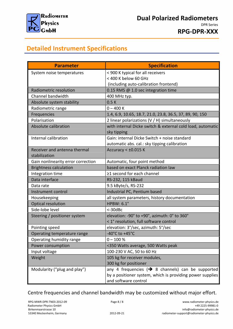
Detailed Instrument Specifications
Centre frequencies and channel bandwidth may be customized without major effort.
Parameter Specification
System noise temperatures < 900 K typical for all receivers < 400 K below 60 GHz (including auto‐calibration frontend)
Radiometric resolution 0.15 RMS @ 1.0 sec integration time
Channel bandwidth 400 MHz typ.
Absolute system stability 0.5 K
Radiometric range 0 – 400 K
Frequencies 1.4, 6.9, 10.65, 18.7, 21.0, 23.8, 36.5, 37, 89, 90, 150
Polarisation 2 linear polarizations (V / H) simultaneously
Absolute calibration with internal Dicke switch & external cold load, automatic sky tipping
Internal calibration Gain: internal Dicke Switch + noise standard automatic abs. cal.: sky tipping calibration
Receiver and antenna thermal stabilization
Accuracy < ±0.015 K
Gain nonlinearity error correction Automatic, four point method
Brightness calculation based on exact Planck radiation law
Integration time ≥1 second for each channel
Data interface RS‐232, 115 kBaud
Data rate 9.5 kByte/s, RS‐232
Instrument control Industrial PC, Pentium based
Housekeeping all system parameters, history documentation
Optical resolution HPBW: 6.1°
Side‐lobe level <‐30dBc
Steering / positioner system elevation: ‐90° to +90°, azimuth: 0° to 360° < 1° resolution, full software control
Pointing speed elevation: 3°/sec, azimuth: 5°/sec
Operating temperature range ‐40°C to +45°C
Operating humidity range 0 – 100 %
Power consumption <350 Watts average, 500 Watts peak
Input voltage 100‐230 V AC, 50 to 60 Hz
Weight 105 kg for receiver modules, 300 kg for positioner
Modularity (“plug and play”) any 4 frequencies ( 8 channels) can be supported by a positioner system, which is providing power suppliesand software control