R649c.pdf - Hansen Technologies
44
Specifications, Applications, Service Instructions & Parts MOTORIZED CONTROL VALVE & CONTROLLERS Bulletin R649c September 2018 Port size 1/16” thru 4” 2mm thru 100mm Motor Operated Valve Model MCV INTRODUCTION The Hansen Motorized Control Valve is a truly unique motor operated valve which eliminates the most common concern of other motor operated valves—valve stem seal leakage. The Motorized Control Valve has no valve stem seal because the non-electric rotor is enclosed in a stainless steel cartridge which contains the fluid pressure. APPLICATIONS Liquid Make-up to Accumulator Liquid Injection to Compressors DX Evaporators Temperature or Pressure Control Low or High Side Level Control Slow Opening and Closing: Suction Stop Valve No Pressure Drop: Gravity Drain Modulating or Slow Open/Close Solenoid Operation ADDITIONAL FEATURES • Self Calibrating • Relay, current, or voltage input for direct connection to plant PLC or computer. • All moving parts are sealed so that frost will not affect operation. • Tight closing Teflon seat. • Canned rotor eliminates valve stem seal leakage. • Controlled opening and closing minimizes liquid velocity shock, “liquid hammer.” • Valve is more compact and light weight than other motor operated valves. • Same flanges and spacing as Hansen HA4A/ HS4A pressure regulators and solenoid valves. • Suitable for use with ammonia, R22, R134a, CO2 (up to 800 psi welded) glycol, water, brines, and other approved refrigerants. • Available with optional Power-Backup feature. • Valve position indicator display included. • Available with weld-in connections. KEY FEATURES TABLE OF CONTENTS Introduction .............................................................................. 1 Specifications/Applications ...................................................2-5 Recommended Piping ............................................................ 6-7 Capacity Tables ................................................................... 8-16 Installation Drawings ......................................................... 17-21 Wiring (customer supplied controller) ............................................ 22-24 HUPS Power Backup System ............................................. 25-26 Hansen Controllers/Wiring ................................................. 27-37 Installation Parameter Sheet ................................................... 38 Valve Operation .................................................................. 39-40 Service and Maintenance ................................................... 41-42 Valve Parts List ....................................................................... 43 Ordering Information ............................................................... 44 DIRECT ACTUATION ELECTRONICS PROVIDE STRONG, SLOW OPERATION WITH MINIMAL POWER CONSUMPTION PRECISE LINEAR FLOW REGULATION OF V-PORT WATER-TIGHT NEMA 6 (IP67) HOUSING ALL VALVES AVAILABLE WITH ACT™ SOLUTION
-
Upload
khangminh22 -
Category
Documents
-
view
3 -
download
0
Transcript of R649c.pdf - Hansen Technologies

Specifications, Applications,Service Instructions & Parts
MOTORIZED CONTROLVALVE
&CONTROLLERS
Bulletin R649cSeptember 2018
Port size 1/16” thru 4”2mm thru 100mm
Motor Operated Valve
Model MCVINTRODUCTIONThe Hansen Motorized Control Valve is a truly unique motor operated valve which eliminates the most common concern of other motor operated valves—valve stem seal leakage. The Motorized Control Valve has no valve stem seal because the non-electric rotor is enclosed in a stainless steel cartridge which contains the fluid pressure.
APPLICATIONSLiquid Make-up to Accumulator Liquid Injection to Compressors DX Evaporators Temperature or Pressure Control Low or High Side Level Control Slow Opening and Closing: Suction Stop Valve No Pressure Drop: Gravity Drain Modulating or Slow Open/Close Solenoid Operation
ADDITIONAL FEATURES• Self Calibrating• Relay, current, or voltage input for direct
connection to plant PLC or computer. • All moving parts are sealed so that
frost will not affect operation. • Tight closing Teflon seat. • Canned rotor eliminates valve stem seal leakage.• Controlled opening and closing minimizes
liquid velocity shock, “liquid hammer.” • Valve is more compact and light weight
than other motor operated valves.• Same flanges and spacing as Hansen HA4A/
HS4A pressure regulators and solenoid valves.• Suitable for use with ammonia, R22, R134a,
CO2 (up to 800 psi welded) glycol, water, brines, and other approved refrigerants.
• Available with optional Power-Backup feature.• Valve position indicator display included.• Available with weld-in connections.
KEY FEATURES
TABLE OF CONTENTSIntroduction .............................................................................. 1Specifications/Applications ...................................................2-5Recommended Piping ............................................................6-7 Capacity Tables ...................................................................8-16Installation Drawings ......................................................... 17-21Wiring (customer supplied controller) ............................................22-24HUPS Power Backup System .............................................25-26Hansen Controllers/Wiring ................................................. 27-37Installation Parameter Sheet ...................................................38Valve Operation ..................................................................39-40Service and Maintenance ...................................................41-42Valve Parts List .......................................................................43Ordering Information ............................................................... 44
DIRECT ACTUATION
ELECTRONICS PROVIDESTRONG, SLOW OPERATIONWITH MINIMAL POWERCONSUMPTION
PRECISE LINEARFLOW REGULATION
OF V-PORT
WATER-TIGHT NEMA 6 (IP67)
HOUSING
ALL VALVES AVAILABLE WITH ACT™ SOLUTION
2R649c SEPTEMBER 2018
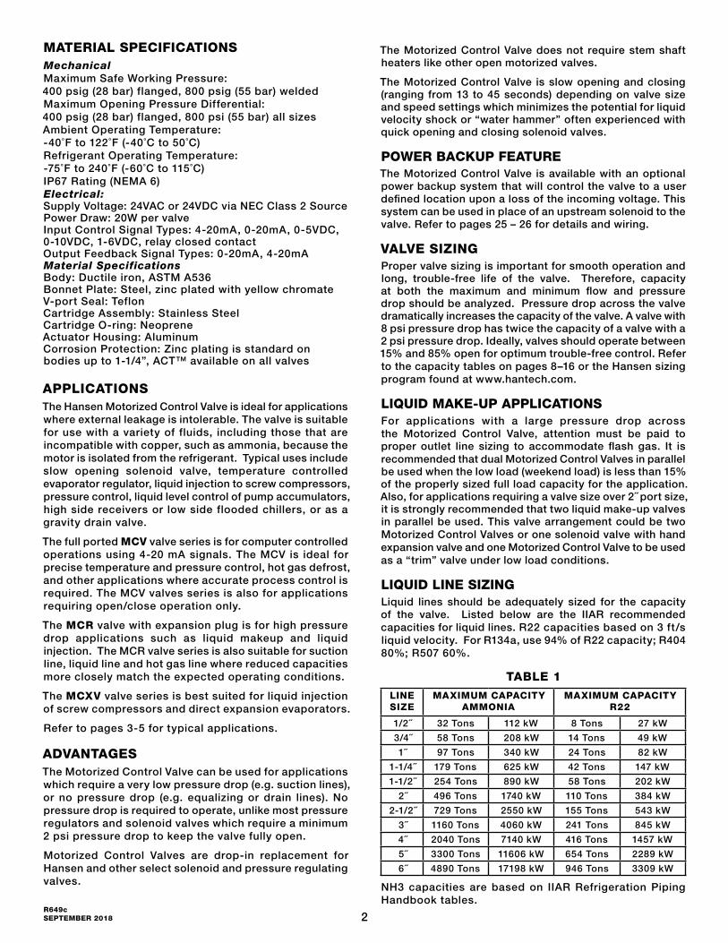
MATERIAL SPECIFICATIONSMechanical Maximum Safe Working Pressure: 400 psig (28 bar) flanged, 800 psig (55 bar) welded Maximum Opening Pressure Differential: 400 psig (28 bar) flanged, 800 psi (55 bar) all sizes Ambient Operating Temperature: -40˚F to 122˚F (-40˚C to 50˚C) Refrigerant Operating Temperature: -75˚F to 240˚F (-60˚C to 115˚C) IP67 Rating (NEMA 6) Electrical: Supply Voltage: 24VAC or 24VDC via NEC Class 2 Source Power Draw: 20W per valve Input Control Signal Types: 4-20mA, 0-20mA, 0-5VDC, 0-10VDC, 1-6VDC, relay closed contact Output Feedback Signal Types: 0-20mA, 4-20mA Material Specifications Body: Ductile iron, ASTM A536 Bonnet Plate: Steel, zinc plated with yellow chromate V-port Seal: Teflon Cartridge Assembly: Stainless Steel Cartridge O-ring: Neoprene Actuator Housing: Aluminum Corrosion Protection: Zinc plating is standard on bodies up to 1-1/4”, ACT™ available on all valves
APPLICATIONSThe Hansen Motorized Control Valve is ideal for applications where external leakage is intolerable. The valve is suitable for use with a variety of fluids, including those that are incompatible with copper, such as ammonia, because the motor is isolated from the refrigerant. Typical uses include slow opening solenoid valve, temperature controlled evaporator regulator, liquid injection to screw compressors, pressure control, liquid level control of pump accumulators, high side receivers or low side flooded chillers, or as a gravity drain valve.
The full ported MCV valve series is for computer controlled operations using 4-20 mA signals. The MCV is ideal for precise temperature and pressure control, hot gas defrost, and other applications where accurate process control is required. The MCV valves series is also for applications requiring open/close operation only.
The MCR valve with expansion plug is for high pressure drop applications such as liquid makeup and liquid injection. The MCR valve series is also suitable for suction line, liquid line and hot gas line where reduced capacities more closely match the expected operating conditions.
The MCXV valve series is best suited for liquid injection of screw compressors and direct expansion evaporators.
Refer to pages 3-5 for typical applications.
ADVANTAGES The Motorized Control Valve can be used for applications which require a very low pressure drop (e.g. suction lines), or no pressure drop (e.g. equalizing or drain lines). No pressure drop is required to operate, unlike most pressure regulators and solenoid valves which require a minimum 2 psi pressure drop to keep the valve fully open.
Motorized Control Valves are drop-in replacement for Hansen and other select solenoid and pressure regulating valves.
The Motorized Control Valve does not require stem shaft heaters like other open motorized valves.
The Motorized Control Valve is slow opening and closing (ranging from 13 to 45 seconds) depending on valve size and speed settings which minimizes the potential for liquid velocity shock or “water hammer” often experienced with quick opening and closing solenoid valves.
POWER BACKUP FEATUREThe Motorized Control Valve is available with an optional power backup system that will control the valve to a user defined location upon a loss of the incoming voltage. This system can be used in place of an upstream solenoid to the valve. Refer to pages 25 – 26 for details and wiring.
VALVE SIZINGProper valve sizing is important for smooth operation and long, trouble-free life of the valve. Therefore, capacity at both the maximum and minimum flow and pressure drop should be analyzed. Pressure drop across the valve dramatically increases the capacity of the valve. A valve with 8 psi pressure drop has twice the capacity of a valve with a 2 psi pressure drop. Ideally, valves should operate between 15% and 85% open for optimum trouble-free control. Refer to the capacity tables on pages 8–16 or the Hansen sizing program found at www.hantech.com.
LIQUID MAKE-UP APPLICATIONSFor applications with a large pressure drop across the Motorized Control Valve, attention must be paid to proper outlet line sizing to accommodate flash gas. It is recommended that dual Motorized Control Valves in parallel be used when the low load (weekend load) is less than 15% of the properly sized full load capacity for the application. Also, for applications requiring a valve size over 2˝ port size, it is strongly recommended that two liquid make-up valves in parallel be used. This valve arrangement could be two Motorized Control Valves or one solenoid valve with hand expansion valve and one Motorized Control Valve to be used as a “trim” valve under low load conditions.
LIQUID LINE SIZINGLiquid lines should be adequately sized for the capacity of the valve. Listed below are the IIAR recommended capacities for liquid lines. R22 capacities based on 3 ft/s liquid velocity. For R134a, use 94% of R22 capacity; R404 80%; R507 60%.
TABLE 1
LINE SIZE
MAXIMUM CAPACITY AMMONIA
MAXIMUM CAPACITY R22
1/2˝ 32 Tons 112 kW 8 Tons 27 kW
3/4˝ 58 Tons 208 kW 14 Tons 49 kW
1˝ 97 Tons 340 kW 24 Tons 82 kW
1-1/4˝ 179 Tons 625 kW 42 Tons 147 kW
1-1/2˝ 254 Tons 890 kW 58 Tons 202 kW
2˝ 496 Tons 1740 kW 110 Tons 384 kW
2-1/2˝ 729 Tons 2550 kW 155 Tons 543 kW
3˝ 1160 Tons 4060 kW 241 Tons 845 kW
4˝ 2040 Tons 7140 kW 416 Tons 1457 kW
5˝ 3300 Tons 11606 kW 654 Tons 2289 kW
6˝ 4890 Tons 17198 kW 946 Tons 3309 kW
NH3 capacities are based on IIAR Refrigeration Piping Handbook tables.

3R649c
SEPTEMBER 2018
TYPICAL APPLICATIONS
MCV MOTORIZED CONTROL VALVE
LIQUID MAKE-UP TO ACCUMULATOR
ROOM TEMPERATURE OR EVAPORATOR PRESSURE CONTROL
(Shown with Pressure Transducer)
The drawings in this bulletin are for illustration purposes only and should not be used for actual engineering or installation. Not to scale.
4-20 mA SIGNAL
HIGH-PRESSURELIQUID
CUSTOMER-SUPPLIER HANSEN VARI-LEVEL (WITH MOD420), SVA/SHA, OR VLT
LOWTEMPERATURE
VESSEL
HANSENPXVC-LLEVEL
CONTROLLER
4-20mA SIGNAL
OPTIONAL SHUT-DOWN SOLENOIDVALVE IN LIEU OF POWER-CLOSE
MCR
(INSTEAD OF HANDEXPANSION VALVE)
"TRIM" MCRMOTORIZED CONTROL VALVEFOR WIDE LOAD SWINGS
FEATURE
MOTORIZED CONTROL VALVE
FOR LINE SIZINGSEE TABLE 1
EVAPORATOR
MCVMOTORIZED CONTROL VALVE
HANSEN PXVC-P PRESSURE CONTROLLER OR COMPUTER/PLC
HANSEN SUPPLIED PRESSURE TRANSDUCER
1/4" NPTHANSEN SUPPLIED
PRESSURE TRANSDUCER
FIGURE 1
FIGURE 2
4R649c SEPTEMBER 2018
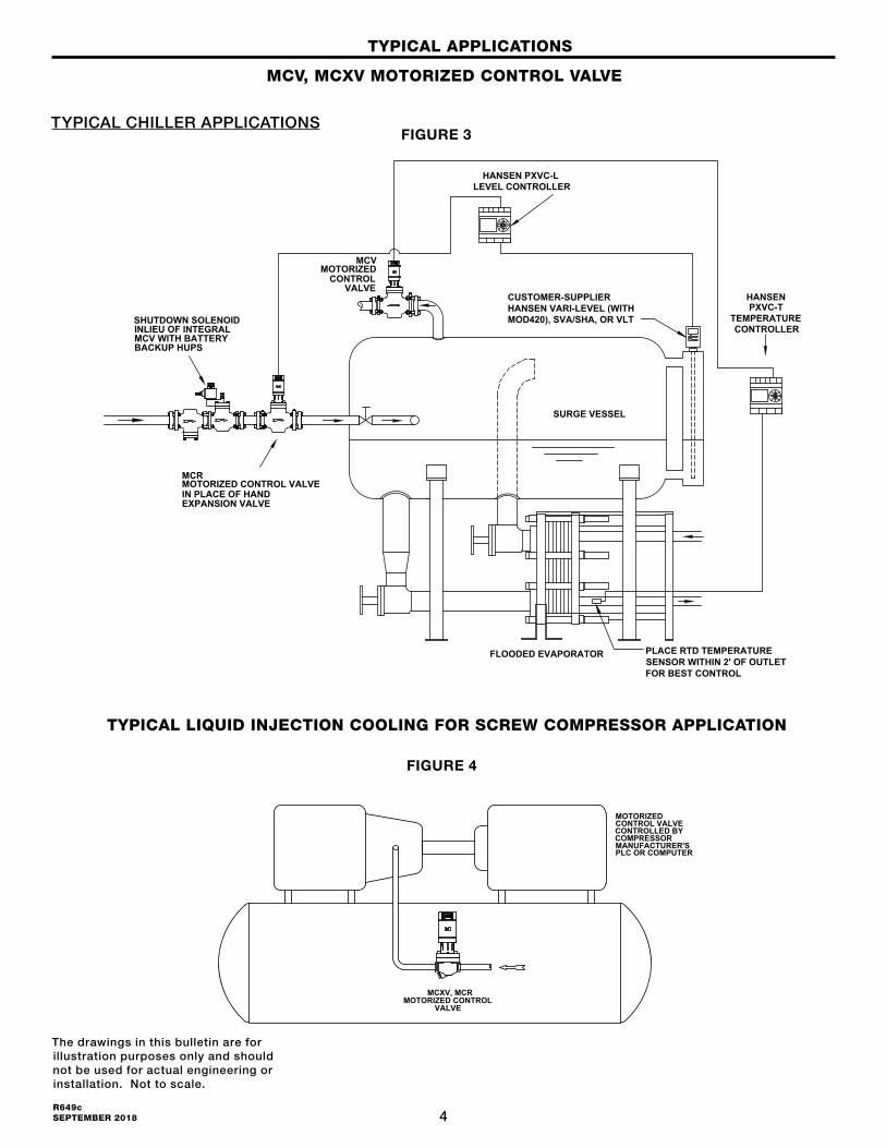
TYPICAL APPLICATIONS
MCV, MCXV MOTORIZED CONTROL VALVE
TYPICAL CHILLER APPLICATIONS
EXPANSION VALVE
SURGE VESSEL
MCR
IN PLACE OF HAND
CUSTOMER-SUPPLIER HANSEN VARI-LEVEL (WITH MOD420), SVA/SHA, OR VLT
LEVEL CONTROLLERHANSEN PXVC-L
FLOODED EVAPORATOR
MOTORIZED
TEMPERATUREPXVC-T
PLACE RTD TEMPERATURESENSOR WITHIN 2' OF OUTLETFOR BEST CONTROL
CONTROLLERSHUTDOWN SOLENOID INLIEU OF INTEGRAL MCV WITH BATTERY BACKUP HUPS
MCV
CONTROLVALVE
HANSEN
MOTORIZED CONTROL VALVE
The drawings in this bulletin are for illustration purposes only and should not be used for actual engineering or installation. Not to scale.
FIGURE 3
TYPICAL LIQUID INJECTION COOLING FOR SCREW COMPRESSOR APPLICATION
FIGURE 4
CONTROLLED BYCOMPRESSORMANUFACTURER'SPLC OR COMPUTER
MCXV, MCRMOTORIZED CONTROL
VALVE
MOTORIZEDCONTROL VALVE
EXPANSION VALVE
SURGE VESSEL
MCR
IN PLACE OF HAND
CUSTOMER-SUPPLIER HANSEN VARI-LEVEL (WITH MOD420), SVA/SHA, OR VLT
LEVEL CONTROLLERHANSEN PXVC-L
FLOODED EVAPORATOR
MOTORIZED
TEMPERATUREPXVC-T
PLACE RTD TEMPERATURESENSOR WITHIN 2' OF OUTLETFOR BEST CONTROL
CONTROLLERSHUTDOWN SOLENOID INLIEU OF INTEGRAL MCV WITH BATTERY BACKUP HUPS
MCV
CONTROLVALVE
HANSEN
MOTORIZED CONTROL VALVE
5R649c
SEPTEMBER 2018
EVAPORATOR
MCV MOTORIZED
CONTROLLINGCONTACT, E.G.FROSTMASTER
CONTROL VALVE
TYPICAL APPLICATIONS
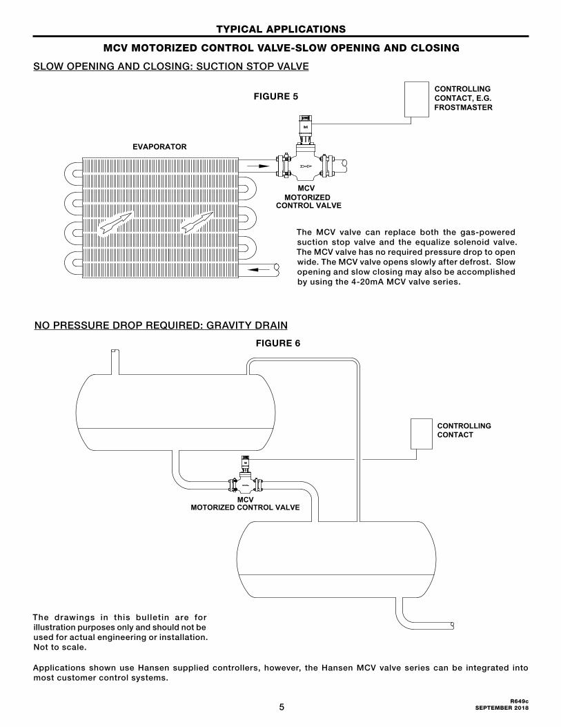
MCV MOTORIZED CONTROL VALVE-SLOW OPENING AND CLOSING
SLOW OPENING AND CLOSING: SUCTION STOP VALVE
NO PRESSURE DROP REQUIRED: GRAVITY DRAIN
The drawings in this bulletin are for illustration purposes only and should not be used for actual engineering or installation. Not to scale.
Applications shown use Hansen supplied controllers, however, the Hansen MCV valve series can be integrated into most customer control systems.
CONTROLLINGCONTACT
MCVMOTORIZED CONTROL VALVE
NO PRESSURE DROP: GRAVITY DRAIN
The MCV valve can replace both the gas-powered suction stop valve and the equalize solenoid valve. The MCV valve has no required pressure drop to open wide. The MCV valve opens slowly after defrost. Slow opening and slow closing may also be accomplished by using the 4-20mA MCV valve series.
FIGURE 5
FIGURE 6
6R649c SEPTEMBER 2018
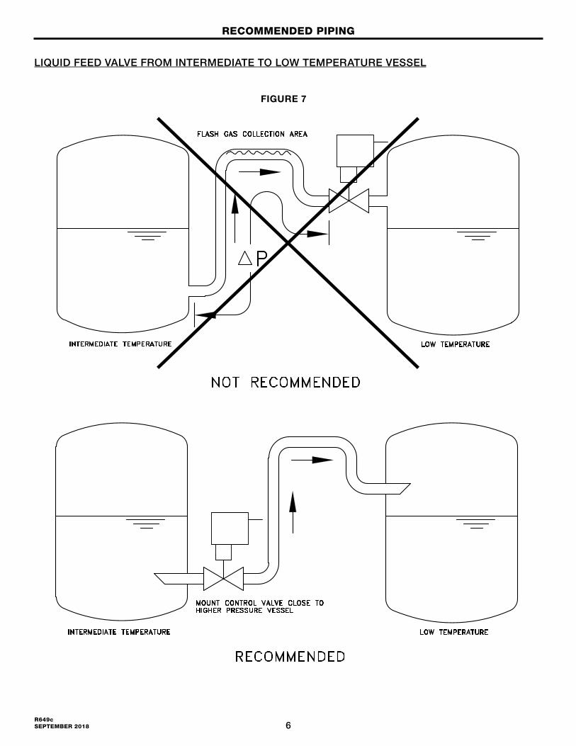
RECOMMENDED PIPING
LIQUID FEED VALVE FROM INTERMEDIATE TO LOW TEMPERATURE VESSEL
FIGURE 7
7R649c
SEPTEMBER 2018
RECOMMENDED PIPING
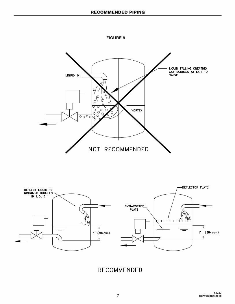
FIGURE 8
8R649c SEPTEMBER 2018
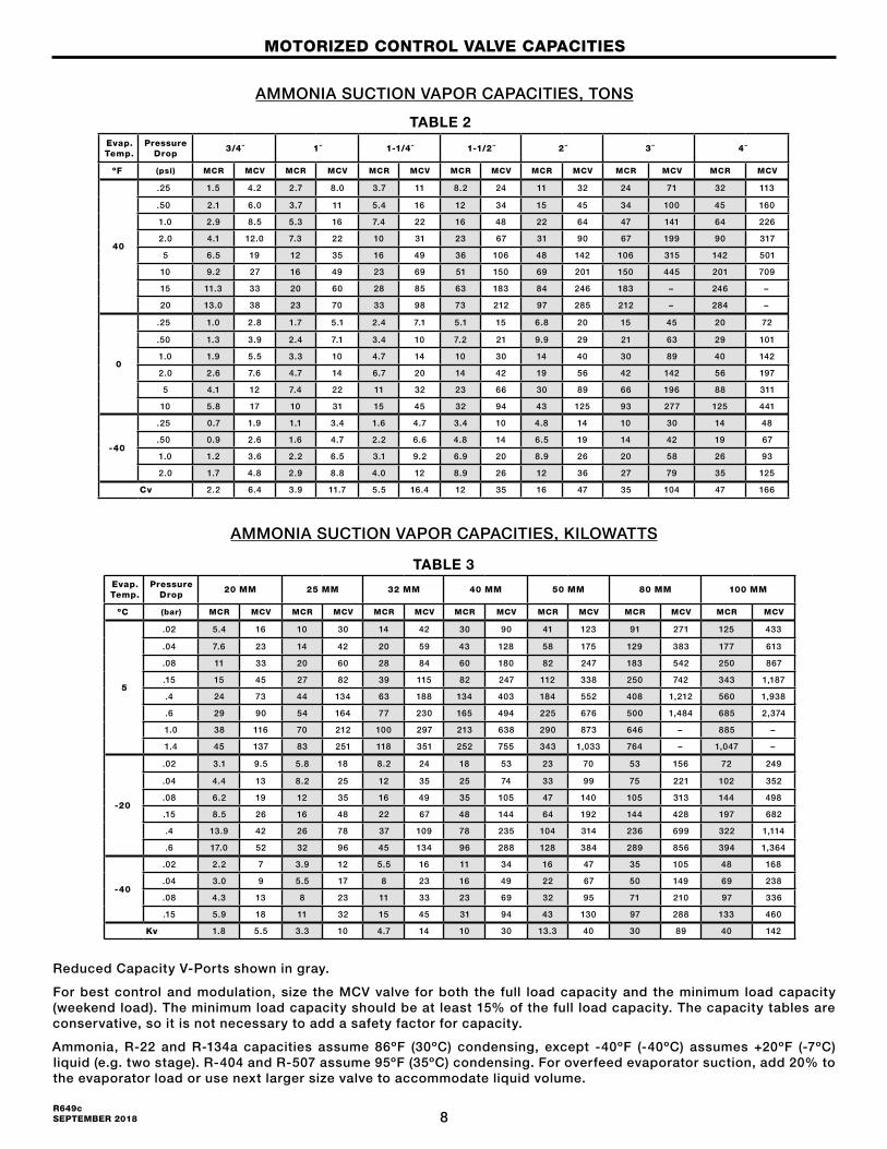
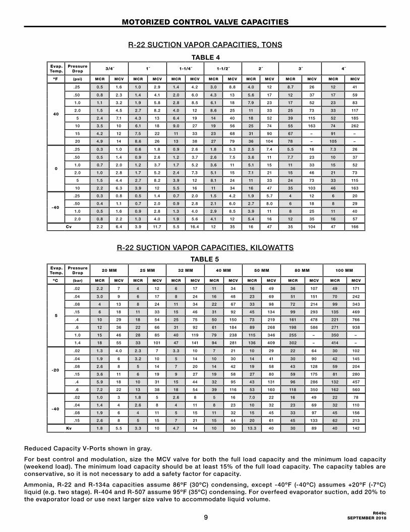
AMMONIA SUCTION VAPOR CAPACITIES, TONS
MOTORIZED CONTROL VALVE CAPACITIES
Reduced Capacity V-Ports shown in gray.
For best control and modulation, size the MCV valve for both the full load capacity and the minimum load capacity (weekend load). The minimum load capacity should be at least 15% of the full load capacity. The capacity tables are conservative, so it is not necessary to add a safety factor for capacity.
Ammonia, R-22 and R-134a capacities assume 86ºF (30ºC) condensing, except -40ºF (-40ºC) assumes +20ºF (-7ºC) liquid (e.g. two stage). R-404 and R-507 assume 95ºF (35ºC) condensing. For overfeed evaporator suction, add 20% to the evaporator load or use next larger size valve to accommodate liquid volume.
AMMONIA SUCTION VAPOR CAPACITIES, KILOWATTS
Evap. Temp.
Pressure Drop
3/4˝ 1˝ 1-1/4˝ 1-1/2˝ 2˝ 3˝ 4˝
ºF (psi) MCR MCV MCR MCV MCR MCV MCR MCV MCR MCV MCR MCV MCR MCV
40
.25 1.5 4.2 2.7 8.0 3.7 11 8.2 24 11 32 24 71 32 113
.50 2.1 6.0 3.7 11 5.4 16 12 34 15 45 34 100 45 160
1.0 2.9 8.5 5.3 16 7.4 22 16 48 22 64 47 141 64 226
2.0 4.1 12.0 7.3 22 10 31 23 67 31 90 67 199 90 317
5 6.5 19 12 35 16 49 36 106 48 142 106 315 142 501
10 9.2 27 16 49 23 69 51 150 69 201 150 445 201 709
15 11.3 33 20 60 28 85 63 183 84 246 183 – 246 –
20 13.0 38 23 70 33 98 73 212 97 285 212 – 284 –
0
.25 1.0 2.8 1.7 5.1 2.4 7.1 5.1 15 6.8 20 15 45 20 72
.50 1.3 3.9 2.4 7.1 3.4 10 7.2 21 9.9 29 21 63 29 101
1.0 1.9 5.5 3.3 10 4.7 14 10 30 14 40 30 89 40 142
2.0 2.6 7.6 4.7 14 6.7 20 14 42 19 56 42 142 56 197
5 4.1 12 7.4 22 11 32 23 66 30 89 66 196 88 311
10 5.8 17 10 31 15 45 32 94 43 125 93 277 125 441
-40
.25 0.7 1.9 1.1 3.4 1.6 4.7 3.4 10 4.8 14 10 30 14 48
.50 0.9 2.6 1.6 4.7 2.2 6.6 4.8 14 6.5 19 14 42 19 67
1.0 1.2 3.6 2.2 6.5 3.1 9.2 6.9 20 8.9 26 20 58 26 93
2.0 1.7 4.8 2.9 8.8 4.0 12 8.9 26 12 36 27 79 35 125
Cv 2.2 6.4 3.9 11.7 5.5 16.4 12 35 16 47 35 104 47 166
Evap. Temp.
Pressure Drop
20 MM 25 MM 32 MM 40 MM 50 MM 80 MM 100 MM
ºC (bar) MCR MCV MCR MCV MCR MCV MCR MCV MCR MCV MCR MCV MCR MCV
5
.02 5.4 16 10 30 14 42 30 90 41 123 91 271 125 433
.04 7.6 23 14 42 20 59 43 128 58 175 129 383 177 613
.08 11 33 20 60 28 84 60 180 82 247 183 542 250 867
.15 15 45 27 82 39 115 82 247 112 338 250 742 343 1,187
.4 24 73 44 134 63 188 134 403 184 552 408 1,212 560 1,938
.6 29 90 54 164 77 230 165 494 225 676 500 1,484 685 2,374
1.0 38 116 70 212 100 297 213 638 290 873 646 – 885 –
1.4 45 137 83 251 118 351 252 755 343 1,033 764 – 1,047 –
-20
.02 3.1 9.5 5.8 18 8.2 24 18 53 23 70 53 156 72 249
.04 4.4 13 8.2 25 12 35 25 74 33 99 75 221 102 352
.08 6.2 19 12 35 16 49 35 105 47 140 105 313 144 498
.15 8.5 26 16 48 22 67 48 144 64 192 144 428 197 682
.4 13.9 42 26 78 37 109 78 235 104 314 236 699 322 1,114
.6 17.0 52 32 96 45 134 96 288 128 384 289 856 394 1,364
-40
.02 2.2 7 3.9 12 5.5 16 11 34 16 47 35 105 48 168
.04 3.0 9 5.5 17 8 23 16 49 22 67 50 149 69 238
.08 4.3 13 8 23 11 33 23 69 32 95 71 210 97 336
.15 5.9 18 11 32 15 45 31 94 43 130 97 288 133 460
Kv 1.8 5.5 3.3 10 4.7 14 10 30 13.3 40 30 89 40 142
TABLE 3
TABLE 2
9R649c
SEPTEMBER 2018
R-22 SUCTION VAPOR CAPACITIES, TONS
R-22 SUCTION VAPOR CAPACITIES, KILOWATTS
Evap. Temp.
Pressure Drop
3/4˝ 1˝ 1-1/4˝ 1-1/2˝ 2˝ 3˝ 4˝
ºF (psi) MCR MCV MCR MCV MCR MCV MCR MCV MCR MCV MCR MCV MCR MCV
40
.25 0.5 1.6 1.0 2.9 1.4 4.2 3.0 8.8 4.0 12 8.7 26 12 41
.50 0.8 2.3 1.4 4.1 2.0 6.0 4.3 13 5.6 17 12 37 17 59
1.0 1.1 3.2 1.9 5.8 2.8 8.5 6.1 18 7.9 23 17 52 23 83
2.0 1.5 4.5 2.7 8.2 4.0 12 8.6 25 11 33 25 73 33 117
5 2.4 7.1 4.3 13 6.4 19 14 40 18 52 39 115 52 185
10 3.5 10 6.1 18 9.0 27 19 56 25 74 55 163 74 262
15 4.2 12 7.5 22 11 33 23 68 31 90 67 – 91 –
20 4.9 14 8.6 26 13 38 27 79 36 104 78 – 105 –
0
.25 0.3 1.0 0.6 1.8 0.9 2.6 1.8 5.3 2.5 7.4 5.5 16 7.3 26
.50 0.5 1.4 0.9 2.6 1.2 3.7 2.6 7.5 3.6 11 7.7 23 10 37
1.0 0.7 2.0 1.2 3.7 1.7 5.2 3.6 11 5.1 15 11 33 15 52
2.0 1.0 2.8 1.7 5.2 2.4 7.3 5.1 15 7.1 21 15 46 21 73
5 1.5 4.4 2.7 8.2 3.9 12 8.1 24 11 33 24 73 33 115
10 2.2 6.3 3.9 12 5.5 16 11 34 16 47 35 103 46 163
-40
.25 0.3 0.8 0.5 1.4 0.7 2.0 1.5 4.2 1.9 5.7 4 12 6 20
.50 0.4 1.1 0.7 2.0 0.9 2.8 2.1 6.0 2.7 8.0 6 18 8 29
1.0 0.5 1.6 0.9 2.8 1.3 4.0 2.9 8.5 3.9 11 8 25 11 40
2.0 0.8 2.2 1.3 4.0 1.9 5.6 4.1 12 5.4 16 12 35 16 57
Cv 2.2 6.4 3.9 11.7 5.5 16.4 12 35 16 47 35 104 47 166
Evap. Temp.
Pressure Drop
20 MM 25 MM 32 MM 40 MM 50 MM 80 MM 100 MM
ºC (bar) MCR MCV MCR MCV MCR MCV MCR MCV MCR MCV MCR MCV MCR MCV
5
.02 2.2 7 4 12 6 17 11 34 16 49 36 107 49 171
.04 3.0 9 6 17 8 24 16 48 23 69 51 151 70 242
.08 4 13 8 24 11 34 22 67 33 98 72 214 99 343
.15 6 18 11 33 15 46 31 92 45 134 99 293 135 469
.4 10 29 18 54 25 75 50 150 73 219 161 478 221 766
.6 12 36 22 66 31 92 61 184 89 268 198 586 271 938
1.0 15 46 28 85 40 119 79 238 115 346 255 – 350 –
1.4 18 55 33 101 47 141 94 281 136 409 302 – 414 –
-20
.02 1.3 4.0 2.3 7 3.3 10 7 21 10 29 22 64 30 102
.04 1.9 6 3.2 10 5 14 10 30 14 41 30 90 42 145
.08 2.6 8 5 14 7 20 14 42 19 58 43 128 59 204
.15 3.6 11 6 19 9 27 19 58 27 80 59 175 81 280
.4 5.9 18 10 31 15 44 32 95 43 131 96 286 132 457
.6 7.2 22 13 38 18 54 39 116 53 160 118 350 162 560
-40
.02 1.0 3 1.8 5 2.6 8 5 16 7.0 22 16 49 22 78
.04 1.4 4 2.6 8 4 11 8 23 10 32 23 69 32 110
.08 1.9 6 4 11 5 15 11 32 15 45 33 97 45 156
.15 2.6 8 5 15 7 21 15 44 20 61 45 133 62 213
Kv 1.8 5.5 3.3 10 4.7 14 10 30 13.3 40 30 89 40 142
Reduced Capacity V-Ports shown in gray.
For best control and modulation, size the MCV valve for both the full load capacity and the minimum load capacity (weekend load). The minimum load capacity should be at least 15% of the full load capacity. The capacity tables are conservative, so it is not necessary to add a safety factor for capacity.
Ammonia, R-22 and R-134a capacities assume 86ºF (30ºC) condensing, except -40ºF (-40ºC) assumes +20ºF (-7ºC) liquid (e.g. two stage). R-404 and R-507 assume 95ºF (35ºC) condensing. For overfeed evaporator suction, add 20% to the evaporator load or use next larger size valve to accommodate liquid volume.
MOTORIZED CONTROL VALVE CAPACITIES
TABLE 5
TABLE 4
10R649c SEPTEMBER 2018
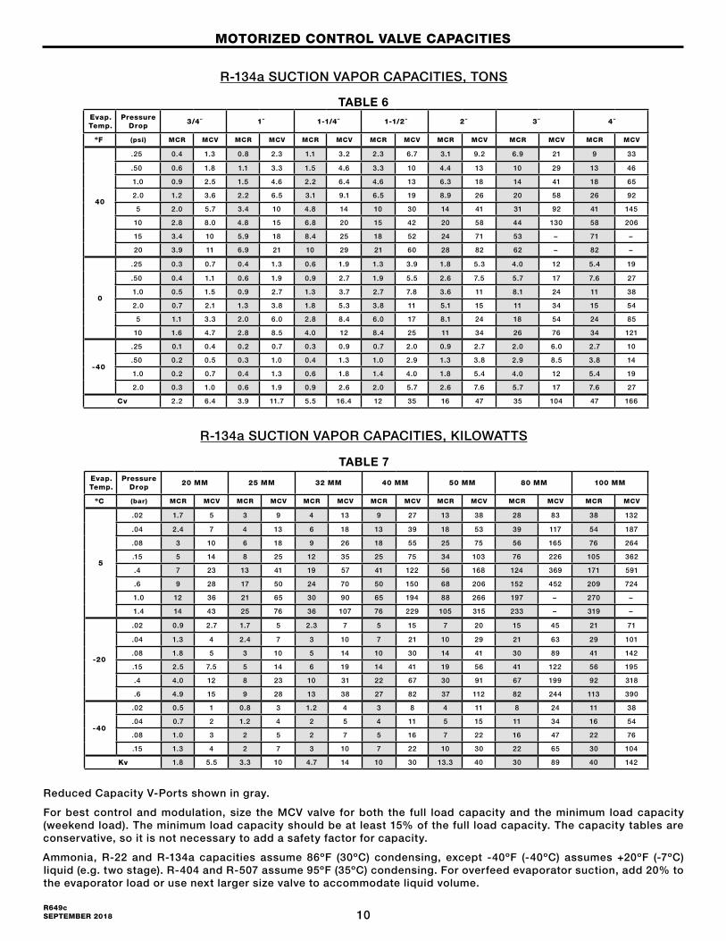
Reduced Capacity V-Ports shown in gray.
For best control and modulation, size the MCV valve for both the full load capacity and the minimum load capacity (weekend load). The minimum load capacity should be at least 15% of the full load capacity. The capacity tables are conservative, so it is not necessary to add a safety factor for capacity.
Ammonia, R-22 and R-134a capacities assume 86ºF (30ºC) condensing, except -40ºF (-40ºC) assumes +20ºF (-7ºC) liquid (e.g. two stage). R-404 and R-507 assume 95ºF (35ºC) condensing. For overfeed evaporator suction, add 20% to the evaporator load or use next larger size valve to accommodate liquid volume.
R-134a SUCTION VAPOR CAPACITIES, TONS
R-134a SUCTION VAPOR CAPACITIES, KILOWATTS
Evap. Temp.
Pressure Drop
3/4˝ 1˝ 1-1/4˝ 1-1/2˝ 2˝ 3˝ 4˝
ºF (psi) MCR MCV MCR MCV MCR MCV MCR MCV MCR MCV MCR MCV MCR MCV
40
.25 0.4 1.3 0.8 2.3 1.1 3.2 2.3 6.7 3.1 9.2 6.9 21 9 33
.50 0.6 1.8 1.1 3.3 1.5 4.6 3.3 10 4.4 13 10 29 13 46
1.0 0.9 2.5 1.5 4.6 2.2 6.4 4.6 13 6.3 18 14 41 18 65
2.0 1.2 3.6 2.2 6.5 3.1 9.1 6.5 19 8.9 26 20 58 26 92
5 2.0 5.7 3.4 10 4.8 14 10 30 14 41 31 92 41 145
10 2.8 8.0 4.8 15 6.8 20 15 42 20 58 44 130 58 206
15 3.4 10 5.9 18 8.4 25 18 52 24 71 53 – 71 –
20 3.9 11 6.9 21 10 29 21 60 28 82 62 – 82 –
0
.25 0.3 0.7 0.4 1.3 0.6 1.9 1.3 3.9 1.8 5.3 4.0 12 5.4 19
.50 0.4 1.1 0.6 1.9 0.9 2.7 1.9 5.5 2.6 7.5 5.7 17 7.6 27
1.0 0.5 1.5 0.9 2.7 1.3 3.7 2.7 7.8 3.6 11 8.1 24 11 38
2.0 0.7 2.1 1.3 3.8 1.8 5.3 3.8 11 5.1 15 11 34 15 54
5 1.1 3.3 2.0 6.0 2.8 8.4 6.0 17 8.1 24 18 54 24 85
10 1.6 4.7 2.8 8.5 4.0 12 8.4 25 11 34 26 76 34 121
-40
.25 0.1 0.4 0.2 0.7 0.3 0.9 0.7 2.0 0.9 2.7 2.0 6.0 2.7 10
.50 0.2 0.5 0.3 1.0 0.4 1.3 1.0 2.9 1.3 3.8 2.9 8.5 3.8 14
1.0 0.2 0.7 0.4 1.3 0.6 1.8 1.4 4.0 1.8 5.4 4.0 12 5.4 19
2.0 0.3 1.0 0.6 1.9 0.9 2.6 2.0 5.7 2.6 7.6 5.7 17 7.6 27
Cv 2.2 6.4 3.9 11.7 5.5 16.4 12 35 16 47 35 104 47 166
Evap. Temp.
Pressure Drop
20 MM 25 MM 32 MM 40 MM 50 MM 80 MM 100 MM
ºC (bar) MCR MCV MCR MCV MCR MCV MCR MCV MCR MCV MCR MCV MCR MCV
5
.02 1.7 5 3 9 4 13 9 27 13 38 28 83 38 132
.04 2.4 7 4 13 6 18 13 39 18 53 39 117 54 187
.08 3 10 6 18 9 26 18 55 25 75 56 165 76 264
.15 5 14 8 25 12 35 25 75 34 103 76 226 105 362
.4 7 23 13 41 19 57 41 122 56 168 124 369 171 591
.6 9 28 17 50 24 70 50 150 68 206 152 452 209 724
1.0 12 36 21 65 30 90 65 194 88 266 197 – 270 –
1.4 14 43 25 76 36 107 76 229 105 315 233 – 319 –
-20
.02 0.9 2.7 1.7 5 2.3 7 5 15 7 20 15 45 21 71
.04 1.3 4 2.4 7 3 10 7 21 10 29 21 63 29 101
.08 1.8 5 3 10 5 14 10 30 14 41 30 89 41 142
.15 2.5 7.5 5 14 6 19 14 41 19 56 41 122 56 195
.4 4.0 12 8 23 10 31 22 67 30 91 67 199 92 318
.6 4.9 15 9 28 13 38 27 82 37 112 82 244 113 390
-40
.02 0.5 1 0.8 3 1.2 4 3 8 4 11 8 24 11 38
.04 0.7 2 1.2 4 2 5 4 11 5 15 11 34 16 54
.08 1.0 3 2 5 2 7 5 16 7 22 16 47 22 76
.15 1.3 4 2 7 3 10 7 22 10 30 22 65 30 104
Kv 1.8 5.5 3.3 10 4.7 14 10 30 13.3 40 30 89 40 142
MOTORIZED CONTROL VALVE CAPACITIES
TABLE 7
TABLE 6
11R649c
SEPTEMBER 2018
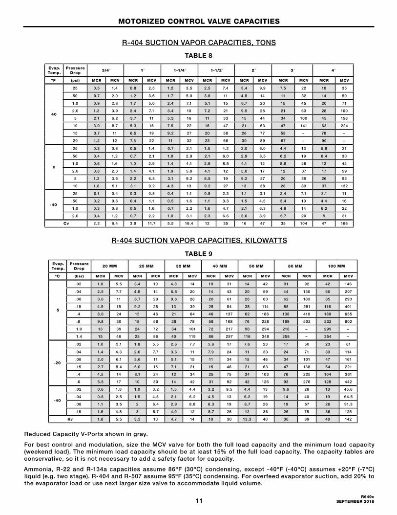
Reduced Capacity V-Ports shown in gray.
For best control and modulation, size the MCV valve for both the full load capacity and the minimum load capacity (weekend load). The minimum load capacity should be at least 15% of the full load capacity. The capacity tables are conservative, so it is not necessary to add a safety factor for capacity.
Ammonia, R-22 and R-134a capacities assume 86ºF (30ºC) condensing, except -40ºF (-40ºC) assumes +20ºF (-7ºC) liquid (e.g. two stage). R-404 and R-507 assume 95ºF (35ºC) condensing. For overfeed evaporator suction, add 20% to the evaporator load or use next larger size valve to accommodate liquid volume.
R-404 SUCTION VAPOR CAPACITIES, TONS
R-404 SUCTION VAPOR CAPACITIES, KILOWATTS
Evap. Temp.
Pressure Drop
3/4˝ 1˝ 1-1/4˝ 1-1/2˝ 2˝ 3˝ 4˝
ºF (psi) MCR MCV MCR MCV MCR MCV MCR MCV MCR MCV MCR MCV MCR MCV
40
.25 0.5 1.4 0.8 2.5 1.2 3.5 2.5 7.4 3.4 9.9 7.5 22 10 35
.50 0.7 2.0 1.2 3.6 1.7 5.0 3.6 11 4.8 14 11 32 14 50
1.0 0.9 2.8 1.7 5.0 2.4 7.1 5.1 15 6.7 20 15 45 20 71
2.0 1.3 3.9 2.4 7.1 3.4 10 7.2 21 9.5 28 21 63 28 100
5 2.1 6.2 3.7 11 5.3 16 11 33 15 44 34 100 45 158
10 3.0 8.7 5.3 16 7.5 22 16 47 21 63 47 141 63 224
15 3.7 11 6.5 19 9.2 27 20 58 26 77 58 – 78 –
20 4.2 12 7.5 22 11 32 23 66 30 89 67 – 90 –
0
.25 0.3 0.8 0.5 1.4 0.7 2.1 1.5 4.2 2.0 6.0 4.4 13 5.9 21
.50 0.4 1.2 0.7 2.1 1.0 2.9 2.1 6.0 2.9 8.5 6.2 19 8.4 30
1.0 0.6 1.6 1.0 2.9 1.4 4.1 2.9 8.5 4.1 12 8.8 26 12 42
2.0 0.8 2.3 1.4 4.1 1.9 5.8 4.1 12 5.8 17 12 37 17 59
5 1.3 3.6 2.2 6.5 3.1 9.2 6.5 19 9.2 27 20 59 26 93
10 1.8 5.1 3.1 9.2 4.3 13 9.2 27 13 38 28 83 37 132
-40
.25 0.1 0.4 0.3 0.8 0.4 1.1 0.8 2.3 1.1 3.1 2.4 7.1 3.1 11
.50 0.2 0.6 0.4 1.1 0.5 1.6 1.1 3.3 1.5 4.5 3.4 10 4.4 16
1.0 0.3 0.8 0.5 1.6 0.7 2.2 1.6 4.7 2.1 6.3 4.8 14 6.2 22
2.0 0.4 1.2 0.7 2.2 1.0 3.1 2.3 6.6 3.0 8.9 6.7 20 9 31
Cv 2.2 6.4 3.9 11.7 5.5 16.4 12 35 16 47 35 104 47 166
Evap. Temp.
Pressure Drop
20 MM 25 MM 32 MM 40 MM 50 MM 80 MM 100 MM
ºC (bar) MCR MCV MCR MCV MCR MCV MCR MCV MCR MCV MCR MCV MCR MCV
5
.02 1.8 5.5 3.4 10 4.8 14 10 31 14 42 31 92 42 146
.04 2.5 7.7 4.8 14 6.8 20 14 43 20 59 44 130 60 207
.08 3.6 11 6.7 20 9.6 28 20 61 28 83 62 183 85 293
.15 4.9 15 9.2 28 13 39 28 84 38 114 85 251 116 401
.4 8.0 24 15 46 21 64 46 137 62 186 138 410 189 655
.6 9.8 30 18 56 26 78 56 168 76 228 169 502 232 802
1.0 13 39 24 72 34 101 72 217 98 294 218 – 299 –
1.4 15 46 28 86 40 119 86 257 116 348 258 – 354 –
-20
.02 1.0 3.1 1.8 5.5 2.6 7.7 5.6 17 7.6 23 17 50 23 81
.04 1.4 4.3 2.6 7.7 3.6 11 7.9 24 11 33 24 71 33 114
.08 2.0 6.1 3.6 11 5.1 15 11 34 15 46 34 101 47 161
.15 2.7 8.4 5.0 15 7.1 21 15 46 21 63 47 138 64 221
.4 4.5 14 8.1 24 12 34 25 75 34 103 76 225 104 361
.6 5.5 17 10 30 14 42 31 92 42 126 93 276 128 442
-40
.02 0.6 1.8 1.0 3.2 1.5 4.4 3.2 9.5 4.4 13 9.6 28 13 45.6
.04 0.8 2.5 1.5 4.5 2.1 6.2 4.5 13 6.2 19 14 40 19 64.5
.08 1.1 3.5 2 6.4 2.9 8.8 6.3 19 8.7 26 19 57 26 91.3
.15 1.6 4.8 3 8.7 4.0 12 8.7 26 12 36 26 78 36 125
Kv 1.8 5.5 3.3 10 4.7 14 10 30 13.3 40 30 89 40 142
MOTORIZED CONTROL VALVE CAPACITIES
TABLE 9
TABLE 8

12R649c SEPTEMBER 2018
Reduced Capacity V-Ports shown in gray.
For best control and modulation, size the MCV valve for both the full load capacity and the minimum load capacity (weekend load). The minimum load capacity should be at least 15% of the full load capacity. The capacity tables are conservative, so it is not necessary to add a safety factor for capacity.
Ammonia, R-22 and R-134a capacities assume 86ºF (30ºC) condensing, except -40ºF (-40ºC) assumes +20ºF (-7ºC) liquid (e.g. two stage). R-404 and R-507 assume 95ºF (35ºC) condensing. For overfeed evaporator suction, add 20% to the evaporator load or use next larger size valve to accommodate liquid volume.
R-507 SUCTION VAPOR CAPACITIES, TONS
R-507 SUCTION VAPOR CAPACITIES, KILOWATTS
Evap. Temp.
Pressure Drop
3/4˝ 1˝ 1-1/4˝ 1-1/2˝ 2˝ 3˝ 4˝
ºF (psi) MCR MCV MCR MCV MCR MCV MCR MCV MCR MCV MCR MCV MCR MCV
40
.25 0.5 1.4 0.9 2.6 1.2 3.5 2.7 7.8 3.5 10 7.7 23 10 37
.50 0.7 2.0 1.2 3.7 1.7 5.0 3.8 11 4.9 15 11 33 15 52
1.0 1.0 2.8 1.7 5.2 2.4 7.1 5.3 16 7.0 21 15 46 21 74
2.0 1.4 4.0 2.4 7.3 3.4 10 7.5 22 9.9 29 22 65 29 104
5 2.2 6.3 3.8 12 5.3 16 12 35 16 46 35 103 47 164
10 3.1 8.9 5.4 16 7.5 22 17 49 22 65 49 145 66 233
15 3.8 11 6.7 20 9.2 27 21 60 27 79 60 – 81 –
20 4.3 13 7.7 23 11 32 24 70 31 92 69 – 93 –
0
.25 0.3 0.8 0.5 1.6 0.7 2.2 1.6 4.6 2.2 6.4 4.6 14 6.2 22
.50 0.4 1.2 0.7 2.2 1.0 3.1 2.2 6.5 3.1 9.0 6.6 20 9 31
1.0 0.6 1.7 1.0 3.1 1.4 4.3 3.2 9.2 4.3 13 9.3 28 12 44
2.0 0.8 2.4 1.5 4.4 2.0 6.1 4.5 13 6.1 18 13 39 18 62
5 1.3 3.8 2.3 7.0 3.2 9.6 7.0 21 9.7 28 21 62 28 98
10 1.8 5.4 3.3 9.8 4.6 14 10 29 14 40 29 87 39 139
-40
.25 0.2 0.5 0.3 0.8 0.4 1.2 0.9 2.5 1.1 3.4 2.5 7.4 3.3 12
.50 0.2 0.7 0.4 1.2 0.6 1.7 1.2 3.6 1.6 4.8 3.5 11 4.7 17
1.0 0.3 0.9 0.6 1.7 0.8 2.3 1.7 5.0 2.3 6.7 5.0 15 6.6 23
2.0 0.4 1.3 0.8 2.4 1.1 3.3 2.4 7.1 3.2 9.5 7.1 21 9 33
Cv 2.2 6.4 3.9 11.7 5.5 16.4 12 35 16 47 35 104 47 166
Evap. Temp.
Pressure Drop
20 MM 25 MM 32 MM 40 MM 50 MM 80 MM 100 MM
ºC (bar) MCR MCV MCR MCV MCR MCV MCR MCV MCR MCV MCR MCV MCR MCV
5
.02 1.9 5.8 3.5 11 4.9 15 11 32 14 43 32 95 44 152
.04 2.7 8.3 4.9 15 6.9 21 15 45 20 61 45 134 62 215
.08 3.8 12 7.0 21 9.8 29 21 64 29 87 64 190 88 304
.15 5.2 16 9.6 29 13 40 29 87 40 119 88 260 120 416
.4 8.6 26 16 47 22 65 47 142 65 194 143 425 196 679
.6 10 32 19 58 27 80 58 174 79 238 175 520 240 832
1.0 14 41 25 75 35 103 75 225 102 307 226 – 310 –
1.4 16 49 29 89 41 122 89 266 121 364 268 – 367 –
-20
.02 1.1 3.2 1.9 5.8 2.8 8.4 6.0 18 8.0 24 18 53 25 85
.04 1.5 4.6 2.7 8.3 4.0 12 8.4 25 11 34 25 75 35 120
.08 2.1 6.5 3.9 12 5.6 17 12 36 16 48 36 107 49 170
.15 2.9 8.9 5.3 16 7.7 23 16 49 22 66 49 146 67 233
.4 4.8 15 8.6 26 13 38 27 80 36 108 80 238 110 380
.6 5.8 18 11 32 15 46 33 98 44 132 98 292 135 466
-40
.02 0.6 1.9 1.1 3.4 1.6 4.7 3.4 10 4.6 14 10 31 14 49
.04 0.9 2.6 1.6 4.8 2.3 6.7 4.8 14 6.5 20 15 43 20 69
.08 1.2 3.7 2.2 6.8 3.2 9.5 6.8 20 9.2 28 21 61 28 98
.15 1.7 5.1 3.1 9.3 4.4 13 9.3 28 13 38 28 84 39 134
Kv 1.8 5.5 3.3 10 4.7 14 10 30 13.3 40 30 89 40 142
MOTORIZED CONTROL VALVE CAPACITIES
TABLE 11
TABLE 10
13R649c
SEPTEMBER 2018
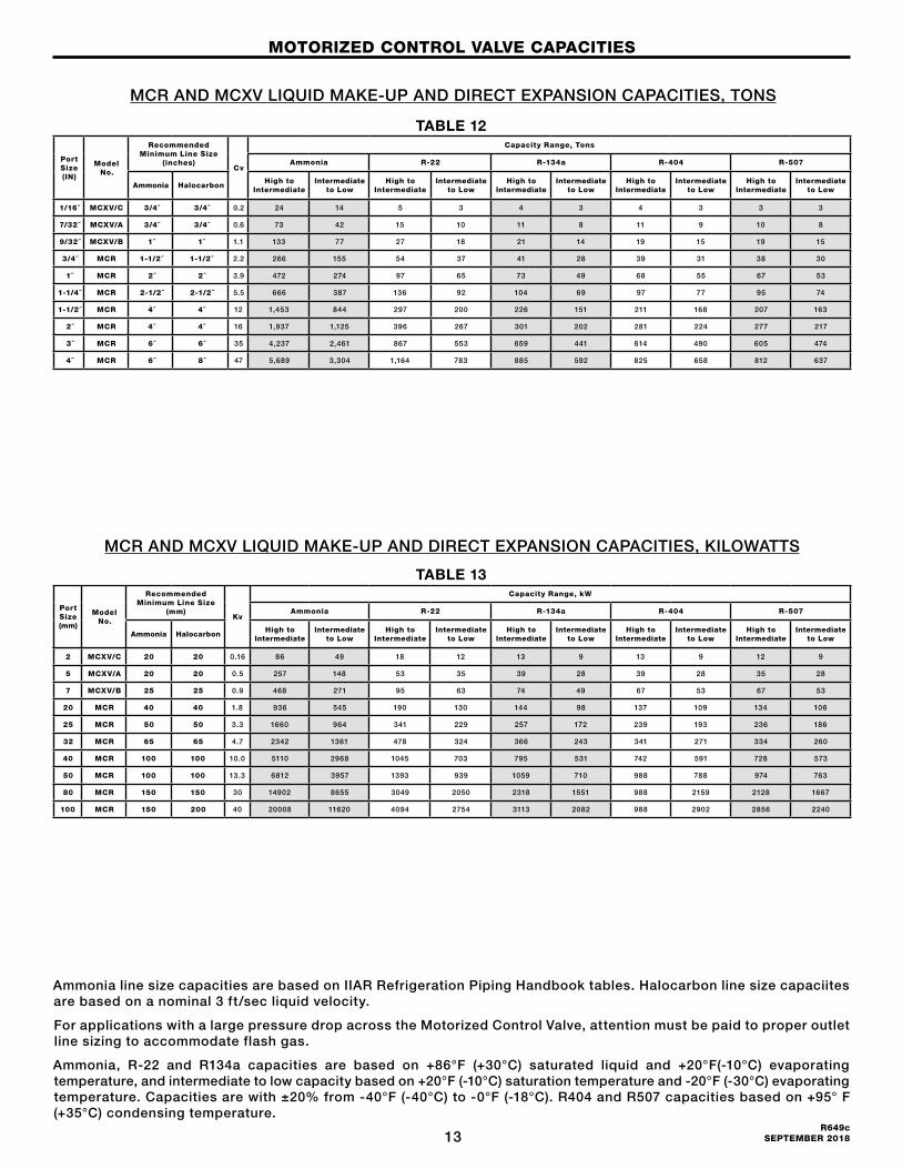
Ammonia line size capacities are based on IIAR Refrigeration Piping Handbook tables. Halocarbon line size capaciites are based on a nominal 3 ft/sec liquid velocity.
For applications with a large pressure drop across the Motorized Control Valve, attention must be paid to proper outlet line sizing to accommodate flash gas.
Ammonia, R-22 and R134a capacities are based on +86°F (+30°C) saturated liquid and +20°F(-10°C) evaporating temperature, and intermediate to low capacity based on +20°F (-10°C) saturation temperature and -20°F (-30°C) evaporating temperature. Capacities are with ±20% from -40°F (-40°C) to -0°F (-18°C). R404 and R507 capacities based on +95° F (+35°C) condensing temperature.
Port Size (mm)
Model No.
Recommended Minimum Line Size
(mm)Kv
Capacity Range, kW
Ammonia R-22 R-134a R-404 R-507
Ammonia HalocarbonHigh to
IntermediateIntermediate
to LowHigh to
IntermediateIntermediate
to LowHigh to
IntermediateIntermediate
to LowHigh to
IntermediateIntermediate
to LowHigh to
IntermediateIntermediate
to Low
2 MCXV/C 20 20 0.16 86 49 18 12 13 9 13 9 12 9
5 MCXV/A 20 20 0.5 257 148 53 35 39 28 39 28 35 28
7 MCXV/B 25 25 0.9 468 271 95 63 74 49 67 53 67 53
20 MCR 40 40 1.8 936 545 190 130 144 98 137 109 134 106
25 MCR 50 50 3.3 1660 964 341 229 257 172 239 193 236 186
32 MCR 65 65 4.7 2342 1361 478 324 366 243 341 271 334 260
40 MCR 100 100 10.0 5110 2968 1045 703 795 531 742 591 728 573
50 MCR 100 100 13.3 6812 3957 1393 939 1059 710 988 788 974 763
80 MCR 150 150 30 14902 8655 3049 2050 2318 1551 988 2159 2128 1667
100 MCR 150 200 40 20008 11620 4094 2754 3113 2082 988 2902 2856 2240
Port Size (mm)
Model No.
Recommended Minimum Line Size
(mm)Kv
Capacity Range, kW
Ammonia R-22 R-134a R-404 R-507
Ammonia HalocarbonHigh to
IntermediateIntermediate
to LowHigh to
IntermediateIntermediate
to LowHigh to
IntermediateIntermediate
to LowHigh to
IntermediateIntermediate
to LowHigh to
IntermediateIntermediate
to Low
Port Size (IN)
Model No.
Recommended Minimum Line Size
(inches)Cv
Capacity Range, Tons
Ammonia R-22 R-134a R-404 R-507
Ammonia HalocarbonHigh to
IntermediateIntermediate
to LowHigh to
IntermediateIntermediate
to LowHigh to
IntermediateIntermediate
to LowHigh to
IntermediateIntermediate
to LowHigh to
IntermediateIntermediate
to Low
1/16˝ MCXV/C 3/4˝ 3/4˝ 0.2 24 14 5 3 4 3 4 3 3 3
7/32˝ MCXV/A 3/4˝ 3/4˝ 0.6 73 42 15 10 11 8 11 9 10 8
9/32˝ MCXV/B 1˝ 1˝ 1.1 133 77 27 18 21 14 19 15 19 15
3/4˝ MCR 1-1/2˝ 1-1/2˝ 2.2 266 155 54 37 41 28 39 31 38 30
1˝ MCR 2˝ 2˝ 3.9 472 274 97 65 73 49 68 55 67 53
1-1/4˝ MCR 2-1/2˝ 2-1/2˝ 5.5 666 387 136 92 104 69 97 77 95 74
1-1/2˝ MCR 4˝ 4˝ 12 1,453 844 297 200 226 151 211 168 207 163
2˝ MCR 4˝ 4˝ 16 1,937 1,125 396 267 301 202 281 224 277 217
3˝ MCR 6˝ 6˝ 35 4,237 2,461 867 553 659 441 614 490 605 474
4˝ MCR 6˝ 8˝ 47 5,689 3,304 1,164 783 885 592 825 658 812 637
Port Size (IN)
Model No.
Recommended Minimum Line Size
(inches)Cv
Capacity Range, Tons
Ammonia R-22 R-134a R-404 R-507
Ammonia HalocarbonHigh to
IntermediateIntermediate
to LowHigh to
IntermediateIntermediate
to LowHigh to
IntermediateIntermediate
to LowHigh to
IntermediateIntermediate
to LowHigh to
IntermediateIntermediate
to Low
TABLE 12
TABLE 13
MCR AND MCXV LIQUID MAKE-UP AND DIRECT EXPANSION CAPACITIES, TONS
MOTORIZED CONTROL VALVE CAPACITIES
MCR AND MCXV LIQUID MAKE-UP AND DIRECT EXPANSION CAPACITIES, KILOWATTS
14R649c SEPTEMBER 2018
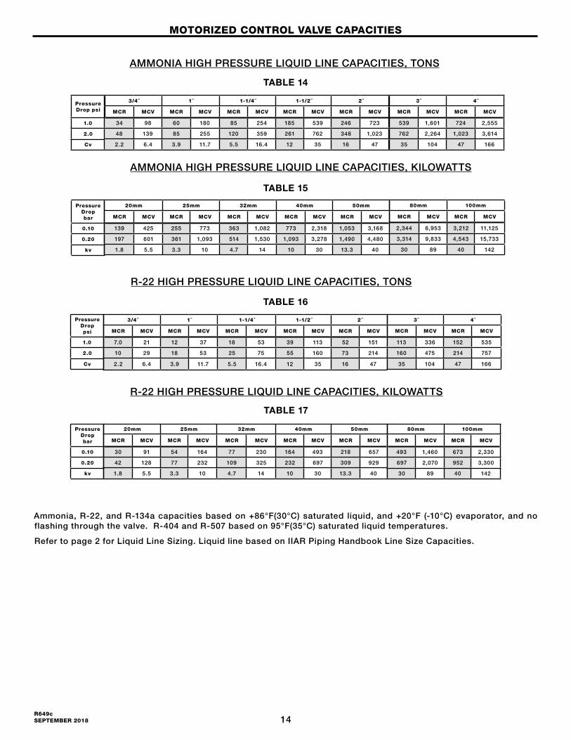
AMMONIA HIGH PRESSURE LIQUID LINE CAPACITIES, TONS
R-22 HIGH PRESSURE LIQUID LINE CAPACITIES, TONS
Ammonia, R-22, and R-134a capacities based on +86°F(30°C) saturated liquid, and +20°F (-10°C) evaporator, and no flashing through the valve. R-404 and R-507 based on 95°F(35°C) saturated liquid temperatures.
Refer to page 2 for Liquid Line Sizing. Liquid line based on IIAR Piping Handbook Line Size Capacities.
AMMONIA HIGH PRESSURE LIQUID LINE CAPACITIES, KILOWATTS
R-22 HIGH PRESSURE LIQUID LINE CAPACITIES, KILOWATTS
TABLE 17
TABLE 16
TABLE 15
TABLE 14
MOTORIZED CONTROL VALVE CAPACITIES
Pressure Drop psi
1.0
2.0
Cv
3/4˝ 1˝ 1-1/4˝ 1-1/2˝ 2˝
MCR MCV MCR MCV MCR MCV MCR MCV MCR MCV
34 98 60 180 85 254 185 539 246 723
48 139 85 255 120 359 261 762 348 1,023
2.2 6.4 3.9 11.7 5.5 16.4 12 35 16 47
3˝ 4˝
MCR MCV MCR MCV
539 1,601 724 2,555
762 2,264 1,023 3,614
35 104 47 166
20mm 25mm 32mm 40mm 50mm
MCR MCV MCR MCV MCR MCV MCR MCV MCR MCV
139 425 255 773 363 1,082 773 2,318 1,053 3,168
197 601 361 1,093 514 1,530 1,093 3,278 1,490 4,480
1.8 5.5 3.3 10 4.7 14 10 30 13.3 40
Pressure Drop bar
0.10
0.20
kv
80mm 100mm
MCR MCV MCR MCV
2,344 6,953 3,212 11,125
3,314 9,833 4,543 15,733
30 89 40 142
3/4˝ 1˝ 1-1/4˝ 1-1/2˝ 2˝
MCR MCV MCR MCV MCR MCV MCR MCV MCR MCV
7.0 21 12 37 18 53 39 113 52 151
10 29 18 53 25 75 55 160 73 214
2.2 6.4 3.9 11.7 5.5 16.4 12 35 16 47
Pressure Drop psi
1.0
2.0
Cv
3˝ 4˝
MCR MCV MCR MCV
113 336 152 535
160 475 214 757
35 104 47 166
20mm 25mm 32mm 40mm 50mm
MCR MCV MCR MCV MCR MCV MCR MCV MCR MCV
30 91 54 164 77 230 164 493 218 657
42 128 77 232 109 325 232 697 309 929
1.8 5.5 3.3 10 4.7 14 10 30 13.3 40
Pressure Drop bar
0.10
0.20
kv
80mm 100mm
MCR MCV MCR MCV
493 1,460 673 2,330
697 2,070 952 3,300
30 89 40 142
15R649c
SEPTEMBER 2018
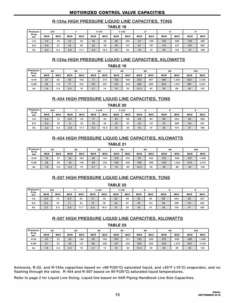
R-134a HIGH PRESSURE LIQUID LINE CAPACITIES, TONS
R-404 HIGH PRESSURE LIQUID LINE CAPACITIES, TONS
Ammonia, R-22, and R-134a capacities based on +86°F(30°C) saturated liquid, and +20°F (-10°C) evaporator, and no flashing through the valve. R-404 and R-507 based on 95°F(35°C) saturated liquid temperatures.
Refer to page 2 for Liquid Line Sizing. Liquid line based on IIAR Piping Handbook Line Size Capacities.
R-134a HIGH PRESSURE LIQUID LINE CAPACITIES, KILOWATTS
R-404 HIGH PRESSURE LIQUID LINE CAPACITIES, KILOWATTS
R-507 HIGH PRESSURE LIQUID LINE CAPACITIES, TONS
R-507 HIGH PRESSURE LIQUID LINE CAPACITIES, KILOWATTS
Pressure Drop psi
3/4˝ 1˝ 1-1/4˝ 1-1/2˝ 2˝ 3˝ 4˝
MCR MCV MCR MCV MCR MCV MCR MCV MCR MCV MCR MCV MCR MCV
1.0 7.0 19 12 35 16 49 36 104 47 139 104 309 140 493
2.0 9.0 27 16 49 23 69 50 147 67 197 147 437 197 697
Cv 2.2 6.4 3.9 11.7 5.5 16.4 12 35 16 47 35 104 47 166
20 25 32 40 50 80 100
MCR MCV MCR MCV MCR MCV MCR MCV MCR MCV MCR MCV MCR MCV
0.10 27 83 50 152 71 213 152 456 202 607 456 1,350 623 2,160
0.20 39 118 71 215 101 301 215 645 286 859 644 1,912 881 3,051
kv 1.8 5.5 3.3 10 4.7 14 10 30 13.3 40 30 89 40 142
3/4˝ 1˝ 1-1/4˝ 1-1/2˝ 2˝ 3˝ 4˝
MCR MCV MCR MCV MCR MCV MCR MCV MCR MCV MCR MCV MCR MCV
1.0 4.0 13 8.0 23 11 33 24 69 32 93 69 204 92 326
2.0 6.0 18 11 33 15 46 33 97 45 131 97 289 131 461
Cv 2.2 6.4 3.9 11.7 5.5 16.4 12 35 16 47 35 104 47 166
20 25 32 40 50 80 100
MCR MCV MCR MCV MCR MCV MCR MCV MCR MCV MCR MCV MCR MCV
0.10 19 57 34 103 48 144 103 310 141 423 313 928 431 1,490
0.20 26 80 48 146 68 204 146 438 199 598 443 1,320 610 2,110
kv 1.8 5.5 3.3 10 4.7 14 10 30 13.3 40 30 89 40 142
3/4˝ 1˝ 1-1/4˝ 1-1/2˝ 2˝ 3˝ 4˝
MCR MCV MCR MCV MCR MCV MCR MCV MCR MCV MCR MCV MCR MCV
1.0 4.0 13 8.0 23 11 33 24 69 32 93 69 205 92 327
2.0 6.0 18 11 33 15 46 33 97 45 131 98 290 131 462
Cv 2.2 6.4 3.9 11.7 5.5 16.4 12 35 16 47 35 104 47 166
20 25 32 40 50 80 100
MCR MCV MCR MCV MCR MCV MCR MCV MCR MCV MCR MCV MCR MCV
0.10 19 57 34 104 49 145 104 311 142 426 313 928 429 1,490
0.20 27 81 49 147 69 205 147 440 200 602 443 1,310 607 2,100
kv 1.8 5.5 3.3 10 4.7 14 10 30 13.3 40 30 89 40 142
AMMONIA HIGH PRESSURE LIQUID LINE CAPACITIES, TONS
R-22 HIGH PRESSURE LIQUID LINE CAPACITIES, TONS
AMMONIA HIGH PRESSURE LIQUID LINE CAPACITIES, KILOWATTS
R-22 HIGH PRESSURE LIQUID LINE CAPACITIES, KILOWATTS
TABLE 18
TABLE 22
TABLE 23
TABLE 21
TABLE 20
TABLE 19
MOTORIZED CONTROL VALVE CAPACITIES
Pressure Drop bar
Pressure Drop bar
Pressure Drop psi
Pressure Drop bar
Pressure Drop psi

16R649c SEPTEMBER 2018
Evaporator tons at 10ºF temperature differential, valve capacities are conservative.
MCR AND MCV HOT GAS SOLENOID DEFROST CAPACITIESEVAPORTATOR SIZE TONS
RefrigerantPort Size (mm)
3/4˝(20)
1˝ (25)
1-1/4˝ (32)
1-1/2˝ (40)
2˝ (50)
Ammonia9-15
(32-53)15-28
(53-99)28-39
(99-137)39-73
(137-256)73-106
(256-373)
R-226-8
(21-28)8-15
(28-53)15-20
(53-70)20-32
(70-113)32-47
(113-165)
R-134a1-4
(4-14)4-8
(14-28)8-12
(28-42)12-20 (42-70)
20-38 (70-134)
R-4043-6
(11-22)6-10
(22-35)10-18
(35-63)18-30
(63-106)30-44
(106-155)
R-5071-4
(4-14)4-8
(14-28)8-12
(28-42)12-20 (42-70)
20-38 (70-134)
TABLE 24
MOTORIZED CONTROL VALVE CAPACITIES
17R649c
SEPTEMBER 2018
MCXV MOTORIZED CONTROL VALVE
6.19"
7.20"
1.60 (41 mm)
(157 mm)
(183 mm)
8.94" WN,ODS(227 mm)
10.75"
8.20" FPT, SW(208 mm)
3.70"(94 mm)
(273 mm)
ALLOW 4" (102 mm)FOR REMOVALOF ACTUATOR
FOR CLOSE-COUPLEDSTRAINER
ADDITIONAL LENGTH
4.74" [120 mm] =MAX WIDTH OF VALVE TYP
9.00"(229 mm)
10.44"(265 mm)
1.67"(42 mm)
10.45"(265 mm)
ALLOW 4" (102 mm)FOR REMOVALOF ACTUATOR
7.28"(185 mm)
7.28"(185 mm)
4.25" (108 mm) =MAX WIDTH OF VALVE TYP
3/4" THRU 1-1/4" MOTORIZED CONTROL VALVE INSTALLATION DRAWING
6.19"
7.20"
1.60 (41 mm)
(157 mm)
(183 mm)
8.94" WN,ODS(227 mm)
10.75"
8.20" FPT, SW(208 mm)
3.70"(94 mm)
(273 mm)
ALLOW 4" (102 mm)FOR REMOVALOF ACTUATOR
FOR CLOSE-COUPLEDSTRAINER
ADDITIONAL LENGTH
4.74" [120 mm] =MAX WIDTH OF VALVE TYP
9.00"(229 mm)
10.44"(265 mm)
1.67"(42 mm)
10.45"(265 mm)
ALLOW 4" (102 mm)FOR REMOVALOF ACTUATOR
7.28"(185 mm)
7.28"(185 mm)
4.25" (108 mm) =MAX WIDTH OF VALVE TYP
3/4" THRU 1-1/4" MOTORIZED CONTROL VALVE INSTALLATION DRAWING 3/4” THRU 1-1/4” MOTORIZED CONTROL VALVE
FIGURE 9
2.11(54mm)
4.95 FPT, SW(117mm)
4.19(106mm)
3.34(85mm)
ALLOW 4.00" (102mm) FOR REMOVALOF ACUTATOR
7504-62
10.79 (274mm)
2.88" (73 mm) =MAX WIDTH OF VALVE TYP
FIGURE 10
MOTORIZED CONTROL VALVE INSTALLATION DRAWINGS
FLANGED WELD-IN-LINE
FLANGED VALVE ONLY
18R649c SEPTEMBER 2018
12.00"(305 mm)
2.87" (73 mm)
10.89"
12.39" FPT, SW
9.88"(251 mm)
(277 mm)
(315 mm)
(340 mm)13.39" WN, ODS
ALLOW 4.00" (102 mm) FOR REMOVALOF ACTUATOR
4.58" (117 mm) = MAX WIDTH OF VALVE
12.00"(305 mm)
2.87" (73 mm)
8.94"(227 mm)
10.44"(265 mm)
WELD-IN-LINE
4.64" (118 mm) = MAX WIDTH OF VALVE
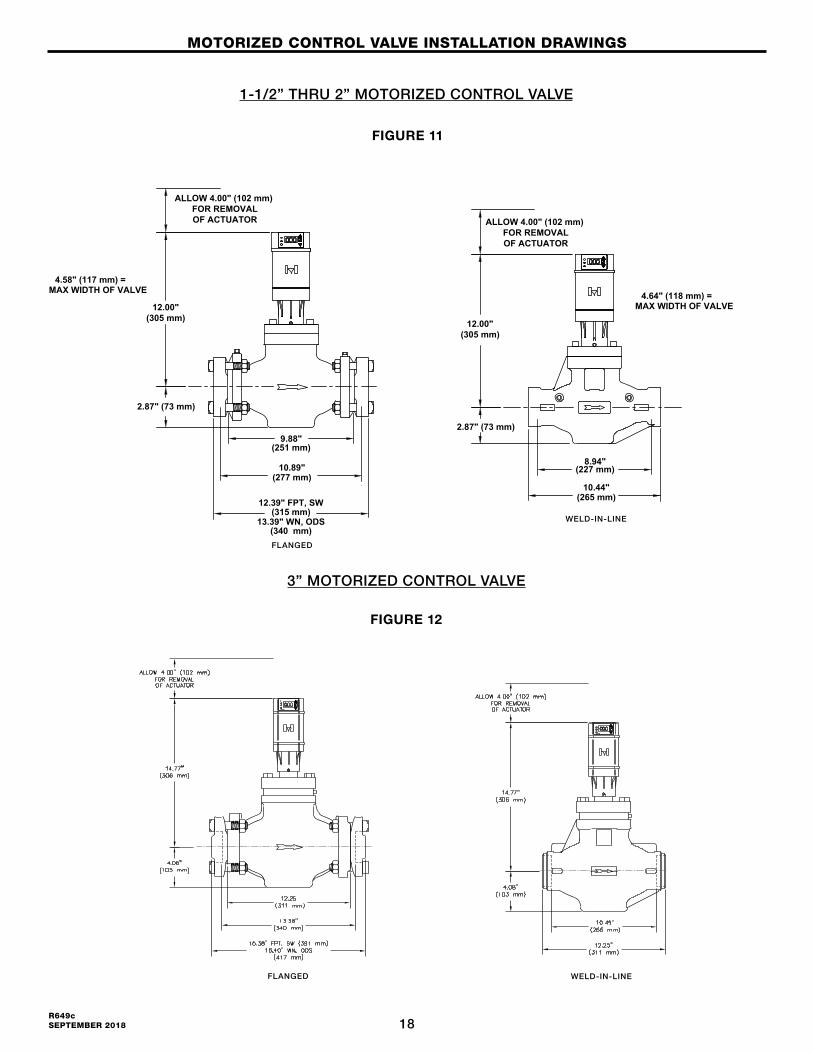
1-1/2" THRU 2" MOTORIZED CONTROL VALVE INSTALLATION DRAWING
ALLOW 4.00" (102 mm) FOR REMOVALOF ACTUATOR
12.00"(305 mm)
2.87" (73 mm)
10.89"
12.39" FPT, SW
9.88"(251 mm)
(277 mm)
(315 mm)
(340 mm)13.39" WN, ODS
ALLOW 4.00" (102 mm) FOR REMOVALOF ACTUATOR
4.58" (117 mm) = MAX WIDTH OF VALVE
12.00"(305 mm)
2.87" (73 mm)
8.94"(227 mm)
10.44"(265 mm)
WELD-IN-LINE
4.64" (118 mm) = MAX WIDTH OF VALVE
1-1/2" THRU 2" MOTORIZED CONTROL VALVE INSTALLATION DRAWING
ALLOW 4.00" (102 mm) FOR REMOVALOF ACTUATOR
1-1/2” THRU 2” MOTORIZED CONTROL VALVE
FIGURE 11
MOTORIZED CONTROL VALVE INSTALLATION DRAWINGS
WELD-IN-LINE
FLANGED
3” MOTORIZED CONTROL VALVE
FIGURE 12
WELD-IN-LINEFLANGED
19R649c
SEPTEMBER 2018
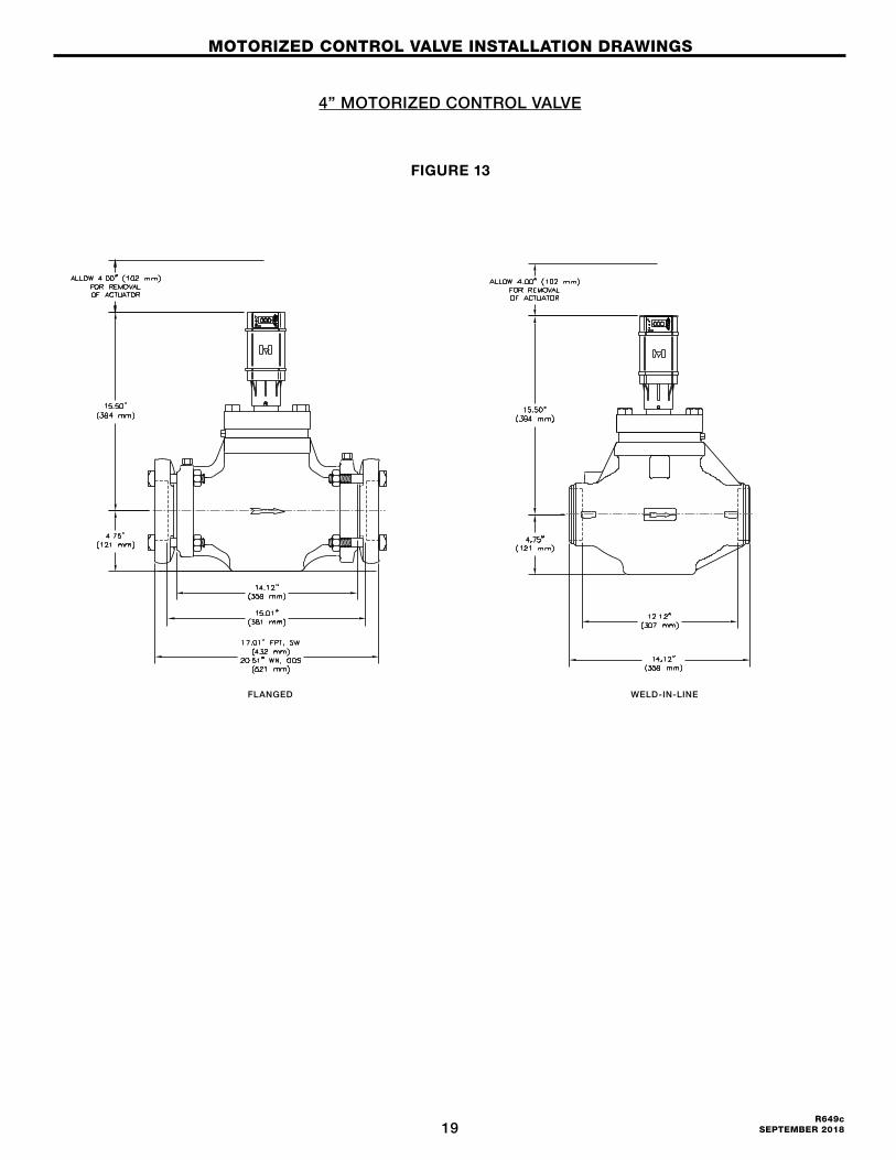
4” MOTORIZED CONTROL VALVE
FIGURE 13
MOTORIZED CONTROL VALVE INSTALLATION DRAWINGS
WELD-IN-LINEFLANGED
20R649c SEPTEMBER 2018
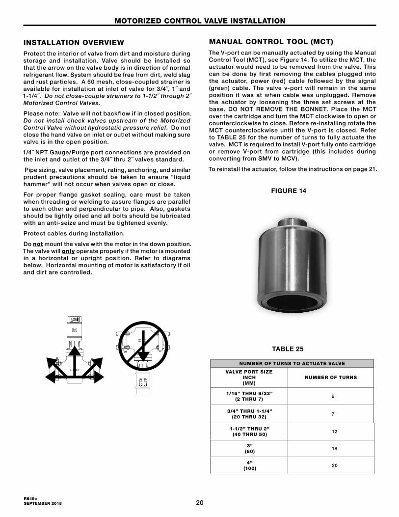
MANUAL CONTROL TOOL (MCT)The V-port can be manually actuated by using the Manual Control Tool (MCT), see Figure 14. To utilize the MCT, the actuator would need to be removed from the valve. This can be done by first removing the cables plugged into the actuator, power (red) cable followed by the signal (green) cable. The valve v-port will remain in the same position it was at when cable was unplugged. Remove the actuator by loosening the three set screws at the base. DO NOT REMOVE THE BONNET. Place the MCT over the cartridge and turn the MCT clockwise to open or counterclockwise to close. Before re-installing rotate the MCT counterclockwise until the V-port is closed. Refer to TABLE 25 for the number of turns to fully actuate the valve. MCT is required to install V-port fully onto cartridge or remove V-port from cartridge (this includes during converting from SMV to MCV).
To reinstall the actuator, follow the instructions on page 21.
INSTALLATION OVERVIEWProtect the interior of valve from dirt and moisture during storage and installation. Valve should be installed so that the arrow on the valve body is in direction of normal refrigerant flow. System should be free from dirt, weld slag and rust particles. A 60 mesh, close-coupled strainer is available for installation at inlet of valve for 3/4˝, 1˝ and 1-1/4˝. Do not close-couple strainers to 1-1/2 ˝ through 2 ˝ Motorized Control Valves.
Please note: Valve will not backflow if in closed position. Do not install check valves upstream of the Motorized Control Valve without hydrostatic pressure relief. Do not close the hand valve on inlet or outlet without making sure valve is in the open position.
1/4˝ NPT Gauge/Purge port connections are provided on the inlet and outlet of the 3/4˝ thru 2˝ valves standard.
Pipe sizing, valve placement, rating, anchoring, and similar prudent precautions should be taken to ensure “liquid hammer” will not occur when valves open or close.
For proper flange gasket sealing, care must be taken when threading or welding to assure flanges are parallel to each other and perpendicular to pipe. Also, gaskets should be lightly oiled and all bolts should be lubricated with an anti-seize and must be tightened evenly.
Protect cables during installation.
Do not mount the valve with the motor in the down position. The valve will only operate properly if the motor is mounted in a horizontal or upright position. Refer to diagrams below. Horizontal mounting of motor is satisfactory if oil and dirt are controlled.
YES NO
MOTORIZED CONTROL VALVE INSTALLATION
TABLE 25
NUMBER OF TURNS TO ACTUATE VALVE
VALVE PORT SIZEINCH(MM)
NUMBER OF TURNS
1/16” THRU 9/32” (2 THRU 7)
6
3/4” THRU 1-1/4” (20 THRU 32)
7
1-1/2” THRU 2” (40 THRU 50)
12
3” (80)
18
4” (100)
20
FIGURE 14
21R649c
SEPTEMBER 2018
INSTALLATION INSTRUCTIONS NEW COMPLETE VALVE
NOTE: Do not power on actuator until it is mounted to the valve and the set screws are properly torqued.
1. Remove valve, actuator, and remaining contents from box.
2. For f langed va lves , a l ign va lve wi th a r row pointing in direction of flow and mount per install protocol. For weld in line valves, it is recommended to remove the cartridge/V-port assembly during we ld ing by loosen ing bo l t s and remov ing bonnet. Replace cartridge/V-port assembly after valve body is installed and ensure o-ring in installed onto cartridge.
3. Install bonnet onto cartridge assembly and tighten four bonnet bolts.
4. Place Manua l Contro l Tool (MCT ) onto the top of magnetic cartridge assembly. Continue to rotate the tool counterclockwise unti l the valve is closed and the V-port will no longer move.
5. Grease exterior of car tridge above the O-ring with supplied low temp, high load, low RPM grease such as Lubriplate Aero or similar.
6. Check the base of the ac tuator to ensure that the set screws are not protruding past the ID of the threaded ring. If necessary back the set screws out to prevent interference during installation.
7. Instal l actuator onto car tr idge. Press f irmly d o w n o n t h e t o p o f t h e a c t u a t o r t o ensure it fully seats. The gap between the base of the actuator and bonnet should be less than 1/16”.
8. Rotate actuator to or ient in desired posit ion and torque the 3 set screws at base to 4 in-lb using 3/32” hex key.
9. Wire the flying lead ends of the cable to power and the desired input signal and feedback loop per wiring diagram.
10. Connect the red and green cables to the actuator
11. Upon power-up, the valve will automatically calibrate.
12. Actuator is programmed for 4-20mA input signal. See page 40 to change if other signal is used.
CONVERSION FROM SMV TO MCVNOTE: Do not power on actuator until it is mounted to
the valve and the set screws are torqued.
1. Isolate and pump down existing valve per PSMs.
2. Disconnect existing powerhead connections.
3. Unscrew the powerhead screws and remove the powerhead.
4. Unscrew bonnet bolts and remove the bonnet.
5. Remove existing can and cartridge assembly. Ensure old gasket is removed from counter bore on top face of valve.
6. Remove new actuator and remaining contents from box.
7. Install new cartridge gasket to counter bore on top face of valve.
8. Install V-port into cartridge while fully supporting the V-port and cartridge and carefully aligning the threaded shaft of cartridge with the low friction nut of V-port. Carefully thread together 6-8 turns and align the anti-rotation slot on the V-port with the anti-rotation pin of the cartridge. Using the MCT, fully thread the V-port into the cartridge, screwing the V-port fully into the cartridge by turning the rotor clockwise.
9. Install new rotor cartridge/V-port assembly into valve.
10. Install new bonnet over cartridge assembly and tighten bonnet bolts.
11. Ensure O-ring is installed onto cartridge assembly.
12. Place Manual Control Tool (MCT) onto the top of magnetic cartridge assembly. Continue to rotate the tool counterclockwise until the valve is closed and the V-port will no longer move.
13. Grease exterior of cartridge above the O-ring with supplied low temp, high load, low RPM grease such as Lubriplate Aero or similar.
14. Check the base of the actuator to ensure that the set screws are not protruding past the ID of the threaded ring. If necessary back the set screws out to prevent interference during installation.
15. Install new actuator onto cartridge. Press firmly down on the top of the actuator to ensure it fully seats. The gap between the base of the actuator and bonnet/cartridge should be less than 1/16”.
16. Rotate actuator to orient in desired position and torque the 3 set screws at base to 4 in-lb using 3/32” hex key.
17. For HMMR/HMMV conversion, connect the black 7 pin dongle connector to the existing connection already wired in place. The VPIF can be left in place if desired.
NOTE: For HMSV conversion cut off black 7 pin dongle connector to power and input/output, per wiring diagram. It is important to remove the 24VAC to the pink and yellow relay signal wires. Voltage to this line will cause damage as the input should only be a closed contact switched to ground.
18. Connect the red and green cables to the actuator.
19. Upon power-up, the valve will automatically calibrate.
20. Confirm actuator is programmed for valve size and input signal through the keypad display. See page 40.
NOTE: Gaskets and O-rings should be replaced with new if they are removed from valve. Recommend to lubricate new gaskets/O-rings with oil prior to installing. Bolts should have anti-seize applied.
MOTORIZED CONTROL VALVE INSTALLATION
22R649c SEPTEMBER 2018
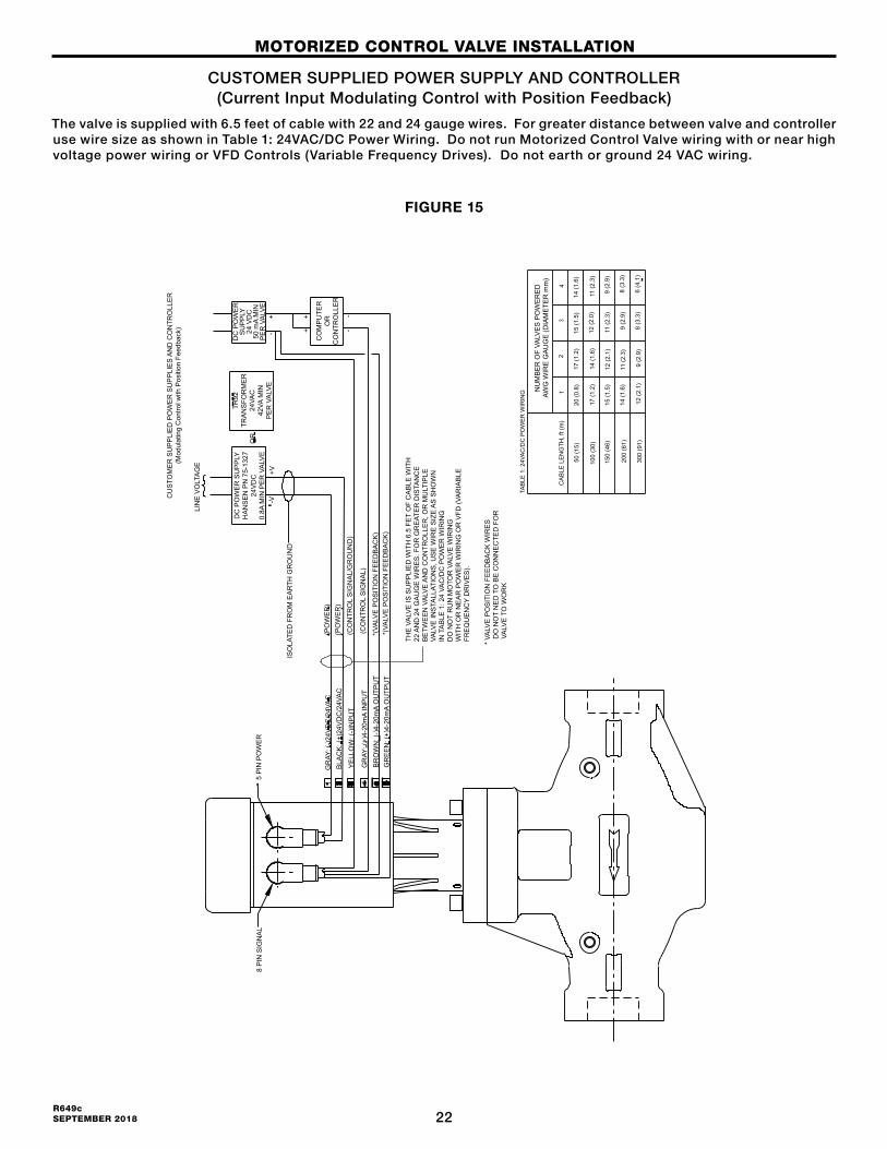
CUSTOMER SUPPLIED POWER SUPPLY AND CONTROLLER(Current Input Modulating Control with Position Feedback)
The valve is supplied with 6.5 feet of cable with 22 and 24 gauge wires. For greater distance between valve and controller use wire size as shown in Table 1: 24VAC/DC Power Wiring. Do not run Motorized Control Valve wiring with or near high voltage power wiring or VFD Controls (Variable Frequency Drives). Do not earth or ground 24 VAC wiring.
FIGURE 15
MOTORIZED CONTROL VALVE INSTALLATION
* VA
LVE
PO
SIT
ION
FE
ED
BA
CK
WIR
ES
D
O N
OT
NE
D T
O B
E C
ON
NE
CTE
D F
OR
VA
LVE
TO
WO
RK
THE
VA
LVE
IS S
UP
PLI
ED
WIT
H 6
.5 F
ET
OF
CA
BLE
WIT
H22
AN
D 2
4 G
AU
GE
WIR
ES
. FO
R G
RE
ATE
R D
ISTA
NC
EB
ETW
EE
N V
ALV
E A
ND
CO
NTR
OLL
ER
, OR
MU
LTIP
LEVA
LVE
INS
TALL
ATIO
NS
, US
E W
IRE
SIZ
E A
S S
HO
WN
IN T
AB
LE 1
: 24
VAC
/DC
PO
WE
R W
IRIN
GD
O N
OT
RU
N M
OTO
R V
ALV
E W
IRIN
GW
ITH
OR
NE
AR
PO
WE
R W
IRIN
G O
R V
FD (V
AR
IAB
LEFR
EQ
UE
NC
Y D
RIV
ES
).
(PO
WE
R)
(PO
WE
R)
(CO
NTR
OL
SIG
NA
L/G
RO
UN
D)
(CO
NTR
OL
SIG
NA
L)
*(VA
LVE
PO
SIT
ION
FE
ED
BA
CK
)*(
VALV
E P
OS
ITIO
N F
EE
DB
AC
K)
GR
AY: (
-)24
VD
C/2
4VA
CB
LAC
K: (
+)24
VD
C/2
4VA
C
YE
LLO
W: (
-)IN
PU
T
GR
AY: (
+)4-
20m
A IN
PU
TB
RO
WN
: (-)
4-20
mA
OU
TPU
TG
RE
EN
: (+)
4-20
mA
OU
TPU
T
ISO
LATE
D F
RO
M E
AR
TH G
RO
UN
D
5 P
IN P
OW
ER
8 P
IN S
IGN
AL
LIN
E V
OLT
AG
E
DC
PO
WE
R S
UP
PLY
HA
NS
EN
PN
75-
1327
24V
DC
0.8A
MIN
PE
R V
ALV
E
TR92
TRA
NS
FOR
ME
R24
VAC
42VA
MIN
PE
R V
ALV
E
OR
-V+V
--
++
+-
DC
PO
WE
RS
UP
PLY
24 V
DC
50 m
A M
INP
ER
VA
LVE
CO
MP
UTE
RO
RC
ON
TRO
LLE
R
CU
STO
ME
R S
UP
PLI
ED
PO
WE
R S
UP
PLI
ES
AN
D C
ON
TRO
LLE
R(M
odul
atin
g C
ontro
l with
Pos
ition
Fee
dbac
k)
NU
MB
ER
OF
VALV
ES
PO
WE
RE
DAW
G W
IRE
GA
UG
E (D
IAM
ETE
R m
m)
CA
BLE
LE
NG
TH, f
t (m
)1
24
3
50 (1
5)
200
(61)
150
(46)
100
(30)
300
(91)
12 (2
.1)
14 (1
.6)
15 (1
.5)
17 (1
.2)
20 (0
.8)
9 (2
.9)
11 (2
.3)
12 (2
.1)
14 (1
.6)
17 (1
.2)
8 (3
.3)
9 (2
.9)
11 (2
.3)
12 (2
.0)
15 (1
.5)
6 (4
.1)
8 (3
.3)
9 (2
.9)
11 (2
.3)
14 (1
.6)
TAB
LE 1
: 24V
AC
/DC
PO
WE
R W
IRIN
G
23R649c
SEPTEMBER 2018
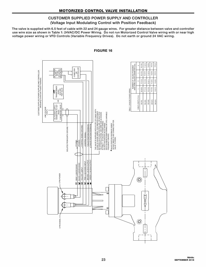
CUSTOMER SUPPLIED POWER SUPPLY AND CONTROLLER(Voltage Input Modulating Control with Position Feedback)
The valve is supplied with 6.5 feet of cable with 22 and 24 gauge wires. For greater distance between valve and controller use wire size as shown in Table 1: 24VAC/DC Power Wiring. Do not run Motorized Control Valve wiring with or near high voltage power wiring or VFD Controls (Variable Frequency Drives). Do not earth or ground 24 VAC wiring.
FIGURE 16
MOTORIZED CONTROL VALVE INSTALLATION
(PO
WE
R)
(PO
WE
R)
(CO
NTR
OL
SIG
NA
L/G
RO
UN
D)
(CO
NTR
OL
SIG
NA
L)
*(VA
LVE
PO
SIT
ION
FE
ED
BA
CK
)*(
VALV
E P
OS
ITIO
N F
EE
DB
AC
K)
GR
AY: (
-)24
VD
C/2
4VA
C
BLA
CK
: (+)
24V
DC
/24V
AC
YE
LLO
W: (
-)IN
PU
T
PIN
K: (
+)0-
5/10
VD
C IN
PU
T
BR
OW
N: (
-)4-
20m
A O
UTP
UT
GR
EE
N: (
+)4-
20m
A O
UTP
UT
ISO
LATE
D F
RO
M E
AR
TH G
RO
UN
D
5 P
IN P
OW
ER
8 P
IN S
IGN
AL
THE
VA
LVE
IS S
UP
PLI
ED
WIT
H 6
.5 F
ET
OF
CA
BLE
WIT
H22
AN
D 2
4 G
AU
GE
WIR
ES
. FO
R G
RE
ATE
R D
ISTA
NC
EB
ETW
EE
N V
ALV
E A
ND
CO
NTR
OLL
ER
, OR
MU
LTIP
LEVA
LVE
INS
TALL
ATIO
NS
, US
E W
IRE
SIZ
E A
S S
HO
WN
IN T
AB
LE 1
: 24
VAC
/DC
PO
WE
R W
IRIN
GD
O N
OT
RU
N M
OTO
R V
ALV
E W
IRIN
GW
ITH
OR
NE
AR
PO
WE
R W
IRIN
G O
R V
FD (V
AR
IAB
LEFR
EQ
UE
NC
Y D
RIV
ES
).
* VA
LVE
PO
SIT
ION
FE
ED
BA
CK
WIR
ES
D
O N
OT
NE
ED
TO
BE
CO
NN
EC
TED
FO
R
VALV
E T
O W
OR
K
CU
STO
ME
R S
UP
PLI
ED
PO
WE
R S
UP
PLI
ES
AN
D C
ON
TRO
LLE
R(M
odul
atin
g C
ontro
l with
Pos
ition
Fee
dbac
k)
LIN
E V
OLT
AG
E
DC
PO
WE
R S
UP
PLY
HA
NS
EN
PN
75-
1327
24V
DC
0.8A
MIN
PE
R V
ALV
E
TR92
TRA
NS
FOR
ME
R24
VAC
42VA
MIN
PE
R V
ALV
E
DC
PO
WE
RS
UP
PLY
24 V
DC
50 m
A M
INP
ER
VA
LVE
OR
-V+V
--
++
+-
CO
MP
UTE
RO
RC
ON
TRO
LLE
R
NU
MB
ER
OF
VALV
ES
PO
WE
RE
DAW
G W
IRE
GA
UG
E (D
IAM
ETE
R m
m)
CA
BLE
LE
NG
TH, f
t (m
)1
24
3
50 (1
5)
200
(61)
150
(46)
100
(30)
300
(91)
12 (2
.1)
14 (1
.6)
15 (1
.5)
17 (1
.2)
20 (0
.8)
9 (2
.9)
11 (2
.3)
12 (2
.1)
14 (1
.6)
17 (1
.2)
8 (3
.3)
9 (2
.9)
11 (2
.3)
12 (2
.0)
15 (1
.5)
6 (4
.1)
8 (3
.3)
9 (2
.9)
11 (2
.3)
14 (1
.6)
TAB
LE 1
: 24V
AC
/DC
PO
WE
R W
IRIN
G
24R649c SEPTEMBER 2018
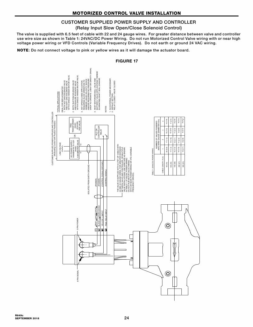
CUSTOMER SUPPLIED POWER SUPPLY AND CONTROLLER(Relay Input Slow Open/Close Solenoid Control)
The valve is supplied with 6.5 feet of cable with 22 and 24 gauge wires. For greater distance between valve and controller use wire size as shown in Table 1: 24VAC/DC Power Wiring. Do not run Motorized Control Valve wiring with or near high voltage power wiring or VFD Controls (Variable Frequency Drives). Do not earth or ground 24 VAC wiring.
NOTE: Do not connect voltage to pink or yellow wires as it will damage the actuator board.
FIGURE 17
MOTORIZED CONTROL VALVE INSTALLATION
NU
MB
ER
OF
VALV
ES
PO
WE
RE
DAW
G W
IRE
GA
UG
E (D
IAM
ETE
R m
m)
CA
BLE
LE
NG
TH, f
t (m
)1
24
3
50 (1
5)
200
(61)
150
(46)
100
(30)
300
(91)
12 (2
.1)
14 (1
.6)
15 (1
.5)
17 (1
.2)
20 (0
.8)
9 (2
.9)
11 (2
.3)
12 (2
.1)
14 (1
.6)
17 (1
.2)
8 (3
.3)
9 (2
.9)
11 (2
.3)
12 (2
.0)
15 (1
.5)
6 (4
.1)
8 (3
.3)
9 (2
.9)
11 (2
.3)
14 (1
.6)
TAB
LE 1
: 24V
AC
/DC
PO
WE
R W
IRIN
G
8 P
IN S
IGN
AL
5 P
IN P
OW
ER
(PO
WE
R)
(PO
WE
R)
(CO
NTR
OL
SIG
NA
L/G
RO
UN
D)
(CO
NTR
OL
SIG
NA
L)
GR
AY: (
-)24
VD
C/2
4VA
C
BLA
CK
: (+)
24V
DC
/24V
AC
YE
LLO
W: (
-)IN
PU
T
PIN
K: R
ELA
Y IN
PU
T
ISO
LATE
D F
RO
M E
AR
TH G
RO
UN
D
THE
VA
LVE
IS S
UP
PLI
ED
WIT
H 6
.5 F
ET
OF
CA
BLE
WIT
H22
AN
D 2
4 G
AU
GE
WIR
ES
. FO
R G
RE
ATE
R D
ISTA
NC
EB
ETW
EE
N V
ALV
E A
ND
CO
NTR
OLL
ER
, OR
MU
LTIP
LEVA
LVE
INS
TALL
ATIO
NS
, US
E W
IRE
SIZ
E A
S S
HO
WN
IN T
AB
LE 1
: 24
VAC
/DC
PO
WE
R W
IRIN
GD
O N
OT
RU
N M
OTO
R V
ALV
E W
IRIN
GW
ITH
OR
NE
AR
PO
WE
R W
IRIN
G O
R V
FD (V
AR
IAB
LEFR
EQ
UE
NC
Y D
RIV
ES
).
CU
STO
ME
R S
UP
PLI
ED
PO
WE
R S
UP
PLI
ES
AN
D C
ON
TRO
LLE
R(M
odul
atin
g C
ontro
l with
Pos
ition
Fee
dbac
k)
LIN
E V
OLT
AG
E
DC
PO
WE
R S
UP
PLY
HA
NS
EN
PN
75-
1327
24V
DC
0.8A
MIN
PE
R V
ALV
E
TR92
TRA
NS
FOR
ME
R24
VAC
42VA
MIN
PE
R V
ALV
E-V
+V
OR P
LC O
RC
ON
TRO
LLE
RR
ELA
Y
TYP
ICA
L A
PP
LIC
ATIO
NS
IDE
AL
FOR
RE
PLA
CE
ME
NTO
F:1.
BO
TH H
OT
GA
S S
OLE
NO
ID V
ALV
E
AN
D S
OFT
GA
S S
OLE
NO
ID V
ALV
E
WIT
H A
SIN
GLE
HA
NS
EN
MO
TOR
VA
LVE
.
2. B
OTH
SU
CTI
ON
SO
LEN
OID
VA
LVE
A
ND
EQ
UA
LIZE
SO
LEN
OID
VA
LVE
W
ITH
A S
ING
LE H
AN
SE
N M
OTO
R V
ALV
E.
3. A
NY
OP
EN
/CLO
SE
D A
PP
LIC
ATIO
N
RE
QU
IRIN
G S
LOW
OP
ER
ATIO
N T
O
MIN
IMIZ
E L
IQU
ID V
ELO
CIT
Y S
HO
CK
A
ND
/OR
RE
QU
IRIN
G N
O P
RE
SS
UR
E
DR
OP
TO O
PE
RAT
E. (
VE
NT
OR
GR
AVIT
Y D
RA
IN)
4. M
OS
T M
OTO
RIZ
ED
BA
LL V
ALV
E A
ND
B
UTT
ER
FLY
VALV
E A
PP
LIC
ATIO
NS
TH
ER
EB
Y
ELI
MIN
ATIN
G S
HA
FT S
EA
L LE
AK
AG
E.
NO
TES
:
1. N
O E
XTE
RN
AL
PO
WE
R N
EC
ES
SA
RY
2. D
EFA
ULT
SE
TTIN
G:
R
ELA
Y C
LOS
ED
= V
ALV
E C
LOS
ED
25R649c
SEPTEMBER 2018
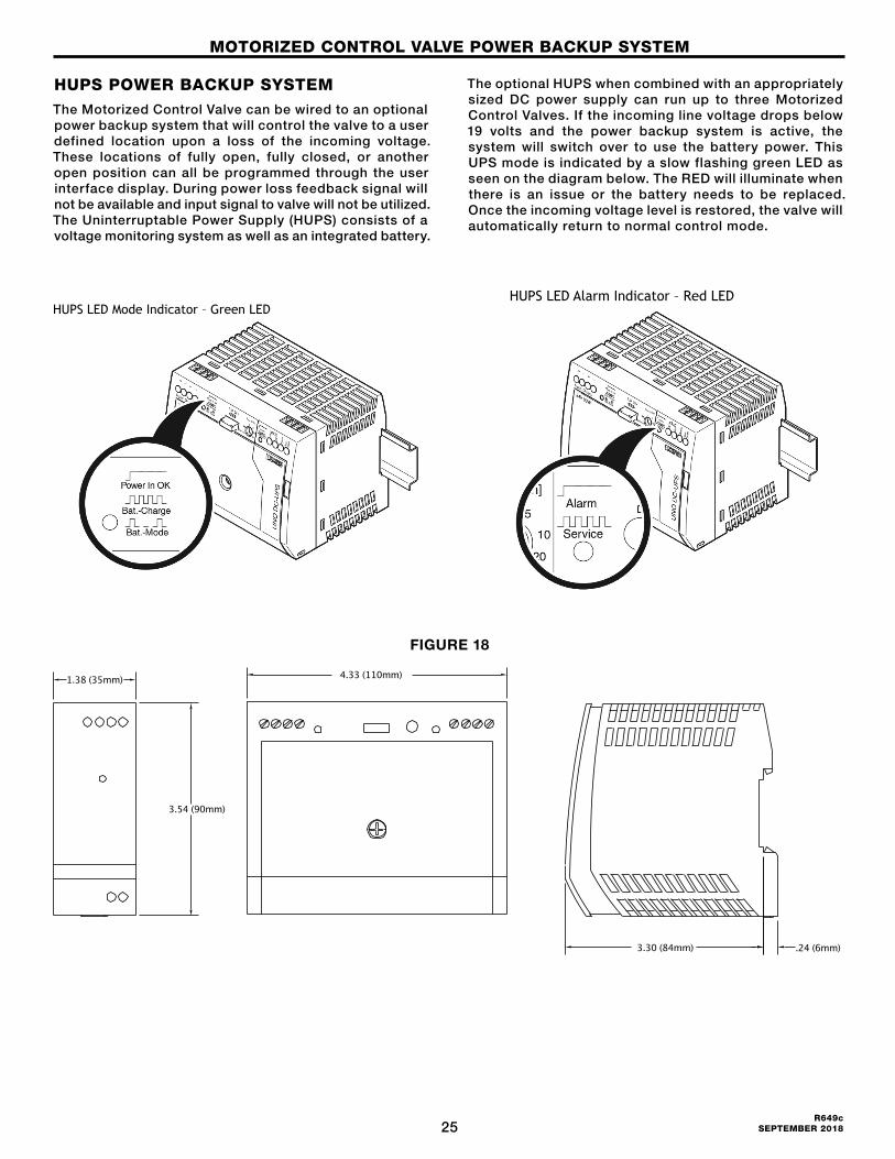
HUPS POWER BACKUP SYSTEMThe Motorized Control Valve can be wired to an optional power backup system that will control the valve to a user defined location upon a loss of the incoming voltage. These locations of fully open, fully closed, or another open position can all be programmed through the user interface display. During power loss feedback signal will not be available and input signal to valve will not be utilized. The Uninterruptable Power Supply (HUPS) consists of a voltage monitoring system as well as an integrated battery.
The optional HUPS when combined with an appropriately sized DC power supply can run up to three Motorized Control Valves. If the incoming line voltage drops below 19 volts and the power backup system is active, the system will switch over to use the battery power. This UPS mode is indicated by a slow flashing green LED as seen on the diagram below. The RED will illuminate when there is an issue or the battery needs to be replaced. Once the incoming voltage level is restored, the valve will automatically return to normal control mode.
MOTORIZED CONTROL VALVE POWER BACKUP SYSTEM
A dd in (Voltage Modulating, Current Modulating, Slow/Open Close) wiring diagrams after this section.
The Motorized Control Valve can be wired to an optional power backup system that will control the valve to a user defined location upon a loss of the incoming voltage. These locations of fully open, fully closed, or another open position can all be programmed through the user interface display. The Uninterruptable Power Supply (UPS) consists of a voltage monitoring system as well as an integrated battery. The optional UPS when combined with an appropriately sized DC power supply can run up to 3 Motorized Control Valves. If the incoming line voltage drops below 19 volts and the power backup system is active, the system will switch over to use the battery power. This UPS mode is indicated by a slow flashing green LED as seen on the diagram below. The RED illuminate when there is an issue or the battery needs to be replaced. Once the incoming voltage level is restored, the valve will automatically return to normal control mode.
HUPS LED Mode Indicator – Green LED
HUPS LED Alarm Indicator – Red LED
5 Gray (+) 0/4-20mA Input Signal
6 Pink (+) 0-5/10VDC & Relay Input Signal
7 Blue Not Used
8 Red Not Used
FIGURE 18
1.38 (35mm)
3.54 (90mm)
3.30 (84mm)
.69 (18mm)
1.76 (45mm)
3.54 (90mm)
.24 (6mm)
1.76 (45mm)
.69 (18mm)
.24 (6mm)
3.54 (90mm)
3.54 (90mm)
4.33 (110mm)
1.38 (35mm)
3.54 (90mm)
3.30 (84mm)
.69 (18mm)
1.76 (45mm)
3.54 (90mm)
.24 (6mm)
1.76 (45mm)
.69 (18mm)
.24 (6mm)
3.54 (90mm)
3.54 (90mm)
4.33 (110mm)1.38 (35mm)
3.54 (90mm)
3.30 (84mm) .24 (6mm)
1.76 (45mm)
.69 (18mm)
.24 (6mm)
3.54 (90mm)
3.54 (90mm)
4.33 (110mm)

26R649c SEPTEMBER 2018
The valve is supplied with 6.5 feet of cable with 22 and 24 gauge wires. For greater distance between valve and controller use wire size as shown in Table 1: 24VAC/DC Power Wiring. Do not run Motorized Control Valve wiring with or near high voltage power wiring or VFD Controls (Variable Frequency Drives).
FIGURE 19
MOTORIZED CONTROL VALVE POWER BACKUP SYSTEM
27R649c
SEPTEMBER 2018
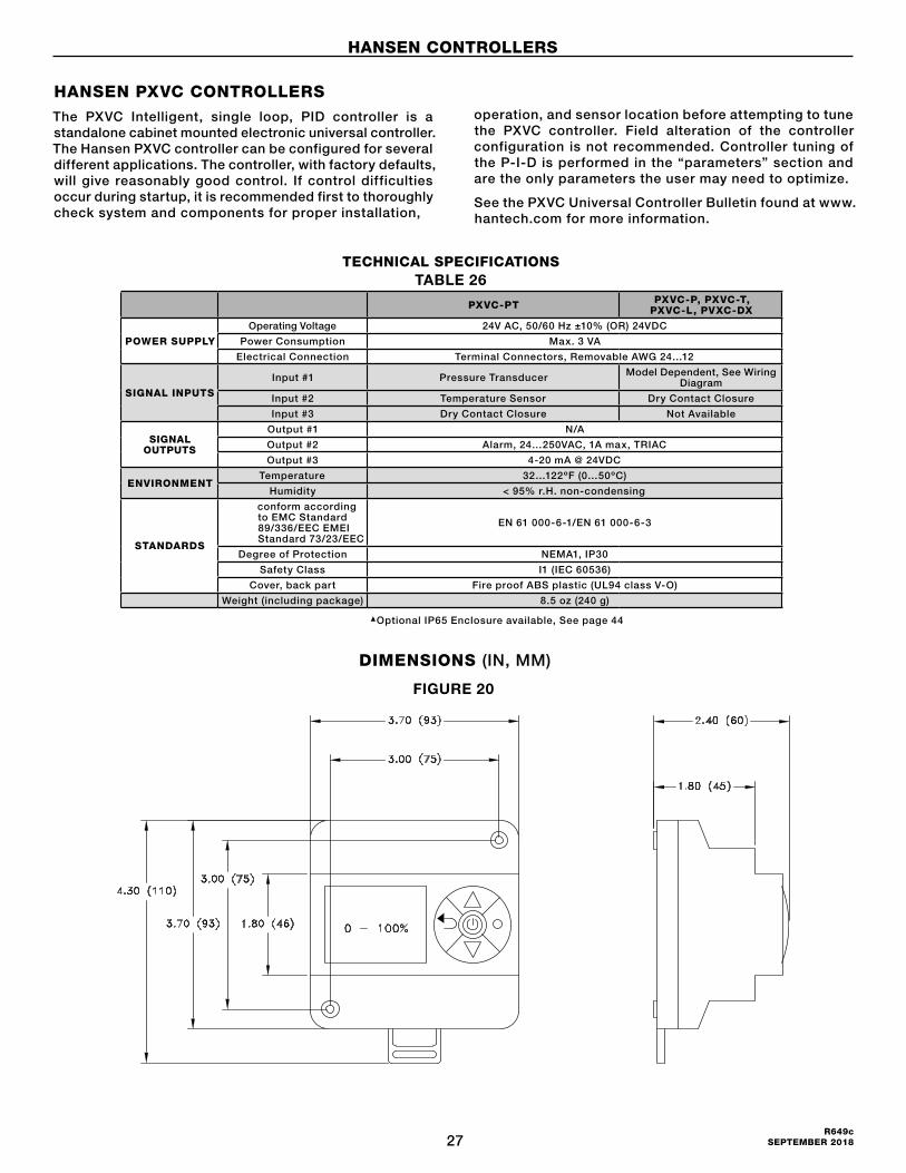
HANSEN PXVC CONTROLLERSThe PXVC Intelligent, single loop, PID controller is a standalone cabinet mounted electronic universal controller. The Hansen PXVC controller can be configured for several different applications. The controller, with factory defaults, will give reasonably good control. If control difficulties occur during startup, it is recommended first to thoroughly check system and components for proper installation,
operation, and sensor location before attempting to tune the PXVC controller. Field alteration of the controller configuration is not recommended. Controller tuning of the P-I-D is performed in the “parameters” section and are the only parameters the user may need to optimize.
See the PXVC Universal Controller Bulletin found at www.hantech.com for more information.
TECHNICAL SPECIFICATIONS
PXVC-PT PXVC-P, PXVC-T, PXVC-L, PVXC-DX
POWER SUPPLY
Operating Voltage 24V AC, 50/60 Hz ±10% (OR) 24VDC
Power Consumption Max. 3 VA
Electrical Connection Terminal Connectors, Removable AWG 24…12
SIGNAL INPUTS
Input #1 Pressure Transducer Model Dependent, See Wiring Diagram
Input #2 Temperature Sensor Dry Contact Closure
Input #3 Dry Contact Closure Not Available
SIGNAL OUTPUTS
Output #1 N/A
Output #2 Alarm, 24…250VAC, 1A max, TRIAC
Output #3 4-20 mA @ 24VDC
ENVIRONMENTTemperature 32…122ºF (0…50ºC)
Humidity < 95% r.H. non-condensing
STANDARDS
conform according to EMC Standard 89/336/EEC EMEI Standard 73/23/EEC
EN 61 000-6-1/EN 61 000-6-3
Degree of Protection NEMA1, IP30
Safety Class I1 (IEC 60536)
Cover, back part Fire proof ABS plastic (UL94 class V-O)
Weight (including package) 8.5 oz (240 g)
Optional IP65 Enclosure available, See page 44
DIMENSIONS (IN, MM)
TABLE 26
FIGURE 20
HANSEN CONTROLLERS
28R649c SEPTEMBER 2018
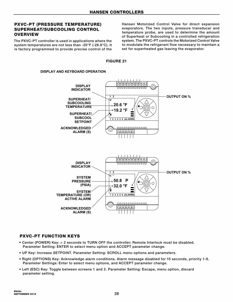
PXVC-PT (PRESSURE TEMPERATURE) SUPERHEAT/SUBCOOLING CONTROL OVERVIEWThe PXVC-PT controller is used in applications where the system temperatures are not less than -20°F (-28.9°C). It is factory programmed to provide precise control of the
Hansen Motorized Control Valve for direct expansion evaporators. The two inputs, pressure transducer and temperature probe, are used to determine the amount of Superheat or Subcooling in a controlled refrigeration system. The PXVC-PT controls the Motorized Control Valve to modulate the refrigerant flow necessary to maintain a set for superheated gas leaving the evaporator.
1 2 3 4 5 6 (ALARMS)
1 2
20.6 °F 19.2 °F
DISPLAYINDICATOR
OUTPUT ON %SUPERHEAT/
SUBCOOLING TEMPERATURE
SUPERHEAT/SUBCOOLSETPOINT
ACKNOWLEDGEDALARM (S)
1 2 3 4 5 6 (ALARMS)
1 2
50.8 P 32.0 °F
DISPLAYINDICATOR
SYSTEMPRESSURE
(PSIA)
SYSTEM
OUTPUT ON %
TEMPERATURE (OR)
ACKNOWLEDGEDALARM (S)
ACTIVE ALARM
DISPLAY AND KEYBOARD OPERATION
PXVC-DX, PXVC-T, PXVC-L, PXVC-P, PXVC-CI
PXVC-PT FUNCTION KEYS• Center (POWER) Key: > 2 seconds to TURN OFF the controller; Remote Interlock must be disabled. Parameter Setting: ENTER to select menu option and ACCEPT parameter change.
• UP Key: Increase SETPOINT. Parameter Setting: SCROLL menu options and parameters.
• Right (OPTIONS) Key: Acknowledge alarm conditions. Alarm message disabled for 15 seconds, priority 1-6. Parameter Settings: Enter to select menu options, and ACCEPT parameter change.
• Left (ESC) Key: Toggle between screens 1 and 2. Parameter Setting: Escape, menu option, discard parameter setting.
FIGURE 21
HANSEN CONTROLLERS
29R649c
SEPTEMBER 2018
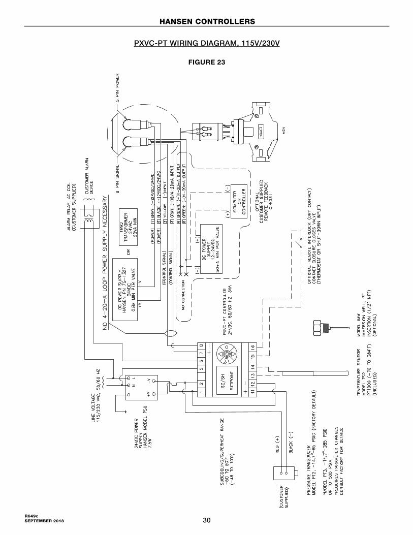
PXVC-PT WIRING DIAGRAM
24-250V AC----------------�
24-250V AC ou::�:E
#14
24V DC(+)--�
24V DC (-)
INPUT #1 PRESSURE
2
INPUT #2 EMPERATURE
6 '---------i OUTPUT # 2 ALARM
--�-�----10UTPUT #3
INPUT #3 INTERLOCK
4-20mA
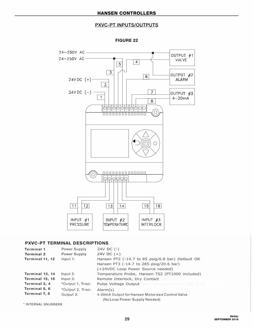
PXVC-PT TERMINAL DESCRIPTIONSTerminal 1 Power Supply Terminal 2 Power Supply Terminal 11, 12
Terminal 13, 14 Terminal 15, 16 Terminal 3, 4 Terminal 5, 6 Terminal 7, 8
Input 1:
Input 2: Input 3: *Output 1, Triac:
*Output 2, Triac: Output 3:
' INTERNAL SNUBBERS
24V DC (-) 24V DC (+) Hansen PT2 (-14.7 to 85 psig/6.8 bar) Default OR Hansen PT3 (-14.7 to 285 psig/20.6 bar) (+24VDC Loop Power Source needed) Temperature Probe, Hansen TS2 (PT1000 included) Remote Interlock, Dry Contact Pulse Voltage Output
Alarm(s) 4-20mA Output for Hansen Motorized Control Valve
(No Loop Power Supply Needed)
5 PXVC MAY 2012
FIGURE 22
HANSEN CONTROLLERS
PXVC-PT INPUTS/OUTPUTS
30R649c SEPTEMBER 2018
FIGURE 23
HANSEN CONTROLLERS
PXVC-PT WIRING DIAGRAM, 115V/230V
31R649c
SEPTEMBER 2018
PXVC-T (TEMPERATURE) CONTROLThe Hansen PXVC-T Controller is factory programmed to provide precise control of temperature in applications such as Liquid Injection of screw compressors. A temperature sensor, included, provides an input to the Hansen PXVC-T controller which controls the Hansen Motorized Control Valve. The valve modulates the refrigerant flow necessary to maintain a set for discharge gas temperature.
PXVC-L (LEVEL) CONTROL OF FLOODED EVAPORATORS The Hansen PXVC-L Controller is factory programmed to provide precise control of liquid level in flooded evaporators, small liquid recirculators, and other refrigerant level vessels. A 4-20 mA input signal from the Hansen VLT level probe, Hansen Vari-Level with 4-20 mA, or other liquid level device to the Hansen PXVC-L controller which controls the Hansen Motorized Control Valve. The valve modulates the refrigerant flow necessary to maintain a set-for liquid level in the vessel.
PXVC-DX CONTROL OF EVAPORATORThe Hansen PXVC-DX Controller is used with system temperatures less than -20°F (-28.9°C). It is factor programmed to provide precise control of the Hansen Motorized Control Valve for direct expansion evaporators. A 4-20mA input signal from the Hansen HPT superheat sensor or computer output of superheat to the PXVC-DX controller which controls the Hansen Motorized Control Valve. The valve modulates the refrigerant flow necessary to maintain a set superheat setpoint.
PXVC-P (PRESSURE) CONTROLThe Hansen PXVC-P Controller is factory programmed to provide precise control of pressure in applications such as hot gas bypass to suction of a compressor. A pressure transducer, available from Hansen, provides an input to the Hansen PXVC-P controller which controls the Hansen Motorized Control Valve. The valve modulates the refrigerant flow necessary to maintain a set for pressure.
SELECTION OF SENSORSTemperature Probe (Included) • TS1, temperature sensor, NTC10K, length 2 inches
with 6.5 feet cable • IMW, temperature probe immersion well, length 4"
Pressure Transducer (Available) • PT2, pressure transducer, -14.7–85 psig, 24VDC,
4-20mA output • PT3 pressure transducer, -14.7–285 psig, 24VDC,
4-20mA output (Factory Default)
Subheat/Subcooling • Hansen HPT
Level Control • Hansen VLT probe or similar
SELECTION OF CONTROL VALVESMotorized Valves • Hansen MCR, MCV, MCXV
POWER FAILUREUpon power-interruption, all parameters and set-points are memorized in non-volatile memory, and therefore do not have to be re-entered
ERROR MESSAGESErr1: Temperature sensor faulty or missing.
Err3: Parameter error; check the input parameter settings.
Err4: Failure of an internal component required for operation. Product must be replaced.
ELECTRICAL CONNECTIONSIn an extremely impaired EMC environment use only shielded cables for input/output connections.
Use safety insulat ing transformers with double insulation; they must be designed for 100% ON-time.
RAMP UP DELAYRamp up delay provides a soft start control at startup. The active state is shown by the clock symbol on the display. At power-up or going from closed to open contacts on the INTERLOCK input, the controller will operate in “RAMP UP DELAY” mode for 2 minutes (default) or a predefined time (IL27 not equal to zero). During the countdown, the P-band is doubled and the KI-bands are halved resulting in a slower control response.
HANSEN CONTROLLERS
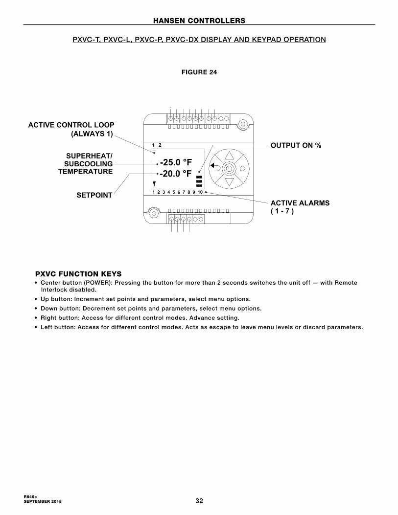
32R649c SEPTEMBER 2018
8PXVC NOV 2012
PXVC-DX, PXVC-T, PXVC-L, PXVC-P, PXVC-CI
1 2 3 4 5 6 7 8 9 10
1 2
-25.0 °F-20.0 °F
ACTIVE CONTROL LOOP(ALWAYS 1)
ACTUAL TEMPERATURE/
PRESSURE/LEVEL/SUPERHEAT
SETPOINT
OUTPUT ON %
ACTIVE ALARMS( 1 - 7 )
PXVC FUNCTION KEYS• Center button (POWER): Pressing the button for more than 2 seconds switches the unit off — with Remote
Interlock disabled.
• Up button: Increment set points and parameters, select menu options.
• Down button: Decrement set points and parameters, select menu options.
• Right button: Access for different control modes. Advance setting.
• Left button: Access for different control modes. Acts as escape to leave menu levels or discard parameters.
DISPLAY AND KEYPAD OPERATION FIGURE 24
HANSEN CONTROLLERS
PXVC-T, PXVC-L, PXVC-P, PXVC-DX DISPLAY AND KEYPAD OPERATION
1 2 3 4 5 6 7 8 9 10
1 2
-25.0 °F -20.0 °F
ACTIVE CONTROL LOOP(ALWAYS 1)
SUPERHEAT/SUBCOOLING
TEMPERATURE
SETPOINT
OUTPUT ON %
ACTIVE ALARMS( 1 - 7 )
PIN #1
PIN #11

33R649c
SEPTEMBER 2018
8PXVC NOV 2012
PXVC-DX, PXVC-T, PXVC-L, PXVC-P, PXVC-CI
1 2 3 4 5 6 7 8 9 10
1 2
-25.0 °F-20.0 °F
ACTIVE CONTROL LOOP(ALWAYS 1)
ACTUAL TEMPERATURE/
PRESSURE/LEVEL/SUPERHEAT
SETPOINT
OUTPUT ON %
ACTIVE ALARMS( 1 - 7 )
PXVC FUNCTION KEYS• Center button (POWER): Pressing the button for more than 2 seconds switches the unit off — with Remote
Interlock disabled.
• Up button: Increment set points and parameters, select menu options.
• Down button: Decrement set points and parameters, select menu options.
• Right button: Access for different control modes. Advance setting.
• Left button: Access for different control modes. Acts as escape to leave menu levels or discard parameters.
DISPLAY AND KEYPAD OPERATION
FIGURE 25
HANSEN CONTROLLERS
PXVC-T, PXVC-L, PXVC-P, PXVC-DX INPUTS/OUTPUTS(i)
PXVC-DX, PXVC-T1 PXVC-L1 PXVC-P
24-250V AC24-250V AC
24V DC (+)
24V DC (-)
INPUT #1 INPUT #2 INTERLOCK
4 OUTPUT #1
VALVE
OUTPUT #2 ALARM
OUTPUT #3 4-20mA
PXVC TERMINAL DESCRIPTIONS Terminal 1
Terminal 2
Terminal 11, 12
Terminal 13, 14
Terminal 3, 4
Terminal 5, 6
Terminal 7, 8
Power Supply
Power Supply Input 1 :
24V DC (-) 24V DC (+)
- P: Hansen PT2 (-14.7 to 85 psig/6.8 bar) OR Hansen PT3 (-14.7 to 285 psig/20.6 bar) DefaultLoop Power Source needed (+24VDC)
- T: Temperature, Hansen TS1 Sensor (Included)Hansen IMW, 4 .. Immersion Well (Purchase Separately)
- Cl: System Controller (Custom Supplied)
- DX: Hansen HPT717(+24VDC Loop Power Source needed)
- L: Hansen VLT or Similar (+24VDC Loop Power Source needed)
Input 2: Optional Remote Interlock, Dry Contact *Output 1, Triac: Pulse Voltage Valve Output
*Output 2, Triac: Alarm(s) Output 3: 4-20m Output for Hansen Motorized Control Valve
(No Loop Power Source needed) • INTERNAL SNUBBER$
PXVC MAY 2012 10
(i) PXVC-DX, PXVC-T1 PXVC-L1 PXVC-P
24-250V AC24-250V AC
24V DC (+)
24V DC (-)
INPUT #1 INPUT #2 INTERLOCK
4 OUTPUT #1
VALVE
OUTPUT #2 ALARM
OUTPUT #3 4-20mA
PXVC TERMINAL DESCRIPTIONS Terminal 1
Terminal 2
Terminal 11, 12
Terminal 13, 14
Terminal 3, 4
Terminal 5, 6
Terminal 7, 8
Power Supply
Power Supply Input 1 :
24V DC (-) 24V DC (+)
- P: Hansen PT2 (-14.7 to 85 psig/6.8 bar) OR Hansen PT3 (-14.7 to 285 psig/20.6 bar) DefaultLoop Power Source needed (+24VDC)
- T: Temperature, Hansen TS1 Sensor (Included)Hansen IMW, 4 .. Immersion Well (Purchase Separately)
- Cl: System Controller (Custom Supplied)
- DX: Hansen HPT717(+24VDC Loop Power Source needed)
- L: Hansen VLT or Similar (+24VDC Loop Power Source needed)
Input 2: Optional Remote Interlock, Dry Contact *Output 1, Triac: Pulse Voltage Valve Output
*Output 2, Triac: Alarm(s) Output 3: 4-20m Output for Hansen Motorized Control Valve
(No Loop Power Source needed) • INTERNAL SNUBBER$
PXVC MAY 2012 10

34R649c SEPTEMBER 2018
FIGURE 26
HANSEN CONTROLLERS
PXVC-T (TEMPERATURE) WIRING DIAGRAM, 115V/230V
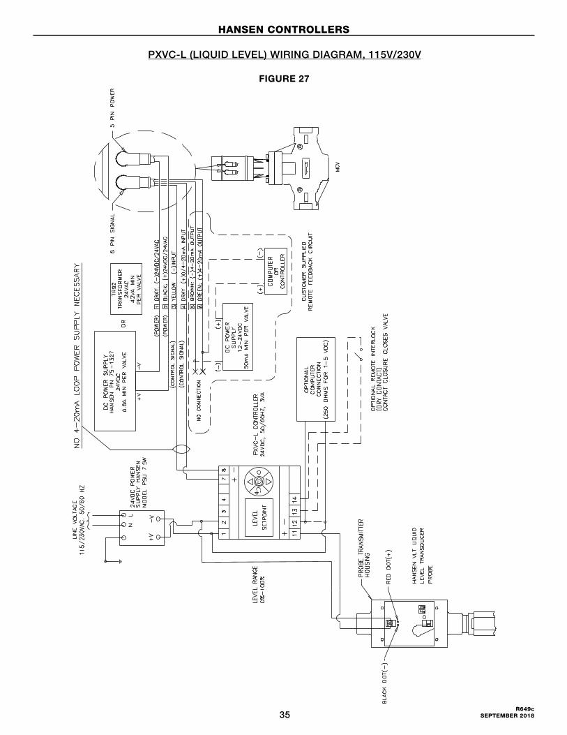
35R649c
SEPTEMBER 2018
FIGURE 27
HANSEN CONTROLLERS
PXVC-L (LIQUID LEVEL) WIRING DIAGRAM, 115V/230V
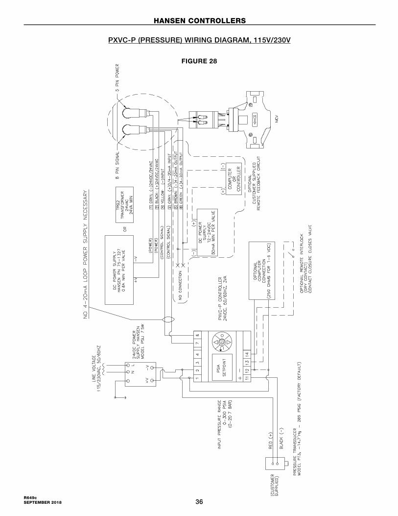
36R649c SEPTEMBER 2018
FIGURE 28
HANSEN CONTROLLERS
PXVC-P (PRESSURE) WIRING DIAGRAM, 115V/230V
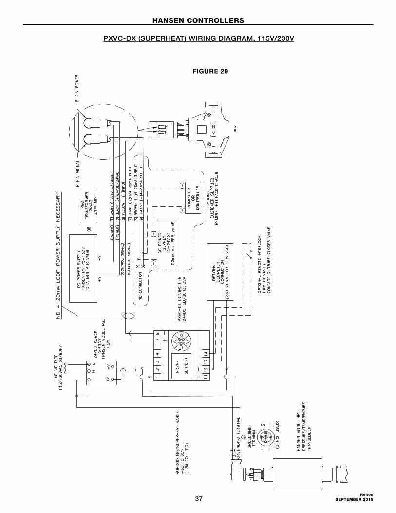
37R649c
SEPTEMBER 2018
FIGURE 29
HANSEN CONTROLLERS
PXVC-DX (SUPERHEAT) WIRING DIAGRAM, 115V/230V
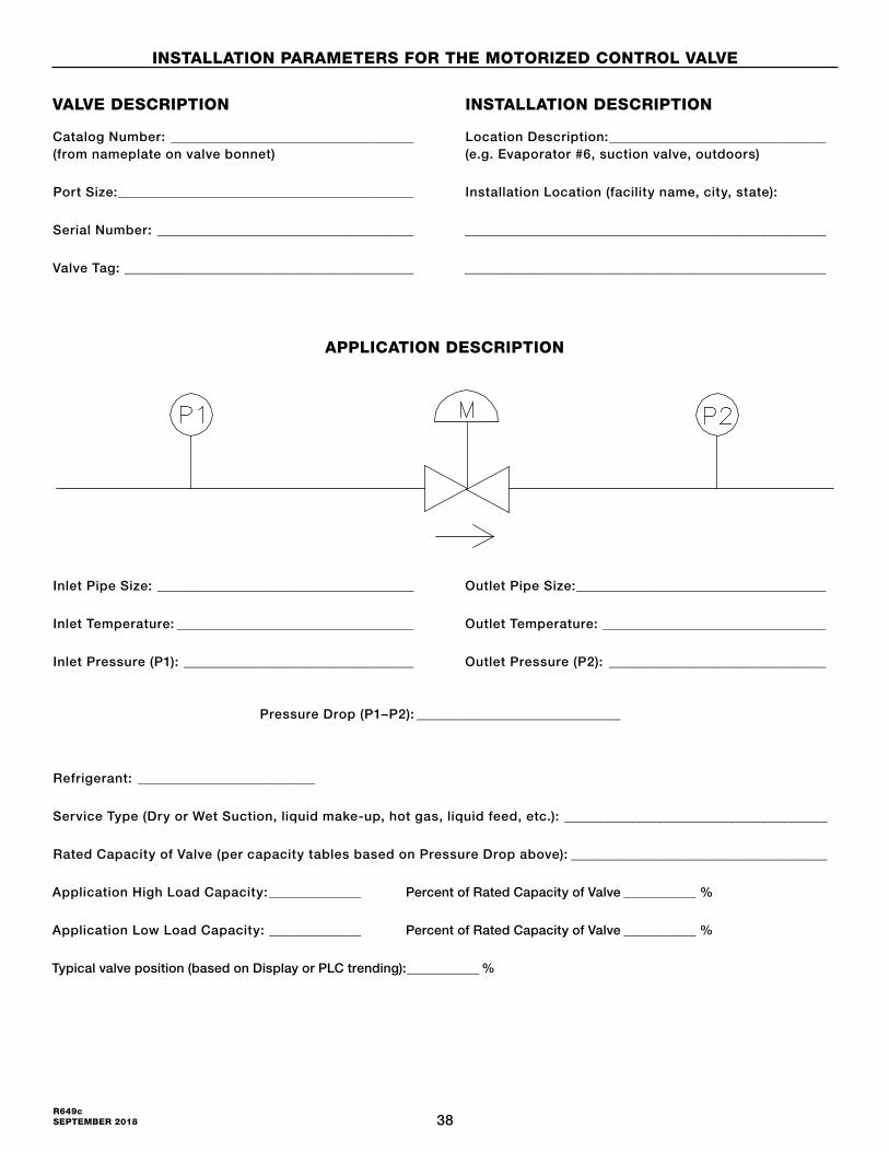
38R649c SEPTEMBER 2018
INSTALLATION PARAMETERS FOR THE MOTORIZED CONTROL VALVE
APPLICATION DESCRIPTION
VALVE DESCRIPTION
Catalog Number: _____________________________________(from nameplate on valve bonnet)
Port Size: _____________________________________________
Serial Number: _______________________________________
Valve Tag: ____________________________________________
Refrigerant: ___________________________
Service Type (Dry or Wet Suction, liquid make-up, hot gas, liquid feed, etc.): ________________________________________
Rated Capacity of Valve (per capacity tables based on Pressure Drop above): _______________________________________
Application High Load Capacity: ______________ Percent of Rated Capacity of Valve ___________ %
Application Low Load Capacity: ______________ Percent of Rated Capacity of Valve ___________ %
Typical valve position (based on Display or PLC trending): ___________ %
Inlet Pipe Size: _______________________________________
Inlet Temperature: ____________________________________
Inlet Pressure (P1): ___________________________________
Pressure Drop (P1–P2): _______________________________
Outlet Pipe Size: ______________________________________
Outlet Temperature: __________________________________
Outlet Pressure (P2): _________________________________
INSTALLATION DESCRIPTION
Location Description: _________________________________(e.g. Evaporator #6, suction valve, outdoors)
Installation Location (facility name, city, state):
_______________________________________________________
_______________________________________________________
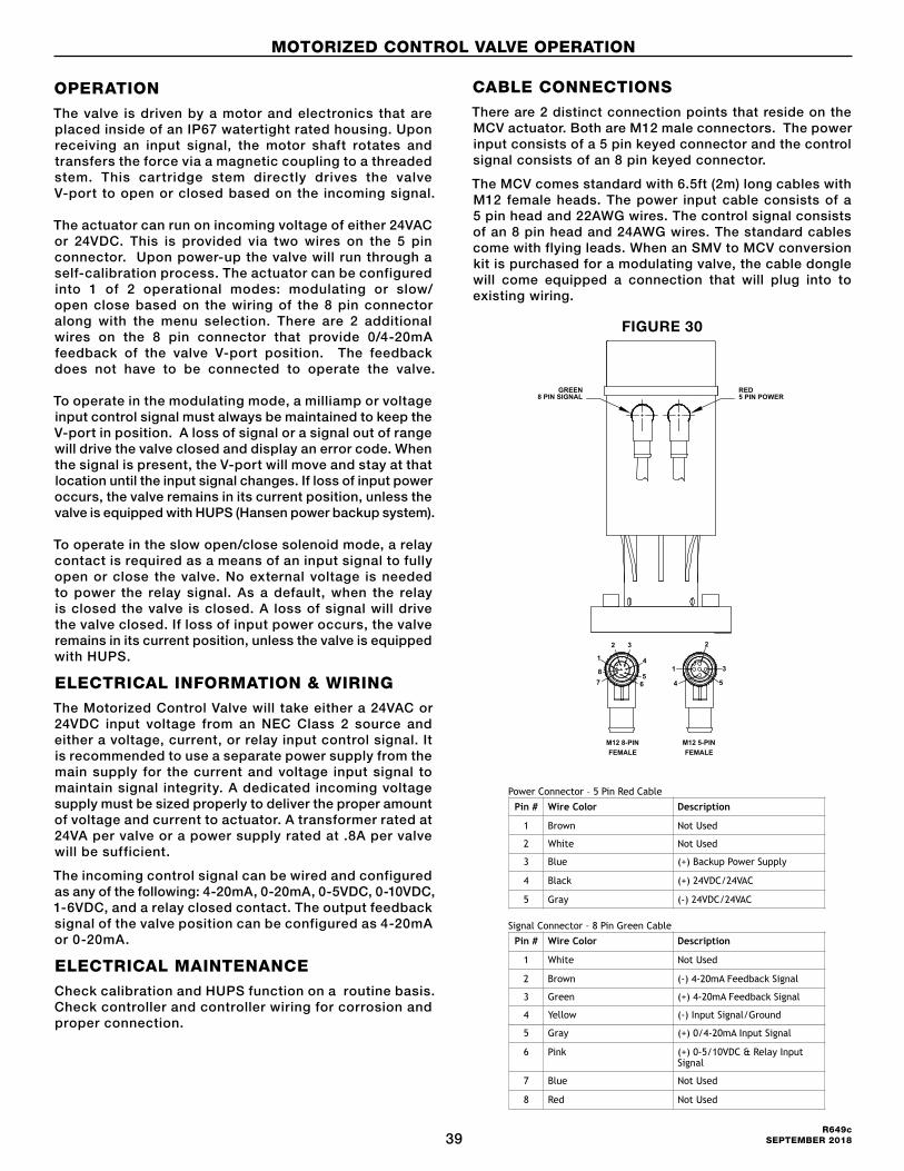
39R649c
SEPTEMBER 2018
OPERATION
The valve is driven by a motor and electronics that are placed inside of an IP67 watertight rated housing. Upon receiving an input signal, the motor shaft rotates and transfers the force via a magnetic coupling to a threaded stem. This cartridge stem directly drives the valve V-port to open or closed based on the incoming signal. The actuator can run on incoming voltage of either 24VAC or 24VDC. This is provided via two wires on the 5 pin connector. Upon power-up the valve will run through a self-calibration process. The actuator can be configured into 1 of 2 operational modes: modulating or slow/open close based on the wiring of the 8 pin connector along with the menu selection. There are 2 additional wires on the 8 pin connector that provide 0/4-20mA feedback of the valve V-port position. The feedback does not have to be connected to operate the valve. To operate in the modulating mode, a milliamp or voltage input control signal must always be maintained to keep the V-port in position. A loss of signal or a signal out of range will drive the valve closed and display an error code. When the signal is present, the V-port will move and stay at that location until the input signal changes. If loss of input power occurs, the valve remains in its current position, unless the valve is equipped with HUPS (Hansen power backup system). To operate in the slow open/close solenoid mode, a relay contact is required as a means of an input signal to fully open or close the valve. No external voltage is needed to power the relay signal. As a default, when the relay is closed the valve is closed. A loss of signal will drive the valve closed. If loss of input power occurs, the valve remains in its current position, unless the valve is equipped with HUPS.
ELECTRICAL INFORMATION & WIRINGThe Motorized Control Valve will take either a 24VAC or 24VDC input voltage from an NEC Class 2 source and either a voltage, current, or relay input control signal. It is recommended to use a separate power supply from the main supply for the current and voltage input signal to maintain signal integrity. A dedicated incoming voltage supply must be sized properly to deliver the proper amount of voltage and current to actuator. A transformer rated at 24VA per valve or a power supply rated at .8A per valve will be sufficient.
The incoming control signal can be wired and configured as any of the following: 4-20mA, 0-20mA, 0-5VDC, 0-10VDC, 1-6VDC, and a relay closed contact. The output feedback signal of the valve position can be configured as 4-20mA or 0-20mA.
ELECTRICAL MAINTENANCECheck calibration and HUPS function on a routine basis. Check controller and controller wiring for corrosion and proper connection.
CABLE CONNECTIONSThere are 2 distinct connection points that reside on the MCV actuator. Both are M12 male connectors. The power input consists of a 5 pin keyed connector and the control signal consists of an 8 pin keyed connector.
The MCV comes standard with 6.5ft (2m) long cables with M12 female heads. The power input cable consists of a 5 pin head and 22AWG wires. The control signal consists of an 8 pin head and 24AWG wires. The standard cables come with flying leads. When an SMV to MCV conversion kit is purchased for a modulating valve, the cable dongle will come equipped a connection that will plug into to existing wiring.
8 PIN SIGNAL 5 PIN POWER
5
2
31
4
M12 8-PIN FEMALE
3
4
5
1
2
87 6
M12 5-PIN FEMALE
GREEN RED
Under Electrical Information & Wiring section on MCV Bulletin Page 15 – CABLE CONNECTIONS There are 2 distinct connection points that reside on the MCV powerhead. Both are M12 male connectors. The power input consists of a 5 pin keyed connector and the control signal consists of an 8 pin keyed connector. The MCV comes standard with 6.5ft (2m) long cables with M12 female heads. The power input cable consists of a 5 pin head and 22AWG wires. The control signal consists of an 8 pin head and 24AWG wires. The standard cables come with flying leads. When an SMV to MCV conversion kit is purchased for a modulating valve, the cable dongle will come equipped a connection that will plug into to existing wiring.
M12 - 8 Pin Connector M12 - 5 Pin Connector Power Connector – 5 Pin Red Cable
Signal Connector – 8 Pin Green Cable
Pin # Wire Color Description
1 Brown Not Used
2 White Not Used
3 Blue (+) Backup Power Supply
4 Black (+) 24VDC/24VAC
5 Gray (-) 24VDC/24VAC
Pin # Wire Color Description
1 White Not Used
2 Brown (-) 4-20mA Feedback Signal
3 Green (+) 4-20mA Feedback Signal
4 Yellow (-) Input Signal/Ground
A dd in (Voltage Modulating, Current Modulating, Slow/Open Close) wiring diagrams after this section.
The Motorized Control Valve can be wired to an optional power backup system that will control the valve to a user defined location upon a loss of the incoming voltage. These locations of fully open, fully closed, or another open position can all be programmed through the user interface display. The Uninterruptable Power Supply (UPS) consists of a voltage monitoring system as well as an integrated battery. The optional UPS when combined with an appropriately sized DC power supply can run up to 3 Motorized Control Valves. If the incoming line voltage drops below 19 volts and the power backup system is active, the system will switch over to use the battery power. This UPS mode is indicated by a slow flashing green LED as seen on the diagram below. The RED illuminate when there is an issue or the battery needs to be replaced. Once the incoming voltage level is restored, the valve will automatically return to normal control mode.
HUPS LED Mode Indicator – Green LED
HUPS LED Alarm Indicator – Red LED
5 Gray (+) 0/4-20mA Input Signal
6 Pink (+) 0-5/10VDC & Relay Input Signal
7 Blue Not Used
8 Red Not Used
FIGURE 30
MOTORIZED CONTROL VALVE OPERATION

40R649c SEPTEMBER 2018
USER INTERFACE MENU AND INSTRUCTION GUIDEThe user interface is a located on the front of the valve and when in normal operation will display the % open of the valve V-port. The setup menu can be entered to automatically calibrate, adjust the control parameters, and view current settings. All displays in this menu start with the letter “H.”. The keypad and display are shown below
All LEDs will be on for couple seconds on power-up. After that the Red and Blue LED should not turn on. The Green LED indicates valve is in manual mode (H.02).
To enter and navigate the menu, follow the steps below: 1. Press and hold the UP and DOWN arrow buttons on the keypad for 3 seconds
2. Upon entering, H.01 will be shown on the display.3. Use the UP and DOWN arrow buttons to navigate through the list below.4. To display and/or modify a value for that description, press the ENTER button.5. Use the UP and DOWN arrow buttons to change the value.6. Press the ENTER button to save the value. The display will return to the setup menu7. Repeat steps 3-6 for all desired changes.8. Exit the menu at any time by pressing and holding the ENTER button on the keypad for 3 seconds.
NOTE: Exiting the menu will NOT save the value to the valve .
NOTE: Valve can stay in Manual Mode (H.02) for an infinite amount of time.
If E.01 or E.02 become active, the valve will drive to zero and close until the signal issue has been rectified. Once the input signal is within the proper limits, the actuator will return to normal operation.
The Setup Menu
The setup menu is used to automatically calibrate, adjust the control parameters, and view current
settings. All displays in this menu start with the letter “H.”. The keypad and display are shown below:
To enter and navigate the menu, follow the steps below:
1. Press and hold the UP and DOWN arrows on the keypad for 3 seconds
2. Upon entering, H.01 will be shown on the display.
3. Use the UP and DOWN arrows to navigate through the list below.
4. To display and/or modify a value for that description, press the ENTER button.
5. Use the UP and DOWN arrows to change the value.
6. Press the ENTER button to save the value. The display will return to the setup menu.
7. Repeat steps 3-6 for all desired changes.
8. Exit the menu at any time by pressing and holding the ENTER button on the keypad for 3
seconds.
Red LED
Green LED
Blue LED Down Button
Enter Button
Up Button
Setup Parameters Display
(Menu #)
Mode Description Min
Value
Max
Value
Factory Setting Comments
- Normal Operation 0 100 - Valve % Open
H.01 Re-Zero
Calibration
0 1 0 0 = No Action
1 = Force motor to recalibrate zero
Display will show CAL
H.02 Automated/Manual
Mode
0 100 0 Mode becomes Manual when entered.
Green LED will illuminate.
Range: 0 - 100% when Enter is pressed
H.03 Valve Size 0 9 0 00 = 3/4” 02 = 1” 03 = 1-1/4” 04 = 1-1/2” 05 = 2” 07 = 3”08 = 4” 09 = 1/16", 7/32", 9/32" Valve will automatically calibrate after selection is made by pressing Enter
H.04 Input Signal Type 0 5 0 0 = 4-20mA
1 = 0-20mA
2 = 0-5Vdc
3 = 0-10Vdc
4 = 1-6Vdc
5 = Relay input
H.05 Output Signal Type 0 1 0 0 = 4-20mA
1 = 0-20mA
H.06 Operation Type 0 3 0 0 = Modulating (Direct)
(input signal increase % open increase)
1 = Modulating (Reverse)
(input signal increase % open decrease)
2 = Open/Close (Direct)
(Closed relay fully closed valve)
3 = Open/Close (Reverse)
(Closed relay fully open valve)
H.07 Speed 25 100 50 Motor speed adjustment
Increments of 25%
H.08 Power Backup
Supply Status
0 1 0 0 = Disabled
1 = Enabled
H.09 Power Backup Fail
Safe Position upon
power loss
0 2 0 Define motor position on power loss
0 = close
1 = open
2 = user defined position @ H. 10
H.10 Fail Safe Position
when H.09 = 2
0 100 0 Number between
0 – 100
Increments of 10
H.11 Alarm Log 0 9 - A0 = Active alarm
A1 A9 = logged alarm. A9 oldest
H. 12 Max. Open Limit 30 100 100 Max. Open must be greater than Min.
Close increments of 10
H. 13 Min. Close Limit 0 40 0 Min. Close Limit must be less than Max.
Open Limit in increments of 10
H. 14 Input Dampening 1 5 -H. 20 Password protected 0 999 -H. 21 Measuring interval 1 50 -H. 34 Factory Reset - Input value of 1 will reset all parameters to
factory defaults
H. 99 Software Version - Displays Software Version
Error Codes with Explanations Error # Description Notes
E.01 Input signal present on the 4-20mA Control Input
greater than expected.
The 4-20mA signal present on the Control Input is
greater than 22mA
E.02 Input signal present on the 4-20mA Control Input
less than expected.
The 4-20mA signal present on the Control Input is less
than 3mA
PF Power Failure when the incoming voltage is less
than expected.
The incoming voltage is less than 19V.
TABLE 27
MOTORIZED CONTROL VALVE OPERATION
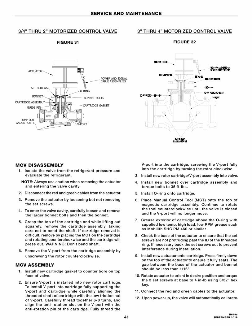
41R649c
SEPTEMBER 2018
SERVICE AND MAINTENANCE
MCV DISASSEMBLY1. Isolate the valve from the refrigerant pressure and
evacuate the refrigerant.
NOTE: Always use caution when removing the actuator and entering the valve cavity.
2. Disconnect the red and green cables from the actuator.
3. Remove the actuator by loosening but not removing the set screws.
4. To enter the valve cavity, carefully loosen and remove the larger bonnet bolts and then the bonnet.
5. Grasp the top of the cartridge and while lifting out squarely, remove the cartridge assembly, taking care not to bend the shaft. If cartridge removal is difficult, remove by placing the MCT on the cartridge and rotating counterclockwise and the cartridge will press out. WARNING: Don’t bend shaft.
6. Remove the V-port from the cartridge assembly by
unscrewing the rotor counterclockwise.
MCV ASSEMBLY1. Install new cartridge gasket to counter bore on top
face of valve.
2. Ensure V-port is installed into new rotor cartridge. To install V-port into cartridge fully supporting the V-port and cartridge while carefully aligning the threaded shaft of cartridge with the low friction nut of V-port. Carefully thread together 6-8 turns, and align the anti-rotation slot on the V-port with the anti-rotation pin of the cartridge. Fully thread the
V-port into the cartridge, screwing the V-port fully into the cartridge by turning the rotor clockwise.
3. Install new rotor cartridge/V-port assembly into valve.
4. Install new bonnet over cartridge assembly and torque bolts to 35 ft-lbs.
5. Install O-ring onto cartridge.
6. Place Manual Control Tool (MCT) onto the top of magnetic cartridge assembly. Continue to rotate the tool counterclockwise until the valve is closed and the V-port will no longer move.
7. Grease exterior of cartridge above the O-ring with supplied low temp, high load, low RPM grease such as Mobilith SHC PM 460 or similar.
8. Check the base of the actuator to ensure that the set screws are not protruding past the ID of the threaded ring. If necessary back the set screws out to prevent interference during installation.
9. Install new actuator onto cartridge. Press firmly down on the top of the actuator to ensure it fully seats. The gap between the base of the actuator and bonnet should be less than 1/16”.
10. Rotate actuator to orient in desire position and torque the 3 set screws at base to 4 in-lb using 3/32” hex key.
11. Connect the red and green cables to the actuator.
12. Upon power-up, the valve will automatically calibrate.
POWER AND SIGNALCABLE ASSEMBLIES
O-RING
BONNET BOLTSBONNET
GUIDE PINCARTRIDGE GASKET
V-PORTPUMP OUT
GAUGE PORTS
ACTUATOR
SET SCREWS
CARTRIDGE ASSEMBLY
FIGURE 31
3/4” THRU 2” MOTORIZED CONTROL VALVE 3” THRU 4” MOTORIZED CONTROL VALVE
FIGURE 32
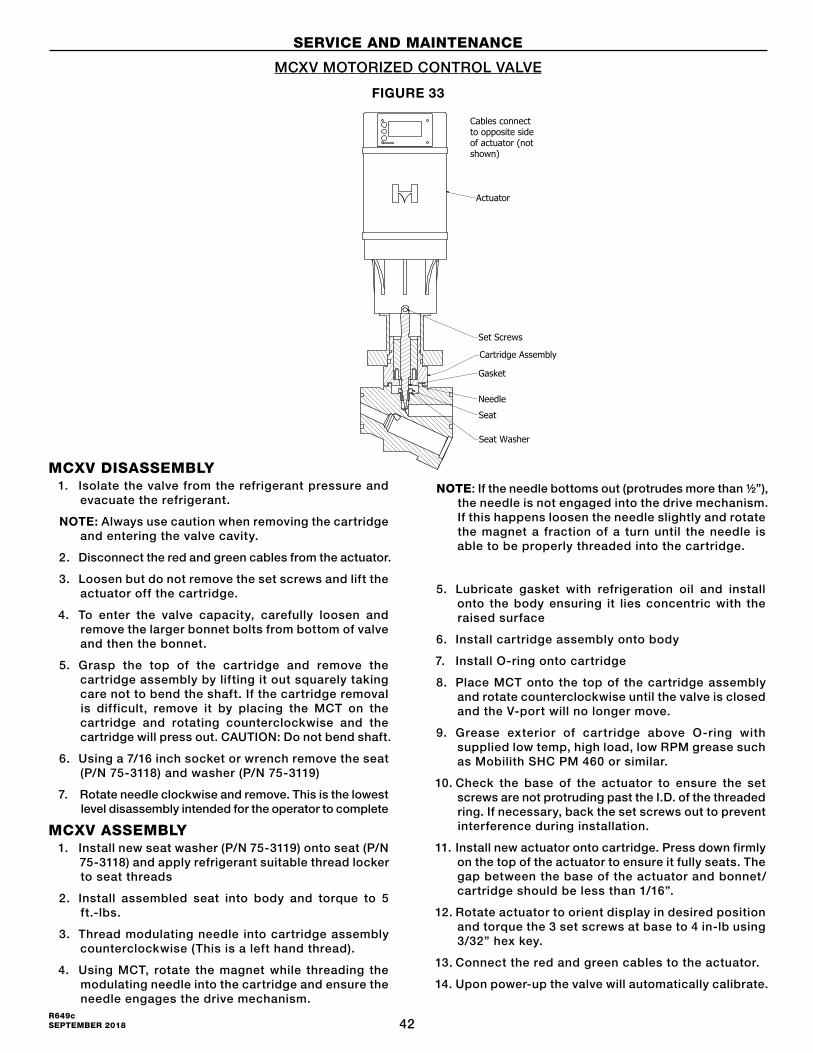
42R649c SEPTEMBER 2018
MCXV DISASSEMBLY1. Isolate the valve from the refrigerant pressure and
evacuate the refrigerant.
NOTE: Always use caution when removing the cartridge and entering the valve cavity.
2. Disconnect the red and green cables from the actuator.
3. Loosen but do not remove the set screws and lift the actuator off the cartridge.
4. To enter the valve capacity, carefully loosen and remove the larger bonnet bolts from bottom of valve and then the bonnet.
5. Grasp the top of the cartridge and remove the cartridge assembly by lifting it out squarely taking care not to bend the shaft. If the cartridge removal is difficult, remove it by placing the MCT on the cartridge and rotating counterclockwise and the cartridge will press out. CAUTION: Do not bend shaft.
6. Using a 7/16 inch socket or wrench remove the seat (P/N 75-3118) and washer (P/N 75-3119)
7. Rotate needle clockwise and remove. This is the lowest level disassembly intended for the operator to complete
MCXV ASSEMBLY1. Install new seat washer (P/N 75-3119) onto seat (P/N
75-3118) and apply refrigerant suitable thread locker to seat threads
2. Install assembled seat into body and torque to 5 ft.-lbs.
3. Thread modulating needle into cartridge assembly counterclockwise (This is a left hand thread).
4. Using MCT, rotate the magnet while threading the modulating needle into the cartridge and ensure the needle engages the drive mechanism.
NOTE: If the needle bottoms out (protrudes more than ½”), the needle is not engaged into the drive mechanism. If this happens loosen the needle slightly and rotate the magnet a fraction of a turn until the needle is able to be properly threaded into the cartridge.
5. Lubricate gasket with refrigeration oil and install onto the body ensuring it lies concentric with the raised surface
6. Install cartridge assembly onto body
7. Install O-ring onto cartridge
8. Place MCT onto the top of the cartridge assembly and rotate counterclockwise until the valve is closed and the V-port will no longer move.
9. Grease exterior of cartridge above O-ring with supplied low temp, high load, low RPM grease such as Mobilith SHC PM 460 or similar.
10. Check the base of the actuator to ensure the set screws are not protruding past the I.D. of the threaded ring. If necessary, back the set screws out to prevent interference during installation.
11. Install new actuator onto cartridge. Press down firmly on the top of the actuator to ensure it fully seats. The gap between the base of the actuator and bonnet/cartridge should be less than 1/16”.
12. Rotate actuator to orient display in desired position and torque the 3 set screws at base to 4 in-lb using 3/32” hex key.
13. Connect the red and green cables to the actuator.
14. Upon power-up the valve will automatically calibrate.
SERVICE AND MAINTENANCE
MCXV MOTORIZED CONTROL VALVE
FIGURE 33
ValveType
1 2 3 4 SMVConversionKits
PortSize ActuatorKitNeedle/V-portAssemblyKit
(includesgasketkit)Cartridge
AssemblyKit(gasketkit,cartridge,
grease)
GasketKit
SMVtoMCVConversionKit**(Actuator,DongleCable,Bonnet,Bolts,CartridgeGasket,BonnetO-ring,
Grease)
SMVPowerClosetoMCVPowerBackupConversionKit**
Inch(mm) Standard PowerBackup P/N Cv
MCXV/A 7/32"(5)75-1331 75-1331with
HUPS
75-1360 0.675-1358 75-1357*
75-1363 75-1363withHUPS
MCXV/B 9/32"(7) 75-1361 1.1 75-1364 75-1364withHUPS
MCXV/C 1/16"(2) 75-1359 0.2 75-1362 75-1362withHUPS
MCV
3/4"(20)
75-133275-1332with
HUPS
75-1381 6.4
75-1325 75-1322 75-1318 75-1318withHUPS1"(25) 75-1382 11.7
1-1/4"(32) 75-1383 16.41-1/2"(40)
75-133375-1333with
HUPS75-1384 35
75-1326 75-1323 75-1319 75-1319withHUPS2"(50) 75-1385 47
3"(80) 75-1334 75-1334with
HUPS75-1396 104 75-1349 75-1351 75-1347*** 75-1347withHUPS***
4"(100) 75-1392 75-1392with
HUPS75-1400 166 75-1350 75-1352 75-1348*** 75-1348withHUPS***
MCR
3/4"(20)75-1332 75-1332with
HUPS
75-1386 2.275-1325 75-1322 75-1318 75-1318withHUPS1"(25) 75-1387 3.9
1-1/4"(32) 75-1381 6.41-1/2"(40)
75-133375-1333with
HUPS75-1388 12
75-1326 75-1323 75-1319 75-1319withHUPS2"(50) 75-1389 16
3"(80) 75-1334 75-1334with
HUPS75-1394 35 75-1349 75-1351 75-1347*** 75-1347withHUPS***
4"(100) 75-1392 75-1392with
HUPS75-1398 47 75-1350 75-1352 75-1348*** 75-1348withHUPS***
NOTE:GasketsandO-ringsshouldbereplacedwithnewiftheyareremovedfromvalve.Recommendtolubricatenewgaskets/O-ringswithoilpriortoinstalling.BoltsshouldhaveanW-seizeapplied.
* Includesstrainer
**All SMV to MCV conversion kits REQUIRE MCT to be available for conversion
*** All 3” and 4” SMV to MCV conversion kits REQUIRE a V-port kit to be requested separately
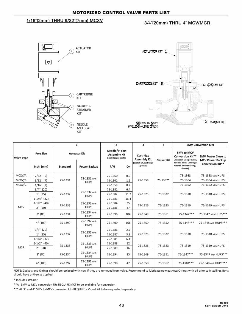
43R649c
SEPTEMBER 2018
1/16˝(2mm) THRU 9/32˝(7mm) MCXV
MOTORIZED CONTROL VALVE PARTS LIST
3/4˝(20mm) THRU 4˝ MCV/MCR
ValveType
1 2 3 4 SMVConversionKits
PortSize ActuatorKitNeedle/V-portAssemblyKit
(includesgasketkit)Cartridge
AssemblyKit(gasketkit,cartridge,
grease)
GasketKit
SMVtoMCVConversionKit**(Actuator,DongleCable,Bonnet,Bolts,CartridgeGasket,BonnetO-ring,
Grease)
SMVPowerClosetoMCVPowerBackupConversionKit**
Inch(mm) Standard PowerBackup P/N Cv
MCXV/A 7/32"(5)75-1331 75-1331with
HUPS
75-1360 0.675-1358 75-1357*
75-1363 75-1363withHUPS
MCXV/B 9/32"(7) 75-1361 1.1 75-1364 75-1364withHUPS
MCXV/C 1/16"(2) 75-1359 0.2 75-1362 75-1362withHUPS
MCV
3/4"(20)
75-133275-1332with
HUPS
75-1381 6.4
75-1325 75-1322 75-1318 75-1318withHUPS1"(25) 75-1382 11.7
1-1/4"(32) 75-1383 16.41-1/2"(40)
75-133375-1333with
HUPS75-1384 35
75-1326 75-1323 75-1319 75-1319withHUPS2"(50) 75-1385 47
3"(80) 75-1334 75-1334with
HUPS75-1396 104 75-1349 75-1351 75-1347*** 75-1347withHUPS***
4"(100) 75-1392 75-1392with
HUPS75-1400 166 75-1350 75-1352 75-1348*** 75-1348withHUPS***
MCR
3/4"(20)75-1332 75-1332with
HUPS
75-1386 2.275-1325 75-1322 75-1318 75-1318withHUPS1"(25) 75-1387 3.9
1-1/4"(32) 75-1381 6.41-1/2"(40)
75-133375-1333with
HUPS75-1388 12
75-1326 75-1323 75-1319 75-1319withHUPS2"(50) 75-1389 16
3"(80) 75-1334 75-1334with
HUPS75-1394 35 75-1349 75-1351 75-1347*** 75-1347withHUPS***
4"(100) 75-1392 75-1392with
HUPS75-1398 47 75-1350 75-1352 75-1348*** 75-1348withHUPS***
NOTE:GasketsandO-ringsshouldbereplacedwithnewiftheyareremovedfromvalve.Recommendtolubricatenewgaskets/O-ringswithoilpriortoinstalling.BoltsshouldhaveanW-seizeapplied.
* Includesstrainer
**All SMV to MCV conversion kits REQUIRE MCT to be available for conversion
*** All 3” and 4” SMV to MCV conversion kits REQUIRE a V-port kit to be requested separately

44R649c SEPTEMBER 2018
Hansen Technologies Corporation681 Commerce StreetBurr Ridge, Illinois 60527 USATel: 630.325.1565 Fax: 630.325.1572 Toll: 866.4HANSEN Email: [email protected] Web: www.hantech.comUSA ∙ Asia ∙ Europe ∙ India ∙ LatinAmerica ∙ MiddleEast© Hansen Technologies Corporation
TO ORDER: Specify valve type (MCV, MCXV, MCR), port size, flange connection style and size.
Motorized Control valves with weld-in connections available (3/4˝ thru 4˝ ), contact factory.
ORDERING INFORMATIONFPT only available up to and including 1¼˝ port size.
PORT SIZEFLANGE CONNECTION
STYLES AND SIZES
FPT, SW, WN ODS
INCH (MM) STANDARD ALSO STANDARD
1/16˝ (2) 1/2 ˝ 3/4˝ 7/8˝
7/32˝ (5) 1/2 ˝ 3/4˝ 7/8˝
9/32˝ (7) 1/2 ˝ 3/4˝ 7/8˝
3/4˝ (20) 3/4˝ 1, 1-1/4˝ 7/8˝
1˝ (25) 1˝ 3/4˝, 1-1/4˝ 1-1/8˝
OPTIONAL CONTROLLERS
MOTORIZED CONTROL VALVE OPTIONAL CONTROLLERS
ACT™Hansen’s advance corrosion protection system ACT™, Anti-Corrosion Technology, is available for all Hansen valves. ACT™ provides 3x to 5x the corrosion protection of standard zinc plating and offers lower acquisition and life cost when compared to other corrosion protection methods. ACT™ protected valves follow all standard and control valve installation processes.
MVPThe Hansen Technologies Multi-Valve Platform (MVP) is a rugged, compact refrigerant control station. The MVP ships pre-tested and assembled for quick and easy installation, requiring only two welds to complete most valve station applications. MVP control functions include Motorized Control Valves (positions 3 and 4), solenoid valves, two-step solenoid valves, and all common Hansen pressure regulator functions. MVP utilizes many of the same pilot modules and internal components as the standard Hansen pressure regulator and solenoid valves
CAUTIONHansen valves are for refrigeration and other Hansen approved systems only. These instructions and related safety precautions must be read completely and understood before selecting, using, or servicing these valves. Only knowledgeable, tra ined refr igerat ion technicians should install, operate, or service these valves. Stated temperature and pressure limits should not be exceeded. Bonnets should not be removed from these valves unless the system has been evacuated to zero pressure. See also Safety Precautions in current List Price Bulletin and Safety Precautions Sheet supplied with product. Escaping refrigerant can cause injury, especially to the eyes and lungs.
WARRANTYHansen electrical and electronic parts are guaranteed against defective materials and workmanship for 90 days F.O.B. our plant. All other components are guaranteed for one year F.O.B. our plant. No consequential damages or field labor is included.
CAT NO DESCRIPTION
PXVC-TTemperature controller with temperature sensor for fully modulating temperature control.
PXVC-LLevel controller for fully modulating applications. Level sensor not included.
PXVC-PPressure controller with pressure transducer for fully modulating pressure control.
PXVC-PTDirect expansion or super heat controller for fully modulating applications.
PXVC-DXDirect expansion or super heat controller for fully modulating applications.
RDR Remote digital readout displays valve position
WTE Watertight Enclosure (NEMA4 for above controller)
OPTIONAL EQUIPMENT
MCT Manual Control Tool
HUPSPower Backup System: Uninterruptable Power Supply and DC power supply for up to 3 valves
75-1321 Cable set 2m long
75-1329 Cable set 5m long
1-1/4˝ (32) 1-1/4˝ 3/4˝, 1˝ 1-3/8˝
1-1/2˝ (40) 1-1/2 ˝ 2 ˝ 1-5/8˝
2˝ (50) 2 ˝ 1-1/2 ˝ 2-1/8˝
3˝ (80) 3˝ - 3-1/8˝
4˝ (100) 4˝ - 4-1/8˝
PSU2Compact Power Supply(100-240VAC: 24VDC) for above enclosure
75-3517 MCV Dongle Conversion Cable
NOTE: For PXVC product bulletin see www.HANTECH.com