Qingqi QM50QT-6 servicemanual - Scootergrisen
144
FOREWORD FOREWORD Jinan Qingqi Motorcycle Co., Ltd. is one of the largest manufacture of motorcycle in China with the best equipment of production and technology, integrated service network and professional service team. This service manual has been produced primarily for experienced mechanics to inspect, adjust, repair and service QINGQI QM50QT-6/6A scooter. This manual contains up-to-date information at the time of its issue. And Jinan Qingqi Motorcycle Co., Ltd. reserves the right to change the specifications without prior written notice. The later-made modifications and changes will be explained to local respective distributor. All rights are lawfully protected. Recitation, reprinting or photocopy of any part of the manual is not allowed without written permission of Jinan Qingqi Motorcycle Co., Ltd..
-
Upload
khangminh22 -
Category
Documents
-
view
3 -
download
0
Transcript of Qingqi QM50QT-6 servicemanual - Scootergrisen

FOREWORD
FOREWORD
Jinan Qingqi Motorcycle Co., Ltd. is one of the largest manufacture of motorcycle
in China with the best equipment of production and technology, integrated service
network and professional service team.
This service manual has been produced primarily for experienced mechanics to
inspect, adjust, repair and service QINGQI QM50QT-6/6A scooter.
This manual contains up-to-date information at the time of its issue.
And Jinan Qingqi Motorcycle Co., Ltd. reserves the right to change the
specifications without prior written notice. The later-made modifications and changes
will be explained to local respective distributor.
All rights are lawfully protected. Recitation, reprinting or photocopy of any part
of the manual is not allowed without written permission of Jinan Qingqi Motorcycle
Co., Ltd..

LOCATIONS OF COMPONENTS
QM50QT-6(Drum Brake) Model LH View
1、Head Light 2、Helmet Hook 3、Seat Assy 4、Seat Lock 5、Rear Carrier 6、Front Reflect 7、Side Stand 8、Center Stand 9、Starter Kick Lever 10、Air Cleaner
RH View
1、Tail Light 2、Foot Rest 3、Rear Winker 4、Muffler 5、Rear Wheel 6、Front Wheel

LOCATIONS OF COMPONENTS
QM50QT-6A(Disk Brake) Model LH view
1、 Head Light 2、Helmet Hook 3、Seat Assy 4、Seat Lock 5、Rear Carrier 6、Front Fork 7、Side Stand 8、Center Stand 9、Starter Kick Lever 10、Air Cleaner RH View
1、Tail Light 2、Rear Winker 3、Foot Rest 4、Muffler 5、Rear Wheel 6、Front Wheel

CONTENTS
CONTENTS Ⅰ General 1 Location of serial No.……………………………………………………… 1 2 Recommended fuel and oil………………………………………………… 1 3 Break-in……………………………………………………………………… 2 4 Information label…………………………………………………………… 2 5 Technical specification……………………………………………………… 3 Ⅱ Periodic Maintenance 1 Periodic maintenance schedule……………………………………………… 4 2 Maintenance procedure……………………………………………………… 6 3 Inspection for compression pressure………………………………………… 20 4 Inspection for lubrication oil pressure……………………………………… 21 5 Inspection for auto-clutch…………………………………………………… 22 Ⅲ Engine 1 Engine removal and disassembly…………………………………………… 23 2 Compression pressure……………………………………………………… 27 3 Cylinder & cylinder head disassembly……………………………………… 28 4 Cylinder & cylinder head inspection………………………………………… 30 5 Cylinder & cylinder head reassembly……………………………………… 36 6 Crankcase parts disassembly………………………………………………… 42 7 Crankcase parts inspection………………………………………………… 50 8 Crankcase parts reassembly………………………………………………… 55 Ⅳ Fuel and lubrication system 1 Fuel tank and gauge………………………………………………………… 65 2 Fuel cock…………………………………………………………………… 66 3 Carburetor…………………………………………………………………… 67 4 Lubrication system………………………………………………………… 74 Ⅴ Frame body 1 Outer part…………………………………………………………………… 75 2 Front wheel………………………………………………………………… 81 3 Front brake………………………………………………………………… 87 4 Front fork…………………………………………………………………… 95 5 Rear wheel, brake and shock absorber……………………………………… 105 6 Rim and tire………………………………………………………………… 108Ⅵ Electric system 1 General……………………………………………………………………… 111 2 location of electric parts……………………………………………………… 113 3 Speedometer………………………………………………………………… 114 4 Fuel level gauge and sensor………………………………………………… 115 5 Switch……………………………………………………………………… 117 6 Battery……………………………………………………………………… 118 7 Charging system…………………………………………………………… 120 8 Self start…………………………………………………………………… 123 9 Ignition system……………………………………………………………… 125Ⅶ Maintenance & Service Information 1 Trouble shooting…………………………………………………………… 127 2 Wiring diagram……………………………………………………………… 131 3 Fasten torque………………………………………………………………… 133 4 Service limit………………………………………………………………… 135

Ⅰ GENERAL Ⅰ- 1 LOCATION OF SERIAL NO. Ⅰ- 2 RECOMMENDED FUEL AND OIL
— 1 —
Ⅰ General
Ⅰ- 1 Location of Serial No. The chassis serial No (or VIN) and the engine serial No is required especially for registering this vehicle and ordering spare part. The chassis serial No (or VIN) is stamped on front pipe of frame. Refer to Fig1.1.1 The engine serial No is stamped on the left side of crankcase. Refer to Fig1.1.2 The identification plate is riveted near to main stand, which shows the specification, manufacture and production date. Refer to Fig1.1.3
Ⅰ- 2 Recommended Fuel and Oil
1. Fuel Gasoline used in this vehicle should be graded 90octane
or higher and unleaded. Normal grade gasoline which might result knocking noise in engine should be replaced. Note
Using lead-free gasoline will be helpful to ensure the spark plug life. 2. Engine Oil and Transmission Oil
Using good quality lubrication oil will ensure the motorcycle service life.
Use SAE10W-40 API-grade engine oil or select according to the table in Fig1.2.1 Note
For new motorcycle, replace the lubrication oil after first 500 km or one month driving, and later on replace for every 6000km.
750ml lubrication oil is required for oil replacement, and 850ml is required for repairing the engine. 3. Hydraulic brake Liquid(only for disk brake model)
Grade: DOT4 Note:
Only DOT4 glycol-based hydraulic brake fluid is equipped in this vehicle.
Don’t mix it with silicon-based or oil-based fluid. Otherwise hydraulic brake system will be damaged.
Don’t use residual fluid in opened container during last maintenance, because it would absorb moisture in atmosphere.
Don’t splash the brake liquid to the surface of paint or
Fig 1.1.1
Fig 1.1.2
Fig 1.1.3
Fig 1.2.1
℃ -30 -20 -10 0 10 20 30 40
-22 -4 -14 32 50 68 86 104°F°TEMP
MULTIGRADE
rubber part. Otherwise their surface will be corroded. 4. Hydraulic oil in front fork
Oil #15

Ⅰ GENERAL Ⅰ- 3 BREAK-IN Ⅰ- 4 INFORMATION LABEL
— 2 —
Ⅰ- 3 Break-in
During manufacture only the best materials are used and all machined parts are finished to a very high standard, but it is still necessary to allow the moving parts to “BREAK-IN” before subjecting the engine to maximum stresses. The future performance and reliability of the engine depends on the care and restraint exercised during its early life.
During break-in, engine rpm should be limited as below: Initial 150km: Less Than 2000rpm Up to 500km: Less Than 2500rpm Up to 1000km: Less Than 3000rpm After 1000km: Less than 4800rpm
During firstly 1000km, full throttle should not be applied, and keep engine rpm less than 4800tpm.
During break-in, engine should avoid to work at constant rpm.
Ⅰ- 4 Information Label
1 VIN Fig1.4.1
2 Engine serial No. Fig1.4.2
3 Rating label Fig1.4.3
4 Anti-tampering label(EC) Fig1.4.4
Fig1.4.1
Fig1.4.2
Fig1.4.3
Fig1.4.4

Ⅰ GENERAL Ⅰ- 5 SPECIFICATION
— 3 —
Ⅰ- 5 Specification
Specification
Item Parameter Item Parameter
Wheels and Brakes
Rim (F/R) Type (F/R) Type Pressure (F/R) kPa Brake Type (F/R) Brake Operation (F/R) Suspension (F)
(R)
Integral type/ Integral type 3.00-10 4PR / 3.00-10 4PR 125/175 Drum/Drum, Disk/drum Manual/Manual Spring / Oil damping Spring / Oil damping
Dim
ension parameters
Model L*W*H (mm) Wheels Base (mm) Ground Clearance (mm) Turning Radius (mm) Cast angle(°) Steering Angle(°)(L/R)
QM50QT-6/6A 1660×700×1070 1200 100 3800 26 45
Quality Param
eter
Curb Mass (kg) Max. laden Mass (kg) Mass Distribution (N) (F/R) Fuel Tank Capacity (L)
79 100 503/1006 6.3 Electrical System
Spark Plug Model Head Light Winker Front Position Light Stop Light/License Light Instrument Light Fuse Battery Horn Speedometer Interference Suppression
A7RTC / LDA7TC 12V 25W/25W 12V 10W 12V 5W 12V 21W/5W 12V 2W 10A 12V 4Ah Electro Magnetic Actuated Diaphragm 12V 1.5A 100dB(A) Magnetic Induction Resistor type
Engine
Model Type Bore × Stroke (mm) Displacement (ml) Compression ratio Max. Power kW/(r/min) Rated Power kW/(r/min) Max. Toque Nm/(r/min) Min. Fuel Consumption g/kw·h Idling Speed r/min Ignition Starting Lubrication Lubrication Oil Fuel Carburetor Type Air Cleaner Valve Timing
139QMB 4 Stroke Single cylinder Forced air-cooling
39.0×41.4 49.58 10.5:1 2.00/7000 1.80/7000 3.10/6000 450 1500±100 C.D.I. Kick/ self start Pressure /Splash 15W/40 Unleaded petrol 90# above Diaphragm Polyurethane-foam elementOHV
Transmission System
Clutch Type Transmission Primary Drive Ratio Final Drive Ratio
Dry, Automatic Centrifugal CVT Belt 3.25 3.40
Performance of M
otorcycle
Brake Distance(20km/h)m Brake Force N (F) (R) Sound Level dB(A) Exhaust Emission TypeⅠ(g/km)
Type Ⅱ Max Speed km/h Cold-starting ability (s) Climbing ability(°) Fuel consumption(l/100km) Acceleration (s) Side stand TTL (%) Side stand TTR (%) Center stand TTL & TTL (%) Downstream (%) side stand
center stand Reliability (km) Durability (km) Head light luminescent intensity (cd)
≤4.00 ≥301 ≥503 ≤73 CO≤6.00 HC + NOX ≤ 3.00 CO≤3.8% HC≤3500×10-6
≤48.0 ≤10 ≥6 ≤2.0 ≤12 ≥9 ≥5 ≥8 ≥6 ≥8 ≥6000 ≥12000 ≥4000

Ⅱ Periodic Maintenance Ⅱ- 1 Periodic Maintenance Schedule
— 4 —
Ⅱ Periodic Maintenance
Ⅱ- 1 Periodic Maintenance Schedule For the best performance of vehicle and engine, the following chart lists out the recommended maintenance
frequency which is shown in mile, km and month.
km 1000 4000 8000
mile 600 2500 5000
Frequency
Item
month 3 20 40
Valve Clearance — I I
Spark Plug — I R
Exhaust Pipe bolts I T T
Air Cleaner — C C
Idling Speed (Carburetor) I I I
Throttle Free Play(Carburetor) I I I
Crankcase Cover LH Filter C R R
— I I Fuel Lining
Replace After Every four years
Fuel Filter — — C
Engine Oil R R R
Oil Filter R — R
Brake System I I I
— I I Brake Hose
Replace After Every four years
— I I Brake Liquid
Replace After Every four years
Gear Box Oil — R R
Drive Belt — I I
Steering I — I
Front Fork — — I
Rear Shock Absorber — — I
Tire — I I
Mounting Bolts and Nuts T T T
Note: I: Inspect and Adjust, Clean, Lubricate, or Replace if necessary C: Clean R: Replace T: Tight

Ⅱ Periodic Maintenance Ⅱ- 1 Periodic Maintenance Schedule
— 5 —
Lubrication Chart Properly lubrication is important for motorcycle smoothly working and durable service.
Rear brake lever holder
Side stand and spring hook Center stand and spring hook Rear brake can
Apply grease to the mentioned parts.
Front brake lever holder
Speedometer cable Speedometer gear box
Apply grease to front brake lever holder and speedometer gear box. Apply oil to speedometer cable. Note:
Remove the rust, grease, oil and dirt before lubricating the parts. Apply anti-rusting agent to the outer parts which is easy to rust after ridding in rain.

Ⅱ PERIODIC MAINTENANCE Ⅱ-2 MAINTENANCE PROCEDURE
— 6 —
Ⅱ-2 Maintenance Procedure Tappet clearance Inspect and adjust for every 4000km or 20 month Disassembly Remove the inspection cap from the bottom of luggage box Remove the lower shroud of cylinder head Remove spark plug Remove cylinder head cover①。Refer to Fig2.2.1 Inspection It will be necessary to inspect and adjust the tappet clearance, when
ⅰ periodical maintenance ⅱ replace or repair cam shaft ⅲ cam shaft was disturbed when replacing other parts Tappet clearance (cold engine) Intake valve: 0.08—0.13mm Exhaust valve:0.08—0.13mm
Note: When inspecting or adjusting tappet clearance, firstly
ensure the piston stopped at TOP DEAD PIONT. Above limit is specified for cold engine. To get correct reading of clearance, crankshaft should
be turned by hand in working direction more than 2 circle and spark plug should be removed. Turn crankshaft till the mark on rotor aligns to the mark on crankcase. Refer to fig2.2.2 Loosen tappet adjusting nut. Insert the thickness gauge between the adjusting screw and top end of valve stem. Refer to fig 2.2.3。 Adjust valve clearance to specification, and fasten the lock nut. Refer to Fig2.2.4, Tools: Thickness gauge Tappet screw driver Wrench
Fig 2.2.1
Fig 2.2.2
Fig 2.2.3
Fig 2.2.4
1
2
3
4

Ⅱ PERIODIC MAINTENANCE Ⅱ-2 MAINTENANCE PROCEDURE
— 7 —
Spark plug Inspect after every 4000km (or 20 month), and replace after every 8000km (or 40 month). Disassembly Remove the inspection cap from the bottom of luggage box Remove spark plug adopter Remove spark plug Refer to Fig2.2.5 Tools:
Spark plug wrench Universal joint
Carbon deposit Check and remove carbon deposit by wire, then inspect and adjust the plug gap to specification. Refer to Fig2.2.6
Service limit 0.7—0.8mm
Tools Thickness gauge
Electric pole Check electric pole for worn and burn. Replace it if it was over worn or damaged, or its insulator and thread was broken. Note:
Ensure thread specification and length of spark plug when replacing it. The too short spark plug will result the carbon deposit in plug hole and engine defect.
Assembly Carefully screw spark plug into its hole by hand to avoid damaging the thread on cylinder head, then tighten it to specified torque by wrench. Specified torque: 11N·m
Fig 2.2.5
Fig 2.2.6
0.7-0.8mm

Ⅱ PERIODIC MAINTENANCE Ⅱ-2 MAINTENANCE PROCEDURE
— 8 —
Muffler mounting Bolts & nuts Tighten the exhaust nuts and mounting bolts after initial 1000 km (3 month) and every 4000km (20 month). Tighten the exhaust nuts and mounting bolts to specified torque by torque wrench. Refer to Fig 2.2.7 Specified torque: 23N·m Air Cleaner Clean the air cleaner for every 4000km (20 month). Disassembly Remove cover of air cleaner case .③ Refer to Fig 2.2.8
Remove filter element from air cleaner case④. Refer to Fig 2.2.9
Wash air filter element in clean stoddard solvent and allow to dry thoroughly. Soak air filter element in clean gear oil (SAE#30 or SAE10W/40) until saturated, then squeeze out excess oil. Refer to Fig 2.2.10 Reinstall cleaned element in the reverse order of removal.
Caution:
Check air filter element for crack or damage. Replace if necessary.
Clean it more frequently if riding in dusty areas. Always keep air cleaner in super-performance.
Damaged element or riding without element will result engine early worn. Note:
Drain out water from air cleaner case when cleaning air cleaner. Refer to Fig 2.2.11
Fig 2.2.7
Fig 2.2.8
Fig 2.2.9
Fig 2.2.10
① ②
④ ③
A
B
Fig 2.2.11

Ⅱ PERIODIC MAINTENANCE Ⅱ-2 MAINTENANCE PROCEDURE
— 9 —
Carburetor Adjust idle speed after initial 1000 km (3 month) and every 4000km (20 month).
Note: Perform the adjustment after engine warmed up.
Remove inspection cap from the bottom of luggage box. Connect electric tachometer. Start engine and turn the throttle valve adjusting screw to ①
adjust the speed to the specified range 1600±100rpm Refer to Fig 2.2.12 Tool: Electric tachometer
Throttle cable free play Refer to Fig 2.2.13 Loosen the lock nut on throttle cable.② Refer to Fig 2.2.14 Turn the adjuster to get ③ the specified free play, then tighten the lock nut .② Specified value A: 2.0—4.0mm Caution
After adjustment, ensure that engine speed will not increase when turning handlebar and throttle grip can return smoothly.
Fig 2.2.12
Fig 2.2.13
Fig 2.2.14

Ⅱ PERIODIC MAINTENANCE Ⅱ-2 MAINTENANCE PROCEDURE
— 10 —
Crankcase cover LH filter Clean the filter after every 1000km (or 3 month), and replace after every 4000km. Remove filter cap . ① Refer to Fig 2.2.15
Remove foam bracket mounting screw . ② Refer to Fig 2.2.16
Carefully clean foam . ③ Refer to Fig 2.2.17
Reinstall the cleaned or new foam in the reverse order of removal.
Fuel hose Inspect after every 4000km (or 20 month), and replace after every 4 years. Refer to Fig 2.2.18 Check fuel hose for crack or leakage, and replace the fault one.
Fuel filter Clean the filter after every 8000km (or 40 month). Clean it by compressed air if clogged. Refer to Fig 2.2.19
Fig 2.2.15
Fig 2.2.16
Fig 2.2.17
Fig 2.2.18
Fig 2.2.19

Ⅱ PERIODIC MAINTENANCE Ⅱ-2 MAINTENANCE PROCEDURE
— 11 —
Engine oil and oil filter Replace engine oil after initial 1000km (3 month) and every 4000km (20 month). Replace engine oil filter after initial 1000km (3 month) and every 8000km (40 month). Note:
Replace engine oil when engine warmed up. Replace engine oil when oil filter replaced.
Stand the vehicle vertically. Place oil pan under engine, and remove oil level gauge . ① Refer to Fig 2.2.20 Remove oil filter cap . ② Refer to Fig 2.2.21 Remove filter cap , spring , screen and O② ③ ④ -ring .⑤ Refer to Fig 2.2.22 Clean out the dust from screen and reinstall with new O-ring.
Tighten the filter cap to specified torque, and fill 800ml engine oil of SAE 10W/40. Specified torque: 18N·m Install O-ring to oil level gauge, and install it to engine. ⑥ Refer to Fig 2.2.23 Start engine and keep it running few minutes at idling speed. Inspect oil level after engine stopped for one minute. Refill engine oil to “F” mark if its level is below “L” mark Refer to 2.2.24
Required engine oil volume: 750ml when replacing engine oil 800ml when replacing oil filter 850ml when repairing engine
Fig 2.2.20
Fig 2.2.21
Fig 2.2.22
Fig 2.2.23
Fig 2.2.24
To check oil level, insert gauge, but do not screw in.
Oil level should be between then limits.
UpperLower
2
3
5
6
1
4 2

Ⅱ PERIODIC MAINTENANCE Ⅱ-2 MAINTENANCE PROCEDURE
— 12 —
Brake system Inspect brake system after initial 1000km (3 month) and every 4000km (20 month). Check brake hose and fluid after every 4000km (20 month). Replace the brake hose after every 4 years and replace brake fluid after every 2 years.
Brake fluid level inspection Stand the vehicle vertically and keep handlebar forward. Compare the level of brake fluid in reservoir with the mark on screen. Refer to Fig2.2.25 Refill if the level below lower limit. Refer to Fig2.2.26 Caution
Only glycol based hydraulic brake fluid is equipped in brake system of this vehicle. Don’t use or mix with silicon or fossil oil based fluid when refilling, otherwise the brake system will be damaged.
Don’t use long-stocking or unsealed brake fluid. Caution
Any brake fluid leakage will be dangerous in running. Ensure hose and sealing not damaged or leaked.
Caliper pad wearing Check the wearing terrain on caliper pad, and replace the pad if friction surface reach the sign “A” of wear. Refer to Fig 2.2.27
Note: Replace the brake pad in set, otherwise brake efficiency will be affected.
Caliper pad replacement Remove brake caliper① ASSY. Refer to Fig 2.2.28 Remove brake pad from caliper② ASSY. Refer to 2.2.29
Reinstall in the reverse order of disassembly
Fig 2.2.25
Fig 2.2.26
Fig 2.2.27
Fig 2.2.28
Fig 2.2.29

Ⅱ PERIODIC MAINTENANCE Ⅱ-2 MAINTENANCE PROCEDURE
— 13 —
Brake fluid replacement Stand the vehicle on horizontal ground with handlebar in verticality. Remove handlebar front cover. Remove the cap and diaphragm of fluid reservoir. Pump out previous brake fluid Refill with fresh brake fluid. Refer to Fig 2.2.30
Connect the bleed valve and other container by sufficient hose. Loosen the bleed valve and pump out all previous brake fluid by forcing brake lever. Refer to Fig 2.2.31 & 2.2.32 After closing bleed valve and disconnecting drain hose, refill with fresh brake fluid till its level reach the upper limit on inspection screen. Specified torque for bleeding valve: 7.5N.m
Bleeding out air from brake system Remaining air in brake system will reduce the master cylinder pressure and affect brake system performance. It is important to bleeding out air from brake system when reinstalling it.
Refill fluid reservoir with brake fluid to “UPPER” mark and cover it by its cap. Refer to Fig 2.2.33
Fig 2.2.30
Fig 2.2.31
Fig 2.2.32
Fig 2.2.33

Ⅱ PERIODIC MAINTENANCE Ⅱ-2 MAINTENANCE PROCEDURE
— 14 —
Connect the bleed valve and other container by transparent hose. Refer to Fig 2.2.34 Rapidly press and release the brake lever several times, then press the lever firmly. Loosen the bleed valve for 1/4 turn to allow brake fluid drain out. Due to this operation the brake lever will release and touch with handlebar, then close the bleed valve. Repeat the above operation till no air bubble is found in the brake fluid drain out from bleed valve. Refer to Fig 2.2.35 Note: When bleeding out air from brake system, if necessary, refill brake fluid to its reservoir to ensure fluid can be always observed in the reservoir.
Close bleeding valve and tighten to specified torque, then remove the drain hose. Specified torque: 7.5N.m Refill brake fluid again to its reservoir to ensure fluid level above “UPPER” mark. Refer to Fig 2.2.36 Caution:
Take care to deal with brake fluid because it can damage the parts of plastic, paint and rubber due to chemistry.
Brake panel free play(rear brake) Adjust the brake panel free play to 15—25mm by turning adjusting nut .② Refer to Fig 2.2.37
Brake shoes Brake indicator is installed on brake lever. During brake ③
operation ensure the indicator turning within the limit B. Refer to Fig 2.2.38. Replace the brake shoes set if the indicator goes above the limit during brake operation.
Fig 2.2.34
Fig 2.2.35
Fig 2.2.36
Fig 2.2.37
Fig 2.2.38

Ⅱ PERIODIC MAINTENANCE Ⅱ-2 MAINTENANCE PROCEDURE
— 15 —
Gear oil Inspect after every 8000km (40 month). Stand the vehicle vertically. Remove crankcase cover LH . Refer to Fig 2.2.39① Put a pan under the gear box. Remove oil level bolt② for checking. Refill oil till overflowing. Grade:SAE 10W/40 SF or SG。 Tighten oil level bolt to specified torque. Specified torque:12N.m
Note: Replace gear oil if it is dirty or used for long time.
Drain gear oil out through drain plug③ and refill with fresh one. Refer to Fig 2.2.40 Drain plug tighten torque: 12N.m Required gear oil volume:
80ml when replacing gear oil 90ml when repairing engine
Drive belt Inspect for every 4000km (20 month).
Stand the vehicle vertically. Remove crankcase cover LH . ④ Refer to Fig 2.2.41 Check the working surface for crack, and replace if damaged. Refer to Fig 2.2.42
Note: Remove oil and grease from working surface of belt.
Fig 2.2.39
Fig 2.2.40
Fig 2.2.41
Fig 2.2.42
1
2
3
4

Ⅱ PERIODIC MAINTENANCE Ⅱ-2 MAINTENANCE PROCEDURE
— 16 —
Steering Inspect steering system after initial 1000km (3 month) and every 12000km (24 month).
Steering system must be properly adjusted to ensure handlebar turning smoothly and safety riding. Too tight steering will affect handlebar balance, and too loose steering will affect riding stability. Stand the vehicle and keep front wheel forward and away from ground, hold the lower end of front fork and pull forward to check the clearance between the parts of front fork. Adjust the steering race if gap is found. Refer to Fig2.2.43
Front fork Inspect front fork for every 8000km (40month). Check the damper tub for leakage or scratch, replace the damaged parts if necessary. Refer to Fig 2.2.44
Rear shock absorber Inspect rear shock absorber for every 8000km (40month). Check rear shock absorber for oil leakage, and check engine mounting bracket for cushion wear. Replace the damaged parts if necessary. Refer to Fig 2.2.45
Fig 2.2.43
Fig 2.2.44
Fig 2.2.45

Ⅱ PERIODIC MAINTENANCE Ⅱ-2 MAINTENANCE PROCEDURE
— 17 —
Tire Inspect tires for every 4000km (20month). Worn tires will affect ridding stability and cause accident. Check the tire surface by depth gauge, and replace with new tires if its groove depth is less than specified value. Refer to 2.2.46 & 2.2.47 Specified depth: (front/rear)1.6mm
Tire pressure Too high or too less tire pressure will affect steering stability. Always inspect and keep proper tire pressure. Refer to Fig 2.2.48 Specified tire pressure of cold tire:
kpa Kgf/m2
Front tire 175 1.75
Rear tire 225 2.25
Note: Only 3.50-10 4PR standard tire is equipped in this vehicle. Any tire other than it might affect steering stability. Qingqi brand Genuine parts is specially recommended.
Fig 2.2.46
Fig 2.2.47
Fig 2.2.48

Ⅱ PERIODIC MAINTENANCE Ⅱ-2 MAINTENANCE PROCEDURE
— 18 —
Bolts and nuts on frame body Tighten the bolts and nuts to specified torque after initial 1000km (3 month) and every 4000km (20 month).
Specified torque
No. Item N·m kg·m Reference
1 Front axle nut 53 5.3 Fig2.2.49
2 Handlebar mounting bolt 49 4.9 Fig2.2.50
3 Steering stem lock nut 30 3.0 Fig2.2.50
4 Handlebar locating bolt 25 2.5 Fig2.2.50
5 Front fork mounting bolt 45 4.5 Fig2.2.51
6 Master cylinder mounting bolt 10 1.0 Fig2.2.52
7 Brake hose union bolt 23 2.3 Fig2.2.53
8 Brake caliper mounting bolt 26 2.6 Fig2.2.54
9 Bleeding valve 7.5 0.75 Fig2.2.54
10 Front panel bolt 23 2.3 Fig2.2.54
11 Rear axle nut 120 12.0 Fig2.2.55
12 Rear shock bolt 29 2.9 Fig2.2.56
13 Rear brake lever nut 11 1.1 Fig2.2.57
14 Engine bracket mounting bolt/nut 98 9.8 Fig2.2.58
15 Engine mounting bolt/nut 80 8.5 Fig2.2.58

Ⅱ PERIODIC MAINTENANCE Ⅱ-2 MAINTENANCE PROCEDURE
— 19 —
Fig 2.2.49
Fig 2.2.51
Fig 2.2.53
Fig 2.2.55
11
Fig 2.2.57
13
Fig 2.2.50
Fig 2.2.52
Fig 2.2.54
Fig 2.2.56
12
Fig 2.2.58
14 15

Ⅱ PERIODIC MAINTENANCE Ⅱ- 3 CYLINDER COMPRESSION
— 20 —
Ⅱ- 3 Cylinder compression Specified compression pressure
standard limit 1400 kPa
(14.0kg/cm2) (198psi)
980 kPa (9.8kg/cm2) (139psi)
Low pressure is due to one of the following cause: 1) over worn on cylinder 2) over worn on piston or rings 3) defective or sticking piston rings 4) leaking valve or valve seat 5) damaged or blown cylinder head gasket Caution
Before checking cylinder compression, ensure that cylinder head nut and bolt has been tighten to specified toque, valve clearance has been adjusted, engine has been warmed up and battery has been fully charged. Rest the vehicle on center stand. Remove the inspection cap from the bottom of luggage box Remove spark plug. Tighten the gauge in plug hole securely to avoid compression leaks. Refer to Fig2.3.1 Keep throttle valve fully opened. Start engine several times by starter motor or kick lever, take the highest reading of gauge. Tools
Compression gauge Compression gauge adopter
Fig 2.3.1
Fig 2.3.2

Ⅱ PERIODIC MAINTENANCE Ⅱ- 4 LUBRICATING PRESSURE
— 21 —
Ⅱ- 4 Lubricating pressure Periodic inspection of lubricating pressure will be helpful to judge the performance of moving parts. Specification:
When engine is running at 3000rpm and temperature of lubrication oil is 60℃(140 F), the pressure of lubrication oil should be more than 15 kPa(0.15kg/cm2)(2.1psi), but less than 35 kPa(0.35 kg/cm2)(4.9psi).
Too low lubricating pressure is due to: Clogged oil screen Leakage in oil channel Damaged O-ring Damaged oil pump
Too high lubricating pressure is due to: Too high coefficient of oil viscosity
Clogged oil screen
Inspection procedure
Stand the vehicle by center stand. Remove inspection cap from engine. Install oil pressure gauge along with its connector to engine. Connect tachometer to engine. Start engine and warm it up at 2000rpm for 10minutes in Summer or 20minutes in Winter. Increase engine rotating speed to 3000rpm. Take the reading of oil pressure gauge. Tools:
Oil pressure gauge Oil pressure gauge connector Tachometer

Ⅱ PERIODIC MAINTENANCE Ⅱ- 5 AUTOMATIC CLUTCH INSPECTION
— 22 —
Ⅱ- 5 Automatic Clutch Inspection Auto-clutch and CVT is equipped in this vehicle. Clutch engaging is controlled by centrifuge shoes in accordance with engine rpm.
Starter engaging inspection Start and warm up the engine. Remove inspection cap from engine. Connect electric tachometer to ignition coil cable①.
Refer to Fig 2.5.1. Seat on scooter, slowly increase engine rotating speed and take the reading of tachometer when scooter just move. Refer to Fig 2.5.2. Specified rpm: 2700—3300rpm
Tool: Electric tachometer
Clutch locking inspection Perform this inspection to ensure clutch engaged firmly without sliding. Hold the front brake and rear brake firmly. Refer to Fig 2.5.3
Increase engine rotating speed to full throttle, and take the Max. reading of tachometer. Refer to Fig 2.5.4 Specified Locking rpm: 4100—4900rpm
Note: Don’t run the engine at full throttle more than 3
minutes, otherwise clutch or engine will be damaged.
Fig 2.5.1
Fig 2.5.2
Fig 2.5.3
Fig 2.5.4

Ⅲ ENGINE Ⅲ-1 ENGINE REMOVAL & DISASSEMBLY
— 23 —
Ⅲ ENGINE
Ⅲ-1 Engine removal & disassembly
Removal Remove luggage box①。 Refer to Fig 3.1.1 Remove frame cover RH &LH②。 Refer to Fig 3.1.2 Disconnect carburetor starting cable and magneto wires from main wire harness. Refer to Fig3.1.3 Disconnect throttle cable③, fuel hose④ and vacuum pipe⑤. Loosen clamping screw of air cleaner⑥。 Refer to Fig 3.1.4 Disconnect the earth wire⑦ of starting motor。 Refer to Fig 3.1.5
图 3.1.1
图 3.1.2
图 3.1.3
图 3.1.4
图 3.1.5
3
4
5
6
1
2
7

Ⅲ ENGINE Ⅲ-1 ENGINE REMOVAL & DISASSEMBLY
— 24 —
Remove the adjusting nut① of rear brake cable。 Refer to Fig3.1.6 Remove air cleaner assy②。 Refer to Fig3.1.7 Remove rear shock absorber assy③。 Refer to Fig3.1.8 Remove spark plug adopter④。 Refer to Fig 3.1.9 Remove the engine assy from frame body by removing the bolt ⑤ of engine mounting bracket set。 Refer to Fig 3.1.10 After removing engine from frame body, throughly clean it to prevent the duct from intering during disassembly.
图 3.1.6
图 3.1.7
图 3.1.8
图 3.1.9
图 3.1.10
1
2
3
4
5

Ⅲ ENGINE Ⅲ-1 ENGINE REMOVAL & DISASSEMBLY
— 25 —
Remove muffler①。 Refer to Fig 3.1.11 and 3.1.12
Remove rear wheel by loosing its nut②。 Refer to Fig 3.1.13 Remove center stand③。 Refer to Fig 3.1.14 Reinstallation Reinstall the engine in the reverse order of removal. Tighten the nut to specified torque to install the rear wheel. Refer to Fig3.1.15. Specified torque: 118N·m
图 3.1.11
图 3.1.12
图 3.1.13
图 3.1.14
图 3.1.15
1
3
4
2

Ⅲ ENGINE Ⅲ-1 ENGINE REMOVAL & DISASSEMBLY
— 26 —
Replace the exhaust gasket① with fresh piece before reinstall muffler. Refer to Fig3.1.16 Tighten the exhaust nuts to specified torque.. Specified torque: 10N·m Refer to Fig3.1.17 Tighten the muffler mounting nut to specified torque. Refer to Fig3.1.18. Specified torque: 24N·m Install center stand and tighten the bolt to specified torque. Refer to Fig3.1.19. Specified torque: 54N·m
图 3.1.16
图 3.1.17
图 3.1.18
图 3.1.19
1
2

Ⅲ ENGINE Ⅲ-2 COMPRESSION PRESSURE
— 27 —
Ⅲ-2 Compression pressure
Caution Before checking cylinder compression, ensure that
cylinder head nut and bolt has been tighten to specified toque, valve clearance has been adjusted, and engine has been warmed up.
Remove spark plug. Tighten the gauge in plug hole securely to avoid compression leaks. Keep throttle valve full opened. Refer to Fig3.2.1 Start engine several times by starter motor or kick lever, take the highest reading of gauge. Refer to Fig3.2.2 Specified pressure: 1540Kpa at 800rpm Low pressure is due to one of the following cause: 1) over worn on cylinder 2) over worn on piston or rings 3) defective or sticking piston rings 4) leaking valve or valve seat 5) blown cylinder head gasket Engine must be disassembled for inspection or repaired if compression is less than specified pressure.
Fig 3.2.1
Fig 3.2.2
1

Ⅲ ENGINE Ⅲ-3 CYLINDER & CYLINDER HEAD DISASSEMBLY
— 28 —
Ⅲ-3 Cylinder &cylinder head Disassembly Remove the drain plug① to drain out engine oil from crankcase. Refer to Fig3.3.1 Remove air cleaner, carburetor, intake pipe, fan cover and shroud A and B. Refer to Fig3.3.2 & 3.3.3 Remove cylinder head cover bolts. Refer to Fig3.3.4 Loosen the nuts over cam shaft holder⑤ diagonally and remove the mounting nuts beside timing chain chamber. Refer to Fig3.3.5.
Fig 3.3.1
Fig 3.3.2
Fig 3.3.3
Fig 3.3.4
Fig 3.3.5
1
2
4
3
5

Ⅲ ENGINE Ⅲ-3 CYLINDER & CYLINDER HEAD DISASSEMBLY
— 29 —
Remove cam shaft holder, then remove timing chain② from cam shaft①. Refer to Fig3.3.6. Remove cylinder head. Remove cylinder head gasket, timing chain guide③ and cylinder. Refer to Fig3.3.7. Cover the crankcase opening with clean rags to prevent clip from entering into the crank chamber, and remove piston pin clip④. Refer to Fig3.3.8。 Remove piston pin and piston. Disassembly cylinder head Screw one M5 bolt⑦ into rocker arm shaft⑤, then remove it and rocker arm⑥ from cam shaft holder.. Refer to Fig3.3.9 Press the spring by valve spring compressor⑧, then remove cotters by forceps. Refer to Fig3.3.10 Remove spring seats, inner and outer springs.
Fig 3.3.6
Fig 3.3.7
Fig 3.3.8
Fig 3.3.9
Fig 3.3.10
3
4
7
65
8
9
12

Ⅲ ENGINE Ⅲ-4 INSPECTION OF CYLINDER & CYLINDER HEAD
— 30 —
Drive out valve and remove valve boot.
Ⅲ-4 Inspection of Cylinder & Cylinder Head Explanation of specificationⅠ and specification Ⅱ This chapter instructs the inspection and maintenance for cylinder head and accessories, cylinder and piston. During inspection, the removed parts should be marked and packed properly to ensure reinstallation. Cam shafts and rocker arms are lubricated by the oil coming from the oil channel inside the cylinder head.
Take care to clean these oil channel before assemble cylinder head. When inspect cylinder head, valves and cylinder, take care not to damage the sealing surface. Take care nor to damage the combustion chamber of piston and cylinder head. All the removed parts should be cleaned by solvent and dried by compressed air before inspection. Remove carbon deposits before inspecting piston and cylinder head.
SpecificationⅠ Unit:mm
Item Standard Service limit Cylinder compression 1540kPa(15.7kgf/cm2) at 800rpm --- Cylinder head warpage --- 0.05
Rocker arm I.D. IN/EX 10.008—10.023 10.10 Rocker arm shaft O.D. IN/EX 9.980—9.995 9.91
Rocker arm Shaft-to-arm clearance IN/EX 0.013—0.043 0.08
IN 25.51—25.61 25.50 Cam Cam lobe height EX 25.11--25.21 25.10 IN 0.06—0.08 --- Valve clearance EX 0.06—0.08 --- IN 4.975—4.990 4.90 Valve stem O.D. EX 4.955—4.970 4.90
Valve guide I.D. IN/EX 5.000--5.012 5.03
IN 0.010—0.037 0.08 Stem-to-guide clearance EX 0.030—0.057 0.10
Valve guide length out of cylinder head
IN/EX 12.85—13.15 ---
Valve Valve guide
Valve seat width IN/EX 0.8 1.5 inner 30 28 Valve spring free length outer 34.35 32.35

Ⅲ ENGINE Ⅲ-4 INSPECTION OF CYLINDER & CYLINDER HEAD
— 31 —
Specification Ⅱ Unit:mm Item Standard Service limit
I.D. 39.010—39.015 39.019 Out of round --- 0.05 Taper --- 0.05
Cylinder
Warpage --- 0.05
Piston O.D. 38.985—38.990 38.98 Piston O.D. measurement point 10mm above piston skirt --- Piston pin hole I.D. 13.002—13.008 13.04
Piston pin O.D. 12.994—13.000 12.98
Piston-to-piston pin clearance 0.002—0.014 0.04 Top ring 0.015—0.045 0.08 Ring-to-ring
groove clearance Second ring 0.015—0.050 0.08 Top ring 0.05—0.15 0.40
Second ring 0.05—0.20 0.40
Piston, Piston ring, Piston pin
Ring end gap
Oil ring 0.20—0.70 0.90 Cylinder-to-piston clearance 0.010—0.040 0.12
Checking warpage of cylinder head After removing the seal ring from cylinder head, press it on the flat surface plate and check its warpage at different point with thickness gauge①. Refer to Fig3.4.1.
Service limit 0.06mm Rocker arm shaft O.D. Measure Rocker arm shaft O.D. by micrometer. Refer to Fig3.4.2
Service limit 9.91mm
Rocker arm I.D. Measure rocker arm I.D. by micrometer. Refer to Fig3.4.3
Service limit 10.10mm
Fig 3.4.1
Fig 3.4.2
Fig 3.4.3
1

Ⅲ ENGINE Ⅲ-4 INSPECTION OF CYLINDER & CYLINDER HEAD
— 32 —
Shaft-to-arm clearance Check shaft-to-arm clearance。 Refer to Fig 3.4.4
Service limit 0.08mm
Cam shaft If abnormal noise or vibration was found, or engine output was less, the bearing① &②, cam profile and shaft journal must be inspected. Refer to Fig 3.4.5. Wear of cam Worn cam shaft will cause insufficient valve timing and less horsepower. Wear of cam shaft can be indicated as cam height of intake cam③ and exhaust cam④ and measured by micrometer. Replace if cam height exceeds the limit. Refer to Fig 3.4.6.
Service limit 25.50mm(in.)/25.10mm(ex.) Cylinder head warpage Remove carbon deposits in combustion chamber, and check warpage by flat surface plate and thickness gauge⑤ at different position. Replace with new cylinder head if the reading of any position exceeds the limit. Refer to Fig 3.4.7
Service limit 0.05mm
Valve spring Check the spring through measuring the free length or spring tension. Replace the spring set if the free length exceeds the limit. Refer Fig 3.4.8
Service limit 30mm(inner)/34.35mm(outer)
Fig 3.4.4
Fig 3.4.5
Fig 3.4.6
Fig 3.4.7
Fig 3.4.8
21
4 3
7
5
6

Ⅲ ENGINE Ⅲ-4 INSPECTION OF CYLINDER & CYLINDER HEAD
— 33 —
Valve/valve guide Ensure valve stem sliding in valve guide smoothly. Check for bending, burns, scratches or over wear. Measure valve stem O.D. Refer Fig 3.4.9
Service limit(in./ex.) 4.90mm Remove valves and measure contact width of valve seat. Refer Fig 3.4.10 Standard: 0.8mm Service limit: 1.5mm Replace valve or reface valve seat, if valve seat contact surface is damaged or not uniform. Refer Fig 3.4.11 Reface the valve seat contact surface if the it is too high or low. Refer Fig 3.4.12 Repair valve seat by reamer Refer to operation manual of reamer. Take care not to over cut valve seat. Refer Fig 3.4.13
Fig 3.4.9
Fig 3.4.10
Contact width
Fig 3.4.11
Damaged contact surface
Not aciform contactsurface
Fig 3.4.12
Too low Too high
Fig 3.4.13

Ⅲ ENGINE Ⅲ-4 INSPECTION OF CYLINDER & CYLINDER HEAD
— 34 —
Reduce the height of contact surface by 32º reamer. Increase the height of contact surface by 60º reamer. Polish the contact surface to specification by 45º reamer. Refer Fig 3.4.14 Remove unequal or rough surface from valve seat by 45º reamer. Refer Fig 3.4.15 Remove top 1/4 length of valve seat by 32º reamer. Refer Fig 3.4.16 Remove bottom 1/4 length of valve seat by 60º reamer. Refer Fig 3.4.17 Polish the contact surface to specified width by 45º reamer. Refer Fig 3.4.18
Fig 3.4.14
Too high contact surface Valve seat width
Too low contact surface
Fig 3.4.15
Rough surface
Fig 3.4.16
Valve seat width
Fig 3.4.17
Valve seat width
Fig 3.4.18
Valve seat width

Ⅲ ENGINE Ⅲ-4 INSPECTION OF CYLINDER & CYLINDER HEAD
— 35 —
Cylinder warpage Check warpage of sealing surface by flat surface plate and thickness gauge at different position. Replace with new cylinder if the reading of any position exceeds the limit. Refer to Fig 3.4.19
Service limit 0.05mm Cylinder I.D. Measure the cylinder I.D. at 6 difference position. Repair the cylinder if any reading exceeds the limit, or replace cylinder and piston in set.
Service limit 39.019mm Piston O.D. Measure the piston O.D. by micrometer at the position 10mm above piston skirt. Replace if reading exceeds the limit. Refer to Fig3.4.20
Service limit 38.98mm Piston-to-cylinder clearance If above measurement shows the piston-to-cylinder clearance exceeds the limit, repair or replace cylinder and piston meanwhile.
Service limit 0.12mm Ring end gap Insert piston ring into cylinder, measure end gap of each ring by thickness gauge②. Replace defect piece whose gap exceeds the limit. Refer to Fig 3.4.21
Service limit Top ring 0.08 mm Second ring 0.08 mm Oil ring 0.04 mm
Piston hole-to-piston pin clearance Measure piston pin hole I.D. by telescope caliper, and measure piston pin O.D. by micrometer. If piston hole-to-piston pin clearance exceeds the limit, replace piston and piston pin meanwhile. Refer to Fig 3.4.22 Piston hole I.D.
Service limit 13.04mm Piston pin O.D. Refer to Fig3.4.23
Service limit 12.98
Fig 3.4.19
Fig 3.4.20
Fig 3.4.21
Fig 3.4.22
Fig 3.4.23
1
2

Ⅲ ENGINE Ⅲ-5 REASSEMBLY OF CYLINDER & CYLINDER HEAD
— 36 —
Ⅲ-5 Reassembly of Cylinder & Cylinder head Installation of piston Apply engine oil to piston ring and piston ring groove, then install piston ring to groove with the stamped mark upward. When installing oil ring, firstly install separating ring, then side track. Refer to Fig 3.5.1 & Fig 3.5.2 Adjust piston rings to ensure the rings end gap uniformly distributed at 120º Apply engine oil to small end of connecting rod. Install piston with “IN” mark on crown toward up. Apply engine oil to piston pin and install it to piston through the small end of connecting rod. Refer to Fig 3.5.3 Installation of cylinder Install dowel pin and new O-ring. Refer to Fig 3.5.4 Install new piston pin circlips properly into its groove and ensure the circlip end gap not aligned with the rabbet of ②
piston pin hole. Refer to Fig 3.5.5 Apply engine oil to cylinder wall. Push cylinder to piston with compressing piston rings into their groove by finger.
Fig 3.5.1
Mark Top ring
Second ring
Separating ring
Oil ringSide track
Fig 3.5.2
Fig 3.5.3
Fig 3.5.4
Fig 3.5.5
IN
1
2

Ⅲ ENGINE Ⅲ-5 REASSEMBLY OF CYLINDER & CYLINDER HEAD
— 37 —
Installation of cylinder head Sub Assembly Blow compressed air through all oil passages. Apply grease to the stem of valves Apply engine oil to new valve boot. Insert valve stem into valve guide slowly to avoid damaging valve boot. Refer to Fig 3.5.6
Install valve spring seats and new ① valve boot②. Refer to Fig 3.5.7
Compress valve spring and spring seat with closely wound coil near to cylinder head, and install valve seat and cotter .③ ④ Tool: Valve spring compressor. Assembly Clean the contact surface between cylinder and cylinder head. Install timing chain guide with the pin fitted into locating ⑤
groove. Refer to Fig 3.5.9 Install dowel pin and new gasket to cylinder. Take out timing chain through chain chamber of cylinder head and install cylinder head to cylinder. Refer to Fig 3.5.10
Fig 3.5.6
Fig 3.5.7
Fig 3.5.8
Fig 3.5.9
Fig 3.5.10
1
2
3
4
5
6

Ⅲ ENGINE Ⅲ-5 REASSEMBLY OF CYLINDER & CYLINDER HEAD
— 38 —
Install cam shaft holder Apply engine oil to sliding surface of rock arm①, and rock arm shaft②③. Refer to Fig 3.5.11 Insert bolt M5 into rocker shaft, then install ④ rock arm and shaft to cam shaft holder by this bolt. Refer to Fig 3.5.12. Insert cam shaft to timing chain . ⑤ ⑥ Refer to Fig 3.5.13. Diagonally tighten cam holder nuts to specified toque. Refer to Fig 3.5.14 Specified toque: 18N.M Turn crankshaft counterclockwise till “T” mark on flywheel align with indicator mark on crankcase RH. Apply engine oil to timing chain and sprocket. Align the mark on sprocket with flat surface of cylinder head. Refer to Fig 3.5.15.
Fig 3.5.11
Fig 3.5.12
Fig 3.5.13
Fig 3.5.14
Fig 3.5.15
3 12
7
4
5 6

Ⅲ ENGINE Ⅲ-5 REASSEMBLY OF CYLINDER & CYLINDER HEAD
— 39 —
Install timing chain tensioner and gasket with two bolts and tighten to specified toque. Refer to Fig 3.5.16. Specified toque: 10N.m Apply engine oil to new O-ring② and insert into tensioner. Insert spring into tensioner by screw and tighten the screw to ③
specified toque. Refer to Fig 3.5.17. Specified toque: 0.8N.m Tappet clearance Turn crankshaft counterclockwise till the mark on sprocket align to flat surface of cylinder head.④ Refer to Fig 3.5.18 Ensure cam profile upward and primary circle downward, and keep “T” mark on flywheel align with indicator mark on ⑤
crankcase RH. Refer to Fig 3.5.19. Adjust Tappet clearance to specification, and tighten the lock nut to specified toque. Refer to Fig 3.5.20. Specified toque: 10N.m.
Specification 0.06mm-0.08mm
Fig 3.5.16
Fig 3.5.17
Fig 3.5.18
Fig 3.5.19
Fig 3.5.20
3
1
2
4
5

Ⅲ ENGINE Ⅲ-5 REASSEMBLY OF CYLINDER & CYLINDER HEAD
— 40 —
Cylinder head cover sub assembly Install plat and new ga② sket to cylinder head cover.① Refer to Fig 3.5.21
Bend the edge of plate to lock the bolts with long nozzle pliers. Refer to Fig 3.5.22 Install reed valve to cylinder head cover and fasten it by its ③
cover . ④ Refer to Fig 3.5.23 & 3.5.24. Install intake pipe of reed valve and its gasket to cylinder head cover, and tighten the mounting bolts to specified toque. Specified toque: 10N.m Installing cylinder head cover Install new rubber ring to sealing surface of cylinder head ⑤
cover. Refer to Fig 3.5.25
Fig 3.5.21
Fig 3.5.22
Fig 3.5.23
Fig 3.5.24
Fig 3.5.25
1
2
3
4
5

Ⅲ ENGINE Ⅲ-5 REASSEMBLY OF CYLINDER & CYLINDER HEAD
— 41 —
Install cylinder head cover to cylinder head, and diagonally tighten the mounting bolts to specified toque. Specified toque: 10N.m Install shroud seal to cylinder head. Refer to Fig 3.5.26 Connect breath hose. Install cooling fan②, and tighten the mounting screws to specified toque. Refer to Fig 3.5.27 Specified toque: 10N.m Install fan cover③, upper shroud and lower shroud④, and tighten the mounting screws to specified toque. Refer to Fig 3.5.28.
Fig 3.5.26
Fig 3.5.27
Fig 3.5.28
1
2
4 3

Ⅲ ENGINE Ⅲ-6 CRANKCASE DISASSEMBLY
— 42 —
Ⅲ-6 Crankcase Disassembly Magneto ASSY Remove screws and fan cover①. Refer to Fig 3.6.1 Remove bolts and cooling fan. Refer to Fig 3.6.2 Hold the flywheel④ by special tool③ and loosen the nut. Refer to Fig 3.6.3 Special tool: flywheel holder Take out flywheel nut and washer. Remove flywheel by special tool ⑤. Refer to Fig 3.6.4 Special tool: flywheel remover Loosen stator bolts and pulse coil bolts. Remove stator⑥ and pulse coil⑦. Refer to Fig 3.6.5
Fig 3.6.1
Fig 3.6.2
Fig 3.6.3
Fig 3.6.4
Fig 3.6.5
7
1
2
3
4
5
6

Ⅲ ENGINE Ⅲ-6 CRANKCASE DISASSEMBLY
— 43 —
Remove the woodruff key① from the crankshaft. Refer to Fig 3.6.6 Starter motor Remove bolts and starter motor. Refer to Fig 3.6.7 Remove O-ring② from starter motor. Refer to Fig 3.6.8 Cover RH /Oil pump Loosen mounting bolts and remove cover RH. Refer to Fig 3.6.9 When removing oil pump, take care to prevent dust from entering the crankcase. Remove mounting nut③ and oil pump gear④. Refer to Fig 3.6.10
Fig 3.6.6
Fig 3.6.7
Fig 3.6.8
Fig 3.6.9
Fig 3.6.10
1
2
34

Ⅲ ENGINE Ⅲ-6 CRANKCASE DISASSEMBLY
— 44 —
Remove mounting bolts and oil pump. Take out O-ring○1 from sealing surface of oil passage. Refer to Fig 3.6.11 Disassemble the oil pump in following order:
Screws Oil pump plate② Pin ③ Inner rotor④ Outer rotor⑤
Refer to Fig 3.6.12 & 3.6.13 COVER LH / KICK START Cover LH Loosen mounting bolts and remove cover LH. Refer to Fig 3.6.14 Remove gasket and dowel pin from cover LH. Refer to Fig 3.6.15
Fig 3.6.11
Fig 3.6.12
Fig 3.6.13
Fig 3.6.14
Fig 3.6.15
1
23
4
5

Ⅲ ENGINE Ⅲ-6 CRANKCASE DISASSEMBLY
— 45 —
Kick start Drive the kick lever on cover LH to remove kick driven gear① and thrust washer. Refer to Fig 3.6.16 Before removing kick lever, scribe the alignment mark of kick lever and kick shaft as reference for reinstallation. Remove lock bolt and kick lever. Refer to Fig 3.6.17 Remove circlip② and washer③ from kick shaft. Refer to Fig 3.6.18 Loosen the kick return spring from rivet on cover LH. Remove kick shaft and kick return spring. Refer to Fig 3.6.19 Remove kick shaft bush⑤ and collar⑥. Refer to Fig 3.6.20
Fig 3.6.16
Fig 3.6.17
Fig 3.6.18
Fig 3.6.19
Fig 3.6.20
1
2
3
4
5 6

Ⅲ ENGINE Ⅲ-6 CRANKCASE DISASSEMBLY
— 46 —
CLUTCH ASSY Pulley drive Hold the kick starter ratchet by special tool○1 , and remove nut and washer. Refer to Fig 3.6.21 Special tool: ratchet holder Remove kick starter ratchet○2 , fixed drive face○3 and cooling fan○4. Refer to Fig 3.6.22 Remove drive belt and clutch assy when removing movable drive face. Refer to Fig 3.6.23 Disassembly Remove roller guide plate and rollers from movable drive ⑥ ⑦
face assy. Take out sliding bush from roller guide plate.⑧ Refer to Fig 3.6.24 Starter gear assy Remove starter gear assy after movable drive face assy ⑨
removed. Refer to Fig 3.6.25
Fig 3.6.21
Fig 3.6.22
Fig 3.6.23
Fig 3.6.24
Fig 3.6.25
7
1
23
4
5
6
9
8

Ⅲ ENGINE Ⅲ-6 CRANKCASE DISASSEMBLY
— 47 —
Clutch ASSY / Driven pulley Hold the clutch hub by special tool to loosen the nut.① Refer to Fig 3.6.26 Special tool: clutch hub holder Remove clutch hub. Refer to Fig 3.6.27 Remove the driven plate assy and belt .② ③ Refer to Fig 3.6.28 GEAR BOX Loosen the bolts, and remove gear box. Remove drive shaft . ④ Refer to Fig 3.6.29 Remove gasket and dowel pins. Refer to Fig 3.6.30
Fig 3.6.26
Fig 3.6.27
Fig 3.6.28
Fig 3.6.29
Fig 3.6.30
1
2
3
4
Ⅲ ENGINE Ⅲ-6 CRANKCASE DISASSEMBLY
— 48 —
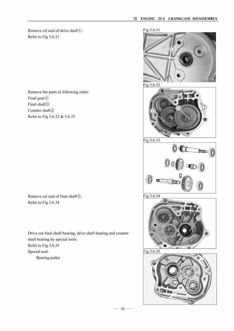
Remove oil seal of drive shaft .① Refer to Fig 3.6.31 Remove the parts in following order: Final gear④ Final shaft③ Counter shaft② Refer to Fig 3.6.32 & 3.6.33 Remove oil seal of final shaft .⑤ Refer to Fig 3.6.34 Drive out final shaft bearing, drive shaft bearing and counter shaft bearing by special tools. Refer to Fig 3.6.35 Special tool: Bearing puller
Fig 3.6.31
Fig 3.6.32
Fig 3.6.33
Fig 3.6.34
Fig 3.6.35
1
23 4
5

Ⅲ ENGINE Ⅲ-6 CRANKCASE DISASSEMBLY
— 49 —
CRANK CASE Remove chain tension pivot and chain guide .① ② Refer to Fig 3.6.36 Loosen crankcase bolts. Refer to Fig 3.6.37 Keep crankcase LH downward, and separate crankcase RH from crankcase LH. Refer to Fig 3.6.38 Remove dowel pins, and clean the sealing surface of crankcase. Refer to Fig 3.6.39 Slide timing chain from timing sprocket of crankshaft, then ③
remove timing chain from crankcase. Remove riming chain. Refer to Fig 3.6.40
Fig 3.6.36
Fig 3.6.37
Fig 3.6.38
Fig 3.6.39
Fig 3.6.40
1
2
3

Ⅲ ENGINE Ⅲ-7 CRANKCASE PARTS INSPECTION
— 50 —
Ⅲ-7 Crankcase parts inspection OIL PUMP ASSY Perform the measurement at different position, and take the Max. reading as the measurement result. Replace the oil pump assy if its any part exceeds service limit. Refer to Fig 3.7.1 Tip clearance Insert outer rotor① and inner rotor② to oil pump body. Measure the clearance between outer rotor and inner rotor by thickness gauge. Refer to Fig 3.7.2
Service limit 0.20mm Body clearance Measure the clearance between outer rotor and body by thickness gauge. Refer to Fig 3.7.3 & 3.7.4
Service limit 0.35mm End clearance Measure the end clearance between body③ and cover④. Refer to Fig 3.7.5
Service limit 0.12mm
Fig 3.7.1
Fig 3.7.2
Fig 3.7.3
Fig 3.7.4
Fig 3.7.5
3
1
2
3
4
1

Ⅲ ENGINE Ⅲ-7 CRANKCASE PARTS INSPECTION
— 51 —
COVER LH / KICK STARTER Inspection Check kick starter shaft○1 for wear and damage. Check the teeth of gears for wear and damage. Check kick return spring○2 for weak tension and damage. Check collar○3 for wear and damage. Check bush○4 for wear and damage. Check kick driven gear○5 and washer⑥ for wear and damage. Refer to Fig 3.7.6 & 3.7.7 Check the kick starter ratchet⑦ for wear and damage. Refer to Fig 3.7.8 Check the socket on cover LH for wear and damage. Refer to Fig 3.7.9 CLUTCH Drive belt Check belt for scratch, separation and over wear, and measure the width of belt. Refer to Fig 3.7.10
Service limit 17.0mm
Fig 3.7.6
Fig 3.7.7
Fig 3.7.8
Fig 3.7.9
Fig 3.7.10
7
1
2
3
4
5 6

Ⅲ ENGINE Ⅲ-7 CRANKCASE PARTS INSPECTION
— 52 —
Ratchet Check the cooling fan○1 for wear and damage. Refer to Fig 3.7.11 Check the rollers② for wear and damage, and measure O.D. of rollers. Refer to Fig 3.7.12 & 3.7.13
Service limit 15.4mm Moveable drive face assy Check the working surface of moveable drive face assy for wear and damage, and measure its I.D. ③. Refer to Fig 3.7.14
Service limit 20.17mm Check the inner bush of moveable drive face assy for wear and damage. Measure O.D. of inner bush. Refer to Fig 3.7.15
Service limit 19.97mm
Fig 3.7.11
Fig 3.7.12
Fig 3.7.13
Fig 3.7.14
Fig 3.7.15
Working surface
Working surface
1
2
3
4

Ⅲ ENGINE Ⅲ-7 CRANKCASE PARTS INSPECTION
— 53 —
Starter motor clutch Ensure starter motor clutch operating smoothly. Check the gear① of clutch for wear or other defect. Check the shaft②③ for wear. Refer to Fig 3.7.16 Clutch/ Driven pulley Check the working surface of clutch hub for wear and damage. Refer to Fig 3.7.17 Measure I.D. of clutch hub.
Service limit 107.5mm Gear box Check the bearing and oil seal in gear box for wear and damage. Refer to Fig 3.7.18 Turn the inner ring of bearings of crankshaft by finger to ensure them working smoothly. Ensure the outer ring of bearings fitted in crankcase without gap. Refer to Fig 3.7.19 Check the final shaft and gears for wear and damage. Refer to Fig 3.7.20
Fig 3.7.16
Fig 3.7.17
Fig 3.7.18
Fig 3.7.19
Fig 3.7.20
Working surface
32
1
7
4
5 6

Ⅲ ENGINE Ⅲ-7 CRANKCASE PARTS INSPECTION
— 54 —
Crankshaft inspection Measure the axial gap at connecting rod big end by thickness gauge. Refer to Fig 3.7.21
Service limit 0.55mm Set the crankshaft on V block, and measure the face run-out at connecting rod small end by diameter-indicator②. Refer to Fig 3.7.22
Service limit 0.02mm Set the crankshaft on V block, and measure the radial run-out at journal by diameter-indicator②. Refer to Fig 3.7.23
Service limit 0.10mm Check the oil pump driving gear on crankshaft for wear and damage. Refer to Fig 3.7.24 Turn the outer ring of bearings of crankshaft by finger to ensure them working smoothly. Ensure the inner ring of bearing firmly fitting on crankshaft. Replace the bearing if turning hardly or loose fitted. Refer to Fig 3.7.25
Fig 3.7.21
Fig 3.7.22
Fig 3.7.23
Fig 3.7.24
Fig 3.7.25
3
1
2

Ⅲ ENGINE Ⅲ-8 CRANKCASE PARTS REINSTALLATION
— 55 —
Ⅲ-8 Crankcase Parts Reinstallation Crankcase Turn the bearing of crankshaft by finger to ensure it moving smoothly and quietly, otherwise replace it. Refer to Fig 3.8.1 Assembly Always take care to avoid damaging the sealing surface of crankcase. Clean the crankcase and check it for scratch or damage. Refer to Fig 3.8.2 & 3.8.3 Apply engine oil to timing chain and insert it into crankcase.③ Refer to Fig 3.8.4 Apply engine oil to crankshaft bearing. Apply engine oil to big end of connecting rod, and crankcase bearing. Press crankshaft assy into crankcase LH through timing chain till it fitted firmly. Refer to 3.8.5
Fig 3.8.1
Fig 3.8.2
Fig 3.8.3
Fig 3.8.4
Fig 3.8.5
3
1 2

Ⅲ ENGINE Ⅲ-8 CRANKCASE PARTS REINSTALLATION
— 56 —
Clean the sealing surface of crankcase RH & LH, and install gasket and dowel pin .① ② Refer to Fig 3.8.6 Install crankcase RH to crankcase LH, and tighten the bolts to specified torque. Refer to Fig 3.8.7 Specified torque: 10N·m Insert tentioner movable guide to c③ rankcase LH. Insert the pin of tentioner movable guide and O④ -ring to ⑤
crankcase LH and tighten to specified torque. Refer to Fig 3.8.8 Specified torque: 10N.M Apply grease to the lip of fresh oil seal⑥. Drive the oil seal into crankcase LH till it equal to crankcase. Refer to Fig 3.8.9 & 3.8.10 Tool: Oil seal driver
Fig 3.8.6
Fig 3.8.7
Fig 3.8.8
Fig 3.8.9
Fig 3.8.10
3
4
5
6
2
12
7

Ⅲ ENGINE Ⅲ-8 CRANKCASE PARTS REINSTALLATION
— 57 —
Oil pump Apply engine oil to inner rotor and outer rotor of oil pump, ① ②
and insert them into oil pump body .③ Refer to Fig 3.8.11 Install dowel pin and plate to oil pump body, and fasten it by tighten the screws to specified torque. Refer to Fig 3.8.12 Specified torque: 3N.m Take care to prevent the duct entering engine when installing oil pump. Install dowel pin to oil pump body, and insert O④ -ring to oil ⑤
channel in crankcase. Refer to Fig 3.8.13 Install oil pump to crankcase RH and tighten its mounting screws to specified torque. Refer to Fig 3.8.14 Specified torque: 10N.m Install dowel pins and gasket to crankcase RH Apply engine oil to oil pump gear .⑥ Align the slot of gear to oil pump shaft, and install the gear to oil pump by tightening nut to specified torque. Refer to Fig 3.8.15 Specified torque:
Fig 3.8.11
Fig 3.8.12
Fig 3.8.13
Fig 3.8.14
Fig 3.8.15
12
3
4
5
6

Ⅲ ENGINE Ⅲ-8 CRANKCASE PARTS REINSTALLATION
— 58 —
Apply grease to the lip of fresh oil seal. Refer to Fig 3.8.16 Drive the oil seal into crankcase cover RH till it equal to crankcase cover. Refer to Fig 3.8.17 Tool: Oil seal driver Fasten crankcase cover RH by tightening the bolts to specified torque. Refer to Fig 3.8.18 Specified torque: 10N·m Starter motor Apply engine oil to new O-ring, and insert it to the end cover of starter motor. Refer to Fig 3.8.19 Install starter motor to crankcase LH, and tighten mounting bolts to specified torque. Refer to Fig 3.8.20 Specified torque: 10N·m
Fig 3.8.16
Fig 3.8.17
Fig 3.8.18
Fig 3.8.19
Fig 3.8.20
3
1
2

Ⅲ ENGINE Ⅲ-8 CRANKCASE PARTS REINSTALLATION
— 59 —
Gear box Bearing replacement Apply grease to bearing socket, and press bearings into their socket. Apply grease to the lip of oil seal of final shaft, and install it into gear box by special tool . ① Refer to Fig 3.8.21 Special tool: Bearing driver Assemble gear box Apply engine oil to gears and shafts. Install final shaft to its bearing. Refer to Fig 3.8.22 Install washer to counter shaft , and install them to bearing.③ ④ Refer to Fig 3.8.23 & 3.8.24 Install final gear to final shaft.⑤ Refer to Fig 3.8.25.
Fig 3.8.21
Fig 3.8.22
Fig 3.8.23
Fig 3.8.24
Fig 3.8.25
3
4
5
1
4
2

Ⅲ ENGINE Ⅲ-8 CRANKCASE PARTS REINSTALLATION
— 60 —
Install new gasket and dowel pins. Fasten crankcase cover LH by tightening the bolts to specified torque. Specified torque: 10N·M Apply grease to the lip of oil seal①, and install it to gear box cover by special tool. Refer to Fig 3.8.26 Starting gear Assy / Kick lever Starting gear Assy Apply 0.1-0.3g grease to shaft of starting gear assy, and insert it into crankcase LH. Refer to Fig 3.8.27 Pulley drive Remove the oil and grease from rollers③, insert them into movable drive face assy , and install guiding plate to cover ④ ⑤
them. Refer to Fig 3.8.28 Remove the oil and grease from the surface of movable drive face assy , and insert the inner bush into it.④ ⑤ Refer to Fig 3.8.29
Driven plate assy
Insert belt into driven plate assy .⑥ ⑦ Refer to Fig 3.8.30
Fig 3.8.26
Fig 3.8.27
Fig 3.8.28
Fig 3.8.29
Fig 3.8.30
7
1
2
3
4
5
6

Ⅲ ENGINE Ⅲ-8 CRANKCASE PARTS REINSTALLATION
— 61 —
Install driven plate assy on drive shaft. Remove oil and grease from the inner surface of clutch hub, and install it. Hold clutch hub by special tool , and tighten nut ② ① to specified torque. Refer to Fig 3.8.31 Specified torque: 50N·m Special tool: Clutch holder Put drive belt out of the bush of drive face assy.③ Refer to Fig 3.8.32 Install fixed drive face , fan and staring ratchet . ④ ⑤ ⑥ Refer to Fig 3.8.33 & 3.8.34 Hold the fixed drive face by special tool⑦, and tighten nut to specified torque. Refer to Fig 3.8.35 Specified torque: 50N·m Special tool: Ratchet holder⑦
Fig 3.8.31
Fig 3.8.32
Fig 3.8.33
Fig 3.8.34
Fig 3.8.35
3
1
2
7
4
5
6

Ⅲ ENGINE Ⅲ-8 CRANKCASE PARTS REINSTALLATION
— 62 —
Kick lever Insert kick shaft bush① and collar② into crankcase cover LH. Refer to Fig 3.8.36 Apply grease on kick shaft, and install it into crankcase cover LH. Refer to Fig 3.8.37. Install kick return spring③, and fix the longer hook to the rivet on crankcase cover LH. Install kick shaft assy into crankcase cover LH, and fix the shorter hook on kick shaft assy. Refer to Fig 3.8.38. Install washer④ and circlip⑤ on kick shaft. Refer to Fig 3.8.39. Reinstall kick lever to previous location according to disassembly mark, and tighten mounting bolt. Refer to Fig 3.8.40.
Fig 3.8.36
Fig 3.8.37
Fig 3.8.38
Fig 3.8.39
Fig 3.8.40
3
12
45

Ⅲ ENGINE Ⅲ-8 CRANKCASE PARTS REINSTALLATION
— 63 —
Turn and hold the kick lever some away from dead point, install thrust washer② and kick ratchet③ into crankcase cover LH, and ensure spring hook① align with the relative groove on crankcase cover RH. Release kick lever to ensure kick gear engaged with kick ratchet. Refer to Fig 3.8.41. Crankcase cover LH
Install dowel pins and new gasket on crankcase LH. Refer to Fig 3.8.42.
Install crankcase cover LH to crankcase LH, and tighten the bolts diagonally to specified torque. Refer to Fig 3.8.43 Specified torque: 10N·m
Magneto Assembly Clean the taper area of crankshaft, and insert the key④ on it. Refer to Fig 3.8.44. Install pulse coil⑤, and tighten the bolts to specified torque. Specified torque: 6N·m Install stator plate⑥, and tighten the bolts to specified torque. Specified torque: 8N·m Refer to Fig 3.8.45
Fig 3.8.41
Fig 3.8.42
Fig 3.8.43
Fig 3.8.44
Fig 3.8.45
3
1
2
3
4
5
6

Ⅲ ENGINE Ⅲ-8 CRANKCASE PARTS REINSTALLATION
— 64 —
Install fly wheel① to crankshaft with its bush groove aligned to key. Refer to Fig 3.8.46 Insert washer, hold fly wheel by special tool②, and tighten nut to specified torque. Refer to Fig 3.8.47 Specified torque: 50N·m Special tool: Universal holder Install cooling fan③, and tighten bolts to specified torque. Refer to Fig 3.8.48 Specified torque: 8N·m Install fan cover④, and tighten bolts to specified torque. Refer to Fig 3.8.49 Specified torque: 0.8N·m Tighten bolts to specified torque. Refer to Fig 3.8.50 Specified torque: 8N·m
Fig 3.8.46
Fig 3.8.47
Fig 3.8.48
Fig 3.8.49
Fig 3.8.50
3
1
2
4

Ⅳ FUEL AND LUBRICATION SYSTEM Ⅳ-1 FUEL TANK & FUEL LEVEL SENSOR
— 65 —
Ⅳ FUEL AND LUBRICATION SYSTEM
Ⅳ-1 Fuel tank & Fuel level sensor Fuel tank & Fuel level sensor Disassembly Remove rear carrier. Remove fuel tank. Remove seat assy and luggage box. Remove rear center regula, side regula RH & LH. Remove center cover, body cover RH & LH. Disconnect the wires. Refer to Fig 4.1.1。 Remove tail lamp assy. Remove fuel guide plate①. Refer to Fig 4.1.2 Remove seat bracket and fuel tank bracket. Disconnect wire② of fuel gauge assy Refer to Fig 4.1.3 Turn and release the lock bracket③ of fuel gauge to remove fuel gauge. Refer to Fig 4.1.4 Disconnect vacuum hose from fuel cock④. Drain out fuel and disconnect fuel hose⑤. Refer to Fig 4.1.5 Warn: Gasoline is extremely flammable and is explosive. Remove fuel tank.
Reinstall fuel tank in the reverse order of removal.
Fig 4.1.1
Fig 4.1.2
Fig 4.1.3
Fig 4.1.4
Fig 4.1.5

Ⅳ FUEL AND LUBRICATION SYSTEM Ⅳ-2 FUEL COCK
— 66 —
Ⅳ-2 Fuel Cock
Disassembly Remove rear carrier. Remove fuel tank cap. Remove seat assy and luggage box. Remove rear center regula, side regula RH & LH. Remove center cover, body cover RH & LH. Drain out fuel and disconnect fuel hose. Refer to Fig 4.2.1 Remove fuel cock from fuel tank. Warn: Gasoline is extremely flammable and is explosive. Inspection Connect vacuum pump and pressure gauge to the vacuum channel of fuel cock. Ensure fuel going from fuel channel of fuel cock under the specified vacuum. Otherwise replace the fuel cock. Specified vacuum: 22mmHg Refer to Fig 4.2.2 Note:
Operate the vacuum pump manually. Don’t apply high vacuum on fuel cock. It will damage
the fuel cock.
Fig 4.2.1
Fig 4.2.2

Ⅳ FUEL AND LUBRICATION SYSTEM Ⅳ-4 CARBURETOR
— 67 —
Ⅳ-4 Carburetor Construct
6
2
4
17
20
21
24 24
14
11
8
1
10
7
12
28
26
25
27
20
131529
22 22
3
16
5
26
19
18
23 23
9
25
1 Carburetor 9 Starter valve 17 Starter valve cover 25 Clamp
2 Needle jet 10 Chock 18 Overflow pipe 26 Clamp
3 Jet needle 11 Spring 19 Vacuum pipe 27 Fuel pipeΦ3.5×210
4 Float 12 Screw M5×12 20 Screw M4×8 28 Main jet
5 Float chamber 13 Washer 21 Screw M4×14 29 Pilot jet
6 Screw A 14 Top cap 22 Screw M4×8
7 Screw B 15 Main jet holder 23 Screw M4×10
8 Needle holder 16 Throttle valve 24 Screw M4×12

Ⅳ FUEL AND LUBRICATION SYSTEM Ⅳ-4 CARBURETOR
— 68 —
Specification
Item Specification
Carburetor type
Model
I.D.No.
Idle speed r/min
Height of float
Main jet (M.J.)
Jet needle (J.N.)
Needle jet (N.J.)
Throttle valve (Th.V.)
Slow jet (S.J.)
Pilot air adjusting screw (P.S.)
Free play of throttle
I.D.No. location I.D.No. is stamped on the body of carburetor.

Ⅳ FUEL AND LUBRICATION SYSTEM Ⅳ-4 CARBURETOR
— 69 —
Disassembly Disconnect the drain pipe①. Refer to Fig 4.3.1 Starter valve Remove SE starter valve cover, screws, mounting plat② and SE starter valve③. Refer to Fig 4.3.2
Remove O-ring④ from SE starter valve, check the valve⑤ and jet⑥ for damage and step wear. Refer to Fig 4.3.3
Vacuum chamber Hold the top cap⑦ of vacuum chamber and remove screws. Refer to Fig 4.3.4
Remove vacuum chamber cap⑦, spring⑧ and diaphragm/vacuum piston⑨. Check vacuum piston for smooth movement in carburetor body. Refer to Fig 4.3.5
Fig 4.3.1
Fig 4.3.2
Fig 4.3.3
Fig 4.3.4
Fig 4.3.5
3
1
2
3
4
5
6
7
8 9

Ⅳ FUEL AND LUBRICATION SYSTEM Ⅳ-4 CARBURETOR
— 70 —
Remove jet needle holder○1 , O-ring○2 and jet needle○3 from vacuum piston. Refer to Fig 4.3.6 Check needle for step wear. Check vacuum piston for wear and damage. Check diaphragm for pinhole, deform and damage. Disassembling float chamber Remove screws Refer to Fig 4.3.7 Remove float chamber body, and take out sealing ring④ from float chamber body. Refer to Fig 4.3.8
Remove screw○5 , float pin○6 , float○7 and needle valve⑧. Check float for damage and leakage. Refer to Fig 4.3.9
Check needle jet seat⑨ for scratch, clog and damage. Check needle jet for step wear. Replace it if it is worn. Refer to Fig 4.3.10
Fig 4.3.6
Fig 4.3.7
Fig 4.3.8
Fig 4.3.9
Fig 4.3.10
31
2
7
4
5 6
8
9

Ⅳ FUEL AND LUBRICATION SYSTEM Ⅳ-4 CARBURETOR
— 71 —
Remove the parts in following order: Main jet①/main jet holder②/pilot jet③ Turn in pilot air adjusting screw slightly tight, and mark down total turns. Remove pilot air adjusting screw ④ and spring⑤. Check and replace it if worn. Refer to Fig 4.3.11 Cleaning carburetor Blow compressed air through all jets(main jet①/main jet holder②/ pilot jet③), air passage and fuel passage. Refer to Fig 4.3.12
Reinstallation Float chamber Install the jets in following order:
Main jet / main jet holder○6 and pilot jet③. Tighten the jets to specified toque: Specified toque: Pilot jet: 1.5N.m Main jet: 2.1N.m Install pilot air adjusting screw④, and turn it to initial opening position. Refer to Fig 4.3.13
Install float⑦ and needle jet⑧ to carburetor body, and hold them by inserting float pin⑨. Refer to Fig 4.3.14
Tighten float pin screw to specified torque. Refer to Fig 4.3.15 Specified torque: 2.1N.m
Fig 4.3.11
Fig 4.3.12
Fig 4.3.13
Fig 4.3.14
Fig 4.3.15
3
4
5
6
87
7
910
4
3 2
1

Ⅳ FUEL AND LUBRICATION SYSTEM Ⅳ-4 CARBURETOR
— 72 —
Ensure float swing smoothly. Refer to Fig 4.3.16 Install new sealing ring③ to float chamber body. Refer to Fig 4.3.17
Install float chamber body to carburetor body, and tighten mounting screws to specified torque. Refer to Fig 4.3.18 Specified torque: 2.1N.m
Vacuum chamber Install jet needle④ O-ring⑤ and jet needle holder⑥ to diaphragm/vacuum piston. Refer to Fig 4.3.19 Install diaphragm/vacuum piston⑦ to carburetor body with the tit of diaphragm aligned with the groove on carburetor. Refer to Fig 4.3.20
Install spring⑧ and vacuum chamber cap⑨, and take care not to damage the spring. Refer to Fig 4.3.20
Fig 4.3.16
Fig 4.3.17
Fig 4.3.18
Fig 4.3.19
Fig 4.3.20
3
1
2
7
5
6
9
8
4

Ⅳ FUEL AND LUBRICATION SYSTEM Ⅳ-4 CARBURETOR
— 73 —
Tighten the mounting screws to specified toque: Specified toque: 2.1N.m Refer to Fig 4.3.21
SE Starter valve Install new O-ring① to SE starter valve. Insert SE starter valve to carburetor firmly. Refer to Fig 4.3.22
Fix the SE starter valve by mounting plate, and tighten the mounting screws to specified toque, then install its cover. Refer to Fig 4.3.23 Specified toque: 2.1N.m
Fig 4.3.21
Fig 4.3.22
Fig 4.3.23
1
2

Ⅳ FUEL AND LUBRICATION SYSTEM Ⅳ LUBRICATION SYSTEM
— 74 —
IV-4 Lubrication system
Oil filter
Oil panOil filter
Oil filter
Oil pump
By pass
Crank shaft RH bearing
Connecting rod big end bearing Crank shaft LH
bearing
CylinderCylinder head
Piston pin
Cam shaft jourant LH
Rocker arm/shaft In( )
Rocker arm/shaft EX( )
Cam shaft
Cam bearing LHtiming chain
Cam bearing RH
Oil channel

Ⅴ FRAME BODY Ⅴ-1 OUTER PARTS
— 75 —
Ⅴ FRAME BODY
Ⅴ- 1 Outer Parts Construct
12
3
4
5
6
7
8
1.Front handlebar cover 2.Rear handle cover 3.Front leg shield 4.Lower shield
5.Upper inner shield 6.Low inner shield 7.Luggage hook 8.Leg shield lid
9.Floor panel 10.Battery case 11.Battery cover 12.Floor mat
13.Center cover 14.Body cover RH 15.Body cover LH 16.Rear center cover
17.Side regula RH 18. Side regula LH 19.Rear regula 20.Luggage box
21.Seat assy 22.Rear carrier cover 23.Fancy cover

Ⅴ FRAME BODY Ⅴ-1 OUTER PARTS
— 76 —
Disassembly Remove mirror RH & LH① Refer to Fig 5.1.1 Remove front handlebar cover② Refer to Fig 5.1.2 Disconnect head lamp cable and front winker cable , and ③
remove speedometer cable .④ Refer to Fig 5.1.3 Remove rear handlebar cover .⑤ Refer to Fig 5.1.3 & 5.1.3
Fig 5.1.1
Fig 5.1.2
Fig 5.1.3
Fig 5.1.4
Fig 5.1.5

Ⅴ FRAME BODY Ⅴ-1 OUTER PARTS
— 77 —
Remove front leg shield .① Refer to Fig 5.1.6 & 5.1.7
Remove rear regula②. Refer to Fig 5.1.8
Remove side regula LH③. Refer to Fig 5.1.9 & 5.1.10
Remove side regula RH in same method.
Fig 5.1.6
Fig 5.1.7
Fig 5.1.8
Fig 5.1.9
Fig 5.1.10

Ⅴ FRAME BODY Ⅴ-1 OUTER PARTS
— 78 —
Remove rear carrier fancy cover .① Refer to Fig 5.1.11
Remove rear carrier .② Refer to Fig 5.1.12
Turn ignition key to unlock seat ASSY, and remove the plugs on the bottom of luggage box .③ Refer to Fig 5.1.13
Remove seat ASSY and luggage box by removing the mounting bolt and nuts. Refer to Fig 5.1.14
Remove floor mat .④ Refer to Fig 5.1.15
Fig 5.1.11
Fig 5.1.12
Fig 5.1.13
Fig 5.1.14
Fig 5.1.15

Ⅴ FRAME BODY Ⅴ-1 OUTER PARTS
— 79 —
Remove center cover .① Refer to Fig 5.1.16 Open fuel tank cap by ignition key. ② Refer to Fig 5.1.17
Remove seat lock cable from seat lock holder before ③
removing body cover RH & LH. Refer to Fig 5.1.18 Remove body cover LH ④ Refer to Fig 5.1.19 & 5.1.20
Remove body cover RH.
Remove rear center cover
Fig 5.1.16
Fig 5.1.17
Fig 5.1.18
Fig 5.1.19
Fig 5.1.20

Ⅴ FRAME BODY Ⅴ-1 OUTER PARTS
— 80 —
Remove battery case cover .① Refer to 5.1.21
Remove battery .② Refer to 5.1.22 Note: When removing battery, disconnect the negative (-) terminal cable first, then remove positive terminal cable at the battery.
Remove floor panel ③ Refer to 5.1.23
Remove ignition switch cap and luggage hook .④ ⑤ Refer to Fig 5.1.24
Loosen the screws, and remove lower shield and inner ⑥
shield .⑦ Refer to Fig 5.1.25
Fig 5.1.21
Fig 5.1.22
Fig 5.1.23
Fig 5.1.24
Fig 5.1.25

Ⅴ FRAME BODY Ⅴ-2 FRONT WHEEL
— 81 —
Ⅴ-2 Front Wheel For the model of front disk brake
Construction
1
2
3
9 8
75
4
6
10
13
15
1411
12
RH LH
1.Front rim 2.Front tire 3.Front tube 4.Spacer 5.Bearing 600201 6.Bearing 600301 7.Oil seal 8.Front brake disk9.Bolt M8×24 10.Bush 11.Nut M12 12.Front axle 13.Speedometer gear box 14.Axle cap RH 15.Axle cap LH

Ⅴ FRAME BODY Ⅴ-2 FRONT WHEEL
— 82 —
Disassembly Remove nut from front axle.① Refer to Fig 5.2.1. Disconnect speedometer cable② Remove brake caliper mounting bolts .③ Refer to Fig 5.2.2. Left the vehicle by jack to free front wheel from ground, and remove front axle and front wheel. Remove brake disk and bush. Refer to Fig 5.2.3. Remove oil seal Refer to Fig 5.2.4. Inspection and reassembly Speedometer gear box Turn the gear in speedometer gear box to ensure gear and pinion moving smoothly. Refer to Fig 5.2.5. Check and replace oil seal of speedometer gear box if it damage
Fig 5.2.1
Fig 5.2.2
Fig 5.2.3
Fig 5.2.4
Fig 5.2.5

Ⅴ FRAME BODY Ⅴ-2 FRONT WHEEL
— 83 —
Rim bearing Rotate the inner ring of bearing by hand to ensure the bearing working smoothly without abnormal noise. Replace it if necessary. Refer to Fig 5.2.6. Replace the bearing according to following procedure: Insert the inner adopter① of bearing remover into bearing. Insert the wedge bar② into inner tube from the opposit end, and ensure it locked in the opening slot of adopter. Knock the wedge bar by hammer to push the bearing out. Refer to Fig 5.2.7 & 5.2.8 Note: Any disassembled bearing must be replaced with fresh pieces. Front rim Inspect the run-out(Radial & Axial)of front rim, and ensure it under service limit. If over run-out was caused by damaged rim bearing, rim could be utilized after replacing the bearing. Otherwise replace with new rim. Refer to Fig 5.2.9.
Service limit 2.0mm Front axle Inspect front axle run-out by micrometer, and replace it if it exceeds service limit. Refer to 5.2.10 Tools: Micrometer
Magnetic basic V-block,
Service limit: 0.25mm Service limit 0.25mm
Fig 5.2.6
Free play
Free play
Fig 5.2.7
Fig 5.2.8 Fig 5.2.9
Fig 5.2.10

Ⅴ FRAME BODY Ⅴ-2 FRONT WHEEL
— 84 —
Reassembly Reassemble the front wheel in the reverse order of removal. 1. Rim bearing Apply grease to rim bearing. Refer to Fig 5.2.11 Install the bearings to rim by special tools. Refer to Fig 5.2.12. Caution:
Firstly install Bearing LH, then bearing RH. Sealing cover of bearing would face outward
Fig 5.2.11
Fig 5.2.12

Ⅴ FRAME BODY Ⅴ-2 FRONT WHEEL
— 85 —
Front Wheel 1. Brake disk Ensure there is no any oil dirt on brake disk. Apply thread locking sealant 1360 to brake disk mounting bolts, and tighten them to specified torque. Specified torque: 23N.m Refer to Fig 5.2.13. 2. Speedometer gear box Apply grease to gear and oil seal before installation. Align the gear drive piece with the groove on rim, and install the speedometer gear box to rim. Refer to Fig 5.2.14 Align the stopper edge on speedometer gear box to the groove on front fork, and install front wheel to front fork by inserting front axle. Refer to Fig 5.2.15
3. Front axle nut Tighten front axle nut to specified torque. Refer to Fig 5.2.16 Specified torque: 53N.m
Fig 5.2.13
Fig 5.2.14
Fig 5.2.15
Fig 5.2.16

Ⅴ FRAME BODY Ⅴ-2 FRONT WHEEL
— 86 —
For the model of front drum brake Construction
1
98
7
5
4
2
3
6
10
7
1920
20
18
21
21
17
26
24
22
23
28
2725
16
1511
12
1314
14
1.Front rim 2.Tire 3.Tube 4.Spacer 5.Washer
6.Spacer 7.Ball bearing 8.Oil seal 9.Bush 10.Nut M12
11.Front axle 12.Collar 13.Front panel 14.Washer 5 15.Pinion
16.Collar 17.Speedometer gear 18.Bush 19.Oil seal 20.Brake shoes
21.Spring 22.Brake cam 23.O-ring 24.Spring 25.Washer
26.Brake lever 27.Bolt M6×30 28.Nut M6

Ⅴ FRAME BODY Ⅴ- 3 FRONT BRAKE SYSTEM
— 87 —
Ⅴ- 3 Front Brake System Construction
1. Cap 2. Diaphragm 3. Master Cylinder 4. Piston Set 5. Dust Cap 6. Front Brake Hose ASSY 7. Front Brake Caliper ASSY 8. Piston 9. Oil Seal
10. O-ring 11. Pad ASSY 12. Spring 13. Caliper Holder
A. Master Cylinder Bolt B. Brake Hose Bolt C. Bleed Valve D. Caliper Bolt
Caution Only Grade DOT4 glycol based hydraulic brake fluid is equipped in brake system of this vehicle. Don’t use or mix with silicon or fossil oil based fluid when refilling, otherwise the brake system will be
damaged. Keep the container properly sealed and away from reaching of child when stocking brake fluid. Don’t
use long-stocking or unsealed brake fluid. Take care to avoid any dirt or dust interring the brake system when refilling brake fluid. Use fresh brake fluid only to wash the parts of brake system. Dirty brake disk and pad will affect brake efficiency. Replace or clean it by neutral abstergent.
Warning: Brake fluid can damage the parts of plastic, paint and rubber due to chemistry.
4
1
2
3
5
6
7
1213
A
B
B
C
89
1011D

Ⅴ FRAME BODY Ⅴ- 3 FRONT BRAKE SYSTEM
— 88 —
Brake pad replacementRemove caliper mounting bolts .① Refer to Fig 5.3.1 Push caliper holder to remove brake pad. Refer to Fig 5.3.2 Caution Don’t force the brake lever before installing brake pad. Brake pad would be replaced in set, otherwise brake performance will be affected Carefully install new brake pad Tight caliper mounting bolts to specified toque.① Refer to Fig 5.3.3 Specified toque: 26N.m Note:
After replacing brake pad, apply brake to confirm its performance and fluid level. Brake fluid replacement Stand the vehicle on horizontal ground with handlebar in verticality. Remove handlebar covers. Remove the cap and diaphragm of fluid reservoir. Drain out old brake fluid, and refill with fresh brake fluid. Refer to Fig 5.3.4 Connect the bleed valve and other container by sufficient hose. Loosen the bleed valve and pump out all previous brake fluid. Refer to Fig 5.3.5 After closing bleed valve and disconnecting drain hose, refill with fresh brake fluid till its level reach the upper limit on inspection screen.
Fig 5.3.1
Fig 5.3.2
Fig 5.3.3
Fig 5.3.4
Fig 5.3.5

Ⅴ FRAME BODY Ⅴ- 3 FRONT BRAKE SYSTEM
— 89 —
Note:
Bleed out the air from brake system. Refer to Fig 5.3.6 Disassemble and reassemble brake caliper Disassembly Remove brake hose from brake caliper ASSY by removing the union bolt , and drain out brake fluid to other container.① Remove caliper ASSY mounting bolts .② Refer to Fig 5.3.7 Caution The remaining brake fluid during last maintenance or long-storing fluid could not be utilized, otherwise the brake system will be damaged. Any brake fluid leakage will be dangerous during running. Ensure hose and sealing not damaged or leaked.
Remove brake pad. Refer to Fig 5.3.8 Remove brake pad spring .③ Remove brake pad holder .④
Cover brake caliper by rap to prevent the piston escape suddenly, push out the piston by compressed air. Refer to Fig 5.3.9
Caution Take care not to damage the piston by compressed air.
Fig 5.3.6
Fig 5.3.7
Fig 5.3.8
Fig 5.3.9

Ⅴ FRAME BODY Ⅴ- 3 FRONT BRAKE SYSTEM
— 90 —
Remove dust ring and piston sealing ring .① ② Refer to fig 5.3.10. Caution Don’t utilize the used dust ring and piston sealing ring.
Brake caliper inspection 1. Brake caliper Check caliper cylinder wall for crack, scratch or other blemish. Replace with new one if necessary. Refer to Fig 5.3.11
2. Brake caliper piston Check caliper piston for crack, scratch or other blemish. Replace with new one if necessary. 3. Reassemble brake caliper Wash the piston and caliper by specified brake fluid, specially the groove for piston ring and dust seal. Reassemble the brake caliper in the reverse order of disassembly Refer to Fig 5.3.12
Caution Wash the caliper cylinder and piston before reassembly. Use the recommended brake fluid to wash caliper cylinder and piston. Don’t use petrol, kerosene or other solvent. Don’t remove brake fluid from caliper after washing. Replace the used dust ring and piston sealing ring with fresh pieces. Apply brake fluid to caliper cylinder, piston and sealing ring. Install piston sealing ring and dust ring Refer to Fig 5.3.13
Fig 5.3.10
Fig 5.3.11
Fig 5.3.12
Fig 5.3.13

Ⅴ FRAME BODY Ⅴ- 3 FRONT BRAKE SYSTEM
— 91 —
Apply grease to caliper holder A. Refer to Fig 5.3.14 Tighten caliper mounting bolts and hose union bolts to ① ②
specified torque. Refer to Fig 5.3.15 Specified torque: Caliper mounting bolts—26N.m Hose union bolts—23N.m
Note Push the piston into caliper cylinder and bleed out air from bleeding valve Brake disk inspection Check the brake disk for scratch, and measure its thickness by micrometer. Refer to Fig 5.3.16 Replace with fresh one if it is scratched or thickness is less than specified service limit. Tool: micrometer
Service limit 2.5mm Measure brake disk run-out by diameter-indicator, and replace with fresh one in it exceeds service limit. Refer to Fig 5.3.17. Tools: Diameter-indicator
Magnetic basic Service limit 0.3mm
Fig 5.3.14
Fig 5.3.15
Fig 5.3.16
Fig 5.3.17

Ⅴ FRAME BODY Ⅴ- 3 FRONT BRAKE SYSTEM
— 92 —
Master cylinder disassembly and installation Remove handlebar covers. Put some cotton under the brake hose bolt, and then loosen the bolt and remove brake hose. Refer to Fig 5.3.18.
Note: Immediately rub the brake fluid away from the surface
of any parts. Brake fluid can damage the parts of plastic, paint and rubber due to chemistry.
Disconnect wire of front brake switch.① Refer to Fig 5.3.19 Remove master cylinder ASSY.
Remove front brake lever and front brake switch .② ③ Refer to Fig 5.3.20
Remove cap and diaphragm .④ ⑤⑥ Refer to Fig 5.3.21 Drain out brake fluid.
Remove Dust cap , clip , washer and piston along with ⑦ ⑧ ⑨ ⑩
spring. Refer to Fig 5.3.22
Fig 5.3.18
Fig 5.3.19
Fig 5.3.20
Fig 5.3.21
Fig 5.3.22

Ⅴ FRAME BODY Ⅴ- 3 FRONT BRAKE SYSTEM
— 93 —
Master cylinder inspection 1. Cylinder Check the inner surface of cylinder for scratch or other damage. Replace it if necessary. Refer to Fig 5.3.23 2. Piston and rubber ring Check piston surface and sealing ring for scratch or wear. Replace it if necessary. Refer to Fig 5.3.24
Master cylinder reassembly and installation Reassemble master cylinder in the reverse order of removal.
Note: Use the recommended brake fluid to wash the parts of
master cylinder before assembly. Don’t use petrol, kerosene or other solvent.
Apply brake fluid on the surface of inner parts of master cylinder.
Install the clip properly. Refer to Fig 5.3.26 Note Ensure clip sharp edge facing outward when installing it.
Fig 5.3.23
Fig 5.3.24
Fig 5.3.25
Fig 5.3.26

Ⅴ FRAME BODY Ⅴ- 3 FRONT BRAKE SYSTEM
— 94 —
Install the brake switch with its top end aligning with the master cylinder hole. Refer to Fig 5.3.27
Install the master cylinder to handlebar with its bracket touching area A aligning with the mark B on handlebar. Refer to Fig 5.3.28 Firstly tighten the upper bolt, and tighten both bolts to specified torque. Specified torque: 10N.m
Note: Ensure “UP” mark on master cylinder upward. Refer to Fig 5.3.29.
Tighten the brake hose bolt to specified torque. Refer to Fig 5.3.30. Specified torque: 23N.m
Caution: Bleed out air from brake system when reassembling master cylinder.
Fig 5.3.27
Fig 5.3.28
Fig 5.3.29
Upside
Handle Bar
Master Cylinder
Gap
Marker
Bolt
AB
Fig 5.3.30

Ⅴ FRAME BODY Ⅴ-4 FRONT FORK
— 95 —
Ⅴ-4 Front fork
Construction
1
2
3
4
5
6
7
8
9
10
11
12
13
14
15
16
17
18
19
20
2122
23
24
25
26
27
28
29
1.Handlebar assy 2.Bolt 3.Nut 4.Bolt 5.Screw
6.Lock nut 7.Lock washer 8.Upper inner race 9.Steel ball 10.Upper outer race
11.Lower outer race 12.Steel ball 13.Lower inner race 14.Steering stem 15.Bolt
16.Fork LH 17.Bolt 18.O-ring 19.Spring 20.Piston
21.Sealing ring 22.Returnig spring 23.Fork pipe 24.Dust ring 25.Spring ring
26.Oil seal 27.Fork RH 28.Gasket 29.Bolt
Note Apply grease to the parts of No.8、9、10、11、12、13、26、28. Tighten the parts of No.3、4、15、17、29 to specified torque.

Ⅴ FRAME BODY Ⅴ-4 FRONT FORK
— 96 —
Dismantle front fork Remove handlebar front cover. Remove front leg shield and lower shield. Remove front wheel assy. Remove front brake caliper assy and master cylinder. Disconnect throttle cable . ① Refer to Fig 5.4.1 Disconnect rear brake cable and rear brake switch . ② ③ Refer to Fig 5.4.2
Remove the handle bar.
Refer to Fig 5.4.3
Remove wire clamp. Refer to Fig 5.4.4
Remove lock nut on steering stem.① Refer to Fig 5.4.5 Tool: Steering lock nut spanner
Fig 5.4.1
Fig 5.4.2
Fig 5.4.3
Fig 5.4.4
Fig 5.4.5

Ⅴ FRAME BODY Ⅴ-4 FRONT FORK
— 97 —
Remove steering nut ① from steering stem. Refer to Fig 5.4.6 Tool: Steering nut spanner Note
Hold front fork to prevent it from dropping down. Remove lock washer on steering stem.② Refer to Fig 5.4.7 Remove steel balls(upper-18 pieces &lower -26 pieces). Refer to Fig 5.4.8 Remove fork assy RH & LH. Refer to fig 5.4.9 Steering stem Inspection Inspect the removed parts, and replace with fresh pieces if following defect is found.
Worn race Worn steel ball Metabolic handlebar or steering stem
Fig 5.4.6
Fig 5.4.7
Fig 5.4.8
Fig 5.4.9

Ⅴ FRAME BODY Ⅴ-4 FRONT FORK
— 98 —
Remove lower inner race① from steering stem by chisel. Refer to Fig 5.4.10 Drive out the upper and lower outer race from head pipe of frame body. Refer to Fig 5.4.11 Steering stem reinstallation Reinstall steering stem and handlebar in the reverse order of removal Press the upper and lower outer race into head pipe of frame body. Refer to Fig 5.4.12 Tool: Upper and lower outer race driver Apply grease to the upper and lower outer race, then install steel balls to race. Refer to Fig 5.4.13 Upper: 18pieces Lower: 26pieces Turn the steering nut all the way in and then back 1/8—1/4 turn. Refer to Fig 5.4.14 Note: Ensure turning smoothly to both Right and Left. Adjustment varies for different model.
Fig 5.4.10
Fig 5.4.11
Fig 5.4.12
Fig 5.4.13
Fig 5.4.14

Ⅴ FRAME BODY Ⅴ-4 FRONT FORK
— 99 —
When installing lock washer, insert its lip① into the groove② on steering stem Refer to Fig 5.4.15 Tighten the lock nut to specified toque. Refer to Fig 5.4.16 Specified toque: 30N.m Tool: Lock nut connector Lock nut spanner
Install handlebar mounting bolt and nut, and tighten to specified toque. Refer to Fig 5.4.17 Specified toque: Mounting bolt 25N.m Mounting nut 49N.m Install front wheel and front brake assy. Refer to Fig 5.4.18 Note:
After installing and adjusting handlebar, push the front wheel frontward and backward to ensure that there is not gap on steering stem race.
Inspect and ensure that the steering stem can turn smoothly under gravity.
Fig 5.4.15
Fig 5.4.16
Fig 5.4.17
Fig 5.4.18

Ⅴ FRAME BODY Ⅴ-4 FRONT FORK
— 100 —
Front fork disassembly Remove steering stem from frame body. Remove front fender bracket mounting screw. Refer to Fig 5.4.19 Remove front brake hose and caliper. Refer to Fig 5.4.20 Remove the bolt from top end of fork. Refer to Fig 5.4.21 Remove the forks from steering stem by loosening the mounting bolts. Remove the spring. Refer to Fig 5.4.22 Compress and release the damper rod to drain out the oil from front fork. Refer to Fig 5.4.23
Fig 5.4.19
Fig 5.4.20
Fig 5.4.21
Fig 5.4.22
Fig 5.4.23

Ⅴ FRAME BODY Ⅴ-4 FRONT FORK
— 101 —
Remove dust seal and clip. Refer to Fig 5.4.24 Remove damper rod bolt and pull out inner tube. Refer to Fig 5.4.25 & 5.4.26 Tool: T Handle spanner Remove damper rod and oil rings from inner tube. Refer to Fig 5.4.27 Remove oil seal by special tool. Refer to Fig 5.4.28 Tool: Oil seal remover
Fig 5.4.24
Fig 5.4.25
Fig 5.4.26
Fig 5.4.27
Fig 5.4.28

Ⅴ FRAME BODY Ⅴ-4 FRONT FORK
— 102 —
Inspection Oil ring on damper rod Check the oil ring for over wear and other defect, and replace if necessary. Refer to Fig 5.4.29 Front fork spring Measure the free length of front fork spring, replace the spring length is less than service limit. Refer to Fig 5.4.30
Service limit 254mm Inner and outer tube Check the sliding surface of inner and outer tube for over wear and other defect, and replace if necessary. Refer to Fig 5.4.31 Reinstallation Reinstall the front fork in the reverse order of removal. Note:
Don’t use the previous fork oil. Replace the oil seal and dust seal with fresh pieces.
Damper rod bolt Apply thread locking sealant “1322”to bolt, insert it into damper rod and tighten it to specified toque. Refer to Fig 5.4.32 Specified toque: 23N.m Tool: T handle spanner
Fig 5.4.29
Fig 5.4.30
Fig 5.4.31
Fig 5.4.32

Ⅴ FRAME BODY Ⅴ-4 FRONT FORK
— 103 —
Install oil seal, clip and dust seal by special tool. Refer to Fig 5.4.33. Tool: Oil seal driver Note:
Apply fork oil to oil seal and dust seal before installation.
Insert the clip firmly. Fill each inner tube with 87ml of fork oil. Refer to Fig 5.4.34 Fork oil: 15# Hold the fork vertically, and check and adjust oil level by special tool. Refer to Fig 5.4.35. Specified oil level: 81mm Tool: Oil level gauge Note: Take out fork spring and push the inner tube to the bottom when adjusting oil level. Install fork spring. Refer to Fig 5.4.36 Note: Install the spring with the tightly wound coil facing up.
Fig 5.4.33
Fig 5.4.34
Fig 5.4.35
Fig 5.4.36

Ⅴ FRAME BODY Ⅴ-4 FRONT FORK
— 104 —
Tighten the fork top bolt① and fork mounting bolt② to specified toque. Refer to Fig 5.4.37 Specified toque: Fork top bolt: 45N.m Fork mounting bolt: 23N.m Install steering stem to frame body. Install handlebar. Ignition Switch ASSY Remove inner shield from frame body Remove the ignition switch ASSY from frame body through removing its mounting bolts by chisel and hammer. Refer to Fig 5.4.38 & 5.4.39. Fasten the ignition switch ASSY to frame body by special bolts and spanner. Refer to Fig 5.4.40. Note: Turn the special bolts by spanner till the bolt head breaking down.
Fig 5.4.37
Fig 5.4.38
Fig 5.4.39
Hammer
Chisel
Bolt
Fig 5.4.40
Tool
Bolt

Ⅴ FRAME BODY Ⅴ- 5 REAR WHEEL/BRAKE/SUSPENSION
— 105 —
Ⅴ- 5 Rear Wheel /Brake/Suspension Note: Apply grease to the brake cam. Disassembly 1. Rear wheel and brake Stand the vehicle by center stand. Remove muffler. Remove rear wheel. Refer to Fig 5.5.1 Remove rear brake shoes①. Refer to Fig 5.5.2.
Fig 5.5.1
Fig 5.5.2
11
1213
14
1
2
3
4
4
5
5
6
78
9
1011
1.Rear rim 2.Rear tire 3.Rear tube 4.Brake shoes 5.Spring 6.Brake cam 7.Brake lever 8.Flange bolt M6×28 9.Nut M6 10.Washer 16 11.Nut M16 12.Flang bolt M10×71 13.Nut 14.Flange nut M8×35 15.Rear shock absorber

Ⅴ FRAME BODY Ⅴ- 5 REAR WHEEL/BRAKE/SUSPENSION
— 106 —
Remove brake adjusting nut①, brake lever bolt and nut②. Refer to Fig 5.5.3.. Remove brake lever③, indicator④ and brake cam⑤. Refer to Fig 5.5.4 2. Rear shock absorber Remove frame cover. Remove air cleaner. Remove rear shock absorber Refer to Fig 5.5.5. Inspection 1. Brake hub Inspect I.D. of brake hub, and replace the rim if I.D. exceeds service limit. Refer to Fig 5.5.6 Tool: Caliper
Service limit 120.7mm 2. Brake shoe Inspect the brake shoes for wear and damage, and replace the completed set of brake shoes if necessary. Refer to Fig 5.5.7 Note: Brake shoes must be replaced in completed set, otherwise brake efficiency will be affected.
Fig 5.5.3
Fig 5.5.4
Fig 5.5.5
Fig 5.5.6
Fig 5.5.7

Ⅴ FRAME BODY Ⅴ- 5 REAR WHEEL/BRAKE/SUSPENSION
— 107 —
3. Rear shock absorber Inspect the rear shock absorber for leakage or other damage, and replace if necessary. Refer to Fig 5.5.8 Reinstallation Reinstall rear wheel, brake and suspension in reverse order of removal. Note: Allow the stamped mark on brake cam facing the rear axle. Refer to Fig 5.5.9 Install the indicator to the brake cam with its tooth aligning with the slot on the brake cam, and then install brake lever to the brake cam. Refer to Fig 5.5.10 Tighten the brake lever bolt to specified toque. Specified toque: 11N.m Apply grease to the brake cam and fixed pin before install brake shoes to them. Refer to Fig 5.5.11 Caution:
Don’t apply extra grease to the brake cam and fixed pin.
Don’t allow grease get on the surface of brake shoes. Install rear wheel to final shaft, and tighten the nut to specified toque. Refer to Fig 5.5.12 Specified toque: 120N.m
Fig 5.5.8
Fig 5.5.9
Fig 5.5.10
Fig 5.5.11
Fig 5.5.12

Ⅴ FRAME BODY Ⅴ-6 TIRE AND RIM
— 108 —
Ⅴ-6 Tire and Rim Dismantle Proper sealing between rim and tire is important for tubeless tire. It is recommended to dismantle and reassemble the tire by tire building machine according to its operation manual. Note
When reinstall tire to rim, ensure the white mark on tire align with inflating valve on rim. Refer to Fig 5.6.1
Balance the rim after repairing and reinstalling tire. Inspection Rim Clean and check the rim, and replace with fresh piece if following defect was found.
Deform, crack Scratch at rim edge; Over wear
Refer to Fig 5.6.2 & 5.6.3
Service limit 2.0mm Tire Check and replace the tire if following defect was found.
Scratch and crack on side face of tire Refer to Fig 5.6.4 Damaged tire cord Abnormal wear of tread Crack on tire edge Tire protector disarrangement
Tool: Tire tread tester
Service limit of tread depth (Front & rear)
1.6mm
Fig 5.6.1
Fig 5.6.2
Fig 5.6.3
Fig 5.6.4

Ⅴ FRAME BODY Ⅴ-6 TIRE AND RIM
— 109 —
Inflating valve Check the inflating valve① and sealing ring for crack or other damage. Replace if necessary. Refer to Fig 5.6.5 Assembly Inflating valve Remove the dust and rust surrounding inflating valve③. Refer to Fig 5.6.6. Install inflating valve① to rim. Refer to Fig 5.6.7. Note: Apply special lubricant or neutral soap emulsion on inflating valve before installing it. Caution: Don’t damage the lip A of inflating valve. Refer to Fig 5.6.8. Tire Apply special lubricant on tire edge. Refer to Fig 5.6.9. Note: Don’t apply grease, oil or petrol.
Fig 5.6.5
①
Fig 5.6.6
②
Fig 5.6.7
③
Fig 5.6.8
A
B
①
Fig 5.6.9

Ⅴ FRAME BODY Ⅴ-6 TIRE AND RIM
— 110 —
When installing tire to rim, ensure arrow mark① on tire aiming to the rotate direction of wheel and balance mark② aligning with inflating valve③. Refer to Fig 5.6.10. Refer to tire building machine operating manual to install tire to rim. Knock the tire on ground when rolling it for the proper sealing between tire and rim. Refer to Fig 5.6.12 Ensure balance mark aligning with inflating valve before inflating. Inflate the tire to specified pressure. Balance the wheel if necessary. Specified cold tire pressure:
Front: 125kPa Rear: 175kPa
Caution: Inflating pressure must not exceed 300kPa. Too high
pressure will be dangerous. Don’t stand on the tire when inflating. Carefully adjust the pre-creation pressure of inflating
pump. Ensure the tire out of rim is balanced after inflating. Refer to Fig 5.6.13 Otherwise bleed it and reinstall again. Caution: Just repaired tire is not sufficient for high speed ridding.
Fig 5.6.10
①②
③
Fig 5.6.11
Fig 5.6.12
Fig 5.6.13
①

Ⅵ ELECTRIC SYSTEM Ⅵ-1 GENERAL
— 111 —
Ⅵ ELECTRIC SYSTEM Ⅵ-1 General
Connector Hold the connectors instead of wire to disconnect it. Push the connectors firmly to connect it. Check the connector terminal for corrosion, dirt or crack. Refer to Fig 6.1.1 Lock connector Release the lock firstly before disconnecting the connectors. Push the connectors firmly to connect it. Hold the connectors instead of wire to disconnect it. Check the connector terminal for corrosion, dirt or bending. Refer to Fig 6.1.2 Wire clamp Clamp the wires at the location shown in wire diagram. Bend the clamp as Fig 6.1.3. Don’t use wire or other succedaneum instead of clamp. Fuse Refer to Fig 6.1.4 Check the defect reason before replacing the burned fuse. Don’t install the unspecified fuse or other material instead of fuse. Semiconductor device Take care not to drop down the parts contain of semiconductor device, such as CDI, rectifier. Refer to Fig 6.1.5 Carefully follow the specified procedure to inspect these parts. Otherwise these parts will be damaged.
Fig 6.1.1
Fig 6.1.2
Fig 6.1.3
√ ×
Fig 6.1.4
Fig 6.1.5

Ⅵ ELECTRIC SYSTEM Ⅵ-1 GENERAL
— 112 —
Battery Sealed battery is equipped in this vehicle. Refer to 6.1.6 When charging the battery, keep it away from fire since hydrogen gas might be emitted due to boost-charging. Don’t equip normal battery instead of this battery since the charging system is different. Connecting battery Disconnect the negative(—)cable firstly from the battery when dismantle or repair it. Refer to Fig 6.1.7 Connect the positive(+)cable firstly with battery when connect it. Refer to Fig 6.1.8 Clean the rust on battery terminal by hot water and metal brush. After installing cables, apply grease to the terminals and cover the positive(+)terminal by its cap. Connecting wire Connect the wires according to diagram. Multi-meter Properly use the probes of multi-meter during measuring, otherwise vehicle and meter will be damaged. Refer to Fig 6.1.9. When measuring the current using the multi-meter, first set it to a high range, and then bring the range down to an appropriate level. When measuring resistance, ensure there is no voltage on this resistor. Otherwise multi-meter will be damaged. Always switch off multi-meter after measurement. Note: Read the multi-meter manual book before using it.
Fig 6.1.6
Fig 6.1.7
Fig 6.1.8
Fig 6.1.9

Ⅵ ELECTRIC SYSTEM Ⅵ-2 LOCATION OF ELECTRIC PARTS
— 113 —
Ⅵ-2 Location of electric parts
1.Ignition switch 2.Rectifier 3.Horn 4.Flasher relay 5.Resistor 6.Starter Valve 7.Fuse 8.CDI 9.Starter relay 10.Battery 11.Starter motor 12.Magneto 13.Ignition coil 14.Fuel gauge

Ⅵ ELECTRIC SYSTEM Ⅵ-3 SPEEDOMETER ASSY
— 114 —
Ⅵ-3 Speedometer ASSY Dismantle Remove handlebar cover. Remove and disassemble speedometer. Refer to Fig 6.3.1 Inspection Check conductance of wires by multi-meter. Refer to Fig 6.3.2 SP:Speedometer light: (+)---Brown
(-) ---Black/white HI:High beam indicator: (+)---Blue
(-)---Black/white TU:Winker indicator(+):Orange (RH)
Light blue (LH)
Fig 6.3.1
Fig 6.3.2
(-)---Black/white
2
3
4
5
6 7
89
10
1111
11
1

Ⅵ ELECTRIC SYSTEM Ⅵ-4 FUEL LEVEL GAUGE & SENSOR
— 115 —
Ⅵ-4 Fuel level gauge & sensor Fuel level gauge inspection Release seat ASSY. Refer to Fig 6.4.1 Remove luggage box. Disconnect wire coupler of fuel level sensor. Refer to Fig 6.4.2 Connect B/W and Y/B wire of main wire harness by another wire. If ignition switch was turned on, fuel level gauge will indicate “”. Refer to Fig 6.4.3 If resistor of 90-100Ωwas connected between B/W & Y/B wire and ignition switch was turned on, fuel level gauge will indicate “E”. Refer to Fig 6.4.4 If resistor of 6-10Ωwas connected between B/W & Y/B wire and ignition switch was turned on, fuel level gauge will indicate “F”. Refer to Fig 6.4.5 Replace fuel level gauge if defect was found in any inspection.
Fig 6.4.1
Fig 6.4.2
Fig 6.4.3
Fuel tank gauge
Wire
Fig 6.4.4
Fig 6.4.5

Ⅵ ELECTRIC SYSTEM Ⅵ-4 FUEL LEVEL GAUGE & SENSOR
— 116 —
Fuel level sensor inspection Remove luggage box. Disconnect wire coupler of fuel level sensor. Remove fuel level sensor. Refer to Fig 6.4.6 Measure the resistance of fuel level sensor at different position. Refer to Fig 6.4.7
Reinstall fuel level sensor Reinstall the fuel level sensor in the reverse order of removal.
Fig 6.4.6
Fig 6.4.7
Floater Position Resistance
Position “F” 6-10Ω Position “E” 90-100Ω

Ⅵ ELECTRIC SYSTEM Ⅵ-5 SWITCH
— 117 —
Ⅵ-5 Switch Flasher Relay Flasher relay is located behind front leg shield. Replace flasher relay when bulbs and electric circuit are in working order, but winkers don’t work. Refer to Fig 6.5.1 Note Ensure battery is fully charged before this inspection. Switch Ensure the performance of every switch by multi-meter. Replace accordingly if defect was found. Ignition Switch
Wire Position
Black Red Black/White
Red/ Black
LOCK(Locked)
(Off)
(On)
Light Switch
Wire Position
Pink Yellow BrownWhite/Blue
(Off)
(Position)
(Ignition)
Beam Switch
Wire Position
White/ Blue
Blue White Black
(High beam)
(Low beam)
Press
Winker Switch
Wire Position
Orange BrownLightblue
(LH)
(RH)
Fig 6.5.1
Starter Switch
Wire Position
Black/White
Yellow/Red
Press
Horn Switch
Wire Position
Black Light green
Press
Front/Rear Brake Switch
Wire Position
Black Green/Yellow
Off
On
Stop Switch on Side Stand
Wire Position
Yellow/Black
Black/Yellow
Released
Compressed

Ⅵ ELECTRIC SYSTEM Ⅵ-6 BATTERY
— 118 —
Ⅵ-6 Battery Specification
Model Capacity 12V/4AH
First Charging Remove the sealing strip① from top of battery. Refer to Fig 6.6.1 Firmly press bunker② on battery electrolyte contain③. Refer to Fig 6.6.2 Firmly insert bunker into battery, and drain electrolyte to battery carefully. Refer to Fig 6.6.3 Keep bubble going up in every case of electrolyte contain for more than 20 minutes, Note:
Slightly knock the contain bottom if no bubble going up. Don’t remove it from battery. Refer to Fig 6.6.4
Fig 6.6.1
①
Sprue
Fig 6.6.2
②
③
Fig 6.6.3
Cut in
Fig 6.6.4

Ⅵ ELECTRIC SYSTEM Ⅵ-6 BATTERY
— 119 —
Ensure all electrolyte drain into battery, then remove electrolyte container from battery. After 20 minutes, press the sealing strip① into filling port of battery and ensure it lower than top of battery. Refer to Fig 6.6.5 Note:
Don’t equip other model battery to this vehicle. Don’t remove the sealing strip from battery once
installed. Don’t beat the sealing strip by hammer.
Check and ensure battery voltage more than 12.5-12.6V(DC). Recharge battery if its voltage is less. Refer to Fig 6.6.6 Note: It is recommended to pre-charge the battery if it is stored more than 2 years. Maintenance Check and replace the battery if crack or leakage is found. Remove rust and acidity powder from terminals by emery paper. Recharge Measure the voltage of battery by multi-meter and recharge it by charger if its voltage is less than 12.0V(DC).
Caution: Remove battery from vehicle before recharging. Note:
Don’t remove the sealing strip from battery when charging.
Charging period: 5h at 0.5A Always keep the charge current less than 1A.
30 minutes later than charging, measure the voltage of battery by multi-meter. Recharge it as above procedure if the reading is less than 12.5V(DC). Replace with new battery if the reading is again less than 12.5V(DC). Check the battery every month to prevent leakage if vehicle is stored for long time.
Fig 6.6.5
①
Fig 6.6.6
0 2 4 6 8 10 ( )minute
Voltage
10
11
12
1325℃30minute
Time

Ⅵ ELECTRIC SYSTEM Ⅵ-7 CHARGING SYSTEM
— 120 —
Ⅵ-7 Charging System
Trouble Shooting
Battery quickly consumed
Any accessory equipment which over consume the battery
Confirm fuse in working condition
Yes
No
Remove
Check battery for leakage Leak
No leakge
Short currentLoss connected or dis connected wireDefective battery
Defective batteryMisapplication
Defective coilDisconnected wire
Defective generator coil
Defective regulator rectifier
Short currentLoss connector
Defective battery
Measure the charging voltage between battery terminals Normal
Ok
Ok
Ok
Less voltage
Less voltage
Not
Confirm stator coil conduce trance Not
Ok
Measure generator coil open circuit voltage
Check regulator rectifier
Check wires Not
Else
Battery over charged Defective regulator rectifierdefective batteryloss wire connector

Ⅵ ELECTRIC SYSTEM Ⅵ-7 CHARGING SYSTEM
— 121 —
Inspection Leakage Test Turn the ignition switch off. Remove battery case cover Disconnect the ground (-) cable from battery. Connect the ammeter (+) probe to the ground cable and the ammeter (-) probe to the battery (-) terminal, and check for current leakage. Refer to Fig 6.7.1 & 6.7.2 Tool: multi-meter Ammeter measurement range :DC 20mA Specified current leakage:1mA max Note:
When measuring, firstly set the meter to a high range, and then bring the range down to an appropriate level. Current flow larger than the selected range may damage the meter.
When measuring, don’t turn the ignition switch on.
Regulated voltage inspection
Start engine, turn Light switch to “ ”ON position and
dimmer switch to “ ”HI position, and keep engine running
at 5000 rpm. Connect the multi-meter between the battery terminals to measure DC voltage. If the reading is less than specified value, check alternator coil and regulator/rectifier. Refer to Fig 6.7.4 Note:
Before performing this inspection, ensure the battery is fully charged.
Tool: multi-meter Voltage measurement range :DC 20V Specified regulated voltage: 14.0-15.0V at 5000rpm Stator coil resistance Disconnect stator coil 3P connector. Measure the resistance between terminals of stator coils. Refer to Fig 6.7.5 If the reading is less than specified value, replace stator coil. Tool: multi-meter Measurement range: Ω Specified resistance: 0.7-0.9Ω (Yellow wire/Ground)
1.0-1.2Ω(White wire/Ground)
Fig 6.7.1
Fig 6.7.2
Fig 6.7.3
Fig 6.7.4
(DCV)Tester
Battery- +
Fig 6.7.5

Ⅵ ELECTRIC SYSTEM Ⅵ-7 CHARGING SYSTEM
— 122 —
Generator coil open-circuit voltage Remove inspection cap at bottom of luggage box. Disconnect stator coil 3P connector. Start engine and keep engine running at 5000 rpm. Measure open-circuit voltage between terminals of stator coils. Refer to Fig 6.7.6 & Fig 6.7.7 If the reading is less than specified value, replace stator coil. Tool: multi-meter Measurement range: AC 50V Specified voltage: 30V at 5000rpm Regulator/rectifier Remove front leg shield and lower shield Disconnect regulator/rectifier connector Measure voltage between terminals according to following table. Refer to Fig 6.7.8 If the reading is out of specified value, replace rectifier /regulator. Tool: multi-meter Measurement range: Diode
(+)Probe
B/R B/W B B B
B/R 0.4-0.7 0.3-0.6 0.3-0.6 0.3-0.6
B/W * 8 8 *
B * * *
B * * * *
(-) P r o b e
B * * * *
Fig 6.7.6
Fig 6.7.7
Fig 6.7.8

Ⅵ ELECTRIC SYSTEM Ⅵ-8 STARTING SYSTEM
— 123 —
Ⅵ-8 Starting System Starter motor component:
Starter motor case①、Holder②、Carbon brush③、Armature④、Commutator bar⑤
Specification
Item Standard Service limit
Carbon brush length 6.8mm 4.8mm
Inspection 1. Carbon brush inspection When carbon brush worn, starter motor can not generate enough torque, and engine is hard to start. To avoid this defect, it is necessary to measure length of carbon brush and replace if it is too short or thin. 2. Armature coil inspection Check armature commutator bar for color changing. Changed color on one couple of commutators bar shows this coil is shorted. Ensure every couple of commutator bar admittance. Ensure insulation between commutator bar and armature.
1
5
3
4
2

Ⅵ ELECTRIC SYSTEM Ⅵ-8 STARTING SYSTEM
— 124 —
Trouble shooting 1. Starter motor can not work. Fuse is burn. Battery is not fully charged Starter motor wire is disconnected or loose. Check tarter relay performance. When pressing the starting button, contact sound can be heard. 2. When starter motor working, engine turns slowly. Battery voltage is low. Battery terminal is not properly connected Starter motor wire is not properly connected Defect in starter motor. 3. When starter motor working, engine can not turn. Starter motor turns in wrong direction. Starter motor terminal is not properly connected. Defect in starter gears. 4. When pressing the starting button, the contact sound can be heard, but engine doesn’t turn. Due to defect in engine, crankshaft doesn’t turn. Defect in starter motor.

Ⅵ ELECTRIC SYSTEM Ⅵ-9 IGNITION SYSTEM
— 125 —
Ⅵ-9 Ignition System Diagram
B/R
L/Y
G
W
Y
12V4AH
Regulator
LoadIgnition switch
Ignition coil CDI
Component in ignition system:
Spark plug①, Ignition coil②, CDI③, Pulse coil④, Stator ASSY⑤, Rotor ASSY⑥
2
1
6
4
3
5

Ⅵ ELECTRIC SYSTEM Ⅵ-9 IGNITION SYSTEM
— 126 —
Specification:
Item Standard
Spark plug gap 0.7±0.1mm
Ignition coil primary peak voltage 100V Min
Pulse coil peak voltage 0.7V Min
Ignition timing 13°BCDC at idle speed
Trouble shooting: Before inspect the ignition system, remove the defect of spark plug as following: Defective spark plug Loosed spark plug adaptor or cable Wet spark plug adaptor (Leakage of ignition coil second voltage) No spark jumping
Unusual Condition Probable Cause(Check in numerical order)
Peak voltage is lower than standard value
1.The multi-meter impedance is too low, less than 10MΩ
/DCV。 2. Engine cranking speed is too low. 3. The sample timing of the meter and measured pulse were not synchronized. 4. Improperly connecting or open circuit in ignition system. 5. Faulty ignition coil. 6. Faulty CDI.
No peak voltage while cranking the engine.
1. Incorrect peak voltage adaptor connection. 2. Faulty peak voltage adaptor. 3. Faulty Pulse coil.
Ignition coil primary voltage
Peak voltage is normal, but does not spark.
1. Faulty spark plug or leaking ignition coil secondary ampere. 2. Faulty ignition coil.
Peak voltage is lower than standard value
1. Engine cranking speed is too low. 2. Faulty pulse coil.
Pulse coil
No peak voltage while cranking the engine.
1. Faulty peak voltage adaptor. 2. Faulty pulse coil.

Ⅶ MAINTENANCE & SERVICE INFORMATION Ⅶ-1 TROUBLE SHOOTING
— 127 —
Ⅶ MAINTENANCE & SERVICE INFORMATION
Ⅶ-1 Trouble shooting
1、Engine
Check point Description Defect Action
Engine is impossible
to start
1.Fuel does not enter into carburetor
Fuel tank cap air vent clogged
Fuel cock clogged
Fuel strainer clogged
Fuel hose clogged
Vacuum pipe clogged
2.Dirty or aged fuel
3.Improperly adjusted carburetor pilot
air adjusting screw
Dirty air cleaner
Too high fuel level in carburetor
Inlet pipe leakage
1. Clean
2. Chang fuel
3. Adjust
Clean air cleaner filter element
Adjust float
Repair or replace
Fuel system(If
engine
compression and
spark jump is
proper)
Engine is hard to
start, unconstant idle
speed or abnormal
noise after starting
1.Carburetor jets clogged
2.Incorrect fuel/air mixture ratio
3.Worn throttle valve
4.Dirty or aged fuel
1. Clean
2. Adjust fuel/air mixture screw
3. Replace
4. Clean fuel tank and change fuel
Weak spark jump or
none spark jump
1.Dirty spark plug or carbon deposit on
spark plug
2.Improperly adjusted spark plug gap
3.Spark plug bridged or bad insulation
4.Defective primary coil
5.Defective CDI
6.Defective Pulse coil
7.Disconnected or loose wire in ignition
system
1. Clean
2. Adjust the gap to 0.6-0.8mm
3. Replace spark plug
4. Replace primary coil
5. Replace CDI
6. Replace pulse coil
7. Connect firmly
Ignition system
Engine is impossible
to start, if spark jump
is proper.
1.Wet spark plug
Carburetor over flow
Too high throttle valve
Dirty air cleaner
2.Dirty spark plug
1.Adjust float
Adjust throttle valve screw
Clean air cleaner filter element
2.Clean

Ⅶ MAINTENANCE & SERVICE INFORMATION Ⅶ-1 TROUBLE SHOOTING
— 128 —
Check point Description Defect Action
Low
compression,
hard to star,
unstably working
at low rpm
1.Cylinder head
Leakage or damaged sealing ring
Tortuous cylinder head
2.Valves
Improperly adjusted tappet clearance
Burn or bent valve
Improperly adjusted timing
Damaged valve spring or less tension
1.
Replace gasket or sealing ring
Replace cylinder head
2.
Adjusted tappet clearance to 0.14mm
Replace valve
Adjust
Replace valve spring
High
compression
Carbon deposit in combustion chamber and
piston top Remove
Cylinder head/
valves
Abnormal noise
1.Improperly adjusted tappet clearance
2.Damaged valve spring or less tension
3.Loose or worn timing chain
4.Damaged or worn timing chain guide
5.Worn timing sprocket
6.Worn rocker arm or shaft
7.Defective piston or cylinder
1. Adjust tappet clearance
2. Replace valve spring
3. Adjust or replace chain tensioner
4. Replace chain guide
5. Replace sprocket
6. Replace rocker arm or shaft
7. Inspect piston or cylinder
Less or unstable
compression Worn cylinder or piston Replace piston or cylinder
Heavy smoke
1.Worn cylinder, piston or piston ring
2.Improperly installed piston ring
3.Damaged or scratched piston and cylinder
4.Worn valve stem or valve guide
1. Replace piston, cylinder or piston ring
2. Reinstall or adjust
3. Replace piston, cylinder
4. Replace valve or valve guide
Cylinder/
Piston
Cylinder and
cylinder head
overheat
Carbon deposit in combustion chamber and
piston top Remove carbon deposit
Abnormal noise
1.Worn piston pin and its hole
2.Worn con-rod small end bearing
3.Worn con-rod big end bearing
4.Bent con-rod
5.Worn crankshaft bearing
6.Less lubrication oil in engine
7.Worn cam shaft and bush
1. Replace piston or piston pin
2. Replace
3. Replace
4. Replace crankshaft ASSY
5. Replace
6. Refill
7. Replace cam shaft or bush
Temporary less engine power
1.Defective spark plug
2.Engine overheat
1. Replace spark plug
2. Cool down engine
Crankshaft/
Crankcase
Perennial less
engine power
1.Clogged fuel line
2.Improper fuel/air mixture
3. Carbon deposit in combustion chamber and
piston top
4.Worn cylinder or piston(ring)
1. Clean
2. Adjust
3. Remove carbon deposit
4. Replace piston, cylinder or piston ring

Ⅶ MAINTENANCE & SERVICE INFORMATION Ⅶ-1 TROUBLE SHOOTING
— 129 —
2、Transmission
Check point Description Defect Action
Vehicle doesn’t move
when increasing
throttle
1.Worn drive belt
2.Damaged slide ramp
3.Worn or damaged clutch hub
4.Damaged driven face spring
1. Replace
2. Replace
3. Replace
4. Replace
Engine stopped when
increasing throttle Damaged clutch spring Replace Drive pulley/Clutch
Less power at high
engine rpm
1.Worn drive belt
2. Less tension of driven pulley spring
3.Worn roller in drive face
4.Dirty drive belt
1. Replace belt
2. Replace spring
3. Replace roller
4. Clean working surface of belt
Vehicle doesn’t move
when increasing
throttle
1.Damaged gears
2.Jamed bearing
1. Replace
2. Replace
Abnormal noise 1.Worn or damaged gear
2.Worn or damaged bearing
1.Replace
2.Replace Gear box
Oil leakage
1.Too much oil
2.Worn or damaged oil seal
3.Damaged crankcase
1.Drain out extra oil
2.Replace oil seal
3.Replace crankcase
Starter motor/ Starting clutch
Crankshaft doesn’t
turn
1.Damaged starting clutch
2.Damaged starting Gear
3.Trouble in electric system
1.Repair or replace
2.Replace
3.Check and repair
Starter motor turn slowly
1.Less gravity in battery
2.Poorly connected cable from battery
3.Poorly connected cable from starter motor
4.Defective starter motor
1. Refill with electrolyte
2. Connect properly
3. Connect properly
4. Repair
Starter motor
Engine doesn’t start
when starter motor
turning
1. Starter motor turning in wrong direction
Crankcase wrongly assembled
Poorly connected terminal
2. Defective starting clutch
3. Damaged starting driven gear or idle gear
1.
Reassemble
Connect properly
2.Check and repair
3.Replace

Ⅶ MAINTENANCE & SERVICE INFORMATION Ⅶ-1 TROUBLE SHOOTING
— 130 —
3、Ridding / Steering
Check point Description Defect Action
Hard steering
1.Damaged steer bearing 2.Improperly adjusted steer bearing 3.Less tire pressure 4.Tube leakage
1. Replace 2. Adjust 3. Charge 4. Repair
Bad stabilization on steering
1.Bent front fork stem 2.Bent front wheel shaft 3.Incorrect wheel alignment 4.Improperly fitted front wheel 5.Wheel bearing trouble
1. Replace 2. Replace 3. Calibrate 4. Reassemble 5. Replace
Front wheel bad stabilization 1.Deformed wheel rim 2.Worn wheel bearing 3. Less tire pressure
1. Replace 2. Replace 3. Repair and charge
Front wheel/ Front suspension/ Steering
Wheel is hard to turn 1.Wheel bearing trouble 2.Trouble in speedometer gear box 3.Improperly adjusted brake
1. Check and repair 2. Check and repair 3. Adjust
Wobbly rear wheel 1.Deformed wheel rim 2.Improperly tightened wheel shaft 3.Less tire pressure
1.Calibrae or replace 2.Tighten 3.Charge
Less tension of suspension 1.Less spring tension in rear shock absorber 2.Leakage in rear shock absorber
1.Replace spring 2.Replace oil seal
Abnormal noise 1.Defective rear shock absorber 2.Loose fitting
1.Repair 2.Tighten
More tension of suspension Piston rod bent Replace damper
Rear wheel/ Rear suspension/ Brake system
Insufficient braking
1. Improperly adjusting 2. Worn / dirty brake shoes 3. Worn / dirty brake drum 4. Worn brake cam 5. Improperly installed brake shoes 6. Seized brake cable 7. Worn contact surface of brake shoe end 8. Brake lever improperly engaging with
cam
1. Readjust 2. Replace/clean 3. Replace/clean 4. Replace 5. Reinstall 6. Lubricate 7. Replace 8. Adjust or replace
More noise 1. Damaged muffler 2. Leaked muffler
1. Replace 2. Repair
Exhaust system
Improper exhaust 1. Damaged muffle 2. Leaked muffler 3. Clogged muffler
1. Replace 2. Repair 3. Clean or replace
Light doesn’t work when engine started and ignition switch at ( )position
1. Burned bulb 2. Damaged ignition switch 3. Improperly connected wires 4. Wrongly connected wires
1. Replace 2. Replace 3. Reconnect 4.Check and reconnect Light/
Instrument/ Ignition switch
Light is too dark 1. Defective magneto unit 2. Too much resistance in circuit 3. Defective rectifier
1. Check and repair 2. Check and repair 3. Check and repair
No response when turning throttle grip
1. Seized or broken wire in throttle cable 2. Improperly installed throttle 3. Improper free play on throttle cable
1. Replace 2. Reinstall 3. Adjust

Ⅶ MAINTENANCE & SERVICE INFORMATION Ⅶ-2 WIRING DIAGRAM
— 131 —
Ⅶ-2 Wiring Diagram ECE Certified mode:

Ⅶ MAINTENANCE & SERVICE INFORMATION Ⅶ-2 WIRING DIAGRAM
— 132 —
Stop switch of side stand:

Ⅶ MAINTENANCE & SERVICE INFORMATION Ⅶ-3 SPECIFIED TORQUE
— 133 —
Ⅶ-3 Specified Torque
Engine
Item N-m
Cylinder head bolt 10
Cam shaft holder nut 18
Tappet lock nut 10
Tensioner lifter bolt 10
Crankcase cover LH bolt 10
Clutch hub nut 50
Drive face assy nut 50
Kick lever bolt 16
Magneto rotor nut 50
Magneto stator bolt 10
Pulse coil bolt 10
Oil pump gear nut 10
Oil filter cap 20
Engine oil drain plug 15
Gear box oil level bolt 12
Gear box bolt 16
Oil pump bolt 10
Crankcase bolt 10
Cylinder stud bolt 25
Timing chain tensioner bolt 10
Cooling fan bolt 8
Intake pipe bolt 10
Spark plug 18

Ⅶ MAINTENANCE & SERVICE INFORMATION Ⅶ-3 SPECIFIED TORQUE
— 134 —
Frame body
Item N-m
Front axle nut 40-52
Steering stem lock nut 30
Handlebar mounting nut 25
Handlebar clamping bolt/nut 48-52
Front fork cover bolt 23
Front fork clamping bolt 23
Front brake master cylinder bolt 10
Front brake hose union bolt 23
Front brake caliper mounting bolt 26
Front brake bleeding valve 7.5
Brake pedal bolt 23
Rear axle nut 60-80
Rear shock absorber bolt (Upper and lower) 28-35
Rear brake cam nut 11
Crankcase bracket mounting nut 98
Engine mounting bolt 32
General Torque Value
Thread Dia. N-m
M5 bolt and nut 4
M6 bolt and nut 9
M8 bolt and nut 12
M10 bolt and nut 26
M12 bolt and nut 39

Ⅶ MAINTENANCE & SERVICE INFORMATION Ⅶ-4 MAINTENANCE SPECIFICATION
— 135 —
Ⅶ-4 Maintenance Specification Valve / valve guide
Unit:mm
Item Standard Service limit
IN. 0.08—0.13 --- Tappet clearance (cold engine)
EX. 0.08-0.13 ---
IN. 0.010-0.037 --- Valve-to-valve guide clearance
EX. 0.030-0.057 ---
Valve guide I.D. IN./ EX. 5.000-5.012 5.03
Valve stem O.D. IN./ EX. 4.975-4.990/4.955-4.970 4.90
Valve seat width IN./ EX. 0.8 1.5
Inner 30 28 Valve spring free length(IN./ EX.)
Outer 34.35 32.35
Inner 43.9-44.7N at 22.45mm --- Valve spring tension(IN./ EX.)
Outer 75.2-91.8N at 25.45mm --- Cam shaft / Cylinder head
Unit:mm
Item Standard Service limit
IN. 25.51-25.61 25.45 Profile height
EX. 25.11-25.21 25.05
Rocker arm I.D. IN./ EX. 10.008-10.023 10.10
Rocker arm shaft O.D. IN./ EX. 9.980-9.995 9.91
Cylinder head flatness --- 0.05
Carburetor
Item Standard
Type / Model Diaphragm / PD18J
Idle speed(rpm) 1500±100
Mixing chamber I.D. ф8.5
Main jet No. 85#
Pilot jet No. 31#
Starter jet No. 36#
Main air jet No. ф.15
Pilot air jet No. ф.85
Needle jet 2.1
Jet needle ф.01/4

Ⅶ MAINTENANCE & SERVICE INFORMATION Ⅶ-4 MAINTENANCE SPECIFICATION
— 136 —
Cylinder / Piston /Piston ring
Item Standard Service limit
Engine compression pressure 1540kPa(15.7kgf/cm2) at 800rpm with full throttle
I.D. 39.010—39.015 39.019
Roundness --- 0.05
Taper --- 0.05
Cylinder
Flatness --- 0.05
Piston O.D. 38.985—38.990 38.98
Measure position 10mm from piston bottom ---
I.D. of piston pin hole 13.002—13.008 13.04
Piston pin O.D. 12.994—13.000 12.98
Piston pin clearance 0.002—0.014 0.04
Top ring 0.015—0.045 0.08 Piston ring to groove clearance 2nd ring 0.015—0.050 0.08
Top ring 0.05—0.15 0.40
2nd ring 0.05—0.20 0.40
Piston/ Piston ring/ Piston pin
Piston ring end gap
Oil ring 0.20—0.70 0.90
Piston to cylinder clearance 0.010—0.040 0.12
Connecting rod small end I.D. 13.027—13.016 13.06
Piston pin to connecting rod clearance 0.016—0.033 0.06
Connecting Rod / Crankshaft
Unit:mm
Item Standard Service limit
Connecting rod small end I.D. 13.027—13.016 13.06
Piston pin to connecting rod clearance 0.016—0.033 0.06

Ⅶ MAINTENANCE & SERVICE INFORMATION Ⅶ-4 MAINTENANCE SPECIFICATION
— 137 —
Oil Pump
Item Standard Service limit
Oil pump capacity(80℃) 3.8l/min at 5500r/min ---
Clutch
Item Standard Service limit
Clutch hub I.D. 107.00-107.20 107.50
Clutch disc thickness --- 2.0
Transmission / Drive belt
Item Standard Service limit
Drive ratio 2.6925-0.7988 ---
Final gear ratio 3.4 ---
Drive belt width 17.25mm 16.30mm
Electrical System
Item Standard Service limit
Model A7RTC Spark plug
Gap 0.7±0.1
Model Battery
Capacity 12V 4Ah
Fuse 10A
Power
Unit:W
Item Standard
High beam 25W Head lamp
Low beam 25W
Position lamp 5W
Stop lamp / Trail lamp 10W
winker 10W
Speedometer lamp 2W
Turning indicator 2W
High beam indicator 2W

Ⅶ MAINTENANCE & SERVICE INFORMATION Ⅶ-4 MAINTENANCE SPECIFICATION
— 138 —
Brake / Wheel
Unit:mm
Item Standard Service limit
Rear brake free play Front 12-25 ----
Front brake disc thickness Front 4.0+0.2 3.5
Brake drum I.D. Rear ---- 120.7
Front brake disc run-out Front ---- 0.3
Master cylinder I.D. Front 11.000-11.043 ----
Master cylinder piston O.D. Front 10.957-10.984 ----
Brake caliper cylinder I.D. Front 30.230-30.306 ----
Brake caliper O.D. Front 30.150-30.200 ----
Brake fluid DOT4
Axial ---- 2.0 Rim run-out
Radial ---- 2.0
Front J10×2.15 ---- Rim size
Rear J10×2.15 ----
Axle run-out Front ---- 0.25
Tire
Item Standard Service limit
Front 125 kPa ---- Cold tire pressure
Rear 175 kPa ----
Front 3.00-10 4PR ---- Tire size
Rear 3.00-10 4PR ----
Front ---- 1.6mm Minimum tire tread depth
Rear ---- 1.6mm
Suspension
Unit:mm
Item Standard Service limit
Front fork stroke 85 ----
Front fork spring free length 259.9 254
Fork oil level (Inner tube fully compressed without spring) 81 ----
Recommended fork oil Fork oil G-15 ----
Fork oil capacity(Single piece) 87ml ----
Rear shock absorber stroke 85 ----

Ⅶ MAINTENANCE & SERVICE INFORMATION Ⅶ-4 MAINTENANCE SPECIFICATION
— 139 —
Fuel/Lubrication system
Item Standard Service limit
Recommended fuel Unleaded gasoline of octant number above 90
Fuel tank capacity 6.3L
Fuel level sensor resistance Full 4-10Ω
End 90-100Ω
Recommended oil SHELL grade SG SAE10W/30 or SAE5W/30
Replacement 750ml Oil capacity
Repair 800ml
Recommended gear oil JKC-1
Replacement 100ml Gear oil capacity
Repair 120ml

Without prior permission of Jinan Qingqi Motorcycle Co.,Ltd. no part
of this Manual may be reproduced, duplicated or quoted in any form at any
time.
The data, explanations, photographs and specifications contained in the
Manual are of the latest products at the moment of publication. On account
of improvement or other reasons, there may be some differences between
the Manual and your motorcycle. Jinan Qingqi Motorcycle Co.,Ltd. shall
reserve rights to modify the specifications at any time without prior notice.
Jinan Qingqi reserves the right to change, without prior written notice,
of specifications, material and other items to each model.
Jinan Qingqi continually seeks advancement in products’ improvement
in different countries or areas, therefore while this manual contains the most
current product information available at the time of printing, there may be
minor discrepancies between your vehicle and this manual. If there is any
question concerning this manual, please consult your local dealer.
All rights reserved. Any reprinting or unauthorized use without written
permission of Jinan Qingqi Motorcycle Co.,Ltd. is expressly prohibited.