
Proposed Change 404 - National Research Council Canada
455
Submit a comment Proposed Change 404 Code Reference(s): NBC15 Div.A 1.4.1.2.(1) Subject: Other Title: Definition of "Post-disaster Building" Description: The proposed change clarifies the definition of "post-disaster building" and updates the accompanying explanatory Note. Related Proposed Change(s): PCF 733 PROPOSED CHANGE [1.4.1.2.] 1.4.1.2. Defined Terms [1] 1) The words and terms in italics in this Code shall have the following meanings: Post-disaster building means a building that is essential to necessary for the provision of essential services to the general public in the event of a disaster, and includes • hospitals, emergency treatment facilities and blood banks, • telephone exchanges, • power generating stations and electrical substations, • natural gas distribution and control centres, • control centres for air, land and marine transportation, • public water treatment and storage facilities, and pumping stations , • water storage facilities, • water and sewage pumping stations, • sewage treatment facilities, and • buildings having critical national defence functions, and • buildings of the following types, unless exempted from this designation by the authority having jurisdiction: • emergency response facilities, • fire, rescue and police stations and housing for vehicles, aircraft or boats used for such purposes, and • communications facilities, including radio and television stations. (See Note A-1.4.1.2.(1).) Note A-1.4.1.2.(1) Defined Terms. Post-disaster Building There may be circumstances where the authority having jurisdiction would choose to exempt certain types of buildings or parts thereof from being designated as post-disaster buildings in order to permit them to be governed by Part 9 rather than by the rest of the Code . Such is the case in the following examples: an ambulance that is stored at a volunteer paramedic ’s residence where an ambulance is stored , or a police station that is housed in a small shopping mall or in a residential complex . The circumstances where such exemptions are permitted are intentionally limited by the definition of post-disaster building . Some municipalities have emergency management plans that specify which buildings are to be used for the provision of essential services after a disaster. Municipalities normally coordinate their requirements with provincial or territorial emergency management protocols, which may or may not be mandatory. If in doubt about whether a building should be designated as a post-disaster building, designers should consult with the authority having jurisdiction. Canadian Commission on Building and Fire Codes 404 Last modified: 2019-09-05 Page: 1/2
-
Upload
khangminh22 -
Category
Documents
-
view
0 -
download
0
Transcript of Proposed Change 404 - National Research Council Canada

Submit a comment
Proposed Change 404Code Reference(s): NBC15 Div.A 1.4.1.2.(1)Subject: OtherTitle: Definition of "Post-disaster Building"Description: The proposed change clarifies the definition of "post-disaster building" and
updates the accompanying explanatory Note.Related ProposedChange(s):
PCF 733
PROPOSED CHANGE
[1.4.1.2.] 1.4.1.2. Defined Terms[1] 1) The words and terms in italics in this Code shall have the following meanings:
Post-disaster building means a building that is essential tonecessary for the provision of essentialservices to the general public in the event of a disaster, and includes
• hospitals, emergency treatment facilities and blood banks,• telephone exchanges,• power generating stations and electrical substations,• natural gas distribution and control centres,• control centres for air, land and marine transportation,• public water treatment and storage facilities, and pumping stations,• water storage facilities,• water and sewage pumping stations,• sewage treatment facilities, and• buildings having critical national defence functions, and• buildings of the following types, unless exempted from this designation by the authority
having jurisdiction:• emergency response facilities,• fire, rescue and police stations and housing for vehicles, aircraft or boats used for
such purposes, and• communications facilities, including radio and television stations.
(See Note A-1.4.1.2.(1).)
Note A-1.4.1.2.(1) Defined Terms.Post-disaster BuildingThere may be circumstances where the authority having jurisdiction would choose to exempt certain types of buildings or
parts thereof from being designated as post-disaster buildings in order to permit them to be governed byPart 9 rather than by the rest of the Code. Such is the case in the following examples: an ambulance thatis stored at a volunteer paramedic’s residence where an ambulance is stored, or a police station that ishoused in a small shopping mall or in a residential complex. The circumstances where such exemptionsare permitted are intentionally limited by the definition of post-disaster building.
Some municipalities have emergency management plans that specify which buildings are to be used for the provision ofessential services after a disaster. Municipalities normally coordinate their requirements with provincialor territorial emergency management protocols, which may or may not be mandatory. If in doubt aboutwhether a building should be designated as a post-disaster building, designers should consult with theauthority having jurisdiction.
Canadian Commission on Building and Fire Codes 404
Last modified: 2019-09-05Page: 1/2
Buildings with rooftop telecommunication or cellular network equipment do not need to be designated as post-disasterbuildings.
RATIONALE
ProblemGaps in the current definition of "post-disaster building" have been identified by authorities having jurisdiction(AHJs) in that some types of buildings that should be categorized as post-disaster buildings are not included in thelist of examples of post-disaster buildings in the NBC.
This lack of information is a source of confusion for AHJs and designers. For example, natural gas distribution andcontrol centres, which provide essential services to the general public, are not included in the list of examples. Theabsence of such buildings from the list led some AHJs and designers to not categorize them as post-disasterbuildings. Following a disaster, such improperly classified buildings would likely not be operable, which couldendanger the health and safety of the general public.
Justification - ExplanationThe proposed change revises the definition of "post-disaster building" by expanding the list of examples of post-disaster buildings and updates the accompanying explanatory Note by clarifying which buildings are to bedesignated as post-disaster buildings. This change will provide AHJs with more flexibility in identifying buildingsthat should be designated as post-disaster buildings and designed to achieve the highest degree of performance. Theproper designation of buildings as post-disaster buildings will increase the likelihood of maintaining the health andsafety of the general public after a disaster at the same level as before the disaster.
Addressing the gaps identified in the list of examples of post-disaster buildings will ensure that the newly listedbuildings will be designed to achieve the highest degree of performance so that they will remain fully functionalafter a disaster.
Impact analysisThe proposed change has no cost implications as it is simply a clarification.
Enforcement implicationsThe clarification will simplify enforcement.
Who is affectedBuilding officials, building owners, consultants and contractors.
Canadian Commission on Building and Fire Codes 404
Last modified: 2019-09-05Page: 2/2

Submit a comment
Proposed Change 1024Code Reference(s): NBC15 Div.B 3.1.Subject: Encapsulated Mass Timber ConstructionTitle: New Subsection for Encapsulated Mass Timber ConstructionDescription: This proposed change adds a new Subsection to set out the scope,
permitted materials and encapsulation requirements for encapsulated masstimber construction.
Related ProposedChange(s):
PCF 1026, PCF 1069, PCF 1322
PROPOSED CHANGE
[3.1.] 3.1. General
[3.1.1.] 3.1.1. Scope and Definitions
[3.1.1.1.] 3.1.1.1. Scope
[3.1.1.2.] 3.1.1.2. Defined Words
[3.1.1.3.] 3.1.1.3. Use of Term Storage Tank
[3.1.1.4.] 3.1.1.4. Fire Protection Information
[3.1.2.] 3.1.2. Classification of Buildings or Parts of Buildings by Major Occupancy(See Note A-3.1.2.)PROPOSED
CHANGEA-3.1.2.
Canadian Commission on Building and Fire Codes 1024
Last modified: 2019-10-28Page: 1/32

[3.1.2.1.] 3.1.2.1. Classification of Buildings
[3.1.2.2.] 3.1.2.2. Occupancies of Same Classification
[3.1.2.3.] 3.1.2.3. Arena-Type Buildings
[3.1.2.4.] 3.1.2.4. Police Stations
[3.1.2.5.] 3.1.2.5. Convalescent and Children’s Custodial Homes
[3.1.2.6.] 3.1.2.6. Storage of Combustible Fibres
[3.1.3.] 3.1.3. Multiple Occupancy Requirements
[3.1.3.1.] 3.1.3.1. Separation of Major Occupancies
[3.1.3.2.] 3.1.3.2. Prohibition of Occupancy Combinations
[3.1.4.] 3.1.4. Combustible Construction
[3.1.4.1.] 3.1.4.1. Combustible Materials Permitted
[3.1.4.2.] 3.1.4.2. Protection of Foamed Plastics
[3.1.4.3.] 3.1.4.3. Wires and Cables
[3.1.4.4.] 3.1.4.4. Non-metallic Raceways
[3.1.4.5.] 3.1.4.5. Fire-Retardant-Treated Wood
[3.1.4.6.] 3.1.4.6. Heavy Timber Construction Alternative
[3.1.4.7.] 3.1.4.7. Heavy Timber Construction
[3.1.4.8.] 3.1.4.8. Exterior Cladding
[3.1.5.] 3.1.5. Noncombustible Construction
[3.1.5.1.] 3.1.5.1. Noncombustible Materials
[3.1.5.2.] 3.1.5.2. Minor Combustible Components
[3.1.5.3.] 3.1.5.3. Combustible Roofing Materials
[3.1.5.4.] 3.1.5.4. Combustible Glazing and Skylights
[3.1.5.5.] 3.1.5.5. Combustible Cladding on Exterior Walls
[3.1.5.6.] 3.1.5.6. Combustible Components in Exterior Walls
[3.1.5.7.] 3.1.5.7. Factory-Assembled Panels
[3.1.5.8.] 3.1.5.8. Nailing Elements
[3.1.5.9.] 3.1.5.9. Combustible Millwork
[3.1.5.10.] 3.1.5.10. Combustible Flooring Elements
Canadian Commission on Building and Fire Codes 1024
Last modified: 2019-10-28Page: 2/32

[3.1.5.11.] 3.1.5.11. Combustible Stairs in Dwelling Units
[3.1.5.12.] 3.1.5.12. Combustible Interior Finishes
[3.1.5.13.] 3.1.5.13. Gypsum Board
[3.1.5.14.] 3.1.5.14. Combustible Insulation
[3.1.5.15.] 3.1.5.15. Foamed Plastic Insulation
[3.1.5.16.] 3.1.5.16. Combustible Elements in Partitions
[3.1.5.17.] 3.1.5.17. Storage Lockers in Residential Buildings
[3.1.5.18.] 3.1.5.18. Combustible Ducts
[3.1.5.19.] 3.1.5.19. Combustible Piping Materials
[3.1.5.20.] 3.1.5.20. Combustible Plumbing Fixtures
[3.1.5.21.] 3.1.5.21. Wires and Cables
[3.1.5.22.] 3.1.5.22. Combustible Travelling Cables for Elevators
[3.1.5.23.] 3.1.5.23. Non-metallic Raceways
[3.1.5.24.] 3.1.5.24. Decorative Wood Cladding
[3.1.6.] 3.1.6. Tents and Air-Supported Structures(See Note A-3.1.6.)PROPOSED
CHANGEA-3.1.6.
Canadian Commission on Building and Fire Codes 1024
Last modified: 2019-10-28Page: 3/32

[3.1.6.1.] 3.1.6.1. Means of Egress
[3.1.6.2.] 3.1.6.2. Restrictions
[3.1.6.3.] 3.1.6.3. Clearance to Other Structures
[3.1.6.4.] 3.1.6.4. Clearance to Flammable Material
[3.1.6.5.] 3.1.6.5. Flame Resistance
[3.1.6.6.] 3.1.6.6. Emergency Air Supply
[3.1.6.7.] 3.1.6.7. Electrical Systems
[3.1.7.] 3.1.7. Fire-Resistance Ratings
[3.1.7.1.] 3.1.7.1. Determination of Ratings
[3.1.7.2.] 3.1.7.2. Exception for Exterior Walls
[3.1.7.3.] 3.1.7.3. Exposure Conditions for Rating
[3.1.7.4.] 3.1.7.4. Minimum Fire-Resistance Rating
[3.1.7.5.] 3.1.7.5. Rating of Supporting Construction
[3.1.8.] 3.1.8. Fire Separations and Closures
[3.1.8.1.] 3.1.8.1. General Requirements
[3.1.8.2.] 3.1.8.2. Combustible Construction Support
[3.1.8.3.] 3.1.8.3. Continuity of Fire Separations
[3.1.8.4.] 3.1.8.4. Determination of Ratings and Classifications
[3.1.8.5.] 3.1.8.5. Installation of Closures
[3.1.8.6.] 3.1.8.6. Maximum Openings
[3.1.8.7.] 3.1.8.7. Location of Fire Dampers and Smoke Dampers
[3.1.8.8.] 3.1.8.8. Fire Dampers Waived
[3.1.8.9.] 3.1.8.9. Smoke Dampers Waived
[3.1.8.10.] 3.1.8.10. Installation of Fire Dampers
[3.1.8.11.] 3.1.8.11. Installation of Smoke Dampers
[3.1.8.12.] 3.1.8.12. Twenty-Minute Closures
[3.1.8.13.] 3.1.8.13. Self-closing Devices
[3.1.8.14.] 3.1.8.14. Hold-Open Devices
[3.1.8.15.] 3.1.8.15. Door Latches
Canadian Commission on Building and Fire Codes 1024
Last modified: 2019-10-28Page: 4/32

[3.1.8.16.] 3.1.8.16. Wired Glass and Glass Block
[3.1.8.17.] 3.1.8.17. Temperature Rise Limit for Doors
[3.1.8.18.] 3.1.8.18. Area Limits for Wired Glass and Glass Block
[3.1.8.19.] 3.1.8.19. Temperature Rise and Area Limits Waived
[3.1.9.] 3.1.9. Penetrations in Fire Separations and Fire-Rated Assemblies(See Note A-3.1.9.)PROPOSED
CHANGEA-3.1.9.
Canadian Commission on Building and Fire Codes 1024
Last modified: 2019-10-28Page: 5/32

[3.1.9.1.] 3.1.9.1. Fire Stops
[3.1.9.2.] 3.1.9.2. Combustibility of Service Penetrations
[3.1.9.3.] 3.1.9.3. Penetration by Wires, Cables and Outlet Boxes
[3.1.9.4.] 3.1.9.4. Penetration by Outlet Boxes
[3.1.9.5.] 3.1.9.5. Combustible Piping Penetrations
[3.1.9.6.] 3.1.9.6. Openings through a Membrane Ceiling
[3.1.9.7.] 3.1.9.7. Plenums
[3.1.10.] 3.1.10. Firewalls
[3.1.10.1.] 3.1.10.1. Prevention of Firewall Collapse
[3.1.10.2.] 3.1.10.2. Rating of Firewalls
[3.1.10.3.] 3.1.10.3. Continuity of Firewalls
[3.1.10.4.] 3.1.10.4. Parapets
[3.1.10.5.] 3.1.10.5. Maximum Openings
[3.1.10.6.] 3.1.10.6. Exposure Protection for Adjacent Walls
[3.1.10.7.] 3.1.10.7. Combustible Projections
[3.1.11.] 3.1.11. Fire Blocks in Concealed Spaces
[3.1.11.1.] 3.1.11.1. Separation of Concealed Spaces
[3.1.11.2.] 3.1.11.2. Fire Blocks in Wall Assemblies
[3.1.11.3.] 3.1.11.3. Fire Blocks between Nailing and Supporting Elements
[3.1.11.4.] 3.1.11.4. Fire Blocks between Vertical and Horizontal Spaces
[3.1.11.5.] 3.1.11.5. Fire Blocks in Horizontal Concealed Spaces
[3.1.11.6.] 3.1.11.6. Fire Blocks in Crawl Spaces
[3.1.11.7.] 3.1.11.7. Fire Block Materials
[3.1.12.] 3.1.12. Flame-Spread Rating and Smoke Developed Classification
[3.1.12.1.] 3.1.12.1. Determination of Ratings
[3.1.13.] 3.1.13. Interior Finish
[3.1.13.1.] 3.1.13.1. Interior Finishes, Furnishings and Decorative Materials
[3.1.13.2.] 3.1.13.2. Flame-Spread Rating
[3.1.13.3.] 3.1.13.3. Bathrooms in Residential Suites
Canadian Commission on Building and Fire Codes 1024
Last modified: 2019-10-28Page: 6/32

[3.1.13.4.] 3.1.13.4. Light Diffusers and Lenses
[3.1.13.5.] 3.1.13.5. Skylights
[3.1.13.6.] 3.1.13.6. Corridors
[3.1.13.7.] 3.1.13.7. High Buildings
[3.1.13.8.] 3.1.13.8. Noncombustible Construction
[3.1.13.9.] 3.1.13.9. Underground Walkways
[3.1.13.10.] 3.1.13.10. Exterior Exit Passageway
[3.1.13.11.] 3.1.13.11. Elevator Cars
[3.1.14.] 3.1.14. Roof Assemblies
[3.1.14.1.] 3.1.14.1. Fire-Retardant-Treated Wood Roof Systems
[3.1.14.2.] 3.1.14.2. Metal Roof Deck Assemblies
[3.1.15.] 3.1.15. Roof Covering
[3.1.15.1.] 3.1.15.1. Roof Covering Classification
[3.1.15.2.] 3.1.15.2. Roof Coverings
[3.1.16.] 3.1.16. Fabrics
[3.1.16.1.] 3.1.16.1. Fabric Canopies and Marquees
[3.1.17.] 3.1.17. Occupant Load
[3.1.17.1.] 3.1.17.1. Occupant Load Determination
[3.1.18.] -- Encapsulated Mass Timber Construction(See Note A-3.1.18.)
[3.1.18.1.] --- Scope
[3.1.18.2.] --- Materials Permitted
[3.1.18.3.] --- Structural Mass Timber Elements(See Note A-3.1.18.3.)
[1] --) Except as otherwise provided in this Subsection and Articles 3.2.2.16. and 3.2.3.19.-2020, a building orpart of a building permitted to be of encapsulated mass timber construction is permitted to includestructural mass timber elements, including beams, columns, arches, and wall, floor and roof assemblies,provided they comply with Sentences (2) and (3).
[2] --) Structural mass timber elements referred to in Sentence (1) shall[a] --) except as provided in Sentence (4), be arranged in heavy solid masses containing no concealed
spaces,[b] --) have essentially smooth flat surfaces with no thin sections or sharp projections, and
Canadian Commission on Building and Fire Codes 1024
Last modified: 2019-10-28Page: 7/32

[c] --) except as provided in Sentence 3.1.18.15.(1), conform to the minimum dimensions stated inTable 3.1.18.3.
[3] --) Adhesives used in structural mass timber elements referred to in Sentence (1) that are constructed ofcross-laminated timber shall conform to the elevated temperature performance requirements inANSI/APA PRG 320 “Standard for Performance-Rated Cross-Laminated Timber.”
[4] --) Concealed spaces are permitted within structural mass timber elements referred to in Sentence (2) andneed not conform to Sentence 3.1.18.4.(1), provided the concealed spaces are[a] --) sprinklered and divided into compartments by fire blocks in conformance with Subsection
3.1.11.,[b] --) completely filled with rock or slag fibre insulation conforming to CAN/ULC-S702, “Mineral
Fibre Thermal Insulation for Buildings,” and having a density not less than 32 kg/m3,[c] --) if horizontal, lined with not less than a single layer of 12.7 mm thick Type X gypsum board or
noncombustible material providing an encapsulation rating of not less than 25 min, or[d] --) if vertical, lined with not less than a single layer of 12.7 mm thick Type X gypsum board or
noncombustible material providing an encapsulation rating of not less than 25 min andvertically divided into compartments by fire blocks in conformance with Subsection 3.1.11.
Table [3.1.18.3.]Minimum Dimensions of Structural Mass Timber Elements in Encapsulated Mass Timber
Construction (1)
Forming Part of Sentence 3.1.18.3.(2)
Structural Wood Elements MinimumThickness, mm
Minimum Width xDepth, mm x mm
Walls that are fire separations or exterior walls (1-sided fireexposure)
96 —
Walls that require a fire-resistance rating, but are not fireseparations (2-sided fire exposure)
192 —
Floors and roofs (1-sided fire exposure) 96 —
Beams, columns and arches (2- or 3-sided fire exposure) — 192 x 192
Beams, columns and arches (4-sided fire exposure) — 224 x 224
Note to Table [3.1.18.3.] :
See Note A-Table 3.1.18.3.(1)PROPOSED CHANGE Table Footnotereferrer
[3.1.18.4.] --- Encapsulation of Mass Timber Elements(See also Note A-3.1.18.3.)
[1] --) Except as provided in Sentences (3) to (6), Sentences 3.1.18.3.(4), 3.1.18.14.(2) and 3.1.18.15.(2), andArticles 3.1.18.5. and 3.1.18.10., the exposed surfaces of structural mass timber elements conforming toArticle 3.1.18.3. shall be protected from adjacent spaces in the building, including adjacent concealedspaces within wall, floor and roof assemblies, by a material or assembly of materials conforming toSentence (2) that provides an encapsulation rating of not less than 50 min. (See Note A-3.1.18.4.(1).)
[2] --) Except as provided in Sentence 3.1.18.9.(1), the material or assembly of materials referred to inSentence (1) shall consist of[a] --) gypsum board,[b] --) gypsum concrete,
PROPOSED CHANGE Table Footnote
Footnote1
Canadian Commission on Building and Fire Codes 1024
Last modified: 2019-10-28Page: 8/32

[c] --) noncombustible materials,[d] --) materials that conform to Sentences 3.1.5.1.(2) to (4), or[e] --) any combination of the materials listed in Clauses (a) to (d).
[3] --) Except as provided in Sentence (5), the exposed surfaces of mass timber beams, columns and archeswithin a suite or fire compartment need not be protected in accordance with Sentence (1), provided[a] --) their aggregate surface area does not exceed 10% of the total wall area of the perimeter of the
suite or fire compartment in which they are located, and[b] --) the flame-spread rating on any exposed surface is not more than 150.(See Note A-3.1.18.4.(3) to (6).)
[4] --) Except as provided in Sentences (5) and (6), the exposed surfaces of mass timber walls within a suiteneed not be protected in accordance with Sentence (1), provided[a] --) each exposed surface faces the same direction, and[b] --) the flame-spread rating on any exposed surface is not more than 150.(See Notes A-3.1.18.4.(4) and A-3.1.18.4.(3) to (6).)
[5] --) The aggregate exposed surface area of mass timber elements within a suite permitted in Sentences (3)and (4) shall not exceed 35% of the total wall area of the perimeter of the suite. (See NoteA-3.1.18.4.(3) to (6).)
[6] --) The exposed surfaces of mass timber ceilings within a suite need not be protected in accordance withSentence (1), provided their aggregate area does not exceed[a] --) 10% of the total ceiling area of the suite, where the exposed surfaces have a flame-spread rating
not more than 150, or[b] --) 25% of the total ceiling area of the suite, where
[i] --) the suite contains no mass timber walls with exposed surfaces, and[ii] --) the exposed surfaces of the mass timber ceiling have a flame-spread rating not more
than 75.(See Note A-3.1.18.4.(3) to (6).)
[3.1.18.5.] --- Combustible Roofing Materials
[3.1.18.6.] --- Combustible Window Sashes and Frames
[3.1.18.7.] --- Exterior Cladding
[3.1.18.8.] --- Combustible Components in Exterior Walls
[3.1.18.9.] --- Nailing Elements
[3.1.18.10.] --- Combustible Flooring Elements
[3.1.18.11.] --- Combustible Stairs
[3.1.18.12.] --- Combustible Interior Finishes
[3.1.18.13.] --- Combustible Elements in Partitions
[3.1.18.14.] --- Exposed Construction Materials and Components in Concealed Spaces
[3.1.18.15.] --- Penetration by Outlet Boxes[1] --) The minimum dimensions stated in Table 3.1.18.3. need not apply at cutouts in structural mass timber
elements where outlet boxes are installed in accordance with Article 3.1.9.4. (See also NoteA-3.1.9.2.(1).)
[2] --) The exposed surfaces of the cutouts described in Sentence (1) need not be protected in accordance withSentence 3.1.18.4.(1).
Canadian Commission on Building and Fire Codes 1024
Last modified: 2019-10-28Page: 9/32

[3] --) Outlet boxes on opposite sides of a vertical structural mass timber element having a fire-resistancerating shall be separated by a horizontal distance of not less than 600 mm.
Note A-3.1.18.4.(1) Encapsulation of Mass Timber Elements.The general intent of Sentence 3.1.18.4.(1) is that all exposed surfaces of the mass timber elements be encapsulated,including the upper surface of a mass timber floor assembly. However, the exposed surfaces in certain concealed spacesformed by or contained within mass timber elements are exempted from complying with this Sentence (see Sentences3.1.18.3.(4), 3.1.18.14.(2) and 3.1.18.15.(2), and Articles 3.1.18.5. and 3.1.18.10.). Moreover, the upper surface of a masstimber roof assembly need not be encapsulated when there is no concealed space above it. As well, the exterior side of amass timber exterior wall assembly need not be encapsulated; however, the provisions of Article 3.1.18.7. and Subsection3.2.3. for exterior walls still need to be considered.
RATIONALE
General informationSee the summary for subject Encapsulated Mass Timber Construction.
ProblemFor the general problem statement for the proposed changes to enable the construction of buildings up to twelvestoreys in building height using EMTC, see the summary for subject “Encapsulated Mass Timber Construction.”
Revised Proposed Change for Fall 2019 Public Review
This revision follows the approval by the Standing Committee on Fire Protection (SC-FP) in May 2018 of a set ofproposed changes to Division B of the NBC, including PCF 1024-2017, to enable the construction of buildings up totwelve storeys in building height using EMTC.
Revised Article 3.1.18.3.-2020 Structural Mass Timber Elements
For performance, design and constructability reasons (e.g., to accommodate building services), it is often necessaryor more practical for concealed spaces to be included within mass timber elements themselves, sometimes as part ofthe manufacturing process. PCF 1024-2017, as approved in May 2018, does not explicitly address this issue.
Article 3.1.18.15.-2020 Penetration by Outlet Boxes
In PCF 1024-2017, Sentence 3.1.18.2.(1) states that, with a few exceptions, a building or part thereof permitted to beconstructed of EMTC must conform to Subsection 3.1.5., Noncombustible Construction. This includes the provisionin Article 3.1.5.2. allowing the use of combustible outlet boxes in buildings required to be of noncombustibleconstruction.
Furthermore, Subsection 3.1.9. contains special provisions intended to limit the impact of outlet box penetrations onthe fire-resistance performance of fire separations and other fire-rated assemblies. These provisions also genericallyapply to fire-rated mass timber elements in EMTC buildings.
However, where outlet boxes are installed in mass timber elements in EMTC buildings, the requirements in PCF1024-2017 relating to minimum dimensions (Clause 3.1.18.3.(2)(c)-2020) and minimum encapsulation ratings(Sentence 3.1.18.4.(1)-2020) of the mass timber elements apply in addition to the requirements in Subsection 3.1.9.
Justification - ExplanationFor the general justification for the proposed changes to enable the construction of buildings up to twelve storeys inbuilding height using EMTC, see the summary for subject “Encapsulated Mass Timber Construction.”
The proposed new Subsection 3.1.18.-2020 sets out the scope and main requirements for EMTC, includingpermitted materials and encapsulation requirement.
Canadian Commission on Building and Fire Codes 1024
Last modified: 2019-10-28Page: 10/32

In general, the building requirements that are applied to EMTC are the same as those applied to buildings required tobe of noncombustible construction. This includes type of construction materials permitted and interior finish flame-spread rating requirements. The application of the majority of the restrictions and permissions that are in place in theNational Building Code (NBC) 2015 for buildings required to be of noncombustible construction is expected toprovide a similar level of fire safety for those aspects.
The major difference from the existing provisions for buildings required to be of noncombustible construction is thepermission for primary structural elements to be of wood, as long as they conform to specific minimum sizerequirements (in order to be considered mass timber – see discussion under “Article 3.1.18.3.-2020 Mass TimberElements” below) and they are encapsulated with noncombustible or limited-combustible materials such as gypsumboard in the majority of cases (see discussion under “Article 3.1.18.4.-2020 Encapsulation of Mass TimberElements” below).
Article 3.1.18.3.-2020 Mass Timber Elements
This proposed new Article provides the minimum size requirements for structural timber elements permitted in theproposed type of construction. The minimum dimension requirements for the structural elements have beendeveloped to provide assurance that they will exhibit fire performance characteristics of mass timber rather than oflightweight, small-dimensioned wood elements (e.g., lumber), including reduced ignition propensity and reducedaverage rate of fuel contribution.[1] The minimum size requirements are intended to provide a predictable charringrate as well as predictable fire behaviour to a two-hour standard fire exposure.
Article 3.1.18.4.-2020 Encapsulation of Mass Timber Elements
This proposed new Article provides the requirements for encapsulation of structural timber elements permitted in theproposed type of construction, including the encapsulation rating level required. (See also PCF 1027 regardingproposed new Subsection 3.1.19.-2020 Encapsulation Ratings.)
Research has shown that wood construction could be developed to meet the intent of the prescriptivenoncombustibility requirement for structural elements.[2] This concept was originally put forward over 50 years agowhen the Committees introduced the idea of noncombustibility as one way to mitigate fire risk in a building. At thattime, it was recognized that construction using combustible materials could be permitted if the risk is mitigated.
Research was conducted by NRC[2] based on the use of encapsulation materials to protect structural wood elementsfor a period of time in order to delay the effects of a fire on the combustible structural elements, including delay ofignition. This method has been proven successful in Europe.
The research performed by the NRC from 2011 to 2013 (see general justification for list of research) related toencapsulation of wood structural elements for midrise and taller buildings included small-scale, intermediate-scaleand full-scale testing, using investigative and realistic design-fire scenarios in addition to standard time-temperatureexposures. As well, the NRC staff mined the data from decades of standard fire-resistance testing at the NRC.
Examining the Subsection 3.2.2. building blocks in the NBC 2015 that require a building to be of noncombustibleconstruction, the applicable functional statements and objectives assigned are F02-OS1.2 and F02-OP1.2. Whensprinklers are required in a building by the NBC’s Subsection 3.2.2. building blocks, the same functional statementsand objectives are applicable (F02-OS1.2 and F02-OP1.2) as for the requirement for noncombustible construction.Therefore, in buildings required in Division B of the NBC 2015 to be sprinklered and of noncombustibleconstruction, the sprinkler system and the noncombustible primary structural elements work together to meet theobjectives and functional statements.
The fire tests involving full-scale apartment tests were conducted without sprinklers. However, the buildings wherethe encapsulation concept is proposed would be sprinklered. Sprinklers are highly effective in controlling orsuppressing fires (91% for residential and 87% for store or office applications) where fires are large enough toactivate the sprinklers.[2] As such, the encapsulation system would likely be challenged by a fire in actual practiceonly in those cases where sprinklers have failed to operate and/or control the fire.
The level of “encapsulation rating” proposed (i.e., 50 min) is based on the research performed at the NRC to beconsistent with the encapsulation performance provided by two layers of 12.7-mm-thick Type X gypsum boardunder the standard fire test and the set of temperature rise criteria (see PCF 1027). With that, the primary objective
Canadian Commission on Building and Fire Codes 1024
Last modified: 2019-10-28Page: 11/32

of using encapsulation materials to protect combustible structural timber elements from the effects of a fire is todelay the time at which the timber subsequently ignites and potentially contributes to a fire.
Proposed Article 3.1.18.4. also includes permissions for some surfaces of structural timber elements of mass timberto remain exposed within some areas of a building. The exception to allow some exposed wood wall and ceilingsurfaces in a suite where the walls and ceiling are otherwise required to be encapsulated is, in part, based on researchconducted by Carleton University.[3],[4] In the room burn tests (cross-laminated timber (CLT) without automaticsprinkler protection), the fire duration was influenced by the amount of mass timber exposed. Using as a baseline aburn test where the CLT was fully-encapsulated (fully-protected), the CLT did not contribute to the fire, it wasfound that one exposed wall (30% of total wall surface area) did not increase the duration of the fire and the exposedmass timber was unable to sustain the fire once the room contents were consumed.
Additionally, the room in which two adjacent walls were left exposed (53% of total wall surface area) demonstratedonly a small increase in fire duration and similar decay behaviour as the fully-encapsulated room. However, in thatcase the corner at which the two exposed walls met did allow the CLT to continue to burn, and subsequentdelamination of the char layer in that area did occur, which led to a second instance of fire growth and flashover.Therefore, while the amount of exposed wall area did not in general pose a problem for the fire to reach its decayphase once the room contents were consumed, the presence of a corner in which re-radiation between exposed wallswas able to occur did seem to present a fire scenario (without sprinklers) in which a portion of the exposed woodcould continue to burn.
The room in which all the walls and ceiling were left fully exposed experienced continued ventilation-controlledburning after the room contents were consumed, with only a small reduction in heat release rate until the experimentwas terminated.
Lastly, the room with opposing walls exposed (60% of total wall surface area) – i.e. two exposed walls facing eachother – demonstrated performance which was between that demonstrated by the fully-exposed room and thatdemonstrated by the fully-encapsulated room. The fire continued to burn after the room contents were consumed,although with decreasing intensity. The re-radiation between opposing/facing walls was sufficient to sustain theflaming combustion of the exposed mass timber panels.
Based on the above findings, it is proposed that any exposed surfaces permitted for mass timber walls be limited toonly walls within suites in which the exposed surfaces are all facing in the same direction. This is intended to ensurethat, in the case of a fire scenario where the sprinkler system failed to operate/control the fire, there is no re-radiationbetween opposing/facing burning mass timber surfaces that could sustain flaming combustion. Additionally, themaximum exposed wall surface area is being limited to 35% of the total wall surface area of the perimeter of a suitein order to ensure the exposed surface area is not sufficient to sustain a ventilation-controlled fire that might providethe radiation required to sustain flaming combustion.
The research described above found that even with 53% of the total mass timber wall area of the compartmentexposed, this was sufficient to allow the fire to decay (with the exception of the corner area in that experiment,where re-radiation could occur due to close proximity combined with radiation angle). All walls at an angle to orfacing those permitted to be exposed within a suite of EMTC are to remain encapsulated. The fact that hot gasescollect at ceiling level due to buoyancy effects, which results in general in greater heat transfer effects at ceilinglevel, means that the amount of exposed mass timber ceiling surface should be limited to a greater degree than forthe walls. As a result, it is proposed to permit only 10% of the ceiling area within a suite to remain exposed masstimber when the exposed timber surface has a flame-spread rating of not more than 150. When the exposed timberceiling surface has a flame-spread of not more than 75, it is proposed to permit up to 25% of the ceiling surfacewithin the suite to be exposed mass timber, but in that case no mass timber walls within the suite are permitted to beexposed. It should be noted that any exposed mass timber walls and ceilings are only permitted within suites and notanywhere else within the proposed EMTC buildings.
In buildings required by the prescriptive provisions of Division B of the NBC to be of noncombustible construction,many construction elements that are combustible are currently permitted. One such set of elements that is permittedunder Subsection 3.1.5. is that of combustible interior finishes. In combination with flame-spread rating (FSR)requirements for interior finishes in buildings required to be of noncombustible construction, this results in thecurrent permission to use combustible interior finishes up to one inch thick with a FSR of 150 or less on most wallsand 10% of ceilings even in those buildings of noncombustible construction permitted to be of unlimited height and
Canadian Commission on Building and Fire Codes 1024
Last modified: 2019-10-28Page: 12/32

unlimited area. The proposed restricted permissions for exposed mass timber walls and ceilings align with thoseFSR requirements, except for the additional permission to allow up to 25% of the ceiling in a suite to be of exposedmass timber as long as the FSR is not more than 75 and there are no exposed timber walls within the same suite.
It is also proposed that beams, columns and arches be permitted to have exposed surfaces if they have a maximumaggregate surface area that does not exceed 10% of the total wall area of the perimeter of the suite or firecompartment in which they occur since there would be little opportunity for re-radiation between such exposed masstimber members or with exposed mass timber walls and ceilings. This coupled with a similar restriction on the totalsurface area of exposed mass timber members, as well as an overall restriction on the combined total exposed masstimber element surface area, is intended to limit the likelihood that, in a fire scenario where the sprinkler system hasfailed to operate/control the fire, there is not enough surface area to sustain a ventilation controlled fire that couldsustain burning of the mass timber members.
Article 3.1.18.5.-2020 Combustible Roofing Materials
This proposed change permits wood roof sheathing and roof sheathing supports on buildings permitted to beconstructed of EMTC, provided similar provisions are met as are required in buildings required to be ofnoncombustible construction. (See also PCF 1040, which requires roof coverings on buildings permitted to beconstructed of EMTC to have a Class A where the roof is greater than 25 m high.)
Article 3.1.18.6.-2020 Combustible Window Sashes and Frames
This proposed change permits combustible window sashes and framing in buildings permitted to be constructed ofEMTC, provided the same criteria are met as are required in buildings required to be of noncombustibleconstruction.
Article 3.1.18.7.-2020 Exterior Cladding
This proposed change permits combustible cladding on buildings permitted to be constructed of EMTC, providedsimilar provisions are met as are necessary in buildings required to be of noncombustible construction, except thatup to 10% of the exterior wall on any building face is permitted to have combustible cladding and an additionalpermission is proposed to allow combustible cladding on the first storey where the exterior wall is located within 15metres of a street or access route. By providing an access route within close proximity allows emergency respondersto limit the involvement of the combustible cladding in the fire as well as to aid in the evacuation of buildingoccupants in a timely manner.
Article 3.1.18.8.-2020 Combustible Components in Exterior Walls
This proposed change permits, within exterior wall assemblies in buildings permitted to be constructed of EMTC,non-loadbearing wood framing that does not meet the mass timber minimum size requirements in proposed Article3.1.18.3.-2020. In buildings required to be of noncombustible construction, via Article 3.1.5.6., both loadbearing andnon-loadbearing lightweight wood framing is permitted provided specific criteria are met. In buildings permitted tobe constructed of EMTC, it is proposed that loadbearing timber elements in exterior wall assemblies must be ofencapsulated mass timber rather than lightweight wood framing.
Article 3.1.18.9.-2020 Nailing Elements
This proposed change permits wood nailing elements for the attachment of encapsulation materials provided theconcealed space created is not more than 25 mm thick. As well, it permits wood nailing elements for the attachmentof interior finishes, provided the exposed surfaces in the concealed space that is created have a flame-spread ratingnot more than 25 or the concealed space is filled with noncombustible insulation. This proposed article is intended toensure that wood nailing elements will insignificantly contribute to fire growth and spread.
Article 3.1.18.10.-2020 Combustible Flooring Elements
This proposed change permits a raised platform to be constructed of lightweight wood framing and subfloor in abuilding permitted to be constructed of EMTC, provided similar provisions are met as are required in buildingsrequired to be of noncombustible construction. This proposed article is intended to ensure that combustible flooringelements will insignificantly contribute to fire growth and spread and is also intended to limit what would otherwisebe considered as combustible concealed spaces.
Article 3.1.18.11.-2020 Combustible Stairs
Canadian Commission on Building and Fire Codes 1024
Last modified: 2019-10-28Page: 13/32

This proposed change permits wood stairs and landings in an exit stair as these elements would meet the minimumsize and encapsulation requirements as applicable to floors. The exit stair shaft is already required to be protected bya fire separation with a 2 h fire-resistance rating. In addition, the encapsulation rating and the minimum dimensionsof the EMTC will further mitigate the fire risk. It is also noted that in EMTC buildings, the entire exit stairway (topto bottom) will also be sprinklered. In an equivalent noncombustible building, the top and bottom landings arerequired to be sprinklered only. Wood stairs (unprotected) are proposed to be permitted within a suite of a buildingpermitted to be constructed of EMTC. It is assumed that wood stairs within a suite will insignificantly contribute tofire growth and spread in noncombustible construction and the same performance is expected in EMTC buildings.
Article 3.1.18.12.-2020 Combustible Interior Finishes
This proposed change requires that, in buildings permitted to be constructed of EMTC, combustible interior finishesother than permitted exposed mass timber elements meet the same maximum thickness limit and flame-spread ratinglimits as required in buildings required to be of noncombustible construction. It is assumed that combustible interiorfinishes will insignificantly contribute to fire growth and spread in noncombustible construction and the sameperformance is expected in EMTC buildings.
Article 3.1.18.13.-2020 Combustible Elements in Partitions
In buildings required to be of noncombustible construction, both wood-frame and solid lumber partitions that areunprotected are permitted to be used for a variety of functions. This proposed change requires that, in buildingspermitted to be constructed of EMTC, solid lumber partitions and partitions containing wood framing that do notconform to the minimum mass timber size requirements proposed in Article 3.1.18.3.-2020 are only permitted ifthey are protected by fire-rated gypsum board or fire-retardant-treated wood. The fire-rated gypsum board or fire-retardant-treated wood will limit the probability that the combustible elements in partitions will have insufficientresistance to fire and could lead to their failure or collapse, which could harm persons or damage the building.
Article 3.1.18.14.-2020 Exposed Construction Materials and Components in Concealed Spaces
This proposed Article provides the main requirements for limiting the combustibility of the materials andcomponents likely to be present in any concealed spaces in EMTC. The provisions are intended to ensure that thepotential for fire spread within concealed spaces in EMTC is limited.
Revised Proposed Change for Fall 2019 Public Review
Revised Article 3.1.18.3.-2020 Structural Mass Timber Elements
This revised proposed change adds requirements and limitations for concealed spaces that are permitted to beincluded within a structural mass timber element itself. The change is not intended to address concealed spacescreated by the attachment of interior finishes or encapsulation materials or systems to a mass timber element, as thearrangement and fire protection requirements of such spaces are covered elsewhere in the set of proposed changesapproved in May 2018.
Concealed spaces within a structural mass timber element, which may or may not be created during themanufacturing process, are necessarily limited by the size of the element. The options in proposed new Sentence3.1.18.3.(4) of sprinklering the concealed spaces, filling them with noncombustible insulation, or lining them with amaterial that provides an encapsulation rating of not less than 25 min significantly reduce the probability that firewill propagate within such spaces. In addition, requirements for fire blocking in concealed spaces not filled withinsulation help to further reduce the potential for fire spread.
Cross-references to proposed new Sentence 3.1.18.3.(4) are needed in both Clause 3.1.18.3.(2)(a) and Sentence3.1.18.4.(1), since the proposed new Sentence is an exception to these provisions. Note A-3.1.18.4.(1)-2020 isrevised to reflect the exceptions to Sentence 3.1.18.4.(1).
Article 3.1.18.15.-2020 Penetration by Outlet Boxes
This proposed new Article clarifies that, where outlet boxes are inset into structural mass timber elements, the sizelimitations for cutouts and the fire stopping requirements for outlet boxes (Articles 3.1.9.3. and 3.1.9.4.) applyregardless of whether the wall assembly is protected by an encapsulation material or has an exposed surface.
In view of these size limitations and fire stopping requirements, the Article exempts the exposed surfaces of cutoutsin mass timber elements for outlet boxes from having to be encapsulated. If the cutout does not exceed the specified
Canadian Commission on Building and Fire Codes 1024
Last modified: 2019-10-28Page: 14/32

size, the small area of the exposed surfaces will not significantly affect fire spread or growth. If the cutout exceedsthe specified size or the outlet box is combustible, the outlet box must be fire stopped.
Also, the Article exempts mass timber elements from conforming to the minimum dimensions stated in Table3.1.18.3. at the location of the cutouts. The minimum dimensions are intended to ensure that the wall assembly as awhole behaves as a mass timber element rather than as a lightweight wood framing element in the event of a fire.Because of the limitations on the size and number of cutouts and the fire stopping requirements, the installation ofoutlet boxes is not expected to significantly increase the rate of fuel contribution and fire spread.
In addition, the Article adds a requirement to provide a minimum horizontal separation between outlet boxes onopposite sides of a vertical structural mass timber element in order to limit the probability that fire or smoke willspread between fire compartments.
Clause 3.1.18.3.(2)(c)-2020 and Sentence 3.1.18.4.(1)-2020 are revised to reference proposed new Article 3.1.18.15.as an exception to these provisions.
[1] CHM Fire Consultants, Defining Mass Timber for Tall Buildings: Rationalization for Minimum Dimensions.2016.
[2] Su, J. Z., and Lougheed, G. D. Fire Safety Summary - Fire Research Conducted for the Project on Mid-RiseWood Construction. Ottawa: National Research Council of Canada. 2014.
[3] McGregor, Cameron J. Contribution of Cross Laminated Timber Panels to Room Fires. Master’s Thesis,Carleton University, Ottawa, Canada. 2013.
[4] Hevia, Alejandro R. M. Fire Resistance of Partially Protected Cross-Laminated Timber Rooms. Master’s Thesis,Carleton University, Ottawa, Canada. 2014.
Impact analysisFor the general cost implications, see the summary for subject “Encapsulated Mass Timber Construction.”
Revised Proposed Change for Fall 2019 Public Review
Revised Article 3.1.18.3.-2020 Structural Mass Timber Elements
The revised Article provides options for addressing concealed spaces within structural mass timber elements inbuildings permitted to be constructed of EMTC. It will allow designers to optimize their designs by using the mostcost-effective option for a particular project. It also will reduce the need for alternative solutions, which will reducethe cost of the design process.
Article 3.1.18.15.-2020 Penetration by Outlet Boxes
This proposed new Article will not entail additional costs because it allows exemptions to requirements in order topermit the use of outlet boxes in EMTC buildings.
Enforcement implicationsBy providing a prescriptive solution for use of some wood products in buildings up to 12 storeys, it is possible thatcost and complexity of enforcement could be reduced in those cases where designers/builders would otherwise applyfor permission to use an alternative solution pathway, which may require significant resources and expertise toevaluate and administer. The overall package of Code change proposals can be enforced by the infrastructurecurrently available to enforce the Code.
Revised Proposed Change for Fall 2019 Public Review
Revised Article 3.1.18.3.-2020 Structural Mass Timber Elements
This revised Article can be enforced by the infrastructure currently available to enforce the Code. Providingrequirements and limitations for concealed spaces within a mass timber element itself could reduce the need for
Canadian Commission on Building and Fire Codes 1024
Last modified: 2019-10-28Page: 15/32

enforcement resources, as fewer alternative solutions related to concealed spaces would likely be submitted bydesigners and builders to the authority having jurisdiction.
Article 3.1.18.15.-2020 Penetration by Outlet Boxes
This proposed new Article will not increase enforcement challenges.
Who is affectedArchitects, engineers, building owners, regulators.
OBJECTIVE-BASED ANALYSIS OF NEW OR CHANGED PROVISIONS
[3.1.1.1.] 3.1.1.1. ([1] 1) no attributions
[3.1.1.2.] 3.1.1.2. ([1] 1) no attributions
[3.1.1.4.] 3.1.1.4. ([1] 1) no attributions
[3.1.2.1.] 3.1.2.1. ([1] 1) no attributions
[3.1.2.1.] 3.1.2.1. ([2] 2) no attributions
[3.1.2.2.] 3.1.2.2. ([1] 1) no attributions
[3.1.2.3.] 3.1.2.3. ([1] 1) no attributions
[3.1.2.4.] 3.1.2.4. ([1] 1) no attributions
[3.1.2.5.] 3.1.2.5. ([1] 1) no attributions
[3.1.2.6.] 3.1.2.6. ([1] 1) no attributions
[3.1.3.1.] 3.1.3.1. ([1] 1) [F03-OS1.2]
[3.1.3.1.] 3.1.3.1. ([1] 1) [F03-OP1.2]
[3.1.3.1.] 3.1.3.1. ([2] 2) [F03-OS1.2]
[3.1.3.1.] 3.1.3.1. ([3] 3) [F02,F03,F06-OS1.2] [F10,F05-OS1.5]
[3.1.3.1.] 3.1.3.1. ([3] 3) [F02,F03,F06-OP1.2]
[3.1.3.2.] 3.1.3.2. ([1] 1) [F02,F03-OS1.2] [F10-OS1.5]
[3.1.3.2.] 3.1.3.2. ([2] 2) [F02,F03-OS1.2]
[3.1.3.2.] 3.1.3.2. ([3] 3) [F02,F03-OS1.2]
[3.1.3.2.] 3.1.3.2. ([3] 3) [F02,F03-OS1.2]
9.11.1.2. (2) [F56-OH3.1]
[3.1.3.2.] 3.1.3.2. ([5] 5) no attributions
[3.1.4.1.] 3.1.4.1. ([1] 1) no attributions
[3.1.4.1.] 3.1.4.1. ([2] 2) [F02-OS1.2]
[3.1.4.1.] 3.1.4.1. ([2] 2) [F02-OP1.2]
[3.1.4.2.] 3.1.4.2. ([1] 1) [F01-OS1.1] [F02-OS1.2]
Canadian Commission on Building and Fire Codes 1024
Last modified: 2019-10-28Page: 16/32

[3.1.4.2.] 3.1.4.2. ([1] 1) [F01-OP1.1] [F02-OP1.2]
[3.1.4.2.] 3.1.4.2. ([2] 2) [F01-OS1.1] [F02-OS1.2]
[3.1.4.2.] 3.1.4.2. ([2] 2) [F01-OP1.1] [F02-OP1.2]
[3.1.4.2.] 3.1.4.2. ([2] 2) no attributions
[3.1.4.2.] 3.1.4.2. ([3] 3) no attributions
[3.1.4.3.] 3.1.4.3. ([1] 1) [F02-OS1.2]
[3.1.4.3.] 3.1.4.3. ([1] 1) [F02-OP1.2]
[3.1.4.3.] 3.1.4.3. ([2] 2) [F02-OS1.2]
[3.1.4.3.] 3.1.4.3. ([2] 2) [F02-OP1.2]
[3.1.4.3.] 3.1.4.3. ([3] 3) [F02-OS1.2]
[3.1.4.3.] 3.1.4.3. ([3] 3) [F02-OP1.2]
[3.1.4.3.] 3.1.4.3. ([3] 3) no attributions
[3.1.4.3.] 3.1.4.3. ([4] 4) no attributions
[3.1.4.4.] 3.1.4.4. ([1] 1) no attributions
[3.1.4.5.] 3.1.4.5. ([1] 1) [F02-OS1.2]
[3.1.4.5.] 3.1.4.5. ([1] 1) [F02-OP1.2]
[3.1.4.6.] 3.1.4.6. ([1] 1) no attributions
[3.1.4.6.] 3.1.4.6. ([2] 2) no attributions
[3.1.4.7.] 3.1.4.7. ([1] 1) no attributions
[3.1.4.7.] 3.1.4.7. ([2] 2) no attributions
[3.1.4.7.] 3.1.4.7. ([3] 3) no attributions
[3.1.4.7.] 3.1.4.7. ([4] 4) no attributions
[3.1.4.7.] 3.1.4.7. ([5] 5) no attributions
[3.1.4.7.] 3.1.4.7. ([6] 6) no attributions
[3.1.4.7.] 3.1.4.7. ([7] 7) no attributions
[3.1.4.7.] 3.1.4.7. ([8] 8) no attributions
[3.1.4.7.] 3.1.4.7. ([9] 9) no attributions
[3.1.4.7.] 3.1.4.7. ([10] 10) no attributions
[3.1.4.7.] 3.1.4.7. ([11] 11) no attributions
[3.1.4.7.] 3.1.4.7. ([12] 12) no attributions
[3.1.4.8.] 3.1.4.8. ([1] 1) [F02,F03-OP3.1]
[3.1.4.8.] 3.1.4.8. ([2] 2) no attributions
[3.1.5.1.] 3.1.5.1. ([1] 1) [F02-OS1.2]
Canadian Commission on Building and Fire Codes 1024
Last modified: 2019-10-28Page: 17/32

[3.1.5.1.] 3.1.5.1. ([1] 1) [F02-OP1.2]
[3.1.5.1.] 3.1.5.1. ([2] 2) no attributions
[3.1.5.1.] 3.1.5.1. ([3] 3) no attributions
[3.1.5.1.] 3.1.5.1. ([4] 4) no attributions
[3.1.5.2.] 3.1.5.2. ([1] 1) no attributions
[3.1.5.3.] 3.1.5.3. ([1] 1) no attributions
[3.1.5.3.] 3.1.5.3. ([2] 2) no attributions
[3.1.5.3.] 3.1.5.3. ([2] 2) ([c] c)
[3.1.5.3.] 3.1.5.3. ([3] 3) no attributions
[3.1.5.3.] 3.1.5.3. ([4] 4) no attributions
[3.1.5.4.] 3.1.5.4. ([1] 1) no attributions
[3.1.5.4.] 3.1.5.4. ([2] 2) no attributions
[3.1.5.4.] 3.1.5.4. ([3] 3) no attributions
[3.1.5.4.] 3.1.5.4. ([4] 4) no attributions
[3.1.5.4.] 3.1.5.4. ([4] 4) ([b] b)
[3.1.5.4.] 3.1.5.4. ([5] 5) no attributions
[3.1.5.5.] 3.1.5.5. ([1] 1) no attributions
[3.1.5.5.] 3.1.5.5. ([2] 2) [F03,F02-OP3.1]
[3.1.5.5.] 3.1.5.5. ([3] 3) no attributions
[3.1.5.6.] 3.1.5.6. ([1] 1) no attributions
[3.1.5.7.] 3.1.5.7. ([1] 1) no attributions
[3.1.5.7.] 3.1.5.7. ([2] 2) no attributions
[3.1.5.7.] 3.1.5.7. ([3] 3) no attributions
[3.1.5.8.] 3.1.5.8. ([1] 1) no attributions
[3.1.5.9.] 3.1.5.9. ([1] 1) no attributions
[3.1.5.10.] 3.1.5.10. ([1] 1) no attributions
[3.1.5.10.] 3.1.5.10. ([2] 2) no attributions
[3.1.5.10.] 3.1.5.10. ([2] 2) no attributions
[3.1.5.10.] 3.1.5.10. ([3] 3) no attributions
[3.1.5.10.] 3.1.5.10. ([4] 4) no attributions
[3.1.5.11.] 3.1.5.11. ([1] 1) no attributions
[3.1.5.12.] 3.1.5.12. ([1] 1) no attributions
[3.1.5.12.] 3.1.5.12. ([2] 2) no attributions
Canadian Commission on Building and Fire Codes 1024
Last modified: 2019-10-28Page: 18/32

[3.1.5.12.] 3.1.5.12. ([3] 3) no attributions
[3.1.5.12.] 3.1.5.12. ([4] 4) no attributions
[3.1.5.13.] 3.1.5.13. ([1] 1) no attributions
[3.1.5.14.] 3.1.5.14. ([1] 1) no attributions
[3.1.5.14.] 3.1.5.14. ([2] 2) no attributions
[3.1.5.14.] 3.1.5.14. ([3] 3) no attributions
[3.1.5.14.] 3.1.5.14. ([4] 4) no attributions
[3.1.5.14.] 3.1.5.14. ([5] 5) no attributions
[3.1.5.14.] 3.1.5.14. ([5] 5) no attributions
[3.1.5.14.] 3.1.5.14. ([6] 6) no attributions
[3.1.5.14.] 3.1.5.14. ([6] 6) no attributions
[3.1.5.15.] 3.1.5.15. ([1] 1) no attributions
[3.1.5.15.] 3.1.5.15. ([2] 2) no attributions
[3.1.5.15.] 3.1.5.15. ([3] 3) no attributions
[3.1.5.15.] 3.1.5.15. ([4] 4) no attributions
[3.1.5.16.] 3.1.5.16. ([1] 1) no attributions
[3.1.5.16.] 3.1.5.16. ([2] 2) no attributions
[3.1.5.16.] 3.1.5.16. ([3] 3) no attributions
[3.1.5.17.] 3.1.5.17. ([1] 1) no attributions
[3.1.5.18.] 3.1.5.18. ([1] 1) no attributions
[3.1.5.18.] 3.1.5.18. ([2] 2) no attributions
[3.1.5.18.] 3.1.5.18. ([3] 3) no attributions
[3.1.5.19.] 3.1.5.19. ([1] 1) no attributions
[3.1.5.19.] 3.1.5.19. ([2] 2) no attributions
[3.1.5.19.] 3.1.5.19. ([3] 3) no attributions
[3.1.5.20.] 3.1.5.20. ([1] 1) no attributions
[3.1.5.21.] 3.1.5.21. ([1] 1) no attributions
[3.1.5.21.] 3.1.5.21. ([2] 2) [F02-OS1.2]
[3.1.5.21.] 3.1.5.21. ([2] 2) [F02-OP1.2]
[3.1.5.21.] 3.1.5.21. ([3] 3) [F02-OS1.2]
[3.1.5.21.] 3.1.5.21. ([3] 3) [F02-OP1.2]
[3.1.5.21.] 3.1.5.21. ([3] 3) no attributions
[3.1.5.21.] 3.1.5.21. ([4] 4) no attributions
Canadian Commission on Building and Fire Codes 1024
Last modified: 2019-10-28Page: 19/32

[3.1.5.22.] 3.1.5.22. ([1] 1) no attributions
[3.1.5.23.] 3.1.5.23. ([1] 1) [F02-OS1.2]
[3.1.5.23.] 3.1.5.23. ([1] 1) [F02-OP1.2]
[3.1.5.23.] 3.1.5.23. ([1] 1) no attributions
[3.1.5.23.] 3.1.5.23. ([2] 2) no attributions
[3.1.5.23.] 3.1.5.23. ([2] 2) [F02-OS1.2]
[3.1.5.23.] 3.1.5.23. ([2] 2) [F02-OP1.2]
[3.1.5.24.] 3.1.5.24. ([1] 1) no attributions
[3.1.6.1.] 3.1.6.1. ([1] 1) no attributions
[3.1.6.2.] 3.1.6.2. ([1] 1) [F10,F12,F36-OS3.7]
[3.1.6.2.] 3.1.6.2. ([1] 1) [F20-OS2.2]
[3.1.6.2.] 3.1.6.2. ([2] 2) [F10,F36-OS3.7] Applies to portion of Code text: “An air-supported structure shallnot be used for Groups B, C, … major occupancies or for classrooms.”
[3.1.6.2.] 3.1.6.2. ([2] 2) [F01,F02,F36-OS1.5] Applies to portion of Code text: “An air-supported structureshall not be used for … Group F, Division 1 major occupancies …”
[3.1.6.2.] 3.1.6.2. ([3] 3) [F10-OS3.7]
[3.1.6.3.] 3.1.6.3. ([1] 1) no attributions
[3.1.6.3.] 3.1.6.3. ([2] 2) ([a] a) [F03-OS1.2]
[3.1.6.3.] 3.1.6.3. ([2] 2) ([b] b) [F10-OS3.7]
[3.1.6.3.] 3.1.6.3. ([2] 2) ([a] a) [F03-OP3.1]
[3.1.6.3.] 3.1.6.3. ([3] 3) no attributions
[3.1.6.3.] 3.1.6.3. ([4] 4) no attributions
[3.1.6.4.] 3.1.6.4. ([1] 1) [F01-OS1.1] [F03-OS1.2]
[3.1.6.4.] 3.1.6.4. ([1] 1) [F01-OP1.1] [F03-OP1.2]
[3.1.6.5.] 3.1.6.5. ([1] 1) [F02-OS1.2]
[3.1.6.6.] 3.1.6.6. ([1] 1) [F20-OS3.7]
[3.1.6.7.] 3.1.6.7. ([1] 1) [F34-OP1.1]
[3.1.6.7.] 3.1.6.7. ([1] 1) [F34-OS3.3]
[3.1.6.7.] 3.1.6.7. ([1] 1) [F34-OS1.1]
[3.1.6.7.] 3.1.6.7. ([2] 2) [F81-OP1.1]
[3.1.6.7.] 3.1.6.7. ([2] 2) [F81-OS1.1]
[3.1.7.1.] 3.1.7.1. ([1] 1) [F03-OS1.2] [F04-OS1.3]
[3.1.7.1.] 3.1.7.1. ([1] 1) [F03-OP1.2] [F04-OP1.3]
Canadian Commission on Building and Fire Codes 1024
Last modified: 2019-10-28Page: 20/32

[3.1.7.1.] 3.1.7.1. ([2] 2) no attributions
[3.1.7.2.] 3.1.7.2. ([1] 1) no attributions
[3.1.7.3.] 3.1.7.3. ([1] 1) no attributions
[3.1.7.3.] 3.1.7.3. ([2] 2) no attributions
[3.1.7.3.] 3.1.7.3. ([3] 3) no attributions
[3.1.7.4.] 3.1.7.4. ([1] 1) no attributions
[3.1.7.5.] 3.1.7.5. ([1] 1) [F04-OS1.3]
[3.1.7.5.] 3.1.7.5. ([1] 1) [F04-OP1.3]
[3.1.7.5.] 3.1.7.5. ([2] 2) no attributions
[3.1.7.5.] 3.1.7.5. ([3] 3) [F04-OS1.3]
[3.1.7.5.] 3.1.7.5. ([3] 3) [F04-OP1.3]
[3.1.8.1.] 3.1.8.1. ([1] 1) ([a] a) [F03-OS1.2]
[3.1.8.1.] 3.1.8.1. ([1] 1) ([a] a) [F03-OP1.2]
[3.1.8.1.] 3.1.8.1. ([1] 1) ([b] b)
[3.1.8.1.] 3.1.8.1. ([2] 2) [F03-OS1.2] Applies to the requirement that openings in fire separations beprotected with closures, shafts or other means.
[3.1.8.1.] 3.1.8.1. ([2] 2) [F03-OP1.2] Applies to the requirement that openings in fire separations beprotected with closures, shafts or other means.
[3.1.8.1.] 3.1.8.1. ([2] 2) no attributions
[3.1.8.2.] 3.1.8.2. ([1] 1) [F04-OS1.2]
[3.1.8.2.] 3.1.8.2. ([1] 1) [F04-OP1.2]
[3.1.8.3.] 3.1.8.3. ([1] 1) [F03-OS1.2]
[3.1.8.3.] 3.1.8.3. ([1] 1) [F03-OP1.2]
[3.1.8.3.] 3.1.8.3. ([2] 2) [F03-OS1.2]
[3.1.8.3.] 3.1.8.3. ([2] 2) [F03-OP1.2]
[3.1.8.3.] 3.1.8.3. ([3] 3) ([a] a) [F03-OS1.2]
[3.1.8.3.] 3.1.8.3. ([3] 3) ([a] a) [F03-OP1.2]
[3.1.8.3.] 3.1.8.3. ([3] 3) ([b] b) [F03-OS1.2]
[3.1.8.3.] 3.1.8.3. ([3] 3) ([b] b) [F03-OP1.2]
[3.1.8.3.] 3.1.8.3. ([4] 4) [F03-OS1.2]
[3.1.8.3.] 3.1.8.3. ([4] 4) [F03-OP1.2]
[3.1.8.4.] 3.1.8.4. ([1] 1) [F03-OS1.2]
[3.1.8.4.] 3.1.8.4. ([1] 1) [F03-OP1.2]
Canadian Commission on Building and Fire Codes 1024
Last modified: 2019-10-28Page: 21/32

[3.1.8.4.] 3.1.8.4. ([2] 2) [F03-OS1.2]
[3.1.8.4.] 3.1.8.4. ([2] 2) [F03-OP1.2]
[3.1.8.4.] 3.1.8.4. ([3] 3) [F03-OS1.2]
[3.1.8.4.] 3.1.8.4. ([3] 3) [F03-OP1.2]
[3.1.8.4.] 3.1.8.4. ([4] 4) [F03-OS1.2]
[3.1.8.4.] 3.1.8.4. ([4] 4) [F03-OP1.2]
[3.1.8.5.] 3.1.8.5. ([1] 1) no attributions
[3.1.8.5.] 3.1.8.5. ([2] 2) [F03-OS1.2]
[3.1.8.5.] 3.1.8.5. ([2] 2) [F03-OP1.2]
[3.1.8.5.] 3.1.8.5. ([3] 3) [F03-OS1.2]
[3.1.8.5.] 3.1.8.5. ([3] 3) [F03-OP1.2]
[3.1.8.5.] 3.1.8.5. ([4] 4) [F81-OS1.2]
[3.1.8.5.] 3.1.8.5. ([4] 4) [F81-OP1.2]
[3.1.8.5.] 3.1.8.5. ([5] 5) [F81-OP1.2]
[3.1.8.5.] 3.1.8.5. ([5] 5) [F81-OS1.2]
[3.1.8.5.] 3.1.8.5. ([6] 6) [F03-OS1.2]
[3.1.8.5.] 3.1.8.5. ([6] 6) [F03-OP1.2]
[3.1.8.5.] 3.1.8.5. ([7] 7) [F03-OS1.2]
[3.1.8.5.] 3.1.8.5. ([7] 7) [F03-OP1.2]
[3.1.8.5.] 3.1.8.5. ([8] 8) no attributions
[3.1.8.6.] 3.1.8.6. ([1] 1) [F03-OS1.2]
[3.1.8.6.] 3.1.8.6. ([1] 1) [F03-OP1.2]
[3.1.8.6.] 3.1.8.6. ([2] 2) [F03-OS1.2]
[3.1.8.6.] 3.1.8.6. ([2] 2) [F03-OP1.2]
[3.1.8.7.] 3.1.8.7. ([1] 1) [F03-OS1.2]
[3.1.8.7.] 3.1.8.7. ([1] 1) [F03-OP1.2]
[3.1.8.7.] 3.1.8.7. ([2] 2) [F03-OS1.2]
[3.1.8.7.] 3.1.8.7. ([2] 2) [F03-OP1.2]
[3.1.8.8.] 3.1.8.8. ([1] 1) ([a] a)
[3.1.8.8.] 3.1.8.8. ([1] 1) ([b] b)
[3.1.8.8.] 3.1.8.8. ([2] 2) no attributions
[3.1.8.9.] 3.1.8.9. ([1] 1) ([a] a)
[3.1.8.9.] 3.1.8.9. ([1] 1) ([b] b)
Canadian Commission on Building and Fire Codes 1024
Last modified: 2019-10-28Page: 22/32

[3.1.8.9.] 3.1.8.9. ([2] 2) ([a] a)
[3.1.8.10.] 3.1.8.10. ([1] 1) [F04-OS1.2]
[3.1.8.10.] 3.1.8.10. ([1] 1) [F04-OP1.2]
[3.1.8.10.] 3.1.8.10. ([2] 2) [F03-OS1.2]
[3.1.8.10.] 3.1.8.10. ([2] 2) [F03-OP1.2]
[3.1.8.10.] 3.1.8.10. ([3] 3) [F03-OS1.2]
[3.1.8.10.] 3.1.8.10. ([3] 3) [F03-OP1.2]
[3.1.8.10.] 3.1.8.10. ([4] 4) [F03-OS1.2]
[3.1.8.10.] 3.1.8.10. ([4] 4) [F03-OP1.2]
[3.1.8.10.] 3.1.8.10. ([5] 5) [F82-OS1.2] Applies to portion of Code text: “A tightly fitted access door shallbe installed for each fire damper to provide access for the inspection of the damper …”
[3.1.8.10.] 3.1.8.10. ([5] 5) [F82-OP1.2] Applies to portion of Code text: “A tightly fitted access door shallbe installed for each fire damper to provide access for the inspection of the damper …”
[3.1.8.10.] 3.1.8.10. ([5] 5) [F82-OH1.2] Applies to portion of Code text: “A tightly fitted access door shallbe installed for each fire damper to provide access for … the resetting of the release device.”
[3.1.8.11.] 3.1.8.11. ([1] 1) [F03-OS1.2]
[3.1.8.11.] 3.1.8.11. ([1] 1) [F03-OP1.2]
[3.1.8.11.] 3.1.8.11. ([2] 2) [F03-OS1.2]
[3.1.8.11.] 3.1.8.11. ([2] 2) [F03-OP1.2]
[3.1.8.11.] 3.1.8.11. ([3] 3) [F03-OS1.2]
[3.1.8.11.] 3.1.8.11. ([3] 3) [F03-OP1.2]
[3.1.8.11.] 3.1.8.11. ([4] 4) [F03-OS1.2]
[3.1.8.11.] 3.1.8.11. ([4] 4) [F03-OP1.2]
[3.1.8.11.] 3.1.8.11. ([5] 5) [F82-OS1.2] Applies to portion of Code text: “A tightly fitted access door shallbe installed for each smoke damper to provide access for the inspection of the damper …”
[3.1.8.11.] 3.1.8.11. ([5] 5) [F82-OP1.2] Applies to portion of Code text: “A tightly fitted access door shallbe installed for each smoke damper to provide access for the inspection of the damper …”
[3.1.8.11.] 3.1.8.11. ([5] 5) [F82-OH1.2] Applies to portion of Code text: “A tightly fitted access door shallbe installed for each fire damper to provide access for the … resetting of the release device.”
[3.1.8.12.] 3.1.8.12. ([1] 1) no attributions
[3.1.8.12.] 3.1.8.12. ([2] 2) no attributions
[3.1.8.12.] 3.1.8.12. ([3] 3) [F03-OS1.2]
[3.1.8.12.] 3.1.8.12. ([3] 3) [F03-OP1.2]
[3.1.8.13.] 3.1.8.13. ([1] 1) [F03-OS1.2]
[3.1.8.13.] 3.1.8.13. ([1] 1) [F03-OP1.2]
Canadian Commission on Building and Fire Codes 1024
Last modified: 2019-10-28Page: 23/32

[3.1.8.13.] 3.1.8.13. ([2] 2) no attributions
[3.1.8.14.] 3.1.8.14. ([1] 1) [F03-OS1.2]
[3.1.8.14.] 3.1.8.14. ([2] 2) [F03-OS1.2]
[3.1.8.14.] 3.1.8.14. ([2] 2) [F03-OP1.2]
[3.1.8.14.] 3.1.8.14. ([3] 3) [F03-OS1.2]
[3.1.8.14.] 3.1.8.14. ([3] 3) [F03-OP1.2]
[3.1.8.14.] 3.1.8.14. ([4] 4) [F03-OS1.2]
[3.1.8.14.] 3.1.8.14. ([4] 4) [F03-OP1.2]
[3.1.8.14.] 3.1.8.14. ([5] 5) [F03-OS1.2]
[3.1.8.14.] 3.1.8.14. ([5] 5) [F03-OP1.2]
[3.1.8.14.] 3.1.8.14. ([6] 6)
[3.1.8.15.] 3.1.8.15. ([1] 1) [F03-OS1.2]
[3.1.8.15.] 3.1.8.15. ([1] 1) [F03-OP1.2]
[3.1.8.16.] 3.1.8.16. ([1] 1) no attributions
[3.1.8.16.] 3.1.8.16. ([2] 2) no attributions
[3.1.8.16.] 3.1.8.16. ([3] 3) no attributions
[3.1.8.16.] 3.1.8.16. ([3] 3) [F04-OS1.2] Applies to portion of Code text: “Glass blocks permitted bySentence (1) shall be … reinforced with steel reinforcement in each horizontal joint.”
[3.1.8.16.] 3.1.8.16. ([3] 3) [F04-OP1.2] Applies to portion of Code text: “Glass blocks permitted bySentence (1) shall be … reinforced with steel reinforcement in each horizontal joint.”
[3.1.8.17.] 3.1.8.17. ([1] 1) [F03,F31-OS1.2] [F05-OS1.5]
[3.1.8.17.] 3.1.8.17. ([1] 1) [F03-OP1.2]
[3.1.8.18.] 3.1.8.18. ([1] 1) [F05-OS1.5] [F31-OS1.2]
[3.1.8.18.] 3.1.8.18. ([1] 1) [F30-OS3.1]
[3.1.8.18.] 3.1.8.18. ([2] 2) [F05-OS1.5] [F31-OS1.2]
[3.1.8.19.] 3.1.8.19. ([1] 1) no attributions
[3.1.9.1.] 3.1.9.1. ([1] 1) [F03-OS1.2] [F04-OS1.3]
[3.1.9.1.] 3.1.9.1. ([1] 1) [F03-OP1.2] [F04-OP1.3]
[3.1.9.1.] 3.1.9.1. ([2] 2) [F03-OS1.2]
[3.1.9.1.] 3.1.9.1. ([2] 2) [F03-OP3.1]
[3.1.9.1.] 3.1.9.1. ([2] 2) [F03-OP1.2]
[3.1.9.1.] 3.1.9.1. ([3] 3) [F03-OS1.2]
[3.1.9.1.] 3.1.9.1. ([3] 3) [F03-OP1.2]
Canadian Commission on Building and Fire Codes 1024
Last modified: 2019-10-28Page: 24/32

[3.1.9.1.] 3.1.9.1. ([4] 4) no attributions
[3.1.9.1.] 3.1.9.1. ([5] 5) no attributions
[3.1.9.2.] 3.1.9.2. ([1] 1) [F03-OS1.2] [F02,F04-OS1.3] Applies to portion of Code text: “Except aspermitted by Articles 3.1.9.3. and 3.1.9.5., pipes, ducts, electrical outlet boxes, totally enclosed raceways orother similar service equipment that penetrate an assembly required to have a fire-resistance rating shall benoncombustible …”
[3.1.9.2.] 3.1.9.2. ([1] 1) no attributions
[3.1.9.2.] 3.1.9.2. ([1] 1) [F03-OP1.2] [F02,F04-OP1.3] Applies to portion of Code text: “Except aspermitted by Articles 3.1.9.3. and 3.1.9.5., pipes, ducts, electrical outlet boxes, totally enclosed raceways orother similar service equipment that penetrate an assembly required to have a fire-resistance rating shall benoncombustible …”
[3.1.9.3.] 3.1.9.3. ([1] 1) no attributions
[3.1.9.3.] 3.1.9.3. ([2] 2) no attributions
[3.1.9.3.] 3.1.9.3. ([3] 3) no attributions
[3.1.9.3.] 3.1.9.3. ([4] 4) no attributions
[3.1.9.3.] 3.1.9.3. ([5] 5) no attributions
[3.1.9.4.] 3.1.9.4. ([1] 1) [F03-OS1.2]
[3.1.9.4.] 3.1.9.4. ([1] 1) [F03-OP1.2]
[3.1.9.4.] 3.1.9.4. ([2] 2) no attributions
[3.1.9.4.] 3.1.9.4. ([3] 3) [F03-OS1.2]
[3.1.9.4.] 3.1.9.4. ([3] 3) [F03-OP1.2]
[3.1.9.5.] 3.1.9.5. ([1] 1) no attributions
[3.1.9.5.] 3.1.9.5. ([2] 2) no attributions
[3.1.9.5.] 3.1.9.5. ([3] 3) [F03-OS1.2] [F02,F04-OS1.3]
[3.1.9.5.] 3.1.9.5. ([3] 3) [F03-OP1.2] [F02,F04-OP1.3]
[3.1.9.5.] 3.1.9.5. ([4] 4) no attributions
[3.1.9.5.] 3.1.9.5. ([5] 5) no attributions
[3.1.9.5.] 3.1.9.5. ([6] 6) no attributions
[3.1.9.6.] 3.1.9.6. ([1] 1) [F04-OS1.3]
[3.1.9.6.] 3.1.9.6. ([1] 1) [F04-OP1.3]
[3.1.9.7.] 3.1.9.7. ([1] 1) no attributions
[3.1.10.1.] 3.1.10.1. ([1] 1) [F04-OP1.2]
[3.1.10.1.] 3.1.10.1. ([1] 1) [F04-OS1.2]
[3.1.10.1.] 3.1.10.1. ([1] 1) [F04-OP3.1]
[3.1.10.1.] 3.1.10.1. ([2] 2) [F03,F04-OP1.2]
Canadian Commission on Building and Fire Codes 1024
Last modified: 2019-10-28Page: 25/32

[3.1.10.1.] 3.1.10.1. ([2] 2) [F03,F04-OS1.2]
[3.1.10.1.] 3.1.10.1. ([2] 2) [F03,F04-OP3.1]
[3.1.10.1.] 3.1.10.1. ([3] 3) no attributions
[3.1.10.1.] 3.1.10.1. ([4] 4) [F04-OS1.2]
[3.1.10.1.] 3.1.10.1. ([4] 4) [F04-OP1.2]
[3.1.10.1.] 3.1.10.1. ([4] 4) [F04-OP3.1]
[3.1.10.2.] 3.1.10.2. ([1] 1) [F03-OS1.2] Applies to portion of Code text: “A firewall that separates a buildingor buildings with floor areas containing a Group E or a Group F, Division 1 or 2 major occupancy shall beconstructed as a fire separation of noncombustible construction having a fire-resistance rating not less than 4 h…”
[3.1.10.2.] 3.1.10.2. ([1] 1) [F03-OP1.2] Applies to portion of Code text: “A firewall that separates a buildingor buildings with floor areas containing a Group E or a Group F, Division 1 or 2 major occupancy shall beconstructed as a fire separation of noncombustible construction having a fire-resistance rating not less than 4 h…”
[3.1.10.2.] 3.1.10.2. ([1] 1) no attributions
[3.1.10.2.] 3.1.10.2. ([1] 1) [F03-OP3.1] Applies to portion of Code text: “A firewall that separates a buildingor buildings with floor areas containing a Group E or a Group F, Division 1 or 2 major occupancy shall beconstructed as a fire separation of noncombustible construction having a fire-resistance rating not less than 4 h…”
[3.1.10.2.] 3.1.10.2. ([2] 2) [F03-OS1.2]
[3.1.10.2.] 3.1.10.2. ([2] 2) [F03-OP1.2]
[3.1.10.2.] 3.1.10.2. ([2] 2) [F03-OP3.1]
[3.1.10.2.] 3.1.10.2. ([3] 3) [F80,F04-OP1.2]
[3.1.10.2.] 3.1.10.2. ([3] 3) [F80,F04-OS1.2]
[3.1.10.2.] 3.1.10.2. ([3] 3) [F80,F04-OP1.3]
[3.1.10.2.] 3.1.10.2. ([4] 4) [F80,F04-OP1.2]
[3.1.10.2.] 3.1.10.2. ([4] 4) [F80,F04-OS1.2]
[3.1.10.2.] 3.1.10.2. ([4] 4) [F80,F04-OP3.1]
[3.1.10.3.] 3.1.10.3. ([1] 1) [F03-OS1.2] Applies to portion of Code text: “A firewall shall extend from theground continuously through, or adjacent to, all storeys of a building or buildings so separated …”
[3.1.10.3.] 3.1.10.3. ([1] 1) [F03-OP1.2] Applies to portion of Code text: “A firewall shall extend from theground continuously through, or adjacent to, all storeys of a building or buildings so separated …”
[3.1.10.3.] 3.1.10.3. ([1] 1) no attributions
[3.1.10.3.] 3.1.10.3. ([1] 1) [F03-OP3.1] Applies to portion of Code text: “A firewall shall extend from theground continuously through, or adjacent to, all storeys of a building or buildings so separated …”
[3.1.10.3.] 3.1.10.3. ([2] 2) no attributions
[3.1.10.4.] 3.1.10.4. ([1] 1) [F03-OP1.2]
Canadian Commission on Building and Fire Codes 1024
Last modified: 2019-10-28Page: 26/32

[3.1.10.4.] 3.1.10.4. ([1] 1) [F03-OS1.2]
[3.1.10.4.] 3.1.10.4. ([1] 1) [F03-OP3.1]
[3.1.10.4.] 3.1.10.4. ([2] 2) no attributions
[3.1.10.5.] 3.1.10.5. ([1] 1) no attributions
[3.1.10.5.] 3.1.10.5. ([1] 1) [F03-OP1.2] Applies to portion of Code text: “… the aggregate width ofopenings shall be not more than 25% of the entire length of the firewall.”
[3.1.10.5.] 3.1.10.5. ([1] 1) [F03-OS1.2] Applies to portion of Code text: “… the aggregate width ofopenings shall be not more than 25% of the entire length of the firewall.”
[3.1.10.5.] 3.1.10.5. ([1] 1) [F03-OP3.1] Applies to portion of Code text: “… the aggregate width ofopenings shall be not more than 25% of the entire length of the firewall.”
[3.1.10.6.] 3.1.10.6. ([1] 1) no attributions
[3.1.10.7.] 3.1.10.7. ([1] 1) [F03-OP1.2] Applies to portion of Code text: “Combustible material shall notextend across the end of a firewall …”
[3.1.10.7.] 3.1.10.7. ([1] 1) [F03-OS1.2] Applies to portion of Code text: “Combustible material shall notextend across the end of a firewall …”
[3.1.10.7.] 3.1.10.7. ([1] 1) no attributions
[3.1.10.7.] 3.1.10.7. ([1] 1) [F03-OP3.1] Applies to portion of Code text: “Combustible material shall notextend across the end of a firewall …”
[3.1.10.7.] 3.1.10.7. ([2] 2) [F03-OS1.2]
[3.1.10.7.] 3.1.10.7. ([2] 2) [F03-OP1.2]
[3.1.10.7.] 3.1.10.7. ([2] 2) [F03-OP3.1]
[3.1.11.1.] 3.1.11.1. ([1] 1) [F03-OS1.2]
[3.1.11.1.] 3.1.11.1. ([1] 1) [F03-OP1.2]
[3.1.11.2.] 3.1.11.2. ([1] 1) [F03-OS1.2]
[3.1.11.2.] 3.1.11.2. ([1] 1) [F03-OP1.2]
[3.1.11.2.] 3.1.11.2. ([2] 2) no attributions
[3.1.11.3.] 3.1.11.3. ([1] 1) [F03-OS1.2]
[3.1.11.3.] 3.1.11.3. ([1] 1) [F03-OP1.2]
[3.1.11.3.] 3.1.11.3. ([2] 2) [F03-OS1.2]
[3.1.11.3.] 3.1.11.3. ([2] 2) [F03-OP1.2]
[3.1.11.4.] 3.1.11.4. ([1] 1) [F03-OS1.2]
[3.1.11.4.] 3.1.11.4. ([1] 1) [F03-OP1.2]
[3.1.11.5.] 3.1.11.5. ([1] 1) [F03,F04-OS1.2]
[3.1.11.5.] 3.1.11.5. ([1] 1) [F03,F04-OP1.2]
[3.1.11.5.] 3.1.11.5. ([2] 2) [F03,F04-OS1.2]
Canadian Commission on Building and Fire Codes 1024
Last modified: 2019-10-28Page: 27/32

[3.1.11.5.] 3.1.11.5. ([2] 2) [F03,F04-OP1.2]
[3.1.11.5.] 3.1.11.5. ([3] 3) [F02,F03-OP1.2] [F04-OP1.3]
[3.1.11.5.] 3.1.11.5. ([3] 3) [F02,F03-OS1.2] [F04-OS1.3]
[3.1.11.5.] 3.1.11.5. ([4] 4) no attributions
[3.1.11.6.] 3.1.11.6. ([1] 1) [F03,F04-OS1.2]
[3.1.11.6.] 3.1.11.6. ([1] 1) [F03,F04-OP1.2]
[3.1.11.7.] 3.1.11.7. ([1] 1) [F04-OS1.2]
[3.1.11.7.] 3.1.11.7. ([1] 1) [F04-OP1.2]
[3.1.11.7.] 3.1.11.7. ([2] 2) no attributions
[3.1.11.7.] 3.1.11.7. ([3] 3) no attributions
[3.1.11.7.] 3.1.11.7. ([4] 4) no attributions
[3.1.11.7.] 3.1.11.7. ([5] 5) [F04-OP1.2]
[3.1.11.7.] 3.1.11.7. ([5] 5) [F04-OS1.2]
[3.1.11.7.] 3.1.11.7. ([6] 6) [F03-OP1.2]
[3.1.11.7.] 3.1.11.7. ([6] 6) [F03-OS1.2]
[3.1.11.7.] 3.1.11.7. ([7] 7) no attributions
[3.1.12.1.] 3.1.12.1. ([1] 1) [F02-OS1.2]
[3.1.12.1.] 3.1.12.1. ([1] 1) [F02-OP1.2]
[3.1.12.1.] 3.1.12.1. ([2] 2) [F02-OS1.2]
[3.1.12.1.] 3.1.12.1. ([2] 2) [F02-OP1.2]
[3.1.12.1.] 3.1.12.1. ([3] 3) no attributions
[3.1.13.1.] 3.1.13.1. ([1] 1) no attributions
[3.1.13.1.] 3.1.13.1. ([2] 2) no attributions
[3.1.13.2.] 3.1.13.2. ([1] 1) [F02-OS1.2]
[3.1.13.2.] 3.1.13.2. ([1] 1) [F02-OP1.2]
[3.1.13.2.] 3.1.13.2. ([2] 2) no attributions
[3.1.13.2.] 3.1.13.2. ([3] 3) no attributions
[3.1.13.2.] 3.1.13.2. ([4] 4) no attributions
[3.1.13.2.] 3.1.13.2. ([5] 5) no attributions
[3.1.13.3.] 3.1.13.3. ([1] 1) no attributions
[3.1.13.4.] 3.1.13.4. ([1] 1) no attributions
[3.1.13.5.] 3.1.13.5. ([1] 1) [F02-OS1.5]
[3.1.13.6.] 3.1.13.6. ([1] 1) [F02-OS1.2,OS1.5]
Canadian Commission on Building and Fire Codes 1024
Last modified: 2019-10-28Page: 28/32

[3.1.13.6.] 3.1.13.6. ([1] 1) [F02-OP1.2]
[3.1.13.6.] 3.1.13.6. ([2] 2) no attributions
[3.1.13.6.] 3.1.13.6. ([3] 3) no attributions
[3.1.13.6.] 3.1.13.6. ([4] 4) no attributions
[3.1.13.6.] 3.1.13.6. ([5] 5) [F02-OS1.2,OS1.5]
[3.1.13.6.] 3.1.13.6. ([5] 5) [F02-OP1.2]
[3.1.13.6.] 3.1.13.6. ([6] 6) [F02-OS1.2]
[3.1.13.6.] 3.1.13.6. ([6] 6) [F02-OP1.2]
[3.1.13.7.] 3.1.13.7. ([1] 1) [F02-OS1.2]
[3.1.13.7.] 3.1.13.7. ([1] 1) no attributions
[3.1.13.7.] 3.1.13.7. ([1] 1) [F02-OP1.2]
[3.1.13.7.] 3.1.13.7. ([2] 2) no attributions
[3.1.13.7.] 3.1.13.7. ([3] 3) no attributions
[3.1.13.7.] 3.1.13.7. ([4] 4) no attributions
[3.1.13.8.] 3.1.13.8. ([1] 1) no attributions
[3.1.13.9.] 3.1.13.9. ([1] 1) [F02-OS1.2]
[3.1.13.9.] 3.1.13.9. ([1] 1) [F02-OP3.1]
[3.1.13.10.] 3.1.13.10. ([1] 1) [F02-OS1.5]
[3.1.13.11.] 3.1.13.11. ([1] 1) [F02-OS1.2]
[3.1.13.11.] 3.1.13.11. ([1] 1) [F02-OP1.2]
[3.1.13.11.] 3.1.13.11. ([2] 2) [F02-OS1.2]
[3.1.13.11.] 3.1.13.11. ([2] 2) [F02-OP1.2]
[3.1.14.1.] 3.1.14.1. ([1] 1) [F02-OS1.2]
[3.1.14.1.] 3.1.14.1. ([1] 1) [F02-OP1.2]
[3.1.14.1.] 3.1.14.1. ([2] 2) [F02-OS1.3,OS1.2]
[3.1.14.1.] 3.1.14.1. ([2] 2) [F02-OP1.3]
[3.1.14.2.] 3.1.14.2. ([1] 1) [F02-OS1.2]
[3.1.14.2.] 3.1.14.2. ([1] 1) [F02-OP1.2]
[3.1.14.2.] 3.1.14.2. ([2] 2) no attributions
[3.1.15.1.] 3.1.15.1. ([1] 1) [F02-OS1.2]
[3.1.15.1.] 3.1.15.1. ([1] 1) [F02-OP1.2]
[3.1.15.1.] 3.1.15.1. ([1] 1) [F02-OP3.1]
[3.1.15.2.] 3.1.15.2. ([1] 1) [F02-OS1.2]
Canadian Commission on Building and Fire Codes 1024
Last modified: 2019-10-28Page: 29/32

[3.1.15.2.] 3.1.15.2. ([1] 1) [F02-OP1.2]
[3.1.15.2.] 3.1.15.2. ([1] 1) [F02-OP3.1]
[3.1.15.2.] 3.1.15.2. ([2] 2) no attributions
[3.1.15.2.] 3.1.15.2. ([3] 3) [F02-OS1.2]
[3.1.15.2.] 3.1.15.2. ([3] 3) [F02-OP1.2]
[3.1.15.2.] 3.1.15.2. ([3] 3) [F02-OP3.1]
[3.1.15.2.] 3.1.15.2. ([4] 4) no attributions
[3.1.16.1.] 3.1.16.1. ([1] 1) [F02-OS1.2,OS1.5]
[3.1.16.1.] 3.1.16.1. ([1] 1) [F02-OP1.2]
[3.1.17.1.] 3.1.17.1. ([1] 1) [F10-OS3.7]
[3.1.17.1.] 3.1.17.1. ([1] 1) [F72-OH2.1] [F71-OH2.3]
[3.1.17.1.] 3.1.17.1. ([2] 2) [F10-OS3.7]
[3.1.17.1.] 3.1.17.1. ([2] 2) [F72-OH2.1] [F71-OH2.3]
[3.1.17.1.] 3.1.17.1. ([3] 3) no attributions
[3.1.17.1.] 3.1.17.1. ([4] 4) [F10-OS3.7]
[3.1.17.1.] 3.1.17.1. ([4] 4) [F72-OH2.1] [F71-OH2.3]
[3.1.18.1. 3.1.18.3.] -- ([1 4] --) no attributions
[3.1.18.2. 3.1.18.15.] -- ([1 1] --) [F02-OS1.2]
[3.1.18.2. 3.1.18.15.] -- ([1 1] --) [F02-OP1.2]
[3.1.18.3. 3.1.18.7. 3.1.18.15.] -- ([1 4 2] --) no attributions
[3.1.18.3. 3.1.18.15.] -- ([2 3] --) [F04-OS1.3]
[3.1.18.3. 3.1.18.15.] -- ([2 3] --) [F04-OP1.3]
[3.1.18.3.] -- ([3] --) [F02-OS1.2]
[3.1.18.3.] -- ([3] --) [F02-OP1.2]
[3.1.18.1. 3.1.18.3.] -- ([1 4] --) no attributions
[3.1.18.4.] -- ([1] --) [F02-OS1.2]
[3.1.18.4.] -- ([1] --) [F02-OP1.2]
[3.1.18.4.] -- ([2] --) [F02-OS1.2]
[3.1.18.4.] -- ([2] --) [F02-OP1.2]
[3.1.18.4.] -- ([3] --) no attributions
[3.1.18.4.] -- ([4] --) no attributions
[3.1.18.4.] -- ([5] --) no attributions
[3.1.18.4.] -- ([6] --) no attributions
Canadian Commission on Building and Fire Codes 1024
Last modified: 2019-10-28Page: 30/32

[3.1.18.5.] -- ([1] --) no attributions
[3.1.18.5.] -- ([1] --) 3.1.18.5.(1)(b)
[3.1.18.5.] -- ([2] --) no attributions
[3.1.18.5.] -- ([3] --) no attributions
[3.1.18.6.] -- ([1] --) no attributions
[3.1.18.7.] -- ([1] --) [F02-OS1.2]
[3.1.18.7.] -- ([1] --) [F02-OP1.2]
[3.1.18.7.] -- ([2] --) no attributions
[3.1.18.7.] -- ([3] --)
[3.1.18.3. 3.1.18.7. 3.1.18.15.] -- ([1 4 2] --) no attributions
[3.1.18.7.] -- ([5] --) [F02,F03-OP3.1]
[3.1.18.7.] -- ([6] --) no attributions
[3.1.18.7.] -- ([7] --) [F03-OS1.2]
[3.1.18.7.] -- ([7] --) [F03-OP1.2]
[3.1.18.8.] -- ([1] --) no attributions
[3.1.18.8.] -- ([2] --) no attributions
[3.1.18.8.] -- ([3] --) no attributions
[3.1.18.9.] -- ([1] --) no attributions
[3.1.18.9.] -- ([2] --) no attributions
[3.1.18.10.] -- ([1] --) no attributions
[3.1.18.10.] -- ([2] --) no attributions
[3.1.18.10.] -- ([3] --) no attributions
[3.1.18.11.] -- ([1] --) no attributions
[3.1.18.11.] -- ([2] --) no attributions
[3.1.18.12.] -- ([1] --) no attributions
[3.1.18.12.] -- ([2] --) no attributions
[3.1.18.12.] -- ([3] --) no attributions
[3.1.18.12.] -- ([4] --) no attributions
[3.1.18.13.] -- ([1] --) no attributions
[3.1.18.14.] -- ([1] --) no attributions
[3.1.18.14.] -- ([2] --) no attributions
[3.1.18.2. 3.1.18.15.] -- ([1 1] --) no attributions
[3.1.18.3. 3.1.18.7. 3.1.18.15.] -- ([1 4 2] --) no attributions
Canadian Commission on Building and Fire Codes 1024
Last modified: 2019-10-28Page: 31/32

[3.1.18.3. 3.1.18.15.] -- ([2 3] --) [F03-OS1.2]
[3.1.18.3. 3.1.18.15.] -- ([2 3] --) [F03-OP1.2]
Canadian Commission on Building and Fire Codes 1024
Last modified: 2019-10-28Page: 32/32

Submit a comment
Proposed Change 1027Code Reference(s): NBC15 Div.B 3.1.Subject: Encapsulated Mass Timber ConstructionTitle: Encapsulation RatingsDescription: This proposed change introduces a new Subsection to specify how
encapsulation ratings are to be determined and to provide genericprescriptive solutions.
Related Code ChangeRequest(s):
CCR 1369, CCR 1370
PROPOSED CHANGE
[3.1.] 3.1. General
[3.1.1.] 3.1.1. Scope and Definitions
[3.1.1.1.] 3.1.1.1. Scope
[3.1.1.2.] 3.1.1.2. Defined Words
[3.1.1.3.] 3.1.1.3. Use of Term Storage Tank
[3.1.1.4.] 3.1.1.4. Fire Protection Information
[3.1.2.] 3.1.2. Classification of Buildings or Parts of Buildings by Major Occupancy(See Note A-3.1.2.)PROPOSED
CHANGEA-3.1.2.
Canadian Commission on Building and Fire Codes 1027
Last modified: 2019-10-29Page: 1/26

[3.1.2.1.] 3.1.2.1. Classification of Buildings
[3.1.2.2.] 3.1.2.2. Occupancies of Same Classification
[3.1.2.3.] 3.1.2.3. Arena-Type Buildings
[3.1.2.4.] 3.1.2.4. Police Stations
[3.1.2.5.] 3.1.2.5. Convalescent and Children’s Custodial Homes
[3.1.2.6.] 3.1.2.6. Storage of Combustible Fibres
[3.1.3.] 3.1.3. Multiple Occupancy Requirements
[3.1.3.1.] 3.1.3.1. Separation of Major Occupancies
[3.1.3.2.] 3.1.3.2. Prohibition of Occupancy Combinations
[3.1.4.] 3.1.4. Combustible Construction
[3.1.4.1.] 3.1.4.1. Combustible Materials Permitted
[3.1.4.2.] 3.1.4.2. Protection of Foamed Plastics
[3.1.4.3.] 3.1.4.3. Wires and Cables
[3.1.4.4.] 3.1.4.4. Non-metallic Raceways
[3.1.4.5.] 3.1.4.5. Fire-Retardant-Treated Wood
[3.1.4.6.] 3.1.4.6. Heavy Timber Construction Alternative
[3.1.4.7.] 3.1.4.7. Heavy Timber Construction
[3.1.4.8.] 3.1.4.8. Exterior Cladding
[3.1.5.] 3.1.5. Noncombustible Construction
[3.1.5.1.] 3.1.5.1. Noncombustible Materials
[3.1.5.2.] 3.1.5.2. Minor Combustible Components
[3.1.5.3.] 3.1.5.3. Combustible Roofing Materials
[3.1.5.4.] 3.1.5.4. Combustible Glazing and Skylights
[3.1.5.5.] 3.1.5.5. Combustible Cladding on Exterior Walls
[3.1.5.6.] 3.1.5.6. Combustible Components in Exterior Walls
[3.1.5.7.] 3.1.5.7. Factory-Assembled Panels
[3.1.5.8.] 3.1.5.8. Nailing Elements
[3.1.5.9.] 3.1.5.9. Combustible Millwork
[3.1.5.10.] 3.1.5.10. Combustible Flooring Elements
Canadian Commission on Building and Fire Codes 1027
Last modified: 2019-10-29Page: 2/26
[3.1.5.11.] 3.1.5.11. Combustible Stairs in Dwelling Units
[3.1.5.12.] 3.1.5.12. Combustible Interior Finishes
[3.1.5.13.] 3.1.5.13. Gypsum Board
[3.1.5.14.] 3.1.5.14. Combustible Insulation
[3.1.5.15.] 3.1.5.15. Foamed Plastic Insulation
[3.1.5.16.] 3.1.5.16. Combustible Elements in Partitions
[3.1.5.17.] 3.1.5.17. Storage Lockers in Residential Buildings
[3.1.5.18.] 3.1.5.18. Combustible Ducts
[3.1.5.19.] 3.1.5.19. Combustible Piping Materials
[3.1.5.20.] 3.1.5.20. Combustible Plumbing Fixtures
[3.1.5.21.] 3.1.5.21. Wires and Cables
[3.1.5.22.] 3.1.5.22. Combustible Travelling Cables for Elevators
[3.1.5.23.] 3.1.5.23. Non-metallic Raceways
[3.1.5.24.] 3.1.5.24. Decorative Wood Cladding
[3.1.6.] 3.1.6. Tents and Air-Supported Structures(See Note A-3.1.6.)PROPOSED
CHANGEA-3.1.6.
Canadian Commission on Building and Fire Codes 1027
Last modified: 2019-10-29Page: 3/26

[3.1.6.1.] 3.1.6.1. Means of Egress
[3.1.6.2.] 3.1.6.2. Restrictions
[3.1.6.3.] 3.1.6.3. Clearance to Other Structures
[3.1.6.4.] 3.1.6.4. Clearance to Flammable Material
[3.1.6.5.] 3.1.6.5. Flame Resistance
[3.1.6.6.] 3.1.6.6. Emergency Air Supply
[3.1.6.7.] 3.1.6.7. Electrical Systems
[3.1.7.] 3.1.7. Fire-Resistance Ratings
[3.1.7.1.] 3.1.7.1. Determination of Ratings
[3.1.7.2.] 3.1.7.2. Exception for Exterior Walls
[3.1.7.3.] 3.1.7.3. Exposure Conditions for Rating
[3.1.7.4.] 3.1.7.4. Minimum Fire-Resistance Rating
[3.1.7.5.] 3.1.7.5. Rating of Supporting Construction
[3.1.8.] 3.1.8. Fire Separations and Closures
[3.1.8.1.] 3.1.8.1. General Requirements
[3.1.8.2.] 3.1.8.2. Combustible Construction Support
[3.1.8.3.] 3.1.8.3. Continuity of Fire Separations
[3.1.8.4.] 3.1.8.4. Determination of Ratings and Classifications
[3.1.8.5.] 3.1.8.5. Installation of Closures
[3.1.8.6.] 3.1.8.6. Maximum Openings
[3.1.8.7.] 3.1.8.7. Location of Fire Dampers and Smoke Dampers
[3.1.8.8.] 3.1.8.8. Fire Dampers Waived
[3.1.8.9.] 3.1.8.9. Smoke Dampers Waived
[3.1.8.10.] 3.1.8.10. Installation of Fire Dampers
[3.1.8.11.] 3.1.8.11. Installation of Smoke Dampers
[3.1.8.12.] 3.1.8.12. Twenty-Minute Closures
[3.1.8.13.] 3.1.8.13. Self-closing Devices
[3.1.8.14.] 3.1.8.14. Hold-Open Devices
[3.1.8.15.] 3.1.8.15. Door Latches
Canadian Commission on Building and Fire Codes 1027
Last modified: 2019-10-29Page: 4/26

[3.1.8.16.] 3.1.8.16. Wired Glass and Glass Block
[3.1.8.17.] 3.1.8.17. Temperature Rise Limit for Doors
[3.1.8.18.] 3.1.8.18. Area Limits for Wired Glass and Glass Block
[3.1.8.19.] 3.1.8.19. Temperature Rise and Area Limits Waived
[3.1.9.] 3.1.9. Penetrations in Fire Separations and Fire-Rated Assemblies(See Note A-3.1.9.)PROPOSED
CHANGEA-3.1.9.
Canadian Commission on Building and Fire Codes 1027
Last modified: 2019-10-29Page: 5/26

[3.1.9.1.] 3.1.9.1. Fire Stops
[3.1.9.2.] 3.1.9.2. Combustibility of Service Penetrations
[3.1.9.3.] 3.1.9.3. Penetration by Wires, Cables and Outlet Boxes
[3.1.9.4.] 3.1.9.4. Penetration by Outlet Boxes
[3.1.9.5.] 3.1.9.5. Combustible Piping Penetrations
[3.1.9.6.] 3.1.9.6. Openings through a Membrane Ceiling
[3.1.9.7.] 3.1.9.7. Plenums
[3.1.10.] 3.1.10. Firewalls
[3.1.10.1.] 3.1.10.1. Prevention of Firewall Collapse
[3.1.10.2.] 3.1.10.2. Rating of Firewalls
[3.1.10.3.] 3.1.10.3. Continuity of Firewalls
[3.1.10.4.] 3.1.10.4. Parapets
[3.1.10.5.] 3.1.10.5. Maximum Openings
[3.1.10.6.] 3.1.10.6. Exposure Protection for Adjacent Walls
[3.1.10.7.] 3.1.10.7. Combustible Projections
[3.1.11.] 3.1.11. Fire Blocks in Concealed Spaces
[3.1.11.1.] 3.1.11.1. Separation of Concealed Spaces
[3.1.11.2.] 3.1.11.2. Fire Blocks in Wall Assemblies
[3.1.11.3.] 3.1.11.3. Fire Blocks between Nailing and Supporting Elements
[3.1.11.4.] 3.1.11.4. Fire Blocks between Vertical and Horizontal Spaces
[3.1.11.5.] 3.1.11.5. Fire Blocks in Horizontal Concealed Spaces
[3.1.11.6.] 3.1.11.6. Fire Blocks in Crawl Spaces
[3.1.11.7.] 3.1.11.7. Fire Block Materials
[3.1.12.] 3.1.12. Flame-Spread Rating and Smoke Developed Classification
[3.1.12.1.] 3.1.12.1. Determination of Ratings
[3.1.13.] 3.1.13. Interior Finish
[3.1.13.1.] 3.1.13.1. Interior Finishes, Furnishings and Decorative Materials
[3.1.13.2.] 3.1.13.2. Flame-Spread Rating
[3.1.13.3.] 3.1.13.3. Bathrooms in Residential Suites
Canadian Commission on Building and Fire Codes 1027
Last modified: 2019-10-29Page: 6/26

[3.1.13.4.] 3.1.13.4. Light Diffusers and Lenses
[3.1.13.5.] 3.1.13.5. Skylights
[3.1.13.6.] 3.1.13.6. Corridors
[3.1.13.7.] 3.1.13.7. High Buildings
[3.1.13.8.] 3.1.13.8. Noncombustible Construction
[3.1.13.9.] 3.1.13.9. Underground Walkways
[3.1.13.10.] 3.1.13.10. Exterior Exit Passageway
[3.1.13.11.] 3.1.13.11. Elevator Cars
[3.1.14.] 3.1.14. Roof Assemblies
[3.1.14.1.] 3.1.14.1. Fire-Retardant-Treated Wood Roof Systems
[3.1.14.2.] 3.1.14.2. Metal Roof Deck Assemblies
[3.1.15.] 3.1.15. Roof Covering
[3.1.15.1.] 3.1.15.1. Roof Covering Classification
[3.1.15.2.] 3.1.15.2. Roof Coverings
[3.1.16.] 3.1.16. Fabrics
[3.1.16.1.] 3.1.16.1. Fabric Canopies and Marquees
[3.1.17.] 3.1.17. Occupant Load
[3.1.17.1.] 3.1.17.1. Occupant Load Determination
[3.1.18.] --
[3.1.19.] -- Encapsulation Ratings
[3.1.19.1.] --- Determination of Ratings[1] --) Except as provided in Article 3.1.19.2., the encapsulation rating rating of a material or assembly of
materials that is required to have an encapsulation rating in Sentence 3.1.18.4.(1) shall be determinedon the basis of the results of tests conducted in conformance with CAN/ULC-S146-19, “Test for theEvaluation of Encapsulation Materials and Assemblies of Materials for the Protection of StructuralTimber Elements.” based on the shortest time at which one of the criteria in Sentence (5) is exceeded,when the material or assembly of materials is subjected to fire testing in accordance with Sentences (2)to (4).
[2] --) The fire testing required in Sentence (1) shall be conducted on a horizontal test assembly that[a] --) has a fire exposed area of not less than 13.4 m2, with no dimension less than 3.6 m,[b] --) consists of a wood substrate not less than 76 mm thick, to the underside of which is attached the
encapsulation material or assembly of materials being tested using a method of attachment thatis representative of the construction for which an encapsulation rating is sought,
Canadian Commission on Building and Fire Codes 1027
Last modified: 2019-10-29Page: 7/26

[c] --) incorporates at least one horizontal joint or air gap in the encapsulation material or assembly ofmaterials, if such joints or gaps are applicable in the field,
[d] --) is supported as required to maintain the vertical stability of the wood substrate for the durationof the test,
[e] --) is constructed so that the outer edges of the encapsulation material or assembly of materials[i] --) are not supported on the wall of the furnace,
[ii] --) lie within the combustion chamber, and[iii] --) have a side clearance of not less than 25 mm from the furnace wall, and
[f] --) is installed in the furnace so that the encapsulation material or assembly of materials is directlyexposed to the fire.
(See Note A-3.1.19.1.(2).)
[3] --) Except as provided in Sentence (4), the fire testing required in Sentence (1) shall be conducted inaccordance with CAN/ULC-S101, “Fire Endurance Tests of Building Construction and Materials,”except that the requirement for the application of a superimposed load on the test assembly shall notapply. (See Note A-3.1.19.1.(3).)
[4] --) During the fire testing carried out in accordance with Sentences (2) and (3), the temperature of theinterface between the encapsulation material or assembly of materials and the wood substrate shall bemeasured by thermocouples installed at nine different locations within the interface on the surface ofthe wood substrate, including[a] --) at the centre of the test specimen,[b] --) at the centre of each quarter of the test specimen, and[c] --) at any potentially critical locations, including at joints or gaps referred to in Clause (2)(d).(See Note A-3.1.19.1.(4).)
[5] --) During the fire testing carried out in accordance with Sentences (2) and (3), the encapsulation materialor assembly of materials shall not allow sufficient heat to be transmitted to raise[a] --) the average temperature on the surface of the wood substrate by more than 250˚C above its
initial average temperature, or[b] --) the temperature at any individual point on the surface of the wood substrate by more than 270˚C
above its initial temperature.(See Note A-3.1.19.1.(5).)
[3.1.19.2.] --- Encapsulation Materials(See Note A-3.1.19.2.)
[1] --) Gypsum-concrete topping and concrete not less than 38 mm thick are deemed to have an encapsulationrating of 50 min when installed on the upper side of a mass timber floor or roof assembly.
[2] --) Two layers of Type X gypsum board each not less than 12.7 mm thick are deemed to have anencapsulation rating of 50 min when installed on a mass timber element, provided they[a] --) are mechanically fastened directly to the mass timber element with a minimum of two rows of
screws in each layer[i] --) fasteners directly to the mass timber element with screws of sufficient length to penetrate
not less than 20 mm into the mass timber element that are spaced not more than 400 mmo.c. and 20 mm to 38 mm from the boards’ edges, or
[ii] --) to wood nailing elementsfurring or resilient metal or steel furring channels not more than25 mm thick spaced not more than 400 mm o.c. on the mass timber element,
[b] --) are installed with their joints in each layer staggered from those in the adjacent layer,[c] --) conform toare installed in conformance with ASTM C 840, “Application and Finishing of
Gypsum Board,” except that their joints need not be taped and finished, and[d] --) conform to
[i] --) ASTM C 1396/C 1396M, “Gypsum Board,” or[ii] --) CAN/CSA-A82.27-M, “Gypsum Board.”
(See Note A-3.1.19.2.(2).)
Canadian Commission on Building and Fire Codes 1027
Last modified: 2019-10-29Page: 8/26

Note A-3.1.19.1.(2) Test Assembly Set-up.For the purpose of the fire testing required in Sentence 3.1.19.1.(1), the test assembly is oriented horizontally with theencapsulation material or assembly of materials attached to the underside of a wood substrate. Unless otherwise noted inthe test report, it is intended that the tested encapsulation material or assembly of materials be permitted to be used onany exposed surface of any mass timber element within a building of encapsulated mass timber construction, includingthe underside and top side of floors, the underside of roofs, and all surfaces of walls, beams, and columns.
Note A-3.1.19.1.(3) Fire Testing Procedure.The fire testing information described in Sentences 3.1.19.1.(2)-2020 to (4)-2020 provides a means to determine theencapsulation rating of a material or assembly of materials. An encapsulation rating indicates the ability of the material orassembly of materials to protect a wood substrate from excessive temperature rise, when exposed in the test to fire frombelow for a specified time period. The fire testing requirements use the standard fire test method in CAN/ULC-S101,“Fire Endurance Tests of Building Construction and Materials,” which is already referenced in the Code for the purposeof determining the fire-resistance rating of building elements and assemblies. The fire testing to determine theencapsulation rating of a material or assembly of materials ends when the temperature reaches a point where thestructural wood substrate is expected to just begin to char and its strength is not yet affected; as such, the requirement inCAN/ULC-S101 to apply a superimposed load does not apply. However, if both an encapsulation rating of theencapsulation material or assembly of materials as well as a fire-resistance rating of the complete assembly are soughtfrom the same test, then the test assembly must be tested with a superimposed load.
Note A-3.1.19.1.(4) Measurement of Interface Temperature.Type K thermocouples should be used to meet the requirement stated in Sentence 3.1.19.1.(4). If the configuration of theencapsulation material or assembly of materials or their method of attachment creates an air gap between theencapsulation material or assembly of materials and the wood substrate, the thermocouples must be placed on the surfaceof the wood substrate. Not less than four readings should be recorded every minute at each of the thermocouples.
Note A-3.1.19.1.(5) Temperature Rise Criteria.The temperature rise criteria stipulated in Sentence 3.1.19.1.(5) are primarily based on the minimum temperature atwhich structural timber typically begins to char, i.e., 300°C. The primary objective of using encapsulation material(s) isto delay the ignition of the timber and its potential contribution to a fire.
RATIONALE
General informationSee the summary for subject Encapsulated Mass Timber Construction.
ProblemFor the general problem statement for the proposed changes enabling the construction of buildings up to 12 storeysin building height using encapsulated mass timber construction (EMTC), see the summary for subject “EncapsulatedMass Timber Construction.”
This revision follows the review by the Standing Committee on Fire Protection (SC-FP) in May 2018 of thecomments received during the fall 2017 public review on a set of proposed changes to enable the construction ofbuildings up to 12 storeys in building height using EMTC.
In PCF 1027, as presented for public review in fall 2017 and subsequently approved, a new Article that explicitly setout the testing procedure for the determination of encapsulation ratings for materials or assemblies used to protectmass timber elements in EMTC buildings was introduced (Article 3.1.19.1.). The testing procedure was explicitlyset out because, at that time, the test standard CAN/ULC-S146-19, "Test for the Evaluation of EncapsulationMaterials and Assemblies of Materials for the Protection of Structural Timber Elements," was still making its waythrough the ULC standards development process.
Canadian Commission on Building and Fire Codes 1027
Last modified: 2019-10-29Page: 9/26

This test standard has since been published. Therefore, this revised proposed change replaces the provisionsexplicitly setting out the test procedure with a reference to the new test standard.
A minor revision is also made to the wording of Sentence 3.1.19.1.(1) to remove the specific reference to Sentence3.1.18.4.(1) in light of the fact that a requirement for an encapsulation rating (of not less than 25 min) is also foundin the proposed NFC provisions addressing safety during the construction of EMTC buildings (see PCF 1054).
New Article 3.1.19.2. provides generic solutions deemed to be materials or assemblies of materials having anencapsulation rating of 50 min.
However, while the gypsum board installation standard ASTM C 840, "Application and Finishing of GypsumBoard," referenced in Clause 3.1.19.2.(2)(d) addresses most of the installation requirements for the generic solutionof two layers of Type X gypsum board not less than 12.7 mm thick described in Sentence 3.1.19.2.(2), it does notaddress all of them. Changes to ASTM C 840 have been proposed to address these gaps; however, these changeshave not been agreed to at this time. To ensure that the specific installation details are available for Code users, thewording of Sentence 3.1.19.2.(2) is revised to include them in the Code.
Justification - ExplanationFor the general justification for the proposed changes to enable the construction of buildings up to 12 storeys inbuilding height using EMTC, see the summary for subject “Encapsulated Mass Timber Construction.”
Proposed new Subsection 3.1.19. specifies how encapsulation ratings are to be determined for use in EMTC.
A different solution using wood construction has been developed to meet the intent of the prescriptivenoncombustibility requirement. This approach uses encapsulation materials to protect the combustible (wood)structural elements for a period of time in order to delay the effects of a fire on the combustible structural elements,including delay of ignition.
The encapsulation time provided by a material or an assembly of materials is dependent on the fire exposure andtemperature rise criteria used for evaluation.
A standard fire test with a standard set of temperature rise criteria is required for the evaluation of materials andassemblies of materials to be used to provide an encapsulation rating.
A ULC fire test standard for the evaluation of encapsulation materials and assemblies of materials for the protectionof mass timber structural members and assemblies has now been published. As such, in this revised proposedchange, the provisions explicitly setting out the test procedure are replaced by a direct reference to the new teststandard.
The level of encapsulation rating proposed (i.e., 50 min) is based on the research performed at NRC[1] to beconsistent with the encapsulation performance provided by two layers of 12.7-mm-thick Type X gypsum boardunder the standard test and set of temperature rise criteria that is the basis of this proposed change.
The generic solutions proposed in Sentence 3.1.19.1.(2) are based on the research performed by NRC from 2011 to2013 (see the general justification for a list of research works) related to encapsulation of wood structural elementsfor midrise and taller buildings. This research included small-scale, intermediate-scale and full-scale testing, usinginvestigative and realistic design fire scenarios in addition to standard time-temperature exposures. As well, theNRC staff mined the data from decades of standard fire-resistance testing at the NRC.
Revised Article 3.1.19.1.
The replacement of the test procedure provisions in new Article 3.1.19.1. with a reference to CAN/ULC-S146 isbeneficial for the following reasons:
• The standard provides a greater degree of detail with respect to the methodology for testing materials andassemblies of materials to determine an encapsulation rating, which provides a greater degree of certaintyin the performance of the materials or assemblies of materials tested.
• As with other fire test standards, referencing CAN/ULC-S146 ensures that the test methodology ismaintained and updated using the most recent scientific techniques and information by those who are mostknowledgeable about standardized fire testing.
Canadian Commission on Building and Fire Codes 1027
Last modified: 2019-10-29Page: 10/26
• Referencing the standard streamlines both the Code and the certification process for innovative andproprietary products and systems.
It should be noted that, as for other test standards, such as CAN/ULC-S101, "Fire Endurance Tests of BuildingConstruction and Materials," the test criteria are set out in CAN/ULC-S146 (Section 7). Therefore, as with the NBCreference to CAN/ULC-S101, there is no need to explicitly set out the test criteria in the NBC.
The minor revision to the wording of Sentence 3.1.19.1.(1) is intended to prevent any confusion for Code users as tohow the encapsulation rating is to be determined, regardless of which provision of the NBC or NFC is applied. Thenew wording is aligned with the wording of existing Sentence 3.1.7.1.(1), which relates to the determination of fire-resistance ratings.
Revised Sentence 3.1.19.2.(2)
This revised proposed change adds installation details for the generic encapsulation solutions using gypsum boarddescribed in Sentence 3.1.19.2.(2) that are not provided in the gypsum board installation standard ASTM C 840.
In the research presented for the generic encapsulation solutions using gypsum board, only screws were used asfasteners to attach the gypsum board to the mass timber element. Therefore, the fasteners should be restricted toscrews. Also, ASTM C 840 provides minimum fastener length requirements for the attachment of gypsum board towood furring or resilient metal or steel furring channels. However, in the standard, the fastener length requirementsfor the direct attachment of gypsum board to a mass timber element are not clear. Therefore, the proposed revisionto Subclause 3.1.19.2.(2)(a)(i) specifies a minimum depth of penetration of the screws into the mass timber element.
In buildings permitted to be of EMTC, some mass timber beams, columns and arches are required to beencapsulated with a material or an assembly of materials providing an encapsulation rating of not less than 50 min.The dimensions of those mass timber elements may be smaller than the maximum spacing (400 mm) permittedbetween the screws or rows of screws. As a result, a requirement for a minimum of two rows of screws is necessaryto avoid the possibility of only a single row of screws being used for narrow or shallow elements. Proposed newClause 3.1.19.2.(2)(a) applies to both the direct-applied solution and the solution with attachment to wood furring orresilient metal or steel furring channels.
[1] Su, J. Z., & Lougheed, G. D. Fire Safety Summary - Fire Research Conducted for the Project on Mid-Rise WoodConstruction. Ottawa: National Research Council. 2014.
Impact analysisFor the general cost implications, see the summary for subject “Encapsulated Mass Timber Construction.”
The revised proposed change does not entail any additional costs. It may reduce costs to manufacturers in that it mayreduce confusion as to the details of the test methodology.
The revised proposed change provides additional details for the generic gypsum board encapsulation solution thatare not currently explicitly stated in the gypsum board installation standard. As such, in some instances, the changemay reduce costs resulting from lack of clarity.
Enforcement implicationsBy providing a prescriptive solution for the use of some wood products in buildings up to 12 storeys, it is possiblethat the cost and complexity of enforcement could be reduced in those cases where designers/builders wouldotherwise apply for permission to use an alternative solution pathway, which may require significant resources andexpertise to evaluate and administer. The set of proposed changes can be enforced by the infrastructure currentlyavailable to enforce the Code.
Since it clarifies the generic gypsum board encapsulation solution, the revised proposed change may reduceenforcement challenges in some instances.
Canadian Commission on Building and Fire Codes 1027
Last modified: 2019-10-29Page: 11/26

Who is affectedArchitects, engineers, building owners, regulators.
OBJECTIVE-BASED ANALYSIS OF NEW OR CHANGED PROVISIONS
[3.1.1.1.] 3.1.1.1. ([1] 1) no attributions
[3.1.1.2.] 3.1.1.2. ([1] 1) no attributions
[3.1.1.4.] 3.1.1.4. ([1] 1) no attributions
[3.1.2.1.] 3.1.2.1. ([1] 1) no attributions
[3.1.2.1.] 3.1.2.1. ([2] 2) no attributions
[3.1.2.2.] 3.1.2.2. ([1] 1) no attributions
[3.1.2.3.] 3.1.2.3. ([1] 1) no attributions
[3.1.2.4.] 3.1.2.4. ([1] 1) no attributions
[3.1.2.5.] 3.1.2.5. ([1] 1) no attributions
[3.1.2.6.] 3.1.2.6. ([1] 1) no attributions
[3.1.3.1.] 3.1.3.1. ([1] 1) [F03-OS1.2]
[3.1.3.1.] 3.1.3.1. ([1] 1) [F03-OP1.2]
[3.1.3.1.] 3.1.3.1. ([2] 2) [F03-OS1.2]
[3.1.3.1.] 3.1.3.1. ([3] 3) [F02,F03,F06-OS1.2] [F10,F05-OS1.5]
[3.1.3.1.] 3.1.3.1. ([3] 3) [F02,F03,F06-OP1.2]
[3.1.3.2.] 3.1.3.2. ([1] 1) [F02,F03-OS1.2] [F10-OS1.5]
[3.1.3.2.] 3.1.3.2. ([2] 2) [F02,F03-OS1.2]
[3.1.3.2.] 3.1.3.2. ([3] 3) [F02,F03-OS1.2]
[3.1.3.2.] 3.1.3.2. ([3] 3) [F02,F03-OS1.2]
9.11.1.2. (2) [F56-OH3.1]
[3.1.3.2.] 3.1.3.2. ([5] 5) no attributions
[3.1.4.1.] 3.1.4.1. ([1] 1) no attributions
[3.1.4.1.] 3.1.4.1. ([2] 2) [F02-OS1.2]
[3.1.4.1.] 3.1.4.1. ([2] 2) [F02-OP1.2]
[3.1.4.2.] 3.1.4.2. ([1] 1) [F01-OS1.1] [F02-OS1.2]
[3.1.4.2.] 3.1.4.2. ([1] 1) [F01-OP1.1] [F02-OP1.2]
[3.1.4.2.] 3.1.4.2. ([2] 2) [F01-OS1.1] [F02-OS1.2]
[3.1.4.2.] 3.1.4.2. ([2] 2) [F01-OP1.1] [F02-OP1.2]
[3.1.4.2.] 3.1.4.2. ([2] 2) no attributions
Canadian Commission on Building and Fire Codes 1027
Last modified: 2019-10-29Page: 12/26

[3.1.4.2.] 3.1.4.2. ([3] 3) no attributions
[3.1.4.3.] 3.1.4.3. ([1] 1) [F02-OS1.2]
[3.1.4.3.] 3.1.4.3. ([1] 1) [F02-OP1.2]
[3.1.4.3.] 3.1.4.3. ([2] 2) [F02-OS1.2]
[3.1.4.3.] 3.1.4.3. ([2] 2) [F02-OP1.2]
[3.1.4.3.] 3.1.4.3. ([3] 3) [F02-OS1.2]
[3.1.4.3.] 3.1.4.3. ([3] 3) [F02-OP1.2]
[3.1.4.3.] 3.1.4.3. ([3] 3) no attributions
[3.1.4.3.] 3.1.4.3. ([4] 4) no attributions
[3.1.4.4.] 3.1.4.4. ([1] 1) no attributions
[3.1.4.5.] 3.1.4.5. ([1] 1) [F02-OS1.2]
[3.1.4.5.] 3.1.4.5. ([1] 1) [F02-OP1.2]
[3.1.4.6.] 3.1.4.6. ([1] 1) no attributions
[3.1.4.6.] 3.1.4.6. ([2] 2) no attributions
[3.1.4.7.] 3.1.4.7. ([1] 1) no attributions
[3.1.4.7.] 3.1.4.7. ([2] 2) no attributions
[3.1.4.7.] 3.1.4.7. ([3] 3) no attributions
[3.1.4.7.] 3.1.4.7. ([4] 4) no attributions
[3.1.4.7.] 3.1.4.7. ([5] 5) no attributions
[3.1.4.7.] 3.1.4.7. ([6] 6) no attributions
[3.1.4.7.] 3.1.4.7. ([7] 7) no attributions
[3.1.4.7.] 3.1.4.7. ([8] 8) no attributions
[3.1.4.7.] 3.1.4.7. ([9] 9) no attributions
[3.1.4.7.] 3.1.4.7. ([10] 10) no attributions
[3.1.4.7.] 3.1.4.7. ([11] 11) no attributions
[3.1.4.7.] 3.1.4.7. ([12] 12) no attributions
[3.1.4.8.] 3.1.4.8. ([1] 1) [F02,F03-OP3.1]
[3.1.4.8.] 3.1.4.8. ([2] 2) no attributions
[3.1.5.1.] 3.1.5.1. ([1] 1) [F02-OS1.2]
[3.1.5.1.] 3.1.5.1. ([1] 1) [F02-OP1.2]
[3.1.5.1.] 3.1.5.1. ([2] 2) no attributions
[3.1.5.1.] 3.1.5.1. ([3] 3) no attributions
[3.1.5.1.] 3.1.5.1. ([4] 4) no attributions
Canadian Commission on Building and Fire Codes 1027
Last modified: 2019-10-29Page: 13/26

[3.1.5.2.] 3.1.5.2. ([1] 1) no attributions
[3.1.5.3.] 3.1.5.3. ([1] 1) no attributions
[3.1.5.3.] 3.1.5.3. ([2] 2) no attributions
[3.1.5.3.] 3.1.5.3. ([2] 2) ([c] c)
[3.1.5.3.] 3.1.5.3. ([3] 3) no attributions
[3.1.5.3.] 3.1.5.3. ([4] 4) no attributions
[3.1.5.4.] 3.1.5.4. ([1] 1) no attributions
[3.1.5.4.] 3.1.5.4. ([2] 2) no attributions
[3.1.5.4.] 3.1.5.4. ([3] 3) no attributions
[3.1.5.4.] 3.1.5.4. ([4] 4) no attributions
[3.1.5.4.] 3.1.5.4. ([4] 4) ([b] b)
[3.1.5.4.] 3.1.5.4. ([5] 5) no attributions
[3.1.5.5.] 3.1.5.5. ([1] 1) no attributions
[3.1.5.5.] 3.1.5.5. ([2] 2) [F03,F02-OP3.1]
[3.1.5.5.] 3.1.5.5. ([3] 3) no attributions
[3.1.5.6.] 3.1.5.6. ([1] 1) no attributions
[3.1.5.7.] 3.1.5.7. ([1] 1) no attributions
[3.1.5.7.] 3.1.5.7. ([2] 2) no attributions
[3.1.5.7.] 3.1.5.7. ([3] 3) no attributions
[3.1.5.8.] 3.1.5.8. ([1] 1) no attributions
[3.1.5.9.] 3.1.5.9. ([1] 1) no attributions
[3.1.5.10.] 3.1.5.10. ([1] 1) no attributions
[3.1.5.10.] 3.1.5.10. ([2] 2) no attributions
[3.1.5.10.] 3.1.5.10. ([2] 2) no attributions
[3.1.5.10.] 3.1.5.10. ([3] 3) no attributions
[3.1.5.10.] 3.1.5.10. ([4] 4) no attributions
[3.1.5.11.] 3.1.5.11. ([1] 1) no attributions
[3.1.5.12.] 3.1.5.12. ([1] 1) no attributions
[3.1.5.12.] 3.1.5.12. ([2] 2) no attributions
[3.1.5.12.] 3.1.5.12. ([3] 3) no attributions
[3.1.5.12.] 3.1.5.12. ([4] 4) no attributions
[3.1.5.13.] 3.1.5.13. ([1] 1) no attributions
[3.1.5.14.] 3.1.5.14. ([1] 1) no attributions
Canadian Commission on Building and Fire Codes 1027
Last modified: 2019-10-29Page: 14/26

[3.1.5.14.] 3.1.5.14. ([2] 2) no attributions
[3.1.5.14.] 3.1.5.14. ([3] 3) no attributions
[3.1.5.14.] 3.1.5.14. ([4] 4) no attributions
[3.1.5.14.] 3.1.5.14. ([5] 5) no attributions
[3.1.5.14.] 3.1.5.14. ([5] 5) no attributions
[3.1.5.14.] 3.1.5.14. ([6] 6) no attributions
[3.1.5.14.] 3.1.5.14. ([6] 6) no attributions
[3.1.5.15.] 3.1.5.15. ([1] 1) no attributions
[3.1.5.15.] 3.1.5.15. ([2] 2) no attributions
[3.1.5.15.] 3.1.5.15. ([3] 3) no attributions
[3.1.5.15.] 3.1.5.15. ([4] 4) no attributions
[3.1.5.16.] 3.1.5.16. ([1] 1) no attributions
[3.1.5.16.] 3.1.5.16. ([2] 2) no attributions
[3.1.5.16.] 3.1.5.16. ([3] 3) no attributions
[3.1.5.17.] 3.1.5.17. ([1] 1) no attributions
[3.1.5.18.] 3.1.5.18. ([1] 1) no attributions
[3.1.5.18.] 3.1.5.18. ([2] 2) no attributions
[3.1.5.18.] 3.1.5.18. ([3] 3) no attributions
[3.1.5.19.] 3.1.5.19. ([1] 1) no attributions
[3.1.5.19.] 3.1.5.19. ([2] 2) no attributions
[3.1.5.19.] 3.1.5.19. ([3] 3) no attributions
[3.1.5.20.] 3.1.5.20. ([1] 1) no attributions
[3.1.5.21.] 3.1.5.21. ([1] 1) no attributions
[3.1.5.21.] 3.1.5.21. ([2] 2) [F02-OS1.2]
[3.1.5.21.] 3.1.5.21. ([2] 2) [F02-OP1.2]
[3.1.5.21.] 3.1.5.21. ([3] 3) [F02-OS1.2]
[3.1.5.21.] 3.1.5.21. ([3] 3) [F02-OP1.2]
[3.1.5.21.] 3.1.5.21. ([3] 3) no attributions
[3.1.5.21.] 3.1.5.21. ([4] 4) no attributions
[3.1.5.22.] 3.1.5.22. ([1] 1) no attributions
[3.1.5.23.] 3.1.5.23. ([1] 1) [F02-OS1.2]
[3.1.5.23.] 3.1.5.23. ([1] 1) [F02-OP1.2]
[3.1.5.23.] 3.1.5.23. ([1] 1) no attributions
Canadian Commission on Building and Fire Codes 1027
Last modified: 2019-10-29Page: 15/26

[3.1.5.23.] 3.1.5.23. ([2] 2) no attributions
[3.1.5.23.] 3.1.5.23. ([2] 2) [F02-OS1.2]
[3.1.5.23.] 3.1.5.23. ([2] 2) [F02-OP1.2]
[3.1.5.24.] 3.1.5.24. ([1] 1) no attributions
[3.1.6.1.] 3.1.6.1. ([1] 1) no attributions
[3.1.6.2.] 3.1.6.2. ([1] 1) [F10,F12,F36-OS3.7]
[3.1.6.2.] 3.1.6.2. ([1] 1) [F20-OS2.2]
[3.1.6.2.] 3.1.6.2. ([2] 2) [F10,F36-OS3.7] Applies to portion of Code text: “An air-supported structure shallnot be used for Groups B, C, … major occupancies or for classrooms.”
[3.1.6.2.] 3.1.6.2. ([2] 2) [F01,F02,F36-OS1.5] Applies to portion of Code text: “An air-supported structureshall not be used for … Group F, Division 1 major occupancies …”
[3.1.6.2.] 3.1.6.2. ([3] 3) [F10-OS3.7]
[3.1.6.3.] 3.1.6.3. ([1] 1) no attributions
[3.1.6.3.] 3.1.6.3. ([2] 2) ([a] a) [F03-OS1.2]
[3.1.6.3.] 3.1.6.3. ([2] 2) ([b] b) [F10-OS3.7]
[3.1.6.3.] 3.1.6.3. ([2] 2) ([a] a) [F03-OP3.1]
[3.1.6.3.] 3.1.6.3. ([3] 3) no attributions
[3.1.6.3.] 3.1.6.3. ([4] 4) no attributions
[3.1.6.4.] 3.1.6.4. ([1] 1) [F01-OS1.1] [F03-OS1.2]
[3.1.6.4.] 3.1.6.4. ([1] 1) [F01-OP1.1] [F03-OP1.2]
[3.1.6.5.] 3.1.6.5. ([1] 1) [F02-OS1.2]
[3.1.6.6.] 3.1.6.6. ([1] 1) [F20-OS3.7]
[3.1.6.7.] 3.1.6.7. ([1] 1) [F34-OP1.1]
[3.1.6.7.] 3.1.6.7. ([1] 1) [F34-OS3.3]
[3.1.6.7.] 3.1.6.7. ([1] 1) [F34-OS1.1]
[3.1.6.7.] 3.1.6.7. ([2] 2) [F81-OP1.1]
[3.1.6.7.] 3.1.6.7. ([2] 2) [F81-OS1.1]
[3.1.7.1.] 3.1.7.1. ([1] 1) [F03-OS1.2] [F04-OS1.3]
[3.1.7.1.] 3.1.7.1. ([1] 1) [F03-OP1.2] [F04-OP1.3]
[3.1.7.1.] 3.1.7.1. ([2] 2) no attributions
[3.1.7.2.] 3.1.7.2. ([1] 1) no attributions
[3.1.7.3.] 3.1.7.3. ([1] 1) no attributions
[3.1.7.3.] 3.1.7.3. ([2] 2) no attributions
Canadian Commission on Building and Fire Codes 1027
Last modified: 2019-10-29Page: 16/26

[3.1.7.3.] 3.1.7.3. ([3] 3) no attributions
[3.1.7.4.] 3.1.7.4. ([1] 1) no attributions
[3.1.7.5.] 3.1.7.5. ([1] 1) [F04-OS1.3]
[3.1.7.5.] 3.1.7.5. ([1] 1) [F04-OP1.3]
[3.1.7.5.] 3.1.7.5. ([2] 2) no attributions
[3.1.7.5.] 3.1.7.5. ([3] 3) [F04-OS1.3]
[3.1.7.5.] 3.1.7.5. ([3] 3) [F04-OP1.3]
[3.1.8.1.] 3.1.8.1. ([1] 1) ([a] a) [F03-OS1.2]
[3.1.8.1.] 3.1.8.1. ([1] 1) ([a] a) [F03-OP1.2]
[3.1.8.1.] 3.1.8.1. ([1] 1) ([b] b)
[3.1.8.1.] 3.1.8.1. ([2] 2) [F03-OS1.2] Applies to the requirement that openings in fire separations beprotected with closures, shafts or other means.
[3.1.8.1.] 3.1.8.1. ([2] 2) [F03-OP1.2] Applies to the requirement that openings in fire separations beprotected with closures, shafts or other means.
[3.1.8.1.] 3.1.8.1. ([2] 2) no attributions
[3.1.8.2.] 3.1.8.2. ([1] 1) [F04-OS1.2]
[3.1.8.2.] 3.1.8.2. ([1] 1) [F04-OP1.2]
[3.1.8.3.] 3.1.8.3. ([1] 1) [F03-OS1.2]
[3.1.8.3.] 3.1.8.3. ([1] 1) [F03-OP1.2]
[3.1.8.3.] 3.1.8.3. ([2] 2) [F03-OS1.2]
[3.1.8.3.] 3.1.8.3. ([2] 2) [F03-OP1.2]
[3.1.8.3.] 3.1.8.3. ([3] 3) ([a] a) [F03-OS1.2]
[3.1.8.3.] 3.1.8.3. ([3] 3) ([a] a) [F03-OP1.2]
[3.1.8.3.] 3.1.8.3. ([3] 3) ([b] b) [F03-OS1.2]
[3.1.8.3.] 3.1.8.3. ([3] 3) ([b] b) [F03-OP1.2]
[3.1.8.3.] 3.1.8.3. ([4] 4) [F03-OS1.2]
[3.1.8.3.] 3.1.8.3. ([4] 4) [F03-OP1.2]
[3.1.8.4.] 3.1.8.4. ([1] 1) [F03-OS1.2]
[3.1.8.4.] 3.1.8.4. ([1] 1) [F03-OP1.2]
[3.1.8.4.] 3.1.8.4. ([2] 2) [F03-OS1.2]
[3.1.8.4.] 3.1.8.4. ([2] 2) [F03-OP1.2]
[3.1.8.4.] 3.1.8.4. ([3] 3) [F03-OS1.2]
[3.1.8.4.] 3.1.8.4. ([3] 3) [F03-OP1.2]
Canadian Commission on Building and Fire Codes 1027
Last modified: 2019-10-29Page: 17/26

[3.1.8.4.] 3.1.8.4. ([4] 4) [F03-OS1.2]
[3.1.8.4.] 3.1.8.4. ([4] 4) [F03-OP1.2]
[3.1.8.5.] 3.1.8.5. ([1] 1) no attributions
[3.1.8.5.] 3.1.8.5. ([2] 2) [F03-OS1.2]
[3.1.8.5.] 3.1.8.5. ([2] 2) [F03-OP1.2]
[3.1.8.5.] 3.1.8.5. ([3] 3) [F03-OS1.2]
[3.1.8.5.] 3.1.8.5. ([3] 3) [F03-OP1.2]
[3.1.8.5.] 3.1.8.5. ([4] 4) [F81-OS1.2]
[3.1.8.5.] 3.1.8.5. ([4] 4) [F81-OP1.2]
[3.1.8.5.] 3.1.8.5. ([5] 5) [F81-OP1.2]
[3.1.8.5.] 3.1.8.5. ([5] 5) [F81-OS1.2]
[3.1.8.5.] 3.1.8.5. ([6] 6) [F03-OS1.2]
[3.1.8.5.] 3.1.8.5. ([6] 6) [F03-OP1.2]
[3.1.8.5.] 3.1.8.5. ([7] 7) [F03-OS1.2]
[3.1.8.5.] 3.1.8.5. ([7] 7) [F03-OP1.2]
[3.1.8.5.] 3.1.8.5. ([8] 8) no attributions
[3.1.8.6.] 3.1.8.6. ([1] 1) [F03-OS1.2]
[3.1.8.6.] 3.1.8.6. ([1] 1) [F03-OP1.2]
[3.1.8.6.] 3.1.8.6. ([2] 2) [F03-OS1.2]
[3.1.8.6.] 3.1.8.6. ([2] 2) [F03-OP1.2]
[3.1.8.7.] 3.1.8.7. ([1] 1) [F03-OS1.2]
[3.1.8.7.] 3.1.8.7. ([1] 1) [F03-OP1.2]
[3.1.8.7.] 3.1.8.7. ([2] 2) [F03-OS1.2]
[3.1.8.7.] 3.1.8.7. ([2] 2) [F03-OP1.2]
[3.1.8.8.] 3.1.8.8. ([1] 1) ([a] a)
[3.1.8.8.] 3.1.8.8. ([1] 1) ([b] b)
[3.1.8.8.] 3.1.8.8. ([2] 2) no attributions
[3.1.8.9.] 3.1.8.9. ([1] 1) ([a] a)
[3.1.8.9.] 3.1.8.9. ([1] 1) ([b] b)
[3.1.8.9.] 3.1.8.9. ([2] 2) ([a] a)
[3.1.8.10.] 3.1.8.10. ([1] 1) [F04-OS1.2]
[3.1.8.10.] 3.1.8.10. ([1] 1) [F04-OP1.2]
[3.1.8.10.] 3.1.8.10. ([2] 2) [F03-OS1.2]
Canadian Commission on Building and Fire Codes 1027
Last modified: 2019-10-29Page: 18/26

[3.1.8.10.] 3.1.8.10. ([2] 2) [F03-OP1.2]
[3.1.8.10.] 3.1.8.10. ([3] 3) [F03-OS1.2]
[3.1.8.10.] 3.1.8.10. ([3] 3) [F03-OP1.2]
[3.1.8.10.] 3.1.8.10. ([4] 4) [F03-OS1.2]
[3.1.8.10.] 3.1.8.10. ([4] 4) [F03-OP1.2]
[3.1.8.10.] 3.1.8.10. ([5] 5) [F82-OS1.2] Applies to portion of Code text: “A tightly fitted access door shallbe installed for each fire damper to provide access for the inspection of the damper …”
[3.1.8.10.] 3.1.8.10. ([5] 5) [F82-OP1.2] Applies to portion of Code text: “A tightly fitted access door shallbe installed for each fire damper to provide access for the inspection of the damper …”
[3.1.8.10.] 3.1.8.10. ([5] 5) [F82-OH1.2] Applies to portion of Code text: “A tightly fitted access door shallbe installed for each fire damper to provide access for … the resetting of the release device.”
[3.1.8.11.] 3.1.8.11. ([1] 1) [F03-OS1.2]
[3.1.8.11.] 3.1.8.11. ([1] 1) [F03-OP1.2]
[3.1.8.11.] 3.1.8.11. ([2] 2) [F03-OS1.2]
[3.1.8.11.] 3.1.8.11. ([2] 2) [F03-OP1.2]
[3.1.8.11.] 3.1.8.11. ([3] 3) [F03-OS1.2]
[3.1.8.11.] 3.1.8.11. ([3] 3) [F03-OP1.2]
[3.1.8.11.] 3.1.8.11. ([4] 4) [F03-OS1.2]
[3.1.8.11.] 3.1.8.11. ([4] 4) [F03-OP1.2]
[3.1.8.11.] 3.1.8.11. ([5] 5) [F82-OS1.2] Applies to portion of Code text: “A tightly fitted access door shallbe installed for each smoke damper to provide access for the inspection of the damper …”
[3.1.8.11.] 3.1.8.11. ([5] 5) [F82-OP1.2] Applies to portion of Code text: “A tightly fitted access door shallbe installed for each smoke damper to provide access for the inspection of the damper …”
[3.1.8.11.] 3.1.8.11. ([5] 5) [F82-OH1.2] Applies to portion of Code text: “A tightly fitted access door shallbe installed for each fire damper to provide access for the … resetting of the release device.”
[3.1.8.12.] 3.1.8.12. ([1] 1) no attributions
[3.1.8.12.] 3.1.8.12. ([2] 2) no attributions
[3.1.8.12.] 3.1.8.12. ([3] 3) [F03-OS1.2]
[3.1.8.12.] 3.1.8.12. ([3] 3) [F03-OP1.2]
[3.1.8.13.] 3.1.8.13. ([1] 1) [F03-OS1.2]
[3.1.8.13.] 3.1.8.13. ([1] 1) [F03-OP1.2]
[3.1.8.13.] 3.1.8.13. ([2] 2) no attributions
[3.1.8.14.] 3.1.8.14. ([1] 1) [F03-OS1.2]
[3.1.8.14.] 3.1.8.14. ([2] 2) [F03-OS1.2]
[3.1.8.14.] 3.1.8.14. ([2] 2) [F03-OP1.2]
Canadian Commission on Building and Fire Codes 1027
Last modified: 2019-10-29Page: 19/26

[3.1.8.14.] 3.1.8.14. ([3] 3) [F03-OS1.2]
[3.1.8.14.] 3.1.8.14. ([3] 3) [F03-OP1.2]
[3.1.8.14.] 3.1.8.14. ([4] 4) [F03-OS1.2]
[3.1.8.14.] 3.1.8.14. ([4] 4) [F03-OP1.2]
[3.1.8.14.] 3.1.8.14. ([5] 5) [F03-OS1.2]
[3.1.8.14.] 3.1.8.14. ([5] 5) [F03-OP1.2]
[3.1.8.14.] 3.1.8.14. ([6] 6)
[3.1.8.15.] 3.1.8.15. ([1] 1) [F03-OS1.2]
[3.1.8.15.] 3.1.8.15. ([1] 1) [F03-OP1.2]
[3.1.8.16.] 3.1.8.16. ([1] 1) no attributions
[3.1.8.16.] 3.1.8.16. ([2] 2) no attributions
[3.1.8.16.] 3.1.8.16. ([3] 3) no attributions
[3.1.8.16.] 3.1.8.16. ([3] 3) [F04-OS1.2] Applies to portion of Code text: “Glass blocks permitted bySentence (1) shall be … reinforced with steel reinforcement in each horizontal joint.”
[3.1.8.16.] 3.1.8.16. ([3] 3) [F04-OP1.2] Applies to portion of Code text: “Glass blocks permitted bySentence (1) shall be … reinforced with steel reinforcement in each horizontal joint.”
[3.1.8.17.] 3.1.8.17. ([1] 1) [F03,F31-OS1.2] [F05-OS1.5]
[3.1.8.17.] 3.1.8.17. ([1] 1) [F03-OP1.2]
[3.1.8.18.] 3.1.8.18. ([1] 1) [F05-OS1.5] [F31-OS1.2]
[3.1.8.18.] 3.1.8.18. ([1] 1) [F30-OS3.1]
[3.1.8.18.] 3.1.8.18. ([2] 2) [F05-OS1.5] [F31-OS1.2]
[3.1.8.19.] 3.1.8.19. ([1] 1) no attributions
[3.1.9.1.] 3.1.9.1. ([1] 1) [F03-OS1.2] [F04-OS1.3]
[3.1.9.1.] 3.1.9.1. ([1] 1) [F03-OP1.2] [F04-OP1.3]
[3.1.9.1.] 3.1.9.1. ([2] 2) [F03-OS1.2]
[3.1.9.1.] 3.1.9.1. ([2] 2) [F03-OP3.1]
[3.1.9.1.] 3.1.9.1. ([2] 2) [F03-OP1.2]
[3.1.9.1.] 3.1.9.1. ([3] 3) [F03-OS1.2]
[3.1.9.1.] 3.1.9.1. ([3] 3) [F03-OP1.2]
[3.1.9.1.] 3.1.9.1. ([4] 4) no attributions
[3.1.9.1.] 3.1.9.1. ([5] 5) no attributions
[3.1.9.2.] 3.1.9.2. ([1] 1) [F03-OS1.2] [F02,F04-OS1.3] Applies to portion of Code text: “Except aspermitted by Articles 3.1.9.3. and 3.1.9.5., pipes, ducts, electrical outlet boxes, totally enclosed raceways orother similar service equipment that penetrate an assembly required to have a fire-resistance rating shall benoncombustible …”
Canadian Commission on Building and Fire Codes 1027
Last modified: 2019-10-29Page: 20/26

[3.1.9.2.] 3.1.9.2. ([1] 1) no attributions
[3.1.9.2.] 3.1.9.2. ([1] 1) [F03-OP1.2] [F02,F04-OP1.3] Applies to portion of Code text: “Except aspermitted by Articles 3.1.9.3. and 3.1.9.5., pipes, ducts, electrical outlet boxes, totally enclosed raceways orother similar service equipment that penetrate an assembly required to have a fire-resistance rating shall benoncombustible …”
[3.1.9.3.] 3.1.9.3. ([1] 1) no attributions
[3.1.9.3.] 3.1.9.3. ([2] 2) no attributions
[3.1.9.3.] 3.1.9.3. ([3] 3) no attributions
[3.1.9.3.] 3.1.9.3. ([4] 4) no attributions
[3.1.9.3.] 3.1.9.3. ([5] 5) no attributions
[3.1.9.4.] 3.1.9.4. ([1] 1) [F03-OS1.2]
[3.1.9.4.] 3.1.9.4. ([1] 1) [F03-OP1.2]
[3.1.9.4.] 3.1.9.4. ([2] 2) no attributions
[3.1.9.4.] 3.1.9.4. ([3] 3) [F03-OS1.2]
[3.1.9.4.] 3.1.9.4. ([3] 3) [F03-OP1.2]
[3.1.9.5.] 3.1.9.5. ([1] 1) no attributions
[3.1.9.5.] 3.1.9.5. ([2] 2) no attributions
[3.1.9.5.] 3.1.9.5. ([3] 3) [F03-OS1.2] [F02,F04-OS1.3]
[3.1.9.5.] 3.1.9.5. ([3] 3) [F03-OP1.2] [F02,F04-OP1.3]
[3.1.9.5.] 3.1.9.5. ([4] 4) no attributions
[3.1.9.5.] 3.1.9.5. ([5] 5) no attributions
[3.1.9.5.] 3.1.9.5. ([6] 6) no attributions
[3.1.9.6.] 3.1.9.6. ([1] 1) [F04-OS1.3]
[3.1.9.6.] 3.1.9.6. ([1] 1) [F04-OP1.3]
[3.1.9.7.] 3.1.9.7. ([1] 1) no attributions
[3.1.10.1.] 3.1.10.1. ([1] 1) [F04-OP1.2]
[3.1.10.1.] 3.1.10.1. ([1] 1) [F04-OS1.2]
[3.1.10.1.] 3.1.10.1. ([1] 1) [F04-OP3.1]
[3.1.10.1.] 3.1.10.1. ([2] 2) [F03,F04-OP1.2]
[3.1.10.1.] 3.1.10.1. ([2] 2) [F03,F04-OS1.2]
[3.1.10.1.] 3.1.10.1. ([2] 2) [F03,F04-OP3.1]
[3.1.10.1.] 3.1.10.1. ([3] 3) no attributions
[3.1.10.1.] 3.1.10.1. ([4] 4) [F04-OS1.2]
[3.1.10.1.] 3.1.10.1. ([4] 4) [F04-OP1.2]
Canadian Commission on Building and Fire Codes 1027
Last modified: 2019-10-29Page: 21/26
[3.1.10.1.] 3.1.10.1. ([4] 4) [F04-OP3.1]
[3.1.10.2.] 3.1.10.2. ([1] 1) [F03-OS1.2] Applies to portion of Code text: “A firewall that separates a buildingor buildings with floor areas containing a Group E or a Group F, Division 1 or 2 major occupancy shall beconstructed as a fire separation of noncombustible construction having a fire-resistance rating not less than 4 h…”
[3.1.10.2.] 3.1.10.2. ([1] 1) [F03-OP1.2] Applies to portion of Code text: “A firewall that separates a buildingor buildings with floor areas containing a Group E or a Group F, Division 1 or 2 major occupancy shall beconstructed as a fire separation of noncombustible construction having a fire-resistance rating not less than 4 h…”
[3.1.10.2.] 3.1.10.2. ([1] 1) no attributions
[3.1.10.2.] 3.1.10.2. ([1] 1) [F03-OP3.1] Applies to portion of Code text: “A firewall that separates a buildingor buildings with floor areas containing a Group E or a Group F, Division 1 or 2 major occupancy shall beconstructed as a fire separation of noncombustible construction having a fire-resistance rating not less than 4 h…”
[3.1.10.2.] 3.1.10.2. ([2] 2) [F03-OS1.2]
[3.1.10.2.] 3.1.10.2. ([2] 2) [F03-OP1.2]
[3.1.10.2.] 3.1.10.2. ([2] 2) [F03-OP3.1]
[3.1.10.2.] 3.1.10.2. ([3] 3) [F80,F04-OP1.2]
[3.1.10.2.] 3.1.10.2. ([3] 3) [F80,F04-OS1.2]
[3.1.10.2.] 3.1.10.2. ([3] 3) [F80,F04-OP1.3]
[3.1.10.2.] 3.1.10.2. ([4] 4) [F80,F04-OP1.2]
[3.1.10.2.] 3.1.10.2. ([4] 4) [F80,F04-OS1.2]
[3.1.10.2.] 3.1.10.2. ([4] 4) [F80,F04-OP3.1]
[3.1.10.3.] 3.1.10.3. ([1] 1) [F03-OS1.2] Applies to portion of Code text: “A firewall shall extend from theground continuously through, or adjacent to, all storeys of a building or buildings so separated …”
[3.1.10.3.] 3.1.10.3. ([1] 1) [F03-OP1.2] Applies to portion of Code text: “A firewall shall extend from theground continuously through, or adjacent to, all storeys of a building or buildings so separated …”
[3.1.10.3.] 3.1.10.3. ([1] 1) no attributions
[3.1.10.3.] 3.1.10.3. ([1] 1) [F03-OP3.1] Applies to portion of Code text: “A firewall shall extend from theground continuously through, or adjacent to, all storeys of a building or buildings so separated …”
[3.1.10.3.] 3.1.10.3. ([2] 2) no attributions
[3.1.10.4.] 3.1.10.4. ([1] 1) [F03-OP1.2]
[3.1.10.4.] 3.1.10.4. ([1] 1) [F03-OS1.2]
[3.1.10.4.] 3.1.10.4. ([1] 1) [F03-OP3.1]
[3.1.10.4.] 3.1.10.4. ([2] 2) no attributions
[3.1.10.5.] 3.1.10.5. ([1] 1) no attributions
[3.1.10.5.] 3.1.10.5. ([1] 1) [F03-OP1.2] Applies to portion of Code text: “… the aggregate width ofopenings shall be not more than 25% of the entire length of the firewall.”
Canadian Commission on Building and Fire Codes 1027
Last modified: 2019-10-29Page: 22/26

[3.1.10.5.] 3.1.10.5. ([1] 1) [F03-OS1.2] Applies to portion of Code text: “… the aggregate width ofopenings shall be not more than 25% of the entire length of the firewall.”
[3.1.10.5.] 3.1.10.5. ([1] 1) [F03-OP3.1] Applies to portion of Code text: “… the aggregate width ofopenings shall be not more than 25% of the entire length of the firewall.”
[3.1.10.6.] 3.1.10.6. ([1] 1) no attributions
[3.1.10.7.] 3.1.10.7. ([1] 1) [F03-OP1.2] Applies to portion of Code text: “Combustible material shall notextend across the end of a firewall …”
[3.1.10.7.] 3.1.10.7. ([1] 1) [F03-OS1.2] Applies to portion of Code text: “Combustible material shall notextend across the end of a firewall …”
[3.1.10.7.] 3.1.10.7. ([1] 1) no attributions
[3.1.10.7.] 3.1.10.7. ([1] 1) [F03-OP3.1] Applies to portion of Code text: “Combustible material shall notextend across the end of a firewall …”
[3.1.10.7.] 3.1.10.7. ([2] 2) [F03-OS1.2]
[3.1.10.7.] 3.1.10.7. ([2] 2) [F03-OP1.2]
[3.1.10.7.] 3.1.10.7. ([2] 2) [F03-OP3.1]
[3.1.11.1.] 3.1.11.1. ([1] 1) [F03-OS1.2]
[3.1.11.1.] 3.1.11.1. ([1] 1) [F03-OP1.2]
[3.1.11.2.] 3.1.11.2. ([1] 1) [F03-OS1.2]
[3.1.11.2.] 3.1.11.2. ([1] 1) [F03-OP1.2]
[3.1.11.2.] 3.1.11.2. ([2] 2) no attributions
[3.1.11.3.] 3.1.11.3. ([1] 1) [F03-OS1.2]
[3.1.11.3.] 3.1.11.3. ([1] 1) [F03-OP1.2]
[3.1.11.3.] 3.1.11.3. ([2] 2) [F03-OS1.2]
[3.1.11.3.] 3.1.11.3. ([2] 2) [F03-OP1.2]
[3.1.11.4.] 3.1.11.4. ([1] 1) [F03-OS1.2]
[3.1.11.4.] 3.1.11.4. ([1] 1) [F03-OP1.2]
[3.1.11.5.] 3.1.11.5. ([1] 1) [F03,F04-OS1.2]
[3.1.11.5.] 3.1.11.5. ([1] 1) [F03,F04-OP1.2]
[3.1.11.5.] 3.1.11.5. ([2] 2) [F03,F04-OS1.2]
[3.1.11.5.] 3.1.11.5. ([2] 2) [F03,F04-OP1.2]
[3.1.11.5.] 3.1.11.5. ([3] 3) [F02,F03-OP1.2] [F04-OP1.3]
[3.1.11.5.] 3.1.11.5. ([3] 3) [F02,F03-OS1.2] [F04-OS1.3]
[3.1.11.5.] 3.1.11.5. ([4] 4) no attributions
[3.1.11.6.] 3.1.11.6. ([1] 1) [F03,F04-OS1.2]
[3.1.11.6.] 3.1.11.6. ([1] 1) [F03,F04-OP1.2]
Canadian Commission on Building and Fire Codes 1027
Last modified: 2019-10-29Page: 23/26
[3.1.11.7.] 3.1.11.7. ([1] 1) [F04-OS1.2]
[3.1.11.7.] 3.1.11.7. ([1] 1) [F04-OP1.2]
[3.1.11.7.] 3.1.11.7. ([2] 2) no attributions
[3.1.11.7.] 3.1.11.7. ([3] 3) no attributions
[3.1.11.7.] 3.1.11.7. ([4] 4) no attributions
[3.1.11.7.] 3.1.11.7. ([5] 5) [F04-OP1.2]
[3.1.11.7.] 3.1.11.7. ([5] 5) [F04-OS1.2]
[3.1.11.7.] 3.1.11.7. ([6] 6) [F03-OP1.2]
[3.1.11.7.] 3.1.11.7. ([6] 6) [F03-OS1.2]
[3.1.11.7.] 3.1.11.7. ([7] 7) no attributions
[3.1.12.1.] 3.1.12.1. ([1] 1) [F02-OS1.2]
[3.1.12.1.] 3.1.12.1. ([1] 1) [F02-OP1.2]
[3.1.12.1.] 3.1.12.1. ([2] 2) [F02-OS1.2]
[3.1.12.1.] 3.1.12.1. ([2] 2) [F02-OP1.2]
[3.1.12.1.] 3.1.12.1. ([3] 3) no attributions
[3.1.13.1.] 3.1.13.1. ([1] 1) no attributions
[3.1.13.1.] 3.1.13.1. ([2] 2) no attributions
[3.1.13.2.] 3.1.13.2. ([1] 1) [F02-OS1.2]
[3.1.13.2.] 3.1.13.2. ([1] 1) [F02-OP1.2]
[3.1.13.2.] 3.1.13.2. ([2] 2) no attributions
[3.1.13.2.] 3.1.13.2. ([3] 3) no attributions
[3.1.13.2.] 3.1.13.2. ([4] 4) no attributions
[3.1.13.2.] 3.1.13.2. ([5] 5) no attributions
[3.1.13.3.] 3.1.13.3. ([1] 1) no attributions
[3.1.13.4.] 3.1.13.4. ([1] 1) no attributions
[3.1.13.5.] 3.1.13.5. ([1] 1) [F02-OS1.5]
[3.1.13.6.] 3.1.13.6. ([1] 1) [F02-OS1.2,OS1.5]
[3.1.13.6.] 3.1.13.6. ([1] 1) [F02-OP1.2]
[3.1.13.6.] 3.1.13.6. ([2] 2) no attributions
[3.1.13.6.] 3.1.13.6. ([3] 3) no attributions
[3.1.13.6.] 3.1.13.6. ([4] 4) no attributions
[3.1.13.6.] 3.1.13.6. ([5] 5) [F02-OS1.2,OS1.5]
[3.1.13.6.] 3.1.13.6. ([5] 5) [F02-OP1.2]
Canadian Commission on Building and Fire Codes 1027
Last modified: 2019-10-29Page: 24/26

[3.1.13.6.] 3.1.13.6. ([6] 6) [F02-OS1.2]
[3.1.13.6.] 3.1.13.6. ([6] 6) [F02-OP1.2]
[3.1.13.7.] 3.1.13.7. ([1] 1) [F02-OS1.2]
[3.1.13.7.] 3.1.13.7. ([1] 1) no attributions
[3.1.13.7.] 3.1.13.7. ([1] 1) [F02-OP1.2]
[3.1.13.7.] 3.1.13.7. ([2] 2) no attributions
[3.1.13.7.] 3.1.13.7. ([3] 3) no attributions
[3.1.13.7.] 3.1.13.7. ([4] 4) no attributions
[3.1.13.8.] 3.1.13.8. ([1] 1) no attributions
[3.1.13.9.] 3.1.13.9. ([1] 1) [F02-OS1.2]
[3.1.13.9.] 3.1.13.9. ([1] 1) [F02-OP3.1]
[3.1.13.10.] 3.1.13.10. ([1] 1) [F02-OS1.5]
[3.1.13.11.] 3.1.13.11. ([1] 1) [F02-OS1.2]
[3.1.13.11.] 3.1.13.11. ([1] 1) [F02-OP1.2]
[3.1.13.11.] 3.1.13.11. ([2] 2) [F02-OS1.2]
[3.1.13.11.] 3.1.13.11. ([2] 2) [F02-OP1.2]
[3.1.14.1.] 3.1.14.1. ([1] 1) [F02-OS1.2]
[3.1.14.1.] 3.1.14.1. ([1] 1) [F02-OP1.2]
[3.1.14.1.] 3.1.14.1. ([2] 2) [F02-OS1.3,OS1.2]
[3.1.14.1.] 3.1.14.1. ([2] 2) [F02-OP1.3]
[3.1.14.2.] 3.1.14.2. ([1] 1) [F02-OS1.2]
[3.1.14.2.] 3.1.14.2. ([1] 1) [F02-OP1.2]
[3.1.14.2.] 3.1.14.2. ([2] 2) no attributions
[3.1.15.1.] 3.1.15.1. ([1] 1) [F02-OS1.2]
[3.1.15.1.] 3.1.15.1. ([1] 1) [F02-OP1.2]
[3.1.15.1.] 3.1.15.1. ([1] 1) [F02-OP3.1]
[3.1.15.2.] 3.1.15.2. ([1] 1) [F02-OS1.2]
[3.1.15.2.] 3.1.15.2. ([1] 1) [F02-OP1.2]
[3.1.15.2.] 3.1.15.2. ([1] 1) [F02-OP3.1]
[3.1.15.2.] 3.1.15.2. ([2] 2) no attributions
[3.1.15.2.] 3.1.15.2. ([3] 3) [F02-OS1.2]
[3.1.15.2.] 3.1.15.2. ([3] 3) [F02-OP1.2]
[3.1.15.2.] 3.1.15.2. ([3] 3) [F02-OP3.1]
Canadian Commission on Building and Fire Codes 1027
Last modified: 2019-10-29Page: 25/26

[3.1.15.2.] 3.1.15.2. ([4] 4) no attributions
[3.1.16.1.] 3.1.16.1. ([1] 1) [F02-OS1.2,OS1.5]
[3.1.16.1.] 3.1.16.1. ([1] 1) [F02-OP1.2]
[3.1.17.1.] 3.1.17.1. ([1] 1) [F10-OS3.7]
[3.1.17.1.] 3.1.17.1. ([1] 1) [F72-OH2.1] [F71-OH2.3]
[3.1.17.1.] 3.1.17.1. ([2] 2) [F10-OS3.7]
[3.1.17.1.] 3.1.17.1. ([2] 2) [F72-OH2.1] [F71-OH2.3]
[3.1.17.1.] 3.1.17.1. ([3] 3) no attributions
[3.1.17.1.] 3.1.17.1. ([4] 4) [F10-OS3.7]
[3.1.17.1.] 3.1.17.1. ([4] 4) [F72-OH2.1] [F71-OH2.3]
[3.1.19.1.] -- ([1] --) [F02-OS1.2]
[3.1.19.1.] -- ([1] --) [F04-OS1.3]
[3.1.19.1.] -- ([1] --) [F02-OP1.2]
[3.1.19.1.] -- ([1] --) [F04-OP1.3]
[3.1.19.1.] -- ([1] --) no attributions
[3.1.19.1.] -- ([2] --) [F02-OS1.2]
[3.1.19.1.] -- ([2] --) [F02-OP1.2]
[3.1.19.1.] -- ([3] --) [F02-OS1.2]
[3.1.19.1.] -- ([3] --) [F02-OP1.2]
[3.1.19.1.] -- ([4] --) [F02-OS1.2]
[3.1.19.1.] -- ([4] --) [F02-OP1.2]
[3.1.19.1.] -- ([5] --) [F02-OS1.2]
[3.1.19.1.] -- ([5] --) [F02-OP1.2]
[3.1.19.2.] -- ([1] --) no attributions
[3.1.19.2.] -- ([2] --) no attributions
Canadian Commission on Building and Fire Codes 1027
Last modified: 2019-10-29Page: 26/26

Submit a comment
Proposed Change 1312Code Reference(s): NBC15 Div.B 3.1.5.6.(1)
NBC15 Div.B 3.1.5.15.Subject: Building Fire SafetyTitle: Foamed Plastic Insulation in Exterior WallsDescription: This proposed change clarifies the application of Sentences 3.1.5.6.(1) and
3.1.5.15.(2) with respect to foamed plastic insulation in exterior walls.Related Code ChangeRequest(s):
CCR 1200
PROPOSED CHANGE
[3.1.5.6.] 3.1.5.6. Combustible Components in Exterior Walls[1] 1) Combustible components, other than those permitted by Article 3.1.5.5. and Sentence 3.1.5.7.(2), are
permitted to be used in an exterior wall assembly of a building required to be of noncombustibleconstruction, provided[a] a) the building is
[i] i) not more than 3 storeys in building height, or[ii] ii) sprinklered throughout, and
[b] b) the wall assembly[i] i) meets the requirements of Clause 3.1.5.5.(1)(b), or
[ii] ii) is protected by masonry or concrete cladding not less than 25 mm thick (see NoteA-3.1.5.5.(1)(b)).
[3.1.5.15.] 3.1.5.15. Foamed Plastic Insulation(See Notes A-3.1.4.2. and A-3.1.4.2.(1).)
[1] 1) Foamed plastic insulation is permitted to be installed above roof decks, outside of foundation wallsbelow ground level, and beneath concrete slabs-on-ground of a building required to be ofnoncombustible construction.
[2] 2) Except as provided in Sentences (3), (4) and 3.1.5.7.(1), foamed plastic insulation with a flame-spreadrating not more than 500 on any exposed surface, or any surface that would be exposed by cuttingthrough the material in any direction, is permitted in a building required to be of noncombustibleconstruction, provided the insulation is protected from adjacent space in the building, other thanadjacent concealed spaces within wall assemblies, by a thermal barrier consisting of[a] a) not less than 12.7 mm thick gypsum board mechanically fastened to a supporting assembly
independent of the insulation,[b] b) lath and plaster, mechanically fastened to a supporting assembly independent of the insulation,[c] c) masonry,[d] d) concrete, or[e] e) any thermal barrier that meets the requirements of classification B when tested in conformance
with CAN/ULC-S124, "Test for the Evaluation of Protective Coverings for Foamed Plastic".
[3] 3) Foamed plastic insulation with a flame-spread rating more than 25 but not more than 500 on anyexposed surface, or any surface that would be exposed by cutting through the material in any direction,is permitted in the exterior walls of a building required to be of noncombustible construction that is notsprinklered and is more than 18 m high, measured from grade to the underside of the roof, provided the
PROPOSEDCHANGEA-3.1.5.5.(1)(b)
PROPOSEDCHANGEA-3.1.4.2.
PROPOSEDCHANGEA-3.1.4.2.(1)
Canadian Commission on Building and Fire Codes 1312
Last modified: 2019-10-10Page: 1/3

insulation is protected from adjacent space in the building, other than adjacent concealed spaces withinwall assemblies, by a thermal barrier consisting of[a] a) gypsum board not less than 12.7 mm thick, mechanically fastened to a supporting assembly
independent of the insulation and with all joints either backed or taped and filled,[b] b) lath and plaster, mechanically fastened to a supporting assembly independent of the insulation,[c] c) masonry or concrete not less than 25 mm thick, or[d] d) any thermal barrier that, when tested in conformance with CAN/ULC-S101, "Fire Endurance
Tests of Building Construction and Materials", does not develop an average temperature risemore than 140°C or a maximum temperature rise more than 180°C at any point on its unexposedface within 10 min (see Note A-3.1.5.14.(5)(d)) (see also Article 3.2.3.7.).
[4] 4) Foamed plastic insulation with a flame-spread rating more than 25 but not more than 500 on anyexposed surface, or any surface that would be exposed by cutting through the material in any direction,is permitted in the interior walls, within ceilings and within roof assemblies of a building required to beof noncombustible construction that is not sprinklered and is more than 18 m high, measured fromgrade to the underside of the roof, provided the insulation is protected from adjacent space in thebuilding, other than adjacent concealed spaces within wall assemblies, by a thermal barrier consisting of[a] a) Type X gypsum board not less than 15.9 mm thick, mechanically fastened to a supporting
assembly independent of the insulation and with all joints either backed or taped and filled,conforming to
[i] i) ASTM C 1177/C 1177M, "Glass Mat Gypsum Substrate for Use as Sheathing",[ii] ii) ASTM C 1178/C 1178M, "Coated Glass Mat Water-Resistant Gypsum Backing Panel",
[iii] iii) ASTM C 1396/C 1396M, "Gypsum Board", or[iv] iv) CAN/CSA-A82.27-M, "Gypsum Board",
[b] b) non-loadbearing masonry or concrete not less than 50 mm thick,[c] c) loadbearing masonry or concrete not less than 75 mm thick, or[d] d) any thermal barrier that, when tested in conformance with CAN/ULC-S101, "Fire Endurance
Tests of Building Construction and Materials",[i] i) does not develop an average temperature rise more than 140°C or a maximum
temperature rise more than 180°C at any point on its unexposed face within 20 min, and[ii] ii) remains in place for not less than 40 min.
RATIONALE
ProblemThe application of Subsection 3.1.5. is particularly confusing regarding factory-assembled panels containing foamedplastic insulation. Depending on the interpretation of Subsection 3.1.5., a factory-assembled panel is required to betested in conformance with either CAN/ULC-S138, "Test for Fire Growth of Insulated Building Panels in a Full-Scale Room Configuration," or CAN/ULC-S134, "Fire Test of Exterior Wall Assemblies."
Articles 3.1.5.2. to 3.1.5.24. all provide exceptions to Sentence 3.1.5.1.(1). However, it is unclear which of theseArticles need to be satisfied to exempt a construction material from the requirements of Sentence 3.1.5.1.(1). Withrespect to factory-assembled panels containing foamed plastic insulation, Article 3.1.5.6. (which relates tocombustible components in exterior walls and requires testing in conformance with CAN/ULC-S134), Article3.1.5.7. (which relates to factory-assembled panels and requires testing in conformance with CAN/ULC-S101, "FireEndurance Tests of Building Construction and Materials," or CAN/ULC-S138) and Article 3.1.5.15. (which relatesto foamed plastic insulation and requires testing in conformance with CAN/ULC-S101 or CAN/ULC-S124, "Testfor the Evaluation of Protective Coverings for Foamed Plastic") all seem to apply.
PROPOSEDCHANGEA-3.1.5.14.(5)(d)
Canadian Commission on Building and Fire Codes 1312
Last modified: 2019-10-10Page: 2/3

Justification - ExplanationThis proposed change clarifies the original intent of Subsection 3.1.5., which was to permit factory-assembledpanels containing foamed plastic insulation to be tested in accordance with either CAN/ULC-S138 or CAN/ULC-S101 without requiring that they be tested in accordance with CAN/ULC-S134.
The use of factory-assembled wall and ceiling panels containing foamed plastic insulation is confined to buildingsthat are sprinklered, limited in height and restricted to certain occupancies.
Impact analysisThe impact of this clarification on building and life safety will be minimal. However, the economic impact could besignificantly beneficial.
The industry has been testing factory-assembled panels in accordance with either CAN/ULC-S138 or CAN/ULC-S101 for some time. Therefore, the fire performance of these panels is not expected to change as a result of theproposed change and no change to building or life safety is expected.
By clarifying the applicable test standard for factory-assembled panels, this proposed change could have asignificant economic impact on the construction industry. It will make it clear that a CAN/ULC-S134 fire test is notrequired, the cost of which can reach as high as $80,000 per test. Repeating this test for each custom assembly couldbe very costly to manufacturers, engineers, architects and building owners.
Enforcement implicationsThis proposed change can be enforced by the infrastructure currently available to enforce the Code.
Who is affectedRegulators, building officials, fire services, engineers, architects, building owners, and manufacturers.
OBJECTIVE-BASED ANALYSIS OF NEW OR CHANGED PROVISIONS
[3.1.5.6.] 3.1.5.6. ([1] 1) no attributions
[3.1.5.15.] 3.1.5.15. ([1] 1) no attributions
[3.1.5.15.] 3.1.5.15. ([2] 2) no attributions
[3.1.5.15.] 3.1.5.15. ([3] 3) no attributions
[3.1.5.15.] 3.1.5.15. ([4] 4) no attributions
Canadian Commission on Building and Fire Codes 1312
Last modified: 2019-10-10Page: 3/3

Submit a comment
Proposed Change 1444Code Reference(s): NBC15 Div.B 3.1.8.16.(1)
NBC15 Div.B Table 3.1.8.17.NBC15 Div.B 3.3.2.
Subject: Safety GlazingTitle: Safety Glazing in Locations Subject to Human Impact in Assembly
OccupanciesDescription: This proposed change introduces an Article that requires safety glazing
installed in areas where human impact is possible in assembly occupanciesto comply with CAN/CGSB-12.1-2017, "Safety Glazing."
Related Code ChangeRequest(s):
CCR 1008
PROPOSED CHANGE
[3.1.8.16.] 3.1.8.16. Wired Glass and Glass Block[1] 1) Except as permitted by Articles 3.1.8.18. and 3.1.8.19. and as required by Article 3.3.2.17. for the
separation of exits, an opening in a fire separation having a fire-resistance rating not more than 1 h ispermitted to be protected with fixed wired glass assemblies or glass blocks installed in conformancewith NFPA 80, "Fire Doors and Other Opening Protectives".
Table [3.1.8.17.] 3.1.8.17.Restrictions on Temperature Rise and Glazing for Closures
Forming Part of Articles 3.1.8.17. and 3.1.8.18.
Location
MinimumRequired
Fire-ProtectionRating of
Door
MaximumTemperature
Rise onOpaque
Portion ofUnexposed
Side of Door,°C
MaximumArea ofWired
Glass andSafety
Glazing inDoor, m2
MaximumAggregate Area ofGlass Block, and
Wired Glass Panelsand Safety Glazingnot in a Door, m2
Less than45 min No limit No limit No limitBetween a dead-end corridor
and an adjacent occupancywhere the corridor provides theonly access to exit and isrequired to have a fire-resistance rating
45 min 250 after 30 min 0.0645 0.0645
Between an exit enclosure andthe adjacent floor area in abuilding not more than 3 storeysin building height
All ratings No limit 0.8 0.8
Canadian Commission on Building and Fire Codes 1444
Last modified: 2019-09-23Page: 1/8

Location
MinimumRequired
Fire-ProtectionRating of
Door
MaximumTemperature
Rise onOpaque
Portion ofUnexposed
Side of Door,°C
MaximumArea ofWired
Glass andSafety
Glazing inDoor, m2
MaximumAggregate Area ofGlass Block, and
Wired Glass Panelsand Safety Glazingnot in a Door, m2
45 min 250 after 30 min 0.0645 0.0645
1.5 h 250 after 1 h 0.0645 0.0645
Between an exit enclosure andthe adjacent floor area (exceptas permitted above)
2 h 250 after 1 h 0.0645 0.0645
1.5 h 250 after 30 min 0.0645 0In a firewall
3 h 250 after 1 h 0 0
Canadian Commission on Building and Fire Codes 1444
Last modified: 2019-09-23Page: 2/8

[3.3.2.] 3.3.2. Assembly Occupancy
[3.3.2.1.] 3.3.2.1. Scope
[3.3.2.2.] 3.3.2.2. Fire Separations
[3.3.2.3.] 3.3.2.3. Non-fixed Seating
[3.3.2.4.] 3.3.2.4. Fixed Seats
[3.3.2.5.] 3.3.2.5. Aisles
[3.3.2.6.] 3.3.2.6. Corridors
[3.3.2.7.] 3.3.2.7. Doors
[3.3.2.8.] 3.3.2.8. Fixed Bench-Type Seats without Arms
[3.3.2.9.] 3.3.2.9. Guards
[3.3.2.10.] 3.3.2.10. Handrails in Aisles with Steps
[3.3.2.11.] 3.3.2.11. Outdoor Places of Assembly
[3.3.2.12.] 3.3.2.12. Bleachers
[3.3.2.13.] 3.3.2.13. Libraries
[3.3.2.14.] 3.3.2.14. Stages for Theatrical Performances
[3.3.2.15.] 3.3.2.15. Risers for Stairs
[3.3.2.16.] 3.3.2.16. Storage Rooms
[3.3.2.17.] --- Safety Glazing[1] --) Except as permitted in Sentence (3), glazing in all fixed and operable panels of doors shall conform to
Class A of CAN/CGSB-12.1-2017, “Safety Glazing.”
[2] --) Except as permitted in Sentence (4), glazing in all fixed and operable panels of windows shall conformto Class A of CAN/CGSB-12.1-2017, “Safety Glazing.”
[3] --) Glazing in individual fixed or operable panels of a door need not comply with Sentence (1), where[a] --) the bottom exposed edge of the glazing is located more than 1 525 mm above the walking
surface on each side of the door, or[b] --) the glazed opening in the door does not permit the passage of a sphere whose diameter is more
than 75 mm.
[4] --) Glazing in individual fixed or operable panels of a window need not comply with Sentence (2), where[a] --) the bottom exposed edge of the glazing is located more than 1 525 mm above the walking
surface on each side of the window, or[b] --) the glazing is located more than 915 mm away from the walking surface on each side of the
window measured perpendicular to the plane of the glazing.
Canadian Commission on Building and Fire Codes 1444
Last modified: 2019-09-23Page: 3/8

RATIONALE
ProblemGlazing is used in both interior and exterior applications, in doors and windows, for aesthetic purposes and to meetsafety requirements. In Part 3 of the NBC, CAN/CGSB-12.1-M90, “Tempered or Laminated Safety Glass”, andCAN/CGSB-12.11-M90, “Wired Safety Glass,” are generally referenced for the use of glass. Furthermore, wiredglass is permitted to be used in a fire separation having a fire-resistance rating not more than 1 hour.
CAN/CGSB-12.1 has undergone a thorough review and update process. The 1990 edition (M90) onlycovers laminated and tempered glass. The revised 2017 edition includes organically coated wired glass, plasticglazing and mirror glazing in addition to fully tempered and laminated glazing along with correspondingqualification tests. It specifically eliminates annealed wired glass as an option for safety glazing. The revisedstandard also includes the Center Punch Fragmentation Test for tempered glass and the Weathering test forLaminated Glass, whereas the 1990 version does not. In addition, CAN/CGSB-12.11-M90, “Wired Safety Glass,”has been withdrawn by the Canadian General Standards Board.
Wired glass has typically been used by designers when designing doors and windows in assembly occupancies,particularly in fire separations. Severe injuries resulting from human impact with wired glass have beendocumented. While it is difficult to gather data regarding specific injuries caused by impact with wired glass, theJoint Task Group on Safety Glazing (JTG-SG) was able to review data from one provincial school board insuranceexchange, which documented occurrences of severe injury caused by inadvertent human impact with wired glass.
Review of the data revealed that the majority of the injuries attributed to glass occurred as a result of inadvertenthuman impact with wired glass in doors and windows. Most commonly, feet (legs) and hands (arms) inadvertentlyimpacted the wired glass. Broadly grouped, the impacts typically resulted from persons tripping and falling into theglass, misjudging the height of push-type door hardware and consequently impacting the glass with their hands andarms, or impacting the glass adjacent to a walking surface with their foot.
Subsequent to the impact, the characteristics of wired glass caused the impacted limb or appendage to be entrappedwithin the glazing assembly, resulting in serious injury when the limb or appendage was withdrawn.
Justification - ExplanationTo mitigate the hazard posed by impact with wired glass, two measures are being proposed to limit both theprobability and consequences of human impact in all assembly occupancies.
The first one is to restrict the use of annealed wired glass in areas where there is a reasonably expected risk ofinadvertent human impact in assembly occupancies. The other measure is to introduce a standoff distance betweenthe glazing and adjacent walking surfaces to reduce the probability of human impact with the glass.
Limiting the Probability
In describing the hazardous areas where inadvertent human impact may be possible, a limiting height of 1 525 mmabove the walking surface was considered to be the threshold value above which the probability of inadvertenthuman impact is reduced. Eye level was assumed to be the height at which a person would naturally raise their armsin order to protect their face in the event of a trip or fall forward. A review of anthropometric data suggests that theaverage height of the average person’s eye level is approximately 1 525 mm above their feet. Furthermore, thisthreshold value is consistent with similar requirements in the International Building Code.
Where the glazing in a window is a minimum distance away from adjacent walking surfaces, it is expected that aperson would be less likely to inadvertently make contact with the glass. In addition, the risk of falling into the glassas a result of tripping is reduced since the glass is separated from adjacent walking surfaces by a prescribed standoffdistance. The standoff distance of 915 mm was considered to represent the average height of a person's hip and waschosen to ensure that walking surfaces would be at least one large stride away from glazing.
Limiting the Consequences
Canadian Commission on Building and Fire Codes 1444
Last modified: 2019-09-23Page: 4/8

In order to limit the consequences of human impact with glazing, proposed Sentences (1) and (2) require that safetyglazing be used in areas reasonably expected to be exposed to inadvertent human impact in assembly occupancies.
As a result of their review, the JTG-SG has recommended that the current reference to CAN/CGSB-12.1-M90 beupdated to the 2017 edition titled “Safety Glazing.” Compliance with the updated standard would help ensure that, ifglazing is broken through human impact, the resulting cutting and piercing injuries would likely be less severe.Furthermore, the updated CAN/CGSB-12.1-2017 is harmonized with ANSI Z97.1, which is referenced in theInternational Building Code.
Safety glazing is not required in doors where the width of the glazing elements is not more than 75 mm. Thisexemption is allowed because it is expected that such narrow glazed openings will not present a significant safetyrisk.
Impact analysisIn non-fire-separation applications, the estimated cost of laminated or tempered glass meeting the requirements ofClass A of CAN/CGSB-12.1-2017 ranges from $67 per m2 to $194 per m2 whereas traditional uncoated wired glassranges from $105 per m2 to $380 per m2. Since laminated or tempered safety glazing is generally less expensivethan non-coated wired glass, there is no expected additional cost associated with requiring safety glass in non-fire-separation applications.
Wired glass is permitted to be used in certain fire separation applications as stated in Part 3 of the NBC. Traditionaluncoated wired glass does not meet the requirements of the proposed updated CAN/CGSB-12.1-2017 to beconsidered “safety glazing;” as such, it would not be permitted to be used in locations subject to human impact inassembly occupancies. However, it is important to note that the National Building Code does not require fireseparations to have glazed areas. Therefore, there is no direct cost impact expected to result from this proposedchange.
Realizing that designers and building owners may want glazed areas in fire separations, it is recognized that safetyglazing that also meets the fire protection requirements of Part 3 of the NBC would impose additional costs rangingfrom $700 per m2 to $970 per m2 compared to the currently used traditional wired glass. Fire-rated glazing typicallyalready meets the Class A impact requirements.
The proposed exemption in Sentence (4) would allow a narrow section of glazing in doors to be uncoated wiredglass. This would negate the cost impact of using small wired glass panels to permit visibility on the other side of adoor.
It is expected that designers will adapt and evolve their designs to restrict the use of glazing within fire separationsin the hazardous locations described in this proposed change in order to avoid added costs while still meeting theirclient’s requirements.
The judicious use of glazing in fire separations in locations subject to human impact is greatly offset by thereduction in the probability and consequences of serious injury occurring to the occupants in assembly occupancies.
Enforcement implicationsThis proposed change can be enforced by the infrastructure currently available to enforce the Code. Compliance ofsafety glazing with CAN/CGSB 12.1-2017 can be easily verified as the standard contains a requirement on thelabeling of the glass. This will facilitate enforcement where safety glazing is required.
Who is affectedDesigners, architects and engineers will need to adapt their designs to accommodate the use of safety glazing in thelocations subject to human impact in assembly occupancies. Designers will either have to specify that safety glazingis to be used in these locations or introduce other mitigation measures to limit the probability of human impact withnon-safety glazing.
Canadian Commission on Building and Fire Codes 1444
Last modified: 2019-09-23Page: 5/8

Where glazing is used in fire separations, the costs associated with using safety glazing that meets the NBC fireprotection requirements may be offset by designers by limiting glazed openings in fire separations. Alternatively, itis expected that designers will develop creative design solutions to incorporate glazing in non-hazardous areas.
Building owners and occupants will be positively impacted through the increased level of safety provided by thelimited use of non-safety glazing in areas where inadvertent human impact is possible.
It is expected that the reduced use of wired glass will not impact Canadian glass manufacturers because, to the bestof the JTG-SG’s knowledge, at the time that this proposed change was developed, there were no Canadianmanufacturers of wired glass.
OBJECTIVE-BASED ANALYSIS OF NEW OR CHANGED PROVISIONS
[3.1.8.16.] 3.1.8.16. ([1] 1) no attributions
N/A
[3.3.2.1.] 3.3.2.1. ([1] 1) no attributions
[3.3.2.1.] 3.3.2.1. ([2] 2) [F30-OS3.1] [F10-OS3.7]
[3.3.2.1.] 3.3.2.1. ([2] 2) no attributions
[3.3.2.1.] 3.3.2.1. ([3] 3) [F30-OS3.1] [F10-OS3.7]
[3.3.2.2.] 3.3.2.2. ([1] 1) [F03-OS1.2]
[3.3.2.2.] 3.3.2.2. ([2] 2) no attributions
[3.3.2.2.] 3.3.2.2. ([3] 3) [F03-OS1.2] Applies where space under tiers of seats is not sprinklered.
[3.3.2.2.] 3.3.2.2. ([3] 3) [F03-OS1.2] Applies where space under tiers of seats is sprinklered.
[3.3.2.3.] 3.3.2.3. ([1] 1) no attributions
[3.3.2.4.] 3.3.2.4. ([1] 1) [F30-OS3.1] [F10-OS3.7]
[3.3.2.4.] 3.3.2.4. ([2] 2) no attributions
[3.3.2.4.] 3.3.2.4. ([2] 2) no attributions
[3.3.2.4.] 3.3.2.4. ([3] 3) [F10-OS3.7]
[3.3.2.4.] 3.3.2.4. ([4] 4) no attributions
[3.3.2.5.] 3.3.2.5. ([1] 1) no attributions
[3.3.2.5.] 3.3.2.5. ([2] 2) [F10-OS3.7]
[3.3.2.5.] 3.3.2.5. ([3] 3) no attributions
[3.3.2.5.] 3.3.2.5. ([3] 3) no attributions
[3.3.2.5.] 3.3.2.5. ([4] 4) [F10-OS3.7]
[3.3.2.5.] 3.3.2.5. ([5] 5) [F10-OS3.7]
[3.3.2.5.] 3.3.2.5. ([6] 6) [F10-OS3.7]
[3.3.2.5.] 3.3.2.5. ([7] 7) [F10-OS3.7]
[3.3.2.5.] 3.3.2.5. ([8] 8) [F10-OS3.7] [F30-OS3.1]
Canadian Commission on Building and Fire Codes 1444
Last modified: 2019-09-23Page: 6/8

[3.3.2.5.] 3.3.2.5. ([9] 9) [F10-OS3.7] [F30-OS3.1]
[3.3.2.5.] 3.3.2.5. ([10] 10) [F10-OS3.7] [F30-OS3.1]
[3.3.2.5.] 3.3.2.5. ([11] 11) [F10-OS3.7] [F30-OS3.1]
[3.3.2.5.] 3.3.2.5. ([12] 12) [F10-OS3.7] [F30-OS3.1]
[3.3.2.5.] 3.3.2.5. ([13] 13) [F10-OS3.7] [F30-OS3.1]
[3.3.2.5.] 3.3.2.5. ([14] 14) [F10-OS3.7] [F30-OS3.1]
[3.3.2.5.] 3.3.2.5. ([15] 15) [F10-OS3.7] [F30-OS3.1]
[3.3.2.5.] 3.3.2.5. ([16] 16) [F10-OS3.7] [F30-OS3.1]
[3.3.2.5.] 3.3.2.5. ([17] 17) no attributions
[3.3.2.6.] 3.3.2.6. ([1] 1) [F03,F05-OS1.5] [F06-OS1.5,OS1.2]
[3.3.2.6.] 3.3.2.6. ([1] 1) [F03,F06-OP1.2]
[3.3.2.6.] 3.3.2.6. ([2] 2) no attributions
[3.3.2.6.] 3.3.2.6. ([3] 3) [F03,F05-OS1.5] [F06-OS1.5,OS1.2]
[3.3.2.6.] 3.3.2.6. ([3] 3) [F03,F06-OP1.2]
[3.3.2.6.] 3.3.2.6. ([4] 4) [F10-OS3.7]
[3.3.2.7.] 3.3.2.7. ([1] 1) [F10-OS3.7]
[3.3.2.8.] 3.3.2.8. ([1] 1) [F10-OS3.7]
[3.3.2.8.] 3.3.2.8. ([1] 1) [F10-OS3.7]
[3.3.2.8.] 3.3.2.8. ([2] 2) no attributions
[3.3.2.8.] 3.3.2.8. ([3] 3) no attributions
[3.3.2.9.] 3.3.2.9. ([1] 1) no attributions
[3.3.2.9.] 3.3.2.9. ([2] 2) no attributions
[3.3.2.9.] 3.3.2.9. ([3] 3) no attributions
[3.3.2.9.] 3.3.2.9. ([4] 4) no attributions
[3.3.2.10.] 3.3.2.10. ([2] 2) [F30-OS3.1] [F10-OS3.7]
[3.3.2.10.] 3.3.2.10. ([2] 2) no attributions
[3.3.2.11.] 3.3.2.11. ([1] 1) [F10-OS3.7]
[3.3.2.11.] 3.3.2.11. ([2] 2) [F10-OS3.7]
[3.3.2.11.] 3.3.2.11. ([3] 3) [F10-OS3.7]
[3.3.2.11.] 3.3.2.11. ([4] 4) no attributions
[3.3.2.11.] 3.3.2.11. ([5] 5) [F10-OS3.7]
[3.3.2.12.] 3.3.2.12. ([1] 1) [F10-OS3.7] [F30-OS3.1]
[3.3.2.12.] 3.3.2.12. ([2] 2) [F10-OS3.7] [F30-OS3.1]
Canadian Commission on Building and Fire Codes 1444
Last modified: 2019-09-23Page: 7/8

[3.3.2.12.] 3.3.2.12. ([3] 3) no attributions
[3.3.2.12.] 3.3.2.12. ([4] 4) [F10-OS3.7] [F30-OS3.1]
[3.3.2.12.] 3.3.2.12. ([5] 5) [F30-OS3.1]
[3.3.2.13.] 3.3.2.13. ([1] 1) [F03-OS1.2]
[3.3.2.13.] 3.3.2.13. ([1] 1) [F03-OP1.2]
[3.3.2.13.] 3.3.2.13. ([2] 2) [F02-OS1.2]
[3.3.2.13.] 3.3.2.13. ([2] 2) [F02-OP1.2]
[3.3.2.13.] 3.3.2.13. ([3] 3) no attributions
[3.3.2.14.] 3.3.2.14. ([1] 1) [F02-OS1.2]
[3.3.2.14.] 3.3.2.14. ([1] 1) [F02-OP1.2]
[3.3.2.14.] 3.3.2.14. ([2] 2) [F03-OS1.2]
[3.3.2.14.] 3.3.2.14. ([2] 2) [F03-OP1.2]
[3.3.2.14.] 3.3.2.14. ([3] 3) [F03-OS1.2]
[3.3.2.14.] 3.3.2.14. ([3] 3) [F03-OP1.2]
[3.3.2.14.] 3.3.2.14. ([4] 4) [F03-OS1.2]
[3.3.2.14.] 3.3.2.14. ([4] 4) [F03-OP1.2]
[3.3.2.14.] 3.3.2.14. ([5] 5) [F02-OS1.2] [F06-OS1.2,OS1.5]
[3.3.2.14.] 3.3.2.14. ([5] 5) [F02,F06-OP1.2]
[3.3.2.14.] 3.3.2.14. ([6] 6) [F03-OS1.2,OS1.5]
[3.3.2.14.] 3.3.2.14. ([6] 6) [F03-OP1.2]
[3.3.2.15.] 3.3.2.15. ([1] 1) [F30-OS3.1]
[3.3.2.16.] 3.3.2.16. ([1] 1) [F12-OS1.2]
[3.3.2.16.] 3.3.2.16. ([1] 1) [F12-OP1.2]
[3.3.2.17.] -- ([1] --) [F20,F30-OS3.1]
[3.3.2.17.] -- ([2] --) [F20,F30-OS3.1]
[3.3.2.17.] -- ([3] --) no attributions
[3.3.2.17.] -- ([4] --) no attributions
Canadian Commission on Building and Fire Codes 1444
Last modified: 2019-09-23Page: 8/8

Submit a comment
Proposed Change 1314Code Reference(s): NBC15 Div.B 3.2.2.17.
NBC15 Div.B 3.2.2.25.(2)NBC15 Div.B 3.2.2.30.(2)NBC15 Div.B 3.2.2.32.(2)
Subject: Building Fire SafetyTitle: Arena-Type Roof AssembliesDescription: This proposed change clarifies the exemptions from the requirement to have
a fire-resistance rating allowed for roof assemblies and mezzanines in somearena-type buildings.
Related Code ChangeRequest(s):
CCR 467
PROPOSED CHANGE
[3.2.2.17.] 3.2.2.17. Arena-Type Building Roof AssemblyRoof Assemblies and Mezzanines inGymnasiums, Swimming Pools, Arenas and Rinks
[1] 1) The requirements for a roof assembly to have a fire-resistance rating stated in Articles 3.2.2.25.,3.2.2.30. and 3.2.2.32. are permitted to be waived for a gymnasiums, a swimming pools, an arenas,orand a rinks, ifprovided[a] --) the roof carries no loads other than normal roof loads, including permanent access walks, and
ventilating, sound and lighting equipment, and[b] a) no part of the roof assembly is less than 6 m above the main floor or balcony, except that the
restriction concerning minimum distance shall not apply to[i] --) an inclined and stepped floor ascending from the main floor which is used for seating
purposes only, or[ii] --) a balcony used for seating purposes only.
(See Note A-3.2.2.17.(1).)
[2] --) The requirements for a mezzanine to have a fire-resistance rating stated in Articles 3.2.2.25., 3.2.2.30.and 3.2.2.32. are permitted to be waived for gymnasiums, swimming pools, arenas, and rinks, provided[a] --) the mezzanine is not required to be considered as a storey as per Sentences 3.2.1.1.(3), (4) and
(5),[b] --) the mezzanine is used only for ventilating, sound and lighting equipment, and[c] --) no part of the mezzanine is less than 6 m above the main floor, except that this minimum
distance shall not apply to[i] --) an inclined and stepped floor ascending from the main floor that is used for seating
purposes only, or[ii] --) a balcony used for seating purposes only.
Note A-3.2.2.17.(1) Roof Assemblies in Gymnasiums, Swimming Pools, Arenas and Rinks.The permission to waive the fire-resistance rating requirements for roof assemblies over gymnasiums, swimming pools,arenas and rinks that meet the conditions of Sentence 3.2.2.17.(1) includes the permission to waive the requirementsrelating to minimum size and construction details stated in Article 3.1.4.7. for wood elements in roof assemblies of heavytimber construction on buildings conforming to Articles 3.2.2.25. and 3.2.2.32. However, wood elements in roofassemblies of heavy timber construction on buildings conforming to Article 3.2.2.30. must nevertheless meet therequirements of Article 3.1.4.7.
Canadian Commission on Building and Fire Codes 1314
Last modified: 2019-08-15Page: 1/5

[3.2.2.25.] 3.2.2.25. Group A, Division 2, up to 2 Storeys[1] 2) The building referred to in Sentence (1) is permitted to be of combustible construction or
noncombustible construction used singly or in combination, and except as permitted by Article3.2.2.17.,[a] a) floor assemblies shall be fire separations and, if of combustible construction, shall have a fire-
resistance rating not less than 45 min,[b] b) mezzanines shall have, if of combustible construction, a fire-resistance rating not less than
45 min,[c] c) roof assemblies shall have, if of combustible construction, a fire-resistance rating not less than
45 min, except that in a building not more than 1 storey in building height, the fire-resistancerating is permitted to be waived provided the roof assembly is constructed as a fire-retardant-treated wood roof system conforming to Article 3.1.14.1., and the building area is not more than
[i] i) 800 m2 if facing one street,[ii] ii) 1 000 m2 if facing 2 streets, or
[iii] iii) 1 200 m2 if facing 3 streets, and[d] d) loadbearing walls, columns and arches supporting an assembly required to have a fire-
resistance rating shall[i] i) have a fire-resistance rating not less than 45 min, or
[ii] ii) be of noncombustible construction.
[3.2.2.30.] 3.2.2.30. Group A, Division 3, up to 2 Storeys[1] 2) Except as permitted by Clauses (c) and (d), the building referred to in Sentence (1) shall be of
noncombustible construction, and except as permitted by Article 3.2.2.17.,[a] a) floor assemblies shall be fire separations with a fire-resistance rating not less than 1 h,[b] b) mezzanines shall have a fire-resistance rating not less than 1 h,[c] c) roof assemblies shall
[i] i) have a fire-resistance rating not less than 45 min, or[ii] ii) be of heavy timber construction, and
[d] d) loadbearing walls, columns and arches shall have a fire-resistance rating not less than thatrequired for the supported assembly, except that arches and structural members within the storeyimmediately below a roof assembly are permitted to be of heavy timber construction.
[3.2.2.32.] 3.2.2.32. Group A, Division 3, One Storey, Increased Area[1] 2) The building referred to in Sentence (1) is permitted to be of combustible construction or
noncombustible construction used singly or in combination, and except as permitted by Article3.2.2.17.,[a] a) mezzanines shall have, if of combustible construction, a fire-resistance rating not less than
45 min,[b] b) roof assemblies shall have, if of combustible construction, a fire-resistance rating not less than
45 min, except that the fire-resistance rating is permitted to be waived provided the roofassembly is constructed as a fire-retardant-treated wood roof system conforming toArticle 3.1.14.1., and the building area is not more than
[i] i) 1 200 m2 if facing one street,[ii] ii) 1 500 m2 if facing 2 streets, or
[iii] iii) 1 800 m2 if facing 3 streets, and[c] c) loadbearing walls, columns and arches supporting an assembly required to have a fire-
resistance rating shall[i] i) have a fire-resistance rating not less than 45 min, or
[ii] ii) be of noncombustible construction.
Canadian Commission on Building and Fire Codes 1314
Last modified: 2019-08-15Page: 2/5

RATIONALE
ProblemThere is confusion regarding the application of the fire-resistance rating requirements for some arena-type roofassemblies due to some ambiguous language and lack of clear intent statements. This confusion could result in themisapplication of the permission in Sentence 3.2.2.17.(1) of Division B of the NBC. Specifically, the current provisiondoes not state to which building configurations the exemption applies and does not state whether the same exemptionapplies to mezzanines required to have a fire-resistance rating.
Incorrect application of the exemption in Sentence (1) could lead to an increased risk of fire spread in roof assembliesover gymnasiums, swimming pools, arenas and rinks, which could impact the safety of the building occupants.
Justification - ExplanationArticle 3.2.2.17. is proposed to be modified to clearly indicate which building configurations the exemption appliesto. The cross-references to Article 3.2.2.17. in the appropriate Articles in Subsection 3.2.2. on building size andconfiguration reinforce the applicability of the exemption. The application of the exemption to mezzanines, alongwith the associated conditions, is clearly defined in the proposed change through the addition of Sentence3.2.2.17.(2).
The proposed explanatory note further clarifies the application of the exemption as it relates to roof assemblies. It alsoclarifies that the waiver includes waiving of the minimum size requirements for wood elements in heavy timberconstruction for buildings described in Articles 3.2.2.25. and 3.2.2.32. Furthermore, the explanatory note reinforces thefact that this waiver does not apply to buildings described in Article 3.2.2.30.
The proposed additions to Article 3.2.2.17. more clearly define the intended application of the permission to waive thefire-resistance rating requirements for roof and mezzanine assemblies for certain building types, thereby reducing thelikelihood of the permission being misinterpreted and applied incorrectly to other building types not intended to beexempt.
Impact analysisThe proposed changes do not impose any additional costs on Code users, builders, designers or building owners, asthey simply clarify the application of existing provisions.
For mezzanines in gymnasiums, swimming pools, arenas and rinks, some cost savings could be realized by nothaving fire-rated assemblies.
Enforcement implicationsThe proposed change provides clarification on the application of the Code and can be enforced by the infrastructurecurrently available to enforce the Code.
Who is affectedRegulators, architects, engineers, fire services, and building owners.
OBJECTIVE-BASED ANALYSIS OF NEW OR CHANGED PROVISIONS
[3.2.2.17.] 3.2.2.17. ([1] 1) no attributions
-- (--) no attributions
[3.2.2.25.] 3.2.2.25. ([1] 2) no attributions
Canadian Commission on Building and Fire Codes 1314
Last modified: 2019-08-15Page: 3/5

[3.2.2.25.] 3.2.2.25. ([1] 2) [F04-OS1.3] Applies to portion of Code text: “… c) roof assemblies shall have, ifof combustible construction, a fire-resistance rating not less than 45 min, …” and to Clause (d).
[3.2.2.25.] 3.2.2.25. ([1] 2) [F04-OP1.3] Applies to portion of Code text: “… c) roof assemblies shall have, ifof combustible construction, a fire-resistance rating not less than 45 min, …” and to Clause (d).
[3.2.2.25.] 3.2.2.25. ([1] 2) ([c] c)
[3.2.2.25.] 3.2.2.25. ([1] 2) ([a] a) [F03-OS1.2] Applies to the requirement that noncombustible floorassemblies be fire separations.
[3.2.2.25.] 3.2.2.25. ([1] 2) ([a] a) [F03-OP1.2] Applies to the requirement that noncombustible floorassemblies be fire separations.
[3.2.2.25.] 3.2.2.25. ([1] 2) ([a] a),([d] d) [F03-OS1.2] [F04-OS1.2,OS1.3]
[3.2.2.25.] 3.2.2.25. ([1] 2) ([a] a),([d] d) [F03-OP1.2] [F04-OP1.2,OP1.3]
[3.2.2.25.] 3.2.2.25. ([1] 2) ([b] b)
[3.2.2.25.] 3.2.2.25. ([1] 2) ([b] b),([d] d) [F04-OS1.3]
[3.2.2.25.] 3.2.2.25. ([1] 2) ([b] b),([d] d) [F04-OP1.3]
[3.2.2.25.] 3.2.2.25. ([1] 2) ([c] c)
[3.2.2.30.] 3.2.2.30. ([1] 2) ([c] c),([d] d)
[3.2.2.30.] 3.2.2.30. ([1] 2) [F02-OS1.2] Applies to portion of Code text: “Except as permitted by Clauses (c)and (d), the building referred to in Sentence (1) shall be of noncombustible construction …”
[3.2.2.30.] 3.2.2.30. ([1] 2) [F02-OP1.2] Applies to portion of Code text: “Except as permitted by Clauses (c)and (d), the building referred to in Sentence (1) shall be of noncombustible construction …”
[3.2.2.30.] 3.2.2.30. ([1] 2) ([a] a),([d] d) [F03-OS1.2] [F04-OS1.2,OS1.3]
[3.2.2.30.] 3.2.2.30. ([1] 2) ([a] a),([d] d) [F03-OP1.2] [F04-OP1.2,OP1.3]
[3.2.2.30.] 3.2.2.30. ([1] 2) ([b] b),([d] d) [F04-OS1.3]
[3.2.2.30.] 3.2.2.30. ([1] 2) ([b] b),([d] d) [F04-OP1.3]
[3.2.2.30.] 3.2.2.30. ([1] 2) [F04-OS1.3] Applies to portion of Code text: “… c) roof assemblies shall … (i)have a fire-resistance rating not less than 45 min, …” and to Clause 3.2.2.30.(2)(d).
[3.2.2.30.] 3.2.2.30. ([1] 2) [F04-OP1.3] Applies to portion of Code text: “… c) roof assemblies shall (i) …have a fire-resistance rating not less than 45 min, …” and to Clause 3.2.2.30.(2)(d).
[3.2.2.32.] 3.2.2.32. ([1] 2) no attributions
[3.2.2.32.] 3.2.2.32. ([1] 2) ([a] a)
[3.2.2.32.] 3.2.2.32. ([1] 2) ([a] a),([c] c) [F04-OS1.3]
[3.2.2.32.] 3.2.2.32. ([1] 2) ([a] a),([c] c) [F04-OP1.3]
[3.2.2.32.] 3.2.2.32. ([1] 2) ([b] b)
[3.2.2.32.] 3.2.2.32. ([1] 2) [F04-OS1.3] Applies to portion of Code text: “… b) roof assemblies shall have, ifof combustible construction, a fire-resistance rating not less than 45 min, …” and to Clause 3.2.2.32.(2)(c).
Canadian Commission on Building and Fire Codes 1314
Last modified: 2019-08-15Page: 4/5

[3.2.2.32.] 3.2.2.32. ([1] 2) [F04-OP1.3] Applies to portion of Code text: “… b) roof assemblies shall have, ifof combustible construction, a fire-resistance rating not less than 45 min, …” and to Clause 3.2.2.32.(2)(c).
[3.2.2.32.] 3.2.2.32. ([1] 2) ([b] b)
Canadian Commission on Building and Fire Codes 1314
Last modified: 2019-08-15Page: 5/5

Submit a comment
Proposed Change 1325Code Reference(s): NBC15 Div.B 3.2.4.20.(8)
NBC15 Div.B 9.10.19.4.(3)Subject: Fire Alarm and Detection SystemsTitle: Alarm Signal Sound Pressure Level for Sounder Base Smoke Detectors
Used in lieu of Smoke AlarmsDescription: This proposed change clarifies the intent of the NBC with regard to sound
pressure level limits that apply to sounder base smoke detectors.
PROPOSED CHANGE
[3.2.4.20.] 3.2.4.20. Smoke Alarms[1] 8) Suites of residential occupancy are permitted to be equipped with smoke detectors in lieu of smoke
alarms, provided the smoke detectors[a] a) are capable of independently sounding audible signals with a sound pressure level between
75 dBA and 110 dBA within the individual suites ,(see also Note A-3.2.4.18.(4)),[b] b) except as permitted in Sentence (9), are installed in conformance with CAN/ULC-S524,
"Installation of Fire Alarm Systems", and[c] c) form part of the fire alarm system.
(See Note A-3.2.4.20.(8).)
[9.10.19.4.] 9.10.19.4. Power Supply[1] 3) Suites of residential occupancy are permitted to be equipped with smoke detectors in lieu of smoke
alarms, provided the smoke detectors[a] a) are capable of independently sounding audible signals with a sound pressure level between
75 dBA and 110 dBA within the individual suites (see also Note A-3.2.4.18.(4)),[b] b) except as permitted in Sentence (4), are installed in conformance with CAN/ULC-S524,
"Installation of Fire Alarm Systems", and[c] c) form part of the fire alarm system.
(See Note A-3.2.4.20.(8).)
RATIONALE
ProblemThe existing provisions are unclear on the sound pressure level limits of the fire alarm signal from sounder basesmoke detectors installed in lieu of smoke alarms.
Justification - ExplanationThis proposed change clarifies that alarm signals produced by sounder base smoke detectors installed in lieu ofsmoke alarms are subject to the same sound pressure level limits as other alarm signals.
PROPOSEDCHANGEA-3.2.4.20.(8)
PROPOSEDCHANGEA-3.2.4.20.(8)
Canadian Commission on Building and Fire Codes 1325
Last modified: 2019-09-23Page: 1/2

Impact analysisNone; this is a clarification of the intent of the NBC.
Enforcement implicationsNone.
Who is affectedDesigners, building owners, building officials, contractors.
OBJECTIVE-BASED ANALYSIS OF NEW OR CHANGED PROVISIONS
[3.2.4.20.] 3.2.4.20. ([1] 8) [F11,F81-OS1.5]
[3.2.4.20.] 3.2.4.20. ([1] 8) no attributions
[9.10.19.4.] 9.10.19.4. ([1] 3) [F11,F81-OS1.5]
[9.10.19.4.] 9.10.19.4. ([1] 3) no attributions
Canadian Commission on Building and Fire Codes 1325
Last modified: 2019-09-23Page: 2/2

Submit a comment
Proposed Change 1493Code Reference(s): NBC15 Div.B 3.2.7.9.Subject: Fire Protection SystemsTitle: Emergency Power for Pumped Water Supplies for Sprinkler SystemsDescription: This proposed change exempts pumped water supplies provided for
sprinkler systems conforming to NFPA 13D, "Installation of SprinklerSystems in One- and Two-Family Dwellings and Manufactured Homes,"from the requirement for an emergency power supply.
PROPOSED CHANGE
[3.2.7.9.] 3.2.7.9. Emergency Power for Building Services[1] 1) An emergency power supply capable of operating under a full load for not less than 2 h shall be
provided by an emergency generator for[a] a) every elevator serving storeys above the first storey in a building that is more than 36 m high
measured between grade and the floor level of the top storey and every elevator for firefightersin conformance with Sentence (2),
[b] b) except as provided in Sentence (4), a water supply for firefighting in conformance withArticle 3.2.5.7., if the supply is dependent on electrical power supplied to the building,
[c] c) fans and other electrical equipment that are installed to maintain the air quality specified inArticles 3.2.6.2. and 3.3.3.6.,
[d] d) fans required for venting by Article 3.2.6.6., and[e] e) fans required by Clause 3.2.8.4.(1)(c) and Article 3.2.8.7. in buildings within the scope of
Subsection 3.2.6.(See Note A-3.2.7.9.(1).)
[2] 2) Except as permitted by Sentence (3), the emergency power supply for elevators required byClause (1)(a) shall be capable of operating all elevators for firefighters plus one additional elevatorsimultaneously.
[3] 3) Sentence (2) does not apply if the time to recall all elevators under emergency power supply is notmore than 5 min, each from its most remote storey to[a] a) the storey containing the entrance for firefighter access referred to in Articles 3.2.5.4.
and 3.2.5.5., or[b] b) to a transfer lobby.
[4] --) The emergency power supply required by Clause (1)(b) for the water supply for firefighting need notbe provided for sprinkler systems conforming to NFPA 13D, “Installation of Sprinkler Systems in One-and Two-Family Dwellings and Manufactured Homes.”
RATIONALE
ProblemCurrently, Clause 3.2.7.9.(1)(b) applies to any water supply for a sprinkler system installed in a Part 3 building,including one installed in accordance with NFPA 13D, "Installation of Sprinkler Systems in One- and Two-FamilyDwellings and Manufactured Homes." If the water supply requires a pump that is dependent on electrical power
PROPOSEDCHANGEA-3.2.7.9.(1)
Canadian Commission on Building and Fire Codes 1493
Last modified: 2019-09-26Page: 1/3

supplied to the building, this Clause requires that an emergency power supply be provided that is capable ofoperating under a full load for not less than 2 h.
This requirement can have a significant impact on the cost of sprinkler systems conforming to NFPA 13D, which aresimple sytems generally intended for one- or two-unit residential dwellings. Therefore, this requirement isproblematic and can be prohibitive to the use of these sprinkler systems.
Justification - ExplanationThe requirements of NFPA 13D are significantly less stringent that those of NFPA 13, "Installation of SprinklerSystems," and NFPA 13R, "Installation of Sprinkler Systems in Low-Rise Residential Occupancies." In particular,NFPA 13 and NFPA 13R require that fire pumps for sprinkler systems comply with NFPA 20, "Installation ofStationary Pumps for Fire Protection," but NFPA 13D does not reference this standard. Therefore, the installation ofa pump for a sprinkler system conforming to NFPA 13D is much simpler and significantly less costly, which is theobjective for one- or two-unit residential buildings, including townhouses. The same objective should apply to theprovision of an emergency power supply for such a pump, which has a significant impact on the cost of sprinklersystems conforming to NFPA 13D.
These sprinkler systems can be an attractive form of automatic fire protection for one- or two-unit residentialbuildings if the system cost can be kept relatively low. NFPA 13D provides uncomplicated sprinkler systems that donot require a fire department connection or a fire pump conforming to NFPA 20 (for pumped water supplies). Clause3.2.7.9.(1)(b) should not apply to these sprinkler systems, as the cost of providing an emergency power supply topower the pump for not less than 2 h during a power failure is often prohibitive to their use in one- or two-unitresidential buildings.
Impact analysisBy removing the requirement to provide an emergency power supply for electric pumps, this proposed change isexpected to decrease the cost of installing sprinkler systems conforming to NFPA 13D in one- or two-unit residentialbuildings. This decrease in cost will outweigh the increase in the level of risk resulting from not requiring anemergency power supply.
Enforcement implicationsThe enforcement implications of removing the requirement to provide an emergency power supply for electricpumps in sprinkler systems conforming to NFPA 13D will be insignificant. Enforcement can be carried out usingthe existing infrastructure.
Who is affectedArchitects, engineers, designers, contractors, and authorities having jurisdiction.
OBJECTIVE-BASED ANALYSIS OF NEW OR CHANGED PROVISIONS
[3.2.7.9.] 3.2.7.9. ([1] 1) [F12,F02,F03-OS1.5,OS1.2]
[3.2.7.9.] 3.2.7.9. ([1] 1) [F12,F02,F03-OP1.2]
[3.2.7.9.] 3.2.7.9. ([1] 1) ([b] b) [F02-OP3.1]
[3.2.7.9.] 3.2.7.9. ([1] 1) ([a] a) [F36-OS3.6] [F12,F10-OS3.7]
[3.2.7.9.] 3.2.7.9. ([2] 2) [F12-OS1.5,OS1.2]
[3.2.7.9.] 3.2.7.9. ([2] 2) [F12-OP1.2]
[3.2.7.9.] 3.2.7.9. ([2] 2) [F36-OS3.6] [F12-OS3.7]
Canadian Commission on Building and Fire Codes 1493
Last modified: 2019-09-26Page: 2/3

[3.2.7.9.] 3.2.7.9. ([3] 3) no attributions
-- (--) no attributions
Canadian Commission on Building and Fire Codes 1493
Last modified: 2019-09-26Page: 3/3

Submit a comment
Proposed Change 1472Code Reference(s): NBC15 Div.B 3.3.1.19.
NBC15 Div.B 3.4.6.15.NBC15 Div.B 9.6.1.4.NBC15 Div.B 9.8.8.7.NBC15 Div.B 9.6.1.3.
Subject: Safety GlazingTitle: Safety Glazing TerminologyDescription: This proposed change replaces the term "safety glass" with "safety glazing."Related ProposedChange(s):
PCF 1446, PCF 1447
PROPOSED CHANGE
[3.3.1.19.] 3.3.1.19. Transparent Doors and Panels[1] 1) Except as permitted by Sentence (5), a glass or transparent door shall be designed and constructed so
that the existence and position of the door is readily apparent, by attaching visually contrastinghardware, bars or other permanent fixtures to it.
[2] 2) The visibility of fully glazed transparent doors, sidelights and panels shall be enhanced through theinclusion of mullions, markings or other elements that[a] a) are visually contrasting,[b] b) are at least 50 mm high,[c] c) extend the full width of the door, sidelight or panel, and[d] d) are located between 1 350 mm and 1 500 mm above the floor.
[3] 3) A glass door shall be constructed of[a] a) laminated or tempered safety glassglazing conforming to CAN/CGSB-12.1-M, "Tempered or
Laminated Safety Glass", or[b] b) wired glass conforming to CAN/CGSB-12.11-M, "Wired Safety Glass".
[4] 4) Except as permitted by Sentence (5), transparent panels used in an access to exit that, because of theirphysical configuration or design, could be mistaken as a means of egress shall be made inaccessible bybarriers or railings.
[5] 5) Sliding glass partitions that separate a public corridor from an adjacent occupancy and that are openduring normal working hours need not conform to Sentences (1) and (4), provided the partitions aresuitably marked in conformance with Sentence (2) to indicate their existence and position.
[6] 6) Where vision glass is provided in doors or transparent sidelights, the lowest edge of the glass shall beno higher than 900 mm above floor level.
[7] 7) Glass in doors and in sidelights that could be mistaken for doors, within or at the entrances to dwellingunits and in public areas, shall conform to the requirements of Article 9.6.1.4.
[8] 8) A window in a public area that extends to less than 1 000 mm above the floor and is located above thesecond storey in a building of residential occupancy, shall be protected by a barrier or railing to not lessthan 1 070 mm above the floor, or the window shall be non-openable and designed to withstand thelateral design loads for balcony guards required by Article 4.1.5.14.
Canadian Commission on Building and Fire Codes 1472
Last modified: 2019-08-26Page: 1/4
[3.4.6.15.] 3.4.6.15. Revolving Doors[1] 1) Except as permitted by Sentence (3), a revolving door, if used, shall
[a] a) be collapsible,[b] b) have hinged doors providing equivalent exiting capacity located adjacent to it,[c] c) be used as an exit from the ground floor level only,[d] d) not be used at the foot of any stairway, and[e] e) have all glass in door leaves and enclosure panels conforming to
[i] i) CAN/CGSB-12.1-M, "Tempered or Laminated Safety Glass", or[ii] ii) CAN/CGSB-12.11-M, "Wired Safety Glass".
[2] 2) Except as permitted by Sentence (3), a revolving door shall not be considered to have an exitingcapacity for more than 45 persons.
[3] 3) An electrically powered revolving door is not required to conform to Sentences (1) and (2) provided[a] a) the door leaves will collapse and stop automatic rotation of the door system and not obstruct the
doorway if a force not more than that specified in Sentence 3.4.6.16.(2) is applied at the centreof a door leaf,
[b] b) the door leaves are capable of being opened from inside the building without requiring keys,special devices, or specialized knowledge of the door opening mechanism,
[c] c) the allowable exiting capacity is based on the clear width of passage through the door enclosurewhen the doors are fully collapsed,
[d] d) a permanent sign, whose centre line is between 1 000 mm and 1 500 mm above the floor, isplaced on each face of each door leaf indicating the method for collapsing the door leaf in anemergency, and
[e] e) glass used for door leaves and enclosure panels is safety glassglazing conforming to[i] i) CAN/CGSB-12.1-M, "Tempered or Laminated Safety Glass", or
[ii] ii) CAN/CGSB-12.11-M, "Wired Safety Glass".
[9.6.1.4.] 9.6.1.4. Types of Glass and Protection of Glass[1] 1) Glass sidelights greater than 500 mm wide that could be mistaken for doors, glass in storm doors and
glass in sliding doors within or at every entrance to a dwelling unit and in public areas shall be[a] a) safety glassglazing of the tempered or laminated type conforming to CAN/CGSB-12.1-M,
"Tempered or Laminated Safety Glass", or[b] b) wired glass conforming to CAN/CGSB-12.11-M, "Wired Safety Glass".
[2] 2) Except as provided in Sentence (4), glass in entrance doors to dwelling units and in public areas, otherthan the entrance doors described in Sentence (1), shall be safety glassglazing or wired glass of the typedescribed in Sentence (1) where the glass area exceeds 0.5 m2 and extends to less than 900 mm fromthe bottom of the door.
[3] 3) Except as provided in Sentence (4), transparent panels that could be mistaken as a means of egressshall be protected by barriers or railings.
[4] 4) Sliding glass partitions that separate a public corridor from an adjacent occupancy and that are openduring normal working hours need not conform to Sentences (2), (3) and (5), except that such partitionsshall be suitably marked to indicate their existence and position.
[5] 5) Except as provided in Sentence (4), every glass or transparent door accessible to the public shall beequipped with hardware, bars or other permanent fixtures designed so that the existence and position ofsuch doors is readily apparent.
[6] 6) Glass other than safety glass shall not be used for a shower or bathtub enclosure.
[9.8.8.7.] 9.8.8.7. Glass in Guards[1] 1) Glass in guards shall be
Canadian Commission on Building and Fire Codes 1472
Last modified: 2019-08-26Page: 2/4

[a] a) safety glassglazing of the laminated or tempered type conforming to CAN/CGSB-12.1-M,"Tempered or Laminated Safety Glass", or
[b] b) wired glass conforming to CAN/CGSB-12.11-M, "Wired Safety Glass".
[9.6.1.3.] 9.6.1.3. Structural Sufficiency of Glass
Note A-Table 9.6.1.3. Glass in Doors.Maximum areas in Table 9.6.1.3.-G for other than fully tempered glazing are cut off at 1.50 m2, as this would be thepractical limit after which safety glassglazing would be required by Sentence 9.6.1.4.(2).
RATIONALE
ProblemThe term "safety glass" used in the NBC is not consistent with the terminology used by the glazing industry. Thisinconsistency could lead to confusion or to misinterpretation of the Code.
Justification - ExplanationReplacing the term "safety glass" with "safety glazing" will more accurately describe the material used in buildingassemblies. This change will also harmonize the Code terminology with the title of the 2017 edition ofCAN/CGSB-12.1, "Safety Glazing," and with the industry terminology.
Impact analysisNo cost impact is associated with this change in terminology.
Enforcement implicationsNo enforcement implications are associated with this change.
Who is affectedArchitects, engineers, designers, contractors and manufacturers.
OBJECTIVE-BASED ANALYSIS OF NEW OR CHANGED PROVISIONS
[3.3.1.19.] 3.3.1.19. ([1] 1) [F30-OS3.1] [F10-OS3.7]
[3.3.1.19.] 3.3.1.19. ([2] 2) [F30-OS3.1] [F10-OS3.7]
[3.3.1.19.] 3.3.1.19. ([3] 3) [F20-OS3.1]
[3.3.1.19.] 3.3.1.19. ([4] 4) [F30-OS3.1] [F10-OS3.7]
[3.3.1.19.] 3.3.1.19. ([5] 5) no attributions
[3.3.1.19.] 3.3.1.19. ([6] 6) [F30-OS3.1] [F10-OS3.7]
[3.3.1.19.] 3.3.1.19. ([7] 7) no attributions
[3.3.1.19.] 3.3.1.19. ([8] 8) [F30-OS3.1]
[3.4.6.15.] 3.4.6.15. ([1] 1) ([a] a) [F30-OS3.1] [F10-OS3.7]
Canadian Commission on Building and Fire Codes 1472
Last modified: 2019-08-26Page: 3/4

[3.4.6.15.] 3.4.6.15. ([1] 1) ([b] b) [F10,F12-OS3.7]
[3.4.6.15.] 3.4.6.15. ([1] 1) ([c] c) [F10-OS3.7]
[3.4.6.15.] 3.4.6.15. ([1] 1) ([d] d) [F30-OS3.1] [F10-OS3.7]
[3.4.6.15.] 3.4.6.15. ([1] 1) ([e] e) [F20-OS3.1]
[3.4.6.15.] 3.4.6.15. ([2] 2) [F10-OS3.7]
[3.4.6.15.] 3.4.6.15. ([3] 3) ([a] a),([b] b),([d] d),([e] e) [F10,F81-OS3.7] [F20,F30-OS3.1]
[3.4.6.15.] 3.4.6.15. ([3] 3) ([c] c)
[9.6.1.4.] 9.6.1.4. ([1] 1) [F30-OS3.1] [F10-OS3.7]
[9.6.1.4.] 9.6.1.4. ([2] 2) no attributions
[9.6.1.4.] 9.6.1.4. ([3] 3) [F30-OS3.1] [F10-OS3.7]
[9.6.1.4.] 9.6.1.4. ([4] 4) no attributions
[9.6.1.4.] 9.6.1.4. ([4] 4) [F30-OS3.1] [F10-OS3.7] Applies to portion of Code text: “… except that suchpartitions shall be suitably marked to indicate their existence and position.”
[9.6.1.4.] 9.6.1.4. ([5] 5) [F30-OS3.1] [F10-OS3.7]
[9.6.1.4.] 9.6.1.4. ([6] 6) [F20,F30-OS3.1]
[9.8.8.7.] 9.8.8.7. ([1] 1) [F20-OS3.1,OS3.7]
[9.8.8.7.] 9.8.8.7. ([1] 1) [F20-OS2.1]
[9.6.1.3.] 9.6.1.3. ([1] 1) [F20-OS2.1]
[9.6.1.3.] 9.6.1.3. ([2] 2) [F20-OS2.1]
[9.6.1.3.] 9.6.1.3. ([3] 3) [F30-OS3.1] [F10-OS3.7]
Canadian Commission on Building and Fire Codes 1472
Last modified: 2019-08-26Page: 4/4

Submit a comment
Proposed Change 1581Code Reference(s): NBC15 Div.B 3.7.2.Subject: Grab BarsTitle: Grab Bars for Bathtubs and ShowersDescription: This proposed change introduces requirements on the installation of grab
bars for bathtubs and showers.Related Code ChangeRequest(s):
CCR 235, CCR 994
Related ProposedChange(s):
PCF 1582
PROPOSED CHANGE
[3.7.2.] 3.7.2. Plumbing Facilities
[3.7.2.1.] 3.7.2.1. Plumbing and Drainage Systems
[3.7.2.2.] 3.7.2.2. Water Closets
[3.7.2.3.] 3.7.2.3. Lavatories
[3.7.2.4.] 3.7.2.4. Mobile Home Facilities
[3.7.2.5.] 3.7.2.5. Safety Glass
[3.7.2.6.] 3.7.2.6. Surface Protection
[3.7.2.7.] 3.7.2.7. Floor Drain
[3.7.2.8.] 3.7.2.8. Grab Bars and Stanchions(See Note A-3.7.2.8.)
[1] 1) Grab bars and stanchions shall[a] a) be slip-resistant and free of any sharp or abrasive elements,[b] b) be mounted on surfaces that are free of any sharp or abrasive elements,[c] --) be secured to the mounting surface using corrosion-resistant connections (see Note
A-3.7.2.8.(1)(c)),[d] c) be able to resist a vertical and horizontal loads of not less than 1.3 kN applied independently
from one anothervertically or horizontally,[e] d) be 30 mm to 40 mm in diameter, and[f] e) where mounted on a wall, have a clearance of 35 mm to 45 mm from the wall,.
[g] --) be installed so as to allow the unobstructed use of grab bars and stanchions along their entirelength (see Note A-3.7.2.8.(1)(g)), and
[h] --) not rotate within their fixings.
Canadian Commission on Building and Fire Codes 1581
Last modified: 2019-10-21Page: 1/12

Note A-3.7.2.8. Stanchions.Vertical stanchions serving as grab bars are commonly installed at the bathtub or shower access end and structurallysecured to separate surfaces, such as the ceiling and the floor or the ceiling and the bathtub rim. Horizontal stanchionscan be installed along the non-access end of a bathtub and structurally secured to the two end walls to provide a tub-length grab bar.In compact bathrooms, a vertical stanchion assists not only bathers with entering and exiting the bathtub or shower butalso water closet users with stand-to-sit and sit-to-stand transfers where the water closet is adjacent to the bathtub orshower.Installing vertical stanchions outside a bathtub or shower enclosure minimizes their exposure to water at their upper andlower fixing points.
Note A-3.7.2.8.(1)(c) Corrosion Resistance.Corrosion-resistant connections should be installed in such a way that prevents the deterioration of the surfaces andstructures to which they are attached due to frequent exposure to water.
Note A-3.7.2.8.(1)(g) Obstructions Adjacent to Grab Bars or Stanchions.The installation of wall-mounted bathroom accessories, such as toilet paper dispensers, towel racks, and soap dishes, isnot regulated by the Code. As such, they can be mounted in any location the installer chooses. If installed too close to agrab bar or stanchion, bathroom accessories could impede the graspability of a portion of the grab bar or stanchion alongits length.
[3.7.2.9.] 3.7.2.9. Bathtubs and Showers in Hotels and Motels[1] 1) Where a bathtub, shower or bathtub/shower combination is installed in a hotel or a motel, it shall
[a] a) have a clear floor space at least 750 mm wide along its length, except that a water closet or alavatory is permitted to encroach this space,
[b] b) have faucets and other controls that conform to Clause 3.8.3.8.(1)(b),[c] c) have a slip-resistant bottom surface,[d] d) have grab bars or stanchions that conform to
[i] i) conform to Sentence 3.7.2.8.(1)Clauses 3.7.2.10.(2)(b) and 3.7.2.10.(2)(c) whereinstalled in bathtubs or bathtub/shower combinations, or,
[ii] ii) Sentence 3.7.2.10.(3) where installed in showers, andare not less than 1 200 mm longlocated vertically at the end of the bathtub that is adjacent to the clear floor space, withthe lower end between 180 mm and 280 mm above the bathtub rim, and
[iii] iii) are not less than 1 200 mm long located horizontally along the length of the bathtub at180 mm to 280 mm above the bathtub rim, and
[e] e) be capable of being accessed along its full length with no tracks mounted on the bathtub rim.
[3.7.2.10.] --- Bathtubs and Showers in All Occupancies(See Note A-3.7.2.10.)
[1] --) For the purposes of this Article, the term “control end” shall mean[a] --) the end wall or end of the bathtub where the faucet and other controls are installed, or[b] --) where the faucet and other controls are not installed at either end of the bathtub, the
unobstructed short end of a rectangular or oval bathtub.
[2] --) Bathtubs and bathtub/shower combinations, other than those required to comply with Section 3.8.,shall have[a] --) a slip-resistant bottom surface,[b] --) at least one vertical grab bar or stanchion conforming to Sentence 3.7.2.8.(1) installed at the
unobstructed access end of the bathtub, which[i] --) if wall-mounted, is at least 900 mm long and positioned 225 mm to 300 mm, measured
horizontally, from the exterior plane of the bathtub, with its lower end not more than
Canadian Commission on Building and Fire Codes 1581
Last modified: 2019-10-21Page: 2/12

600 mm or the height of the top of the bathtub rim above the finished floor and its upperend not less than 1 500 mm above the finished floor (see Note A-3.7.2.10.(2)(b)(i) and(c)),
[ii] --) if installed as a stanchion extending from the ceiling to the floor, is positioned not morethan 150 mm, measured horizontally, from the exterior plane of the bathtub and not morethan 750 mm, measured horizontally, from the control end (see NoteA-3.7.2.10.(2)(b)(ii) and (iii)), or
[iii] --) if installed as a stanchion extending from the ceiling to the bathtub rim, is positioned notmore than 750 mm, measured horizontally, from the control end (see NoteA-3.7.2.10.(2)(b)(ii) and (iii)), and
[c] --) except for free-standing bathtubs, at least one horizontal or diagonal grab bar conforming toSentence 3.7.2.8.(1) that is at least 900 mm long installed on the back wall of the bathtub andpositioned 180 mm to 280 mm above the bathtub rim, which,[i] --) if horizontal, has one end positioned not more than 300 mm, measured horizontally,
from the control end, or[ii] --) if diagonal, is sloped at a 30° to 60° angle, with its upper end positioned not more than
300 mm, measured horizontally, from the control end(see Note A-3.7.2.10.(2)(b)(i) and (c)).
[3] --) Stand-alone showers, other than those required to comply with Section 3.8., shall have[a] --) a slip-resistant bottom surface, and[b] --) one vertical grab bar or stanchion conforming to Sentence 3.7.2.8.(1) installed within reach of a
person accessing the shower enclosure, which,[i] --) if wall-mounted, is at least 900 mm long and located either inside or outside the shower
enclosure, positioned with its lower end not more than 600 mm above the finished floorand its upper end not less than 1 500 mm above the finished floor, or
[ii] --) if installed as a stanchion extending from the ceiling to the floor, is located outside theshower enclosure.
(See Note A-3.7.2.10.(3).)
Note A-3.7.2.10. Grab Bars and Stanchions for Bathtubs and Showers.Grab bars and stanchions provide points of control for bathtub and shower users as they enter, exit and occupy thebathtub or shower, thereby reducing the risk of injuries due to falls and near-falls. They must be securely attached to asurface and positioned within the reach of users as they step over the bathtub rim or into/out of the shower.Bathtubs and bathtub/shower combinations must have two points of control: one vertical grab bar or stanchion at the endwhere users enter and exit the bathtub, and one horizontal or diagonal grab bar to assist users as they sit down and standup in the bathtub. In the case of a bathtub installed within a deck, a horizontal grab bar can be attached to the deck.Stand-alone showers must have one point of control, which is provided by a vertical grab bar or stanchion installed at theend where users enter and exit the shower.The grab bar and stanchion installation locations required by Article 3.7.2.10. do not preclude their installation in otherlocations in cases where a user has unique needs, as long as the justification for the different locations is welldocumented.The provision of both points of control and effective slip control should mitigate the occurrences of injuries in bathtubsand showers.
Note A-3.7.2.10.(2)(b)(i) and (c) Locations of Grab Bars for Bathtubs and Bathtub/ShowerCombinations.Height of Bathtub RimIn the case of a non-standard bathtub whose rim is more than 600 mm above the finished floor, positioning the lower endof the vertical grab bar no higher than the height of the top of the bathtub rim allows children and adults of any height touse it.
Locations of Grab Bars for Bathtubs and Bathtub/Shower Combinations
Canadian Commission on Building and Fire Codes 1581
Last modified: 2019-10-21Page: 3/12

Figure [A-3.7.2.10.(2)(b)(i) and (c)-A]Locations of grab bars where bathtub access is unobstructed at both ends
Figure [A-3.7.2.10.(2)(b)(i) and (c)-B]Locations of grab bars where bathtub access is obstructed at one end
Canadian Commission on Building and Fire Codes 1581
Last modified: 2019-10-21Page: 4/12

In cases where the faucet and controls are located at the centre of the bathtub, as shown in Figure A-3.7.2.10.(b)(i) and(c)-C, the unobstructed short end of the bathtub is considered the control end.
Figure [A-3.7.2.10.(2)(b)(i) and (c)-C]Locations of grab bars where faucet and controls are located at centre of bathtub
Canadian Commission on Building and Fire Codes 1581
Last modified: 2019-10-21Page: 5/12

Note A-3.7.2.10.(2)(b)(ii) and (iii) Vertical stanchions for Bathtubs.
Figure [A-3.7.2.10.(2)(b)(ii) and (iii)]Vertical stanchions for bathtubs
Canadian Commission on Building and Fire Codes 1581
Last modified: 2019-10-21Page: 6/12

Note A-3.7.2.10.(3) Locations of Grab Bars and Stanchions for Stand-alone Showers.
Figure [A-3.7.2.10.(3)-A]Vertical grab bar for stand-alone showers
Canadian Commission on Building and Fire Codes 1581
Last modified: 2019-10-21Page: 7/12

Figure [A-3.7.2.10.(3)-B]Vertical stanchion for stand-alone showers
Canadian Commission on Building and Fire Codes 1581
Last modified: 2019-10-21Page: 8/12

RATIONALE
General informationSee the summary for subject Grab Bars.
ProblemFalls and fall-related injuries are a priority issue in Canada. It is estimated that 40% of nursing home admissions arethe result of a fall-related injury. Moreover Canadians of all ages are exposed to fall hazards in bathtubs andshowers. A Canadian study showed that 73% of all bathroom falls resulted in mild to severe bruising, pain, andfractures (Aminzadeh et al., 2000). In fact, except for stairs, the rate of fall-related injuries is higher in the bathroomthan in all other locations (Aminzadeh et al., 2000, Edwards et al., 2002).
In 2009, the Research Institute at Nationwide Children's Hospital in Columbus, Ohio provided data showing thatmore than 43,000 children were injured in slips and falls in bathtubs each year in the United States (Steven ReinbergHealth Day Reporter).
Another US study indicated that for older adults, bathroom falls are almost 2.5 times more likely to result in aninjury when compared to other areas of the home (Stevens et al., 2014).
An analysis of all direct ER admissions conducted from 1 January 2000 to 28 February 2014 at the UniversityHospital of Bern in Bern, Switzerland found that approximately 84% of bathtub- and shower-related accidentsresulted in musculoskeletal trauma (22.5% with fracture) and 10% resulted in traumatic brain injury (Sauter et al.,2015).
Canadian Commission on Building and Fire Codes 1581
Last modified: 2019-10-21Page: 9/12

There are currently no requirements in the National Building Code (NBC) for grab bars in bathtubs or showers,other than in bathtubs in hotels and motels.
Benefit of installing grab bars
Bathtub- and shower-related injuries are one of the leading causes of predictable and preventable injuries inbuildings. Bathroom falls are due to a combination of wet surfaces and the activities of navigating into, out of, andaround tubs or showers. Moreover, the underfoot dangers of slipping on bathing surfaces (and, sometimes, adjacentfloors too) exacerbate the risk.
Research over the past 20 years clearly indicates that installing grab bars in bathtubs and showers can provide a saferbathing environment and can reduce the risk of falls for all age groups and, consequently, fall-related injuries andlonger-term disabilities. Grab bars facilitate safe transfer into/out of bathtubs and showers and during bathingactivities (i.e. sit to stand tasks within the tub/shower).
There are two major components of bathing transfers that should be considered when evaluating the effectiveness ofbathroom aids such as grab bars. When completing a bathing transfer, individuals encounter slippery wet surfacespaired with inherent physical challenges associated with clearing a large obstacle (bathtub rim) or smaller obstacle(shower threshold, when present).
Required number of grab bars
CSA B651-12, "Accessible Design for the-Built Environment," recommends that a horizontally-mounted grab barbe installed along the bathtub wall and a vertically-mounted grab bar be installed at each end of the bathtub, adjacentto the clear floor area.
Following a laboratory-induced perturbation during a bathtub transfer (Guitard et al., 2011), the vertical grab bar onthe side wall was favoured by young and older adults to regain balance.
Both laboratory (Sveistrup et al., 2006; Guitard et al., 2006) and community-based studies consistently indicate theneed for two grab bars in bathtubs as follows:
• the vertically-mounted grab bar at the entrance to the bathtub or shower is recommended to assist withbalance control and balance recovery, and to prevent falls during the bathtub transfer (into and out of thebathtub and shower)
• a second grab bar (along the back wall of the tub) is recommended to provide stability at any point duringthe bathing activity and, in the case of seated bathing, the bar must be positioned so as to providecontinuous support during all phases of rising and lowering so that the bather can remain laterallysymmetrical.
This research also indicated that, when bathtub grab bars are not present, seniors as well as healthy young adultsattempt to use other available surfaces for balance and support (e.g., sink ledges, soap dish holders in walls ofbathtubs, tiled surfaces).
Justification - ExplanationThis proposed change:
• introduces stanchions as acceptable grab bars in the Code• keeps existing requirements for bathtubs and showers in hotels and motels• requires that all bathtubs and showers be equipped with grab bars:
◦ 2 grab bars for bathtubs and bathtub/shower combinations◦ 1 vertical grab bar for showers
• specifies the minimum dimensions of grab bars, their locations and other ergonomic installationrequirements to optimize their use
• clarifies that grab bars must be capable of resisting loads of 1.3 kN (292 lbf.) applied in the verticaldirection and in the horizontal direction, but that the loads in the two directions do not need to be appliedsimultaneously
Canadian Commission on Building and Fire Codes 1581
Last modified: 2019-10-21Page: 10/12

New explanatory notes and figures provide additional information to support the interpretation of the Codeprovisions.
Points of control
A Canadian study has shown that unsuccessful transfers played a role in ~70% of falls in the bathtub. The singlebiggest factor in bathing falls appears to be a loss of balance and/or footing while trying to negotiate the demandinggeometry and treacherous underfoot surfaces of a bathing facility without proper “points of control,” which can bereliably provided by functional grab bars.
Grab bars provide "points of control" comparable to handrails for stair and ramp use where the exposure-adjustedrisks of missteps and falls are lower than for transfers into and out of bathtubs and showers (i.e., several steps on astair flight used several times per day versus a few steps taken once a day or less). Grab bars would provide userstrying to enter and exit bathtubs/showers a comparable set of points of control (i.e., one or two handholds), as wouldbe the minimum for occupational settings where a minimum set of three points of control are needed to avoidinstituting fall protection measures.
In considering the role of grab bars, one must look at their effectiveness: (1) effectiveness as a point of control tosupport a person's balance when transferring in and out of the bathtub/shower (i.e., assisting with balance andreducing task demands to prevent the unexpected occurrence of a slip, trip, or other event that could lead to a fall inthe first place); and (2) effectiveness for fall prevention when an unexpected event occurs and the bathtub/showeruser must generate appropriate balance recovery reactions.
Impact analysisSee the supporting material attached to the summary for subject Grab Bars.
Enforcement implicationsThis proposed change can be readily enforced. It presents clear parameters to assess both the presence andappropriate configuration and dimensions of grab bars. Compliance with the requirements can be determined by abuilding inspector.
Who is affectedDesign professionals, building officials, homeowners, builders.
OBJECTIVE-BASED ANALYSIS OF NEW OR CHANGED PROVISIONS
[3.7.2.1.] 3.7.2.1. ([1] 1) [F72-OH2.1]
[3.7.2.1.] 3.7.2.1. ([2] 2) [F72-OH2.1]
[3.7.2.2.] 3.7.2.2. ([1] 1) [F72-OH2.1] Applies to portion of Code text: “... water closets shall be provided ...”
[3.7.2.2.] 3.7.2.2. ([1] 1) no attributions
[3.7.2.2.] 3.7.2.2. ([2] 2) no attributions
[3.7.2.2.] 3.7.2.2. ([3] 3) no attributions
[3.7.2.2.] 3.7.2.2. ([4] 4) no attributions
[3.7.2.2.] 3.7.2.2. ([5] 5) no attributions
[3.7.2.2.] 3.7.2.2. ([6] 6) [F72-OH2.1]
[3.7.2.2.] 3.7.2.2. ([7] 7) [F72-OH2.1]
Canadian Commission on Building and Fire Codes 1581
Last modified: 2019-10-21Page: 11/12

[3.7.2.2.] 3.7.2.2. ([8] 8) [F72-OH2.1]
[3.7.2.2.] 3.7.2.2. ([9] 9) [F72-OH2.1]
[3.7.2.2.] 3.7.2.2. ([10] 10) [F72-OH2.1]
[3.7.2.2.] 3.7.2.2. ([11] 11) [F72-OH2.1]
[3.7.2.2.] 3.7.2.2. ([12] 12) [F72-OH2.1]
[3.7.2.2.] 3.7.2.2. ([13] 13) [F72-OH2.1]
[3.7.2.2.] 3.7.2.2. ([14] 14) [F72-OH2.1]
[3.7.2.2.] 3.7.2.2. ([15] 15) [F72-OH2.1]
[3.7.2.2.] 3.7.2.2. ([16] 16) [F72-OH2.1]
[3.7.2.3.] 3.7.2.3. ([1] 1) [F71-OH2.3]
[3.7.2.3.] 3.7.2.3. ([2] 2) no attributions
[3.7.2.3.] 3.7.2.3. ([3] 3) [F30-OS3.1]
[3.7.2.3.] 3.7.2.3. ([4] 4) [F71-OH2.3]
[3.7.2.4.] 3.7.2.4. ([1] 1) [F72-OH2.1] [F71-OH2.3]
[3.7.2.4.] 3.7.2.4. ([2] 2) [F72-OH2.1]
[3.7.2.4.] 3.7.2.4. ([3] 3) no attributions
[3.7.2.4.] 3.7.2.4. ([3] 3) [F71-OH2.3] Applies to the minimum number of laundry trays or similar facilities,and of bathtubs or showers for each sex.
[3.7.2.5.] 3.7.2.5. ([1] 1) [F20-OS3.1]
[3.7.2.6.] 3.7.2.6. ([1] 1) [F72-OH2.1] [F40-OH2.4]
[3.7.2.6.] 3.7.2.6. ([2] 2) [F72-OH2.1] [F40-OH2.4]
[3.7.2.7.] 3.7.2.7. ([1] 1) [F40-OH2.4]
[3.7.2.7.] 3.7.2.7. ([1] 1) [F30-OS3.1]
[3.7.2.8.] 3.7.2.8. ([1] 1) [F20-OS3.1]
[3.7.2.8.] 3.7.2.8. ([1] 1) [F30-OS3.1] [F80-OS3.1]
[3.7.2.9.] 3.7.2.9. ([1] 1) [F74-OA2]
[3.7.2.9.] 3.7.2.9. ([1] 1) ([b] b) [F31-OS3.2]
[3.7.2.9.] 3.7.2.9. ([1] 1) ([d] d) [F30-OS3.1]
-- (--) no attributions
-- (--) [F30-OS3.1]
-- (--) no attributions
-- (--) [F30-OS3.1]
Canadian Commission on Building and Fire Codes 1581
Last modified: 2019-10-21Page: 12/12

Submit a comment
Proposed Change 1446Code Reference(s): NBC15 Div.B 3.7.2.5.Subject: Safety GlazingTitle: Safety Glazing for Shower and Tub Enclosures (Part 3)Description: This proposed change adds a reference to CAN/CGSB-12.1-2017, "Safety
Glazing," for glazing used in shower and bathtub enclosures regulated byPart 3.
Related ProposedChange(s):
PCF 1447, PCF 1472
PROPOSED CHANGE
[3.7.2.5.] 3.7.2.5. Safety GlassGlazing[1] 1) GlassGlazing, other than safety glass, shall not be used for a shower or bathtub enclosure shall conform
to Class A of CAN/CGSB-12.1-2017, “Safety Glazing.”
RATIONALE
ProblemGlass used in shower and bathtub enclosures is required to be safety glass, however there is no standard referencedin the NBC that establishes what types of glass are considered as safety glazing. This lack of criteria may result inthe use of glass in showers or bathtubs that, if broken through human impact, is more likely to cause cutting orpiercing injuries.
Also, the term "safety glass" used in the NBC is not consistent with glazing industry terminology, which could leadto confusion or misinterpretation.
Justification - ExplanationAdding the reference to CAN/CGSB-12.1-2017, "Safety Glazing," to the existing Article provides an enforceabledescription of safety glazing and clarifies the intent of the Code provision. Compliance with this standard will helpensure that, if the glazing is broken through human impact, the resulting cutting and piercing injuries will likely beless severe.
Changing the terminology from "glass" to "glazing" harmonizes the Code with the term used in the proposedreferenced standard and in the glazing industry.
Impact analysisIt is not expected that this change would have any cost impact since the existing provision already requires safetyglazing to be used in shower and bathtub enclosures. Safety glazing used in Canada typically already conforms toClass A of CAN/CGSB-12.1-2017, "Safety Glazing," which is harmonized with ANSI Z97.1, "Safety GlazingMaterials Used in Buildings – Safety Performance Specifications and Methods of Test," which is referenced in theInternational Building Code.
Canadian Commission on Building and Fire Codes 1446
Last modified: 2019-09-30Page: 1/2

Enforcement implicationsThis proposed change can be enforced by the infrastructure currently available to enforce the Code. Compliance ofsafety glazing with CAN/CGSB 12.1-2017 can be easily verified as the standard contains a requirement on thelabeling of the glass. This will facilitate enforcement where safety glazing is required.
Who is affectedArchitects, engineers, designers and contractors will now have a standard of compliance and expected performancelevel they can refer to during design and construction.
Authorities having jurisdiction will be able to verify the compliance of safety glazing using the standard.
Industry suppliers and manufacturers will all be required to meet the same standard for what is considered a safetyglazing.
Building owners and occupants will know that the glazing being used for bathtub and shower enclosures meets therequirements for safety glazing.
OBJECTIVE-BASED ANALYSIS OF NEW OR CHANGED PROVISIONS
[3.7.2.5.] 3.7.2.5. ([1] 1) [F20-OS3.1]
Canadian Commission on Building and Fire Codes 1446
Last modified: 2019-09-30Page: 2/2

Submit a comment
Proposed Change 733Code Reference(s): NBC15 Div.B 4.1.2.1.Subject: Importance CategoriesTitle: Importance Categories for BuildingsDescription: This proposed change revises the descriptions of the types of buildings in
the Importance Categories of Table 4.1.2.1. and updates the accompanyingexplanatory Note.
Related ProposedChange(s):
PCF 404
PROPOSED CHANGE
[4.1.2.1.] 4.1.2.1. Loads and Effects(See Note A-4.1.2.1.)
[1] 1) Except as provided in Article 4.1.2.2., the following categories of loads, specified loads and effectsshall be taken into consideration in the design of a building and its structural members and connections:
D dead load – a permanent load due to the weight of building components, asspecified in Subsection 4.1.4.,
E earthquake load and effects – a rare load due to an earthquake, as specified inSubsection 4.1.8.,
H a permanent load due to lateral earth pressure, including groundwater,
L live load – a variable load due to intended use and occupancy (including loads dueto cranes and the pressure of liquids in containers), as specified inSubsection 4.1.5.,
LXC live load exclusive of crane loads,
C live load due to cranes including self weight,
Cd self weight of all cranes positioned for maximum effects,
C7 crane bumper impact load,
P permanent effects caused by pre-stress,
S variable load due to snow, including ice and associated rain, as specified inArticle 4.1.6.2., or due to rain, as specified in Article 4.1.6.4.,
T effects due to contraction, expansion, or deflection caused by temperature changes,shrinkage, moisture changes, creep, ground settlement, or a combination thereof(see Note A-4.1.2.1.(1)), andPROPOSED
CHANGEA-4.1.2.1.(1)
W wind load – a variable load due to wind, as specified in Subsection 4.1.7.,
where[a] a) load means the imposed deformations (i.e. deflections, displacements or motions that induce
deformations and forces in the structure), forces and pressures applied to the building structure,[b] b) permanent load is a load that changes very little once it has been applied to the structure, except
during repair,[c] c) variable load is a load that frequently changes in magnitude, direction or location, and[d] d) rare load is a load that occurs infrequently and for a short time only.
PROPOSEDCHANGEA-4.1.2.1.
Canadian Commission on Building and Fire Codes 733
Last modified: 2019-10-16Page: 1/4

[2] 2) Minimum specified values of the loads described in Sentence (1), as set forth in Subsections 4.1.4. to4.1.8., shall be increased to account for dynamic effects where applicable.
[3] 3) For the purpose of determining specified loads S, W or E in Subsections 4.1.6., 4.1.7. and 4.1.8.,buildings shall be assigned an Importance Category based on intended use and occupancy, inaccordance with Table 4.1.2.1. (See Note A-4.1.2.1.(3).)
Table [4.1.2.1.] 4.1.2.1.Importance Categories for Buildings (1)
Forming Part of Sentence [4.1.2.1.] 4.1.2.1.([3] 3)
Type of BuildingUse and Occupancy ImportanceCategory
BuildingsA Low Importance Category building is a building that represents a low direct orindirect hazard to human life in the event of structural failure., including:
• low human-occupancy buildings, where it can be shown that collapse is notlikely to cause injury or other serious consequences
• minor storage buildings
Low (2)
All buildings except those listed in Importance Categories Low, High and Post-disasterANormal Importance Category building is a building that does not meet the criteria for aLow Importance Category building, High Importance Category building or post-disasterbuilding.
Normal
Buildings that are likely to be used as post-disaster shelters, including buildings whoseprimary use is:
• as an elementary, middle or secondary school• as a community centre
Manufacturing and storage facilities containing toxic, explosive or other hazardoussubstances in sufficient quantities to be dangerous to the public if released (1) A HighImportance Category building is a building that provides a greater degree of safety tohuman life than a Normal Importance Category building. Community centres andelementary, middle and secondary schools are High Importance Category buildings.
High
A pPost-disaster buildings are buildings that are necessary to the provision of services tothe general public in the event of a disaster, and include buildings meeting these criteriaand not limited to:
• hospitals, emergency treatment facilities and blood banks• telephone exchanges• power generating stations and electrical substations• natural gas distribution and control centres• control centres for air, land and marine transportation• water treatment and storage facilities, and pumping stations• sewage treatment facilities• buildings having critical national defence functions, and• buildings of the following types, unless exempted from this designation by the
authority having jurisdiction: (3)
• emergency response facilities• fire, rescue and police stations, and housing for vehicles, aircraft or
boats used for such purposes• communications facilities, including radio and television stations
Post-disaster
PROPOSEDCHANGEA-4.1.2.1.(3)
PROPOSED CHANGE Table 4.1.2.1. Footnote
PROPOSED CHANGE Table 4.1.2.1. Footnote
PROPOSED CHANGE Table 4.1.2.1. Footnote
PROPOSED CHANGE Table 4.1.2.1. Footnote
Canadian Commission on Building and Fire Codes 733
Last modified: 2019-10-16Page: 2/4

Notes to Table [4.1.2.1.] 4.1.2.1.:
See Note A-Table 4.1.2.1.PROPOSEDCHANGEA-Table4.1.2.1.
(1)PROPOSED CHANGE Table 4.1.2.1. Footnotereferrer
See Note A-Table 4.1.2.1.PROPOSEDCHANGEA-Table4.1.2.1.
(2)PROPOSED CHANGE Table 4.1.2.1. Footnotereferrer
See Note A-1.4.1.2.(1), Post-disaster Buildings, in Division A.PROPOSEDCHANGEA-1.4.1.2.(1)
(3)PROPOSED CHANGE Table 4.1.2.1. Footnotereferrer
Note A-Table 4.1.2.1. Importance Categories for Buildings.Low Importance Category BuildingsA minor storage building is an example of a Low Importance Category building.Low human-occupancy farm buildings are defined in the National Farm Building Code of Canada 1995 as having withan occupant load of 1 person or less per 40 m2 of floor area are also examples of Low Importance Category buildings.Minor storage buildings include only those storage buildings that represent a low direct or indirect hazard to human lifein the event of structural failure, either because people are unlikely to be affected by structural failure, or becausestructural failure causing damage to materials or equipment does not present a direct threat to human life.
Normal Importance CategoryMost buildings will fall into the Normal Importance Category.The following types of buildings may be classified in the Normal Importance Category: buildings that are equipped withsecondary containment of toxic, explosive or other hazardous substancesdangerous goods, including but not limited to,double-wall tanks, dikes of sufficient size to contain a spill, or other means to contain a spill or a blast within the propertyboundary of the facility and prevent the release of harmful quantities of contaminants to the air, soil, groundwater,surface water or atmosphere, as the case may be.
Buildings Containing Hazardous MaterialsHigh Importance CategoryThe following buildings may contain sufficient quantities of toxic, explosive or other hazardous substances dangerousgoods to be classified in the High Importance Category of use and occupancy:
• petrochemical facilities,• fuel storage facilities (other than those required for post-disaster use), and• manufacturing or storage facilities for dangerous goods.
The following types of buildings may be classified in the Normal Importance Category: buildings that are equipped withsecondary containment of toxic, explosive or other hazardous substances, including but not limited to, double-wall tanks,dikes of sufficient size to contain a spill, or other means to contain a spill or a blast within the property boundary of thefacility and prevent the release of harmful quantities of contaminants to the air, soil, groundwater, surface water oratmosphere, as the case may be.
Post-disaster Importance CategoryBefore classifying a building as a post-disaster building, Code users should consider the intent of the classification andlook beyond the name of the building. For example, a building that is named “ABC Treatment” but is used foremergency care should be considered as a hospital and, as such, classified as a post-disaster building. Conversely, abuilding named “XYZ Hospital” that is only used for walk-in medical services could be classified as a NormalImportance Category building.
RATIONALE
ProblemIn existing Table 4.1.2.1., the descriptions of the types of buildings in the Low, Normal and High ImportanceCategories include specific examples that confuse Code users. Code users tend to interpret the ImportanceCategories on the basis of the specific examples, rather than on the basis of an understanding of the intent of thecategories, leading to inappropriate application of the categories.
Footnote1Footnote2Footnote3
Canadian Commission on Building and Fire Codes 733
Last modified: 2019-10-16Page: 3/4

In addition, "post-disaster building" is a defined term. The duplication of the definition of this term in the existingTable adds to the confusion, as Code users think that the two definitions are different concepts.
Justification - ExplanationTable 4.1.2.1. defines the Importance Categories used for structural design. The Importance Category assigned to abuilding determines the importance factors to be applied to the loads used in its design. Applying the appropriateimportance factors ensures a safe design; applying inappropriate importance factors could lead to structural failureor collapse of the building.
Making the definitions of the Low and Normal Importance Categories more generic by moving the specificexamples from Table 4.1.2.1. to Note A-Table 4.1.2.1. will provide authorities having jurisdiction (AHJs) with moreflexibility in interpreting the categories and will simplify the enforcement of Sentence 4.1.2.1.(3). It will also allowdesigners to more easily compare the use and occupancy of a proposed building to the definitions in order todetermine the applicable Importance Category to be used in the design of the building, which will be checked by theAHJ to ensure that the design loads are adequately determined.
Specific examples are retained in the definition of the High Importance Category, which is narrow in scope.
Impact analysisThis proposed change has no cost implications, as it simply clarifies the Importance Categories that are used toappropriately design buildings.
Enforcement implicationsThe proposed change will facilitate enforcement by clarifying the Importance Categories and eliminating duplicationof the definition of "post-disaster building."
Who is affectedDesigners, contractors, building officials and building owners.
OBJECTIVE-BASED ANALYSIS OF NEW OR CHANGED PROVISIONS
[4.1.2.1.] 4.1.2.1. ([1] 1) [F20-OS2.1]
[4.1.2.1.] 4.1.2.1. ([1] 1) [F20-OP2.1] [F22-OP2.4]
[4.1.2.1.] 4.1.2.1. ([1] 1) [F22-OH4]
[4.1.2.1.] 4.1.2.1. ([2] 2) [F20-OS2.1]
[4.1.2.1.] 4.1.2.1. ([3] 3) [F20-OS2.1]
Canadian Commission on Building and Fire Codes 733
Last modified: 2019-10-16Page: 4/4

Submit a comment
Proposed Change 1448Code Reference(s): NBC15 Div.B 4.1.4.1.Subject: Dead LoadsTitle: Partition WeightDescription: This proposed change clarifies the weight of partitions for the design of
structural members.
EXISTING PROVISION
4.1.4.1. Dead Loads1) The specified dead load for a structural member consists of
a) the weight of the member itself,b) the weight of all materials of construction incorporated into the building to be supported
permanently by the member,c) the weight of partitions,d) the weight of permanent equipment, ande) the vertical load due to earth, plants and trees.
2) Except as provided in Sentence (5), in areas of a building where partitions, other than permanentpartitions, are shown on the drawings, or where partitions might be added in the future, allowance shallbe made for the weight of such partitions.
3) The partition weight allowance referred to in Sentence (2) shall be determined from the actual oranticipated weight of the partitions placed in any probable position, but shall be not less than 1 kPa overthe area of floor being considered.
4) Partition loads used in design shall be shown on the drawings as provided inClause 2.2.4.3.(1)(d) of Division C.
5) In cases where the dead load of the partition is counteractive, the load allowances referred to inSentences (2) and (3) shall not be included in the design calculations.
6) Except for structures where the dead load of soil is part of the load-resisting system, where the deadload due to soil, superimposed earth, plants and trees is counteractive, it shall not be included in thedesign calculations. (See Note A-4.1.4.1.(6).)
Note A-4.1.4.1.(6) Counteracting Dead Load Due to Soil.Examples of structures that traditionally employ the dead load of soil to resist loadings are pylon signs, tower structures,retaining walls, and deadmen, which resist wind uplift and overturning in light structures.
PROPOSED CHANGE
[4.1.4.1.] 4.1.4.1. Dead Loads[1] 1) The specified dead load for a structural member consists of
[a] a) the weight of the member itself,[b] b) the weight of all materials of construction incorporated into the building to be supported
permanently by the member,[c] c) the weight of partitions,[d] d) the weight of permanent equipment, and
EXISTINGPROVISIONA-4.1.4.1.(6)
Canadian Commission on Building and Fire Codes 1448
Last modified: 2019-08-23Page: 1/3

[e] e) the vertical load due to soil, superimposed earth, plants and trees.
[2] 2) Except as provided in Sentence (5), in In areas of a building wherefor which partitions, other thanpermanent partitions, are shown on the drawings, or where partitions might be added in the future,allowance shall be made the weight of partitions referred to in Clause (1)(c) shall be taken as the actualfor the weight of such partitions. (See Note A-4.1.4.1.(2).)
[3] 3) In areas of a building for which partitions are not shown on the drawings, the weight of partitions Thepartition weight allowance referred to in Sentence (2)Clause (1)(c) shall be a partition weightallowance determined from the anticipated weight and position of the partitions, but shall bedetermined from the actual or anticipated weight of the partitions placed in any probable position, butshall be not less than 1 kPa over the area of floor being considered. (See Note A-4.1.4.1.(3).)
[4] 4) The weights of Partitionpartitions loadsand partition weight allowances used in the design shall beshown on the drawings as provided in Clause 2.2.4.3.(1)(d) of Division C.
[5] 5) In cases wWhere the dead load of the partition partition weight allowance referred to in Sentence (3)is counteractive to other loads, the load allowances referred to in Sentences (2) and (3) it shall not beincluded in the design calculations.
[6] 6) Except for structures where the dead load of soil is part of the load-resisting system, where the deadload due to soil, superimposed earth, plants and trees is counteractive to other loads, it shall not beincluded in the design calculations. (See Note A-4.1.4.1.(6).)
Note A-4.1.4.1.(2) Permanent Partitions Fixed to the Structure.Partitions in residential buildings, including condominiums, apartments and hotels, are typically permanent and fixed tothe structure. In such cases, the weight of partitions referred to in Clause 4.1.4.1.(1)(c) is the actual weight of thepartitions that are shown on the drawings.
Note A-4.1.4.1.(3) Partitions Not Shown on the Drawings.The potential locations of partitions in work areas, such as offices, are not typically shown on the drawings. For suchareas, a partition weight allowance must be considered based on the anticipated weight and location of partitions, but notless than 1 kPa over the area of floor being considered.
RATIONALE
ProblemThe current wording of Article 4.1.4.1. is not clear and could lead to misinterpretation of its intent. Inappropriatedetermination of the weight of partitions could lead to a nonconservative building design, which could lead tostructural failure or to collapse of the building.
Justification - ExplanationThe misinterpretation of partition weight requirements could result in inappropriate design partition weights,particularly for residential building structures. The use of inappropriate design partition weights would affect notonly the design gravity loads, but also the design seismic loads. Accurately determining the magnitude anddistribution of partition weight is particularly important for the design of wood-frame floors. The proposed changeclarifies the partition weight requirements in Article 4.1.4.1. to ensure that they are properly applied by designers.
Impact analysisThe proposed change has no cost implications as it is simply a clarification.
Enforcement implicationsNone.
PROPOSEDCHANGEA-4.1.4.1.(6)
Canadian Commission on Building and Fire Codes 1448
Last modified: 2019-08-23Page: 2/3

Who is affectedStructural designers and authorities having jurisdiction.
OBJECTIVE-BASED ANALYSIS OF NEW OR CHANGED PROVISIONS
[4.1.4.1.] 4.1.4.1. ([1] 1) no attributions
[4.1.4.1.] 4.1.4.1. ([1] 1) no attributions
[4.1.4.1.] 4.1.4.1. ([2] 2) [F20-OS2.1]
[4.1.4.1.] 4.1.4.1. ([2] 2) [F20-OP2.1] [F22-OP2.4]
[4.1.4.1.] 4.1.4.1. ([3] 3) [F20-OS2.1]
[4.1.4.1.] 4.1.4.1. ([3] 3) [F20-OP2.1] [F22-OP2.4]
[4.1.4.1.] 4.1.4.1. ([4] 4) no attributions
[4.1.4.1.] 4.1.4.1. ([5] 5) [F20-OS2.1]
[4.1.4.1.] 4.1.4.1. ([5] 5) [F20-OP2.1] [F22-OP2.4]
[4.1.4.1.] 4.1.4.1. ([6] 6) [F20-OS2.1] [F22-OS2.4,OS2.5]
Canadian Commission on Building and Fire Codes 1448
Last modified: 2019-08-23Page: 3/3

Submit a comment
Proposed Change 1199Code Reference(s): NBC15 Div.B 4.1.6.Subject: Solar CollectorsTitle: Snow Loads for Roofs with Solar PanelsDescription: This proposed change introduces requirements for the determination of
design snow loads for roofs with solar panels.
PROPOSED CHANGE
[4.1.6.] 4.1.6. Loads Due to Snow and Rain
[4.1.6.1.] 4.1.6.1. Specified Load Due to Rain or to Snow and Associated Rain
[4.1.6.2.] 4.1.6.2. Specified Snow Load
[4.1.6.3.] 4.1.6.3. Full and Partial Loading
[4.1.6.4.] 4.1.6.4. Specified Rain Load
[4.1.6.5.] 4.1.6.5. Multi-level Roofs
[4.1.6.6.] 4.1.6.6. Horizontal Gap between a Roof and a Higher Roof
[4.1.6.7.] 4.1.6.7. Areas Adjacent to Roof Projections
[4.1.6.8.] 4.1.6.8. Snow Drift at Corners
[4.1.6.9.] 4.1.6.9. Gable Roofs
[4.1.6.10.] 4.1.6.10. Arch Roofs, Curved Roofs and Domes
[4.1.6.11.] 4.1.6.11. Snow Loads Due to Sliding
[4.1.6.12.] 4.1.6.12. Valleys in Curved or Sloped Roofs
[4.1.6.13.] 4.1.6.13. Specific Weight of Snow
[4.1.6.14.] 4.1.6.14. Snow Removal
[4.1.6.15.] 4.1.6.15. Ice Loading of Structures
[4.1.6.16.] --- Roofs with Solar Panels(See Note A-4.1.6.16.)
[1] --) Where solar panels are installed on a roof, the snow loads, S, shall be determined in accordance withSentences (2) to (6) or with the requirements for roofs without solar panels, whichever produces themost critical effect.
[2] --) For the purposes of this Article, solar panels shall be classified as[a] --) Parallel Flush, where the panels are installed parallel to the roof surface with their upper surface
less than or equal to CbCwCs / γ above the roof surface,
Canadian Commission on Building and Fire Codes 1199
Last modified: 2019-10-10Page: 1/10

[b] --) Parallel Raised, where the panels are installed parallel to the roof surface with their uppersurface greater than CbCwCs / γ above the roof surface, or
[c] --) Tilted, where the panels are installed at an angle to the roof surface with their highest edgegreater than CbCwCs / γ above the roof surface.
[3] --) For sloped roofs with solar panels, the snow loads, S, shall be determined in accordance with therequirements for roofs without solar panels, except that the slope factor, Cs, shall be taken as[a] --) 1.0 for roof areas extending upslope from the downslope edge of a panel or array of panels at an
angle of 45° from each side edge of the panel or array, and[b] --) as specified in Sentences 4.1.6.2.(5) to (7) for all other roof areas.(See Note A-4.1.6.16.(3).)
[4] --) For sloped roofs with Parallel Flush solar panels, the snow loads, S, shall be determined in accordancewith the requirements for roofs without solar panels, except that[a] --) Cs shall be determined in accordance with Sentence (3),[b] --) where the gap width, wg, between the panels along the roof slope is greater than or equal to the
panel width, wp, along the roof slope, the accumulation factor, Ca, shall be taken as[i] --) 0.0 for the panels,
[ii] --) 2.0 for roof areas within a distance of wp downslope from a downslope panel edge, and[iii] --) 1.0 for all other roof areas(see Note A-4.1.6.16.(4)(b)), and
[c] --) where the gap width, wg, between the panels along the roof slope is less than the panel width,wp, along the roof slope, Ca shall be taken as[i] --) 0.0 for panel areas within a distance of wg downslope from an upslope panel edge,
[ii] --) 1.0 for other panel areas,[iii] --) 2.0 for roof areas in gaps between the panels, and[iv] --) 1.0 for all other roof areas(see Note A-4.1.6.16.(4)(c)).
[5] --) For roofs with Parallel Raised solar panels, the snow loads, S, shall be determined in accordance withthe requirements for roofs without solar panels, except that[a] --) where the roof is flat, the accumulation factor, Ca, shall be taken as
[i] --) 1.0 for the panels,[ii] --) 1.0 for roof areas not under the panels,
[iii] --) 1.0 for roof areas under the panels within a distance of min(2hg,2wg) from a panel edge,where hg is the gap height between the lower surface of the panels and the roof surface,and wg is the gap width between the panels, and
[iv] --) 0.0 for other roof areas under the panels(see Note A-4.1.6.16.(5)(a)), and
[b] --) where the roof is sloped, the snow loads, S, derived from Clause (a) shall be used, except that[i] --) Cs shall be determined in accordance with Sentence (3),
[ii] --) S shall be taken as 0.0 on the panels, and[iii] --) S for all roof areas shall be taken as the sum of S on the panels, as derived from
Subclause (a)(i) and shifted by a distance of wp downslope onto the roof, where wp is thepanel width along the roof slope, and S on the roof areas, as derived from Subclauses(a)(ii) to (iv)
(see Note A-4.1.6.16.(5)(b)).
[6] --) For flat roofs with Tilted solar panels, the snow loads, S, shall be determined in accordance with therequirements for roofs without solar panels, except that[a] --) Ca shall be taken as 0.0 for the panels,
[b] --) Ca shall be taken as 1.0 for roof areas beyond a distance of 5(h − CbCwCs / γ ) from the lowestedge of the panels, where h is the height of the highest edge of the panels above the roof surface,
Canadian Commission on Building and Fire Codes 1199
Last modified: 2019-10-10Page: 2/10

[c] --) except as provided in Clauses (d) and (e), for roof areas within a distance of 5(h − CbCwCs / γ )from the lowest edge of the panels, Ca shall be taken as[i] --) 1.25 for (hg − CbCwCs / γ ) ≤ 0.3 m , where hg is the gap height between the lowest
edge of the panels and the roof surface,
[ii] --) 1.294 − 0.1471(hg − CbCwCs / γ ) for 0.3 < (hg − CbCwCs / γ ) ≤ 2.0 m , and
[iii] --) 1.0 for (hg − CbCwCs / γ ) > 2.0 m(see Note A-4.1.6.16.(6)(c)),
[d] --) Ca shall be taken as 2.0 for roof areas within a distance of wph beyond the lowest edge of thepanels, where wph is the horizontal projection of the panel width, wp, along the sloped paneledges, and
[e] --) where panel supports or back plates obstruct snow from sliding under the panels, the load effectof the increased volume of sliding snow in the gaps between the panels shall be considered.
(See Note A-4.1.6.16.(6).)
Note A-4.1.6.16. Roofs with Solar Panels.Information on the design of roofs with solar panels can be found in the Commentary entitled Snow Loads in the "User’sGuide – NBC 2015, Structural Commentaries (Part 4 of Division B)".
Note A-4.1.6.16.(3)(a) Snow Obstructed from Sliding by Solar Panels.Figure A-4.1.6.16.(3)(a) shows the areas on sloped roofs with solar panels where snow is considered to be obstructedfrom sliding by the solar panels and the slope factor, Cs, must be taken as 1.0.
Figure [A-4.1.6.16.(3)(a)]Areas on sloped roofs with solar panels where snow is obstructed from sliding by the solarpanels
Areas on sloped roofs with solar panels where snow is obstructed from sliding by the solar panels
Note A-4.1.6.16.(4)(b) Snow Loads for a Sloped Roof with Parallel Flush Solar Panels Where wg ≥wp.Figure A-4.1.6.16.(4)(b) shows the snow loads for a sloped roof with Parallel Flush solar panels where the gap width, wg,between the panels is greater than or equal to the panel width, wp.
Figure [A-4.1.6.16.(4)(b)]Snow loads for a sloped roof with Parallel Flush solar panels where wg ≥ wp
Canadian Commission on Building and Fire Codes 1199
Last modified: 2019-10-10Page: 3/10

Note A-4.1.6.16.(4)(c) Snow Loads for a Sloped Roof with Parallel Flush Solar Panels Where wg <wp.Figure A-4.1.6.16.(4)(c) shows the snow loads for a sloped roof with Parallel Flush solar panels where the gap width, wg,between the panels is less than the panel width, wp.
Figure [A-4.1.6.16.(4)(c)]Snow loads for a sloped roof with Parallel Flush solar panels where wg < wp
Note A-4.1.6.16.(5)(a) Snow Loads for a Flat Roof with Parallel Raised Solar Panels.Figure A-4.1.6.16.(5)(a) shows the snow loads for a flat roof with Parallel Raised solar panels.
Figure [A-4.1.6.16.(5)(a)]Snow loads for a flat roof with Parallel Raised solar panels
Canadian Commission on Building and Fire Codes 1199
Last modified: 2019-10-10Page: 4/10

Note A-4.1.6.16.(5)(b) Snow Loads for a Sloped Roof with Parallel Raised Solar Panels.Figure A-4.1.6.16.(5)(b) shows the snow loads for a sloped roof with Parallel Raised solar panels.
Figure [A-4.1.6.16.(5)(b)]Snow loads for a sloped roof with Parallel Raised solar panels
Note A-4.1.6.16.(6) Snow Loads for a Flat Roof with Tilted Solar Panels.Figure A-4.1.6.16.(6) shows the snow loads for a flat roof with Tilted solar panels.
Figure [A-4.1.6.16.(6)]Snow loads for a flat roof with Tilted solar panels
Note A-4.1.6.16.(6)(c) Variation of Ca with hg − CbCwSs/γ.Figure A-4.1.6.16.(6)(c) shows the variation of the accumulation factor, Ca, with the height of the lowest edge of thepanels above the surface of the uniform snow load, hg − CbCwSs/γ, for a flat roof with Tilted solar panels.
Figure [A-4.1.6.16.(6)(c)]Variation of Ca with hg − CbCwSs/γ for a flat roof with Tilted solar panels
Canadian Commission on Building and Fire Codes 1199
Last modified: 2019-10-10Page: 5/10

RATIONALE
ProblemIn many parts of Canada, solar panels are being installed on the roofs of new and existing buildings. The installationof solar panels affects the quantity and distribution of snow on a roof and, hence, the design snow loads. The NBCdoes not currently address this issue. Introducing requirements for the determination of snow loads on roofs withsolar panels will ensure that such roofs are properly designed.
The use of inappropriate design snow loads could lead to structural failure or collapse of the building structure andcladding.
Justification - ExplanationThe proposed requirements are based on the snow loading observed in various studies of models in water flumes andwind tunnels, as reported in the literature. They present modifications to the basic snow loading equation for typicalinstallations of solar panels. The proposed requirements will help designers account for the effects of the installationof solar panels in the design of roofs and will help ensure that solar panels are installed safely.
Impact analysisThe impact of the installation of solar panels on the design of roofs depends not only on the redistribution of snowloads on the roof surface but also on the application of the snow loads to the roof trusses.
Typically, solar panels are supported on rails, which are, in turn, connected to every other roof truss. In thisarrangement, twice the snow load on the panels is applied to every other truss. This loading is in addition to thesnow loads applied directly to the roof surface.
According to truss manufacturers who have compared the cost of trusses with and without solar panels, theinstallation of solar panels on a roof is expected to result in a cost increase of 20 to 50%.
The installation of solar panels is not mandated by the NBC. Installing solar panels on a roof is the building owner'schoice, and any increase in cost is a consequence of this choice. The purpose of this proposed change is to supportthe national focus on alternative energy sources and to facilitate the enforcement of a proper and uniform method ofdesigning roofs with solar panels across the country.
Enforcement implicationsThis change will facilitate enforcement.
Who is affectedBuilding owners, building officials, and designers.
OBJECTIVE-BASED ANALYSIS OF NEW OR CHANGED PROVISIONS
[4.1.6.1.] 4.1.6.1. ([1] 1) no attributions
[4.1.6.2.] 4.1.6.2. ([1] 1) [F20-OS2.1]
[4.1.6.2.] 4.1.6.2. ([1] 1) [F20-OP2.1] [F22-OP2.4]
[4.1.6.2.] 4.1.6.2. ([2] 2) [F20-OS2.1]
[4.1.6.2.] 4.1.6.2. ([2] 2) [F20-OP2.1] [F22-OP2.4]
Canadian Commission on Building and Fire Codes 1199
Last modified: 2019-10-10Page: 6/10

[4.1.6.2.] 4.1.6.2. ([3] 3) [F20-OS2.1]
[4.1.6.2.] 4.1.6.2. ([3] 3) [F20-OP2.1] [F22-OP2.4]
[4.1.6.2.] 4.1.6.2. ([4] 4) no attributions
[4.1.6.2.] 4.1.6.2. ([5] 5) [F20-OS2.1]
[4.1.6.2.] 4.1.6.2. ([5] 5) [F20-OP2.1] [F22-OP2.4]
[4.1.6.2.] 4.1.6.2. ([6] 6) [F20-OS2.1]
[4.1.6.2.] 4.1.6.2. ([6] 6) [F20-OP2.1] [F22-OP2.4]
[4.1.6.2.] 4.1.6.2. ([7] 7) [F20-OS2.1]
[4.1.6.2.] 4.1.6.2. ([7] 7) [F20-OP2.1] [F22-OP2.4]
[4.1.6.2.] 4.1.6.2. ([8] 8) [F20-OS2.1] Applies to portion of Code text: “The accumulation factor, Ca, shall be1.0, …”
[4.1.6.2.] 4.1.6.2. ([8] 8) [F20-OP2.1] [F22-OP2.4] Applies to portion of Code text: “The accumulationfactor, Ca, shall be 1.0,…”
[4.1.6.2.] 4.1.6.2. ([8] 8) ([a] a) to ([f] f) [F20-OS2.1] Applies to roof shapes and configurations that call fora higher accumulation factor.
[4.1.6.2.] 4.1.6.2. ([8] 8) ([a] a) to ([f] f) [F20-OP2.1] [F22-OP2.4] Applies to roof shapes andconfigurations that call for a higher accumulation factor.
[4.1.6.2.] 4.1.6.2. ([9] 9) [F20-OS2.1]
[4.1.6.2.] 4.1.6.2. ([9] 9) [F20-OP2.1] [F22-OP2.4]
[4.1.6.3.] 4.1.6.3. ([1] 1) [F20-OS2.1]
[4.1.6.3.] 4.1.6.3. ([1] 1) [F20-OP2.1] [F22-OP2.4]
[4.1.6.3.] 4.1.6.3. ([2] 2) [F20-OS2.1]
[4.1.6.3.] 4.1.6.3. ([2] 2) [F20-OP2.1] [F22-OP2.4]
[4.1.6.4.] 4.1.6.4. ([1] 1) [F20-OS2.1]
[4.1.6.4.] 4.1.6.4. ([1] 1) [F20-OP2.1] [F22-OP2.4]
[4.1.6.4.] 4.1.6.4. ([2] 2) [F20-OS2.1]
[4.1.6.4.] 4.1.6.4. ([2] 2) [F20-OP2.1] [F22-OP2.4]
[4.1.6.4.] 4.1.6.4. ([3] 3) no attributions
[4.1.6.4.] 4.1.6.4. ([4] 4) [F20-OS2.1]
[4.1.6.4.] 4.1.6.4. ([4] 4) [F20-OP2.1] [F22-OP2.4]
[4.1.6.5.] 4.1.6.5. ([1] 1) [F20-OS2.1]
[4.1.6.5.] 4.1.6.5. ([1] 1) [F20-OP2.1] [F22-OP2.4]
[4.1.6.5.] 4.1.6.5. ([2] 2) [F20-OS2.1]
[4.1.6.5.] 4.1.6.5. ([2] 2) [F20-OP2.1] [F22-OP2.4]
Canadian Commission on Building and Fire Codes 1199
Last modified: 2019-10-10Page: 7/10

[4.1.6.5.] 4.1.6.5. ([3] 3) [F20-OS2.1]
[4.1.6.5.] 4.1.6.5. ([3] 3) [F20-OP2.1] [F22-OP2.4]
[4.1.6.5.] 4.1.6.5. ([4] 4) [F20-OS2.1]
[4.1.6.5.] 4.1.6.5. ([4] 4) [F20-OP2.1] [F22-OP2.4]
[4.1.6.6.] 4.1.6.6. ([1] 1) [F20-OS2.1]
[4.1.6.6.] 4.1.6.6. ([1] 1) [F20-OP2.1] [F22-OP2.4]
[4.1.6.7.] 4.1.6.7. ([1] 1) [F20-OS2.1]
[4.1.6.7.] 4.1.6.7. ([1] 1) [F20-OP2.1] [F22-OP2.4]
[4.1.6.7.] 4.1.6.7. ([2] 2) no attributions
[4.1.6.7.] 4.1.6.7. ([3] 3) no attributions
[4.1.6.8.] 4.1.6.8. ([1] 1) [F20-OS2.1]
[4.1.6.8.] 4.1.6.8. ([1] 1) [F20-OP2.1] [F22-OP2.4]
[4.1.6.8.] 4.1.6.8. ([2] 2) [F20-OS2.1]
[4.1.6.8.] 4.1.6.8. ([2] 2) [F20-OP2.1] [F22-OP2.4]
[4.1.6.9.] 4.1.6.9. ([1] 1) [F20-OS2.1]
[4.1.6.9.] 4.1.6.9. ([1] 1) [F20-OP2.1] [F22-OP2.4]
[4.1.6.9.] 4.1.6.9. ([2] 2) [F20-OS2.1]
[4.1.6.9.] 4.1.6.9. ([2] 2) [F20-OP2.1] [F22-OP2.4]
[4.1.6.9.] 4.1.6.9. ([4] 4) [F20-OS2.1]
[4.1.6.9.] 4.1.6.9. ([4] 4) [F20-OP2.1] [F22-OP2.4]
[4.1.6.9.] 4.1.6.9. ([4] 4) no attributions
[4.1.6.10.] 4.1.6.10. ([1] 1) [F20-OS2.1]
[4.1.6.10.] 4.1.6.10. ([1] 1) [F20-OP2.1] [F22-OP2.4]
[4.1.6.10.] 4.1.6.10. ([2] 2) [F20-OS2.1]
[4.1.6.10.] 4.1.6.10. ([2] 2) [F20-OP2.1] [F22-OP2.4]
[4.1.6.10.] 4.1.6.10. ([3] 3) [F20-OS2.1]
[4.1.6.10.] 4.1.6.10. ([3] 3) [F20-OP2.1] [F22-OP2.4]
[4.1.6.10.] 4.1.6.10. ([4] 4) [F20-OS2.1]
[4.1.6.10.] 4.1.6.10. ([4] 4) [F20-OP2.1] [F22-OP2.4]
[4.1.6.10.] 4.1.6.10. ([5] 5) [F20-OS2.1]
[4.1.6.10.] 4.1.6.10. ([5] 5) [F20-OP2.1] [F22-OP2.4]
[4.1.6.10.] 4.1.6.10. ([6] 6) [F20-OS2.1]
[4.1.6.10.] 4.1.6.10. ([6] 6) [F20-OP2.1] [F22-OP2.4]
Canadian Commission on Building and Fire Codes 1199
Last modified: 2019-10-10Page: 8/10

[4.1.6.10.] 4.1.6.10. ([7] 7) [F20-OS2.1]
[4.1.6.10.] 4.1.6.10. ([7] 7) [F20-OP2.1] [F22-OP2.4]
[4.1.6.10.] 4.1.6.10. ([8] 8) no attributions
[4.1.6.10.] 4.1.6.10. ([9] 9) [F20-OS2.1]
[4.1.6.10.] 4.1.6.10. ([9] 9) [F20-OP2.1] [F22-OP2.4]
[4.1.6.10.] 4.1.6.10. ([9] 9) no attributions
[4.1.6.11.] 4.1.6.11. ([1] 1) [F20-OS2.1]
[4.1.6.11.] 4.1.6.11. ([1] 1) [F20-OP2.1] [F22-OP2.4]
[4.1.6.11.] 4.1.6.11. ([2] 2) no attributions
[4.1.6.11.] 4.1.6.11. ([3] 3) [F20-OS2.1]
[4.1.6.11.] 4.1.6.11. ([3] 3) [F20-OP2.1] [F22-OP2.4]
[4.1.6.12.] 4.1.6.12. ([1] 1) [F20-OS2.1]
[4.1.6.12.] 4.1.6.12. ([1] 1) [F20-OP2.1] [F22-OP2.4]
[4.1.6.12.] 4.1.6.12. ([1] 1) no attributions
[4.1.6.12.] 4.1.6.12. ([2] 2) [F20-OS2.1]
[4.1.6.12.] 4.1.6.12. ([2] 2) [F20-OP2.1] [F22-OP2.4]
[4.1.6.12.] 4.1.6.12. ([3] 3) [F20-OS2.1]
[4.1.6.12.] 4.1.6.12. ([3] 3) [F20-OP2.1] [F22-OP2.4]
[4.1.6.13.] 4.1.6.13. ([1] 1) [F20-OS2.1]
[4.1.6.13.] 4.1.6.13. ([1] 1) [F20-OP2.1] [F22-OP2.4]
[4.1.6.14.] 4.1.6.14. ([1] 1) [F20-OS2.1]
[4.1.6.14.] 4.1.6.14. ([1] 1) [F20-OP2.1] [F22-OP2.4]
[4.1.6.15.] 4.1.6.15. ([1] 1) [F20-OS2.1]
[4.1.6.15.] 4.1.6.15. ([1] 1) [F20-OP2.1] [F22-OP2.4]
[4.1.6.16.] -- ([1] --) [F20-OS2.1]
[4.1.6.16.] -- ([1] --) [F20-OP2.1] [F22-OP2.4]
[4.1.6.16.] -- ([2] --) no attributions
[4.1.6.16.] -- ([3] --) [F20-OS2.1]
[4.1.6.16.] -- ([3] --) [F20-OP2.1] [F22-OP2.4]
[4.1.6.16.] -- ([4] --) [F20-OS2.1]
[4.1.6.16.] -- ([4] --) [F20-OP2.1] [F22-OP2.4]
[4.1.6.16.] -- ([5] --) [F20-OS2.1]
[4.1.6.16.] -- ([5] --) [F20-OP2.1] [F22-OP2.4]
Canadian Commission on Building and Fire Codes 1199
Last modified: 2019-10-10Page: 9/10

[4.1.6.16.] -- ([6] --) [F20-OS2.1]
[4.1.6.16.] -- ([6] --) [F20-OP2.1] [F22-OP2.4]
Canadian Commission on Building and Fire Codes 1199
Last modified: 2019-10-10Page: 10/10

Submit a comment
Proposed Change 1385Code Reference(s): NBC15 Div.B 4.1.6.5.Subject: Snow LoadsTitle: Snow Loads in High Roof Steps and on CanopiesDescription: This proposed change addresses snow drift loads in high roof steps and on
canopies where the difference in elevation between the lower roof surfaceand the top of the parapet on the upper roof is large.
PROPOSED CHANGE
[4.1.6.5.] 4.1.6.5. Multi-level Roofs[1] 1) The drifting load of snow on a roof adjacent to a higher roof shall be taken as trapezoidal, as shown in Figure 4.1.6.5.-A, and the accumulation
factor, Ca, shall be determined as follows:
Ca = Ca0 − (Ca0 − 1)( xxd ) for 0 ≤ x ≤ xd,
orCa = 1.0 for x > xd
where
Ca0 = peak value of Ca at x = 0 determined in accordance with Sentences (3), (4)-2020and (4) and as shown in Figure 4.1.6.5.-B,
x = distance from roof step as shown in Figure 4.1.6.5.-A, and
xd = length of drift determined in accordance with Sentence (2) and as shown inFigure 4.1.6.5.-A.
[2] 2) The length of the drift, xd, shall be calculated as follows:
xd = 5CbSs
γ (Ca0 − 1)where
γ = specific weight of snow as specified in Article 4.1.6.13.
Figure [4.1.6.5.-A] 4.1.6.5.-ASnow load factors for lower level roofsForming Part of Sentences 4.1.6.5.(1) and (3) and 4.1.6.6.(1)
Canadian Commission on Building and Fire Codes 1385
Last modified: 2019-10-29Page: 1/5

Notes to Figure 4.1.6.5.-A:(1) If a > 5 m or h ≤ 0.8S s/γ, drifting from the higher roof need not be considered.(2) For lower roofs with parapets, C S = 1.0, otherwise it varies as a function of slope α as defined in Sentences 4.1.6.2.(5) and (6).
[3] 3) Except as provided in Sentence (4)-2020, tThe value of Ca0 for each of Cases I, II, and III shall be the lesser of
Ca0 = β γ hCbSs
and
Ca0 = FCb
where
β = 1.0 for Case I, and 0.67 for Cases II and III,
h = difference in elevation between the lower roof surface and the top of the parapeton the upper roof as shown in Figure 4.1.6.5.-A, and
F = 0.35 β √ γ (lcs − 5hp′ )
Ss+ Cb, but F ≤ 5 for Cws = 1.0
where
Cws = value of Cw applicable to the source of drifting,
lcs = characteristic length of the source area for drifting, defined as lcs = 2ws − (ws2 / ls)
, where ws and ls are respectively the shorter and longer dimensions of therelevant source areas for snow drifting shown in Figure 4.1.6.5.-B for Cases I, IIand III, and
hp′ = hp − (0.8Ss
γ ), but 0 ≤ hp′ ≤ ( lcs
5 )where
hp = height of the roof perimeter parapet of the source area, to be taken as zero unlessall the roof edges of the source area have parapets.
[4] 4) Where h ≥ 5 m, the value of Ca0 for Case I is permitted to be taken as
Canadian Commission on Building and Fire Codes 1385
Last modified: 2019-10-29Page: 2/5

Ca0 = (25 − h20 )( F
Cb− 1) + 1 for 5 m ≤ h ≤ 25 m, and
Ca0 = 1 for h > 25 m
[5] 4) The value of Ca0 shall be the highest of Cases I, II and III, considering the different roof source areas for drifting snow, as specified inSentences (3) and (4)-2020 and Figure 4.1.6.5.-B.
Figure [4.1.6.5.-B] 4.1.6.5.-BSnow load cases I, II and III for lower level roofsForming Part of Sentences 4.1.6.5.(1), (3) and (4)
RATIONALE
ProblemExisting Article 4.1.6.5. provides insufficient guidance for determining the snow drift loads on multi-level roofs where the difference in elevation betweenthe lower roof surface and the top of the parapet on the upper roof is large. Using the current calculation can result in an overestimation of the snow driftloads in the roof step for Case I of Figure 4.1.6.5.-B.
Also, additional guidance is needed for determining snow drift loads on small canopies and lower roofs adjacent to tall buildings, which is discussed inparagraph 40 of the Commentary entitled Snow Loads in the "Structural Commentaries (User's Guide – NBC 2015: Part 4 of Division B)." The Commentaryonly provides guidance for canopies and roofs with an area less than 25 m2.
The inappropriate design of canopies and lower roofs could lead to their structural failure.
Justification - ExplanationTests on scale models of multi-level roofs placed in a water flume have been carried out at the consulting firm RWDI to gather data on the effect of theheight of the roof step on the loads on the lower roof due to snow drifting off the upper roof (corresponding to Case I in Figure 4.1.6.5.-B). These data areillustrated in Figure 1.
Canadian Commission on Building and Fire Codes 1385
Last modified: 2019-10-29Page: 3/5

Figure 1. Water flume data showing the effect of roof step height on relative snow surcharge depth (RWDI Report 1702484, March 31, 2018)
Paragraph 40 of the Commentary entitled Snow Loads in the "Structural Commentaries (User's Guide – NBC 2015: Part 4 of Division B)," currentlyprovides a formula for small canopies and lower roofs adjacent to tall buildings, which is mainly based on engineering judgment. The variation of relativesnow surcharge depth with roof step height according to the existing formula is shown as the broken line in Figure 1. The variation according to theproposed formula is shown as the solid line in Figure 1. This line provides a better fit to the data, which indicate that the transition to lower snow drift loadsbegins at a roof step height of about 5 m (rather than 10 m according to the existing formula) and that the snow drift load does not become insignificant untilthe roof step height reaches about 25 m.
The formula in proposed new Sentence 4.1.6.5.(4)-2020 reflects these findings for Case I snow drift loads. Case II and III loads are due to snow drifting overa lower roof and include the effect of the lower roof area. The formula applies to canopies and lower roofs of any size. Canopies do not need to be treateddifferently from lower roofs of the same area.
Impact analysisThe formula in proposed new Sentence 4.1.6.5.(4)-2020 tends to reduce the snow drift loads in roof steps where the difference in elevation between thelower roof surface and the top of the parapet on the upper roof is more than 5 m. The reduced loads will reduce construction costs.
Enforcement implicationsThe enforcement of proposed new Sentence 4.1.6.5.(4)-2020 will be the same as for any other provision in Part 4. No enforcement difficulties are expected.
Who is affectedStructural designers, architects, contractors and building officials.
OBJECTIVE-BASED ANALYSIS OF NEW OR CHANGED PROVISIONS
[4.1.6.5.] 4.1.6.5. ([1] 1) [F20-OS2.1]
[4.1.6.5.] 4.1.6.5. ([1] 1) [F20-OP2.1] [F22-OP2.4]
[4.1.6.5.] 4.1.6.5. ([2] 2) [F20-OS2.1]
[4.1.6.5.] 4.1.6.5. ([2] 2) [F20-OP2.1] [F22-OP2.4]
[4.1.6.5.] 4.1.6.5. ([3] 3) [F20-OS2.1]
[4.1.6.5.] 4.1.6.5. ([3] 3) [F20-OP2.1] [F22-OP2.4]
[4.1.6.5. 4.1.6.5.] 4.1.6.5. ([4 5] 4) [F20-OS2.1]
[4.1.6.5. 4.1.6.5.] 4.1.6.5. ([4 5] 4) [F20-OP2.1] [F22-OP2.4]
[4.1.6.5. 4.1.6.5.] 4.1.6.5. ([4 5] 4) [F20-OS2.1]
Canadian Commission on Building and Fire Codes 1385
Last modified: 2019-10-29Page: 4/5

[4.1.6.5. 4.1.6.5.] 4.1.6.5. ([4 5] 4) [F20-OP2.1] [F22-OP2.4]
Canadian Commission on Building and Fire Codes 1385
Last modified: 2019-10-29Page: 5/5

Submit a comment
Proposed Change 1497Code Reference(s): NBC15 Div.B 4.2.3.2.Subject: FoundationsTitle: Preservation Treatment of WoodDescription: This proposed change updates the standards referenced in Article 4.2.3.2.
for the preservation treatment of wood.Related Code ChangeRequest(s):
CCR 449
PROPOSED CHANGE
[4.2.3.2.] 4.2.3.2. Preservation Treatment of Wood[1] 1) Wood exposed to soil, rock or air above the lowest anticipated groundwater table shall be treated with
preservative in conformance with CAN/CSA-O80 Series, "Wood Preservation", and the requirements ofthe appropriate commodity standard as follows:[a] c) CAN/CSA-O80.1, “Specification of Treated Wood,”O80.15, "Preservative Treatment of Wood
for Building Foundation Systems, Basements, and Crawl Spaces by Pressure Processes".[b] a) CAN/CSA-O80.2, "Processing and Treatment", or[c] b) CAN/CSA-O80.3, "Preservative Formulations". or
[2] 2) Where timber has been treated asWood treated as required in Sentence (1), it shall be cared for asprovided in AWPA M4, "Care of Preservative-Treated Wood Products", as revised by Clause 46 ofCAN/CSA-O80.0, “General Requirements for Wood Preservation.”CAN/CSA-O80 Series, "WoodPreservation".
RATIONALE
ProblemThe reference in existing Sentence 4.2.3.2.(1) to CSA O80.15, "Preservative Treatment of Wood for BuildingFoundation Systems, Basements, and Crawl Spaces by Pressure Processes," is outdated. This standard was part ofthe 1997 edition of CSA O80 Series, "Wood Preservation," which was commodity-based. Each of the standards inthe 1997 edition of this series dealt with the preservation treatment of a particular wood commodity (e.g., bridge ties(O80.2), piles (O80.3), poles (O80.4), posts (O80.5), plywood (O80.9)). In addition, reference to AWPA M4 hasbeen removed considering that CAN/CSA-O80.0 addresses all requirements related to treated wood.
The current edition of CAN/CSA-O80 Series is based on the Use Category System. According to this system, thepreservation treatment of a wood product is specific to its application and environment, rather than the type ofproduct. The Use Categories clearly describe the exposure conditions that wood products will be subjected to inservice.
The proposed change references CAN/CSA-O80.1, "Specification of Treated Wood," which is already referenced inPart 9, in place of CSA O80.15.
Canadian Commission on Building and Fire Codes 1497
Last modified: 2019-08-15Page: 1/2

Justification - ExplanationReferencing CAN/CSA-O80.1 instead of CSA O80.15 aligns the Part 4 provisions for the preservation treatment ofwood with the current edition of CAN/CSA-O80 Series. In addition, this proposed change will improve consistencywithin the NBC with respect to the preservation treatment of wood.
Impact analysisThe proposed change has no cost implications as it simply updates referenced standards.
Enforcement implicationsNone.
Who is affectedBuilders, engineers, architects and homeowners.
OBJECTIVE-BASED ANALYSIS OF NEW OR CHANGED PROVISIONS
[4.2.3.2.] 4.2.3.2. ([1] 1) [F80-OS2.3]
[4.2.3.2.] 4.2.3.2. ([1] 1) [F80-OP2.3]
[4.2.3.2.] 4.2.3.2. ([2] 2) [F82-OS2.3]
[4.2.3.2.] 4.2.3.2. ([2] 2) [F82-OP2.3]
Canadian Commission on Building and Fire Codes 1497
Last modified: 2019-08-15Page: 2/2

Submit a comment
Proposed Change 184Code Reference(s): NBC15 Div.B 4.4.2.1.Subject: Storage Garage - DefinitionTitle: Structural Provisions for Storage GaragesDescription: This proposed change replaces the phrase "parking structure" with the
defined term "storage garage" and clarifies the application of Article 4.4.2.1.Related ProposedChange(s):
PCF 438
EXISTING PROVISION
4.4.2.1. Design Basis for Parking Structures and Repair Garages1) Parking structures and repair garages shall be designed in conformance with CSA S413, "Parking
Structures". (See Note A-4.4.2.1.(1).)
Note A-4.4.2.1.(1) Design Basis for Parking Structures and Repair Garages.See the Commentary entitled Live Loads in the "User’s Guide – NBC 2015, Structural Commentaries (Part 4 of DivisionB)".
PROPOSED CHANGE
[4.4.2.1.] 4.4.2.1. Design Basis for Parking Structures Storage Garages and Repair Garages[1] 1) Parking structures and repair garagesStorage garages and repair garages, including associated ramps
and pedestrian areas, shall be designed in conformance with the performance requirements of CSAS413, "Parking Structures". (See Note A-4.4.2.1.(1).)
Note A-4.4.2.1.(1) Design Basis for Parking Structures Storage Garages and Repair Garages.Although the scope of CSA S413, "Parking Structures", is limited to structural steel and reinforced concrete (includingprestressed and post-tensioned), the intent of Sentence 4.4.2.1.(1) is to require any type of material used in theconstruction of storage garages and repair garages to conform to the performance level outlined in the standard.See the Commentary entitled Live Loads in the "User’s Guide – NBC 2015, Structural Commentaries (Part 4 of DivisionB)".
RATIONALE
ProblemThe existing provision could be interpreted as requiring the application of CSA S413, "Parking Structures," in thedesign of parking structures that are standalone buildings, but not in the design of other types of storage garages.However, the intent of the provision is to require all storage garages as defined in the Code (buildings or partsthereof intended for the storage or parking of motor vehicles and containing no provision for the repair or servicingof such vehicles) to be designed in conformance with CSA S413.
Additionally, it is not clear whether the existing provision applies to associated ramps and pedestrian areas.
EXISTINGPROVISIONA-4.4.2.1.(1)
PROPOSEDCHANGEA-4.4.2.1.(1)
Canadian Commission on Building and Fire Codes 184
Last modified: 2019-08-21Page: 1/2

Furthermore, the provision could be interpreted as not applying to parking structures that are constructed ofmaterials not specifically identified as falling within the scope of CSA S413.
Inappropriate design and construction of storage garages could lead to structural failure or collapse due to theingress of precipitation, water and moisture from the exterior or due to deterioration resulting from the aggressivegarage environment and the expected service conditions.
Justification - ExplanationThe intent of this provision is to ensure that the design and construction of all storage garages, including associatedramps and pedestrian areas, will limit the ingress of precipitation, water and moisture from the exterior and resistdeterioration resulting from the aggressive garage environment and the expected service conditions.
Replacing the phrase "parking structures" with the defined term "storage garages" clarifies the application of theprovision and simplifies its enforcement by the authority having jurisdiction (AHJ).
Additionally, since the scope of CSA S413 is limited to storage garages constructed of structural steel or reinforcedconcrete (including prestressed and post-tensioned concrete), a sentence was added to Note A-4.4.2.1.(1) to clarifythat storage garages constructed of other materials must achieve the same level of performance as storage garagescovered by the standard and complying with Part 4 when exposed to the aggressive garage environment and theexpected service conditions.
Impact analysisThe proposed change clarifies the intent of the provision.
In particular, the sentence added to Note A-4.4.2.1.(1) will clarify for AHJs and Code users that storage garagesconstructed of materials outside the scope of CSA S413, including wood, must achieve the same level ofperformance as storage garages constructed of materials within the scope of the standard.
Enforcement implicationsThe proposed change facilitates enforcement through the standardization of terminology.
Who is affectedBuilding officials, designers, contractors and building owners.
OBJECTIVE-BASED ANALYSIS OF NEW OR CHANGED PROVISIONS
[4.4.2.1.] 4.4.2.1. ([1] 1) [F21,F61,F80-OS2.3]
[4.4.2.1.] 4.4.2.1. ([1] 1) [F21,F61,F80-OP2.3,OP2.4]
[4.4.2.1.] 4.4.2.1. ([1] 1) [F21,F61,F80-OH4]
Canadian Commission on Building and Fire Codes 184
Last modified: 2019-08-21Page: 2/2

Submit a comment
Proposed Change 1600Code Reference(s): NBC15 Div.B 9.3.1.1.
NBC15 Div.B 9.15.1.1.NBC15 Div.B 9.20.1.1.
Subject: Insulating Concrete Forms (ICF)Title: Removal of Limitation on Use of Flat ICF WallsDescription: This proposed change removes the limitation on the use of flat ICF walls in
buildings with a single dwelling unit only.
EXISTING PROVISION
9.3.1.1. General1) Except as provided in Sentence (2) and Articles 9.3.1.6. and 9.3.1.7., unreinforced and nominally
reinforced concrete shall be designed, mixed, placed, cured and tested in accordance with therequirements for “R” class concrete stated in Section 9 of CSA A23.1, "Concrete Materials andMethods of Concrete Construction".
2) Unreinforced and nominally reinforced site-batched concrete shall be designed, mixed, placed andcured in accordance with Articles 9.3.1.2. to 9.3.1.9.
3) Except as provided in Sentence (4), reinforced concrete shall be designed to conform to therequirements of Part 4.
4) For flat insulating concrete form walls not exceeding 2 storeys in building height and having amaximum floor to floor height of 3 m, in buildings of light-frame construction containing only a singledwelling unit, the concrete and reinforcing shall comply with Part 4 or
a) the concrete shall conform to CSA A23.1, "Concrete Materials and Methods of ConcreteConstruction", with a maximum aggregate size of 19 mm, and
b) the reinforcing shalli) conform to CSA G30.18, "Carbon Steel Bars for Concrete Reinforcement",
ii) have a minimum specified yield strength of 400 MPa, andiii) be lapped a minimum of 450 mm for 10M bars and 650 mm for 15M bars (see also
Articles 9.15.4.5. and 9.20.17.2. to 9.20.17.4.).
9.15.1.1. General(See Notes A-9.15.1.1. and A-9.4.4.6. and 9.15.1.1.)
1) Except as provided in Articles 9.15.1.2. and 9.15.1.3., this Section applies toa) concrete or unit masonry foundation walls and concrete footings not subject to surcharge
i) on stable soils with an allowable bearing pressure of 75 kPa or greater, andii) for buildings of wood-frame or masonry construction,
b) wood-frame foundation walls and wood or concrete footings not subject to surchargei) on stable soils with an allowable bearing pressure of 75 kPa or greater, and
ii) for buildings of wood-frame construction, andc) flat insulating concrete form foundation walls and concrete footings not subject to surcharge
(see Note A-9.15.1.1.(1)(c) and 9.20.1.1.(1)(b))i) on stable soils with an allowable bearing pressure of 75 kPa or greater, and
EXISTINGPROVISIONA-9.15.1.1.
EXISTINGPROVISIONA-9.4.4.6.and9.15.1.1.
EXISTINGPROVISIONA-9.15.1.1.(1)(c)and9.20.1.1.(1)(b)
Canadian Commission on Building and Fire Codes 1600
Last modified: 2019-09-26Page: 1/5

ii) for buildings of light-frame or flat insulating concrete form construction that are notmore than 2 storeys in building height, with a maximum floor to floor height of 3 m, andcontaining only a single dwelling unit.
2) Foundations for applications other than as described in Sentence (1) shall be designed in accordancewith Section 9.4.
Note A-9.15.1.1.(1)(c) and 9.20.1.1.(1)(b) Flat Insulating Concrete Form Walls.Insulating concrete form (ICF) walls are concrete walls that are cast into polystyrene forms, which remain in place afterthe concrete has cured. Flat ICF walls are solid ICF walls where the concrete is of uniform thickness over the height andwidth of the wall.
9.20.1.1. General1) Except as provided in Article 9.20.1.2., this Section applies to
a) unreinforced masonry and masonry veneer walls not in contact with the ground, wherei) the height of the walls constructed on the foundation walls does not exceed 11 m, and
ii) the roof or floor assembly above the first storey is not of concrete construction, andb) flat insulating concrete form walls not in contact with the ground that (see Note
A-9.15.1.1.(1)(c) and 9.20.1.1.(1)(b))i) have a maximum floor-to-floor height of 3 m,
ii) are erected in buildings not more than 2 storeys in building height and containing only asingle dwelling unit, and
iii) are erected in locations where the seismic spectral response acceleration, Sa(0.2), is notgreater than 0.4 (see Note A-9.20.1.2.).
2) For walls other than those described in Sentence (1), or where the masonry walls or insulating concreteform walls not in contact with the ground are designed for specified loads on the basis of ultimate andserviceability limit states, Subsection 4.3.2. shall apply.
PROPOSED CHANGE
[9.3.1.1.] 9.3.1.1. General[1] 1) Except as provided in Sentence (2) and Articles 9.3.1.6. and 9.3.1.7., unreinforced and nominally
reinforced concrete shall be designed, mixed, placed, cured and tested in accordance with therequirements for “R” class concrete stated in Section 9 of CSA A23.1, "Concrete Materials andMethods of Concrete Construction".
[2] 2) Unreinforced and nominally reinforced site-batched concrete shall be designed, mixed, placed andcured in accordance with Articles 9.3.1.2. to 9.3.1.9.
[3] 3) Except as provided in Sentence (4), reinforced concrete shall be designed to conform to therequirements of Part 4.
[4] 4) For flat insulating concrete form walls not exceeding 2 storeys in building height and having amaximum floor to floor height of 3 m, in buildings of light-frame construction containing only a singledwelling unit, the concrete and reinforcing shall comply with Part 4 or[a] a) the concrete shall conform to CSA A23.1, "Concrete Materials and Methods of Concrete
Construction", with a maximum aggregate size of 19 mm, and[b] b) the reinforcing shall
[i] i) conform to CSA G30.18, "Carbon Steel Bars for Concrete Reinforcement",[ii] ii) have a minimum specified yield strength of 400 MPa, and
[iii] iii) be lapped a minimum of 450 mm for 10M bars and 650 mm for 15M bars (see alsoArticles 9.15.4.5. and 9.20.17.2. to 9.20.17.4.).
EXISTINGPROVISIONA-9.15.1.1.(1)(c)and9.20.1.1.(1)(b)EXISTING
PROVISIONA-9.20.1.2.
Canadian Commission on Building and Fire Codes 1600
Last modified: 2019-09-26Page: 2/5

[9.15.1.1.] 9.15.1.1. General(See Notes A-9.15.1.1. and A-9.4.4.6. and 9.15.1.1.)
[1] 1) Except as provided in Articles 9.15.1.2. and 9.15.1.3., this Section applies to[a] a) concrete or unit masonry foundation walls and concrete footings not subject to surcharge
[i] i) on stable soils with an allowable bearing pressure of 75 kPa or greater, and[ii] ii) for buildings of wood-frame or masonry construction,
[b] b) wood-frame foundation walls and wood or concrete footings not subject to surcharge[i] i) on stable soils with an allowable bearing pressure of 75 kPa or greater, and
[ii] ii) for buildings of wood-frame construction, and[c] c) flat insulating concrete form foundation walls and concrete footings not subject to surcharge
(see Note A-9.15.1.1.(1)(c) and 9.20.1.1.(1)(b))[i] i) on stable soils with an allowable bearing pressure of 75 kPa or greater, and
[ii] ii) for buildings of light-frame or flat insulating concrete form construction that are notmore than 2 storeys in building height, with a maximum floor to floor height of 3 m, andcontaining only a single dwelling unit.
[2] 2) Foundations for applications other than as described in Sentence (1) shall be designed in accordancewith Section 9.4.
[9.20.1.1.] 9.20.1.1. General[1] 1) Except as provided in Article 9.20.1.2., this Section applies to
[a] a) unreinforced masonry and masonry veneer walls not in contact with the ground, where[i] i) the height of the walls constructed on the foundation walls does not exceed 11 m, and
[ii] ii) the roof or floor assembly above the first storey is not of concrete construction, and[b] b) flat insulating concrete form walls not in contact with the ground that (see Note
A-9.15.1.1.(1)(c) and 9.20.1.1.(1)(b))[i] i) have a maximum floor-to-floor height of 3 m,
[ii] ii) are erected in buildings not more than 2 storeys in building height and containing only asingle dwelling unit, and
[iii] iii) are erected in locations where the seismic spectral response acceleration, Sa(0.2), is notgreater than 0.4 (see Note A-9.20.1.2.).
[2] 2) For walls other than those described in Sentence (1), or where the masonry walls or insulating concreteform walls not in contact with the ground are designed for specified loads on the basis of ultimate andserviceability limit states, Subsection 4.3.2. shall apply.
RATIONALE
ProblemSince the original 2003 draft of the Part 9 prescriptive design provisions on flat insulating concrete form walls, theirscope has been limited to single-family dwelling units with a maximum of 2 storeys above grade and 1 storey belowgrade. This specified limitation is substantially more restrictive than what is currently enabled under Part 9 forwood-frame construction (i.e., without the involvement of a professional engineer designing to Part 4). The NBCArticles imposing these restrictions put ICF manufacturers and ICF builders at a distinct competitive disadvantagewith the traditional wood-frame construction industry.
Justification - ExplanationThis proposed change would resolve the problem by expanding the application of the prescriptive requirements forflat insulating concrete form walls that are currently in the NBC. Subject to the current 2-storey maximum heightlimitations, Article 9.15.4.5. and Subsection 9.20.17. could safely be applied to semi-detached houses, attached
PROPOSEDCHANGEA-9.15.1.1.
PROPOSEDCHANGEA-9.4.4.6.and9.15.1.1.
PROPOSEDCHANGEA-9.15.1.1.(1)(c)and9.20.1.1.(1)(b)
PROPOSEDCHANGEA-9.15.1.1.(1)(c)and9.20.1.1.(1)(b)PROPOSED
CHANGEA-9.20.1.2.
Canadian Commission on Building and Fire Codes 1600
Last modified: 2019-09-26Page: 3/5

townhouses, small commercial buildings, and small warehouse buildings that comply with thelimitations established for Part 9 buildings (i.e., 600 m2 maximum building area, etc.) under Sentence 1.3.3.3.(1) ofDivision A.
Impact analysisSubstantial cost savings for building owners, contractors and ICF builders in the form of reduced engineering feesfor the design and construction of ICF walls for single- and multi-unit dwelling units and small buildings thatconform to the occupancy and area limitations associated with Part 9 buildings and that are a maximum of 2 storeysin height.
Enforcement implicationsThis proposed change can be enforced by the infrastructure currently in place to enforce the Code.
Who is affectedDesigners, specifiers, ICF manufacturers and contractors, building owners, building officials.
OBJECTIVE-BASED ANALYSIS OF NEW OR CHANGED PROVISIONS
[9.3.1.1.] 9.3.1.1. ([1] 1) [F20-OS2.1] [F20,F21,F80-OS2.3]
[9.3.1.1.] 9.3.1.1. ([1] 1) [F20-OP2.1,OP2.4] [F21-OP2.3,OP2.4] [F20,F80-OP2.3]
[9.3.1.1.] 9.3.1.1. ([1] 1) [F20,F21,F80-OH1.1] Applies where concrete supports or is used in the walls ofchimneys or fireplaces.[F20,F21,F55,F61,F80-OH1.1,OH1.2] [F20,F21,F61,F80-OH1.3] Applies whereconcrete supports or is used in an environmental separator.
[9.3.1.1.] 9.3.1.1. ([1] 1) [F20,F21,F80-OH4] Applies where concrete elements support wood-frame floors.
[9.3.1.1.] 9.3.1.1. ([1] 1) [F20,F21,F80-OS3.1,OS3.7] Applies to concrete floors or steps, concrete thatsupports wood-frame floors or steps, and concrete steps that support guards orhandrails.[F20,F21,F80-OS3.4] Applies where concrete supports or is used in chimneys or fireplaces.
[9.3.1.1.] 9.3.1.1. ([1] 1) [F20,F21,F80-OS1.1] Applies where concrete supports or is used in chimneys orfireplaces.
[9.3.1.1.] 9.3.1.1. ([2] 2) no attributions
[9.3.1.1.] 9.3.1.1. ([3] 3) no attributions
[9.3.1.1.] 9.3.1.1. ([4] 4) [F20-OS2.1] [F80-OS2.3] [F20-OS2.3] Applies to elements that support or arepart of an environmental separator.
[9.3.1.1.] 9.3.1.1. ([4] 4) [F20-OP2.1,OP2.4] [F21,F80-OP2.3,OP2.4] [F20-OP2.3] Applies to elementsthat support or are part of an environmental separator.
[9.3.1.1.] 9.3.1.1. ([4] 4) [F20,F21,F80-OH1.1] Applies where concrete supports or is used in the walls ofchimneys or fireplaces. [F20,F21,F80,F61,F55-OH1.1,OH1.2] [F20,F21,F80,F61-OH1.3] Applies toelements that support or are part of an environmental separator.
[9.3.1.1.] 9.3.1.1. ([4] 4) [F20,F21,F80-OH4] Applies to elements that support floors.
[9.3.1.1.] 9.3.1.1. ([4] 4) [F20,F80-OS3.1] Applies to concrete that supports wood-frame floors or steps.[F20,F80-OS3.4,OS3.7] Applies where concrete supports or is used in chimneys or fireplaces.
Canadian Commission on Building and Fire Codes 1600
Last modified: 2019-09-26Page: 4/5

[9.3.1.1.] 9.3.1.1. ([4] 4) [F20,F80-OS1.1] Applies where concrete supports or is used in chimneys orfireplaces.
[9.15.1.1.] 9.15.1.1. ([1] 1) no attributions
[9.15.1.1.] 9.15.1.1. ([2] 2) no attributions
[9.20.1.1.] 9.20.1.1. ([1] 1) no attributions
[9.20.1.1.] 9.20.1.1. ([2] 2) no attributions
Canadian Commission on Building and Fire Codes 1600
Last modified: 2019-09-26Page: 5/5

Submit a comment
Proposed Change 1447Code Reference(s): NBC15 Div.B 9.6.1.4.Subject: Safety GlazingTitle: Safety Glazing for Shower and Tub Enclosures (Part 9)Description: This proposed change adds a reference to CAN/CGSB-12.1-2017, "Safety
Glazing," for glazing used in shower and bathtub enclosures regulated byPart 9.
Related ProposedChange(s):
PCF 1446, PCF 1472
PROPOSED CHANGE
[9.6.1.4.] 9.6.1.4. Types of GlassGlazing and Protection of GlassGlazing[1] 1) Glass sidelights greater than 500 mm wide that could be mistaken for doors, glass in storm doors and
glass in sliding doors within or at every entrance to a dwelling unit and in public areas shall be[a] a) safety glass of the tempered or laminated type conforming to CAN/CGSB-12.1-M, "Tempered
or Laminated Safety Glass", or[b] b) wired glass conforming to CAN/CGSB-12.11-M, "Wired Safety Glass".
[2] 2) Except as provided in Sentence (4), glass in entrance doors to dwelling units and in public areas, otherthan the entrance doors described in Sentence (1), shall be safety glass or wired glass of the typedescribed in Sentence (1) where the glass area exceeds 0.5 m2 and extends to less than 900 mm fromthe bottom of the door.
[3] 3) Except as provided in Sentence (4), transparent panels that could be mistaken as a means of egressshall be protected by barriers or railings.
[4] 4) Sliding glass partitions that separate a public corridor from an adjacent occupancy and that are openduring normal working hours need not conform to Sentences (2), (3) and (5), except that such partitionsshall be suitably marked to indicate their existence and position.
[5] 5) Except as provided in Sentence (4), every glass or transparent door accessible to the public shall beequipped with hardware, bars or other permanent fixtures designed so that the existence and position ofsuch doors is readily apparent.
[6] 6) Glass other than safety glass shall not beGlazing used for a shower or bathtub enclosure shall conformto Class A of CAN/CGSB-12.1-2017, “Safety Glazing.”
RATIONALE
ProblemGlass used in shower and bathtub enclosures is required to be safety glass, however there is no standard referencedin the NBC that establishes what types of glass are considered as safety glazing. This lack of criteria may result inthe use of glass in showers or bathtubs that, if broken through human impact, is more likely to cause cutting orpiercing injuries.
Also, the term "safety glass" used in the NBC is not consistent with glazing industry terminology, which could leadto confusion or misinterpretation.
Canadian Commission on Building and Fire Codes 1447
Last modified: 2019-10-10Page: 1/2

Justification - ExplanationAdding the reference to CAN/CGSB-12.1-2017, "Safety Glazing," to the existing Article provides an enforceabledescription of safety glazing and clarifies the intent of the Code provision. Compliance with this standard will helpensure that, if the glazing is broken through human impact, the resulting cutting and piercing injuries will likely beless severe.
Changing the terminology from "glass" to "glazing" harmonizes the Code with the term used in the proposedreferenced standard and in the glazing industry.
Impact analysisIt is not expected that this change would have any cost impact since the existing provision already requires safetyglazing to be used in shower and bathtub enclosures. Safety glazing used in Canada typically already conforms toClass A of CAN/CGSB-12.1-2017, "Safety Glazing," which is harmonized with ANSI Z97.1, "Safety GlazingMaterials Used in Buildings – Safety Performance Specifications and Methods of Test," which is referenced in theInternational Building Code.
Enforcement implicationsThis proposed change can be enforced by the infrastructure currently available to enforce the Code. Compliance ofsafety glazing with CAN/CGSB 12.1-2017 can be easily verified as the standard contains a requirement on thelabeling of the glass. This will facilitate enforcement where safety glazing is required.
Who is affectedArchitects, engineers, designers and contractors will now have a standard of compliance and expected performancelevel they can refer to during design and construction.
Authorities having jurisdiction will be able to verify the compliance of safety glazing using the standard.
Industry suppliers and manufacturers will all be required to meet the same standard for what is considered a safetyglazing.
Building owners and occupants will know that the glazing being used for bathtub and shower enclosures meets therequirements for safety glazing.
OBJECTIVE-BASED ANALYSIS OF NEW OR CHANGED PROVISIONS
[9.6.1.4.] 9.6.1.4. ([1] 1) [F30-OS3.1] [F10-OS3.7]
[9.6.1.4.] 9.6.1.4. ([2] 2) no attributions
[9.6.1.4.] 9.6.1.4. ([3] 3) [F30-OS3.1] [F10-OS3.7]
[9.6.1.4.] 9.6.1.4. ([4] 4) no attributions
[9.6.1.4.] 9.6.1.4. ([4] 4) [F30-OS3.1] [F10-OS3.7] Applies to portion of Code text: “… except that suchpartitions shall be suitably marked to indicate their existence and position.”
[9.6.1.4.] 9.6.1.4. ([5] 5) [F30-OS3.1] [F10-OS3.7]
[9.6.1.4.] 9.6.1.4. ([6] 6) [F20,F30-OS3.1]
Canadian Commission on Building and Fire Codes 1447
Last modified: 2019-10-10Page: 2/2

Submit a comment
Proposed Change 1496Code Reference(s): NBC15 Div.B Table 9.10.3.1.A
NBC15 Div.B 9.10.3.1.Subject: Building Fire SafetyTitle: Updates to Table 9.10.3.1.-A, Fire and Sound Resistance of WallsDescription: This proposed change updates the descriptions, fire-resistance ratings and
sound transmission classes of some existing wall assemblies andintroduces new types of wall assemblies.
Related Code ChangeRequest(s):
CCR 1282
PROPOSED CHANGE
Table [9.10.3.1.-A] 9.10.3.1.-AFire and Sound Resistance of Walls (1)
Forming Part of Article 5.8.1.3., Sentence 9.10.3.1.(1), Articles 9.11.1.3. and 9.11.1.4., and Sentence 9.29.5.9.(5)
Fire-Resistance Rating (2) (3)
Type of Wall WallNumber Description
Loadbearing Non-Loadbearing
Typical SoundTransmission
Class (2) (4) (5)
• Wood Studs
W1
• 38 mm x 89 mm studsspaced 400 mm or600 mm o.c.
• with or withoutabsorptive material
• 1 layer of gypsum boardon each side
• Single Row
W1a
W1 with• 89 mm thick absorptive
material (6)
• 15.9 mm Type Xgypsum board (7)
1 h 1 h 36
• Loadbearing orNon-Loadbearing W1b
W1 with• 89 mm thick absorptive
material (6)
• 12.7 mm Type Xgypsum board (7)
45 min[1 h (8) ]
45 min[1 h (8) ] 34
W1c
W1 with• 89 mm thick absorptive
material (6)
• 12.7 mm regular gypsumboard (7) (9)
30 min30 min
[45 min (8) ] 32
W1d
W1 with• no absorptive material• 15.9 mm Type X
gypsum board (7)
1 h 1 h 32
W1e W1 with• no absorptive material 45 min 45 min 32
PROPOSED CHANGE Table 9.10.3.1.A. Footnote
PROPOSED CHANGE Table 9.10.3.1.A. FootnotePROPOSED CHANGE Table 9.10.3.1.A. FootnotePROPOSED CHANGE Table 9.10.3.1.A. FootnotePROPOSED CHANGE Table 9.10.3.1.A. FootnotePROPOSED CHANGE Table 9.10.3.1.A. Footnote
PROPOSED CHANGE Table 9.10.3.1.A. Footnote
PROPOSED CHANGE Table 9.10.3.1.A. Footnote
PROPOSED CHANGE Table 9.10.3.1.A. Footnote
PROPOSED CHANGE Table 9.10.3.1.A. Footnote
PROPOSED CHANGE Table 9.10.3.1.A. FootnotePROPOSED CHANGE Table 9.10.3.1.A. Footnote
PROPOSED CHANGE Table 9.10.3.1.A. Footnote
PROPOSED CHANGE Table 9.10.3.1.A. FootnotePROPOSED CHANGE Table 9.10.3.1.A. Footnote
PROPOSED CHANGE Table 9.10.3.1.A. Footnote
PROPOSED CHANGE Table 9.10.3.1.A. Footnote
Canadian Commission on Building and Fire Codes 1496
Last modified: 2019-10-27Page: 1/48

Fire-Resistance Rating (2) (3)
Type of Wall WallNumber Description
Loadbearing Non-Loadbearing
Typical SoundTransmission
Class (2) (4) (5)
• 12.7 mm Type Xgypsum board (7)
W2
• 38 mm x 89 mm studsspaced 400 mm or600 mm o.c.
• with or withoutabsorptive material
• 2 layers of gypsumboard on each side
W2a
W2 with• 89 mm thick absorptive
material (6)
• 15.9 mm Type Xgypsum board (7)
1.5 h 2 h 38
W2b
W2 with• 89 mm thick absorptive
material (6)
• 12.7 mm Type Xgypsum board (7)
1 h 1.5 h 38
W2c
W2 with• 89 mm thick absorptive
material (6)
• 12.7 mm regular gypsumboard (7)
45 min 1 h 36
W2d
W2 with• no absorptive material• 15.9 mm Type X
gypsum board (7)
1.5 h 2 h 36
W2e
W2 with• no absorptive material• 12.7 mm Type X
gypsum board (7)
1 h 1.5 h 35
W2f
W2 with• no absorptive material• 12.7 mm regular gypsum
board (7)
45 min 1 h 34
W3
• 38 mm x 89 mm studsspaced 400 mm or600 mm o.c.
• 89 mm thick absorptivematerial (6)
• resilient metal channelson one side spaced400 mm or 600 mm o.c.
• 1 layer of gypsum boardon each side
W3a W3 with 45 min 1 h 45
PROPOSED CHANGE Table 9.10.3.1.A. FootnotePROPOSED CHANGE Table 9.10.3.1.A. FootnotePROPOSED CHANGE Table 9.10.3.1.A. FootnotePROPOSED CHANGE Table 9.10.3.1.A. FootnotePROPOSED CHANGE Table 9.10.3.1.A. Footnote
PROPOSED CHANGE Table 9.10.3.1.A. Footnote
PROPOSED CHANGE Table 9.10.3.1.A. Footnote
PROPOSED CHANGE Table 9.10.3.1.A. Footnote
PROPOSED CHANGE Table 9.10.3.1.A. Footnote
PROPOSED CHANGE Table 9.10.3.1.A. Footnote
PROPOSED CHANGE Table 9.10.3.1.A. Footnote
PROPOSED CHANGE Table 9.10.3.1.A. Footnote
PROPOSED CHANGE Table 9.10.3.1.A. Footnote
PROPOSED CHANGE Table 9.10.3.1.A. Footnote
PROPOSED CHANGE Table 9.10.3.1.A. Footnote
PROPOSED CHANGE Table 9.10.3.1.A. Footnote
Canadian Commission on Building and Fire Codes 1496
Last modified: 2019-10-27Page: 2/48

Fire-Resistance Rating (2) (3)
Type of Wall WallNumber Description
Loadbearing Non-Loadbearing
Typical SoundTransmission
Class (2) (4) (5)
• studs spaced 400 mmo.c.
• 15.9 mm Type Xgypsum board (7)
W3b
W3 with• studs spaced 600 mm
o.c.• 15.9 mm Type X
gypsum board (7)
45 min 1 h 48
W3c
W3 with• studs spaced 400 mm or
600 mm o.c.• 12.7 mm Type X
gypsum board (7)
45 min 45 min 43
W4
• 38 mm x 89 mm studsspaced 400 mm or600 mm o.c.
• 89 mm thick absorptivematerial (6)
• resilient metal channelson one side spaced400 mm or 600 mm o.c.
• 2 layers of gypsumboard on resilient metalchannel side
• 1 layer of gypsum boardon other side
W4a
W4 with• studs spaced 400 mm
o.c.• 15.9 mm Type X
gypsum board (7)
1 h1 h
[1.5 h (8) ] 51
W4b
W4 with• studs spaced 600 mm
o.c.• 15.9 mm Type X
gypsum board (7)
1 h1 h
[1.5 h (8) ] 54
W4c
W4 with• studs spaced 400 mm
o.c.• 12.7 mm Type X
gypsum board (7)
45 min[1 h (8) ] 1 h 49
W4d
W4 with• studs spaced 600 mm
o.c.• 12.7 mm Type X
gypsum board (7)
45 min[1 h (8) ] 1 h 53
PROPOSED CHANGE Table 9.10.3.1.A. FootnotePROPOSED CHANGE Table 9.10.3.1.A. FootnotePROPOSED CHANGE Table 9.10.3.1.A. FootnotePROPOSED CHANGE Table 9.10.3.1.A. FootnotePROPOSED CHANGE Table 9.10.3.1.A. Footnote
PROPOSED CHANGE Table 9.10.3.1.A. Footnote
PROPOSED CHANGE Table 9.10.3.1.A. Footnote
PROPOSED CHANGE Table 9.10.3.1.A. Footnote
PROPOSED CHANGE Table 9.10.3.1.A. Footnote
PROPOSED CHANGE Table 9.10.3.1.A. Footnote
PROPOSED CHANGE Table 9.10.3.1.A. Footnote
PROPOSED CHANGE Table 9.10.3.1.A. Footnote
PROPOSED CHANGE Table 9.10.3.1.A. Footnote
PROPOSED CHANGE Table 9.10.3.1.A. Footnote
PROPOSED CHANGE Table 9.10.3.1.A. Footnote
PROPOSED CHANGE Table 9.10.3.1.A. Footnote
PROPOSED CHANGE Table 9.10.3.1.A. Footnote
Canadian Commission on Building and Fire Codes 1496
Last modified: 2019-10-27Page: 3/48

Fire-Resistance Rating (2) (3)
Type of Wall WallNumber Description
Loadbearing Non-Loadbearing
Typical SoundTransmission
Class (2) (4) (5)
W5
• 38 mm x 89 mm studsspaced 400 mm or600 mm o.c.
• 89 mm thick absorptivematerial (6)
• resilient metal channelson one side spaced400 mm or 600 mm o.c.
• 1 layer of gypsum boardon resilient metalchannel side
• 2 layers of gypsumboard on other side
W5a
W5 with• studs spaced 400 mm
o.c.• 15.9 mm Type X
gypsum board (7)
45 min 1 h 51
W5b
W5 with• studs spaced 600 mm
o.c.• 15.9 mm Type X
gypsum board (7)
45 min 1 h 54
W5c
W5 with• studs spaced 400 mm
o.c.• 12.7 mm Type X
gypsum board (7)
45 min 1 h 49
W5d
W5 with• studs spaced 600 mm
o.c.• 12.7 mm Type X
gypsum board (7)
45 min 1 h 53
W6
• 38 mm x 89 mm studsspaced 400 mm or600 mm o.c.
• with or withoutabsorptive material
• resilient metal channelson one side
• 2 layers of gypsumboard on each side
W6a
W6 with• studs spaced 400 mm or
600 mm o.c.• 89 mm thick absorptive
material (6)
• resilient metal channelsspaced 400 mm o.c.
1.5 h 2 h 55
PROPOSED CHANGE Table 9.10.3.1.A. FootnotePROPOSED CHANGE Table 9.10.3.1.A. FootnotePROPOSED CHANGE Table 9.10.3.1.A. FootnotePROPOSED CHANGE Table 9.10.3.1.A. FootnotePROPOSED CHANGE Table 9.10.3.1.A. Footnote
PROPOSED CHANGE Table 9.10.3.1.A. Footnote
PROPOSED CHANGE Table 9.10.3.1.A. Footnote
PROPOSED CHANGE Table 9.10.3.1.A. Footnote
PROPOSED CHANGE Table 9.10.3.1.A. Footnote
PROPOSED CHANGE Table 9.10.3.1.A. Footnote
PROPOSED CHANGE Table 9.10.3.1.A. Footnote
Canadian Commission on Building and Fire Codes 1496
Last modified: 2019-10-27Page: 4/48

Fire-Resistance Rating (2) (3)
Type of Wall WallNumber Description
Loadbearing Non-Loadbearing
Typical SoundTransmission
Class (2) (4) (5)
• 15.9 mm Type Xgypsum board (7)
W6b
W6 with• studs spaced 400 mm or
600 mm o.c. withblocking at mid-height (10)
• 89 mm thick rock or slagfibre insulation (11)
absorptive material (6)
• resilient metal channelsspaced 400 mm or600 mm o.c.
• 15.9 mm Type Xgypsum board (7)
21.5 h 2 h 58–
W6c
W6 with• studs spaced 400 mm
o.c. with blocking atmid-height (10)
• 89 mm thick cellulosefibre insulation (12)
absorptive material (6)
• resilient metal channelsspaced 400 mm o.c.
• 15.92.7 mm Type Xgypsum board (7)
21 h 21.5 h 53–
W6d
W6 with• studs spaced 400 mm or
600 mm o.c.• 89 mm thick absorptive
material (6)
• resilient metal channelsspaced 600 mm o.c.
• 15.92.7 mm Type Xgypsum board (7)
1.5 h 21.5 h 585
W6e
W6 with• studs spaced 4600 mm
o.c.• 89 mm thick absorptive
material (6)
• resilient metal channelsspaced 400 mm o.c.
• 12.7 mm Type Xgypsum board (7)
1 h 1.5 h 535
W6f
W6 with• studs spaced 4600 mm
o.c.• 89 mm thick absorptive
material (6)
• resilient metal channelsspaced 600 mm o.c.
1 h 1.5 h 558
PROPOSED CHANGE Table 9.10.3.1.A. FootnotePROPOSED CHANGE Table 9.10.3.1.A. FootnotePROPOSED CHANGE Table 9.10.3.1.A. FootnotePROPOSED CHANGE Table 9.10.3.1.A. FootnotePROPOSED CHANGE Table 9.10.3.1.A. Footnote
PROPOSED CHANGE Table 9.10.3.1.A. Footnote
PROPOSED CHANGE Table 9.10.3.1.A. Footnote
PROPOSED CHANGE Table 9.10.3.1.A. FootnotePROPOSED CHANGE Table 9.10.3.1.A. Footnote
PROPOSED CHANGE Table 9.10.3.1.A. Footnote
PROPOSED CHANGE Table 9.10.3.1.A. Footnote
PROPOSED CHANGE Table 9.10.3.1.A. FootnotePROPOSED CHANGE Table 9.10.3.1.A. Footnote
PROPOSED CHANGE Table 9.10.3.1.A. Footnote
PROPOSED CHANGE Table 9.10.3.1.A. Footnote
PROPOSED CHANGE Table 9.10.3.1.A. Footnote
PROPOSED CHANGE Table 9.10.3.1.A. Footnote
PROPOSED CHANGE Table 9.10.3.1.A. Footnote
PROPOSED CHANGE Table 9.10.3.1.A. Footnote
Canadian Commission on Building and Fire Codes 1496
Last modified: 2019-10-27Page: 5/48

Fire-Resistance Rating (2) (3)
Type of Wall WallNumber Description
Loadbearing Non-Loadbearing
Typical SoundTransmission
Class (2) (4) (5)
• 12.7 mm Type Xgypsum board (7)
W6g
W6 with• studs spaced 400 mm or
600 mm o.c.• 89 mm thick absorptive
material (6)
• resilient metal channelsspaced 400 mm o.c.
• 12.7 mm Type X regulargypsum board (7)
1 h45 min 1.5 h 550
W6h
W6 with• studs spaced 400 mm or
600 mm o.c.• 89 mm thick absorptive
material (6)
• resilient metal channelsspaced 600 mm o.c.
• 12.7 mm Type X regulargypsum board (7)
1 h45 min 1.5 h 582
W6i
W6 with• studs spaced 400 mm or
600 mm o.c.• no absorptive material• resilient metal channels
spaced 400 mm or600 mm o.c.
• 15.9 mm Type Xgypsum board (7)
1.5 h 2 h 47
W6j
W6 with• studs spaced 400 mm or
600 mm o.c.• no absorptive material• resilient metal channels
spaced 400 mm or600 mm o.c.
• 12.7 mm Type Xgypsum board (7)
1 h 1.5 h 46
• Wood Studs• Two Rows
Staggered on38 mm ×140 mm Plate
W7
• two rows 38 mm x89 mm studs eachspaced 400 mm or600 mm o.c. staggeredon common 38 mm x140 mm plate
• 89 mm thick absorptivematerial on one side or65 mm thick on eachside (6)
• 1 layer of gypsum boardon each side
PROPOSED CHANGE Table 9.10.3.1.A. FootnotePROPOSED CHANGE Table 9.10.3.1.A. FootnotePROPOSED CHANGE Table 9.10.3.1.A. FootnotePROPOSED CHANGE Table 9.10.3.1.A. FootnotePROPOSED CHANGE Table 9.10.3.1.A. Footnote
PROPOSED CHANGE Table 9.10.3.1.A. Footnote
PROPOSED CHANGE Table 9.10.3.1.A. Footnote
PROPOSED CHANGE Table 9.10.3.1.A. Footnote
PROPOSED CHANGE Table 9.10.3.1.A. Footnote
PROPOSED CHANGE Table 9.10.3.1.A. Footnote
PROPOSED CHANGE Table 9.10.3.1.A. Footnote
PROPOSED CHANGE Table 9.10.3.1.A. Footnote
PROPOSED CHANGE Table 9.10.3.1.A. Footnote
Canadian Commission on Building and Fire Codes 1496
Last modified: 2019-10-27Page: 6/48

Fire-Resistance Rating (2) (3)
Type of Wall WallNumber Description
Loadbearing Non-Loadbearing
Typical SoundTransmission
Class (2) (4) (5)
• Loadbearing orNon-Loadbearing
W7aW7 with• 15.9 mm Type X
gypsum board (7)1 h 1 h 47
W7bW7 with• 12.7 mm Type X
gypsum board (7)
45 min[1 h (8) ]
45 min[1 h (8) ] 45
W7cW7 with• 12.7 mm regular gypsum
board (7) (9)30 min
30 min[45 min (8) ] 42
W8
• Two rows 38 mm x89 mm studs eachspaced 400 mm or600 mm o.c. staggeredon common 38 mm x140 mm plate
• 89 mm thick absorptivematerial on one side or65 mm thick on eachside (6)
• 2 layers of gypsumboard on one side
• 1 layer of gypsum boardon other side
W8aW8 with• 15.9 mm Type X
gypsum board (7)1 h 1.5 h 52
W8bW8 with• 12.7 mm Type X
gypsum board (7)45 min 1 h 50
W9
• two rows 38 mm x89 mm studs eachspaced 400 mm or600 mm o.c. staggeredon common 38 mm x140 mm plate
• with or withoutabsorptive material
• 2 layers of gypsumboard on each side
W9a
W9 with• 89 mm thick absorptive
material on one side or65 mm thick on eachside (6)
• 15.9 mm Type Xgypsum board (7)
1.5 h 2 h 56
W9b W9 with 1 h 1.5 h 55
PROPOSED CHANGE Table 9.10.3.1.A. FootnotePROPOSED CHANGE Table 9.10.3.1.A. FootnotePROPOSED CHANGE Table 9.10.3.1.A. FootnotePROPOSED CHANGE Table 9.10.3.1.A. FootnotePROPOSED CHANGE Table 9.10.3.1.A. Footnote
PROPOSED CHANGE Table 9.10.3.1.A. Footnote
PROPOSED CHANGE Table 9.10.3.1.A. FootnotePROPOSED CHANGE Table 9.10.3.1.A. FootnotePROPOSED CHANGE Table 9.10.3.1.A. Footnote
PROPOSED CHANGE Table 9.10.3.1.A. FootnotePROPOSED CHANGE Table 9.10.3.1.A. FootnotePROPOSED CHANGE Table 9.10.3.1.A. Footnote
PROPOSED CHANGE Table 9.10.3.1.A. Footnote
PROPOSED CHANGE Table 9.10.3.1.A. Footnote
PROPOSED CHANGE Table 9.10.3.1.A. Footnote
PROPOSED CHANGE Table 9.10.3.1.A. Footnote
PROPOSED CHANGE Table 9.10.3.1.A. Footnote
Canadian Commission on Building and Fire Codes 1496
Last modified: 2019-10-27Page: 7/48

Fire-Resistance Rating (2) (3)
Type of Wall WallNumber Description
Loadbearing Non-Loadbearing
Typical SoundTransmission
Class (2) (4) (5)
• 89 mm thick absorptivematerial on one side or65 mm thick on eachside (6)
• 12.7 mm Type Xgypsum board (7)
W9c
W9 with• 89 mm thick absorptive
material on one side or65 mm thick on eachside (6)
• 12.7 mm regular gypsumboard (7)
45 min 1 h 53
W9d
W9 with• no absorptive material• 15.9 mm Type X
gypsum board (7)
1.5 h 2 h 48
W10
• two rows 38 mm x89 mm studs eachspaced 400 mm or600 mm o.c. staggeredon common 38 mm x140 mm plate
• with or withoutabsorptive material
• resilient metal channelson one side spaced400 mm or 600 mm o.c.
• 2 layers of gypsumboard on each side
W10a
W10 with• 89 mm thick absorptive
material on one side or65 mm thick on eachside (6)
• 15.9 mm Type Xgypsum board (7)
1.5 h 2 h 62
W10b
W10 with• 89 mm thick absorptive
material on one side or65 mm thick on eachside (6)
• 12.7 mm Type Xgypsum board (7)
1 h 1.5 h 60
W10c
W10 with• no absorptive material• 15.9 mm Type X
gypsum board (7)
1.5 h 2 h 50
W10d W10 with 1 h 1.5 h 48
PROPOSED CHANGE Table 9.10.3.1.A. FootnotePROPOSED CHANGE Table 9.10.3.1.A. FootnotePROPOSED CHANGE Table 9.10.3.1.A. FootnotePROPOSED CHANGE Table 9.10.3.1.A. FootnotePROPOSED CHANGE Table 9.10.3.1.A. Footnote
PROPOSED CHANGE Table 9.10.3.1.A. Footnote
PROPOSED CHANGE Table 9.10.3.1.A. Footnote
PROPOSED CHANGE Table 9.10.3.1.A. Footnote
PROPOSED CHANGE Table 9.10.3.1.A. Footnote
PROPOSED CHANGE Table 9.10.3.1.A. Footnote
PROPOSED CHANGE Table 9.10.3.1.A. Footnote
PROPOSED CHANGE Table 9.10.3.1.A. Footnote
PROPOSED CHANGE Table 9.10.3.1.A. Footnote
PROPOSED CHANGE Table 9.10.3.1.A. Footnote
PROPOSED CHANGE Table 9.10.3.1.A. Footnote
Canadian Commission on Building and Fire Codes 1496
Last modified: 2019-10-27Page: 8/48

Fire-Resistance Rating (2) (3)
Type of Wall WallNumber Description
Loadbearing Non-Loadbearing
Typical SoundTransmission
Class (2) (4) (5)
• no absorptive material• 12.7 mm Type X
gypsum board (7)
W11
• two rows 38 mm x89 mm studs eachspaced 400 mm or600 mm o.c. staggeredon common 38 mm x140 mm plate
• 89 mm thick absorptivematerial on one side or65 mm thick on eachside (6)
• resilient metal channelson one side spaced400 mm or 600 mm o.c.
• 2 layers of gypsumboard on resilientchannel side
• 1 layer of gypsum boardon other side
W11aW11 with• 15.9 mm Type X
gypsum board (7)1 h 1 h 56
W11bW11 with• 12.7 mm Type X
gypsum board (7)
45 min[1 h (8) ] 1 h 54
W12
• two rows 38 mm x89 mm studs eachspaced 400 mm or600 mm o.c. staggeredon common 38 mm x140 mm plate
• 89 mm thick absorptivematerial on one side or65 mm thick on eachside (6)
• resilient metal channelson one side spaced400 mm or 600 mm o.c.
• 1 layer of gypsum boardon resilient metalchannel side
• 2 layers of gypsumboard on other side
W12aW12 with• 15.9 mm Type X
gypsum board (7)45 min 1 h 56
W12b W12 with 45 min 1 h 54
PROPOSED CHANGE Table 9.10.3.1.A. FootnotePROPOSED CHANGE Table 9.10.3.1.A. FootnotePROPOSED CHANGE Table 9.10.3.1.A. FootnotePROPOSED CHANGE Table 9.10.3.1.A. FootnotePROPOSED CHANGE Table 9.10.3.1.A. Footnote
PROPOSED CHANGE Table 9.10.3.1.A. Footnote
PROPOSED CHANGE Table 9.10.3.1.A. Footnote
PROPOSED CHANGE Table 9.10.3.1.A. Footnote
PROPOSED CHANGE Table 9.10.3.1.A. FootnotePROPOSED CHANGE Table 9.10.3.1.A. Footnote
PROPOSED CHANGE Table 9.10.3.1.A. Footnote
PROPOSED CHANGE Table 9.10.3.1.A. Footnote
Canadian Commission on Building and Fire Codes 1496
Last modified: 2019-10-27Page: 9/48

Fire-Resistance Rating (2) (3)
Type of Wall WallNumber Description
Loadbearing Non-Loadbearing
Typical SoundTransmission
Class (2) (4) (5)
• 12.7 mm Type Xgypsum board (7)
• Wood Studs• Two Rows on
Separate Plates
W13
• two rows 38 mm x89 mm studs, eachspaced 400 mm or600 mm o.c. onseparate 38 mm x89 mm plates set25 mm apart
• with or withoutabsorptive material
• 1 layer of gypsum boardon each side
• Loadbearing orNon-Loadbearing W13a
W13 with• 89 mm thick absorptive
material on eachside (6) (13)
• 15.9 mm Type Xgypsum board (7)
1 h 1 h 57
W13b
W13 with• 89 mm thick absorptive
material on eachside (6) (13)
• 12.7 mm Type Xgypsum board (7)
45 min[1 h (8) ]
45 min[1 h (8) ] 57
W13c
W13 with• 89 mm thick absorptive
material on one sideonly (6) (13)
• 15.9 mm Type Xgypsum board (7)
1 h 1 h 54
W13d
W13 with• 89 mm thick absorptive
material on one sideonly (6) (13)
• 12.7 mm Type Xgypsum board (7)
45 min 45 min 53
W13e
W13 with• no absorptive material• 15.9 mm Type X
gypsum board (7)
1 h 1 h 45
W13f
W13 with• no absorptive material• 12.7 mm Type X
gypsum board (7)
45 min 45 min 45
PROPOSED CHANGE Table 9.10.3.1.A. FootnotePROPOSED CHANGE Table 9.10.3.1.A. FootnotePROPOSED CHANGE Table 9.10.3.1.A. FootnotePROPOSED CHANGE Table 9.10.3.1.A. FootnotePROPOSED CHANGE Table 9.10.3.1.A. Footnote
PROPOSED CHANGE Table 9.10.3.1.A. Footnote
PROPOSED CHANGE Table 9.10.3.1.A. FootnotePROPOSED CHANGE Table 9.10.3.1.A. Footnote
PROPOSED CHANGE Table 9.10.3.1.A. Footnote
PROPOSED CHANGE Table 9.10.3.1.A. FootnotePROPOSED CHANGE Table 9.10.3.1.A. Footnote
PROPOSED CHANGE Table 9.10.3.1.A. Footnote
PROPOSED CHANGE Table 9.10.3.1.A. FootnotePROPOSED CHANGE Table 9.10.3.1.A. Footnote
PROPOSED CHANGE Table 9.10.3.1.A. FootnotePROPOSED CHANGE Table 9.10.3.1.A. Footnote
PROPOSED CHANGE Table 9.10.3.1.A. Footnote
PROPOSED CHANGE Table 9.10.3.1.A. FootnotePROPOSED CHANGE Table 9.10.3.1.A. Footnote
PROPOSED CHANGE Table 9.10.3.1.A. Footnote
PROPOSED CHANGE Table 9.10.3.1.A. Footnote
PROPOSED CHANGE Table 9.10.3.1.A. Footnote
Canadian Commission on Building and Fire Codes 1496
Last modified: 2019-10-27Page: 10/48

Fire-Resistance Rating (2) (3)
Type of Wall WallNumber Description
Loadbearing Non-Loadbearing
Typical SoundTransmission
Class (2) (4) (5)
W14
• two rows 38 mm x89 mm studs, eachspaced 400 mm or600 mm o.c. onseparate 38 mm x89 mm plates set25 mm apart
• with or withoutabsorptive material
• 2 layers of gypsumboard on one side
• 1 layer of gypsum boardon other side
W14a W14 with• 89 mm thick absorptive
material on eachside (6) (13)
• 15.9 mm Type Xgypsum board (7)
1 h1 h
[1.5 h (8) ] 61
W14b
W14 with• 89 mm thick absorptive
material on eachside (6) (13)
• 12.7 mm Type Xgypsum board (7)
45 min 1 h 61
W14c
W14 with• 89 mm thick absorptive
material on one sideonly (6) (13)
• 15.9 mm Type Xgypsum board (7)
1 h 1 h 57
W14d
W14 with• 89 mm thick absorptive
material on one sideonly (6) (13)
• 12.7 mm Type Xgypsum board (7)
45 min 1 h 57
W14e
W14 with• no absorptive material• 15.9 mm Type X
gypsum board (7)
1 h 1 h 51
W14f
W14 with• no absorptive material• 12.7 mm Type X
gypsum board (7)
45 min 1 h 51
PROPOSED CHANGE Table 9.10.3.1.A. FootnotePROPOSED CHANGE Table 9.10.3.1.A. FootnotePROPOSED CHANGE Table 9.10.3.1.A. FootnotePROPOSED CHANGE Table 9.10.3.1.A. FootnotePROPOSED CHANGE Table 9.10.3.1.A. Footnote
PROPOSED CHANGE Table 9.10.3.1.A. FootnotePROPOSED CHANGE Table 9.10.3.1.A. Footnote
PROPOSED CHANGE Table 9.10.3.1.A. Footnote
PROPOSED CHANGE Table 9.10.3.1.A. Footnote
PROPOSED CHANGE Table 9.10.3.1.A. FootnotePROPOSED CHANGE Table 9.10.3.1.A. Footnote
PROPOSED CHANGE Table 9.10.3.1.A. Footnote
PROPOSED CHANGE Table 9.10.3.1.A. FootnotePROPOSED CHANGE Table 9.10.3.1.A. Footnote
PROPOSED CHANGE Table 9.10.3.1.A. Footnote
PROPOSED CHANGE Table 9.10.3.1.A. FootnotePROPOSED CHANGE Table 9.10.3.1.A. Footnote
PROPOSED CHANGE Table 9.10.3.1.A. Footnote
PROPOSED CHANGE Table 9.10.3.1.A. Footnote
PROPOSED CHANGE Table 9.10.3.1.A. Footnote
Canadian Commission on Building and Fire Codes 1496
Last modified: 2019-10-27Page: 11/48

Fire-Resistance Rating (2) (3)
Type of Wall WallNumber Description
Loadbearing Non-Loadbearing
Typical SoundTransmission
Class (2) (4) (5)
W15
• two rows 38 mm x89 mm studs, eachspaced 400 mm or600 mm o.c. onseparate 38 mm x89 mm plates set25 mm apart
• with or withoutabsorptive material
• 2 layers of gypsumboard on each side
W15a
W15 with• 89 mm thick absorptive
material on eachside (6) (13)
• 15.9 mm Type Xgypsum board (7)
1.5 h 2 h 66
W15b
W15 with• 89 mm thick absorptive
material on eachside (6) (13)
• 12.7 mm Type Xgypsum board (7)
1 h 1.5 h 65
W15c
W15 with• 89 mm thick absorptive
material on eachside (6) (13)
• 12.7 mm regular gypsumboard (7)
45 min 1 h 61
W15d
W15 with• 89 mm thick absorptive
material on one sideonly (6) (13)
• 15.9 mm Type Xgypsum board (7)
1.5 h 2 h 62
W15e
W15 with• 89 mm thick absorptive
material on one sideonly (6) (13)
• 12.7 mm Type Xgypsum board (7)
1 h 1.5 h 60
W15f
W15 with• 89 mm thick absorptive
material on one sideonly (6) (13)
• 12.7 mm regular gypsumboard (7)
45 min 1 h 57
W15g W15 with• no absorptive material 1.5 h 2 h 56
PROPOSED CHANGE Table 9.10.3.1.A. FootnotePROPOSED CHANGE Table 9.10.3.1.A. FootnotePROPOSED CHANGE Table 9.10.3.1.A. FootnotePROPOSED CHANGE Table 9.10.3.1.A. FootnotePROPOSED CHANGE Table 9.10.3.1.A. Footnote
PROPOSED CHANGE Table 9.10.3.1.A. FootnotePROPOSED CHANGE Table 9.10.3.1.A. Footnote
PROPOSED CHANGE Table 9.10.3.1.A. Footnote
PROPOSED CHANGE Table 9.10.3.1.A. FootnotePROPOSED CHANGE Table 9.10.3.1.A. Footnote
PROPOSED CHANGE Table 9.10.3.1.A. Footnote
PROPOSED CHANGE Table 9.10.3.1.A. FootnotePROPOSED CHANGE Table 9.10.3.1.A. Footnote
PROPOSED CHANGE Table 9.10.3.1.A. Footnote
PROPOSED CHANGE Table 9.10.3.1.A. FootnotePROPOSED CHANGE Table 9.10.3.1.A. Footnote
PROPOSED CHANGE Table 9.10.3.1.A. Footnote
PROPOSED CHANGE Table 9.10.3.1.A. FootnotePROPOSED CHANGE Table 9.10.3.1.A. Footnote
PROPOSED CHANGE Table 9.10.3.1.A. Footnote
PROPOSED CHANGE Table 9.10.3.1.A. FootnotePROPOSED CHANGE Table 9.10.3.1.A. Footnote
PROPOSED CHANGE Table 9.10.3.1.A. Footnote
Canadian Commission on Building and Fire Codes 1496
Last modified: 2019-10-27Page: 12/48

Fire-Resistance Rating (2) (3)
Type of Wall WallNumber Description
Loadbearing Non-Loadbearing
Typical SoundTransmission
Class (2) (4) (5)
• 15.9 mm Type Xgypsum board (7)
W15h
W15 with• no absorptive material• 12.7 mm Type X
gypsum board (7)
1 h 1.5 h 55
W15i
W15 with• no absorptive material• 12.7 mm regular gypsum
board (7)
45 min 1 h 51
W16
• two rows 38 mm x89 mm studs, eachspaced 400 mm or600 mm o.c. onseparate 38 mm x89 mm plates set25 mm apart
• resilient metal channelson one side spaced400 mm or 600 mm o.c.
• with or withoutabsorptive material
• 2 layers of gypsumboard on each side
W16a
W16 with• 89 mm thick absorptive
material on eachside (6) (13)
• 15.9 mm Type Xgypsum board (7)
1.5 h 2 h 66
W16b
W16 with• studs spaced 400 mm
o.c. with blocking atmid-height (10)
• 89 mm thick rock or slagfibre insulation on eachside (11)
• resilient metal channelson one sidespaced 400 mm o.c.
• 15.9 mm Type Xgypsum board (7) (14)
2 h 2 h –
W16c
W16 with• 89 mm thick absorptive
material on eachside (6) (13)
• 12.7 mm Type Xgypsum board (7)
1 h 1.5 h 65
W16d W16 with 1.5 h 2 h 62
PROPOSED CHANGE Table 9.10.3.1.A. FootnotePROPOSED CHANGE Table 9.10.3.1.A. FootnotePROPOSED CHANGE Table 9.10.3.1.A. FootnotePROPOSED CHANGE Table 9.10.3.1.A. FootnotePROPOSED CHANGE Table 9.10.3.1.A. Footnote
PROPOSED CHANGE Table 9.10.3.1.A. Footnote
PROPOSED CHANGE Table 9.10.3.1.A. Footnote
PROPOSED CHANGE Table 9.10.3.1.A. Footnote
PROPOSED CHANGE Table 9.10.3.1.A. FootnotePROPOSED CHANGE Table 9.10.3.1.A. Footnote
PROPOSED CHANGE Table 9.10.3.1.A. Footnote
PROPOSED CHANGE Table 9.10.3.1.A. Footnote
PROPOSED CHANGE Table 9.10.3.1.A. Footnote
PROPOSED CHANGE Table 9.10.3.1.A. FootnotePROPOSED CHANGE Table 9.10.3.1.A. Footnote
PROPOSED CHANGE Table 9.10.3.1.A. FootnotePROPOSED CHANGE Table 9.10.3.1.A. Footnote
PROPOSED CHANGE Table 9.10.3.1.A. Footnote
Canadian Commission on Building and Fire Codes 1496
Last modified: 2019-10-27Page: 13/48

Fire-Resistance Rating (2) (3)
Type of Wall WallNumber Description
Loadbearing Non-Loadbearing
Typical SoundTransmission
Class (2) (4) (5)
• 89 mm thick absorptivematerial on one sideonly (6) (13)
• 15.9 mm Type Xgypsum board (7)
W16e
W16 with• 89 mm thick absorptive
material on one sideonly (6) (13)
• 12.7 mm Type Xgypsum board (7)
1 h 1.5 h 60
W16f
W16 with• no absorptive material• 15.9 mm Type X
gypsum board (7)
1.5 h 2 h 56
W16g
W16 with• no absorptive material• 12.7 mm Type X
gypsum board (7)
1 h 1.5 h 55
• Exterior WoodStuds
• Wood Studs• Single Row• Loadbearing or
Non-Loadbearing
EW1
• wood studs• 38 mm x 89 mm studs
spaced 400 mm or600 mm o.c.
• 89 mm thick rock or slagfibre insulation(11) absorptivematerial (8)
• 1 or 2 layers of gypsumboard on inside
• exterior sheathing andcladding on outside
EW1a
EW1 with• 38 mm x 89 mm studs
spaced 400 mm or600 mm o.c.
• 1 layer of 15.9 mm TypeX gypsumboard (7) (15)
• fastener spacing andblocking conforming toNote (16)
• exterior OSB or plywoodsheathing (17) orexterior gypsumsheathing (18) sheathingand cladding (19)
1 h 1 h n/a
EW1b
EW1 with• 38 mm x 89 mm studs
spaced 400 mm or600 mm o.c.
45 min 1 h45 min n/a
PROPOSED CHANGE Table 9.10.3.1.A. FootnotePROPOSED CHANGE Table 9.10.3.1.A. FootnotePROPOSED CHANGE Table 9.10.3.1.A. FootnotePROPOSED CHANGE Table 9.10.3.1.A. FootnotePROPOSED CHANGE Table 9.10.3.1.A. Footnote
PROPOSED CHANGE Table 9.10.3.1.A. FootnotePROPOSED CHANGE Table 9.10.3.1.A. Footnote
PROPOSED CHANGE Table 9.10.3.1.A. Footnote
PROPOSED CHANGE Table 9.10.3.1.A. FootnotePROPOSED CHANGE Table 9.10.3.1.A. Footnote
PROPOSED CHANGE Table 9.10.3.1.A. Footnote
PROPOSED CHANGE Table 9.10.3.1.A. Footnote
PROPOSED CHANGE Table 9.10.3.1.A. Footnote
PROPOSED CHANGE Table 9.10.3.1.A. FootnotePROPOSED CHANGE Table 9.10.3.1.A. Footnote
PROPOSED CHANGE Table 9.10.3.1.A. FootnotePROPOSED CHANGE Table 9.10.3.1.A. Footnote
PROPOSED CHANGE Table 9.10.3.1.A. FootnotePROPOSED CHANGE Table 9.10.3.1.A. Footnote
PROPOSED CHANGE Table 9.10.3.1.A. Footnote
PROPOSED CHANGE Table 9.10.3.1.A. Footnote
Canadian Commission on Building and Fire Codes 1496
Last modified: 2019-10-27Page: 14/48

Fire-Resistance Rating (2) (3)
Type of Wall WallNumber Description
Loadbearing Non-Loadbearing
Typical SoundTransmission
Class (2) (4) (5)
• 1 layer 15.92.7 mm TypeX gypsumboard (7) (15)
• exterior sheathing andcladding (19)
• exterior OSB or plywoodsheathing (17) orexterior gypsumsheathing (18) andcladding (19)
EW1c
EW1 with• 38 mm x 89 mm studs
spaced 400 mm or600 mm o.c.
• 2 layers of 12.7 mmregular gypsumboard (7) (15)
• exterior sheathing andcladding (19)
• 12.7 mm Type Xgypsum board (7) (15)
• fastener spacing andblocking conforming toNote (16)
• exterior OSB or plywoodsheathing (17) orexterior gypsumsheathing (18) andcladding (19)
45 min 1 h45 min n/a
EW1d
EW1 with• 38 mm x 89 mm studs
spaced 400 mm or600 mm o.c.
• 1 layer of 12.7 mm TypeX gypsumboard (7) (15)
• masonry veneercladding
• exterior sheathing andcladding (19)
• 12.7 mm Type Xgypsum board (7) (15)
• exterior OSB or plywoodsheathing (17) orexterior gypsumsheathing (18) andcladding (19)
–45 min 45 min n/a
EW1eEW1 with• 38 mm x 140 mm studs
spaced 400 mm o.c.45 min 45 min n/a
PROPOSED CHANGE Table 9.10.3.1.A. FootnotePROPOSED CHANGE Table 9.10.3.1.A. FootnotePROPOSED CHANGE Table 9.10.3.1.A. FootnotePROPOSED CHANGE Table 9.10.3.1.A. FootnotePROPOSED CHANGE Table 9.10.3.1.A. Footnote
PROPOSED CHANGE Table 9.10.3.1.A. FootnotePROPOSED CHANGE Table 9.10.3.1.A. Footnote
PROPOSED CHANGE Table 9.10.3.1.A. Footnote
PROPOSED CHANGE Table 9.10.3.1.A. Footnote
PROPOSED CHANGE Table 9.10.3.1.A. FootnotePROPOSED CHANGE Table 9.10.3.1.A. Footnote
PROPOSED CHANGE Table 9.10.3.1.A. FootnotePROPOSED CHANGE Table 9.10.3.1.A. Footnote
PROPOSED CHANGE Table 9.10.3.1.A. Footnote
PROPOSED CHANGE Table 9.10.3.1.A. FootnotePROPOSED CHANGE Table 9.10.3.1.A. Footnote
PROPOSED CHANGE Table 9.10.3.1.A. FootnotePROPOSED CHANGE Table 9.10.3.1.A. Footnote
PROPOSED CHANGE Table 9.10.3.1.A. FootnotePROPOSED CHANGE Table 9.10.3.1.A. Footnote
PROPOSED CHANGE Table 9.10.3.1.A. FootnotePROPOSED CHANGE Table 9.10.3.1.A. Footnote
PROPOSED CHANGE Table 9.10.3.1.A. Footnote
PROPOSED CHANGE Table 9.10.3.1.A. FootnotePROPOSED CHANGE Table 9.10.3.1.A. FootnotePROPOSED CHANGE Table 9.10.3.1.A. Footnote
PROPOSED CHANGE Table 9.10.3.1.A. FootnotePROPOSED CHANGE Table 9.10.3.1.A. Footnote
Canadian Commission on Building and Fire Codes 1496
Last modified: 2019-10-27Page: 15/48

Fire-Resistance Rating (2) (3)
Type of Wall WallNumber Description
Loadbearing Non-Loadbearing
Typical SoundTransmission
Class (2) (4) (5)
• 15.9 mm Type Xgypsumboard (7) (15) (16)
• exterior wood sheathing,exterior gypsumsheathing, or insulatedexterior sheathing (20)
• masonry veneercladding not less than89 mm thick
EW2
• wood studs• 89 mm thick glass fibre
insulation (21)
• 1 layer of gypsum boardon inside
• exterior sheathing andcladding on outside
EW2a
EW2 with• 38 mm x 89 mm studs
spaced not more than400 mm o.c.
• 15.9 mm Type Xgypsum board (7) (15)
• fastener spacing andblocking conforming toNote (16)
• exterior sheathing andcladding (19)
• exterior OSB or plywoodsheathing (17) andcladding (19)
1 h 1 h n/a
EW2b
EW2 with• 38 mm x 89 mm studs
spaced not more than400 mm o.c.
• 12.7 mm Type Xgypsum board (7) (15)
• exterior sheathing (20)
• masonry veneercladding
• 38 mm x 89 mm studsspaced 600 mm o.c.
• 15.9 mm Type Xgypsum board (7) (15)
• fastener spacing andblocking conforming toNote (16)
• exterior OSB or plywoodsheathing (17) andcladding (19)
45 min 1 h45 min n/a
EW2c EW2 with 45 min 1 h45 min n/a
PROPOSED CHANGE Table 9.10.3.1.A. FootnotePROPOSED CHANGE Table 9.10.3.1.A. FootnotePROPOSED CHANGE Table 9.10.3.1.A. FootnotePROPOSED CHANGE Table 9.10.3.1.A. FootnotePROPOSED CHANGE Table 9.10.3.1.A. Footnote
PROPOSED CHANGE Table 9.10.3.1.A. FootnotePROPOSED CHANGE Table 9.10.3.1.A. FootnotePROPOSED CHANGE Table 9.10.3.1.A. Footnote
PROPOSED CHANGE Table 9.10.3.1.A. Footnote
PROPOSED CHANGE Table 9.10.3.1.A. Footnote
PROPOSED CHANGE Table 9.10.3.1.A. FootnotePROPOSED CHANGE Table 9.10.3.1.A. Footnote
PROPOSED CHANGE Table 9.10.3.1.A. FootnotePROPOSED CHANGE Table 9.10.3.1.A. Footnote
PROPOSED CHANGE Table 9.10.3.1.A. FootnotePROPOSED CHANGE Table 9.10.3.1.A. Footnote
PROPOSED CHANGE Table 9.10.3.1.A. FootnotePROPOSED CHANGE Table 9.10.3.1.A. FootnotePROPOSED CHANGE Table 9.10.3.1.A. Footnote
PROPOSED CHANGE Table 9.10.3.1.A. FootnotePROPOSED CHANGE Table 9.10.3.1.A. Footnote
PROPOSED CHANGE Table 9.10.3.1.A. FootnotePROPOSED CHANGE Table 9.10.3.1.A. Footnote
PROPOSED CHANGE Table 9.10.3.1.A. Footnote
Canadian Commission on Building and Fire Codes 1496
Last modified: 2019-10-27Page: 16/48

Fire-Resistance Rating (2) (3)
Type of Wall WallNumber Description
Loadbearing Non-Loadbearing
Typical SoundTransmission
Class (2) (4) (5)
• 38 mm x 140 mm studsspaced not more than600 mm o.c
• 38 mm x 89 mm studsspaced 400 mm or 600mm o.c.
• 15.9 mm Type Xgypsum board (7) (15)
• fastener spacing andblocking conforming toNote (16)
• exterior gypsumsheathing (18) exteriorsheathing andcladding (19)
EW2d
EW2 with• 38 mm x 89 mm studs
spaced at 400 mm o.c.• 15.9 mm Type X
gypsum board (7) (15)
• exterior OSB or plywoodsheathing (17) andcladding (19)
45 min 1 h n/a
EW2e
EW2 with• 38 mm x 89 mm studs
spaced at 600 mm o.c.• 15.9 mm Type X
gypsum board (7) (15)
• exterior OSB or plywoodsheathing (17) andcladding (19)
– 45 min n/a
EW2f
EW2 with• 38 mm x 89 mm studs
spaced 400 mm or 600mm o.c.
• 15.9 mm Type Xgypsum board (7) (15)
• exterior gypsumsheathing (18) andcladding (19)
– 45 min n/a
EW2g
EW2 with• 38 mm x 89 mm studs
spaced at 400 mm o.c.• 12.7 mm Type X
gypsum board (7) (15)
• fastener spacing andblocking conforming toNote (16)
• exterior OSB or plywoodsheathing (17) andcladding (19)
45 min 1 h n/a
PROPOSED CHANGE Table 9.10.3.1.A. FootnotePROPOSED CHANGE Table 9.10.3.1.A. FootnotePROPOSED CHANGE Table 9.10.3.1.A. FootnotePROPOSED CHANGE Table 9.10.3.1.A. FootnotePROPOSED CHANGE Table 9.10.3.1.A. Footnote
PROPOSED CHANGE Table 9.10.3.1.A. FootnotePROPOSED CHANGE Table 9.10.3.1.A. Footnote
PROPOSED CHANGE Table 9.10.3.1.A. FootnotePROPOSED CHANGE Table 9.10.3.1.A. Footnote
PROPOSED CHANGE Table 9.10.3.1.A. Footnote
PROPOSED CHANGE Table 9.10.3.1.A. FootnotePROPOSED CHANGE Table 9.10.3.1.A. FootnotePROPOSED CHANGE Table 9.10.3.1.A. Footnote
PROPOSED CHANGE Table 9.10.3.1.A. Footnote
PROPOSED CHANGE Table 9.10.3.1.A. FootnotePROPOSED CHANGE Table 9.10.3.1.A. FootnotePROPOSED CHANGE Table 9.10.3.1.A. Footnote
PROPOSED CHANGE Table 9.10.3.1.A. Footnote
PROPOSED CHANGE Table 9.10.3.1.A. FootnotePROPOSED CHANGE Table 9.10.3.1.A. FootnotePROPOSED CHANGE Table 9.10.3.1.A. Footnote
PROPOSED CHANGE Table 9.10.3.1.A. Footnote
PROPOSED CHANGE Table 9.10.3.1.A. FootnotePROPOSED CHANGE Table 9.10.3.1.A. Footnote
PROPOSED CHANGE Table 9.10.3.1.A. FootnotePROPOSED CHANGE Table 9.10.3.1.A. Footnote
PROPOSED CHANGE Table 9.10.3.1.A. Footnote
Canadian Commission on Building and Fire Codes 1496
Last modified: 2019-10-27Page: 17/48

Fire-Resistance Rating (2) (3)
Type of Wall WallNumber Description
Loadbearing Non-Loadbearing
Typical SoundTransmission
Class (2) (4) (5)
EW2h
EW2 with• 38 mm x 89 mm studs
spaced at 600 mm o.c.• 12.7 mm Type X
gypsumboard (7) (15) (16)
• exterior OSB or plywoodsheathing (17) andcladding (19)
– 45 min n/a
EW2i
EW2 with• 38 mm x 89 mm studs
spaced 400 mm or 600mm o.c.
• 12.7 mm Type Xgypsumboard (7) (15) (16)
• exterior gypsumsheathing (18) andcladding (19)
– 45 min n/a
EW2j
EW2 with• 38 mm x 89 mm studs
spaced at 400 mm o.c.• 12.7 mm Type X
gypsum board (7) (15)
• exterior OSB or plywoodsheathing (17) andcladding (19)
– 45 min n/a
EW2k
EW2 with• 38 mm x 140 mm studs
spaced at 400 mm o.c.• 15.9 mm Type X
gypsumboard (7) (15) (16)
• exterior wood sheathing,exterior gypsumsheathing or insulatedexterior sheathing (20)
• masonry veneercladding not less than89 mm thick
45 min 45 min n/a
EW3
• wood studs• 89 mm thick dry-blown
cellulose fibre insulation(12)
• 1 layer of gypsum boardon inside
• exterior sheathing andcladding on outside
EW3a EW3 with 1 h 1 h n/a
PROPOSED CHANGE Table 9.10.3.1.A. FootnotePROPOSED CHANGE Table 9.10.3.1.A. FootnotePROPOSED CHANGE Table 9.10.3.1.A. FootnotePROPOSED CHANGE Table 9.10.3.1.A. FootnotePROPOSED CHANGE Table 9.10.3.1.A. Footnote
PROPOSED CHANGE Table 9.10.3.1.A. FootnotePROPOSED CHANGE Table 9.10.3.1.A. FootnotePROPOSED CHANGE Table 9.10.3.1.A. Footnote
PROPOSED CHANGE Table 9.10.3.1.A. FootnotePROPOSED CHANGE Table 9.10.3.1.A. Footnote
PROPOSED CHANGE Table 9.10.3.1.A. FootnotePROPOSED CHANGE Table 9.10.3.1.A. FootnotePROPOSED CHANGE Table 9.10.3.1.A. Footnote
PROPOSED CHANGE Table 9.10.3.1.A. FootnotePROPOSED CHANGE Table 9.10.3.1.A. Footnote
PROPOSED CHANGE Table 9.10.3.1.A. FootnotePROPOSED CHANGE Table 9.10.3.1.A. FootnotePROPOSED CHANGE Table 9.10.3.1.A. Footnote
PROPOSED CHANGE Table 9.10.3.1.A. Footnote
PROPOSED CHANGE Table 9.10.3.1.A. FootnotePROPOSED CHANGE Table 9.10.3.1.A. FootnotePROPOSED CHANGE Table 9.10.3.1.A. Footnote
PROPOSED CHANGE Table 9.10.3.1.A. Footnote
PROPOSED CHANGE Table 9.10.3.1.A. Footnote
Canadian Commission on Building and Fire Codes 1496
Last modified: 2019-10-27Page: 18/48
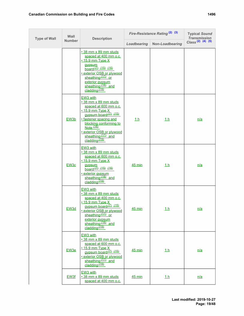
Fire-Resistance Rating (2) (3)
Type of Wall WallNumber Description
Loadbearing Non-Loadbearing
Typical SoundTransmission
Class (2) (4) (5)
• 38 mm x 89 mm studsspaced at 400 mm o.c.
• 15.9 mm Type Xgypsumboard (7) (15) (16)
• exterior OSB or plywoodsheathing (17) orexterior gypsumsheathing (18) andcladding (19)
EW3b
EW3 with• 38 mm x 89 mm studs
spaced at 600 mm o.c.• 15.9 mm Type X
gypsum board (7) (15)
• fastener spacing andblocking conforming toNote (16)
• exterior OSB or plywoodsheathing (17) andcladding (19)
1 h 1 h n/a
EW3c
EW3 with• 38 mm x 89 mm studs
spaced at 600 mm o.c.• 15.9 mm Type X
gypsumboard (7) (15) (16)
• exterior gypsumsheathing (18) andcladding (19)
45 min 1 h n/a
EW3d
EW3 with• 38 mm x 89 mm studs
spaced at 400 mm o.c.• 15.9 mm Type X
gypsum board (7) (15)
• exterior OSB or plywoodsheathing (17) orexterior gypsumsheathing (18) andcladding (19)
45 min 1 h n/a
EW3e
EW3 with• 38 mm x 89 mm studs
spaced at 600 mm o.c.• 15.9 mm Type X
gypsum board (7) (15)
• exterior OSB or plywoodsheathing (17) andcladding (19)
45 min 1 h n/a
EW3fEW3 with• 38 mm x 89 mm studs
spaced at 400 mm o.c.45 min 1 h n/a
PROPOSED CHANGE Table 9.10.3.1.A. FootnotePROPOSED CHANGE Table 9.10.3.1.A. FootnotePROPOSED CHANGE Table 9.10.3.1.A. FootnotePROPOSED CHANGE Table 9.10.3.1.A. FootnotePROPOSED CHANGE Table 9.10.3.1.A. Footnote
PROPOSED CHANGE Table 9.10.3.1.A. FootnotePROPOSED CHANGE Table 9.10.3.1.A. FootnotePROPOSED CHANGE Table 9.10.3.1.A. Footnote
PROPOSED CHANGE Table 9.10.3.1.A. Footnote
PROPOSED CHANGE Table 9.10.3.1.A. FootnotePROPOSED CHANGE Table 9.10.3.1.A. Footnote
PROPOSED CHANGE Table 9.10.3.1.A. FootnotePROPOSED CHANGE Table 9.10.3.1.A. Footnote
PROPOSED CHANGE Table 9.10.3.1.A. FootnotePROPOSED CHANGE Table 9.10.3.1.A. Footnote
PROPOSED CHANGE Table 9.10.3.1.A. Footnote
PROPOSED CHANGE Table 9.10.3.1.A. FootnotePROPOSED CHANGE Table 9.10.3.1.A. FootnotePROPOSED CHANGE Table 9.10.3.1.A. Footnote
PROPOSED CHANGE Table 9.10.3.1.A. FootnotePROPOSED CHANGE Table 9.10.3.1.A. Footnote
PROPOSED CHANGE Table 9.10.3.1.A. FootnotePROPOSED CHANGE Table 9.10.3.1.A. FootnotePROPOSED CHANGE Table 9.10.3.1.A. Footnote
PROPOSED CHANGE Table 9.10.3.1.A. FootnotePROPOSED CHANGE Table 9.10.3.1.A. Footnote
PROPOSED CHANGE Table 9.10.3.1.A. FootnotePROPOSED CHANGE Table 9.10.3.1.A. FootnotePROPOSED CHANGE Table 9.10.3.1.A. Footnote
PROPOSED CHANGE Table 9.10.3.1.A. Footnote
Canadian Commission on Building and Fire Codes 1496
Last modified: 2019-10-27Page: 19/48

Fire-Resistance Rating (2) (3)
Type of Wall WallNumber Description
Loadbearing Non-Loadbearing
Typical SoundTransmission
Class (2) (4) (5)
• 12.7 mm Type Xgypsum board (7) (15)
• fastener spacing andblocking conforming toNote (16)
• exterior OSB or plywoodsheathing (17) orexterior gypsumsheathing (18) andcladding (19)
EW3g
EW3 with• 38 mm x 89 mm studs
spaced at 600 mm o.c.• 12.7 mm Type X
gypsum board (7) (15)
• fastener spacing andblocking conforming toNote (16)
• exterior OSB or plywoodsheathing (17) andcladding (19)
45 min 1 h n/a
EW3h
EW3 with• 38 mm x 89 mm studs
spaced at 600 mm o.c.• 12.7 mm Type X
gypsumboard (7) (15) (16)
• exterior gypsumsheathing (18) andcladding (19)
– 45 min n/a
EW3i
EW3 with• 38 mm x 89 mm studs
spaced at 400 mm o.c.• 12.7 mm Type X
gypsum board (7) (15)
• exterior OSB or plywoodsheathing (17) orexterior gypsumsheathing (18) andcladding (19)
– 45 min n/a
EW3j
EW3 with• 38 mm x 89 mm studs
spaced at 600 mm o.c.• 12.7 mm Type X
gypsum board (7) (15)
• exterior OSB or plywoodsheathing (17) andcladding (19)
– 45 min n/a
EW3kEW3 with• 38 mm x 140 mm studs
spaced at 400 mm o.c.45 min 45 min n/a
PROPOSED CHANGE Table 9.10.3.1.A. FootnotePROPOSED CHANGE Table 9.10.3.1.A. FootnotePROPOSED CHANGE Table 9.10.3.1.A. FootnotePROPOSED CHANGE Table 9.10.3.1.A. FootnotePROPOSED CHANGE Table 9.10.3.1.A. Footnote
PROPOSED CHANGE Table 9.10.3.1.A. FootnotePROPOSED CHANGE Table 9.10.3.1.A. Footnote
PROPOSED CHANGE Table 9.10.3.1.A. FootnotePROPOSED CHANGE Table 9.10.3.1.A. Footnote
PROPOSED CHANGE Table 9.10.3.1.A. FootnotePROPOSED CHANGE Table 9.10.3.1.A. Footnote
PROPOSED CHANGE Table 9.10.3.1.A. FootnotePROPOSED CHANGE Table 9.10.3.1.A. Footnote
PROPOSED CHANGE Table 9.10.3.1.A. FootnotePROPOSED CHANGE Table 9.10.3.1.A. Footnote
PROPOSED CHANGE Table 9.10.3.1.A. Footnote
PROPOSED CHANGE Table 9.10.3.1.A. FootnotePROPOSED CHANGE Table 9.10.3.1.A. FootnotePROPOSED CHANGE Table 9.10.3.1.A. Footnote
PROPOSED CHANGE Table 9.10.3.1.A. FootnotePROPOSED CHANGE Table 9.10.3.1.A. Footnote
PROPOSED CHANGE Table 9.10.3.1.A. FootnotePROPOSED CHANGE Table 9.10.3.1.A. FootnotePROPOSED CHANGE Table 9.10.3.1.A. Footnote
PROPOSED CHANGE Table 9.10.3.1.A. FootnotePROPOSED CHANGE Table 9.10.3.1.A. Footnote
PROPOSED CHANGE Table 9.10.3.1.A. FootnotePROPOSED CHANGE Table 9.10.3.1.A. FootnotePROPOSED CHANGE Table 9.10.3.1.A. Footnote
PROPOSED CHANGE Table 9.10.3.1.A. Footnote
Canadian Commission on Building and Fire Codes 1496
Last modified: 2019-10-27Page: 20/48

Fire-Resistance Rating (2) (3)
Type of Wall WallNumber Description
Loadbearing Non-Loadbearing
Typical SoundTransmission
Class (2) (4) (5)
• 15.9 mm Type Xgypsumboard (7) (15) (16)
• exterior wood sheathing,exterior gypsumsheathing or insulatedexterior sheathing (20)
• masonry veneercladding not less than89 mm thick
• Non-LoadbearingSteel Studs
S1
• 31 mm x 64 mm steelstuds spaced 400 mmor 600 mm o.c.
• with or withoutabsorptive material
• 1 layer of gypsum boardon each side
• 0.46 mm(25 Gauge)
S1a
S1 with• studs spaced 600 mm
o.c.• 65 mm thick absorptive
material (6)
• 15.9 mm Type Xgypsum board (7)
–45 min[1 h (8) ] 43
S1b
S1 with• studs spaced 400 mm
o.c.• 65 mm thick absorptive
material (6)
• 15.9 mm Type Xgypsum board (7)
–45 min[1 h (8) ] 39
S1c
S1 with• studs spaced 400 mm or
600 mm o.c.• no absorptive material•15.9 mm Type X gypsum
board (7)
– 45 min 35
S2
• 31 mm x 64 mm steelstuds spaced 400 mmor 600 mm o.c.
• with or withoutabsorptive material
• 1 layer of gypsum boardon one side
• 2 layers of gypsumboard on other side
S2aS2 with• studs spaced 600 mm
o.c.– 1 h 50
PROPOSED CHANGE Table 9.10.3.1.A. FootnotePROPOSED CHANGE Table 9.10.3.1.A. FootnotePROPOSED CHANGE Table 9.10.3.1.A. FootnotePROPOSED CHANGE Table 9.10.3.1.A. FootnotePROPOSED CHANGE Table 9.10.3.1.A. Footnote
PROPOSED CHANGE Table 9.10.3.1.A. FootnotePROPOSED CHANGE Table 9.10.3.1.A. FootnotePROPOSED CHANGE Table 9.10.3.1.A. Footnote
PROPOSED CHANGE Table 9.10.3.1.A. Footnote
PROPOSED CHANGE Table 9.10.3.1.A. Footnote
PROPOSED CHANGE Table 9.10.3.1.A. Footnote
PROPOSED CHANGE Table 9.10.3.1.A. Footnote
PROPOSED CHANGE Table 9.10.3.1.A. Footnote
PROPOSED CHANGE Table 9.10.3.1.A. Footnote
PROPOSED CHANGE Table 9.10.3.1.A. Footnote
PROPOSED CHANGE Table 9.10.3.1.A. Footnote
Canadian Commission on Building and Fire Codes 1496
Last modified: 2019-10-27Page: 21/48

Fire-Resistance Rating (2) (3)
Type of Wall WallNumber Description
Loadbearing Non-Loadbearing
Typical SoundTransmission
Class (2) (4) (5)
• 65 mm thick absorptivematerial (6)
• 15.9 mm Type Xgypsum board (7)
S2b
S2 with• studs spaced 400 mm
o.c.• 65 mm thick absorptive
material (6)
• 15.9 mm Type Xgypsum board (7)
– 1 h 44
S2c
S2 with• studs spaced 600 mm
o.c.• 65 mm thick absorptive
material (6)
• 12.7 mm Type Xgypsum board (7)
– 1 h 50
S2d
S2 with• studs spaced 400 mm
o.c.• 65 mm thick absorptive
material (6)
• 12.7 mm Type Xgypsum board (7)
– 1 h 42
S2e
S2 with• studs spaced 600 mm
o.c.• no absorptive material• 15.9 mm Type X
gypsum board (7)
– 1 h 41
S2f
S2 with• studs spaced 400 mm
o.c.• no absorptive material• 15.9 mm Type X
gypsum board (7)
– 1 h 37
S2g
S2 with• studs spaced 600 mm
o.c.• no absorptive material• 12.7 mm Type X
gypsum board (7)
– 1 h 40
S2h
S2 with• studs spaced 400 mm
o.c.• no absorptive material• 12.7 mm Type X
gypsum board (7)
– 1 h 35
PROPOSED CHANGE Table 9.10.3.1.A. FootnotePROPOSED CHANGE Table 9.10.3.1.A. FootnotePROPOSED CHANGE Table 9.10.3.1.A. FootnotePROPOSED CHANGE Table 9.10.3.1.A. FootnotePROPOSED CHANGE Table 9.10.3.1.A. Footnote
PROPOSED CHANGE Table 9.10.3.1.A. Footnote
PROPOSED CHANGE Table 9.10.3.1.A. Footnote
PROPOSED CHANGE Table 9.10.3.1.A. Footnote
PROPOSED CHANGE Table 9.10.3.1.A. Footnote
PROPOSED CHANGE Table 9.10.3.1.A. Footnote
PROPOSED CHANGE Table 9.10.3.1.A. Footnote
PROPOSED CHANGE Table 9.10.3.1.A. Footnote
PROPOSED CHANGE Table 9.10.3.1.A. Footnote
PROPOSED CHANGE Table 9.10.3.1.A. Footnote
PROPOSED CHANGE Table 9.10.3.1.A. Footnote
PROPOSED CHANGE Table 9.10.3.1.A. Footnote
PROPOSED CHANGE Table 9.10.3.1.A. Footnote
Canadian Commission on Building and Fire Codes 1496
Last modified: 2019-10-27Page: 22/48

Fire-Resistance Rating (2) (3)
Type of Wall WallNumber Description
Loadbearing Non-Loadbearing
Typical SoundTransmission
Class (2) (4) (5)
S3
• 31 mm x 64 mm steelstuds spaced 400 mmor 600 mm o.c.
• with or withoutabsorptive material
• 2 layers of gypsumboard on each side
S3a
S3 with• studs spaced 600 mm
o.c.• 65 mm thick absorptive
material (6)
• 15.9 mm Type Xgypsum board (7)
– 2 h 54
S3b
S3 with• studs spaced 400 mm
o.c.• 65 mm thick absorptive
material (6)
• 15.9 mm Type Xgypsum board (7)
– 2 h 51
S3c
S3 with• studs spaced 600 mm
o.c.• 65 mm thick absorptive
material (6)
• 12.7 mm Type Xgypsum board (7)
– 1.5 h 53
S3d
S3 with• studs spaced 400 mm
o.c.• 65 mm thick absorptive
material (6)
• 12.7 mm Type Xgypsum board (7)
– 1.5 h 47
S3e
S3 with• studs spaced 600 mm
o.c.• 65 mm thick absorptive
material (6)
• 12.7 mm regular gypsumboard (7)
– 1 h 49
S3f
S3 with• studs spaced 400 mm
o.c.• 65 mm thick absorptive
material (6)
• 12.7 mm regular gypsumboard (7)
– 1 h 41
S3g S3 with – 2 h 45
PROPOSED CHANGE Table 9.10.3.1.A. FootnotePROPOSED CHANGE Table 9.10.3.1.A. FootnotePROPOSED CHANGE Table 9.10.3.1.A. FootnotePROPOSED CHANGE Table 9.10.3.1.A. FootnotePROPOSED CHANGE Table 9.10.3.1.A. Footnote
PROPOSED CHANGE Table 9.10.3.1.A. Footnote
PROPOSED CHANGE Table 9.10.3.1.A. Footnote
PROPOSED CHANGE Table 9.10.3.1.A. Footnote
PROPOSED CHANGE Table 9.10.3.1.A. Footnote
PROPOSED CHANGE Table 9.10.3.1.A. Footnote
PROPOSED CHANGE Table 9.10.3.1.A. Footnote
PROPOSED CHANGE Table 9.10.3.1.A. Footnote
PROPOSED CHANGE Table 9.10.3.1.A. Footnote
PROPOSED CHANGE Table 9.10.3.1.A. Footnote
PROPOSED CHANGE Table 9.10.3.1.A. Footnote
PROPOSED CHANGE Table 9.10.3.1.A. Footnote
PROPOSED CHANGE Table 9.10.3.1.A. Footnote
Canadian Commission on Building and Fire Codes 1496
Last modified: 2019-10-27Page: 23/48

Fire-Resistance Rating (2) (3)
Type of Wall WallNumber Description
Loadbearing Non-Loadbearing
Typical SoundTransmission
Class (2) (4) (5)
• studs spaced 600 mmo.c.
• no absorptive material• 15.9 mm Type X
gypsum board (7)
S3h
S3 with• studs spaced 400 mm
o.c.• no absorptive material• 15.9 mm Type X
gypsum board (7)
– 2 h 42
S3i
S3 with• studs spaced 600 mm
o.c.• no absorptive material• 12.7 mm Type X
gypsum board (7)
– 1.5 h 44
S3j
S3 with• studs spaced 400 mm
o.c.• no absorptive material• 12.7 mm Type X
gypsum board (7)
– 1.5 h 39
S3k
S3 with• studs spaced 600 mm
o.c.• no absorptive material• 12.7 mm regular gypsum
board (7)
– 1 h 40
S3l
S3 with• studs spaced 400 mm
o.c.• no absorptive material• 12.7 mm regular gypsum
board (7)
– 1 h 37
S4
• 31 mm x 92 mm steelstuds spaced 400 mmor 600 mm o.c.
• with or withoutabsorptive material
• 1 layer of gypsum boardon each side
S4a
S4 with• studs spaced 600 mm
o.c.• 89 mm thick absorptive
material (6)
• 15.9 mm Type Xgypsum board (7)
–45 min[1 h (8) ] 48
PROPOSED CHANGE Table 9.10.3.1.A. FootnotePROPOSED CHANGE Table 9.10.3.1.A. FootnotePROPOSED CHANGE Table 9.10.3.1.A. FootnotePROPOSED CHANGE Table 9.10.3.1.A. FootnotePROPOSED CHANGE Table 9.10.3.1.A. Footnote
PROPOSED CHANGE Table 9.10.3.1.A. Footnote
PROPOSED CHANGE Table 9.10.3.1.A. Footnote
PROPOSED CHANGE Table 9.10.3.1.A. Footnote
PROPOSED CHANGE Table 9.10.3.1.A. Footnote
PROPOSED CHANGE Table 9.10.3.1.A. Footnote
PROPOSED CHANGE Table 9.10.3.1.A. Footnote
PROPOSED CHANGE Table 9.10.3.1.A. Footnote
PROPOSED CHANGE Table 9.10.3.1.A. Footnote
PROPOSED CHANGE Table 9.10.3.1.A. Footnote
Canadian Commission on Building and Fire Codes 1496
Last modified: 2019-10-27Page: 24/48

Fire-Resistance Rating (2) (3)
Type of Wall WallNumber Description
Loadbearing Non-Loadbearing
Typical SoundTransmission
Class (2) (4) (5)
S4b
S4 with• studs spaced 400 mm
o.c.• 89 mm thick absorptive
material (6)
• 15.9 mm Type Xgypsum board (7)
–45 min[1 h (8) ] 47
S4c
S4 with• studs spaced 600 mm
o.c.• no absorptive material• 15.9 mm Type X
gypsum board (7)
– 45 min 38
S4d
S4 with• studs spaced 400 mm
o.c.• no absorptive material• 15.9 mm Type X
gypsum board (7)
– 45 min 38
S5
• 31 mm x 92 mm steelstuds spaced 400 mmor 600 mm o.c.
• with or withoutabsorptive material
• 1 layer of gypsum boardon one side
• 2 layers of gypsumboard on other side
S5a
S5 with• studs spaced 600 mm
o.c.• 89 mm thick absorptive
material (6)
• 15.9 mm Type Xgypsum board (7)
–1 h
[1.5 h (8) ] 53
S5b
S5 with• studs spaced 400 mm
o.c.• 89 mm thick absorptive
material (6)
• 15.9 mm Type Xgypsum board (7)
–1 h
[1.5 h (8) ] 52
S5c
S5 with• studs spaced 600 mm
o.c.• 89 mm thick absorptive
material (6)
• 12.7 mm Type Xgypsum board (7)
–1 h
[1.5 h (8) ] 51
PROPOSED CHANGE Table 9.10.3.1.A. FootnotePROPOSED CHANGE Table 9.10.3.1.A. FootnotePROPOSED CHANGE Table 9.10.3.1.A. FootnotePROPOSED CHANGE Table 9.10.3.1.A. FootnotePROPOSED CHANGE Table 9.10.3.1.A. Footnote
PROPOSED CHANGE Table 9.10.3.1.A. Footnote
PROPOSED CHANGE Table 9.10.3.1.A. Footnote
PROPOSED CHANGE Table 9.10.3.1.A. Footnote
PROPOSED CHANGE Table 9.10.3.1.A. Footnote
PROPOSED CHANGE Table 9.10.3.1.A. Footnote
PROPOSED CHANGE Table 9.10.3.1.A. Footnote
PROPOSED CHANGE Table 9.10.3.1.A. Footnote
PROPOSED CHANGE Table 9.10.3.1.A. Footnote
PROPOSED CHANGE Table 9.10.3.1.A. Footnote
PROPOSED CHANGE Table 9.10.3.1.A. Footnote
PROPOSED CHANGE Table 9.10.3.1.A. Footnote
PROPOSED CHANGE Table 9.10.3.1.A. Footnote
PROPOSED CHANGE Table 9.10.3.1.A. Footnote
PROPOSED CHANGE Table 9.10.3.1.A. Footnote
Canadian Commission on Building and Fire Codes 1496
Last modified: 2019-10-27Page: 25/48

Fire-Resistance Rating (2) (3)
Type of Wall WallNumber Description
Loadbearing Non-Loadbearing
Typical SoundTransmission
Class (2) (4) (5)
S5d
S5 with• studs spaced 400 mm
o.c.• 89 mm thick absorptive
material (6)
• 12.7 mm Type Xgypsum board (7)
–1 h
[1.5 h (8) ] 50
S5e
S5 with• studs spaced 600 mm
o.c.• no absorptive material•15.9 mm Type X gypsum
board (7)
– 1 h 43
S5f
S5 with• studs spaced 400 mm
o.c.• no absorptive material• 15.9 mm Type X
gypsum board (7)
– 1 h 42
S5g
S5 with• studs spaced 600 mm
o.c.• no absorptive material• 12.7 mm Type X
gypsum board (7)
– 1 h 41
S5h
S5 with• studs spaced 400 mm
o.c.• no absorptive material• 12.7 mm Type X
gypsum board (7)
– 1 h 40
S6
• 31 mm x 92 mm steelstuds spaced 400 mmor 600 mm o.c.
• with or withoutabsorptive material
• 2 layers of gypsumboard on each side
S6a
S6 with• studs spaced 600 mm
o.c.• 89 mm thick absorptive
material (6)
• 15.9 mm Type Xgypsum board (7)
– 2 h 56
S6bS6 with• studs spaced 400 mm
o.c.– 2 h 55
PROPOSED CHANGE Table 9.10.3.1.A. FootnotePROPOSED CHANGE Table 9.10.3.1.A. FootnotePROPOSED CHANGE Table 9.10.3.1.A. FootnotePROPOSED CHANGE Table 9.10.3.1.A. FootnotePROPOSED CHANGE Table 9.10.3.1.A. Footnote
PROPOSED CHANGE Table 9.10.3.1.A. Footnote
PROPOSED CHANGE Table 9.10.3.1.A. Footnote
PROPOSED CHANGE Table 9.10.3.1.A. Footnote
PROPOSED CHANGE Table 9.10.3.1.A. Footnote
PROPOSED CHANGE Table 9.10.3.1.A. Footnote
PROPOSED CHANGE Table 9.10.3.1.A. Footnote
PROPOSED CHANGE Table 9.10.3.1.A. Footnote
PROPOSED CHANGE Table 9.10.3.1.A. Footnote
PROPOSED CHANGE Table 9.10.3.1.A. Footnote
Canadian Commission on Building and Fire Codes 1496
Last modified: 2019-10-27Page: 26/48

Fire-Resistance Rating (2) (3)
Type of Wall WallNumber Description
Loadbearing Non-Loadbearing
Typical SoundTransmission
Class (2) (4) (5)
• 89 mm thick absorptivematerial (6)
• 15.9 mm Type Xgypsum board (7)
S6c
S6 with• studs spaced 600 mm
o.c.• 89 mm thick absorptive
material (6)
• 12.7 mm Type Xgypsum board (7)
– 1.5 h 55
S6d
S6 with• studs spaced 400 mm
o.c.• 89 mm thick absorptive
material (6)
• 12.7 mm Type Xgypsum board (7)
– 1.5 h 54
S6e
S6 with• studs spaced 600 mm
o.c.• 89 mm thick absorptive
material (6)
• 12.7 mm regular gypsumboard (7)
– 1 h 50
S6f
S6 with• studs spaced 400 mm
o.c.• 89 mm thick absorptive
material (6)
• 12.7 mm regular gypsumboard (7)
– 1 h 48
S6g
S6 with• studs spaced 600 mm
o.c.• no absorptive material• 15.9 mm Type X
gypsum board (7)
– 2 h 47
S6h
S6 with• studs spaced 400 mm
o.c.• no absorptive material• 15.9 mm Type X
gypsum board (7)
– 2 h 45
S6i
S6 with• studs spaced 600 mm
o.c.• no absorptive material• 12.7 mm Type X
gypsum board (7)
– 1.5 h 45
PROPOSED CHANGE Table 9.10.3.1.A. FootnotePROPOSED CHANGE Table 9.10.3.1.A. FootnotePROPOSED CHANGE Table 9.10.3.1.A. FootnotePROPOSED CHANGE Table 9.10.3.1.A. FootnotePROPOSED CHANGE Table 9.10.3.1.A. Footnote
PROPOSED CHANGE Table 9.10.3.1.A. Footnote
PROPOSED CHANGE Table 9.10.3.1.A. Footnote
PROPOSED CHANGE Table 9.10.3.1.A. Footnote
PROPOSED CHANGE Table 9.10.3.1.A. Footnote
PROPOSED CHANGE Table 9.10.3.1.A. Footnote
PROPOSED CHANGE Table 9.10.3.1.A. Footnote
PROPOSED CHANGE Table 9.10.3.1.A. Footnote
PROPOSED CHANGE Table 9.10.3.1.A. Footnote
PROPOSED CHANGE Table 9.10.3.1.A. Footnote
PROPOSED CHANGE Table 9.10.3.1.A. Footnote
PROPOSED CHANGE Table 9.10.3.1.A. Footnote
PROPOSED CHANGE Table 9.10.3.1.A. Footnote
PROPOSED CHANGE Table 9.10.3.1.A. Footnote
Canadian Commission on Building and Fire Codes 1496
Last modified: 2019-10-27Page: 27/48

Fire-Resistance Rating (2) (3)
Type of Wall WallNumber Description
Loadbearing Non-Loadbearing
Typical SoundTransmission
Class (2) (4) (5)
S6j
S6 with• studs spaced 400 mm
o.c.• no absorptive material• 12.7 mm Type X
gypsum board (7)
– 1.5 h 44
S6k
S6 with• studs spaced 600 mm
o.c.• no absorptive material• 12.7 mm regular gypsum
board (7)
– 1 h 41
S6l
S6 with• studs spaced 400 mm
o.c.• no absorptive material• 12.7 mm regular gypsum
board (7)
– 1 h 39
S7
• 31 mm x 152 mm steelstuds spaced 400 mmor 600 mm o.c.
• with or withoutabsorptive material
• 1 layer of gypsum boardon each side
S7a
S7 with• 150 mm thick absorptive
material (6)
• 15.9 mm Type Xgypsum board (7)
–45 min[1 h (8) ] 51
S7b
S7 with• no absorptive material• 15.9 mm Type X
gypsum board (7)
– 45 min 41
S8
• 31 mm x 152 mm steelstuds spaced 400 mmor 600 mm o.c.
• with or withoutabsorptive material
• 1 layer of gypsum boardon one side
• 2 layers of gypsumboard on other side
S8a
S8 with• 150 mm thick absorptive
material (6)
• 15.9 mm Type Xgypsum board (7)
–1 h
[1.5 h (8) ] 55
PROPOSED CHANGE Table 9.10.3.1.A. FootnotePROPOSED CHANGE Table 9.10.3.1.A. FootnotePROPOSED CHANGE Table 9.10.3.1.A. FootnotePROPOSED CHANGE Table 9.10.3.1.A. FootnotePROPOSED CHANGE Table 9.10.3.1.A. Footnote
PROPOSED CHANGE Table 9.10.3.1.A. Footnote
PROPOSED CHANGE Table 9.10.3.1.A. Footnote
PROPOSED CHANGE Table 9.10.3.1.A. Footnote
PROPOSED CHANGE Table 9.10.3.1.A. Footnote
PROPOSED CHANGE Table 9.10.3.1.A. Footnote
PROPOSED CHANGE Table 9.10.3.1.A. Footnote
PROPOSED CHANGE Table 9.10.3.1.A. Footnote
PROPOSED CHANGE Table 9.10.3.1.A. Footnote
PROPOSED CHANGE Table 9.10.3.1.A. Footnote
PROPOSED CHANGE Table 9.10.3.1.A. Footnote
Canadian Commission on Building and Fire Codes 1496
Last modified: 2019-10-27Page: 28/48

Fire-Resistance Rating (2) (3)
Type of Wall WallNumber Description
Loadbearing Non-Loadbearing
Typical SoundTransmission
Class (2) (4) (5)
S8b
S8 with• 150 mm thick absorptive
material (6)
• 12.7 mm Type Xgypsum board (7)
–1 h
[1.5 h (8) ] 54
S8c
S8 with• no absorptive material• 15.9 mm Type X
gypsum board (7)
– 1 h 45
S8d
S8 with• no absorptive material• 12.7 mm Type X
gypsum board (7)
– 1 h 44
S9
• 31 mm x 152 mm steelstuds spaced 400 mmor 600 mm o.c.
• with or withoutabsorptive material
• 2 layers of gypsumboard on each side
S9a
S9 with• 150 mm thick absorptive
material (6)
• 15.9 mm Type Xgypsum board (7)
– 2 h 59
S9b
S9 with• 150 mm thick absorptive
material (6)
• 12.7 mm Type Xgypsum board (7)
– 1.5 h 57
S9c
S9 with• 150 mm thick absorptive
material (6)
• 12.7 mm regular gypsumboard (7)
– 1 h 53
S9d
S9 with• no absorptive material• 15.9 mm Type X
gypsum board (7)
– 2 h 49
S9e
S9 with• no absorptive material• 12.7 mm Type X
gypsum board (7)
– 1.5 h 47
S9f
S9 with• no absorptive material• 12.7 mm regular gypsum
board (7)
– 1 h 43
PROPOSED CHANGE Table 9.10.3.1.A. FootnotePROPOSED CHANGE Table 9.10.3.1.A. FootnotePROPOSED CHANGE Table 9.10.3.1.A. FootnotePROPOSED CHANGE Table 9.10.3.1.A. FootnotePROPOSED CHANGE Table 9.10.3.1.A. Footnote
PROPOSED CHANGE Table 9.10.3.1.A. Footnote
PROPOSED CHANGE Table 9.10.3.1.A. Footnote
PROPOSED CHANGE Table 9.10.3.1.A. Footnote
PROPOSED CHANGE Table 9.10.3.1.A. Footnote
PROPOSED CHANGE Table 9.10.3.1.A. Footnote
PROPOSED CHANGE Table 9.10.3.1.A. Footnote
PROPOSED CHANGE Table 9.10.3.1.A. Footnote
PROPOSED CHANGE Table 9.10.3.1.A. Footnote
PROPOSED CHANGE Table 9.10.3.1.A. Footnote
PROPOSED CHANGE Table 9.10.3.1.A. Footnote
PROPOSED CHANGE Table 9.10.3.1.A. Footnote
PROPOSED CHANGE Table 9.10.3.1.A. Footnote
PROPOSED CHANGE Table 9.10.3.1.A. Footnote
PROPOSED CHANGE Table 9.10.3.1.A. Footnote
Canadian Commission on Building and Fire Codes 1496
Last modified: 2019-10-27Page: 29/48

Fire-Resistance Rating (2) (3)
Type of Wall WallNumber Description
Loadbearing Non-Loadbearing
Typical SoundTransmission
Class (2) (4) (5)
• LoadbearingSteel Studs
• 0.84 mm to1.52 mmThickness S10
• 41 mm x 92 mmloadbearing steel studsspaced400 mm or 600 mm o.c.
• with or without cross-bracing on one side
• with or withoutabsorptive material
• 2 layers gypsum boardon each side
S10a
S10 with• 89 mm thick absorptive
material (6)
• 15.9 mm Type Xgypsum board (7)
1 h – 38
S10b
S10 with• 89 mm thick absorptive
material (6)
• 12.7 mm Type Xgypsum board (7)
45 min [1 h] – 38
S10c
S10 with• 89 mm thick absorptive
material (6)
• 12.7 mm regular gypsumboard (7)
– – 36
S10d
S10 with• no absorptive material• 15.9 mm Type X
gypsum board (7)
1 h – 36
S10e
S10 with• no absorptive material• 12.7 mm Type X
gypsum board (7)
1 h – 35
S10f
S10 with• no absorptive material• 12.7 mm regular gypsum
board (7)
– – 34
S11
• 41 mm x 92 mmloadbearing steel studsspaced400 mm or 600 mm o.c.
• with or without cross-bracing on one side
• with or withoutabsorptive material
• resilient metal channelson one side
• 1 layer gypsum board oneach side
PROPOSED CHANGE Table 9.10.3.1.A. FootnotePROPOSED CHANGE Table 9.10.3.1.A. FootnotePROPOSED CHANGE Table 9.10.3.1.A. FootnotePROPOSED CHANGE Table 9.10.3.1.A. FootnotePROPOSED CHANGE Table 9.10.3.1.A. Footnote
PROPOSED CHANGE Table 9.10.3.1.A. Footnote
PROPOSED CHANGE Table 9.10.3.1.A. Footnote
PROPOSED CHANGE Table 9.10.3.1.A. Footnote
PROPOSED CHANGE Table 9.10.3.1.A. Footnote
PROPOSED CHANGE Table 9.10.3.1.A. Footnote
PROPOSED CHANGE Table 9.10.3.1.A. Footnote
PROPOSED CHANGE Table 9.10.3.1.A. Footnote
PROPOSED CHANGE Table 9.10.3.1.A. Footnote
PROPOSED CHANGE Table 9.10.3.1.A. Footnote
Canadian Commission on Building and Fire Codes 1496
Last modified: 2019-10-27Page: 30/48

Fire-Resistance Rating (2) (3)
Type of Wall WallNumber Description
Loadbearing Non-Loadbearing
Typical SoundTransmission
Class (2) (4) (5)
S11a
S11 with• 89 mm thick absorptive
material (6)
• resilient metal channelsspaced at 600 mm o.c.
• 15.9 mm Type Xgypsum board (7)
– – 50
S11b
S11 with• 89 mm thick absorptive
material (6)
• resilient metal channelsspaced at 400 mm o.c.
• 15.9 mm Type Xgypsum board (7)
– – 47
S11c
S11 with• no absorptive material• resilient metal channels
spaced at 600 mm o.c.• 15.9 mm Type X
gypsum board (7)
– – 41
S11d
S11 with• 89 mm thick absorptive
material (6)
• resilient metal channelsspaced at 600 mm o.c.
• 12.7 mm Type Xgypsum board (7)
– – 47
S11e
S11 with• 89 mm thick absorptive
material (6)
• resilient metal channelsspaced at 400 mm o.c.
• 12.7 mm Type Xgypsum board (7)
– – 45
S11f
S11 with• no absorptive
material (6)
• resilient metal channelsspaced at 400 mm o.c.
• 15.9 mm Type Xgypsum board (7)
– – 39
S11g
S11 with• no absorptive
material (6)
• resilient metal channelsspaced at 400 mm o.c.
• 12.7 mm Type Xgypsum board (7)
– – 36
S11h S11 with – – 38
PROPOSED CHANGE Table 9.10.3.1.A. FootnotePROPOSED CHANGE Table 9.10.3.1.A. FootnotePROPOSED CHANGE Table 9.10.3.1.A. FootnotePROPOSED CHANGE Table 9.10.3.1.A. FootnotePROPOSED CHANGE Table 9.10.3.1.A. Footnote
PROPOSED CHANGE Table 9.10.3.1.A. Footnote
PROPOSED CHANGE Table 9.10.3.1.A. Footnote
PROPOSED CHANGE Table 9.10.3.1.A. Footnote
PROPOSED CHANGE Table 9.10.3.1.A. Footnote
PROPOSED CHANGE Table 9.10.3.1.A. Footnote
PROPOSED CHANGE Table 9.10.3.1.A. Footnote
PROPOSED CHANGE Table 9.10.3.1.A. Footnote
PROPOSED CHANGE Table 9.10.3.1.A. Footnote
PROPOSED CHANGE Table 9.10.3.1.A. Footnote
PROPOSED CHANGE Table 9.10.3.1.A. Footnote
PROPOSED CHANGE Table 9.10.3.1.A. Footnote
PROPOSED CHANGE Table 9.10.3.1.A. Footnote
PROPOSED CHANGE Table 9.10.3.1.A. Footnote
Canadian Commission on Building and Fire Codes 1496
Last modified: 2019-10-27Page: 31/48

Fire-Resistance Rating (2) (3)
Type of Wall WallNumber Description
Loadbearing Non-Loadbearing
Typical SoundTransmission
Class (2) (4) (5)
• no absorptivematerial (6)
• resilient metal channelsspaced at 600 mm o.c.
• 12.7 mm Type Xgypsum board (7)
S12
• 41 mm x 92 mmloadbearing steel studsspaced400 mm or 600 mm o.c.
• with or without cross-bracing on one side
• with or withoutabsorptive material
• resilient metal channelson one side
• 2 layers gypsum boardon resilient channelside
• 1 layer gypsum board onother side
S12a
S12 with• 89 mm thick absorptive
material (6)
• resilient metal channelsspaced at 600 mm o.c.
• 15.9 mm Type Xgypsum board (7)
– – 54
S12b
S12 with• no absorptive material• resilient metal channels
spaced at 600 mm o.c.• 15.9 mm Type X
gypsum board (7)
– – 46
S12c
S12 with• 89 mm thick absorptive
material (6)
• resilient metal channelsspaced at 400 mm o.c.
• 15.9 mm Type Xgypsum board (7)
– – 52
S12d
S12 with• no absorptive material• resilient metal channels
spaced at 400 mm o.c.• 15.9 mm Type X
gypsum board (7)
– – 43
S12eS12 with• 89 mm thick absorptive
material (6)– – 52
PROPOSED CHANGE Table 9.10.3.1.A. FootnotePROPOSED CHANGE Table 9.10.3.1.A. FootnotePROPOSED CHANGE Table 9.10.3.1.A. FootnotePROPOSED CHANGE Table 9.10.3.1.A. FootnotePROPOSED CHANGE Table 9.10.3.1.A. Footnote
PROPOSED CHANGE Table 9.10.3.1.A. Footnote
PROPOSED CHANGE Table 9.10.3.1.A. Footnote
PROPOSED CHANGE Table 9.10.3.1.A. Footnote
PROPOSED CHANGE Table 9.10.3.1.A. Footnote
PROPOSED CHANGE Table 9.10.3.1.A. Footnote
PROPOSED CHANGE Table 9.10.3.1.A. Footnote
PROPOSED CHANGE Table 9.10.3.1.A. Footnote
PROPOSED CHANGE Table 9.10.3.1.A. Footnote
PROPOSED CHANGE Table 9.10.3.1.A. Footnote
Canadian Commission on Building and Fire Codes 1496
Last modified: 2019-10-27Page: 32/48

Fire-Resistance Rating (2) (3)
Type of Wall WallNumber Description
Loadbearing Non-Loadbearing
Typical SoundTransmission
Class (2) (4) (5)
• resilient metal channelsspaced at 600 mm o.c.
• 12.7 mm Type Xgypsum board (7)
S12f
S12 with• no absorptive material• resilient metal channels
spaced at 600 mm o.c.• 12.7 mm Type X
gypsum board (7)
– – 43
S12g
S12 with• 89 mm thick absorptive
material (6)
• resilient metal channelsspaced at 400 mm o.c.
• 12.7 mm Type Xgypsum board (7)
– – 50
S12h
S12 with• no absorptive material• resilient metal channels
spaced at 400 mm o.c.• 12.7 mm Type X
gypsum board (7)
– – 41
S13
• 41 mm x 92 mmloadbearing steel studsspaced400 mm or 600 mm o.c.
• with or withoutabsorptive material
• resilient metal channelson one side spaced at400 mm o.c.
• 2 layers gypsum boardon resilient channelside
• 1 layer shear membraneand 1 layer gypsumboard on other side
S13a
S13 with• 89 mm thick absorptive
material (6)
• 12.7 mm OSB shearmembrane
• 12.7 mm Type Xgypsum board (7)
30 min – 57
PROPOSED CHANGE Table 9.10.3.1.A. FootnotePROPOSED CHANGE Table 9.10.3.1.A. FootnotePROPOSED CHANGE Table 9.10.3.1.A. FootnotePROPOSED CHANGE Table 9.10.3.1.A. FootnotePROPOSED CHANGE Table 9.10.3.1.A. Footnote
PROPOSED CHANGE Table 9.10.3.1.A. Footnote
PROPOSED CHANGE Table 9.10.3.1.A. Footnote
PROPOSED CHANGE Table 9.10.3.1.A. Footnote
PROPOSED CHANGE Table 9.10.3.1.A. Footnote
PROPOSED CHANGE Table 9.10.3.1.A. Footnote
PROPOSED CHANGE Table 9.10.3.1.A. Footnote
PROPOSED CHANGE Table 9.10.3.1.A. Footnote
Canadian Commission on Building and Fire Codes 1496
Last modified: 2019-10-27Page: 33/48

Fire-Resistance Rating (2) (3)
Type of Wall WallNumber Description
Loadbearing Non-Loadbearing
Typical SoundTransmission
Class (2) (4) (5)
S14
• 41 mm x 92 mmloadbearing steel studsspaced400 mm or 600 mm o.c.
• with or withoutabsorptive material
• resilient metal channelson one side
• 2 layers gypsum boardon each side
S14a
S14 with• 89 mm thick absorptive
material (6)
• resilient metal channelsspaced at 600 mm o.c.
• 15.9 mm Type Xgypsum board (7)
1 h – 60
S14b
S14 with• 89 mm thick absorptive
material (6)
• resilient metal channelsspaced at 600 mm o.c.
• 12.7 mm Type Xgypsum board (7)
45 min [1 h] – 57
S14c
S14 with• 89 mm thick absorptive
material (6)
• resilient metal channelsspaced at 600 mm o.c.
• 12.7 mm regular gypsumboard (7)
– – 54
S14d
S14 with• no absorptive material• resilient metal channels
spaced at 600 mm o.c.• 15.9 mm Type X
gypsum board (7)
1 h – 51
S14e
S14 with• studs at 400 mm o.c.• no absorptive material• resilient metal channels
spaced at 600 mm o.c.• 12.7 mm Type X
gypsum board (7)
1 h – 49
S14f
S14 with• studs at 600 mm o.c.• no absorptive material• resilient metal channels
spaced at 600 mm o.c.
1 h – 50
PROPOSED CHANGE Table 9.10.3.1.A. FootnotePROPOSED CHANGE Table 9.10.3.1.A. FootnotePROPOSED CHANGE Table 9.10.3.1.A. FootnotePROPOSED CHANGE Table 9.10.3.1.A. FootnotePROPOSED CHANGE Table 9.10.3.1.A. Footnote
PROPOSED CHANGE Table 9.10.3.1.A. Footnote
PROPOSED CHANGE Table 9.10.3.1.A. Footnote
PROPOSED CHANGE Table 9.10.3.1.A. Footnote
PROPOSED CHANGE Table 9.10.3.1.A. Footnote
PROPOSED CHANGE Table 9.10.3.1.A. Footnote
PROPOSED CHANGE Table 9.10.3.1.A. Footnote
PROPOSED CHANGE Table 9.10.3.1.A. Footnote
PROPOSED CHANGE Table 9.10.3.1.A. Footnote
Canadian Commission on Building and Fire Codes 1496
Last modified: 2019-10-27Page: 34/48

Fire-Resistance Rating (2) (3)
Type of Wall WallNumber Description
Loadbearing Non-Loadbearing
Typical SoundTransmission
Class (2) (4) (5)
• 12.7 mm regular gypsumboard (7)
S14g
S14 with• no absorptive material• resilient metal channels
spaced at 600 mm o.c.• 12.7 mm regular gypsum
board (7)
– – 45
S14h
S14 with• studs at 400 mm o.c.• 89 mm thick absorptive
material• resilient metal channels
spaced at 400 mm o.c.• 15.9 mm Type X
gypsum board (7)
1 h – 58
S14i
S14 with• studs at 600 mm o.c.• 89 mm thick absorptive
material• resilient metal channels
spaced at 400 mm o.c.• 15.9 mm Type X
gypsum board (7)
1 h – 60
S14j
S14 with• 89 mm thick absorptive
material• resilient metal channels
spaced at 400 mm o.c.• 12.7 mm Type X
gypsum board (7)
45 min[1 h] – 55
S14k
S14 with• studs at 400 mm o.c.• no absorptive material• resilient metal channels
spaced at 400 mm o.c.• 15.9 mm Type X
gypsum board (7)
1 h – 49
S14l
S14 with• studs at 600 mm o.c.• no absorptive material• resilient metal channels
spaced at 400 mm o.c.• 15.9 mm Type X
gypsum board (7)
1 h – 51
S14m
S14 with• no absorptive material• resilient metal channels
spaced at 400 mm o.c.
1 h – 47
PROPOSED CHANGE Table 9.10.3.1.A. FootnotePROPOSED CHANGE Table 9.10.3.1.A. FootnotePROPOSED CHANGE Table 9.10.3.1.A. FootnotePROPOSED CHANGE Table 9.10.3.1.A. FootnotePROPOSED CHANGE Table 9.10.3.1.A. Footnote
PROPOSED CHANGE Table 9.10.3.1.A. Footnote
PROPOSED CHANGE Table 9.10.3.1.A. Footnote
PROPOSED CHANGE Table 9.10.3.1.A. Footnote
PROPOSED CHANGE Table 9.10.3.1.A. Footnote
PROPOSED CHANGE Table 9.10.3.1.A. Footnote
PROPOSED CHANGE Table 9.10.3.1.A. Footnote
PROPOSED CHANGE Table 9.10.3.1.A. Footnote
Canadian Commission on Building and Fire Codes 1496
Last modified: 2019-10-27Page: 35/48

Fire-Resistance Rating (2) (3)
Type of Wall WallNumber Description
Loadbearing Non-Loadbearing
Typical SoundTransmission
Class (2) (4) (5)
• 12.7 mm Type Xgypsum board (7)
S15
• 2 rows of 92 mmloadbearing steel studsspaced 400 mm or 600mm o.c.
• with cross-bracing• with or without
absorptive material• 2 layers of gypsum
board each side
S15a
S15 with• 89 mm thick absorptive
material in each cavity• 12.7 mm Type X
gypsum board (7)
1 h – 68
S15b
S15 with• no absorptive material• 12.7 mm Type X
gypsum board (7)
1 h – 52
S15c
S15 with• 89 mm thick absorptive
material in each cavity• 15.9 mm Type X
gypsum board (7)
1 h – 68
S15d
S15 with• no absorptive material• 15.9 mm Type X
gypsum board (7)
1.5 h – 52
• Hollow ConcreteBlock (NormalWeightAggregate) B1
• 140 mm or 190 mmconcrete block
B1a • 140 mm bare concreteblock (5) 1 h 1 h 48
B1b • 190 mm bare concreteblock (5) 1.5 h 1.5 h 50
PROPOSED CHANGE Table 9.10.3.1.A. FootnotePROPOSED CHANGE Table 9.10.3.1.A. FootnotePROPOSED CHANGE Table 9.10.3.1.A. FootnotePROPOSED CHANGE Table 9.10.3.1.A. FootnotePROPOSED CHANGE Table 9.10.3.1.A. Footnote
PROPOSED CHANGE Table 9.10.3.1.A. Footnote
PROPOSED CHANGE Table 9.10.3.1.A. Footnote
PROPOSED CHANGE Table 9.10.3.1.A. Footnote
PROPOSED CHANGE Table 9.10.3.1.A. Footnote
PROPOSED CHANGE Table 9.10.3.1.A. Footnote
PROPOSED CHANGE Table 9.10.3.1.A. Footnote
PROPOSED CHANGE Table 9.10.3.1.A. Footnote
Canadian Commission on Building and Fire Codes 1496
Last modified: 2019-10-27Page: 36/48

Fire-Resistance Rating (2) (3)
Type of Wall WallNumber Description
Loadbearing Non-Loadbearing
Typical SoundTransmission
Class (2) (4) (5)
B2
•140 mm or 190 mmconcrete block
• no absorptive material• 1 layer gypsum-sand
plaster or gypsumboard on each side
B2a
B2 with• 140 mm concrete block• 12.7 mm gypsum-sand
plaster
2 h 2 h 50
B2b
B2 with• 140 mm concrete block• 12.7 mm Type X
gypsum board or15.9 mmType X gypsumboard (7)
2 h 2 h 47
B2c
B2 with• 140 mm concrete block• 12.7 mm regular gypsum
board (7)
1.5 h 1.5 h 46
B2d
B2 with• 190 mm concrete block• 12.7 mm gypsum-sand
plaster
2.5 h 2.5 h 51
B2e
B2 with• 190 mm concrete block• 15.9 mm Type X
gypsum board (7)
3 h 3 h 50
B2f
B2 with• 190 mm concrete block• 12.7 mm Type X
gypsum board (7)
2.5 h 2.5 h 49
B2g
B2 with• 190 mm concrete block• 12.7 mm regular gypsum
board (7)
2 h 2 h 48
B3
• 140 mm or 190 mmconcrete block
• resilient metal channelson one side spaced at400 mm or 600 mm o.c.
• absorptive material fillingresilient metal channelspace (6)
PROPOSED CHANGE Table 9.10.3.1.A. FootnotePROPOSED CHANGE Table 9.10.3.1.A. FootnotePROPOSED CHANGE Table 9.10.3.1.A. FootnotePROPOSED CHANGE Table 9.10.3.1.A. FootnotePROPOSED CHANGE Table 9.10.3.1.A. Footnote
PROPOSED CHANGE Table 9.10.3.1.A. Footnote
PROPOSED CHANGE Table 9.10.3.1.A. Footnote
PROPOSED CHANGE Table 9.10.3.1.A. Footnote
PROPOSED CHANGE Table 9.10.3.1.A. Footnote
PROPOSED CHANGE Table 9.10.3.1.A. Footnote
PROPOSED CHANGE Table 9.10.3.1.A. Footnote
Canadian Commission on Building and Fire Codes 1496
Last modified: 2019-10-27Page: 37/48

Fire-Resistance Rating (2) (3)
Type of Wall WallNumber Description
Loadbearing Non-Loadbearing
Typical SoundTransmission
Class (2) (4) (5)
• 1 layer gypsum board oneach side
B3a
B3 with• 140 mm concrete block• 12.7 mm Type X
gypsum board or15.9 mmType X gypsumboard (7)
2 h 2 h 51
B3b
B3 with• 140 mm concrete block• 12.7 mm regular gypsum
board (7) (9)
1.5 h 1.5 h 48
B3c
B3 with• 190 mm concrete block• 15.9 mm Type X
gypsum board (7)
3 h 3 h 54
B3d
B3 with• 190 mm concrete block• 12.7 mm Type X
gypsum board (7)
2.5 h 2.5 h 53
B3e
B3 with• 190 mm concrete block• 12.7 mm regular gypsum
board (7) (9)
2 h 2 h 51
B4
•140 mm or 190 mmconcrete block
• resilient metal channelson each side spaced at400 mm or 600 mm o.c.
• with or withoutabsorptive material
• 1 layer gypsum board oneach side
B4a
B4 with• 140 mm concrete block•12.7 mm Type X gypsum
board (7) , or 15.9 mmType X gypsumboard (7)
2 h 2 h 47
B4b
B4 with• 140 mm concrete block• 12.7 mm regular gypsum
board (7) (9)
1.5 h 1.5 h 42
B4c
B4 with• 190 mm concrete block• 15.9 mm Type X
gypsum board (7)
3 h 3 h 50
PROPOSED CHANGE Table 9.10.3.1.A. FootnotePROPOSED CHANGE Table 9.10.3.1.A. FootnotePROPOSED CHANGE Table 9.10.3.1.A. FootnotePROPOSED CHANGE Table 9.10.3.1.A. FootnotePROPOSED CHANGE Table 9.10.3.1.A. Footnote
PROPOSED CHANGE Table 9.10.3.1.A. Footnote
PROPOSED CHANGE Table 9.10.3.1.A. FootnotePROPOSED CHANGE Table 9.10.3.1.A. Footnote
PROPOSED CHANGE Table 9.10.3.1.A. Footnote
PROPOSED CHANGE Table 9.10.3.1.A. Footnote
PROPOSED CHANGE Table 9.10.3.1.A. FootnotePROPOSED CHANGE Table 9.10.3.1.A. Footnote
PROPOSED CHANGE Table 9.10.3.1.A. Footnote
PROPOSED CHANGE Table 9.10.3.1.A. Footnote
PROPOSED CHANGE Table 9.10.3.1.A. FootnotePROPOSED CHANGE Table 9.10.3.1.A. Footnote
PROPOSED CHANGE Table 9.10.3.1.A. Footnote
Canadian Commission on Building and Fire Codes 1496
Last modified: 2019-10-27Page: 38/48

Fire-Resistance Rating (2) (3)
Type of Wall WallNumber Description
Loadbearing Non-Loadbearing
Typical SoundTransmission
Class (2) (4) (5)
B4d
B4 with• 190 mm concrete block• 12.7 mm Type X
gypsum board (7)
2.5 h 2.5 h 49
B4e
B4 with•190 mm concrete block•12.7 mm regular gypsum
board (7) (9)
2 h 2 h 45
B5
• 190 mm concrete block• 38 mm x 38 mm
horizontal or verticalwood strapping on oneside spaced at 600 mmo.c.
• with or withoutabsorptive material
• 1 layer gypsum board oneach side
B5aB5 with• 15.9 mm Type X
gypsum board (7)3 h 3 h 54
B5bB5 with• 12.7 mm Type X
gypsum board (7)2.5 h 2.5 h 53
B5cB5 with• 12.7 mm regular gypsum
board (7) (9)2 h 2 h 51
B6
• 140 mm or 190 mmconcrete block
• 38 mm x 38 mmhorizontal or verticalwood strapping on eachside spaced at 600 mmo.c.
• absorptive material fillingstrapping space oneach side (6)
• 1 layer gypsum board oneach side
B6a
B6 with• 140 mm concrete block• 12.7 mm Type X
gypsum board or15.9 mm Type Xgypsum board (7)
2 h 2 h 57
B6b B6 with• 140 mm concrete block 1.5 h 1.5 h 56
PROPOSED CHANGE Table 9.10.3.1.A. FootnotePROPOSED CHANGE Table 9.10.3.1.A. FootnotePROPOSED CHANGE Table 9.10.3.1.A. FootnotePROPOSED CHANGE Table 9.10.3.1.A. FootnotePROPOSED CHANGE Table 9.10.3.1.A. Footnote
PROPOSED CHANGE Table 9.10.3.1.A. Footnote
PROPOSED CHANGE Table 9.10.3.1.A. FootnotePROPOSED CHANGE Table 9.10.3.1.A. Footnote
PROPOSED CHANGE Table 9.10.3.1.A. Footnote
PROPOSED CHANGE Table 9.10.3.1.A. Footnote
PROPOSED CHANGE Table 9.10.3.1.A. FootnotePROPOSED CHANGE Table 9.10.3.1.A. Footnote
PROPOSED CHANGE Table 9.10.3.1.A. Footnote
PROPOSED CHANGE Table 9.10.3.1.A. Footnote
Canadian Commission on Building and Fire Codes 1496
Last modified: 2019-10-27Page: 39/48

Fire-Resistance Rating (2) (3)
Type of Wall WallNumber Description
Loadbearing Non-Loadbearing
Typical SoundTransmission
Class (2) (4) (5)
• 12.7 mm regular gypsumboard (7) (9)
B6c
B6 with• 190 mm concrete block• 15.9 mm Type X
gypsum board (7)
3 h 3 h 60
B6d
B6 with• 190 mm concrete block• 12.7 mm Type X
gypsum board (7)
2.5 h 2.5 h 59
B6e
B6 with• 190 mm concrete block• 12.7 regular gypsum
board (7) (9)
2 h 2 h 57
B7
• 190 mm concrete block• 65 mm steel studs each
side spaced at600 mm o.c.
• absorptive material fillingstud space on eachside (6)
• 1 layer gypsum board oneach side
B7aB7 with• 15.9 mm Type X
gypsum board (7)3 h 3 h 71
B7bB7 with• 12.7 mm Type X
gypsum board (7)2.5 h 2.5 h 70
B7cB7 with• 12.7 mm regular gypsum
board (7) (9)2 h 2 h 69
B8
• 190 mm concrete block• 38 mm x 64 mm wood
studs on each sidespaced at 600 mm o.c.
• absorptive material fillingstud space on eachside (6)
• 1 layer gypsum board oneach side
B8aB8 with• 15.9 mm Type X
gypsum board (7)3 h 3 h 71
PROPOSED CHANGE Table 9.10.3.1.A. FootnotePROPOSED CHANGE Table 9.10.3.1.A. FootnotePROPOSED CHANGE Table 9.10.3.1.A. FootnotePROPOSED CHANGE Table 9.10.3.1.A. FootnotePROPOSED CHANGE Table 9.10.3.1.A. Footnote
PROPOSED CHANGE Table 9.10.3.1.A. FootnotePROPOSED CHANGE Table 9.10.3.1.A. Footnote
PROPOSED CHANGE Table 9.10.3.1.A. Footnote
PROPOSED CHANGE Table 9.10.3.1.A. Footnote
PROPOSED CHANGE Table 9.10.3.1.A. FootnotePROPOSED CHANGE Table 9.10.3.1.A. Footnote
PROPOSED CHANGE Table 9.10.3.1.A. Footnote
PROPOSED CHANGE Table 9.10.3.1.A. Footnote
PROPOSED CHANGE Table 9.10.3.1.A. Footnote
PROPOSED CHANGE Table 9.10.3.1.A. FootnotePROPOSED CHANGE Table 9.10.3.1.A. Footnote
PROPOSED CHANGE Table 9.10.3.1.A. Footnote
PROPOSED CHANGE Table 9.10.3.1.A. Footnote
Canadian Commission on Building and Fire Codes 1496
Last modified: 2019-10-27Page: 40/48

Fire-Resistance Rating (2) (3)
Type of Wall WallNumber Description
Loadbearing Non-Loadbearing
Typical SoundTransmission
Class (2) (4) (5)
B8bB8 with• 12.7 mm Type X
gypsum board (7)2.5 h 2.5 h 70
B8cB8 with• 12.7 mm regular gypsum
board (7) (9)2 h 2 h 69
B9
• 190 mm concrete block• 50 mm metal Z-bars on
each side spaced at600 mm o.c. (or 38 mmx 38 mm horizontal orvertical wood strappingplus resilient metalchannels)
• absorptive material fillingZ-bar space on eachside (6)
• 1 layer gypsum board oneach side
B9aB9 with• 15.9 mm Type X
gypsum board (7)3 h 3 h 65
B9bB9 with• 12.7 mm Type X
gypsum board (7)2.5 h 2.5 h 64
B9cB9 with• 12.7 mm regular gypsum
board (7) (9)2 h 2 h 63
B10
• 190 mm concrete block• resilient metal channels
on one side spaced at600 mm o.c.
• absorptive material fillingresilient metal channelspace (6)
• 2 layers gypsum boardon one side only
B10aB10 with• 15.9 mm Type X
gypsum board (7)3 h 3 h 56
B10bB10 with• 12.7 mm Type X
gypsum board (7)2.5 h 2.5 h 55
B10cB10 with• 12.7 mm regular gypsum
board (7)2 h 2 h 54
PROPOSED CHANGE Table 9.10.3.1.A. FootnotePROPOSED CHANGE Table 9.10.3.1.A. FootnotePROPOSED CHANGE Table 9.10.3.1.A. FootnotePROPOSED CHANGE Table 9.10.3.1.A. FootnotePROPOSED CHANGE Table 9.10.3.1.A. Footnote
PROPOSED CHANGE Table 9.10.3.1.A. Footnote
PROPOSED CHANGE Table 9.10.3.1.A. FootnotePROPOSED CHANGE Table 9.10.3.1.A. Footnote
PROPOSED CHANGE Table 9.10.3.1.A. Footnote
PROPOSED CHANGE Table 9.10.3.1.A. Footnote
PROPOSED CHANGE Table 9.10.3.1.A. Footnote
PROPOSED CHANGE Table 9.10.3.1.A. FootnotePROPOSED CHANGE Table 9.10.3.1.A. Footnote
PROPOSED CHANGE Table 9.10.3.1.A. Footnote
PROPOSED CHANGE Table 9.10.3.1.A. Footnote
PROPOSED CHANGE Table 9.10.3.1.A. Footnote
PROPOSED CHANGE Table 9.10.3.1.A. Footnote
Canadian Commission on Building and Fire Codes 1496
Last modified: 2019-10-27Page: 41/48

Notes to Table [9.10.3.1.-A] 9.10.3.1.-A:
See Note A-9.10.3.1.PROPOSEDCHANGEA-9.10.3.1.
(1)PROPOSED CHANGE Table 9.10.3.1.A. Footnotereferrer
Fire-resistance ratings and STC ratings of wood-frame construction were evaluated only for constructions with solid-sawn38 mm x 89 mm lumber. However, the fire-resistance ratings and STC ratings provided for 38 mm x 89 mm wood-frameconstruction may be applied to wood-frame constructions with solid-sawn 38 mm x 140 mm lumber; in some cases the ratingsmay be conservative. Where 38 mm x 140 mm framing is used and absorptive material is called for, the absorptive materialmust be 140 mm thick. (See D-1.2.1.(2) in Appendix D for the significance of fire-resistance ratings.) The STC ratings mayalso be applied to fingerjoined lumber. The fire-resistance ratings are applicable to constructions using fingerjoined lumberthat has been manufactured with a heat-resistant adhesive (HRA) in accordance with NLGA special product standard SPS-1,"Fingerjoined Structural Lumber", or SPS-3, "Fingerjoined "Vertical Stud Use Only" Lumber". (See also NoteA-9.23.10.4.(1).)PROPOSED
CHANGEA-9.23.10.4.(1)
(2)PROPOSED CHANGE Table 9.10.3.1.A. Footnotereferrer
For all fire-resistance ratings, the given spacing for framing is a maximum value.(3)PROPOSED CHANGE Table 9.10.3.1.A. Footnotereferrer
Sound ratings listed are based on the most reliable laboratory test data available for specimens conforming to installationdetails required by CSA A82.31-M, "Gypsum Board Application". Results of specific tests may differ slightly because ofmeasurement precision and minor variations in construction details. These results should only be used where the actualconstruction details, including spacing of fasteners and supporting framing, correspond exactly to the details of the testspecimens on which the ratings are based. Assemblies with sound transmission class ratings of 50 or more require acousticalsealant applied around electrical boxes and other openings, and at the junction of intersecting walls and floors, exceptintersection of walls constructed of concrete or solid masonry units where the masonry joints at the intersection are mortared.
(4)PROPOSED CHANGE Table 9.10.3.1.A. Footnotereferrer
Sound ratings are only valid where there are no discernible cracks or voids in the visible surfaces. For concrete blocks,surfaces must be sealed by at least 2 coats of paint or other surface finish described in Section 9.29. to prevent sound leakage.
(5)PROPOSED CHANGE Table 9.10.3.1.A. Footnotereferrer
Sound absorptive material includes fibre processed from rock, slag, glass or cellulose fibre. It must fill at least 90% of thecavity thickness for the wall to have the listed STC value. The absorptive material should not overfill the cavity to the point ofproducing significant outward pressure on the finishes; such an assembly will not achieve the STC rating. Where theabsorptive material used with steel stud assemblies is in batt form, “steel stud batts,” which are wide enough to fill the cavityfrom the web of one stud to the web of the adjacent stud, must be used.
(6)PROPOSED CHANGE Table 9.10.3.1.A. Footnotereferrer
The complete descriptions of indicated finishes are as follows:• 12.7 mm regular gypsum board – 12.7 mm regular gypsum board conforming to Article 9.29.5.2.• 12.7 mm Type X gypsum board – 12.7 mm special fire-resistant Type X gypsum board conforming to Article 9.29.5.2.• 15.9 mm Type X gypsum board – 15.9 mm special fire-resistant Type X gypsum board conforming to Article 9.29.5.2.• Except for exterior walls (see Note 915), the outer layer of finish on both sides of the wall must have its joints taped and
finished.• Except as otherwise required (see Notes 14 and 16), fFastener types and spacing must conform to CSA A82.31-M, "Gypsum
Board Application".
(7)PROPOSED CHANGE Table 9.10.3.1.A. Footnotereferrer
Absorptive material required for the higher fire-resistance rating shall be mineral fibre processed from rock or slag with amass per unit area of wall surface of at least 4.8 kg/m² for 150 mm thickness, 2.8 kg/m² for 89 mm thickness and 2.0 kg/m²for 65 mm thickness and shall completely filling the wall cavity. For assemblies with double wood studs on separate plates,absorptive material is required in the stud cavities on both sides.
(8)PROPOSED CHANGE Table 9.10.3.1.A. Footnotereferrer
Regular gypsum board used in single layer assemblies must be installed so all edges are supported.(9)PROPOSED CHANGE Table 9.10.3.1.A. Footnotereferrer
The fire-resistance rating values are achieved as follows:• for a single row of studs, by installing blocking at a spacing of not more than 1 524 mm o.c. as shown in Case A of Figure
A-9.10.3.1.-E, or• for two rows of studs on separate plates, by installing blocking in both rows at a spacing of not more than 1 524 mm o.c. as
shown in Case B of Figure A-9.10.3.1.-E.
(10)PROPOSED CHANGE Table 9.10.3.1.A. Footnotereferrer
The mineral fibre insulation processed from rock or slag shall have a mass per unit area of wall surface of not less than4.48 kg/m2 for 140 mm thickness and 2.85 kg/m2 for 89 mm thickness and shall completely fill the wall cavity.
(11)PROPOSED CHANGE Table 9.10.3.1.A. Footnotereferrer
Footnote1Footnote2
Footnote3Footnote4
Footnote5
Footnote6
Footnote7
Footnote8
Footnote9Footnote10
Footnote11
Footnote12
Canadian Commission on Building and Fire Codes 1496
Last modified: 2019-10-27Page: 42/48

The dry-blown cellulose fibre insulation shall have a mass per unit area of wall surface of not less than 6.80 kg/m2 for140 mm thickness and 4.32 kg/m2 for 89 mm thickness and shall completely fill the wall cavity.
(12)PROPOSED CHANGE Table 9.10.3.1.A. Footnotereferrer
Where bracing material, such as diagonal lumber or plywood, OSB, gypsum board or fibreboard sheathing is installed on theinner face of one row of studs in double stud assemblies, the STC rating will be reduced by 3 for any assemblies containingabsorptive material in both rows of studs or in the row of studs opposite to that to which the bracing material is attached.Attaching such layers on both inner faces of the studs may drastically reduce the STC value but enough data to permitassignment of STC ratings for this situation is not available. The fire-resistance rating is not affected by the inclusion of suchbracing.
(13)PROPOSED CHANGE Table 9.10.3.1.A. Footnotereferrer
For the attachment of the gypsum board, fasteners shall be spaced at not more than 200 mm (nominal) o.c. along the framingmembers and resilient metal channels in both the base and face layers.
(14)PROPOSED CHANGE Table 9.10.3.1.A. Footnotereferrer
For exterior walls, the finish joints must be taped and finished for the outer layer of the interior side only. The gypsum boardon the exterior side may be replaced with gypsum sheathing of the same thickness and type (regular or Type X).
(15)PROPOSED CHANGE Table 9.10.3.1.A. Footnotereferrer
For the attachment of the gypsum board on the interior side of exterior wall assemblies, fasteners shall be spaced at not morethan 200 mm (nominal) o.c along the framing members. All joints shall be backed with lumber having the same dimensionsas the framing members as shown in Figures A-9.10.3.1.-F and A-9.10.3.1.-G. For EW1e, EW2k and EW3k walls, andblocking shall be installed at a spacing of not more than 1 524 mm o.c. as shown in Case A of Figure A-9.10.3.1.-E wherejoints are backed at a spacing of more than 1 524 mm o.c. along the height of the wall.
(16)PROPOSED CHANGE Table 9.10.3.1.A. Footnotereferrer
The exterior OSB or plywood sheathing shall be not less than 11.1 mm thick and shall be installed with a gap of not less than2 mm between sheets. Fastener types and spacing shall conform to Table 9.23.3.5.-A. All joints shall be backed with lumberhaving the same dimensions as the framing members as shown in Figures A-9.10.3.1.-F and A-9.10.3.1.-G.
(17)PROPOSED CHANGE Table 9.10.3.1.A. Footnotereferrer
The exterior gypsum sheathing shall be Type X gypsum sheathing not less than 15.9 mm thick. Fasteners shall be spaced atnot more than 200 mm (nominal) o.c. along the framing members. All joints shall be backed with lumber having the samedimensions as the framing members as shown in Figures A-9.10.3.1.-F and A-9.10.3.1.-G.
(18)PROPOSED CHANGE Table 9.10.3.1.A. Footnotereferrer
AnyIncludes any exterior wall sheathing and cladding combination allowed under Part 9 is permitted. other than foamedplastic sheathing. The cladding portion can include foamed plastic and other insulations outboard of noncombustible,structural wood-based or gypsum-based sheathing conforming to the minimum thicknesses listed in Table 9.23.17.2.-A. thesheathing, where permitted by spatial separation requirements in Subsection 9.10.14. or 9.10.15. Where OSB or plywoodsheathing acts as the cladding, no additional outboard cladding is required, but is permitted.
(19)PROPOSED CHANGE Table 9.10.3.1.A. Footnotereferrer
Includes any exterior wall sheathing listed in Table 9.23.17.2.-A and masonry veneer cladding conforming to Section 9.20.Foamed plastic sheathing is permitted in EW1e, EW2k and EW3k walls without the use of other sheathing, provided it isdirectly attached to the framing.
(20)PROPOSED CHANGE Table 9.10.3.1.A. Footnotereferrer
The glass fibre insulation filling the cavity shall have a mass per unit area of wall surface of not less than 1.3057.0 kg/m2
for 140 mm thickness and 1.0 kg/m2 for 89 mm thickness and shall completely fill the wall cavityof wall surface.(21)
PROPOSED CHANGE Table 9.10.3.1.A. Footnotereferrer
Figure is for illustrative purposes only and is not to scale.(22)PROPOSED CHANGE Table 9.10.3.1.A. Footnotereferrer
The structural member can be any one of the types described in the Table.(23)PROPOSED CHANGE Table 9.10.3.1.A. Footnotereferrer
Adjacent gypsum board butt ends are attached to separate resilient channels using regular Type S screws, located a minimumof 38 mm from the butt end.
(24)PROPOSED CHANGE Table 9.10.3.1.A. Footnotereferrer
Figure is for illustrative purposes only and is not to scale.(25)PROPOSED CHANGE Table 9.10.3.1.A. Footnotereferrer
The structural member can be any one of the types described in the Table.(26)PROPOSED CHANGE Table 9.10.3.1.A. Footnotereferrer
Base layer butt ends can be attached to a single resilient channel using regular Type S screws.(27)PROPOSED CHANGE Table 9.10.3.1.A. Footnotereferrer
Footnote13
Footnote14
Footnote15
Footnote16
Footnote17
Footnote18
Footnote19
Footnote20
Footnote21
Footnote22Footnote23Footnote24
Footnote25Footnote26Footnote27Footnote28
Canadian Commission on Building and Fire Codes 1496
Last modified: 2019-10-27Page: 43/48
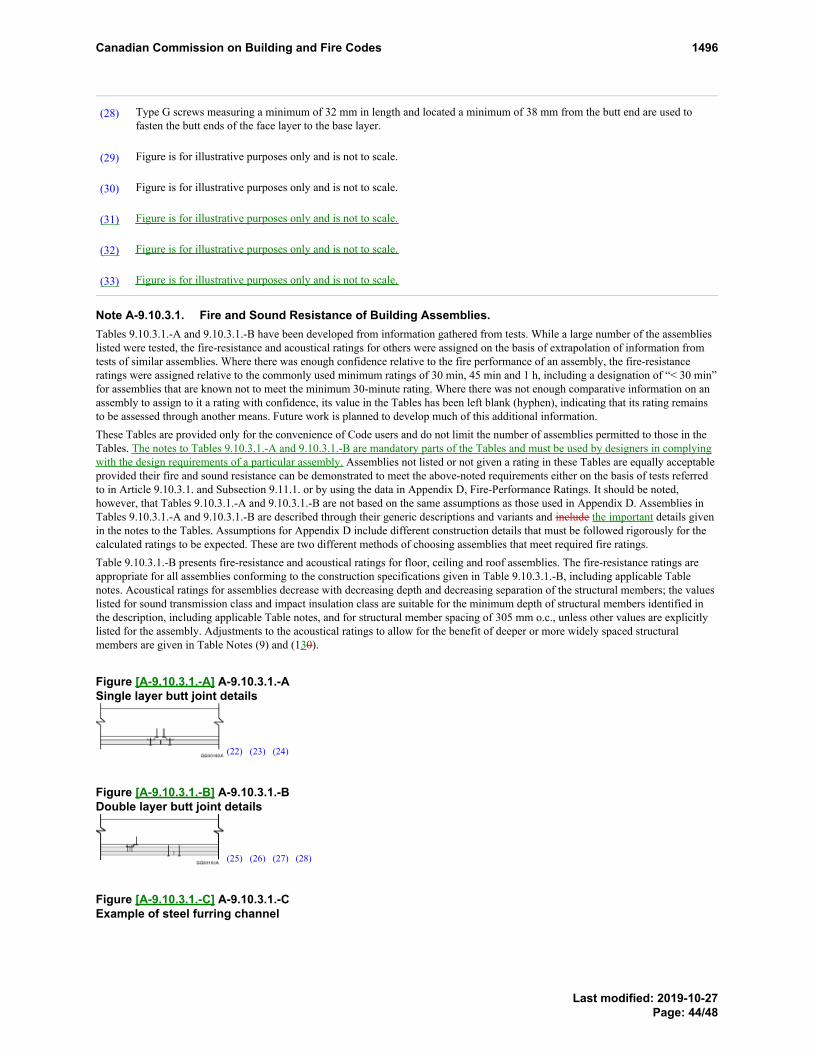
Type G screws measuring a minimum of 32 mm in length and located a minimum of 38 mm from the butt end are used tofasten the butt ends of the face layer to the base layer.
(28)PROPOSED CHANGE Table 9.10.3.1.A. Footnotereferrer
Figure is for illustrative purposes only and is not to scale.(29)PROPOSED CHANGE Table 9.10.3.1.A. Footnotereferrer
Figure is for illustrative purposes only and is not to scale.(30)PROPOSED CHANGE Table 9.10.3.1.A. Footnotereferrer
Figure is for illustrative purposes only and is not to scale.(31)PROPOSED CHANGE Table 9.10.3.1.A. Footnotereferrer
Figure is for illustrative purposes only and is not to scale.(32)PROPOSED CHANGE Table 9.10.3.1.A. Footnotereferrer
Figure is for illustrative purposes only and is not to scale.(33)PROPOSED CHANGE Table 9.10.3.1.A. Footnotereferrer
Note A-9.10.3.1. Fire and Sound Resistance of Building Assemblies.Tables 9.10.3.1.-A and 9.10.3.1.-B have been developed from information gathered from tests. While a large number of the assemblieslisted were tested, the fire-resistance and acoustical ratings for others were assigned on the basis of extrapolation of information fromtests of similar assemblies. Where there was enough confidence relative to the fire performance of an assembly, the fire-resistanceratings were assigned relative to the commonly used minimum ratings of 30 min, 45 min and 1 h, including a designation of “< 30 min”for assemblies that are known not to meet the minimum 30-minute rating. Where there was not enough comparative information on anassembly to assign to it a rating with confidence, its value in the Tables has been left blank (hyphen), indicating that its rating remainsto be assessed through another means. Future work is planned to develop much of this additional information.These Tables are provided only for the convenience of Code users and do not limit the number of assemblies permitted to those in theTables. The notes to Tables 9.10.3.1.-A and 9.10.3.1.-B are mandatory parts of the Tables and must be used by designers in complyingwith the design requirements of a particular assembly. Assemblies not listed or not given a rating in these Tables are equally acceptableprovided their fire and sound resistance can be demonstrated to meet the above-noted requirements either on the basis of tests referredto in Article 9.10.3.1. and Subsection 9.11.1. or by using the data in Appendix D, Fire-Performance Ratings. It should be noted,however, that Tables 9.10.3.1.-A and 9.10.3.1.-B are not based on the same assumptions as those used in Appendix D. Assemblies inTables 9.10.3.1.-A and 9.10.3.1.-B are described through their generic descriptions and variants and include the important details givenin the notes to the Tables. Assumptions for Appendix D include different construction details that must be followed rigorously for thecalculated ratings to be expected. These are two different methods of choosing assemblies that meet required fire ratings.Table 9.10.3.1.-B presents fire-resistance and acoustical ratings for floor, ceiling and roof assemblies. The fire-resistance ratings areappropriate for all assemblies conforming to the construction specifications given in Table 9.10.3.1.-B, including applicable Tablenotes. Acoustical ratings for assemblies decrease with decreasing depth and decreasing separation of the structural members; the valueslisted for sound transmission class and impact insulation class are suitable for the minimum depth of structural members identified inthe description, including applicable Table notes, and for structural member spacing of 305 mm o.c., unless other values are explicitlylisted for the assembly. Adjustments to the acoustical ratings to allow for the benefit of deeper or more widely spaced structuralmembers are given in Table Notes (9) and (130).
Figure [A-9.10.3.1.-A] A-9.10.3.1.-ASingle layer butt joint details
(22) (23) (24)
Figure [A-9.10.3.1.-B] A-9.10.3.1.-BDouble layer butt joint details
(25) (26) (27) (28)
Figure [A-9.10.3.1.-C] A-9.10.3.1.-CExample of steel furring channel
Footnote29Footnote30Footnote31Footnote32Footnote33
PROPOSED CHANGE Table 9.10.3.1.A. FootnotePROPOSED CHANGE Table 9.10.3.1.A. FootnotePROPOSED CHANGE Table 9.10.3.1.A. Footnote
PROPOSED CHANGE Table 9.10.3.1.A. FootnotePROPOSED CHANGE Table 9.10.3.1.A. FootnotePROPOSED CHANGE Table 9.10.3.1.A. FootnotePROPOSED CHANGE Table 9.10.3.1.A. Footnote
Canadian Commission on Building and Fire Codes 1496
Last modified: 2019-10-27Page: 44/48
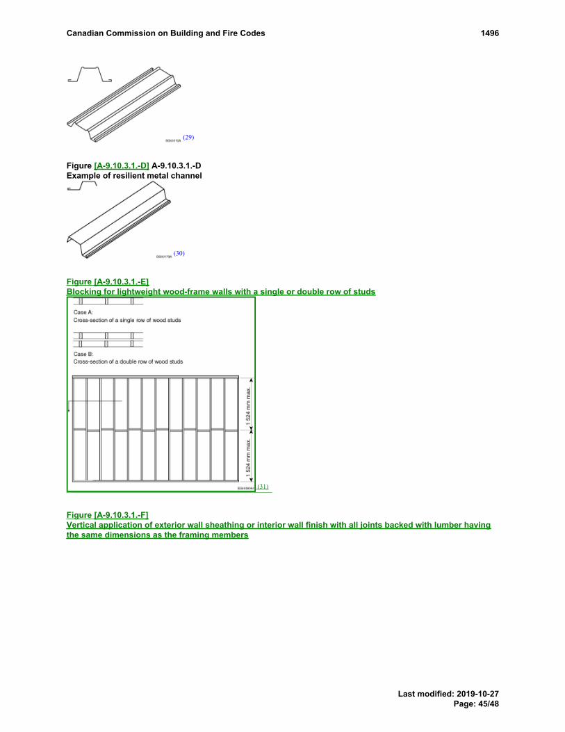
(29)
Figure [A-9.10.3.1.-D] A-9.10.3.1.-DExample of resilient metal channel
(30)
Figure [A-9.10.3.1.-E]Blocking for lightweight wood-frame walls with a single or double row of studs
(31)
Figure [A-9.10.3.1.-F]Vertical application of exterior wall sheathing or interior wall finish with all joints backed with lumber havingthe same dimensions as the framing members
PROPOSED CHANGE Table 9.10.3.1.A. Footnote
PROPOSED CHANGE Table 9.10.3.1.A. Footnote
PROPOSED CHANGE Table 9.10.3.1.A. Footnote
Canadian Commission on Building and Fire Codes 1496
Last modified: 2019-10-27Page: 45/48

(32)
Figure [A-9.10.3.1.-G]Horizontal application of exterior wall sheathing or interior wall finish with all joints backed with lumberhaving the same dimensions as the framing members
(33)
[9.10.3.1.] 9.10.3.1. Fire-Resistance and Fire-Protection Ratings
RATIONALE
ProblemNew research performed under the NRC project entitled “Joint Research Program on Fire Resistance Performance of BuildingAssemblies” (JRP) provides greater insight into various aspects of fire resistance in lightweight wood-frame exterior and interiorwall assemblies and identifies aspects of existing assemblies that could lead to variability in fire-resistance ratings. Based on testresults and analysis of 13 full-scale wall assemblies, the JRP determined that some of the assemblies for exterior wood-framewalls failed to achieve the fire-resistance ratings listed in existing Table 9.10.3.1.-A.
As such, some assemblies currently being built according to Table 9.10.3.1.-A actually provide a lower fire resistance than theratings listed in the Table. These discrepancies present a safety risk for housing and small buildings, such as premature failure ofwall assemblies in a fire, which could result in structural failure, injury or loss of life. The proposed updates to the Table areurgently required and should be incorporated into the NBC 2020.
Justification - ExplanationScope and application:
The control of the spread of fire and smoke is an objective of the NBC, and the proposed change is aimed at addressing the relatedobjectives: OS1, Fire Safety; OS2, Structural Safety; and OP6, Fire and Structural Protection of Buildings. The application of the
PROPOSED CHANGE Table 9.10.3.1.A. Footnote
PROPOSED CHANGE Table 9.10.3.1.A. Footnote
Canadian Commission on Building and Fire Codes 1496
Last modified: 2019-10-27Page: 46/48

requirements in Parts 5 and 9 is unchanged and remains limited to walls and floors separating dwelling units from each other andfrom every other space in a building in which fire may occur.
Results of research and analysis:
The JRP conducted an analysis of fire-resistance results for wall assemblies and took into account fire test data from proprietarytesting, as well as experience, expertise and knowledge gained in the field. The analysis identified variability in the performanceof materials and installation methods that would result in assemblies that have lower fire-resistance ratings than those listed inexisting Table 9.10.3.1.-A. This analysis was used to revise existing entries for wood-frame wall assemblies in Table 9.10.3.1.-Aand the accompanying table notes, as well as to add new entries and table notes.
The JRP proposed modifications to several of the assemblies in Table 9.10.3.1.-A (e.g., closer fastener spacing, use of Type Xgypsum board, requiring some joints to be supported), as well as clarifications to the table notes, to align the fire-resistance ratingsin the Table with the JRP test results and analysis. Compliance with the proposed updates to Table 9.10.3.1.-A will allow users tospecify and construct wall assemblies that will achieve the fire-resistance ratings listed therein, thus improving the safety ofbuildings in the event of a fire. The JRP also proposed adding new wall assemblies to provide users with more options.
Proposed corrections:
The JRP proposed several corrections to Table 9.10.3.1.-A based on research results, including the following:
a. the revision of several existing entries for exterior lightweight wood-frame wall assemblies;b. the addition of new exterior lightweight wood-frame wall assemblies;c. the revision of several existing entries for interior lightweight wood-frame wall assemblies;d. the addition of a new set of interior wall assemblies using a double row of studs with two layers of gypsum board on
each side and resilient metal channels on one side; ande. the revision and addition of table notes to better explain the construction requirements for the listed ratings.
Expected results of corrections:
If the proposed corrections are incorporated into Table 9.10.3.1.-A, new buildings constructed in accordance with the Table willprovide improved fire resistance and greater safety in the event of a fire.
Impact analysisBenefit
The proposed updates to Table 9.10.3.1.-A increase the likelihood that the wall assemblies will achieve the fire-resistance ratingslisted therein. This will reduce the likelihood of premature failure of the assemblies, which could cause structural damage, injuryor death.
The proposed updates clarify and expand the wall assemblies available for the application of Subsection 9.10.3. on required fire-resistance ratings. They revise and supplement the information provided in the NBC for builders and designers, using currentresearch data, and provide more options for designers by adding several new efficient and cost-effective design solutions that meetthe fire safety objectives of the Code.
Cost
Some updates to existing assemblies would entail additional costs by requiring specific materials that have proven fire-resistanceratings where generic materials were previously permitted.
The proposed updates to the Table may reduce the need for full-scale fire-resistance testing by providing new generic fire-resistance rating information.
This PCF revises 5 existing W6 assemblies, 4 existing EW1 assemblies, and 3 existing EW2 assemblies. It also adds 1 newE1 assembly, 8 new EW2 assemblies, 11 new EW3 assemblies, and 7 new W16 assemblies.
The cost impacts of these updates, estimated for a representative sample of 6 wall assemblies with various sheathing options(EW1a, EW1c, EW1d, W6b, W6d and W6h), vary from a decrease of $0.46/m2 (EW1c with OSB sheathing) to an increase of$17.06/m2 (EW1d with exterior gypsum sheathing), for an average increase of $7.87/m2. The revised assemblies have fire-resistance and sound transmission class (STC) ratings equal to or better than those of the assemblies they replace. Eight of therevised assemblies (W6b, W6c, W6d, W6g, W6h, EW1b, EW2b and EW2c) have increased fire-resistance ratings.
Note: The assemblies in Table 9.10.3.1.-A are options that are deemed to provide the fire-resistance and STC ratings listedtherein. Code users are not required to use these assemblies, but may choose from these options or propose other options.Consequently, including these proposed updates in the NBC will not necessarily lead to increased construction costs.
Canadian Commission on Building and Fire Codes 1496
Last modified: 2019-10-27Page: 47/48

Enforcement implicationsSince this proposed change merely provides additional information to assist designers in the development of and regulators in theevaluation of fire-resistance-rated designs, it will not increase enforcement requirements and can be enforced by the infrastructurecurrently available to enforce the Code. In fact, the proposed change is likely to reduce the amount of enforcement resourcesexpended by authorities having jurisdiction.
Who is affectedBuilding officials, designers, engineers, architects, builders, suppliers.
Supporting Document(s)Impact Analysis Results (1282_cba4-v2_ptsedits_mkp_am_jr_final1022_w_gp_chgs.pdf)
OBJECTIVE-BASED ANALYSIS OF NEW OR CHANGED PROVISIONS
N/A
[9.10.3.1.] 9.10.3.1. ([1] 1) no attributions
Canadian Commission on Building and Fire Codes 1496
Last modified: 2019-10-27Page: 48/48

Wall Type Exterior EW1a (NBC 2015) EW1a (NBC 2020) Increased cost $/m2 Total cost
$/m2 x 1.2 Notes
Fire-resistance rating Loadbearing 1 h Non-loadbearing 1 h Loadbearing 1 h Loadbearing 1 h No change
Stud spacing 38 x 89 mm @ 400 mm o.c. 38 x 89 mm @ 600 mm o.c. 38 x 89 mm @ 400 mm o.c. 38 x 89 mm @ 600 mm o.c. No change 4 x 8 ft. = 3.0 m2 (32 ft.2) /3 = 1.0 m2
Interior gypsum board CSA A82.31-M
9.5 mm
CSA A82.31-M
12.7 mm
15.9 mm Type X gypsum board
Joints backed and blocked as per
Figures A-9.10.3.1.-E,-F,-G
15.9 mm Type X gypsum board
Joints backed and blocked as per
Figures A-9.10.3.1.-E,-F,-G
$2.00 gypsum matl. $0.45 S-P-F matl. $2.11 2 x 4 labour
$0.59 HST
$18.90-$12.90 /3 = $2.00
⅓ of 8 ft. stud
4 x $1.58 /3
Fasteners as per Table
9.23.3.5.-A: 150 mm o.c.
(edge), 300 mm o.c.
Fasteners as per Table
9.23.3.5.-A: 150 mm o.c.
(edge), 300 mm o.c.
Fasteners 200 mm o.c. (see Table
Note (16) in proposed change)
Fasteners 200 mm o.c. (see Table
Note (16) in proposed change)
No change
Number of screws unchanged
(19/21)
Exterior OSB or plywood
sheathing
Table 9.23.17.2.-A,
6.0 mm OSB or plywood
Table 9.23.17.2.-A,
7.5 mm OSB or plywood
11.7 mm OSB or plywood (see Table
Note (17) in proposed change)
Joints backed as per Figures A-
9.10.3.1.-F,-G
11.7 mm OSB or plywood (see Table
Note (17) in proposed change)
Joints backed as per Figures A-9.10.3.1.-F,-G
$0.29 OSB matl. $0.45 S-P-F matl. ($2.11 2 x 4 labour)
$0.04 HST
$6.58
⅓ of 8 ft. stud
(4 x $1.58 /3 backing not required if
interior backing in same location)
Fasteners as per Table
9.23.3.5.-A: 150 mm o.c.
(edge), 300 mm o.c.
Fasteners as per Table
9.23.3.5.-A: 150 mm o.c.
(edge), 300 mm o.c.
Fasteners as per Table
9.23.3.5.-A: 150 mm o.c.
(edge), 300 mm o.c.
Fasteners as per Table
9.23.3.5.-A: 150 mm o.c.
(edge), 300 mm o.c.
No change
Exterior gypsum
sheathing
Table 9.23.17.2.-A,
9.5 mm gypsum sheathing
12.7 mm gypsum sheathing 15.9 mm Type X gypsum sheathing
All joints backed
15.9 mm Type X gypsum board
All joints backed
$4.33 gypsum matl. $0.45 S-P-F matl. ($2.11 2 x 4 labour) $0.62 HST
$12.12 ⅓ of 8 ft. stud
(4 x $1.58 /3 backing not required if
interior backing in same location)
Fasteners as per Table
9.23.3.5.-A: 150 mm o.c.
(edge), 300 mm o.c.
Fasteners as per Table 9.23.3.5.-A:
150 mm o.c. (edge), 300 mm o.c.
Fasteners 200 mm o.c. (see Table
Note (18) in proposed change)
Fasteners 200 mm o.c. (see Table
Note (18) in proposed change)
No change Number of screws unchanged
(19/21)
Wall Type Exterior EW1d (NBC 2015) EW1e (NBC 2020) Increased cost $/m2 Total cost
$/m2 x 1.2 Notes
Fire-resistance rating Loadbearing 45 min Non-loadbearing 45 min Loadbearing 45 min Non-loadbearing 45 min No change
Stud spacing 38 x 89 mm @ 400 mm o.c. 38 x 89 mm @ 600 mm o.c. 38 x 140 mm @ 400 mm o.c. $3.00 S-P-F matl.
$0.45 HST
((3 x $4.80) – (2 x $2.69)) /3
Interior gypsum board CSA A82.31-M
9.5 mm
CSA A82.31-M
12.7 mm
15.9 mm Type X gypsum board
Joints backed and blocked as per
Figures A-9.10.3.1.-E,-F,-G
$2.00 gypsum matl. $0.80 S-P-F matl. $2.40 2 x 6 labour
$0.68 HST
$18.90-$12.90 /3 = $2.00
$4.80/2 = $2.40 /3 = $0.80
4 x $1.80 /3 = $2.40
Fasteners as per Table
9.23.3.5.-A: 150 mm o.c.
(edge), 300 mm o.c.
Fasteners as per Table
9.23.3.5.-A: 150 mm o.c.
(edge), 300 mm o.c.
Fasteners 200 mm o.c. (see Table
Note (16) in proposed change)
No change Number of screws unchanged
(19/21)
Exterior OSB or plywood
sheathing
Table 9.23.17.2.-A,
6.0 mm OSB or plywood
Table 9.23.17.2.-A,
7.5 mm OSB or plywood
Table 9.23.17.2.-A,
11.7 mm OSB or plywood (see Table
Note (17) in proposed change)
$0.66
$0.09 HST
$12.10
Fasteners as per Table
9.23.3.5.-A: 150 mm o.c.
(edge), 300 mm o.c.
Fasteners as per Table
9.23.3.5.-A: 150 mm o.c.
(edge), 300 mm o.c.
Fasteners as per Table
9.23.3.5.-A: 150 mm o.c.
(edge), 300 mm o.c.
No change

Exterior gypsum
sheathing
Table 9.23.17.2.-A,
9.5 mm gypsum sheathing
Table 9.23.17.2.-A,
12.7 mm gypsum sheathing
Table 9.23.17.2.-A,
15.9 mm Type X gypsum sheathing
$4.33 gypsum matl.
$0.56 HST
$17.06
Fasteners as per Table
9.23.3.5.-A: 150 mm o.c. (edge),
300 mm o.c.
Fasteners as per Table
9.23.3.5.-A: 150 mm o.c. (edge),
300 mm o.c.
Fasteners as per Table
9.23.3.5.-A: 150 mm o.c.
(edge), 300 mm o.c.
No change
Exterior foamed plastic
sheathing
Table 9.23.17.2.-A
Polystyrene Types 1,2 38 mm
Polyurethane, polyiso Type 1
38 mm
Polystyrene Types 3,4 25 mm
Polyurethane, polyiso Types 2,3
25 mm
Table 9.23.17.2.-A
Polystyrene Types 1,2 38 mm Polyurethane, polyiso Type 1 38 mm Polystyrene Types 3,4 25 mm
Polyurethane, polyiso Types 2,3
25 mm
Table 9.23.17.2.-A
Polystyrene Types 1,2 38 mm
Polyurethane, polyiso Type 1 38 mm
Polystyrene Types 3,4 25 mm
Polyurethane, polyiso Types 2,3 25 mm
No change
Masonry veneer
cladding
Minimum 89 mm thick
Wall Type Exterior EW1c (NBC 2015) EW1c (NBC 2020) Increased cost $/m2 Total cost
$/m2 x 1.2 Notes
Fire-resistance rating Loadbearing 45 min; non-loadbearing 45 min Loadbearing 45 min; non-loadbearing 1 h ($ value added) Fire-resistance rating increased in
non-loadbearing wall
Stud spacing 38 x 89 mm @ 400 mm o.c. 38 x 89 mm @ 600 mm o.c. 38 x 89 mm @ 400 mm o.c. 38 x 89 mm @ 600 mm o.c. No change
Interior gypsum board 2 layers 12.7 mm regular gypsum
board
2 layers 12.7 mm regular gypsum
board
12.7 mm Type X gypsum board
Joints backed and blocked as per
Figures A-9.10.3.1.-E,-F,-G
12.7 mm Type X gypsum board. Joints
backed and blocked as per Figures A-
9.10.3.1.-E,-F,-G
(-$3.27 gypsum board) $0.45 S-P-F matl. $2.11 2 x 4 labour
(2 x $12.90) - $16.00 = ($9.80 credit)
/3
⅓ of 8 ft. stud
4 x $1.58 /3
Fasteners as per Table
9.23.3.5.-A: 150 mm o.c.
(edge), 300 mm o.c.
Fasteners as per Table
9.23.3.5.-A: 150 mm o.c.
(edge), 300 mm o.c.
Fasteners 200 mm o.c. (see Table
Note (16) in proposed change)
Fasteners 200 mm o.c. (see Table
Note (16) in proposed change)
No change
Exterior OSB or plywood
sheathing
Table 9.23.17.2.-A,
6.0 mm OSB or plywood
Table 9.23.17.2.-A,
7.5 mm OSB or plywood
11.7 mm OSB or plywood (see Table
Note (17) in proposed change)
Joints backed as per Figures A-
9.10.3.1.-F,-G
11.7 mm OSB or plywood (see Table
Note (17) in proposed change)
Joints backed as per Figures A-
9.10.3.1.-F,-G
$0.29 OSB matl. $0.45 S-P-F matl. ($2.11 2 x 4 labour)
$0.04 HST
$-0.46
(credit)
$0.88/3 = $0.29
⅓ of 8 ft. stud
(4 x $1.58 /3 backing not required if
interior backing in same location)
Fasteners as per Table
9.23.3.5.-A: 150 mm o.c.
(edge), 300 mm o.c.
Fasteners as per Table
9.23.3.5.-A: 150 mm o.c.
(edge), 300 mm o.c.
Fasteners as per Table
9.23.3.5.-A: 150 mm o.c.
(edge), 300 mm o.c.
Fasteners as per Table
9.23.3.5.-A: 150 mm o.c.
(edge), 300 mm o.c.
No change
Exterior gypsum
sheathing
Table 9.23.17.2.-A,
9.5 mm gypsum sheathing
Table 9.23.17.2.-A,
12.7 mm gypsum sheathing
15.9 mm Type X exterior gypsum board
Joints supported
15.9 mm Type X exterior gypsum board
Joints supported
$4.33 gypsum matl. $0.45 S-P-F matl. ($2.11 2 x 4 labour) $0.62 HST
$5.09 ⅓ of 8 ft. stud
(4 x $1.58 /3 backing not required if
interior backing in same location)
Fasteners as per Table
9.23.3.5.-A: 150 mm o.c.
(edge), 300 mm o.c.
Fasteners as per Table
9.23.3.5.-A: 150 mm o.c.
(edge), 300 mm o.c.
Fasteners 200 mm o.c. (see Table
Note (18) in proposed change)
Fasteners 200 mm o.c. (see Table
Note (18) in proposed change)
No change
Exterior foamed plastic
sheathing
Cladding can have foamed plastic
only outside of noncombustible
sheathing
Cladding can have foamed
plastic only outside of
noncombustible sheathing
Cladding can have foamed plastic only
outside of sheathing where permitted
by spatial separation requirements in
Subsections 9.10.14. and 9.10.15.
Cladding can have foamed plastic only
outside of sheathing where permitted
by spatial separation requirements in
Subsections 9.10.14. and 9.10.15.

Wall Type Interior W6b (NBC 2015) W6b (NBC 2020) Increased cost $/m2 Total cost
$/m2 x 1.2 Notes
Fire-resistance rating Loadbearing 1.5 h Loadbearing 2 h Loadbearing 2 h Loadbearing 2 h ($ value added) Fire-resistance rating increased in
non-loadbearing wall
Stud spacing 400 mm or 600 mm o.c. 400 mm or 600 mm o.c. w/ mid-height blocking $0.45 S-P-F matl.
$2.11 1 x 4 labour
$0.33 HST
$10.23 ⅓ of 8 ft. stud
4 x $1.58 /3
Interior gypsum board 89 mm absorptive material: rock, slag, glass or cellulose fibre 89 mm rock or slag fibre insulation $4.91 rock matl.
$0.74 HST
Wall Type Interior W6d (NBC 2015) W6d (NBC 2020) Increased cost $/m2 Total cost
$/m2 x 1.2 Notes
Fire-resistance rating Loadbearing 1 h Non-loadbearing 1.5 h Loadbearing 1.5 h Non-loadbearing 2 h (-$ value added) Fire-resistance rating increased in
both walls
Stud spacing 400 mm o.c. 400 mm or 600 mm o.c. (-$1.15)
Interior gypsum board 12.7 mm Type X gypsum board 15.9 mm Type X gypsum board $1.67 gypsum matl.
$0.10 HST
$0.74
Wall Type Interior W6h (NBC 2015) W6h (NBC 2020) Increased cost $/m2 Total cost
$/m2 x 1.2 Notes
Fire-resistance rating Loadbearing 45 min Non-loadbearing 1 h Loadbearing 1 h Non-loadbearing 1.5 h (-$ value added) Fire-resistance rating increased in
both walls
Stud spacing 400 or 600 mm o.c. 600 mm o.c. No change
Interior gypsum board 12.7 mm regular gypsum board 12.7 mm Type X gypsum board $3.77 gypsum matl.
$0.49 HST
$24.30-$13.00 /3 = $3.77
Resilient metal channels 600 mm o.c. 400 mm o.c. $1.34 RC1 matl.
$0.33 RC1 labour
$0.22 HST
$7.38 7/5 x $10.46
1 min x $60/h /3
Note: All costs based on 4 x 8 ft. (3.0 m2) wall panel and converted to cost/m2
Interior
½” Regular gypsum board 4 x 8 ft. panel $12 (interior- $13.82) – Average $12.90
½” Firecode C 4 x 8 ft. panel, the cost is $16
⅝” Firecode Type X 4 x 8 ft. panel $21 (Type X interior- $16.79) – Average $18.90 Exterior
½” gypsum sheathing with a non-fire rated core and the cost for a 4 x 8 ft. panel is $13.
(½” Type X glass matt- $24.30; exterior treated core- $21.25 (special order))
⅝” gypsum sheathing Type X (paper-faced) for a 4 x 8 ft. panel is $26. (exterior treated core- $26.56 (special order))
½” glass matt sheathing (½” Type X glass matt- $24.30)
⅝” glass mat sheathing Type X for a 4 x 8 ft. sheet is $30. (⅝” Type X glass matt- $28.21) – Average $29.11
½” plywood for a 4 x 8 ft. panel is $28.
¼” plywood for a 4 x 8 ft. panel is $39. 716⁄ ” OSB for a 4 x 8 ft. panel is $15. (⅜” (9.5 mm) not used - replacing ⅜” OSB with 7 16⁄ ”- $0.88 per sheet)
¼” OSB for a 4 x 8 ft. panel is $12.

2 x 4 x 8 ft. S-P-F $2.69
2 x 6 x 8 ft. #2 and Better Kiln-Dried Heat Treated Spruce-Pine-Fir Lumber $4.80
Horizontal 2 x 4 ft. or 2 x 6 ft. backing between studs at 400 and 600 mm o.c. (materials and labour- 2 x 4 -$1.58 per lin. ft. 2 x 6 ft. $1.80) Resilient channel x 12 ft.- $6.28 material only 1⅝” #6 drywall screws (4574/box) $50

Type de mur, extérieur EW1a (CNB 2015) EW1a (CNB 2020) Hausse du coût,
en $/m2 Coût total $/m2 x 1,2
Notes
Degré de résistance au feu
Porteur, 1 h Non-porteur, 1 h Porteur, 1 h Porteur, 1 h Aucun changement
Espacement des poteaux
38 x 89 mm à 400 mm entre axes 38 x 89 mm à 600 mm entre axes 38 x 89 mm à 400 mm entre axes 38 x 89 mm à 600 mm entre axes Aucun changement 4 x 8 pi = 3,0 m2 (32 pi2) /3 = 1,0 m2
Plaques de plâtre, intérieur
CSA A82.31-M 9,5 mm
CSA A82.31-M 12,7 mm
Plaques de plâtre de type X de 15,9 mm Joints supportés et calés conformément aux figures A-9.10.3.1.-E,-F,-G
Plaques de plâtre de type X de 15,9 mm Joints supportés et calés conformément aux figures A-9.10.3.1.-E,-F,-G
Plaques de plâtre, matériaux 2,00 $ Épinette-pin-sapin, matériaux 0,45 $ 2 x 4, main-d'œuvre 2,11 $ TVH 0,59 $
18,90 $-12,90 $ /3 = 2,00 $ ⅓ de poteau de 8 pi 4 x 1,58 $ /3
Dispositifs de fixation, conformément au tableau 9.23.3.5.-A : 150 mm entre axes (rive), 300 mm entre axes
Dispositifs de fixation, conformément au tableau 9.23.3.5.-A : 150 mm entre axes (rive), 300 mm entre axes
Dispositifs de fixation, 200 mm entre axes (voir la note (16) du tableau de la modification proposée)
Dispositifs de fixation, 200 mm entre axes (voir la note (16) du tableau de la modification proposée)
Aucun changement
Nombre de vis inchangé (19/21)
Revêtement intermédiaire extérieur en panneaux de copeaux orientés ou en contreplaqué
Tableau 9.23.17.2.-A Panneaux de copeaux orientés ou contreplaqué de 6,0 mm
Tableau 9.23.17.2.-A Panneaux de copeaux orientés ou contreplaqué de 7,5 mm
Panneaux de copeaux orientés ou contreplaqué de 11,7 mm (voir la note (17) du tableau de la modification proposée) Joints supportés conformément aux figures A-9.10.3.1.-F,-G
Panneaux de copeaux orientés ou contreplaqué de 11,7 mm (voir la note (17) du tableau de la modification proposée) Joints supportés conformément aux figures A-9.10.3.1.-F,-G
Panneaux de copeaux orientés, matériaux 0,29 $ Épinette-pin-sapin, matériaux 0,45 $ (2 x 4, main-d'œuvre 2,11 $) TVH 0,04 $
6,58 $
⅓ de poteau de 8 pi (4 x 1,58 $ /3 - support non requis si un support se trouve au même endroit à l'intérieur)
Dispositifs de fixation, conformément au tableau 9.23.3.5.-A : 150 mm entre axes (rive), 300 mm entre axes
Dispositifs de fixation, conformément au tableau 9.23.3.5.-A : 150 mm entre axes (rive), 300 mm entre axes
Dispositifs de fixation, conformément au tableau 9.23.3.5.-A : 150 mm entre axes (rive), 300 mm entre axes
Dispositifs de fixation, conformément au tableau 9.23.3.5.-A : 150 mm entre axes (rive), 300 mm entre axes
Aucun changement
Revêtement intermédiaire extérieur en plaques de plâtre
Tableau 9.23.17.2.-A Revêtement intermédiaire en plaques de plâtre de 9,5 mm
Revêtement intermédiaire en plaques de plâtre de 12,7 mm
Revêtement intermédiaire en plaques de plâtre de type X de 15,9 mm Tous les joints sont supportés
Revêtement intermédiaire en plaques de plâtre de type X de 15,9 mm Tous les joints sont supportés
Plaques de plâtre, matériaux 4,33 $ Épinette-pin-sapin, matériaux 0,45 $ (2 x 4, main-d'œuvre 2,11 $) TVH 0,62 $
12,12 $ ⅓ de poteau de 8 pi (4 x 1,58 $ /3 - support non requis si un support se trouve au même endroit à l'intérieur)
Dispositifs de fixation, conformément au tableau 9.23.3.5.-A : 150 mm entre axes (rive), 300 mm entre axes
Dispositifs de fixation, conformément au tableau 9.23.3.5.-A : 150 mm entre axes (rive), 300 mm entre axes
Dispositifs de fixation, 200 mm entre axes (voir la note (18) du tableau de la modification proposée)
Dispositifs de fixation, 200 mm entre axes (voir la note (18) du tableau de la modification proposée)
Aucun changement Nombre de vis inchangé (19/21)

Type de mur, extérieur EW1d (CNB 2015) EW1e (CNB 2020) Hausse du coût,
en $/m2 Coût total $/m2 x 1,2
Notes
Degré de résistance au feu
Porteur, 45 min Non-porteur, 45 min Porteur, 45 min Non-porteur, 45 min Aucun changement
Espacement des poteaux
38 x 89 mm à 400 mm entre axes 38 x 89 mm à 600 mm entre axes 38 x 140 mm à 400 mm entre axes Épinette-pin-sapin, matériaux 3,00 $ TVH 0,45 $
((3 x 4,80 $) – (2 x 2,69 $)) /3
Plaques de plâtre, intérieur
CSA A82.31-M 9,5 mm
CSA A82.31-M 12,7 mm
Plaques de plâtre de type X de 15,9 mm Joints supportés et calés conformément aux figures A-9.10.3.1.-E,-F,-G
Plaques de plâtre, matériaux 2,00 $ Épinette-pin-sapin, matériaux 0,80 $ 2 x 6, main-d'œuvre 2,40 $ TVH 0,68 $
18,90 $-12,90 $ /3 = 2,00 $ 4,80 $/2= 2,40 $ /3 = 0,80 $ 4 x 1,80 $ /3 = 2,40 $
Dispositifs de fixation, conformément au tableau 9.23.3.5.-A : 150 mm entre axes (rive), 300 mm entre axes
Dispositifs de fixation, conformément au tableau 9.23.3.5.-A : 150 mm entre axes (rive), 300 mm entre axes
Dispositifs de fixation, 200 mm entre axes (voir la note (16) du tableau de la modification proposée)
Aucun changement Nombre de vis inchangé (19/21)
Revêtement intermédiaire extérieur en panneaux de copeaux orientés ou en contreplaqué
Tableau 9.23.17.2.-A Panneaux de copeaux orientés ou contreplaqué de 6,0 mm
Tableau 9.23.17.2.-A Panneaux de copeaux orientés ou contreplaqué de 7,5 mm
Tableau 9.23.17.2.-A Panneaux de copeaux orientés ou contreplaqué de 11,7 mm (voir la note (17) du tableau de la modification proposée)
0,66 $ TVH 0,09 $
12,10 $
Dispositifs de fixation, conformément au tableau 9.23.3.5.-A : 150 mm entre axes (rive), 300 mm entre axes
Dispositifs de fixation, conformément au tableau 9.23.3.5.-A : 150 mm entre axes (rive), 300 mm entre axes
Dispositifs de fixation, conformément au tableau 9.23.3.5.-A : 150 mm entre axes (rive), 300 mm entre axes
Aucun changement
Revêtement intermédiaire extérieur en plaques de plâtre
Tableau 9.23.17.2.-A Revêtement intermédiaire en plaques de plâtre de 9,5 mm
Tableau 9.23.17.2.-A Revêtement intermédiaire en plaques de plâtre de 12,7 mm
Tableau 9.23.17.2.-A Revêtement intermédiaire en plaques de plâtre de type X de 15,9 mm
Plaques de plâtre, matériaux 4,33 $ TVH 0,56 $
17,06 $
Dispositifs de fixation, conformément au tableau 9.23.3.5.-A : 150 mm entre axes (rive), 300 mm entre axes
Dispositifs de fixation, conformément au tableau 9.23.3.5.-A : 150 mm entre axes (rive), 300 mm entre axes
Dispositifs de fixation, conformément au tableau 9.23.3.5.-A : 150 mm entre axes (rive), 300 mm entre axes
Aucun changement
Revêtement intermédiaire extérieur en mousse plastique
Tableau 9.23.17.2.-A Polystyrène de types 1 et 2, 38 mm Polyuréthane et polyisocyanurate de type 1, 38 mm Polystyrène de types 3 et 4, 25 mm Polyuréthane et polyisocyanurate de types 2 et 3, 25 mm
Tableau 9.23.17.2.-A Polystyrène de types 1 et 2, 38 mm Polyuréthane et polyisocyanurate de type 1, 38 mm Polystyrène de types 3 et 4, 25 mm Polyuréthane et polyisocyanurate de types 2 et 3, 25 mm
Tableau 9.23.17.2.-A Polystyrène de types 1 et 2, 38 mm Polyuréthane et polyisocyanurate de type 1, 38 mm Polystyrène de types 3 et 4, 25 mm Polyuréthane et polyisocyanurate de types 2 et 3, 25 mm
Aucun changement
Contre-mur en maçonnerie
Épaisseur minimale de 89 mm

Type de mur, extérieur EW1c (CNB 2015) EW1c (CNB 2020) Hausse du coût,
en $/m2 Coût total $/m2 x 1,2
Notes
Degré de résistance au feu
Porteur, 45 min; non-porteur, 45 min Porteur, 45 min; non-porteur, 1 h (valeur ajoutée en $) Degré de résistance au feu accru pour les murs non-porteurs
Espacement des poteaux
38 x 89 mm à 400 mm entre axes 38 x 89 mm à 600 mm entre axes 38 x 89 mm à 400 mm entre axes 38 x 89 mm à 600 mm entre axes Aucun changement
Plaques de plâtre, intérieur
2 épaisseurs de 12,7 mm de plaques de plâtre standards
2 épaisseurs de 12,7 mm de plaques de plâtre standards
Plaques de plâtre de type X de 12,7 mm Joints supportés et calés conformément aux figures A-9.10.3.1.-E,-F,-G
Plaques de plâtre de type X de 12,7 mm Joints supportés et calés conformément aux figures A-9.10.3.1.-E,-F,-G
(Plaques de plâtre -3,27 $) Épinette-pin-sapin, matériaux 0,45 $ 2 x 4, main-d'œuvre 2,11 $
(2 x 12,90 $) - 16,00 $ = (crédit de 9,80 $) /3 ⅓ de poteau de 8 pi 4 x 1,58 $ /3
Dispositifs de fixation, conformément au tableau 9.23.3.5.-A : 150 mm entre axes (rive), 300 mm entre axes
Dispositifs de fixation, conformément au tableau 9.23.3.5.-A : 150 mm entre axes (rive), 300 mm entre axes
Dispositifs de fixation, 200 mm entre axes (voir la note (16) du tableau de la modification proposée)
Dispositifs de fixation, 200 mm entre axes (voir la note (16) du tableau de la modification proposée)
Aucun changement
Revêtement intermédiaire extérieur en panneaux de copeaux orientés ou en contreplaqué
Tableau 9.23.17.2.-A Panneaux de copeaux orientés ou contreplaqué de 6,0 mm
Tableau 9.23.17.2.-A Panneaux de copeaux orientés ou contreplaqué de 7,5 mm
Panneaux de copeaux orientés ou contreplaqué de 11,7 mm (voir la note (17) du tableau de la modification proposée) Joints supportés conformément aux figures A-9.10.3.1.-F,-G
Panneaux de copeaux orientés ou contreplaqué de 11,7 mm (voir la note (17) du tableau de la modification proposée) Joints supportés conformément aux figures A-9.10.3.1.-F,-G
Panneaux de copeaux orientés, matériaux 0,29 $ Épinette-pin-sapin, matériaux 0,45 $ (2 x 4, main-d'œuvre 2,11 $) TVH 0,04 $
-0,46 $ (crédit)
0,88 $/3 = 0,29 $ ⅓ de poteau de 8 pi (4 x 1,58 $ /3 - support non requis si un support se trouve au même endroit à l'intérieur)
Dispositifs de fixation, conformément au tableau 9.23.3.5.-A : 150 mm entre axes (rive), 300 mm entre axes
Dispositifs de fixation, conformément au tableau 9.23.3.5.-A : 150 mm entre axes (rive), 300 mm entre axes
Dispositifs de fixation, conformément au tableau 9.23.3.5.-A : 150 mm entre axes (rive), 300 mm entre axes
Dispositifs de fixation, conformément au tableau 9.23.3.5.-A : 150 mm entre axes (rive), 300 mm entre axes
Aucun changement
Revêtement intermédiaire extérieur en plaques de plâtre
Tableau 9.23.17.2.-A Revêtement intermédiaire en plaques de plâtre de 9,5 mm
Tableau 9.23.17.2.-A Revêtement intermédiaire en plaques de plâtre de 12,7 mm
Revêtement intermédiaire en plaques de plâtre de type X de 15,9 mm Joints supportés
Revêtement intermédiaire en plaques de plâtre de type X de 15,9 mm Joints supportés
Plaques de plâtre, matériaux 4,33 $ Épinette-pin-sapin, matériaux 0,45 $ (2 x 4, main-d'œuvre 2,11 $) TVH 0,62 $
5,09 $ ⅓ de poteau de 8 pi (4 x 1,58 $ /3 - support non requis si un support se trouve au même endroit à l'intérieur)
Dispositifs de fixation, conformément au tableau 9.23.3.5.-A : 150 mm entre axes (rive), 300 mm entre axes
Dispositifs de fixation, conformément au tableau 9.23.3.5.-A : 150 mm entre axes (rive), 300 mm entre axes
Dispositifs de fixation, 200 mm entre axes (voir la note (18) du tableau de la modification proposée)
Dispositifs de fixation, 200 mm entre axes (voir la note (18) du tableau de la modification proposée)
Aucun changement
Revêtement intermédiaire extérieur en mousse plastique
Le revêtement extérieur en mousse plastique est uniquement permis à l'extérieur d'un revêtement intermédiaire incombustible
Le revêtement extérieur en mousse plastique est uniquement permis à l'extérieur d'un revêtement intermédiaire incombustible
Le revêtement extérieur en mousse plastique est uniquement permis à l'extérieur d'un revêtement intermédiaire si les exigences de séparation spatiale le permettent aux sous-sections 9.10.4. et 9.10.15.
Le revêtement extérieur en mousse plastique est uniquement permis à l'extérieur d'un revêtement intermédiaire si les exigences de séparation spatiale le permettent aux sous-sections 9.10.4. et 9.10.15.

Type de mur, intérieur W6b (CNB 2015) W6b (CNB 2020) Hausse du coût,
en $/m2 Coût total $/m2 x 1,2
Notes
Degré de résistance au feu
Porteur, 1,5 h Porteur, 2 h Porteur, 2 h Porteur, 2 h (valeur ajoutée en $) Degré de résistance au feu accru pour les murs non-porteurs
Espacement des poteaux
400 mm ou 600 mm entre axes 400 mm ou 600 mm entre axes avec cales à mi-hauteur Épinette-pin-sapin, matériaux 0,45 $ 1 x 4, main-d'œuvre 2,11 $ TVH 0,33 $
10,23 $ ⅓ de poteau de 8 pi 4 x 1,58 $ /3
Plaques de plâtre, intérieur
Matériau absorbant de 89 mm : fibres de roche, de laitier, de verre ou cellulosiques
Isolant en fibres de roche ou de laitier de 89 mm Fibres de roche, matériaux 4,91 $ TVH 0,74 $
Type de mur, intérieur W6d (CNB 2015) W6d (CNB 2020) Hausse du coût,
en $/m2 Coût total $/m2 x 1,2
Notes
Degré de résistance au feu
Porteur, 1 h Non-porteur, 1,5 h Porteur, 1,5 h Non-porteur, 2 h (valeur ajoutée en -$)
Degré de résistance au feu accru pour les deux murs
Espacement des poteaux
400 mm entre axes 400 mm ou 600 mm entre axes (-1,15 $)
Plaques de plâtre, intérieur
Plaques de plâtre de type X de 12,7 mm Plaques de plâtre de type X de 15,9 mm Plaques de plâtre, matériaux 1,67 $ TVH 0,10 $
0,74 $
Type de mur, intérieur W6h (CNB 2015) W6h (CNB 2020) Hausse du coût,
en $/m2 Coût total $/m2 x 1,2
Notes
Degré de résistance au feu
Porteur, 45 min Non-porteur, 1 h Porteur, 1 h Non-porteur, 1,5 h (valeur ajoutée en -$)
Degré de résistance au feu accru pour les deux murs
Espacement des poteaux
400 mm ou 600 mm entre axes 600 mm entre axes Aucun changement
Plaques de plâtre, intérieur
Plaques de plâtre standards de 12,7 mm Plaques de plâtre de type X de 12,7 mm Plaques de plâtre, matériaux 3,77 $ TVH 0,49 $
24,30 $-13,00 $ /3 = 3,77 $
Profilés métalliques souples
600 mm entre axes 400 mm entre axes Profilés souples no 1, matériaux 1,34 $ Profilés souples no 1, main-d'œuvre 0,33 $ TVH 0,22 $
7,38 $ 7/5 x 10,46 $ 1 min x 60 $/h/3
Note : Tous les coûts sont fondés sur des panneaux muraux de 4 x 8 pi (3,0 m2) et convertis en coût/m2 Intérieur Plaque de plâtre standard de ½ po et de 4 x 8 pi, 12 $ (intérieur - 13,82 $) – coût moyen de 12,90 $. Panneau FirecodeMD C de ½ po et de 4 x 8 pi; coût : 16 $. Panneau FirecodeMD de Type X de ⅝ po et de 4 x 8 pi, 21 $ (intérieur, de type X - 16,79 $) – coût moyen de 18,90 $.
Extérieur Revêtement intermédiaire en plaques de plâtre de ½ po dont le noyau ne présente pas de degré de résistance au feu et dont le coût d’un panneau de 4 x 8 pi est de 13 $. (Mat de fibres de verre de type X de ½ po - 24,30 $; noyau ignifugé par l'extérieur - 21,25 $ (commande spéciale).) Revêtement intermédiaire en plaques de plâtre de type X de ⅝ po (revêtu de papier) dont le coût d'un panneau de 4 x 8 pi est de 26 $. (Noyau ignifugé par l'extérieur - 26,56 $ (commande spéciale).) Revêtement intermédiaire en mat de fibres de verre de ½ po (mat de fibres de verre de type X de ½ po - 24,30 $). Revêtement intermédiaire en mat de fibres de verre de type X de ⅝ po dont le coût d'une feuille de 4 x 8 pi est de 30 $. (Mat de fibres de verre de type X de ⅝ po - 28,21 $) – coût moyen de 29,11 $. Contreplaqué de ½ po dont le coût d'un panneau de 4 x 8 pi est de 28 $. Contreplaqué de ¼ po dont le coût d'un panneau de 4 x 8 pi est de 39 $. Panneau de copeaux orientés de 7 16� po dont le coût d'un panneau de 4 x 8 pi est de 15 $. (Panneau de ⅜ po (9,5 mm) non utilisé - remplacement du panneau de copeaux orientés de ⅜ po par un panneau de 7 16� po - 0,88 $ par panneau.) Panneau de copeaux orientés de ¼ po dont le coût d'un panneau de 4 x 8 pi est de 12 $. Épinette-pin-sapin de 2 x 4 x 8 pi - 2,69 $. Bois de construction d'épinette-pin-sapin no 2 de 2 x 6 x 8 pi séché au séchoir et traité à la chaleur - 4,80 $. Support horizontal de 2 x 4 pi ou de 2 x 6 pi entre les poteaux espacés de 400 et de 600 mm entre axes (matériaux et main-d'œuvre - 2 x 4 - 1,58 $ par pied linéaire, 2 x 6 pi - 1,80 $). Profilé métallique souple x 12 pi - 6,28 $ pour les matériaux seulement. Vis no 6 de 1 ⅝ po pour plaque de plâtre (4574/boîte) - 50 $.

Submit a comment
Proposed Change 1140Code Reference(s): NBC15 Div.B 9.10.14.1.Subject: Spatial Separation Between BuildingsTitle: Application of Subsection 9.10.14. to Detached CarportsDescription: This proposed change introduces new Sentence 9.10.14.1.(2) to clarify that
detached carports are exempted from the spatial separation requirements ofSubsection 9.10.14.
Related ProposedChange(s):
PCF 1141
EXISTING PROVISION
9.10.14.1. Application1) This Subsection applies to buildings other than those to which Subsection 9.10.15. applies.
PROPOSED CHANGE
[9.10.14.1.] 9.10.14.1. Application[1] 1) This Subsection applies to buildings other than those to which Subsection 9.10.15. applies.
[2] --) This Subsection does not apply to detached carports conforming to Section 9.35. that serve not morethan one dwelling unit or a house with a secondary suite.
RATIONALE
ProblemUnder Subsection 9.10.14., a detached garage serving a single dwelling unit is considered as a building.
The Code does not contain spatial separation requirements for detached carports located close to a property line,which has led to inconsistency in the application of Subsection 9.10.14. to detached carports.
Some authorities having jurisdiction (AHJs) consider detached carports as detached garages or accessory buildingswith 100% openings and so require them to be enclosed or even to have a fire-resistance rating when they are closerthan 0.6 m from the property line. Some AHJs use the defining criteria for carports given in Article 9.35.2.1. asgrounds to exclude detached carports from the application of Subsection 9.10.14. if more than 60% of the perimeterof the carport is open.
A clarification regarding detached carports is needed in Subsection 9.10.14.
Justification - ExplanationThis proposed change clarifies that the spatial separation requirements in Subsection 9.10.14. do not apply todetached carports serving one dwelling unit or a house with a secondary suite. The proposed change exemptsdetached carports that are not considered as garages, as defined in Section 9.35., from the spatial separationrequirements of Subsection 9.10.14.
Canadian Commission on Building and Fire Codes 1140
Last modified: 2019-10-21Page: 1/2

Detached carports are considered safer than enclosed detached garages as far as spatial separation is concerned. Anybuild-up of heat from a fire within the carport (e.g., due to a car fire) would dissipate and a fire propagating to anadjacent building would be more noticeable.
Impact analysisThis proposed change would not impose any additional costs. The cost of building a carport would be reduced asbuilding officials would no longer require them to be enclosed and have a fire-resistance rating and soffit protection.
Enforcement implicationsThis proposed change will facilitate consistent interpretation and application of the spatial separationrequirements and would not require any additional resources.
Who is affectedDesigners, regulators, building owners.
OBJECTIVE-BASED ANALYSIS OF NEW OR CHANGED PROVISIONS
[9.10.14.1.] 9.10.14.1. ([1] 1) no attributions
Canadian Commission on Building and Fire Codes 1140
Last modified: 2019-10-21Page: 2/2

Submit a comment
Proposed Change 1441Code Reference(s): NBC15 Div.B 9.10.14.5.(4)Subject: Spatial Separation Between BuildingsTitle: Type of Construction for Detached GaragesDescription: This proposed change adds "type of construction" to the exemptions that
apply to the construction of the exposing building face of detached garagesunder Article 9.10.14.5.
Related Code ChangeRequest(s):
CCR 1412
PROPOSED CHANGE
[9.10.14.5.] 9.10.14.5. Construction of Exposing Building Face and Walls above Exposing BuildingFace
[1] 4) Except as provided in Sentence (5), where a garage or accessory building serves one dwelling unit onlyand is detached from any building, the exposing building face[a] a) need not conform to the minimum required fire-resistance rating stated in Table 9.10.14.5.-A,
where the limiting distance is 0.6 m or more,[b] b) shall have a fire-resistance rating of not less than 45 min, where the limiting distance is less
than 0.6 m, and[c] c) need not conform to the type of cladding and type of construction required by Table 9.10.14.5.-
A, regardless of the limiting distance.
RATIONALE
ProblemSentence 9.10.14.5.(5) exempts one wall of a detached garage--its exposing building face--that faces the dwellingunit from the requirement on type of construction stated in Table 9.10.14.5.-A, i.e., from the requirement to benoncombustible in cases where the maximum area of unprotected openings is 10% or less; the exemption does notapply to the other exterior walls of a detached garage. To summarize, the facing wall is allowed to be combustiblebut the other walls are required to be noncombustible. To qualify for a full exemption (i.e., all walls allowed to be ofcombustible construction), the limiting distance of a detached garage would have to be 2 m or more.
Justification - ExplanationIt is proposed to add "type of construction" as an exemption in Clause 9.10.14.5.(4)(c), regardless of the limitingdistance, for the following reasons:
1. It would be too onerous to build a noncombustible garage.2. Under current construction practices, no one builds a noncombustible garage despite what Table
9.10.14.5.-A says and municipalities do not enforce the requirement.3. The risks associated with a fire in a residential garage are typically less severe than in other types of
garages.4. The relaxation would only apply to detached garages and accessory buildings on the same property that
serve only one dwelling unit.
Canadian Commission on Building and Fire Codes 1441
Last modified: 2019-10-21Page: 1/2

Impact analysisThis proposed change is simply a clarification. No additional costs would be imposed since people already buildcombustible garages on residential lots serving one dwelling unit, even when the limiting distance is less than 2 m.
Enforcement implicationsThis proposed change would not entail any additional enforcement implications. It simply formalizes currentpractice.
Who is affectedHome owners, designers, builders, regulators.
OBJECTIVE-BASED ANALYSIS OF NEW OR CHANGED PROVISIONS
[9.10.14.5.] 9.10.14.5. ([1] 4) [F03-OP3.1]
Canadian Commission on Building and Fire Codes 1441
Last modified: 2019-10-21Page: 2/2

Submit a comment
Proposed Change 1440Code Reference(s): NBC15 Div.B 9.10.15.3.Subject: Spatial Separation Between HousesTitle: Limiting Distance and Fire Department ResponseDescription: This proposed change clarifies that the locations exempted from having to
be sprinklered according to the standards referenced in Article 3.2.5.12. arenot actually exempted in the context of the application of Article 9.10.15.3.when they are located adjacent to the exposing building face.
EXISTING PROVISION
9.10.15.3. Limiting Distance and Fire Department Response1) Except for the purpose of applying Sentences 9.10.15.2.(2), 9.10.15.4.(3) and 9.10.15.5.(13), a limiting
distance equal to half the actual limiting distance shall be used as input to the requirements of thisSubsection, where
a) the time from receipt of notification of a fire by the fire department until the first fire departmentvehicle arrives at the building exceeds 10 min in 10% or more of all calls to the building, and
b) any storey in the building is not sprinklered.(See Notes A-3.2.3. and A-3.2.3.1.(8).)
PROPOSED CHANGE
[9.10.15.3.] 9.10.15.3. Limiting Distance and Fire Department Response[1] 1) Except for the purpose of applying Sentences 9.10.15.2.(2), 9.10.15.4.(3) and 9.10.15.5.(13), a limiting
distance equal to half the actual limiting distance shall be used as input to the requirements of thisSubsection, where[a] a) the time from receipt of notification of a fire by the fire department until the first fire department
vehicle arrives at the building exceeds 10 min in 10% or more of all calls to the building, and[b] b) any storey in the building is not completely sprinklered, including any attached garages, closets
and bathrooms that are adjacent to the exposing building face, notwithstanding any exemptionsafforded in the sprinkler standards referenced in Article 3.2.5.12.
(See Notes A-3.2.3. and A-3.2.3.1.(8).)
RATIONALE
ProblemArticles 8.3.2, 8.3.3 and 8.3.4 of NFPA 13D, "Standard for the Installation of Sprinkler Systems in One- and Two-Family Dwellings and Manufactured Homes,” exempt certain locations from having to be sprinklered as follows:
8.3.2 Sprinklers shall not be required in bathrooms of 55 ft2 (5.1 m2) and less.
8.3.3 Sprinklers shall not be required in clothes closets, linen closets, and pantries that meet all of the followingconditions:
EXISTINGPROVISIONA-3.2.3.
EXISTINGPROVISIONA-3.2.3.1.(8)
PROPOSEDCHANGEA-3.2.3.
PROPOSEDCHANGEA-3.2.3.1.(8)
Canadian Commission on Building and Fire Codes 1440
Last modified: 2019-10-24Page: 1/2

(1) The area of the space does not exceed 24 ft2 (2.2 m2).
(2) The shortest dimension does not exceed 3 ft (0.9 m).
(3) The walls and ceilings are surfaced with noncombustible or limited-combustible materials as defined inNFPA 220.
8.3.4 Sprinklers shall not be required in garages, open attached porches, carports, and similar structures.
Justification - ExplanationThis proposed change clarifies that the locations exempted in the sprinkler standards referenced in Article3.2.5.12. are not, in fact, exempted when they are adjacent to the exposing building face: these locations must besprinklered despite what is stated in those standards.
Impact analysisThis proposed change would not impose any additional costs. It simply clarifies that the exemptions in thestandards do not apply.
Enforcement implicationsThis proposed change would not entail any additional enforcement implications. It simply clarifies the intent of theCode.
Who is affectedHome owners, designers, builders, regulators.
OBJECTIVE-BASED ANALYSIS OF NEW OR CHANGED PROVISIONS
[9.10.15.3.] 9.10.15.3. ([1] 1) [F03-OP3.1]
Canadian Commission on Building and Fire Codes 1440
Last modified: 2019-10-24Page: 2/2

Submit a comment
Proposed Change 1239Code Reference(s): NBC15 Div.B 9.10.15.4.Subject: Spatial Separation Between HousesTitle: Application of 9.10.15. to Wired Glass and Glass BlocksDescription: This proposed change adds a Sentence to allow the maximum area of
glazed openings in dwelling units conforming to 9.10.15. to be doubledwhere they consist of wired glass or glass block.
PROPOSED CHANGE
[9.10.15.4.] 9.10.15.4. Glazed Openings in Exposing Building Face[1] 1) Except as provided in Sentences (6) and (7), the maximum aggregate area of glazed openings in an
exposing building face shall[a] a) conform to Table 9.10.15.4.,[b] b) conform to Subsection 3.2.3., or[c] c) where the limiting distance is not less than 1.2 m, be equal to or less than the limiting distance
squared.
[2] 2) Where the limits on the area of glazed openings are determined for individual portions of the exteriorwall, as described in Subclause 9.10.15.2.(1)(b)(iii), the maximum aggregate area of glazed openingsfor any portion shall conform to the values in the row of Table 9.10.15.4. corresponding to themaximum total area of exposing building face (see column 1 of the Table) that is equal to the sum of allportions of the exposing building face. (See Note A-9.10.15.4.(2).)
[3] 3) Except for buildings that are sprinklered and for openable windows having an unobstructed openingequal to 0.35 m2 installed in accordance with Sentences 9.9.10.1.(1) and (2), where the limiting distanceis 2 m or less, individual glazed openings or a group of glazed openings in an exposing building faceshall not exceed 50% of the maximum allowable aggregate area of glazed openings determined inSentence (1).
[4] 4) The spacing between individual glazed openings described in Sentence (3) serving a single room orspace described in Sentence (5) shall be not less than[a] a) 2 m horizontally of another glazed opening that is on the same exposing building face and serves
the single room or space, or[b] b) 2 m vertically of another glazed opening that serves the single room or space, or another room
or space on the same storey.
[5] 5) For the purpose of Sentence (4), “single room or space” shall mean[a] a) two or more adjacent spaces having a full-height separating wall extending less than 1.5 m from
the interior face of the exterior wall, or[b] b) two or more stacked spaces that are on the same storey.
[6] 6) The limits on the area of glazed openings shall not apply to the exposing building face of a dwellingunit facing a detached garage or accessory building, where[a] a) the detached garage or accessory building serves only one dwelling unit,[b] b) the detached garage or accessory building is located on the same property as that dwelling unit,
and[c] c) the dwelling unit served by the detached garage or accessory building is the only major
occupancy on the property.
PROPOSEDCHANGEA-9.10.15.4.(2)
Canadian Commission on Building and Fire Codes 1239
Last modified: 2019-10-22Page: 1/4

[7] --) The maximum aggregate area of glazed openings in an exposing building face is permitted to be up totwice the area determined in accordance with Sentence (1), where[a] --) the glazed openings consist of glass blocks, as described in Article 9.10.13.7., or
[i] --) wired glass in steel frames, as described in Article 9.10.13.5., or[ii] --) glass blocks, as described in Article 9.10.13.7., or
[b] --) the building is sprinklered, provided all rooms, including closets, and bathrooms and attachedgarages, that are adjacent to the exposing building face and that have glazed openings aresprinklered, notwithstanding any exemptions in the sprinkler standards referenced in Article3.2.5.12.
Table [9.10.15.4.] 9.10.15.4.Maximum Area of Glazed Openings in Exterior Walls of HousesForming Part of Sentences [9.10.15.4.] 9.10.15.4.([1] 1) and ([2] 2)
Maximum Aggregate Area of Glazed Openings, % of Exposing BuildingFace Area
Limiting Distance, mMaximum Total Area
of ExposingBuilding Face, m2
Lessthan1.2
1.2 1.5 2.0 4.0 6.0 8.0 10.0 12.0 16.0 20.0 25.0
30 0 7 9 12 39 88 100 — — — — —
40 0 7 8 11 32 69 100 — — — — —
50 0 7 8 10 28 57 100 — — — — —
100 0 7 8 9 18 34 56 84 100 — — —
Over 100 0 7 7 8 12 19 28 40 55 92 100 —
RATIONALE
ProblemIn the NBC 1995 and previous editions, the spatial separation requirements were commonly applicable to allbuildings.
During the 1995-2005 Code cycle, proposed changes were developed to reorganize and split Subsection 9.10.14.into two Subsections: Subsection 9.10.14., which applies to Part 9 buildings in general, and Subsection 9.10.15.,which applies only to dwelling units that have no dwelling unit above another dwelling unit.
The NBC 2005 and subsequent editions allowed buildings designed under Subsection 9.10.14. to have double themaximum area of unprotected openings where they were glazed with wired glass or glass blocks, or where thebuilding was sprinklered. This relaxation (permission to double the maximum area of unprotected openings undercertain conditions) did not extend to houses constructed under Subsection 9.10.15.
Justification - ExplanationThis proposed change corrects an oversight that occurred during the 1995-2005 Code cycle when the originalSubsection 9.10.14. was split into two subsections. It adds a new Sentence to allow the maximum area of glazed
Canadian Commission on Building and Fire Codes 1239
Last modified: 2019-10-22Page: 2/4

openings in dwelling units conforming to Subsection 9.10.15. to be doubled where they consist of glass block, orwhere the building is sprinklered.
A review of the NBC 1995 revealed that the permission to double the maximum area of unprotected openingsapplied to dwelling units in which there is no dwelling unit above another dwelling unit.
In the NBC 1995:
• Article 9.10.14.1. addresses the maximum area of unprotected openings for buildings and refers toexceptions in Articles 9.10.14.3. to 9.10.14.11. Article 9.10.14.6. deals with the exception for wired glassand glass blocks.
• Sentence 9.10.14.1.(1) states that: "Except as provided in Articles 9.10.14.3. to 9.10.14.11., the maximumpercentage area of unprotected openings in an exposing building face shall conform to Table 9.10.14.1. orto Subsection 3.2.3., whichever is the least restrictive for the occupancy being considered."
• Article 9.10.14.6. says that the maximum area is permitted to be doubled where the building is sprinkleredand where the unprotected openings are glazed with wired glass or glass blocks.
• Article 9.10.14.12., which addresses the construction of the exposing building face of buildings containingonly dwelling units in which there is no dwelling unit above another dwelling unit, refers back to Article9.10.14.1. for glazed openings.
• Sentence 9.10.14.12.(2) addresses the construction of the exposing building face of dwelling units wherethere is no dwelling unit above another dwelling unit.
• Sentence 9.10.14.12.(3) states that glazed openings in the exposing building face referred to in Sentence(2) shall be limited in conformance with the requirements for unprotected openings in Article 9.10.14.1.
Proposed changes for Public Review 2019
• Deletion of proposed Subclause 9.10.15.4.(7)(a)(i)--"wired glass in steel frames, as described in Article9.10.13.5."--following Public Review 2018 because wired glass is under review by a TG on safety glazing
• Addition of "attached garages" to Clause 9.10.15.4.(7)(b) to clarify that sprinklers are required in attachedgarages that are adjacent to the exposing building face despite their exemption in NFPA 13D, "Standard forthe Installation of Sprinkler Systems in One- and Two-Family Dwellings and Manufactured Homes,"which is referenced in Article 3.2.5.12.
Impact analysisThe change would not impose any additional costs, would help ensure consistency, and would allow more designoptions for houses constructed under Subsection 9.10.15.
Enforcement implicationsEnforcement would be more consistent and would not require any additional resources.
Who is affectedArchitects, regulators, designers, home owners.
OBJECTIVE-BASED ANALYSIS OF NEW OR CHANGED PROVISIONS
[9.10.15.4.] 9.10.15.4. ([1] 1) [F03-OP3.1]
[9.10.15.4.] 9.10.15.4. ([2] 2) no attributions
[9.10.15.4.] 9.10.15.4. ([3] 3) [F03-OP3.1]
[9.10.15.4.] 9.10.15.4. ([4] 4) [F03-OP3.1]
[9.10.15.4.] 9.10.15.4. ([5] 5) no attributions
Canadian Commission on Building and Fire Codes 1239
Last modified: 2019-10-22Page: 3/4

[9.10.15.4.] 9.10.15.4. ([6] 6) no attributions
[9.10.15.4.] -- ([7] --) [F03-OP3.1]
Canadian Commission on Building and Fire Codes 1239
Last modified: 2019-10-22Page: 4/4

Submit a comment
Proposed Change 1247Code Reference(s): NBC15 Div.B 9.10.22.3.(1)Subject: Protection near Cooktops and OvensTitle: Protection around CooktopsDescription: This proposed change expands on the existing requirement in Sentence
9.10.22.3.(1) by providing performance requirements for materials otherthan gypsum board to be installed to protect walls and cabinets aroundcooktops.
Related Code ChangeRequest(s):
CCR 1037
EXISTING PROVISION
9.10.22.3. Protection around Cooktops1) Except as provided in Sentences (2) and (3), combustible wall framing, finishes or cabinets within
450 mm of the area where the cooktop is to be located shall be protected above the level of the heatingelements or burners by material providing fire resistance at least equivalent to that provided by a 9.5mm thickness of gypsum board.
2) Counter-top splash boards or back plates that extend above the level of heating elements or burnersneed not be protected as described in Sentence (1).
3) Except for cabinetry described in Article 9.10.22.2., cabinetry located not less than 450 mm above thelevel of the heating elements or burners need not be protected as described in Sentence (1).
PROPOSED CHANGE
[9.10.22.3.] 9.10.22.3. Protection around Cooktops[1] 1) Except as provided in Sentences (2) and (3), combustible wall framing, finishes or cabinets within
450 mm of the area where the cooktop is to be located shall be protected above the level of the heatingelements or burners by material providing fire resistance at least equivalent to that provided by a9.5 mm thickness of gypsum board.[a] --) gypsum board not less than 9.5 mm thick, or[b] --) any material providing a fire-resistance rating of not less than 10 min and a flame-spread rating
of not more than 25.
RATIONALE
ProblemThe Code currently requires that combustible elements above the level of the heating elements or burners beprotected by "material providing fire resistance at least equivalent to that provided by a 9.5 mm thickness of gypsumboard." However, the fire performance characteristics of 9.5 mm gypsum board are not stated. This lack ofinformation creates a challenge for authorities having jurisdiction when they are asked to consider accepting amaterial other than 9.5 mm gypsum board to satisfy the requirement in Sentence 9.10.22.3.(1).
Canadian Commission on Building and Fire Codes 1247
Last modified: 2019-10-18Page: 1/2

Justification - ExplanationPrevious editions of the Code contained similar requirements on the protection of elements around cooktops, as farback as the 1941 edition of the NBC.
The first specific requirement on horizontal clearances for fire protection near gas and electric ranges appeared inthe NBC 1995. In that edition, 9.5 mm gypsum board was considered acceptable, but was not assigned a fire-resistance rating in the Component Additive Method in Appendix D.
For reference, 9.5 mm gypsum is deemed acceptable for the protection of sprinkler piping in Article 3.2.5.13. and isthe minimum thickness permitted for a gypsum board finish in Subsection 9.29.5.
The 2015 International Building Code (IBC) assigns the following fire-resistance ratings to gypsum board: 15 minto ½”, 30 min to 5/8”, 25 min to ½” Type X, and 40 min to 5/8” Type X. Appendix D of the Code assigns thesame times to 12.7 mm and 15.9 mm Type X gypsum board in Table D-2.3.4.-A. The IBC assigns a fire-resistancerating of 10 min to 3/8” (9.5 mm) gypsum board, so it follows that this rating would be acceptable for reference inthe NBC.
Clause 9.10.22.3.(1)(b) is meant to allow the flexibility of using materials other than gypsum board to meet theintended level of safety by specifying a minimum fire-resistance rating (FRR) and a maximum flame-spread rating(FSR).
Impact analysisNo additional costs are associated with this proposed change because 9.5 mm gypsum board is still permitted to beused to satisfy the requirements. In some cases, the proposed change would reduce costs because, when materialsother than 9.5 mm gypsum board are proposed, it may be easier to satisfy the authority having jurisdiction that theproposed material meets the intent of Sentence 9.10.22.3.(1).
Enforcement implicationsThis proposed change can be enforced by the infrastructure currently available to enforce the Code. It would make iteasier for authorities having jurisdiction to approve the use of a material other than 9.5 mm gypsum board to meetthe requirement of Sentence 9.10.22.3.(1).
Who is affectedArchitects, engineers, designers, specifiers, manufacturers, building owners, building officials, contractors.
OBJECTIVE-BASED ANALYSIS OF NEW OR CHANGED PROVISIONS
[9.10.22.3.] 9.10.22.3. ([1] 1) [F01-OS1.1,OS1.2]
Canadian Commission on Building and Fire Codes 1247
Last modified: 2019-10-18Page: 2/2

Submit a comment
Proposed Change 1599Code Reference(s): NBC15 Div.B 9.15.1.1.
NBC15 Div.B 9.20.1.1.Subject: Insulating Concrete Forms (ICF)Title: Revision to Note on Flat ICF WallsDescription: This proposed change clarifies that flat wall insulating concrete forms are
permanent forms that do not fall within the scope of CSA S269.1,"Falsework for Construction Purposes," which applies to temporaryfalsework for concrete structures.
EXISTING PROVISION
9.15.1.1. General(See Notes A-9.15.1.1. and A-9.4.4.6. and 9.15.1.1.)
1) Except as provided in Articles 9.15.1.2. and 9.15.1.3., this Section applies toa) concrete or unit masonry foundation walls and concrete footings not subject to surcharge
i) on stable soils with an allowable bearing pressure of 75 kPa or greater, andii) for buildings of wood-frame or masonry construction,
b) wood-frame foundation walls and wood or concrete footings not subject to surchargei) on stable soils with an allowable bearing pressure of 75 kPa or greater, and
ii) for buildings of wood-frame construction, andc) flat insulating concrete form foundation walls and concrete footings not subject to surcharge
(see Note A-9.15.1.1.(1)(c) and 9.20.1.1.(1)(b))i) on stable soils with an allowable bearing pressure of 75 kPa or greater, and
ii) for buildings of light-frame or flat insulating concrete form construction that are notmore than 2 storeys in building height, with a maximum floor to floor height of 3 m, andcontaining only a single dwelling unit.
2) Foundations for applications other than as described in Sentence (1) shall be designed in accordancewith Section 9.4.
Note A-9.15.1.1.(1)(c) and 9.20.1.1.(1)(b) Flat Insulating Concrete Form Walls.Insulating concrete form (ICF) walls are concrete walls that are cast into polystyrene forms, which remain in place afterthe concrete has cured. Flat ICF walls are solid ICF walls where the concrete is of uniform thickness over the height andwidth of the wall.
9.20.1.1. General1) Except as provided in Article 9.20.1.2., this Section applies to
a) unreinforced masonry and masonry veneer walls not in contact with the ground, wherei) the height of the walls constructed on the foundation walls does not exceed 11 m, and
ii) the roof or floor assembly above the first storey is not of concrete construction, andb) flat insulating concrete form walls not in contact with the ground that (see Note
A-9.15.1.1.(1)(c) and 9.20.1.1.(1)(b))i) have a maximum floor-to-floor height of 3 m,
ii) are erected in buildings not more than 2 storeys in building height and containing only asingle dwelling unit, and
EXISTINGPROVISIONA-9.15.1.1.
EXISTINGPROVISIONA-9.4.4.6.and9.15.1.1.
EXISTINGPROVISIONA-9.15.1.1.(1)(c)and9.20.1.1.(1)(b)
EXISTINGPROVISIONA-9.15.1.1.(1)(c)and9.20.1.1.(1)(b)
Canadian Commission on Building and Fire Codes 1599
Last modified: 2019-10-08Page: 1/3

iii) are erected in locations where the seismic spectral response acceleration, Sa(0.2), is notgreater than 0.4 (see Note A-9.20.1.2.).
2) For walls other than those described in Sentence (1), or where the masonry walls or insulating concreteform walls not in contact with the ground are designed for specified loads on the basis of ultimate andserviceability limit states, Subsection 4.3.2. shall apply.
PROPOSED CHANGE
[9.15.1.1.] 9.15.1.1. General
Note A-9.15.1.1.(1)(c) and 9.20.1.1.(1)(b) Flat Insulating Concrete Form Walls.Insulating concrete form (ICF) walls are concrete walls that are cast into polystyrenemanufactured insulating forms,which remain in place after the concrete has cured.Flat wall insulating concrete forms do not fall within the scope of CSA S269.1, “Falsework for Construction Purposes,”which addresses temporary falsework for concrete structures.Flat ICF walls are solid ICF walls where the concrete is of uniform thickness over the height and width of the wall.
[9.20.1.1.] 9.20.1.1. General
RATIONALE
ProblemThere have only been a few reports of ICF blowouts in the field, which can be repaired on the spot. However,concerns have lead to the referencing of ad hoc forming capacity standards that do not address all ICF systems onthe market, thus potentially restricting the use of some ICF systems. This can also lead to unnecessary testingrequirements that impede the implementation of ICFs in the field.
Justification - ExplanationThe proposed additions to the explanatory Note clarify that not all forming and falsework standards apply toinsulating concrete form (ICF) units. The intent is to better inform building officials and reduce limitations placedon ICF through the enforcement of standards that may not be applicable.
Research into the use of ICFs has been ongoing for fourteen years and ICFs have been used in construction for overforty years in North America with no major concerns about blowouts. Furthermore, the development of CAN/ULC-S717.1:2017, "Standard for Flat Wall Insulating Concrete Form (ICF) Units - Material Properties," by the industryestablishes the material properties that provide the field performance that was demonstrated early on in the research.
Impact analysisNo cost implications.
Enforcement implicationsThis proposed change can be enforced by the infrastructure currently in place to enforce the Code.
Who is affectedDesigners, specifiers, ICF manufacturers and contractors, building owners, building officials.
EXISTINGPROVISIONA-9.20.1.2.
Canadian Commission on Building and Fire Codes 1599
Last modified: 2019-10-08Page: 2/3

OBJECTIVE-BASED ANALYSIS OF NEW OR CHANGED PROVISIONS
[9.15.1.1.] 9.15.1.1. ([1] 1) no attributions
[9.15.1.1.] 9.15.1.1. ([2] 2) no attributions
[9.20.1.1.] 9.20.1.1. ([1] 1) no attributions
[9.20.1.1.] 9.20.1.1. ([2] 2) no attributions
Canadian Commission on Building and Fire Codes 1599
Last modified: 2019-10-08Page: 3/3
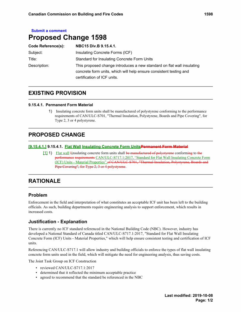
Submit a comment
Proposed Change 1598Code Reference(s): NBC15 Div.B 9.15.4.1.Subject: Insulating Concrete Forms (ICF)Title: Standard for Insulating Concrete Form UnitsDescription: This proposed change introduces a new standard on flat wall insulating
concrete form units, which will help ensure consistent testing andcertification of ICF units.
EXISTING PROVISION
9.15.4.1. Permanent Form Material1) Insulating concrete form units shall be manufactured of polystyrene conforming to the performance
requirements of CAN/ULC-S701, "Thermal Insulation, Polystyrene, Boards and Pipe Covering", forType 2, 3 or 4 polystyrene.
PROPOSED CHANGE
[9.15.4.1.] 9.15.4.1. Flat Wall Insulating Concrete Form UnitsPermanent Form Material[1] 1) Flat wall Iinsulating concrete form units shall be manufactured of polystyrene conforming to the
performance requirements CAN/ULC-S717.1:2017, “Standard for Flat Wall Insulating Concrete Form(ICF) Units - Material Properties”.of CAN/ULC-S701, "Thermal Insulation, Polystyrene, Boards andPipe Covering", for Type 2, 3 or 4 polystyrene.
RATIONALE
ProblemEnforcement in the field and interpretation of what constitutes an acceptable ICF unit has been left to the buildingofficials. As such, building departments require engineering analysis to support enforcement, which results inincreased costs.
Justification - ExplanationThere is currently no ICF standard referenced in the National Building Code (NBC). However, industry hasdeveloped a National Standard of Canada titled CAN/ULC-S717.1:2017, "Standard for Flat Wall InsulatingConcrete Form (ICF) Units - Material Properties," which will help ensure consistent testing and certification of ICFunits.
Referencing CAN/ULC-S717.1 will allow industry and building officials to enforce the types of flat wall insulatingconcrete form units used in the field, which will mitigate the need for engineering analysis, thus saving costs.
The Joint Task Group on ICF Construction
• reviewed CAN/ULC-S717.1:2017• determined that it reflected the minimum acceptable practice• agreed to recommend that the standard be referenced in the NBC
Canadian Commission on Building and Fire Codes 1598
Last modified: 2019-10-08Page: 1/2

Impact analysisCost neutral. The intent of the change is to improve the consistency of design and construction using flat wall ICFunits and, in turn, the approval process, which could result in potential cost savings.
Enforcement implicationsThis proposed change can be enforced by the infrastructure currently in place to enforce the Code.
Adding the reference to the standard will facilitate the approval process.
Who is affectedDesigners, specifiers, ICF manufacturers and contractors, building owners, building officials.
OBJECTIVE-BASED ANALYSIS OF NEW OR CHANGED PROVISIONS
[9.15.4.1.] 9.15.4.1. ([1] 1) [F22,F63,F55-OH1.1,OH1.2,OH1.3]
Canadian Commission on Building and Fire Codes 1598
Last modified: 2019-10-08Page: 2/2

Submit a comment
Proposed Change 1601Code Reference(s): NBC15 Div.B 9.15.4.2.Subject: Insulating Concrete Forms (ICF)Title: ICF Foundation WallsDescription: This proposed change allows flat insulating concrete form walls to be used
as foundation walls under Article 9.15.4.2.
EXISTING PROVISION
9.15.4.2. Foundation Wall Thickness and Required Lateral Support1) Except as required in Sentence (2), the thickness of foundation walls made of unreinforced concrete
block or solid concrete and subject to lateral earth pressure shall conform to Table 9.15.4.2.-A for wallsnot exceeding 3.0 m in unsupported height.
2) The thickness of concrete in flat insulating concrete form foundation walls shall be not less than thegreater of
a) 140 mm, orb) the thickness of the concrete in the wall above.
3) Foundation walls made of flat insulating concrete form units shall be laterally supported at the top andat the bottom.
Table 9.15.4.2.-AThickness of Solid Concrete and Unreinforced Concrete Block Foundation Walls
Forming Part of Sentence 9.15.4.2.(1)
Maximum Height of Finished Ground Above Basement Flooror Crawl Space Ground Cover, m
Height of Foundation WallLaterally Unsupported at the
Top (1) (2)
Height of Foundation WallLaterally Supported at the
Top (1) (2)
Type ofFoundation
Wall
MinimumWall
Thickness,mm
≤ 3.0 m ≤2.5 m
> 2.5 mand
≤ 2.75 m
> 2.75 mand
≤ 3.0 m
150 0.8 1.5 1.5 1.4
200 1.2 2.15 2.15 2.1
250 1.4 2.3 2.6 2.5
Solid concrete,15 MPa min.
strength
300 1.5 2.3 2.6 2.85
150 0.8 1.8 1.6 1.6
200 1.2 2.3 2.3 2.2
Solid concrete,20 MPa min.
strength250 1.4 2.3 2.6 2.85
EXISTING PROVISION Table 9.15.4.2.A. FootnoteEXISTING PROVISION Table 9.15.4.2.A. FootnoteEXISTING PROVISION Table 9.15.4.2.A. FootnoteEXISTING PROVISION Table 9.15.4.2.A. Footnote
Canadian Commission on Building and Fire Codes 1601
Last modified: 2019-10-01Page: 1/11

Maximum Height of Finished Ground Above Basement Flooror Crawl Space Ground Cover, m
Height of Foundation WallLaterally Unsupported at the
Top (1) (2)
Height of Foundation WallLaterally Supported at the
Top (1) (2)
Type ofFoundation
Wall
MinimumWall
Thickness,mm
≤ 3.0 m ≤2.5 m
> 2.5 mand
≤ 2.75 m
> 2.75 mand
≤ 3.0 m
300 1.5 2.3 2.6 2.85
140 0.6 0.8 — —
190 0.9 1.2 (3) (3)
240 1.2 1.8 (3) (3)
Unreinforcedconcrete block
290 1.4 2.2 — —
Notes to Table 9.15.4.2.-A:
See Article 9.15.4.3.(1)EXISTING PROVISION Table 9.15.4.2.A. Footnotereferrer
See Article 9.15.4.6.(2)EXISTING PROVISION Table 9.15.4.2.A. Footnotereferrer
See Table 9.15.4.2.-B.(3)EXISTING PROVISION Table 9.15.4.2.A. Footnotereferrer
4) The thickness and reinforcing of foundation walls made of reinforced concrete block and subject tolateral earth pressure shall conform to Table 9.15.4.2.-B and Sentences (5) to (8), where
a) the walls are laterally supported at the top,b) average stable soils are encountered, andc) wind loads on the exposed portion of the foundation are no greater than 0.70 kPa.
5) For concrete block walls required to be reinforced, continuous vertical reinforcement shalla) be provided at wall corners, wall ends, wall intersections, at changes in wall height, at the jambs
of all openings and at movement joints,b) extend from the top of the footing to the top of the foundation wall, andc) where foundation walls are laterally supported at the top, have not less than 50 mm embedment
into the footing, if the floor slab does not provide lateral support at the wall base.
6) For concrete block walls required to be reinforced, a continuous horizontal bond beam containing notless than one 15M bar shall be installed
a) along the top of the wall,b) at the sill and head of all openings greater than 1.20 m in width, andc) at structurally connected floors.
EXISTING PROVISION Table 9.15.4.2.A. FootnoteEXISTING PROVISION Table 9.15.4.2.A. FootnoteEXISTING PROVISION Table 9.15.4.2.A. FootnoteEXISTING PROVISION Table 9.15.4.2.A. Footnote
EXISTING PROVISION Table 9.15.4.2.A. FootnoteEXISTING PROVISION Table 9.15.4.2.A. Footnote
EXISTING PROVISION Table 9.15.4.2.A. FootnoteEXISTING PROVISION Table 9.15.4.2.A. Footnote
Footnote1Footnote2Footnote3
Canadian Commission on Building and Fire Codes 1601
Last modified: 2019-10-01Page: 2/11

Table 9.15.4.2.-BReinforced Concrete Block Foundation Walls Laterally Supported at the Top (1)
Forming Part of Sentence 9.15.4.2.(4)
Size and Spacing of Continuous VerticalReinforcement, M at mm o.c.
190 mm Minimum WallThickness
240 mm Minimum WallThickness
Foundation WallHeight
Foundation WallHeight
Maximum Height of Finished Ground AboveBasement Floor or Crawl Space Ground
Cover, m (2)
≤2.5 m
≤2.75 m
≤3.0 m
≤2.5 m
≤2.75 m
≤3.0 m
0.8 (3) (3) (3) (3) (3) (3)
1 (3) 1-15Mat 1 800
1-15Mat
1 800
(3) (3) (3)
1.2 (3) 1-15Mat 1 600
1-15Mat
1 600
(3) 1-20Mat 2 000
1-20Mat
2 000
1.4 1-15Mat
1 600
1-15Mat 1 600
1-15Mat
1 600
(3) 1-20Mat 1 800
1-20Mat
1 800
1.6 1-15Mat
1 400
1-15Mat 1 400
1-15Mat
1 400
(3) 1-20Mat 1 600
1-20Mat
1 600
1.8 1-15Mat
1 400
1-15Mat 1 400
1-15Mat
1 200
(3) 1-20Mat 1 600
1-20Mat
1 600
2 1-15Mat
1 200
1-15Mat 1 000
or1-20M
at 1 200
2-15Mat
1 200
1-20Mat
1 600
1-20Mat 1 600
1-20Mat
1 600
2.2 2-15Mat
1 200
2-15Mat 1 000
2-15Mat
1 000
1-20Mat
1 400
1-20Mat 1 400
1-20Mat
1 400
2.4 2-15Mat
1 000
2-15Mat 1 000
2-15Mat 800
1-20Mat
1 400
1-20Mat 1 400
1-20Mat
1 200
EXISTING PROVISION Table 9.15.4.2.B. Footnote
EXISTING PROVISION Table 9.15.4.2.B. Footnote
EXISTING PROVISION Table 9.15.4.2.B. FootnoteEXISTING PROVISION Table 9.15.4.2.B. FootnoteEXISTING PROVISION Table 9.15.4.2.B. FootnoteEXISTING PROVISION Table 9.15.4.2.B. FootnoteEXISTING PROVISION Table 9.15.4.2.B. FootnoteEXISTING PROVISION Table 9.15.4.2.B. Footnote
EXISTING PROVISION Table 9.15.4.2.B. FootnoteEXISTING PROVISION Table 9.15.4.2.B. FootnoteEXISTING PROVISION Table 9.15.4.2.B. FootnoteEXISTING PROVISION Table 9.15.4.2.B. Footnote
EXISTING PROVISION Table 9.15.4.2.B. FootnoteEXISTING PROVISION Table 9.15.4.2.B. Footnote
EXISTING PROVISION Table 9.15.4.2.B. Footnote
EXISTING PROVISION Table 9.15.4.2.B. Footnote
EXISTING PROVISION Table 9.15.4.2.B. Footnote
Canadian Commission on Building and Fire Codes 1601
Last modified: 2019-10-01Page: 3/11

Size and Spacing of Continuous VerticalReinforcement, M at mm o.c.
190 mm Minimum WallThickness
240 mm Minimum WallThickness
Foundation WallHeight
Foundation WallHeight
Maximum Height of Finished Ground AboveBasement Floor or Crawl Space Ground
Cover, m (2)
≤2.5 m
≤2.75 m
≤3.0 m
≤2.5 m
≤2.75 m
≤3.0 m
2.6 n/a 2-15Mat 800
or1-25M
at 1 000
2-15Mat 800
or1-25M
at1 000
n/a 1-20Mat 1 000
1-20Mat
1 000
2.8 n/a n/a 1-20Mat 600
n/a n/a 1-20Mat 800
or2-15M
at1 000
3 n/a n/a 1-20Mat 400
or1-25Mat 600
n/a n/a 2-15Mat 800
Notes to Table 9.15.4.2.-B:
See Article 9.15.4.3.(1)EXISTING PROVISION Table 9.15.4.2.B. Footnotereferrer
See Article 9.15.4.6.(2)EXISTING PROVISION Table 9.15.4.2.B. Footnotereferrer
No reinforcement required.(3)EXISTING PROVISION Table 9.15.4.2.B. Footnotereferrer
7) In concrete block walls required to be reinforced, all vertical bar reinforcement shall be installed alongthe centre line of the wall.
8) In concrete block walls required to be reinforced, ladder- or truss-type lateral reinforcement not lessthan 3.8 mm in diameter (no. 9 ASWG) shall be installed in the bed joint of every second masonrycourse.
EXISTING PROVISION Table 9.15.4.2.B. Footnote
Footnote1Footnote2Footnote3
Canadian Commission on Building and Fire Codes 1601
Last modified: 2019-10-01Page: 4/11

PROPOSED CHANGE
[9.15.4.2.] 9.15.4.2. Foundation Wall Thickness and Required Lateral Support[1] 1) Except as required in Sentence (2), the thickness of foundation walls made of unreinforced concrete
block, concrete core in flat wall insulating concrete forms or solid concrete and subject to lateral earthpressure shall conform to Table 9.15.4.2.-A for walls not exceeding 3.0 m in unsupported height.
[2] 2) The thickness of concrete core in flat insulating concrete form foundation walls shall be not less thanthe greater of[a] a) 150140 mm, or[b] b) the thickness of the concrete in the wall above.
[3] 3) Foundation walls made of flat insulating concrete form units shall be laterally supported at the top andat the bottom.
Table [9.15.4.2.-A] 9.15.4.2.-AThickness of Solid Concrete, Concrete Core in Flat Wall Insulating Concrete Forms, and
Unreinforced Concrete Block Foundation WallsForming Part of Sentence [9.15.4.2.] 9.15.4.2.([1] 1)
Maximum Height of Finished Ground AboveBasement Floor or Crawl Space Ground
Cover, m
Height ofFoundation Wall
LaterallyUnsupported at the
Top (1) (2)
Height of FoundationWall Laterally
Supported at theTop (1) (2)Type of Foundation Wall
Minimum WallThickness ofConcrete or
Concrete Block,mm
≤ 3.0 m ≤2.5 m
> 2.5m and
≤2.75 m
>2.75m
and≤
3.0 m
150 0.8 1.5 1.5 1.4
200 1.2 2.15 2.15 2.1
250 1.4 2.3 2.6 2.5
Solid concrete and concretecore in flat wall insulating
concrete forms, (3) 15 MPamin. strength
300 1.5 2.3 2.6 2.85
150 0.8 1.8 1.6 1.6
200 1.2 2.3 2.3 2.2
250 1.4 2.3 2.6 2.85
Solid concrete and concretecore in flat wall insulating
concrete forms, (3) 20 MPamin. strength
300 1.5 2.3 2.6 2.85
Unreinforced concrete block 140 0.6 0.8 — —
PROPOSED CHANGE Table 9.15.4.2.A. FootnotePROPOSED CHANGE Table 9.15.4.2.A. FootnotePROPOSED CHANGE Table 9.15.4.2.A. FootnotePROPOSED CHANGE Table 9.15.4.2.A. Footnote
PROPOSED CHANGE Table 9.15.4.2.A. Footnote
PROPOSED CHANGE Table 9.15.4.2.A. Footnote
Canadian Commission on Building and Fire Codes 1601
Last modified: 2019-10-01Page: 5/11

Maximum Height of Finished Ground AboveBasement Floor or Crawl Space Ground
Cover, m
Height ofFoundation Wall
LaterallyUnsupported at the
Top (1) (2)
Height of FoundationWall Laterally
Supported at theTop (1) (2)Type of Foundation Wall
Minimum WallThickness ofConcrete or
Concrete Block,mm
≤ 3.0 m ≤2.5 m
> 2.5m and
≤2.75 m
>2.75m
and≤
3.0 m
190 0.9 1.2 (4) (4)
240 1.2 1.8 (4) (4)
290 1.4 2.2 — —
Notes to Table [9.15.4.2.-A] 9.15.4.2.-A:
See Article 9.15.4.3.(1)PROPOSED CHANGE Table 9.15.4.2.A. Footnotereferrer
See Article 9.15.4.6.(2)PROPOSED CHANGE Table 9.15.4.2.A. Footnotereferrer
See Note A-Table 9.15.4.2.-A.(3)PROPOSED CHANGE Table 9.15.4.2.A. Footnotereferrer
See Table 9.15.4.2.-B.(4)PROPOSED CHANGE Table 9.15.4.2.A. Footnotereferrer
[4] 4) The thickness and reinforcing of foundation walls made of reinforced concrete block and subject tolateral earth pressure shall conform to Table 9.15.4.2.-B and Sentences (5) to (8), where[a] a) the walls are laterally supported at the top,[b] b) average stable soils are encountered, and[c] c) wind loads on the exposed portion of the foundation are no greater than 0.70 kPa.
[5] 5) For concrete block walls required to be reinforced, continuous vertical reinforcement shall[a] a) be provided at wall corners, wall ends, wall intersections, at changes in wall height, at the jambs
of all openings and at movement joints,[b] b) extend from the top of the footing to the top of the foundation wall, and[c] c) where foundation walls are laterally supported at the top, have not less than 50 mm embedment
into the footing, if the floor slab does not provide lateral support at the wall base.
[6] 6) For concrete block walls required to be reinforced, a continuous horizontal bond beam containing notless than one 15M bar shall be installed[a] a) along the top of the wall,[b] b) at the sill and head of all openings greater than 1.20 m in width, and[c] c) at structurally connected floors.
PROPOSED CHANGE Table 9.15.4.2.A. FootnotePROPOSED CHANGE Table 9.15.4.2.A. FootnotePROPOSED CHANGE Table 9.15.4.2.A. FootnotePROPOSED CHANGE Table 9.15.4.2.A. Footnote
PROPOSED CHANGE Table 9.15.4.2.A. FootnotePROPOSED CHANGE Table 9.15.4.2.A. Footnote
PROPOSED CHANGE Table 9.15.4.2.A. FootnotePROPOSED CHANGE Table 9.15.4.2.A. Footnote
Footnote1Footnote2Footnote3Footnote4
Canadian Commission on Building and Fire Codes 1601
Last modified: 2019-10-01Page: 6/11

Table [9.15.4.2.-B] 9.15.4.2.-BReinforced Concrete Block Foundation Walls Laterally Supported at the Top (1)
Forming Part of Sentence [9.15.4.2.] 9.15.4.2.([4] 4)
Size and Spacing of Continuous VerticalReinforcement, M at mm o.c.
190 mm Minimum WallThickness
240 mm Minimum WallThickness
Foundation WallHeight
Foundation WallHeight
Maximum Height of Finished Ground AboveBasement Floor or Crawl Space Ground
Cover, m (2)
≤2.5 m
≤2.75 m
≤3.0 m
≤2.5 m
≤2.75 m
≤3.0 m
0.8 (3) (3) (3) (3) (3) (3)
1 (3) 1-15Mat 1 800
1-15Mat
1 800
(3) (3) (3)
1.2 (3) 1-15Mat 1 600
1-15Mat
1 600
(3) 1-20Mat 2 000
1-20Mat
2 000
1.4 1-15Mat
1 600
1-15Mat 1 600
1-15Mat
1 600
(3) 1-20Mat 1 800
1-20Mat
1 800
1.6 1-15Mat
1 400
1-15Mat 1 400
1-15Mat
1 400
(3) 1-20Mat 1 600
1-20Mat
1 600
1.8 1-15Mat
1 400
1-15Mat 1 400
1-15Mat
1 200
(3) 1-20Mat 1 600
1-20Mat
1 600
2 1-15Mat
1 200
1-15Mat 1 000
or1-20M
at 1 200
2-15Mat
1 200
1-20Mat
1 600
1-20Mat 1 600
1-20Mat
1 600
2.2 2-15Mat
1 200
2-15Mat 1 000
2-15Mat
1 000
1-20Mat
1 400
1-20Mat 1 400
1-20Mat
1 400
2.4 2-15Mat
1 000
2-15Mat 1 000
2-15Mat 800
1-20Mat
1 400
1-20Mat 1 400
1-20Mat
1 200
PROPOSED CHANGE Table 9.15.4.2.B. Footnote
PROPOSED CHANGE Table 9.15.4.2.B. Footnote
PROPOSED CHANGE Table 9.15.4.2.B. FootnotePROPOSED CHANGE Table 9.15.4.2.B. FootnotePROPOSED CHANGE Table 9.15.4.2.B. FootnotePROPOSED CHANGE Table 9.15.4.2.B. FootnotePROPOSED CHANGE Table 9.15.4.2.B. FootnotePROPOSED CHANGE Table 9.15.4.2.B. Footnote
PROPOSED CHANGE Table 9.15.4.2.B. FootnotePROPOSED CHANGE Table 9.15.4.2.B. FootnotePROPOSED CHANGE Table 9.15.4.2.B. FootnotePROPOSED CHANGE Table 9.15.4.2.B. Footnote
PROPOSED CHANGE Table 9.15.4.2.B. FootnotePROPOSED CHANGE Table 9.15.4.2.B. Footnote
PROPOSED CHANGE Table 9.15.4.2.B. Footnote
PROPOSED CHANGE Table 9.15.4.2.B. Footnote
PROPOSED CHANGE Table 9.15.4.2.B. Footnote
Canadian Commission on Building and Fire Codes 1601
Last modified: 2019-10-01Page: 7/11

Size and Spacing of Continuous VerticalReinforcement, M at mm o.c.
190 mm Minimum WallThickness
240 mm Minimum WallThickness
Foundation WallHeight
Foundation WallHeight
Maximum Height of Finished Ground AboveBasement Floor or Crawl Space Ground
Cover, m (2)
≤2.5 m
≤2.75 m
≤3.0 m
≤2.5 m
≤2.75 m
≤3.0 m
2.6 n/a 2-15Mat 800
or1-25M
at 1 000
2-15Mat 800
or1-25M
at1 000
n/a 1-20Mat 1 000
1-20Mat
1 000
2.8 n/a n/a 1-20Mat 600
n/a n/a 1-20Mat 800
or2-15M
at1 000
3 n/a n/a 1-20Mat 400
or1-25Mat 600
n/a n/a 2-15Mat 800
Notes to Table [9.15.4.2.-B] 9.15.4.2.-B:
See Article 9.15.4.3.(1)PROPOSED CHANGE Table 9.15.4.2.B. Footnotereferrer
See Article 9.15.4.6.(2)PROPOSED CHANGE Table 9.15.4.2.B. Footnotereferrer
No reinforcement required.(3)PROPOSED CHANGE Table 9.15.4.2.B. Footnotereferrer
[7] 7) In concrete block walls required to be reinforced, all vertical bar reinforcement shall be installed alongthe centre line of the wall.
[8] 8) In concrete block walls required to be reinforced, ladder- or truss-type lateral reinforcement not lessthan 3.8 mm in diameter (no. 9 ASWG) shall be installed in the bed joint of every second masonrycourse.
Note A-Table 9.15.4.2.-A Flat Insulating Concrete Form Walls as Foundation Walls.Article 9.15.4.2. allows insulating concrete forms (ICF) to be used to form both laterally supported and laterallyunsupported flat, plain (unreinforced) concrete foundation walls intended to support wood-frame walls, floors and roofsunder the conditions stipulated in Table 9.15.4.2.-A. Where the limits stated in the Table are exceeded, or where the ICFfoundation wall is intended to support one or two storeys of concrete walls formed with flat wall ICFs above ground,Article 9.15.4.5. applies.
PROPOSED CHANGE Table 9.15.4.2.B. Footnote
Footnote1Footnote2Footnote3
Canadian Commission on Building and Fire Codes 1601
Last modified: 2019-10-01Page: 8/11

RATIONALE
ProblemThe current wording of Sentence 9.15.4.2.(3) places limitations on the use of flat wall insulating concrete form units(ICFs) compared to their equivalent--unreinforced solid concrete--in that, it specifically states that all walls formedwith flat wall insulating concrete form units must be laterally supported at both the top and the bottom. However,Table 9.15.4.2.-A allows plain (unreinforced) concrete walls to be laterally unsupported at the top where thefoundation and finished ground are limited in height. Since Table 9.15.4.2.-A does not specifically address ICFunits, building officials commonly prohibit builders from using Table 9.15.4.2.-A to achieve compliance whenforming laterally unsupported, unreinforced, plain concrete with insulating concrete form units under the heightlimitations in the Table, directing them instead to Article 9.15.4.5., which requires reinforcement within ICF walls.
The unreinforced concrete material formed by ICF units is the same material as unreinforced solid concrete formedby other means. For example, if a contractor were to simply remove the insulating concrete form units from theoutside of the cured concrete, the remaining concrete wall would comply with Table 9.15.4.2.-A.
The requirement for lateral support at both the top and bottom of ICF walls was introduced in the original 2003proposed change by the Cement Association of Canada, which sought to add insulating concrete form unitsto Article 9.15.4.5. The 2003 proposed change was intended for reinforced ICF supporting a maximum of 2 storeysof flat wall reinforced ICF above. It was never intended that ICFs would not be used for forming plain orunreinforced concrete walls supporting wood-frame construction only, within the bounds of the limitations to wallheight provided in Table 9.15.4.2.-A for plain unreinforced solid concrete walls.
Justification - ExplanationThe deletion of Sentence 9.15.4.2.(3) and addition of "concrete core in flat wall insulating concrete forms" toSentence 9.15.4.2.(1) and Table 9.15.4.2.-A make it clear that concrete formed in flat wall insulating concrete formscan be installed using Table 9.15.4.2.-A for all plain unreinforced wall scenarios that are in conformance with theconditions in the Table and only support wood-frame construction.
However, the proposed change to Table 9.15.4.2.-A conflicts with current Clause 9.15.4.2.(2)(a) in that the Clauseallows a minimum ICF thickness of 140 mm and the Table allows a minimum thickness of 150 mm. This conflict isresolved by changing "140 mm" in Clause 9.15.4.2.(2)(a) to "150 mm".
The addition of Note A-Table 9.15.4.2.-A is intended to inform users that
• for the prescriptive design of foundation walls constructed with ICFs, Table 9.15.4.2.-A can be used forboth laterally supported and laterally unsupported walls supporting wood framing only
• foundation walls supporting 1 or 2 storeys of concrete walls formed with flat wall ICFs above ground mustbe reinforced and designed in accordance with Article 9.15.4.5.
The proposed change will allow ICF builders to compete on a even playing field with traditional forming contractorsfor the construction of foundation walls supporting wood-frame construction.
Impact analysisNo significant cost implications.
Enforcement implicationsWill allow authorities having jurisdiction (AHJs) to inspect ICF foundation walls using Table 9.15.4.2.-A, as is thecase for traditionally formed concrete foundation walls.
The addition of the clarifying note would minimize conflict between AHJs and contractors during inspections.
Canadian Commission on Building and Fire Codes 1601
Last modified: 2019-10-01Page: 9/11

Who is affectedDesigners, specifiers, ICF manufacturers and contractors, building owners, building officials.
OBJECTIVE-BASED ANALYSIS OF NEW OR CHANGED PROVISIONS
[9.15.4.2.] 9.15.4.2. ([1] 1) [F20-OS2.1,OS2.3] [F22-OS2.3]
[9.15.4.2.] 9.15.4.2. ([1] 1) [F20-OP2.1,OP2.3] [F22-OP2.3,OP2.4]
[9.15.4.2.] 9.15.4.2. ([1] 1) [F20,F22-OH1.1,OH1.2,OH1.3]
[9.15.4.2.] 9.15.4.2. ([1] 1) [F20,F22-OH4] Applies to floors and elements that support floors.
[9.15.4.2.] 9.15.4.2. ([1] 1) [F20,F22-OS3.1] Applies to floors and elements that support floors.
[9.15.4.2.] 9.15.4.2. ([2] 2) [F20-OS2.1,OS2.3] [F22-OS2.3]
[9.15.4.2.] 9.15.4.2. ([2] 2) [F20-OP2.1,OP2.3] [F22-OP2.3,OP2.4]
[9.15.4.2.] 9.15.4.2. ([2] 2) [F20,F22-OH1.1,OH1.2,OH1.3]
[9.15.4.2.] 9.15.4.2. ([2] 2) [F20,F22-OH4] Applies to floors and elements that support floors.
[9.15.4.2.] 9.15.4.2. ([2] 2) [F20,F22-OS3.1] Applies to floors and elements that support floors.
[9.15.4.2.] 9.15.4.2. ([3] 3) [F20-OS2.1,OS2.3] [F22-OS2.3,OS2.4]
[9.15.4.2.] 9.15.4.2. ([3] 3) [F20-OP2.1,OP2.3] [F22-OP2.3,OP2.4]
[9.15.4.2.] 9.15.4.2. ([3] 3) [F20,F22-OH1.1,OH1.2,OH1.3]
[9.15.4.2.] 9.15.4.2. ([3] 3) [F20,F22-OH4] Applies to floors and elements that support floors.
[9.15.4.2.] 9.15.4.2. ([3] 3) [F20,F22-OS3.1] Applies to floors and elements that support floors.
[9.15.4.2.] 9.15.4.2. ([4] 4) [F20-OS2.1,OS2.3] [F22-OS2.3]
[9.15.4.2.] 9.15.4.2. ([4] 4) [F20-OP2.1,OP2.3] [F22-OP2.3,OP2.4]
[9.15.4.2.] 9.15.4.2. ([4] 4) [F20,F22-OH1.1,OH1.2,OH1.3]
[9.15.4.2.] 9.15.4.2. ([4] 4) [F20,F22-OH4] Applies to floors and elements that support floors.
[9.15.4.2.] 9.15.4.2. ([4] 4) [F20,F22-OS3.1] Applies to floors and elements that support floors.
[9.15.4.2.] 9.15.4.2. ([5] 5) [F20-OS2.1,OS2.3] [F22-OS2.3,OS2.4]
[9.15.4.2.] 9.15.4.2. ([5] 5) [F20-OP2.1,OP2.3] [F22-OP2.3,OP2.4]
[9.15.4.2.] 9.15.4.2. ([5] 5) [F20,F22-OH1.1,OH1.2,OH1.3]
[9.15.4.2.] 9.15.4.2. ([5] 5) [F20,F22-OH4] Applies to floors and elements that support floors.
[9.15.4.2.] 9.15.4.2. ([5] 5) [F20,F22-OS3.1] Applies to floors and elements that support floors.
[9.15.4.2.] 9.15.4.2. ([6] 6) [F20-OS2.1,OS2.3] [F22-OS2.3,OS2.4]
[9.15.4.2.] 9.15.4.2. ([6] 6) [F20-OP2.1,OP2.3] [F22-OP2.3,OP2.4]
[9.15.4.2.] 9.15.4.2. ([6] 6) [F20,F22-OH1.1,OH1.2,OH1.3]
Canadian Commission on Building and Fire Codes 1601
Last modified: 2019-10-01Page: 10/11

[9.15.4.2.] 9.15.4.2. ([6] 6) [F20,F22-OH4] Applies to floors and elements that support floors.
[9.15.4.2.] 9.15.4.2. ([6] 6) [F20,F22-OS3.1] Applies to floors and elements that support floors.
[9.15.4.2.] 9.15.4.2. ([7] 7) [F20-OS2.1,OS2.3] [F22-OS2.3,OS2.4]
[9.15.4.2.] 9.15.4.2. ([7] 7) [F20-OP2.1,OP2.3] [F22-OP2.3,OP2.4]
[9.15.4.2.] 9.15.4.2. ([7] 7) [F20,F22-OH1.1,OH1.2,OH1.3]
[9.15.4.2.] 9.15.4.2. ([7] 7) [F20,F22-OH4] Applies to floors and elements that support floors.
[9.15.4.2.] 9.15.4.2. ([7] 7) [F20,F22-OS3.1] Applies to floors and elements that support floors.
[9.15.4.2.] 9.15.4.2. ([8] 8) [F20-OS2.1,OS2.3] [F22-OS2.3,OS2.4]
[9.15.4.2.] 9.15.4.2. ([8] 8) [F20-OP2.1,OP2.3] [F22-OP2.3,OP2.4]
[9.15.4.2.] 9.15.4.2. ([8] 8) [F20,F22-OH1.1,OH1.2,OH1.3]
[9.15.4.2.] 9.15.4.2. ([8] 8) [F20,F22-OH4] Applies to floors and elements that support floors.
[9.15.4.2.] 9.15.4.2. ([8] 8) [F20,F22-OS3.1] Applies to floors and elements that support floors.
Canadian Commission on Building and Fire Codes 1601
Last modified: 2019-10-01Page: 11/11

Submit a comment
Proposed Change 1603Code Reference(s): NBC15 Div.B 9.15.4.3.(2)Subject: Insulating Concrete Forms (ICF)Title: Lateral Support of Foundation Walls (Top)Description: This proposed change clarifies that lateral support at the top of a foundation
wall can be achieved by backfilling with soil on both sides of the wall.
EXISTING PROVISION
9.15.4.3. Foundation Walls Considered to be Laterally Supported at the Top1) Sentences (2) to (4) pertain to lateral support for walls described in Sentence 9.15.4.2.(1).
2) Foundation walls shall be considered to be laterally supported at the top ifa) such walls support a solid masonry superstructure,b) the floor joists are embedded in the top of the foundation walls, orc) the floor system is anchored to the top of the foundation walls with anchor bolts, in which case
the joists may run either parallel or perpendicular to the foundation walls.
3) Unless the wall around an opening is reinforced to withstand earth pressure, the portion of thefoundation wall beneath an opening shall be considered laterally unsupported if
a) the opening is more than 1.2 m wide, orb) the total width of the openings in the foundation wall constitutes more than 25% of the length of
the wall.
4) For the purposes of Sentence (3), the combined width of the openings shall be considered as a singleopening if the average width is greater than the width of solid wall between them.
5) Flat insulating concrete form foundation walls shall be considered to be laterally supported at the top ifthe floor joists are installed according to Article 9.20.17.5.
PROPOSED CHANGE
[9.15.4.3.] 9.15.4.3. Foundation Walls Considered to be Laterally Supported at the Top[1] 2) Foundation walls shall be considered to be laterally supported at the top if
[a] a) such walls support a solid masonry superstructure or flat insulating concrete form wall,[b] b) the floor joists are embedded in the top of the foundation walls, or[c] c) the floor system is anchored to the top of the foundation walls with anchor bolts, in which case
the joists may run either parallel or perpendicular to the foundation walls., or[d] --) they extend from the footing to no more than 300 mm above the finished ground level and there
is no more than 150 mm difference between the finished ground levels on either side of the wall.
Canadian Commission on Building and Fire Codes 1603
Last modified: 2019-10-21Page: 1/2

RATIONALE
ProblemWhen new requirements for defining lateral support at the top and bottom of walls were added to the 2005 NBC (forthe purposes of Table 9.15.4.2.-A and for reinforced flat insulating concrete form walls under Article9.15.4.5.), Article 9.15.4.3. was not modified to indicate whether walls that were backfilled to finished groundlevel on both sides of the wall were deemed to be laterally supported at the top. In some cases, building officialshave required drawings stamped by an engineer to ensure that these types of foundation walls met the intent of theArticle.
Justification - ExplanationThe stated problem is resolved by introducing Clause 9.15.4.3.(2)(d) to describe
• the conditions where a foundation wall is considered to be laterally supported at the top as a result ofbackfill on either side of the wall
• the allowable limits for the difference in backfill height on either side of a foundation wall that is notconnected directly to the building frame
The proposed new Clause would clarify for building officials that a frost or stem wall extending to a footing that islocated below the prevailing frost line is also considered to be laterally supported at its top when it is backfilled onboth sides but not necessarily structurally connected to any other interconnecting structural material above ground(e.g., a garage floor slab).
Impact analysisPotential cost savings for builders constructing in jurisdictions where building officials are requiring drawingssealed by an engineer.
Enforcement implicationsThis proposed change would simplify enforcement as it clarifies lateral support conditions for frost and stem walls.
Who is affectedDesigners, specifiers, ICF manufacturers and contractors, building owners, building officials.
OBJECTIVE-BASED ANALYSIS OF NEW OR CHANGED PROVISIONS
[9.15.4.3.] 9.15.4.3. ([1] 2) no attributions
Canadian Commission on Building and Fire Codes 1603
Last modified: 2019-10-21Page: 2/2

Submit a comment
Proposed Change 1602Code Reference(s): NBC15 Div.B 9.15.4.4.Subject: Insulating Concrete Forms (ICF)Title: Lateral Support of ICF Foundation Walls (Bottom)Description: This proposed change introduces 10M reinforcing bars as an option for
lateral support at the bottom of ICF foundation walls.
EXISTING PROVISION
9.15.4.4. Foundation Walls Considered to be Laterally Supported at the Bottom1) Flat insulating concrete form foundation walls shall be considered to be laterally supported at the
bottom where the foundation walla) supports backfill not more than 1.2 m in height,b) is supported at the footing by a shear key and at the top by the ground floor framing, orc) is doweled to the footing with not less than 15M bars spaced not more than 1.2 m o.c.
PROPOSED CHANGE
[9.15.4.4.] 9.15.4.4. Foundation Walls Considered to be Laterally Supported at the Bottom[1] 1) Flat insulating concrete form foundation walls shall be considered to be laterally supported at the
bottom where the foundation wall[a] a) supports backfill not more than 1.2 m in height,[b] b) is supported at the footing by a shear key and at the top by the ground floor framing, or[c] c) is doweled to the footing with not less than 15M bars spaced not more than 1.2 m o.c.
[i] --) 15M bars spaced not more than 1.2 m o.c., or[ii] --) 10M bars spaced not more than 600 mm o.c.
RATIONALE
ProblemClause 9.15.4.4.(1)(c) is currently the most widely used option for connecting flat insulating concrete form walls tofootings. However, 15M diameter bars are difficult to cut in the field using hand-operated rebar bender/cutterequipment (which is the most commonly available means of cutting rebars for residential builders and ICFinstallers).
Justification - ExplanationThe proposed addition of the 10M bar option spaced at one half the spacing noted for 15M bars would provide anequivalent option to current Clause 9.15.4.4.(1)(c), which would be retained as Subclause (i)-2020. As the cross-sectional area of a 10M diameter reinforcing steel bar is exactly half that of a 15M steel reinforcing bar, structuralengineers recognize that the lateral shear strength provided by 10M bars placed at 600 mm o.c. is equivalent to thatprovided by 15M bars placed at 1.2 m o.c.
Canadian Commission on Building and Fire Codes 1602
Last modified: 2019-10-10Page: 1/2

The proposed change is intended to afford ICF installation contractors and builders more flexibility and safety in-field while ensuring proper lateral support or linkage of flat walls formed with ICFs at the bottom connection to thefooting.
It is a well-known fact that 10M bars are more easily cut and bent in the field using hand-operated rebarbender/cutter equipment than 15M bars. This proposed change would alleviate the strain on workers and potentiallyreduce the risk of on-site injuries resulting from workers attempting to hand cut or bend 15M diameter bars onresidential or small building sites.
Impact analysisCost neutral since the cost to use 10M bars at 600 mm centres is roughly the same as the cost to use 15M bars at1200 mm centres.
Enforcement implicationsBuilding inspectors need to ensure that the smaller diameter 10M bars are positioned at half the spacing of 15Mbars.
Who is affectedDesigners, specifiers, ICF manufacturers and contractors, building owners, building officials.
OBJECTIVE-BASED ANALYSIS OF NEW OR CHANGED PROVISIONS
[9.15.4.4.] 9.15.4.4. ([1] 1) no attributions
Canadian Commission on Building and Fire Codes 1602
Last modified: 2019-10-10Page: 2/2

Submit a comment
Proposed Change 1555Code Reference(s): NBC15 Div.B 9.25.2.3.Subject: FoundationsTitle: Installation of Thermal Insulation on Foundation WallsDescription: This proposed change requires that insulation be installed over the full
height of foundation walls enclosing a basement or heated crawl space.Related Code ChangeRequest(s):
CCR 904
EXISTING PROVISION
9.25.2.3. Installation of Thermal Insulation1) Insulation shall be installed so that there is a reasonably uniform insulating value over the entire face of
the insulated area.
2) Insulation shall be applied to the full width and length of the space between furring or framing.
3) Except where the insulation provides the principal resistance to air leakage, thermal insulation shall beinstalled so that at least one face is in full and continuous contact with an element with low airpermeance. (See Note A-9.25.2.3.(3).)
4) Insulation on the interior of foundation walls enclosing a crawl space shall be applied so that there isnot less than 50 mm clearance above the crawl space floor, if the insulation is of a type that may bedamaged by water.
5) Insulation around concrete slabs-on-ground shall be located so that heat from the building is notrestricted from reaching the ground beneath the perimeter, where exterior walls are not supported byfootings extending below frost level.
6) Where insulation is exposed to the weather and subject to mechanical damage, it shall be protectedwith not less than
a) 6 mm asbestos-cement board,b) 6 mm preservative-treated plywood, orc) 12 mm cement parging on wire lath applied to the exposed face and edge.
7) Insulation located in areas where it may be subject to mechanical damage shall be protected by acovering such as gypsum board, plywood, particleboard, OSB, waferboard or hardboard.
8) Insulation in factory-built buildings shall be installed so that it will not become dislodged duringtransportation.
Note A-9.25.2.3.(3) Position of Insulation.For thermal insulation to be effective, it must not be short-circuited by convective airflow through or around the material.If low-density fibrous insulation is installed with an air space on both sides of the insulation, the temperature differentialbetween the warm and cold sides will drive convective airflow around the insulation. If foamed plastic insulation is spot-adhered to a backing wall or adhered in a grid pattern to an air-permeable substrate, and is not sealed at the joints andaround the perimeter, air spaces between the insulation and the substrate will interconnect with spaces behind thecladding. Any temperature or air pressure differential across the insulation will again lead to short circuiting of theinsulation by airflow. Thermal insulation must therefore be installed in full and continuous contact with the air barrier oranother continuous component with low air permeance. (See Note A-9.25.5.1.(1) for examples of low-air-permeancematerials.)
EXISTINGPROVISIONA-9.25.2.3.(3)
EXISTINGPROVISIONA-9.25.5.1.(1)
Canadian Commission on Building and Fire Codes 1555
Last modified: 2019-10-10Page: 1/4

PROPOSED CHANGE
[9.25.2.3.] 9.25.2.3. Installation of Thermal Insulation[1] 1) Insulation shall be installed so that there is a reasonably uniform insulating value over the entire face of
the insulated area.
[2] 2) Insulation shall be applied to the full width and length of the space between furring or framing.
[3] 3) Except where the insulation provides the principal resistance to air leakage, thermal insulation shall beinstalled so that at least one face is in full and continuous contact with an element with low airpermeance. (See Note A-9.25.2.3.(3).)
[4] 4) Insulation shall be installed over the full height of foundation walls enclosing a basement or heatedcrawl space. (See also Note A-9.36.2.5.(5).)Insulation on the interior of foundation walls enclosing acrawl space shall be applied so that there is not less than 50 mm clearance above the crawl space floor,if the insulation is of a type that may be damaged by water.
[5] 5) Insulation around concrete slabs-on-ground shall be located so that heat from the building is notrestricted from reaching the ground beneath the perimeter, where exterior walls are not supported byfootings extending below frost level.
[6] 6) Where insulation is exposed to the weather and subject to mechanical damage, it shall be protectedwith not less than[a] a) 6 mm asbestos-cement board,[b] b) 6 mm preservative-treated plywood, or[c] c) 12 mm cement parging on wire lath applied to the exposed face and edge.
[7] 7) Insulation located in areas where it may be subject to mechanical damage shall be protected by acovering such as gypsum board, plywood, particleboard, OSB, waferboard or hardboard.
[8] 8) Insulation in factory-built buildings shall be installed so that it will not become dislodged duringtransportation.
RATIONALE
ProblemCast-in-place concrete retains moisture for a considerable period of time. Where cast-in-place concrete is used forfoundation walls, moisture is often retained long after basement interior finishes are installed. Concrete and masonryfoundation walls can also become wet in service. Moisture in foundation walls may be driven to the interior by solarheating. Where the moisture reaches a surface at a temperature that is below the dew point, the moisture willcondense on that surface (e.g., the inside surface of the concrete or masonry, or other material inboard of these).
Where moisture-susceptible insulation is installed on a foundation wall, the insulation may hold the moisture in thewall assembly. If the insulation is not installed over the full height of (and in continuous contact with) thefoundation wall, there is a higher likelihood of the moisture condensing in the interstitial space and pooling on thebasement floor.
Water pooling can adversely affect the safety and health of building users by causing injury due to slipping, orillness due to inadequate indoor air quality or contact with moisture. Condensation can adversely affect structuralsafety by causing damage to or deterioration of building elements, and can adversely affect the health of buildingusers by causing illness due to inadequate thermal comfort.
Justification - ExplanationContinuity of insulation across the entire building envelope is a requirement in Section 9.36. However, existingArticle 9.25.2.3. allows a small portion at the bottom of a foundation wall in a crawl space to be left uninsulated so
PROPOSEDCHANGEA-9.25.2.3.(3)
Canadian Commission on Building and Fire Codes 1555
Last modified: 2019-10-10Page: 2/4

as to minimize problems in the event of flooding. This provision originated at a time when most insulation productswere made of moisture-susceptible materials. Most new products in use today are impervious to water damage, andsome are used in direct contact with the ground.
The proposed change specifies that when insulation is installed on foundation walls it must be installed over the fullheight of (and, therefore, in continuous contact with) the walls in order to reduce the likelihood of condensation andwater pooling on the floor.
Impact analysisA cost increase will only occur where full-height insulation is not required for other reasons. A commonrecommended maximum clearance for water-permeable fibreglass insulation is 0.38 m. The added cost of installingR20 insulation and a vapour barrier over this area in accordance with the proposed change would be approximately$2.35 per linear metre of wall affected.
A benefit of the proposed change is a reduced likelihood of condensation and water pooling. Condensation andwater pooling on the floor can cause premature deterioration of interior finishes within the expected lifespan of thewall assembly and the growth of mould. The average cost of mould remediation for a basement is $2,640. Thisamount does not include the cost of the replacement of wall materials (insulation, vapour barrier, painted drywall),which could be $33/m2.
Another benefit is a reduced likelihood of adverse health effects caused by mould exposure in occupied basements.
Enforcement implicationsThe proposed change can be enforced using existing infrastructure without an increase in resources.
Who is affectedDesigners, contractors, building owners, building officials.
OBJECTIVE-BASED ANALYSIS OF NEW OR CHANGED PROVISIONS
[9.25.2.3.] 9.25.2.3. ([1] 1) [F51,F63-OH1.1,OH1.2]
[9.25.2.3.] 9.25.2.3. ([1] 1) [F63-OS2.3]
[9.25.2.3.] 9.25.2.3. ([2] 2) [F51,F63-OH1.1,OH1.2]
[9.25.2.3.] 9.25.2.3. ([2] 2) [F63-OS2.3]
[9.25.2.3.] 9.25.2.3. ([3] 3) [F55-OH1.1,OH1.2]
[9.25.2.3.] 9.25.2.3. ([3] 3) [F55-OS2.3]
[9.25.2.3.] 9.25.2.3. ([4] 4) [F51,F63,F80-OH1.1,OH1.2]
[9.25.2.3.] 9.25.2.3. ([4] 4) [F63,F80-OS2.3]
[9.25.2.3.] 9.25.2.3. ([5] 5) [F21-OH1.1,OH1.2,OH1.3]
[9.25.2.3.] 9.25.2.3. ([5] 5) [F21-OS2.2,OS2.3]
[9.25.2.3.] 9.25.2.3. ([6] 6) [F80-OH1.1,OH1.2]
[9.25.2.3.] 9.25.2.3. ([6] 6) [F80-OS2.3]
[9.25.2.3.] 9.25.2.3. ([7] 7) [F80-OH1.1,OH1.2]
Canadian Commission on Building and Fire Codes 1555
Last modified: 2019-10-10Page: 3/4

[9.25.2.3.] 9.25.2.3. ([7] 7) [F80-OS2.3]
[9.25.2.3.] 9.25.2.3. ([8] 8) [F21-OH1.1,OH1.2]
[9.25.2.3.] 9.25.2.3. ([8] 8) [F21-OS2.3]
Canadian Commission on Building and Fire Codes 1555
Last modified: 2019-10-10Page: 4/4

Submit a comment
Proposed Change 1350Code Reference(s): NBC15 Div.B 9.25.4.2.Subject: Building Envelope - GeneralTitle: Protection of Vapour BarriersDescription: This proposed change introduces a new Sentence 9.25.4.2.(5) to protect
non-polyethylene membrane-type vapour barriers that are susceptible todeterioration under prolonged exposure to direct ultraviolet radiation.
Related Code ChangeRequest(s):
CCR 905
EXISTING PROVISION
9.25.4.2. Vapour Barrier Materials1) Vapour barriers shall have a permeance not greater than 60 ng/(Pa·s·m2) measured in accordance with
ASTM E 96/E 96M, "Water Vapor Transmission of Materials", using the desiccant method (dry cup).
2) Where the intended use of the interior space will result in high moisture generation, the assembly shallbe designed according to Part 5. (See Note A-9.25.4.2.(2).)
3) Where polyethylene is installed to serve only as the vapour barrier, it shall comply with Clause 4.4,Thermal Stability, and Clause 5.7, Oxidative Induction Time, of CAN/CGSB-51.34-M, "VapourBarrier, Polyethylene Sheet for Use in Building Construction".
4) Membrane-type vapour barriers other than polyethylene shall conform to the requirements ofCAN/CGSB-51.33-M, "Vapour Barrier Sheet, Excluding Polyethylene, for Use in BuildingConstruction".
5) Where a coating is applied to gypsum board to function as the vapour barrier, the permeance of thecoating shall be determined in accordance with CAN/CGSB-1.501-M, "Method for Permeance ofCoated Wallboard".
6) Where foamed plastic insulation functions as the vapour barrier, it shall be sufficiently thick so as tomeet the requirement of Sentence (1).
Note A-9.25.4.2.(2) Normal Conditions.The requirement for a 60 ng/Pa·s·m2 vapour barrier stated in Sentence 9.25.4.2.(1) is based on the assumption that thebuilding assembly is subjected to conditions that are considered normal for typical residential occupancies, and businessand personal services occupancies.However, where the intended use of an occupancy includes facilities or activities that will generate a substantial amountof moisture indoors during the heating season, such as swimming pools, greenhouses, laundromats, and any continuousoperation of hot tubs and saunas, the building envelope assemblies would have to demonstrate acceptable performancelevels in accordance with the requirements in Part 5.
PROPOSED CHANGE
[9.25.4.2.] 9.25.4.2. Vapour Barrier Materials[1] 1) Vapour barriers shall have a permeance not greater than 60 ng/(Pa·s·m2) measured in accordance with
ASTM E 96/E 96M, "Water Vapor Transmission of Materials", using the desiccant method (dry cup).
EXISTINGPROVISIONA-9.25.4.2.(2)
Canadian Commission on Building and Fire Codes 1350
Last modified: 2019-10-21Page: 1/3

[2] 2) Where the intended use of the interior space will result in high moisture generation, the assembly shallbe designed according to Part 5. (See Note A-9.25.4.2.(2).)
[3] 3) Where polyethylene is installed to serve only as the vapour barrier, it shall comply with Clause 4.4,Thermal Stability, and Clause 5.7, Oxidative Induction Time, of CAN/CGSB-51.34-M, "VapourBarrier, Polyethylene Sheet for Use in Building Construction".
[4] 4) Membrane-type vapour barriers other than polyethylene shall conform to the requirements ofCAN/CGSB-51.33-M, "Vapour Barrier Sheet, Excluding Polyethylene, for Use in BuildingConstruction".
[5] --) Membrane-type vapour barriers other than polyethylene that are susceptible to deterioration underprolonged exposure to direct ultraviolet radiation shall[a] --) be covered, or[b] --) only be installed in locations that are not exposed to direct ultraviolet radiation after the
completion of construction.(See Note A-9.25.4.2.(5).)
[6] 5) Where a coating is applied to gypsum board to function as the vapour barrier, the permeance of thecoating shall be determined in accordance with CAN/CGSB-1.501-M, "Method for Permeance ofCoated Wallboard".
[7] 6) Where foamed plastic insulation functions as the vapour barrier, it shall be sufficiently thick so as tomeet the requirement of Sentence (1).
Note A-9.25.4.2.(5) Protection of Vapour Barriers.The requirements of CAN/CGSB-51.33-M, “Vapour Barrier Sheet, Excluding Polyethylene, for Use in BuildingConstruction,” were developed for paper-based vapour barriers, which are not susceptible to deterioration underprolonged exposure to direct ultraviolet (UV) radiation. Since the publication of the last edition of this standard in 1989,non-polyethylene vapour barriers have become available that are susceptible to UV-induced deterioration. These vapourbarriers must be protected by a covering or installed in locations where they will not be exposed to direct UV radiationafter the completion of construction. Exposure to direct UV radiation most commonly occurs around window openings.
RATIONALE
ProblemSentence 9.25.4.2.(4) requires that non-polyethylene membrane-type vapour barriers comply withCAN/CGSB-51.33-M, “Vapour Barrier Sheet Excluding Polyethylene, for Use in Building Construction.” Thisstandard addresses the classification of non-polyethylene vapour barriers by permeance, appearance, blocking,dimensions, pliability, tensile strength, elongation, etc., but does not address their resistance to ultraviolet (UV)radiation.
Where the interior side of a wall assembly is not finished, the vapour barrier may be exposed to UV radiation. Somenon-polyethylene vapour barriers may deteriorate under prolonged exposure to direct UV radiation, which maycompromise their performance.
Justification - ExplanationProposed new Sentence 9.25.4.2.(5)-2020 requires that UV-sensitive non-polyethylene membrane-type vapourbarriers be protected from prolonged exposure to direct UV radiation by a covering or installed in locations that arenot exposed to direct UV radiation after the completion of construction.
This requirement would prevent UV-induced deterioration of the vapour barriers and help to maintain theirperformance over their expected service life.
PROPOSEDCHANGEA-9.25.4.2.(2)
Canadian Commission on Building and Fire Codes 1350
Last modified: 2019-10-21Page: 2/3

Impact analysisNon-polyethylene membrane-type vapour barriers are primarily left uncovered in basements. They are only exposedto direct UV radiation when they are installed in locations in close proximity to windows, such as the windowsurround and the adjacent wall surface.
The proposed change would affect approximately 5% of the houses built in Canada and would affect an average areaof approximately 10 m2 in each affected house. This area could be protected by a gypsum board covering at a cost of$12/m2, resulting in a cost of approximately $120 per affected house.
Protecting non-polyethylene membrane-type vapour barriers that are susceptible to UV-induced deterioration isexpected to ensure that they maintain their hygrothermal performance over their expected service life.
Enforcement implicationsThe proposed new requirement can be enforced by the existing infrastructure without an increase in resources.
Who is affectedDesigners (including architects and professional engineers), specifiers, manufacturers, contractors, building owners,building officials.
OBJECTIVE-BASED ANALYSIS OF NEW OR CHANGED PROVISIONS
[9.25.4.2.] 9.25.4.2. ([1] 1) [F63-OS2.3]
[9.25.4.2.] 9.25.4.2. ([1] 1) [F63-OH1.1,OH1.2]
[9.25.4.2.] 9.25.4.2. ([2] 2) no attributions
[9.25.4.2.] 9.25.4.2. ([2] 2) [F62,F63-OS2.3]
[9.25.4.2.] 9.25.4.2. ([2] 2) [F62,F63-OH1.1,OH1.2,OH1.3]
[9.25.4.2.] 9.25.4.2. ([3] 3) [F63,F80-OS2.3]
[9.25.4.2.] 9.25.4.2. ([3] 3) [F63,F80-OH1.1,OH1.2]
[9.25.4.2.] 9.25.4.2. ([4] 4) [F63,F80-OS2.3]
[9.25.4.2.] 9.25.4.2. ([4] 4) [F63,F80-OH1.1,OH1.2]
[9.25.4.2.] 9.25.4.2. ([4] 4) [F63,F80-OS2.3]
[9.25.4.2.] 9.25.4.2. ([4] 4) [F63,F80-OH1.1,OH1.2]
[9.25.4.2.] 9.25.4.2. ([6] 5) [F63-OS2.3]
[9.25.4.2.] 9.25.4.2. ([6] 5) [F63-OH1.1,OH1.2]
[9.25.4.2.] 9.25.4.2. ([7] 6) [F63-OS2.3]
[9.25.4.2.] 9.25.4.2. ([7] 6) [F63-OH1.1,OH1.2]
Canadian Commission on Building and Fire Codes 1350
Last modified: 2019-10-21Page: 3/3
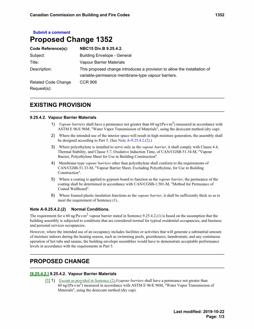
Submit a comment
Proposed Change 1352Code Reference(s): NBC15 Div.B 9.25.4.2.Subject: Building Envelope - GeneralTitle: Vapour Barrier MaterialsDescription: This proposed change introduces a provision to allow the installation of
variable-permeance membrane-type vapour barriers.Related Code ChangeRequest(s):
CCR 906
EXISTING PROVISION
9.25.4.2. Vapour Barrier Materials1) Vapour barriers shall have a permeance not greater than 60 ng/(Pa·s·m2) measured in accordance with
ASTM E 96/E 96M, "Water Vapor Transmission of Materials", using the desiccant method (dry cup).
2) Where the intended use of the interior space will result in high moisture generation, the assembly shallbe designed according to Part 5. (See Note A-9.25.4.2.(2).)
3) Where polyethylene is installed to serve only as the vapour barrier, it shall comply with Clause 4.4,Thermal Stability, and Clause 5.7, Oxidative Induction Time, of CAN/CGSB-51.34-M, "VapourBarrier, Polyethylene Sheet for Use in Building Construction".
4) Membrane-type vapour barriers other than polyethylene shall conform to the requirements ofCAN/CGSB-51.33-M, "Vapour Barrier Sheet, Excluding Polyethylene, for Use in BuildingConstruction".
5) Where a coating is applied to gypsum board to function as the vapour barrier, the permeance of thecoating shall be determined in accordance with CAN/CGSB-1.501-M, "Method for Permeance ofCoated Wallboard".
6) Where foamed plastic insulation functions as the vapour barrier, it shall be sufficiently thick so as tomeet the requirement of Sentence (1).
Note A-9.25.4.2.(2) Normal Conditions.The requirement for a 60 ng/Pa·s·m2 vapour barrier stated in Sentence 9.25.4.2.(1) is based on the assumption that thebuilding assembly is subjected to conditions that are considered normal for typical residential occupancies, and businessand personal services occupancies.However, where the intended use of an occupancy includes facilities or activities that will generate a substantial amountof moisture indoors during the heating season, such as swimming pools, greenhouses, laundromats, and any continuousoperation of hot tubs and saunas, the building envelope assemblies would have to demonstrate acceptable performancelevels in accordance with the requirements in Part 5.
PROPOSED CHANGE
[9.25.4.2.] 9.25.4.2. Vapour Barrier Materials[1] 1) Except as provided in Sentence (2),Vvapour barriers shall have a permeance not greater than
60 ng/(Pa·s·m2) measured in accordance with ASTM E 96/E 96M, "Water Vapor Transmission ofMaterials", using the desiccant method (dry cup).
EXISTINGPROVISIONA-9.25.4.2.(2)
Canadian Commission on Building and Fire Codes 1352
Last modified: 2019-10-22Page: 1/3

[2] --) Thermally insulated foundation wall assemblies are permitted to be constructed with variable-permeance vapour barriers having a permeance not greater than 60 ng/(Pa·s·m²) using the desiccantmethod (dry cup) and greater than 300 ng/(Pa·s·m²) using the water method (wet cup) measured inaccordance with ASTM E 96/E 96M, "Water Vapor Transmission of Materials".(See NoteA-9.25.4.2.(2).)
[3] 2) Where the intended use of the interior space will result in high moisture generation, the assembly shallbe designed according to Part 5. (See Note A-9.25.4.2.(2).)
[4] 3) Where polyethylene is installed to serve only as the vapour barrier, it shall comply with Clause 4.4,Thermal Stability, and Clause 5.7, Oxidative Induction Time, of CAN/CGSB-51.34-M, "VapourBarrier, Polyethylene Sheet for Use in Building Construction".
[5] 4) Membrane-type vapour barriers other than polyethylene shall conform to the requirements ofCAN/CGSB-51.33-M, "Vapour Barrier Sheet, Excluding Polyethylene, for Use in BuildingConstruction".
[6] 5) Where a coating is applied to gypsum board to function as the vapour barrier, the permeance of thecoating shall be determined in accordance with CAN/CGSB-1.501-M, "Method for Permeance ofCoated Wallboard".
[7] 6) Where foamed plastic insulation functions as the vapour barrier, it shall be sufficiently thick so as tomeet the requirement of Sentence (1).
Note A-9.25.4.2.(2) Vapour Barrier Materials in Foundation Wall Assemblies EnclosingBasements or Heated Crawl Spaces.In the summer, solar heating can cause condensation to form on the wall-facing side of polyethylene membranes that areinstalled on the warm side of foundation wall assemblies enclosing a basement or heated crawl space. Moisture in thefoundation wall due to wind-driven rain is driven to the interior when the above-ground portion of the wall is exposed tosolar heating. Variable-permeance vapour barrier materials allow moisture to dissipate into the basement or heated crawlspace during the summer and have thus been shown to minimize the formation of condensation in foundation wallassemblies. These materials have proven effective whether installed continuously over the full area of the foundation wallor continuously over not less than the top half of the full height of the wall area, starting from the above-ground portion,with polyethylene installed over the remaining bottom portion.
RATIONALE
ProblemInstalling polyethylene on the warm side of cast-in-place concrete or concrete block foundation assembliesenclosing basements or heated crawl spaces can lead to summer condensation on the outside of the membrane. Thisis caused by moisture in the foundation wall being driven to the interior when the above-ground portion of the wallis exposed to solar heating.
Justification - ExplanationThe installation of variable-permeance materials that comply with the vapour barrier material requirements butallow moisture dissipation to the interior during the summer has been shown to alleviate the problem ofcondensation in foundation wall assemblies. Research shows that these materials are effective when installed inconjunction with polyethylene, provided they are installed at the level of the above-ground portion of the wall andover not less than one-half of that area. These "smart" vapour barriers allow vapour movement, either inwards oroutwards, depending on the indoor and outdoor humidity differential, which varies seasonally. Theirinstallation reduces the formation of condensation within the wall assembly, which commonly occurs onconventional polyethylene vapour barriers, and reduces the risk of moisture and mould problems.
PROPOSEDCHANGEA-9.25.4.2.(2)
Canadian Commission on Building and Fire Codes 1352
Last modified: 2019-10-22Page: 2/3

Proposed Note A-9.25.4.2.(2) provides information on the installation of variable-permeance non-polyethylenemembrane vapour barriers to increase industry knowledge and understanding of these materials and their proper useto reduce condensation in foundation wall assemblies and water pooling.
Impact analysisThis proposed change introduces the permission to install variable-permeance vapour barriers. There are no costimplications as compliance is optional.
Enforcement implicationsThis proposed change can be enforced by the infrastructure currently available to enforce the Code.
Who is affectedDesigners, architects, engineers, specifiers, manufacturers, contractors, building owners, building officials.
OBJECTIVE-BASED ANALYSIS OF NEW OR CHANGED PROVISIONS
[9.25.4.2.] 9.25.4.2. ([1] 1) [F63-OS2.3]
[9.25.4.2.] 9.25.4.2. ([1] 1) [F63-OH1.1,OH1.2]
[9.25.4.2.] 9.25.4.2. ([3] 2) [F63-OS2.3]
[9.25.4.2.] 9.25.4.2. ([3] 2) [F63-OH1.1,OH1.2,OH1.3]
[9.25.4.2.] 9.25.4.2. ([3] 2) no attributions
[9.25.4.2.] 9.25.4.2. ([3] 2) [F62,F63-OS2.3]
[9.25.4.2.] 9.25.4.2. ([3] 2) [F62,F63-OH1.1,OH1.2,OH1.3]
[9.25.4.2.] 9.25.4.2. ([4] 3) [F63,F80-OS2.3]
[9.25.4.2.] 9.25.4.2. ([4] 3) [F63,F80-OH1.1,OH1.2]
[9.25.4.2.] 9.25.4.2. ([5] 4) [F63,F80-OS2.3]
[9.25.4.2.] 9.25.4.2. ([5] 4) [F63,F80-OH1.1,OH1.2]
[9.25.4.2.] 9.25.4.2. ([6] 5) [F63-OS2.3]
[9.25.4.2.] 9.25.4.2. ([6] 5) [F63-OH1.1,OH1.2]
[9.25.4.2.] 9.25.4.2. ([7] 6) [F63-OS2.3]
[9.25.4.2.] 9.25.4.2. ([7] 6) [F63-OH1.1,OH1.2]
Canadian Commission on Building and Fire Codes 1352
Last modified: 2019-10-22Page: 3/3

Submit a comment
Proposed Change 1353Code Reference(s): NBC15 Div.B 9.25.5.2.Subject: Building Envelope - GeneralTitle: Location of Low Permeance MaterialsDescription: This proposed change clarifies the application of Table 9.25.5.2.
EXISTING PROVISION
9.25.5.2. Position of Low Permeance Materials(See Note A-9.25.5.2.)
1) Sheet and panel-type materials described in Article 9.25.5.1. shall be installeda) on the warm face of the assembly (see also Article 9.25.4.2.),b) at a location where the ratio between the total thermal resistance of all materials outboard of its innermost impermeable
surface and the total thermal resistance of all materials inboard of that surface is not less than that required byTable 9.25.5.2., or
c) outboard of an air space that is vented to the outdoors.
2) For walls, the air space described in Clause (1)(c) shall comply with Clause 9.27.2.2.(1)(a).
Table 9.25.5.2.Ratio of Outboard to Inboard Thermal Resistance
Forming Part of Sentence 9.25.5.2.(1)
Heating Degree-Days of BuildingLocation (1) , Celsius degree-days
Minimum Ratio of Total Thermal Resistance Outboard of Material’s InnerSurface to Total Thermal Resistance Inboard of Material’s Inner Surface
up to 4 999 0.20
5 000 to 5 999 0.30
6 000 to 6 999 0.35
7 000 to 7 999 0.40
8 000 to 8 999 0.50
9 000 to 9 999 0.55
10 000 to 10 999 0.60
11 000 to 11 999 0.65
12 000 or higher 0.75
Note to Table 9.25.5.2.:
See Sentence 1.1.3.1.(1).(1)EXISTING PROVISION Table 9.25.5.2. Footnotereferrer
Note A-9.25.5.2. Assumptions Followed in Developing Table 9.25.5.2.Article 9.25.5.2. specifies that a low air- and vapour-permeance material must be located on the warm face of the assembly, outboard of a vented airspace, or within the assembly at a position where its inner surface is likely to be warm enough for most of the heating season such that no significantaccumulation of moisture will occur. This last position is defined by the ratio of the thermal resistance values outboard and inboard of the innermostimpermeable surface of the material in question.The design values given in Table 9.25.5.2. are based on the assumption that the building includes a mechanical ventilation system (between 0.3 and0.5 air changes per hour), a 60 ng/Pa·s·m2 vapour barrier, and an air barrier (values between 0.024 and 0.1 L/sm2 through the assembly were used).The moisture generated by occupants and their use of bathrooms, cleaning, laundry and kitchen appliances was assumed to fall between 7.5 and11.5 L per day.It has been demonstrated through modelling under these conditions that assemblies constructed according to the requirements in Table 9.25.5.2. donot lead to moisture accumulation levels that may lead to deterioration as long as the average monthly vapour pressure difference between theexterior and interior sides over the heating season does not increase above 750 Pa, which would translate into an interior relative humidity of 35% incolder climates and 60% in mild climates.
EXISTINGPROVISIONA-9.25.5.2.
EXISTING PROVISION Table 9.25.5.2. Footnote
Footnote1
Canadian Commission on Building and Fire Codes 1353
Last modified: 2019-10-22Page: 1/5

Health Canada recommends an indoor relative humidity between 35% and 50% for healthy conditions. ASHRAE accepts a 30% to 60% range.Environments that are much drier tend to exacerbate respiratory problems and allergies; more humid environments tend to support the spread ofmicrobes, moulds and dust mites, which can adversely affect health.In most of Canada in the winter, indoor RH is limited by the exterior temperature and the corresponding temperature on the inside of windows.During colder periods, indoor RH higher than 35% will cause significant condensation on windows. When this occurs, occupants are likely toincrease the ventilation to remove excess moisture. Although indoor RH may exceed 35% for short periods when the outside temperature is warmer,the criteria provided in Table 9.25.5.2. will still apply. Where higher relative humidities are maintained for extended periods in these colderclimates, the ratios listed in the Table may not provide adequate protection. Some occupancies require that RH be maintained above 35% throughoutthe year, and some interior spaces support activities such as swimming that create high relative humidities. In these cases, Table 9.25.5.2. cannot beused and the position of the materials must be determined according to Part 5.It should be noted that Part 9 building envelopes in regions with colder winters have historically performed acceptably when the interior RH doesnot exceed 35% over most of the heating season. With tighter building envelopes, it is possible to raise interior RH levels above 35%. There is noinformation, however, on howPart 9 building envelopes will perform when exposed to these higher indoor RH levels for extended periods during the heating season over manyyears. Operation of the ventilation system, as intended to remove indoor pollutants, will maintain the lower RH levels as necessary.
Calculating Inboard to Outboard Thermal Resistance
Figure A-9.25.5.2.Example of a wall section showing thermal resistance inboard and outboard of a plane of low air and vapour permeance
The method of calculating the inboard to outboard thermal resistance ratio is illustrated in Figure A-9.25.5.2. The example wall section shows threeplanes where low air- and vapour-permeance materials have been installed. A vapour barrier, installed to meet the requirements ofSubsection 9.25.4., is on the warm side of the insulation consistent with Clause 9.25.5.2.(1)(a) and Sentences 9.25.4.1.(1) and 9.25.4.3.(2). The vinylsiding has an integral drained and vented air space consistent with Clause 9.25.5.2.(1)(c). The position of the interior face of the low-permeanceinsulating sheathing, however, must be reviewed in terms of its thermal resistance relative to the overall thermal resistance of the wall, and theclimate where the building is located.Comparing the RSI ratio from the example wall section with those in Table 9.25.5.2. indicates that this wall would be acceptable in areas withCelsius degree-day values up to 7999, which includes, for example, Whitehorse, Fort McMurray, Yorkton, Flin Flon, Geraldton, Val-d’Or andWabush. (Degree-day values for various locations in Canada are provided in Appendix C.)A similar calculation would indicate that, for a similar assembly with a 140 mm stud cavity filled with an RSI 3.52 batt, the ratio would be 0.28.Thus such a wall could be used in areas with Celsius degree-day values up to 4999, which includes, for example, Cranbrook, Lethbridge, Ottawa,Montreal, Fredericton, Sydney, Charlottetown and St. John’s.Similarly, if half the thickness of the same low-permeance sheathing were used, the ratio with an 89 mm cavity would be 0.25, permitting its use inareas with Celsius degree-day values up to 4999. The ratio with a 140 mm cavity would be 0.16; thus this assembly could not be used anywhere,since this ratio is below the minimum permitted in Table 9.25.5.2.
Canadian Commission on Building and Fire Codes 1353
Last modified: 2019-10-22Page: 2/5

Table A-9.25.5.2. shows the minimum thicknesses of low-permeance insulating sheathing necessary to satisfy Article 9.25.5.2. in various degree-day zones for a range of resistivity values of insulating sheathing. These thicknesses are based on the detail shown in Figure A-9.25.5.2. but couldalso be used with cladding details, such as brick veneer or wood siding, which provide equal or greater outboard thermal resistance.
Table A-9.25.5.2.Minimum Thicknesses of Low-Permeance Insulating Sheathing
Forming Part of Note A-9.25.5.2.
38 x 89 Framing 38 x 140 Framing
Min. Sheathing Thickness, mm Min. Sheathing Thickness, mm
Sheathing Thermal Resistance,RSI/mm
Sheathing Thermal Resistance,RSI/mm
CelsiusHeatingDegree-
days
Min.RSI
Ratio
Min.OutboardThermal
Resistance,RSI 0.0300 0.0325 0.0350 0.0400
Min.OutboardThermal
Resistance,RSI 0.0300 0.0325 0.0350 0.0400
≤ 4999 0.20 0.46 10 10 9 8 0.72 19 17 16 14
5000 to5999 0.30 0.69 18 17 16 14 1.07 31 28 26 23
6000 to6999 0.35 0.81 22 20 19 16 1.25 37 34 32 28
7000 to7999 0.40 0.92 26 24 22 19 1.43 43 39 37 32
8000 to8999 0.50 1.16 34 31 29 25 1.79 55 50 47 41
9000 to9999 0.55 1.27 37 34 32 28 1.97 61 56 52 45
10000 to10999 0.60 1.39 41 38 35 31 2.15 67 61 57 50
11000 to11999 0.65 1.50 45 42 39 34 2.33 73 67 62 54
≥ 12000 0.75 1.73 53 49 45 40 2.69 85 78 72 63
References1. "Exposure Guidelines for Residential Indoor Air Quality", Environmental Health Directorate, Health Protection Branch, Health Canada,
Ottawa, April 1987 (Revised July 1989).2. ANSI/ASHRAE 62, "Ventilation for Acceptable Indoor Air Quality".
PROPOSED CHANGE
[9.25.5.2.] 9.25.5.2. Position of Low Permeance Materials(See Note A-9.25.5.2.)
[1] 1) Sheet and panel-type materials described in Article 9.25.5.1. shall be installed[a] a) on the warm face of the assembly (see also Article 9.25.4.2.),[b] b) at a location where the ratio between the total thermal resistance of all materials outboard of its innermost impermeable
surface and the total thermal resistance of all materials inboard of that surface is not less than that required byTable 9.25.5.2., for above-ground insulated foundation wall assemblies and permanent wood foundation wall assemblies,or
[c] c) outboard of an air space that is vented to the outdoors.
[2] 2) For walls, the air space described in Clause (1)(c) shall comply with Clause 9.27.2.2.(1)(a).
EXISTINGPROVISIONA-9.25.5.2.
PROPOSEDCHANGEA-9.25.5.2.
Canadian Commission on Building and Fire Codes 1353
Last modified: 2019-10-22Page: 3/5

Table [9.25.5.2.] 9.25.5.2.Ratio of Outboard to Inboard Thermal Resistance for Above-Ground Insulated Foundation Wall Assemblies and
Permanent Wood Foundation Wall AssembliesForming Part of Sentence [9.25.5.2.] 9.25.5.2.([1] 1)
Heating Degree-Days of BuildingLocation (1) , Celsius degree-days
Minimum Ratio of Total Thermal Resistance Outboard of Material’s InnerSurface to Total Thermal Resistance Inboard of Material’s Inner Surface
up to 4 999 0.20
5 000 to 5 999 0.30
6 000 to 6 999 0.35
7 000 to 7 999 0.40
8 000 to 8 999 0.50
9 000 to 9 999 0.55
10 000 to 10 999 0.60
11 000 to 11 999 0.65
12 000 or higher 0.75
Note to Table [9.25.5.2.] 9.25.5.2.:
See Sentence 1.1.3.1.(1).(1)PROPOSED CHANGE Table 9.25.5.2. Footnotereferrer
RATIONALE
ProblemTable 9.25.5.2. was developed for above-ground wood-frame wall assemblies. However, the Table has also been applied to the construction ofconcrete and masonry block foundation walls with split insulation assemblies, for which it was never intended. The hygrothermal performanceand boundary conditions for below-ground concrete and masonry constructions are not the same as those for above-ground wood-frame wallassemblies.
The construction of insulated foundation wall assemblies with poured concrete or masonry block is addressed in other Code provisions.
Justification - ExplanationLimiting the application of Table 9.25.5.2. to above-ground insulated foundation wall assemblies and permanent wood (preserved wood)foundation wall assemblies will help minimize the risk of condensation in assemblies incorporating low permeance sheathings and minimizeinward vapor diffusion from condensing on colder interior surfaces.
Impact analysisThis proposed change clarifies the application of Table 9.25.5.2.
No longer applying the Table to the construction of concrete and masonry block foundation walls could reduce the cost of insulation by asmuch as $10/m2.
Another benefit is reduced condensation problems in below-ground concrete and masonry block foundation walls, where the insulation on theinterior insulated wood-frame wall assembly may otherwise have to be replaced to remediate condensation and mould issues.
Enforcement implicationsThis proposed change can be enforced by the infrastructure currently available to enforce the Code.
Who is affectedDesigners, architects, engineers, specifiers, manufacturers, contractors, building owners, building officials.
PROPOSED CHANGE Table 9.25.5.2. Footnote
Footnote1
Canadian Commission on Building and Fire Codes 1353
Last modified: 2019-10-22Page: 4/5

OBJECTIVE-BASED ANALYSIS OF NEW OR CHANGED PROVISIONS
[9.25.5.2.] 9.25.5.2. ([1] 1) [F62,F63-OS2.3]
[9.25.5.2.] 9.25.5.2. ([1] 1) [F62,F63-OH1.1,OH1.2]
[9.25.5.2.] 9.25.5.2. ([2] 2) no attributions
Canadian Commission on Building and Fire Codes 1353
Last modified: 2019-10-22Page: 5/5

Submit a comment
Proposed Change 1604Code Reference(s): NBC15 Div.B 9.27.1.1.Subject: Insulating Concrete Forms (ICF)Title: Addition of ICF Walls as Acceptable Substrate for CladdingDescription: This proposed change introduces above-ground flat insulating concrete form
walls to the lists of acceptable substrates for the connection of cladding.
EXISTING PROVISION
9.27.1.1. General1) Where lumber, wood shingles, shakes, fibre-cement shingles, planks and sheets, plywood, OSB,
waferboard, hardboard, vinyl, aluminum or steel, including trim and soffits, are installed as cladding onwood-frame walls exposed to precipitation, the cladding assembly shall comply with
a) Subsections 9.27.2. to 9.27.12., orb) Part 5.
2) Where stucco is installed as cladding on wood-frame or masonry walls exposed to precipitation, thecladding assembly shall comply with
a) Subsections 9.27.2. to 9.27.5., and Section 9.28., orb) Part 5.
3) Where masonry serves as cladding on wood-frame or masonry walls exposed to precipitation, thecladding assembly shall comply with
a) Subsections 9.27.2. to 9.27.4., and Section 9.20., orb) Part 5.
4) Where asphalt shingles are installed as cladding on wood-frame walls exposed to precipitation, thecladding assembly shall comply with
a) Subsections 9.26.7. and 9.27.2. to 9.27.4., orb) Part 5.
5) Where an exterior insulation finish system is installed as cladding on wood-frame, masonry, cold-formed steel stud or cast-in-place concrete walls exposed to precipitation, the cladding assembly shallcomply with
a) Subsections 9.25.5., 9.27.2. to 9.27.4., and 9.27.13., orb) Part 5.
(See Note A-9.27.1.1.(5).)
6) Where cladding materials other than those described in Sentences (1) to (5) are installed, or where thecladding materials described in Sentences (1) to (5) are installed on substrates other than thoseidentified in Sentences (1) to (5), the materials and installation shall comply with Part 5.
Note A-9.27.1.1.(5) EIFS on Walls with Cold-Formed Steel Stud Framing.While Part 9 permits the installation of exterior insulation finish systems on walls with cold-formed steel stud framing,the design of loadbearing steel walls is outside the scope of Part 9 and is addressed in Part 4 (see Sentence 9.24.1.1.(2)).
EXISTINGPROVISIONA-9.27.1.1.(5)
Canadian Commission on Building and Fire Codes 1604
Last modified: 2019-10-17Page: 1/3

PROPOSED CHANGE
[9.27.1.1.] 9.27.1.1. General[1] 1) Where lumber, wood shingles, shakes, fibre-cement shingles, planks and sheets, plywood, OSB,
waferboard, hardboard, vinyl, aluminum or steel, including trim and soffits, are installed as cladding onwood-frame walls or above-ground flat insulating concrete form walls exposed to precipitation, thecladding assembly shall comply with[a] a) Subsections 9.27.2. to 9.27.12., or[b] b) Part 5.
[2] 2) Where stucco is installed as cladding on wood-frame walls, above-ground flat insulating concrete formwalls or masonry walls exposed to precipitation, the cladding assembly shall comply with[a] a) Subsections 9.27.2. to 9.27.5., and Section 9.28., or[b] b) Part 5.
[3] 3) Where masonry serves as cladding on wood-frame walls, above-ground flat insulating concrete formwalls or masonry walls exposed to precipitation, the cladding assembly shall comply with[a] a) Subsections 9.27.2. to 9.27.4., and Section 9.20., or[b] b) Part 5.
[4] 4) Where asphalt shingles are installed as cladding on wood-frame walls exposed to precipitation, thecladding assembly shall comply with[a] a) Subsections 9.26.7. and 9.27.2. to 9.27.4., or[b] b) Part 5.
[5] 5) Where an exterior insulation finish system is installed as cladding on wood-frame, masonry, cold-formed steel stud, above-ground flat insulating concrete form walls or cast-in-place concrete wallsexposed to precipitation, the cladding assembly shall comply with[a] a) Subsections 9.25.5., 9.27.2. to 9.27.4., and 9.27.13., or[b] b) Part 5.
(See Note A-9.27.1.1.(5).)
[6] 6) Where cladding materials other than those described in Sentences (1) to (5) are installed, or where thecladding materials described in Sentences (1) to (5) are installed on substrates other than thoseidentified in Sentences (1) to (5), the materials and installation shall comply with Part 5.
RATIONALE
ProblemOf the five prescribed solutions for affixing cladding under Article 9.27.1.1., none of the substrate options includeabove-ground flat insulating concrete form walls. This omission automatically forces Code users to refer to Sentence9.27.1.1.(6), which, in turn, directs them to engineered cladding solutions under Part 5.
Justification - ExplanationThe stated problem is resolved by adding a reference to above-ground flat insulating concrete form walls in each ofthe four applicable sentences under Article 9.27.1.1,. thus recognizing ICF walls as being equivalent to woodframing, though subject to their own specifications for cladding attachment per PCF 1612.
The North American Insulating Concrete Form Industry had been carrying out fastener testing to ASTM D 1761," Standard Test Methods for Mechanical Fasteners in Wood," long before this proposed change was developed(some manufacturers have been using the resulting data for more than 20 years). This testing forms a mandatory partof the insulating concrete form materials standard CAN/ULC-S717.1, "Standard for Flat Wall Insulating Concrete
PROPOSEDCHANGEA-9.27.1.1.(5)
Canadian Commission on Building and Fire Codes 1604
Last modified: 2019-10-17Page: 2/3

Form (ICF) Units - Material Properties." The structural support capability of form systems with web fastening stripstested to the standard will limit situations where direct attachment of a finish to the concrete core is required. Thiscapability is supported by data, which indicates that, with a fastening grid of 200 mm x 200 mm, the formsystems can support a finish having a mass per unit area of approximately 264 kg/m2 (54 lbs/ft.2).
Impact analysisPotential cost savings for contractors (passed on to home buyers and building owners) who would no longer berequired to use engineered cladding solutions for housing and small buildings constructed using flat wall insulatingconcrete form units meeting the testing requirements of CAN/ULC-S717.1.
Enforcement implicationsBuilding inspectors would need to ensure that ICF units comply with CAN/ULC-S717.1.
Who is affectedDesigners, specifiers, ICF manufacturers and contractors, building owners, building officials.
OBJECTIVE-BASED ANALYSIS OF NEW OR CHANGED PROVISIONS
[9.27.1.1.] 9.27.1.1. ([1] 1) no attributions
[9.27.1.1.] 9.27.1.1. ([2] 2) no attributions
[9.27.1.1.] 9.27.1.1. ([3] 3) no attributions
[9.27.1.1.] 9.27.1.1. ([4] 4) no attributions
[9.27.1.1.] 9.27.1.1. ([5] 5) no attributions
[9.27.1.1.] 9.27.1.1. ([6] 6) no attributions
Canadian Commission on Building and Fire Codes 1604
Last modified: 2019-10-17Page: 3/3

Submit a comment
Proposed Change 1612Code Reference(s): NBC15 Div.B 9.27.5.1.
NBC15 Div.B 9.27.5.4.Subject: Insulating Concrete Forms (ICF)Title: Attachment of Cladding to Flat ICF WallsDescription: This proposed change introduces a permission to attach cladding to the web
fastening strips of flat wall ICF units using screws that conform to new Table9.27.5.4.-B on screw size, number and spacing.
EXISTING PROVISION
9.27.5.1. Attachment1) Except as permitted by Sentences (2) to (6), cladding shall be fastened to the framing members or
furring members, or to blocking between the framing members.
2) Vertical lumber and stucco lath or reinforcing are permitted to be attached to sheathing only where thesheathing consists of not less than
a) 14.3 mm lumber,b) 12.5 mm plywood, orc) 12.5 mm OSB or waferboard.
3) Vertically applied metal siding and wood shingles and shakes are permitted to be attached to thesheathing only where the sheathing consists of not less than
a) 14.3 mm lumber,b) 7.5 mm plywood, orc) 7.5 mm OSB or waferboard.
4) Where wood shingles or shakes are applied to sheathing which is not suitable for attaching the shinglesor shakes, the shingles or shakes are permitted to be attached to a wood lath not less than 38 mm by9.5 mm thick securely nailed to the framing and applied as described in Article 9.27.7.5.
5) Where asbestos-cement shingles are applied to sheathing that is not suitable for attaching the shingles,the shingles are permitted to be fastened to a wood lath not less than 89 mm by 9.5 mm thick securelynailed to the framing.
6) Lath referred to in Sentence (5) shall be applied so that it overlaps the preceding shingle course by notless than 20 mm.
9.27.5.4. Size and Spacing of Fasteners1) Nail or staple size and spacing for the attachment of cladding and trim shall conform to Table 9.27.5.4.
Canadian Commission on Building and Fire Codes 1612
Last modified: 2019-10-22Page: 1/7

Table 9.27.5.4.Attachment of Cladding
Forming Part of Sentence 9.27.5.4.(1)
Type of CladdingMinimum Nail orStaple Length,
mmMinimum Numberof Nails or Staples
Maximum Nail orStaple Spacing, mm
o.c.
Wood trim 51 — 600
Lumber siding or horizontalsiding made from sheetmaterial
51 — 600
Metal cladding 38 — 600 (nailed to framing)
400 (nailed to sheathingonly)
Wood shakes
up to 200 mm in width 51 2 —
over 200 mm in width 51 3 —
Wood shingles
200 mm in width 32 2 —
over 200 mm in width 32 3 —
Panel or sheet type cladding
up to 7 mm thick 38 — 150 (along edges)
more than 7 mm thick 51 — 300 (along intermediatesupports)
PROPOSED CHANGE
[9.27.5.1.] 9.27.5.1. Attachment[1] 1) Except as permitted by Sentences (2) to (6)to (7), cladding shall be fastened to the framing members or
furring members, or to blocking between the framing members.
[2] 2) Vertical lumber and stucco lath or reinforcing are permitted to be attached to sheathing only where thesheathing consists of not less than[a] a) 14.3 mm lumber,[b] b) 12.5 mm plywood, or[c] c) 12.5 mm OSB or waferboard.
Canadian Commission on Building and Fire Codes 1612
Last modified: 2019-10-22Page: 2/7

[3] 3) Vertically applied metal siding and wood shingles and shakes are permitted to be attached to thesheathing only where the sheathing consists of not less than[a] a) 14.3 mm lumber,[b] b) 7.5 mm plywood, or[c] c) 7.5 mm OSB or waferboard.
[4] 4) Where wood shingles or shakes are applied to sheathing which is not suitable for attaching the shinglesor shakes, the shingles or shakes are permitted to be attached to a wood lath not less than 38 mm by9.5 mm thick securely nailed to the framing and applied as described in Article 9.27.7.5.
[5] 5) Where asbestos-cement shingles are applied to sheathing that is not suitable for attaching the shingles,the shingles are permitted to be fastened to a wood lath not less than 89 mm by 9.5 mm thick securelynailed to the framing.
[6] 6) Lath referred to in Sentence (5) shall be applied so that it overlaps the preceding shingle course by notless than 20 mm.
[7] --) Cladding, trim and furring members are permitted to be attached to the web fastening strips of flat wallinsulating concrete form units using screws in accordance with Sentence 9.27.5.4.(2).
[9.27.5.4.] 9.27.5.4. Size and Spacing of Fasteners[1] 1) Nail or staple size and spacing for the attachment of cladding and trim to wood or metal framing,
furring members or blocking shall conform to Table 9.27.5.4.-A.
Table [9.27.5.4.-A] 9.27.5.4.Attachment of Cladding to Wood or Metal Framing, Furring Members or Blocking
Forming Part of Sentence [9.27.5.4.] 9.27.5.4.([1] 1)
Type of CladdingMinimum Nail orStaple Length,
mmMinimum Numberof Nails or Staples
Maximum Nail orStaple Spacing, mm
o.c.
Wood trim 51 — 600
Lumber siding or horizontalsiding made from sheetmaterial
51 — 600
Metal cladding 38 — 600 (nailed to framing)
400 (nailed to sheathingonly)
Wood shakes
up to 200 mm in width 51 2 —
over 200 mm in width 51 3 —
Wood shingles
200 mm in width 32 2 —
over 200 mm in width 32 3 —
Canadian Commission on Building and Fire Codes 1612
Last modified: 2019-10-22Page: 3/7

Type of CladdingMinimum Nail orStaple Length,
mmMinimum Numberof Nails or Staples
Maximum Nail orStaple Spacing, mm
o.c.
Panel or sheet type cladding
up to 7 mm thick 38 — 150 (along edges)
more than 7 mm thick 51 — 300 (along intermediatesupports)
[2] 1) Screw size, number and spacing for the attachment of cladding, trim and furring members to the webfastening strips of flat wall insulating concrete form (ICF) units shall conform to Table 9.27.5.4.-B.
Table [9.27.5.4.-B] 9.27.5.4.Attachment of Cladding to Flat Wall Insulating Concrete Form Units (1)
Forming Part of Sentence [9.27.5.4.] 9.27.5.5.([2] 1)
Type of CladdingMinimum
ScrewLength
MinimumDiameter Screw,
mm (gauge)
MinimumNumber of
Screws
Maximum ScrewSpacing, mm o.c.
Wood trim (3) 1.8 (No. 6) — 400 or 450 (2)
(screwed to webfastening strip)
Lumber siding or horizontalsiding made from sheetmaterial
(3) 3.2 (No. 8) — 400 or 450 (2)
(screwed to webfastening strip)
Metal cladding (3) 3.2 (No. 8) — 400 or 450 (2)
(screwed to webfastening strip)
Vinyl cladding (3) 1.8 (No. 6) — 400 or 450 (2)
(screwed to webfastening strip)
Wood shakes
up to 200 mm in width (3) 1.8 (No. 6) 2 —
over 200 mm in width (3) 1.8 (No. 6) 3 —
Wood shingles
up to 200 mm in width (3) 1.8 (No. 6) 2 —
over 200 mm in width (3) 1.8 (No. 6) 3 —
PROPOSED CHANGE Table 9.27.5.4. Footnote
PROPOSED CHANGE Table 9.27.5.4. Footnote
PROPOSED CHANGE Table 9.27.5.4. Footnote PROPOSED CHANGE Table 9.27.5.4. Footnote
PROPOSED CHANGE Table 9.27.5.4. Footnote
PROPOSED CHANGE Table 9.27.5.4. Footnote
Canadian Commission on Building and Fire Codes 1612
Last modified: 2019-10-22Page: 4/7

Type of CladdingMinimum
ScrewLength
MinimumDiameter Screw,
mm (gauge)
MinimumNumber of
Screws
Maximum ScrewSpacing, mm o.c.
Panel- or sheet-typecladding
up to 7 mm thick (3) 1.8 (No. 6) — 150 or 200 (2) (alongedges)
over 7 mm thick (3) 3.2 (No. 8) — 300 or 400 (2) (alongintermediate
supports)
Notes to Table [9.27.5.4.-B] 9.27.5.4.:
See Note A-Table 9.27.5.4.-B.(1)PROPOSED CHANGE Table 9.27.5.4. Footnotereferrer
Two screw spacing options are given to accommodate the 150 mm o.c. and 200 mm o.c. vertical spacing ofweb fastening strips.
(2)PROPOSED CHANGE Table 9.27.5.4. Footnotereferrer
Screws must be long enough to penetrate through the web fastening strips by a minimum of 6 mm.(3)PROPOSED CHANGE Table 9.27.5.4. Footnotereferrer
Note A-Table 9.27.5.4.-B Attachment of Cladding to Web Fastening Strips of Flat Wall ICFUnits.The screw size and spacing requirements listed in Table 9.27.5.4.-B for the attachment of cladding to flat wall ICF unitsare based on the results of testing various types of screws for direct withdrawal and lateral shear to ASTM D 1761,“Standard Test Methods for Mechanical Fasteners in Wood,” on numerous flat wall ICF systems known to comply withCAN/ULC-S717.1, “Standard for Flat Wall Insulating Concrete Form (ICF) Units - Material Properties.” The listedspacing requirements ensure a maximum suction force per screw of 107 N under a 1-in-50 reference wind velocitypressure of 1.23 kPa. If the factored load per fastener is expected to be higher than 107 N for a particular flat ICF wall,suitable screws tested to ASTM D 1761 should be obtained from the ICF manufacturer.
RATIONALE
ProblemArticle 9.27.5.4. currently allows for nail or staple attachment of various types of cladding and trim into woodframing members but not into the web fastening strips of flat wall ICF units. In order for ICF web fastening strips tobe considered acceptable, the Article needs to be amended to include prescriptive solutions for fastener type and sizeand for fastener spacing into the web fastening strips.
Justification - ExplanationThis problem is resolved by introducing requirements to address the method of attachment of cladding to ICF webfastening strips.
Proposed Note A-Table 9.27.5.4.-B reflects the fact that the ICF industry has been testing fasteners to ASTM D1761 for many years (some manufacturers have been using the resulting data for more than 20 years) and that thistesting now forms a mandatory part of CAN/ULC-S717.1.
PROPOSED CHANGE Table 9.27.5.4. Footnote
PROPOSED CHANGE Table 9.27.5.4. Footnote
Footnote1Footnote2
Footnote3
Canadian Commission on Building and Fire Codes 1612
Last modified: 2019-10-22Page: 5/7

The structural support capacity of ICF web fastening strips has been tested in compliance with CAN/ULC-S717.1.They have a maximum capacity of five times the factored loading of 107 N (24 lbs). Thus, a fastening grid of200 mm x 200 mm would allow the connection of cladding with a mass per unit area of approximately 264 kg/m2
(54 lbs/ft.2), which is more than triple the weight of most manufactured stone masonry veneer systems, whichtypically have a comparative mass per unit area of 78 kg/m2 (16 lbs/ft.2). As such, the need for the direct attachmentof cladding into the concrete core of the ICF unit will be rare.
Impact analysisPotential cost savings for contractors (passed on to home buyers and building owners) who will no longer berequired to obtain engineered cladding solutions for houses and small buildings constructed from flat insulatingconcrete form walls meeting the testing requirements of CAN/ULC-S717.1.
Enforcement implicationsBuilding inspectors would need to ensure that flat wall insulating concrete form units comply with CAN/ULC-S717.1. Otherwise, this proposed change can be enforced by the infrastructure currently in place to enforce theCode. Adding the reference to ASTM D 1761 will facilitate the approval process.
Who is affectedDesigners, specifiers, ICF manufacturers and contractors, building owners, building officials.
OBJECTIVE-BASED ANALYSIS OF NEW OR CHANGED PROVISIONS
[9.27.5.1.] 9.27.5.1. ([1] 1)[F20-OS2.1,OS2.3] [F20-OS2.1,OS2.3,OS2.4] [F22-OS2.3,OS2.4,OS2.5] Applies where panel-typecladding is installed to provide the required bracing.
[9.27.5.1.] 9.27.5.1. ([1] 1) [F20-OP2.1,OP2.3,OP2.4] [F22-OP2.3,OP2.4,OP2.5] Applies where panel-type cladding is installed to provide the required bracing.
[9.27.5.1.] 9.27.5.1. ([1] 1) [F20-OH1.1,OH1.2,OH1.3] [F20,F22-OH1.1,OH1.2,OH1.3] Applies wherepanel-type cladding is installed to provide the required bracing.
[9.27.5.1.] 9.27.5.1. ([1] 1) [F20,F22-OH4] Applies where panel-type cladding is installed to provide therequired bracing of walls that support floors.
[9.27.5.1.] 9.27.5.1. ([1] 1) [F20,F22-OS3.1] Applies where panel-type cladding is installed to provide therequired bracing of walls that support floors. [F20,F22-OS3.7] Applies where panel-type cladding is installedto provide required bracing of walls that contain doors or windows required for emergency egress.
[9.27.5.1.] 9.27.5.1. ([2] 2) [F20-OH1.1,OH1.2,OH1.3]
[9.27.5.1.] 9.27.5.1. ([2] 2) [F20-OS2.1,OS2.3]
[9.27.5.1.] 9.27.5.1. ([3] 3) [F20-OH1.1,OH1.2,OH1.3]
[9.27.5.1.] 9.27.5.1. ([3] 3) [F20-OS2.3]
[9.27.5.1.] 9.27.5.1. ([4] 4) [F20-OH1.1,OH1.2,OH1.3]
[9.27.5.1.] 9.27.5.1. ([4] 4) [F20-OS2.1,OS2.3]
[9.27.5.1.] 9.27.5.1. ([5] 5) [F20-OH1.1,OH1.2,OH1.3]
[9.27.5.1.] 9.27.5.1. ([5] 5) [F20-OS2.1,OS2.3]
Canadian Commission on Building and Fire Codes 1612
Last modified: 2019-10-22Page: 6/7

[9.27.5.1.] 9.27.5.1. ([6] 6) [F20-OH1.1,OH1.2,OH1.3]
[9.27.5.1.] 9.27.5.1. ([6] 6) [F20-OS2.1,OS2.3]
-- (--) no attributions
[9.27.5.4.] 9.27.5.4. ([1] 1) [F20-OH1.1,OH1.2,OH1.3] [F20,F22-OH1.1,OH1.2,OH1.3] Applies to theattachment of panel-type cladding installed to provide the required bracing.
[9.27.5.4.] 9.27.5.4. ([1] 1)[F20-OS2.1,OS2.3] [F20-OS2.1,OS2.3,OS2.4] [F22-OS2.3,OS2.4,OS2.5] Applies where panel-typecladding is installed to provide the required bracing.
-- (--) [F20-OH1.1,OH1.2,OH1.3] [F20-OH1.1,OH1.2,OH1.3] [F22-OH1.1,OH1.2,OH1.3] Applies tothe attachement of panel-type cladding installed to provide the required bracing.
-- (--) [F20-OS2.1,OS2.3] [F20-OS2.1,OS2.3,OS2.4] [F22-OS2.3,OS2.4,OS2.5] Applies where panel-type cladding is installed to provide the required bracing.
Canadian Commission on Building and Fire Codes 1612
Last modified: 2019-10-22Page: 7/7

Submit a comment
Proposed Change 1461Code Reference(s): NBC15 Div.B 9.27.13.1.Subject: EIFSTitle: Exterior Insulation Finish Systems -- Geometrically Defined Drainage CavityDescription: This proposed change deletes Figure A-9.27.13.1.(1) as it causes confusion
among Code users and imposes limitations on innovation in the design ofgeometrically defined drainage cavities.
Related Code ChangeRequest(s):
CCR 1236, CCR 1237
EXISTING PROVISION
9.27.13.1. Application1) Except as provided in Sentence (2), this Subsection applies to exterior insulation finish systems (EIFS)
thata) are covered in the scope of CAN/ULC-S716.1, "Exterior Insulation and Finish Systems (EIFS) -
Materials and Systems", andb) have a geometrically defined drainage cavity with a minimum cavity depth of 10 mm and an
open area equal to not less than 13% of the area of a full-size EIFS panel.(See Note A-9.27.13.1.(1).)
2) EIFS that are not covered by Sentence (1) shall comply with Part 5.
Note A-9.27.13.1.(1) Geometrically Defined Drainage Cavity.“Geometrically defined drainage cavity” (GDDC) refers to the channels, grooves or profiles cut into the insulationbacking of an EIFS panel for the purpose of providing a way for water that gets behind the system to drain out. Thechannels, grooves or profiles of one panel need to connect to the channels, grooves or profiles of adjacent panels in orderfor drainage to occur consistently and uniformly across the entire EIFS. While the size of a channel, groove or profile canbe verified by inspecting a single panel, the intent of Sentence 9.27.13.1.(1) is that the required drainage capacity beachieved across the entire system.Additional information on the design and installation of EIFS can be found in
• the "EIFS Practice Manual", published by the EIFS Council of Canada, and• the manufacturer’s literature.
Figure A-9.27.13.1.(1)Geometrically defined drainage cavity
EXISTINGPROVISIONA-9.27.13.1.(1)
Canadian Commission on Building and Fire Codes 1461
Last modified: 2019-10-10Page: 1/3

PROPOSED CHANGE
[9.27.13.1.] 9.27.13.1. Application
Note A-9.27.13.1.(1) Geometrically Defined Drainage Cavity.“Geometrically defined drainage cavity” (GDDC) refers to the channels, grooves or profiles cut into the insulationbacking of an EIFS panel for the purpose of providing a way for water that gets behind the system to drain out. Thechannels, grooves or profiles of one panel need to connect to the channels, grooves or profiles of adjacent panels in orderfor drainage to occur consistently and uniformly across the entire EIFS. While the size of a channel, groove or profile canbe verified by inspecting a single panel, the intent of Sentence 9.27.13.1.(1) is that the required drainage capacity beachieved across the entire system.Additional information on the design and installation of EIFS can be found in
• the "EIFS Practice Manual", published by the EIFS Council of Canada, and• the manufacturer’s literature.
Figure [A-9.27.13.1.(1)] A-9.27.13.1.(1)Geometrically defined drainage cavity
Canadian Commission on Building and Fire Codes 1461
Last modified: 2019-10-10Page: 2/3

RATIONALE
ProblemThe figure in Note A-9.27.13.1.(1) causes confusion as it appears to limit the use of geometrical profiles that differfrom those shown in the figure. The wide opening of the trapezoidal drainage cavity in the insulation shown inFigure A-9.27.13.1.(1) would be positioned against the wall. However, there are EIFS products on the market whosegeometrically defined drainage cavity (GDDC) is an inverted trapezoid (compared to the one shown in FigureA-9.27.13.1.(1)), the narrow dimension of which is to be positioned against the wall. As such, FigureA-9.27.13.1.(1) inflicts hardship on EIFS manufacturers whose products have GDDCs that currently meet or couldmeet the moisture performance levels (drainage) that have been the basis for demonstrating and validatingequivalent performance to the Code. In addition, the Figure inhibits the development of innovative products withequal or better moisture management performance.
Justification - ExplanationThis proposed change removes the confusion caused by Figure A-9.27.13.1.(1) and allows innovation in EIFS paneldesign as long as the EIFS panels meet CAN/ULC-S716.1 and the prescriptive requirements of the Code.
Impact analysisNo significant impact anticipated.
Enforcement implicationsNo implication on enforcement.
Who is affectedEIFS manufacturers, building officials, designers.
OBJECTIVE-BASED ANALYSIS OF NEW OR CHANGED PROVISIONS
[9.27.13.1.] 9.27.13.1. ([1] 1) no attributions
[9.27.13.1.] 9.27.13.1. ([2] 2) no attributions
Canadian Commission on Building and Fire Codes 1461
Last modified: 2019-10-10Page: 3/3

Submit a comment
Proposed Change 1613Code Reference(s): NBC15 Div.B 9.29.5.1.Subject: Insulating Concrete Forms (ICF)Title: Gypsum Board Application on Flat ICF WallsDescription: This proposed change introduces a requirement containing a reference to
ASTM C 840, "Application and Finishing of Gypsum Board," to address theapplication of gypsum board to flat insulating concrete form (ICF) walls.
EXISTING PROVISION
9.29.5.1. Application1) The requirements for application of gypsum board in this Subsection apply to the single layer
application of gypsum board to wood furring or framing using nails or screws.
2) Gypsum board applications not described in this Subsection shall conform to CSA A82.31-M,"Gypsum Board Application".
PROPOSED CHANGE
[9.29.5.1.] 9.29.5.1. Application[1] 1) The requirements for application of gypsum board in this Subsection apply to the single layer
application of gypsum board to wood furring or framing using nails or screws.
[2] 2) Except as provided in Sentence (3), Ggypsum board applications not described in this Subsection shallconform to CSA A82.31-M, "Gypsum Board Application".
[3] --) The application of gypsum board to flat insulating concrete form (ICF) walls shall conform to ASTMC 840, “Standard Specification for Application and Finishing of Gypsum Board.” (See NoteA-9.29.5.1.(3).)
Note A-9.29.5.1.(3) Application of Gypsum Board to Flat ICF Walls.ASTM C 840, “Standard Specification for Application and Finishing of Gypsum Board,” specifies requirements for the
anchorage of gypsum board panels to flat wall insulating concrete form units in the section on SystemXVI. While the standard practice for the application of gypsum board panels over traditional verticalwood studs or metal framing members is to align the vertical joints of the panels on a supportingmember, ASTM C 840 requires that the vertical joints between the panels be positioned halfwaybetween the web fastening strips of the flat wall ICF units to minimize damage to the edges of thepanels during screw anchorage. The full surface of the flat wall ICF insulation panels (backed by theconcrete cores) provides solid, continuous support of the taped gypsum board panel joints, whichprotects them from potential deflection, cracking and impact damage.
Canadian Commission on Building and Fire Codes 1613
Last modified: 2019-10-22Page: 1/3

RATIONALE
ProblemSince the NBC contains no specific criteria for the attachment of gypsum board panels to plastic web fasteningstrips, authorities having jurisdiction often require additional furring or direct attachment to the concrete core, eventhough hundreds of houses and buildings have been constructed with ICFs over the past thirty years with no issues.The NBC currently only allows gypsum board panels to be attached to steel or wood furring, which has created anunnecessary impediment to the use of ICFs in the marketplace.
Justification - ExplanationThe problem is resolved by referencing ASTM C 840, which is the first gypsum board application standard to bereferenced under Subsection 9.25.1. of the NBC that specifically acknowledges the acceptance of flat wall insulatingconcrete forms as an approved substrate material. Furthermore, the ASTM C 840 provisions on the application ofgypsum board panels to flat ICF walls represent a departure from standard edge fastening requirements for gypsumboard applications to vertical wood or metal framing members in that the vertical joints of the boards are notrequired to land directly on vertical web fastening strips. In accordance with accepted ICF industry practice, theprovisions require that the vertical gypsum board joints occur halfway between the designated locations of webfastening strips within the ICF units. This practice is acceptable as the solid expanded polystyrene foam and thecontinuous solid concrete backing of the foam panels provide full support of the joints between the web fasteningstrips thereby enabling the panels to be more safely anchored no more than 100 mm away from the edges of thegypsum board panels.
ASTM C 840 includes fastener testing requirements to allow ICF attachment on an equivalent basis as steelattachment. This provides a technical basis for different fasteners to be used in conjunction with ICFs into theirplastic webs. The testing requirements and protocol are specified in Section 23 of the standard.
Note A-9.29.5.1.(3) is intended to inform Code users of the accepted installation practice for gypsum boards on ICFunits outlined in ASTM C 840.
Impact analysisICF manufacturers will be required to list the fasteners they use as having been tested to ASTM C 840.Manufacturers already test to this standard so this proposed change will not impose any additional costs.
Enforcement implicationsThis proposed change can be enforced by the infrastructure currently in place to enforce the Code. Enforcement willbe simplified because the recommended fastener will be part of the manufacturers specifications. The explanatoryNote is intended to minimize conflict between AHJs and contractors during inspections.
Who is affectedDesigners, specifiers, ICF manufacturers and contractors, building owners, building officials.
OBJECTIVE-BASED ANALYSIS OF NEW OR CHANGED PROVISIONS
[9.29.5.1.] 9.29.5.1. ([1] 1) no attributions
[9.29.5.1.] 9.29.5.1. ([2] 2) [F20,F80-OS2.1,OS2.3]
[9.29.5.1.] 9.29.5.1. ([2] 2) [F20,F22,F80,F81-OH1.1,OH1.2] Applies where interior finishes support orserve as required environmental separation elements.
Canadian Commission on Building and Fire Codes 1613
Last modified: 2019-10-22Page: 2/3

[9.29.5.1.] 9.29.5.1. ([2] 2) [F20,F22,F80-OS1.2] Applies where interior finishes are required to act as fireprotection for foamed plastics or to contribute to the required fire resistance of assemblies.
[9.29.5.1.] 9.29.5.1. ([2] 2) [F20,F80-OP2.1,OP2.3] [F22,F80-OP2.4]
[9.29.5.1.] 9.29.5.1. ([2] 2) [F20,F80-OS2.1,OS2.3]
[9.29.5.1.] 9.29.5.1. ([2] 2) [F20,F22,F80,F81-OH1.1,OH1.2] Applies where interior finishes support orserve as required environmental separation elements.
[9.29.5.1.] 9.29.5.1. ([2] 2) [F20,F22,F80-OS1.2] Applies where interior finishes are required to act as fireprotection for foamed plastics or to contribute to the required fire resistance of assemblies.
[9.29.5.1.] 9.29.5.1. ([2] 2) [F20,F80-OP2.1,OP2.3] [F22,F80-OP2.4]
Canadian Commission on Building and Fire Codes 1613
Last modified: 2019-10-22Page: 3/3

Submit a comment
Proposed Change 1582Code Reference(s): NBC15 Div.B 9.31.1.
NBC15 Div.B 9.31.2.Subject: Grab BarsTitle: Grab Bars in Bathtubs and ShowersDescription: This proposed change introduces a requirement for the installation of grab
bars in all bathtubs and showers.Related Code ChangeRequest(s):
CCR 235, CCR 994
Related ProposedChange(s):
PCF 1581
EXISTING PROVISION
9.31.1. Scope
9.31.1.1. Application1) This Section applies to the plumbing facilities and plumbing systems within dwelling units.
2) In occupancies other than dwelling units, plumbing facilities, grab bars, floor drains, and floor and wallfinishes around urinals shall conform to Subsection 3.7.2. (See also Section 3.8. regarding barrier-freeplumbing facilities.)
3) Medical gas piping systems shall conform to Subsection 3.7.3.
4) Systems used for service water heating shall conform to the energy efficiency requirements inSection 9.36.
9.31.2. General
9.31.2.1. General1) The construction, extension, alteration, renewal or repair of plumbing systems and sewage disposal
systems shall conform to Part 7.
9.31.2.2. Corrosion Protection1) Metal pipes in contact with cinders or other corrosive material shall be protected by a heavy coating of
bitumen or other corrosion protection.
9.31.2.3. Grab Bars1) When provided, grab bars shall be capable of resisting a load of not less than 1.3 kN applied vertically
or horizontally.
Canadian Commission on Building and Fire Codes 1582
Last modified: 2019-10-21Page: 1/4

PROPOSED CHANGE
[9.31.1.] 9.31.1. Scope
[9.31.1.1.] 9.31.1.1. Application
[9.31.2.] 9.31.2. General
[9.31.2.1.] 9.31.2.1. General
[9.31.2.2.] 9.31.2.2. Corrosion Protection
[9.31.2.3.] 9.31.2.3. Grab Bars[1] 1) When provided, Ggrab bars installed in any location shall be capable of resisting a vertical and
horizontal loads of not less than 1.3 kN applied vertically or horizontallyindependently from oneanother.
[2] --) Grab bars shall be installed in all bathtubs and showers in conformance with Article 3.7.2.10-2020.
RATIONALE
General informationSee the summary for subject Grab Bars.
ProblemFalls and fall-related injuries are a priority issue in Canada. It is estimated that 40% of nursing home admissions arethe result of a fall-related injury. Moreover Canadians of all ages are exposed to fall hazards in bathtubs andshowers. A Canadian study showed that 73% of all bathroom falls resulted in mild to severe bruising, pain, andfractures (Aminzadeh et al., 2000). In fact, except for stairs, the rate of fall-related injuries is higher in the bathroomthan in all other locations (Aminzadeh et al., 2000, Edwards et al., 2002).
In 2009, the Research Institute at Nationwide Children's Hospital in Columbus, Ohio provided data showing thatmore than 43,000 children were injured in slips and falls in bathtubs each year in the United States (Steven ReinbergHealth Day Reporter).
Another US study indicated that for older adults, bathroom falls are almost 2.5 times more likely to result in aninjury when compared to other areas of the home (Stevens et al., 2014).
An analysis of all direct ER admissions conducted from 1 January 2000 to 28 February 2014 at the UniversityHospital of Bern in Bern, Switzerland found that approximately 84% of bathtub- and shower-related accidentsresulted in musculoskeletal trauma (22.5% with fracture) and 10% resulted in traumatic brain injury (Sauter et al.,2015).
There are currently no requirements in the National Building Code (NBC) for grab bars in bathtubs or showers,other than in bathtubs in hotels and motels.
Benefit of installing grab bars
Bathtub- and shower-related injuries are one of the leading causes of predictable and preventable injuries inbuildings. Bathroom falls are due to a combination of wet surfaces and the activities of navigating into, out of, andaround tubs or showers. Moreover, the underfoot dangers of slipping on bathing surfaces (and, sometimes, adjacentfloors too) exacerbate the risk.
Canadian Commission on Building and Fire Codes 1582
Last modified: 2019-10-21Page: 2/4

Research over the past 20 years clearly indicates that installing grab bars in bathtubs and showers can provide a saferbathing environment and can reduce the risk of falls for all age groups and, consequently, fall-related injuries andlonger-term disabilities. Grab bars facilitate safe transfer into/out of bathtubs and showers and during bathingactivities (i.e. sit to stand tasks within the tub/shower).
There are two major components of bathing transfers that should be considered when evaluating the effectiveness ofbathroom aids such as grab bars. When completing a bathing transfer, individuals encounter slippery wet surfacespaired with inherent physical challenges associated with clearing a large obstacle (bathtub rim) or smaller obstacle(shower threshold, when present).
Required number of grab bars
CSA B651-12, "Accessible Design for the-Built Environment," recommends that a horizontally-mounted grab barbe installed along the bathtub wall and a vertically-mounted grab bar be installed at each end of the bathtub, adjacentto the clear floor area.
Following a laboratory-induced perturbation during a bathtub transfer (Guitard et al., 2011), the vertical grab bar onthe side wall was favoured by young and older adults to regain balance.
Both laboratory (Sveistrup et al., 2006; Guitard et al., 2006) and community-based studies consistently indicate theneed for two grab bars in bathtubs as follows:
• the vertically-mounted grab bar at the entrance to the bathtub or shower is recommended to assist withbalance control and balance recovery, and to prevent falls during the bathtub transfer (into and out of thebathtub and shower)
• a second grab bar (along the back wall of the tub) is recommended to provide stability at any point duringthe bathing activity and, in the case of seated bathing, the bar must be positioned so as to providecontinuous support during all phases of rising and lowering so that the bather can remain laterallysymmetrical.
This research also indicated that, when bathtub grab bars are not present, seniors as well as healthy young adultsattempt to use other available surfaces for balance and support (e.g., sink ledges, soap dish holders in walls ofbathtubs, tiled surfaces).
Justification - ExplanationProposed new Sentence 9.31.2.3.(2) requires that all bathtubs and showers in dwelling units be provided with grabbars conforming to Article 3.7.2.10.-2020 (PCF 1581). For small buildings not considered dwelling units, Codeusers are already directed to Subsection 3.7.2. from existing Sentence 9.31.1.1.(2). (Articles 3.7.2.8., 3.7.2.9. and3.7.2.10. contain requirements for grab bars.)
The proposed revisions to Sentence 9.31.2.3.(1) are intended to clarify that all grab bars must be capable of resistingloads of 1.3 kN (292 lbf.) applied in the vertical direction and in the horizontal direction, but that the loads in thetwo directions do not need to be applied simultaneously.
The proposed change refers Code users to proposed new Article 3.7.2.10., which
• introduces stanchions as acceptable grab bars in the Code• keeps existing requirements for bathtubs and showers in hotels and motels• requires that all bathtubs and showers be equipped with grab bars:
◦ 2 grab bars for bathtubs and bathtub/shower combinations◦ 1 vertical grab bar for showers
• specifies the minimum dimensions of grab bars, their locations and other ergonomic installationrequirements to optimize their use
• clarifies that grab bars must be capable of resisting loads of 1.3 kN (292 lbf.) applied in the verticaldirection and in the horizontal direction, but that the loads in the two directions do not need to be appliedsimultaneously
Points of control
Canadian Commission on Building and Fire Codes 1582
Last modified: 2019-10-21Page: 3/4

A Canadian study has shown that unsuccessful transfers played a role in ~70% of falls in the bathtub. The singlebiggest factor in bathing falls appears to be a loss of balance and/or footing while trying to negotiate the demandinggeometry and treacherous underfoot surfaces of a bathing facility without proper "points of control," which can bereliably provided by functional grab bars.
Grab bars provide "points of control" comparable to handrails for stair and ramp use where the exposure-adjustedrisks of missteps and falls are lower than for transfers into and out of bathtubs and showers (i.e., several steps on astair flight used several times per day versus a few steps taken once a day or less). Grab bars would provide userstrying to enter and exit bathtubs/showers a comparable set of points of control (i.e., one or two handholds), as wouldbe the minimum for occupational settings where a minimum set of three points of control are needed to avoidinstituting fall protection measures.
In considering the role of grab bars, one must look at their effectiveness: (1) effectiveness as a point of control tosupport a person's balance when transferring in and out of the bathtub/shower (i.e., assisting with balance andreducing task demands to prevent the unexpected occurrence of a slip, trip, or other event that could lead to a fall inthe first place); and (2) effectiveness for fall prevention when an unexpected event occurs and the bathtub/showeruser must generate appropriate balance recovery reactions.
Impact analysisSee the supporting material attached to the summary for subject Grab Bars.
Enforcement implicationsThis proposed change can be readily enforced. It presents clear parameters to assess both the presence andappropriate configuration and dimensions of grab bars. Compliance with the requirements can be determined by abuilding inspector.
Who is affectedDesign professionals, building officials, homeowners, builders.
OBJECTIVE-BASED ANALYSIS OF NEW OR CHANGED PROVISIONS
[9.31.1.1.] 9.31.1.1. ([1] 1) no attributions
[9.31.1.1.] 9.31.1.1. ([2] 2) no attributions
[9.31.1.1.] 9.31.1.1. ([3] 3) no attributions
[9.31.1.1.] 9.31.1.1. ([4] 4) no attributions
[9.31.2.1.] 9.31.2.1. ([1] 1) no attributions
[9.31.2.2.] 9.31.2.2. ([1] 1) [F80-OH2.1]
[9.31.2.2.] 9.31.2.2. ([1] 1) [F80-OS2.3]
[9.31.2.3.] 9.31.2.3. ([1] 1) [F20-OS3.1]
-- (--) no attributions
Canadian Commission on Building and Fire Codes 1582
Last modified: 2019-10-21Page: 4/4

Submit a comment
Proposed Change 1468Code Reference(s): NBC15 Div.B 9.32.3.13.Subject: Ventilation (Part 9) — Laundry VentingTitle: Location of Exhaust Outlets Relative to Soffits and Air IntakesDescription: This proposed change introduces requirements to prevent the infiltration of
exhaust air into roofs through soffits and back into the building through airintakes.
Related Code ChangeRequest(s):
CCR 868
EXISTING PROVISION
9.32.3.13. Outdoor Intake and Exhaust Openings1) Intake openings shall be located so as to avoid contamination of the ventilation air from other local
sources such as automobile exhaust and exhaust from the building or adjacent buildings.
2) The distance from the bottom of an air intake opening to finished ground or to any nearer and lowerpermanent horizontal surface shall be not less than 450 mm or the depth of expected snowaccumulation, whichever is greater.
3) The distance separating air intakes from building envelope penetrations that are potential sources ofcontaminants, such as gas vents or oil fill pipes, shall be not less than 900 mm.
4) Air intakes shall be clearly labeled as such for identification from locations outside the dwelling unit.5) The distance from the bottom of an exhaust outlet to finished ground or to any nearer and lower
permanent horizontal surface shall be not less than 100 mm.
6) Where air intake and exhaust openings are in exposed locations, provision shall be made to protectthem from the entry of precipitation by the use of louvres, weather cowls or other suitable protection.
7) Air intake openings shall incorporate screens or grilles to protect against the entry of animals andinsects.
8) Except for exhaust outlets serving heat recovery ventilators, exhaust outlets shall incorporate backdraftdampers.
9) An exhaust outlet that does not incorporate a backdraft damper located at the building envelope shallincorporate a screen located at the building envelope to protect against the entry of animals.
10) Screens, grilles and filters installed in air intake and exhaust openings shall be easily removable forcleaning purposes, without the need for special tools.
11) Where screens or grilles are installed in air intake and exhaust openings, the net free area of the airintake or exhaust opening shall be equal to or greater than the required cross-sectional area of the ductserved or such openings shall comply with Table 9.32.3.13.
12) Screens and grilles shall be of corrosion-resistant material.
Canadian Commission on Building and Fire Codes 1468
Last modified: 2019-10-22Page: 1/5

Table 9.32.3.13.Area of Openings with Screens or Grilles
Forming Part of Sentence 9.32.3.13.(11)
Mesh Size of Screen or Grille, mm Area of Opening
Less than 4 3 times required area of duct served
4 to 6 2 times required area of duct served
Larger than 6 Required area of duct served
PROPOSED CHANGE
[9.32.3.13.] 9.32.3.13. Outdoor Intake and Exhaust Openings[1] 1) Intake openings shall be located so as to avoid contamination of the ventilation air from other local
sources such as automobile exhaust and exhaust from the building or adjacent buildings.
[2] 2) The distance from the bottom of an air intake opening to finished ground or to any nearer and lowerpermanent horizontal surface shall be not less than 450 mm or the depth of expected snowaccumulation, whichever is greater.
[3] 3) The distance separating air intakes from building envelope penetrations that are potential sources ofcontaminants, such as gas vents or oil fill pipes, shall be not less than 1 800900 mm.
[4] --) Except as provided in Sentences (5) and (6), exhaust outlets that discharge air containing moisture,such as bathroom ventilation and clothes dryer exhaust outlets, shall be located at least 1 800 mm fromair intakes and vented soffits.
[5] --) Where an exhaust outlet referred to in Sentence (4) is located within a soffit, the soffit shall either beunvented, or if vented, the full depth of the soffit shall be blocked, for a distance of 1 800 mm on eachside of the exhaust outlet.
[6] --) Where an exhaust outlet referred to in Sentence (4) is located in a side wall less than 1 800 mm from asoffit, a section of the soffit above the exhaust outlet shall be unvented, or if vented, the full depth of thesoffit shall be blocked, in accordance with the widths stipulated in Table 9.32.3.13.-A, centred over thelocation of the outlet.
Table [9.32.3.13.-A]Widths of Unvented or Blocked Soffits Where Exhaust Outlets Are Less than 1 800 mm from a
SoffitForming Part of Sentence [9.32.3.13.] -- ([6] --)
Distance Between Exhaust Outletand Soffit, mm
Total Width of Unvented or Blocked Soffit Centred Over Locationof Exhaust Outlet, mm
1 to 300 3 600
301 to 600 3 400
601 to 900 3 100
901 to 1 200 2 700
1 201 to 1 500 2 000
1 501 to 1799 1 000
Canadian Commission on Building and Fire Codes 1468
Last modified: 2019-10-22Page: 2/5

[7] 4) Air intakes shall be clearly labeled as such for identification from locations outside the dwelling unit.[8] 5) The distance from the bottom of an exhaust outlet to finished ground or to any nearer and lower
permanent horizontal surface shall be not less than 100 mm.
[9] 6) Where air intake and exhaust openings are in exposed locations, provision shall be made to protectthem from the entry of precipitation by the use of louvres, weather cowls or other suitable protection.
[10] 7) Air intake openings shall incorporate screens or grilles to protect against the entry of animals andinsects.
[11] 8) Except for exhaust outlets serving heat recovery ventilators, exhaust outlets shall incorporate backdraftdampers.
[12] 9) An exhaust outlet that does not incorporate a backdraft damper located at the building envelope shallincorporate a screen located at the building envelope to protect against the entry of animals.
[13] 10) Screens, grilles and filters installed in air intake and exhaust openings shall be easily removable forcleaning purposes, without the need for special tools.
[14] 11) Where screens or grilles are installed in air intake and exhaust openings, the net free area of the airintake or exhaust opening shall be equal to or greater than the required cross-sectional area of the ductserved or such openings shall comply with Table 9.32.3.13.
[15] 12) Screens and grilles shall be of corrosion-resistant material.
Table [9.32.3.13.-B] 9.32.3.13.Area of Openings with Screens or Grilles
Forming Part of Sentence [9.32.3.13.] 9.32.3.13.([14] 11)
Mesh Size of Screen or Grille, mm Area of Opening
Less than 4 3 times required area of duct served
4 to 6 2 times required area of duct served
Larger than 6 Required area of duct served
RATIONALE
ProblemExhaust from clothes dryers and bathroom fans is allowed to discharge from vents installed in the soffits and in theside walls below the soffits. This warm, moist air can enter the attic space through any vented soffits in theimmediate vicinity of the exhaust vent, potentially causing mold, mildew, rot, loss of the insulation's R -value, icedamming, and water infiltration. Approximately 5% of houses with soffit exhaust vents conforming to the currentCode requirements show signs mould, mildew, rot, and water infiltration.
Justification - ExplanationInstalling unvented soffits or blocking a section of vented soffits for a certain width on each side of exhaust ventswill prevent the infiltration of warm, moist air from the exhaust vents into the attic space, which can cause mold,mildew, rot, loss of the insulation's R-value, ice damming, and water infiltration.
Air containing moisture rises from the exhaust outlets and infiltrates the attic through the soffits, then condensationbuilds up in the attic over time, resulting in the growth of mould, which causes the deterioration of the ceiling belowthe roof. Most homeowners do not realize that the roof sheathing on their house is rotting until they replace the roofor notice mould on an interior finish--mould that could be affecting the health of the occupants.
Canadian Commission on Building and Fire Codes 1468
Last modified: 2019-10-22Page: 3/5

This proposed change is based on the provisions of CSA B139, "Installation Code for Oil-BurningEquipment," which stipulates that side wall vents need to be a minimum 1.8 m from soffits or unvented soffits mustbe installed.
Impact analysisThere is no difference between the cost of a vented soffit and an unvented one.
Installing a vertical roof vent instead of a side wall or soffit vent is an option for houses with perimeters of a limitedlength, such as townhomes, which represent approximately 30% of new construction starts. This optionwould impose an additional cost of $55.
Installing either unvented or blocked soffits for the widths proposed in Article 9.32.3.13., or a vertical roof vent, toaddress the proposed change would avoid an average of $350 in remedial costs per affected roof area.
Enforcement implicationsThis proposed change can be enforced by the infrastructure currently in place to enforce the Code.
Who is affectedDesigners, architects, engineers, specifiers, manufacturers, contractors, building owners, building officials.
OBJECTIVE-BASED ANALYSIS OF NEW OR CHANGED PROVISIONS
[9.32.3.13.] 9.32.3.13. ([1] 1) [F40,F50,F52-OH1.1]
[9.32.3.13.] 9.32.3.13. ([1] 1) [F40,F44,F50-OS3.4]
[9.32.3.13.] 9.32.3.13. ([2] 2) [F40,F50,F52,F53-OH1.1]
[9.32.3.13.] 9.32.3.13. ([2] 2) [F43,F53-OS3.4]
[9.32.3.13.] 9.32.3.13. ([3] 3) [F40,F50,F52-OH1.1]
[9.32.3.13.] 9.32.3.13. ([3] 3) [F40,F50,F44-OS3.4]
[9.32.3.13.] -- ([4] --) [F62,F63-OS2.3]
[9.32.3.13.] -- ([4] --) [F62,F63-OP2.3]
[9.32.3.13.] -- ([5] --) [F62,F63-OS2.3]
[9.32.3.13.] -- ([5] --) [F62,F63-OP2.3]
[9.32.3.13.] -- ([6] --) no attributions
[9.32.3.13.] 9.32.3.13. ([7] 4) [F40,F50,F52-OH1.1]
[9.32.3.13.] 9.32.3.13. ([7] 4) [F40,F44,F50,F53-OS3.4]
[9.32.3.13.] 9.32.3.13. ([8] 5) [F40,F53-OH1.1]
[9.32.3.13.] 9.32.3.13. ([9] 6) [F61-OH1.1]
[9.32.3.13.] 9.32.3.13. ([9] 6) [F61-OS2.3]
[9.32.3.13.] 9.32.3.13. ([10] 7) [F42-OH1.1]
[9.32.3.13.] 9.32.3.13. ([10] 7) [F01,F42-OS1.1]
Canadian Commission on Building and Fire Codes 1468
Last modified: 2019-10-22Page: 4/5
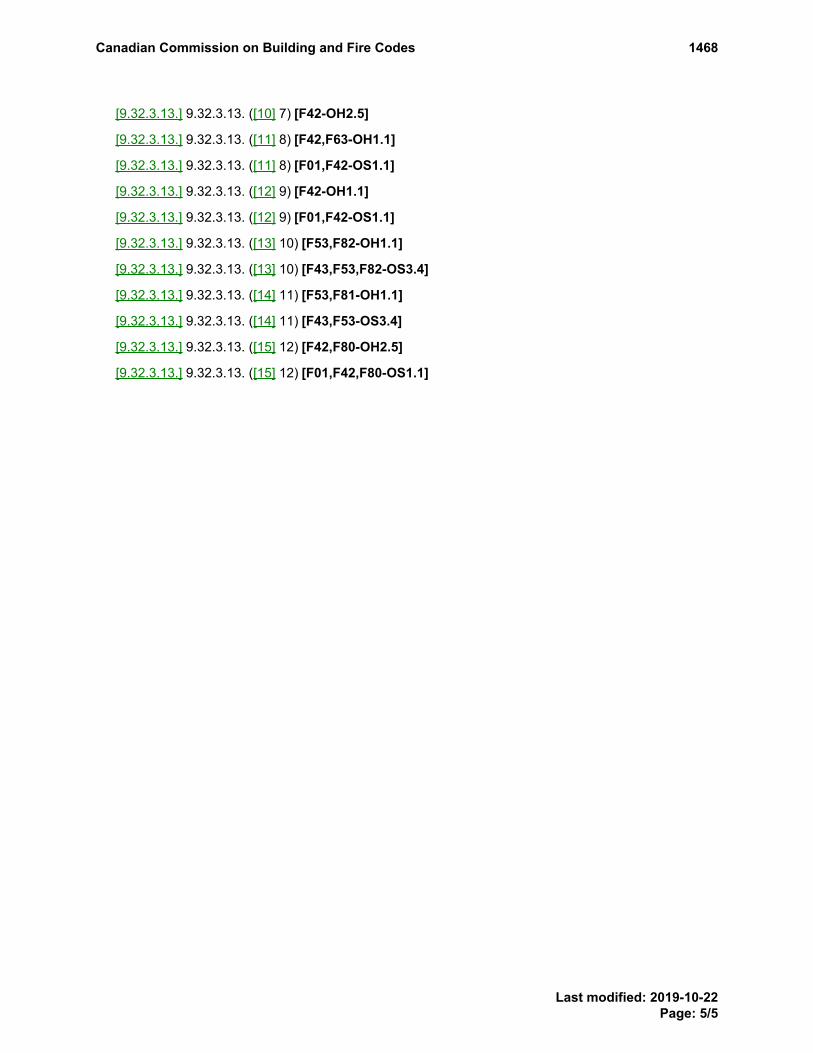
[9.32.3.13.] 9.32.3.13. ([10] 7) [F42-OH2.5]
[9.32.3.13.] 9.32.3.13. ([11] 8) [F42,F63-OH1.1]
[9.32.3.13.] 9.32.3.13. ([11] 8) [F01,F42-OS1.1]
[9.32.3.13.] 9.32.3.13. ([12] 9) [F42-OH1.1]
[9.32.3.13.] 9.32.3.13. ([12] 9) [F01,F42-OS1.1]
[9.32.3.13.] 9.32.3.13. ([13] 10) [F53,F82-OH1.1]
[9.32.3.13.] 9.32.3.13. ([13] 10) [F43,F53,F82-OS3.4]
[9.32.3.13.] 9.32.3.13. ([14] 11) [F53,F81-OH1.1]
[9.32.3.13.] 9.32.3.13. ([14] 11) [F43,F53-OS3.4]
[9.32.3.13.] 9.32.3.13. ([15] 12) [F42,F80-OH2.5]
[9.32.3.13.] 9.32.3.13. ([15] 12) [F01,F42,F80-OS1.1]
Canadian Commission on Building and Fire Codes 1468
Last modified: 2019-10-22Page: 5/5

Submit a comment
Proposed Change 1498Code Reference(s): NBC15 Div.B Appendix CSubject: Climatic LoadsTitle: Wind Data in Table C-2Description: This proposed change updates the wind data in Table C-2 of Appendix C.
PROPOSED CHANGE
Appendix C Climatic and Seismic Information for Building Design in CanadaFootnote: This information is included for explanatory purposes only and does not form part of the requirements.
IntroductionThe great diversity of climate in Canada has a considerable effect on the performance of buildings; consequently, building design must reflect this diversity. This Appendix brieflydescribes how climatic design values are computed and provides recommended design data for a number of cities, towns, and lesser populated locations. Through the use of suchdata, appropriate allowances can be made for climate variations in different localities of Canada and the National Building Code can be applied nationally.The climatic design data presented in Table C-2 are based on weather observations collected by the Atmospheric Environment Service, Environment and Climate Change Canada.The data were researched and analyzed for the Canadian Commission on Building and Fire Codes by Environment and Climate Change Canada.As it is not practical to list values for all municipalities in Canada, recommended climatic design values for locations not listed can be obtained by contacting the AtmosphericEnvironment ServiceEngineering Climate Services Unit of , Environment and Climate Change Canada, 4905 Dufferin Street, Downsview, Ontario M3H 5T4, (416) 739-4365,[email protected]. It should be noted, however, that these recommended values may differ from the legal requirements set by provincial, territorial or municipal buildingauthorities.The information on seismic hazard in spectral format given in Table C-3 has been provided by the Geological Survey of Canada of Natural Resources Canada. Information formunicipalities not listed can be obtained at www.earthquakescanada.nrcan.gc.ca or by writing to the Geological Survey of Canada at 7 Observatory Crescent, Ottawa, Ontario K1A0Y3, or at P.O. Box 6000, Sidney, B.C. V8L 4B2.
Wind EffectsAll structures need to be designed to ensure that the main structural system and all secondary components, such as cladding and appurtenances, will withstand the pressures andsuctions caused by the strongest wind likely to blow at that location in many years. Some flexible structures, such as tall buildings, slender towers and bridges, also need to bedesigned to minimize excessive wind-induced oscillations or vibrations.At any time, the wind acting upon a structure can be treated as a mean or time-averaged component and as a gust or unsteady component. For a small structure, which is completelyenveloped by wind gusts, it is only the peak gust velocity that needs to be considered. For a large structure, the wind gusts are not well correlated over its different parts and theeffects of individual gusts become less significant. The "User’s Guide – NBC 2015, Structural Commentaries (Part 4 of Division B)" evaluates the mean pressure acting on astructure, provide appropriate adjustments for building height and exposure and for the influence of the surrounding terrain and topography (including wind speed-up for hills), andthen incorporate the effects of wind gusts by means of the gust factor, which varies according to the type of structure and the size of the area over which the pressure acts.The wind speeds and corresponding velocity pressures used in the Code are regionally representative or reference values. The reference wind speeds are nominal one-hour averagesof wind speeds representative of the 10 m height in flat open terrain corresponding to Exposure A or open terrain in the terminology of the "User’s Guide – NBC 2015, StructuralCommentaries (Part 4 of Division B)". The reference wind speeds and wind velocity pressures are based on long-term wind records observed at a large number of weather stationsacross Canada.Reference wind velocity pressures in previous versionsthe 1961 to 2005 editions of the Code since 1961 were based mostly on records of hourly averaged wind speeds (i.e. thenumber of miles of wind passing an anemometer in an hour) from over 100 stations with 10 to 22 years of observations ending in the 1950s. The wind pressure values derived fromthese measurements represented true hourly wind pressures.The reference wind velocity pressures were reviewed and updated for the 2010 edition of the Code. The primary data set used for the analysis comprised wind records compiledfrom about 135 stations with hourly averaged wind speeds and from 465 stations with aviation (one- or two-minute average) speeds or surface weather (ten-minute average) speedsobserved once per hour at the top of the hour; the periods of record used ranged from 10 to 54 years. In addition, peak wind gust records from 400 stations with periods of recordranging from 10 to 43 years were used. Peak wind gusts (gust durations of approximately 3 to 7 seconds) were used to supplement the primary once-per-hour observations in theanalysis.Several steps were involved in updating the reference wind values. Where needed, speeds were adjusted to represent the standard anemometer height above ground of 10 m. Thedata from years when the anemometer at a station was installed on the top of a lighthouse or building were eliminated from the analysis since it is impractical to adjust for the effectsof wind flow over the structure. (Most anemometers were moved to 10 m towers by the 1960s.) Wind speeds of the various observation types—hourly averaged, aviation, surfaceweather and peak wind gust—were adjusted to account for different measure durations to represent a one-hour averaging period and to account for differences in the surfaceroughness of flat open terrain at observing stations.The annual maximum wind speed data was fitted to the Gumbel distribution using the method of moments(4) to calculate hourly wind speeds having the annual probability ofoccurrence of 1-in-10 and 1-in-50 (10-year and 50-year return periods). The values were plotted on maps, then analyzed and abstracted for the locations in Table C-2.The wind velocity pressures, q, were calculated in Pascals using the following equation:
q = 12 ρ V2
where ρ is an average air density for the windy months of the year and V is wind speed in metres per second. While air density depends on both air temperature and atmosphericpressure, the density of dry air at 0°C and standard atmospheric pressure of 1.2929 kg/m3 was used as an average value for the wind pressure calculations. As explained by Boyd(10),this value is within 10% of the monthly average air densities for most of Canada in the windy part of the year.As a result of the updating procedure for the 2010 edition of the Code, the 1-in-50 reference wind velocity pressures remained unchanged for most of the locations listed inTable C-2; both increases and decreases were noted for the remaining locations. Many of the decreases resulted from the fact that anemometers at most of the stations used in theprevious analysis were installed on lighthouses, airport hangers and other structures. Wind speeds on the tops of buildings are often much higher compared to those registered by astandard 10 m tower. Eliminating anemometer data recorded on the tops of buildings from the analysis resulted in lower values at several locations.For the 2020 edition of the Code, the reference wind velocity pressures were updated to reflect the new data collected in the approximately 10 years since the previous update for the2010 edition. Only data collected at stations with a period of record of at least 20 years were used in the analysis. As a result, the data set comprised wind records from 368 hourlyand 222 daily peak wind gust stations with periods of record ranging from 20 to 65 years. The annual maximum wind speed data were fitted to the Gumbel distribution.The 1-in-50 hourly wind speeds, after adjusting for roughness to represent open exposure, were mapped and compared to the NBC 2015 values for the locations in Table C-2. Thisupdating procedure resulted in small changes to the 1-in-50 reference wind velocity pressures for 60 locations.
Canadian Commission on Building and Fire Codes 1498
Last modified: 2019-10-21Page: 1/22

The 1-in-10 reference wind velocity pressures were updated using the same procedure, except that regional values of the coefficient of variation were used in the calculations insteadof the national value used previously. This procedure resulted in small changes to the 1-in-10 reference wind velocity pressures for 322 locations, including many for which therewas no change to the 1-in-50 reference wind velocity pressure.Hourly wind speeds that have 1 chance in 10 and 50 of being exceeded in any one year were analyzed using the Gumbel extreme value distribution fitted using the method ofmoments with correction for sample size. Values of the 1-in-30-year wind speeds for locations in the Table were estimated from a mapping analysis of wind speeds. The 1-in-10-and 1-in-50-year speeds were then computed from the 1-in-30-year speeds using a map of the dispersion parameter that occurs in the Gumbel analysis.(4)
Wind speeds that have a 1-in-”n” chance of being exceeded in any year can be calculated from the wind speeds corresponding to the 1-in-10 and 1-in-50 return period values inTable C-2 using the following equation:
V1 / n = 11.4565{V1 / 50 + 0.4565V1 / 10 +
V1 / 50 − V1 / 101.1339 × 1n − 0.0339
1n(1 − 1 / n)}Table C-1 has been arranged to give pressures to the nearest one-hundredth of a kPa and their corresponding wind speeds. The value of “q” in kPa is assumed to be equalto 0.00064645 V2, where V is given in m/s.
Table [C-2] C-2Climatic Design Data for Selected Locations in Canada
Design Temperature
SnowLoad,kPa,1/50
Hourly WindPressures, kPa
January July 2.5%
Province andLocation
Elev.,m
2.5%°C
1%°C
Dry°C
Wet°C
Degree-Days
Below18°C
15Min.Rain,mm
OneDay
Rain,1/50,mm
Ann.Rain,mm
Moist.Index
Ann.Tot.
Ppn.,mm
DrivingRain WindPressures,
Pa, 1/5Ss Sr 1/10 1/50
British Columbia
100 Mile House 1040 -30 -32 29 17 5030 10 48 300 0.4 425 60 2.6 0.3 0.27 0.35
Abbotsford 70 -8 -10 29 20 2860 12 112 1525 1.6 1600 160 2.0 0.3 0.340.33 0.44
Agassiz 15 -9 -11 31 21 2750 8 128 1650 1.7 1700 160 2.4 0.7 0.360.35 0.47
Alberni 12 -5 -8 31 19 3100 10 144 1900 2.0 2000 220 2.6 0.4 0.250.24 0.32
Ashcroft 305 -24 -27 34 20 3700 10 37 250 0.3 300 80 1.7 0.1 0.29 0.38
Bamfield 20 -2 -4 23 17 3080 13 170 2870 3.0 2890 280 1.0 0.4 0.390.38 0.50
Beatton River 840 -37 -39 26 18 6300 15 64 330 0.5 450 80 3.3 0.1 0.23 0.30
Bella Bella 25 -5 -7 23 18 3180 13 145 2715 2.8 2800 350 2.6 0.8 0.390.40 0.50
Bella Coola 40 -14 -18 27 19 3560 10 140 1500 1.9 1700 350 4.5 0.8 0.300.29 0.39
Burns Lake 755 -31 -34 26 17 5450 12 54 300 0.6 450 100 3.4 0.2 0.300.29 0.39
Cache Creek 455 -24 -27 34 20 3700 10 37 250 0.3 300 80 1.7 0.2 0.300.29 0.39
Campbell River 20 -5 -7 26 18 3000 10 116 1500 1.6 1600 260 2.8 0.4 0.400.41 0.520.48
Carmi 845 -24 -26 31 19 4750 10 64 325 0.4 550 60 3.6 0.2 0.29 0.38
Castlegar 430 -18 -20 32 20 3580 10 54 560 0.6 700 60 4.2 0.1 0.270.26 0.34
Chetwynd 605 -35 -38 27 18 5500 15 70 400 0.6 625 60 2.4 0.2 0.310.30 0.40
Chilliwack 10 -9 -11 30 20 2780 8 139 1625 1.7 1700 160 2.2 0.3 0.360.35 0.47
Comox 15 -7 -9 27 18 3100 10 106 1175 1.3 1200 260 2.4 0.4 0.400.41 0.520.48
Courtenay 10 -7 -9 28 18 3100 10 106 1400 1.5 1450 260 2.4 0.4 0.400.41 0.520.48
Cranbrook 910 -26 -28 32 18 4400 12 59 275 0.3 400 100 3.0 0.2 0.25 0.33
Crescent Valley 585 -18 -20 31 20 3650 10 54 675 0.8 850 80 4.2 0.1 0.25 0.33
Crofton 5 -4 -6 28 19 2880 8 86 925 1.1 950 160 1.8 0.2 0.310.32 0.40
Dawson Creek 665 -38 -40 27 18 5900 18 75 325 0.5 475 100 2.5 0.2 0.310.30 0.40
Dease Lake 800 -37 -40 24 15 6730 10 45 265 0.6 425 50 2.8 0.1 0.23 0.30
Dog Creek 450 -28 -30 29 17 4800 10 48 275 0.4 375 100 1.8 0.2 0.27 0.35
Duncan 10 -6 -8 28 19 2980 8 103 1000 1.1 1050 180 1.8 0.4 0.300.31 0.39
Elko 1065 -28 -31 30 19 4600 13 64 440 0.5 650 100 3.6 0.2 0.310.30 0.40
Fernie 1010 -27 -30 30 19 4750 13 118 860 0.9 1175 100 4.5 0.2 0.310.30 0.40
Fort Nelson 465 -39 -42 28 18 6710 15 70 325 0.6 450 80 2.4 0.1 0.23 0.30
Canadian Commission on Building and Fire Codes 1498
Last modified: 2019-10-21Page: 2/22

Design Temperature
SnowLoad,kPa,1/50
Hourly WindPressures, kPa
January July 2.5%
Province andLocation
Elev.,m
2.5%°C
1%°C
Dry°C
Wet°C
Degree-Days
Below18°C
15Min.Rain,mm
OneDay
Rain,1/50,mm
Ann.Rain,mm
Moist.Index
Ann.Tot.
Ppn.,mm
DrivingRain WindPressures,
Pa, 1/5Ss Sr 1/10 1/50
Fort St. John 685 -35 -37 26 18 5750 15 72 320 0.5 475 100 2.8 0.1 0.300.29 0.39
Glacier 1145 -27 -30 27 17 5800 10 70 625 0.8 1500 80 9.4 0.2 0.250.24 0.32
Gold River 120 -8 -11 31 18 3230 13 200 2730 2.8 2850 250 2.8 0.6 0.250.24 0.32
Golden 790 -27 -30 30 17 4750 10 55 325 0.6 500 100 3.7 0.2 0.270.26 0.35
Grand Forks 565 -19 -22 34 20 3820 10 48 390 0.5 475 80 2.8 0.1 0.310.30 0.40
Greenwood 745 -20 -23 34 20 4100 10 64 430 0.5 550 80 3.6 0.1 0.310.30 0.40
Hope 40 -13 -15 31 20 3000 8 139 1825 1.9 1900 140 2.8 0.7 0.480.47 0.63
Jordan River 20 -1 -3 22 17 2900 12 170 2300 2.4 2370 250 1.2 0.4 0.430.44 0.55
Kamloops 355 -23 -25 34 20 3450 13 42 225 0.2 275 80 1.8 0.2 0.310.30 0.40
Kaslo 545 -17 -20 30 19 3830 10 55 660 0.8 850 80 2.8 0.1 0.240.23 0.31
Kelowna 350 -17 -20 33 20 3400 12 43 260 0.3 325 80 1.7 0.1 0.310.30 0.40
Kimberley 1090 -25 -27 31 18 4650 12 59 350 0.4 500 100 3.0 0.2 0.25 0.33
Kitimat Plant 15 -16 -18 25 16 3750 13 193 2100 2.2 2500 220 5.5 0.8 0.370.36 0.48
Kitimat Townsite 130 -16 -18 24 16 3900 13 171 1900 2.0 2300 220 6.5 0.8 0.370.36 0.48
Ladysmith 80 -7 -9 27 19 3000 8 97 1075 1.2 1160 180 2.4 0.4 0.310.32 0.40
Langford 80 -4 -6 27 19 2750 9 135 1095 1.2 1125 220 1.8 0.3 0.310.32 0.40
Lillooet 245 -21 -23 34 20 3400 10 70 300 0.3 350 100 2.1 0.1 0.340.33 0.44
Lytton 325 -17 -20 35 20 3300 10 70 330 0.3 425 80 2.8 0.3 0.330.32 0.43
Mackenzie 765 -34 -38 27 17 5550 10 50 350 0.5 650 60 5.1 0.2 0.25 0.32
Masset 10 -5 -7 17 15 3700 13 80 1350 1.5 1400 400 1.8 0.4 0.480.50 0.61
McBride 730 -29 -32 29 18 4980 13 54 475 0.6 650 60 4.3 0.2 0.27 0.35
McLeod Lake 695 -35 -37 27 17 5450 10 50 350 0.5 650 60 4.1 0.2 0.25 0.32
Merritt 570 -24 -27 34 20 3900 8 54 240 0.2 310 80 1.8 0.3 0.340.33 0.44
Mission City 45 -9 -11 30 20 2850 13 123 1650 1.7 1700 160 2.4 0.3 0.330.32 0.43
Montrose 615 -16 -18 32 20 3600 10 54 480 0.6 700 60 4.1 0.1 0.270.26 0.35
Nakusp 445 -20 -22 31 20 3560 10 60 650 0.8 850 60 4.4 0.1 0.25 0.33
Nanaimo 15 -6 -8 27 19 3000 10 91 1000 1.1 1050 200 2.1 0.4 0.390.38 0.500.48
Nelson 600 -18 -20 31 20 3500 10 59 460 0.6 700 60 4.2 0.1 0.25 0.33
Ocean Falls 10 -10 -12 23 17 3400 13 260 4150 4.2 4300 350 3.9 0.8 0.460.44 0.59
Osoyoos 285 -14 -17 35 21 3100 10 48 275 0.3 310 60 1.1 0.1 0.310.30 0.40
Parksville 40 -6 -8 26 19 3200 10 91 1200 1.3 1250 200 2.0 0.4 0.390.40 0.500.48
Penticton 350 -15 -17 33 20 3350 10 48 275 0.3 300 60 1.3 0.1 0.350.30 0.450.40
Port Alberni 15 -5 -8 31 19 3100 10 161 1900 2.0 2000 240 2.6 0.4 0.250.24 0.32
Port Alice 25 -3 -6 26 17 3010 13 200 3300 3.4 3340 220 1.1 0.4 0.250.24 0.32
Port Hardy 5 -5 -7 20 16 3440 13 150 1775 1.9 1850 220 0.9 0.4 0.400.36 0.520.48
Port McNeill 5 -5 -7 22 17 3410 13 128 1750 1.9 1850 260 1.1 0.4 0.400.36 0.520.48
Port Renfrew 20 -3 -5 24 17 2900 13 200 3600 3.6 3675 270 1.1 0.4 0.400.42 0.52
Powell River 10 -7 -9 26 18 3100 10 80 1150 1.3 1200 220 1.7 0.4 0.39 0.510.48
Prince George 580 -32 -36 28 18 4720 15 54 425 0.6 600 80 3.4 0.2 0.290.28 0.37
Canadian Commission on Building and Fire Codes 1498
Last modified: 2019-10-21Page: 3/22

Design Temperature
SnowLoad,kPa,1/50
Hourly WindPressures, kPa
January July 2.5%
Province andLocation
Elev.,m
2.5%°C
1%°C
Dry°C
Wet°C
Degree-Days
Below18°C
15Min.Rain,mm
OneDay
Rain,1/50,mm
Ann.Rain,mm
Moist.Index
Ann.Tot.
Ppn.,mm
DrivingRain WindPressures,
Pa, 1/5Ss Sr 1/10 1/50
Prince Rupert 20 -13 -15 19 15 3900 13 160 2750 2.8 2900 240 1.9 0.4 0.420.43 0.54
Princeton 655 -24 -29 33 19 4250 10 43 235 0.4 350 80 2.9 0.6 0.280.27 0.36
Qualicum Beach 10 -7 -9 27 19 3200 10 96 1200 1.3 1250 200 2.0 0.4 0.41 0.530.48
Queen CharlotteCity
35 -6 -8 21 16 3520 13 110 1300 1.5 1350 360 1.8 0.4 0.480.50 0.61
Quesnel 475 -31 -33 30 17 4650 10 50 380 0.5 525 80 3.0 0.1 0.24 0.31
Revelstoke 440 -20 -23 31 19 4000 13 55 625 0.8 950 80 7.2 0.1 0.250.24 0.32
Salmon Arm 425 -19 -24 33 21 3650 13 48 400 0.5 525 80 3.5 0.1 0.300.29 0.39
Sandspit 5 -4 -6 18 15 3450 13 86 1300 1.5 1350 500 1.8 0.4 0.600.59 0.780.72
Sechelt 25 -6 -8 27 20 2680 10 75 1140 1.3 1200 160 1.8 0.4 0.370.38 0.48
Sidney 10 -4 -6 26 18 2850 8 96 825 1.0 850 160 1.1 0.2 0.330.34 0.42
Smith River 660 -45 -47 26 17 7100 10 64 300 0.6 500 40 2.8 0.1 0.230.24 0.30
Smithers 500 -29 -31 26 17 5040 13 60 325 0.6 500 120 3.5 0.2 0.310.30 0.40
Sooke 20 -1 -3 21 16 2900 9 130 1250 1.4 1280 220 1.3 0.3 0.370.38 0.48
Squamish 5 -9 -11 29 20 2950 10 140 2050 2.1 2200 160 2.8 0.7 0.390.38 0.50
Stewart 10 -17 -20 25 16 4350 13 135 1300 1.5 1900 180 7.9 0.8 0.280.27 0.36
Tahsis 25 -4 -6 26 18 3150 13 200 3845 3.9 3900 300 1.1 0.4 0.26 0.34
Taylor 515 -35 -37 26 18 5720 15 72 320 0.5 450 100 2.3 0.1 0.310.30 0.40
Terrace 60 -19 -21 27 17 4150 13 120 950 1.1 1150 200 5.4 0.6 0.280.27 0.36
Tofino 10 -2 -4 20 16 3150 13 193 3275 3.4 3300 300 1.1 0.4 0.530.51 0.68
Trail 440 -14 -17 33 20 3600 10 54 580 0.7 700 60 4.1 0.1 0.270.26 0.35
Ucluelet 5 -2 -4 18 16 3120 13 180 3175 3.3 3200 280 1.0 0.4 0.530.51 0.68
VancouverRegion
Burnaby(Simon FraserUniv.)
330 -7 -9 25 17 3100 10 150 1850 1.9 1950 160 2.9 0.7 0.360.35 0.47
Cloverdale 10 -8 -10 29 20 2700 10 112 1350 1.4 1400 160 2.5 0.2 0.340.33 0.44
Haney 10 -9 -11 30 20 2840 10 134 1800 1.9 1950 160 2.4 0.2 0.340.33 0.44
Ladner 3 -6 -8 27 19 2600 10 80 1000 1.1 1050 160 1.3 0.2 0.360.37 0.46
Langley 15 -8 -10 29 20 2700 10 112 1450 1.5 1500 160 2.4 0.2 0.340.33 0.44
NewWestminster
10 -8 -10 29 19 2800 10 134 1500 1.6 1575 160 2.3 0.2 0.340.33 0.44
NorthVancouver
135 -7 -9 26 19 2910 12 150 2000 2.1 2100 160 3.0 0.3 0.350.34 0.45
Richmond 5 -7 -9 27 19 2800 10 86 1070 1.2 1100 160 1.5 0.2 0.350.36 0.45
Surrey (88 Ave& 156 St.)
90 -8 -10 29 20 2750 10 128 1500 1.6 1575 160 2.4 0.3 0.340.33 0.44
Vancouver(City Hall)
40 -7 -9 28 20 2825 10 112 1325 1.4 1400 160 1.8 0.2 0.350.34 0.45
Vancouver(Granville & 41Ave)
120 -6 -8 28 20 2925 10 107 1325 1.4 1400 160 1.9 0.3 0.350.36 0.45
WestVancouver
45 -7 -9 28 19 2950 12 150 1600 1.7 1700 160 2.4 0.2 0.370.36 0.48
Vernon 405 -20 -23 33 20 3600 13 43 350 0.4 400 80 2.2 0.1 0.310.30 0.40
Canadian Commission on Building and Fire Codes 1498
Last modified: 2019-10-21Page: 4/22

Design Temperature
SnowLoad,kPa,1/50
Hourly WindPressures, kPa
January July 2.5%
Province andLocation
Elev.,m
2.5%°C
1%°C
Dry°C
Wet°C
Degree-Days
Below18°C
15Min.Rain,mm
OneDay
Rain,1/50,mm
Ann.Rain,mm
Moist.Index
Ann.Tot.
Ppn.,mm
DrivingRain WindPressures,
Pa, 1/5Ss Sr 1/10 1/50
Victoria Region
Victoria(Gonzales Hts)
65 -4 -6 24 17 2700 9 91 600 0.8 625 220 1.5 0.3 0.440.46 0.57
Victoria(Mt Tolmie)
125 -6 -8 24 16 2700 9 91 775 1.0 800 220 2.1 0.3 0.480.46 0.630.57
Victoria 10 -4 -6 24 17 2650 8 91 800 1.0 825 220 1.1 0.2 0.46 0.57
Whistler 665 -17 -20 30 20 4180 10 85 845 1.0 1215 160 9.5 0.9 0.250.24 0.32
White Rock 30 -5 -7 25 20 2620 10 80 1065 1.2 1100 160 2.0 0.2 0.340.33 0.44
Williams Lake 615 -30 -33 29 17 4400 10 48 350 0.5 425 80 2.4 0.2 0.27 0.35
Youbou 200 -5 -8 31 19 3050 10 161 2000 2.1 2100 200 3.5 0.7 0.250.26 0.32
Alberta
Athabasca 515 -35 -38 27 19 6000 18 86 370 0.6 480 80 1.5 0.1 0.280.27 0.36
Banff 1400 -31 -33 27 16 5500 18 65 300 0.6 500 120 3.3 0.1 0.250.26 0.32
Barrhead 645 -33 -36 27 19 5740 20 86 375 0.6 475 100 1.7 0.1 0.340.35 0.44
Beaverlodge 730 -36 -39 28 18 5700 20 86 315 0.5 470 100 2.4 0.1 0.280.27 0.36
Brooks 760 -32 -34 32 20 4880 18 86 260 0.3 340 220 1.2 0.1 0.400.35 0.520.44
Calgary 1045 -30 -32 28 17 5000 23 103 325 0.4 425 220 1.1 0.1 0.370.38 0.48
Campsie 660 -33 -36 27 19 5750 20 86 375 0.6 475 100 1.7 0.1 0.340.33 0.44
Camrose 740 -33 -35 29 19 5500 20 86 355 0.5 470 160 2.0 0.1 0.300.31 0.39
Canmore 1320 -31 -33 28 17 5400 18 86 325 0.6 500 120 3.2 0.1 0.290.30 0.37
Cardston 1130 -29 -32 30 19 4700 20 108 340 0.4 550 140 1.5 0.1 0.560.58 0.72
Claresholm 1030 -30 -32 30 18 4680 15 97 310 0.4 440 200 1.3 0.1 0.450.46 0.58
Cold Lake 540 -35 -38 28 19 5860 18 81 320 0.5 430 140 1.7 0.1 0.29 0.38
Coleman 1320 -31 -34 29 18 5210 15 86 400 0.5 550 120 2.7 0.3 0.480.50 0.63
Coronation 790 -32 -34 30 19 5640 20 92 300 0.5 400 200 1.9 0.1 0.290.30 0.37
Cowley 1175 -29 -32 29 18 4810 15 92 310 0.4 525 140 1.6 0.1 0.780.81 1.01
Drumheller 685 -32 -34 30 18 5050 20 86 300 0.4 375 220 1.2 0.1 0.340.35 0.44
Edmonton 645 -30 -33 28 19 5120 23 97 360 0.5 460 160 1.7 0.1 0.350.36 0.45
Edson 920 -34 -37 27 18 5750 18 81 450 0.6 570 100 2.1 0.1 0.360.37 0.46
EmbarrasPortage
220 -41 -43 28 19 7100 12 81 250 0.6 390 80 2.2 0.1 0.290.28 0.37
Fairview 670 -37 -40 27 18 5840 15 86 330 0.5 450 100 2.4 0.1 0.270.26 0.35
Fort MacLeod 945 -30 -32 31 19 4600 16 97 300 0.4 425 180 1.2 0.1 0.530.54 0.68
Fort McMurray 255 -38 -40 28 19 6250 13 86 340 0.5 460 60 1.5 0.1 0.270.28 0.35
FortSaskatchewan
610 -32 -35 28 19 5420 20 86 350 0.5 425 140 1.6 0.1 0.330.34 0.43
Fort Vermilion 270 -41 -43 28 18 6700 13 70 250 0.5 380 60 2.1 0.1 0.23 0.30
Grande Prairie 650 -36 -39 27 18 5790 20 86 315 0.5 450 120 2.2 0.1 0.330.32 0.43
Habay 335 -41 -43 28 18 6750 13 70 275 0.5 425 60 2.4 0.1 0.23 0.30
Hardisty 615 -33 -36 30 19 5640 20 81 325 0.5 425 140 1.7 0.1 0.280.29 0.36
High River 1040 -31 -32 28 17 4900 18 97 300 0.4 425 200 1.3 0.1 0.500.52 0.65
Hinton 990 -34 -38 27 17 5500 13 81 375 0.6 500 100 2.6 0.1 0.360.37 0.46
Jasper 1060 -31 -34 28 17 5300 12 76 300 0.5 400 80 3.0 0.1 0.250.26 0.32
Canadian Commission on Building and Fire Codes 1498
Last modified: 2019-10-21Page: 5/22

Design Temperature
SnowLoad,kPa,1/50
Hourly WindPressures, kPa
January July 2.5%
Province andLocation
Elev.,m
2.5%°C
1%°C
Dry°C
Wet°C
Degree-Days
Below18°C
15Min.Rain,mm
OneDay
Rain,1/50,mm
Ann.Rain,mm
Moist.Index
Ann.Tot.
Ppn.,mm
DrivingRain WindPressures,
Pa, 1/5Ss Sr 1/10 1/50
Keg River 420 -40 -42 28 18 6520 13 70 310 0.5 450 80 2.4 0.1 0.23 0.30
Lac la Biche 560 -35 -38 28 19 6100 15 86 375 0.6 475 80 1.6 0.1 0.280.27 0.36
Lacombe 855 -33 -36 28 19 5500 23 92 350 0.5 450 180 1.9 0.1 0.310.32 0.40
Lethbridge 910 -30 -32 31 19 4500 20 97 250 0.3 390 200 1.2 0.1 0.510.53 0.66
Manning 465 -39 -41 27 18 6300 13 76 280 0.5 390 80 2.3 0.1 0.23 0.30
Medicine Hat 705 -31 -34 32 19 4540 23 92 250 0.3 325 220 1.1 0.1 0.370.38 0.48
Peace River 330 -37 -40 27 18 6050 15 81 300 0.5 390 100 2.2 0.1 0.250.24 0.32
Pincher Creek 1130 -29 -32 29 18 4740 16 103 325 0.4 575 140 1.5 0.1 0.750.77 0.96
Ranfurly 670 -34 -37 29 19 5700 18 92 325 0.5 420 100 1.9 0.1 0.280.29 0.36
Red Deer 855 -32 -35 28 19 5550 20 97 375 0.5 475 200 1.8 0.1 0.310.32 0.40
Rocky MountainHouse
985 -32 -34 27 18 5640 20 92 425 0.6 550 120 1.9 0.1 0.280.29 0.36
Slave Lake 590 -35 -38 26 19 5850 15 81 380 0.6 500 80 1.9 0.1 0.290.28 0.37
Stettler 820 -32 -34 30 19 5300 20 97 370 0.5 450 200 1.9 0.1 0.280.29 0.36
Stony Plain 710 -32 -35 28 19 5300 23 97 410 0.5 540 120 1.7 0.1 0.350.36 0.45
Suffield 755 -31 -34 32 20 4770 20 86 230 0.2 325 220 1.3 0.1 0.380.39 0.49
Taber 815 -31 -33 31 19 4580 20 92 260 0.3 370 200 1.2 0.1 0.480.50 0.63
Turner Valley 1215 -31 -32 28 17 5220 20 97 350 0.5 600 180 1.4 0.1 0.500.52 0.65
Valleyview 700 -37 -40 27 18 5600 18 86 360 0.5 490 80 2.3 0.1 0.330.34 0.42
Vegreville 635 -34 -37 29 19 5780 18 86 325 0.5 410 100 1.9 0.1 0.280.29 0.36
Vermilion 580 -35 -38 29 19 5740 18 86 310 0.5 410 100 1.7 0.1 0.280.29 0.36
Wagner 585 -35 -38 26 19 5850 15 81 380 0.6 500 80 1.9 0.1 0.290.28 0.37
Wainwright 675 -33 -36 29 19 5700 20 81 310 0.5 425 120 2.0 0.1 0.280.29 0.36
Wetaskiwin 760 -33 -35 29 19 5500 23 86 400 0.6 500 160 2.0 0.1 0.300.31 0.39
Whitecourt 690 -33 -36 27 19 5650 20 97 440 0.6 550 80 1.9 0.1 0.290.28 0.37
Wimborne 975 -31 -34 29 18 5310 23 92 325 0.5 450 200 1.6 0.1 0.310.32 0.40
Saskatchewan
Assiniboia 740 -32 -34 31 21 5180 25 81 290 0.3 375 240 1.6 0.1 0.380.39 0.49
Battrum 700 -32 -34 32 20 5080 23 81 270 0.4 350 260 1.2 0.1 0.420.43 0.54
Biggar 645 -34 -36 30 20 5720 23 81 270 0.4 350 180 2.1 0.1 0.350.36 0.45
Broadview 600 -34 -35 30 21 5760 25 103 320 0.5 420 160 1.7 0.1 0.36 0.46
Dafoe 530 -35 -37 29 21 5860 20 92 300 0.5 380 140 1.7 0.1 0.29 0.37
Dundurn 525 -35 -37 30 21 5600 23 86 275 0.4 380 180 1.5 0.1 0.36 0.46
Estevan 565 -32 -34 32 22 5340 28 92 330 0.4 420 200 1.6 0.1 0.400.41 0.52
Hudson Bay 370 -36 -38 29 21 6280 20 81 340 0.6 450 80 2.0 0.1 0.29 0.37
Humboldt 565 -36 -38 28 21 6000 20 86 320 0.5 375 140 2.1 0.1 0.300.31 0.39
Island Falls 305 -39 -41 27 20 7100 18 76 370 0.6 510 80 2.1 0.1 0.270.26 0.35
Kamsack 455 -34 -37 29 22 6040 20 97 360 0.6 450 120 2.1 0.2 0.310.32 0.40
Kindersley 685 -33 -35 31 20 5550 23 81 260 0.4 325 200 1.4 0.1 0.36 0.46
Lloydminster 645 -34 -37 28 20 5880 18 81 310 0.5 430 120 2.0 0.1 0.310.32 0.40
Maple Creek 765 -31 -34 31 20 4780 25 81 275 0.3 380 220 1.2 0.1 0.350.36 0.45
Meadow Lake 480 -38 -40 28 20 6280 18 81 320 0.5 450 120 1.7 0.1 0.310.30 0.40
Melfort 455 -36 -38 28 21 6050 20 81 310 0.5 410 120 2.1 0.1 0.28 0.36
Canadian Commission on Building and Fire Codes 1498
Last modified: 2019-10-21Page: 6/22

Design Temperature
SnowLoad,kPa,1/50
Hourly WindPressures, kPa
January July 2.5%
Province andLocation
Elev.,m
2.5%°C
1%°C
Dry°C
Wet°C
Degree-Days
Below18°C
15Min.Rain,mm
OneDay
Rain,1/50,mm
Ann.Rain,mm
Moist.Index
Ann.Tot.
Ppn.,mm
DrivingRain WindPressures,
Pa, 1/5Ss Sr 1/10 1/50
Melville 550 -34 -36 29 21 5880 23 97 340 0.5 410 160 1.7 0.1 0.310.32 0.40
Moose Jaw 545 -32 -34 31 21 5270 25 86 270 0.3 360 200 1.4 0.1 0.400.41 0.52
Nipawin 365 -37 -39 28 21 6300 20 76 340 0.6 450 100 2.0 0.1 0.290.30 0.38
North Battleford 545 -34 -36 29 20 5900 20 81 280 0.5 370 120 1.7 0.1 0.36 0.46
Prince Albert 435 -37 -40 28 21 6100 20 81 320 0.5 410 140 1.9 0.1 0.290.30 0.38
Qu'Appelle 645 -34 -36 30 22 5620 25 97 340 0.5 430 160 1.7 0.1 0.33 0.42
Regina 575 -34 -36 31 21 5600 28 103 300 0.4 365 200 1.4 0.1 0.380.39 0.49
Rosetown 595 -34 -36 31 20 5620 23 81 260 0.4 330 200 1.7 0.1 0.380.39 0.49
Saskatoon 500 -35 -37 30 21 5700 23 86 265 0.4 350 160 1.7 0.1 0.330.36 0.430.46
Scott 645 -34 -36 30 20 5960 20 81 270 0.4 360 140 1.9 0.1 0.350.36 0.45
Strasbourg 545 -34 -36 30 22 5600 25 92 300 0.4 390 180 1.5 0.1 0.33 0.42
Swift Current 750 -31 -34 31 20 5150 25 81 260 0.3 350 240 1.4 0.1 0.420.43 0.54
Uranium City 265 -42 -44 26 19 7500 12 54 300 0.6 360 100 2.0 0.1 0.280.27 0.36
Weyburn 575 -33 -35 31 23 5400 28 97 320 0.4 400 200 1.8 0.1 0.370.38 0.48
Yorkton 510 -34 -37 29 21 6000 23 97 350 0.5 440 140 1.9 0.1 0.310.32 0.40
Manitoba
Beausejour 245 -33 -35 29 23 5680 28 103 430 0.6 530 180 2.0 0.2 0.32 0.41
Boissevain 510 -32 -34 30 23 5500 28 119 390 0.5 510 180 2.2 0.2 0.400.41 0.52
Brandon 395 -33 -35 30 22 5760 28 108 375 0.6 460 180 2.1 0.2 0.380.39 0.49
Churchill 10 -38 -40 25 18 8950 12 76 265 0.8 410 260 3.0 0.2 0.43 0.55
Dauphin 295 -33 -35 30 22 5900 28 103 400 0.6 490 160 1.9 0.2 0.310.32 0.40
Flin Flon 300 -38 -40 27 20 6440 18 81 340 0.6 475 80 2.2 0.2 0.270.28 0.35
Gimli 220 -34 -36 29 23 5800 28 108 410 0.7 530 180 1.9 0.2 0.310.32 0.40
Island Lake 240 -36 -38 27 20 6900 18 86 380 0.7 550 80 2.6 0.2 0.29 0.37
Lac du Bonnet 260 -34 -36 29 23 5730 28 103 445 0.7 560 180 1.9 0.2 0.29 0.37
Lynn Lake 350 -40 -42 27 19 7770 18 86 310 0.6 490 100 2.4 0.2 0.29 0.37
Morden 300 -31 -33 30 24 5400 28 119 420 0.6 520 180 2.2 0.2 0.400.41 0.52
Neepawa 365 -32 -34 29 23 5760 28 108 410 0.6 470 180 2.2 0.2 0.340.35 0.44
Pine Falls 220 -34 -36 28 23 5900 25 97 440 0.7 420 180 1.9 0.2 0.300.31 0.39
Portage la Prairie 260 -31 -33 30 23 5600 28 108 390 0.5 525 180 2.1 0.2 0.36 0.46
Rivers 465 -34 -36 29 23 5840 28 108 370 0.6 460 180 2.1 0.2 0.36 0.46
Sandilands 365 -32 -34 29 23 5650 28 113 460 0.6 550 180 2.2 0.2 0.310.32 0.40
Selkirk 225 -33 -35 29 23 5700 28 108 420 0.6 500 180 1.9 0.2 0.32 0.41
Split Lake 175 -38 -40 27 19 7900 18 76 325 0.7 500 120 2.5 0.2 0.300.31 0.39
Steinbach 270 -33 -35 29 23 5700 28 108 440 0.6 500 180 2.0 0.2 0.310.32 0.40
Swan River 335 -34 -37 29 22 6100 20 92 370 0.6 500 120 2.0 0.2 0.270.28 0.35
The Pas 270 -36 -38 28 21 6480 18 81 330 0.6 450 160 2.2 0.2 0.29 0.37
Thompson 205 -40 -43 27 19 7600 18 86 350 0.6 540 100 2.4 0.2 0.28 0.36
Virden 435 -33 -35 30 23 5620 28 108 350 0.5 460 180 2.0 0.2 0.36 0.46
Winnipeg 235 -33 -35 30 23 5670 28 108 415 0.6 500 180 1.9 0.2 0.350.36 0.45
Ontario
Canadian Commission on Building and Fire Codes 1498
Last modified: 2019-10-21Page: 7/22

Design Temperature
SnowLoad,kPa,1/50
Hourly WindPressures, kPa
January July 2.5%
Province andLocation
Elev.,m
2.5%°C
1%°C
Dry°C
Wet°C
Degree-Days
Below18°C
15Min.Rain,mm
OneDay
Rain,1/50,mm
Ann.Rain,mm
Moist.Index
Ann.Tot.
Ppn.,mm
DrivingRain WindPressures,
Pa, 1/5Ss Sr 1/10 1/50
Ailsa Craig 230 -17 -19 30 23 3840 25 103 800 0.9 950 180 2.2 0.4 0.390.37 0.500.48
Ajax 95 -20 -22 30 23 3820 23 92 760 0.9 825 160 1.0 0.4 0.37 0.48
Alexandria 80 -24 -26 30 23 4600 25 103 800 0.9 975 160 2.4 0.4 0.31 0.40
Alliston 220 -23 -25 29 23 4200 28 113 690 0.8 875 120 2.0 0.4 0.28 0.36
Almonte 120 -26 -28 30 23 4620 25 97 730 0.8 800 140 2.5 0.4 0.32 0.41
Armstrong 340 -37 -40 28 21 6500 23 97 525 0.8 725 100 2.7 0.4 0.230.22 0.30
Arnprior 85 -27 -29 30 23 4680 23 86 630 0.8 775 140 2.5 0.4 0.29 0.37
Atikokan 400 -33 -35 29 22 5750 25 103 570 0.8 760 100 2.4 0.3 0.230.22 0.30
Attawapiskat 10 -37 -39 28 21 7100 18 81 450 0.8 650 160 2.8 0.3 0.320.30 0.41
Aurora 270 -21 -23 30 23 4210 28 108 700 0.8 800 140 2.0 0.4 0.34 0.44
Bancroft 365 -28 -31 29 23 4740 25 92 720 0.9 900 100 3.1 0.4 0.25 0.32
Barrie 245 -24 -26 29 23 4380 28 97 700 0.8 900 120 2.5 0.4 0.28 0.36
Barriefield 100 -22 -24 28 23 3990 23 108 780 1.0 950 160 2.1 0.4 0.360.37 0.47
Beaverton 240 -24 -26 30 23 4300 25 108 720 0.9 950 120 2.2 0.4 0.28 0.36
Belleville 90 -22 -24 29 23 3910 23 97 760 0.9 850 180 1.7 0.4 0.330.34 0.43
Belmont 260 -17 -19 30 24 3840 25 97 850 1.0 950 180 1.7 0.4 0.360.37 0.47
Kitchenuhmay-koosib(Big Trout Lake)
215 -38 -40 26 20 7450 18 92 400 0.75 600 150 3.2 0.2 0.313 0.42
CFB Borden 225 -23 -25 29 23 4300 28 103 690 0.82 875 120 2.2 0.4 0.28 0.36
Bracebridge 310 -26 -28 29 23 4800 25 103 830 1.0 1050 120 3.1 0.4 0.27 0.35
Bradford 240 -23 -25 30 23 4280 28 108 680 0.8 800 120 2.1 0.4 0.28 0.36
Brampton 215 -19 -21 30 23 4100 28 119 720 0.8 820 140 1.3 0.4 0.34 0.44
Brantford 205 -18 -20 30 23 3900 23 103 780 0.9 850 160 1.3 0.4 0.33 0.42
Brighton 95 -21 -23 29 23 4000 23 94 760 0.9 850 160 1.6 0.4 0.37 0.48
Brockville 85 -23 -25 29 23 4060 25 103 770 0.9 975 180 2.2 0.4 0.34 0.44
Burk's Falls 305 -26 -28 29 22 5020 25 97 810 0.9 1010 120 2.7 0.4 0.27 0.35
Burlington 80 -17 -19 31 23 3740 23 103 770 0.9 850 160 1.1 0.4 0.36 0.46
Cambridge 295 -18 -20 29 23 4100 25 113 800 0.9 890 160 1.6 0.4 0.28 0.36
Campbellford 150 -23 -26 30 23 4280 25 97 730 0.9 850 160 1.7 0.4 0.32 0.41
Cannington 255 -24 -26 30 23 4310 25 108 740 0.9 950 120 2.2 0.4 0.28 0.36
Carleton Place 135 -25 -27 30 23 4600 25 97 730 0.8 850 160 2.5 0.4 0.32 0.41
Cavan 200 -23 -25 30 23 4400 25 97 740 0.9 850 140 2.0 0.4 0.34 0.44
Centralia 260 -17 -19 30 23 3800 25 103 820 1.0 1000 180 2.3 0.4 0.380.37 0.490.48
Chapleau 425 -35 -38 27 21 5900 20 97 530 0.7 850 80 3.6 0.4 0.23 0.30
Chatham 180 -16 -18 31 24 3470 28 103 800 0.9 850 180 1.0 0.4 0.330.34 0.43
Chesley 275 -19 -21 29 22 4320 28 103 810 0.9 1125 140 2.8 0.4 0.370.35 0.480.45
Clinton 280 -17 -19 29 23 4150 25 103 810 0.9 1000 160 2.6 0.4 0.380.36 0.490.46
Coboconk 270 -25 -27 30 23 4500 25 108 740 0.9 950 120 2.5 0.4 0.27 0.35
Cobourg 90 -21 -23 29 23 3980 23 94 760 0.9 825 160 1.2 0.4 0.38 0.49
Cochrane 245 -34 -36 29 21 6200 20 92 575 0.8 875 80 2.8 0.3 0.27 0.35
Canadian Commission on Building and Fire Codes 1498
Last modified: 2019-10-21Page: 8/22

Design Temperature
SnowLoad,kPa,1/50
Hourly WindPressures, kPa
January July 2.5%
Province andLocation
Elev.,m
2.5%°C
1%°C
Dry°C
Wet°C
Degree-Days
Below18°C
15Min.Rain,mm
OneDay
Rain,1/50,mm
Ann.Rain,mm
Moist.Index
Ann.Tot.
Ppn.,mm
DrivingRain WindPressures,
Pa, 1/5Ss Sr 1/10 1/50
Colborne 105 -21 -23 29 23 3980 23 94 760 0.9 850 160 1.6 0.4 0.38 0.49
Collingwood 190 -21 -23 29 23 4180 28 97 720 0.9 950 160 2.7 0.4 0.30 0.39
Cornwall 35 -23 -25 30 23 4250 25 103 780 0.9 960 180 2.2 0.4 0.32 0.41
Corunna 185 -16 -18 31 24 3600 25 100 760 0.9 800 180 1.0 0.4 0.360.37 0.47
Deep River 145 -29 -32 30 22 4900 23 92 650 0.8 850 100 2.5 0.4 0.27 0.35
Deseronto 85 -22 -24 29 23 4070 23 92 760 0.9 900 160 1.9 0.4 0.330.34 0.43
Dorchester 260 -18 -20 30 24 3900 28 103 850 1.0 950 180 1.9 0.4 0.360.37 0.47
Dorion 200 -33 -35 28 21 5950 20 103 550 0.8 725 160 2.8 0.4 0.300.29 0.39
Dresden 185 -16 -18 31 24 3750 28 97 760 0.8 820 180 1.0 0.4 0.330.34 0.43
Dryden 370 -34 -36 28 22 5850 25 97 550 0.7 700 120 2.4 0.3 0.230.22 0.30
Dundalk 525 -22 -24 29 22 4700 28 108 750 0.9 1080 150 3.2 0.4 0.33 0.42
Dunnville 175 -15 -17 30 24 3660 23 108 830 1.0 950 160 2.0 0.4 0.36 0.46
Durham 340 -20 -22 29 22 4340 28 103 815 0.9 1025 140 2.8 0.4 0.34 0.44
Dutton 225 -16 -18 31 24 3700 28 92 850 1.0 925 180 1.3 0.4 0.360.37 0.47
Earlton 245 -33 -36 29 22 5730 23 92 560 0.8 820 120 3.1 0.4 0.35 0.45
Edison 365 -34 -36 28 22 5740 25 108 510 0.7 680 120 2.4 0.3 0.240.23 0.31
Elliot Lake 380 -26 -28 29 21 4950 23 108 630 0.8 950 160 2.9 0.4 0.290.30 0.38
Elmvale 220 -24 -26 29 23 4200 28 97 720 0.9 950 140 2.6 0.4 0.28 0.36
Embro 310 -19 -21 30 23 3950 28 113 830 0.9 950 160 2.0 0.4 0.37 0.48
Englehart 205 -33 -36 29 22 5800 23 92 600 0.8 880 100 2.8 0.4 0.32 0.41
Espanola 220 -25 -27 29 21 4920 23 108 650 0.8 840 160 2.3 0.4 0.33 0.42
Exeter 265 -17 -19 30 23 3900 25 113 810 0.9 975 180 2.4 0.4 0.380.37 0.490.48
Fenelon Falls 260 -25 -27 30 23 4440 25 108 730 0.9 950 120 2.3 0.4 0.28 0.36
Fergus 400 -20 -22 29 23 4300 28 108 760 0.9 925 160 2.2 0.4 0.28 0.36
Forest 215 -16 -18 31 23 3740 25 103 810 1.0 875 160 2.0 0.4 0.37 0.48
Fort Erie 180 -15 -17 30 24 3650 23 108 860 1.0 1020 160 2.3 0.4 0.36 0.46
Fort Erie(Ridgeway)
190 -15 -17 30 24 3600 25 108 860 1.0 1000 160 2.3 0.4 0.36 0.46
Fort Frances 340 -33 -35 29 22 5440 25 108 570 0.7 725 120 2.3 0.3 0.240.23 0.31
Gananoque 80 -22 -24 28 23 4010 23 103 760 0.9 900 180 2.1 0.4 0.360.37 0.47
Geraldton 345 -36 -39 28 21 6450 20 86 550 0.8 725 100 2.9 0.4 0.230.22 0.30
Glencoe 215 -16 -18 31 24 3680 28 103 800 0.9 925 180 1.5 0.4 0.330.34 0.43
Goderich 185 -16 -18 29 23 4000 25 92 810 1.0 950 180 2.4 0.4 0.430.37 0.550.48
Gore Bay 205 -24 -26 28 22 4700 23 92 640 0.8 860 160 2.6 0.4 0.34 0.44
Graham 495 -35 -37 29 22 5940 23 97 570 0.8 750 140 2.6 0.3 0.230.22 0.30
Gravenhurst(MuskokaAirport)
255 -26 -28 29 23 4760 25 103 790 0.9 1050 120 2.7 0.4 0.28 0.36
Grimsby 85 -16 -18 30 23 3520 23 108 760 0.9 875 160 0.9 0.4 0.36 0.46
Guelph 340 -19 -21 29 23 4270 28 103 770 0.9 875 140 1.9 0.4 0.28 0.36
Guthrie 280 -24 -26 29 23 4300 28 103 700 0.8 950 120 2.5 0.4 0.28 0.36
Haileybury 210 -32 -35 30 22 5600 23 92 590 0.8 820 120 2.4 0.4 0.34 0.44
Canadian Commission on Building and Fire Codes 1498
Last modified: 2019-10-21Page: 9/22

Design Temperature
SnowLoad,kPa,1/50
Hourly WindPressures, kPa
January July 2.5%
Province andLocation
Elev.,m
2.5%°C
1%°C
Dry°C
Wet°C
Degree-Days
Below18°C
15Min.Rain,mm
OneDay
Rain,1/50,mm
Ann.Rain,mm
Moist.Index
Ann.Tot.
Ppn.,mm
DrivingRain WindPressures,
Pa, 1/5Ss Sr 1/10 1/50
Haldimand(Caledonia)
190 -18 -20 30 23 3750 23 108 810 0.9 875 160 1.2 0.4 0.34 0.44
Haldimand(Hagersville)
215 -17 -19 30 23 3760 25 97 840 1.0 875 160 1.3 0.4 0.36 0.46
Haliburton 335 -27 -29 29 23 4840 25 92 780 0.9 980 100 2.9 0.4 0.27 0.35
Halton Hills(Georgetown)
255 -19 -21 30 23 4200 28 119 750 0.8 850 140 1.4 0.4 0.29 0.37
Hamilton 90 -17 -19 31 23 3460 23 108 810 0.9 875 160 1.1 0.4 0.36 0.46
Hanover 270 -19 -21 29 22 4300 28 103 790 0.9 1050 140 2.6 0.4 0.370.34 0.480.44
Hastings 200 -24 -26 30 23 4280 25 92 730 0.9 840 140 2.0 0.4 0.32 0.41
Hawkesbury 50 -25 -27 30 23 4610 23 103 800 0.9 925 160 2.3 0.4 0.32 0.41
Hearst 245 -35 -37 29 21 6450 20 86 520 0.7 825 80 2.8 0.3 0.23 0.30
HoneyHarbour
180 -24 -26 29 23 4300 25 97 710 0.9 1050 160 2.7 0.4 0.30 0.39
Hornepayne 360 -37 -40 28 21 6340 20 93 420 0.7 750 80 3.3 0.4 0.230.22 0.30
Huntsville 335 -26 -29 29 22 4850 25 103 800 0.9 1000 120 2.9 0.4 0.27 0.35
Ingersoll 280 -18 -20 30 23 3920 28 108 840 1.0 950 180 1.7 0.4 0.37 0.48
Iroquois Falls 275 -33 -36 29 21 6100 20 86 575 0.8 825 100 2.9 0.3 0.29 0.37
Jellicoe 330 -36 -39 28 21 6400 20 86 550 0.8 750 100 2.7 0.4 0.230.22 0.30
Kapuskasing 245 -34 -36 29 21 6250 20 86 550 0.8 825 100 3.0 0.3 0.24 0.31
Kemptville 90 -25 -27 30 23 4540 25 92 750 0.9 925 160 2.3 0.4 0.32 0.41
Kenora 370 -33 -35 28 22 5630 25 113 515 0.6 630 120 2.5 0.3 0.240.23 0.31
Killaloe 185 -28 -31 30 22 4960 23 86 680 0.8 825 120 2.7 0.4 0.27 0.35
Kincardine 190 -17 -19 28 22 3890 25 92 800 1.0 950 180 2.6 0.4 0.430.37 0.550.48
Kingston 80 -22 -24 28 23 4000 23 108 780 1.0 950 180 2.1 0.4 0.360.37 0.47
Kinmount 295 -26 -28 29 23 4600 25 108 750 0.9 950 120 2.7 0.4 0.27 0.35
Kirkland Lake 325 -33 -36 29 22 6000 23 92 600 0.8 875 100 2.9 0.3 0.30 0.39
Kitchener 335 -19 -21 29 23 4200 28 119 780 0.9 925 140 2.0 0.4 0.29 0.37
Lakefield 240 -24 -26 30 23 4330 25 92 720 0.9 850 140 2.2 0.4 0.290.30 0.38
LansdowneHouse
240 -38 -40 28 21 7150 23 92 500 0.8 680 140 3.0 0.2 0.250.24 0.32
Leamington 190 -15 -17 31 24 3400 28 113 800 0.9 875 180 0.8 0.4 0.360.37 0.47
Lindsay 265 -24 -26 30 23 4320 25 103 720 0.8 850 140 2.3 0.4 0.290.30 0.38
Lion's Head 185 -19 -21 27 22 4300 25 103 700 0.9 950 180 2.7 0.4 0.37 0.48
Listowel 380 -19 -21 29 23 4300 28 119 800 0.9 1000 160 2.6 0.4 0.360.34 0.470.43
London 245 -18 -20 30 24 3900 28 103 825 0.9 975 180 1.9 0.4 0.360.37 0.47
Lucan 300 -17 -19 30 23 3900 25 113 810 0.9 1000 180 2.3 0.4 0.390.37 0.500.48
Maitland 85 -23 -25 29 23 4080 25 103 770 0.9 975 180 2.2 0.4 0.34 0.44
Markdale 425 -20 -22 29 22 4500 28 103 820 0.9 1050 160 3.2 0.4 0.32 0.41
Markham 175 -21 -23 31 24 4000 25 86 720 0.8 825 140 1.3 0.4 0.34 0.44
Martin 485 -35 -37 29 22 5900 25 103 560 0.8 750 120 2.6 0.3 0.230.22 0.30
Matheson 265 -33 -36 29 21 6080 20 86 580 0.8 825 100 2.8 0.3 0.30 0.39
Canadian Commission on Building and Fire Codes 1498
Last modified: 2019-10-21Page: 10/22

Design Temperature
SnowLoad,kPa,1/50
Hourly WindPressures, kPa
January July 2.5%
Province andLocation
Elev.,m
2.5%°C
1%°C
Dry°C
Wet°C
Degree-Days
Below18°C
15Min.Rain,mm
OneDay
Rain,1/50,mm
Ann.Rain,mm
Moist.Index
Ann.Tot.
Ppn.,mm
DrivingRain WindPressures,
Pa, 1/5Ss Sr 1/10 1/50
Mattawa 165 -29 -31 30 22 5050 23 86 700 0.9 875 100 2.1 0.4 0.25 0.32
Midland 190 -24 -26 29 23 4200 25 97 740 0.9 1060 160 2.7 0.4 0.30 0.39
Milton 200 -18 -20 30 23 3920 25 125 750 0.9 850 160 1.3 0.4 0.330.34 0.43
Milverton 370 -19 -21 29 23 4200 28 108 800 0.9 1050 160 2.4 0.4 0.330.34 0.43
Minden 270 -27 -29 29 23 4640 25 97 780 0.9 1010 100 2.7 0.4 0.27 0.35
Mississauga 160 -18 -20 30 23 3880 25 113 720 0.9 800 160 1.1 0.4 0.34 0.44
Mississauga(Lester B.Pearson Int’lAirport)
170 -20 -22 31 24 3890 26 108 685 0.8 790 160 1.1 0.4 0.34 0.44
Mississauga(Port Credit)
75 -18 -20 29 23 3780 25 108 720 0.9 800 160 0.9 0.4 0.37 0.48
Mitchell 335 -18 -20 29 23 4100 28 113 810 0.9 1050 160 2.4 0.4 0.370.35 0.480.45
Moosonee 10 -36 -38 28 22 6800 18 81 500 0.8 700 160 2.7 0.3 0.270.26 0.35
Morrisburg 75 -23 -25 30 23 4370 25 103 800 0.9 950 180 2.3 0.4 0.32 0.41
Mount Forest 420 -21 -24 28 22 4700 28 103 740 0.9 940 140 2.7 0.4 0.32 0.41
Nakina 325 -36 -38 28 21 6500 20 86 540 0.8 750 100 2.8 0.4 0.230.22 0.30
Nanticoke(Jarvis)
205 -17 -18 30 23 3700 28 108 840 1.0 900 160 1.4 0.4 0.37 0.48
Nanticoke (PortDover)
180 -15 -17 30 24 3600 25 108 860 1.0 950 140 1.2 0.4 0.37 0.48
Napanee 90 -22 -24 29 23 4140 23 92 770 0.9 900 160 1.9 0.4 0.330.34 0.43
New Liskeard 180 -32 -35 30 22 5570 23 92 570 0.8 810 100 2.6 0.4 0.330.34 0.43
Newcastle 115 -20 -22 30 23 3990 23 86 760 0.9 830 160 1.5 0.4 0.37 0.48
Newcastle(Bowmanville) 95 -20 -22 30 23 4000 23 86 760 0.90 830 160 1.4 0.4 0.37 0.48
Newmarket 185 -22 -24 30 23 4260 28 108 700 0.8 800 140 2.0 0.4 0.290.30 0.38
Niagara Falls 210 -16 -18 30 23 3600 23 96 810 0.9 950 160 1.8 0.4 0.330.34 0.43
North Bay 210 -28 -30 28 22 5150 25 95 775 0.9 975 120 2.2 0.4 0.27 0.34
Norwood 225 -24 -26 30 23 4320 25 92 720 0.8 850 120 2.1 0.4 0.32 0.41
Oakville 90 -18 -20 30 23 3760 23 97 750 0.9 850 160 1.1 0.4 0.360.37 0.47
Orangeville 430 -21 -23 29 23 4450 28 108 730 0.8 875 140 2.3 0.4 0.28 0.36
Orillia 230 -25 -27 29 23 4260 25 103 740 0.9 1000 120 2.4 0.4 0.28 0.36
Oshawa 110 -19 -21 30 23 3860 23 86 760 0.9 875 160 1.4 0.4 0.37 0.48
Ottawa(Metropolitan)
Ottawa (CityHall)
70 -25 -27 30 23 4440 23 86 750 0.8 900 160 2.4 0.4 0.32 0.41
Ottawa(Barrhaven)
98 -25 -27 30 23 4500 25 92 750 0.8 900 160 2.4 0.4 0.32 0.41
Ottawa(Kanata)
98 -25 -27 30 23 4520 25 92 730 0.8 900 160 2.5 0.4 0.32 0.41
Ottawa (M-CInt'l Airport)
125 -25 -27 30 23 4500 24 89 750 0.8 900 160 2.4 0.4 0.32 0.41
Ottawa(Orleans)
70 -26 -28 30 23 4500 23 91 750 0.8 900 160 2.4 0.4 0.32 0.41
Canadian Commission on Building and Fire Codes 1498
Last modified: 2019-10-21Page: 11/22

Design Temperature
SnowLoad,kPa,1/50
Hourly WindPressures, kPa
January July 2.5%
Province andLocation
Elev.,m
2.5%°C
1%°C
Dry°C
Wet°C
Degree-Days
Below18°C
15Min.Rain,mm
OneDay
Rain,1/50,mm
Ann.Rain,mm
Moist.Index
Ann.Tot.
Ppn.,mm
DrivingRain WindPressures,
Pa, 1/5Ss Sr 1/10 1/50
Owen Sound 215 -19 -21 29 22 4030 28 113 760 0.9 1075 160 2.8 0.4 0.370.34 0.480.44
Pagwa River 185 -35 -37 28 21 6500 20 86 540 0.8 825 80 2.7 0.4 0.230.22 0.30
Paris 245 -18 -20 30 23 4000 23 96 790 0.9 925 160 1.4 0.4 0.33 0.42
Parkhill 205 -16 -18 31 23 3800 25 103 800 0.9 925 180 2.1 0.4 0.390.37 0.500.48
Parry Sound 215 -24 -26 28 22 4640 23 97 820 1.0 1050 160 2.8 0.4 0.30 0.39
Pelham (Fonthill) 230 -15 -17 30 23 3690 23 96 820 0.9 950 160 2.1 0.4 0.33 0.42
Pembroke 125 -28 -31 30 23 4980 23 105 640 0.8 825 100 2.5 0.4 0.27 0.35
Penetanguishene 220 -24 -26 29 23 4200 25 97 720 0.9 1050 160 2.8 0.4 0.30 0.39
Perth 130 -25 -27 30 23 4540 25 92 730 0.8 900 140 2.3 0.4 0.32 0.41
Petawawa 135 -29 -31 30 23 4980 23 92 640 0.8 825 100 2.6 0.4 0.27 0.35
Peterborough 200 -23 -25 30 23 4400 25 92 710 0.8 840 140 2.0 0.4 0.32 0.41
Petrolia 195 -16 -18 31 24 3640 25 108 810 0.9 920 180 1.3 0.4 0.360.37 0.47
Pickering(Dunbarton)
85 -19 -21 30 23 3800 23 92 730 0.9 825 140 1.0 0.4 0.37 0.48
Picton 95 -21 -23 29 23 3980 23 92 770 0.9 940 160 2.0 0.4 0.38 0.49
Plattsville 300 -19 -21 29 23 4150 28 103 820 0.9 950 140 1.9 0.4 0.33 0.42
Point Alexander 150 -29 -32 30 22 4960 23 92 650 0.8 850 100 2.5 0.4 0.27 0.35
Port Burwell 195 -15 -17 30 24 3800 25 92 930 1.1 1000 180 1.2 0.4 0.360.37 0.47
Port Colborne 180 -15 -17 30 24 3600 23 108 850 1.0 1000 160 2.1 0.4 0.36 0.46
Port Elgin 205 -17 -19 28 22 4100 25 92 790 0.9 850 180 2.8 0.4 0.430.37 0.550.48
Port Hope 100 -21 -23 29 23 3970 23 94 760 0.9 825 180 1.2 0.4 0.37 0.48
Port Perry 270 -22 -24 30 23 4260 25 97 720 0.8 850 140 2.4 0.4 0.34 0.44
Port Stanley 180 -15 -17 31 24 3850 25 92 940 1.1 975 180 1.2 0.4 0.360.37 0.47
Prescott 90 -23 -25 29 23 4120 25 103 770 0.9 975 180 2.2 0.4 0.34 0.44
Princeton 280 -18 -20 30 23 4000 25 97 810 0.9 925 160 1.5 0.4 0.33 0.42
Raith 475 -34 -37 28 22 5900 23 97 570 0.8 750 120 2.7 0.4 0.230.22 0.30
Rayside-Balfour(Chelmsford)
270 -28 -30 29 21 5200 25 92 650 0.8 850 180 2.5 0.4 0.35 0.45
Red Lake 360 -35 -37 28 21 6220 20 92 470 0.7 630 120 2.6 0.3 0.230.22 0.30
Renfrew 115 -27 -30 30 23 4900 23 97 620 0.8 810 140 2.5 0.4 0.27 0.35
Richmond Hill 230 -21 -23 31 24 4000 25 97 740 0.8 850 140 1.5 0.4 0.34 0.44
Rockland 50 -26 -28 30 23 4600 23 92 780 0.9 950 160 2.4 0.4 0.31 0.40
Sarnia 190 -16 -18 31 24 3750 25 100 750 0.9 825 180 1.1 0.4 0.360.37 0.47
Sault Ste. Marie 190 -25 -28 29 22 4960 23 97 660 0.9 950 200 3.1 0.4 0.340.33 0.44
Schreiber 310 -34 -36 27 21 5960 20 103 600 0.8 850 160 3.3 0.4 0.300.29 0.39
Seaforth 310 -17 -19 30 23 4100 25 108 810 0.9 1025 160 2.5 0.4 0.370.35 0.480.45
Shelburne 495 -22 -24 29 23 4700 28 108 740 0.9 900 150 3.1 0.4 0.31 0.40
Simcoe 210 -17 -19 30 24 3700 28 113 860 1.0 950 160 1.3 0.4 0.35 0.45
Sioux Lookout 375 -34 -36 28 22 5950 25 97 520 0.7 710 100 2.6 0.3 0.230.22 0.30
Smiths Falls 130 -25 -27 30 23 4540 25 92 730 0.8 850 140 2.3 0.4 0.32 0.41
Smithville 185 -16 -18 30 23 3650 23 108 800 0.9 900 160 1.5 0.4 0.33 0.42
Canadian Commission on Building and Fire Codes 1498
Last modified: 2019-10-21Page: 12/22

Design Temperature
SnowLoad,kPa,1/50
Hourly WindPressures, kPa
January July 2.5%
Province andLocation
Elev.,m
2.5%°C
1%°C
Dry°C
Wet°C
Degree-Days
Below18°C
15Min.Rain,mm
OneDay
Rain,1/50,mm
Ann.Rain,mm
Moist.Index
Ann.Tot.
Ppn.,mm
DrivingRain WindPressures,
Pa, 1/5Ss Sr 1/10 1/50
Smooth RockFalls
235 -34 -36 29 21 6250 20 92 560 0.8 850 80 2.7 0.3 0.25 0.32
South River 355 -27 -29 29 22 5090 25 103 830 1.0 975 120 2.8 0.4 0.27 0.35
Southampton 180 -17 -19 28 22 4100 25 92 800 1.0 830 180 2.7 0.4 0.410.37 0.530.48
St. Catharines 105 -16 -18 30 23 3540 23 92 770 0.9 850 160 1.0 0.4 0.36 0.46
St. Mary's 310 -18 -20 30 23 4000 28 108 820 1.0 1025 160 2.2 0.4 0.360.37 0.47
St. Thomas 225 -16 -18 31 24 3780 25 103 900 1.0 975 180 1.4 0.4 0.360.37 0.47
Stirling 120 -23 -25 30 23 4220 25 97 740 0.9 850 120 1.7 0.4 0.31 0.40
Stratford 360 -18 -20 29 23 4050 28 113 820 1.0 1050 160 2.3 0.4 0.35 0.45
Strathroy 225 -17 -19 31 24 3780 25 103 770 0.9 950 180 1.9 0.4 0.360.37 0.47
Sturgeon Falls 205 -28 -30 29 21 5200 25 95 700 0.9 910 140 2.4 0.4 0.27 0.35
Sudbury 275 -28 -30 29 21 5180 25 97 650 0.8 875 200 2.5 0.4 0.36 0.46
Sundridge 340 -27 -29 29 22 5080 25 97 840 1.0 975 120 2.8 0.4 0.27 0.35
Tavistock 340 -19 -21 29 23 4100 28 113 820 1.0 1010 160 2.1 0.4 0.35 0.45
Temagami 300 -30 -33 30 22 5420 23 92 650 0.8 875 120 2.6 0.4 0.29 0.37
Thamesford 280 -19 -21 30 23 3950 28 108 820 0.9 975 160 1.9 0.4 0.37 0.48
Thedford 205 -16 -18 31 23 3710 25 103 810 1.0 900 180 2.1 0.4 0.390.37 0.500.48
Thunder Bay 210 -31 -33 29 21 5650 23 108 560 0.8 710 160 2.9 0.4 0.300.29 0.39
Tillsonburg 215 -17 -19 30 24 3840 25 103 880 1.0 980 160 1.3 0.4 0.34 0.44
Timmins 300 -34 -36 29 21 5940 20 108 560 0.8 875 100 3.1 0.3 0.27 0.35
Timmins(Porcupine)
295 -34 -36 29 21 6000 20 103 560 0.8 875 100 2.9 0.3 0.29 0.37
TorontoMetropolitanRegion
Etobicoke 160 -20 -22 31 24 3800 26 108 720 0.8 800 160 1.1 0.4 0.34 0.44
North York 175 -20 -22 31 24 3760 25 108 730 0.8 850 150 1.2 0.4 0.34 0.44
Scarborough 180 -20 -22 31 24 3800 25 92 730 0.9 825 160 1.2 0.4 0.360.37 0.47
Toronto (CityHall)
90 -18 -20 31 23 3520 25 97 720 0.9 820 160 0.9 0.4 0.34 0.44
Trenton 80 -22 -24 29 23 4110 23 97 760 0.9 850 160 1.6 0.4 0.360.37 0.47
Trout Creek 330 -27 -29 29 22 5100 25 103 780 0.9 975 120 2.7 0.4 0.27 0.35
Uxbridge 275 -22 -24 30 23 4240 25 103 700 0.8 850 140 2.4 0.4 0.33 0.42
Vaughan(Woodbridge)
165 -20 -22 31 24 4100 26 113 700 0.8 800 140 1.1 0.4 0.34 0.44
Vittoria 215 -15 -17 30 24 3680 25 113 880 1.0 950 160 1.3 0.4 0.360.37 0.47
Walkerton 275 -18 -20 30 22 4300 28 103 790 0.9 1025 160 2.7 0.4 0.390.36 0.500.46
Wallaceburg 180 -16 -18 31 24 3600 28 97 760 0.9 825 180 0.9 0.4 0.35 0.45
Waterloo 330 -19 -21 29 23 4200 28 119 780 0.9 925 160 2.0 0.4 0.29 0.37
Watford 240 -17 -19 31 24 3740 25 108 790 0.9 950 160 1.9 0.4 0.360.37 0.47
Wawa 290 -34 -36 26 21 5840 20 93 725 0.9 950 160 3.4 0.4 0.30 0.39
Welland 180 -15 -17 30 23 3670 23 103 840 1.0 975 160 2.0 0.4 0.330.34 0.43
West Lorne 215 -16 -18 31 24 3700 28 103 840 1.0 900 180 1.3 0.4 0.360.37 0.47
Canadian Commission on Building and Fire Codes 1498
Last modified: 2019-10-21Page: 13/22

Design Temperature
SnowLoad,kPa,1/50
Hourly WindPressures, kPa
January July 2.5%
Province andLocation
Elev.,m
2.5%°C
1%°C
Dry°C
Wet°C
Degree-Days
Below18°C
15Min.Rain,mm
OneDay
Rain,1/50,mm
Ann.Rain,mm
Moist.Index
Ann.Tot.
Ppn.,mm
DrivingRain WindPressures,
Pa, 1/5Ss Sr 1/10 1/50
Whitby 85 -20 -22 30 23 3820 23 86 760 0.9 850 160 1.2 0.4 0.37 0.48
Whitby (Brooklin) 160 -20 -22 30 23 4010 23 86 770 0.9 850 140 1.9 0.4 0.35 0.45
White River 375 -39 -42 28 21 6150 20 92 575 0.8 825 100 3.6 0.4 0.230.22 0.30
Wiarton 185 -19 -21 29 22 4300 25 103 740 0.9 1000 180 2.7 0.4 0.370.34 0.480.44
Windsor 185 -16 -18 32 24 3400 28 103 800 0.9 900 180 0.8 0.4 0.360.37 0.47
Wingham 310 -18 -20 30 23 4220 28 108 780 0.9 1050 160 2.6 0.4 0.390.36 0.500.46
Woodstock 300 -19 -21 30 23 3910 28 113 830 0.9 930 160 1.9 0.4 0.34 0.44
Wyoming 215 -16 -18 31 24 3700 25 103 815 0.9 900 180 1.6 0.4 0.360.37 0.47
Quebec
Acton-Vale 95 -24 -27 30 23 4620 21 107 860 1.0 1050 180 2.3 0.4 0.27 0.35
Alma 110 -31 -33 28 22 5800 20 91 700 0.9 950 160 3.3 0.4 0.27 0.35
Amos 295 -34 -36 28 21 6160 20 91 670 0.9 920 100 3.2 0.3 0.25 0.32
Asbestos 245 -26 -28 29 22 4800 23 96 870 1.0 1050 160 2.8 0.6 0.27 0.35
Aylmer 90 -25 -28 30 23 4520 23 91 730 0.8 900 160 2.5 0.4 0.32 0.41
Baie-Comeau 60 -27 -29 25 19 6020 16 91 680 1.0 1000 220 4.3 0.4 0.39 0.50
Baie-Saint-Paul 20 -27 -29 28 21 5280 18 102 730 0.9 1000 180 3.4 0.6 0.37 0.48
Beauport 45 -26 -29 28 22 5100 20 107 980 1.1 1200 200 3.4 0.6 0.33 0.42
Bedford 55 -24 -26 29 23 4420 23 91 880 1.0 1260 160 2.1 0.4 0.320.29 0.410.37
Beloeil 25 -24 -26 30 23 4500 23 91 840 1.0 1025 180 2.4 0.4 0.29 0.37
Brome 210 -25 -27 29 23 4730 23 96 990 1.1 1240 160 2.5 0.4 0.29 0.37
Brossard 15 -24 -26 30 23 4420 23 91 800 0.9 1025 180 2.4 0.4 0.330.34 0.420.44
Buckingham 130 -26 -28 30 23 4880 23 91 810 0.9 990 160 2.6 0.4 0.31 0.40
Campbell's Bay 115 -28 -30 30 23 4900 23 96 700 0.8 850 140 2.6 0.4 0.25 0.32
Chambly 20 -24 -26 30 23 4450 23 91 850 1.0 1000 160 2.3 0.4 0.31 0.40
Coaticook 295 -25 -27 28 22 4750 23 96 860 1.0 1060 160 2.3 0.6 0.27 0.35
Contrecoeur 10 -25 -27 30 23 4500 20 102 810 0.9 1000 180 2.8 0.4 0.330.34 0.43
Cowansville 120 -25 -27 29 23 4540 23 91 940 1.0 1150 160 2.3 0.4 0.320.29 0.410.37
Deux-Montagnes 25 -25 -27 29 23 4440 23 96 820 0.9 1025 160 2.4 0.4 0.29 0.37
Dolbeau 120 -32 -34 28 22 6250 22 91 670 0.9 900 140 3.5 0.3 0.27 0.35
Drummondville 85 -26 -28 30 23 4700 22 107 870 1.0 1075 180 2.5 0.4 0.27 0.35
Farnham 60 -24 -26 29 23 4500 23 96 910 1.0 1050 180 2.5 0.4 0.29 0.37
Fort-Coulonge 110 -28 -30 30 23 4950 23 96 720 0.9 900 100 2.5 0.4 0.25 0.32
Gagnon 545 -34 -36 24 19 7600 17 80 580 0.9 925 140 4.6 0.4 0.30 0.39
Gaspé 55 -25 -26 26 20 5500 19 118 760 1.0 1100 300 4.3 0.6 0.37 0.48
Gatineau 95 -25 -28 30 23 4600 23 91 790 0.9 950 160 2.5 0.4 0.32 0.41
Gracefield 175 -28 -31 30 23 5080 23 96 700 0.9 950 140 2.6 0.4 0.25 0.32
Granby 120 -25 -27 29 23 4500 23 102 940 1.0 1175 160 2.3 0.4 0.27 0.35
Harrington-Harbour
30 -27 -29 19 16 6150 15 96 900 1.2 1150 300 4.9 0.6 0.56 0.72
Havre-St-Pierre 5 -27 -29 22 18 6100 15 96 780 1.1 1125 300 4.1 0.6 0.480.49 0.63
Canadian Commission on Building and Fire Codes 1498
Last modified: 2019-10-21Page: 14/22

Design Temperature
SnowLoad,kPa,1/50
Hourly WindPressures, kPa
January July 2.5%
Province andLocation
Elev.,m
2.5%°C
1%°C
Dry°C
Wet°C
Degree-Days
Below18°C
15Min.Rain,mm
OneDay
Rain,1/50,mm
Ann.Rain,mm
Moist.Index
Ann.Tot.
Ppn.,mm
DrivingRain WindPressures,
Pa, 1/5Ss Sr 1/10 1/50
Hemmingford 75 -24 -26 30 23 4380 23 91 770 0.9 1025 160 2.4 0.4 0.31 0.40
Hull 65 -25 -28 30 23 4550 23 91 730 0.8 900 160 2.4 0.4 0.32 0.41
Iberville 35 -24 -26 29 23 4450 23 91 880 1.0 1010 160 2.2 0.4 0.32 0.41
Inukjuak 5 -36 -38 21 15 9150 9 54 270 0.9 420 240 4.1 0.2 0.470.37 0.600.48
Joliette 45 -26 -28 29 23 4720 21 102 790 0.9 1000 160 3.1 0.4 0.28 0.36
Kuujjuaq 25 -37 -39 24 17 8550 9 54 280 0.8 525 260 4.8 0.2 0.47 0.60
Kuujjuarapik 20 -36 -38 25 17 7990 12 80 410 0.9 610 180 4.2 0.3 0.430.37 0.550.48
La Pocatière 55 -24 -26 28 22 5160 18 102 675 0.9 965 180 3.2 0.6 0.39 0.50
La-Malbaie 25 -26 -28 28 21 5400 18 102 640 0.8 900 180 3.1 0.6 0.37 0.48
La-Tuque 165 -30 -32 29 22 5500 23 96 720 0.9 930 160 3.4 0.4 0.27 0.35
Lac-Mégantic 420 -27 -29 27 22 5180 23 91 790 0.9 1025 160 3.2 0.6 0.27 0.35
Lachute 65 -26 -28 29 23 4640 23 96 910 1.0 1075 160 2.4 0.4 0.31 0.40
Lennoxville 155 -28 -30 29 22 4700 23 96 850 1.0 1100 160 2.1 0.6 0.25 0.32
Léry 30 -24 -26 29 23 4420 23 91 800 0.9 950 180 2.3 0.4 0.33 0.42
Loretteville 100 -26 -29 28 22 5200 20 102 980 1.1 1225 200 3.7 0.6 0.32 0.41
Louiseville 15 -25 -28 29 23 4900 20 102 800 0.9 1025 160 2.9 0.4 0.330.34 0.43
Magog 215 -26 -28 29 23 4730 23 96 860 1.0 1125 160 2.3 0.4 0.27 0.35
Malartic 325 -33 -36 29 21 6200 20 86 640 0.8 900 100 3.3 0.3 0.25 0.32
Maniwaki 180 -30 -32 29 22 5280 23 96 700 0.9 900 100 2.4 0.4 0.24 0.31
Masson 50 -26 -28 30 23 4610 23 91 790 0.9 975 160 2.4 0.4 0.31 0.40
Matane 5 -24 -26 24 20 5510 18 91 640 0.9 1050 220 3.7 0.4 0.470.43 0.600.55
Mont-Joli 90 -24 -26 26 21 5370 18 91 610 0.8 920 220 4.1 0.4 0.400.41 0.52
Mont-Laurier 225 -29 -32 29 22 5320 24 102 790 0.9 1000 160 2.6 0.4 0.23 0.30
Montmagny 10 -25 -28 28 22 5090 20 102 880 1.0 1090 180 2.9 0.6 0.360.37 0.47
Montréal Region
Beaconsfield 25 -24 -26 30 23 4440 23 91 780 0.9 950 180 2.3 0.4 0.33 0.42
Dorval 25 -24 -26 30 23 4400 23 91 760 0.9 940 180 2.4 0.4 0.330.34 0.420.44
Laval 35 -24 -26 29 23 4500 23 96 830 0.9 1025 160 2.6 0.4 0.33 0.42
Montréal (CityHall) 20 -23 -26 30 23 4200 23 96 830 0.93 1025 180 2.6 0.4 0.330.34 0.420.44
Montréal-Est 25 -23 -26 30 23 4470 23 96 830 0.93 1025 180 2.7 0.4 0.330.34 0.420.44
Montréal-Nord 20 -24 -26 30 23 4470 23 96 830 0.93 1025 160 2.6 0.4 0.33 0.42
Outremont 105 -23 -26 30 23 4300 23 96 820 0.91 1025 180 2.8 0.4 0.330.34 0.420.44
Pierrefonds 25 -24 -26 30 23 4430 23 96 800 0.90 960 180 2.4 0.4 0.33 0.42
St-Lambert 15 -23 -26 30 23 4400 23 96 810 0.91 1050 160 2.5 0.4 0.330.34 0.420.44
St-Laurent 45 -23 -26 30 23 4270 23 96 790 0.89 950 160 2.5 0.4 0.330.34 0.420.44
Ste-Anne-deBellevue
35 -24 -26 29 23 4460 23 96 780 0.9 960 180 2.3 0.4 0.33 0.42
Verdun 20 -23 -26 30 23 4200 23 91 780 0.9 1025 180 2.5 0.4 0.330.34 0.420.44
Nicolet (Gentilly) 15 -25 -28 29 23 4900 20 107 860 1.0 1025 160 2.8 0.4 0.33 0.42
Canadian Commission on Building and Fire Codes 1498
Last modified: 2019-10-21Page: 15/22

Design Temperature
SnowLoad,kPa,1/50
Hourly WindPressures, kPa
January July 2.5%
Province andLocation
Elev.,m
2.5%°C
1%°C
Dry°C
Wet°C
Degree-Days
Below18°C
15Min.Rain,mm
OneDay
Rain,1/50,mm
Ann.Rain,mm
Moist.Index
Ann.Tot.
Ppn.,mm
DrivingRain WindPressures,
Pa, 1/5Ss Sr 1/10 1/50
Nitchequon 545 -39 -41 23 19 8100 15 70 500 0.9 825 140 3.5 0.3 0.29 0.37
Noranda 305 -33 -36 29 21 6050 20 91 650 0.8 875 100 3.2 0.3 0.27 0.35
Percé 5 -21 -24 25 19 5400 16 107 1000 1.2 1300 300 3.8 0.6 0.560.49 0.720.63
Pincourt 25 -24 -26 29 23 4480 23 96 780 0.9 950 180 2.3 0.4 0.33 0.42
Plessisville 145 -26 -28 29 23 5100 21 107 890 1.0 1150 180 2.8 0.6 0.27 0.35
Port-Cartier 20 -28 -30 25 19 6060 15 106 730 1.0 1125 300 4.1 0.4 0.42 0.54
Puvinrituq 5 -36 -38 23 16 9200 7 54 210 0.9 375 240 4.5 0.2 0.47 0.60
Québec CityRegion
Ancienne-Lorette
35 -25 -28 28 23 5130 20 102 940 1.1 1200 200 3.4 0.6 0.32 0.41
Lévis 50 -25 -28 28 22 5050 20 107 920 1.0 1200 160 3.3 0.6 0.32 0.41
Québec 120 -25 -28 28 22 5080 20 107 925 1.0 1210 200 3.6 0.6 0.32 0.41
Sillery 10 -25 -28 28 23 5070 20 107 930 1.1 1200 200 3.1 0.6 0.32 0.41
Ste-Foy 115 -25 -28 28 23 5100 20 107 940 1.1 1200 180 3.7 0.6 0.32 0.41
Richmond 150 -25 -27 29 22 4700 23 96 870 1.0 1060 160 2.4 0.6 0.25 0.32
Rimouski 30 -25 -27 26 20 5300 18 91 640 0.8 890 200 3.8 0.4 0.400.41 0.52
Rivière-du-Loup 55 -25 -27 26 21 5380 18 91 660 0.8 900 180 3.5 0.6 0.39 0.50
Roberval 100 -31 -33 28 21 5750 22 91 590 0.8 910 140 3.5 0.3 0.27 0.35
Rock-Island 160 -25 -27 29 23 4850 23 91 900 1.0 1125 160 2.0 0.4 0.27 0.35
Rosemère 25 -24 -26 29 23 4550 23 96 840 1.0 1050 160 2.6 0.4 0.31 0.40
Rouyn 300 -33 -36 29 21 6050 20 91 650 0.8 900 100 3.1 0.3 0.27 0.35
Saguenay 10 -30 -32 28 22 5700 18 86 710 0.9 975 140 2.7 0.4 0.28 0.36
Saguenay(Bagotville)
5 -31 -33 28 21 5700 18 86 690 0.9 925 160 2.7 0.4 0.290.30 0.38
Saguenay(Jonquière)
135 -30 -32 28 22 5650 18 86 710 0.9 925 160 3.1 0.4 0.27 0.35
Saguenay(Kénogami)
140 -30 -32 28 22 5650 18 86 690 0.9 925 160 3.1 0.4 0.27 0.35
Saint-Eustache 35 -25 -27 29 23 4500 23 96 820 0.9 1025 160 2.4 0.4 0.29 0.37
Saint-Jean-sur-Richelieu
35 -24 -26 29 23 4450 23 91 880 1.0 1010 180 2.2 0.4 0.32 0.41
Salaberry-deValleyfield
50 -23 -25 29 23 4400 23 96 760 0.9 900 180 2.3 0.4 0.33 0.42
Schefferville 550 -37 -39 24 16 8550 13 64 410 0.8 800 180 4.5 0.3 0.33 0.42
Senneterre 310 -34 -36 29 21 6180 22 91 740 0.9 925 100 3.3 0.3 0.25 0.32
Sept-Îles 5 -29 -31 24 18 6200 15 106 760 1.0 1125 300 4.1 0.4 0.42 0.54
Shawinigan 60 -26 -29 29 23 5050 22 102 820 1.0 1050 180 3.1 0.4 0.27 0.35
Shawville 170 -27 -30 30 23 4880 23 96 670 0.8 880 160 2.8 0.4 0.27 0.35
Sherbrooke 185 -28 -30 29 23 4700 23 96 900 1.0 1100 160 2.2 0.6 0.25 0.32
Sorel 10 -25 -27 29 23 4550 20 102 800 0.9 975 180 2.8 0.4 0.330.34 0.43
St-Félicien 105 -32 -34 28 22 5850 22 91 570 0.8 900 140 3.5 0.3 0.27 0.35
St-Georges-de-Cacouna
35 -25 -27 26 21 5400 18 91 660 0.9 925 180 3.2 0.6 0.39 0.50
Canadian Commission on Building and Fire Codes 1498
Last modified: 2019-10-21Page: 16/22

Design Temperature
SnowLoad,kPa,1/50
Hourly WindPressures, kPa
January July 2.5%
Province andLocation
Elev.,m
2.5%°C
1%°C
Dry°C
Wet°C
Degree-Days
Below18°C
15Min.Rain,mm
OneDay
Rain,1/50,mm
Ann.Rain,mm
Moist.Index
Ann.Tot.
Ppn.,mm
DrivingRain WindPressures,
Pa, 1/5Ss Sr 1/10 1/50
St-Hubert 25 -24 -26 30 23 4490 23 91 820 0.9 1020 180 2.5 0.4 0.330.34 0.420.44
St-Hubert-de-Rivière-du-Loup
310 -26 -28 26 21 5520 22 91 740 0.9 1025 180 4.4 0.6 0.31 0.40
St-Hyacinthe 35 -24 -27 30 23 4500 21 91 840 1.0 1030 160 2.3 0.4 0.27 0.35
St-Jérôme 95 -26 -28 29 23 4820 23 96 830 1.0 1025 160 2.7 0.4 0.29 0.37
St-Jovite 230 -29 -31 28 22 5250 23 96 810 1.0 1025 160 2.8 0.4 0.250.26 0.33
St-Lazare-Hudson
60 -24 -26 30 23 4520 23 96 750 0.9 950 180 2.3 0.4 0.33 0.42
St-Nicolas 65 -25 -28 28 22 4990 20 102 890 1.0 1200 200 3.5 0.6 0.33 0.42
Ste-Agathe-des-Monts
360 -28 -30 28 22 5390 23 96 820 1.0 1170 140 3.4 0.4 0.27 0.35
Sutton 185 -25 -27 29 23 4600 23 96 990 1.1 1260 160 2.4 0.4 0.320.29 0.410.37
Tadoussac 65 -26 -28 27 21 5450 18 96 700 0.9 1000 180 3.7 0.4 0.400.41 0.52
Témiscaming 240 -30 -32 30 22 5020 23 96 730 0.9 940 100 2.5 0.4 0.25 0.32
Terrebonne 20 -25 -27 29 23 4500 23 96 830 0.9 1025 160 2.6 0.4 0.31 0.40
Thetford Mines 330 -26 -28 28 22 5120 22 107 950 1.1 1230 160 3.5 0.6 0.27 0.35
Thurso 50 -26 -28 30 23 4820 23 91 800 0.9 950 160 2.4 0.4 0.31 0.40
Trois-Rivières 25 -25 -28 29 23 4900 20 107 860 1.0 1050 180 2.8 0.4 0.330.34 0.43
Val-d'Or 310 -33 -36 29 21 6180 20 86 640 0.8 925 100 3.4 0.3 0.25 0.32
Varennes 15 -24 -26 30 23 4500 23 96 810 0.9 1000 160 2.6 0.4 0.31 0.40
Verchères 15 -24 -26 30 23 4450 23 96 810 0.9 1000 160 2.7 0.4 0.330.34 0.43
Victoriaville 125 -26 -28 29 23 4900 21 102 850 1.0 1100 180 2.6 0.6 0.27 0.35
Ville-Marie 200 -31 -34 30 22 5550 23 96 630 0.8 825 120 2.3 0.4 0.31 0.40
Wakefield 120 -27 -30 30 23 4820 23 91 780 0.9 1020 160 2.4 0.4 0.27 0.34
Waterloo 205 -25 -27 29 23 4650 23 96 980 1.1 1250 160 2.5 0.4 0.27 0.35
Windsor 150 -25 -27 29 23 4700 23 96 930 1.0 1075 160 2.3 0.4 0.25 0.32
New Brunswick
Alma 5 -21 -23 26 20 4500 18 144 1175 1.3 1450 260 2.6 0.6 0.37 0.48
Bathurst 10 -23 -26 30 22 5020 20 106 775 0.9 1020 180 4.1 0.6 0.37 0.48
Boiestown 65 -25 -28 29 21 4900 20 96 800 0.9 1075 180 3.6 0.6 0.30 0.39
Campbellton 30 -26 -28 29 22 5500 20 107 725 0.9 1025 180 4.3 0.4 0.35 0.45
Edmundston 160 -27 -29 28 22 5320 23 91 750 0.9 1000 160 3.4 0.6 0.290.30 0.38
Fredericton 15 -24 -27 29 22 4670 22 112 900 1.0 1100 160 3.1 0.6 0.290.30 0.38
Gagetown 20 -24 -26 29 22 4460 20 112 900 1.0 1125 180 2.8 0.6 0.31 0.40
Grand Falls 115 -27 -30 28 22 5300 23 107 850 1.0 1100 160 3.6 0.6 0.290.30 0.38
Miramichi 5 -24 -26 30 22 4950 20 96 825 1.0 1050 200 3.4 0.6 0.32 0.41
Moncton 20 -23 -25 28 21 4680 20 112 850 1.0 1175 220 3.0 0.6 0.39 0.50
Oromocto 20 -24 -26 29 22 4650 22 112 900 1.0 1110 160 3.0 0.6 0.30 0.39
Sackville 15 -22 -24 27 21 4590 18 112 975 1.1 1175 220 2.5 0.6 0.38 0.49
Saint Andrews 35 -22 -24 25 20 4680 19 123 1000 1.2 1200 220 2.8 0.6 0.35 0.45
Saint George 35 -21 -23 25 20 4680 18 123 1000 1.2 1200 220 2.8 0.6 0.35 0.45
Saint John 5 -22 -24 25 20 4570 18 139 1100 1.3 1425 260 2.3 0.6 0.41 0.53
Canadian Commission on Building and Fire Codes 1498
Last modified: 2019-10-21Page: 17/22

Design Temperature
SnowLoad,kPa,1/50
Hourly WindPressures, kPa
January July 2.5%
Province andLocation
Elev.,m
2.5%°C
1%°C
Dry°C
Wet°C
Degree-Days
Below18°C
15Min.Rain,mm
OneDay
Rain,1/50,mm
Ann.Rain,mm
Moist.Index
Ann.Tot.
Ppn.,mm
DrivingRain WindPressures,
Pa, 1/5Ss Sr 1/10 1/50
Shippagan 5 -22 -24 28 21 4930 18 96 800 1.0 1050 260 3.4 0.6 0.480.49 0.63
St. Stephen 20 -24 -26 28 22 4700 20 123 1000 1.2 1160 180 2.9 0.6 0.33 0.42
Woodstock 60 -26 -29 30 22 4910 22 107 875 1.0 1100 160 3.1 0.6 0.29 0.37
Nova Scotia
Amherst 25 -21 -24 27 21 4500 18 118 950 1.1 1150 220 2.4 0.6 0.37 0.48
Antigonish 10 -17 -20 27 21 4510 15 123 1100 1.3 1250 240 2.3 0.6 0.42 0.54
Bridgewater 10 -15 -17 27 20 4140 16 144 1300 1.5 1475 260 1.9 0.6 0.43 0.55
Canso 5 -13 -15 25 20 4400 15 123 1325 1.5 1400 260 1.7 0.6 0.48 0.61
Debert 45 -21 -24 27 21 4500 18 118 1000 1.2 1200 240 2.1 0.6 0.37 0.48
Digby 35 -15 -17 25 20 4020 15 130 1100 1.3 1275 260 2.2 0.6 0.43 0.55
Greenwood(CFB)
28 -18 -20 29 22 4140 16 118 925 1.1 1100 280 2.7 0.6 0.42 0.54
Halifax Region
Dartmouth 10 -16 -18 26 20 4100 18 144 1250 1.4 1400 280 1.6 0.6 0.45 0.58
Halifax 55 -16 -18 26 20 4000 17 150 1350 1.5 1500 280 1.9 0.6 0.45 0.58
Kentville 25 -18 -20 28 21 4130 17 118 950 1.1 1200 260 2.6 0.6 0.42 0.54
Liverpool 20 -16 -18 27 20 3990 16 150 1325 1.5 1425 280 1.7 0.6 0.48 0.61
Lockeport 5 -14 -16 25 20 4000 18 139 1250 1.4 1450 280 1.4 0.6 0.47 0.60
Louisburg 5 -15 -17 26 20 4530 15 118 1300 1.5 1500 300 2.1 0.7 0.500.51 0.65
Lunenburg 25 -15 -17 26 20 4140 16 144 1300 1.5 1450 260 1.9 0.6 0.48 0.61
New Glasgow 30 -19 -21 27 21 4320 15 135 975 1.1 1200 260 2.2 0.6 0.43 0.55
North Sydney 20 -16 -19 27 21 4500 15 123 1200 1.4 1475 300 2.4 0.6 0.46 0.59
Pictou 25 -19 -21 27 21 4310 15 107 950 1.1 1175 260 2.2 0.6 0.43 0.55
Port Hawkesbury 40 -17 -19 27 21 4500 15 128 1325 1.5 1450 260 2.1 0.6 0.570.48 0.740.61
Springhill 185 -20 -23 27 21 4540 18 118 1075 1.2 1175 220 3.1 0.6 0.37 0.48
Stewiacke 25 -20 -22 27 21 4400 18 128 1050 1.2 1250 240 1.8 0.6 0.39 0.50
Sydney 5 -16 -19 27 21 4530 15 123 1200 1.4 1475 300 2.3 0.6 0.46 0.59
Tatamagouche 25 -20 -23 27 21 4380 18 118 875 1.1 1150 260 2.2 0.6 0.43 0.55
Truro 25 -20 -22 27 21 4500 18 118 1000 1.2 1175 240 2.0 0.6 0.37 0.48
Wolfville 35 -19 -21 28 21 4140 17 118 975 1.1 1175 260 2.6 0.6 0.42 0.54
Yarmouth 10 -14 -16 22 19 3990 19 135 1125 1.3 1260 280 1.8 0.6 0.430.44 0.56
Prince EdwardIsland
Charlottetown 5 -20 -22 26 21 4460 16 107 900 1.1 1150 350 2.7 0.6 0.430.44 0.56
Souris 5 -19 -21 27 21 4550 15 112 950 1.1 1130 350 2.7 0.6 0.45 0.58
Summerside 10 -20 -22 27 21 4600 16 112 825 1.0 1060 350 3.1 0.6 0.47 0.60
Tignish 10 -20 -22 27 21 4770 16 96 800 1.0 1100 350 3.2 0.6 0.51 0.66
Newfoundland
Argentia 15 -12 -14 21 18 4600 15 107 1250 1.5 1400 400 2.4 0.7 0.580.59 0.75
Bonavista 15 -14 -16 24 19 5000 18 96 825 1.1 1010 400 3.1 0.6 0.650.66 0.84
Buchans 255 -24 -27 27 20 5250 13 107 850 1.0 1125 200 4.7 0.6 0.47 0.60
Cape Harrison 5 -29 -31 26 16 6900 10 106 475 0.9 950 350 6.3 0.4 0.47 0.60
Cape Race 5 -11 -13 19 18 4900 18 130 1425 1.7 1550 400 2.3 0.7 0.810.82 1.05
Canadian Commission on Building and Fire Codes 1498
Last modified: 2019-10-21Page: 18/22

Design Temperature
SnowLoad,kPa,1/50
Hourly WindPressures, kPa
January July 2.5%
Province andLocation
Elev.,m
2.5%°C
1%°C
Dry°C
Wet°C
Degree-Days
Below18°C
15Min.Rain,mm
OneDay
Rain,1/50,mm
Ann.Rain,mm
Moist.Index
Ann.Tot.
Ppn.,mm
DrivingRain WindPressures,
Pa, 1/5Ss Sr 1/10 1/50
Channel-Portaux Basques
5 -13 -15 19 18 5000 13 123 1175 1.4 1520 450 3.6 0.7 0.600.61 0.78
Corner Brook 35 -16 -18 26 20 4760 13 91 875 1.1 1190 300 3.7 0.6 0.43 0.55
Gander 125 -18 -20 27 20 5110 18 91 775 1.0 1180 280 3.7 0.6 0.47 0.60
Grand Bank 5 -14 -15 20 18 4550 15 123 1350 1.6 1525 400 2.4 0.7 0.570.58 0.74
Grand Falls 60 -26 -29 27 20 5020 15 86 775 1.0 1030 240 3.4 0.6 0.47 0.60
Happy Valley-Goose Bay
15 -31 -32 27 19 6670 18 80 575 0.8 960 160 5.3 0.4 0.33 0.42
Labrador City 550 -36 -38 24 17 7710 15 70 500 0.8 880 140 4.8 0.3 0.31 0.40
St. Anthony 10 -25 -27 22 18 6440 13 86 800 1.1 1280 450 6.1 0.6 0.670.68 0.87
St. John's 65 -15 -16 24 20 4800 18 118 1200 1.4 1575 400 2.9 0.7 0.600.61 0.78
Stephenville 25 -16 -18 24 19 4850 14 102 1000 1.2 1275 350 4.1 0.6 0.45 0.58
Twin Falls 425 -35 -37 24 17 7790 15 70 500 0.9 950 120 4.8 0.4 0.31 0.40
Wabana 75 -15 -17 24 20 4750 18 112 1125 1.3 1500 400 3.0 0.7 0.580.59 0.75
Wabush 550 -36 -38 24 17 7710 15 70 500 0.8 880 140 4.8 0.3 0.31 0.40
Yukon
Aishihik 920 -44 -46 23 15 7500 8 43 190 0.6 275 40 1.9 0.1 0.290.27 0.38
Dawson 330 -50 -51 26 16 8120 10 49 200 0.6 350 40 2.9 0.1 0.240.22 0.31
Destruction Bay 815 -43 -45 23 14 7800 8 49 190 0.6 300 80 1.9 0.1 0.470.42 0.60
Faro 670 -46 -47 25 16 7300 10 33 215 0.6 315 40 2.3 0.1 0.270.26 0.35
Haines Junction 600 -45 -47 24 14 7100 8 51 145 0.6 315 180 2.2 0.1 0.260.24 0.34
Snag 595 -51 -53 23 16 8300 8 59 290 0.6 350 40 2.2 0.1 0.240.22 0.31
Teslin 690 -42 -44 24 15 6770 10 38 200 0.5 340 40 3.0 0.1 0.26 0.34
Watson Lake 685 -46 -48 26 16 7470 10 54 250 0.6 410 60 3.2 0.1 0.270.26 0.35
Whitehorse 655 -41 -43 25 15 6580 8 43 170 0.5 275 40 2.0 0.1 0.29 0.38
NorthwestTerritories
Aklavik 5 -42 -44 26 17 9600 6 49 115 0.7 250 60 2.8 0.1 0.370.31 0.480.40
Echo Bay /Port Radium
195 -42 -44 22 16 9300 8 60 160 0.7 250 80 3.0 0.1 0.41 0.53
Fort Good Hope 100 -43 -45 28 18 8700 9 60 140 0.6 280 80 2.9 0.1 0.34 0.44
Fort McPherson 25 -44 -46 26 17 9150 6 50 145 0.7 315 60 3.2 0.1 0.31 0.40
Fort Providence 150 -40 -43 28 18 7620 10 71 210 0.6 350 100 2.4 0.1 0.27 0.35
Fort Resolution 160 -40 -42 26 18 7750 10 60 175 0.6 300 140 2.3 0.1 0.30 0.39
Fort Simpson 120 -42 -44 28 19 7660 12 76 225 0.6 360 80 2.3 0.1 0.30 0.39
Fort Smith 205 -41 -43 28 19 7300 10 65 250 0.6 350 80 2.3 0.2 0.30 0.39
Hay River 45 -38 -41 27 18 7550 10 60 200 0.6 325 140 2.4 0.1 0.27 0.35
Inuvik 45 -43 -45 26 17 9600 6 49 115 0.7 425 60 3.1 0.1 0.370.31 0.480.40
Mould Bay 5 -44 -46 11 8 12900 3 33 25 0.9 100 140 1.5 0.1 0.45 0.58
Norman Wells 65 -43 -45 28 18 8510 9 60 165 0.6 320 80 3.0 0.1 0.34 0.44
Rae-Edzo 160 -42 -44 25 17 8300 10 60 175 0.6 275 80 2.3 0.1 0.360.31 0.470.40
Tungsten 1340 -49 -51 26 16 7700 10 44 315 0.8 640 40 4.3 0.1 0.34 0.44
Canadian Commission on Building and Fire Codes 1498
Last modified: 2019-10-21Page: 19/22

Design Temperature
SnowLoad,kPa,1/50
Hourly WindPressures, kPa
January July 2.5%
Province andLocation
Elev.,m
2.5%°C
1%°C
Dry°C
Wet°C
Degree-Days
Below18°C
15Min.Rain,mm
OneDay
Rain,1/50,mm
Ann.Rain,mm
Moist.Index
Ann.Tot.
Ppn.,mm
DrivingRain WindPressures,
Pa, 1/5Ss Sr 1/10 1/50
Ulukhaqtuuq /Holman /Ulukhaqtuuq
10 -39 -41 18 12 10700 3 44 80 0.9 250 120 2.1 0.1 0.660.67 0.86
Wrigley 80 -42 -44 28 18 8050 10 54 220 0.6 350 80 2.8 0.1 0.30 0.39
Yellowknife 160 -41 -44 25 17 8170 10 60 175 0.6 275 100 2.2 0.1 0.360.31 0.470.40
Nunavut
Alert 5 -43 -44 13 8 13030 3 22 20 1.0 150 100 2.6 0.1 0.580.59 0.75
Arctic Bay 15 -42 -44 14 10 11900 3 38 60 0.9 150 160 2.4 0.1 0.43 0.55
Arviat / EskimoPoint
5 -40 -41 22 16 9850 8 65 225 0.9 300 240 3.0 0.2 0.45 0.58
Baker Lake 5 -42 -44 23 15 10700 5 55 160 0.8 260 180 3.4 0.2 0.42 0.54
Eureka 5 -47 -48 12 8 13500 3 27 25 1.0 70 100 1.6 0.1 0.43 0.55
Iqaluktuuttiaq /Cambridge Bay /Iqaluktuuttiaq
15 -41 -44 18 13 11670 4 38 70 0.9 140 100 1.9 0.1 0.420.39 0.540.50
Igluligaarjuk /Chesterfield Inlet/ Igluligaarjuk
10 -40 -41 20 14 10500 5 60 175 0.9 270 240 3.6 0.2 0.44 0.56
Iqaluit 45 -40 -41 17 12 9980 5 58 200 0.9 433 200 2.9 0.2 0.51 0.65
Isachsen 10 -46 -48 12 9 13600 3 27 25 1.0 75 140 1.9 0.1 0.47 0.6
Kangiqiniq /Rankin Inlet /Kangiqiniq
10 -41 -42 21 15 10500 5 65 180 0.9 250 240 3.0 0.2 0.47 0.6
Kanngiqtugaapik/ Clyde River /Kanngiqtugaapik
5 -40 -42 14 10 11300 5 44 55 0.9 225 220 4.2 0.2 0.560.43 0.720.55
Kugluktuk /Coppermine(Kugluktuk)
10 -41 -43 23 16 10300 6 65 140 0.8 150 80 3.4 0.1 0.36 0.46
NottinghamIsland
30 -37 -39 16 13 10000 5 54 175 0.9 325 200 4.7 0.2 0.600.61 0.78
Resolute 25 -42 -43 11 9 12360 3 27 50 0.9 140 180 2.0 0.1 0.540.46 0.690.59
Resolution Island 5 -32 -34 12 10 9000 5 71 240 0.9 550 200 5.5 0.2 0.950.96 1.23
Salliq / CoralHarbour / Salliq
15 -41 -42 20 14 10720 5 65 150 0.9 280 200 3.8 0.2 0.540.45 0.690.58
RATIONALE
ProblemThe wind data in Table C-2 of Appendix C should be routinely reviewed and updated with more recent data. The use of outdated data could lead to inappropriate designloads, which could lead to structural failure or collapse of the building structure and cladding.
Justification - ExplanationThis proposed change updates the wind data in Table C-2 and revises the explanatory material in Appendix C accordingly. The update will ensure that the wind data in theNBC are based on the most up-to-date observed data and reflect recent climate trends.
Impact analysisFor the 2020 edition of the Code, the reference wind velocity pressures will be updated to reflect the new data collected in the approximately 10 years since the previousupdate for the 2010 edition.
Canadian Commission on Building and Fire Codes 1498
Last modified: 2019-10-21Page: 20/22
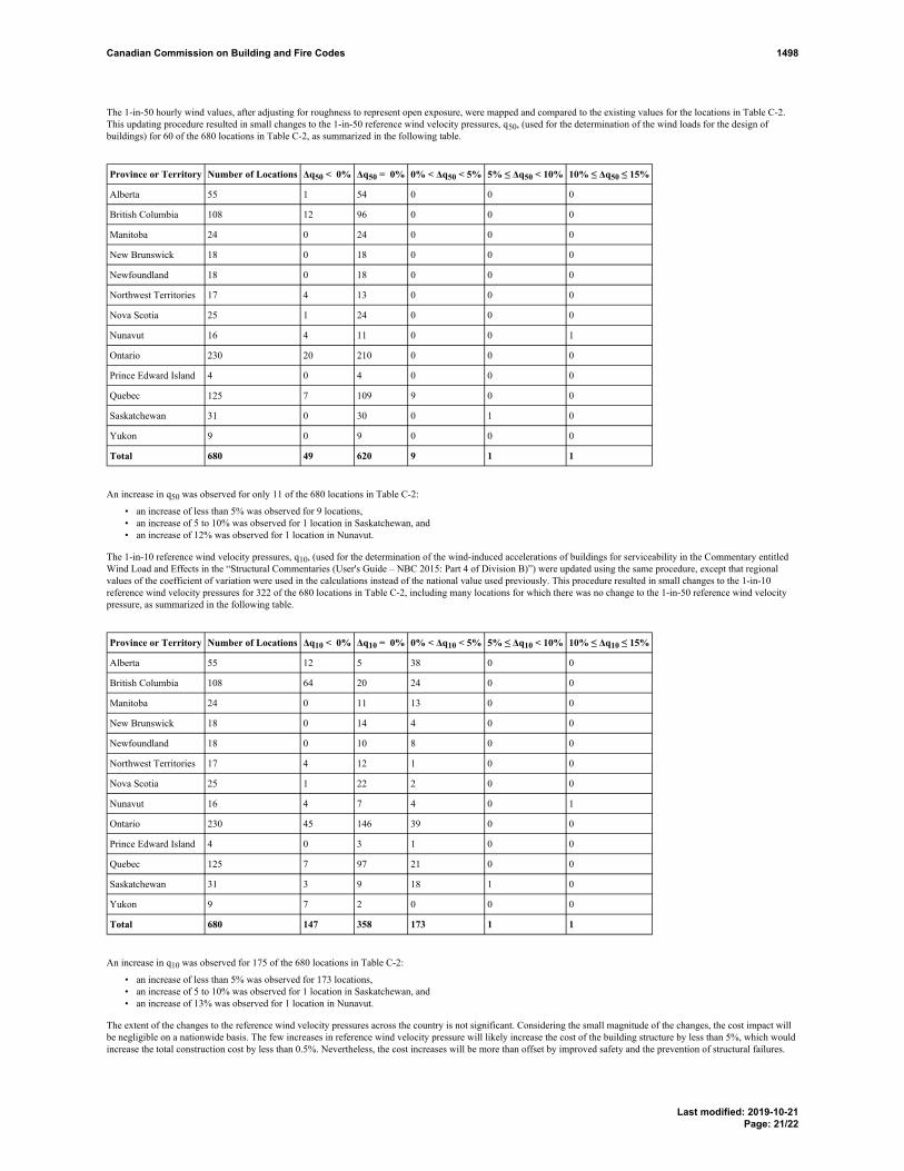
The 1-in-50 hourly wind values, after adjusting for roughness to represent open exposure, were mapped and compared to the existing values for the locations in Table C-2.This updating procedure resulted in small changes to the 1-in-50 reference wind velocity pressures, q50, (used for the determination of the wind loads for the design ofbuildings) for 60 of the 680 locations in Table C-2, as summarized in the following table.
Province or Territory Number of Locations Δq50 < 0% Δq50 = 0% 0% < Δq50 < 5% 5% ≤ Δq50 < 10% 10% ≤ Δq50 ≤ 15%
Alberta 55 1 54 0 0 0
British Columbia 108 12 96 0 0 0
Manitoba 24 0 24 0 0 0
New Brunswick 18 0 18 0 0 0
Newfoundland 18 0 18 0 0 0
Northwest Territories 17 4 13 0 0 0
Nova Scotia 25 1 24 0 0 0
Nunavut 16 4 11 0 0 1
Ontario 230 20 210 0 0 0
Prince Edward Island 4 0 4 0 0 0
Quebec 125 7 109 9 0 0
Saskatchewan 31 0 30 0 1 0
Yukon 9 0 9 0 0 0
Total 680 49 620 9 1 1
An increase in q50 was observed for only 11 of the 680 locations in Table C-2:
• an increase of less than 5% was observed for 9 locations,• an increase of 5 to 10% was observed for 1 location in Saskatchewan, and• an increase of 12% was observed for 1 location in Nunavut.
The 1-in-10 reference wind velocity pressures, q10, (used for the determination of the wind-induced accelerations of buildings for serviceability in the Commentary entitledWind Load and Effects in the “Structural Commentaries (User's Guide – NBC 2015: Part 4 of Division B)”) were updated using the same procedure, except that regionalvalues of the coefficient of variation were used in the calculations instead of the national value used previously. This procedure resulted in small changes to the 1-in-10reference wind velocity pressures for 322 of the 680 locations in Table C-2, including many locations for which there was no change to the 1-in-50 reference wind velocitypressure, as summarized in the following table.
Province or Territory Number of Locations Δq10 < 0% Δq10 = 0% 0% < Δq10 < 5% 5% ≤ Δq10 < 10% 10% ≤ Δq10 ≤ 15%
Alberta 55 12 5 38 0 0
British Columbia 108 64 20 24 0 0
Manitoba 24 0 11 13 0 0
New Brunswick 18 0 14 4 0 0
Newfoundland 18 0 10 8 0 0
Northwest Territories 17 4 12 1 0 0
Nova Scotia 25 1 22 2 0 0
Nunavut 16 4 7 4 0 1
Ontario 230 45 146 39 0 0
Prince Edward Island 4 0 3 1 0 0
Quebec 125 7 97 21 0 0
Saskatchewan 31 3 9 18 1 0
Yukon 9 7 2 0 0 0
Total 680 147 358 173 1 1
An increase in q10 was observed for 175 of the 680 locations in Table C-2:
• an increase of less than 5% was observed for 173 locations,• an increase of 5 to 10% was observed for 1 location in Saskatchewan, and• an increase of 13% was observed for 1 location in Nunavut.
The extent of the changes to the reference wind velocity pressures across the country is not significant. Considering the small magnitude of the changes, the cost impact willbe negligible on a nationwide basis. The few increases in reference wind velocity pressure will likely increase the cost of the building structure by less than 5%, which wouldincrease the total construction cost by less than 0.5%. Nevertheless, the cost increases will be more than offset by improved safety and the prevention of structural failures.
Canadian Commission on Building and Fire Codes 1498
Last modified: 2019-10-21Page: 21/22

Enforcement implicationsNone.
Who is affectedDesigners and builders.
OBJECTIVE-BASED ANALYSIS OF NEW OR CHANGED PROVISIONS
N/A
Canadian Commission on Building and Fire Codes 1498
Last modified: 2019-10-21Page: 22/22

Submit a comment
Proposed Change 1525Code Reference(s): NBC15 Div.B Appendix DSubject: Encapsulated Mass Timber ConstructionTitle: New Method of Calculating Fire-Resistance Ratings for Mass Timber
ElementsDescription: This proposed change adds a new method of calculating fire-resistance
ratings for mass timber elements to Appendix D.Related Code ChangeRequest(s):
CCR 1234
PROPOSED CHANGE
Appendix D Fire-Performance RatingsFootnote: This information is included for explanatory purposes only and does not form part of the requirements.The bold face reference numbers that introduce each item do not relate to specific requirements in this Division.
[D-1.] D-1. General[D-2.] D-2. Fire-Resistance Ratings[D-2.11.] D-2.11. Glued-Laminated Timber Beams and ColumnsMass Timber Elements[D-2.11.1.] Determination of Ratings
[1] --) The calculation methods described in this Subsection are intended to be used to determine fire-resistance ratings for structural mass timber elements on the basis of the elements being subjected to the standard fireexposure conditions described in CAN/ULC-S101, “Fire Endurance Tests of Building Construction and Materials.”
[2] --) Loadbearing mass timber members, such as beams and columns, subjected to the conditionsdescribed in Sentence (1) are assigned a fire-resistance rating that relates to the time at which the applied load is no longersustained.
[3] --) Mass timber wall, floor and roof assemblies subjected to the conditions described in Sentence (1)are assigned a fire-resistance rating that relates to the lesser of the times at which
a) an average temperature rise of 140°C or a maximum temperature rise of 180°C at any individuallocation is recorded on the unexposed side of the assembly,
b) there is passage of flame or gases hot enough to ignite cotton pads through the unexposed side of theassembly, or
c) the applied load is no longer sustained, where the assembly is loadbearing.
[D-2.11.2.] D-2.11.1. Applicability of InformationCalculation Methods[1] --) The informationMethod A described in Subsection D-2.11.D-2.11.3. applies to glued-laminated
timber beams and columns required to have fire-resistance ratings greater than those afforded under the provisions ofArticle 3.1.4.6.
[2] --) Method B described in D-2.11.4. applies to mass timber elements, including solid sawn timberand glued-laminated timber beams and columns, required to have fire-resistance ratings greater than those afforded underthe provisions of Article 3.1.4.6.
[3] --) The calculation methods described in D-2.11.3. and D-2.11.4. are separate and independentmethods that use different approaches to determine fire-resistance ratings for mass timber elements.
Canadian Commission on Building and Fire Codes 1525
Last modified: 2019-10-22Page: 1/6

[D-2.11.3.] D-2.11.2. Method of CalculationA for Glued-Laminated Timber Beams and Columns[1] 1) The fire-resistance rating of glued-laminated timber beams and columns in minutes shallis
permitted to be taken as equal toa) 0.1 fB [4 − 2(B/D)] for beams that may be exposed to fire on 4 sides,b) 0.1 fB [4 − (B/D)] for beams that may be exposed to fire on 3 sides,c) 0.1 fB [3 − (B/D)] for columns that may be exposed to fire on 4 sides, andd) 0.1 fB [3 − (B/2D)] for columns that may be exposed to fire on 3 sides,
where
f = the load factor shown in Figure D-2.11.2.-A,
B
= the full dimension of the smaller side of a beam or column in millimetres before exposure tofire [see Figure D-2.11.2.-B],
D
= the full dimension of the larger side of a beam or column in millimetres before exposure to fire[see Figure D-2.11.2.-B],
k = the effective length factor obtained from CSA O86, "Engineering Design in Wood",
L = the unsupported length of a column in millimetres.
[2] 2) The factored resistance of a beam or column shall be determined by using the specified strengthsin CSA O86, "Engineering Design in Wood".
Figure [D-2.11.3.-A] D-2.11.2.-AFactors to compensate for partially loaded columns and beams
Note to Figure D-2.11.2.-A:(1) See Sentence (2).
Canadian Commission on Building and Fire Codes 1525
Last modified: 2019-10-22Page: 2/6

Figure [D-2.11.3.-B] D-2.11.2.-BFull dimensions of glued-laminated beams and columns
[D-2.11.4.] Method B for Mass Timber Elements[1] --) The fire-resistance rating of structural mass timber members, such as beams and columns
constructed of glued-laminated timber, solid sawn timber, or structural composite lumber, is permitted to be determinedusing the calculation method described in Annex B, Fire resistance of large cross-section wood elements, of CSA O86,“Engineering Design in Wood.”
[2] --) Except as provided in Sentences (3) to (6), the fire-resistance rating of mass timber wall, floorand roof assemblies, including those constructed of cross-laminated timber, is permitted to be determined using thecalculation method described in Annex B, Fire resistance of large cross-section wood elements, of CSA O86, “EngineeringDesign in Wood.”
[3] --) Except as provided in Sentence (4), the assemblies described in Sentence (2) shall be protected tomaintain the integrity and thermal insulation properties of the assembly for the time period corresponding to the calculatedfire-resistance rating as follows:
Canadian Commission on Building and Fire Codes 1525
Last modified: 2019-10-22Page: 3/6
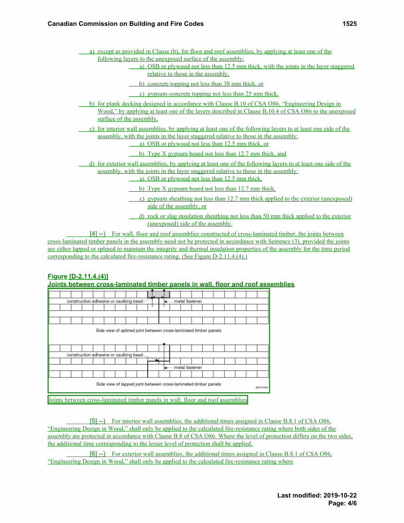
a) except as provided in Clause (b), for floor and roof assemblies, by applying at least one of thefollowing layers to the unexposed surface of the assembly:
a) OSB or plywood not less than 12.5 mm thick, with the joints in the layer staggeredrelative to those in the assembly,
b) concrete topping not less than 38 mm thick, orc) gypsum-concrete topping not less than 25 mm thick,
b) for plank decking designed in accordance with Clause B.10 of CSA O86, “Engineering Design inWood,” by applying at least one of the layers described in Clause B.10.4 of CSA O86 to the unexposedsurface of the assembly,
c) for interior wall assemblies, by applying at least one of the following layers to at least one side of theassembly, with the joints in the layer staggered relative to those in the assembly:
a) OSB or plywood not less than 12.5 mm thick, orb) Type X gypsum board not less than 12.7 mm thick, and
d) for exterior wall assemblies, by applying at least one of the following layers to at least one side of theassembly, with the joints in the layer staggered relative to those in the assembly:
a) OSB or plywood not less than 12.5 mm thick,b) Type X gypsum board not less than 12.7 mm thick,c) gypsum sheathing not less than 12.7 mm thick applied to the exterior (unexposed)
side of the assembly, ord) rock or slag insulation sheathing not less than 50 mm thick applied to the exterior
(unexposed) side of the assembly.
[4] --) For wall, floor and roof assemblies constructed of cross-laminated timber, the joints betweencross-laminated timber panels in the assembly need not be protected in accordance with Sentence (3), provided the jointsare either lapped or splined to maintain the integrity and thermal insulation properties of the assembly for the time periodcorresponding to the calculated fire-resistance rating. (See Figure D-2.11.4.(4).)
Figure [D-2.11.4.(4)]Joints between cross-laminated timber panels in wall, floor and roof assemblies
Joints between cross-laminated timber panels in wall, floor and roof assemblies
[5] --) For interior wall assemblies, the additional times assigned in Clause B.8.1 of CSA O86,“Engineering Design in Wood,” shall only be applied to the calculated fire-resistance rating where both sides of theassembly are protected in accordance with Clause B.8 of CSA O86. Where the level of protection differs on the two sides,the additional time corresponding to the lesser level of protection shall be applied.
[6] --) For exterior wall assemblies, the additional times assigned in Clause B.8.1 of CSA O86,“Engineering Design in Wood,” shall only be applied to the calculated fire-resistance rating where
Canadian Commission on Building and Fire Codes 1525
Last modified: 2019-10-22Page: 4/6

a) the interior (fire-exposed) side of the assembly is protected in accordance with Clause B.8 of CSAO86, and
b) except where the assembly is constructed of cross-laminated timber panels with lapped or splined jointsas described in Sentence (4), the exterior (unexposed) side of the assembly is protected in accordancewith Clause (3)(d).
[D-3.] D-3. Flame-Spread Ratings and Smoke Developed Classifications[D-4.] D-4. Noncombustibility[D-5.] D-5. Protection of Openings in Fire-Rated Assemblies[D-6.] D-6. Background Information
RATIONALE
General informationSee the summary for subject Encapsulated Mass Timber Construction.
ProblemThe design and construction of buildings using structural mass timber elements, such as those constructed of solidsawn timber, glued-laminated timber (glulam), structural composite lumber (SCL), or cross-laminated timber (CLT),has grown in popularity over the last few decades in Canada. Appendix D, Fire-Performance Ratings, currentlycontains some generic information on fire-resistance ratings (e.g., in D-2.4. for some types of solid wood walls, floorsand roofs, and in D-2.11. for glued-laminated timber beams and columns). However, easier access to additionalmethods of determining fire-resistance ratings that address both a greater range of situations and a greater range ofmass timber products would be very helpful to Code users.
Justification - ExplanationThe proposed change will introduce a simple way to calculate standard fire-resistance ratings for mass timberelements, such those constructed of solid sawn timber, glued-laminated timber, structural composite lumber, orcross-laminated timber, using the methodology provided in Annex B, Fire resistance of large cross-section woodelements, of CSA O86, "Engineering design in wood," the Canadian wood design standard.
The new methodology does not replace the existing methodology described in D-2.11. for glued-laminated timberbeams and columns, which many designers are familiar with and which is still useful and valid. The addition of theAnnex B methodology merely provides a second, equally valid, method of determining a fire-resistance rating.
Annex B of CSA O86 was created through the Canadian Standards Association (CSA) standards developmentprocess. The CSA website describes the mandate of the organization as follows: "CSA develops standards that addressreal needs, such as enhancing public safety and health, advancing the quality of life, and helping to preserve theenvironment." CSA maintains its accreditation by developing consensus-based standards that adhere to requirementsestablished by the Standards Council of Canada, a process that provides a voice to all stakeholders.
Annex B of CSA O86 was developed by Canadian fire safety engineering experts, on the basis of standard fire-resistance testing to CAN/ULC-S101, "Fire Endurance Tests of Building Construction and Materials," on large cross-section wood elements. This Annex was first published in 2014, and by the time of the publication of the NBC 2020, itwill have undergone several iterations of examination and analysis, including public review and comment periods, asis typical in the CSA consensus-based process.
The Annex B methodology is currently being used by designers across Canada. In most provinces, its use must beapproved by the authority having jurisdiction (AHJ) on a case-by-case basis, as is the case with all alternativesolutions. In Quebec, however, the Régie du bâtiment du Québec (RBQ), the provincial government organizationresponsible for the Quebec Construction Code, adopted Annex B of the 2014 edition of CSA O86, including its 2016
Canadian Commission on Building and Fire Codes 1525
Last modified: 2019-10-22Page: 5/6

supplement, as an acceptable solution in 2017 (www.rbq.gouv.qc.ca/batiment/les-mesures-equivalentes-et-les-mesures-differentes/utilisation-de-la-norme-csa-o86-2014-pour-une-construction-en-bois.html).
A reference to the Annex B methodology would be a very useful addition to the information on generic fire-resistanceratings and methods of calculating such ratings currently provided in Appendix D. In particular, adding such areference would reduce the number of regulatory hurdles a designer would need to overcome in using the Annex Bmethodology for a fire-resistant design. It would also allow AHJs to expend fewer resources on assessing alternativesolutions that use the Annex B methodology.
As the majority of the provisions in Annex B of CSA O86 address only the structural aspect of the fire resistance ofmass timber members and assemblies, additional prescriptive requirements have been included in proposed D-2.11.4.to ensure that the integrity and thermal insulation properties of wall, floor and roof assemblies are maintained for thetime period corresponding to the fire-resistance rating.
Impact analysisThe proposed change will not entail any additional costs. It is intended to clarify and expand the tools available forassigning a fire-resistance rating in accordance with Subsection 3.1.7., and is, therefore, likely to be of benefit todesigners and builders in the development of efficient and cost-effective fire-resistance-rated designs that meet the firesafety objectives of the Code.
Enforcement implicationsSince this proposed change merely provides additional tools to assist designers in the development of and regulators inthe evaluation of fire-resistance-rated designs, it will not increase enforcement requirements and can be enforced bythe infrastructure currently available to enforce the Code. In fact, the proposed change is likely to reduce the amountof enforcement resources expended by AHJs.
Who is affectedArchitects, engineers, builders, regulators.
OBJECTIVE-BASED ANALYSIS OF NEW OR CHANGED PROVISIONS
N/A
Canadian Commission on Building and Fire Codes 1525
Last modified: 2019-10-22Page: 6/6

Submit a comment
Proposed Change 741Code Reference(s): NBC15 Div.C 2.2.4.3.Subject: OtherTitle: Information Required on Structural DrawingsDescription: This proposed change deletes the reference to cladding in Sentence (1) and
adds a new Sentence dealing with structural drawings of secondarystructural elements.
PROPOSED CHANGE
[2.2.4.3.] 2.2.4.3. Information Required on Structural Drawings(See Note A-2.2.4.3.)
[1] 1) Structural drawings and related documents submitted with the application to build shall indicate, inaddition to those items specified in Article 2.2.4.6. and in Part 4 of Division B applicable to the specificmaterial,[a] a) the name and address of the company or person responsible for the structural design,[b] b) the date of issue of the Code and standards to which the design conforms,[c] c) the dimensions, location and size of all structural members in sufficient detail to enable the
design to be checked,[d] d) sufficient detail to enable the dead loads due to the self weight of the structure to be determined,
and[e] e) for the primary building structure, all effects and loads, other than dead loads, used for the
design of the structural members and exterior cladding., including dead loads due to the selfweight of the structure and superimposed dead loads, as well as the allowances for live and deadloads transferred from the secondary structural elements, including cladding.
[2] --) Structural drawings for the secondary structural elements, including cladding, prepared under thedirection of the structural engineer for the secondary structural elements shall indicate all loads appliedto the secondary structural elements and all connection loads applied to the primary building structure.
Note A-2.2.4.3. Information Required on Structural Drawings.Sentence 2.2.4.3.(1) deals with the structural drawings for the primary building structure, which are prepared, signed andsealed by the engineer of record for the primary building structure. These drawings do not typically include the design ofthe secondary structural elements and systems, such as cladding, guards, exterior ornamentations, equipment andappendages, that are attached to the primary building structure. Nevertheless, the engineer of record for the primarybuilding structure must indicate the allowances used in the design of the primary building structure to account for liveand dead loads transferred from the secondary structural elements.Sentence 2.2.4.3.(2) deals with the structural drawings for the structural components of buildings that are commonlyreferred to as “secondary structural elements” (e.g., cladding). These elements are typically designed by structuralengineers other than the engineer of record for the primary building structure.The structural engineer for the secondary structural elements must indicate the design loads on the drawings, as theseloads may have an impact on the primary building structure and need to be reviewed by the engineer of record for theprimary building structure for several purposes including to validate the original allowances used to account for dead andlive loads transferred from the secondary structural elements. Connection loads to the primary building structure fromsecondary structural elements are required for the engineer of record for the primary building structure to providestructural details within the primary structure to safely support the connection loads from secondary structural elements.
Canadian Commission on Building and Fire Codes 741
Last modified: 2019-09-05Page: 1/2

In determining the design loads for the secondary structural elements, the engineer may use the information on thestructural drawings for the primary building structure in combination with the applicable Code provisions. However, theengineer should not assume that the information on the structural drawings for the primary building structure, which isspecific to location, importance factors, and wind and seismic parameters, is applicable to the design of the secondarystructural elements, and should not rely on any loads prescribed for the primary building structure as being appropriatefor the secondary structural elements.
RATIONALE
ProblemThe current wording is problematic in that the building cladding is not typically designed by the structural engineerresponsible for the primary building structure (structural engineer of record). There is a need to provide the loadinginformation for the cladding and other secondary building elements and all connection loads of the secondary buildingelements that are applied to the primary building structure on the drawings for the secondary structural elements as theseelements are not designed by the engineer of record for the primary building structure.
This would ensure that appropriate cladding loads and all connection loads applied to the primary building structureare clearly provided for design purposes. Inappropriate loading could lead to structural failure and potential collapseof the building structure and cladding.
Justification - ExplanationThe resolution of this problem is to have the design engineer for the secondary structural elements, such as cladding,provide the loadings on the drawings for the secondary structural elements while maintaining the requirement for theengineer of record for the primary building structure to provide the loadings on the structural drawings for theprimary building structure and to ensure that the appropriate connection loads of the secondary structural elementsare accounted for in the design of the primary building structure.
Impact analysisThis proposed change clarifies that loading information must be added to the drawings for the primary buildingstructure as well as to those for the secondary structural elements.
Enforcement implicationsNone.
Who is affectedBuilding officials, designers, contractors, property managers.
Canadian Commission on Building and Fire Codes 741
Last modified: 2019-09-05Page: 2/2

Submit a comment
Proposed Change 1623Code Reference(s): NECB17 Div.B Appendix CSubject: Climatic LoadsTitle: Update of Wind Pressure DataDescription: This proposed change updates the hourly wind pressure data in Table C-1.
PROPOSED CHANGE
Climatic Information for Building Design in CanadaTable C-1, which is referenced in Sentence 1.1.4.1.(1), represents a partial reproduction of Table C-2 of Division B of theNBC (see the section on Climatic and Seismic Information for Building Design in Canada in the NBC for furtherinformation on these climatic data categories). The additional data for “Degree-Days Below 15°C” was developed byEnvironment Canada for inclusion in the NECB.
Table [C-1] C-1Design Data for Selected Locations in Canada
Design TemperatureHourly WindPressures,
kPa (1)
January July 2.5%Province and
LocationElev.,
m
2.5%°C
1%°C
Dry°C
Wet°C
Degree-Days
Below18°C
Degree-Days
Below15°C 1/10 1/50
British Columbia
100 Mile House 1040 -30 -32 29 17 5030 4040 0.27 0.35
Abbotsford 70 -8 -10 29 20 2860 2000 0.340.33 0.44
Agassiz 15 -9 -11 31 21 2750 1900 0.360.35 0.47
Alberni 12 -5 -8 31 19 3100 2220 0.250.24 0.32
Ashcroft 305 -24 -27 34 20 3700 2790 0.29 0.38
Bamfield 20 -2 -4 23 17 3080 2060 0.390.38 0.50
Beatton River 840 -37 -39 26 18 6300 5230 0.23 0.30
Bella Bella 25 -5 -7 23 18 3180 2150 0.390.40 0.50
Bella Coola 40 -14 -18 27 19 3560 2660 0.300.29 0.39
Burns Lake 755 -31 -34 26 17 5450 4430 0.300.29 0.39
Cache Creek 455 -24 -27 34 20 3700 2790 0.300.29 0.39
PROPOSED CHANGE Table C-1. Footnote
Canadian Commission on Building and Fire Codes 1623
Last modified: 2019-10-24Page: 1/32

Design TemperatureHourly WindPressures,
kPa (1)
January July 2.5%Province and
LocationElev.,
m
2.5%°C
1%°C
Dry°C
Wet°C
Degree-Days
Below18°C
Degree-Days
Below15°C 1/10 1/50
Campbell River 20 -5 -7 26 18 3000 2130 0.400.41 0.520.48
Carmi 845 -24 -26 31 19 4750 3770 0.29 0.38
Castlegar 430 -18 -20 32 20 3580 2680 0.270.26 0.34
Chetwynd 605 -35 -38 27 18 5500 4480 0.310.30 0.40
Chilliwack 10 -9 -11 30 20 2780 1920 0.360.35 0.47
Comox 15 -7 -9 27 18 3100 2220 0.400.41 0.520.48
Courtenay 10 -7 -9 28 18 3100 2220 0.400.41 0.520.48
Cranbrook 910 -26 -28 32 18 4400 3450 0.25 0.33
Crescent Valley 585 -18 -20 31 20 3650 2740 0.25 0.33
Crofton 5 -4 -6 28 19 2880 2020 0.310.32 0.40
Dawson Creek 665 -38 -40 27 18 5900 4860 0.310.30 0.40
Dease Lake 800 -37 -40 24 15 6730 5630 0.23 0.30
Dog Creek 450 -28 -30 29 17 4800 3820 0.27 0.35
Duncan 10 -6 -8 28 19 2980 2110 0.300.31 0.39
Elko 1065 -28 -31 30 19 4600 3630 0.310.30 0.40
Fernie 1010 -27 -30 30 19 4750 3770 0.310.30 0.40
Fort Nelson 465 -39 -42 28 18 6710 5740 0.23 0.30
Fort St. John 685 -35 -37 26 18 5750 4710 0.300.29 0.39
Glacier 1145 -27 -30 27 17 5800 4760 0.250.24 0.32
Gold River 120 -8 -11 31 18 3230 2350 0.250.24 0.32
Golden 790 -27 -30 30 17 4750 3770 0.270.26 0.35
Grand Forks 565 -19 -22 34 20 3820 2900 0.310.30 0.40
Greenwood 745 -20 -23 34 20 4100 3160 0.310.30 0.40
Hope 40 -13 -15 31 20 3000 2130 0.480.47 0.63
Jordan River 20 -1 -3 22 17 2900 1900 0.430.44 0.55
PROPOSED CHANGE Table C-1. Footnote
Canadian Commission on Building and Fire Codes 1623
Last modified: 2019-10-24Page: 2/32

Design TemperatureHourly WindPressures,
kPa (1)
January July 2.5%Province and
LocationElev.,
m
2.5%°C
1%°C
Dry°C
Wet°C
Degree-Days
Below18°C
Degree-Days
Below15°C 1/10 1/50
Kamloops 355 -23 -25 34 20 3450 2670 0.310.30 0.40
Kaslo 545 -17 -20 30 19 3830 2910 0.240.23 0.31
Kelowna 350 -17 -20 33 20 3400 2510 0.310.30 0.40
Kimberley 1090 -25 -27 31 18 4650 3680 0.25 0.33
Kitimat Plant 15 -16 -18 25 16 3750 2830 0.370.36 0.48
Kitimat Townsite 130 -16 -18 24 16 3900 2980 0.370.36 0.48
Ladysmith 80 -7 -9 27 19 3000 2130 0.310.32 0.40
Langford 80 -4 -6 27 19 2750 1770 0.310.32 0.40
Lillooet 245 -21 -23 34 20 3400 2610 0.340.33 0.44
Lytton 325 -17 -20 35 20 3300 2410 0.330.32 0.43
Mackenzie 765 -34 -38 27 17 5550 4530 0.25 0.32
Masset 10 -5 -7 17 15 3700 2600 0.480.50 0.61
McBride 730 -29 -32 29 18 4980 3990 0.27 0.35
McLeod Lake 695 -35 -37 27 17 5450 4430 0.25 0.32
Merritt 570 -24 -27 34 20 3900 2980 0.340.33 0.44
Mission City 45 -9 -11 30 20 2850 1990 0.330.32 0.43
Montrose 615 -16 -18 32 20 3600 2690 0.270.26 0.35
Nakusp 445 -20 -22 31 20 3560 2660 0.25 0.33
Nanaimo 15 -6 -8 27 19 3000 2130 0.390.38 0.500.48
Nelson 600 -18 -20 31 20 3500 2600 0.25 0.33
Ocean Falls 10 -10 -12 23 17 3400 2510 0.460.44 0.59
Osoyoos 285 -14 -17 35 21 3100 2220 0.310.30 0.40
Parksville 40 -6 -8 26 19 3200 2320 0.390.40 0.500.48
Penticton 350 -15 -17 33 20 3350 2460 0.350.30 0.450.40
Port Alberni 15 -5 -8 31 19 3100 2220 0.250.24 0.32
PROPOSED CHANGE Table C-1. Footnote
Canadian Commission on Building and Fire Codes 1623
Last modified: 2019-10-24Page: 3/32

Design TemperatureHourly WindPressures,
kPa (1)
January July 2.5%Province and
LocationElev.,
m
2.5%°C
1%°C
Dry°C
Wet°C
Degree-Days
Below18°C
Degree-Days
Below15°C 1/10 1/50
Port Alice 25 -3 -6 26 17 3010 2000 0.250.24 0.32
Port Hardy 5 -5 -7 20 16 3440 2370 0.400.36 0.520.48
Port McNeill 5 -5 -7 22 17 3410 2350 0.400.36 0.520.48
Port Renfrew 20 -3 -5 24 17 2900 1900 0.400.42 0.52
Powell River 10 -7 -9 26 18 3100 2220 0.39 0.510.48
Prince George 580 -32 -36 28 18 4720 3750 0.290.28 0.37
Prince Rupert 20 -13 -15 19 15 3900 2770 0.420.43 0.54
Princeton 655 -24 -29 33 19 4250 3300 0.280.27 0.36
Qualicum Beach 10 -7 -9 27 19 3200 2320 0.41 0.530.48
Queen CharlotteCity
35 -6 -8 21 16 3520 2440 0.480.50 0.61
Quesnel 475 -31 -33 30 17 4650 3680 0.24 0.31
Revelstoke 440 -20 -23 31 19 4000 3070 0.250.24 0.32
Salmon Arm 425 -19 -24 33 21 3650 2740 0.300.29 0.39
Sandspit 5 -4 -6 18 15 3450 2380 0.600.59 0.780.72
Sechelt 25 -6 -8 27 20 2680 1830 0.370.38 0.48
Sidney 10 -4 -6 26 18 2850 1860 0.330.34 0.42
Smith River 660 -45 -47 26 17 7100 5980 0.230.24 0.30
Smithers 500 -29 -31 26 17 5040 4050 0.310.30 0.40
Sooke 20 -1 -3 21 16 2900 1900 0.370.38 0.48
Squamish 5 -9 -11 29 20 2950 2080 0.390.38 0.50
Stewart 10 -17 -20 25 16 4350 3400 0.280.27 0.36
Tahsis 25 -4 -6 26 18 3150 2120 0.26 0.34
Taylor 515 -35 -37 26 18 5720 4690 0.310.30 0.40
PROPOSED CHANGE Table C-1. Footnote
Canadian Commission on Building and Fire Codes 1623
Last modified: 2019-10-24Page: 4/32

Design TemperatureHourly WindPressures,
kPa (1)
January July 2.5%Province and
LocationElev.,
m
2.5%°C
1%°C
Dry°C
Wet°C
Degree-Days
Below18°C
Degree-Days
Below15°C 1/10 1/50
Terrace 60 -19 -21 27 17 4150 3210 0.280.27 0.36
Tofino 10 -2 -4 20 16 3150 2120 0.530.51 0.68
Trail 440 -14 -17 33 20 3600 2690 0.270.26 0.35
Ucluelet 5 -2 -4 18 16 3120 2100 0.530.51 0.68
Vancouver Region
Burnaby (SimonFraser Univ.)
330 -7 -9 25 17 3100 2220 0.360.35 0.47
Cloverdale 10 -8 -10 29 20 2700 1850 0.340.33 0.44
Haney 10 -9 -11 30 20 2840 1980 0.340.33 0.44
Ladner 3 -6 -8 27 19 2600 1750 0.360.37 0.46
Langley 15 -8 -10 29 20 2700 1850 0.340.33 0.44
NewWestminster
10 -8 -10 29 19 2800 1940 0.340.33 0.44
North Vancouver 135 -7 -9 26 19 2910 2050 0.350.34 0.45
Richmond 5 -7 -9 27 19 2800 1940 0.350.36 0.45
Surrey (88 Ave& 156 St.)
90 -8 -10 29 20 2750 1900 0.340.33 0.44
Vancouver(City Hall)
40 -7 -9 28 20 2825 1970 0.350.34 0.45
Vancouver(Granville & 41Ave)
120 -6 -8 28 20 2925 2060 0.350.36 0.45
West Vancouver 45 -7 -9 28 19 2950 2080 0.370.36 0.48
Vernon 405 -20 -23 33 20 3600 2690 0.310.30 0.40
Victoria Region
Victoria(Gonzales Hts)
65 -4 -6 24 17 2700 1690 0.440.46 0.57
Victoria(Mt Tolmie)
125 -6 -8 24 16 2700 1730 0.480.46 0.630.57
Victoria 10 -4 -6 24 17 2650 1730 0.46 0.57
PROPOSED CHANGE Table C-1. Footnote
Canadian Commission on Building and Fire Codes 1623
Last modified: 2019-10-24Page: 5/32

Design TemperatureHourly WindPressures,
kPa (1)
January July 2.5%Province and
LocationElev.,
m
2.5%°C
1%°C
Dry°C
Wet°C
Degree-Days
Below18°C
Degree-Days
Below15°C 1/10 1/50
Whistler 665 -17 -20 30 20 4180 3240 0.250.24 0.32
White Rock 30 -5 -7 25 20 2620 1770 0.340.33 0.44
Williams Lake 615 -30 -33 29 17 4400 3450 0.27 0.35
Youbou 200 -5 -8 31 19 3050 2180 0.250.26 0.32
Alberta
Athabasca 515 -35 -38 27 19 6000 5000 0.280.27 0.36
Banff 1400 -31 -33 27 16 5500 4520 0.250.26 0.32
Barrhead 645 -33 -36 27 19 5740 4750 0.340.35 0.44
Beaverlodge 730 -36 -39 28 18 5700 4710 0.280.27 0.36
Brooks 760 -32 -34 32 20 4880 3940 0.400.35 0.520.44
Calgary 1045 -30 -32 28 17 5000 4050 0.370.38 0.48
Campsie 660 -33 -36 27 19 5750 4760 0.340.33 0.44
Camrose 740 -33 -35 29 19 5500 4520 0.300.31 0.39
Canmore 1320 -31 -33 28 17 5400 4430 0.290.30 0.37
Cardston 1130 -29 -32 30 19 4700 3770 0.560.58 0.72
Claresholm 1030 -30 -32 30 18 4680 3750 0.450.46 0.58
Cold Lake 540 -35 -38 28 19 5860 4860 0.29 0.38
Coleman 1320 -31 -34 29 18 5210 4250 0.480.50 0.63
Coronation 790 -32 -34 30 19 5640 4660 0.290.30 0.37
Cowley 1175 -29 -32 29 18 4810 3870 0.780.81 1.01
Drumheller 685 -32 -34 30 18 5050 4100 0.340.35 0.44
Edmonton 645 -30 -33 28 19 5120 4160 0.350.36 0.45
Edson 920 -34 -37 27 18 5750 4760 0.360.37 0.46
Embarras Portage 220 -41 -43 28 19 7100 6040 0.290.28 0.37
Fairview 670 -37 -40 27 18 5840 4850 0.270.26 0.35
Fort MacLeod 945 -30 -32 31 19 4600 3670 0.530.54 0.68
PROPOSED CHANGE Table C-1. Footnote
Canadian Commission on Building and Fire Codes 1623
Last modified: 2019-10-24Page: 6/32

Design TemperatureHourly WindPressures,
kPa (1)
January July 2.5%Province and
LocationElev.,
m
2.5%°C
1%°C
Dry°C
Wet°C
Degree-Days
Below18°C
Degree-Days
Below15°C 1/10 1/50
Fort McMurray 255 -38 -40 28 19 6250 5230 0.270.28 0.35
Fort Saskatchewan 610 -32 -35 28 19 5420 4450 0.330.34 0.43
Fort Vermilion 270 -41 -43 28 18 6700 5660 0.23 0.30
Grande Prairie 650 -36 -39 27 18 5790 4800 0.330.32 0.43
Habay 335 -41 -43 28 18 6750 5710 0.23 0.30
Hardisty 615 -33 -36 30 19 5640 4660 0.280.29 0.36
High River 1040 -31 -32 28 17 4900 3960 0.500.52 0.65
Hinton 990 -34 -38 27 17 5500 4520 0.360.37 0.46
Jasper 1060 -31 -34 28 17 5300 4330 0.250.26 0.32
Keg River 420 -40 -42 28 18 6520 5490 0.23 0.30
Lac la Biche 560 -35 -38 28 19 6100 5090 0.280.27 0.36
Lacombe 855 -33 -36 28 19 5500 4520 0.310.32 0.40
Lethbridge 910 -30 -32 31 19 4500 3580 0.510.53 0.66
Manning 465 -39 -41 27 18 6300 5280 0.23 0.30
Medicine Hat 705 -31 -34 32 19 4540 3610 0.370.38 0.48
Peace River 330 -37 -40 27 18 6050 5040 0.250.24 0.32
Pincher Creek 1130 -29 -32 29 18 4740 3800 0.750.77 0.96
Ranfurly 670 -34 -37 29 19 5700 4710 0.280.29 0.36
Red Deer 855 -32 -35 28 19 5550 4570 0.310.32 0.40
Rocky MountainHouse
985 -32 -34 27 18 5640 4660 0.280.29 0.36
Slave Lake 590 -35 -38 26 19 5850 4850 0.290.28 0.37
Stettler 820 -32 -34 30 19 5300 4330 0.280.29 0.36
Stony Plain 710 -32 -35 28 19 5300 4330 0.350.36 0.45
Suffield 755 -31 -34 32 20 4770 3830 0.380.39 0.49
Taber 815 -31 -33 31 19 4580 3650 0.480.50 0.63
Turner Valley 1215 -31 -32 28 17 5220 4260 0.500.52 0.65
PROPOSED CHANGE Table C-1. Footnote
Canadian Commission on Building and Fire Codes 1623
Last modified: 2019-10-24Page: 7/32

Design TemperatureHourly WindPressures,
kPa (1)
January July 2.5%Province and
LocationElev.,
m
2.5%°C
1%°C
Dry°C
Wet°C
Degree-Days
Below18°C
Degree-Days
Below15°C 1/10 1/50
Valleyview 700 -37 -40 27 18 5600 4620 0.330.34 0.42
Vegreville 635 -34 -37 29 19 5780 4790 0.280.29 0.36
Vermilion 580 -35 -38 29 19 5740 4750 0.280.29 0.36
Wagner 585 -35 -38 26 19 5850 4850 0.290.28 0.37
Wainwright 675 -33 -36 29 19 5700 4710 0.280.29 0.36
Wetaskiwin 760 -33 -35 29 19 5500 4520 0.300.31 0.39
Whitecourt 690 -33 -36 27 19 5650 4670 0.290.28 0.37
Wimborne 975 -31 -34 29 18 5310 4340 0.310.32 0.40
Saskatchewan
Assiniboia 740 -32 -34 31 21 5180 4300 0.380.39 0.49
Battrum 700 -32 -34 32 20 5080 4210 0.420.43 0.54
Biggar 645 -34 -36 30 20 5720 4820 0.350.36 0.45
Broadview 600 -34 -35 30 21 5760 4850 0.36 0.46
Dafoe 530 -35 -37 29 21 5860 4950 0.29 0.37
Dundurn 525 -35 -37 30 21 5600 4700 0.36 0.46
Estevan 565 -32 -34 32 22 5340 4450 0.400.41 0.52
Hudson Bay 370 -36 -38 29 21 6280 5350 0.29 0.37
Humboldt 565 -36 -38 28 21 6000 5080 0.300.31 0.39
Island Falls 305 -39 -41 27 20 7100 6130 0.270.26 0.35
Kamsack 455 -34 -37 29 22 6040 5120 0.310.32 0.40
Kindersley 685 -33 -35 31 20 5550 4650 0.36 0.46
Lloydminster 645 -34 -37 28 20 5880 4970 0.310.32 0.40
Maple Creek 765 -31 -34 31 20 4780 3920 0.350.36 0.45
Meadow Lake 480 -38 -40 28 20 6280 5350 0.310.30 0.40
Melfort 455 -36 -38 28 21 6050 5130 0.28 0.36
Melville 550 -34 -36 29 21 5880 4970 0.310.32 0.40
Moose Jaw 545 -32 -34 31 21 5270 4390 0.400.41 0.52
PROPOSED CHANGE Table C-1. Footnote
Canadian Commission on Building and Fire Codes 1623
Last modified: 2019-10-24Page: 8/32

Design TemperatureHourly WindPressures,
kPa (1)
January July 2.5%Province and
LocationElev.,
m
2.5%°C
1%°C
Dry°C
Wet°C
Degree-Days
Below18°C
Degree-Days
Below15°C 1/10 1/50
Nipawin 365 -37 -39 28 21 6300 5370 0.290.30 0.38
North Battleford 545 -34 -36 29 20 5900 4990 0.36 0.46
Prince Albert 435 -37 -40 28 21 6100 5180 0.290.30 0.38
Qu'Appelle 645 -34 -36 30 22 5620 4720 0.33 0.42
Regina 575 -34 -36 31 21 5600 4700 0.380.39 0.49
Rosetown 595 -34 -36 31 20 5620 4720 0.380.39 0.49
Saskatoon 500 -35 -37 30 21 5700 4800 0.330.36 0.430.46
Scott 645 -34 -36 30 20 5960 5040 0.350.36 0.45
Strasbourg 545 -34 -36 30 22 5600 4700 0.33 0.42
Swift Current 750 -31 -34 31 20 5150 4270 0.420.43 0.54
Uranium City 265 -42 -44 26 19 7500 6510 0.280.27 0.36
Weyburn 575 -33 -35 31 23 5400 4510 0.370.38 0.48
Yorkton 510 -34 -37 29 21 6000 5080 0.310.32 0.40
Manitoba
Beausejour 245 -33 -35 29 23 5680 4780 0.32 0.41
Boissevain 510 -32 -34 30 23 5500 4610 0.400.41 0.52
Brandon 395 -33 -35 30 22 5760 4850 0.380.39 0.49
Churchill 10 -38 -40 25 18 8950 7890 0.43 0.55
Dauphin 295 -33 -35 30 22 5900 4990 0.310.32 0.40
Flin Flon 300 -38 -40 27 20 6440 5500 0.270.28 0.35
Gimli 220 -34 -36 29 23 5800 4890 0.310.32 0.40
Island Lake 240 -36 -38 27 20 6900 5940 0.29 0.37
Lac du Bonnet 260 -34 -36 29 23 5730 4830 0.29 0.37
Lynn Lake 350 -40 -42 27 19 7770 6770 0.29 0.37
Morden 300 -31 -33 30 24 5400 4510 0.400.41 0.52
Neepawa 365 -32 -34 29 23 5760 4850 0.340.35 0.44
PROPOSED CHANGE Table C-1. Footnote
Canadian Commission on Building and Fire Codes 1623
Last modified: 2019-10-24Page: 9/32

Design TemperatureHourly WindPressures,
kPa (1)
January July 2.5%Province and
LocationElev.,
m
2.5%°C
1%°C
Dry°C
Wet°C
Degree-Days
Below18°C
Degree-Days
Below15°C 1/10 1/50
Pine Falls 220 -34 -36 28 23 5900 4990 0.300.31 0.39
Portage la Prairie 260 -31 -33 30 23 5600 4700 0.36 0.46
Rivers 465 -34 -36 29 23 5840 4930 0.36 0.46
Sandilands 365 -32 -34 29 23 5650 4750 0.310.32 0.40
Selkirk 225 -33 -35 29 23 5700 4800 0.32 0.41
Split Lake 175 -38 -40 27 19 7900 6890 0.300.31 0.39
Steinbach 270 -33 -35 29 23 5700 4800 0.310.32 0.40
Swan River 335 -34 -37 29 22 6100 5180 0.270.28 0.35
The Pas 270 -36 -38 28 21 6480 5540 0.29 0.37
Thompson 205 -40 -43 27 19 7600 6600 0.28 0.36
Virden 435 -33 -35 30 23 5620 4720 0.36 0.46
Winnipeg 235 -33 -35 30 23 5670 4770 0.350.36 0.45
Ontario
Ailsa Craig 230 -17 -19 30 23 3840 3050 0.390.37 0.500.48
Ajax 95 -20 -22 30 23 3820 3030 0.37 0.48
Alexandria 80 -24 -26 30 23 4600 3740 0.31 0.40
Alliston 220 -23 -25 29 23 4200 3380 0.28 0.36
Almonte 120 -26 -28 30 23 4620 3760 0.32 0.41
Armstrong 340 -37 -40 28 21 6500 5530 0.230.22 0.30
Arnprior 85 -27 -29 30 23 4680 3820 0.29 0.37
Atikokan 400 -33 -35 29 22 5750 4810 0.230.22 0.30
Attawapiskat 10 -37 -39 28 21 7100 6120 0.320.30 0.41
Aurora 270 -21 -23 30 23 4210 3390 0.34 0.44
Bancroft 365 -28 -31 29 23 4740 3870 0.25 0.32
Barrie 245 -24 -26 29 23 4380 3540 0.28 0.36
Barriefield 100 -22 -24 28 23 3990 3190 0.360.37 0.47
PROPOSED CHANGE Table C-1. Footnote
Canadian Commission on Building and Fire Codes 1623
Last modified: 2019-10-24Page: 10/32

Design TemperatureHourly WindPressures,
kPa (1)
January July 2.5%Province and
LocationElev.,
m
2.5%°C
1%°C
Dry°C
Wet°C
Degree-Days
Below18°C
Degree-Days
Below15°C 1/10 1/50
Beaverton 240 -24 -26 30 23 4300 3470 0.28 0.36
Belleville 90 -22 -24 29 23 3910 3110 0.330.34 0.43
Belmont 260 -17 -19 30 24 3840 3050 0.360.37 0.47
Kitchenuhmay-koosib(Big Trout Lake)
215 -38 -40 26 20 7450 – 0.313 0.42
CFB Borden 225 -23 -25 29 23 4300 3470 0.28 0.36
Bracebridge 310 -26 -28 29 23 4800 3920 0.27 0.35
Bradford 240 -23 -25 30 23 4280 3450 0.28 0.36
Brampton 215 -19 -21 30 23 4100 3290 0.34 0.44
Brantford 205 -18 -20 30 23 3900 3110 0.33 0.42
Brighton 95 -21 -23 29 23 4000 3200 0.37 0.48
Brockville 85 -23 -25 29 23 4060 3250 0.34 0.44
Burk's Falls 305 -26 -28 29 22 5020 4120 0.27 0.35
Burlington 80 -17 -19 31 23 3740 2960 0.36 0.46
Cambridge 295 -18 -20 29 23 4100 3290 0.28 0.36
Campbellford 150 -23 -26 30 23 4280 3450 0.32 0.41
Cannington 255 -24 -26 30 23 4310 3480 0.28 0.36
Carleton Place 135 -25 -27 30 23 4600 3740 0.32 0.41
Cavan 200 -23 -25 30 23 4400 3560 0.34 0.44
Centralia 260 -17 -19 30 23 3800 3010 0.380.37 0.490.48
Chapleau 425 -35 -38 27 21 5900 4950 0.23 0.30
Chatham 180 -16 -18 31 24 3470 2710 0.330.34 0.43
Chesley 275 -19 -21 29 22 4320 3490 0.370.35 0.480.45
Clinton 280 -17 -19 29 23 4150 3330 0.380.36 0.490.46
Coboconk 270 -25 -27 30 23 4500 3650 0.27 0.35
PROPOSED CHANGE Table C-1. Footnote
Canadian Commission on Building and Fire Codes 1623
Last modified: 2019-10-24Page: 11/32

Design TemperatureHourly WindPressures,
kPa (1)
January July 2.5%Province and
LocationElev.,
m
2.5%°C
1%°C
Dry°C
Wet°C
Degree-Days
Below18°C
Degree-Days
Below15°C 1/10 1/50
Cobourg 90 -21 -23 29 23 3980 3180 0.38 0.49
Cochrane 245 -34 -36 29 21 6200 5240 0.27 0.35
Colborne 105 -21 -23 29 23 3980 3180 0.38 0.49
Collingwood 190 -21 -23 29 23 4180 3360 0.30 0.39
Cornwall 35 -23 -25 30 23 4250 3420 0.32 0.41
Corunna 185 -16 -18 31 24 3600 2830 0.360.37 0.47
Deep River 145 -29 -32 30 22 4900 3980 0.27 0.35
Deseronto 85 -22 -24 29 23 4070 3260 0.330.34 0.43
Dorchester 260 -18 -20 30 24 3900 3110 0.360.37 0.47
Dorion 200 -33 -35 28 21 5950 5000 0.300.29 0.39
Dresden 185 -16 -18 31 24 3750 2970 0.330.34 0.43
Dryden 370 -34 -36 28 22 5850 4940 0.230.22 0.30
Dundalk 525 -22 -24 29 22 4700 3830 0.33 0.42
Dunnville 175 -15 -17 30 24 3660 2890 0.36 0.46
Durham 340 -20 -22 29 22 4340 3510 0.34 0.44
Dutton 225 -16 -18 31 24 3700 2920 0.360.37 0.47
Earlton 245 -33 -36 29 22 5730 4790 0.35 0.45
Edison 365 -34 -36 28 22 5740 4840 0.240.23 0.31
Elliot Lake 380 -26 -28 29 21 4950 4030 0.290.30 0.38
Elmvale 220 -24 -26 29 23 4200 3380 0.28 0.36
Embro 310 -19 -21 30 23 3950 3150 0.37 0.48
Englehart 205 -33 -36 29 22 5800 4860 0.32 0.41
Espanola 220 -25 -27 29 21 4920 4000 0.33 0.42
Exeter 265 -17 -19 30 23 3900 3110 0.380.37 0.490.48
Fenelon Falls 260 -25 -27 30 23 4440 3600 0.28 0.36
Fergus 400 -20 -22 29 23 4300 3470 0.28 0.36
PROPOSED CHANGE Table C-1. Footnote
Canadian Commission on Building and Fire Codes 1623
Last modified: 2019-10-24Page: 12/32

Design TemperatureHourly WindPressures,
kPa (1)
January July 2.5%Province and
LocationElev.,
m
2.5%°C
1%°C
Dry°C
Wet°C
Degree-Days
Below18°C
Degree-Days
Below15°C 1/10 1/50
Forest 215 -16 -18 31 23 3740 2960 0.37 0.48
Fort Erie 180 -15 -17 30 24 3650 2880 0.36 0.46
Fort Erie(Ridgeway)
190 -15 -17 30 24 3600 2830 0.36 0.46
Fort Frances 340 -33 -35 29 22 5440 4550 0.240.23 0.31
Gananoque 80 -22 -24 28 23 4010 3210 0.360.37 0.47
Geraldton 345 -36 -39 28 21 6450 5490 0.230.22 0.30
Glencoe 215 -16 -18 31 24 3680 2900 0.330.34 0.43
Goderich 185 -16 -18 29 23 4000 3200 0.430.37 0.550.48
Gore Bay 205 -24 -26 28 22 4700 3830 0.34 0.44
Graham 495 -35 -37 29 22 5940 4990 0.230.22 0.30
Gravenhurst(Muskoka Airport)
255 -26 -28 29 23 4760 3890 0.28 0.36
Grimsby 85 -16 -18 30 23 3520 2760 0.36 0.46
Guelph 340 -19 -21 29 23 4270 3440 0.28 0.36
Guthrie 280 -24 -26 29 23 4300 3470 0.28 0.36
Haileybury 210 -32 -35 30 22 5600 4660 0.34 0.44
Haldimand(Caledonia)
190 -18 -20 30 23 3750 2970 0.34 0.44
Haldimand(Hagersville)
215 -17 -19 30 23 3760 2980 0.36 0.46
Haliburton 335 -27 -29 29 23 4840 3960 0.27 0.35
Halton Hills(Georgetown)
255 -19 -21 30 23 4200 3380 0.29 0.37
Hamilton 90 -17 -19 31 23 3460 2700 0.36 0.46
Hanover 270 -19 -21 29 22 4300 3470 0.370.34 0.480.44
Hastings 200 -24 -26 30 23 4280 3450 0.32 0.41
Hawkesbury 50 -25 -27 30 23 4610 3750 0.32 0.41
PROPOSED CHANGE Table C-1. Footnote
Canadian Commission on Building and Fire Codes 1623
Last modified: 2019-10-24Page: 13/32

Design TemperatureHourly WindPressures,
kPa (1)
January July 2.5%Province and
LocationElev.,
m
2.5%°C
1%°C
Dry°C
Wet°C
Degree-Days
Below18°C
Degree-Days
Below15°C 1/10 1/50
Hearst 245 -35 -37 29 21 6450 5490 0.23 0.30
HoneyHarbour
180 -24 -26 29 23 4300 3470 0.30 0.39
Hornepayne 360 -37 -40 28 21 6340 5380 0.230.22 0.30
Huntsville 335 -26 -29 29 22 4850 3970 0.27 0.35
Ingersoll 280 -18 -20 30 23 3920 3120 0.37 0.48
Iroquois Falls 275 -33 -36 29 21 6100 5150 0.29 0.37
Jellicoe 330 -36 -39 28 21 6400 5440 0.230.22 0.30
Kapuskasing 245 -34 -36 29 21 6250 5290 0.24 0.31
Kemptville 90 -25 -27 30 23 4540 3690 0.32 0.41
Kenora 370 -33 -35 28 22 5630 4730 0.240.23 0.31
Killaloe 185 -28 -31 30 22 4960 4070 0.27 0.35
Kincardine 190 -17 -19 28 22 3890 3100 0.430.37 0.550.48
Kingston 80 -22 -24 28 23 4000 3200 0.360.37 0.47
Kinmount 295 -26 -28 29 23 4600 3740 0.27 0.35
Kirkland Lake 325 -33 -36 29 22 6000 5050 0.30 0.39
Kitchener 335 -19 -21 29 23 4200 3380 0.29 0.37
Lakefield 240 -24 -26 30 23 4330 3500 0.290.30 0.38
Lansdowne House 240 -38 -40 28 21 7150 6160 0.250.24 0.32
Leamington 190 -15 -17 31 24 3400 2650 0.360.37 0.47
Lindsay 265 -24 -26 30 23 4320 3490 0.290.30 0.38
Lion's Head 185 -19 -21 27 22 4300 3470 0.37 0.48
Listowel 380 -19 -21 29 23 4300 3470 0.360.34 0.470.43
London 245 -18 -20 30 24 3900 3110 0.360.37 0.47
Lucan 300 -17 -19 30 23 3900 3110 0.390.37 0.500.48
Maitland 85 -23 -25 29 23 4080 3270 0.34 0.44
PROPOSED CHANGE Table C-1. Footnote
Canadian Commission on Building and Fire Codes 1623
Last modified: 2019-10-24Page: 14/32

Design TemperatureHourly WindPressures,
kPa (1)
January July 2.5%Province and
LocationElev.,
m
2.5%°C
1%°C
Dry°C
Wet°C
Degree-Days
Below18°C
Degree-Days
Below15°C 1/10 1/50
Markdale 425 -20 -22 29 22 4500 3650 0.32 0.41
Markham 175 -21 -23 31 24 4000 3200 0.34 0.44
Martin 485 -35 -37 29 22 5900 4950 0.230.22 0.30
Matheson 265 -33 -36 29 21 6080 5130 0.30 0.39
Mattawa 165 -29 -31 30 22 5050 4130 0.25 0.32
Midland 190 -24 -26 29 23 4200 3380 0.30 0.39
Milton 200 -18 -20 30 23 3920 3120 0.330.34 0.43
Milverton 370 -19 -21 29 23 4200 3380 0.330.34 0.43
Minden 270 -27 -29 29 23 4640 3780 0.27 0.35
Mississauga 160 -18 -20 30 23 3880 3090 0.34 0.44
Mississauga(Lester B. PearsonInt’l Airport)
170 -20 -22 31 24 3890 – 0.34 0.44
Mississauga(Port Credit)
75 -18 -20 29 23 3780 3000 0.37 0.48
Mitchell 335 -18 -20 29 23 4100 3290 0.370.35 0.480.45
Moosonee 10 -36 -38 28 22 6800 5820 0.270.26 0.35
Morrisburg 75 -23 -25 30 23 4370 3530 0.32 0.41
Mount Forest 420 -21 -24 28 22 4700 3830 0.32 0.41
Nakina 325 -36 -38 28 21 6500 5530 0.230.22 0.30
Nanticoke(Jarvis)
205 -17 -18 30 23 3700 2920 0.37 0.48
Nanticoke (PortDover)
180 -15 -17 30 24 3600 2830 0.37 0.48
Napanee 90 -22 -24 29 23 4140 3320 0.330.34 0.43
New Liskeard 180 -32 -35 30 22 5570 4630 0.330.34 0.43
Newcastle 115 -20 -22 30 23 3990 3190 0.37 0.48
Newcastle(Bowmanville) 95 -20 -22 30 23 4000 – 0.37 0.48
PROPOSED CHANGE Table C-1. Footnote
Canadian Commission on Building and Fire Codes 1623
Last modified: 2019-10-24Page: 15/32

Design TemperatureHourly WindPressures,
kPa (1)
January July 2.5%Province and
LocationElev.,
m
2.5%°C
1%°C
Dry°C
Wet°C
Degree-Days
Below18°C
Degree-Days
Below15°C 1/10 1/50
Newmarket 185 -22 -24 30 23 4260 3430 0.290.30 0.38
Niagara Falls 210 -16 -18 30 23 3600 2830 0.330.34 0.43
North Bay 210 -28 -30 28 22 5150 4230 0.27 0.34
Norwood 225 -24 -26 30 23 4320 3490 0.32 0.41
Oakville 90 -18 -20 30 23 3760 2980 0.360.37 0.47
Orangeville 430 -21 -23 29 23 4450 3610 0.28 0.36
Orillia 230 -25 -27 29 23 4260 3430 0.28 0.36
Oshawa 110 -19 -21 30 23 3860 3070 0.37 0.48
Ottawa(Metropolitan)
Ottawa (CityHall)
70 -25 -27 30 23 4440 3600 0.32 0.41
Ottawa(Barrhaven)
98 -25 -27 30 23 4500 3650 0.32 0.41
Ottawa (Kanata) 98 -25 -27 30 23 4520 3670 0.32 0.41
Ottawa (M-C Int'lAirport)
125 -25 -27 30 23 4500 3650 0.32 0.41
Ottawa(Orleans)
70 -26 -28 30 23 4500 3650 0.32 0.41
Owen Sound 215 -19 -21 29 22 4030 3220 0.370.34 0.480.44
Pagwa River 185 -35 -37 28 21 6500 5530 0.230.22 0.30
Paris 245 -18 -20 30 23 4000 3200 0.33 0.42
Parkhill 205 -16 -18 31 23 3800 3010 0.390.37 0.500.48
Parry Sound 215 -24 -26 28 22 4640 3780 0.30 0.39
Pelham (Fonthill) 230 -15 -17 30 23 3690 2910 0.33 0.42
Pembroke 125 -28 -31 30 23 4980 4090 0.27 0.35
Penetanguishene 220 -24 -26 29 23 4200 3380 0.30 0.39
Perth 130 -25 -27 30 23 4540 3690 0.32 0.41
PROPOSED CHANGE Table C-1. Footnote
Canadian Commission on Building and Fire Codes 1623
Last modified: 2019-10-24Page: 16/32

Design TemperatureHourly WindPressures,
kPa (1)
January July 2.5%Province and
LocationElev.,
m
2.5%°C
1%°C
Dry°C
Wet°C
Degree-Days
Below18°C
Degree-Days
Below15°C 1/10 1/50
Petawawa 135 -29 -31 30 23 4980 4090 0.27 0.35
Peterborough 200 -23 -25 30 23 4400 3560 0.32 0.41
Petrolia 195 -16 -18 31 24 3640 2870 0.360.37 0.47
Pickering(Dunbarton)
85 -19 -21 30 23 3800 3010 0.37 0.48
Picton 95 -21 -23 29 23 3980 3180 0.38 0.49
Plattsville 300 -19 -21 29 23 4150 3330 0.33 0.42
Point Alexander 150 -29 -32 30 22 4960 4040 0.27 0.35
Port Burwell 195 -15 -17 30 24 3800 3010 0.360.37 0.47
Port Colborne 180 -15 -17 30 24 3600 2830 0.36 0.46
Port Elgin 205 -17 -19 28 22 4100 3290 0.430.37 0.550.48
Port Hope 100 -21 -23 29 23 3970 3170 0.37 0.48
Port Perry 270 -22 -24 30 23 4260 3430 0.34 0.44
Port Stanley 180 -15 -17 31 24 3850 3060 0.360.37 0.47
Prescott 90 -23 -25 29 23 4120 3310 0.34 0.44
Princeton 280 -18 -20 30 23 4000 3200 0.33 0.42
Raith 475 -34 -37 28 22 5900 4950 0.230.22 0.30
Rayside-Balfour(Chelmsford)
270 -28 -30 29 21 5200 4280 0.35 0.45
Red Lake 360 -35 -37 28 21 6220 5290 0.230.22 0.30
Renfrew 115 -27 -30 30 23 4900 4020 0.27 0.35
Richmond Hill 230 -21 -23 31 24 4000 3200 0.34 0.44
Rockland 50 -26 -28 30 23 4600 3740 0.31 0.40
Sarnia 190 -16 -18 31 24 3750 2970 0.360.37 0.47
Sault Ste. Marie 190 -25 -28 29 22 4960 4040 0.340.33 0.44
Schreiber 310 -34 -36 27 21 5960 5010 0.300.29 0.39
Seaforth 310 -17 -19 30 23 4100 3290 0.370.35 0.480.45
PROPOSED CHANGE Table C-1. Footnote
Canadian Commission on Building and Fire Codes 1623
Last modified: 2019-10-24Page: 17/32

Design TemperatureHourly WindPressures,
kPa (1)
January July 2.5%Province and
LocationElev.,
m
2.5%°C
1%°C
Dry°C
Wet°C
Degree-Days
Below18°C
Degree-Days
Below15°C 1/10 1/50
Shelburne 495 -22 -24 29 23 4700 3830 0.31 0.40
Simcoe 210 -17 -19 30 24 3700 2920 0.35 0.45
Sioux Lookout 375 -34 -36 28 22 5950 5030 0.230.22 0.30
Smiths Falls 130 -25 -27 30 23 4540 3690 0.32 0.41
Smithville 185 -16 -18 30 23 3650 2880 0.33 0.42
Smooth Rock Falls 235 -34 -36 29 21 6250 5290 0.25 0.32
South River 355 -27 -29 29 22 5090 4190 0.27 0.35
Southampton 180 -17 -19 28 22 4100 3290 0.410.37 0.530.48
St. Catharines 105 -16 -18 30 23 3540 2780 0.36 0.46
St. Mary's 310 -18 -20 30 23 4000 3200 0.360.37 0.47
St. Thomas 225 -16 -18 31 24 3780 3000 0.360.37 0.47
Stirling 120 -23 -25 30 23 4220 3400 0.31 0.40
Stratford 360 -18 -20 29 23 4050 3240 0.35 0.45
Strathroy 225 -17 -19 31 24 3780 3000 0.360.37 0.47
Sturgeon Falls 205 -28 -30 29 21 5200 4280 0.27 0.35
Sudbury 275 -28 -30 29 21 5180 4260 0.36 0.46
Sundridge 340 -27 -29 29 22 5080 4180 0.27 0.35
Tavistock 340 -19 -21 29 23 4100 3290 0.35 0.45
Temagami 300 -30 -33 30 22 5420 4490 0.29 0.37
Thamesford 280 -19 -21 30 23 3950 3150 0.37 0.48
Thedford 205 -16 -18 31 23 3710 2930 0.390.37 0.500.48
Thunder Bay 210 -31 -33 29 21 5650 4710 0.300.29 0.39
Tillsonburg 215 -17 -19 30 24 3840 3050 0.34 0.44
Timmins 300 -34 -36 29 21 5940 4990 0.27 0.35
Timmins(Porcupine)
295 -34 -36 29 21 6000 5050 0.29 0.37
PROPOSED CHANGE Table C-1. Footnote
Canadian Commission on Building and Fire Codes 1623
Last modified: 2019-10-24Page: 18/32

Design TemperatureHourly WindPressures,
kPa (1)
January July 2.5%Province and
LocationElev.,
m
2.5%°C
1%°C
Dry°C
Wet°C
Degree-Days
Below18°C
Degree-Days
Below15°C 1/10 1/50
TorontoMetropolitanRegion
Etobicoke 160 -20 -22 31 24 3800 3010 0.34 0.44
North York 175 -20 -22 31 24 3760 2980 0.34 0.44
Scarborough 180 -20 -22 31 24 3800 3010 0.360.37 0.47
Toronto (CityHall)
90 -18 -20 31 23 3520 2760 0.34 0.44
Trenton 80 -22 -24 29 23 4110 3300 0.360.37 0.47
Trout Creek 330 -27 -29 29 22 5100 4200 0.27 0.35
Uxbridge 275 -22 -24 30 23 4240 3410 0.33 0.42
Vaughan(Woodbridge)
165 -20 -22 31 24 4100 3290 0.34 0.44
Vittoria 215 -15 -17 30 24 3680 2900 0.360.37 0.47
Walkerton 275 -18 -20 30 22 4300 3470 0.390.36 0.500.46
Wallaceburg 180 -16 -18 31 24 3600 2830 0.35 0.45
Waterloo 330 -19 -21 29 23 4200 3380 0.29 0.37
Watford 240 -17 -19 31 24 3740 2960 0.360.37 0.47
Wawa 290 -34 -36 26 21 5840 4900 0.30 0.39
Welland 180 -15 -17 30 23 3670 2900 0.330.34 0.43
West Lorne 215 -16 -18 31 24 3700 2920 0.360.37 0.47
Whitby 85 -20 -22 30 23 3820 3030 0.37 0.48
Whitby (Brooklin) 160 -20 -22 30 23 4010 3210 0.35 0.45
White River 375 -39 -42 28 21 6150 5200 0.230.22 0.30
Wiarton 185 -19 -21 29 22 4300 3470 0.370.34 0.480.44
Windsor 185 -16 -18 32 24 3400 2650 0.360.37 0.47
Wingham 310 -18 -20 30 23 4220 3400 0.390.36 0.500.46
PROPOSED CHANGE Table C-1. Footnote
Canadian Commission on Building and Fire Codes 1623
Last modified: 2019-10-24Page: 19/32

Design TemperatureHourly WindPressures,
kPa (1)
January July 2.5%Province and
LocationElev.,
m
2.5%°C
1%°C
Dry°C
Wet°C
Degree-Days
Below18°C
Degree-Days
Below15°C 1/10 1/50
Woodstock 300 -19 -21 30 23 3910 3110 0.34 0.44
Wyoming 215 -16 -18 31 24 3700 2920 0.360.37 0.47
Quebec
Acton-Vale 95 -24 -27 30 23 4620 3790 0.27 0.35
Alma 110 -31 -33 28 22 5800 4860 0.27 0.35
Amos 295 -34 -36 28 21 6160 5210 0.25 0.32
Asbestos 245 -26 -28 29 22 4800 3890 0.27 0.35
Aylmer 90 -25 -28 30 23 4520 3620 0.32 0.41
Baie-Comeau 60 -27 -29 25 19 6020 5070 0.39 0.50
Baie-Saint-Paul 20 -27 -29 28 21 5280 4350 0.37 0.48
Beauport 45 -26 -29 28 22 5100 4180 0.33 0.42
Bedford 55 -24 -26 29 23 4420 3610 0.320.29 0.410.37
Beloeil 25 -24 -26 30 23 4500 3680 0.29 0.37
Brome 210 -25 -27 29 23 4730 3880 0.29 0.37
Brossard 15 -24 -26 30 23 4420 3610 0.330.34 0.420.44
Buckingham 130 -26 -28 30 23 4880 3970 0.31 0.40
Campbell's Bay 115 -28 -30 30 23 4900 3980 0.25 0.32
Chambly 20 -24 -26 30 23 4450 3630 0.31 0.40
Coaticook 295 -25 -27 28 22 4750 3840 0.27 0.35
Contrecoeur 10 -25 -27 30 23 4500 3680 0.330.34 0.43
Cowansville 120 -25 -27 29 23 4540 3710 0.320.29 0.410.37
Deux-Montagnes 25 -25 -27 29 23 4440 3630 0.29 0.37
Dolbeau 120 -32 -34 28 22 6250 5290 0.27 0.35
Drummondville 85 -26 -28 30 23 4700 3860 0.27 0.35
Farnham 60 -24 -26 29 23 4500 3680 0.29 0.37
PROPOSED CHANGE Table C-1. Footnote
Canadian Commission on Building and Fire Codes 1623
Last modified: 2019-10-24Page: 20/32

Design TemperatureHourly WindPressures,
kPa (1)
January July 2.5%Province and
LocationElev.,
m
2.5%°C
1%°C
Dry°C
Wet°C
Degree-Days
Below18°C
Degree-Days
Below15°C 1/10 1/50
Fort-Coulonge 110 -28 -30 30 23 4950 4030 0.25 0.32
Gagnon 545 -34 -36 24 19 7600 6600 0.30 0.39
Gaspé 55 -25 -26 26 20 5500 4570 0.37 0.48
Gatineau 95 -25 -28 30 23 4600 3690 0.32 0.41
Gracefield 175 -28 -31 30 23 5080 4160 0.25 0.32
Granby 120 -25 -27 29 23 4500 3680 0.27 0.35
Harrington-Harbour
30 -27 -29 19 16 6150 5200 0.56 0.72
Havre-St-Pierre 5 -27 -29 22 18 6100 5150 0.480.49 0.63
Hemmingford 75 -24 -26 30 23 4380 3570 0.31 0.40
Hull 65 -25 -28 30 23 4550 3650 0.32 0.41
Iberville 35 -24 -26 29 23 4450 3630 0.32 0.41
Inukjuak 5 -36 -38 21 15 9150 8100 0.470.37 0.600.48
Joliette 45 -26 -28 29 23 4720 3870 0.28 0.36
Kuujjuaq 25 -37 -39 24 17 8550 7520 0.47 0.60
Kuujjuarapik 20 -36 -38 25 17 7990 6980 0.430.37 0.550.48
La Pocatière 55 -24 -26 28 22 5160 4240 0.39 0.50
La-Malbaie 25 -26 -28 28 21 5400 3800 0.37 0.48
La-Tuque 165 -30 -32 29 22 5500 4260 0.27 0.35
Lac-Mégantic 420 -27 -29 27 22 5180 4470 0.27 0.35
Lachute 65 -26 -28 29 23 4640 4570 0.31 0.40
Lennoxville 155 -28 -30 29 22 4700 3790 0.25 0.32
Léry 30 -24 -26 29 23 4420 3610 0.33 0.42
Loretteville 100 -26 -29 28 22 5200 4280 0.32 0.41
Louiseville 15 -25 -28 29 23 4900 4030 0.330.34 0.43
Magog 215 -26 -28 29 23 4730 3880 0.27 0.35
PROPOSED CHANGE Table C-1. Footnote
Canadian Commission on Building and Fire Codes 1623
Last modified: 2019-10-24Page: 21/32

Design TemperatureHourly WindPressures,
kPa (1)
January July 2.5%Province and
LocationElev.,
m
2.5%°C
1%°C
Dry°C
Wet°C
Degree-Days
Below18°C
Degree-Days
Below15°C 1/10 1/50
Malartic 325 -33 -36 29 21 6200 5240 0.25 0.32
Maniwaki 180 -30 -32 29 22 5280 4350 0.24 0.31
Masson 50 -26 -28 30 23 4610 3700 0.31 0.40
Matane 5 -24 -26 24 20 5510 4580 0.470.43 0.600.55
Mont-Joli 90 -24 -26 26 21 5370 4440 0.400.41 0.52
Mont-Laurier 225 -29 -32 29 22 5320 4390 0.23 0.30
Montmagny 10 -25 -28 28 22 5090 4170 0.360.37 0.47
Montréal Region
Beaconsfield 25 -24 -26 30 23 4440 3630 0.33 0.42
Dorval 25 -24 -26 30 23 4400 3590 0.330.34 0.420.44
Laval 35 -24 -26 29 23 4500 3680 0.33 0.42
Montréal (CityHall) 20 -23 -26 30 23 4200 3410 0.330.34 0.420.44
Montréal-Est 25 -23 -26 30 23 4470 3650 0.330.34 0.420.44
Montréal-Nord 20 -24 -26 30 23 4470 3650 0.33 0.42
Outremont 105 -23 -26 30 23 4300 3500 0.330.34 0.420.44
Pierrefonds 25 -24 -26 30 23 4430 3620 0.33 0.42
St-Lambert 15 -23 -26 30 23 4400 3590 0.330.34 0.420.44
St-Laurent 45 -23 -26 30 23 4270 3470 0.330.34 0.420.44
Ste-Anne-deBellevue
35 -24 -26 29 23 4460 3640 0.33 0.42
Verdun 20 -23 -26 30 23 4200 3410 0.330.34 0.420.44
Nicolet (Gentilly) 15 -25 -28 29 23 4900 3980 0.33 0.42
Nitchequon 545 -39 -41 23 19 8100 7080 0.29 0.37
Noranda 305 -33 -36 29 21 6050 5100 0.27 0.35
PROPOSED CHANGE Table C-1. Footnote
Canadian Commission on Building and Fire Codes 1623
Last modified: 2019-10-24Page: 22/32

Design TemperatureHourly WindPressures,
kPa (1)
January July 2.5%Province and
LocationElev.,
m
2.5%°C
1%°C
Dry°C
Wet°C
Degree-Days
Below18°C
Degree-Days
Below15°C 1/10 1/50
Percé 5 -21 -24 25 19 5400 4470 0.560.49 0.720.63
Pincourt 25 -24 -26 29 23 4480 3660 0.33 0.42
Plessisville 145 -26 -28 29 23 5100 4180 0.27 0.35
Port-Cartier 20 -28 -30 25 19 6060 5110 0.42 0.54
Puvinrituq 5 -36 -38 23 16 9200 8150 0.47 0.60
Québec CityRegion
Ancienne-Lorette
35 -25 -28 28 23 5130 4210 0.32 0.41
Lévis 50 -25 -28 28 22 5050 4130 0.32 0.41
Québec 120 -25 -28 28 22 5080 4160 0.32 0.41
Sillery 10 -25 -28 28 23 5070 4150 0.32 0.41
Ste-Foy 115 -25 -28 28 23 5100 4180 0.32 0.41
Richmond 150 -25 -27 29 22 4700 3860 0.25 0.32
Rimouski 30 -25 -27 26 20 5300 4370 0.400.41 0.52
Rivière-du-Loup 55 -25 -27 26 21 5380 4450 0.39 0.50
Roberval 100 -31 -33 28 21 5750 4810 0.27 0.35
Rock-Island 160 -25 -27 29 23 4850 3990 0.27 0.35
Rosemère 25 -24 -26 29 23 4550 3720 0.31 0.40
Rouyn 300 -33 -36 29 21 6050 5100 0.27 0.35
Saguenay 10 -30 -32 28 22 5700 4760 0.28 0.36
Saguenay(Bagotville)
5 -31 -33 28 21 5700 4760 0.290.30 0.38
Saguenay(Jonquière)
135 -30 -32 28 22 5650 4710 0.27 0.35
Saguenay(Kénogami)
140 -30 -32 28 22 5650 4710 0.27 0.35
Saint-Eustache 35 -25 -27 29 23 4500 3680 0.29 0.37
PROPOSED CHANGE Table C-1. Footnote
Canadian Commission on Building and Fire Codes 1623
Last modified: 2019-10-24Page: 23/32

Design TemperatureHourly WindPressures,
kPa (1)
January July 2.5%Province and
LocationElev.,
m
2.5%°C
1%°C
Dry°C
Wet°C
Degree-Days
Below18°C
Degree-Days
Below15°C 1/10 1/50
Saint-Jean-sur-Richelieu
35 -24 -26 29 23 4450 3630 0.32 0.41
Salaberry-deValleyfield
50 -23 -25 29 23 4400 3590 0.33 0.42
Schefferville 550 -37 -39 24 16 8550 7520 0.33 0.42
Senneterre 310 -34 -36 29 21 6180 5220 0.25 0.32
Sept-Îles 5 -29 -31 24 18 6200 5240 0.42 0.54
Shawinigan 60 -26 -29 29 23 5050 4130 0.27 0.35
Shawville 170 -27 -30 30 23 4880 3970 0.27 0.35
Sherbrooke 185 -28 -30 29 23 4700 3790 0.25 0.32
Sorel 10 -25 -27 29 23 4550 3720 0.330.34 0.43
St-Félicien 105 -32 -34 28 22 5850 4900 0.27 0.35
St-Georges-de-Cacouna
35 -25 -27 26 21 5400 4470 0.39 0.50
St-Hubert 25 -24 -26 30 23 4490 3670 0.330.34 0.420.44
St-Hubert-de-Rivière-du-Loup
310 -26 -28 26 21 5520 4590 0.31 0.40
St-Hyacinthe 35 -24 -27 30 23 4500 3680 0.27 0.35
St-Jérôme 95 -26 -28 29 23 4820 3960 0.29 0.37
St-Jovite 230 -29 -31 28 22 5250 4340 0.250.26 0.33
St-Lazare-Hudson 60 -24 -26 30 23 4520 3700 0.33 0.42
St-Nicolas 65 -25 -28 28 22 4990 4070 0.33 0.42
Ste-Agathe-des-Monts
360 -28 -30 28 22 5390 4470 0.27 0.35
Sutton 185 -25 -27 29 23 4600 3770 0.320.29 0.410.37
Tadoussac 65 -26 -28 27 21 5450 4520 0.400.41 0.52
Témiscaming 240 -30 -32 30 22 5020 4100 0.25 0.32
Terrebonne 20 -25 -27 29 23 4500 3680 0.31 0.40
PROPOSED CHANGE Table C-1. Footnote
Canadian Commission on Building and Fire Codes 1623
Last modified: 2019-10-24Page: 24/32

Design TemperatureHourly WindPressures,
kPa (1)
January July 2.5%Province and
LocationElev.,
m
2.5%°C
1%°C
Dry°C
Wet°C
Degree-Days
Below18°C
Degree-Days
Below15°C 1/10 1/50
Thetford Mines 330 -26 -28 28 22 5120 4200 0.27 0.35
Thurso 50 -26 -28 30 23 4820 3910 0.31 0.40
Trois-Rivières 25 -25 -28 29 23 4900 3980 0.330.34 0.43
Val-d'Or 310 -33 -36 29 21 6180 5220 0.25 0.32
Varennes 15 -24 -26 30 23 4500 3680 0.31 0.40
Verchères 15 -24 -26 30 23 4450 3630 0.330.34 0.43
Victoriaville 125 -26 -28 29 23 4900 3980 0.27 0.35
Ville-Marie 200 -31 -34 30 22 5550 4610 0.31 0.40
Wakefield 120 -27 -30 30 23 4820 3910 0.27 0.34
Waterloo 205 -25 -27 29 23 4650 3810 0.27 0.35
Windsor 150 -25 -27 29 23 4700 3860 0.25 0.32
New Brunswick
Alma 5 -21 -23 26 20 4500 3600 0.37 0.48
Bathurst 10 -23 -26 30 22 5020 4100 0.37 0.48
Boiestown 65 -25 -28 29 21 4900 – 0.30 0.39
Campbellton 30 -26 -28 29 22 5500 4570 0.35 0.45
Edmundston 160 -27 -29 28 22 5320 4500 0.290.30 0.38
Fredericton 15 -24 -27 29 22 4670 3760 0.290.30 0.38
Gagetown 20 -24 -26 29 22 4460 3560 0.31 0.40
Grand Falls 115 -27 -30 28 22 5300 4450 0.290.30 0.38
Miramichi 5 -24 -26 30 22 4950 4030 0.32 0.41
Moncton 20 -23 -25 28 21 4680 3770 0.39 0.50
Oromocto 20 -24 -26 29 22 4650 3740 0.30 0.39
Sackville 15 -22 -24 27 21 4590 3680 0.38 0.49
Saint Andrews 35 -22 -24 25 20 4680 3770 0.35 0.45
Saint George 35 -21 -23 25 20 4680 3770 0.35 0.45
Saint John 5 -22 -24 25 20 4570 3670 0.41 0.53
PROPOSED CHANGE Table C-1. Footnote
Canadian Commission on Building and Fire Codes 1623
Last modified: 2019-10-24Page: 25/32

Design TemperatureHourly WindPressures,
kPa (1)
January July 2.5%Province and
LocationElev.,
m
2.5%°C
1%°C
Dry°C
Wet°C
Degree-Days
Below18°C
Degree-Days
Below15°C 1/10 1/50
Shippagan 5 -22 -24 28 21 4930 4010 0.480.49 0.63
St. Stephen 20 -24 -26 28 22 4700 3790 0.33 0.42
Woodstock 60 -26 -29 30 22 4910 3990 0.29 0.37
Nova Scotia
Amherst 25 -21 -24 27 21 4500 3600 0.37 0.48
Antigonish 10 -17 -20 27 21 4510 3610 0.42 0.54
Bridgewater 10 -15 -17 27 20 4140 3250 0.43 0.55
Canso 5 -13 -15 25 20 4400 3500 0.48 0.61
Debert 45 -21 -24 27 21 4500 3600 0.37 0.48
Digby 35 -15 -17 25 20 4020 3130 0.43 0.55
Greenwood (CFB) 28 -18 -20 29 22 4140 3250 0.42 0.54
Halifax Region
Dartmouth 10 -16 -18 26 20 4100 3210 0.45 0.58
Halifax 55 -16 -18 26 20 4000 3110 0.45 0.58
Kentville 25 -18 -20 28 21 4130 3240 0.42 0.54
Liverpool 20 -16 -18 27 20 3990 3100 0.48 0.61
Lockeport 5 -14 -16 25 20 4000 3110 0.47 0.60
Louisburg 5 -15 -17 26 20 4530 3630 0.500.51 0.65
Lunenburg 25 -15 -17 26 20 4140 3250 0.48 0.61
New Glasgow 30 -19 -21 27 21 4320 3420 0.43 0.55
North Sydney 20 -16 -19 27 21 4500 3600 0.46 0.59
Pictou 25 -19 -21 27 21 4310 3410 0.43 0.55
Port Hawkesbury 40 -17 -19 27 21 4500 3600 0.570.48 0.740.61
Springhill 185 -20 -23 27 21 4540 3640 0.37 0.48
Stewiacke 25 -20 -22 27 21 4400 3500 0.39 0.50
Sydney 5 -16 -19 27 21 4530 3630 0.46 0.59
PROPOSED CHANGE Table C-1. Footnote
Canadian Commission on Building and Fire Codes 1623
Last modified: 2019-10-24Page: 26/32

Design TemperatureHourly WindPressures,
kPa (1)
January July 2.5%Province and
LocationElev.,
m
2.5%°C
1%°C
Dry°C
Wet°C
Degree-Days
Below18°C
Degree-Days
Below15°C 1/10 1/50
Tatamagouche 25 -20 -23 27 21 4380 3480 0.43 0.55
Truro 25 -20 -22 27 21 4500 3600 0.37 0.48
Wolfville 35 -19 -21 28 21 4140 3250 0.42 0.54
Yarmouth 10 -14 -16 22 19 3990 3100 0.430.44 0.56
Prince EdwardIsland
Charlottetown 5 -20 -22 26 21 4460 3650 0.430.44 0.56
Souris 5 -19 -21 27 21 4550 3650 0.45 0.58
Summerside 10 -20 -22 27 21 4600 3690 0.47 0.60
Tignish 10 -20 -22 27 21 4770 3860 0.51 0.66
Newfoundland
Argentia 15 -12 -14 21 18 4600 3620 0.580.59 0.75
Bonavista 15 -14 -16 24 19 5000 4000 0.650.66 0.84
Buchans 255 -24 -27 27 20 5250 4240 0.47 0.60
Cape Harrison 5 -29 -31 26 16 6900 5920 0.47 0.60
Cape Race 5 -11 -13 19 18 4900 3900 0.810.82 1.05
Channel-Portaux Basques
5 -13 -15 19 18 5000 4000 0.600.61 0.78
Corner Brook 35 -16 -18 26 20 4760 3770 0.43 0.55
Gander 125 -18 -20 27 20 5110 4110 0.47 0.60
Grand Bank 5 -14 -15 20 18 4550 3570 0.570.58 0.74
Grand Falls 60 -26 -29 27 20 5020 4020 0.47 0.60
Happy Valley-Goose Bay
15 -31 -32 27 19 6670 5700 0.33 0.42
Labrador City 550 -36 -38 24 17 7710 6710 0.31 0.40
St. Anthony 10 -25 -27 22 18 6440 5380 0.670.68 0.87
St. John's 65 -15 -16 24 20 4800 3810 0.600.61 0.78
Stephenville 25 -16 -18 24 19 4850 3860 0.45 0.58
PROPOSED CHANGE Table C-1. Footnote
Canadian Commission on Building and Fire Codes 1623
Last modified: 2019-10-24Page: 27/32

Design TemperatureHourly WindPressures,
kPa (1)
January July 2.5%Province and
LocationElev.,
m
2.5%°C
1%°C
Dry°C
Wet°C
Degree-Days
Below18°C
Degree-Days
Below15°C 1/10 1/50
Twin Falls 425 -35 -37 24 17 7790 6880 0.31 0.40
Wabana 75 -15 -17 24 20 4750 3760 0.580.59 0.75
Wabush 550 -36 -38 24 17 7710 6710 0.31 0.40
Yukon
Aishihik 920 -44 -46 23 15 7500 6500 0.290.27 0.38
Dawson 330 -50 -51 26 16 8120 7100 0.240.22 0.31
Destruction Bay 815 -43 -45 23 14 7800 6790 0.470.42 0.60
Faro 670 -46 -47 25 16 7300 6310 0.270.26 0.35
Haines Junction 600 -45 -47 24 14 7100 6120 0.260.24 0.34
Snag 595 -51 -53 23 16 8300 7280 0.240.22 0.31
Teslin 690 -42 -44 24 15 6770 5800 0.26 0.34
Watson Lake 685 -46 -48 26 16 7470 6470 0.270.26 0.35
Whitehorse 655 -41 -43 25 15 6580 5610 0.29 0.38
NorthwestTerritories
Aklavik 5 -42 -44 26 17 9600 8540 0.370.31 0.480.40
Echo Bay /Port Radium
195 -42 -44 22 16 9300 8250 0.41 0.53
Fort Good Hope 100 -43 -45 28 18 8700 7660 0.34 0.44
Fort McPherson 25 -44 -46 26 17 9150 8100 0.31 0.40
Fort Providence 150 -40 -43 28 18 7620 6620 0.27 0.35
Fort Resolution 160 -40 -42 26 18 7750 6740 0.30 0.39
Fort Simpson 120 -42 -44 28 19 7660 6660 0.30 0.39
Fort Smith 205 -41 -43 28 19 7300 6310 0.30 0.39
Hay River 45 -38 -41 27 18 7550 6550 0.27 0.35
Inuvik 45 -43 -45 26 17 9600 9600 0.370.31 0.480.40
PROPOSED CHANGE Table C-1. Footnote
Canadian Commission on Building and Fire Codes 1623
Last modified: 2019-10-24Page: 28/32

Design TemperatureHourly WindPressures,
kPa (1)
January July 2.5%Province and
LocationElev.,
m
2.5%°C
1%°C
Dry°C
Wet°C
Degree-Days
Below18°C
Degree-Days
Below15°C 1/10 1/50
Mould Bay 5 -44 -46 11 8 12900 8540 0.45 0.58
Norman Wells 65 -43 -45 28 18 8510 11730 0.34 0.44
Rae-Edzo 160 -42 -44 25 17 8300 7480 0.360.31 0.470.40
Tungsten 1340 -49 -51 26 16 7700 7280 0.34 0.44
Ulukhaqtuuq /Holman /Ulukhaqtuuq
10 -39 -41 18 12 107006700
0.660.67 0.86
Wrigley 80 -42 -44 28 18 8050 7040 0.30 0.39
Yellowknife 160 -41 -44 25 17 8170 7150 0.360.31 0.470.40
Nunavut
Alert 5 -43 -44 13 8 13030 11860 0.580.59 0.75
Arctic Bay 15 -42 -44 14 10 11900 10760 0.43 0.55
Arviat / EskimoPoint
5 -40 -41 22 16 9850 8780 0.45 0.58
Baker Lake 5 -42 -44 23 15 10700 9600 0.42 0.54
Eureka 5 -47 -48 12 8 13500 10540 0.43 0.55
Iqaluktuuttiaq /Cambridge Bay /Iqaluktuuttiaq
15 -41 -44 18 13 116709410
0.420.39 0.540.50
Igluligaarjuk /Chesterfield Inlet /Igluligaarjuk
10 -40 -41 20 14 1050010180
0.44 0.56
Iqaluit 45 -40 -41 17 12 9980 9210 0.51 0.65
Isachsen 10 -46 -48 12 9 13600 9620 0.47 0.6
Kangiqiniq /Rankin Inlet /Kangiqiniq
10 -41 -42 21 15 1050012310
0.47 0.6
Kanngiqtugaapik /Clyde River /Kanngiqtugaapik
5 -40 -42 14 10 113008900
0.560.43 0.720.55
PROPOSED CHANGE Table C-1. Footnote
Canadian Commission on Building and Fire Codes 1623
Last modified: 2019-10-24Page: 29/32

Design TemperatureHourly WindPressures,
kPa (1)
January July 2.5%Province and
LocationElev.,
m
2.5%°C
1%°C
Dry°C
Wet°C
Degree-Days
Below18°C
Degree-Days
Below15°C 1/10 1/50
Kugluktuk /Coppermine(Kugluktuk)
10 -41 -43 23 16 1030012410
0.36 0.46
Nottingham Island 30 -37 -39 16 13 10000 8920 0.600.61 0.78
Resolute 25 -42 -43 11 9 12360 9410 0.540.46 0.690.59
Resolution Island 5 -32 -34 12 10 9000 11210 0.950.96 1.23
Salliq / CoralHarbour / Salliq
15 -41 -42 20 14 10720 7960 0.540.45 0.690.58
Note to Table [C-1] C-1:
The hourly wind pressure data are used in Clause 3.2.4.2.(3)(a).(1)PROPOSED CHANGE Table C-1. Footnotereferrer
RATIONALE
ProblemThe wind data in Table C-1 should be routinely reviewed and updated with more recent data. The use of outdateddata could lead to inappropriate design loads.
Justification - ExplanationThis proposed change updates the wind data in Table C-1. The update will ensure that the wind data in the NECBare based on the most up-to-date observed data and reflect recent climate trends.
Impact analysisFor the 2020 edition of the Code, the reference wind velocity pressures will be updated to reflect the new datacollected in the approximately 10 years since the previous update.
The 1-in-50 hourly wind values, after adjusting for roughness to represent open exposure, were mapped andcompared to the existing values for the locations in Table C-1. This updating procedure resulted in small changes tothe 1-in-50 reference wind velocity pressures, q50, (used for the determination of the wind loads for the design ofbuildings) for 60 of the 680 locations in Table C-1, as summarized in the following table.
PROPOSED CHANGE Table C-1. Footnote
Footnote1
Canadian Commission on Building and Fire Codes 1623
Last modified: 2019-10-24Page: 30/32

Province orTerritory
Number ofLocations
Δq50 <0%
Δq50 =0%
0% < Δq50 <5%
5% ≤ Δq50 <10%
10% ≤ Δq50 ≤15%
Alberta 55 1 54 0 0 0
British Columbia 108 12 96 0 0 0
Manitoba 24 0 24 0 0 0
New Brunswick 18 0 18 0 0 0
Newfoundland 18 0 18 0 0 0
NorthwestTerritories
17 4 13 0 0 0
Nova Scotia 25 1 24 0 0 0
Nunavut 16 4 11 0 0 1
Ontario 230 20 210 0 0 0
Prince EdwardIsland
4 0 4 0 0 0
Quebec 125 7 109 9 0 0
Saskatchewan 31 0 30 0 1 0
Yukon 9 0 9 0 0 0
Total 680 49 620 9 1 1
An increase in q50 was observed for only 11 of the 680 locations in Table C-1:
• an increase of less than 5% was observed for 9 locations,• an increase of 5 to 10% was observed for 1 location in Saskatchewan, and• an increase of 12% was observed for 1 location in Nunavut.
The 1-in-10 reference wind velocity pressures, q10, which are used for the determination of the wind-inducedaccelerations of buildings for serviceability in the “Structural Commentaries (User's Guide – NBC 2015: Part 4 ofDivision B),” were updated using the same procedure, except that regional values of the coefficient of variation wereused in the calculations instead of the national value used previously. This procedure resulted in small changes to the1-in-10 reference wind velocity pressures for 322 of the 680 locations in Table C-1, including many locations forwhich there was no change to the 1-in-50 reference wind velocity pressure, as summarized in the following table.
Province orTerritory
Number ofLocations
Δq10 <0%
Δq10 =0%
0% < Δq10 <5%
5% ≤ Δq10 <10%
10% ≤ Δq10 ≤15%
Alberta 55 12 5 38 0 0
British Columbia 108 64 20 24 0 0
Manitoba 24 0 11 13 0 0
New Brunswick 18 0 14 4 0 0
Canadian Commission on Building and Fire Codes 1623
Last modified: 2019-10-24Page: 31/32

Newfoundland 18 0 10 8 0 0
NorthwestTerritories
17 4 12 1 0 0
Nova Scotia 25 1 22 2 0 0
Nunavut 16 4 7 4 0 1
Ontario 230 45 146 39 0 0
Prince EdwardIsland
4 0 3 1 0 0
Quebec 125 7 97 21 0 0
Saskatchewan 31 3 9 18 1 0
Yukon 9 7 2 0 0 0
Total 680 147 358 173 1 1
An increase in q10 was observed for 175 of the 680 locations in Table C-1:
• an increase of less than 5% was observed for 173 locations,• an increase of 5 to 10% was observed for 1 location in Saskatchewan, and• an increase of 13% was observed for 1 location in Nunavut.
The extent of the changes to the reference wind velocity pressures across the country is not significant. Consideringthe small magnitude of the changes, the cost impact will be negligible on a nationwide basis. The few increases inreference wind velocity pressure will likely increase the cost of the building structure by less than 5%, which wouldincrease the total construction cost by less than 0.5%. Nevertheless, the cost increases will be more than offset byimproved safety and the prevention of structural failures.
Enforcement implicationsNone.
Who is affectedDesigners, builders.
OBJECTIVE-BASED ANALYSIS OF NEW OR CHANGED PROVISIONS
N/A
Canadian Commission on Building and Fire Codes 1623
Last modified: 2019-10-24Page: 32/32

Submit a comment
Proposed Change 1529Code Reference(s): NFC15 Div.B 2.1.5.1.
NFC15 Div.B 2.6.1.6.Subject: Home-Type Care OccupanciesTitle: Portable Extinguishers and Operation of Disconnect Switches for HVAC
Systems in Home-Type Care OccupanciesDescription: This proposed change clarifies that portable extinguishers and the operation
of disconnect switches for HVAC systems are required in home-type careoccupancies.
Related ProposedChange(s):
PCF 1313, PCF 1315, PCF 1320, PCF 1323
PROPOSED CHANGE
[2.1.5.1.] 2.1.5.1. Selection and Installation[1] 1) Except as provided in Sentence (2), Pportable extinguishers shall be installed in all buildings except
dwelling units.
[2] --) Sentence (1) does not apply to dwelling units, unless the dwelling unit is a home-type care occupancy.
[3] 2) Except as otherwise required by this Code, portable extinguishers shall be selected and installed inaccordance with NFPA 10, "Portable Fire Extinguishers".
[4] 3) Notwithstanding the requirements of Sentence (2), portable extinguishers used to comply with thisCode shall conform to the following performance standards as applicable:[a] a) CAN/ULC-S503, "Carbon-Dioxide Fire Extinguishers",[b] b) CAN/ULC-S504, "Dry Chemical Fire Extinguishers",[c] c) CAN/ULC-S507, "Water Fire Extinguishers",[d] d) CAN/ULC-S512-M, "Halogenated Agent Hand and Wheeled Fire Extinguishers",[e] e) CAN/ULC-S554, "Water Based Agent Fire Extinguishers", and[f] f) CAN/ULC-S566, "Halocarbon Clean Agent Fire Extinguishers".
[5] 4) Notwithstanding the requirements of Sentence (2), portable extinguishers shall be rated and identifiedin conformance with CAN/ULC-S508, "Rating and Fire Testing of Fire Extinguishers".
[6] 5) Portable extinguishers in proximity to a fire hazard shall be located so as to be accessible withoutexposing the operator to undue risk. (See Note A-2.1.5.1.(5).)
[7] 6) Portable extinguishers that are subject to corrosion shall not be installed in a corrosive environmentunless they are provided with appropriate corrosion protection.
[2.6.1.6.] 2.6.1.6. Operation and Maintenance Procedures[1] 1) Heating, ventilating and air-conditioning systems, including appliances, chimneys and flue pipes, shall
be operated and maintained so as not to create a hazardous condition.
[2] 2) Except as provided in Sentence (3) for self-contained systems within dwelling units, disconnectswitches for mechanical heating, ventilating and air-conditioning and ventilating systems shall beoperated at intervals not greater than 12 months to establish that the system can be shut down in anemergency.
PROPOSEDCHANGEA-2.1.5.1.(5)
Canadian Commission on Building and Fire Codes 1529
Last modified: 2019-10-17Page: 1/3

[3] --) Sentence (2) does not apply to self-contained systems within dwelling units, unless the dwelling unit isa home-type care occupancy.
RATIONALE
General informationSee the summary for subject Home-Type Care Occupancies.
ProblemWith the aging of the Canadian population, there is a demand for affordable lodging in a home-type environment forpeople with a loss of autonomy. Except as permitted in NBC Sentences 3.1.2.5.(1) and 9.10.2.2.(1), which allowchildren’s custodial homes and convalescent homes for ambulatory occupants to be built without sprinklers, careoccupancies are currently subject to the NBC Part 3 requirements for sprinklers. Sprinklers, along with other designconsiderations, increase the construction costs of these buildings.
Buildings are designed to meet the needs of occupants at the time of construction. It is challenging for authoritieshaving jurisdiction to define the future needs of the occupants. The ambulatory level of the residents may change asthey age or new people move in, may vary depending on how they feel on a given day, etc.; these variables, amongothers, will affect the residents’ capacity to exit the building.
In summary, a one-storey care occupancy serving as a residence for no more than four people who receive carecurrently needs to be sprinklered and built in accordance with NBC Part 3, which, in many jurisdictions, implies theintervention of professional engineers and architects. Such conditions often make the project unaffordable,especially for the conversion of existing homes. Many jurisdictions include amendments to the NBC to address theissue so that safe and affordable places to live are available.
Justification - ExplanationThe Joint Task Group on Home-Type Care Occupancy has developed a series of requirements that allow home-typecare occupancies to be built under strict conditions that offer affordable lodging in a safe environment.
The existing NBC requirements for care occupancies are based on protect-in-place measures, such as sprinklers, thatcompensate for the difficulty of conducting a full evacuation of these facilities. The proposed change packagesubmitted to public review in 2018 focused on building design that provides a means of egress that allows the fullevacuation of residents in a timely manner. All residents would be located on the first floor with a means of egressthrough barrier-free ramps.
To allow these facilities, a new subset of care occupancies called "home-type care occupancies" was proposed underNBC Part 9. The construction techniques and expertise required to build such facilities are similar to those used forresidential projects.
This proposed change revises the NFC requirements on portable extinguishers and the operation of disconnectswitches for HVAC systems to clarify that they are required in the proposed home-type care occupancies.
Impact analysisNone, as the proposed changes are clarifications.
Enforcement implicationsNone.
Canadian Commission on Building and Fire Codes 1529
Last modified: 2019-10-17Page: 2/3

Who is affectedDesigners, building owners, building officials, contractors.
OBJECTIVE-BASED ANALYSIS OF NEW OR CHANGED PROVISIONS
[2.1.5.1.] 2.1.5.1. ([1] 1) [F02-OS1.2]
[2.1.5.1.] 2.1.5.1. ([1] 1) [F02-OP1.2]
-- (--) no attributions
[2.1.5.1.] 2.1.5.1. ([3] 2) [F02,F12-OS1.2]
[2.1.5.1.] 2.1.5.1. ([3] 2) [F02,F12-OP1.2]
[2.1.5.1.] 2.1.5.1. ([4] 3) [F02,F12-OS1.2]
[2.1.5.1.] 2.1.5.1. ([4] 3) [F02,F12-OP1.2]
[2.1.5.1.] 2.1.5.1. ([5] 4) [F02,F12-OS1.2]
[2.1.5.1.] 2.1.5.1. ([5] 4) [F02,F12-OP1.2]
[2.1.5.1.] 2.1.5.1. ([6] 5) [F12,F06-OS1.2]
[2.1.5.1.] 2.1.5.1. ([6] 5) [F12,F06-OP1.2]
[2.1.5.1.] 2.1.5.1. ([7] 6) [F80-OP1.2]
[2.1.5.1.] 2.1.5.1. ([7] 6) [F80-OS1.2]
[2.6.1.6.] 2.6.1.6. ([1] 1) [F01,F81,F82-OP1.2,OP1.1]
[2.6.1.6.] 2.6.1.6. ([1] 1) [F81,F82-OS3.4]
[2.6.1.6.] 2.6.1.6. ([1] 1) [F01,F81,F82-OS1.1,OS1.2]
[2.6.1.6.] 2.6.1.6. ([2] 2) [F82-OP1.2]
[2.6.1.6.] 2.6.1.6. ([2] 2) [F82-OS1.2]
-- (--) no attributions
Canadian Commission on Building and Fire Codes 1529
Last modified: 2019-10-17Page: 3/3

Submit a comment
Proposed Change 1530Code Reference(s): NFC15 Div.B 4.1.1.1.
NFC15 Div.B 4.1.2.Subject: Flammable and Combustible LiquidsTitle: Classification of Water-Miscible Liquid MixturesDescription: This proposed change adds new provisions for the classification of mixtures
of a water-miscible liquid (methanol, ethanol, 2-propanol, acetone or aceticacid) and water on the basis of the concentration of the water-miscibleliquid.
PROPOSED CHANGE
[4.1.1.1.] 4.1.1.1. Application[1] 1) Except as provided in Sentences (2) and (3), this Part applies to the storage, handling, use and
processing of[a] a) flammable liquids and combustible liquids in buildings, structures and open areas, and
[b] --) water-miscible liquid mixtures classified as flammable liquids or combustible liquids inconformance with Article 4.1.2.2. in buildings, structures and open areas, and
[c] b) dangerous goods classified as flammable gases at fuel-dispensing stations.(See Note A-4.1.1.1.(1).)
[2] 2) Areas in process plants, where conditions must be addressed by design and operational details specificto the hazard, need not conform to this Part, where alternative protection is provided in conformancewith Article 1.2.1.1. of Division A. (See Note A-4.1.1.1.(2).)
[3] 3) This Part shall not apply to[a] a) the transportation of flammable liquids or combustible liquids under TC SOR/2008-34,
"Transportation of Dangerous Goods Regulations (TDGR)",[b] b) appliances and their ancillary equipment within the scope of CSA B139, "Installation Code for
Oil-Burning Equipment" (see Note A-4.1.1.1.(3)(b)),[c] c) the storage of flammable liquids or combustible liquids on farms for individual farm use and on
isolated construction projects, or[d] d) the storage of aerosol products covered under Subsection 3.2.5.
[4] 4) In addition to the requirements in this Part, the storage, handling and use of flammable liquids andcombustible liquids in laboratories shall be in conformance with Section 5.5.
[5] 5) Unless otherwise specified, this Section shall apply to all areas involved in the storage, handling or useof flammable liquids and combustible liquids covered in this Part.
[4.1.2.] 4.1.2. Classification
[4.1.2.1.] 4.1.2.1. Classification(See Note A-4.1.2.1.)
[1] 1) Except as provided in Article 4.1.2.2., fFor the purposes of this Part, flammable liquids andcombustible liquids shall be classified in conformance with Sentences (2) and (3).
[2] 2) Flammable liquids shall be Class I liquids, and shall be subdivided into:
PROPOSEDCHANGEA-4.1.1.1.(1)
PROPOSEDCHANGEA-4.1.1.1.(2)
PROPOSEDCHANGEA-4.1.1.1.(3)(b)
PROPOSEDCHANGEA-4.1.2.1.
Canadian Commission on Building and Fire Codes 1530
Last modified: 2019-10-18Page: 1/8

[a] a) Class IA liquids, which shall include those having a flash point below 22.8°C and a boilingpoint below 37.8°C,
[b] b) Class IB liquids, which shall include those having a flash point below 22.8°C and a boiling pointat or above 37.8°C, and
[c] c) Class IC liquids, which shall include those having a flash point at or above 22.8°C and below37.8°C.
[3] 3) Combustible liquids shall be Class II or Class IIIA liquids, and shall be subdivided into:[a] a) Class II liquids, which shall include those having a flash point at or above 37.8°C and below
60°C, and[b] b) Class IIIA liquids, which shall include those having a flash point at or above 60°C and below
93.3°C (see Note A-4.1.2.1.(3)(b)).
[4.1.2.2.] --- Water-Miscible Liquid Mixtures(See Note A-4.1.2.2.)
[1] --) For the purposes of this Part, mixtures of methanol, ethanol, 2-propanol, acetone or acetic acid andwater shall be classified in conformance with Sentences (2) to (6).
[2] --) A mixture of methanol and water shall be classified as[a] --) a Class IB liquid if the concentration of methanol is 90% or more by volume,[b] --) a Class IC liquid if the concentration of methanol is 30% or more but less than 90% by volume,
or[c] --) a Class II liquid if the concentration of methanol is 20% or more but less than 30% by volume.
[3] --) A mixture of ethanol and water shall be classified as[a] --) a Class IB liquid if the concentration of ethanol is 90% or more by volume,[b] --) a Class IC liquid if the concentration of ethanol is 30% or more but less than 90% by volume, or[c] --) a Class II liquid if the concentration of ethanol is 20% or more but less than 30% by volume.
[4] --) A mixture of 2-propanol and water shall be classified as a Class IC liquid if the concentration of2-propanol is 20% or more by volume.
[5] --) A mixture of acetone and water shall be classified as a Class IB liquid if the concentration of acetone is5% or more by volume.
[6] --) A mixture of acetic acid and water shall be classified as a Class IB liquid if the concentration of aceticacid is 8% or more by volume.
Note A-4.1.2.2.According to research and test results, mixtures containing less than 20% by volume methanol, ethanol or 2-propanol,less than 5% by volume acetone, or less than 8% by volume acetic acid in water are unlikely to present a fire hazard.While these water-miscible liquid mixtures still have flash points, they may not be able to develop sustained burningbecause of the presence of water in the mixtures. Therefore, these mixtures are not classified as flammable orcombustible liquids. They may, however, be classified as dangerous goods to which the requirements of Part 3 wouldapply.The flash points and fire points of water-miscible liquid mixtures depend on the concentration of the water-miscibleliquid. The classifications noted in Article 4.1.2.2. for mixtures of methanol, ethanol, 2-propanol, acetone or acetic acidand water, which are summarized in Table A-4.1.2.2., take into account the flash points and fire points of the mixtures atvarious concentrations of the water-miscible liquid, as well as their unique fire and chemical properties.
PROPOSEDCHANGEA-4.1.2.1.(3)(b)
Canadian Commission on Building and Fire Codes 1530
Last modified: 2019-10-18Page: 2/8

Table [4.1.2.2.] A-4.1.2.2.Classification of Mixtures of a Water-Miscible Liquid and Water
ClassificationVolume Concentration of the Water-Miscible Liquid, %
Class IB Class IC Class II
Methanol
≥ 90 Ö — —
≥ 30 and < 90 — Ö —
≥ 20 and < 30 — — Ö
Ethanol
≥ 90 Ö — —
≥ 30 and < 90 — Ö —
≥ 20 and < 30 — — Ö
2-Propanol
≥ 20 — Ö —
Acetone
≥ 5 Ö — —
Acetic Acid
≥ 8 Ö — —
It is impractical for every type and concentration of water-miscible liquid mixture to be classified in the Code. Theclassification of a mixture not covered in Article 4.1.2.2. can be determined by measuring its fire point using the open-cup test described in ASTM D92, “Standard Test Method for Flash and Fire Points by Cleveland Open Cup Tester,” andthen classifying it in accordance with Sentences 4.1.2.1.(2) and (3) by treating the measured fire point as the flash pointof the mixture. This procedure should also be followed to determine the classification of a mixture containing multiplewater-miscible liquids and water, as the flash point and fire point of the mixture are likely to differ from those of eachwater-miscible liquid in water. (Note that closed-cup tests are used to determine the flash points of pure liquids.)
[4.1.2.3.] 4.1.2.2. Heated Liquids
[4.1.2.4.] 4.1.2.3. Used Lubricating Oil
RATIONALE
ProblemWater-miscible liquid (WML) mixtures are commonly stored, handled and used in a manner that is consideredunsafe according to their classifications in the NFC. This issue was first raised in Alberta by the windshield washerfluid industry. A Code change request (CCR) was submitted to request that windshield washer fluid be exemptedfrom complying with the requirements in the NFC.
Canadian Commission on Building and Fire Codes 1530
Last modified: 2019-10-18Page: 3/8

Alberta issued a Fire Code Safety Alert relating to the storage of windshield washer antifreeze (a mixture ofmethanol and water), which stated that this antifreeze is to be treated as a Class IC flammable liquid. Otherprovinces and territories do not have similar approaches to deal with windshield washer fluid to the best knowledgeof the Task Group. This means that windshield washer fluid is treated as a Class IB flammable liquid (i.e., asmethanol) for the application of Code provisions, unless the local authority having jurisdiction (AHJ) makes anexception for it.
The issue raised by the windshield washer fluid industry identified a gap in the NFC with regards to regulatingWML mixtures (not limited to windshield washer fluid). The Code does not take into account the specialcharacteristics of WMLs or the effect of water in the mixture. It may be too stringent to treat WML mixtures as pureflammable liquids, which could result in unnecessary costs for the industry without sufficient technicaljustifications. However, it is too risky to exempt these mixtures from the NFC requirements and treat them as water,which would pose a significant threat to life safety and the safety of properties where the WML mixtures arelocated. The AHJs and the relevant industries are waiting for the Code to address WML mixtures, and are expectingthe Code to provide appropriate classifications and protection measures for these mixtures in order to reduce therisks to lives and buildings.
Justification - ExplanationThe NFC does not currently classify or address mixtures of water-miscible flammable or combustible liquids andwater. This proposed change introduces classifications for five WMLs in water, which take into account the flashpoints and fire points of the mixtures at various concentrations of WML by volume, as well as their unique fire andchemical properties.
A Task Group was struck to determine the appropriate classifications and levels of protection for WML mixtures inall occupancies and, most specifically, in industrial occupancies. The scope of work was expanded to consider allWMLs. After reviewing approximately 18 water-miscible flammable liquids, the Task Group agreed to addressmethanol, ethanol, acetone, acetic acid, and 2-propanol, as these WMLs are the most widely used. The other WMLseither have limited applications or have not yet raised fire or safety concerns.
Other than these five WMLs, only a small number of ignitable liquids meet the definition of water-miscible,including alcohols (e.g., isobutyl alcohol, n-propyl alcohol, tert-butyl alcohol, and allyl alcohol), ethylene glycol,propylene glycol, 2,3-butanedione, cyclohexylamine, N,N-dimethylformamide, 1,4-dioxane, 2-isopropoxyethanol,tetrahydrofuran, morpholine, acetaldehyde and acetonitrile.
While the existing classifications of flammable and combustible liquids in the Code are based on the flash point ofthe liquid, this approach may not be applicable to WML mixtures. According to research and test results, WMLmixtures may have a flash point, but may not have a fire point because of the presence of water. A fire point is thetemperature at which ignition develops into sustained burning. Fire testing has shown that methanol, ethanol or2-propanol in water is unlikely to burn at a concentration of less than 20% by volume. Therefore, classifying WMLmixtures solely according to the flash point of the WML is deemed inappropriate.
The data in Tables 1 and 2 were gathered by the Task Group by reviewing literature, standards, and test results. Itshould be noted that some of the fire point data were obtained from technical reports or papers, and that the otherdata were estimated by adding 10°C to the flash point, which is an accepted approach. There is uncertainty in theflash point and fire point data. The only way to determine the fire point of a mixture is by open-cup testing inaccordance with ASTM D92, "Standard Test Method for Flash and Fire Points by Cleveland Open Cup Tester."
Canadian Commission on Building and Fire Codes 1530
Last modified: 2019-10-18Page: 4/8

Table 1: Flash Points of Mixtures of a Water-Miscible Liquid and Water
Methanol Ethanol 2-Propanol Acetone Acetic Acid
VolumeConcentration
(%)
FlashPoint
(°C)
VolumeConcentration
(%)
FlashPoint
(°C)
VolumeConcentration
(%)
FlashPoint
(°C)
VolumeConcentration
(%)
FlashPoint
(°C)
VolumeConcentration
(%)
FlashPoint
(°C)
100 9 100 13 100 14 100 −23 100 39
75 19 95 17 90 18 90 −21 90 50
50 27 80 20 80 19 80 −19.5
25 41 70 21 70 21 60 −15
10 61 60 22 60 21 50 −12.5
50 24 50 21 40 −9.5
40 26 40 23 30 −5
30 29 30 25 20 3
20 36 20 30 10 16
10 49 10 41 5 29
5 62 5 50
2 65
Canadian Commission on Building and Fire Codes 1530
Last modified: 2019-10-18Page: 5/8

Table 2: Fire Points of Mixtures of a Water-Miscible Liquid and Water
Methanol Ethanol 2-Propanol Acetone Acetic Acid
VolumeConcentration
(%)
FirePoint
(°C)
VolumeConcentration
(%)
FirePoint
(°C)
VolumeConcentration
(%)
FirePoint
(°C)
VolumeConcentration
(%)
FirePoint
(°C)
VolumeConcentration
(%)
FirePoint
(°C)
100 20.00 100 20.0 100 24 100 −13.5 100 49.5
90 21.80 90 25.5 90 28 90 −11.0 95 54.5
70 26.07 80 27.5 80 29 80 −9.5 90 61.0
50 31.07 70 30.0 70 31 60 −5.0 85 64.0
30 37.70 60 31.5 60 31 50 −2.5 80 69.0
10 54.60 50 33.5 50 31 40 1.5
5 69.30 40 36.0 40 33 30 5.0
30 40.0 30 35 20 13.0
20 46.5 20 40 10 26.0
10 58.0 10 51 5 39.5
5 60
2 75
The Task Group considered both the flash points and fire points when classifying the WML mixtures.
Mixtures containing less than 20% by volume methanol, ethanol or 2-propanol in water are not classified ascombustible liquids because the test results show that they are unlikely to burn at these low concentrations. Mixturescontaining greater than or equal to 20% by volume methanol, ethanol or 2-propanol in water are classified asflammable or combustible liquids.
Mixtures of acetone and water have relatively low flash points and fire points. They are classified according to theirflash points, as this data is more reliable. Mixtures containing greater than or equal to 5% by volume acetone inwater are classified as Class IB liquids. Mixtures containing greater than or equal to 8% by volume acetic acid inwater, despite their high flash points and fire points, are also classified as Class IB liquids, as they can producehydrogen in some chemical reactions, which presents a higher risk.
The use, storage and handling of these five WML mixtures must meet the requirements of the NFC.
Mixtures of propylene glycol or ethylene glycol and water are ignitable liquids with high flash points (above93.3°C). With dilution, these mixtures quickly cease to have a fire point; bench-scale testing has shown that they nolonger have a fire point once the concentration of water reaches 20% by volume.
Most grades of denatured alcohol (DA) and specially denatured alcohol (SDA) are flammable water-miscibleliquid mixtures. Except for grade DA-2J, all grades of DA and SDA contain at least 95% by volume absoluteethanol at 20°C. Therefore, they must be considered to be equivalent to a mixture containing 95% by volumeethanol in water, unless their flash point is measured for classification.
In proposed new Article 4.1.2.2., the five WML mixtures noted above are classified according to theirconcentrations by volume so that Code users do not need to test their WML mixtures. However, if the WML mixturecontains more than one flammable or combustible WML and water, an open-cup test will be required to determine
Canadian Commission on Building and Fire Codes 1530
Last modified: 2019-10-18Page: 6/8

the fire point of the WML mixture and then classify it in accordance with Sentences 4.1.2.1.(2) and (3) by treatingthe fire point as a flash point. After WML mixtures are classified, the risks associated with the mixtures can be dealtwith by the respective requirements for each classification in Part 4 of the NFC.
Impact analysisCost
Presently, mixtures of methanol, ethanol, acetone, acetic acid, or 2-propanol and water are classified according tothe flammability properties of the flammable WML in its pure form (specifically, its flash point). The proposedchange takes into account not only the flammability properties of the WML, but also its concentration in a watermixture. Thus, the classification of the flammable WML may change depending on its concentration. For example, aWML mixture containing 60% by volume ethanol in water will be classified as a Class IC liquid, instead of a ClassIB liquid as it is presently. Mixtures containing greater than or equal to 8% by volume acetic acid in water areclassified as Class IB liquids, as they can produce hydrogen in some chemical reactions.
This proposed change will not impose additional costs on Code users, as in general the change provides relaxationsfor WML mixtures. On the contrary, the new classifications will result in cost savings.
As Alberta already treats windshield washer fluid (a mixture containing approximately 50% by volume methanol inwater) as a Class IC liquid, there will be no cost implications for the windshield washer fluid industry in Alberta.However, in other provinces and territories where windshield washer fluid is still being treated as a Class IB liquid,the proposed change will provide a relaxation for it. Cost savings would be anticipated.
Benefit
The proposed change will provide guidance for AHJs and the relevant industries on how to deal with WMLmixtures, which they are presently awaiting. Another benefit is that it could allow greater quantities of flammable orcombustible WML mixtures to be stored in the same location and will facilitate their handling in most of the relatedindustrial occupancies and environments.
While a WML mixture may not be the direct fuel for a fire, it may contribute significantly to the spread of the fire. ATask Group member noted that a fire in Edmonton did not start because of an ethanol mixture, but that the mixturesignificantly contributed to the growth and development of the fire. Fire reports usually focus on the origin of a fireand may not capture the role of WML mixtures in spreading the fire, which may be the reason why it is difficult tofind fire incidents involving WML mixtures.
The classifications in this proposed change will allow the requirements for each classification (relating to spillcontrol, containment, drainage, ventilation, etc.) in Part 4 of the NFC to be applied to WML mixtures.
Enforcement implicationsThis proposed change can be enforced by the infrastructure currently available to enforce this Code. The changesimply classifies WML mixtures as one of the existing classes of flammable or combustible liquids. Regulators andconsultants are already familiar with how to deal with these classes of flammable or combustible liquids.
Who is affectedRegulators, engineers, building owners, contractors, fire services, storage tank manufacturers, and certain businessesusing WML mixtures.
ý
OBJECTIVE-BASED ANALYSIS OF NEW OR CHANGED PROVISIONS
[4.1.1.1.] 4.1.1.1. ([1] 1) no attributions
[4.1.1.1.] 4.1.1.1. ([1] 1) (c)
Canadian Commission on Building and Fire Codes 1530
Last modified: 2019-10-18Page: 7/8

[4.1.1.1.] 4.1.1.1. ([2] 2) no attributions
[4.1.1.1.] 4.1.1.1. ([3] 3) ([a] a), ([b] b), ([d] d)
[4.1.1.1.] 4.1.1.1. ([3] 3) ([c] c)
[4.1.1.1.] 4.1.1.1. ([4] 4) no attributions
[4.1.1.1.] 4.1.1.1. ([5] 5) no attributions
[4.1.2.1.] 4.1.2.1. ([1] 1) no attributions
[4.1.2.1.] 4.1.2.1. ([2] 2) no attributions
[4.1.2.1.] 4.1.2.1. ([3] 3) no attributions
[4.1.2.1.] 4.1.2.1. ([1] 1) no attributions
-- (--) no attributions
-- (--) no attributions
-- (--) no attributions
-- (--) no attributions
-- (--) no attributions
[4.1.2.3.] 4.1.2.2. ([1] 1) no attributions
[4.1.2.4.] 4.1.2.3. ([1] 1) no attributions
[4.1.2.4.] 4.1.2.3. ([2] 2) no attributions
Canadian Commission on Building and Fire Codes 1530
Last modified: 2019-10-18Page: 8/8

Submit a comment
Proposed Change 1564Code Reference(s): NFC15 Div.B 4.1.6.1.
NFC15 Div.B 4.3.6.4.NFC15 Div.B 4.3.15.1.
Subject: Storage TanksTitle: Spill Containment Devices for Aboveground Storage TanksDescription: This proposed change introduces requirements for aboveground storage
tanks to be provided with a spill containment device in conformance withCAN/ULC-S663-11, "Spill Containment Devices for Flammable andCombustible Liquid Aboveground Storage Tanks."
Related Code ChangeRequest(s):
CCR 822
PROPOSED CHANGE
[4.1.6.1.] 4.1.6.1. Spill Control[1] 1) Except as permitted in Sentence (3), a spill of flammable liquids or combustible liquids shall be
prevented from flowing outside the spill area and from reaching waterways, sewer systems and potablewater sources by[a] a) constructing a noncombustible barrier capable of containing the spill, or[b] b) grading the site or sloping the floor to divert the spill to a drainage system conforming to
Article 4.1.6.2.(See Note A-4.1.6.1.(1).)
[2] 2) When barriers required in Sentence (1) are provided to contain accidental spillage from abovegroundstorage tanks, they shall conform to the requirements for secondary containment in Subsection 4.3.7.
[3] 3) Water-miscible effluent from spills and firefighting operations is permitted to be directed into a sewersystem provided it does not create a fire hazard or any risk to public health or safety.
[4] 4) The fire safety plan required by Article 4.1.5.5. shall include measures to be taken to direct theoverflow of spilled liquids and firefighting water away from[a] a) buildings,[b] b) adjoining properties,[c] c) means of egress,[d] d) air intakes or openings that could permit vapour entry into the building,[e] e) fire alarm control panels,[f] f) fire department access routes,
[g] g) valves controlling the water supply for firefighting, or fire protection systems,[h] h) fire department pumper connections or wall hydrants,[i] i) isolation valves controlling processes, and[j] j) valves controlling the flow of flammable liquids or combustible liquids.
[5] --) Aboveground storage tanks shall be provided with a spill containment device as required by Sentences4.3.6.4.(4) and 4.3.15.1.(3).
PROPOSEDCHANGEA-4.1.6.1.(1)
Canadian Commission on Building and Fire Codes 1564
Last modified: 2019-10-29Page: 1/4

[4.3.6.4.] 4.3.6.4. Connections for Filling and Emptying[1] 1) Except as provided in Sentence (3), connections used as part of normal operating conditions for filling
or emptying storage tanks for flammable liquids and combustible liquids shall be located[a] a) outside buildings,[b] b) at a location free of sources of ignition, and[c] c) not less than 1.5 m away from building openings.
[2] 2) Connections for filling or emptying storage tanks shall be kept closed to prevent leakage when not inuse.
[3] 3) A filling connection described in Sentence (1) is permitted to be located inside a building if[a] a) this is made necessary
[i] i) by a process or activity located indoors and to which the tank is directly associated, or[ii] ii) for the collection of used liquids, and
[b] b) the fill piping is provided with means to prevent flammable vapours from returning to thebuilding.
[4] --) Connections for filling or emptying storage tanks shall be provided with a spill containment devicedesigned to catch, retain and provide for the evacuation of spilled flammable liquids or combustibleliquids in conformance with CAN/ULC-S663-11, “Spill Containment Devices for Flammable andCombustible Liquid Aboveground Storage Tanks.”
[4.3.15.1.] 4.3.15.1. Connections[1] 1) Connections for all openings in storage tanks in buildings shall be liquid- and vapour-tight.
[2] 2) Connections to storage tanks through which liquid can flow shall be provided with valves located asclose as practicable to the tank.
[3] --) Connections for filling or emptying storage tanks shall be provided with a spill containment device inaccordance with Sentence 4.3.6.4.(4).
RATIONALE
ProblemAboveground storage tanks can be filled in one of two ways: through a hose nozzle that delivers liquid into the tankthrough an opening at the top of the tank, or through a tight-filled connection between the delivery hose and anadapter fitting on the tank. There is potential for spillage at the fill point during open delivery or upon disconnectionof the delivery hose in a tight-filled connection.
Prior to 2007, some ULC standards for storage tanks covered accessories such as spill containment devices to catchliquid spilled during filling operations. Subsequent editions of those standards referenced a standard for spillcontainment devices as an option only. Sentence 4.3.9.2.(2) currently references ULC/ORD-C58.19, "SpillContainment Devices for Underground Flammable Liquid Storage Tanks," for spill containment devices forunderground storage tanks. However, no comparable standard for spill containment devices for aboveground storagetanks is referenced in the NFC.
Without an appropriate spill containment device installed on an aboveground storage tank, the flammable orcombustible liquid could spill during filling or emptying operations inside or outside a building. The escaped liquidcould accidentally ignite, which could cause a fire or explosion, which could endanger people in or adjacent to abuilding and cause significant property losses. Moreover, if the spilled liquid seeps into the soil outside a building orthrough a floor drain inside a building, it could contaminate the soil and water and eventually cause harm to thepublic.
Canadian Commission on Building and Fire Codes 1564
Last modified: 2019-10-29Page: 2/4

Justification - ExplanationSpilled flammable and combustible liquids can present a fire and/or environmental (health) risk. The cumulativeeffects of spills of less than 15 L of liquid into the soil will have severe consequences for the environment and forthe value of the property where the storage tank is situated. Spills are common for loose-filled tanks. Without properspill containment devices, liquid will run down the side of a horizontal storage tank or directly onto the ground fromthe bottom of a vertical storage tank. Most storage tanks installed indoors are double-walled. A spill during indoorfilling has the potential to migrate to a floor drain.
The spill containment devices in CAN/ULC-S663-11, "Spill Containment Devices for Flammable and CombustibleLiquid Aboveground Storage Tanks," can be applied to indoor and outdoor aboveground storage tanks (bothhorizontal and vertical). Referencing CAN/ULC-S663-11 in Article 4.3.6.4. will ensure that spilled liquids arecontained by spill containment devices installed on indoor and outdoor aboveground storage tanks. This change willminimize the risks to safety, property and the environment.
A new Sentence is added to Article 4.1.6.1., which contains the general requirements for spill control. This Article iswhere Code users will look first if they are looking for requirements for spill control. The new Sentence will directthem to Sentence 4.3.6.4.(4) for outdoor aboveground storage tanks and Sentence 4.3.15.1.(3) for indooraboveground storage tanks.
Impact analysisSpill containment devices for aboveground tanks can be welded to the top of a horizontal or small vertical storagetank. They can also be situated remotely from the tank, at the end of a filler pipe. The latter type is typical for largehorizontal and vertical storage tanks. These devices typically cost $500 to $600 and account for less than 3% of thecost of a storage tank.
However, by installing these devices, the risk of spill of flammable or combustible liquid is minimized, as are thefire and environmental risks. While there is a cost of $500 to $600 per device, it is minor compared to the potentialcost of an environmental cleanup after a spill or of fire damage caused by the ignition of spilled liquid.
Enforcement implicationsMost storage tank operators purchase storage tanks that are equipped with a spill containment device around thetank-top filler. Requiring a ULC-compliant device will ensure that manufacturers of tank-top fillers install spillcontainment devices at the time of construction. This change can be enforced by the infrastructure currentlyavailable to enforce this Code.
The enforcement challenge is for tight-filled storage tanks with a remote filler and for vertical storage tanks installedin a secondary containment dike with a single inlet/outlet at the bottom of the tank. Spill containment devices forremote filling are typically purchased separately from the storage tank, so the new requirement would have to beknown by the design engineer. Operators of vertical storage tanks with a single inlet/outlet may believe that it isacceptable to allow minor spills because the tanks are located inside a secondary containment dike.
Who is affectedStorage tank owners, regulators, engineers, building owners, contractors, and storage tank manufacturers.
OBJECTIVE-BASED ANALYSIS OF NEW OR CHANGED PROVISIONS
[4.1.6.1.] 4.1.6.1. ([1] 1) [F44-OS1.1,OS1.2] Applies to preventing spills from flowing outside the spill area.
[4.1.6.1.] 4.1.6.1. ([1] 1) [F44-OP1.1,OP1.2] Applies to preventing spills from flowing outside the spill area.
[4.1.6.1.] 4.1.6.1. ([1] 1) [F44-OH5]
[4.1.6.1.] 4.1.6.1. ([1] 1) ([b] b)
Canadian Commission on Building and Fire Codes 1564
Last modified: 2019-10-29Page: 3/4

[4.1.6.1.] 4.1.6.1. ([2] 2) no attributions
[4.1.6.1.] 4.1.6.1. ([3] 3) [F44-OH5]
[4.1.6.1.] 4.1.6.1. ([3] 3) [F44-OS1.1,OS1.2]
[4.1.6.1.] 4.1.6.1. ([4] 4) [F44-OP1.1,OP1.2]
[4.1.6.1.] 4.1.6.1. ([4] 4) [F44-OS1.1,OS1.2]
[4.1.6.1.] 4.1.6.1. ([4] 4) [F44-OH5]
-- (--) no attributions
[4.3.6.4.] 4.3.6.4. ([1] 1) ([a] a),([b] b) [F01-OS1.1]
[4.3.6.4.] 4.3.6.4. ([1] 1) ([a] a),([c] c) [F01-OS1.1]
[4.3.6.4.] 4.3.6.4. ([2] 2) [F43,F01,F81,F34-OS1.1]
[4.3.6.4.] 4.3.6.4. ([2] 2) [F43,F81,F34-OH5]
[4.3.6.4.] 4.3.6.4. ([3] 3) [F01-OS1.1]
-- (--) [F01,F43-OS1.1]
-- (--) [F01,F43-OP1.1]
-- (--) [F43-OH5]
[4.3.15.1.] 4.3.15.1. ([1] 1) [F43,F01-OS1.1]
[4.3.15.1.] 4.3.15.1. ([1] 1) [F43-OH5]
[4.3.15.1.] 4.3.15.1. ([2] 2) [F44-OS1.1]
[4.3.15.1.] 4.3.15.1. ([2] 2) [F44-OH5]
[4.3.15.1.] 4.3.15.1. ([2] 2) [F44-OP1.1]
-- (--) no attributions
Canadian Commission on Building and Fire Codes 1564
Last modified: 2019-10-29Page: 4/4

Submit a comment
Proposed Change 1513Code Reference(s): NFC15 Div.B 4.3.1.8.Subject: Storage TanksTitle: Overfill Protection for Aboveground Vertical Storage TanksDescription: This proposed change revises Sentence 4.3.1.8.(2) to clarify that a positive
shut-off device is only required for tight-filled aboveground horizontalstorage tanks and underground storage tanks. Tight-filled abovegroundvertical storage tanks will need to comply with Sentence 4.3.1.8.(1).
Related Code ChangeRequest(s):
CCR 1284
Related ProposedChange(s):
PCF 1559
PROPOSED CHANGE
[4.3.1.8.] 4.3.1.8. Overfill Protection[1] 1) Except as required in Sentence (2), a storage tank shall be prevented from being overfilled by
providing[a] a) continuous supervision of the filling operations by personnel qualified to supervise such
operations, or[b] b) an overfill protection device conforming to CAN/ULC-S661, "Overfill Protection Devices for
Flammable and Combustible Liquid Storage Tanks" (see Note A-4.3.1.8.(1)(b)).
[2] 2) Tight-filled aboveground horizontal storage tanks and underground storage tanks shall be preventedfrom being overfilled by providing a positive shut-off device conforming to CAN/ULC-S661, "OverfillProtection Devices for Flammable and Combustible Liquid Storage Tanks" (See Note A-4.3.1.8.(2).)
RATIONALE
ProblemThe requirement for storage tanks that are filled through a tight-filled connection to be provided with a positive shut-off device is not appropriate for most aboveground vertical storage tanks. There are no readily available positiveshut-off devices that can be used for an aboveground vertical storage tank where a single nozzle is used to fill andempty the tank. There are shut-off devices that can be installed at the top of an aboveground vertical storage tank,but this solution is not practical for filling the tank. Sentence 4.3.1.8.(2) needs to be revised to clarify that therequirement for a positive shut-off device does not apply to tight-filled aboveground vertical storage tanks.
Justification - ExplanationInstead of relying on an alarm or supervision by qualified personnel, positive shut-off devices are installed onstorage tanks to eliminate human error in responding promptly to an overfill situation. However, positive shut-offdevices are not suitable for all types of storage tanks.
Underground storage tanks must be tight-filled and can be equipped with a positive shut-off device to preventoverfill. Positive shut-off devices suitable for underground storage tanks are available on the market.
PROPOSEDCHANGEA-4.3.1.8.(1)(b)
PROPOSEDCHANGEA-4.3.1.8.(2)
Canadian Commission on Building and Fire Codes 1513
Last modified: 2019-10-10Page: 1/3

Aboveground horizontal storage tanks can also be equipped with a positive shut-off device to prevent overfill. Thesetanks are typically low in height, and their fill point is at the top of the tank. Once a certain capacity, typically 95%,is reached, the positive shut-off device terminates delivery to the tank. For example, a float could activate the shut-off device at the fill point at the top of the tank. Positive shut-off devices suitable for aboveground horizontal storagetanks are available on the market.
Aboveground vertical storage tanks are typically much taller than aboveground horizontal tanks; they are typically60 000 L to 90 000 L in capacity and 6 m (20 ft.) to 9 m (30 ft.) in height. These tanks are filled through a nozzlenear the bottom of the tank. A positive shut-off device that senses the level of liquid near the top of the tank andterminates delivery near the bottom of the tank is not available on the market for aboveground vertical storage tankswhere the fill point also serves as the emptying point. Since these tanks often have a single nozzle for filling andemptying, the mechanical valve at the nozzle would need to have two-way operation.
Alternatively, aboveground vertical storage tanks could be filled from the top, and a float could be used to sense thelevel of liquid and activate a shut-off device. However, because of the height of these tanks, a drop tube of 6 m(20 ft.) to 9 m (30 ft.) in length would be required for filling. This drop tube would need to be secured inside thetank to withstand vibration and prevent swinging. As standards for storage tanks do not include specifications fordrop tubes, an aboveground vertical storage tank constructed to include an internally supported drop tube would notbe covered by the standards.
In conclusion, suitable positive shut-off devices are not currently available for most aboveground vertical storagetanks. This proposed change revises Sentence 4.3.1.8.(2) to clarify that a positive shut-off device is only required fortight-filled aboveground horizontal storage tanks and underground storage tanks. Overfill protection for tight-filledaboveground vertical storage tanks will need to be achieved through either of the options in Sentence 4.3.1.8.(1).Should a positive shut-off device for single-nozzle aboveground vertical storage tanks become available in thefuture, the proposed change would not preclude its use.
Impact analysisThis proposed change will not result in additional costs for the industry. The intent of the change is to clarify theapplication of Sentence 4.3.1.8.(2). Overfill protection for tight-filled aboveground vertical storage tanks can beachieved by providing continuous supervision or an overfill protection device. Should a positive shut-off device foraboveground vertical storage tanks become available in the future, the proposed change would not preclude its use.
Enforcement implicationsThe proposed change clarifies the application of Sentence 4.3.1.8.(2) and facilitates enforcement of the Code. Thechange can be enforced by the infrastructure currently available to enforce the Code.
Who is affectedRegulators, engineers, storage tank manufacturers, contractors, and industries that use aboveground vertical storagetanks.
OBJECTIVE-BASED ANALYSIS OF NEW OR CHANGED PROVISIONS
[4.3.1.8.] 4.3.1.8. ([1] 1) [F43-OS1.1]
[4.3.1.8.] 4.3.1.8. ([1] 1) [F43-OH5]
[4.3.1.8.] 4.3.1.8. ([1] 1) [F43-OP1.1]
[4.3.1.8.] 4.3.1.8. ([2] 2) [F43-OS1.1]
[4.3.1.8.] 4.3.1.8. ([2] 2) [F43-OH5]
Canadian Commission on Building and Fire Codes 1513
Last modified: 2019-10-10Page: 2/3

[4.3.1.8.] 4.3.1.8. ([2] 2) [F43-OP1.1]
Canadian Commission on Building and Fire Codes 1513
Last modified: 2019-10-10Page: 3/3
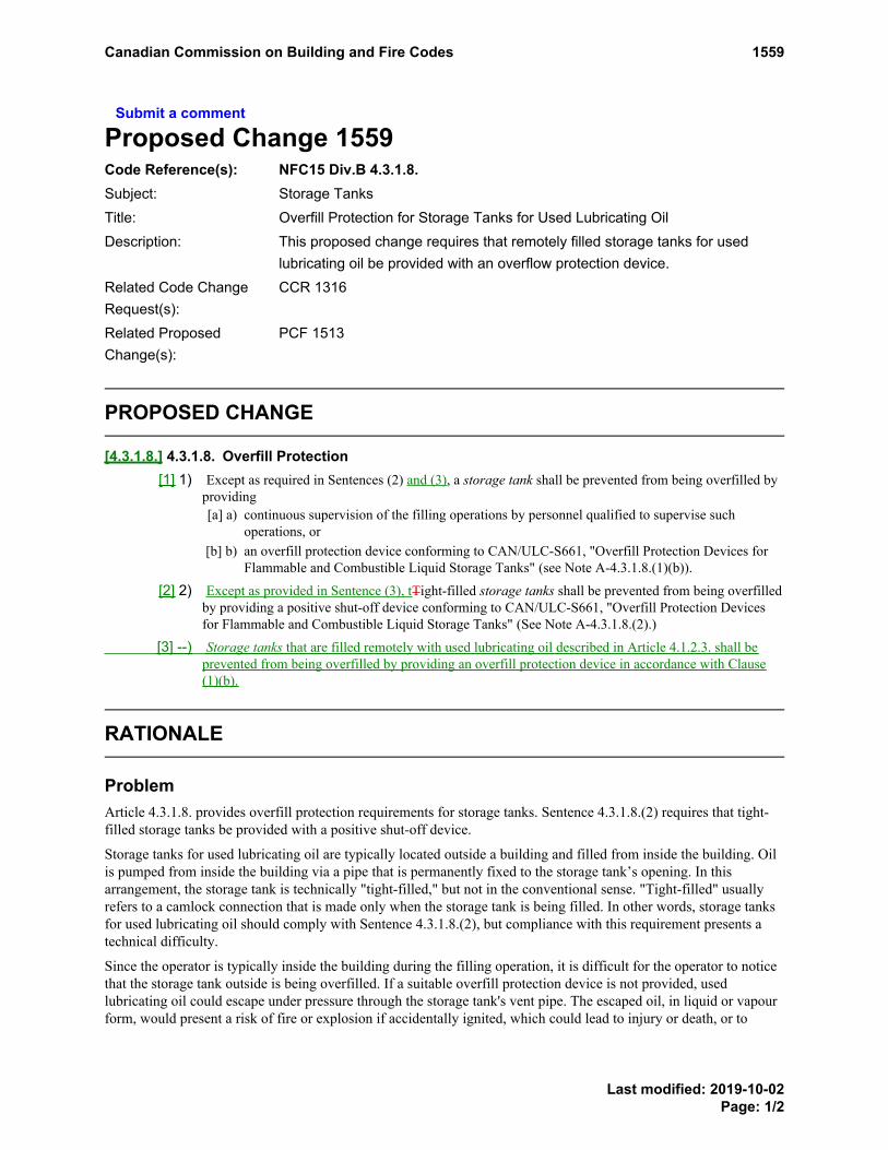
Submit a comment
Proposed Change 1559Code Reference(s): NFC15 Div.B 4.3.1.8.Subject: Storage TanksTitle: Overfill Protection for Storage Tanks for Used Lubricating OilDescription: This proposed change requires that remotely filled storage tanks for used
lubricating oil be provided with an overflow protection device.Related Code ChangeRequest(s):
CCR 1316
Related ProposedChange(s):
PCF 1513
PROPOSED CHANGE
[4.3.1.8.] 4.3.1.8. Overfill Protection[1] 1) Except as required in Sentences (2) and (3), a storage tank shall be prevented from being overfilled by
providing[a] a) continuous supervision of the filling operations by personnel qualified to supervise such
operations, or[b] b) an overfill protection device conforming to CAN/ULC-S661, "Overfill Protection Devices for
Flammable and Combustible Liquid Storage Tanks" (see Note A-4.3.1.8.(1)(b)).
[2] 2) Except as provided in Sentence (3), tTight-filled storage tanks shall be prevented from being overfilledby providing a positive shut-off device conforming to CAN/ULC-S661, "Overfill Protection Devicesfor Flammable and Combustible Liquid Storage Tanks" (See Note A-4.3.1.8.(2).)
[3] --) Storage tanks that are filled remotely with used lubricating oil described in Article 4.1.2.3. shall beprevented from being overfilled by providing an overfill protection device in accordance with Clause(1)(b).
RATIONALE
ProblemArticle 4.3.1.8. provides overfill protection requirements for storage tanks. Sentence 4.3.1.8.(2) requires that tight-filled storage tanks be provided with a positive shut-off device.
Storage tanks for used lubricating oil are typically located outside a building and filled from inside the building. Oilis pumped from inside the building via a pipe that is permanently fixed to the storage tank’s opening. In thisarrangement, the storage tank is technically "tight-filled," but not in the conventional sense. "Tight-filled" usuallyrefers to a camlock connection that is made only when the storage tank is being filled. In other words, storage tanksfor used lubricating oil should comply with Sentence 4.3.1.8.(2), but compliance with this requirement presents atechnical difficulty.
Since the operator is typically inside the building during the filling operation, it is difficult for the operator to noticethat the storage tank outside is being overfilled. If a suitable overfill protection device is not provided, usedlubricating oil could escape under pressure through the storage tank's vent pipe. The escaped oil, in liquid or vapourform, would present a risk of fire or explosion if accidentally ignited, which could lead to injury or death, or to
PROPOSEDCHANGEA-4.3.1.8.(1)(b)
PROPOSEDCHANGEA-4.3.1.8.(2)
Canadian Commission on Building and Fire Codes 1559
Last modified: 2019-10-02Page: 1/2

damage to nearby buildings. Even if not ignited, the escaped oil would still have a negative impact on theenvironment.
Justification - ExplanationWithout an overfill protection device, remotely filled storage tanks for used lubricating oil could allow oil to escapeunder high pressure through their vent pipe. Therefore, the proposed change requires that such storage tanks beprovided with an overflow protection device conforming to CAN/ULC-S661, "Overfill Protection Devices forFlammable and Combustible Liquid Storage Tanks," such as a device that automatically shuts off the pumpdelivering the oil to the storage tank or an audible/visual alarm inside the building that alerts the operator before thestorage tank is overfilled.
Storage tanks for used lubricating oil, which vary in capacity and orientation, are typically different from otherstorage tanks covered in Section 4.3. Therefore, proposed new Sentence 4.3.1.8.(3) specifically addresses storagetanks for used lubricating oil.
Impact analysisCurrently, most storage tank operators are properly interpreting the existing provision or are voluntarily installingoverfill protection devices. Although different types of overfill protection devices are available, the additional costassociated with the installation of such a device is expected to be approximately $1,000. This cost is minimalcompared to the potential life safety risks, property losses and environmental remediation costs resulting fromoverfilling.
Enforcement implicationsArticle 4.3.1.8. applies at the time of storage tank installation and is not applied retroactively. A fire officialinspecting a storage tank would have to consider its installation date to determine the edition of the NFC to beapplied. Sentence 4.3.1.8.(2), which requires that a positive shut-off device be provided for tight-filled storage tanks,was introduced in the NFC 2010. Regulators will have to do some research regarding the date of installation and usesome discretion in applying the appropriate requirement.
The proposed change can be enforced by the infrastructure currently available to enforce the NFC.
Who is affectedOwners, engineers, regulators, contractors, facility managers, and facility operators.
OBJECTIVE-BASED ANALYSIS OF NEW OR CHANGED PROVISIONS
[4.3.1.8.] 4.3.1.8. ([1] 1) [F43-OS1.1]
[4.3.1.8.] 4.3.1.8. ([1] 1) [F43-OH5]
[4.3.1.8.] 4.3.1.8. ([1] 1) [F43-OP1.1]
[4.3.1.8.] 4.3.1.8. ([2] 2) [F43-OS1.1]
[4.3.1.8.] 4.3.1.8. ([2] 2) [F43-OH5]
[4.3.1.8.] 4.3.1.8. ([2] 2) [F43-OP1.1]
-- (--) [F43-OS1.1]
-- (--) [F43-OP1.1]
-- (--) [F43-OH5]
Canadian Commission on Building and Fire Codes 1559
Last modified: 2019-10-02Page: 2/2

Submit a comment
Proposed Change 1560Code Reference(s): NFC15 Div.B 4.3.7.2.Subject: Storage TanksTitle: Membranes for Secondary ContainmentsDescription: This proposed change replaces the requirement to cover combustible
membranes with a noncombustible material by a requirement to installmembranes in accordance with the manufacturer's instructions.
Related Code ChangeRequest(s):
CCR 1317
PROPOSED CHANGE
[4.3.7.2.] 4.3.7.2. Construction[1] 1) Except as provided in Sentence (2), tThe base and walls of a secondary containment shall be made of
noncombustible materials, and shall be designed, constructed and maintained to[a] a) withstand full hydrostatic head, and[b] b) provide a permeability of not more than 10-6 cm/s to the flammable liquids or combustible
liquids contained in the storage tanks.
[2] 2) A membrane providing the level of impermeability required in Clause (1)(b) shall[a] a) conform to CAN/ULC-S668, "Liners Used for Secondary Containment of Aboveground
Flammable and Combustible Liquid Tanks", and[b] b) if it is combustible, be covered with a noncombustible material that will prevent the membrane
from failing in the event that the secondary containment is exposed to firebe installed inaccordance with the manufacturer’s instructions.
[3] 3) Except as provided in Sentence (4), openings shall not be permitted in a secondary containment.
[4] 4) Where piping passes through a secondary containment, such passages shall conform to Sentences (1)and (2).
RATIONALE
ProblemWhen a secondary containment is installed, the owner has the option of using a membrane (geotextile or polymericliner) or earth to contain spills and leaks. If clay is available that has a permeability of not more than 10−6 cm/s, itcan be used without a membrane.
Some owners prefer the extra security of a membrane and like to have the membrane terminate on the top of the wallof the secondary containment. In this arrangement, soil needs to extend to the top of the wall to cover the membranein accordance with existing Clause 4.3.7.2.(2)(b). The minimum spacing between a storage tank and the secondarycontainment wall is 1.5 m. Therefore, the soil extending to the top of the wall is likely to obstruct or cover the fillopenings at the bottom of the tank. Moreover, the soil tends to slough off, exposing the membrane over time. Onesolution to these problems is to make the containment area larger. However, the additional cost of the necessaryconcrete, membrane, piping and space has led to some owners choosing to use the less reliable earthen containmentrather than a synthetic membrane.
Canadian Commission on Building and Fire Codes 1560
Last modified: 2019-09-20Page: 1/3

Covering the membrane with soil is intended to protect it from heat in the event of a pool fire. However, in a poolfire, the portion of the membrane that is above the level of the burning liquid will melt. Nevertheless, the liquid willremain contained within the walls of the secondary containment, and the level of risk will not rise. Therefore,covering the membrane with soil does not increase the level of safety, but only creates construction difficulties inpractice.
In addition, some tank owners prefer that high-density polyethylene or polymeric membranes not be covered withsoil so that they can be inspected for tears and cracks that may develop over time. A small leak from a tank bottommay not be obvious if the leaking liquid escapes through a membrane breach. Moreover, some membranes areintended to be exposed after they are installed; there is no need to cover them with soil.
Other owners may want to protect only the floor of the lined containment with soil, so that there is less chance ofdamaging the membrane.
The current wording of Sentence 4.3.7.2.(2) does not give owners the flexibility to completely or partially exposemembranes in secondary containments for the purpose of membrane protection or inspection.
Justification - ExplanationThe two main purposes for secondary containment around storage tanks are the following:
1. to enhance the protection of structures and the safety of firefighters by confining burning liquids in anisolated location, and
2. to prevent flammable and combustible liquids from seeping into the ground and contaminating soil andwater.
During normal operations, the second purpose is achieved by a membrane with a permeability sufficiently low toretain escaped liquid until a cleanup is conducted. Covering the membrane with soil is intended to protect it fromheat in the event of a pool fire in the secondary containment. However, in a pool fire, the portion of a membraneconforming to CAN/ULC-S668, "Liners Used for Secondary Containment of Aboveground Flammable andCombustible Liquid Tanks," that is above the level of the burning liquid will melt. The risk to structures andfirefighters will not rise as a result of the melted membrane. The noncombustible walls of the secondarycontainment are designed to withstand a full hydrostatic head of liquid and will not break when subjected to fire orheat.
The proposed change gives tank owners the flexibility to decide whether or not to cover the membrane with soil, aslong as the membrane is installed in accordance with the manufacturer's instructions.
If the impermeability requirement in Clause 4.3.7.2.(1)(b) cannot be met by the base and walls of the secondarycontainment, a membrane conforming to Sentence 4.3.7.2.(2) can be used to provide the required level ofimpermeability. However, the base and walls of the secondary containment must nevertheless be made ofnoncombustible materials and designed, constructed and maintained to withstand full hydrostatic head. Therefore,Sentence (2) is not an exception to Sentence (1).
Additionally, the Standing Committee on Hazardous Materials and Activities revised the attributions and intentstatements for Article 4.3.7.2. while developing the proposed change.
Impact analysisThis proposed change will not result in additional costs for the industry. On the contrary, it will likely reduce costsby giving owners more flexibility in the choice of materials or products to be used in the construction of secondarycontainments (provided the Code requirements are met).
Enforcement implicationsThe removal of the requirement to cover combustible membranes with a noncombustible material will not result inadditional enforcement challenges. This proposed change can be enforced by the infrastructure currently available toenforce the Code.
Canadian Commission on Building and Fire Codes 1560
Last modified: 2019-09-20Page: 2/3

Who is affectedOwners, engineers, regulators, contractors, and membrane manufacturers.
OBJECTIVE-BASED ANALYSIS OF NEW OR CHANGED PROVISIONS
[4.3.7.2.] 4.3.7.2. ([1] 1) [F04-OS1.1] Applies to the construction of the base and walls of secondarycontainments with noncombustible materials.
[4.3.7.2.] 4.3.7.2. ([1] 1) ([a] a) [F20-OS1.1] Applies to the base and walls of secondary containments beingdesigned, constructed and maintained to withstand full hydrostatic head.
[4.3.7.2.] 4.3.7.2. ([1] 1) ([b] b) [F44-OS1.1] Applies to the base and walls of secondary containments beingdesigned, constructed and maintained to provide the stated permeability.
[4.3.7.2.] 4.3.7.2. ([1] 1) [F04-OP1.1] Applies to the construction of the base and walls of secondarycontainments with noncombustible materials.
[4.3.7.2.] 4.3.7.2. ([1] 1) ([a] a) [F20-OP1.1] Applies to the base and walls of secondary containments beingdesigned, constructed and maintained to withstand full hydrostatic head.
[4.3.7.2.] 4.3.7.2. ([1] 1) ([a] a) [F20-OH5] Applies to the base and walls of secondary containments beingdesigned, constructed and maintained to withstand full hydrostatic head.
[4.3.7.2.] 4.3.7.2. ([1] 1) ([b] b) [F44-OP1.1] Applies to the base and walls of secondary containments beingdesigned, constructed and maintained to provide the stated permeability.
[4.3.7.2.] 4.3.7.2. ([1] 1) ([b] b) [F44-OH5] Applies to the base and walls of secondary containments beingdesigned, constructed and maintained to provide the stated permeability.
[4.3.7.2.] 4.3.7.2. ([2] 2) [F43,F44-OS1.1]
[4.3.7.2.] 4.3.7.2. ([2] 2) [F43,F44-OP1.1]
[4.3.7.2.] 4.3.7.2. ([2] 2) [F43,F44-OH5]
[4.3.7.2.] 4.3.7.2. ([3] 3) [F44-OS1.1]
[4.3.7.2.] 4.3.7.2. ([3] 3) [F44-OH5]
[4.3.7.2.] 4.3.7.2. ([3] 3) [F44-OP1.1]
[4.3.7.2.] 4.3.7.2. ([4] 4) no attributions
Canadian Commission on Building and Fire Codes 1560
Last modified: 2019-09-20Page: 3/3

Submit a comment
Proposed Change 1562Code Reference(s): NFC15 Div.B 4.3.9.Subject: Storage TanksTitle: New Standard for SumpsDescription: This proposed change replaces references to two superseded other
recognized documents (ORDs) with a reference to CAN/ULC-S664-2017,"Containment Sumps, Sump Fittings, and Accessories for Flammable andCombustible Liquids."
EXISTING PROVISION
4.3.9. Sumps
4.3.9.1. Installation1) A dispenser sump shall be provided under a dispenser, unless the dispenser is located on top of an
aboveground storage tank.
2) A spill containment sump shall be provided at every underground storage tank fill point.
3) A transition sump shall be provided for all mechanical pipe connections located below grade.
4) A turbine sump shall be provided for all turbine pump assemblies located below grade or above gradewhere they are not readily visible.
5) In addition to the requirements of Article 4.3.9.2., the sumps referred to in Sentences (1) to (4) shall beinstalled in conformance with the sump manufacturer's instructions.
4.3.9.2. Construction1) Dispenser sumps shall conform to the construction and performance requirements of ULC/ORD-
C107.21, "Under-Dispenser Sumps".
2) Spill containment sumps shall conform to the construction and performance requirements ofULC/ORD-C58.19, "Spill Containment Devices for Underground Flammable Liquid Storage Tanks".
4.3.9.3. Leak Detection Monitoring1) Where dispenser sumps, turbine sumps and transition sumps referred to in Article 4.3.9.1. are used in
underground applications, they shall be provided with an electronic monitoring device to indicate thepresence of liquid.
PROPOSED CHANGE
[4.3.9.] 4.3.9. Sumps
[4.3.9.1.] 4.3.9.1. Installation
[4.3.9.2.] 4.3.9.2. Construction[1] 1) Dispenser sumps shall conform to the construction and performance requirements of ULC/ORD-
C107.21, "Under-Dispenser Sumps".
Canadian Commission on Building and Fire Codes 1562
Last modified: 2019-09-20Page: 1/4
[2] 2) Spill containment sumps shall conform to the construction and performance requirements ofULC/ORD-C58.19, "Spill Containment Devices for Underground Flammable Liquid Storage Tanks".
[3] --) Sumps installed in accordance with Article 4.3.9.1. shall be constructed in accordance with CAN/ULC-S664-2017, “Containment Sumps, Sump Fittings, and Accessories for Flammable and CombustibleLiquids.”
[4.3.9.3.] 4.3.9.3. Leak Detection Monitoring
RATIONALE
ProblemArticle 4.3.9.1. of the NFC currently requires the installation of four types of sumps (i.e., dispenser sumps, spillcontainment sumps, transition sumps and turbine sumps), but Article 4.3.9.2. only references other recognizeddocuments (ORDs) for the first two types of sumps. No standards or ORDs are currently referenced in the NFC toprovide guidance on the construction of transition sumps or turbine sumps. The lack of appropriate constructionguidance for these two types of sumps could lead to the escape and spread of flammable and combustible liquidsduring operation, which could lead to accidental ignition or explosion of the liquids, contamination of soil andwater, and loss of property.
Moreover, the two ORDs that are currently referenced in Article 4.3.9.2. have been withdrawn by ULC Standardsand replaced by a new standard: CAN/ULC-S664-2017, "Containment Sumps, Sump Fittings, and Accessories forFlammable and Combustible Liquids." The new standard was developed on the basis of comprehensive review anddiscussions. It incorporates the requirements of the ORDs and now supersedes them. In addition, the new standardalso incorporates guidance regarding all of the ancillary equipment required to operate these sumps. Therefore, thereis a need to replace the references to the ORDs with a reference to the new standard and to revise the wording ofArticle 4.3.9.2. This change will provide guidance on the construction of the sumps mentioned in Article 4.3.9.1.
Status Date Document Title
Superseded Withdrawn:2018-07-12
ULC/ORD-C107.21-1992 Under-Dispenser Sumps
Superseded Withdrawn:2018-08-09
ULC/ORD-C58.19-1992 Spill Containment Devices for Underground FlammableLiquid Storage Tanks
New Published:2017-07-01
CAN/ULC-S664-2017 Containment Sumps, Sump Fittings, and Accessories forFlammable and Combustible Liquids
Justification - ExplanationThis proposed change recognizes a new standard, CAN/ULC-S664-2017, which incorporates guidance on all sumpsintended to contain spills and leaks from underground storage tank systems. Currently, Article 4.3.9.2. referencestwo superseded ORDs that address sumps for only two potential points of spills and leaks: the fill point of anunderground tank, and the area under a dispenser.
CAN/ULC-S664-2017 not only addresses sumps for fill points and areas under dispensers, but also transition sumps(installed at connections between aboveground and underground piping) and tank sumps (referred to as "turbinesumps" in the NFC). The new standard also includes guidance on all of the fittings for the sumps. This is animportant improvement since leaks in sumps generally occur at openings that accommodate piping and electricalconduit. The new standard includes requirements for all four types of sumps, as well as their ancillary equipment,and supersedes the two ORDs.
Canadian Commission on Building and Fire Codes 1562
Last modified: 2019-09-20Page: 2/4

Note that ULC Standards has submitted requests to Codes Canada for the replacement of ULC/ORD-C58.19 andULC/ORD-C107.21 with CAN/ULC-S664-2017 (request ID numbers 358 and 359). Since the wording of the Codeprovision needs to be revised, this proposed change has been developed.
Impact analysisAlthough the standard uses somewhat different terminology from the NFC, it does not conflict with the Code. TheNFC uses the defined terms "dispenser sump," "spill containment sump," "transition sump" and "turbine sump."The new standard uses the defined terms "dispenser sump," "fill/vent sump," "transition sump" and "tank sump."While the new standard places fill sumps (i.e., spill containment sumps) and vent sumps in the same category, anddistinguishes that category from transition sumps, a vent sump could also be described as a transition sump. (Thepurpose of the transition sump is to contain leaks where double-walled underground piping transitions to steel ventpiping.)
No additional costs are associated with this proposed change. The benefit of the proposed change is that it providesappropriate guidance on the construction of all four types of sumps listed in the NFC to reduce the risk of spills andleaks during operation.
Enforcement implicationsThe proposed change will facilitate enforcement and provide clearer guidance to regulators, engineers, storage tankowners, contractors, and storage tank system manufacturers. The change can be enforced by the infrastructurecurrently available to enforce this Code.
Who is affectedRegulators, engineers, storage tank owners, contractors, and storage tank system manufacturers.
OBJECTIVE-BASED ANALYSIS OF NEW OR CHANGED PROVISIONS
[4.3.9.1.] 4.3.9.1. ([1] 1) [F44-OH5]
[4.3.9.1.] 4.3.9.1. ([1] 1) [F44-OS3.4]
[4.3.9.1.] 4.3.9.1. ([1] 1) [F01,F44-OS1.1]
[4.3.9.1.] 4.3.9.1. ([1] 1) [F01,F44-OP1.1]
[4.3.9.1.] 4.3.9.1. ([2] 2) [F43,F44-OH5]
[4.3.9.1.] 4.3.9.1. ([2] 2) [F43,F44-OS3.4]
[4.3.9.1.] 4.3.9.1. ([2] 2) [F01,F43,F44-OS1.1]
[4.3.9.1.] 4.3.9.1. ([2] 2) [F01,F43,F44-OP1.1]
[4.3.9.1.] 4.3.9.1. ([3] 3) [F43,F44-OH5]
[4.3.9.1.] 4.3.9.1. ([3] 3) [F30,F43,F44-OS3.4]
[4.3.9.1.] 4.3.9.1. ([3] 3) [F01,F43,F44-OS1.1]
[4.3.9.1.] 4.3.9.1. ([3] 3) [F01,F43,F44-OP1.1]
[4.3.9.1.] 4.3.9.1. ([4] 4) [F44,F82-OH5]
[4.3.9.1.] 4.3.9.1. ([4] 4) [F44,F82-OS3.4]
[4.3.9.1.] 4.3.9.1. ([4] 4) [F01,F44,F82-OS1.1]
Canadian Commission on Building and Fire Codes 1562
Last modified: 2019-09-20Page: 3/4

[4.3.9.1.] 4.3.9.1. ([4] 4) [F01,F44,F82-OP1.1]
[4.3.9.1.] 4.3.9.1. ([5] 5) no attributions
[4.3.9.2.] 4.3.9.2. ([1] 1) [F20,F44,F80,F81-OH5]
[4.3.9.2.] 4.3.9.2. ([1] 1) [F20,F44,F80,F81-OS3.4]
[4.3.9.2.] 4.3.9.2. ([1] 1) [F01,F20,F44,F80,F81-OS1.1]
[4.3.9.2.] 4.3.9.2. ([1] 1) [F01,F20,F44,F80,F81-OP1.1]
[4.3.9.2.] 4.3.9.2. ([2] 2) [F20,F44,F80,F81-OH5]
[4.3.9.2.] 4.3.9.2. ([2] 2) [F20,F44,F80,F81-OS3.4]
[4.3.9.2.] 4.3.9.2. ([2] 2) [F01,F20,F44,F80,F81-OS1.1]
[4.3.9.2.] 4.3.9.2. ([2] 2) [F01,F20,F44,F80,F81-OP1.1]
-- (--) [F20,F44,F80,F81-OH5]
-- (--) [F20,F44,F80,F81-OS3.4]
-- (--) [F20,F01,F44,F80,F81-OS1.1]
-- (--) [F20,F01,F44,F80,F81-OP1.1]
[4.3.9.3.] 4.3.9.3. ([1] 1) [F43,F82-OS1.1]
[4.3.9.3.] 4.3.9.3. ([1] 1) [F43,F82-OS3.4]
[4.3.9.3.] 4.3.9.3. ([1] 1) [F43,F82-OP1.1]
[4.3.9.3.] 4.3.9.3. ([1] 1) [F43,F82-OH5]
Canadian Commission on Building and Fire Codes 1562
Last modified: 2019-09-20Page: 4/4

Submit a comment
Proposed Change 1557Code Reference(s): NFC15 Div.B 4.6.4.1.Subject: Fuel-Dispensing StationsTitle: Location of Shut-off DevicesDescription: This proposed change clarifies the location of devices that shut off power to
all dispensers and pumps at fuel-dispensing stations.Related Code ChangeRequest(s):
CCR 1315
Related ProposedChange(s):
PCF 1556
EXISTING PROVISION
4.6.4.1. Location and Identification1) A device to shut off power to all dispensers and pumps shall be provided at a remote location on the
site of the fuel-dispensing station and shielded from any fire that might occur in the dispensing area.
2) The device required in Sentence (1) shall be clearly identified and readily accessible to attendants andemergency responders.
3) Steel shut-off valves shall be provided at connecting outlets on aboveground storage tanks.
PROPOSED CHANGE
[4.6.4.1.] 4.6.4.1. Location and Identification[1] 1) A device to shut off power to all dispensers and pumps shall be provided at a remote location on the
site of the fuel-dispensing station and shielded from any fire that might occur in the dispensing areanotless than 6 m and not more than 30 m away from the dispensers and pumps. (See Note A-4.6.4.1.(1) and(2).)
[2] 2) The device required in Sentence (1) shall be clearly identified and readily accessible to attendants andemergency responders. (See Note A-4.6.4.1.(1) and (2).)
[3] 3) Steel shut-off valves shall be provided at connecting outlets on aboveground storage tanks.
Note A-4.6.4.1.(1) and (2)The device described in Sentence 4.6.4.1.(1) is an emergency shut-off device that allows power to all dispensers andpumps to be rapidly shut off in the event of a spill, fire or other dangerous situation. A circuit breaker on an electricalpanel is not considered to be such a device.The shut-off device can be located indoors or outdoors, but should be placed close enough to the dispensers and pumps toallow it to be quickly located and activated.The shut-off device is primarily intended for use by station attendants and emergency responders. Nevertheless, theowner of a fuel-dispensing station may choose to install the shut-off device in a location where it is accessible to thepublic.
Canadian Commission on Building and Fire Codes 1557
Last modified: 2019-10-29Page: 1/3

RATIONALE
ProblemThe current wording of Article 4.6.4.1. does not provide clear guidance on where the shut-off device should belocated. It also presents an enforcement problem, as some regulators insist on the shut-off device being located closeto the dispensers and pumps.
The phrase "at a remote location on the site" in existing Sentence 4.6.4.1.(1) could be perceived as meaning at alocation outside the building, perhaps as far away as possible from the likely location of a fire.
If the shut-off device is located far from the dispensers and pumps, there will be a delay in responding to anemergency, which could pose a significant risk to life safety, property and the environment. If the shut-off device islocated close to the dispensers and pumps and is accessible to the general public, it could be misused or vandalised,which would result in economic losses for the station owner. Therefore, it is necessary to clarify theappropriate location of the shut-off device.
Justification - ExplanationThe introduction of an explanatory Note is necessary to provide owners, engineers, contractors and regulators withclarification on where shut-off devices should be located.
The current wording of Sentence 4.6.4.1.(2) stems from a proposed change to the NFC 1995. The rationale of theproposed change indicated that the shut-off device needed to be readily accessible to attendants and emergencyresponders but not accessible to the general public. When the change was published in the NFC 2005, it required thedevice to be "readily accessible to attendants and emergency responders," and did not mention whether it should beaccessible to the public. This wording has been the cause of enforcement difficulties.
Many owners of fuel-dispensing stations do not want the general public to have access to the shut-off devicebecause of the possibility of mischief. Other owners may want to install the shut-off device in the forecourt of thestation, allowing customers to activate the device in an emergency. Proposed explanatory Note A-4.6.4.1.(1) and(2) resolves the enforcement difficulties with respect to the location of the shut-off device and provides flexibilityfor owners.
The control console at a self-service outlet has an emergency shut-off switch that can stop fuel delivery to thedispenser nozzles, but there must be a second shut-off device that shuts off power to the dispensers. Typically, thisshut-off device is located near the self-service attendant inside the building.
Impact analysisThis proposed change will not result in additional costs for the industry, but will prevent the misinterpretation ofArticle 4.6.4.1.
Enforcement implicationsRegulators are not consistent in their interpretation of Article 4.6.4.1. This proposed change will resolve conflicts inhow this Article is interpreted and applied by regulators and owners. It can be enforced by the infrastructurecurrently available to enforce the Code.
Who is affectedRegulators, engineers, fire services, facility operators, and contractors.
Canadian Commission on Building and Fire Codes 1557
Last modified: 2019-10-29Page: 2/3

OBJECTIVE-BASED ANALYSIS OF NEW OR CHANGED PROVISIONS
[4.6.4.1.] 4.6.4.1. ([1] 1) [F44-OS1.1,OS3.4] [F02-OS1.1] Applies to the requirement to provide shut-offdevices to all dispensers and pumps. [F06-OS1.1] Applies to the location and shielding of the shut-off devicesaway from any dispensers and pumps.
[4.6.4.1.] 4.6.4.1. ([1] 1) [F44-OH5] Applies to the requirement to provide shut-off devices to all dispensersand pumps. [F06-OH5] Applies to the location and shielding of the shut-off devices.
[4.6.4.1.] 4.6.4.1. ([1] 1) [F44,F02-OP1.1,OP1.1] Applies to the requirement to provide shut-off devices toall dispensers and pumps. [F06-OP1.1] Applies to the location and shielding of the shut-off devices.
[4.6.4.1.] 4.6.4.1. ([2] 2) [F12-OS1.1,OS1.2]
[4.6.4.1.] 4.6.4.1. ([2] 2) [F12-OP1.1,OP1.2]
[4.6.4.1.] 4.6.4.1. ([2] 2) [F12-OH5]
[4.6.4.1.] 4.6.4.1. ([3] 3) [F12,F44-OS1.1,OS3.4] Applies to the requirement for shut-off valves.
[4.6.4.1.] 4.6.4.1. ([3] 3) [F04,F20-OP1.1] Applies to the requirement for steel shut-off valves.
[4.6.4.1.] 4.6.4.1. ([3] 3) [F12,F44-OH5] Applies to the requirement for shut-off valves.
[4.6.4.1.] 4.6.4.1. ([3] 3) [F12,F44-OP1.1] Applies to the requirement for shut-off valves.
[4.6.4.1.] 4.6.4.1. ([3] 3) [F04,F20-OS1.1] Applies to the requirement for steel shut-off valves.
[4.6.4.1.] 4.6.4.1. ([3] 3) [F04,F20-OH5] Applies to the requirement for steel shut-off valves.
Canadian Commission on Building and Fire Codes 1557
Last modified: 2019-10-29Page: 3/3

Submit a comment
Proposed Change 1556Code Reference(s): NFC15 Div.B 4.6.8.1.
NFC15 Div.B 4.6.8.2.Subject: Fuel-Dispensing StationsTitle: Attendants at Fuel-Dispensing Stations Offering Attended Service and Self-
serviceDescription: This proposed change clarifies the requirements for attendants at fuel-
dispensing stations that offer both attended service and self-service. It alsoremoves the potential for confusion about the location of emergency shut-offdevices.
Related Code ChangeRequest(s):
CCR 1313
Related ProposedChange(s):
PCF 1557
PROPOSED CHANGE
[4.6.8.1.] 4.6.8.1. Attendants[1] 1) Except as provided in Sentence (2), every fuel-dispensing station shall have at least one attendant
referred to in Article 4.6.8.5. on duty when the station is open for business.
[2] 2) Fuel-dispensing stations that do not serve the general public do not require an attendant.
[3] 3) Except as permitted at self-service outlets, a qualified attendant shall be in constant control of thedispensing of Class I and II liquids into the fuel tanks of motor vehicles, watercraft or floatplanes, orinto containers.
[4] 4) Duties of attendants and fuel-dispensing procedures, as stated in Articles 4.6.8.5. and 4.6.8.6., shall beposted at every fuel-dispensing station.
[5] --) At fuel-dispensing stations that offer both attended service and self-service, the attendant required inSentence (1) is permitted to dispense flammable liquids or combustible liquids at an attended servicedispenser, provided that there is an additional attendant supervising the activities at the self-servicedispensers from a location in close proximity to one of the emergency shut-off devices required inSentences 4.6.4.1.(1) and 4.6.4.2.(1).
[4.6.8.2.] 4.6.8.2. Self-service Outlets[1] 1) Instructions for the operation of dispensers in self-service outlets shall be posted in a conspicuous
location.
[2] 2) A control console shall be provided at self-service outlets within 25 m of all dispensers so that theattendant has an unobstructed view of all units at the same time.
[3] 3) The control console referred to in Sentence (2) shall be equipped to regulate the operation of eachdispenser.
[4] 4) A 2-way communication system between the control console and each pump island shall be providedat self-service outlets.
Canadian Commission on Building and Fire Codes 1556
Last modified: 2019-10-29Page: 1/4

[5] 5) At fuel-dispensing stations that provide both attended service and self-service, the attendant required inSentence 4.6.8.1.(1) is permitted to dispense flammable liquids or combustible liquids at the attendedservice island, provided that[a] a) each island has an emergency shut-off switch as described in Article 4.6.4.2., and[b] b) the attendant is never more than 25 m from the self-service island or control console.
RATIONALE
ProblemIn existing Sentence 4.6.8.2.(5), the requirements for the attendant supervising the dispensing of fuel at a fuel-dispensing station that offers both attended service and self-service are not clear.
The current wording of Sentence 4.6.8.2.(5) suggests that a single attendant can oversee the fuel-dispensingoperations at self-service islands while attending to customers at an attended service island. It is impractical andunsafe to ask a single attendant to fulfill both of these duties. Moreover, in case of fire, the single attendant will haveto run to the central control console to activate the emergency shut-off switch, which will cause a delay inresponding to the emergency, which could result in severe consequences for life safety, property and theenvironment.
Existing Clause 4.6.8.2.(5)(a) states that each island must have an emergency shut-off switch as described in Article4.6.4.2. The intent of this wording might have been to require a shut-off switch that controls all the dispensers onthat island. However, by requiring that "each island" have an emergency shut-off switch, the switch will beaccessible to customers, which contradicts Article 4.6.4.1. (where shut-off devices are not intended to be accessibleto the public). This lack of clarity makes it difficult for designers and regulators to interpret the Code requirementsfor the location of the shut-off switch. If the location of the shut-off switch does not allow a quick response to anemergency, there could be significant losses as there is usually a large amount of fuel at fuel-dispensing stations.
In addition, it is an unsafe practice to locate a shut-off switch in close proximity to a dispenser (as required byexisting Clause 4.6.8.2.(5)(a)), as a fire is most likely to occur at a dispenser. The National Fire ProtectionAssociation (NFPA) recommends that shut-off switches be located 6 to 30 m away from dispensers.
Justification - ExplanationFuel-dispensing stations that offer both attended service and self-service are not common. However, where theyexist, it is important that the emergency shut-off switch be appropriately located and that personnel be able toactivate the switch.
The proposed change moves the requirements for attendants at fuel-dispensing stations offering both attendedservice and self-service to a more appropriate location in Article 4.6.8.1. The change also clarifies that twoattendants are necessary: one to safely supervise self-service activities, and one to attend to attended serviceactivities. The change also addresses the location of the emergency shut-off switch, which will conform toSubsection 4.6.4. and will not present a contradiction.
Impact analysisThis proposed change will only lead to additional costs if one attendant is currently responsible for attending to storesales and attended service activities, while supervising self-service activities. In this case, an additional attendantwill need to be hired. However, it is unlikely that any fuel-dispensing station operates in this fashion. The proposedchange will ensure that at least two attendants are available to supervise and attend to the dispensing of fuel at afuel-dispensing station that offers both attended service and self-service. It also eliminates the potential formisinterpretation of the Code, which could lead to severe consequences for life safety, property and theenvironment.
For fuel-dispensing stations that do not offer both attended service and self-service (i.e., most stations), there will beno additional costs.
Canadian Commission on Building and Fire Codes 1556
Last modified: 2019-10-29Page: 2/4

Enforcement implicationsFuel-dispensing stations that offer both attended service and self-service are not common. Having one attendantoversee all of the activities at such a station is unsafe. However, if this is the case, the regulator will have a clearCode provision to reference as a result of this proposed change.
This change can be enforced by the infrastructure currently available to enforce the Code.
Who is affectedConsultants, regulators, fire services, facility owners, and facility operators.
OBJECTIVE-BASED ANALYSIS OF NEW OR CHANGED PROVISIONS
[4.6.8.1.] 4.6.8.1. ([1] 1) [F43,F01,F44-OS1.1]
[4.6.8.1.] 4.6.8.1. ([1] 1) [F43,F44,F01-OP1.1]
[4.6.8.1.] 4.6.8.1. ([1] 1) [F43,F44-OH5]
[4.6.8.1.] 4.6.8.1. ([2] 2) [F43,F01,F34-OS1.1]
[4.6.8.1.] 4.6.8.1. ([2] 2) [F43,F34-OH5]
[4.6.8.1.] 4.6.8.1. ([2] 2) [F43,F01,F34-OP1.1]
[4.6.8.1.] 4.6.8.1. ([3] 3) [F43-OH5]
[4.6.8.1.] 4.6.8.1. ([3] 3) [F43,F01-OS1.1]
[4.6.8.1.] 4.6.8.1. ([3] 3) [F43,F01-OP1.1]
[4.6.8.1.] 4.6.8.1. ([4] 4) [F81-OS1.1]
[4.6.8.1.] 4.6.8.1. ([4] 4) [F81-OH5]
[4.6.8.1.] 4.6.8.1. ([4] 4) [F81-OP1.1]
-- (--) [F43,F44,F12,F01,F02-OS1.1]
-- (--) [F43,F44,F12,F01,F02-OP1.1]
-- (--) [F43,F44,F12-OH5]
[4.6.8.2.] 4.6.8.2. ([1] 1) [F81-OS1.1]
[4.6.8.2.] 4.6.8.2. ([1] 1) [F81-OP1.1]
[4.6.8.2.] 4.6.8.2. ([1] 1) [F81-OH5]
[4.6.8.2.] 4.6.8.2. ([2] 2) [F43,F44,F12,F01-OS1.1]
[4.6.8.2.] 4.6.8.2. ([2] 2) [F43,F44,F12,F01-OH5]
[4.6.8.2.] 4.6.8.2. ([2] 2) [F43,F44,F12,F01-OP1.1]
[4.6.8.2.] 4.6.8.2. ([3] 3) [F44-OS1.1,OS1.2]
[4.6.8.2.] 4.6.8.2. ([3] 3) [F44-OH5]
[4.6.8.2.] 4.6.8.2. ([3] 3) [F44-OP1.1,OP1.2]
Canadian Commission on Building and Fire Codes 1556
Last modified: 2019-10-29Page: 3/4

[4.6.8.2.] 4.6.8.2. ([4] 4) [F43,F44,F01-OS1.1]
[4.6.8.2.] 4.6.8.2. ([4] 4) [F43,F44,F01-OP1.1]
[4.6.8.2.] 4.6.8.2. ([4] 4) [F43,F44-OH5]
[4.6.8.2.] 4.6.8.2. ([5] 5) [F43,F44,F12,F01-OS1.1]
[4.6.8.2.] 4.6.8.2. ([5] 5) [F43,F44,F12,F01-OP1.1]
[4.6.8.2.] 4.6.8.2. ([5] 5) [F43,F44,F12-OH5]
Canadian Commission on Building and Fire Codes 1556
Last modified: 2019-10-29Page: 4/4

Submit a comment
Proposed Change 1336Code Reference(s): NPC15 Div.A 1.4.1.2.Subject: OtherTitle: Replacement of the defined terms "soil-or-waste pipe," "soil-or-waste stack,"
and "waste pipe"Description: This proposed change replaces the defined terms "soil-or-waste pipe" and
"waste pipe" with "sanitary drainage pipe" and the defined term "soil-or-waste stack" with "stack" throughout the NPC. It also removes the definitionfor "waste pipe."
PROPOSED CHANGE
[1.4.1.2.] 1.4.1.2. Defined Terms[1] 1) The words and terms in italics in this Code shall have the following meanings (an asterisk (*)
following a defined word or term indicates that the definition for that word or term is taken from theNBC):Soil-or-waste pipe Sanitary drainage pipe or waste pipe means a pipe in a sanitary drainage system.Soil-or-waste sStack means a vertical soil-or-waste pipe sanitary drainage pipe that passes through one
or more storeys, and includes any offset that is part of the stack.Waste pipe (see soil-or-waste pipe).
RATIONALE
ProblemUse of the term "soil-or-waste" does not apply in the context of current plumbing systems.
Justification - ExplanationUse of the term "soil-or-waste" in the National Plumbing Code (NPC) may have been relevant years ago when thetwo types of drainage were purposely diverted to different locations because of their contents.
Today, plumbing systems handle all types of waste—with and without fecal matter—and the same Code provisionsapply. This outdated terminology will cause confusion as the trend towards water reuse and recycling continues. Assuch, the defined terms "soil-or-waste pipe" and "soil-or-waste stack" are obsolete and should be replaced. Just asthe defined term "leader" only applies to storm water systems, the defined term "stack" would only apply to sanitarysystems.
Furthermore, the definition for "waste pipe" is redundant as it simply refers users back to the definition for "soil-or-waste pipe;" as such, it should be deleted.
The defined terms "soil-or-waste pipe" and "soil-or-waste stack" are each used approximately 65 times in the NPC.The proposed changes will cause no technical issues and will entail a simple search and replace exercise. There areno instances where the intent of the provisions would be altered by the proposed changes.
In all cases, the Code becomes easier to read and enforce with the proposed updated wording.
Canadian Commission on Building and Fire Codes 1336
Last modified: 2019-08-14Page: 1/2

Impact analysisNo cost implications as there is no change to the technical requirements resulting from this simple substitution ofterminology.
Enforcement implicationsThis would facilitate enforcement by building officials and regulators.
Who is affectedDesigners, specifiers, manufacturers, building owners, building officials, contractors.
Canadian Commission on Building and Fire Codes 1336
Last modified: 2019-08-14Page: 2/2

Submit a comment
Proposed Change 946Code Reference(s): NPC15 Div.B 2.1.2.Subject: Water-Use EfficiencyTitle: Update to Exceptions in Sentences 2.1.2.1.(1), 2.1.2.2.(1) and 2.1.2.3.(1)Description: This proposed change updates the exceptions in Sentences 2.1.2.1.(1),
2.1.2.2.(1) and 2.1.2.3.(1) for consistency with proposed requirements fornon-potable water systems (PCF 940-2018) and non-potable rainwaterharvesting systems (PCF 945-2018) in Section 2.7. The change isassociated with a reorganization of Section 2.7. to enable the inclusion ofrequirements for water recovery systems.
Related ProposedChange(s):
PCF 940, PCF 942, PCF 945
PROPOSED CHANGE
[2.1.2.] 2.1.2. Service Connections
[2.1.2.1.] 2.1.2.1. Sanitary Drainage Systems[1] 1) Except where they are supplied by non-potable watersupplying systems that are covered in Section
2.7., sanitary drainage systems shall be connected to a public sanitary sewer, a public combined seweror a private sewage disposal system.
[2] 2) A combined building drain shall not be installed. (See Note A-2.1.2.1.(2).)
[2.1.2.2.] 2.1.2.2. Storm Drainage Systems
[2.1.2.3.] 2.1.2.3. Water Distribution Systems
[2.1.2.4.] 2.1.2.4. Separate Services
RATIONALE
ProblemThis proposed change was originally presented for public review in fall 2018. In response to the comments receivedduring the public review, the proposed change was revised by correcting the exception in Sentence 2.1.2.1.(1) toreflect the intent of the provision.
The current requirements relating to the diversion of waste water from sanitary drainage systems, storm drainagesystems, and water distribution systems in Sentences 2.1.2.1.(1), 2.1.2.2.(2) and 2.1.2.3.(3), respectively, eachinclude the exception "except as provided in Subsection 2.7.4." With the other proposed changes to Section 2.7.regarding non-potable water systems (PCF 940-2018) and non-potable rainwater harvesting systems (PCF945-2018), the reference to Subsection 2.7.4. is incorrect and needs to be updated to allow for waste water to bediverted to non-potable water systems.
PROPOSEDCHANGEA-2.1.2.1.(2)
Canadian Commission on Building and Fire Codes 946
Last modified: 2019-09-26Page: 1/2

Justification - ExplanationAs explained above, the current exception in Sentences 2.1.2.1.(1), 2.1.2.2.(1) and 2.1.2.3.(1) is incorrect and needsto be adjusted to allow for waste water and rainwater to be diverted to non-potable water systems.
Accordingly, the exception should directly reference Section 2.7., which deals with non-potable water systems,instead of Subsection 2.7.4. dealing with non-potable water system design only.
Impact analysisNo cost increase is associated with the proposed change.
Enforcement implicationsNo adverse public reaction is anticipated as a result of this change.
Who is affectedDesigners, plumbers, and authorities having jurisdiction.
OBJECTIVE-BASED ANALYSIS OF NEW OR CHANGED PROVISIONS
[2.1.2.1.] 2.1.2.1. ([1] 1) [F72-OH2.1]
[2.1.2.1.] 2.1.2.1. ([2] 2) [F72-OH2.1]
[2.1.2.1.] 2.1.2.1. ([2] 2) [F72-OP5]
[2.1.2.2.] 2.1.2.2. ([1] 1) [F72-OP5]
[2.1.2.3.] 2.1.2.3. ([1] 1) [F46-OH2.2]
[2.1.2.4.] 2.1.2.4. ([1] 1) [F71-OH2.1,OH2.3] [F70-OH2.1]
Canadian Commission on Building and Fire Codes 946
Last modified: 2019-09-26Page: 2/2

Submit a comment
Proposed Change 1415Code Reference(s): NPC15 Div.B 2.1.2.3.Subject: Potable Water SystemsTitle: Protection of Drinking Water from Chemical ContaminationDescription: This proposed change introduces a new Sentence with a reference to a new
standard entitled NSF/ANSI/CAN 61-2018, "Drinking Water SystemComponents - Health Effects," which deals with the protection of drinkingwater from contamination by chemicals or impurities.
Related Code ChangeRequest(s):
CCR 1006
PROPOSED CHANGE
[2.1.2.3.] 2.1.2.3. Water Distribution Systems[1] 1) Except as provided in Subsection 2.7.4., every water distribution system shall be connected to a public
water main or a potable private water supply system.
[2] --) Wetted plumbing products used in sections of a potable water distribution system that convey waterintended for drinking shall conform to NSF/ANSI/CAN 61-2018, “Drinking Water System Components– Health Effects.” (See Note A-2.1.2.3.(2).)
Note A-2.1.2.3.(2) Wetted Plumbing Products.Products referred to in Sentence 2.1.2.3.(2) are permitted to conform to editions of NSF/ANSI/CAN 61, “Drinking WaterSystem Components – Health Effects,” published prior to 2018, where conformance to the previous editions is requiredby other product standards referenced in the Code.Examples of wetted plumbing products include pipes, pipe fittings, valves, faucets, flexible hoses, and joining andsealing materials such as solder, solvent cements, welding materials, lubricants, o-rings and gaskets.
RATIONALE
ProblemThe NPC does not currently contain requirements addressing the adverse health effects resulting from chemicalcontaminants and impurities that are indirectly imparted to potable water from the components of potable waterdistribution systems. The lack of such requirements could lead to the contamination of potable water, which couldlead to harm to persons.
Justification - ExplanationNSF/ANSI/CAN 61-2018, "Drinking Water System Components - Health Effects," is an American and Canadiannational standard that establishes requirements to prevent chemical contaminants and impurities from beingindirectly imparted to drinking water from products, components and materials used in drinking water systems.
Eleven provinces and territories have regulations or policies that require conformance to older editions of NSF 61for municipal systems or well construction. Ontario and Quebec also require conformance to older editions ofNSF 61 for plumbing system components.
Canadian Commission on Building and Fire Codes 1415
Last modified: 2019-10-29Page: 1/2

While some Canadian product standards referenced in the NPC refer to older editions of NSF 61, many others donot. Introducing NSF/ANSI/CAN 61-2018 to the NPC will resolve the current problem of persons not beingprotected from exposure to chemical contaminants and impurities that could potentially affect their health.
Impact analysisMost plumbing products used in the assembly and construction of potable water distribution systems are sold in boththe U.S. and Canada and are, therefore, already required to conform to older editions of NSF 61.
This proposed change will not adversely affect plumbing products sold in both countries. It will provide a consistentbasis for all plumbing products sold in North America. Therefore, this proposed change is not expected to have anycost implications.
Enforcement implicationsNo additional resources are required to enforce this proposed change.
Who is affectedEngineers, plumbers, designers, building owners, contractors and regulators.
OBJECTIVE-BASED ANALYSIS OF NEW OR CHANGED PROVISIONS
[2.1.2.3.] 2.1.2.3. ([1] 1) [F46-OH2.2]
-- (--) [F40,F46-OH2.2]
Canadian Commission on Building and Fire Codes 1415
Last modified: 2019-10-29Page: 2/2

Submit a comment
Proposed Change 1439Code Reference(s): NPC15 Div.B 2.2.5.Subject: PipingTitle: Cellular Core PVC PipeDescription: This proposed change introduces a new plumbing material into the NPC:
cellular core PVC pipe.Related Code ChangeRequest(s):
CCR 989
PROPOSED CHANGE
[2.2.5.] 2.2.5. Non-Metallic Pipe and Fittings(For a summary of pipe applications, see Note A-2.2.5., 2.2.6. and 2.2.7.)
[2.2.5.1.] 2.2.5.2. Concrete Pipe and Fittings
[2.2.5.2.] 2.2.5.3. Vitrified Clay Pipe and Fittings
[2.2.5.3.] 2.2.5.4. Polyethylene Pipe and Fittings
[2.2.5.4.] 2.2.5.5. Polyethylene Pipe Used Underground
[2.2.5.5.] 2.2.5.6. Crosslinked Polyethylene Pipe and Fittings
[2.2.5.6.] 2.2.5.7. PVC Pipe and Fittings
[2.2.5.7.] 2.2.5.8. CPVC Pipe, Fittings and Solvent Cements
[2.2.5.8.] 2.2.5.9. Plastic Pipe, Fittings and Solvent Cement Used Underground
[2.2.5.9.] 2.2.5.10. Transition Solvent Cement
[2.2.5.10.] 2.2.5.11. Plastic Pipe, Fittings and Solvent Cement Used in Buildings
[2.2.5.11.] 2.2.5.12. Polyethylene/Aluminum/Polyethylene Composite Pipe and Fittings
[2.2.5.12.] 2.2.5.13. Crosslinked Polyethylene/Aluminum/Crosslinked Polyethylene CompositePressure Pipe and Fittings
[2.2.5.13.] 2.2.5.14. Polypropylene Pipe and Fittings
[2.2.5.14.] --- Cellular Core PVC Pipe and Fittings[1] --) Cellular core PVC pipe shall
[a] --) conform to ASTM F 3128-19, “Poly(Vinyl Chloride) (PVC) Schedule 40 Drain, Waste, andVent Pipe with a Cellular Core,” and
[b] --) be light grey, as specified in CAN/CSA-B181.2, “Polyvinylchloride (PVC) and ChlorinatedPolyvinylchloride (CPVC) Drain, Waste, and Vent Pipe and Pipe Fittings.”
PROPOSEDCHANGEA-2.2.5.,2.2.6.and2.2.7.
Canadian Commission on Building and Fire Codes 1439
Last modified: 2019-09-26Page: 1/4

[2] --) Fittings and solvent cements for cellular core PVC pipe shall conform to CAN/CSA-B181.2,“Polyvinylchloride (PVC) and Chlorinated Polyvinylchloride (CPVC) Drain, Waste, and Vent Pipe andPipe Fittings.”
[3] --) Cellular core PVC pipe shall only be used in residential buildings containing 1 or 2 dwelling units androw houses that do not exceed 3 storeys in height.
RATIONALE
ProblemCurrently, the NPC does not list cellular core PVC pipe as an acceptable plumbing material. This situation maycreate enforcement issues in some jurisdictions where the omission of certain plumbing materials in the NPC meansthat they cannot be used. The use of cellular core PVC pipe would need to be considered as an alternative solution,which would require third-party validation, potentially adding significant cost to a construction project. In someinstances, the absence of Code provisions could even prevent this material from being used.
This situation may also create an economic burden for some manufacturers to reach the construction market.
Justification - ExplanationThe proposed change adds cellular core PVC pipe as an acceptable plumbing material in Subsection 2.2.5., Non-Metallic Pipe and Fittings, and references ASTM F 3128-19, "Poly(Vinyl Chloride) (PVC) Schedule 40 Drain,Waste, and Vent Pipe with a Cellular Core."
This change will provide Code users with an additional option for plastic drain pipe. It will also providemanufacturers with requirements that are acceptable and prevent the use of non-conforming products, which maylead to unsanitary conditions.
ASTM F 3128 refers to ASTM D 2665, "Poly(Vinyl Chloride) (PVC) Plastic Drain, Waste, and Vent Pipe andFittings," and ASTM D 3311, "Drain, Waste, and Vent (DWV) Plastic Fittings Patterns," for fittings, and to ASTMD 2564, "Solvent Cements for Poly(Vinyl Chloride) (PVC) Plastic Piping Systems," for solvent cements. ASTM F3128 does not refer to CSA B181.2, "Polyvinylchloride (PVC) and Chlorinated Polyvinylchloride (CPVC)Drain, Waste, and Vent Pipe and Pipe Fittings," for fittings and solvent cements. However, CSA B181.2 is the onlystandard for PVC DWV pipe fittings referenced in the NPC, and there are some conflicts between the requirementsof this standard and the ASTM standards (D 2665, D 3311 and D 2564). Therefore, to ensure that the correctfittings, solvent cements and primers are used with cellular core PVC pipe, compliance with CSA B181.2 isrequired.
Also, ASTM F 3128 has no colour requirements for cellular core PVC pipe. To ensure that the pipe is manufacturedin a colour that is consistent with that of the DWV PVC pipe currently permitted in the NPC and to make it easilydistinguishable from PVC pressure pipe and PVC appliance-venting pipe, compliance with CSA B181.2 is required.
As cellular core PVC pipe is a product that is entirely new to the Canadian market, it was decided to limit its use toresidential installations. This limitation will give designers and installers the opportunity to determine the mostappropriate applications for this piping material.
Impact analysisThe proposed change will allow cellular core PVC pipe, a product new to the Canadian market, to be used fordrainage service in residential projects and will prevent the use of non-conforming products. The change willprovide Code users with an additional option, the cost of which is 15% to 20% lower than that of other materials,such as solid core PVC pipe.
Enforcement implicationsThe proposed change will facilitate enforcement, and no additional resources will be required.
Canadian Commission on Building and Fire Codes 1439
Last modified: 2019-09-26Page: 2/4

Who is affectedEngineers, plumbers, designers, building owners, contractors, regulators.
OBJECTIVE-BASED ANALYSIS OF NEW OR CHANGED PROVISIONS
[2.2.5.1.] 2.2.5.2. ([1] 1) [F20-OH2.1]
[2.2.5.1.] 2.2.5.2. ([2] 2) [F20-OH2.1]
[2.2.5.1.] 2.2.5.2. ([3] 3) [F20-OH2.1]
[2.2.5.1.] 2.2.5.2. ([4] 4) [F20-OH2.1]
[2.2.5.1.] 2.2.5.2. ([5] 5) [F20-OH2.1]
[2.2.5.2.] 2.2.5.3. ([1] 1) [F20-OH2.1]
[2.2.5.2.] 2.2.5.3. ([2] 2) [F20-OH2.1]
[2.2.5.2.] 2.2.5.3. ([3] 3) [F20-OH2.1]
[2.2.5.3.] 2.2.5.4. ([1] 1) [F20-OH2.1,OH2.2,OH2.3]
[2.2.5.3.] 2.2.5.4. ([1] 1) [F20-OP5]
[2.2.5.3.] 2.2.5.4. ([2] 2) [F20-OP5]
[2.2.5.3.] 2.2.5.4. ([3] 3) [F20-OP5]
[2.2.5.4.] 2.2.5.5. ([1] 1) [F72-OH2.1,OH2.3]
[2.2.5.5.] 2.2.5.6. ([1] 1) [F20-OH2.2]
[2.2.5.5.] 2.2.5.6. ([1] 1) [F20-OP5]
[2.2.5.6.] 2.2.5.7. ([1] 1) [F20-OH2.1,OH2.2,OH2.3]
[2.2.5.6.] 2.2.5.7. ([1] 1) [F20-OP5]
[2.2.5.6.] 2.2.5.7. ([2] 2) [F20-OH2.1,OH2.2,OH2.3]
[2.2.5.6.] 2.2.5.7. ([2] 2) [F20-OP5]
[2.2.5.6.] 2.2.5.7. ([3] 3) [F20-OH2.1,OH2.2,OH2.3]
[2.2.5.6.] 2.2.5.7. ([3] 3) [F20-OP5]
[2.2.5.6.] 2.2.5.7. ([4] 4) [F20-OP5]
[2.2.5.7.] 2.2.5.8. ([1] 1) [F20-OH2.2,OH2.3,OH2.4]
[2.2.5.7.] 2.2.5.8. ([1] 1) [F20-OP5]
[2.2.5.7.] 2.2.5.8. ([2] 2) [F20-OP5]
[2.2.5.8.] 2.2.5.9. ([1] 1) [F20,F80,F81-OH2.1,OH2.3]
[2.2.5.8.] 2.2.5.9. ([1] 1) [F20,F80-OP5]
[2.2.5.9.] 2.2.5.10. ([1] 1) [F20,F80,F81-OH2.1,OH2.3]
[2.2.5.9.] 2.2.5.10. ([2] 2) [F20,F80,F81-OH2.1,OH2.3]
Canadian Commission on Building and Fire Codes 1439
Last modified: 2019-09-26Page: 3/4

[2.2.5.10.] 2.2.5.11. ([1] 1) [F20,F80,F81-OH2.1,OH2.3]
[2.2.5.10.] 2.2.5.11. ([2] 2) no attributions
[2.2.5.10.] 2.2.5.11. ([3] 3) no attributions
[2.2.5.11.] 2.2.5.12. ([1] 1) [F20,F80,F81-OH2.1,OH2.2,OH2.3]
[2.2.5.11.] 2.2.5.12. ([1] 1) [F20-OP5]
[2.2.5.11.] 2.2.5.12. ([2] 2) [F20-OP5]
[2.2.5.11.] 2.2.5.12. ([2] 2) [F20-OH2.1,OH2.2,OH2.3]
[2.2.5.11.] 2.2.5.12. ([3] 3) [F20-OP5]
[2.2.5.11.] 2.2.5.12. ([3] 3) [F20-OH2.1,OH2.2,OH2.3]
[2.2.5.11.] 2.2.5.12. ([4] 4) [F20-OP5]
[2.2.5.11.] 2.2.5.12. ([4] 4) [F20-OH2.1,OH2.2,OH2.3]
[2.2.5.12.] 2.2.5.13. ([1] 1) [F20-OH2.1,OH2.2,OH2.3]
[2.2.5.12.] 2.2.5.13. ([1] 1) [F20-OP5]
[2.2.5.13.] 2.2.5.14. ([1] 1) [F20-OH2.1,OH2.2,OH2.3]
[2.2.5.13.] 2.2.5.14. ([1] 1) [F20-OP5]
-- (--) [F20-OH2.1,OH2.2,OH2.3]
-- (--) [F20-OP5]
-- (--) [F20-OH2.1,OH2.2,OH2.3]
-- (--) [F20-OP5]
Canadian Commission on Building and Fire Codes 1439
Last modified: 2019-09-26Page: 4/4

Submit a comment
Proposed Change 1471Code Reference(s): NPC15 Div.B 2.2.5.Subject: PipingTitle: Fibrocement Pipe and FittingsDescription: This proposed change introduces a new Article on fibrocement pipe and
fittings with a reference to CAN/CSA-B127.3-18, “Fibrocement Drain,Waste, and Vent Pipe and Pipe Fittings.”
Related Code ChangeRequest(s):
CCR 1346
PROPOSED CHANGE
[2.2.5.] 2.2.5. Non-Metallic Pipe and Fittings(For a summary of pipe applications, see Note A-2.2.5., 2.2.6. and 2.2.7.)
[2.2.5.1.] --- Fibrocement Pipe and Fittings[1] --) Fibrocement pipe and fittings for use in a drain, waste and vent system shall conform to CAN/CSA-
B127.3-18, “Fibrocement Drain, Waste, and Vent Pipe and Pipe Fittings.”
[2.2.5.2.] 2.2.5.2. Concrete Pipe and Fittings
[2.2.5.3.] 2.2.5.3. Vitrified Clay Pipe and Fittings
[2.2.5.4.] 2.2.5.4. Polyethylene Pipe and Fittings
[2.2.5.5.] 2.2.5.5. Polyethylene Pipe Used Underground
[2.2.5.6.] 2.2.5.6. Crosslinked Polyethylene Pipe and Fittings
[2.2.5.7.] 2.2.5.7. PVC Pipe and Fittings
[2.2.5.8.] 2.2.5.8. CPVC Pipe, Fittings and Solvent Cements
[2.2.5.9.] 2.2.5.9. Plastic Pipe, Fittings and Solvent Cement Used Underground
[2.2.5.10.] 2.2.5.10. Transition Solvent Cement
[2.2.5.11.] 2.2.5.11. Plastic Pipe, Fittings and Solvent Cement Used in Buildings
[2.2.5.12.] 2.2.5.12. Polyethylene/Aluminum/Polyethylene Composite Pipe and Fittings
[2.2.5.13.] 2.2.5.13. Crosslinked Polyethylene/Aluminum/Crosslinked Polyethylene CompositePressure Pipe and Fittings
[2.2.5.14.] 2.2.5.14. Polypropylene Pipe and Fittings
Note A-2.2.5., 2.2.6. and 2.2.7. Pipe and Fitting Applications.
PROPOSEDCHANGEA-2.2.5.,2.2.6.and2.2.7.
Canadian Commission on Building and Fire Codes 1471
Last modified: 2019-09-03Page: 1/10

Table [2.2.5., 2.2.6. and 2.2.7.] A-2.2.5., 2.2.6. and 2.2.7.Summary of Pipe and Fitting Applications
Forming Part of Note A-2.2.5., 2.2.6. and 2.2.7.
Use of Piping and Fittings (1)
Drainage System Venting System Potable Water System
Above-ground UndergroundTypes of Piping and
FittingsStandard
ReferencesNPC
References Above-groundinside
building
Under-groundunder
building
Buildingsewer
Above-ground
Under-ground Cold Hot Under
buildingOutsidebuilding
Fibrocement DWV pipe
Type 1, Class 3000,and
Type 2, Class 4000
CAN/CSA-B127.3-18
2.2.5.1.(1) P P P P P N N N N
Concrete sewer pipe CSA SeriesA257
Sewer, storm drain andculvert
CSA A257.1 2.2.5.2. N P (2) P N N N N N N
Reinforced culvert,storm drain and sewer
CSA A257.2 2.2.5.2. N P (2) P N N N N N N
Vitrified clay pipe CSAA60.1-M
2.2.5.3. N P P N P N N N N
Polyethylene water pipeand tubing
Series 160 sizes withcompression fittings
CSACAN/CSA-
B137.1
2.2.5.4. N N N N N N N P (3) P (3)
Series 50, 75, 100 and125
2.2.5.4. N N N N N N N N N
PROPOSEDCHANGEA-2.2.5.,2.2.6.and2.2.7.
PROPOSED CHANGE Table A-2.2.5., 2.2.6. and 2.2.7. Footnote
PROPOSED CHANGE Table A-2.2.5., 2.2.6. and 2.2.7. Footnote
PROPOSED CHANGE Table A-2.2.5., 2.2.6. and 2.2.7. Footnote
PROPOSED CHANGE Table A-2.2.5., 2.2.6. and 2.2.7. FootnotePROPOSED CHANGE Table A-2.2.5., 2.2.6. and 2.2.7. Footnote
Canadian Commission on Building and Fire Codes 1471
Last modified: 2019-09-03Page: 2/10

Use of Piping and Fittings (1)
Drainage System Venting System Potable Water System
Above-ground UndergroundTypes of Piping and
FittingsStandard
ReferencesNPC
References Above-groundinside
building
Under-groundunder
building
Buildingsewer
Above-ground
Under-ground Cold Hot Under
buildingOutsidebuilding
Polyethylene (PE) plasticpipe (SDR-PR) basedon outside diameter
ASTM F 714 2.2.5.5.(1) N P P N P N N N N
Polyvinyl chloride (PVC)pressure fittings
CSACAN/CSA-
B137.2
2.2.5.7. N N N N N P (4) (5) N P P
Polyvinyl chloride (PVC)water pipe
Dimension ratios (DR)or standard dimensionratios (SDR) 14, 17, 18,21, 25 and 26
CSACAN/CSA-
B137.3
2.2.5.7. N N N N N P N P (6) P (6)
Schedule 40 in sizesfrom ½ inch to2½ inches inclusively
Schedule 80 in sizesfrom ½ inch to 6 inchesinclusively
PVC fittings, Schedule 40 ASTM D2466
2.2.5.7.(2) N N N N N P (4) (5) N N N
PVC fittings, Schedule 80 ASTM D2467
2.2.5.7.(2) N N N N N P (4) (5) N P P
PROPOSED CHANGE Table A-2.2.5., 2.2.6. and 2.2.7. Footnote
PROPOSED CHANGE Table A-2.2.5., 2.2.6. and 2.2.7. FootnotePROPOSED CHANGE Table A-2.2.5., 2.2.6. and 2.2.7. Footnote
PROPOSED CHANGE Table A-2.2.5., 2.2.6. and 2.2.7. FootnotePROPOSED CHANGE Table A-2.2.5., 2.2.6. and 2.2.7. Footnote
PROPOSED CHANGE Table A-2.2.5., 2.2.6. and 2.2.7. FootnotePROPOSED CHANGE Table A-2.2.5., 2.2.6. and 2.2.7. Footnote
PROPOSED CHANGE Table A-2.2.5., 2.2.6. and 2.2.7. FootnotePROPOSED CHANGE Table A-2.2.5., 2.2.6. and 2.2.7. Footnote
Canadian Commission on Building and Fire Codes 1471
Last modified: 2019-09-03Page: 3/10

Use of Piping and Fittings (1)
Drainage System Venting System Potable Water System
Above-ground UndergroundTypes of Piping and
FittingsStandard
ReferencesNPC
References Above-groundinside
building
Under-groundunder
building
Buildingsewer
Above-ground
Under-ground Cold Hot Under
buildingOutsidebuilding
Crosslinked polyethylene(PEX) pressure tubing
CSACAN/CSA-
B137.5
2.2.5.6. N N N N N P (4) (5) P (4) (5) P P
Chlorinated polyvinylchloride (CPVC) waterpipe
CSACAN/CSA-
B137.6
2.2.5.8. N N N N N P (4) (5) (7) P (4) (5) (7) P (7) P (7)
Polyethylene/aluminum/polyethylene(PE/AL/PE) pressurepipe
CSACAN/CSA-
B137.9
2.2.5.12. N N N N N P (4) (5) N P P
Crosslinkedpolyethylene/aluminum/crosslinkedpolyethylene(PEX/AL/PEX) pressurepipe
CSACAN/CSA-B137.10
2.2.5.13. N N N N N P (4) (5) P (4) (5) P P
Polypropylene (PP-R)pressure pipe
CSACAN/CSA-B137.11
2.2.5.14. N N N N N P (4) (5) P (4) (5) P P
Plastic sewer pipePS ≥ 320 kPa
CAN/CSA-B182.1
2.2.5.9. N P P N N N N N N
CAN/CSA-B181.1
2.2.5.9. P (4) (5) P P P (4) (5) P N N N NAcrylonitrile-butadiene-styrene (ABS) DWVpipe
2.2.5.10.
PROPOSED CHANGE Table A-2.2.5., 2.2.6. and 2.2.7. Footnote
PROPOSED CHANGE Table A-2.2.5., 2.2.6. and 2.2.7. FootnotePROPOSED CHANGE Table A-2.2.5., 2.2.6. and 2.2.7. FootnotePROPOSED CHANGE Table A-2.2.5., 2.2.6. and 2.2.7. FootnotePROPOSED CHANGE Table A-2.2.5., 2.2.6. and 2.2.7. Footnote
PROPOSED CHANGE Table A-2.2.5., 2.2.6. and 2.2.7. FootnotePROPOSED CHANGE Table A-2.2.5., 2.2.6. and 2.2.7. FootnotePROPOSED CHANGE Table A-2.2.5., 2.2.6. and 2.2.7. FootnotePROPOSED CHANGE Table A-2.2.5., 2.2.6. and 2.2.7. FootnotePROPOSED CHANGE Table A-2.2.5., 2.2.6. and 2.2.7. FootnotePROPOSED CHANGE Table A-2.2.5., 2.2.6. and 2.2.7. FootnotePROPOSED CHANGE Table A-2.2.5., 2.2.6. and 2.2.7. FootnotePROPOSED CHANGE Table A-2.2.5., 2.2.6. and 2.2.7. Footnote
PROPOSED CHANGE Table A-2.2.5., 2.2.6. and 2.2.7. FootnotePROPOSED CHANGE Table A-2.2.5., 2.2.6. and 2.2.7. Footnote
PROPOSED CHANGE Table A-2.2.5., 2.2.6. and 2.2.7. FootnotePROPOSED CHANGE Table A-2.2.5., 2.2.6. and 2.2.7. FootnotePROPOSED CHANGE Table A-2.2.5., 2.2.6. and 2.2.7. FootnotePROPOSED CHANGE Table A-2.2.5., 2.2.6. and 2.2.7. Footnote
PROPOSED CHANGE Table A-2.2.5., 2.2.6. and 2.2.7. FootnotePROPOSED CHANGE Table A-2.2.5., 2.2.6. and 2.2.7. FootnotePROPOSED CHANGE Table A-2.2.5., 2.2.6. and 2.2.7. FootnotePROPOSED CHANGE Table A-2.2.5., 2.2.6. and 2.2.7. Footnote
PROPOSED CHANGE Table A-2.2.5., 2.2.6. and 2.2.7. FootnotePROPOSED CHANGE Table A-2.2.5., 2.2.6. and 2.2.7. FootnotePROPOSED CHANGE Table A-2.2.5., 2.2.6. and 2.2.7. FootnotePROPOSED CHANGE Table A-2.2.5., 2.2.6. and 2.2.7. Footnote
Canadian Commission on Building and Fire Codes 1471
Last modified: 2019-09-03Page: 4/10

Use of Piping and Fittings (1)
Drainage System Venting System Potable Water System
Above-ground UndergroundTypes of Piping and
FittingsStandard
ReferencesNPC
References Above-groundinside
building
Under-groundunder
building
Buildingsewer
Above-ground
Under-ground Cold Hot Under
buildingOutsidebuilding
ABS Schedule 40 DWVpipe with a cellular core
ASTM F 628 2.2.5.9. P (4) (5) P P P (4) (5) P N N N N
CAN/CSA-B181.2
2.2.5.9. P (4) (5) P P P (4) (5) P N N N NPolyvinyl chloride (PVC)DWV pipe
2.2.5.10.
PVC sewer pipe (PSMtype) ≤ 35-SDR
CAN/CSA-B182.2
2.2.5.9. N P P N P N N N N
Profile polyvinyl chloride(PVC) sewer pipePS ≥ 320 kPa
CAN/CSA-B182.4
2.2.5.9.(1)(f) N P P N P N N N N
Profile polyethylenesewer pipePS ≥ 320 kPa
CAN/CSA-B182.6
2.2.5.9.(1)(g) N P P N P N N N N
Polyolefin laboratorydrainage systems
CAN/CSA-B181.3
2.2.8.1. P (4) (5) P P P (4) (5) P N N N N
Cast-iron soil pipe CSA B70 2.2.6.1. P P P P P N N N N
Cast-iron water pipe ANSI/AWWAC151/A21.51(Ductile iron)
2.2.6.5. P P P P P P P P P
Cast-iron screwed fittings ASME B16.4(Cast iron)
2.2.6.6. N N N N N P P P P
PROPOSED CHANGE Table A-2.2.5., 2.2.6. and 2.2.7. Footnote
PROPOSED CHANGE Table A-2.2.5., 2.2.6. and 2.2.7. FootnotePROPOSED CHANGE Table A-2.2.5., 2.2.6. and 2.2.7. FootnotePROPOSED CHANGE Table A-2.2.5., 2.2.6. and 2.2.7. FootnotePROPOSED CHANGE Table A-2.2.5., 2.2.6. and 2.2.7. Footnote
PROPOSED CHANGE Table A-2.2.5., 2.2.6. and 2.2.7. FootnotePROPOSED CHANGE Table A-2.2.5., 2.2.6. and 2.2.7. FootnotePROPOSED CHANGE Table A-2.2.5., 2.2.6. and 2.2.7. FootnotePROPOSED CHANGE Table A-2.2.5., 2.2.6. and 2.2.7. Footnote
PROPOSED CHANGE Table A-2.2.5., 2.2.6. and 2.2.7. FootnotePROPOSED CHANGE Table A-2.2.5., 2.2.6. and 2.2.7. FootnotePROPOSED CHANGE Table A-2.2.5., 2.2.6. and 2.2.7. FootnotePROPOSED CHANGE Table A-2.2.5., 2.2.6. and 2.2.7. Footnote
Canadian Commission on Building and Fire Codes 1471
Last modified: 2019-09-03Page: 5/10

Use of Piping and Fittings (1)
Drainage System Venting System Potable Water System
Above-ground UndergroundTypes of Piping and
FittingsStandard
ReferencesNPC
References Above-groundinside
building
Under-groundunder
building
Buildingsewer
Above-ground
Under-ground Cold Hot Under
buildingOutsidebuilding
ASME B16.3(Malleable
iron)
2.2.6.7. N N N N N P P P P
Stainless steel pipe ASTM A312/A 312M
2.2.6.11. P P P P P P P P P
Stainless steel tube ASTM A 269 2.2.6.15. N N N N N P P P P
Welded and seamlesssteel galvanized pipe
ASTM A 53/A53M
2.2.6.8. P N N P N P (8) P (8) P (8) P (8)
Corrugated steelgalvanized pipe
CSA G401 2.2.6.9. N N P (9) N N N N N N
Sheet metal pipe (10) — 2.2.6.10. N N N N N N N N N
Copper and brass pipe ASTM B 42(Copper)
2.2.7.1. P P P P P P P P P
ASTM B 43(Red brass)
2.2.7.1. P P P P P P P P P
Brass or bronze threadedwater fittings
ASMEB16.15
2.2.7.3. N N N N N P P P P
Copper tube
Types K and L hardtemper
ASTM B 88 2.2.7.4. P P P P P P P N N
Types K and L softtemper
ASTM B 88 2.2.7.4. N N N N N P P P P
PROPOSED CHANGE Table A-2.2.5., 2.2.6. and 2.2.7. Footnote
PROPOSED CHANGE Table A-2.2.5., 2.2.6. and 2.2.7. FootnotePROPOSED CHANGE Table A-2.2.5., 2.2.6. and 2.2.7. FootnotePROPOSED CHANGE Table A-2.2.5., 2.2.6. and 2.2.7. FootnotePROPOSED CHANGE Table A-2.2.5., 2.2.6. and 2.2.7. Footnote
PROPOSED CHANGE Table A-2.2.5., 2.2.6. and 2.2.7. Footnote
PROPOSED CHANGE Table A-2.2.5., 2.2.6. and 2.2.7. Footnote
Canadian Commission on Building and Fire Codes 1471
Last modified: 2019-09-03Page: 6/10

Use of Piping and Fittings (1)
Drainage System Venting System Potable Water System
Above-ground UndergroundTypes of Piping and
FittingsStandard
ReferencesNPC
References Above-groundinside
building
Under-groundunder
building
Buildingsewer
Above-ground
Under-ground Cold Hot Under
buildingOutsidebuilding
Type M hard temper ASTM B 88 2.2.7.4. P N N P N P P N N
Type M soft temper ASTM B 88 2.2.7.4. N N N N N N N N N
Type DWV ASTM B 306, 2.2.7.4. P (11) N N P (11) N N N N N
Solder-joint drainagefittings
ASMEB16.23
2.2.7.5. P P P P P N N N N
ASMEB16.29
Solder-joint water fittings ASMEB16.18
2.2.7.6. N N N P P P P P P
ASMEB16.22
Lead waste pipe — 2.2.7.8. P (4) (5) P N P (4) (5) P N N N N
N = Not permitted P = Permitted
PROPOSED CHANGE Table A-2.2.5., 2.2.6. and 2.2.7. Footnote
PROPOSED CHANGE Table A-2.2.5., 2.2.6. and 2.2.7. FootnotePROPOSED CHANGE Table A-2.2.5., 2.2.6. and 2.2.7. Footnote
PROPOSED CHANGE Table A-2.2.5., 2.2.6. and 2.2.7. FootnotePROPOSED CHANGE Table A-2.2.5., 2.2.6. and 2.2.7. FootnotePROPOSED CHANGE Table A-2.2.5., 2.2.6. and 2.2.7. FootnotePROPOSED CHANGE Table A-2.2.5., 2.2.6. and 2.2.7. Footnote
Canadian Commission on Building and Fire Codes 1471
Last modified: 2019-09-03Page: 7/10
Notes to Table [2.2.5., 2.2.6. and 2.2.7.] A-2.2.5., 2.2.6. and 2.2.7.:
Where fire stops are pierced by pipes, the integrity of the fire stop must be maintained.(1)PROPOSED CHANGE Table A-2.2.5., 2.2.6. and 2.2.7. Footnotereferrer
Gasketted joints required.(2)PROPOSED CHANGE Table A-2.2.5., 2.2.6. and 2.2.7. Footnotereferrer
Permitted only for water service pipe.(3)PROPOSED CHANGE Table A-2.2.5., 2.2.6. and 2.2.7. Footnotereferrer
Combustible piping in noncombustible construction is subject to the requirements of Sentence 3.1.5.19.(1) of Division Bof the NBC.
(4)PROPOSED CHANGE Table A-2.2.5., 2.2.6. and 2.2.7. Footnotereferrer
Combustible piping that penetrates a fire separation is subject to the requirements in Articles 3.1.9.1., 9.10.9.6. and9.10.9.7. of Division B of the NBC.
(5)PROPOSED CHANGE Table A-2.2.5., 2.2.6. and 2.2.7. Footnotereferrer
Not permitted in hot water systems.(6)PROPOSED CHANGE Table A-2.2.5., 2.2.6. and 2.2.7. Footnotereferrer
Not to exceed design temperature and design pressure stated in Sentence 2.2.5.8.(2).(7)PROPOSED CHANGE Table A-2.2.5., 2.2.6. and 2.2.7. Footnotereferrer
Permitted only in buildings of industrial occupancy as described in the NBC, or for the repair of existing galvanized steelpiping systems.
(8)PROPOSED CHANGE Table A-2.2.5., 2.2.6. and 2.2.7. Footnotereferrer
Permitted underground only in a storm drainage system.(9)PROPOSED CHANGE Table A-2.2.5., 2.2.6. and 2.2.7. Footnotereferrer
Permitted only for an external leader.(10)PROPOSED CHANGE Table A-2.2.5., 2.2.6. and 2.2.7. Footnotereferrer
Not permitted for the fixture drain or vent below the flood level rim of a flush-valve-operated urinal.(11)PROPOSED CHANGE Table A-2.2.5., 2.2.6. and 2.2.7. Footnotereferrer
RATIONALE
ProblemThe reference to the standard covering asbestos-cement pipe, CAN/CSA-B127.1-99, "Asbestos Cement Drain, Waste andVent Pipe and Pipe Fittings," was removed from the NPC 2015 as an interim change in response to a new Canadianregulation banning the use of asbestos.
The marketplace identified the need to replace asbestos-cement pipe and fittings with fibrocement products. However, thelack of performance requirements in the NPC for fibrocement pipe and fittings could create enforcement issues, which couldlead to failure of the pipe or fittings and result in unsanitary conditions.
Justification - ExplanationIntroducing the new standard CAN/CSA-B127.3-18, "Fibrocement Drain, Waste, and Vent Pipe and Pipe Fittings," into theNPC 2020 will provide stakeholders with an acceptable solution by defining the minimum level of performance thatfibrocement pipe and fittings should achieve.
The new standard will replace CAN/CSA-B127.1-99, which was removed from the NPC 2015 as an interim change inresponse to the new Canadian regulation banning the use of asbestos.
The new standard was developed to cover fibrocement pipe and fittings and to make up for the removed standard by ensuringan equivalent level of performance in sanitary systems in buildings.
Impact analysisThe proposed change would allow a new product (fibrocement DWV pipe and fittings) to be used to replace a product that isno longer allowed (asbestos-cement DWV pipe and fittings).
Footnote1Footnote2Footnote3Footnote4
Footnote5
Footnote6Footnote7Footnote8
Footnote9Footnote10Footnote11
Canadian Commission on Building and Fire Codes 1471
Last modified: 2019-09-03Page: 8/10

Enforcement implicationsThe proposed change can be enforced, and its enforcement will not require an increase in resources.
Who is affectedEngineers, plumbers, designers, building owners, contractors and regulators.
OBJECTIVE-BASED ANALYSIS OF NEW OR CHANGED PROVISIONS
-- (--) [F20-OH2.1]
-- (--) [F20-OP5]
[2.2.5.2.] 2.2.5.2. ([1] 1) [F20-OH2.1]
[2.2.5.2.] 2.2.5.2. ([2] 2) [F20-OH2.1]
[2.2.5.2.] 2.2.5.2. ([3] 3) [F20-OH2.1]
[2.2.5.2.] 2.2.5.2. ([4] 4) [F20-OH2.1]
[2.2.5.2.] 2.2.5.2. ([5] 5) [F20-OH2.1]
[2.2.5.3.] 2.2.5.3. ([1] 1) [F20-OH2.1]
[2.2.5.3.] 2.2.5.3. ([2] 2) [F20-OH2.1]
[2.2.5.3.] 2.2.5.3. ([3] 3) [F20-OH2.1]
[2.2.5.4.] 2.2.5.4. ([1] 1) [F20-OH2.1,OH2.2,OH2.3]
[2.2.5.4.] 2.2.5.4. ([1] 1) [F20-OP5]
[2.2.5.4.] 2.2.5.4. ([2] 2) [F20-OP5]
[2.2.5.4.] 2.2.5.4. ([3] 3) [F20-OP5]
[2.2.5.5.] 2.2.5.5. ([1] 1) [F72-OH2.1,OH2.3]
[2.2.5.6.] 2.2.5.6. ([1] 1) [F20-OH2.2]
[2.2.5.6.] 2.2.5.6. ([1] 1) [F20-OP5]
[2.2.5.7.] 2.2.5.7. ([1] 1) [F20-OH2.1,OH2.2,OH2.3]
[2.2.5.7.] 2.2.5.7. ([1] 1) [F20-OP5]
[2.2.5.7.] 2.2.5.7. ([2] 2) [F20-OH2.1,OH2.2,OH2.3]
[2.2.5.7.] 2.2.5.7. ([2] 2) [F20-OP5]
[2.2.5.7.] 2.2.5.7. ([3] 3) [F20-OH2.1,OH2.2,OH2.3]
[2.2.5.7.] 2.2.5.7. ([3] 3) [F20-OP5]
[2.2.5.7.] 2.2.5.7. ([4] 4) [F20-OP5]
[2.2.5.8.] 2.2.5.8. ([1] 1) [F20-OH2.2,OH2.3,OH2.4]
[2.2.5.8.] 2.2.5.8. ([1] 1) [F20-OP5]
[2.2.5.8.] 2.2.5.8. ([2] 2) [F20-OP5]
[2.2.5.9.] 2.2.5.9. ([1] 1) [F20,F80,F81-OH2.1,OH2.3]
[2.2.5.9.] 2.2.5.9. ([1] 1) [F20,F80-OP5]
Canadian Commission on Building and Fire Codes 1471
Last modified: 2019-09-03Page: 9/10

[2.2.5.10.] 2.2.5.10. ([1] 1) [F20,F80,F81-OH2.1,OH2.3]
[2.2.5.10.] 2.2.5.10. ([2] 2) [F20,F80,F81-OH2.1,OH2.3]
[2.2.5.11.] 2.2.5.11. ([1] 1) [F20,F80,F81-OH2.1,OH2.3]
[2.2.5.11.] 2.2.5.11. ([2] 2) no attributions
[2.2.5.11.] 2.2.5.11. ([3] 3) no attributions
[2.2.5.12.] 2.2.5.12. ([1] 1) [F20,F80,F81-OH2.1,OH2.2,OH2.3]
[2.2.5.12.] 2.2.5.12. ([1] 1) [F20-OP5]
[2.2.5.12.] 2.2.5.12. ([2] 2) [F20-OP5]
[2.2.5.12.] 2.2.5.12. ([2] 2) [F20-OH2.1,OH2.2,OH2.3]
[2.2.5.12.] 2.2.5.12. ([3] 3) [F20-OP5]
[2.2.5.12.] 2.2.5.12. ([3] 3) [F20-OH2.1,OH2.2,OH2.3]
[2.2.5.12.] 2.2.5.12. ([4] 4) [F20-OP5]
[2.2.5.12.] 2.2.5.12. ([4] 4) [F20-OH2.1,OH2.2,OH2.3]
[2.2.5.13.] 2.2.5.13. ([1] 1) [F20-OH2.1,OH2.2,OH2.3]
[2.2.5.13.] 2.2.5.13. ([1] 1) [F20-OP5]
[2.2.5.14.] 2.2.5.14. ([1] 1) [F20-OH2.1,OH2.2,OH2.3]
[2.2.5.14.] 2.2.5.14. ([1] 1) [F20-OP5]
Canadian Commission on Building and Fire Codes 1471
Last modified: 2019-09-03Page: 10/10

Submit a comment
Proposed Change 1386Code Reference(s): NPC15 Div.B 2.2.7.4.Subject: PipingTitle: Copper Tube for UrinalsDescription: This proposed change extends the prohibition on the use of copper tube to
all urinals.Related Code ChangeRequest(s):
CCR 1094
PROPOSED CHANGE
[2.2.7.4.] 2.2.7.4. Copper Tube[1] 1) Copper tube shall conform to
[a] a) ASTM B 88, "Seamless Copper Water Tube", or[b] b) ASTM B 306, "Copper Drainage Tube (DWV)".
[2] 2) Except as provided in Sentence (3), the use of copper tube shall conform to Table 2.2.7.4.
[3] 3) Copper tube shall not be used for the fixture drain or the portion of the vent pipe below the flood levelrim of manuallyflushing or waterlessa urinals.
Table [2.2.7.4.] 2.2.7.4.Permitted Use of Copper Tube and Pipe
Forming Part of Sentence [2.2.7.4.] 2.2.7.4.([2] 2)
Plumbing Purposes
WaterDistribution
SystemDrainage System Venting SystemType of
Copper Tubeor Pipe
WaterService
Pipe Under-ground
Above-ground
BuildingSewer
Under-ground
Above-ground
Under-ground
Above-ground
K & L hardtemper N N P P P P P P
K & L softtemper P P P N N N N N
M hard temper N N P N N P N P
M soft temper N N N N N N N N
DWV N N N N N P N P
P = Permitted N = Not Permitted
Canadian Commission on Building and Fire Codes 1386
Last modified: 2019-08-26Page: 1/2

RATIONALE
ProblemCopper tube is subject to corrosion and deterioration when used for urinal waste. The corrosion could lead toperforation of the copper tube in the urinal drainage system, which could lead to unsanitary conditions, which couldlead to harm to persons.
Justification - ExplanationIn the 1970s, research and testing indicated that the corrosion of copper tube used for urinal waste was due to a lackof flushing and, in some cases, certain urinary tract infections. As a result, the use of copper tube for flush-valve-operated urinals was prohibited.
Later, automatically flushing urinals were exempted from this prohibition. With the introduction of waterlessurinals, the prohibition was expanded to include them.
Although it was thought that automatically flushing urinals would prevent the corrosion of copper tube, this turnedout not to be the case, primarily because of power disruptions to the urinals. As a result, this proposed changeextends the prohibition on the use of copper tube to all urinals, including those with automatic flush valves.
Other piping materials are commonly available for carrying urinal waste.
Impact analysisNo additional costs are expected to result from the proposed change, which would limit the probability of unsanitaryconditions that could lead to health issues.
Enforcement implicationsThe proposed change can be enforced, and its enforcement will not require an increase in resources.
Who is affectedDesigners, plumbers, regulators, engineers, building owners, and contractors.
OBJECTIVE-BASED ANALYSIS OF NEW OR CHANGED PROVISIONS
[2.2.7.4.] 2.2.7.4. ([1] 1) [F80-OH2.1,OH2.3] Applies to drainage systems and ventingsystems.[F46-OH2.2] Applies to water systems.
[2.2.7.4.] 2.2.7.4. ([1] 1) [F80-OP5]
[2.2.7.4.] 2.2.7.4. ([2] 2) [F80-OH2.1,OH2.2,OH2.3]
[2.2.7.4.] 2.2.7.4. ([3] 3) no attributions
[2.2.7.4.] 2.2.7.4. ([3] 3) [F80-OH2.1,OH2.4]
Canadian Commission on Building and Fire Codes 1386
Last modified: 2019-08-26Page: 2/2

Submit a comment
Proposed Change 1495Code Reference(s): NPC15 Div.B 2.2.10.Subject: PipingTitle: Flexible Water ConnectorsDescription: This proposed change introduces a new Article with a reference to ASME
A112.18.6-2017/CSA B125.6-17, "Flexible Water Connectors," to setminimum performance requirements for flexible water connectors and toaddress the health hazard of exposure to lead from such connectors.
Related Code ChangeRequest(s):
CCR 1215, CCR 1310
Canadian Commission on Building and Fire Codes 1495
Last modified: 2019-08-26Page: 1/4

PROPOSED CHANGE
[2.2.10.] 2.2.10. Miscellaneous Materials
[2.2.10.1.] 2.2.10.1. Brass Floor Flanges
[2.2.10.2.] 2.2.10.2. Screws, Bolts, Nuts and Washers
[2.2.10.3.] 2.2.10.3. Cleanout Fittings
[2.2.10.4.] 2.2.10.4. Mechanical Couplings
[2.2.10.5.] 2.2.10.5. Saddle Hubs
[2.2.10.6.] 2.2.10.6. Supply and Waste Fittings
[2.2.10.7.] 2.2.10.7. Water Temperature Control
[2.2.10.8.] 2.2.10.8. Direct Flush Valves
[2.2.10.9.] 2.2.10.9. Drinking Fountain Bubblers
[2.2.10.10.] 2.2.10.10. Back-Siphonage Preventers and Backflow Preventers
[2.2.10.11.] 2.2.10.11. Relief Valves
[2.2.10.12.] 2.2.10.12. Reducing Valves
[2.2.10.13.] 2.2.10.13. Solar Domestic Hot Water
[2.2.10.14.] 2.2.10.14. Vent Pipe Flashing
[2.2.10.15.] 2.2.10.15. Water Hammer Arresters
[2.2.10.16.] 2.2.10.16. Air Admittance Valves
[2.2.10.17.] 2.2.10.17. Water Treatment Systems
[2.2.10.18.] --- Flexible Water Connectors[1] --) Flexible water connectors exposed to continuous pressure shall conform to ASME
A112.18.6-2017/CSA B125.6-17, “Flexible Water Connectors.”
RATIONALE
ProblemThe NPC does not currently address flexible water connectors. The absence of minimum performance requirementsfor flexible water connectors in the NPC could create enforcement issues and could lead to failure or inadequateoperation of such connectors, which could lead to leakage. It could even prevent such connectors from being used.
In addition, non-conformance of flexible water connectors to the appropriate standard could lead to an unexpectedlyhigh lead content in potable water, which could lead to harm to persons.
Canadian Commission on Building and Fire Codes 1495
Last modified: 2019-08-26Page: 2/4

Justification - ExplanationIntroducing ASME A112.18.6-2017/CSA B125.6-17, "Flexible Water Connectors," to the NPC will providestakeholders with performance requirements for flexible water connectors for use in water supply systems undercontinuous pressure.
It will also address the health hazard of exposure to lead from such connectors.
Impact analysisThe proposed change is not expected to have any cost implications. It will provide manufacturers with performancerequirements that are acceptable in both Canada and the U.S., and will prevent the use of non-conforming products.
Enforcement implicationsThe proposed change can be enforced, and its enforcement will not require an increase in resources.
Who is affectedEngineers, plumbers, designers, building owners, contractors and regulators.
OBJECTIVE-BASED ANALYSIS OF NEW OR CHANGED PROVISIONS
[2.2.10.1.] 2.2.10.1. ([1] 1) [F80-OH2.1]
[2.2.10.2.] 2.2.10.2. ([1] 1) [F80-OH2.1,OH2.3]
[2.2.10.3.] 2.2.10.3. ([1] 1) [F80-OH2.1,OH2.3] Applies to drainage systems.[F46-OH2.2] Applies towater systems.
[2.2.10.3.] 2.2.10.3. ([2] 2) [F80-OH2.1]
[2.2.10.4.] 2.2.10.4. ([1] 1) [F80-OP5]
[2.2.10.4.] 2.2.10.4. ([2] 2) [F80-OH2.1,OH2.3]
[2.2.10.5.] 2.2.10.5. ([1] 1) [F81-OH2.1,OH2.3]
[2.2.10.5.] 2.2.10.5. ([1] 1) [F81-OP5]
[2.2.10.6.] 2.2.10.6. ([1] 1) [F80-OP5]
[2.2.10.6.] 2.2.10.6. ([2] 2) [F131–OE1.2]
[2.2.10.6.] 2.2.10.6. ([3] 3) [F30-OS3.1]
[2.2.10.6.] 2.2.10.6. ([3] 3) [F31-OS3.2]
[2.2.10.6.] 2.2.10.6. ([4] 4) [F131–OE1.2]
[2.2.10.6.] 2.2.10.6. ([5] 5) [F131–OE1.2]
[2.2.10.6.] 2.2.10.6. ([6] 6) [F80-OH2.1,OH2.3]
[2.2.10.7.] 2.2.10.7. ([1] 1) [F80-OS3.2]
[2.2.10.7.] 2.2.10.7. ([2] 2) no attributions
[2.2.10.7.] 2.2.10.7. ([3] 3) ([a] a) [F31-OS3.2] ([b] b) [F30-OS3.1]
Canadian Commission on Building and Fire Codes 1495
Last modified: 2019-08-26Page: 3/4

[2.2.10.7.] 2.2.10.7. ([4] 4) [F31-OS3.2]
[2.2.10.8.] 2.2.10.8. ([1] 1) ([c] c) and ([d] d) [F80-OH2.1] [F81-OH2.4]
[2.2.10.8.] 2.2.10.8. ([1] 1) ([a] a) and ([b] b) [F80,F81-OP5]
[2.2.10.9.] 2.2.10.9. ([1] 1) [F40,F46-OH2.4]
[2.2.10.9.] 2.2.10.9. ([2] 2) [F41,F46-OH2.2]
[2.2.10.9.] 2.2.10.9. ([3] 3) [F41,F46-OH2.2]
[2.2.10.10.] 2.2.10.10. ([1] 1) [F46-OH2.2]
[2.2.10.10.] 2.2.10.10. ([2] 2) [F46-OH2.2]
[2.2.10.11.] 2.2.10.11. ([1] 1) [F31-OS3.2]
[2.2.10.11.] 2.2.10.11. ([1] 1) [F31-OP5]
[2.2.10.12.] 2.2.10.12. ([1] 1) [F81-OP5]
[2.2.10.13.] 2.2.10.13. ([1] 1) [F81-OS3.2]
[2.2.10.13.] 2.2.10.13. ([1] 1) [F46-OH2.2]
[2.2.10.13.] 2.2.10.13. ([1] 1) [F80,F81-OP5]
[2.2.10.14.] 2.2.10.14. ([1] 1) [F80,F81-OP5]
[2.2.10.14.] 2.2.10.14. ([2] 2) [F80,F81-OP5]
[2.2.10.15.] 2.2.10.15. ([1] 1) [F20,F80-OP5]
[2.2.10.16.] 2.2.10.16. ([1] 1) [F81-OH1.1]
[2.2.10.17.] 2.2.10.17. ([1] 1) [F46,F70-OH2.2]
[2.2.10.17.] 2.2.10.17. ([1] 1) [F30-OS3.1] [F46,F70-OS3.4]
-- (--) [F81-OP5]
-- (--) [F46-OH2.2]
Canadian Commission on Building and Fire Codes 1495
Last modified: 2019-08-26Page: 4/4

Submit a comment
Proposed Change 1491Code Reference(s): NPC15 Div.B 2.2.10.6.Subject: PipingTitle: Manually Operated ValvesDescription: This proposed change introduces a new Sentence with a reference to a new
standard entitled ASME A112.4.14-2017/CSA B125.14-17, “ManuallyOperated Valves for Use in Plumbing Systems,” to set minimumperformance requirements for manually operated valves and to addresspublic safety in relation to exposure to lead.
Related Code ChangeRequest(s):
CCR 1308
PROPOSED CHANGE
[2.2.10.6.] 2.2.10.6. Valves, and Supply and Waste Fittings[1] 1) Supply fittings shall conform to
[a] a) ASME A112.18.1/CSA B125.1, "Plumbing Supply Fittings", or[b] b) CSA B125.3, "Plumbing Fittings".
[2] 2) Except for lavatories in health care facilities, emergency eye washes, and emergency showers, supplyfittings and individual shower heads shall have an integral means of limiting the maximum water flowrate to that specified in Table 2.2.10.6. (See Note A-2.2.10.6.(2).)
Table [2.2.10.6.] 2.2.10.6.Water Flow Rates from Supply Fittings
Forming Part of Sentence [2.2.10.6.] 2.2.10.6.([2] 2)
Supply Fittings Maximum Water Flow Rate,L/min
Lavatory supply fittings
private 5.7
public 1.9
Kitchen supply fittings (except those in industrial, commercial orinstitutional kitchens)
8.3
Shower heads 7.6
[3] 3) An automatic compensating valve serving an individual shower head addressed in Sentence (1) shallhave a water flow rate equal to or less than the shower head it serves. (See Note A-2.2.10.6.(3).)
[4] 4) Where multiple shower heads installed in a public showering facility are served by one temperaturecontrol, each shower head shall be equipped with a device capable of automatically shutting off theflow of water when the shower head is not in use. (See Note A-2.2.10.6.(4) and (5).)
PROPOSEDCHANGEA-2.2.10.6.(2)
PROPOSEDCHANGEA-2.2.10.6.(3)
PROPOSEDCHANGEA-2.2.10.6.(4)and(5)
Canadian Commission on Building and Fire Codes 1491
Last modified: 2019-10-29Page: 1/3

[5] 5) Each lavatory in a public washroom shall be equipped with a device capable of automatically shuttingoff the flow of water when the lavatory is not in use. (See Note A-2.2.10.6.(4) and (5).)
[6] 6) Waste fittings shall conform to ASME A112.18.2/CSA B125.2, "Plumbing Waste Fittings".
[7] --) Manually operated valves of NPS 4 or less for use in plumbing systems shall conform to ASMEA112.4.14-2017/CSA B125.14-17, “Manually Operated Valves for Use in Plumbing Systems.” (SeeNote A-2.2.10.6.(7).)
Note A-2.2.10.6.(7) Manually Operated Valves.Manually operated valves are also known in the industry as supply line stops.
RATIONALE
ProblemASME A112.4.14-2017/CSA B125.14-17, "Manually Operated Valves for Use in Plumbing Systems," wasdeveloped by harmonizing the requirements for manually operated valves in CSA B125.3-12, "Plumbing Fittings,"and ASME A112.4.14-2004, "Manually Operated, Quarter-Turn Shutoff Valves for Use in Plumbing Systems."
Currently, the NPC does not explicitly address manually operated valves (also known as supply line stops) ofNominal Pipe Size (NPS) 4 or less, but refers Code users to CSA B125.3-12, "Plumbing Fittings," and ASMEA112.18.1-2012/CSA B125.1-12, "Plumbing Supply Fittings," for requirements on supply fittings. (ASMEA112.18.1-2012/CSA B125.1-12 does not address manually operated valves.)
As the NPC 2020 will reference the 2018 edition of CSA B125.3, from which the requirements for manuallyoperated valves have been removed, there will be a lack of performance requirements for manually operated valves.This could create enforcement issues and could lead to failure and an inability to control the water flow, which couldlead to leakage.
In addition, non-conformance of manually operated valves to the appropriate standard could lead to an unexpectedlyhigh lead content in potable water, which could lead to harm to persons.
Justification - ExplanationIntroducing ASME A112.4.14-2017/CSA B125.14-17 into the NPC will provide stakeholders with performancerequirements for manually operated valves, and will address public safety in relation to lead exposure resulting fromthe use of such valves.
In addition, introducing this standard will harmonize Canadian and American requirements, providing stakeholderswith one set of requirements for North America and preventing the introduction of non-conforming products to theCanadian market.
Impact analysisThe proposed change maintains performance requirements for manually operated valves in the NPC. As such, it willhave no impact.
Enforcement implicationsThe proposed change can be enforced, and its enforcement will not require an increase in resources.
Who is affectedEngineers, plumbers, designers, building owners, contractors and regulators.
PROPOSEDCHANGEA-2.2.10.6.(4)and(5)
Canadian Commission on Building and Fire Codes 1491
Last modified: 2019-10-29Page: 2/3

OBJECTIVE-BASED ANALYSIS OF NEW OR CHANGED PROVISIONS
[2.2.10.6.] 2.2.10.6. ([1] 1) [F80-OP5]
[2.2.10.6.] 2.2.10.6. ([2] 2) [F131–OE1.2]
[2.2.10.6.] 2.2.10.6. ([3] 3) [F30-OS3.1]
[2.2.10.6.] 2.2.10.6. ([3] 3) [F31-OS3.2]
[2.2.10.6.] 2.2.10.6. ([4] 4) [F131–OE1.2]
[2.2.10.6.] 2.2.10.6. ([5] 5) [F131–OE1.2]
[2.2.10.6.] 2.2.10.6. ([6] 6) [F80-OH2.1,OH2.3]
-- (--) [F81-OP5]
-- (--) [F46-OH2.2]
Canadian Commission on Building and Fire Codes 1491
Last modified: 2019-10-29Page: 3/3

Submit a comment
Proposed Change 1366Code Reference(s): NPC15 Div.B 2.2.10.7.Subject: Materials and Equipment — Water Temperature ControlTitle: Maximum Discharge Water TemperatureDescription: This proposed change introduces a reduced maximum temperature for
water discharging from a shower head or into a bathtub in health carefacilities and seniors' residences. It also revises Article 2.2.10.7. to addressall types of shower heads, as well as bathtubs.
Related Code ChangeRequest(s):
CCR 783, CCR 1079, CCR 1309
EXISTING PROVISION
2.2.10.7. Water Temperature Control(See Note A-2.2.10.7.)
1) Except as provided in Sentence (2), valves supplying fixed-location shower heads shall be individualpressure-balanced or thermostatic-mixing valves conforming to ASME A112.18.1/CSA B125.1,"Plumbing Supply Fittings".
2) Individual pressure-balanced or thermostatic-mixing valves shall not be required for shower headshaving a single tempered water supply that is controlled by an automatic compensating valveconforming to CSA B125.3, "Plumbing Fittings".
3) Mixing valves that supply shower heads shall be of the pressure-balanced, thermostatic, orcombination pressure-balanced/thermostatic type capable of
a) maintaining a water outlet temperature that does not exceed 49°C, andb) limiting thermal shock.
4) The temperature of water discharging into a bathtub shall not exceed 49°C.
Note A-2.2.10.7. Hot Water Temperature.Hot water delivered at 60°C will severely burn human skin in 1 to 5 seconds. At 49°C, the time for a full thickness scaldburn to occur is 10 minutes. Children, the elderly and persons with disabilities are particularly at risk of scald burns.Compliance with Article 2.2.10.7. will reduce the risk of scalding in showers and bathtubs, and reduce the risk of thermalshock from wall-mounted shower heads.These requirements apply to all occupancies, not just residential occupancies.The water outlet temperature at other fixtures, such as lavatories, sinks, laundry trays or bidets, is not addressed byArticle 2.2.10.7., but a scald risk may exist at such fixtures nonetheless.
PROPOSED CHANGE
[2.2.10.7.] 2.2.10.7. Water Temperature Control(See Note A-2.2.10.7.)
EXISTINGPROVISIONA-2.2.10.7.
PROPOSEDCHANGEA-2.2.10.7.
Canadian Commission on Building and Fire Codes 1366
Last modified: 2019-10-29Page: 1/4

[1] 1) Except as provided in Sentences (2) and (3), valves supplying fixed-locationwater supplied to showerheads or bathtubs shall be individual pressure-balanced or thermostatic-mixing controlled by anautomatic compensating valves conforming to ASME A112.18.1/CSA B125.1, "Plumbing SupplyFittings".
[2] 2) Individual pressure-balanced or thermostatic-mixing valves shall not be required for shower headshaving a single tempered water supply that is controlled by an automatic compensating valveconforming to CSA B125.3, "Plumbing Fittings". The requirement in Sentence (1) is permitted to bewaived where hot water supplied only to bathtubs is controlled by[a] --) an automatic compensating valve conforming to CSA B125.3, "Plumbing Fittings," or[b] --) a temperature-limiting device conforming to ASSE 1070/ASME A112.1070/CSA B125.70,
“Performance Requirements for Water Temperature Limiting Devices.”
[3] 3) Mixing valves that supply shower heads shall be of the pressure-balanced, thermostatic, orcombination pressure-balanced/thermostatic type capable of The requirement in Sentence (1) ispermitted to be waived where the water is supplied by a single tempered water line controlled by anautomatic compensating valve conforming to CSA B125.3, “Plumbing Fittings.”[a] a) maintaining a water outlet temperature that does not exceed 49°C, and[b] b) limiting thermal shock.
[4] 4) Except as provided in Sentence (5), Tthe temperature of water discharging from a shower head or intoa bathtub shall not exceed 49°C.
[5] --) In health care facilities and seniors’ residences, the temperature of water discharging from a showerhead or into a bathtub shall[a] --) not exceed 43°C, and[b] --) be adjusted at the shower or bathtub controls.
Note A-2.2.10.7. Hot Water Temperature.Hot water delivered at 60°C, a typical thermostat setting for storage-type service water heaters, will severely burn humanskin in 1 to 5 seconds. Consequently, Article 2.2.10.7. sets an upper limit on the temperature of water discharging fromshower heads and into bathtubs. The water temperature is maintained at or below this limit through the installation andadjustment of automatic compensating valves or temperature-limiting devices. Compliance with the Article reduces therisk of scalding in showers and bathtubs, which could result in severe burns, and the risk of thermal shock in showers,which could lead to falls. Children, older adults and people with disabilities are particularly at risk of scalding becausethey are not always able to remove themselves quickly from a shower or bathtub if the water becomes too hot.At a water temperature of 49°C, the time for a full thicknessscald burn to occur on an adult is nearly 10 minutes., whereasthe time for a scald burn to occur on an older adult is only 2 min because their skin is thinner and less vascularized. At awater temperature of 43°C, scald burns occur only after several hours of exposure. Therefore, setting 43°C as themaximum temperature for water discharging from shower heads and into bathtubs provides suitable protection from scaldburns in health care facilities and seniors’ residences.Children, the elderly and persons with disabilities are particularly at risk of scald burns. Compliance withArticle 2.2.10.7. will reduce the risk of scalding in showers and bathtubs, and reduce the risk of thermal shock from wall-mounted shower heads.These requirements apply to all occupancies, not just residential occupancies.Although tThe water outlet temperature atof water discharging into other fixtures, such as lavatories, sinks, laundry traysorand bidets, is not addressed by Article 2.2.10.7., but a scald risk of scalding may nonetheless exist at such fixturesnonetheless.It should be noted that pressure-balanced valves are sensitive to seasonal changes in the temperature of the cold watersupply and may require adjustments throughout the year to avoid exceeding the maximum water temperature prescribedin Article 2.2.10.7.
Canadian Commission on Building and Fire Codes 1366
Last modified: 2019-10-29Page: 2/4

RATIONALE
ProblemThe existing provision does not address valves supplying bathtubs or shower heads other than fixed-location showerheads. Therefore, valves that do not control water temperature can be used for these applications, which couldexpose users to excessively high water temperatures, which could lead to scalding, or to unexpected variations inwater temperature, which could lead to thermal shock.
The existing provision limits the temperature of water discharging into a bathtub or from a fixed-location showerhead to 49°C. However, it does not limit the temperature of water discharging from other types of shower heads,which could expose users to excessively high water temperatures, which could lead to scalding. In addition, themaximum water temperature of 49°C applies to all occupancies.
At a water temperature of 49°C, the time for a scald burn to occur on an adult is nearly 10 min, whereas the time fora scald burn to occur on an elderly person (i.e., "older adult") is only 2 min. Therefore, limiting the watertemperature to 49°C does not allow enough time for elderly people to remove themselves or be removed from thewater before scalding is likely to occur.
Justification - ExplanationRevising Article 2.2.10.7. to address valves supplying all types of shower heads, as well as bathtubs, will providethe ability to control the temperature of water discharging from these fixtures. This change will reduce the risk ofscalding due to exposure to excessively high water temperatures and the risk of thermal shock due to unexpectedvariations in water temperature.
Requiring that automatic compensating valves and temperature-limiting devices conform to a standard ensures theirsatisfactory performance and safety:
• The automatic compensating valves conforming to ASME A112.18.1/CSA B125.1, "Plumbing SupplyFittings," or CSA B125.3, "Plumbing Fittings," referred to in Sentences 2.2.10.7.(1) to (3)-2020 provide ameans of automatically maintaining the selected water temperature to reduce the risk of scalding andthermal shock.
• Introducing a reference to ASSE 1070/ASME A112.1070/CSA B125.70, "Performance Requirements forWater Temperature Limiting Devices," in Sentence 2.2.10.7.(2)-2020, provides performance requirementsfor temperature-limiting devices. Temperature-limiting devices conforming to this standard limit the watertemperature to reduce the risk of scalding.
The intent of Article 2.2.10.7. is to reduce the probability of exposure to excessively hot water discharging intobathtubs or from shower heads to prevent scald burns.
The skin of elderly people is thinner and less vascularized than that of adults. For elderly people, a watertemperature of 49°C poses a significant risk of scalding. The proposed maximum water temperature of 43°Cwill provide more suitable protection for elderly people because scald burns only occur after a number of hours ofexposure to water at this temperature.
This proposed change extends the scope of Article 2.2.10.7. to minimize the risk of scalding caused by exposure towater discharging into bathtubs and from all types of shower heads. Isolating the water supplied to bathtubs andshower heads from the rest of the plumbing system through the use of automatic compensating valves ortemperature-limiting devices will ensure that a consistent water temperature is maintained. The use of automaticcompensating valves, in particular, will reduce the risk of scalding and thermal shock and provide increasedprotection to the user.
Impact analysisRevising Article 2.2.10.7. to address valves supplying all types of shower heads, as well as bathtubs, is not expectedto have any cost implications. The proposed change will prevent the use of non-conforming products.
Canadian Commission on Building and Fire Codes 1366
Last modified: 2019-10-29Page: 3/4

Setting a lower temperature limit for water discharging from shower heads or into bathtubs in health care facilitiesand seniors' residences will prevent the scalding of elderly people, which will likely reduce the associated healthcare costs. As this change will simply necessitate that a valve (already required) be set at a lower temperature afterinstallation, there will be no associated cost increase.
Enforcement implicationsThe proposed change can be enforced without an increase in resources. Revised Article 2.2.10.7. is clearer and willallow for a better understanding of its requirements, which are more uniform.
Who is affectedRegulators, engineers, building owners, and contractors.
OBJECTIVE-BASED ANALYSIS OF NEW OR CHANGED PROVISIONS
[2.2.10.7.] 2.2.10.7. ([1] 1) [F31-OS3.2]
[2.2.10.7.] 2.2.10.7. ([2] 2) [F31-OS3.2]
[2.2.10.7.] 2.2.10.7. ([3] 3) ([a] a) [F31-OS3.2] ([b] b) [F30-OS3.1]
[2.2.10.7.] 2.2.10.7. ([4] 4) [F31-OS3.2]
-- (--) [F31-OS3.2] [F41-OS3.4]
Canadian Commission on Building and Fire Codes 1366
Last modified: 2019-10-29Page: 4/4

Submit a comment
Proposed Change 1489Code Reference(s): NPC15 Div.B 2.2.10.8.Subject: PipingTitle: New Standard for Direct Flush ValvesDescription: This proposed change introduces a new standard, ASSE 1037-2015/ASME
A112.1037-2015/CSA B125.37-15, “Performance Requirements forPressurized Flushing Devices for Plumbing Fixtures,” to define theperformance of direct flush valves.
Related Code ChangeRequest(s):
CCR 1312
EXISTING PROVISION
2.2.10.8. Direct Flush Valves1) Direct flush valves shall
a) open fully and close positively under service pressure,b) complete their cycle of operation automatically,c) be provided with a means of regulating the volume of water that they discharge, andd) be provided with a vacuum breaker unless the fixture is designed so that back-siphonage cannot
occur.
PROPOSED CHANGE
[2.2.10.8.] 2.2.10.8. Direct Flush Valves[1] 1) Direct flush valves shall
[a] a) open fully and close positively under service pressure,[b] b) complete their cycle of operation automatically,[c] c) be provided with a means of regulating the volume of water that they discharge, and[d] d) be provided with a vacuum breaker unless the fixture is designed so that back-siphonage cannot
occur, and.[e] --) conform to ASSE 1037-2015/ASME A112.1037-2015/CSA B125.37-15, “Performance
Requirements for Pressurized Flushing Devices for Plumbing Fixtures.”
RATIONALE
ProblemThe NPC 2020 will reference the updated 2018 edition of CSA B125.3, "Plumbing Fittings." CSA removed therequirements for direct flush valves from this updated edition and developed a new standard, ASSE1037-2015/ASME A112.1037-2015/CSA B125.37-15, "Performance Requirements for Pressurized FlushingDevices for Plumbing Fixtures," to make up for the removed requirements.
Canadian Commission on Building and Fire Codes 1489
Last modified: 2019-08-26Page: 1/2
Direct flush valves are designed to meet the demands of highly frequented public toilets and to reduce the risk ofleaks. A lack of performance requirements for direct flush valves could create enforcement issues that could lead tofailure or inadequate operation of such devices, which could lead to unsanitary conditions and harm to persons.
Justification - ExplanationThe introduction of ASSE 1037-2015/ASME A112.1037-2015/CSA B125.37-15, "Performance Requirements forPressurized Flushing Devices for Plumbing Fixtures," into the NPC will provide stakeholders with performancerequirements for direct flush valves, which are used to flush water closets and urinals. These requirements wereremoved from the updated 2018 edition of CSA B125.3, "Plumbing Fittings."
A lack of performance requirements for direct flush valves, which are commonly found in highly frequented publictoilets, could create enforcement issues that could lead to failure or inadequate operation of such devices, whichcould lead to leaks, which could lead to unsanitary conditions and harm to persons.
Impact analysisThe proposed change references the same performance requirements for direct flush valves, albeit in a new standard.As such, it will have no impact.
Enforcement implicationsThe proposed change can be enforced, and its enforcement will not require an increase in resources.
Who is affectedEngineers, plumbers, designers, building owners, contractors and regulators.
OBJECTIVE-BASED ANALYSIS OF NEW OR CHANGED PROVISIONS
[2.2.10.8.] 2.2.10.8. ([1] 1) ([c] c) and, ([d] d)and (e) [F81,F80-OH2.1] [F81-OH2.4]
[2.2.10.8.] 2.2.10.8. ([1] 1) ([a] a) ,and ([b] b) and (e) [F80,F81-OP5]
Canadian Commission on Building and Fire Codes 1489
Last modified: 2019-08-26Page: 2/2

Submit a comment
Proposed Change 1488Code Reference(s): NPC15 Div.B 2.2.10.10.Subject: PipingTitle: Back-Siphonage Preventers for Water Closet TanksDescription: This proposed change introduces a new standard for back-siphonage
preventers for water closet tanks (anti-siphon fill valves): ASSE1002-2015/ASME A112.1002-2015/CSA B125.12-15, "Anti-Siphon FillValves for Water Closet Tanks."
Related Code ChangeRequest(s):
CCR 1311, CCR 1067
PROPOSED CHANGE
[2.2.10.10.] 2.2.10.10. Back-Siphonage Preventers and Backflow Preventers[1] 1) Except as provided in Sentence (2), back-siphonage preventers and backflow preventers shall conform
to[a] a) CSA B64.0, "Definitions, General Requirements, and Test Methods for Vacuum Breakers and
Backflow Preventers",[b] b) CSA B64.1.1, "Atmospheric Vacuum Breakers (AVB)",[c] c) CSA B64.1.2, "Pressure Vacuum Breakers (PVB)",[d] d) CSA B64.1.3, "Spill-Resistant Pressure Vacuum Breakers (SRPVB)",[e] e) CSA B64.2, "Hose Connection Vacuum Breakers (HCVB)",[f] f) CSA B64.2.1, "Hose Connection Vacuum Breakers (HCVB) with Manual Draining Feature",
[g] g) CSA B64.2.2, "Hose Connection Vacuum Breakers (HCVB) with Automatic Draining Feature",[h] h) CSA B64.3, "Dual Check Valve Backflow Preventers with Atmospheric Port (DCAP)",[i] i) CSA B64.4, "Reduced Pressure Principle (RP) Backflow Preventers",[j] j) CSA B64.5, "Double Check Valve (DCVA) Backflow Preventers",
[k] k) CSA B64.6, "Dual Check Valve (DuC) Backflow Preventers ",[l] l) CSA B64.7, "Laboratory Faucet Vacuum Breakers (LFVB)", or
[m] m) CSA B64.8, "Dual Check Valve Backflow Preventers with Intermediate Vent (DuCV)".
[2] 2) Back-siphonage preventers for tank-type water closets (anti-siphon fill valves) shall conform to CSAB125.3, "Plumbing Fittings".ASSE 1002-2015/ASME A112.1002-2015/CSA B125.12-15, “Anti-Siphon Fill Valves for Water Closet Tanks.”
RATIONALE
ProblemIn the NPC 2015, the performance of back-siphonage preventers for water closet tanks is addressed by referencingCSA B125.3-12, "Plumbing Fittings."
The NPC 2020 will reference the new edition of this standard, CSA B125.3-18. However, CSA removed therequirements for anti-siphon fill valves from the new edition and developed a new standard, ASSE
Canadian Commission on Building and Fire Codes 1488
Last modified: 2019-08-26Page: 1/2

1002-2015/ASME A112.1002-2015/CSA B125.12-15, "Anti-Siphon Fill Valves for Water Closet Tanks," to makeup for the removed requirements.
A lack of performance requirements for anti-siphon fill valves could create enforcement issues and could lead tofailure or inadequate operation during filling, which could lead to contamination of water.
Justification - ExplanationIntroducing ASSE 1002-2015/ASME A112.1002-2015/CSA B125.12-15, "Anti-Siphon Fill Valves for Water ClosetTanks," into the NPC will provide stakeholders with performance requirements for back-siphonage preventers forwater closet tanks, as these requirements were removed from CSA B125.3-18, "Plumbing Fittings."
Impact analysisNone. The proposed change simply keeps the performance requirements for back-siphonage preventers for watercloset tanks in the NPC 2020.
Enforcement implicationsThe proposed change can be enforced, and its enforcement will not require an increase in resources.
Who is affectedEngineers, plumbers, designers, building owners, contractors and regulators.
OBJECTIVE-BASED ANALYSIS OF NEW OR CHANGED PROVISIONS
[2.2.10.10.] 2.2.10.10. ([1] 1) [F46-OH2.2]
[2.2.10.10.] 2.2.10.10. ([2] 2) [F46-OH2.2]
Canadian Commission on Building and Fire Codes 1488
Last modified: 2019-08-26Page: 2/2

Submit a comment
Proposed Change 1387Code Reference(s): NPC15 Div.B 2.3.3.8.
NPC15 Div.B 2.3.4.1.Subject: Materials and EquipmentTitle: Connection of Floor or Wall Outlet FixturesDescription: This proposed change clarifies that floor-mounted water closets can be
attached to either the floor or floor flange. It also clarifies the method ofattachment of wall-mounted water closets.
Related Code ChangeRequest(s):
CCR 1168, CCR 1098
PROPOSED CHANGE
[2.3.3.8.] 2.3.3.8. Connection of Floor or Wall Outlet Fixtures[1] 1) Pedestal urinals, floor-mounted water closets and S-trap standards shall be connected to a fixture drain
by a floor flange or other means of connection, except that a cast-iron trap standard may be caulked toa cast-iron pipe.
[2] 2) Except as provided in Sentence (3), floor flanges shall be brass.
[3] 3) Where cast-iron or plastic pipe is used, a floor flange of the same material is permitted to be used.
[4] 4) Floor flanges and fixtures shall be securely set on a firm base and fastened to the floor or trap flange ofthe fixture.
[5] --) Water-closet bowls shall be securely attached to the floor flange, floor or wall carrier.
[6] 5) Joints in a floor flange or between a fixture and the drainage system shall be sealed with a resilientwatertight and gas-tight seal.
[7] 6) Where a lead water-closet stub is used, the length of the stub below the floor flange shall be not lessthan 75 mm.
[2.3.4.1.] 2.3.4.1. Capability of Support[1] 1) Piping shall be provided with support that is capable of keeping the pipe in alignment and bearing the
weight of the pipe and its contents.
[2] 2) Floor-mounted and wall-mounted water-closet bowls shall be securely attached to the floor or wall bymeans of a flange and shall be stable.
[3] 3) Wall-mounted fixtures shall be supported so that no strain is transmitted to the piping.
RATIONALE
ProblemNPC Sentence 2.3.4.1.(2), which addresses the support of outlet fixtures, is incorrectly located in Subsection 2.3.4.,which addresses the support of piping.
Canadian Commission on Building and Fire Codes 1387
Last modified: 2019-10-29Page: 1/3

Furthermore, this Sentence lacks clarity on the method of attachment of wall-mounted water closets and isinconsistent with the methods of attachment of floor-mounted water closets indicated in Clauses 2.2.10.2.(1)(a) and(c).
The inadequate attachment or instability of a water-closet bowl may lead to it being unable to support persons usingit and cause them harm, or may lead to joint leakage, which may lead to unsanitary conditions.
Justification - ExplanationThe changes to Sentence 2.3.3.8.(5) clarify that floor-mounted water closets can be attached to either the floor orfloor flange as indicated in Clauses 2.2.10.2.(1)(a) and (c) and that wall-mounted water closets have differentattachment requirements than floor-mounted ones.
To support the proposed change, the attachment methods outlined for both floor-mounted and wall-mounted waterclosets were confirmed with plumbing industry representatives and manufacturers.
This proposed change should help Code users to better understand the three options permitted by the Code for theconnection of water-closet bowls in a building, thus reducing the likelihood that inadequate attachment methods willbe used that could cause the fixture to become unstable and potentially result in harm to persons.
Impact analysisNo cost implications. The proposed change removes inconsistencies and clarifies requirements.
Enforcement implicationsThis proposed change would facilitate enforcement by building officials and regulators.
Who is affectedDesigners, specifiers, manufacturers, building owners, building officials, contractors.
OBJECTIVE-BASED ANALYSIS OF NEW OR CHANGED PROVISIONS
[2.3.3.8.] 2.3.3.8. ([1] 1) [F80-OH2.1,OH2.3]
[2.3.3.8.] 2.3.3.8. ([2] 2) [F80-OH2.1]
[2.3.3.8.] 2.3.3.8. ([3] 3) no attributions
[2.3.3.8.] 2.3.3.8. ([4] 4) [F20-OH2.1]
[2.3.3.8.] 2.3.3.8. ([4] 4) [F20-OS3.1]
2.3.4.1. (2) [F20,F43-OH2.1]
2.3.4.1. (2) [F20,F30-OS3.1]
[2.3.3.8.] 2.3.3.8. ([6] 5) [F81-OH2.1]
[2.3.3.8.] 2.3.3.8. ([7] 6) [F21-OH2.1]
[2.3.4.1.] 2.3.4.1. ([1] 1) [F20-OH2.1,OH2.4]
[2.3.4.1.] 2.3.4.1. ([1] 1) [F20-OS3.1]
[2.3.4.1.] 2.3.4.1. ([1] 1) [F20-OP5]
[2.3.4.1.] 2.3.4.1. ([2] 2) [F20-OH2.1,OH2.3]
Canadian Commission on Building and Fire Codes 1387
Last modified: 2019-10-29Page: 2/3

[2.3.4.1.] 2.3.4.1. ([2] 2) [F20-OS3.1]
[2.3.4.1.] 2.3.4.1. ([3] 3) [F20-OS3.1]
[2.3.4.1.] 2.3.4.1. ([3] 3) [F20-OH2.1,OH2.3]
Canadian Commission on Building and Fire Codes 1387
Last modified: 2019-10-29Page: 3/3

Submit a comment
Proposed Change 1389Code Reference(s): NPC15 Div.B 2.4.2.3.Subject: Drainage SystemsTitle: Location of Drain PipesDescription: This proposed change requires that a drain pipe that is directly connected to
multiple fixture outlet pipes or a fixture drain be located within a single roomor suite.
Related Code ChangeRequest(s):
CCR 1187
PROPOSED CHANGE
[2.4.2.3.] 2.4.2.3. Direct Connections[1] 1) Two or more fixture outlet pipes that serve outlets from a single fixture that is listed in
Clause 2.4.2.1.(1)(e) are permitted to be directly connected to a branch that[a] a) has a size of not less than 1.25 inches, and[b] b) is terminated above the flood level rim of a directly connected fixture to form an air break., and[c] --) is located within a single room or suite.
[2] 2) Fixture drains from fixtures that are listed in Subclauses 2.4.2.1.(1)(e)(i) and (ii) are permitted to bedirectly connected to a pipe that[a] a) is terminated to form an air break above the flood level rim of a fixture that is directly connected
to a sanitary drainage system, and[b] b) is extended through the roof when fixtures on 3 or more storeys are connected to it (see Note
A-2.4.2.1.(1)(a)(ii) and (e)(vi))., and[c] --) is located within a single room or suite.
[3] 3) Fixture drains from fixtures that are listed in Subclauses 2.4.2.1.(1)(e)(iii) to (vi) are permitted to bedirectly connected to a pipe that[a] a) is terminated to form an air break above the flood level rim of a fixture that is directly connected
to a storm drainage system, and[b] b) is extended through the roof when fixtures on 3 or more storeys are connected to it., and[c] --) is located within a single room or suite.
RATIONALE
ProblemA drain pipe that serves multiple fixture outlet pipes or a fixture drain and is indirectly connected to a drainagesystem could allow the spread of smoke to multiple suites or storeys, which could inhibit or prevent people fromsafely evacuating a building in a fire emergency.
Additionally, if the vent pipe is extended through the roof, it creates a permanent opening in the building envelope,resulting in heat loss and increasing the energy demand of the building.
Moreover, the piping can transmit noise from one suite to another, which is a great annoyance for tenants ofbuildings with multiple suites.
PROPOSEDCHANGEA-2.4.2.1.(1)(a)(ii)and(e)(vi)
Canadian Commission on Building and Fire Codes 1389
Last modified: 2019-09-20Page: 1/2

Justification - ExplanationBy restricting the drain pipe to a single room or suite, the spread of smoke to other suites in a multi-suite buildingwill be limited, which will permit people to evacuate the building safely in a fire emergency.
This restriction will also decrease heat loss if the vent pipe is not extended through the roof, which will decrease theenergy demand of the building.
In the case of a multi-suite building, this restriction will also remove the annoyance of noise being transmittedthrough the piping from one suite to another.
Impact analysisAdding an indirect connection to the drainage piping serving each room or suite will not have a significant costimpact on the installation of the plumbing system. Furthermore, the proposed change will help to reduce heat lossthrough the roof if the vent pipe is not extended through it.
Enforcement implicationsNo increase in enforcement resources will be needed. The proposed change is easily enforceable.
Who is affectedDesigners, specifiers, manufacturers, building owners, building officials, and contractors.
OBJECTIVE-BASED ANALYSIS OF NEW OR CHANGED PROVISIONS
[2.4.2.3.] 2.4.2.3. ([1] 1) [F81-OH2.2]
[2.4.2.3.] 2.4.2.3. ([1] 1) [F02-OS1.1]
[2.4.2.3.] 2.4.2.3. ([1] 1) [F40-OH1.1]
[2.4.2.3.] 2.4.2.3. ([2] 2) [F81-OH2.1,OH2.4]
[2.4.2.3.] 2.4.2.3. ([2] 2) [F02-OS1.1]
[2.4.2.3.] 2.4.2.3. ([3] 3) [F81-OH2.4]
[2.4.2.3.] 2.4.2.3. ([3] 3) [F02-OS1.1]
Canadian Commission on Building and Fire Codes 1389
Last modified: 2019-09-20Page: 2/2

Submit a comment
Proposed Change 1383Code Reference(s): NPC15 Div.B 2.4.6.3.Subject: Other — HVAC and PlumbingTitle: Minimization of the Ingress of Soil GasesDescription: This proposed change introduces a new Sentence requiring that a sump or
tank receiving subsurface water from a subsoil drainage pipe be providedwith a water- and air-tight cover to minimize the ingress of soil gases, suchas radon, into the building.
Related Code ChangeRequest(s):
CCR 1061
PROPOSED CHANGE
[2.4.6.3.] 2.4.6.3. Sumps or Tanks(See Note A-2.4.6.3.)
[1] 1) Piping that is too low to drain into a building sewer by gravity shall be drained to a sump or receivingtank.
[2] 2) Where the sump or tank receives sewage, it shall be water- and air-tight and shall be vented.
[3] --) Where the sump or tank receives subsurface water from a subsoil drainage pipe, it shall be providedwith a water- and air-tight cover.
[4] 3) Equipment such as a pump or ejector that can lift the contents of the sump or tank and discharge it intothe building drain or building sewer shall be installed.
[5] 4) Where the equipment does not operate automatically, the capacity of the sump shall be sufficient tohold at least a 24 h accumulation of liquid.
[6] 5) Where there is a building trap, the discharge pipe from the equipment shall be connected to thebuilding drain downstream of the trap.
[7] 6) The discharge pipe from every pumped sump shall be equipped with a union, a backwater valve and ashut-off valve installed in that sequence in the direction of discharge.
[8] 7) The discharge piping from a pump or ejector shall be sized for optimum flow velocities at pump designconditions.
RATIONALE
ProblemThe NBC requires the provision of a continuous barrier to air leakage from the ground inward to minimize theingress of soil gases. The NBC also requires that sump pit covers be air-tight.
The NPC does not currently require air-tightness for sumps and tanks receiving subsurface water from a subsoildrainage pipe. However, such a sump or tank may provide a path for the ingress of soil gases into the building,which could adversely affect the indoor air quality, which could lead to harm to persons.
PROPOSEDCHANGEA-2.4.6.3.
Canadian Commission on Building and Fire Codes 1383
Last modified: 2019-09-30Page: 1/2

Justification - ExplanationThe principal method of preventing the ingress of soil gases into a building is to seal the interface between the soiland the occupied space.
A subsoil drainage pipe is a perforated pipe that is installed underground to intercept and convey subsurface water.As such, it can channel soil gases to a sump or tank to which it is connected. If the sump or tank is not equipped withan air-tight cover, the soil gases will ingress into the building and adversely affect the indoor air quality of theoccupied spaces.
This proposed change introduces a new Sentence requiring that a sump or tank receiving subsurface water from asubsoil drainage pipe be provided with a water- and air-tight cover to harmonize the NPC with the NBC and toensure that acceptable indoor air quality is maintained.
Impact analysisThe proposed change is not expected to have any cost implications. It fills a gap in the NPC requirements for sumpsand tanks to harmonize the NPC with the NBC and to ensure that acceptable indoor air quality is maintained.
Enforcement implicationsThe proposed change can be enforced, and its enforcement will not require an increase in resources.
Who is affectedDesigners, specifiers, manufacturers, building owners, building officials, and contractors.
OBJECTIVE-BASED ANALYSIS OF NEW OR CHANGED PROVISIONS
[2.4.6.3.] 2.4.6.3. ([1] 1) [F81-OH2.1]
[2.4.6.3.] 2.4.6.3. ([2] 2) [F81-OH2.1] Applies to the watertightness of sumps or tanks.
[2.4.6.3.] 2.4.6.3. ([2] 2) [F40,F81-OH1.1]
-- (--) [F81-OH2.1]
-- (--) [F40,F81-OH1.1]
[2.4.6.3.] 2.4.6.3. ([4] 3) [F81-OH2.1]
[2.4.6.3.] 2.4.6.3. ([5] 4) [F81-OH2.1]
[2.4.6.3.] 2.4.6.3. ([6] 5) [F81-OH2.1]
[2.4.6.3.] 2.4.6.3. ([7] 6) [F81-OH2.1]
[2.4.6.3.] 2.4.6.3. ([8] 7) [F81-OH2.1]
Canadian Commission on Building and Fire Codes 1383
Last modified: 2019-09-30Page: 2/2

Submit a comment
Proposed Change 1412Code Reference(s): NPC15 Div.B 2.4.6.4.Subject: Drainage SystemsTitle: Protection from BackflowDescription: This proposed change revises Article 2.4.6.4. to remove gate valves and
screw caps as options for backflow protection. It also removes NoteA-2.4.6.4.(1) and revises Note A-2.4.6.4.(6).
Related Code ChangeRequest(s):
CCR 1177
EXISTING PROVISION
2.4.6.4. Protection from Backflow1) Except as permitted in Sentence (2), a backwater valve or a gate valve that would prevent the free
circulation of air shall not be installed in a building drain or in a building sewer. (See NoteA-2.4.6.4.(1).)
2) A backwater valve is permitted to be installed in a building drain provided thata) it is a “normally open” design conforming to
i) CSA B70, "Cast Iron Soil Pipe, Fittings, and Means of Joining",ii) CAN/CSA-B181.1, "Acrylonitrile-Butadiene-Styrene (ABS) Drain, Waste, and Vent
Pipe and Pipe Fittings",iii) CAN/CSA-B181.2, "Polyvinylchloride (PVC) and Chlorinated Polyvinylchloride
(CPVC) Drain, Waste, and Vent Pipe and Pipe Fittings", oriv) CAN/CSA-B182.1, "Plastic Drain and Sewer Pipe and Pipe Fittings", and
b) it does not serve more than one dwelling unit.3) Except as provided in Sentences (4) to (6), where a building drain or a branch may be subject to
backflow, a gate valve or a backwater valve shall be installed on every fixture drain connected to themwhen the fixture is located below the level of the adjoining street.
4) Where the fixture is a floor drain, a removable screw cap is permitted to be installed on the upstreamside of the trap.
5) Where more than one fixture is located on a storey and all are connected to the same branch, the gatevalve or backwater valve is permitted to be installed on the branch.
6) A subsoil drainage pipe that drains into a sanitary drainage system that is subject to surcharge shall beconnected in such a manner that sewage cannot back up into the subsoil drainage pipe. (See NoteA-2.4.6.4.(6).)
Note A-2.4.6.4.(1) Backwater Valve or Gate Valve.The installation of a backwater valve or a gate valve in a building drain or in a building sewer may have provenacceptable on the basis of past performance in some localities, and their acceptance under this Code may be warranted.
Note A-2.4.6.4.(6) Protection from Backflow Caused by Surcharge.These requirements are intended to apply when in the opinion of the authority having jurisdiction there is danger ofbackup from a public sewer.
EXISTINGPROVISIONA-2.4.6.4.(1)
EXISTINGPROVISIONA-2.4.6.4.(6)
Canadian Commission on Building and Fire Codes 1412
Last modified: 2019-10-15Page: 1/4
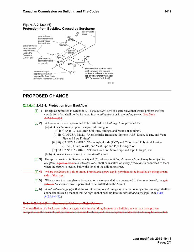
Figure A-2.4.6.4.(6)Protection from Backflow Caused by Surcharge
PROPOSED CHANGE
[2.4.6.4.] 2.4.6.4. Protection from Backflow[1] 1) Except as permitted in Sentence (2), a backwater valve or a gate valve that would prevent the free
circulation of air shall not be installed in a building drain or in a building sewer. (See NoteA-2.4.6.4.(1).)
[2] 2) A backwater valve is permitted to be installed in a building drain provided that[a] a) it is a “normally open” design conforming to
[i] i) CSA B70, "Cast Iron Soil Pipe, Fittings, and Means of Joining",[ii] ii) CAN/CSA-B181.1, "Acrylonitrile-Butadiene-Styrene (ABS) Drain, Waste, and Vent
Pipe and Pipe Fittings",[iii] iii) CAN/CSA-B181.2, "Polyvinylchloride (PVC) and Chlorinated Polyvinylchloride
(CPVC) Drain, Waste, and Vent Pipe and Pipe Fittings", or[iv] iv) CAN/CSA-B182.1, "Plastic Drain and Sewer Pipe and Pipe Fittings", and
[b] b) it does not serve more than one dwelling unit.[3] 3) Except as provided in Sentences (5) and (6), where a building drain or a branch may be subject to
backflow, a gate valve or a backwater valve shall be installed on every fixture drain connected to themwhen the fixture is located below the level of the adjoining street.
[4] 4) Where the fixture is a floor drain, a removable screw cap is permitted to be installed on the upstreamside of the trap.
[5] 5) Where more than one fixture is located on a storey and all are connected to the same branch, the gatevalve or backwater valve is permitted to be installed on the branch.
[6] 6) A subsoil drainage pipe that drains into a sanitary drainage system that is subject to surcharge shall beconnected in such a manner that sewage cannot back up into the subsoil drainage pipe. (See NoteA-2.4.6.4.(6).)
Note A-2.4.6.4.(1) Backwater Valve or Gate Valve.The installation of a backwater valve or a gate valve in a building drain or in a building sewer may have provenacceptable on the basis of past performance in some localities, and their acceptance under this Code may be warranted.
PROPOSEDCHANGEA-2.4.6.4.(1)
PROPOSEDCHANGEA-2.4.6.4.(6)
Canadian Commission on Building and Fire Codes 1412
Last modified: 2019-10-15Page: 2/4

Note A-2.4.6.4.(6) Protection from Backflow Caused by Surcharge.TheseThis requirements areis intended to apply when in the opinion of the authority having jurisdiction there is danger ofbackup from a public sewer.
Figure [A-A-2.4.6.4.(6)] A-2.4.6.4.(6)Protection from Backflow Caused by Surcharge
RATIONALE
ProblemExisting Sentence 2.4.6.4.(3) allows a gate valve to be installed on a fixture drain. Existing Sentence 2.4.6.4.(4)allows a screw cap to be installed on the upstream side of the trap for a floor drain.
Protection from backflow is typically needed in emergency situations. However, as a result of societal changes inCanada, someone is not typically available in the home at all times to detect backflow and then close a gate valve orscrew a cap onto a floor drain. The failure to take such action early on in a backflow situation could lead tounsanitary conditions, which could lead to harm to persons.
Justification - ExplanationCurrently, the NPC allows the installation of gate valves and screw caps to prevent sewage and storm water fromentering the building as a result of backflow.
Canadian Commission on Building and Fire Codes 1412
Last modified: 2019-10-15Page: 3/4

Closing a gate valve and screwing a cap onto a floor drain are both manual interventions that need to be carried outearly on in a backflow situation to minimize damage. However, as a result of societal changes in Canada, manybuildings are now unoccupied for significant periods of time.
In addition, many basements located below the level of the adjoining street are now developed. Failure to close agate valve or to screw a cap onto a floor drain in a backflow situation in such basements would likely result insignificant losses.
This proposed change removes gate valves and screw caps as options for preventing sewage and storm water frombacking up into basements and, thereby, reduces the likelihood of unsanitary conditions and harm to persons.
Impact analysisIn new construction, backflow protection is required for all fixtures below the level of the adjoining street.Removing gate valves and screw caps, which require manual intervention, as options for backflow protection willreduce the risk of basement flooding. Gate valves are rarely used in plumbing systems and are similar in cost tobackwater valves. Since backwater valves are required for other plumbing applications, there should be noadditional cost to use such valves to protect floor drains and other fixtures that could have been protected by a gatevalve or screw cap. In fact, the use of backwater valves may result in a cost reduction.
Enforcement implicationsNo additional resources are required to enforce this proposed change.
Who is affectedDesigners, specifiers, manufacturers, building owners, building officials, plumbers and contractors.
OBJECTIVE-BASED ANALYSIS OF NEW OR CHANGED PROVISIONS
[2.4.6.4.] 2.4.6.4. ([1] 1) [F81-OH2.1]
[2.4.6.4.] 2.4.6.4. ([1] 1) [F81-OH1.1]
[2.4.6.4.] 2.4.6.4. ([2] 2) [F81-OH1.1]
[2.4.6.4.] 2.4.6.4. ([2] 2) [F81-OH2.1]
[2.4.6.4.] 2.4.6.4. ([3] 3) [F81-OH2.1]
[2.4.6.4.] 2.4.6.4. ([4] 4) no attributions
[2.4.6.4.] 2.4.6.4. ([5] 5) no attributions
[2.4.6.4.] 2.4.6.4. ([6] 6) [F81-OH2.1]
Canadian Commission on Building and Fire Codes 1412
Last modified: 2019-10-15Page: 4/4

Submit a comment
Proposed Change 1390Code Reference(s): NPC15 Div.B 2.4.9.2.Subject: Drainage SystemsTitle: Size of Drainage Pipes Serving Water ClosetsDescription: This proposed change deletes Sentence 2.4.9.2.(2), which sets a minimum
size for branch and building drains serving 3 or more water closets, andSentence 2.4.9.2.(3), which sets a minimum size for soil-or-waste stacksserving more than 6 water closets.
Related Code ChangeRequest(s):
CCR 1242
PROPOSED CHANGE
[2.4.9.2.] 2.4.9.2. Serving Water Closets[1] 1) Drainage pipes that serve a water closet shall be not less than 3 inches in size.
[2] 2) Branch and building drains downstream of the third water closet fixture drain connection shall be notless than 4 inches in size.
[3] 3) Soil-or-waste stacks that serve more than 6 water closets shall be not less than 4 inches in size.
[4] 4) Discharge pipes serving a macerating toilet system shall be not less than ¾ inch in size.
RATIONALE
ProblemExisting Article 2.4.9.2. restricts the number of water closets that discharge to a 3-inch branch or building drain or a3-inch soil-or-waste stack.
A branch or building drain that serves 3 or more water closet fixtures is required to be not less than 4 inches in size.Likewise, a soil-or-waste stack that serves more than 6 water closets is required to be not less than 4 inches in size.These restrictions on pipe size could lead to an oversizing of pipes, which could lead to insufficient flow velocity,which could contribute to blockage issues, which could lead to unsanitary conditions and harm to persons.
Justification - ExplanationAccording to Table 2.4.9.3., water closets with flush tanks have a hydraulic load of 4 fixture units drained (FUD),and water closets with direct flush valves have a hydraulic load of 6 FUD.
According to Table 2.4.10.6.-B, a maximum hydraulic load of 27 FUD is permitted to drain to a 3-inch branch.Therefore, 6 water closets with flush tanks or 4 water closets with direct flush valves are permitted to discharge to a3-inch branch.
According to Table 2.4.10.6.-A, a maximum hydraulic load of 18 FUD per storey is permitted to drain to a 3-inchsoil-or-waste stack. Therefore, 4 water closets with flush tanks or 3 water closets with direct flush valves per storeyare permitted to discharge to a 3-inch stack.
Using the applicable NPC Tables to determine the appropriate pipe size for a particular number of water closets willprevent the oversizing of pipes.
Canadian Commission on Building and Fire Codes 1390
Last modified: 2019-09-30Page: 1/2
Impact analysisThe proposed change will reduce plumbing installation costs while ensuring that the Code objectives and functionalstatements continue to be met. Use of the applicable NPC Tables will ensure that water closets discharge into a pipeof a size appropriate for the number of water closets, which will limit the likelihood that persons will be exposed toan unacceptable risk of illness due to unsanitary conditions.
Enforcement implicationsThe proposed change will facilitate the enforcement of Section 2.4. by building officials and regulators.
Who is affectedDesigners, plumbers, regulators, engineers, building owners, and contractors.
OBJECTIVE-BASED ANALYSIS OF NEW OR CHANGED PROVISIONS
[2.4.9.2.] 2.4.9.2. ([1] 1) [F81-OH2.1]
[2.4.9.2.] 2.4.9.2. ([2] 2) [F81-OH2.1]
[2.4.9.2.] 2.4.9.2. ([3] 3) [F81-OH2.1]
[2.4.9.2.] 2.4.9.2. ([4] 4) [F81-OH2.1]
Canadian Commission on Building and Fire Codes 1390
Last modified: 2019-09-30Page: 2/2

Submit a comment
Proposed Change 1391Code Reference(s): NPC15 Div.B 2.4.9.3.Subject: Drainage SystemsTitle: Shower Drains: Minimum Size of Fixture Outlet Pipe and Hydraulic LoadDescription: This proposed change replaces number of shower heads with volume of
discharge from shower heads and introduces volume of discharge frombody sprays as the criteria to determine the minimum size of fixture outletpipe and minimum hydraulic load required for shower drains.
Related Code ChangeRequest(s):
CCR 1267
PROPOSED CHANGE
[2.4.9.3.] 2.4.9.3. Size of Fixture Outlet Pipes[1] 1) Except as provided in Sentence (2), the size of fixture outlet pipes shall conform to Table 2.4.9.3.
[2] 2) The part of the fixture outlet pipe that is common to 3 compartments of a sink shall be one size largerthan the largest fixture outlet pipe of the compartments that it serves. (See Note A-2.4.9.3.(2).)
Table [2.4.9.3.] 2.4.9.3.Minimum Permitted Size of Fixture Outlet Pipe and Hydraulic Loads for Fixtures (1)
Forming Part of Sentences [2.4.9.3.] 2.4.9.3.([1] 1) and 2.4.10.2.(1)
FixtureMinimum Size of
Fixture OutletPipe, inches
Hydraulic Load, fixtureunits
Autopsy table 1½ 2
Bathroom group
(a) with flush tank n/a 6
(b) with direct flush valve n/a 8
Bathtub (with or without shower) 1½ 1½
Bath: foot, sitz or slab 1½ 1½
Beer cabinet 1½ 1½
Bidet 1¼ 1
Clothes washer
(a) domestic (1) n/a 2 with 2-in. trap
(b) commercial n/a 2 with 2-in. trap
PROPOSEDCHANGEA-2.4.9.3.(2)
PROPOSED CHANGE Table 2.4.9.3. Footnote
PROPOSED CHANGE Table 2.4.9.3. Footnote
Canadian Commission on Building and Fire Codes 1391
Last modified: 2019-08-15Page: 1/4

FixtureMinimum Size of
Fixture OutletPipe, inches
Hydraulic Load, fixtureunits
Dental unit or cuspidor 1¼ 1
Dishwasher
(a) domestic type 1½ 1½ no load when connectedto garbage grinder or
domestic sink
(b) commercial type 2 3
Drinking fountain 1¼ ½
Floor drain (2) 2 2 with 2-in. trap
3 with 3-in. trap
Garbage grinder, commercial type 2 3
Icebox 1¼ 1
Laundry tray
(a) single or double units or 2 single units withcommon trap
1½ 1½
(b) 3 compartments 1½ 2
Lavatory
(a) barber or beauty parlor 1½ 1½
(b) dental 1¼ 1
(c) domestic type, single or 1¼ 1 with 1¼-in. trap
2 single with common trap 1½ with 1½-in. trap
(d) multiple or industrial type 1½ according to Table 2.4.10.2.
Macerating toilet system ¾ 4
Potato peeler 2 3
Shower drain
Total volume of discharge from all shower headsand body sprays:
(a) < 9.5 LPM from 1 head 1½ 1½
(b) 9.5 LPM to 20 LPM from 2 or 3 heads 2 3
(c) > 20 LPM from 4 to 6 heads 3 6
PROPOSED CHANGE Table 2.4.9.3. Footnote
Canadian Commission on Building and Fire Codes 1391
Last modified: 2019-08-15Page: 2/4

FixtureMinimum Size of
Fixture OutletPipe, inches
Hydraulic Load, fixtureunits
Sink
(a) domestic and other small types with or withoutgarbage grinders, single, double or 2 single witha common trap
1½ 1½
(b) Other sinks 1½ 1½ with 1½-in. trap
2 with 2-in. trap
3 with 3-in. trap
Urinal
(a) pedestal, siphon-jet or blowout type 2 4
(b) stall, washout type 2 2
(c) wall
(i) washout type 1½ 1½
(ii) other types 2 3
Water closet
(a) with flush tank 3 4
(b) with direct flush valve 3 6
Notes to Table [2.4.9.3.] 2.4.9.3.:
See Note A-Table 2.4.9.3.PROPOSEDCHANGEA-Table2.4.9.3.
(1)PROPOSED CHANGE Table 2.4.9.3. Footnotereferrer
No hydraulic load for emergency floor drains.(2)PROPOSED CHANGE Table 2.4.9.3. Footnotereferrer
[3] 3) Where clothes washers do not drain to a laundry tray, the trap inlet shall be fitted with a verticalstandpipe that is not less than 600 mm long measured from the trap weir and terminates above the floodlevel rim of the clothes washer. (See Note A-2.4.9.3.(3).)
RATIONALE
ProblemThe NPC requirements on the minimum size of fixture outlet pipe and minimum hydraulic load for shower drains donot take into account the volume of water discharged from body sprays in a shower.
Fixture outlet pipes that are inadequately sized for the flow capacity of specific fixtures may not provide adequatewater drainage capacity, which may lead to water backing up, which may lead to unsanitary conditions and to harmto persons.
Footnote1Footnote2
PROPOSEDCHANGEA-2.4.9.3.(3)
Canadian Commission on Building and Fire Codes 1391
Last modified: 2019-08-15Page: 3/4

Justification - ExplanationShower drains are currently sized based on the number of shower heads and the maximum water-flow rate pershower head. The discharge from body sprays, which are now a common feature in many showers, is not accountedfor when sizing shower drains. As such, discharged water may back up into the bathroom due to an inadequatelysized shower drain.
Impact analysisNo foreseen additional costs. The proposed change will ensure adequate sizing according to the volume of waterdischarged into a shower drain, which will limit the likelihood that a person may be exposed to an unacceptable riskof illness due to unsanitary conditions resulting from the inadequate design to the discharge system.
Enforcement implicationsThe proposed change can be enforced and its enforcement will not require an increase in resources.
Who is affectedEngineers, plumbers, building owners, contractors and regulators.
OBJECTIVE-BASED ANALYSIS OF NEW OR CHANGED PROVISIONS
[2.4.9.3.] 2.4.9.3. ([1] 1) [F81-OH2.1]
[2.4.9.3.] 2.4.9.3. ([2] 2) [F81-OH2.1]
[2.4.9.3.] 2.4.9.3. ([3] 3) [F81-OP5]
[2.4.9.3.] 2.4.9.3. ([3] 3) [F81-OH1.1]
Canadian Commission on Building and Fire Codes 1391
Last modified: 2019-08-15Page: 4/4

Submit a comment
Proposed Change 1413Code Reference(s): NPC15 Div.B 2.7.4.1.Subject: Non-Potable Water SystemsTitle: Use of Non-Potable Water in Health Care FacilitiesDescription: This proposed change prohibits the use of non-potable water systems to
supply fixtures in health care facilities.Related Code ChangeRequest(s):
CCR 977
PROPOSED CHANGE
[2.7.4.1.] 2.7.4.1. Non-potable Water System Design(See Note A-2.7.4.1.)
[1] 1) Except as provided in Sentence (2), non-potable water systems shall be designed, fabricated andinstalled in accordance with good engineering practice, such as that described in the ASHRAEHandbooks, ASPE Handbooks and CAN/CSA-B128.1, "Design and Installation of Non-Potable WaterSystems".
[2] 2) Except as provided in Sentence (3) and in Subsection 2.7.2.-2020 (see PCF 945), Nnon-potable watersystems shall only be used to supply water closets, urinals, and directly connected undergroundirrigation systems that only dispense water below the surface of the ground.
[3] --) Non-potable water systems shall not be used to supply fixtures in health care facilities.
RATIONALE
ProblemThe use of non-potable water systems to supply water closets and urinals in health care facilities needs to berestricted, as residents of such facilities are more prone to being affected by contaminants in the non-potable water.For instance, non-potable water may contain chemicals or pathogenic micro-organisms, which could lead to harm topersons upon exposure.
Justification - ExplanationThe presence of pathogenic micro-organisms (bacteria, protozoa and viruses) and chemicals in non-potable watermay pose a health risk. This is of particular concern for persons with a weakened immune system, who may bepatients in a health care facility, for whom the effects may be severe, chronic or even fatal.
Prohibiting the use of non-potable water systems to supply water closets and urinals in health care facilities willreduce the potential for exposure to pathogenic micro-organisms and chemicals that could affect the health offacility residents.
Impact analysisThe proposed change has no cost implications, as the use of non-potable water systems to supply water closets andurinals is optional. Designers and building owners are free to choose whether or not to use this option in a particularbuilding. As such, prohibiting this option in health care facilities is not expected to impose an economic burden.
PROPOSEDCHANGEA-2.7.4.1.
Canadian Commission on Building and Fire Codes 1413
Last modified: 2019-10-29Page: 1/2

Enforcement implicationsThe proposed change can be enforced, and its enforcement will not require an increase in resources.
Who is affectedDesigners, specifiers, manufacturers, building owners, building officials, and contractors.
Supporting Document(s)PCF 945 (2018) (pcf_945.pdf)
OBJECTIVE-BASED ANALYSIS OF NEW OR CHANGED PROVISIONS
[2.7.4.1.] 2.7.4.1. ([1] 1) [F81-OH2.1]
[2.7.4.1.] 2.7.4.1. ([2] 2) [F82-OH2.2]
-- (--) [F40-OH2.2]
Canadian Commission on Building and Fire Codes 1413
Last modified: 2019-10-29Page: 2/2

Soumettre un commentaire
Modification proposée 945Renvoi(s) : CNP15 Div.B 2.7.2.Sujet : Utilisation efficiente de l'eauTitre : Introduction des exigences relatives aux installations de collecte d'eau de
pluie non potableDescription : La présente modification proposée introduit des exigences relatives aux
installations de collecte d'eau de pluie non potable. La modification faitpartie d'une réorganisation de la section 2.7. qui vise à inclure desexigences relatives aux installations de récupération de l'eau.
Modification(s)proposée(s) connexe(s) :
FMP 940, FMP 942, FMP 946
EXIGENCE ACTUELLE
2.7.2. Identification
2.7.2.1. Marquage1) potable
MODIFICATION PROPOSÉE
[2.7.2.] 2.7.2. Identification Installations de collecte de l'eau de pluie non potable
[2.7.2.1.] --- Généralités[1] --) eaux pluviales
[2] --) potable
installation de plomberie
[2.7.2.2.] --- Utilisations permises[1] --) potable
Commission canadienne des codes du bâtiment et de prévention des incendies 945
Dernière modification : 2018-11-05Page : 1/6

[2.7.2.3.] --- Conception du toit[1] --)
potable[2] --)
potable
[2.7.2.4.] --- Conception des installations de collecte d'eau de pluie non potable[1] --) potable
[2] --) potable
[3] --) potablepotable
[4] --) potable
potable
[5] --) appareil sanitairepotable
appareil sanitaire[6] --) potable
[7] --) potable
égout pluvialégout unitaire
eaux pluvialeseaux pluviales
[8] --)
bâtimentclapet antiretour
[9] --) potable
Commission canadienne des codes du bâtiment et de prévention des incendies 945
Dernière modification : 2018-11-05Page : 2/6

dispositif antirefoulementcoupure antiretour
[10] --) appareil sanitaire potablepotable potable réseau d’alimentation en eau potable
dispositif antirefoulement
Note A-2.7.2.1. 1) Surfaces de toit hors sol.
Note A-2.7.2.2. 1) et 2.7.2.4. 3) et 4) Traitement pour utilisation.
Note A-2.7.2.3. 1) Circulation de piétons.
Note A-2.7.2.3. 2) Matériaux de couverture et d'adduction.
Note A-2.7.2.4. 1). Règles de l’art.
RAISON
Problème
Commission canadienne des codes du bâtiment et de prévention des incendies 945
Dernière modification : 2018-11-05Page : 3/6

Justification - Explication
Commission canadienne des codes du bâtiment et de prévention des incendies 945
Dernière modification : 2018-11-05Page : 4/6

Analyse des répercussions
Répercussions sur la mise en application
Personnes concernées
ANALYSE AXÉE SUR LES OBJECTIFS DES EXIGENCES NOUVELLESOU MODIFIÉES
[2.7.2.1.] -- [1] --) aucune attribution[2.7.2.1.] -- [2] --) aucune attribution[2.7.2.2.] -- [1] --) [F46-OH2.2][2.7.2.2.] -- [1] --) [F81-OH2.2][2.7.2.3.] -- [1] --) [F41-OH2.2][2.7.2.3.] -- [2] --) [F46-OH2.2][2.7.2.4. 2.7.2.4.] -- [1 4] --) [F41-OH2.2][2.7.2.4.] -- [2] --) [F41-OH2.2]-- --) [F40-OH2.2]
Commission canadienne des codes du bâtiment et de prévention des incendies 945
Dernière modification : 2018-11-05Page : 5/6

[2.7.2.4. 2.7.2.4.] -- [1 4] --) [F41-OH2.2]-- --) [F81-OS3.2][2.7.2.4.] -- [6] --) [F40-OH2.2][2.7.2.4.] -- [7] --) [F81-OH2.2][2.7.2.4.] -- [7] --) [F81-OP5][2.7.2.4.] -- [8] --) [F81-OH2.2][2.7.2.4.] -- [8] --) [F81-OP5][2.7.2.4.] -- [9] --) [F46-OH2.2][2.7.2.4.] -- [10] --) [F46-OH2.2]
Commission canadienne des codes du bâtiment et de prévention des incendies 945
Dernière modification : 2018-11-05Page : 6/6

Submit a comment
Proposed Change 945Code Reference(s): NPC15 Div.B 2.7.2.Subject: Water-Use EfficiencyTitle: Introduction of Requirements for Non-Potable Rainwater Harvesting
SystemsDescription: This proposed change introduces requirements for non-potable rainwater
harvesting systems. The change is part of a reorganization of Section 2.7. toinclude requirements for water recovery systems.
Related ProposedChange(s):
PCF 940, PCF 942, PCF 946
EXISTING PROVISION
2.7.2. Identification
2.7.2.1. Markings Required1) potable
PROPOSED CHANGE
[2.7.2.] 2.7.2. IdentificationNon-Potable Rainwater Harvesting Systems
[2.7.2.1.] --- General[1] --) storm water
[2] --) potable
plumbing system
[2.7.2.2.] --- Permitted Applications[1] --) potable
[2.7.2.3.] --- Roof Design[1] --) potable
Canadian Commission on Building and Fire Codes 945
Last modified: 2018-11-05Page: 1/5

[2] --)potable
[2.7.2.4.] --- Non-Potable Rainwater Harvesting System Design[1] --) potable
[2] --) potable
[3] --) potablepotable
[4] --) potable
potable
[5] --) fixture potablefixture
[6] --) potable
[7] --) potable
storm sewer
storm waterstorm water
[8] --)
buildingbackwater valve
[9] --) potablebackflow preventer
air gap[10] --) fixture potable potable
potable potable water system backflowpreventer
Canadian Commission on Building and Fire Codes 945
Last modified: 2018-11-05Page: 2/5

Note A-2.7.2.1.(1) Above-Ground Roof Surfaces.
Note A-2.7.2.2.(1) and 2.7.2.4.(3) and (4) Treatment for Use.
Note A-2.7.2.3.(1) Pedestrian Traffic.
Note A-2.7.2.3.(2) Roofing and Conveyance Materials.
Note A-2.7.2.4.(1). Good Engineering Practice.
RATIONALE
Problem
Justification - Explanation
Canadian Commission on Building and Fire Codes 945
Last modified: 2018-11-05Page: 3/5

Impact analysis
Canadian Commission on Building and Fire Codes 945
Last modified: 2018-11-05Page: 4/5

Enforcement implications
Who is affected
OBJECTIVE-BASED ANALYSIS OF NEW OR CHANGED PROVISIONS
[2.7.2.1.] -- ([1] --) no attributions[2.7.2.1.] -- ([2] --) no attributions[2.7.2.2.] -- ([1] --) [F46-OH2.2][2.7.2.2.] -- ([1] --) [F81-OH2.2][2.7.2.3.] -- ([1] --) [F41-OH2.2][2.7.2.3.] -- ([2] --) [F46-OH2.2][2.7.2.4. 2.7.2.4.] -- ([1 4] --) [F41-OH2.2][2.7.2.4.] -- ([2] --) [F41-OH2.2]-- (--) [F40-OH2.2][2.7.2.4. 2.7.2.4.] -- ([1 4] --) [F41-OH2.2]-- (--) [F81-OS3.2][2.7.2.4.] -- ([6] --) [F40-OH2.2][2.7.2.4.] -- ([7] --) [F81-OH2.2][2.7.2.4.] -- ([7] --) [F81-OP5][2.7.2.4.] -- ([8] --) [F81-OH2.2][2.7.2.4.] -- ([8] --) [F81-OP5][2.7.2.4.] -- ([9] --) [F46-OH2.2][2.7.2.4.] -- ([10] --) [F46-OH2.2]
Canadian Commission on Building and Fire Codes 945
Last modified: 2018-11-05Page: 5/5

Encapsulated Mass Timber Construction
ProblemDevelopers, architects, engineers and builders across Canada are seeking additional options for a greater variety ofheights and sizes of buildings that are permitted to be constructed of wood. This quest is driven, in part, by their interest inthe demonstrable positive environmental attributes of wood. In addition, actions undertaken by the governments of BritishColumbia, Ontario and Quebec show that the development of technical prescriptive provisions for the construction of tallwood buildings is a priority. For example, in Quebec, the provincial government department responsible for regulating thedesign and construction of buildings published a guide for designers/builders in August 2015 entitled Mass timber buildingsof up to 12 storeys: Directives and Explanatory Guide. This guide lays out a path for those wanting to obtain approvalthrough an expedited alternative-solution process to build wood buildings up to 12 storeys in height in Quebec.
Under the current prescriptive provisions of the National Building Code of Canada (NBC) 2015, all buildings are separatedinto only two construction type categories: those of combustible construction and those of noncombustible construction.The provisions severely restrict the height and area of buildings of combustible construction whereas they permit unlimitedheight and area for noncombustible construction. NBC Subsection 3.1.5. of Division B (Noncombustible Construction)prohibits the use of certain structural wood elements in noncombustible buildings; such elements are therefore restricted tobeing used in smaller buildings permitted to be combustible construction. This restriction on the use of structural woodelements can affect building design in three ways: (a) the height and area of the building must not exceed the limitscurrently placed on all forms of combustible construction; (b) the design must be altered to eliminate the inclusion of suchwood elements; or (c) the design must include a proposed alternative solution (on a specific project-by-project basis) forapproval by the Authority Having Jurisdiction (AHJ), which can require significant resources and expertise, both for thedesigner to develop and for the AHJ to evaluate. As such, this combustible/noncombustible construction classificationsystem, which was introduced in the National Construction Codes over 50 years ago, is increasingly regarded as beingoutdated and unnecessarily restrictive.
Even with the increased use of performance-based design, some Code users will continue to prefer to follow prescriptivebuilding fire-safety design provisions—whether for simplicity, efficiency, cost-effectiveness or some other reason—formany years to come. The Canadian Commission on Building and Fire Codes should therefore consider the inclusion ofprescriptive means for permitting the use of systems and methodologies of construction for tall buildings usingwood—which have been, and continue to be, developed around the world—while limiting the probability of anunacceptable level of risk of illness, injury or building damage. One such methodology, which limits the probability of anunacceptable level of fire risk in tall wood buildings and is being used successfully elsewhere, is that of encapsulated masstimber construction.
Justification - ExplanationA Code change request was submitted that proposed provisions to permit the use of mass timber structural elements in thedesign of Group C and Group D sprinklered buildings up to 12 storeys in building height.
The set of proposed Code provisions brought forward for public review collectively defines and lays out requirements forthis new type of construction for buildings up to 12 storeys in building height, which is proposed to be called “encapsulatedmass timber construction”(EMTC). None of the proposed changes affects the existing prescriptive requirements (i.e.,acceptable solutions) for combustible and noncombustible construction; EMTC is being proposed as an additionalconstruction option for builders.
Buildings up to 12 storeys in building height are currently required to have a 2-h fire-resistance rating, be sprinklered, andbe of noncombustible construction. The proposed Code provisions would permit them to be constructed of EMTC underthe following conditions:
• Building height is no more than 12 storeys.
• Building area is no more than 6 000 m2 for Group C major occupancies and no more than 7 200 m2 for Group Dmajor occupancies.
• Except for a few specific exceptions, permitted mass timber elements meet minimum size requirements and areencapsulated.
Canadian Commission on Building and Fire Codes
Page 1/4

• Combustible concealed spaces are limited in number; horizontal concealed spaces have more fire blocking; otherthan solid lumber nailing elements, only non-wood-based fire blocking materials are permitted to be used in anyconcealed space.
• Types of major occupancies permitted in mixed-use buildings are limited if the building is entirely constructed ofEMTC:
◦ For buildings constructed using the requirements for Group C major occupancies, the following majoroccupancies would not be permitted:
▪ Group A, Division 1▪ Group A, Division 3▪ Group B▪ Group F, Division 1▪ Group F, Division 2▪ Group F, Division 3 (except storage garages)
◦ For buildings constructed using the requirements for Group D major occupancies, the following majoroccupancies would not be permitted:
▪ Group A, Division 1▪ Group A, Division 3▪ Group B▪ Group F, Division 1
• Location of major occupancies is restricted if the building is entirely constructed of EMTC:◦ For buildings constructed using the requirements for Group C major occupancies, the following major
occupancies are restricted to the following locations:▪ Group E below the third storey▪ Group A, Division 2 below the fourth storey▪ storage garage below the fifth storey
◦ For buildings constructed using the requirements for Group D major occupancies, the following majoroccupancies are restricted to the following locations:
▪ Group E below the third storey▪ Group F, Division 2 below the third storey▪ Group F, Division 3 below the third storey (except storage garages)▪ Group A, Division 2 below the fourth storey▪ storage garage below the fifth storey
• Fire-resistance ratings are higher for fire separations between certain major occupancies.
• Requirements for high buildings in Subsection 3.2.6. of Division B of the National Building Code (NBC) 2015 areapplied to Group D, Business and Personal Services Occupancies, more than 18 m in height, instead of thecurrent trigger of more than 36 m in height (Group C, Residential Occupancies, are already considered highbuildings if greater than 18 m in height).
• Buildings of residential occupancy throughout that are up to four storeys in building height are sprinklered inaccordance with NFPA 13, “Installation of Sprinkler Systems,” rather than NFPA 13R, “Installation of SprinklerSystems in Low-Rise Residential Occupancies,” as is the case with all other 1-to-4-storey buildings of residentialoccupancy throughout that are required to be sprinklered.
• Roof coverings on any roof that is more than 25 m above the floor of the first storey are Class A.
• Storage garages considered as separate buildings and having openings that are not protected by closures arerequired to be protected by larger projections than those required in noncombustible construction.
• The fire safety requirements in the National Fire Code 2015 that apply to construction sites for buildings designedin conformance with Articles 3.2.2.50. and 3.2.2.58. of the NBC 2015 (i.e., mid-rise buildings of combustibleconstruction of Group C and Group D major occupancies, respectively) are also applied to buildings of EMTCalong with new proposed fire safety requirements, which further reduce the risk of fire in buildings of EMTC.
Canadian Commission on Building and Fire Codes
Page 2/4

It is intended that the fire safety requirements and specific design restrictions presented in this set of proposed changeswill sufficiently limit the probability of risk of unacceptable loss in buildings using EMTC.
Additional supporting documents:
• CHM Fire Consultants, Ltd.; Defining Mass Timber for Tall Buildings: Rationalization for Minimum Dimensions,February 2016.
• Berzins, R.; Lafrance, P-S.; Leroux, P.; Lougheed, G.D.; Su, J.Z.; and Bénichou, N.; Client ReportA1-100035-01.2: Intermediate-Scale Furnace Tests with Encapsulation Materials, National Research Council,Ottawa, December 2014.
• Bijloos, M.; Lougheed, G.D.; Su, J.Z.; and Bénichou, N.; Client Report A1-100035-01.1: Cone Calorimeter Resultsfor Encapsulation Materials, National Research Council, Ottawa, December 2014.
• Bijloos, M.; Lougheed, G.D.; Su, J.Z.; and Bénichou, N.; Client Report A1-100035-01.12: Ignition of SelectedWood Building Materials, National Research Council, Ottawa, December 2014.
• Calder, K.; The Historical Development of the Building Size Limits in the National Building Code of Canada,Sereca Consulting Inc., Vancouver, March 2015.
• Ferguson, R.S.; and Shorter, G.W.; Technical Note No. 428 - “The Problem of ‘Noncombustible’”, Division ofBuilding Research, National Research Council, Ottawa, December 1964.
• Lougheed, G.D.; Su, J.Z.; and Bénichou, N.; Client Report A1-100035-01.14: Encapsulation Time Data from NRCFire-resistance Projects, National Research Council, Ottawa, December 2014.
• Su, J.Z.; and Lougheed, G.D.; Client Report A1-004377.1: Fire Safety Summary – Fire Research Conducted forthe Project on Mid-Rise Wood Construction, National Research Council, Ottawa, December 2014.
• Taber, B.C.; Lougheed, G.D.; Su, J.Z.; Bénichou, N.; Client Report A1-100035-01.10: Apartment Fire Test withEncapsulated Cross Laminated Timber Construction (Test APT-CLT), National Research Council, Ottawa,December 2014.
Impact AnalysisEncapsulated mass timber construction (EMTC) is a new construction type being proposed for buildings up to 12 storeys inbuilding height. Buildings of EMTC achieve the same performance level with regard to fire and structural protection, healthand safety, and accessibility as other types of buildings addressed in the National Building Code (NBC) 2015. Furthermore,the proposed additional protection measures for buildings of EMTC are intended to ensure that such buildings present thesame fire and life safety risks during construction as other types of buildings addressed by the NBC.
Buildings of EMTC up to 12 storeys in building height may have a better environmental performance compared to othertypes of buildings up to 12 storeys currently prescribed in the NBC, as they can be more sustainable and are mainly madeof wood, which is a renewable resource that sequesters carbon dioxide, thus helping reduce the carbon footprint of thebuilding. Wood is also a natural insulator and has better thermal performance than masonry or concrete.
The construction process for buildings of EMTC presents several potential benefits, including:
• shorter construction timeframes compared to other types of construction because the pre-fabricated mass timberpanels for floor and wall assemblies used in EMTC do not require on-site assembly: they come ready to be placedand joined together; the time savings may result in reduced costs and minimizes the impact of constructionactivities on the surrounding community;
• less waste material on site compared to lightweight wood-frame construction because EMTC uses pre-fabricatedfloor and wall panels.
The overall cost of constructing buildings of EMTC is not known at this time and appears to be affected by marketconditions. Although several buildings around the world have been constructed of mass timber, the overall cost associatedwith their construction cannot be used to establish the cost of constructing a building of EMTC in Canada because their
Canadian Commission on Building and Fire Codes
Page 3/4

construction methods and protection features vary from those being proposed for inclusion in the NBC and National FireCode 2020.
Attached Supporting Materialnone
Canadian Commission on Building and Fire Codes
Last modified: 2019-10-22 Page 4/4

Grab Bars
Attached Supporting Material
• Appendix A• Impact Analysis Summary• Bibliography
Canadian Commission on Building and Fire Codes
Last modified: 2019-10-31 Page 1/1

Bibliography
• Guay M, D'Amour M, Provencher V. When bathing leads to drowning in older adults: a look intocircumstances surrounding these tragic events. Age & Ageing Under Review, 2017
• King EC, Novak AC. Effect of bathroom aids and age on balance control during bathing transfers.American Journal of Occupational Therapy 2017; 71: 1-9
• Drowning Prevention Resource Centre of Canada. Canadian Drowning Report, 2016 Edition.• Lawrence BA, Spicer RS, Miller TR. A fresh look at the costs of non-fatal consumer product
injuries. Inj Prev 2015;21:23-29.• Parachute. The cost of injury in Canada. Toronto, ON 2015.• Sauter TC, Kreher J, Ricklin ME, Haider DG, Exadaktylos AK. Risk factors for intracranial
haemorrhage in accidents associated with the shower or bathtub. Plos One.2015; https://doi.org/10.1371/journal.pone.0141812
• Accreditation Canada, Canadian Institute for Health Information, Canadian Patient SafetyInstitute (2014) Report: Preventing falls: from evidence to improvement in Canadian health care.
• Volpe R. Best practices in the prevention of mid-life falls in everyday activities. Final Report toOntario Neurotrauma Foundation,2014; onf.org/system/attachments/294/original/MLF_COMBO_RS_Fin_Dec_14.pdf
• Stevens JA, Mahoney JE, Ehrenreich H. Circumstances and outcomes of falls among high riskcommunity-dwelling older adults. Injury epidemiology 2014;1:5.
• Carol Goodall (Public Health Nurse-Prince Edwards/Hastings). Literature review on grab bars andfalls, 2013.
• Thrall P. Perceptions of residential grab bars among community dwelling seniors: Oregon StateUniversity, 2012.
• Guitard P, Sveistrup H, Edwards N, Lockett D. Use of different bath grab bar configurationsfollowing a balance perturbation. Assistive technology : the official journal of RESNA2011;23:205-215; quiz 216-207.
• Stevens JA, Haas EN. Nonfatal bathroom injuries among persons aged >15 years - United States,2008. 2011.
• Bhatt T, Wening JD, Pai Y-C. Adaptive control of gait stability in reducing slip-related backwardloss of balance. Experimental Brain Res 2006; 170: 61-73.
• Sveistrup H, Lockett D, Edwards N, Aminzadeh F. Evaluation of bath grab bar placement forolder adults. Technology and Disability 2006;18: 1-11 and 45-55.
• Edwards, N., Birkett N., Nair, R., Murphy, M., Roberge, G., & Lockett, D. (2006). Access tobathtub
• grab bars: Evidence of a policy gap. Canadian Journal on Aging. 25(3), 295-304• PHAC (2006). It’s your health. Seniors and Aging: Preventing falls in and around your home:• Accessed Sept 26, 2009. http://www.hc-sc.gc.ca/hl-vs/iyh-vsv/life-vie/fp-pc-eng.php• Lockhart TE, Smith JL, Woldstad JC. Effects of aging on the biomechanics of slips and falls. Hum
Factors 2005; 47:708-729• Lockett, D., Aminzadeh, F., & Edwards, N. (2002). Development and evaluation of an instrument
to measure seniors' attitudes towards the use of bathroom grab bars. Public Health Nursing.19(5), 390-397.
• PHAC (2004) Canadian Hospitals Injury Reporting and Prevention Program Re: leading causes ofdeaths. http://www.phac-aspc.gc.ca/publicat/lcd-pcd97/table1-eng.php

• Aminzadeh F, Edwards N, Lockett D, Nair R. Utilization of bathroom safety devices, patterns of bathing and toileting, and bathroom falls in a sample of community living older adults. Technology and Disability 2000;13:95-103.
• Tremblay B, Turner S. Assurez votre securite. Faits saillants sure les noyades et les autres deces lies a l'eau au Quebec de 2000 a 2008. 2010.
• Tinetti, M.E. Williams, C.S. (1997). Falls, injuries due to falls, and the risk of admission to a nursing home. New England Journal of Medicine. 337(18):1279-84.
• DeVito CA, Lambert DA, Sattin RW, Bacchelli S, Ros A, Rodriguez JG. Fall injuries among the elderly. Community-based surveillance. J Am Geriatr Soc 1988;36:1029-1035.
Table 1: Grab Bar QuantitiesFixture Number of Grab
Bars1
Bathtub 2
Shower 1
Table 2: Item Unit Costs (Material+Labour)
Item %O&P
900 mm Grab Bars $88.11 /grab bar $108.19 /grab bar 19%
2"x8" blocking $6.24 /grab bar $8.47 /grab bar 26%
Table 3: Cost per Installation (Material/Labour/O&P)Fixture Grab Bars
Bathtub 233.31$ Shower 116.66$
Table 4: Calculation of Direct Costs ‐ Minimum Installations per Dwelling UnitBuilding and Fixture
TypeInstallations
4 Cost/Dwelling No. of
Dwelling
Starts5
Estimated
Annual Cost
House (Bathtub/Shower)
1.0 233.31$ 104,596 24,403,606$
MURBs (Bathtub/Shower)
1.0 233.31$ 84,009 19,600,368$
Residential Care Facilities
6
1.0 233.31$ 4839 1,128,949$
Total Direct Cost (Minimum) = 45,130,000$
Direct Cost per New Dwelling Unit Starts (Minimum)7 = 233.30$
Table 5: Calculation of Direct Costs ‐ Maximum Installations per Dwelling UnitBuilding and Fixture
TypeInstallations
4 Cost/Dwelling No. of
Dwelling
Starts5
Estimated
Annual Cost
House (Bathtub/shower)
2.0 466.63$ 104,596 48,807,211$
House (Shower) 1.0 116.66$ 104,596 12,201,861$ MURBs (Bathtub/shower)
1.5 349.97$ 84,009 29,400,552$
MURBs (Shower) 1.0 116.66$ 84,009 9,800,242$ Residential Care Facilities
6 1.0 233.31$ 4839 1,128,949$
Total Direct Cost (Maximum) = 101,340,000$
Direct Cost per New Dwelling Unit Starts (Maximum)7 = 523.88$
Total Unit Cost2,3
Estimated Annual Direct Cost of Proposed Change
Bare Unit Cost
Appendix A

Notes:
1. Number of grab bars for bathtubs and showers as per consensus of the Joint Task Group on Grab Bars forBathtubs and Showers during their 2015‐09 meeting.
2. Unit cost calculated using the 2019 edition of Building Construction Costs with RSMeans data. The data, which isin USD is converted to CAD using the average exchange rate for 2018 as reported by the Bank of Canada.
3. Unit costs do not include "general conditions" which are more applicable to commercial construction projects.Included in the unit cost are overhead and profit as per RSMeans "How to Use the Cost Data: The Details" whichsays that "Total Cost including O&P for the installing contractor is shown in the last column of the Unit Price and/or Assemblies. This figure is the sum of the bare material cost plus 10% for profit, the bare labor cost plus totaloverhead and profit, and the bare equipment cost plus 10% for profit."
4. Tables 4 and 5 include different installation quantities to facilitate a sensitivity analysis. Installations in Table 4represent the lower boundary. For the lower boundary, it is assumed that, at a minimum, new starts will have atleast one bathtub/shower combination. The upper boundary is included in Table 5; the values for the upperboundary are calculated based on JTG member scans of building plans/data in jurisdictions located in BritishColumbia (West) and Nova Scotia (East). Values are rounded to the nearest single decimal point.
5. Average number of dwelling starts over four years from 2014 to 2017 using Statistics Canada, "Table: 34‐10‐0135‐01 Canada Mortgage and Housing Corporation, housing starts, under construction and completions, allareas, quarterly" for houses and MURBs. For residential care facilities, new suites are calculated using the averagenumber of new residential care facilities and average number of beds per residential care facilities for the years2005/2006 to 2009/2010 per Statistics Canada, "Table: 13‐10‐0178‐01 Residents on books in residentialcare facilities, by age group, sex, principal characteristic of the predominant group of residents and size of facility,Canada, provinces and territories."
6. It is assumed that a residential care facility will have a bathtub/shower combo requiring 2 grabs bars.
7. The direct cost per dwelling is calculated by dividing the total direct cost by total number of new dwelling starts(houses, MURBs, and residential care facilities).

PIRE Data for Falls in Bathtubs/Showers
Table 6: Rate of Falls Data from May 18, 2016 presentation by Dr. Miller (US Data)Quantity Rate
5.7 million 1 in 54 1.85% of Americans
1.0 million 17.5% of stairs and bathroom falls
37,058,856 686,275 1.85% of total population
Canadian Population (2018) =Falls on Stairs and in Bathrooms (CAN using US statistics)1 = Falls in Bathtubs and Showers (CAN using US statistics)1 = 120,098 17.5% of falls on stairs and in
bathrooms
Table 7: Incidence of medically treated injuries by treatment level in the US, bathtub and shower falls, 2010‐20142
via ED Direct
00‐09 37,209.4 43,339.8 1,331.7 666.4 82,547.3 8.3%
10‐19 35,633.2 23,065.4 550.0 193.0 59,441.6 6.0%
20‐29 69,977.6 35,853.2 1,362.6 482.8 107,676.2 10.8%
30‐39 111,103.0 36,699.4 1,497.8 444.1 149,744.3 15.0%
40‐49 128,478.0 37,743.3 2,339.7 706.7 169,267.7 16.9%
50‐59 122,562.0 37,817.5 3,806.7 1,332.2 165,518.4 16.6%
60‐69 70,334.1 24,507.2 4,954.2 1,648.5 101,444.0 10.2%
70‐79 50,248.3 18,727.5 5,880.1 1,832.0 76,687.9 7.7%
>=80 49,813.7 23,342.6 10,501.9 2,864.2 86,522.4 8.7%
Total 675,359.3 281,095.9 32,224.7 10,169.9 998,849.8 100.0%
00‐0910‐1920‐2930‐3940‐4950‐5960‐6970‐79>=80
Total
10,403 120,098
Table 8: Calculated falls by age for the Canadian population
3
7,147 12,947 18,005 20,352 19,901
Age Doc/Outp ED
Hospital‐admitted
Total Distribution
PercentageDescription
Medically Treated Stairs and Bathroom Falls
Medically Treated Bathtub/Shower Falls
Age
9,925 Bathtub/ Shower Falls per Age
12,197 9,221

00‐09 2,022$ 6,852$ 18,869$ 10‐19 1,717$ 3,744$ 15,668$ 20‐29 1,956$ 6,214$ 19,095$ 30‐39 1,697$ 6,194$ 21,847$ 40‐49 1,823$ 6,832$ 24,621$ 50‐59 2,496$ 7,253$ 26,701$ 60‐69 4,017$ 7,784$ 28,447$ 70‐79 5,475$ 3,636$ 27,704$ >=80 7,614$ 5,054$ 33,065$ Total 2,447$ 6,278$ 22,201$
1.0600 US Inflation 2014 to 20185 = Exchange Rate USD to CAD6 = 1.2957
Table 10: Estimated annual cost of medically treated injuries converted to CAD
00‐09 2,777$ 9,410.66$ 25,915.70$ 38,103.43$ 10‐19 2,358$ 5,142.40$ 21,519.19$ 29,019.62$ 20‐29 2,687$ 8,534.55$ 26,225.60$ 37,447.20$ 30‐39 2,331$ 8,507.62$ 30,005.31$ 40,843.56$ 40‐49 2,504$ 9,383.45$ 33,815.34$ 45,703.11$ 50‐59 3,428$ 9,961.52$ 36,672.18$ 50,062.19$ 60‐69 5,517$ 10,691.06$ 39,070.11$ 55,277.77$ 70‐79 7,520$ 4,993.40$ 38,049.55$ 50,562.90$ >=80 10,458$ 6,940.77$ 45,413.05$ 62,811.82$ Total 3,361$ 8,622.08$ 30,491.92$ 42,475.34$
Medical
(A)Age
Work Loss
(B)
Pain & Suff.
(C)
Total Cost
(A) + (B) + (C)
Age Medical Work Loss Pain & Suff.
Table 9: Estimated annual cost of medically treated injuries in the US, bathtub and shower falls, 2010‐20144
1. Calculated based on the rate of injuries on stairs and in bathrooms in the US‐‐in Table 6‐‐per thepresentation by Dr. T. Miller delivered at a pre‐conference workshop of Public Health '16, inToronto, Ontario.
2. US Data provided to J. Pauls via consultation with B. Lawrence at the Pacific Institute for Researchand Evaluation, PIRE, Maryland, October 2018. The distribution in the last column is calculated aspart of the impact analysis to relate the distribution of falls in the United States to the Canadianpopulation.
3. Canadian falls per age group calculated based on the rate of falls in bathtubs and showers in theUS per Table 6 and the percentage distribution of fall incidents across the age groups as shown inthe US per Table 7.
4. US Data provided to J. Pauls via consultation with B. Lawrence at the Pacific Institute for Researchand Evaluation, PIRE, Maryland, October 2018.
5. US inflation calculated using online calculator, which determines US inflation based on the "latestgovernment CPI data published April 10."
6. USD is converted to CAD using the average exchange rate for 2018 as reported by the Bank ofCanada.

Canadian Pop. (2018)1 = 37,058,856 Avg. Persons per Dwelling Unit2 = 2.9
Age
Total Falls in Tubs
and Showers4
Grab bar impact
factor5
Average cost per
fall (2018)6
Annual Direct Benefit
(National)
00‐09 9950 20.0% $2,777 $5,526,412
10‐19 7165 20.0% $2,358 $3,379,045
20‐29 12979 20.0% $2,687 $6,975,054
30‐39 18050 20.0% $2,331 $8,413,471
40‐49 20403 20.0% $2,504 $10,219,207
50‐59 19951 20.0% $3,428 $13,680,536
60‐69 12228 20.0% $5,517 $13,491,202
70‐79 9244 20.0% $7,520 $13,902,571
>=80 10429 20.0% $10,458 $21,813,736
Total National Direct Benefits = $97,401,233
Annual Direct Benefit per New Dwelling Unit Start7 = $7.62
Age
Total Falls in Tubs
and Showers4
Grab bar impact
factor5
Average cost per
fall (2018)6
Annual Direct Benefit
(National)
00‐09 9950 30.0% $2,777 $8,289,618
10‐19 7165 30.0% $2,358 $5,068,567
20‐29 12979 30.0% $2,687 $10,462,581
30‐39 18050 30.0% $2,331 $12,620,206
40‐49 20403 30.0% $2,504 $15,328,810
50‐59 19951 30.0% $3,428 $20,520,803
60‐69 12228 30.0% $5,517 $20,236,803
70‐79 9244 30.0% $7,520 $20,853,856
>=80 10429 30.0% $10,458 $32,720,604
Total National Direct Benefits = $146,101,849
Annual Direct Benefit per New Dwelling Unit Start7 = $11.43
Age
Total Falls in Tubs
and Showers4
Grab bar impact
factor5
Average cost per
fall (2018)6
Annual Direct Benefit
(National)
00‐09 9950 35.0% $2,777 $9,671,221
10‐19 7165 35.0% $2,358 $5,913,329
20‐29 12979 35.0% $2,687 $12,206,344
30‐39 18050 35.0% $2,331 $14,723,574
40‐49 20403 35.0% $2,504 $17,883,612
50‐59 19951 35.0% $3,428 $23,940,937
60‐69 12228 35.0% $5,517 $23,609,603
70‐79 9244 35.0% $7,520 $24,329,499
>=80 10429 35.0% $10,458 $38,174,038
Total National Direct Benefits = $170,452,157
Annual Direct Benefit per New Dwelling Unit Start7 = $13.34
Estimated Annual Direct Benefit of Proposed Change ‐ PIRE BENEFITS
Table 11: Calculation of annual direct benefit resulting from a 20% reduction in medically treated falls when using a Grab Bar3
Table 12: Calculation of annual direct benefit resulting from a 30% reduction in medically treated falls when using a Grab Bar3
Table 13: Calculation of annual direct benefit resulting from a 35% reduction in medically treated falls when using a Grab Bar3

Age
Total Falls in Tubs
and Showers4
Grab bar impact
factor5
Average cost per
fall (2018)6
Annual Direct Benefit
(National)
00‐09 9950 40.0% $2,777 $11,052,824
10‐19 7165 40.0% $2,358 $6,758,090
20‐29 12979 40.0% $2,687 $13,950,108
30‐39 18050 40.0% $2,331 $16,826,942
40‐49 20403 40.0% $2,504 $20,438,414
50‐59 19951 40.0% $3,428 $27,361,071
60‐69 12228 40.0% $5,517 $26,982,404
70‐79 9244 40.0% $7,520 $27,805,142
>=80 10429 40.0% $10,458 $43,627,472
Total National Direct Benefits = $194,802,465
Annual Direct Benefit per New Dwelling Unit Start7 = $15.24
Age
Total Falls in Tubs
and Showers4
Grab bar impact
factor5
Average cost per
fall (2018)6
Annual Direct Benefit
(National)
00‐09 9950 50.0% $2,777 $13,816,030
10‐19 7165 50.0% $2,358 $8,447,612
20‐29 12979 50.0% $2,687 $17,437,634
30‐39 18050 50.0% $2,331 $21,033,677
40‐49 20403 50.0% $2,504 $25,548,017
50‐59 19951 50.0% $3,428 $34,201,339
60‐69 12228 50.0% $5,517 $33,728,004
70‐79 9244 50.0% $7,520 $34,756,427
>=80 10429 50.0% $10,458 $54,534,340
Total National Direct Benefits = $243,503,081
Annual Direct Benefit per New Dwelling Unit Start7 = $19.06
6. Direct costs for fall injuries (medical costs) obtained from data provided to J. Pauls via consultation with B. Lawrence atthe Pacific Institute for Research and Evaluation, PIRE, Maryland, October 2018.
7. The calculation of annual direct benefit per new dwelling unit start is completed by dividing the annual national directbenefit by the population of Canada to obtain the direct benefit per person in Canada and then multiplying by the averagesize of census families in private households of 2.9.
1. Canadian population obtained from Statistics Canada, Table 17‐10‐0005‐01Population estimates on July 1st, by age andsex https://www150.statcan.gc.ca/t1/tbl1/en/tv.action?pid=1710000501
2. Average persons per dwelling unit based on the average size of census families in private households obtained fromStatistics Canada. 2017. Census Profile. 2016 Census. Statistics Canada Catalogue no. 98‐316‐X2016001. Ottawa. ReleasedNovember 29, 2017. http://www12.statcan.gc.ca/census‐recensement/2016/dp‐pd/prof/index.cfm?Lang=E
4. Total falls per age group calculated based on fall statistics obtained from a presentation by Dr. T.R. Miller, PhD, "Falls inHome Stairways & Bathrooms: How Many? How Costly?" delivered at a pre‐conference workshop of Public Health '16,June 13, 2016 and data supplied to J. Pauls from B. Lawrence at PIRE based on analysis of NEISS data per Tables 6, 7 and 8.
5. The Working Group on Impact Analysis for Grab Bars, consisting of Nancy Edwards, Alison Novak, Jake Pauls, providedguidance on the grab bars impact factor parameter.
3. Table is based on installation of grab bars in new dwelling unit starts.
Table 14: Calculation of annual direct benefit resulting from a 40% reduction in medically treated falls when using a Grab Bar3
Table 15: Calculation of annual direct benefit resulting from a 50% reduction in medically treated falls when using a Grab Bar3

Return on Investment (Direct) ‐ PIRE BENEFITS
Min. One‐time Direct Cost = $ 233.30 /new dwelling unit startMax. One‐time Direct Cost = $ 523.88 /new dwelling unit start
Direct Benefit (20% IF) = $ 7.62 /new dwelling unit startDirect Benefit (30% IF) = $ 11.43 /new dwelling unit startDirect Benefit (35% IF) = $ 13.34 /new dwelling unit startDirect Benefit (40% IF) = $ 15.24 /new dwelling unit startDirect Benefit (50% IF) = $ 19.06 /new dwelling unit start
Table 16: Comparison of One‐time Direct Cost versus Direct Benefit Accruing AnnuallyYear1 Min. One‐time
Direct Cost
Mean One‐time
Direct Cost
Max. One‐time
Direct Cost
Direct Benefit
Accruing Annually (20%)
Direct Benefit
Accruing Annually
(30%)
Direct Benefit
Accruing Annually
(Mean)
Direct Benefit
Accruing Annually
(40%)
Direct Benefit
Accruing Annually
(50%)
0 $ 233.30 $ 378.59 $ 523.88 ‐$ ‐$ ‐$ ‐$ ‐$ 1 $ 233.30 $ 378.59 $ 523.88 $ 7.62 11.43$ 13.34$ 15.24$ 19.06$ 2 $ 233.30 $ 378.59 $ 523.88 $ 15.24 22.87$ 26.68$ 30.49$ 38.11$ 3 $ 233.30 $ 378.59 $ 523.88 $ 22.87 34.30$ 40.02$ 45.73$ 57.17$ 4 $ 233.30 $ 378.59 $ 523.88 $ 30.49 45.73$ 53.35$ 60.98$ 76.22$ 5 $ 233.30 $ 378.59 $ 523.88 $ 38.11 57.17$ 66.69$ 76.22$ 95.28$ 6 $ 233.30 $ 378.59 $ 523.88 $ 45.73 68.60$ 80.03$ 91.46$ 114.33$ 7 $ 233.30 $ 378.59 $ 523.88 $ 53.35 80.03$ 93.37$ 106.71$ 133.39$ 8 $ 233.30 $ 378.59 $ 523.88 $ 60.98 91.46$ 106.71$ 121.95$ 152.44$ 9 $ 233.30 $ 378.59 $ 523.88 $ 68.60 102.90$ 120.05$ 137.20$ 171.50$ 10 $ 233.30 $ 378.59 $ 523.88 $ 76.22 114.33$ 133.39$ 152.44$ 190.55$ 11 $ 233.30 $ 378.59 $ 523.88 $ 83.84 125.76$ 146.72$ 167.68$ 209.61$ 12 $ 233.30 $ 378.59 $ 523.88 $ 91.46 137.20$ 160.06$ 182.93$ 228.66$ 13 $ 233.30 $ 378.59 $ 523.88 $ 99.09 148.63$ 173.40$ 198.17$ 247.72$ 14 $ 233.30 $ 378.59 $ 523.88 $ 106.71 160.06$ 186.74$ 213.42$ 266.77$ 15 $ 233.30 $ 378.59 $ 523.88 $ 114.33 171.50$ 200.08$ 228.66$ 285.83$ 16 $ 233.30 $ 378.59 $ 523.88 $ 121.95 182.93$ 213.42$ 243.90$ 304.88$ 17 $ 233.30 $ 378.59 $ 523.88 $ 129.57 194.36$ 226.76$ 259.15$ 323.94$ 18 $ 233.30 $ 378.59 $ 523.88 $ 137.20 205.79$ 240.09$ 274.39$ 342.99$ 19 $ 233.30 $ 378.59 $ 523.88 $ 144.82 217.23$ 253.43$ 289.64$ 362.05$ 20 $ 233.30 $ 378.59 $ 523.88 $ 152.44 228.66$ 266.77$ 304.88$ 381.10$ 21 $ 233.30 $ 378.59 $ 523.88 $ 160.06 240.09$ 280.11$ 320.13$ 400.16$ 22 $ 233.30 $ 378.59 $ 523.88 $ 167.68 251.53$ 293.45$ 335.37$ 419.21$ 23 $ 233.30 $ 378.59 $ 523.88 $ 175.31 262.96$ 306.79$ 350.61$ 438.27$ 24 $ 233.30 $ 378.59 $ 523.88 $ 182.93 274.39$ 320.13$ 365.86$ 457.32$ 25 $ 233.30 $ 378.59 $ 523.88 $ 190.55 285.83$ 333.46$ 381.10$ 476.38$ 26 $ 233.30 $ 378.59 $ 523.88 $ 198.17 297.26$ 346.80$ 396.35$ 495.43$ 27 $ 233.30 $ 378.59 $ 523.88 $ 205.79 308.69$ 360.14$ 411.59$ 514.49$ 28 $ 233.30 $ 378.59 $ 523.88 $ 213.42 320.13$ 373.48$ 426.83$ 533.54$ 29 $ 233.30 $ 378.59 $ 523.88 $ 221.04 331.56$ 386.82$ 442.08$ 552.60$ 30 $ 233.30 $ 378.59 $ 523.88 $ 228.66 342.99$ 400.16$ 457.32$ 571.65$ 31 $ 233.30 $ 378.59 $ 523.88 $ 236.28 354.42$ 413.49$ 472.57$ 590.71$ 32 $ 233.30 $ 378.59 $ 523.88 $ 243.90 365.86$ 426.83$ 487.81$ 609.76$ 33 $ 233.30 $ 378.59 $ 523.88 $ 251.53 377.29$ 440.17$ 503.05$ 628.82$ 34 $ 233.30 $ 378.59 $ 523.88 $ 259.15 388.72$ 453.51$ 518.30$ 647.87$ 35 $ 233.30 $ 378.59 $ 523.88 $ 266.77 400.16$ 466.85$ 533.54$ 666.93$ 36 $ 233.30 $ 378.59 $ 523.88 $ 274.39 411.59$ 480.19$ 548.79$ 685.98$ 37 $ 233.30 $ 378.59 $ 523.88 $ 282.01 423.02$ 493.53$ 564.03$ 705.04$ 38 $ 233.30 $ 378.59 $ 523.88 $ 289.64 434.46$ 506.86$ 579.27$ 724.09$ 39 $ 233.30 $ 378.59 $ 523.88 $ 297.26 445.89$ 520.20$ 594.52$ 743.15$ 40 $ 233.30 $ 378.59 $ 523.88 $ 304.88 457.32$ 533.54$ 609.76$ 762.20$ 41 $ 233.30 $ 378.59 $ 523.88 $ 312.50 468.75$ 546.88$ 625.01$ 781.26$ 42 $ 233.30 $ 378.59 $ 523.88 $ 320.13 480.19$ 560.22$ 640.25$ 800.31$ 43 $ 233.30 $ 378.59 $ 523.88 $ 327.75 491.62$ 573.56$ 655.49$ 819.37$ 44 $ 233.30 $ 378.59 $ 523.88 $ 335.37 503.05$ 586.90$ 670.74$ 838.42$ 45 $ 233.30 $ 378.59 $ 523.88 $ 342.99 514.49$ 600.23$ 685.98$ 857.48$ 46 $ 233.30 $ 378.59 $ 523.88 $ 350.61 525.92$ 613.57$ 701.23$ 876.53$ 47 $ 233.30 $ 378.59 $ 523.88 $ 358.24 537.35$ 626.91$ 716.47$ 895.59$ 48 $ 233.30 $ 378.59 $ 523.88 $ 365.86 548.79$ 640.25$ 731.71$ 914.64$ 49 $ 233.30 $ 378.59 $ 523.88 $ 373.48 560.22$ 653.59$ 746.96$ 933.70$ 50 $ 233.30 $ 378.59 $ 523.88 $ 381.10 571.65$ 666.93$ 762.20$ 952.75$

1. The maximum year of fifty is used based on CSA S478‐19, "Durability in buildings", which supplies a minimum design service life for single‐unit residentialand multi‐unit residential of 50 years
$‐
$100.00
$200.00
$300.00
$400.00
$500.00
$600.00
$700.00
$800.00
$900.00
$1,000.00
0 2 4 6 8 10 12 14 16 18 20 22 24 26 28 30 32 34 36 38 40 42 44 46 48 50
Cost/Ben
efit
Year
Return on Investment, Direct Cost vs. Direct Benefit
Min. One‐time Direct Cost
Mean One‐time Direct Cost
Max. One‐time Direct Cost
Direct Benefit Accruing Annually (20%)
Direct Benefit Accruing Annually (30%)
Direct Benefit Accruing Annually (Mean)
Direct Benefit Accruing Annually (40%)
Direct Benefit Accruing Annually (50%)

Canadian Pop. (2018)1 = 37,058,856 Avg. Persons per Dwelling2 = 2.9
Age
Total Falls in Tubs
and Showers4
Grab bar impact
factor5
Average cost per
fall (2018)6
Annual Direct and Indirect Benefit (National)
00‐09 9950 20.0% $38,103 $75,826,347
10‐19 7165 20.0% $29,020 $41,584,877
20‐29 12979 20.0% $37,447 $97,205,817
30‐39 18050 20.0% $40,844 $147,443,979
40‐49 20403 20.0% $45,703 $186,497,512
50‐59 19951 20.0% $50,062 $199,760,384
60‐69 12228 20.0% $55,278 $135,185,495
70‐79 9244 20.0% $50,563 $93,478,555
>=80 10429 20.0% $62,812 $131,015,628
$1,107,998,594Total National Direct and Indirect Benefits =Annual Direct and Indirect Benefit per New Housing Start7 = $86.71
Age
Total Falls in Tubs
and Showers4
Grab bar impact
factor5
Average cost per
fall (2018)6
Annual Direct and Indirect Benefit (National)
00‐09 9950 30.0% $38,103 $113,739,520
10‐19 7165 30.0% $29,020 $62,377,316
20‐29 12979 30.0% $37,447 $145,808,725
30‐39 18050 30.0% $40,844 $221,165,969
40‐49 20403 30.0% $45,703 $279,746,267
50‐59 19951 30.0% $50,062 $299,640,576
60‐69 12228 30.0% $55,278 $202,778,242
70‐79 9244 30.0% $50,563 $140,217,833
>=80 10429 30.0% $62,812 $196,523,443
$1,661,997,891Total National Direct and Indirect Benefits =Annual Direct and Indirect Benefit per New Housing Start7 = $130.06
Age
Total Falls in Tubs
and Showers4
Grab bar impact
factor5
Average cost per
fall (2018)6
Annual Direct and Indirect Benefit (National)
00‐09 9950 35.0% $38,103 $132,696,107
10‐19 7165 35.0% $29,020 $72,773,536
20‐29 12979 35.0% $37,447 $170,110,179
30‐39 18050 35.0% $40,844 $258,026,964
40‐49 20403 35.0% $45,703 $326,370,645
50‐59 19951 35.0% $50,062 $349,580,671
60‐69 12228 35.0% $55,278 $236,574,616
70‐79 9244 35.0% $50,563 $163,587,471
>=80 10429 35.0% $62,812 $229,277,350
$1,938,997,539Total National Direct and Indirect Benefits =Annual Direct and Indirect Benefit per New Housing Start7 = $151.73
Estimated Annual Direct and Indirect Benefit of Proposed Change ‐ PIRE BENEFITS
Table 17: Calculation of annual direct and indirect benefit resulting from a 20% reduction in medically treated falls when using a Grab Bar installed in New Dwelling Unit Starts3
Table 18: Calculation of annual direct and indirect benefit resulting from a 30% reduction in medically treated falls when using a Grab Bar installed in New Dwelling Unit Starts3
Table 19: Calculation of annual direct and indirect benefit resulting from a 35% reduction in medically treated falls when using a Grab Bar installed in New Dwelling Unit Starts3

Age
Total Falls in Tubs
and Showers4
Grab bar impact
factor5
Average cost per
fall (2018)6
Annual Direct and Indirect Benefit (National)
00‐09 9950 40.0% $38,103 $151,652,694
10‐19 7165 40.0% $29,020 $83,169,755
20‐29 12979 40.0% $37,447 $194,411,633
30‐39 18050 40.0% $40,844 $294,887,959
40‐49 20403 40.0% $45,703 $372,995,023
50‐59 19951 40.0% $50,062 $399,520,767
60‐69 12228 40.0% $55,278 $270,370,990
70‐79 9244 40.0% $50,563 $186,957,110
>=80 10429 40.0% $62,812 $262,031,257
$2,215,997,188Total National Direct and Indirect Benefits =Annual Direct and Indirect Benefit per New Housing Start7 = $173.41
Age
Total Falls in Tubs
and Showers4
Grab bar impact
factor5
Average cost per
fall (2018)6
Annual Direct and Indirect Benefit (National)
00‐09 9950 50.0% $38,103 $189,565,867
10‐19 7165 50.0% $29,020 $103,962,194
20‐29 12979 50.0% $37,447 $243,014,541
30‐39 18050 50.0% $40,844 $368,609,948
40‐49 20403 50.0% $45,703 $466,243,779
50‐59 19951 50.0% $50,062 $499,400,959
60‐69 12228 50.0% $55,278 $337,963,737
70‐79 9244 50.0% $50,563 $233,696,388
>=80 10429 50.0% $62,812 $327,539,071
$2,769,996,484Total National Direct and Indirect Benefits =Annual Direct and Indirect Benefit per New Housing Start7 = $216.76
7. The calculation of annual direct and indirect benefit per new dwelling unit starts is completed by dividing the annualnational direct benefit by the population of Canada to obtain the direct benefit per person in Canada and thenmultiplying by the average size of census families in private households of 2.9.
3. Table is based on installation of grab bars in the new dwelling unit starts.
6. Direct and indirect costs for fall injuries (medical, work loss and pain/suffering costs) obtained from data provided toJ. Pauls via consultation with B. Lawrence at the Pacific Institute for Research and Evaluation, PIRE, Maryland, October2018.
1. Canadian population obtained from Statistics Canada, Table 17‐10‐0005‐01Population estimates on July 1st, by ageand sex https://www150.statcan.gc.ca/t1/tbl1/en/tv.action?pid=1710000501
2. Average persons per dwelling unit based on average size of census families obtained from Statistics Canada. 2017.Census Profile. 2016 Census. Statistics Canada Catalogue no. 98‐316‐X2016001. Ottawa. Released November 29, 2017.http://www12.statcan.gc.ca/census‐recensement/2016/dp‐pd/prof/index.cfm?Lang=E
4. Total falls per age group calculated based on fall statistics obtained from a presentation by Dr. T.R. Miller, PhD, "Fallsin Home Stairways & Bathrooms: How Many? How Costly?" delivered at a pre‐conference workshop of Public Health'16, June 13, 2016 and data supplied to J. Pauls from B. Lawrence at PIRE based on analysis of NEISS data per Tables 6, 7and 8.
5. The Working Group, consisting of Nancy Edwards, Alison Novak, Jake Pauls, provided guidance on the grab barsimpact factor parameter.
Table 20: Calculation of annual direct and indirect benefit resulting from a 40% reduction in medically treated falls when using a Grab Bar installed in New Dwelling Unit Starts3
Table 21: Calculation of annual direct and indirect benefit resulting from a 50% reduction in medically treated falls when using a Grab Bar installed in New Dwelling Unit Starts3

Return on Investment (Direct+Indirect) ‐ PIRE BENEFITS
Min. One‐time Direct Cost = $ 233.30 Max. One‐time Direct Cost = $ 523.88
Direct + Indirect Benefit (20% IF) = $ 86.71 Direct + Indirect Benefit (30% IF) = $ 130.06 Direct + Indirect Benefit (35% IF) = $ 151.73 Direct + Indirect Benefit (40% IF) = $ 173.41 Direct + Indirect Benefit (50% IF) = $ 216.76
Table 22: Comparison of One‐time Direct Cost versus Direct + Indirect Benefit Accruing AnnuallyYear1 Min. One‐time
Direct Cost
Mean One‐time
Direct Cost
Max. One‐time
Direct Cost
Direct + Indirect
Benefit Accruing
Annually (20%)
Direct + Indirect
Benefit Accruing
Annually (30%)
Direct + Indirect
Benefit Accruing
Annually (Mean)
Direct + Indirect
Benefit Accruing
Annually (40%)
Direct + Indirect
Benefit Accruing
Annually (50%)
0 $ 233.30 $ 378.59 $ 523.88 ‐$ ‐$ ‐$ ‐$ ‐$ 1 $ 233.30 $ 378.59 $ 523.88 $ 86.71 130.06$ 151.73$ 173.41$ 216.76$ 2 $ 233.30 $ 378.59 $ 523.88 $ 173.41 260.12$ 303.47$ 346.82$ 433.53$ 3 $ 233.30 $ 378.59 $ 523.88 $ 260.12 390.17$ 455.20$ 520.23$ 650.29$ 4 $ 233.30 $ 378.59 $ 523.88 $ 346.82 520.23$ 606.94$ 693.64$ 867.05$ 5 $ 233.30 $ 378.59 $ 523.88 $ 433.53 650.29$ 758.67$ 867.05$ 1,083.82$ 6 $ 233.30 $ 378.59 $ 523.88 $ 520.23 780.35$ 910.40$ 1,040.46$ 1,300.58$ 7 $ 233.30 $ 378.59 $ 523.88 $ 606.94 910.40$ 1,062.14$ 1,213.87$ 1,517.34$ 8 $ 233.30 $ 378.59 $ 523.88 $ 693.64 1,040.46$ 1,213.87$ 1,387.28$ 1,734.10$ 9 $ 233.30 $ 378.59 $ 523.88 $ 780.35 1,170.52$ 1,365.61$ 1,560.69$ 1,950.87$ 10 $ 233.30 $ 378.59 $ 523.88 $ 867.05 1,300.58$ 1,517.34$ 1,734.10$ 2,167.63$ 11 $ 233.30 $ 378.59 $ 523.88 $ 953.76 1,430.64$ 1,669.08$ 1,907.51$ 2,384.39$ 12 $ 233.30 $ 378.59 $ 523.88 $ 1,040.46 1,560.69$ 1,820.81$ 2,080.93$ 2,601.16$ 13 $ 233.30 $ 378.59 $ 523.88 $ 1,127.17 1,690.75$ 1,972.54$ 2,254.34$ 2,817.92$ 14 $ 233.30 $ 378.59 $ 523.88 $ 1,213.87 1,820.81$ 2,124.28$ 2,427.75$ 3,034.68$ 15 $ 233.30 $ 378.59 $ 523.88 $ 1,300.58 1,950.87$ 2,276.01$ 2,601.16$ 3,251.45$ 16 $ 233.30 $ 378.59 $ 523.88 $ 1,387.28 2,080.93$ 2,427.75$ 2,774.57$ 3,468.21$ 17 $ 233.30 $ 378.59 $ 523.88 $ 1,473.99 2,210.98$ 2,579.48$ 2,947.98$ 3,684.97$ 18 $ 233.30 $ 378.59 $ 523.88 $ 1,560.69 2,341.04$ 2,731.21$ 3,121.39$ 3,901.73$ 19 $ 233.30 $ 378.59 $ 523.88 $ 1,647.40 2,471.10$ 2,882.95$ 3,294.80$ 4,118.50$ 20 $ 233.30 $ 378.59 $ 523.88 $ 1,734.10 2,601.16$ 3,034.68$ 3,468.21$ 4,335.26$ 21 $ 233.30 $ 378.59 $ 523.88 $ 1,820.81 2,731.21$ 3,186.42$ 3,641.62$ 4,552.02$ 22 $ 233.30 $ 378.59 $ 523.88 $ 1,907.51 2,861.27$ 3,338.15$ 3,815.03$ 4,768.79$ 23 $ 233.30 $ 378.59 $ 523.88 $ 1,994.22 2,991.33$ 3,489.88$ 3,988.44$ 4,985.55$ 24 $ 233.30 $ 378.59 $ 523.88 $ 2,080.93 3,121.39$ 3,641.62$ 4,161.85$ 5,202.31$ 25 $ 233.30 $ 378.59 $ 523.88 $ 2,167.63 3,251.45$ 3,793.35$ 4,335.26$ 5,419.08$ 26 $ 233.30 $ 378.59 $ 523.88 $ 2,254.34 3,381.50$ 3,945.09$ 4,508.67$ 5,635.84$ 27 $ 233.30 $ 378.59 $ 523.88 $ 2,341.04 3,511.56$ 4,096.82$ 4,682.08$ 5,852.60$ 28 $ 233.30 $ 378.59 $ 523.88 $ 2,427.75 3,641.62$ 4,248.56$ 4,855.49$ 6,069.36$ 29 $ 233.30 $ 378.59 $ 523.88 $ 2,514.45 3,771.68$ 4,400.29$ 5,028.90$ 6,286.13$ 30 $ 233.30 $ 378.59 $ 523.88 $ 2,601.16 3,901.73$ 4,552.02$ 5,202.31$ 6,502.89$ 31 $ 233.30 $ 378.59 $ 523.88 $ 2,687.86 4,031.79$ 4,703.76$ 5,375.72$ 6,719.65$ 32 $ 233.30 $ 378.59 $ 523.88 $ 2,774.57 4,161.85$ 4,855.49$ 5,549.13$ 6,936.42$ 33 $ 233.30 $ 378.59 $ 523.88 $ 2,861.27 4,291.91$ 5,007.23$ 5,722.54$ 7,153.18$ 34 $ 233.30 $ 378.59 $ 523.88 $ 2,947.98 4,421.97$ 5,158.96$ 5,895.95$ 7,369.94$ 35 $ 233.30 $ 378.59 $ 523.88 $ 3,034.68 4,552.02$ 5,310.69$ 6,069.36$ 7,586.71$ 36 $ 233.30 $ 378.59 $ 523.88 $ 3,121.39 4,682.08$ 5,462.43$ 6,242.78$ 7,803.47$ 37 $ 233.30 $ 378.59 $ 523.88 $ 3,208.09 4,812.14$ 5,614.16$ 6,416.19$ 8,020.23$ 38 $ 233.30 $ 378.59 $ 523.88 $ 3,294.80 4,942.20$ 5,765.90$ 6,589.60$ 8,237.00$ 39 $ 233.30 $ 378.59 $ 523.88 $ 3,381.50 5,072.25$ 5,917.63$ 6,763.01$ 8,453.76$ 40 $ 233.30 $ 378.59 $ 523.88 $ 3,468.21 5,202.31$ 6,069.36$ 6,936.42$ 8,670.52$ 41 $ 233.30 $ 378.59 $ 523.88 $ 3,554.91 5,332.37$ 6,221.10$ 7,109.83$ 8,887.28$ 42 $ 233.30 $ 378.59 $ 523.88 $ 3,641.62 5,462.43$ 6,372.83$ 7,283.24$ 9,104.05$ 43 $ 233.30 $ 378.59 $ 523.88 $ 3,728.32 5,592.49$ 6,524.57$ 7,456.65$ 9,320.81$ 44 $ 233.30 $ 378.59 $ 523.88 $ 3,815.03 5,722.54$ 6,676.30$ 7,630.06$ 9,537.57$ 45 $ 233.30 $ 378.59 $ 523.88 $ 3,901.73 5,852.60$ 6,828.04$ 7,803.47$ 9,754.34$ 46 $ 233.30 $ 378.59 $ 523.88 $ 3,988.44 5,982.66$ 6,979.77$ 7,976.88$ 9,971.10$ 47 $ 233.30 $ 378.59 $ 523.88 $ 4,075.14 6,112.72$ 7,131.50$ 8,150.29$ 10,187.86$ 48 $ 233.30 $ 378.59 $ 523.88 $ 4,161.85 6,242.78$ 7,283.24$ 8,323.70$ 10,404.63$ 49 $ 233.30 $ 378.59 $ 523.88 $ 4,248.56 6,372.83$ 7,434.97$ 8,497.11$ 10,621.39$ 50 $ 233.30 $ 378.59 $ 523.88 $ 4,335.26 6,502.89$ 7,586.71$ 8,670.52$ 10,838.15$

1. The maximum year of fifty is used based on CSA S478‐19, "Durability in buildings", which supplies a minimum design service life for single‐unit residentialand multi‐unit residential of 50 years
$‐
$100.00
$200.00
$300.00
$400.00
$500.00
$600.00
$700.00
0 1 2 3 4 5 6 7 8 9 10
Cost/Ben
efit
Year
Return on Investment, Direct Cost vs. Direct + Indirect Benefit
Min. One‐time Direct Cost
Mean One‐time Direct Cost
Max. One‐time Direct Cost
Direct + Indirect Benefit Accruing Annually (20%)
Direct + Indirect Benefit Accruing Annually (30%)
Direct + Indirect Benefit Accruing Annually (Mean)
Direct + Indirect Benefit Accruing Annually (40%)
Direct + Indirect Benefit Accruing Annually (50%)
This document is a working paper related to the National Model Codes. Work on these Codes is carried out under the authority of the Canadian Commission on Building and Fire Codes.
Summary of Impact Analysis for Grab Bars in Bathtubs and Showers

Table of Contents Introduction .................................................................................................................................................. 3
Data Sources ................................................................................................................................................. 3
Construction Materials ................................................................................................................................. 3
Types of Buildings ......................................................................................................................................... 3
Direct Costs ................................................................................................................................................... 3
Direct Benefits............................................................................................................................................... 4
Direct Cost versus Direct Benefit .................................................................................................................. 5
Direct and Indirect Benefits .......................................................................................................................... 6
Direct Cost versus Direct and Indirect Benefits ............................................................................................ 6
Conclusion ..................................................................................................................................................... 7

Introduction The impact analysis for proposed changes PCF 1581 and PCF 1582 compares the cost of installing grab bars in bathtubs and showers in all occupancies with the benefit — the reduction in falls and fall-related injuries. Direct costs include those for labour and materials required to install the grab bars, including the installer’s overhead and profit. Direct benefits include the reduction of medical costs, and indirect benefits include the reduction of costs associated with loss of work and litigation for pain and suffering. The impact analysis results are included in Appendix A.
Data Sources The following is a list of data sources used to develop and support the results of the impact analysis: • RSMeans construction cost data from Gordian in the 2019 edition of Building Construction Costs with
RSMeans Data – used to calculate direct costs. RSMeans provides costs for both material and labour, including overhead and profit.
• Housing data from the Canadian Mortgage and Housing Corporation available on the Statistics Canada website – used to determine the annual number of new dwelling unit starts in Canada.
• Population data from Statistics Canada available on the Statistics Canada website – used to determine the average number of persons per dwelling unit and the population of Canada.
• Results of analysis of National Electronic Injury Surveillance System (NEISS) data by the Pacific Institute for Research and Evaluation (PIRE) – used to determine the number of falls and associated medical, loss of work, and pain and suffering costs.
• Currency exchange rate data available on the Bank of Canada website – used to obtain the average USD to CAD exchange rate in 2018.
Construction Materials The proposed changes require two 900 mm grab bars in bathtubs or bathtub/shower combinations, and a single 900 mm grab bar in standalone showers. Refer to Appendix A, Table 1. It is assumed that each end of the grab bar is connected through the finished surface to 2” × 8” wood blocking located between studs spaced at 400 mm on centre.
Types of Buildings The impact analysis considers the number of bathtubs, bathtub/shower combinations and standalone showers in houses (detached, semi-detached, row houses), multi-unit residential buildings (MURBs) and residential care facilities (B3 occupancies). Refer to Appendix A, Tables 4 and 5, for the number of new dwelling unit starts (NDUSs) and the distribution between types of building.
Direct Costs RSMeans cost data is provided in United States dollars (USD). The values herein were converted to Canadian dollars (CAD) using the average exchange rate in 2018 per the Bank of Canada, which was USD 1 equals CAD 1.2957.

According to the RSMeans cost data, the cost to install one 900 mm grab bar is $108.19. The cost, per grab bar, to install 2” × 8” blocking between wall studs at each end of the grab bar is $8.47. Costs include overhead and profit. Refer to Appendix A, Table 2. The total cost for fixture type — bathtub, bathtub/shower combination or standalone shower — is based on the number of grab bars installed in each. Therefore, the cost to install grab bars complete with 2” × 8” blocking in a bathtub or bathtub/shower combination is $233.31 ($108.19 + $8.47/grab bar × 2 grab bars) and for a standalone shower is $116.66 ($108.19 + $8.47/grab bar). Refer to Appendix A, Table 3. The analysis includes 2 iterations of direct cost calculation using a minimum and maximum number of fixtures (bathtubs, bathtub/shower combination and standalone shower) per new dwelling unit start. To establish the minimum and maximum number of fixtures, a jurisdictional scan (review of building permit submissions) was completed in eastern and western Canada. Using the results of the jurisdictional scan, a minimum of 1 bathtub/shower combination is assumed in each of the housing types. The maximum number of fixtures varies depending on housing type. It is assumed that a house has 2 bathtub/shower combinations and 1 standalone shower, a MURB has an average of 1.5 bathtub/shower combinations and 1 standalone shower, and a residential care facility has 1 bathtub/shower combination. Refer to the “Installations” column in Appendix A, Tables 4 and 5. A minimum and maximum cost to install grab bars in each housing type is calculated and multiplied by the number of new dwelling unit starts to obtain a minimum total direct cost of $233.30/NDUS and a maximum total direct cost of $523.88/NDUS. These values are compared with the direct benefits and direct plus indirect benefits.
Direct Benefits Canadian data collection on falls and injuries in bathtubs and showers is limited. As such, the direct benefits are determined from US injury data (NEISS data) analyzed by PIRE. The PIRE analysis provides the rate/number of falls and the associated health care costs per age group. Refer to Appendix A, Table 7. The estimate of the number of Canadian falls in bathtubs and showers is derived from the rate of US falls as calculated based on a presentation delivered by Dr. Ted Miller of PIRE at a pre-conference workshop of Public Health 2016 in Toronto. The presentation notes that 1 in 54 Americans are medically treated for falls both on stairs and in bathrooms. This represents 5.7 million Americans. Based on a Canadian population of approximately 37 million, this fall rate (i.e., 1 in 54) would represent approximately 686,000 Canadians falling both on stairs and in bathrooms. Of the 5.7 million Americans, 1 million (1 in 5.7) of the stair/bathroom falls are medically treated bathtub/shower falls. This is equivalent to approximately 120,000 Canadian falls in bathtubs and showers. Refer to Appendix A, Table 6. The estimated Canadian falls per age group are determined using the distribution from the PIRE analysis. Refer to Appendix A, Tables 7 and 8. The costs provided by the PIRE analysis are estimated annual costs in USD (refer to Appendix A, Table 9) for a data set collected between 2010 and 2014. The costs per fall per age group are converted to 2018 CAD using the US inflation rate and the average 2018 exchange rate. Refer to Appendix A, Table 10, column “A” for medical costs (direct benefit).

To determine the number of falls prevented by grab bar installation, an impact factor (i.e., percentage reduction in falls resulting from the installation of grab bars) is used in the calculation of benefits. The benefit analysis examines four impact factor iterations at 20%, 30%, 40% and 50% as per the recommendation of researchers, who supported development of the proposed change. An impact factor of 35% is also used to calculate the average direct benefit. Refer to Appendix A, Tables 11, 12, 13, 14 and 15. The impact factor is multiplied by the estimated Canadian falls per age group from Appendix A, Table 8, to determine the number of falls prevented by grab bar installation. The number of falls prevented is multiplied by the average cost per fall per age group to determine the total annual benefit. Refer to Appendix A, Tables 11, 12, 13, 14 and 15. To compare the direct benefit to the direct cost per NDUS, the total benefit (sum of all age groups) is divided by the population of Canada to obtain a per person cost, then multiplied by an average of 2.9 persons per dwelling unit, to arrive at a benefit per NDUS. Refer to Appendix A, Tables 11, 12, 13, 14 and 15.
Direct Cost versus Direct Benefit The one-time direct cost required to install grab bars in a new dwelling unit start is compared to the benefit (the medical cost savings resulting from reduced falls in bathtubs and showers because of grab bar installation). This benefit is accrued each year over the assumed life of the building, which is 50 years. This comparison is completed for the minimum and maximum direct cost and for each of the impact factors, 20%, 30%, 35%, 40% and 50%. Refer to Appendix A, Table 16. The results are plotted in Figure 1, and the worst- and best-case scenarios are determined. The return on investment is the point at which the health care costs saved, due to prevented falls, equals the initial cost to install the grab bars.
Figure 1: Direct cost versus direct benefit

The worst-case scenario results from an impact factor of 20% (i.e., only 20% of falls are prevented by the grab bar installation) combined with the maximum grab bar installation cost (i.e., $523.88/NDUS). For the worst-case scenario, the return on investment is not realized until after the 50-year life cycle. The best-case scenario results from an impact factor of 50% combined with the minimum grab bar installation cost (i.e., $233.30). Under this scenario, the return on investment occurs between year 12 and 13.
Direct and Indirect Benefits As for the direct benefits, the indirect benefits (costs associated with loss of work and litigation for pain and suffering) are determined from US injury data (NEISS data) analyzed by PIRE. Refer to Appendix A, Table 9. The estimated number of Canadian falls in bathtubs and showers reported above (Appendix A, Table 8) is also used in the calculation of direct plus indirect benefits. As for the health care costs above (direct benefit), the indirect costs in the PIRE analysis are converted to 2018 CAD costs per person per age group using the inflation rates from 2014 to 2018 and the average 2018 exchange rate. Refer to Appendix A, Table 10, column “B” for loss of work and column “C” for pain and suffering. Analysis of the direct plus indirect benefits incorporates impact factors of 20%, 30%, 40% and 50%. Similar calculations to those used for direct benefits are completed to obtain a direct and indirect benefit per NDUS (i.e., divide the sum of direct and indirect benefits for each age group by the Canadian population and multiply by 2.9 persons per dwelling unit). An impact factor of 35% is also used to calculate the average direct plus indirect benefit. Refer to Appendix A, Tables 17, 18, 19, 20 and 21.
Direct Cost versus Direct and Indirect Benefits The one-time minimum and maximum direct costs are now compared with the direct plus indirect benefits over the 50-year building life cycle for each of the impact factors, 20%, 30%, 35%, 40% and 50%. Refer to Appendix A, Table 22. The plotted results illustrate the return on investment for the worst- and best-case scenarios. Refer to Figure 2 below.

Figure 2: Direct cost versus direct plus indirect benefits When comparing direct costs to the combination of direct and indirect benefits, the worst-case scenario provides a return on investment of approximately 6 years and between 2 and 3 years for the best-case scenario.
Conclusion The impact of installing grab bars in all occupancies is evaluated by comparing the direct costs to the direct benefits, and to the direct plus indirect benefits. The direct costs (additional construction costs) are between $233.30 and $523.88/NDUS. However, because of grab bar installation, the health care costs (direct benefits) saved per NDUS in each year following construction ranges from $7.62 (worst case) and $19.06 (best case). This results in a return on investment as soon as 12 to 13 years following construction. The heath care, loss of work and pain and suffering costs (direct plus indirect benefits) saved per NDUS in each year following construction ranges from $86.71 (worst case) and $216.76 (best case). This results in a return on investment as soon as 2 to 3 years following construction.

Home-Type Care Occupancies
ProblemWith the aging of the Canadian population, there is a demand for affordable lodging in a home-type environment for people with a lossof autonomy. Except as permitted in NBC Sentences 3.1.2.5.(1) and 9.10.2.2.(1), which allow children’s custodial homes andconvalescent homes for ambulatory occupants to be built without sprinklers, care occupancies are currently subject to the NBC Part 3requirements for sprinklers. Sprinklers, along with other design considerations, increase the construction costs of these buildings.
Buildings are designed to meet the needs of occupants at the time of construction. It is challenging for authorities having jurisdiction todefine the future needs of the occupants. The ambulatory level of the residents may change as they age or new people move in, mayvary depending on how they feel on a given day, etc.; these variables, among others, will affect the residents’ capacity to exit thebuilding.
In summary, a one-storey care occupancy serving as a residence for no more than four people who receive care currently needs to besprinklered and built in accordance with NBC Part 3, which, in many jurisdictions, implies the intervention of professional engineers andarchitects. Such conditions often make the project unaffordable, especially for the conversion of existing homes. Many jurisdictionsinclude amendments to the NBC to address the issue so that safe and affordable places to live are available.
Justification - ExplanationThe Joint Task Group on Home-Type Care Occupancy has developed a series of requirements that allow home-type care occupanciesto be built under strict conditions that offer affordable lodging in a safe environment.
The proposed changes include requirements for fire protection elements, improved fire detection, and enhanced means of egress (viatwo paths of travel with no steps and limited travel distance). The resulting assisted evacuation time from a home-type care occupancyis no more than the evacuation time in buildings complying with Sentences 3.1.2.5.(1) and 9.10.2.2.(1).
Impact AnalysisThe NBC currently allows care occupancies to be built for residents who are not ambulatory, provided the building
• has no more than 5 residents,• is sprinklered throughout in compliance with NFPA 13D, and• is built in accordance with Part 3.
The table below compares the costs associated with providing a care occupancy complying with the NBC 2015 requirements to thoseof providing a home-type care occupancy as proposed, in a new building and in an existing one.
The comparison considers the following two archetypes:
Home-type care occupancy in a new building Home-type care occupancy in an existing building(alteration)
Building height: one storey without a basement Building height: two storeys with a basement
Overall floor area: 160 m² Overall floor area: 250 m²
Number of sleeping accommodations: ≤ 10 people of which ≤ 4are residents
Number of sleeping accommodations: ≤ 10 people of which ≤ 4are residents
Home-type care in a new building Home-type care in an existing building (alteration)Costsconsidered
NBC 2015 Proposed Change NBC 2015 Proposed Change
AlarmSystem1
interconnectedsmoke alarms
residentialwarningsystem
+ $4 000 interconnectedsmoke alarms
residentialwarningsystem
+ $4 500
Canadian Commission on Building and Fire Codes
Page 1/2

Home-type care in a new building Home-type care in an existing building (alteration)Costsconsidered
NBC 2015 Proposed Change NBC 2015 Proposed Change
Means ofEgress2
one ramp foraccess
tworamps foregress
+ $2 000 one ramp foraccess
tworamps foregress
+ $8 000
at $2.85/ft.2 + $5 000 at $5.70/ft.2 + $15 250Sprinklers3,4
no municipalwater supply
+ $1 500
notrequired
no municipalwater supply
+ $1 500
notrequired
EmergencyLighting1
not required 2 units at$400/unit
+ $800 not required 4 units at$400/unit
+ $1 600
Smoke-Barrier FlooroverBasement3
not required nobasement
not required drywallfinish +painting
+ $2 500
ProfessionalFees5,6
10% of theoverall projectcost($400 000)
+ $40 000 notrequired
16% of theoverall projectcost($200 000)
+ $32 000 notrequired
Total + $46 500 Total + $6 800 Total + $48 750 Total + $16 600
Overall savings on building to proposed change:
$39 700
Overall savings on building to proposed change:
$32 150
1 Joint Task Group on Fire Alarm Systems2 Joint Working Group on Visitability3 Report of the Joint Task Group on Residential Sprinklers4 Canadian Automated Sprinkler Association5 Joint Task Group on Home-Type Care Occupancy6 Many jurisdictions require that a Part 3 project be approved by architects and engineers.
See attached supporting material containing archetype floor plans.
Attached Supporting Material
• Archetype floor plans
Canadian Commission on Building and Fire Codes
Last modified: 2019-10-22 Page 2/2

Building Area: 1738 ft² or161 m²