18cadenza.pdf - Kia Canada
492
Kia, THE COMPANY Thank you for becoming the owner of a new Kia vehicle. As a global car manufacturer focused on building high-quality vehi- cles with exceptional value, Kia Motors is dedicated to providing you with a customer service experience that exceeds your expectations. All information contained in this Owner’s Manual was accurate at the time of publication. However, Kia reserves the right to make changes at any time so that our policy of continual product improvement can be carried out. This manual applies to all models of this vehicle and includes descrip- tions and explanations of optional as well as standard equipment. As a result, you may encounter material in this manual that is not applica- ble to your specific Kia vehicle. Drive safely and enjoy your Kia!
-
Upload
khangminh22 -
Category
Documents
-
view
0 -
download
0
Transcript of 18cadenza.pdf - Kia Canada
Kia, THE COMPANYThank you for becoming the owner of a new Kia vehicle.
As a global car manufacturer focused on building high-quality vehi-
cles with exceptional value, Kia Motors is dedicated to providing you
with a customer service experience that exceeds your expectations.
All information contained in this Owner’s Manual was accurate at the
time of publication. However, Kia reserves the right to make changes
at any time so that our policy of continual product improvement can
be carried out.
This manual applies to all models of this vehicle and includes descrip-
tions and explanations of optional as well as standard equipment. As a
result, you may encounter material in this manual that is not applica-
ble to your specific Kia vehicle.
Drive safely and enjoy your Kia!

i
Thank you for choosing a Kia vehicle.
When you require service, remember that your Kia dealerknows your vehicle best. Your dealer has factory-trained tech-nicians, recommended special tools and genuine Kia replace-ment parts. It is dedicated to your complete customer satisfac-tion.
Because subsequent owners require this important informationas well, this publication should remain with the vehicle if it issold.
This manual will familiarize you with operational, mainte-nance and safety information about your new vehicle. It is sup-plemented by a Warranty and Consumer Information manualthat provides important information on all warranties regardingyour vehicle.
We urge you to read these publications carefully and follow therecommendations to help assure enjoyable and safe operationof your new vehicle.
Kia offers a great variety of options, components and featuresfor its various models. Therefore, some of the equipmentdescribed in this manual, along with the various illustrations,may not be applicable to your particular vehicle.
The information and specifications provided in this manualwere accurate at the time of printing. Kia reserves the right todiscontinue or change specifications or design at any timewithout notice and without incurring any obligation. If youhave questions, always check with your Kia dealer.
We assure you of our continuing interest in your motoringpleasure and satisfaction in your Kia vehicle.
© 2017 Kia Canada Inc.
All rights reserved. Reproduction by any means, electronic ormechanical, including photocopying, recording, or by anyinformation storage and retrieval system or translation inwhole or part is not permitted without written authorizationfrom Kia Canada Inc..
Printed in Korea
Foreword

ii
1
2
3
4
5
6
7
8
I
Introduction
Your vehicle at a glance
Safety features of your vehicle
Features of your vehicle
Driving your vehicle
What to do in an emergency
Maintenance
Specifications & Consumer information
Index
table of contents

Introduction
How to use this manual . . . . . . . . . . . . . . . . . . . . . . 1-2
Fuel requirements . . . . . . . . . . . . . . . . . . . . . . . . . . 1-2• Gasoline containing alcohol and methanol . . . . . . . . . 1-3
• Do not use methanol . . . . . . . . . . . . . . . . . . . . . . . . . . . 1-4
• Fuel Additives . . . . . . . . . . . . . . . . . . . . . . . . . . . . . . . . 1-5
• Operation in foreign countries. . . . . . . . . . . . . . . . . . . 1-5
Vehicle break-in process . . . . . . . . . . . . . . . . . . . . . 1-5
Vehicle data collection and event data recorders . 1-6
1
Introduction
21
HOW TO USE THIS MANUALWe want to help you get the greatestpossible driving pleasure from yourvehicle. Your Owner’s Manual canassist you in many ways. We strong-ly recommend that you read theentire manual. In order to minimizethe chance of death or injury, youmust read the WARNING and CAU-TION sections in the manual.Illustrations complement the wordsin this manual to best explain how toenjoy your vehicle. By reading yourmanual, you will learn about fea-tures, important safety information,and driving tips under various roadconditions.The general layout of the manual isprovided in the Table of Contents.Use the index when looking for aspecific area or subject; it has analphabetical listing of all informationin your manual.Sections: This manual has eight sec-tions plus an index. Each sectionbegins with a brief list of contents soyou can tell at a glance if that sectionhas the information you want.
You will find various WARNINGs,CAUTIONs, and NOTICEs in thismanual. These WARNINGs were pre-pared to enhance your personal safe-ty.You should carefully read and followALL procedures and recommenda-tions provided in these WARNINGs,CAUTIONs and NOTICEs.
✽✽ NOTICEA NOTICE indicates interesting orhelpful information is being provided.
Your new vehicle is designed to useonly unleaded fuel having a pumpoctane number ((R+M)/2) of 87(Research Octane Number 91) orhigher. (Do not use methanol blend-ed fuels.)
Your new vehicle is designed toobtain maximum performance withUNLEADED FUEL, as well as mini-mize exhaust emissions and sparkplug fouling.Never add any fuel system cleaningagents to the fuel tank other thanwhat has been specified. (Consult anauthorized Kia dealer for details.)• Tighten the cap until it clicks one
time, otherwise the Check Enginelight will illuminate.
WARNINGA WARNING indicates a situa-tion in which harm, serious bod-ily injury or death could result ifthe warning is ignored.
CAUTIONA CAUTION indicates a situationin which damage to your vehiclecould result if the caution isignored.
FUEL REQUIREMENTS

1 3
Introduction
Gasoline containing alcohol andmethanolGasohol, a mixture of gasoline andethanol (also known as grain alco-hol), and gasoline or gasohol con-taining methanol (also known aswood alcohol) are being marketedalong with or instead of leaded orunleaded gasoline.
Pursuant to EPA regulations, ethanolmay be used in your vehicle.Do not use gasohol containing morethan 15% ethanol, and do not usegasoline or gasohol containing anymethanol. Ethanol provides lessenergy than gasoline and it attractswater, and it is thus likely to reduceyour fuel efficiency and could loweryour MPG results.Methanol may cause drivability prob-lems and damage to the fuel system,engine control system and emissioncontrol system.Discontinue using gasohol of anykind if drivability problems occur.Vehicle damage or drivability prob-lems may not be covered by themanufacturer’s warranty if they resultfrom the use of:1. Gasoline or gasohol containing
methanol.2. Leaded fuel or leaded gasohol.3. Gasohol containing more than
15% ethanol.
"E85" fuel is an alternative fuel com-prised of 85 percent ethanol and 15percent gasoline, and is manufac-tured exclusively for use in FlexibleFuel Vehicles. “E85” is not compati-ble with your vehicle. Use of “E85”may result in poor engine perform-ance and damage to your vehicle'sengine and fuel system. Kia recom-mends that customers do not usefuel with an ethanol content exceed-ing 15%.
✽✽ NOTICEYour New Vehicle Limited Warrantydoes not cover damage to the fuel sys-tem or any performance problemscaused by the use of “E85” fuel.
✽✽ NOTICENever use any fuel containingmethanol. Discontinue use of anymethanol containing product whichmay inhibit proper drivability.
WARNING - Refueling• Do not "top off" after the noz-
zle automatically shuts off.Attempts to force more fuelinto the tank can cause fueloverflow onto you and theground causing a risk of fire.
• Always check that the fuel capis installed securely to pre-vent fuel spillage, especiallyin the event of an accident.

Introduction
41
Other fuelsUsing fuels that contain Silicone (Si),MMT (Manganese, Mn), Ferrocene(Fe), and Other metalic additives,may cause vehicle and engine dam-age or cause misfiring, poor acceler-ation, engine stalling, catalyst melt-ing, clogging, abnormal corrosion,life cycle reduction, etc.Also, the Malfunction Indicator Lamp(MIL) may illuminate.
✽✽ NOTICEDamage to the fuel system or per-formance problem caused by the useof these fuels may not be covered byyour New Vehicle LimitedWarranty.
Use of MTBEKia recommends avoiding fuels con-taining MTBE (Methyl Tertiary ButylEther) over 15.0% vol. (OxygenContent 2.7% weight) in your vehicle.Fuel containing MTBE over 15.0%vol. (Oxygen Content 2.7% weight)may reduce vehicle performance andproduce vapor lock or hard starting.
✽✽ NOTICEYour New Vehicle LimitedWarranty may not cover damage tothe fuel system and any perform-ance problems that are caused bythe use of fuels containing methanolor fuels containing MTBE (MethylTertiary Butyl Ether) over 15.0%vol. (Oxygen Content 2.7% weight.)
Gasoline containing MMTSome gasoline contains harmful man-ganese-based fuel additives Such asMMT(Me thy l cyc lopen tad ieny lManganese Tricarbonyl). Kia does notrecommend the use of gasoline con-taining MMT. This type of fuel canreduce vehicle performance and affectyour emission control system. TheMalfunction Indicator Lamp on thecluster may come on.
Do not use methanolFuels containing methanol (woodalcohol) should not be used in yourvehicle. This type of fuel can reducevehicle performance and damagecomponents of the fuel system,engine control system and emissioncontrol system.

1 5
Introduction
Fuel Additives
Kia recommends that you use goodquality gasolines treated with deter-gent additives such as TOP TIERDetergent Gasoline, which help pre-vent deposit formation in the engine.These gasolines will help the enginerun cleaner and enhance performanceof the Emission Control System. Formore information on TOP TIERDetergent Gasoline, please go to thewebsite (www.toptiergas.com)For customers who do not use TOPTIER Detergent Gasoline regularly,and have problems starting or theengine does not run smoothly, addi-tives that you can buy separately maybe added to the gasoline.If TOP TIER Detergent Gasoline is notavailable, one bottle of additive shouldbe added to the fuel tank at every12,000 km (7,500 miles) or everyengine oil change is recommended.Additives are available from yourauthorized Kia dealer along with infor-mation on how to use them. Do notmix other additives.
Operation in foreign countriesIf you are going to drive your vehiclein another country, be sure to:• Observe all regulations regarding
registration and insurance.• Determine that acceptable fuel is
available.
No special break-in period is need-ed. By following a few simple precau-tions for the first 1,000 km (600miles) you may add to the perform-ance, economy and life of your vehi-cle.• Do not race the engine.• While driving, keep your engine
speed (rpm, or revolutions perminute) between 2,000 rpm and4,000 rpm.
• Do not maintain a single speed forlong periods of time, either fast orslow. Varying engine speed isneeded to properly break-in theengine.
• Avoid hard stops, except in emer-gencies, to allow the brakes to seatproperly.
• Don't tow a trailer during the first2,000 km (1,200 miles) of operation.
VEHICLE BREAK-INPROCESS
Introduction
61
This vehicle is equipped with anevent data recorder (EDR). Themain purpose of an EDR is torecord, in certain crash or nearcrash-like situations, such as anair bag deployment or hitting aroad obstacle, data that will assistin understanding how a vehicle'ssystems performed. The EDR isdesigned to record data related tovehicle dynamics and safety sys-tems for a short period of time,typically 30 seconds or less. TheEDR in this vehicle is designed torecord such data as:• How various systems in your
vehicle were operating;• Whether or not the driver and
passenger safety belts werebuckled/ fastened;
• How far (if at all) the driver wasdepressing the acceleratorand/or brake pedal; and,
• How fast the vehicle was travel-ing.
These data can help provide a bet-ter understanding of the circum-stances in which crashes andinjuries occur. NOTE: EDR dataare recorded by your vehicle onlyif a non-trivial crash situationoccurs; no data are recorded bythe EDR under normal drivingconditions and no personal data(e.g., name, gender, age, andcrash location) are recorded.However, other parties, such aslaw enforcement, could combinethe EDR data with the type of per-sonally identifying data routinelyacquired during a crash investiga-tion.
To read data recorded by an EDR,special equipment is required, andaccess to the vehicle or the EDR isneeded. In addition to the vehiclemanufacturer, other parties, suchas law enforcement, that have thespecial equipment, can read theinformation if they have access tothe vehicle or the EDR.
VEHICLE DATA COLLECTION AND EVENT DATA RECORDERS

Your vehicle at a glance
Exterior overview . . . . . . . . . . . . . . . . . . . . . . . . . . . 2-2Interior overview . . . . . . . . . . . . . . . . . . . . . . . . . . . 2-4Instrument panel overview . . . . . . . . . . . . . . . . . . . 2-5Engine compartment . . . . . . . . . . . . . . . . . . . . . . . . 2-6 2

Your vehicle at a glance
22
EXTERIOR OVERVIEW
1. Hood .....................................................4-35
2. Head lamp (Features of your vehicle)..4-106Head lamp (Maintenance) ....................7-80
3. Front fog lamp (Features of your vehicle) ...................4-111Front fog lamp (Maintenance)...............7-80
4. Wheel and tire (Maintenance) ..............7-47Wheel and tire (Specification) ................8-4
5. Outside rearview mirror ........................4-61
6. Panorama sunroof ................................4-41
7. Front windshield wiper blades (Features of your vehicle) ...................4-113Front windshield wiper blades (Maintenance).......................................7-41
8. Windows ...............................................4-31
OYG016001N
■ Front view
❈ The actual shape may differ from the illustration.

2 3
Your vehicle at a glance
1. Door ......................................................4-16
2. Fuel filler lid ..........................................4-37
3. Rear combination lamp (Maintenance).......................................7-81
4. High mounted stop lamp (Maintenance).......................................7-81
5. Trunk lid .......................................4-20, 4-27
6. Antenna ..............................................4-154
7. Rearview camera................................4-104360° camera monitoring system.........4-105
8. Rear parking assist system ................4-100
OYG016002
■ Rear view
❈ The actual shape may differ from the illustration.

Your vehicle at a glance
42
INTERIOR OVERVIEW
1. Door lock/unlock button.........................4-17
2. Power window switches ........................4-31
3. Central door lock switch........................4-18
4. Power window lock button.....................4-34
5. Outside rearview mirror control switch..4-62
6. Outside rearview mirror folding button..4-63
7. Fuel filler lid release button...................4-37
8. Trunk lid release button................4-20, 4-21
9. ESC OFF button ...................................5-31
10. Instrument panel illumination control switch ......................................4-65
11. BSD On/OFF button............................5-77
12. Lane departure warning systembutton ..................................................5-88
13. Steering wheel ....................................4-47
14. Steering wheel tilt control....................4-48
15. Inner fuse panel ..................................7-63
16. Brake pedal .........................................5-17
17. Parking brake pedal ............................5-19
18. Hood release lever ..............................4-35
19. Seat.......................................................3-4
OYG016003N❈ The actual shape may differ from the illustration.

2 5
Your vehicle at a glance
INSTRUMENT PANEL OVERVIEW
1. Steering wheel audio controls ............4-1552. Driver`s front air bag.............................3-543. Horn......................................................4-514. Instrument cluster .................................4-645. Wiper/Washer .....................................4-1136. Engine start/stop button .........................5-67. Cruise control ..............................5-49, 5-538. Audio...................................................4-1549. Hazard warning flasher switch................6-210. Climate control system .....................4-12211. Shift lever............................................5-1012. Seat warmer /
Air ventilation switch..............4-142, 4-14413. Heated steering wheel button.............4-5014. Drive mode control button ..................5-6815. Electronic parking brake(EPB) switch...5-2016. AUTO HOLD control button ................5-2617. 360° camera monitoring system.......4-10518. Rear curtain button...........................4-15119. Wireless smart phone charging
system ..............................................4-14620. Power outlet ......................................4-14521. AUX, USB port..................................4-15622. Center console box...........................4-14023. Glove box..........................................4-14024. Passenger`s front air bag ...................3-54
OYG016004N❈ The actual shape may differ from the illustration.
Your vehicle at a glance
62
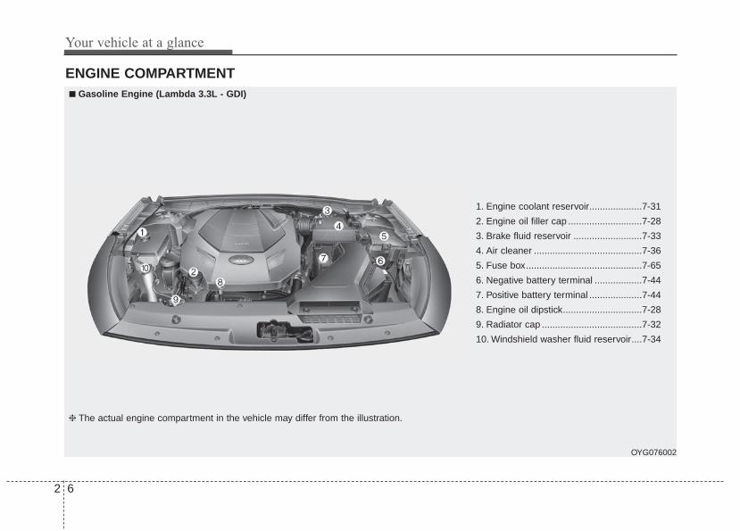
ENGINE COMPARTMENT
OYG076002
1. Engine coolant reservoir....................7-31
2. Engine oil filler cap ............................7-28
3. Brake fluid reservoir ..........................7-33
4. Air cleaner .........................................7-36
5. Fuse box............................................7-65
6. Negative battery terminal ..................7-44
7. Positive battery terminal ....................7-44
8. Engine oil dipstick..............................7-28
9. Radiator cap ......................................7-32
10. Windshield washer fluid reservoir....7-34
■■ Gasoline Engine (Lambda 3.3L - GDI)
❈ The actual engine compartment in the vehicle may differ from the illustration.

Safety features of your vehicle
Important safety precautions . . . . . . . . . . . . . . . . . 3-2• Always wear your seat belt . . . . . . . . . . . . . . . . . . . . . 3-2• Restrain all children . . . . . . . . . . . . . . . . . . . . . . . . . . . 3-2• Air bag hazards . . . . . . . . . . . . . . . . . . . . . . . . . . . . . . 3-2• Driver distraction . . . . . . . . . . . . . . . . . . . . . . . . . . . . . 3-2• Control your speed . . . . . . . . . . . . . . . . . . . . . . . . . . . . 3-3• Keep your vehicle in safe condition . . . . . . . . . . . . . . 3-3
Seat. . . . . . . . . . . . . . . . . . . . . . . . . . . . . . . . . . . . . . . 3-4• Front seat adjustment - power . . . . . . . . . . . . . . . . . . 3-7• Driver position memory system (for power seat). . . 3-10• Headrest (for front seat) . . . . . . . . . . . . . . . . . . . . . . . 3-12• Seatback pocket . . . . . . . . . . . . . . . . . . . . . . . . . . . . . . 3-14• Rear seat adjustment . . . . . . . . . . . . . . . . . . . . . . . . . 3-14
Seat belts . . . . . . . . . . . . . . . . . . . . . . . . . . . . . . . . . 3-18• Seat belt restraint system . . . . . . . . . . . . . . . . . . . . . . 3-18• Pre-tensioner seat belt . . . . . . . . . . . . . . . . . . . . . . . . 3-23• Seat belt precautions . . . . . . . . . . . . . . . . . . . . . . . . . . 3-25• Care of seat belts . . . . . . . . . . . . . . . . . . . . . . . . . . . . . 3-27
Child restraint system (CRS) . . . . . . . . . . . . . . . . 3-28• Children Always in the Rear . . . . . . . . . . . . . . . . . . . 3-28• Selecting a Child Restraint System (CRS) . . . . . . . . 3-29• Installing a Child Restraint System (CRS). . . . . . . . 3-32
Air bag - advanced supplemental restraint system . . . . . . . . . . . . . . . . . . . . . . . . . . . 3-39• How does the air bag system operate? . . . . . . . . . . . 3-40• Air bag warning light . . . . . . . . . . . . . . . . . . . . . . . . . 3-42• SRS components and functions . . . . . . . . . . . . . . . . . 3-43• Occupant Detection System (ODS) . . . . . . . . . . . . . . 3-46• Driver's and passenger's front air bag . . . . . . . . . . . 3-54• Side air bag . . . . . . . . . . . . . . . . . . . . . . . . . . . . . . . . . 3-56• Curtain air bag . . . . . . . . . . . . . . . . . . . . . . . . . . . . . . 3-58• Inflation and non-inflation conditions of the
air bag. . . . . . . . . . . . . . . . . . . . . . . . . . . . . . . . . . . . . 3-59• SRS Care . . . . . . . . . . . . . . . . . . . . . . . . . . . . . . . . . . . 3-64• Adding equipment to or modifying your
air bag-equipped vehicle. . . . . . . . . . . . . . . . . . . . . . 3-65• Air bag warning label . . . . . . . . . . . . . . . . . . . . . . . . . 3-65
3

Safety features of your vehicle
23
You will find many safety precautionsand recommendations throughoutthis section, and throughout this man-ual.The safety precautions in this sec-tion are among the most important.
Always wear your seat belt A seat belt is your best protection inall types of accidents. Air bags aredesigned to supplement seat belts,not replace them. So even thoughyour vehicle is equipped with airbags, ALWAYS make sure you andyour passengers wear your seatbelts, and wear them properly.
Restrain all children All children under age 13 should ridein your vehicle properly restrained ina rear seat, not the front seat. Infantsand small children should berestrained in an appropriate childrestraint. Larger children should usea booster seat with the lap/shoulderbelt until they can use the seat beltproperly without a booster seat.
Air bag hazards While air bags can save lives, theycan also cause serious or fatalinjuries to occupants who sit tooclose to them, or who are not prop-erly restrained. Infants, young chil-dren, and shorter adults are at thegreatest risk of being injured by aninflating air bag. Follow all instruc-tions and warnings in this manual.
Driver distraction Driver distraction presents a seriousand potentially deadly danger, espe-cially for inexperienced drivers.Safety should be the first concernwhen behind the wheel and driversneed to be aware of the wide array ofpotential distractions, such as drowsi-ness, reaching for objects, eating,personal grooming, other passen-gers, and using cellular phones.Drivers can become distracted whenthey take their eyes and attention offthe road or their hands off the wheelto focus on activities other than driv-ing. To reduce your risk of distractionor getting into an accident:• ALWAYS set up your mobile
devices (i.e., MP3 players, phones,navigation units, etc.) when yourvehicle is parked or safely stopped.
IMPORTANT SAFETY PRECAUTIONS

3 3
Safety features of your vehicle
• ONLY use your mobile devicewhen allowed by laws and whenconditions permit safe use. NEVERtext or email while driving. Mostcountries have laws prohibitingdrivers from texting. Some coun-tries and cities also prohibit driversfrom using handheld phones.
• NEVER let the use of a mobiledevice distract you from driving.You have a responsibility to yourpassengers and others on the roadto always drive safely, with yourhands on the wheel as well as youreyes and attention on the road.
Control your speed Excessive speed is a major factor incrash injuries and deaths. Generally,the higher the speed, the greater therisk, but serious injuries can alsooccur at lower speeds. Never drivefaster than is safe for current condi-tions, regardless of the maximumspeed posted.
Keep your vehicle in safe con-dition Having a tire blowout or a mechani-cal failure can be extremely haz-ardous. To reduce the possibility ofsuch problems, check your tire pres-sures and condition frequently, andperform all regularly scheduledmaintenance.

Safety features of your vehicle
43
Driver`s seat(1) Driver position memory system*(2) Forward and backward(3) Seat back angle(4) Seat cushion height(5) Lumbar support*(6) Cushion extension*(7) Head rest
Front Passenger`s seat(8) Forward and backward(9) Seat back angle(10) Seat cushion height*(11) Lumbar support*(12) Head rest
Rear seat(13) Armrest(14) Ski-pass through(15) Head rest
* : if equipped
SEAT
OYG036093N

3 5
Safety features of your vehicle
WARNING - Uprightingseat
Do not press the release leveron a manual seatback withoutholding and controlling theseatback. The seatback willspring upright possibly impact-ing you or other passengers.
WARNING - Looseobjects
Do not place anything in the dri-ver's foot well or under the frontseats. Loose objects in the dri-ver's foot area could interferewith the operation of the footpedals.
WARNING - Driver respon-sibility for passengers
The driver must advise the pas-sengers to keep the seatback inan upright position wheneverthe vehicle is in motion. If a seatis reclined during an accident,the restraint system's ability torestrain will be greatly reduced.
1KMN3662
WARNING - Seat cushionOccupants should never sit onaftermarket seat cushions or sit-ting cushions. The passenger'ships may slide under the lap por-tion of the seat belt during anaccident or a sudden stop.
WARNING - Driver’s seat• Never attempt to adjust the
seat while the vehicle is mov-ing. This could result in lossof control of your vehicle.
• Do not allow anything to inter-fere with the normal positionof the seatback. Storing itemsagainst the seatback couldresult in serious or fatal injuryin a sudden stop or collision.
• Sit as far back as possible fromthe steering wheel while stillmaintaining comfortable con-trol of the your vehicle. A dis-tance of at least 25 cm (10 in.)from your chest to the steeringwheel is recommended. Failureto do so can result in air baginflation injuries to the driver.

Safety features of your vehicle
63
Feature of Seat Leather • Leather is made from the outer
skin of an animal, which goesthrough a special process to beavailable for use. Since it is a nat-ural substance, each part differs inthickness or density.Wrinkles may appear as a naturalresult of stretching and shrinkingdepending on the temperature andhumidity.
• The seat is made of stretchablefabric to improve comfort.
• The parts contacting the body arecurved and the side supportingarea is high which provides drivingcomfort and stability.
WARNING - UnexpectedSeat Movement
After adjusting a manual seat,always check that it is locked byshifting your weight to the frontand back. Sudden or unexpect-ed movement of the driver'sseat could cause you to losecontrol of the vehicle.
WARNING - Rear seatbacksAlways lock the rear seatbackbefore driving. Failure to do socould result in passengers orobjects being thrown forwardinjuring vehicle occupants.
WARNING - Luggage andCargo
Do not stack pile or stack lug-gage or cargo higher than theseatback in the cargo area. In anaccident the cargo could strikeand injury a passenger. Ifobjects are large, heavy or mustbe piled, they must be securedin the cargo area.
WARNING - Cargo AreaDo not allow passengers to ridein the cargo area under any cir-cumstance. The cargo area issolely for the purpose of trans-porting luggage or cargo.
WARNING - Seat adjustment
• Do not adjust the seat whilewearing seat belts. Moving theseat forward will cause strongpressure on the abdomen.
• Do not place your hand nearthe seat bottom or seat trackwhile adjusting the seat. Yourhand could get caught in theseat mechanism.
WARNING - SmallObjects
Use extreme caution when pick-ing up small objects trappedunder the seats or between theseat and the center console.Your hands might be cut orinjured by the sharp edges ofthe seats mechanism.

3 7
Safety features of your vehicle
• Wrinkles may appear naturallyfrom usage. It is not a fault of theproduct.
✽✽ NOTICEWrinkles or abrasions which appearnaturally from usage are not cov-ered by warranty.
Front seat adjustment - power The front seat can be adjusted byusing the control switches located onthe outside of the seat cushion.Before driving, adjust the seat to theproper position so you can easily con-trol the steering wheel, pedals andswitches on the instrument panel.
When in operation, the power seat-consumes a large amount of electri-cal power. To prevent unnecessarysystem drain, don’t adjust the powerseat longer than necessary while theengine is not running.
WARNING - Unattendedchildren
Do not leave children unattend-ed in the vehicle. Children mightoperate features of the vehiclethat could injure them.
CAUTION - Power seatadjustments
The power seating controlsfunction by electronic motor.Excessive operation may causedamage to the electrical equip-ment.
CAUTION - Power SeatingDo not operate two or morepower seat control switches atthe same time. Doing so maydamage the power seat motor orelectrical components.
CAUTION• Belts with metallic acces-
sories, zippers or keys insideyour back pants pocket maydamage the seat fabric.
• Make sure not to wet the seat.It may change the nature ofnatural leather.
• Jeans or clothes which con-tain bleach may contaminatethe surface of the seat cover-ing fabric and cause damageor discoloration.

Safety features of your vehicle
83
Forward and backward
Push the control switch forward orbackward to move the seat to thedesired position. When the controlswitch is operated forward, the seatcushion is slightly raised, and theseat cushion lowered when theswitch is operated backward.Release the switch once the seatreaches the desired position.
Cushion extension (for driver's seat, if equipped)
To move the front part of cushion for-ward:1. Push the front part of control
switch to move the seat cushion tothe desired length.
2. Release the switch once the seatcushion reaches the desired length.
To move the front part of cushionrearward:1. Push the rear part of control
switch to move the seat cushion tothe desired length.
2. Release the switch once the seatcushion reaches the desiredlength.
OYG036006
OYG036007
3 9
Safety features of your vehicle
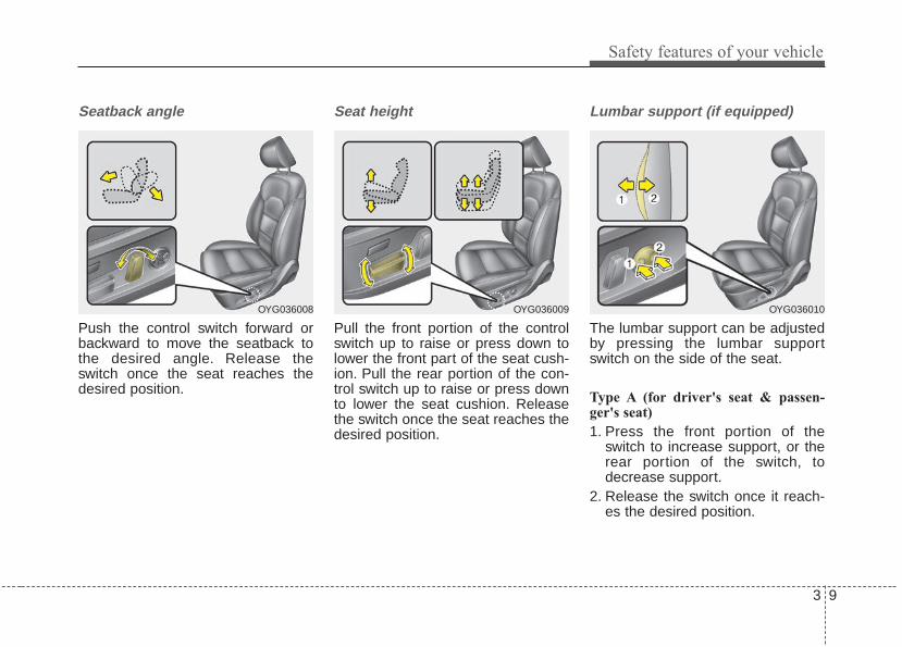
Seatback angle
Push the control switch forward orbackward to move the seatback tothe desired angle. Release theswitch once the seat reaches thedesired position.
Seat height
Pull the front portion of the controlswitch up to raise or press down tolower the front part of the seat cush-ion. Pull the rear portion of the con-trol switch up to raise or press downto lower the seat cushion. Releasethe switch once the seat reaches thedesired position.
Lumbar support (if equipped)
The lumbar support can be adjustedby pressing the lumbar supportswitch on the side of the seat.
Type A (for driver's seat & passen-ger's seat)
1. Press the front portion of theswitch to increase support, or therear portion of the switch, todecrease support.
2. Release the switch once it reach-es the desired position.
OYG036008 OYG036009 OYG036010

Safety features of your vehicle
103
Type B (for driver's seat)
1. Press the front portion of theswitch (1) to increase support, orthe rear portion of the switch (2),to decrease support.
2. Release the switch once it reach-es the desired position.
3. Press the upper portion (3) of theswitch to move the support posi-tion up, or press the lower portion(4) of the switch, to move the sup-port position down.
4. Release the switch once it reach-es the desired position.
Driver position memory system(if equipped, for power seat)
A driver position memory system isprovided to store and recall the driv-er seat and outside rearview mirrorposition with a simple button opera-tion. By saving the desired positioninto the system memory, differentdrivers can reposition the driver seatbased upon their driving preference.If the battery is disconnected, thedesired seat position memory willneed to be re-saved.
OYG036011
OYG036026
WARNING - DriverPosition Memory System
Never attempt to operate thedriver position memory systemwhile the vehicle is moving.This could result in loss of con-trol, and an accident causingdeath or serious injury.

3 11
Safety features of your vehicle
Storing positions into memoryusing the buttons on the doorStoring driver’s seat positions
1. Shift the shift lever into P while theengine start/stop button is ON.
2. Adjust the driver’s seat and out-side rearview mirror comfortablefor the driver.
3. Press SET button on the controlpanel. The system will beep once.
4. Press one of the memory buttons(1 or 2) within 5 seconds afterpressing the SET button. The sys-tem will beep twice when memoryhas been successfully stored.
When recalling an adjustment mem-ory button while sitting in the vehicle,you can be surprised by the settingchosen if the memory has beenadjusted by someone else. If thatoccurs, immediately push the seatposition control knob in the directionof the desired position to stop furtherundesired movement.
Recalling positions from memory
1. Shift the shift lever into P while theengine start/stop button is ON.
2. To recall the position in the memo-ry, press the desired memory but-ton (1 or 2). The system will beeponce, then the driver’s seat willautomatically adjust to the storedposition.
Adjusting the control switch for thedriver’s seat while the system isrecalling the stored position willcause the movement to stop andmove in the direction that the controlswitch is moved.
Easy access function (if equipped)The system will move the driver'sseat automatically as follows:• With smart key system
- It will move the driver’s seat rear-ward when the engine start/stopbutton is changed to the OFFposition.
- It will move the driver’s seat for-ward when the engine start/stopbutton is changed to the ACC orSTART position.
- It will move the driver's seat for-ward when you get in your vehiclewith the smart key after closingthe driver's door.
You can activate or deactivate thisfeature. Refer to "User settings" inchapter 4.

Safety features of your vehicle
123
Headrest (for front seat)
The driver's and front passenger'sseats are equipped with a headrestfor the occupant's safety and comfort.The headrest not only provides com-fort for the driver and front passenger,but also helps protect the head andneck in the event of a rear collision.For maximum effectiveness in caseof an accident, the headrest shouldbe adjusted so the middle of theheadrest is at the same height of thecenter of gravity of an occupant'shead. Generally, the center of gravityof most people's head is similar withthe height of the top of their eyes.
Also, adjust the headrest as close toyour head as possible. For this rea-son, the use of a cushion that holdsthe body away from the seatback isnot recommended.
Adjusting the height up and down
To raise the headrest, pull it up to thedesired position (1). To lower theheadrest, push and hold the releasebutton (2) on the headrest supportand lower the headrest to the desiredposition (3).
WARNING - Headrestremoval/adjustment
• Do not operate the vehiclewith the headrests removed.Headrests can provide criticalneck and head support in acrash.
• Do not adjust the headrestheight while the vehicle is inmotion. Driver may lose con-trol of the vehicle.
OMG038400
CAUTIONExcessive pulling or pushingmay damage the headrest.
OYG036013

3 13
Safety features of your vehicle
✽✽ NOTICEIf you recline the seatback towardsthe front with the headrest and seatcushion raised, the headrest maycome in contact with the sunvisor orother parts of the vehicle.
Removal and reinstallation
To remove the headrest:1. Recline the seatback (2) with the
recline lever or switch (1).2. Raise headrest as far as it can go.3. Press the headrest release button
(3) while pulling the headrest up (4).
To reinstall the headrest :1. Put the headrest poles (2) into the
holes while pressing the releasebutton (1) or switch(1).
2. Recline the seatback (4) with therecline lever or switch (3).
3. Adjust the headrest to the appro-priate height.
OYG036015
OYFH034205
WARNING - HeadrestRemoval
NEVER allow anyone to ride in aseat with the headrest removed.Headrests can provide criticalneck and head support in acrash.
OYG036017
WARNING - HeadrestReinstallation
To reduce the risk of injury tothe head or neck, always makesure the headrest is locked intoposition and adjusted properlyafter reinstalling.

Safety features of your vehicle
143
Seatback pocket
The seatback pocket is provided onthe back of the front passenger’s anddriver’s seatbacks.
Rear seat adjustmentHeadrest
The rear seat is equipped with head-rests in all the seating positions forthe occupant's safety and comfort.The headrest not only provides com-fort for passengers, but also helpsprotect the head and neck in theevent of a collision.
For maximum effectiveness in caseof an accident, the headrest shouldbe adjusted so the middle of theheadrest is at the same height of thecenter of gravity of an occupant'shead. Generally, the center of gravityof most people's heads is similar withthe height as the top of their eyes.Also, adjust the headrest as close toyour head as possible. For this rea-son, the use of a cushion that holdsthe body away from the seatback isnot recommended.
OYG036019
WARNING - Seatbackpockets
Do not put heavy or sharpobjects in the seatback pockets.In an accident they could comeloose from the pocket andinjure vehicle occupants.
OMG038401

3 15
Safety features of your vehicle
Adjusting the height up and down(if equipped)
To raise the headrest, pull it up to thedesired position (1). To lower theheadrest, push and hold the releasebutton (2) on the headrest supportand lower the headrest to the desiredposition (3).
Removal and reinstallation (if equipped)
To remove the headrest, raise it asfar as it can go then press therelease button (1) while pulling theheadrest upward (2).To reinstall the headrest, put theheadrest poles (3) into the holeswhile pressing the release button (1).Then adjust it to the appropriateheight and ensure that it locks inposition.
Armrest
To use the armrest, pull it forwardfrom the seatback.
OYG036020 OYG036021
OYG036022

Safety features of your vehicle
163
Cup holder and multi box (if equipped)
To use the cup holder, lift the coverup (2).
Carrying long/narrow cargo (if equipped)
Additional cargo space is provided toaccommodate long/narrow cargo(skis, poles, etc.) not able to fit prop-erly in the trunk when closed.1. Pull the armrest down.2. Pull the cover down while pushing
the release lever down.
OYG036024 OYG036025
CAUTIONBe careful when loading cargothrough the rear passengerseats to prevent damage to thevehicle interior.
CAUTION - Damaging rear seat belt
bucklesWhen you fold the rear seat-back, insert the buckle betweenthe rear seatback and cushion.Doing so can prevent the bucklefrom being damaged by the rearseatback.

3 17
Safety features of your vehicle
WARNING - Cargo loadingMake sure the engine is off, thetransaxle is in P (Park) and theparking brake is securely appliedwhenever loading or unloadingcargo. Failure to take these stepsmay allow the vehicle to move ifthe shift lever is inadvertentlymoved to another position.
WARNING - ObjectsObjects carried on the foldeddown seatback should not extendhigher than the top of the frontseatbacks.This could allow cargoto slide forward and cause injuryor damage during sudden stops.
WARNING - CargoCargo should always besecured to prevent it from beingthrown about the vehicle in acollision and causing injury tothe vehicle occupants. Do notplace objects in the rear seats,since they cannot be properlysecured and may hit the frontseat occupants in a collision.
WARNING - FoldedSeatback
The purpose of the middle fold-down rear seatbacks is to allowyou to carry longer objects thancould not otherwise be accom-modated.• Never allow a passenger to sit
on top of the folded downseatback while the car is mov-ing. This is not a proper seat-ing position since no seatbelts are available for use.
• To reduce the risk of injurycaused by sliding cargo withinthe passenger compartmentof the vehicle, objects carriedon the folded down seatbackshould not extend higher thanthe top of the front seats.

Safety features of your vehicle
183
SEAT BELTSSeat belt restraint system• For maximum restraint system pro-
tection, the seat belts must alwaysbe used whenever the vehicle ismoving. A properly positionedshoulder belt should be positionedmidway over your shoulder acrossyour collarbone.
• Never allow children to ride in thefront passenger seat. See childrestraint system section for furtherdiscussion.
Seat belts are designed to bear uponthe bony structure of the body, andshould be worn low across the frontof the pelvis, chest and shoulders, asapplicable; wearing the lap section ofthe belt across the abdominal areamust be avoided.Seat belts should be adjusted asfirmly as possible, consistent withcomfort, to provide the protection forwhich they have been designed.A slack belt will greatly reduce theprotection afforded to the wearer.Care should be taken to avoid con-tamination of the webbing with pol-ishes, oils and chemicals, and partic-ularly battery acid. Cleaning maysafely be carried out using mild soapand water. The belt should bereplaced if webbing becomes frayed,contaminated or damaged.• No modifications or additions
should be made by the user whichwould either prevent the seat beltadjusting devices from operating toremove slack, or prevent the seatbelt assembly from being adjustedto remove slack.
WARNING - Damagedseat belt
Replace the entire seat beltassembly if any part of the web-bing or hardware is damaged asyou can no longer be sure that adamaged seat belt will provideprotection in a crash.
WARNING - Twisted seatbelt
Make sure your seat belt is nottwisted when worn. A twistedseat belt may not properly pro-tect you in an accident andcould even cut into your body.
WARNING - Shoulder Belt• Never wear the shoulder belt
under your arm or behindyour back. An improperlypositioned shoulder belt can-not protect the occupant in acrash.
• Always wear both the shoul-der portion and lap portion ofthe lap/shoulder belt.

3 19
Safety features of your vehicle
• When you fasten the seat belt, becareful not to latch the seat belt inbuckles of other seat. It's very dan-gerous and you may not be pro-tected by the seat belt properly.
• Do not unfasten the seat belt anddo not fasten and unfasten the seatbelt repeatedly while driving. Thiscould result in loss of control, andan accident causing death, seriousinjury, or property damage.
• When fastening the seat belt,make sure that the seat belt doesnot pass over objects that are hardor can break easily.
Seat belt warning
Driver’s seat belt warning
As a reminder to the driver, the seatbelt warning light and chime will acti-vate for approximately 6 secondseach time you when the EngineStart/Stop button is in ON positionregardless of belt fastening.If the vehicle is moving at or fasterthan 9 km/h (6 mph) without the driv-er seatbelt fastened, the warninglight will stay on.
If you continue not to fasten the seatbelt and you drive over 20 km/h (12mph) the seat belt warning light andchime will activate for approximately100 seconds and the correspondingwarning light will blink.When the seatbelt is unfastenedafter it has been fastened, if the vehi-cle is going at less than 20 km/h (12mph), the warning light will illumi-nate, and if the vehicle is moving ator faster than 20 km/h (12 mph), thewarning light will flash and warningchime will sound for more than 100seconds.
WARNING - Seat beltbuckle
Do not allow foreign material(gum, crumbs, coins, etc.) toobstruct the seat belt buckle.This may prevent the seat beltfrom fastening securely.
1GQA2083

Safety features of your vehicle
203
Front passenger's seat belt warning
As a reminder to the front passenger,the front passenger’s seat belt warn-ing lights will illuminate for approxi-mately 6 seconds each time whenthe Engine Start/Stop button is in ONposition regardless of belt fastening.If the vehicle is moving at or fasterthan 9 km/h (6 mph) without the driv-er seatbelt fastened, the warninglight will stay on.If you continue not to fasten the seatbelt and you drive over 20 km/h (12mph) the seat belt warning light andchime will activate for approximately100 seconds and the correspondingwarning light will blink.
When the seatbelt is unfastenedafter it has been fastened, if the vehi-cle is going at less than 20 km/h (12mph), the warning light will illumi-nate, and if the vehicle is moving ator faster than 20 km/h (12 mph), thewarning light will flash and warningchime will sound for more than 100seconds.
Lap/shoulder belt
Height adjustment
You can adjust the height of the shoul-der belt anchor to one of 4 positionsfor maximum comfort and safety.The height of the adjusting seat beltshould not be too close to your neck.You will not be getting the most effec-tive protection. The shoulder portionshould be adjusted so that it liesacross your chest and midway overyour shoulder near the door and notyour neck.
OYG036028
OJF035092L

3 21
Safety features of your vehicle
To adjust the height of the seat beltanchor, lower or raise the heightadjuster into an appropriate position.To raise the height adjuster, pull it up(1). To lower it, push it down (3) whilepressing the height adjuster button (2).Release the button to lock theanchor into position. Try sliding theheight adjuster to make sure that ithas locked into position.Improperly positioned seat belts cancause serious injuries in an accident.
To fasten your seat belt:
To fasten your seat belt, pull it out ofthe retractor and insert the metal tab(1) into the buckle (2). There will bean audible "click" when the tab locksinto the buckle.The seat belt automatically adjusts tothe proper length only after the lapbelt portion is adjusted manually sothat it fits snugly around your hips. Ifyou lean forward in a slow, easymotion, the belt will extend and letyou move around. If there is a sud-den stop or impact, however, the beltwill lock into position. It will also lockif you try to lean forward too quickly.
✽✽ NOTICEIf you are not able to pull out theseat belt from the retractor, firmlypull the belt out and release it. Thenyou will be able to pull the belt outsmoothly.
B180A01NF-1
WARNING - Shoulder belt positioning
Never position the shoulder beltacross your neck or face.
WARNING - Seat belt replacement
Replace your seat belts afterbeing in an accident. Failure toreplace seat belts after an acci-dent could leave you with dam-aged seat belts that will not pro-vide protection in the event ofanother collision.

Safety features of your vehicle
223
To release the seat belt:
The seat belt is released by pressingthe release button (A) in the lockingbuckle. When it is released, the beltshould automatically draw back intothe retractor.If this does not happen, check thebelt to be sure it is not twisted, thentry again.
When using the rear center seat beltthe buckle with the “CENTER” markmust be used.
✽✽ NOTICEIf you are not able to pull out thesafety belt from the retractor, firmlypull the belt out and release it. Afterrelease, you will be able to pull thebelt out smoothly.
B200A01NF
WARNINGYou should place the lap beltportion as low as possible andsnugly across your hips, not onyour waist. If the lap belt is locat-ed too high on your waist, it mayincrease the chance of injury inthe event of a collision. Botharms should not be under orover the belt. Rather, one shouldbe over and the other under, asshown in the illustration.Never wear the seat belt underthe arm near the door.
OUM036100L OBH038023N

3 23
Safety features of your vehicle
Pre-tensioner seat belt
Your vehicle is equipped with driver'sand front passenger's pre-tensionerseat belts (retractor pretensioner andEFD (Emergency Fastening Device)).The pre-tensioner seat belts may beactivated, when a frontal collision issevere enough, together with the airbags.When the vehicle stops suddenly, or ifthe occupant tries to lean forward tooquickly, the seat belt retractor maylock into position. In certain frontal col-lisions, the pre-tensioner will activateand pull the seat belt into tighter con-tact against the occupant's body.
(1) Retractor PretensionerThe purpose of the retractor pre-tensioner is to make sure that theshoulder belts fit in tightly againstthe occupant's upper body in cer-tain frontal collisions.
(2) EFD (Emergency Fastening Device)The purpose of the EFD is tomake sure that the pelvis belts fitin tightly against the occupant'slower body in certain frontal colli-sions.
If the system senses excessive ten-sion on the driver or passenger'sseat belt when the pre-tensioner sys-tem activates, the load limiter insidethe retractor pre-tensioner will releasesome of the pressure on the affectedseat belt.
✽✽ NOTICEWhen the pre-tensioner seat beltsare activated, a loud noise may beheard and fine dust, which mayappear to be smoke, may be visiblein the passenger compartment.These are normal operating condi-tions and are not hazardous.
OXMA033101

Safety features of your vehicle
243
The seat belt pre-tensioner systemconsists mainly of the following com-ponents.Their locations are shown inthe illustration:(1) SRS air bag warning light(2) Front retractor pre-tensioner
assembly(3) SRS control module(4) Emergency fastening device (EFD)
✽✽ NOTICE• Both the driver's and front pas-
senger's seat belt pre-tensioner sys-tem may be activated not only incertain frontal collision, but also incertain side collisions or rollovers,if the vehicle is equipped with aside or curtain air bag.
• Because the sensor that activatesthe SRS air bag is connected withthe pre-tensioner seat belt, theSRS air bag warning light onthe instrument panel will illumi-nate for approximately 6 secondsafter the Engine Start/Stop buttonhas been turned to the ON posi-tion, and then it should turn off.
WARNING - Skin Irritation Wash all exposed skin areasthoroughly after an accident inwhich the pre-tensioner seatbelts were activated. The finedust from the pre-tensioneractivation may cause skin irrita-tion and should not be breathedfor prolonged periods.
OJF045207L

3 25
Safety features of your vehicle
If the pre-tensioner seat belt systemis not working properly, this warninglight will illuminate even if there is nota malfunction with the SRS air bag. Ifthe SRS air bag warning light doesnot illuminate when the EngineStart/Stop button is turned ON, or if itremains illuminated after illuminatingfor approximately 6 seconds, or if itilluminates while the vehicle is beingdriven, have an authorized Kia dealerinspect the pre-tensioner seat beltand SRS air bag system as soon aspossible.
✽✽ NOTICEDo not attempt to service or repairthe pre-tensioner seat belt system inany manner. Do not attempt toinspect or replace the pre-tensionerseat belts yourself. This must bedone by an authorized Kia dealer.
Pre-tensioners are designed to oper-ate only one time. After activation,pre-tensioner seat belts must bereplaced. If the pre-tensioner mustbe replaced, contact an authorizedKia dealer.
Seat belt precautionsInfant or small childYou should be aware of the specificrequirements in your country. Childand/or infant seats must be properlyplaced and installed in the rear seat.For more information about the use ofthese restraints, refer to “Childrestraint system” in this section.
✽✽ NOTICESmall children are best protectedfrom injury in an accident whenproperly restrained in the rear seat bya child restraint system that meets therequirements of the Safety standardsof your country. Before buying anychild restraint system, make sure thatit has a label certifying that it meetsSafety standards of your country. Therestraint must be appropriate foryour child's height and weight. Checkthe label on the child restraint for thisinformation. Refer to “Child restraintsystem” in this section.
WARNING - Hot preten-sioner
Do not touch the pre-tensionerseat belt assemblies for severalminutes after they have beenactivated. When the pre-ten-sioner seat belt mechanismfires during a collision the pre-tensioner becomes hot and canburn you.

Safety features of your vehicle
263
Larger childrenChildren who are too large for childrestraint systems should alwaysoccupy the rear seat and use theavailable lap/shoulder belts. The lapportion should be fastened andsnugged on the hips as low as possi-ble. Check periodically to insure thatthe belt fits. A child's squirming couldput the belt out of position. Childrenare given the most safety in the eventof an accident when they arerestrained by a proper restraint sys-tem in the rear seat. If a larger child(over age 12) must be seated in thefront seat, the child should besecurely restrained by the availablelap/shoulder belt and the seat shouldbe placed in the rearmost position.Children age 12 and under should berestrained securely in the rear seat.NEVER place a child age 12 andunder in the front seat. NEVER placea rear facing child seat in the frontseat of a vehicle.
If the shoulder belt portion slightlytouches the child’s neck or face, tryplacing the child closer to the center ofthe vehicle. If the shoulder belt stilltouches their face or neck they need tobe returned to a child restraint system.
Restraint of pregnant women Pregnant women should wearlap/shoulder belt assemblies when-ever possible according to specificrecommendations by their doctors.The lap portion of the belt should beworn AS SECURELY AND LOW ASPOSSIBLE.WARNING - Small children
Do not allow small children toride in the vehicle without anappropriate child restraint sys-tem. If the shoulder belt comesin contact with your child's neckor face your child is too small toride in the vehicle. In a crash theseat belt will inflict injury to yourchild's neck, throat and face.
WARNING - Pregnantwomen
Pregnant women must neverplace the lap portion of the seatbelt above or on the abdomenwhere the fetus is located. Theforce of the seat belt during acollision will crush the fetus.
3 27
Safety features of your vehicle
Injured personA seat belt should be used when aninjured person is being transported.When this is necessary, you shouldconsult a physician for recommenda-tions.
One person per beltTwo people (including children)should never attempt to use a singleseat belt. This could increase theseverity of injuries in case of an acci-dent.
Do not lie downTo reduce the chance of injuries inthe event of an accident and toachieve maximum effectiveness ofthe restraint system, all passengersshould be sitting up and the front andrear seats should be in an uprightposition when the vehicle is moving.A seat belt cannot provide properprotection if the person is lying downin the rear seat or if the front and rearseats are in a reclined position.
Care of seat beltsSeat belt systems should never bedisassembled or modified. In addi-tion, care should be taken to assurethat seat belts and belt hardware arenot damaged by seat hinges, doorsor other abuse.
Periodic inspectionAll seat belts should be inspectedperiodically for wear or damage ofany kind. Any damaged parts shouldbe replaced as soon as possible.
Keep belts clean and drySeat belts should be kept clean anddry. If belts become dirty, they can becleaned by using a mild soap solu-tion and warm water. Chemical sub-stances should not be used on seatbelts to prevent any damage. Heatedup seatbelts may burn infants andchildren.
When to replace seat beltsThe entire in-use seat belt assemblyor assemblies should be replaced ifthe vehicle has been involved in anaccident. This should be done even ifno damage is visible. Additionalquestions concerning seat belt oper-ation should be directed to anauthorized Kia dealer.
WARNING - Pinched seatbelt
Make sure that the webbingand/or buckle does not getcaught or pinched in the rearseat when returning the rearseatback to its upright position.A caught or pinched webbing/buckle may become damagedand could fail during a collisionor sudden stop.
WARNINGSeatbelts can become hot in avehicle that has been closed upin sunny weather. They couldburn infants and children.

Safety features of your vehicle
283
CHILD RESTRAINT SYSTEM (CRS) Children Always in the Rear Children under age 13 must always
ride in the rear seats and must alwaysbe properly restrained to minimize therisk of injury in an accident, suddenstop or sudden maneuver. Accordingto accident statistics, children aresafer when properly restrained in therear seats than in the front seat. Evenwith air bags, children can be serious-ly injured or killed. Children too largefor a child restraint must use the seatbelts provided.Most countries have child restraintlaws which require children to travelin approved child restraint devices.The laws governing the age orheight/weight restrictions at whichseat belts can be used instead ofchild restraints differs among coun-tries, so you should be aware of thespecific requirements in your coun-try, and where you are travelling.
Child restraint systems must beproperly placed and installed in therear seat. You must use a commer-cially available child restraint systemthat meets the requirements of theSafety Standards of your country.Child restraint systems are generallydesigned to be secured in a vehicleseat by lap belt portion of alap/shoulder belt, or by a LATCH sys-tem in the rear seats of the vehicle.
WARNING - RestraintLocation
Never install a child or infantseat on the front passenger'sseat. A child riding in the frontpassenger seat can be forceful-ly struck by an inflating airbagand seriously injured.
WARNING - Hot ChildRestraint
A child restraint system canbecome very hot if it is left in aclosed vehicle on a sunny day.Be sure to check the seat cover,buckles and latches beforeplacing a child in the restraintsystem.

3 29
Safety features of your vehicle
Child restraint system (CRS) Infants and younger children must berestrained in an appropriate rear-fac-ing or forward-facing CRS that hasfirst been properly secured to therear seat of the vehicle. Read andcomply with the instructions forinstallation and use provided by themanufacturer of the child restraint.
✽✽ NOTICEAfter an accident, have a Kia dealercheck the child restraint system, seatbelts, tether anchors and loweranchors.
Selecting a Child RestraintSystem (CRS) When selecting a CRS for your child,always:• Make sure the CRS has a label
certifying that it meets applicableSafety Standards of your country.
• Select a child restraint based onyour child’s height and weight. Therequired label or the instructionsfor use typically provide this infor-mation.
• Select a child restraint that fits thevehicle seating position where itwill be used.
• Read and comply with the warn-ings and instructions for installationand use provided with the childrestraint system.
WARNING - Child Restraint Installation
An improperly secured childrestraint can increase the riskof serious injury or death in anaccident. Always take the fol-lowing precautions when usinga child restraint system:• Always follow the child
restraint system manufactur-er’s instructions for installa-tion and use.
(Continued)
(Continued)• Always properly restrain your
child in the child restraint.• If the vehicle head restraint
prevents proper installation ofa child seat (as described inthe child restraint systemmanual), the head restraint ofthe respective seating posi-tion shall be readjusted orentirely removed.
• Do not use an infant carrier ora child safety seat that"hooks" over a seatback, itmay not provide adequateprotection in an accident.
Safety features of your vehicle
303
Child restraint system types There are three main types of childrestraint systems: rear-facing seats,forward-facing seats, and boosterseats. They are classified accordingto the child’s age, height and weight.
WARNING - HoldingChildren
Never hold a child in your armsor lap when riding in a vehicle.The violent forces created dur-ing a crash will tear the childfrom your arms and throw thechild against the car’s interior.Always use a child restraintsystem which is appropriate foryour child's height and weight.
WARNING - UnattendedChildren
Never leave children unattendedin a vehicle. The car can heat upvery quickly, resulting in injuriesto the child in the vehicle.
WARNING - Seat Belt UseDo not use one seat belt for twooccupants at the same time.This will eliminate any safetybenefit provided by the seat beltto the occupants.

3 31
Safety features of your vehicle
Rear-facing child seats
A rear-facing child seat providesrestraint with the seating surfaceagainst the back of the child. Theharness system holds the child inplace, and in an accident, acts tokeep the child positioned in the seatand reduces the stress to the neckand spinal cord.All children under age one mustalways ride in a rear-facing infantchild restraint.
Convertible and 3-in-1 child seatstypically have higher height andweight limits for the rear-facing posi-tion, allowing you to keep your childrear-facing for a longer period of time.Continue to use a rear-facing childseat for as long as your child will fitwithin the height and weight limitsallowed by the child seat manufactur-er. It’s the best way to keep themsafe. Once your child has outgrownthe rear-facing child restraint, yourchild is ready for a forward-facingchild restraint with a harness.
Forward-facing child restraints
A forward-facing child seat providesrestraint for the child’s body with aharness. Keep children in a forward-facing child seat with a harness untilthey reach the top height or weightlimit allowed by your child restraint’smanufacturer.Once your child outgrows the for-ward-facing child restraint, your childis ready for a booster seat.
CRS09 OYG036030

Safety features of your vehicle
323
Booster seats
A booster seat is a restraint designedto improve the fit of the vehicle’s seatbelt system. A booster seat positionsthe seat belt so that it fits properlyover the lap of your child.Keep your child in a booster seatuntil they are big enough to sit in theseat without a booster and still havethe seat belt fit properly. For a seatbelt to fit properly, the lap belt mustlie snugly across the upper thighs,not the stomach. The shoulder beltshould lie snug across the shoulderand chest and not across the neck orface. Children under age 13 mustalways ride in the rear seats andmust always be properly restrainedto minimize the risk of injury.
Installing a Child RestraintSystem (CRS)After selecting a proper child seat foryour child, check to make sure it fitsproperly in your vehicle. Follow theinstructions provided by the manu-facturer when installing the childseat. Note these general steps wheninstalling the seat to your vehicle:• Properly secure the child
restraint to the vehicle. All childrestraints must be secured to thevehicle with the lap part of alap/shoulder belt or with theLATCH system.
• Make sure the child restraint isfirmly secured. After installing achild restraint to the vehicle, pushand pull the seat forward and fromside-to-side to verify that it issecurely attached to the seat. Achild restraint secured with a seatbelt should be installed as firmly aspossible. However, some side-to-side movement can be expected.
• Secure the child in the childrestraint. Make sure the child isproperly strapped in the childrestraint according to the manufac-turer instructions.

3 33
Safety features of your vehicle
Lower Anchors and Tether forChildren (LATCH) System The LATCH system holds a childrestraint during driving and in anaccident. This system is designed tomake installation of the child restrainteasier and reduce the possibility ofimproperly installing your childrestraint. The LATCH system usesanchors in the vehicle and attach-ments on the child restraint. TheLATCH system eliminates the needto use seat belts to secure the childrestraint to the rear seats.Lower anchors are metal bars builtinto the vehicle. There are two loweranchors for each LATCH seatingposition that will accommodate achild restraint with lower attachments.To use the LATCH system in yourvehicle, you must have a childrestraint with LATCH attachments.The child seat manufacturer will pro-vide you with instructions on how touse the child seat with its attach-ments for the LATCH lower anchors.
LATCH anchors have been providedin the left and right outboard rearseating positions. Their locations areshown in the illustration. There areno LATCH anchors provided for thecenter rear seating position.
B230D01NF
WARNING - LATCH LowerAnchors
Never attempt to attach a LATCHequipped seat in the centerseating position. LATCH loweranchors are only to be used inthe left and right rear outboardseating positions.You may dam-age the anchors or the anchorsmay fail and break in a collision.

Safety features of your vehicle
343
The lower anchor position indicatorsymbols are located on the left andright rear seat backs to identify theposition of the lower anchors in yourvehicle (see arrows in illustration).The LATCH anchors are locatedbetween the seatback and the seatcushion of the rear seat left and rightoutboard seating positions.To use the lower anchor, push theupper portion of the lower anchorcover.
❈ (1) : Lower Anchor position indicator(2) : Lower Anchor
Securing a child restraint withthe LATCH anchors system To install a LATCH-compatible childrestraint in either of the rear outboardseating positions:1. Move the seat belt buckle away
from the lower anchors.2. Move any other objects away from
the anchors that could prevent asecure connection between thechild restraint and the loweranchors.
3. Place the child restraint on thevehicle seat, then attach the seatto the lower anchors according tothe instructions provided by thechild restraint manufacturer.
4. Follow the child restraint instruc-tions for properly adjusting andtightening the lower attachmentson the child restraint to the loweranchors.
OYG036034L
WARNINGTake the following precautionswhen using the LATCH system:• Read and follow all installation
instructions provided withyour child restraint system.
• To prevent the child fromreaching and taking hold ofunretracted seat belts, buckleall unused rear seat belts andretract the seat belt webbingbehind the child. Children canbe strangled if a shoulder beltbecomes wrapped around theirneck and the seat belt tightens.
• NEVER attach more than onechild restraint to a singleanchor. This could cause theanchor or attachment to comeloose or break.
• Always have the LATCH sys-tem inspected by your author-ized Kia dealer after an acci-dent. An accident can damagethe LATCH system and maynot properly secure the childrestraint.

3 35
Safety features of your vehicle
Securing a child restraint seatwith "Tether Anchor" system
First secure the child restraint withthe LATCH lower anchors or the seatbelt. If the child restraint manufactur-er recommends that the top tetherstrap be attached, attach and tightenthe top tether strap to the top tetherstrap anchor.Child restraint hook holders arelocated on the shelf behind the rearseats.
To install the tether anchor:1. Route the child restraint tether
strap over the child restraint seat-back. Route the tether strap underthe head restraint and betweenthe head restraint posts, or routethe tether strap over the top of thevehicle seatback. Make sure thestrap is not twisted.
2. Connect the tether strap hook tothe tether anchor, then tighten thetether strap according to the childseat manufacturer’s instructions tofirmly secure the child restraint tothe seat.
OYG036031
WARNINGTake the following precautionswhen installing the tether strap:• Read and follow all installation
instructions provided withyour child restraint system.
• NEVER attach more than onechild restraint to a single teth-er anchor. This could causethe anchor or attachment tocome loose or break.
• Do not attach the tether strapto anything other than the cor-rect tether anchor. It may notwork properly if attached tosomething else.
• Do not use the tether anchorsfor adult seat belts or harness-es, or for attaching other itemsor equipment to the vehicle.
• Always fasten the seat beltsbehind the child restraint seatwhen they are not used tosecure the child seat. Failureto do so may result in childstrangulation.
OYG036032

Safety features of your vehicle
363
3. Check that the child restraint issecurely attached to the seat bypushing and pulling the seat for-ward and from side-to-side.
Securing a child restraint with alap belt or lap/shoulder beltWhen not using the LATCH system,all child restraints must be secured toa vehicle rear seat with the lap partof a lap/shoulder belt.
Automatic locking mode
Since all passenger seat belts movefreely under normal conditions andonly lock under extreme or emer-gency conditions (emergency lockingmode), you must manually pull theseat belt all the way out to shift theretractor to the “Automatic Locking”mode to secure a child restraint.The “Automatic Locking” mode willhelp prevent the normal movementof the child in the vehicle from caus-ing the seat belt to loosen and com-promise the child restraint system. Tosecure a child restraint system, usethe following procedure.
OLMB033044

3 37
Safety features of your vehicle
To install a child restraint system onthe rear seats, do the following:1.Place the child restraint system on
a rear seat and route the lap/ shoul-der belt around or through the childrestraint, following the restraintmanufacturer’s instructions.Be sure the seat belt webbing isnot twisted.
2. Fasten the lap/shoulder belt latchinto the buckle. Listen for the dis-tinct "click" sound.
Position the release button so thatit is easy to access in case of anemergency.
3. Pull the shoulder portion of theseat belt all the way out. When theshoulder portion of the seat belt isfully extended, it will shift theretractor to the "AutomaticLocking" (child restraint) mode.
OEN036101 OEN036102

Safety features of your vehicle
383
4. Slowly allow the shoulder portionof the seat belt to retract and listenfor an audible "clicking" or "ratchet-ing" sound. This indicates that theretractor is in the "AutomaticLocking" mode. If no distinct soundis heard, repeat steps 3 and 4.
5. Remove as much slack from thebelt as possible by pushing downon the child restraint system whilefeeding the shoulder belt back intothe retractor.
6. Push and pull on the child restraintsystem to confirm that the seatbelt is holding it firmly in place. If itis not, release the seat belt andrepeat steps 2 through 6.
7. Double check that the retractor isin the "Automatic Locking" modeby attempting to pull more of theseat belt out of the retractor. If youcannot, the retractor is in the"Automatic Locking" mode.
If your CRS manufacturer instructs orrecommends you to use a tetheranchor with the lap/shoulder belt,refer to the previous pages for moreinformation.
✽✽ NOTICEWhen the seat belt is allowed toretract to its fully stowed position,the retractor will automaticallyswitch from the "AutomaticLocking" mode to the emergencylock mode for normal adult usage.
To remove the child restraint, pressthe release button on the buckle andthen pull the lap/shoulder belt out ofthe restraint and allow the seat beltto retract fully.
OEN036103
WARNING - Auto lockmode
Set the retractor to AutomaticLock mode when installing anychild restraint system. If theretractor is not in the AutomaticLocking mode, the child restraintcan move when your vehicleturns or stops suddenly.

3 39
Safety features of your vehicle
(1) Driver’s front air bag(2) Passenger’s front air bag(3) Side air bag(4) Curtain air bag
(5) Driver’s knee air bag
Even in vehicles with air bags, youand your passengers must alwayswear the safety belts provided inorder to minimize the risk and sever-ity of injury in the event of a collisionor rollover.
AIR BAG - ADVANCED SUPPLEMENTAL RESTRAINT SYSTEM
The actual air bags in the vehicle may differ from the illustration.
OYG036035N

Safety features of your vehicle
403
How does the air bag systemoperate? • Air bags are activated (able to
inflate if necessary) only when theEngine Start/Stop button is turnedto the ON or engine is running.
• The appropriate air bags inflateinstantly in the event of a seriousfrontal collision or side collision inorder to help protect the occupantsfrom serious physical injury.
• There is no single speed at whichthe air bags will inflate.Generally, air bags are designed toinflate based upon the severity of acollision and its direction. Thesetwo factors determine whether thesensors produce an electronicdeployment/ inflation signal.
• Air bag deployment depends on anumber of factors including vehiclespeed, angles of impact, and, thedensity and stiffness of the vehi-cles or objects which your vehiclehits in the collision. The determin-ing factors are not limited to thosementioned above.
• The front air bags will completelyinflate and deflate in an instant.It is virtually impossible for you tosee the air bags inflate during anaccident.It is much more likely that you willsimply see the deflated air bagshanging out of their storage com-partments after the collision.
• In addition to inflating in seriousside collisions, side and/or curtainair bags will inflate if the sensingsystem detects a rollover.
• When a rollover is detected, sideand/or curtain air bags will remaininflated longer to help provide pro-tection from ejection, especiallywhen used in conjunction with theseat belts.
• In order to help provide protection,the air bags must inflate rapidly.The speed of the air bag inflation isa consequence of extremely shorttime in which to inflate the air bagbetween the occupant and thevehicle structures before the occu-pant impacts those structures. Thisspeed of inflation reduces the riskof serious or life-threateninginjuries and is thus a necessarypart of the air bag design.However, air bag inflation can alsocause injuries which can includefacial abrasions, bruises and bro-ken bones because the inflationspeed also causes the air bags toexpand with a great deal of force.
• There are even circumstancesunder which contact with thesteering wheel or passenger airbag can cause fatal injuries,especially if the occupant ispositioned excessively close tothe steering wheel or passengerair bag.

3 41
Safety features of your vehicle
Noise and smokeWhen inflated, the air bags make aloud noise and leave smoke andpowder in the air inside the vehicle.This is normal and is a result of theignition of the air bag inflator. Afterthe air bag inflates, you may feel sub-stantial discomfort in breathing dueto the contact of your chest with boththe seat belt and the air bag, as wellas from breathing the smoke andpowder. Open your doors and/orwindows as soon as possible afterimpact in order to reduce discom-fort and prevent prolonged expo-sure to the smoke and powder.Though smoke and powder are non-toxic, it may cause irritation to theskin (eyes, nose and throat, etc). Ifthis is the case, wash and rinse withcold water immediately and consult adoctor if the symptom persists.
WARNING - Hot compo-nents
Do not touch the air bag storagearea's internal componentsimmediately after airbag infla-tion. The air bag related parts inthe steering wheel, instrumentpanel and the roof rails abovethe front and rear doors arevery hot. Hot components canresult in burn injuries.
WARNING - Airbag infla-tion
Sit as far back as possible fromthe steering wheel while stillmaintaining comfortable con-trol of your vehicle. A distanceof at least 25 cm (10 in.) fromyour chest to the steering wheelis recommended. Failure to doso can result in airbag inflationinjuries to the driver.
WARNINGDo not install or place anyaccessories near air bagdeployment areas, such as theinstrument panel, windows, pil-lars, and roof rails.

Safety features of your vehicle
423
Do not install a child restraint onthe front passenger’s seat.
Never place a rear-facing childrestraint in the front passenger’sseat. If the air bag deploys, it wouldimpact the rear-facing child restraint,causing serious or fatal injury.In addition, do not place front-facingchild restraints in the front passen-ger’s seat. If the front passenger airbag inflates, it could cause serious orfatal injuries to the child.
Air bag warning light
The purpose of air bag warning lightin your instrument panel is to alertyou of a potential problem with yourair bag system, which could includeyour side and/or curtain air bagsused for rollover protection.
1JBH3051
W7-147
WARNING - Air bagdeployment
• When children are seated inthe rear outboard seats of avehicle equipped with sideand/or curtain air bags, installthe child restraint system asfar away from the door side aspossible. Inflation of the sideand/or curtain air bags couldimpact the child.
• Do not install or place anyaccessories near air bagdeployment areas, such asthe instrument panel, win-dows, pillars, and roof rails.

3 43
Safety features of your vehicle
SRS components and functions
The SRS consists of the followingcomponents:1. Driver's front air bag module2. Passenger's front air bag module3. Side air bag modules4. Curtain air bag modules5. Retractor pre-tensioner assemblies6. Air bag warning light7. SRS control module (SRSCM) /
Rollover sensor8. Front impact sensors
9. Side impact sensors10. PASSENGER AIR BAG “OFF”
indicator (Front passenger’s seatonly)
11. Occupant detection system (Front passenger’s seat only)
12. Emergency fastening device(EFD)
13. Driver`s knee air bag module
If the air bag warning light is illumi-nated for more than 6 seconds afterthe Engine Start/Stop button isturned on, or of it illuminates duringvehicle operation, an SRS compo-nent may not be functioning properlyand you should have your vehiclechecked by an authorized Kia dealer.
W7-147
OYG036094N

Safety features of your vehicle
443
If any of the following conditionsoccur, this indicates a malfunction inthe air bag system. Have an author-ized Kia dealer inspect the air bagsystem as soon as possible.• The light does not turn on briefly
when you turn the Engine Start/Stopbutton to the ON position.
• The light stays on after illuminatingfor approximately 6 seconds.
• The light comes on while the vehi-cle is in motion.
• The light blinks when the EngineStart/Stop button to the ON posi-tion.
The front air bag modules are locat-ed both in the center of the steeringwheel and in the front passenger'spanel above the glove box. When theSRSCM detects a sufficiently severeimpact to the front of the vehicle, itwill automatically deploy the front airbags.
Upon deployment, tear seams mold-ed directly into the pad covers willseparate under pressure from theexpansion of the air bags. Furtheropening of the covers then allows fullinflation of the air bags.
B240B01L
Driver’s front air bag (1)
B240B02L
Driver’s front air bag (2)

3 45
Safety features of your vehicle
A fully inflated air bag, in combina-tion with a properly worn seat belt,slows the driver's or the passenger'sforward motion, reducing the risk ofhead and chest injury.
After complete inflation, the air bagimmediately starts deflating, enablingthe driver to maintain forward visibilityand the ability to steer or operateother controls.
• If an air bag deploys, there may bea loud noise followed by a fine dustreleased in the vehicle. These con-ditions are normal and are not haz-ardous - the air bags are packed inthis fine powder. The dust generat-ed during air bag deployment maycause skin or eye irritation as wellas aggravate asthma for some per-sons. Always wash all exposedskin areas thoroughly with coldwater and a mild soap after anaccident in which the air bags weredeployed.
B240B03L
Driver’s front air bag (3)
B240B05L
Passenger’s front air bag
WARNING - Air bagobstructions
Do not install or place anyaccessories on the steeringwheel, instrument panel, or onthe front passenger's panelabove the glove box in a vehi-cle. Such objects may becomedangerous projectiles if the airbag deploys.
WARNING - Flying objectsDo not place any objects (anumbrella, bag, etc.) between thefront door and the front seat.Such objects may become dan-gerous projectiles if the sideairbag inflates.

Safety features of your vehicle
463
• The SRS can function only whenthe Engine Start/Stop button is inthe ON position. If the SRS air bagwarning light does not illuminate,or continuously remains on afterilluminating for about 6 secondswhen the ignition switch is turnedto the ON position, or after theengine is started, comes on whiledriving, the SRS is not workingproperly. If this occurs, have yourvehicle immediately inspected byan authorized Kia dealer.
✽✽ NOTICEBefore you replace a fuse or discon-nect a battery terminal, turn theEngine Start/Stop button to the OFFposition. Never remove or replace the air bagrelated fuse(s) when the EngineStart/Stop button to the ON position. Failure to heed this warning willcause the SRS air bag warning lightto illuminate.
Occupant Detection System(ODS)
Your vehicle is equipped with anoccupant detection system in thefront passenger's seat.The occupant detection system isdesigned to detect the presence of aproperly-seated front passenger anddetermine if the passenger's front airbag should be enabled (may inflate)or not. Only the front passenger frontair bag is controlled by the OccupantDetection System.
Do not put anything in front of thepassenger air bag indicator.
OYG036041

3 47
Safety features of your vehicle
Main components of the occu-pant detection system• An detection device located within
the front passenger seat cushion.• An electronic system which deter-
mines whether the passenger airbag systems should be activatedor deactivated.
• An indicator light located on theinstrument panel which illuminatesthe words PASSENGER AIR BAG“OFF” indicates the front passen-ger air bag system is deactivated.
• The instrument panel air bag warn-ing light is interconnected with theoccupant detection system.
If the front passenger seat is occu-pied by a person that the systemdetermines to be of appropriate size,and he/she sits properly (sittingupright with the seatback in anupright position, centered on theseat cushion with their seat belt on,legs comfortably extended and theirfeet on the floor), the PASSENGERAIR BAG “OFF” indicator will turn offand the front passenger's air bag willbe able to inflate, if necessary, infrontal crashes.You will find the PASSENGER AIRBAG “OFF” indicator on the centerfacia panel. This system detects theconditions 1~4 in the following tableand activates or deactivates the frontpassenger air bag based on theseconditions.
Always be sure that you and all vehicleoccupants are seated and restrainedproperly (sitting upright with the seat inan upright position, centered on theseat cushion, with the person’s legscomfortably extended, feet on thefloor, and wearing the safety belt prop-erly) for the most effective protectionby the air bag and the safety belt.
• The ODS (Occupant DetectionSystem) may not function properly ifthe passenger takes actions whichcan defeat the detection system.These include:
(1) Failing to sit in an upright position.(2) Leaning against the door or cen-
ter console.(3) Sitting towards the sides or the
front of the seat.(4) Putting legs on the dashboard or
resting them on other locationswhich reduce the passengerweight on the front seat.
(5) Improperly wearing the safety belt.(6) Reclining the seat back.

Safety features of your vehicle
483
Condition and operation in the front passenger occupant detectionsystem
*1 The system judges a person of adult size as an adult. When a smaller adult sits inthe front passenger seat, the system may recognize him/her as a child dependingon his/her physique and posture.
*2 Do not allow children to ride in the front passenger seat. When a larger child who hasoutgrown a child restraint system sits in the front passenger seat, the system may rec-ognize him/her as an adult depending upon his/her physique or sitting position.
*3 Never install a child restraint system on the front passenger seat.
*4 The PASSENGER AIR BAG "OFF" indicator may turn on or off when a child above12 months to 12 years old (with or without child restraint system) sits in the frontpassenger seat. This is a normal condition.
Condition detected by theoccupant classification system
Indicator/Warning light Devices
"PASSENGERAIR BAG OFF"indicator light
SRS warninglight
Front passenger air bag
1. Adult*1 Off Off Activated
2. Child restraint system withchild under 12 months old*2 *3 *4
On Off Deactivated
3. Unoccupied On Off Deactivated
4. Malfunction in the system Off On Activated
CAUTION• Do not install a child restraint
seat in the passenger seatwhen the seat is heavilysoaked with any type of liquid.
• Do not alter or remodel theODS (Occupant DetectionSystem).This may damage thesystem and prevent its properfunction in a collision.

3 49
Safety features of your vehicle
✽✽ NOTICE• Do not use car seat cushions that
cover up the surface of the seatand aftermarket manufacturedpassenger seat heaters.
• After conducting car interior clean-ing using steam or detergent, theseat should be dried properly.Afterward, check for normal oper-ation of the “PASS AIR BAG“OFF”” and air bag warning lights.
• Any service related to the passen-ger seat and the ODS must bedone at Kia service center.
• After the passenger seat has beenremoved or installed for repairpurposes, check for normal opera-tion of the “PASS AIR BAG“OFF”” and air bag warninglights with a person seated or notseated in the passenger seat.
✽✽ NOTICEWhen the “PASS AIR BAG “OFF””symbol is illuminated, the passengerair bag system will not operate. Thepassenger air bag system will oper-ate when necessary if the symbol isnot illuminated.
✽✽ NOTICEDo not modify or replace the frontpassenger seat. Don't place anythingon or attach anything such as a blan-ket, front seat cover or after marketseat heater to the front passengerseat. This can adversely affect theoccupant detection system.
WARNING - ODS SystemRiding in an improper positionadversely affects the OccupantDetection System and mayresult in the deactivation of thefront passenger airbag. It isimportant for the driver toinstruct the passenger as to theproper seating instructions ascontained in this manual.

Safety features of your vehicle
503
OJFA035106
- Never sit with hips shiftedtowards the front of the seat.
OJFA035104
- Do not place a heavy load inthe front passenger seatbackpocket or on the front passen-ger seat.
OJFA035105
- Do not place feet on the frontpassenger seatback.
WARNING - ODS SystemRiding in an improper positionadversely affects the OccupantDetection System and mayresult in the deactivation of thefront passenger airbag. It isimportant for the driver toinstruct the passenger as tothe proper seating instructionsas contained in this manual.
(Continued)
OJFA035107
- Never excessively recline thefront passenger seatback.
OJFA035108
- Never place feet on the dash-board.

3 51
Safety features of your vehicle
OJFA035109
- Never lean on the door or cen-ter console.
- Never sit on one side of thefront passenger seat.
OJFA035101
- Do not use car seat acces-sories such as thick blanketsand cushions which cover upthe car seat surface.
(Continued)
OJFA035102
- Do not place electronicdevices such as laptops, DVDplayer, or conductive materi-als such as water bottles onthe passenger seat.
Do not use electronic devicessuch as laptops and satelliteradios which use inverterchargers.

Safety features of your vehicle
523
When an adult is seated in the frontpassenger seat, if the PASSENGERAIR BAG “OFF” indicator is on, turnthe Engine Start/Stop button to theOFF position and ask the passengerto sit properly (sitting upright with theseat back in an upright position, cen-tered on the seat cushion with theirseat belt on, legs comfortablyextended and their feet on the floor).Restart the engine and have the per-son remain in that position. This willallow the system to detect the personand to enable the passenger air bag.
If the PASSENGER AIR BAG “OFF”indicator is still on, ask the passen-ger to move to the rear seat.
B990A01O
Proper position
WARNING - “AIR BAGOFF” light
Do not allow an adult passengerto ride in the front seat when thePASSENGER AIR BAG “OFF”indicator is illuminated,because the air bag will notdeploy in the event of a crash.The driver must instruct thepassenger to reposition himselfin the seat. Failure to properlyposition yourself may lead to airbag deactivation resulting in airbag non-deployment in a colli-sion. If the PASSENGER AIRBAG “OFF” indicator remainsilluminated after the passengerrepositions themselves proper-ly and the car is restarted, it isrecommended that passengermove to the rear seat becausethe passenger's front air bagwill not deploy.
WARNING - Wet Passenger Seat
Do not spill liquid in the pas-senger seat. Spilled liquid onthe passenger seat may causethe air bag warning light to illu-minate or malfunction. If any liq-uid is spilled, make sure theseat has been completely driedbefore driving the vehicle.

3 53
Safety features of your vehicle
✽✽ NOTICEThe PASSENGER AIR BAG “OFF”indicator illuminates for about 4 sec-onds after the Engine Start/Stopbutton is turned to the ON positionor after the engine is started. If thefront passenger seat is occupied, theoccupant detection sensor will thenclassify the front passenger afterseveral more seconds.
• Even though your vehicle isequipped with the occupant detec-tion system, never install a childrestraint system in the front pas-senger's seat. A deploying air bagcan forcefully strike a child result-ing in serious injuries or death. Anychild age 12 and under should ridein the rear seat. Children too largefor child restraints should use theavailable lap/shoulder belts. Nomatter what type of crash, childrenof all ages are safer whenrestrained in the rear seat.
• If the PASSENGER AIR BAG“OFF” indicator is illuminated whenthe front passenger's seat is occu-pied by an adult and he/she sitsproperly (sitting upright with theseatback in an upright position,centered on the seat cushion withtheir seat belt on, legs comfortablyextended and their feet on thefloor), have that person sit in therear seat.
Any child age 12 and under shouldride in the rear seat. Children toolarge for child restraints should usethe available lap/shoulder belts. Nomatter what type of crash, children ofall ages are safer when restrained inthe rear seat.
If the occupant detection system isnot working properly, the SRS airbag warning light on the instrumentpanel will illuminate because thepassenger's front air bag is connect-ed with the occupant detection sys-tem. If there is a malfunction of theoccupant detection system, the PAS-SENGER AIR BAG “OFF” indicatorwill not illuminate and the passen-ger's front air bag will inflate in frontalimpact crashes even if there is nooccupant in the front passenger'sseat.

Safety features of your vehicle
543
Driver's and passenger's frontair bag
Your vehicle is equipped with anAdvanced Supplemental Restraint(Air Bag) System and lap/shoulderbelts at both the driver and passen-ger seating position.The indication of the system's pres-ence are the letters "AIR BAG" locatedon the air bag pad cover on the steer-ing wheel and the passenger's sidefront panel pad above the glove box.
The SRS consists of air bagsinstalled under the pad covers in thecenter of the steering wheel and thepassenger's side front panel abovethe glove box.The purpose of the SRS is to providethe vehicle's driver and/or the frontpassenger with additional protectionthan that offered by the seat belt sys-tem alone in case of a frontal impactof sufficient severity. The SRS usessensors to gather information aboutthe driver's and front passenger'sseat belt usage and impact severity.The seat belt buckle sensors deter-mine if the driver and front passen-ger's seat belts are fastened.
These sensors provide the ability tocontrol the SRS deployment based onwhether or not the seat belts are fas-tened, and how severe the impact is.
The advanced SRS offers the abilityto control the air bag inflation withtwo levels. A first stage level is pro-vided for moderate-severity impacts.A second stage level is provided formore severe impacts.
The passenger’s front air bag isdesigned to help reduce the injury ofchildren sitting close to the instru-ment panel in low speed collisions.However, children are safer if theyare restrained in the rear seat.
According to the impact severity andseat belt usage, the SRSCM (SRSControl Module) controls the air baginflation. Failure to properly wearseat belts can increase the risk orseverity of injury in an accident.
✽✽ NOTICEThe driver’s hands should be placed onthe steering wheel at the 9:00 and 3:00positions. The passenger’s arm andhands should be placed on their laps.
OYG036069L
■ Driver’s front air bag
■ Driver’s knee air bagOYG036036
OYG036037
■ Passenger’s front air bag

3 55
Safety features of your vehicle
Additionally, your vehicle is equippedwith an occupant detection system inthe front passenger's seat. The occu-pant detection system detects thepresence of a passenger in the frontpassenger's seat and will turn off thefront passenger's air bag under cer-tain conditions. For more detail, see"Occupant detection system" in thischapter.
Modification to the seat structure cancause the air bag to deploy at a dif-ferent level than should be provided.
Manufacturers are required by gov-ernment regulations to provide acontact point concerning modifica-tions to the vehicle for persons withdisabilities, which modifications mayaffect the vehicle’s advanced air bagsystem. However, Kia does notendorse nor will it support anychanges to any part or structure ofthe vehicle that could affect theadvanced air bag system, includingthe occupant detection system.
Advanced air bags are combined withpre-tensioner seat belts to help pro-vide enhanced occupant protection infrontal crashes. Front air bags are notintended to deploy in collisions inwhich sufficient protection can be pro-vided by the pre-tensioner seat belt.
✽✽ NOTICEAir bags can only be used once –have an authorized Kia dealerreplace the air bag immediatelyafter deployment.
Front air bags are not intended todeploy in side-impact, rear-impact orrollover crashes. However, whenfrontal deployment threshold is satis-fied at side-impact, front air bagsmay deploy. In addition, front air bagswill not deploy in frontal crashesbelow the deployment threshold.
WARNING - Replacement /modifications
The front passenger seat, dash-board or door should not bereplaced except by an author-ized Kia dealer using originalKia parts designed for this vehi-cle and model. Any other suchreplacement or modificationcould adversely affect the oper-ation of the occupant detectionsystem and your advanced airbags.
WARNING - SRS WiringDo not tamper with or discon-nect SRS wiring or other com-ponents of the SRS system.Doing so could result in injury,due to accidental deployment ofthe air bags or by rendering theSRS inoperative.

Safety features of your vehicle
563
Side air bag
❈ The actual air bags in the vehicle may differfrom the illustration.
Your vehicle is equipped with a sideair bag in each front seat. The pur-pose of the air bag is to provide thevehicle's driver and/or the front pas-senger with additional protection thanthat offered by the seat belt alone.• The side air bags are designed to
deploy during certain side-impactcollisions, depending on the crashseverity, angle, speed and point ofimpact. However, when side deploy-ment threshold is satisfied at front-impact, side air bags may deploy.
• The side air bags may deploy onthe side of the impact or on bothsides.
• The side and/or curtain air bags onboth sides of the vehicle will deployif a rollover or possible rollover isdetected.
• The side air bags are not designedto deploy in all side impact orrollover situations.
OJF035041
OYG036038
WARNING - No attachingobjects
• No objects (such as crash padcover, cellular phone holder,cup holder, perfume or stick-ers) should be placed over ornear the air bag modules onthe steering wheel, instrumentpanel, windshield glass, andthe front passenger's panelabove the glove box. Suchobjects could cause harm ifthe vehicle is in a crashsevere enough to cause theair bags to deploy.Do not place any objects overthe air bag or between the airbag and yourself.
• Never place or insert anyobject into any small openingnear side airbag labelsattached to the vehicle seats.When the air bag deploys, theobject may affect the deploy-ment and result in unexpectedaccident or bodily harm.

3 57
Safety features of your vehicle
• The side air bag is supplemental tothe driver's and the passenger'sseat belt systems and is not a sub-stitute for them. Therefore yourseat belts must be worn at all timeswhile the vehicle is in operation.
• For best protection from the sideair bag system and to avoid beinginjured by the deploying side airbag, both front seat occupantsshould sit in an upright positionwith the seat belt properly fas-tened. The driver's hands shouldbe placed on the steering wheel atthe 9:00 and 3:00 positions. Thepassenger's arms and handsshould be placed on their laps.
• If seat or seat cover is damaged,have the vehicle checked andrepaired by an authorized Kia deal-er. Inform the dealer that your vehi-cle is equipped with side air bagsand an occupant detection system.
WARNING - Flying objectsDo not place any objects (anumbrella, bag, etc.) between thefront door and the front seat.Such objects may become dan-gerous projectiles if the sideairbag inflates.
WARNING - DeploymentDo not install any accessoriesincluding seat covers, on theside or near the side air bag asthis may affect the deploymentof the side air bags.
WARNING - Unexpecteddeployment
Avoid impact to the side impactairbag sensor when the EngineStart/Stop button is ON to pre-vent unexpected deployment ofthe side air bag.
WARNING - No attachingobjects
• Do not place any objects overthe air bag or between the airbag and yourself. Also, do notattach any objects around thearea the air bag inflates suchas the door, side door glass,front and rear pillar.
• Do not put any objectsbetween the side airbag labeland seat cushion. It couldcause harm if the vehicle is ina crash severe enough tocause the air bags to deploy.
• Never place or insert anyobject into any small openingnear side airbag labelsattached to the vehicle seats.When the air bag deploys, theobject may affect the deploy-ment and result in unexpectedaccident or bodily harm.
• Do not install any accessorieson the side or near the side airbags.

Safety features of your vehicle
583
Curtain air bag
❈ The actual air bags in the vehicle may differfrom the illustration.
Curtain air bags are located alongboth sides of the roof rails above thefront and rear doors.They are designed to help protectoccupants in certain side impactsand to help prevent them from eject-ing out of the vehicle as a result of arollover, especially when the seat-belts are also in use.• The curtain air bags are designed to
deploy during certain side impactcollisions, depending on the crashseverity, angle, speed and point ofimpact. However, when side deploy-ment threshold is satisfied at front-impact, side air bags may deploy.
• The curtain air bags may deploy onthe side of the impact or on bothsides.
• Also, the curtain air bags on bothsides of the vehicle will deploy incertain rollover situations.
• The curtain air bags are notdesigned to deploy in all sideimpact or rollover situations.
Do not allow the passengers to leantheir heads or bodies against thedoors, put their arms on the doors,stretch their arms out of the windowor place objects between the doorsand passengers when they are seat-ed on seats equipped with sideimpact and/or curtain air bags.
✽✽ NOTICENever try to open or repair any com-ponents of the side and curtain airbag system. This should only bedone by an authorized Kia dealer.
OJF035042
OJF035043
WARNING - No attachingobjects
• Do not place any objects overthe air bag. Also, do not attachany objects around the areathe air bag inflates such as thedoor, side door glass, frontand rear pillar, roof side rail.
• Do not hang hard or breakableobjects on the coat hook.

3 59
Safety features of your vehicle
Why didn’t my air bag go off in acollision? (Inflation and non-infla-tion conditions of the air bag)There are many types of accidents inwhich the air bag would not beexpected to provide additional pro-tection.These include rear impacts, secondor third collisions in multiple impactaccidents, as well as low speedimpacts.
Air bag collision sensors
(1) SRS control module/Rollover sensor
(2) Front impact sensor
(3) Side impact sensor(4) Side impact sensor(5) Side impact sensor
OYG036047/OYG036048/OYG036049/OYG036050/OYG036051/OYG036052

Safety features of your vehicle
603
Problems may arise if the sensorinstallation angles are changed dueto the deformation of the frontbumper, front end module, body orfront doors where side collision sen-sors are installed. Have the vehiclechecked and repaired by an author-ized Kia dealer.Installing bumper guards (or sidestep or running board) or replacing abumper (or front door module) withnon-genuine parts may adverselyaffect your vehicle’s collision and airbag deployment performance.
Air bag inflation conditions
Front air bags
Front air bags are designed to inflatein a frontal collision depending onthe intensity, speed or angles ofimpact of the front collision.
OYG036076
WARNING - Air bag sen-sors
• Do not hit or allow any objectsto impact the locations whereair bags or sensors areinstalled.This may cause unexpectedair bag deployment, whichcould result in serious per-sonal injury or death.
• If the installation location orangle of the sensors is alteredin any way, the air bags maydeploy when they should notor they may not deploy whenthey should.Therefore, do not try to per-form maintenance on oraround the air bag sensors.Have the vehicle checked andrepaired by an authorized Kiadealer.

3 61
Safety features of your vehicle
❈ The actual air bags in the vehicle may differfrom the illustration.
Side and/or curtain air bags
Side and/or curtain air bags aredesigned to inflate when an impact isdetected by side collision sensorsdepending on the strength, speed orangles of impact resulting from aside impact collision.Also, the side and curtain air bags aredesigned to inflate when a rollover isdetected by a rollover sensor.Although the front air bags (driver’sand front passenger’s air bags) aredesigned to inflate in frontal colli-sions, they also may inflate in othertypes of collisions if the front impactsensors detect a sufficient frontalforce in another type of impact. Sideand curtain air bags are designed toinflate in certain side impact colli-sions. They may inflate in other typesof collisions where a side force isdetected by the sensors. Side air bagand/or curtain air bags may alsoinflate where rollover sensors indi-cate the possibility of a rolloveroccurring (even if none actuallyoccurs) or in other situations, includ-ing when the vehicle is tilted whilebeing towed.
Even where side and/or curtain airbags would not provide impact pro-tection in a rollover, however, theywill deploy to prevent ejection ofoccupants, especially those who arerestrained with seat belts.If the vehicle chassis is impacted bybumps or objects on unimprovedroads, the air bags may deploy. Drivecarefully on unimproved roads or onsurfaces not designed for vehicletraffic to prevent unintended air bagdeployment.
OYG036054
OJF035052

Safety features of your vehicle
623
Air bag non-inflation conditions
• In certain low-speed collisions theair bags may not deploy. The airbags are designed not to deploy insuch cases because they may notprovide benefits beyond the pro-tection of the seat belts in such col-lisions.
• Air bags are not designed to inflatein rear collisions, because occu-pants are moved backward by theforce of the impact. In this case,inflated air bags would not be ableto provide any additional benefit.
• Front air bags may not inflate inside impact collisions, becauseoccupants move to the direction ofthe collision, and thus in sideimpacts, frontal air bag deploymentwould not provide additional occu-pant protection.
OYG036077
OYG036058 OYG036078

3 63
Safety features of your vehicle
• In an angled collision, the force ofimpact may direct the occupants ina direction where the air bagswould not be able to provide anyadditional benefit, and thus thesensors may not deploy any airbags.
• Just before impact, drivers oftenbrake heavily. Such heavy brakinglowers the front portion of the vehi-cle causing it to “ride” under a vehi-cle with a higher ground clearance.Air bags may not inflate in this"under-ride" situation becausedeceleration forces that are detect-ed by sensors may be significantlyreduced by such “under-ride” colli-sions.
• Front air bags may not inflate in allrollover accidents where theSRSCM indicates that the front airbag deployment would not provideadditional occupant protection.
OYG036079 OYG036075 OYG036080

Safety features of your vehicle
643
• Air bags may not inflate if the vehi-cle collides with objects such as util-ity poles or trees, where the point ofimpact is concentrated to one areaand the full force of the impact is notdelivered to the sensors.
SRS CareThe SRS is virtually maintenance-free and so there are no parts you cansafely service by yourself. If the SRSair bag warning light does not illumi-nate, or continuously remains on, haveyour vehicle immediately inspected byan authorized Kia dealer.
Any work on the SRS system, suchas removing, installing, repairing, orany work on the steering wheel, thefront passenger’s panel, front seatsand roof rails must be performed byan authorized Kia dealer. Improperhandling of the SRS system mayresult in serious personal injury.
For cleaning the air bag pad covers,use only a soft, dry cloth or one whichhas been moistened with plain water.Solvents or cleaners could adverselyaffect the air bag covers and properdeployment of the system.If components of the air bag systemmust be discarded, or if the vehiclemust be scrapped, certain safetyprecautions must be observed. Anauthorized Kia dealer knows theseprecautions and can give you thenecessary information. Failure to fol-low these precautions and proce-dures could increase the risk of per-sonal injury.
OYG036061L

3 65
Safety features of your vehicle
Adding equipment to or modi-fying your air bag-equippedvehicleIf you modify your vehicle by chang-ing your vehicle's frame, bumper sys-tem, front end or side sheet metal orride height, this may affect the opera-tion of your vehicle's air bag system.
Air bag warning label
Air bag warning labels, somerequired by the Canada MotorVehicle Safety Standards (CMVSS),are attached to the sunvisor to alertthe driver and passengers of poten-tial risks of the air bag system.
WARNING - Tamperingwith SRS
Do not tamper with or discon-nect SRS wiring, or other com-ponents of the SRS system.Doing so could result in theaccidental inflation of the airbags or by rendering the SRSinoperative.
WARNING - Towing VehicleAlways have the EngineStart/Stop button in the OFFposition when your vehicle isbeing towed. The side air bagsmay inflate if the vehicle is tiltedsuch as when being towedbecause of the rollover sensorsin the vehicle.
OJFA035061

Features of your vehicle
Smart key . . . . . . . . . . . . . . . . . . . . . . . . . . . . . . . . . 4-5
• Record your key number . . . . . . . . . . . . . . . . . . . . . . . 4-5
• Smart key functions . . . . . . . . . . . . . . . . . . . . . . . . . . . 4-5
• Remote keyless entry system operations. . . . . . . . . . . 4-8
• Transmitter precautions . . . . . . . . . . . . . . . . . . . . . . . . 4-9
• Battery replacement . . . . . . . . . . . . . . . . . . . . . . . . . . 4-10
• Mechanical key operations . . . . . . . . . . . . . . . . . . . . . 4-11
• Restrictions in Handling Keys . . . . . . . . . . . . . . . . . . 4-12
• Immobilizer system . . . . . . . . . . . . . . . . . . . . . . . . . . . 4-12
Theft-alarm system . . . . . . . . . . . . . . . . . . . . . . . . 4-14
• Armed stage . . . . . . . . . . . . . . . . . . . . . . . . . . . . . . . . . 4-14
• Theft-alarm stage . . . . . . . . . . . . . . . . . . . . . . . . . . . . 4-15
• Disarmed stage. . . . . . . . . . . . . . . . . . . . . . . . . . . . . . . 4-15
Door locks . . . . . . . . . . . . . . . . . . . . . . . . . . . . . . . . 4-16
• Operating door locks from outside the vehicle . . . . 4-16
• Operating door locks from inside the vehicle. . . . . . 4-17
• Impact sensing door unlock system. . . . . . . . . . . . . . 4-19
• Auto door lock/unlock feature . . . . . . . . . . . . . . . . . . 4-19
• Child-protector rear door lock. . . . . . . . . . . . . . . . . . 4-19
Trunk . . . . . . . . . . . . . . . . . . . . . . . . . . . . . . . . . . . . 4-20
• Non-Powered Trunk . . . . . . . . . . . . . . . . . . . . . . . . . . 4-20
• Power Trunk . . . . . . . . . . . . . . . . . . . . . . . . . . . . . . . . 4-21
• Trunk Lid Control Button . . . . . . . . . . . . . . . . . . . . . 4-24
• Emergency Trunk Safety Release . . . . . . . . . . . . . . . 4-25
Smart trunk . . . . . . . . . . . . . . . . . . . . . . . . . . . . . . 4-27
Windows . . . . . . . . . . . . . . . . . . . . . . . . . . . . . . . . . 4-31
• Power windows . . . . . . . . . . . . . . . . . . . . . . . . . . . . . . 4-32
Hood. . . . . . . . . . . . . . . . . . . . . . . . . . . . . . . . . . . . . 4-35
• Opening the hood . . . . . . . . . . . . . . . . . . . . . . . . . . . . 4-35
• Closing the hood . . . . . . . . . . . . . . . . . . . . . . . . . . . . . 4-36
Fuel filler lid . . . . . . . . . . . . . . . . . . . . . . . . . . . . . . 4-37
• Opening the fuel filler lid . . . . . . . . . . . . . . . . . . . . . . 4-37
• Closing the fuel filler lid . . . . . . . . . . . . . . . . . . . . . . . 4-37
• Emergency fuel filler lid release . . . . . . . . . . . . . . . . 4-38
Panoramic sunroof . . . . . . . . . . . . . . . . . . . . . . . . . 4-41
• Sunroof open warning. . . . . . . . . . . . . . . . . . . . . . . . . 4-42
• Sunshade . . . . . . . . . . . . . . . . . . . . . . . . . . . . . . . . . . . 4-43
• Sliding the sunroof . . . . . . . . . . . . . . . . . . . . . . . . . . . 4-43
• Tilting the sunroof . . . . . . . . . . . . . . . . . . . . . . . . . . . . 4-45
• Closing the sunroof . . . . . . . . . . . . . . . . . . . . . . . . . . . 4-45
• Resetting the sunroof . . . . . . . . . . . . . . . . . . . . . . . . . 4-46
4

Steering wheel . . . . . . . . . . . . . . . . . . . . . . . . . . . . . 4-47
• Electric power steering (EPS) . . . . . . . . . . . . . . . . . . 4-47
• Tilt and telescopic steering . . . . . . . . . . . . . . . . . . . . 4-48
• Heated steering wheel . . . . . . . . . . . . . . . . . . . . . . . . . 4-50
• Horn . . . . . . . . . . . . . . . . . . . . . . . . . . . . . . . . . . . . . . . 4-51
Mirrors . . . . . . . . . . . . . . . . . . . . . . . . . . . . . . . . . . 4-52
• Inside rearview mirror . . . . . . . . . . . . . . . . . . . . . . . . 4-52
• Outside rearview mirror. . . . . . . . . . . . . . . . . . . . . . . 4-61
Instrument cluster . . . . . . . . . . . . . . . . . . . . . . . . . 4-64
• Instrument cluster control . . . . . . . . . . . . . . . . . . . . . 4-65
• LCD display control . . . . . . . . . . . . . . . . . . . . . . . . . . 4-65
• Gauges . . . . . . . . . . . . . . . . . . . . . . . . . . . . . . . . . . . . . 4-66
• Transaxle shift indicator. . . . . . . . . . . . . . . . . . . . . . . 4-69
LCD windows . . . . . . . . . . . . . . . . . . . . . . . . . . . . . 4-70
• Over view . . . . . . . . . . . . . . . . . . . . . . . . . . . . . . . . . . . 4-70
• Trip information (Trip computer) . . . . . . . . . . . . . . . 4-70
• LCD Modes . . . . . . . . . . . . . . . . . . . . . . . . . . . . . . . . . 4-74
Warning and indicator lights . . . . . . . . . . . . . . . . 4-86
• Warning lights . . . . . . . . . . . . . . . . . . . . . . . . . . . . . . . 4-86
• Indicator Lights . . . . . . . . . . . . . . . . . . . . . . . . . . . . . . 4-93
Head up display (HUD) . . . . . . . . . . . . . . . . . . . . . 4-98
• Description . . . . . . . . . . . . . . . . . . . . . . . . . . . . . . . . . . 4-98
• Head Up Display ON/OFF . . . . . . . . . . . . . . . . . . . . . 4-99
• Head Up Display Information . . . . . . . . . . . . . . . . . . 4-99
• Head Up Display Setting. . . . . . . . . . . . . . . . . . . . . . . 4-99
Rear parking assist system . . . . . . . . . . . . . . . . . 4-100
• Operation of the rear parking assist system. . . . . . 4-100
• Non-operational conditions of rear parking
assist system. . . . . . . . . . . . . . . . . . . . . . . . . . . . . . . 4-101
• Rear parking assist system precautions . . . . . . . . . 4-102
• Self-diagnosis . . . . . . . . . . . . . . . . . . . . . . . . . . . . . . . 4-103
Rearview camera . . . . . . . . . . . . . . . . . . . . . . . . . 4-104
360° camera monitoring system . . . . . . . . . . . . . 4-105
Lighting . . . . . . . . . . . . . . . . . . . . . . . . . . . . . . . . . 4-106
• Battery saver function. . . . . . . . . . . . . . . . . . . . . . . . 4-106
• Daytime running light. . . . . . . . . . . . . . . . . . . . . . . . 4-106
• Lighting control . . . . . . . . . . . . . . . . . . . . . . . . . . . . . 4-106
• High beam operation. . . . . . . . . . . . . . . . . . . . . . . . . 4-108
• High Beam Assist. . . . . . . . . . . . . . . . . . . . . . . . . . . . 4-109
• Turn signals and lane change signals. . . . . . . . . . . . 4-111
• Front fog light . . . . . . . . . . . . . . . . . . . . . . . . . . . . . . 4-111
• Check headlight . . . . . . . . . . . . . . . . . . . . . . . . . . . . . 4-112
• Headlight leveling device . . . . . . . . . . . . . . . . . . . . . 4-112
4

Wipers and washers . . . . . . . . . . . . . . . . . . . . . . . 4-113
• Windshield wipers . . . . . . . . . . . . . . . . . . . . . . . . . . 4-113
• Front windshield washers . . . . . . . . . . . . . . . . . . . . . 4-115
Interior lights . . . . . . . . . . . . . . . . . . . . . . . . . . . . 4-117
• Automatic turn off function . . . . . . . . . . . . . . . . . . . 4-117
• Room lamp . . . . . . . . . . . . . . . . . . . . . . . . . . . . . . . . . 4-117
• Map lamp . . . . . . . . . . . . . . . . . . . . . . . . . . . . . . . . . . 4-118
• Trunk room lamp. . . . . . . . . . . . . . . . . . . . . . . . . . . . 4-119
• Vanity mirror lamp . . . . . . . . . . . . . . . . . . . . . . . . . . 4-119
• Glove box lamp . . . . . . . . . . . . . . . . . . . . . . . . . . . . . 4-119
Welcome system . . . . . . . . . . . . . . . . . . . . . . . . . . 4-120
• Headlight (Headlamp) escort function . . . . . . . . . . 4-120
• Interior light . . . . . . . . . . . . . . . . . . . . . . . . . . . . . . . 4-120
• Pocket lamp . . . . . . . . . . . . . . . . . . . . . . . . . . . . . . . . 4-120
Defroster . . . . . . . . . . . . . . . . . . . . . . . . . . . . . . . . 4-121
• Rear window defroster . . . . . . . . . . . . . . . . . . . . . . . 4-121
Automatic climate control system . . . . . . . . . . . 4-122
• Automatic heating and air conditioning . . . . . . . . . 4-123
• Manual heating and air conditioning . . . . . . . . . . . 4-125
• System operation . . . . . . . . . . . . . . . . . . . . . . . . . . . . 4-131
• Climate control air filter. . . . . . . . . . . . . . . . . . . . . . 4-133
• Checking the amount of air conditioner
refrigerant and compressor lubricant. . . . . . . . . . 4-134
Windshield defrosting and defogging. . . . . . . . . 4-135
• Automatic climate control system . . . . . . . . . . . . . . 4-135
• Defogging logic. . . . . . . . . . . . . . . . . . . . . . . . . . . . . . 4-136
Clean air . . . . . . . . . . . . . . . . . . . . . . . . . . . . . . . . 4-139
Automatic ventilation. . . . . . . . . . . . . . . . . . . . . . 4-139
• To cancel or reset the Automatic Ventilation . . . . . 4-139
Storage compartments . . . . . . . . . . . . . . . . . . . . . 4-140
• Center console storage . . . . . . . . . . . . . . . . . . . . . . . 4-140
• Glove box . . . . . . . . . . . . . . . . . . . . . . . . . . . . . . . . . . 4-140
• Sunglass holder . . . . . . . . . . . . . . . . . . . . . . . . . . . . . 4-141
Interior features . . . . . . . . . . . . . . . . . . . . . . . . . . 4-142
• Cup holder . . . . . . . . . . . . . . . . . . . . . . . . . . . . . . . . . 4-142
• Seat warmer . . . . . . . . . . . . . . . . . . . . . . . . . . . . . . . . 4-142
• Air ventilation seat . . . . . . . . . . . . . . . . . . . . . . . . . . 4-144
• Sunvisor . . . . . . . . . . . . . . . . . . . . . . . . . . . . . . . . . . . 4-144
• Power outlet . . . . . . . . . . . . . . . . . . . . . . . . . . . . . . . . 4-145
• Wireless smart phone charging system. . . . . . . . . . 4-146
• Coat hook . . . . . . . . . . . . . . . . . . . . . . . . . . . . . . . . . . 4-149
• Floor mat anchor (s) . . . . . . . . . . . . . . . . . . . . . . . . . 4-150
• Side curtain . . . . . . . . . . . . . . . . . . . . . . . . . . . . . . . . 4-151
• Rear curtain . . . . . . . . . . . . . . . . . . . . . . . . . . . . . . . . 4-151
• Clock. . . . . . . . . . . . . . . . . . . . . . . . . . . . . . . . . . . . . . 4-152
• Luggage net (Holder) . . . . . . . . . . . . . . . . . . . . . . . . 4-153
4

Audio system. . . . . . . . . . . . . . . . . . . . . . . . . . . . . 4-154
• Antenna. . . . . . . . . . . . . . . . . . . . . . . . . . . . . . . 4-154
• Steering wheel audio controls. . . . . . . . . . . . . . . . . . 4-155
• AUX, USB port . . . . . . . . . . . . . . . . . . . . . . . . . . . . . 4-156
4

4 5
Features of your vehicle
Record your key numberThe key code num-ber is stamped onthe key code tagattached to the keyset. Should you
lose your keys, this number willenable an authorized Kia dealer toduplicate the keys easily.Remove the key code tag and store itin a safe place. Also, record the keycode number and keep it in a safeand handy place, but not in the vehi-cle.
Smart key functions
1. Door lock2. Door unlock3. Trunk open4. Panic alarm
With smart key, you can lock orunlock doors (and trunk) and startthe engine without inserting the key.Refer to the following, for moredetails.
SMART KEY
WARNING - Smart keyNever leave the keys in yourvehicle with unsupervised chil-dren. Leaving children unat-tended in a vehicle with a smartkey is dangerous. Childrencopy adults and they couldpress the start button. The keywould enable children to oper-ate power windows or othercontrols, or even make the vehi-cle move, which could result inserious bodily injury or death. OYG046056N

Features of your vehicle
64
Locking
Pressing the button of the front out-side door handles with all doorsclosed and any door unlocked, locksall the doors. The hazard warninglights will blink and the chime willsound once to indicate that all doorsare locked. The button will only oper-ate when the smart key is within0.7~1 m (28~40 in.) from the outsidedoor handle. If you want to makesure that a door has locked or not,you should check the door lock but-ton inside the vehicle or pull the out-side door handle.
In some instances, when the outsidedoor button is selected, the doors willnot lock and an audible chime willsound for 3 seconds if any of the fol-lowing occurs:• The smart key is in the vehicle.• The Engine Start/Stop button is in
the ACC or ON position.• Any door except the trunk is
opened.
UnlockingPressing the button of the driver's (orfront passenger’s) outside door han-dle with all doors closed and locked,unlocks the driver's door.The hazard warning lights will blinktwice to indicate that the driver's dooris unlocked. Also, the outsiderearview mirrors will automaticallyunfold if the outside rearview mirrorfolding switch is in the AUTO position.The button will only operate whenthe smart key is within 0.7~1m(28~40 in.) from the outside doorhandle.
OYG046004

4 7
Features of your vehicle
When Two press unlock function isactivated, - If you press the driver's outside
door handle button, driver`s doorwill unlock.
- If you press the driver's outsidedoor handle button within four sec-onds again, then all the doors willunlock.
✽✽ NOTICEYou can activate or deactivate theTwo Press Unlock function. Refer to“User settings” in this chapter.
Start-upYou can start the engine withoutinserting the key.❈ For detailed information refer to
“ENGINE START/STOP button” inchapter 5.
Smart key precautions• If you lose your smart key, you will
not be able to start the engine. Towthe vehicle, if necessary, and con-tact an authorized Kia dealer.
• A maximum of 2 smart keys can beregistered to a single vehicle. If youlose a smart key, you should imme-diately take the vehicle and key toyour authorized Kia dealer to pro-tect it from potential theft.
• The smart key will not work if anyof following occurs:- The smart key is close to a radio
transmitter such as a radio sta-tion or an airport which can inter-fere with normal operation of thesmart key.
- The smart key near a mobile two-way radio system or a cellularphone.
- Another vehicle’s smart key isbeing operated close to yourvehicle.

Features of your vehicle
84
When the smart key does not workcorrectly, open and close the doorwith the mechanical key. If youhave a problem with the smart key,contact an authorized Kia dealer.
• If the smart key is in close proximi-ty to your cell phone or smartphone, the signal from the smartkey could be blocked by normaloperation of your cell phone orsmart phone.This is especially important whenthe phone is active such as makingcall, receiving calls, text messag-ing, and/or sending/receivingemails. Avoid placing the smart keyand your cell phone or smartphone in the same pants or jacketpocket and maintain adequate dis-tance between the two devices.
Remote keyless entry systemoperations
Lock (1)All doors are locked if the lock buttonis pressed. If all doors (and trunk) areclosed, the hazard warning lights willblink once to indicate that all doors(and trunk) are locked.However, if any door remains open,the hazard warning lights will notoperate. But if all doors are closedafter the lock button is pressed, thehazard warning lights will blink once.
Unlock (2)All doors can be unlocked if theunlock button is pressed. The hazardwarning lights will blink twice again toindicate that all doors are unlocked.After pressing this button, the doorswill lock automatically unless youopen any door within 30 seconds.When Two press unlock function isactivated, - If you press the Door Unlock but-
ton(2) on the smart key, driver`sdoor will unlock.
- If you press Door Unlock button(2)on the smart key within four sec-onds again, then all the doors willunlock.
✽✽ NOTICEYou can activate or deactivate theTwo Press Unlock function. Refer to“User settings” in this chapter.
OYG046056N
CAUTION - TransmitterKeep the smart key away fromwater or any liquid as it canbecome damaged and not func-tion properly.

4 9
Features of your vehicle
✽✽ NOTICEIf the keyless entry system is inoper-ative due to exposure to water or liq-uids, it will not be covered by yourmanufacturer's vehicle warranty.
Trunk open (3)The trunk is opened if the button ispressed for more than 1 second.Once the trunk is opened and thenclosed, the trunk will lock automati-cally.
Panic alarm (4)The horn sounds and the hazardwarning lights blink for about 30 sec-onds if this button is pressed formore than 0.5 seconds. To stop thehorn and lights, press any button onthe transmitter.
Transmitter precautionsThe smart key will notwork if any of following occurs:• You exceed the operating distance
limit (about 30 m [90 feet]).• The battery in the smart key is
weak.• Other vehicles or objects may be
blocking the signal.• The weather is extremely cold.• The smart key is close to a radio
transmitter such as a radio stationor an airport which can interferewith normal operation of the trans-mitter.
When the smart key does not workproperly, open and close the doorwith the smart key. If you have aproblem with the smart key, contactan authorized Kia dealer.
• If the transmitter is in close proxim-ity to your cell phone or smartphone, the signal from the trans-mitter could be blocked by normaloperation of your cell phone orsmart phone. This is especiallyimportant when the phone is activesuch as making call, receivingcalls, text messaging, and/or send-ing/receiving emails.Avoid placing the transmitter andyour cell phone or smart phone inthe same pants or jacket pocketand maintain adequate distancebetween the two devices.
CAUTION - Transmitterdamage
Do not drop, wet or expose thekeyless entry system transmit-ter to heat or sunlight.
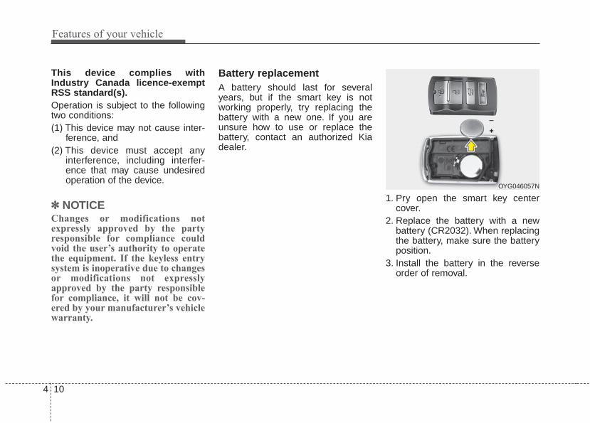
Features of your vehicle
104
This device complies withIndustry Canada licence-exemptRSS standard(s).Operation is subject to the followingtwo conditions:(1) This device may not cause inter-
ference, and (2) This device must accept any
interference, including interfer-ence that may cause undesiredoperation of the device.
✽✽ NOTICEChanges or modifications notexpressly approved by the partyresponsible for compliance couldvoid the user’s authority to operatethe equipment. If the keyless entrysystem is inoperative due to changesor modifications not expresslyapproved by the party responsiblefor compliance, it will not be cov-ered by your manufacturer’s vehiclewarranty.
Battery replacementA battery should last for severalyears, but if the smart key is notworking properly, try replacing thebattery with a new one. If you areunsure how to use or replace thebattery, contact an authorized Kiadealer.
1. Pry open the smart key centercover.
2. Replace the battery with a newbattery (CR2032). When replacingthe battery, make sure the batteryposition.
3. Install the battery in the reverseorder of removal.
OYG046057N

4 11
Features of your vehicle
Mechanical key operations• Used to lock and unlock the glove
box.• Lock and unlock the doors when
the vehicle or smart key battery isdischarged.
Smart key
To remove the mechanical key, pressand hold the release button andremove the mechanical key.To reinstall the mechanical key, putthe key into the hole and push it untila click sound is heard.
OVG043401L
IC WARNINGThis device complies withIndustry Canada licence-exempt RSS standard(s).Operation is subject to the fol-lowing two conditions: (1) thisdevice may not cause interfer-ence, and (2) this device mustaccept any interference, includ-ing interference that may causeundesired operation of thedevice.

Features of your vehicle
124
Restrictions in Handling Keys
When leaving keys with parking lotand valet attendants, the followingprocedures will ensure your vehicle’strunk and glove box compartmentcan not be opened in your absence.
To activate the trunk lock system sothat the trunk can only be opened withthe main key, perform the following:1. Unlock the glove box by using the
main key (1) then open it (2).2. Set the trunk lid control button to
the LOCK position.3. Close and lock the glove box using
the main key.
When leaving your keys with a park-ing lot or valet attendant, performsteps 1 to 3 above, and leave the subkey with the attendant. In this mannerthe sub key can only be used to startthe engine and operate door locks.
Lock release
To release the trunk lock feature,open the glove box with the main keyand set the trunk lid control button tothe UNLOCK position.
Immobilizer systemYour vehicle is equipped with anelectronic engine immobilizer systemto reduce the risk of unauthorizedvehicle use.Whenever the ENGINE START/STOPbutton is changed to the ON position,the immobilizer system checks andverifies if the key is valid or not.If the key is valid, the engine willstart.If the key is invalid, the engine willnot start.
✽✽ NOTICEIn order to prevent theft of yourvehicle, do not leave spare keys any-where in your vehicle. YourImmobilizer password is a customerunique password and should be keptconfidential. Do not leave this num-ber anywhere in your vehicle.
OYG046003

4 13
Features of your vehicle
To deactivate the immobilizersystemChange the ENGINE START/STOPbutton to the ON position.
To activate the immobilizer sys-tem Change the ENGINE START/STOPbutton to the OFF position. Theimmobilizer system activates auto-matically. Without a valid smart keyfor your vehicle, the engine will notstart.
In order to prevent theft of your vehi-cle, do not leave spare keys any-where in your vehicle.
Your immobilizer password is a cus-tomer unique password and shouldbe kept confidential. Do not leave thisnumber anywhere in your vehicle.
✽✽ NOTICEKeep each key separate in order toavoid a starting malfunction.
Do not put metal accessories nearthe smart key.Metal accessories may interrupt thetransponder signal and may preventthe engine from being started.If you need additional keys or loseyour keys, consult an authorized Kiadealer.
This device complies with IndustryCanada licence-exempt RSS stan-dard(s).Operation is subject to the followingtwo conditions:(1) This device may not cause inter-
ference, and (2) This device must accept any
interference, including interfer-ence that may cause undesiredoperation of the device.
✽✽ NOTICEChanges or modifications notexpressly approved by the partyresponsible for compliance couldvoid the user's authority to operatethe equipment.
CAUTION - Immobilizerdamage
Do not expose your immobilizersystem to moisture, static elec-tricity and rough handling. Thismay damage your immobilizer.
CAUTION - Immobilizeralterations
Do not change, alter or adjustthe immobilizer system becauseit could cause the immobilizersystem to malfunction.

Features of your vehicle
144
This system is designed to provideprotection from unauthorized entryinto the vehicle. This system is oper-ated in three stages: the first is the“Armed” stage, the second is the“Theft-alarm” stage, and the third isthe “Disarmed” stage. If triggered,the system provides an audiblealarm with blinking of the hazardwarning lights.
Armed stagePark the vehicle and stop the engine.Arm the system as described below.1. Turn off the engine.2. Make sure that all doors (and
trunk) and engine hood are closedand latched.
3. Lock the doors by depressing thedoor lock button on the smart key.
After completion of the steps above,the hazard warning lights will blink(for smart key, the chime alsosounds) once to indicate that thesystem is armed.If any door (or trunk) or engine hoodremains open, the hazard warninglights and the chime will not operateand the theft-alarm will not arm. If alldoors and trunk and engine hood areclosed after the lock button ispressed, the hazard warning lightsblink once.
The system can also be armed bylocking the doors with the key fromthe front doors; however, the hazardwarning lights will not blink using thismethod.
✽✽ NOTICEThe theft-alarm system can be deac-tivated by an authorized Kia dealer.If you want this feature, consult anauthorized Kia dealer.
Do not arm the system until allpassengers have left the vehicle. Ifthe system is armed while a pas-senger(s) remains in the vehicle,the alarm may be activated whenthe remaining passenger(s) leavethe vehicle. If any door (or trunk)or engine hood is opened within30 seconds after the systementers the armed stage, the sys-tem is disarmed to prevent anunnecessary alarm.
THEFT-ALARM SYSTEM
Armedstage
Theft-alarmstage
Disarmedstage

4 15
Features of your vehicle
Theft-alarm stageThe alarm will be activated if any ofthe following occurs while the systemis armed.• A front or rear door is opened with-
out using the smart key.• The trunk is opened without using
the smart key.• The engine hood is opened.The horn will sound and the hazardwarning lights will blink continuouslyfor approximately 27 seconds, andrepeat the horn 2 times unless thesystem is disarmed. To turn off thesystem, unlock the doors with thesmart key.
Disarmed stageThe system will be disarmed when• The doors (and trunk) are unlocked
with the smart key.After depressing the unlock button,the hazard warning lights will blinkand the chime will sound twice (insmart key) to indicate that the sys-tem is disarmed.After depressing the unlock button, ifany door (or trunk) is not openedwithin 30 seconds, the system will berearmed.• Avoid trying to start the engine
while the alarm is activated. Thevehicle starting motor is disabledduring the theft-alarm stage.If the system is not disarmed withthe smart key, open the doors byusing the mechanical key and startthe engine by directly pressing theengine Start/Stop button with thesmart key.
• If you lose your keys, consult yourauthorized Kia dealer.
✽✽ NOTICEMalfunctions caused by improperalterations, adjustments or modifi-cations to the theft-alarm system arenot covered by your vehicle manu-facturer warranty.
CAUTION - Adjustingalarm system
Do not change, alter or adjustthe theft-alarm system becauseit could cause the theft-alarmsystem to malfunction.

Features of your vehicle
164
DOOR LOCKS Operating door locks fromoutside the vehicle
• After removing the cover (2) whilepressing the hole (1) usingmechanical key or screw driver (-),turn the key toward the front of thevehicle to unlock and toward therear of the vehicle to lock.
• If you lock/unlock the driver’s doorwith a key, only the driver’s doorwill lock/unlock.
• Once the doors are unlocked, theymay be opened by pulling the doorhandle.
• Once the doors are unlocked, theymay be opened by pulling the doorhandle.
• When closing the door, push thedoor by hand. Make sure the doorsare closed securely.
✽✽ NOTICE• In cold and wet climates, door lock
and door mechanisms may notwork properly due to freezing con-ditions.
• If the door is locked/unlockedmultiple times in rapid successionwith either the vehicle key or doorlock switch, the system may stopoperating temporarily in order toprotect the circuit and preventdamage to system components.
OYG046006L
■ Type A ■ Type B
WARNINGIf people must spend a longertime in the vehicle while it isvery hot or cold outside, there isrick of injuries or danger to life.Do not lock the vehicle from theoutside when there are peoplein it.
CAUTIONDo not unnecessarily open andclose the door repeatedly orwith excessive force. Suchaction can damage the vehicledoor.

4 17
Features of your vehicle
• To lock a door without the key,push the inside door lock button (1)or central door lock switch (2) tothe “Lock” position and close thedoor (3).
• If you lock the door with the centraldoor lock switch (2), all vehicledoors will lock automatically.
✽✽ NOTICEAlways place the Engine Start/Stopbutton is in the OFF position,engage the parking brake, close allwindows, and lock all doors whenleaving your vehicle unattended.
Operating door locks frominside the vehicleWith the door lock button
• To unlock a door, push the doorlock button (1) to the “Unlock” posi-tion. The red mark on the buttonwill be visible.
• To lock a door, push the door lockbutton (1) to the “Lock” position. Ifthe door is locked properly, the redmark on the door lock button willnot be visible.
• To open a door, pull the door handle(2) outward.
• If the inner door handle of the dri-ver’s (or front passenger’s) door ispulled when the door lock button isin the lock position, the button willunlock and the door will open. (ifequipped)
• Front doors cannot be locked if thesmart key is in the vehicle and anyfront door is opened.
• Doors cannot be locked if thesmart key is in the vehicle and andoor is open.
OYG046008
OYG046007

Features of your vehicle
184
If a power door lock ever fails to func-tion while you are in the vehicle, tryone or more of the following tech-niques to exit:• Operate the door unlock feature
repeatedly (both electronic andmanual) while simultaneouslypulling on the door handle.
• Operate the other door locks andhandles, front and rear.
• Lower a front window and use thekey to unlock the door from out-side.
With central door lock switch
Operate by pressing the central doorlock switch.For Driver’s door:• When pushing down on the right
portion (1) of the switch, all vehicledoors will lock.
• When pushing down on left portion(2) of the switch, all vehicle doorswill unlock.
For Passenger’s door:• When pushing down on the front
portion (1) of the switch, all vehicledoors will lock.
• When pushing down on the rearportion (2) of the switch, all vehicledoors will unlock.
• If the smart key is in the vehicleand any front door is opened, thedoors will not lock even though theright portion(1, driver`s door) of thecentral door lock switch is pressed.
OYG046009
OYG046010
■ Driver side
■ Passenger side
WARNINGDo not pull the inner door han-dle of driver's (or passenger's)door while the vehicle is mov-ing.

4 19
Features of your vehicle
Impact sensing door unlock systemIn the event of air bag deploymentresulting from a vehicle impact, alldoors will automatically unlock.
Auto door lock/unlock feature• All doors will automatically lock
when the transaxle shift lever isshifted out of P(Park).
• All doors will automatically unlockwhen the transaxle shift lever isshifted into P (Park).
✽✽ NOTICEYou can select some auto doorlock/unlock features in “User Settings”For more information, refer to“User Settings” in this chapter.
Child-protector rear door lock
The child safety lock is provided tohelp prevent children from acciden-tally opening the rear doors frominside the vehicle. The rear doorsafety locks should be used whenev-er children are in the vehicle.1. Open the rear door.2. Push the child safety lock (1)
located on the rear edge of thedoor to the lock ( ) position.When the child safety lock is in thelock position, the rear door will notopen even when the inner doorhandle is pulled.
OYG046011
WARNING - Unattendedchildren/animals
Never leave children or animalsunattended in your vehicle. Anenclosed vehicle can becomeextremely hot, causing death orsevere injury to unattendedchildren or animals who cannotescape the vehicle.
WARNING - DoorsThe doors should always befully closed and locked while thevehicle is in motion to preventaccidental opening of the door.

Features of your vehicle
204
3. Close the rear door.To open the rear door, pull the out-side door handle (2).Even though the doors may beunlocked, the rear door will not openby pulling the inner door handle untilthe rear door child safety lock isunlocked.
Non-Powered Trunk To open:1.Make sure the shift lever is in P
(Park).2.Then do one of the following :
- Press the smart key trunk unlockbutton for more than one second.
- Press the button on the trunkitself with the smart key in yourpossession.
- Use the mechanical key.3.Lift the trunk lid up.
To close:Lower the trunk lid and press downuntil it locks.
OYG046012
OYG046013
WARNING - Rear doorlocks
Use the rear door safety lockswhenever children are in thevehicle. If a child accidentlyopens the rear doors while thevehicle is moving, they may fallout.
TRUNK

4 21
Features of your vehicle
✽✽ NOTICEIn cold and wet climates, trunk lockand trunk mechanisms may notwork properly due to freezing condi-tions.
Power Trunk The power trunk can be opened andclosed automatically as follows.- Power trunk main button (Type A) :
Open and close- Smart key and trunk handle switch
(Type B) : Open only- Close button on the trunk lid
(Type C) : Close onlyIf you depress the power trunk mainbutton, trunk handle button or closebutton while operating the powertrunk, you could stop operating thepower trunk.If that happens, to operate the powertrunk again, push any button or switch.
OYG046014
OYG046015
OYG046016
■Type B
■Type A
■Type C
WARNING - Exhaustfumes
The trunk lid should always bekept completely closed whilethe vehicle is in motion. If it isleft open or ajar, exhaust gasesmay enter the car and seriousillness or death may result.
WARNINGThe trunk swings upward. Makesure no objects or people arenear the rear of the vehiclewhen opening the trunk.

Features of your vehicle
224
Opening the trunkThe power trunk will open automati-cally by doing one of the following:• Press the trunk open button on the
smart key more than 1 second.Thechime will sound twice.
• Press and hold the open button ofthe power trunk main switch. Thechime will sound twice.
• Press the trunk handle switch car-rying the smart key with you. If alldoors have unlocked, you canopen the trunk by pressing thetrunk handle switch without thesmart key.
Closing the trunkTo close the power trunk, do one ofthe following:• Push the close button of the power
trunk main button, until the powertrunk is closed securely. The chimewill sound twice.
• Push the power trunk close button.• Push the power trunk lock button
when all doors and engine hoodare closed with the smart key inyour possession. After closing, alldoors and trunk lock automatically.
✽✽ NOTICEThe power trunk lock button willnot work if you press the buttonwhen:- Any door is open.- The engine start/stop button is not
in the OFF position.- The smart key is in the vehicle.
WARNINGMake sure there are no peopleor objects around the trunkbefore opening or closing thepower trunk. Wait until the trunkis open fully and stoppedbefore loading or unloadingcargo from the vehicle.
CAUTION• Do not close or open the
power trunk manually. Thismay cause damage to thepower trunk. If it is necessaryto close or open the powertrunk manually when the bat-tery is drained or disconnect-ed, do not apply excessiveforce.
• To prevent damage to thetrunk lift cylinders and theattached hardware, alwaysclose the trunk before driving.

4 23
Features of your vehicle
Do not leave the power trunk openfor a long period of time. This maydrain the battery.
✽✽ NOTICEIn cold and wet climates, trunk lockand trunk mechanisms may notwork properly due to freezing condi-tions.
Power Trunk Non-Opening orClosing Conditions:• The power trunk will not open or
close automatically, when the vehi-cle is moving more than 3 km/h(1.8 mph).
• The power trunk can be operatedwhen the engine is not running.However, the power trunk opera-tion consumes large amounts ofvehicle electric power. To preventthe battery from draining, do notoperate it excessively (e.g., morethan approximately 10 timesrepeatedly).
• Do not modify or repair any part ofthe power trunk by yourself. Thismust be done by an authorized Kiadealer.
• Before jacking up the vehicle tochange a tire or repair the vehicle,open the power trunk. Do not oper-ate the power trunk when the vehi-cle is raised or this could cause thepower trunk to operate improperly.
• If there are obstacles such assnow on the power trunk, it maynot open automatically. Afterremoving the obstacle, try to openit again.
Automatic stop and Reverse
If, during power opening or closing,the trunk is blocked by an object orpart of someone’s body, the powertrunk will detect the resistance and itwill stop movement or move to thefull open position to allow the objectto be cleared.However, if an object is thin or soft,or the trunk is near the latched posi-tion, the automatic stop and reversalmay not detect the resistance andthe closing operation will continue. Ifthe power trunk is forced by a strongimpact, the automatic stop and rever-sal may operate.
OYG046018

Features of your vehicle
244
If the automatic stop and reverse fea-ture operates more than twice duringone opening or closing operation, thepower trunk may stop at that posi-tion.If this occurs, close the trunk manu-ally and operate the trunk automati-cally again.
To Reset the Power TrunkIf the battery has been discharged ordisconnected, or if the related fusehas been replaced or disconnected,reset the power trunk as follows:1. Move the shift lever to the P (Park)
position.2. Close the trunk manually.If the power trunk doesn't work prop-erly after performing the above pro-cedure, have the system checked byan authorized Kia dealer.
Trunk Lid Control Button
When the trunk lid control button isUNLOCK, the power trunk can becontrolled with the power trunk maincontrol button, power trunk open,close button, and the smart key.When this trunk lid control button isLOCK, the power trunk can be con-trolled using the mechanical key ofthe smart key only.
WARNINGTo prevent serious injury anddamage take the following pre-cautions when operating thepower trunk:- Keep all faces, hands, arms,
body parts and other objectsaway from the path of thepower trunk.
- Do not intentionally place anybody parts or objects in thepath of the power trunk tomake sure the automatic stopand reversal operates.
- Do not allow children to playwith the power trunk.
OYG046005

4 25
Features of your vehicle
Even though the trunk lid control but-ton is LOCK, the trunk will still bepropelled upward by mechanicalforce if the trunk is manually openedmore than 10 degrees beyond thefully closed position.In addition, if the trunk is manuallyclosed to the secondary latch posi-tion, the trunk will be electricallymoved to the fully latched position.
✽✽ NOTICEClose the trunk, and keep the trunklid control button in the UNLOCKposition before washing the vehiclein an automatic car wash.
Emergency Trunk SafetyRelease
Your vehicle is equipped with anEmergency Trunk Safety Releaselever located inside the trunk. Whensomeone is inadvertently locked inthe trunk, the trunk can be openedby moving the lever in the direction ofthe arrow and pushing the trunkopen.
WARNINGAlways keep the Trunk LidControl Button in the UNLOCKposition when not in use.Serious injury or death canresult from unintentional opera-tion by a child.
OYG046020
WARNINGNEVER allow anyone to occupythe trunk of the vehicle at anytime. If the trunk is partially ortotally latched and the person isunable to get out, serious injuryor death could occur due to lackof ventilation, exhaust fumesand rapid heat build-up, orbecause of exposure to coldweather conditions.The trunk isalso a highly dangerous loca-tion in the event of a crashbecause it is not a protectedoccupant space but is a part ofthe vehicle’s crush zone.

Features of your vehicle
264
• You and your passengers must beaware of the location of theEmergency Trunk Safety Releaselever in this vehicle and how toopen the trunk in case you areaccidentally locked in the trunk.
• Your vehicle should be kept lockedand the Smart Key should be keptout of the reach of children.Parents should teach their childrenabout the dangers of playing intrunks.
• Use the release lever for emergen-cies only.
WARNING
Make sure that there are no peo-ple or objects in the path of thepower trunk (or smart trunk)prior to use. Serious injury,damage to the vehicle or dam-age to surrounding objects mayresult if contact with the powertrunk (or smart trunk) occurs.
OYG046451L
WARNINGMake sure there are no peopleor objects around the trunkbefore opening or closing thepower trunk. Wait until the trunkis open fully and stoppedbefore loading or unloadingcargo from the vehicle.

4 27
Features of your vehicle
On a vehicle equipped with a smartkey, the trunk can be opened withno-touch activation using the SmartTrunk system.
How to use the Smart Trunk The trunk can be opened with no-touch activation satisfying all theconditions below.• After 15 seconds when all doors
are closed and locked• Positioned in the detecting area for
more than 3 seconds.
✽✽ NOTICE• The Smart Trunk does not operate
when:- The smart key is detected within
15 seconds after the doors areclosed and locked, and is contin-uously detected.
- The smart key is detected within15 seconds after the doors areclosed and locked, and 1.5 m (60inches) from the front door han-dles. (for vehicles equipped withWelcome Light)
- A door is not locked or closed.- The smart key is in the vehicle.
SMART TRUNK (IF EQUIPPED)
OYG046021

Features of your vehicle
284
1. SettingTo activate the Smart Trunk, go toUser Settings Mode and selectSmart Trunk on the LCD display.❈ For more details, refer to “LCD
Display” in this chapter.
2. Detect and AlertIf you are positioned in the detectingarea (50 ~100 cm (20 ~ 40 inches)behind the vehicle) carrying a smartkey, the hazard warning lights willblink and the chime will sound forabout 3 seconds to alert you thesmart key has been detected and thetrunk will open.
✽✽ NOTICEDo not approach the detecting area ifyou do not want the trunk to open. Ifyou have unintentionally entered thedetecting area and the hazard warn-ing lights and chime starts to operate,leave the detecting area with thesmart key. The trunk will stay closed.
OYG046022

4 29
Features of your vehicle
3. Automatic openingThe hazard warning lights will blinkand the chime will sound 2 times andthen the trunk will slowly open.Make certain that you close the trunkbefore driving your vehicle.Make sure there are no people orobjects around the trunk beforeopening or closing the trunk.Make sure to deactivate the Smarttrunk function when washing yourvehicle.Otherwise, the trunk may open inad-vertently.
✽✽ NOTICEThe key should be kept out of reachof children. Children may inadver-tently open the Smart Trunk whileplaying around the rear area of thevehicle.
How to deactivate the Smart Trunkfunction using the smart key
1. Door lock2. Door unlock3. Trunk open4. Panic
If you press any button of the smartkey during the Detect and Alertstage, the Smart Trunk function willbe deactivated.Make sure to be aware of how todeactivate the Smart Trunk functionfor emergency situations.
OYG046023
WARNINGMake sure objects in the rearcargo area do not come outwhen opening the trunk on theslope way. It may cause seriousinjury.
OYG046056N

Features of your vehicle
304
✽✽ NOTICE• If you press the door unlock but-
ton (2), the Smart Trunk functionwill be deactivated temporarily.But, if you do not open any doorfor 30 seconds, the smart trunkfunction will be activated again.
• If you press the trunk open button(3) for more than 1 second, thetrunk opens.
• If you press the door lock button(1) or trunk open button (3) whenthe Smart Trunk function is not inthe Detect and Alert stage, thesmart trunk function will not bedeactivated.
• In case you have deactivated theSmart Trunk function by pressingthe smart key button and opened adoor, the smart trunk function canbe activated again by closing andlocking all doors.
Detecting area
• The Smart Trunk operates with awelcome alert if the smart key isdetected within 50 ~ 100 cm (20 ~40 inches) from the trunk.
• The alert stops at once if the smartkey is positioned outside thedetecting area during the Detectand Alert stage.
✽✽ NOTICE• The Smart Trunk function will not
work if any of the followingoccurs:- The smart key is close to a radio
transmitter such as a radio sta-tion or an airport which caninterfere with normal operationof the transmitter.
- The smart key is near a mobiletwo way radio system or a cellu-lar phone.
- Another vehicle's smart key isbeing operated close to yourvehicle.
• The detecting range may decreaseor increase when :- One side of the tire is raised to
replace a tire or to inspect thevehicle.
- The vehicle is slantingly parkedon a slope or unpaved road, etc.
OYG046024

4 31
Features of your vehicle
(1) Driver’s door power windowswitch
(2) Front passenger’s door powerwindow switch
(3) Rear door (left) power windowswitch
(4) Rear door (right) power windowswitch
(5) Window opening and closing(6) Automatic power window
up/down (Driver's andPassenger's window)
(7) Power window lock button
In cold and wet climates, power win-dows may not work properly due tofreezing conditions.
WINDOWS
OYG046025
■■ Front
■■ Rear

Features of your vehicle
324
Power windowsThe Engine Start/Stop button must bein the ON position for power windowsto operate. Each door has a powerwindow switch that controls the door’swindow. The driver has a power win-dow lock switch which can block theoperation of rear passenger windows.The power windows can be operatedfor approximately 30 seconds afterengine is turned off. However, if thefront doors are opened, the powerwindows cannot be operated evenwithin the 30 second period.If the window cannot be closebecause it is blocked by objects,remove the objects and close thewindow.
✽✽ NOTICEWhile driving with the rear windowsdown or with the sunroof (ifequipped) in an open (or partiallyopen) position, your vehicle maydemonstrate a wind buffeting or pul-sation noise. This noise is a normaloccurrence and can be reduced oreliminated by taking the followingactions. If the noise occurs with oneor both of the rear windows down,partially lower both front windowsapproximately 2.5 cm (1 inch). If youexperience the noise with the sunroofopen, slightly reduce the size of thesunroof opening.
Window opening and closing
The driver’s door has a master powerwindow switch that controls all thewindows in the vehicle.To open or close a window, pressdown or pull up the front portion ofthe corresponding switch to the firstdetent position (5).
OYG046027
CAUTIONDo not install any accessoriesin the vehicle that extend intothe open window area. Suchobjects will impact the properfunction of the Automatic rever-sal "jam protection" featuredescribed on page 4-33 of thismanual.

4 33
Features of your vehicle
Auto up/down window (Driver`s and Passenger`s side)
Pressing or pulling up the power win-dow switch momentarily to the seconddetent position (6) completely lowersor raises the window even when theswitch is released. To stop the windowat the desired position while the win-dow is in operation, pull up or pressdown and release the switch.If the power window does not operatenormally, the automatic power win-dow system must be reset as follows:
1. Press the Engine Start/StopButton twice to the ON position.
2. Close the driver's and passenger'swindow and continue pulling upthe driver’s power window switchfor at least 1 second after the win-dow is completely closed.
Automatic reversal(for Auto up/down window)
If the upward movement of the win-dow is blocked by an object or part ofthe body, the window will detect theresistance and will stop upwardmovement. The window will thenlower approximately 30 cm (11.8 in.)to allow the object to be cleared.The distance may vary based on thesize or position of the window. If thewindow detects the resistance whilethe power window switch is pulled upcontinuously, the window will stopupward movement then lowerapproximately 2.5 cm (1 in.).
OUN026013
OYG046026

Features of your vehicle
344
If the power window switch is pulledup continuously again within 5 sec-onds after the window is lowered bythe automatic window reversal fea-ture, the automatic window reversalwill not operate.The automatic reverse feature for thedriver’s window is only active whenthe “auto up” feature is used by fullypulling up the switch. The automaticreverse feature will not operate if thewindow is raised using the halfwayposition on the power window switch.
Power window lock button
• The driver can disable the powerwindow switches on the passengerdoors by pressing the power win-dow lock button located on the dri-ver’s door to the LOCK position(pressed).
• When the power window lockbutton is pressed :- The driver's master control can
operate all the power windows.- The front passenger's control can
operate the front passenger'spower window.
OYG046028
WARNINGAlways check for obstructionsbefore raising any window toavoid injuries or vehicle damage.If an object less than 4 mm (0.16in.) in diameter is caughtbetween the window glass andthe upper window channel, theautomatic reverse window maynot detect the resistance and willnot stop and reverse direction.
WARNINGThe automatic reverse featuredoesn't active while resettingpower window system.Make sure body parts or otherobjects are safely out of the waybefore closing the windows toavoid injuries or vehicle damage.

4 35
Features of your vehicle
- The rear passenger's control can-not operate the rear passenger'spower window.
Always double check to make sureall arms, hands, head and otherobstructions are safely out of the waybefore closing a window.
Opening the hood
1. Pull the release lever to unlatchthe hood. The hood should popopen slightly.
Open the hood after turning off theengine on a flat surface, shifting theshift lever to the P (Park) positionand setting the parking brake.
2. Go to the front of the vehicle, raisethe hood slightly, push the second-ary latch (1) left side of the hoodcenter and lift the hood (2).
3. Raise the hood. It will completelyrise by itself after it has beenraised about halfway.
HOOD
OYG046029
OYG046030
CAUTION - Opening /clos-ing Window
To prevent possible damage tothe power window system, donot open or close two windowsor more at the same time. Thiswill also ensure the longevity ofthe fuse.
WARNING - Power win-dows
Do not allow children to playwith the power windows. Keepthe power window lock button(on the driver's door) in theLOCK (pressed) position.

Features of your vehicle
364
Hood open warning
The warning message will appear onthe LCD display when hood is open.The warning chime will operate whenthe vehicle is being driven at orabove 3 km/h (2 mph) with the hoodopen.
Closing the hood1. Before closing the hood, check the
following:• All filler caps in engine compart-
ment must be correctly installed.• Gloves, rags or any other com-
bustible material must beremoved from the engine com-partment.
2. Return the support rod to its clip toprevent it from rattling.
3.Lower the hood until it is about 30cm above the closed position andlet it drop. Make sure that it locksinto place.
4. Check that the hood has engagedproperly. If the hood can be raisedslightly, it is not properly engaged.Open it again and close it with a lit-tle more force.
WARNING - Fire riskDo not leave gloves, rags or anyother combustible material in theengine compartment. Doing somay cause a heat-induced fire.
WARNING - Unsecuredengine hood
Always double check to be surethat the hood is firmly latchedbefore driving away. If it is notlatched, the hood could fly openwhile the vehicle is being driv-en, causing a total loss of visi-bility, which might result in anaccident.
CAUTION - Hood obstruc-tion
Before closing the hood, ensurethat all obstructions are removedfrom the hood opening. Closingthe hood with an obstructionpresent in the hood opening mayresult in property damage.
OYG046172N

4 37
Features of your vehicle
Opening the fuel filler lid
The fuel filler lid must be openedfrom inside the vehicle by pressingthe fuel filler lid opener button.If the fuel filler lid does not openbecause ice has formed around it,tap lightly or push on the lid to breakthe ice and release the lid. Do not pryon the lid. If necessary, spray aroundthe lid with an approved de-icer fluid(do not use radiator anti-freeze) ormove the vehicle to a warm placeand allow the ice to melt.
1. Stop the engine.2. To open the fuel filler lid, push the
fuel filler lid opener button.3. Pull open the fuel filler lid (1).4. To remove the cap, turn the fuel
filler cap (2) counterclockwise.5. Refuel as needed.
Closing the fuel filler lid1. To install the cap, turn it clockwise
until it “clicks” once. This indicatesthat the cap is securely tightened.
2. Close the fuel filler lid and push itin lightly making sure that it issecurely closed.
✽✽ NOTICEThere may be an intermittent noisenear the refueling hole while theengine is idling if the fuel cap is notclosed securely. This occurs normal-ly with the OBD system.
✽✽ NOTICEWhen refueling on unlevel ground,the fuel gauge may not point to the Fposition.It is not a malfunction. If you moveyour vehicle to a level ground, the fuelgauge will move to the full position.
FUEL FILLER LID
OYG046031
OYG046032

Features of your vehicle
384
Emergency fuel filler lid release
If the fuel filler lid does not openusing the remote fuel filler lidrelease, you can open it manually.Remove the panel in the cargo area.Pull the handle out slightly.
Always check that the fuel cap isinstalled securely to prevent fuelspillage in the event of an accident.
✽✽ NOTICETighten the cap until it clicks once,otherwise the fuel cap open warningindicator light will illuminate.
WARNING - Fire/explo-sion risk
Read and follow all warningsposted at the gas station facili-ty. Failure to follow all warningsmay result in severe personalinjury, severe burns or deathdue to fire or explosion.
WARNING - RefuelingAlways remove the fuel capcarefully and slowly. If the capis venting fuel or if you hear ahissing sound, wait until thecondition stops before com-pletely removing the cap. Ifpressurized fuel sprays out, itcan cover your clothes or skinand subject you to the risk offire and burns.
CAUTIONDo not pull the handle exces-sively, otherwise the luggagearea trim or release handle maybe damaged.
OYG046034

4 39
Features of your vehicle
WARNING - Cell phonefires
Do not use cellular phoneswhile refueling. Electric currentand/or electronic interferencefrom cellular phones can poten-tially ignite fuel vapors causinga fire.
WARNING - Portable fuelcontainer
When using an approvedportable fuel container, be sureto place the container on theground prior to refueling. Staticelectricity discharge from thecontainer can ignite fuel vaporscausing a fire. Once refuelinghas begun, contact with thevehicle should be maintaineduntil the filling is complete. Useonly approved portable plasticfuel containers designed tocarry and store gasoline.
WARNING - Static electricity
• Before touching the fuel noz-zle, you should eliminatepotentially dangerous staticelectricity discharge by touch-ing another metal part of thevehicle, a safe distance awayfrom the fuel filler neck, noz-zle, or other gas source.
• Do not get back into a vehicleonce you have begun refuelingsince you can generate staticelectricity by touching, rubbingor sliding against any item orfabric (polyester, satin, nylon,etc.) capable of producing staticelectricity. Static electricity dis-charge can ignite fuel vaporsresulting in rapid burning. If youmust reenter the vehicle, youshould once again eliminatepotentially dangerous staticelectricity discharge by touch-ing a metal part of the vehicle,away from the fuel filler neck,nozzle or other gasoline source.

Features of your vehicle
404
Make sure to refuel your vehicleaccording to the “Fuel requirements”suggested in chapter 1.If the fuel filler cap requires replace-ment, use only a genuine Kia cap orthe equivalent specified for your vehi-cle. An incorrect fuel filler cap canresult in a serious malfunction of thefuel system or emission control sys-tem.
CAUTION - Exterior paintDo not spill fuel on the exteriorsurfaces of the vehicle. Anytype of fuel spilled on paintedsurfaces may damage the paint.
WARNING - SmokingDO NOT use matches or a lighterand DO NOT SMOKE or leave a litcigarette in your vehicle while ata gas station especially duringrefueling. Automotive fuel ishighly flammable and can, whenignited, result in fire.
WARNING - Refueling &Vehicle fires
When refueling, always shut theengine off. Sparks produced byelectrical components relatedto the engine can ignite fuelvapors causing a fire. Oncerefueling is complete, check tomake sure the filler cap andfiller door are securely closed,before starting the engine.

4 41
Features of your vehicle
If your vehicle is equipped with asunroof, you can slide or tilt yoursunroof with the sunroof control leverlocated on the overhead console.The sunroof can be operated forapproximately 30 seconds after theEngine Start/Stop button is in theOFF position.However, if the driver’s door isopened, the sunroof cannot be oper-ated even within the 30 second peri-od.
In cold and wet climates, the sunroofmay not work properly due to freez-ing conditions.After the vehicle is washed or in arainstorm, be sure to wipe off anywater that is on the sunroof beforeoperating it.
The sunroof cannot slide when it is inthe tilt position nor can it be tiltedwhile in an open or slide position.
PANORAMIC SUNROOF (IF EQUIPPED)
CAUTION - Sunroof control lever
Do not continue to press the sun-roof control lever after the sun-roof is fully opened, closed, ortilted. Damage to the motor orsystem components could occur.
CAUTION - Sunroof motordamage
To prevent damage to the sun-roof, periodically remove anydirt that may accumulate on theguide rail.
WARNING - Roof cargoDo not operate the sun roofwhile using the roof rack totransport cargo.This may causethe cargo to come loose anddistract the driver.
OYG046035
WARNING Never adjust the sunroof orsunshade while driving. Thiscould result in loss of controland an accident that may causedeath, serious injury, or proper-ty damage.

Features of your vehicle
424
Sunroof open warning (if equipped)
If the driver turns off the engine whenthe sunroof is not fully closed, thewarning chime will sound for a fewseconds and above warning illustra-tion will appear on the LCD display orthe warning indicator will illuminate.Close the sunroof securely whenleaving your vehicle.
WARNING • In order to prevent accidental
operation of the sunroof,especially by a child, do notlet a child operate the sun-roof.
• Do not sit on the top of thevehicle. It may cause vehicledamage.
CAUTIONDo not extend any luggage out-side the sunroof while driving.
OYG046145
CAUTIONMake sure the sunroof is fullyclosed when leaving your vehi-cle. If the sunroof is opened, rainor snow may leak through thesunroof and wet the interior aswell as cause theft.
WARNING Do not allow children to operatethe sunroof. This may result ininjury to the child.

4 43
Features of your vehicle
Sunshade
To open the sunshadePush the sunroof control lever back-ward to the 1st detent position.
To close the sunshade when thesunroof glass is closedPush the sunroof control lever for-ward to the 1st detent position.To stop the sliding at any point, pressthe sunshade control switch momen-tarily.
✽✽ NOTICEWrinkles formed on the sunshade asmaterial characteristic are normal.
✽✽ NOTICEOnly the front glass of the panora-ma sunroof opens and closes.
Sliding the sunroof
When the sunshade is closedPush the sunroof control lever back-ward to the 2nd detent position, boththe sunshade and sunroof glass willslide all the way open. To stop thesunroof movement at any point, pushthe sunroof control glass levermomentarily.
CAUTION - Automaticsunroof shade
• Do not pull or push the sun-shade by hand as such actionmay damage the sunshade orcause it to malfunction.
• Close the sunroof when driv-ing in dusty environments.Dust may cause a malfunctionof the vehicle system.
OYG046452L OYG046036

Features of your vehicle
444
When the sunshade is openedIf you push the sunroof control leverbackward, the sunroof glass will slideall the way open. To stop the sunroofmovement at any point, push the sun-roof control lever momentarily.
Automatic reversal
If an object or part of the body isdetected while the sunroof is closingautomatically, it will reverse the direc-tion, and then stop.The auto reverse function does notwork if a tiny obstacle is between thesliding glass and the sunroof sash.You should always check that all pas-sengers and objects are away fromthe sunroof before closing it.Objects less than 0.16 inch (4 mm) indiameter caught between the sun-roof glass and the front glass chan-nel may not be detected by the auto-matic reverse glass and the glass willnot stop and reverse direction.
OXM049029
WARNING - SunroofOperation
When closing the sunroof, makesure there are no body parts inthe movement range of the slid-ing roof. Parts of the body couldbecome trapped or crushed.
WARNING - Sunroof• Be careful that no head, hands
and body parts are obstructedby a closing sunroof.
• Do not extend the face, neck,arms or body outside the sun-roof while driving.

4 45
Features of your vehicle
✽✽ NOTICEIf you drive with the sunroof openedright after a vehicle wash or rain,water may get inside the vehicle.
Tilting the sunroof
When the sunshade is closedPush the sunroof control lever upward,the sunshade will slide all the wayopen then the sunroof glass will tilt.To stop the sunroof movement at anypoint, push the sunroof control levermomentarily.
When the sunshade is openedPush the sunroof control leverupward, the sunroof glass will tilt.To stop the sunroof movement at anypoint, push the sunroof control levermomentarily.
Closing the sunroofTo close the sunroof glass withthe sunshade Push the sunroof control lever for-ward to the first detent position.
To close the sunroof glass onlyPush the sunroof control lever for-ward to the second detent position.The sunroof glass will close then thesunshade close automatically.To stop the sunroof movement at anypoint, push the sunroof control levermomentarily.
CAUTIONTo prevent damage to the sun-roof, periodically remove anydirt that may accumulate on theguide rail.
CAUTION - Sunroof motordamage
If you try to open the sunroofwhen the temperature is belowfreezing or when the sunroof iscovered with snow or ice, theglass or the motor could bedamaged.
OYG046037

Features of your vehicle
464
Resetting the sunroofWhenever the vehicle battery is dis-connected or discharged, you mustreset your sunroof system as follows:1.Start the engine.2.Close the sunshade and sunroof
completely if opened.3.Release the sunroof control lever.4.Push the sunroof control lever for-
ward in the direction of close(about 10 seconds) until the sun-shade slightly moves. Then,release the lever.
5.Push the sunroof control lever for-ward in the direction of close, untilthe sunroof operates as followsagain:
Sunshade Open → Glass Tilt Open→ Glass Tilt Close → Glass SlideOpen → Glass Slide Close →Sunshade Close
Then, release the lever.
When this is complete, the sunroofsystem has been reset and onetouch open and close should berestored.
✽✽ NOTICEIf you do not reset the sunroof, itmay not work properly.

4 47
Features of your vehicle
Electric power steering (EPS)The power steering uses a motor toassist you in steering the vehicle. Ifthe engine is off or if the power steer-ing system becomes inoperative, thevehicle may still be steered, but it willrequire increased steering effort.The motor driven power steering iscontrolled by a power steering con-trol unit which senses the steeringwheel torque and vehicle speed tocommand the motor.The steering becomes heavier as thevehicle’s speed increases andbecomes lighter as the vehicle’sspeed decreases for optimum steer-ing control.Should you notice any change in theeffort required to steer during normalvehicle operation, have the powersteering checked by an authorizedKia dealer.
• If the Electric Power SteeringSystem does not operate normally,the warning light will illuminate onthe instrument cluster.The steeringwheel may require increasedsteering effort. Take your vehicle toan authorized Kia dealer and havethe vehicle checked as soon aspossible.
• When you operate the steeringwheel in low temperature, noisemay occur. If temperature rises, thenoise will likely disappear. This is anormal condition.
• When the vehicle is stationary, andthe steering wheel is turned all theway to the left or right continuous-ly, the steering wheel becomesharder to turn. The power assist islimited to protect the motor fromoverheating.As time passes, the steering wheelwill return to its normal condition.
✽✽ NOTICEThe following symptoms may occurduring normal vehicle operation:• The EPS warning light does not
illuminate.• The steering gets heavy immedi-
ately after turning the ignitionswitch on. This happens as the sys-tem performs the EPS systemdiagnostics. When the diagnosticsare completed, the steering wheelwill return to its normal condition.
• A click noise may be heard fromthe EPS relay after the EngineStart/Stop button is turned to theON or OFF position.
• A motor noise may be heard whenthe vehicle is at a stop or at a lowdriving speed.
• If the Electric Power SteeringSystem does not operate normally,the warning light will illuminate onthe instrument cluster. The powersteering system will not operateand steering effort can highlyincrease. Take your vehicle to anauthorized Kia dealer and have thevehicle checked as soon as possible.
(Continued)
STEERING WHEEL

Features of your vehicle
484
(Continued)• When the charging system warning
light comes on due to the low volt-age (When the alternator or bat-tery) does not operate normally ormalfunctions), the steering wheelmay require increased steeringeffort.
Tilt and telescopic steering Tilt and telescopic steering allowsyou to adjust the steering wheelbefore you drive.You can also raise itto give your legs more room whenyou exit and enter the vehicle.
The steering wheel should be posi-tioned so that it is comfortable foryou to drive, while permitting you tosee the instrument panel warninglights and gauges.
Manual typeTo change the steering wheel angle,pull down the lock-release lever (1),adjust the steering wheel to thedesired angle (2) and height (3) thenpull up the lock-release lever to lock(4) the steering wheel in place. Besure to adjust the steering wheel tothe desired position before driving.
▼
WARNING - Steeringwheel adjustment
Never adjust the angle andheight of the steering wheelwhile driving. You may losesteering control.
OYG046038

4 49
Features of your vehicle
✽✽ NOTICEAfter adjustment, sometimes thelock release lever may not lock thesteering wheel. It is not a malfunc-tion. This occurs when two gears arenot engaged correctly. In this case,adjust the steering wheel again andthen lock the steering wheel.
Electric typeAdjust the steering wheel angle (2)and position (3) with the knob (1) onthe steering column. Move the steer-ing wheel, so it points toward yourchest, not toward your face. Makesure you can see the instrumentpanel warning lights and gauges.After adjusting, push the steeringwheel both up and down to be cer-tain it is locked in position. Alwaysadjust the position of the steeringwheel before driving.
✽✽ NOTICETo prevent discharge of the battery,do not operate when the engine isstopped.
▼
OYG046039

Features of your vehicle
504
Heated steering wheel (if equipped)
With the Engine Start/Stop Button inthe ON position, pressing the heat-ed steering wheel button warms thesteering wheel. The indicator on thebutton will illuminate.To turn the heated steering wheel off,press the button once again. Theindicator on the button will turn off.
✽✽ NOTICEThe heated steering wheel will turnoff automatically approximately 30minutes after the heated steeringwheel is turned on.
OYG046040
CAUTION• Do not install any type of grip
cover for the steering wheel, itmay impair the function of theheated steering wheel system.
• When cleaning the heatedsteering wheel, do not use anorganic solvent such as paintthinner, benzene, alcohol andgasoline. Doing so may dam-age the surface of the steeringwheel.
• If the surface of steeringwheel is damaged by sharpobject, damage to the heatedsteering wheel componentscould occur.
WARNINGIf the steering wheel becomestoo warm, turn the system off.The heated steering wheel maycause burns even at low tem-peratures, especially if used forlong periods of time.

4 51
Features of your vehicle
Horn
To sound the horn, press the hornsymbols on your steering wheel.Check the horn regularly to be sure itoperates properly.
✽✽ NOTICETo sound the horn, press the areaindicated by the horn symbol onyour steering wheel (see illustra-tion). The horn will operate onlywhen this area is pressed.
OYG046041

Features of your vehicle
524
MIRRORSInside rearview mirrorAdjust the rearview mirror so that thecenter view through the rear windowis seen. Make this adjustment beforeyou start driving.Do not place objects in the rear seator cargo area which would interferewith your vision through the rear win-dow.
Day/night rearview mirror (if equipped)
Make this adjustment before youstart driving and while the day/nightlever (3) is in the day position.Pull the day/night lever (3) towardyou to reduce the glare from theheadlights of the vehicles behind youduring night driving.Remember that you lose somerearview clarity in the night position.
❈ (1) : Day, (2) : Night
WARNING - Mirror adjust-ment
Do not adjust the rearview mir-ror while the vehicle is moving.This could result in loss of con-trol.
WARNINGDo not modify the inside mirrorand don’t install a wide mirror. Itcould result in injury during anaccident or deployment of theair bag.
OYG046054L

4 53
Features of your vehicle
Electric chromic mirror (ECM)with HomeLink® system and com-pass (if equipped)Your vehicle may be equipped with aGentex Automatic-Dimming Mirrorwith a Z-Nav® Electronic CompassDisplay and an IntegratedHomeLink® Wireless ControlSystem.During nighttime driving, this featurewill automatically detect and reducerearview mirror glare while the com-pass indicates the direction the vehi-cle is pointed. The HomeLink®
Universal Transceiver allows you toactivate your garage door(s), electricgate, home lighting, etc.
(1) Channel 1 button(2) Channel 2 button(3) Status indicator LED(4) Channel 3 button(5) Rear light sensor(6) Dimming ON/OFF button(7) Compass control button(8) Compass display
Automatic-Dimming Night VisionSafety™ (NVS®) Mirror
The NVS® Mirror in your vehicle isthe most advanced way to reduceannoying glare in the rearview mirrorduring any driving situation. For moreinformation regarding NVS® mirrorsand other applications, please referto the Gentex website:www.gentex.com❈ Night Vision Safety™ is a registered
trademark of Gentex Corporation.OJFA045335
CAUTIONThe NVS® Mirror automaticallyreduces glare during drivingconditions based upon light lev-els monitored in front of thevehicle and from the rear of thevehicle. These light sensors arevisible through openings in thefront and rear of the mirror case.Any object that obstructs eitherlight sensor will degrade theautomatic dimming control fea-ture.

Features of your vehicle
544
Automatic-dimming functionYour mirror will automatically dimupon detecting glare from the vehi-cles traveling behind you. The auto-dimming function can be controlledby the Dimming ON/OFF Button:
1. Pressing the button turns theauto-dimming function OFF whichis indicated by the green StatusIndicator LED turning off.
2. Pressing the button again turnsthe auto-dimming function ONwhich is indicated by the greenStatus Indicator LED turning on.
✽✽ NOTICEThe mirror defaults to the ON posi-tion each time the vehicle is started.
Z-Nav™ Compass Display
The NVS® Mirror in your vehicle isalso equipped with a Z-NAV™Compass that shows the vehicleCompass heading in the DisplayWindow using the 8 basic cardinalheadings (N, NE, E, SE, etc.).❈ Z-Nav™ is a registered trademark
of Gentex Corporation.

4 55
Features of your vehicle
Compass functionThe Compass can be turned ON andOFF and will remember the last statewhen the ignition is cycled. To turnthe display feature ON/OFF:1. Press and release the button toturn the display feature OFF.2. Press and release the buttonagain to turn the display back ON.Additional options can be set withpress and hold sequences of thebutton and are detailed below.
There is a difference between mag-netic north and true north. The com-pass in the mirror can compensatefor this difference when it knows theMagnetic Zone in which it is operat-ing. This is set either by the dealer orby the user. The operating ZoneNumbers for North America areshown in the figure on the followingsection.
B520C05NF

Features of your vehicle
564
To adjust the Zone setting:1. Determine the desired Zone
Number based upon your currentlocation on the Zone Map.
2. Press and hold the button formore than 3, but less than 6 sec-onds, the current Zone Numberwill appear on the display.
3. Pressing and holding the buttonagain will cause the numbers toincrement (Note: they will repeat…13, 14, 15, 1, 2, …). Releasingthe button when the desired ZoneNumber appears on the displaywill set the new Zone.
4. Within about 5 seconds, the com-pass will start displaying a com-pass heading again.
There are some conditions that cancause changes to the vehicle mag-nets, such as installing a ski rack ora CB antenna. Body repair work onthe vehicle can also cause changesto the vehicle's magnetic field. Inthese situations, the compass willneed to be re-calibrated to quicklycorrect for these changes. To re-cali-brate the compass:1. Press and hold the button for
more than 6 seconds. When thecompass memory is cleared, a "C"will appear in the display.
2. To calibrate the compass, drive thevehicle in 2 complete circles atless than 8 km/h (5 mph).
Integrated HomeLink® WirelessControl System
The HomeLink® Wireless ControlSystem provides a convenient way toreplace up to three hand-held radio-frequency (RF) transmitters with asingle built-in device. This innovativefeature will learn the radio frequencycodes of most current transmitters tooperate devices such as gate opera-tors, garage door openers, entrydoor locks, security systems, evenhome lighting. Both standard androlling code-equipped transmitterscan be programmed by following theoutlined procedures. AdditionalHomeLink® information can be foundat: www.homelink.com or by calling1-800-355-3515.❈ HomeLink® is a registered trade-
mark of Johnson Controls, Inc.

4 57
Features of your vehicle
Retain the original transmitter of theRF device you are programming foruse in other vehicles as well as forfuture HomeLink® programming. It isalso suggested that upon the sale ofthe vehicle, the programmedHomeLink® buttons be erased forsecurity purposes.
Programming HomeLink®
✽✽ NOTICE• When programming a garage
door opener, it is advised to parkthe vehicle outside of the garage.
• It is recommended that a new bat-tery be placed in the hand-heldtransmitter of the device being pro-grammed to HomeLink® for quick-er training and accurate transaxle ofthe radio-frequency signal.
• Some vehicles may require the igni-tion switch to be turned to the sec-ond position for programmingand/or operation of HomeLink®.
• In the event that there are still pro-gramming difficulties or questionsafter following the programmingsteps listed below, contactHomeLink® at: www.homelink.comor 1-800-355-3515.
Standard programmingTo train most devices, follow theseinstructions:1. For first-time programming, press
and hold the two outside buttons,HomeLink® Channel 1 andChannel 3 Buttons, until the indi-cator light begins to flash (after 20seconds). Release both buttons.Do not hold the buttons for longerthan 30 seconds.
2. Position the end of your hand-heldtransmitter 2-8 cm (1-3 inches)away from the HomeLink® buttonswhile keeping the indicator light inview.
3. Simultaneously press and holdboth the HomeLink® and hand-held transmitter button. DO NOTrelease the buttons until step 4has been completed.
4. While continuing to hold the but-tons the red Indicator Status LEDwill flash slowly and then rapidlyafter HomeLink® successfullytrains to the frequency signal fromthe hand-held transmitter. Releaseboth buttons.

Features of your vehicle
584
5. Press and hold the just-trainedHomeLink® button and observethe red Status Indicator LED. If theindicator light stays on constantly,programming is complete andyour device should activate whenthe HomeLink® button is pressedand released.
6. To program the remaining twoHomeLink® buttons, follow steps 2through 5.
Rolling code programmingRolling code devices which are“code-protected” and manufacturedafter 1996 may be determined by thefollowing:• Reference the device owner's
manual for verification.• The handheld transmitter appears
to program the HomeLink®
Universal Transceiver but does notactivate the device.
• Press and hold the trainedHomeLink® button. The device hasthe rolling code feature if the indi-cator light flashes rapidly and thenturns solid after 2 seconds.
To train rolling code devices, followthese instructions:1.At the garage door opener receiver
(motor-head unit) in the garage,locate the “learn” or “smart” button.This can usually be found wherethe hanging antenna wire isattached to the motor-head unit.Exact location and color of the but-ton may vary by garage door open-er brand.If there is difficulty locating thetraining button, reference thedevice owner's manual or pleasevisit our web site at www.home-link.com.
2.Firmly press and release the“learn” or “smart” button (whichactivates the “training light”).
✽✽ NOTICEThere are 30 seconds in which to ini-tiate step 3.

4 59
Features of your vehicle
3.Return to the vehicle, firmly pressand hold for two seconds thedesired HomeLink® button thenrelease. Repeat the“press/hold/release” sequence asecond time to complete the pro-gramming. (Some devices mayrequire you to repeat this sequencea third time to complete the pro-gramming.)
4.Press and hold the just-trainedHomeLink® button and observe thered Status Indicator LED. If the indi-cator light stays on constantly, pro-gramming is complete and yourdevice should activate.
5.To program the remaining twoHomeLink® buttons, follow eithersteps 1 through 4 above for otherRolling Code devices or steps 2through 5 in Standard Programmingfor standard devices.
Gate operator & Canadian pro-grammingDuring programming, your handheldtransmitter may automatically stoptransmitting. Continue to press theIntegrated HomeLink® WirelessControl System button (note steps 2through 4 in the StandardProgramming portion of this docu-ment) while you press and re-press(“cycle”) your handheld transmitterevery two seconds until the frequen-cy signal has been learned. The indi-cator light will flash slowly and thenrapidly after several seconds uponsuccessful training.
Operating HomeLink®
To operate, simply press and releasethe programmed HomeLink® button.Activation will now occur for thetrained device (i.e. garage dooropener, gate operator, security sys-tem, entry door lock, home/officelighting, etc.). For convenience, thehand-held transmitter of the devicemay also be used at any time.

Features of your vehicle
604
Reprogramming a singleHomeLink® buttonTo program a new device to a previ-ously trained HomeLink® button, fol-low these steps:1. Press and hold the desired
HomeLink® button. Do NOTrelease until step 4 has been com-pleted.
2. When the indicator light begins toflash slowly (after 20 seconds),position the handheld transmitter2-8 cm (1 to 3 inches) away fromthe HomeLink® surface.
3. Press and hold the handheldtransmitter button. The HomeLink®
indicator light will flash, first slowlyand then rapidly.
4. When the indicator light begins toflash rapidly, release both buttons.
5. Press and hold the just-trainedHomeLink® button and observethe red Status Indicator LED. If theindicator light stays on constantly,programming is complete andyour new device should activate.
Erasing HomeLink® buttonsIndividual buttons cannot be erased.However, to erase all three pro-grammed buttons:1. Press and hold the two outer
HomeLink® buttons until the indi-cator light begins to flash-after 20seconds.
2. Release both buttons. Do not holdfor longer than 30 seconds.
The Integrated HomeLink® WirelessControl System is now in the training(learn) mode and can be pro-grammed at any time following theappropriate steps in theProgramming sections above.
FCC ID: NZLZTVHL3IC: 4112A-ZTVHL3
This device complies with IndustryCanada licence-exempt RSS stan-dard(s).Operation is subject to the followingtwo conditions:(1) This device may not cause inter-
ference, and (2) This device must accept any
interference, including interfer-ence that may cause undesiredoperation of the device.

4 61
Features of your vehicle
The transceiver has been tested andcomplies with FCC and IndustryCanada rules. Changes or modifica-tions not expressly approved by theparty responsible for compliancecould void the user's authority tooperate the device.NVS® and Z-NAV™ are registeredtrademarks. Nav® are of GentexCorporation, Zeeland, Michigan.HomeLink® is a registered trademarkowned by Johnson ControlsTechnology Company, Holland,Michigan.
Outside rearview mirror Be sure to adjust the mirror anglesbefore driving.Your vehicle is equipped with bothleft-hand and right-hand outsiderearview mirrors. The mirrors can beadjusted remotely with the remoteswitch. The mirror heads can be fold-ed back to prevent damage during anautomatic vehicle wash or whenpassing through a narrow street.The right outside rearview mirror isconvex. Objects seen in the mirrorare closer than they appear.Use your interior rearview mirror ordirect observation to determine theactual distance of following vehicleswhen changing lanes.
If the mirror is jammed with ice, donot adjust the mirror by force. Use anapproved spray de-icer (not radiatorantifreeze) to release the frozenmechanism or move the vehicle to awarm place and allow the ice to melt.
WARNING - Mirror adjustment
Do not adjust or fold the outsiderearview mirrors while the vehi-cle is moving. This could resultin loss of control.
CAUTION - Rearview mirror
Do not scrape ice off the mirrorface; this may damage the sur-face of the glass. If ice shouldrestrict the movement of the mir-ror, do not force the mirror foradjustment. To remove ice, use adeicer spray, a sponge or softcloth with very warm water.
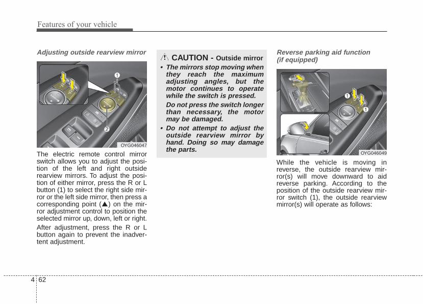
Features of your vehicle
624
Adjusting outside rearview mirror
The electric remote control mirrorswitch allows you to adjust the posi-tion of the left and right outsiderearview mirrors. To adjust the posi-tion of either mirror, press the R or Lbutton (1) to select the right side mir-ror or the left side mirror, then press acorresponding point ( ) on the mir-ror adjustment control to position theselected mirror up, down, left or right.After adjustment, press the R or Lbutton again to prevent the inadver-tent adjustment.
Reverse parking aid function (if equipped)
While the vehicle is moving inreverse, the outside rearview mir-ror(s) will move downward to aidreverse parking. According to theposition of the outside rearview mir-ror switch (1), the outside rearviewmirror(s) will operate as follows:
OYG046047
CAUTION - Outside mirror• The mirrors stop moving when
they reach the maximumadjusting angles, but themotor continues to operatewhile the switch is pressed.Do not press the switch longerthan necessary, the motormay be damaged.
• Do not attempt to adjust theoutside rearview mirror byhand. Doing so may damagethe parts.
OYG046049

4 63
Features of your vehicle
L/R : When the remote control outsiderearview mirror switch (1) isselected to the L (left) or R (right)position, both outside rearviewmirrors will move downward.
Neutral : When the remote controloutside rearview mirrorswitch is placed in the mid-dle, the outside rearviewmirrors will not operatewhile the vehicle is movingrearward.
The outside rearview mirrors will auto-matically revert to their original posi-tions under the following conditions:1. The Engine Start/Stop button is in
the OFF position.2. Shift lever is moved to any position
except R (Reverse).3. Remote control outside rearview
mirror switch is placed in the middle.
Folding the outside rearview mirror(if equipped)
Electric type
The outside rearview mirror can befolded or unfolded by pressing theswitch as below.Left (1) : The mirror will unfold.Right (2) : The mirror will fold.
Center (AUTO, 3) :The mirror will fold or unfold automat-ically as follows:• The mirror will fold or unfold when
the door is locked or unlocked bythe folding key or smart key.
• The mirror will fold or unfold whenthe door is locked or unlocked by thebutton on the outside door handle.
• The mirror will unfold when youapproach the vehicle (all doorsclosed and locked) with a smartkey in possession. (if equipped)
OYG046048L
CAUTION - Electric typeoutside rearview mirror
The electric type outside rearviewmirror operates even though theengine start/stop button is in theOFF position. However, to preventunnecessary battery discharge,do not adjust the mirrors longerthan necessary while the engineis not running.In case it is an electric type out-side rearview mirror, don’t fold itby hand. It could cause motor fail-ure.

Features of your vehicle
644
INSTRUMENT CLUSTER
1. Tachometer
2. Speedometer
3. Engine coolant temperature gauge
4. Fuel gauge
5. LCD display
6. Warning and indicator lights
OYG046100C/OYG046101C
■■ Type A
❈ The actual cluster in the vehicle may differfrom the illustration.For more details, refer to the “Gauges” inthis chapter.
■■ Type B

4 65
Features of your vehicle
Instrument Cluster ControlAdjusting Instrument ClusterIllumination
The brightness of the instrumentpanel illumination is changed bypressing the illumination control button(“+” or “-”) when the Engine Start/Stopbutton is ON, or the taillights areturned on.
• If you hold the illumination controlbutton (“+” or “-”), the brightnesswill be changed continuously.
• If the brightness reaches to themaximum or minimum level, analarm will sound.
LCD Display Control
The LCD display modes can bechanged by using the control buttonson the steering wheel.
OYG046102
OYG046157L OYG046103L
OYG046104L
■ Type A
■ Type B

Features of your vehicle
664
(1) : MODE button for changingmodes
(2) / /OK : SELECT scroll switchfor setting theselected item andRESET scroll switchfor resetting items
(3) : RETURN button for movingthe previous mode or item (if equipped)
❈ For the LCD modes, refer to “LCDDisplay” in this chapter.
GaugesSpeedometer
The speedometer indicates thespeed of the vehicle and is calibratedin kilometers per hour (km/h) and/ormiles per hour (mph).
Tachometer
The tachometer indicates theapproximate number of engine revo-lutions per minute (rpm).Use the tachometer to select the cor-rect shift points and to prevent lug-ging and/or over-revving the engine.
OYG046105C
OYG046106
CAUTION - Red zoneDo not operate the engine with-in the tachometer's RED ZONE.This may cause severe enginedamage.

4 67
Features of your vehicle
Engine Coolant TemperatureGauge
This gauge indicates the tempera-ture of the engine coolant when theEngine Start/Stop button is ON.
If the gauge pointer moves beyondthe normal range area toward the “H”position, it indicates overheating thatmay damage the engine.Do not continue driving with an over-heated engine. If your vehicle over-heats, refer to “If the EngineOverheats” in chapter 6.
Fuel Gauge
This gauge indicates the approxi-mate amount of fuel remaining in thefuel tank.
✽✽ NOTICE• The fuel tank capacity is given in
chapter 8.• The fuel gauge is supplemented by
a low fuel warning light which willilluminate when the fuel tank isnearly empty.
• On inclines or curves, the fuelgauge pointer may fluctuate or thelow fuel warning light may comeon earlier than usual due to themovement of fuel in the tank.
OYG046108
WARNING - Hot radiatorNever remove the radiator capwhen the engine is hot. Theengine coolant is under pres-sure and could cause severeburns. Wait until the engine iscool before adding coolant tothe reservoir.
OYG046168N

Features of your vehicle
684
✽✽ NOTICE - Fuel gaugeRunning out of fuel can expose vehi-cle occupants to danger. You musttop and obtain additional fuel assoon as possible after the warninglight comes on or when the gaugeindicator comes close to the “E(Empty)” level.
✽✽ NOTICEFuel display may not be accurate ifyou are filling in sloping places.
Odometer
The odometer Indicates the total dis-tance that the vehicle has been driv-en and should be used to determinewhen periodic maintenance shouldbe performed.- Odometer range : 0 ~ 1599999 kilo-
meters or 0 ~ 999999 miles.
Outside Temperature Gauge
This gauge indicates the current out-side air temperatures by 1°C (1°F).- Temperature range : -40°C ~ 85°C
(-40°F ~ 211°F)
CAUTION - Low fuelAvoid driving with an extremelylow fuel level. Running out offuel could cause the engine tomisfire damaging the catalyticconverter.
OYG046116
OYG046117
■ Type A
■ Type BOYG046118
OYG046119
■ Type A
■ Type B

4 69
Features of your vehicle
The outside temperature on the dis-play may not change immediatelylike a general thermometer to pre-vent the driver from being distracted.To change the temperature unit (from°C to °F or from °F to °C)The temperature unit can bechanged by using the “User Settings”mode of the LCD display.
❈ For more details, refer to “LCDDisplay” in this chapter.
Transaxle Shift IndicatorAutomatic Transaxle Shift Indicator
This indicator displays which auto-matic transaxle shift lever is selected.
• Park : P• Reverse : R• Neutral : N• Drive : D• Sports Mode : 1, 2, 3, 4, 5, 6, 7, 8
OYG046120
OYG046121
■ Type A
■ Type B

Features of your vehicle
704
Over view LCD windows show the following var-ious information to drivers.- Trip information- LCD modes- Warning messages
Trip information (Trip computer)The trip computer is a microcomput-er-controlled driver information sys-tem that displays information relatedto driving.
✽✽ NOTICESome driving information stored inthe trip computer (for exampleAverage Vehicle Speed) resets if thebattery is disconnected.
LCD WINDOWS (IF EQUIPPED)
OYG046162L
OYG046161L
■ Type A
■ Type B

4 71
Features of your vehicle
Trip Modes Fuel Economy
Distance To Empty (1)
• The distance to empty is the esti-mated distance the vehicle can bedriven with the remaining fuel.- Distance range : 1 ~ 9999km or 1
~ 9999mi.• If the estimated distance is below 1
km (1 mi) the trip computer will dis-play “---” as distance to empty.
✽✽ NOTICE• If the vehicle is not on level ground
or the battery power has beeninterrupted, the distance to emptyfunction may not operate correctly.
• The distance to empty may differfrom the actual driving distance asit is an estimate of the availabledriving distance.
• The trip computer may not regis-ter additional fuel if less than 6liters (1.6 gallons) of fuel areadded to the vehicle.
• The fuel economy and distance toempty may vary significantly basedon driving conditions, drivinghabits, and condition of the vehicle.
OYG046153C
• Tripmeter• Fuel Economy• Timer
Accumulated Info
• Tripmeter• Fuel Economy• Timer
Digital speedometer
Drive Info
• Average Fuel Economy• Instant Fuel Economy
TRIP
Smart Shift

Features of your vehicle
724
Average Fuel Economy (2)
• The average fuel economy is calcu-lated by the total driving distanceand fuel consumption since the lastaverage fuel economy reset.- Fuel economy range: 0.0 ~ 99.9
L/100km or MPG• The average fuel economy can be
reset both manually and automati-cally.
Manual resetTo clear the average fuel economymanually, press the OK button(reset) on the steering wheel formore than 1 second when the aver-age fuel economy is displayed.
Automatic resetTo make the average fuel economybe reset automatically wheneverrefueling, select the “Fuel economyauto reset” mode in User Settingmenu of the LCD window (Refer to“LCD window”).Under “Fuel economy auto reset”mode, the average fuel economy willbe cleared to zero (---) when the vehi-cle speed exceeds 1 km/h (1 mph)after refueling more than 6 liters (2gallons).
✽✽ NOTICEThe average fuel economy is not dis-played for more accurate calculationif the vehicle does not drive morethan 10 seconds or 50 meters (0.03miles) since Engine Start/Stop but-ton is turned to ON.
Instant Fuel Economy (3)
• This mode displays the instant fueleconomy during the last few sec-onds when the vehicle speed ismore than 8 km/h (4.9 mph).- Fuel economy range: 0 ~ 30
(km/L, L/100 km), 0 ~ 50 (MPG).
CAUTION - Low FuelLevel
Level warning light on or withthe fuel level below “E” cancause the engine to misfire anddamage the catalytic converter(if equipped).

4 73
Features of your vehicle
Accumulated driving informationmode
Displays accumulated informationstarting from mileage/fuelefficiency/time default point.• Accumulated information is calcu-
lated after the vehicle has run formore than 300 meters (0.19 mi).
• If you press “OK” button for morethan 1 second after the CumulativeInformation is displayed, the infor-mation will be reset.
• If the engine is running, even whenthe vehicle is not in motion, theinformation will be accumulated.
One time driving information mode
The vehicle will display DrivingInformation once per one ignition cycle.- Fuel efficiency is calculated after the
vehicle has run for more than 300meters (0.19 mi).
- The Driving Information will be reset4 hours after ignition has been turnedoff. So, when the vehicle ignition isturned on within 4 hours, the informa-tion will not be reset.
- If you press “OK” button for morethan 1 second after the DrivingInformation is displayed, the informa-tion will be reset.
- If the engine is running, even whenthe vehicle is not in motion, the infor-mation will be accumulated.
OYG046154C
OYG046155C

Features of your vehicle
744
Digital speedometer
This mode displays the currentspeed of the vehicle.
LCD Modes
(1) Trip Computer modeThis mode displays driving informa-tion like the tripmeter, fuel economy,and so on.
❈ For more details, refer to “TripComputer” in this chapter.
(2) Turn By Turn mode (if equipped)This mode displays the state of thenavigation.
(3) ASCC/LDWS (if equipped)This mode displays the state of theAdvanced Smart Cruise Control(ASCC) and Lane DepartureWarning System (LDWS).
(4) User Setting mode On this mode, you can change set-tings of the doors, lamps and so on.
(5) Master warning modeThis mode informs of warning mes-sages related to washer fluid or mal-function of Blind Spot Detection sys-tem (BSD) and so on.
❈ For controlling the LCD modes,refer to “LCD window Control” inthis chapter.
OYG046453LOYG048156

4 75
Features of your vehicle
Turn By Turn Mode (if equipped)
This mode displays the state of thenavigation.
ASCC/LDWS Mode (if equipped)
This mode displays the state of theAdvanced Smart Cruise Control(ASCC) and Lane DepartureWarning System (LDWS).
❈ For more information, refer to“Advanced Smart Cruise Control(ASCC)” and “Lane DepartureWarning System (LDWS)” in chap-ter 5.
OYG046123 OYG048124
OYG046169N
■ LDWS
■ ASCC

Features of your vehicle
764
Service Mode
Service in
It calculates and displays when youneed a scheduled maintenanceservice (mileage or days).If the remaining mileage or timereaches 1,500 km (900 mi) or 30days, “Service in” message is dis-played for several seconds each timeyou set the Engine Start/Stop Buttonto the ON position.
Service requiredIf you do not have your vehicle serv-iced according to the already inputtedservice interval, “Service required”message is displayed for several sec-onds each time you set the EngineStart/Stop Button to the ON position.To reset the service interval to themileage and days you inputted before:• Press the OK button (reset) for
more than 1 second.
✽✽ NOTICEIf any of the following conditionsoccurs, the mileage and days may beincorrect.- The battery cable is disconnected.- The fuse switch is turned off.- The battery is discharged.
OYG046164L
OYG046163L

4 77
Features of your vehicle
User Settings Mode
On this mode, you can change set-ting of the doors, lamps, and so on.
Head-Up Display (HUD) (if equipped)• Display Height : Adjust the height
of the HUD image on the wind-shield glass.
• Rotation : Adjust the degree of theHUD rotation.
• Brightness : Adjust the intensity ofthe HUD brightness
• Contents Select- Activate or deactivate each con-
tents of the HUD.- Turn by Turn*- Traffic Information*- Advanced Smart Cruise control*- Cruise control*- Blind Spot Detection** : if equipped
• Speedometer Size : Choose thesize of the HUD speedometer(Small, Medium, Large).
• Speedometer Color : Choose thecolor of the HUD speedometer(White, Orange, Green).
✽✽ NOTICEIf you select the Turn By Turn(TBT) navigation information asHUD contents, the Turn By Turn(TBT) navigation information willnot be displayed on the LCD.
OYG046129L
WARNINGDo not adjust the User Settingwhile driving.You may lose yoursteering control and causesevere personal injury or acci-dents.

Features of your vehicle
784
Driving Assist (if equipped)• Smart Cruise Control Response
(if equipped) : Choose the sensi-tivity of the smart cruise control.
❈For more details, refer to“Advanced Smart Cruise ControlSystem” in chapter 5.
• AEB (Autonomous EmergencyBraking) (if equipped) : To acti-vate or deactivate the AEB system.
❈For more details, refer to“Autonomous Emergency Braking(AEB)” in chapter 5.
• FCW (Forward Collision Warning)(if equipped) : Choose the sensitiv-ity of the FCW.
❈For more details, refer to“Autonomous Emergency Braking(AEB)” in chapter 5.
• LCA (Lane change assist) (ifequipped) : To adjust the initialwarning alert time for the LaneChange Assist.
❈For more information, refer to “BlindSpot Detection System” in chapter5.
• Rear Cross Traffic Alert (ifequipped) : If this item is checked,the rear cross traffic alert functionwill be activated.
❈For more details, refer to “Blind SpotDetection System” in chapter 5.
• BSD (Blind Spot Detection)Sound (if equipped) : If this itemchecked, the blind spot detectionsound will be activated.
❈For more details, refer to “Blind SpotDetection System” in chapter 5.
Door• Automatically Lock- Enable on Speed : All doors will be
automatically locked when thevehicle speed exceeds 15 km/h(9.3 mph).
- Enable on Shift : All doors will beautomatically locked if thetransaxle shift lever is shifted fromthe P (Park) position to the R(Reverse), N (Neutral), or D (Drive)position.
• Automatically Unlock- Off : The auto door unlock opera-
tion will be canceled.- Vehicle Off/On key out : All doors
will be automatically unlockedwhen the Engine Star/Stop buttonis set to the OFF position.
- On Shift to P : All doors will beautomatically unlocked if thetransaxle shift lever is shifted to theP (Park) position.

4 79
Features of your vehicle
• Two Press Unlock (if equipped)- Off : The two press unlock function
will be deactivated. Therefore, alldoors will unlock upon one press ofthe button.
- On : Only the driver's door willunlock when unlock button ispressed once and all doors willunlock when the same button ispressed again within 4 seconds.
• Door Lock Sound (if equipped) :If this item checked, the door locksound function will be activatedwhen locking doors.
• Smart Trunk (if equipped) : Toactivate or deactivate the SmartTrunk system.
❈For more details, refer to “SmartTrunk” in this chapter.
Lights• One Touch Turn Signal- Off : The one touch turn lamp func-
tion will be deactivated.- 3, 5, 7 Flashing : The lane change
signals will blink 3, 5, or 7 timeswhen the turn signal lever ismoved slightly.
❈For more details, refer to “Lighting”in this chapter.
• Headlamp escort (if equipped) :If this item checked, the headlampescort function will be activated.
• Welcome Light (if equipped) : Ifthis item checked, the welcomelight function will be activated.
Sound• Park Assist System Vol. (if
equipped) : Adjust the Park AssistSystem volume. (Level 1~3)
❈For more details, refer to “ParkingAssist System” in this chapter.
• Cluster voice guide Vol. (ifequipped) : Adjust the clustervoice guide volume. (Level 0~3)
• Welcome Sound (if equipped) : Ifthis item checked, the welcomesound function will be activated.

Features of your vehicle
804
Convenience• Seat Easy Access (if equipped)- None : The seat easy access func-
tion will be deactivated.- Normal/Enhanced : When you turn
off the engine, the driver’s seat willautomatically move rear 7.6 cm (3inches) (Enhanced) for you toenter or exit the vehicle more com-fortably.If you change the EngineStart/Stop Button from OFF posi-tion to the AC function, the driver’sseat will return to the original posi-tion.
❈For more details, refer to “DriverPosition Memory System” in chap-ter 3.
• Steering Easy Access (if equipped)
- On (checked) : The steering wheelwill automatically move forward orrearward for the driver enter or exitthe vehicle comfortably.
- Off (unchecked) : The steeringeasy access function will be deac-tivated.
❈For more details, refer to “DriverPosition Memory System” in chap-ter 3.
• Wireless smart phone chargingsystem (if equipped) : If this itemchecked, the Wireless smartphone charging system will be acti-vated.
• Wiper/Light Display (if equipped) :If this item checked, the Wiper/LightDisplay will be activated.
• Gear position pop up (ifequipped) : To activate or deacti-vate the gear position pop-up.When activated, the gear positionwill be displayed on the LCD dis-play.
Service interval• Service IntervalTo activate or deactivate the serviceinterval function.
• Adjust IntervalTo adjust the interval by mileage andperiod.
• ResetTo reset the service interval functionOther Features
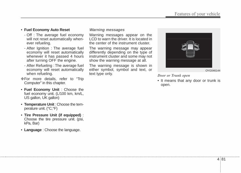
4 81
Features of your vehicle
• Fuel Economy Auto Reset- Off : The average fuel economy
will not reset automatically when-ever refueling.
- After Ignition : The average fueleconomy will reset automaticallywhenever it has passed 4 hoursafter turning OFF the engine.
- After Refueling : The average fueleconomy will reset automaticallywhen refueling.
❈For more details, refer to “TripComputer” in this chapter.
• Fuel Economy Unit : Choose thefuel economy unit. (L/100 km, km/L,US gallon, UK gallon)
• Temperature Unit : Choose the tem-perature unit. (°C,°F)
• Tire Pressure Unit (if equipped) :Choose the tire pressure unit. (psi,kPa, Bar)
• Language : Choose the language.
Warning messagesWarning messages appear on theLCD to warn the driver. It is located inthe center of the instrument cluster.The warning message may appeardifferently depending on the type ofinstrument cluster and some may notshow the warning message at all.The warning message is shown ineither symbol, symbol and text, ortext type only. Door or Trunk open
• It means that any door or trunk isopen.
OYG046144

Features of your vehicle
824
Sunroof Open (if equipped)• This warning is displayed if you
turn off the engine when the sun-roof is open.
Engine has overheatedThis warning message illuminateswhen the engine coolant tempera-ture is above 120°C (248°F).This means that the engine is over-heated and may be damaged.If your vehicle is overheated, refer to“Overheating” in chapter 6.
Turn on FUSE SWITCH (if equipped)• This warning message illuminates
if the fuse switch under the steer-ing wheel is OFF.
• It means that you should turn thefuse switch on.
❈For more details, refer to “Fuses” inchapter 7.
Shift to P (for smart key system)• This warning message illuminates if
you try to turn off the engine withoutthe shift lever in P (Park) position.If the driver’s door is opened withthe Engine Start/Stop Button in theACC or ON position and shift leveris not in P(Park) position, the mes-sage above will appear.
• At this time, the Engine Start/StopButton turns to the ACC position (Ifyou press the Engine Start/StopButton once more, it will turn to theON position).
OYG046166L
■ Type BOYG046165L
■ Type A
OYG046145

4 83
Features of your vehicle
Low Key Battery (for smart key system)• This warning message illuminates
if the battery of the smart key isdischarged when the EngineStart/Stop Button changes to theOFF position.
Press START button while turningwheel (for smart key system)• This warning message illuminates
if the steering wheel does notunlock normally when the EngineStart/Stop Button is pressed.
• It means that you should press theEngine Start/Stop Button whileturning the steering wheel rightand left.
Press brake pedal to start engine (for smart key system)• This warning message illuminates
if the Engine Start/Stop Buttonchanges to the ACC position twiceby pressing the button repeatedlywithout depressing the brake pedal.
• It means that you should depressthe brake pedal to start the engine.
Key not in vehicle (for smart key system)• This warning message illuminates
if the smart key is not in the vehiclewhen you press the EngineStart/Stop Button.
• It means that you should alwayshave the smart key with you.
Key not detected (for smart key system)• This warning message illuminates
if the smart key is not detectedwhen you press the EngineStart/Stop Button.
Vehicle is On(for smart key system)• If the driver’s door is opened with
the engine start/stop button in theON position and shift lever inP(Park) position, the messageabove will appear.

Features of your vehicle
844
Press START button again (for smart key system)• This warning message illuminates
if you can not operate the EngineStart/Stop Button when there is aproblem with the Engine Start/StopButton system.
• It means that you could start theengine by pressing the EngineStart/ Stop Button once more.
• If the warning illuminates eachtime you press the EngineStart/Stop Button, we recommendthat you have the vehicle inspectedby an authorized Kia dealer.
Press START button with key (for smart key system)• This warning message illuminates
if you press the Engine Start/StopButton while the warning message“Key not detected” is illuminating.
• At this time, the immobilizer indica-tor light blinks.
Check BRAKE SWITCH fuse (for smart key system)• This warning message illuminates
if the brake switch fuse is discon-nected.
• It means that you should replacethe fuse with a new one. If that isnot possible, you can start theengine by pressing the EngineStart/Stop Button for 10 seconds inthe ACC position.
Shift to P or N to start engine (for smart key system)• This warning message illuminates
if you try to start the engine withthe shift lever not in the P (Park) orN (Neutral) position.
✽✽ NOTICEYou can start the engine with theshift lever in the N (Neutral) position.But, for your safety, we recommendthat you start the engine with theshift lever in the P (Park) position.

4 85
Features of your vehicle
Low Washer Fluid (if equipped)• This warning message illuminates
on the service reminder mode ifthe washer fluid level in the reser-voir is nearly empty.
• It means that you should refill thewasher fluid.
Low Fuel• This warning message illuminates
if the fuel tank is nearly empty.- When the low fuel level warning
light is illuminates.Add fuel as soon as possible.
Device in wireless charger (if equipped)Warning messages will illuminatewhen the vehicle ignition is in OFFand the smart phone is on the wire-less charging pad in below two situa-tions.1. When the driver or passenger
door is opened2. When one minute passed after the
ignition has been turned OFF (andthe door has not been opened formore than one minute)
❈For more details, refer to “SmartPhone Wireless Charger” in thischapter.
Check headlamp LED (if equipped) This warning message illuminates ifthe headlamp does not turned onnormally when you turn the headlamp on. In this case, have your vehi-cle inspected by an authorized Kiadealer.

Features of your vehicle
864
Warning lights
✽✽ NOTICE - Warning lightsMake sure that all warning lightsare OFF after starting the engine. Ifany light is still ON, this indicates asituation that needs attention.
Air bag Warning Light
This warning light illuminates:
• Once you set the EngineStart/Stop Button to the ON posi-tion.- It illuminates for approximately 6
seconds and then goes off.• When there is a malfunction with
the SRS.In this case, have your vehicleinspected by an authorized Kiadealer.
Seat Belt Warning Light
This warning light informs the driverthat the seat belt is not fastened.
❈ For more details, refer to the “SeatBelts” in chapter 3.
WARNING AND INDICATOR LIGHTS

4 87
Features of your vehicle
Parking Brake & BrakeFluid Warning Light
This warning light illuminates:
• Once you set the EngineStart/Stop Button to the ON posi-tion.- It illuminates for approximately 3
seconds- It remains on if the parking brake
is applied.• When the parking brake is applied.• When the brake fluid level in the
reservoir is low.- If the warning light illuminates
with the parking brake released, itindicates the brake fluid level inreservoir is low.
If the brake fluid level in the reservoiris low:
1. Drive carefully to the nearest safelocation and stop your vehicle.
2. With the engine stopped, check thebrake fluid level immediately and addfluid as required (For more details,refer to “Brake Fluid” in chapter 7).Then check all brake componentsfor fluid leaks. If any leaks in thebrake system are still found, thewarning light remains on, or thebrakes do not operate properly, donot drive the vehicle.In this case, have your vehicletowed to an authorized Kia dealerand inspected.
Dual-diagonal braking system
Your vehicle is equipped with dual-diagonal braking systems. Thismeans you still have braking on twowheels even if one of the dual sys-tems should fail.With only one of the dual systemsworking, more than normal pedaltravel and greater pedal pressure arerequired to stop the vehicle.Also, the vehicle will not stop in asshort a distance with only a portionof the brake system working.If the brakes fail while you are driv-ing, shift to a lower gear for addition-al engine braking and stop the vehi-cle as soon as it is safe to do so.Driving the vehicle with a warninglight ON is dangerous. If the ParkingBrake & Brake Fluid Warning Lightilluminate with the parking brakereleased, it indicates that the brakefluid level is low.In this case, have your vehicle inspect-ed by an authorized Kia dealer.

Features of your vehicle
884
Anti-lock Brake System(ABS) Warning Light
This warning light illuminates:
• Once you set the EngineStart/Stop Button to the ON posi-tion.- It illuminates for approximately 3
seconds and then goes off.• When there is a malfunction with
the ABS (The normal braking sys-tem will still be operational withoutthe assistance of the anti-lockbrake system).In this case, have your vehicleinspected by an authorized Kiadealer.
ElectronicBrake forceDistribution(EBD) SystemWarning LightThese two warning lights illuminate atthe same time while driving:
• When the ABS and regular brakesystem may not work normally.In this case, have your vehicleinspected by an authorized Kiadealer.
✽✽ NOTICE - Electronic Brakeforce Distribution (EBD)System Warning Light
When the ABS Warning Light is onor both ABS and Parking Brake &Brake Fluid Warning Lights are on,the speedometer, odometer, or trip-meter may not work. Also, the EPSWarning Light may illuminate andthe steering effort may increase ordecrease.In this case, have your vehicle inspect-ed by an authorized Kia dealer assoon as possible.
WARNING - ElectronicBrake force Distribution(EBD) System Warning Light
When both ABS and ParkingBrake & Brake Fluid WarningLights are on, the brake systemwill not work normally and youmay experience an unexpectedand dangerous situation duringsudden braking therebyincreasing the risk of a crashand injury. In this case, avoidhigh speed driving and abruptbraking. Have your vehicleinspected by an authorized Kiadealer as soon as possible.

4 89
Features of your vehicle
Electronic PowerSteering (EPS) WarningLight This warning light illuminates:
• Once you set the EngineStart/Stop Button to the ON posi-tion.- It remains on until the engine is
started.• When there is a malfunction with
the EPS.In this case, have your vehicleinspected by an authorized Kiadealer.
Malfunction IndicatorLamp (MIL)
This warning light illuminates:
• Once you set the EngineStart/Stop Button to the ON posi-tion.- It remains on until the engine is
started.• When there is a malfunction with
the emission control system.In this case, have your vehicleinspected by an authorized Kiadealer.
CAUTION - CatalyticConverter Damage
If the Malfunction IndicatorLamp (MIL) illuminates, poten-tial catalytic converter damageis possible which could result inloss of engine power.In this case, have your vehicleinspected by an authorized Kiadealer as soon as possible.
CAUTION - MalfunctionIndicator Lamp (MIL)
Driving with the MalfunctionIndicator Lamp (MIL) on maycause damage to the emissioncontrol systems which couldaffect drivability and/or fueleconomy.

Features of your vehicle
904
Charging SystemWarning Light
This warning light illuminates:
• Once you set the EngineStart/Stop Button to the ON posi-tion.- It remains on until the engine is
started.• When there is a malfunction with
either the alternator or electricalcharging system.
If there is a malfunction with eitherthe alternator or electrical chargingsystem:
1. Drive carefully to the nearest safelocation and stop your vehicle.
2. Turn the engine off and check thealternator drive belt for loosenessor breakage.If the belt is adjusted properly,there may be a problem in theelectrical charging system.In this case, have your vehicleinspected by an authorized Kiadealer as soon as possible.
Engine Oil PressureWarning Light
This warning light illuminates:
• Once you set the EngineStart/Stop Button to the ON posi-tion.- It remains on until the engine is
started.• When the engine oil pressure is low.
If the engine oil pressure is low:
1. Drive carefully to the nearest safelocation and stop your vehicle.
2. Turn the engine off and check theengine oil level (For more details,refer to “Engine Oil” in chapter 7). Ifthe level is low, add oil as required.If the warning light remains onafter adding oil or if oil is not avail-able, have your vehicle inspectedby an authorized Kia dealer assoon as possible.
CAUTION - EngineOverheating
Do not continue driving with theengine overheated. Otherwiseengine may be damaged.
CAUTION - Engine damage
If the engine is not stoppedimmediately after the engine oilpressure warning light is illumi-nated and stays on while theengine is running, seriousengine damage may result.

4 91
Features of your vehicle
If the warning light stays on while theengine is running, it indicates thatthere may be serious engine dam-age or malfunction. In this case,1. Stop the vehicle as soon as it is
safe to do so.2. Turn off the engine and check the
oil level. If the oil level is low, fill theengine oil to the proper level.
3. Start the engine again. If the warn-ing light stays on after the engineis started, turn the engine offimmediately. In this case, haveyour vehicle inspected by anauthorized Kia dealer.
Low Tire PressureWarning Light
This warning light illuminates:
• Once you set the EngineStart/Stop Button to the ON posi-tion.- It illuminates for approximately 3
seconds and then goes off.• When one or more of your tires are
significantly underinflated.
❈For more details, refer to “TirePressure Monitoring System(TPMS)” in chapter 6.
This warning light remains on afterblinking for approximately 60 secondsor repeats blinking and off at theintervals of approximately 3 seconds:
• When there is a malfunction withthe TPMS.In this case, have your vehicleinspected by an authorized Kiadealer as soon as possible.
❈For more details, refer to “TirePressure Monitoring System(TPMS)” in chapter 6.
• The TPMS cannot alert you tosevere and sudden tire damagecaused by external factors.
• If you notice any vehicle instability,immediately take your foot off theaccelerator pedal, apply the brakesgradually with light force, and slow-ly move to a safe position off theroad.
WARNING - Low tire pressure
• Significantly low tire pressuremakes the vehicle unstableand can contribute to loss ofvehicle control and increasedbraking distances.
• Continued driving or low pres-sure tires will cause the tires tooverheat and fail.

Features of your vehicle
924
Electronic Parking Brake(EPB) Warning Light(if equipped)
This warning light illuminates:
• Once you set the EngineStart/Stop Button to the ON posi-tion.- It illuminates for approximately 3
seconds and then goes off.• When there is a malfunction with
the EPB.In this case, have your vehicleinspected by an authorized Kiadealer.
✽✽ NOTICE - Electronic ParkingBrake (EPB) Warning Light
The Electronic Parking Brake(EPB) Warning Light may illumi-nate when the Electronic Stabilitycontrol (ESC) Indicator Light comeson to indicate that the ESC is notworking properly (This does notindicate malfunction of the EPB).
Master Warning light (if equipped)
• This warning light informs the driverof the following situations- Blind Spot Detection fail- Advanced Smart Cruise Control fail - Blind Spot Detection automatic can-
celation - Advanced Smart Cruise Control
radar fail - Lamp wire disconnection and so on
The Master Warning Light illumi-nates when more than one of theabove warning situations occur. Atthis time, the LCD Modes Icon willchange from ( ) to ( ).If the warning situation is solved, themaster warning light will be turned offand the LCD Modes Icon will bechanged back to its previous icon ( ).
Autonomous EmergencyBraking (AEB) Warninglight (if equipped)
This indicator light illuminates:
• When there is a malfunction withthe AEB.
In this case, have the vehicle inspect-ed by an authorized Kia dealer.
EPB
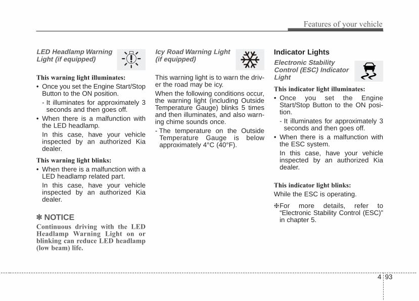
4 93
Features of your vehicle
LED Headlamp WarningLight (if equipped)
This warning light illuminates:
• Once you set the Engine Start/StopButton to the ON position.- It illuminates for approximately 3
seconds and then goes off.• When there is a malfunction with
the LED headlamp.In this case, have your vehicleinspected by an authorized Kiadealer.
This warning light blinks:
• When there is a malfunction with aLED headlamp related part.In this case, have your vehicleinspected by an authorized Kiadealer.
✽✽ NOTICEContinuous driving with the LEDHeadlamp Warning Light on orblinking can reduce LED headlamp(low beam) life.
Icy Road Warning Light (if equipped)
This warning light is to warn the driv-er the road may be icy.When the following conditions occur,the warning light (including OutsideTemperature Gauge) blinks 5 timesand then illuminates, and also warn-ing chime sounds once.- The temperature on the Outside
Temperature Gauge is belowapproximately 4°C (40°F).
Indicator LightsElectronic StabilityControl (ESC) IndicatorLight
This indicator light illuminates:
• Once you set the EngineStart/Stop Button to the ON posi-tion.- It illuminates for approximately 3
seconds and then goes off.• When there is a malfunction with
the ESC system.In this case, have your vehicleinspected by an authorized Kiadealer.
This indicator light blinks:
While the ESC is operating.
❈For more details, refer to“Electronic Stability Control (ESC)”in chapter 5.
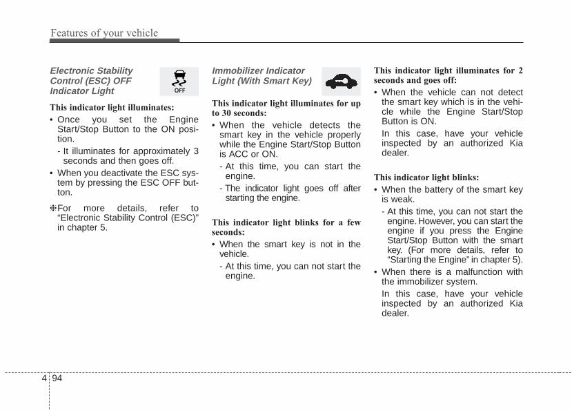
Features of your vehicle
944
Electronic StabilityControl (ESC) OFFIndicator Light
This indicator light illuminates:
• Once you set the EngineStart/Stop Button to the ON posi-tion.- It illuminates for approximately 3
seconds and then goes off.• When you deactivate the ESC sys-
tem by pressing the ESC OFF but-ton.
❈For more details, refer to“Electronic Stability Control (ESC)”in chapter 5.
Immobilizer IndicatorLight (With Smart Key)
This indicator light illuminates for upto 30 seconds:
• When the vehicle detects thesmart key in the vehicle properlywhile the Engine Start/Stop Buttonis ACC or ON.- At this time, you can start the
engine.- The indicator light goes off after
starting the engine.
This indicator light blinks for a fewseconds:
• When the smart key is not in thevehicle.- At this time, you can not start the
engine.
This indicator light illuminates for 2seconds and goes off:
• When the vehicle can not detectthe smart key which is in the vehi-cle while the Engine Start/StopButton is ON.In this case, have your vehicleinspected by an authorized Kiadealer.
This indicator light blinks:
• When the battery of the smart keyis weak.- At this time, you can not start the
engine. However, you can start theengine if you press the EngineStart/Stop Button with the smartkey. (For more details, refer to“Starting the Engine” in chapter 5).
• When there is a malfunction withthe immobilizer system.In this case, have your vehicleinspected by an authorized Kiadealer.

4 95
Features of your vehicle
Turn Signal IndicatorLight
This indicator light blinks:
• When you turn the turn signal lighton.
If any of the following occurs, theremay be a malfunction with the turnsignal system. In this case, have yourvehicle inspected by an authorizedKia dealer.
- The indicator light does not blinkbut illuminates.
- The indicator light blinks morerapidly.
- The indicator light does not illumi-nate at all.
High Beam IndicatorLight
This indicator light illuminates:
• When the headlights are on and inthe high beam position
• When the turn signal lever is pulledinto the Flash-to-Pass position.
High beam assist indica-tor (if equipped)
This warning light illuminates :
• When the high-Beam is on with thelight switch in the AUTO light posi-tion.
• If your vehicle detects oncoming orpreceding vehicles, the High beamassist system will switch the highbeam to low beam automatically.
❈For more details, refer to “Highbeam assist” in this chapter.
Light ON Indicator Light
This indicator light illuminates:
• When the tail lights or headlightsare on.
Front Fog IndicatorLight
This indicator light illuminates:
• When the front fog lights are on.

Features of your vehicle
964
CruiseIndicator Light (if equipped)
This indicator light illuminates:
• When the cruise control system isenabled.
❈For more details, refer to “CruiseControl System” in chapter 5.
AUTO HOLD IndicatorLight (if equipped)
This indicator light illuminates:
• [White] When you activate the autohold system by pressing the AUTOHOLD button.
• [Green] When you stop the vehiclecompletely by depressing thebrake pedal with the auto hold sys-tem activated.
• [Yellow] When there is a malfunc-tion with the auto hold system.In this case, have your vehicleinspected by an authorized Kiadealer.
❈For more details, refer to “AutoHold” in chapter 5.
Lane Departure WarningSystem (LDWS) IndicatorLight (if equipped)
This indicator light illuminates:
• [White] When the lane departurewarning system does not detectthe lane line.
• [Green] When you activate the lanedeparture warning system bypressing the LDWS button.
• [Yellow] When there is a malfunc-tion with the lane departure warn-ing system.
In this case, have your vehicle inspect-ed by an authorized Kia dealer.
❈For more details, refer to “LaneDeparture Warning System(LDWS)” in chapter 5.
AUTOHOLDCRUISE

4 97
Features of your vehicle
ECO Indicator Light(if equipped)
This indicator light illuminates :
• When the Active ECO system isactivated by pressing the DRIVEmode button.
• The ECO indicator (green) will illu-minate to show that the ActiveECO is operating.
❈For more details, refer to “DriveMode Integrated Control System"in chapter 5.
SPORT Mode IndicatorLight (if equipped)
This indicator light illuminates:
• When you select “SPORT” modeas drive mode.
❈For more details, refer to “DriveMode” in chapter 5.
WARNING - Distracteddriving
Driving while distracted canresult in a loss of vehicle con-trol that may lead to an acci-dent, severe personal injury,and death. The driver’s primaryresponsibility is in the safe andlegal operation of a vehicle, anduse of any handheld devices,other equipment, or vehicle sys-tems which take the driver’seyes, attention and focus awayfrom the safe operation of avehicle or which are not permis-sible by law should never beused during operation of thevehicle.

Features of your vehicle
984
Description
The head up display is a transparentdisplay which projects a shadow ofsome information of the instrumentcluster and navigation on the wind-shield glass.
• The head up display image on thewindshield glass may be invisiblewhen:- Sitting posture is bad.- Wearing a polarized sunglasses.- There is an object on the cover of
the head up display.- Driving on a wet road.- An inadequate lighting is turned
on inside the vehicle.- Any light comes from the outside.- Wearing an inadequate glasses
to your eyesight.• If the head up display image is not
shown well, adjust the height, rota-tion or illumination of the head updisplay in the LCD window.
❈ For more details, refer to “LCDwindow” in this chapter.
• When the head up display needsinspection or repair, we recom-mend that you consult an author-ized Kia dealer.
• Do not place any accessories onthe clash pad or attach any objectson the windshield glass.
✽✽ NOTICEInstalling window tint or any othertype of metallic coating on the wind-shield can prevent the driver fromseeing the Head Up Display images.
✽✽ NOTICEWhen replacing the front wind-shield glass of the vehicles equippedwith the head up display, replace itwith a windshield glass designed forthe head up display operation.Otherwise, duplicated images maybe displayed on the windshield glass.
HEAD UP DISPLAY (HUD) (IF EQUIPPED)
OYG046430
WARNING - Head up display
The Head up display is a supple-mental system. Do not solelyrely on the system, always drivesafely, and pay attention to thedriving conditions on the road.

4 99
Features of your vehicle
Head Up Display ON/OFF
The HUD display will be activated ordeactivated in user setting modewhile engine is ON.
Head Up Display Information
1. Turn By Turn navigation information2. Road signs3. Speedometer4. Cruise setting speed5. Advanced Smart Cruise
Control(ASCC) information6. Blind Spot Detection (BSD) sys-
tem information7. Warning lights (Low fuel, BSD)8. AV mode information
Head Up Display SettingOn the LCD display, you can changethe head up display settings as fol-lows.1. Display height2. Rotation3. Brightness4. Content select 5. Speedometer size6. Speedometer color
❈ For more details, refer to “LCDwindow” in this chapter.
OYG046113L OYG046158L

Features of your vehicle
1004
The rear parking assist systemassists the driver during backwardmovement of the vehicle by chiming ifany object is sensed within a distanceof 120 cm (47 in.) behind the vehicle.This system is a supplemental systemand it is not intended to nor does itreplace the need for extreme care andattention of the driver. The sensingrange and objects detectable by theback sensors (➀) are limited.Whenever backing-up, pay as muchattention to what is behind you as youwould in a vehicle without a rear park-ing assist system.
Operation of the rear parkingassist systemOperating condition• This system will activate when the
indicator on the rear parking assistOFF button is not illuminated. Ifyou desire to deactivate the rearparking assist system, press therear parking assist OFF buttonagain. (The indicator on the buttonwill illuminate.) To turn the systemon, press the button again. (Theindicator on the button will go off.)If the vehicle is moving at a speedover 5 km/h (3 mph), the systemmay not be activated correctly.
REAR PARKING ASSIST SYSTEM (IF EQUIPPED)
WARNING - Rear parkingassist system
Never rely solely on the rearparking assist system. Alwaysperform a visual inspection tomake sure the vehicle is clear ofall obstructions before movingthe vehicle in any direction. Stopimmediately if you are aware ofa child anywhere near your vehi-cle. Some objects may not bedetected by the sensors, due tothe object's size or material.
OYG046400N

4 101
Features of your vehicle
• This system will activate whenbacking up with the ignition switchON.If the vehicle is moving at a speedover 5 km/h (3 mph), the systemmay not be activated correctly.
• The sensing distance while theback-up warning system is in oper-ation is approximately 120 cm (47in.) at the rear bumper center area,60 cm (23.5 in.) at the rear bumperboth side area.
• When more than two objects aresensed at the same time, the clos-est one will be recognized first.
Types of warning sound• When an object is 120 cm to 61 cm
(47 in. to 24 in.) from the rearbumper: Buzzer beeps intermit-tently.
• When an object is 60 cm to 31 cm(24 in. to 12 in.) from the rearbumper: Buzzer beeps more fre-quently.
• When an object is within 40 cm (16in.) of the rear bumper:Buzzer sounds continuously.
Non-operational conditions ofrear parking assist systemThe rear parking assist systemmay not operate properly when:1. Moisture is frozen to the sensor. (It
will operate normally once themoisture clears.
2. The sensor is covered with foreignmatter, such as snow or water, orthe sensor cover is blocked. (It willoperate normally when the materi-al is removed or the sensor is nolonger blocked.)
3. Driving on uneven road surfaces(unpaved roads, gravel, bumps,gradient).
4. Objects generating excessivenoise (vehicle horns, loud motor-cycle engines, or truck air brakes)are within range of the sensor.
5. Heavy rain or water spray exists.6. Wireless transmitters or mobile
phones are within range of thesensor.
7. The sensor is covered with snow.8. Trailer towing

Features of your vehicle
1024
The detecting range may decreasewhen:1. The sensor is covered with foreign
matter such as snow or water.(The sensing range will return tonormal when removed.)
2. Outside air temperature isextremely hot or cold.
The following objects may not berecognized by the sensor:1. Sharp or slim objects such as
ropes, chains or small poles.2. Objects which tend to absorb the
sensor frequency such as clothes,sound absorbent material or snow.
3. Undetectable objects smaller than1 m (40 in.) in height and narrowerthan 14 cm (6 in.) in diameter.
Rear parking assist systemprecautions• The rear parking assist system
may not sound consistentlydepending on the speed andshapes of the objects detected.
• The rear parking assist system maymalfunction if the vehicle bumperheight or sensor installation hasbeen modified or damaged. Anynon-factory installed equipment oraccessories may also interfere withthe sensor performance.
• The sensor may not recognizeobjects less than 40 cm (15 in.)from the sensor, or it may sense anincorrect distance. Use caution.
• When the sensor is frozen or cov-ered with snow, dirt, or water, thesensor may be inoperative until thematerial is removed using a softcloth.
• To prevent damage, do not push,scratch or strike the sensor.
✽✽ NOTICEThis system can only sense objectswithin the range and location of thesensors. It cannot detect objects inother areas where sensors are notinstalled. Also, small or slim objects,such as poles or objects locatedbetween sensors may not be detectedby the sensors.Always visually check behind thevehicle when backing up.Be sure to inform any drivers of thevehicle that may be unfamiliar withthe system regarding the systemscapabilities and limitations.

4 103
Features of your vehicle
Self-diagnosisIf you don’t hear an audible warningsound or if the buzzer sounds inter-mittently when shifting the gear to theR (Reverse) position, this may indi-cate a malfunction in the rear parkingassist system. If this occurs, haveyour vehicle checked by an author-ized Kia dealer as soon as possible.
✽✽ NOTICEYour new vehicle warranty does notcover any accidents or damage tothe vehicle or injuries to its occu-pants due to a rear parking assistsystem malfunction. Always drivesafely and cautiously.

Features of your vehicle
1044
The rearview camera will activatewith the ignition switch ON and theshift lever in the R (Reverse) position.
This system is a supplemental sys-tem that shows behind the vehiclethrough the audio screen while back-ing up unless equipped with a navi-gation system, then will display onthe navigation screen.• This system is a supplementary
function only. It is the responsibilityof the driver to always check theinside/outside rearview mirrors andthe area behind the vehicle beforeand while backing up becausethere is a dead zone that can't beseen by the camera.
• Always keep the camera lensclean. If lens is covered with for-eign matter, the camera may notoperate normally.
❈ If your vehicle is equipped withAVN (Audio, Video and Navigation)system, rearview display will showbehind the vehicle through theAVN monitor while backing-up.Refer to a separately suppliedmanual for detailed information.
REARVIEW CAMERA
WARNING - Backing &using camera
Never rely solely on the rear viewcamera when backing. You mustalways use methods of viewingthe area behind you includinglooking over both shoulders aswell as continuously checking allthree rear view mirrors. Due tothe difficulty of ensuring that thearea behind you remains clear,always back slowly and stopimmediately if you even suspectthat a person, and especially achild, might be behind you.
OYG046403
OYG046404L

4 105
Features of your vehicle
The 360° camera monitoring systemis not a substitute for proper and safeparking procedures. The 360° cam-era monitoring system may notdetect every object surrounding thevehicle. Always drive safely and usecaution when parking.The 360° camera monitoring systemcan assist in parking by allowing thedriver to see around the vehicle.Push the button into the [ON] posi-tion to operate the system.To cancel the system, push the but-ton again.
Operating conditions- When the Engine Start/Stop
Button is ON position- When the transaxle is on D, N or R- When the vehicle speed is not over
15 km/h (9.32 mph) • When the vehicle speed is over 15
km/h (9.32 mph), the 360° cameramonitoring system is turned off. Ifthe vehicle speed is not over 9.32mph (15 km/h) after turning off the360° camera monitoring system byover speed, the 360° camera mon-itoring system is not turned on. Tooperate again, push the button.
• When the vehicle moves back-wards, regardless of On/Off of but-ton and vehicle speed, the 360°camera monitoring system is oper-ated.
• When the trunk and driver/passen-ger door are opened and the out-side mirror is folded, the warning isilluminated in the 360° cameramonitoring system.
• If the 360° camera monitoring sys-tem is not operating normally, thesystem should be checked by anauthorized Kia dealer.
• When the vehicle moves over 15km/h (9.32 mph) forward after mov-ing backward, the 360° cameramonitoring system screen will beturned off.
360° CAMERA MONITORING SYSTEM (IF EQUIPPED)
OYG046405WARNING
This system is a supplementaryfunction only. It is the responsi-bility of the driver to alwayscheck the area around the vehi-cle before and while moving.

Features of your vehicle
1064
Battery saver function• The purpose of this feature is to
prevent the battery from being dis-charged if the lights are left in theON position. The system automati-cally shuts off the parking lights 30seconds after the ignition key isremoved and the driver’s door isopened and closed.
• With this feature, the parking lightswill turn off automatically if the driverparks on the side of the road at nightand opens the driver’s side door.If necessary, to keep the parkinglights on when the ignition key isremoved, perform the following:1) Open the driver-side door.2) Turn the parking lights OFF and
ON again using the light switchon the steering column.
Daytime running light (if equipped)The Daytime Running Lights (DRL)can make it easier for others to seethe front of your vehicle during theday. DRL can be helpful in many dif-ferent driving conditions, and it isespecially helpful after dawn andbefore sunset.The DRL system turns OFF when:1. The headlight switch is ON.2. The engine is OFF.3. The front fog light is ON.4. Engaging the Parking Brake
Lighting control
The light switch has a Headlight anda Parking light position.To operate the lights, turn the knob atthe end of the control lever to one ofthe following positions:(1) OFF position(2) Auto light position(3) Parking & Tail light(4) Headlight position
LIGHTING
OUM044053

4 107
Features of your vehicle
Parking & Tail light ( )
When the light switch is in the park-ing light position, the tail, license andinstrument panel lights will turn ON.
Headlight position ( )
When the light switch is in the head-light position, the head, tail, licenselights will turn ON.
✽✽ NOTICEThe ignition switch must be in the ONposition to turn on the headlights.
Auto light position
When the light switch is in the AUTOlight position, the taillights and head-lights will turn ON or OFF automati-cally depending on the amount oflight outside the vehicle.When the light switch is positioned atan auto light position, at first, thewiper will turn on and then, after 5seconds the head lamp will turn onautomatically.If the head lamp has been turned ondue to this function of the vehicle, thehead lamp will turn off 60 secondsafter the wiper has been turned off.
OUMA046056 OYG046407OUMA046054

Features of your vehicle
1084
High beam operation
To turn on the high beam headlamp,push the lever away from you.The leverwill return to its original position. Thehigh beam indicator will light when theheadlight high beams are switched on.To prevent the battery from beingdischarged, do not leave the lightson for a prolonged time while theengine is not running.
To flash the headlights, pull the levertowards you. It will return to the nor-mal (low beam) position whenreleased. The headlight switch doesnot need to be on to use this flashingfeature.
WARNING - High beamsDo not use high beam whenthere are other vehicles. Usinghigh beam could obstruct theother driver’s vision.
OUM044058
OUM044059
CAUTION• Never place anything over the
sensor (1) located on theinstrument panel, this willensure better auto-light sys-tem control.
• Don’t clean the sensor using awindow cleaner, the cleanermay leave a light film whichcould interfere with sensoroperation.

4 109
Features of your vehicle
High Beam Assist (if equipped)
The High Beam Assist is a systemthat automatically adjusts the head-lamp range (switches between highbeam and low beam) according tothe brightness of other vehicles androad conditions.
Operating condition
1.Place the light switch in the AUTOposition.
2.Turn on the high beam by pushingthe lever away from you.The High Beam Assist ( ) indica-tor will illuminate.
3.The High Beam Assist will turn onwhen vehicle speed is above 40km/h (25 mph).• If the lever is pushed away when
the High Beam Assist is operat-ing, the High Beam Assist willturn off and the high beam will beon continuously. The High BeamAssist ( ) indicator will turn off.
• If the lever is pulled towards youwhen the High Beam Assist isoperating, the High Beam Assistwill turn off.
4.If the light switch is placed to theheadlamp position, the High BeamAssist will turn off and the lowbeam will be on continuously.
The high beam switches to low beamin the below conditions.- When the High Beam Assist is off.- When the light switch is not in the
AUTO position.- When the headlamp is detected
from the on-coming vehicle.- When the tail lamp is detected
from the front vehicle.- When the surrounding is bright
enough high beams are not need-ed.
- When streetlights or other lightsare detected.
- When vehicle speed is below 24km/h (15 mph).
- When headlamp / taillamp of bicy-cle/motorcycle is detected.
OYG046454N

Features of your vehicle
1104
The system may not operate normal-ly in the below conditions.• When the light from the on-coming
or front vehicle is not detectedbecause of lamp damage, hiddenfrom sight, etc.
• When the lamp of the on-coming orfront vehicle is covered with dust,snow or water.
• When the light from the on-comingor front vehicle is not detectedbecause of exhaust fume, smoke,fog, snow, etc.
• When the front window is coveredwith foreign matters such as ice,dust, fog, or is damaged.
• When there is a similar shape lampwith the front vehicle’s lamps.
• When it is hard to see because offog, heavy rain or snow.
• When the headlamp is not repairedor replaced at an authorized deal-er.
• When headlamp aiming is notproperly adjusted.
• When driving on a narrow curvedroad or rough road.
• When driving downhill or uphill.• When only part of the vehicle in
front is visible on a crossroad orcurved road.
• When there is a traffic light, reflect-ing sign, flashing sign or mirror.
• When the road conditions are badsuch as being wet or covered withsnow.
• When the front vehicle’s head-lamps are off but the fog lamps on.
• When a vehicle suddenly appearsfrom a curve.
• When the vehicle is tilted from aflat tire or being towed.
• When the LDWS (lane departurewarning system) warning light illu-minates. (if equipped)
✽✽ NOTICE• Do not place any accessories,
stickers or tint the windshield.• Have the windshield glass replaced
from an authorized dealer.• Do not remove or damage related
parts of the High Beam Assist sys-tem.
• Be careful that water doesn’t getinto the High Beam Assist unit.
• Do not place objects on the dash-board that reflect light such asmirrors, white paper, etc. The sys-tem may malfunction if sunlight isreflected.
• At times, the Smart High Beamsystem may not work properly,always check the road conditionsfor your safety. When the systemdoes not operate normally, manu-ally change between the highbeam and low beam.

4 111
Features of your vehicle
Turn signals and lane changesignals
The ignition switch must be on for theturn signals to function. To turn onthe turn signals, move the lever up ordown (A). The green arrow indicatorson the instrument panel indicatewhich turn signal is operating.They will self-cancel after a turn iscompleted. If the indicator continuesto flash after a turn, manually returnthe lever to the OFF position.To signal a lane change, move theturn signal lever slightly and hold it inposition (B). The lever will return tothe OFF position when released.
If an indicator stays on and does notflash or if it flashes abnormally, one ofthe turn signal bulbs may be burnedout and will require replacement.
✽✽ NOTICEIf an indicator flash is abnormallyquick or slow, a bulb may be burnedout or have a poor electrical connec-tion in the circuit.
Front fog light
Fog lights are used to provideimproved visibility when visibility ispoor due to fog, rain or snow, etc. Thefog lights will turn on when the fog lightswitch (1) is turned to the on positionafter the headlight is turned on.To turn off the fog lights, turn the foglight switch (1) to the OFF position.When in operation, the fog lightsconsume large amounts of vehicleelectrical power. Only use the foglights when visibility is poor.
OUM044060
OUM044061

Features of your vehicle
1124
Check headlight
This warning message illuminates ifthere is a malfunction (burned-outbulb except LED lamp or circuit mal-function) with the headlamp. In thiscase, have your vehicle inspected byan authorized Kia dealer.
✽✽ NOTICE• When replacing the bulb, use the
same wattage bulb. For more information, refer to“BULB WATTAGE” in chapter 8.
• If the different wattage bulb isequipped with the vehicle, thiswarning message is not displayed.
Headlight leveling device (if equipped)Automatic typeTo ensure the proper headlight beamis used under various conditions, theheadlight beam levels are automati-cally adjusted depending on thenumber of passengers, the weight inthe trunk, and other driving condi-tions.
✽✽ NOTICEIf it does not work properly eventhough your car is inclined backwardaccording to passenger's posture, orthe headlight beam is irradiated tothe high or low position, have the sys-tem be inspected by an authorizedKia dealer.Do not attempt to inspect or replacethe wiring yourself.
OJFA055274

4 113
Features of your vehicle
A : Wiper speed control (front)· MIST – Single wipe· OFF – Off· INT – Intermittent wipe
AUTO* – Auto control wipe· LO – Low wiper speed· HI – High wiper speed
B : Intermittent control wipe timeadjustment
C : Wash with brief wipes (front)** if equipped
Windshield wipers Operates as follows when the igni-tion switch is turned ON.MIST : For a single wiping cycle,
move the lever to this (MIST)position and release it. Thewipers will operate continu-ously if the lever is held in thisposition.
OFF : Wiper is not in operation INT : Wiper operates intermittently at
the same wiping intervals. Usethis mode in light rain or mist.To vary the speed setting, turnthe speed control knob.
LO : Normal wiper speed HI : Fast wiper speed
✽✽ NOTICEIf there is heavy accumulation ofsnow or ice on the windshield, defrostthe windshield for about 10 minutes,or until the snow and/or ice isremoved before using the windshieldwipers to ensure proper operation.
WIPERS AND WASHERSWindshield wiper/washer
OYG046456N

Features of your vehicle
1144
Auto control (if equipped)
The rain sensor (A) located on theupper end of the windshield glasssenses the amount of rainfall andcontrols the wiping cycle for theproper interval. The more it rains, thefaster the wiper operates. When therain stops, the wiper stops.
To vary the speed setting, turn thespeed control knob (1).If the wiper switch is set in AUTOmode when the ignition switch is ON,the wiper will operate once to per-form a self-check of the system. Setthe wiper to OFF (O) position whenthe wiper is not in use.
OYG046455N
CAUTIONWhen the ignition switch is ONand the windshield wiper switchis placed in the AUTO mode, usecaution in the following situa-tions to avoid any injury to thehands or other parts of the body:• Do not touch the upper end of
the windshield glass facingthe rain sensor.
• Do not wipe the upper end ofthe windshield glass with adamp or wet cloth.
• Do not put pressure on thewindshield glass.
CAUTION• When washing the vehicle, set
the wiper switch in the OFF(O) position to stop the autowiper operation.The wiper may operate and bedamaged if the switch is set inthe AUTO mode while washingthe vehicle.
• Do not remove the sensorcover located on the upperend of the passenger sidewindshield glass. Damage tosystem parts could occur andmay not be covered by yourvehicle warranty.
• When starting the vehicle inwinter, set the wiper switch inthe OFF (O) position.Otherwise, wipers may oper-ate and ice may damage thewindshield wiper blades.Always remove all snow andice and defrost the windshieldproperly prior to operating thewindshield wipers.
(Continued)

4 115
Features of your vehicle
Front windshield washers
In the OFF position, pull the levergently toward you to spray washerfluid on the windshield and to run thewipers 1-3 cycles.Use this function when the wind-shield is dirty.The spray and wiper operation willcontinue until you release the lever.If the washer does not work, checkthe washer fluid level. If the fluid levelis not sufficient, you will need to addappropriate non-abrasive windshieldwasher fluid to the washer reservoir.
The reservoir filler neck is located inthe front of the engine compartmenton the passenger side.
(Continued)• When tinting the windshield,
be careful of any fluid gettinginto the sensor located in thetop center of the front wind-shield. It may damage therelated parts.
OJF045063L
CAUTION - Washer pumpTo prevent possible damage tothe washer pump, do not oper-ate the washer when the fluidreservoir is empty.
WARNING - Obscuredvisibility
Do not use the washer in freez-ing temperatures without firstwarming the windshield withthe defrosters; the washer solu-tion could freeze on the wind-shield and obscure your vision.

Features of your vehicle
1164
CAUTION - Wipers &windshields
• To prevent possible damageto the wipers or windshield,do not operate the wiperswhen the windshield is dry.
• To prevent damage to the wiperblades, do not use gasoline,kerosene, paint thinner, orother solvents on or near them.
• To prevent damage to thewiper arms and other compo-nents, do not attempt to movethe wipers manually.
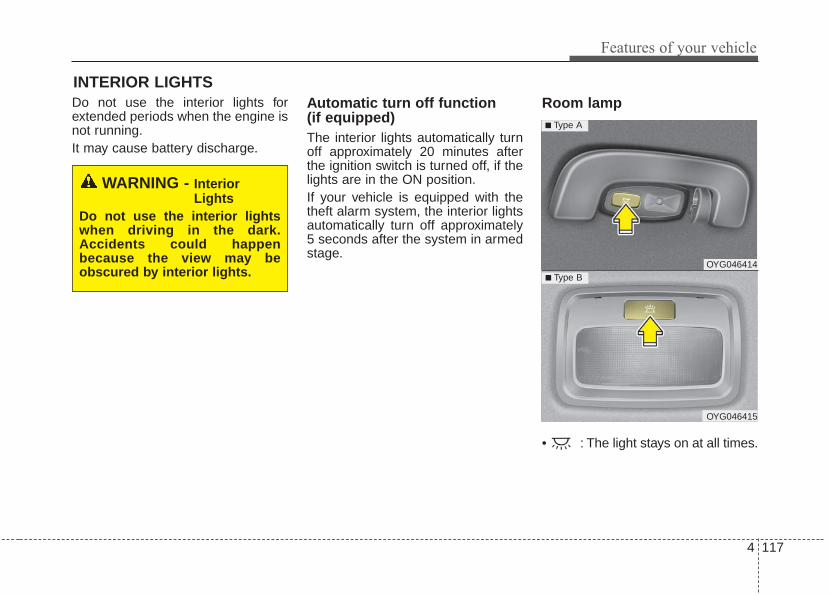
4 117
Features of your vehicle
Do not use the interior lights forextended periods when the engine isnot running.It may cause battery discharge.
Automatic turn off function (if equipped)The interior lights automatically turnoff approximately 20 minutes afterthe ignition switch is turned off, if thelights are in the ON position.If your vehicle is equipped with thetheft alarm system, the interior lightsautomatically turn off approximately5 seconds after the system in armedstage.
Room lamp
• : The light stays on at all times.
INTERIOR LIGHTS
WARNING - InteriorLights
Do not use the interior lightswhen driving in the dark.Accidents could happenbecause the view may beobscured by interior lights.
OYG046414
OYG046415
■ Type B
■ Type A

Features of your vehicle
1184
Map lamp
• Press the lens (1) to turn ON themap lamp.To turn the map lamp OFF pressthe lens (1) again.
• (2) : DOOR mode- The map lamp and room lamp
come on when a door is opened.The lamps go out after approxi-mately 30 seconds.
- The map lamp and room lampcome on for approximately 30 sec-onds when doors are unlockedwith a transmitter or smart key aslong as the doors are not opened.
- The map lamp and room lamp willstay on for approximately 20 min-utes if a door is opened with theignition switch in the ACC orLOCK/OFF position.
- The map lamp and room lamp willstay on continuously if the door isopened with the ignition switch inthe ON position.
- The map lamp and room lamp willgo out immediately if the ignitionswitch is changed to the ON posi-tion or all doors are locked.
- To turn off the DOOR mode, pressthe DOOR button (2) once again(not pressed).
✽✽ NOTICEThe DOOR mode and ROOM modecan not be selected at the same time.
(3):The map lamp stays on at all times.
(1):The map lamp of driver’s side stayson at all times.
(1):The map lamp of passenger’s sidestays on at all times.
OYG046413
OYG046412
■ Type B
■ Type A

4 119
Features of your vehicle
Trunk room lamp (if equipped)
The trunk room lamp comes onwhen the trunk is opened.The trunk room lamp comes on aslong as the trunk lid opens. To pre-vent unnecessary battery drain,close the trunk lid securely afterusing the trunk room.
Vanity mirror lamp (if equipped)
Opening the lid of the vanity mirrorwill automatically turn on the mirrorlight.
* The actual sunvisor lamp in the vehi-cle may differ from the illustration.
Glove box lamp (if equipped)
The glove box lamp comes on whenthe glove box is opened.To prevent unnecessary batterydrain, close the glove box securelyafter using the glove box.
CAUTION - Vanity mirrorlamp
Always have the switch in theoff position when the vanity mir-ror lamp is not in use. If the sun-visor is closed without the lampoff, it may discharge the batteryor damage the sunvisor.
OYG046416 OJF045072 OYG046418

Features of your vehicle
1204
WELCOME SYSTEM (IF EQUIPPED)Headlight (Headlamp) escortfunctionWhen the headlight(light switch inthe headlight or AUTO position) is onand all doors (and trunk) are lockedand closed, the position light andheadlight will come on for 15 sec-onds if any of the below is per-formed.• Without smart key system
- When the door unlock button ispressed on the transmitter.
• With the smart key system- When the door unlock button is
pressed on the smart key.
At this time, if you press the door lockor unlock button, the position lightand headlight will turn off immediate-ly.
Interior light When the interior light switch is in theDOOR position and all doors (andtrunk) are locked and closed, theroom lamp will come on for 30 sec-onds if any of the below is performed.• Without smart key system
- When the door unlock button ispressed on the transmitter.
• With the smart key system- When the door unlock button is
pressed on the smart key.- When the button of the outside
door handle is pressed.
At this time, if you press the door lockbutton, the lamps will turn off imme-diately.
Pocket lamp (if equipped)When all the doors (and trunk) arelocked and closed, the pocket lampand puddle lamp will come on forabout 15 seconds if any of the belowis performed.• With the smart key system
- When the vehicle is approachedwith the smart key in possession.

4 121
Features of your vehicle
If you want to defrost and defog thefront windshield, refer to “Windshielddefrosting and defogging” in this sec-tion.
Rear window defroster
The defroster heats the window toremove frost, fog and thin ice fromthe rear window, while the engine isrunning.
To activate the rear windowdefroster, press the rear windowdefroster button located in the centerfacia switch panel. The indicator onthe rear window defroster button illu-minates when the defroster is ON.If there is heavy accumulation ofsnow on the rear window, brush it offbefore operating the rear defroster.The rear window defroster automati-cally turns off after approximately 20minutes or when the ignition switch isturned off. To turn off the defroster,press the rear window defroster buttonagain.
Outside rearview mirror defroster (if equipped)If your vehicle is equipped with theoutside rearview mirror defrosters,they will operate at the same time youturn on the rear window defroster.
Wiper deicer (if equipped)If your vehicle is equipped with thewiper deicer, it will operate at thesame time you turn on the rear win-dow defroster.
DEFROSTER
CAUTION - ConductorsTo prevent damage to the con-ductors bonded to the insidesurface of the rear window,never use sharp instruments orwindow cleaners containingabrasives to clean the window.
OYG046302
■ Type A
■ Type B

Features of your vehicle
1224
AUTOMATIC CLIMATE CONTROL SYSTEM
OYG046301L/OYG046300L
1. Driver’s temperature control knob
2. AUTO (automatic control) button
3. Front windshield defroster button
4. Rear window defroster button
5. Air conditioning button
6. Air intake control button
7. OFF button
8. Fan speed control button
9. Mode selection button
10. Passenger's temperature control knob
11. SYNC temperature control selection but-ton
12. Clock
13. Climate information screen selection but-ton
■■ Type B
■■ Type A
CAUTIONOperating the blower when theignition switch is in the ON posi-tion could cause the battery todischarge. Operate the blowerwhen the engine is running.

4 123
Features of your vehicle
Automatic heating and air con-ditioning
1. Press the AUTO button. Themodes, fan speeds, air intake andair-conditioning will be controlledautomatically by setting the tem-perature.
2. Turn the temperature control knobto the desired temperature.
✽✽ NOTICE• To turn the automatic operation
off, select any button or switch ofthe following:- Mode selection button- Air conditioning button- Front windshield defroster button
(Press the button one more timeto deselect the front windshielddefroster function. The ‘AUTO’sign will illuminate on the infor-mation display once again.)
- Air intake control button- Fan speed control switchThe selected function will be con-trolled manually while other func-tions operate automatically.
• For your convenience and toimprove the effectiveness of theclimate control, use the AUTObutton and set the temperature to23°C (73°F).
OYG046303
■ Driver’s side ■ Passenger’s side
OYG046309

Features of your vehicle
1244
✽✽ NOTICENever place anything over the sensorlocated on the instrument panel toensure better control of the heatingand cooling system.
OYG046304

4 125
Features of your vehicle
Manual heating and air condi-tioningThe heating and cooling system canbe controlled manually by pressingbuttons or turning knob(s) other thanthe AUTO button. In this case, thesystem works sequentially accordingto the order of buttons or knob(s)selected.1. Start the engine.2. Set the mode to the desired posi-
tion.For improving the effectiveness ofheating and cooling;- Heating:- Cooling:
3. Set the temperature control to thedesired position.
4. Set the air intake control to theoutside (fresh) air position.
5. Set the fan speed control to thedesired speed.
6. If air conditioning is desired, turnthe air conditioning system on.
Press the AUTO button in order toconvert to full automatic control ofthe system.
Mode selection
OYG046306

Features of your vehicle
1264
The mode selection button controlsthe direction of the air flow throughthe ventilation system.The air flow outlet port is convertedas follows:
Face-Level (B, C, D, E, F)
Air flow is directed toward the upperbody and face. Additionally, eachoutlet can be controlled to direct theair discharged from the outlet.
Bi-Level (B, C, D, E, F)
Air flow is directed towards the faceand the floor.
Floor-Level (A, C, D, E)
Most of the air flow is directed to thefloor, with a small amount of the airbeing directed to the windshield andside window defrosters.
Floor/Defrost-Level (A, C, D, E)
Most of the air flow is directed to thefloor and the windshield with a smallamount directed to the side windowdefrosters.
■ Type A ■ Type B
OYG046305

4 127
Features of your vehicle
Defrost-Level
Most of the air flow is directed to thewindshield with a small amount of airdirected to the side window defrosters.
Instrument panel vents
The outlet vents can be opened orclosed separately using the thumb-wheel (if equipped).Also, you can adjust the direction ofair delivery from these vents usingthe vent control lever as shown.
Temperature control
The temperature will increase to themaximum (HI) by turning the knob tothe extreme right.The temperature will decrease to theminimum (Lo) by turning the knob tothe extreme left.When turning the knob, the tempera-ture will increase or decrease by0.5°C/1°F. When set to the lowesttemperature setting, the air condi-tioning will operate continuously.
OYG046307 OYG046308
■ Driver’s side ■ Passenger’s side
OYG046309

Features of your vehicle
1284
Adjusting the driver and passengerside temperature equally
• Press the “SYNC” button to adjustthe driver and passenger side tem-perature equally.The passenger side temperaturewill be set to the same temperatureas the driver side temperature.
• Turn the driver side temperaturecontrol knob. The driver and pas-senger side temperature will beadjusted equally.
Adjusting the driver and passengerside temperature individually
• Press the “SYNC” button again toadjust the driver and passengerside temperature individually. Theillumination of button turns off.
• Operate the driver side tempera-ture control knob to adjust the driv-er side temperature.
• Operate the passenger side tem-perature control knob to adjust thepassenger side temperature.
Temperature conversion
You can switch the temperaturemode from Centigrade to Fahrenheitas follows:While pressing the OFF button,press the AUTO button for 3 secondsor more.The display will change fromCentigrade to Fahrenheit, or fromFahrenheit to Centigrade.If the battery has been discharged ordisconnected, the temperature modedisplay will reset to Fahrenheit.
Air intake control
This is used to select the outside(fresh) air position or recirculated airposition.To change the air intake control posi-tion, push the control button.
OYG046310
OYG046311

4 129
Features of your vehicle
Outside (fresh) air position
With the outside (fresh)air position selected, airenters the vehicle fromoutside and is heated orcooled according to thefunction selected.
Recirculated air position
With the recirculated airposition selected, airfrom the passengercompartment will bedrawn through the heat-ing system and heatedor cooled according tothe function selected.
Prolonged operation of the heater inthe recirculated air position (withoutair conditioning selected) may causefogging of the windshield and sidewindows and the air within the pas-senger compartment may becomestale.In addition, prolonged use of the airconditioning with the recirculated airposition selected will result in exces-sively dry air in the passenger com-partment.
Sunroof inside air recirculation(if equipped)If the sunroof opens while the heateror Air Conditioning system operates,the outside (fresh) air will be select-ed automatically for ventilating thecar. Then, if you select the recirculat-ed air position, the outside (fresh) airwill be selected automatically after 3minutes.If you close the sunroof, the intakemode will be changed to the previousselected mode.
Fan speed control
The fan speed can be set to thedesired speed by operating the fanspeed control button.To change the fan speed, press ( )the button for higher speed, or push ( ) the button for lower speed. Toturn the fan speed control off, pressthe front blower OFF button.
OYG046312

Features of your vehicle
1304
Air conditioning
Press the A/C button to turn the airconditioning system on (indicatorlight will illuminate).Press the button again to turn the airconditioning system off.
OFF mode
Press the front blower OFF button toturn off the front air climate controlsystem. However, you can still oper-ate the mode and air intake buttonsas long as the ignition switch is in theON position.
OYG046313
WARNING - ReducedVisibility
Continuous use of the climatecontrol system in the recirculat-ed air position may allowhumidity to increase inside thevehicle which may fog the glassand obscure visibility.
WARNING - RecirculatedAir
Continued use of the climatecontrol system in the recirculat-ed air position can causedrowsiness or sleepiness, andloss of vehicle control. Set theair intake control to the outside(fresh) air position as much aspossible while driving.
WARNING - Sleeping withAC on
Do not sleep in a vehicle withthe air conditioning or heatingon as this may cause seriousharm or death due to a drop inthe oxygen level and/or bodytemperature.
OYG046314

4 131
Features of your vehicle
Climate information screen selection (if equipped)
Press the climate information screenselection button to display climateinformation on the screen.
System operationVentilation1.Set the mode to the position.2.Set the air intake control to the out-
side (fresh) air position.3.Set the temperature control to the
desired position.4.Set the fan speed control to the
desired speed.
Heating1.Set the mode to the position.2.Set the air intake control to the out-
side (fresh) air position.3.Set the temperature control to the
desired position.4.Set the fan speed control to the
desired speed.5.If dehumidified heating is desired,
turn the air conditioning system (ifequipped) on.
• If the windshield fogs up, set themode to the or position.
Operation Tips
• To keep dust or unpleasant fumesfrom entering the vehicle throughthe ventilation system, temporarilyset the air intake control to therecirculated air position. Be sure toreturn the control to the fresh airposition when the irritation haspassed to keep fresh air in thevehicle. This will help keep the driv-er alert and comfortable.
• Air for the heating/cooling systemis drawn in through the grilles justahead of the windshield. Careshould be taken that these are notblocked by leaves, snow, ice orother obstructions.
• To prevent interior fog on the wind-shield, set the air intake control tothe fresh air position and fan speedto the desired position, turn on theair conditioning system, and adjustthe temperature control to desiredtemperature.
OYG046315

Features of your vehicle
1324
Air conditioning (if equipped) All Kia Air Conditioning Systems arefilled with R-1234yf refrigerant.1.Start the engine. Press the air con-
ditioning button.2.Set the mode to the position.3.Set the air intake control to the out-
side air or recirculated air position.4.Adjust the fan speed control and
temperature control to maintainmaximum comfort.
• When maximum cooling is desired,set the temperature control to theextreme left position, set the modecontrol to the MAX A/C position,then set the fan speed control tothe highest speed. ✽✽ NOTICE
When opening the windows in humidweather, air conditioning may createwater droplets inside the vehicle.Since excessive water droplets maycause damage to electrical equip-ment, air conditioning should only beused with the windows closed.
Air conditioning system operation tips
• If the vehicle has been parked indirect sunlight during hot weather,open the windows for a short timeto let the hot air inside the vehicleescape.
• To help reduce moisture inside ofthe windows on rainy or humiddays, decrease the humidity insidethe vehicle by operating the airconditioning system.
• During air conditioning systemoperation, you may occasionallynotice a slight change in enginespeed as the air conditioning com-pressor cycles. This is a normalsystem operation characteristic.
• Use the air conditioning systemevery month only for a few minutesto ensure maximum system per-formance.
CAUTION - Excessive A/CUse
When using the air conditioningsystem, monitor the tempera-ture gauge closely while drivingup hills or in heavy traffic whenoutside temperatures are high.Air conditioning system opera-tion may cause engine over-heating. Continue to use theblower fan but turn the air con-ditioning system off if the tem-perature gauge indicates engineoverheating.

4 133
Features of your vehicle
• When using the air conditioningsystem, you may notice clear waterdripping (or even puddling) on theground under the passenger sideof the vehicle. This is a normal sys-tem operation characteristic.
• Operating the air conditioning sys-tem in the recirculated air positionprovides maximum cooling, how-ever, continual operation in thismode may cause the air inside thevehicle to become stale.
• During cooling operation, you mayoccasionally notice a misty air flowbecause of rapid cooling andhumid air intake. This is a normalsystem operation characteristic.
Climate control air filter (if equipped)
The climate control air filter installedbehind the glove box filters the dust orother pollutants that come into thevehicle from the outside through theheating and air conditioning system. Ifdust or other pollutants accumulate inthe filter over a period of time, the airflow from the air vents may decrease,resulting in moisture accumulation onthe inside of the windshield evenwhen the outside (fresh) air position isselected. If this happens, have the cli-mate control air filter replaced by anauthorized Kia dealer.
✽✽ NOTICE• Replace the filter every 24,000 km
(15,000 miles) or once a year.If the vehicle is being driven insevere conditions such as dusty orrough roads, more frequent airconditioner filter inspections andchanges are required.
• When the air flow rate suddenlydecreases, the system should bechecked at an authorized Kiadealer.
1LDA5047
Outside air
Recirculatedair
Climate controlair filter
Blower
Evaporatorcore
Heater core

Features of your vehicle
1344
Checking the amount of airconditioner refrigerant andcompressor lubricantWhen the amount of refrigerant islow, the performance of the air condi-tioning is reduced. Overfilling alsohas a negative impact on the air con-ditioning system.Therefore, if abnormal operation isfound, have the system inspected byan authorized Kia dealer.
WARNINGThe oil and refrigerant in yourvehicle's air conditioning sys-tem is under very high pres-sure. If proper service proce-dures are not followed an explo-sion may result. To reduce therisk of serious injury or death,the air conditioning system inyour vehicle should only beserviced by trained and certi-fied technicians.
CAUTIONIt is important that the correcttype and amount of oil and refrig-erant is used, otherwise damageto the vehicle may occur. To pre-vent damage, the air conditioningsystem in your vehicle shouldonly be serviced by trained andcertified technicians.

4 135
Features of your vehicle
• For maximum defrosting, set thetemperature control to the extremeright/hot position and the fan speedcontrol to the highest speed.
• If warm air to the floor is desiredwhile defrosting or defogging, setthe mode to the floor-defrost posi-tion.
• Before driving, clear all snow andice from the windshield, rear win-dow, outside rear view mirrors, andall side windows.
• Clear all snow and ice from thehood and air inlet in the cowl grill toimprove heater and defroster effi-ciency and to reduce the probabili-ty of fogging up the inside of thewindshield.
Automatic climate control systemTo defog inside windshield
1. Set the fan speed to the desiredposition.
2. Select desired temperature.3. Press the defroster button ( ).4. The outside (fresh) air position will
be selected automatically and theair conditioning will turn onaccording to the detected ambienttemperature.
WINDSHIELD DEFROSTING AND DEFOGGING
WARNING - Windshieldheating
Do not use the or posi-tion during cooling operation inextremely humid weather. Thedifference between the temper-ature of the outside air and thewindshield could cause theouter surface of the windshieldto fog up, causing loss of visi-bility. In this case, set the modeselection to the positionand fan speed control to thelower speed.
OYG046316N

Features of your vehicle
1364
If the air conditioning and outside(fresh) air position are not selectedautomatically, adjust the correspon-ding button manually. If the posi-tion is selected, lower fan speed isadjusted to a higher fan speed.
To defrost outside windshield
1. Set the fan speed to the highestposition.
2. Set the temperature to theextreme hot (HI) position.
3. Press the defroster button ( ).4. The outside (fresh) air position will
be selected automatically and theair conditioning will turn onaccording to the detected ambienttemperature.
Defogging logicTo reduce the possibility of foggingup the inside of the windshield, theair intake or air conditioning is con-trolled automatically according tocertain conditions such as or position. To cancel automatic defog-ging logic or return to the automaticdefogging logic, do the following.
OYG046317N

4 137
Features of your vehicle
Automatic climate control system
1. Turn the ignition switch to the ONposition.
2. Press the defroster button ( ).3. While pressing the air conditioning
button (A/C), press the air intakecontrol button at least 5 times with-in 3 seconds.
The recirculation indicator blinks 3times with 0.5 second of interval. Itindicates that the defogging logic iscanceled or returned to the pro-grammed status.If the battery has been discharged ordisconnected, it resets to the defoglogic status.
Auto defogging system (if equipped)
Auto defogging reduces the probabil-ity of fogging up the inside of thewindshield by automatically sensingthe moisture of inside the windshield.The auto defogging system operateswhen the heater or air conditioning ison.
This indicator illuminateswhen the auto defoggingsystem senses the mois-ture on the inside of thewindshield and operates.
If more moisture is in the vehicle,higher steps operate as follow. Forexample if auto defogging does notdefog inside the windshield at step 1Outside air position, it tries to defogagain at step 2 Operating the air con-ditioning.
Step 1 : Outside air positionStep 2 : Operating the air condition-
ingStep 3 : Blowing air flow toward the
windshieldStep 4 : Increasing air flow toward
the windshield
OYG046318N
OYG046319

Features of your vehicle
1384
To cancel or reset the Auto DefoggingSystem
Press the front windshield defrosterbutton for 3 seconds when the igni-tion switch is in the ON position.When the Auto Defogging System iscanceled, ADS OFF symbol will blink3 times and the ADS OFF will be dis-played on the climate control infor-mation screen.When the Auto Defogging System isreset, ADS OFF symbol will blink 6times without a signal.Do not remove the sensor coverlocated on the upper end of the pas-senger side windshield glass.Damage to the system parts couldoccur and may not be covered byyour vehicle warranty.
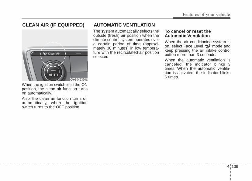
4 139
Features of your vehicle
When the ignition switch is in the ONposition, the clean air function turnson automatically.Also, the clean air function turns offautomatically, when the ignitionswitch turns to the OFF position.
The system automatically selects theoutside (fresh) air position when theclimate control system operates overa certain period of time (approxi-mately 30 minutes) in low tempera-ture with the recirculated air positionselected.
To cancel or reset theAutomatic VentilationWhen the air conditioning system ison, select Face Level mode andkeep pressing the air intake controlbutton more than 3 seconds.When the automatic ventilation iscanceled, the indicator blinks 3times. When the automatic ventila-tion is activated, the indicator blinks6 times.
CLEAN AIR (IF EQUIPPED)
OYG046320L
AUTOMATIC VENTILATION

Features of your vehicle
1404
STORAGE COMPARTMENTS These compartments can be used tostore small items required by thedriver or passengers.
• To avoid possible theft, do notleave valuables in the storagecompartment.
• Always keep the storage compart-ment covers closed while driving.Do not attempt to place so manyitems in the storage compartmentthat the storage compartmentcover can not close securely.
Center console storage
To open the center console storage,pull up the lever.
Glove box
The glove box can be locked andunlocked with a master key (1). (ifequipped)To open the glove box, pull the lever(2) and the glove box will automati-cally open. Close the glove box afteruse.
WARNING - Flammablematerials
Do not store, propane cylindersor other flammable/explosivematerials in the vehicle. Theseitems may catch fire and/orexplode if the vehicle isexposed to hot temperatures forextended periods.
OYG046323OYG046321

4 141
Features of your vehicle
✽✽ NOTICEIf the temperature control knob is inthe warm or hot position, warm orhot air will flow into the glove box.
Sunglass holder
To open the sunglass holder, pressthe cover and the holder will slowlyopen. Place your sunglasses with thelenses facing out.To close the sunglass holder push it up.
WARNING - Glove BoxTo reduce the risk of injury in anaccident or sudden stop, alwayskeep the glove box door closedwhile driving.
WARNING - Sunglassholder
Do not keep objects except sun-glasses inside the sunglassholder. Heavier objects can bethrown from the holder in theevent of a sudden stop or anaccident, possibly injuring thepassengers.
OYG046324

Features of your vehicle
1424
Cup holder
Cups or small beverage cans may beplaced in the cup holders.
Seat warmer (if equipped)
The seat warmer is provided to warmthe front seats during cold weather.With the ignition switch in the ONposition, push either of the switchesto warm the driver's seat or the frontpassenger's seat.
INTERIOR FEATURES
WARNING - Hot liquidsDo not place uncovered cupswith hot liquid in the cup holderwhile the vehicle is in motion. Ifthe hot liquid spills, you mayburn yourself. Such a burn tothe driver could lead to loss ofcontrol of the vehicle. OYG046325
■ Front seat
■ Rear seat
OYG046327
CAUTIONKeep your drinks sealed whiledriving to prevent spilling yourdrink. If liquid spills, it may getinto the vehicle's electrical/elec-tronic system and damage elec-trical/electronic parts.
CAUTIONWhen cleaning spilled liquids,do not use heat to dry the cupholders. This may damage thecup holder.
OYG046331
OYG046332
■ Front seat
■ Rear seat

4 143
Features of your vehicle
During mild weather or under condi-tions where the operation of the seatwarmer is not needed, keep theswitches in the “OFF” position.
Temperature control (Manual)• Each time you press the switch,
the temperature setting of the seatwill change as follows :
■ Front seat
■ Rear seat
• The seat warmer defaults to theOFF position whenever the ignitionswitch is turned on.
Temperature control(Automatic)The seat warmer starts to automati-cally control the seat temperature inorder to prevent low-temperatureburns after being manually turnedON.
You may manually press the buttonto increase the seat temperature.However, it soon returns to the auto-matic mode again.• When pressing the switch for more
than 1.5 seconds with the seatwarmer operating, the seat warmerwill turn OFF.
• The seat warmer defaults to theOFF position whenever the EngineStart/Stop button is in the ON posi-tion.
✽✽ NOTICEWith the seat warmer switch in theON position, the heating system inthe seat turns off or on automaticallydepending on the seat temperature.
▼
▼
OFF→HIGH( )→MIDDLE( )→LOW( )
→
OFF→HIGH( )→LOW( )
→
OFF→HIGH( )→MIDDLE( )→LOW( )
→→
30min 60min
WARNING - Seat warmerburns
The seat warmer may causeburns, even at low tempera-tures, if used over a long periodof time. Never allow passengerswho may not be able to takecare of themselves to beexposed to the risk of seatheater burns. These include:1. Infants, children, elderly or
disabled persons, or hospitaloutpatients
2. Persons with sensitive skinor those that burn easily
3. Fatigued individuals4. Intoxicated individuals5. Individuals taking medication
that can cause drowsiness orsleepiness (sleeping pills,cold tablets, etc.)

Features of your vehicle
1444
Air ventilation seat (if equipped)
The temperature setting of the seatchanges according to the switchposition.• If you want to ventilate your seat
cushion, press the switch (bluecolor).
• Each time you press the button,the airflow will change as follows:
• The seat warmer (with air ventila-tion) defaults to the OFF positionwhenever the ignition switch isturned on.
Sunvisor
Use the sunvisor to shield direct lightthrough the front or side windows.To use the sunvisor, pull it downward.To use the sunvisor for the side win-dow, pull it downward, unsnap it fromthe bracket (1) and swing it to theside (2).To use the vanity mirror, pull down thevisor and slide the mirror cover (3).Adjust the sunvisor extension for-ward or backward (4).The ticket holder (5) is provided forholding a tollgate ticket. (if equipped)
OFF→HIGH( )→MIDDLE( )→LOW( )
→
CAUTION - Seat damage• When cleaning the seats, do
not use an organic solventsuch as paint thinner, ben-zene, alcohol and gasoline.Doing so may damage the airventilation seat.
• Do not place heavy or sharpobjects on the seat. Thosethings may damage the airventilation seat.
• Be careful not to spill liquidsuch as water or beverages onthe seat. If you spill some liquid,wipe the seat with a dry towel.Before using the air ventilationseat, dry the seat completely.
OYG046333 OJF045121

4 145
Features of your vehicle
* The actual sunvisor lamp in the vehi-cle may differ from the illustration.
Power outlet (if equipped) The power outlet is designed to pro-vide power for mobile telephones orother devices designed to operatewith vehicle electrical systems. Thedevices should draw less than 10amps with the engine running.• Use the power outlet only when the
engine is running and remove theaccessory plug after use. Using theaccessory plug for prolonged peri-ods of time with the engine off couldcause the battery to discharge.
• Only use 12V electric accessorieswhich are less than 10A in electriccapacity.
• Adjust the air-conditioner or heaterto the lowest operating level whenusing the power outlet.
• Close the cover when not in use.• Some electronic devices can cause
electronic interference whenplugged into a vehicle’s power out-let. These devices may causeexcessive audio static and malfunc-tions in other electronic systems ordevices used in your vehicle.
CAUTION - Vanity mirrorlamp
If you use the vanity mirror lamp,turn off the lamp before return-ing the sunvisor to its originalposition, otherwise it couldresult in battery discharge andpossible sunvisor damage.
OYG046328
OYG046438
OYG046329
■ Front• Type B
■ Front• Type A
■ Center

Features of your vehicle
1464
• Push the plug in as far as it will go.If good contact is not made, theplug may overheat and the fusemay open.
• Plug in battery equipped electronicdevices with reverse current protec-tion. The current from the batterymay flow into the vehicle’s electrical/electronic system and causesystem malfunction.
Wireless smart phone charg-ing system (if equipped)
A wireless smart phone chargingsystem located in front of the centerconsoleFirmly close all doors, and turn theignition to ACC or IGN ON. To startwireless charging, place the smartphone equipped with wireless charg-ing function on the wireless chargingpad.For best wireless charging results,place the smart phone on the centerof the charging pad.
The wireless charging system isdesigned for one smart phoneequipped with QI per single usageonly. Please refer to the smart phoneaccessory cover or the smart phonemanufacturer homepage to checkwhether your smart phone supportsQI function.
WARNING - Electric shockDo not put a finger or a foreignelement (pen, etc.) into a poweroutlet and do not touch with awet hand. You may receive anelectric shock.
OYG046334

4 147
Features of your vehicle
Wireless smart phone charging 1. Remove any object on the smart
phone charging pad including thesmart key. If there is any foreignobject on the pad other than asmart phone, the wireless chargingfunction may not operate properly.
2. Place the smart phone on the cen-ter of the wireless charging pad.
3. The indicator light will change toorange once the wireless chargingbegins. After the charging is com-plete, the orange light will changeto green.
4. You can choose to turn the wirelesscharging function to either ON orOFF by selecting the USM on theinstrument cluster. (Please refer to“Instrument Cluster” for details).
If the wireless charging does notwork, gently move your smart phonearound the pad until the charging indi-cator light turns yellow. Depending onthe smart phone, the charging indica-tor light may not turn green even afterthe charging is complete.
If the wireless charging is not func-tioning properly, the orange light willblink and flash for ten seconds thenturn off. In such cases, remove thesmart phone from the pad andreplace it on the pad again, or doublecheck the charging status.If you leave the smart phone on thecharging pad when the vehicle igni-tion is in OFF, the vehicle will alertyou through warning messages andsound (applicable for vehicles withvoice guidance function) after the‘Good bye’ function on the instru-ment cluster ends.
WARNING - Distracteddriving
Driving while distracted canresult in a loss of vehicle con-trol that may lead to an acci-dent, severe personal injury,and death. The driver’s primaryresponsibility is in the safe andlegal operation of a vehicle, anduse of any handheld devices,other equipment, or vehicle sys-tems which take the driver’seyes, attention and focus awayfrom the safe operation of avehicle or which are not permis-sible by law should never beused during operation of thevehicle.

Features of your vehicle
1484
✽✽ NOTICE• If it is not possible to close the tray
cover due to the size of your smartphone or because the tray coverhas been broken, do not use thewireless smart phone chargingfunction.
• When the interior temperature ofthe wireless charging system risesabove a set temperature, the wire-less charging will cease to func-tion. After the interior tempera-ture drops below the threshold,the wireless charging function willresume.
• The wireless charging may notfunction properly when there is aheavy accessory cover on thesmart phone.
• The wireless charging will stopwhen using the wireless smart keysearch function to prevent radiowave disruption.
• The wireless charging will stopwhen the smart key is moved outof the vehicle with the ignition inON.
(Continued)
(Continued)• The wireless charging will stop
when any of the doors is opened(applicable for vehicles equippedwith smart keys).
• The wireless charging will stopwhen the vehicle is turned OFF.
• The wireless charging will stopwhen the smart phone is not incomplete contact with the wirelesscharging pad.
• Items equipped with magneticcomponents such as credit card,telephone card, bankbook, anytransportation ticket and suchmay become damaged duringwireless charging.
• Place the smart phone on the cen-ter of the charge pad for bestresults. The smart phone may notcharge when placed near the rimof the charging pad. When thesmart phone does get charged, itmay heat up excessively.
• For smart phones without built-inwireless charging system, anappropriate accessory has to beequipped.
(Continued)
CAUTION - Liquid inWireless Smart PhoneCharger
To prevent liquid from damagingthe wireless smart phone charg-ing system in your vehicle,securely close the tray coverwhen charging your phone.
CAUTION - Metal inWireless Charging System
If any metallic object such ascoins is located between thewireless charging system andthe smart phone, the chargingmay be disrupted. Also, themetallic object may heat up andpotentially damage the chargingsystem. If there is any metallicobject between the smart phoneand the charging pad, immedi-ately remove the smart phone.Remove the metallic object afterit has cooled down.

4 149
Features of your vehicle
(Continued)• Smart phones of some manufac-
turers may display messages onweak current. This is due to theparticular characteristic of thesmart phone and does not imply amalfunction on wireless chargingfunction.
• The indicator light of some manu-facturers’ smart phones may stillbe yellow after the smart phone isfully charged. This is due to theparticular characteristic of thesmart phone and not a malfunc-tion of the wireless charging.
• When any smart phone without awireless charging function or ametallic object is placed on thecharging pad, a small noise maysound. This small sound is due tothe vehicle discerning compatibili-ty of the object placed on thecharging pad. It does not affectyour vehicle or the smart phone inany way.
Coat hook (if equipped)
❈ This actual feature may differ from the illus-tration.
To use the coat hook, pull down theupper portion of hanger.
OYG046335
■ Type A
■ Type B
OYG046429
CAUTION - Hangingclothing
Do not hang heavy clothes, sincethose may damage the hook.
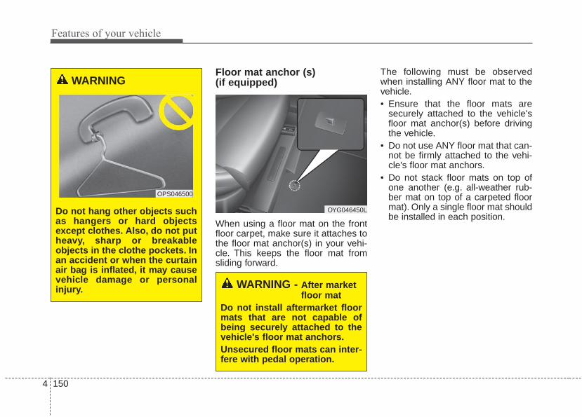
Features of your vehicle
1504
Floor mat anchor (s) (if equipped)
When using a floor mat on the frontfloor carpet, make sure it attaches tothe floor mat anchor(s) in your vehi-cle. This keeps the floor mat fromsliding forward.
The following must be observedwhen installing ANY floor mat to thevehicle.• Ensure that the floor mats are
securely attached to the vehicle'sfloor mat anchor(s) before drivingthe vehicle.
• Do not use ANY floor mat that can-not be firmly attached to the vehi-cle's floor mat anchors.
• Do not stack floor mats on top ofone another (e.g. all-weather rub-ber mat on top of a carpeted floormat). Only a single floor mat shouldbe installed in each position.
OYG046450L
WARNING - After marketfloor mat
Do not install aftermarket floormats that are not capable ofbeing securely attached to thevehicle's floor mat anchors.Unsecured floor mats can inter-fere with pedal operation.
WARNING
Do not hang other objects suchas hangers or hard objectsexcept clothes. Also, do not putheavy, sharp or breakableobjects in the clothe pockets. Inan accident or when the curtainair bag is inflated, it may causevehicle damage or personalinjury.
OPS046500

4 151
Features of your vehicle
Side curtain (if equipped)
To use the side curtain:1. Lift the curtain by the handle (1).2. Hang the curtain on the hooks on
both sides of the handle.To avoid injury or damage to the sidecurtain and door moldings, lowerside curtain by the handle all the wayback to the stowed position. Do notrelease handle after disengagingfrom the hooks on the door.
Rear curtain (if equipped)
To fold the rear curtain, press thebutton. To unfold the rear curtain,press the button again.
The rear curtain will fold automatical-ly when you shift the shift lever into R(Reverse) and unfold automaticallywhen you shift the shift lever from R(Reverse) into P (Park).After the rear curtain is folded by shift-ing the shift lever into R (Reverse) anddrive more than 20 km/h with the shiftlever in D (Drive), the rear curtain willunfold automatically.
OYG046337
OYG046338
CAUTIONDo not pull or fold the rear cur-tain by hand. It could causemotor failure.
OYG046336

Features of your vehicle
1524
ClockWhenever the battery terminals orrelated fuses are disconnected, youmust reset the time.When the ignition switch is in theACC or ON position, the clock but-tons operate as follows:
■■ Type AHour (1)Pressing the H button will advancethe time displayed by one hour.
Minute (2)Pressing the M button will advancethe time displayed by one minute.
Display conversionTo change the 12 hour format to the24 hour format, press the “H” and “M”buttons at the same time for morethan 5 seconds.For example, if the “H” and “M” but-tons are pressed for more than 5seconds while the time is 10:15 p.m.,the display will change to 22:15.
■■ Type BYou can set the clock by using theAVN (Audio or Navigation).For the details, refer to the AVN man-ual.
■ Type A
OYG046339
OYG046340
■ Type B
WARNINGDo not adjust the clock whiledriving.You may lose your steer-ing control and cause an acci-dent that results in severe per-sonal injury or death.
WARNINGDo not adjust the clock whiledriving. You may lose yoursteering control and cause anaccident that results in severepersonal injury or death.

4 153
Features of your vehicle
Luggage net (holder) (if equipped)
To keep items from shifting in thecargo area, you can use the holderslocated in the cargo area to attachthe luggage net.
WARNINGTo avoid eye injury, DO NOToverstretch the luggage net.ALWAYS keep your face andbody out of the luggage net’srecoil path. DO NOT use the lug-gage net when the strap has vis-ible signs of wear or damage.
OYG046341
CAUTIONTo prevent damage to the goodsor the vehicle, care should betaken when carrying fragile orbulky objects in the luggagecompartment.

Features of your vehicle
1544
✽✽ NOTICEIf you install an after market HIDhead lamp, your vehicle’s audio andelectronic device may malfunction.
❈ If your vehicle is equipped withAVN(Audio, Video and Navigation)system, refer to a separately sup-plied manual for detailed informa-tion.
Antenna
Glass antennaYour vehicle uses a glass antenna toreceive both AM and FM signals.
Shark fin antenna (if equipped)The shark fin antenna will receive thetransmit data.
AUDIO SYSTEM
OYG046421
CAUTION• Do not clean the inside of the
rear window glass or quarterglass with a cleaner or use ascraper to remove any foreigndeposits as this may causedamage to the antenna ele-ments.
• Avoid adding metallic coatingsuch as Ni, Cd, and so on.These can interfere withAM/FM reception.
• To prevent damage to the rearglass antenna, never use sharpinstruments or window cleanercontaining abrasives to cleanthe window. Clean the insidesurface of the rear glass win-dow with a piece of soft cloth.
• When putting a sticker on theinside surface of the rear win-dow, be careful not to damageto the rear glass antenna.
• Do not put sharp instrumentsnearby the rear glass antenna.
• Tinted rear window may affectthe proper functioning of theantenna.

4 155
Features of your vehicle
Steering wheel audio controls (if equipped)
The steering wheel may incorporateaudio control buttons.
VOLUME ( / ) (1)• Press the lever upward ( ) to
increase the volume.• Press the lever downward ( ) to
decrease the volume.
SEEK/PRESET ( / ) (2)The SEEK/PRESET lever has differ-ent functions based on the systemmode. For the following functions thelever should be pressed for 0.8 sec-onds or more.
RADIO mode
It will function as the AUTO SEEKselect button.
CD/USB/iPod® mode
It will function as the FF/REW button.
If the SEEK/PRESET button ispressed for less than 0.8 seconds, itwill work as follows in each mode.
RADIO mode
It will function as the PRESET STA-TION buttons.
CD/USB/iPod® mode
It will function as TRACK UP/DOWNbutton.
MODE ( ) (3)Press the button to change audiosource.FM ➟ AM ➟ CD ➟ USB/iPod® ➟ AUX ➟MY MUSIC ➟ Bluetooth® wirelesstechnology audio
MUTE ( ) (4)• Press the button to mute the
sound.• Press the button to turn off the
microphone during a telephonecall.
Detailed information for audio controlbuttons are described in the followingpages in this section.
CAUTIONDo not operate audio remotecontrol buttons simultaneously.
OYG046422

AUX, USB port
You can use an aux port to connectaudio devices and an USB port toplug in an USB or iPod®.
✽✽ NOTICEWhen using a portable audio deviceconnected to the power outlet, noisemay occur during playback. If thishappens, use the power source of theportable audio device.
* iPod® is a trademark of Apple Inc.
OYG046437
OYG046423
■ Type A
■ Type B
WARNING - Distracteddriving
Driving while distracted canresult in a loss of vehicle controlthat may lead to an accident,severe personal injury, and death.The driver's primary responsibili-ty is in the safe and legal opera-tion of a vehicle, and use of anyhandheld devices, other equip-ment, or vehicle systems whichtake the driver's eyes, attentionand focus away from the safeoperation of a vehicle or whichare not permissible by law shouldnever be used during operationof the vehicle.
4 156
Features of your vehicle

Driving your vehicle
Before driving . . . . . . . . . . . . . . . . . . . . . . . . . . . . . . 5-4• Before entering vehicle . . . . . . . . . . . . . . . . . . . . . . . . . 5-4• Necessary inspections . . . . . . . . . . . . . . . . . . . . . . . . . . 5-4• Before starting . . . . . . . . . . . . . . . . . . . . . . . . . . . . . . . 5-4
Engine start/stop button . . . . . . . . . . . . . . . . . . . . . 5-6• Illuminated Engine start/stop button . . . . . . . . . . . . . 5-6• Engine start/stop button position. . . . . . . . . . . . . . . . . 5-6• Starting the engine with a smart key . . . . . . . . . . . . . 5-8
Automatic transaxle . . . . . . . . . . . . . . . . . . . . . . . . 5-10• Automatic transaxle operation. . . . . . . . . . . . . . . . . . 5-10• Good driving practices . . . . . . . . . . . . . . . . . . . . . . . . 5-16
Brake system. . . . . . . . . . . . . . . . . . . . . . . . . . . . . . 5-17• Power brakes . . . . . . . . . . . . . . . . . . . . . . . . . . . . . . . . 5-17• Parking brake – Foot type . . . . . . . . . . . . . . . . . . . . . 5-19• Electronic parking brake (EPB) . . . . . . . . . . . . . . . . 5-20• AUTO HOLD. . . . . . . . . . . . . . . . . . . . . . . . . . . . . . . . 5-26• Warning messages . . . . . . . . . . . . . . . . . . . . . . . . . . . . 5-28• Anti-lock brake system (ABS) . . . . . . . . . . . . . . . . . . 5-29• Electronic stability control (ESC) . . . . . . . . . . . . . . . 5-31• Vehicle stability management (VSM) . . . . . . . . . . . . 5-34• Hill-start assist control (HAC) . . . . . . . . . . . . . . . . . . 5-36• Good braking practices. . . . . . . . . . . . . . . . . . . . . . . . 5-36
Autonomous emergency braking (AEB) / Forward collision warning (FCW) . . . . . . . . . . . 5-38• System setting and activation. . . . . . . . . . . . . . . . . . . 5-38
• AEB warning message and system control . . . . . . . . 5-41• Brake operation . . . . . . . . . . . . . . . . . . . . . . . . . . . . . . 5-42• Sensor to detect the distance from the vehicle in front
(front radar). . . . . . . . . . . . . . . . . . . . . . . . . . . . . . . . 5-43• System malfunction . . . . . . . . . . . . . . . . . . . . . . . . . . . 5-44• Limitation of the system . . . . . . . . . . . . . . . . . . . . . . . 5-45• Recognizing pedestrians . . . . . . . . . . . . . . . . . . . . . . . 5-48
Cruise control system. . . . . . . . . . . . . . . . . . . . . . . 5-49• To set cruise control speed . . . . . . . . . . . . . . . . . . . . . 5-50• To increase cruise control set speed. . . . . . . . . . . . . . 5-50• To decrease the cruising speed . . . . . . . . . . . . . . . . . . 5-51• To temporarily accelerate with the
cruise control on . . . . . . . . . . . . . . . . . . . . . . . . . . . . 5-51• To cancel cruise control . . . . . . . . . . . . . . . . . . . . . . . 5-51• To resume cruising speed at more than
approximately 30 km/h (20 mph) . . . . . . . . . . . . . . 5-52• To turn cruise control off . . . . . . . . . . . . . . . . . . . . . . 5-52
Advanced smart cruise control system (ASCC). . 5-53• Speed setting (ASCC) . . . . . . . . . . . . . . . . . . . . . . . . . 5-54• Vehicle to vehicle distance setting (ASCC) . . . . . . . . 5-58• To adjust the sensitivity of
Advanced Smart Cruise Control . . . . . . . . . . . . . . . 5-62• To convert to cruise control mode . . . . . . . . . . . . . . . 5-62• Limitations of the system . . . . . . . . . . . . . . . . . . . . . . 5-62
5

Drive mode integrated control system . . . . . . . . . 5-68• DRIVE MODE. . . . . . . . . . . . . . . . . . . . . . . . . . . . . . . 5-68• ECO MODE Driving. . . . . . . . . . . . . . . . . . . . . . . . . . 5-69• Conditions that limit Active ECO MODE . . . . . . . . 5-69• DRIVE MODE Indicator Screen. . . . . . . . . . . . . . . . 5-72
Blind spot detection system (BSD) . . . . . . . . . . . . 5-76• BSD (Blind Spot Detection) /
LCA (Lane Change Assist). . . . . . . . . . . . . . . . . . . . 5-77• RCTA (Rear Cross Traffic Alert). . . . . . . . . . . . . . . . 5-80• Limitations condition . . . . . . . . . . . . . . . . . . . . . . . . . 5-82
Smart blind spot detection system . . . . . . . . . . . . 5-84• Limitations of the system . . . . . . . . . . . . . . . . . . . . . . 5-85
Lane departure warning system (LDWS) . . . . . . 5-88• Warning indicator . . . . . . . . . . . . . . . . . . . . . . . . . . . . 5-90• Conditions that cause the LDWS not to operate . . . 5-90• Conditions that cause missed warnings and
false warnings . . . . . . . . . . . . . . . . . . . . . . . . . . . . . . 5-91Economical operation . . . . . . . . . . . . . . . . . . . . . . 5-92Special driving conditions . . . . . . . . . . . . . . . . . . . 5-94
• Hazardous driving conditions . . . . . . . . . . . . . . . . . . 5-94• Rocking the vehicle . . . . . . . . . . . . . . . . . . . . . . . . . . . 5-94• Smooth cornering . . . . . . . . . . . . . . . . . . . . . . . . . . . . 5-95• Driving at night . . . . . . . . . . . . . . . . . . . . . . . . . . . . . . 5-95• Driving in the rain. . . . . . . . . . . . . . . . . . . . . . . . . . . . 5-96• Driving in flooded areas . . . . . . . . . . . . . . . . . . . . . . . 5-97
• Driving off-road. . . . . . . . . . . . . . . . . . . . . . . . . . . . . . 5-97• Highway driving . . . . . . . . . . . . . . . . . . . . . . . . . . . . . 5-97
Winter driving . . . . . . . . . . . . . . . . . . . . . . . . . . . . 5-98• Snowy or icy conditions . . . . . . . . . . . . . . . . . . . . . . . 5-98• Use high quality ethylene glycol coolant . . . . . . . . . . 5-99• Check battery and cables . . . . . . . . . . . . . . . . . . . . . . 5-99• Change to "winter weight" oil if necessary . . . . . . . 5-99• Check spark plugs and ignition system. . . . . . . . . . . 5-99• To keep locks from freezing . . . . . . . . . . . . . . . . . . . . 5-99• Use approved window washer anti-freeze in
system . . . . . . . . . . . . . . . . . . . . . . . . . . . . . . . . . . . . . 5-99• Don’t let your parking brake freeze . . . . . . . . . . . . 5-100• Don't let ice and snow accumulate underneath . . . 5-100• Carry emergency equipment . . . . . . . . . . . . . . . . . . 5-100
Vehicle load limit . . . . . . . . . . . . . . . . . . . . . . . . . 5-101• Tire and loading information label . . . . . . . . . . . . . 5-101• Certification label . . . . . . . . . . . . . . . . . . . . . . . . . . . 5-104
Vehicle weight . . . . . . . . . . . . . . . . . . . . . . . . . . . . 5-105
5

5 3
Driving your vehicle
Be sure the exhaust system doesnot leak.The exhaust system should bechecked whenever the vehicle israised to change the oil or for anyother purpose. If you hear a change inthe sound of the exhaust or if you driveover something that strikes the under-neath side of the vehicle, have theexhaust system checked as soon aspossible by an authorized Kia dealer.
WARNING - Engineexhaust
Do not inhale exhaust fumes orleave your engine running in aenclosed area for a prolongedtime. Exhaust fumes containcarbon monoxide, a colorless,odorless gas that can causeunconsciousness and death byasphyxiation.
WARNING - Open liftgate Do not drive with the liftgateopen. Poisonous exhaust gasescan enter the passenger com-partment. If you must drive withthe liftgate open proceed as fol-lows:1. Close all windows.2. Open side vents.3. Set the air intake control at
"Fresh", the air flow control at"Floor" or "Face" and the fanat the highest speed.

Driving your vehicle
45
Before entering vehicle• Be sure that all windows, outside
mirror(s), and outside lights areclean.
• Check the condition of the tires.• Check under the vehicle for any
sign of leaks.• Be sure there are no obstacles
behind you if you intend to back up.
Necessary inspectionsFluid levels, such as engine oil,engine coolant, brake fluid, andwasher fluid should be checked on aregular basis, at the exact intervaldepending on the fluid. Furtherdetails are provided in chapter 7,“Maintenance”.
Before starting • Close and lock all doors.• Position the seat so that all con-
trols are easily reached.• Buckle your seat belt.• Adjust the inside and outside
rearview mirrors.• Be sure that all lights work.• Check all gauges.• Check the operation of warning
lights when the ignition switch isturned to the ON position.
• Release the parking brake andmake sure the brake warning lightgoes out.
For safe operation, be sure you arefamiliar with your vehicle and itsequipment.
BEFORE DRIVING
WARNING - Distracteddriving
Focus on the road while driving.The driver's primary responsi-bility is in the safe and legaloperation of the vehicle. Use ofany handled devices, otherequipment or vehicle systemsthat distract the drive shouldnot be used during vehicleoperation.

5 5
Driving your vehicle
WARNING - Check sur-roundings
Always check the surroundingareas near your vehicle for peo-ple, especially children, beforeputting a vehicle into D (Drive)or R (Reverse).
WARNING - Fire riskWhen you intend to park or stopthe vehicle with the engine on,be careful not to depress theaccelerator pedal for a longperiod of time. It may overheatthe engine or exhaust systemand cause fire.
WARNING - Looseobjects
Securely store items in yourvehicle. When you make a sud-den stop or turn the steeringwheel rapidly, loose objectsmay drop on the floor and itcould interfere with the opera-tion of the foot pedals, possiblycausing an accident.
WARNING - Driving whileintoxicated
Do not drive while intoxicated.Drinking and driving is danger-ous. Even a small amount ofalcohol will affect your reflexes,perceptions and judgment.Driving while under the influ-ence of drugs is as dangerousas or more dangerous than driv-ing drunk.

Driving your vehicle
65
Illuminated ENGINESTART/STOP button
Whenever the front door is opened,the ENGINE START/STOP buttonwill illuminate for your convenience.The light will go off after about 30seconds when the door is closed.When all entrances are closed, if youlock the vehicle by using the trans-mitter or the smart key, the light willgo off immediately.
ENGINE START/STOP buttonpositionOFF
To turn off the engine (START/RUNposition) or vehicle power (ON posi-tion), press the ENGINESTART/STOP button with the shiftlever in the P (Park) position. Whenyou press the ENGINESTART/STOP button without the shiftlever in the P (Park) position, theENGINE START/STOP button willnot change to the OFF position but tothe ACC position.
In an emergency situation while thevehicle is in motion, you are able toturn the engine off and to the ACCposition by pressing the ENGINESTART/STOP button for more than 2seconds or 3 times successivelywithin 3 seconds. If the vehicle is stillmoving, you can restart the enginewithout depressing the brake pedalby pressing the ENGINESTART/STOP button with the shiftlever in the N (Neutral) position.
ENGINE START/STOP BUTTON
OYG056003
Not illuminated

5 7
Driving your vehicle
ACC(Accessory)
Press the ENGINE START/STOPbutton while it is in the OFF positionwithout depressing the brake pedal.If the ENGINE START/STOP buttonis in the ACC position for more than1 hour, the button is turned off auto-matically to prevent battery dis-charge.
ON
Press the ENGINE START/STOPbutton while it is in the ACC positionwithout depressing the brake pedal.The warning lights can be checkedbefore the engine is started. Do notleave the ENGINE START/STOPbutton in the ON position for a longtime. The battery may discharge,because the engine is not running.
START/RUN
To start the engine, depress thebrake pedal and press the ENGINESTART/ STOP button with the shiftlever in the P (Park) or the N(Neutral) position. For your safety,start the engine with the shift lever inthe P (Park) position.If you press the ENGINESTART/STOP button without depress-ing the brake pedal for automatictransaxle vehicles, the engine will notstart and the ENGINE START/STOPbutton changes as follow:OFF ➔ ACC ➔ ON ➔ OFF or ACC
Not illuminated Amber Super red

Driving your vehicle
85
✽✽ NOTICEIf you leave the ENGINE START/STOP button in the ACC or ONposition for a long time, the batterywill discharge.
Starting the engine with asmart key1.Carry the smart key or place it
inside the vehicle.2.Make sure the parking brake is
firmly applied3.Place the transaxle shift lever in P
(Park). Depress the brake pedalfully.You can also start the engine whenthe shift lever is in the N (Neutral)position.
4.Press the ENGINE START/STOPbutton while depressing the brakepedal.It should be started withoutdepressing the accelerator.
5.Do not wait for the engine to warmup while the vehicle remains sta-tionary.Start driving at moderate enginespeeds. (Steep accelerating anddecelerating should be avoided.)
• Even if the smart key is in the vehi-cle, if it is far away from you, theengine may not start.
• When the ENGINE START/STOPbutton is in the ACC position orabove, if any door is opened, thesystem checks for the smart key. Ifthe smart key is not in the vehicle,a message "key is not in the vehi-cle" will appear on the LCD display.And if all doors are closed, thechime will sound for 5 seconds.The indicator or warning will turnoff while the vehicle is moving.Always have the smart key withyou.
WARNING - Startingvehicle
Never press the ENGINESTART/STOP button while thevehicle is in motion except in anemergency. This would result inloss of directional control andbraking function, which couldcause an accident.

5 9
Driving your vehicle
• If the battery is weak or the smartkey does not work correctly, youcan start the engine by pressingthe engine start/stop button withthe smart key.The side with the lock buttonshould contact the enginestart/stop button directly.When you press the enginestart/stop button directly with thesmart key, the smart key shouldcontact the button at a right angle.
• When the stop lamp fuse is blown,you can't start the engine normally.Replace the fuse with a new one. Ifit is not possible, you can start theengine by pressing the ENGINESTART/STOP button for 10 sec-onds while it is in the ACC posi-tion. The engine can start withoutdepressing the brake pedal. But foryour safety always depress thebrake pedal before starting theengine.
Do not press the ENGINE START/STOP button for more than 10 sec-onds except when the stop lamp fuseis blown.
WARNING - Unintendedvehicle movement
Never leave the smart key in thevehicle with children or vehicleoccupants who are unfamiliarwith the vehicle operation.Pushing the ENGINESTART/STOP button while thesmart key is in the vehicle mayresult in unintended engineactivation and/or unintendedvehicle movement.
OYG056008

Driving your vehicle
105
Automatic transaxle operationThe automatic transaxle has 8 for-ward speeds and one reverse speed.The individual speeds are selectedautomatically, depending on theposition of the shift lever.
✽✽ NOTICEThe first few shifts on a new vehicle,if the battery has been disconnected,may be somewhat abrupt. This is anormal condition, and the shiftingsequence will adjust after shifts arecycled a few times by the TCM(Transaxle Control Module) orPCM (Powertrain Control Module).
For smooth operation, depress thebrake pedal and the lock release but-ton when shifting from N (Neutral) toa forward or reverse gear.
AUTOMATIC TRANSAXLE
OYG056011
++++ ((((UUUUPPPP))))
---- ((((DDDDOOOOWWWWNNNN))))
The shift lever can be shifted freely.
Press the lock release button when shifting.
Depress the brake pedal and the lock release button when shifting.

5 11
Driving your vehicle
When stopped on an incline, do nothold the vehicle with the enginepower. Use the service brake or theparking brake.
Transaxle rangesThe indicator in the instrument clus-ter displays the shift lever positionwhen the ignition switch is in the ONposition.
P (Park)
Always come to a complete stopbefore shifting into P (Park). Thisposition locks the transaxle and pre-vents the drive wheels from rotating.Shifting into P (Park) while the vehi-cle is in motion will cause the drivewheels to lock which will cause youto lose control of the vehicle.
R (Reverse)
Use this position to drive the vehiclebackward.
N (Neutral)
The wheels and transaxle are notengaged. The vehicle will roll freelyeven on the slightest incline unlessthe parking brake or service brakesare applied.
WARNING - LeavingVehicle
Before leaving the driver’s seat,always make sure the shift leveris in the P (Park) position; thenset the parking brake fully andshut the engine off. Do not usethe P position in place of theparking brake. Always makesure the shift lever is locked inthe P position and set the park-ing brake fully. Unexpected andsudden vehicle movement canoccur if these precautions arenot followed.
CAUTION - TransaxleTo avoid damage to yourtransaxle, do not accelerate theengine in R (Reverse) or any for-ward gear position with thebrakes on.The transaxle may bedamaged if you shift into P(Park) while the vehicle is inmotion.
CAUTION - ShiftingAlways come to a complete stopbefore shifting into or out of R(Reverse); you may damage thetransaxle if you shift into R(Reverse) while the vehicle is inmotion, except when “Rockingthe vehicle” explained in thischapter.

Driving your vehicle
125
- Parking in N (Neutral) gearFollow below steps when parkingand you want the vehicle to movewhen pushed.1.After stopping your vehicle, depress
the brake pedal and move thetransaxle shift lever to [P] with theignition button in [ON] or while theengine is running.
2.If the parking brake is applied,release the parking brake.- For EPB (Electronic Parking
Brake) equipped vehicles,depress the brake pedal with theignition button in [ON] or while theengine is running to disengagethe parking brake. If [AUTOHOLD] function is used whiledriving (If [AUTO HOLD] indicatoris on in the cluster), press [AUTOHOLD] switch and [AUTO HOLD]function should be turn off.
3.While depressing the brake pedal,turn the ignition button [OFF].- For smart key equipped vehicles,
the ignition switch can be movedto [OFF] only when the shift leveris in [P].
4.Change the gear shift lever to [N](Neutral) while depressing thebrake pedal and inserting, press-ing down a tool (e.g. flatheadscrew-driver) into the [SHIFTLOCK RELEASE] access hole atthe same time. Then, the vehiclewill move when external force isapplied.
✽✽ NOTICE• After the ignition switch has been
turned off, the EPB (ElectronicParking Brake) cannot be released.
• For EPB (Electronic ParkingBrake) equipped vehicles with[AUTO HOLD] function usedwhile driving, if the ignition but-ton has been turned [OFF], theEPB (Electronic Parking Brake)will be engaged automatically.Therefore, [AUTO HOLD] func-tion should be turned off beforethe ignition button is turned off.
WARNING - Parking InNeutral
• With the exception of parkingin neutral gear, always park thevehicle in [P] (Park) for safetyand apply the parking brake.
• Before parking in [N] (Neutral)gear, make sure the parkingground is level and flat. Do notpark in [N] gear on any slopesor gradients. If parked and leftin [N], the vehicle may moveand cause serious damage orinjury.

5 13
Driving your vehicle
D (Drive)
This is the normal forward drivingposition. The transaxle will automati-cally shift through a 8-gearsequence, providing the best fueleconomy and power.
For extra power when passing anoth-er vehicle or climbing grades,depress the accelerator fully, atwhich time the transaxle will auto-matically downshift to the next lowergear. Manual mode
Whether the vehicle is stationary orin motion, manual mode is selectedby pushing the shift lever from the D(Drive) position into the manual gate.To return to D (Drive) range opera-tion, push the shift lever back into themain gate.
In manual mode, moving the shiftlever backwards and forwards willallow you to make gearshifts rapidly.In contrast to a manual transaxle, themanual mode allows gearshifts withthe accelerator pedal depressed.Up (+) : Push the lever forward once
to shift up one gear.Down (-) : Pull the lever backwards
once to shift down onegear.
• In manual mode, the driver mustexecute upshifts in accordancewith road conditions, taking care tokeep the engine speed below thered zone.
• In manual mode, only the 8 forwardgears can be selected. To reverseor park the vehicle, move the shiftlever to the R (Reverse) or P (Park)position as required.
OYG056013

Driving your vehicle
145
• In manual mode, downshifts aremade automatically when the vehi-cle slows down. When the vehiclestops, 1st gear is automaticallyselected.
• In manual mode, when the enginerpm approaches the red zone shiftpoints are varied to upshift auto-matically.
• To maintain the required levels ofvehicle performance and safety,the system may not execute cer-tain gearshifts when the shift leveris operated.
• When driving on a slippery road,push the shift lever forward into the+(up) position. This causes thetransaxle to shift into the 2nd gearwhich is better for smooth drivingon a slippery road. Push the shiftlever to the -(down) side to shiftback to the 1st gear.
Paddle shifter (if equipped)
The paddle shifter is available whenthe shift lever is in the D position orthe manual mode.
With the shift lever in the D position
The paddle shifter will operate whenthe vehicle speed is more than 10km/h (6.2 mph).Pull the [+] or [-] paddle shifter onceto shift up or down one gear and thesystem changes from automaticmode to manual mode.When the vehicle speed is lower than10 km/h (6.2 mph), if you depress theaccelerator pedal for more than 5seconds or if you shift the shift leverfrom D (Drive) to manual mode andshift it from manual mode to D (Drive)again, the system changes frommanual mode to automatic mode.
With the shift lever in the manual mode
Pull the [+] or [-] paddle shifter onceto shift up or down one gear.
✽✽ NOTICEIf you pull the [+] and [-] paddleshifters at the same time, you cannotshift the gear.
OYG056145L

5 15
Driving your vehicle
Shift lock systemFor your safety, the automatictransaxle has a shift lock systemwhich prevents shifting the transaxlefrom P (Park) into R (Reverse)unless the brake pedal is depressed.To shift the transaxle from P (Park)into R (Reverse):1.Depress and hold the brake pedal.2.Start the engine or turn the ignition
switch to the ON position.3.Move the shift lever.If the brake pedal is repeatedlydepressed and released with theshift lever in the P (Park) position, achattering noise & vibration near theshift lever may be heard. It is a nor-mal condition.
Shift-lock override
If the shift lever cannot be movedfrom the P (Park) position into R(Reverse) position with the brakepedal depressed, continue depress-ing the brake, then do the following:1. Place the ignition switch in the
LOCK/OFF position.2. Apply the parking brake.3. Carefully remove the cap (1) cov-
ering the shift-lock release accesshole.
4. Insert a tool (e.g. flathead screw-driver) into the access hole andpress down on the tool.
WARNING - Shifting frompark
Always fully depress the brakepedal before and while shiftingout of the P (Park) position intoanother position to avoid inad-vertent motion of the vehiclewhich could injure persons inor around the vehicle.
OYG056146L

Driving your vehicle
165
5. Move the shift lever.6. Remove the tool from the shiftlock
override access hole then installthe cap.
7. We recommend that the system beinspected by an authorized Kiadealer.
Ignition key interlock system The ignition key cannot be removedunless the shift lever is in the P(Park) position. Even if the ignitionswitch is in the LOCK position, thekey cannot be removed.If your vehicle is equipped withENGINE START/STOP button, thebutton will not change to the OFFposition unless the shift lever is in theP (Park) position.
Good driving practices• Never move the gear shift lever
from P (Park) to any other positionwith the accelerator pedaldepressed.
• Never move the gear shift lever intoP (Park) when the vehicle is inmotion.
• Slow down before shifting to alower gear. Otherwise, the lowergear may not be engaged.
• Always use the parking brake. Donot depend on placing thetransaxle in P (Park) to keep thevehicle from moving.
• Optimum vehicle performance andeconomy is obtained by smoothlydepressing and releasing theaccelerator pedal.
✽✽ NOTICE - KickdownMechanism
Use the kickdown mechanism formaximum acceleration. Depress theaccelerator pedal beyond the pres-sure point. The automatic transaxlewill shift to a lower gear dependingon the engine speed.
Moving up a steep grade from astanding startTo move up a steep grade from astanding start, depress the brakepedal, shift the shift lever to D(Drive). Select the appropriate geardepending on load weight and steep-ness of the grade, and release theparking brake. Depress the accelera-tor gradually while releasing theservice brakes.

5 17
Driving your vehicle
Power brakesYour vehicle has power-assistedbrakes that adjust automaticallythrough normal usage.In the event that the power-assistedbrakes lose power because of astalled engine or some other reason,you can still stop your vehicle byapplying greater force to the brakepedal than you normally would. Thestopping distance, however, will belonger.When the engine is not running, thereserve brake power is partiallydepleted each time the brake pedalis applied. Do not pump the brakepedal when the power assist hasbeen interrupted.Pump the brake pedal only whennecessary to maintain steering con-trol on slippery surfaces.
Wet brakes may impair the vehicle’sability to safely slow down; the vehi-cle may also pull to one side whenthe brakes are applied. Applying thebrakes lightly will indicate whetherthey have been affected in this way.Always test your brakes in this fash-ion after driving through deep water.To dry the brakes, apply them lightlywhile maintaining a safe forwardspeed until brake performancereturns to normal.
BRAKE SYSTEM
WARNING - Steep hillbraking
Avoid continuous application ofthe brakes when descending along or steep hill by shifting to alower gear. Continuous brakeapplication will cause the brakesto overheat and could result in atemporary loss of braking per-formance.
CAUTION - Brake PedalDo not drive with your foot rest-ing on the brake pedal. This willcreate abnormally high braketemperatures which can causeexcessive brake lining and padwear.

Driving your vehicle
185
In the event of brake failure If service brakes fail to operate whilethe vehicle is in motion, you canmake an emergency stop with theparking brake. The stopping dis-tance, however, will be much greaterthan normal.
Disc brakes wear indicatorWhen your brake pads are worn andnew pads are required, you will heara high-pitched warning sound fromyour front brakes or rear brakes. Youmay hear this sound come and go orit may occur whenever you depressthe brake pedal.Please remember that some drivingconditions or climates may cause abrake squeal when you first apply (orlightly apply) the brakes. This is nor-mal and does not indicate a problemwith your brakes.Always replace the front or rearbrake pads as pairs.
WARNING - Parkingbrake
Avoid applying the parkingbrake to stop the vehicle while itis moving except in an emer-gency situation. Applying theparking brake while the vehicleis moving at normal speeds cancause a sudden loss of controlof the vehicle. If you must usethe parking brake to stop thevehicle, use great caution inapplying the brake.
WARNING - Brake wearDo not ignore high pitched wearsounds from your brakes. If youignore this audible warning, youwill eventually lose braking per-formance, which could lead to aserious accident.
CAUTION - Replace brakepads
Do not continue to drive withworn brake pads. Continuing todrive with worn brake pads candamage the braking system andresult in costly brake repairs.
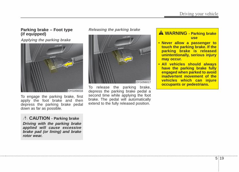
5 19
Driving your vehicle
Parking brake – Foot type (if equipped)Applying the parking brake
To engage the parking brake, firstapply the foot brake and thendepress the parking brake pedaldown as far as possible.
Releasing the parking brake
To release the parking brake,depress the parking brake pedal asecond time while applying the footbrake. The pedal will automaticallyextend to the fully released position.
CAUTION - Parking brakeDriving with the parking brakeapplied will cause excessivebrake pad (or lining) and brakerotor wear.
WARNING - Parking brakeuse
• Never allow a passenger totouch the parking brake. If theparking brake is releasedunintentionally, serious injurymay occur.
• All vehicles should alwayshave the parking brake fullyengaged when parked to avoidinadvertent movement of thevehicles which can injureoccupants or pedestrians.
OYG056016
OYG056017

Driving your vehicle
205
Check the brake warning light byturning the ignition switch ON (do notstart the engine). This light will beilluminated when the parking brake isapplied with the ignition switch in theSTART or ON position.Before driving, be sure the parkingbrake is fully released and the brakewarning light is off.If the brake warning light remains onafter the parking brake is releasedwhile the engine is running, theremay be a malfunction in the brakesystem. Immediate attention is nec-essary.
If at all possible, cease driving thevehicle immediately. If that is not pos-sible, use extreme caution whileoperating the vehicle and only con-tinue to drive the vehicle until youcan reach a safe location or repairshop.
Electronic parking brake (EPB) (if equipped)Applying the parking brake
To apply the EPB (electronic parkingbrake):
1. Depress the brake pedal.2. Pull up the EPB switch.Make sure the warning light comeson.
W-75
OYG056018N

5 21
Driving your vehicle
Also, the EPB is applied automatical-ly if the Auto Hold button is on whenthe engine is turned off. However, ifyou press the EPB switch after theengine is turned off, the EPB will notbe Applied.
✽✽ NOTICEOn a steep incline or when pulling atrailer, if the vehicle does not remainat a standstill, do as follows:1. Apply the EPB.2. Pull up the EPB switch for more
than 3 seconds.
Do not operate the parking brake/EPB while the vehicle is movingexcept in an emergency situation.
✽✽ NOTICEA click or electric brake motorwhine sound may be heard whileoperating or releasing the EPB, butthese conditions are normal andindicate that the EPB is functioningproperly.
Releasing the parking brake
To release the EPB (electronic parkingbrake), press the EPB switch whiledoing the following:
• Have the ignition switch or enginestart/stop button in the ON posi-tion.
• Depress the brake pedal.• The shift lever must be in P (Park).Make sure the brake warning lightgoes off.
OYG056019

Driving your vehicle
225
To release EPB (electronic parkingbrake) automatically:
• Shift lever in P (Park)With the engine running depressthe brake pedal and shift out of P(Park) to R (Reverse) or D (Drive).
• Shift lever in N (Neutral)With the engine running depressthe brake pedal and shift out of N(Neutral) to R (Reverse) or D(Drive).
• Automatic Transaxle 1. Start the engine.2. Fasten the driver's seat belt.3. Close the driver's door, engine
hood and trunk.4. Depress the accelerator pedal
while the shift lever is in R(Reverse), D (Drive) or Sportsmode.
Make sure the brake warning lightgoes off.
✽✽ NOTICE• For your safety, you can engage
the EPB even though the ignitionswitch or engine stop/start buttonis in the OFF position, but youcannot release it.
• For your safety, depress the brakepedal and release the parkingbrake manually with the EPBswitch when you drive downhill orwhen backing up the vehicle.
Do not follow the above procedurewhen driving on a flat level ground.The vehicle may suddenly move for-ward.
✽✽ NOTICEIf the parking brake warning light isstill on even though the EPB hasbeen released, have the systemchecked by an authorized Kia dealer.
EPB (electronic parking brake) maybe automatically applied when:
• The EPB is overheated• Requested by other systems
✽✽ NOTICEIf the driver turns the engine off bymistake while Auto Hold is operat-ing, EPB will be automaticallyapplied. (Vehicles equipped withAuto Hold)
CAUTIONDo not drive your vehicle withthe EPB applied. It may causeexcessive brake pad and brakerotor wear.

5 23
Driving your vehicle
System warning“To release EPB, fasten seatbelt, closedoor, hood and trunk”• If you try to drive off depressing the
accelerator pedal with the EPBapplied, but the EPB doesn'trelease automatically, a warningwill sound and a message willappear.
• If the driver's seat belt is not fas-tened and the engine hood, driver'sdoor or trunk is opened, a warningwill sound and a message willappear.
• If there is a problem with the vehi-cle, a warning may sound and amessage may appear.
If the above situation occurs, depressthe brake pedal and release EPB bypressing the EPB switch.
• A click or electric brake motorwhine sound may be heard whileoperating or releasing the EPB, butthese conditions are normal andindicate that the EPB is functioningproperly.
• When leaving your keys with aparking lot attendant or valet, makesure to inform him/her how to oper-ate the EPB.
• The EPB may malfunction if youdrive with the EPB applied.
• When you automatically releaseEPB by depressing the acceleratorpedal, depress it slowly.
WARNING - ParkingBrake Use
All vehicles should always havethe parking brake fully engagedwhen parked to avoid inadver-tent movement of the car whichcan injure occupants or pedes-trians.

Driving your vehicle
245
System warning“AUTO HOLD deactivating. Pressbrake pedal”When the conversion from Auto Holdto EPB is not working properly awarning will sound and a messagewill appear.
✽✽ NOTICEDepress the brake pedal when theabove message appears for the AutoHold and EPB may not activate.
System warning“Parking brake automatically locked”If the EPB is applied while Auto Holdis activated because of ESC(Electronic Stability Control) signal, awarning will sound and a messagewill appear.
EPB malfunction indicator (if equipped)
This warning light illuminates if theengine start/stop button is changedto the ON position and goes off inapproximately 3 seconds if the sys-tem is operation normally.If the EPB malfunction indicatorremains on, comes on while driving,or does not come on when the igni-tion switch or the engine start/stopbutton is changed to the ON position,this indicates that the EPB may havemalfunctioned.
If this occurs, have your vehiclechecked by an authorized Kia dealeras soon as possible.The EPB malfunction indicator mayilluminate when the ESC indicatorcomes on to indicate that the ESC isnot working properly, but it does notindicate a malfunction of the EPB.
OYG056020

5 25
Driving your vehicle
• The EPB warning light may illumi-nate if the EPB switch operatesabnormally. Shut the engine offand turn it on again after a few min-utes. The warning light will go offand the EPB switch will operatenormally. However, if the EPBwarning light is still on, have thesystem checked by an authorizedKia dealer.
• If the parking brake warning lightdoes not illuminate or blinks eventhough the EPB switch was pulledup, the EPB is not applied.
• If the parking brake warning lightblinks when the EPB warning lightis on, press the switch, then pull itup. Once more press it back to itsoriginal position and pull it back up.If the EPB warning does not go off,have the system checked by anauthorized Kia dealer.
Emergency brakingIf there is a problem with the brakepedal while driving, emergency brak-ing is possible by pulling up andholding the EPB switch. Braking ispossible only while you are holdingthe EPB switch.
✽✽ NOTICEDuring emergency braking by theEPB, the parking brake warninglight will illuminate to indicate thatthe system is operating.
If you notice a continuous noise orburning smell when the EPB is usedfor emergency braking, have yourvehicle checked by an authorized Kiadealer.
When the EPB (electronic parkingbrake) is not releasedIf the EPB does not release normal-ly, take your vehicle to an authorizedKia dealer by loading the vehicle ona flatbed tow truck and have the sys-tem checked.
WARNINGDo not operate the electronicparking brake while the vehicle ismoving except in an emergencysituation. Applying the electronicparking brake while the vehicle ismoving at normal speeds cancause a sudden loss of control ofthe vehicle. If you must use theelectronic parking brake to stopthe vehicle, use great caution inapplying the brake.

Driving your vehicle
265
AUTO HOLD (if equipped)The Auto Hold maintains the vehiclein a standstill even though the brakepedal is not depressed after the driv-er brings the vehicle to a completestop by depressing the brake pedal.
1.Depress the brake pedal, start theengine and then press the AutoHold button. The white AUTOHOLD indicator will come on indi-cating the system is in standby.Before the Auto Hold will engage,the driver's door, engine hood mustbe closed and the driver's seat beltmust be fastened.
2.When coming to a complete stopby depressing the brake pedal, theAUTO HOLD indicator changesfrom white to green indicating theAUTO HOLD is engaged. The vehi-cle will remain at a standstill even ifyou release the brake pedal.
3.If EPB is applied, Auto Hold will bereleased.
OYG056021 OYG056022

5 27
Driving your vehicle
4. If you press the accelerator pedalwith the shift lever in D (Drive) ormanual mode, the Auto Hold willbe released automatically and thevehicle will start to move. The indi-cator changes from green to whiteindicating the Auto Hold is instandby and the EPB is released.
When driving off from Auto Hold bydepressing the accelerator pedal,always check the surrounding areanear your vehicle.Slowly depress the accelerator pedalfor a smooth launch.
Cancel
To cancel the Auto Hold operation,press the Auto Hold switch. TheAUTO HOLD indicator will go out.To cancel the Auto Hold operationwhen the vehicle is at a standstill,press the Auto Hold switch whiledepressing the brake pedal.
✽✽ NOTICE• The following are conditions when
the Auto Hold will not engage(Auto Hold light will not turngreen and the Auto Hold systemremains in stand by):- The driver's seat belt is unfas-
tened and driver's door is opened- The engine hood is opened- The shift lever is in P (Park) or R
(Reverse)- The EPB is applied
• For your safety, the Auto Holdautomatically switches to EPBunder any of the following condi-tions (Auto Hold light remainswhite and the EPB automaticallyapplies):- The driver's seat belt is unfas-
tened and driver's door is opened- The engine hood is opened- The vehicle is in a standstill for
more than 10 minutes- The vehicle is standing on a steep
slope- The vehicle moved several times
(Continued)
OYG056023

Driving your vehicle
285
(Continued)In these cases, the brake warninglight comes on, the AUTO HOLDindicator changes from green towhite, and a warning sounds and amessage will appear to inform youthat EPB has been automaticallyengaged. Before driving off again,press foot brake pedal, check thesurrounding area near your vehi-cle and release parking brakemanually with the EPB switch.
• If the AUTO HOLD indicatorlights up yellow, the Auto Hold isnot working properly. Take yourvehicle to an authorized Kia deal-er and have the system checked.
If there is a malfunction with the dri-ver’s door, engine hood open detec-tion system, the Auto Hold may notwork properly.Take your vehicle to an authorized Kiadealer and have the system checked.
✽✽ NOTICEA click or electric brake motorwhine sound may be heard whileoperating or releasing the EPB, butthese conditions are normal andindicate that the EPB is functioningproperly.
Warning messages“Parking brake automatically locked”When the EPB is applied from AutoHold, a warning will sound and amessage will appear.
“AUTO HOLD deactivating. Pressbrake pedal”When the conversion from Auto Holdto EPB is not working properly awarning will sound and a messagewill appear.
✽✽ NOTICEWhen this message is displayed, theAuto Hold and EPB may not oper-ate. For your safety, depress thebrake pedal.
WARNINGTo reduce the risk of an acci-dent, do not activate Auto Holdwhile driving downhill, backingup or parking your vehicle.
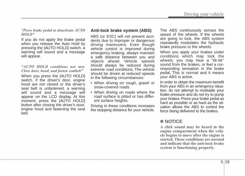
5 29
Driving your vehicle
“Press brake pedal to deactivate AUTOHOLD”If you do not apply the brake pedalwhen you release the Auto Hold bypressing the [AUTO HOLD] switch, awarning will sound and a messagewill appear.
“AUTO HOLD conditions not met.Close door, hood, and fasten seatbelt”When you press the [AUTO HOLD]switch, if the driver’s door, enginehood are not closed or the driver’sseat belt is unfastened, a warningwill sound and a message willappear on the LCD display. At thismoment, press the [AUTO HOLD]button after closing the driver’s door,engine hood and fastening the seatbelt.
Anti-lock brake system (ABS)ABS (or ESC) will not prevent acci-dents due to improper or dangerousdriving maneuvers. Even thoughvehicle control is improved duringemergency braking, always maintaina safe distance between you andobjects ahead. Vehicle speedsshould always be reduced duringextreme road conditions. The vehicleshould be driven at reduced speedsin the following circumstances:• When driving on rough, gravel or
snow-covered roads• When driving on roads where the
road surface is pitted or has differ-ent surface heights.
Driving in these conditions increasesthe stopping distance for your vehicle.
The ABS continuously senses thespeed of the wheels. If the wheelsare going to lock, the ABS systemrepeatedly modulates the hydraulicbrake pressure to the wheels.When you apply your brakes underconditions which may lock thewheels, you may hear a “tik-tik’’sound from the brakes, or feel a cor-responding sensation in the brakepedal. This is normal and it meansyour ABS is active.In order to obtain the maximum benefitfrom your ABS in an emergency situa-tion, do not attempt to modulate yourbrake pressure and do not try to pumpyour brakes. Press your brake pedal ashard as possible or as hard as the sit-uation allows the ABS to control theforce being delivered to the brakes.
✽✽ NOTICEA click sound may be heard in theengine compartment when the vehi-cle begins to move after the engine isstarted. These conditions are normaland indicate that the anti-lock brakesystem is functioning properly.

Driving your vehicle
305
• Even with the anti-lock brake sys-tem, your vehicle still requires suf-ficient stopping distance. Alwaysmaintain a safe distance from thevehicle in front of you.
• Always slow down when cornering.The anti-lock brake system cannotprevent accidents resulting fromexcessive speeds.
• On loose or uneven road surfaces,operation of the anti-lock brakesystem may result in a longer stop-ping distance than for vehiclesequipped with a conventionalbrake system.
The ABS warning light will stay on forapproximately 3 seconds after theignition switch is ON. During thattime, the ABS will go through self-diagnosis and the light will go off ifeverything is normal. If the light stayson, you may have a problem withyour ABS. Contact an authorized Kiadealer as soon as possible.
• When you drive on a road havingpoor traction, such as an icy road,and have operated your brakescontinuously, the ABS will be activecontinuously and the ABS warninglight may illuminate. Pull your vehi-cle over to a safe place and stopthe engine.
• Restart the engine. If the ABSwarning light goes off, then yourABS system is normal. Otherwise,you may have a problem with theABS. Contact an authorized Kiadealer as soon as possible.
✽✽ NOTICEWhen you jump start your vehiclebecause of a drained battery, theengine may not run as smoothly andthe ABS warning light may turn on atthe same time. This happens becauseof low battery voltage. It does notmean your ABS has malfunctioned.• Do not pump your brakes!• Have the battery recharged before
driving the vehicle.
W-78

5 31
Driving your vehicle
Electronic stability control(ESC)
The Electronic Stability control(ESC) system is designed to stabi-lize the vehicle during corneringmaneuvers. ESC checks where youare steering and where the vehicle isactually going. ESC applies thebrakes on individual wheels andintervenes with the engine manage-ment system to stabilize the vehicle.
Electronic stability control (ESC) willnot prevent accidents. Excessivespeed in turns, abrupt maneuversand hydroplaning on wet surfacescan still result in serious accidents.Only a safe and attentive driver canprevent accidents by avoidingmaneuvers that cause the vehicle tolose traction. Even with ESCinstalled, always follow all the normalprecautions for driving - includingdriving at safe speeds for the condi-tions.
The Electronic Stability Control (ESC)system is an electronic systemdesigned to help the driver maintainvehicle control under adverse condi-tions. It is not a substitute for safe driv-ing practices. Factors including speed,road conditions and driver steeringinput can all affect whether ESC will beeffective in preventing a loss of control.It is still your responsibility to drive andcorner at reasonable speeds and toleave a sufficient margin of safety.When you apply your brakes underconditions which may lock the wheels,you may hear a “tik-tik’’ sound from thebrakes, or feel a corresponding sensa-tion in the brake pedal. This is normaland it means your ESC is active.
✽✽ NOTICEA click sound may be heard in theengine compartment when the vehi-cle begins to move after the engine isstarted. These conditions are normaland indicate that the ElectronicStability Control System is function-ing properly.
OYG056024

Driving your vehicle
325
ESC operationESC ON condition
• When the ignition is turnedON, ESC and ESC OFFindicator lights illuminate forapproximately 3 seconds,then ESC is turned on.
• Press the ESC OFF but-ton for at least half a sec-ond after turning the igni-tion ON to turn ESC off.(ESC OFF indicator willilluminate). To turn theESC on, press the ESCOFF button (ESC OFFindicator light will go off).
• When starting the engine,you may hear a slight tick-ing sound. This is the ESCperforming an automaticsystem self-check and doesnot indicate a problem.
When operating
When the ESC is in opera-tion, the ESC indicator lightblinks.• When the Electronic
Stability Control is operat-ing properly, you can feel aslight pulsation in the vehi-cle. This is only the effectof brake control and indi-cates nothing unusual.
• When moving out of themud or driving on a slip-pery road, pressing theaccelerator pedal may notcause the engine rpm(revolutions per minute) toincrease.
ESC operation offESC OFF state
This car has 2 kinds of ESCoff states.If the engine stops whenESC is off, ESC remains off.Upon restarting the engine,the ESC will automaticallyturn on again.
-

5 33
Driving your vehicle
• ESC off state 1“Traction Control disabled”To cancel ESC operation, press theESC OFF button (ESC OFF ) short-ly (ESC OFF indicator light (ESC OFF
) illuminates). At this state, theengine control function does not oper-ate. It means the traction control func-tion does not operate. Brake controlfunction only operates.
• ESC off state 2“Traction & Stability Control disabled”To cancel ESC operation, press theESC OFF button (ESC OFF ) formore than 3 seconds. ESC OFF indi-cator light (ESC OFF ) illuminatesand ESC OFF warning chime willsound. At this state, the engine con-trol function and brake control func-tion do not operate. It means the carstability control function does notoperate any more.
Indicator light
When ignition switch is turned to ON,the indicator light illuminates, thengoes off if the ESC system is operat-ing normally.The ESC indicator light blinks when-ever ESC is operating or illuminateswhen ESC fails to operate.The ESC OFF indicator light comeson when the ESC is turned off withthe button.
■ ESC indicator light
■ ESC OFF indicator light
WARNING - Electronic sta-bility control
Drive carefully even though yourvehicle has Electronic StabilityControl. It can only assist you inmaintaining control under cer-tain circumstances.

Driving your vehicle
345
ESC OFF usageWhen driving
• ESC should be turned on for dailydriving whenever possible.
• To turn ESC off while driving, pressthe ESC OFF button while drivingon a flat road surface.
✽✽ NOTICE• When operating the vehicle on a
dynamometer, ensure that theESC is turned off (ESC OFF lightilluminated). If the ESC is left on,it may prevent the vehicle speedfrom increasing, and result in falsediagnosis.
• Turning the ESC off does not affectABS or brake system operation.
Vehicle stability management(VSM)This system provides furtherenhancements to vehicle stabilityand steering responses when a vehi-cle is driving on a slippery road or avehicle detects changes in coeffi-cient of friction between right wheelsand left wheels when braking.
VSM operationWhen the VSM is in operation, ESCindicator light ( ) blinks.When the vehicle stability manage-ment is operating properly, you canfeel a slight pulsation in the vehicleand/or abnormal steering responses(EPS- Electronic Power Steering).This is only the effect of brake andEPS control and indicates nothingunusual.
The VSM does not operate when:
• Driving on a sloping road such as agradient or incline
• Driving in reverse• ESC OFF indicator light ( )
remains on the instrument cluster• EPS indicator light remains on the
instrument cluster
WARNING - OperatingESC
Never press the ESC OFF but-ton while ESC is operating (ESCindicator light blinks).If ESC is turned off while ESC isoperating, the vehicle may slipout of control.
WARNING - Tire/Wheel size
When replacing tires and wheels,make sure they are the same sizeas the original tires and wheelsinstalled. Driving with varyingtire or wheel sizes may diminishany supplemental safety benefitsof the VSM system.

5 35
Driving your vehicle
VSM operation offIf you press the ESC OFF button toturn off the ESC, the VSM will alsocancel and the ESC OFF indicatorlight ( ) illuminates.To turn on the VSM, press the buttonagain. The ESC OFF indicator lightgoes out.
Malfunction indicatorThe VSM can be deactivated even ifyou don’t cancel the VSM operationby pressing the ESC OFF button. Itindicates that a malfunction hasbeen detected somewhere in theElectric Power Steering system orVSM system. If the ESC indicatorlight ( ) or EPS warning lightremains on, take your vehicle to anauthorized Kia dealer and have thesystem checked.
✽✽ NOTICE• The VSM is designed to function
above approximately 22 km/h (13mph) on curves.
• The VSM is designed to functionabove approximately 10 km/h (6mph) when a vehicle is braking ona split-mu surface. A split-mu sur-face is made of two surfaces whichhave different friction forces.
• The Vehicle Stability Managementsystem is not a substitute for safedriving practices but a supplemen-tary function only. It is the respon-sibility of the driver to always checkthe speed and the distance to thevehicle ahead. Always hold thesteering wheel firmly while driving.
• Your vehicle is designed to activateaccording to the driver’s intention,even with installed VSM. Always fol-low all the normal precautions fordriving at safe speeds for the condi-tions – including driving in clementweather and on a slippery road.
✽✽ NOTICEFor maximum protection, alwayswear your seat belt. No system, nomatter how advanced, can compen-sate for all driver error and/or driv-ing conditions. Always drive respon-sibly.

Driving your vehicle
365
Hill-start assist control (HAC)A vehicle has the tendency to rollback on a steep hill when it starts togo after stopping. The Hill-startAssist Control (HAC) prevents thevehicle from rolling back by applyingthe brakes automatically for about 2seconds. The brakes are releasedwhen the accelerator pedal isdepressed or after about 2 seconds.The HAC is activated only for about 2seconds, so when the vehicle isstarting off always depress the accel-erator pedal.
Good braking practices• Check to be sure the parking brake
is not engaged and the parkingbrake indicator light is out beforedriving away.
• Driving through water may get thebrakes wet. They can also get wetwhen the vehicle is washed. Wetbrakes can be dangerous! Yourvehicle will not stop as quickly if thebrakes are wet. Wet brakes maycause the vehicle to pull to one side.To dry the brakes, apply the brakeslightly until the braking actionreturns to normal, taking care tokeep the vehicle under control at alltimes. If the braking action does notreturn to normal, stop as soon as itis safe to do so and call an author-ized Kia dealer for assistance.
• Don't coast down hills with thevehicle out of gear.This is extreme-ly hazardous. Keep the vehicle ingear at all times, use the brakes toslow down, then shift to a lowergear so that engine braking willhelp you maintain a safe speed.
• Don't "ride" the brake pedal.Resting your foot on the brakepedal while driving can be danger-ous because the brakes mightoverheat and lose their effective-ness. It also increases the wear ofthe brake components.
• If a tire goes flat while you are driv-ing, apply the brakes gently andkeep the vehicle pointed straightahead while you slow down. Whenyou are moving slowly enough for itto be safe to do so, pull off the roadand stop in a safe place.
• If your vehicle is equipped with anAutomatic Transaxle, don't let yourvehicle creep forward. To avoidcreeping forward, keep your footfirmly on the brake pedal when thevehicle is stopped.
WARNING - MaintainingBrake Pressure on Incline
HAC does not replace the needto apply brakes while stopped onan incline. While stopped, makesure you maintain brake pres-sure sufficient to prevent yourvehicle from rolling backwardand causing an accident. Don’trelease the brake pedal until youare ready to accelerate forward.

5 37
Driving your vehicle
• Be cautious when parking on a hill.Firmly engage the parking brakeand place the shift lever in P (auto-matic transaxle). If your vehicle isfacing downhill, turn the frontwheels into the curb to help keepthe vehicle from rolling.If your vehicle is facing uphill, turnthe front wheels away from thecurb to help keep the vehicle fromrolling. If there is no curb or if it isrequired by other conditions tokeep the vehicle from rolling, blockthe wheels.
• Under some conditions your park-ing brake can freeze in theengaged position. This is most like-ly to happen when there is anaccumulation of snow or icearound or near the rear brakes or ifthe brakes are wet. If there is a riskthat the parking brake may freeze,apply it only temporarily while youput the shift lever in P (automatictransaxle) and block the rearwheels so the vehicle cannot roll.Then release the parking brake.
• Do not hold the vehicle on anincline with the accelerator pedal.This can cause the transaxle tooverheat. Always use the brakepedal or parking brake.

Driving your vehicle
385
The AEB system is to reduce or toavoid accident risk. It recognizes thedistance from the vehicle ahead orthe pedestrian through the sensors(i.e. radar and camera), and, if nec-essary, warns the driver of accidentrisk with the warning message or thewarning alarms.
✽✽ NOTICETake the following precautions whenusing the Autonomous EmergencyBraking (AEB):• This system is only a supplemental
system and it is not intended to,nor does it replace the need forextreme care and attention of thedriver. The sensing range andobjects detectable by the sensorsare limited. Pay attention to theroad conditions at all times.
• NEVER drive too fast in accor-dance with the road conditions orwhile cornering.
• Always drive cautiously to preventunexpected and sudden situationsfrom occurring. AEB does not stopthe vehicle completely and doesnot avoid collisions.
System setting and activationSystem settingThe driver can activate the AEB byplacing the ignition switch to the ONposition and by selecting 'UserSettings', 'Driving Assist', and'Autonomous Emergency Braking.The AEB deactivates, when the driv-er cancels the system setting.
WARNING - Autonomous Emergency
Braking (AEB) Limitations The AEB system is a supple-mental system and is not a sub-stitute for safe driving prac-tices. It is the responsibility ofthe driver to always check thespeed and distance to the vehi-cle ahead to ensure it is safetyto use the AEB system.
AUTONOMOUS EMERGENCY BRAKING (AEB)/ FORWARD COLLISION WARNING (FCW)(IF EQUIPPED)

5 39
Driving your vehicle
The warning light illumi-nates on the LCD display,when you cancel the AEBsystem. The driver can
monitor the AEB ON/OFF status onthe LCD display. When the warninglight remains ON with the AEB acti-vated, we recommend you to havethe system checked by an authorizedKia dealer.
The driver can select the initial warn-ing activation time in the UserSettings in the instrument clusterLCD display. The options for the ini-tial Forward Collision Warninginclude the following:
• EARLY - When this condition isselected, the initialForward Collision Warningis activated earlier thannormal. This setting maxi-mizes the amount of dis-tance between the vehicleor pedestrian ahead beforethe initial warning occurs.
• NORMAL - When this condition isselected, the initialForward CollisionWarning is activated nor-mally. This setting allowsfor a nominal amount ofdistance between thevehicle or pedestrianahead before the initialwarning occurs.
• LATE - When this condition isselected, the initial ForwardCollision Warning is activat-ed later than normal. Thissetting reduces the amountof distance between thevehicle or pedestrian aheadbefore the initial warningoccurs.

Driving your vehicle
405
Prerequisite for activationThe AEB will activate when the AEBis selected on the LCD display, andwhen the following prerequisites aresatisfied:- The ESC (Electronic Stability
Control) is activated.- The driving speed is over 6 mph.
(The AEB only works within a cer-tain range of vehicle speeds)
- When the AEB recognizes a vehi-cle or the pedestrian in front. (TheAEB may not recognize everyobstacle or provide warnings andbraking in every situation, so donot rely on the AEB to stop thevehicle in instances where the driv-er sees an obstacle and has theability to apply the brakes)
• The AEB automatically activateswhen you turn the vehicle on.The driver can deactivate the AEBby canceling the system setting onthe LCD display.
• The AEB automatically deactivateswhen canceling the ESC.When theESC is canceled, the AEB cannotbe activated on the LCD display.
WARNING To avoid driver distractions, donot attempt to set or cancel theAEB while operating the vehicle.

5 41
Driving your vehicle
AEB warning message andsystem controlThe AEB produces warning mes-sages, warning alarms, and emer-gency braking based on the level ofrisk of a frontal collision, such aswhen a vehicle ahead suddenlybrakes, when there is no following dis-tance from the vehicle in front, orwhen it detects a collision with apedestrian is imminent.
Forward Warning (1st warning)
The warning message appears onthe LCD display with the warningalarms.
Collision Warning (2nd warning)
• The warning message appears onthe LCD display with the warningalarms.
• The AEB applies the brakes withincertain limit to reduce the impactfrom a collision.
OYG056089N OYG056090N

Driving your vehicle
425
Emergency braking (3rd warning)
• The warning message appears onthe LCD display with the warningalarms.
• The AEB controls the brakes with-in certain limit to release shockfrom the collision.The AEB controls the maximumbrakes just before the collision.
Brake operation• In an urgent situation, the braking
system enters into the ready statusfor prompt reaction against the dri-ver’s depressing the brake pedal.
• The AEB provides additional brak-ing power for optimum braking per-formance, when the driverdepresses the brake pedal.
• The braking control is automatical-ly deactivated, when the driversharply depresses the brake pedal,or when the driver abruptly turnsthe steering wheel.
• The braking control is automatical-ly canceled, when risk factors dis-appear.
The driver should always exercisecaution when operating the vehicle,even though there is no warningmessage or warning alarm.
✽✽ NOTICEThe AEB operates in accordancewith the risk levels, such as the dis-tance from the vehicle/passer-by infront, the speed of the vehicle/pass-er-by in front, and the driver's vehi-cle operation.
OYG056091N
WARNING The AEB cannot avoid all colli-sions. The AEB might not com-pletely stop the vehicle beforecollision, due to ambient weath-er and road conditions. Thedriver has the responsibility todrive safely and control thevehicle.

5 43
Driving your vehicle
Sensor to detect the distancefrom the vehicle in front (front radar)
The sensor is to maintain a certaindistance from the vehicle in front.However, the smudged sensor lenswith foreign substances, such assnow and rain, adversely affects thesensing performance. It may eventemporarily cancel the AEB. Alwayskeep the sensor lens clean.
Warning message and warninglightWhen the sensor is covered or thesensor lens is dirty with foreign sub-stances, such as snow or rain, theAEB operation may temporarily stop.In this case, a warning message(“Auto Emergency Braking disabled.Radar blocked”) will appear to notifythe driver.
This is not a malfunction with theAEB. To operate the AEB again,remove the foreign substances.
✽✽ NOTICE• Do not install any accessories, such
as a license plate bracket orbumper sticker near the sensorarea. Do not replace the bumperby yourself. Doing so may adverse-ly affect the sensing performance.
• Always keep the sensor/bumperarea clean.
• Use only a soft cloth to wash thevehicle. Also, do not spray highlypressurized water on the sensorinstalled on the bumper.
• Be careful not to apply unneces-sary force on the frontal sensorarea. When the sensor moves outof the correct position due toexternal force, the system may notoperate correctly even without thewarning light or message. In thiscase, we recommend you to havethe vehicle inspected by anauthorized Kia dealer.
• Use only the genuine Kia sensorcover. Do not arbitrarily applypaint on the sensor cover.
OYG056025

Driving your vehicle
445
System malfunction
• When the AEB is not working prop-erly, the AEB warning light ( ) willilluminate and the warning mes-sage will appear for a few seconds.After the message disappears, themaster warning light ( ) will illu-minate. In this case, we recommendyou to have the vehicle inspected byan authorized Kia dealer.
• The AEB warning message mayappear along with the illuminationof the ESC warning light.
• The AEB may unnecessarily pro-duce warning messages and warn-ing alarms. Due to the sensing lim-itation, the AEB may not producewarning messages or warningalarm at all.
• When there is a malfunction withthe AEB, the braking control doesnot operate upon detecting a colli-sion risk even with other brakingsystems normally operating.
• The AEB operates only for thevehicle / pedestrian in front, whiledriving forward. It does not operatefor any animals or vehicles in theopposite direction.
• The AEB can not recognize cross-traffic or parked vehicles present-ing a side-profile.
OYG056094N
WARNING The AEB is only a supplementalsystem for the driver’s conven-ience.The driver still maintainsresponsibility to control thevehicle. Do not solely dependon the AEB system. Rather,maintain a safe braking dis-tance, and, if necessary,depress the brake pedal tolower the driving speed.

5 45
Driving your vehicle
Limitation of the systemThe AEB is an assistant system for adriver in a certain risky driving condi-tion and it does not take everyresponsibility for all risks from drivingcondition.The AEB monitors the driving situa-tions through the radar and the cam-era sensor. For any vehicle activityoccurring outside the sensor range,the AEB may not function. The drivershould exercise caution in the follow-ing situations, as the AEB operationmay be limited:
Recognizing vehicles- The radar or the camera is con-
taminated with foreign substances.- It heavily rains or snows.- There is electromagnetic interfer-
ence.- Something in the path of travel
deflects the radar waves.- The vehicle in front has a narrow
body. (i.e. motorcycles and bicycles)- The driver’s view is degraded by
driving towards sunlight, reflectedlight, or darkness.
- The camera cannot see the fullprofile of the vehicle in front.
- The vehicle in front is a specialvehicle, such as a heavily-loadedtruck or a trailer.
The vehicle in front does not turnON the rear lights, does not haverear lights, has asymmetric rearlights, or has rear lights out of angle.
- The outside brightness is greatlychanged, such as entering/exitingthe tunnel.
- The vehicle driving is unstable.- The radar/camera sensor recogni-
tion is limited.

Driving your vehicle
465
- Driving on a curveThe AEB performance decreaseswhile driving on a curve. The AEBmay not recognize the vehicle in fronteven in the same lane. It may unnec-essarily produce the warning mes-sage and the warning alarm, or itmay not produce the warning mes-sage and the warning alarm at all.While driving on a curve, exercisecaution, and, if necessary, depressthe brake pedal.
While driving on a curve, the AEBmay recognize the vehicle in front inthe next lane. Exercise caution, and, ifnecessary, depress the brake pedal.Or, depress the accelerator pedal tomaintain the driving speed. Always,take a look around the vehicle foryour safety.
- Driving on a slopeThe AEB performance decreaseswhile driving upward or downward ona slope, not recognizing the vehiclein front in the same lane. It mayunnecessarily produce the warningmessage and the warning alarm, or itmay not produce the warning mes-sage and the warning alarm at all.When the AEB suddenly recognizesthe vehicle in front while passingover a slope, you may experiencesharp deceleration.Always keep your eyes forward whiledriving upward or downward on aslope, and, if necessary, depress thebrake pedal.
OYG056043 OYG056044OYG056042

5 47
Driving your vehicle
- Changing lanes Even though the vehicle in the nextlane enters into your lane, it may notbe recognized by the AEB, until itenters the AEB sensing range.Especially when the vehicle in thenext lane abruptly enters into yourlane, it is more likely not be recog-nized. Always be attentive to drivingconditions.
When the stopped vehicle in frontgets out of the lane, it may not berecognized by your AEB. Always beattentive to driving conditions.
- Recognizing the vehicle When the vehicle in front has heavyloading extended rearward, or whenthe vehicle in front has higher groundclearance, it may induce a haz-ardous situation.
OYG056045 OYG056048 OYG056050
Driving your vehicle
485
Recognizing pedestrians- The pedestrian is not fully captured
by the camera sensor, or thepedestrian does not walk in theupright position.
- The pedestrian moves very fast.- The pedestrian abruptly appears in
front.- The pedestrian wears clothes sim-
ilar in color to the background.- Conditions outside are too bright or
too dark.- The vehicle drives at night or in the
darkness.- There is an item similar in shape a
person’s body structure.- The pedestrian is small.- The pedestrian has impaired
mobility.- The pedestrian blends in with their
surroundings.- Sensor recognition is limited by
rain, snow, fog, etc.- There is a group of pedestrians.
✽✽ NOTICEThe system may temporarily canceldue to the strong electric waves.
• Pay great caution to the vehicle infront, when it has heavy loadingextended rearward, or when it hashigher ground clearance.
• The sensor only detects pedestri-an, not carts, bicycles, motorcy-cles, luggage bags, or strollers.
WARNING - Testing theAEB
The AEB does not operate incertain situations. Thus, nevertest-operate the AEB against aperson or an object. It maycause a severe injury or evendeath.
WARNING - AEB andTowing
Cancel the AEB in the UserSettings on the LCD display,before towing another vehicle.While towing, the brake applica-tion may adversely affect yourvehicle safety.
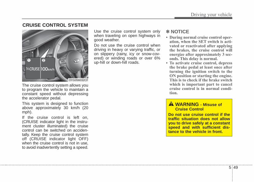
5 49
Driving your vehicle
The cruise control system allows youto program the vehicle to maintain aconstant speed without depressingthe accelerator pedal.This system is designed to functionabove approximately 30 km/h (20mph).If the cruise control is left on,(CRUISE indicator light in the instru-ment cluster illuminated) the cruisecontrol can be switched on acciden-tally. Keep the cruise control systemoff (CRUISE indicator light OFF)when the cruise control is not in use,to avoid inadvertently setting a speed.
Use the cruise control system onlywhen traveling on open highways ingood weather.Do not use the cruise control whendriving in heavy or varying traffic, oron slippery (rainy, icy or snow-cov-ered) or winding roads or over 6%up-hill or down-hill roads.
✽✽ NOTICE• During normal cruise control oper-
ation, when the SET switch is acti-vated or reactivated after applyingthe brakes, the cruise control willenergize after approximately 3 sec-onds. This delay is normal.
• To activate cruise control, depressthe brake pedal at least once afterturning the ignition switch to theON position or starting the engine.This is to check if the brake switchwhich is important part to cancelcruise control is in normal condi-tion.
CRUISE CONTROL SYSTEM
WARNING - Misuse ofCruise Control
Do not use cruise control if thetraffic situation does not allowyou to drive safely at a constantspeed and with sufficient dis-tance to the vehicle in front.
OYG056032CF

Driving your vehicle
505
To set cruise control speed:
1. Press the CRUISE button on thesteering wheel to turn the systemon. The CRUISE indicator light inthe instrument cluster will illumi-nate.
2. Accelerate to the desired speed,which must be more than 30 km/h(20 mph).
3. Move the lever down (to SET-), andrelease it at the desired speed.Thecruise indicator and set speed onthe LCD screen will illuminate.Release the accelerator at thesame time. The desired speed willautomatically be maintained.
On a steep grade, the vehicle mayslow down or speed up slightly whilegoing downhill.
To increase cruise control setspeed:
Follow either of these procedures:• Move the lever up (to RES+) and
hold it. Your vehicle will accelerate.Release the lever at the speed youwant.
• Move the lever up (to RES+) andrelease it immediately. The cruisingspeed will increase by 1 km/h (1.0mph) each time the lever is operat-ed in this manner.
OYG056033
OYG056034
OYG056035

5 51
Driving your vehicle
To decrease the cruisingspeed:
Follow either of these procedures:• Move the lever down (to SET-) and
hold it. Your vehicle will graduallyslow down. Release the lever at thespeed you want to maintain.
• Move the lever down (to SET-) andrelease it immediately. The cruisingspeed will decrease by 1 km/h (1.0mph) each time the lever is operat-ed in this manner.
To temporarily accelerate withthe cruise control on:If you want to speed up temporarilywhen the cruise control is on,depress the accelerator pedal.Increased speed will not interferewith the cruise control operation orchange the set speed.To return to the set speed, take yourfoot off the accelerator.
To cancel cruise control, doone of the following:
• Depress the brake pedal.• Shift into N (Neutral) with an
Automatic Transaxle.• Press the CANCEL switch.• Decrease the vehicle speed lower
than the set speed by 20 km/h (12mph).
• Decrease the vehicle speed to lessthan approximately 25 km/h (15mph).
OYG056036OYG056034

Driving your vehicle
525
Each of these actions will cancelcruise control operation (The setspeed on the LCD will disappear andthe CRUISE indicator will illuminatecontinuously.), but it will not turn thesystem off. If you wish to resumecruise control operation, move thelever up (to RES+). You will return toyour previously preset speed.
To resume cruising speed atmore than approximately 30km/h (20 mph):
If any method other than theCRUISE ON-OFF switch was usedto cancel cruising speed and the sys-tem is still activated, the most recentset speed will automatically resumewhen you move the lever up.It will not resume, however, if thevehicle speed has dropped belowapproximately 30 km/h (20 mph).
To turn cruise control off, doone of the following:
• Press the CRUISE button (theCRUISE indicator light in theinstrument cluster will go off).
• Turn the ignition off.Both of these actions will cancel thecruise control operation. If you wantto resume the cruise control opera-tion, repeat the steps provided in “Toset cruise control speed” on the pre-vious page.
OYG056035
OYG056033

5 53
Driving your vehicle
ADVANCED SMART CRUISE CONTROL SYSTEM (ASCC) (IF EQUIPPED)
➀ Cruise indicator➁ Set speed➂ Vehicle-to-vehicle distance
The ASCC allows you to program thevehicle to maintain a set speed solong as it is not limited by traffic.Whentraffic is encountered the vehicle willslow down to maintain a set distancebehind traffic without depressing theaccelerator or brake pedal.
WARNING - AdvancedSmart Cruise ControlInadvertent Activation
If the advanced smart cruisecontrol is left on (CRUISE indi-cator in the instrument clusterilluminated), it can be activatedinadvertently. Keep theadvanced smart cruise controlsystem off (CRUISE indicatorturn off) when the advancedsmart cruise control is not inuse to avoid setting a speedwhich the driver is not aware of.
WARNING- Advanced Smart Cruise
Control Limitations• The advanced smart cruise
control is a supplemental sys-tem and is not a substitute forsafe driving practices. It is theresponsibility of the driver toalways check the speed anddistance to the vehicle ahead.
(Continued)
OYG056096C
(Continued)• Do not use the advanced
smart cruise control when itmay not be safe to keep thecar at a constant speed, forinstance, driving in heavy orvarying traffic, or on slippery(rainy, icy or snow-covered) orwinding roads or over 6%uphill or down-hill roads.- Highway interchange and
tollgate- Road surrounded by abnor-
mally multiple steel con-structions (subway con-struction, steel tunnel, etc)
- Parking lot- Lanes beside guard rail on a
road- Slippery road with rain, ice,
or snow covered- Abrupt curved road- Steep hills- Windy roads- Off roads
(Continued)

Driving your vehicle
545
Speed setting (ASCC)To set cruise control speed:
1. Press the CRUISE button, to turnthe system on. The CRUISE indi-cator in the instrument cluster willilluminate.
2. Accelerate to the desired speed.• 30 km/h (20 mph) ~ 200 km/h
(120 mph) : when there is novehicle in front
• 0 km/h (0 mph) ~ 200 km/h (120mph) : when there is a vehicle infront
3. Move the lever down (to SET-),and release it at the desiredspeed. The set speed and vehicleto vehicle distance on the LCDscreen will illuminate.
4. Release the accelerator pedal.The desired speed will automati-cally be maintained.
If there is a vehicle in front of you, thespeed may decrease to maintain thedistance to the vehicle ahead.On a steep grade, the vehicle mayslow down or speed up slightly whilegoing uphill or downhill.
OYG056037
OYG056038
(Continued)- Rods under construction- Rumble strip- The sensing ability decreas-
es if the level of front andrear vehicle is changed fromthe factory.
- Limited visibility (rain, snow,smog, etc)
- Cruise function should notbe used when the vehicle isbeing towed to prevent anydamage.
• The advanced smart cruisecontrol system cannot recog-nize a stopped vehicle, pedes-trians or an oncoming vehicle.Always look ahead cautiouslyto prevent unexpected and sud-den situations from occurring.
• Use the advanced smart cruisecontrol system only when trav-eling on open highways ingood weather conditions.

5 55
Driving your vehicle
To increase cruise control setspeed:
Follow either of these procedures:• Move the lever up (to RES+), and
hold it. Your vehicle set speed willincrease by 10 km/h (5 mph).Release the lever at the speed youwant.
• Move the lever up (to RES+), andrelease it immediately. The cruisingspeed will increase by 1.0 km/h (1mph) each time you move the leverup (to RES+) in this manner.
• ASCC will operate to a maximumsetting of 200 km/h (120 mph).However all local speed limit lawsmust be followed.
To decrease the cruise controlset speed:
Follow either of these procedures:• Move the lever down (to SET-), and
hold it. Your vehicle set speed willdecrease by 10 km/h (5 mph).Release the lever at the speed youwant.
• Move the lever down (to SET-), andrelease it immediately. The cruisingspeed will decrease by 1.0 km/h (1mph) each time you move the leverdown (to SET-) in this manner.
• You can set the cruise control to anyspeed above 30 km/h (20 mph).
To temporarily accelerate with thecruise control on:If you want to speed up temporarilywhen the cruise control is on,depress the accelerator pedal.Increased speed will not interferewith cruise control operation orchange the set speed.To return to the set speed, take yourfoot off the accelerator.If you move the lever down (to SET-)at increased speed, the cruisingspeed will be set again.
✽✽ NOTICEBe careful when accelerating tem-porarily, because the speed is notregulated automatically at this timeeven if there is a vehicle in front ofyou.
OYG056148N OYG056038

Driving your vehicle
565
ASCC will be temporarily can-celed when:
Cancelled manually
The advanced smart cruise control istemporarily canceled when the brakepedal is depressed or the CANCELbutton is pressed. The speed andvehicle to vehicle distance indicatoron the cluster will disappear and theCRUISE indicator is illuminated con-tinuously.
Cancelled automatically
• The driver's door is opened.• The shift lever is shifted to N
(Neutral), R (Reverse) or P(Parking).• The EPB (electronic parking brake)
is applied.• The vehicle speed is over 210
km/h (130 mph)• The ESC, ABS or TCS is operat-
ing.• The ESC is turned off.• The sensor or the cover is dirty or
blocked with foreign matter.• When the vehicle is stopped for
over 5 minutes.• The driver starts driving by pushing
the lever up (RES +) or down (SET -) or depressing the acceler-ator pedal approximately 3 sec-onds after the vehicle is stopped bythe Advanced Smart CruiseControl System with no other vehi-cle ahead or a vehicle stopped faraway in front.
• The engine speed is in dangerousrange.
• The ASCC system has malfunc-tioned.
• The accelerator pedal is continu-ously depressed for long time.
Each of these actions will cancel theASCC operation. (The set speedand vehicle-to-vehicle distance onthe LCD display will go off.)If the ASCC is cancelled automati-cally, the ASCC will not resumeeven though the RES+ or SET-lever is moved. Also, the EPB (elec-tronic parking brake) will be appliedwhen the vehicle is stopped.- When activating the AEB
(Autonomous Emergency Braking)
If the ASCC is cancelled by a reasonnot mentioned, have the systemchecked by an authorized Kia dealer.
OYG056040

5 57
Driving your vehicle
“Smart Cruise Control canceled”✽✽ NOTICEIf the system is automatically can-celled, the warning chime will soundand a message will appear for a fewseconds. You must adjust the vehiclespeed by depressing the acceleratoror brake pedal according to the roadconditions ahead and driving condi-tion. Always check the road condi-tions. Do not rely on the warningchime.
To resume cruise control setspeed:
If any method other than theCRUISE button was used to cancelcruising speed and the system is stillactivated, the cruising speed willautomatically resume when youmove the lever up/down (to RES+ orSET-).If you move the lever up (to RES+),the speed will resume to the recentlyset speed. It will not resume if thevehicle speed has dropped belowapproximately 30 km/h (20 mph).
WARNING - FollowingDistance
• To avoid collisions, always beaware of the selected speedand vehicle to vehicle dis-tance settings when activat-ing your smart cruise controlsystem.
• Always maintain sufficientbraking distance and deceler-ate your vehicle by applyingthe brakes if necessary.
OYG056148N

Driving your vehicle
585
To turn cruise control off:
Press the CRUISE button. (theCRUISE indicator in the instrumentcluster will go off).
Vehicle to vehicle distancesetting (ASCC)To set vehicle to vehicle distance:
This function allows you to programthe vehicle to maintain relative dis-tance to the vehicle ahead withoutdepressing the accelerator pedal orbrake pedal.
The vehicle to vehicle distance willautomatically activate when theASCC is on.Select the appropriate distanceaccording to road conditions andvehicle speed.
Each time the button is pressed, thevehicle to vehicle distance changesas follows:
OYG056037
OYG056041
Distance 4 Distance 3 Distance 2
Distance 1
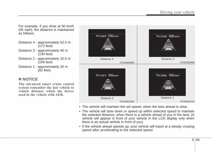
5 59
Driving your vehicle
For example, if you drive at 90 km/h(56 mph), the distance is maintainedas follows;
Distance 4 - approximately 52.5 m(172 feet)
Distance 3 - approximately 40 m(130 feet)
Distance 2 - approximately 32.5 m(106 feet)
Distance 1 - approximately 25 m(82 feet)
✽✽ NOTICEThe advanced smart cruise controlsystem remember the last vehicle tovehicle distance which the driverused in the vehicle with AEB.
• The vehicle will maintain the set speed, when the lane ahead is clear.• The vehicle will slow down or speed up within selected speed to maintain
the selected distance, when there is a vehicle ahead of you in the lane. (Avehicle will appear in front of your vehicle in the LCD display only whenthere is an actual vehicle in front of you)
• If the vehicle ahead speeds up, your vehicle will travel at a steady cruisingspeed after accelerating to the selected speed.
OYG056100C
OYG056099C
OYG056101C
OYG056098C
Distance 4
Distance 2
Distance 3
Distance 1

Driving your vehicle
605
• The warning chime sounds andLCD display blinks if it is hard tomaintain the selected distance tothe vehicle ahead.
• If the warning chime sounds,actively adjust the vehicle speed bydepressing the brake pedalaccording to the road conditionahead and driving condition.
• Even if the warning chime is not acti-vated, always pay attention to thedriving conditions to prevent danger-ous situations from occurring.
If the vehicle ahead (vehicle speed:less than 30 km/h (20 mph)) movesto the next lane, the warning chimewill sound and a message (“Watchfor stopped vehicle”) will appear.If a vehicle enters into your lane mov-ing less than the designated speed,you can adjust your vehicle speed bydepressing the brake pedal.
In heavy trafficIn traffic, your vehicle will stop if thevehicle ahead of you stops. Also, ifthe vehicle ahead of you starts mov-ing, your vehicle will start as well.However, if the vehicle stops formore than 3 seconds, you mustdepress the accelerator pedal ormove up/down the lever (to RES+ orSET-) to start driving. A message(“Use switch or pedal to accelerate”)will appear.OYG056128

5 61
Driving your vehicle
Radar to detect distance to thevehicle ahead
The sensor detects distance to thevehicle ahead.If the sensor is covered with dirt orother foreign matter, the vehicle tovehicle distance control may notoperate correctly.Always keep the sensor clean.
Radar check message
“Smart Cruise Control disabled. Radarblocked”If the radar or cover is dirty orobscured with foreign matter such assnow, this message will appear and itwill disappear after for a while. In thiscase, the system may not functiontemporarily, but it does not indicate amalfunction of the Advanced SmartCruise Control System. Clean theradar or cover by using a soft clothand it will operate normally.
ASCC (Advanced Smart CruiseControl) malfunction message
“Check Smart Cruise Control System”The message will appear when thevehicle to vehicle distance controlsystem is not functioning normally.Take your vehicle to an authorizedKia dealer and have the systemchecked.
• Always keep the sensor andbumper clean.
• Use only a genuine Kia sensorcover for your vehicle.
• Do not install accessories aroundthe sensor and do not replace thebumper by yourself. It may interferewith the sensor performance.
• Impact damage to the sensor orsensor area may cause the sensorto move slightly off position andresult in the ASCC not operatingcorrectly without any warning orindicator from the cluster. If thisoccurs, have your vehicle checkedby an authorized Kia dealer assoon as possible.
OYG056025
CAUTION - SensorDamage
To prevent sensor cover dam-age from occurring, wash thecar with a soft cloth.

Driving your vehicle
625
To adjust the sensitivity ofAdvanced Smart Cruise ControlThe sensitivity of vehicle speed whenfollowing the front vehicle to maintainthe set distance can be adjusted. Goto the User Settings Mode (DrivingAssist) and select SCC (SmartCruise Control). You may select oneof the three stages you prefer.• Slow:
Vehicle speed following the frontvehicle to maintain the set distanceis slower than normal speed.
• Normal:Vehicle speed following the frontvehicle to maintain the set distanceis normal
• Fast:Vehicle speed following the frontvehicle to maintain the set distanceis faster than normal speed.
✽✽ NOTICEThe system remembers the lastselected mode.
To convert to cruise controlmode:
The driver may choose to only usethe cruise control mode (speed con-trol function) by doing as follows:1.Turn the ASCC on (the cruise indi-
cator light will be on but the systemwill not be activated).
2.Push the distance to distanceswitch for more than 2 seconds.
3.Choose between "Smart cruisecontrol (SCC) mode" and "Cruisecontrol (CC) mode".
When using the cruise control mode,you must manually assess the dis-tance to other vehicles as the systemwill not automatically brake to slowdown for other vehicles.
Limitations of the system
The ASCC may have limits to its abil-ity to detect distance to the vehicleahead due to road and traffic condi-tions.
OYG056042

5 63
Driving your vehicle
On curves• On curves, the ASCC may not
detect a moving vehicle in yourlane, and then your vehicle couldaccelerate to the set speed. Also,the vehicle speed will rapidly slowdown when the vehicle ahead isrecognized suddenly.
• Select the appropriate set speedon curves and adjust your vehiclespeed by depressing the accelera-tor or brake pedal according to theroad condition ahead and drivingcondition.
• Your vehicle speed can be reduceddue to a vehicle in the adjacentlane. Adjust your vehicle speed bydepressing the brake pedalaccording to the road conditionahead and driving condition. Applythe accelerator pedal and selectthe appropriate set speed. Checkto be sure that the road conditionspermit safe operation of the ASCC.
On inclines
• During uphill or downhill driving, theASCC may not detect a movingvehicle in your lane, and causeyour vehicle to accelerate to the setspeed. Also, the vehicle speed willrapidly slow down when the vehicleahead is recognized suddenly.
• Select the appropriate set speedon inclines and adjust your vehiclespeed by depressing the accelera-tor or brake pedal according to theroad condition ahead.
OYG056043
OYG056044

Driving your vehicle
645
Lane changing
• A vehicle which moves into yourlane from an adjacent lane cannotbe recognized by the sensor until itis in the sensor's detection range.
• The sensor may not detect imme-diately when a vehicle cuts in sud-denly. Always pay attention to thetraffic, road and driving conditions.
• If a vehicle which moves into yourlane is slower than your vehicle,your speed may decrease to main-tain the distance to the vehicleahead.
• If a vehicle which moves into yourlane is faster than your vehicle,your vehicle will accelerate to theselected speed.
• Your vehicle may accelerate whena vehicle ahead of you disappears.
• When you are warned that thevehicle ahead of you is not detect-ed, drive with caution.
OYG056045
OYG056047

5 65
Driving your vehicle
Vehicle recognition
Some vehicles ahead in your lanecannot be recognized by the sensoras follows:- Narrow vehicles such as motorcy-
cles or bicycles- Vehicles offset to one side- Slow-moving vehicles or sudden-
decelerating vehicles - Stopped vehicles- Vehicles with small rear profile such
as trailers with no loads
A vehicle ahead cannot be recog-nized correctly by the sensor if any offollowing occurs:- When the vehicle is pointing
upwards due to overloading in thetrunk
- While making turns by steering- When driving to one side of the lane- When driving on narrow lanes or on
curvesAdjust your vehicle speed bydepressing the brake pedal accord-ing to the road condition ahead anddriving condition.
• When vehicles are at a standstilland the vehicle in front of youchanges to the next lane, be care-ful when your vehicle starts tomove because it may not recog-nize the stopped vehicle in front ofyou.
OYG056046
OYG056048

Driving your vehicle
665
• Always look out for pedestrianswhen your vehicle is maintaining adistance with the vehicle ahead.
• Always be cautious for vehiclesthat are taller with higher clear-ance, or vehicles carrying loadsthat stick out of the back of thevehicle.
WARNING - Safe Use ofASCC
The ASCC can provide you withan additional level of safety andfatigue reduction. However youmust maintain careful observa-tion of the roadway in front andaround you and maintain controlof your vehicle and spacingaround other vehicles as younormally would. For example,this will require you to apply thebrakes as needed when comingupon a slower moving vehicle, orwhen a vehicle from another lanedrives quickly in front of you.
OJF055050 OYG056050

5 67
Driving your vehicle
- After an engine start, please stopfor several seconds. If system ini-tialization is not completed, theASCC does not normally operate.
- After an engine start, if any objectsare not detected or the sensorcover is obscured with foreign sub-stances, there is a possibility thatthe ASCC system may not work.
- The following conditions maycause a malfunction: over-loadingthe trunk, suspension modification,tire replacement with unauthorizedtires or tires with different treadwear and pressure levels.
This device complies withIndustry Canada licence-exemptRSS standard(s).Operation is subject to the followingconditions:(1) This device may not cause inter-
ference, and (2) This device must accept any
interference, including interfer-ence that may cause undesiredoperation of the device.
(3) Changes or modifications notexpressly approved by the partyresponsible for compliance couldvoid the user's authority to oper-ate the device.
WARNING - Inclines &Towing
Do not use ASCC on steepinclines or when towing anothervehicle or trailer since suchextreme loading can interferewith your vehicle's ability tomaintain the selected speed.
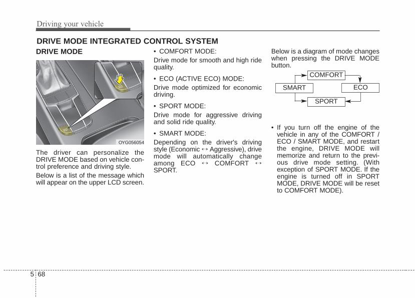
Driving your vehicle
685
DRIVE MODE
The driver can personalize theDRIVE MODE based on vehicle con-trol preference and driving style.Below is a list of the message whichwill appear on the upper LCD screen.
• COMFORT MODE:Drive mode for smooth and high ridequality.
• ECO (ACTIVE ECO) MODE:Drive mode optimized for economicdriving.
• SPORT MODE:Drive mode for aggressive drivingand solid ride quality.
• SMART MODE:Depending on the driver's drivingstyle (Economic ↔ Aggressive), drivemode will automatically changeamong ECO ↔ COMFORT ↔SPORT.
Below is a diagram of mode changeswhen pressing the DRIVE MODEbutton.
• If you turn off the engine of thevehicle in any of the COMFORT /ECO / SMART MODE, and restartthe engine, DRIVE MODE willmemorize and return to the previ-ous drive mode setting. (Withexception of SPORT MODE. If theengine is turned off in SPORTMODE, DRIVE MODE will be resetto COMFORT MODE).
DRIVE MODE INTEGRATED CONTROL SYSTEM
OYG056054
COMFORT
SMART ECO
SPORT

5 69
Driving your vehicle
ECO (ACTIVE ECO) MODE • ACTIVE ECO system
enhances fuel efficiencythrough eco control ofthe engine and trans-mission. The actual fuelefficiency will depend onpersonal driving styleand habits.
• By pressing the DRIVEMODE button andselecting ECO MODE,green ECO indicatorlight will illuminate.
ECO MODE Driving:The vehicle engine and transmissionwill operate in fuel economy orientedmode.ACTIVE ECO MODE system willrestrain fuel economy worseningdriving habits, such as suddenlystarts and accelerations, compare tothe COMFORT MODE.
Conditions that limit ActiveECO MODE:Below are a list of conditions in whichwhen in ACTIVE ECO MODE, theindicator light will not change, but theinternal system may operate differ-ently.• When engine coolant temperature
is low:When temperature of the transaxleoil is below the comfort range, theACTIVE ECO MODE may becometemporarily unavailable until thetransaxle oil heats up after vehicleignition.
• When in an uphill gradient:Since the ACTIVE ECO MODEpartially limits the engine torque,ACTIVE ECO MODE may becometemporarily unavailable when moretorque is essential for going uphill.
• When using the manual transmis-sion operation mode:If transmission operation ischanged from automatic to manual,vehicle will reflect it and automati-cally stop the ACTIVE ECO MODE.

Driving your vehicle
705
SPORT MODE• When the DRIVE MODE
button is pressed andthe SPORT MODE isselected, the SPORTindicator (red) will illumi-nate on the dashboard.
• When the SPORT MODEis activated, and theEngine Start/Stop buttonis turned off and on again,drive mode will reset toCOMFORT MODE.To turn on SPORTMODE, press DRIVEMODE button again.
• If the system is activated:- After increasing speed
and turning your footoff the acceleratorpedal, it maintains thecurrent gear and RPMfor some time eventhough the acceleratorpedal is not depressed.
- Up-shift during accel-eration is delayed.
✽✽ NOTICEIn SPORT DRIVE MODE, the fuelefficiency may decrease.
SMART MODE• SMART MODE is an intel-
ligent driving mode whichautomatically selects themost appropriate drivemode (Economic ↔Aggressive) by measuringusage of steering wheel,and accelerator pedal.
• When DRIVE MODE but-ton is pressed and theSMART MODE is select-ed, SMART indicator willilluminate on the dash-board.
• The color of the SMARTMODE indicator light willdepend on the drivingstyle. If the driving style iseconomic, average, andspeedy, the indicator lightwill be green, white, andred in respective order.
• When the SMART MODEis activated, and theEngine Start/Stop buttonis turned off and on again,your car will still maintainthe SMART MODE.

5 71
Driving your vehicle
• Below is a summary of theautomatic drive mode con-trol depending on theusage of the steeringwheel, engine andtransaxle system.
Driving style SMART DRIVE MODEGear Shift
PatternEngine Torque
Economic SMART ECO Fuel Efficient Fuel Efficient
Average SMART COMFORT Average Average
Aggressive SMART SPORT Acceleration Highly Responsive
✽✽ NOTICE• SMART MODE an intelligent driving mode and when the driving style is
economic and fuel efficient, the SMART ECO MODE will be automati-cally selected. The engine and transaxle system will become more fuel effi-cient, but the actual fuel economy will depend on various driving factors(on uphill/ downhill, heavy revving or braking).
• If you make sudden accelerations or turns in SMART MODE, the intelli-gent mode will select SMART SPORT MODE. This may decrease fuel effi-ciency.

Driving your vehicle
725
DRIVE MODE Indicator ScreenThe DRIVE MODE indicator screencan be displayed by using the trip com-puter button on the steering wheel.DRIVE MODE indicator screen dis-plays status of current drive mode.• DRIVE MODE button is located on
the lower part of the transmissionlever for selecting drive mode.If drive mode is selected manuallyby the user, the drive mode indica-tor screen will show user-selecteddrive mode. (COMFORT, ECO, orSPORT)If SMART MODE is selected byDRIVE MODE button, the drivemode indicator screen will showcurrent drive mode automaticallyselected by SMART MODE sys-tem. (SMART COMFORT, SMARTECO, or SMART SPORT)
• When the trip computer mode isselected to show DRIVE MODEand the SMART MODE is in oper-ation, an automatically selecteddriving mode SMART ECO,SMART COMFORT, or SMARTSPORT, will be selected on thecluster's center.And right below is the horizontaldriving style gauge which reflectsthe driving style in real time.
• If you drive carefully and slowly inSMART MODE, the left side of thedriving style gauge will illuminate,and be automatically shifted to theSMART ECO MODE.When the driver accelerates morefrequently, the right side of the driv-ing style gauge will fill up, and shiftto SMART COMFORT MODE.In addition, if the rate of accelera-tion and speed is high, drive modewill change to SMART SPORTMODE.
• If the auto cruise control function isoperated or the transmission isshifted to manual mode whileSMART MODE is on, the SMARTMODE will stop temporarily, andthe DRIVE MODE will be displayedas OFF. The driving style gaugelight will be turned off accordingly.
• If the trip computer is not set toshow DRIVE MODE indicatorscreen, and you want to know theon/off status of the SMART MODE,simply check whether the letters'SMART' is lighten up on thescreen or not (green - ECO MODE,white - COMFORT MODE, red -SPORT MODE).

5 73
Driving your vehicle
Driving Style Gauge
Once the SMART MODE is selectedby pressing the DRIVE MODE but-ton, and the DRIVE MODE indicatorscreen is selected by pressing thetrip computer button on the steeringwheel, the driving style gauge barwill show up at the bottom of screenand visualize current style of driving.
• Left poles of the driving style gaugeindicates degree of economic andgentle driving in green color. Themore economic and gentle youdrive, the more left poles will light upin green.Likewise, the right pole of the drivingstyle gauge indicates degree ofaggressive and sporty driving in redcolor. The faster and more aggres-sive you drive, the more far rightpoles will light up in red.
• When driving style gauge fills uptoward left side (or Economic side)and kept for certain time, then yourvehicle will be automatically switchto SMART ECO MODE.Likewise, when driving style gaugefills up toward right side (orAggressive side) and kept for certaintime, then your vehicle will be auto-matically the switch to SMARTSPORT MODE.
• If you wish to maintain the SMARTECO MODE for better fuel econo-my, try to maintain economic driv-ing style and keep the driving stylegauge green.
OYG056149N

Driving your vehicle
745
Attributes of SMART MODE.• If the accelerator pedal is pressed
gently, your vehicle will recognize itas a economic driving style. Aftersome time, the system will automat-ically shift to SMART ECO MODE.
• If you press the accelerator pedalfrequently and heavily in SMARTECO MODE, the system will auto-matically shift to SMART COM-FORT MODE.
• Even when driving style has notchanged from SMART ECOMODE, if your vehicle is drivenuphill considerably, the system willdetect the gradient. Then, theSMART system will automaticallychange the setting to the SMARTCOMFORT MODE temporarily.Once your vehicle is out of the hillyground, your vehicle will automati-cally return to the SMART ECOMODE.
• The SMART system will recognizesudden and repetitive acceleration orsteering as aggressive driving andautomatically turn to the SMARTSPORT MODE.Your vehicle will runat a lower gear in SMART SPORTMODE compared to those inSMART COMFORT MODE.The vehicle's start and stopresponse rate will become faster.
• When the SMART SPORT MODEis activated, and you take your feetoff the accelerator pedal, the vehi-cle will remain in low gear and youmay sense engine brake. This isdue to necessary preparatory timefor the next acceleration and isonly comfort.
• The SMART SPORT MODE is acti-vated only when very aggressiveand high speed is detected.Therefore, in average drivingstyles, the SMART system willselect either SMART ECO orSMART COMFORT MODE.
• The artificial intelligence algorithmwill instantly calculate each driver'sstyle of driving. So if the driver ischanged to a different person, thealgorithm will measure accordingly.

5 75
Driving your vehicle
Conditions which Limit SMARTMODEIn following conditions your vehicle willtemporarily stop the SMART Modeand the indicator light will turn off.• When using the manual transmis-
sion operation mode: If thetransaxle system is changed fromautomatic to manual, your vehiclewill automatically stop the SMARTMODE.If transmission operation ischanged from automatic to manu-al, vehicle will reflect it and auto-matically stop the SMART MODE.
• When the Cruise Control system isturned on:When the driver sets a targetcruise control speed, your vehiclewill automatically stop the SMARTMODE. (The SMART MODE willstop not immediately after youpress the cruise control button, butwhen the cruise control systemtakes control of the vehicle speed.)
• If the temperature of the transaxleoil is very high or low:The SMART MODE control systemwill operate in nearly all drivingconditions. But when the tempera-ture of the transaxle oil is out of thecomfort range, the SMART MODEsystem may become temporarilyunavailable.

Driving your vehicle
765
The Blind Spot Detection System(BSD) uses a radar sensor to alertthe driver.It senses toward the rear sides of thevehicle and provides and early warn-ing to the driver.
(1) BSD (Blind Spot Detection)The warning range depends onyour vehicle speed. However, ifyour vehicle is about 10 km/h (6mph) faster than the other vehi-cle, the system will not warn you.
(2) LCA (Lane Change Assist)When a vehicle approaches youat high speed, the system willwarn you.
(3) RCTA (Rear Cross Traffic Alert)When your vehicle moves rear-ward, and the sensor detects anapproaching vehicle in the left orright side, the system will warnyou.
BLIND SPOT DETECTION SYSTEM (BSD) (IF EQUIPPED)
WARNING - BSDLimitations
• The Blind Spot DetectionSystem (BSD) is a supplemen-tal system. Do not solely relyon the system and always payattention to drive safely.
• The Blind Spot DetectionSystem may not detect everyobject alongside the vehicleand is not a substitute forproper and safe lane chang-ing procedures. Always drivesafely and use caution whenchanging lanes.
OYG056141L

5 77
Driving your vehicle
BSD (Blind Spot Detection) / LCA (Lane Change Assist)Operating conditions
The indicator on the switch will illumi-nate when the Blind Spot DetectionSystem (BSD) switch is pressed withthe Engine Start/Stop Button ON.If vehicle speed exceeds 30 km/h(20 mph), the system will activate.If you press the switch again, theswitch indicator and system will beturned off.If the vehicle is turned off, the systemwill remember the last settings uponrestart.
When the system is not used turn thesystem off by turning off the switch.When the system is turned on thewarning light will illuminate for 3 sec-onds on the outside rearview mirror.
Warning typeThe system will activate when:1. The system is on.2. Vehicle speed is above 30 km/h
(20 mph).3. Other vehicles are detected in the
rear side.
WARNINGThe Blind Spot DetectionSystem with Lane ChangeAssist and Rear Cross TrafficAlert is not a substitute forproper and safe lane changingprocedures. Always drive safelyand use caution when changinglanes. The Blind Spot DetectionSystem may not detect everyobject alongside the vehicle.
OYG056057N

Driving your vehicle
785
If a vehicle is detected within theboundary of the system, a warninglight will illuminate on the outsiderearview mirror.If the detected vehicle is not indetecting range, the warning will turnoff.
The second stage alarm will activatewhen:1.The first stage alert is on2.The turn signal is on to change a
lane
When the second stage alert is acti-vated, a warning light will blink on theoutside rearview mirror and an alarmwill sound.If you move the turn signal switch tothe original position, the secondstage alert will be deactivated.
- The second stage alarm may bedeactivated.
• To activate the alarm:Go to the User Settings Mode →Sound and select "BSD" on theLCD display.
• To deactivate the alarm:Go to the User Settings Mode →Sound and deselect "BSD" on theLCD display.
✽✽ NOTICEThe alarm function helps alert thedriver. Deactivate this function onlywhen it is necessary.
OUM054029
2nd stage
OUM054028
1st stage

5 79
Driving your vehicle
Detecting sensor
The sensors are located inside of therear bumper.Always keep the rear bumper cleanfor the system to work properly.
Warning message“Blind Spot Detection disabled. Radarblocked”The message will appear to notifythe driver with one of followings. Thelight on the switch and the systemwill turn off automatically.- There are foreign substances on the
surface or inside the rear bumper orit is hot near the rear bumper.
- When a trailer or carrier is installed.- When driving wide area like desert
around few vehicles.- When driving in the bad weather
such as heavy rain or snowWhen you install a trailer or carrier,turn off BSD system. When you usethe BSD system, remove a trailer orcarrier.Remove the foreign substance onthe rear bumper.After the foreign substance isremoved, if you drive for approxi-mately 10 minutes, the system willwork normally.
If the system does not work normallyeven though the foreign substance isremoved, take your vehicle to anauthorized Kia dealer and have thesystem checked.
OYG056058

Driving your vehicle
805
“Check BSD System”If the system does not work properly,a warning message will appear andthe light on the switch will turn off.Thesystem will turn off automatically.
Have your vehicle inspected by anauthorized Kia dealer.
RCTA (Rear Cross Traffic Alert)
When your vehicle moves backwardsfrom a parking position, the sensordetects approaching vehicles to theleft or right side direction and givesinformation to the driver.
Operating conditions• Select RCTA (Rear Cross Traffic
Alert) in "User Settings" under"Driving Assist" on the instrumentcluster. The system will turn on andstandby to activate.
• Select RCTA again, to turn the sys-tem off.
• If the vehicle is turned off, theRCTA system will remember thelast settings upon restart. Alwaysturn the RCTA system off when notin use.
• The system operates when thevehicle speed is below 8 km/h (5mph) with the shift lever in R(Reverse).
• The RCTA (Rear Cross TrafficAlert) detecting range is 1.6 feet ~65 feet based on the side direction.If the approaching vehicle speed is 4 km/h (2.5 mph) ~ 36 km/h (22mph) within sensing range, it isdetected. However, the systemsensing range can vary based onconditions. Always pay attention toyour surroundings.
OYG056140

5 81
Driving your vehicle
Warning type
• If the vehicle detected by sensorsapproaches your vehicle, the warn-ing chime will sound and the warn-ing light will blink on the outsiderearview mirror.
• If the detected object is not in yourway, move the vehicle away fromthe detected object slowly; and thewarning will cancel once the objecthas been safely cleared.
• The system may not operate prop-erly due to other factors or circum-stances. Always pay attention toyour surroundings.
❈ If your vehicle's left or right sidebumper is blinded by a barrier orvehicles, the system sensing abili-ty may be deteriorated.
✽✽ NOTICE• The system may not work proper-
ly if the bumper has been replacedor if repair work has been donenear the sensor.
• The detection area differs accord-ing to the road's width. If the roadis narrow the system may detectother vehicles in the next lane.
• If the road is very wide the systemmay not detect other vehicles.
• The system may turn off due tostrong electromagnetic interfer-ence.
OYG056144L
WARNINGThe Blind Spot DetectionSystem with Lane ChangeAssist and Rear Cross TrafficAlert is not a substitute forproper and safe lane changingprocedures. Always drive safelyand use caution when changinglanes. The Blind Spot DetectionSystem may not detect everyobject alongside the vehicle.

Driving your vehicle
825
Limitations conditionDriver's AttentionThe driver must be cautious in thebelow situations for the system maynot assist the driver and may notwork properly.
- Curved roads, tollgates, etc.- The surrounding of the sensor cover
is dirty with rain, snow, mud, etc.- The rear bumper near the sensor is
covered or obstructed with foreignmatter such as a sticker, bumperguard, bicycle racks, etc.
- The rear bumper is damaged or thesensor is out of place.
- The height of the vehicle has signif-icantly changed such as when thetrunk is loaded with heavy objects,abnormal tire pressure etc.
- Due to bad weather such as heavyrain or snow.
- A fixed object is near such as aguardrail, etc.
- A substantial amount of metallicobjects such as a constructionarea.
- A large vehicle is nearby such as abus or truck.
- A motorcycle or bicycle is near.- A flat trailer is near.- If two vehicles near each other
accelerate together.- When another vehicle passes by at
a high rate of speed.- When changing lanes.- When going down or up a steep,
uneven road.- When another vehicle drives very
close the back bumper/trunk.- When a trailer or carrier is installed.
- When the temperature of the rearbumper is very high or low.
- When bike racks, etc. cover thesensor.
- When reversing from a parkingspace with pillars or metal struc-tures.
- When you are reversing and if thedetected vehicle is simultaneouslyreversing.
- If there are small objects like shop-ping carts and baby carriages.
- If there is a vehicle with decreasedride height (lowered).
- When the vehicle is close to anoth-er vehicle.
- When driving through a narrowroad with many plants.
- When driving on wet surface.

5 83
Driving your vehicle
Outside rearview mirror may notalert the driver when:- The outside rearview mirror hous-
ing is very dirty.- The window is very dirty.- The windows are tinted very dark.- When driving through a narrow
road with many trees or bushes.
This device complies withIndustry Canada licence-exemptRSS standard(s).Operation is subject to the followingtwo conditions:(1) This device may not cause inter-
ference, and (2) This device must accept any
interference, including interfer-ence that may cause undesiredoperation of the device.

Driving your vehicle
845
The Smart Blind Spot DetectionSystem detects the front areathrough the camera installed on theupper front windshield and detectsthe side/rear areas through radarsensors.The Smart Blind Spot DetectionSystem may activate the ElectronicStability Control (ESC) in accor-dance with a colliding possibility withan approaching vehicle while chang-ing lanes. It is to lower the collidingrisk or mitigate the colliding damage.
Operating conditions The system enters the ready status,when the following conditions aresatisfied with the smart blind systemin the ON position:- Vehicle speed is between 60 km/h
and 180 km/h (40 mph and 110mph).
- The system detects both of thelane lines.
- An approaching vehicle is detectednext to/behind your vehicle.
Activation (with braking perform-ance)
The Smart Blind Spot DetectionSystem may apply braking power,when an approaching vehicle isdetected within a certain distancenext to/behind your vehicle.
SMART BLIND SPOT DETECTION SYSTEM (IF EQUIPPED)
OYG056060
OYG056059

5 85
Driving your vehicle
It gently applies braking power on thetire, which is located in the oppositeside of the possibly-colliding point.The instrument cluster will inform thedriver of the system activation.The Smart Blind Spot DetectionSystem is automatically deactivated,when the vehicle drives a certain dis-tance away, when the vehicle direc-tion is changed against the possible-colliding point, when the steeringwheel is abruptly moved, or when thebrake pedal is depressed.When the turn signals operate, theSmart Blind Spot Detection Systemoperates only once. However, whenthe turn signals are turned off, the sys-tem re-enters the activation conditions.The driver should drive the vehicle inthe middle of the vehicle lanes tokeep the system in the ready status.When the vehicle drives too close toone side of the vehicle lanes, thesystem may not properly operate.In addition, the system may not prop-erly control your vehicle in accordancewith driving situations. Thus, alwayspay close attention to road situations.
Warning messageWhen there is a malfunction with theSmart Blind Spot Detection System,warning message ("Smart BSD brak-ing system malfunction") appears onLCD display and deactivates theSmart Blind Spot Detection System.In this case, we recommend you tohave your vehicle inspected by anauthorized Kia dealer.
Limitations of the systemThe driver must be cautious in thebelow situations, because the sys-tem may not detect other vehicles orobjects in certain circumstances.
• The vehicle drives on a curvedroad or through a tollgate.
• The sensor is polluted with rain,snow, mud, etc.
• The rear bumper where the sensoris located is covered with a foreignobject such as a bumper sticker, abumper guard, a bike rack, etc.
• The rear bumper is damaged, orthe sensor is out of the originaldefault position.
• The vehicle height gets lower orhigher due to heavy loading in atrunk, abnormal tire pressure, etc.
• The vehicle drives in inclementweather such as heavy rain or snow.
• There is a fixed object near thevehicle, such as a guardrail.
• A big vehicle is near such as a busor truck.

Driving your vehicle
865
• A motorcycle or bicycle is near.• A flat trailer is near.• If the vehicle has started at the
same time as the vehicle next toyou and has accelerated.
• When the other vehicle passes at avery fast speed.
• While changing lanes.• While going down or up a steep
road where the height of the lane isdifferent.
• When the other vehicle approach-es very close.
• When a trailer or carrier isinstalled.
• When the temperature of the rearbumper is high.
• When the sensors are blocked byother vehicles, walls or parking-lotpillars.
• When the detected vehicle alsomoves back, as your vehicle drivesback.
• If there are small objects in thedetecting area such as a shoppingcart or a baby stroller.
• If there is a low height vehicle suchas a sports car.
• When other vehicles are close toyour vehicle.
• The lanes ahead are not visibledue to rain, snow, water on theroad, damaged or stained roadsurface, or other factors.
• The brightness outside changessuddenly such as when entering orexiting a tunnel.
• The brightness outside is too lowsuch as when the headlamps arenot on at night or the vehicle isgoing through a tunnel.
• It is difficult to distinguish the lanemarking from the road surface orthe lane marking is faded or notclearly marked.
• Driving on a steep grade, over ahill, or when driving on a curvedroad.
• When light coming from a streetlight or an oncoming vehicle isreflected on a wet road surfacesuch as a puddle in the road.
• The field of view in front isobstructed by sun glare.
• The lanes are incomplete or thearea is in a construction zone.
• There are more than two lane lineson the road in front of you.
• The lane markings are not clearlyvisible from the road.
• The lane width is too wide or toonarrow.
• The windshield glass is fogged up;a clear view of the road is obstruct-ed.
• There are markings on the roadsurface that look like a lane linethat is inadvertently being detectedby the camera.
• There is a boundary structure inthe roadway such as a concretebarrier that is inadvertently beingdetected by the camera.
• There is not enough distancebetween you and the vehicle infront to be able to detect the laneline or the vehicle ahead is drivingon the lane line.
5 87
Driving your vehicle
• The road pavement (or the periph-eral ground) abnormally containsmetallic components (i.e. possiblydue to subway construction).
• The brake pedal is depressed.• ESC (Electronic Stability Control)
is activated.• The tire pressure is low or a tire is
damaged.• The brake is reworked.• The vehicle is driven near a
guardrail or near the boundary lineof a road.
• The windshield or the camera lensis blocked with dirt or debris.
• The vehicle drives on a small-radius curve.
• The vehicle drives in the oppositedirection from the designated lanedirection.
• The lane sensing operation is inter-rupted by another vehicle in front.
• The vehicle drives under 40 mphor over 115 mph.
• The vehicle abruptly changes driv-ing direction.
• The vehicle abruptly enters thenext lane.
• The vehicle sharply stops.• Temperature is extremely low
around the vehicle.• The vehicle severely vibrates while
driving over a bumpy road, uneven/bumpy road, or concrete patch.
• The vehicle drives on a slipperysurface due to snow, water puddle,or ice.
• The driver is responsible for accu-rate steering.
• Do not unnecessarily operate thesteering wheel, when the SmartBlind Spot Detection System is inoperation.
• Always pay extreme caution whiledriving. The Smart Blind SpotDetection System may not operateor unnecessarily operate in accor-dance with your driving situations.
WARNING - Smart Blind Spot Detection
System LimitationsThe Smart Blind Spot DetectionSystem is not a substitute forsafe driving practices, but aconvenience function only. It isthe responsibility of the driverto always drive cautiously toprevent unexpected and sud-den situations from occurring.Pay attention to the road condi-tions at all times.

Driving your vehicle
885
LANE DEPARTURE WARNING SYSTEM (LDWS) (IF EQUIPPED)This system detects the lane with asensor at the front windshield andnotifies you if it detects that yourvehicle leaves the lane.
• The LDWS does not make thevehicle change lanes. It is the dri-ver's responsibility to always checkthe road conditions.
• If the sensor cannot detect the laneor if the vehicle speed does notexceed 64 km/h (40 mph), theLDWS will not be able to notify youif the vehicle leaves the lane.
• If your vehicle has window tint orother types of coating on the frontwindshield, the LDWS may notwork properly.
• Prevent damage to the LDWS sen-sor from water or any liquid.
• Do not remove the LDWS partsand avoid damaging the sensor byavoiding a strong impacts.
• Do not put objects that reflect lighton the dash board.
• The operation of the LDWS can beaffected by several factors (includ-ing environmental conditions). It isthe responsibility of the driver topay attention to the roadway and tomaintain the vehicle in it's lane atall times.
WARNING - LDWS AlertThe LDWS is only intended toprovide you with informationregarding your vehicle's posi-tion on the roadway. Uponreceiving an LDWS alert, youmust take the necessary stepsto maintain control of your vehi-cle. The LDWS does not provideany steering inputs into thevehicle for you. It can be dan-gerous to make a large suddensteering input in response to analert, since that could result inloss of control.
OYG056052
OUM054149
OYG056053

5 89
Driving your vehicle
• If the sensor on the front wind-shield is removed and reinstalledagain due to front windshield tint orother types of coating on it, you arestrongly recommend to take yourvehicle to an authorized Kia dealerand have the system calibrated.
To operate the LDWS, press the but-ton with the engine start/stop button inthe ON position. The indicator illumi-nates white on the cluster. To cancelthe LDWS, press LDWS button again.The indicator on the cluster will gooff.
If the system detects that your vehi-cle is leaving the lane when theLDWS is operating and vehiclespeed exceeds 64 km/h (40 mph),the warning operates as follows:
1. Visual warningIf you leave a lane, the lane youcross will blink (yellow) and LDWSindicator will blink green on LCD dur-ing max 3 seconds.
OYG056112N
OYG056113N
OYG056114N
■ Left lane departure warning
■ Right lane departure warning

Driving your vehicle
905
2. Auditory warningIf you leave the lane, the warningsound operates for maximum 3 sec-onds.The color of symbol will changedepend on the condition of LDWSsystem.- White color : When you activate the
lane departure warn-ing system by press-ing the LDWS button,system operating con-ditions are not satis-fied or the sensor doesnot detect the lane line
- Green color : When you activate thelane departure warn-ing system by press-ing the LDWS button,system operating con-ditions are satisfiedand the sensor detectthe lane line
- Yellow color : when there is a mal-function with the lanedeparture warningsystem.
Warning indicator
When the LDWS is not working prop-erly, the warning light will illuminateand the warning message will comeon for a few second. After the mes-sage disappears, the master warninglight will illuminate.Take your vehicle to an authorizedKia dealer and have the systemchecked.
Conditions that cause theLDWS not to operate:• The driver turns on the turn signal
or the hazard warning flasher tochange lanes.
• Driving on the lane line.
✽✽ NOTICETo change lanes, operate the turnsignal switch then change the lane.
WARNING - LDWSLimitations
The Lane Departure WarningSystem is a supplemental sys-tem. Do not solely rely on thesystem but always pay attentionand drive safely.
OYG056115N

5 91
Driving your vehicle
Conditions that cause missedwarnings and false warnings:• The lane is not visible due to snow,
rain, debris, puddles or other envi-ronmental conditions.
• The brightness outside changessuddenly such as whenentering/exiting a tunnel.
• The headlights are off at night or ina tunnel.
• The color of the lane marking fromthe road is difficult to distinguish.
• Driving on a steep grade or acurve.
• Light such as street lights, sunlightor oncoming vehicle lights reflectoff of water on the road.
• The lens or windshield is obscuredby debris.
• The sensor cannot detect the lanebecause of fog, heavy rain orheavy snow.
• The rear view mirror housing hasoverheated from exposure to directsunlight.
• The lane is very wide or narrow.
• The lane line is damaged or indis-tinct.
• The windshield is fogged up byhumidity.
• Objects in the median or along theside of the road cast shadows overthe lane markings
• The sensor cannot distinguish thelane from the road due to thedust/dirt.
• There are other markings similar tolane lines.
• There are lane boundaries insteadof markings.
• The vehicle ahead is very close,obscuring the view of the lanemarkings, or the vehicle ahead isdriving over the lane markings.
• The vehicle vibrates heavily due topoor road conditions.
• The lanes are merging, expanding,or otherwise overlapping
• Something reflective is placed onthe dashboard.
• Driving with the sun in front of you.• Driving in areas under construc-
tion.• Lanes are marked by more than
two sets of lines.• The windshield is fogged by humid
air in the vehicle.
This device complies withIndustry Canada licence-exemptRSS standard(s).Operation is subject to the followingtwo conditions:(1) This device may not cause inter-
ference, and (2) This device must accept any
interference, including interfer-ence that may cause undesiredoperation of the device.

Driving your vehicle
925
Your vehicle's fuel economy dependsmainly on your style of driving, whereyou drive and when you drive.Each of these factors affects howmany miles (kilometers) you can getfrom a gallon (liter) of fuel.To operateyour vehicle as economically as pos-sible, use the following driving sug-gestions to help save money in bothfuel and repairs:• Drive smoothly. Accelerate at a
moderate rate. Don't make "jack-rabbit" starts or full-throttle shiftsand maintain a steady cruisingspeed. Don't race between stop-lights. Try to adjust your speed tothe traffic so you don't have tochange speeds unnecessarily.Avoid heavy traffic whenever pos-sible. Always maintain a safe dis-tance from other vehicles so youcan avoid unnecessary braking.This also reduces brake wear.
• Drive at a moderate speed. Thefaster you drive, the more fuel yourvehicle uses. Driving at a moderatespeed, especially on the highway,is one of the most effective ways toreduce fuel consumption.
• Don't "ride" the brake pedal. Thiscan increase fuel consumption andalso increase wear on these com-ponents. In addition, driving withyour foot resting on the brake pedalmay cause the brakes to overheat,which reduces their effectivenessand may lead to more serious con-sequences.
• Take care of your tires. Keep theminflated to the recommended pres-sure. Incorrect inflation, either toomuch or too little, results in unnec-essary tire wear. Check the tirepressures at least once a month.
• Be sure that the wheels arealigned correctly. Improper align-ment can result from hitting curbsor driving too fast over irregularsurfaces. Poor alignment causesfaster tire wear and may also resultin other problems as well asgreater fuel consumption.
• Keep your vehicle in good condi-tion. For better fuel economy andreduced maintenance costs, main-tain your vehicle in accordancewith the maintenance schedule inchapter 7. If you drive your vehiclein severe conditions, more frequentmaintenance is required (seechapter 7 for details).
• Keep your vehicle clean. For maxi-mum service, your vehicle shouldbe kept clean and free of corrosivematerials. It is especially importantthat mud, dirt, ice, etc. not beallowed to accumulate on theunderside of the vehicle. This extraweight can result in increased fuelconsumption and also contribute tocorrosion.
• Travel lightly. Don't carry unneces-sary weight in your vehicle. Weightreduces fuel economy.
• Don't let the engine idle longerthan necessary. If you are waiting(and not in traffic), turn off yourengine and restart only whenyou're ready to go.
ECONOMICAL OPERATION
5 93
Driving your vehicle
• Remember, your vehicle does notrequire extended warm-up. Afterthe engine has started, allow theengine to run for 10 to 20 secondsprior to placing the vehicle in gear.In very cold weather, however, giveyour engine a slightly longer warm-up period.
• Don't "lug" or "over-rev" the engine.Lugging is driving too slowly in avery high gear resulting in enginebucking. If this happens, shift to alower gear. Over-revving is racingthe engine beyond its safe limit.This can be avoided by shifting atthe recommended speed.
• Use your air conditioning sparingly.The air conditioning system isoperated by engine power so yourfuel economy is reduced when youuse it.
• Open windows at high speeds canreduce fuel economy.
• Fuel economy is less in crosswindsand headwinds. To help offsetsome of this loss, slow down whendriving in these conditions.
Keeping a vehicle in good operatingcondition is important both for econ-omy and safety. Therefore, have anauthorized Kia dealer performscheduled inspections and mainte-nance.
WARNING - Engine offduring motion
Never turn the engine off tocoast down hills or anytime thevehicle is in motion. The powersteering and power brakes willnot function properly without theengine running. In addition, turn-ing off the ignition while drivingcould lead to out of workingpower driven steering wheel andhard to control steering wheel.Keep the engine on and down-shift to an appropriate gear foran engine braking effect.

Driving your vehicle
945
Hazardous driving conditions When hazardous driving conditionsare encountered such as water,snow, ice, mud, sand, or similar haz-ards, follow these suggestions:• Drive cautiously and allow extra
distance for braking.• Avoid sudden braking or steering.• When braking with non-ABS
brakes pump the brake pedal witha light up-and-down motion untilthe vehicle is stopped.
Do not pump the brake pedal on avehicle equipped with ABS.
• If stalled in snow, mud, or sand,use the second gear. Accelerateslowly to avoid spinning the drivewheels.
• Use sand, rock salt, or other non-slip material under the drivewheels to provide traction whenstalled in ice, snow, or mud.
Rocking the vehicleIf it is necessary to rock the vehicleto free it from snow, sand, or mud,first turn the steering wheel right andleft to clear the area around yourfront wheels. Then, shift back andforth between R (Reverse) and anyforward gear in vehicles equippedwith an Automatic Transaxle. Do notrace the engine, and spin the wheelsas little as possible. If you are stillstuck after a few tries, have the vehi-cle pulled out by a tow vehicle toavoid engine overheating and possi-ble damage to the transaxle.
SPECIAL DRIVING CONDITIONS
WARNING - DownshiftingDo not downshift with an auto-matic transaxle while driving onslippery surfaces. The suddenchange in tire speed couldcause the tires to skid andresult in an accident.
WARNING - SuddenVehicle Movement
Do not attempt to rock the vehi-cle if people or objects are near-by. The vehicle may suddenlymove forward or backwards as itbecomes unstuck.

5 95
Driving your vehicle
The ESC system should be turnedOFF prior to rocking the vehicle.
Smooth corneringAvoid braking or gear changing incorners, especially when roads arewet. Ideally, corners should alwaysbe taken under gentle acceleration. Ifyou follow these suggestions, tirewear will be held to a minimum.
Driving at night
Because night driving presents morehazards than driving in the daylight,here are some important tips toremember:• Slow down and keep more dis-
tance between you and other vehi-cles, as it may be more difficult tosee at night, especially in areaswhere there may not be any streetlights.
CAUTION - Vehicle rockingProlonged rocking may causeengine overheating, transaxledamage or failure, and tire dam-age.
CAUTION - Spinning tiresDo not spin the wheels, espe-cially at speeds more than 35mph (56 km/h). Spinning thewheels at high speeds when thevehicle is stationary couldcause a tire to overheat whichcould result in tire damage thatmay injure bystanders.
OYG056065

Driving your vehicle
965
• Adjust your mirrors to reduce theglare from other driver's head-lights.
• Keep your headlights clean andproperly aimed. (On vehicles notequipped with the automatic head-light aiming feature.) Dirty orimproperly aimed headlights willmake it much more difficult to seeat night.
• Avoid staring directly at the head-lights of oncoming vehicles. Youcould be temporarily blinded, and itwill take several seconds for youreyes to readjust to the darkness.
Driving in the rain Rain and wet roads can make drivingdangerous, especially if you’re notprepared for the slick pavement.Here are a few things to considerwhen driving in the rain:• A heavy rainfall will make it harder
to see and will increase the dis-tance needed to stop your vehicle,so slow down.
• Keep your windshield wipingequipment in good shape. Replaceyour windshield wiper blades whenthey show signs of streaking ormissing areas on the windshield.
• If your tires are not in good condi-tion, making a quick stop on wetpavement can cause a skid andpossibly lead to an accident. Besure your tires are in good shape.
• Turn on your headlights to make iteasier for others to see you.
• Driving too fast through large pud-dles can affect your brakes. If youmust go through puddles, try todrive through them slowly.
• If you believe you may have gottenyour brakes wet, apply them lightlywhile driving until normal brakingoperation returns.

5 97
Driving your vehicle
Driving in flooded areas Avoid driving through flooded areasunless you are sure the water is nohigher than the bottom of the wheelhub. Drive through any water slowly.Allow adequate stopping distancebecause brake performance may beaffected.After driving through water, dry thebrakes by gently applying them sev-eral times while the vehicle is movingslowly.
Driving off-road Drive carefully off-road because yourvehicle may be damaged by rocks orroots of trees. Become familiar withthe off-road conditions where youare going to drive before you begindriving.
Highway drivingTiresAdjust the tire inflation pressures tospecification. Low tire inflation pres-sures will result in overheating andpossible failure of the tires.Avoid using worn or damaged tireswhich may result in reduced tractionor tire failure.Never exceed the maximum tireinflation pressure shown on the tires. Fuel, engine coolant and engine oil
High speed travel consumes morefuel than urban motoring. Do not for-get to check both the engine coolantand engine oil.
Drive beltA loose or damaged drive belt mayresult in overheating of the engine.
WARNING - Under/overinflated tires
Always check the tires for properinflation before driving.Underinflated or overinflatedtires can cause poor handling,loss of vehicle control, and sud-den tire failure leading to acci-dents, injuries, and even death.For proper tire pressures, refer to“Tires and wheels” in chapter 8.
WARNING - Tire treadAlways check the tire treadbefore driving your vehicle.Worn-out tires can result in lossof vehicle control. Worn-out tiresshould be replaced as soon aspossible. For further informationand tread limits, refer to "Tiresand wheels" in chapter 7.

Driving your vehicle
985
Severe weather conditions in thewinter result in greater wear andother problems. To minimize theproblems of winter driving, youshould follow these suggestions:
Snowy or icy conditionsTo drive your vehicle in deep snow, itmay be necessary to use snow tireson your tires. If snow tires are need-ed, it is necessary to select tiresequivalent in size and type of theoriginal equipment tires. Failure to doso may adversely affect the safetyand handling of your vehicle.Furthermore, speeding, rapid accel-eration, sudden brake applications,and sharp turns are potentially veryhazardous practices.During deceleration, use enginebraking to the fullest extent. Suddenbrake applications on snowy or icyroads may cause skids to occur. Youneed to keep sufficient distancebetween the vehicle in operation infront of your vehicle. Also, apply thebrake gently.
Snow tiresIf you mount snow tires on your vehi-cle, make sure they are radial tires ofthe same size and load range as theoriginal tires. Mount snow tires on allfour wheels to balance your vehicle’shandling in all weather conditions.Keep in mind that the traction provid-ed by snow tires on dry roads maynot be as high as your vehicle's orig-inal equipment tires.You should drivecautiously even when the roads areclear. Check with the tire dealer formaximum speed recommendations.Do not install studded tires withoutfirst checking local, state and munic-ipal regulations for possible restric-tions against their use.
WINTER DRIVING
WARNING - Snow tire sizeSnow tires should be equivalentin size and type to the vehicle'sstandard tires. Otherwise, thesafety and handling of your vehi-cle may be adversely affected.

5 99
Driving your vehicle
Use high quality ethylene gly-col coolantYour vehicle is delivered with highquality ethylene glycol coolant in thecooling system. It is the only type ofcoolant that should be used becauseit helps prevent corrosion in the cool-ing system, lubricates the waterpump and prevents freezing. Be sureto replace or replenish your coolantin accordance with the maintenanceschedule in chapter 7. Before winter,have your coolant tested to assurethat its freezing point is sufficient forthe temperatures anticipated duringthe winter.
Check battery and cablesWinter puts additional burdens onthe battery system. Visually inspectthe battery and cables as describedin chapter 7. The level of charge inyour battery can be checked by anauthorized Kia dealer or a servicestation.
Change to "winter weight" oilif necessaryIn some climates it is recommendedthat a lower viscosity "winter weight"oil be used during cold weather. Seechapter 8 for recommendations. Ifyou aren't sure what weight oil youshould use, consult an authorizedKia dealer.
Check spark plugs and ignitionsystemInspect your spark plugs asdescribed in chapter 7 and replacethem if necessary. Also check allignition wiring and components to besure they are not cracked, worn ordamaged in any way.
To keep locks from freezingTo keep the locks from freezing,squirt an approved de-icer fluid orglycerine into the key opening. If alock is covered with ice, squirt it withan approved de-icing fluid to removethe ice. If the lock is frozen internally,you may be able to thaw it out byusing a heated key. Handle the heat-ed key with care to avoid injury.
Use approved window washeranti-freeze in systemTo keep the water in the windowwasher system from freezing, add anapproved window washer anti-freezesolution in accordance with instruc-tions on the container. Window wash-er anti-freeze is available from anauthorized Kia dealer and most autoparts outlets. Do not use enginecoolant or other types of anti-freezeas these may damage the paint finish.
Driving your vehicle
1005
Don’t let your parking brakefreezeUnder some conditions your parkingbrake can freeze in the engagedposition.This is most likely to happenwhen there is an accumulation ofsnow or ice around or near the rearbrakes or if the brakes are wet. Ifthere is a risk the parking brake mayfreeze, apply it only temporarily whileyou put the gear shift lever in P(Park, Automatic Transaxle) andblock the rear wheels so the vehiclecannot roll. Then release the parkingbrake.
Don't let ice and snow accu-mulate underneathUnder some conditions, snow andice can build up under the fendersand interfere with the steering. Whendriving in severe winter conditionswhere this may happen, you shouldperiodically check underneath thevehicle to be sure the movement ofthe front wheels and the steeringcomponents are not obstructed.
Carry emergency equipmentDepending on the severity of theweather, you should carry appropri-ate emergency equipment. Some ofthe items you may want to carryinclude tow straps or chains, flash-light, emergency flares, sand, shov-el, jumper cables, window scraper,gloves, ground cloth, coveralls, blan-ket, etc.
TRAILER TOWINGWe do not recommend using thisvehicle for trailer towing.

5 101
Driving your vehicle
Tire and loading informationlabel
The label located on the driver's doorsill gives the original tire size, coldtire pressures recommended for yourvehicle, the number of people thatcan be in your vehicle and vehiclecapacity weight.
Vehicle capacity weight:410 kg (904 lbs.)
Vehicle capacity weight is the maxi-mum combined weight of occupantsand cargo. If your vehicle is equippedwith a trailer, the combined weightincludes the tongue load.
Seating capacity:Total : 5 persons
(Front seat : 2 persons, Rear seat : 3 persons)
Seating capacity is the maximumnumber of occupants including adriver, your vehicle may carry.However, the seating capacity maybe reduced based upon the weight ofall of the occupants, and the weightof the cargo being carried or towed.Do not overload the vehicle as thereis a limit to the total weight, or loadlimit including occupants and cargo,the vehicle can carry.
VEHICLE LOAD LIMIT
OYG066040N
OYG066041N

Driving your vehicle
1025
Towing capacity:We do not recommend using thisvehicle for trailer towing.
Cargo capacity:The cargo capacity of your vehiclewill increase or decrease dependingon the weight and the number ofoccupants.
Steps For Determining CorrectLoad Limit -1. Locate the statement "The com-
bined weight of occupants andcargo should never exceed XXXkg or XXX lbs.'' on your vehicle'splacard.
2. Determine the combined weight ofthe driver and passengers that willbe riding in your vehicle.
3. Subtract the combined weight ofthe driver and passengers fromXXX kg or XXX lbs.
4. The resulting figure equals theavailable amount of cargo and lug-gage load capacity. For example, ifthe "XXX" amount equals 635 kg(1400 lbs.) and there will be five68 kg (150 lbs.) passengers inyour vehicle, the amount of avail-able cargo and luggage loadcapacity is 295 kg (650 lbs).
(635-340 (5 x 68) = 295 kg or1400-750 (5 x 150) = 650 lbs.)
5. Determine the combined weight ofluggage and cargo being loadedon the vehicle. That weight maynot safely exceed the availablecargo and luggage load capacitycalculated in Step 4.
6. If your vehicle will be towing a trail-er, load from your trailer will betransferred to your vehicle.Consult this manual to determinehow this reduces the availablecargo and luggage load capacityof your vehicle.
WARNING - Loose cargoDo not travel with unsecuredblunt objects in the passengercompartment of your vehicle(e.g. suit cases or unsecuredchild seats). These items maystrike occupant during a sud-den stop or crash.

5 103
Driving your vehicle
C190F03JM
Item Description Total
AVehicle Capacity 385 kg
Weight (849 lbs)Subtract Occupant
B Weight 365 kg
73 kg (161 lbs) × 5(805 lbs)
CAvailable Cargo and 20 kg
Luggage weight (44 lbs)
A B C
Example 3
C190F02JM
Item Description Total
AVehicle Capacity 385 kg
Weight (849 lbs)Subtract Occupant
B Weight 340 kg
68 kg (150 lbs) × 5(750 lbs)
CAvailable Cargo and 45 kg
Luggage weight (99 lbs)
A B C
Example 2
C190F01JM
Item Description Total
AVehicle Capacity 385 kg
Weight (849 lbs)Subtract Occupant
B Weight 136 kg
68 kg (150 lbs) × 2(300 lbs)
CAvailable Cargo and 249 kg
Luggage weight (549 lbs)
Example 1
A B C
Refer to your vehicle’s tire and loading information label for specific information about your vehicle's capacity weightand seating positions. The combined weight of the driver, passengers and cargo should never exceed your vehicle'scapacity weight.

Driving your vehicle
1045
Certification labelThe certification label is located onthe driver's door sill at the center pillar.This label shows the maximum allow-able weight of the fully loaded vehi-cle. This is called the GVWR (GrossVehicle Weight Rating). The GVWRincludes the weight of the vehicle, alloccupants, fuel and cargo.This label also tells you the maxi-mum weight that can be supportedby the front and rear axles, calledGross Axle Weight Rating (GAWR).To find out the actual loads on yourfront and rear axles, you need to go toa weigh station and weigh your vehi-cle.Your dealer can help you with this.Be sure to spread out your load equal-ly on both sides of the centerline.
The label will help you decide howmuch cargo and installed equipmentyour vehicle can carry.
If you carry items inside your vehicle- like suitcases, tools, packages, oranything else - they are moving asfast as the vehicle. If you have to stopor turn quickly, or if there is a crash,the items will keep going and cancause an injury if they strike the driv-er or a passenger.
✽✽ NOTICEOverloading your vehicle may causedamage. Repairs would not be cov-ered by your warranty. Do not over-load your vehicle.
WARNING - Over loadingNever exceed the GVWR foryour vehicle, the GAWR foreither the front or rear axle andvehicle capacity weight.Exceeding these ratings canaffect your vehicle’s handlingand braking ability.
WARNING - Over loadingDo not overload your vehicle.Overloading your vehicle cancause heat buildup in your vehi-cle's tires and possible tire fail-ure, increased stopping dis-tances and poor vehicle han-dling--all of which may result ina crash.

5 105
Driving your vehicle
This chapter will guide you in theproper loading of your vehicle and/ortrailer, to keep your loaded vehicleweight within its design rating capa-bility, with or without a trailer.Properly loading your vehicle willprovide maximum return of the vehi-cle design performance. Before load-ing your vehicle, familiarize yourselfwith the following terms for determin-ing your vehicle's weight ratings, withor without a trailer, from the vehicle'sspecifications and the compliancelabel:
Base curb weight This is the weight of the vehicleincluding a full tank of fuel and allstandard equipment. It does notinclude passengers, cargo, or option-al equipment.
Vehicle curb weightThis is the weight of your new vehiclewhen you picked it up from your deal-er plus any aftermarket equipment.
Cargo weightThis figure includes all weight addedto the Base Curb Weight, includingcargo and optional equipment.
GAW (Gross axle weight)This is the total weight placed oneach axle (front and rear) - includingvehicle curb weight and all payload.
GAWR (Gross axle weight rating)This is the maximum allowableweight that can be carried by a singleaxle (front or rear). These numbersare shown on the compliance label.The total load on each axle mustnever exceed its GAWR.
GVW (Gross vehicle weight)This is the Base Curb Weight plusactual Cargo Weight plus passen-gers.
GVWR (Gross vehicle weight rating)This is the maximum allowableweight of the fully loaded vehicle(including all options, equipment,passengers and cargo). The GVWRis shown on the certification labellocated on the driver’s door sill.
VEHICLE WEIGHT

What to do in an emergency
Road warning . . . . . . . . . . . . . . . . . . . . . . . . . . . . . . 6-2• Hazard warning flasher . . . . . . . . . . . . . . . . . . . . . . . 6-2
In case of an emergency while driving. . . . . . . . . . 6-3• If the engine stalls at a crossroad or crossing. . . . . . . 6-3
• If you have a flat tire while driving. . . . . . . . . . . . . . . 6-3
• If the engine stalls while driving . . . . . . . . . . . . . . . . . 6-3
If the engine will not start . . . . . . . . . . . . . . . . . . . . 6-4• If engine doesn't turn over or turns over slowly . . . . 6-4
• If engine turns over normally but does not start . . . . 6-4
Emergency starting . . . . . . . . . . . . . . . . . . . . . . . . . 6-5• Jump starting. . . . . . . . . . . . . . . . . . . . . . . . . . . . . . . . . 6-5
• Push-starting . . . . . . . . . . . . . . . . . . . . . . . . . . . . . . . . . 6-6
If the engine overheats. . . . . . . . . . . . . . . . . . . . . . . 6-7
Tire Pressure Monitoring System (TPMS) . . . . . . 6-8• Check tire pressure . . . . . . . . . . . . . . . . . . . . . . . . . . . . 6-8
• Low tire pressure telltale . . . . . . . . . . . . . . . . . . . . . . 6-10
• Changing a tire with TPMS . . . . . . . . . . . . . . . . . . . . 6-12
If you have a flat tire . . . . . . . . . . . . . . . . . . . . . . . 6-15• Jack and tools . . . . . . . . . . . . . . . . . . . . . . . . . . . . . . . 6-15
• Removing and storing the spare tire . . . . . . . . . . . . . 6-16
• Changing tires . . . . . . . . . . . . . . . . . . . . . . . . . . . . . . . 6-17
Towing . . . . . . . . . . . . . . . . . . . . . . . . . . . . . . . . . . . 6-24• Towing service . . . . . . . . . . . . . . . . . . . . . . . . . . . . . . . 6-24
• Removable towing hook . . . . . . . . . . . . . . . . . . . . . . . 6-25
• Emergency towing . . . . . . . . . . . . . . . . . . . . . . . . . . . . 6-26
6

What to do in an emergency
26
ROAD WARNING Hazard warning flasher
The hazard warning flasher servesas a warning to other drivers to exer-cise extreme caution whenapproaching, overtaking, or passingyour vehicle.
It should be used whenever emer-gency repairs are being made orwhen the vehicle is stopped near theedge of a roadway.Depress the flasher switch with theignition switch in any position. Theflasher switch is located in the centerfacia panel. All turn signal lights willflash simultaneously.• The hazard warning flasher oper-
ates whether your vehicle is run-ning or not.
• The turn signals do not work whenthe hazard flasher is on.
• Care must be taken when usingthe hazard warning flasher whilethe vehicle is being towed.
OYG066001
OYG066029
■ Type A
■ Type B

6 3
What to do in an emergency
If the engine stalls at a cross-road or crossingIf the engine stalls at a crossroad orcrossing, set the shift lever in the N(Neutral) position and then push thevehicle to a safe place.
If you have a flat tire whiledrivingIf a tire goes flat while you are driv-ing:1. Take your foot off the accelerator
pedal and let the vehicle slowdown while driving straight ahead.Do not apply the brakes immedi-ately or attempt to pull off the roadas this may cause a loss of con-trol. When the vehicle has slowedto such a speed that it is safe to doso, brake carefully and pull off theroad. Drive off the road as far aspossible and park on firm levelground. If you are on a dividedhighway, do not park in the medianarea between the two traffic lanes.
2. When the vehicle is stopped, turnon your emergency hazard flash-ers, set the parking brake and putthe transaxle in P.
3. Have all passengers get out of thevehicle. Be sure they all get out onthe side of the vehicle that is awayfrom traffic.
4. When changing a flat tire, followthe instruction provided later inthis section.
If the engine stalls while driv-ing1. Reduce your speed gradually,
keeping a straight line. Move cau-tiously off the road to a safe place.
2. Turn on your emergency flashers.3. Try to start the engine again. If
your vehicle will not start, contactan authorized Kia dealer or seekother qualified assistance.
✽✽ NOTICEIf there was a check engine light andloss of power or stall and if safe to doso, wait at least 10 seconds to restartthe vehicle after it stalls. This mayreset the car so it will no longer runat low power (limp home) condition.
IN CASE OF AN EMERGENCY WHILE DRIVING

What to do in an emergency
46
IF THE ENGINE WILL NOT STARTIf engine doesn't turn over orturns over slowly1. Be sure the shift lever is in N
(Neutral) or P (Park) and theemergency brake is set.
2. Check the battery connections tobe sure they are clean and tight.
3. Turn on the interior light. If the lightdims or goes out when you oper-ate the starter, the battery is dis-charged.
4. Check the starter connections tobe sure they are securely tight-ened.
5. Do not push or pull the vehicle tostart it. See instructions for "Jumpstarting".
If engine turns over normallybut does not start1. Check the fuel level.2. With the Engine Start/Stop Button
in the OFF position, check all con-nectors at the ignition coils andspark plugs. Reconnect any thatmay be disconnected or loose.
3. Check the fuel line in the enginecompartment.
4. If the engine still does not start,call an authorized Kia dealer orseek other qualified assistance.
WARNING - Push/pull start
Do not push or pull the vehicleto start it. Push or pull startingmay cause the catalytic con-verter to overload and create afire hazard.

6 5
What to do in an emergency
EMERGENCY STARTING
Connect cables in numerical orderand disconnect in reverse order.
Jump startingJump starting can be dangerous ifdone incorrectly. Therefore, to avoidharm to yourself or damage to yourvehicle or battery, follow these jumpstarting procedures. If in doubt, westrongly recommend that you have acompetent technician or towing serv-ice jump start your vehicle.
CAUTION - Push/pull startto 12 Volt Battery
Use only a 12-volt jumper sys-tem. You can damage a 12-voltstarting motor, ignition system,and other electrical partsbeyond repair by use of a 24-volt power supply (either two12-volt batteries in series or a24-volt motor generator set).
WARNING - BatteryNever attempt to check the elec-trolyte level of the battery asthis may cause the battery torupture or explode.
WARNING - Frozenbatteries
Do not attempt to jump start thevehicle if the discharged batteryis frozen or if the electrolytelevel is low as the battery mayrupture or explode.
WARNING - Sulfuric acidrisk
When jump starting your vehi-cle, be careful not to get acid onyourself, your clothing or on thevehicle. Automobile batteriescontain sulfuric acid.This is poi-sonous and highly corrosive.
WARNING - BatteryKeep all flames or sparks awayfrom the battery. The batteryproduces hydrogen gas whichwill explode if exposed to flameor sparks.
OYG066004

What to do in an emergency
66
Jump starting procedure 1.Make sure the booster battery is
12-volt and that its negative termi-nal is grounded.
2.If the booster battery is in anothervehicle, do not allow the vehicles tocome in contact.
3.Turn off all unnecessary electricalloads.
4.Connect the jumper cables in theexact sequence shown in the illus-tration. First connect one end of ajumper cable to the positive termi-nal of the discharged battery (1),then connect the other end to thepositive terminal of the boosterbattery (2).Proceed to connect one end of theother jumper cable to the negativeterminal of the booster battery (3),then the other end to a solid, sta-tionary, metallic point (for example,the engine lifting bracket) awayfrom the battery (4). Do not con-nect it to or near any part thatmoves when the engine is cranked.
Do not allow the jumper cables tocontact anything except the correctbattery terminals or the correctground. Do not lean over the bat-tery when making connections.
5.Start the engine of the vehicle withthe booster battery and let it run at2,000 rpm, then start the engine ofthe vehicle with the dischargedbattery.
If the cause of your battery discharg-ing is not apparent, you should haveyour vehicle checked by an author-ized Kia dealer.
Push-startingVehicles equipped with automatictransaxle lock system cannot bepush-started.Follow the directions in this sectionfor jump-starting.
WARNING - Tow startingvehicle
Never tow a vehicle to start it.When the engine starts, thevehicle can suddenly surge for-ward and could cause a colli-sion with the tow vehicle.
CAUTION - Battery cablesDo not connect the jumpercable from the negative terminalof the booster battery to thenegative terminal of the dis-charged battery.This can cause the dischargedbattery to overheat and crack,releasing battery acid.Make sure to connect one endof the jumper cable to the nega-tive terminal of the booster bat-tery, and the other end to ametallic point, far away from thebattery.

6 7
What to do in an emergency
IF THE ENGINE OVERHEATSIf your temperature gauge indicatesoverheating, you experience a lossof power, or hear loud pinging orknocking, the engine will probably betoo hot. If this happens, you should:
1.Pull off the road and stop as soonas it is safe to do so.
2.Place the shift lever in P and setthe parking brake. If the air condi-tioning is on, turn it off.
3.If engine coolant is running outunder the vehicle or steam is com-ing out from underneath the hood,stop the engine. Do not open thehood until the coolant has stoppedrunning or the steaming hasstopped. If there is no visible lossof engine coolant and no steam,leave the engine running andcheck to be sure the engine cool-ing fan is operating. If the fan is notrunning, turn the engine off.
4.Check to see if the water pumpdrive belt is missing. If it is notmissing, check to see that it istight. If the drive belt seems to besatisfactory, check for coolant leak-ing from the radiator, hoses orunder the vehicle. (If the air condi-tioning had been in use, it is nor-mal for cold water to be drainingfrom it when you stop).
5.If the water pump drive belt is bro-ken or engine coolant is leakingout, stop the engine immediatelyand call the nearest authorized Kiadealer for assistance.
6.If you cannot find the cause of theoverheating, wait until the enginetemperature has returned to nor-mal. If coolant has been lost, care-fully add coolant to the reservoir tobring the fluid level in the reservoirup to the halfway mark.
7.Proceed with caution, keepingalert for further signs of overheat-ing. If overheating happens again,call an authorized Kia dealer forassistance.
Serious loss of coolant indicatesthere is a leak in the cooling systemand this should be checked as soonas possible by an authorized Kiadealer.
WARNING - Under thehood
While the engine isrunning, keep hair,hands and clothingaway from movingparts such as the fanand drive belts to pre-vent injury.
WARNING - Radiator capDo not remove theradiator cap when theengine is hot.This mayresult in coolant beingblown out of the open-ing and cause seriousburns.

What to do in an emergency
86
TIRE PRESSURE MONITORING SYSTEM (TPMS) (IF EQUIPPED)
(1) Low tire pressure telltale / TPMS malfunction indicator
(2) Low tire pressure position telltale(Shown on the LCD display)
Check tire pressure• You can check the tire pressure in
the information mode on the clus-ter.- Refer to “User settings mode” in
chapter 4.• Tire pressure is displayed 1~2 min-
utes later after driving.• If tire pressure is not displayed
when the vehicle is stopped, “Driveto display” message displays. Afterdriving, check the tire pressure.
• You can change the tire pressureunit in the user settings mode onthe cluster.- psi, kpa, bar (Refer to “User set-
tings mode” in chapter 4).
✽✽ NOTICE• The tire pressure may change due
to factors such as parking condi-tion, driving style, and altitudeabove sea level.
• Low tire pressure warning maysound when a tire’s pressure unit isequal or higher than nearby tires.This is a normal occurrence, whichis due to the change in tire pressurealong with tire temperature.
• The tire pressure shown on thedashboard may differ from thetire pressure measured by tirepressure gauge.
OYG066006
OYG066030L

6 9
What to do in an emergency
Each tire, including the spare (if pro-vided), should be checked monthlywhen cold and inflated to the inflationpressure recommended by the vehi-cle manufacturer on the vehicle plac-ard or tire inflation pressure label. (Ifyour vehicle has tires of a differentsize than the size indicated on thevehicle placard or tire inflation pres-sure label, you should determine theproper tire inflation pressure forthose tires.)As an added safety feature, yourvehicle has been equipped with a tirepressure monitoring system (TPMS)that illuminates a low tire pressuretelltale when one or more of yourtires is significantly under-inflated.Accordingly, when the low tire pres-sure telltale illuminates, you shouldstop and check your tires as soon aspossible, and inflate them to theproper pressure. Driving on a signifi-cantly under-inflated tire causes thetire to overheat and can lead to tirefailure. Under-inflation also reducesfuel efficiency and tire tread life, andmay affect the vehicle’s handling andstopping ability.
Please note that the TPMS is not asubstitute for proper tire maintenance,and it is the driver’s responsibility tomaintain correct tire pressure, even ifunder-inflation has not reached thelevel to trigger illumination of theTPMS low tire pressure telltale.Your vehicle has also been equippedwith a TPMS malfunction indicator toindicate when the system is notoperating properly. The TPMS mal-function indicator is combined withthe low tire pressure telltale. Whenthe system detects a malfunction,the telltale will flash for approximate-ly one minute and then remain con-tinuously illuminated. This sequencewill continue upon subsequent vehi-cle start-ups as long as the malfunc-tion exists. When the malfunctionindicator is illuminated, the systemmay not be able to detect or signallow tire pressure as intended. TPMSmalfunctions may occur for a varietyof reasons, including the installationof replacement, alternate tires orwheels on the vehicle that preventthe TPMS from functioning properly.
Always check the TPMS malfunctiontelltale after replacing one or moretires or wheels on your vehicle toensure that the replacement or alter-nate tires and wheels allow the TPMSto continue to function properly.

What to do in an emergency
106
✽✽ NOTICEIf the TPMS, Low Tire Pressureindicator does not illuminate for 3seconds when the Engine Start/Stopbutton is turned to the ON, orengine is running, or if they remainilluminated after coming on forapproximately 3 seconds, take yourvehicle to your nearest authorizedKia dealer and have the systemchecked.
Low tire pressure telltale
When the tire pressure monitoringsystem warning indicators are illumi-nated, one or more of your tires issignificantly under-inflated.
If the telltale illuminates, immediatelyreduce your speed, avoid hard cor-nering and anticipate increased stop-ping distances. You should stop andcheck your tires as soon as possible.Inflate the tires to the proper pres-sure as indicated on the vehicle’splacard or tire inflation pressure labellocated on the driver’s side center pil-lar outer panel. If you cannot reach aservice station or if the tire cannothold the newly added air, replace thelow pressure tire with the spare tire.Then the TPMS malfunction indicatorand the Low Tire Pressure telltalemay turn on and illuminate afterrestarting and about 20 minutes ofcontinuous driving before you havethe low pressure tire repaired andreplaced on the vehicle.In winter or cold weather, the low tirepressure telltale may be illuminated ifthe tire pressure was adjusted to therecommended tire inflation pressurein warm weather. It does not meanyour TPMS is malfunctioningbecause the decreased temperatureleads to a proportional lowering oftire pressure.
WBH-11
OYG066038L
■ Low tire pressure position information

6 11
What to do in an emergency
When you drive your vehicle from awarm area to a cold area or from acold area to a warm area, or the out-side temperature is greatly higher orlower, you should check the tire infla-tion pressure and adjust the tires tothe recommended tire inflation pres-sure.When filling tires with more air, con-ditions to turn off the low tire pres-sure telltale may not be met. This isbecause a tire inflator has a marginof error in performance. The low tirepressure telltale will be turned off ifthe tire pressure is above the recom-mended tire inflation pressure.
TPMS (Tire PressureMonitoring System)malfunction indicator
The low tire pressure telltale will illu-minate after it blinks for approximate-ly one minute when there is a prob-lem with the Tire PressureMonitoring System. If the system isable to correctly detect an underinfla-tion warning at the same time as sys-tem failure then it will illuminate boththe TPMS malfunction and low tirepressure position telltales e.g. ifFront Left sensor fails, the TPMSmalfunction indicator illuminates, butif the Front Right, Rear Left, or RearRight tire is under-inflated, the lowtire pressure position telltales mayilluminate together with the TPMSmalfunction indicator.Have the system checked by anauthorized Kia dealer as soon aspossible to determine the cause ofthe problem.
• The TPMS malfunction indicatormay be illuminated if the vehicle ismoving around electric power sup-ply cables or radios transmitterssuch as at police stations, govern-ment and public offices, broadcast-ing stations, military installations,airports, or transmitting towers,etc. This can interfere with normaloperation of the Tire PressureMonitoring System (TPMS).
• The TPMS malfunction indicatormay be illuminated if snow chainsare used or some separate elec-tronic devices such as notebookcomputer, mobile charger, remotestarter or navigation etc., are usedin the vehicle. This can interferewith normal operation of the TirePressure Monitoring System(TPMS).
WARNING - Low pressuredamage
Do not drive on low pressuretires. Significantly low tire pres-sure can cause the tires to over-heat and fail making the vehicleunstable resulting in increasedbraking distances and a loss ofvehicle control.

What to do in an emergency
126
Changing a tire with TPMSIf you have a flat tire, the Low TirePressure telltale will come on. Havethe flat tire repaired by an authorizedKia dealer as soon as possible orreplace the flat tire with the sparetire.
Each wheel is equipped with a tirepressure sensor mounted inside thetire behind the valve stem. You mustuse TPMS specific wheels. It is rec-ommended that you always haveyour tires serviced by an authorizedKia dealer.
Even if you replace the low pressuretire with the spare tire, the Low TirePressure telltale will remain on untilthe low pressure tire is repaired andplaced on the vehicle.After you replace the low pressuretire with the spare tire, the TPMSmalfunction indicator may illuminateafter a few minutes because theTPMS sensor mounted on the sparewheel is not initiated.Once the low pressure tire is inflatedagain to the recommended pressureand installed on the vehicle or theTPMS sensor mounted on thereplaced spare wheel is initiated byan authorized Kia dealer, the TPMSmalfunction indicator and the low tirepressure telltale will turn off within afew minutes of driving.If the indicator has not disappearedafter a few minutes of driving, pleasevisit an authorized Kia dealer.
If an original mounted tire is replacedwith the spare tire, the TPMS sensoron the replaced spare wheel shouldbe initiated and the TPMS sensor onthe original mounted wheel should bedeactivated. If the TPMS sensor onthe original mounted wheel located inthe spare tire carrier still activates,the tire pressure monitoring systemmay not operate properly. Have thetire with TPMS serviced or replacedby an authorized Kia dealer.
CAUTION - Repair AgentsNever use a puncture-repairingagent not approved by Kia torepair and/or inflate a low pres-sure tire. The sealant notapproved by Kia may damagethe tire pressure sensor.

6 13
What to do in an emergency
You may not be able to identify a lowtire by simply looking at it. Alwaysuse a good quality tire pressuregauge to measure the tire's inflationpressure. Please note that a tire thatis hot (from being driven) will have ahigher pressure measurement than atire that is cold (from sitting station-ary for at least 3 hours and drivenless than 1.6 km (1 mile) during that3 hour period).Allow the tire to cool before measur-ing the inflation pressure. Always besure the tire is cold before inflating tothe recommended pressure.A cold tire means the vehicle hasbeen sitting for 3 hours and driven forless than 1.6 km (1 mile) in that 3hour period.Never use tire sealant if your vehicleis equipped with a Tire PressureMonitoring System. The liquidsealant can damage the tire pres-sure sensors.
• The TPMS cannot alert you tosevere and sudden tire damagecaused by external factors such asnails or road debris.
• If you feel any vehicle instability,immediately take your foot off theaccelerator, apply the brakes grad-ually and with light force, and slow-ly move to a safe position off theroad.
✽✽ NOTICE - Protecting TPMSTampering with, modifying, or dis-abling the Tire Pressure MonitoringSystem (TPMS) components mayinterfere with the system's ability towarn the driver of low tire pressureconditions and/or TPMS malfunc-tions. Tampering with, modifying,or disabling the Tire PressureMonitoring System (TPMS) compo-nents may void the warranty forthat portion of the vehicle.

What to do in an emergency
146
This device complies withIndustry Canada licence-exemptRSS standard(s).Operation is subject to the followingtwo conditions:(1) This device may not cause inter-
ference, and (2) This device must accept any
interference, including interfer-ence that may cause undesiredoperation of the device.

6 15
What to do in an emergency
IF YOU HAVE A FLAT TIREJack and tools
The jack and wheel lug nut wrenchare stored in the luggage compart-ment.Remove the panel indicated in theillustration.(1) Jack handle(2) Jack(3) Wheel lug nut wrench
Jacking instructions The jack is provided for emergencytire changing only.To prevent the jack from “rattling”while the vehicle is in motion, store itproperly.Follow jacking instructions to reducethe possibility of personal injury.
• Always move the vehicle complete-ly off the road and onto the shoul-der before trying to change a tire.The jack should be used on a firmlevel ground. If you cannot find afirm, level place off the road, call atowing service company for assis-tance.
• Be sure to use the correct front andrear jacking positions on the vehi-cle; never use the bumpers or anyother part of the vehicle for jacksupport.
• Do not allow anyone to remain inthe vehicle while it is on the jack.
• Make sure any children presentare in a secure place away fromthe road and from the vehicle to beraised with the jack.
WARNING - Changingtires
Never attempt vehicle repairs inthe traffic lanes of a public roador highway.
OYG066009
WARNING - Tire JackDo not place any portion of yourbody under a vehicle that isonly supported by a jack sincethe vehicle can easily roll off thejack. Use vehicle supportstands.
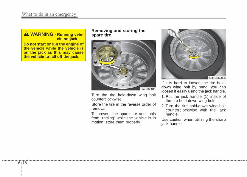
What to do in an emergency
166
Removing and storing thespare tire
Turn the tire hold-down wing boltcounterclockwise.Store the tire in the reverse order ofremoval.To prevent the spare tire and toolsfrom “rattling” while the vehicle is inmotion, store them properly.
If it is hard to loosen the tire hold-down wing bolt by hand, you canloosen it easily using the jack handle.1. Put the jack handle (1) inside of
the tire hold-down wing bolt.2. Turn the tire hold-down wing bolt
counterclockwise with the jackhandle.
Use caution when utilizing the sharpjack handle.
WARNING - Running vehi-cle on jack
Do not start or run the engine ofthe vehicle while the vehicle ison the jack as this may causethe vehicle to fall off the jack.
OYG066011
OJFC065035

6 17
What to do in an emergency
Changing tires
1. Park on a level surface and applythe parking brake firmly.
2. Place the transaxle shift lever in P(Park).
3. Activate the hazard warning flash-ers.
4. Remove the wheel lug nut wrench,jack and spare tire from the vehi-cle.
5. Block both the front and rear of thewheel that is diagonally oppositefrom the jack position.
1JBA6504
OED066033
WARNING - Jack locationTo reduce the possibility ofinjury, be sure to use only thejack provided with the vehicle inthe correct jack position; neveruse any other part of the vehiclefor jack support.
WARNING - Changing atire
• To prevent vehicle movementwhile changing a tire, alwaysset the parking brake fully,and always block the wheeldiagonally opposite the wheelbeing changed.
• We recommend that thewheels of the vehicle beblocked, and that no personremain in a vehicle that isbeing jacked.
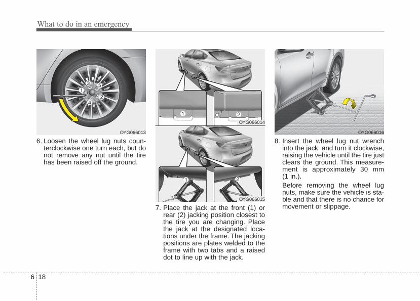
What to do in an emergency
186
6. Loosen the wheel lug nuts coun-terclockwise one turn each, but donot remove any nut until the tirehas been raised off the ground.
7. Place the jack at the front (1) orrear (2) jacking position closest tothe tire you are changing. Placethe jack at the designated loca-tions under the frame. The jackingpositions are plates welded to theframe with two tabs and a raiseddot to line up with the jack.
8. Insert the wheel lug nut wrenchinto the jack and turn it clockwise,raising the vehicle until the tire justclears the ground. This measure-ment is approximately 30 mm(1 in.).Before removing the wheel lugnuts, make sure the vehicle is sta-ble and that there is no chance formovement or slippage.
OYG066016OYG066013
OYG066014
OYG066015

6 19
What to do in an emergency
9. Loosen the wheel nuts andremove them with your fingers.Slide the wheel off the studs andlay it flat so it cannot roll away. Toput the wheel on the hub, pick upthe spare tire, line up the holeswith the studs and slide the wheelonto them. If this is difficult, tip thewheel slightly and get the top holein the wheel lined up with the topstud. Jiggle the wheel back andforth until the wheel can slide overthe other studs.
Wheels may have sharp edges.Handle them carefully to avoid possi-ble severe injury. Before putting thewheel into place, be sure that thereis nothing on the hub or wheel (suchas mud, tar, gravel, etc.) that pre-vents the wheel from fitting solidlyagainst the hub.
10. To install the wheel, hold it on thestuds, put the wheel nuts on thestuds and tighten them fingertight. Jiggle the tire to be sure it iscompletely seated, then tightenthe nuts as much as possiblewith your fingers again.
11. Insert the wrench into the jackand lower the vehicle to theground by turning the wheel nutwrench counterclockwise.WARNING - Installing a
wheelMake sure the wheel makesgood contact with the hub wheninstalled. If the contact of themounting surface between thewheel and hub is not good, thewheel nuts could come looseand cause the loss of a wheel.Loss of a wheel may result inloss of control of the vehicle.

What to do in an emergency
206
Position the wrench as shown in thedrawing and tighten the wheel nuts.Be sure the socket is seated com-pletely over the nut. Do not stand onthe wrench handle or use an exten-sion pipe over the wrench handle. Goaround the wheel, tightening everynut following the numerical sequenceshown in the image until they are alltight. Double-check each nut fortightness. After changing wheels,have an authorized Kia dealer tight-en the wheel nuts to their propertorque as soon as possible.
Wheel nut tightening torque:11~13 kgf·m (79~94 lbf·ft)
If you have a tire gauge, remove thevalve cap and check the air pressure.If the pressure is lower than recom-mended, drive slowly to the nearestservice station and inflate to the cor-rect pressure. If it is too high, adjustit until it is correct. Always reinstallthe valve cap after checking oradjusting the tire pressure. If the capis not replaced, dust and dirt may getinto the tire valve and air may leakfrom the tire. If you lose a valve cap,buy another and install it as soon aspossible.After you have changed the wheels,always secure the flat tire in its placeand return the jack and tools to theirproper storage locations.
Note that most lug nuts do not havemetric threads. Be sure to useextreme care in checking for threadstyle before installing aftermarket lugnuts or wheels. If in doubt, consult anauthorized Kia dealer.
CAUTION - Reusing lugnuts
Make certain during wheelremoval that the same nuts thatwere removed are reinstalled -or, if replaced, that nuts withmetric threads and the samechamfer configuration are used.Your vehicle has metric threadson the wheel studs and nuts.Installation of a non-metricthread nut on a metric stud willnot secure the wheel to the hubproperly and will damage thestud so that it must be replaced.
OYG066017

6 21
What to do in an emergency
To prevent the jack, wheel lug nutwrench and spare tire from rattlingwhile the vehicle is in motion, storethem properly.Check the inflation pressures assoon as possible after installing thespare tire. Adjust it to the specifiedpressure, if necessary. Refer to“Tires and wheels” in section 7.
Important - use of compact sparetireYour vehicle is equipped with a com-pact spare tire. This compact sparetire takes up less space than a regu-lar-size tire. This tire is smaller than aconventional tire and is designed fortemporary use only.• You should drive carefully when
the compact spare is in use. Thecompact spare should be replacedby the proper conventional tire andrim at the first opportunity.
• The operation of this vehicle is notrecommended with more than onecompact spare tire in use at thesame time.
The compact spare should be inflat-ed to 420 kPa (60 psi).
✽✽ NOTICECheck the inflation pressure afterinstalling the spare tire. Adjust it tothe specified pressure, as necessary.
WARNING - Spare tireThe compact spare tire is foremergency use only. Do notoperate your vehicle on thiscompact spare at speeds over80 km/h (50 mph). The originaltire should be repaired orreplaced as soon as possible toavoid failure of the spare possi-bly leading to personal injury ordeath.
WARNING - Wheel studsIf the studs are damaged, theymay lose their ability to retainthe wheel.This could lead to theloss of the wheel and a collisionresulting in serious injuries.

What to do in an emergency
226
When using a compact spare tire,observe the following precautions:• Under no circumstances should you
exceed 80 km/h (50 mph); a higherspeed could damage the tire.
• Ensure that you drive slowly enoughfor the road conditions to avoid allhazards. Any road hazard, such as apothole or debris, could seriouslydamage the compact spare.
• Any continuous road use of this tirecould result in tire failure, loss ofvehicle control, and possible per-sonal injury.
• Do not exceed the vehicle’s maxi-mum load rating or the load-carry-ing capacity shown on the sidewallof the compact spare tire.
• Avoid driving over obstacles. Thecompact spare tire diameter issmaller than the diameter of a con-ventional tire and reduces theground clearance approximately25 mm (1 inch), which could resultin damage to the vehicle.
• Do not take this vehicle through anautomatic vehicle wash while thecompact spare tire is installed.
• Do not use the compact spare tireon any other vehicle because thistire has been designed especiallyfor your vehicle.
• The compact spare tire’s tread lifeis shorter than a regular tire.Inspect your compact spare tireregularly and replace worn com-pact spare tires with the same sizeand design, mounted on the samewheel.
• The compact spare tire should notbe used on any other wheels, norshould standard tires, snow tires,wheel covers or trim rings be usedwith the compact spare wheel. Ifsuch use is attempted, damage tothese items or other vehicle com-ponents may occur.
• Do not use more than one compactspare tire at a time.
• Do not tow a trailer while the com-pact spare tire is installed.

6 23
What to do in an emergency
Jack label 1. Model Name2. Maximum allowable load3. When using the jack, set your
parking brake.4. When using the jack, stop the
engine.5. Do not get under a vehicle that is
supported by a jack.6. The designated locations under
the frame7. When supporting the vehicle, the
base plate of jack must be verticalunder the lifting point.
8. Move the shift lever to the P posi-tion on vehicles with automatictransmission.
9. The jack should be used on firmlevel ground.
10. Jack manufacturer11. Production date12. Representative company and
address
OHYK064001
OHYK064005
OHYK064002
• Type A■ Example
• Type B
• Type C
❈ The actual Jack label in the vehicle may differ from the illustration. Formore detailed specifications, refer to the label attached to the jack.

What to do in an emergency
246
TOWINGTowing service
If emergency towing is necessary,we recommend having it done by anauthorized Kia dealer or a commer-cial tow-truck service. Proper liftingand towing procedures are neces-sary to prevent damage to the vehi-cle. The use of wheel dollies orflatbed is recommended.
It is acceptable to tow the vehiclewith the rear wheels on the ground(without dollies) and the front wheelsoff the ground.If any of the loaded wheels or sus-pension components are damagedor the vehicle is being towed with thefront wheels on the ground, use atowing dolly under the front wheels.When being towed by a commercialtow truck and wheel dollies are notused, the front of the vehicle shouldalways be lifted, not the rear.
✽✽ NOTICEIf the EPB does not release normal-ly, take your vehicle to an author-ized Kia dealer by loading the vehi-cle on a flatbed tow truck and havethe system checked.
WARNING - Side and curtain Air bag
If your vehicle is equipped withside and curtain air bag, set thethe Engine Start/Stop button toACC position when the vehicleis being towed.The side and curtain air bagmay deploy when the ignition isON, and the rollover sensordetects the situation as arollover.
OYG066032
A
B
C
dolly

6 25
What to do in an emergency
When towing your vehicle in anemergency without wheel dollies :1. Set the Engine Start/Stop button
to ACC position.2. Place the transaxle shift lever in N
(Neutral).3. Release the parking brake.
Removable towing hook(if equipped)
1. Open the trunk, and remove thetowing hook from the tool case.
2. Remove the hole cover pressingthe upper part of the cover on thebumper.
CAUTION - Towing gearposition
Failure to place the transaxleshift lever in N (Neutral) maycause internal damage to thetransaxle.
CAUTION - Towing• Do not tow the vehicle back-
wards with the front wheels onthe ground as this may causedamage to the vehicle.
• Do not tow with sling-typeequipment. Use wheel lift orflatbed equipment.
HXD02
HXD03
OYG066025

What to do in an emergency
266
3. Install the towing hook by turning itclockwise into the hole until it isfully secured.
4. Remove the towing hook andinstall the cover after use.
Emergency towing
If towing is necessary, we recom-mend you to have it done by anauthorized Kia dealer or a com-mercial tow truck service.
If towing service is not available in anemergency, your vehicle may betemporarily towed using a cable orchain secured to the emergency tow-ing hook under the front (or rear) ofthe vehicle. Use extreme cautionwhen towing the vehicle. A drivermust be in the vehicle to steer it andoperate the brakes.Towing in this manner may be doneonly on hard-surfaced roads for ashort distance and at low speed.Also, the wheels, axles, power train,steering and brakes must all be ingood condition.• Do not use the tow hooks to pull a
vehicle out of mud, sand or otherconditions from which the vehiclecannot be driven out under its ownpower.
• Avoid towing a vehicle heavier thanthe vehicle doing the towing.
• The drivers of both vehicles shouldcommunicate with each other fre-quently.
OYG066026
OYG066027
■ Front
■ Rear

6 27
What to do in an emergency
• Attach a towing strap to the towhook.
• Use only a cable or chain specifical-ly intended for use in towing vehi-cles. Securely fasten the cable orchain to the towing hook provided.
• Before emergency towing, check ifthe hook is not broken or damaged.
• Fasten the towing cable or chainsecurely to the hook.
• Do not jerk the hook. Apply itsteadily and with even force.
• To avoid damaging the hook, do notpull from the side or at a verticalangle. Always pull straight ahead.
• Use a towing strap less than 5 m(16 feet) long. Attach a white or redcloth (about 30 cm (12 inches)wide) in the middle of the strap foreasy visibility.
• Drive carefully so that the towingstrap is not loosened during towing.
CAUTIONUsing a portion of the vehicleother than the tow hooks fortowing may damage the body ofyour vehicle.
WARNING - EmergencyTowing Precautions
Use extreme caution when tow-ing the vehicle.• Avoid sudden starts or erratic
driving maneuvers whichwould place excessive stresson the emergency towing hookand towing cable or chain. Thehook and towing cable orchain may break and causeserious injury or damage.
• If the disabled vehicle isunable to be moved, do notforcibly continue the towing.We recommend that you con-tact an authorized Kia dealeror a commercial tow truckservice for assistance.
• Tow the vehicle as straightahead as possible.
• Keep away from the vehicleduring towing.
OYG066034

What to do in an emergency
286
Emergency towing precautions• Turn the Engine Start/Stop button
to ACC position so the steeringwheel isn’t locked.
• Place the transaxle shift lever in N(Neutral).
• Release the parking bake.• Press the brake pedal with more
force than normal since you willhave reduced brake performance.
• More steering effort will berequired because the power steer-ing system will be disabled.
• If you are driving down a long hill,the brakes may overheat and brakeperformance will be reduced. Stopoften and let the brakes cool off.
• If the car is being towed with allfour wheels on the ground, it canbe towed only from the front. Besure that the transaxle is in neutral.Be sure the steering is unlocked byplacing the Engine Start/Stop but-ton to ACC position. A driver mustbe in the towed vehicle to operatethe steering and brakes.
CAUTION - Automatictransaxle
• To avoid serious damage tothe automatic transaxle, limitthe vehicle speed to 15 km/h(10 mph) and drive less than1.5 km (1 mile) when towing.
• Before towing, check the auto-matic transaxle for fluid leaksunder your vehicle. If the auto-matic transaxle fluid is leak-ing, flatbed equipment or atowing dolly must be used.
Maintenance
Engine compartment . . . . . . . . . . . . . . . . . . . . . . . . 7-3
Maintenance services . . . . . . . . . . . . . . . . . . . . . . . . 7-4• Owner’s responsibility . . . . . . . . . . . . . . . . . . . . . . . . . 7-4
• Owner maintenance precautions . . . . . . . . . . . . . . . . . 7-5
Owner maintenance . . . . . . . . . . . . . . . . . . . . . . . . . 7-6• Owner maintenance schedule . . . . . . . . . . . . . . . . . . . 7-6
Scheduled maintenance service. . . . . . . . . . . . . . . . 7-8
Explanation of scheduled maintenance items . . . 7-24
Checking fluid levels . . . . . . . . . . . . . . . . . . . . . . . 7-27
Engine oil. . . . . . . . . . . . . . . . . . . . . . . . . . . . . . . . . 7-28• Checking the engine oil level . . . . . . . . . . . . . . . . . . . 7-28
• Changing the engine oil and filter . . . . . . . . . . . . . . . 7-29
Engine coolant . . . . . . . . . . . . . . . . . . . . . . . . . . . . 7-30• Checking the coolant level . . . . . . . . . . . . . . . . . . . . . 7-30
• Changing the coolant . . . . . . . . . . . . . . . . . . . . . . . . . 7-32
Brake fluid . . . . . . . . . . . . . . . . . . . . . . . . . . . . . . . 7-33• Checking the brake fluid level . . . . . . . . . . . . . . . . . . 7-33
Washer fluid . . . . . . . . . . . . . . . . . . . . . . . . . . . . . . 7-34• Checking the washer fluid level . . . . . . . . . . . . . . . . . 7-34
Parking brake . . . . . . . . . . . . . . . . . . . . . . . . . . . . . 7-35• Checking the parking brake. . . . . . . . . . . . . . . . . . . . 7-35
Air cleaner. . . . . . . . . . . . . . . . . . . . . . . . . . . . . . . . 7-36• Filter replacement . . . . . . . . . . . . . . . . . . . . . . . . . . . 7-36
Climate control air filter . . . . . . . . . . . . . . . . . . . . 7-38• Filter inspection . . . . . . . . . . . . . . . . . . . . . . . . . . . . . . 7-38
Wiper blades . . . . . . . . . . . . . . . . . . . . . . . . . . . . . . 7-40• Blade inspection. . . . . . . . . . . . . . . . . . . . . . . . . . . . . . 7-40
• Blade replacement . . . . . . . . . . . . . . . . . . . . . . . . . . . . 7-40
Battery . . . . . . . . . . . . . . . . . . . . . . . . . . . . . . . . . . . 7-44• For best battery service . . . . . . . . . . . . . . . . . . . . . . . 7-44
• Recharging the battery . . . . . . . . . . . . . . . . . . . . . . . . 7-45
• Reset items . . . . . . . . . . . . . . . . . . . . . . . . . . . . . . . . . . 7-46
Tires and wheels . . . . . . . . . . . . . . . . . . . . . . . . . . . 7-47• Tire care . . . . . . . . . . . . . . . . . . . . . . . . . . . . . . . . . . . . 7-47
• Recommended cold tire inflation pressures . . . . . . . 7-47
• Tire pressure . . . . . . . . . . . . . . . . . . . . . . . . . . . . . . . . 7-48
• Checking tire inflation pressure. . . . . . . . . . . . . . . . . 7-48
• Tire rotation . . . . . . . . . . . . . . . . . . . . . . . . . . . . . . . . . 7-49
• Wheel alignment and tire balance . . . . . . . . . . . . . . . 7-50
• Tire replacement . . . . . . . . . . . . . . . . . . . . . . . . . . . . . 7-51
• Wheel replacement . . . . . . . . . . . . . . . . . . . . . . . . . . . 7-52
• Tire traction . . . . . . . . . . . . . . . . . . . . . . . . . . . . . . . . . 7-52
• Tire maintenance. . . . . . . . . . . . . . . . . . . . . . . . . . . . . 7-52
• Tire sidewall labeling . . . . . . . . . . . . . . . . . . . . . . . . . 7-52
• Tire terminology and definitions . . . . . . . . . . . . . . . . 7-56
• All season tires . . . . . . . . . . . . . . . . . . . . . . . . . . . . . . 7-59
• Summer tires . . . . . . . . . . . . . . . . . . . . . . . . . . . . . . . . 7-59
• Snow tires . . . . . . . . . . . . . . . . . . . . . . . . . . . . . . . . . . . 7-59
7

• Radial-ply tires . . . . . . . . . . . . . . . . . . . . . . . . . . . . . . 7-59
• Low aspect ratio tire . . . . . . . . . . . . . . . . . . . . . . . . . . 7-60
Fuses . . . . . . . . . . . . . . . . . . . . . . . . . . . . . . . . . . . . 7-62• Inner panel fuse replacement . . . . . . . . . . . . . . . . . . . 7-63
• Engine compartment fuse replacement. . . . . . . . . . . 7-65
• Fuse/relay panel description. . . . . . . . . . . . . . . . . . . . 7-68
Light bulbs . . . . . . . . . . . . . . . . . . . . . . . . . . . . . . . 7-79• Bulb replacement precaution . . . . . . . . . . . . . . . . . . 7-79
• Light bulb position (Front) . . . . . . . . . . . . . . . . . . . . 7-80
• Light bulb position (Rear) . . . . . . . . . . . . . . . . . . . . . 7-81
• Light bulb position (Side) . . . . . . . . . . . . . . . . . . . . . . 7-81
• Headlamp (LED type) bulb replacement . . . . . . . . . 7-82
• Headlamp (Low beam) bulb replacement . . . . . . . . 7-82
• Headlamp (High beam) bulb replacement . . . . . . . . 7-84
• Front turn signal lamp bulb replacement . . . . . . . . 7-84
• Front fog lamp (LED type) bulb replacement . . . . . 7-85
• Position lamp + DRL (LED type) bulb replacement . . 7-86
• Side repeater lamp bulb replacement . . . . . . . . . . . . 7-86
• Rear turn signal lamp bulb replacement . . . . . . . . . 7-87
• Stop and tail lamp (LED type) bulb replacement . . 7-88
• Back-up lamp bulb replacement . . . . . . . . . . . . . . . . 7-88
• License plate lamp bulb replacement . . . . . . . . . . . . 7-89
• High mounted stop lamp (LED type) bulb
replacement . . . . . . . . . . . . . . . . . . . . . . . . . . . . . . . . 7-89
• Map lamp bulb replacement . . . . . . . . . . . . . . . . . . . 7-90
• Vanity mirror lamp bulb replacement . . . . . . . . . . . 7-90
• Room lamp bulb replacement . . . . . . . . . . . . . . . . . . 7-91
• Personal lamp bulb replacement . . . . . . . . . . . . . . . 7-91
• Glove box lamp bulb replacement . . . . . . . . . . . . . . 7-92
• Trunk lamp (LED type) bulb replacement . . . . . . . . 7-92
Appearance care. . . . . . . . . . . . . . . . . . . . . . . . . . . 7-93• Exterior care . . . . . . . . . . . . . . . . . . . . . . . . . . . . . . . . 7-93
• Interior care . . . . . . . . . . . . . . . . . . . . . . . . . . . . . . . . . 7-98
Emission control system . . . . . . . . . . . . . . . . . . . 7-101• Crankcase emission control system . . . . . . . . . . . . . 7-101
• Evaporative emission control (including ORVR:
Onboard Refueling Vapor Recovery) system . . . . 7-101
• Exhaust emission control system . . . . . . . . . . . . . . . 7-102
7

7 3
Maintenance
ENGINE COMPARTMENT
OYG076002
■■ Gasoline Engine (Lambda 3.3L - GDI)
❈ The actual engine compartment in the vehicle may differ from the illustration.
1. Engine coolant reservoir
2. Engine oil filler cap
3. Brake fluid reservoir
4. Air cleaner
5. Fuse box
6. Negative battery terminal
7. Positive battery terminal
8. Engine oil dipstick
9. Radiator cap
10.Windshield washer fluid reservoir

Maintenance
47
MAINTENANCE SERVICESYou should exercise the utmost careto prevent damage to your vehicleand injury to yourself whenever per-forming any maintenance or inspec-tion procedures.Should you have any doubts con-cerning the inspection or servicing ofyour vehicle, we strongly recom-mend that you have an authorizedKia dealer perform this work.An authorized Kia dealer has factory-trained technicians and genuine Kiaparts to service your vehicle proper-ly. For expert advice and quality serv-ice, see an authorized Kia dealer.Inadequate, incomplete or insuffi-cient servicing may result in opera-tional problems with your vehicle thatcould lead to vehicle damage, anaccident, or personal injury.
Owner’s responsibility
✽✽ NOTICEMaintenance Service and RecordRetention are the owner's responsi-bility.You should retain documents thatshow proper maintenance has beenperformed on your vehicle in accor-dance with the scheduled mainte-nance service charts shown on thefollowing pages. You need this infor-mation to establish your compliancewith the servicing and maintenancerequirements of your vehicle war-ranties.Detailed warranty information isprovided in your Warranty &Consumer Information manual.
Repairs and adjustments required asa result of improper maintenance ora lack of required maintenance arenot covered.We recommend you have your vehi-cle maintained and repaired by anauthorized Kia dealer. An authorizedKia dealer meets Kia’s high servicequality standards and receives tech-nical support from Kia in order to pro-vide you with a high level of servicesatisfaction.

7 5
Maintenance
Owner maintenance precau-tions Improper or incomplete service mayresult in problems. This section givesinstructions only for the maintenanceitems that are easy to perform.As explained earlier in this section,several procedures can be done onlyby an authorized Kia dealer with spe-cial tools.
✽✽ NOTICEImproper owner maintenance dur-ing the warranty period may affectwarranty coverage. For details, readthe separate Warranty & ConsumerInformation manual provided withthe vehicle. If you're unsure aboutany servicing or maintenance proce-dure, have it done by an authorizedKia dealer.
WARNING - Maintenancework
Do not wear jewelry or looseclothing while working underthe hood of your vehicle withthe engine running. These canbecome entangled in movingparts, if you must run theengine while working under thehood, make certain that youremove all jewelry (especiallyrings, bracelets, watches, andnecklaces) and all neckties,scarves, and similar looseclothing before getting near theengine or cooling fans.

Maintenance
67
OWNER MAINTENANCE The following lists are vehicle checksand inspections that should be per-formed by the owner or an author-ized Kia dealer at the frequenciesindicated to help ensure safe,dependable operation of your vehi-cle.Any adverse conditions should bebrought to the attention of your deal-er as soon as possible.These Owner Maintenance Checksare generally not covered by war-ranties and you may be charged forlabor, parts and lubricants used.
Owner maintenance schedule When you stop for fuel:• Check the engine oil level.• Check the coolant level in coolant
reservoir.• Check the windshield washer fluid
level.• Look for low or under-inflated tires.
While operating your vehicle:• Note any changes in the sound of
the exhaust or any smell ofexhaust fumes in the vehicle.
• Check for vibrations in the steeringwheel. Notice any increased steer-ing effort or looseness in the steer-ing wheel, or change in its straight-ahead position.
• Notice if your vehicle constantlyturns slightly or “pulls” to one sidewhen traveling on smooth, levelroad.
• When stopping, listen and checkfor unusual sounds, pulling to oneside, increased brake pedal travelor “hard-to-push” brake pedal.
• If any slipping or changes in theoperation of your transaxle occurs,check the transaxle fluid level.
• Check the automatic transaxle P(Park) function.
• Check the parking brake.• Check for fluid leaks under your
vehicle (water dripping from the airconditioning system during or afteruse is normal).
WARNING - Hot coolantBe careful when checking yourengine coolant level when theengine is hot. Scalding hotcoolant and steam may blowout under pressure.

7 7
Maintenance
At least monthly:• Check the coolant level in the
engine coolant reservoir.• Check the operation of all exterior
lights, including the stoplights, turnsignals and hazard warning flash-ers.
• Check the inflation pressures of alltires including the spare.
At least twice a year (i.e., every Spring and Fall) :• Check the radiator, heater and air
conditioning hoses for leaks ordamage.
• Check the windshield washerspray and wiper operation. Cleanthe wiper blades with clean clothdampened with washer fluid.
• Check the headlight alignment.• Check the muffler, exhaust pipes,
shields and clamps.• Check the lap/shoulder belts for
wear and function.• Check for worn tires and loose
wheel lug nuts.
At least once a year :• Clean the body and door drain
holes.• Lubricate the door hinges and
check the hood hinges.• Lubricate the door and hood locks
and latches.• Lubricate the door rubber weather-
strips.• Check the air conditioning system.• Inspect and lubricate automatic
transaxle linkage and controls.• Clean the battery and terminals.• Check the brake fluid level.

Maintenance
87
SCHEDULED MAINTENANCE SERVICE Follow the Normal MaintenanceSchedule if the vehicle is usuallyoperated where none of the followingconditions apply. If any of the followingconditions apply, follow theMaintenance Under Severe UsageConditions.• Repeated driving short distance of
less than 8 km (5 miles) in normaltemperature or less than 16 km (10miles) in freezing temperature
• Extensive engine idling or lowspeed driving for long distances
• Driving on rough, dusty, muddy,unpaved, graveled or salt-spreadroads
• Driving in areas using salt or othercorrosive materials or in very coldweather
• Driving in heavy dust condition• Driving in heavy traffic area• Driving on uphill, downhill, or
mountain road repeatedly
• Towing a trailer or using a camper,or roof rack
• Driving as a patrol car, taxi, othercommercial use of vehicle towing
• Driving over 170 km/h (106 mph)• Frequently driving in stop-and-go
condition
If your vehicle is operated under theabove conditions, you shouldinspect, replace or refill more fre-quently than the following NormalMaintenance Schedule. After 120months or 240,000 km (150,000miles) continue to follow the pre-scribed maintenance intervals.

7 9
Maintenance
Normal Maintenance ScheduleThe following maintenance services must be performed to ensure good emission control and performance.Keep receipts for all vehicle emission services to protect your warranty. Where both mileage and time are shown, thefrequency of service is determined by whichever occurs first.
12,000 km (7,500 miles) or 6 months
❑ Inspect air cleaner filter❑ Inspect vacuum hose❑ Replace engine oil and filter
(12,000 km (7,500 miles) or 12 months)❑ Add fuel additive *3 (12,000 km (7,500 miles) or 12 months)❑ Rotate tire position (Every 12,000 km (7,500 miles))❑ Inspect battery condition❑ Inspect cooling system hoses and connections❑ Inspect clutch (if equipped) and brake pedal free play
*3 If TOP TIER Detergent Gasoline is not available, one bottle of additive is rec-ommended. Additives are available from your authorized Kia dealer along withinformation on how to use them. Do not mix other additives.
❈ Inspect : Inspect and if necessary, adjust, correct, clean or replace.

Maintenance
107
Normal Maintenance Schedule (CONT.)
36,000 km (22,500 miles) or 18 months
❑ Inspect air cleaner filter❑ Inspect vacuum hose
❑ Replace engine oil and filter(36,000 km (22,500 miles) or 36 months)
❑ Add fuel additive *3 (36,000 km (22,500 miles) or 36 months)❑ Rotate tire position (Every 12,000 km (7,500 miles))❑ Inspect battery condition❑ Inspect cooling system hoses and connections❑ Inspect clutch (if equipped) and brake pedal free play
24,000 km (15,000 miles) or 12 months
❑ Inspect air cleaner filter❑ Inspect vacuum hose❑ Inspect air conditioning refrigerant❑ Inspect brake hoses and lines❑ Inspect drive shafts and boots❑ Inspect exhaust pipe and muffler❑ Inspect front brake disc/pads, calipers❑ Inspect rear brake disc/pads
❑ Inspect steering gear box, linkage & boots/lower arm ball joint, upper arm ball joint
❑ Inspect suspension mounting bolts❑ Replace climate control air filter (for evaporator and blower unit)
❑ Replace engine oil and filter(24,000 km (15,000 miles) or 24 months)
❑ Add fuel additive *3 (24,000 km (15,000 miles) or 24 months)❑ Rotate tire position (Every 12,000 km (7,500 miles))❑ Inspect all latch, hinges and locks❑ Inspect battery condition❑ Inspect cooling system hoses and connections❑ Inspect clutch (if equipped) and brake pedal free play
*3 If TOP TIER Detergent Gasoline is not available, one bottle of additive is rec-ommended. Additives are available from your authorized Kia dealer along withinformation on how to use them. Do not mix other additives.
❈ Inspect : Inspect and if necessary, adjust, correct, clean or replace.
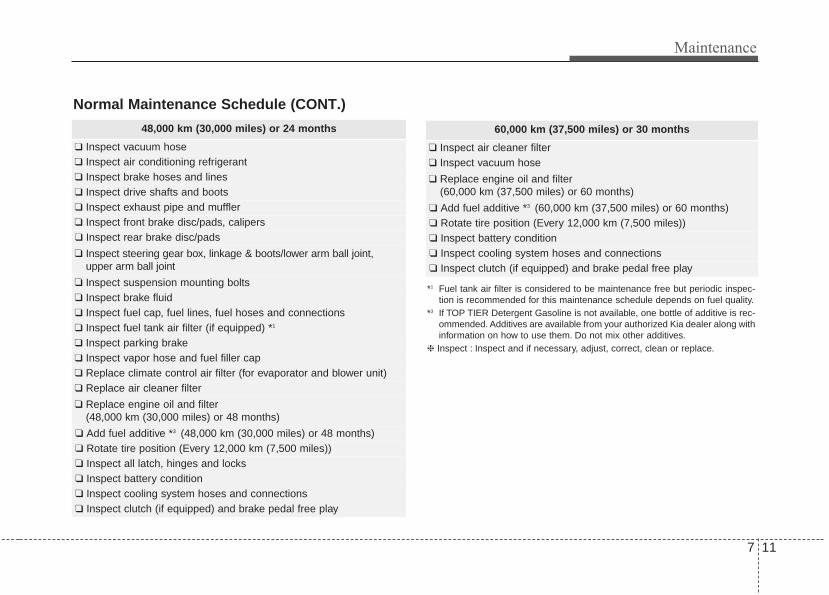
7 11
Maintenance
Normal Maintenance Schedule (CONT.)
60,000 km (37,500 miles) or 30 months
❑ Inspect air cleaner filter❑ Inspect vacuum hose
❑ Replace engine oil and filter(60,000 km (37,500 miles) or 60 months)
❑ Add fuel additive *3 (60,000 km (37,500 miles) or 60 months)❑ Rotate tire position (Every 12,000 km (7,500 miles))❑ Inspect battery condition❑ Inspect cooling system hoses and connections❑ Inspect clutch (if equipped) and brake pedal free play
*1 Fuel tank air filter is considered to be maintenance free but periodic inspec-tion is recommended for this maintenance schedule depends on fuel quality.
*3 If TOP TIER Detergent Gasoline is not available, one bottle of additive is rec-ommended. Additives are available from your authorized Kia dealer along withinformation on how to use them. Do not mix other additives.
❈ Inspect : Inspect and if necessary, adjust, correct, clean or replace.
48,000 km (30,000 miles) or 24 months
❑ Inspect vacuum hose❑ Inspect air conditioning refrigerant❑ Inspect brake hoses and lines❑ Inspect drive shafts and boots❑ Inspect exhaust pipe and muffler❑ Inspect front brake disc/pads, calipers❑ Inspect rear brake disc/pads
❑ Inspect steering gear box, linkage & boots/lower arm ball joint, upper arm ball joint
❑ Inspect suspension mounting bolts❑ Inspect brake fluid ❑ Inspect fuel cap, fuel lines, fuel hoses and connections❑ Inspect fuel tank air filter (if equipped) *1
❑ Inspect parking brake❑ Inspect vapor hose and fuel filler cap❑ Replace climate control air filter (for evaporator and blower unit)❑ Replace air cleaner filter
❑ Replace engine oil and filter(48,000 km (30,000 miles) or 48 months)
❑ Add fuel additive *3 (48,000 km (30,000 miles) or 48 months)❑ Rotate tire position (Every 12,000 km (7,500 miles))❑ Inspect all latch, hinges and locks❑ Inspect battery condition❑ Inspect cooling system hoses and connections❑ Inspect clutch (if equipped) and brake pedal free play

Maintenance
127
Normal Maintenance Schedule (CONT.)
72,000 km (45,000 miles) or 36 months
❑ Inspect air cleaner filter❑ Inspect vacuum hose❑ Inspect air conditioning refrigerant❑ Inspect brake hoses and lines❑ Inspect drive shafts and boots❑ Inspect exhaust pipe and muffler❑ Inspect front brake disc/pads, calipers❑ Inspect rear brake disc/pads
❑ Inspect steering gear box, linkage & boots/lower arm ball joint, upper arm ball joint
❑ Inspect suspension mounting bolts❑ Replace climate control air filter (for evaporator and blower unit)
❑ Replace engine oil and filter (2.4 GDI) *3
(72,000 km (45,000 miles) or 72 months)
❑ Add fuel additive *3 (72,000 km (45,000 miles) or 72 months)❑ Rotate tire position (Every 12,000 km (7,500 miles))❑ Inspect all latch, hinges and locks❑ Inspect battery condition❑ Inspect cooling system hoses and connections❑ Inspect clutch (if equipped) and brake pedal free play
84,000 km (52,500 miles) or 42 months
❑ Inspect air cleaner filter❑ Inspect vacuum hose
❑ Replace engine oil and filter(84,000 km (52,500 miles) or 84 months)
❑ Add fuel additive *3 (84,000 km (52,500 miles) or 84 months)❑ Rotate tire position (Every 12,000 km (7,500 miles))❑ Inspect battery condition❑ Inspect cooling system hoses and connections❑ Inspect clutch (if equipped) and brake pedal free play
*3 If TOP TIER Detergent Gasoline is not available, one bottle of additive is rec-ommended. Additives are available from your authorized Kia dealer along withinformation on how to use them. Do not mix other additives.
❈ Inspect : Inspect and if necessary, adjust, correct, clean or replace.

7 13
Maintenance
96,000 km (60,000 miles) or 48 months
❑ Inspect vacuum hose❑ Inspect air conditioning refrigerant❑ Inspect brake hoses and lines❑ Inspect drive shafts and boots❑ Inspect exhaust pipe and muffler❑ Inspect front brake disc/pads, calipers❑ Inspect rear brake disc/pads
❑ Inspect steering gear box, linkage & boots/lower arm ball joint, upper arm ball joint
❑ Inspect suspension mounting bolts❑ Inspect brake fluid❑ Inspect fuel cap, fuel lines, fuel hoses and connections❑ Inspect fuel tank air filter (if equipped) *1
❑ Inspect parking brake❑ Inspect vapor hose and fuel filler cap
❑ Inspect valve clearance (if equipped) *2
(Every 96,000 km (60,000 miles) or 72 months)❑ Inspect drive belts
(First, 96,000 km (60,000 miles) or 72 months after every 24,000 km (15,000 miles) or 24 months)
❑ Replace climate control air filter (for evaporator and blower unit)❑ Replace air cleaner filter
(Continued)
(Continued)
❑ Replace engine oil and filter(96,000 km (60,000 miles) or 96 months)
❑ Add fuel additive *3 (96,000 km (60,000 miles) or 96 months)❑ Rotate tire position (Every 12,000 km (7,500 miles))❑ Inspect all latch, hinges and locks❑ Inspect battery condition❑ Inspect cooling system hoses and connections❑ Inspect clutch (if equipped) and brake pedal free play
Normal Maintenance Schedule (CONT.)
*1 Fuel tank air filter is considered to be maintenance free but periodic inspec-tion is recommended for this maintenance schedule depends on fuel quality.
*2 Inspect for excessive tappet noise and/or engine vibration and adjust if nec-essary.
*3 If TOP TIER Detergent Gasoline is not available, one bottle of additive is rec-ommended. Additives are available from your authorized Kia dealer along withinformation on how to use them. Do not mix other additives.
❈ Inspect : Inspect and if necessary, adjust, correct, clean or replace.

Maintenance
147
Normal Maintenance Schedule (CONT.)
108,000 km (67,500 miles) or 54 months
❑ Inspect air cleaner filter❑ Inspect vacuum hose
❑ Replace engine oil and filter(108,000 km (67,500 miles) or 108 months)
❑ Add fuel additive *3 (108,000 km (67,500 miles) or 108 months)❑ Rotate tire position (Every 12,000 km (7,500 miles))❑ Inspect battery condition❑ Inspect cooling system hoses and connections❑ Inspect clutch (if equipped) and brake pedal free play
*3 If TOP TIER Detergent Gasoline is not available, one bottle of additive is rec-ommended. Additives are available from your authorized Kia dealer along withinformation on how to use them. Do not mix other additives.
❈ Inspect : Inspect and if necessary, adjust, correct, clean or replace.

7 15
Maintenance
120,000 km (75,000 miles) or 60 months
❑ Inspect air cleaner filter❑ Inspect vacuum hose❑ Inspect air conditioning refrigerant❑ Inspect brake hoses and lines❑ Inspect drive shafts and boots❑ Inspect exhaust pipe and muffler❑ Inspect front brake disc/pads, calipers❑ Inspect rear brake disc/pads
❑ Inspect steering gear box, linkage & boots/lower arm ball joint, upper arm ball joint
❑ Inspect suspension mounting bolts❑ Inspect drive belts
(First, 96,000 km (60,000 miles) or 72 months after every 24,000 km (15,000 miles) or 24 months)
❑ Replace climate control air filter (for evaporator and blower unit)
❑ Replace engine oil and filter(120,000 km (75,000 miles) or 120 months)
❑ Add fuel additive *3 (120,000 km (75,000 miles) or 120 months)❑ Rotate tire position (Every 12,000 km (7,500 miles))❑ Inspect all latch, hinges and locks❑ Inspect battery condition❑ Inspect cooling system hoses and connections❑ Inspect clutch (if equipped) and brake pedal free play
132,000 km (82,500 miles) or 66 months
❑ Inspect air cleaner filter❑ Inspect vacuum hose
❑ Replace engine oil and filter(82,500 miles (132,000 km) or 132 months)
❑ Add fuel additive *3 (132,000 km (82,500 miles) or 132 months)❑ Rotate tire position (Every 12,000 km (7,500 miles))❑ Inspect battery condition❑ Inspect cooling system hoses and connections❑ Inspect clutch (if equipped) and brake pedal free play
*3 If TOP TIER Detergent Gasoline is not available, one bottle of additive is rec-ommended. Additives are available from your authorized Kia dealer along withinformation on how to use them. Do not mix other additives.
❈ Inspect : Inspect and if necessary, adjust, correct, clean or replace.
Normal Maintenance Schedule (CONT.)

Maintenance
167
Normal Maintenance Schedule (CONT.)
144,000 km (90,000 miles) or 72 months
❑ Inspect vacuum hose❑ Inspect air conditioning refrigerant❑ Inspect brake hoses and lines❑ Inspect drive shafts and boots❑ Inspect exhaust pipe and muffler❑ Inspect front brake disc/pads, calipers❑ Inspect rear brake disc/pads
❑ Inspect steering gear box, linkage & boots/lower arm ball joint, upper arm ball joint
❑ Inspect suspension mounting bolts❑ Inspect brake fluid❑ Inspect fuel cap, fuel lines, fuel hoses and connections❑ Inspect fuel tank air filter (if equipped) *1
❑ Inspect parking brake❑ Inspect vapor hose and fuel filler cap
❑ Inspect drive belts (First, 96,000 km (60,000 miles) or 72 months after every 24,000 km (15,000 miles) or 24 months)
❑ Replace climate control air filter (for evaporator and blower unit)❑ Replace air cleaner filter
❑ Replace engine oil and filter(144,000 km (90,000 miles) or 144 months)
(Continued)
*1 Fuel tank air filter is considered to be maintenance free but periodic inspec-tion is recommended for this maintenance schedule depends on fuel quality.
*3 If TOP TIER Detergent Gasoline is not available, one bottle of additive is rec-ommended. Additives are available from your authorized Kia dealer along withinformation on how to use them. Do not mix other additives.
❈ Inspect : Inspect and if necessary, adjust, correct, clean or replace.
(Continued)❑ Add fuel additive *3 (144,000 km (90,000 miles) or 144 months)❑ Rotate tire position (Every 12,000 km (7,500 miles))❑ Inspect all latch, hinges and locks❑ Inspect battery condition❑ Inspect cooling system hoses and connections❑ Inspect clutch (if equipped) and brake pedal free play
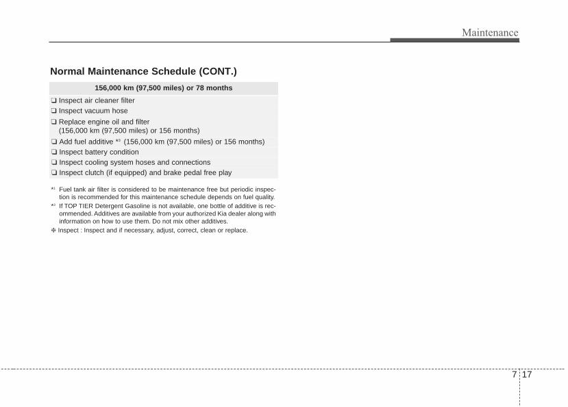
7 17
Maintenance
156,000 km (97,500 miles) or 78 months
❑ Inspect air cleaner filter❑ Inspect vacuum hose
❑ Replace engine oil and filter(156,000 km (97,500 miles) or 156 months)
❑ Add fuel additive *3 (156,000 km (97,500 miles) or 156 months)❑ Inspect battery condition❑ Inspect cooling system hoses and connections❑ Inspect clutch (if equipped) and brake pedal free play
*1 Fuel tank air filter is considered to be maintenance free but periodic inspec-tion is recommended for this maintenance schedule depends on fuel quality.
*3 If TOP TIER Detergent Gasoline is not available, one bottle of additive is rec-ommended. Additives are available from your authorized Kia dealer along withinformation on how to use them. Do not mix other additives.
❈ Inspect : Inspect and if necessary, adjust, correct, clean or replace.
Normal Maintenance Schedule (CONT.)

Maintenance
187
180,000 km (112,500 miles) or 90 months
❑ Inspect air cleaner filter❑ Inspect vacuum hose
❑ Replace engine oil and filter(180,000 km (112,500 miles) or 180 months)
❑ Add fuel additive *3 (180,000 km (112,500 miles) or 180 months❑ Rotate tire position (Every 12,000 km (7,500 miles))❑ Inspect battery condition❑ Inspect cooling system hoses and connections❑ Inspect clutch (if equipped) and brake pedal free play
*3 If TOP TIER Detergent Gasoline is not available, one bottle of additive is rec-ommended. Additives are available from your authorized Kia dealer along withinformation on how to use them. Do not mix other additives.
❈ Inspect : Inspect and if necessary, adjust, correct, clean or replace.
Normal Maintenance Schedule (CONT.)
168,000 km (105,000 miles) or 84 months
❑ Inspect air cleaner filter❑ Inspect vacuum hose❑ Inspect air conditioning refrigerant❑ Inspect brake hoses and lines❑ Inspect drive shafts and boots❑ Inspect exhaust pipe and muffler❑ Inspect front brake disc/pads, calipers❑ Inspect rear brake disc/pads
❑ Inspect steering gear box, linkage & boots/lower arm ball joint, upper arm ball joint
❑ Inspect suspension mounting bolts
❑ Inspect drive belts(First, 96,000 km (60,000 miles) or 72 months after every 24,000 km (15,000 miles) or 24 months)
❑ Replace climate control air filter (for evaporator and blower unit)❑ Replace spark plugs (iridium coated)
❑ Replace engine oil and filter (168,000 km (105,000 miles) or 168 months)
❑ Add fuel additive *3 (168,000 km (105,000 miles) or 168 months❑ Rotate tire position (Every 12,000 km (7,500 miles))❑ Inspect all latch, hinges and locks❑ Inspect battery condition❑ Inspect cooling system hoses and connections❑ Inspect clutch (if equipped) and brake pedal free play

7 19
Maintenance
Normal Maintenance Schedule (CONT.)
192,000 km (120,000 miles) or 96 months
❑ Inspect vacuum hose❑ Inspect air conditioning refrigerant❑ Inspect brake hoses and lines❑ Inspect drive shafts and boots❑ Inspect exhaust pipe and muffler❑ Inspect front brake disc/pads, calipers❑ Inspect rear brake disc/pads❑ Inspect steering gear box, linkage & boots/lower arm ball joint,
upper arm ball joint❑ Inspect suspension mounting bolts❑ Inspect brake fluid ❑ Inspect fuel cap, fuel lines, fuel hoses and connections❑ Inspect fuel tank air filter (if equipped) *1
❑ Inspect parking brake❑ Inspect vapor hose and fuel filler cap
❑ Inspect valve clearance (if equipped) *2
(Every 96,000 km (60,000 miles) or 72 months)
❑ Inspect drive belts (First, 96,000 km (60,000 miles) or 72 months after every 24,000 km (15,000 miles) or 24 months)
❑ Replace climate control air filter (for evaporator and blower unit)❑ Replace air cleaner filter
❑ Replace engine oil and filter(192,000 km (120,000 miles) or 192 months)
(Continued)
*1 Fuel tank air filter is considered to be maintenance free but periodic inspec-tion is recommended for this maintenance schedule depends on fuel quality.
*2 Inspect for excessive tappet noise and/or engine vibration and adjust if nec-essary.
*3 If TOP TIER Detergent Gasoline is not available, one bottle of additive is rec-ommended. Additives are available from your authorized Kia dealer along withinformation on how to use them. Do not mix other additives.
❈ Inspect : Inspect and if necessary, adjust, correct, clean or replace.
(Continued)
❑ Replace coolant(First, 192,000 km (120,000 miles) or 120 months after that,every 48,000 km (30,000 miles) or 24 months)
❑ Add fuel additive *3 (192,000 km (120,000 miles) or 192 months)❑ Rotate tire position (Every 12,000 km (7,500 miles))❑ Inspect all latch, hinges and locks❑ Inspect battery condition❑ Inspect cooling system hoses and connections❑ Inspect clutch (if equipped) and brake pedal free play

Maintenance
207
*3 If TOP TIER Detergent Gasoline is not available, one bottle of additive is rec-ommended. Additives are available from your authorized Kia dealer along withinformation on how to use them. Do not mix other additives.
❈ Inspect : Inspect and if necessary, adjust, correct, clean or replace.
204,000 km (127,500 miles) or 102 months
❑ Inspect air cleaner filter❑ Inspect vacuum hose
❑ Replace engine oil and filter(204,000 km (127,500 miles) or 204 months)
❑ Add fuel additive *3 (204,000 km (127,500 miles) or 204 months)❑ Rotate tire position (Every 12,000 km (7,500 miles))❑ Inspect battery condition❑ Inspect cooling system hoses and connections❑ Inspect clutch (if equipped) and brake pedal free play
Normal Maintenance Schedule (CONT.)

7 21
Maintenance
Normal Maintenance Schedule (CONT.)
216,000 km (135,000 miles) or 108 months
❑ Inspect air cleaner filter❑ Inspect vacuum hose❑ Inspect air conditioning refrigerant❑ Inspect brake hoses and lines❑ Inspect drive shafts and boots❑ Inspect exhaust pipe and muffler❑ Inspect front brake disc/pads, calipers❑ Inspect rear brake disc/pads
❑ Inspect steering gear box, linkage & boots/lower arm ball joint, upper arm ball joint
❑ Inspect suspension mounting bolts
❑ Inspect drive belts(First, 96,000 km (60,000 miles) or 72 months after every 24,000 km (15,000 miles) or 24 months)
❑ Replace climate control air filter (for evaporator and blower unit)
❑ Replace engine oil and filter(216,000 km (135,000 miles) or 216 months)
❑ Add fuel additive *3 (216,000 km (135,000 miles) or 216 months)❑ Rotate tire position (Every 12,000 km (7,500 miles))❑ Inspect all latch, hinges and locks❑ Inspect battery condition❑ Inspect cooling system hoses and connections❑ Inspect clutch (if equipped) and brake pedal free play
228,000 km (142,500 miles) or 114 months
❑ Inspect air cleaner filter❑ Inspect vacuum hose
❑ Replace engine oil and filter(228,000 km (142,500 miles) or 228 months)
❑ Add fuel additive *3 (228,000 km (142,500 miles) or 228 months)❑ Rotate tire position (Every 12,000 km (7,500 miles))❑ Inspect battery condition❑ Inspect cooling system hoses and connections❑ Inspect clutch (if equipped) and brake pedal free play
*3 If TOP TIER Detergent Gasoline is not available, one bottle of additive is rec-ommended. Additives are available from your authorized Kia dealer along withinformation on how to use them. Do not mix other additives.
❈ Inspect : Inspect and if necessary, adjust, correct, clean or replace.

Maintenance
227
Normal Maintenance Schedule (CONT.)
240,000 km (150,000 miles) or 120 months
❑ Inspect vacuum hose❑ Inspect air conditioning refrigerant❑ Inspect brake hoses and lines❑ Inspect drive shafts and boots❑ Inspect exhaust pipe and muffler❑ Inspect front brake disc/pads, calipers❑ Inspect rear brake disc/pads
❑ Inspect steering gear box, linkage & boots/lower arm ball joint, upper arm ball joint
❑ Inspect suspension mounting bolts❑ Inspect brake fluid❑ Inspect fuel lines, fuel hoses and connections❑ Inspect fuel tank air filter (if equipped) *1
❑ Inspect parking brake❑ Inspect vapor hose and fuel filler cap
❑ Inspect drive belts(First, 96,000 km (60,000 miles) or 72 months after every 24,000 km (15,000 miles) or 24 months)
❑ Replace climate control air filter (for evaporator and blower unit)❑ Replace air cleaner filter
(Continued)
(Continued)
❑ Replace engine oil and filter(240,000 km (150,000 miles) or 240 months)
❑ Replace coolant(First, 192,000 km (120,000 miles) or 120 months after that,every 48,000 km (30,000 miles) or 24 months)
❑ Add fuel additive *3 (240,000 km (150,000 miles) or 240 months)❑ Rotate tire position (Every 12,000 km (7,500 miles))❑ Inspect all latch, hinges and locks❑ Inspect battery condition❑ Inspect cooling system hoses and connections❑ Inspect clutch (if equipped) and brake pedal free play
No check, No service required
❑ Automatic transmission fluid (if equipped)
*1 Fuel tank air filter is considered to be maintenance free but periodic inspec-tion is recommended for this maintenance schedule depends on fuel quality.
*3 If TOP TIER Detergent Gasoline is not available, one bottle of additive is rec-ommended. Additives are available from your authorized Kia dealer along withinformation on how to use them. Do not mix other additives.
❈ Inspect : Inspect and if necessary, adjust, correct, clean or replace.

7 23
Maintenance
Maintenance Under Severe Usage Conditions
Severe Driving ConditionsA - Repeatedly driving short distance of less than 8 km (5 miles) in normal
temperature or less than 16 km (10 miles) in freezing temperatureB - Extensive engine idling or low speed driving for long distancesC - Driving on rough, dusty, muddy, unpaved, graveled or salt- spread roadsD - Driving in areas using salt or other corrosive materials or in very cold
weatherE - Driving in heavy dust condition
F - Driving in heavy traffic areaG - Driving on uphill, downhill, or mountain roadH - Towing a Trailer, or using a camper, or roof rackI - Driving as a patrol car, taxi, other commercial use or vehicle towingJ - Driving over 170 km/h (106 mph)K - Frequently driving in stop-and-go conditions
The following items must be serviced more frequently on cars normally used under severe driving conditions.Refer to the chart below for the appropriate maintenance intervals.R : Replace I : Inspect and, after inspection, clean, adjust, repair or replace if necessary
MAINTENANCE ITEMMAINTENANCE
OPERATIONMAINTENANCE INTERVALS DRIVING CONDITION
Engine oil and filter R Every 6,000 km (3,750 miles) or 6 monthsA, B, C, D, E, F, G, H, I, J, K
Air cleaner filter R More frequently C, E
Spark plugs R More frequently B, H
Automatic transmission fluid R Every 96,000 km (60,000 miles) A, C, E, F, G, I
Front brake disc/pads, calipers I More frequently C, D, G, H
Rear brake disc/pads I More frequently C, D, G, F
Parking brake I More frequently C, D, G, H
Steering gear box, linkage & boots/lower arm ball joint,upper arm ball joint
I More frequently C, D, E, F, G, H, I
Drive shafts and boots I More frequently C, D, E, F, G, H, I, J
Climate control air filter (for evaporator and blower unit) R More frequently C, E

Maintenance
247
EXPLANATION OF SCHEDULED MAINTENANCE ITEMSEngine oil and filterThe engine oil and filter should bechanged at the intervals specified inthe maintenance schedule. If thevehicle is being driven in severe con-ditions, more frequent oil and filterchanges are required.
Drive beltsInspect all drive belts for evidence ofcuts, cracks, excessive wear or oilsaturation and replace if necessary.Drive belts should be checked peri-odically for proper tension andadjusted as necessary.
Fuel filter (for gasoline)Kia gasoline vehicle is equipped alifetime fuel filter that integrated withthe fuel tank. Regular maintenanceor replacement is not needed butdepends on fuel quality. If there aresome important safety matters likefuel flow restriction, surging, loss ofpower, hard starting problem etc, fuelfilter inspection or replace is needed.The fuel filter be Inspected orreplaced by an authorized Kia dealer.
Fuel lines, fuel hoses and con-nectionsCheck the fuel lines, fuel hoses andconnections for leakage and dam-age. Have an authorized Kia dealerreplace any damaged or leakingparts immediately.
Vapor hose and fuel filler capThe vapor hose and fuel filler capshould be inspected at those inter-vals specified in the maintenanceschedule. Make sure that a newvapor hose or fuel filler cap is cor-rectly replaced.
7 25
Maintenance
Vacuum crankcase ventilationhosesInspect the surface of hoses for evi-dence of heat and/or mechanicaldamage. Hard and brittle rubber,cracking, tears, cuts, abrasions, andexcessive swelling indicate deterio-ration. Particular attention should bepaid to examine those hose surfacesnearest to high heat sources, suchas the exhaust manifold.Inspect the hose routing to assurethat the hoses do not come in con-tact with any heat source, sharpedges or moving component whichmight cause heat damage ormechanical wear. Inspect all hoseconnections, such as clamps andcouplings, to make sure they aresecure, and that no leaks are pres-ent. Hoses should be replacedimmediately if there is any evidenceof deterioration or damage.
Air cleaner filterA Genuine Kia air cleaner filter is rec-ommended when the filter is replaced.
Spark plugsMake sure to install new spark plugsof the correct heat range.
Valve clearance (if equipped)Inspect excessive valve noise and/orengine vibration and adjust if neces-sary. An authorized Kia dealershould perform the operation.
Cooling systemCheck the cooling system compo-nents, such as the radiator, coolantreservoir, hoses and connections forleakage and damage. Replace anydamaged parts.
CoolantThe coolant should be changed atthe intervals specified in the mainte-nance schedule.
Automatic transaxle fluidAutomatic transaxle fluid should notbe checked under normal usageconditions.But in severe conditions, the fluidshould be changed at an authorizedKia dealer in accordance to thescheduled maintenance at the begin-ning of this chapter.
✽✽ NOTICEAutomatic transaxle fluid color isbasically red. As the vehicle is driven, the auto-matic transaxle fluid will begin tolook darker.It is normal condition and you shouldnot judge the need to replace the fluidbased upon the changed color.

Maintenance
267
Brake hoses and linesVisually check for proper installation,chafing, cracks, deterioration andany leakage. Replace any deteriorat-ed or damaged parts immediately.
Brake fluidCheck the brake fluid level in thebrake fluid reservoir. The level shouldbe between “MIN” and “MAX” markson the side of the reservoir. Use onlyhydraulic brake fluid conforming toDOT 3 or DOT 4 specification.
Parking brakeInspect the parking brake systemincluding the parking brake pedaland cables.
Brake discs, pads, calipersand rotorsCheck the pads for excessive wear,discs for run out and wear, andcalipers for fluid leakage.
Exhaust pipe and mufflerVisually inspect the exhaust pipes,muffler and hangers for cracks, dete-rioration, or damage. Start theengine and listen carefully for anyexhaust gas leakage. Tighten con-nections or replace parts as neces-sary.
Suspension mounting boltsCheck the suspension connectionsfor looseness or damage. Retightento the specified torque.
CAUTIONUse only specified automatictransaxle fluid.The use of a non-specified fluid could result in atransaxle malfunction and fail-ure. (Refer to "Recommendedlubricants and capacities" inchapter 8.)

7 27
Maintenance
Steering gear box, linkage &boots/lower arm ball jointWith the vehicle stopped and engineoff, check for excessive free-play inthe steering wheel.Check the linkage for bends or dam-age. Check the dust boots and balljoints for deterioration, cracks, ordamage. Replace any damagedparts.
Drive shafts and bootsCheck the drive shafts, boots andclamps for cracks, deterioration, ordamage. Replace any damagedparts and, if necessary, repack thegrease.
Air conditioning refrigerant Check the air conditioning lines andconnections for leakage and damage.
When checking engine oil, enginecoolant, brake fluid, and washer fluid,always be sure to clean the areaaround any filler plug, drain plug, ordipstick before checking or drainingany lubricant or fluid. This is espe-cially important in dusty or sandyareas and when the vehicle is usedon unpaved roads. Cleaning the plugand dipstick areas will prevent dirtand grit from entering the engine andother mechanisms that could bedamaged.
CHECKING FLUID LEVELS

Maintenance
287
ENGINE OILChecking the engine oil level
1. Be sure the vehicle is on levelground.
2. Start the engine and allow it toreach normal operating tempera-ture.
3. Turn the engine off and wait for afew minutes (about 5 minutes) forthe oil to return to the oil pan.
4. Pull the dipstick out, wipe it clean,and reinsert it fully.
5. Pull the dipstick out again andcheck the level. The level shouldbe between F and L.
If it is near or at L, add enough oil tobring the level to F. Do not overfill.
Use a funnel to help prevent oilfrom being spilled on engine com-ponents.
Use only the specified engine oil.(Refer to “Recommended lubricantsand capacities” in chapter 8.)
WARNING - Radiator hoseBe very careful not to touch theradiator hose when checking oradding the engine oil as it maybe hot enough to burn you.
OYG076007
■ Gasoline Engine (Lambda 3.3L - GDI)
OYG076011
■ Gasoline Engine (Lambda 3.3L - GDI)
CAUTION - Replacingengine oil
Do not overfill the engine oil. Itmay damage the engine.

7 29
Maintenance
Changing the engine oil andfilterHave engine oil and filter changed byan authorized Kia dealer accordingto the Maintenance Schedule at thebeginning of this chapter.
WARNINGUsed engine oil may cause irrita-tion or cancer of the skin if left incontact with the skin for pro-longed periods of time. Alwaysprotect your skin by washingyour hands thoroughly withsoap and warm water as soon aspossible after handling used oil.

Maintenance
307
ENGINE COOLANTThe high-pressure cooling systemhas a reservoir filled with year roundantifreeze coolant. The reservoir isfilled at the factory.Check the antifreeze protection andcoolant level at least once a year: atthe beginning of the winter season,and before traveling to a colder cli-mate.
Checking the coolant level • Turn the engine off and wait until itcools down. Use extreme carewhen removing the radiator cap.Wrap a thick towel around it, andturn it counterclockwise slowly tothe first stop. Step back while thepressure is released from the cool-ing system.When you are sure all the pressurehas been released, press down onthe cap, using a thick towel, andcontinue turning counterclockwiseto remove it.
• Even if the engine is not operating,do not remove the radiator cap orthe drain plug while the engine andradiator are hot. Hot coolant andsteam may still blow out underpressure, causing serious injury.
WARNINGRemoving radiatorcap
Never attempt to remove theradiator cap while the engine isoperating or hot. Doing somight lead to cooling systemand engine damage and couldresult in serious personal injuryfrom escaping hot coolant orsteam.
CAUTION - Radiator capNever attempt to remove theradiator cap while the engine isoperating or hot. Doing somight lead to cooling systemand engine damage.

7 31
Maintenance
Check the condition and connectionsof all cooling system hoses andheater hoses. Replace any swollenor deteriorated hoses.The coolant level should be filledbetween F and L marks on the sideof the coolant reservoir when theengine is cool.If the coolant level is low, add enoughspecified coolant to provide protec-tion against freezing and corrosion.Bring the level to F, but do not over-fill. If frequent additions are required,see an authorized Kia dealer for acooling system inspection.
Recommended engine coolant• When adding coolant, use only
deionized water or soft water foryour vehicle and never mix hardwater in the coolant filled at the fac-tory. An improper coolant mixturecan result in serious malfunction orengine damage.
• The engine in your vehicle has alu-minum engine parts and must beprotected by an ethylene-glycolwith phosphate based coolant toprevent corrosion and freezing.
• DO NOT USE alcohol or methanolcoolant or mix them with the spec-ified coolant.
• Do not use a solution that containsmore than 60% antifreeze or lessthan 35% antifreeze. This wouldreduce the effectiveness of thesolution.
OYG076013
WARNING - Cooling fanUse caution whenworking near theblade of the coolingfan. The electricmotor (cooling fan) is
controlled by engine coolanttemperature, refrigerant pres-sure and vehicle speed. it maysometimes operate even whenthe engine is not running.

Maintenance
327
For mixture percentage, refer to thefollowing table.
Changing the coolantHave the coolant changed by anauthorized Kia dealer according tothe Maintenance Schedule at thebeginning of this chapter.Put a thick cloth around the radiatorcap before refilling the coolant inorder to prevent the coolant fromoverflowing into engine parts such asthe alternator.
OYG076014
AmbientTemperature
Mixture Percentage (volume)
Antifreeze Water-15°C (5°F) 35 65
-25°C (-13°F) 40 60
-35°C (-31°F) 50 50
-45°C (-49°F) 60 40
WARNING Radiator cap
Do not remove the radiator capwhen the engine and radiatorare hot. Scalding hot coolantand steam may blow out underpressure which may result inserious injury.
CAUTIONPut a thick cloth or fabricaround the radiator cap beforerefilling the coolant in order toprevent the coolant from over-flowing into engine parts suchas the generator.

7 33
Maintenance
BRAKE FLUID Checking the brake fluid level
Check the fluid level in the reservoirperiodically. The fluid level should bebetween MAX (Maximum) and MIN(Minimum) marks on the side of thereservoir.Before removing the reservoir capand adding brake fluid, clean thearea around the reservoir cap thor-oughly to prevent brake fluid contam-ination.
If the level is low, add fluid to theMAX (Maximum) level. The level willfall with accumulated mileage. This isa normal condition associated withthe wear of brake linings. If the fluidlevel is excessively low, have thebrake system checked by an author-ized Kia dealer.
Use only the specified brake fluid.(Refer to “Recommended lubricantsand capacities” in chapter 8.)
Never mix different types of fluid.
In the event the brake systemrequires frequent additions of fluid,the vehicle should be inspected byan authorized Kia dealer.When changing and adding brakefluid, handle it carefully. Do not let itcome in contact with your eyes. Ifbrake fluid should come in contactwith your eyes, immediately flushthem with a large quantity of freshtap water. Have your eyes examinedby a doctor as soon as possible.
Brake fluid, which has been exposedto open air for an extended timeshould never be used as its qualitycannot be guaranteed. It should bedisposed of properly.
OYG076015CAUTION - Brake fluid
Do not allow brake fluid to con-tact the vehicle's body paint, aspaint damage will result.
CAUTION - Proper fluidOnly use brake fluid in brakesystem. Small amounts ofimproper fluids (such as engineoil) can cause damage to thebrake system.

Maintenance
347
WASHER FLUIDChecking the washer fluidlevel
The reservoir is translucent so thatyou can check the level with a quickvisual inspection.Check the fluid level in the washerfluid reservoir and add fluid if neces-sary. Plain water may be used ifwasher fluid is not available.However, use washer solvent withantifreeze characteristics in cold cli-mates to prevent freezing.
WARNING - Flammablefluid
Do not allow the washer fluid tocome in contact with openflames or sparks.The windshieldwasher fluid reservoir is flamma-ble under certain circumstances.This can result in a fire.
WARNING - Windshieldfluid
Do not drink the windshieldwasher fluid. The windshieldwasher fluid is poisonous tohumans and animals.
WARNING - Coolant• Do not use radiator coolant or
antifreeze in the washer fluidreservoir.
• Radiator coolant can severelyobscure visibility when sprayedon the windshield and maycause loss of vehicle control.
OYG076016

7 35
Maintenance
Checking the parking brake
Check whether the stroke is withinspecification when the parking brakepedal is depressed with 30 kg, 294 N(66 lb) of force. Also, the parkingbrake alone should securely hold thevehicle on a fairly steep grade. If thestroke is more or less than specified,have the parking brake adjusted byan authorized Kia dealer.Stroke : 6~7 notch
PARKING BRAKE
OYG056016

Maintenance
367
AIR CLEANERFilter replacement
It must be replaced when necessary,and should not be washed.You can clean the filter when inspect-ing the air cleaner element.Clean the filter by using compressedair.
1. Pull out the air cleaner cover.
2. Unlock by turning the locking leverdownward.
3. Pull the air cleaner filter to replace.4. Lock the cover with the reverse
order.
OYG076018
OYG076019
OYG076020
OYG076021

7 37
Maintenance
Replace the filter according to theMaintenance Schedule.If the vehicle is operated in extreme-ly dusty or sandy areas, replace theelement more often than the usualrecommended intervals. (Refer to“Maintenance under severe usageconditions” in this chapter.)
CAUTION - Air filter maintenance
• Do not drive with the air clean-er removed; this will result inexcessive engine wear.
• When removing the air cleanerfilter, be careful that dust ordirt does not enter the airintake, or damage may result.
• Use a Kia genuine part. Use ofa non-genuine part coulddamage the air flow sensor.

Maintenance
387
CLIMATE CONTROL AIR FILTERFilter inspectionThe climate control air filter shouldbe replaced according to theMaintenance Schedule. If the vehicleis operated in severely air-pollutedcities or on dusty rough roads for along period, it should be inspectedmore frequently and replaced earlier.When you replace the climate controlair filter, replace it performing the fol-lowing procedure, and be careful toavoid damaging other components.
1. Open the glove box and removethe stoppers on both sides.
2. With the glove box open, pull thesupport strap (1).
OYG076022OYG076023

7 39
Maintenance
3. Remove the climate control air fil-ter cover while pressing the lockon the right side of the cover.
4. Replace the climate control air fil-ter.
5. Reassemble in the reverse orderof disassembly.
When replacing the climate controlair filter install it properly. Otherwise,the system may produce noise andthe effectiveness of the filter may bereduced.
OYG076024 OYG076025

Maintenance
407
WIPER BLADES Blade inspection
Commercial hot waxes applied byautomatic car washes have beenknown to make the windshield diffi-cult to clean.
Contamination of either the wind-shield or the wiper blades with for-eign matter can reduce the effective-ness of the windshield wipers.Common sources of contaminationare insects, tree sap, and hot waxtreatments used by some commer-cial car washes. If the blades are notwiping properly, clean both the win-dow and the blades with a goodcleaner or mild detergent, and rinsethoroughly with clean water.
Blade replacement When the wipers no longer cleanadequately, the blades may be wornor cracked, and require replacement.To prevent damage to the wiper armsor other components, do not attemptto move the wipers manually.The use of a non-specified wiperblade could result in wiper malfunc-tion and failure.
1JBA5122 CAUTION - Wiper bladesTo prevent damage to the wiperblades, do not use gasoline,kerosene, paint thinner, or othersolvents on or near them.

7 41
Maintenance
Front windshield wiper blade
For your convenience, move thewindshield wiper blades to the serv-ice position as follows;After turning off the engine, move thewiper switch to the single wiping(MIST) position within 20 secondsand hold the switch more than 2 sec-onds until the wiper blade is in thefully up position. Type A
1. Raise the wiper arm.2. Lift up the wiper blade clip. Then
pull down the blade assembly andremove it.
3. Install the new blade assembly.
OHM078060
OHM078061
CAUTION - Wiper armsDo not allow the wiper arm tofall against the windshield,since it may chip or crack thewindshield.
OYG076026

Maintenance
427
4. Return the wiper arm on the wind-shield.
5. Turn ignition to the ON positionand wiper arms will return to thenormal operating position.
Type B
1. Raise the wiper arm and turn thewiper blade assembly to exposethe plastic locking clip.
2. Compress the clip and slide theblade assembly downward.
3. Lift it off the arm.4. Install the new blade assembly.
1JBA7037
1JBA7038
1LDA5023

7 43
Maintenance
5. Return the wiper arm on the wind-shield.
6. Turn ignition to the ON positionand wiper arms will return to thenormal operating position.

Maintenance
447
BATTERYFor best battery service
• Keep the battery securely mount-ed.
• Keep the battery top clean and dry.• Keep the terminals and connec-
tions clean, tight, and coated withpetroleum jelly or terminal grease.
• Rinse any spilled electrolyte fromthe battery immediately with asolution of water and baking soda.
• If the vehicle is not going to beused for an extended time, discon-nect the battery cables.
Always read the followinginstructions carefully whenhandling a battery.If any electrolyte gets intoyour eyes, flush your eyeswith clean water for at least15 minutes and get immedi-ate medical attention.If electrolyte gets on yourskin, thoroughly wash thecontacted area. If you feelpain or burning sensation,get medical attention imme-diately.
An inappropriately disposedbattery can be harmful to theenvironment and humanhealth. Dispose the batteryaccording to your local law(s)or regulation.The battery contains lead. Donot dispose of it after use.Please return the battery toan authorized Kia dealer tobe recycled.
Never attempt to recharge the bat-tery when the battery cables are con-nected.
WARNING - Risk of explosion
Keep lit cigarettes andall other flames orsparks away from thebattery.The battery containshydrogen -- a highlycombustible gas whichwill explode if it comesin contact with a flame orspark.Keep batteries out of thereach of childrenbecause batteries con-tain highly corrosiveSULFURIC ACID andelectrolytes. Do notallow battery acid tocontact your skin, eyes,clothing or paint finish.Wear eye protectionwhen charging or work-ing near a battery.Always provide ventila-tion when working in anenclosed space.
OYG076027

7 45
Maintenance
✽✽ NOTICEIf you connect unauthorized elec-tronic devices to the battery, the bat-tery may be discharged. Never useunauthorized devices.
Recharging the batteryYour vehicle has a maintenance-free,calcium-based battery.• If the battery becomes discharged
in a short time (because, for exam-ple, the headlamps or interiorlamps were left on while the vehi-cle was not in use), recharge it byslow charging (trickle) for 10 hours.
• If the battery gradually dischargesbecause of high electric load whilethe vehicle is being used, rechargeit at 20-30A for two hours.
WARNING - Risk of elec-trocution
Never touch the electrical igni-tion system while the vehicle isrunning. This system workswith high voltage which canshock you.
WARNING - RechargingBattery
Never attempt to recharge thebattery when the battery cablesare connected.

Maintenance
467
When recharging the battery,observe the following precautions:• The battery must be removed from
the vehicle and placed in an areawith good ventilation.
• Do not allow cigarettes, sparks, orflame near the battery.
• Watch the battery during charging,and stop or reduce the chargingrate if the battery cells begingassing (boiling) violently or if thetemperature of the electrolyte ofany cell exceeds 49°C (120°F).
• Wear eye protection when check-ing the battery during charging.
• Disconnect the battery charger inthe following order.
1. Turn off the battery charger mainswitch.
2. Unhook the negative clamp fromthe negative battery terminal.
3. Unhook the positive clamp fromthe positive battery terminal.
• Before performing maintenance orrecharging the battery, turn off allaccessories and stop the engine.
• The negative battery cable must beremoved first and installed lastwhen the battery is disconnected.
Reset itemsItems should be reset after the bat-tery has been discharged or the bat-tery has been disconnected.• Auto up/down window
(See chapter 4)• Sunroof (See chapter 4)• Trip computer (See chapter 4)• Climate control system
(See chapter 4)• Driver position memory system
(See chapter 3)

7 47
Maintenance
TIRES AND WHEELS Tire care For proper maintenance, safety, andmaximum fuel economy, you mustalways maintain recommended tireinflation pressures and stay withinthe load limits and weight distributionrecommended for your vehicle.
Recommended cold tire infla-tion pressures All tire pressures (including thespare) should be checked when thetires are cold. “Cold Tires” means thevehicle has not been driven for atleast three hours or driven less than1.6 km (one mile).Recommended pressures must bemaintained for the best ride, top vehi-cle handling, and minimum tire wear.For recommended inflation pressurerefer to “Tire and wheels” in chapter8.
All specifications (sizes and pres-sures) can be found on a labelattached to the driver’s side centerpillar.
WARNING - Tire underin-flation
Inflate your tires consistent withthe instructions provided in thismanual. Severe underinflation(70 kPa (10 psi) or more) canlead to severe heat build-up,causing blowouts, tread separa-tion and other tire failures thatcan result in the loss of vehiclecontrol.This risk is much higheron hot days and when drivingfor long periods at high speeds.
OYG086001

Maintenance
487
• Underinflation also results inexcessive wear, poor handling andreduced fuel economy. Wheeldeformation also is possible. Keepyour tire pressures at the properlevels. If a tire frequently needsrefilling, have it checked by anauthorized Kia dealer.
• Overinflation produces a harshride, excessive wear at the centerof the tire tread, and a greater pos-sibility of damage from road haz-ards.
• Warm tires normally exceed rec-ommended cold tire pressures by28 to 41 kPa (4 to 6 psi). Do notrelease air from warm tires toadjust the pressure or the tires willbe underinflated.
• Be sure to reinstall the tire inflationvalve caps. Without the valve cap,dirt or moisture could get into thevalve core and cause air leakage. Ifa valve cap is missing, install anew one as soon as possible.
Tire pressureAlways observe the following:• Check tire pressure when the tires
are cold. (After vehicle has beenparked for at least three hours orhasn't been driven more than 1.6km (one mile) since startup.)
• Check the pressure of your sparetire each time you check the pres-sure of other tires.
• Never overload your vehicle. Becareful not to overload a vehicleluggage rack if your vehicle isequipped with one.
Checking tire inflation pres-sureCheck your tires once a month ormore.Also, check the tire pressure of thespare tire.
How to checkUse a good quality gauge to checktire pressure. You can not tell if yourtires are properly inflated simply bylooking at them. Radial tires maylook properly inflated even whenthey're underinflated.Check the tire's inflation pressurewhen the tires are cold. - "Cold"means your vehicle has been sittingfor at least three hours or driven nomore than 1.6 km (1 mile).
WARNING - Tire InflationOverinflation or underinflationcan reduce tire life, adverselyaffect vehicle handling, andlead to sudden tire failure. Thiscould result in loss of vehiclecontrol and potential injury.

7 49
Maintenance
Remove the valve cap from the tirevalve stem. Press the tire gauge firm-ly onto the valve to get a pressuremeasurement. If the cold tire inflationpressure matches the recommendedpressure on the tire and loadinginformation label, no further adjust-ment is necessary. If the pressure islow, add air until you reach the rec-ommended amount.If you overfill the tire, release air bypushing on the metal stem in thecenter of the tire valve. Recheck thetire pressure with the tire gauge. Besure to put the valve caps back onthe valve stems. They help preventleaks by keeping out dirt and mois-ture.
• Inspect your tires frequently forproper inflation as well as wear anddamage. Always use a tire pres-sure gauge.
• Tires with too much or too littlepressure wear unevenly causingpoor handling, loss of vehicle con-trol, and sudden tire failure leadingto accidents, injuries, and evendeath. The recommended cold tirepressure for your vehicle can befound in this manual and on the tirelabel located on the driver's sidecenter pillar.
• Remember to check the pressureof your spare tire. Kia recommendsthat you check the spare everytime you check the pressure of theother tires on your vehicle.
Tire rotation To equalize tread wear, it is recom-mended that the tires be rotatedevery 12,000 km (7,500 miles) orsooner if irregular wear develops.During rotation, check the tires forcorrect balance.When rotating tires, check for unevenwear and damage. Abnormal wear isusually caused by incorrect tire pres-sure, improper wheel alignment, out-of-balance wheels, severe braking orsevere cornering. Look for bumps orbulges in the tread or side of tire.Replace the tire if you find either ofthese conditions. Replace the tire iffabric or cord is visible. After rotation,be sure to bring the front and rear tirepressures to specification and checklug nut tightness.Refer to “Tire and wheels” in chapter8.

Maintenance
507
Disc brake pads should be inspectedfor wear whenever tires are rotated.Rotate radial tires that have anasymmetric tread pattern only fromfront to rear and not from right to left.
Wheel alignment and tire bal-ance The wheels on your vehicle werealigned and balanced carefully at thefactory to give you the longest tire lifeand best overall performance.In most cases, you will not need tohave your wheels aligned again.However, if you notice unusual tirewear or your vehicle pulling one wayor the other, the alignment may needto be reset.If you notice your vehicle vibratingwhen driving on a smooth road, yourwheels may need to be rebalanced.
WARNING - Mixing tires• Do not use the compact spare
tire (if equipped) for tire rota-tion.
• Do not mix bias ply and radialply tires under any circum-stances. This may causeunusual handling characteris-tics.
CAUTION - Wheel weightImproper wheel weights candamage your vehicle's alu-minum wheels. Use onlyapproved wheel weights.
S2BLA790A
CBGQ0707A
Without a spare tire
Directional tires (if equipped)
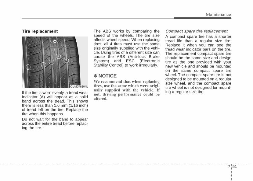
7 51
Maintenance
Tire replacement
If the tire is worn evenly, a tread wearIndicator (A) will appear as a solidband across the tread. This showsthere is less than 1.6 mm (1/16 inch)of tread left on the tire. Replace thetire when this happens.Do not wait for the band to appearacross the entire tread before replac-ing the tire.
The ABS works by comparing thespeed of the wheels. The tire sizeaffects wheel speed. When replacingtires, all 4 tires must use the samesize originally supplied with the vehi-cle. Using tires of a different size cancause the ABS (Anti-lock BrakeSystem) and ESC (ElectronicStability Control) to work irregularly.
✽✽ NOTICEWe recommend that when replacingtires, use the same which were origi-nally supplied with the vehicle. Ifnot, driving performance could bealtered.
Compact spare tire replacement A compact spare tire has a shortertread life than a regular size tire.Replace it when you can see thetread wear indicator bars on the tire.The replacement compact spare tireshould be the same size and designtire as the one provided with yournew vehicle and should be mountedon the same compact spare tirewheel. The compact spare tire is notdesigned to be mounted on a regularsize wheel, and the compact sparetire wheel is not designed for mount-ing a regular size tire.
OUM076204L

Maintenance
527
Wheel replacement When replacing the metal wheels forany reason, make sure the newwheels are equivalent to the originalfactory units in diameter, rim widthand offset.A wheel that is not the correct sizemay adversely affect wheel andbearing life, braking and stoppingabilities, handling characteristics,ground clearance, body-to-tire clear-ance, snow chain clearance,speedometer and odometer calibra-tion, headlight aim and bumperheight.
Tire tractionTire traction can be reduced if youdrive on worn tires, tires that areimproperly inflated or on slipperyroad surfaces. Tires should bereplaced when tread wear indicatorsappear. Slow down whenever thereis rain, snow or ice on the road, toreduce the possibility of losing con-trol of the vehicle.
Tire maintenance In addition to proper inflation, correctwheel alignment helps to decreasetire wear. If you find a tire is wornunevenly, have your dealer check thewheel alignment.When you have new tires installed,make sure they are balanced. Thiswill increase vehicle ride comfort andtire life. Additionally, a tire shouldalways be rebalanced if it is removedfrom the wheel.
Tire sidewall labeling
This information identifies anddescribes the fundamental charac-teristics of the tire and also providesthe tire identification number (TIN)for safety standard certification. TheTIN can be used to identify the tire incase of a recall.
1. Manufacturer or brand nameManufacturer or Brand name isshown.
CAUTION - WheelWheels that do not meet Kia'sspecifications may fit poorlyand result in damage to thevehicle or unusual handling andpoor vehicle control.
OJF085008L

7 53
Maintenance
2. Tire size designation A tire’s sidewall is marked with a tiresize designation. You will need thisinformation when selecting replace-ment tires for your car. The followingexplains what the letters and num-bers in the tire size designationmean.Example tire size designation:(These numbers are provided as anexample only; your tire size designa-tor could vary depending on yourvehicle.)P205/55R16 89H
P - Applicable vehicle type (tiresmarked with the prefix “P’’ areintended for use on passengervehicles or light trucks; however,not all tires have this marking).
205 - Tire width in millimeters.55 - Aspect ratio. The tire’s section
height as a percentage of itswidth.
R - Tire construction code (Radial).16 - Rim diameter in inches.
89 - Load Index, a numerical codeassociated with the maximumload the tire can carry.
H - Speed Rating Symbol. See thespeed rating chart in this sectionfor additional information.
Wheel size designation
Wheels are also marked with impor-tant information that you need if youever have to replace one. The follow-ing explains what the letters andnumbers in the wheel size designa-tion mean.
Example wheel size designation:6.0JX16
6.0 - Rim width in inches.J - Rim contour designation.16 - Rim diameter in inches.
Tire speed ratings
The chart below lists many of the dif-ferent speed ratings currently beingused for passenger vehicles. Thespeed rating is part of the tire sizedesignation on the sidewall of thetire. This symbol corresponds to thattire's designed maximum safe oper-ating speed.
S 180 km/h (112 mph)T 190 km/h (118 mph)H 210 km/h (130 mph)V 240 km/h (149 mph)Z Above 240 km/h (149 mph)
Maximum SpeedSpeedRatingSymbol

Maintenance
547
3. Checking tire life (TIN : TireIdentification Number)
Any tires that are over 6 years old,based on the manufacturing date,(including the spare tire) should bereplaced by new ones. You can findthe manufacturing date on the tiresidewall (possibly on the inside of thewheel), displaying the DOT Code.The DOT Code is a series of num-bers on a tire consisting of numbersand English letters. The manufactur-ing date is designated by the last fourdigits (characters) of the DOT code.
DOT : XXXX XXXX OOOOThe front part of the DOT means aplant code number, tire size andtread pattern and the last four num-bers indicate week and year manu-factured.For example:DOT XXXX XXXX 1617 representsthat the tire was produced in the 16thweek of 2017.
4. Tire ply composition and mate-rial
The number of layers or plies of rub-ber-coated fabric in the tire. Tiremanufacturers also must indicate thematerials in the tire, which includesteel, nylon, polyester, and others.The letter "R" means radial ply con-struction; the letter "D" means diago-nal or bias ply construction; and theletter "B" means belted-bias ply con-struction.
5. Maximum permissible inflationpressure
This number is the greatest amount ofair pressure that should be put in thetire. Do not exceed the maximum per-missible inflation pressure. Refer tothe Tire and Loading Information labelfor recommended inflation pressure.
6. Maximum load ratingThis number indicates the maximumload in kilograms and pounds that canbe carried by the tire. When replacingthe tires on the vehicle, always use atire that has the same load rating asthe factory installed tire.
7. Uniform tire quality grading Quality grades can be found whereapplicable on the tire sidewallbetween tread shoulder and maxi-mum section width.For example:TREADWEAR 440TRACTION ATEMPERATURE A
WARNING - Tire ageReplace tires within the recom-mended time frame. Failure toreplace tires as recommendedcan result in sudden tire failure,which could lead to a loss ofcontrol and an accident.

7 55
Maintenance
Tread wear
The tread wear grade is a compara-tive rating based on the wear rate ofthe tire when tested under controlledconditions on a specified govern-ment test course. For example, a tiregraded 150 would wear one-and-a-half times (1½) as well on the gov-ernment course as a tire graded 100.The relative performance of tiresdepends upon the actual conditionsof their use, however, and maydepart significantly from the normdue to variations in driving habits,service practices and differences inroad characteristics and climate.
Tires degrade over time, even whenthey are not being used. Regardlessof the remaining tread, we recom-mend that tires be replaced afterapproximately six (6) years of normalservice. Heat caused by hot climatesor frequent high loading conditionscan accelerate the aging process.These grades are molded on theside-walls of passenger vehicle tires.The tires available as standard oroptional equipment on your vehiclesmay vary with respect to grade.
Traction - AA, A, B & C
The traction grades, from highest tolowest, are AA, A, B and C. Thosegrades represent the tires ability tostop on wet pavement as measuredunder controlled conditions on spec-ified government test surfaces ofasphalt and concrete. A tire markedC may have poor traction perform-ance.The traction grade assigned to thistire is based on straight-ahead brak-ing traction tests, and does notinclude acceleration, cornering,hydroplaning, or peak traction char-acteristics.

Maintenance
567
Temperature -A, B & C
The temperature grades are A (thehighest), B and C representing thetire’s resistance to the generation ofheat and its ability to dissipate heatwhen tested under controlled condi-tions on a specified indoor laboratorytest wheel.Sustained high temperature cancause the material of the tire todegenerate and reduce tire life, andexcessive temperature can lead tosudden tire failure. Grades B and Arepresent higher levels of perform-ance on the laboratory test wheelthan the minimum required by law.
Tire terminology and definitionsAir Pressure: The amount of airinside the tire pressing outward onthe tire. Air pressure is expressed inkilopascal (kPa) or pounds persquare inch (psi).Accessory Weight: This means thecombined weight of optional acces-sories. Some examples of optionalaccessories are, automatictransaxle, power seats, and air con-ditioning.Aspect Ratio: The relationship of atire's height to its width.Belt: A rubber coated layer of cordsthat is located between the plies andthe tread. Cords may be made fromsteel or other reinforcing materials.Bead: The tire bead contains steelwires wrapped by steel cords thathold the tire onto the rim.Bias Ply Tire: A pneumatic tire inwhich the plies are laid at alternateangles less than 90 degrees to thecenterline of the tread.
Cold Tire Pressure: The amount ofair pressure in a tire, measured inkilopascals (kPa) or pounds persquare inch (psi) before a tire hasbuilt up heat from driving.Curb Weight: This means the weightof a motor vehicle with standard andoptional equipment including themaximum capacity of fuel, oil andcoolant, but without passengers andcargo.DOT Markings: The DOT codeincludes the Tire IdentificationNumber (TIN), an alphanumeric des-ignator which can also identify thetire manufacturer, production plant,brand and date of production.

7 57
Maintenance
GVWR: Gross Vehicle Weight RatingGAWR FRT: Gross Axle WeightRating for the Front Axle.GAWR RR: Gross Axle WeightRating for the Rear axle.Intended Outboard Sidewall: Theside of an asymmetrical tire, thatmust always face outward whenmounted on a vehicle.Kilopascal (kPa): The metric unit forair pressure.Light truck(LT) tire: A tire designat-ed by its manufacturer as primarilyintended for use on lightweight trucksor multipurpose passenger vehicles.Load Index: An assigned numberranging from 1 to 279 that corre-sponds to the load carrying capacityof a tire.Load ratings: The maximum loadthat a tire is rated to carry for a giveninflation pressure.
Maximum Inflation Pressure: Themaximum air pressure to which acold tire may be inflated. The maxi-mum air pressure is molded onto thesidewall.Maximum Load Rating: The loadrating for a tire at the maximum per-missible inflation pressure for thattire.Maximum Loaded Vehicle Weight:The sum of curb weight; accessoryweight; vehicle capacity weight; andproduction options weight.Normal Occupant Weight: Thenumber of occupants a vehicle isdesigned to seat multiplied by 68 kg(150 lbs.).
Occupant Distribution: Designatedseating positions.Outward Facing Sidewall: The sideof a asymmetrical tire that has a par-ticular side that faces outward whenmounted on a vehicle. The outwardfacing sidewall bears white letteringor bears manufacturer, brand, and/ormodel name molding that is higher ordeeper than the same moldings onthe inner facing sidewall.Passenger (P-Metric) Tire: A tireused on passenger cars and somelight duty trucks and multipurposevehicles.Ply: A layer of rubber-coated parallelcordsPneumatic tire: A mechanicaldevice made of rubber, chemicals,fabric and steel or other materials,that, when mounted on an automo-tive wheel, provides the traction andcontains the gas or fluid that sustainsthe load.

Maintenance
587
Production options weight: Thecombined weight of installed regularproduction options weighing over 2.3kg (5 lb.) in excess of the standarditems which they replace, not previ-ously considered in curb weight oraccessory weight, including heavyduty brakes, ride levelers, roof rack,heavy duty battery, and special trim.Recommended Inflation Pressure:Vehicle manufacturer's recommend-ed tire inflation pressure and shownon the tire placard.Radial Ply Tire: A pneumatic tire inwhich the ply cords that extend to thebeads are laid at 90 degrees to thecenterline of the tread.Rim: A metal support for a tire andupon which the tire beads are seat-ed.Sidewall: The portion of a tirebetween the tread and the bead.
Speed Rating: An alphanumericcode assigned to a tire indicating themaximum speed at which a tire canoperate.Traction: The friction between thetire and the road surface. Theamount of grip provided.Tread: The portion of a tire thatcomes into contact with the road.Treadwear Indicators: Narrowbands, sometimes called "wearbars," that show across the tread of atire when only 1/16 inch of treadremains.UTQGS: Uniform Tire QualityGrading Standards, a tire informationsystem that provides consumers withratings for a tire's traction, tempera-ture and treadwear. Ratings aredetermined by tire manufacturersusing government testing proce-dures. The ratings are molded intothe sidewall of the tire.Vehicle Capacity Weight: The num-ber of designated seating positionsmultiplied by 68 kg (150 lbs.) plus therated cargo and luggage load.
Vehicle Maximum Load on theTire: Load on an individual tire dueto curb and accessory weight plusmaximum occupant and cargoweight.Vehicle Normal Load on the Tire:Load on an individual tire that isdetermined by distributing to eachaxle its share of the curb weight,accessory weight, and normal occu-pant weight and driving by 2.Vehicle Placard: A label permanent-ly attached to a vehicle showing theoriginal equipment tire size and rec-ommended inflation pressure.

7 59
Maintenance
All season tires Kia specifies all season tires onsome models to provide good per-formance for use all year round,including snowy and icy road condi-tions. All season tires are identifiedby ALL SEASON and/or M+S (Mudand Snow) on the tire sidewall. Snowtires have better snow traction thanall season tires and may be moreappropriate in some areas.
Summer tires Kia specifies summer tires on somemodels to provide superior perform-ance on dry roads. Summer tire per-formance is substantially reduced insnow and ice. Summer tires do nothave the tire traction rating M+S(Mud and Snow) on the tire side wall.If you plan to operate your vehicle insnowy or icy conditions, Kia recom-mends the use of snow tires or allseason tires on all four wheels.
Snow tiresIf you equip your car with snow tires,they should be the same size andhave the same load capacity as theoriginal tires. Snow tires should beinstalled on all four wheels; other-wise, poor handling may result.Snow tires should carry 28 kPa (4psi) more air pressure than the pres-sure recommended for the standardtires on the tire label on the driver'sside of the center pillar, or up to themaximum pressure shown on the tiresidewall, whichever is less.Do not drive faster than 120 km/h (75mph) when your vehicle is equippedwith snow tires.
Radial-ply tiresRadial-ply tires provide improvedtread life, road hazard resistance andsmoother high speed ride. The radi-al-ply tires used on this vehicle areof belted construction and are select-ed to complement the ride and han-dling characteristics of your vehicle.Radial-ply tires have the same loadcarrying capacity as bias-ply or biasbelted tires of the same size and usethe same recommended inflationpressure. Mixing of radial-ply tireswith bias-ply or bias belted tires isnot recommended. Any combina-tions of radial-ply and bias-ply or biasbelted tires when used on the samevehicle will seriously deterioratevehicle handling. The best rule to fol-low is: identical radial-ply tires shouldalways be used as a set of four.

Maintenance
607
Longer wearing tires can be moresusceptible to irregular tread wear. Itis very important to follow the tirerotation interval shown in this sectionto achieve the tread life potential ofthese tires. Cuts and punctures inradial-ply tires are repairable only inthe tread area, because of sidewallflexing. Consult your tire dealer forradial-ply tire repairs.
Low aspect ratio tire(if equipped)Low aspect ratio tires, whose aspectratio is lower than 50, are providedfor sporty looks.Because the low aspect ratio tiresare optimized for handling and brak-ing, it may be more uncomfortable toride in and there is more noise com-pare with normal tires.
CAUTIONBecause the sidewall of the lowaspect ratio tire is shorter thanthe normal, the wheel and tire ofthe low aspect ratio tire is easi-er to be damaged. So, follow theinstructions below.• When driving on a rough road
or off road, drive cautiouslybecause tires and wheels maybe damaged. And after driv-ing, inspect tires and wheels.
• When passing over a pothole,speed bump, manhole, or curbstone, drive slowly so that thetires and wheels are not dam-aged.
• If the tire is impacted, we rec-ommend that you inspect thetire condition or contact anauthorized Kia dealer.
• To prevent damage to the tire,inspect the tire condition andpressure every 3,000 km(1,900 miles).

7 61
Maintenance
• It is not easy to recognize the tiredamage with your own eyes. But ifthere is the slightest hint of tiredamage, even though you cannotsee it, have the tire checked orreplaced because the tire damagemay cause air leakage from the tire.
• If the tire is damaged by driving ona rough road, off road, pothole,manhole, or curb stone, it will notbe covered by the warranty.
• You can find out the tire informationon the tire sidewall.

Maintenance
627
FUSES
❈ Left side : Normal , Right side : Blown
A vehicle’s electrical system is pro-tected from electrical overload dam-age by fuses.This vehicle has 2 (or 3) fuse panels,one located in the driver’s side panelbolster, the other in the engine com-partment near the battery.If any of your vehicle’s lights, acces-sories, or controls do not work, checkthe appropriate circuit fuse. If a fusehas blown, the element inside thefuse will melt.If the electrical system does notwork, first check the driver’s sidefuse panel.Always replace a blown fuse withone of the same rating.If the replacement fuse blows, thisindicates an electrical problem. Avoidusing the system involved and imme-diately consult an authorized Kiadealer.Three kinds of fuses are used: bladetype for lower amperage rating, car-tridge type, and multi fuse for higheramperage ratings.
• Do not arbitrarily modify or add-onelectric wiring to the vehicle.
WARNING - Fuse replace-ment
• Never replace a fuse with any-thing but another fuse of thesame rating.
• A higher capacity fuse couldcause damage and possibly afire.
• Never install a wire or alu-minum foil instead of theproper fuse - even as a tem-porary repair. It may causeextensive wiring damage anda possible fire.
CAUTIONDo not use a screwdriver or anyother metal object to removefuses because it may cause ashort circuit and damage thesystem.
OJF075021
■ Blade type
■ Cartridge type
■ Multi fuse
■ BFT

7 63
Maintenance
✽✽ NOTICE• When replacing fuse, turn the
ignition “OFF” and turn offswitches of all electrical devicesthen remove battery (-) terminal.
• The actual fuse/relay panel labelmay differ from equipped items.
Inner panel fuse replacement
1. Turn the ignition switch and allother switches off.
2. Open the fuse panel cover.If the switch is located in the “OFF”position, a caution indicator will bedisplayed in the cluster.
WARNING - Electrical FireAlways ensure replacementsfuses and relays are securelyfastened when installed. Failureto do so can result in a vehiclefire.
CAUTION• When replacing a blown fuse
or relay, make sure the newfuse or relay fits tightly intothe clips. Failure to tightlyinstall the fuse or relay maycause damage to the wiringand electric systems.
• Do not remove fuses, relaysand terminals fastened withbolts or nuts.The fuses, relaysand terminals may not be fas-tened correctly which maycause vehicle damage.
OYG076028

Maintenance
647
3. Pull the suspected fuse straightout. Use the removal tool providedon the engine compartment fusepanel cover.
4. Check the removed fuse; replace itif it is blown.Spare fuses are provided in theengine compartment fuse panel.
5. Push in a new fuse of the samerating, and make sure it fits tightlyin the clips.
If it fits loosely, consult an authorizedKia dealer.
If you do not have a spare, use afuse of the same rating from a circuityou may not need for operating thevehicle, such as the power outletfuse.If the head lamp, turn signal lamp,stop signal lamp, fog lamp, DRL, taillamp, HMSL do not work and thefuses are OK, check the fuse panelin the engine compartment. If a fuseis blown, it must be replaced.
✽✽ NOTICEIf the headlamp, fog lamp, turn sig-nal lamp, or tail lamp malfunctioneven without any problem to thelamps, have the vehicle checked byan authorized Kia dealer for assis-tance.
✽✽ NOTICE• Set all switches to ON before driv-
ing.• If the vehicle is going to be unused
for over 1 month, set all switchesto OFF to prevent the batteriesfrom draining.
CAUTION - Fuse PanelCovers
The contact points of theswitches may wear out withexcessive use. Please refrainfrom excessive use of theswitches (except for long-termparking for over 1 month).
OYG076029

7 65
Maintenance
Fuse switch
Always set the fuse switch to the ONposition before using the vehicle.If you move the switch to the OFFposition, some items such as audioand digital clock must be reset andtransmitter (or smart key) may notwork properly. When the switch isOff, the caution indicator will be dis-played on the instrument cluster.Always place the fuse switch in theON position while driving the vehicle.If the switch is located in the “OFF”position, a caution indicator will bedisplayed in the cluster.
Engine compartment fusereplacement
1. Turn the ignition switch and allother switches off.
2. Remove the fuse panel cover bypressing the tab and pulling thecover up. When the blade typefuse is disconnected, remove it byusing the clip designed for chang-ing fuses located in the enginecompartment fuse box. Uponremoval, securely insert reservefuse of the same rating.
3. Check the removed fuse; replace itif it is blown. To remove or insertthe fuse, use the fuse puller in theengine compartment fuse panel.
4. Push in a new fuse of the samerating, and make sure it fits tightlyin the clips. If it fits loosely, consultan authorized Kia dealer.
CAUTIONAfter checking the fuse panel inthe engine compartment,securely install the fuse panelcover through the audible click-ing sound.If not, electrical failures mayoccur from water contact.
OYG076030
OYG076031

Maintenance
667
Multi fuse
If the multi fuse is blown, it must beremoved as follows:1. Turn off the engine.2. Disconnect the negative battery
cable.3. Remove the nuts shown in the pic-
ture above.4. Replace the fuse with a new one
of the same rating.5. Reverse these steps to reinstall
the multi fuse.
✽✽ NOTICEDo not disassemble nor assemble themulti fuse when it is secured withnuts and bolts. Incorrect or partialassembly torque may cause a fire.Have the vehicle checked by anauthorized Kia dealer.
Main fuse
If the main fuse is blown, it must beremoved as follows:1. Turn off the engine.2. Disconnect the negative battery
cable.3. Remove the nuts shown in the pic-
ture above.4. Replace the fuse with a new one
of the same rating.5. Reverse these steps to reinstall
the main fuse.
OYG076032 OYG076033

7 67
Maintenance
✽✽ NOTICEThe electronic system may not func-tion correctly even when the enginecompartment and internal fusebox’s individual fuses are not dis-connected. In such case the cause ofthe problem may be disconnectionof the main fuse (BFT type), which islocated inside the positive batteryterminal (+) cap. Since the main fuse is designed moreintricately than other parts, have thevehicle checked by an authorizedKia dealer.
CAUTIONVisually inspect the battery capto ensure it is securely closed.If the battery cap is not securelyclosed, moisture may enter thesystem and damage the electri-cal components.

Maintenance
687
Fuse/relay panel descriptionDriver’s side fuse panel
Inside the fuse/relay panel covers,you can find the fuse/relay labeldescribing fuse/relay name andcapacity.
✽✽ NOTICENot all fuse panel descriptions inthis manual may be applicable toyour vehicle. It is accurate at thetime of printing. When you inspectthe fuse panel in your vehicle, referto the fuse panel label.
OYG076035L
OYG076034

7 69
Maintenance
Fuse Name Fuse rating Circuit Protected
MODULE 7 10A Driver Door Module, Passenger Door Module
SPARE 10A Spare
MODULE 3 10A Stop Lamp Switch, BCM (Body Control Module), Sports Mode Switch
MODULE 5 10AConsole Switch, Blind Spot Detection Radar Left Handle side/Right Handle side, BCM (Body ControlModule), Smart Cruise Control Unit, Crash Pad Switch, Fuel Filler & Trunk Open Switch, Lane DepartureWarning Unit, Steering Tilt & Telescopic Module
IG1 25A PCB (Printed Circuit Board) Block
MDPS 7.5A MDPS (Motor Driven Power Steering) Unit
MODULE 6 10A
Air Conditioner Switch, Air Conditioner Control Module, Electro Chromic Mirror, Head Lamp Left Handleside/Right Handle side, Auto Head Lamp Leveling Device Module, Front Seat Warmer Control Module, FrontAir Ventilation Seat Control Module, Rear Seat Warmer Control Module, Audio/Video & Navigation HeadUnit, Driver Integrated memory system Module, Auto Transmission Shift Lever Indicator, MultipurposeCheck Connector
CLUSTER 10A Instrument Cluster, Head-Up Display
AIR BAG 15A SRS (Supplemental Restraint System) Control Module
MULTIMEDIA 1 20A IGPM (Integrated Gateway Power control Module), Audio/Video & Navigation Head Unit
A/BAG IND 7.5A Air Conditioner Switch, Instrument Cluster
MODULE 4 10A Smart Key Control Module, Immobilizer Module
SPARE 2 10A Spare
Instrument panel (Driver’s side fuse panel)

Maintenance
707
Fuse Name Fuse rating Circuit Protected
A/CON 7.5A Air Conditioner Switch, Air Conditioner Control Module, Ionizer, Engine Room Junction Block (Blower Relay)
MEMORY 1 10AHead-Up Display, Instrument Cluster, Wireless Charger Unit , Analog Clock, BCM (Body Control Module),Rain Sensor, Driver Door Module, Power Trunk Module, Passenger Door Module, Air Conditioner Switch,Air Conditioner Control Module, Security Indicator
MEMORY 2 15A Driver Door Module
MEMORY 3 10A Passenger Door Module
START 7.5A Transaxle Range Switch, ECM (Engine Control Module)
HEATED STEERING
15A BCM (Body Control Module)
MODULE 9 7.5ASurround View Unit, Rear Seat Warmer Control Module, Front Seat Warmer Control Module, Front AirVentilation Seat Control Module
WASHER 15A Multifunction Switch
INTERIORLAMP
10AGlove Box Lamp, Passenger Foot Lamp, Driver Foot Lamp, Trunk Room Lamp, Front Vanity Lamp SwitchLeft Handle side/Right Handle side, Overhead Console Lamp, Room Lamp, Rear Personal Lamp LeftHandle side/Right Handle side
DOOR LOCK 20A Door Lock/Unlock Relay
S/HEATER (FR) 25A Front Seat Warmer Control Module, Front Air Ventilation Seat Control Module
SMART KEY 2 10A Start/Stop Button Switch
BRAKE SWITCH 10A Stop Lamp Switch, Immobilizer Module, Smart Key Control Module
AMP 30A AMP (Amplifier)

7 71
Maintenance
Fuse Name Fuse rating Circuit Protected
P/WINDOW (RH) 25A Passenger Safety Power Window Module, Rear Power Window Switch Right Handle side
SUNROOF 1 20A Sunroof Control Unit (Glass)
TRUNK 10A Trunk Relay, Fuel Filler & Trunk Open Switch, Engine Room Junction Block(Fuel Lid Relay)
MULTIMEDIA 2 10A Front Monitor
POWER TRUNK 30A Power Trunk Module
S/HEATER (RR) 25A Rear Seat Warmer Control Module
SPARE 1 10A Spare
P/WINDOW (LH) 25A Rear Power Window Switch Left Handle side, Driver Safety Power Window Module
P/SEAT (PASS) 30A Passenger Seat Manual Switch
SUNROOF 2 20A Sunroof Control Unit (Roller)
POWER HANDLE 15A Steering Tilt & Telescopic Module
B/ALARM HORN 10A Burglar Alarm Horn Relay
SMART KEY 1 15A Smart Key Control Module
MODULE 1 7.5A Data Link Connector, Hazard Switch, Console Switch

Maintenance
727
Fuse Name Fuse rating Circuit Protected
P/SEAT (DRV) 30A Driver Seat Manual Switch, Driver Integrated memory system Module
POWER OUTLET 20A Front Power Outlet, Rear Power Outlet
MODULE 2 10AAMP (Amplifier), Surround View Unit, BCM (Body Control Module), Air Conditioner Control Module, AnalogClock, Wireless Charger Unit, Air Conditioner Switch, Smart Key Control Module, Front Monitor,Audio/Video & Navigation Head Unit, Engine Room Junction Block(Power Outlet Relay), USB Charger
SPARE 10A Spare
MODULE 8 7.5A BCM (Body Control Module), Smart Key Control Module

7 73
Maintenance
Engine compartment fuse panel
OYG076037N
OYG076036

Maintenance
747
Fuse Name Fuse rating Circuit Protected
MULTIFUSE
MDPS 80A MDPS (Motor Driven Power Steering) UNIT
B+2 60A IGPM (Integrated Gateway Power control Module)
BLOWER 50A Blower Relay
B+3 50A IGPM (Integrated Gateway Power control Module)
REARHEATED
50A Rear Heated Relay
ABS1 40A ESC (Electronic Stability Control) Module
IG2 30AWithout Smart Key : Start Relay, Ignition SwitchWith Smart Key : Start Relay
B+5 80A WIPER1, HORN, ECU2, FUEL PUMP, Engine Control Relay
B+1 60A IGPM (Integrated Gateway Power control Module)
COOLINGFAN2
60A Cooling Fan1 Relay, Cooling Fan2 Relay
B+4 50A IGPM (Integrated Gateway Power control Module)
POWEROUTLET1
40A Power Outlet Relay
IG1 40AWithout Smart Key : Ignition SwitchWith Smart Key : Ignition switch 1, ACC Relay
ABS2 30A ESC (Electronic Stability Control) Control Module, Multipurpose Check Connector
Engine room compartment fuse panel

7 75
Maintenance
Fuse Name Fuse rating Circuit Protected
FUSE
TCU1 15A TCM (Transmission Control Module)
CRUISE 10A Smart Cruise Control Unit
AMS 10A Battery Sensor
DEICER 20A Front Deicer Relay
A/CON 10A Air Conditioner Control Module
WIPER2 10A BCM (Body Control Module), ECM (Engine Control Module)
HEATEDMIRROR
10A Air Conditioner Switch, Driver/Passenger Power Outside Mirror
ECU3 10A ECM (Engine Control Module)
POWEROUTLET2
20A Front Power Outlet & Cigarette Lighter
HORN 20A Horn Relay
WIPER1 30A Wiper Power Relay
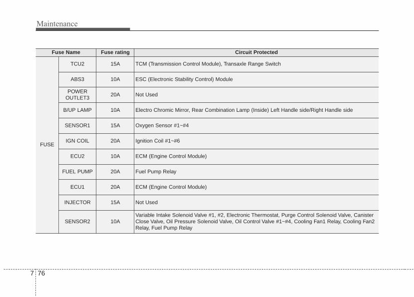
Maintenance
767
Fuse Name Fuse rating Circuit Protected
FUSE
TCU2 15A TCM (Transmission Control Module), Transaxle Range Switch
ABS3 10A ESC (Electronic Stability Control) Module
POWEROUTLET3
20A Not Used
B/UP LAMP 10A Electro Chromic Mirror, Rear Combination Lamp (Inside) Left Handle side/Right Handle side
SENSOR1 15A Oxygen Sensor #1~#4
IGN COIL 20A Ignition Coil #1~#6
ECU2 10A ECM (Engine Control Module)
FUEL PUMP 20A Fuel Pump Relay
ECU1 20A ECM (Engine Control Module)
INJECTOR 15A Not Used
SENSOR2 10AVariable Intake Solenoid Valve #1, #2, Electronic Thermostat, Purge Control Solenoid Valve, CanisterClose Valve, Oil Pressure Solenoid Valve, Oil Control Valve #1~#4, Cooling Fan1 Relay, Cooling Fan2Relay, Fuel Pump Relay

7 77
Maintenance
Relay Name Type
Blower Relay MINI
Cooling Fan1 Relay MINI
Cooling Fan2 Relay MINI
Power Outlet Relay MICRO
Start Relay MICRO
Front Deicer Relay MICRO
Fuel Filler Relay MICRO
Rear Heated Relay MINI
Relay

Maintenance
787
Engine compartment fuse panel(Battery terminal cover)
✽✽ NOTICENot all fuse panel descriptions inthis manual may be applicable toyour vehicle. It is accurate at thetime of printing. When you inspectthe fuse panel in your vehicle, referto the fuse panel label.
OYG076038
OYG076039

7 79
Maintenance
LIGHT BULBSBulb replacement precaution Please keep extra bulbs on handwith appropriate wattage ratings incase of emergencies.Refer to “Bulb Wattage” in chapter 8.When changing lamps, first turn offthe engine at a safe place, firmlyapply the parking brake and detachthe battery’s negative (-) terminal.
Use only bulbs of the specifiedwattage.
✽✽ NOTICE• If the light bulb or lamp connector
is removed while the lamp is stillon, the fuse box's electronic sys-tem may log it as a malfunction.Therefore, a lamp malfunctionincident may be recorded as aDiagnostic Trouble Code (DTC) inthe fuse box.
• It is normal for an operating lampto flicker momentarily. This is dueto a stabilization function of thevehicle’s electronic control device.If the lamp lights up normallyafter momentarily blinking, thenit is functioning as normal.However, if the lamp continues toflicker several times or turns offcompletely, there may be an errorin the vehicle’s electronic controldevice. Please have the vehiclechecked by an authorized Kiadealer immediately.
WARNING - Working onthe lights
Prior to working on the light,firmly apply the parking brake,ensure that the ignition switchis turned to the LOCK positionand turn off the lights to avoidsudden movement of the vehi-cle and burning your fingers orreceiving an electric shock.
CAUTION - Light replace-ment
Be sure to replace the burned-out bulb with one of the samewattage rating. Otherwise, itmay cause damage to the fuseor electric wiring system.
CAUTION - HeadlampLens
To prevent damage, do notclean the headlamp lens withchemical solvents or strongdetergents.

Maintenance
807
If you don’t have the necessary tools,the correct bulbs and the expertise,consult an authorized Kia dealer. Inmany cases, it is difficult to replacevehicle light bulbs because otherparts of the vehicle must be removedbefore you can get to the bulb. This isespecially true if you have to removethe headlamp assembly to get to thebulb(s).Removing/installing the headlampassembly can result in damage tothe vehicle.If non-genuine parts or substandardbulbs are used, it may lead to blow-ing a fuse or other wiring damages.Do not install extra lamps or LEDs tothe vehicle. If additional lights areinstalled, it may lead to lamp mal-functions and flickering. Additionally,the fuse box and other writing maybe damaged.
Light bulb position (Front)
(1) Headlamp (Low)(2) Headlamp (High)(3) Front turn signal lamp(4) Day time running lamp/
Position lamp (LED type)
(5) Front fog lamp (Bulb type)(6) Front fog lamp (LED type)(7) Front side marker
OYG076044N
OYG076109N
■ Head lamp - Type A
■ Head lamp - Type B
OYG076045
OYG076046
■ Fog lamp - Type A
■ Fog lamp - Type B

7 81
Maintenance
Light bulb position (Rear)(1) Stop and tail lamp (LED type) (2) Stop and tail lamp (LED type)
(3) Rear turn signal lamp(4) Back-up lamp(5) High mounted stop lamp (LED
type)(6) License plate lamp
Light bulb position (Side)
(1) Side repeater lamp (LED type)
OYG076047
OYG076048
OYG076049
■ Rear combination lamp
■ High mounted stop lamp
■ License plate lamp
OYG076050

Maintenance
827
Headlamp (LED type) bulbreplacement
If the head lamp (LED) (1,2) doesnot operate, have the vehiclechecked by an authorized Kia dealer.The LED lamps cannot be replacedas a single unit because it is an inte-grated unit. The LED lamps has to bereplaced with the unit.A skilled technician should check orrepair the head lamp (LED), for itmay damage related parts of thevehicle.
Headlamp (Low beam) bulbreplacement
1. Open the hood.2. Remove the headlamp bulb cover
by turning it counterclockwise.3. Remove the bulb-socket from the
headlamp assembly by turning thebulb-socket counterclockwise untilthe tabs on the bulb-socket alignwith the slots on the headlampassembly.
4. Remove the bulb from bulb-socketby pulling it out.
5. Insert a new bulb by inserting itinto the bulb-socket.
6. Install the bulb-socket in the head-lamp assembly by aligning thetabs on the bulb-socket with theslots in the headlamp assembly.Push the bulb-socket into theheadlamp assembly and turn thebulb-socket clockwise.
7. Install the headlamp bulb cover byturning it clockwise.
OYG076051OYG076110N

7 83
Maintenance
Headlamp bulb • Always handle them carefully, andavoid scratches and abrasions. Ifthe bulbs are lit, avoid contact withliquids. Never touch the glass withbare hands. Residual oil maycause the bulb to overheat andburst when lit. A bulb should beoperated only when installed in aheadlamp.
• If a bulb becomes damaged orcracked, replace it immediatelyand carefully dispose of it.
• Wear eye protection when chang-ing a bulb. Allow the bulb to cooldown before handling it.
WARNING - Halogenbulbs
Handle halogen bulbs with care.• Halogen bulbs contain pres-
surized gas that will produceflying pieces of glass if bro-ken.
OHD076046
CAUTIONIf your vehicle is equipped withHigh Intensity Discharge (HID)headlights, these headlightscontain mercury. Accordingly, ifyou need to have your vehicledisposed of, you should removethe HID Headlights before dis-posal. The removed HID head-lights should be recycled or dis-posed of as hazardous wasteaccording to applicable laws.For more information on thesafe handling procedures andoptions for disposal and recy-cling of HID bulbs, includingwhat to do in case the bulbbreaks, please visithttps://www.ec.gc.ca/mercure-mercury/.

Maintenance
847
Headlamp (High beam) bulbreplacement
1. Open the hood.2. Remove the headlamp bulb cover
by turning it counterclockwise.3. Disconnect the headlamp bulb
socket-connector.4. Remove the bulb-socket from the
headlamp assembly by turning thebulb-socket counterclockwise untilthe tabs on the bulb-socket alignwith the slots on the headlampassembly.
5. Install a new bulb-socket assem-bly in the headlamp assembly byaligning the tabs on the bulb-sock-et with the slots in the headlampassembly. Push the bulb-socketinto the headlamp assembly andturn the bulb-socket clockwise.
6. Install the headlamp bulb cover byturning it clockwise.
Front turn signal lamp bulbreplacement
1. Open the hood.2. Remove the bulb-socket from the
headlamp assembly by turning thebulb-socket counterclockwise untilthe tabs on the bulb-socket alignwith the slots on the headlampassembly.
3. Remove the bulb from the bulb-socket by pressing it in and rotat-ing it counterclockwise until thetabs on the bulb align with theslots in the bulb-socket. Pull thebulb out of the bulb-socket.
OYG076052 OYG076053

7 85
Maintenance
4. Insert a new bulb by inserting itinto the bulb-socket and rotating ituntil it locks into place.
5. Install the socket in the headlampassembly by aligning the tabs onthe bulb-socket with the slots inthe assembly. Push the bulb-sock-et into the headlamp assemblyand turn the socket clockwise.
Front fog lamp (LED type) bulbreplacement
If the front fog lamp (LED) (1, 2) doesnot operate, have the vehiclechecked by an authorized Kia dealer.
The LED lamps cannot be replacedas a single unit because it is an inte-grated unit. The LED lamps has to bereplaced with the unit.A skilled technician should check orrepair the front fog lamp (LED), for itmay damage related parts of thevehicle.
OYG076054
OYG076055
■ Type A
■ Type B

Maintenance
867
Position lamp + DRL (LEDtype) bulb replacement
If the position lamp + DRL (1) doesnot operate, have the vehiclechecked by an authorized Kia dealer.
The LED lamps cannot be replacedas a single unit because it is an inte-grated unit. The LED lamps has to bereplaced with the unit.A skilled technician should check orrepair the position lamp + DRL (1),for it may damage related parts ofthe vehicle.
Side repeater lamp bulbreplacement
If the Side repeater lamp does notoperate, have the vehicle checked byan authorized Kia dealer.The LED lamps cannot be replacedas a single unit because it is an inte-grated unit. The LED lamps has to bereplaced with the unit.A skilled technician should check orrepair the side repeater lamp, for itmay damage related parts of thevehicle.
OYG076056
OYG076111N
■ Type A
■ Type BOYG076050

7 87
Maintenance
Rear turn signal lamp bulbreplacement
1. Open the trunk lid.2. Open the service cover.
3. Remove the socket from theassembly by turning the socketcounterclockwise until the tabs onthe socket align with the slots onthe assembly.
4. Remove the bulb from the socketby pressing it in and rotating itcounterclockwise until the tabs onthe bulb align with the slots in thesocket. Pull the bulb out of thesocket.
5. Insert a new bulb by inserting itinto the socket and rotating it untilit locks into place.
6. Install the socket in the assemblyby aligning the tabs on the socketwith the slots in the assembly.Push the socket into the assemblyand turn the socket clockwise.
7. Install the service cover by puttingit into the service hole.
OYG076057
OYG076058

Maintenance
887
Stop and tail lamp (LED type)bulb replacement
If the stop and tail lamp (LED) (1,2)does not operate, have the vehiclechecked by an authorized Kia dealer.The LED lamps cannot be replacedas a single unit because it is an inte-grated unit. The LED lamps has to bereplaced with the unit.A skilled technician should check orrepair the stop and tail lamp (LED),for it may damage related parts ofthe vehicle.
Back-up lamp bulb replacement
1. Open the trunk lid.2. Loosen the retaining screw of the
trunk lid cover and then removethe cover.
3. Remove the socket from theassembly by turning the socketcounterclockwise until the tabs onthe socket align with the slots onthe assembly.
4. Remove the bulb from bulb-socketby pulling it out.
5. Insert a new bulb by inserting itinto the bulb-socket.
6. Install the socket in the assemblyby aligning the tabs on the socketwith the slots in the assembly.Push the socket into the assemblyand turn the socket clockwise.
7. Install the trunk lid cover.
OYG076059
OYG076061
OYG076060
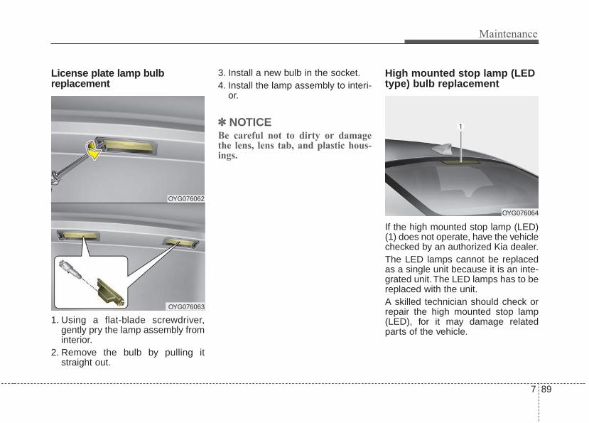
7 89
Maintenance
License plate lamp bulbreplacement
1. Using a flat-blade screwdriver,gently pry the lamp assembly frominterior.
2. Remove the bulb by pulling itstraight out.
3. Install a new bulb in the socket.4. Install the lamp assembly to interi-
or.
✽✽ NOTICEBe careful not to dirty or damagethe lens, lens tab, and plastic hous-ings.
High mounted stop lamp (LEDtype) bulb replacement
If the high mounted stop lamp (LED)(1) does not operate, have the vehiclechecked by an authorized Kia dealer.The LED lamps cannot be replacedas a single unit because it is an inte-grated unit. The LED lamps has to bereplaced with the unit.A skilled technician should check orrepair the high mounted stop lamp(LED), for it may damage relatedparts of the vehicle.
OYG076062
OYG076063
OYG076064
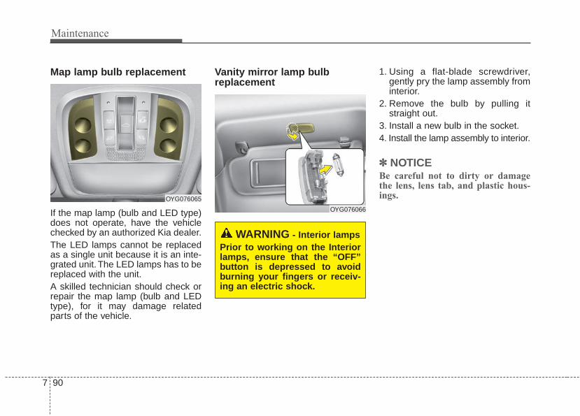
Maintenance
907
Map lamp bulb replacement
If the map lamp (bulb and LED type)does not operate, have the vehiclechecked by an authorized Kia dealer.The LED lamps cannot be replacedas a single unit because it is an inte-grated unit. The LED lamps has to bereplaced with the unit.A skilled technician should check orrepair the map lamp (bulb and LEDtype), for it may damage relatedparts of the vehicle.
Vanity mirror lamp bulbreplacement
1. Using a flat-blade screwdriver,gently pry the lamp assembly frominterior.
2. Remove the bulb by pulling itstraight out.
3. Install a new bulb in the socket.4. Install the lamp assembly to interior.
✽✽ NOTICEBe careful not to dirty or damagethe lens, lens tab, and plastic hous-ings.OYG076065
OYG076066
WARNING - Interior lampsPrior to working on the Interiorlamps, ensure that the “OFF”button is depressed to avoidburning your fingers or receiv-ing an electric shock.
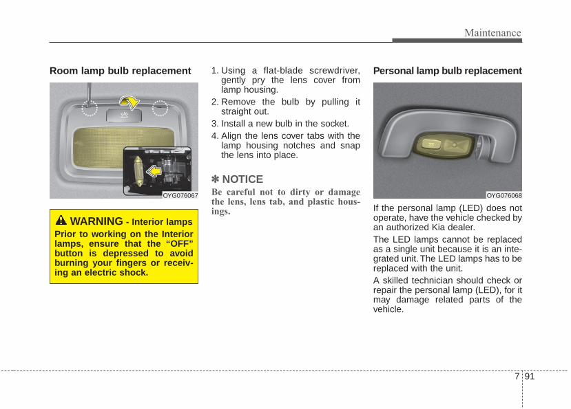
7 91
Maintenance
Room lamp bulb replacement 1. Using a flat-blade screwdriver,gently pry the lens cover fromlamp housing.
2. Remove the bulb by pulling itstraight out.
3. Install a new bulb in the socket.4. Align the lens cover tabs with the
lamp housing notches and snapthe lens into place.
✽✽ NOTICEBe careful not to dirty or damagethe lens, lens tab, and plastic hous-ings.
Personal lamp bulb replacement
If the personal lamp (LED) does notoperate, have the vehicle checked byan authorized Kia dealer.The LED lamps cannot be replacedas a single unit because it is an inte-grated unit. The LED lamps has to bereplaced with the unit.A skilled technician should check orrepair the personal lamp (LED), for itmay damage related parts of thevehicle.
OYG076067
WARNING - Interior lampsPrior to working on the Interiorlamps, ensure that the “OFF”button is depressed to avoidburning your fingers or receiv-ing an electric shock.
OYG076068

Maintenance
927
Glove box lamp bulb replacement
1. Using a flat-blade screwdriver,gently pry the lamp assembly frominterior.
2. Remove the bulb by pulling itstraight out.
3. Install a new bulb in the socket.4. Install the lamp assembly to interior.
✽✽ NOTICEBe careful not to dirty or damagethe lens, lens tab, and plastic hous-ings.
Trunk lamp (LED type) bulbreplacement
If the trunk lamp (LED) does notoperate, have the vehicle checked byan authorized Kia dealer.The LED lamps cannot be replacedas a single unit because it is an inte-grated unit. The LED lamps has to bereplaced with the unit.A skilled technician should check orrepair the trunk lamp (LED), for itmay damage related parts of thevehicle.
OYG076069 OYG076070

7 93
Maintenance
APPEARANCE CAREExterior careExterior general caution It is very important to follow the labeldirections when using any chemicalcleaner or polish. Read all warningand caution statements that appearon the label.
Finish maintenanceWashing
To help protect your vehicle’s finishfrom rust and deterioration, wash itthoroughly and frequently at leastonce a month with lukewarm or coldwater.If you use your vehicle for off-roaddriving, you should wash it after eachoff-road trip. Pay special attention tothe removal of any accumulation ofsalt, dirt, mud, and other foreign mate-rials. Make sure the drain holes in thelower edges of the doors and rockerpanels are kept clear and clean.Insects, tar, tree sap, bird droppings,industrial pollution and similardeposits can damage your vehicle’sfinish if not removed immediately.Even prompt washing with plain watermay not completely remove all thesedeposits. A mild soap, safe for use onpainted surfaces, may be used.After washing, rinse the vehicle thor-oughly with lukewarm or cold water.Do not allow soap to dry on the finish.
After washing the vehicle, test thebrakes while driving slowly to see ifthey have been affected by water. Ifbraking performance is impaired, drythe brakes by applying them lightlywhile maintaining a slow forwardspeed.

Maintenance
947
High-pressure washing
• When using high-pressure wash-ers, make sure to maintain suffi-cient distance from the vehicle.Insufficient clearance or excessivepressure can lead to componentdamage or water penetration.
• Do not spray the camera, sensorsor its surrounding area directly witha high pressure washer. Shockapplied from high pressure watermay cause the device to not oper-ate normally.
• Do not bring the nozzle tip close toboots (rubber or plastic covers) orconnectors as they may be dam-aged if they come into contact withhigh pressure water.
Waxing
Wax the vehicle when water will nolonger bead on the paint.Always wash and dry the vehiclebefore waxing. Use a good qualityliquid or paste wax, and follow themanufacturer’s instructions. Wax allmetal trim to protect it and to main-tain its luster.Removing oil, tar, and similar materi-als with a spot remover will usuallystrip the wax from the finish. Be sureto re-wax these areas even if the restof the vehicle does not yet need wax-ing.Do not apply wax on embossedunpainted unit, as it may tarnish theunit.
OJB037800
CAUTION - Wet engine• Water washing in the engine
compartment including highpressure water washing maycause the failure of electricalcircuits located in the enginecompartment.
• Never allow water or other liq-uids to come in contact withelectrical/electronic compo-nents inside the vehicle asthis may damage them.

7 95
Maintenance
Finish damage repair Deep scratches or stone chips in thepainted surface must be repairedpromptly. Exposed metal will quicklyrust and may develop into a majorrepair expense.If your vehicle is damaged andrequires any metal repair or replace-ment, be sure the body shop appliesanti-corrosion materials to the partsrepaired or replaced.
Bright-metal maintenance• To remove road tar and insects,
use a tar remover, not a scraper orother sharp object.
• To protect the surfaces of bright-metal parts from corrosion, apply acoating of wax or chrome preser-vative and rub to a high luster.
• During winter weather or in coastalareas, cover the bright metal partswith a heavier coating of wax orpreservative. If necessary, coat theparts with non-corrosive petroleumjelly or other protective compound.
Underbody maintenanceRoad salt and other corrosive chemi-cals are used in cold weather states tomelt snow and prevent ice accumula-tion. If these chemicals are not regu-larly removed, they will corrode thevehicle underbody and over time dam-age fuel lines, the fuel tank retentionsystem, the vehicle suspension, theexhaust system, and even the bodyframe. The National Highway TrafficSafety Administration has warned allvehicle owners of all brands of theneed to take the following steps:• Wash the undercarriage of your
vehicle regularly during the winterand whenever your vehicle hasbeen exposed to such salts orchemicals.
CAUTION - Drying vehicle• Wiping dust or dirt off the
body with a dry cloth willscratch the finish.
• Do not use steel wool, abra-sive cleaners, acid detergentsor strong detergents contain-ing high alkaline or causticagents on chrome-plated oranodized aluminum parts.This may result in damage tothe protective coating andcause discoloration or paintdeterioration.

Maintenance
967
• Do a thorough washing of theundercarriage at the end of thewinter.
• Use professional service techni-cians or governmental inspectionstations to annually inspect for cor-rosion.
• Immediately seek an inspection ofyour vehicle if you become visuallyaware of corrosion flaking or scal-ing or if you become aware of achange in vehicle performance,such as soft or spongey brakes,fluids leaking, impairment of direc-tional control, suspension noisesor rattling metal straps.
Aluminum wheel maintenance The aluminum wheels are coatedwith a clear protective finish.• Do not use any abrasive cleaner,
polishing compound, solvent, orwire brushes on aluminum wheels.They may scratch the finish.
• Clean the wheel when it hascooled.
• Use only a mild soap or neutraldetergent, and rinse thoroughlywith water. Also, be sure to cleanthe wheels after driving on saltedroads. This helps prevent corro-sion.
• Avoid washing the wheels withhighspeed vehicle wash brushes.
• Do not use any alkaline or aciddetergents It may damage and cor-rode the aluminum wheels coatedwith a clear protective finish.
Corrosion protectionProtecting your vehicle from corrosion
By using the most advanced designand construction practices to combatcorrosion, we produce vehicles ofthe highest quality. However, this isonly part of the job. To achieve thelong-term corrosion resistance yourvehicle can deliver, the owner'scooperation and assistance is alsorequired.
Common causes of corrosion
The most common causes of corro-sion on your vehicle are:• Road salt, dirt and moisture that is
allowed to accumulate underneaththe vehicle.
• Removal of paint or protectivecoatings by stones, gravel, abra-sion or minor scrapes and dentswhich leave unprotected metalexposed to corrosion.

7 97
Maintenance
High-corrosion areas
If you live in an area where your vehi-cle is regularly exposed to corrosivematerials, corrosion protection isparticularly important. Some of thecommon causes of accelerated cor-rosion are road salts, dust controlchemicals, ocean air and industrialpollution.
Moisture breeds corrosion
Moisture creates the conditions inwhich corrosion is most likely tooccur. For example, corrosion isaccelerated by high humidity, partic-ularly when temperatures are justabove freezing. In such conditions,the corrosive material is kept in con-tact with the vehicle’s surface bymoisture that evaporates slowly.Mud is particularly corrosivebecause it dries slowly and holdsmoisture in contact with the vehicle.Although the mud appears to be dry,it can still retain the moisture andpromote corrosion.
High temperatures can also acceler-ate corrosion of parts that are notproperly ventilated so the moisturecan be dispersed. For all these rea-sons, it is particularly important tokeep your vehicle clean and free ofmud or accumulations of other mate-rials. This applies not only to the vis-ible surfaces but particularly to theunderside of the vehicle.
To help prevent corrosion
You can help prevent corrosion frombeginning by observing the following:
Keep your vehicle cleanThe best way to prevent corrosion isto keep your vehicle clean and freeof corrosive materials. Attention tothe underside of the vehicle is partic-ularly important.
• If you live in a high-corrosion area— where road salts are used, nearthe ocean, areas with industrialpollution, acid rain, etc.—, youshould take extra care to preventcorrosion. In winter, hose off theunderside of your vehicle at leastonce a month and be sure to cleanthe underside thoroughly whenwinter is over.
• When cleaning underneath thevehicle, give particular attention tothe components under the fendersand other areas that are hiddenfrom view. Do a thorough job; justdampening the accumulated mudrather than washing it away willaccelerate corrosion rather thanprevent it. Water under high pres-sure and steam are particularlyeffective in removing accumulatedmud and corrosive materials.

Maintenance
987
• When cleaning lower door panels,rocker panels and frame members,be sure that drain holes are keptopen so that moisture can escapeand not be trapped inside to accel-erate corrosion.
Keep your garage dryDon't park your vehicle in a damp,poorly ventilated garage. This cre-ates a favorable environment for cor-rosion. This is particularly true if youwash your vehicle in the garage ordrive it into the garage when it is stillwet or covered with snow, ice ormud. Even a heated garage can con-tribute to corrosion unless it is wellventilated so moisture is dispersed.
Keep paint and trim in good con-ditionScratches or chips in the finishshould be covered with "touch-up"paint as soon as possible to reducethe possibility of corrosion. If baremetal is showing through, the atten-tion of a qualified body and paintshop is recommended.
Bird droppings : Bird droppings arehighly corrosive and may damagepainted surfaces in just a few hours.Always remove bird droppings assoon as possible.
Don't neglect the interiorMoisture can collect under the floormats and carpeting and cause corro-sion. Check under the mats periodi-cally to be sure the carpeting is dry.Use particular care if you carry fertil-izers, cleaning materials or chemi-cals in the vehicle.These should be carried only in prop-er containers and any spills or leaksshould be cleaned up, flushed withclean water and thoroughly dried.
Interior careInterior general precautions Prevent chemicals such as perfume,cosmetic oil, sun cream, hand clean-er, and air freshener from contactingthe interior parts because they maycause damage or discoloration. Ifthey do contact the interior parts,wipe them off immediately. If neces-sary, use a vinyl cleaner, see productinstructions for correct usage.

7 99
Maintenance
Taking care of leather seats • Vacuum the seat periodically to
remove dust and sand on the seat.It will prevent abrasion or damage ofthe leather and maintain its quality.
• Wipe the natural leather seat coveroften with dry or soft cloth.
• Sufficient use of a leather protec-tive may prevent abrasion of thecover and helps maintain the color.Be sure to read the instructionsand consult a specialist whenusing leather coating or protectiveagents.
• Leather with bright colors(beige,cream beige) is easily contaminat-ed and clear in appearance. Cleanthe seats frequently.
• Avoid wiping with wet cloth. It maycause the surface to crack.
Cleaning the leather seats• Remove all contaminations instant-
ly. Refer to instructions below forremoval of each contaminant.
• Cosmetic products(sunscreen,foundation, etc.)- Apply cleansing cream on a cloth
and wipe the contaminated point.Wipe off the cream with a wetcloth and remove water with a drycloth.
• Beverages(coffee, soft drink, etc.)- Apply a small amount of neutral
detergent and wipe until contami-nations do not smear.
• Oil- Remove oil instantly with
absorbable cloth and wipe withstain remover for natural leatheronly.
• Chewing gum - Harden the gum with ice and
remove gradually.
CAUTION - Electricalcomponents
Never allow water or other liq-uids to come in contact withelectrical/electronic compo-nents inside the vehicle as thismay damage them.
CAUTION - LeatherWhen cleaning leather products(steering wheel, seats etc.), useneutral detergents or low alco-hol content solutions. If you usehigh alcohol content solutionsor acid/alkaline detergents, thecolor of the leather may fade orthe surface may get stripped off.

Maintenance
1007
Fabric seat cover using precau-tions (If equipped)Please clean the fabric seats regu-larly with a vacuum cleaner in con-sideration of fabric material charac-teristics. If they are heavily soiledwith beverage stains, etc., use a suit-able interior cleaner. To prevent dam-age to seat covers, wipe off the seatcovers down to the seams with alarge wiping motion and moderatepressure using a soft sponge ormicrofiber cloth.Velcro closures on clothing or sharpobjects may cause snagging orscratches on the surface of theseats. Make sure not to rub suchobjects against the surface.
Cleaning the upholstery and inte-rior trim Vinyl
Remove dust and loose dirt fromvinyl with a whisk broom or vacuumcleaner. Clean vinyl surfaces with avinyl cleaner.
Fabric
Remove dust and loose dirt from fab-ric with a whisk broom or vacuumcleaner. Clean with a mild soap solu-tion recommended for upholstery orcarpets. Remove fresh spots imme-diately with a fabric spot cleaner. Iffresh spots do not receive immediateattention, the fabric can be stainedand its color can be affected. Also, itsfire-resistant properties can bereduced if the material is not proper-ly maintained.Using anything but recommendedcleaners and procedures may affectthe fabric’s appearance and fire-resistant properties.
Cleaning the lap/shoulder beltwebbing Clean the belt webbing with any mildsoap solution recommended forcleaning upholstery or carpet. Followthe instructions provided with thesoap. Do not bleach or re-dye thewebbing because this may weaken it.
Cleaning the interior windowglass If the interior glass surfaces of thevehicle become fogged (that is, cov-ered with an oily, greasy or waxyfilm), they should be cleaned with aglass cleaner. Follow the directionson the glass cleaner container.
CAUTION - Rear windowDo not scrape or scratch theinside of the rear window. Thismay result in damage of the rearwindow defroster grid.

7 101
Maintenance
EMISSION CONTROL SYSTEMThe emission control system of yourvehicle is covered by a written limitedwarranty. Please see the warrantyinformation contained in theWarranty & Consumer Informationmanual in your vehicle.Your vehicle is equipped with anemission control system to meet allapplicable emission regulations.There are three emission controlsystems, as follows.
(1) Crankcase emission control sys-tem
(2) Evaporative emission control sys-tem
(3) Exhaust emission control system
In order to assure the proper functionof the emission control systems, it isrecommended that you have yourvehicle inspected and maintained byan authorized Kia dealer in accor-dance with the maintenance sched-ule in this manual.
Caution for the Inspection andMaintenance Test (With ElectronicStability Control (ESC) system)• To prevent the vehicle from mis-
firing during dynamometer test-ing, turn the Electronic StabilityControl (ESC) system off bypressing the ESC switch.
• After dynamometer testing iscompleted, turn the ESC systemback on by pressing the ESCswitch again.
1. Crankcase emission controlsystem
The positive crankcase ventilationsystem is employed to prevent airpollution caused by blow-by gasesbeing emitted from the crankcase.This system supplies fresh filtered airto the crankcase through the airintake hose. Inside the crankcase,the fresh air mixes with blow-bygases, which then pass through thePCV valve into the induction system.
2. Evaporative emission con-trol (including ORVR:Onboard Refueling VaporRecovery) system
The Evaporative Emission ControlSystem is designed to prevent fuelvapors from escaping into the atmos-phere.(The ORVR system is designed toallow the vapors from the fuel tank tobe loaded into a canister while refu-eling at the gas station, preventingthe escape of fuel vapors into theatmosphere.)

Maintenance
1027
CanisterFuel vapors generated inside the fueltank are absorbed and stored in theonboard canister. When the engine isrunning, the fuel vapors absorbed inthe canister are drawn into the surgetank through the purge control sole-noid valve.
Purge Control Solenoid Valve(PCSV)The purge control solenoid valve iscontrolled by the Engine ControlModule (ECM); when the enginecoolant temperature is low duringidling, the PCSV closes so that evap-orated fuel is not taken into theengine. After the engine warms upduring ordinary driving, the PCSVopens to introduce evaporated fuel tothe engine.
3. Exhaust emission control system
The Exhaust Emission ControlSystem is a highly effective systemwhich controls exhaust emissionswhile maintaining good vehicle per-formance.
Vehicle modifications This vehicle should not be modified.Modification of your vehicle couldaffect its performance, safety ordurability and may even violate gov-ernmental safety and emissions reg-ulations.In addition, damage or performanceproblems resulting from any modifi-cation may not be covered underwarranty.• If you use unauthorized electronic
devices, it may cause the vehicle tooperate abnormally, wire damage,battery discharge and fire. For yoursafety, do not use unauthorizedelectronic devices.
Engine exhaust gas precautions(carbon monoxide) • Carbon monoxide can be present
with other exhaust fumes.Therefore, if you smell exhaustfumes of any kind inside your vehi-cle, have it inspected and repairedimmediately. If you ever suspectexhaust fumes are coming intoyour vehicle, drive it only with allthe windows fully open. Have yourvehicle checked and repairedimmediately.
WARNING - ExhaustEngine exhaust gases containcarbon monoxide (CO). Thoughcolorless and odorless, it isdangerous and could be lethal ifinhaled. Follow the instructionson this page to avoid CO poi-soning.

7 103
Maintenance
• Do not operate the engine in con-fined or closed areas (such asgarages) any more than what isnecessary to move the vehicle in orout of the area.
• When the vehicle is stopped in anopen area for more than a shorttime with the engine running,adjust the ventilation system (asneeded) to draw outside air into thevehicle.
• Never sit in a parked or stoppedvehicle for any extended time withthe engine running.
• When the engine stalls or fails tostart, excessive attempts to restartthe engine may cause damage tothe emission control system.
Operating precautions for catalyt-ic converters (if equipped)
WARNING - Catalyticconverter
Keep away from the catalyticconverter and exhaust systemwhile the vehicle is running orimmediately thereafter. Theexhaust and catalytic systemsare very hot and may burn you.
WARNING - Fire• Do not park, idle or drive the
vehicle over or near flamma-ble objects, such as grass,vegetation, paper, leaves, etc.A hot exhaust system canignite flammable items underyour vehicle.
• Also, do not remove the heatsink around the exhaust sys-tem, do not seal the bottom ofthe vehicle or do not coat thevehicle for corrosion control.It may present a fire risk undercertain conditions.

Maintenance
1047
Your vehicle is equipped with a cat-alytic converter emission controldevice.Therefore, the following precautionsmust be observed:• Use only UNLEADED FUEL for
gasoline engines.• Do not operate the vehicle when
there are signs of engine malfunc-tion, such as misfire or a noticeableloss of performance.
• Do not misuse or abuse theengine. Examples of misuse arecoasting with the ignition off anddescending steep grades in gearwith the ignition off.
• Do not operate the engine at highidle speed for extended periods (5minutes or more).
• Do not modify or tamper with anypart of the engine or emission con-trol system. All inspections andadjustments must be made by anauthorized Kia dealer.
• Avoid driving with an extremely lowfuel level. Running out of fuel couldcause the engine to misfire, dam-aging the catalytic converter.
Failure to observe these precautionscould result in damage to the catalyt-ic converter and to your vehicle.Additionally, such actions could voidyour warranties.
Specifications & Consumer information
Dimensions . . . . . . . . . . . . . . . . . . . . . . . . . . . . . . . . 8-2Engine . . . . . . . . . . . . . . . . . . . . . . . . . . . . . . . . . . . . 8-2Bulb wattage . . . . . . . . . . . . . . . . . . . . . . . . . . . . . . . 8-3Tires and wheels . . . . . . . . . . . . . . . . . . . . . . . . . . . . 8-4Gross vehicle weight. . . . . . . . . . . . . . . . . . . . . . . . . 8-5Luggage volume . . . . . . . . . . . . . . . . . . . . . . . . . . . . 8-5Air conditioning system . . . . . . . . . . . . . . . . . . . . . . 8-5Recommended lubricants and capacities. . . . . . . . 8-6
• Recommended SAE viscosity number. . . . . . . . . . . . . 8-7Vehicle identification number (VIN) . . . . . . . . . . . 8-8Vehicle certification label. . . . . . . . . . . . . . . . . . . . . 8-8Tire specification and pressure label . . . . . . . . . . . 8-9Engine number . . . . . . . . . . . . . . . . . . . . . . . . . . . . . 8-9
8

28
DIMENSIONS
Specifications & Consumer information
ENGINE
ITEM mm (In)
Overall length 4,970 (195.6)
Overall width 1,870 (73.6)
Overall height 1,470 (57.8) (high suspension : 1,480 (58.2))
Front tread245/45R18 1,607 (63.2)
245/40R19 1,602 (63.0)
Rear tread245/45R18 1,615 (63.5)
245/40R19 1,610 (63.3)
Wheelbase 2,855 (112.4)
Item Gasoline Lambda II 3.3
Displacement cc (cu. in)
3,342 (203.94)
Bore x Stroke
mm (in.)92 x 83.8 (3.62 x 3.29)
Firing order 1-2-3-4-5-6
No. of cylinders 6.V - type

8 3
BULB WATTAGE
Specifications & Consumer information
Light Bulb Wattage Bulb type
Front
Headlights (High) 60W HB3
Headlights (Low) 55 or LED H7 or LED
Front turn signal lights 28W P28/8W
Position lights LED LED
Daytime running light (DRL) LED LED
Side repeater lights (Outside mirror) LED LED
Front fog lightsHalogen 55W HB4
LED LED LED
Rear
Stop and tail lights LED LED
Rear turn signal lights 28W P28/8W
Back-up lights 16 W16W
High mounted stop light LED LED
License plate lights 5W W5W
Interior
Map lamps/Room lamps 10W W10W
Mood lamp LED LED
Trunk lamp LED LED
Glove box lamp 5 FESTOON
Vanity mirror lamps 5 FESTOON
Foot lamp 5 FESTOON
Overhead Console lamp (LED Type, Sunroof only) LED LED

48
Specifications & Consumer information
TIRES AND WHEELS
*1: Load Index *2: Speed Symbol *3: Normal load : Up to 3 persons
CAUTIONWhen replacing tires, use the same size originally supplied with the vehicle.Using tires of a different size can damage the related parts or make them work irregularly.
✽✽ NOTICE• It is permissible to add 3psi to the standard tire pressure specification if colder temperatures are expected soon.
Tires typically loose 1psi for every 12°F temperature drop. If extreme temperature variations are expected, re-check your tire pressure as necessary to keep them properly inflated.
• We recommend that when replacing tires, use the same originally supplied with the vehicles. If not, that affectsdriving performance.
• When driving in high altitude grades, it is natural for the atmospheric pressure to decrease. Therefore, pleasecheck the tire pressure and add more air when necessary. Additionally required tire air pressure per km above sea level: 1.5psi/km
Item Tire sizeWheelsize
Load Speed Inflation pressure [bar(psi, kPa)] Wheel lug nuttorque Kgf·m
(lb·ft, N·m)Capacity Capacity Normal load *3 Maximum load
LI *1 Kg SS *2 Km/h Front Rear Front Rear
Full sizetire
245/45R18
7.5Jx18 96 710 V 2402.3
(33, 230)2.3
(33, 230)2.3
(33, 230)2.3
(33, 230)
11~13 (79 ~94, 107 ~ 127)
245/40R19
8.0Jx19 94 670 V 2402.3
(33, 230)2.3
(33, 230)2.3
(33, 230)2.3
(33, 230)
Compactspare tire
T135/80D17
4.0Tx17 103 875 M 1302.3
(33, 230)2.3
(33, 230)2.3
(33, 230)2.3
(33, 230)

8 5
Specifications & Consumer information
GROSS VEHICLE WEIGHT
AIR CONDITIONING SYSTEM
LUGGAGE VOLUME
We recommend that you contact an authorized Kia dealer for more details.
Items Gasoline Lambda II 3.3
Gross vehicle weightkg (lbs.)
18 inch tire 19 inch tire
2,140 (4,718) 2,170 (4,784)
ITEM Volume
SAE 452L (15.96 cu ft)
Items Weight of Volume Classification
Refrigerant
g (oz.) 550 ± 25 (19.4 ± 0.88) R-1234yf
Compressor lubricant
cc (oz.) 100 ± 10 (3.53 ± 0.35) PAG (FD46XG)

68
Specifications & Consumer information
RECOMMENDED LUBRICANTS AND CAPACITIESTo help achieve proper engine and powertrain performance and durability, use only lubricants of the proper quality.The correct lubricants also help promote engine efficiency that results in improved fuel economy.These lubricants and fluids are recommended for use in your vehicle.
*1 : Refer to the recommended SAE viscosity numbers on the next page.
*2 : Engine oils labeled Energy Conserving Oil are now available. Along with other additional benefits, they contribute to fuel economy by reducingthe amount of fuel necessary to overcome engine friction. Often, these improvements are difficult to measure in everyday driving, but in a year’stime, they can offer significant cost and energy savings.
*3 : If the API SM engine oil is not available, you can use API SN or above.
*4 : If the ILSAC GF-4 engine oil is not available, you can use ILSAC GF-5 or above.
Lubricant Volume Classification
Engine oil *1 *2
(drain and refill)
Recommends 3.3L GDI 6.5 liter (6.86 US qt.)API SM or above*3, ILSAC GF-4 or above*4, ACEA-A5 or above
Automatic transmissionfluid
3.3L GDI 7.0 liter (7.39 US qt.)ATF SP-IV(Recommended Kia genuine, Michang, SK, NOCA)
Coolant 3.3L GDI 8.5 liter (8.98 US qt.)Mixture of antifreeze and distilled water (Ethylene glycol base coolant for aluminum radiator)
Brake fluid0.7 ~ 0.8 liter
(0.74 ~ 0.85 US qt.)FMVSS116 DOT-3 or DOT-4
Fuel 70 l (18.5 US gal.) Unleaded gasoline

8 7
Recommended SAE viscositynumberEngine oil viscosity (thickness) has aneffect on fuel economy and coldweather operating (engine start andengine oil flowability). Lower viscosityengine oils can provide better fueleconomy and cold weather perform-ance; however, higher viscosityengine oils are required for satisfacto-ry lubrication in hot weather. Usingoils of any viscosity other than thoserecommended could result in enginedamage. When choosing an oil, con-sider the range of temperature yourvehicle will be operated in before thenext oil change. Proceed to select therecommended oil viscosity from thechart.
Specifications & Consumer information
Temperature Range for SAE Viscosity Numbers
Temperature
Gasoline Engine Oil *1
(3.3 L)
°C(°F)
-30 -20 -10 0 10 20 30 40 50-10 0 20 40 60 80 100 120
20W-50
10W-30
15W-40
5W-30
An engine oil displaying this API Certification Mark con-forms to the international Lubricant SpecificationAdvisory Committee (ILSAC). It is recommended to onlyuse engine oils that uphold this API Certification Mark.

88
Specifications & Consumer information
VEHICLE IDENTIFICATION NUMBER (VIN)
The vehicle identification number(VIN) is the number used in register-ing your vehicle and in all legal mat-ters pertaining to its ownership, etc.The number is punched under driveror front passenger seat.
The VIN is also on a plate attachedto the top of the dashboard. Thenumber on the plate can easily beseen through the windshield fromoutside.
The vehicle certification labelattached on the driver’s side centerpillar gives the vehicle identificationnumber (VIN).
VEHICLE CERTIFICATIONLABEL
OYG086002
■ Frame number
OYG086001
■ VIN label
OYG086009N

8 9
Specifications & Consumer information
The tires supplied on your new vehi-cle are chosen to provide the bestperformance for normal driving.The tire label located on the driver'sside center pillar gives the tire pres-sures recommended for your vehicle.
The engine number is stamped onthe engine block as shown in thedrawing.
ENGINE NUMBERTIRE SPECIFICATION ANDPRESSURE LABEL
OMG055004
OYG086004
■ 3.3L GDI

Index
I
Index
2I
Advanced smart cruise control system (ASCC). . . . . . 5-53Limitations of the system. . . . . . . . . . . . . . . . . . . . . 5-62Speed setting (ASCC) . . . . . . . . . . . . . . . . . . . . . . . 5-54To adjust the sensitivity of Advanced Smart Cruise
Control . . . . . . . . . . . . . . . . . . . . . . . . . . . . . . . . . . 5-62To convert to cruise control mode . . . . . . . . . . . . . . 5-62Vehicle to vehicle distance setting (ASCC). . . . . . . 5-58
Air bag - advanced supplemental restraint system. . . . 3-39Adding equipment to or modifying your air
bag-equipped vehicle . . . . . . . . . . . . . . . . . . . . . . . 3-65Air bag warning label. . . . . . . . . . . . . . . . . . . . . . . . 3-65Air bag warning light . . . . . . . . . . . . . . . . . . . . . . . . 3-42Curtain air bag . . . . . . . . . . . . . . . . . . . . . . . . . . . . . 3-58Driver's and passenger's front air bag . . . . . . . . . . . 3-54How does the air bag system operate?. . . . . . . . . . . 3-40Inflation and non-inflation conditions of the air bag . . 3-59Occupant Detection System (ODS) . . . . . . . . . . . . . 3-46Side air bag. . . . . . . . . . . . . . . . . . . . . . . . . . . . . . . . 3-56SRS Care . . . . . . . . . . . . . . . . . . . . . . . . . . . . . . . . . 3-64SRS components and functions . . . . . . . . . . . . . . . . 3-43
Air cleaner . . . . . . . . . . . . . . . . . . . . . . . . . . . . . . . . . . 7-36Filter replacement . . . . . . . . . . . . . . . . . . . . . . . . . . 7-36
Air conditioning system . . . . . . . . . . . . . . . . . . . . . . . . . 8-5Appearance care . . . . . . . . . . . . . . . . . . . . . . . . . . . . . . 7-93
Exterior care . . . . . . . . . . . . . . . . . . . . . . . . . . . . . . . 7-93Interior care . . . . . . . . . . . . . . . . . . . . . . . . . . . . . . . 7-98
Audio system . . . . . . . . . . . . . . . . . . . . . . . . . . . . . . . 4-154Antenna . . . . . . . . . . . . . . . . . . . . . . . . . . . . . . . . . 4-154AUX, USB port . . . . . . . . . . . . . . . . . . . . . . . . . . . 4-156Steering wheel audio controls . . . . . . . . . . . . . . . . 4-155
Automatic climate control system . . . . . . . . . . . . . . . 4-122Automatic heating and air conditioning. . . . . . . . . 4-123Checking the amount of air conditioner
refrigerant and compressor lubricant . . . . . . . . . . 4-134Climate control air filter. . . . . . . . . . . . . . . . . . . . . 4-133Manual heating and air conditioning . . . . . . . . . . . 4-125System operation . . . . . . . . . . . . . . . . . . . . . . . . . . 4-131
Automatic transaxle . . . . . . . . . . . . . . . . . . . . . . . . . . . 5-10Automatic transaxle operation . . . . . . . . . . . . . . . . . 5-10Good driving practices . . . . . . . . . . . . . . . . . . . . . . . 5-16
Automatic ventilation . . . . . . . . . . . . . . . . . . . . . . . . . 4-139To cancel or reset the Automatic Ventilation . . . . . 4-139
Autonomous emergency braking (AEB) /Forward collision warning (FCW) . . . . . . . . . . . . . . . 5-38
AEB warning message and system control . . . . . . . 5-41Brake operation . . . . . . . . . . . . . . . . . . . . . . . . . . . . 5-42Limitation of the system . . . . . . . . . . . . . . . . . . . . . 5-45Recognizing pedestrians. . . . . . . . . . . . . . . . . . . . . . 5-48Sensor to detect the distance from the vehicle in
front (front radar) . . . . . . . . . . . . . . . . . . . . . . . . . . 5-43System malfunction . . . . . . . . . . . . . . . . . . . . . . . . . 5-44System setting and activation. . . . . . . . . . . . . . . . . . 5-38
A

I 3
Index
Battery. . . . . . . . . . . . . . . . . . . . . . . . . . . . . . . . . . . . . . 7-44For best battery service . . . . . . . . . . . . . . . . . . . . . . 7-44Recharging the battery . . . . . . . . . . . . . . . . . . . . . . . 7-45Reset items . . . . . . . . . . . . . . . . . . . . . . . . . . . . . . . . 7-46
Before driving . . . . . . . . . . . . . . . . . . . . . . . . . . . . . . . . . 5-4Before entering vehicle . . . . . . . . . . . . . . . . . . . . . . . 5-4Before starting . . . . . . . . . . . . . . . . . . . . . . . . . . . . . . 5-4Necessary inspections . . . . . . . . . . . . . . . . . . . . . . . . 5-4
Blind spot detection system (BSD) . . . . . . . . . . . . . . . 5-76BSD (Blind Spot Detection) /
LCA (Lane Change Assist) . . . . . . . . . . . . . . . . . . 5-77Limitations condition . . . . . . . . . . . . . . . . . . . . . . . . 5-82RCTA (Rear Cross Traffic Alert) . . . . . . . . . . . . . . . 5-80
Brake fluid . . . . . . . . . . . . . . . . . . . . . . . . . . . . . . . . . . 7-33Checking the brake fluid level . . . . . . . . . . . . . . . . . 7-33
Brake system. . . . . . . . . . . . . . . . . . . . . . . . . . . . . . . . . 5-17Anti-lock brake system (ABS). . . . . . . . . . . . . . . . . 5-29AUTO HOLD. . . . . . . . . . . . . . . . . . . . . . . . . . . . . . 5-26Electronic parking brake (EPB) . . . . . . . . . . . . . . . . 5-20Electronic stability control (ESC) . . . . . . . . . . . . . . 5-31Good braking practices . . . . . . . . . . . . . . . . . . . . . . 5-36Hill-start assist control (HAC) . . . . . . . . . . . . . . . . . 5-36Parking brake – Foot type . . . . . . . . . . . . . . . . . . . . 5-19Power brakes . . . . . . . . . . . . . . . . . . . . . . . . . . . . . . 5-17Vehicle stability management (VSM) . . . . . . . . . . . 5-34Warning messages . . . . . . . . . . . . . . . . . . . . . . . . . . 5-28
Bulb wattage . . . . . . . . . . . . . . . . . . . . . . . . . . . . . . . . . . 8-3
Checking fluid levels . . . . . . . . . . . . . . . . . . . . . . . . . . 7-27Child restraint system (CRS) . . . . . . . . . . . . . . . . . . . . 3-28
Children Always in the Rear . . . . . . . . . . . . . . . . . . 3-28Installing a Child Restraint System (CRS) . . . . . . . 3-32Selecting a Child Restraint System (CRS) . . . . . . . 3-29
Clean air . . . . . . . . . . . . . . . . . . . . . . . . . . . . . . . . . . . 4-139Climate control air filter . . . . . . . . . . . . . . . . . . . . . . . . 7-38
Filter inspection . . . . . . . . . . . . . . . . . . . . . . . . . . . . 7-38Cruise control system . . . . . . . . . . . . . . . . . . . . . . . . . . 5-49
To cancel cruise control . . . . . . . . . . . . . . . . . . . . . . 5-51To decrease the cruising speed. . . . . . . . . . . . . . . . . 5-51To increase cruise control set speed. . . . . . . . . . . . . 5-50To resume cruising speed at more than
approximately 30 km/h (20 mph) . . . . . . . . . . . . . 5-52To set cruise control speed. . . . . . . . . . . . . . . . . . . . 5-50To temporarily accelerate with the cruise control on. . 5-51To turn cruise control off . . . . . . . . . . . . . . . . . . . . . 5-52
Defroster . . . . . . . . . . . . . . . . . . . . . . . . . . . . . . . . . . . 4-121Rear window defroster . . . . . . . . . . . . . . . . . . . . . . 4-121
Dimensions . . . . . . . . . . . . . . . . . . . . . . . . . . . . . . . . . . . 8-2
B
C
D

Index
4I
Door locks. . . . . . . . . . . . . . . . . . . . . . . . . . . . . . . . . . . 4-16Auto door lock/unlock feature . . . . . . . . . . . . . . . . . 4-19Child-protector rear door lock . . . . . . . . . . . . . . . . . 4-19Impact sensing door unlock system . . . . . . . . . . . . . 4-19Operating door locks from inside the vehicle . . . . . 4-17Operating door locks from outside the vehicle . . . . 4-16
Drive mode integrated control system . . . . . . . . . . . . . 5-68Conditions that limit Active ECO MODE . . . . . . . . 5-69DRIVE MODE. . . . . . . . . . . . . . . . . . . . . . . . . . . . . 5-68DRIVE MODE Indicator Screen . . . . . . . . . . . . . . . 5-72ECO MODE Driving . . . . . . . . . . . . . . . . . . . . . . . . 5-69
Economical operation . . . . . . . . . . . . . . . . . . . . . . . . . . 5-92Emergency starting . . . . . . . . . . . . . . . . . . . . . . . . . . . . . 6-5
Jump starting . . . . . . . . . . . . . . . . . . . . . . . . . . . . . . . 6-5Push-starting. . . . . . . . . . . . . . . . . . . . . . . . . . . . . . . . 6-6
Emission control system. . . . . . . . . . . . . . . . . . . . . . . 7-101Crankcase emission control system . . . . . . . . . . . . 7-101Evaporative emission control (including ORVR:
Onboard Refueling Vapor Recovery) system. . . . 7-101Exhaust emission control system . . . . . . . . . . . . . . 7-102
Engine . . . . . . . . . . . . . . . . . . . . . . . . . . . . . . . . . . . . . . . 8-2Engine compartment . . . . . . . . . . . . . . . . . . . . . . . . 2-6, 7-3Engine coolant . . . . . . . . . . . . . . . . . . . . . . . . . . . . . . . 7-30
Changing the coolant . . . . . . . . . . . . . . . . . . . . . . . . 7-32Checking the coolant level . . . . . . . . . . . . . . . . . . . . 7-30
Engine number . . . . . . . . . . . . . . . . . . . . . . . . . . . . . . . . 8-9Engine oil . . . . . . . . . . . . . . . . . . . . . . . . . . . . . . . . . . . 7-28
Changing the engine oil and filter . . . . . . . . . . . . . . 7-29Checking the engine oil level. . . . . . . . . . . . . . . . . . 7-28
Engine start/stop button . . . . . . . . . . . . . . . . . . . . . . . . . 5-6Engine start/stop button position . . . . . . . . . . . . . . . . 5-6Illuminated Engine start/stop button . . . . . . . . . . . . . 5-6Starting the engine with a smart key . . . . . . . . . . . . . 5-8
Explanation of scheduled maintenance items . . . . . . . 7-24Exterior overview . . . . . . . . . . . . . . . . . . . . . . . . . . . . . . 2-2
Fuel filler lid . . . . . . . . . . . . . . . . . . . . . . . . . . . . . . . . . 4-37Closing the fuel filler lid . . . . . . . . . . . . . . . . . . . . . 4-37Emergency fuel filler lid release . . . . . . . . . . . . . . . 4-38Opening the fuel filler lid. . . . . . . . . . . . . . . . . . . . . 4-37
Fuel requirements . . . . . . . . . . . . . . . . . . . . . . . . . . . . . . 1-2Do not use methanol . . . . . . . . . . . . . . . . . . . . . . . . . 1-4Fuel Additives . . . . . . . . . . . . . . . . . . . . . . . . . . . . . . 1-5Gasoline containing alcohol and methanol . . . . . . . . 1-3Operation in foreign countries . . . . . . . . . . . . . . . . . . 1-5
Fuses . . . . . . . . . . . . . . . . . . . . . . . . . . . . . . . . . . . . . . . 7-62Engine compartment fuse replacement . . . . . . . . . . 7-65Fuse/relay panel description. . . . . . . . . . . . . . . . . . . 7-68Inner panel fuse replacement . . . . . . . . . . . . . . . . . . 7-63
EF

I 5
Index
Gross vehicle weight. . . . . . . . . . . . . . . . . . . . . . . . . . . . 8-5
Head up display (HUD) . . . . . . . . . . . . . . . . . . . . . . . . 4-98Description . . . . . . . . . . . . . . . . . . . . . . . . . . . . . . . . 4-98Head Up Display Information . . . . . . . . . . . . . . . . . 4-99Head Up Display ON/OFF. . . . . . . . . . . . . . . . . . . . 4-99Head Up Display Setting . . . . . . . . . . . . . . . . . . . . . 4-99
Hood . . . . . . . . . . . . . . . . . . . . . . . . . . . . . . . . . . . . . . . 4-35Closing the hood . . . . . . . . . . . . . . . . . . . . . . . . . . . 4-36Opening the hood . . . . . . . . . . . . . . . . . . . . . . . . . . . 4-35
How to use this manual . . . . . . . . . . . . . . . . . . . . . . . . . 1-2
If the engine overheats . . . . . . . . . . . . . . . . . . . . . . . . . . 6-7If the engine will not start . . . . . . . . . . . . . . . . . . . . . . . 6-4
If engine doesn't turn over or turns over slowly . . . . 6-4If engine turns over normally but does not start . . . . 6-4
If you have a flat tire . . . . . . . . . . . . . . . . . . . . . . . . . . 6-15Changing tires . . . . . . . . . . . . . . . . . . . . . . . . . . . . . 6-17Jack and tools . . . . . . . . . . . . . . . . . . . . . . . . . . . . . . 6-15Removing and storing the spare tire . . . . . . . . . . . . 6-16
Important safety precautions . . . . . . . . . . . . . . . . . . . . . 3-2Air bag hazards . . . . . . . . . . . . . . . . . . . . . . . . . . . . . 3-2
Always wear your seat belt . . . . . . . . . . . . . . . . . . . . 3-2Control your speed . . . . . . . . . . . . . . . . . . . . . . . . . . . 3-3Driver distraction . . . . . . . . . . . . . . . . . . . . . . . . . . . . 3-2Keep your vehicle in safe condition. . . . . . . . . . . . . . 3-3Restrain all children . . . . . . . . . . . . . . . . . . . . . . . . . . 3-2
In case of an emergency while driving. . . . . . . . . . . . . . 6-3If the engine stalls at a crossroad or crossing . . . . . . 6-3If the engine stalls while driving . . . . . . . . . . . . . . . . 6-3If you have a flat tire while driving . . . . . . . . . . . . . . 6-3
Instrument cluster . . . . . . . . . . . . . . . . . . . . . . . . . . . . . 4-64Gauges . . . . . . . . . . . . . . . . . . . . . . . . . . . . . . . . . . . 4-66Instrument cluster control . . . . . . . . . . . . . . . . . . . . 4-65LCD display control. . . . . . . . . . . . . . . . . . . . . . . . . 4-65Transaxle shift indicator. . . . . . . . . . . . . . . . . . . . . . 4-69
Instrument panel overview . . . . . . . . . . . . . . . . . . . . . . . 2-5Interior features. . . . . . . . . . . . . . . . . . . . . . . . . . . . . . 4-142
Air ventilation seat . . . . . . . . . . . . . . . . . . . . . . . . . 4-144Clock . . . . . . . . . . . . . . . . . . . . . . . . . . . . . . . . . . . 4-152Coat hook . . . . . . . . . . . . . . . . . . . . . . . . . . . . . . . . 4-149Cup holder . . . . . . . . . . . . . . . . . . . . . . . . . . . . . . . 4-142Floor mat anchor (s). . . . . . . . . . . . . . . . . . . . . . . . 4-150Luggage net (Holder) . . . . . . . . . . . . . . . . . . . . . . . 4-153Power outlet . . . . . . . . . . . . . . . . . . . . . . . . . . . . . . 4-145Rear curtain . . . . . . . . . . . . . . . . . . . . . . . . . . . . . . 4-151Seat warmer . . . . . . . . . . . . . . . . . . . . . . . . . . . . . . 4-142Side curtain. . . . . . . . . . . . . . . . . . . . . . . . . . . . . . . 4-151Sunvisor . . . . . . . . . . . . . . . . . . . . . . . . . . . . . . . . . 4-144Wireless smart phone charging system . . . . . . . . . 4-146
G
H
I

Index
6I
Interior lights . . . . . . . . . . . . . . . . . . . . . . . . . . . . . . . 4-117Automatic turn off function . . . . . . . . . . . . . . . . . . 4-117Glove box lamp . . . . . . . . . . . . . . . . . . . . . . . . . . . 4-119Map lamp . . . . . . . . . . . . . . . . . . . . . . . . . . . . . . . . 4-118Room lamp . . . . . . . . . . . . . . . . . . . . . . . . . . . . . . . 4-117Trunk room lamp . . . . . . . . . . . . . . . . . . . . . . . . . . 4-119Vanity mirror lamp . . . . . . . . . . . . . . . . . . . . . . . . . 4-119
Interior overview. . . . . . . . . . . . . . . . . . . . . . . . . . . . . . . 2-4
Lane departure warning system (LDWS). . . . . . . . . . . 5-88Conditions that cause missed warnings and false
warnings . . . . . . . . . . . . . . . . . . . . . . . . . . . . . . . . . 5-91Conditions that cause the LDWS not to operate . . . 5-90Warning indicator . . . . . . . . . . . . . . . . . . . . . . . . . . . 5-90
LCD windows . . . . . . . . . . . . . . . . . . . . . . . . . . . . . . . . 4-70LCD Modes . . . . . . . . . . . . . . . . . . . . . . . . . . . . . . . 4-74Over view . . . . . . . . . . . . . . . . . . . . . . . . . . . . . . . . . 4-70Trip information (Trip computer) . . . . . . . . . . . . . . 4-70
Light bulbs . . . . . . . . . . . . . . . . . . . . . . . . . . . . . . . . . . 7-79Back-up lamp bulb replacement . . . . . . . . . . . . . . . 7-88Bulb replacement precaution . . . . . . . . . . . . . . . . . . 7-79Front fog lamp (LED type) bulb replacement . . . . . 7-85Front turn signal lamp bulb replacement . . . . . . . . . 7-84Glove box lamp bulb replacement . . . . . . . . . . . . . . 7-92Headlamp (High beam) bulb replacement . . . . . . . . 7-84Headlamp (LED type) bulb replacement . . . . . . . . . 7-82
Headlamp (Low beam) bulb replacement . . . . . . . . 7-82High mounted stop lamp (LED type) bulb
replacement . . . . . . . . . . . . . . . . . . . . . . . . . . . . . . 7-89License plate lamp bulb replacement. . . . . . . . . . . . 7-89Light bulb position (Front). . . . . . . . . . . . . . . . . . . . 7-80Light bulb position (Rear) . . . . . . . . . . . . . . . . . . . . 7-81Light bulb position (Side) . . . . . . . . . . . . . . . . . . . . 7-81Map lamp bulb replacement. . . . . . . . . . . . . . . . . . . 7-90Personal lamp bulb replacement . . . . . . . . . . . . . . . 7-91Position lamp + DRL (LED type) bulb replacement . . 7-86Rear turn signal lamp bulb replacement . . . . . . . . . 7-87Room lamp bulb replacement . . . . . . . . . . . . . . . . . 7-91Side repeater lamp bulb replacement . . . . . . . . . . . . 7-86Stop and tail lamp (LED type) bulb replacement . . 7-88Trunk lamp (LED type) bulb replacement. . . . . . . . 7-92Vanity mirror lamp bulb replacement . . . . . . . . . . . 7-90
Lighting. . . . . . . . . . . . . . . . . . . . . . . . . . . . . . . . . . . . 4-106Battery saver function . . . . . . . . . . . . . . . . . . . . . . 4-106Check headlight . . . . . . . . . . . . . . . . . . . . . . . . . . . 4-112Daytime running light . . . . . . . . . . . . . . . . . . . . . . 4-106Front fog light . . . . . . . . . . . . . . . . . . . . . . . . . . . . 4-111Headlight leveling device. . . . . . . . . . . . . . . . . . . . 4-112High Beam Assist. . . . . . . . . . . . . . . . . . . . . . . . . . 4-109High beam operation . . . . . . . . . . . . . . . . . . . . . . . 4-108Lighting control . . . . . . . . . . . . . . . . . . . . . . . . . . . 4-106Turn signals and lane change signals. . . . . . . . . . . 4-111
Luggage volume . . . . . . . . . . . . . . . . . . . . . . . . . . . . . . . 8-5
L

I 7
Index
Maintenance services . . . . . . . . . . . . . . . . . . . . . . . . . . . 7-4Owner maintenance precautions . . . . . . . . . . . . . . . . 7-5Owner’s responsibility . . . . . . . . . . . . . . . . . . . . . . . . 7-4
Mirrors . . . . . . . . . . . . . . . . . . . . . . . . . . . . . . . . . . . . . 4-52Inside rearview mirror . . . . . . . . . . . . . . . . . . . . . . . 4-52Outside rearview mirror . . . . . . . . . . . . . . . . . . . . . . 4-61
Owner maintenance . . . . . . . . . . . . . . . . . . . . . . . . . . . . 7-6Owner maintenance schedule. . . . . . . . . . . . . . . . . . . 7-6
Panoramic sunroof . . . . . . . . . . . . . . . . . . . . . . . . . . . . 4-41Closing the sunroof . . . . . . . . . . . . . . . . . . . . . . . . . 4-45Resetting the sunroof . . . . . . . . . . . . . . . . . . . . . . . . 4-46Sliding the sunroof . . . . . . . . . . . . . . . . . . . . . . . . . . 4-43Sunroof open warning . . . . . . . . . . . . . . . . . . . . . . . 4-42Sunshade. . . . . . . . . . . . . . . . . . . . . . . . . . . . . . . . . . 4-43Tilting the sunroof . . . . . . . . . . . . . . . . . . . . . . . . . . 4-45
Parking brake . . . . . . . . . . . . . . . . . . . . . . . . . . . . . . . . 7-35Checking the parking brake . . . . . . . . . . . . . . . . . . . 7-35
Rear parking assist system . . . . . . . . . . . . . . . . . . . . . 4-100Non-operational conditions of rear parking
assist system. . . . . . . . . . . . . . . . . . . . . . . . . . . . . 4-101Operation of the rear parking assist system. . . . . . 4-100Rear parking assist system precautions . . . . . . . . . 4-102Self-diagnosis . . . . . . . . . . . . . . . . . . . . . . . . . . . . . 4-103
Rearview camera. . . . . . . . . . . . . . . . . . . . . . . . . . . . . 4-104Recommended lubricants and capacities . . . . . . . . . . . . 8-6
Recommended SAE viscosity number. . . . . . . . . . . . 8-7Road warning . . . . . . . . . . . . . . . . . . . . . . . . . . . . . . . . . 6-2
Hazard warning flasher . . . . . . . . . . . . . . . . . . . . . . . 6-2
Scheduled maintenance service . . . . . . . . . . . . . . . . . . . 7-8Seat . . . . . . . . . . . . . . . . . . . . . . . . . . . . . . . . . . . . . . . . . 3-5
Driver position memory system (for power seat) . . 3-10Front seat adjustment - power . . . . . . . . . . . . . . . . . . 3-7Headrest (for front seat) . . . . . . . . . . . . . . . . . . . . . . 3-12Rear seat adjustment . . . . . . . . . . . . . . . . . . . . . . . . 3-14Seatback pocket . . . . . . . . . . . . . . . . . . . . . . . . . . . . 3-14
Seat belts . . . . . . . . . . . . . . . . . . . . . . . . . . . . . . . . . . . . 3-18Care of seat belts . . . . . . . . . . . . . . . . . . . . . . . . . . . 3-27Pre-tensioner seat belt . . . . . . . . . . . . . . . . . . . . . . . 3-23Seat belt precautions . . . . . . . . . . . . . . . . . . . . . . . . 3-25Seat belt restraint system . . . . . . . . . . . . . . . . . . . . . 3-18
M
O
P
R
S

Index
8I
Smart blind spot detection system . . . . . . . . . . . . . . . . 5-84Limitations of the system. . . . . . . . . . . . . . . . . . . . . 5-85
Smart key . . . . . . . . . . . . . . . . . . . . . . . . . . . . . . . . . . . . 4-5Battery replacement . . . . . . . . . . . . . . . . . . . . . . . . . 4-10Immobilizer system . . . . . . . . . . . . . . . . . . . . . . . . . 4-12Mechanical key operations. . . . . . . . . . . . . . . . . . . . 4-11Record your key number . . . . . . . . . . . . . . . . . . . . . . 4-5Remote keyless entry system operations . . . . . . . . . . 4-8Restrictions in Handling Keys . . . . . . . . . . . . . . . . . 4-12Smart key functions . . . . . . . . . . . . . . . . . . . . . . . . . . 4-5Transmitter precautions . . . . . . . . . . . . . . . . . . . . . . . 4-9
Smart trunk . . . . . . . . . . . . . . . . . . . . . . . . . . . . . . . . . . 4-27Special driving conditions . . . . . . . . . . . . . . . . . . . . . . 5-94
Driving at night . . . . . . . . . . . . . . . . . . . . . . . . . . . . 5-95Driving in flooded areas. . . . . . . . . . . . . . . . . . . . . . 5-97Driving in the rain . . . . . . . . . . . . . . . . . . . . . . . . . . 5-96Driving off-road . . . . . . . . . . . . . . . . . . . . . . . . . . . . 5-97Hazardous driving conditions . . . . . . . . . . . . . . . . . 5-94Highway driving. . . . . . . . . . . . . . . . . . . . . . . . . . . . 5-97Rocking the vehicle . . . . . . . . . . . . . . . . . . . . . . . . . 5-94Smooth cornering . . . . . . . . . . . . . . . . . . . . . . . . . . . 5-95
Steering wheel . . . . . . . . . . . . . . . . . . . . . . . . . . . . . . . 4-47Electric power steering (EPS) . . . . . . . . . . . . . . . . . 4-47Heated steering wheel . . . . . . . . . . . . . . . . . . . . . . . 4-50Horn . . . . . . . . . . . . . . . . . . . . . . . . . . . . . . . . . . . . . 4-51Tilt and telescopic steering . . . . . . . . . . . . . . . . . . . 4-48
Storage compartments . . . . . . . . . . . . . . . . . . . . . . . . 4-140Center console storage . . . . . . . . . . . . . . . . . . . . . . 4-140Glove box . . . . . . . . . . . . . . . . . . . . . . . . . . . . . . . . 4-140Sunglass holder . . . . . . . . . . . . . . . . . . . . . . . . . . . 4-141
Theft-alarm system . . . . . . . . . . . . . . . . . . . . . . . . . . . . 4-14Armed stage . . . . . . . . . . . . . . . . . . . . . . . . . . . . . . . 4-14Disarmed stage . . . . . . . . . . . . . . . . . . . . . . . . . . . . . 4-15Theft-alarm stage . . . . . . . . . . . . . . . . . . . . . . . . . . . 4-15
Tire Pressure Monitoring System (TPMS). . . . . . . . . . . 6-8Changing a tire with TPMS . . . . . . . . . . . . . . . . . . . 6-12Check tire pressure. . . . . . . . . . . . . . . . . . . . . . . . . . . 6-8Low tire pressure telltale . . . . . . . . . . . . . . . . . . . . . 6-10
Tire specification and pressure label . . . . . . . . . . . . . . . 8-9Tires and wheels . . . . . . . . . . . . . . . . . . . . . . . . . . . . . . 7-47
All season tires . . . . . . . . . . . . . . . . . . . . . . . . . . . . 7-59Checking tire inflation pressure . . . . . . . . . . . . . . . . 7-48Low aspect ratio tire. . . . . . . . . . . . . . . . . . . . . . . . . 7-60Radial-ply tires . . . . . . . . . . . . . . . . . . . . . . . . . . . . . 7-59Recommended cold tire inflation pressures. . . . . . . 7-47Snow tires. . . . . . . . . . . . . . . . . . . . . . . . . . . . . . . . . 7-59Summer tires . . . . . . . . . . . . . . . . . . . . . . . . . . . . . . 7-59Tire care . . . . . . . . . . . . . . . . . . . . . . . . . . . . . . . . . . 7-47Tire maintenance . . . . . . . . . . . . . . . . . . . . . . . . . . . 7-52Tire pressure . . . . . . . . . . . . . . . . . . . . . . . . . . . . . . . 7-48Tire replacement. . . . . . . . . . . . . . . . . . . . . . . . . . . . 7-51
T

I 9
Index
Tire rotation . . . . . . . . . . . . . . . . . . . . . . . . . . . . . . . 7-49Tire sidewall labeling . . . . . . . . . . . . . . . . . . . . . . . . 7-52Tire terminology and definitions . . . . . . . . . . . . . . . 7-56Tire traction . . . . . . . . . . . . . . . . . . . . . . . . . . . . . . . 7-52Wheel alignment and tire balance . . . . . . . . . . . . . . 7-50Wheel replacement. . . . . . . . . . . . . . . . . . . . . . . . . . 7-52
Tires and wheels . . . . . . . . . . . . . . . . . . . . . . . . . . . . . . . 8-4Towing . . . . . . . . . . . . . . . . . . . . . . . . . . . . . . . . . . . . . 6-24
Emergency towing . . . . . . . . . . . . . . . . . . . . . . . . . . 6-26Removable towing hook. . . . . . . . . . . . . . . . . . . . . . 6-25Towing service . . . . . . . . . . . . . . . . . . . . . . . . . . . . . 6-24
Trunk. . . . . . . . . . . . . . . . . . . . . . . . . . . . . . . . . . . . . . . 4-20Emergency Trunk Safety Release . . . . . . . . . . . . . . 4-25Non-Powered Trunk . . . . . . . . . . . . . . . . . . . . . . . . . 4-20Power Trunk . . . . . . . . . . . . . . . . . . . . . . . . . . . . . . . 4-21Trunk Lid Control Button . . . . . . . . . . . . . . . . . . . . 4-24
Vehicle break-in process . . . . . . . . . . . . . . . . . . . . . . . . . 1-5Vehicle certification label . . . . . . . . . . . . . . . . . . . . . . . . 8-8Vehicle data collection and event data recorders . . . . . . 1-6Vehicle identification number (VIN) . . . . . . . . . . . . . . . 8-8Vehicle load limit . . . . . . . . . . . . . . . . . . . . . . . . . . . . 5-101
Certification label . . . . . . . . . . . . . . . . . . . . . . . . . . 5-104Tire and loading information label. . . . . . . . . . . . . 5-101
Vehicle weight . . . . . . . . . . . . . . . . . . . . . . . . . . . . . . 5-105
Warning and indicator lights. . . . . . . . . . . . . . . . . . . . . 4-86Indicator Lights . . . . . . . . . . . . . . . . . . . . . . . . . . . . 4-93Warning lights . . . . . . . . . . . . . . . . . . . . . . . . . . . . . 4-86
Washer fluid . . . . . . . . . . . . . . . . . . . . . . . . . . . . . . . . . 7-34Checking the washer fluid level. . . . . . . . . . . . . . . . 7-34
Welcome system . . . . . . . . . . . . . . . . . . . . . . . . . . . . . 4-120Headlight (Headlamp) escort function. . . . . . . . . . 4-120Interior light . . . . . . . . . . . . . . . . . . . . . . . . . . . . . 4-120Pocket lamp . . . . . . . . . . . . . . . . . . . . . . . . . . . . . . 4-120
Windows . . . . . . . . . . . . . . . . . . . . . . . . . . . . . . . . . . . . 4-31Power windows . . . . . . . . . . . . . . . . . . . . . . . . . . . . 4-32
Windshield defrosting and defogging. . . . . . . . . . . . . 4-135Automatic climate control system . . . . . . . . . . . . . 4-135Defogging logic . . . . . . . . . . . . . . . . . . . . . . . . . . . 4-136
Winter driving. . . . . . . . . . . . . . . . . . . . . . . . . . . . . . . . 5-98Carry emergency equipment . . . . . . . . . . . . . . . . . 5-100Change to "winter weight" oil if necessary . . . . . . . 5-99Check battery and cables . . . . . . . . . . . . . . . . . . . . . 5-99Check spark plugs and ignition system . . . . . . . . . . 5-99Don’t let your parking brake freeze . . . . . . . . . . . . 5-100Don't let ice and snow accumulate underneath . . . 5-100Snowy or icy conditions. . . . . . . . . . . . . . . . . . . . . . 5-98To keep locks from freezing. . . . . . . . . . . . . . . . . . . 5-99Use approved window washer anti-freeze in system. . 5-99Use high quality ethylene glycol coolant. . . . . . . . . 5-99
V
W
Index
10I
Wiper blades . . . . . . . . . . . . . . . . . . . . . . . . . . . . . . . . . 7-40Blade inspection . . . . . . . . . . . . . . . . . . . . . . . . . . . . 7-40Blade replacement . . . . . . . . . . . . . . . . . . . . . . . . . . 7-40
Wipers and washers . . . . . . . . . . . . . . . . . . . . . . . . . . 4-113Front windshield washers. . . . . . . . . . . . . . . . . . . . 4-115Windshield wipers . . . . . . . . . . . . . . . . . . . . . . . . . 4-113
360° camera monitoring system . . . . . . . . . . . . . . . . . 4-105
ETC