Proposed Change 566 - National Research Council Canada
352
Comment Proposed Change 566 Code Reference(s): NECB11 Div.A 1.4.1.2.(1) Subject: Energy Use Intensity Title: 01 NECB11-DivA-01.04.01.02-delete-EEB-definitions EUI Description: The proposed change is intended to delete the defined terms annual energy consumption and building energy target. PROPOSED CHANGE [1.4.1.2.] 1.4.1.2. Defined Terms [1] 1) The words and terms in italics in this Code shall have the following meanings: Annual energy consumption means the annual sum of the lighting, service water heating and space- conditioning energy consumption of the proposed building design, as calculated in accordance with the requirements of Part 8 of Division B. Building energy target means the annual energy consumption of a hypothetical replica of the proposed building , using the same energy sources for the same functions and having the same environmental requirements, occupancy , climatic data and operation schedules as the proposed building , but made to comply with all applicable prescriptive requirements of this Code. RATIONALE General information See the summary for subject Energy Use Intensity. Problem The defined terms annual energy consumption and building energy target are no longer used with the introduction of energy use intensity. Justification - Explanation Delete the defined terms. Cost implications None. Enforcement implications None. Who is affected Designers, manufacturers, builders, specification writers and building officials. Canadian Commission on Building and Fire Codes 566 Last modified: 2013-09-23 Page: 1/1
-
Upload
khangminh22 -
Category
Documents
-
view
0 -
download
0
Transcript of Proposed Change 566 - National Research Council Canada

Comment
Proposed Change 566Code Reference(s): NECB11 Div.A 1.4.1.2.(1)Subject: Energy Use IntensityTitle: 01 NECB11-DivA-01.04.01.02-delete-EEB-definitions EUIDescription: The proposed change is intended to delete the defined terms annual energy
consumption and building energy target.
PROPOSED CHANGE
[1.4.1.2.] 1.4.1.2. Defined Terms[1] 1) The words and terms in italics in this Code shall have the following meanings:
Annual energy consumption means the annual sum of the lighting, service water heating and space-conditioning energy consumption of the proposed building design, as calculated in accordance withthe requirements of Part 8 of Division B.
Building energy target means the annual energy consumption of a hypothetical replica of the proposedbuilding, using the same energy sources for the same functions and having the same environmentalrequirements, occupancy, climatic data and operation schedules as the proposed building, but madeto comply with all applicable prescriptive requirements of this Code.
RATIONALE
General informationSee the summary for subject Energy Use Intensity.
ProblemThe defined terms annual energy consumption and building energy target are no longer used with the introduction ofenergy use intensity.
Justification - ExplanationDelete the defined terms.
Cost implicationsNone.
Enforcement implicationsNone.
Who is affectedDesigners, manufacturers, builders, specification writers and building officials.
Canadian Commission on Building and Fire Codes 566
Last modified: 2013-09-23Page: 1/1

Comment
Proposed Change 568Code Reference(s): NECB11 Div.A 1.4.1.2.(1)Subject: Interior Lighting PowerTitle: 01 NECB11-DivA-01.04.01.02.-insert-EEB-definitions care occupancyDescription: The proposed change is intended to introduce the NBC definition for care
occupancy and its appendix note into the NECB.
PROPOSED CHANGE
[1.4.1.2.] 1.4.1.2. Defined Terms[1] 1) The words and terms in italics in this Code shall have the following meanings:
Care occupancy* means the occupancy or use of a building or part thereof where care is provided toresidents. (See Appendix A.)
A-1.4.1.2.(1) Defined Terms.Building Envelope ApplicationSeveral types of spaces can be unconditioned and thus need to be treated differently, e.g., mechanical rooms, crawl
spaces, garages, loading docks.There is also a need to consider components that separate spaces that are conditioned to substantially different
temperatures (e.g., swimming pools, skating rinks).
Care OccupancySupport services rendered by or through care facility management refer to services provided by the organization that is
responsible for the care for a period exceeding 24 consecutive hours. They do not refer to servicesprovided by residents of dwelling units or suites, or to services arranged directly by residents ofdwelling units or suites with outside agencies.
In the context of care occupancies, these services may include a daily assessment of the resident’s functioning, awarenessof their whereabouts, the making of appointments for residents and reminding them of thoseappointments, the ability and readiness to intervene if a crisis arises for a resident, supervision in areasof nutrition or medication, and provision of transient medical services. Services may also includeactivities of daily living such as bathing, dressing, feeding, and assistance in the use of washroomfacilities, etc. No actual treatment is provided by or through care facility management.
Gross Lighted AreaGross lighted area cannot be tied to the building envelope because the building envelope relates only to conditioned
space. Gross lighted area is used in the calculation of interior lighting power allowance, which includesall interior lighting, whether the space is conditioned or not, and some lighting of exterior spaces;lighting in elevator and service shafts, if provided at all, is not factored in since it would not have asignificant impact on the interior lighting power allowance.
Interior LightingBuilding envelopeGiven the definition of building envelope, Clause (a) of the definition of interior lighting applies to lighting of all
conditioned spaces.
Other sheltered spacesStorage garages (parking garages), bus shelters and retail outlets (such as market stalls) are examples of interior spaces
that are sheltered from the exterior environment and not necessarily conditioned where the interiorlighting is intended only to illuminate that space.
Canadian Commission on Building and Fire Codes 568
Last modified: 2013-09-20Page: 1/2

The illumination of a covered exterior walkway may be considered exterior lighting or interior lighting, depending onwhether the lighting is intended to light the area around the walkway or only the walkway itself. If onlythe covered walkway is illuminated, limits for lighting interior corridors would apply.
Overall Thermal Transmittance (U-value)
The overall thermal transmittance, U-value in W/(m2·K), is the inverse of the effective RSI in m2·K/W. To convert RSIto an imperial R-value, use 1 m2·K/W = 5.678263 h·ft2·°F/Btu.
Service RoomTypical examples of service rooms include boiler rooms, furnace rooms, incinerator rooms, garbage-handling rooms, and
rooms to accommodate air-conditioning or heating appliances, pumps, compressors and electricalequipment. Rooms such as elevator machine rooms and common laundry rooms are not considered tobe service rooms.
SuiteTenancy in the context of the term “suite” applies to both rental and ownership tenure. In a condominium arrangement,
for example, dwelling units are considered separate suites even though they are individually owned. Inorder to be of complementary use, a series of rooms that constitute a suite must be in reasonably closeproximity to each other and have access to each other either directly by means of a common doorway orindirectly by a corridor, vestibule or other similar arrangement.
The term “suite” does not apply to rooms such as service rooms, common laundry rooms and common recreational roomsthat are not leased or under a separate tenure in the context of the Code. Similarly, the term “suite” isnot normally applied in the context of buildings such as schools and hospitals, since the entire buildingis under a single tenure. However, a room that is individually rented is considered a suite. Awarehousing unit in a mini-warehouse is a suite. A rented room in a nursing home could be consideredas a suite if the room were under a separate tenure. A hospital bedroom, on the other hand, is notconsidered to be under a separate tenure, since the patient has little control of that space, even though heor she pays the hospital a per diem rate for the privilege of using the hospital facilities, which includethe sleeping areas.
RATIONALE
ProblemThe term “care occupancy” is being introduced as a space type in the lighting power density requirements. There iscurrently no definition for care occupancy in the NECB.
Justification - ExplanationIntroduce the NECB definition for care occupancy and its appendix note into the NECB.
Cost implicationsNone.
Enforcement implicationsNone.
Who is affectedDesigners, manufacturers, builders, specification writers and building officials.
Canadian Commission on Building and Fire Codes 568
Last modified: 2013-09-20Page: 2/2

Comment
Proposed Change 570Code Reference(s): NECB11 Div.A 1.4.1.2.(1)Subject: NECB Definition - FirewallTitle: 01 NECB2011-DivA-01.04.01.02.-add-EEB-firewallsDescription: The proposed change is intended to add the NBC definition of “firewalls”
into Division A of NECB.
PROPOSED CHANGE
[1.4.1.2.] 1.4.1.2. Defined Terms[1] 1) The words and terms in italics in this Code shall have the following meanings:
Firewall* means a type of fire separation* of noncombustible construction that subdivides a buildingor separates adjoining buildings to resist the spread of fire and that has a fire-resistance rating* asprescribed in this Code and has structural stability to remain intact under fire conditions for therequired fire-rated time.
RATIONALE
ProblemThe proposed change to Sentence 8.1.1.2.(5) uses the term “firewalls”, yet the definition is not included in DivisionA.
Justification - ExplanationThe proposed change adds the NBC definition of “firewalls” to Division A of the NECB.
Cost implicationsNone.
Enforcement implicationsNone.
Who is affectedDesigners, manufacturers, builders, specification writers and building officials.
Canadian Commission on Building and Fire Codes 570
Last modified: 2013-09-20Page: 1/1

Comment
Proposed Change 746Code Reference(s): NECB11 Div.A 1.4.1.2.(1)Subject: Building Envelope - GeneralTitle: NECB11-DivA-01.04.01.02.-replace-EEB-Definition_FenestrationDescription: The proposed change is intended to revise the definition of fenestration in
Article 1.4.1.2. of Division A to be clearer and consistent with the definitionused in NBC Section 9.36.
PROPOSED CHANGE
[1.4.1.2.] 1.4.1.2. Defined Terms[1] 1) The words and terms in italics in this Code shall have the following meanings:
Fenestration means all building envelope assemblies, including their frames, that transfer visible light,such as windows, clerestories, skylights, translucent wall panels, glass blocksblock assemblies,transoms, sidelights, sliding, overhead or swinging glass doors, and glazed inserts in doors, etc.
RATIONALE
ProblemGlass blocks could be confused to be the glass block unit only, whereas the intent is to include the assembly,including pre-manufactured panels. As well, the definition is not consistent with the definition in NBC Section 9.36,which uses “glass block assemblies”.
Justification - ExplanationReplace “glass blocks” with “glass block assemblies”.
Cost implicationsNone.
Enforcement implicationsNone.
Who is affectedDesigners, manufacturers, builders, specification writers and building officials.
Canadian Commission on Building and Fire Codes 746
Last modified: 2013-09-20Page: 1/1

Comment
Proposed Change 565Code Reference(s): NECB11 Div.B 1.1.2.1.Subject: Energy Use IntensityTitle: 00 NECB11-DivB-A.01.01.02.01-replace-EEB-Appnote ComplianceDescription: The proposed change updates Appendix note A-1.1.2.1. to accommodate
the addition of EUIs to the Code.
EXISTING PROVISION
1.1.2.1. Prescriptive, Trade-off or Performance Compliance(See Appendix A.)
1) Buildings shall comply witha) the prescriptive or trade-off requirements stated in Parts 3 to 7, orb) the performance requirements stated in Part 8.
A-1.1.2.1. NECB Compliance Options.Figure A-1.1.2.1. shows the three compliance options available in Division B.
Figure A-1.1.2.1.Decision flow chart for Code compliance
EXISTINGPROVISIONA-1.1.2.1.
Canadian Commission on Building and Fire Codes 565
Last modified: 2013-10-15Page: 1/4

Prescriptive PathThe first compliance option is to apply the prescriptive requirements of the Code, which generally dictate minimum thermal characteristics for envelope elements and energyefficiency measures that can be stated as specific instructions.
Trade-off PathThe second option affords some degree of flexibility in the application of the prescriptive requirements. For example, the trade-off paths for Part 3 allow Code users to vary thethermal characteristics of one or more components of the building envelope and/or vary the fenestration and door area from that permitted in Section 3.2., provided it can bedemonstrated that the resultant building envelope will not transfer more energy than it would if all its components complied with that Section. The trade-off options present an easyway to make small adjustments to the characteristics of the building without having to follow the whole-building performance route.
Performance PathThe third option is a performance path: if some aspects of the prescriptive and trade-off routes are considered too limiting, the building could, for example, be designed with anythermal characteristics desired (subject to certain limitations), provided that it would not have a calculated energy consumption under standardized conditions that is greater than itwould have been had the building been designed in strict conformity with the prescriptive requirements, all other aspects of the building (those that are not the object of a requirement
Canadian Commission on Building and Fire Codes 565
Last modified: 2013-10-15Page: 2/4

in this Code) remaining the same in both cases. The proof of compliance when using the performance path option is achieved through two energy analyses: one on the building as if itmet the prescriptive requirements, which gives the “target” performance, and the other on the actual design for which a building permit is requested.
PROPOSED CHANGE
[1.1.2.1.] 1.1.2.1. Prescriptive, Trade-off or Performance Compliance
A-1.1.2.1. NECB Compliance Options.Figure A-1.1.2.1. shows the three compliance options available in Division B.
Figure [A-1.1.2.1.] A-1.1.2.1.Decision flow chart for Code compliance
Canadian Commission on Building and Fire Codes 565
Last modified: 2013-10-15Page: 3/4

Prescriptive PathThe first compliance option is to apply the prescriptive requirements of the Code, which generally dictate minimum thermal characteristics for envelope elements and energyefficiency measures that can be stated as specific instructions.
Trade-off PathThe second option affords some degree of flexibility in the application of the prescriptive requirements. For example, the trade-off paths for Part 3 allow Code users to vary thethermal characteristics of one or more components of the building envelope and/or vary the fenestration and door area from that permitted in Section 3.2., provided it can bedemonstrated that the resultant building envelope will not transfer more energy than it would if all its components complied with that Section. The trade-off options present an easyway to make small adjustments to the characteristics of the building without having to follow the whole-building performance route.
Performance PathThe third option is a performance path: if some aspects of the prescriptive and trade-off routes are considered too limiting, the building could, for example, be designed with anythermal characteristics desired (subject to certain limitations), provided that it would not have a calculated energy consumption under standardized conditions that is greater than itwould have been had the building been designed in strict conformity with the prescriptive requirements, all other aspects of the building (those that are not the object of a requirementin this Code) remaining the same in both cases. The proof of compliance when using the performance path option is achieved through performing an energy analysis of the proposedbuilding resulting in an Energy Use Intensity (EUI) for the proposed building, and comparing it to a table value maximum allowable energy use intensity or an energy use intensitydetermined through an energy analysis of a reference building. two energy analyses: one on the building as if it met the prescriptive requirements, which gives the “target”performance, and the other on the actual design for which a building permit is requested.
RATIONALE
General informationSee the summary for subject Energy Use Intensity.
ProblemWith the addition of the EUIs compliance path to Part 8 of the Code, the Appendix note A-1.1.2.1 no longer accurately describes the Performance Compliance Path.
Justification - ExplanationThe proposed change updates Appendix note A-1.1.2.1 to accommodate the addition of EUIs to the Code.
Cost implicationsNone.
Enforcement implicationsNone.
Who is affectedDesigners, energy modeller, builders, contractors, and building officials.
OBJECTIVE-BASED ANALYSIS OF NEW OR CHANGED PROVISIONSN/A
Canadian Commission on Building and Fire Codes 565
Last modified: 2013-10-15Page: 4/4

Comment
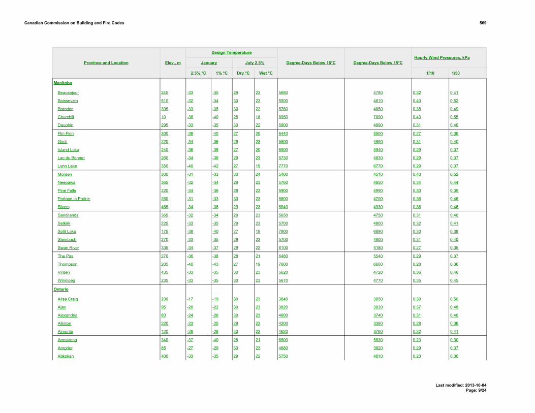
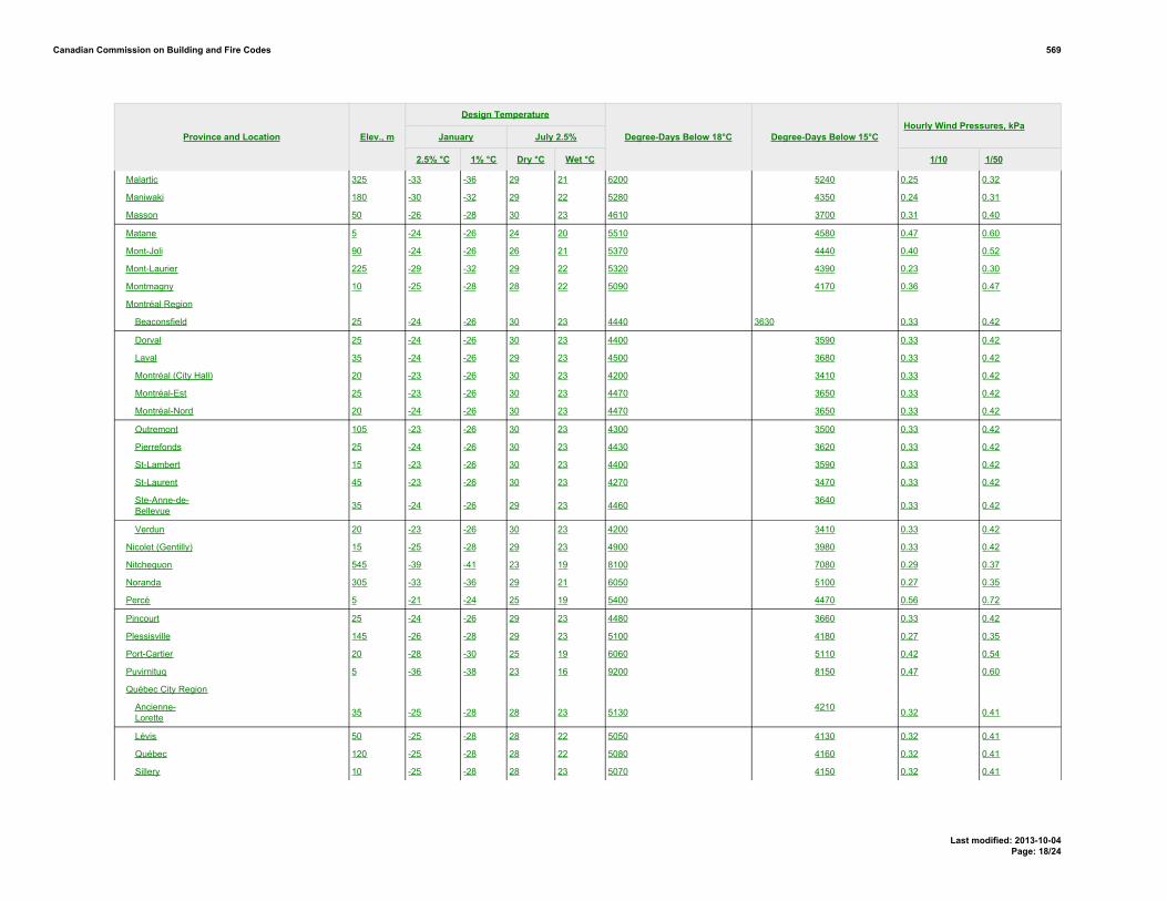
Proposed Change 569Code Reference(s): NECB11 Div.B 1.1.4.1.(1)Subject: NECB Climatic ValuesTitle: 01 NECB11-DivB-01.01.04.01.-insert-EEB-Climatic dataDescription: The proposed change is intended to introduce relevant climatic values from
the National Building Code’s (NBC) Table C-2, Design Data for SelectedLocations in Canada, into the NECB and to add a column for degree-daysbelow 15˚C which is used to calculate the prescriptive semi-heated buildingthermal requirements.
EXISTING PROVISION
1.1.4.1. Climatic Values1) The climatic values required for the design of buildings under this Code shall be in conformance with the values established by the authority having jurisdiction or, in the absence
of such data, with the climatic values in Appendix C, Climatic and Seismic Information for Building Design in Canada, of the National Building Code of Canada for the locationnearest to the building site. (See Appendix A.)
A-1.1.4.1.(1) Climatic Values.Climatic values for municipalities not listed in Table C-2 of Appendix C of the National Building Code may be obtained by contacting the Meteorological Service of Canada, Environment Canada,4905 Dufferin Street, Downsview, Ontario M3H 5T4; http://climate.weatheroffice.gc.ca/Welcome_e.html.Hourly climatic values are available from multiple sources such as Environment Canada, Natural Resources Canada, the Regional Conservation Authority and other such public agencies that recordthis type of information. Hourly weather data are also available from public and private agencies that format this information for use with annual energy consumption simulation software; in somecases, these data have been incorporated into the software.
Figure A-1.1.4.1.(1)Average annual heating degree-days (C-degrees)
PROPOSED CHANGE
[1.1.4.1.] 1.1.4.1. Climatic Values[1] 1) The climatic values required for the design of buildings under this Code shall be in conformance with the values established by the authority having jurisdiction or, in the absence
of such data, with the climatic values in Appendix CB, Climatic and Seismic Information for Building Design in Canada, of the National Buildingthis Code of Canada for thelocation nearest to the building site. (See Appendix A.)
EXISTINGPROVISIONA-1.1.4.1.(1)
PROPOSEDCHANGEA-1.1.4.1.(1)
Canadian Commission on Building and Fire Codes 569
Last modified: 2013-10-04Page: 1/24

A-1.1.4.1.(1) Climatic Values.Climatic values for municipalities not listed in Table CB-21 of Appendix CB of the National Building this Code may be obtained by contacting the Meteorological Service of Canada, Environment
Canada, 4905 Dufferin Street, Downsview, Ontario M3H 5T4; http://climate.weatheroffice.gc.ca/Welcome_e.html.Hourly climatic values are available from multiple sources such as Environment Canada, Natural Resources Canada, the Regional Conservation Authority and other such public agencies that record
this type of information. Hourly weather data are also available from public and private agencies that format this information for use with annual energy consumption simulationsoftware; in some cases, these data have been incorporated into the software.
Figure [A-1.1.4.1.(1)] A-1.1.4.1.(1)Contour map showing approximate Aaverage annual heating degree-days (C-degrees) taken at 18˚C
B-1
Canadian Commission on Building and Fire Codes 569
Last modified: 2013-10-04Page: 2/24

Table [B-1]Design Data for Selected Locations in Canada
Forming part of Sentence -- (--)
Design Temperature
January July 2.5%Hourly Wind Pressures, kPa
Province and Location Elev., m
2.5% °C 1% °C Dry °C Wet °C
Degree-Days Below 18°C Degree-Days Below 15°C
1/10 1/50
British Columbia
100 Mile House 1040 -30 -32 29 17 5030 4040 0.27 0.35
Abbotsford 70 -8 -10 29 20 2860 2000 0.34 0.44
Agassiz 15 -9 -11 31 21 2750 1900 0.36 0.47
Alberni 12 -5 -8 31 19 3100 2220 0.25 0.32
Ashcroft 305 -24 -27 34 20 3700 2790 0.29 0.38
Bamfield 20 -2 -4 23 17 3080 2060 0.39 0.50
Beatton River 840 -37 -39 26 18 6300 5230 0.23 0.30
Bella Bella 25 -5 -7 23 18 3180 2150 0.39 0.50
Bella Coola 40 -14 -18 27 19 3560 2660 0.30 0.39
Burns Lake 755 -31 -34 26 17 5450 4430 0.30 0.39
Cache Creek 455 -24 -27 34 20 3700 2790 0.30 0.39
Campbell River 20 -5 -7 26 18 3000 2130 0.40 0.52
Carmi 845 -24 -26 31 19 4750 3770 0.29 0.38
Castlegar 430 -18 -20 32 20 3580 2680 0.27 0.34
Chetwynd 605 -35 -38 27 18 5500 4480 0.31 0.40
Chilliwack 10 -9 -11 30 20 2780 1920 0.36 0.47
Comox 15 -7 -9 27 18 3100 2220 0.40 0.52
Courtenay 10 -7 -9 28 18 3100 2220 0.40 0.52
Cranbrook 910 -26 -28 32 18 4400 3450 0.25 0.33
Crescent Valley 585 -18 -20 31 20 3650 2740 0.25 0.33
Crofton 5 -4 -6 28 19 2880 2020 0.31 0.40
Dawson Creek 665 -38 -40 27 18 5900 4860 0.31 0.40
Dease Lake 800 -37 -40 24 15 6730 5630 0.23 0.30
Dog Creek 450 -28 -30 29 17 4800 3820 0.27 0.35
Duncan 10 -6 -8 28 19 2980 2110 0.30 0.39
Elko 1065 -28 -31 30 19 4600 3630 0.31 0.40
Fernie 1010 -27 -30 30 19 4750 3770 0.31 0.40
Fort Nelson 465 -39 -42 28 18 6710 5740 0.23 0.30
Fort St. John 685 -35 -37 26 18 5750 4710 0.30 0.39
Glacier 1145 -27 -30 27 17 5800 4760 0.25 0.32
Canadian Commission on Building and Fire Codes 569
Last modified: 2013-10-04Page: 3/24

Design Temperature
January July 2.5%Hourly Wind Pressures, kPa
Province and Location Elev., m
2.5% °C 1% °C Dry °C Wet °C
Degree-Days Below 18°C Degree-Days Below 15°C
1/10 1/50
Gold River 120 -8 -11 31 18 3230 2350 0.25 0.32
Golden 790 -27 -30 30 17 4750 3770 0.27 0.35
Grand Forks 565 -19 -22 34 20 3820 2900 0.31 0.40
Greenwood 745 -20 -23 34 20 4100 3160 0.31 0.40
Hope 40 -13 -15 31 20 3000 2130 0.48 0.63
Jordan River 20 -1 -3 22 17 2900 1900 0.43 0.55
Kamloops 355 -23 -25 34 20 3450 2670 0.31 0.40
Kaslo 545 -17 -20 30 19 3830 2910 0.24 0.31
Kelowna 350 -17 -20 33 20 3400 2510 0.31 0.40
Kimberley 1090 -25 -27 31 18 4650 3680 0.25 0.33
Kitimat Plant 15 -16 -18 25 16 3750 2830 0.37 0.48
Kitimat Townsite 130 -16 -18 24 16 3900 2980 0.37 0.48
Ladysmith 80 -7 -9 27 19 3000 2130 0.31 0.40
Langford 80 -4 -6 27 19 2750 1770 0.31 0.40
Lillooet 245 -21 -23 34 20 3400 2610 0.34 0.44
Lytton 325 -17 -20 35 20 3300 2410 0.33 0.43
Mackenzie 765 -34 -38 27 17 5550 4530 0.25 0.32
Masset 10 -5 -7 17 15 3700 2600 0.48 0.61
McBride 730 -29 -32 29 18 4980 3990 0.27 0.35
McLeod Lake 695 -35 -37 27 17 5450 4430 0.25 0.32
Merritt 570 -24 -27 34 20 3900 2980 0.34 0.44
Mission City 45 -9 -11 30 20 2850 1990 0.33 0.43
Montrose 615 -16 -18 32 20 3600 2690 0.27 0.35
Nakusp 445 -20 -22 31 20 3560 2660 0.25 0.33
Nanaimo 15 -6 -8 27 19 3000 2130 0.39 0.50
Nelson 600 -18 -20 31 20 3500 2600 0.25 0.33
Ocean Falls 10 -10 -12 23 17 3400 2510 0.46 0.59
Osoyoos 285 -14 -17 35 21 3100 2220 0.31 0.40
Parksville 40 -6 -8 26 19 3200 2320 0.39 0.50
Penticton 350 -15 -17 33 20 3350 2460 0.35 0.45
Port Alberni 15 -5 -8 31 19 3100 2220 0.25 0.32
Port Alice 25 -3 -6 26 17 3010 2000 0.25 0.32
Port Hardy 5 -5 -7 20 16 3440 2370 0.40 0.52
Port McNeill 5 -5 -7 22 17 3410 2350 0.40 0.52
Canadian Commission on Building and Fire Codes 569
Last modified: 2013-10-04Page: 4/24

Design Temperature
January July 2.5%Hourly Wind Pressures, kPa
Province and Location Elev., m
2.5% °C 1% °C Dry °C Wet °C
Degree-Days Below 18°C Degree-Days Below 15°C
1/10 1/50
Port Renfrew 20 -3 -5 24 17 2900 1900 0.40 0.52
Powell River 10 -7 -9 26 18 3100 2220 0.39 0.51
Prince George 580 -32 -36 28 18 4720 3750 0.29 0.37
Prince Rupert 20 -13 -15 19 15 3900 2770 0.42 0.54
Princeton 655 -24 -29 33 19 4250 3300 0.28 0.36
Qualicum Beach 10 -7 -9 27 19 3200 2320 0.41 0.53
Queen Charlotte City 35 -6 -8 21 16 3520 2440 0.48 0.61
Quesnel 475 -31 -33 30 17 4650 3680 0.24 0.31
Revelstoke 440 -20 -23 31 19 4000 3070 0.25 0.32
Salmon Arm 425 -19 -24 33 21 3650 2740 0.30 0.39
Sandspit 5 -4 -6 18 15 3450 2380 0.60 0.78
Sechelt 25 -6 -8 27 20 2680 1830 0.37 0.48
Sidney 10 -4 -6 26 18 2850 1860 0.33 0.42
Smith River 660 -45 -47 26 17 7100 5980 0.23 0.30
Smithers 500 -29 -31 26 17 5040 4050 0.31 0.40
Sooke 20 -1 -3 21 16 2900 1900 0.37 0.48
Squamish 5 -9 -11 29 20 2950 2080 0.39 0.50
Stewart 10 -17 -20 25 16 4350 3400 0.28 0.36
Tahsis 25 -4 -6 26 18 3150 2120 0.26 0.34
Taylor 515 -35 -37 26 18 5720 4690 0.31 0.40
Terrace 60 -19 -21 27 17 4150 3210 0.28 0.36
Tofino 10 -2 -4 20 16 3150 2120 0.53 0.68
Trail 440 -14 -17 33 20 3600 2690 0.27 0.35
Ucluelet 5 -2 -4 18 16 3120 2100 0.53 0.68
Vancouver Region
Burnaby (Simon Fraser Univ.) 330 -7 -9 25 17 3100 2220 0.36 0.47
Cloverdale 10 -8 -10 29 20 2700 1850 0.34 0.44
Haney 10 -9 -11 30 20 2840 1980 0.34 0.44
Ladner 3 -6 -8 27 19 2600 1750 0.36 0.46
Langley 15 -8 -10 29 20 2700 1850 0.34 0.44
New Westminster 10 -8 -10 29 19 2800 1940 0.34 0.44
North Vancouver 135 -7 -9 26 19 2910 2050 0.35 0.45
Richmond 5 -7 -9 27 19 2800 1940 0.35 0.45
Surrey (88 Ave & 156 St.) 90 -8 -10 29 20 2750 1900 0.34 0.44
Canadian Commission on Building and Fire Codes 569
Last modified: 2013-10-04Page: 5/24

Design Temperature
January July 2.5%Hourly Wind Pressures, kPa
Province and Location Elev., m
2.5% °C 1% °C Dry °C Wet °C
Degree-Days Below 18°C Degree-Days Below 15°C
1/10 1/50
Vancouver(City Hall) 40 -7 -9 28 20 2825 1970 0.35 0.45
Vancouver(Granville & 41 Ave) 120 -6 -8 28 20 2925 2060 0.35 0.45
West Vancouver 45 -7 -9 28 19 2950 2080 0.37 0.48
Vernon 405 -20 -23 33 20 3600 2690 0.31 0.40
Victoria Region
Victoria(Gonzales Hts) 65 -4 -6 24 17 2700 1690 0.44 0.57
Victoria(Mt Tolmie) 125 -6 -8 24 16 2700 1730 0.48 0.63
Victoria 10 -4 -6 24 17 2650 1730 0.44 0.57
Whistler 665 -17 -20 30 20 4180 3240 0.25 0.32
White Rock 30 -5 -7 25 20 2620 1770 0.34 0.44
Williams Lake 615 -30 -33 29 17 4400 3450 0.27 0.35
Youbou 200 -5 -8 31 19 3050 2180 0.25 0.32
Alberta
Athabasca 515 -35 -38 27 19 6000 5000 0.28 0.36
Banff 1400 -31 -33 27 16 5500 4520 0.25 0.32
Barrhead 645 -33 -36 27 19 5740 4750 0.34 0.44
Beaverlodge 730 -36 -39 28 18 5700 4710 0.28 0.36
Brooks 760 -32 -34 32 20 4880 3940 0.40 0.52
Calgary 1045 -30 -32 28 17 5000 4050 0.37 0.48
Campsie 660 -33 -36 27 19 5750 4760 0.34 0.44
Camrose 740 -33 -35 29 19 5500 4520 0.30 0.39
Canmore 1320 -31 -33 28 17 5400 4430 0.29 0.37
Cardston 1130 -29 -32 30 19 4700 3770 0.56 0.72
Claresholm 1030 -30 -32 30 18 4680 3750 0.45 0.58
Cold Lake 540 -35 -38 28 19 5860 4860 0.29 0.38
Coleman 1320 -31 -34 29 18 5210 4250 0.48 0.63
Coronation 790 -32 -34 30 19 5640 4660 0.29 0.37
Cowley 1175 -29 -32 29 18 4810 3870 0.78 1.01
Drumheller 685 -32 -34 30 18 5050 4100 0.34 0.44
Edmonton 645 -30 -33 28 19 5120 4160 0.35 0.45
Edson 920 -34 -37 27 18 5750 4760 0.36 0.46
Embarras Portage 220 -41 -43 28 19 7100 6040 0.29 0.37
Canadian Commission on Building and Fire Codes 569
Last modified: 2013-10-04Page: 6/24

Design Temperature
January July 2.5%Hourly Wind Pressures, kPa
Province and Location Elev., m
2.5% °C 1% °C Dry °C Wet °C
Degree-Days Below 18°C Degree-Days Below 15°C
1/10 1/50
Fairview 670 -37 -40 27 18 5840 4850 0.27 0.35
Fort MacLeod 945 -30 -32 31 19 4600 3670 0.53 0.68
Fort McMurray 255 -38 -40 28 19 6250 5230 0.27 0.35
Fort Saskatchewan 610 -32 -35 28 19 5420 4450 0.33 0.43
Fort Vermilion 270 -41 -43 28 18 6700 5660 0.23 0.30
Grande Prairie 650 -36 -39 27 18 5790 4800 0.33 0.43
Habay 335 -41 -43 28 18 6750 5710 0.23 0.30
Hardisty 615 -33 -36 30 19 5640 4660 0.28 0.36
High River 1040 -31 -32 28 17 4900 3960 0.50 0.65
Hinton 990 -34 -38 27 17 5500 4520 0.36 0.46
Jasper 1060 -31 -34 28 17 5300 4330 0.25 0.32
Keg River 420 -40 -42 28 18 6520 5490 0.23 0.30
Lac la Biche 560 -35 -38 28 19 6100 5090 0.28 0.36
Lacombe 855 -33 -36 28 19 5500 4520 0.31 0.40
Lethbridge 910 -30 -32 31 19 4500 3580 0.51 0.66
Manning 465 -39 -41 27 18 6300 5280 0.23 0.30
Medicine Hat 705 -31 -34 32 19 4540 3610 0.37 0.48
Peace River 330 -37 -40 27 18 6050 5040 0.25 0.32
Pincher Creek 1130 -29 -32 29 18 4740 3800 0.75 0.96
Ranfurly 670 -34 -37 29 19 5700 4710 0.28 0.36
Red Deer 855 -32 -35 28 19 5550 4570 0.31 0.40
Rocky Mountain House 985 -32 -34 27 18 5640 4660 0.28 0.36
Slave Lake 590 -35 -38 26 19 5850 4850 0.29 0.37
Stettler 820 -32 -34 30 19 5300 4330 0.28 0.36
Stony Plain 710 -32 -35 28 19 5300 4330 0.35 0.45
Suffield 755 -31 -34 32 20 4770 3830 0.38 0.49
Taber 815 -31 -33 31 19 4580 3650 0.48 0.63
Turner Valley 1215 -31 -32 28 17 5220 4260 0.50 0.65
Valleyview 700 -37 -40 27 18 5600 4620 0.33 0.42
Vegreville 635 -34 -37 29 19 5780 4790 0.28 0.36
Vermilion 580 -35 -38 29 19 5740 4750 0.28 0.36
Wagner 585 -35 -38 26 19 5850 4850 0.29 0.37
Wainwright 675 -33 -36 29 19 5700 4710 0.28 0.36
Wetaskiwin 760 -33 -35 29 19 5500 4520 0.30 0.39
Canadian Commission on Building and Fire Codes 569
Last modified: 2013-10-04Page: 7/24

Design Temperature
January July 2.5%Hourly Wind Pressures, kPa
Province and Location Elev., m
2.5% °C 1% °C Dry °C Wet °C
Degree-Days Below 18°C Degree-Days Below 15°C
1/10 1/50
Whitecourt 690 -33 -36 27 19 5650 4670 0.29 0.37
Wimborne 975 -31 -34 29 18 5310 4340 0.31 0.40
Saskatchewan
Assiniboia 740 -32 -34 31 21 5180 4300 0.38 0.49
Battrum 700 -32 -34 32 20 5080 4210 0.42 0.54
Biggar 645 -34 -36 30 20 5720 4820 0.35 0.45
Broadview 600 -34 -35 30 21 5760 4850 0.36 0.46
Dafoe 530 -35 -37 29 21 5860 4950 0.29 0.37
Dundurn 525 -35 -37 30 21 5600 4700 0.36 0.46
Estevan 565 -32 -34 32 22 5340 4450 0.40 0.52
Hudson Bay 370 -36 -38 29 21 6280 5350 0.29 0.37
Humboldt 565 -36 -38 28 21 6000 5080 0.30 0.39
Island Falls 305 -39 -41 27 20 7100 6130 0.27 0.35
Kamsack 455 -34 -37 29 22 6040 5120 0.31 0.40
Kindersley 685 -33 -35 31 20 5550 4650 0.36 0.46
Lloydminster 645 -34 -37 28 20 5880 4970 0.31 0.40
Maple Creek 765 -31 -34 31 20 4780 3920 0.35 0.45
Meadow Lake 480 -38 -40 28 20 6280 5350 0.31 0.40
Melfort 455 -36 -38 28 21 6050 5130 0.28 0.36
Melville 550 -34 -36 29 21 5880 4970 0.31 0.40
Moose Jaw 545 -32 -34 31 21 5270 4390 0.40 0.52
Nipawin 365 -37 -39 28 21 6300 5370 0.29 0.38
North Battleford 545 -34 -36 29 20 5900 4990 0.36 0.46
Prince Albert 435 -37 -40 28 21 6100 5180 0.29 0.38
Qu'Appelle 645 -34 -36 30 22 5620 4720 0.33 0.42
Regina 575 -34 -36 31 21 5600 4700 0.38 0.49
Rosetown 595 -34 -36 31 20 5620 4720 0.38 0.49
Saskatoon 500 -35 -37 30 21 5700 4800 0.33 0.43
Scott 645 -34 -36 30 20 5960 5040 0.35 0.45
Strasbourg 545 -34 -36 30 22 5600 4700 0.33 0.42
Swift Current 750 -31 -34 31 20 5150 4270 0.42 0.54
Uranium City 265 -42 -44 26 19 7500 6510 0.28 0.36
Weyburn 575 -33 -35 31 23 5400 4510 0.37 0.48
Yorkton 510 -34 -37 29 21 6000 5080 0.31 0.40
Canadian Commission on Building and Fire Codes 569
Last modified: 2013-10-04Page: 8/24
Design Temperature
January July 2.5%Hourly Wind Pressures, kPa
Province and Location Elev., m
2.5% °C 1% °C Dry °C Wet °C
Degree-Days Below 18°C Degree-Days Below 15°C
1/10 1/50
Manitoba
Beausejour 245 -33 -35 29 23 5680 4780 0.32 0.41
Boissevain 510 -32 -34 30 23 5500 4610 0.40 0.52
Brandon 395 -33 -35 30 22 5760 4850 0.38 0.49
Churchill 10 -38 -40 25 18 8950 7890 0.43 0.55
Dauphin 295 -33 -35 30 22 5900 4990 0.31 0.40
Flin Flon 300 -38 -40 27 20 6440 5500 0.27 0.35
Gimli 220 -34 -36 29 23 5800 4890 0.31 0.40
Island Lake 240 -36 -38 27 20 6900 5940 0.29 0.37
Lac du Bonnet 260 -34 -36 29 23 5730 4830 0.29 0.37
Lynn Lake 350 -40 -42 27 19 7770 6770 0.29 0.37
Morden 300 -31 -33 30 24 5400 4510 0.40 0.52
Neepawa 365 -32 -34 29 23 5760 4850 0.34 0.44
Pine Falls 220 -34 -36 28 23 5900 4990 0.30 0.39
Portage la Prairie 260 -31 -33 30 23 5600 4700 0.36 0.46
Rivers 465 -34 -36 29 23 5840 4930 0.36 0.46
Sandilands 365 -32 -34 29 23 5650 4750 0.31 0.40
Selkirk 225 -33 -35 29 23 5700 4800 0.32 0.41
Split Lake 175 -38 -40 27 19 7900 6890 0.30 0.39
Steinbach 270 -33 -35 29 23 5700 4800 0.31 0.40
Swan River 335 -34 -37 29 22 6100 5180 0.27 0.35
The Pas 270 -36 -38 28 21 6480 5540 0.29 0.37
Thompson 205 -40 -43 27 19 7600 6600 0.28 0.36
Virden 435 -33 -35 30 23 5620 4720 0.36 0.46
Winnipeg 235 -33 -35 30 23 5670 4770 0.35 0.45
Ontario
Ailsa Craig 230 -17 -19 30 23 3840 3050 0.39 0.50
Ajax 95 -20 -22 30 23 3820 3030 0.37 0.48
Alexandria 80 -24 -26 30 23 4600 3740 0.31 0.40
Alliston 220 -23 -25 29 23 4200 3380 0.28 0.36
Almonte 120 -26 -28 30 23 4620 3760 0.32 0.41
Armstrong 340 -37 -40 28 21 6500 5530 0.23 0.30
Arnprior 85 -27 -29 30 23 4680 3820 0.29 0.37
Atikokan 400 -33 -35 29 22 5750 4810 0.23 0.30
Canadian Commission on Building and Fire Codes 569
Last modified: 2013-10-04Page: 9/24

Design Temperature
January July 2.5%Hourly Wind Pressures, kPa
Province and Location Elev., m
2.5% °C 1% °C Dry °C Wet °C
Degree-Days Below 18°C Degree-Days Below 15°C
1/10 1/50
Attawapiskat 10 -37 -39 28 21 7100 6120 0.32 0.41
Aurora 270 -21 -23 30 23 4210 3390 0.34 0.44
Bancroft 365 -28 -31 29 23 4740 3870 0.25 0.32
Barrie 245 -24 -26 29 23 4380 3540 0.28 0.36
Barriefield 100 -22 -24 28 23 3990 3190 0.36 0.47
Beaverton 240 -24 -26 30 23 4300 3470 0.28 0.36
Belleville 90 -22 -24 29 23 3910 3110 0.33 0.43
Belmont 260 -17 -19 30 24 3840 3050 0.36 0.47
Kitchenuhmay-koosib (Big Trout Lake) 215 -38 -40 26 20 7450 0.33 0.42
CFB Borden 225 -23 -25 29 23 4300 3470 0.28 0.36
Bracebridge 310 -26 -28 29 23 4800 3920 0.27 0.35
Bradford 240 -23 -25 30 23 4280 3450 0.28 0.36
Brampton 215 -19 -21 30 23 4100 3290 0.34 0.44
Brantford 205 -18 -20 30 23 3900 3110 0.33 0.42
Brighton 95 -21 -23 29 23 4000 3200 0.37 0.48
Brockville 85 -23 -25 29 23 4060 3250 0.34 0.44
Burk's Falls 305 -26 -28 29 22 5020 4120 0.27 0.35
Burlington 80 -17 -19 31 23 3740 2960 0.36 0.46
Cambridge 295 -18 -20 29 23 4100 3290 0.28 0.36
Campbellford 150 -23 -26 30 23 4280 3450 0.32 0.41
Cannington 255 -24 -26 30 23 4310 3480 0.28 0.36
Carleton Place 135 -25 -27 30 23 4600 3740 0.32 0.41
Cavan 200 -23 -25 30 23 4400 3560 0.34 0.44
Centralia 260 -17 -19 30 23 3800 3010 0.38 0.49
Chapleau 425 -35 -38 27 21 5900 4950 0.23 0.30
Chatham 180 -16 -18 31 24 3470 2710 0.33 0.43
Chesley 275 -19 -21 29 22 4320 3490 0.37 0.48
Clinton 280 -17 -19 29 23 4150 3330 0.38 0.49
Coboconk 270 -25 -27 30 23 4500 3650 0.27 0.35
Cobourg 90 -21 -23 29 23 3980 3180 0.38 0.49
Cochrane 245 -34 -36 29 21 6200 5240 0.27 0.35
Colborne 105 -21 -23 29 23 3980 3180 0.38 0.49
Collingwood 190 -21 -23 29 23 4180 3360 0.30 0.39
Cornwall 35 -23 -25 30 23 4250 3420 0.32 0.41
Canadian Commission on Building and Fire Codes 569
Last modified: 2013-10-04Page: 10/24

Design Temperature
January July 2.5%Hourly Wind Pressures, kPa
Province and Location Elev., m
2.5% °C 1% °C Dry °C Wet °C
Degree-Days Below 18°C Degree-Days Below 15°C
1/10 1/50
Corunna 185 -16 -18 31 24 3600 2830 0.36 0.47
Deep River 145 -29 -32 30 22 4900 3980 0.27 0.35
Deseronto 85 -22 -24 29 23 4070 3260 0.33 0.43
Dorchester 260 -18 -20 30 24 3900 3110 0.36 0.47
Dorion 200 -33 -35 28 21 5950 5000 0.30 0.39
Dresden 185 -16 -18 31 24 3750 2970 0.33 0.43
Dryden 370 -34 -36 28 22 5850 4940 0.23 0.30
Dundalk 525 -22 -24 29 22 4700 3830 0.33 0.42
Dunnville 175 -15 -17 30 24 3660 2890 0.36 0.46
Durham 340 -20 -22 29 22 4340 3510 0.34 0.44
Dutton 225 -16 -18 31 24 3700 2920 0.36 0.47
Earlton 245 -33 -36 29 22 5730 4790 0.35 0.45
Edison 365 -34 -36 28 22 5740 4840 0.24 0.31
Elliot Lake 380 -26 -28 29 21 4950 4030 0.29 0.38
Elmvale 220 -24 -26 29 23 4200 3380 0.28 0.36
Embro 310 -19 -21 30 23 3950 3150 0.37 0.48
Englehart 205 -33 -36 29 22 5800 4860 0.32 0.41
Espanola 220 -25 -27 29 21 4920 4000 0.33 0.42
Exeter 265 -17 -19 30 23 3900 3110 0.38 0.49
Fenelon Falls 260 -25 -27 30 23 4440 3600 0.28 0.36
Fergus 400 -20 -22 29 23 4300 3470 0.28 0.36
Forest 215 -16 -18 31 23 3740 2960 0.37 0.48
Fort Erie 180 -15 -17 30 24 3650 2880 0.36 0.46
Fort Erie (Ridgeway) 190 -15 -17 30 24 3600 2830 0.36 0.46
Fort Frances 340 -33 -35 29 22 5440 4550 0.24 0.31
Gananoque 80 -22 -24 28 23 4010 3210 0.36 0.47
Geraldton 345 -36 -39 28 21 6450 5490 0.23 0.30
Glencoe 215 -16 -18 31 24 3680 2900 0.33 0.43
Goderich 185 -16 -18 29 23 4000 3200 0.43 0.55
Gore Bay 205 -24 -26 28 22 4700 3830 0.34 0.44
Graham 495 -35 -37 29 22 5940 4990 0.23 0.30
Gravenhurst (Muskoka Airport) 255 -26 -28 29 23 4760 3890 0.28 0.36
Grimsby 85 -16 -18 30 23 3520 2760 0.36 0.46
Guelph 340 -19 -21 29 23 4270 3440 0.28 0.36
Canadian Commission on Building and Fire Codes 569
Last modified: 2013-10-04Page: 11/24

Design Temperature
January July 2.5%Hourly Wind Pressures, kPa
Province and Location Elev., m
2.5% °C 1% °C Dry °C Wet °C
Degree-Days Below 18°C Degree-Days Below 15°C
1/10 1/50
Guthrie 280 -24 -26 29 23 4300 3470 0.28 0.36
Haileybury 210 -32 -35 30 22 5600 4660 0.34 0.44
Haldimand (Caledonia) 190 -18 -20 30 23 3750 2970 0.34 0.44
Haldimand (Hagersville) 215 -17 -19 30 23 3760 2980 0.36 0.46
Haliburton 335 -27 -29 29 23 4840 3960 0.27 0.35
Halton Hills (Georgetown) 255 -19 -21 30 23 4200 3380 0.29 0.37
Hamilton 90 -17 -19 31 23 3460 2700 0.36 0.46
Hanover 270 -19 -21 29 22 4300 3470 0.37 0.48
Hastings 200 -24 -26 30 23 4280 3450 0.32 0.41
Hawkesbury 50 -25 -27 30 23 4610 3750 0.32 0.41
Hearst 245 -35 -37 29 21 6450 5490 0.23 0.30
Honey Harbour 180 -24 -26 29 23 4300 3470 0.30 0.39
Hornepayne 360 -37 -40 28 21 6340 5380 0.23 0.30
Huntsville 335 -26 -29 29 22 4850 3970 0.27 0.35
Ingersoll 280 -18 -20 30 23 3920 3120 0.37 0.48
Iroquois Falls 275 -33 -36 29 21 6100 5150 0.29 0.37
Jellicoe 330 -36 -39 28 21 6400 5440 0.23 0.30
Kapuskasing 245 -34 -36 29 21 6250 5290 0.24 0.31
Kemptville 90 -25 -27 30 23 4540 3690 0.32 0.41
Kenora 370 -33 -35 28 22 5630 4730 0.24 0.31
Killaloe 185 -28 -31 30 22 4960 4070 0.27 0.35
Kincardine 190 -17 -19 28 22 3890 3100 0.43 0.55
Kingston 80 -22 -24 28 23 4000 3200 0.36 0.47
Kinmount 295 -26 -28 29 23 4600 3740 0.27 0.35
Kirkland Lake 325 -33 -36 29 22 6000 5050 0.30 0.39
Kitchener 335 -19 -21 29 23 4200 3380 0.29 0.37
Lakefield 240 -24 -26 30 23 4330 3500 0.29 0.38
Lansdowne House 240 -38 -40 28 21 7150 6160 0.25 0.32
Leamington 190 -15 -17 31 24 3400 2650 0.36 0.47
Lindsay 265 -24 -26 30 23 4320 3490 0.29 0.38
Lion's Head 185 -19 -21 27 22 4300 3470 0.37 0.48
Listowel 380 -19 -21 29 23 4300 3470 0.36 0.47
London 245 -18 -20 30 24 3900 3110 0.36 0.47
Lucan 300 -17 -19 30 23 3900 3110 0.39 0.50
Canadian Commission on Building and Fire Codes 569
Last modified: 2013-10-04Page: 12/24

Design Temperature
January July 2.5%Hourly Wind Pressures, kPa
Province and Location Elev., m
2.5% °C 1% °C Dry °C Wet °C
Degree-Days Below 18°C Degree-Days Below 15°C
1/10 1/50
Maitland 85 -23 -25 29 23 4080 3270 0.34 0.44
Markdale 425 -20 -22 29 22 4500 3650 0.32 0.41
Markham 175 -21 -23 31 24 4000 3200 0.34 0.44
Martin 485 -35 -37 29 22 5900 4950 0.23 0.30
Matheson 265 -33 -36 29 21 6080 5130 0.30 0.39
Mattawa 165 -29 -31 30 22 5050 4130 0.25 0.32
Midland 190 -24 -26 29 23 4200 3380 0.30 0.39
Milton 200 -18 -20 30 23 3920 3120 0.33 0.43
Milverton 370 -19 -21 29 23 4200 3380 0.33 0.43
Minden 270 -27 -29 29 23 4640 3780 0.27 0.35
Mississauga 160 -18 -20 30 23 3880 3090 0.34 0.44
Mississauga (Lester B. Pearson Int'l Airport) 170 -20 -22 31 24 3890 0.34 0.44
Mississauga(Port Credit) 75 -18 -20 29 23 3780 3000 0.37 0.48
Mitchell 335 -18 -20 29 23 4100 3290 0.37 0.48
Moosonee 10 -36 -38 28 22 6800 5820 0.27 0.35
Morrisburg 75 -23 -25 30 23 4370 3530 0.32 0.41
Mount Forest 420 -21 -24 28 22 4700 3830 0.32 0.41
Nakina 325 -36 -38 28 21 6500 5530 0.23 0.30
Nanticoke (Jarvis) 205 -17 -18 30 23 3700 2920 0.37 0.48
Nanticoke (Port Dover) 180 -15 -17 30 24 3600 2830 0.37 0.48
Napanee 90 -22 -24 29 23 4140 3320 0.33 0.43
New Liskeard 180 -32 -35 30 22 5570 4630 0.33 0.43
Newcastle 115 -20 -22 30 23 3990 3190 0.37 0.48
Newcastle (Bowmanville) 95 -20 -22 30 23 4000 0.37 0.48
Newmarket 185 -22 -24 30 23 4260 3430 0.29 0.38
Niagara Falls 210 -16 -18 30 23 3600 2830 0.33 0.43
North Bay 210 -28 -30 28 22 5150 4230 0.27 0.34
Norwood 225 -24 -26 30 23 4320 3490 0.32 0.41
Oakville 90 -18 -20 30 23 3760 2980 0.36 0.47
Orangeville 430 -21 -23 29 23 4450 3610 0.28 0.36
Orillia 230 -25 -27 29 23 4260 3430 0.28 0.36
Oshawa 110 -19 -21 30 23 3860 3070 0.37 0.48
Ottawa (Metropolitan)
Ottawa (City Hall) 70 -25 -27 30 23 4440 3600 0.32 0.41
Canadian Commission on Building and Fire Codes 569
Last modified: 2013-10-04Page: 13/24

Design Temperature
January July 2.5%Hourly Wind Pressures, kPa
Province and Location Elev., m
2.5% °C 1% °C Dry °C Wet °C
Degree-Days Below 18°C Degree-Days Below 15°C
1/10 1/50
Ottawa (Barrhaven) 98 -25 -27 30 23 4500 3650 0.32 0.41
Ottawa (Kanata) 98 -25 -27 30 23 4520 3670 0.32 0.41
Ottawa (M-C Int'l Airport) 125 -25 -27 30 23 4500 3650 0.32 0.41
Ottawa (Orleans) 70 -26 -28 30 23 4500 3650 0.32 0.41
Owen Sound 215 -19 -21 29 22 4030 3220 0.37 0.48
Pagwa River 185 -35 -37 28 21 6500 5530 0.23 0.30
Paris 245 -18 -20 30 23 4000 3200 0.33 0.42
Parkhill 205 -16 -18 31 23 3800 3010 0.39 0.50
Parry Sound 215 -24 -26 28 22 4640 3780 0.30 0.39
Pelham (Fonthill) 230 -15 -17 30 23 3690 2910 0.33 0.42
Pembroke 125 -28 -31 30 23 4980 4090 0.27 0.35
Penetanguishene 220 -24 -26 29 23 4200 3380 0.30 0.39
Perth 130 -25 -27 30 23 4540 3690 0.32 0.41
Petawawa 135 -29 -31 30 23 4980 4090 0.27 0.35
Peterborough 200 -23 -25 30 23 4400 3560 0.32 0.41
Petrolia 195 -16 -18 31 24 3640 2870 0.36 0.47
Pickering (Dunbarton) 85 -19 -21 30 23 3800 3010 0.37 0.48
Picton 95 -21 -23 29 23 3980 3180 0.38 0.49
Plattsville 300 -19 -21 29 23 4150 3330 0.33 0.42
Point Alexander 150 -29 -32 30 22 4960 4040 0.27 0.35
Port Burwell 195 -15 -17 30 24 3800 3010 0.36 0.47
Port Colborne 180 -15 -17 30 24 3600 2830 0.36 0.46
Port Elgin 205 -17 -19 28 22 4100 3290 0.43 0.55
Port Hope 100 -21 -23 29 23 3970 3170 0.37 0.48
Port Perry 270 -22 -24 30 23 4260 3430 0.34 0.44
Port Stanley 180 -15 -17 31 24 3850 3060 0.36 0.47
Prescott 90 -23 -25 29 23 4120 3310 0.34 0.44
Princeton 280 -18 -20 30 23 4000 3200 0.33 0.42
Raith 475 -34 -37 28 22 5900 4950 0.23 0.30
Rayside-Balfour (Chelmsford) 270 -28 -30 29 21 5200 4280 0.35 0.45
Red Lake 360 -35 -37 28 21 6220 5290 0.23 0.30
Renfrew 115 -27 -30 30 23 4900 4020 0.27 0.35
Richmond Hill 230 -21 -23 31 24 4000 3200 0.34 0.44
Rockland 50 -26 -28 30 23 4600 3740 0.31 0.40
Canadian Commission on Building and Fire Codes 569
Last modified: 2013-10-04Page: 14/24

Design Temperature
January July 2.5%Hourly Wind Pressures, kPa
Province and Location Elev., m
2.5% °C 1% °C Dry °C Wet °C
Degree-Days Below 18°C Degree-Days Below 15°C
1/10 1/50
Sarnia 190 -16 -18 31 24 3750 2970 0.36 0.47
Sault Ste. Marie 190 -25 -28 29 22 4960 4040 0.34 0.44
Schreiber 310 -34 -36 27 21 5960 5010 0.30 0.39
Seaforth 310 -17 -19 30 23 4100 3290 0.37 0.48
Shelburne 495 -22 -24 29 23 4700 3830 0.31 0.40
Simcoe 210 -17 -19 30 24 3700 2920 0.35 0.45
Sioux Lookout 375 -34 -36 28 22 5950 5030 0.23 0.30
Smiths Falls 130 -25 -27 30 23 4540 3690 0.32 0.41
Smithville 185 -16 -18 30 23 3650 2880 0.33 0.42
Smooth Rock Falls 235 -34 -36 29 21 6250 5290 0.25 0.32
South River 355 -27 -29 29 22 5090 4190 0.27 0.35
Southampton 180 -17 -19 28 22 4100 3290 0.41 0.53
St. Catharines 105 -16 -18 30 23 3540 2780 0.36 0.46
St. Mary's 310 -18 -20 30 23 4000 3200 0.36 0.47
St. Thomas 225 -16 -18 31 24 3780 3000 0.36 0.47
Stirling 120 -23 -25 30 23 4220 3400 0.31 0.40
Stratford 360 -18 -20 29 23 4050 3240 0.35 0.45
Strathroy 225 -17 -19 31 24 3780 3000 0.36 0.47
Sturgeon Falls 205 -28 -30 29 21 5200 4280 0.27 0.35
Sudbury 275 -28 -30 29 21 5180 4260 0.36 0.46
Sundridge 340 -27 -29 29 22 5080 4180 0.27 0.35
Tavistock 340 -19 -21 29 23 4100 3290 0.35 0.45
Temagami 300 -30 -33 30 22 5420 4490 0.29 0.37
Thamesford 280 -19 -21 30 23 3950 3150 0.37 0.48
Thedford 205 -16 -18 31 23 3710 2930 0.39 0.50
Thunder Bay 210 -31 -33 29 21 5650 4710 0.30 0.39
Tillsonburg 215 -17 -19 30 24 3840 3050 0.34 0.44
Timmins 300 -34 -36 29 21 5940 4990 0.27 0.35
Timmins (Porcupine) 295 -34 -36 29 21 6000 5050 0.29 0.37
Toronto Metropolitan Region
Etobicoke 160 -20 -22 31 24 3800 3010 0.34 0.44
North York 175 -20 -22 31 24 3760 2980 0.34 0.44
Scarborough 180 -20 -22 31 24 3800 3010 0.36 0.47
Toronto (City Hall) 90 -18 -20 31 23 3520 2760 0.34 0.44
Canadian Commission on Building and Fire Codes 569
Last modified: 2013-10-04Page: 15/24

Design Temperature
January July 2.5%Hourly Wind Pressures, kPa
Province and Location Elev., m
2.5% °C 1% °C Dry °C Wet °C
Degree-Days Below 18°C Degree-Days Below 15°C
1/10 1/50
Trenton 80 -22 -24 29 23 4110 3300 0.36 0.47
Trout Creek 330 -27 -29 29 22 5100 4200 0.27 0.35
Uxbridge 275 -22 -24 30 23 4240 3410 0.33 0.42
Vaughan (Woodbridge) 165 -20 -22 31 24 4100 3290 0.34 0.44
Vittoria 215 -15 -17 30 24 3680 2900 0.36 0.47
Walkerton 275 -18 -20 30 22 4300 3470 0.39 0.50
Wallaceburg 180 -16 -18 31 24 3600 2830 0.35 0.45
Waterloo 330 -19 -21 29 23 4200 3380 0.29 0.37
Watford 240 -17 -19 31 24 3740 2960 0.36 0.47
Wawa 290 -34 -36 26 21 5840 4900 0.30 0.39
Welland 180 -15 -17 30 23 3670 2900 0.33 0.43
West Lorne 215 -16 -18 31 24 3700 2920 0.36 0.47
Whitby 85 -20 -22 30 23 3820 3030 0.37 0.48
Whitby (Brooklin) 160 -20 -22 30 23 4010 3210 0.35 0.45
White River 375 -39 -42 28 21 6150 5200 0.23 0.30
Wiarton 185 -19 -21 29 22 4300 3470 0.37 0.48
Windsor 185 -16 -18 32 24 3400 2650 0.36 0.47
Wingham 310 -18 -20 30 23 4220 3400 0.39 0.50
Woodstock 300 -19 -21 30 23 3910 3110 0.34 0.44
Wyoming 215 -16 -18 31 24 3700 2920 0.36 0.47
Quebec
Acton-Vale 95 -24 -27 30 23 4620 3790 0.27 0.35
Alma 110 -31 -33 28 22 5800 4860 0.27 0.35
Amos 295 -34 -36 28 21 6160 5210 0.25 0.32
Asbestos 245 -26 -28 29 22 4800 3890 0.27 0.35
Aylmer 90 -25 -28 30 23 4520 3620 0.32 0.41
Baie-Comeau 60 -27 -29 25 19 6020 5070 0.39 0.50
Baie-Saint-Paul 20 -27 -29 28 21 5280 4350 0.37 0.48
Beauport 45 -26 -29 28 22 5100 4180 0.33 0.42
Bedford 55 -24 -26 29 23 4420 3610 0.32 0.41
Beloeil 25 -24 -26 30 23 4500 3680 0.29 0.37
Brome 210 -25 -27 29 23 4730 3880 0.29 0.37
Brossard 15 -24 -26 30 23 4420 3610 0.33 0.42
Buckingham 130 -26 -28 30 23 4880 3970 0.31 0.40
Canadian Commission on Building and Fire Codes 569
Last modified: 2013-10-04Page: 16/24

Design Temperature
January July 2.5%Hourly Wind Pressures, kPa
Province and Location Elev., m
2.5% °C 1% °C Dry °C Wet °C
Degree-Days Below 18°C Degree-Days Below 15°C
1/10 1/50
Campbell's Bay 115 -28 -30 30 23 4900 3980 0.25 0.32
Chambly 20 -24 -26 30 23 4450 3630 0.31 0.40
Coaticook 295 -25 -27 28 22 4750 3840 0.27 0.35
Contrecoeur 10 -25 -27 30 23 4500 3680 0.33 0.43
Cowansville 120 -25 -27 29 23 4540 3710 0.32 0.41
Deux-Montagnes 25 -25 -27 29 23 4440 3630 0.29 0.37
Dolbeau 120 -32 -34 28 22 6250 5290 0.27 0.35
Drummondville 85 -26 -28 30 23 4700 3860 0.27 0.35
Farnham 60 -24 -26 29 23 4500 3680 0.29 0.37
Fort-Coulonge 110 -28 -30 30 23 4950 4030 0.25 0.32
Gagnon 545 -34 -36 24 19 7600 6600 0.30 0.39
Gaspé 55 -25 -26 26 20 5500 4570 0.37 0.48
Gatineau 95 -25 -28 30 23 4600 3690 0.32 0.41
Gracefield 175 -28 -31 30 23 5080 4160 0.25 0.32
Granby 120 -25 -27 29 23 4500 3680 0.27 0.35
Harrington-Harbour 30 -27 -29 19 16 6150 5200 0.56 0.72
Havre-St-Pierre 5 -27 -29 22 18 6100 5150 0.48 0.63
Hemmingford 75 -24 -26 30 23 4380 3570 0.31 0.40
Hull 65 -25 -28 30 23 4550 3650 0.32 0.41
Iberville 35 -24 -26 29 23 4450 3630 0.32 0.41
Inukjuak 5 -36 -38 21 15 9150 8100 0.47 0.60
Joliette 45 -26 -28 29 23 4720 3870 0.28 0.36
Kuujjuaq 25 -37 -39 24 17 8550 7520 0.47 0.60
Kuujjuarapik 20 -36 -38 25 17 7990 6980 0.43 0.55
La Pocatière 55 -24 -26 28 22 5160 4240 0.39 0.50
La-Malbaie 25 -26 -28 28 21 5400 3800 0.37 0.48
La-Tuque 165 -30 -32 29 22 5500 4260 0.27 0.35
Lac-Mégantic 420 -27 -29 27 22 5180 4470 0.27 0.35
Lachute 65 -26 -28 29 23 4640 4570 0.31 0.40
Lennoxville 155 -28 -30 29 22 4700 3790 0.25 0.32
Léry 30 -24 -26 29 23 4420 3610 0.33 0.42
Loretteville 100 -26 -29 28 22 5200 4280 0.32 0.41
Louiseville 15 -25 -28 29 23 4900 4030 0.33 0.43
Magog 215 -26 -28 29 23 4730 3880 0.27 0.35
Canadian Commission on Building and Fire Codes 569
Last modified: 2013-10-04Page: 17/24
Design Temperature
January July 2.5%Hourly Wind Pressures, kPa
Province and Location Elev., m
2.5% °C 1% °C Dry °C Wet °C
Degree-Days Below 18°C Degree-Days Below 15°C
1/10 1/50
Malartic 325 -33 -36 29 21 6200 5240 0.25 0.32
Maniwaki 180 -30 -32 29 22 5280 4350 0.24 0.31
Masson 50 -26 -28 30 23 4610 3700 0.31 0.40
Matane 5 -24 -26 24 20 5510 4580 0.47 0.60
Mont-Joli 90 -24 -26 26 21 5370 4440 0.40 0.52
Mont-Laurier 225 -29 -32 29 22 5320 4390 0.23 0.30
Montmagny 10 -25 -28 28 22 5090 4170 0.36 0.47
Montréal Region
Beaconsfield 25 -24 -26 30 23 4440 3630 0.33 0.42
Dorval 25 -24 -26 30 23 4400 3590 0.33 0.42
Laval 35 -24 -26 29 23 4500 3680 0.33 0.42
Montréal (City Hall) 20 -23 -26 30 23 4200 3410 0.33 0.42
Montréal-Est 25 -23 -26 30 23 4470 3650 0.33 0.42
Montréal-Nord 20 -24 -26 30 23 4470 3650 0.33 0.42
Outremont 105 -23 -26 30 23 4300 3500 0.33 0.42
Pierrefonds 25 -24 -26 30 23 4430 3620 0.33 0.42
St-Lambert 15 -23 -26 30 23 4400 3590 0.33 0.42
St-Laurent 45 -23 -26 30 23 4270 3470 0.33 0.42
Ste-Anne-de-Bellevue 35 -24 -26 29 23 4460 3640 0.33 0.42
Verdun 20 -23 -26 30 23 4200 3410 0.33 0.42
Nicolet (Gentilly) 15 -25 -28 29 23 4900 3980 0.33 0.42
Nitchequon 545 -39 -41 23 19 8100 7080 0.29 0.37
Noranda 305 -33 -36 29 21 6050 5100 0.27 0.35
Percé 5 -21 -24 25 19 5400 4470 0.56 0.72
Pincourt 25 -24 -26 29 23 4480 3660 0.33 0.42
Plessisville 145 -26 -28 29 23 5100 4180 0.27 0.35
Port-Cartier 20 -28 -30 25 19 6060 5110 0.42 0.54
Puvirnituq 5 -36 -38 23 16 9200 8150 0.47 0.60
Québec City Region
Ancienne-Lorette 35 -25 -28 28 23 5130 4210 0.32 0.41
Lévis 50 -25 -28 28 22 5050 4130 0.32 0.41
Québec 120 -25 -28 28 22 5080 4160 0.32 0.41
Sillery 10 -25 -28 28 23 5070 4150 0.32 0.41
Canadian Commission on Building and Fire Codes 569
Last modified: 2013-10-04Page: 18/24

Design Temperature
January July 2.5%Hourly Wind Pressures, kPa
Province and Location Elev., m
2.5% °C 1% °C Dry °C Wet °C
Degree-Days Below 18°C Degree-Days Below 15°C
1/10 1/50
Ste-Foy 115 -25 -28 28 23 5100 4180 0.32 0.41
Richmond 150 -25 -27 29 22 4700 3860 0.25 0.32
Rimouski 30 -25 -27 26 20 5300 4370 0.40 0.52
Rivière-du-Loup 55 -25 -27 26 21 5380 4450 0.39 0.50
Roberval 100 -31 -33 28 21 5750 4810 0.27 0.35
Rock-Island 160 -25 -27 29 23 4850 3990 0.27 0.35
Rosemère 25 -24 -26 29 23 4550 3720 0.31 0.40
Rouyn 300 -33 -36 29 21 6050 5100 0.27 0.35
Saguenay 10 -30 -32 28 22 5700 4760 0.28 0.36
Saguenay (Bagotville) 5 -31 -33 28 21 5700 4760 0.29 0.38
Saguenay (Jonquière) 135 -30 -32 28 22 5650 4710 0.27 0.35
Saguenay (Kenogami) 140 -30 -32 28 22 5650 4710 0.27 0.35
Saint-Eustache 35 -25 -27 29 23 4500 3680 0.29 0.37
Saint-Jean-sur-Richelieu 35 -24 -26 29 23 4450 3630 0.32 0.41
Salaberry-de-Valleyfield 50 -23 -25 29 23 4400 3590 0.33 0.42
Schefferville 550 -37 -39 24 16 8550 7520 0.33 0.42
Senneterre 310 -34 -36 29 21 6180 5220 0.25 0.32
Sept-Îles 5 -29 -31 24 18 6200 5240 0.42 0.54
Shawinigan 60 -26 -29 29 23 5050 4130 0.27 0.35
Shawville 170 -27 -30 30 23 4880 3970 0.27 0.35
Sherbrooke 185 -28 -30 29 23 4700 3790 0.25 0.32
Sorel 10 -25 -27 29 23 4550 3720 0.33 0.43
St-Félicien 105 -32 -34 28 22 5850 4900 0.27 0.35
St-Georges-de-Cacouna 35 -25 -27 26 21 5400 4470 0.39 0.50
St-Hubert 25 -24 -26 30 23 4490 3670 0.33 0.42
Saint-Hubert-de-Rivière-du-Loup 310 -26 -28 26 21 5520 4590 0.31 0.40
St-Hyacinthe 35 -24 -27 30 23 4500 3680 0.27 0.35
St-Jérôme 95 -26 -28 29 23 4820 3960 0.29 0.37
St-Jovite 230 -29 -31 28 22 5250 4340 0.25 0.33
St-Lazare-Hudson 60 -24 -26 30 23 4520 3700 0.33 0.42
St-Nicolas 65 -25 -28 28 22 4990 4070 0.33 0.42
Canadian Commission on Building and Fire Codes 569
Last modified: 2013-10-04Page: 19/24

Design Temperature
January July 2.5%Hourly Wind Pressures, kPa
Province and Location Elev., m
2.5% °C 1% °C Dry °C Wet °C
Degree-Days Below 18°C Degree-Days Below 15°C
1/10 1/50
Ste-Agathe-des-Monts 360 -28 -30 28 22 5390 4470 0.27 0.35
Sutton 185 -25 -27 29 23 4600 3770 0.32 0.41
Tadoussac 65 -26 -28 27 21 5450 4520 0.40 0.52
Témiscaming 240 -30 -32 30 22 5020 4100 0.25 0.32
Terrebonne 20 -25 -27 29 23 4500 3680 0.31 0.40
Thetford Mines 330 -26 -28 28 22 5120 4200 0.27 0.35
Thurso 50 -26 -28 30 23 4820 3910 0.31 0.40
Trois-Rivières 25 -25 -28 29 23 4900 3980 0.33 0.43
Val-d'Or 310 -33 -36 29 21 6180 5220 0.25 0.32
Varennes 15 -24 -26 30 23 4500 3680 0.31 0.40
Verchères 15 -24 -26 30 23 4450 3630 0.33 0.43
Victoriaville 125 -26 -28 29 23 4900 3980 0.27 0.35
Ville-Marie 200 -31 -34 30 22 5550 4610 0.31 0.40
Wakefield 120 -27 -30 30 23 4820 3910 0.27 0.34
Waterloo 205 -25 -27 29 23 4650 3810 0.27 0.35
Windsor 150 -25 -27 29 23 4700 3860 0.25 0.32
New Brunswick
Alma 5 -21 -23 26 20 4500 3600 0.37 0.48
Bathurst 10 -23 -26 30 22 5020 4100 0.37 0.48
Campbellton 30 -26 -28 29 22 5500 4570 0.35 0.45
Edmundston 160 -27 -29 28 22 5320 4500 0.29 0.38
Fredericton 15 -24 -27 29 22 4670 3760 0.29 0.38
Gagetown 20 -24 -26 29 22 4460 3560 0.31 0.40
Grand Falls 115 -27 -30 28 22 5300 4450 0.29 0.38
Miramichi 5 -24 -26 30 22 4950 4030 0.32 0.41
Moncton 20 -23 -25 28 21 4680 3770 0.39 0.50
Oromocto 20 -24 -26 29 22 4650 3740 0.30 0.39
Sackville 15 -22 -24 27 21 4590 3680 0.38 0.49
Saint Andrews 35 -22 -24 25 20 4680 3770 0.35 0.45
Saint George 35 -21 -23 25 20 4680 3770 0.35 0.45
Saint John 5 -22 -24 25 20 4570 3670 0.41 0.53
Shippagan 5 -22 -24 28 21 4930 4010 0.48 0.63
St. Stephen 20 -24 -26 28 22 4700 3790 0.33 0.42
Woodstock 60 -26 -29 30 22 4910 3990 0.29 0.37
Canadian Commission on Building and Fire Codes 569
Last modified: 2013-10-04Page: 20/24

Design Temperature
January July 2.5%Hourly Wind Pressures, kPa
Province and Location Elev., m
2.5% °C 1% °C Dry °C Wet °C
Degree-Days Below 18°C Degree-Days Below 15°C
1/10 1/50
Nova Scotia
Amherst 25 -21 -24 27 21 4500 3600 0.37 0.48
Antigonish 10 -17 -20 27 21 4510 3610 0.42 0.54
Bridgewater 10 -15 -17 27 20 4140 3250 0.43 0.55
Canso 5 -13 -15 25 20 4400 3500 0.48 0.61
Debert 45 -21 -24 27 21 4500 3600 0.37 0.48
Digby 35 -15 -17 25 20 4020 3130 0.43 0.55
Greenwood (CFB) 28 -18 -20 29 22 4140 3250 0.42 0.54
Halifax Region
Dartmouth 10 -16 -18 26 20 4100 3210 0.45 0.58
Halifax 55 -16 -18 26 20 4000 3110 0.45 0.58
Kentville 25 -18 -20 28 21 4130 3240 0.42 0.54
Liverpool 20 -16 -18 27 20 3990 3100 0.48 0.61
Lockeport 5 -14 -16 25 20 4000 3110 0.47 0.60
Louisburg 5 -15 -17 26 20 4530 3630 0.50 0.65
Lunenburg 25 -15 -17 26 20 4140 3250 0.48 0.61
New Glasgow 30 -19 -21 27 21 4320 3420 0.43 0.55
North Sydney 20 -16 -19 27 21 4500 3600 0.46 0.59
Pictou 25 -19 -21 27 21 4310 3410 0.43 0.55
Port Hawkesbury 40 -17 -19 27 21 4500 3600 0.57 0.74
Springhill 185 -20 -23 27 21 4540 3640 0.37 0.48
Stewiacke 25 -20 -22 27 21 4400 3500 0.39 0.50
Sydney 5 -16 -19 27 21 4530 3630 0.46 0.59
Tatamagouche 25 -20 -23 27 21 4380 3480 0.43 0.55
Truro 25 -20 -22 27 21 4500 3600 0.37 0.48
Wolfville 35 -19 -21 28 21 4140 3250 0.42 0.54
Yarmouth 10 -14 -16 22 19 3990 3100 0.43 0.56
Prince Edward Island
Charlottetown 5 -20 -22 26 21 4460 3650 0.43 0.56
Souris 5 -19 -21 27 21 4550 3650 0.45 0.58
Summerside 10 -20 -22 27 21 4600 3690 0.47 0.60
Tignish 10 -20 -22 27 21 4770 3860 0.51 0.66
Newfoundland
Argentia 15 -12 -14 21 18 4600 3620 0.58 0.75
Canadian Commission on Building and Fire Codes 569
Last modified: 2013-10-04Page: 21/24

Design Temperature
January July 2.5%Hourly Wind Pressures, kPa
Province and Location Elev., m
2.5% °C 1% °C Dry °C Wet °C
Degree-Days Below 18°C Degree-Days Below 15°C
1/10 1/50
Bonavista 15 -14 -16 24 19 5000 4000 0.65 0.84
Buchans 255 -24 -27 27 20 5250 4240 0.47 0.60
Cape Harrison 5 -29 -31 26 16 6900 5920 0.47 0.60
Cape Race 5 -11 -13 19 18 4900 3900 0.81 1.05
Channel-Port aux Basques 5 -13 -15 19 18 5000 4000 0.60 0.78
Corner Brook 35 -16 -18 26 20 4760 3770 0.43 0.55
Gander 125 -18 -20 27 20 5110 4110 0.47 0.60
Grand Bank 5 -14 -15 20 18 4550 3570 0.57 0.74
Grand Falls 60 -26 -29 27 20 5020 4020 0.47 0.60
Happy Valley-Goose Bay 15 -31 -32 27 19 6670 5700 0.33 0.42
Labrador City 550 -36 -38 24 17 7710 6710 0.31 0.40
St. Anthony 10 -25 -27 22 18 6440 5380 0.67 0.87
St. John's 65 -15 -16 24 20 4800 3810 0.60 0.78
Stephenville 25 -16 -18 24 19 4850 3860 0.45 0.58
Twin Falls 425 -35 -37 24 17 7790 6880 0.31 0.40
Wabana 75 -15 -17 24 20 4750 3760 0.58 0.75
Wabush 550 -36 -38 24 17 7710 6710 0.31 0.40
Yukon
Aishihik 920 -44 -46 23 15 7500 6500 0.29 0.38
Dawson 330 -50 -51 26 16 8120 7100 0.24 0.31
Destruction Bay 815 -43 -45 23 14 7800 6790 0.47 0.60
Faro 670 -46 -47 25 16 7300 6310 0.27 0.35
Haines Junction 600 -45 -47 24 14 7100 6120 0.26 0.34
Snag 595 -51 -53 23 16 8300 7280 0.24 0.31
Teslin 690 -42 -44 24 15 6770 5800 0.26 0.34
Watson Lake 685 -46 -48 26 16 7470 6470 0.27 0.35
Whitehorse 655 -41 -43 25 15 6580 5610 0.29 0.38
Northwest Territories
Aklavik 5 -42 -44 26 17 9600 8540 0.37 0.48
Echo Bay / Port Radium 195 -42 -44 22 16 9300 8250 0.41 0.53
Fort Good Hope 100 -43 -45 28 18 8700 7660 0.34 0.44
Fort McPherson 25 -44 -46 26 17 9150 8100 0.31 0.40
Fort Providence 150 -40 -43 28 18 7620 6620 0.27 0.35
Fort Resolution 160 -40 -42 26 18 7750 6740 0.30 0.39
Canadian Commission on Building and Fire Codes 569
Last modified: 2013-10-04Page: 22/24

Design Temperature
January July 2.5%Hourly Wind Pressures, kPa
Province and Location Elev., m
2.5% °C 1% °C Dry °C Wet °C
Degree-Days Below 18°C Degree-Days Below 15°C
1/10 1/50
Fort Simpson 120 -42 -44 28 19 7660 6660 0.30 0.39
Fort Smith 205 -41 -43 28 19 7300 6310 0.30 0.39
Hay River 45 -38 -41 27 18 7550 6550 0.27 0.35
Holman/Ulukhaqtuuq 10 -39 -41 18 12 10700 9600 0.66 0.86
Inuvik 45 -43 -45 26 17 9600 8540 0.37 0.48
Mould Bay 5 -44 -46 11 8 12900 11730 0.45 0.58
Norman Wells 65 -43 -45 28 18 8510 7480 0.34 0.44
Rae-Edzo 160 -42 -44 25 17 8300 7280 0.36 0.47
Tungsten 1340 -49 -51 26 16 7700 6700 0.34 0.44
Wrigley 80 -42 -44 28 18 8050 7040 0.30 0.39
Yellowknife 160 -41 -44 25 17 8170 7150 0.36 0.47
Nunavut
Alert 5 -43 -44 13 8 13030 11860 0.58 0.75
Arctic Bay 15 -42 -44 14 10 11900 10760 0.43 0.55
Arviat / Eskimo Point 5 -40 -41 22 16 9850 8780 0.45 0.58
Baker Lake 5 -42 -44 23 15 10700 9600 0.42 0.54
Cambridge Bay/Iqaluktuuttiaq 15 -41 -44 18 13 11670 10540 0.42 0.54
Chesterfield Inlet/Igluligaarjuk 10 -40 -41 20 14 10500 9410 0.43 0.56
Clyde River /Kanngiqtugaapik 5 -40 -42 14 10 11300 10180 0.56 0.72
Coppermine (Kugluktuk) 10 -41 -43 23 16 10300 9210 0.36 0.46
Coral Harbour /Salliq 15 -41 -42 20 14 10720 9620 0.54 0.69
Eureka 5 -47 -48 12 8 13500 12310 0.43 0.55
Iqaluit 45 -40 -41 17 12 9980 8900 0.45 0.58
Isachsen 10 -46 -48 12 9 13600 12410 0.47 0.60
Nottingham Island 30 -37 -39 16 13 10000 8920 0.60 0.78
Rankin Inlet (Kangiqiniq) 10 -41 -42 21 15 10500 9410 0.47 0.60
Resolute 25 -42 -43 11 9 12360 11210 0.54 0.69
Resolution Island 5 -32 -34 12 10 9000 7960 0.95 1.23
Canadian Commission on Building and Fire Codes 569
Last modified: 2013-10-04Page: 23/24

RATIONALE
ProblemThe NECB 2011 currently references the NBC for climatic data. The NBC does not have information on degree-days below 15˚C.
Justification - ExplanationIntroduce relevant portions of NBC Table C-2 (removing columns that are not needed for design to NECB) and add a column for degree-days below 15˚C, which is used to calculate theprescriptive semi-heated building thermal requirements.
Cost implicationsNone.
Enforcement implicationsNone.
Who is affectedBuilding officials, designers, contractors, manufacturers.
OBJECTIVE-BASED ANALYSIS OF NEW OR CHANGED PROVISIONSN/A
Canadian Commission on Building and Fire Codes 569
Last modified: 2013-10-04Page: 24/24

Comment
Proposed Change 573Code Reference(s): NECB11 Div.B 1.2.1.2.
NECB11 Div.B 3.3.4.1.(3)NECB11 Div.B 8.4.4.3.(2)
Subject: Semi-heated buildingsTitle: 02 NECB11-DivB-01.02.01.02.-replace-EEB-Defined TermsDescription: The proposed change is intended to move and revise the definition of semi-
heated buildings from the NECB Appendix Note A-3.3.4.1.(3) and 8.4.4.3.(2)to Part 1 of Division B.
Related ProposedChange(s):
PCF 610, PCF 636
PROPOSED CHANGE
[1.2.1.2.] 1.2.1.2. Defined Terms[1] 1) The words and terms in italics in Division B shall have the meanings assigned to them in
Article 1.4.1.2. of Division A.
[2] --) For the purposes of this Code, a semi-heated building is considered to be a building with a design set-point temperature less than 15°C.
[3.3.4.1.] 3.3.4.1. Scope[1] 3) A semi-heated building is permitted to meet less stringent building envelope requirements if it can be
shown that the total energy transferred through the building envelope of the proposed semi-heatedbuilding is less than or equal to the total energy transferred through the building envelope of thereference building, subject to the following limitations:[a] a) the reference building's setpoint temperature is 18°C,[b] b) the proposed building's setpoint temperature is that shown in the specifications, and[c] c) the capacity of the installed heating equipment is no more than the building heating load plus
5%.(See A-3.3.4.1.(3) and 8.4.4.3.(2) in Appendix A.)
A-3.3.4.1.(3) and 8.4.4.3.(2) Semi-heated Buildings.For the purposes of Subsection 3.3.4. and Part 8, a semi-heated building is considered to be a building heated to less than
18°C.
[8.4.4.3.] 8.4.4.3. Internal and Service Water Heating Loads[1] 2) A semi-heated building is permitted to have its set-point temperature set at 18°C, provided the capacity
of the installed heating equipment in the proposed building is no more than the proposed building's peakheating load plus 5%. (See A-3.3.4.1.(3) and 8.4.4.3.(2) in Appendix A.)
PROPOSEDCHANGEA-3.3.4.1.(3)and8.4.4.3.(2)
PROPOSEDCHANGEA-3.3.4.1.(3)and8.4.4.3.(2)
Canadian Commission on Building and Fire Codes 573
Last modified: 2013-10-15Page: 1/2
RATIONALE
ProblemThe definition should not be in Appendix A as it is not enforceable. With the introduction of prescriptive semi-heated building requirements in Part 3, the current definition is too broad.
Justification - ExplanationMove the definition to NECB Part 1 of Division B. There will be consideration to move the definition into DivisionA at a later time. Modify the definition of semi-heated buildings to be more appropriate.
Cost implicationsNone.
Enforcement implicationsNone.
Who is affectedBuilding officials, designers, contractors, manufacturers.
OBJECTIVE-BASED ANALYSIS OF NEW OR CHANGED PROVISIONSN/A[3.3.4.1.] 3.3.4.1. ([1] 3) no attributions[8.4.4.3.] 8.4.4.3. ([1] 2) no attributions
Canadian Commission on Building and Fire Codes 573
Last modified: 2013-10-15Page: 2/2

Comment
Proposed Change 579Code Reference(s): NECB11 Div.B 3.1.1.5.(5)Subject: Building Envelope - GeneralTitle: 03 NECB11-DivB-03.01.01.05.(5)-replace-EEB-Therm Charac Bldg
AssembliesDescription: The proposed change is intended to clarify that calculations to determine
the thermal characteristics of building assemblies other than fenestrationand doors are to be completed in accordance with NECB Article 3.1.1.7.and to modify ASTM C1363 test temperatures.
PROPOSED CHANGE
[3.1.1.5.] 3.1.1.5. Thermal Characteristics of Building Assemblies[1] 5) The thermal characteristics of building assemblies other than fenestration and doors shall be
determined from[a] a) calculations conforming to Article 3.1.1.7., or[b] b) laboratory tests performed in accordance with ASTM C 1363, "Thermal Performance of
Building Materials and Envelope Assemblies by Means of a Hot Box Apparatus", using anaverageindoor air temperature of 2421±1°C and aan outdoor air temperature difference of2218±1°C.
RATIONALE
ProblemThere is no guidance that the calculations in this Sentence are to be completed in accordance with Article 3.1.1.7.
The temperatures listed for testing to ASTM C1363 are not the typical tested temperatures by the laboratories forassemblies.
Justification - ExplanationClarify that calculations to determine the thermal characteristics of building assemblies other than fenestration anddoors are to be completed in accordance with NECB Article 3.1.1.7.
Modify the temperatures so that they are consistent with temperatures typically used by the laboratories. The -18°Coutdoor air temperature provides an equal comparison between building envelope wall systems and fenestrationproducts. Referencing these conditions, will allow building designers to estimate the overall building envelopethermal performance values (of both fenestration and wall assemblies) using the same conditions.
The proposed boundary conditions (interior: 21°C / exterior: −18°C) is intended to harmonize with the existingfenestration thermal boundary conditions that are well established in the United States and Canada and alreadyreferenced in the National Energy Code (CSA A440.2-09).
Cost implicationsNone – There are numerous wall assemblies that have been tested in accordance with ASTM C1363 in NorthAmerica at the interior: 21°C / exterior: −18°C setpoints.
Canadian Commission on Building and Fire Codes 579
Last modified: 2013-10-15Page: 1/2

Enforcement implicationsNone.
Who is affectedDesigners, manufacturers, builders, specification writers and building officials.
OBJECTIVE-BASED ANALYSIS OF NEW OR CHANGED PROVISIONS[3.1.1.5.] 3.1.1.5. ([1] 5) [F92-OE1.1]
Canadian Commission on Building and Fire Codes 579
Last modified: 2013-10-15Page: 2/2

Comment
Proposed Change 747Code Reference(s): NECB11 Div.B 3.1.1.7.(5)Subject: Building Envelope - GeneralTitle: NECB11-DivB-03.03.01.04.-replace-EEB-Unconditioned_SpaceDescription: The proposed change is intended to move explanatory material to the
appendix.
PROPOSED CHANGE
[3.1.1.7.] 3.1.1.7. Calculation of Overall Thermal Transmittance[1] 5) Where a component of the building envelope is protected by an enclosed unconditioned space, such as
a sun porch, enclosed veranda or vestibule, the unconditioned enclosure may be considered to have anoverall thermal transmittance of 6.25 W/(m2·K), which is equivalent to that of one layer of glass. (SeeAppendix A.)
A-3.1.1.7.(5) Effect of an Unconditioned Space.The conservative overall thermal transmittance allowed in Sentence 3.1.1.7.(5) , which is equivalent to that of a layer of
glass, is intended to provide an easy credit under the prescriptive path for any unconditioned space thatmay be protecting a component of the building envelope.
The value given does not take into account the construction of the enclosure surrounding the unconditioned space; theconstruction of this enclosure being uncontrolled by this Code, too many variables, such as its size orairtightness, may negate any higher credit that could be allowed. There may be simulation tools underthe performance path that can provide a better assessment of the effect of an indirectly heated space,which may be used to advantage when an unheated space is designed to provide significantly betterprotection than the worst-case scenario assumed here. Vented spaces, such as attic and roof spaces orcrawl spaces, are considered to be part of the exterior space; therefore, Sentence 3.1.1.7.(5) does notapply when calculating the overall thermal transmittance of their building envelope components.
RATIONALE
ProblemThe statement that the thermal requirement is equivalent to one layer of glass is explanatory and belongs in theappendix material.
Justification - ExplanationMove the statement that the thermal requirement is equivalent to one layer of glass to Appendix A.
Cost implicationsNone.
Enforcement implicationsNone.
PROPOSEDCHANGEA-3.1.1.7.(5)
Canadian Commission on Building and Fire Codes 747
Last modified: 2013-10-15Page: 1/2

Who is affectedDesigners, specification writers and building authorities.
OBJECTIVE-BASED ANALYSIS OF NEW OR CHANGED PROVISIONS[3.1.1.7.] 3.1.1.7. ([1] 5) no attributions
Canadian Commission on Building and Fire Codes 747
Last modified: 2013-10-15Page: 2/2

Comment
Proposed Change 564Code Reference(s): NECB11 Div.B 3.2.2.2.Subject: Semi-heated buildingsTitle: 04 NECB11-DivB-03.02.02.02.-replace-EEB-Opaque_ThermalDescription: The proposed change is intended to provide prescriptive thermal
requirements of above-ground opaque building assemblies for semi-heatedbuildings.
PROPOSED CHANGE
[3.2.2.2.] 3.2.2.2. Thermal Characteristics of Above-ground Opaque Building Assemblies[1] 1) Except as provided in Sentences (2) to (3) and in Sentence 3.2.1.3.(1), the overall thermal
transmittance of above-ground opaque building assemblies shall be not more than that shown inTable 3.2.2.2. for the building or part thereof enclosed by the opaque building assembly, for theapplicable heating-degree day category taken at 18°C. (See Appendix A.)
Table [3.2.2.2.] 3.2.2.2.Overall Thermal Transmittance of Above-ground Opaque Building Assemblies
Forming part of Sentences [3.2.2.2.] 3.2.2.2.([1] 1)to ([3] 2)
Heating Degree-Days of Building Location, (1) in CelsiusDegree-Days
Zone4: (2)
< 3000
Zone5: (2)
3000 to3999
Zone6: (2)
4000 to4999
Zone7A: (2)
5000 to5999
Zone7B: (2)
6000 to6999
Zone8: (2)
≥ 7000
Above-ground OpaqueBuilding Assembly
Maximum Overall Thermal Transmittance, in W/(m2·K)
Walls 0.315 0.278 0.247 0.210 0.210 0.183
Roofs 0.227 0.183 0.183 0.162 0.162 0.142
Floors 0.227 0.183 0.183 0.162 0.162 0.142
Notes to Table [3.2.2.2.] 3.2.2.2.:
See Sentence 1.1.4.1.(1).(1)PROPOSED CHANGE Table 3.2.2.2. Footnotereferrer
See Appendix A.PROPOSEDCHANGEA-Table3.2.2.2.
(2)PROPOSED CHANGE Table 3.2.2.2. Footnotereferrer
[2] --) Except as provided in Sentences (3) and (4) and in Sentence 3.2.1.3.(1), for semi-heated buildings asdefined in Sentence 1.2.1.2.(2), the overall thermal transmittance of above-ground opaque buildingassemblies shall be not more than that shown in Table 3.2.2.2. for the building or part thereof enclosedby the opaque building assembly, for the applicable heating-degree day category taken at 15 °C.
PROPOSEDCHANGEA-3.2.2.2.(1)
PROPOSED CHANGE Table 3.2.2.2. Footnote
PROPOSED CHANGE Table 3.2.2.2. FootnotePROPOSED CHANGE Table 3.2.2.2. FootnotePROPOSED CHANGE Table 3.2.2.2. FootnotePROPOSED CHANGE Table 3.2.2.2. FootnotePROPOSED CHANGE Table 3.2.2.2. FootnotePROPOSED CHANGE Table 3.2.2.2. Footnote
Footnote1Footnote2
Canadian Commission on Building and Fire Codes 564
Last modified: 2013-10-15Page: 1/2

[3] 2) The overall thermal transmittance of portions of a foundation wall that are above ground, where thetop of a foundation wall is less than 0.4 m above the adjoining ground level, shall be not more than thatshown in Table 3.2.2.2.
[4] 3) Where radiant heating cables or heating or cooling pipes or membranes are embedded in the surface ofan above-ground opaque building assembly, this assembly shall have an overall thermal transmittanceno greater than 80% of that required by Sentence (1). (See Appendix A.)
RATIONALE
ProblemThe NECB 2011 does not contain prescriptive thermal requirements of above-ground building assemblies for semi-heated buildings. The NECB 2011 only addressed semi-heated buildings in the detailed building trade-offcompliance path and the performance path.
The current NECB 2011 requirements for semi-heated buildings results in them being much more energy efficient.
Justification - ExplanationAdd prescriptive thermal requirements of above-ground building assemblies for semi-heated buildings. Therequirements are based on determining the heating degree-day at 15°C and referring to the appropriate U-valuebased on Table 3.2.2.2.
By adding separate requirements for semi-heated buildings the energy efficiency of semi-heated buildings is more inline with regular buildings, however, semi-heated buildings are still slightly more energy efficient.
Cost implicationsIn the NECB 2011, semi-heated buildings are permitted to trade-off requirements to show equivalent or betterenergy performance as a heated building in the detailed trade-off path and performance path. There are currently noprescriptive thermal requirements for semi-heated buildings in the NECB 2011 and therefore, if the existingprescriptive path is followed, the building would use the more stringent U-values in Table 3.2.2.2.
With the introduction of prescriptive semi-heated requirements, if the prescriptive path is chosen, the new possiblyless stringent U-values would result in a reduction in capital construction cost but there would be an increase inenergy use.
Enforcement implicationsThe proposed change can be enforced with the available infrastructure. No additional knowledge or resources arerequired.
Who is affectedBuilding officials, designers, contractors, manufacturers.
OBJECTIVE-BASED ANALYSIS OF NEW OR CHANGED PROVISIONS[3.2.2.2.] 3.2.2.2. ([1] 1) [F92-OE1.1][3.2.2.2.] -- ([2] --) [F92-OE1.1][3.2.2.2.] 3.2.2.2. ([3] 2) [F92-OE1.1][3.2.2.2.] 3.2.2.2. ([4] 3) [F92,F95-OE1.1]
PROPOSEDCHANGEA-3.2.2.2.(3)
Canadian Commission on Building and Fire Codes 564
Last modified: 2013-10-15Page: 2/2

Comment
Proposed Change 589Code Reference(s): NECB11 Div.B 3.2.2.3.Subject: Semi-heated buildingsTitle: 05 NECB11-DivB-03.02.02.03.-replace-EEB-Fenestration ThermalDescription: The proposed change is intended to provide prescriptive thermal
requirements of fenestration in semi-heated buildings.
PROPOSED CHANGE
[3.2.2.3.] 3.2.2.3. Thermal Characteristics of Fenestration[1] 1) For the purposes of this Article, use of the term “fenestration” does not include doors, which are
covered in Article 3.2.2.4.
[2] 2) Except as provided in Sentences (3), (4) and 3.2.1.3.(1), the overall thermal transmittance offenestration, shall be not more than that shown in Table 3.2.2.3. for the applicable heating-degree-daycategory taken at 18°C, as determined in accordance with Article 3.1.1.5.
Table [3.2.2.3.] 3.2.2.3.Overall Thermal Transmittance of Fenestration
Forming part of Sentences [3.2.2.3.] 3.2.2.3.([2] 2) and ([4] 3)
Heating Degree-Days of Building Location, (1) in Celsius Degree-Days
Zone4: (2)
< 3000
Zone 5: (2)
3000 to3999
Zone 6: (2)
4000 to4999
Zone7A: (2)
5000 to5999
Zone7B: (2)
6000 to6999
Zone8: (2)
≥ 7000Component
Maximum Overall Thermal Transmittance, in W/(m2·K)
Allfenestration
2.4 2.2 2.2 2.2 2.2 1.6
Notes to Table [3.2.2.3.] 3.2.2.3.:
See Sentence 1.1.4.1.(1).(1)PROPOSED CHANGE Table 3.2.2.3. Footnotereferrer
See A-Table 3.2.2.2. in Appendix A.PROPOSEDCHANGEA-Table3.2.2.2.
(2)PROPOSED CHANGE Table 3.2.2.3. Footnotereferrer
[3] --) Except as provided in Sentences (4) and 3.2.1.3.(1), for semi-heated buildings as defined in Sentence1.2.1.2.(2), the overall thermal transmittance of fenestration shall be not more than that shown in Table3.2.2.3. for the applicable heating-degree-day category taken at 15°C, as determined in accordance withArticle 3.1.1.5.
[4] 3) Skylights whose overall thermal transmittance exceeds the values shown in Table 3.2.2.3. arepermitted, provided that[a] a) the total area of such skylights does not exceed 2% of the gross roof area calculated in
accordance with Article 3.1.1.6., and
PROPOSED CHANGE Table 3.2.2.3. Footnote
PROPOSED CHANGE Table 3.2.2.3. FootnotePROPOSED CHANGE Table 3.2.2.3. FootnotePROPOSED CHANGE Table 3.2.2.3. FootnotePROPOSED CHANGE Table 3.2.2.3. FootnotePROPOSED CHANGE Table 3.2.2.3. FootnotePROPOSED CHANGE Table 3.2.2.3. Footnote
Footnote1Footnote2
Canadian Commission on Building and Fire Codes 589
Last modified: 2013-10-15Page: 1/2

[b] b) the overall thermal transmittance of such skylights is not more than 3.4 W/(m2·K).(See Appendix A.)
RATIONALE
ProblemThe NECB 2011 does not contain prescriptive thermal requirements of fenestration in semi-heated buildings. TheNECB 2011 only addressed semi-heated buildings in the detailed building trade-off compliance path and theperformance path.
The current NECB 2011 requirements for semi-heated buildings results in them being much more energy efficient.
Justification - ExplanationAdd prescriptive thermal requirements of fenestration in semi-heated buildings. The requirements are based ondetermining the HDD at 15 C and referring to the appropriate U-value based on Table 3.2.2.3.
By adding separate requirements for semi-heated buildings the energy efficiency of semi-heated buildings is more inline with regular buildings, however, semi-heated buildings are still slightly more energy efficient.
Cost implicationsIn the NECB 2011, semi-heated buildings are permitted to trade-off requirements to show equivalent or betterenergy performance as a heated building in the detailed trade-off path and performance path. There are currently noprescriptive thermal requirements for semi-heated buildings in the NECB 2011 and therefore, if the existingprescriptive path is followed, the building would use the more stringent U-values in Table 3.2.2.3.
With the introduction of prescriptive semi-heated requirements, if the prescriptive path is chosen, the new possiblyless stringent U-values would result in a reduction in capital construction cost but there would be an increase inenergy use.
Enforcement implicationsThe proposed change can be enforced with the available infrastructure. No additional knowledge or resources arerequired.
Who is affectedBuilding officials, designers, contractors, manufacturers.
OBJECTIVE-BASED ANALYSIS OF NEW OR CHANGED PROVISIONS[3.2.2.3.] 3.2.2.3. ([1] 1) no attributions[3.2.2.3.] 3.2.2.3. ([2] 2) [F92-OE1.1][3.2.2.3.] -- ([3] --) [F92-OE1.1][3.2.2.3.] 3.2.2.3. ([4] 3) [F92-OE1.1]
PROPOSEDCHANGEA-3.2.2.3.(3)
Canadian Commission on Building and Fire Codes 589
Last modified: 2013-10-15Page: 2/2

Comment
Proposed Change 594Code Reference(s): NECB11 Div.B 3.2.2.4.Subject: Semi-heated buildingsTitle: 06 NECB11-DivB-03.02.02.04.-replace-EEB-Doors ThermalDescription: The proposed change is intended to provide prescriptive thermal
requirements of doors in semi-heated buildings.
PROPOSED CHANGE
[3.2.2.4.] 3.2.2.4. Thermal Characteristics of Doors and Access Hatches[1] 1) Except as provided in Sentences (2)-2015, (2), (4) and 3.2.1.3.(1), the overall thermal transmittance of
doors shall be not more than that shown in Table 3.2.2.4. for the applicable heating-degree-day categorytaken at 18°C, as determined in accordance with Article 3.1.1.5.
Table [3.2.2.4.] 3.2.2.4.Overall Thermal Transmittance of Doors
Forming part of Sentence [3.2.2.4.] 3.2.2.4.([1] 1)
Heating Degree-Days of Building Location, (1) in Celsius Degree-Days
Zone4: (2)
< 3000
Zone 5: (2)
3000 to3999
Zone 6: (2)
4000 to4999
Zone7A: (2)
5000 to5999
Zone7B: (2)
6000 to6999
Zone8: (2)
≥ 7000Component
Maximum Overall Thermal Transmittance, in W/(m2·K)
All doors 2.4 2.2 2.2 2.2 2.2 1.6
Notes to Table [3.2.2.4.] 3.2.2.4.:
See Sentence 1.1.4.1.(1).(1)PROPOSED CHANGE Table 3.2.2.4. Footnotereferrer
See A-Table 3.2.2.2. in Appendix A.PROPOSEDCHANGEA-Table3.2.2.2.
(2)PROPOSED CHANGE Table 3.2.2.4. Footnotereferrer
[2] --) Except as provided in Sentences (3) and (5), for semi-heated buildings as defined in Sentence1.2.1.2.(2), the overall thermal transmittance of doors, shall be not more than that shown in Table3.2.2.4. for the applicable heating-degree day category taken at 15°C, as determined in accordance withArticle 3.1.1.5.
[3] 2) Doors need not comply with Sentence (1) Sentence (1) or (2) where[a] a) their total area does not exceed 2% of the gross wall area calculated in accordance with
Article 3.1.1.6., and
[b] b) their overall thermal transmittance does not exceed 4.4 W/(m2·K).
[4] 3) Access hatches that are part of a building envelope shall be insulated to a nominal thermaltransmittance of not more than 1.3 W/(m2·K), exclusive of stiffeners or edge construction.
PROPOSED CHANGE Table 3.2.2.4. Footnote
PROPOSED CHANGE Table 3.2.2.4. FootnotePROPOSED CHANGE Table 3.2.2.4. FootnotePROPOSED CHANGE Table 3.2.2.4. FootnotePROPOSED CHANGE Table 3.2.2.4. FootnotePROPOSED CHANGE Table 3.2.2.4. FootnotePROPOSED CHANGE Table 3.2.2.4. Footnote
Footnote1Footnote2
Canadian Commission on Building and Fire Codes 594
Last modified: 2013-10-15Page: 1/2

[5] 4) Storm doors, automatic sliding glass doors, revolving doors, and fire shutters need not comply withSentence (1)Sentence (1) or (2). (See Appendix A.)
RATIONALE
ProblemThe NECB 2011 does not contain prescriptive thermal requirements of doors in semi-heated buildings. The NECB2011 only addressed semi-heated buildings in the detailed building trade-off compliance path and the performancepath.
The current NECB 2011 requirements for semi-heated buildings results in them being much more energy efficient.
Justification - ExplanationAdd prescriptive thermal requirements of doors in semi-heated buildings. The requirements are based ondetermining the HDD at 15°C and referring to the appropriate U-value based on Table 3.2.2.4.
By adding separate requirements for semi-heated buildings the energy efficiency of semi-heated buildings is more inline with regular buildings, however, semi-heated buildings are still slightly more energy efficient.
Cost implicationsIn the NECB 2011, semi-heated buildings are permitted to trade-off requirements to show equivalent or betterenergy performance as a heated building in the detailed trade-off path and performance path. There are currently noprescriptive thermal requirements for semi-heated buildings in the NECB 2011 and therefore, if the existingprescriptive path is followed, the building would use the more stringent U-values in Table 3.2.2.4.
With the introduction of prescriptive semi-heated requirements, if the prescriptive path is chosen, the new possiblyless stringent U-values would result in a reduction in capital construction cost but there would be an increase inenergy use.
Enforcement implicationsThe proposed change can be enforced with the available infrastructure. No additional knowledge or resources arerequired.
Who is affectedBuilding officials, designers, contractors, manufacturers.
OBJECTIVE-BASED ANALYSIS OF NEW OR CHANGED PROVISIONS[3.2.2.4.] 3.2.2.4. ([1] 1) [F92-OE1.1][3.2.2.4.] -- ([2] --) [F92-OE1.1][3.2.2.4.] 3.2.2.4. ([3] 2) [F92-OE1.1][3.2.2.4.] 3.2.2.4. ([4] 3) [F92-OE1.1][3.2.2.4.] 3.2.2.4. ([5] 4) no attributions
PROPOSEDCHANGEA-3.2.2.4.(4)
Canadian Commission on Building and Fire Codes 594
Last modified: 2013-10-15Page: 2/2

Comment
Proposed Change 601Code Reference(s): NECB11 Div.B 3.2.3.Subject: Semi-heated buildingsTitle: 07 NECB11-DivB-03.02.03.-replace-EEB-In Contact w Ground ThermalDescription: The proposed change is intended to provide prescriptive thermal
requirements of assemblies in contact with the ground for semi-heatedbuildings.
PROPOSED CHANGE
[3.2.3.] 3.2.3. Building Assemblies in Contact with the Ground
[3.2.3.1.] 3.2.3.1. Thermal Characteristics of Walls in Contact with the Ground[1] 1) Except as provided in Sentence (2) and (3), the overall thermal transmittance of walls or portions
thereof that are below the exterior ground level and are part of the building envelope shall be not greaterthan that shown in Table 3.2.3.1. for the applicable heating-degree-day category taken at 18°C.
[2] --) Except as provided in Sentence (3), for semi-heated buildings as defined in Sentence 1.2.1.2.(2), theoverall thermal transmittance of walls or portions thereof that are below the exterior ground level andare part of the building envelope shall be not greater than that shown in Table 3.2.3.1. for the applicableheating-degree-day category taken at 15°C.
Table [3.2.3.1.] 3.2.3.1.Overall Thermal Transmittance of Building Assemblies in Contact with the GroundForming Part of Sentences 3.2.3.2.(1) and (2), 3.3.3.2.(1) and (2) and 3.2.3.3.(1) to (4)
Heating Degree-Days of Building Location, (1) in Celsius Degree-Days
Zone4: (2)
< 3000
Zone5: (2)
3000 to3999
Zone6: (2)
4000 to4999
Zone7A: (2)
5000 to5999
Zone7B: (2)
6000 to6999
Zone8: (2)
≥ 7000
Assembly in Contact withthe Ground
Maximum Overall Thermal Transmittance, in W/(m2·K)
Walls 0.568 0.379 0.284 0.284 0.284 0.210
Roofs 0.568 0.379 0.284 0.284 0.284 0.210
Floors 0.757 for1.2 m
0.757 for1.2 m
0.757 for1.2 m
0.757 for1.2 m
0.757 for1.2 m
0.379 for fullarea
Notes to Table [3.2.3.1.] 3.2.3.1.:
See Sentence 1.1.4.1.(1).(1)PROPOSED CHANGE Table 3.2.3.1. Footnotereferrer
PROPOSED CHANGE Table 3.2.3.1. Footnote
PROPOSED CHANGE Table 3.2.3.1. FootnotePROPOSED CHANGE Table 3.2.3.1. FootnotePROPOSED CHANGE Table 3.2.3.1. FootnotePROPOSED CHANGE Table 3.2.3.1. FootnotePROPOSED CHANGE Table 3.2.3.1. FootnotePROPOSED CHANGE Table 3.2.3.1. Footnote
Footnote1Footnote2
Canadian Commission on Building and Fire Codes 601
Last modified: 2013-10-15Page: 1/3

See A-Table 3.2.2.2. in Appendix A.PROPOSEDCHANGEA-Table3.2.2.2.
(2)PROPOSED CHANGE Table 3.2.3.1. Footnotereferrer
[3] 2) Where radiant heating cables or heating or cooling pipes or membranes are embedded in the surface ofa wall or portion thereof that is below the exterior ground level and that separates conditioned spacefrom the ground, the wall shall have an overall thermal transmittance no greater than 80% of thatrequired by Sentence (1). (See A-3.2.2.2.(3) in Appendix A.)
[4] 3) Insulation on walls or portions thereof that are in contact with the ground shall extend 2.4 m downfrom ground level or to the bottom of the wall, whichever is less. (See Appendix A.)
[5] 4) Where the top of the footing is less than 0.6 m below the exterior ground level, the same level ofinsulation stated in Sentence (1) shall be placed on the top or bottom surface of the floor for a distancenot less than 1.2 m from the perimeter.
[3.2.3.2.] 3.2.3.2. Thermal Characteristics of Roofs in Contact with the Ground[1] 1) Except as provided in Sentence (2), Tthe overall thermal transmittance of below-ground roofs that are
part of the building envelope and are less than 1.2 m below the exterior ground level shall be not greaterthan that shown in Table 3.2.3.1. for the applicable heating-degree-day category taken at 18°C. (SeeAppendix A.)
[2] --) For semi-heated buildings as defined in Sentence 1.2.1.2.(2), the overall thermal transmittance ofbelow-ground roofs that are part of the building envelope and are less than 1.2 m below the exteriorground level shall be not greater than that shown in Table 3.2.3.1. for the applicable heating-degree-daycategory taken at 15°C.
[3.2.3.3.] 3.2.3.3. Thermal Characteristics of Floors in Contact with the Ground(See Appendix A.)
[1] 1) Except as provided in Sentences (2) and (4), the overall thermal transmittance of floors separatingconditioned space from the ground that are less than 0.6 m below grade shall be not greater than thatshown in Table 3.2.3.1. for the applicable heating-degree-day category taken at 18°C.
[2] --) Except as provided in Sentence (4), for semi-heated buildings as defined in Sentence 1.2.1.2.(2), theoverall thermal transmittance of floors separating conditioned space from the ground that are less than0.6 m below grade shall be not greater than that shown in Table 3.2.3.1. for the applicable heating-degree-day category taken at 15°C
[3] 2) Floors-on-ground with no embedded heating ducts, cables or heating or cooling pipes that are requiredto be insulated shall have insulation placed on their top or bottom surface for a distance of not less than1.2 m from their perimeter or over their full area as shown in Table 3.2.3.1. for the applicable heating-degree-day category.
[4] 3) Floors-on-ground with embedded heating ducts or cables or heating and cooling pipes shall[a] a) have an overall thermal transmittance that is no greater than that shown in Table 3.2.3.1. for the
applicable heating-degree-day category, and[b] b) be insulated under their full area.
[5] 4) Except where the wall insulation is placed on the outside of the foundation wall and extends down tothe level of the bottom of the floor, the insulation for floors-on-ground that are required to be insulatedshall extend vertically around the perimeter of the floor.
PROPOSEDCHANGEA-3.2.2.2.(3) PROPOSED
CHANGEA-3.2.3.1.(3)
PROPOSEDCHANGEA-3.2.3.2.(1)
PROPOSEDCHANGEA-3.2.3.3.
Canadian Commission on Building and Fire Codes 601
Last modified: 2013-10-15Page: 2/3

RATIONALE
ProblemThe NECB 2011 does not contain prescriptive thermal requirements of assemblies in contact with the ground forsemi-heated buildings. The NECB 2011 only addressed semi-heated buildings in the detailed building trade-offcompliance path and the performance path.
The current NECB 2011 requirements for semi-heated buildings results in them being much more energy efficientby adding separate requirements for semi-heated buildings it brings them more inline with regular buildings,however, they are still slightly more energy efficient.
Justification - ExplanationAdd prescriptive thermal requirements of assemblies in contact with the ground for semi-heated buildings. Therequirements are based on determining the HDD at 15 C and referring to the appropriate U-value based on Table3.2.3.1.
Cost implicationsIn the NECB 2011, semi-heated buildings are permitted to trade-off requirements to show equivalent or betterenergy performance as a heated building in the detailed trade-off path and performance path. There are currently noprescriptive thermal requirements for semi-heated buildings in the NECB 2011 and therefore, if the existingprescriptive path is followed, the building would use the more stringent U-values in Table 3.2.3.1.
With the introduction of prescriptive semi-heated requirements, if the prescriptive path is chosen, the new possiblyless stringent U-values would result in a reduction in capital construction cost but there would be an increase inenergy use.
Enforcement implicationsThe proposed change can be enforced with the available infrastructure. No additional knowledge or resources arerequired.
Who is affectedBuilding officials, designers, contractors, manufacturers.
OBJECTIVE-BASED ANALYSIS OF NEW OR CHANGED PROVISIONS[3.2.3.1.] 3.2.3.1. ([1] 1) [F92-OE1.1][3.2.3.1.] -- ([2] --) [F92-OE1.1][3.2.3.1.] 3.2.3.1. ([3] 2) [F92,F95-OE1.1][3.2.3.1.] 3.2.3.1. ([4] 3) [F92-OE1.1][3.2.3.1.] 3.2.3.1. ([5] 4) [F92-OE1.1][3.2.3.2.] 3.2.3.2. ([1] 1) [F92-OE1.1][3.2.3.2.] -- ([2] --) [F92-OE1.1][3.2.3.3.] 3.2.3.3. ([1] 1) [F92-OE1.1][3.2.3.3.] -- ([2] --) [F92-OE1.1][3.2.3.3.] 3.2.3.3. ([3] 2) [F92-OE1.1][3.2.3.3.] 3.2.3.3. ([4] 3) [F92,F95-OE1.1][3.2.3.3.] 3.2.3.3. ([5] 4) [F92-OE1.1]
Canadian Commission on Building and Fire Codes 601
Last modified: 2013-10-15Page: 3/3

Comment
Proposed Change 574Code Reference(s): NECB11 Div.B 3.2.4.2.Subject: Air LeakageTitle: 02 NECB11-DivB-03.02.04.02.(02)-insert-EEB-Air Leakage OpaqueDescription: The proposed change is intended to specify maximum air leakage rates and
testing procedures for air barrier assemblies of opaque building assembliesthat are environmental separators.
PROPOSED CHANGE
[3.2.4.2.] 3.2.4.2. Opaque Building Assemblies[1] 1) All opaque building assemblies that act as environmental separators shall include an air barrier
assembly.
[2] --) Air barrier assemblies shall have an air leakage rate no greater than 0.2 L/(s•m2) at the reference airpressure difference of 75 Pa.
[3] --) Air barrier assemblies shall[a] --) be tested to ASTM E 2357, “Determining Air Leakage of Air Barrier Assemblies”, when the
building will not be subjected to 1/50 sustained wind loads exceeding 0.65 kPa, or[b] --) conform to CAN/ULC-S742, “Air Barrier Assemblies – Specification”.(See Appendix A.)
A-3.2.4.2.(3) Air Barrier Assembly Testing.Air barrier assemblies are subject to structural loading due to mechanical systems, wind pressure and stack effect. Inaddition, there may be physical degradation from thermal and structural movement. Both CAN/ULC-S742 and ASTM E2357 have testing limits outlined within the referenced standards. As local climatic data and building conditions mayexceed these parameters, some guidance on testing compliance is offered here.The maximum building height and sustained 1-in-50 hourly wind pressure values covered in Table 1 of CAN/ULC-S742may be extrapolated beyond the listed ranges to apply to any building height in any location, provided the air barrierassembly in question has been tested to the specific site and design parameters.Air barrier assemblies tested to ASTM E 2357 are not subject to temperature variations during testing, and there is noindication that testing data may be extrapolated beyond the 0.65 kPa limit.
RATIONALE
ProblemWhile the NECB 2011 requires air barrier assemblies for opaque building assemblies that are environmentalseparators, it does not specify a performance value for air leakage. Without maximum air leakage rates, theeffectiveness of including an air barrier assembly requirement is questionable. The NECB also does not specifytesting procedures for air barrier assemblies and without a test procedure, there is no guidance to the authorityhaving jurisdiction on how to verify compliance.
Canadian Commission on Building and Fire Codes 574
Last modified: 2013-10-15Page: 1/3

Justification - ExplanationPreventing air leakage is a critical factor in creating an energy-efficient structure. A study (NISTR 7238) preparedby the National Institute of Standards and Technology (U.S. Department of Commerce) showed energy savings ofup to 39% through preventing air leakage.
ASTM E2357 was approved as a test method in 2005 and has been adopted as the basis measuring the air leakagerate of building assemblies by both the Air Barrier Association of America and the National Air Barrier Associationas a key element of its acceptance criteria. Individual states have required ASTM E2357 testing for a few yearsalready (e.g. Georgia, New York). ASTM E2357 is included in ASHRAE Standard 189 and ASHRAE 90.1.CAN/ULC-S742 was approved in 2011 and provides a testing and performance standard for evaluating air barrierassemblies. It is similar to ASTM E2357 in design, but has greater provisions for extreme climatic conditions asfound in Canada.
Both CAN/ULC-S742 and ASTM E2357 test representative air barrier assemblies as installed in buildings,including several types and sizes of penetrations, transitions and material joints. As such, they represent a moreaccurate indication of installed performance than single material tests.
The test procedures referenced will allow designers and contractors to choose materials, components , accessories orassemblies that are compatible and that will remain airtight during operation. Designers, contractors and buildingauthorities shall be able to use the test report to verify compliance of air barrier assemblies installed in buildings.
Cost implicationsInformation and statistics on air leakage shows that failures consistently occur at the transitions and penetrations inthe air barrier assembly and not often in the material themselves. In adopting reference standards that test air barrierassemblies, it will limit the probability of premature air barrier system failures.
Such air barrier system failures:
• increase energy consumption of buildings,• increase the probability of mould, efflorescence, and ice dams,• can cause premature degradation of building components,• can cause health issues,• increase operation, remediation and environmental costs.
Testing of the air barrier assembly would be done by an independent laboratory. There are facilities in both Canadaand the U.S. that are accredited to conduct both CAN/ULC-S742 and ASTM E2357 tests. The manufacturer wouldconduct this test on an air barrier assembly using their air barrier material with appropriate air barrier accessoriesand transitions. The assembly would not require further testing, unless the manufacturer makes substantial changesto the air barrier assembly. Typically, designs and evaluations are valid for extended periods of time. The testcertificate would then be furnished by the manufacturer (either directly or through wholesalers) to designers,contractors, and building authorities or anyone who asks for it.
The cost of a single test is in the range of $15,000 to $20,000. This cost would presumably be spread over manyyears, and many units of product. Therefore, the cost of testing to the industry is minimal. Anecdotal informationhas been received that manufacturers do not raise their product costs due to the cost of testing. Many air barrierproducts on the market have indeed already been tested to CAN/ULC S742 and/or ASTM E 2357 and comply today.
Enforcement implicationsThe proposed changes would simplify enforcement by providing defined products and verifiable details.
Upon request, test certificates would be required to be submitted to authorities having jurisdiction to demonstratecompliance. The proposed changes would facilitate the enforcement of air tightness criteria.
Who is affectedBuilding officials, designers, contractors, manufacturers.
Canadian Commission on Building and Fire Codes 574
Last modified: 2013-10-15Page: 2/3

OBJECTIVE-BASED ANALYSIS OF NEW OR CHANGED PROVISIONS[3.2.4.2.] 3.2.4.2. ([1] 1) [F90-OE1.1][3.2.4.2.] -- ([2] --) [F90-OE1.1][3.2.4.2.] -- ([3] --) [F90-OE1.1]
Canadian Commission on Building and Fire Codes 574
Last modified: 2013-10-15Page: 3/3

Comment
Proposed Change 610Code Reference(s): NECB11 Div.B 3.3.Subject: Detailed building envelope trade-off pathTitle: 09 NECB11-DivB-03.03.04.-delete-EEB-Detailed Trade Off PathDescription: The proposed change is intended to delete the detailed trade-off path and
its application and limitations.
PROPOSED CHANGE
[3.3.] 3.3. Trade-off Path(See A-1.1.2.1. in Appendix A.)
[3.3.1.] 3.3.1. General
[3.3.1.1.] 3.3.1.1. Limitations[1] 1) Trade-off calculations described in this Section shall be subject to the limitations described in
Sentences (2) and (3).
[2] 2) The overall thermal transmittance of building envelope assemblies that have radiant heating cables orheating or cooling pipes or membranes embedded in them shall not be increased to more than theoverall thermal transmittance permitted by Sentence 3.2.2.2.(3).
[3] 3) Where the construction techniques used result in increased performance compared to those required tobe used by Articles 3.2.1.1. and 3.2.2.1. and Subsection 3.2.4., that difference in performance levelsshall not be used in trade-off calculations. (See Appendix A.)
[4] 4) Where the building envelope components used are more energy-efficient than those prescribed inSection 3.2., the trade-off calculation is permitted to take this increased performance level into account,provided it can be quantified and is not dependent on occupant interaction.
[3.3.1.2.] 3.3.1.2. Application[1] 1) This Section applies only to buildings whose occupancy is known and for which sufficient information
is known about their components that are covered by the scope of this Section.
[2] 2) If, during construction, conditions are found to be altered from those used in the original trade-offassessment, the building shall be reassessed for compliance with this Section.
[3] 3) Except as provided in Sentence (4), the procedures stated in this Section shall be applied to a singlebuilding at a time.
[4] 4) Where a structure is divided into multiple buildings, the whole structure is permitted to be treated asone building.
[3.3.1.3.] 3.3.1.3. Calculation Procedures[1] 1) For the purposes of this Section, “reference building” is defined as a building whose building envelope
is constructed in accordance with Section 3.2.
[2] 2) For the purposes of trade-off calculations described in this Section, the insulated surface areas ofabove-ground roof assemblies shall[a] a) be calculated along the plane of the insulation using dimensions measured to the interior
surfaces of intersecting exterior walls, and
PROPOSEDCHANGEA-1.1.2.1.
PROPOSEDCHANGEA-3.1.1.7.(5)
Canadian Commission on Building and Fire Codes 610
Last modified: 2013-10-15Page: 1/8

[b] b) exclude openings for skylights and chimneys as measured to the surfaces of structural framingsurrounding such openings.
[3] 3) For the purposes of trade-off calculations described in this Section, the insulated surface areas ofexterior above-ground wall assemblies shall[a] a) be calculated using dimensions measured to the exterior surfaces of intersecting exterior walls
and to the exterior ground level, exclusive of the perimeter areas where floor or roof slabsinterrupt the wall construction (see A-3.1.1.7.(8) in Appendix A),
[b] b) include perimeter areas of intersecting interior walls, and[c] c) exclude openings for doors and fenestration, as measured to the surfaces of structural framing
surrounding such openings.
[4] 4) For the purposes of trade-off calculations described in this Section, the insulated surface areas ofabove-ground exterior floor assemblies shall be calculated using dimensions measured to the exteriorsurface of perimeter walls.
[5] 5) For the purposes of trade-off calculations described in this Section, the insulated surface areas of roofassemblies in contact with the ground shall be calculated along the plane of the insulation usingdimensions measured to the exterior surfaces of intersecting exterior walls.
[6] 6) For the purposes of trade-off calculations described in this Section, the insulated surface areas of wallassemblies in contact with the ground shall be calculated using dimensions measured[a] a) horizontally to the exterior surfaces of perimeter wall assemblies in contact with the ground, and[b] b) vertically from the exterior ground level to the underside of intersecting floors in contact with
the ground.
[7] 7) For the purposes of trade-off calculations described in this Section, the insulated surface areas of floorassemblies in contact with the ground shall be calculated using dimensions measured to the exteriorsurfaces of perimeter walls.
[3.3.2.] 3.3.2. Compliance
[3.3.2.1.] 3.3.2.1. General[1] 1) Compliance with this Section shall be achieved by complying with
[a] a) the simple trade-off provisions of Subsection 3.3.3., or[b] b) the detailed trade-off provisions of Subsection 3.3.4.
[3.3.3.] 3.3.3. Simple Trade-off Path
[3.3.3.1.] 3.3.3.1. Application
[3.3.3.2.] 3.3.3.2. Simple Trade-off Calculations
[3.3.4.] 3.3.4. Detailed Trade-off Path
[3.3.4.1.] 3.3.4.1. Scope[1] 1) Subject to the limitations stated in Article 3.3.1.1., the thermal characteristics of one or more
components of the building envelope of a single building are permitted to be less energy-efficient thanotherwise prescribed by Section 3.2., provided it can be demonstrated that the building envelope willnot transfer more energy than it would if all its components complied with that Section.
[2] 2) Subject to the limitations stated in Article 3.3.1.1., the allowable fenestration and door areas arepermitted to be varied from those prescribed in Article 3.2.1.4., provided it can be demonstrated that thebuilding envelope will not transfer more energy than it would if all its components complied withSection 3.2.
[3] 3) A semi-heated building is permitted to meet less stringent building envelope requirements if it can beshown that the total energy transferred through the building envelope of the proposed semi-heated
PROPOSEDCHANGEA-3.1.1.7.(8)
Canadian Commission on Building and Fire Codes 610
Last modified: 2013-10-15Page: 2/8

building is less than or equal to the total energy transferred through the building envelope of thereference building, subject to the following limitations:[a] a) the reference building's setpoint temperature is 18°C,[b] b) the proposed building's setpoint temperature is that shown in the specifications, and[c] c) the capacity of the installed heating equipment is no more than the building heating load plus
5%.(See A-3.3.4.1.(3) and 8.4.4.3.(2) in Appendix A.)
[3.3.4.2.] 3.3.4.2. Compliance[1] 1) In the establishment of the reference building’s building envelope energy target, building components
must be accounted for in accordance with the requirements of Section 3.2. for the climatic zone underconsideration.
[2] 2) Subject to the provisions of this Subsection, the annual energy consumption of the proposed building’sbuilding envelope, as determined in accordance with this Subsection, shall not exceed the referencebuilding’s building envelope energy target.
[3.3.4.3.] 3.3.4.3. Treatment of Additions[1] 1) For the purpose of detailed trade-off compliance calculations, the assessment of additions shall be
based upon[a] a) the addition being considered by itself, or[b] b) the addition being considered together with the existing building, in which case the thermal
characteristics of the existing building's building envelope shall be used in the calculation of theannual energy consumption of the proposed building’s building envelope and of the energytarget of the reference building’s building envelope (see Appendix A).
[2] 2) Where the addition is being considered together with the existing building, the existing building'svertical fenestration area, door area and gross wall area are permitted to be combined with the addition'sareas in calculating the addition's total vertical fenestration and door area to gross wall area ratio(FDWR) to determine the building envelope energy target.
[3] 3) Where the addition is being considered together with the existing building, the existing building'sskylight area and gross roof area are permitted to be combined with the addition's areas in calculatingthe addition's total skylight area to gross roof area ratio to determine the building envelope energytarget.
[3.3.4.4.] 3.3.4.4. Compliance Calculations[1] 1) Compliance with this Subsection shall be assessed through energy modelling that conforms to the
specifications detailed in this Article and in Articles 3.3.4.5. to 3.3.4.10.
[2] 2) The energy model calculations shall be performed for a one-year period (8 760 hours) using timeintervals no greater than one hour.
[3] 3) Schedules and climatic data input in the energy model shall be for a time interval no greater than onehour.
[4] 4) If a computer program is used to carry out the compliance calculations, the calculation methodsemployed in the energy model shall conform to ANSI/ASHRAE 140, "Evaluation of Building EnergyAnalysis Computer Programs", or an equivalent test method.
[3.3.4.5.] 3.3.4.5. Climatic Data[1] 1) The energy model calculations shall be performed using values of climatic data, including temperature,
humidity and insolation, that are derived from measured climatic data and are shown to be goodrepresentations of climate at the building site compared to the average of at least 10 years of measuredclimatic data collected at the weather station nearest to the building site. (See A-8.4.2.3. in AppendixA.)
PROPOSEDCHANGEA-3.3.4.1.(3)and8.4.4.3.(2)
PROPOSEDCHANGEA-3.3.4.3.(1)(b)
PROPOSEDCHANGEA-8.4.2.3.
Canadian Commission on Building and Fire Codes 610
Last modified: 2013-10-15Page: 3/8

[2] 2) For urban regions with several climatic data sets and for locations where weather data are not available,the energy model calculations shall be performed using available weather data that best represent theclimate at the building site. (See A-8.4.2.3. in Appendix A.)
[3.3.4.6.] 3.3.4.6. Thermal Mass[1] 1) The energy model calculations shall account for the effect of thermal mass.
[3.3.4.7.] 3.3.4.7. Space Temperature[1] 1) The energy model calculations shall include dynamic calculation of indoor space temperatures.
[3.3.4.8.] 3.3.4.8. Building Envelope Loads[1] 1) The energy model shall calculate heat transfer through walls, roofs and floors, while accounting for the
dynamic response due to thermal characteristics of the particular assembly.
[2] 2) Calculations of heat transfer through walls and roofs shall account for the effect of solar radiationabsorbed on their exterior surfaces, which depends on the orientation and absorptance of each surface.
[3] 3) The energy model calculations shall account for heat transfer through fenestration, including skylights,while accounting for both temperature difference and transmission of solar radiation through theglazing.
[4] 4) Calculations of cooling and heating loads due to the transmission of solar radiation throughfenestration shall account for[a] a) orientation,[b] b) glazing solar-optic properties, and[c] c) dynamic response due to the effect of thermal characteristics of the thermal block.
[3.3.4.9.] 3.3.4.9. Proposed Building Envelope Annual Energy Consumption Calculation[1] 1) The proposed building's building envelope annual energy consumption shall be calculated as described
in this Article.
[2] 2) The energy model shall be consistent with the proposed building’s specifications, including itsfenestration and door components and opaque building assemblies and their respective areas.
[3] 3) The following characteristics of the proposed building shall be input into the energy model using thebuilding's specifications:[a] a) the overall thermal transmittance and area of each type of
[i] i) above-ground wall,[ii] ii) wall in contact with the ground,
[iii] iii) above-ground roof,[iv] iv) roof in contact with the ground,
[v] v) exposed floor,[vi] vi) floor in contact with the ground,
[vii] vii) fenestration, and[viii] viii) door forming part of the building envelope,
[b] b) the space-heating set-point temperature for each thermal block in accordance with Sentence (7),[c] c) where cooling is provided, the space-cooling set-point temperature for each thermal block in
accordance with Sentence (8),[d] d) the floor-to-roof height,[e] e) the depth below grade of floors in contact with the ground,[f] f) the interior or exterior placement of insulation for below-grade walls, and
[g] g) the geographic location of the building.
[4] 4) The following information on the building envelope assemblies shall be input into the energy modelusing the building's specifications:[a] a) orientation or azimuth,
PROPOSEDCHANGEA-8.4.2.3.
Canadian Commission on Building and Fire Codes 610
Last modified: 2013-10-15Page: 4/8
[b] b) tilt angle of walls,[c] c) roof slope,[d] d) thermal mass (see Appendix A), and[e] e) solar heat gain coefficient (see A-8.4.3.4.(2) in Appendix A).
[5] 5) The solar absorptance of the building envelope assemblies shall be set at a constant value of 0.7.
[6] 6) Air leakage shall be set at a constant value of 0.25 L/(s·m2) of gross above-ground wall and roof areas.(See A-8.4.3.4.(3) in Appendix A.)
[7] 7) The space-heating set-point shall be entered as[a] a) a schedule corresponding to a typical weekly profile using hourly values, or[b] b) a fixed value for each hour of the week.
[8] 8) Where cooling is provided, the space-cooling set-point shall be entered as[a] a) a schedule corresponding to a typical weekly profile using hourly values, or[b] b) a fixed value for each hour of the week.
[9] 9) The occupant density, interior lighting, receptacle loads, service water heating loads and schedules ofoccupancy and equipment operation shall not be included.
[10] 10) The energy used by heating, cooling and distribution of ventilation and/or air circulation shall not beincluded.
[11] 11) Space-heating shall be set to electric resistance and sized for the peak heating load using the averageheating set-point temperature for the weekly schedule or fixed set-point temperature that was entered atSentence (7).
[12] 12) Where cooling is provided, space-cooling shall be set to electric direct expansion with a COP of 1.0and sized for the peak cooling load using the average cooling set-point temperature for the weeklyschedule or fixed set-point temperature that was entered at Sentence (8).
[13] 13) The energy used by exhaust fans shall not be included.
[14] 14) If the proposed building is an addition, the energy model calculations shall include both the existingbuilding and the addition.
[15] 15) The energy model calculations shall follow the calculation procedures defined in Part 8 to determinethe annual energy consumption of the proposed building's building envelope.
[3.3.4.10.] 3.3.4.10. Reference Building Envelope Energy Target Calculation[1] 1) The reference building's building envelope energy target shall be calculated as described in this Article.
[2] 2) The energy model shall be consistent with the proposed building's specifications and shall match itsphysical size, shape, roof slope, floor to roof height, and orientation or azimuth, but shall set thebuilding envelope component areas at the maximum allowable total vertical fenestration and door areato gross wall area ratio in Article 3.2.1.4. for all above-ground walls and using a 5% skylight area togross roof area ratio for all above-ground roofs.
[3] 3) Walls, floors in contact with the ground, roofs and exposed floors shall be input in the energy modelwith the following characteristics:[a] a) area matching that of the proposed building, and[b] b) the overall thermal transmittance as prescribed in Section 3.2.
[4] 4) Each conditioned thermal block in the reference building shall match the proposed building'scharacteristics as described in Sentence 3.3.4.9.(3).
[5] 5) The thermal mass shall be set to “light-weight,” which corresponds to a framed exterior wall or a51 mm concrete floor slab (150 kg/m2 of floor area).
[6] 6) Except as stated in Sentence 3.3.4.1.(3), the space-heating set-point and schedule entered in the energymodel shall match those identified in Sentence 3.3.4.9.(7).
PROPOSEDCHANGEA-3.3.4.9.(4)(d)
PROPOSEDCHANGEA-8.4.3.4.(2)
PROPOSEDCHANGEA-8.4.3.4.(3)
Canadian Commission on Building and Fire Codes 610
Last modified: 2013-10-15Page: 5/8

[7] 7) The space-cooling set-point and schedule entered in the energy model shall match those identified inSentence 3.3.4.9.(8).
[8] 8) The energy used by heating, cooling and distribution of ventilation and/or air circulation shall not beincluded.
[9] 9) Space heating shall be set to electric resistance and sized for the peak heating load of the thermal blockusing the average heating set-point temperature for the weekly schedule or fixed set-point temperaturethat was entered in Sentence 3.3.4.9.(7).
[10] 10) Where cooling is provided, space cooling shall be set to electric direct expansion with a COP of 1.0and sized for the peak cooling load of the thermal block using the average cooling set-point temperaturefor the weekly schedule or fixed set-point temperature that was entered in Sentence 3.3.4.9.(8).
[11] 11) The energy used by exhaust fans shall not be included.
[12] 12) If the proposed building is an addition, the energy model calculations shall include all defined thermalblocks, including the existing building.
[13] 13) The energy model calculations shall follow the calculation procedures defined in Part 8 to determinethe reference building's building envelope energy target.
A-3.3.1.1.(3) Limits to Trade-offs.There are several reasons why the listed prescriptive provisions are not subject to trade-off calculations. In some cases,the energy-conserving impact of provisions cannot be easily quantified and allowing trade-offs would be unenforceable:this is the case, for instance, for building envelope air leakage requirements (Subsection 3.2.4.). Other prescriptiveprovisions simply do not lend themselves to trade-offs.
A-3.3.4.1.(3) and 8.4.4.3.(2) Semi-heated Buildings.For the purposes of Subsection 3.3.4. and Part 8, a semi-heated building is considered to be a building heated to less than18°C.
A-3.3.4.3.(1)(b) Treatment of Additions.The trade-off path cannot be used to allow the upgrading of existing components of the building envelope to compensatefor components of the addition that do not satisfy the prescriptive requirements of this Code; for example, takingadvantage of new windows that are replacing existing ones. Thus, even if windows in the existing building are to beupgraded at the same time as the addition is built, the new characteristics of the existing building’s windows cannot beused in the trade-off calculations described in Sentences 3.3.4.2.(1) and 3.3.4.4.(1). However, the provision ofSentence 3.1.1.6.(4) that permits averaging the window-to-wall ratio over the entire building—including existing andadded portions’ parts—may be used to determine the window-to-wall ratio for the addition.
A-3.3.4.9.(4)(d) Thermal Mass.The building envelope assemblies should follow the layer structure of the proposed building’s assemblies (type andorder) but the insulation thickness should be varied to match the maximum overall thermal transmittance of Section 3.2.
RATIONALE
ProblemThe detailed trade-off path is based on the whole building performance compliance path of Part 8 with non-buildingenvelope parameters kept constant or specified as defaults. The detailed-trade off path does not reduce transactioncosts for demonstrating compliance compared to the whole building performance compliance path, given thatmodeling would be required in both cases and modeling is becoming more common place. Trading only buildingenvelope parameters can be done with the modeling rules in the existing performance compliance path and thereforethe detailed trade-off path is redundant.
Canadian Commission on Building and Fire Codes 610
Last modified: 2013-10-15Page: 6/8

Justification - ExplanationRemove the detailed trade-off path. The existing performance compliance path of which the detailed trade-off pathis a subset offers more flexibility and can accomplish the same outcome.
Cost implicationsNone.
Enforcement implicationsThe detailed trade-off path is difficult to enforce. Simplifies enforcement since this compliance path, which isthought to be redundant, is removed.
Who is affectedBuilding officials, designers, contractors, manufacturers.
OBJECTIVE-BASED ANALYSIS OF NEW OR CHANGED PROVISIONS[3.3.1.1.] 3.3.1.1. ([1] 1)[3.3.1.1.] 3.3.1.1. ([2] 2) [F92,F95-OE1.1][3.3.1.1.] 3.3.1.1. ([3] 3) [F91,F92-OE1.1][3.3.1.1.] 3.3.1.1. ([4] 4) [F92-OE1.1][3.3.1.2.] 3.3.1.2. ([1] 1) [F92-OE1.1][3.3.1.2.] 3.3.1.2. ([2] 2) [F92-OE1.1][3.3.1.2.] 3.3.1.2. ([3] 3) [F92-OE1.1][3.3.1.2.] 3.3.1.2. ([4] 4) no attributions[3.3.1.3.] 3.3.1.3. ([1] 1) no attributions[3.3.1.3.] 3.3.1.3. ([2] 2) [F92-OE1.1][3.3.1.3.] 3.3.1.3. ([3] 3) [F92-OE1.1][3.3.1.3.] 3.3.1.3. ([4] 4) [F92-OE1.1][3.3.1.3.] 3.3.1.3. ([5] 5) [F92-OE1.1][3.3.1.3.] 3.3.1.3. ([6] 6) [F92-OE1.1][3.3.1.3.] 3.3.1.3. ([7] 7) [F92-OE1.1][3.3.2.1.] 3.3.2.1. ([1] 1) no attributions[3.3.3.1.] 3.3.3.1. ([1] 1) no attributions[3.3.3.1.] 3.3.3.1. ([2] 2) [F92-OE1.1][3.3.3.1.] 3.3.3.1. ([3] 3) [F92-OE1.1][3.3.3.1.] 3.3.3.1. ([4] 4) [F92-OE1.1][3.3.3.1.] 3.3.3.1. ([5] 5) [F92-OE1.1][3.3.3.2.] 3.3.3.2. ([1] 1) [F92-OE1.1][3.3.3.2.] 3.3.3.2. ([2] 2) [F92-OE1.1][3.3.4.1.] 3.3.4.1. ([1] 1) [F92-OE1.1][3.3.4.1.] 3.3.4.1. ([2] 2) [F92-OE1.1][3.3.4.1.] 3.3.4.1. ([3] 3) no attributions[3.3.4.2.] 3.3.4.2. ([1] 1) [F92-OE1.1][3.3.4.2.] 3.3.4.2. ([2] 2) [F92-OE1.1][3.3.4.3.] 3.3.4.3. ([1] 1) [F92-OE1.1][3.3.4.3.] 3.3.4.3. ([2] 2) no attributions[3.3.4.3.] 3.3.4.3. ([3] 3) no attributions[3.3.4.4.] 3.3.4.4. ([1] 1) [F92-OE1.1][3.3.4.4.] 3.3.4.4. ([2] 2) [F92-OE1.1][3.3.4.4.] 3.3.4.4. ([3] 3) [F92-OE1.1]
Canadian Commission on Building and Fire Codes 610
Last modified: 2013-10-15Page: 7/8

[3.3.4.4.] 3.3.4.4. ([4] 4) [F92-OE1.1][3.3.4.5.] 3.3.4.5. ([1] 1) [F92-OE1.1][3.3.4.5.] 3.3.4.5. ([2] 2) [F92-OE1.1][3.3.4.6.] 3.3.4.6. ([1] 1) [F92-OE1.1][3.3.4.7.] 3.3.4.7. ([1] 1) [F92-OE1.1][3.3.4.8.] 3.3.4.8. ([1] 1) [F92-OE1.1][3.3.4.8.] 3.3.4.8. ([2] 2) [F92-OE1.1][3.3.4.8.] 3.3.4.8. ([3] 3) [F92-OE1.1][3.3.4.8.] 3.3.4.8. ([4] 4) [F92-OE1.1][3.3.4.9.] 3.3.4.9. ([1] 1) no attributions[3.3.4.9.] 3.3.4.9. ([2] 2) [F92-OE1.1][3.3.4.9.] 3.3.4.9. ([3] 3) [F92-OE1.1][3.3.4.9.] 3.3.4.9. ([4] 4) [F92-OE1.1][3.3.4.9.] 3.3.4.9. ([5] 5) [F92-OE1.1][3.3.4.9.] 3.3.4.9. ([6] 6) [F90-OE1.1][3.3.4.9.] 3.3.4.9. ([7] 7) [F92,F99-OE1.1][3.3.4.9.] 3.3.4.9. ([8] 8) [F92-OE1.1][3.3.4.9.] 3.3.4.9. ([9] 9) [F92-OE1.1][3.3.4.9.] 3.3.4.9. ([10] 10) [F92-OE1.1][3.3.4.9.] 3.3.4.9. ([11] 11) [F92-OE1.1][3.3.4.9.] 3.3.4.9. ([12] 12) [F92-OE1.1][3.3.4.9.] 3.3.4.9. ([13] 13) [F92-OE1.1][3.3.4.9.] 3.3.4.9. ([14] 14) [F92-OE1.1][3.3.4.9.] 3.3.4.9. ([15] 15) [F92-OE1.1][3.3.4.10.] 3.3.4.10. ([1] 1) no attributions[3.3.4.10.] 3.3.4.10. ([2] 2) [F92-OE1.1][3.3.4.10.] 3.3.4.10. ([3] 3) [F92-OE1.1][3.3.4.10.] 3.3.4.10. ([4] 4) [F92-OE1.1][3.3.4.10.] 3.3.4.10. ([5] 5) no attributions[3.3.4.10.] 3.3.4.10. ([6] 6) [F92-OE1.1][3.3.4.10.] 3.3.4.10. ([7] 7) [F92-OE1.1][3.3.4.10.] 3.3.4.10. ([8] 8) [F92-OE1.1][3.3.4.10.] 3.3.4.10. ([9] 9) [F92-OE1.1][3.3.4.10.] 3.3.4.10. ([10] 10) [F92-OE1.1][3.3.4.10.] 3.3.4.10. ([11] 11) [F92-OE1.1][3.3.4.10.] 3.3.4.10. ([12] 12) [F92-OE1.1][3.3.4.10.] 3.3.4.10. ([13] 13) [F92-OE1.1]
Canadian Commission on Building and Fire Codes 610
Last modified: 2013-10-15Page: 8/8

Comment
Proposed Change 606Code Reference(s): NECB11 Div.B 3.3.1.1.
NECB11 Div.B 3.3.3.1.Subject: Semi-heated buildingsTitle: 08 NECB11-DivB-03.03.03.01.-replace-EEB-Simple Trade Off Semi HeatedDescription: The proposed change is intended to clarify that semi-heated buildings
cannot use the simple trade-off path and to move the limitation in Sentence3.1.1.1.(2) to an appropriate location.
EXISTING PROVISION
3.3.1.1. Limitations1) Trade-off calculations described in this Section shall be subject to the limitations described in
Sentences (2) and (3).
2) The overall thermal transmittance of building envelope assemblies that have radiant heating cables orheating or cooling pipes or membranes embedded in them shall not be increased to more than theoverall thermal transmittance permitted by Sentence 3.2.2.2.(3).
3) Where the construction techniques used result in increased performance compared to those required tobe used by Articles 3.2.1.1. and 3.2.2.1. and Subsection 3.2.4., that difference in performance levelsshall not be used in trade-off calculations. (See Appendix A.)
4) Where the building envelope components used are more energy-efficient than those prescribed inSection 3.2., the trade-off calculation is permitted to take this increased performance level into account,provided it can be quantified and is not dependent on occupant interaction.
A-3.1.1.7.(5) Effect of an Unconditioned Space.The conservative overall thermal transmittance allowed in Sentence 3.1.1.7.(5) is intended to provide an easy creditunder the prescriptive path for any unconditioned space that may be protecting a component of the building envelope.The value given does not take into account the construction of the enclosure surrounding the unconditioned space; theconstruction of this enclosure being uncontrolled by this Code, too many variables, such as its size or airtightness, maynegate any higher credit that could be allowed. There may be simulation tools under the performance path that canprovide a better assessment of the effect of an indirectly heated space, which may be used to advantage when an unheatedspace is designed to provide significantly better protection than the worst-case scenario assumed here. Vented spaces,such as attic and roof spaces or crawl spaces, are considered to be part of the exterior space; therefore,Sentence 3.1.1.7.(5) does not apply when calculating the overall thermal transmittance of their building envelopecomponents.
3.3.3.1. Application1) Subject to the limitations stated in this Article and Article 3.3.1.1., the simple trade-off path applies
only to variations from the maximum overall thermal transmittance of above-ground assemblies and tothe allowable fenestration and door areas prescribed in Section 3.2., provided it can be demonstratedusing the equation in Article 3.3.3.2. that the building envelope will not transfer more energy than itwould if all its components complied with that Section.
2) Except as provided in Sentence (1), this Subsection applies only to proposed buildings whose set-pointtemperature is 18°C or above.
3) This Subsection does not apply to additions.
4) Vertical above-ground portions of the building envelope are only permitted to be traded off againstother vertical above-ground portions of the building envelope.
EXISTINGPROVISIONA-3.1.1.7.(5)
Canadian Commission on Building and Fire Codes 606
Last modified: 2013-10-15Page: 1/3

5) Horizontal above-ground portions of the building envelope are only permitted to be traded off againstother horizontal above-ground portions of the building envelope.
PROPOSED CHANGE
[3.3.1.1.] 3.3.1.1. Limitations[1] 1) Trade-off calculations described in this Section shall be subject to the limitations described in
Sentences (2) and (3).
[2] 2) The overall thermal transmittance of building envelope assemblies that have radiant heating cables orheating or cooling pipes or membranes embedded in them shall not be increased to more than theoverall thermal transmittance permitted by Sentence 3.2.2.2.(3).
[3] 3) Where the construction techniques used result in increased performance compared to those required tobe used by Articles 3.2.1.1. and 3.2.2.1. and Subsection 3.2.4., that difference in performance levelsshall not be used in trade-off calculations. (See Appendix A.)
[4] 4) Where the building envelope components used are more energy-efficient than those prescribed inSection 3.2., the trade-off calculation is permitted to take this increased performance level into account,provided it can be quantified and is not dependent on occupant interaction.
[3.3.3.1.] 3.3.3.1. Application and Limitations[1] 1) Subject to the limitations stated in this Article and Article 3.3.1.1., the simple trade-off path applies
only to variations from the maximum overall thermal transmittance of above-ground assemblies and tothe allowable fenestration and door areas prescribed in Section 3.2., provided it can be demonstratedusing the equation in Article 3.3.3.2. that the building envelope will not transfer more energy than itwould if all its components complied with that Section.
[2] 2) Except as provided in Sentence (1), this Subsection applies only to proposed buildings whose set-pointtemperature is 18°C or above.
[3] 3) This Subsection does not apply to additions or to semi-heated buildings as defined in Sentence1.2.1.2.(2).
[4] 4) Vertical above-ground portions of the building envelope are only permitted to be traded off againstother vertical above-ground portions of the building envelope.
[5] 5) Horizontal above-ground portions of the building envelope are only permitted to be traded off againstother horizontal above-ground portions of the building envelope.
[6] 2) The overall thermal transmittance of building envelope assemblies that have radiant heating cables orheating or cooling pipes or membranes embedded in them shall not be increased to more than theoverall thermal transmittance permitted by Sentence 3.2.2.2.(3).
RATIONALE
ProblemThe current language is not clear with respect to the simple trade-off path not applying to semi-heated buildings.
Sentence 3.1.1.1.(2) is located in the general limitations of the trade-off path subsection which applies to both thesimple and detailed trade-off paths. Another PCF proposes deleting the detailed trade-off path and its limitations.This Sentence still applies to the simple trade-off path and should be moved.
PROPOSEDCHANGEA-3.1.1.7.(5)
Canadian Commission on Building and Fire Codes 606
Last modified: 2013-10-15Page: 2/3

Justification - ExplanationClarify the language and move the limitation.
Cost implicationsNone.
Enforcement implicationsNone.
Who is affectedBuilding officials, designers, contractors, manufacturers.
OBJECTIVE-BASED ANALYSIS OF NEW OR CHANGED PROVISIONS[3.3.1.1.] 3.3.1.1. ([1] 1)[3.3.1.1.] 3.3.1.1. ([2] 2) [F92,F95-OE1.1][3.3.1.1.] 3.3.1.1. ([3] 3) [F91,F92-OE1.1][3.3.1.1.] 3.3.1.1. ([4] 4) [F92-OE1.1][3.3.3.1.] 3.3.3.1. ([1] 1) no attributions[3.3.3.1.] 3.3.3.1. ([2] 2) [F92-OE1.1][3.3.3.1.] 3.3.3.1. ([3] 3) [F92-OE1.1][3.3.3.1.] 3.3.3.1. ([4] 4) [F92-OE1.1][3.3.3.1.] 3.3.3.1. ([5] 5) [F92-OE1.1][3.3.3.1.] 3.3.1.1. ([6] 2) [F92,F95-OE1.1]
Canadian Commission on Building and Fire Codes 606
Last modified: 2013-10-15Page: 3/3

Comment
Proposed Change 787Code Reference(s): NECB11 Div.B 3.4.1.2.(1)Subject: Building Envelope - GeneralTitle: 6.08.09 NECB11 DivB-03.04.01.02 replace-EEB-Perf LimitationsDescription: The proposed change is intended to revise the limitations in the
performance path.
PROPOSED CHANGE
[3.4.1.2.] 3.4.1.2. Limitations[1] 1) The performance path described in this Section shall be subject to the following
limitations:Notwithstanding use of the performance path, Article 3.2.1.1. and Subsection 3.2.4. shallapply.[a] a) the overall thermal transmittance of the building envelope assemblies that have radiant heating
cables or heating or cooling pipes or membranes embedded in them shall not be increased tomore than the overall thermal transmittance permitted by Sentence 3.2.2.2.(3), and
[b] b) Article 3.2.1.1. shall apply.
RATIONALE
ProblemThe current limitation requiring that the prescriptive requirements for thermally active building envelope elementsbe followed even when using the performance path is not necessary as the performance compliance calculations canaccount for these elements. The performance compliance calculations cannot adequately account for air leakage.The prescriptive air barrier requirements in Subsection 3.2.4. should therefore apply.
Justification - ExplanationRemove the limitation on thermally active building envelope elements in the performance path. Add the limitationthat the prescriptive air barrier requirements in Subsection 3.2.4. must be complied with, even if using theperformance path.
Cost implicationsNone
Enforcement implicationsNone
Who is affectedBuilding officials, designers, contractors, manufacturers
OBJECTIVE-BASED ANALYSIS OF NEW OR CHANGED PROVISIONS[3.4.1.2.] 3.4.1.2. ([1] 1) [F90,F92,F99-OE1.1]
Canadian Commission on Building and Fire Codes 787
Last modified: 2013-10-15Page: 1/1

Comment
Proposed Change 580Code Reference(s): NECB11 Div.B 4.2.1.4.(4)
NECB11 Div.B 4.2.1.6.Subject: Interior Lighting PowerTitle: 03 NECB11-DivB-04.02.01.06.-replace-EEB-LPD Space MethodDescription: The proposed change is intended to update the lighting power densities
used in the space-by-space method calculation of interior lighting powerallowance.
PROPOSED CHANGE
[4.2.1.4.] 4.2.1.4. Determination of the Installed Interior Lighting Power[1] 4) Lighting for the following functions, spaces or equipment need not be included in the calculation of
installed interior lighting power:[a] a) display or accent lighting that is an essential element for the function it performs in galleries,
museums, and monuments,[b] b) lighting that is integral to equipment or instrumentation and is installed by its manufacturer,[c] c) lighting specifically designed for use only during medical or dental procedures,[d] d) lighting integral to both open and glass-enclosed refrigerator and freezer cases,[e] e) lighting integral to food warming and food preparation equipment,[f] f) lighting for plant growth or maintenance,
[g] g) lighting in spaces specifically designed for use by occupants with special lighting needsincluding visual impairment and other medical or age-related issues,
[h] h) lighting in retail display windows, provided the display area is enclosed by ceiling-heightpartitions,
[i] i) lighting in interior spaces that have been specifically designated as a registered interior historiclandmark,
[j] j) lighting that is an integral part of advertising or directional signage,[k] k) exit signs,[l] l) lighting that is for sale or for lighting educational demonstration systems,
[m] m) lighting for theatrical purposes, including performance, stage, and film and video production,[n] n) lighting for television broadcasting in sporting activity areas,[o] o) casino gaming areas,[p] p) mirror lighting in dressing rooms, and[q] q) accent lighting in religious pulpit and choir areas.
[4.2.1.6.] 4.2.1.6. Calculation of Interior Lighting Power Allowance Using the Space-by-SpaceMethod
[1] 1) The interior lighting power allowance using the space-by-space method shall be determined asfollows:[a] a) the gross interior floor area of each enclosed space shall be determined based on the inside
dimensions of the space,[b] b) the allowed lighting power density (LPD) for each enclosed space shall be determined using
Table 4.2.1.6. for the exact space type or a space type that most closely represents the proposeduse of each space,
Canadian Commission on Building and Fire Codes 580
Last modified: 2013-10-15Page: 1/9

[c] c) the lighting power allowance for each enclosed space shall be calculated by multiplying thefloor area determined in Clause (a) by the allowed LPD determined in Clause (b), and
[d] d) the interior lighting power allowance for the entire building shall be calculated by summing thelighting power allowances of all enclosed spaces determined in Clause (c).
Table [4.2.1.6.] 4.2.1.6.Lighting Power Density Using the Space-by-Space Method
Forming part of Sentences [4.2.1.6.] 4.2.1.6.([1] 1) and 4.3.3.2.(1)
Common Space Types (1)
Space TypesLighting Power Density,
W/m2
Atrium
first 1312 m in height 0.10 per m (height)
height above 1312 m 4.3 + 0.07 per m (height)
Audience seating area – permanent 4.7
for auditorium 8.56.8
for convention centre 8.9
for gymnasium 7.0
for motion picture theatre 12.3
for penitentiary 3.0
for performing arts theatre 26.2
for religious buildings 16.5
for sports arena 4.6
other 4.6
for motion picture theatre 12.3
Banking activity area and offices 10.9
Classroom/lecture hall/training room 13.3
for penitentiary 14.5
other 13.4
Computer/server room 18.4
Conference area/meeting/multi-purpose 13.213.3
Confinement cell 8.8
Copy/print room 7.8
Corridor/transition area
PROPOSED CHANGE Table 4.2.1.6. Footnote
Canadian Commission on Building and Fire Codes 580
Last modified: 2013-10-15Page: 2/9

for care occupancy designed to ANSI/IES RP-28 (and used primarilyby residents)
9.9
for hospital 10.7
for manufacturing facility 4.4
≥ 2.4 m wideother 7.1
< 2.4 m wide 8.4
Courtroom 18.6
Dining area
for bar lounge/leisure dining 14.111.6
for cafeteria/fast food dining 7.0
for family dining 9.6
for care occupancy designed to ANSI/IES RP-28 (and used primarilyby residents)
20.5
for penitentiary 10.3
other 7.0
Dressing/fitting room for performing arts theatre 4.36.6
Electrical/Mechanical arearoom 13.44.6
Emergency vehicle garage 6.1
Food preparation area 10.713.1
Guest room 5.1
Laboratory
for classrooms 17.215.5
for medical/industrial/researchother 23.619.5
Laundry/washing area 6.5
Loading dock, interior 5.1
Lobby
for care occupancy designed to ANSI/IES RP-28 (and used primarilyby residents)
19.4
for elevator 6.97.0
for hotel 11.5
for performing arts theatre 21.5
for motion picture theatre 5.66.4
for performing arts theatre 21.6
Canadian Commission on Building and Fire Codes 580
Last modified: 2013-10-15Page: 3/9

other 9.7
Locker room 9.88.1
Lounge/recreation areabreak room
for healthcare facility 10.0
other 7.9
Office
enclosed 11.912.0
open plan 11.010.6
Parking area, interior 2.1
Pharmacy area 18.1
Sales area 18.115.5
Seating area, general 5.9
Stairway 7.4
Storage arearoom ≥ 5 m2 6.8
Storage room < 5 m2 13,3
Vehicular maintenance area 7.3
Washroom 10.5
for care occupancy designed to ANSI/IES RP-28 (and used primarilyby residents)
13.1
other 10.5
Workshop 17.117.2
Building-Specific Space Types (1)
Space TypesLighting Power Density,
W/m2
Automotive – repair garage 7.2
Bank – banking activity area and offices 14.9
Care occupancy designed to ANSI/IES RP-28
chapel (used primarily by residents) 23.8
recreation room (used primarily by residents) 25.9
Convention centre
audience seating 8.8
exhibit space 15.615.7
PROPOSED CHANGE Table 4.2.1.6. Footnote
Canadian Commission on Building and Fire Codes 580
Last modified: 2013-10-15Page: 4/9

Courthouse/Police station/Penitentiary
courtroom 18.5
confinement cell 14.8
judges' chambers 12.6
penitentiary – audience seating 4.6
penitentiary – classroom 14.4
penitentiary – dining 11.5
Dormitory – living quarters 4.1
living quarters 4.2
Fire station
engine room 6.0
sleeping quarters 3.42.4
Gymnasium/Fitness centre
fitnessexercise area 9.87.8
gymnasium – audience seating 4.6
playplaying area 12.913.0
HospitalHealthcare facility
corridor/transition area ≥ 2.4 m wide 9.6
corridor/transition area < 2.4 m wide 11.7
emergency 24.3
exam/treatment room 17.918.0
laundry – washing 8.0
lounge/recreation 11.5
medical supply room 13.78.0
nursery 9.5
nurses' station 9.47.6
operating room 20.326.8
patient room 6.7
pharmacy 12.3
physical therapy 9.89.9
radiology/imaging room 14.216.3
recovery 12.4
Canadian Commission on Building and Fire Codes 580
Last modified: 2013-10-15Page: 5/9

Hotel/Motel
hotel dining 8.8
hotel guest rooms 11.9
hotel lobby 11.4
highway lodging dining 9.5
highway lodging guest rooms 8.1
Library
card file and cataloging 7.8
reading area 10.011.5
stacks 22.918.4
Manufacturing facility
corridor/transition area ≥ 2.4 m wide 4.4
corridor/transition area < 2.4 m wide 5.5
detailed manufacturing area 13.9
equipment room 13.48.0
extra high bay (> 15 m floor-to-ceiling height) 11.3
high bay (7.5 m to 15 m floor-to-ceiling height) 13.213.3
low bay (< 7.5 m floor-to-ceiling height) 12.812.9
Museum
general exhibition 11.311.4
restoration 11.0
Parking garage – garage area 2.0
Post office – sorting area 10.110.2
Religious building
audience seating 18.2
fellowship hall 6.9
worship/ pulpit/, choir 18.216.5
Retail facilities
dressing/fitting room 9.47.7
mall concourse 11.811.9
sales area 18.1
Sports arena – playing area
Canadian Commission on Building and Fire Codes 580
Last modified: 2013-10-15Page: 6/9
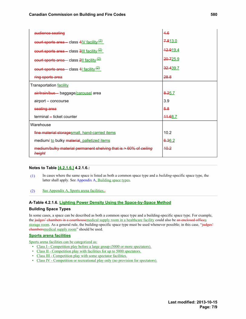
audience seating 4.6
court sports area – class 4IV facility (2) 7.813.0
court sports area – class 3III facility (2) 12.919.4
court sports area – class 2II facility (2) 20.725.9
court sports area – class 1I facility (2) 32.439.7
ring sports area 28.8
Transportation facility
air/train/bus – baggage/carousel area 8.25.7
airport – concourse 3.9
seating area 5.8
terminal – ticket counter 11.68.7
Warehouse
fine material storagesmall, hand-carried items 10.2
medium/ to bulky material, palletized items 6.36.2
medium/bulky material permanent shelving that is > 60% of ceilingheight
10.2
Notes to Table [4.2.1.6.] 4.2.1.6.:
In cases where the same space is listed as both a common space type and a building-specific space type, thelatter shall apply. See Appendix A, Building space types.PROPOSED
CHANGEA-Table4.2.1.6.
(1)PROPOSED CHANGE Table 4.2.1.6. Footnotereferrer
See Appendix A, Sports arena facilities..(2)PROPOSED CHANGE Table 4.2.1.6. Footnotereferrer
A-Table 4.2.1.6. Lighting Power Density Using the Space-by-Space MethodBuilding Space TypesIn some cases, a space can be described as both a common space type and a building-specific space type. For example,the judges’ chambers in a courthousemedical supply room in a healthcare facility could also be an enclosed officeastorage room. As a general rule, the building-specific space type must be used whenever possible; in this case, “judges’chambersmedical supply room” should be used.
Sports arena facilitiesSports arena facilities can be categorized as:
• Class I - Competition play before a large group (5000 or more spectators).• Class II - Competition play with facilities for up to 5000 spectators.• Class III - Competition play with some spectator facilities.• Class IV - Competition or recreational play only (no provision for spectators).
PROPOSED CHANGE Table 4.2.1.6. Footnote
PROPOSED CHANGE Table 4.2.1.6. Footnote
PROPOSED CHANGE Table 4.2.1.6. Footnote
PROPOSED CHANGE Table 4.2.1.6. Footnote
Footnote1
Footnote2
Canadian Commission on Building and Fire Codes 580
Last modified: 2013-10-15Page: 7/9

RATIONALE
ProblemThe lighting power density (LPD) table used with the space-by-space method needs to be updated to reflect currentrecommended illuminance levels as published in the new IES Lighting Handbook, 10th Edition. Further, the LPDs inNECB 2011 are harmonized with those in ASHRAE 90.1 – 2010, which are updated in ASHRAE 90.1-2010addenda (which are expected to be published as ASHRAE 90.1-2013) to reflect current recommended illuminancelevels. Closer harmonization will facilitate design and enforcement in those jurisdictions that reference both NECBand ASHRAE 90.1.
Justification - ExplanationUpdate the lighting power density table to be used with the space-by-space method calculation of interior lightingpower allowance based on the current recommended illuminance levels in the IES Handbook, 10th Edition and toharmonize more closely with ASHRAE 90.1 – 2013 requirements.
Clause 4.2.4.1.(4)(g) is deleted as there are now space types and associated LPDs that address care occupancydesigned to ANSI/IES RP-28.
Cost implicationsSome of the LPDs did not change, some went up (less stringent) due to higher illuminance recommendations in IESHandbook but most went down (more stringent). Overall, as an area weighted average by building type based on2012 construction starts in Canada, the space-by-space LPDs, when applied to derive building area LPDs, wentdown by approximately 8%. In many applications, this will result in no incremental capital cost increase but reducedenergy costs. In applications where there is an incremental capital cost increase, the following example shows thatthe increase is justified.
Assumptions
Hours of Operation 3000
Cost/kWh 0.12
Space type Open office
Size of space 300 m2
No. of luminaires 49
Lumbinaire/ballast combo meeting:
NECB 2011 (Baseline): 2 lamp T12 Electronic 34 W 2800 lumens RS ballast BF .88 LLD .8
Proposed change (Proposed): 2 - T8 32 W std lamp 2850 lumens std instant start ballast BF .87 LLD .85
Annual Energy Cost Savings
W/luminaire-ballast Power (W) Total
Baseline 67 3283
Proposed 60 2940
Canadian Commission on Building and Fire Codes 580
Last modified: 2013-10-15Page: 8/9

Annual Energy Cost Savings = (Baseline power - proposed power in kW) x hrs of operation xCost /kWh
$123.48
Incremental Capital Costs
Units Unit Cost Total
Baseline 49 $104.00 $5,096.00
Proposed 49 $106.00 $5,194.00
Total incremental capital cost = (Baseline costs - proposed costs) $98.00
Enforcement implicationsCloser harmonization with ASHRAE 90.1 will facilitate enforcement in those jurisdictions that reference bothNECB and ASHRAE 90.1.
Who is affectedDesigners, manufacturers, builders, specification writers and building officials.
OBJECTIVE-BASED ANALYSIS OF NEW OR CHANGED PROVISIONS[4.2.1.4.] 4.2.1.4. ([1] 4) no attributions[4.2.1.6.] 4.2.1.6. ([1] 1) [F94-OE1.1]
Canadian Commission on Building and Fire Codes 580
Last modified: 2013-10-15Page: 9/9

Comment
Proposed Change 575Code Reference(s): NECB11 Div.B Table 4.2.1.5.Subject: Interior Lighting PowerTitle: 02 NECB11-DivB-04.02.01.05.-replace-EEB-LPD Bldg Area MethodDescription: The proposed change is intended to update the lighting power densities
used in the building area method calculation of interior lighting powerallowance.
PROPOSED CHANGE
Table [4.2.1.5.] 4.2.1.5.Lighting Power Density by Building Type for Use with the Building Area Method
Forming part of Sentences 4.2.1.5.(1), (4) and (5)
Building Type Lighting Power Density, W/m2
Automotive facility 8.88.6
Convention centre 11.610.9
Courthouse 11.310.9
Dining:
bar lounge/leisure 10.710.9
cafeteria/fast food 9.7
family 9.610.2
Dormitory 6.66.1
Exercise centre 9.59.0
Fire station 7.67.2
Gymnasium 10.810.1
Health-care clinic 9.49.7
Hospital 13.011.3
Hotel / Motel 10.89.4
Library 12.712.8
Manufacturing facility 11.912.6
Motel 9.5
Motion picture theatre 8.98.2
Multi-unit residential building 6.55.5
Canadian Commission on Building and Fire Codes 575
Last modified: 2013-10-15Page: 1/3

Building Type Lighting Power Density, W/m2
Museum 11.411.0
Office 9.78.8
Parking garage 2.72.3
Penitentiary 10.48.7
Performing arts theatre 15.014.9
Police station 10.39.4
Post office 9.4
Religious building 11.310.8
Retail area 15.113.5
School/university 10.79.4
Sports arena 8.49.8
Town hall 9.99.6
Transportation 8.37.5
Warehouse 7.1
Workshop 12.912.8
RATIONALE
ProblemThe lighting power density (LPD) table used with the building area method needs to be updated to reflect currentrecommended illuminance levels as published in the new IES Lighting Handbook, 10th Edition. Further, the LPDs inNECB 2011 are harmonized with those in ASHRAE 90.1 – 2010, which are updated in ASHRAE 90.1-2010addenda (which are expected to be published as ASHRAE 90.1-2013) to reflect current recommended illuminancelevels used as a basis of the LPDs. Harmonization will facilitate design and enforcement in those jurisdictions thatreference both NECB and ASHRAE 90.1.
Justification - ExplanationUpdate the lighting power density table to be used with the building area method calculation of interior lightingpower allowance based on the current recommended illuminance levels in the IES Handbook, 10th Edition and toharmonize with requirements in ASHRAE 90.1 – 2010 and its addenda (which are expected to be published asASHRAE 90.1-2013).
Cost implicationsSome of the LPDs did not change, some went up (less stringent) due to higher illuminance recommendations in IESHandbook but most went down (more stringent). Overall, as an area weighted average by building type based on2012 construction starts in Canada, the LPDs went down by approximately 8%. In many applications, this will result
Canadian Commission on Building and Fire Codes 575
Last modified: 2013-10-15Page: 2/3

in no incremental capital cost increase relative to current practice but reduced energy costs. In applications wherethere is an incremental capital cost increase, the following example shows that the increase is justified.
The example shown is for an open office space which is a common space used to derive the building area methodLPDs:
Assumptions
Hours of Operation 3000
Cost/kWh 0.12
Space type Open office
Size of space 300 m2
No. of luminaires 49
Lumbinaire/ballast combo meeting:
NECB 2011 (Baseline): 2 lamp T12 Electronic 34 W 2800 lumens RS ballast BF .88 LLD .8
Proposed change (Proposed): 2 - T8 32 W std lamp 2850 lumens std instant start ballast BF .87 LLD .85
Annual Energy Cost Savings
W/luminaire-ballast Power (W) Total
Baseline 67 3283
Proposed 60 2940
Annual Energy Cost Savings = (Baseline power - proposed power in kW) x hrs of operation xCost/kWh
$123.48
Incremental Capital Costs
Units Unit Cost Total
Baseline 49 $104.00 $5,096.00
Proposed 49 $106.00 $5,194.00
Total incremental capital cost = (Baseline costs - proposed costs) $98.00
Enforcement implicationsHarmonization with ASHRAE 90.1 will facilitate enforcement in those jurisdictions that reference both NECB andASHRAE 90.1.
Who is affectedDesigners, manufacturers, builders, specification writers and building officials.
OBJECTIVE-BASED ANALYSIS OF NEW OR CHANGED PROVISIONSN/A
Canadian Commission on Building and Fire Codes 575
Last modified: 2013-10-15Page: 3/3
Comment
Proposed Change 585Code Reference(s): NECB11 Div.B 4.2.2.Subject: Interior Lighting ControlsTitle: 04 NECB11-DivB-04.02.02.01.-replace-EEB-Auto Shutoff CtrlsDescription: The proposed change is intended to increase the stringency of the lighting
control requirements by requiring the use of certain lighting controls in morespaces types, shortening times until the lights being automatically reducedor shut off, and introducing manual-on or automatic partial-on controls. Theproposed change also presents the control requirements in a tabular form.
PROPOSED CHANGE
[4.2.2.] 4.2.2. Interior Lighting Controls
[4.2.2.1.] 4.2.2.1. Automatic Lighting Shut-off Controls(See Appendix A.)
[1] --) Except as provided in Sentence (2), for each space in the building, all of the lighting control functions indicated in Sentence (3) and Table 4.2.2.1. shall beimplemented.
[2] --) If the space-by-space method is used for LPD requirements in Article 4.2.1.6., the space types used for determining control requirements in Table 4.2.2.1. shallbe the same space types as used to determine the LPD.
[3] --) Except as provided in Sentence (4), for all spaces in Table 4.2.2.1., there shall be one or more manual lighting controls in the space controlling all of thelighting in the space, where each lighting control device shall[a] --) be readily accessible,[b] --) be located so that the occupants can see some of the controlled lighting when using the control device,
[c] --) control an area less than or equal to 250 m2 for spaces that are less than or equal to 1000 m2, and
[d] --) control an area less than or equal to 1000 m2 for spaces that are greater than 1000 m2.
[4] --) The control device prescribed in Sentence (3) may be located remotely for reasons of safety or security, provided each control device[a] --) has an indicator pilot light integral with or adjacent to the control device, and[b] --) is clearly labeled to identify the controlled lighting.
[5] --) Except as provided in Sentence (6), for spaces requiring controls that are restricted to “Manual On” in Table 4.2.2.1., none of the lighting shall be turned onautomatically.
[6] --) The provisions of Sentence (5) need not apply where “Manual On” operation of the general lighting would endanger the safety or security of the buildingoccupants.
[7] --) For spaces requiring controls that are restricted to “Partial Automatic On” in Table 4.2.2.1., no more than 50% of the lighting power for the general lighting,and none of the other lighting, shall be allowed to be automatically turned on.
[8] --) For spaces requiring Bi-Level Lighting Control in Table 4.2.2.1., the general lighting in the space shall be controlled so as to provide at least one intermediatestep between 30% and 70% inclusive of full lighting power, or continuous dimming, in addition to full on and full off.
[9] --) Except as provided in Sentence (11), for spaces requiring Automatic Daylight Responsive Controls for Sidelighting in Table 4.2.2.1.,[a] --) when the combined input power of all general lighting completely or partially within the primary sidelighted areas is 150 W or greater, the general
lighting in the primary sidelighted areas shall be controlled by photocontrols meeting the requirements of Sentence (10), and[b] --) when the combined input power of all general lighting completely or partially within the primary and secondary sidelighted areas is 300 W or greater,
the general lighting in the primary and secondary sidelighted areas shall be controlled by photocontrols meeting the requirements of Sentence (10).
[10] --) The control device or system required in Sentence (9) shall meet the following criteria:[a] --) the calibration adjustments shall be readily accessible,[b] --) the photocontrol shall reduce electric lighting in response to available daylight using controls with one or more control points between 50% and 70% of
design lighting power, one or more control points between 20% and 40% of design lighting power or the lowest dimming level the technology allows,and a control point that turns off all the controlled lighting, or with using continuous dimming, and
[c] --) the general lighting in the secondary sidelighted area shall be controlled independently of the general lighting in the primary sidelighted area.(See Appendix A.)
[11] --) The following areas need not comply with the provisions of Sentence (9):[a] --) primary sidelighted areas where the vertical projected distance from the top of the windows to the top of any adjacent structure divided by the horizontal
distance from the window to the adjacent structure is greater than or equal to 2,
[b] --) sidelighted areas where the total glazing is less than 2 m2, or[c] --) retail spaces.
[12] --) Except as provided in Sentence (14), for spaces requiring Automatic Daylight Responsive Controls for Toplighting in Table 4.2.2.1., when the combined inputpower of all general lighting completely or partially within the daylight areas under skylights and under roof monitors is 150 W or greater, the general lightingin the daylight area shall be controlled by photocontrols meeting the requirements of Sentence (12).
[13] --) The control device or system required in Sentence (12) shall meet the following criteria:[a] --) the calibration adjustments shall be readily accessible,[b] --) the photocontrol shall reduce electric lighting in response to available daylight using controls with one or more control points between 50% and 70% of
design lighting power, one or more control points between 20% and 40% of design lighting power or the lowest dimming level the technology allows,and a control point that turns off all the controlled lighting, or with using continuous dimming, and
[c] --) the general lighting in overlapping toplighted and sidelighted daylight areas shall be controlled together with the general lighting in the daylight areasunder skylights or roof monitors.
(See Appendix A.)
[14] --) The following areas need not comply with the provisions of Sentence (12):
PROPOSEDCHANGEA-4.2.2.1.
Canadian Commission on Building and Fire Codes 585
Last modified: 2013-10-26Page: 1/11

[a] --) daylight areas under skylights and roof monitors where it is documented that existing adjacent structures or natural objects block direct sunlight for morethan 1500 daytime hours per year between the hours of 8 am and 4 pm,
[b] --) daylight areas where the skylight and roof monitors visual transmittance (VT) is less than 0.4, or[c] --) spaces in buildings located above the 55°N latitude where the input power of the general lighting within daylight areas is less than 200 W.
[15] --) Except as provided in Sentence (16), for spaces requiring controls that are “Automatic Partial Off” in Table 4.2.2.1., the general lighting power in the spaceshall be automatically reduced 50% or more within 20 minutes of all occupants leaving the space.
[16] --) Spaces meeting the following criteria need not comply with the provisions of Sentence (15):[a] --) the lighting power density is not greater than 8.6 W/m2,[b] --) the space is lighted by high-intensity discharge (HID) lamps, and[c] --) the general lighting power in the space is automatically reduced by 30% or more within 20 minutes of all occupants leaving the space.
[17] --) Except as provided in Sentence (18), for spaces requiring controls that are “Automatic Full Off” in Table 4.2.2.1., all lighting shall be shut off within 20minutes of all occupants leaving the space using automatic controls, where each automatic control device controls an area not greater than 50 m2.
[18] --) The following need not comply with the provisions of Sentence (17),[a] --) general lighting and task lighting in shop and laboratory classrooms,[b] --) general lighting and task lighting in spaces where automatic shutoff would endanger the safety or security of the building occupants, or[c] --) lighting required for continuous operation.
[19] --) Except as provided in Sentence (22), for spaces requiring controls that are “Scheduled Shut Off” in Table 4.2.2.1., all lighting in the space shall beautomatically shut off during periods when the space is scheduled to be unoccupied using control devices meeting the requirements of Sentence (20) that areeither[a] --) a time-of-day operated control device that automatically turns the lighting off at specific programmed times, or[b] --) a signal from another automatic control device or alarm/security system.
[20] --) The control device or system required in Sentence (19) shall provide independent control sequences that[a] --) control the lighting for an area of no more than 2500 m2, and[b] --) includes no more than one floor.
[21] --) Any manual control installed to override the “Scheduled Shut Off” control device or system required in Sentence (19) shall[a] --) not turn the lighting on for more than 2 hours per activation during scheduled off periods, and
[b] --) not control an area greater than 500 m2.
[22] --) The following need not comply with the provisions of Sentence (19)[a] --) lighting required for continuous operation,[b] --) spaces where patient care is rendered, and[c] --) spaces where automatic shut off would endanger the safety or security of the building occupants.
Table [4.2.2.1.]Minimum Lighting Control Requirements (1)
Manualcontrol
see4.2.2.1.(3)
Restrictedto Manual
ON see4.2.2.1.(5)
Restrictedto Partial
AutomaticON see
4.2.2.1.(7)
Bi-levelLightingControl
see4.2.2.1.(8)
AutomaticDaylight
ResponsiveControls forSidelightingsee 4.2.2.1.
(9) (2)
AutomaticDaylight
ResponsiveControls forToplighting
see4.2.2.1.(12) (2)
AutomaticPartial
OFF see4.2.2.1.
(15)
AutomaticFull OFF
see4.2.2.1.(17)
ScheduledShutoff
see4.2.2.1.(19)
Common Space Types (3)
Atrium
that is < 6 m inheight
X a a X X b b
that is ≥ 6 m and ≤12 m in height
X a a X X X b b
that is > 12 m inheight
X a a X X X b b
Audience seatingarea - permanent
for auditorium X a a X X X b b
for conventioncentre
X a a X X X b b
for gymnasium X a a X X X b b
for motion picturetheatre
X a a X X X b b
for penitentiary X a a X X b b
for performing artstheatre
X a a X X X b b
for religiousbuilding
X a a X X X b b
PROPOSED CHANGE Table Footnote
PROPOSED CHANGE Table FootnotePROPOSED CHANGE Table Footnote
PROPOSED CHANGE Table Footnote
Canadian Commission on Building and Fire Codes 585
Last modified: 2013-10-26Page: 2/11

Manualcontrol
see4.2.2.1.(3)
Restrictedto Manual
ON see4.2.2.1.(5)
Restrictedto Partial
AutomaticON see
4.2.2.1.(7)
Bi-levelLightingControl
see4.2.2.1.(8)
AutomaticDaylight
ResponsiveControls forSidelightingsee 4.2.2.1.
(9) (2)
AutomaticDaylight
ResponsiveControls forToplighting
see4.2.2.1.(12) (2)
AutomaticPartial
OFF see4.2.2.1.
(15)
AutomaticFull OFF
see4.2.2.1.(17)
ScheduledShutoff
see4.2.2.1.(19)
for sports arena X a a X X b b
other X a a X X b b
Banking activity areaand offices
X a a X X X b b
Classroom/lecturehall/training room
for penitentiary X a a X X X X
other X a a X X X X
Computer / serverroom
X a a X X X b b
Conference/meeting/multipurpose room
X a a X X X X
Confinement cell X a a X X X b b
Copy/print room X a a X X X X
Corridor / transitionarea
for careoccupanciesdesigned toANSI/IES RP-28(and used primarilyby residents)
X X X X b b
for hospital X X X b b b
for manufacturingfacility
X X X X b b
other X X X
b b
Courtroom X a a X X X b b
Dining Area
for bar lounge /leisure dining
X a a X X X b b
for cafeteria or fastfood dining
X a a X X X b b
for family dining X a a X X X b b
for careoccupanciesdesigned toANSI/IES RP-28(and used primarilyby residents)
X a a X X X b b
for penitentiary X a a X X X b b
other X a a X X X b b
Electrical/Mechanicalroom
X X X
Emergency vehiclegarage
X a a X X b b
Food preparationarea
X a a X X X b b
Guest room See Sentence 4.2.2.3.(2)
Laboratory
PROPOSED CHANGE Table FootnotePROPOSED CHANGE Table Footnote
Canadian Commission on Building and Fire Codes 585
Last modified: 2013-10-26Page: 3/11

Manualcontrol
see4.2.2.1.(3)
Restrictedto Manual
ON see4.2.2.1.(5)
Restrictedto Partial
AutomaticON see
4.2.2.1.(7)
Bi-levelLightingControl
see4.2.2.1.(8)
AutomaticDaylight
ResponsiveControls forSidelightingsee 4.2.2.1.
(9) (2)
AutomaticDaylight
ResponsiveControls forToplighting
see4.2.2.1.(12) (2)
AutomaticPartial
OFF see4.2.2.1.
(15)
AutomaticFull OFF
see4.2.2.1.(17)
ScheduledShutoff
see4.2.2.1.(19)
for classroom X a a X X X X b b
other X a a X X X b b
Laundry/washingarea
X a a X X X b b
Loading dock, interior X a a X X b b
Lobby
for careoccupanciesdesigned toANSI/IES RP-28(and used primarilyby residents)
X X X X b b
for elevator X X X b b
for hotel X X X b b
for motion picturetheatre
X X X b b
for performing artstheatre
X X X X b b
other X X X X b b
Locker room X a a X X X X
Lounge/breakroom
for healthcarefacility
X a a X X X X
other X a a X X X X
Office
enclosed and ≤ 25m2
X a a X X X X
enclosed and > 25m2
X a a X X X b b
open plan X a a X X X b b
Parking area, interior See Article 4.2.2.2.
Pharmacy area X a a X X X b b
Sales Area (4) X a a X X b b
Seating area, general X a a X X b b
Stairway The space containing the stairway shall determine the LPD and control requirements for the stairway.
Stairwell X X X X X b b
Storage room
< 5 m2 X b b
≥ 5 m2 and ≤100m2
X a a X X X
other X a a X X X b b
Vehicularmaintenance area
X a a X X X b b
Washroom
PROPOSED CHANGE Table FootnotePROPOSED CHANGE Table Footnote
PROPOSED CHANGE Table Footnote
Canadian Commission on Building and Fire Codes 585
Last modified: 2013-10-26Page: 4/11

Manualcontrol
see4.2.2.1.(3)
Restrictedto Manual
ON see4.2.2.1.(5)
Restrictedto Partial
AutomaticON see
4.2.2.1.(7)
Bi-levelLightingControl
see4.2.2.1.(8)
AutomaticDaylight
ResponsiveControls forSidelightingsee 4.2.2.1.
(9) (2)
AutomaticDaylight
ResponsiveControls forToplighting
see4.2.2.1.(12) (2)
AutomaticPartial
OFF see4.2.2.1.
(15)
AutomaticFull OFF
see4.2.2.1.(17)
ScheduledShutoff
see4.2.2.1.(19)
for careoccupanciesdesigned toANSI/IES RP-28(and used primarilyby residents)
X X X X
other X X X X
Workshop X a a X X X b b
Building Specific Space Types (3)
Care occupanciesdesigned to ANSI/IESRP-28
chapel (usedprimarily byresidents)
X a a X X X b b
recreation room(used primarily byresidents)
X a a X X X b b
Convention centre
Exhibit space X a a X X X b b
Dormitory - LivingQuarters
X
Fire Station -Sleeping Quarters
X
Gymnasium/fitnesscentre
exercise area X a a X X X b b
playing area X a a X X X b b
Healthcare facility
exam/treatmentroom
X X X X b b
imaging room X X b b
medical supplyroom
(See Storage Room in Common Space Types for control requirements)
nursery X X X X b b
nurses' station X X X X b b
operating room X X b b
patient room X X X X b b
physical therapyroom
X X X X b b
recovery room X X X X b b
Library
reading area X a a X X X b b
stacks X a a X X X X b b
Manufacturing Facility
detailedmanufacturing area
X a a X X X b b
equipment room X a a X X X b b
PROPOSED CHANGE Table FootnotePROPOSED CHANGE Table Footnote
PROPOSED CHANGE Table Footnote
Canadian Commission on Building and Fire Codes 585
Last modified: 2013-10-26Page: 5/11

Manualcontrol
see4.2.2.1.(3)
Restrictedto Manual
ON see4.2.2.1.(5)
Restrictedto Partial
AutomaticON see
4.2.2.1.(7)
Bi-levelLightingControl
see4.2.2.1.(8)
AutomaticDaylight
ResponsiveControls forSidelightingsee 4.2.2.1.
(9) (2)
AutomaticDaylight
ResponsiveControls forToplighting
see4.2.2.1.(12) (2)
AutomaticPartial
OFF see4.2.2.1.
(15)
AutomaticFull OFF
see4.2.2.1.(17)
ScheduledShutoff
see4.2.2.1.(19)
extra high bay area(> 15 m floor-to-ceiling height)
X a a X X X b b
high bay area(7.5-15 m floor-to-ceiling height)
X a a X X X b b
low bay area (< 7.5floor-to-ceilingheight)
X a a X X X b b
Museum
general exhibitionarea
X a a X X X b b
restoration room X a a X X X b b
Performing artstheatre - dressingroom
X a a X X X X
Post office - sortingarea
X a a X X X X b b
Religious buildings
fellowship hall X a a X X X b b
Worship/pulpit/choirarea
X a a X X X b b
Retail facilities
dressing/fittingroom
X a a X X X
mall concourse X a a X X X b b
Sports arena -playing area
Class I facility (5) X a a X X X b b
Class II facility (5) X a a X X X b b
Class III facility (5) X a a X X X b b
Class IV facility (5) X a a X X X b b
TransportationFacility
baggage/carouselarea
X a a X X b b
airport concourse X a a X X b b
terminal ticketcounter
X a a X X X b b
Warehouse - StorageArea
medium to bulky,palletized items
X a a X X X X b b
smaller, hand-carried items (5)
X a a X X X X b b
Notes to Table [4.2.2.1.] :
PROPOSED CHANGE Table FootnotePROPOSED CHANGE Table Footnote
PROPOSED CHANGE Table Footnote
PROPOSED CHANGE Table Footnote
PROPOSED CHANGE Table Footnote
PROPOSED CHANGE Table Footnote
PROPOSED CHANGE Table Footnote
Canadian Commission on Building and Fire Codes 585
Last modified: 2013-10-26Page: 6/11

The control functions listed in Table 4.2.2.1. shall be implemented in accordance with the descriptions found in the referenced Sentences within Article 4.2.2.1. Foreach Space Type:
• all lighting controls with an "X" entry shall be implemented,• at least one of the lighting controls with an "a" entry (when present) shall be implemented, and• at least one of the lighting controls with a "b" entry (when present) shall be implemented
(1)PROPOSED CHANGE Table Footnotereferrer
Automatic Daylight Responsive Controls are mandatory only if the requirements of the specified Sentences are met.(2)PROPOSED CHANGE Table Footnotereferrer
In cases where both a common space type and a building area specific space type are listed, the building area specific space type shall apply.(3)PROPOSED CHANGE Table Footnotereferrer
For accent lighting, see Sentence 4.2.2.3.(1).(4)PROPOSED CHANGE Table Footnotereferrer
See Appendix A.(5)PROPOSED CHANGE Table Footnotereferrer
[23] 1) Except as provided in Sentence (4), interior lighting in buildings shall be controlled with automatic control devices to shut off building lighting in all spaces.
[24] 2) The automatic control devices referred to in Sentence (1) shall be[a] a) time-of-day operated control devices that turn lighting off at scheduled times,[b] b) occupant sensors that turn lighting off within 30 minutes of a space being unoccupied, or[c] c) a signal from another control or alarm system that indicates the area is unoccupied.
[25] 3) A time-of-day operated control device provided in accordance with Clause (2)(a) shall not have the capability of being overridden by more than two hours.
[26] 4) The requirements of Sentence (1) shall not apply to[a] a) lighting required round the clock due to operational requirements,[b] b) lighting in spaces where patient care is rendered, and[c] c) lighting in spaces where an automatic shut-off would endanger the safety or security of its occupants.
[4.2.2.2.] 4.2.2.2. Lighting Controls in Enclosed Spaces[1] 1) Each enclosed space shall have at least one control device that allows the independent control of general lighting within
[a] a) a maximum area of 250 m2 in the case of an enclosed space that is 1 000 m2 or less in area, or
[b] b) a maximum area of 1 000 m2 in the case of an enclosed space greater than 1 000 m2 in area.
[2] 2) Except as provided in Sentence (3), the control device required in Sentence (1) shall be[a] a) an occupant sensor that automatically extinguishes lighting in the following enclosed spaces within 30 minutes of their being unoccupied:
[i] i) classrooms and lecture halls, excluding shop and laboratory classrooms,[ii] ii) conference, meeting, and training rooms,
[iii] iii) employee lunch and break rooms,[iv] iv) storage and supply rooms up to 100 m2,
[v] v) rooms used for document copying and printing,[vi] vi) office spaces up to 25 m2,
[vii] vii) washrooms, and[viii] viii) dressing, locker, and fitting rooms, or
[b] b) a control device that is activated either manually by an occupant or automatically by a sensor in all other enclosed spaces not listed in Clause (a).
[3] 3) Bathrooms in guest rooms of commercial temporary lodgings shall have a control device installed that automatically extinguishes the bathroom lighting, exceptfor night lighting not exceeding 5 W, within 60 minutes of being unoccupied. (See Appendix A.)
[4.2.2.3.] 4.2.2.3. Additional Requirements for Lighting Controls[1] 1) Except as provided in Sentences (2) and (4) to (7), lighting controls provided in accordance with Articles 4.2.2.1. and 4.2.2.2. shall be
[a] a) located next to the main entrance or entrances to the room or space whose lighting they control,[b] b) located such that there is a clear line of sight from the controls to the lighted area, and[c] c) readily accessible to persons occupying or using the room or space.
[2] 2) Lighting controls are permitted to be installed in remote locations where[a] a) controls are automatic,[b] b) controls are programmable, or[c] c) it is desirable, for security or safety reasons, that lighting be under the control of staff or building management (see Appendix A).
[3] 3) Lighting controls installed in remote locations shall have[a] a) an indicator pilot light that is part of or next to the control device, and[b] b) a label clearly identifying which lighting they control.
[4] 4) Supplemental task lighting, including permanently installed undershelf or undercabinet lighting, shall have a control device that is[a] a) integral to the luminaires, or[b] b) readily accessible and located so that the occupant can see the controlled lighting.
(See Appendix A.)
[5] 5) Guest rooms in commercial temporary lodgings shall have one or more control devices at the entrance door that collectively control all permanently installedluminaires, except those in the bathroom(s). (See Appendix A and A-4.2.2.2.(3) and 4.2.2.3.(5) in Appendix A.)
[6] 6) Hotel suites shall have control devices meeting the requirements of Sentence (5)[a] a) at the entrance to each room, or[b] b) at the primary entrance to the suite.
(See Appendix A.)
[7] 7) The following lighting applications shall have separate control devices:[a] a) display or accent lighting,[b] b) lighting in cases used for display purposes,[c] c) lighting for non-visual applications, such as plant growth and food warming, and
Footnote1
Footnote2Footnote3Footnote4Footnote5
PROPOSEDCHANGEA-4.2.2.2.(3)and4.2.2.3.(5)
PROPOSEDCHANGEA-4.2.2.3.(2)(c)
PROPOSEDCHANGEA-4.2.2.3.(4)to(7)
PROPOSEDCHANGEA-4.2.2.3.(4)to(7)
PROPOSEDCHANGEA-4.2.2.2.(3)and4.2.2.3.(5)
PROPOSEDCHANGEA-4.2.2.3.(4)to(7)
Canadian Commission on Building and Fire Codes 585
Last modified: 2013-10-26Page: 7/11

[d] d) lighting equipment that is for sale or for demonstrations in lighting education (see Appendix A).(See Appendix A.)
[8] 8) Where lighting controls are grouped, each control shall be labelled to indicate which area it controls.
[4.2.2.4.] 4.2.2.4. Automatic Daylighting Controls for Toplighting(See Appendix A.)
[1] 1) Except as provided in Sentence (2), when the total daylighted area under skylights, as determined in accordance with Article 4.2.2.5., plus the total daylightedarea under rooftop monitors, as determined in accordance with Article 4.2.2.6., in an enclosed space exceeds 400 m2, the electric general lighting over thedaylighted area shall be separately controlled by at least one multi-level photocontrol having the following characteristics:[a] a) the light sensor for the photocontrol shall be remote from where calibration adjustments are made,[b] b) the means for calibration adjustments shall be readily accessible, and[c] c) the multi-level photocontrol shall reduce electric general lighting in response to available daylight with at least two control levels, one being greater
than or equal to 35% and less than 70% of design lighting power and the other being less than 35%, including off, of design lighting power.(See Appendix A.)
[2] 2) The requirements of Sentence (1) shall not apply to[a] a) daylighted areas under skylights where it can be demonstrated that existing adjacent buildings or natural objects block direct beam sunlight for more
than 1 500 daytime hours per year between 8 a.m. and 4 p.m. local time,[b] b) daylighted areas where the skylight effective aperture, as determined in accordance with Article 4.2.2.7., is less than 0.006 (0.6%), and
[c] c) enclosed spaces less than 800 m2 in area in buildings located above the 55°N latitude.
[4.2.2.5.] 4.2.2.5. Determination of Daylighted Area Under Skylights
[4.2.2.6.] 4.2.2.6. Determination of Daylighted Area Under Rooftop Monitors
[4.2.2.7.] 4.2.2.7. Calculation of Skylight Effective Aperture
[4.2.2.8.] 4.2.2.8. Automatic Daylighting Controls for Primary Sidelighted Areas(See Appendix A.)
[1] 1) Except as provided in Sentence (2), when the combined primary sidelighted areas, as determined in accordance with Article 4.2.2.9., in an enclosed spaceexceed 100 m2, the electric general lighting over the primary sidelighted area shall be separately controlled by at least one multi-level photocontrol having thefollowing characteristics:[a] a) the light sensor for the photocontrol shall be remote from where calibration adjustments are made,[b] b) the means for calibration adjustments shall be readily accessible, and[c] c) the multi-level photocontrol shall reduce electric general lighting in response to available daylight with at least two control levels, one being greater
than or equal to 35% and less than 70% of design lighting power and the other being less than 35%, including off, of design lighting power.(See A-4.2.2.4.(1) in Appendix A.)
[2] 2) The requirements of Sentence (1) shall not apply to[a] a) primary sidelighted areas where the tops of the existing adjacent buildings are at least twice as high above the windows as their distance away from the
windows,[b] b) primary sidelighted areas where the sidelighting effective aperture, as determined in accordance with Article 4.2.2.10., is less than 0.1 (10%), and[c] c) retail spaces.
[4.2.2.9.] 4.2.2.9. Determination of Primary Sidelighted Areas
[4.2.2.10.] 4.2.2.10. Calculation of Sidelighting Effective Aperture
A-4.2.2.1. Automatic Control Devices.“Occupant sensors”Automatic control devices designed to align lighting use with space occupancy may include occupant sensors such as refers to motion sensors, presencesensors, vacancy sensors, and other similar devices.Products that allow for on-site calibration of their sensitivity are recommended as they allow situations of false tripping to be managed.Using controllable circuit breakers as a means of automatic control is only permitted when they are connected to sensors.
A-4.2.2.1.(10) and (13) Automatic Daylighting Controls.Calibration adjustments are generally made with a remotely mounted controller, but may also be made with handheld devices that communicate with the photocontrol sensor orother system devices, such as continuous dimming devices.Continuous dimming is not required; the minimum requirement is stepped dimming controls with at least two control levels, which can be accomplished by selective lampextinguishing or stepped dimming ballasts.
A-Table 4.2.2.1.Controls meeting the requirements for Partial Automatic ON in Sentence 4.2.2.1.(7) also comply with the requirements for Bi-level Lighting Control in Sentence 4.2.2.1.(8).Controls meeting the requirements for Full Off in Sentence 4.2.2.1.(17) also comply with the requirements for Automatic Partial OFF in Sentence 4.2.2.1.(15).In a warehouse – storage area, the space used for smaller, hand-carried items is sometimes known as a "picking area".
Sports Arena FacilitiesSports arena facilities can be categorized as:
• Class I - Competition play before a large group (5000 or more spectators).• Class II - Competition play with facilities for up to 5000 spectators.• Class III - Competition play with some spectator facilities.• Class IV - Competition or recreational play only (no provision for spectators).
PROPOSEDCHANGEA-4.2.2.3.(7)(d)
PROPOSEDCHANGEA-4.2.2.3.(4)to(7)
PROPOSEDCHANGEA-4.2.2.4.
PROPOSEDCHANGEA-4.2.2.4.(1)
PROPOSEDCHANGEA-4.2.2.8.
PROPOSEDCHANGEA-4.2.2.4.(1)
Canadian Commission on Building and Fire Codes 585
Last modified: 2013-10-26Page: 8/11

RATIONALE
ProblemThe current lighting control requirements are out of line with current standard practice.
Justification - ExplanationAlign the provisions with the direction of current technologies and standard practices by making them more harmonized with those of ASHRAE 90.1-2010 and itsaddenda (which are expected to be published as ASHRAE 90.1-2013).
Cost implicationsThe analysis of the cost implications for two space types and two example sets of buildings are shown below:
Open Office Area :
Assumptions
Hours of Operation 2932.8
Energy Savings 15%
Cost/kWh $0.12
Annual Energy Cost Savings
m2 LPD (W/m2) Power (W) Total
Zone size 10 m x 25 m 250.0 10.6 2650
Annual Energy Cost Savings = Power in kW x hours of operation x Energy Savings x Cost /kWh $139.89
Incremental Capital Costs
Units Source Unit Cost Total
Original Controls
Added Manual Control 1 RSM - CDN avg $ 135.38 $135.38
Total Cost for 250 m2 zone with local manual control (total incremental capital cost) $135.38
NB: RSM – is RSMeans 2010, Canadian average
Enclosed Office:
Assumptions
Hours of Operation 2932.8
Energy Savings 10%
Cost/kWh $0.12
Annual Energy Cost Savings
m2 LPD (W/m2) Power (W) Total
Zone size 5 m x 5 m 25.0 12.0 300
Annual Energy Cost Savings = Power in kW x hours of operation x Energy Savings x Cost /kWh $10.56
Incremental Capital Costs
Units Source Unit Cost Total
Original Controls
Added Manual Control 1 RSM - CDN avg $ 135.38 $135.38
Total Cost for 25 m2 zone with local manual control (total incremental capital cost) $135.38
Canadian Commission on Building and Fire Codes 585
Last modified: 2013-10-26Page: 9/11

NB: RSM – is RSMeans 2010, Canadian average
Automatic Daylighting Controls
Sidelighting Controls
Assumptions
Hours of Operation 2932.8
Energy Savings 40%
Cost/kWh $0.12
Open office area 10 m x 10 m
No. of sides with windows 1
Head height 2.7 m
Annual Energy Cost Savings
m2 LPD (W/m2) Power (W) Total
Sidelighted area 2.7 x 10 27.0 10.6 286.2
Annual Energy Cost Savings = Power in kW x hours of operation x Energy Savings x Cost /kWh $40.29
Incremental Capital Costs
Units Source Unit Cost Total
Original Controls 1 photocell - 3 levels
Added relay 1 RSM - CDN avg $ 95.05 $95.05
Total Cost for 27.0 m2 zone with incremental daylight control (total incremental capital cost) $95.05
NB: RSM – is RSMeans 2010, Canadian average
Toplighting Controls
Assumptions
Hours of Operation 2932.8
Energy Savings 0.4
Cost/kWh 0.12
Open office area 20 m x 20 m
No. of skylights 4
Ceiling height 4 m
Annual Energy Cost Savings
m2 LPD (W/m2) Power (W) Total
Sidelighted area 0.7 x 4 x 0.7 x 4 31.4 10.6 332.416
Annual Energy Cost Savings = Power in kW x hours of operation x Energy Savings x Cost /kWh $46.80
Incremental Capital Costs
Units Source Unit Cost Total
Original Controls 4 photocells - 3 levels
Added relay each area 4 RSM - CDN avg $ 95.05 $380.20
Total Cost for 31.4 m2 of toplighted area with incremental daylight control (total incremental capital cost) $380.20
NB: RSM – is RSMeans 2010, Canadian average
Canadian Commission on Building and Fire Codes 585
Last modified: 2013-10-26Page: 10/11

Enforcement implicationsCloser harmonization with ASHRAE 90.1-2010 and its addenda (which are expected to be published as ASHRAE 90.1-2013) will facilitate enforcement in thosejurisdictions that reference both NECB and ASHRAE 90.1.
Putting these requirements into a tabular format makes the provisions clearer and easier to enforce.
Who is affectedDesigners, manufacturers, builders, specification writers and building officials.
OBJECTIVE-BASED ANALYSIS OF NEW OR CHANGED PROVISIONS[4.2.2.1.] -- ([1] --) [F94-OE1.1][4.2.2.1.] -- ([2] --) [F94-OE1.1][4.2.2.1.] -- ([3] --) [F94-OE1.1][4.2.2.1.] -- ([4] --) no attributions[4.2.2.1.] -- ([5] --) [F94-OE1.1][4.2.2.1.] -- ([6] --) no attributions[4.2.2.1.] -- ([7] --) [F94-OE1.1][4.2.2.1.] -- ([8] --) [F94-OE1.1][4.2.2.1.] -- ([9] --) [F94-OE1.1][4.2.2.1.] -- ([10] --) [F94-OE1.1][4.2.2.1.] -- ([11] --) no attributions[4.2.2.1.] -- ([12] --) [F94-OE1.1][4.2.2.1.] -- ([13] --) [F94-OE1.1][4.2.2.1.] -- ([14] --) no attributions[4.2.2.1.] -- ([15] --) [F94-OE1.1][4.2.2.1.] -- ([16] --) no attributions[4.2.2.1.] -- ([17] --) [F94-OE1.1][4.2.2.1.] -- ([18] --) no attributions[4.2.2.1.] -- ([19] --) [F94-OE1.1][4.2.2.1.] -- ([20] --) [F94-OE1.1][4.2.2.1.] -- ([21] --) [F94-OE1.1][4.2.2.1.] -- ([22] --) no attributions[4.2.2.1.] 4.2.2.1. ([23] 1) [F94-OE1.1][4.2.2.1.] 4.2.2.1. ([24] 2) [F94-OE1.1][4.2.2.1.] 4.2.2.1. ([25] 3) [F94-OE1.1][4.2.2.1.] 4.2.2.1. ([26] 4) no attributions[4.2.2.2.] 4.2.2.2. ([1] 1) [F94-OE1.1][4.2.2.2.] 4.2.2.2. ([2] 2) [F94-OE1.1][4.2.2.2.] 4.2.2.2. ([3] 3) [F94-OE1.1][4.2.2.3.] 4.2.2.3. ([1] 1) [F94-OE1.1][4.2.2.3.] 4.2.2.3. ([2] 2) no attributions[4.2.2.3.] 4.2.2.3. ([3] 3) [F94-OE1.1][4.2.2.3.] 4.2.2.3. ([4] 4) [F94-OE1.1][4.2.2.3.] 4.2.2.3. ([5] 5) [F94-OE1.1][4.2.2.3.] 4.2.2.3. ([6] 6) [F94-OE1.1][4.2.2.3.] 4.2.2.3. ([7] 7) [F94-OE1.1][4.2.2.3.] 4.2.2.3. ([8] 8) [F94-OE1.1][4.2.2.4.] 4.2.2.4. ([1] 1) [F94-OE1.1][4.2.2.4.] 4.2.2.4. ([2] 2) no attributions[4.2.2.5.] 4.2.2.5. ([1] 1) [F94-OE1.1][4.2.2.5.] 4.2.2.5. ([2] 2) [F94-OE1.1][4.2.2.6.] 4.2.2.6. ([1] 1) [F94-OE1.1][4.2.2.6.] 4.2.2.6. ([2] 2) [F94-OE1.1][4.2.2.7.] 4.2.2.7. ([1] 1) [F94-OE1.1][4.2.2.8.] 4.2.2.8. ([1] 1) [F94-OE1.1][4.2.2.8.] 4.2.2.8. ([2] 2) no attributions[4.2.2.9.] 4.2.2.9. ([1] 1) [F94-OE1.1][4.2.2.9.] 4.2.2.9. ([2] 2) [F94-OE1.1][4.2.2.9.] 4.2.2.9. ([3] 3) [F94-OE1.1][4.2.2.9.] 4.2.2.9. ([4] 4) [F94-OE1.1][4.2.2.10.] 4.2.2.10. ([1] 1) [F94-OE1.1]
Canadian Commission on Building and Fire Codes 585
Last modified: 2013-10-26Page: 11/11

Comment
Proposed Change 590Code Reference(s): NECB11 Div.B 4.2.2.Subject: Interior Lighting ControlsTitle: 05 NECB11-DivB-04.02.02.02.-insert-EEB-Parking CtrlsDescription: The proposed change is intended to add lighting control requirements for
storage garages.
PROPOSED CHANGE
[4.2.2.] 4.2.2. Interior Lighting Controls
[4.2.2.1.] 4.2.2.1. Automatic Lighting Shut-off Controls
[4.2.2.2.] --- Lighting Controls in Storage Garages[1] --) Except as provided in Sentence (4), lighting in a storage garage shall be divided into zones no larger
than 360 m2 and the lighting power in each zone shall be automatically reduced by at least 30% whenthere is no activity detected within a lighting zone for 20 minutes.
[2] --) Lighting for covered vehicle entrances and exits from storage garages shall be separately controlled bya device that automatically reduces the lighting by at least 50% from sunset to sunrise. (See AppendixA.)
[3] --) Except as provided in Sentence (4), the power to luminaires within 6.1 m of any perimeter wallstructure that has a net opening to wall ratio of at least 40% and no exterior obstructions within 6.1 mshall be automatically reduced in response to daylight.
[4] --) Daylight transition zones and ramps without parking need not comply with the provisions of Sentences(1) and (3).
[4.2.2.3.] 4.2.2.2. Lighting Controls in Enclosed Spaces
[4.2.2.4.] 4.2.2.3. Additional Requirements for Lighting Controls
[4.2.2.5.] 4.2.2.4. Automatic Daylighting Controls for Toplighting
[4.2.2.6.] 4.2.2.5. Determination of Daylighted Area Under Skylights
[4.2.2.7.] 4.2.2.6. Determination of Daylighted Area Under Rooftop Monitors
[4.2.2.8.] 4.2.2.7. Calculation of Skylight Effective Aperture
[4.2.2.9.] 4.2.2.8. Automatic Daylighting Controls for Primary Sidelighted Areas
[4.2.2.10.] 4.2.2.9. Determination of Primary Sidelighted Areas
[4.2.2.11.] 4.2.2.10. Calculation of Sidelighting Effective Aperture
A-4.2.2.2.(2) Covered Vehicle Entrances and Exits from Storage Garages.At night, a transition zone of mid luminance is needed when traveling from a high luminance zone (garage) to a lowluminance zone (street), and vice versa. This mid luminance zone will have lower electrical lighting intensity than thehigh luminance zone and thus will save energy.
Canadian Commission on Building and Fire Codes 590
Last modified: 2013-10-15Page: 1/3

RATIONALE
ProblemRequirements for lighting controls for storage garages are not explicitly defined. Requirements for storage garagesare included in ASHRAE 90.1-2010 and its addenda (which are expected to be published as ASHRAE 90.1-2013).Harmonization will facilitate design and enforcement in those jurisdictions that reference both NECB and ASHRAE90.1.
Justification - ExplanationAdd new requirements and harmonize with requirements in ASHRAE 90.1 – 2010 and its addenda (which areexpected to be published as ASHRAE 90.1-2013).
Cost implicationsThe analysis of the cost implications is shown below.
Assumptions
Hours of Operation 8760
Energy Savings 40%
Cost/kWh $0.12
Annual Energy Cost Savings
m2 LPD (W/m2) Power (W) Total
Zone size 18 m x 20 m max 360.0 2.04 734.4
Annual Energy Cost Savings = Power in kW x hours of operation x Energy Savings x Cost /kWh $308.80
Incremental Capital Costs
Units Source Unit Cost Total
Original Controls
Added Automatic Controls & luminaire ballasts 1 RSM - CDN avg $ 704.02 $704.02
Total Cost for 360 m2 zone with automatic controls (total incremental capital cost) $704.02
NB: RSM – is RSMeans 2010, Canadian average
Enforcement implicationsHarmonization with ASHRAE 90.1 will facilitate enforcement in those jurisdictions that reference both NECB andASHRAE 90.1.
Who is affectedDesigners, manufacturers, builders, specification writers and building officials.
Canadian Commission on Building and Fire Codes 590
Last modified: 2013-10-15Page: 2/3

OBJECTIVE-BASED ANALYSIS OF NEW OR CHANGED PROVISIONS[4.2.2.1.] 4.2.2.1. ([1] 1) [F94-OE1.1][4.2.2.1.] 4.2.2.1. ([2] 2) [F94-OE1.1][4.2.2.1.] 4.2.2.1. ([3] 3) [F94-OE1.1][4.2.2.1.] 4.2.2.1. ([4] 4) no attributions[4.2.2.2.] -- ([1] --) [F94-OE1.1][4.2.2.2.] -- ([2] --) [F94-OE1.1][4.2.2.2.] -- ([3] --) [F94-OE1.1][4.2.2.2.] -- ([4] --) no attributions[4.2.2.3.] 4.2.2.2. ([1] 1) [F94-OE1.1][4.2.2.3.] 4.2.2.2. ([2] 2) [F94-OE1.1][4.2.2.3.] 4.2.2.2. ([3] 3) [F94-OE1.1][4.2.2.4.] 4.2.2.3. ([1] 1) [F94-OE1.1][4.2.2.4.] 4.2.2.3. ([2] 2) no attributions[4.2.2.4.] 4.2.2.3. ([3] 3) [F94-OE1.1][4.2.2.4.] 4.2.2.3. ([4] 4) [F94-OE1.1][4.2.2.4.] 4.2.2.3. ([5] 5) [F94-OE1.1][4.2.2.4.] 4.2.2.3. ([6] 6) [F94-OE1.1][4.2.2.4.] 4.2.2.3. ([7] 7) [F94-OE1.1][4.2.2.4.] 4.2.2.3. ([8] 8) [F94-OE1.1][4.2.2.5.] 4.2.2.4. ([1] 1) [F94-OE1.1][4.2.2.5.] 4.2.2.4. ([2] 2) no attributions[4.2.2.6.] 4.2.2.5. ([1] 1) [F94-OE1.1][4.2.2.6.] 4.2.2.5. ([2] 2) [F94-OE1.1][4.2.2.7.] 4.2.2.6. ([1] 1) [F94-OE1.1][4.2.2.7.] 4.2.2.6. ([2] 2) [F94-OE1.1][4.2.2.8.] 4.2.2.7. ([1] 1) [F94-OE1.1][4.2.2.9.] 4.2.2.8. ([1] 1) [F94-OE1.1][4.2.2.9.] 4.2.2.8. ([2] 2) no attributions[4.2.2.10.] 4.2.2.9. ([1] 1) [F94-OE1.1][4.2.2.10.] 4.2.2.9. ([2] 2) [F94-OE1.1][4.2.2.10.] 4.2.2.9. ([3] 3) [F94-OE1.1][4.2.2.10.] 4.2.2.9. ([4] 4) [F94-OE1.1][4.2.2.11.] 4.2.2.10. ([1] 1) [F94-OE1.1]
Canadian Commission on Building and Fire Codes 590
Last modified: 2013-10-15Page: 3/3

Comment
Proposed Change 611Code Reference(s): NECB11 Div.B 4.2.2.Subject: Interior Lighting ControlsTitle: 09 NECB11-DivB-04.02.02.07.-delete-EEB-Toplight Eff ApertureDescription: The proposed change is intended to delete the calculation of skylight
effective aperture as the proposed change to Article 4.2.2.1. makes itredundant.
PROPOSED CHANGE
[4.2.2.] 4.2.2. Interior Lighting Controls
[4.2.2.1.] 4.2.2.1. Automatic Lighting Shut-off Controls
[4.2.2.2.] 4.2.2.2. Lighting Controls in Enclosed Spaces
[4.2.2.3.] 4.2.2.3. Additional Requirements for Lighting Controls
[4.2.2.4.] 4.2.2.4. Automatic Daylighting Controls for Toplighting
[4.2.2.5.] 4.2.2.5. Determination of Daylighted Area Under Skylights
[4.2.2.6.] 4.2.2.6. Determination of Daylighted Area Under Rooftop Monitors
[4.2.2.7.] 4.2.2.7. Calculation of Skylight Effective Aperture(See Appendix A.)
[1] 1) The skylight effective aperture shall be calculated using the following equation:
where
glazingarea
= total glazing area of skylights,
glazingVT
= area-weighted average visible transmittance of skylight glazing, and
WF = area-weighted average well factor, where well factor is 0.9 if light well depth is lessthan 0.6 m, or 0.7 if light well depth is 0.6 m or greater (light well depth is measuredvertically from the underside of the lowest point on the skylight glazing to the ceilingplane under the skylight).
PROPOSEDCHANGEA-4.2.2.7.
Canadian Commission on Building and Fire Codes 611
Last modified: 2013-10-15Page: 1/3

[4.2.2.8.] 4.2.2.8. Automatic Daylighting Controls for Primary Sidelighted Areas
[4.2.2.9.] 4.2.2.9. Determination of Primary Sidelighted Areas
[4.2.2.10.] 4.2.2.10. Calculation of Sidelighting Effective Aperture
A-4.2.2.7. Skylight Effective Aperture.The effective aperture of a skylight approximates the percentage of available daylight that will reach the floor or task areain a space with skylights. It is used to determine whether a daylighted space has enough daylight to justify the use ofautomatic daylighting controls.
RATIONALE
ProblemSkylight Effective Aperture definition is not required with proposed modifications to Article 4.2.2.1. The proposedchange to Article 4.2.2.1. revises the exception criteria for daylighting areas for skylights from "daylighted areaswhere the skylight effective aperture, as determined in accordance with Article 4.2.2.7., is less than 0.006 (0.6%)" to"daylight areas where the skylight visual transmittance (VT) is less than 0.4".
Justification - ExplanationAlignment with other proposed revisions.
Cost implicationsNone.
Enforcement implicationsRemoving the need for an additional calculation for compliance makes it easier to enforce.
Who is affectedDesigners, manufacturers, builders, specification writers and building officials.
OBJECTIVE-BASED ANALYSIS OF NEW OR CHANGED PROVISIONS[4.2.2.1.] 4.2.2.1. ([1] 1) [F94-OE1.1][4.2.2.1.] 4.2.2.1. ([2] 2) [F94-OE1.1][4.2.2.1.] 4.2.2.1. ([3] 3) [F94-OE1.1][4.2.2.1.] 4.2.2.1. ([4] 4) no attributions[4.2.2.2.] 4.2.2.2. ([1] 1) [F94-OE1.1][4.2.2.2.] 4.2.2.2. ([2] 2) [F94-OE1.1][4.2.2.2.] 4.2.2.2. ([3] 3) [F94-OE1.1][4.2.2.3.] 4.2.2.3. ([1] 1) [F94-OE1.1][4.2.2.3.] 4.2.2.3. ([2] 2) no attributions[4.2.2.3.] 4.2.2.3. ([3] 3) [F94-OE1.1][4.2.2.3.] 4.2.2.3. ([4] 4) [F94-OE1.1][4.2.2.3.] 4.2.2.3. ([5] 5) [F94-OE1.1][4.2.2.3.] 4.2.2.3. ([6] 6) [F94-OE1.1][4.2.2.3.] 4.2.2.3. ([7] 7) [F94-OE1.1][4.2.2.3.] 4.2.2.3. ([8] 8) [F94-OE1.1]
Canadian Commission on Building and Fire Codes 611
Last modified: 2013-10-15Page: 2/3

[4.2.2.4.] 4.2.2.4. ([1] 1) [F94-OE1.1][4.2.2.4.] 4.2.2.4. ([2] 2) no attributions[4.2.2.5.] 4.2.2.5. ([1] 1) [F94-OE1.1][4.2.2.5.] 4.2.2.5. ([2] 2) [F94-OE1.1][4.2.2.6.] 4.2.2.6. ([1] 1) [F94-OE1.1][4.2.2.6.] 4.2.2.6. ([2] 2) [F94-OE1.1][4.2.2.7.] 4.2.2.7. ([1] 1) [F94-OE1.1][4.2.2.8.] 4.2.2.8. ([1] 1) [F94-OE1.1][4.2.2.8.] 4.2.2.8. ([2] 2) no attributions[4.2.2.9.] 4.2.2.9. ([1] 1) [F94-OE1.1][4.2.2.9.] 4.2.2.9. ([2] 2) [F94-OE1.1][4.2.2.9.] 4.2.2.9. ([3] 3) [F94-OE1.1][4.2.2.9.] 4.2.2.9. ([4] 4) [F94-OE1.1][4.2.2.10.] 4.2.2.10. ([1] 1) [F94-OE1.1]
Canadian Commission on Building and Fire Codes 611
Last modified: 2013-10-15Page: 3/3

Comment
Proposed Change 617Code Reference(s): NECB11 Div.B 4.2.2.Subject: Interior Lighting ControlsTitle: 11 NECB11-DivB-04.02.02.10.-delete-EEB-Sidelight Eff ApertureDescription: The proposed change is intended to delete the calculation of sidelighting
effective aperture as the proposed change to Article 4.2.2.1. makes itredundant.
PROPOSED CHANGE
[4.2.2.] 4.2.2. Interior Lighting Controls
[4.2.2.1.] 4.2.2.1. Automatic Lighting Shut-off Controls
[4.2.2.2.] 4.2.2.2. Lighting Controls in Enclosed Spaces
[4.2.2.3.] 4.2.2.3. Additional Requirements for Lighting Controls
[4.2.2.4.] 4.2.2.4. Automatic Daylighting Controls for Toplighting
[4.2.2.5.] 4.2.2.5. Determination of Daylighted Area Under Skylights
[4.2.2.6.] 4.2.2.6. Determination of Daylighted Area Under Rooftop Monitors
[4.2.2.7.] 4.2.2.7. Calculation of Skylight Effective Aperture
[4.2.2.8.] 4.2.2.8. Automatic Daylighting Controls for Primary Sidelighted Areas
[4.2.2.9.] 4.2.2.9. Determination of Primary Sidelighted Areas
[4.2.2.10.] 4.2.2.10. Calculation of Sidelighting Effective Aperture(See Appendix A.)
[1] 1) The sidelighting effective aperture shall be calculated using the following equation:
where
glazingarea
= total glazing area of windows, and
glazingVT
= area-weighted average visible transmittance of glazing in windows.
PROPOSEDCHANGEA-4.2.2.10.
Canadian Commission on Building and Fire Codes 617
Last modified: 2013-10-15Page: 1/3

A-4.2.2.10. Calculation of Sidelighting Effective Aperture.The effective aperture of a sidelight approximates the percentage of available daylight that will reach the floor or taskarea in a space with windows. It is used to determine whether a daylighted space has enough daylight to justify the use ofautomatic daylighting controls.
RATIONALE
ProblemSidelighting Effective Aperture definition is not required with proposed modifications to Article 4.2.2.1. Theproposed change to Article 4.2.2.1 revises the exception criteria for daylighting controls for sidelighted areas from"primary sidelighted areas where the sidelighting effective aperture, as determined in accordance with Article4.2.2.10., is less than 0.1 (10%)" to "sidelighted areas where the total glazing area is less than 2 sq.m."
Justification - ExplanationAlignment with other proposed revisions.
Cost implicationsNone.
Enforcement implicationsRemoving the need for an additional calculation for compliance makes it easier to enforce.
Who is affectedDesigners, manufacturers, builders, specification writers and building officials.
OBJECTIVE-BASED ANALYSIS OF NEW OR CHANGED PROVISIONS[4.2.2.1.] 4.2.2.1. ([1] 1) [F94-OE1.1][4.2.2.1.] 4.2.2.1. ([2] 2) [F94-OE1.1][4.2.2.1.] 4.2.2.1. ([3] 3) [F94-OE1.1][4.2.2.1.] 4.2.2.1. ([4] 4) no attributions[4.2.2.2.] 4.2.2.2. ([1] 1) [F94-OE1.1][4.2.2.2.] 4.2.2.2. ([2] 2) [F94-OE1.1][4.2.2.2.] 4.2.2.2. ([3] 3) [F94-OE1.1][4.2.2.3.] 4.2.2.3. ([1] 1) [F94-OE1.1][4.2.2.3.] 4.2.2.3. ([2] 2) no attributions[4.2.2.3.] 4.2.2.3. ([3] 3) [F94-OE1.1][4.2.2.3.] 4.2.2.3. ([4] 4) [F94-OE1.1][4.2.2.3.] 4.2.2.3. ([5] 5) [F94-OE1.1][4.2.2.3.] 4.2.2.3. ([6] 6) [F94-OE1.1][4.2.2.3.] 4.2.2.3. ([7] 7) [F94-OE1.1][4.2.2.3.] 4.2.2.3. ([8] 8) [F94-OE1.1][4.2.2.4.] 4.2.2.4. ([1] 1) [F94-OE1.1][4.2.2.4.] 4.2.2.4. ([2] 2) no attributions[4.2.2.5.] 4.2.2.5. ([1] 1) [F94-OE1.1][4.2.2.5.] 4.2.2.5. ([2] 2) [F94-OE1.1][4.2.2.6.] 4.2.2.6. ([1] 1) [F94-OE1.1]
Canadian Commission on Building and Fire Codes 617
Last modified: 2013-10-15Page: 2/3

[4.2.2.6.] 4.2.2.6. ([2] 2) [F94-OE1.1][4.2.2.7.] 4.2.2.7. ([1] 1) [F94-OE1.1][4.2.2.8.] 4.2.2.8. ([1] 1) [F94-OE1.1][4.2.2.8.] 4.2.2.8. ([2] 2) no attributions[4.2.2.9.] 4.2.2.9. ([1] 1) [F94-OE1.1][4.2.2.9.] 4.2.2.9. ([2] 2) [F94-OE1.1][4.2.2.9.] 4.2.2.9. ([3] 3) [F94-OE1.1][4.2.2.9.] 4.2.2.9. ([4] 4) [F94-OE1.1][4.2.2.10.] 4.2.2.10. ([1] 1) [F94-OE1.1]
Canadian Commission on Building and Fire Codes 617
Last modified: 2013-10-15Page: 3/3

Comment
Proposed Change 595Code Reference(s): NECB11 Div.B 4.2.2.2.
NECB11 Div.B 4.2.2.3.Subject: Interior Lighting ControlsTitle: 06 NECB11-DivB-04.02.02.03.-replace-EEB-Addtnl CtrlsDescription: The proposed change is intended to update the format for providing
separate controls for special lighting not included in Table 4.2.2.1. and tointroduce automatic control requirements for lighting in guest rooms andsuites in commercial temporary lodgings.
PROPOSED CHANGE
[4.2.2.2.] 4.2.2.2. Lighting Controls in Enclosed Spaces[1] 1) Each enclosed space shall have at least one control device that allows the independent control of
general lighting within[a] a) a maximum area of 250 m2 in the case of an enclosed space that is 1 000 m2 or less in area, or
[b] b) a maximum area of 1 000 m2 in the case of an enclosed space greater than 1 000 m2 in area.
[2] 2) Except as provided in Sentence (3), the control device required in Sentence (1) shall be[a] a) an occupant sensor that automatically extinguishes lighting in the following enclosed spaces
within 30 minutes of their being unoccupied:[i] i) classrooms and lecture halls, excluding shop and laboratory classrooms,
[ii] ii) conference, meeting, and training rooms,[iii] iii) employee lunch and break rooms,[iv] iv) storage and supply rooms up to 100 m2,
[v] v) rooms used for document copying and printing,[vi] vi) office spaces up to 25 m2,
[vii] vii) washrooms, and[viii] viii) dressing, locker, and fitting rooms, or
[b] b) a control device that is activated either manually by an occupant or automatically by a sensor inall other enclosed spaces not listed in Clause (a).
[3] 3) Bathrooms in guest rooms of commercial temporary lodgings shall have a control device installed thatautomatically extinguishes the bathroom lighting, except for night lighting not exceeding 5 W, within60 minutes of being unoccupied. (See Appendix A.)
A-4.2.2.2.(3) and 4.2.2.3.(5) Commercial Temporary Lodgings.For the purposes of Sentences 4.2.2.2.(3) and 4.2.2.3.(5), “commercial temporary lodgings” refers to hotels, motels andother similar buildings.
[4.2.2.3.] 4.2.2.3. Additional Requirements for Lighting ControlsSpecial Applications[1] 7) The following lighting applications shall have separate control devicesbe separately controlled from
the general lighting in all spaces:[a] a) display or accent lighting,[b] b) lighting in cases used for display purposesand merchandising cases,[c] c) lighting for non-visual applications, such as plant growth and food warming, and[d] d) lighting equipment that is for sale or for demonstrations in lighting education (see Appendix A).
.
PROPOSEDCHANGEA-4.2.2.2.(3)and4.2.2.3.(5)
PROPOSEDCHANGEA-4.2.2.3.(7)(d)
Canadian Commission on Building and Fire Codes 595
Last modified: 2013-10-04Page: 1/4

(See Appendix A.)
[2] --) Except for switched receptacles used for lighting controlled by captive key systems and bathroomlighting, all lighting and all switched receptacles used for lighting in guest rooms and suites incommercial temporary lodgings shall be automatically controlled so that the power to the lighting andswitched receptacles used for lighting will be turned off within 20 minutes after all occupants leave theroom. (See Appendix A.)
[3] 6) Hotel suites shall have control devices meeting the requirements of Sentence (5)Sentence (2) at theentrance to each room.[a] a) at the entrance to each room, or[b] b) at the primary entrance to the suite.
(See Appendix A.)
[4] --) Except for night lighting not exceeding 5 W per bathroom, bathrooms in guest rooms and suites incommercial temporary lodgings shall have a separate control device installed to automatically turn offthe bathroom lighting within 20 minutes of the occupant leaving the space.
[5] 4) SAll supplemental task lighting, including permanently installed undershelf or undercabinet lighting,shall have a control device that isbe controlled from either[a] a) a control device integral to the luminaires, or[b] b) by a wall-mounted control device that is readily accessible and located so that the occupant can
see the controlled lighting.(See Appendix A.)
[6] 1) Except as provided in Sentences (2) and (4) to (7), lighting controls provided in accordance withArticles 4.2.2.1. and 4.2.2.2. shall be[a] a) located next to the main entrance or entrances to the room or space whose lighting they control,[b] b) located such that there is a clear line of sight from the controls to the lighted area, and[c] c) readily accessible to persons occupying or using the room or space.
[7] 2) Lighting controls are permitted to be installed in remote locations where[a] a) controls are automatic,[b] b) controls are programmable, or[c] c) it is desirable, for security or safety reasons, that lighting be under the control of staff or
building management (see Appendix A).
[8] 3) Lighting controls installed in remote locations shall have[a] a) an indicator pilot light that is part of or next to the control device, and[b] b) a label clearly identifying which lighting they control.
[9] 5) Guest rooms in commercial temporary lodgings shall have one or more control devices at the entrancedoor that collectively control all permanently installed luminaires, except those in the bathroom(s). (SeeAppendix A and A-4.2.2.2.(3) and 4.2.2.3.(5) in Appendix A.)
[10] 8) Where lighting controls are grouped, each control shall be labelled to indicate which area it controls.
A-4.2.2.2.(3) and 4.2.2.3.(5)A-4.2.2.3.(2) Commercial Temporary Lodgings.For the purposes of Sentences 4.2.2.2.(3) and 4.2.2.3.(5)Sentences 4.2.2.3.(2) and (4), “commercial temporary lodgings”refers to hotels, motels and other similar buildings.
A-4.2.2.3.(4) to (7) Additional Requirements for Lighting Controls.All types of lighting are required to meet automatic shut-off requirements; the same shut-off system can be used toextinguish all lighting in the same space. The manual control of general lighting, however, must be separate fromcontrols for specific lighting loads such as those mentioned in Sentences 4.2.2.3.(4) to (7).
A-4.2.2.3.(5) and (6) Master Switches in Guest Rooms and Suites.For the purposes of Sentences 4.2.2.3.(5) and (6), a guest room or suite is intended to include all areas under the controlof the guest, such as hallways, kitchens, sleeping spaces, etc., but not bathrooms.
PROPOSEDCHANGEA-4.2.2.3.(4)to(7)
PROPOSEDCHANGEA-4.2.2.3.(4)to(7)
PROPOSEDCHANGEA-4.2.2.3.(4)to(7)
PROPOSEDCHANGEA-4.2.2.3.(2)(c)
PROPOSEDCHANGEA-4.2.2.3.(4)to(7)
PROPOSEDCHANGEA-4.2.2.2.(3)and4.2.2.3.(5)
Canadian Commission on Building and Fire Codes 595
Last modified: 2013-10-04Page: 2/4

A-4.2.2.3.(7)(d) Lighting Equipment for Sale or Demonstrations in Lighting Education.The intent of Clause 4.2.2.3.(7)(d) is that it be possible to collectively extinguish the lighting equipment by means ofseparate control devices such as circuit breakers, switches, etc.
RATIONALE
ProblemIt is necessary to provide separate controls for special lighting not included in Table 4.2.2.1. and bathrooms in guestrooms and hotel suites. Controls for special lighting are included in ASHRAE 90.1-2010 and its addenda (which areexpected to be published as ASHRAE 90.1-2013). Harmonization will facilitate design and enforcement in thosejurisdictions that reference both NECB and ASHRAE 90.1.
Justification - ExplanationUpdate the format for providing separate controls for special lighting not included in Table 4.2.2.1. and harmonizewith requirements in ASHRAE 90.1 – 2010 and its addenda (which are expected to be published as ASHRAE90.1-2013).
Cost implicationsSentence (2) has cost implications for hotel guest rooms and suites are as follows:
Assumptions
Hours of Light Operation (assuming 16 hours/day, 70% capacity) 4088
Energy Savings 31%
Cost/kWh $0.12
Annual Energy Cost Savings
m2 LPD (W/m2) Power (W) Total
Zone size 3 m x 6 m 18.0 5.1 91.8
Annual Energy Cost Savings = Power in kW x hours of operation x Energy Savings x Cost /kWh $14.07
Incremental Capital Costs
Units Source Unit Cost Total
Original Controls
Added Occ Sensor Control two wall switch 1 RSM - CDN avg $ 192.08 $192.08
Total Cost for 18 m2 zone with local occupancy sensor control (total incremental capital cost) $192.08
NB: RSM – is RSMeans 2010, Canadian average
Canadian Commission on Building and Fire Codes 595
Last modified: 2013-10-04Page: 3/4
Enforcement implicationsNone.
Who is affectedDesigners, manufacturers, builders, specification writers and building officials.
OBJECTIVE-BASED ANALYSIS OF NEW OR CHANGED PROVISIONS[4.2.2.2.] 4.2.2.2. ([1] 1) [F94-OE1.1][4.2.2.2.] 4.2.2.2. ([2] 2) [F94-OE1.1][4.2.2.2.] 4.2.2.2. ([3] 3) [F94-OE1.1][4.2.2.3.] 4.2.2.3. ([1] 7) [F94-OE1.1][4.2.2.3.] -- ([2] --) [F94-OE1.1][4.2.2.3.] 4.2.2.3. ([3] 6) [F94-OE1.1][4.2.2.3.] -- ([4] --) [F94-OE1.1][4.2.2.3.] 4.2.2.3. ([5] 4) [F94-OE1.1][4.2.2.3.] 4.2.2.3. ([6] 1) [F94-OE1.1][4.2.2.3.] 4.2.2.3. ([7] 2) no attributions[4.2.2.3.] 4.2.2.3. ([8] 3) [F94-OE1.1][4.2.2.3.] 4.2.2.3. ([9] 5) [F94-OE1.1][4.2.2.3.] 4.2.2.3. ([10] 8) [F94-OE1.1]
Canadian Commission on Building and Fire Codes 595
Last modified: 2013-10-04Page: 4/4

Comment
Proposed Change 602Code Reference(s): NECB11 Div.B 4.2.2.5.(2)Subject: Interior Lighting ControlsTitle: 07 NECB11-DivB-04.02.02.05.-replace-EEB-Toplight Skylight AreaDescription: The proposed change is intended to revise the calculation of daylighted
area under skylights to the distance to nearest face instead of front face ofan obstruction. Article 4.2.2.5. becomes 4.2.2.4.
PROPOSED CHANGE
[4.2.2.5.] 4.2.2.5. Determination of Daylighted Area Under Skylights[1] 2) The daylighted area under each skylight shall be calculated as the area of the skylight’s projection from
the ceiling onto the floor plus the horizontal distances extending from that projection assessedseparately in each direction using the smallest of the following values:[a] a) 70% of the ceiling height,[b] b) the distance to any primary sidelighted area, as determined in accordance with Article 4.2.2.9.,
or the daylighted area under rooftop monitors, or[c] c) the distance to the frontnearest face of any vertical obstruction where any part of the obstruction
is farther away than 70% of the distance between the top of the obstruction and the ceiling.(See Appendix A.)
RATIONALE
ProblemThe front face of an obstruction may not be the nearest face.
Justification - ExplanationRevise to the nearest space.
Cost implicationsNone.
Enforcement implicationsNone.
Who is affectedDesigners, manufacturers, builders, specification writers and building officials.
OBJECTIVE-BASED ANALYSIS OF NEW OR CHANGED PROVISIONS[4.2.2.5.] 4.2.2.5. ([1] 2) [F94-OE1.1]
PROPOSEDCHANGEA-4.2.2.5.(2)
Canadian Commission on Building and Fire Codes 602
Last modified: 2013-10-15Page: 1/1

Comment
Proposed Change 607Code Reference(s): NECB11 Div.B 4.2.2.6.(2)Subject: Interior Lighting ControlsTitle: 08 NECB11-DivB-04.02.02.06.-replace-EEB-Toplight Rooftop Monitor AreaDescription: The proposed change is intended to revise the criteria on how to calculate
the daylight area under rooftop monitors. Article 4.2.2.6. becomes 4.2.2.5.
PROPOSED CHANGE
[4.2.2.6.] 4.2.2.6. Determination of Daylighted Area Under Rooftop Monitors[1] 2) The daylighted area under each rooftop monitor shall be calculated as the product of
[a] a) the width of the vertical glazing above the ceiling plus on each side the smallest of[i] --) 0.6 m,
[ii] --) the distance to any 1.5 m or higher vertical obstruction, and[iii] --) the distance to the edge of any primary sidelighted area, and
[b] b) the smallest of the following horizontal distances measured inward from the bottom edge of theglazing:the distance to the edge of any primary sidelighted area, as determined in accordancewith Article 4.2.2.9., or[i] --) the monitor's sill height, which is the vertical distance from the floor to the bottom edge
of the monitor's glazing, or[ii] --) the distance to the frontnearest face of any vertical obstruction where any part of the
obstruction is farther away than the difference between the height of the obstruction andthe monitor's sill height.
(See Appendix A.)
RATIONALE
ProblemThe current calculation for toplighting due to rooftop monitors does not align with that in ASHRAE 90.1 – 2010 –and its addenda (expected to be published as ASHRAE 90.1 – 2013).
Justification - ExplanationHarmonize to ASHRAE 90.1 – 2010 and its addenda (expected to be published as ASHRAE 90.1 – 2013).
Cost implicationsNone.
Enforcement implicationsHarmonization with ASHRAE 90.1 will facilitate enforcement in those jurisdictions that reference both NECB andASHRAE 90.1.
Who is affectedDesigners, manufacturers, builders, specification writers and building officials.
PROPOSEDCHANGEA-4.2.2.6.(2)
Canadian Commission on Building and Fire Codes 607
Last modified: 2013-10-15Page: 1/2

OBJECTIVE-BASED ANALYSIS OF NEW OR CHANGED PROVISIONS[4.2.2.6.] 4.2.2.6. ([1] 2) [F94-OE1.1]
Canadian Commission on Building and Fire Codes 607
Last modified: 2013-10-15Page: 2/2

Comment
Proposed Change 614Code Reference(s): NECB11 Div.B 4.2.2.9.Subject: Interior Lighting ControlsTitle: 10 NECB11-DivB-04.02.02.09.-insert-EEB-Sidelighted AreaDescription: The proposed change is intended to add calculation methods for secondary
sidelighted areas. Article 4.2.2.9. becomes 4.2.2.6. Article 4.2.2.9. becomes4.2.2.6.
EXISTING PROVISION
4.2.2.9. Determination of Primary Sidelighted Areas(See Appendix A.)
1) The total primary sidelighted area shall refer to the combined primary sidelighted areas without double-counting overlapping areas. (SeeAppendix A.)
2) Each primary sidelighted area, which is the floor area directly adjacent to vertical glazing below the ceiling, shall be calculated as theproduct of the width of the primary sidelighted area, as determined in Sentence (3), and its depth, as determined in Sentence (4).
3) The width of the primary sidelighted area shall be calculated as the width of the window plus, on each side, the smaller of the followingvalues:
a) 0.6 m, orb) the distance to any vertical obstruction that is 1.5 m or more in height.
4) The depth of the primary sidelighted area shall be calculated as the horizontal distance perpendicular to the glazing that is the smaller ofthe following values:
a) one window head height, which is the distance from the floor to the top of the glazing, orb) the distance to any vertical obstruction that is 1.5 m or more in height.
A-4.2.2.9. Primary Sidelighted Areas.Figure A-4.2.2.9. illustrates how to determine primary sidelighted areas.
Figure A-4.2.2.9.Determining primary sidelighted areas
EXISTINGPROVISIONA-4.2.2.9.EXISTING
PROVISIONA-4.2.2.9.(1)
Canadian Commission on Building and Fire Codes 614
Last modified: 2013-10-08Page: 1/9

Canadian Commission on Building and Fire Codes 614
Last modified: 2013-10-08Page: 2/9
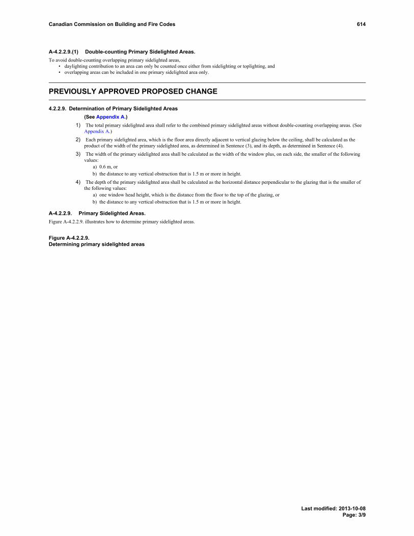
A-4.2.2.9.(1) Double-counting Primary Sidelighted Areas.To avoid double-counting overlapping primary sidelighted areas,
• daylighting contribution to an area can only be counted once either from sidelighting or toplighting, and• overlapping areas can be included in one primary sidelighted area only.
PREVIOUSLY APPROVED PROPOSED CHANGE
4.2.2.9. Determination of Primary Sidelighted Areas(See Appendix A.)
1) The total primary sidelighted area shall refer to the combined primary sidelighted areas without double-counting overlapping areas. (SeeAppendix A.)
2) Each primary sidelighted area, which is the floor area directly adjacent to vertical glazing below the ceiling, shall be calculated as theproduct of the width of the primary sidelighted area, as determined in Sentence (3), and its depth, as determined in Sentence (4).
3) The width of the primary sidelighted area shall be calculated as the width of the window plus, on each side, the smaller of the followingvalues:
a) 0.6 m, orb) the distance to any vertical obstruction that is 1.5 m or more in height.
4) The depth of the primary sidelighted area shall be calculated as the horizontal distance perpendicular to the glazing that is the smaller ofthe following values:
a) one window head height, which is the distance from the floor to the top of the glazing, orb) the distance to any vertical obstruction that is 1.5 m or more in height.
A-4.2.2.9. Primary Sidelighted Areas.Figure A-4.2.2.9. illustrates how to determine primary sidelighted areas.
Figure A-4.2.2.9.Determining primary sidelighted areas
PREVIOUSLYAPPROVEDPROPOSEDCHANGEA-4.2.2.9.
PREVIOUSLYAPPROVEDPROPOSEDCHANGEA-4.2.2.9.(1)
Canadian Commission on Building and Fire Codes 614
Last modified: 2013-10-08Page: 3/9
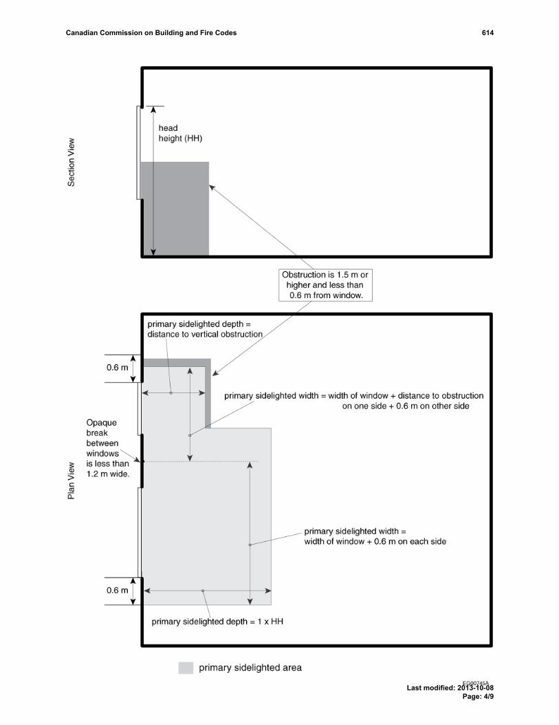
Canadian Commission on Building and Fire Codes 614
Last modified: 2013-10-08Page: 4/9

A-4.2.2.9.(1) Double-counting Primary Sidelighted Areas.To avoid double-counting overlapping primary sidelighted areas,
• daylighting contribution to an area can only be counted once either from sidelighting or toplighting, and• overlapping areas can be included in one primary sidelighted area only.
PROPOSED CHANGE
[4.2.2.9.] 4.2.2.9. Determination of Primary and Secondary Sidelighted Areas(See Appendix A.)
[1] 1) The total primary sidelighted area shall refer to the combined primary sidelighted areas without double-counting overlapping areas. (SeeAppendix A.)
[2] 2) Each primary sidelighted area, which is the floor area directly adjacent to vertical glazing below the ceiling, shall be calculated as theproduct of the width of the primary sidelighted area, as determined in Sentence (3), and its depth, as determined in Sentence (4).
[3] 3) The width of the primary sidelighted area shall be calculated as the width of the window plus, on each side, the smaller of the followingvalues:[a] a) 0.6 m, or[b] b) the distance to any vertical obstruction that is 1.5 m or more in height.
[4] 4) The depth of the primary sidelighted area shall be calculated as the horizontal distance perpendicular to the glazing that is the smaller ofthe following values:[a] a) one window head height, which is the distance from the floor to the top of the glazing, or[b] b) the distance to any vertical obstruction that is 1.5 m or more in height.
[5] --) The total secondary sidelighted area shall refer to the secondary sidelighted areas without double-counting overlapping areas. (SeeAppendix A.)
[6] --) Each secondary sidelighted area, which is the floor area directly adjacent to a primary sidelighted area, shall be calculated as the productof the width of the secondary sidelighted area, as determined in Sentence (7), and its depth, as determined in Sentence (8).
[7] --) Except as provided in Sentence (9), the width of the secondary sidelighted area shall be calculated as the width of the window plus, oneach side, the smaller of the following values:[a] --) 0.6 m, or[b] --) the distance to any vertical obstruction that is 1.5 m or more in height.
[8] --) Except as provided in Sentence (9), the depth of the secondary sidelighted area shall be calculated as the horizontal distance perpendicularto the glazing which begins at the primary sidelighted area and ends at the smaller of the following values:[a] --) one window head height, which is the distance from the floor to the top of the glazing, or[b] --) the distance to any vertical obstruction that is 1.5 m or more in height.
[9] --) If the adjacent primary sidelighted area ends at a 1.5 m or higher vertical obstruction or beyond the nearest edge of a neighbouringdaylight area under skylight or primary sidelighted area, there is no secondary sidelighted area beyond such obstruction or the edge of suchareas.
A-4.2.2.96.(1) and 4.2.2.6.(5) Double-counting Primary or Secondary Sidelighted Areas.To avoid double-counting overlapping primary or secondary sidelighted areas,
• daylighting contribution to an area can only be counted once either from sidelighting or toplighting, and• overlapping areas can be included in one primary or secondary sidelighted area only.
A-4.2.2.96. Primary and Secondary Sidelighted Areas.Figures A-4.2.2.6.A. and 4.2.2.6.B. illustrate how to determine primary and secondary sidelighted areas.
Figure [A-4.2.2.96.-A] A-4.2.2.9.Determining primary sidelighted areas
PROPOSEDCHANGEA-4.2.2.9.PROPOSED
CHANGEA-4.2.2.9.(1)
Canadian Commission on Building and Fire Codes 614
Last modified: 2013-10-08Page: 5/9

Canadian Commission on Building and Fire Codes 614
Last modified: 2013-10-08Page: 6/9

Figure [A-4.2.2.96.-B]Determining secondary sidelighted areas
Canadian Commission on Building and Fire Codes 614
Last modified: 2013-10-08Page: 7/9

Canadian Commission on Building and Fire Codes 614
Last modified: 2013-10-08Page: 8/9

RATIONALE
ProblemThe revised daylighting controls for sidelighted areas in Article 4.2.2.1. introduce secondary sidelighted area. Calculation methods for secondarysidelighted areas are therefore required.
Justification - ExplanationIntroduce calculation methods for secondary sidelighted areas.
Cost implicationsNone.
Enforcement implicationsAdditional compliance calculation required.
Who is affectedDesigners, manufacturers, builders, specification writers and building officials.
OBJECTIVE-BASED ANALYSIS OF NEW OR CHANGED PROVISIONS[4.2.2.9.] 4.2.2.9. ([1] 1) [F94-OE1.1][4.2.2.9.] 4.2.2.9. ([2] 2) [F94-OE1.1][4.2.2.9.] 4.2.2.9. ([3] 3) [F94-OE1.1][4.2.2.9.] 4.2.2.9. ([4] 4) [F94-OE1.1][4.2.2.9.] -- ([5] --) no attributions[4.2.2.9.] -- ([6] --) no attributions[4.2.2.9.] -- ([7] --) no attributions[4.2.2.9.] -- ([8] --) no attributions[4.2.2.9.] -- ([9] --) no attributions
Canadian Commission on Building and Fire Codes 614
Last modified: 2013-10-08Page: 9/9

Comment
Proposed Change 620Code Reference(s): NECB11 Div.B 4.2.4.1.Subject: Exterior Lighting ControlsTitle: 12 NECB11-DivB-04.02.04.01.-insert-EEB-exterior lighting controlsDescription: The PCF is intended to update exterior control requirements for lighting.
PROPOSED CHANGE
[4.2.4.1.] 4.2.4.1. Requirements[1] 1) Except as provided in Sentences (2) and (3), exterior lighting shall be controlled by
[a] a) astronomical time controls,[b] b) photosensors,[c] c) a combination of photosensors and timer shut-off switch, or[d] d) other types of controls that perform the same function as those referred to in Clauses (a) to (c).
[2] 2) Except as provided in Sentence (3), exterior lighting designated for dusk-to-dawn operation shall becontrolled by[a] a) astronomical time controls, or[b] b) photosensors.
[3] 3) Exterior lighting for covered vehicle exterior entrances or exterior exits from buildings or parkingstructures need not comply with Sentences (1) and (2) where it is required for safety, security, or eyeadaptation. (See Appendix A.)(See also Article 4.2.2.2.)
[4] --) All building façade and landscape lighting shall have the capacity to be automatically shut off.
[5] --) Lighting not specified in Sentence (4), including advertising signage and parking lot lighting, shall becontrolled by a device that has the capacity to automatically reduce the total connected lighting powerby at least 30%.
[6] 4) All lighting schedule controllers shall be equipped with backup provisions to retain programming andthe time setting for at least 10 h during a power outage.
A-4.2.4.1.(3) Exterior Lighting Controls.Using controllable circuit breakers as a means of automatic control is only permitted when they are connected to sensors.
RATIONALE
ProblemThe current dusk-to-dawn operation could result in excessive energy use at times where no lighting is required, i.e.when the building is not in use. These requirements are in ASHRAE 90.1-2010 and its addenda (which are expectedto be published as ASHRAE 90.1-2013). Harmonization will facilitate design and enforcement in those jurisdictionsthat reference both NECB and ASHRAE 90.1.
The appendix note is of no value and should therefore be deleted.
Justification - ExplanationThe additional requirement helps limiting the energy use for exterior lighting at times when the business is closed.This is obtained by either shutting unnecessary lighting applications off or reducing their power demand.
PROPOSEDCHANGEA-4.2.4.1.(3)
Canadian Commission on Building and Fire Codes 620
Last modified: 2013-10-15Page: 1/2

Also, the proposed changes are to harmonize more closely with the exterior lighting control requirements inASHRAE 90.1-2010 and its addenda (expected to be published as ASHRAE 90.1-2013) so to eliminate anyconfusion in the industry.
Cost implicationsAdditional timers and branch wiring may have to be installed. When the power of an application is to be reducedthis can be obtained by selectively switching off luminaires or by dimming luminaires down. In either case, a controlsolution would have to be added.
Enforcement implicationsNone.
Who is affectedDesigners, manufacturers, builders, specification writers and building officials.
OBJECTIVE-BASED ANALYSIS OF NEW OR CHANGED PROVISIONS[4.2.4.1.] 4.2.4.1. ([1] 1) [F94-OE1.1][4.2.4.1.] 4.2.4.1. ([2] 2) [F94-OE1.1][4.2.4.1.] 4.2.4.1. ([3] 3) no attributions[4.2.4.1.] -- ([4] --) [F94-OE1.1][4.2.4.1.] -- ([5] --) [F94-OE1.1][4.2.4.1.] 4.2.4.1. ([6] 4) [F94-OE1.1]
Canadian Commission on Building and Fire Codes 620
Last modified: 2013-10-15Page: 2/2

Comment
Proposed Change 571Code Reference(s): NECB11 Div.B 5.1.1.3.(2)Subject: Heating, Ventilating and Air-conditioning Systems - OtherTitle: 01 NECB2011-DivB-05.01.01.03.(2)-replace-EEB-back-up systemsDescription: The proposed change is intended to clarify the term “back-up systems”.
PROPOSED CHANGE
[5.1.1.3.] 5.1.1.3. Compliance[1] 2) Back-up systems shall comply with the prescriptive requirements stated in Section 5.2. (See Appendix
A.)
A-5.1.1.3.(2) Back-up Systems.“Back-up Systems” are systems installed within a building for the sole purpose of operating only in the event of its
primary system being out of service owing to either malfunction or scheduled maintenance.
RATIONALE
ProblemThe usage of the term “back-up systems” is not explicitly clear and could be opened to Code interpretation issues.
Justification - ExplanationThe proposed change clarifies the term “back-up systems”.
Cost implicationsNone.
Enforcement implicationsNone, enforcement could be done using existing infrastructure.
Who is affectedDesigners, manufacturers, builders, contractors, specification writers and building officials.
OBJECTIVE-BASED ANALYSIS OF NEW OR CHANGED PROVISIONS[5.1.1.3.] 5.1.1.3. ([1] 2) no attributions
Canadian Commission on Building and Fire Codes 571
Last modified: 2013-10-15Page: 1/1

Comment
Proposed Change 597Code Reference(s): NECB11 Div.B 5.2.Subject: Heat Rejection EquipmentTitle: 06 NECB2011-DivB-05.02.13.01.-table-add-EEB- heat rejection equipmentDescription: The proposed change is intended to set prescriptive requirements for heat
rejection equipment.
EXISTING PROVISION
5.2. Prescriptive Path
5.2.1. Equipment Sizing
5.2.1.1. Load Calculations1) Heating, ventilating and air-conditioning systems shall be sized in accordance with good engineering practice
such as that prescribed in the NBC. (See Appendix A.)
5.2.2. Air Distribution Systems
5.2.2.1. Design and Installation of Ducts1) Ducts shall be designed and installed in accordance with the NBC. (See Appendix A.)
5.2.2.2. Provision for Balancing1) All air distribution systems shall be designed so that they can be balanced. (See Appendix A.)
5.2.2.3. Duct Sealing1) Except as provided in Sentences (2) to (5), air-handling ducts and plenums forming part of a heating, ventilating
or air-conditioning system shall be constructed, installed and sealed as described in the ANSI/SMACNA 006,"HVAC Duct Construction Standards – Metal and Flexible", and in accordance with Table 5.2.2.3. (SeeAppendix A.)
2) Air-handling ducts and plenums that do not conform to Sentence (1) shall be tested to meet the requirements ofArticle 5.2.2.4.
3) Return ducts located within conditioned space or in spaces used as return air plenums need not comply withSentence (1).
4) Except for supply ducts located upstream of zone coils, mixing boxes, variable-air-volume boxes and diffuserswith integral variable-air-volume controls, supply ducts located within the conditioned space to which theysupply air need not comply with Sentence (1). (See Appendix A.)
5) Sealing tape shall not be used as the primary sealant for air-handling ducts and plenums.
Table 5.2.2.3.Sealing of Ducts
Forming part of Sentence 5.2.2.3.(1)
Static Pressure Class (1) Seal Class (1)
≤ 2 C
> 2 and < 4 B
≥ 4 A
EXISTINGPROVISIONA-5.2.1.1.(1)
EXISTINGPROVISIONA-5.2.2.1.(1)
EXISTINGPROVISIONA-5.2.2.2.(1)
EXISTINGPROVISIONA-5.2.2.3.(1)
EXISTINGPROVISIONA-5.2.2.3.(4)
EXISTING PROVISION Table 5.2.2.3. Footnote EXISTING PROVISION Table 5.2.2.3. Footnote
Canadian Commission on Building and Fire Codes 597
Last modified: 2013-09-05Page: 1/55

Note to Table 5.2.2.3.:
The Static Pressure and Seal Classes are taken from ANSI/SMACNA 006, "HVAC Duct Construction Standards –Metal and Flexible". The Static Pressure Classes (inches, water gauge) shown do not refer to actual design staticpressure and include both negatively and positively pressurized ducts.
(1)EXISTING PROVISION Table 5.2.2.3. Footnotereferrer
5.2.2.4. Leakage Testing of Ducts1) Where ducts are not constructed, installed and sealed in accordance with Sentence 5.2.2.3.(1), they shall be
tested for leakage in conformance with the , "" and shall meet the requirements of Sentence (2). (SeeAppendix A.)
2) For ducts tested in accordance with Sentence (1), the maximum permitted leakage shall be calculated asfollows:
where
Lmax = maximum permitted leakage, in L/s/100 m2 of duct surface area,
CL = leakage class taken from Table 5.2.2.4., and
P = maximum operating static pressure, in Pa.
Table 5.2.2.4.Leakage Classes, CL
Forming part of Sentence 5.2.2.4.(2)
Maximum Operating Static Pressure, Pa
< 500 500-750 > 750Shape of Duct
CL
Rectangular 24 12 6
Round 12 6 3
5.2.2.5. Duct and Plenum Insulation1) Except as provided in Sentences (2) to (5), all air-handling ducts, plenums and run-outs forming part of a
heating, ventilating, or air-conditioning system shall be thermally insulated in accordance with Table 5.2.2.5.
Footnote1
EXISTINGPROVISIONA-5.2.2.4.(1)
Canadian Commission on Building and Fire Codes 597
Last modified: 2013-09-05Page: 2/55

Table 5.2.2.5.Insulation of Ducts
Forming part of Sentence 5.2.2.5.(1)
TemperatureDifference, (1) °C
Minimum Thermal Resistance of Ductsand Plenums,
m2·°C/W
Minimum Thermal Resistance ofRun-outs, (2)
m2·°C/W
< 5 0 0
5 to 22 0.58 0.58
> 22 0.88 0.58
Notes to Table 5.2.2.5.:
Refers to the temperature difference at design conditions between the space within which the duct is located and thedesign temperature of the air carried by the duct. Where a duct is used for both heating and cooling purposes, the largertemperature difference shall be used.
(1)EXISTING PROVISION Table 5.2.2.5. Footnotereferrer
Refers to ducts not exceeding 3 m in length that connect to terminal grilles or diffusers.(2)EXISTING PROVISION Table 5.2.2.5. Footnotereferrer
2) Exhaust ducts, return ducts and plenums located within conditioned space need not comply with Sentence (1).
3) Ducts and plenums located within conditioned space in a dwelling unit and serving only that dwelling unit neednot comply with Sentence (1).
4) Except for relief and outside air ducts and except as provided in Sentence (5), all air-handling ducts andplenums forming part of a heating, ventilating, or air-conditioning system that are located outside the buildingenvelope shall be insulated to the same level as required for walls in Subsection 3.2.2.
5) Factory-installed plenums and ducts provided as part of equipment tested and rated in accordance withArticle 5.2.12.1. need not comply with Sentences (1) and (4), provided they are insulated to a thermal resistancenot less than 0.58 m2·°C/W.
6) Insulation material required in Sentence (1) shall be installed in accordance with good practice. (SeeA-5.2.2.5.(6) and 5.2.5.3.(8) in Appendix A.)
5.2.2.6. Protection of Duct Insulation1) Insulation on cold-air supply ducts shall be provided with vapour barrier protection to prevent condensation,
where the surface temperature of the duct is below the dew point of the air surrounding the duct.
2) Duct insulation installed in areas where it may be subject to mechanical damage or weathering shall beprotected.
5.2.2.7. Cooling with Outdoor Air1) Except for HVAC systems serving only dwelling units or hotel or motel rooms, each system that incorporates
mechanical cooling and has an air-handling capacity of more than 1 500 L/s or a cooling capacity of more than20 kW shall be designed to use outdoor air to reduce mechanical cooling energy by one of the means covered inArticles 5.2.2.8. and 5.2.2.9.
5.2.2.8. Cooling by Direct Use of Outdoor Air (Air Economizer System)1) HVAC systems that use less mechanical cooling energy by direct use of outdoor air shall be capable of mixing
return air with up to 100% outdoor air to produce the temperature required to condition the space. (SeeAppendix A.)
2) Systems described in Sentence (1) shall be designed to automatically revert to the minimum outdoor airflowrequired for acceptable indoor air quality as prescribed by the NBC, when either the return air temperature is lessthan the outdoor air temperature or the return air enthalpy is less than the outdoor air enthalpy. (See Appendix A.)
EXISTING PROVISION Table 5.2.2.5. FootnoteEXISTING PROVISION Table 5.2.2.5. Footnote
Footnote1
Footnote2
EXISTINGPROVISIONA-5.2.2.5.(6)and5.2.5.3.(8)
EXISTINGPROVISIONA-5.2.2.8.(1)
EXISTINGPROVISIONA-5.2.2.8.(2)
Canadian Commission on Building and Fire Codes 597
Last modified: 2013-09-05Page: 3/55

3) Except as provided in Sentence (6), systems described in Sentence (1) shall be designed to mix outdoor air andreturn air to a temperature as near as possible to that required to condition the space, even when mechanicalcooling is provided.
4) Systems described in Sentence (1) with cooling capacities of 70 kW or more shall incorporate coolingequipment that can operate at less than full capacity, with the lowest stage providing no more than 25% of thefull capacity of each system.
5) Systems described in Sentence (1) with cooling capacities of more than 25 kW but less than 70 kW shallincorporate cooling equipment that can operate at less than full capacity, with the lowest stage providing nomore than 50% of the full capacity of each system.
6) Direct expansion HVAC systems are permitted to include controls to reduce the quantity of outdoor air at thelowest stage of cooling equipment output as necessary to permit proper operation of the equipment. (SeeAppendix A.)
5.2.2.9. Cooling by Indirect Use of Outdoor Air (Water Economizer System)1) HVAC systems that reduce mechanical cooling energy use by using outdoor air to chill cooling distribution
fluid by direct evaporation, indirect evaporation, or both, shall be capable of cooling supply air so as to provide100% of the cooling load when the outdoor air wet-bulb temperature is 7?°C or lower.
2) HVAC systems that reduce mechanical cooling energy use by using outdoor air to chill cooling distributionfluid by sensible heat transfer shall be capable of cooling supply air so as to provide 100% of the cooling loadwhen the outdoor air dry-bulb temperature is 10°C or lower.
5.2.3. Fan System Design
5.2.3.1. Application1) Except for equipment covered by Article 5.2.12.1. and whose minimum performance includes fan energy, this
Subsection applies to all fan systemsa) that are used for comfort heating, ventilating or air-conditioning, or any combination thereof, andb) for which the total of all fan motor nameplate ratings is 10 kW or more (see A-5.2.3.1.(2) in Appendix
A).
2) For the purposes of this Subsection, the power demand of a fan system shall be the sum of the demand of allfans required to operate at design conditions to supply air to the conditioned space. (See Appendix A.)
5.2.3.2. Constant-Volume Fan Systems1) Where fans produce a constant airflow rate whenever the system is operating, the power demand required by the
motors for the combined supply and return fan system at design conditions shall not exceed 1.6 W per L/s ofsupply air delivered to the conditioned space, calculated using the following equation:
where
W = power demand, in watts,
F = design flow rate, in L/s,
SP = design static pressure across the fan, in Pa, and
η = combined fan-drive-motor efficiency, expressed as a decimal fraction.
(See Appendix A.)
5.2.3.3. Variable-Air-Volume Fan Systems1) For fan systems through which airflow varies automatically as a function of load, the power demand required by
the motors for the combined supply and return fan system, as calculated using the equation in
EXISTINGPROVISIONA-5.2.2.8.(6)
EXISTINGPROVISIONA-5.2.3.1.(2)
EXISTINGPROVISIONA-5.2.3.1.(2)
EXISTINGPROVISIONA-5.2.3.2.(1)
Canadian Commission on Building and Fire Codes 597
Last modified: 2013-09-05Page: 4/55

Sentence 5.2.3.2.(1), shall not exceed 2.65 W per L/s of supply air delivered to the conditioned space at designconditions. (See Appendix A.)
2) In variable-air-volume systems, any individual supply, relief or return fan with a power demand greater than7.5 kW and less than 25 kW, as calculated using the equation in Sentence 5.2.3.2.(1), shall incorporate controlsand devices such that, if air delivery volume is reduced to 50% of design air volume, the corresponding fanpower demand will be no more than 55% of design wattage, based on the manufacturer‘s test data.
3) In variable-air-volume systems, any individual supply, relief or return fan with a power demand equal to orgreater than 25 kW, as calculated using the equation in Sentence 5.2.3.2.(1), shall incorporate controls anddevices necessary to prevent the fan motor from demanding more than 30% of design wattage at 50% of designair volume, based on the manufacturer’s test data.
5.2.4. Air Intake and Outlet Dampers
5.2.4.1. Required Dampers1) Except as provided in Sentences (2) to (4), every duct or opening intended to discharge air from a conditioned
space to the outdoors or to unconditioned space, and every outdoor air intake duct or opening shall be equippedwith a motorized damper.
2) Where dampers are not permitted by other regulations, air intakes and outlets need not comply withSentence (1).
3) Air intakes and outlets serving HVAC systems required to operate continuously need not comply withSentence (1).
4) Where the duct or opening does not exceed 0.08 m2 in cross-sectional area, air intake dampers required bySentence (1) are permitted to be manually operated and air outlet dampers required by Sentence (1) are permittedto consist of gravity or spring-operated backflow dampers.
5.2.4.2. Type and Location of Dampers1) Except as provided in Sentences (3) and (4), dampers required by Article 5.2.4.1. shall be
a) located as near as possible to the plane of the building envelope, andb) designed to close automatically when the HVAC system is not in operation.
2) Motorized dampers required in Sentence 5.2.4.1.(1) shall be designed so that, when the damper is in the closedposition, airflow does not exceed 15 L/s per m2 of cross-sectional area at a pressure differential of 250 Pa, whentested in accordance with AMCA 500, "Louvers, Dampers and Shutters".
3) Dampers required in Article 5.2.4.1. are permitted to be located inboard of the building envelope, provided theportion of the duct between the damper and the building envelope is insulated in conformance withSentence 5.2.2.5.(4) for ducts located outdoors.
4) Dampers in air intakes and outlets serving air-heating or -cooling equipment located outside of the buildingenvelope are permitted to be located within the equipment.
5.2.5. Piping for Heating, Ventilating and Air-conditioning Systems
5.2.5.1. Design and Installation of Piping1) HVAC piping shall be designed and installed in accordance with the NBC.
5.2.5.2. Provision for Balancing1) All hydronic systems shall be designed so that they can be balanced. (See Appendix A.)
5.2.5.3. Piping Insulation1) Except as provided in Sentences (2) to (5), piping forming part of an HVAC system shall be thermally insulated
in accordance with Table 5.2.5.3.
2) Except for suction-line piping of direct expansion systems, piping located within conditioned space in adwelling unit and serving only that dwelling unit need not comply with Sentence (1).
3) HVAC piping located outside the building envelope shall be insulated to the level specified in Table 5.2.5.3. forheating system piping conveying fluid with design operating temperatures above 177°C.
EXISTINGPROVISIONA-5.2.3.3.(1)
EXISTINGPROVISIONA-5.2.5.2.(1)
Canadian Commission on Building and Fire Codes 597
Last modified: 2013-09-05Page: 5/55

4) HVAC piping that conveys fluids with design operating temperatures greater than 13°C and less than 41°C neednot comply with Table 5.2.5.3.
5) Where piping insulation has a thermal conductivity that is greater than the ranges given in Table 5.2.5.3., theinsulation thickness given in the Table shall be increased by the ratio u1/u2, where u1 is the value at the higherend of the conductivity range for the operating temperature and u2 is the measured thermal conductivity of theinsulation at the mean rating temperature.
6) Where piping insulation has a thermal conductivity that is lower than the ranges given in Table 5.2.5.3., theinsulation thickness given in the Table may be decreased by the ratio u1/u2, where u1 is the value at lower endof the conductivity range for the operating temperature and u2 is the measured thermal conductivity of theinsulation at the mean rating temperature.
7) The thermal conductivity of piping insulation at a mean rating temperature shall be determined in conformancewith ASTM C 335/C 335M, "Steady-State Heat Transfer Properties of Pipe Insulation".
8) Insulation material required in Sentence (1) shall be installed in accordance with good practice. (SeeA-5.2.2.5.(6) and 5.2.5.3.(8) in Appendix A.)
Table 5.2.5.3.Minimum Thickness of Piping Insulation
Forming part of Sentences 5.2.5.3.(1) and (3) to (6)
Thermal Conductivity ofInsulation Nominal Pipe Diameter, inches (mm)
Runouts (1)
≤ 2 (51)≤ 1(25.4)
1¼to2(32to51)
2½to 4(64to102)
≥ 5(127)
Type ofSystem
DesignOperatingTemperatureRange, °C
ConductivityRange,W/m·°C
Mean RatingTemperature,°C
Minimum Thickness of PipingInsulation, mm
> 177 0.046-0.049 121 38.1 63.5 63.5 76.2 88.9
122-177 0.042-0.045 93 38.1 50.8 63.5 63.5 88.9
94-121 0.039-0.043 65 25.4 38.1 38.1 50.8 50.8
61-93 0.036-0.042 52 25.4 25.4 25.4 38.1 38.1
HeatingSystems(Steam, SteamCondensateand Hot Water)
41-60 0.035-0.040 38 25.4 25.4 25.4 25.4 38.1
5-13 0.033-0.039 24 25.4 25.4 25.4 25.4 25.4CoolingSystems(Chilled Water,Brine andRefrigerant) (2)
< 5 0.033-0.039 24 25.4 25.4 38.1 38.1 38.1
Notes to Table 5.2.5.3.:
Refers to runouts to individual terminal units not exceeding 3.7 m in length.(1)EXISTING PROVISION Table 5.2.5.3. Footnotereferrer
The required minimum thicknesses of insulation do not take into consideration water vapour transmission andcondensation; additional insulation, vapour barriers, or both, may be required to limit these.
(2)EXISTING PROVISION Table 5.2.5.3. Footnotereferrer
EXISTINGPROVISIONA-5.2.2.5.(6)and5.2.5.3.(8)
EXISTING PROVISION Table 5.2.5.3. Footnote
EXISTING PROVISION Table 5.2.5.3. Footnote
Footnote1Footnote2
Canadian Commission on Building and Fire Codes 597
Last modified: 2013-09-05Page: 6/55

5.2.5.4. Protection of Piping Insulation1) Insulation on piping conveying chilled fluid shall be provided with vapour barrier protection to prevent
condensation, where the surface temperature of the pipe is below the dew point of the air.
2) Piping insulation installed in areas where it may be subject to mechanical damage or weathering shall beprotected.
5.2.6. Pumping System Design
5.2.6.1. Application1) This Subsection applies to HVAC pumping systems with a total pump system motor nameplate power of
7.5 kW or greater determined in accordance with Sentence (2).
2) For the purposes of this Subsection, the total pump system motor nameplate power shall be the sum of thenameplate power of all pumps required to operate at design conditions to supply fluid to a conditioned space.
5.2.6.2. Variable-Flow Pumping Systems1) Except as provided in Sentence (2), HVAC pumping systems that serve control valves designed to modulate or
to open and close in steps as a function of load shall bea) designed for variable fluid flow, andb) capable of reducing system flow to 50% or less of design flow.
(See Appendix A.)
2) Sentence (1) does not apply to systemsa) in which a minimum flow greater than 50% of the design flow is required for the proper operation of
primary equipment serving the system, such as chillers and boilers,b) with a single control valve, orc) that include controls to reset the fluid supply temperature based on either outdoor temperature or system
loads.
5.2.7. Equipment Installed Outdoors
5.2.7.1. Manufacturer's Designation1) Equipment installed outdoors or in an unconditioned space shall be designated by the manufacturer for such
installation.
5.2.8. Temperature Controls
5.2.8.1. Temperature Controls1) Each heating, ventilating or air-conditioning system intended to provide comfort heating or cooling shall
include at least one automatic space temperature control device that is accurate to within 1°C.
2) Each dwelling unit shall be controlled by at least one thermostatic control device.
5.2.8.2. Temperature Control within Dwelling Units1) Dwelling units shall be provided with manually operated or automatic devices as a means to reduce the heating
of each room, as appropriate for the heating system used.
2) Where dwelling units are provided with a mechanical cooling system, they shall be provided with manuallyoperated or automatic devices as a means to reduce the cooling of each room, as appropriate for the coolingsystem used.
5.2.8.3. Installation of Thermostats1) Except as otherwise stated in the manufacturer’s instructions and as required in barrier-free installations and for
stratified ventilation, sensors for wall-mounted thermostats shall be installeda) between 1 400 and 1 500 mm above the floor,b) on interior partitions or walls, or on exterior walls with a maximum overall thermal transmittance of
0.286 W/(m2·K),
EXISTINGPROVISIONA-5.2.6.2.(1)
Canadian Commission on Building and Fire Codes 597
Last modified: 2013-09-05Page: 7/55

c) away from direct exposure to sunlight and heat-producing sources, andd) away from drafts and dead pockets of air.(See Appendix A.)
5.2.8.4. Heat Pump Controls1) Heat pumps equipped with supplementary heaters shall incorporate controls to prevent supplementary heater
operation when the heating load can be met by the heat pump alone, except during defrost cycles. (SeeAppendix A.)
5.2.8.5. Space Temperature Control1) Except as provided in Sentence (2), the supply of heating and cooling energy to a zone shall be controlled by
individual thermostatic controls responding to temperature within the zone.
2) An independent perimeter heating and cooling system designed to offset only building envelope heat losses orgains, or both, is permitted to be used, provided
a) it includes at least one thermostatic control for each building exposure having exterior walls facing onlyone orientation for an uninterrupted distance of 15 m or more (see Appendix A), and
b) its heating and cooling energy supply is controlled by thermostat(s) located within the zone(s) it serves.
3) Where separate thermostatic controls are provided to control heating and cooling to a space, means shall beprovided to prevent these controls from simultaneously calling for heating and cooling. (See Appendix A.)
4) Thermostats installed to control electric resistance heater units shall conform to CAN/CSA-C828, "ThermostatsUsed with Individual Room Electric Space Heating Devices".
5) Vestibules between conditioned spaces and the outdoors shall have a temperature-control device that limits themaximum heating temperature in the vestibule to 15°C.
5.2.8.6. Ice- and Snow-Melting Heater Controls1) Ice- and snow-melting heaters shall be provided with automatic controls or readily accessible manual controls
that allow them to be shut down when not required.
5.2.8.7. Control of Temperature of Air Leaving the Supply Air Handler1) Except as provided in Sentences (2) and (3), a supply air handler shall be designed and equipped with controls
to achieve the design supply air temperature withouta) heating previously cooled air,b) cooling previously heated air, orc) heating outdoor air, separately from the return air or mixed with it, in excess of the minimum required for
ventilation.
2) Reheating supply air for humidity control is permitted where specified humidity levels are required. (SeeAppendix A.)
3) Reheating supply air is permitted where such reheating will not cause an increase in energy consumption.
5.2.8.8. Control of Space Temperature by Reheating or Recooling1) Except as provided in Sentence (4), HVAC systems that control the temperature of a space by reheating
previously cooled air shall be equipped with controls that automatically adjust the temperature of the cool airsupply to the highest temperature that will satisfy the temperature-control zone requiring the coolest air.
2) Except as provided in Sentence (4), HVAC systems that control the temperature of a space by recoolingpreviously heated air shall be equipped with controls that automatically adjust the temperature of the warm airsupply to the lowest temperature that will satisfy the temperature-control zone requiring the warmest air.
3) Except as provided in Sentence (4), HVAC systems that control the temperature of a space by mixing heatedsupply air and cooled supply air shall be equipped with controls that
a) automatically adjust the temperature of the warm supply air to the lowest temperature that will satisfy thetemperature-control zone requiring the warmest air, and
b) automatically adjust the temperature of the cool supply air to the highest temperature that will satisfy thetemperature-control zone requiring the coolest air.
4) HVAC systems that are designed to reduce the air supplied to each temperature-control zone to no more than2 L/s per m2 of floor surface area of the temperature-control zone before reheating, recooling or mixing ofsupply air takes place need not comply with Sentences (1) to (3).
EXISTINGPROVISIONA-5.2.8.3.(1)
EXISTINGPROVISIONA-5.2.8.4.(1)
EXISTINGPROVISIONA–5.2.8.5.(2)(a)
EXISTINGPROVISIONA-5.2.8.5.(3)
EXISTINGPROVISIONA-5.2.8.7.(2)
Canadian Commission on Building and Fire Codes 597
Last modified: 2013-09-05Page: 8/55

5.2.9. Humidification
5.2.9.1. Humidification Controls1) If an HVAC system is equipped with a means for adding or removing moisture to maintain specific humidity
levels in a space, an automatic humidity control device shall be provided.
5.2.10. Heat Recovery
5.2.10.1. Heat-Recovery Systems1) Except as provided in Sentence (3), when the sensible heat content of an exhaust air system as calculated in
accordance with Sentence (4) exceeds 150 kW, the system shall be equipped with a heat-recovery apparatuscapable of recovering sensible heat with a minimum 50% efficiency. (See Appendix A.)
2) Heat recovered in accordance with Sentence (1) shall be used in building systems.
3) Specialized exhaust systems, such as those used to exhaust smoke, grease-laden vapours, or toxic, flammable,paint, or corrosive fumes or dust, need not comply with Sentence (1).
4) The sensible heat, in kW, referred to in Sentence (1), which is the sensible heat content of the total quantity ofexhaust, shall be calculated as follows:
where
Q = rated capacity of exhaust system at normal exhaust air temperature, in L/s,
Te = temperature of exhaust air before heat recovery, in °C, and
To = outdoor 2.5% January design temperature, in °C (see Appendix A).
5) At airflow rates not less than the system design capacity, the sensible-heat-recovery efficiency of a heat-recovery apparatus referred to in Sentence (1) shall be determined in conformance with
a) the test method described in , "", orb) another acceptable test method.
5.2.10.2. Heat Recovery from Dehumidification in Swimming Pools
1) Except for pools with a water surface area of less than 10 m2 and except as provided in Sentence (2), systemsthat exhaust air from swimming pools within conditioned spaces shall be capable of recovering at least 40% ofthe sensible heat from exhaust air at design conditions, as calculated in accordance with Sentence 5.2.10.1.(4).(See Appendix A .)
2) Indoor swimming pools need not comply with Sentence (1), provided a stationary mechanical or desiccantdehumidification system is installed that provides 80% of the dehumidification that would result fromcompliance with Sentence (1).
5.2.10.3. Heat Recovery from Ice-making Machines in Ice Arenas and Curling Rinks1) Where an ice arena or a curling rink has a heating requirement, the refrigeration system shall incorporate a
means of recovering the heat rejected by the system to satisfy some or all of the building’s space-heating orservice water heating requirements. (See Appendix A.)
5.2.10.4. Heat Recovery in Dwelling Units1) Except for climate zones 4, 5 and 6, where a self-contained mechanical ventilation system serves a single
dwelling unit, the principal exhaust component of the ventilation system shall be equipped with heat-recoverycapability. (See Appendix A.)
2) Heat-recovery ventilators used to meet the requirements of Sentence (1) shall have a sensible-heat-recoveryefficiency, when tested in conformance with the low-temperature thermal and ventilation test methods describedin CAN/CSA-C439, "Rating the Performance of Heat/Energy-Recovery Ventilators", of
EXISTINGPROVISIONA-5.2.10.1.(1)
EXISTINGPROVISIONA-5.2.10.1.(4)
EXISTINGPROVISIONA-5.2.10.2.(1)
EXISTINGPROVISIONA-5.2.10.3.(1)
EXISTINGPROVISIONA-5.2.10.4.(1)
Canadian Commission on Building and Fire Codes 597
Last modified: 2013-09-05Page: 9/55

a) at least 65% at an outside air test temperature of 0°C, andb) not less than that required by Table 5.2.10.4. for the 2.5% January design temperature for the building’s
location, as listed in Appendix C of Division B of the NBC.(See Appendix A.)
Table 5.2.10.4.Performance of Heat-recovery Ventilators
Forming part of Sentence 5.2.10.4.(2)
2.5% January Design Temperature atBuilding Location
Outside Air Test Temperature atStation 1, (1) °C
Sensible-Heat-RecoveryEfficiency, %
≥ –10 0 65
< –10 and > –30 –25 55
≤ –30 –40 45
Note to Table 5.2.10.4.:
“Station 1” is a term that is defined in CAN/CSA-C439 and means the location where temperature is measured.(1)EXISTING PROVISION Table 5.2.10.4. Footnotereferrer
3) The tests described in Sentence (2) shall be performed at the rated airflow for continuous operation of theequipment, which meets the principal exhaust component of the ventilation system referred to in Sentence (1).
4) Except as stated in Sentence (5), where a heat-recovery system other than a heat-recovery ventilator is used tomeet the requirements of Sentence (1), that system shall have a heat-recovery performance equivalent to thatrequired in Sentence (2) for heat-recovery ventilators.
5) Where heat-recovery systems are required in multi-unit residential buildings, the minimum sensible-heat-recovery efficiency shall be 50%. (See Appendix A.)
5.2.11. Shut-off and Setback Controls
5.2.11.1. Off-hours Controls1) Except as provided in Sentence (3), systems serving dwelling units or other areas that are not intended to
operate continuously and whose zone-heating or -cooling capacity requirement is 5 kW or more shall beequipped with automatic controls capable of setting back or shutting down the systems during periods of non-useof the zones served. (See Appendix A.)
2) Controls required by Sentence (1) shall be capable ofa) shutting down fan systems and/or heating and cooling equipment and auxiliaries, where appropriate,
when conditioning is not required by the space,b) setting back the space-heating temperature setpoint,c) setting up the space-cooling temperature setpoint if the cooling system is required to operate during
periods when the space is not in use,d) reducing or shutting off outdoor air intake during heating or cooling system operation when the space is
not in use (see Appendix A), ande) in the case of heat pumps, temporarily suppressing electrical back-up or adaptive anticipation of the
recovery point in order to prevent the unit from resorting to supplementary heat at the time of recovery(see Appendix A and A-5.2.8.4.(1) in Appendix A).
3) Zones with a total heating or cooling capacity requirement of less than 5 kW may be controlled by readilyaccessible manual controls.
4) Controls required by Sentence (1) shall be designed so that lowering a heating thermostat setpoint will not causeenergy for cooling to be expended to reach the lowered setting and raising a cooling thermostat setpoint will notcause energy for heating to be expended to reach the raised setting.
EXISTINGPROVISIONA-5.2.10.4.(2)
EXISTING PROVISION Table 5.2.10.4. Footnote
Footnote1
EXISTINGPROVISIONA-5.2.10.4.(5)
EXISTINGPROVISIONA-5.2.11.1.(1)
EXISTINGPROVISIONA-5.2.11.1.(2)(d)
EXISTINGPROVISIONA-5.2.11.1.(2)(e)
EXISTINGPROVISIONA-5.2.8.4.(1)
Canadian Commission on Building and Fire Codes 597
Last modified: 2013-09-05Page: 10/55

5.2.11.2. Airflow Control Areas1) Except as provided in Sentences (2) and (8), each air distribution system serving multiple temperature-control
zones having a combined floor surface area of conditioned space of more than 2 500 m2 shall be divided intoairflow control areas so that the supply and exhaust of air to individual airflow control areas can be reduced orstopped independently of other airflow control areas served by the system.
2) Where it is impractical to control air distribution as described in Sentence (1), individual air distribution systemsshall serve airflow control areas no greater than 2 500 m2.
3) Each airflow control area required by Sentences (1) and (2) shall include only temperature-control zonesintended to be operated simultaneously. (See Appendix A.)
4) Each airflow control area required by Sentences (1) and (2) shall not span more than one storey.
5) Each airflow control area required by Sentence (1) shall be equipped with controls meeting the requirements ofArticle 5.2.11.1.
6) The air distribution system shall be designed such that a reduction in air delivery of up to 50% of design flowresults in at least a proportional reduction in fan power.
7) Controls and devices such as direct digital control and variable-air-volume systems shall be provided to allowstable operation of all fan systems and associated primary systems for any length of time while they are serving asingle airflow control area.
8) Temperature-control zones in which outdoor air and exhaust requirements prevent the reduction or stopping ofthe air supply need not be incorporated into airflow control areas.
5.2.11.3. Seasonal Shutdown1) HVAC pumping systems that are used on a seasonal basis shall be equipped with
a) automatic controls, orb) readily accessible and clearly labeled manual controls that allow them to be shut down when not
required.
5.2.11.4. Multiple Boilers1) HVAC systems with multiple boilers shall incorporate a means for preventing heat loss through the boilers
when they are not operating, such as a device that prevents the flow of heat-carrying fluid through the boilers ordampers installed in the flues.
2) Except as provided in Sentence (3), where the heating load exceeds 176 kW, the boiler plant shall consist ofa) more than one boiler,b) a two-stage single boiler, orc) a multi-stage boiler.
3) Where the heating load exceeds 352 kW, the boiler plant shall be fully modulating.
5.2.11.5. Loop Temperature Reset for Chilled- and Hot-Water Systems1) Except as provided in Sentences (2) and (3), chilled- or hot-water systems with a design capacity greater than
88 kW supplying chilled or heated water to comfort-conditioning systems shall be equipped with automaticcontrols that reset the supply water loop temperatures
a) in relation to the outdoor temperature using an indoor/outdoor controller, orb) in relation to representative building heating and cooling loads using the return water temperature in the
system.
2) Chilled- and hot-water systems described in Sentence (1) need not be equipped with loop temperature resetcontrols where such controls would cause the improper operation of heating, cooling, humidifying, ordehumidifying equipment or systems.
3) Chilled- and hot-water systems described in Sentence (1) that are designed with variable-flow pumpingcomplying with Sentence 5.2.6.2.(1) need not be equipped with loop temperature reset controls.
EXISTINGPROVISIONA-5.2.11.2.(3)
Canadian Commission on Building and Fire Codes 597
Last modified: 2013-09-05Page: 11/55

5.2.12. Equipment Efficiency
5.2.12.1. Unitary and Packaged HVAC Equipment1) Unitary and packaged HVAC equipment and components shall comply with the performance requirements in
Table 5.2.12.1. (See Appendix A.) (See also Article 6.2.2.4.)
Table 5.2.12.1.Unitary and Packaged HVAC Equipment Performance Requirements
Forming part of Sentences 5.2.12.1.(1), 6.2.2.4.(2), 6.2.2.5.(1) and 8.4.4.19.(6)
Air-cooled Unitary Air Conditioners and Heat Pumps — Electrically Operated
Component orEquipment
Cooling orHeating
Capacity, kW(Btu/h)
StandardRating
Conditions (1)Minimum
Performance (2)
Split system ≤ 19 (65 000) CAN/CSA-C656 SEER = 15
Single-package system ≤ 19 (65 000) CAN/CSA-C656 SEER = 14
All phases > 19 (65 000) and< 73 (250 000)
CAN/CSA-C746
—
EER = 9.7
≥ 19 kW and < 40 kW,electric resistance
heating section
COP = 3.28ICOP = 3.34
≥ 19 kW and < 40 kW,other heating section
COP = 3.22ICOP = 3.28
≥ 40 kW and < 70 kW,electric resistance
heating section
COP = 3.22ICOP = 3.28
≥ 40 kW and < 70 kW,other heating section
COP = 3.16ICOP = 3.22
≥ 70 kW and < 223 kW,electric resistance
heating section
COP = 2.93ICOP = 2.96
≥ 70 kW and < 223 kW,other heating section
COP = 2.87ICOP = 2.90
73 (250 000) –222.7 (760 000)
≥ 223 kW, electricresistance heating
section
COP = 2.84ICOP = 2.87
Air conditioners, allphases, split and single-package
> 222.7 (760 000)
CAN/CSA-C746
≥ 223 kW, other heatingsection
COP = 2.78ICOP = 2.81
≥ 19 kW and < 40 kW,electric resistance
heating section, splitand single
COP = 3.22ICOP = 3.28
Heat pumps 73 (250 000) –222.7 (760 000)
CAN/CSA-C746
≥ 19 kW and < 40 kW,other heating section,
split and single
COP = 3.16ICOP = 3.22
EXISTINGPROVISIONA-5.2.12.1.(1)
EXISTING PROVISION Table 5.2.12.1. FootnoteEXISTING PROVISION Table 5.2.12.1. Footnote
Canadian Commission on Building and Fire Codes 597
Last modified: 2013-09-05Page: 12/55

≥ 40 kW and < 70 kW,electric resistance
heating section, splitand single
COP = 3.10ICOP = 3.13
≥ 40 kW and < 70 kW,other heating section,
split and single
COP = 3.04ICOP = 3.08
≥ 70 kW, electricresistance heating
section, split and single
COP = 2.78ICOP = 2.81
≥ 70 kW, other heatingsection, split and single
COP = 2.72ICOP = 2.75
≥ 19 kW and < 70 kW incooling mode at 8.3°C
db / 6.1°C wb
COP = 3.3
≥ 19 kW and < 70 kW incooling mode at –8.3°C
db / –9.4°C wb
COP = 2.25
≥ 70 kW in coolingmode at 8.3°C db /
6.1°C wb
COP = 3.2
≥ 70 kW in coolingmode at –8.3°C db /
–9.4°C wb
COP = 2.05
Single-Package Vertical Air Conditioners (SPVAC) and Heat Pumps (SPVHP)
Component orEquipment
Cooling orHeating
Capacity, kW(Btu/h)
StandardRating
Conditions (1)Minimum
Performance (2)
ANSI/AHRI 390 < 19 kW EER = 10
CAN/CSA-C746 ≥ 19 kW and < 40 kW EER = 9.5
SPVAC and SPVHP incooling mode
—
CAN/CSA-C746 ≥ 40 kW and < 70 kW EER = 8.6
ANSI/AHRI 390 < 19 kW COP = 3.1
CAN/CSA-C746 ≥ 19 kW and < 40 kW COP = 3.0
SPVHP in heating mode —
CAN/CSA-C746 ≥ 40 kW and < 70 kW COP = 2.9
Evaporatively Cooled and Water Evaporatively Cooled Unitary Air Conditioners and Heat Pumps —Electrically Operated
Component orEquipment
Cooling orHeating
Capacity, kW(Btu/h)
StandardRating
Conditions (1)Minimum
Performance (2)
EXISTING PROVISION Table 5.2.12.1. FootnoteEXISTING PROVISION Table 5.2.12.1. Footnote
EXISTING PROVISION Table 5.2.12.1. FootnoteEXISTING PROVISION Table 5.2.12.1. Footnote
Canadian Commission on Building and Fire Codes 597
Last modified: 2013-09-05Page: 13/55

Evaporatively cooled ≤ 19 (65 000) ANSI/AHRI210/240 or
CTI 201
< 19 kW COP = 3.54
≥ 19 kW and < 40 kW,electric resistance
heating section
COP = 3.37
≥ 19 kW and < 40 kW,other heating section
COP = 3.31
≥ 40 kW and < 70 kW,electric resistance
heating section
COP = 3.22
Evaporatively cooled andwater evaporativelycooled, split and single-package
> 19 (65 000) and< 73 (250 000)
CAN/CSA-C746
≥ 40 kW and < 70 kW,other heating section
COP = 3.16
≥ 70 kW, electricresistance heating
section
COP = 3.22IPLV = 3.02
Water evaporativelycooled air conditioners,split and single-package
≥ 73 (250 000) ANSI/AHRI340/360 or
CTI 201
≥ 70 kW, other heatingsection
COP = 3.16IPLV = 2.96
Condensing Units
Component orEquipment
Cooling orHeating
Capacity, kW(Btu/h)
StandardRating
Conditions (1)Minimum
Performance (2)
Air-cooled and waterevaporatively cooled
> 19 (65 000) and< 73 (250 000)
CAN/CSA-C746 — See standard
Air-cooled AHRI 365 COP = 2.96IPLV = 3.28
Water evaporativelycooled
≥ 73 (250 000)
CTI 201
≥ 40 kW
COP = 3.84IPLV = 3.84
Water-Cooled Unitary Air Conditioners and Heat Pumps — Electrically Operated
Component orEquipment
Cooling orHeating
Capacity, kW(Btu/h)
StandardRating
Conditions (1)Minimum
Performance (2)
Ground-source andwater-source heat pumps
< 35 (119 500) CAN/CSA-C13256-1
Internal water-loop heatpumps
< 40 (136 500) CAN/CSA-C13256-2
— See standard
< 19 (65 000) ANSI/AHRI210/240 or CTI 201
< 19 kW COP = 3.54ICOP = 3.60
Water-cooled airconditioners
19 (65 000) –39.5 (135 000)
ANSI/AHRI340/360 or CTI 201
≥ 19 kW and < 40 kW,electric resistanceheating (or none)
COP = 3.37ICOP = 3.43
EXISTING PROVISION Table 5.2.12.1. FootnoteEXISTING PROVISION Table 5.2.12.1. Footnote
EXISTING PROVISION Table 5.2.12.1. FootnoteEXISTING PROVISION Table 5.2.12.1. Footnote
Canadian Commission on Building and Fire Codes 597
Last modified: 2013-09-05Page: 14/55

≥ 19 kW and < 40 kW,all other
COP = 3.31ICOP = 3.37
≥ 40 kW and < 70 kW,electric resistanceheating (or none)
COP = 3.22ICOP = 3.28
≥ 40 kW and < 70 kW,all other
COP = 3.16ICOP = 3.22
≥ 70 kW, electricresistance heating (or
none)
COP = 3.22IPLV = 3.02ICOP = 3.25
≥ 70 kW, all other COP = 3.16IPLV = 2.96ICOP = 3.19
Direct-Expansion Ground-Source Heat Pumps — Electrically Operated
Component orEquipment
Cooling orHeating
Capacity, kW(Btu/h)
StandardRating
Conditions (1)Minimum
Performance (2)
Direct-expansion ground-source heat pumps
≤ 21 (71 700) CSA C748 — See standard
Packaged Terminal Air Conditioners (PTAC) and Heat Pumps (PTHP)
Component orEquipment
Cooling orHeating
Capacity, kW(Btu/h)
StandardRating
Conditions (1)Minimum
Performance (2)
PTAC and PTHP, air-cooled, electricallyoperated
— COP = 3.66 –(0.213 x
Capc/1000)
PTAC Application rating COP = 3.19 –(0.213 x
Capc/1000)
PTHP in cooling mode
All capacities ARI310/380/CAN/CSA-
C744
Standard rating COP = 3.6 –(0.213 x
Capc/1000)
EXISTING PROVISION Table 5.2.12.1. FootnoteEXISTING PROVISION Table 5.2.12.1. Footnote
EXISTING PROVISION Table 5.2.12.1. FootnoteEXISTING PROVISION Table 5.2.12.1. Footnote
Canadian Commission on Building and Fire Codes 597
Last modified: 2013-09-05Page: 15/55

Application rating COP = 3.16 –(0.213 x
Capc/1000)
Standard rating COP = 3.2 –(0.026 x
Capc/1000)
PTHP in heating mode
Application rating COP = 2.9 –(0.026 x
Capc/1000)
Room Air Conditioners and Room Air Conditioner Heat Pumps
Component orEquipment
Cooling orHeating
Capacity, kW(Btu/h)
StandardRating
Conditions (1)Minimum
Performance (2)
Room air conditionerswith reverse cycle
with louvered sides EER = 8.5
without louvered sides
ANSI/AHAMRAC-1
EER = 8.0
Room air conditionerswithout reverse cycle
< 10.55 (36 000)
CAN/CSA-C368.1
—
See standard
< 1.8 (6 150) < 1.8 kW COP = 2.84
≥ 1.8 (6 150) and< 2.3 (7 800)
≥ 1.8 kW and < 2.3 kW COP = 2.84
≥ 2.3 (7 800) and< 4.1 (14 000)
≥ 2.3 kW and < 4.1 kW COP = 2.87
≥ 4.1 (14 000)and
< 5.9 (20 150)
≥ 4.1 kW and < 5.9 kW COP = 2.84
Room air conditionerswith louvered sides
≥ 5.9 (20 150) ≥ 5.9 kW COP = 2.49
< 2.3 (7 800) < 2.3 kW COP = 2.64
≥ 2.3 (7 800) and< 5.9 (20 150)
≥ 2.3 kW and < 5.9 kW COP = 2.49
Room air conditionerswithout louvered sides
≥ 5.9 (20 150) ≥ 5.9 kW COP = 2.49
< 5.9 (20 150) < 5.9 kW COP = 2.65Room air conditioner heatpumps with louveredsides ≥ 5.9 (20 150) ≥ 5.9 kW COP = 2.49
Room air conditioner heatpumps without louveredsides
< 4.1 (14 000)
CAN/CSA-C368.1
< 4.1 kW COP = 2.49
EXISTING PROVISION Table 5.2.12.1. FootnoteEXISTING PROVISION Table 5.2.12.1. Footnote
Canadian Commission on Building and Fire Codes 597
Last modified: 2013-09-05Page: 16/55

≥ 4.1 (14 000) ≥ 4.1 kW COP = 2.34
Room air conditioner,casement only
All capacities All capacities COP = 2.55
Room air conditioner,casement slider
All capacities All capacities COP = 2.78
Computer Room Air Conditioners
Component orEquipment
Cooling orHeating
Capacity, kW(Btu/h)
StandardRating
Conditions (1)Minimum
Performance (2)
< 19 (65 000) SCOP = 2.20 /2.09
≥ 19 (65 000) and< 70 (240 000)
SCOP = 2.10 /1.99
Air conditioners, air-cooled
≥ 70 (240 000) SCOP = 1.90 /1.79
< 19 (65 000) SCOP = 2.60 /2.49
≥ 19 (65 000) and< 70 (240 000)
SCOP = 2.50 /2.39
Air conditioners, water-cooled
≥ 70 (240 000) SCOP = 2.40 /2.29
< 19 (65 000) SCOP = 2.55 /2.44
≥ 19 (65 000) and< 70 (240 000)
SCOP = 2.45 /2.34
Air conditioners, water-cooled with fluideconomizer
≥ 70 (240 000)
—
SCOP = 2.35 /2.24
< 19 (65 000) SCOP = 2.50 /2.39
≥ 19 (65 000) and< 70 (240 000)
SCOP = 2.15 /2.04
Air conditioners, glycol-cooled
≥ 70 (240 000) SCOP = 2.10 /1.99
< 19 (65 000) SCOP = 2.45 /2.34
≥ 19 (65 000) and< 70 (240 000)
SCOP = 2.10 /1.99
Air conditioners, glycol-cooled with fluideconomizer
≥ 70 (240 000)
ANSI/ASHRAE 127
rated at 40% propyleneglycol
SCOP = 2.05 /1.94
EXISTING PROVISION Table 5.2.12.1. FootnoteEXISTING PROVISION Table 5.2.12.1. Footnote
Canadian Commission on Building and Fire Codes 597
Last modified: 2013-09-05Page: 17/55

< 19 (65 000) SCOP = 8.00 /6.06
≥ 19 (65 000) and< 70 (240 000)
SCOP = 9.00 /7.06
Chilled water air handler
≥ 70 (240 000)
—
SCOP = 11.00 /9.06
Packaged Water Chillers
Component orEquipment
Cooling orHeating
Capacity, kW(Btu/h)
StandardRating
Conditions (1)Minimum
Performance (2)
Vapour compression, air-or water-cooled,electrically operated
Absorption, single- ordouble-effect, indirect-or direct-fired
< 5 600 (19 000000)
CAN/CSA-C743 — See standard
Boilers
Component orEquipment
Cooling orHeating
Capacity, kW(Btu/h)
StandardRating
Conditions (1)Minimum
Performance (2)
Electric boilers — — — (3)
< 88 (300 000) ANSI Z21.13/CSA4.9
— AFUE = 85%
≥ 88 (300 000)and
< 733 (2 500 000)
— Ec ≥ 82.5%Et ≥ 83.0%
Gas-fired boilers (4)
≥ 733 (2 500 000)
ANSI Z21.13/CSA4.9 or ASME PTC
4
— Ec ≥ 83.3%
< 88 (300 000) AFUE ≥ 84.7%
≥ 88 (300 000)and
< 733 (2 500 000)
Et ≥ 83.4%
Oil-fired boilers
≥ 733 (2 500 000)
CSA B212 orASME PTC 4
—
Ec ≥ 85.8%
EXISTING PROVISION Table 5.2.12.1. FootnoteEXISTING PROVISION Table 5.2.12.1. Footnote
EXISTING PROVISION Table 5.2.12.1. FootnoteEXISTING PROVISION Table 5.2.12.1. Footnote
EXISTING PROVISION Table 5.2.12.1. Footnote
EXISTING PROVISION Table 5.2.12.1. Footnote
Canadian Commission on Building and Fire Codes 597
Last modified: 2013-09-05Page: 18/55

< 88 (300 000) CSA B212 AFUE ≥ 84.7%
≥ 88 (300 000)and
< 733 (2 500 000)
Et ≥ 83.4%
Oil-fired boilers, residual(No. 5 or No. 6 oil) andother
≥ 733 (2 500 000)
ASME PTC 4
—
Ec ≥ 85.8%
Warm-Air Furnaces, Combination Warm-Air Furnace/Air-conditioning Units, Duct Furnaces and UnitHeaters
Component orEquipment
Cooling orHeating
Capacity, kW(Btu/h)
StandardRating
Conditions (1)Minimum
Performance (2)
≤ 117.23 (400000)
— AFUE ≥ 92.4%
Maximum ratedcapacity, steady-state
Et ≥ 81%
Gas-fired warm-airfurnaces (4)
> 117.23 (400000)
ANSI Z21.47/CSA2.3
Minimum ratedcapacity, steady-state
Et ≥ 81%
Gas-fired ductfurnaces (4)
Et ≥ 81%
Gas-fired unit heaters (4)
≤ 117.23 (400000)
ANSI Z83.8/CSA2.6
Et ≥ 82%
≤ 66 (225 000) CSA B212 Et ≥ 84.5%Oil-fired warm-airfurnaces
> 66 (225 000) Et ≥ 81.3%
Oil-fired duct furnacesand unit heaters
—
CAN/CSA-B140.4
—
Et ≥ 81%
Notes to Table 5.2.12.1.:
The abbreviations that appear in this column have the following meanings:
db = dry bulb outdoor air temperature
wb = wet bulb outdoor air temperature
(1)EXISTING PROVISION Table 5.2.12.1. Footnotereferrer
EXISTING PROVISION Table 5.2.12.1. FootnoteEXISTING PROVISION Table 5.2.12.1. Footnote
EXISTING PROVISION Table 5.2.12.1. Footnote
EXISTING PROVISION Table 5.2.12.1. Footnote
EXISTING PROVISION Table 5.2.12.1. Footnote
Footnote1
Footnote2
Canadian Commission on Building and Fire Codes 597
Last modified: 2013-09-05Page: 19/55

The symbols and abbreviations that appear in this column have the following meanings:
AFUE = annual fuel utilization efficiency, in %
Capc = rated cooling capacity, in W(Btu/h)
COP = coefficient of performance, in W/W
Ec = combustion efficiency, in %
EER = energy efficiency ratio, in (Btu/h)/W
Et = thermal efficiency, in %
ICOP = integrated coefficient of performance, in W/W
IPLV = integrated part-load value (no units)
SCOP = sensible coefficient of performance, in downflow units/upflow units (first value is downflow; second value isupflow). The SCOP is a ratio that is calculated by dividing the net sensible cooling capacity, in W, by thetotal power input, in W (excluding re-heaters and humidifiers).
SEER = seasonal energy efficiency ratio, in (Btu/h)/W (no metric equivalent)
(2)EXISTING PROVISION Table 5.2.12.1. Footnotereferrer
No standards address the performance efficiency of electric boilers; however, their efficiency typically approaches100%.
(3)EXISTING PROVISION Table 5.2.12.1. Footnotereferrer
Includes propane.(4)EXISTING PROVISION Table 5.2.12.1. Footnotereferrer
5.2.12.2. Field-Assembled Equipment and Components1) Where components from more than one manufacturer are used as parts of a heating, ventilating or air-
conditioning system, the system shall be designed in accordance with good engineering practice and based oncomponent efficiency data provided by the component manufacturers so as to provide the overall efficiencyrequired by Article 5.2.12.1.
5.2.12.3. Service Water Heating Equipment Used for Space Heating1) Service water heating equipment used solely to provide space heating or used to provide a combination of space
and service water heating shall comply with the applicable standard listed in Table 6.2.2.1. or, where suchequipment is not covered in this Table, with the Energy Efficiency Act and its Regulations.
A-5.2.1.1.(1) Load Calculations.ASHRAE Handbooks and Standards and, for smaller buildings, the HRAI Digest, are also useful sources of information onHVAC systems.
A-5.2.2.1.(1) Design and Installation of Ducts.The following publications are a useful source of additional information on this subject:
• Publications by ASHRAE:–the ASHRAE Handbooks
• Publications by SMACNA:–HVAC Duct Construction Standards — Metal and Flexible–Fibrous Glass Duct Construction Standards–HVAC Systems — Duct Design–HVAC Air Duct Leakage Test Manual
Footnote3
Footnote4
Canadian Commission on Building and Fire Codes 597
Last modified: 2013-09-05Page: 20/55

A-5.2.2.2.(1) Provision for Balancing.Balancing an air distribution system is a means of fine-tuning it so that the correct amount of air for which the heating, ventilatingor air-conditioning system is designed can be delivered. Except for systems having some other means of air-volume control, suchas variable air-volume systems, major supply air ducts such as main, sub-main or branch ducts intended to carry conditioned airmust contain air-volume balancing dampers capable of being set for specified airflows.
A-5.2.2.3.(1) SMACNA Duct Sealing Classification.Table A-5.2.2.3.(1) provides examples of how to achieve the SMACNA air duct leakage seal classes.
Table A-5.2.2.3.(1)SMACNA Duct Sealing Classification
Static PressureClass
SealClass Description
≤ 2 C Sealing required at transverse joints
> 2 and < 4 B Sealing required at all transverse joints and longitudinal seams
≥ 4 A Sealing required at all transverse joints, longitudinal seams and duct wallpenetrations
A-5.2.2.3.(4) Duct Sealing Exemption.The exemption afforded by Sentence 5.2.2.3.(4) does not apply to ducts in ceiling plenums or other service spaces that areimmediately adjacent to the conditioned space served by the ducts.The rationale behind the exemption from compliance with Sentence 5.2.2.3.(1) is that the energy penalty would be insignificant ifa little supply air from a duct located in the same conditioned space to which it is supplying air leaks into the conditioned spacebefore it gets to the diffuser. However, if there is a controlled element, such as a reheat coil, mixing box or variable-air-volumebox or a damper, between the leak and the diffuser, a more significant energy loss may result; these types of elements aretherefore required to comply with Sentence 5.2.2.3.(1).
A-5.2.2.4.(1) Leakage Testing of Ducts.The choice of ducts to be tested is left to the authority having jurisdiction.
A-5.2.2.8.(1) High-Limit Shut-off.All air economizers should be capable of automatically reducing outdoor air intake to the design minimum outdoor air quantitywhen outdoor air intake no longer reduces cooling energy usage. Table A-5.2.2.8.(1) shows the high-limit shut-off settings fordifferent types of air economizers.
Table A-5.2.2.8.(1)High-Limit Shut-off (HLSO) Control Settings for Air Economizers
Conditions at which Air Economizer Turns OffType of HLSOControl (1)
Equation (2) Description
TOA > 24°C (dryclimate)
Outdoor air temperature exceeds 24°CFixed dry bulb
TOA > 18°C (humidclimate)
Outdoor air temperature exceeds 18°C
Differential dry bulb TOA > TRA Outdoor air temperature exceeds return air temperature
EXISTING PROVISION Table A-5.2.2.8.(1) Footnote
EXISTING PROVISION Table A-5.2.2.8.(1) Footnote
Canadian Commission on Building and Fire Codes 597
Last modified: 2013-09-05Page: 21/55

Conditions at which Air Economizer Turns OffType of HLSOControl (1)
Equation (2) Description
Electronic enthalpy (3) (TOA,RHOA) > A Outdoor air temperature/RH exceeds the “A” setpointcurve (4)
Differential enthalpy hOA > hRA Outdoor air enthalpy exceeds return air enthalpy
Dew-point and dry-bulbtemperatures
DPoa > 18°C or Toa> 24°C
Outdoor air dry bulb exceeds 24°C or outside dew pointexceeds 13°C (65 gr/lb)
Notes to Table A-5.2.2.8.(1):
Fixed enthalpy is a prohibited type of control for the climate zones to which the NECB applies, namely zones 4 to 8.(1)EXISTING PROVISION Table A-5.2.2.8.(1) Footnotereferrer
TOA = temperature outdoor air; TRA = temperature return air; hOA = enthalpy outdoor air; RHOA = relative humidityoutdoor air; hRA = enthalpy return air; DPOA = dew point outdoor air
(2)EXISTING PROVISION Table A-5.2.2.8.(1) Footnotereferrer
Electronic enthalpy controls use a combination of humidity and dry-bulb temperature in their switching algorithm.(3)EXISTING PROVISION Table A-5.2.2.8.(1) Footnotereferrer
Setpoint “A” corresponds to a curve on the psychrometric chart that goes through a point at approximately 24°C and40% relative humidity and is nearly parallel to dry-bulb lines at low humidity levels and nearly parallel to enthalpy linesat high humidity levels.
(4)EXISTING PROVISION Table A-5.2.2.8.(1) Footnotereferrer
A-5.2.2.8.(2) Outdoor Air Intake for Acceptable Indoor Air Quality.Outdoor air requirements for acceptable indoor air quality are covered in Part 6 of Division B of the NBC.
A-5.2.2.8.(6) Controls to Allow Proper Operation of Direct Expansion Systems.Preventing frost build-up on coils is an example of how the controls referred to in Sentence 5.2.2.8.(6) enable the proper operationof the equipment.
A-5.2.3.1.(2) Fan System Design.Although the allowed maximum power demand of a fan system is based solely on the supply airflow, the calculation of actualpower demand includes supply fans, return fans, relief fans, and fans for series fan-powered boxes, but not parallel-powered boxesor exhaust fans such as bathroom or laboratory exhausts.
A-5.2.3.2.(1) Constant-Volume Fan Systems.This type of system includes bypass variable-air-volume systems in which the airflow through the fan is not varied.Both supply and return fans must be accounted for, but not exhaust fans.The power demand of the motors refers to the power drawn by the motors and not their nameplate rating.
A-5.2.3.3.(1) Variable-Air-Volume Fan Systems.The power demand of supply, relief and return fans—but not that of exhaust fans—must be accounted for in Sentence 5.2.3.2.(1).The power demand of fans for series-fan-powered boxes—but not that of fans in parallel-fan-powered boxes—must be accountedfor in Sentence 5.2.3.2.(1).The power demand of the motors refers to the power drawn by the motors and not their nameplate rating.
A-5.2.5.2.(1) Provision for Balancing.Balancing a hydronic system is a means of fine-tuning it so that the correct amount of fluid for which the system is designed canbe delivered to each of the sectors served. Pumps and major circuit divisions must be installed with adequate access to the fluid tomeasure differential pressure or flow, and must be equipped with a means of adjusting the flow.The following publications are useful sources of information on hydronic systems:
EXISTING PROVISION Table A-5.2.2.8.(1) Footnote
EXISTING PROVISION Table A-5.2.2.8.(1) Footnote
EXISTING PROVISION Table A-5.2.2.8.(1) Footnote EXISTING PROVISION Table A-5.2.2.8.(1) Footnote
Footnote1Footnote2
Footnote3Footnote4
Canadian Commission on Building and Fire Codes 597
Last modified: 2013-09-05Page: 22/55

• ANSI/ASHRAE 111, "Measurement, Testing, Adjusting and Balancing of Building HVAC Systems"• the ASHRAE Handbooks• publications by the National Environmental Balancing Bureau
A-5.2.6.2.(1) Variable-Flow Pumping Systems.Flow may be varied by one of several methods such as variable-speed-driven pumps, staged multiple pumps or pumps riding theircharacteristic performance curves, etc. Sentence 5.2.6.2.(1) reduces the use of three-way valves.
A-5.2.8.3.(1) Mounting Height and Location of Thermostats.Mounting Height of ThermostatsArticle 3.8.1.5. of Division B of the NBC contains a specific requirement regarding the mounting height of thermostats located ina barrier-free path of travel; the use of thermostats with separate sensors and controls may be the best option in such spaces.
Location of ThermostatsExamples of locations to be avoided are exterior walls and locations near exterior entrances, corners and within throw of supplyair diffusers. Installation should include all necessary settings and adjustments, including, in the case of electric heaters, setting ofthe heat anticipator to match the capacity of the heaters being controlled, as required on some thermostats for performancecertification.
A-5.2.8.4.(1) Supplementary Heater.For the purposes of Sentence 5.2.8.4.(1) and Clause 5.2.11.1.(2)(e), “supplementary” heat or heater refers to the provision of heatover and above the capacity of the heat pump in order to meet peak heating load demand.
A–5.2.8.5.(2)(a) Thermostatic Controls for Perimeter Systems.Clause 5.2.8.5.(2)(a) is intended to prohibit the use of an outdoor sensor as the sole control that determines the heat supplied to aspace. However, a single-zone thermostat is permitted to be used to measure the radiation for each building exposure as input tocontrol the heat supplied to the perimeter system.
A-5.2.8.5.(3) Heating and Cooling Controls.The requirement in Sentence 5.2.8.5.(3) can be met by means of software in a direct digital control system, or through theprovision of a concealed, adjustable mechanical stop in each thermostat.
A-5.2.8.7.(2) Reheating Supply Air for Humidity Control.Sentence 5.2.8.7.(2) could apply to spaces such as computer rooms, operating rooms and museums. Theatres often requirereheating since the cooling coil discharge temperature necessary to maintain reasonable humidity levels is too low for adequatecomfort conditions.
A-5.2.10.1.(1) Heat-Recovery Systems.Building exhaust airstreams are an important source of recoverable heat (assuming the exhaust air is clean and safe). However,heat recovery on small amounts of airflow is not economical due to the costs involved in installing a heat-recovery apparatus,which will vary by project as will the actual savings realized for each project.The minimum value of sensible heat in the exhaust air system at which the Code requirement for a heat-recovery apparatus istriggered is based on a reasonable amount of airflow, as could be expected in a small- to medium-size building or air handler, atwinter design conditions. The minimum 150 kW sensible heat content stated in Sentence 5.2.10.1.(1) is derived from theminimum airflow recommended in ANSI/ASHRAE/IESNA 90.1, "Energy Standard for Buildings Except Low-Rise ResidentialBuildings", for heat recovery (2 360 L/s), at a winter design condition giving a difference of 55°C between exhaust air andincoming air (the temperature difference between outside air and building exhaust air can range up to approximately 55°C atwinter design conditions in cold climates, but for the most part will be somewhat less).
A-5.2.10.1.(4) January Design Temperatures.The outdoor 2.5% January design temperature for many locations across Canada can be found in Appendix C of Division B of theNBC.
A-5.2.10.2.(1) Heat Recovery from Dehumidification in Swimming Pools.Sentence 5.2.10.2.(1) is not intended to require that all exhaust air from the swimming pool area pass through a heat-recovery unit,only sufficient air to recover 40% of the total sensible heat. Most heat-recovery units can recover more than 40% of the sensible
Canadian Commission on Building and Fire Codes 597
Last modified: 2013-09-05Page: 23/55

heat from the exhaust air, but because it may not be cost-effective to reclaim heat from all exhaust systems, the overall recoveryrequirement is set at 40%.
A-5.2.10.3.(1) Heat Recovery from Ice-making Machines in Ice Arenas and Curling Rinks.Heat recovered from refrigeration equipment can also be used for ice resurfacing or heating the soil beneath the ice’s surface toprevent frost heave.
A-5.2.10.4.(1) Heat Recovery in Dwelling Units.The NBC contains detailed requirements for the mechanical ventilation of dwelling units. As the NECB only addresses theobjective of energy efficiency, requirements that address other objectives can be found in the NBC and NPC. Therefore, therequirements of this Code should be read in conjunction with those of the NBC. For example, the requirements of Subsection9.32.3. of Division B of the NBC can be satisfied using a heat-recovery ventilator but can also be satisfied with other types ofventilation equipment. In cases where the NECB requires heat recovery from the exhaust component of the ventilation system, aheat-recovery ventilator is often the most likely choice.Article 9.32.3.4. of Division B of the NBC describes the principal exhaust component of a mechanical ventilation system, whichrepresents 50% of the total ventilation capacity required by Article 9.32.3.3. of that Code.
A-5.2.10.4.(2) Heat-Recovery Ventilators.CAN/CSA-C439, "Rating the Performance of Heat/Energy-Recovery Ventilators", describes a laboratory test that determines theenergy performance of a heat-recovery ventilator. Test results for many models are listed in HVI’s Certified Home VentilatingProducts Directory. The results also usually appear on a label on the equipment itself or in the manufacturer’s published literature.Sentence 5.2.10.4.(2) is not intended to preclude the use of energy-recovery ventilators (ERVs).
A-5.2.10.4.(5) Heat-Recovery Ventilators in Multi-Unit Residential Buildings.Heat-recovery ventilators used in multi-unit residential buildings must not allow any cross-contamination of airflow from onedwelling unit to another as per the NBC. The minimum sensible-heat-recovery efficiency can be calculated in accordance withformula 6-J of ASHRAE 90.1, "User’s Manual".
A-5.2.11.1.(1) Off-hours Controls.For a system serving only a single dwelling unit, one way to satisfy Sentence 5.2.11.1.(1) is to use an automatic programmablethermostat that permits automatic setback of the thermostat setpoint. For larger buildings with more than one system, a centralcontrol is recommended.
A-5.2.11.1.(2)(d) Reducing or Shutting off Outdoor Air Intake.Setback and morning startup periods are examples of periods when outdoor air intake may be reduced or shut off.
A-5.2.11.1.(2)(e) Heat Pump Controls for Recovery from Setback.The requirements of Clause 5.2.11.1.(2)(e) can be achieved through several methods:
a. installation of a separate exterior temperature sensor,b. setting a gradual rise of the control point,c. installation of controls that “learn” when to start recovery based on stored data.
A-5.2.11.2.(3) Temperature Control for Airflow Control Areas.All of the zones in a building should not have to be conditioned when only some of them are occupied. At the very least, eachfloor should be able to be isolated; where the floor surface area exceeds 2 500 m2, it should be divided into areas no greater than2 500 m2.
A-5.2.12.1.(1) Unitary and Packaged HVAC Equipment.Units of equipment subject to federal, provincial or territorial appliance or equipment energy efficiency acts carry a labelcertifying that their performance meets the requirements of the standard and acts shown thereon; there is therefore no need forfigures to be checked.It should be noted that, where a building is served by multiple heating or cooling units that are activated in sequence in responseto increasing heating or cooling needs, it is likely economically justified to specify higher efficiency than is mandated in this Codefor the lead units, which operate for the longest periods of time.
Canadian Commission on Building and Fire Codes 597
Last modified: 2013-09-05Page: 24/55

PREVIOUSLY APPROVED PROPOSED CHANGE
5.2. Prescriptive Path
5.2.1. Equipment Sizing
5.2.1.1. Load Calculations1) Heating, ventilating and air-conditioning systems shall be sized in accordance with good engineering practice
such as that prescribed in the NBC. (See Appendix A.)
5.2.2. Air Distribution Systems
5.2.2.1. Design and Installation of Ducts1) Ducts shall be designed and installed in accordance with the NBC. (See Appendix A.)
5.2.2.2. Provision for Balancing1) All air distribution systems shall be designed so that they can be balanced. (See Appendix A.)
5.2.2.3. Duct Sealing1) Except as provided in Sentences (2) to (5), air-handling ducts and plenums forming part of a heating, ventilating
or air-conditioning system shall be constructed, installed and sealed as described in the ANSI/SMACNA 006,"HVAC Duct Construction Standards – Metal and Flexible", and in accordance with Table 5.2.2.3. (SeeAppendix A.)
2) Air-handling ducts and plenums that do not conform to Sentence (1) shall be tested to meet the requirements ofArticle 5.2.2.4.
3) Return ducts located within conditioned space or in spaces used as return air plenums need not comply withSentence (1).
4) Except for supply ducts located upstream of zone coils, mixing boxes, variable-air-volume boxes and diffuserswith integral variable-air-volume controls, supply ducts located within the conditioned space to which theysupply air need not comply with Sentence (1). (See Appendix A.)
5) Sealing tape shall not be used as the primary sealant for air-handling ducts and plenums.
Table 5.2.2.3.Sealing of Ducts
Forming part of Sentence 5.2.2.3.(1)
Static Pressure Class (1) Seal Class (1)
≤ 2 C
> 2 and < 4 B
≥ 4 A
Note to Table 5.2.2.3.:
The Static Pressure and Seal Classes are taken from ANSI/SMACNA 006, "HVAC Duct Construction Standards –Metal and Flexible". The Static Pressure Classes (inches, water gauge) shown do not refer to actual design staticpressure and include both negatively and positively pressurized ducts.
(1)PREVIOUSLY APPROVED PROPOSED CHANGE Table 5.2.2.3. Footnotereferrer
PREVIOUSLYAPPROVEDPROPOSEDCHANGEA-5.2.1.1.(1)
PREVIOUSLYAPPROVEDPROPOSEDCHANGEA-5.2.2.1.(1)
PREVIOUSLYAPPROVEDPROPOSEDCHANGEA-5.2.2.2.(1)
PREVIOUSLYAPPROVEDPROPOSEDCHANGEA-5.2.2.3.(1)
PREVIOUSLYAPPROVEDPROPOSEDCHANGEA-5.2.2.3.(4)
PREVIOUSLY APPROVED PROPOSED CHANGE Table 5.2.2.3. FootnotePREVIOUSLY APPROVED PROPOSED CHANGE Table 5.2.2.3. Footnote
Footnote1
Canadian Commission on Building and Fire Codes 597
Last modified: 2013-09-05Page: 25/55

5.2.2.4. Leakage Testing of Ducts1) Where ducts are not constructed, installed and sealed in accordance with Sentence 5.2.2.3.(1), they shall be
tested for leakage in conformance with the , "" and shall meet the requirements of Sentence (2). (SeeAppendix A.)
2) For ducts tested in accordance with Sentence (1), the maximum permitted leakage shall be calculated asfollows:
where
Lmax = maximum permitted leakage, in L/s/100 m2 of duct surface area,
CL = leakage class taken from Table 5.2.2.4., and
P = maximum operating static pressure, in Pa.
Table 5.2.2.4.Leakage Classes, CL
Forming part of Sentence 5.2.2.4.(2)
Maximum Operating Static Pressure, Pa
< 500 500-750 > 750Shape of Duct
CL
Rectangular 24 12 6
Round 12 6 3
5.2.2.5. Duct and Plenum Insulation1) Except as provided in Sentences (2) to (5), all air-handling ducts, plenums and run-outs forming part of a
heating, ventilating, or air-conditioning system shall be thermally insulated in accordance with Table 5.2.2.5.
Table 5.2.2.5.Insulation of Ducts
Forming part of Sentence 5.2.2.5.(1)
TemperatureDifference, (1) °C
Minimum Thermal Resistance of Ductsand Plenums,
m2·°C/W
Minimum Thermal Resistance ofRun-outs, (2)
m2·°C/W
< 5 0 0
5 to 22 0.58 0.58
> 22 0.88 0.58
Notes to Table 5.2.2.5.:
PREVIOUSLYAPPROVEDPROPOSEDCHANGEA-5.2.2.4.(1)
PREVIOUSLY APPROVED PROPOSED CHANGE Table 5.2.2.5. FootnotePREVIOUSLY APPROVED PROPOSED CHANGE Table 5.2.2.5. Footnote
Canadian Commission on Building and Fire Codes 597
Last modified: 2013-09-05Page: 26/55

Refers to the temperature difference at design conditions between the space within which the duct is located and thedesign temperature of the air carried by the duct. Where a duct is used for both heating and cooling purposes, the largertemperature difference shall be used.
(1)PREVIOUSLY APPROVED PROPOSED CHANGE Table 5.2.2.5. Footnotereferrer
Refers to ducts not exceeding 3 m in length that connect to terminal grilles or diffusers.(2)PREVIOUSLY APPROVED PROPOSED CHANGE Table 5.2.2.5. Footnotereferrer
2) Exhaust ducts, return ducts and plenums located within conditioned space need not comply with Sentence (1).
3) Ducts and plenums located within conditioned space in a dwelling unit and serving only that dwelling unit neednot comply with Sentence (1).
4) Except for relief and outside air ducts and except as provided in Sentence (5), all air-handling ducts andplenums forming part of a heating, ventilating, or air-conditioning system that are located outside the buildingenvelope shall be insulated to the same level as required for walls in Subsection 3.2.2.
5) Factory-installed plenums and ducts provided as part of equipment tested and rated in accordance withArticle 5.2.12.1. need not comply with Sentences (1) and (4), provided they are insulated to a thermal resistancenot less than 0.58 m2·°C/W.
6) Insulation material required in Sentence (1) shall be installed in accordance with good practice. (SeeA-5.2.2.5.(6) and 5.2.5.3.(8) in Appendix A.)
5.2.2.6. Protection of Duct Insulation1) Insulation on cold-air supply ducts shall be provided with vapour barrier protection to prevent condensation,
where the surface temperature of the duct is below the dew point of the air surrounding the duct.
2) Duct insulation installed in areas where it may be subject to mechanical damage or weathering shall beprotected.
5.2.2.7. Cooling with Outdoor Air1) Except for HVAC systems serving only dwelling units or hotel or motel rooms, each system that incorporates
mechanical cooling and has an air-handling capacity of more than 1 500 L/s or a cooling capacity of more than20 kW shall be designed to use outdoor air to reduce mechanical cooling energy by one of the means covered inArticles 5.2.2.8. and 5.2.2.9.
5.2.2.8. Cooling by Direct Use of Outdoor Air (Air Economizer System)1) HVAC systems that use less mechanical cooling energy by direct use of outdoor air shall be capable of mixing
return air with up to 100% outdoor air to produce the temperature required to condition the space. (SeeAppendix A.)
2) Systems described in Sentence (1) shall be designed to automatically revert to the minimum outdoor airflowrequired for acceptable indoor air quality as prescribed by the NBC, when either the return air temperature is lessthan the outdoor air temperature or the return air enthalpy is less than the outdoor air enthalpy. (See Appendix A.)
3) Except as provided in Sentence (6), systems described in Sentence (1) shall be designed to mix outdoor air andreturn air to a temperature as near as possible to that required to condition the space, even when mechanicalcooling is provided.
4) Systems described in Sentence (1) with cooling capacities of 70 kW or more shall incorporate coolingequipment that can operate at less than full capacity, with the lowest stage providing no more than 25% of thefull capacity of each system.
5) Systems described in Sentence (1) with cooling capacities of more than 25 kW but less than 70 kW shallincorporate cooling equipment that can operate at less than full capacity, with the lowest stage providing nomore than 50% of the full capacity of each system.
6) Direct expansion HVAC systems are permitted to include controls to reduce the quantity of outdoor air at thelowest stage of cooling equipment output as necessary to permit proper operation of the equipment. (SeeAppendix A.)
Footnote1
Footnote2
PREVIOUSLYAPPROVEDPROPOSEDCHANGEA-5.2.2.5.(6)and5.2.5.3.(8)
PREVIOUSLYAPPROVEDPROPOSEDCHANGEA-5.2.2.8.(1)
PREVIOUSLYAPPROVEDPROPOSEDCHANGEA-5.2.2.8.(2)
PREVIOUSLYAPPROVEDPROPOSEDCHANGEA-5.2.2.8.(6)
Canadian Commission on Building and Fire Codes 597
Last modified: 2013-09-05Page: 27/55

5.2.2.9. Cooling by Indirect Use of Outdoor Air (Water Economizer System)1) HVAC systems that reduce mechanical cooling energy use by using outdoor air to chill cooling distribution
fluid by direct evaporation, indirect evaporation, or both, shall be capable of cooling supply air so as to provide100% of the cooling load when the outdoor air wet-bulb temperature is 7?°C or lower.
2) HVAC systems that reduce mechanical cooling energy use by using outdoor air to chill cooling distributionfluid by sensible heat transfer shall be capable of cooling supply air so as to provide 100% of the cooling loadwhen the outdoor air dry-bulb temperature is 10°C or lower.
5.2.3. Fan System Design
5.2.3.1. Application1) Except for equipment covered by Article 5.2.12.1. and whose minimum performance includes fan energy, this
Subsection applies to all fan systemsa) that are used for comfort heating, ventilating or air-conditioning, or any combination thereof, andb) for which the total of all fan motor nameplate ratings is 10 kW or more (see A-5.2.3.1.(2) in Appendix
A).
2) For the purposes of this Subsection, the power demand of a fan system shall be the sum of the demand of allfans required to operate at design conditions to supply air to the conditioned space. (See Appendix A.)
5.2.3.2. Constant-Volume Fan Systems1) Where fans produce a constant airflow rate whenever the system is operating, the power demand required by the
motors for the combined supply and return fan system at design conditions shall not exceed 1.6 W per L/s ofsupply air delivered to the conditioned space, calculated using the following equation:
where
W = power demand, in watts,
F = design flow rate, in L/s,
SP = design static pressure across the fan, in Pa, and
η = combined fan-drive-motor efficiency, expressed as a decimal fraction.
(See Appendix A.)
5.2.3.3. Variable-Air-Volume Fan Systems1) For fan systems through which airflow varies automatically as a function of load, the power demand required by
the motors for the combined supply and return fan system, as calculated using the equation inSentence 5.2.3.2.(1), shall not exceed 2.65 W per L/s of supply air delivered to the conditioned space at designconditions. (See Appendix A.)
2) In variable-air-volume systems, any individual supply, relief or return fan with a power demand greater than7.5 kW and less than 25 kW, as calculated using the equation in Sentence 5.2.3.2.(1), shall incorporate controlsand devices such that, if air delivery volume is reduced to 50% of design air volume, the corresponding fanpower demand will be no more than 55% of design wattage, based on the manufacturer‘s test data.
3) In variable-air-volume systems, any individual supply, relief or return fan with a power demand equal to orgreater than 25 kW, as calculated using the equation in Sentence 5.2.3.2.(1), shall incorporate controls anddevices necessary to prevent the fan motor from demanding more than 30% of design wattage at 50% of designair volume, based on the manufacturer’s test data.
PREVIOUSLYAPPROVEDPROPOSEDCHANGEA-5.2.3.1.(2)
PREVIOUSLYAPPROVEDPROPOSEDCHANGEA-5.2.3.1.(2)
PREVIOUSLYAPPROVEDPROPOSEDCHANGEA-5.2.3.2.(1)
PREVIOUSLYAPPROVEDPROPOSEDCHANGEA-5.2.3.3.(1)
Canadian Commission on Building and Fire Codes 597
Last modified: 2013-09-05Page: 28/55

5.2.4. Air Intake and Outlet Dampers
5.2.4.1. Required Dampers1) Except as provided in Sentences (2) to (4), every duct or opening intended to discharge air from a conditioned
space to the outdoors or to unconditioned space, and every outdoor air intake duct or opening shall be equippedwith a motorized damper.
2) Where dampers are not permitted by other regulations, air intakes and outlets need not comply withSentence (1).
3) Air intakes and outlets serving HVAC systems required to operate continuously need not comply withSentence (1).
4) Where the duct or opening does not exceed 0.08 m2 in cross-sectional area, air intake dampers required bySentence (1) are permitted to be manually operated and air outlet dampers required by Sentence (1) are permittedto consist of gravity or spring-operated backflow dampers.
5.2.4.2. Type and Location of Dampers1) Except as provided in Sentences (3) and (4), dampers required by Article 5.2.4.1. shall be
a) located as near as possible to the plane of the building envelope, andb) designed to close automatically when the HVAC system is not in operation.
2) Motorized dampers required in Sentence 5.2.4.1.(1) shall be designed so that, when the damper is in the closedposition, airflow does not exceed 15 L/s per m2 of cross-sectional area at a pressure differential of 250 Pa, whentested in accordance with AMCA 500, "Louvers, Dampers and Shutters".
3) Dampers required in Article 5.2.4.1. are permitted to be located inboard of the building envelope, provided theportion of the duct between the damper and the building envelope is insulated in conformance withSentence 5.2.2.5.(4) for ducts located outdoors.
4) Dampers in air intakes and outlets serving air-heating or -cooling equipment located outside of the buildingenvelope are permitted to be located within the equipment.
5.2.5. Piping for Heating, Ventilating and Air-conditioning Systems
5.2.5.1. Design and Installation of Piping1) HVAC piping shall be designed and installed in accordance with the NBC.
5.2.5.2. Provision for Balancing1) All hydronic systems shall be designed so that they can be balanced. (See Appendix A.)
5.2.5.3. Piping Insulation1) Except as provided in Sentences (2) to (5), piping forming part of an HVAC system shall be thermally insulated
in accordance with Table 5.2.5.3.
2) Except for suction-line piping of direct expansion systems, piping located within conditioned space in adwelling unit and serving only that dwelling unit need not comply with Sentence (1).
3) HVAC piping located outside the building envelope shall be insulated to the level specified in Table 5.2.5.3. forheating system piping conveying fluid with design operating temperatures above 177°C.
4) HVAC piping that conveys fluids with design operating temperatures greater than 13°C and less than 41°C neednot comply with Table 5.2.5.3.
5) Where piping insulation has a thermal conductivity that is greater than the ranges given in Table 5.2.5.3., theinsulation thickness given in the Table shall be increased by the ratio u2/u1, where u1 is the value at the higherend of the conductivity range for the operating temperature and u2 is the measured thermal conductivity of theinsulation at the mean rating temperature.
6) Where piping insulation has a thermal conductivity that is lower than the ranges given in Table 5.2.5.3., theinsulation thickness given in the Table may be decreased by the ratio u2/u1, where u1 is the value at lower endof the conductivity range for the operating temperature and u2 is the measured thermal conductivity of theinsulation at the mean rating temperature.
PREVIOUSLYAPPROVEDPROPOSEDCHANGEA-5.2.5.2.(1)
Canadian Commission on Building and Fire Codes 597
Last modified: 2013-09-05Page: 29/55

7) The thermal conductivity of piping insulation at a mean rating temperature shall be determined in conformancewith ASTM C 335/C 335M, "Steady-State Heat Transfer Properties of Pipe Insulation".
8) Insulation material required in Sentence (1) shall be installed in accordance with good practice. (SeeA-5.2.2.5.(6) and 5.2.5.3.(8) in Appendix A.)
Table 5.2.5.3.Minimum Thickness of Piping Insulation
Forming part of Sentences 5.2.5.3.(1) and (3) to (6)
Thermal Conductivity ofInsulation Nominal Pipe Diameter, inches (mm)
Runouts (1)
≤ 2 (51)≤ 1(25.4)
1¼to2(32to51)
2½to 4(64to102)
≥ 5(127)
Type ofSystem
DesignOperatingTemperatureRange, °C
ConductivityRange,W/m·°C
Mean RatingTemperature,°C
Minimum Thickness of PipingInsulation, mm
> 177 0.046-0.049 121 38.1 63.5 63.5 76.2 88.9
122-177 0.042-0.045 93 38.1 50.8 63.5 63.5 88.9
94-121 0.039-0.043 65 25.4 38.1 38.1 50.8 50.8
61-93 0.036-0.042 52 25.4 25.4 25.4 38.1 38.1
HeatingSystems(Steam, SteamCondensateand Hot Water)
41-60 0.035-0.040 38 25.4 25.4 25.4 25.4 38.1
5-13 0.033-0.039 24 25.4 25.4 25.4 25.4 25.4CoolingSystems(Chilled Water,Brine andRefrigerant) (2)
< 5 0.033-0.039 24 25.4 25.4 38.1 38.1 38.1
Notes to Table 5.2.5.3.:
Refers to runouts to individual terminal units not exceeding 3.7 m in length.(1)PREVIOUSLY APPROVED PROPOSED CHANGE Table 5.2.5.3. Footnotereferrer
The required minimum thicknesses of insulation do not take into consideration water vapour transmission andcondensation; additional insulation, vapour barriers, or both, may be required to limit these.
(2)PREVIOUSLY APPROVED PROPOSED CHANGE Table 5.2.5.3. Footnotereferrer
5.2.5.4. Protection of Piping Insulation1) Insulation on piping conveying chilled fluid shall be provided with vapour barrier protection to prevent
condensation, where the surface temperature of the pipe is below the dew point of the air.
2) Piping insulation installed in areas where it may be subject to mechanical damage or weathering shall beprotected.
5.2.6. Pumping System Design
5.2.6.1. Application1) This Subsection applies to HVAC pumping systems with a total pump system motor nameplate power of
7.5 kW or greater determined in accordance with Sentence (2).
PREVIOUSLYAPPROVEDPROPOSEDCHANGEA-5.2.2.5.(6)and5.2.5.3.(8)
PREVIOUSLY APPROVED PROPOSED CHANGE Table 5.2.5.3. Footnote
PREVIOUSLY APPROVED PROPOSED CHANGE Table 5.2.5.3. Footnote
Footnote1Footnote2
Canadian Commission on Building and Fire Codes 597
Last modified: 2013-09-05Page: 30/55

2) For the purposes of this Subsection, the total pump system motor nameplate power shall be the sum of thenameplate power of all pumps required to operate at design conditions to supply fluid to a conditioned space.
5.2.6.2. Variable-Flow Pumping Systems1) Except as provided in Sentence (2), HVAC pumping systems that serve control valves designed to modulate or
to open and close in steps as a function of load shall bea) designed for variable fluid flow, andb) capable of reducing system flow to 50% or less of design flow.
(See Appendix A.)
2) Sentence (1) does not apply to systemsa) in which a minimum flow greater than 50% of the design flow is required for the proper operation of
primary equipment serving the system, such as chillers and boilers,b) with a single control valve, orc) that include controls to reset the fluid supply temperature based on either outdoor temperature or system
loads.
5.2.7. Equipment Installed Outdoors
5.2.7.1. Manufacturer's Designation1) Equipment installed outdoors or in an unconditioned space shall be designated by the manufacturer for such
installation.
5.2.8. Temperature Controls
5.2.8.1. Temperature Controls1) Each heating, ventilating or air-conditioning system intended to provide comfort heating or cooling shall
include at least one automatic space temperature control device that is accurate to within 1°C.
2) Each dwelling unit shall be controlled by at least one thermostatic control device.
5.2.8.2. Temperature Control within Dwelling Units1) Dwelling units shall be provided with manually operated or automatic devices as a means to reduce the heating
of each room, as appropriate for the heating system used.
2) Where dwelling units are provided with a mechanical cooling system, they shall be provided with manuallyoperated or automatic devices as a means to reduce the cooling of each room, as appropriate for the coolingsystem used.
5.2.8.3. Installation of Thermostats1) Except as otherwise stated in the manufacturer’s instructions and as required in barrier-free installations and for
stratified ventilation, sensors for wall-mounted thermostats shall be installeda) between 1 400 and 1 500 mm above the floor,b) on interior partitions or walls, or on exterior walls with a maximum overall thermal transmittance of
0.286 W/(m2·K),c) away from direct exposure to sunlight and heat-producing sources, andd) away from drafts and dead pockets of air.(See Appendix A.)
5.2.8.4. Heat Pump Controls1) Heat pumps equipped with supplementary heaters shall incorporate controls to prevent supplementary heater
operation when the heating load can be met by the heat pump alone, except during defrost cycles. (SeeAppendix A.)
5.2.8.5. Space Temperature Control1) Except as provided in Sentence (2), the supply of heating and cooling energy to a zone shall be controlled by
individual thermostatic controls responding to temperature within the zone.
PREVIOUSLYAPPROVEDPROPOSEDCHANGEA-5.2.6.2.(1)
PREVIOUSLYAPPROVEDPROPOSEDCHANGEA-5.2.8.3.(1)
PREVIOUSLYAPPROVEDPROPOSEDCHANGEA-5.2.8.4.(1)
Canadian Commission on Building and Fire Codes 597
Last modified: 2013-09-05Page: 31/55

2) An independent perimeter heating and cooling system designed to offset only building envelope heat losses orgains, or both, is permitted to be used, provided
a) it includes at least one thermostatic control for each building exposure having exterior walls facing onlyone orientation for an uninterrupted distance of 15 m or more (see Appendix A), and
b) its heating and cooling energy supply is controlled by thermostat(s) located within the zone(s) it serves.
3) Where separate thermostatic controls are provided to control heating and cooling to a space, means shall beprovided to prevent these controls from simultaneously calling for heating and cooling. (See Appendix A.)
4) Thermostats installed to control electric resistance heater units shall conform to CAN/CSA-C828, "ThermostatsUsed with Individual Room Electric Space Heating Devices".
5) Vestibules between conditioned spaces and the outdoors shall have a temperature-control device that limits themaximum heating temperature in the vestibule to 15°C.
5.2.8.6. Ice- and Snow-Melting Heater Controls1) Ice- and snow-melting heaters shall be provided with automatic controls or readily accessible manual controls
that allow them to be shut down when not required.
5.2.8.7. Control of Temperature of Air Leaving the Supply Air Handler1) Except as provided in Sentences (2) and (3), a supply air handler shall be designed and equipped with controls
to achieve the design supply air temperature withouta) heating previously cooled air,b) cooling previously heated air, orc) heating outdoor air, separately from the return air or mixed with it, in excess of the minimum required for
ventilation.
2) Reheating supply air for humidity control is permitted where specified humidity levels are required. (SeeAppendix A.)
3) Reheating supply air is permitted where such reheating will not cause an increase in energy consumption.
5.2.8.8. Control of Space Temperature by Reheating or Recooling1) Except as provided in Sentence (4), HVAC systems that control the temperature of a space by reheating
previously cooled air shall be equipped with controls that automatically adjust the temperature of the cool airsupply to the highest temperature that will satisfy the temperature-control zone requiring the coolest air.
2) Except as provided in Sentence (4), HVAC systems that control the temperature of a space by recoolingpreviously heated air shall be equipped with controls that automatically adjust the temperature of the warm airsupply to the lowest temperature that will satisfy the temperature-control zone requiring the warmest air.
3) Except as provided in Sentence (4), HVAC systems that control the temperature of a space by mixing heatedsupply air and cooled supply air shall be equipped with controls that
a) automatically adjust the temperature of the warm supply air to the lowest temperature that will satisfy thetemperature-control zone requiring the warmest air, and
b) automatically adjust the temperature of the cool supply air to the highest temperature that will satisfy thetemperature-control zone requiring the coolest air.
4) HVAC systems that are designed to reduce the air supplied to each temperature-control zone to no more than2 L/s per m2 of floor surface area of the temperature-control zone before reheating, recooling or mixing ofsupply air takes place need not comply with Sentences (1) to (3).
5.2.9. Humidification
5.2.9.1. Humidification Controls1) If an HVAC system is equipped with a means for adding or removing moisture to maintain specific humidity
levels in a space, an automatic humidity control device shall be provided.
PREVIOUSLYAPPROVEDPROPOSEDCHANGEA–5.2.8.5.(2)(a)PREVIOUSLY
APPROVEDPROPOSEDCHANGEA-5.2.8.5.(3)
PREVIOUSLYAPPROVEDPROPOSEDCHANGEA-5.2.8.7.(2)
Canadian Commission on Building and Fire Codes 597
Last modified: 2013-09-05Page: 32/55

5.2.10. Heat Recovery
5.2.10.1. Heat-Recovery Systems1) Except as provided in Sentence (3), when the sensible heat content of an exhaust air system as calculated in
accordance with Sentence (4) exceeds 150 kW, the system shall be equipped with a heat-recovery apparatuscapable of recovering sensible heat with a minimum 50% efficiency. (See Appendix A.)
2) Heat recovered in accordance with Sentence (1) shall be used in building systems.
3) Specialized exhaust systems, such as those used to exhaust smoke, grease-laden vapours, or toxic, flammable,paint, or corrosive fumes or dust, need not comply with Sentence (1).
4) The sensible heat, in kW, referred to in Sentence (1), which is the sensible heat content of the total quantity ofexhaust, shall be calculated as follows:
where
Q = rated capacity of exhaust system at normal exhaust air temperature, in L/s,
Te = temperature of exhaust air before heat recovery, in °C, and
To = outdoor 2.5% January design temperature, in °C (see Appendix A).
5) At airflow rates not less than the system design capacity, the sensible-heat-recovery efficiency of a heat-recovery apparatus referred to in Sentence (1) shall be determined in conformance with
a) the test method described in , "", orb) another acceptable test method.
5.2.10.2. Heat Recovery from Dehumidification in Swimming Pools
1) Except for pools with a water surface area of less than 10 m2 and except as provided in Sentence (2), systemsthat exhaust air from swimming pools within conditioned spaces shall be capable of recovering at least 40% ofthe sensible heat from exhaust air at design conditions, as calculated in accordance with Sentence 5.2.10.1.(4).(See Appendix A .)
2) Indoor swimming pools need not comply with Sentence (1), provided a stationary mechanical or desiccantdehumidification system is installed that provides at least 80% of the dehumidification that would result fromcompliance with Sentence (1).
5.2.10.3. Heat Recovery from Ice-making Machines in Ice Arenas and Curling Rinks1) Where an ice arena or a curling rink has a heating requirement, the refrigeration system shall incorporate a
means of recovering the heat rejected by the system to satisfy some or all of the building’s space-heating orservice water heating requirements. (See Appendix A.)
5.2.10.4. Heat Recovery in Dwelling Units1) Except for climate zones 4, 5 and 6, where a self-contained mechanical ventilation system serves a single
dwelling unit, the principal exhaust component of the ventilation system shall be equipped with heat-recoverycapability. (See Appendix A.)
2) Heat-recovery ventilators used to meet the requirements of Sentence (1) shall have a sensible-heat-recoveryefficiency, when tested in conformance with the low-temperature thermal and ventilation test methods describedin CAN/CSA-C439, "Rating the Performance of Heat/Energy-Recovery Ventilators", of
a) at least 65% at an outside air test temperature of 0°C, andb) not less than that required by Table 5.2.10.4. for the 2.5% January design temperature for the building’s
location, as listed in Appendix C of Division B of the NBC.(See Appendix A.)
PREVIOUSLYAPPROVEDPROPOSEDCHANGEA-5.2.10.1.(1)
PREVIOUSLYAPPROVEDPROPOSEDCHANGEA-5.2.10.1.(4)
PREVIOUSLYAPPROVEDPROPOSEDCHANGEA-5.2.10.2.(1)
PREVIOUSLYAPPROVEDPROPOSEDCHANGEA-5.2.10.3.(1)
PREVIOUSLYAPPROVEDPROPOSEDCHANGEA-5.2.10.4.(1)
PREVIOUSLYAPPROVEDPROPOSEDCHANGEA-5.2.10.4.(2)
Canadian Commission on Building and Fire Codes 597
Last modified: 2013-09-05Page: 33/55

Table 5.2.10.4.Performance of Heat-recovery Ventilators
Forming part of Sentence 5.2.10.4.(2)
2.5% January Design Temperature atBuilding Location
Outside Air Test Temperature atStation 1, (1) °C
Sensible-Heat-RecoveryEfficiency, %
≥ –10 0 65
< –10 and > –30 –25 55
≤ –30 –40 45
Note to Table 5.2.10.4.:
“Station 1” is a term that is defined in CAN/CSA-C439 and means the location where temperature is measured.(1)PREVIOUSLY APPROVED PROPOSED CHANGE Table 5.2.10.4. Footnotereferrer
3) The tests described in Sentence (2) shall be performed at the rated airflow for continuous operation of theequipment, which meets the principal exhaust component of the ventilation system referred to in Sentence (1).
4) Except as stated in Sentence (5), where a heat-recovery system other than a heat-recovery ventilator is used tomeet the requirements of Sentence (1), that system shall have a heat-recovery performance equivalent to thatrequired in Sentence (2) for heat-recovery ventilators.
5) Where heat-recovery systems are required in multi-unit residential buildings, the minimum sensible-heat-recovery efficiency shall be 50%. (See Appendix A.)
5.2.11. Shut-off and Setback Controls
5.2.11.1. Off-hours Controls1) Except as provided in Sentence (3), systems serving dwelling units or other areas that are not intended to
operate continuously and whose zone-heating or -cooling capacity requirement is 5 kW or more shall beequipped with automatic controls capable of setting back or shutting down the systems during periods of non-useof the zones served. (See Appendix A.)
2) Controls required by Sentence (1) shall be capable ofa) shutting down fan systems and/or heating and cooling equipment and auxiliaries, where appropriate,
when conditioning is not required by the space,b) setting back the space-heating temperature setpoint,c) setting up the space-cooling temperature setpoint if the cooling system is required to operate during
periods when the space is not in use,d) reducing or shutting off outdoor air intake during heating or cooling system operation when the space is
not in use (see Appendix A), ande) in the case of heat pumps, temporarily suppressing electrical back-up or adaptive anticipation of the
recovery point in order to prevent the unit from resorting to supplementary heat at the time of recovery(see Appendix A and A-5.2.8.4.(1) in Appendix A).
3) Zones with a total heating or cooling capacity requirement of less than 5 kW may be controlled by readilyaccessible manual controls.
4) Controls required by Sentence (1) shall be designed so that lowering a heating thermostat setpoint will not causeenergy for cooling to be expended to reach the lowered setting and raising a cooling thermostat setpoint will notcause energy for heating to be expended to reach the raised setting.
5.2.11.2. Airflow Control Areas1) Except as provided in Sentences (2) and (8), each air distribution system serving multiple temperature-control
zones having a combined floor surface area of conditioned space of more than 2 500 m2 shall be divided intoairflow control areas so that the supply and exhaust of air to individual airflow control areas can be reduced orstopped independently of other airflow control areas served by the system.
PREVIOUSLY APPROVED PROPOSED CHANGE Table 5.2.10.4. Footnote
Footnote1
PREVIOUSLYAPPROVEDPROPOSEDCHANGEA-5.2.10.4.(5)
PREVIOUSLYAPPROVEDPROPOSEDCHANGEA-5.2.11.1.(1)
PREVIOUSLYAPPROVEDPROPOSEDCHANGEA-5.2.11.1.(2)(d)
PREVIOUSLYAPPROVEDPROPOSEDCHANGEA-5.2.11.1.(2)(e)
PREVIOUSLYAPPROVEDPROPOSEDCHANGEA-5.2.8.4.(1)
Canadian Commission on Building and Fire Codes 597
Last modified: 2013-09-05Page: 34/55

2) Where it is impractical to control air distribution as described in Sentence (1), individual air distribution systemsshall serve airflow control areas no greater than 2 500 m2.
3) Each airflow control area required by Sentences (1) and (2) shall include only temperature-control zonesintended to be operated simultaneously. (See Appendix A.)
4) Each airflow control area required by Sentences (1) and (2) shall not span more than one storey.
5) Each airflow control area required by Sentence (1) shall be equipped with controls meeting the requirements ofArticle 5.2.11.1.
6) The air distribution system shall be designed such that a reduction in air delivery of up to 50% of design flowresults in at least a proportional reduction in fan power.
7) Controls and devices such as direct digital control and variable-air-volume systems shall be provided to allowstable operation of all fan systems and associated primary systems for any length of time while they are serving asingle airflow control area.
8) Temperature-control zones in which outdoor air and exhaust requirements prevent the reduction or stopping ofthe air supply need not be incorporated into airflow control areas.
5.2.11.3. Seasonal Shutdown1) HVAC pumping systems that are used on a seasonal basis shall be equipped with
a) automatic controls, orb) readily accessible and clearly labeled manual controls that allow them to be shut down when not
required.
5.2.11.4. Multiple Boilers1) HVAC systems with multiple boilers shall incorporate a means for preventing heat loss through the boilers
when they are not operating, such as a device that prevents the flow of heat-carrying fluid through the boilers ordampers installed in the flues.
2) Except as provided in Sentence (3), where the heating load exceeds 176 kW, the boiler plant shall consist ofa) more than one boiler,b) a two-stage single boiler, orc) a multi-stage boiler.
3) Where the heating load exceeds 352 kW, the boiler plant shall be fully modulating.
5.2.11.5. Loop Temperature Reset for Chilled- and Hot-Water Systems1) Except as provided in Sentences (2) and (3), chilled- or hot-water systems with a design capacity greater than
88 kW supplying chilled or heated water to comfort-conditioning systems shall be equipped with automaticcontrols that reset the supply water loop temperatures
a) in relation to the outdoor temperature using an indoor/outdoor controller, orb) in relation to representative building heating and cooling loads using the return water temperature in the
system.
2) Chilled- and hot-water systems described in Sentence (1) need not be equipped with loop temperature resetcontrols where such controls would cause the improper operation of heating, cooling, humidifying, ordehumidifying equipment or systems.
3) Chilled- and hot-water systems described in Sentence (1) that are designed with variable-flow pumpingcomplying with Sentence 5.2.6.2.(1) need not be equipped with loop temperature reset controls.
5.2.12. Equipment Efficiency
5.2.12.1. Unitary and Packaged HVAC Equipment1) Unitary and packaged HVAC equipment and components shall comply with the performance requirements in
Table 5.2.12.1. (See Appendix A.) (See also Article 6.2.2.4.)
PREVIOUSLYAPPROVEDPROPOSEDCHANGEA-5.2.11.2.(3)
PREVIOUSLYAPPROVEDPROPOSEDCHANGEA-5.2.12.1.(1)
Canadian Commission on Building and Fire Codes 597
Last modified: 2013-09-05Page: 35/55

Table 5.2.12.1.Unitary and Packaged HVAC Equipment Performance Requirements
Forming part of Sentences 5.2.12.1.(1), 6.2.2.4.(2), 6.2.2.5.(1) and 8.4.4.19.(6)
Air-cooled Unitary Air Conditioners and Heat Pumps — Electrically Operated
Component orEquipment
Cooling orHeating
Capacity, kW(Btu/h)
StandardRating
Conditions (1)Minimum
Performance (2)
Split system ≤ 19 (65 000) CAN/CSA-C656 SEER = 15
Single-package system ≤ 19 (65 000) CAN/CSA-C656 SEER = 14
All phases > 19 (65 000) and< 73 (250 000)
CAN/CSA-C746
—
EER = 9.7
≥ 19 kW and < 40 kW,electric resistance
heating section
COP = 3.28ICOP = 3.34
≥ 19 kW and < 40 kW,other heating section
COP = 3.22ICOP = 3.28
≥ 40 kW and < 70 kW,electric resistance
heating section
COP = 3.22ICOP = 3.28
≥ 40 kW and < 70 kW,other heating section
COP = 3.16ICOP = 3.22
≥ 70 kW and < 223 kW,electric resistance
heating section
COP = 2.93ICOP = 2.96
≥ 70 kW and < 223 kW,other heating section
COP = 2.87ICOP = 2.90
73 (250 000) –222.7 (760 000)
≥ 223 kW, electricresistance heating
section
COP = 2.84ICOP = 2.87
Air conditioners, allphases, split and single-package
> 222.7 (760 000)
CAN/CSA-C746
≥ 223 kW, other heatingsection
COP = 2.78ICOP = 2.81
≥ 19 kW and < 40 kW,electric resistance
heating section, splitand single
COP = 3.22ICOP = 3.28
≥ 19 kW and < 40 kW,other heating section,
split and single
COP = 3.16ICOP = 3.22
Heat pumps 73 (250 000) –222.7 (760 000)
CAN/CSA-C746
≥ 40 kW and < 70 kW,electric resistance
heating section, splitand single
COP = 3.10ICOP = 3.13
PREVIOUSLY APPROVED PROPOSED CHANGE Table 5.2.12.1. FootnotePREVIOUSLY APPROVED PROPOSED CHANGE Table 5.2.12.1. Footnote
Canadian Commission on Building and Fire Codes 597
Last modified: 2013-09-05Page: 36/55

≥ 40 kW and < 70 kW,other heating section,
split and single
COP = 3.04ICOP = 3.08
≥ 70 kW, electricresistance heating
section, split and single
COP = 2.78ICOP = 2.81
≥ 70 kW, other heatingsection, split and single
COP = 2.72ICOP = 2.75
≥ 19 kW and < 70 kW incooling mode at 8.3°C
db / 6.1°C wb
COP = 3.3
≥ 19 kW and < 70 kW incooling mode at –8.3°C
db / –9.4°C wb
COP = 2.25
≥ 70 kW in coolingmode at 8.3°C db /
6.1°C wb
COP = 3.2
≥ 70 kW in coolingmode at –8.3°C db /
–9.4°C wb
COP = 2.05
Single-Package Vertical Air Conditioners (SPVAC) and Heat Pumps (SPVHP)
Component orEquipment
Cooling orHeating
Capacity, kW(Btu/h)
StandardRating
Conditions (1)Minimum
Performance (2)
ANSI/AHRI 390 < 19 kW EER = 10
CAN/CSA-C746 ≥ 19 kW and < 40 kW EER = 9.5
SPVAC and SPVHP incooling mode
—
CAN/CSA-C746 ≥ 40 kW and < 70 kW EER = 8.6
ANSI/AHRI 390 < 19 kW COP = 3.1
CAN/CSA-C746 ≥ 19 kW and < 40 kW COP = 3.0
SPVHP in heating mode —
CAN/CSA-C746 ≥ 40 kW and < 70 kW COP = 2.9
Evaporatively Cooled and Water Evaporatively Cooled Unitary Air Conditioners and Heat Pumps —Electrically Operated
Component orEquipment
Cooling orHeating
Capacity, kW(Btu/h)
StandardRating
Conditions (1)Minimum
Performance (2)
PREVIOUSLY APPROVED PROPOSED CHANGE Table 5.2.12.1. FootnotePREVIOUSLY APPROVED PROPOSED CHANGE Table 5.2.12.1. Footnote
PREVIOUSLY APPROVED PROPOSED CHANGE Table 5.2.12.1. FootnotePREVIOUSLY APPROVED PROPOSED CHANGE Table 5.2.12.1. Footnote
Canadian Commission on Building and Fire Codes 597
Last modified: 2013-09-05Page: 37/55

Evaporatively cooled ≤ 19 (65 000) ANSI/AHRI210/240 or
CTI 201
< 19 kW COP = 3.54
≥ 19 kW and < 40 kW,electric resistance
heating section
COP = 3.37
≥ 19 kW and < 40 kW,other heating section
COP = 3.31
≥ 40 kW and < 70 kW,electric resistance
heating section
COP = 3.22
Evaporatively cooled andwater evaporativelycooled, split and single-package
> 19 (65 000) and< 73 (250 000)
CAN/CSA-C746
≥ 40 kW and < 70 kW,other heating section
COP = 3.16
≥ 70 kW, electricresistance heating
section
COP = 3.22IPLV = 3.02
Water evaporativelycooled air conditioners,split and single-package
≥ 73 (250 000) ANSI/AHRI340/360 or
CTI 201
≥ 70 kW, other heatingsection
COP = 3.16IPLV = 2.96
Condensing Units
Component orEquipment
Cooling orHeating
Capacity, kW(Btu/h)
StandardRating
Conditions (1)Minimum
Performance (2)
Air-cooled and waterevaporatively cooled
> 19 (65 000) and< 73 (250 000)
CAN/CSA-C746 — See standard
Air-cooled AHRI 365 COP = 2.96IPLV = 3.28
Water evaporativelycooled
≥ 73 (250 000)
CTI 201
≥ 40 kW
COP = 3.84IPLV = 3.84
Water-Cooled Unitary Air Conditioners and Heat Pumps — Electrically Operated
Component orEquipment
Cooling orHeating
Capacity, kW(Btu/h)
StandardRating
Conditions (1)Minimum
Performance (2)
Ground-source andwater-source heat pumps
< 35 (119 500) CAN/CSA-C13256-1
Internal water-loop heatpumps
< 40 (136 500) CAN/CSA-C13256-2
— See standard
< 19 (65 000) ANSI/AHRI210/240 or CTI 201
< 19 kW COP = 3.54ICOP = 3.60
Water-cooled airconditioners
19 (65 000) –39.5 (135 000)
ANSI/AHRI340/360 or CTI 201
≥ 19 kW and < 40 kW,electric resistanceheating (or none)
COP = 3.37ICOP = 3.43
PREVIOUSLY APPROVED PROPOSED CHANGE Table 5.2.12.1. FootnotePREVIOUSLY APPROVED PROPOSED CHANGE Table 5.2.12.1. Footnote
PREVIOUSLY APPROVED PROPOSED CHANGE Table 5.2.12.1. FootnotePREVIOUSLY APPROVED PROPOSED CHANGE Table 5.2.12.1. Footnote
Canadian Commission on Building and Fire Codes 597
Last modified: 2013-09-05Page: 38/55

≥ 19 kW and < 40 kW,all other
COP = 3.31ICOP = 3.37
≥ 40 kW and < 70 kW,electric resistanceheating (or none)
COP = 3.22ICOP = 3.28
≥ 40 kW and < 70 kW,all other
COP = 3.16ICOP = 3.22
≥ 70 kW, electricresistance heating (or
none)
COP = 3.22IPLV = 3.02ICOP = 3.25
≥ 70 kW, all other COP = 3.16IPLV = 2.96ICOP = 3.19
Direct-Expansion Ground-Source Heat Pumps — Electrically Operated
Component orEquipment
Cooling orHeating
Capacity, kW(Btu/h)
StandardRating
Conditions (1)Minimum
Performance (2)
Direct-expansion ground-source heat pumps
≤ 21 (71 700) CSA C748 — See standard
Packaged Terminal Air Conditioners (PTAC) and Heat Pumps (PTHP)
Component orEquipment
Cooling orHeating
Capacity, kW(Btu/h)
StandardRating
Conditions (1)Minimum
Performance (2)
PTAC and PTHP, air-cooled, electricallyoperated
— COP = 3.66 –(0.213 x
Capc/1000)
PTAC Application rating COP = 3.19 –(0.213 x
Capc/1000)
PTHP in cooling mode
All capacities ARI310/380/CAN/CSA-
C744
Standard rating COP = 3.6 –(0.213 x
Capc/1000)
PREVIOUSLY APPROVED PROPOSED CHANGE Table 5.2.12.1. FootnotePREVIOUSLY APPROVED PROPOSED CHANGE Table 5.2.12.1. Footnote
PREVIOUSLY APPROVED PROPOSED CHANGE Table 5.2.12.1. FootnotePREVIOUSLY APPROVED PROPOSED CHANGE Table 5.2.12.1. Footnote
Canadian Commission on Building and Fire Codes 597
Last modified: 2013-09-05Page: 39/55

Application rating COP = 3.16 –(0.213 x
Capc/1000)
Standard rating COP = 3.2 –(0.026 x
Capc/1000)
PTHP in heating mode
Application rating COP = 2.9 –(0.026 x
Capc/1000)
Room Air Conditioners and Room Air Conditioner Heat Pumps
Component orEquipment
Cooling orHeating
Capacity, kW(Btu/h)
StandardRating
Conditions (1)Minimum
Performance (2)
Room air conditionerswith reverse cycle
with louvered sides EER = 8.5
without louvered sides
ANSI/AHAMRAC-1
EER = 8.0
Room air conditionerswithout reverse cycle
< 10.55 (36 000)
CAN/CSA-C368.1
—
See standard
< 1.8 (6 150) < 1.8 kW COP = 2.84
≥ 1.8 (6 150) and< 2.3 (7 800)
≥ 1.8 kW and < 2.3 kW COP = 2.84
≥ 2.3 (7 800) and< 4.1 (14 000)
≥ 2.3 kW and < 4.1 kW COP = 2.87
≥ 4.1 (14 000)and
< 5.9 (20 150)
≥ 4.1 kW and < 5.9 kW COP = 2.84
Room air conditionerswith louvered sides
≥ 5.9 (20 150) ≥ 5.9 kW COP = 2.49
< 2.3 (7 800) < 2.3 kW COP = 2.64
≥ 2.3 (7 800) and< 5.9 (20 150)
≥ 2.3 kW and < 5.9 kW COP = 2.49
Room air conditionerswithout louvered sides
≥ 5.9 (20 150) ≥ 5.9 kW COP = 2.49
< 5.9 (20 150) < 5.9 kW COP = 2.65Room air conditioner heatpumps with louveredsides ≥ 5.9 (20 150) ≥ 5.9 kW COP = 2.49
Room air conditioner heatpumps without louveredsides
< 4.1 (14 000)
CAN/CSA-C368.1
< 4.1 kW COP = 2.49
PREVIOUSLY APPROVED PROPOSED CHANGE Table 5.2.12.1. FootnotePREVIOUSLY APPROVED PROPOSED CHANGE Table 5.2.12.1. Footnote
Canadian Commission on Building and Fire Codes 597
Last modified: 2013-09-05Page: 40/55

≥ 4.1 (14 000) ≥ 4.1 kW COP = 2.34
Room air conditioner,casement only
All capacities All capacities COP = 2.55
Room air conditioner,casement slider
All capacities All capacities COP = 2.78
Computer Room Air Conditioners
Component orEquipment
Cooling orHeating
Capacity, kW(Btu/h)
StandardRating
Conditions (1)Minimum
Performance (2)
< 19 (65 000) SCOP = 2.20 /2.09
≥ 19 (65 000) and< 70 (240 000)
SCOP = 2.10 /1.99
Air conditioners, air-cooled
≥ 70 (240 000) SCOP = 1.90 /1.79
< 19 (65 000) SCOP = 2.60 /2.49
≥ 19 (65 000) and< 70 (240 000)
SCOP = 2.50 /2.39
Air conditioners, water-cooled
≥ 70 (240 000) SCOP = 2.40 /2.29
< 19 (65 000) SCOP = 2.55 /2.44
≥ 19 (65 000) and< 70 (240 000)
SCOP = 2.45 /2.34
Air conditioners, water-cooled with fluideconomizer
≥ 70 (240 000)
—
SCOP = 2.35 /2.24
< 19 (65 000) SCOP = 2.50 /2.39
≥ 19 (65 000) and< 70 (240 000)
SCOP = 2.15 /2.04
Air conditioners, glycol-cooled
≥ 70 (240 000) SCOP = 2.10 /1.99
< 19 (65 000) SCOP = 2.45 /2.34
≥ 19 (65 000) and< 70 (240 000)
SCOP = 2.10 /1.99
Air conditioners, glycol-cooled with fluideconomizer
≥ 70 (240 000)
ANSI/ASHRAE 127
rated at 40% propyleneglycol
SCOP = 2.05 /1.94
PREVIOUSLY APPROVED PROPOSED CHANGE Table 5.2.12.1. FootnotePREVIOUSLY APPROVED PROPOSED CHANGE Table 5.2.12.1. Footnote
Canadian Commission on Building and Fire Codes 597
Last modified: 2013-09-05Page: 41/55

< 19 (65 000) SCOP = 8.00 /6.06
≥ 19 (65 000) and< 70 (240 000)
SCOP = 9.00 /7.06
Chilled water air handler
≥ 70 (240 000)
—
SCOP = 11.00 /9.06
Packaged Water Chillers
Component orEquipment
Cooling orHeating
Capacity, kW(Btu/h)
StandardRating
Conditions (1)Minimum
Performance (2)
Vapour compression, air-or water-cooled,electrically operated
Absorption, single- ordouble-effect, indirect-or direct-fired
< 5 600 (19 000000)
CAN/CSA-C743 — See standard
Boilers
Component orEquipment
Cooling orHeating
Capacity, kW(Btu/h)
StandardRating
Conditions (1)Minimum
Performance (2)
Electric boilers — — — (3)
< 88 (300 000) ANSI Z21.13/CSA4.9
— AFUE = 85%
≥ 88 (300 000)and
< 733 (2 500 000)
— Ec ≥ 82.5%Et ≥ 83.0%
Gas-fired boilers (4)
≥ 733 (2 500 000)
ANSI Z21.13/CSA4.9 or ASME PTC
4
— Ec ≥ 83.3%
< 88 (300 000) AFUE ≥ 84.7%
≥ 88 (300 000)and
< 733 (2 500 000)
Et ≥ 83.4%
Oil-fired boilers
≥ 733 (2 500 000)
CSA B212 orASME PTC 4
—
Ec ≥ 85.8%
PREVIOUSLY APPROVED PROPOSED CHANGE Table 5.2.12.1. FootnotePREVIOUSLY APPROVED PROPOSED CHANGE Table 5.2.12.1. Footnote
PREVIOUSLY APPROVED PROPOSED CHANGE Table 5.2.12.1. FootnotePREVIOUSLY APPROVED PROPOSED CHANGE Table 5.2.12.1. Footnote
PREVIOUSLY APPROVED PROPOSED CHANGE Table 5.2.12.1. Footnote
PREVIOUSLY APPROVED PROPOSED CHANGE Table 5.2.12.1. Footnote
Canadian Commission on Building and Fire Codes 597
Last modified: 2013-09-05Page: 42/55

< 88 (300 000) CSA B212 AFUE ≥ 84.7%
≥ 88 (300 000)and
< 733 (2 500 000)
Et ≥ 83.4%
Oil-fired boilers, residual(No. 5 or No. 6 oil) andother
≥ 733 (2 500 000)
ASME PTC 4
—
Ec ≥ 85.8%
Warm-Air Furnaces, Combination Warm-Air Furnace/Air-conditioning Units, Duct Furnaces and UnitHeaters
Component orEquipment
Cooling orHeating
Capacity, kW(Btu/h)
StandardRating
Conditions (1)Minimum
Performance (2)
≤ 117.23 (400000)
— AFUE ≥ 92.4%
Maximum ratedcapacity, steady-state
Et ≥ 81%
Gas-fired warm-airfurnaces (4) (5)
> 117.23 (400000)
ANSI Z21.47/CSA2.3
Minimum ratedcapacity, steady-state
Et ≥ 81%
Gas-fired ductfurnaces (4) (5)
Et ≥ 81%
Gas-fired unit heaters (4)
≤ 117.23 (400000)
ANSI Z83.8/CSA2.6
Et ≥ 82%
≤ 66 (225 000) CSA B212 Et ≥ 84.5%Oil-fired warm-airfurnaces (5)
> 66 (225 000) Et ≥ 81.3%
Oil-fired duct furnaces (5)
and unit heaters—
CAN/CSA-B140.4
—
Et ≥ 81%
Notes to Table 5.2.12.1.:
The abbreviations that appear in this column have the following meanings:
db = dry bulb outdoor air temperature
wb = wet bulb outdoor air temperature
(1)PREVIOUSLY APPROVED PROPOSED CHANGE Table 5.2.12.1. Footnotereferrer
PREVIOUSLY APPROVED PROPOSED CHANGE Table 5.2.12.1. FootnotePREVIOUSLY APPROVED PROPOSED CHANGE Table 5.2.12.1. Footnote
PREVIOUSLY APPROVED PROPOSED CHANGE Table 5.2.12.1. FootnotePREVIOUSLY APPROVED PROPOSED CHANGE Table 5.2.12.1. Footnote
PREVIOUSLY APPROVED PROPOSED CHANGE Table 5.2.12.1. FootnotePREVIOUSLY APPROVED PROPOSED CHANGE Table 5.2.12.1. Footnote
PREVIOUSLY APPROVED PROPOSED CHANGE Table 5.2.12.1. Footnote
PREVIOUSLY APPROVED PROPOSED CHANGE Table 5.2.12.1. Footnote
PREVIOUSLY APPROVED PROPOSED CHANGE Table 5.2.12.1. Footnote
Footnote1
Footnote2
Canadian Commission on Building and Fire Codes 597
Last modified: 2013-09-05Page: 43/55

The symbols and abbreviations that appear in this column have the following meanings:
AFUE = annual fuel utilization efficiency, in %
Capc = rated cooling capacity, in W(Btu/h)
COP = coefficient of performance, in W/W
Ec = combustion efficiency, in %
EER = energy efficiency ratio, in (Btu/h)/W
Et = thermal efficiency, in %
ICOP = integrated coefficient of performance, in W/W
IPLV = integrated part-load value (no units)
SCOP = sensible coefficient of performance, in downflow units/upflow units (first value is downflow; second value isupflow). The SCOP is a ratio that is calculated by dividing the net sensible cooling capacity, in W, by thetotal power input, in W (excluding re-heaters and humidifiers).
SEER = seasonal energy efficiency ratio, in (Btu/h)/W (no metric equivalent)
(2)PREVIOUSLY APPROVED PROPOSED CHANGE Table 5.2.12.1. Footnotereferrer
No standards address the performance efficiency of electric boilers; however, their efficiency typically approaches100%.
(3)PREVIOUSLY APPROVED PROPOSED CHANGE Table 5.2.12.1. Footnotereferrer
Includes propane.(4)PREVIOUSLY APPROVED PROPOSED CHANGE Table 5.2.12.1. Footnotereferrer
Excludes packaged rooftop units.(5)PREVIOUSLY APPROVED PROPOSED CHANGE Table 5.2.12.1. Footnotereferrer
5.2.12.2. Field-Assembled Equipment and Components1) Where components from more than one manufacturer are used as parts of a heating, ventilating or air-
conditioning system, the system shall be designed in accordance with good engineering practice and based oncomponent efficiency data provided by the component manufacturers so as to provide the overall efficiencyrequired by Article 5.2.12.1.
5.2.12.3. Service Water Heating Equipment Used for Space Heating1) Service water heating equipment used solely to provide space heating or used to provide a combination of space
and service water heating shall comply with the applicable standard listed in Table 6.2.2.1. or, where suchequipment is not covered in this Table, with the Energy Efficiency Act and its Regulations.
A-5.2.1.1.(1) Load Calculations.ASHRAE Handbooks and Standards and, for smaller buildings, the HRAI Digest, are also useful sources of information onHVAC systems.
A-5.2.2.1.(1) Design and Installation of Ducts.The following publications are a useful source of additional information on this subject:
• Publications by ASHRAE:–the ASHRAE Handbooks
• Publications by SMACNA:–HVAC Duct Construction Standards — Metal and Flexible–Fibrous Glass Duct Construction Standards–HVAC Systems — Duct Design–HVAC Air Duct Leakage Test Manual
Footnote3
Footnote4Footnote5
Canadian Commission on Building and Fire Codes 597
Last modified: 2013-09-05Page: 44/55

A-5.2.2.2.(1) Provision for Balancing.Balancing an air distribution system is a means of fine-tuning it so that the correct amount of air for which the heating, ventilatingor air-conditioning system is designed can be delivered. Except for systems having some other means of air-volume control, suchas variable air-volume systems, major supply air ducts such as main, sub-main or branch ducts intended to carry conditioned airmust contain air-volume balancing dampers capable of being set for specified airflows.
A-5.2.2.3.(1) SMACNA Duct Sealing Classification.Table A-5.2.2.3.(1) provides examples of how to achieve the SMACNA air duct leakage seal classes.
Table A-5.2.2.3.(1)SMACNA Duct Sealing Classification
Static PressureClass
SealClass Description
≤ 2 C Sealing required at transverse joints
> 2 and < 4 B Sealing required at all transverse joints and longitudinal seams
≥ 4 A Sealing required at all transverse joints, longitudinal seams and duct wallpenetrations
A-5.2.2.3.(4) Duct Sealing Exemption.The exemption afforded by Sentence 5.2.2.3.(4) does not apply to ducts in ceiling plenums or other service spaces that areimmediately adjacent to the conditioned space served by the ducts.The rationale behind the exemption from compliance with Sentence 5.2.2.3.(1) is that the energy penalty would be insignificant ifa little supply air from a duct located in the same conditioned space to which it is supplying air leaks into the conditioned spacebefore it gets to the diffuser. However, if there is a controlled element, such as a reheat coil, mixing box or variable-air-volumebox or a damper, between the leak and the diffuser, a more significant energy loss may result; these types of elements aretherefore required to comply with Sentence 5.2.2.3.(1).
A-5.2.2.4.(1) Leakage Testing of Ducts.The choice of ducts to be tested is left to the authority having jurisdiction.
A-5.2.2.8.(1) High-Limit Shut-off.All air economizers should be capable of automatically reducing outdoor air intake to the design minimum outdoor air quantitywhen outdoor air intake no longer reduces cooling energy usage. Table A-5.2.2.8.(1) shows the high-limit shut-off settings fordifferent types of air economizers.
Table A-5.2.2.8.(1)High-Limit Shut-off (HLSO) Control Settings for Air Economizers
Conditions at which Air Economizer Turns OffType of HLSOControl (1)
Equation (2) Description
TOA > 24°C (dryclimate)
Outdoor air temperature exceeds 24°CFixed dry bulb
TOA > 18°C (humidclimate)
Outdoor air temperature exceeds 18°C
Differential dry bulb TOA > TRA Outdoor air temperature exceeds return air temperature
PREVIOUSLY APPROVED PROPOSED CHANGE Table A-5.2.2.8.(1) Footnote
PREVIOUSLY APPROVED PROPOSED CHANGE Table A-5.2.2.8.(1) Footnote
Canadian Commission on Building and Fire Codes 597
Last modified: 2013-09-05Page: 45/55

Conditions at which Air Economizer Turns OffType of HLSOControl (1)
Equation (2) Description
Electronic enthalpy (3) (TOA,RHOA) > A Outdoor air temperature/RH exceeds the “A” setpointcurve (4)
Differential enthalpy hOA > hRA Outdoor air enthalpy exceeds return air enthalpy
Dew-point and dry-bulbtemperatures
DPoa > 18°C or Toa> 24°C
Outdoor air dry bulb exceeds 24°C or outside dew pointexceeds 13°C (65 gr/lb)
Notes to Table A-5.2.2.8.(1):
Fixed enthalpy is a prohibited type of control for the climate zones to which the NECB applies, namely zones 4 to 8.(1)PREVIOUSLY APPROVED PROPOSED CHANGE Table A-5.2.2.8.(1) Footnotereferrer
TOA = temperature outdoor air; TRA = temperature return air; hOA = enthalpy outdoor air; RHOA = relative humidityoutdoor air; hRA = enthalpy return air; DPOA = dew point outdoor air
(2)PREVIOUSLY APPROVED PROPOSED CHANGE Table A-5.2.2.8.(1) Footnotereferrer
Electronic enthalpy controls use a combination of humidity and dry-bulb temperature in their switching algorithm.(3)PREVIOUSLY APPROVED PROPOSED CHANGE Table A-5.2.2.8.(1) Footnotereferrer
Setpoint “A” corresponds to a curve on the psychrometric chart that goes through a point at approximately 24°C and40% relative humidity and is nearly parallel to dry-bulb lines at low humidity levels and nearly parallel to enthalpy linesat high humidity levels.
(4)PREVIOUSLY APPROVED PROPOSED CHANGE Table A-5.2.2.8.(1) Footnotereferrer
A-5.2.2.8.(2) Outdoor Air Intake for Acceptable Indoor Air Quality.Outdoor air requirements for acceptable indoor air quality are covered in Part 6 of Division B of the NBC.
A-5.2.2.8.(6) Controls to Allow Proper Operation of Direct Expansion Systems.Preventing frost build-up on coils is an example of how the controls referred to in Sentence 5.2.2.8.(6) enable the proper operationof the equipment.
A-5.2.3.1.(2) Fan System Design.Although the allowed maximum power demand of a fan system is based solely on the supply airflow, the calculation of actualpower demand includes supply fans, return fans, relief fans, and fans for series fan-powered boxes, but not parallel-powered boxesor exhaust fans such as bathroom or laboratory exhausts.
A-5.2.3.2.(1) Constant-Volume Fan Systems.This type of system includes bypass variable-air-volume systems in which the airflow through the fan is not varied.Both supply and return fans must be accounted for, but not exhaust fans.The power demand of the motors refers to the power drawn by the motors and not their nameplate rating.
A-5.2.3.3.(1) Variable-Air-Volume Fan Systems.The power demand of supply, relief and return fans—but not that of exhaust fans—must be accounted for in Sentence 5.2.3.2.(1).The power demand of fans for series-fan-powered boxes—but not that of fans in parallel-fan-powered boxes—must be accountedfor in Sentence 5.2.3.2.(1).The power demand of the motors refers to the power drawn by the motors and not their nameplate rating.
A-5.2.5.2.(1) Provision for Balancing.Balancing a hydronic system is a means of fine-tuning it so that the correct amount of fluid for which the system is designed canbe delivered to each of the sectors served. Pumps and major circuit divisions must be installed with adequate access to the fluid tomeasure differential pressure or flow, and must be equipped with a means of adjusting the flow.The following publications are useful sources of information on hydronic systems:
PREVIOUSLY APPROVED PROPOSED CHANGE Table A-5.2.2.8.(1) Footnote
PREVIOUSLY APPROVED PROPOSED CHANGE Table A-5.2.2.8.(1) Footnote
PREVIOUSLY APPROVED PROPOSED CHANGE Table A-5.2.2.8.(1) Footnote PREVIOUSLY APPROVED PROPOSED CHANGE Table A-5.2.2.8.(1) Footnote
Footnote1Footnote2
Footnote3Footnote4
Canadian Commission on Building and Fire Codes 597
Last modified: 2013-09-05Page: 46/55

• ANSI/ASHRAE 111, "Measurement, Testing, Adjusting and Balancing of Building HVAC Systems"• the ASHRAE Handbooks• publications by the National Environmental Balancing Bureau
A-5.2.6.2.(1) Variable-Flow Pumping Systems.Flow may be varied by one of several methods such as variable-speed-driven pumps, staged multiple pumps or pumps riding theircharacteristic performance curves, etc. Sentence 5.2.6.2.(1) reduces the use of three-way valves.
A-5.2.8.3.(1) Mounting Height and Location of Thermostats.Mounting Height of ThermostatsArticle 3.8.1.5. of Division B of the NBC contains a specific requirement regarding the mounting height of thermostats located ina barrier-free path of travel; the use of thermostats with separate sensors and controls may be the best option in such spaces.
Location of ThermostatsExamples of locations to be avoided are exterior walls and locations near exterior entrances, corners and within throw of supplyair diffusers. Installation should include all necessary settings and adjustments, including, in the case of electric heaters, setting ofthe heat anticipator to match the capacity of the heaters being controlled, as required on some thermostats for performancecertification.
A-5.2.8.4.(1) Supplementary Heater.For the purposes of Sentence 5.2.8.4.(1) and Clause 5.2.11.1.(2)(e), “supplementary” heat or heater refers to the provision of heatover and above the capacity of the heat pump in order to meet peak heating load demand.
A–5.2.8.5.(2)(a) Thermostatic Controls for Perimeter Systems.Clause 5.2.8.5.(2)(a) is intended to prohibit the use of an outdoor sensor as the sole control that determines the heat supplied to aspace. However, a single-zone thermostat is permitted to be used to measure the radiation for each building exposure as input tocontrol the heat supplied to the perimeter system.
A-5.2.8.5.(3) Heating and Cooling Controls.The requirement in Sentence 5.2.8.5.(3) can be met by means of software in a direct digital control system, or through theprovision of a concealed, adjustable mechanical stop in each thermostat.
A-5.2.8.7.(2) Reheating Supply Air for Humidity Control.Sentence 5.2.8.7.(2) could apply to spaces such as computer rooms, operating rooms and museums. Theatres often requirereheating since the cooling coil discharge temperature necessary to maintain reasonable humidity levels is too low for adequatecomfort conditions.
A-5.2.10.1.(1) Heat-Recovery Systems.Building exhaust airstreams are an important source of recoverable heat (assuming the exhaust air is clean and safe). However,heat recovery on small amounts of airflow is not economical due to the costs involved in installing a heat-recovery apparatus,which will vary by project as will the actual savings realized for each project.The minimum value of sensible heat in the exhaust air system at which the Code requirement for a heat-recovery apparatus istriggered is based on a reasonable amount of airflow, as could be expected in a small- to medium-size building or air handler, atwinter design conditions. The minimum 150 kW sensible heat content stated in Sentence 5.2.10.1.(1) is derived from theminimum airflow recommended in ANSI/ASHRAE/IESNA 90.1, "Energy Standard for Buildings Except Low-Rise ResidentialBuildings", for heat recovery (2 360 L/s), at a winter design condition giving a difference of 55°C between exhaust air andincoming air (the temperature difference between outside air and building exhaust air can range up to approximately 55°C atwinter design conditions in cold climates, but for the most part will be somewhat less).
A-5.2.10.1.(4) January Design Temperatures.The outdoor 2.5% January design temperature for many locations across Canada can be found in Appendix C of Division B of theNBC.
A-5.2.10.2.(1) Heat Recovery from Dehumidification in Swimming Pools.Sentence 5.2.10.2.(1) is not intended to require that all exhaust air from the swimming pool area pass through a heat-recovery unit,only sufficient air to recover 40% of the total sensible heat. Most heat-recovery units can recover more than 40% of the sensible
Canadian Commission on Building and Fire Codes 597
Last modified: 2013-09-05Page: 47/55
heat from the exhaust air, but because it may not be cost-effective to reclaim heat from all exhaust systems, the overall recoveryrequirement is set at 40%.
A-5.2.10.3.(1) Heat Recovery from Ice-making Machines in Ice Arenas and Curling Rinks.Heat recovered from refrigeration equipment can also be used for ice resurfacing or heating the soil beneath the ice’s surface toprevent frost heave.
A-5.2.10.4.(1) Heat Recovery in Dwelling Units.The NBC contains detailed requirements for the mechanical ventilation of dwelling units. As the NECB only addresses theobjective of energy efficiency, requirements that address other objectives can be found in the NBC and NPC. Therefore, therequirements of this Code should be read in conjunction with those of the NBC. For example, the requirements of Subsection9.32.3. of Division B of the NBC can be satisfied using a heat-recovery ventilator but can also be satisfied with other types ofventilation equipment. In cases where the NECB requires heat recovery from the exhaust component of the ventilation system, aheat-recovery ventilator is often the most likely choice.Article 9.32.3.4. of Division B of the NBC describes the principal exhaust component of a mechanical ventilation system, whichrepresents 50% of the total ventilation capacity required by Article 9.32.3.3. of that Code.
A-5.2.10.4.(2) Heat-Recovery Ventilators.CAN/CSA-C439, "Rating the Performance of Heat/Energy-Recovery Ventilators", describes a laboratory test that determines theenergy performance of a heat-recovery ventilator. Test results for many models are listed in HVI’s Certified Home VentilatingProducts Directory. The results also usually appear on a label on the equipment itself or in the manufacturer’s published literature.Sentence 5.2.10.4.(2) is not intended to preclude the use of energy-recovery ventilators (ERVs).
A-5.2.10.4.(5) Heat-Recovery Ventilators in Multi-Unit Residential Buildings.Heat-recovery ventilators used in multi-unit residential buildings must not allow any cross-contamination of airflow from onedwelling unit to another as per the NBC. The minimum sensible-heat-recovery efficiency can be calculated in accordance withformula 6-J of ASHRAE 90.1, "User’s Manual".
A-5.2.11.1.(1) Off-hours Controls.For a system serving only a single dwelling unit, one way to satisfy Sentence 5.2.11.1.(1) is to use an automatic programmablethermostat that permits automatic setback of the thermostat setpoint. For larger buildings with more than one system, a centralcontrol is recommended.
A-5.2.11.1.(2)(d) Reducing or Shutting off Outdoor Air Intake.Setback and morning startup periods are examples of periods when outdoor air intake may be reduced or shut off.
A-5.2.11.1.(2)(e) Heat Pump Controls for Recovery from Setback.The requirements of Clause 5.2.11.1.(2)(e) can be achieved through several methods:
a. installation of a separate exterior temperature sensor,b. setting a gradual rise of the control point,c. installation of controls that “learn” when to start recovery based on stored data.
A-5.2.11.2.(3) Temperature Control for Airflow Control Areas.All of the zones in a building should not have to be conditioned when only some of them are occupied. At the very least, eachfloor should be able to be isolated; where the floor surface area exceeds 2 500 m2, it should be divided into areas no greater than2 500 m2.
A-5.2.12.1.(1) Unitary and Packaged HVAC Equipment.Units of equipment subject to federal, provincial or territorial appliance or equipment energy efficiency acts carry a labelcertifying that their performance meets the requirements of the standard and acts shown thereon; there is therefore no need forfigures to be checked.It should be noted that, where a building is served by multiple heating or cooling units that are activated in sequence in responseto increasing heating or cooling needs, it is likely economically justified to specify higher efficiency than is mandated in this Codefor the lead units, which operate for the longest periods of time.
Canadian Commission on Building and Fire Codes 597
Last modified: 2013-09-05Page: 48/55

PROPOSED CHANGE
[5.2.] 5.2. Prescriptive Path
[5.2.1.] 5.2.1. Equipment Sizing
[5.2.1.1.] 5.2.1.1. Load Calculations
[5.2.2.] 5.2.2. Air Distribution Systems
[5.2.2.1.] 5.2.2.1. Design and Installation of Ducts
[5.2.2.2.] 5.2.2.2. Provision for Balancing
[5.2.2.3.] 5.2.2.3. Duct Sealing
[5.2.2.4.] 5.2.2.4. Leakage Testing of Ducts
[5.2.2.5.] 5.2.2.5. Duct and Plenum Insulation
[5.2.2.6.] 5.2.2.6. Protection of Duct Insulation
[5.2.2.7.] 5.2.2.7. Cooling with Outdoor Air
[5.2.2.8.] 5.2.2.8. Cooling by Direct Use of Outdoor Air (Air Economizer System)
[5.2.2.9.] 5.2.2.9. Cooling by Indirect Use of Outdoor Air (Water Economizer System)
[5.2.3.] 5.2.3. Fan System Design
[5.2.3.1.] 5.2.3.1. Application
[5.2.3.2.] 5.2.3.2. Constant-Volume Fan Systems
[5.2.3.3.] 5.2.3.3. Variable-Air-Volume Fan Systems
[5.2.4.] 5.2.4. Air Intake and Outlet Dampers
[5.2.4.1.] 5.2.4.1. Required Dampers
[5.2.4.2.] 5.2.4.2. Type and Location of Dampers
[5.2.5.] 5.2.5. Piping for Heating, Ventilating and Air-conditioning Systems
[5.2.5.1.] 5.2.5.1. Design and Installation of Piping
[5.2.5.2.] 5.2.5.2. Provision for Balancing
[5.2.5.3.] 5.2.5.3. Piping Insulation
[5.2.5.4.] 5.2.5.4. Protection of Piping Insulation
[5.2.6.] 5.2.6. Pumping System Design
[5.2.6.1.] 5.2.6.1. Application
[5.2.6.2.] 5.2.6.2. Variable-Flow Pumping Systems
Canadian Commission on Building and Fire Codes 597
Last modified: 2013-09-05Page: 49/55

[5.2.7.] 5.2.7. Equipment Installed Outdoors
[5.2.7.1.] 5.2.7.1. Manufacturer's Designation
[5.2.8.] 5.2.8. Temperature Controls
[5.2.8.1.] 5.2.8.1. Temperature Controls
[5.2.8.2.] 5.2.8.2. Temperature Control within Dwelling Units
[5.2.8.3.] 5.2.8.3. Installation of Thermostats
[5.2.8.4.] 5.2.8.4. Heat Pump Controls
[5.2.8.5.] 5.2.8.5. Space Temperature Control
[5.2.8.6.] 5.2.8.6. Ice- and Snow-Melting Heater Controls
[5.2.8.7.] 5.2.8.7. Control of Temperature of Air Leaving the Supply Air Handler
[5.2.8.8.] 5.2.8.8. Control of Space Temperature by Reheating or Recooling
[5.2.9.] 5.2.9. Humidification
[5.2.9.1.] 5.2.9.1. Humidification Controls
[5.2.10.] 5.2.10. Heat Recovery
[5.2.10.1.] 5.2.10.1. Heat-Recovery Systems
[5.2.10.2.] 5.2.10.2. Heat Recovery from Dehumidification in Swimming Pools
[5.2.10.3.] 5.2.10.3. Heat Recovery from Ice-making Machines in Ice Arenas and Curling Rinks
[5.2.10.4.] 5.2.10.4. Heat Recovery in Dwelling Units
[5.2.11.] 5.2.11. Shut-off and Setback Controls
[5.2.11.1.] 5.2.11.1. Off-hours Controls
[5.2.11.2.] 5.2.11.2. Airflow Control Areas
[5.2.11.3.] 5.2.11.3. Seasonal Shutdown
[5.2.11.4.] 5.2.11.4. Multiple Boilers
[5.2.11.5.] 5.2.11.5. Loop Temperature Reset for Chilled- and Hot-Water Systems
[5.2.12.] 5.2.12. Equipment Efficiency
[5.2.12.1.] 5.2.12.1. Unitary and Packaged HVAC Equipment
[5.2.12.2.] 5.2.12.2. Field-Assembled Equipment and Components
[5.2.12.3.] 5.2.12.3. Service Water Heating Equipment Used for Space Heating
[5.2.13.] -- Heat Rejection Equipment
[5.2.13.1.] --- Application
Canadian Commission on Building and Fire Codes 597
Last modified: 2013-09-05Page: 50/55

[1] --) Except for equipment covered by Article 5.2.12.1 and whose performance includes heat rejection energy, thissubsection applies to heat rejection equipment (see Appendix A).
[2] --) Heat rejection equipment and component shall comply with the performance requirements in Table 5.2.13.1.
[3] --) Each individual fan shall operate at constant speed with cycling control to maintain the leaving fluidtemperature or condensing temperature/pressure of the heat rejection device at the setpoint.
Table [5.2.13.1.]Heat Rejection Equipment Performance Requirements
Forming Part of Sentence 5.2.13.1.(2)
Equipment Type
HeatRejectionCapacity
(kW)Standard (1) Rating
Conditions
Performance Requirementselectrical kW / thermal
kW (2) (3)
Centrifugal fan direct-contactcooling towers
All ≤ 0.026
Propeller or axial fan direct-contact cooling towers
AllCTI ATC-105
andCTI STD-201
35°C enteringwater
29.4°C leavingwater
23.9°C wetbulb
≤ 0.013
Centrifugal fan indirect-contact evaporative coolingtowers
All ≤ 0.061
Propeller or axial fan indirect-contact evaporative coolingtowers
All
CTI ATC-105sand
CTI STD-201
38.9°Centering water32.2°C leaving
water23.9°C wet
bulb
≤ 0.030
Centrifugal fan indirect-contact evaporativecondensers
All ≤ 0.023
Propeller or axial fan indirect-contact evaporativecondensers
AllCTI ATC-106
Ammonia testfluid
35.7°Ccondensingtemperature
60°C enteringgas
temperature23.9°C wet
bulb
≤ 0.019
Air-cooled condensers All AHRI 460 51.7°Ccondensingtemperature
87.8°Centering gastemperature
9.3°Csubcooling
35°C dry bulb
≤ 0.015
Notes to Table [5.2.13.1.] :
The efficiencies and test procedures for both direct- and indirect-contact cooling towers are not applicable to hybridcooling towers that contain a combination of separate wet and dry heat exchange sections. The certification requirementsdo not apply to field erected cooling towers.
(1)PROPOSED CHANGE Table Footnotereferrer
PROPOSED CHANGE Table FootnotePROPOSED CHANGE Table FootnotePROPOSED CHANGE Table Footnote
Footnote1
Footnote2
Canadian Commission on Building and Fire Codes 597
Last modified: 2013-09-05Page: 51/55

“Performance Requirements” is the maximum allowed total motor power demand (fans power demand combined withspray pumps power demand where present) per unit of heat rejection capacity at rating conditions (electrical kW /thermal kW).
(2)PROPOSED CHANGE Table Footnotereferrer
The effect of any project specific accessories and / or options shall be included in the capacity of the cooling tower.(3)PROPOSED CHANGE Table Footnotereferrer
A-5.2.13.1.(1) Heat rejection equipment.This article provides minimum performance requirements for stand-alone heat rejection equipment, which refers to equipmentsuch as cooling towers, fluid coolers and condensers.Heat rejection equipment can be categorized as follows:
• “Direct-contact” refers to equipment for which the heat transfer fluid is in direct contact with the atmosphere. Heat rejectionto the environment is mainly realized by partial evaporation of water (the heat transfer fluid). This is typical of most coolingtowers where water is circulated in an open loop.
• “Indirect-contact” refers to equipment for which the heat transfer fluid circulates in a heat exchanger separating it from theatmosphere. There is no evaporation of the heat transfer fluid. This is typical of most refrigerant condensers and liquidcoolers where the heat transfer fluid is circulated in a closed loop.
• “Evaporative” refers to indirect-contact equipment for which the heat rejection during warm weather is enhanced by sprayingwater on the air-side of the equipment. This increases the heat rejection capacity of the equipment by benefiting from thepartial evaporation of the water circulated in an open-loop. During cold weather, the spraying of water is stopped and theequipment operates as strictly air-cooled. This is typical of “closed-circuit” (indirect-contact) cooling towers and evaporativecondensers.
• “Air-cooled” refers to indirect-contact equipment for which the heat rejection is done strictly by passing air over the heatexchanger of the heat rejection equipment, which cools or condenses the heat transfer fluid. This is typical of mostcondensers and liquid coolers.
RATIONALE
ProblemCurrently, the code does not contain prescriptive performance requirements for heat rejection equipment, yet heat rejectionequipment is widely used in Canada. NECB 2011 Part 5 does not set maximum power requirements for heat rejectionequipments such as cooling towers. However, when such a device is required by the modeling rules of the reference buildingin Part 8, the technical description for a default equipment is provided to allow for performance calculations to proceed (seeSentence 8.4.4.12.(6)).
Justification - ExplanationThe current proposal is to add prescriptive requirements for heat rejection equipment to Part 5. This harmonizes the coderequirements with ASHRAE 90.1-2010, which does have requirements for heat rejection equipments. On the other hand,ASHRAE 90.1 has requirements covering a broader range of equipment types, and the metric used is different (e.g. gpm ofcooled water per fan nameplate hp). For the sake of completion and coherence, it is further proposed that all thoserequirements be imported into NECB Part 5, converted to “NECB metrics” (fan kW / rated thermal kW capacity).
The proposed performance levels in Table 5.2.13.1. are based on ASHRAE proposed addendum BP to Standard 90.1-2010requirements.
Cost implicationsNone. The recommended change represents the industry minimum.
Enforcement implicationsNone, could be enforced using existing infrastructure.
Who is affectedDesigners, manufacturers, builders, specification writers and building officials.
Footnote3
Canadian Commission on Building and Fire Codes 597
Last modified: 2013-09-05Page: 52/55

OBJECTIVE-BASED ANALYSIS OF NEW OR CHANGED PROVISIONS[5.2.1.1.] 5.2.1.1. ([1] 1) no attributions[5.2.2.1.] 5.2.2.1. ([1] 1) no attributions[5.2.2.2.] 5.2.2.2. ([1] 1) [F95,F99-OE1.1][5.2.2.3.] 5.2.2.3. ([1] 1) [F91,F99-OE1.1][5.2.2.3.] 5.2.2.3. ([2] 2) [F91,F99-OE1.1][5.2.2.3.] 5.2.2.3. ([3] 3) no attributions[5.2.2.3.] 5.2.2.3. ([4] 4) no attributions[5.2.2.3.] 5.2.2.3. ([5] 5) [F91,F99-OE1.1][5.2.2.4.] 5.2.2.4. ([1] 1) [F91,F99-OE1.1][5.2.2.4.] 5.2.2.4. ([2] 2) [F91,F99-OE1.1][5.2.2.5.] 5.2.2.5. ([1] 1) [F92,F93-OE1.1][5.2.2.5.] 5.2.2.5. ([2] 2) no attributions[5.2.2.5.] 5.2.2.5. ([3] 3) no attributions[5.2.2.5.] 5.2.2.5. ([4] 4) [F93-OE1.1][5.2.2.5.] 5.2.2.5. ([5] 5) no attributions[5.2.2.5.] 5.2.2.5. ([6] 6) [F92,F93-OE1.1][5.2.2.6.] 5.2.2.6. ([1] 1) [F92,F93,F95-OE1.1][5.2.2.6.] 5.2.2.6. ([2] 2) [F92,F93,F95-OE1.1][5.2.2.7.] 5.2.2.7. ([1] 1) no attributions[5.2.2.8.] 5.2.2.8. ([1] 1) [F95-OE1.1][5.2.2.8.] 5.2.2.8. ([2] 2) no attributions[5.2.2.8.] 5.2.2.8. ([3] 3) [F95-OE1.1][5.2.2.8.] 5.2.2.8. ([4] 4) [F95-OE1.1][5.2.2.8.] 5.2.2.8. ([5] 5) [F95-OE1.1][5.2.2.8.] 5.2.2.8. ([6] 6) no attributions[5.2.2.9.] 5.2.2.9. ([1] 1) [F95-OE1.1][5.2.2.9.] 5.2.2.9. ([2] 2) [F95-OE1.1][5.2.3.1.] 5.2.3.1. ([1] 1) no attributions[5.2.3.1.] 5.2.3.1. ([2] 2) [F95,F97-OE1.1][5.2.3.2.] 5.2.3.2. ([1] 1) [F95,F97-OE1.1][5.2.3.3.] 5.2.3.3. ([1] 1) [F95,F97-OE1.1][5.2.3.3.] 5.2.3.3. ([2] 2) [F95,F97-OE1.1][5.2.3.3.] 5.2.3.3. ([3] 3) [F95,F97-OE1.1][5.2.4.1.] 5.2.4.1. ([1] 1) [F91,F95-OE1.1][5.2.4.1.] 5.2.4.1. ([2] 2) no attributions[5.2.4.1.] 5.2.4.1. ([3] 3) no attributions[5.2.4.1.] 5.2.4.1. ([4] 4) no attributions[5.2.4.2.] 5.2.4.2. ([1] 1) [F90,F91,F95-OE1.1][5.2.4.2.] 5.2.4.2. ([2] 2) [F90,F91,F95-OE1.1][5.2.4.2.] 5.2.4.2. ([3] 3) [F92,F95-OE1.1][5.2.4.2.] 5.2.4.2. ([4] 4) no attributions[5.2.5.1.] 5.2.5.1. ([1] 1) no attributions[5.2.5.2.] 5.2.5.2. ([1] 1) [F95,F99-OE1.1][5.2.5.3.] 5.2.5.3. ([1] 1) [F92,F93-OE1.1][5.2.5.3.] 5.2.5.3. ([2] 2) no attributions[5.2.5.3.] 5.2.5.3. ([3] 3) [F92-OE1.1][5.2.5.3.] 5.2.5.3. ([4] 4) no attributions[5.2.5.3.] 5.2.5.3. ([5] 5) [F92,F93-OE1.1][5.2.5.3.] 5.2.5.3. ([6] 6) no attributions[5.2.5.3.] 5.2.5.3. ([7] 7) [F92,F93-OE1.1][5.2.5.3.] 5.2.5.3. ([8] 8) [F92,F93-OE1.1][5.2.5.4.] 5.2.5.4. ([1] 1) [F92,F93,F95-OE1.1][5.2.5.4.] 5.2.5.4. ([2] 2) [F92,F93,F95-OE1.1][5.2.6.1.] 5.2.6.1. ([1] 1) no attributions
Canadian Commission on Building and Fire Codes 597
Last modified: 2013-09-05Page: 53/55

[5.2.6.1.] 5.2.6.1. ([2] 2) no attributions[5.2.6.2.] 5.2.6.2. ([1] 1) [F95,F97-OE1.1][5.2.6.2.] 5.2.6.2. ([2] 2) no attributions[5.2.7.1.] 5.2.7.1. ([1] 1) [F95,F99-OE1.1][5.2.8.1.] 5.2.8.1. ([1] 1) [F95-OE1.1][5.2.8.1.] 5.2.8.1. ([2] 2) [F95-OE1.1][5.2.8.2.] 5.2.8.2. ([1] 1) [F95-OE1.1][5.2.8.2.] 5.2.8.2. ([2] 2) [F95-OE1.1][5.2.8.3.] 5.2.8.3. ([1] 1) [F95-OE1.1][5.2.8.4.] 5.2.8.4. ([1] 1) [F95,F97,F99-OE1.1][5.2.8.5.] 5.2.8.5. ([1] 1) [F95-OE1.1][5.2.8.5.] 5.2.8.5. ([2] 2) [F95-OE1.1][5.2.8.5.] 5.2.8.5. ([3] 3) [F95-OE1.1][5.2.8.5.] 5.2.8.5. ([4] 4) [F95-OE1.1][5.2.8.5.] 5.2.8.5. ([5] 5) [F95-OE1.1][5.2.8.6.] 5.2.8.6. ([1] 1) [F95-OE1.1][5.2.8.7.] 5.2.8.7. ([1] 1) [F95-OE1.1][5.2.8.7.] 5.2.8.7. ([2] 2) no attributions[5.2.8.7.] 5.2.8.7. ([3] 3) no attributions[5.2.8.8.] 5.2.8.8. ([1] 1) [F95-OE1.1][5.2.8.8.] 5.2.8.8. ([2] 2) [F95-OE1.1][5.2.8.8.] 5.2.8.8. ([3] 3) [F95-OE1.1][5.2.8.8.] 5.2.8.8. ([4] 4) no attributions[5.2.9.1.] 5.2.9.1. ([1] 1) [F95-OE1.1][5.2.10.1.] 5.2.10.1. ([1] 1) [F95,F100-OE1.1][5.2.10.1.] 5.2.10.1. ([2] 2) [F95,F100-OE1.1][5.2.10.1.] 5.2.10.1. ([3] 3) no attributions[5.2.10.1.] 5.2.10.1. ([4] 4) no attributions[5.2.10.1.] 5.2.10.1. ([5] 5) [F95,F100-OE1.1][5.2.10.2.] 5.2.10.2. ([1] 1) [F95,F100-OE1.1][5.2.10.2.] 5.2.10.2. ([2] 2) no attributions[5.2.10.3.] 5.2.10.3. ([1] 1) [F95,F96,F100-OE1.1][5.2.10.4.] 5.2.10.4. ([1] 1) [F95,F100-OE1.1][5.2.10.4.] 5.2.10.4. ([2] 2) [F95,F100-OE1.1][5.2.10.4.] 5.2.10.4. ([3] 3) [F95,F100-OE1.1][5.2.10.4.] 5.2.10.4. ([4] 4) [F95,F100-OE1.1][5.2.10.4.] 5.2.10.4. ([5] 5) [F95,F100-OE1.1][5.2.11.1.] 5.2.11.1. ([1] 1) [F95-OE1.1][5.2.11.1.] 5.2.11.1. ([2] 2) [F95-OE1.1][5.2.11.1.] 5.2.11.1. ([3] 3) no attributions[5.2.11.1.] 5.2.11.1. ([4] 4) [F95-OE1.1][5.2.11.2.] 5.2.11.2. ([1] 1) [F95,F97-OE1.1][5.2.11.2.] 5.2.11.2. ([2] 2) [F95,F97-OE1.1][5.2.11.2.] 5.2.11.2. ([3] 3) [F95,F97-OE1.1][5.2.11.2.] 5.2.11.2. ([4] 4) [F95,F97-OE1.1][5.2.11.2.] 5.2.11.2. ([5] 5) [F95,F97-OE1.1][5.2.11.2.] 5.2.11.2. ([6] 6) [F95,F97-OE1.1][5.2.11.2.] 5.2.11.2. ([7] 7) [F95,F97,F99-OE1.1][5.2.11.2.] 5.2.11.2. ([8] 8) no attributions[5.2.11.3.] 5.2.11.3. ([1] 1) [F97-OE1.1][5.2.11.4.] 5.2.11.4. ([1] 1) [F93-OE1.1][5.2.11.4.] 5.2.11.4. ([2] 2) [F95-OE1.1][5.2.11.4.] 5.2.11.4. ([3] 3) [F95-OE1.1][5.2.11.5.] 5.2.11.5. ([1] 1) [F95,F98-OE1.1][5.2.11.5.] 5.2.11.5. ([2] 2) no attributions[5.2.11.5.] 5.2.11.5. ([3] 3) no attributions[5.2.12.1.] 5.2.12.1. ([1] 1) [F95,F98,F99-OE1.1]
Canadian Commission on Building and Fire Codes 597
Last modified: 2013-09-05Page: 54/55

[5.2.12.2.] 5.2.12.2. ([1] 1) [F99-OE1.1][5.2.12.3.] 5.2.12.3. ([1] 1) [F98-OE1.1][5.2.13.1.] -- ([1] --) no attributions[5.2.13.1.] -- ([2] --) [F95,F97,F98,F99-OE1.1][5.2.13.1.] -- ([3] --) [F95,F97-OE1.1]
Canadian Commission on Building and Fire Codes 597
Last modified: 2013-09-05Page: 55/55

Comment
Proposed Change 577Code Reference(s): NECB11 Div.B Table 5.2.2.3.
NECB11 Div.B 5.2.2.4.Subject: Heating, Ventilating and Air-conditioning Systems - OtherTitle: 02 NECB2011-DivB-05.02.02.03 (04)-replace-EEB-Duct SealingDescription: The proposed change is intended to update the referenced SMACNA
manual from 1985 to 2012 and related Code material, to correct errors andto convert all units from imperial to SI units.
EXISTING PROVISION
5.2.2.3. Duct Sealing1) Except as provided in Sentences (2) to (5), air-handling ducts and plenums forming part of a heating,
ventilating or air-conditioning system shall be constructed, installed and sealed as described in theANSI/SMACNA 006, "HVAC Duct Construction Standards – Metal and Flexible", and in accordancewith Table 5.2.2.3. (See Appendix A.)
2) Air-handling ducts and plenums that do not conform to Sentence (1) shall be tested to meet therequirements of Article 5.2.2.4.
3) Return ducts located within conditioned space or in spaces used as return air plenums need not complywith Sentence (1).
4) Except for supply ducts located upstream of zone coils, mixing boxes, variable-air-volume boxes anddiffusers with integral variable-air-volume controls, supply ducts located within the conditioned spaceto which they supply air need not comply with Sentence (1). (See Appendix A.)
5) Sealing tape shall not be used as the primary sealant for air-handling ducts and plenums.
Table 5.2.2.3.Sealing of Ducts
Forming part of Sentence 5.2.2.3.(1)
Static Pressure Class (1) Seal Class (1)
≤ 2 C
> 2 and < 4 B
≥ 4 A
Note to Table 5.2.2.3.:
The Static Pressure and Seal Classes are taken from ANSI/SMACNA 006, "HVAC Duct ConstructionStandards – Metal and Flexible". The Static Pressure Classes (inches, water gauge) shown do not refer to actualdesign static pressure and include both negatively and positively pressurized ducts.
(1)EXISTING PROVISION Table 5.2.2.3. Footnotereferrer
A-5.2.2.3.(1) SMACNA Duct Sealing Classification.Table A-5.2.2.3.(1) provides examples of how to achieve the SMACNA air duct leakage seal classes.
EXISTINGPROVISIONA-5.2.2.3.(1)
EXISTINGPROVISIONA-5.2.2.3.(4)
EXISTING PROVISION Table 5.2.2.3. Footnote EXISTING PROVISION Table 5.2.2.3. Footnote
Footnote1
Canadian Commission on Building and Fire Codes 577
Last modified: 2013-09-05Page: 1/5

Table A-5.2.2.3.(1)SMACNA Duct Sealing Classification
Static PressureClass
SealClass Description
≤ 2 C Sealing required at transverse joints
> 2 and < 4 B Sealing required at all transverse joints and longitudinal seams
≥ 4 A Sealing required at all transverse joints, longitudinal seams and ductwall penetrations
A-5.2.2.3.(4) Duct Sealing Exemption.The exemption afforded by Sentence 5.2.2.3.(4) does not apply to ducts in ceiling plenums or other service spaces thatare immediately adjacent to the conditioned space served by the ducts.The rationale behind the exemption from compliance with Sentence 5.2.2.3.(1) is that the energy penalty would beinsignificant if a little supply air from a duct located in the same conditioned space to which it is supplying air leaks intothe conditioned space before it gets to the diffuser. However, if there is a controlled element, such as a reheat coil, mixingbox or variable-air-volume box or a damper, between the leak and the diffuser, a more significant energy loss may result;these types of elements are therefore required to comply with Sentence 5.2.2.3.(1).
5.2.2.4. Leakage Testing of Ducts1) Where ducts are not constructed, installed and sealed in accordance with Sentence 5.2.2.3.(1), they
shall be tested for leakage in conformance with the , "" and shall meet the requirements of Sentence (2).(See Appendix A.)
2) For ducts tested in accordance with Sentence (1), the maximum permitted leakage shall be calculatedas follows:
where
Lmax = maximum permitted leakage, in L/s/100 m2 of duct surface area,
CL = leakage class taken from Table 5.2.2.4., and
P = maximum operating static pressure, in Pa.
EXISTINGPROVISIONA-5.2.2.4.(1)
Canadian Commission on Building and Fire Codes 577
Last modified: 2013-09-05Page: 2/5

Table 5.2.2.4.Leakage Classes, CL
Forming part of Sentence 5.2.2.4.(2)
Maximum Operating Static Pressure, Pa
< 500 500-750 > 750Shape of Duct
CL
Rectangular 24 12 6
Round 12 6 3
A-5.2.2.4.(1) Leakage Testing of Ducts.The choice of ducts to be tested is left to the authority having jurisdiction.
PROPOSED CHANGE
Table [5.2.2.3.] 5.2.2.3.Sealing of Ducts
Forming part of Sentence 5.2.2.3.(1)
Static Pressure Class (1) Seal Class (1)
≤ 5002 C
> 5002 and < 10004 B
≥ 10004 A
Note to Table [5.2.2.3.] 5.2.2.3.:
The Static Pressure and Seal Classes are taken from ANSI/SMACNA 006, "HVAC Duct ConstructionStandards – Metal and Flexible". The Static Pressure Classes (Painches, water gauge) shown do not refer toactual design static pressure and include both negatively and positively pressurized ducts.
(1)PROPOSED CHANGE Table 5.2.2.3. Footnotereferrer
[5.2.2.4.] 5.2.2.4. Leakage Testing of Ducts[1] 1) Where ducts are not constructed, installed and sealed in accordance with Sentence 5.2.2.3.(1), they
shall be tested for leakage in conformance with the SMACNA, 1985 2012, “HVAC Air Duct LeakageTest Manual” and shall meet the requirements of Sentence (2). (See Appendix A.)
[2] 2) For ducts tested in accordance with Sentence (1), the maximum permitted leakage shall be calculatedas follows:
PROPOSED CHANGE Table 5.2.2.3. Footnote PROPOSED CHANGE Table 5.2.2.3. Footnote
Footnote1
PROPOSEDCHANGEA-5.2.2.4.(1)
Canadian Commission on Building and Fire Codes 577
Last modified: 2013-09-05Page: 3/5

where
Lmax = maximum permitted leakage, in L/s/100 m2 of duct surface area,litres per second persquare metre of duct (L/s/m2)
CL = leakage class taken from Table 5.2.2.4., and
P = maximum operating static pressure, in Pa.
Table [5.2.2.4.] 5.2.2.4.Leakage Classes, CL
Forming part of Sentence [5.2.2.4.] 5.2.2.4.([2] 2)
Maximum Operating Static Pressure, Pa
< 500 500-7501000 > 7501000Shape of Duct
CL, L/s/m2
Rectangular 240.81 120.41 60.20
Round 120.41 60.20 30.10
RATIONALE
ProblemThe “pressure classes”, referred to in Table 5.2.2.3, are listed in imperial units.
The SMACNA leakage classes referenced in the Code are dated. More current and stringent requirements have beenintroduced since the publication of the NECB 2011.
Justification - ExplanationAll values listed in the Code should be in metric units. The proposed change lists the values from Table 5.2.2.4 inmetric units.
The proposed change lists the “leakage classes” from the most current (2012) SMACNA manual.
Cost implicationsN/A. The changes relate to material in an updated referenced standard.
Enforcement implicationsNone.
Who is affectedDesigners, manufacturers, builders, contractors, specification writers and building officials.
Canadian Commission on Building and Fire Codes 577
Last modified: 2013-09-05Page: 4/5

OBJECTIVE-BASED ANALYSIS OF NEW OR CHANGED PROVISIONSN/A[5.2.2.4.] 5.2.2.4. ([1] 1) [F91,F99-OE1.1][5.2.2.4.] 5.2.2.4. ([2] 2) [F91,F99-OE1.1]
Canadian Commission on Building and Fire Codes 577
Last modified: 2013-09-05Page: 5/5

Comment
Proposed Change 637Code Reference(s): NECB11 Div.B 5.2.2.5.Subject: Piping and Duct InsulationTitle: 3-NECB2011-DivB-table-add-EEB-5.2.2.5-TableNote(3)(4)Description: The proposed change is intended to require that the properties of the
insulation be those of the product after installation.
PROPOSED CHANGE
[5.2.2.5.] 5.2.2.5. Duct and Plenum Insulation[1] 1) Except as provided in Sentences (2) to (5), all air-handling ducts, plenums and run-outs forming part of
a heating, ventilating, or air-conditioning system shall be thermally insulated in accordance withTable 5.2.2.5.
[2] --) The thickness used to determine compliance with the Code is the thickness of the insulation afterinstallation. (See Appendix A.)
Table [5.2.2.5.] 5.2.2.5.Insulation of Ducts
Forming part of Sentence [5.2.2.5.] 5.2.2.5.([1] 1)
TemperatureDifference, (1) °C
Minimum Thermal Resistance ofDucts and Plenums,
m2·°C/W
Minimum Thermal Resistanceof Run-outs, (2)
m2·°C/W
< 5 0 0
5 to 22 0.58 0.58
> 22 0.88 0.58
Notes to Table [5.2.2.5.] 5.2.2.5.:
Refers to the temperature difference at design conditions between the space within which the duct is locatedand the design temperature of the air carried by the duct. Where a duct is used for both heating and coolingpurposes, the larger temperature difference shall be used.
(1)PROPOSED CHANGE Table 5.2.2.5. Footnotereferrer
Refers to ducts not exceeding 3 m in length that connect to terminal grilles or diffusers.(2)PROPOSED CHANGE Table 5.2.2.5. Footnotereferrer
[3] 2) Exhaust ducts, return ducts and plenums located within conditioned space need not comply withSentence (1).
[4] 3) Ducts and plenums located within conditioned space in a dwelling unit and serving only that dwellingunit need not comply with Sentence (1).
[5] 4) Except for relief and outside air ducts and except as provided in Sentence (5), all air-handling ductsand plenums forming part of a heating, ventilating, or air-conditioning system that are located outsidethe building envelope shall be insulated to the same level as required for walls in Subsection 3.2.2.
PROPOSED CHANGE Table 5.2.2.5. FootnotePROPOSED CHANGE Table 5.2.2.5. Footnote
Footnote1
Footnote2
Canadian Commission on Building and Fire Codes 637
Last modified: 2013-10-17Page: 1/2

[6] 5) Factory-installed plenums and ducts provided as part of equipment tested and rated in accordance withArticle 5.2.12.1. need not comply with Sentences (1) and (4), provided they are insulated to a thermalresistance not less than 0.58 m2·°C/W.
[7] 6) Insulation material required in Sentence (1) shall be installed in accordance with good practice. (SeeA-5.2.2.5.(6) and 5.2.5.3.(8) in Appendix A.)
A-5.2.2.5.(2), A-5.2.2.5.(6) and 5.2.5.3.(8) Installation Standards.For the purposes of Sentences 5.2.2.5.(6) and 5.2.5.3.(8), “good practice” includes the TIAC Best Practices Guide.Insulation must be installed sufficiently tightly around ductwork to avoid an air-gap between the duct and the insulation.Doing so often deforms the insulation, thereby reducing the thickness and thermal performance of the product. Insulationshould be installed with minimal stretching or compression.
RATIONALE
ProblemIt is currently not mandated by the Code that the properties of insulation be those of the product after installation.Since during installation, insulation is often compressed which leads to a reduction in thermal performance,compliance should be determined based on the properties of the installed product.
Justification - ExplanationThe addition of Sentence (2) requires that the properties of insulation used to determined compliance be those of theinstalled product.
The addition of the Appendix note is added to give the user additional information relating to the installation ofinsulation.
Cost implicationsNone.
Enforcement implicationsNone.
Who is affectedDesigners, manufacturers, builders, specification writers and building authorities.
OBJECTIVE-BASED ANALYSIS OF NEW OR CHANGED PROVISIONS[5.2.2.5.] 5.2.2.5. ([1] 1) [F92,F93-OE1.1][5.2.2.5.] -- ([2] --) [F93,F95-OE1.1][5.2.2.5.] 5.2.2.5. ([3] 2) no attributions[5.2.2.5.] 5.2.2.5. ([4] 3) no attributions[5.2.2.5.] 5.2.2.5. ([5] 4) [F93-OE1.1][5.2.2.5.] 5.2.2.5. ([6] 5) no attributions[5.2.2.5.] 5.2.2.5. ([7] 6) [F92,F93-OE1.1]
PROPOSEDCHANGEA-5.2.2.5.(6)and5.2.5.3.(8)
Canadian Commission on Building and Fire Codes 637
Last modified: 2013-10-17Page: 2/2

Comment
Proposed Change 745Code Reference(s): NECB11 Div.B 5.2.2.5.Subject: Piping and Duct InsulationTitle: 1-NECB2011-DivB-add-EEB-5.2.2.5(7)Description: The proposed change is intended to avoid the tampering of duct insulation.
PROPOSED CHANGE
[5.2.2.5.] 5.2.2.5. Duct and Plenum Insulation[1] 1) Except as provided in Sentences (2) to (5), all air-handling ducts, plenums and run-outs forming part of
a heating, ventilating, or air-conditioning system shall be thermally insulated in accordance withTable 5.2.2.5.
Table [5.2.2.5.] 5.2.2.5.Insulation of Ducts
Forming part of Sentence [5.2.2.5.] 5.2.2.5.([1] 1)
TemperatureDifference, (1) °C
Minimum Thermal Resistance ofDucts and Plenums,
m2·°C/W
Minimum Thermal Resistanceof Run-outs, (2)
m2·°C/W
< 5 0 0
5 to 22 0.58 0.58
> 22 0.88 0.58
Notes to Table [5.2.2.5.] 5.2.2.5.:
Refers to the temperature difference at design conditions between the space within which the duct is locatedand the design temperature of the air carried by the duct. Where a duct is used for both heating and coolingpurposes, the larger temperature difference shall be used.
(1)PROPOSED CHANGE Table 5.2.2.5. Footnotereferrer
Refers to ducts not exceeding 3 m in length that connect to terminal grilles or diffusers.(2)PROPOSED CHANGE Table 5.2.2.5. Footnotereferrer
[2] 2) Exhaust ducts, return ducts and plenums located within conditioned space need not comply withSentence (1).
[3] 3) Ducts and plenums located within conditioned space in a dwelling unit and serving only that dwellingunit need not comply with Sentence (1).
[4] 4) Except for relief and outside air ducts and except as provided in Sentence (5), all air-handling ductsand plenums forming part of a heating, ventilating, or air-conditioning system that are located outsidethe building envelope shall be insulated to the same level as required for walls in Subsection 3.2.2.
[5] 5) Factory-installed plenums and ducts provided as part of equipment tested and rated in accordance withArticle 5.2.12.1. need not comply with Sentences (1) and (4), provided they are insulated to a thermalresistance not less than 0.58 m2·°C/W.
PROPOSED CHANGE Table 5.2.2.5. FootnotePROPOSED CHANGE Table 5.2.2.5. Footnote
Footnote1
Footnote2
Canadian Commission on Building and Fire Codes 745
Last modified: 2013-10-15Page: 1/2

[6] 6) Insulation material required in Sentence (1) shall be installed in accordance with good practice. (SeeA-5.2.2.5.(6) and 5.2.5.3.(8) in Appendix A.)
[7] --) Manufactured insulation thicknesses shall not be altered.
RATIONALE
ProblemWith the current code provisions, the user can achieve the desired insulation thickness by cutting or modifyingthicker insulation, which may affect the thermal properties of the installed insulation.
Justification - ExplanationThe addition of sentence (7) puts restrictions on the modification of duct insulation to ensure that the thermalproperties of the installed insulation are as close to those of the manufacturer’s specifications.
Cost implicationsNone - Clarifications only.
Enforcement implicationsNone - Clarifications only.
Who is affectedDesigners, manufacturers, builders, specification writers and building authorities.
OBJECTIVE-BASED ANALYSIS OF NEW OR CHANGED PROVISIONS[5.2.2.5.] 5.2.2.5. ([1] 1) [F92,F93-OE1.1][5.2.2.5.] 5.2.2.5. ([2] 2) no attributions[5.2.2.5.] 5.2.2.5. ([3] 3) no attributions[5.2.2.5.] 5.2.2.5. ([4] 4) [F93-OE1.1][5.2.2.5.] 5.2.2.5. ([5] 5) no attributions[5.2.2.5.] 5.2.2.5. ([6] 6) [F92,F93-OE1.1][5.2.2.5.] -- ([7] --) [F93,F95,F99-OE1.1]
PROPOSEDCHANGEA-5.2.2.5.(6)and5.2.5.3.(8)
Canadian Commission on Building and Fire Codes 745
Last modified: 2013-10-15Page: 2/2

Comment
Proposed Change 638Code Reference(s): NECB11 Div.B 5.2.5.3.
NECB11 Div.B 5.2.2.5.(6)Subject: Piping and Duct InsulationTitle: 2-NECB2011-DivB-05.02.05.03-EEB-Thickness TablesDescription: The proposed change is intended to set more stringent insulation
requirements for piping for increase energy efficiency and to be in-line withother standards and codes. It corrects exemptions in Sentences (3) and (4),gives additional guidance about the installation of insulation for pipinglocated outside the building envelope or in an unconditioned space andensures that thickness used to determine compliance with the Code is thethickness of the insulation after installation.
PROPOSED CHANGE
[5.2.5.3.] 5.2.5.3. Piping Insulation[1] 1) Except as provided in Sentences (2) to (5), piping forming part of an HVAC system shall be thermally insulated in accordance with
Table 5.2.5.3. (See Appendix A.)
[2] 2) Except for suction-line piping of direct expansion systems, piping located within conditioned space in a dwelling unit and serving only thatdwelling unit need not comply with Sentence (1).
[3] 3) HVAC piping located outside the building envelope shall be insulated to the level specified in Table 5.2.5.3. for heating system pipingconveying fluid with design operating temperatures above 177°C.
[4] 4) HVAC piping that conveys fluids with design operating temperatures greater than 13°C and less than 41°C need not comply withTable 5.2.5.3., if located within a conditioned space.
[5] 5) Where piping insulation has a thermal conductivity that is greater than the ranges given in Table 5.2.5.3., the insulation thickness given inthe Table shall be increased by the ratio u2/u1, where u1 is the value at the higher end of the conductivity range for the operatingtemperature and u2 is the measured thermal conductivity of the insulation at the mean rating temperature.
[6] 6) Where piping insulation has a thermal conductivity that is lower than the ranges given in Table 5.2.5.3., the insulation thickness given in theTable may be decreased by the ratio u2/u1, where u1 is the value at lower end of the conductivity range for the operating temperature and u2is the measured thermal conductivity of the insulation at the mean rating temperature.
[7] 7) The thermal conductivity of piping insulation at a mean rating temperature shall be determined in conformance with ASTM C 335/C 335M,"Steady-State Heat Transfer Properties of Pipe Insulation".
[8] 8) Insulation material required in Sentence (1) shall be installed in accordance with good practice. (See A-5.2.2.5.(6) and 5.2.5.3.(8) inAppendix A.)
[9] --) The thickness used to determine compliance with the Code is the thickness of the insulation after installation. (See Appendix A.)
Table [5.2.5.3.] 5.2.5.3.Minimum Thickness of Piping Insulation
Forming part of Sentences [5.2.5.3.] 5.2.5.3.([1] 1) and ([3] 3) to ([6] 6)
Thermal Conductivity of Insulation Nominal Pipe Diameter, inches (mm (inches)
Runouts (1)
≤ 2 (51)51(2)
≤ 1(25.4)25.4(1)
1¼ to 2(32 to51) (11/4 to2)
64 to102(2½ to4)(64 to102)
≥ 5(127127(5)
Type ofSystem
DesignOperatingTemperatureRange, °C
Conductivity Range,W/m·°C
Mean RatingTemperature,°C
Minimum Thickness of Piping Insulation, mm
> 177 0.046-0.049 121 38.1 63.5114 63.5127 76.2127 88.9127
122-177 0.042-0.045 93 38.1 50.876.2 63.5101.6 63.5114 88.9114
94-121 0.039-0.043 65 25.438.1 38.163.5 38.163.5 50.876.2 50.876.2
HeatingSystems(Steam, SteamCondensateand Hot Water)
61-93 0.036-0.042 52 25.4 25.438.1 25.450.8 38.150.8 38.150.8
PROPOSEDCHANGEA-5.2.2.5.(6)and5.2.5.3.(8)
PROPOSED CHANGE Table 5.2.5.3. Footnote
Canadian Commission on Building and Fire Codes 638
Last modified: 2013-10-17Page: 1/6

Thermal Conductivity of Insulation Nominal Pipe Diameter, inches (mm (inches)
Runouts (1)
≤ 2 (51)51(2)
≤ 1(25.4)25.4(1)
1¼ to 2(32 to51) (11/4 to2)
64 to102(2½ to4)(64 to102)
≥ 5(127127(5)
Type ofSystem
DesignOperatingTemperatureRange, °C
Conductivity Range,W/m·°C
Mean RatingTemperature,°C
Minimum Thickness of Piping Insulation, mm
41-60 0.035-0.040 38 25.4 25.4 25.438.1 25.438.1 38.1
5-134–16 0.033-0.0390.030-0.039 24 25.4 25.4 25.4 25.4 25.4CoolingSystems(Chilled Water,Brine andRefrigerant) (2)
< 54 0.033-0.0390.030-0.039 24 25.4 25.4 38.1 38.1 38.1
Notes to Table [5.2.5.3.] 5.2.5.3.:
Refers to runouts to individual terminal units not exceeding 3.7 m in length.(1)PROPOSED CHANGE Table 5.2.5.3. Footnotereferrer
The required minimum thicknesses of insulation do not take into consideration water vapour transmission and condensation; additional insulation,vapour barriers, or both, may be required to limit these.
(2)PROPOSED CHANGE Table 5.2.5.3. Footnotereferrer
A-5.2.5.3.(1) Other Considerations.The required minimum thicknesses of insulation do not take into consideration water vapour transmission and condensation, burn protection, and severeclimatic conditions; additional insulation, vapour barriers, or both, may be required to limit these.
[5.2.2.5.] 5.2.2.5. Duct and Plenum Insulation[1] 6) Insulation material required in Sentence (1) shall be installed in accordance with good practice. (See A-5.2.2.5.(6) and 5.2.5.3.(8) in
Appendix A.)
A-5.2.2.5.(6) and 5.2.5.3.(8) Installation Standards.For the purposes of Sentences 5.2.2.5.(6) and 5.2.5.3.(8) of Sentence 5.2.5.3.(8), “good practice” includes the TIAC Best Practices Guide. Insulation must be
installed sufficiently tightly around piping to avoid an air-gap between the duct and the insulation. Doing so often stretches the insulations,thereby reducing the thickness and thermal performance of the product. Insulation should be installed with minimal stretching orcompression.
RATIONALE
ProblemThe current piping insulation requirements allow excessive heat loss through piping. NECB 2011 requirements are based on 1989 ASHRAE 90.1requirements.
Sentence (3) exempts piping conveying fluid at temperatures below 177°C, located outside the building envelope.
Sentence (4) exempts piping conveying fluid at temperatures greater than 13°C and less 41°C even if located within an unconditioned space. Theexemption is too broad. Significant heat losses could occur through piping located outside the building envelope or in unconditioned spaces.
Additionally, the current Code does not require that the thickness of the insulation listed in Table 5.2.5.3. be that of the installed insulation. Wheninstalling pipe elbows and fittings or when installing blanket type insulation, the thickness is often reduced, which could lead to undersized pipeinsulation.
Justification - ExplanationIncreasing piping insulation could reduce piping heat loss as shown in the cost benefit analysis below.
Deleting Sentence (3) removes the exemption for piping conveying fluid at temperatures below 177°C, located outside the building envelope. Pipinglocated outside the building envelope should not be exempted from Table 5.2.5.3. due to the potentially large difference in temperature between thetemperature of the fluid and the temperature of the ambient air. Additionally, the heat lost by the fluid through pipes located outside the buildingenvelope cannot be recuperated as is often the case with piping located inside the building envelope.
The change to Sentence (4) exempts piping conveying fluid at temperatures greater than 13°C and less 41°C only if located within the buildingenvelope. Additionally, the change removes the potential for piping located in unconditioned spaces or outside the building envelope, to be exemptfrom Table 5.2.5.3. requirements.
PROPOSED CHANGE Table 5.2.5.3. Footnote
PROPOSED CHANGE Table 5.2.5.3. Footnote
Footnote1Footnote2
PROPOSEDCHANGEA-5.2.2.5.(6)and5.2.5.3.(8)
Canadian Commission on Building and Fire Codes 638
Last modified: 2013-10-17Page: 2/6

The addition of Sentence (9) will help ensure that pipe insulation is not undersized by requiring that the insulation thickness used to determinecompliance be that of the installed insulation.
Moving Table Note (2) to Appendix Note A-5.2.5.3.(1) gives additional guidance relating to the sizing of piping insulation.
The changes to A-5.2.5.3.(8) notes gives the Code user additional background information relating to the installation of insulation.
Cost implicationsIncreasing piping insulation thickness requirements may lead to incremental cost increases as follows:
Table 1: Incremental Installed Cost Increase Associated with the Proposed ChangePipeSize
Design Operating TemperatureRanges, °C
Proposed InsulationThickness
2011 NECB InsulationThickness
QSaved(W/m/Year)
Cost Savings($/m/Year)
> 177 114 63.5 5 3.29
122-177 76.2 50.8 3 1.97
94-121 63.5 38.1 3 1.97
61-93 38.1 25.4 1 0.66
41-60 25.4 25.4 No Change No change
4-16 25.4 25.4 No Change No change
≤ 25.4mm
<4 25.4 25.4 No Change No change
> 177 38.1 38.1 No Change No Change
122-177 38.1 38.1 No Change No Change
94-121 38.1 25.4 5 3.29
61-93 25.4 25.4 No Change No Change
41-60 25.4 25.4 No Change No Change
4-16 25.4 25.4 No Change No Change
Runouts
≤ 51 mm
<4 25.4 25.4 No Change No Change
> 177 127 63.5 7 4.6
122-177 101.6 63.5 6 3.95
94-121 63.5 38.1 6 3.95
61-93 50.8 25.4 6 3.95
41-60 38.1 25.4 3 1.97
4-16 25.4 25.4 No Change No change
32-51mm
<4 38.1 38.1 No Change No change
> 177 127 76.2 9 5.92
122-177 114 63.5 8 5.26
94-121 76.2 50.8 5 3.29
61-93 50.8 38.1 3 1.97
41-60 38.1 25.4 2 1.32
4-16 25.4 25.4 No Change No change
64-102mm
<4 38.1 38.1 No Change No Change
> 177 127 88.9 10 6.58
122-177 114 88.9 6 3.95
94-121 76.2 50.8 9 5.92
≥ 127mm
61-93 50.8 38.1 5 3.29
Canadian Commission on Building and Fire Codes 638
Last modified: 2013-10-17Page: 3/6

Table 1: Incremental Installed Cost Increase Associated with the Proposed Change (Continued)
41-60 38.1 38.1 No Change No change
4-16 25.4 25.4 No Change No change
<4 38.1 38.1 No Change No Change
The results in Table 2 were calculatedassuming 0% heat recovery by the building while the results in Table 3 were calculated assuming 50% heatrecovery by the building.
Table 2: 0% Heat Recovered by the BuildingPipeSize
Design Operating TemperatureRanges, °C
Proposed InsulationThickness
2011 NECB InsulationThickness
QSaved(W/m/Year)
Cost Savings($/m/Year)
> 177 114 63.5 5 3.29
122-177 76.2 50.8 3 1.97
94-121 63.5 38.1 3 1.97
61-93 38.1 25.4 1 0.66
41-60 25.4 25.4 No Change No change
4-16 25.4 25.4 No Change No change
≤ 25.4mm
<4 25.4 25.4 No Change No change
> 177 38.1 38.1 No Change No Change
122-177 38.1 38.1 No Change No Change
94-121 38.1 25.4 5 3.29
61-93 25.4 25.4 No Change No Change
41-60 25.4 25.4 No Change No Change
4-16 25.4 25.4 No Change No Change
Runouts
≤ 51 mm
<4 25.4 25.4 No Change No Change
> 177 127 63.5 7 4.6
122-177 101.6 63.5 6 3.95
94-121 63.5 38.1 6 3.95
61-93 50.8 25.4 6 3.95
41-60 38.1 25.4 3 1.97
4-16 25.4 25.4 No Change No change
32-51mm
<4 38.1 38.1 No Change No change
> 177 127 76.2 9 5.92
122-177 114 63.5 8 5.26
94-121 76.2 50.8 5 3.29
61-93 50.8 38.1 3 1.97
41-60 38.1 25.4 2 1.32
4-16 25.4 25.4 No Change No change
64-102mm
<4 38.1 38.1 No Change No Change
> 177 127 88.9 10 6.58
122-177 114 88.9 6 3.95
≥ 127mm
94-121 76.2 50.8 9 5.92
Canadian Commission on Building and Fire Codes 638
Last modified: 2013-10-17Page: 4/6

Table 2: 0% Heat Recovered by the Building (Continued)
61-93 50.8 38.1 5 3.29
41-60 38.1 38.1 No Change No change
4-16 25.4 25.4 No Change No change
<4 38.1 38.1 No Change No Change
Table 3: 50% Heat Recovered by BuildingPipeSize
Design Operating TemperatureRanges, °C
Proposed InsulationThickness
2011 NECB InsulationThickness
QSaved(W/m/Year)
Cost Savings($/m/Year)
> 177 114 63.5 3 1.97
122-177 76.2 50.8 2 1.32
94-121 63.5 38.1 1 0.66
61-93 38.1 25.4 1 0.66
41-60 25.4 25.4 No Change No change
4-16 25.4 25.4 No Change No change
≤ 25.4mm
<4 25.4 25.4 No Change No change
> 177 38.1 38.1 No Change No Change
122-177 38.1 38.1 No Change No Change
94-121 38.1 25.4 3 1.97
61-93 25.4 25.4 No Change No Change
41-60 25.4 25.4 No Change No Change
4-16 25.4 25.4 No Change No Change
Runouts
≤ 51 mm
<4 25.4 25.4 No Change No Change
> 177 127 63.5 4 2.63
122-177 101.6 63.5 3 1.97
94-121 63.5 38.1 3 1.97
61-93 50.8 25.4 3 1.97
41-60 38.1 25.4 1 0.66
4-16 25.4 25.4 No Change No change
32-51mm
<4 38.1 38.1 No Change No Change
> 177 127 76.2 4 2.63
122-177 114 63.5 4 2.63
94-121 76.2 50.8 2 1.32
61-93 50.8 38.1 1 0.66
41-60 38.1 25.4 1 0.66
4-16 25.4 25.4 No Change No change
64-102mm
<4 38.1 38.1 No Change No Change
Canadian Commission on Building and Fire Codes 638
Last modified: 2013-10-17Page: 5/6

Table 3: 50% Heat Recovered by Building (Continued)
> 177 127 88.9 5 3.29
122-177 114 88.9 3 1.97
94-121 76.2 50.8 5 3.29
61-93 50.8 38.1 3 1.97
41-60 38.1 38.1 No Change No change
4-16 25.4 25.4 No Change No change
≥ 127mm
<4 38.1 38.1 No Change No Change
Enforcement implicationsNone.
Who is affectedDesigners, manufacturers, builders, specification writers and building officials.
OBJECTIVE-BASED ANALYSIS OF NEW OR CHANGED PROVISIONS[5.2.5.3.] 5.2.5.3. ([1] 1) [F92,F93-OE1.1][5.2.5.3.] 5.2.5.3. ([2] 2) no attributions[5.2.5.3.] 5.2.5.3. ([3] 3) [F92-OE1.1][5.2.5.3.] 5.2.5.3. ([4] 4) no attributions[5.2.5.3.] 5.2.5.3. ([5] 5) [F92,F93-OE1.1][5.2.5.3.] 5.2.5.3. ([6] 6) no attributions[5.2.5.3.] 5.2.5.3. ([7] 7) [F92,F93-OE1.1][5.2.5.3.] 5.2.5.3. ([8] 8) [F92,F93-OE1.1][5.2.5.3.] -- ([9] --) [F93,F95-OE1.1][5.2.2.5.] 5.2.2.5. ([1] 6) [F92,F93-OE1.1]
Canadian Commission on Building and Fire Codes 638
Last modified: 2013-10-17Page: 6/6

Comment
Proposed Change 582Code Reference(s): NECB11 Div.B 5.2.6.Subject: Hydronic PumpingTitle: 03 NECB2011-DivB-05.02.06.03.-add-EEB-Hydronic PumpingDescription: The proposed change is intended to set maximum pumping power
allowances for hydronic systems and to clarify the scope of application.
EXISTING PROVISION
5.2.6. Pumping System Design
5.2.6.1. Application1) This Subsection applies to HVAC pumping systems with a total pump system motor nameplate power
of 7.5 kW or greater determined in accordance with Sentence (2).
2) For the purposes of this Subsection, the total pump system motor nameplate power shall be the sum ofthe nameplate power of all pumps required to operate at design conditions to supply fluid to aconditioned space.
5.2.6.2. Variable-Flow Pumping Systems1) Except as provided in Sentence (2), HVAC pumping systems that serve control valves designed to
modulate or to open and close in steps as a function of load shall bea) designed for variable fluid flow, andb) capable of reducing system flow to 50% or less of design flow.
(See Appendix A.)
2) Sentence (1) does not apply to systemsa) in which a minimum flow greater than 50% of the design flow is required for the proper
operation of primary equipment serving the system, such as chillers and boilers,b) with a single control valve, orc) that include controls to reset the fluid supply temperature based on either outdoor temperature or
system loads.
A-5.2.6.2.(1) Variable-Flow Pumping Systems.Flow may be varied by one of several methods such as variable-speed-driven pumps, staged multiple pumps or pumpsriding their characteristic performance curves, etc. Sentence 5.2.6.2.(1) reduces the use of three-way valves.
PROPOSED CHANGE
[5.2.6.] 5.2.6. Pumping System Design
[5.2.6.1.] 5.2.6.1. Application[1] 1) TExcept as provided in Article 5.2.6.3, this Subsection applies to HVAC pumping systems with a total
pump system motor nameplate power of 7.5 kW or greater determined in accordance with Sentence (2).
[2] 2) For the purposes of this Subsection, the total pump system motor nameplate power shall be the sum ofthe nameplate power of all pumps required to operate at design conditions to supply fluidthermal energyto an HVAC system, equipment or appliance, or to a conditioned space.
EXISTINGPROVISIONA-5.2.6.2.(1)
Canadian Commission on Building and Fire Codes 582
Last modified: 2013-09-03Page: 1/2

[5.2.6.2.] 5.2.6.2. Variable-Flow Pumping Systems
[5.2.6.3.] --- Pumping Power Demand[1] --) The combined pumping power demand required by the motors of all the pumps of a given hydronic
system shall not exceed:[a] --) 14 Wmotor power per kWthermal-peak for cooling systems,
[b] --) 4.5 Wmotor power per kWthermal-peak for heating systems,
[c] --) 12 Wmotor power per kWthermal-peak for heat rejection systems, and
[d] --) 22 Wmotor power per kWthermal-peak for water-source heat pumps systems.
Where
kWthermal-
peak
is the peak thermal demand of the space at design conditions
Wmotor
power
is the combined power of the pump motors.
RATIONALE
ProblemCurrently, Part 5 of the code does not have maximum power requirements for hydronic system pumps, yet whenmodeling the reference building (Performance Compliance Path; NECB Part 8), a value for power of hydronicsystem pumps must be provided. Additionally, hydronic system pumps are commonly oversized in the industry.
Justification - ExplanationThe proposed change sets prescriptive performance requirements for hydronic system pumps.
Cost implicationsCost savings could result, as a result of not oversizing pumps.
Enforcement implicationsNone, could be enforced using existing infrastructure.
Who is affectedDesigners, builders, specification writers and building officials.
OBJECTIVE-BASED ANALYSIS OF NEW OR CHANGED PROVISIONS[5.2.6.1.] 5.2.6.1. ([1] 1) no attributions[5.2.6.1.] 5.2.6.1. ([2] 2) no attributions[5.2.6.2.] 5.2.6.2. ([1] 1) [F95,F97-OE1.1][5.2.6.2.] 5.2.6.2. ([2] 2) no attributions[5.2.6.3.] -- ([1] --) [F95,F97,F98,F99-OE1.1]
Canadian Commission on Building and Fire Codes 582
Last modified: 2013-09-03Page: 2/2

Comment
Proposed Change 572Code Reference(s): NECB11 Div.B 5.2.12.1.(1)
NECB11 Div.B 6.2.2.1.(1)Subject: Heating, Ventilating and Air-conditioning Systems - OtherTitle: 01 NECB2011-DivB-05.02.12.01-add-Appendix NoteDescription: The proposed change is intended to give the user background information
about the Energy Efficiency Regulations (EERegs) and the CSA standardslisted in Table 5.2.12.1 and Table 6.2.2.1 in relation to the NECB.
PROPOSED CHANGE
[5.2.12.1.] 5.2.12.1. Unitary and Packaged HVAC Equipment[1] 1) Unitary and packaged HVAC equipment and components shall comply with the performance
requirements in Table 5.2.12.1. (See Appendix A and A-5.2.12.1.(1) and 6.2.2.1.(1) in Appendix A.)(See also Article 6.2.2.4.)
A-5.2.12.1.(1) and 6.2.2.1.(1) Relation to the Energy Efficiency Act.Equipment standards provided by organizations such as CSA for HVAC and service water heating components of
building systems are reviewed on a regular basis and do not always correlate with the code cycles of theCCBFC. Similarly, the Energy Efficiency Regulations are changed or equipment is added to theregulations without a set time schedule, as they require a different review and legislative protocol priorto becoming a federal requirement. It is due to the overlapping schedules to changes in either the NECBor the Regulations, that the performance requirement of any component in this table can changebetween the code cycles and without notice.
Canada's Energy Efficiency Act, introduced in 1992, provides for the making and enforcement of regulations concerningminimum energy performance levels for energy-using products and products that affect energy use, aswell as the labelling of energy-using products and the collection of data on energy use. The EnergyEfficiency Regulations (The Regulations), which came into effect in 1995, establish energy efficiencystandards for a wide range of energy-using products imported into Canada or manufactured in Canadaand shipped from one province or territory to another, with the objective of eliminating the least energy-efficient products from the Canadian market. They set test procedures and require a verification markfrom a Standards Council of Canada accredited product certification body that certifies the energyperformance of the product to ensure that the product is in compliance with the energy efficiencystandard. The Regulations are amended on a regular basis in accordance with the Government'sregulatory process. A summary of the current Regulations is available on the webpage of the Office ofEnergy Efficiency of Natural Resources Canada.
[6.2.2.1.] 6.2.2.1. Equipment Efficiency[1] 1) Storage-type and non-storage-type service water heaters and pool heaters shall comply with the
performance requirements stated in Table 6.2.2.1. (See Appendix A.) and A-5.2.12.1.(1) and 6.2.2.1.(1)in Appendix A.)
PROPOSEDCHANGEA-5.2.12.1.(1)
PROPOSEDCHANGEA-6.2.2.1.(1)
Canadian Commission on Building and Fire Codes 572
Last modified: 2013-10-24Page: 1/2

RATIONALE
ProblemThe Code does not currently address why the performance requirements in Table 5.2.12.1 and Table 6.2.2.1 canchange without notice.
The Code gives no information about the Energy Efficiency Regulations.
Justification - ExplanationThe proposed change gives background information about the NECB code cycle in relations to other applicablestandards or regulations referred to in Table 5.2.12.1 and Table 6.2.2.1. Additionally, the proposed change givesbackground information about the Energy Efficiency Regulations.
Cost implicationsNone.
Enforcement implicationsNone, the proposed change adds clarity by giving background information.
Who is affectedDesigners, manufacturers, builders, specification writers and building officials.
OBJECTIVE-BASED ANALYSIS OF NEW OR CHANGED PROVISIONS[5.2.12.1.] 5.2.12.1. ([1] 1) [F95,F98,F99-OE1.1][6.2.2.1.] 6.2.2.1. ([1] 1) [F96,F98-OE1.1]
Canadian Commission on Building and Fire Codes 572
Last modified: 2013-10-24Page: 2/2

Comment
Proposed Change 587Code Reference(s): NECB11 Div.B 5.2.12.1.Subject: HVAC Equipment Efficiency TableTitle: 04 NECB2011-DivB-05.02.12.01.-table-replace-EEBDescription: The proposed change is intended to update the prescriptive Part 5
requirements to at least meet the federal Energy Efficiency Regulations,where the federal Energy Efficiency Regulations have surpassed Table5.2.12.1 requirements.
PROPOSED CHANGE
[5.2.12.1.] 5.2.12.1. Unitary and Packaged HVAC Equipment[1] 1) Unitary and packaged HVAC equipment and components with capacities listed in Table 5.2.12.1. shall
comply with the stated performance requirements in Table 5.2.12.1. . (See Appendix A.) (See alsoArticle 6.2.2.4.)
Table [5.2.12.1.] 5.2.12.1.Unitary and Packaged HVAC Equipment Performance Requirements
Forming part of Sentences [5.2.12.1.] 5.2.12.1.([1] 1), 6.2.2.4.(2), 6.2.2.5.(1) and 8.4.4.19.(6)
Air-cooled Unitary Air Conditioners and Heat Pumps — Electrically Operated
Componentor
Equipment
Cooling or HeatingCapacity, kW (Btu/h) Standard
RatingConditions (1)
MinimumPerformance (2)
Split system ≤< 19 (65 000) CAN/CSA-C656 SEER = 15
Single-packagesystem
≤< 19 (65 000) CAN/CSA-C656 SEER = 14
All phases > 19 (65 000) and< 73 (250 000)
CAN/CSA-C746
—
EER = 9.7
≥ 19 kW and <40 kW, electric
resistanceheating sectionor no heating
section
COP = 3.28ICOP = 3.34
Airconditioners, allelectric phases,split and single-package
≥ 1973 (250 00065 000)and <– 2232.7 (760 000)
CAN/CSA-C746
≥ 19 kW and <40 kW,
othernon-electricheating section
COP = 3.22ICOP = 3.28
PROPOSEDCHANGEA-5.2.12.1.(1)
PROPOSED CHANGE Table 5.2.12.1. FootnotePROPOSED CHANGE Table 5.2.12.1. Footnote
Canadian Commission on Building and Fire Codes 587
Last modified: 2013-10-15Page: 1/13

≥ 40 kW and <70 kW, electric
resistanceheating sectionor no heating
section
COP = 3.22ICOP = 3.28
≥ 40 kW and <70 kW,
othernon-electricheating section
COP = 3.176ICOP = 3.22
≥ 70 kW and <223 kW, electric
resistanceheating sectionor no heating
section
COP = 2.93ICOP = 2.96
≥ 70 kW and <223 kW,
othernon-electricheating section
COP = 2.87ICOP = 2.90
≥ 223 kW,electric
resistanceheating sectionor no heating
section
COP = 2.84ICOP = 2.87
≥≥ 223 kW, non-electric other
heating section
COP = 2.78ICOP = 2.81
≥ 19 kW and <40 kW, electric
resistanceheating section,split and singleor
no heatingsection
COP = 3.22ICOP = 3.28EER
= 11.0Heating COP ≥ 3.3
at 8.3°CHeating COP ≥2.25 at -8.3°CICOP = 3.28
(IEER = 11.2)
Heat pumps,split and single-package
73 (250 000) – 222.7 (760000)≥ 19 (65 000)
CAN/CSA-C746
≥ 19 kW and <40 kW, non-
electric heatingsectionother
heating section,split and single
COP = 3.16ICOP = 3.22EER
= 10.8Heating COP ≥ 3.3
at 8.3°CHeating COP ≥2.25 at -8.3°CICOP = 3.22
(IEER = 11.0)
Canadian Commission on Building and Fire Codes 587
Last modified: 2013-10-15Page: 2/13

≥ 40 kW and <70 kW, electric
resistanceheating section,split and singleor
no heatingsection
COP = 3.10ICOP = 3.13EER
= 10.6Heating COP ≥ 3.2
at 8.3°CHeating COP ≥2.05 at -8.3°CICOP = 3.14
(IEER = 10.7)
≥ 40 kW and <70 kW, other
heating section,split and
singlenon-electric heating
section
COP = 3.04ICOP = 3.08EER
= 10.4Heating COP ≥ 3.2
at 8.3°CHeating COP ≥2.05 at -8.3°CICOP = 3.08
(IEER = 10.5)
≥ 70 kW, electricresistance
heating section,split and singleor no heating
section
COP = 2.78ICOP = 2.81EER
= 9.5Heating COP = 3.2
at 8.3°CHeating COP =2.05 at -8.3°CICOP = 2.81(IEER = 9.6)
≥ 70 kW, otherheating section,split and single
non-electricheating section
COP = 2.72ICOP = 2.75EER
= 9.3Heating COP = 3.2
at 8.3°CHeating COP =2.05 at -8.3°CICOP = 2.75(IEER = 9.4)
≥ 19 kW and <70 kW in coolingmode at 8.3°Cdb / 6.1°C wb
COP = 3.3
Canadian Commission on Building and Fire Codes 587
Last modified: 2013-10-15Page: 3/13

≥ 19 kW and <70 kW in coolingmode at –8.3°Cdb / –9.4°C wb
COP = 2.25
≥ 70 kW incooling mode at8.3°C db / 6.1°C
wb
COP = 3.2
≥ 70 kW incooling mode at
–8.3°C db /–9.4°C wb
COP = 2.05
Single-Package Vertical Air Conditioners (SPVAC) and Heat Pumps (SPVHP)
Componentor
Equipment
Cooling or HeatingCapacity, kW (Btu/h) Standard
RatingConditions (1)
MinimumPerformance (2)
ANSI/AHRI 390 < 19 kW EER = 10
CAN/CSA-C746 ≥ 19 kW and <40 kW
EER = 9.5
SPVAC andSPVHP incooling mode
—
CAN/CSA-C746 ≥ 40 kW and <70 kW
EER = 8.6
ANSI/AHRI 390 < 19 kW COP = 3.1
CAN/CSA-C746 ≥ 19 kW and <40 kW
COP = 3.0
SPVHP inheating mode
—
CAN/CSA-C746 ≥ 40 kW and <70 kW
COP = 2.9
Evaporatively Cooled and Water Evaporatively Cooled Unitary Air Conditioners and Heat Pumps— Electrically Operated
Componentor
Equipment
Cooling or HeatingCapacity, kW (Btu/h) Standard
RatingConditions (1)
MinimumPerformance (2)
Evaporativelycooled
≤< 19 (65 000) ANSI/AHRI 210/240or
CTI 201
< 19 kW COP = 3.54
Evaporativelycooled andwaterevaporativelycooled, splitand single-package
>≥ 19 (65 000) and< 73 (250 000)70 (240 000)
CAN/CSA-C746 andANSI/AHRI 340/360
(for IEER)
≥ 19 kW and <40 kW, electric
resistanceheating sectionor no heating
section
COP = 3.37ICOP = 3.43
(IEER = 11.7)
PROPOSED CHANGE Table 5.2.12.1. FootnotePROPOSED CHANGE Table 5.2.12.1. Footnote
PROPOSED CHANGE Table 5.2.12.1. FootnotePROPOSED CHANGE Table 5.2.12.1. Footnote
Canadian Commission on Building and Fire Codes 587
Last modified: 2013-10-15Page: 4/13

≥ 19 kW and <40 kW, othernon-electric
heating section
COP = 3.31ICOP = 3.37
(IEER = 11.5)
≥ 40 kW and <70 kW, electric
resistanceheating sectionor no heating
section
COP = 3.22ICOP = 3.28
(IEER = 11.2)
≥ 40 kW and <70 kW, othernon-electric
heating section
COP = 3.163.17ICOP = 3.22
(IEER = 11.0)
≥ 70 kW, electricresistance
heating sectionor no heating
section
COP = 3.22IPLV = 3.02ICOP
= 3.25(IEER = 11.1)
Waterevaporativelycooled airconditioners,split and single-package
≥ 73 (250 000)70 (240 000) ANSI/AHRI 340/360or
CTI 201
≥ 70 kW, othernon-electric
heating section
COP = 3.163.17IPLV = 2.96ICOP
= 3.19(IEER = 10.9)
Condensing Units
Componentor
Equipment
Cooling or HeatingCapacity, kW (Btu/h) Standard
RatingConditions (1)
MinimumPerformance (2)
Air-cooled andwaterevaporativelycooled
>≥ 19 (65 000) and< 73 (250 000)70 (240 000)
CAN/CSA-C746 — See standardEER= 11.2 for air-
cooledEER = 13.1 forwater-cooled
Air-cooled AHRI 365 COP = 2.96IPLV = 3.28
Waterevaporativelycooled
≥ 73 (250 000)70 (240 000)
CTI 201
≥ 4070 kW
COP = 3.84IPLV = 3.84
Water-Cooled Unitary Air Conditioners and Heat Pumps — Electrically Operated
Componentor
Equipment
Cooling or HeatingCapacity, kW (Btu/h) Standard
RatingConditions (1)
MinimumPerformance (2)
PROPOSED CHANGE Table 5.2.12.1. FootnotePROPOSED CHANGE Table 5.2.12.1. Footnote
PROPOSED CHANGE Table 5.2.12.1. FootnotePROPOSED CHANGE Table 5.2.12.1. Footnote
Canadian Commission on Building and Fire Codes 587
Last modified: 2013-10-15Page: 5/13

Ground-sourceand water-source heatpumps
< 35 (119 500) CAN/CSA-C13256-1 (3)
See standard
Internal water-loop heatpumps
< 40 (136 500) CAN/CSA-C13256-2CAN/CSA-
C13256-1
—
For < 5 kW,cooling COP =3.28 at 30°C inletwater, heatingCOP = 4.2 at 20°Cinlet waterFor 5-40 kW,cooling COP =3.52 at 30°C inletwater, heatingCOP = 4.2 at 20°Cinlet water
< 19 (65 000) ANSI/AHRI 210/240or CTI 201
< 19 kW COP = 3.54ICOP = 3.60
≥ 19 kW and <40 kW, electric
resistanceheating (ornone)or no
heating section
COP = 3.37ICOP = 3.43
≥ 19 kW and <40 kW, all
othernon-electricheating section
COP = 3.31ICOP = 3.37
Water-cooledair conditioners
≥ 19 (65 000) – 39.5 (135000)
ANSI/AHRI 340/360or CTI 201
≥ 40 kW and <70 kW, electric
resistanceheating (ornone) or no
heating section
COP = 3.22ICOP = 3.28
PROPOSED CHANGE Table 5.2.12.1. Footnote
Canadian Commission on Building and Fire Codes 587
Last modified: 2013-10-15Page: 6/13

≥ 40 kW and <70 kW, all
othernon-electricheating section
COP = 3.163.17ICOP = 3.22
≥ 70 kW, electricresistanceheating (ornone)or no
heating section
COP = 3.22IPLV = 3.02ICOP = 3.25
≥ 70 kW, allothernon-electricheating section
COP = 3.163.17IPLV = 2.96ICOP = 3.19
Direct-Expansion Ground-Source Heat Pumps — Electrically Operated
Componentor
Equipment
Cooling or HeatingCapacity, kW (Btu/h) Standard
RatingConditions (1)
MinimumPerformance (2)
Direct-expansionground-sourceheat pumps
≤ 21 (71 700) CSA C748 — See standard
Packaged Terminal Air Conditioners (PTAC) and Heat Pumps (PTHP)
Componentor
Equipment
Cooling or HeatingCapacity, kW (Btu/h) Standard
RatingConditions (1)
MinimumPerformance (2)
PTAC andPTHP, air-cooled,electricallyoperated
—Newconstruction
COP = 3.66 –(0.213 x
Capc/1000)
PTAC Applicationrating
COP = 3.19 –(0.213 x
Capc/1000)
PTHP incooling mode
All capacities ARI310/380/CAN/CSA-
C744ARI310/380/CAN/CSA-
C744
StandardratingNew
construction
COP = 3.6 –(0.213 x
Capc/1000)
PROPOSED CHANGE Table 5.2.12.1. FootnotePROPOSED CHANGE Table 5.2.12.1. Footnote
PROPOSED CHANGE Table 5.2.12.1. FootnotePROPOSED CHANGE Table 5.2.12.1. Footnote
Canadian Commission on Building and Fire Codes 587
Last modified: 2013-10-15Page: 7/13

Applicationrating
COP = 3.16 –(0.213 x
Capc/1000)
StandardratingNew
construction
COP = 3.2 –(0.026 x
Capc/1000)
PTHP inheating mode
Applicationrating
COP = 2.9 –(0.026 x
Capc/1000)
Room Air Conditioners and Room Air Conditioner Heat Pumps
Componentor
Equipment
Cooling or HeatingCapacity, kW (Btu/h) Standard
RatingConditions (1)
MinimumPerformance (2)
Room airconditionerswith reversecycle
with louveredsides
EER = 8.59.0
withoutlouveredsides
ANSI/AHAMRAC-1CAN/CSA
C368.1
EER = 8.08.5
Room airconditionerswithout reversecycle
<≤ 10.55 (36 000)
CAN/CSA-C368.1
—
See standard
< 1.8 (6 150) < 1.8 kW COP = 2.84
≥ 1.8 (6 150) and< 2.3 (7 800)
≥ 1.8 kW and <2.3 kW
COP = 2.84
≥ 2.3 (7 800) and< 4.1 (14 000)
≥ 2.3 kW and <4.1 kW
COP = 2.87
≥ 4.1 (14 000) and< 5.9 (20 150)
≥ 4.1 kW and <5.9 kW
COP = 2.84
Room airconditionerswith louveredsides withreverse cycle
≥ 5.9 (20 150) ≥ 5.9 kW COP = 2.49
< 2.3 (7 800) < 2.3 kW COP = 2.64
≥ 2.3 (7 800) and< 5.9 (20 150)
≥ 2.3 kW and <5.9 kW
COP = 2.49
Room airconditionerswithoutlouvered sides
≥ 5.9 (20 150)
CAN/CSA-C368.1
≥ 5.9 kW COP = 2.49
PROPOSED CHANGE Table 5.2.12.1. FootnotePROPOSED CHANGE Table 5.2.12.1. Footnote
Canadian Commission on Building and Fire Codes 587
Last modified: 2013-10-15Page: 8/13

< 5.9 (20 150) < 5.9 kW COP = 2.65Room airconditionerheat pumpswith louveredsides
≥ 5.9 (20 150) ≥ 5.9 kW COP = 2.49
< 4.1 (14 000) < 4.1 kW COP = 2.49Room airconditionerheat pumpswithoutlouvered sides
≥ 4.1 (14 000) ≥ 4.1 kW COP = 2.34
Room airconditioner,casement only
All capacities All capacities COP = 2.55
Room airconditioner,casement slider
All capacities All capacities COP = 2.78
Computer Room Air Conditioners
Componentor
Equipment
Cooling or HeatingCapacity, kW (Btu/h) Standard
RatingConditions (1)
MinimumPerformance (2)
< 19 (65 000) SCOP = 2.20 /2.09
≥ 19 (65 000) and< 70 (240 000)
SCOP = 2.10 /1.99
Airconditioners,air-cooled
≥ 70 (240 000) SCOP = 1.90 /1.79
< 19 (65 000) SCOP = 2.60 /2.49
≥ 19 (65 000) and< 70 (240 000)
SCOP = 2.50 /2.39
Airconditioners,water-cooled
≥ 70 (240 000) SCOP = 2.40 /2.29
< 19 (65 000) SCOP = 2.55 /2.44
≥ 19 (65 000) and< 70 (240 000)
SCOP = 2.45 /2.34
Airconditioners,water-cooledwith fluideconomizer
≥ 70 (240 000)
—
SCOP = 2.35 /2.24
< 19 (65 000) SCOP = 2.50 /2.39
Airconditioners,glycol-cooled
≥ 19 (65 000) and< 70 (240 000)
ANSI/ASHRAE 127
rated at 40%propylene glycol
SCOP = 2.15 /2.04
PROPOSED CHANGE Table 5.2.12.1. FootnotePROPOSED CHANGE Table 5.2.12.1. Footnote
Canadian Commission on Building and Fire Codes 587
Last modified: 2013-10-15Page: 9/13

≥ 70 (240 000) SCOP = 2.10 /1.99
< 19 (65 000) SCOP = 2.45 /2.34
≥ 19 (65 000) and< 70 (240 000)
SCOP = 2.10 /1.99
Airconditioners,glycol-cooledwith fluideconomizer
≥ 70 (240 000) SCOP = 2.05 /1.94
< 19 (65 000) SCOP = 8.00 /6.06
≥ 19 (65 000) and< 70 (240 000)
SCOP = 9.00 /7.06
Chilled waterair handler
≥ 70 (240 000)
—
SCOP = 11.00 /9.06
Packaged Water Chillers
Componentor
Equipment
Cooling or HeatingCapacity, kW (Btu/h) Standard
RatingConditions (1)
MinimumPerformance (2)
Vapourcompression,air- or water-cooled,electricallyoperated
Absorption,single- ordouble-effect,indirect-or direct-fired
< 5 600 (19 000 000) CAN/CSA-C743 — SeestandardTables 9to 15 in Standard
Boilers
Componentor
Equipment
Cooling or HeatingCapacity, kW (Btu/h) Standard
RatingConditions (1)
MinimumPerformance (2)
Electric boilers — — — (4)
< 88 (300 000) ANSI Z21.13/CSA4.9
— AFUE = 85%
≥ 88 (300 000) and< 733 (2 500 000)
— Ec ≥ 82.5%Et ≥ 83.0%
Gas-firedboilers (5)
≥ 733 (2 500 000)
ANSI Z21.13/CSA4.9 or ASME PTC 4
— Ec ≥ 83.3%
PROPOSED CHANGE Table 5.2.12.1. FootnotePROPOSED CHANGE Table 5.2.12.1. Footnote
PROPOSED CHANGE Table 5.2.12.1. FootnotePROPOSED CHANGE Table 5.2.12.1. Footnote
PROPOSED CHANGE Table 5.2.12.1. Footnote
PROPOSED CHANGE Table 5.2.12.1. Footnote
Canadian Commission on Building and Fire Codes 587
Last modified: 2013-10-15Page: 10/13

< 88 (300 000) AFUE ≥ 84.7%
≥ 88 (300 000) and< 733 (2 500 000)
Et ≥ 83.4%
Oil-fired boilers(No. 2 oil)
≥ 733 (2 500 000)
CSA B212 or ASMEPTC 4
—
Ec ≥ 85.8%
< 88 (300 000) CSA B212 AFUE ≥ 84.7%
≥ 88 (300 000) and< 733 (2 500 000)
Et ≥ 83.4%
Oil-fired boilers,residual (No. 5or No. 6 oil)and other oils
≥ 733 (2 500 000)
ASME PTC 4
—
Ec ≥ 85.8%
Warm-Air Furnaces, Combination Warm-Air Furnace/Air-conditioning Units, Duct Furnaces andUnit Heaters
Componentor
Equipment
Cooling or HeatingCapacity, kW (Btu/h) Standard
RatingConditions (1)
MinimumPerformance (2)
≤ 117.23 (400 000) — AFUE ≥ 92.4%
Maximum ratedcapacity, steady-
state
Et ≥ 81%
Gas-firedwarm-airfurnaces (5) (6) > 117.23 (400 000)
ANSI Z21.47/CSA2.3
Minimum ratedcapacity, steady-
state
Et ≥ 81%
Gas-fired ductfurnaces (5) (6)
Et ≥ 81%
Gas-fired unitheaters (5)
≤ 117.23 (400 000) ANSI Z83.8/CSA2.6
Et ≥ 82%
≤ 66 (225 000) CSA B212 Et ≥ 84.5% andSEUE ≥ 78%
Oil-fired warm-air furnaces (6)
> 66 (225 000) Et ≥ 81.3%
Oil-fired ductfurnaces (6)
and unitheaters
—
CAN/CSA-B140.4
—
Et ≥ 81%
Notes to Table [5.2.12.1.] 5.2.12.1.:
PROPOSED CHANGE Table 5.2.12.1. FootnotePROPOSED CHANGE Table 5.2.12.1. Footnote
PROPOSED CHANGE Table 5.2.12.1. FootnotePROPOSED CHANGE Table 5.2.12.1. Footnote
PROPOSED CHANGE Table 5.2.12.1. FootnotePROPOSED CHANGE Table 5.2.12.1. Footnote
PROPOSED CHANGE Table 5.2.12.1. Footnote
PROPOSED CHANGE Table 5.2.12.1. Footnote
PROPOSED CHANGE Table 5.2.12.1. Footnote
Canadian Commission on Building and Fire Codes 587
Last modified: 2013-10-15Page: 11/13

The abbreviations that appear in this column have the following meanings:
db = dry bulb outdoor air temperature
wb = wet bulb outdoor air temperature
(1)PROPOSED CHANGE Table 5.2.12.1. Footnotereferrer
The symbols and abbreviations that appear in this column have the following meanings:
AFUE = annual fuel utilization efficiency, in %
Capc = rated cooling capacity, in W(Btu/h)
COP = coefficient of performance, in W/W
Ec = combustion efficiency, in %
EER = energy efficiency ratio, in (Btu/h)/W
Et = thermal efficiency, in %
ICOP = integrated coefficient of performance, in W/W, equivalent to the IEER divided by 3.412
IEER = integrated energy efficiency ratio
IPLV = integrated part-load value (no units)
SCOP = sensible coefficient of performance, in downflow units/upflow units (first value is downflow; secondvalue is upflow). The SCOP is a ratio that is calculated by dividing the net sensible cooling capacity,in W, by the total power input, in W (excluding re-heaters and humidifiers).
SEER = seasonal energy efficiency ratio, in (Btu/h)/W (no metric equivalent)
SEUE = seasonal energy utilization efficiency, in %. The SEUE is the ratio of seasonal output energy toseasonal input energy.
(2)PROPOSED CHANGE Table 5.2.12.1. Footnotereferrer
Refer to CSA C13256-1, Table 10A, first row, for the open-loop system, and CSA C13256-1, Table 10A, secondrow for the closed-loop.
(3)PROPOSED CHANGE Table 5.2.12.1. Footnotereferrer
No standards address the performance efficiency of electric boilers; however, their efficiency typicallyapproaches 100%.
(4)PROPOSED CHANGE Table 5.2.12.1. Footnotereferrer
Includes propane.(5)PROPOSED CHANGE Table 5.2.12.1. Footnotereferrer
Excludes packaged rooftop units.(6)PROPOSED CHANGE Table 5.2.12.1. Footnotereferrer
Footnote1
Footnote2
Footnote3
Footnote4
Footnote5Footnote6
Canadian Commission on Building and Fire Codes 587
Last modified: 2013-10-15Page: 12/13

RATIONALE
ProblemThe requirements from the federal Energy Efficiency Regulations have surpassed those of the 2011 NECB for certainregulated equipment types. In order for selected equipment that is regulated by the federal Energy EfficiencyRegulations to be sold across provincial territorial, or national borders, their performance levels must meet or exceedthose of the federal Energy Efficiency Regulations. As such, the performance levels listed in the NECB should not bebelow those of the federal Energy Efficiency Regulations.
Table 5.2.12.1 contains redundant requirements and errors in the input heating or cooling capacities for selectequipment types.
Sentence (1) may be misinterpreted; unit types not listed in Table 5.2.12.1. may be excluded.
Justification - ExplanationThe proposed change improves the prescriptive Part 5 requirements in Table 5.2.12.1. where the performance of theequipment regulated under the federal Energy Efficiency Regulations has surpassed the performance levels of theNECB. The listed performance requirements have been changed for selected equipment types to align with therequirements of the federal Energy Efficiency Regulations.
Additionally, redundant equipment requirements were removed and errors in the input ranges for select equipmenttypes were corrected. Table note (3) was added for clarification.
The proposed change to Sentence (1) is intended to clarify the scope of application.
Cost implicationsNone. The proposed change aligns the requirements in Table 5.2.12.1 with the federal Energy Efficiency Regulations,where applicable, and corrects error and inconsistencies in the table.
Enforcement implicationsNone.
Who is affectedDesigners, manufacturers, builders, specification writers and building officials.
OBJECTIVE-BASED ANALYSIS OF NEW OR CHANGED PROVISIONS[5.2.12.1.] 5.2.12.1. ([1] 1) [F95,F98,F99-OE1.1]
Canadian Commission on Building and Fire Codes 587
Last modified: 2013-10-15Page: 13/13

Comment
Proposed Change 592Code Reference(s): NECB11 Div.B 5.2.12.1.Subject: HVAC Equipment Efficiency TableTitle: 05 NECB2011-DivB-05 02 12 2 -table-insert-EEB-RTUDescription: The proposed change is intended to set prescriptive requirements for gas-
fired outdoor packaged units.
PROPOSED CHANGE
[5.2.12.1.] 5.2.12.1. Unitary and Packaged HVAC Equipment[1] 1) Unitary and packaged HVAC equipment and components shall comply with the performance
requirements in Table 5.2.12.1. (See Appendix A.) (See also Article 6.2.2.4.)
Table [5.2.12.1.] 5.2.12.1.Unitary and Packaged HVAC Equipment Performance Requirements
Forming part of Sentences [5.2.12.1.] 5.2.12.1.([1] 1), 6.2.2.4.(2), 6.2.2.5.(1) and 8.4.4.19.(6)
Air-cooled Unitary Air Conditioners and Heat Pumps — Electrically Operated
Component orEquipment
Cooling orHeating
Capacity, kW(Btu/h)
StandardRating
Conditions (1)Minimum
Performance (2)
Split system ≤ 19 (65 000) CAN/CSA-C656 SEER = 15
Single-packagesystem
≤ 19 (65 000) CAN/CSA-C656 SEER = 14
All phases > 19 (65 000) and< 73 (250 000)
CAN/CSA-C746
—
EER = 9.7
≥ 19 kW and < 40kW, electric
resistance heatingsection
COP = 3.28ICOP = 3.34
≥ 19 kW and < 40kW, other heating
section
COP = 3.22ICOP = 3.28
≥ 40 kW and < 70kW, electric
resistance heatingsection
COP = 3.22ICOP = 3.28
Air conditioners, allphases, split andsingle-package
73 (250 000) –222.7 (760 000)
CAN/CSA-C746
≥ 40 kW and < 70kW, other heating
section
COP = 3.16ICOP = 3.22
PROPOSEDCHANGEA-5.2.12.1.(1)
PROPOSED CHANGE Table 5.2.12.1. FootnotePROPOSED CHANGE Table 5.2.12.1. Footnote
Canadian Commission on Building and Fire Codes 592
Last modified: 2013-10-15Page: 1/11

≥ 70 kW and < 223kW, electric
resistance heatingsection
COP = 2.93ICOP = 2.96
≥ 70 kW and < 223kW, other heating
section
COP = 2.87ICOP = 2.90
≥ 223 kW, electricresistance heating
section
COP = 2.84ICOP = 2.87
> 222.7 (760 000) ≥ 223 kW, otherheating section
COP = 2.78ICOP = 2.81
≥ 19 kW and < 40kW, electric
resistance heatingsection, split and
single
COP = 3.22ICOP = 3.28
≥ 19 kW and < 40kW, other heatingsection, split and
single
COP = 3.16ICOP = 3.22
≥ 40 kW and < 70kW, electric
resistance heatingsection, split and
single
COP = 3.10ICOP = 3.13
≥ 40 kW and < 70kW, other heatingsection, split and
single
COP = 3.04ICOP = 3.08
≥ 70 kW, electricresistance heatingsection, split and
single
COP = 2.78ICOP = 2.81
≥ 70 kW, otherheating section, split
and single
COP = 2.72ICOP = 2.75
Heat pumps 73 (250 000) –222.7 (760 000)
CAN/CSA-C746
≥ 19 kW and < 70kW in cooling modeat 8.3°C db / 6.1°C
wb
COP = 3.3
Canadian Commission on Building and Fire Codes 592
Last modified: 2013-10-15Page: 2/11

≥ 19 kW and < 70kW in cooling mode
at –8.3°C db /–9.4°C wb
COP = 2.25
≥ 70 kW in coolingmode at 8.3°C db /
6.1°C wb
COP = 3.2
≥ 70 kW in coolingmode at –8.3°C db /
–9.4°C wb
COP = 2.05
Single-Package Vertical Air Conditioners (SPVAC) and Heat Pumps (SPVHP)
Component orEquipment
Cooling orHeating
Capacity, kW(Btu/h)
StandardRating
Conditions (1)Minimum
Performance (2)
ANSI/AHRI 390 < 19 kW EER = 10
CAN/CSA-C746 ≥ 19 kW and < 40kW
EER = 9.5
SPVAC and SPVHPin cooling mode
—
CAN/CSA-C746 ≥ 40 kW and < 70kW
EER = 8.6
ANSI/AHRI 390 < 19 kW COP = 3.1
CAN/CSA-C746 ≥ 19 kW and < 40kW
COP = 3.0
SPVHP in heatingmode
—
CAN/CSA-C746 ≥ 40 kW and < 70kW
COP = 2.9
Evaporatively Cooled and Water Evaporatively Cooled Unitary Air Conditioners and HeatPumps — Electrically Operated
Component orEquipment
Cooling orHeating
Capacity, kW(Btu/h)
StandardRating
Conditions (1)Minimum
Performance (2)
Evaporatively cooled ≤ 19 (65 000) ANSI/AHRI210/240 or
CTI 201
< 19 kW COP = 3.54
≥ 19 kW and < 40kW, electric
resistance heatingsection
COP = 3.37Evaporatively cooledand waterevaporatively cooled,split and single-package
> 19 (65 000) and< 73 (250 000)
CAN/CSA-C746
≥ 19 kW and < 40kW, other heating
section
COP = 3.31
PROPOSED CHANGE Table 5.2.12.1. FootnotePROPOSED CHANGE Table 5.2.12.1. Footnote
PROPOSED CHANGE Table 5.2.12.1. FootnotePROPOSED CHANGE Table 5.2.12.1. Footnote
Canadian Commission on Building and Fire Codes 592
Last modified: 2013-10-15Page: 3/11

≥ 40 kW and < 70kW, electric
resistance heatingsection
COP = 3.22
≥ 40 kW and < 70kW, other heating
section
COP = 3.16
≥ 70 kW, electricresistance heating
section
COP = 3.22IPLV = 3.02
Water evaporativelycooled airconditioners, split andsingle-package
≥ 73 (250 000) ANSI/AHRI340/360 or
CTI 201
≥ 70 kW, otherheating section
COP = 3.16IPLV = 2.96
Condensing Units
Component orEquipment
Cooling orHeating
Capacity, kW(Btu/h)
StandardRating
Conditions (1)Minimum
Performance (2)
Air-cooled and waterevaporatively cooled
> 19 (65 000) and< 73 (250 000)
CAN/CSA-C746 — See standard
Air-cooled AHRI 365 COP = 2.96IPLV = 3.28
Water evaporativelycooled
≥ 73 (250 000)
CTI 201
≥ 40 kW
COP = 3.84IPLV = 3.84
Water-Cooled Unitary Air Conditioners and Heat Pumps — Electrically Operated
Component orEquipment
Cooling orHeating
Capacity, kW(Btu/h)
StandardRating
Conditions (1)Minimum
Performance (2)
Ground-source andwater-source heatpumps
< 35 (119 500) CAN/CSA-C13256-1
Internal water-loopheat pumps
< 40 (136 500) CAN/CSA-C13256-2
— See standard
< 19 (65 000) ANSI/AHRI210/240 or CTI 201
< 19 kW COP = 3.54ICOP = 3.60
≥ 19 kW and < 40kW, electric
resistance heating(or none)
COP = 3.37ICOP = 3.43
Water-cooled airconditioners
19 (65 000) –39.5 (135 000)
ANSI/AHRI340/360 or CTI 201
≥ 19 kW and < 40kW, all other
COP = 3.31ICOP = 3.37
PROPOSED CHANGE Table 5.2.12.1. FootnotePROPOSED CHANGE Table 5.2.12.1. Footnote
PROPOSED CHANGE Table 5.2.12.1. FootnotePROPOSED CHANGE Table 5.2.12.1. Footnote
Canadian Commission on Building and Fire Codes 592
Last modified: 2013-10-15Page: 4/11

≥ 40 kW and < 70kW, electric
resistance heating(or none)
COP = 3.22ICOP = 3.28
≥ 40 kW and < 70kW, all other
COP = 3.16ICOP = 3.22
≥ 70 kW, electricresistance heating
(or none)
COP = 3.22IPLV = 3.02ICOP = 3.25
≥ 70 kW, all other COP = 3.16IPLV = 2.96ICOP = 3.19
Direct-Expansion Ground-Source Heat Pumps — Electrically Operated
Component orEquipment
Cooling orHeating
Capacity, kW(Btu/h)
StandardRating
Conditions (1)Minimum
Performance (2)
Direct-expansionground-source heatpumps
≤ 21 (71 700) CSA C748 — See standard
Packaged Terminal Air Conditioners (PTAC) and Heat Pumps (PTHP)
Component orEquipment
Cooling orHeating
Capacity, kW(Btu/h)
StandardRating
Conditions (1)Minimum
Performance (2)
PTAC and PTHP, air-cooled, electricallyoperated
— COP = 3.66 –(0.213 x
Capc/1000)
PTAC Application rating COP = 3.19 –(0.213 x
Capc/1000)
PTHP in coolingmode
All capacities ARI310/380/CAN/CSA-
C744
Standard rating COP = 3.6 –(0.213 x
Capc/1000)
PROPOSED CHANGE Table 5.2.12.1. FootnotePROPOSED CHANGE Table 5.2.12.1. Footnote
PROPOSED CHANGE Table 5.2.12.1. FootnotePROPOSED CHANGE Table 5.2.12.1. Footnote
Canadian Commission on Building and Fire Codes 592
Last modified: 2013-10-15Page: 5/11

Application rating COP = 3.16 –(0.213 x
Capc/1000)
Standard rating COP = 3.2 –(0.026 x
Capc/1000)
PTHP in heatingmode
Application rating COP = 2.9 –(0.026 x
Capc/1000)
Room Air Conditioners and Room Air Conditioner Heat Pumps
Component orEquipment
Cooling orHeating
Capacity, kW(Btu/h)
StandardRating
Conditions (1)Minimum
Performance (2)
Room air conditionerswith reverse cycle
with louvered sides EER = 8.5
without louveredsides
ANSI/AHAMRAC-1
EER = 8.0
Room air conditionerswithout reverse cycle
< 10.55 (36 000)
CAN/CSA-C368.1
—
See standard
< 1.8 (6 150) < 1.8 kW COP = 2.84
≥ 1.8 (6 150) and< 2.3 (7 800)
≥ 1.8 kW and < 2.3kW
COP = 2.84
≥ 2.3 (7 800) and< 4.1 (14 000)
≥ 2.3 kW and < 4.1kW
COP = 2.87
≥ 4.1 (14 000)and
< 5.9 (20 150)
≥ 4.1 kW and < 5.9kW
COP = 2.84
Room air conditionerswith louvered sides
≥ 5.9 (20 150) ≥ 5.9 kW COP = 2.49
< 2.3 (7 800) < 2.3 kW COP = 2.64
≥ 2.3 (7 800) and< 5.9 (20 150)
≥ 2.3 kW and < 5.9kW
COP = 2.49
Room air conditionerswithout louveredsides
≥ 5.9 (20 150) ≥ 5.9 kW COP = 2.49
< 5.9 (20 150) < 5.9 kW COP = 2.65Room air conditionerheat pumps withlouvered sides ≥ 5.9 (20 150)
CAN/CSA-C368.1
≥ 5.9 kW COP = 2.49
PROPOSED CHANGE Table 5.2.12.1. FootnotePROPOSED CHANGE Table 5.2.12.1. Footnote
Canadian Commission on Building and Fire Codes 592
Last modified: 2013-10-15Page: 6/11

< 4.1 (14 000) < 4.1 kW COP = 2.49Room air conditionerheat pumps withoutlouvered sides ≥ 4.1 (14 000) ≥ 4.1 kW COP = 2.34
Room air conditioner,casement only
All capacities All capacities COP = 2.55
Room air conditioner,casement slider
All capacities All capacities COP = 2.78
Computer Room Air Conditioners
Component orEquipment
Cooling orHeating
Capacity, kW(Btu/h)
StandardRating
Conditions (1)Minimum
Performance (2)
< 19 (65 000) SCOP = 2.20 /2.09
≥ 19 (65 000) and< 70 (240 000)
SCOP = 2.10 /1.99
Air conditioners, air-cooled
≥ 70 (240 000) SCOP = 1.90 /1.79
< 19 (65 000) SCOP = 2.60 /2.49
≥ 19 (65 000) and< 70 (240 000)
SCOP = 2.50 /2.39
Air conditioners,water-cooled
≥ 70 (240 000) SCOP = 2.40 /2.29
< 19 (65 000) SCOP = 2.55 /2.44
≥ 19 (65 000) and< 70 (240 000)
SCOP = 2.45 /2.34
Air conditioners,water-cooled withfluid economizer
≥ 70 (240 000)
—
SCOP = 2.35 /2.24
< 19 (65 000) SCOP = 2.50 /2.39
≥ 19 (65 000) and< 70 (240 000)
SCOP = 2.15 /2.04
Air conditioners,glycol-cooled
≥ 70 (240 000) SCOP = 2.10 /1.99
< 19 (65 000) SCOP = 2.45 /2.34
Air conditioners,glycol-cooled withfluid economizer
≥ 19 (65 000) and< 70 (240 000)
ANSI/ASHRAE 127
rated at 40%propylene glycol
SCOP = 2.10 /1.99
PROPOSED CHANGE Table 5.2.12.1. FootnotePROPOSED CHANGE Table 5.2.12.1. Footnote
Canadian Commission on Building and Fire Codes 592
Last modified: 2013-10-15Page: 7/11

≥ 70 (240 000) SCOP = 2.05 /1.94
< 19 (65 000) SCOP = 8.00 /6.06
≥ 19 (65 000) and< 70 (240 000)
SCOP = 9.00 /7.06
Chilled water airhandler
≥ 70 (240 000)
—
SCOP = 11.00 /9.06
Packaged Water Chillers
Component orEquipment
Cooling orHeating
Capacity, kW(Btu/h)
StandardRating
Conditions (1)Minimum
Performance (2)
Vapour compression,air- or water-cooled,electrically operated
Absorption, single- ordouble-effect,indirect-or direct-fired
< 5 600 (19 000000)
CAN/CSA-C743 — See standard
Boilers
Component orEquipment
Cooling orHeating
Capacity, kW(Btu/h)
StandardRating
Conditions (1)Minimum
Performance (2)
Electric boilers — — — (3)
< 88 (300 000) ANSI Z21.13/CSA4.9
— AFUE = 85%
≥ 88 (300 000)and
< 733 (2 500 000)
— Ec ≥ 82.5%Et ≥ 83.0%
Gas-fired boilers (4)
≥ 733 (2 500 000)
ANSI Z21.13/CSA4.9 or ASME PTC
4
— Ec ≥ 83.3%
< 88 (300 000) AFUE ≥ 84.7%
≥ 88 (300 000)and
< 733 (2 500 000)
Et ≥ 83.4%
Oil-fired boilers
≥ 733 (2 500 000)
CSA B212 orASME PTC 4
—
Ec ≥ 85.8%
PROPOSED CHANGE Table 5.2.12.1. FootnotePROPOSED CHANGE Table 5.2.12.1. Footnote
PROPOSED CHANGE Table 5.2.12.1. FootnotePROPOSED CHANGE Table 5.2.12.1. Footnote
PROPOSED CHANGE Table 5.2.12.1. Footnote
PROPOSED CHANGE Table 5.2.12.1. Footnote
Canadian Commission on Building and Fire Codes 592
Last modified: 2013-10-15Page: 8/11

< 88 (300 000) CSA B212 AFUE ≥ 84.7%
≥ 88 (300 000)and
< 733 (2 500 000)
Et ≥ 83.4%
Oil-fired boilers,residual (No. 5 or No.6 oil) and other
≥ 733 (2 500 000)
ASME PTC 4
—
Ec ≥ 85.8%
Warm-Air Furnaces, Combination Warm-Air Furnace/Air-conditioning Units, Duct Furnaces andUnit Heaters
Component orEquipment
Cooling orHeating
Capacity, kW(Btu/h)
StandardRating
Conditions (1)Minimum
Performance (2)
≤ 117.23 (400000)
— AFUE ≥ 92.4%
Maximum ratedcapacity, steady-
state
Et ≥ 81%
Gas-fired warm-airfurnaces (4) (5)
> 117.23 (400000)
ANSI Z21.47/CSA2.3
Minimum ratedcapacity, steady-
state
Et ≥ 81%
Gas-fired ductfurnaces (4) (5)
Et ≥ 81%
Gas-fired unitheaters (4)
≤ 117.23 (400000)
ANSI Z83.8/CSA2.6
Et ≥ 82%
Gas-fired outdoorpackaged units
> 65.9 kW(225000 Btu/h) <2930 kW (10 000
000 Btu/h)CSA P.8 (6) Et ≥ 80%
≤ 66 (225 000) CSA B212 Et ≥ 84.5%Oil-fired warm-airfurnaces (5)
> 66 (225 000) Et ≥ 81.3%
Oil-fired ductfurnaces (5) and unitheaters
—
CAN/CSA-B140.4
—
Et ≥ 81%
Notes to Table [5.2.12.1.] 5.2.12.1.:
PROPOSED CHANGE Table 5.2.12.1. FootnotePROPOSED CHANGE Table 5.2.12.1. Footnote
PROPOSED CHANGE Table 5.2.12.1. FootnotePROPOSED CHANGE Table 5.2.12.1. Footnote
PROPOSED CHANGE Table 5.2.12.1. FootnotePROPOSED CHANGE Table 5.2.12.1. Footnote
PROPOSED CHANGE Table 5.2.12.1. Footnote
PROPOSED CHANGE Table 5.2.12.1. Footnote
PROPOSED CHANGE Table 5.2.12.1. Footnote
PROPOSED CHANGE Table 5.2.12.1. Footnote
Canadian Commission on Building and Fire Codes 592
Last modified: 2013-10-15Page: 9/11

The abbreviations that appear in this column have the following meanings:
db = dry bulb outdoor air temperature
wb = wet bulb outdoor air temperature
(1)PROPOSED CHANGE Table 5.2.12.1. Footnotereferrer
The symbols and abbreviations that appear in this column have the following meanings:
AFUE = annual fuel utilization efficiency, in %
Capc = rated cooling capacity, in W(Btu/h)
COP = coefficient of performance, in W/W
Ec = combustion efficiency, in %
EER = energy efficiency ratio, in (Btu/h)/W
Et = thermal efficiency, in %
ICOP = integrated coefficient of performance, in W/W
IPLV = integrated part-load value (no units)
SCOP = sensible coefficient of performance, in downflow units/upflow units (first value is downflow; secondvalue is upflow). The SCOP is a ratio that is calculated by dividing the net sensible cooling capacity,in W, by the total power input, in W (excluding re-heaters and humidifiers).
SEER = seasonal energy efficiency ratio, in (Btu/h)/W (no metric equivalent)
(2)PROPOSED CHANGE Table 5.2.12.1. Footnotereferrer
No standards address the performance efficiency of electric boilers; however, their efficiency typicallyapproaches 100%.
(3)PROPOSED CHANGE Table 5.2.12.1. Footnotereferrer
Includes propane.(4)PROPOSED CHANGE Table 5.2.12.1. Footnotereferrer
Excludes packaged rooftop unitsgas-fired outdoor packaged units.(5)PROPOSED CHANGE Table 5.2.12.1. Footnotereferrer
For the purpose of this Code, Annex C applies.(6)PROPOSED CHANGE Table 5.2.12.1. Footnotereferrer
RATIONALE
ProblemCurrently, the code does not contain prescriptive efficiency requirements for gas-fired outdoor packaged units, yetthese units are commonly used in Canada. Additionally, there have been code interpretation issues with respect togas-fired outdoor packaged units being classified as furnaces in Table 5.2.12.1, which was not the intent of the table.
Footnote1
Footnote2
Footnote3
Footnote4Footnote5Footnote6
Canadian Commission on Building and Fire Codes 592
Last modified: 2013-10-15Page: 10/11

Justification - ExplanationThe proposed change sets prescriptive performance requirements for gas-fired outdoor packaged units.
Table note “(6)” is intended to make Annex C, of test standard CSA P.8, a requirement. Additionally, the proposedchange will help code users differentiate between gas-fired outdoor packaged units and furnaces. The revision totable note “(5)” is intended to include all gas-fired units installed outdoors and not only units installed on buildingrooftops (RTUs).
Cost implicationsNone.
Enforcement implicationsNone, could be done using existing infrastructure.
Who is affectedDesigners, manufacturers, builders, specification writers and building officials.
OBJECTIVE-BASED ANALYSIS OF NEW OR CHANGED PROVISIONS[5.2.12.1.] 5.2.12.1. ([1] 1) [F95,F98,F99-OE1.1]
Canadian Commission on Building and Fire Codes 592
Last modified: 2013-10-15Page: 11/11

Comment
Proposed Change 583Code Reference(s): NECB11 Div.B Table 5.2.12.1.Subject: Heating, Ventilating and Air-conditioning Systems - OtherTitle: 03 NECB2011-DivB-05.02.12.01.-add-Tablenote-revisedDescription: The proposed change is intended to identify which components listed in
Table 5.2.12.1. of the NECB were regulated by the Energy EfficiencyRegulations at the time of publication of the Code.
PROPOSED CHANGE
Table [5.2.12.1.] 5.2.12.1.Unitary and Packaged HVAC Equipment Performance Requirements
Forming part of Sentences 5.2.12.1.(1), 6.2.2.4.(2), 6.2.2.5.(1) and 8.4.4.19.(6)
Air-cooled Unitary Air Conditioners and Heat Pumps — Electrically Operated
Component orEquipment
Cooling orHeating
Capacity, kW(Btu/h)
StandardRating
Conditions (1)Minimum
Performance (2)
Split system ≤ 19 (65 000) CAN/CSA-C656 SEER = 15 (3)
Single-packagesystem
≤ 19 (65 000) CAN/CSA-C656 SEER = 14 (3)
All phases > 19 (65 000) and< 73 (250 000)
CAN/CSA-C746
—
EER = 9.7
≥ 19 kW and < 40kW, electric
resistance heatingsection
COP = 3.28 (3)
ICOP = 3.34
≥ 19 kW and < 40kW, other heating
section
COP = 3.22 (3)
ICOP = 3.28
≥ 40 kW and < 70kW, electric
resistance heatingsection
COP = 3.22 (3)
ICOP = 3.28
Air conditioners, allphases, split andsingle-package
73 (250 000) –222.7 (760 000)
CAN/CSA-C746
≥ 40 kW and < 70kW, other heating
section
COP = 3.16 (3)
ICOP = 3.22
PROPOSED CHANGE Table 5.2.12.1. FootnotePROPOSED CHANGE Table 5.2.12.1. Footnote
PROPOSED CHANGE Table 5.2.12.1. Footnote
PROPOSED CHANGE Table 5.2.12.1. Footnote
PROPOSED CHANGE Table 5.2.12.1. Footnote
PROPOSED CHANGE Table 5.2.12.1. Footnote
PROPOSED CHANGE Table 5.2.12.1. Footnote
PROPOSED CHANGE Table 5.2.12.1. Footnote
Canadian Commission on Building and Fire Codes 583
Last modified: 2013-10-15Page: 1/11

≥ 70 kW and < 223kW, electric
resistance heatingsection
COP = 2.93 (3)
ICOP = 2.96
≥ 70 kW and < 223kW, other heating
section
COP = 2.87 (3)
ICOP = 2.90
≥ 223 kW, electricresistance heating
section
COP = 2.84 (3)
ICOP = 2.87
> 222.7 (760 000) ≥ 223 kW, otherheating section
COP = 2.78 (3)
ICOP = 2.81
≥ 19 kW and < 40kW, electric
resistance heatingsection, split and
single
COP = 3.22ICOP = 3.28
≥ 19 kW and < 40kW, other heatingsection, split and
single
COP = 3.16ICOP = 3.22
≥ 40 kW and < 70kW, electric
resistance heatingsection, split and
single
COP = 3.10ICOP = 3.13
≥ 40 kW and < 70kW, other heatingsection, split and
single
COP = 3.04ICOP = 3.08
≥ 70 kW, electricresistance heatingsection, split and
single
COP = 2.78ICOP = 2.81
≥ 70 kW, otherheating section, split
and single
COP = 2.72ICOP = 2.75
Heat pumps 73 (250 000) –222.7 (760 000)
CAN/CSA-C746
≥ 19 kW and < 70kW in cooling modeat 8.3°C db / 6.1°C
wb
COP = 3.3
PROPOSED CHANGE Table 5.2.12.1. Footnote
PROPOSED CHANGE Table 5.2.12.1. Footnote
PROPOSED CHANGE Table 5.2.12.1. Footnote
PROPOSED CHANGE Table 5.2.12.1. Footnote
Canadian Commission on Building and Fire Codes 583
Last modified: 2013-10-15Page: 2/11

≥ 19 kW and < 70kW in cooling mode
at –8.3°C db /–9.4°C wb
COP = 2.25
≥ 70 kW in coolingmode at 8.3°C db /
6.1°C wb
COP = 3.2
≥ 70 kW in coolingmode at –8.3°C db /
–9.4°C wb
COP = 2.05
Single-Package Vertical Air Conditioners (SPVAC) and Heat Pumps (SPVHP)
Component orEquipment
Cooling orHeating
Capacity, kW(Btu/h)
StandardRating
Conditions (1)Minimum
Performance (2)
ANSI/AHRI 390 < 19 kW EER = 10 (3)
CAN/CSA-C746 ≥ 19 kW and < 40kW
EER = 9.5 (3)
SPVAC and SPVHPin cooling mode
—
CAN/CSA-C746 ≥ 40 kW and < 70kW
EER = 8.6 (3)
ANSI/AHRI 390 < 19 kW COP = 3.1 (3)
CAN/CSA-C746 ≥ 19 kW and < 40kW
COP = 3.0 (3)
SPVHP in heatingmode
—
CAN/CSA-C746 ≥ 40 kW and < 70kW
COP = 2.9 (3)
Evaporatively Cooled and Water Evaporatively Cooled Unitary Air Conditioners and HeatPumps — Electrically Operated
Component orEquipment
Cooling orHeating
Capacity, kW(Btu/h)
StandardRating
Conditions (1)Minimum
Performance (2)
Evaporatively cooled ≤ 19 (65 000) ANSI/AHRI210/240 or
CTI 201
< 19 kW COP = 3.54
Evaporatively cooledand waterevaporatively cooled,split and single-package
> 19 (65 000) and< 73 (250 000)
CAN/CSA-C746 ≥ 19 kW and < 40kW, electric
resistance heatingsection
COP = 3.37 (3)
PROPOSED CHANGE Table 5.2.12.1. FootnotePROPOSED CHANGE Table 5.2.12.1. Footnote
PROPOSED CHANGE Table 5.2.12.1. Footnote
PROPOSED CHANGE Table 5.2.12.1. Footnote
PROPOSED CHANGE Table 5.2.12.1. Footnote
PROPOSED CHANGE Table 5.2.12.1. Footnote
PROPOSED CHANGE Table 5.2.12.1. Footnote
PROPOSED CHANGE Table 5.2.12.1. Footnote
PROPOSED CHANGE Table 5.2.12.1. FootnotePROPOSED CHANGE Table 5.2.12.1. Footnote
PROPOSED CHANGE Table 5.2.12.1. Footnote
Canadian Commission on Building and Fire Codes 583
Last modified: 2013-10-15Page: 3/11

≥ 19 kW and < 40kW, other heating
section
COP = 3.31 (3)
≥ 40 kW and < 70kW, electric
resistance heatingsection
COP = 3.22 (3)
≥ 40 kW and < 70kW, other heating
section
COP = 3.16 (3)
≥ 70 kW, electricresistance heating
section
COP = 3.22 (3)
IPLV = 3.02Water evaporativelycooled airconditioners, split andsingle-package
≥ 73 (250 000) ANSI/AHRI340/360 or
CTI 201
≥ 70 kW, otherheating section
COP = 3.16 (3)
IPLV = 2.96
Condensing Units
Component orEquipment
Cooling orHeating
Capacity, kW(Btu/h)
StandardRating
Conditions (1)Minimum
Performance (2)
Air-cooled and waterevaporatively cooled
> 19 (65 000) and< 73 (250 000)
CAN/CSA-C746 — See standard
Air-cooled AHRI 365 COP = 2.96IPLV = 3.28
Water evaporativelycooled
≥ 73 (250 000)
CTI 201
≥ 40 kW
COP = 3.84IPLV = 3.84
Water-Cooled Unitary Air Conditioners and Heat Pumps — Electrically Operated
Component orEquipment
Cooling orHeating
Capacity, kW(Btu/h)
StandardRating
Conditions (1)Minimum
Performance (2)
Ground-source andwater-source heatpumps
< 35 (119 500) CAN/CSA-C13256-1
Internal water-loopheat pumps
< 40 (136 500) CAN/CSA-C13256-2
— See standard (3)
Water-cooled airconditioners
< 19 (65 000) ANSI/AHRI210/240 or CTI 201
< 19 kW COP = 3.54 (3)
ICOP = 3.60
PROPOSED CHANGE Table 5.2.12.1. Footnote
PROPOSED CHANGE Table 5.2.12.1. Footnote
PROPOSED CHANGE Table 5.2.12.1. Footnote
PROPOSED CHANGE Table 5.2.12.1. Footnote
PROPOSED CHANGE Table 5.2.12.1. Footnote
PROPOSED CHANGE Table 5.2.12.1. FootnotePROPOSED CHANGE Table 5.2.12.1. Footnote
PROPOSED CHANGE Table 5.2.12.1. FootnotePROPOSED CHANGE Table 5.2.12.1. Footnote
PROPOSED CHANGE Table 5.2.12.1. Footnote
PROPOSED CHANGE Table 5.2.12.1. Footnote
Canadian Commission on Building and Fire Codes 583
Last modified: 2013-10-15Page: 4/11

≥ 19 kW and < 40kW, electric
resistance heating(or none)
COP = 3.37 (3)
ICOP = 3.43
≥ 19 kW and < 40kW, all other
COP = 3.31 (3)
ICOP = 3.37
≥ 40 kW and < 70kW, electric
resistance heating(or none)
COP = 3.22 (3)
ICOP = 3.28
≥ 40 kW and < 70kW, all other
COP = 3.16 (3)
ICOP = 3.22
≥ 70 kW, electricresistance heating
(or none)
COP = 3.22 (3)
IPLV = 3.02ICOP = 3.25
19 (65 000) –39.5 (135 000)
ANSI/AHRI340/360 or CTI 201
≥ 70 kW, all other COP = 3.16 (3)
IPLV = 2.96ICOP = 3.19
Direct-Expansion Ground-Source Heat Pumps — Electrically Operated
Component orEquipment
Cooling orHeating
Capacity, kW(Btu/h)
StandardRating
Conditions (1)Minimum
Performance (2)
Direct-expansionground-source heatpumps
≤ 21 (71 700) CSA C748 — See standard
Packaged Terminal Air Conditioners (PTAC) and Heat Pumps (PTHP)
Component orEquipment
Cooling orHeating
Capacity, kW(Btu/h)
StandardRating
Conditions (1)Minimum
Performance (2)
PTAC and PTHP, air-cooled, electricallyoperated
— COP = 3.66 –(0.213 x
Capc/1000) (3)
PTAC Application rating COP = 3.19 –(0.213 x
Capc/1000)
PTHP in coolingmode
All capacities ARI310/380/CAN/CSA-
C744
Standard rating COP = 3.6 –(0.213 x
Capc/1000) (3)
PROPOSED CHANGE Table 5.2.12.1. Footnote
PROPOSED CHANGE Table 5.2.12.1. Footnote
PROPOSED CHANGE Table 5.2.12.1. Footnote
PROPOSED CHANGE Table 5.2.12.1. Footnote
PROPOSED CHANGE Table 5.2.12.1. Footnote
PROPOSED CHANGE Table 5.2.12.1. Footnote
PROPOSED CHANGE Table 5.2.12.1. FootnotePROPOSED CHANGE Table 5.2.12.1. Footnote
PROPOSED CHANGE Table 5.2.12.1. FootnotePROPOSED CHANGE Table 5.2.12.1. Footnote
PROPOSED CHANGE Table 5.2.12.1. Footnote
PROPOSED CHANGE Table 5.2.12.1. Footnote
Canadian Commission on Building and Fire Codes 583
Last modified: 2013-10-15Page: 5/11

Application rating COP = 3.16 –(0.213 x
Capc/1000)
Standard rating COP = 3.2 –(0.026 x
Capc/1000) (3)
PTHP in heatingmode
Application rating COP = 2.9 –(0.026 x
Capc/1000)
Room Air Conditioners and Room Air Conditioner Heat Pumps
Component orEquipment
Cooling orHeating
Capacity, kW(Btu/h)
StandardRating
Conditions (1)Minimum
Performance (2)
Room air conditionerswith reverse cycle
with louvered sides EER = 8.5 (3)
without louveredsides
ANSI/AHAMRAC-1
EER = 8.0 (3)
Room air conditionerswithout reverse cycle
< 10.55 (36 000)
CAN/CSA-C368.1
—
See standard (3)
< 1.8 (6 150) < 1.8 kW COP = 2.84 (3)
≥ 1.8 (6 150) and< 2.3 (7 800)
≥ 1.8 kW and < 2.3kW
COP = 2.84 (3)
≥ 2.3 (7 800) and< 4.1 (14 000)
≥ 2.3 kW and < 4.1kW
COP = 2.87 (3)
≥ 4.1 (14 000)and
< 5.9 (20 150)
≥ 4.1 kW and < 5.9kW
COP = 2.84 (3)
Room air conditionerswith louvered sides
≥ 5.9 (20 150) ≥ 5.9 kW COP = 2.49 (3)
< 2.3 (7 800) < 2.3 kW COP = 2.64 (3)
≥ 2.3 (7 800) and< 5.9 (20 150)
≥ 2.3 kW and < 5.9kW
COP = 2.49
Room air conditionerswithout louveredsides
≥ 5.9 (20 150) ≥ 5.9 kW COP = 2.49 (3)
< 5.9 (20 150) < 5.9 kW COP = 2.65 (3)Room air conditionerheat pumps withlouvered sides ≥ 5.9 (20 150)
CAN/CSA-C368.1
≥ 5.9 kW COP = 2.49 (3)
PROPOSED CHANGE Table 5.2.12.1. Footnote
PROPOSED CHANGE Table 5.2.12.1. FootnotePROPOSED CHANGE Table 5.2.12.1. Footnote
PROPOSED CHANGE Table 5.2.12.1. Footnote
PROPOSED CHANGE Table 5.2.12.1. Footnote
PROPOSED CHANGE Table 5.2.12.1. Footnote
PROPOSED CHANGE Table 5.2.12.1. Footnote
PROPOSED CHANGE Table 5.2.12.1. Footnote
PROPOSED CHANGE Table 5.2.12.1. Footnote
PROPOSED CHANGE Table 5.2.12.1. Footnote
PROPOSED CHANGE Table 5.2.12.1. Footnote
PROPOSED CHANGE Table 5.2.12.1. Footnote
PROPOSED CHANGE Table 5.2.12.1. Footnote
PROPOSED CHANGE Table 5.2.12.1. Footnote
PROPOSED CHANGE Table 5.2.12.1. Footnote
Canadian Commission on Building and Fire Codes 583
Last modified: 2013-10-15Page: 6/11
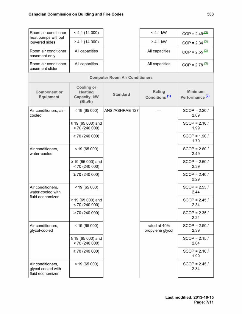
< 4.1 (14 000) < 4.1 kW COP = 2.49 (3)Room air conditionerheat pumps withoutlouvered sides ≥ 4.1 (14 000) ≥ 4.1 kW COP = 2.34 (3)
Room air conditioner,casement only
All capacities All capacities COP = 2.55 (3)
Room air conditioner,casement slider
All capacities All capacities COP = 2.78 (3)
Computer Room Air Conditioners
Component orEquipment
Cooling orHeating
Capacity, kW(Btu/h)
StandardRating
Conditions (1)Minimum
Performance (2)
< 19 (65 000) SCOP = 2.20 /2.09
≥ 19 (65 000) and< 70 (240 000)
SCOP = 2.10 /1.99
Air conditioners, air-cooled
≥ 70 (240 000) SCOP = 1.90 /1.79
< 19 (65 000) SCOP = 2.60 /2.49
≥ 19 (65 000) and< 70 (240 000)
SCOP = 2.50 /2.39
Air conditioners,water-cooled
≥ 70 (240 000) SCOP = 2.40 /2.29
< 19 (65 000) SCOP = 2.55 /2.44
≥ 19 (65 000) and< 70 (240 000)
SCOP = 2.45 /2.34
Air conditioners,water-cooled withfluid economizer
≥ 70 (240 000)
—
SCOP = 2.35 /2.24
< 19 (65 000) SCOP = 2.50 /2.39
≥ 19 (65 000) and< 70 (240 000)
SCOP = 2.15 /2.04
Air conditioners,glycol-cooled
≥ 70 (240 000) SCOP = 2.10 /1.99
Air conditioners,glycol-cooled withfluid economizer
< 19 (65 000)
ANSI/ASHRAE 127
rated at 40%propylene glycol
SCOP = 2.45 /2.34
PROPOSED CHANGE Table 5.2.12.1. Footnote
PROPOSED CHANGE Table 5.2.12.1. Footnote
PROPOSED CHANGE Table 5.2.12.1. Footnote
PROPOSED CHANGE Table 5.2.12.1. Footnote
PROPOSED CHANGE Table 5.2.12.1. FootnotePROPOSED CHANGE Table 5.2.12.1. Footnote
Canadian Commission on Building and Fire Codes 583
Last modified: 2013-10-15Page: 7/11

≥ 19 (65 000) and< 70 (240 000)
SCOP = 2.10 /1.99
≥ 70 (240 000) SCOP = 2.05 /1.94
< 19 (65 000) SCOP = 8.00 /6.06
≥ 19 (65 000) and< 70 (240 000)
SCOP = 9.00 /7.06
Chilled water airhandler
≥ 70 (240 000)
—
SCOP = 11.00 /9.06
Packaged Water Chillers
Component orEquipment
Cooling orHeating
Capacity, kW(Btu/h)
StandardRating
Conditions (1)Minimum
Performance (2)
Vapour compression,air- or water-cooled,electrically operated
Absorption, single- ordouble-effect,indirect-or direct-fired
< 5 600 (19 000000)
CAN/CSA-C743 — See standard (3)
Boilers
Component orEquipment
Cooling orHeating
Capacity, kW(Btu/h)
StandardRating
Conditions (1)Minimum
Performance (2)
Electric boilers — — — (4)
< 88 (300 000) ANSI Z21.13/CSA4.9
— AFUE = 85% (3)
≥ 88 (300 000)and
< 733 (2 500 000)
— Ec ≥ 82.5%Et ≥ 83.0%
Gas-fired boilers (5)
≥ 733 (2 500 000)
ANSI Z21.13/CSA4.9 or ASME PTC
4
— Ec ≥ 83.3%
< 88 (300 000) AFUE ≥ 84.7% (3)
≥ 88 (300 000)and
< 733 (2 500 000)
Et ≥ 83.4%
Oil-fired boilers
≥ 733 (2 500 000)
CSA B212 orASME PTC 4
—
Ec ≥ 85.8%
PROPOSED CHANGE Table 5.2.12.1. FootnotePROPOSED CHANGE Table 5.2.12.1. Footnote
PROPOSED CHANGE Table 5.2.12.1. Footnote
PROPOSED CHANGE Table 5.2.12.1. FootnotePROPOSED CHANGE Table 5.2.12.1. Footnote
PROPOSED CHANGE Table 5.2.12.1. Footnote
PROPOSED CHANGE Table 5.2.12.1. Footnote PROPOSED CHANGE Table 5.2.12.1. Footnote
PROPOSED CHANGE Table 5.2.12.1. Footnote
Canadian Commission on Building and Fire Codes 583
Last modified: 2013-10-15Page: 8/11

< 88 (300 000) CSA B212 AFUE ≥ 84.7% (3)
≥ 88 (300 000)and
< 733 (2 500 000)
Et ≥ 83.4%
Oil-fired boilers,residual (No. 5 or No.6 oil) and other
≥ 733 (2 500 000)
ASME PTC 4
—
Ec ≥ 85.8%
Warm-Air Furnaces, Combination Warm-Air Furnace/Air-conditioning Units, Duct Furnaces andUnit Heaters
Component orEquipment
Cooling orHeating
Capacity, kW(Btu/h)
StandardRating
Conditions (1)Minimum
Performance (2)
≤ 117.23 (400000)
— AFUE ≥ 92.4% (3)
Maximum ratedcapacity, steady-
state
Et ≥ 81%
Gas-fired warm-airfurnaces (5)
> 117.23 (400000)
ANSI Z21.47/CSA2.3
Minimum ratedcapacity, steady-
state
Et ≥ 81%
Gas-fired ductfurnaces (5)
Et ≥ 81%
Gas-fired unitheaters (5)
≤ 117.23 (400000)
ANSI Z83.8/CSA2.6
Et ≥ 82% (3)
≤ 66 (225 000) CSA B212 Et ≥ 84.5% (3)Oil-fired warm-airfurnaces
> 66 (225 000) Et ≥ 81.3%
Oil-fired ductfurnaces and unitheaters
—
CAN/CSA-B140.4
—
Et ≥ 81%
Notes to Table [5.2.12.1.] 5.2.12.1.:
The abbreviations that appear in this column have the following meanings:
db = dry bulb outdoor air temperature
wb = wet bulb outdoor air temperature
(1)PROPOSED CHANGE Table 5.2.12.1. Footnotereferrer
PROPOSED CHANGE Table 5.2.12.1. Footnote
PROPOSED CHANGE Table 5.2.12.1. FootnotePROPOSED CHANGE Table 5.2.12.1. Footnote
PROPOSED CHANGE Table 5.2.12.1. Footnote PROPOSED CHANGE Table 5.2.12.1. Footnote
PROPOSED CHANGE Table 5.2.12.1. Footnote
PROPOSED CHANGE Table 5.2.12.1. Footnote PROPOSED CHANGE Table 5.2.12.1. Footnote
PROPOSED CHANGE Table 5.2.12.1. Footnote
Footnote1
Footnote2
Canadian Commission on Building and Fire Codes 583
Last modified: 2013-10-15Page: 9/11

The symbols and abbreviations that appear in this column have the following meanings:
AFUE = annual fuel utilization efficiency, in %
Capc = rated cooling capacity, in W(Btu/h)
COP = coefficient of performance, in W/W
Ec = combustion efficiency, in %
EER = energy efficiency ratio, in (Btu/h)/W
Et = thermal efficiency, in %
ICOP = integrated coefficient of performance, in W/W
IPLV = integrated part-load value (no units)
SCOP = sensible coefficient of performance, in downflow units/upflow units (first value is downflow; secondvalue is upflow). The SCOP is a ratio that is calculated by dividing the net sensible cooling capacity,in W, by the total power input, in W (excluding re-heaters and humidifiers).
SEER = seasonal energy efficiency ratio, in (Btu/h)/W (no metric equivalent)
(2)PROPOSED CHANGE Table 5.2.12.1. Footnotereferrer
Components or equipment regulated in the Energy Efficiency Regulations at time of publication of the code(See Article 1.1.1.3. of Division A.)
(3)PROPOSED CHANGE Table 5.2.12.1. Footnotereferrer
No standards address the performance efficiency of electric boilers; however, their efficiency typicallyapproaches 100%.
(4)PROPOSED CHANGE Table 5.2.12.1. Footnotereferrer
Includes propane.(5)PROPOSED CHANGE Table 5.2.12.1. Footnotereferrer
RATIONALE
ProblemThe code does not currently identify which components are regulated by the Energy Efficiency Regulations, whichcan change minimum performance requirements between code cycles.
Justification - ExplanationThe proposed change identifies which components were regulated by the Energy Efficiency Regulations at the timeof publication of the NECB.
Cost implicationsNone, the change provides better clarity.
Enforcement implicationsNone, the change provides better clarity.
Footnote3
Footnote4
Footnote5
Canadian Commission on Building and Fire Codes 583
Last modified: 2013-10-15Page: 10/11

Who is affectedDesigners, manufacturers, builders, specification writers and building officials.
OBJECTIVE-BASED ANALYSIS OF NEW OR CHANGED PROVISIONSN/A
Canadian Commission on Building and Fire Codes 583
Last modified: 2013-10-15Page: 11/11

Comment
Proposed Change 600Code Reference(s): NECB11 Div.B Table 5.3.2.2.
NECB11 Div.B Table 5.3.2.4.NECB11 Div.B Table 5.3.2.7.NECB11 Div.B 5.3.2.8.
Subject: HVAC Trade-off-PathTitle: 06bNECB2011-DivB-05.03.01.01.-TOP-replace-EEBDescription: The proposed change updates the Trade-off-Path coefficient tables in
Section 5.3. of the NECB.
PROPOSED CHANGE
Table [5.3.2.2.] 5.3.2.2.Component Factors, γi, for Trade-off CalculationsForming part of Sentences 5.3.1.1.(1) and 5.3.2.2.(1)
HVAC System ID (2)
1 2 3 4 5 6 7 8 9 10 11 12 13 14 15 16 17 18 19 20 21 22 23 24 25 26 27Trade-offValue (1)
γi Factor (3)
ToV1 1 1 1 1 1 1 1 1 1 1 1 1 1 1 1 1 1 1 1 1 1 1 1 1 10 1 1
ToV2 1 1 1 1 1 1 1 1 1 1 1 1 1 1 1 1 1 1 1 1 1 1 1 1 10 1 1
ToV3 1 1 1 1 1 1 1 1 1 1 1 1 1 1 1 1 1 1 1 1 1 1 1 1 0 0 1
ToV4 1 1 1 1 1 1 1 1 1 1 1 1 1 1 1 1 1 1 1 1 1 1 1 1 0 0 1
ToV5 1 1 0 0 1 1 1 1 1 1 1 1 1 1 1 1 1 1 1 1 1 1 01 1 0 0 1
ToV6 1 10 0 0 1 1 0 0 1 10 10 10 1 0 0 0 0 0 0 0 0 0 0 0 0 0 0
ToV7 1 1 1 1 1 1 1 1 1 1 1 1 1 1 1 1 1 1 1 1 1 1 1 1 10 1 1
ToV8 1 1 1 1 1 1 1 1 1 1 1 1 1 1 1 1 1 1 1 1 1 1 1 1 10 1 1
ToV9 1 1 1 1 1 1 1 1 1 1 1 1 1 1 1 1 1 1 1 1 1 1 1 1 10 10 1
ToV10 1 1 01 1 1 1 1 1 1 1 1 1 1 1 1 1 1 1 1 1 1 1 1 1 1 1 1
ToV11 1 1 1 1 1 1 1 1 1 01 0 0 0 1 1 1 1 1 1 1 1 01 1 1 01 01 1
ToV12 1 1 1 1 1 1 1 1 1 1 1 1 1 1 1 1 1 1 1 1 1 1 1 1 1 1 1
ToV13 1 1 1 1 1 1 1 1 1 1 1 1 1 1 1 1 1 1 1 1 1 1 1 1 0 0 1
ToV14 1 1 1 1 1 1 1 1 1 1 1 1 1 1 1 1 1 0 1 1 1 1 1 1 0 0 1
ToV15 1 1 1 1 1 1 1 1 1 1 1 1 1 1 1 1 1 0 1 1 1 1 10 1 0 0 10
ToV16 1 1 1 1 1 1 1 1 1 1 1 1 1 1 1 1 1 1 1 1 1 1 1 1 0 01 1
ToV17 1 1 1 1 1 1 1 1 1 1 1 1 1 1 1 1 1 1 1 1 1 10 1 1 0 0 1
ToV18 1 1 0 1 0 0 1 0 1 1 0 1 1 1 1 1 01 0 1 1 1 0 1 1 0 0 1
ToV19 1 1 01 1 01 01 1 01 1 1 0 1 1 1 1 1 0 1 1 1 1 1 1 1 01 01 1
ToV20 1 1 0 1 0 0 1 0 1 10 0 1 1 1 1 1 01 1 1 1 1 10 1 1 0 0 1
ToV21 1 1 01 1 01 01 1 01 1 1 0 1 1 1 1 1 0 10 1 1 1 1 1 1 01 01 1
ToV22 1 1 0 1 0 0 1 0 1 10 0 1 1 1 1 1 01 1 1 1 1 10 1 1 0 0 1
ToV23 1 1 01 1 01 01 1 01 1 1 0 1 1 1 1 1 10 10 1 1 1 1 1 1 01 01 1
ToV24 1 1 0 1 0 0 1 0 1 10 0 1 1 1 1 1 1 1 1 1 1 10 1 1 0 0 1
PROPOSED CHANGE Table 5.3.2.2. FootnotePROPOSED CHANGE Table 5.3.2.2. Footnote
PROPOSED CHANGE Table 5.3.2.2. Footnote
Canadian Commission on Building and Fire Codes 600
Last modified: 2013-10-01Page: 1/36

HVAC System ID (2)
1 2 3 4 5 6 7 8 9 10 11 12 13 14 15 16 17 18 19 20 21 22 23 24 25 26 27Trade-offValue (1)
γi Factor (3)
ToV25 1 1 01 1 01 01 1 01 1 1 0 1 1 1 1 1 10 10 1 1 1 1 1 1 01 01 1
ToV26 1 1 0 1 0 0 1 0 1 1 0 1 1 1 1 1 1 1 1 1 1 1 1 1 0 0 1
ToV27 1 1 01 1 01 01 1 0 1 1 0 1 1 1 1 1 10 10 1 1 1 1 1 1 01 01 1
ToV28 1 1 0 1 0 0 1 0 1 1 0 1 1 1 1 1 1 1 1 1 1 10 1 1 0 0 1
ToV29 1 1 01 1 01 01 1 01 1 1 0 1 1 1 1 1 10 10 1 1 1 1 1 1 01 01 1
ToV30 1 1 0 1 0 0 1 0 1 1 0 1 1 1 1 1 1 1 1 1 1 10 1 1 0 0 1
ToV31 1 1 01 1 01 01 1 01 1 1 0 1 1 1 1 1 10 10 1 1 1 1 1 1 01 01 1
ToV32 1 1 0 1 0 0 1 0 1 10 0 1 1 1 1 1 1 1 1 1 1 10 1 1 0 0 1
Notes to Table [5.3.2.2.] 5.3.2.2.:
See Table 5.3.2.3. for a description of these values.(1)PROPOSED CHANGE Table 5.3.2.2. Footnotereferrer
See Table 5.3.1.1. for a description of each system.(2)PROPOSED CHANGE Table 5.3.2.2. Footnotereferrer
Only components with γi = 1 are to be included for a given HVAC system.(3)PROPOSED CHANGE Table 5.3.2.2. Footnotereferrer
PROPOSED CHANGE Table 5.3.2.2. FootnotePROPOSED CHANGE Table 5.3.2.2. Footnote
PROPOSED CHANGE Table 5.3.2.2. Footnote
Footnote1Footnote2Footnote3
Canadian Commission on Building and Fire Codes 600
Last modified: 2013-10-01Page: 2/36

Table [5.3.2.4.] 5.3.2.4.Base Values, BaVi
Forming part of Sentence 5.3.2.4.(1)
HVAC System ID (1)BaVi
1 2 3 4 5 6 7 8 9 10 11 12 13 14 15 16 17 18 19 20 21 22 23 24 25 26 27
BaV1 60.00% 60.00% 43.64% 54.55% 60.00% 49.09% 60.00% 49.09% 65.00% 60.00% 49.09% 60.00% 60.00% 60.00% 60.00% 60.00% 60.00% 60.00% 65.40% 65.00% 65.00% 43.64% 60.00% 65.40% 54.55% 54.55% 60.00%
BaV2 91.67% 91.67% 91.67% 91.67% 91.67% 91.67% 91.67% 91.67% 92.31% 91.67% 91.67% 91.67% 91.67% 91.67% 91.67% 91.67% 91.67% 91.67% 91.67% 91.67% 91.67% 91.67% 91.67% 91.67% 91.67% 91.67% 91.67%
BaV3 37.50% 37.50% 31.25% 31.25% 37.50% 25.00% 37.50% 25.00% 30.00% 37.50% 25.00% 37.50% 37.50% 37.50% 37.50% 37.50% 37.50% 37.50% 31.25% 37.50% 37.50% 31.25% 37.50% 31.25% 31.25% 31.25% 37.50%
BaV4 80% 80% 80% 80% 80% 80% 80% 80% 80% 80% 80% 80% 80% 80% 80% 80% 80% 80% 80% 80% 80% 80% 80% 80% 80% 80% 80%
BaV5 0.5 0 0 0 0 0 0 0 0 0 0 0 0 0 0 0 0 0 0 0 0 0 0.5 0 0.943 0.943 0.5
BaV6 0.3286113 0.3286113 0.3286113 0.3286113 0.3286113 0.3286113 0.3286113 0.3286113 0.556982128 0.556982128 0.556982128 0.3286113 0.3286113 0.3286113 0.3286113 0.3286113 0.3286113 0.3286113 0.3286113 0.3286113 0.3286113 0.3286113 0.3286113 0.3286113 0.556982128 0.556982128 0.3286113
BaV7 1000 1000 325 500 1000 750 1000 750 1500 1000 750 1000 500 500 500 500 500 500 500 1500 1500 500 500 500 500 500 500
BaV8 0.58 0.58 0.58 0.58 0.58 0.58 0.58 0.58 0.58 0.58 0.58 0.58 0.579429377 0.579429377 0.58 0.58 0.579429377 0.579429377 0.58 0.58 0.58 0.58 0.579429377 0.58 0.58 0.58 0.579429377
BaV9 250 250 0 150 250 150 250 150 375 250 150 250 150 150 150 150 150 150 150 375 375 150 150 150 150 150 150
BaV10 11.11 11.11 11.11 11.11 11.11 11.11 11.11 11.11 11.11 11.11 11.11 11.11 11.11 11.11 11.11 11.11 11.11 11.11 11.11 11.11 11.11 11.11 11.11 11.11 11.11 11.11 11.11
BaV11 11.11 11.11 11.11 11.11 11.11 11.11 11.11 11.11 11.11 11.11 11.11 11.11 11.11 11.11 11.11 11.11 11.11 11.11 11.11 11.11 11.11 11.11 11.11 11.11 11.11 11.11 11.11
BaV12(2) 0.8 0.8 0.8 0.8 0.8 0.8 0.8 0.8 0.8 0.8 0.8 0.8 0.8 0.8 0.8 0.8 0.8 3.095975232 0.8 0.8 0.8 0.8 0.8 0.8 0.8 0.8 0.8
BaV13 5.2 5.2 2.95945546 5.2 2.777777778 2.777777778 5.2 2.777777778 5.200208008 5.2 2.8 5.2 5.2 5.2 5.2 5.2 3.52 3.937007874 5.2 5.2 5.2 5.2 5.2 5.2 5.2 5.2 5.2
BaV14 0.015 0.015 0.015 0.015 0.015 0.015 0.015 0.015 0.015 0.015 0 0.015 0.015 0.015 0.015 0.015 0.015 0.015 0.015 0.015 0.015 0.015 0.015 0.015 0.015 0.015 0.015
BaV15 0.8 0.8 0.8 0.8 0.8 0.8 0.8 0.8 0.8 0.8 0.8 0.8 0.8 0.8 0.8 0.8 0.8 0.8 0.8 0.8 0.8 0.8 0.8 0.8 0.8 0.8 0.8
BaV16 0.8 0.8 0.8 0.8 0.8 0.8 0.8 0.8 0.8 0.8 0.8 0.8 0.8 0.8 0.8 0.8 0.8 0.8 0.8 0.8 0.8 0.8 0.8 0.8 0.8 0.8 0.8
BaV17 0 0 0 0 0 0 0 0 0 0 0 0 0 0 0 0 0 0 0 0 0 0 0 0 0 0 0
BaV18 0 0 0 0 0 0 0 0 0 0 0 0 0 0 0 0 0 0 0 0 0 0 0 0 0 0 0
BaV19 0.880591758 0.880591758 0.880591758 0.880591758 0.880591758 0.880591758 0.880591758 0.880591758 0.880591758 0.880591758 0.880591758 0.880591758 0.880591758 0.880591758 0.880591758 0.880591758 0.880591758 0.880591758 0.880591758 0.880591758 0.880591758 0.880591758 0.880591758 0.880591758 0.880591758 0.880591758 0.880591758
BaV20 0.880591758 0.880591758 0.880591758 0.880591758 0.880591758 0.880591758 0.880591758 0.880591758 0.880591758 0.880591758 0.880591758 0.880591758 0.880591758 0.880591758 0.880591758 0.880591758 0.880591758 0.880591758 0.880591758 0.880591758 0.880591758 0.880591758 0.880591758 0.880591758 0.880591758 0.880591758 0.880591758
BaV21 179.344014 179.344014 179.344014 179.344014 179.344014 179.344014 179.344014 179.344014 179.344014 179.344014 179.344014 179.344014 179.344014 179.344014 179.344014 179.344014 179.344014 179.344014 179.344014 179.344014 179.344014 179.344014 179.344014 179.344014 179.344014 179.344014 179.344014
BaV22 119.562676 119.562676 119.562676 119.562676 119.562676 119.562676 119.562676 119.562676 119.562676 119.562676 119.562676 119.562676 119.562676 179.344014 119.562676 119.562676 179.344014 179.344014 179.344014 119.562676 119.562676 119.562676 119.562676 179.344014 119.562676 119.562676 119.562676
BaV23 60% 60% 60% 60% 60% 60% 60% 60% 60% 60% 60% 60% 60% 60% 60% 60% 60% 60% 60% 60% 60% 60% 60% 60% 60% 60% 60%
PROPOSED CHANGE Table 5.3.2.4. Footnote
PROPOSED CHANGE Table 5.3.2.4. Footnote
Canadian Commission on Building and Fire Codes 600
Last modified: 2013-10-01Page: 3/36

HVAC System ID (1)BaVi
1 2 3 4 5 6 7 8 9 10 11 12 13 14 15 16 17 18 19 20 21 22 23 24 25 26 27
BaV24 60% 60% 60% 60% 60% 60% 60% 60% 60% 60% 60% 60% 60% 60% 60% 60% 60% 60% 60% 60% 60% 60% 60% 60% 60% 60% 60%
BaV25 90% 90% 90% 90% 90% 90% 90% 90% 90% 90% 90% 90% 90% 90% 90% 90% 90% 90% 90% 90% 90% 90% 90% 90% 90% 90% 90%
BaV26 90% 90% 90% 90% 90% 90% 90% 90% 90% 90% 90% 90% 90% 90% 90% 90% 90% 90% 90% 90% 90% 90% 90% 90% 90% 90% 90%
BaV27 0 0 0 0 0 0 0 0 0 0 0 0 0 0 0 0 0 0 0 0 0 0 0 0 0 0 0
BaV28 0 0 0 0 0 0 0 0 0 0 0 0 0 0 0 0 0 0 0 0 0 0 0 0 0 0 0
BaV29 0 0 0 0 0 0 0 0 0 0 0 0 0 0 0 0 0 0 0 0 0 0 0 0 0 0 0
BaV30 0 0 0 0 0 0 0 0 0 0 0 0 0 0 0 0 0 0 0 0 0 0 0 0 0 0 0
BaV31 0 0 0 0 0 0 0 0 0 0 0 0 0 0 0 0 0 0 0 0 0 0 0 0 0 0 0
BaV32 0 0 0 0 0 0 0 0 0 0 0 0 0 0 0 0 0 0 0 0 0 0 0 0 0 0 0
PROPOSED CHANGE Table 5.3.2.4. Footnote
Canadian Commission on Building and Fire Codes 600
Last modified: 2013-10-01Page: 4/36

Notes to Table [5.3.2.4.] 5.3.2.4.:
See Table 5.3.1.1. for a description of each system.(1)PROPOSED CHANGE Table 5.3.2.4. Footnotereferrer
BaV12 shall not be a gas-fired unit heater < 117.23 kW.(2)PROPOSED CHANGE Table 5.3.2.4. Footnotereferrer
Footnote1Footnote2
Canadian Commission on Building and Fire Codes 600
Last modified: 2013-10-01Page: 5/36

Table [5.3.2.4.] 5.3.2.7.Base Values, BaVi
Forming part of Sentence 5.3.2.7.(1)
HVAC System ID (1)ToVi
1 2 3 4 5 6 7 8 9 10 11 12 13 14 15 16 17 18 19 20 21 22 23 24 25 26 27
ToV5
SupplyOA Reset
0.718351808 0.229475163 0 0 0.223979284 0.238648343 0.201095898 0.217943619 0.1136173 -0.042439104 -0.039957226 0.150994256 0.0668164 0 0 0 0 1.38589E-05 0.042101813 0.107816719 0.107816719 0 0.934369236 0.042101813 0.918046961 0.918046961 0.934369236
Warmest 0.870840928 0.42542159 0 0 0.387123049 0.445572664 0.354270283 0.379669081 0.173625767 -0.065092919 -0.064031493 0.190276915 0.04350134 0 0 0 0 1.38589E-05 0.069829339 0.124817224 0.124817224 0 1 0.069829339 0.730260865 0.730260865 1
Constant> 15°C
0.687428631 0.199016302 0 0 0.186118515 0.200863221 0.172008154 0.180814882 0.093545499 -0.040125161 -0.034976262 0.129934449 0.05047574 0 0 0 0 1.38589E-05 0.03525774 0.095822879 0.095822879 0 0.862293326 0.03525774 0.918110782 0.918110782 0.862293326
Constant≤ 15°C
0.718351808 0.229475163 0 0 0.223979284 0.238648343 0.201095898 0.217943619 0.1136173 -0.042439104 -0.039957226 0.150994256 0.0668164 0 0 0 0 1.38589E-05 0.042101813 0.107816719 0.107816719 0 0.934369236 0.042101813 0.918046961 0.918046961 0.934369236
ToV6
Forwardcurve with
vanes
0.3286113 0.604498703 0.6044987 0.6044987 0.3286113 0.604498703 0.604498703 0.604498703 0.604498703 0.604498703 0.604498703 0.3286113 0.3286113 0.6044987 0.604498703 0.6044987 0.604498703 0.604498703 0.604498703 0.604498703 0.604498703 0.604498703 0.604498703 0.604498703 0.604498703 0.604498703 0.604498703
VSD 0.335103272 0.608350396 0.6083504 0.6083504 0.335103272 0.608350396 0.608350396 0.608350396 0.608350396 0.608350396 0.608350396 0.335103272 0.33510327 0.6083504 0.608350396 0.6083504 0.608350396 0.608350396 0.608350396 0.608350396 0.608350396 0.608350396 0.608350396 0.608350396 0.608350396 0.608350396 0.608350396
Airfoil withinlet
vanes
0.238631568 0.365583687 0.36558369 0.36558369 0.238631568 0.365583687 0.365583687 0.365583687 0.365583687 0.365583687 0.365583687 0.238631568 0.23863157 0.3655837 0.365583687 0.36558369 0.365583687 0.365583687 0.365583687 0.365583687 0.365583687 0.365583687 0.365583687 0.365583687 0.365583687 0.365583687 0.365583687
Riding fancurve
0.1007824 0.2069982 0.2069982 0.2069982 0.1007824 0.2069982 0.2069982 0.2069982 0.2069982 0.2069982 0.2069982 0.1007824 0.1007824 0.2069982 0.2069982 0.2069982 0.2069982 0.2069982 0.2069982 0.2069982 0.2069982 0.2069982 0.2069982 0.2069982 0.2069982 0.2069982 0.2069982
ToV15
Dual DBT 0.8 0.8 0.8 0.8 0.8 0.8 0.8 0.8 0.8 0.8 0.8 0.8 0.8 0.8 0.8 0.8 0.8 0.8 0.8 0.8 0.8 0.8 0.8 0.8 0.8 0.8 0.8
Enthalpy 0.800006736 0.800002536 0.80000254 0.80000254 0.800002536 0.800002536 0.800002536 0.800002536 0.800002536 0.800002536 0.800015077 0.800003694 0.79999215 0.799989 0.799992413 0.79999241 0.800002536 0.800002536 0.8 0.800006804 0.800006804 0.8 0.8 0.8 0.8 0.8 0.8
DualEnthalpy
0.800356531 0.800035432 0.80003543 0.80003543 0.800035432 0.800035432 0.800035432 0.800035432 0.800035432 0.800035432 0.800032578 0.800044806 0.79999215 0.7999904 0.8 0.8 0.800035432 0.800035432 0.8 0.800086124 0.800086124 0.8 0.8 0.8 0.8 0.8 0.8
Fixed 0.781327086 0.784564115 0.78456412 0.78456412 0.784564115 0.784564115 0.784564115 0.784564115 0.784564115 0.784564115 0.734038432 0.783197266 0.7509573 0.7903048 0.783322707 0.78332271 0.784564115 0.784564115 0.797511902 0.794313288 0.794313288 0.8 0.8 0.797511902 0.8 0.8 0.8
Dry Bulb 0.8 0.8 0.8 0.8 0.8 0.8 0.8 0.8 0.8 0.8 0.8 0.8 0.8 0.8 0.8 0.8 0.8 0.8 0.8 0.8 0.8 0.8 0.8 0.8 0.8 0.8 0.8
ToV16
Fraction ofhourly
0.801720851 0.8 0.8 0.8 0.801977461 0.8 0.8 0.801814092 0.834086341 0.80001221 0.800643861 0.8 0.80210748 0.7999904 0.800007587 0.80000759 0.8 0.8 0.8 0.8 0.8 0.8 0.8 0.8 0.8 0.8 0.8
DCVReturn
0.896566233 0.849310871 0.84931087 0.84931087 0.809399509 0.806763058 0.849310871 0.808479453 0.839320988 0.828631643 0.913669122 0.896900912 0.84698829 0.9965024 0.941970184 0.94197018 0.849310871 0.849310871 0.920086284 0.904778636 0.904778636 0.898056935 0.879910469 0.920086284 0.8 0.801383158 0.879910469
PROPOSED CHANGE Table 5.3.2.7. Footnote
Canadian Commission on Building and Fire Codes 600
Last modified: 2013-10-01Page: 6/36

HVAC System ID (1)ToVi
1 2 3 4 5 6 7 8 9 10 11 12 13 14 15 16 17 18 19 20 21 22 23 24 25 26 27
DCVSupply
0.896503116 0.849302909 0.84930291 0.84930291 0.809192102 0.806568335 0.849302909 0.808281051 0.837154394 0.828692942 0.912955127 0.896886253 0.84657377 0.986393 0.93445703 0.93445703 0.849302909 0.849302909 0.920075818 0.904778719 0.904778719 0.898189892 0.878615078 0.920075818 0.8 0.801297732 0.878615078
DCV,fraction of
hourly,Return
0.896896383 0.849310871 0.84931087 0.84931087 0.810266715 0.806763058 0.849310871 0.809273254 0.844313534 0.828712745 0.91888869 0.896900912 0.84736667 0.9965024 0.941970184 0.94197018 0.849310871 0.849310871 0.920086284 0.904778636 0.904778636 0.898056935 0.879930043 0.920086284 0.8 0.801383158 0.879930043
Fixed 0.8 0.8 0.8 0.8 0.8 0.8 0.8 0.8 0.8 0.8 0.8 0.8 0.8 0.8 0.8 0.8 0.8 0.8 0.8 0.8 0.8 0.8 0.8 0.8 0.8 0.8 0.8
ToV27
Demand-only
0.014097387 0.008428726 0.10349849 0.09412882 0.014718819 0.006510265 0.010871025 -0.002731037 0.015448861 -0.002107471 -0.004700312 -0.033059135 -0.0124044 0 0.155008196 0.1550082 0.00986064 0.028421888 0 0.162415906 0.162415906 0.120515511 0.043369963 0 0.192644632 0.197739422 0.043369963
Standby -0.002185283 -0.004756411 -0.01955425 -0.01771632 -0.001176924 -0.005663251 -0.00452742 -0.013602785 -0.019153065 -0.003179163 -0.0047663 -0.033308781 -0.01831123 0 -0.028303756 -0.0283038 0 1.38589E-05 -0.039674347 -0.022891111 -0.022891111 -0.02090152 -0.026227106 -0.039674347 -0.027757908 -0.03065251 -0.026227106
Snapzone
0.001928189 -0.001743114 0.04581534 0.04131761 0.00267384 -0.003132194 -0.00049369 -0.01209296 -0.009410877 0.489773396 0.423761589 0.159492108 0.08557561 0 0.068155728 0.06815573 0.00986064 0.028421888 -0.015717632 0.039021363 0.039021363 0.05624936 0.113113553 -0.015717632 0.193382096 0.195314315 0.113113553
Scheduled -0.001395159 -0.004043922 -0.01709318 -0.01543893 -0.000371866 -0.005024138 -0.00375234 -0.013722514 -0.018302268 -0.002517693 -0.003398453 -0.024734596 -0.01526479 0 -0.02456961 -0.0245696 -0.098432728 -0.149720021 -0.039674347 -0.02089664 -0.02089664 -0.01822073 -0.022857143 -0.039674347 -0.020827964 -0.02150766 -0.022857143
Snapoutdoor
0 0 0 0 0 0 0 0 0 0 0 0 0 0 0 0 0 0 0 0 0 0 0 0 0 0 0
ToV28
Demand-only
0.02638576 0.040836268 0 -0.04563853 0 0 0.02246887 0 -0.004884129 0.047403255 0 0.033536419 0.02879389 0 -0.008390456 -0.0083905 0.00986064 0.028421888 0 0.003747625 0.003747625 0 0.045798336 0 0 0 0.045798336
Standby 0.020151612 0.036372428 0 -0.08644353 0 0 0.016940544 0 -0.018917067 0.048080242 0 0.029575806 0.01746008 -0.00883 -0.024904845 -0.0249048 0 1.38589E-05 -0.039674347 -0.003409486 -0.003409486 0 -0.035231958 -0.039674347 0 0 -0.035231958
Snapzone
0.020426732 0.040919034 0 -0.06854804 0 0 0.016103426 0 -0.007343508 0.048080242 0 0.029575806 0.01810534 0.0072988 -0.022859499 -0.0228595 0.00986064 0.028421888 -0.021347749 -0.002435476 -0.002435476 0 -0.030956659 -0.021347749 0 0 -0.030956659
Scheduled 0.026552992 0.042292208 0 -0.0287094 0 0 0.022950013 0 -0.017608321 0.042477068 0 0.037685298 0.01456422 -0.133527 -0.03972269 -0.0397227 -0.098432728 -0.149720021 -0.039674347 -0.00101341 -0.00101341 0 -0.056647691 -0.039674347 0 0 -0.056647691
Snapoutdoor
0 0 0 0 0 0 0 0 0 0 0 0 0 0 0 0 0 0 0 0 0 0 0 0 0 0 0
ToV29
Fixed 0 0 0 0 0 0 0 0 0 0 0 0 0 0 0 0 0 0 0 0 0 0 0 0 0 0 0
Scheduled 0 0 0 0 0 0 0 0 0 0 0 0 0 0 0 0 0 0 0 0 0 0 0 0 0 0 0
Load reset 0.028574068 0.017855456 0.11984956 0.10876105 0.028335783 0.000574583 0.000713518 0.027328148 0.022032499 -0.002168953 0.000498809 0.002305777 0.01547191 0 0.196746154 0.19674615 0 1.38589E-05 0.025197064 0.179841213 0.179841213 0.150212536 0.022347086 0.025197064 0.211289668 0.22003175 0.022347086
OA Reset,min 140
°F
-0.04034809 -0.028866175 -0.00809919 -0.00748025 -0.038293859 -0.000699829 -0.0007692 -0.036443635 -0.005096088 -0.006158602 -0.00512882 -0.002280002 -0.00634717 0 0.009053602 0.0090536 0.003806676 0.000400832 -0.00366448 -0.002847047 -0.002847047 -0.01734916 -0.030326214 -0.00366448 -0.028262732 -0.0280636 -0.030326214
PROPOSED CHANGE Table 5.3.2.7. Footnote
Canadian Commission on Building and Fire Codes 600
Last modified: 2013-10-01Page: 7/36

HVAC System ID (1)ToVi
1 2 3 4 5 6 7 8 9 10 11 12 13 14 15 16 17 18 19 20 21 22 23 24 25 26 27
OA Reset,min >140
°F
0 0 0 0 0 0 0 0 0 0 0 0 0 0 0 0 0 0 0 0 0 0 0 0 0 0 0
ToV30
Fixed -0.019212644 -0.015443597 0 -0.03355809 0 0 -0.01828079 0 -0.033624684 -0.002412572 0 -0.010736884 -0.01903273 0 -0.025749585 -0.0257496 0 1.38589E-05 0 -0.013614452 -0.013614452 0 -0.017722959 0 0 0 -0.017722959
Scheduled -0.010381618 -0.008533429 0 -0.02299299 0 0 -0.00981598 0 -0.018678517 -0.001413943 0 -0.005976246 -0.00959202 0.0023123 -0.012738478 -0.0127385 0.008382105 1.38589E-05 0.00111889 -0.007501003 -0.007501003 0 -0.007842079 0.00111889 0 0 -0.007842079
Load reset 0.026038946 0.019434213 0 0.00241259 0 0 0.025026065 0 0.034814823 -0.001523831 0 0.012635092 0.02392107 0.0122016 0.033970836 0.03397084 0 1.38589E-05 0.000797061 0.006228691 0.006228691 0 0.02011674 0.000797061 0 0 0.02011674
OA Reset,min 58 °F
0.013393214 0.01084633 0 0.01385172 0 0 0.012943329 0 0.021708643 0.002030324 0 0.007595084 0.01306747 0.0090018 0.014995535 0.01499554 0.009736828 1.38589E-05 0.001828049 0.010367364 0.010367364 0 0.007653688 0.001828049 0 0 0.007653688
OA Reset,min <54
°F
0 0 0 0 0 0 0 0 0 0 0 0 0 0 0 0 0 0 0 0 0 0 0 0 0 0 0
ToV31
VSD,valvereset
0.032148038 0.027604491 0.00892042 0.00801012 0.030676063 0.025192414 0.030449862 0.029433667 -0.001060675 0.008110535 0.009965783 0.015983651 0.03467979 0.0110277 0.017270984 0.01727098 0.031189964 0.062778632 0.016015763 0.009887893 0.009887893 0.011583804 0.010337786 0.016015763 0.05373368 0.053217395 0.010337786
Twospeed, .67
0.029174856 0.025016031 0.01052838 0.00948619 0.027836214 0.022819451 0.027630282 0.026710427 -0.000565494 0.007043044 0.008795346 0.01422252 0.0318937 0.0091629 0.013700067 0.01370007 0 8.62441E-05 0.012626964 0.00791288 0.00791288 0.013236846 0.007997638 0.012626964 0.04946042 0.048876886 0.007997638
VSD, fixed 0.032081675 0.027539763 0.00891061 0.00802792 0.030611543 0.025123499 0.030385099 0.029371506 -0.001049716 0.008045401 0.009893423 0.015890003 0.03468747 0.0110277 0.017270984 0.01727098 0.006553928 -0.016674072 0.015146753 0.009883044 0.009883044 0.011606316 0.010229609 0.015146753 0.053713954 0.053172745 0.010229609
Twospeed, .5
0.032036509 0.02650506 0.01013651 0.00911621 0.030600621 0.02410137 0.030364673 0.02936881 -0.000572088 0.006013116 0.007981359 0.014152212 0.03478371 0.0109663 0.017491848 0.01749185 0 1.38589E-05 0.013245671 0.009982115 0.009982115 0.012807221 0.008906526 0.013245671 0.053966885 0.053265404 0.008906526
Constant 0 0 0 0 0 0 0 0 0 0 0 0 0 0 0 0 0 0 0 0 0 0 0 0 0 0 0
ToV32
VSD,valvereset
0.004329907 0.003457231 0 0.05179635 0 0 0.004210254 0 0.007265315 0.000830607 0 0.002415135 0.00555284 0.0115862 0.005987662 0.00598766 0.031189964 0.062778632 0.016015763 0.002428834 0.002428834 0 0.010485886 0.016015763 0 0 0.010485886
Twospeed,
.67, valvereset
0.00335213 0.002650556 0 0.05023688 0 0 0.003249938 0 0.00557344 0.00053239 0 0.001832895 0.00431031 0.0091807 0.004691493 0.00469149 0 8.62441E-05 0.012626964 0.001364941 0.001364941 0 0.009556002 0.012626964 0 0 0.009556002
VSD, fixed 0.001521945 0.001190057 0 0.04737392 0 0 0.001504536 0 0.002455674 0.000359769 0 0.00083423 0.00193367 0.0110277 0.002248092 0.00224809 0.006553928 -0.016674072 0.015146753 0.000930528 0.000930528 0 0.007879005 0.015146753 0 0 0.007879005
Twospeed, .5,
fixed
0 0 0 0.04461117 0 0 0 0 0 0 0 0 0 0.0109663 0 0 0 1.38589E-05 0.013245671 0 0 0 0.006397432 0.013245671 0 0 0.006397432
Constant 0 0 0 0 0 0 0 0 0 0 0 0 0 0 0 0 0 0 0 0 0 0 0 0 0 0 0
PROPOSED CHANGE Table 5.3.2.7. Footnote
Canadian Commission on Building and Fire Codes 600
Last modified: 2013-10-01Page: 8/36

Note to Table [5.3.2.4.] 5.3.2.7.:
See Table 5.3.1.1. for a description of each system.(1)PROPOSED CHANGE Table 5.3.2.7. Footnotereferrer
[5.3.2.8.] 5.3.2.8. Coefficient Values: α1i, α2i, α3i, β1i, β2i and β3i
[1] 1) The coefficient values of α1i, α2i, α3i, β1i, β2i and β3i to be used for weighting αi and βi in Article 5.3.2.5. shall be selected from Tables 5.3.2.8.A.to 5.3.2.8.AA. for the given HVAC type and component.
Table [5.3.2.8.A] 5.3.2.8.A.Coefficient Values for System Type HVAC-1 (Built-up Variable-Volume)
Forming part of Sentences 5.3.2.6.(1) and [5.3.2.8.] 5.3.2.8.([1] 1)
Coefficient ValuesTrade-off Values for Componenti, ToVi
Climatic Parameter for Componenti, XDDi α1i α2i α3i β1i β2i β3i
ToV1 HDD 7.289E-01 -1.664E-05 -2.964E-09 -3.944E-01 2.766E-06 2.386E-09
ToV2 HDD 5.659E-01 -4.171E-05 1.409E-09 -2.264E-01 1.600E-05 -5.029E-10
ToV3 HDD 2.815E-01 6.340E-05 -4.712E-09 -2.521E-01 -5.779E-05 4.289E-09
ToV4 HDD 1.390E-01 2.729E-05 -2.006E-09 -6.338E-02 -1.200E-05 8.783E-10
ToV5 HDD -7.005E+00 2.684E-03 -2.056E-07 6.871E+00 -2.305E-03 1.767E-07
ToV6 TDD 1.289E-01 2.027E-05 -2.737E-09 -4.376E-02 -1.289E-05 -9.358E-11
ToV7 HDD -1.365E-04 1.085E-08 -3.832E-13 1.973E-09 -3.677E-13 1.409E-17
ToV8 HDD 1.596E-01 -4.054E-05 2.288E-09 -1.051E-01 2.792E-05 -1.713E-09
ToV9 HDD -1.264E-04 -1.765E-08 1.329E-12 2.481E-08 -1.184E-11 8.575E-16
ToV10 HDD 1.028E-02 -1.207E-06 6.055E-11 -2.684E-04 3.165E-08 -1.579E-12
ToV11 HDD 1.374E-02 -1.653E-06 1.089E-10 -3.808E-04 4.554E-08 -2.981E-12
ToV12 HDD 2.235E+00 1.029E-04 -3.360E-10 -9.039E-01 -4.253E-05 2.048E-10
ToV13 HDD 3.169E-03 2.177E-04 -2.055E-07 -2.055E-04 -1.400E-05 1.319E-08
ToV14 TDD -1.287E-02 -5.159E-04 2.107E-07 -4.509E-01 1.151E-03 -3.587E-07
ToV15 CDD -4.598E+00 7.017E-01 -1.668E-03 3.221E+00 -4.405E-01 1.050E-03
ToV16 TDD -6.642E+01 2.557E-02 -2.180E-06 3.988E+01 -1.513E-02 1.289E-06
ToV17 TDD 1.302E-01 -5.298E-05 4.634E-09 -1.412E-01 5.706E-05 -4.982E-09
ToV18 CDD -1.193E-02 8.378E-05 -1.197E-07 1.624E-02 -2.165E-05 2.748E-08
ToV19 TDD 4.508E-01 -6.310E-05 1.945E-09 -1.174E-01 1.276E-05 7.327E-11
ToV20 CDD 3.078E-03 3.911E-05 -5.421E-08 -1.067E-03 -1.038E-05 1.310E-08
ToV21 HDD -2.063E-04 1.512E-08 -9.821E-13 -3.726E-07 7.623E-11 -4.367E-15
ToV22 CDD 2.462E-06 -2.983E-07 3.722E-10 -3.630E-08 3.402E-10 -5.659E-13
ToV23 TDD 5.430E+00 -1.230E-03 6.439E-08 -5.275E+00 1.197E-03 -6.615E-08
ToV24 CDD 3.457E-03 1.411E-04 -1.474E-07 -1.795E-03 -8.202E-05 8.575E-08
ToV25 HDD 2.510E-01 -3.693E-05 2.366E-09 -9.854E-02 1.537E-05 -1.012E-09
ToV26 CDD 3.108E-03 9.808E-05 -1.257E-07 -1.372E-03 -4.117E-05 5.601E-08
ToV27 HDD 7.309E-02 5.762E-04 -6.822E-08 2.041E+02 -8.085E-02 7.183E-06
ToV28 CDD 4.436E+00 -2.503E-02 3.333E-05 -9.523E+01 7.052E-01 -9.516E-04
ToV29 HDD 3.175E+00 -7.257E-04 5.340E-08 4.942E+00 -3.457E-03 4.293E-07
Footnote1
Canadian Commission on Building and Fire Codes 600
Last modified: 2013-10-01Page: 9/36

ToV30 CDD 2.806E-01 5.773E-03 -8.277E-06 -4.603E+00 3.810E-02 -5.581E-05
ToV31 TDD 1.674E+00 -1.893E-04 1.049E-08 3.752E-01 -3.238E-04 4.304E-08
ToV32 CDD 9.517E-02 5.884E-03 -7.048E-06 -1.837E-02 -5.594E-02 1.368E-04
Table [5.3.2.8.B] 5.3.2.8.B.Coefficient Values for System Type HVAC-2 (Constant-Volume Reheat)
Forming part of Sentences 5.3.2.6.(1) and [5.3.2.8.] 5.3.2.8.([1] 1)
Coefficient ValuesTrade-off Values forComponent i, ToVi
Climatic Parameter forComponent i, XDDi α1i α2i α3i β1i β2i β3i
ToV1 HDD 7.692E-01 2.524E-05 -8.421E-09 -4.120E-01 -2.340E-05 5.790E-09
ToV2 HDD 6.736E-01 -4.363E-05 5.836E-10 -2.812E-01 2.052E-05 -4.466E-10
ToV3 HDD 2.591E-01 1.263E-04 -1.089E-08 -2.338E-01 -1.140E-04 9.823E-09
ToV4 HDD 1.181E-01 6.083E-05 -5.236E-09 -5.177E-02 -2.790E-05 2.393E-09
ToV5 HDD -6.115E-02 3.313E-04 -2.324E-08 4.440E+00 -1.392E-03 9.807E-08
ToV6 HDD 7.219E-02 -8.589E-07 -2.636E-10 -9.363E-02 1.257E-06 3.284E-10
ToV7 TDD -1.408E-04 4.572E-09 3.008E-13 -2.439E-09 1.098E-12 -9.571E-17
ToV8 HDD 5.434E-02 -1.280E-05 4.978E-10 -2.984E-02 6.126E-06 -2.020E-10
ToV9 TDD -1.133E-04 -4.272E-08 3.737E-12 1.370E-08 -9.801E-12 7.672E-16
ToV10 HDD 6.912E-03 -6.839E-07 4.144E-11 -1.787E-04 1.787E-08 -1.091E-12
ToV11 HDD 1.142E-02 -1.296E-06 1.084E-10 -3.167E-04 3.610E-08 -3.018E-12
ToV12 HDD 2.341E+00 6.209E-05 2.417E-09 -9.499E-01 -2.499E-05 -9.923E-10
ToV13 CDD 4.086E-03 1.756E-04 -1.685E-07 -2.687E-04 -1.126E-05 1.076E-08
ToV14 CDD -3.211E-02 -4.123E-04 2.321E-07 2.090E-02 -5.644E-04 -1.485E-07
ToV15 CDD -8.682E+02 5.589E+00 -1.799E-02 5.482E+02 -3.523E+00 1.135E-02
ToV16 HDD 2.463E+02 -1.388E-01 1.457E-05 -1.479E+02 8.405E-02 -8.823E-06
ToV17 TDD 1.256E-01 -5.015E-05 4.365E-09 -1.367E-01 5.412E-05 -4.697E-09
ToV18 CDD -6.578E-03 1.874E-05 -2.457E-08 1.045E-02 -1.299E-05 1.584E-08
ToV19 HDD 1.185E-02 -1.376E-06 2.885E-11 -4.931E-03 6.679E-07 -2.083E-11
ToV20 CDD 2.449E-03 3.414E-05 -5.533E-08 -7.925E-04 -1.102E-05 1.777E-08
ToV21 HDD -2.098E-04 2.621E-08 -2.251E-12 -1.319E-07 7.787E-12 3.124E-16
ToV22 CDD -6.238E-06 -1.574E-07 1.683E-10 -1.433E-09 -5.745E-11 1.192E-13
ToV23 HDD 2.808E-01 -3.229E-05 2.161E-09 -1.662E-01 1.933E-05 -1.264E-09
ToV24 CDD 8.769E-04 1.192E-04 -1.339E-07 2.401E-04 -6.876E-05 7.553E-08
ToV25 HDD 1.609E-01 -1.592E-05 1.137E-09 -5.816E-02 5.107E-06 -3.578E-10
ToV26 CDD 2.567E-03 5.061E-05 -5.296E-08 -1.007E-03 -1.766E-05 1.827E-08
ToV27 HDD 9.170E-01 2.075E-04 -3.266E-08 3.376E+02 -1.354E-01 1.216E-05
ToV28 CDD 3.713E+00 -1.999E-02 2.685E-05 -5.341E+01 3.792E-01 -4.940E-04
ToV29 HDD 2.928E+00 -7.050E-04 5.785E-08 8.900E+00 -5.092E-03 5.800E-07
Canadian Commission on Building and Fire Codes 600
Last modified: 2013-10-01Page: 10/36

Coefficient ValuesTrade-off Values forComponent i, ToVi
Climatic Parameter forComponent i, XDDi α1i α2i α3i β1i β2i β3i
ToV30 CDD 3.707E-01 5.221E-03 -7.659E-06 -5.171E+00 3.475E-02 -4.302E-05
ToV31 HDD 1.189E+00 -8.042E-05 7.597E-09 8.994E+00 -2.594E-03 1.516E-07
ToV32 CDD 2.551E-01 4.950E-03 -6.060E-06 -2.304E+01 8.263E-02 -1.534E-05
Table [5.3.2.8.C] 5.3.2.8.C.Coefficient Values for System Type HVAC-3 (Packaged Single Duct – Single Zone)
Forming part of Sentences 5.3.2.6.(1) and [5.3.2.8.] 5.3.2.8.([1] 1)
Coefficient ValuesTrade-off Values forComponent i, ToVi
Climatic Parameter forComponent i, XDDi α1i α2i α3i β1i β2i β3i
ToV1 HDD 2.326E+00 -5.537E-04 3.451E-08 -1.810E+00 4.293E-04 -2.671E-08
ToV2 HDD 1.130E+00 -2.689E-04 1.675E-08 -4.528E-01 1.070E-04 -6.630E-09
ToV3 HDD 1.959E+00 -3.596E-04 1.839E-08 -2.116E+00 3.874E-04 -1.978E-08
ToV4 HDD 7.882E-01 -1.475E-04 7.673E-09 -3.594E-01 6.773E-05 -3.557E-09
ToV5 CDD 0.000E+00 0.000E+00 0.000E+00 0.000E+00 0.000E+00 0.000E+00
ToV6 TDD 1.363E-01 -2.656E-05 1.353E-09 -1.770E-01 3.455E-05 -1.763E-09
ToV7 HDD -7.800E-04 1.926E-07 -1.217E-11 -4.143E-08 4.368E-12 -2.244E-16
ToV8 HDD 3.707E-01 -1.059E-04 6.653E-09 -2.130E-01 6.037E-05 -3.777E-09
ToV9 TDD 7.820E-04 -1.442E-07 7.439E-12 -5.412E-06 9.969E-10 -5.095E-14
ToV10 HDD -2.890E-03 1.139E-06 -6.934E-11 7.378E-05 -2.904E-08 1.762E-12
ToV11 HDD 3.858E-02 -8.188E-06 5.949E-10 -1.068E-03 2.269E-07 -1.648E-11
ToV12 HDD 1.070E+00 3.992E-04 -1.938E-08 -4.344E-01 -1.618E-04 7.869E-09
ToV13 CDD -3.375E-03 5.896E-04 -5.845E-07 3.815E-04 -6.710E-05 6.653E-08
ToV14 CDD 2.901E-03 -1.281E-02 1.267E-05 3.137E-01 1.403E-02 -4.230E-06
ToV15 CDD 1.454E+02 1.743E+00 -2.131E-03 -9.113E+01 -1.091E+00 1.331E-03
ToV16 TDD 1.934E+04 -1.581E+01 1.022E-03 -1.173E+04 9.587E+00 -6.197E-04
ToV17 TDD -6.006E-02 3.145E-05 1.631E-10 2.391E-02 -1.847E-05 -1.015E-09
ToV18 CDD 0.000E+00 0.000E+00 0.000E+00 0.000E+00 0.000E+00 0.000E+00
ToV19 HDD 8.455E-01 -2.423E-04 1.789E-08 -3.794E-01 1.230E-04 -9.375E-09
ToV20 HDD 0.000E+00 0.000E+00 0.000E+00 0.000E+00 0.000E+00 0.000E+00
ToV21 HDD -3.908E-04 6.815E-08 -5.051E-12 -8.405E-08 4.313E-11 -3.586E-15
ToV22 HDD 0.000E+00 0.000E+00 0.000E+00 0.000E+00 0.000E+00 0.000E+00
ToV23 HDD 9.271E-01 -3.229E-04 2.201E-08 -6.952E-01 2.467E-04 -1.685E-08
ToV24 HDD 0.000E+00 0.000E+00 0.000E+00 0.000E+00 0.000E+00 0.000E+00
ToV25 HDD 2.859E-01 -5.744E-05 4.268E-09 -1.117E-01 2.294E-05 -1.700E-09
ToV26 HDD 0.000E+00 0.000E+00 0.000E+00 0.000E+00 0.000E+00 0.000E+00
ToV27 HDD 8.737E-01 2.847E-04 -4.441E-08 2.898E+01 -1.119E-02 9.714E-07
ToV28 CDD 0.000E+00 0.000E+00 0.000E+00 0.000E+00 0.000E+00 0.000E+00
ToV29 HDD 3.941E+00 -9.084E-04 5.979E-08 5.406E-01 -3.655E-04 4.480E-08
Canadian Commission on Building and Fire Codes 600
Last modified: 2013-10-01Page: 11/36

Coefficient ValuesTrade-off Values forComponent i, ToVi
Climatic Parameter forComponent i, XDDi α1i α2i α3i β1i β2i β3i
ToV30 CDD 0.000E+00 0.000E+00 0.000E+00 0.000E+00 0.000E+00 0.000E+00
ToV31 HDD 5.910E+00 -1.530E-03 1.021E-07 -1.883E+02 5.691E-02 -3.615E-06
ToV32 CDD 0.000E+00 0.000E+00 0.000E+00 0.000E+00 0.000E+00 0.000E+00
Table [5.3.2.8.D] 5.3.2.8.D.Coefficient Values for System Type HVAC-4 (Built-up Single Duct – Single Zone)
Forming part of Sentences 5.3.2.6.(1) and [5.3.2.8.] 5.3.2.8.([1] 1)
Coefficient ValuesTrade-off Values forComponent i, ToVi
Climatic Parameter forComponent i, XDDi α1i α2i α3i β1i β2i β3i
ToV1 HDD 1.997E+00 -4.452E-04 2.631E-08 -1.239E+00 2.731E-04 -1.602E-08
ToV2 HDD 1.252E+00 -2.816E-04 1.684E-08 -5.112E-01 1.145E-04 -6.856E-09
ToV3 HDD 1.545E+00 -2.511E-04 1.141E-08 -1.660E+00 2.666E-04 -1.194E-08
ToV4 HDD 5.931E-01 -9.404E-05 4.167E-09 -2.635E-01 4.092E-05 -1.774E-09
ToV5 HDD 0.000E+00 0.000E+00 0.000E+00 0.000E+00 0.000E+00 0.000E+00
ToV6 TDD 1.316E-01 -2.403E-05 1.151E-09 -1.704E-01 3.114E-05 -1.492E-09
ToV7 HDD -5.546E-04 1.356E-07 -8.446E-12 -6.640E-09 -6.831E-12 7.210E-16
ToV8 HDD 1.981E-01 -3.909E-05 1.791E-09 -3.761E-02 3.025E-06 1.075E-10
ToV9 HDD -8.608E-04 1.482E-07 -6.992E-12 1.378E-08 -1.590E-11 8.835E-16
ToV10 HDD -2.517E-03 9.630E-07 -5.496E-11 6.412E-05 -2.452E-08 1.393E-12
ToV11 HDD 3.103E-02 -6.202E-06 4.608E-10 -8.569E-04 1.711E-07 -1.270E-11
ToV12 HDD 5.334E-01 4.772E-04 -2.221E-08 -2.156E-01 -1.938E-04 9.040E-09
ToV13 CDD 6.488E-04 3.516E-04 -3.645E-07 -2.193E-05 -2.247E-05 2.333E-08
ToV14 CDD -5.746E-03 -4.698E-04 5.319E-08 -5.910E-02 -1.829E-03 3.275E-06
ToV15 CDD -1.017E+01 2.304E+00 -3.534E-03 6.733E+00 -1.448E+00 2.221E-03
ToV16 TDD 2.111E+04 -1.504E+01 9.189E-04 -1.280E+04 9.121E+00 -5.572E-04
ToV17 HDD 1.350E-01 -2.746E-05 3.939E-09 -1.616E-01 3.326E-05 -4.153E-09
ToV18 CDD -4.141E-03 2.010E-04 -3.120E-07 2.951E-03 -1.331E-04 2.071E-07
ToV19 HDD 7.082E-01 -2.004E-04 1.480E-08 -3.242E-01 1.045E-04 -7.951E-09
ToV20 CDD 1.083E-03 1.287E-04 -1.641E-07 -2.032E-04 -3.808E-05 4.338E-08
ToV21 HDD -2.879E-04 4.084E-08 -3.200E-12 -1.296E-07 5.714E-11 -4.625E-15
ToV22 CDD -5.138E-05 -2.306E-06 2.804E-09 7.954E-08 7.922E-10 -8.067E-13
ToV23 HDD 7.352E-01 -2.442E-04 1.550E-08 -5.494E-01 1.856E-04 -1.173E-08
ToV24 CDD -1.600E-02 3.524E-03 -4.470E-06 2.093E-02 -2.487E-03 3.121E-06
ToV25 HDD 2.339E-01 -4.548E-05 3.542E-09 -9.044E-02 1.802E-05 -1.399E-09
ToV26 CDD 8.377E-03 4.270E-04 -4.996E-07 -3.193E-03 -1.576E-04 1.792E-07
ToV27 HDD 5.697E-01 3.896E-04 -5.247E-08 3.123E+01 -1.219E-02 1.068E-06
ToV28 CDD 1.186E+00 -4.615E-04 -3.776E-07 5.413E+00 -3.298E-02 3.674E-05
ToV29 HDD 3.634E+00 -8.092E-04 5.283E-08 3.713E-01 -3.595E-04 4.925E-08
Canadian Commission on Building and Fire Codes 600
Last modified: 2013-10-01Page: 12/36

Coefficient ValuesTrade-off Values forComponent i, ToVi
Climatic Parameter forComponent i, XDDi α1i α2i α3i β1i β2i β3i
ToV30 CDD 1.410E-01 5.703E-03 -6.975E-06 1.002E+00 -4.549E-02 1.030E-04
ToV31 HDD 5.605E+00 -1.443E-03 9.711E-08 -2.078E+02 6.347E-02 -4.104E-06
ToV32 CDD 2.133E-01 4.489E-03 -4.598E-06 -1.465E+00 1.809E-02 -3.232E-05
Table [5.3.2.8.E] 5.3.2.8.E.Coefficient Values for System Type HVAC-5 (Packaged Variable-Volume)
Forming part of Sentences 5.3.2.6.(1) and [5.3.2.8.] 5.3.2.8.([1] 1)
Coefficient ValuesTrade-off Values forComponent i, ToVi
Climatic Parameter forComponent i, XDDi α1i α2i α3i β1i β2i β3i
ToV1 HDD 8.329E-01 -6.751E-05 3.752E-09 -4.666E-01 3.785E-05 -2.125E-09
ToV2 HDD 5.824E-01 -4.895E-05 2.781E-09 -2.391E-01 2.106E-05 -1.238E-09
ToV3 HDD 3.363E-01 3.920E-04 -5.259E-07 -3.038E-01 -3.499E-04 4.726E-07
ToV4 HDD 1.509E-01 1.629E-05 -1.732E-09 -6.572E-02 -8.083E-06 8.425E-10
ToV5 HDD -1.056E-02 3.341E-04 -2.518E-08 6.266E+00 -2.090E-03 1.592E-07
ToV6 HDD 1.330E-01 2.073E-05 -2.606E-09 1.819E-02 -3.700E-05 1.508E-09
ToV7 HDD -1.400E-04 1.276E-08 -7.153E-13 3.640E-09 -1.058E-12 7.019E-17
ToV8 TDD -3.000E-02 -1.289E-07 -1.299E-10 2.351E-02 -3.726E-06 4.134E-10
ToV9 HDD -1.515E-04 -4.340E-09 7.172E-13 2.720E-08 -1.064E-11 8.264E-16
ToV10 HDD 9.325E-03 -1.004E-06 4.818E-11 -2.384E-04 2.452E-08 -1.105E-12
ToV11 HDD 1.313E-02 -1.630E-06 1.121E-10 -3.629E-04 4.455E-08 -3.040E-12
ToV12 HDD 2.516E+00 -7.083E-05 1.275E-08 -1.021E+00 2.924E-05 -5.216E-09
ToV13 CDD 6.497E-02 8.017E-05 4.253E-08 -6.212E-03 -7.665E-06 -4.056E-09
ToV14 CDD -3.835E-01 -1.442E-02 1.761E-05 -4.585E-01 -5.723E-03 7.264E-06
ToV15 CDD -3.415E+02 7.419E+00 -1.916E-02 2.177E+02 -4.663E+00 1.206E-02
ToV16 CDD -5.624E+02 2.044E-01 -1.662E-05 3.503E+02 -1.269E-01 1.031E-05
ToV17 HDD 1.006E-01 -3.813E-05 3.400E-09 -1.089E-01 4.094E-05 -3.626E-09
ToV18 CDD 0.000E+00 0.000E+00 0.000E+00 0.000E+00 0.000E+00 0.000E+00
ToV19 HDD 4.241E-01 -6.732E-05 2.773E-09 -1.145E-01 1.563E-05 -2.966E-10
ToV20 CDD 0.000E+00 0.000E+00 0.000E+00 0.000E+00 0.000E+00 0.000E+00
ToV21 HDD -2.919E-04 5.103E-08 -4.043E-12 -1.078E-07 -1.957E-11 3.421E-15
ToV22 CDD 0.000E+00 0.000E+00 0.000E+00 0.000E+00 0.000E+00 0.000E+00
ToV23 HDD 3.567E-01 -4.527E-05 2.505E-09 -2.122E-01 2.647E-05 -1.382E-09
ToV24 CDD 0.000E+00 0.000E+00 0.000E+00 0.000E+00 0.000E+00 0.000E+00
ToV25 HDD 2.500E-01 -3.659E-05 2.298E-09 -9.866E-02 1.481E-05 -9.258E-10
ToV26 CDD 0.000E+00 0.000E+00 0.000E+00 0.000E+00 0.000E+00 0.000E+00
ToV27 HDD -1.448E-01 6.658E-04 -7.645E-08 1.927E+02 -7.731E-02 6.949E-06
ToV28 CDD 0.000E+00 0.000E+00 0.000E+00 0.000E+00 0.000E+00 0.000E+00
ToV29 HDD 3.107E+00 -7.096E-04 5.288E-08 4.902E+00 -3.623E-03 4.587E-07
Canadian Commission on Building and Fire Codes 600
Last modified: 2013-10-01Page: 13/36

Coefficient ValuesTrade-off Values forComponent i, ToVi
Climatic Parameter forComponent i, XDDi α1i α2i α3i β1i β2i β3i
ToV30 CDD 0.000E+00 0.000E+00 0.000E+00 0.000E+00 0.000E+00 0.000E+00
ToV31 HDD 1.810E+00 -2.480E-04 1.612E-08 -2.109E+00 6.759E-04 -4.706E-08
ToV32 CDD 0.000E+00 0.000E+00 0.000E+00 0.000E+00 0.000E+00 0.000E+00
Table [5.3.2.8.F] 5.3.2.8.F.Coefficient Values for System Type HVAC-6 (Packaged Constant-Volume with Reheat)
Forming part of Sentences 5.3.2.6.(1) and [5.3.2.8.] 5.3.2.8.([1] 1)
Coefficient ValuesTrade-off Values forComponent i, ToVi
Climatic Parameter forComponent i, XDDi α1i α2i α3i β1i β2i β3i
ToV1 HDD 1.179E+00 -8.678E-05 3.150E-09 -8.154E-01 6.148E-05 -2.298E-09
ToV2 HDD 6.865E-01 -5.461E-05 2.200E-09 -2.846E-01 2.380E-05 -1.007E-09
ToV3 HDD 6.263E-01 1.302E-03 -1.593E-06 -1.054E+00 -2.176E-03 2.665E-06
ToV4 HDD 3.877E-02 2.698E-05 -1.778E-09 -1.923E-02 -1.176E-05 7.592E-10
ToV5 HDD -5.619E-02 3.205E-04 -2.159E-08 4.342E+00 -1.337E-03 9.202E-08
ToV6 HDD 0.000E+00 0.000E+00 0.000E+00 0.000E+00 0.000E+00 0.000E+00
ToV7 TDD -1.924E-04 1.031E-08 -1.552E-13 -5.477E-09 2.354E-12 -2.046E-16
ToV8 TDD -9.062E-02 1.260E-05 -8.662E-10 4.951E-02 -7.756E-06 5.696E-10
ToV9 TDD -2.301E-04 -1.152E-08 1.945E-12 3.068E-08 -1.765E-11 1.526E-15
ToV10 HDD 6.638E-03 -5.919E-07 3.348E-11 -1.708E-04 1.462E-08 -7.875E-13
ToV11 HDD 9.228E-03 -9.822E-07 8.387E-11 -2.549E-04 2.674E-08 -2.272E-12
ToV12 HDD 2.742E+00 -1.459E-04 1.842E-08 -1.112E+00 5.930E-05 -7.478E-09
ToV13 CDD 6.820E-02 6.478E-05 5.104E-08 -6.521E-03 -6.181E-06 -4.898E-09
ToV14 CDD -4.612E-01 -1.170E-02 1.459E-05 -8.032E-02 -8.133E-03 1.097E-05
ToV15 TDD -4.599E+02 5.200E+00 -1.735E-02 2.924E+02 -3.267E+00 1.092E-02
ToV16 CDD 1.712E+03 -5.306E-01 3.637E-05 -1.064E+03 3.300E-01 -2.263E-05
ToV17 HDD 1.118E-01 -4.159E-05 3.654E-09 -1.224E-01 4.535E-05 -3.966E-09
ToV18 CDD 0.000E+00 0.000E+00 0.000E+00 0.000E+00 0.000E+00 0.000E+00
ToV19 HDD 2.672E-01 -3.311E-05 8.725E-10 -7.124E-02 6.305E-06 2.000E-10
ToV20 HDD 0.000E+00 0.000E+00 0.000E+00 0.000E+00 0.000E+00 0.000E+00
ToV21 HDD -1.988E-04 3.125E-08 -2.866E-12 -9.094E-08 -1.322E-11 2.423E-15
ToV22 HDD 0.000E+00 0.000E+00 0.000E+00 0.000E+00 0.000E+00 0.000E+00
ToV23 HDD 2.894E-01 -3.596E-05 2.151E-09 -1.767E-01 2.424E-05 -1.496E-09
ToV24 HDD 0.000E+00 0.000E+00 0.000E+00 0.000E+00 0.000E+00 0.000E+00
ToV25 HDD 1.540E-01 -1.840E-05 1.394E-09 -5.744E-02 6.934E-06 -5.341E-10
ToV26 HDD 0.000E+00 0.000E+00 0.000E+00 0.000E+00 0.000E+00 0.000E+00
ToV27 HDD 1.520E+00 -5.122E-05 -8.049E-09 4.234E+02 -1.727E-01 1.574E-05
ToV28 HDD 0.000E+00 0.000E+00 0.000E+00 0.000E+00 0.000E+00 0.000E+00
ToV29 HDD 1.592E+00 -2.126E-04 1.711E-08 4.086E+02 -2.554E-01 3.030E-05
Canadian Commission on Building and Fire Codes 600
Last modified: 2013-10-01Page: 14/36

Coefficient ValuesTrade-off Values forComponent i, ToVi
Climatic Parameter forComponent i, XDDi α1i α2i α3i β1i β2i β3i
ToV30 HDD 0.000E+00 0.000E+00 0.000E+00 0.000E+00 0.000E+00 0.000E+00
ToV31 HDD 1.084E+00 -5.343E-05 6.395E-09 1.326E+01 -3.738E-03 2.088E-07
ToV32 HDD 0.000E+00 0.000E+00 0.000E+00 0.000E+00 0.000E+00 0.000E+00
Table [5.3.2.8.G] 5.3.2.8.G.Coefficient Values for System Type HVAC-7 (Built-up Ceiling Bypass VAV)
Forming part of Sentences 5.3.2.6.(1) and [5.3.2.8.] 5.3.2.8.([1] 1)
Coefficient ValuesTrade-off Values forComponent i, ToVi
Climatic Parameter forComponent i, XDDi α1i α2i α3i β1i β2i β3i
ToV1 HDD 1.071E+00 -4.790E-06 -8.776E-09 -5.775E-01 -8.284E-06 6.152E-09
ToV2 TDD 8.626E-01 -6.095E-05 3.034E-10 -3.485E-01 2.463E-05 -1.273E-10
ToV3 TDD 5.216E-01 1.021E-03 -1.601E-06 -4.735E-01 -9.162E-04 1.451E-06
ToV4 HDD 2.473E-01 4.720E-04 -7.582E-07 -1.078E-01 -1.156E-05 1.143E-09
ToV5 HDD 1.448E-01 2.664E-04 -1.862E-08 6.298E+00 -2.077E-03 1.562E-07
ToV6 TDD 1.125E-01 -8.124E-06 7.335E-11 -1.451E-01 1.045E-05 -9.334E-11
ToV7 HDD -2.006E-04 1.396E-08 -3.877E-14 1.097E-09 -1.637E-13 6.426E-18
ToV8 HDD 7.436E-02 -8.350E-06 -1.360E-10 -5.151E-02 8.382E-06 -2.495E-10
ToV9 TDD -1.830E-04 -3.989E-07 5.411E-10 6.543E-08 -2.410E-11 1.381E-15
ToV10 HDD 8.699E-03 -8.417E-07 3.908E-11 -2.258E-04 2.176E-08 -9.941E-13
ToV11 HDD 1.193E-02 -1.239E-06 8.408E-11 -3.317E-04 3.441E-08 -2.315E-12
ToV12 HDD 1.983E+00 9.518E-05 3.119E-09 -8.019E-01 -3.939E-05 -1.200E-09
ToV13 CDD 3.181E-03 2.187E-04 -2.097E-07 -2.039E-04 -1.411E-05 1.355E-08
ToV14 CDD -3.843E-02 -4.114E-04 9.597E-08 2.796E-01 -3.378E-03 4.687E-06
ToV15 CDD -9.821E+02 1.404E+00 -1.293E-02 6.201E+02 -8.826E-01 8.152E-03
ToV16 TDD 1.874E+03 -8.771E-01 7.750E-05 -1.135E+03 5.317E-01 -4.698E-05
ToV17 TDD 1.291E-01 -5.715E-05 5.150E-09 -1.370E-01 6.057E-05 -5.461E-09
ToV18 CDD -1.227E-02 3.578E-05 -4.900E-08 1.490E-02 4.668E-07 -1.280E-11
ToV19 HDD 3.821E-01 -5.276E-05 1.673E-09 -1.012E-01 1.103E-05 5.533E-11
ToV20 CDD 3.139E-03 3.009E-05 -3.982E-08 -1.106E-03 -7.754E-06 9.331E-09
ToV21 HDD -1.985E-04 1.623E-08 -1.193E-12 -2.640E-07 4.393E-11 -2.075E-15
ToV22 CDD -2.737E-06 -2.724E-07 3.405E-10 -1.167E-08 2.486E-10 -4.352E-13
ToV23 HDD 3.921E-01 -5.968E-05 3.723E-09 -2.508E-01 4.157E-05 -2.630E-09
ToV24 CDD 3.188E-03 1.048E-04 -5.552E-08 -1.510E-03 -5.316E-05 9.212E-09
ToV25 HDD 2.265E-01 -3.209E-05 2.093E-09 -9.069E-02 1.403E-05 -9.421E-10
ToV26 CDD 9.613E-04 8.416E-05 -9.311E-08 -1.330E-04 -3.381E-05 3.760E-08
ToV27 HDD 7.106E-01 3.095E-04 -4.337E-08 2.506E+02 -9.942E-02 8.844E-06
ToV28 CDD 4.823E+00 -2.828E-02 3.813E-05 -1.237E+02 9.346E-01 -1.282E-03
ToV29 HDD 2.296E+00 -4.054E-04 2.720E-08 2.890E+02 -1.766E-01 2.075E-05
Canadian Commission on Building and Fire Codes 600
Last modified: 2013-10-01Page: 15/36

Coefficient ValuesTrade-off Values forComponent i, ToVi
Climatic Parameter forComponent i, XDDi α1i α2i α3i β1i β2i β3i
ToV30 CDD 2.980E-01 5.639E-03 -8.092E-06 -4.876E+00 3.689E-02 -5.065E-05
ToV31 HDD 1.595E+00 -1.735E-04 1.035E-08 -2.175E+00 6.171E-04 -3.490E-08
ToV32 CDD 1.135E-01 6.026E-03 -7.543E-06 4.196E+00 -1.217E-01 2.632E-04
Table [5.3.2.8.H] 5.3.2.8.H.Coefficient Values for System Type HVAC-8 (Packaged Ceiling Bypass VAV)
Forming part of Sentences 5.3.2.6.(1) and [5.3.2.8.] 5.3.2.8.([1] 1)
Coefficient ValuesTrade-off Values forComponent i, ToVi
Climatic Parameter forComponent i, XDDi α1i α2i α3i β1i β2i β3i
ToV1 HDD 1.525E+00 -1.312E-04 4.156E-09 -1.049E+00 9.179E-05 -3.034E-09
ToV2 HDD 8.665E-01 -7.395E-05 2.356E-09 -3.539E-01 3.070E-05 -1.030E-09
ToV3 HDD 1.071E+00 2.754E-05 -8.271E-09 -1.785E+00 -5.257E-05 1.436E-08
ToV4 HDD 7.960E-02 3.638E-05 -3.250E-09 -3.580E-02 -1.687E-05 1.498E-09
ToV5 CDD -6.379E-02 3.364E-04 -2.399E-08 6.312E+00 -2.078E-03 1.559E-07
ToV6 HDD 0.000E+00 0.000E+00 0.000E+00 0.000E+00 0.000E+00 0.000E+00
ToV7 TDD -2.674E-04 2.233E-08 -6.170E-13 4.164E-09 -8.164E-13 3.536E-17
ToV8 TDD -4.280E-02 6.449E-07 -4.484E-11 3.281E-02 -4.413E-06 3.662E-10
ToV9 TDD -3.099E-04 -8.217E-09 2.539E-12 3.568E-08 -1.418E-11 1.012E-15
ToV10 HDD 8.500E-03 -8.484E-07 4.105E-11 -2.167E-04 2.039E-08 -9.133E-13
ToV11 HDD 1.206E-02 -1.437E-06 1.037E-10 -3.330E-04 3.913E-08 -2.801E-12
ToV12 HDD 2.310E+00 -5.534E-05 1.354E-08 -9.369E-01 2.246E-05 -5.480E-09
ToV13 CDD 6.466E-02 7.797E-05 3.773E-08 -6.180E-03 -7.460E-06 -3.598E-09
ToV14 CDD -4.081E-01 -1.394E-02 1.717E-05 -1.794E-01 -8.114E-03 1.084E-05
ToV15 CDD -5.867E+02 8.223E+00 -2.020E-02 3.724E+02 -5.173E+00 1.272E-02
ToV16 TDD -6.437E+02 2.315E-01 -1.864E-05 4.012E+02 -1.438E-01 1.157E-05
ToV17 TDD 1.015E-01 -3.883E-05 3.460E-09 -1.097E-01 4.158E-05 -3.683E-09
ToV18 CDD 0.000E+00 0.000E+00 0.000E+00 0.000E+00 0.000E+00 0.000E+00
ToV19 TDD 3.894E-01 -5.933E-05 2.306E-09 -1.047E-01 1.337E-05 -1.648E-10
ToV20 CDD 0.000E+00 0.000E+00 0.000E+00 0.000E+00 0.000E+00 0.000E+00
ToV21 HDD -2.653E-04 4.529E-08 -3.728E-12 -1.070E-07 -1.742E-11 3.167E-15
ToV22 CDD 0.000E+00 0.000E+00 0.000E+00 0.000E+00 0.000E+00 0.000E+00
ToV23 HDD 3.542E-01 -4.521E-05 2.520E-09 -2.083E-01 2.817E-05 -1.641E-09
ToV24 CDD 0.000E+00 0.000E+00 0.000E+00 0.000E+00 0.000E+00 0.000E+00
ToV25 HDD 2.301E-01 -3.278E-05 2.117E-09 -9.082E-02 1.328E-05 -8.508E-10
ToV26 CDD 0.000E+00 0.000E+00 0.000E+00 0.000E+00 0.000E+00 0.000E+00
ToV27 HDD -8.530E+00 5.121E-03 -5.646E-07 -6.175E+02 3.370E-01 -3.746E-05
ToV28 CDD 0.000E+00 0.000E+00 0.000E+00 0.000E+00 0.000E+00 0.000E+00
ToV29 HDD 3.013E+00 -6.850E-04 5.170E-08 5.290E+00 -3.913E-03 4.957E-07
Canadian Commission on Building and Fire Codes 600
Last modified: 2013-10-01Page: 16/36

Coefficient ValuesTrade-off Values forComponent i, ToVi
Climatic Parameter forComponent i, XDDi α1i α2i α3i β1i β2i β3i
ToV30 CDD 0.000E+00 0.000E+00 0.000E+00 0.000E+00 0.000E+00 0.000E+00
ToV31 HDD 1.731E+00 -2.292E-04 1.544E-08 -2.028E+00 6.479E-04 -4.490E-08
ToV32 CDD 0.000E+00 0.000E+00 0.000E+00 0.000E+00 0.000E+00 0.000E+00
Table [5.3.2.8.I] 5.3.2.8.I.Coefficient Values for System Type HVAC-9 (Powered Induction Unit)
Forming part of Sentences 5.3.2.6.(1) and [5.3.2.8.] 5.3.2.8.([1] 1)
Coefficient ValuesTrade-off Values forComponent i, ToVi
Climatic Parameter forComponent i, XDDi α1i α2i α3i β1i β2i β3i
ToV1 HDD 1.294E+00 -1.600E-04 5.943E-09 -7.090E-01 8.487E-05 -3.009E-09
ToV2 HDD 9.470E-01 -1.129E-04 4.034E-09 -3.976E-01 4.423E-05 -1.417E-09
ToV3 HDD 6.295E-01 -1.448E-05 -1.732E-09 -6.928E-01 1.050E-05 2.373E-09
ToV4 HDD 2.371E-01 -5.381E-06 -6.698E-10 -1.040E-01 1.450E-06 3.725E-10
ToV5 CDD 4.939E+00 -1.160E-03 7.477E-08 -3.383E+00 6.630E-04 -9.317E-09
ToV6 HDD 1.901E-01 8.493E-05 -8.564E-09 9.888E-01 -2.007E-04 1.203E-08
ToV7 TDD -1.589E-04 2.690E-08 -1.428E-12 6.895E-09 -2.504E-12 1.935E-16
ToV8 TDD 2.748E-01 -5.107E-05 2.818E-09 -1.625E-01 3.037E-05 -1.687E-09
ToV9 TDD -1.555E-04 1.409E-08 -5.605E-13 1.581E-08 -7.567E-12 6.248E-16
ToV10 HDD 0.000E+00 0.000E+00 0.000E+00 0.000E+00 0.000E+00 0.000E+00
ToV11 HDD 3.662E-03 -1.212E-07 1.795E-11 -9.139E-05 3.200E-09 -4.848E-13
ToV12 HDD 2.035E+00 1.218E-04 1.199E-09 -8.255E-01 -4.934E-05 -4.943E-10
ToV13 CDD 5.729E-03 3.147E-04 -3.104E-07 -3.767E-04 -2.020E-05 1.992E-08
ToV14 CDD -5.792E-02 -5.599E-04 1.900E-07 -1.106E-01 -2.188E-04 4.295E-07
ToV15 CDD -6.531E+02 6.464E-01 -7.520E-03 4.124E+02 -4.056E-01 4.742E-03
ToV16 TDD -2.574E+02 8.134E-02 -5.545E-06 1.569E+02 -4.943E-02 3.377E-06
ToV17 HDD 2.718E-02 -2.481E-05 4.069E-09 -9.517E-02 4.416E-05 -3.869E-09
ToV18 CDD -2.240E-02 9.584E-05 -1.352E-07 3.381E-02 -3.851E-05 4.871E-08
ToV19 HDD 1.001E-01 -1.214E-05 6.912E-10 -3.383E-02 4.072E-06 -2.318E-10
ToV20 CDD 1.475E-03 1.930E-05 -2.666E-08 -3.397E-04 -7.028E-06 9.894E-09
ToV21 HDD 1.415E-05 -3.012E-09 2.147E-13 -1.319E-08 4.182E-12 -3.135E-16
ToV22 CDD -1.090E-05 -3.421E-07 3.260E-10 -1.457E-08 -3.761E-11 1.789E-13
ToV23 HDD -8.743E-03 2.145E-06 -1.863E-10 5.063E-03 -1.439E-06 1.287E-10
ToV24 CDD 1.069E-02 2.328E-04 -2.166E-07 -6.738E-03 -1.355E-04 1.230E-07
ToV25 HDD 7.899E-03 2.358E-06 -7.705E-11 1.223E-03 -2.027E-06 9.306E-11
ToV26 CDD 4.970E-03 1.632E-04 -2.068E-07 -1.871E-03 -6.740E-05 8.987E-08
ToV27 HDD 2.163E+00 -2.451E-04 4.232E-09 1.614E+02 -6.093E-02 5.169E-06
ToV28 CDD 1.353E+00 -3.125E-03 4.778E-06 7.392E+00 -8.249E-02 1.416E-04
ToV29 HDD 1.957E+00 -2.155E-04 5.810E-09 -3.163E+01 1.193E-02 -1.011E-06
Canadian Commission on Building and Fire Codes 600
Last modified: 2013-10-01Page: 17/36

Coefficient ValuesTrade-off Values forComponent i, ToVi
Climatic Parameter forComponent i, XDDi α1i α2i α3i β1i β2i β3i
ToV30 CDD 3.156E-01 5.655E-03 -8.273E-06 -3.755E+00 2.571E-02 -3.240E-05
ToV31 HDD 1.281E+00 -6.600E-05 2.178E-09 -3.334E+02 1.263E-01 -1.075E-05
ToV32 CDD 1.604E-01 5.244E-03 -6.013E-06 2.893E-01 -2.266E-02 5.300E-05
Table [5.3.2.8.J] 5.3.2.8.J.Coefficient Values for System Type HVAC-10 (Built-up Multi-zone System)
Forming part of Sentences 5.3.2.6.(1) and [5.3.2.8.] 5.3.2.8.([1] 1)
Coefficient ValuesTrade-off Values forComponent i, ToVi
Climatic Parameter forComponent i, XDDi α1i α2i α3i β1i β2i β3i
ToV1 HDD -5.564E-01 5.384E-04 -5.164E-08 3.493E-01 -3.216E-04 3.071E-08
ToV2 HDD -5.327E-01 4.222E-04 -3.985E-08 2.701E-01 -1.927E-04 1.798E-08
ToV3 HDD -2.701E-01 5.474E-04 -4.737E-08 2.650E-01 -5.034E-04 4.358E-08
ToV4 HDD -1.445E-01 2.613E-04 -2.246E-08 7.275E-02 -1.204E-04 1.033E-08
ToV5 HDD -6.572E-01 6.338E-04 -5.543E-08 -3.667E+01 1.440E-02 -1.288E-06
ToV6 HDD -7.998E-02 5.603E-05 -5.152E-09 1.038E-01 -7.254E-05 6.662E-09
ToV7 TDD -1.727E-05 -3.002E-08 3.220E-12 3.441E-08 -1.826E-11 1.647E-15
ToV8 HDD 3.586E-01 -5.364E-05 3.512E-09 -1.481E-01 1.997E-05 -1.490E-09
ToV9 TDD -1.321E-05 -1.568E-07 1.353E-11 1.668E-07 -8.651E-11 7.676E-15
ToV10 HDD -6.155E-04 2.617E-07 -2.163E-11 1.701E-05 -6.943E-09 5.651E-13
ToV11 HDD -9.956E-04 3.798E-07 -3.204E-11 2.639E-05 -9.768E-09 8.300E-13
ToV12 HDD 2.438E+00 3.202E-05 4.194E-09 -9.884E-01 -1.303E-05 -1.695E-09
ToV13 CDD 2.376E-03 4.608E-05 -2.489E-08 -1.563E-04 -2.908E-06 1.490E-09
ToV14 CDD -1.088E-02 -4.454E-05 -7.965E-08 9.763E-03 -5.995E-04 5.940E-07
ToV15 CDD 4.137E+02 -1.244E+00 2.026E-03 -2.594E+02 7.900E-01 -1.288E-03
ToV16 CDD 7.969E+02 -2.744E-01 2.231E-05 -4.890E+02 1.696E-01 -1.381E-05
ToV17 TDD -1.243E-04 4.599E-08 -3.499E-12 2.194E-04 -8.118E-08 6.178E-12
ToV18 CDD -4.530E-03 1.820E-05 -2.474E-08 7.022E-03 -1.703E-05 2.299E-08
ToV19 HDD 1.491E-02 1.346E-05 -6.296E-10 -3.683E-03 -5.243E-06 2.574E-10
ToV20 CDD -1.491E-02 -6.326E-05 1.028E-07 4.923E-03 2.056E-05 -3.245E-08
ToV21 HDD 6.962E-05 -1.134E-08 4.934E-13 -1.261E-07 1.595E-11 -2.218E-16
ToV22 CDD -8.716E-06 -8.109E-08 6.029E-11 3.687E-09 -2.830E-11 6.024E-14
ToV23 HDD 7.226E-02 -9.404E-06 8.413E-10 -3.971E-02 5.047E-06 -4.536E-10
ToV24 CDD -1.580E-03 3.781E-05 7.963E-09 3.040E-03 -1.885E-05 -1.683E-08
ToV25 HDD 4.719E-02 -5.545E-06 4.930E-10 -1.740E-02 1.908E-06 -1.692E-10
ToV26 CDD 9.787E-04 4.198E-05 -4.134E-08 -1.570E-04 -1.725E-05 1.786E-08
ToV27 HDD -4.990E+00 2.349E-03 -2.067E-07 1.251E+01 -4.923E-03 4.349E-07
ToV28 CDD 3.121E+00 -9.635E-03 6.368E-06 -1.215E+01 3.436E-03 8.993E-05
ToV29 HDD 8.407E-01 5.806E-05 -4.748E-09 1.908E+01 -7.240E-03 6.173E-07
Canadian Commission on Building and Fire Codes 600
Last modified: 2013-10-01Page: 18/36

Coefficient ValuesTrade-off Values forComponent i, ToVi
Climatic Parameter forComponent i, XDDi α1i α2i α3i β1i β2i β3i
ToV30 CDD -4.809E-02 6.022E-03 -6.227E-06 6.336E+01 2.654E-01 -1.161E-03
ToV31 HDD 3.727E+00 -9.819E-04 7.922E-08 -2.391E+02 8.333E-02 -6.478E-06
ToV32 CDD 7.361E-01 2.162E-03 -3.145E-06 -3.041E+02 2.197E+00 -2.904E-03
Table [5.3.2.8.K] 5.3.2.8.K.Coefficient Values for System Type HVAC-11 (Packaged Multi-zone System)
Forming part of Sentences 5.3.2.6.(1) and [5.3.2.8.] 5.3.2.8.([1] 1)
Coefficient ValuesTrade-off Values forComponent i, TOVi
Climatic Parameter forComponent i, XDDi α1i α2i α3i β1i β2i β3i
ToV1 HDD -1.235E+00 8.897E-04 -7.914E-08 8.806E-01 -6.342E-04 5.653E-08
ToV2 HDD -5.884E-01 4.507E-04 -3.914E-08 2.319E-01 -1.819E-04 1.564E-08
ToV3 HDD -8.949E-01 1.193E-03 -1.039E-07 1.720E+00 -2.105E-03 1.831E-07
ToV4 HDD -1.726E-01 2.864E-04 -2.401E-08 7.969E-02 -1.316E-04 1.084E-08
ToV5 HDD 7.886E-02 4.662E-04 -4.968E-08 -2.373E+01 1.218E-02 -1.309E-06
ToV6 HDD 4.995E-02 -1.700E-05 1.860E-07 -6.347E-02 1.319E-05 -2.370E-07
ToV7 HDD 1.533E-04 -1.092E-07 9.350E-12 2.247E-08 -1.763E-11 1.754E-15
ToV8 HDD -3.713E-01 6.257E-05 5.713E-08 2.489E-01 -1.329E-05 1.240E-09
ToV9 HDD 2.084E-05 -2.275E-07 2.005E-11 3.502E-07 -1.742E-10 1.484E-14
ToV10 HDD 2.046E-03 -2.252E-07 1.910E-11 -5.311E-05 5.934E-09 -4.994E-13
ToV11 HDD 4.629E-03 -6.070E-07 6.584E-11 -1.285E-04 1.698E-08 -1.836E-12
ToV12 HDD 2.775E+00 -5.804E-05 9.276E-09 -1.125E+00 2.347E-05 -3.755E-09
ToV13 CDD 1.378E-02 -3.570E-05 9.797E-08 -1.313E-03 3.404E-06 -9.337E-09
ToV14 CDD -5.000E-02 -9.302E-04 -4.881E-07 4.606E-02 -9.663E-05 5.177E-07
ToV15 CDD 6.764E+01 -6.524E-01 1.054E-03 -4.365E+01 4.275E-01 -6.909E-04
ToV16 TDD 6.523E+01 -1.715E-02 8.473E-07 -3.716E+01 9.929E-03 -4.920E-07
ToV17 TDD 3.604E-01 -6.442E-05 4.505E-09 -3.895E-01 6.986E-05 -4.921E-09
ToV18 CDD 0.000E+00 0.000E+00 0.000E+00 0.000E+00 0.000E+00 0.000E+00
ToV19 HDD -3.245E-03 2.099E-05 -1.582E-09 3.297E-03 -8.298E-06 6.460E-10
ToV20 CDD 0.000E+00 0.000E+00 0.000E+00 0.000E+00 0.000E+00 0.000E+00
ToV21 HDD -7.506E-05 7.535E-08 -7.956E-11 -1.559E-08 3.414E-12 -1.894E-16
ToV22 CDD 0.000E+00 0.000E+00 0.000E+00 0.000E+00 0.000E+00 0.000E+00
ToV23 HDD 7.026E-02 -6.963E-05 7.628E-08 -3.941E-02 4.164E-05 -4.732E-08
ToV24 CDD 0.000E+00 0.000E+00 0.000E+00 0.000E+00 0.000E+00 0.000E+00
ToV25 HDD 6.049E-02 -8.832E-06 8.365E-10 -2.388E-02 3.696E-06 -3.438E-10
ToV26 CDD 0.000E+00 0.000E+00 0.000E+00 0.000E+00 0.000E+00 0.000E+00
ToV27 HDD -3.552E+00 1.858E-03 -1.695E-07 1.024E+01 -4.224E-03 3.889E-07
ToV28 CDD 0.000E+00 0.000E+00 0.000E+00 0.000E+00 0.000E+00 0.000E+00
ToV29 HDD 2.374E+00 -5.327E-04 4.638E-08 9.343E+01 -3.962E-02 3.732E-06
Canadian Commission on Building and Fire Codes 600
Last modified: 2013-10-01Page: 19/36

Coefficient ValuesTrade-off Values forComponent i, TOVi
Climatic Parameter forComponent i, XDDi α1i α2i α3i β1i β2i β3i
ToV30 CDD 0.000E+00 0.000E+00 0.000E+00 0.000E+00 0.000E+00 0.000E+00
ToV31 HDD 2.482E+00 -6.211E-04 5.797E-08 -1.016E+02 4.101E-02 -3.707E-06
ToV32 CDD 0.000E+00 0.000E+00 0.000E+00 0.000E+00 0.000E+00 0.000E+00
Table [5.3.2.8.L] 5.3.2.8.L.Coefficient Values for System Type HVAC-12 (Constant-Volume Dual-Duct System)
Forming part of Sentences 5.3.2.6.(1) and [5.3.2.8.] 5.3.2.8.([1] 1)
Coefficient ValuesTrade-off Values forComponent i, ToVi
Climatic Parameter forComponent i, XDDi α1i α2i α3i β1i β2i β3i
ToV1 HDD 5.258E-01 1.009E-05 -3.110E-09 -2.908E-01 -6.878E-06 1.891E-09
ToV2 HDD 3.306E-01 1.837E-05 -2.898E-09 -1.225E-01 -1.110E-05 1.453E-09
ToV3 HDD 1.618E-01 1.382E-04 -1.188E-08 -1.412E-01 -1.259E-04 1.085E-08
ToV4 HDD 6.580E-02 6.809E-05 -5.802E-09 -2.587E-02 -3.173E-05 2.698E-09
ToV5 HDD -2.052E+00 9.235E-04 -6.199E-08 1.772E+01 -5.579E-03 3.955E-07
ToV6 HDD 2.695E-02 7.577E-05 -1.087E-07 -6.540E-02 -1.780E-04 2.526E-07
ToV7 TDD -8.867E-05 -5.785E-10 3.008E-13 1.751E-10 1.441E-13 2.057E-17
ToV8 HDD 4.197E-02 -2.371E-05 2.120E-09 -3.731E-02 1.697E-05 -1.667E-09
ToV9 TDD -5.526E-05 -5.547E-08 4.571E-12 -2.551E-08 5.607E-12 -2.038E-16
ToV10 HDD 2.388E-03 -2.346E-07 1.657E-11 -6.198E-05 6.200E-09 -4.383E-13
ToV11 HDD 8.788E-03 -9.721E-07 8.849E-11 -2.426E-04 2.675E-08 -2.436E-12
ToV12 HDD 2.751E+00 7.327E-06 4.876E-09 -1.115E+00 -3.046E-06 -1.971E-09
ToV13 CDD 2.652E-03 1.352E-04 -1.323E-07 -1.732E-04 -8.690E-06 8.497E-09
ToV14 CDD -1.843E-02 -3.770E-04 2.400E-07 -5.815E-02 3.756E-04 -8.603E-07
ToV15 TDD 3.651E+01 3.323E-01 -1.099E-03 -2.276E+01 -2.067E-01 6.891E-04
ToV16 HDD 1.359E+02 -5.516E-02 5.041E-06 -7.955E+01 3.251E-02 -2.970E-06
ToV17 HDD 9.603E-02 -3.420E-05 3.012E-09 -1.041E-01 3.730E-05 -3.301E-09
ToV18 CDD -4.517E-03 1.786E-05 -2.349E-08 7.266E-03 -1.787E-05 2.295E-08
ToV19 TDD 1.959E-02 3.238E-06 -3.049E-10 -7.854E-03 -7.565E-07 7.606E-11
ToV20 CDD 2.735E-03 1.336E-05 -1.201E-08 -1.024E-03 -1.366E-06 -1.765E-09
ToV21 HDD -1.484E-04 1.788E-08 -1.493E-12 2.461E-09 -1.107E-12 1.207E-16
ToV22 CDD -4.607E-06 -1.345E-07 1.572E-10 -3.775E-09 6.545E-11 -1.463E-13
ToV23 HDD 1.381E-01 -1.641E-05 1.320E-09 -7.744E-02 9.232E-06 -7.327E-10
ToV24 CDD 9.574E-04 9.593E-05 -1.075E-07 3.677E-04 -6.088E-05 7.012E-08
ToV25 HDD 9.187E-02 -1.031E-05 8.353E-10 -3.575E-02 4.085E-06 -3.226E-10
ToV26 CDD 3.249E-03 3.751E-05 -2.716E-08 -1.624E-03 -1.173E-05 4.978E-09
ToV27 HDD -6.491E-01 8.162E-04 -8.579E-08 1.434E+01 -6.262E-03 6.038E-07
ToV28 CDD 4.147E+00 -2.174E-02 2.764E-05 -7.129E+01 4.912E-01 -6.227E-04
ToV29 HDD 1.377E-01 3.716E-04 -3.545E-08 -1.273E+02 3.836E-02 -2.426E-06
Canadian Commission on Building and Fire Codes 600
Last modified: 2013-10-01Page: 20/36

Coefficient ValuesTrade-off Values forComponent i, ToVi
Climatic Parameter forComponent i, XDDi α1i α2i α3i β1i β2i β3i
ToV30 CDD 3.979E-01 4.860E-03 -6.998E-06 -5.863E+00 6.231E-02 -1.047E-04
ToV31 HDD 1.011E+00 -9.177E-05 1.527E-08 2.325E+01 -3.619E-03 -1.339E-07
ToV32 CDD 1.778E-01 5.441E-03 -6.633E-06 5.946E+00 -2.131E-01 4.723E-04
Table [5.3.2.8.M] 5.3.2.8.M.Coefficient Values for System Type HVAC-13 (Variable-Volume Dual-Duct System)
Forming part of Sentences 5.3.2.6.(1) and [5.3.2.8.] 5.3.2.8.([1] 1)
Coefficient ValuesTrade-off Values forComponent i, ToVi
Climatic Parameter forComponent i, XDDi α1i α2i α3i β1i β2i β3i
ToV1 HDD 9.562E-01 -3.379E-05 5.930E-10 -5.525E-01 2.320E-05 -6.819E-10
ToV2 HDD 5.829E-01 2.544E-06 -1.508E-09 -2.227E-01 -5.983E-06 9.575E-10
ToV3 HDD 4.794E-01 9.259E-05 -8.294E-09 -4.284E-01 -8.540E-05 7.614E-09
ToV4 HDD 2.360E-01 3.917E-05 -3.525E-09 -1.064E-01 -1.753E-05 1.568E-09
ToV5 HDD 7.723E+00 -1.981E-03 1.278E-07 -8.559E+01 2.544E-02 -1.662E-06
ToV6 HDD 1.478E-01 4.655E-05 -4.743E-09 -9.858E-02 -2.206E-05 -4.615E-10
ToV7 HDD -2.607E-04 -1.202E-10 9.153E-13 -3.026E-08 8.071E-12 -8.296E-16
ToV8 TDD -9.379E-01 3.400E-04 -2.536E-08 5.510E-01 -2.390E-04 1.709E-08
ToV9 HDD -3.968E-04 -1.811E-07 5.662E-11 -7.195E-08 1.319E-11 -1.913E-15
ToV10 HDD 6.202E-03 -8.037E-07 4.781E-11 -1.600E-04 2.074E-08 -1.231E-12
ToV11 HDD 2.268E-02 -3.214E-06 2.350E-10 -6.262E-04 8.902E-08 -6.526E-12
ToV12 HDD 2.001E+00 5.192E-05 6.487E-09 -8.125E-01 -2.064E-05 -2.666E-09
ToV13 CDD 1.901E-03 2.770E-04 -2.555E-07 -1.137E-04 -1.793E-05 1.658E-08
ToV14 CDD -1.884E-02 -6.099E-04 1.183E-07 -7.092E-02 -1.499E-03 3.403E-06
ToV15 CDD 1.869E+01 2.810E-01 -8.294E-04 -1.155E+01 -1.793E-01 5.313E-04
ToV16 HDD -1.908E+02 6.785E-02 -5.368E-06 1.160E+02 -4.106E-02 3.250E-06
ToV17 TDD 2.035E-01 -4.692E-05 3.493E-09 -2.364E-01 5.579E-05 -4.109E-09
ToV18 CDD -1.330E-02 9.797E-05 -1.492E-07 2.668E-02 -1.073E-04 1.667E-07
ToV19 HDD 1.331E-01 -1.113E-05 6.733E-10 -3.560E-02 1.565E-06 -1.053E-10
ToV20 CDD -4.089E-04 3.800E-05 -7.489E-08 6.168E-04 -1.358E-05 2.568E-08
ToV21 HDD -3.255E-04 3.998E-08 -2.773E-12 -1.050E-07 2.888E-11 -1.937E-15
ToV22 CDD -1.104E-05 -2.598E-07 2.467E-10 9.416E-09 -6.744E-11 1.394E-13
ToV23 HDD 3.741E-01 -5.634E-05 3.814E-09 -2.148E-01 3.339E-05 -2.273E-09
ToV24 CDD 2.405E-04 1.851E-04 -1.790E-07 1.756E-03 -1.106E-04 1.057E-07
ToV25 HDD 2.525E-01 -4.048E-05 2.882E-09 -9.975E-02 1.698E-05 -1.227E-09
ToV26 CDD 7.205E-03 4.581E-05 -2.223E-08 -3.822E-03 -5.633E-06 -7.738E-09
ToV27 HDD -9.688E-01 8.915E-04 -8.829E-08 3.863E+01 -1.766E-02 1.762E-06
ToV28 CDD 2.613E+00 -1.579E-02 2.552E-05 -3.669E+01 3.633E-01 -5.904E-04
ToV29 HDD 2.598E+00 -4.287E-04 2.146E-08 2.261E+01 -7.008E-03 4.639E-07
Canadian Commission on Building and Fire Codes 600
Last modified: 2013-10-01Page: 21/36

Coefficient ValuesTrade-off Values forComponent i, ToVi
Climatic Parameter forComponent i, XDDi α1i α2i α3i β1i β2i β3i
ToV30 CDD 2.319E-01 6.118E-03 -8.725E-06 -3.334E-01 1.568E-02 -3.560E-05
ToV31 HDD 1.804E+00 -2.440E-04 1.562E-08 -1.718E+00 2.501E-04 1.283E-08
ToV32 CDD 2.931E-01 3.762E-03 -3.468E-06 -2.271E+01 1.712E-01 -2.343E-04
Table [5.3.2.8.N] 5.3.2.8.N.Coefficient Values for System Type HVAC-14 (Two-Pipe Fan Coil with Optional Make-up Air Unit)
Forming part of Sentences 5.3.2.6.(1) and [5.3.2.8.] 5.3.2.8.([1] 1)
Coefficient ValuesTrade-off Values forComponent i, ToVi
Climatic Parameter forComponent i, XDDi α1i α2i α3i β1i β2i β3i
ToV1 HDD 3.680E+00 -8.997E-04 5.911E-08 -2.159E+00 5.298E-04 -3.496E-08
ToV2 HDD 2.806E+00 -7.056E-04 4.726E-08 -1.249E+00 3.186E-04 -2.156E-08
ToV3 HDD 5.117E-01 -1.266E-04 8.712E-09 -4.936E-01 1.260E-04 -8.827E-09
ToV4 HDD 3.603E-01 -1.097E-04 8.537E-09 -2.131E-01 6.468E-05 -4.951E-09
ToV5 HDD 0.000E+00 0.000E+00 0.000E+00 0.000E+00 0.000E+00 0.000E+00
ToV6 HDD 0.000E+00 0.000E+00 0.000E+00 0.000E+00 0.000E+00 0.000E+00
ToV7 HDD -6.380E-04 1.285E-07 -6.284E-12 -3.682E-07 1.151E-10 -9.602E-15
ToV8 CDD 1.290E-01 -4.932E-05 5.618E-09 -9.669E-02 3.901E-05 -4.261E-09
ToV9 TDD -3.684E-04 8.670E-08 -5.546E-12 1.919E-07 -4.376E-11 2.158E-15
ToV10 HDD 6.070E-03 -9.334E-08 -1.581E-11 -1.933E-04 7.086E-09 2.062E-13
ToV11 HDD 0.000E+00 0.000E+00 0.000E+00 0.000E+00 0.000E+00 0.000E+00
ToV12 HDD -1.397E-01 7.318E-04 -4.331E-08 5.821E-02 -2.971E-04 1.759E-08
ToV13 CDD -1.446E-03 3.946E-04 -4.505E-07 1.157E-04 -2.563E-05 2.925E-08
ToV14 CDD -2.455E-03 -3.859E-04 6.345E-08 1.820E-02 3.516E-03 -7.159E-06
ToV15 CDD 8.751E+01 4.930E-01 -1.904E-03 -5.503E+01 -3.043E-01 1.189E-03
ToV16 TDD 4.032E+00 -6.804E-04 1.802E-08 -2.679E+00 6.921E-04 -3.142E-08
ToV17 TDD 4.992E-02 -6.824E-06 -7.280E-10 -1.344E-01 8.386E-05 -4.369E-09
ToV18 CDD -1.187E-03 5.354E-05 -7.073E-08 7.859E-04 -3.544E-05 4.681E-08
ToV19 HDD 0.000E+00 0.000E+00 0.000E+00 0.000E+00 0.000E+00 0.000E+00
ToV20 TDD 1.412E-02 2.992E-04 -5.185E-07 -3.610E-03 -1.140E-04 1.944E-07
ToV21 HDD -1.887E-04 3.512E-08 -2.388E-12 1.743E-08 -9.601E-12 1.051E-15
ToV22 TDD -5.276E-05 -1.858E-07 2.534E-10 4.711E-09 -4.948E-11 8.135E-14
ToV23 HDD -1.743E-01 6.903E-05 -6.445E-09 1.484E-01 -5.665E-05 5.162E-09
ToV24 TDD -5.298E-02 1.600E-04 -4.117E-08 3.852E-02 -9.133E-05 -1.312E-08
ToV25 HDD 1.062E-01 -1.959E-05 1.308E-09 -4.062E-02 7.649E-06 -5.113E-10
ToV26 TDD 3.464E-02 3.011E-05 -3.335E-09 -1.343E-02 1.037E-06 -2.411E-08
ToV27 HDD 0.000E+00 0.000E+00 0.000E+00 0.000E+00 0.000E+00 0.000E+00
ToV28 HDD 4.532E-01 5.561E-03 -9.155E-06 1.986E+00 -6.385E-03 -4.759E-07
ToV29 HDD 0.000E+00 0.000E+00 0.000E+00 0.000E+00 0.000E+00 0.000E+00
Canadian Commission on Building and Fire Codes 600
Last modified: 2013-10-01Page: 22/36

Coefficient ValuesTrade-off Values forComponent i, ToVi
Climatic Parameter forComponent i, XDDi α1i α2i α3i β1i β2i β3i
ToV30 HDD -4.544E-04 9.056E-03 -1.402E-05 -2.176E+00 -1.457E-01 3.735E-04
ToV31 HDD 2.301E+00 -4.334E-04 3.183E-08 1.012E+01 6.980E-04 -4.455E-07
ToV32 HDD 7.205E-01 2.337E-03 -3.445E-06 -5.588E+00 2.584E-02 -1.788E-05
Table [5.3.2.8.O] 5.3.2.8.O.Coefficient Values for System Type HVAC-15 (Four-Pipe Fan Coil with Optional Make-up Air Unit)
Forming part of Sentences 5.3.2.6.(1) and [5.3.2.8.] 5.3.2.8.([1] 1)
Coefficient ValuesTrade-off Values forComponent i, ToVi
Climatic Parameter forComponent i, XDDi α1i α2i α3i β1i β2i β3i
ToV1 HDD 1.752E+00 -3.796E-04 2.279E-08 -1.026E+00 2.241E-04 -1.360E-08
ToV2 HDD 1.239E+00 -2.749E-04 1.707E-08 -5.363E-01 1.218E-04 -7.779E-09
ToV3 HDD 2.972E-01 -6.543E-05 4.324E-09 -2.723E-01 6.136E-05 -4.144E-09
ToV4 HDD 1.605E-01 -3.837E-05 2.729E-09 -7.542E-02 1.861E-05 -1.358E-09
ToV5 HDD 0.000E+00 0.000E+00 0.000E+00 0.000E+00 0.000E+00 0.000E+00
ToV6 HDD 0.000E+00 0.000E+00 0.000E+00 0.000E+00 0.000E+00 0.000E+00
ToV7 TDD -3.322E-04 6.142E-08 -2.785E-12 -1.368E-07 3.582E-11 -2.718E-15
ToV8 CDD 9.661E-02 -2.968E-05 3.586E-09 -6.419E-02 2.133E-05 -2.511E-09
ToV9 TDD -1.885E-04 3.800E-08 -2.202E-12 -4.348E-08 2.064E-11 -2.340E-15
ToV10 HDD 6.395E-03 -6.829E-07 6.327E-11 -1.457E-04 1.200E-08 -1.252E-12
ToV11 HDD 4.453E-03 -8.289E-07 6.583E-11 -1.083E-04 1.915E-08 -1.519E-12
ToV12 HDD 1.352E+00 3.541E-04 -1.832E-08 -5.470E-01 -1.440E-04 7.470E-09
ToV13 CDD 9.407E-04 2.501E-04 -2.667E-07 -5.813E-05 -1.612E-05 1.716E-08
ToV14 CDD -4.374E-02 -5.312E-04 4.179E-07 2.892E-01 -1.782E-03 1.340E-06
ToV15 CDD -1.735E+01 1.473E+00 -3.448E-03 1.115E+01 -9.263E-01 2.172E-03
ToV16 TDD 1.419E-02 5.577E-04 -6.317E-08 -7.421E-01 8.153E-05 1.006E-08
ToV17 HDD 5.396E-02 -2.104E-05 9.950E-10 -2.184E-01 1.150E-04 -7.520E-09
ToV18 CDD 1.356E-02 4.980E-04 -7.950E-07 -1.164E-02 -2.318E-04 3.821E-07
ToV19 HDD 1.755E-01 -6.194E-05 4.524E-09 -1.194E-01 5.893E-05 -4.742E-09
ToV20 CDD 2.268E-03 1.361E-05 -2.072E-08 -8.230E-04 -1.074E-06 1.537E-09
ToV21 HDD -2.724E-04 4.400E-08 -2.817E-12 1.767E-07 -1.725E-11 -3.183E-16
ToV22 CDD -1.116E-05 -3.181E-07 4.013E-10 3.313E-09 -5.142E-11 9.929E-14
ToV23 HDD 3.325E+00 -1.156E-03 8.173E-08 -2.541E+00 8.970E-04 -6.348E-08
ToV24 CDD 7.781E-03 1.656E-04 -1.912E-07 -4.685E-03 -8.222E-05 8.766E-08
ToV25 HDD 1.452E-01 -2.361E-05 1.713E-09 -5.494E-02 8.952E-06 -6.430E-10
ToV26 CDD 1.716E-03 1.420E-04 -1.944E-07 -3.698E-04 -6.009E-05 8.404E-08
ToV27 HDD 1.205E-01 5.079E-04 -5.812E-08 2.107E+01 -7.932E-03 6.709E-07
ToV28 CDD 1.247E+00 -1.362E-03 1.326E-06 1.072E+01 -6.480E-02 7.145E-05
ToV29 HDD -8.919E-01 8.384E-04 -8.173E-08 2.265E+01 -8.381E-03 6.965E-07
Canadian Commission on Building and Fire Codes 600
Last modified: 2013-10-01Page: 23/36

Coefficient ValuesTrade-off Values forComponent i, ToVi
Climatic Parameter forComponent i, XDDi α1i α2i α3i β1i β2i β3i
ToV30 CDD 2.660E-01 6.359E-03 -9.591E-06 -3.174E+00 2.456E-02 -3.431E-05
ToV31 HDD 2.200E+00 -4.018E-04 2.970E-08 -8.032E+00 2.573E-03 -1.790E-07
ToV32 CDD 1.870E-01 5.922E-03 -7.883E-06 -3.491E+00 -1.914E-02 7.500E-05
Table [5.3.2.8.P] 5.3.2.8.P.Coefficient Values for System Type HVAC-16 (Three-Pipe Fan Coil with Optional Make-up Air Unit)
Forming part of Sentences 5.3.2.6.(1) and [5.3.2.8.] 5.3.2.8.([1] 1)
Coefficient ValuesTrade-off Values forComponent i, ToVi
Climatic Parameter forComponent i, XDDi α1i α2i α3i β1i β2i β3i
ToV1 HDD 1.752E+00 -3.796E-04 2.279E-08 -1.026E+00 2.241E-04 -1.360E-08
ToV2 HDD 1.239E+00 -2.749E-04 1.707E-08 -5.363E-01 1.218E-04 -7.779E-09
ToV3 HDD 2.972E-01 -6.543E-05 4.324E-09 -2.723E-01 6.136E-05 -4.144E-09
ToV4 HDD 1.605E-01 -3.837E-05 2.729E-09 -7.542E-02 1.861E-05 -1.358E-09
ToV5 HDD 0.000E+00 0.000E+00 0.000E+00 0.000E+00 0.000E+00 0.000E+00
ToV6 HDD 0.000E+00 0.000E+00 0.000E+00 0.000E+00 0.000E+00 0.000E+00
ToV7 TDD -3.322E-04 6.142E-08 -2.785E-12 -1.368E-07 3.582E-11 -2.718E-15
ToV8 CDD 9.661E-02 -2.968E-05 3.586E-09 -6.419E-02 2.133E-05 -2.511E-09
ToV9 TDD -1.885E-04 3.800E-08 -2.202E-12 -4.348E-08 2.064E-11 -2.340E-15
ToV10 HDD 6.395E-03 -6.829E-07 6.327E-11 -1.457E-04 1.200E-08 -1.252E-12
ToV11 HDD 4.453E-03 -8.289E-07 6.583E-11 -1.083E-04 1.915E-08 -1.519E-12
ToV12 HDD 1.352E+00 3.541E-04 -1.832E-08 -5.470E-01 -1.440E-04 7.470E-09
ToV13 CDD 9.407E-04 2.501E-04 -2.667E-07 -5.813E-05 -1.612E-05 1.716E-08
ToV14 CDD -4.374E-02 -5.312E-04 4.179E-07 2.892E-01 -1.782E-03 1.340E-06
ToV15 CDD -1.735E+01 1.473E+00 -3.448E-03 1.115E+01 -9.263E-01 2.172E-03
ToV16 TDD 1.419E-02 5.577E-04 -6.317E-08 -7.421E-01 8.153E-05 1.006E-08
ToV17 HDD 5.396E-02 -2.104E-05 9.950E-10 -2.184E-01 1.150E-04 -7.520E-09
ToV18 CDD 1.356E-02 4.980E-04 -7.950E-07 -1.164E-02 -2.318E-04 3.821E-07
ToV19 HDD 1.755E-01 -6.194E-05 4.524E-09 -1.194E-01 5.893E-05 -4.742E-09
ToV20 CDD 2.268E-03 1.361E-05 -2.072E-08 -8.230E-04 -1.074E-06 1.537E-09
ToV21 HDD -2.724E-04 4.400E-08 -2.817E-12 1.767E-07 -1.725E-11 -3.183E-16
ToV22 CDD -1.116E-05 -3.181E-07 4.013E-10 3.313E-09 -5.142E-11 9.929E-14
ToV23 HDD 3.325E+00 -1.156E-03 8.173E-08 -2.541E+00 8.970E-04 -6.348E-08
ToV24 CDD 7.781E-03 1.656E-04 -1.912E-07 -4.685E-03 -8.222E-05 8.766E-08
ToV25 HDD 1.452E-01 -2.361E-05 1.713E-09 -5.494E-02 8.952E-06 -6.430E-10
ToV26 CDD 1.716E-03 1.420E-04 -1.944E-07 -3.698E-04 -6.009E-05 8.404E-08
ToV27 HDD 1.205E-01 5.079E-04 -5.812E-08 2.107E+01 -7.932E-03 6.709E-07
ToV28 CDD 1.247E+00 -1.362E-03 1.326E-06 1.072E+01 -6.480E-02 7.145E-05
ToV29 HDD -8.919E-01 8.384E-04 -8.173E-08 2.265E+01 -8.381E-03 6.965E-07
Canadian Commission on Building and Fire Codes 600
Last modified: 2013-10-01Page: 24/36

Coefficient ValuesTrade-off Values forComponent i, ToVi
Climatic Parameter forComponent i, XDDi α1i α2i α3i β1i β2i β3i
ToV30 CDD 2.660E-01 6.359E-03 -9.591E-06 -3.174E+00 2.456E-02 -3.431E-05
ToV31 HDD 2.200E+00 -4.018E-04 2.970E-08 -8.032E+00 2.573E-03 -1.790E-07
ToV32 CDD 1.870E-01 5.922E-03 -7.883E-06 -3.491E+00 -1.914E-02 7.500E-05
Table [5.3.2.8.Q] 5.3.2.8.Q.Coefficient Values for System Type HVAC-17 (Water-Loop Heat Pump with Optional Make-up Air Unit)
Forming part of Sentences 5.3.2.6.(1) and [5.3.2.8.] 5.3.2.8.([1] 1)
Coefficient ValuesTrade-off Values forComponent i, ToVi
Climatic Parameter forComponent i, XDDi α1i α2i α3i β1i β2i β3i
ToV1 HDD 4.054E+00 -9.184E-04 5.910E-08 -2.365E+00 5.407E-04 -3.505E-08
ToV2 HDD 2.803E+00 -6.356E-04 4.153E-08 -1.183E+00 2.705E-04 -1.791E-08
ToV3 HDD 4.680E-01 -1.095E-04 7.496E-09 -4.552E-01 1.098E-04 -7.665E-09
ToV4 HDD 2.520E-01 -6.365E-05 4.740E-09 -1.292E-01 3.421E-05 -2.628E-09
ToV5 HDD 0.000E+00 0.000E+00 0.000E+00 0.000E+00 0.000E+00 0.000E+00
ToV6 HDD 0.000E+00 0.000E+00 0.000E+00 0.000E+00 0.000E+00 0.000E+00
ToV7 HDD -8.046E-04 1.535E-07 -8.185E-12 -3.214E-07 9.289E-11 -7.205E-15
ToV8 CDD 1.084E-01 -4.198E-05 4.614E-09 -9.052E-02 3.460E-05 -3.504E-09
ToV9 TDD -1.231E-04 1.173E-08 -1.750E-13 -4.628E-07 1.474E-10 -1.130E-14
ToV10 HDD 0.000E+00 0.000E+00 0.000E+00 0.000E+00 0.000E+00 0.000E+00
ToV11 HDD 0.000E+00 0.000E+00 0.000E+00 0.000E+00 0.000E+00 0.000E+00
ToV12 HDD -1.081E+00 7.004E-04 -4.022E-08 4.378E-01 -2.839E-04 1.631E-08
ToV13 CDD 7.465E-02 9.943E-04 -1.344E-06 -8.197E-03 -9.110E-05 1.290E-07
ToV14 CDD -3.876E-03 -6.133E-04 3.952E-07 4.219E-01 -6.364E-03 1.139E-05
ToV15 CDD 0.000E+00 0.000E+00 0.000E+00 0.000E+00 0.000E+00 0.000E+00
ToV16 TDD 7.060E+04 -3.075E+01 2.018E-03 -4.280E+04 1.864E+01 -1.224E-03
ToV17 CDD 1.462E-02 1.578E-06 -1.331E-09 -5.202E-02 6.165E-05 -2.330E-09
ToV18 CDD 2.921E-02 -1.029E-05 1.080E-09 -1.209E-05 -8.127E-07 2.725E-11
ToV19 HDD 2.184E-02 -4.800E-06 3.062E-10 -1.060E-02 2.653E-06 -1.801E-10
ToV20 TDD 2.355E-02 -4.992E-06 3.038E-10 -1.161E-02 2.799E-06 -1.826E-10
ToV21 TDD -8.013E-04 1.779E-07 -1.068E-11 -2.674E-07 1.317E-11 1.616E-15
ToV22 TDD -7.314E-04 1.636E-07 -1.003E-11 -4.505E-07 5.245E-11 -3.018E-16
ToV23 HDD 1.172E+00 -2.516E-04 1.445E-08 -7.347E-01 1.598E-04 -9.272E-09
ToV24 HDD 1.172E+00 -2.516E-04 1.445E-08 -7.347E-01 1.598E-04 -9.272E-09
ToV25 HDD 6.076E-01 -7.780E-05 3.111E-09 -2.182E-01 2.481E-05 -7.302E-10
ToV26 HDD 6.076E-01 -7.780E-05 3.111E-09 -2.182E-01 2.481E-05 -7.302E-10
ToV27 HDD 3.114E+00 -5.448E-04 2.732E-08 4.569E+00 -9.741E-04 2.556E-08
ToV28 HDD 3.114E+00 -5.448E-04 2.732E-08 4.569E+00 -9.741E-04 2.556E-08
ToV29 HDD 2.882E+00 -5.874E-04 3.932E-08 -6.864E+02 2.144E-01 -1.436E-05
Canadian Commission on Building and Fire Codes 600
Last modified: 2013-10-01Page: 25/36

Coefficient ValuesTrade-off Values forComponent i, ToVi
Climatic Parameter forComponent i, XDDi α1i α2i α3i β1i β2i β3i
ToV30 HDD -1.255E+01 4.468E-03 -3.357E-07 1.272E+03 -4.000E-01 2.832E-05
ToV31 HDD -1.359E-01 2.896E-04 -1.415E-08 7.103E+01 -1.885E-02 1.007E-06
ToV32 HDD -1.359E-01 2.896E-04 -1.415E-08 7.103E+01 -1.885E-02 1.007E-06
Table [5.3.2.8.R] 5.3.2.8.R.Coefficient Values for System Type HVAC-18 (Ground-Source Heat Pump with Optional Make-up Air Unit)
Forming part of Sentences 5.3.2.6.(1) and [5.3.2.8.] 5.3.2.8.([1] 1)
Coefficient ValuesTrade-off Values forComponent i, ToVi
Climatic Parameter forComponent i, XDDi α1i α2i α3i β1i β2i β3i
ToV1 HDD 4.204E-01 -7.029E-05 3.993E-09 -2.235E-01 3.547E-05 -1.925E-09
ToV2 HDD 2.334E-01 -3.463E-05 2.051E-09 -7.980E-02 1.020E-05 -6.019E-10
ToV3 HDD 4.332E-01 -8.116E-05 4.992E-09 -3.921E-01 7.454E-05 -4.689E-09
ToV4 HDD 2.473E-01 -5.751E-05 4.297E-09 -1.180E-01 2.922E-05 -2.289E-09
ToV5 HDD 3.419E+00 -1.597E-03 1.439E-07 -6.481E+05 3.028E+02 -2.728E-02
ToV6 HDD -1.979E-05 5.418E-07 -1.916E-09 2.125E-05 -5.820E-07 2.058E-09
ToV7 HDD -1.622E-04 2.937E-08 -1.639E-12 7.375E-09 -2.478E-13 -1.652E-16
ToV8 CDD 1.732E-01 -5.112E-05 3.972E-09 -9.472E-02 2.856E-05 -2.255E-09
ToV9 TDD -2.626E-04 4.033E-08 -1.849E-12 -1.695E-07 7.585E-11 -7.434E-15
ToV10 HDD -5.647E-06 3.082E-09 -2.944E-13 2.541E-07 -1.387E-10 1.325E-14
ToV11 HDD 9.463E-06 -5.164E-09 4.934E-13 -3.804E-07 2.076E-10 -1.984E-14
ToV12 HDD 9.459E-02 1.100E-04 -6.511E-09 -8.950E-03 -1.122E-05 6.748E-10
ToV13 CDD -3.833E-02 2.925E-04 -2.409E-07 1.838E-03 -2.756E-05 2.285E-08
ToV14 CDD -8.321E-04 2.279E-05 -8.056E-08 2.774E-02 -7.595E-04 2.685E-06
ToV15 CDD -3.188E+00 8.730E-02 -3.086E-04 2.012E+00 -5.509E-02 1.948E-04
ToV16 TDD 1.707E+04 -9.000E+00 5.944E-04 -1.035E+04 5.458E+00 -3.605E-04
ToV17 HDD -3.119E-02 8.087E-06 -1.855E-09 5.668E-02 3.302E-05 -4.599E-10
ToV18 CDD 1.010E-04 -3.642E-08 1.227E-12 -2.206E-04 9.881E-08 -7.356E-12
ToV19 HDD 5.949E-02 -1.701E-05 1.451E-09 -1.801E-02 5.065E-06 -4.417E-10
ToV20 TDD 1.983E-02 -1.710E-05 3.335E-10 -7.028E-03 9.096E-06 -5.529E-09
ToV21 TDD -2.789E-03 2.937E-07 -1.806E-11 6.329E-09 -9.371E-11 1.752E-13
ToV22 HDD -1.524E-03 -2.031E-06 3.037E-09 3.594E-09 -8.162E-11 1.535E-13
ToV23 HDD 2.595E+00 -2.779E-04 1.720E-08 -1.453E+00 1.574E-04 -9.791E-09
ToV24 HDD 2.595E+00 -2.779E-04 1.720E-08 -1.453E+00 1.574E-04 -9.791E-09
ToV25 HDD 1.708E+00 -1.855E-04 1.238E-08 -6.490E-01 7.138E-05 -4.830E-09
ToV26 HDD 1.752E+00 -1.860E-04 1.178E-08 -6.642E-01 7.117E-05 -4.569E-09
ToV27 HDD 3.875E+00 -8.166E-04 4.961E-08 -3.263E+00 1.287E-03 -1.156E-07
ToV28 HDD 3.875E+00 -8.166E-04 4.961E-08 -3.263E+00 1.287E-03 -1.156E-07
ToV29 HDD 8.193E+00 -2.303E-03 1.669E-07 -1.009E+04 3.545E+00 -2.860E-04
Canadian Commission on Building and Fire Codes 600
Last modified: 2013-10-01Page: 26/36

Coefficient ValuesTrade-off Values forComponent i, ToVi
Climatic Parameter forComponent i, XDDi α1i α2i α3i β1i β2i β3i
ToV30 HDD 3.419E+00 -1.597E-03 1.439E-07 -6.481E+05 3.028E+02 -2.728E-02
ToV31 HDD 1.917E+00 -2.626E-04 1.618E-08 1.077E+01 -2.949E-03 1.677E-07
ToV32 HDD 1.917E+00 -2.626E-04 1.618E-08 1.077E+01 -2.949E-03 1.677E-07
Table [5.3.2.8.S] 5.3.2.8.S.Coefficient Values for System Type HVAC-19 (Induction Unit – Two-Pipe)
Forming part of Sentences 5.3.2.6.(1) and [5.3.2.8.] 5.3.2.8.([1] 1)
Coefficient ValuesTrade-off Values forComponent i, ToVi
Climatic Parameter forComponent i, XDDi α1i α2i α3i β1i β2i β3i
ToV1 HDD 2.006E+00 -4.097E-04 2.335E-08 -1.068E+00 2.077E-04 -1.133E-08
ToV2 HDD 1.684E+00 -3.566E-04 2.096E-08 -7.398E-01 1.517E-04 -8.674E-09
ToV3 TDD 1.568E+00 -1.826E-04 7.241E-09 -1.668E+00 1.870E-04 -7.043E-09
ToV4 TDD 5.951E-01 -6.246E-05 2.001E-09 -2.585E-01 2.393E-05 -5.405E-10
ToV5 HDD 1.330E+01 -3.673E-03 2.418E-07 -1.136E+02 3.178E-02 -1.879E-06
ToV6 HDD 0.000E+00 0.000E+00 0.000E+00 0.000E+00 0.000E+00 0.000E+00
ToV7 HDD -7.142E-04 1.814E-07 -1.208E-11 4.122E-08 -2.606E-11 2.369E-15
ToV8 CDD 6.350E-01 -1.556E-04 1.037E-08 -3.537E-01 8.453E-05 -5.560E-09
ToV9 TDD -9.647E-04 1.481E-07 -7.791E-12 1.308E-07 -6.628E-11 5.095E-15
ToV10 HDD 4.418E-03 -1.559E-07 3.678E-12 -1.150E-04 4.727E-09 -2.162E-13
ToV11 HDD 3.655E-03 -3.068E-07 1.188E-11 -1.009E-04 8.875E-09 -3.711E-13
ToV12 HDD 1.907E+00 2.032E-04 -6.940E-09 -7.706E-01 -8.321E-05 2.876E-09
ToV13 CDD -1.139E-03 1.023E-04 -3.790E-08 7.416E-05 -6.573E-06 2.377E-09
ToV14 CDD -9.075E-03 -2.026E-04 -3.053E-07 3.362E-01 -3.109E-03 4.732E-06
ToV15 CDD -1.340E-01 2.889E-03 -4.014E-06 -2.632E-01 5.671E-03 -7.881E-06
ToV16 HDD -1.732E+02 5.178E-02 -3.197E-06 9.943E+01 -2.958E-02 1.830E-06
ToV17 TDD -2.521E-01 8.365E-05 -2.332E-09 3.480E-02 -4.232E-06 -1.449E-09
ToV18 CDD -2.660E-04 5.774E-06 -4.296E-09 1.760E-04 -3.822E-06 2.843E-09
ToV19 HDD 6.220E-02 -9.154E-06 5.114E-10 -5.231E-03 -9.663E-07 1.050E-10
ToV20 CDD 1.409E-02 1.548E-04 -2.514E-07 -3.838E-03 -3.619E-05 6.216E-08
ToV21 HDD -1.089E-04 -5.224E-09 1.067E-12 -6.902E-08 2.449E-11 -1.966E-15
ToV22 CDD -7.546E-05 -1.537E-07 1.249E-10 1.977E-09 3.701E-13 3.515E-14
ToV23 HDD 1.359E-01 -8.110E-06 6.587E-11 -7.901E-02 5.804E-06 -1.423E-10
ToV24 CDD 6.713E-02 1.665E-04 -1.802E-07 -3.678E-02 -1.013E-04 1.178E-07
ToV25 HDD 1.014E-01 -7.329E-06 1.133E-10 -3.983E-02 3.071E-06 -5.117E-11
ToV26 CDD 4.389E-02 1.384E-04 -1.573E-07 -1.587E-02 -5.993E-05 7.082E-08
ToV27 HDD 7.998E+00 -2.265E-03 1.599E-07 1.517E+02 -5.156E-02 3.887E-06
ToV28 CDD -6.786E-01 1.880E-02 -3.233E-05 -2.877E+01 3.931E-01 -7.271E-04
ToV29 HDD 4.302E+00 -1.021E-03 6.731E-08 1.417E+01 -5.804E-03 5.312E-07
Canadian Commission on Building and Fire Codes 600
Last modified: 2013-10-01Page: 27/36

Coefficient ValuesTrade-off Values forComponent i, ToVi
Climatic Parameter forComponent i, XDDi α1i α2i α3i β1i β2i β3i
ToV30 CDD -6.329E-02 5.587E-03 -5.040E-06 6.417E+01 -1.223E+00 2.467E-03
ToV31 HDD 2.338E+00 -3.444E-04 1.549E-08 -6.097E+01 1.779E-02 -1.062E-06
ToV32 CDD 2.867E-01 6.071E-03 -9.055E-06 2.676E+01 -2.833E-01 4.754E-04
Table [5.3.2.8.T] 5.3.2.8.T.Coefficient Values for System Type HVAC-20 (Induction Unit – Four-Pipe)
Forming part of Sentences 5.3.2.6.(1) and [5.3.2.8.] 5.3.2.8.([1] 1)
Coefficient ValuesTrade-off Values forComponent i, ToVi
Climatic Parameter forComponent i, XDDi α1i α2i α3i β1i β2i β3i
ToV1 HDD 5.377E-01 -6.367E-05 1.734E-09 -2.223E-01 2.051E-05 -1.545E-10
ToV2 HDD 6.440E-01 -7.341E-05 1.810E-09 -2.565E-01 2.498E-05 -3.125E-10
ToV3 TDD 3.453E-01 9.389E-04 -1.220E-06 -3.146E-01 -8.402E-04 1.089E-06
ToV4 TDD 1.618E-01 4.380E-04 -5.646E-07 -9.200E-02 -9.140E-06 1.224E-09
ToV5 HDD 6.630E+00 -1.426E-03 6.863E-08 -2.043E+01 3.512E-03 2.445E-08
ToV6 HDD 0.000E+00 0.000E+00 0.000E+00 0.000E+00 0.000E+00 0.000E+00
ToV7 HDD -1.384E-04 2.690E-08 -1.473E-12 1.043E-08 -3.434E-12 2.492E-16
ToV8 HDD 6.145E-01 -1.214E-04 7.581E-09 -3.513E-01 6.729E-05 -4.141E-09
ToV9 TDD -1.301E-04 -1.149E-09 7.204E-13 5.932E-09 -5.959E-12 4.624E-16
ToV10 HDD 4.005E-03 -1.940E-08 5.617E-12 -8.994E-05 -2.344E-09 6.889E-14
ToV11 HDD 2.213E-03 -2.214E-07 1.641E-11 -5.433E-05 5.214E-09 -3.963E-13
ToV12 HDD 2.295E+00 1.321E-04 -3.283E-09 -9.315E-01 -5.318E-05 1.309E-09
ToV13 CDD 1.983E-03 1.753E-04 -1.682E-07 -1.247E-04 -1.126E-05 1.077E-08
ToV14 CDD -2.054E-02 -5.219E-04 2.736E-07 -5.862E-02 3.047E-04 5.904E-08
ToV15 CDD -1.935E+02 2.392E+00 -4.268E-03 1.217E+02 -1.498E+00 2.673E-03
ToV16 HDD 4.197E+03 -1.416E+00 1.060E-04 -2.462E+03 8.310E-01 -6.220E-05
ToV17 TDD -2.225E-02 -3.738E-06 2.761E-09 -3.375E-02 2.037E-05 -2.822E-09
ToV18 CDD -1.253E-02 -3.304E-05 6.623E-08 1.615E-02 9.996E-05 -1.692E-07
ToV19 HDD 9.306E-02 -3.406E-05 2.657E-09 -7.401E-02 2.679E-05 -2.098E-09
ToV20 CDD 1.766E-03 2.155E-05 -3.229E-08 -5.850E-04 -7.187E-06 1.097E-08
ToV21 HDD 3.769E-04 -8.380E-08 5.174E-12 -9.896E-07 1.875E-10 -1.120E-14
ToV22 CDD -8.075E-07 -1.976E-07 2.122E-10 -1.359E-08 1.105E-10 -1.676E-13
ToV23 HDD -4.129E-02 3.931E-05 -2.855E-09 1.726E-02 -2.467E-05 1.825E-09
ToV24 CDD -5.456E-04 1.244E-04 -1.311E-07 1.158E-03 -7.409E-05 7.889E-08
ToV25 HDD 5.843E-02 -5.364E-06 3.758E-10 -2.320E-02 2.353E-06 -1.684E-10
ToV26 CDD -1.947E-03 1.115E-04 -1.355E-07 1.323E-03 -5.154E-05 6.546E-08
ToV27 HDD 1.363E-02 6.043E-04 -7.108E-08 8.638E+00 -4.467E-03 4.821E-07
ToV28 CDD 5.386E-01 6.935E-03 -1.320E-05 1.673E+02 -1.532E+00 2.389E-03
ToV29 HDD 2.570E+00 -3.641E-04 1.134E-08 -6.022E+00 1.339E-03 -3.375E-08
Canadian Commission on Building and Fire Codes 600
Last modified: 2013-10-01Page: 28/36

Coefficient ValuesTrade-off Values forComponent i, ToVi
Climatic Parameter forComponent i, XDDi α1i α2i α3i β1i β2i β3i
ToV30 CDD 3.354E-01 5.704E-03 -8.553E-06 -1.172E+00 -4.752E-04 1.064E-05
ToV31 HDD 1.491E+00 -1.540E-04 1.040E-08 -8.939E+00 2.726E-03 -1.758E-07
ToV32 CDD 1.636E-01 7.534E-03 -1.163E-05 7.116E-01 -5.929E-01 1.442E-03
Table [5.3.2.8.U] 5.3.2.8.U.Coefficient Values for System Type HVAC-21 (Induction Unit – Three-Pipe)
Forming part of Sentences 5.3.2.6.(1) and [5.3.2.8.] 5.3.2.8.([1] 1)
Coefficient ValuesTrade-off Values forComponent i, ToVi
Climatic Parameter forComponent i, XDDi α1i α2i α3i β1i β2i β3i
ToV1 HDD 5.377E-01 -6.367E-05 1.734E-09 -2.223E-01 2.051E-05 -1.545E-10
ToV2 HDD 6.440E-01 -7.341E-05 1.810E-09 -2.565E-01 2.498E-05 -3.125E-10
ToV3 TDD 3.453E-01 9.389E-04 -1.220E-06 -3.146E-01 -8.402E-04 1.089E-06
ToV4 TDD 1.618E-01 4.380E-04 -5.646E-07 -9.200E-02 -9.140E-06 1.224E-09
ToV5 HDD 6.630E+00 -1.426E-03 6.863E-08 -2.043E+01 3.512E-03 2.445E-08
ToV6 HDD 0.000E+00 0.000E+00 0.000E+00 0.000E+00 0.000E+00 0.000E+00
ToV7 HDD -1.384E-04 2.690E-08 -1.473E-12 1.043E-08 -3.434E-12 2.492E-16
ToV8 HDD 6.145E-01 -1.214E-04 7.581E-09 -3.513E-01 6.729E-05 -4.141E-09
ToV9 TDD -1.301E-04 -1.149E-09 7.204E-13 5.932E-09 -5.959E-12 4.624E-16
ToV10 HDD 4.005E-03 -1.940E-08 5.617E-12 -8.994E-05 -2.344E-09 6.889E-14
ToV11 HDD 2.213E-03 -2.214E-07 1.641E-11 -5.433E-05 5.214E-09 -3.963E-13
ToV12 HDD 2.295E+00 1.321E-04 -3.283E-09 -9.315E-01 -5.318E-05 1.309E-09
ToV13 CDD 1.983E-03 1.753E-04 -1.682E-07 -1.247E-04 -1.126E-05 1.077E-08
ToV14 CDD -2.054E-02 -5.219E-04 2.736E-07 -5.862E-02 3.047E-04 5.904E-08
ToV15 CDD -1.935E+02 2.392E+00 -4.268E-03 1.217E+02 -1.498E+00 2.673E-03
ToV16 HDD 4.197E+03 -1.416E+00 1.060E-04 -2.462E+03 8.310E-01 -6.220E-05
ToV17 TDD -2.225E-02 -3.738E-06 2.761E-09 -3.375E-02 2.037E-05 -2.822E-09
ToV18 CDD -1.253E-02 -3.304E-05 6.623E-08 1.615E-02 9.996E-05 -1.692E-07
ToV19 HDD 9.306E-02 -3.406E-05 2.657E-09 -7.401E-02 2.679E-05 -2.098E-09
ToV20 CDD 1.766E-03 2.155E-05 -3.229E-08 -5.850E-04 -7.187E-06 1.097E-08
ToV21 HDD 3.769E-04 -8.380E-08 5.174E-12 -9.896E-07 1.875E-10 -1.120E-14
ToV22 CDD -8.075E-07 -1.976E-07 2.122E-10 -1.359E-08 1.105E-10 -1.676E-13
ToV23 HDD -4.129E-02 3.931E-05 -2.855E-09 1.726E-02 -2.467E-05 1.825E-09
ToV24 CDD -5.456E-04 1.244E-04 -1.311E-07 1.158E-03 -7.409E-05 7.889E-08
ToV25 HDD 5.843E-02 -5.364E-06 3.758E-10 -2.320E-02 2.353E-06 -1.684E-10
ToV26 CDD -1.947E-03 1.115E-04 -1.355E-07 1.323E-03 -5.154E-05 6.546E-08
ToV27 HDD 1.363E-02 6.043E-04 -7.108E-08 8.638E+00 -4.467E-03 4.821E-07
ToV28 CDD 5.386E-01 6.935E-03 -1.320E-05 1.673E+02 -1.532E+00 2.389E-03
ToV29 HDD 2.570E+00 -3.641E-04 1.134E-08 -6.022E+00 1.339E-03 -3.375E-08
Canadian Commission on Building and Fire Codes 600
Last modified: 2013-10-01Page: 29/36
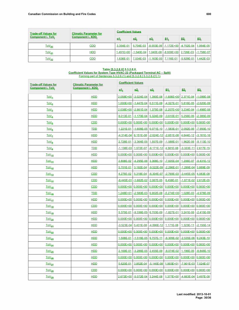
Coefficient ValuesTrade-off Values forComponent i, ToVi
Climatic Parameter forComponent i, XDDi α1i α2i α3i β1i β2i β3i
ToV30 CDD 3.354E-01 5.704E-03 -8.553E-06 -1.172E+00 -4.752E-04 1.064E-05
ToV31 HDD 1.491E+00 -1.540E-04 1.040E-08 -8.939E+00 2.726E-03 -1.758E-07
ToV32 CDD 1.636E-01 7.534E-03 -1.163E-05 7.116E-01 -5.929E-01 1.442E-03
Table [5.3.2.8.V] 5.3.2.8.V.Coefficient Values for System Type HVAC-22 (Packaged Terminal AC – Split)
Forming part of Sentences 5.3.2.6.(1) and [5.3.2.8.] 5.3.2.8.([1] 1)
Coefficient ValuesTrade-off Values forComponent i, ToVi
Climatic Parameter forComponent i, XDDi α1i α2i α3i β1i β2i β3i
ToV1 HDD 2.058E+00 -3.024E-04 1.390E-08 -1.606E+00 2.371E-04 -1.099E-08
ToV2 HDD 1.000E+00 -1.447E-04 6.511E-09 -4.027E-01 5.816E-05 -2.620E-09
ToV3 HDD 2.038E+00 -2.981E-04 1.375E-08 -2.207E+00 3.234E-04 -1.498E-08
ToV4 HDD 8.013E-01 -1.170E-04 5.324E-09 -3.610E-01 5.256E-05 -2.385E-09
ToV5 CDD 0.000E+00 0.000E+00 0.000E+00 0.000E+00 0.000E+00 0.000E+00
ToV6 TDD 1.221E-01 -1.608E-05 6.071E-10 -1.583E-01 2.092E-05 -7.950E-10
ToV7 HDD -4.314E-04 6.151E-08 -2.624E-12 -2.651E-08 4.644E-12 -3.161E-16
ToV8 HDD 2.728E-01 -3.364E-05 1.557E-09 -1.588E-01 1.962E-05 -9.113E-10
ToV9 TDD -1.138E-03 1.572E-07 -6.171E-12 4.581E-08 -3.333E-11 2.617E-15
ToV10 HDD 0.000E+00 0.000E+00 0.000E+00 0.000E+00 0.000E+00 0.000E+00
ToV11 HDD 2.808E-02 -4.295E-06 3.368E-10 -7.835E-04 1.206E-07 -9.431E-12
ToV12 HDD 5.701E-01 3.192E-04 -9.522E-09 -2.296E-01 -1.299E-04 3.889E-09
ToV13 CDD 4.276E-02 5.318E-04 -6.304E-07 -2.769E-03 -3.445E-05 4.083E-08
ToV14 CDD -8.445E-01 -1.682E-02 2.087E-05 8.458E-01 -1.871E-02 2.612E-05
ToV15 CDD 0.000E+00 0.000E+00 0.000E+00 0.000E+00 0.000E+00 0.000E+00
ToV16 TDD 1.248E+01 -2.580E-03 6.902E-08 -5.274E+00 1.028E-03 -4.978E-09
ToV17 HDD 0.000E+00 0.000E+00 0.000E+00 0.000E+00 0.000E+00 0.000E+00
ToV18 CDD 0.000E+00 0.000E+00 0.000E+00 0.000E+00 0.000E+00 0.000E+00
ToV19 HDD 5.375E-01 -9.336E-05 6.703E-09 -1.827E-01 3.241E-05 -2.415E-09
ToV20 HDD 0.000E+00 0.000E+00 0.000E+00 0.000E+00 0.000E+00 0.000E+00
ToV21 HDD -3.523E-04 5.431E-08 -4.096E-12 1.171E-08 1.323E-11 -2.155E-14
ToV22 HDD 0.000E+00 0.000E+00 0.000E+00 0.000E+00 0.000E+00 0.000E+00
ToV23 HDD 1.508E-01 -1.516E-05 9.757E-11 -6.309E-02 -2.535E-06 9.243E-10
ToV24 HDD 0.000E+00 0.000E+00 0.000E+00 0.000E+00 0.000E+00 0.000E+00
ToV25 HDD 2.169E-01 -3.286E-05 2.455E-09 -8.074E-02 1.196E-05 -8.848E-10
ToV26 HDD 0.000E+00 0.000E+00 0.000E+00 0.000E+00 0.000E+00 0.000E+00
ToV27 HDD 5.620E-01 3.852E-04 -5.146E-08 1.993E+01 -7.901E-03 7.024E-07
ToV28 CDD 0.000E+00 0.000E+00 0.000E+00 0.000E+00 0.000E+00 0.000E+00
ToV29 HDD 2.672E+00 -5.072E-04 3.244E-08 1.377E+00 -4.663E-04 3.497E-08
Canadian Commission on Building and Fire Codes 600
Last modified: 2013-10-01Page: 30/36

Coefficient ValuesTrade-off Values forComponent i, ToVi
Climatic Parameter forComponent i, XDDi α1i α2i α3i β1i β2i β3i
ToV30 CDD 0.000E+00 0.000E+00 0.000E+00 0.000E+00 0.000E+00 0.000E+00
ToV31 HDD 5.052E+00 -1.248E-03 8.184E-08 -1.284E+02 3.823E-02 -2.367E-06
ToV32 CDD 0.000E+00 0.000E+00 0.000E+00 0.000E+00 0.000E+00 0.000E+00
Table [5.3.2.8.W] 5.3.2.8.W.Coefficient Values for System Type HVAC-23 (Radiant (In-floor, Ceiling) with Optional Make-up Air Unit)
Forming part of Sentences 5.3.2.6.(1) and [5.3.2.8.] 5.3.2.8.([1] 1)
Coefficient ValuesTrade-off Values forComponent i, ToVi
Climatic Parameter forComponent i, XDDi α1i α2i α3i β1i β2i β3i
ToV1 HDD 1.869E+00 -4.636E-04 3.229E-08 -1.047E+00 2.595E-04 -1.808E-08
ToV2 HDD 1.273E+00 -3.116E-04 2.155E-08 -5.115E-01 1.244E-04 -8.573E-09
ToV3 HDD 1.541E+00 -3.557E-04 2.355E-08 -1.381E+00 3.187E-04 -2.111E-08
ToV4 HDD 7.212E-01 -1.665E-04 1.102E-08 -3.218E-01 7.428E-05 -4.919E-09
ToV5 HDD 0.000E+00 0.000E+00 0.000E+00 0.000E+00 0.000E+00 0.000E+00
ToV6 HDD 0.000E+00 0.000E+00 0.000E+00 0.000E+00 0.000E+00 0.000E+00
ToV7 TDD -5.969E-04 1.474E-07 -1.024E-11 -3.046E-09 1.479E-12 -1.204E-16
ToV8 CDD 4.472E-01 -5.709E-04 8.471E-07 -2.534E-01 3.165E-04 -4.703E-07
ToV9 TDD -1.028E-03 2.374E-07 -1.572E-11 2.476E-08 -5.715E-12 3.785E-16
ToV10 HDD 1.062E-02 -3.159E-06 2.294E-10 -7.764E-05 2.568E-08 -1.829E-12
ToV11 HDD 0.000E+00 0.000E+00 0.000E+00 0.000E+00 0.000E+00 0.000E+00
ToV12 HDD 1.221E+00 5.589E-04 -3.707E-08 -5.031E-01 -2.237E-04 1.481E-08
ToV13 CDD -4.507E-04 1.149E-04 -1.434E-07 2.966E-05 -7.356E-06 9.142E-09
ToV14 CDD 2.984E-03 -2.457E-04 2.560E-07 -2.334E-01 1.408E-03 5.490E-07
ToV15 CDD 0.000E+00 0.000E+00 0.000E+00 0.000E+00 0.000E+00 0.000E+00
ToV16 TDD -5.268E+00 2.357E-03 -1.992E-07 3.553E+00 -1.361E-03 1.171E-07
ToV17 HDD -6.996E-03 1.514E-06 4.263E-11 -1.155E-01 4.647E-05 -3.233E-09
ToV18 CDD -3.913E-03 1.322E-04 -2.101E-07 2.808E-03 -8.513E-05 1.364E-07
ToV19 HDD 7.896E-01 -1.909E-04 1.345E-08 -2.394E-01 5.606E-05 -3.919E-09
ToV20 CDD 2.501E-04 1.634E-04 -2.146E-07 -1.623E-04 -5.484E-05 7.227E-08
ToV21 HDD 7.476E-06 7.313E-09 1.007E-11 -1.512E-08 3.861E-12 -2.244E-16
ToV22 CDD -1.454E-06 -6.895E-07 9.287E-10 -1.428E-08 1.762E-10 -2.116E-13
ToV23 HDD 9.553E-02 -7.144E-06 2.558E-10 -5.951E-02 5.887E-06 -2.663E-10
ToV24 CDD 1.196E-02 3.126E-04 -3.899E-07 -8.749E-03 -1.507E-04 1.731E-07
ToV25 HDD 1.773E-01 -3.759E-05 2.595E-09 -9.136E-02 2.128E-05 -1.492E-09
ToV26 CDD 1.663E-03 2.348E-04 -3.798E-07 -9.303E-04 -9.164E-05 1.580E-07
ToV27 HDD 4.891E+00 -1.178E-03 7.796E-08 -1.557E+01 5.237E-03 -3.853E-07
ToV28 CDD 3.461E-01 4.752E-03 -6.315E-06 -3.956E+00 2.799E-02 -3.635E-05
ToV29 HDD 3.540E+00 -7.487E-04 4.553E-08 -2.472E+01 8.899E-03 -7.180E-07
Canadian Commission on Building and Fire Codes 600
Last modified: 2013-10-01Page: 31/36

Coefficient ValuesTrade-off Values forComponent i, ToVi
Climatic Parameter forComponent i, XDDi α1i α2i α3i β1i β2i β3i
ToV30 CDD 8.049E-02 7.997E-03 -1.209E-05 -4.364E+00 1.580E-02 -3.280E-06
ToV31 HDD 2.263E+00 -3.228E-04 1.422E-08 -9.794E+01 2.717E-02 -1.467E-06
ToV32 CDD -1.102E-02 7.105E-03 -9.170E-06 3.697E+00 -4.185E-03 -1.970E-05
Table [5.3.2.8.X] 5.3.2.8.X.Coefficient Values for System Type HVAC-24 (Active Chilled Beams with Optional Make-up Air Unit)
Forming part of Sentences 5.3.2.6.(1) and [5.3.2.8.] 5.3.2.8.([1] 1)
Coefficient ValuesTrade-off Values forComponent i, ToVi
Climatic Parameter forComponent i, XDDi α1i α2i α3i β1i β2i β3i
ToV1 HDD 2.006E+00 -4.097E-04 2.335E-08 -1.068E+00 2.077E-04 -1.133E-08
ToV2 HDD 1.684E+00 -3.566E-04 2.096E-08 -7.398E-01 1.517E-04 -8.674E-09
ToV3 HDD 1.568E+00 -1.826E-04 7.241E-09 -1.668E+00 1.870E-04 -7.043E-09
ToV4 HDD 5.951E-01 -6.246E-05 2.001E-09 -2.585E-01 2.393E-05 -5.405E-10
ToV5 HDD 1.330E+01 -3.673E-03 2.418E-07 -1.136E+02 3.178E-02 -1.879E-06
ToV6 HDD 0.000E+00 0.000E+00 0.000E+00 0.000E+00 0.000E+00 0.000E+00
ToV7 TDD -7.142E-04 1.814E-07 -1.208E-11 4.122E-08 -2.606E-11 2.369E-15
ToV8 TDD 6.350E-01 -1.556E-04 1.037E-08 -3.537E-01 8.453E-05 -5.560E-09
ToV9 HDD -9.647E-04 1.481E-07 -7.791E-12 1.308E-07 -6.628E-11 5.095E-15
ToV10 HDD 4.418E-03 -1.559E-07 3.678E-12 -1.150E-04 4.727E-09 -2.162E-13
ToV11 HDD 3.655E-03 -3.068E-07 1.188E-11 -1.009E-04 8.875E-09 -3.711E-13
ToV12 HDD 1.907E+00 2.032E-04 -6.940E-09 -7.706E-01 -8.321E-05 2.876E-09
ToV13 CDD -1.139E-03 1.023E-04 -3.790E-08 7.416E-05 -6.573E-06 2.377E-09
ToV14 CDD -9.075E-03 -2.026E-04 -3.053E-07 3.362E-01 -3.109E-03 4.732E-06
ToV15 CDD -1.340E-01 2.889E-03 -4.014E-06 -2.632E-01 5.671E-03 -7.881E-06
ToV16 HDD -1.732E+02 5.178E-02 -3.197E-06 9.943E+01 -2.958E-02 1.830E-06
ToV17 TDD -2.521E-01 8.365E-05 -2.332E-09 3.480E-02 -4.232E-06 -1.449E-09
ToV18 CDD -1.110E-02 -3.656E-05 7.065E-08 1.351E-02 1.088E-04 -1.809E-07
ToV19 HDD 6.220E-02 -9.154E-06 5.114E-10 -5.231E-03 -9.663E-07 1.050E-10
ToV20 CDD 1.409E-02 1.548E-04 -2.514E-07 -3.838E-03 -3.619E-05 6.216E-08
ToV21 HDD -1.089E-04 -5.224E-09 1.067E-12 -6.902E-08 2.449E-11 -1.966E-15
ToV22 CDD -7.546E-05 -1.537E-07 1.249E-10 1.977E-09 3.701E-13 3.515E-14
ToV23 HDD 1.359E-01 -8.110E-06 6.587E-11 -7.901E-02 5.804E-06 -1.423E-10
ToV24 CDD 6.713E-02 1.665E-04 -1.802E-07 -3.678E-02 -1.013E-04 1.178E-07
ToV25 HDD 1.014E-01 -7.329E-06 1.133E-10 -3.983E-02 3.071E-06 -5.117E-11
ToV26 CDD 4.389E-02 1.384E-04 -1.573E-07 -1.587E-02 -5.993E-05 7.082E-08
ToV27 HDD 7.998E+00 -2.265E-03 1.599E-07 1.517E+02 -5.156E-02 3.887E-06
ToV28 CDD -6.786E-01 1.880E-02 -3.233E-05 -2.877E+01 3.931E-01 -7.271E-04
ToV29 HDD 4.302E+00 -1.021E-03 6.731E-08 1.417E+01 -5.804E-03 5.312E-07
Canadian Commission on Building and Fire Codes 600
Last modified: 2013-10-01Page: 32/36

Coefficient ValuesTrade-off Values forComponent i, ToVi
Climatic Parameter forComponent i, XDDi α1i α2i α3i β1i β2i β3i
ToV30 CDD -6.329E-02 5.587E-03 -5.040E-06 6.417E+01 -1.223E+00 2.467E-03
ToV31 HDD 2.338E+00 -3.444E-04 1.549E-08 -6.097E+01 1.779E-02 -1.062E-06
ToV32 CDD 2.867E-01 6.071E-03 -9.055E-06 2.676E+01 -2.833E-01 4.754E-04
Table [5.3.2.8.Y] 5.3.2.8.Y.Coefficient Values for System Type HVAC-25 (Unit Heater)
Forming part of Sentences 5.3.2.6.(1) and [5.3.2.8.] 5.3.2.8.([1] 1)
Coefficient ValuesTrade-off Values forComponent i, ToVi
Climatic Parameter forComponent i, XDDi α1i α2i α3i β1i β2i β3i
ToV1 HDD 2.018E-02 -7.240E-06 6.010E-10 -2.125E-02 7.347E-06 -5.925E-10
ToV2 HDD 2.037E-02 -6.659E-06 5.372E-10 -1.154E-02 3.551E-06 -2.753E-10
ToV3 HDD 0.000E+00 0.000E+00 0.000E+00 0.000E+00 0.000E+00 0.000E+00
ToV4 HDD 0.000E+00 0.000E+00 0.000E+00 0.000E+00 0.000E+00 0.000E+00
ToV5 HDD 0.000E+00 0.000E+00 0.000E+00 0.000E+00 0.000E+00 0.000E+00
ToV6 TDD 0.000E+00 0.000E+00 0.000E+00 0.000E+00 0.000E+00 0.000E+00
ToV7 HDD 1.508E-05 -5.341E-09 4.370E-13 -1.175E-08 4.571E-12 -3.781E-16
ToV8 HDD 0.000E+00 0.000E+00 0.000E+00 0.000E+00 0.000E+00 0.000E+00
ToV9 HDD 0.000E+00 0.000E+00 0.000E+00 0.000E+00 0.000E+00 0.000E+00
ToV10 HDD 9.496E-05 -3.590E-09 -2.998E-13 -2.406E-06 1.036E-10 6.442E-15
ToV11 HDD 7.866E-02 -1.617E-05 1.083E-09 -2.157E-03 4.423E-07 -2.958E-11
ToV12 HDD 2.899E+00 1.504E-04 -1.004E-08 -1.181E+00 -5.898E-05 3.906E-09
ToV13 CDD 0.000E+00 0.000E+00 0.000E+00 0.000E+00 0.000E+00 0.000E+00
ToV14 CDD 0.000E+00 0.000E+00 0.000E+00 0.000E+00 0.000E+00 0.000E+00
ToV15 CDD 0.000E+00 0.000E+00 0.000E+00 0.000E+00 0.000E+00 0.000E+00
ToV16 HDD 0.000E+00 0.000E+00 0.000E+00 0.000E+00 0.000E+00 0.000E+00
ToV17 HDD -9.985E-02 2.913E-05 -1.964E-09 8.327E-02 -2.429E-05 1.638E-09
ToV18 CDD 0.000E+00 0.000E+00 0.000E+00 0.000E+00 0.000E+00 0.000E+00
ToV19 HDD 4.972E-01 -7.098E-05 2.600E-09 1.538E-01 -5.889E-05 4.921E-09
ToV20 CDD 0.000E+00 0.000E+00 0.000E+00 0.000E+00 0.000E+00 0.000E+00
ToV21 HDD -1.046E-03 2.227E-07 -1.484E-11 1.040E-07 -5.223E-11 4.862E-15
ToV22 CDD 0.000E+00 0.000E+00 0.000E+00 0.000E+00 0.000E+00 0.000E+00
ToV23 HDD 9.126E-01 -1.794E-04 1.121E-08 -5.060E-01 9.816E-05 -6.048E-09
ToV24 CDD 0.000E+00 0.000E+00 0.000E+00 0.000E+00 0.000E+00 0.000E+00
ToV25 HDD 5.786E-01 -1.163E-04 7.802E-09 -2.018E-01 3.884E-05 -2.593E-09
ToV26 CDD 0.000E+00 0.000E+00 0.000E+00 0.000E+00 0.000E+00 0.000E+00
ToV27 HDD 2.365E+00 -2.573E-04 -2.180E-10 1.361E+01 -5.367E-03 4.748E-07
ToV28 CDD 0.000E+00 0.000E+00 0.000E+00 0.000E+00 0.000E+00 0.000E+00
ToV29 HDD 3.239E+00 -6.098E-04 3.159E-08 9.103E+00 -3.524E-03 3.064E-07
Canadian Commission on Building and Fire Codes 600
Last modified: 2013-10-01Page: 33/36

Coefficient ValuesTrade-off Values forComponent i, ToVi
Climatic Parameter forComponent i, XDDi α1i α2i α3i β1i β2i β3i
ToV30 CDD 0.000E+00 0.000E+00 0.000E+00 0.000E+00 0.000E+00 0.000E+00
ToV31 HDD 3.155E+00 -6.815E-04 4.653E-08 -8.619E-01 3.353E-04 -2.928E-08
ToV32 CDD 0.000E+00 0.000E+00 0.000E+00 0.000E+00 0.000E+00 0.000E+00
Table [5.3.2.8.Z] 5.3.2.8.Z.Coefficient Values for System Type HVAC-26 (Unit Ventilator)Forming part of Sentences 5.3.2.6.(1) and [5.3.2.8.] 5.3.2.8.([1] 1)
Coefficient ValuesTrade-off Values forComponent i, ToVi
Climatic Parameter forComponent i, XDDi α1i α2i α3i β1i β2i β3i
ToV1 HDD 2.079E-02 -3.680E-06 1.977E-10 -1.462E-02 2.728E-06 -1.494E-10
ToV2 HDD 1.332E-02 -2.017E-06 8.076E-11 -5.521E-03 7.293E-07 -1.788E-11
ToV3 HDD 0.000E+00 0.000E+00 0.000E+00 0.000E+00 0.000E+00 0.000E+00
ToV4 HDD 0.000E+00 0.000E+00 0.000E+00 0.000E+00 0.000E+00 0.000E+00
ToV5 HDD 0.000E+00 0.000E+00 0.000E+00 0.000E+00 0.000E+00 0.000E+00
ToV6 TDD 0.000E+00 0.000E+00 0.000E+00 0.000E+00 0.000E+00 0.000E+00
ToV7 HDD -6.713E-06 2.523E-09 -2.154E-13 7.503E-09 -3.541E-12 3.247E-16
ToV8 HDD 0.000E+00 0.000E+00 0.000E+00 0.000E+00 0.000E+00 0.000E+00
ToV9 HDD 0.000E+00 0.000E+00 0.000E+00 0.000E+00 0.000E+00 0.000E+00
ToV10 HDD 1.941E-04 -3.029E-08 2.036E-12 -5.273E-06 9.362E-10 -6.525E-14
ToV11 HDD 7.643E-02 -1.554E-05 1.038E-09 -2.097E-03 4.252E-07 -2.835E-11
ToV12 HDD 5.685E+00 -6.037E-04 3.653E-08 -8.219E-01 1.685E-04 -1.088E-08
ToV13 CDD 0.000E+00 0.000E+00 0.000E+00 0.000E+00 0.000E+00 0.000E+00
ToV14 CDD 0.000E+00 0.000E+00 0.000E+00 0.000E+00 0.000E+00 0.000E+00
ToV15 CDD 0.000E+00 0.000E+00 0.000E+00 0.000E+00 0.000E+00 0.000E+00
ToV16 HDD -7.604E+03 2.837E+00 -2.377E-04 4.748E+03 -1.771E+00 1.484E-04
ToV17 HDD 0.000E+00 0.000E+00 0.000E+00 0.000E+00 0.000E+00 0.000E+00
ToV18 CDD 0.000E+00 0.000E+00 0.000E+00 0.000E+00 0.000E+00 0.000E+00
ToV19 HDD 4.063E-01 -4.595E-05 8.590E-10 1.873E-01 -6.735E-05 5.475E-09
ToV20 CDD 0.000E+00 0.000E+00 0.000E+00 0.000E+00 0.000E+00 0.000E+00
ToV21 HDD -1.024E-03 2.152E-07 -1.429E-11 1.261E-07 -5.572E-11 5.026E-15
ToV22 CDD 0.000E+00 0.000E+00 0.000E+00 0.000E+00 0.000E+00 0.000E+00
ToV23 HDD 8.312E-01 -1.538E-04 9.372E-09 -4.466E-01 7.919E-05 -4.670E-09
ToV24 CDD 0.000E+00 0.000E+00 0.000E+00 0.000E+00 0.000E+00 0.000E+00
ToV25 HDD 6.460E-01 -1.359E-04 9.157E-09 -2.444E-01 5.123E-05 -3.455E-09
ToV26 CDD 0.000E+00 0.000E+00 0.000E+00 0.000E+00 0.000E+00 0.000E+00
ToV27 HDD 6.634E-01 3.508E-04 -4.887E-08 2.203E+01 -8.353E-03 7.115E-07
ToV28 CDD 0.000E+00 0.000E+00 0.000E+00 0.000E+00 0.000E+00 0.000E+00
ToV29 HDD 2.972E+00 -5.137E-04 2.385E-08 9.331E+00 -3.597E-03 3.114E-07
Canadian Commission on Building and Fire Codes 600
Last modified: 2013-10-01Page: 34/36

Coefficient ValuesTrade-off Values forComponent i, ToVi
Climatic Parameter forComponent i, XDDi α1i α2i α3i β1i β2i β3i
ToV30 CDD 0.000E+00 0.000E+00 0.000E+00 0.000E+00 0.000E+00 0.000E+00
ToV31 HDD 3.084E+00 -6.535E-04 4.406E-08 -6.206E-01 1.748E-04 -9.741E-09
ToV32 CDD 0.000E+00 0.000E+00 0.000E+00 0.000E+00 0.000E+00 0.000E+00
Table [5.3.2.8.AA] 5.3.2.8.AA.Coefficient Values for System Type HVAC-27 (Radiation with Optional Make-up Air Unit)
Forming part of Sentences 5.3.2.6.(1) and [5.3.2.8.] 5.3.2.8.([1] 1)
Coefficient ValuesTrade-off Values forComponent i, ToVi
Climatic Parameter forComponent i, XDDi α1i α2i α3i β1i β2i β3i
ToV1 HDD 1.869E+00 -4.636E-04 3.229E-08 -1.047E+00 2.595E-04 -1.808E-08
ToV2 HDD 1.273E+00 -3.116E-04 2.155E-08 -5.115E-01 1.244E-04 -8.573E-09
ToV3 HDD 1.541E+00 -3.557E-04 2.355E-08 -1.381E+00 3.187E-04 -2.111E-08
ToV4 HDD 7.212E-01 -1.665E-04 1.102E-08 -3.218E-01 7.428E-05 -4.919E-09
ToV5 HDD 0.000E+00 0.000E+00 0.000E+00 0.000E+00 0.000E+00 0.000E+00
ToV6 HDD 0.000E+00 0.000E+00 0.000E+00 0.000E+00 0.000E+00 0.000E+00
ToV7 TDD -5.969E-04 1.474E-07 -1.024E-11 -3.046E-09 1.479E-12 -1.204E-16
ToV8 CDD 4.472E-01 -5.709E-04 8.471E-07 -2.534E-01 3.165E-04 -4.703E-07
ToV9 TDD -1.028E-03 2.374E-07 -1.572E-11 2.476E-08 -5.715E-12 3.785E-16
ToV10 HDD 1.062E-02 -3.159E-06 2.294E-10 -7.764E-05 2.568E-08 -1.829E-12
ToV11 HDD 0.000E+00 0.000E+00 0.000E+00 0.000E+00 0.000E+00 0.000E+00
ToV12 HDD 1.221E+00 5.589E-04 -3.707E-08 -5.031E-01 -2.237E-04 1.481E-08
ToV13 CDD -4.507E-04 1.149E-04 -1.434E-07 2.966E-05 -7.356E-06 9.142E-09
ToV14 CDD 2.984E-03 -2.457E-04 2.560E-07 -2.334E-01 1.408E-03 5.490E-07
ToV15 CDD 0.000E+00 0.000E+00 0.000E+00 0.000E+00 0.000E+00 0.000E+00
ToV16 TDD -5.268E+00 2.357E-03 -1.992E-07 3.553E+00 -1.361E-03 1.171E-07
ToV17 HDD -6.996E-03 1.514E-06 4.263E-11 -1.155E-01 4.647E-05 -3.233E-09
ToV18 CDD -3.913E-03 1.322E-04 -2.101E-07 2.808E-03 -8.513E-05 1.364E-07
ToV19 HDD 7.896E-01 -1.909E-04 1.345E-08 -2.394E-01 5.606E-05 -3.919E-09
ToV20 CDD 2.501E-04 1.634E-04 -2.146E-07 -1.623E-04 -5.484E-05 7.227E-08
ToV21 HDD 7.476E-06 7.313E-09 1.007E-11 -1.512E-08 3.861E-12 -2.244E-16
ToV22 CDD -1.454E-06 -6.895E-07 9.287E-10 -1.428E-08 1.762E-10 -2.116E-13
ToV23 HDD 9.553E-02 -7.144E-06 2.558E-10 -5.951E-02 5.887E-06 -2.663E-10
ToV24 CDD 1.196E-02 3.126E-04 -3.899E-07 -8.749E-03 -1.507E-04 1.731E-07
ToV25 HDD 1.773E-01 -3.759E-05 2.595E-09 -9.136E-02 2.128E-05 -1.492E-09
ToV26 CDD 1.663E-03 2.348E-04 -3.798E-07 -9.303E-04 -9.164E-05 1.580E-07
ToV27 HDD 4.891E+00 -1.178E-03 7.796E-08 -1.557E+01 5.237E-03 -3.853E-07
ToV28 CDD 3.461E-01 4.752E-03 -6.315E-06 -3.956E+00 2.799E-02 -3.635E-05
ToV29 HDD 3.540E+00 -7.487E-04 4.553E-08 -2.472E+01 8.899E-03 -7.180E-07
Canadian Commission on Building and Fire Codes 600
Last modified: 2013-10-01Page: 35/36

Coefficient ValuesTrade-off Values forComponent i, ToVi
Climatic Parameter forComponent i, XDDi α1i α2i α3i β1i β2i β3i
ToV30 CDD 8.049E-02 7.997E-03 -1.209E-05 -4.364E+00 1.580E-02 -3.280E-06
ToV31 HDD 2.263E+00 -3.228E-04 1.422E-08 -9.794E+01 2.717E-02 -1.467E-06
ToV32 CDD -1.102E-02 7.105E-03 -9.170E-06 3.697E+00 -4.185E-03 -1.970E-05
RATIONALE
ProblemWith the proposed changes to the prescriptive requirements in Part 5 of the NECB, the Trade-off-Path coefficient tables are outdated. Furthermore, the valueslisted in Section 5.3. of the NECB are in imperial units and should be listed in metric units.
Justification - ExplanationThe proposed change updates Section 5.3. of the NECB with the latest proposed changes to the Part 5 prescriptive requirements and provides the Trade-off Pathcoefficients in metric units.
Cost implicationsNone.
Enforcement implicationsNone, could be enforced using existing infrastructure.
Who is affectedDesigners, manufacturers, builders, specification writers and building officials.
Supporting Document(s)06bNECB2011-ToV_Tables_Update.xlsx
OBJECTIVE-BASED ANALYSIS OF NEW OR CHANGED PROVISIONSN/AN/AN/A[5.3.2.8.] 5.3.2.8. ([1] 1) [F95,F99-OE1.1]
Canadian Commission on Building and Fire Codes 600
Last modified: 2013-10-01Page: 36/36

Comment
Proposed Change 604Code Reference(s): NECB11 Div.B 6.2.2.1.Subject: Service Water Heating Equipment Efficiency TableTitle: 07 NECB2011-DivB-06.02.02.01.-table-replace-EEB-table updateDescription: The proposed change is intended to update the prescriptive Part 6
requirements to at least meet the federal Energy Efficiency Regulations,where the federal Energy Efficiency Regulations have surpassed Table6.2.2.1. requirements, to add clarity to the Table 6.2.2.1. and to correct anyconsistencies to Table 6.2.2.1.
PROPOSED CHANGE
[6.2.2.1.] 6.2.2.1. Equipment Efficiency[1] 1) Storage-type and non-storage-type sService water heaters and pool heaters with capacities listed in
Table 6.2.2.1. shall comply with the stated performance requirements stated in Table 6.2.2.1.. (SeeAppendix A.)
Table [6.2.2.1.] 6.2.2.1.Service Water Heating Equipment Performance Standards
Forming part of Sentences 5.2.12.3.(1), [6.2.2.1.] 6.2.2.1.([1] 1), 6.2.2.4.(2), 6.2.2.5.(1), 6.3.2.5.(1)and 6.3.2.6.(1)
Storage-Type and Non-Storage-Type (Instantaneous) Service Water Heaters
Component Input Capacity,L
Vt,L
(USgal.)
Input/Vt,W/L
(Btu/h/USgal.)
Standard RatingConditions
PerformanceRequirement (1)
SL ≤ 35 + 0.20Vr(top inlet)≤ 12
kW 50 – 270SL ≤ 40 + 0.20Vr
(bottom inlet)
SL ≤ (0.472Vr) –38.5
(top inlet)—
> 270and
≤ 454
CAN/CSA-C191
Seestandard
SL ≤ (0.472Vr) –33.5
(bottom inlet)
Electricstorage
> 12kW > 454
— —
ANSIZ21.10.3/CSA4.3 (2)
Δt = 44.4°C(80°F)
Et ≥ 98%EF ≥ 0.98
PROPOSEDCHANGEA-6.2.2.1.(1)
PROPOSED CHANGE Table 6.2.2.1. Footnote
PROPOSED CHANGE Table 6.2.2.1. Footnote
Canadian Commission on Building and Fire Codes 604
Last modified: 2013-10-15Page: 1/5

Electricinstantaneous
> 12kW — — —
ANSIZ21.10.3/CSA
4.3 (2)
Δt = 44.4°C(80°F)
Et ≥ 98%
Heat pumpwater heaters
≤ 24 Aand
≤ 250V
— — — CAN/CSA-C745 — EF ≥ 2.1
< 22kW
22 –117kW
— — CAN/CSA-P.3 —EF ≥ 0.67 –
0.0005Vr
— < 310(4000)
Δt = 50°C(90°F)
Et ≥ 80%
<37.8(10)
Et ≥ 80% (3)
Gas-firedstorage
> 117kW
—
≥37.8(10)
≥ 310(4000)
ANSIZ21.10.3/CSA
4.3
Δt = 50°C(90°F) Et ≥ 77% (3)
Gas-firedinstantaneous
≥ 14.7and ≤73.2kW
< 7.57 L — — CAN/CSA-P.7 Seestandard EF ≥ 0.8
≤ 61.5kW (4) — — —
DOE (5) testprocedures,US Code ofFederalRegulations,10CFR, Part430, SubpartB, AppendixE
—EF ≥ 0.59 –0.0019 Vm
— < 310(4000)
Δt = 50°C(90°F)
Et ≥ 78% (3)
SL ≤ 1.3 +95/Vtr
(2)
<37.8(10)
— Et ≥ 80% (3)
Oil-fired,instantaneous
Others —
≥37.8(10)
≥ 310(4000)
ANSIZ21.10.3/CSA
4.3
Δt = 50°C(90°F)
Et ≥ 77% (5)
SL ≤ 2.3 +67/Vtr
(2)
PROPOSED CHANGE Table 6.2.2.1. Footnote
PROPOSED CHANGE Table 6.2.2.1. Footnote
PROPOSED CHANGE Table 6.2.2.1. Footnote
PROPOSED CHANGE Table 6.2.2.1. FootnotePROPOSED CHANGE Table 6.2.2.1. Footnote
PROPOSED CHANGE Table 6.2.2.1. Footnote
PROPOSED CHANGE Table 6.2.2.1. Footnote
PROPOSED CHANGE Table 6.2.2.1. Footnote
PROPOSED CHANGE Table 6.2.2.1. Footnote
PROPOSED CHANGE Table 6.2.2.1. Footnote
Canadian Commission on Building and Fire Codes 604
Last modified: 2013-10-15Page: 2/5

≤ 190 CAN/CSA-B211
≤ 30.5kW
> 190— —
DOE (5) testprocedures,US Code of
FederalRegulations,10 CFR, Part430, SubpartB, Appendix
E
—EF ≥ 0.55EF ≥
0.59 – 0.0005 Vr
— < 310(4000)
Δt = 50°C(90°F) EF ≥ 0.55
<37.8(10)
— EF ≥ 0.55
Oil-fired,storage-type
> 30.5kW > 190
≥37.8(10)
≥ 310(4000)
ANSIZ21.10.3/CSA
4.3
Δt = 50°C(90°F)
EF ≥ 0.55SL ≤ 2.3 +67/Vrt
(2)
Pool Heaters
Component Input Capacity,L
Vt,L
(USgal.)
Input/Vt,W/L
(Btu/h/USgal.)
Standard RatingConditions
PerformanceRequirement (1)
Gas-fired (2)<
117.2kW
Et ≥ 78%
Oil-fired —
— — —ANSI
Z21.56/CSA4.7
—
Et ≥ 78% (3)
Notes to Table [6.2.2.1.] 6.2.2.1.:
PROPOSED CHANGE Table 6.2.2.1. Footnote
PROPOSED CHANGE Table 6.2.2.1. Footnote
PROPOSED CHANGE Table 6.2.2.1. Footnote
PROPOSED CHANGE Table 6.2.2.1. Footnote
PROPOSED CHANGE Table 6.2.2.1. Footnote
Canadian Commission on Building and Fire Codes 604
Last modified: 2013-10-15Page: 3/5

The symbols and abbreviations used in this column have the following meanings:
Vt = tank storage volume, in L, as measured according to the referenced standard
SL = standby losses, in %/h or in W, depending on standard
Et = thermal efficiency with 38.9°C (70°F) water temperature difference
EF = energy factor, in %/h a ratio of energy output over energy consumption over a 24 hperiod
V = storage volume, in L, as specified by the manufacturer
Vr = the rated volume as specified by the manufacturer
Vm = the volume of the tank as measured in accordance with the listed test standard
Q = capacity, in W
(1)PROPOSED CHANGE Table 6.2.2.1. Footnotereferrer
When testing an electric storage-type service water heater for standby losses using the test procedure described inSection 2.9. of the referenced standard, the electrical supply voltage shall be maintained within ±1% of the centreof the voltage range specified on the water heater nameplate. Also, when needed for calculations, the thermalefficiency (Et) shall be 98%.
(2)PROPOSED CHANGE Table 6.2.2.1. Footnotereferrer
Includes propane.(3)PROPOSED CHANGE Table 6.2.2.1. Footnotereferrer
Consistent with the US National Appliance Energy Conservation Act of 1987.(4)PROPOSED CHANGE Table 6.2.2.1. Footnotereferrer
DOE = (US) Department of Energy(5)PROPOSED CHANGE Table 6.2.2.1. Footnotereferrer
RATIONALE
ProblemThe requirements of the federal Energy Efficiency Regulations have surpassed those of the 2011 NECB for certainregulated equipment types. In order for selected equipment that is regulated by the federal Energy EfficiencyRegulations to be sold across provincial territorial, or national borders, their performance levels must meet or exceedthose of the federal Energy Efficiency Regulations. As such, the performance levels listed in the NECB should not bebelow those of the federal Energy Efficiency Regulations.
Other changes to the table and table notes are needed for clarification. The current entries for “electric” and “gas-fired”unit types to not make the distinction between “instantaneous” and “storage” type units, yet Table 6.2.2.1. applies toboth unit types.
Sentence (1) may be misinterpreted; unit types not listed in Table 6.2.2.1. may be excluded.
Justification - ExplanationThe proposed change improves the prescriptive Part 6 requirements in Table 6.2.2.1. where the performance of theequipment regulated under the federal Energy Efficiency Act has surpassed the performance levels of the NECB. In thecase of the equipment in Table 6.2.2.1., the oil-fired, storage type service water heater requirements have been updated.
Footnote1
Footnote2
Footnote3Footnote4Footnote5
Canadian Commission on Building and Fire Codes 604
Last modified: 2013-10-15Page: 4/5

Table notes are added for clarification. The table entries for “electric” and “gas-fired” unit types were separated by“instantaneous” and “storage” type units to add clarity to the table. For the “gas-fired instantaneous” table entries, thetest standard and performance requirements were corrected.
The proposed change to Sentence (1) is intended to clarify the scope of application.
Cost implicationsNone. The proposed change aligns the requirements in Table 6.2.2.1. with the federal Energy Efficiency Regulations,where applicable, and corrects error and inconsistencies in the table.
Enforcement implicationsNone.
Who is affectedDesigners, manufacturers, builders, specification writers and building officials.
OBJECTIVE-BASED ANALYSIS OF NEW OR CHANGED PROVISIONS[6.2.2.1.] 6.2.2.1. ([1] 1) [F96,F98-OE1.1]
Canadian Commission on Building and Fire Codes 604
Last modified: 2013-10-15Page: 5/5

Comment
Proposed Change 598Code Reference(s): NECB11 Div.B Table 6.2.2.1.Subject: Service Water Heating - OtherTitle: 06 NECB2011-DivB-06.02.2.01-add-TablenoteDescription: The proposed change is intended to identify which components listed in
Table 6.2.2.1 of the NECB, were regulated by the Energy EfficiencyRegulations at the time of publication of the code.
PROPOSED CHANGE
Table [6.2.2.1.] 6.2.2.1.Service Water Heating Equipment Performance Standards
Forming part of Sentences 5.2.12.3.(1), 6.2.2.1.(1), 6.2.2.4.(2), 6.2.2.5.(1), 6.3.2.5.(1) and 6.3.2.6.(1)
Storage-Type and Non-Storage-Type (Instantaneous) Service Water Heaters
Component Input Capacity,L
Vt,L
(USgal.)
Input/Vt,W/L
(Btu/h/USgal.)
Standard RatingConditions
PerformanceRequirement (1)
SL ≤ 35 + 0.20V(top inlet) (2)
≤ 12kW 50 – 270
SL ≤ 40 + 0.20V(bottom inlet) (2)
SL ≤ (0.472V) –38.5
(top inlet) (2)
—> 270and
≤ 454
CAN/CSA-C191
Seestandard
SL ≤ (0.472V) –33.5
(bottom inlet) (2)
Electric
> 12kW > 454
— —
ANSIZ21.10.3/CSA4.3 (3)
Δt = 44.4°C(80°F)
Et ≥ 98%EF ≥ 0.98
Heat pumpwater heaters
≤ 24 Aand
≤ 250V
— — — CAN/CSA-C745 — EF ≥ 2.1
< 22kW
Gas-fired 22 –117kW
— — — CAN/CSA-P.3 —EF ≥ 0.67 –0.0005V (2)
PROPOSED CHANGE Table 6.2.2.1. Footnote
PROPOSED CHANGE Table 6.2.2.1. Footnote
PROPOSED CHANGE Table 6.2.2.1. Footnote
PROPOSED CHANGE Table 6.2.2.1. Footnote
PROPOSED CHANGE Table 6.2.2.1. Footnote
PROPOSED CHANGE Table 6.2.2.1. Footnote
PROPOSED CHANGE Table 6.2.2.1. Footnote
Canadian Commission on Building and Fire Codes 598
Last modified: 2013-10-15Page: 1/4

— < 310(4000)
Δt = 50°C(90°F)
Et ≥ 80%
<37.8(10)
Et ≥ 80% (4)> 117kW
≥37.8(10)
≥ 310(4000)
ANSIZ21.10.3/CSA
4.3
Δt = 50°C(90°F) Et ≥ 77% (4)
≤ 61.5kW (5) — — —
DOE (6) testprocedures,US Code ofFederalRegulations,10CFR, Part430, SubpartB, AppendixE
— EF ≥ 0.59 –0.0019 V
— < 310(4000)
Δt = 50°C(90°F)
Et ≥ 78% (4)
SL ≤ 1.3 +95/Vt
(3)
<37.8(10)
— Et ≥ 80% (4)
Oil-fired,instantaneous
Others —
≥37.8(10)
≥ 310(4000)
ANSIZ21.10.3/CSA
4.3
Δt = 50°C(90°F)
Et ≥ 77% (6)
SL ≤ 2.3 +67/Vt
(3)
≤ 190 CAN/CSA-B211
Oil-fired,storage-type
≤ 30.5kW
> 190 (2)— —
DOE (6) testprocedures,US Code of
FederalRegulations,10 CFR, Part430, SubpartB, Appendix
E
— EF ≥ 0.55
PROPOSED CHANGE Table 6.2.2.1. Footnote
PROPOSED CHANGE Table 6.2.2.1. Footnote
PROPOSED CHANGE Table 6.2.2.1. FootnotePROPOSED CHANGE Table 6.2.2.1. Footnote
PROPOSED CHANGE Table 6.2.2.1. Footnote
PROPOSED CHANGE Table 6.2.2.1. Footnote
PROPOSED CHANGE Table 6.2.2.1. Footnote
PROPOSED CHANGE Table 6.2.2.1. Footnote
PROPOSED CHANGE Table 6.2.2.1. Footnote
PROPOSED CHANGE Table 6.2.2.1. FootnotePROPOSED CHANGE Table 6.2.2.1. Footnote
Canadian Commission on Building and Fire Codes 598
Last modified: 2013-10-15Page: 2/4

— < 310(4000)
Δt = 50°C(90°F) EF ≥ 0.55
<37.8(10)
— EF ≥ 0.55> 30.5kW > 190
≥37.8(10)
≥ 310(4000)
ANSIZ21.10.3/CSA
4.3
Δt = 50°C(90°F)
EF ≥ 0.55SL ≤ 2.3 +67/Vt
(3)
Pool Heaters
Component Input Capacity,L
Vt,L
(USgal.)
Input/Vt,W/L
(Btu/h/USgal.)
Standard RatingConditions
PerformanceRequirement (1)
Gas-fired (3)<
117.2kW
Et ≥ 78%
Oil-fired —
— — —ANSI
Z21.56/CSA4.7
—
Et ≥ 78% (4)
Notes to Table [6.2.2.1.] 6.2.2.1.:
The symbols and abbreviations used in this column have the following meanings:
Vt = tank storage volume, in L, as measured according to the referencedstandard
SL = standby losses, in %/h or in W, depending on standard
Et = thermal efficiency with 38.9°C (70°F) water temperature difference
EF = energy factor, in %/h
V = storage volume, in L, as specified by the manufacturer
(1)PROPOSED CHANGE Table 6.2.2.1. Footnotereferrer
Components or Equipment regulated in the Energy Efficiency Regulations at time of publication of the code. (SeeArticle 1.1.1.3. of Division A.)
(2)PROPOSED CHANGE Table 6.2.2.1. Footnotereferrer
When testing an electric storage-type service water heater for standby losses using the test procedure described inSection 2.9. of the referenced standard, the electrical supply voltage shall be maintained within ±1% of the centreof the voltage range specified on the water heater nameplate. Also, when needed for calculations, the thermalefficiency (Et) shall be 98%.
(3)PROPOSED CHANGE Table 6.2.2.1. Footnotereferrer
Includes propane.(4)PROPOSED CHANGE Table 6.2.2.1. Footnotereferrer
Consistent with the US National Appliance Energy Conservation Act of 1987.(5)PROPOSED CHANGE Table 6.2.2.1. Footnotereferrer
PROPOSED CHANGE Table 6.2.2.1. Footnote
PROPOSED CHANGE Table 6.2.2.1. Footnote
PROPOSED CHANGE Table 6.2.2.1. Footnote
PROPOSED CHANGE Table 6.2.2.1. Footnote
Footnote1
Footnote2
Footnote3
Footnote4Footnote5Footnote6
Canadian Commission on Building and Fire Codes 598
Last modified: 2013-10-15Page: 3/4

DOE = (US) Department of Energy(6)PROPOSED CHANGE Table 6.2.2.1. Footnotereferrer
RATIONALE
ProblemThe code does not currently identify which components are regulated by the Energy Efficiency Regulations, which canchange minimum performance requirements between code cycles.
Justification - ExplanationThe proposed change identifies which components were regulated by the Energy Efficiency Regulations at the time ofpublication of the NECB.
Cost implicationsNone, the change provides better clarity.
Enforcement implicationsNone, the change provides better clarity.
Who is affectedDesigners, manufacturers, builders, specification writers and building officials.
OBJECTIVE-BASED ANALYSIS OF NEW OR CHANGED PROVISIONSN/A
Canadian Commission on Building and Fire Codes 598
Last modified: 2013-10-15Page: 4/4

Comment
Proposed Change 639Code Reference(s): NECB11 Div.B 6.2.3.1.Subject: Piping and Duct InsulationTitle: 4-NECB2011-DivB-insert-EEB-6.2.3.1-InstalledDescription: The proposed change is intended to require that thickness used to
determine compliance with the Code is the thickness of the insulation afterinstallation, to set prescriptive requirements for the protection of pipeinsulation, to change a table entry and to add clarity to the Code.
PROPOSED CHANGE
[6.2.3.1.] 6.2.3.1. Insulation[1] 1) All piping conveying hot service water in circulating systems, non-circulating systems without heat
traps and non-circulating systems with electric heating elements along the pipes to maintaintemperature shall be insulated in accordance with Table 6.2.3.1. and Sentences (2) to (4). (SeeAppendix A.)
[2] 2) Where piping insulation has a thermal conductivity, as determined in accordance with Sentence (4),that is greater than the range given in Table 6.2.3.1., the thickness given in the Table shall be increasedby the ratio u2/u1, where u1 is the value at the higher end of the conductivity range for the operatingtemperature and u2 is the measured thermal conductivity of the insulation at the mean ratingtemperature. (See Appendix A).
[3] 3) Where piping insulation has a thermal conductivity, as determined in accordance with Sentence (4),that is lower than the range given in Table 6.2.3.1., the thickness given in the Table may be decreasedby the ratio u2/u1, where u1 is the value at the lower end of the conductivity range for the operatingtemperature and u2 is the measured thermal conductivity of the insulation at the mean ratingtemperature.
[4] 4) The thermal conductivity of piping insulation at the mean rating temperature shall be determined inconformance with ASTM C 335/C 335M, "Steady-State Heat Transfer Properties of Pipe Insulation".
[5] 5) On non-circulating systems with heat traps, the inlet and outlet piping between the storage or heatingvessel and the heat traps as well as the first 2.4 m of outlet piping downstream of the heat trap, shall beinsulated in accordance with Table 6.2.3.1. and Sentences 5.2.5.3.(5) to (7).
[6] --) The thickness listed in Table 6.2.3.1. used to determine compliance with the Code is the thickness ofthe insulation after installation.
[7] --) The insulation on piping conveying hot service water that is installed in areas where it may be subjectto mechanical damage or weathering shall be protected.
PROPOSEDCHANGEA-6.2.3.1.(1)
Canadian Commission on Building and Fire Codes 639
Last modified: 2013-10-15Page: 1/3

Table [6.2.3.1.] 6.2.3.1.Minimum Thickness of Piping Insulation for Service Water Heating SystemsForming part of Sentences [6.2.3.1.] 6.2.3.1.([1] 1), ([2] 2), ([3] 3), ([5] 5)and ([6] --)
Thermal Conductivity ofInsulation
Location ofPiping Conductivity
Range,W/m·°C
Mean RatingTemperature,
°C
Nominal PipeDiameter, in.
(mm)
Minimum Thickness ofPiping Insulation, (1) mm
Runouts (1) ≤ 2(51)
≤ 1 (25.4)
1¼ to 2 (32 to 51)
25.4
2½ to 4 (64 to 102)
Conditionedspace
0.035-0.040 38
≥ 5 (127)
38.1
Runouts (1) ≤ 2(51)
38.1
≤ 1 (25.4)
1¼ to 2 (32 to 51)
63.5
2½ to 4 (64 to 102) 76.2
Unconditionedspace or outside
0.046-0.049 38
≥ 5 (127) 88.9
Note to Table [6.2.3.1.] 6.2.3.1.:
Applies to recirculating sections of service water heating systems and to the first 2.4 m from storage tanks fornon-recirculating systems.
(1)PROPOSED CHANGE Table 6.2.3.1. Footnotereferrer
A-6.2.3.1.(2) Mean Rating Temperature (MRT).The mean rating temperature can be found from the equation below.
RATIONALE
ProblemIt is currently not required by the Code that the properties of insulation be those of the product after installation.Since during installation, insulation is often compressed which leads to a reduction in thermal performance,compliance should be determined based on the properties of the installed product.
PROPOSED CHANGE Table 6.2.3.1. Footnote
PROPOSED CHANGE Table 6.2.3.1. Footnote
PROPOSED CHANGE Table 6.2.3.1. Footnote
Footnote1
Canadian Commission on Building and Fire Codes 639
Last modified: 2013-10-15Page: 2/3

Currently, the Code requirements for the insulation of service water heating piping do not include the protection ofpipe insulation, yet mechanical damage to, or the weathering of pipe insulation, can greatly reduce its thermalperformance.
In Table 6.2.3.1., at a mean rating temperature of 121°C, the service hot water would be steam. Steam is not used forservice water.
Additionally, insufficient information is given about the installation of insulation and the usage of the term “meanrating temperature” is not explicitly clear.
Justification - ExplanationThe addition of Sentence (6) requires that the properties of insulation used to determined compliance be those of theinstalled product.
The addition of Sentence (7) sets prescriptive requirements for the protection of service water heating pipeinsulation.
The addition of the appendix note helps give context and clarity to the code.
Changing the “Mean Rating Temperature “of “Unconditioned space or outside” in Table 6.2.3.1. to 38°C representsa more common operating temperature for service water heating systems.
Cost implicationsNone.
Enforcement implicationsNone.
Who is affectedDesigners, manufacturers, builders, specification writers and building officials.
OBJECTIVE-BASED ANALYSIS OF NEW OR CHANGED PROVISIONS[6.2.3.1.] 6.2.3.1. ([1] 1) [F92,F93-OE1.1][6.2.3.1.] 6.2.3.1. ([2] 2) [F92,F93-OE1.1][6.2.3.1.] 6.2.3.1. ([3] 3) no attributions[6.2.3.1.] 6.2.3.1. ([4] 4) [F92,F93-OE1.1][6.2.3.1.] 6.2.3.1. ([5] 5) [F92,F93-OE1.1][6.2.3.1.] -- ([6] --) [OE1.1,F93-F96][6.2.3.1.] -- ([7] --) [OE1.1,F93-F96]
Canadian Commission on Building and Fire Codes 639
Last modified: 2013-10-15Page: 3/3

Comment
Proposed Change 605Code Reference(s): NECB11 Div.B 6.3.2.1.
NECB11 Div.B 6.3.2.2.(1)NECB11 Div.B 6.3.2.4.(1)
Subject: Service Water Heating Trade-off-PathTitle: 07bNECB2011-DivB-06.03.02.01.-TOP-replace-EEBDescription: The proposed change updates the Trade-off-Path coefficient tables in
Section 6.3. of the NECB.
EXISTING PROVISION
6.3.2.1. SWH Trade-off Index1) The service water heating trade-off index, SWH-TOI, for an SWH-1 tank system shall be calculated
using the following equation:
where
PDR = peak daily flow ratio, determined as per Article 6.3.2.2.,
ToV1 = service water heating equipment efficiency, determined as per Article 6.3.2.5.,
ToV2 = tank insulation value, determined as per Article 6.3.2.5.,
ToV3 = piping insulation value, determined as per Article 6.3.2.5.,
ToV4 = pump motor efficiency, determined as per Article 6.3.2.5.,
ToV5 = pump efficiency, determined as per Article 6.3.2.5.,
ToV6 = heat recovery ratio, determined as per Article 6.3.2.5.,
Anorm = normalized tank area, determined as per Article 6.3.2.3., and
ŋref = reference heat generator efficiency, determined as per Article 6.3.2.6.
2) The SWH-TOI for an SWH-2 tankless system shall be calculated using the following equation:
Canadian Commission on Building and Fire Codes 605
Last modified: 2013-10-11Page: 1/6

where
PDR = peak daily flow ratio, determined as per Article 6.3.2.2.,
ToV1 = service water heating equipment efficiency, determined as per Article 6.3.2.5.,
ToV3 = piping insulation value, determined as per Article 6.3.2.5.,
ToV4 = pump motor efficiency, determined as per Article 6.3.2.5.,
ToV5 = pump efficiency, determined as per Article 6.3.2.5.,
ToV6 = heat recovery ratio, determined as per Article 6.3.2.5., and
ŋref = reference heat generator efficiency, determined as per Article 6.3.2.6.
3) The SWH-TOI for an SWH-3 space-heating boiler system shall be calculated using the followingequation:
where
PDR = peak daily flow ratio, determined as per Article 6.3.2.2.,
ToV2 = tank insulation value, determined as per Article 6.3.2.5.,
ToV3 = piping insulation value, determined as per Article 6.3.2.5.,
ToV4 = pump motor efficiency, determined as per Article 6.3.2.5.,
ToV5 = pump efficiency, determined as per Article 6.3.2.5.,
Canadian Commission on Building and Fire Codes 605
Last modified: 2013-10-11Page: 2/6

ToV6 = heat recovery ratio, determined as per Article 6.3.2.5.,
Anorm = normalized tank area, determined as per Article 6.3.2.3., and
ŋref = reference heat generator efficiency, determined as per Article 6.3.2.6.
6.3.2.2. Determination of Peak Daily Flow Ratio1) The peak daily flow ratio, PDR, shall be calculated using the following equation:
where
ToV7 = average flow of all faucets, determined as per Article 6.3.2.5.,
ToV8 = average flow of all showers, determined as per Article 6.3.2.5.,
ToV9 = faucet flow ratio, determined as per Article 6.3.2.5.,
ToV10 = shower flow ratio, determined as per Article 6.3.2.5., and
AFOU = average flow of other uses, in USGPM as per specification.
6.3.2.4. Determination of Normalized Tank Diameter1) The normalized tank diameter, Dnorm, shall be calculated using the following equation
where
STS = storage tank size, in US gal., as per specification.
PROPOSED CHANGE
[6.3.2.1.] 6.3.2.1. SWH Trade-off Index[1] 1) The service water heating trade-off index, SWH-TOI, for an SWH-1 tank system shall be calculated
using the following equation:
Canadian Commission on Building and Fire Codes 605
Last modified: 2013-10-11Page: 3/6

where
PDR = peak daily flow ratio, determined as per Article 6.3.2.2.,
ToV1 = service water heating equipment efficiency, determined as per Article 6.3.2.5.,
ToV2 = tank insulation value, determined as per Article 6.3.2.5.,
ToV3 = piping insulation value, determined as per Article 6.3.2.5.,
ToV4 = pump motor efficiency, determined as per Article 6.3.2.5.,
ToV5 = pump efficiency, determined as per Article 6.3.2.5.,
ToV6 = heat recovery ratio, determined as per Article 6.3.2.5.,
Anorm = normalized tank area, determined as per Article 6.3.2.3., and
ŋref = reference heat generator efficiency, determined as per Article 6.3.2.6.
[2] 2) The SWH-TOI for an SWH-2 tankless system shall be calculated using the following equation:
where
PDR = peak daily flow ratio, determined as per Article 6.3.2.2.,
ToV1 = service water heating equipment efficiency, determined as per Article 6.3.2.5.,
ToV3 = piping insulation value, determined as per Article 6.3.2.5.,
ToV4 = pump motor efficiency, determined as per Article 6.3.2.5.,
Canadian Commission on Building and Fire Codes 605
Last modified: 2013-10-11Page: 4/6

ToV5 = pump efficiency, determined as per Article 6.3.2.5.,
ToV6 = heat recovery ratio, determined as per Article 6.3.2.5., and
ŋref = reference heat generator efficiency, determined as per Article 6.3.2.6.
[3] 3) The SWH-TOI for an SWH-3 space-heating boiler system shall be calculated using the followingequation:
where
PDR = peak daily flow ratio, determined as per Article 6.3.2.2.,
ToV2 = tank insulation value, determined as per Article 6.3.2.5.,
ToV3 = piping insulation value, determined as per Article 6.3.2.5.,
ToV4 = pump motor efficiency, determined as per Article 6.3.2.5.,
ToV5 = pump efficiency, determined as per Article 6.3.2.5.,
ToV6 = heat recovery ratio, determined as per Article 6.3.2.5.,
Anorm = normalized tank area, determined as per Article 6.3.2.3., and
ŋref = reference heat generator efficiency, determined as per Article 6.3.2.6.
[6.3.2.2.] 6.3.2.2. Determination of Peak Daily Flow Ratio[1] 1) The peak daily flow ratio, PDR, shall be calculated using the following equation:
where
ToV7 = average flow of all faucets, determined as per Article 6.3.2.5.,
ToV8 = average flow of all showers, determined as per Article 6.3.2.5.,
Canadian Commission on Building and Fire Codes 605
Last modified: 2013-10-11Page: 5/6

ToV9 = faucet flow ratio, determined as per Article 6.3.2.5.,
ToV10 = shower flow ratio, determined as per Article 6.3.2.5., and
AFOU = average flow of other uses, in USGPML/min as per specification.
[6.3.2.4.] 6.3.2.4. Determination of Normalized Tank Diameter[1] 1) The normalized tank diameter, Dnorm, shall be calculated using the following equation
where
STS = storage tank size, in US gal.,m3 as per specification.
RATIONALE
ProblemWith the proposed changes to the prescriptive requirements in Part 6 of the NECB, the Trade-off-Path coefficienttables are outdated. Furthermore, the values listed in Section 6.3. of the NECB are in Imperial units and should belisted in Metric units.
Justification - ExplanationThe proposed change updates Section 6.3. of the NECB with the latest proposed changes to the Part 6 prescriptiverequirements and provides the Trade-off Path coefficients in Metric units.
Cost implicationsNone.
Enforcement implicationsNone, could be enforced using existing infrastructure.
Who is affectedDesigners, manufacturers, builders, specification writers and building officials.
OBJECTIVE-BASED ANALYSIS OF NEW OR CHANGED PROVISIONS[6.3.2.1.] 6.3.2.1. ([1] 1) [F96,F99-OE1.1][6.3.2.1.] 6.3.2.1. ([2] 2) [F96,F99-OE1.1][6.3.2.1.] 6.3.2.1. ([3] 3) [F96,F99-OE1.1][6.3.2.2.] 6.3.2.2. ([1] 1) [F96,F99-OE1.1][6.3.2.4.] 6.3.2.4. ([1] 1) [F96,F99-OE1.1]
Canadian Commission on Building and Fire Codes 605
Last modified: 2013-10-11Page: 6/6
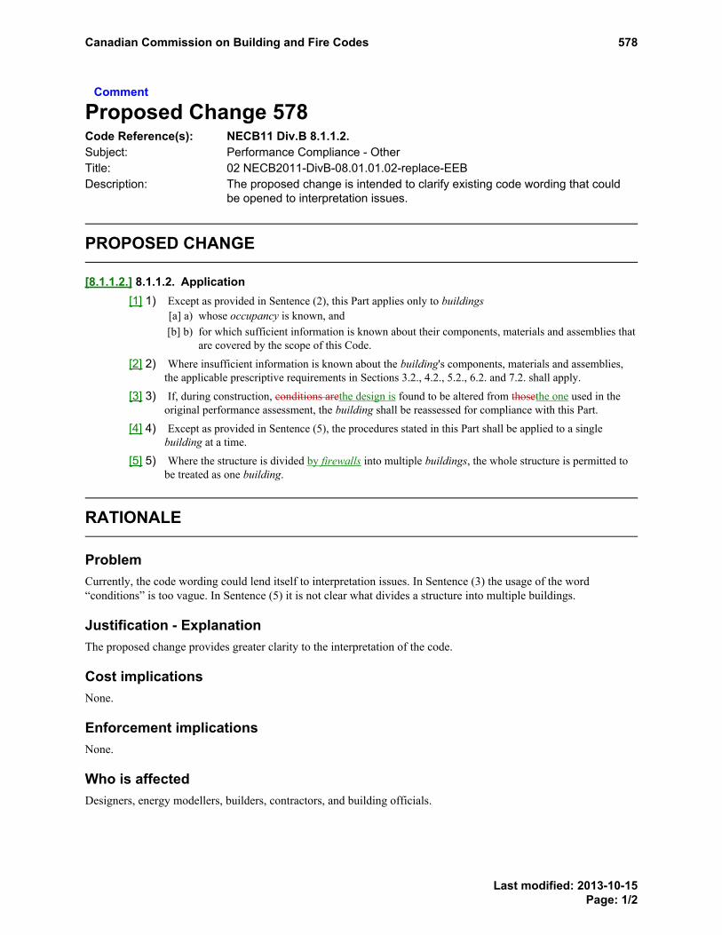
Comment
Proposed Change 578Code Reference(s): NECB11 Div.B 8.1.1.2.Subject: Performance Compliance - OtherTitle: 02 NECB2011-DivB-08.01.01.02-replace-EEBDescription: The proposed change is intended to clarify existing code wording that could
be opened to interpretation issues.
PROPOSED CHANGE
[8.1.1.2.] 8.1.1.2. Application[1] 1) Except as provided in Sentence (2), this Part applies only to buildings
[a] a) whose occupancy is known, and[b] b) for which sufficient information is known about their components, materials and assemblies that
are covered by the scope of this Code.
[2] 2) Where insufficient information is known about the building's components, materials and assemblies,the applicable prescriptive requirements in Sections 3.2., 4.2., 5.2., 6.2. and 7.2. shall apply.
[3] 3) If, during construction, conditions arethe design is found to be altered from thosethe one used in theoriginal performance assessment, the building shall be reassessed for compliance with this Part.
[4] 4) Except as provided in Sentence (5), the procedures stated in this Part shall be applied to a singlebuilding at a time.
[5] 5) Where the structure is divided by firewalls into multiple buildings, the whole structure is permitted tobe treated as one building.
RATIONALE
ProblemCurrently, the code wording could lend itself to interpretation issues. In Sentence (3) the usage of the word“conditions” is too vague. In Sentence (5) it is not clear what divides a structure into multiple buildings.
Justification - ExplanationThe proposed change provides greater clarity to the interpretation of the code.
Cost implicationsNone.
Enforcement implicationsNone.
Who is affectedDesigners, energy modellers, builders, contractors, and building officials.
Canadian Commission on Building and Fire Codes 578
Last modified: 2013-10-15Page: 1/2

OBJECTIVE-BASED ANALYSIS OF NEW OR CHANGED PROVISIONS[8.1.1.2.] 8.1.1.2. ([1] 1) [F99-OE1.1][8.1.1.2.] 8.1.1.2. ([2] 2) no attributions[8.1.1.2.] 8.1.1.2. ([3] 3) [F99-OE1.1][8.1.1.2.] 8.1.1.2. ([4] 4) [F99-OE1.1][8.1.1.2.] 8.1.1.2. ([5] 5) no attributions
Canadian Commission on Building and Fire Codes 578
Last modified: 2013-10-15Page: 2/2

Comment
Proposed Change 576Code Reference(s): NECB11 Div.B 8.4.1.1.Subject: Energy Use IntensityTitle: 02 NECB11-DivB-08.04.01.01-replace-EEB-EUIDescription: The proposed change is intended to align the general performance
compliance provisions with the establishment of the energy use intensity,and to exclude certain prescriptive compliant parts of the building from theanalysis.
PROPOSED CHANGE
[8.4.1.1.] 8.4.1.1. General[1] 1) In establishing the building energy target, building components must be accounted for in accordance
with the prescriptive requirements of Sections 3.2., 4.2., 5.2., 6.2. and 7.2. for the climate zone underconsideration.) For the purposes of this Part, energy use intensity, EUI, expressed as ekWh/m2/year,refers to the energy use as determined in this Part divided by the sum of interior floor areas. (SeeAppendix A.)
[2] 2) Where the construction techniques or building components used are more energy-efficient than thoseprescribed by the prescriptive requirements, the performance compliance calculations are permitted totake this increased performance level into account in the determination of the annual energyconsumptionEUI, provided it can be quantified and is not dependent on occupant interactionbehaviour.
[3] 3) The following building components areExterior lighting is permitted to be excluded from theperformance compliance calculations, provided they comply it complies with the prescriptiverequirements of Parts 4 and 5, as applicable:.[a] a) lighting of unconditioned spaces,[b] b) exterior lighting, and[c] c) ventilation of unconditioned spaces.
A-8.4.1.1.(1) Energy Use Intensity.The EUI is not intended to be a prediction of the actual energy use of the building.
RATIONALE
General informationSee the summary for subject Energy Use Intensity.
ProblemEnergy use intensity is being set as the default method of code compliance by whole building modeling.
Justification - ExplanationRevise the code text to be compatible with energy use intensity.
Cost implicationsN/A – the associated costs are accounted for in the prescriptive requirements.
Canadian Commission on Building and Fire Codes 576
Last modified: 2013-10-15Page: 1/2

Enforcement implicationsNone.
Who is affectedDesigners, contractors, building officials, building owners.
OBJECTIVE-BASED ANALYSIS OF NEW OR CHANGED PROVISIONS[8.4.1.1.] 8.4.1.1. ([1] 1) [F99-OE1.1][8.4.1.1.] 8.4.1.1. ([2] 2) [F92,F93,F94,F95,F96,F97,F98,F99,F100-OE1.1][8.4.1.1.] 8.4.1.1. ([3] 3) no attributions
Canadian Commission on Building and Fire Codes 576
Last modified: 2013-10-15Page: 2/2

Comment
Proposed Change 586Code Reference(s): NECB11 Div.B 8.4.1.1.
NECB11 Div.B 8.4.1.3.Subject: Energy Use IntensityTitle: 04 NECB11-DivB-08.04.01.03.-move-Limitations add-EEB-Process LoadsDescription: This proposed change is intended to move the requirement that links the
performance compliance path to the limitations stated in the other Parts tothe appropriate Article in the revised Part 8 and to add requirements relatingto evaluation of process loads.
PROPOSED CHANGE
[8.4.1.1.] 8.4.1.1. General[1] 1) In establishing the building energy target, building components must be accounted for in accordance
with the prescriptive requirements of Sections 3.2., 4.2., 5.2., 6.2. and 7.2. for the climate zone underconsideration.
[2] 2) Where the construction techniques or building components used are more energy-efficient than thoseprescribed by the prescriptive requirements, the performance compliance calculations are permitted totake this increased performance level into account in the determination of the annual energyconsumption, provided it can be quantified and is not dependent on occupant interaction.
[3] 3) The following building components are permitted to be excluded from the performance compliancecalculations, provided they comply with the prescriptive requirements of Parts 4 and 5, as applicable:[a] a) lighting of unconditioned spaces,[b] b) exterior lighting, and[c] c) ventilation of unconditioned spaces.
[4] 1) Compliance with this Part shall be subject to the limitations stated in Sections 3.4., 4.4., 5.4., 6.4.and 7.4.
[8.4.1.3.] 8.4.1.3. LimitationsTreatment of Process Loads[1] 1) Compliance with this Part shall be subject to the limitations stated in Sections 3.4., 4.4., 5.4., 6.4.
and 7.4.
[2] --) Except as provided in Sentence (5), the energy consumed by the process loads need not be included inthe determination of the EUI.
[3] --) Where the effects of process loads are included to reduce the EUI of the proposed building, the energyconsumed by the process loads shall also be accounted for in the modeling of the proposed building andin the maximum allowable EUI.
RATIONALE
General informationSee the summary for subject Energy Use Intensity.
Canadian Commission on Building and Fire Codes 586
Last modified: 2013-10-15Page: 1/2
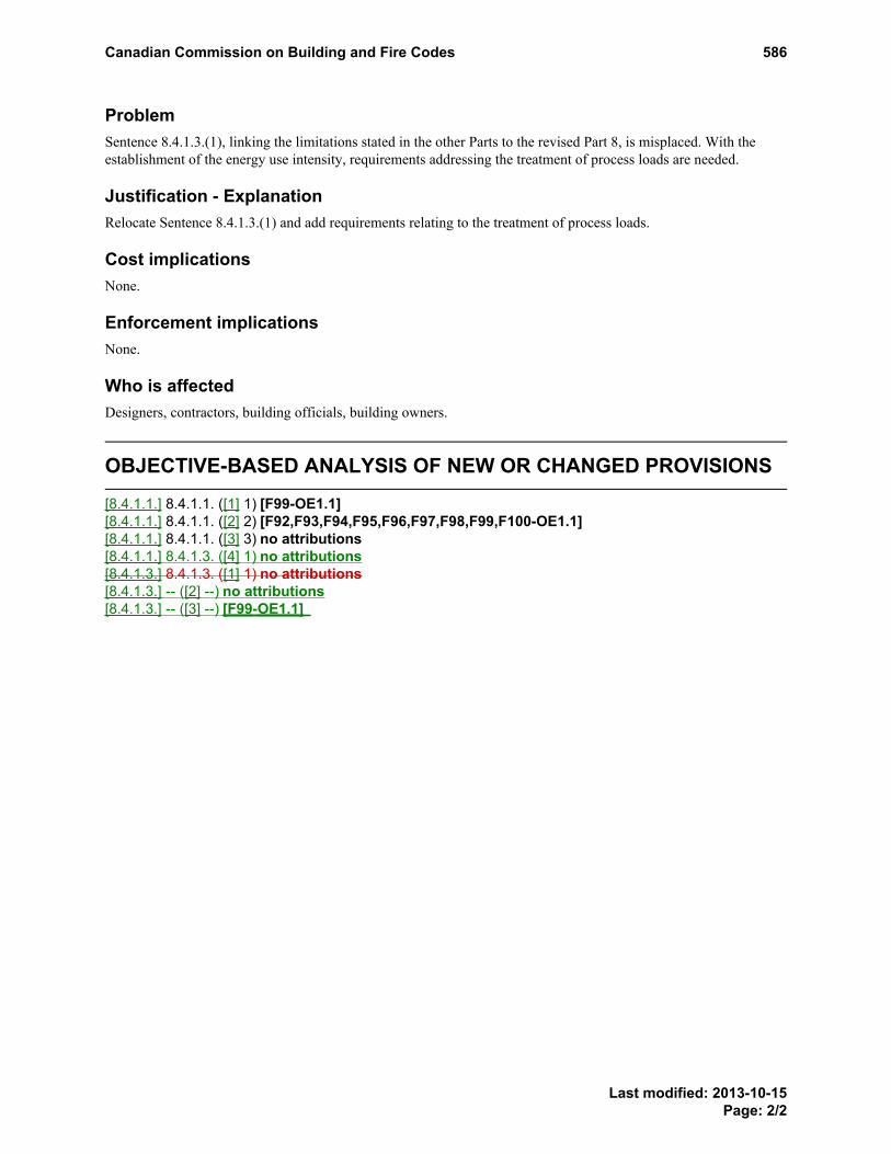
ProblemSentence 8.4.1.3.(1), linking the limitations stated in the other Parts to the revised Part 8, is misplaced. With theestablishment of the energy use intensity, requirements addressing the treatment of process loads are needed.
Justification - ExplanationRelocate Sentence 8.4.1.3.(1) and add requirements relating to the treatment of process loads.
Cost implicationsNone.
Enforcement implicationsNone.
Who is affectedDesigners, contractors, building officials, building owners.
OBJECTIVE-BASED ANALYSIS OF NEW OR CHANGED PROVISIONS[8.4.1.1.] 8.4.1.1. ([1] 1) [F99-OE1.1][8.4.1.1.] 8.4.1.1. ([2] 2) [F92,F93,F94,F95,F96,F97,F98,F99,F100-OE1.1][8.4.1.1.] 8.4.1.1. ([3] 3) no attributions[8.4.1.1.] 8.4.1.3. ([4] 1) no attributions[8.4.1.3.] 8.4.1.3. ([1] 1) no attributions[8.4.1.3.] -- ([2] --) no attributions[8.4.1.3.] -- ([3] --) [F99-OE1.1]
Canadian Commission on Building and Fire Codes 586
Last modified: 2013-10-15Page: 2/2

Comment
Proposed Change 581Code Reference(s): NECB11 Div.B 8.4.1.2.Subject: Energy Use IntensityTitle: 03 NECB11-DivB-08.04.01.02.(1)(2)-replace-add-EEB-EUI-Equation &
TableDescription: The proposed change is intended to align the general performance
compliance methodology with the establishment of the energy use intensity.
EXISTING PROVISION
8.4.1.2. Determination of Compliance1) Subject to the limitations stated in Article 8.4.1.3., compliance with this Part shall be determined based on Sentences (2) to (5).
2) The annual energy consumption of the proposed building, as determined in accordance with this Part, shall not exceed the building energy target of thereference building.
3) The number of hours during which the heating loads for each thermal block are not met shall not exceed 100 hours in a simulated year for both the proposedand reference buildings.
4) The number of hours during which the cooling loads for each thermal block of the proposed building are not met shall not differ by more than ±10% from thenumber of hours in a simulated year that the cooling loads of the reference building are not met.
5) Where the requirements of Sentences (3) and (4) are not met, the capacities of the primary and secondary systems of the proposed or reference building shall beincrementally increased until those loads are met.
PROPOSED CHANGE
[8.4.1.2.] 8.4.1.2. Determination of Compliance[1] 1) Subject to the limitations stated in Article 8.4.1.3., compliance with this Part shall be determined based on Sentences (2) to (5).
[2] 2) The annual energy consumptionenergy use intensity of the proposed building, EUIPROPOSED, as determined in accordance with this Part, shall not exceed thebuilding energy target of the reference buildingmaximum allowable energy use intensity, EUIMAX, as follows (see Appendix A).:
where
EUIPROPOSED is determined in accordance with Subsection 8.4.3.,
EUIMAX is determined in accordance with Sentence 8.4.1.2.(2).
Table [8.4.1.2.]Energy Use Intensities for Space Uses
Forming Part of Sentence 8.4.4.1.(1)
Space Use EUI (ekWh/m2/yr)
Restaurant 0.126∙HDD + 132
School 0.016∙HDD + 88
Long-term care 0.047∙HDD + 174
Residential 0.012∙HDD + 94
Office 0.008∙HDD + 95
Parking Garage (heated to 5°C) 0.067∙HDD - 152
Warehouse 0.020∙HDD + 73
Multi-tenant Retail 0.034∙HDD + 107
Large Format Retail 0.022∙HDD + 89
Illuminated and Ventilated Unheated Space (1) 19
Note to Table [8.4.1.2.] :
See Appendix A(1)PROPOSED CHANGE Table Footnotereferrer
[3] --) The EUIMAX shall be calculated[a] --) based on the requirements described in Sentences (5) and (6) where 90% or more of the sums of the gross interior floor areas, as calculated in Sentence
(4), of building space uses are known and represented in Table 8.4.1.2., or
PROPOSED CHANGE Table Footnote
Footnote1
Canadian Commission on Building and Fire Codes 581
Last modified: 2013-10-11Page: 1/4

[b] --) in accordance with Subsection 8.4.4. where less than 90% of the of the sums of the gross interior floor areas, as calculated in Sentence (4), of buildingspace uses are known and are represented in Table 8.4.1.2.
[4] --) The gross interior floor area of each space use shall be the sum of the interior floor areas sharing this space use, determined based on the dimensions measuredfrom the inside of the exterior walls to the middle line of the partition walls separating the space use.
[5] --) The EUI for each space use shall be determined using Table 8.4.1.2. for the space use that appropriately represents the proposed use of each space.
[6] --) The EUIMAX shall be determined as follows:
where
i = the space use identified in Table 8.4.4.1.
n = the total number of space uses in the building that are identified in Table 8.4.1.2.
gross interiorfloor area
= calculated per Sentence 8.4.1.2.(3)
EUIi = the energy use intensity of the space use
[7] 3) The number of hours during which the heating loads for each thermal block are not met shall not exceed 100 hours in a simulated year for both the proposedand reference buildings.
[8] 4) The number of hours during which the cooling loads for each thermal block of the proposed building are not met shall not differ by more than ±10% from thenumber of hours in a simulated year that the cooling loads of the reference building are not met.
[9] 5) Where the requirements of Sentences (3) and (4) are not met, the capacities of the primary and secondary systems of the proposed or reference building shall beincrementally increased until those loads are met.
A-8.4.1.2.(1) Compliance.The flow chart in Figure A-8.4.1.2.(1) illustrates the process to determine compliance using Part 8.
Figure [A-8.4.1.2.(1)]Code Compliance Using the Building Energy Performance Compliance Path
Canadian Commission on Building and Fire Codes 581
Last modified: 2013-10-11Page: 2/4

A-Table 8.4.1.2. Illuminated and Ventilated Unheated Space.The EUI for this space type is based on an unheated underground storage garage.
Canadian Commission on Building and Fire Codes 581
Last modified: 2013-10-11Page: 3/4
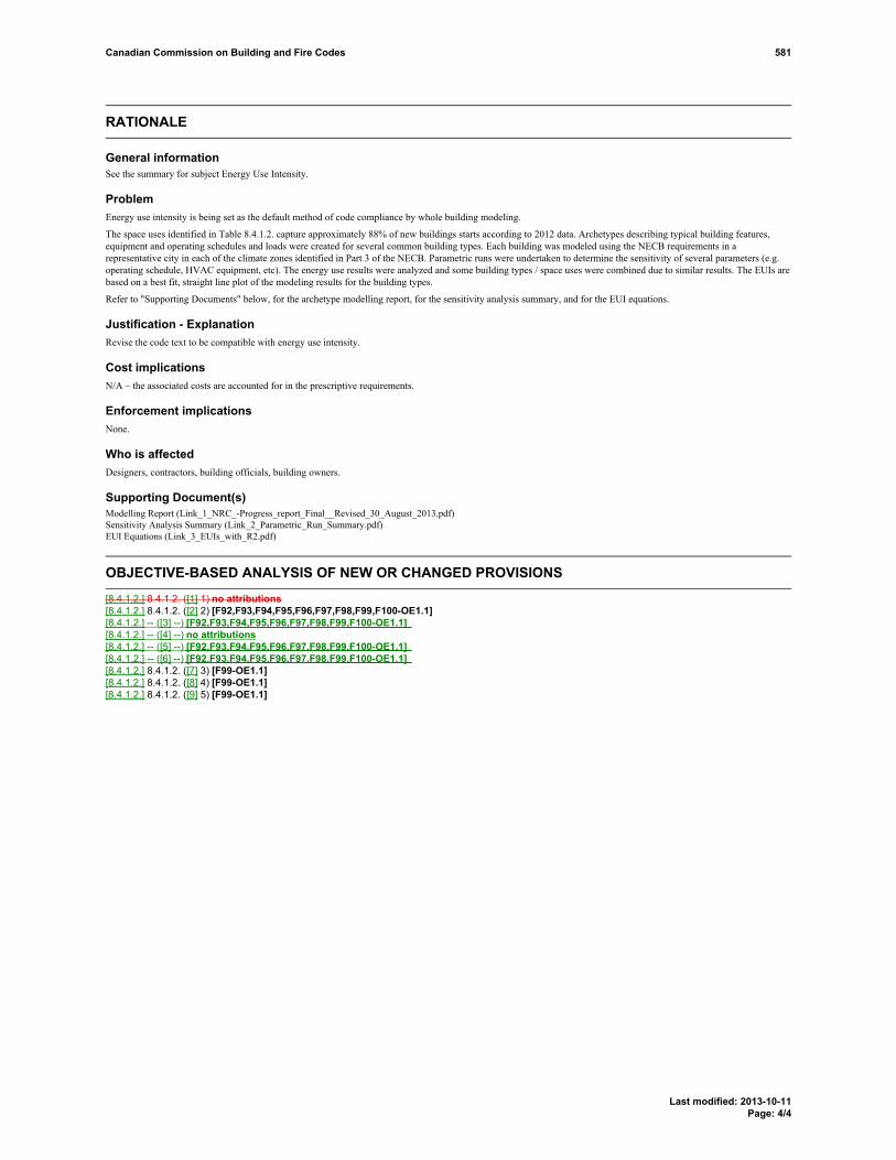
RATIONALE
General informationSee the summary for subject Energy Use Intensity.
ProblemEnergy use intensity is being set as the default method of code compliance by whole building modeling.
The space uses identified in Table 8.4.1.2. capture approximately 88% of new buildings starts according to 2012 data. Archetypes describing typical building features,equipment and operating schedules and loads were created for several common building types. Each building was modeled using the NECB requirements in arepresentative city in each of the climate zones identified in Part 3 of the NECB. Parametric runs were undertaken to determine the sensitivity of several parameters (e.g.operating schedule, HVAC equipment, etc). The energy use results were analyzed and some building types / space uses were combined due to similar results. The EUIs arebased on a best fit, straight line plot of the modeling results for the building types.
Refer to "Supporting Documents" below, for the archetype modelling report, for the sensitivity analysis summary, and for the EUI equations.
Justification - ExplanationRevise the code text to be compatible with energy use intensity.
Cost implicationsN/A – the associated costs are accounted for in the prescriptive requirements.
Enforcement implicationsNone.
Who is affectedDesigners, contractors, building officials, building owners.
Supporting Document(s)Modelling Report (Link_1_NRC_-Progress_report_Final__Revised_30_August_2013.pdf)Sensitivity Analysis Summary (Link_2_Parametric_Run_Summary.pdf)EUI Equations (Link_3_EUIs_with_R2.pdf)
OBJECTIVE-BASED ANALYSIS OF NEW OR CHANGED PROVISIONS[8.4.1.2.] 8.4.1.2. ([1] 1) no attributions[8.4.1.2.] 8.4.1.2. ([2] 2) [F92,F93,F94,F95,F96,F97,F98,F99,F100-OE1.1][8.4.1.2.] -- ([3] --) [F92,F93,F94,F95,F96,F97,F98,F99,F100-OE1.1][8.4.1.2.] -- ([4] --) no attributions[8.4.1.2.] -- ([5] --) [F92,F93,F94,F95,F96,F97,F98,F99,F100-OE1.1][8.4.1.2.] -- ([6] --) [F92,F93,F94,F95,F96,F97,F98,F99,F100-OE1.1][8.4.1.2.] 8.4.1.2. ([7] 3) [F99-OE1.1][8.4.1.2.] 8.4.1.2. ([8] 4) [F99-OE1.1][8.4.1.2.] 8.4.1.2. ([9] 5) [F99-OE1.1]
Canadian Commission on Building and Fire Codes 581
Last modified: 2013-10-11Page: 4/4

Comment
Proposed Change 584Code Reference(s): NECB11 Div.B 8.4.1.2.
NECB11 Div.B 8.4.2.Subject: Performance Compliance - OtherTitle: 03 NECB2011-DivB-08.04.01.02-add-EEB-CapacityDescription: The proposed change moves code wording to a more appropriate location.
PROPOSED CHANGE
[8.4.1.2.] 8.4.1.2. Determination of Compliance[1] 1) Subject to the limitations stated in Article 8.4.1.3., compliance with this Part shall be determined based
on Sentences (2) to (5).
[2] 2) The annual energy consumption of the proposed building, as determined in accordance with this Part,shall not exceed the building energy target of the reference building.
[3] 3) The number of hours during which the heating loads for each thermal block are not met shall notexceed 100 hours in a simulated year for both the proposed and reference buildings.
[4] 4) The number of hours during which the cooling loads for each thermal block of the proposed buildingare not met shall not differ by more than ±10% from the number of hours in a simulated year that thecooling loads of the reference building are not met.
[5] 5) Where the requirements of Sentences (3) and (4) are not met, the capacities of the primary andsecondary systems of the proposed or reference building shall be incrementally increased until thoseloads are met.
[8.4.2.] 8.4.2. Compliance Calculations
[8.4.2.1.] 8.4.2.1. General
[8.4.2.2.] 8.4.2.2. Calculation Methods
[8.4.2.3.] 8.4.2.3. Climatic Data
[8.4.2.4.] 8.4.2.4. Thermal Mass
[8.4.2.5.] 8.4.2.5. Space Temperature
[8.4.2.6.] 8.4.2.6. Heat Transfer Between Thermal Blocks
[8.4.2.7.] 8.4.2.7. Internal and Service Water Heating Loads
[8.4.2.8.] 8.4.2.8. Building Envelope
[8.4.2.9.] 8.4.2.9. Air Leakage
[8.4.2.10.] 8.4.2.10. HVAC Systems Calculations
[8.4.2.11.] --- Equipment Capacities[1] 3) The number of hours during which the heating loads for each thermal block are not met shall not
exceed 100 hours in a simulated year for both the proposed and reference buildings.
Canadian Commission on Building and Fire Codes 584
Last modified: 2013-10-15Page: 1/3

[2] 4) The number of hours during which the cooling loads for each thermal block of the proposed buildingare not met shall not differ by more than ±10% from the number of hours in a simulated year that thecooling loads of the reference building are not met.
[3] 5) Where the requirements of Sentences (1) and (2) are not met, the capacities of the primary andsecondary systems of the proposed or reference building shall be incrementally increased until thoseloads are met.
RATIONALE
ProblemWith the addition of Energy Use Intensity compliance option, provisions relating to “Equipment Capacity” are nolonger appropriately placed under “8.4.1.2. Determination of Compliance”.
Justification - ExplanationThe proposed change moves the code provisions relating to “Equipment Capacity” to a more appropriate locationand creates Article 8.4.2.11. Equipment Capacities.The proposed change provides greatly clarity to the code.
Cost implicationsNone, the proposed change would not have any cost implications.
Enforcement implicationsNone, enforcement could be done using existing infrastructure.
Who is affectedDesigners, manufacturers, builders, contractors, specification writers and building officials.
OBJECTIVE-BASED ANALYSIS OF NEW OR CHANGED PROVISIONS[8.4.1.2.] 8.4.1.2. ([1] 1) no attributions[8.4.1.2.] 8.4.1.2. ([2] 2) [F92,F93,F94,F95,F96,F97,F98,F99,F100-OE1.1][8.4.1.2.] 8.4.1.2. ([3] 3) [F99-OE1.1][8.4.1.2.] 8.4.1.2. ([4] 4) [F99-OE1.1][8.4.1.2.] 8.4.1.2. ([5] 5) [F99-OE1.1][8.4.2.1.] 8.4.2.1. ([1] 1) [F99-OE1.1][8.4.2.2.] 8.4.2.2. ([1] 1) [F99-OE1.1][8.4.2.2.] 8.4.2.2. ([2] 2) no attributions[8.4.2.2.] 8.4.2.2. ([3] 3) [F99-OE1.1][8.4.2.2.] 8.4.2.2. ([4] 4) [F99-OE1.1][8.4.2.2.] 8.4.2.2. ([5] 5) [F99-OE1.1][8.4.2.2.] 8.4.2.2. ([6] 6) no attributions[8.4.2.3.] 8.4.2.3. ([1] 1) [F99-OE1.1][8.4.2.3.] 8.4.2.3. ([2] 2) [F99-OE1.1][8.4.2.4.] 8.4.2.4. ([1] 1) [F99-OE1.1][8.4.2.5.] 8.4.2.5. ([1] 1) [F99-OE1.1][8.4.2.6.] 8.4.2.6. ([1] 1) [F99-OE1.1][8.4.2.6.] 8.4.2.6. ([2] 2) [F99-OE1.1][8.4.2.7.] 8.4.2.7. ([1] 1) [F99-OE1.1]
Canadian Commission on Building and Fire Codes 584
Last modified: 2013-10-15Page: 2/3

[8.4.2.7.] 8.4.2.7. ([2] 2) [F99-OE1.1][8.4.2.7.] 8.4.2.7. ([3] 3) [F99-OE1.1][8.4.2.7.] 8.4.2.7. ([4] 4) [F99-OE1.1][8.4.2.7.] 8.4.2.7. ([5] 5) [F99-OE1.1][8.4.2.8.] 8.4.2.8. ([1] 1) [F99-OE1.1][8.4.2.8.] 8.4.2.8. ([2] 2) [F99-OE1.1][8.4.2.8.] 8.4.2.8. ([3] 3) [F99-OE1.1][8.4.2.8.] 8.4.2.8. ([4] 4) [F99-OE1.1][8.4.2.8.] 8.4.2.8. ([5] 5) [F99-OE1.1][8.4.2.8.] 8.4.2.8. ([6] 6) [F99-OE1.1][8.4.2.8.] 8.4.2.8. ([7] 7) [F99-OE1.1][8.4.2.8.] 8.4.2.8. ([8] 8) [F99-OE1.1][8.4.2.8.] 8.4.2.8. ([9] 9) [F99-OE1.1][8.4.2.8.] 8.4.2.8. ([10] 10) [F99-OE1.1][8.4.2.9.] 8.4.2.9. ([1] 1) [F99-OE1.1][8.4.2.10.] 8.4.2.10. ([1] 1) [F99-OE1.1][8.4.2.10.] 8.4.2.10. ([2] 2) [F99-OE1.1][8.4.2.10.] 8.4.2.10. ([3] 3) [F99-OE1.1][8.4.2.10.] 8.4.2.10. ([4] 4) [F99-OE1.1][8.4.2.10.] 8.4.2.10. ([5] 5) [F99-OE1.1][8.4.2.11.] 8.4.1.2. ([1] 3) [F99-OE1.1][8.4.2.11.] 8.4.1.2. ([2] 4) [F99-OE1.1][8.4.2.11.] 8.4.1.2. ([3] 5) [F99-OE1.1]
Canadian Commission on Building and Fire Codes 584
Last modified: 2013-10-15Page: 3/3

Comment
Proposed Change 588Code Reference(s): NECB11 Div.B 8.4.1.4.(1)Subject: Performance Compliance - OtherTitle: 04 NECB2011-DivB-08.04.01.04-replace-EEB-AdditionsDescription: The proposed change is intended to clarify existing code wording that could
be opened to interpretation issues.
PROPOSED CHANGE
[8.4.1.4.] 8.4.1.4. Treatment of Additions[1] 1) For the purpose of performance compliance calculations, the assessment of additions shall be based on
[a] a) the addition being considered by itself, or[b] b) the addition being considered together with the existing building, in which case both the
building energy target and the annual energy consumption shall be determined using the thermalcharacteristics of existing components of the building envelope.
RATIONALE
ProblemThe current code wording includes unnecessary details relating to existing building characteristics.
Justification - ExplanationThe proposed change provides greater clarity to the code.
Cost implicationsNone.
Enforcement implicationsNone.
Who is affectedDesigners, energy modellers, builders, contractors, and building officials.
OBJECTIVE-BASED ANALYSIS OF NEW OR CHANGED PROVISIONS[8.4.1.4.] 8.4.1.4. ([1] 1) [F99-OE1.1]
Canadian Commission on Building and Fire Codes 588
Last modified: 2013-10-15Page: 1/1

Comment
Proposed Change 593Code Reference(s): NECB11 Div.B 8.4.2.2.Subject: Performance Compliance - OtherTitle: 05 NECB2011-DivB-08.04.02.02 -replace-EEB-klDescription: The proposed change is intended to clarify wording that could be open to
interpretation issues.
PROPOSED CHANGE
[8.4.2.2.] 8.4.2.2. Calculation Methods[1] 1) Except as provided in Sentences (2) and (6)Sentence (5), the energy model calculations shall account
for the annual energy consumption of[a] a) space-heating equipment,[b] b) space-cooling equipment,[c] c) fans,[d] d) interior and exterior lighting devices,[e] e) service water heating equipment,[f] f) pumps,
[g] g) auxiliary HVAC equipment (see Appendix A),[h] h) receptacle loads and miscellaneous equipment as per Article 8.4.2.7.,[i] i) appliances, and[j] j) elevators and escalators.
[2] 2) For the purpose of compliance calculations, building components that meet the prescriptiverequirements of this Code are permitted to be excluded from the energy model, provided their energyconsumption or output produces no cross effects with other building components covered by this Codethat result in an increase in the overall energy consumption of the proposed building.
[3] 3) The energy model calculations shall be performed for a one-year period (8 760 hours) using timeintervals no greater than one hour.
[4] 4) Operating schedules and climatic data input in the energy model shall use a time interval no greaterthan one hour.
[5] 5) If a computer program is used to carry out the compliance calculations, the calculation methodsemployed in the energy model shall conform to[a] a) ANSI/ASHRAE 140, "Evaluation of Building Energy Analysis Computer Programs", or[b] b) an equivalent test method.
[6] 6) Redundant or back-up equipment is permitted to be excluded from the energy model, provided it isequipped with controls that operate the equipment only when the primary equipment is downnotoperating.
RATIONALE
ProblemCurrently, the Code wording could lend itself to interpretation issues. The content of Sentence (2) is redundant.Ambiguous terminology is used.
PROPOSEDCHANGEA-8.4.2.2.(1)(g)
Canadian Commission on Building and Fire Codes 593
Last modified: 2013-10-15Page: 1/2

Justification - ExplanationThe proposed change provides greater clarity to the interpretation of the Code. Sentence (2) is deleted as its contentis redundant and considered in 8.4.1.2.(3).
Cost implicationsNone.
Enforcement implicationsNone.
Who is affectedDesigners, energy modellers, builders, contractors, and building officials.
OBJECTIVE-BASED ANALYSIS OF NEW OR CHANGED PROVISIONS[8.4.2.2.] 8.4.2.2. ([1] 1) [F99-OE1.1][8.4.2.2.] 8.4.2.2. ([2] 2) no attributions[8.4.2.2.] 8.4.2.2. ([3] 3) [F99-OE1.1][8.4.2.2.] 8.4.2.2. ([4] 4) [F99-OE1.1][8.4.2.2.] 8.4.2.2. ([5] 5) [F99-OE1.1][8.4.2.2.] 8.4.2.2. ([6] 6) no attributions
Canadian Commission on Building and Fire Codes 593
Last modified: 2013-10-15Page: 2/2

Comment
Proposed Change 603Code Reference(s): NECB11 Div.B 8.4.2.2.Subject: Energy Use IntensityTitle: 07 NECB11-DivB-08.04.02.02-Replace-Calc-MethodsDescription: The proposed change is intended to align the calculation methods for the
performance compliance path with the establishment of the energy useintensity.
PROPOSED CHANGE
[8.4.2.2.] 8.4.2.2. Calculation Methods[1] 1) Except as provided in Sentences (2) and (6), the energy model calculations shall account for the annual
energy consumptionenergy usage of[a] a) space-heating equipment,[b] b) space-cooling equipment,[c] c) fans,[d] d) interior and exterior lighting devices,[e] e) service water heating equipment,[f] f) pumps,
[g] g) auxiliary HVAC equipment (see Appendix A),[h] h) receptacle loads and miscellaneous equipment as per Article 8.4.2.7.,[i] i) appliances, and[j] j) elevators and escalators.
[2] 2) For the purpose of compliance calculations, building components that meet the prescriptiverequirements of this Code are permitted to be excluded from the energy model, provided their energyconsumption or output produces no cross effects with other building components covered by this Codethat result in an increase in the overall energy consumption of the proposed building.
[3] 3) The energy model calculations shall be performed for a one-year period (8 760 hours) using timeintervals no greater than one hour.
[4] 4) Operating schedules and climatic data input in the energy model shall use a time interval no greaterthan one hour.
[5] 5) If a computer program is used to carry out the compliance calculations, the calculation methodsemployed in the energy model shall conform to[a] a) ANSI/ASHRAE 140, "Evaluation of Building Energy Analysis Computer Programs", or[b] b) an equivalent test method.
[6] 6) Redundant or back-up equipment is permitted to be excluded from the energy model, provided it isequipped with controls that operate the equipment only when the primary equipment is down.
RATIONALE
General informationSee the summary for subject Energy Use Intensity.
PROPOSEDCHANGEA-8.4.2.2.(1)(g)
Canadian Commission on Building and Fire Codes 603
Last modified: 2013-10-15Page: 1/2

ProblemThe code text is incompatible with the energy use intensity methodology for the performance compliance path.
Justification - ExplanationRevise the text.
Cost implicationsN/A – the associated costs are accounted for in the prescriptive requirements.
Enforcement implicationsNone.
Who is affectedBuilding officials, designers, consultants, contractors, building owners.
OBJECTIVE-BASED ANALYSIS OF NEW OR CHANGED PROVISIONS[8.4.2.2.] 8.4.2.2. ([1] 1) [F99-OE1.1][8.4.2.2.] 8.4.2.2. ([2] 2) no attributions[8.4.2.2.] 8.4.2.2. ([3] 3) [F99-OE1.1][8.4.2.2.] 8.4.2.2. ([4] 4) [F99-OE1.1][8.4.2.2.] 8.4.2.2. ([5] 5) [F99-OE1.1][8.4.2.2.] 8.4.2.2. ([6] 6) no attributions
Canadian Commission on Building and Fire Codes 603
Last modified: 2013-10-15Page: 2/2

Comment
Proposed Change 599Code Reference(s): NECB11 Div.B 8.4.2.10.(3)Subject: Performance Compliance - OtherTitle: 06 NECB2011-DivB-08.04.02.10-delete-EEB-VAVDescription: The proposed change is intended to remove restrictions on modelling of fan
power.
PROPOSED CHANGE
[8.4.2.10.] 8.4.2.10. HVAC Systems Calculations[1] 3) Where applicable, the energy modelling of secondary systems shall account for
[a] a) temperature rise of supply air due to heat from supply fan,[b] b) temperature rise of return air due to heat from return fan,[c] c) temperature rise of return air due to heat gain from lights,[d] d) fan power as a function of supply airflow in variable-air-volume systems,[e] e) temperature and humidity rise or drop of supply or return air due to heat (sensible and latent
energy) transferred from a heat-recovery device, and[f] f) temperature rise of the outside air due to preheaters.
RATIONALE
ProblemCurrently, the code wording is unnecessarily restrictive. It does not consider systems with variable speed fans, whichare not variable air volume systems.
Justification - ExplanationThe proposed change removes restrictions on fan power modelling.
Cost implicationsNone.
Enforcement implicationsNone.
Who is affectedDesigners, energy modellers, builders, contractors, and building officials.
OBJECTIVE-BASED ANALYSIS OF NEW OR CHANGED PROVISIONS[8.4.2.10.] 8.4.2.10. ([1] 3) [F99-OE1.1]
Canadian Commission on Building and Fire Codes 599
Last modified: 2013-10-15Page: 1/1

Comment
Proposed Change 616Code Reference(s): NECB11 Div.B 8.4.3.
NECB11 Div.B 8.4.4.Subject: Semi-heated buildingsTitle: 10 NECB11-DivB-08.04.03.02.-replace-EEB-Schedules Loads Semi HeatedDescription: The proposed change is intended to define the energy compliance
calculations for semi-heated buildings in the performance path.
PROPOSED CHANGE
[8.4.3.] 8.4.3. Annual Energy Consumption of Proposed Building
[8.4.3.1.] 8.4.3.1. General
[8.4.3.2.] 8.4.3.2. Operating Schedules, Internal Loads, Service Water Heating Loads and Set-pointTemperature
[1] 1) The operating schedules relating to the presence of occupants and of loads due to the operation oflighting, receptacle equipment, and heating, cooling and service water heating systems shall berepresentative of the proposed building's type or space functions. (See Appendix A.)
[2] 1) Internal and service water heating loads used in the energy compliance calculations shall berepresentative of the proposed building's type or space functions. (See Appendix A.)
[3] --) For semi-heated buildings as defined in Sentence 1.2.1.2.(2), the set-point temperature of the proposedbuilding shall be that shown in the specifications.
[8.4.3.3.] 8.4.3.3. Internal and Service Water Heating Loads[1] 1) Internal and service water heating loads used in the energy compliance calculations shall be
representative of the proposed building's type or space functions. (See Appendix A.)
[8.4.3.4.] 8.4.3.4. Building Envelope Components
[8.4.3.5.] 8.4.3.5. Interior Lighting
[8.4.3.6.] 8.4.3.6. Purchased Energy
[8.4.3.7.] 8.4.3.7. Outdoor Air
[8.4.3.8.] 8.4.3.8. Space Temperature Control
[8.4.3.9.] 8.4.3.9. Part-Load Performance Curves
[8.4.3.10.] 8.4.3.10. Ice-Making Machines for Curling Rinks and Ice Arenas
PROPOSEDCHANGEA-8.4.3.2.(1)PROPOSEDCHANGEA-8.4.3.3.(1)
PROPOSEDCHANGEA-8.4.3.3.(1)
Canadian Commission on Building and Fire Codes 616
Last modified: 2013-09-05Page: 1/6

[8.4.4.] 8.4.4. Building Energy Target of the Reference Building
[8.4.4.1.] 8.4.4.1. General
[8.4.4.2.] 8.4.4.2. Operating Schedules, Internal Loads, Service Water Heating Loads and Set-pointTemperature
[1] 1) Except as provided in Sentence (3), Tthe reference building's operating schedules shall be modeled asbeing identical to those determined for the proposed building in Sentence 8.4.3.2.(1).
[2] 1) The reference building's internal and service water heating loads shall be modeled as being identical tothose determined for the proposed building in Sentence 8.4.3.2.(2).
[3] 2) The reference building of aA semi-heated building as defined in Sentence 1.2.1.2.(2) shall is permittedto have its set-point temperature set at 18°C, provided the capacity of the installed heating equipment inthe proposed building is no more than the proposed building's peak heating load plus 5%. (SeeA-3.3.4.1.(3) and 8.4.4.3.(2) in Appendix A.)[a] --) is permitted to have its set-point temperature set at 18°C, and[b] --) the thermal characteristics shall be based on the heating degree-days at 18°C of the building’s
location.(See Appendix A.)
[8.4.4.3.] 8.4.4.3. Internal and Service Water Heating Loads[1] 1) The reference building's internal and service water heating loads shall be modeled as being identical to
those determined for the proposed building in Sentence 8.4.3.3.(1).
[2] 2) A semi-heated building is permitted to have its set-point temperature set at 18°C, provided the capacityof the installed heating equipment in the proposed building is no more than the proposed building's peakheating load plus 5%. (See A-3.3.4.1.(3) and 8.4.4.3.(2) in Appendix A.)
PROPOSEDCHANGEA-3.3.4.1.(3)and8.4.4.3.(2)
PROPOSEDCHANGEA-3.3.4.1.(3)and8.4.4.3.(2)
Canadian Commission on Building and Fire Codes 616
Last modified: 2013-09-05Page: 2/6

[8.4.4.4.] 8.4.4.4. Building Envelope Components
[8.4.4.5.] 8.4.4.5. Thermal Mass
[8.4.4.6.] 8.4.4.6. Lighting
[8.4.4.7.] 8.4.4.7. Purchased Energy
[8.4.4.8.] 8.4.4.8. HVAC System Selection
[8.4.4.9.] 8.4.4.9. Equipment Oversizing
[8.4.4.10.] 8.4.4.10. Heating System
[8.4.4.11.] 8.4.4.11. Cooling Systems
[8.4.4.12.] 8.4.4.12. Cooling Tower Systems
[8.4.4.13.] 8.4.4.13. Cooling with Outside Air
[8.4.4.14.] 8.4.4.14. Heat Pumps
[8.4.4.15.] 8.4.4.15. Hydronic Pumps
[8.4.4.16.] 8.4.4.16. Outdoor Air
[8.4.4.17.] 8.4.4.17. Space Temperature Control
[8.4.4.18.] 8.4.4.18. Fans
[8.4.4.19.] 8.4.4.19. Supply Air Systems
[8.4.4.20.] 8.4.4.20. Heat-Recovery System
[8.4.4.21.] 8.4.4.21. Service Water Heating Systems
[8.4.4.22.] 8.4.4.22. Part-Load Performance Curves
A-8.4.4.2.(3)A reference building with a set-point of 18°C and thermal characteristics based on the heating degree-days at 18°C isintended to have the same energy performance as a building with a set-point of 15°C and thermal characteristics based onthe heating degree-days at 15°C.
RATIONALE
ProblemThe energy compliance calculations for semi-heated buildings in NECB 2011 are not adequately defined and canresult in higher energy performance compared to heated buildings.
Justification - ExplanationDefine the energy compliance calculations for semi-heated buildings in the performance path so that their energyperformance is consistent with heated buildings.
Canadian Commission on Building and Fire Codes 616
Last modified: 2013-09-05Page: 3/6

Cost implicationsPotential capital cost savings.
Enforcement implicationsNone.
Who is affectedBuilding officials, designers, contractors, manufacturers.
OBJECTIVE-BASED ANALYSIS OF NEW OR CHANGED PROVISIONS[8.4.3.1.] 8.4.3.1. ([1] 1) no attributions[8.4.3.1.] 8.4.3.1. ([2] 2) [F99-OE1.1][8.4.3.1.] 8.4.3.1. ([3] 3) [F99-OE1.1][8.4.3.1.] 8.4.3.1. ([4] 4) [F99-OE1.1][8.4.3.1.] 8.4.3.1. ([5] 5) [F99-OE1.1][8.4.3.1.] 8.4.3.1. ([6] 6) no attributions[8.4.3.1.] 8.4.3.1. ([7] 7) [F99-OE1.1][8.4.3.1.] 8.4.3.1. ([8] 8) [F99-OE1.1][8.4.3.2.] 8.4.3.2. ([1] 1) [F99-OE1.1][8.4.3.2. 8.4.3.3.] 8.4.3.3. ([2 1] 1) [F99-OE1.1][8.4.3.2.] -- ([3] --) [F99-OE1.1][8.4.3.2. 8.4.3.3.] 8.4.3.3. ([2 1] 1) [F99-OE1.1][8.4.3.4.] 8.4.3.4. ([1] 1) [F99-OE1.1][8.4.3.4.] 8.4.3.4. ([2] 2) [F99-OE1.1][8.4.3.4.] 8.4.3.4. ([3] 3) [F99-OE1.1][8.4.3.5.] 8.4.3.5. ([1] 1) [F99-OE1.1][8.4.3.5.] 8.4.3.5. ([2] 2) [F99-OE1.1][8.4.3.5.] 8.4.3.5. ([3] 3) [F99-OE1.1][8.4.3.6.] 8.4.3.6. ([1] 1) no attributions[8.4.3.6.] 8.4.3.6. ([2] 2) [F99-OE1.1][8.4.3.6.] 8.4.3.6. ([3] 3) [F99-OE1.1][8.4.3.6.] 8.4.3.6. ([4] 4) [F99-OE1.1][8.4.3.6.] 8.4.3.6. ([5] 5) [F99-OE1.1][8.4.3.6.] 8.4.3.6. ([6] 6) no attributions[8.4.3.7.] 8.4.3.7. ([1] 1) [F99-OE1.1][8.4.3.8.] 8.4.3.8. ([1] 1) [F99-OE1.1][8.4.3.9.] 8.4.3.9. ([1] 1) [F99-OE1.1][8.4.3.9.] 8.4.3.9. ([2] 2) [F99-OE1.1][8.4.3.10.] 8.4.3.10. ([1] 1) [F99-OE1.1][8.4.4.1.] 8.4.4.1. ([1] 1) no attributions[8.4.4.1.] 8.4.4.1. ([2] 2) [F99-OE1.1][8.4.4.1.] 8.4.4.1. ([3] 3) [F99-OE1.1][8.4.4.1.] 8.4.4.1. ([4] 4) [F99-OE1.1][8.4.4.1.] 8.4.4.1. ([5] 5) [F99-OE1.1][8.4.4.1.] 8.4.4.1. ([6] 6) [F99-OE1.1][8.4.4.1.] 8.4.4.1. ([7] 7) [F99-OE1.1][8.4.4.2.] 8.4.4.2. ([1] 1) [F99-OE1.1][8.4.4.2. 8.4.4.3.] 8.4.4.3. ([2 1] 1) [F99-OE1.1][8.4.4.2. 8.4.4.3.] 8.4.4.3. ([3 2] 2) [F99-OE1.1]
Canadian Commission on Building and Fire Codes 616
Last modified: 2013-09-05Page: 4/6

[8.4.4.2. 8.4.4.3.] 8.4.4.3. ([3 2] 2) no attributions[8.4.4.2. 8.4.4.3.] 8.4.4.3. ([2 1] 1) [F99-OE1.1][8.4.4.2. 8.4.4.3.] 8.4.4.3. ([3 2] 2) no attributions[8.4.4.4.] 8.4.4.4. ([1] 1) [F99-OE1.1][8.4.4.4.] 8.4.4.4. ([2] 2) ([a] a) [F99-OE1.1][8.4.4.4.] 8.4.4.4. ([2] 2) no attributions[8.4.4.4.] 8.4.4.4. ([3] 3) [F99-OE1.1][8.4.4.4.] 8.4.4.4. ([4] 4) [F99-OE1.1][8.4.4.4.] 8.4.4.4. ([5] 5) [F99-OE1.1][8.4.4.4.] 8.4.4.4. ([6] 6) [F99-OE1.1][8.4.4.4.] 8.4.4.4. ([7] 7) [F99-OE1.1][8.4.4.5.] 8.4.4.5. ([1] 1) no attributions[8.4.4.5.] 8.4.4.5. ([2] 2) [F99-OE1.1][8.4.4.6.] 8.4.4.6. ([1] 1) [F99-OE1.1][8.4.4.6.] 8.4.4.6. ([2] 2) [F99-OE1.1][8.4.4.6.] 8.4.4.6. ([3] 3) [F99-OE1.1][8.4.4.6.] 8.4.4.6. ([4] 4) [F99-OE1.1][8.4.4.7.] 8.4.4.7. ([1] 1) [F99-OE1.1][8.4.4.7.] 8.4.4.7. ([2] 2) [F99-OE1.1][8.4.4.7.] 8.4.4.7. ([3] 3) [F99-OE1.1][8.4.4.7.] 8.4.4.7. ([4] 4) [F99-OE1.1][8.4.4.8.] 8.4.4.8. ([1] 1) [F99-OE1.1][8.4.4.8.] 8.4.4.8. ([2] 2) [F99-OE1.1][8.4.4.8.] 8.4.4.8. ([3] 3) no attributions[8.4.4.8.] 8.4.4.8. ([4] 4) [F99-OE1.1][8.4.4.9.] 8.4.4.9. ([1] 1) [F99-OE1.1][8.4.4.9.] 8.4.4.9. ([2] 2) [F99-OE1.1][8.4.4.10.] 8.4.4.10. ([1] 1) [F99-OE1.1][8.4.4.10.] 8.4.4.10. ([2] 2) no attributions[8.4.4.10.] 8.4.4.10. ([3] 3) [F99-OE1.1][8.4.4.10.] 8.4.4.10. ([4] 4) [F99-OE1.1][8.4.4.10.] 8.4.4.10. ([5] 5) [F99-OE1.1][8.4.4.10.] 8.4.4.10. ([6] 6) [F99-OE1.1][8.4.4.10.] 8.4.4.10. ([7] 7) [F99-OE1.1][8.4.4.10.] 8.4.4.10. ([8] 8) [F99-OE1.1][8.4.4.11.] 8.4.4.11. ([1] 1) [F99-OE1.1][8.4.4.11.] 8.4.4.11. ([2] 2) no attributions[8.4.4.11.] 8.4.4.11. ([3] 3) [F99-OE1.1][8.4.4.11.] 8.4.4.11. ([4] 4) [F99-OE1.1][8.4.4.11.] 8.4.4.11. ([5] 5) [F99-OE1.1][8.4.4.11.] 8.4.4.11. ([6] 6) [F99-OE1.1][8.4.4.11.] 8.4.4.11. ([7] 7) [F99-OE1.1][8.4.4.11.] 8.4.4.11. ([8] 8) [F99-OE1.1][8.4.4.11.] 8.4.4.11. ([9] 9) [F99,F100-OE1.1][8.4.4.12.] 8.4.4.12. ([1] 1) [F99-OE1.1][8.4.4.12.] 8.4.4.12. ([2] 2) [F99-OE1.1][8.4.4.12.] 8.4.4.12. ([3] 3) [F99-OE1.1][8.4.4.12.] 8.4.4.12. ([4] 4) [F99-OE1.1][8.4.4.12.] 8.4.4.12. ([5] 5) [F99-OE1.1][8.4.4.12.] 8.4.4.12. ([6] 6) [F99-OE1.1][8.4.4.13.] 8.4.4.13. ([1] 1) [F99-OE1.1][8.4.4.14.] 8.4.4.14. ([1] 1) [F99-OE1.1][8.4.4.14.] 8.4.4.14. ([2] 2) [F99-OE1.1][8.4.4.15.] 8.4.4.15. ([1] 1) [F99-OE1.1]
Canadian Commission on Building and Fire Codes 616
Last modified: 2013-09-05Page: 5/6

[8.4.4.15.] 8.4.4.15. ([2] 2) [F99-OE1.1][8.4.4.15.] 8.4.4.15. ([3] 3) [F99-OE1.1][8.4.4.15.] 8.4.4.15. ([4] 4) [F99-OE1.1][8.4.4.15.] 8.4.4.15. ([5] 5) [F99-OE1.1][8.4.4.15.] 8.4.4.15. ([6] 6) [F99-OE1.1][8.4.4.16.] 8.4.4.16. ([1] 1) [F99-OE1.1][8.4.4.16.] 8.4.4.16. ([2] 2) no attributions[8.4.4.17.] 8.4.4.17. ([1] 1) [F99-OE1.1][8.4.4.17.] 8.4.4.17. ([2] 2) [F99-OE1.1][8.4.4.18.] 8.4.4.18. ([1] 1) [F99-OE1.1][8.4.4.18.] 8.4.4.18. ([2] 2) [F99-OE1.1][8.4.4.18.] 8.4.4.18. ([3] 3) [F99-OE1.1][8.4.4.18.] 8.4.4.18. ([4] 4) [F99-OE1.1][8.4.4.18.] 8.4.4.18. ([5] 5) [F99-OE1.1][8.4.4.19.] 8.4.4.19. ([1] 1) [F99-OE1.1][8.4.4.19.] 8.4.4.19. ([2] 2) [F99-OE1.1][8.4.4.19.] 8.4.4.19. ([3] 3) [F99-OE1.1][8.4.4.19.] 8.4.4.19. ([4] 4) [F99-OE1.1][8.4.4.19.] 8.4.4.19. ([5] 5) [F99-OE1.1][8.4.4.19.] 8.4.4.19. ([6] 6) [F99-OE1.1][8.4.4.20.] 8.4.4.20. ([1] 1) [F99,F100-OE1.1][8.4.4.20.] 8.4.4.20. ([2] 2) [F99,F100-OE1.1][8.4.4.20.] 8.4.4.20. ([3] 3) [F99-OE1.1][8.4.4.20.] 8.4.4.20. ([3] 3) ,([a] a), ([d] d) [F100-OE1.1][8.4.4.21.] 8.4.4.21. ([1] 1) [F99-OE1.1][8.4.4.21.] 8.4.4.21. ([2] 2) [F99-OE1.1][8.4.4.21.] 8.4.4.21. ([3] 3) [F99-OE1.1][8.4.4.21.] 8.4.4.21. ([4] 4) [F99-OE1.1][8.4.4.21.] 8.4.4.21. ([5] 5) [F99-OE1.1][8.4.4.21.] 8.4.4.21. ([6] 6) [F99-OE1.1][8.4.4.21.] 8.4.4.21. ([7] 7) [F99-OE1.1][8.4.4.21.] 8.4.4.21. ([8] 8) [F99-OE1.1][8.4.4.21.] 8.4.4.21. ([9] 9) [F99-OE1.1][8.4.4.22.] 8.4.4.22. ([1] 1) [F99-OE1.1]
Canadian Commission on Building and Fire Codes 616
Last modified: 2013-09-05Page: 6/6

Comment
Proposed Change 627Code Reference(s): NECB11 Div.B 8.4.3.Subject: Energy Use IntensityTitle: 16 NECB11-DivB-08.04.03.01.-EUI Prop GeneralDescription: The proposed change is intended to align the modeling of the proposed
building with the establishment of the energy use intensity methodology forperformance compliance.
PROPOSED CHANGE
[8.4.3.] 8.4.3. Annual Energy ConsumptionEnergy Use Intensity of ProposedBuilding
[8.4.3.1.] 8.4.3.1. General[1] 1) The annual energy consumption of the proposed building shall be calculated as described in this
Subsection.
[2] 2) Except as stated otherwise in this Subsection, the energy model shall be consistent with the proposedbuilding's specifications including proper accounting of[a] a) fenestration, doors and opaque building assembly types and areas,[b] b) lighting systems and controls,[c] c) HVAC system types, capacities and controls,[d] d) service water heating system types, capacities and controls, and[e] e) electrical systems.
[3] 3) The energy model calculations shall include all the energy use addressed inSections 3.2., 4.2., 5.2., 6.2. and 7.2.
[4] --) In establishing the EUI of the proposed building, the entire building shall be modeled regardless ofwhether all space uses in the building can be identified in Table 8.4.1.2.
[5] 4) Each conditioned thermal block in the proposed building shall be modeled as being[a] a) heated, if only heating systems are provided,[b] b) cooled, if only cooling systems are provided, and[c] c) heated and cooled, if complete heating and cooling systems or only rough-ins are provided.
[6] 5) For the purpose of compliance calculations, where a building system or part of a building system hasnot been fully specified, it shall be assumed that it complies with the prescriptive requirements.
[7] 6) Where a building envelope assembly covers less than 5% of the total area of that assembly type, it ispermitted to be excluded from the energy model, provided its area is included in an adjacent assemblyhaving a similar U-value and the same orientation.
[8] 7) The energy model calculations shall not include manually operated fenestration shading devices, suchas blinds or shades.
[9] 8) The energy model calculations shall include permanent fenestration shading devices, such as fins,overhangs, and light shelves.
Canadian Commission on Building and Fire Codes 627
Last modified: 2013-10-27Page: 1/3

[8.4.3.2.] 8.4.3.2. Operating Schedules
[8.4.3.3.] 8.4.3.3. Internal and Service Water Heating Loads
[8.4.3.4.] 8.4.3.4. Building Envelope Components
[8.4.3.5.] 8.4.3.5. Interior Lighting
[8.4.3.6.] 8.4.3.6. Purchased Energy
[8.4.3.7.] 8.4.3.7. Outdoor Air
[8.4.3.8.] 8.4.3.8. Space Temperature Control
[8.4.3.9.] 8.4.3.9. Part-Load Performance Curves
[8.4.3.10.] 8.4.3.10. Ice-Making Machines for Curling Rinks and Ice Arenas
RATIONALE
General informationSee the summary for subject Energy Use Intensity.
ProblemEnergy use intensity is being set as the default method of code compliance by whole building modeling.
Justification - ExplanationRevise the code text to be compatible with energy use intensity.
Cost implicationsN/A – the associated costs are accounted for in the prescriptive requirements.
Enforcement implicationsNone.
Who is affectedDesigners, contractors, building officials, building owners.
OBJECTIVE-BASED ANALYSIS OF NEW OR CHANGED PROVISIONS[8.4.3.1.] 8.4.3.1. ([1] 1) no attributions[8.4.3.1.] 8.4.3.1. ([2] 2) [F99-OE1.1][8.4.3.1.] 8.4.3.1. ([3] 3) [F99-OE1.1][8.4.3.1.] -- ([4] --) [F99-OE1.1][8.4.3.1.] 8.4.3.1. ([5] 4) [F99-OE1.1][8.4.3.1.] 8.4.3.1. ([6] 5) [F99-OE1.1][8.4.3.1.] 8.4.3.1. ([7] 6) no attributions[8.4.3.1.] 8.4.3.1. ([8] 7) [F99-OE1.1]
Canadian Commission on Building and Fire Codes 627
Last modified: 2013-10-27Page: 2/3

[8.4.3.1.] 8.4.3.1. ([9] 8) [F99-OE1.1][8.4.3.2.] 8.4.3.2. ([1] 1) [F99-OE1.1][8.4.3.3.] 8.4.3.3. ([1] 1) [F99-OE1.1][8.4.3.4.] 8.4.3.4. ([1] 1) [F99-OE1.1][8.4.3.4.] 8.4.3.4. ([2] 2) [F99-OE1.1][8.4.3.4.] 8.4.3.4. ([3] 3) [F99-OE1.1][8.4.3.5.] 8.4.3.5. ([1] 1) [F99-OE1.1][8.4.3.5.] 8.4.3.5. ([2] 2) [F99-OE1.1][8.4.3.5.] 8.4.3.5. ([3] 3) [F99-OE1.1][8.4.3.6.] 8.4.3.6. ([1] 1) no attributions[8.4.3.6.] 8.4.3.6. ([2] 2) [F99-OE1.1][8.4.3.6.] 8.4.3.6. ([3] 3) [F99-OE1.1][8.4.3.6.] 8.4.3.6. ([4] 4) [F99-OE1.1][8.4.3.6.] 8.4.3.6. ([5] 5) [F99-OE1.1][8.4.3.6.] 8.4.3.6. ([6] 6) no attributions[8.4.3.7.] 8.4.3.7. ([1] 1) [F99-OE1.1][8.4.3.8.] 8.4.3.8. ([1] 1) [F99-OE1.1][8.4.3.9.] 8.4.3.9. ([1] 1) [F99-OE1.1][8.4.3.9.] 8.4.3.9. ([2] 2) [F99-OE1.1][8.4.3.10.] 8.4.3.10. ([1] 1) [F99-OE1.1]
Canadian Commission on Building and Fire Codes 627
Last modified: 2013-10-27Page: 3/3

Comment
Proposed Change 629Code Reference(s): NECB11 Div.B 8.4.3.Subject: Energy Use IntensityTitle: 17 NECB11-DivB-08.04.03.02.-03.-EUI Prop SWH Op SchlDescription: The proposed change is intended to align the modeling of the proposed
building with the establishment of the energy use intensity methodology forperformance compliance.
PROPOSED CHANGE
[8.4.3.] 8.4.3. Annual Energy Consumption of Proposed Building
[8.4.3.1.] 8.4.3.1. General
[8.4.3.2.] 8.4.3.2. Operating Schedules, Internal and Service Water Heating Loads and Set-Point Temperature[1] --) If the conditions of 8.4.1.2.(2)(a) apply, the inputs in Table 8.4.3.2.A. shall be used in the energy model.
Table [8.4.3.2.A]Modeling Inputs
Space use OccupantDensity,
m2/occupant
Ventilation rate PeakReceptacle
Load,W/m2
Service WaterHeating Load,(L/person·day)
Operating Schedule(per Tables8.4.3.2.B –8.4.3.2.M)
Airinfiltration
L/ (s·m2) (1)
Restaurant 12 Overall: 5.0 L/s·m2
Dining: 5.1 L/s·person,Kitchen: 7 L/s·personkitchen exhaust: 897 L/s
180 With commercialdishwashing: 9.1Otherwise: 2.6
Schedule 2 0.25
School 9 0.96 L/s·m2 3.2 2.3 Schedule 4 fromSeptember to JuneSchedule 12 from Julyto August
0.25
Long-term care 23 Overall Ventilation: 1.25 L/s·m2
Patient Room: 2 air changes perhour Dining/Lounge/Office/Lobby: 2air changes per hourLaundry: 3 air changes per hourCorridor: 1 air change per hour
1.6 53 Schedule 10 forpatient roomsSchedule 2 for allother spaces
0.25
Multi-unitresidentialbuilding:
26
Multi-unit residential building:Overall: 0.575 L/s·m2
Corridor: 0.3 L/s·m2
Multi-unitresidentialbuilding:
5.6
Multi-unitresidential building:
53
Multi-unit residentialbuilding:Schedule 7
Hotel:23
Rooms 1 Bed: 35 L/s,Rooms 2 Bed: 40 L/s,Rooms 3 Bed: 50 L/s
Hotel:2.2
Hotel:34
Hotel:Schedule 6
Residential
Hotel:0.40 L/s·m2
0.25
Office 40 0.5 L/s·m2 7.5 3.8 Schedule 1 0.25
Parking Garage(heated to 5 °C)
3.7 L/s·m2 N/A N/A Schedule 11 0.25
Warehouse 1080 0.35 L/s·m2 1 N/A Schedule 1 0.25
Multi-tenantRetail
30 0.9 L/s·m2 2.5 N/A Schedule 3 0.25
Large FormatRetail
8 0.8 L/s·m2 2.75 N/A Schedule 3 0.25
Illuminated andVentilatedUnheated Space
Demand control ventilation N/A N/A Schedule 11 withoutheating
0.25
PROPOSED CHANGE Table Footnote
Canadian Commission on Building and Fire Codes 629
Last modified: 2013-10-15Page: 1/13

Note to Table [8.4.3.2.A] :
The values in the table are based on floor area except the infiltration rate which is based on building envelope surface area. See Appendix A.(1)PROPOSED CHANGE Table Footnotereferrer
[2] --) If the conditions of 8.4.1.2.(2)(a) apply, the input parameters for the unrepresented spaces shall be[a] --) the actual design parameters used, or[b] --) the distributed pro-rated share of the represented spaces.
[3] 1) If the conditions of 8.4.1.2.(2)(b) apply, Tthe operating schedules relating to the presence of occupants and of loads due to the operation of lighting,receptacle equipment, and heating, cooling and service water heating systems shall be representative of the proposed building's type or space functions.(See Appendix A.)
[4] 1) If the conditions of 8.4.1.2.(2)(b) apply, Iinternal and service water heating loads used in the energy compliance calculations shall be representative ofthe proposed building's type or space functions. (See Appendix A.)
Table [8.4.3.2.B]Operating Schedule 1
Time of DayDay
1a 2a 3a 4a 5a 6a 7a 8a 9a 10a 11a 12 1p 2p 3p 4p 5p 6p 7p 8p 9p 10p 11p 12
Occupants, fraction occupied
Mon- Fri
0 0 0 0 0 0 0.1 0.7 0.9 0.9 0.9 0.5 0.5 0.9 0.9 0.9 0.7 0.3 0.1 0.1 0.1 0.1 0 0
Sat 0 0 0 0 0 0 0 0 0 0 0 0 0 0 0 0 0 0 0 0 0 0 0 0
Sun 0 0 0 0 0 0 0 0 0 0 0 0 0 0 0 0 0 0 0 0 0 0 0 0
Lighting, fraction “on”
Mon- Fri
0.05 0.05 0.05 0.05 0.05 0.05 0.3 0.8 0.9 0.9 0.9 0.9 0.9 0.9 0.9 0.9 0.8 0.5 0.3 0.3 0.1 0.1 0.05 0.05
Sat 0.05 0.05 0.05 0.05 0.05 0.05 0.05 0.05 0.05 0.05 0.05 0.05 0.05 0.05 0.05 0.05 0.05 0.05 0.05 0.05 0.05 0.05 0.05 0.05
Sun 0.05 0.05 0.05 0.05 0.05 0.05 0.05 0.05 0.05 0.05 0.05 0.05 0.05 0.05 0.05 0.05 0.05 0.05 0.05 0.05 0.05 0.05 0.05 0.05
Receptacle Equipment, fraction of load
Mon- Fri
0.2 0.2 0.2 0.2 0.2 0.2 0.3 0.8 0.9 0.9 0.9 0.9 0.9 0.9 0.9 0.9 0.9 0.5 0.3 0.3 0.2 0.2 0.2 0.2
Sat 0.2 0.2 0.2 0.2 0.2 0.2 0.2 0.2 0.2 0.2 0.2 0.2 0.2 0.2 0.2 0.2 0.2 0.2 0.2 0.2 0.2 0.2 0.2 0.2
Sun 0.2 0.2 0.2 0.2 0.2 0.2 0.2 0.2 0.2 0.2 0.2 0.2 0.2 0.2 0.2 0.2 0.2 0.2 0.2 0.2 0.2 0.2 0.2 0.2
Fans
Mon- Fri
Off Off Off Off Off On On On On On On On On On On On On On On On Off Off Off Off
Sat Off Off Off Off Off Off Off Off Off Off Off Off Off Off Off Off Off Off Off Off Off Off Off Off
Sun Off Off Off Off Off Off Off Off Off Off Off Off Off Off Off Off Off Off Off Off Off Off Off Off
Cooling System, °C
Mon- Fri
Off Off Off Off Off 24 24 24 24 24 24 24 24 24 24 24 24 24 24 24 Off Off Off Off
Sat Off Off Off Off Off Off Off Off Off Off Off Off Off Off Off Off Off Off Off Off Off Off Off Off
Sun Off Off Off Off Off Off Off Off Off Off Off Off Off Off Off Off Off Off Off Off Off Off Off Off
Heating System, °C
Mon- Fri
18 18 18 18 18 20 22 22 22 22 22 22 22 22 22 22 22 22 22 22 18 18 18 18
Sat 18 18 18 18 18 18 18 18 18 18 18 18 18 18 18 18 18 18 18 18 18 18 18 18
Sun 18 18 18 18 18 18 18 18 18 18 18 18 18 18 18 18 18 18 18 18 18 18 18 18
Service Water Heating System, fraction of load
Mon- Fri
0.05 0.05 0.05 0.05 0.05 0.05 0.1 0.5 0.5 0.9 0.9 0.9 0.9 0.9 0.9 0.7 0.5 0.3 0.2 0.2 0.2 0.05 0.05 0.05
Sat 0.05 0.05 0.05 0.05 0.05 0.05 0.05 0.05 0.05 0.05 0.05 0.05 0.05 0.05 0.05 0.05 0.05 0.05 0.05 0.05 0.05 0.05 0.05 0.05
Sun 0.05 0.05 0.05 0.05 0.05 0.05 0.05 0.05 0.05 0.05 0.05 0.05 0.05 0.05 0.05 0.05 0.05 0.05 0.05 0.05 0.05 0.05 0.05 0.05
Footnote1
PROPOSEDCHANGEA-8.4.3.2.(1) PROPOSED
CHANGEA-8.4.3.3.(1)
Canadian Commission on Building and Fire Codes 629
Last modified: 2013-10-15Page: 2/13

Table [8.4.3.2.C]Operating Schedule 2
Time of DayDay
1a 2a 3a 4a 5a 6a 7a 8a 9a 10a 11a 12 1p 2p 3p 4p 5p 6p 7p 8p 9p 10p 11p 12
Occupants, fraction occupied
Mon -Fri
0.1 0 0 0 0 0 0 0 0.1 0.2 0.5 0.9 0.8 0.5 0.2 0.2 0.3 0.6 0.9 0.9 0.9 0.6 0.4 0.3
Sat 0.3 0 0 0 0 0 0 0 0.1 0.2 0.5 0.9 0.8 0.5 0.2 0.2 0.3 0.6 0.9 0.9 0.9 0.6 0.6 0.5
Sun 0.3 0 0 0 0 0 0 0 0 0.1 0.4 0.5 0.5 0.4 0.2 0.2 0.2 0.5 0.7 0.7 0.5 0.3 0.1 0.1
Lighting, fraction “on”
Mon -Fri
0.5 0.1 0.1 0.1 0.1 0.1 0.1 0.1 0.5 0.7 0.9 0.9 0.9 0.9 0.9 0.9 0.9 0.9 0.9 0.9 0.9 0.9 0.9 0.9
Sat 0.5 0.1 0.1 0.1 0.1 0.1 0.1 0.1 0.5 0.7 0.9 0.9 0.9 0.9 0.9 0.9 0.9 0.9 0.9 0.9 0.9 0.9 0.9 0.9
Sun 0.5 0.1 0.1 0.1 0.1 0.1 0.1 0.1 0.1 0.5 0.9 0.9 0.9 0.9 0.9 0.9 0.9 0.9 0.9 0.9 0.9 0.9 0.5 0.5
Receptacle Equipment, fraction of load
Mon -Fri
0.5 0.1 0.1 0.1 0.1 0.1 0.1 0.1 0.5 0.7 0.9 0.9 0.9 0.9 0.9 0.9 0.9 0.9 0.9 0.9 0.9 0.9 0.9 0.9
Sat 0.5 0.1 0.1 0.1 0.1 0.1 0.1 0.1 0.5 0.7 0.9 0.9 0.9 0.9 0.9 0.9 0.9 0.9 0.9 0.9 0.9 0.9 0.9 0.9
Sun 0.5 0.1 0.1 0.1 0.1 0.1 0.1 0.1 0.1 0.5 0.9 0.9 0.9 0.9 0.9 0.9 0.9 0.9 0.9 0.9 0.9 0.9 0.5 0.5
Fans
Mon -Fri
On Off Off Off Off Off Off On On On On On On On On On On On On On On On On On
Sat On Off Off Off Off Off Off On On On On On On On On On On On On On On On On On
Sun On Off Off Off Off Off Off Off On On On On On On On On On On On On On On Off Off
Cooling System, °C
Mon -Fri
Off Off Off Off Off Off Off 24 24 24 24 24 24 24 24 24 24 24 24 24 24 24 24 24
Sat Off Off Off Off Off Off Off 24 24 24 24 24 24 24 24 24 24 24 24 24 24 24 24 24
Sun Off Off Off Off Off Off Off Off 24 24 24 24 24 24 24 24 24 24 24 24 24 24 Off Off
Heating System, °C
Mon -Fri
22 18 18 18 18 18 18 20 22 22 22 22 22 22 22 22 22 22 22 22 22 22 22 22
Sat 22 18 18 18 18 18 18 20 22 22 22 22 22 22 22 22 22 22 22 22 22 22 22 22
Sun 22 18 18 18 18 18 18 18 20 22 22 22 22 22 22 22 22 22 22 22 22 22 18 18
Service Water Heating System, fraction of load
Mon -Fri
0.5 0.05 0.05 0.05 0.05 0.05 0.05 0.05 0.7 0.7 0.4 0.5 0.6 0.6 0.4 0.3 0.3 0.4 0.5 0.8 0.8 0.9 0.9 0.6
Sat 0.6 0.05 0.05 0.05 0.05 0.05 0.05 0.05 0.7 0.7 0.4 0.5 0.6 0.6 0.4 0.3 0.3 0.4 0.5 0.8 0.8 0.9 0.9 0.7
Sun 0.6 0.05 0.05 0.05 0.05 0.05 0.05 0.05 0.7 0.7 0.4 0.5 0.6 0.6 0.4 0.3 0.3 0.4 0.5 0.8 0.8 0.5 0.5 0.5
Table [8.4.3.2.D]Operating Schedule 3
Time of DayDay
1a 2a 3a 4a 5a 6a 7a 8a 9a 10a 11a 12 1p 2p 3p 4p 5p 6p 7p 8p 9p 10p 11p 12
Occupants, fraction occupied
Mon -Fri
0 0 0 0 0 0 0 0.1 0.2 0.5 0.5 0.7 0.7 0.7 0.7 0.8 0.7 0.5 0.3 0.3 0 0 0 0
Sat 0 0 0 0 0 0 0 0.1 0.2 0.5 0.6 0.8 0.9 0.9 0.9 0.8 0.7 0.5 0.2 0.2 0 0 0 0
Canadian Commission on Building and Fire Codes 629
Last modified: 2013-10-15Page: 3/13

Time of DayDay
1a 2a 3a 4a 5a 6a 7a 8a 9a 10a 11a 12 1p 2p 3p 4p 5p 6p 7p 8p 9p 10p 11p 12
Sun 0 0 0 0 0 0 0 0.1 0.2 0.5 0.6 0.8 0.9 0.9 0.9 0.8 0.7 0.5 0 0 0 0 0 0
Lighting, fraction “on”
Mon -Fri
0.05 0.05 0.05 0.05 0.05 0.05 0.05 0.5 0.9 0.9 0.9 0.9 0.9 0.9 0.9 0.9 0.9 0.9 0.6 0.5 0.05 0.05 0.05 0.05
Sat 0.05 0.05 0.05 0.05 0.05 0.05 0.05 0.5 0.9 0.9 0.9 0.9 0.9 0.9 0.9 0.9 0.9 0.9 0.6 0.5 0.05 0.05 0.05 0.05
Sun 0.05 0.05 0.05 0.05 0.05 0.05 0.05 0.5 0.9 0.9 0.9 0.9 0.9 0.9 0.9 0.9 0.9 0.9 0.05 0.05 0.05 0.05 0.05 0.05
Receptacle Equipment, fraction of load
Mon -Fri
0.05 0.05 0.05 0.05 0.05 0.05 0.05 0.5 0.9 0.9 0.9 0.9 0.9 0.9 0.9 0.9 0.9 0.9 0.6 0.5 0.05 0.05 0.05 0.05
Sat 0.05 0.05 0.05 0.05 0.05 0.05 0.05 0.5 0.9 0.9 0.9 0.9 0.9 0.9 0.9 0.9 0.9 0.9 0.6 0.5 0.05 0.05 0.05 0.05
Sun 0.05 0.05 0.05 0.05 0.05 0.05 0.05 0.5 0.9 0.9 0.9 0.9 0.9 0.9 0.9 0.9 0.9 0.9 0.05 0.05 0.05 0.05 0.05 0.05
Fans
Mon -Fri
Off Off Off Off Off Off On On On On On On On On On On On On On On Off Off Off Off
Sat Off Off Off Off Off Off On On On On On On On On On On On On On On Off Off Off Off
Sun Off Off Off Off Off Off On On On On On On On On On On On On Off Off Off Off Off Off
Cooling System, °C
Mon -Fri
Off Off Off Off Off Off 24 24 24 24 24 24 24 24 24 24 24 24 24 24 Off Off Off Off
Sat Off Off Off Off Off Off 24 24 24 24 24 24 24 24 24 24 24 24 24 24 Off Off Off Off
Sun Off Off Off Off Off Off 24 24 24 24 24 24 24 24 24 24 24 24 Off Off Off Off Off Off
Heating System, °C
Mon -Fri
18 18 18 18 18 18 20 22 22 22 22 22 22 22 22 22 22 22 22 22 18 18 18 18
Sat 18 18 18 18 18 18 20 22 22 22 22 22 22 22 22 22 22 22 22 22 18 18 18 18
Sun 18 18 18 18 18 18 18 18 20 22 22 22 22 22 22 22 22 22 18 18 18 18 18 18
Service Water Heating System, fraction of load
Mon -Fri
0.05 0.05 0.05 0.05 0.05 0.05 0.05 0.1 0.2 0.3 0.4 0.8 0.8 0.8 0.8 0.6 0.4 0.3 0.2 0.2 0.05 0.05 0.05 0.05
Sat 0.05 0.05 0.05 0.05 0.05 0.05 0.05 0.1 0.2 0.3 0.5 0.9 0.9 0.9 0.9 0.7 0.5 0.3 0.2 0.2 0.05 0.05 0.05 0.05
Sun 0.05 0.05 0.05 0.05 0.05 0.05 0.05 0.1 0.2 0.3 0.5 0.9 0.9 0.9 09 0.9 0.5 0.3 0.05 0.05 0.05 0.05 0.05 0.05
Table [8.4.3.2.E]Operating Schedule 4
Time of DayDay
1a 2a 3a 4a 5a 6a 7a 8a 9a 10a 11a 12 1p 2p 3p 4p 5p 6p 7p 8p 9p 10p 11p 12
Occupants, fraction occupied
Mon- Fri
0 0 0 0 0 0 0 0.1 0.9 0.9 0.9 0.8 0.8 0.8 0.8 0.5 0.2 0.1 0.3 0.3 0.3 0.1 0 0
Sat 0 0 0 0 0 0 0 0 0 0 0 0 0 0 0 0 0 0 0 0 0 0 0 0
Sun 0 0 0 0 0 0 0 0 0 0 0 0 0 0 0 0 0 0 0 0 0 0 0 0
Lighting, fraction “on”
Mon- Fri
0.05 0.05 0.05 0.05 0.05 0.05 0.05 0.3 0.9 0.9 0.9 0.9 0.9 0.9 0.9 0.7 0.5 0.5 0.7 0.7 0.7 0.3 0.05 0.05
Sat 0.05 0.05 0.05 0.05 0.05 0.05 0.05 0.05 0.05 0.05 0.05 0.05 0.05 0.05 0.05 0.05 0.05 0.05 0.05 0.05 0.05 0.05 0.05 0.05
Canadian Commission on Building and Fire Codes 629
Last modified: 2013-10-15Page: 4/13

Time of DayDay
1a 2a 3a 4a 5a 6a 7a 8a 9a 10a 11a 12 1p 2p 3p 4p 5p 6p 7p 8p 9p 10p 11p 12
Sun 0.05 0.05 0.05 0.05 0.05 0.05 0.05 0.05 0.05 0.05 0.05 0.05 0.05 0.05 0.05 0.05 0.05 0.05 0.05 0.05 0.05 0.05 0.05 0.05
Receptacle Equipment, fraction of load
Mon- Fri
0.05 0.05 0.05 0.05 0.05 0.05 0.05 0.3 0.9 0.9 0.9 0.9 0.9 0.9 0.9 0.7 0.5 0.5 0.7 0.7 0.7 0.3 0.05 0.05
Sat 0.05 0.05 0.05 0.05 0.05 0.05 0.05 0.05 0.05 0.05 0.05 0.05 0.05 0.05 0.05 0.05 0.05 0.05 0.05 0.05 0.05 0.05 0.05 0.05
Sun 0.05 0.05 0.05 0.05 0.05 0.05 0.05 0.05 0.05 0.05 0.05 0.05 0.05 0.05 0.05 0.05 0.05 0.05 0.05 0.05 0.05 0.05 0.05 0.05
Fans
Mon- Fri
Off Off Off Off Off Off On On On On On On On On On On On On On On On On Off Off
Sat Off Off Off Off Off Off Off Off Off Off Off Off Off Off Off Off Off Off Off Off Off Off Off Off
Sun Off Off Off Off Off Off Off Off Off Off Off Off Off Off Off Off Off Off Off Off Off Off Off Off
Cooling System, °C
Mon- Fri
Off Off Off Off Off Off 24 24 24 24 24 24 24 24 24 24 24 24 24 24 24 24 Off Off
Sat Off Off Off Off Off Off Off Off Off Off Off Off Off Off Off Off Off Off Off Off Off Off Off Off
Sun Off Off Off Off Off Off Off Off Off Off Off Off Off Off Off Off Off Off Off Off Off Off Off Off
Heating System, °C
Mon- Fri
18 18 18 18 18 18 20 22 22 22 22 22 22 22 22 22 22 22 22 22 22 22 18 18
Sat 18 18 18 18 18 18 18 18 18 18 18 18 18 18 18 18 18 18 18 18 18 18 18 18
Sun 18 18 18 18 18 18 18 18 18 18 18 18 18 18 18 18 18 18 18 18 18 18 18 18
Service Water Heating System, fraction of load
Mon- Fri
0.05 0.05 0.05 0.05 0.05 0.05 0.05 0.5 0.5 0.9 0.9 0.9 0.9 0.9 0.9 0.7 0.3 0.5 0.5 0.5 0.3 0.05 0.05 0.05
Sat 0.05 0.05 0.05 0.05 0.05 0.05 0.05 0.05 0.05 0.05 0.05 0.05 0.05 0.05 0.05 0.05 0.05 0.05 0.05 0.05 0.05 0.05 0.05 0.05
Sun 0.05 0.05 0.05 0.05 0.05 0.05 0.05 0.05 0.05 0.05 0.05 0.05 0.05 0.05 0.05 0.05 0.05 0.05 0.05 0.05 0.05 0.05 0.05 0.05
Table [8.4.3.2.F]Operating Schedule 5
Time of DayDay
1a 2a 3a 4a 5a 6a 7a 8a 9a 10a 11a 12 1p 2p 3p 4p 5p 6p 7p 8p 9p 10p 11p 12
Occupants, fraction occupied
Mon- Fri
0 0 0 0 0 0 0 0.2 0.7 0.9 0.9 0.9 0.9 0.5 0.9 0.8 0.8 0.2 0 0 0 0 0 0
Sat 0 0 0 0 0 0 0 0 0.2 0.2 0.2 0.2 0.1 0.1 0.1 0.1 0 0 0 0 0 0 0 0
Sun 0 0 0 0 0 0 0 0 0 0 0 0 0 0 0 0 0 0 0 0 0 0 0 0
Lighting, fraction “on”
Mon- Fri
0.05 0.05 0.05 0.05 0.05 0.05 0.05 0.4 0.7 0.9 0.9 0.9 0.9 0.9 0.9 0.9 0.9 0.4 0.05 0.05 0.05 0.05 0.05 0.05
Sat 0.05 0.05 0.05 0.05 0.05 0.05 0.05 0.05 0.5 0.9 0.9 0.9 0.9 0.9 0.7 0.5 0.05 0.05 0.05 0.05 0.05 0.05 0.05 0.05
Sun 0.05 0.05 0.05 0.05 0.05 0.05 0.05 0.05 0.05 0.05 0.05 0.05 0.05 0.05 0.05 0.05 0.05 0.05 0.05 0.05 0.05 0.05 0.05 0.05
Receptacle Equipment, fraction of load
Mon- Fri
0.05 0.05 0.05 0.05 0.05 0.05 0.05 0.4 0.7 0.9 0.9 0.9 0.9 0.9 0.9 0.9 0.9 0.4 0.05 0.05 0.05 0.05 0.05 0.05
Sat 0.05 0.05 0.05 0.05 0.05 0.05 0.05 0.05 0.5 0.9 0.9 0.9 0.9 0.9 0.7 0.5 0.05 0.05 0.05 0.05 0.05 0.05 0.05 0.05
Canadian Commission on Building and Fire Codes 629
Last modified: 2013-10-15Page: 5/13

Time of DayDay
1a 2a 3a 4a 5a 6a 7a 8a 9a 10a 11a 12 1p 2p 3p 4p 5p 6p 7p 8p 9p 10p 11p 12
Sun 0.05 0.05 0.05 0.05 0.05 0.05 0.05 0.05 0.05 0.05 0.05 0.05 0.05 0.05 0.05 0.05 0.05 0.05 0.05 0.05 0.05 0.05 0.05 0.05
Fans
Mon- Fri
Off Off Off Off Off Off On On On On On On On On On On On On Off Off Off Off Off Off
Sat Off Off Off Off Off Off Off On On On On On On On On On Off Off Off Off Off Off Off Off
Sun Off Off Off Off Off Off Off Off Off Off Off Off Off Off Off Off Off Off Off Off Off Off Off Off
Cooling System, °C
Mon- Fri
Off Off Off Off Off Off 24 24 24 24 24 24 24 24 24 24 24 24 Off Off Off Off Off Off
Sat Off Off Off Off Off Off Off 24 24 24 24 24 24 24 24 24 Off Off Off Off Off Off Off Off
Sun Off Off Off Off Off Off Off Off Off Off Off Off Off Off Off Off Off Off Off Off Off Off Off Off
Heating System, °C
Mon- Fri
18 18 18 18 18 18 20 22 22 22 22 22 22 22 22 22 22 22 18 18 18 18 18 18
Sat 18 18 18 18 18 18 18 20 22 22 22 22 22 22 22 22 18 18 18 18 18 18 18 18
Sun 18 18 18 18 18 18 18 18 18 18 18 18 18 18 18 18 18 18 18 18 18 18 18 18
Service Water Heating System, fraction of load
Mon- Fri
0.05 0.05 0.05 0.05 0.05 0.05 0.05 0.1 0.4 0.5 0.5 0.7 0.9 0.8 0.7 0.8 0.3 0.05 0.05 0.05 0.05 0.05 0.05 0.05
Sat 0.05 0.05 0.05 0.05 0.05 0.05 0.05 0.05 0.05 0.2 0.2 0.4 0.2 0.2 0.2 0.05 0.05 0.05 0.05 0.05 0.05 0.05 0.05 0.05
Sun 0.05 0.05 0.05 0.05 0.05 0.05 0.05 0.05 0.05 0.05 0.05 0.05 0.05 0.05 0.05 0.05 0.05 0.05 0.05 0.05 0.05 0.05 0.05 0.05
Table [8.4.3.2.G]Operating Schedule 6
Time of DayDay
1a 2a 3a 4a 5a 6a 7a 8a 9a 10a 11a 12 1p 2p 3p 4p 5p 6p 7p 8p 9p 10p 11p 12
Occupants, fraction occupied
Mon– Fri
0.63 0.63 0.63 0.63 0.63 0.63 0.49 0.28 0.28 0.14 0.14 0.14 0.14 0.14 0.14 0.21 0.35 0.35 0.35 0.49 0.49 0.56 0.63 0.63
Sat 0.63 0.63 0.63 0.63 0.63 0.63 0.49 0.28 0.28 0.14 0.14 0.14 0.14 0.14 0.14 0.21 0.35 0.35 0.35 0.49 0.49 0.56 0.63 0.63
Sun 0.63 0.63 0.63 0.63 0.63 0.63 0.49 0.28 0.28 0.14 0.14 0.14 0.14 0.14 0.14 0.21 0.35 0.35 0.35 0.49 0.49 0.56 0.63 0.63
Lighting, fraction “on”
Mon– Fri
0.14 0.14 0.07 0.07 0.07 0.14 0.28 0.35 0.28 0.28 0.21 0.14 0.14 0.14 0.14 0.14 0.14 0.14 0.42 0.56 0.63 0.56 0.42 0.21
Sat 0.14 0.14 0.07 0.07 0.07 0.14 0.28 0.35 0.28 0.28 0.21 0.14 0.14 0.14 0.14 0.14 0.14 0.14 0.42 0.56 0.63 0.56 0.42 0.21
Sun 0.14 0.14 0.07 0.07 0.07 0.14 0.28 0.35 0.28 0.28 0.21 0.14 0.14 0.14 0.14 0.14 0.14 0.14 0.42 0.56 0.63 0.56 0.42 0.21
Receptacle Equipment, fraction of load
Mon– Fri
0.14 0.14 0.07 0.07 0.07 0.14 0.28 0.35 0.28 0.28 0.21 0.14 0.14 0.14 0.14 0.14 0.14 0.14 0.42 0.56 0.63 0.56 0.42 0.21
Sat 0.14 0.14 0.07 0.07 0.07 0.14 0.28 0.35 0.28 0.28 0.21 0.14 0.14 0.14 0.14 0.14 0.14 0.14 0.42 0.56 0.63 0.56 0.42 0.21
Sun 0.14 0.14 0.07 0.07 0.07 0.14 0.28 0.35 0.28 0.28 0.21 0.14 0.14 0.14 0.14 0.14 0.14 0.14 0.42 0.56 0.63 0.56 0.42 0.21
Fans
Mon– Fri
On On On On On On On On On On On On On On On On On On On On On On On On
Sat On On On On On On On On On On On On On On On On On On On On On On On On
Canadian Commission on Building and Fire Codes 629
Last modified: 2013-10-15Page: 6/13

Time of DayDay
1a 2a 3a 4a 5a 6a 7a 8a 9a 10a 11a 12 1p 2p 3p 4p 5p 6p 7p 8p 9p 10p 11p 12
Sun On On On On On On On On On On On On On On On On On On On On On On On On
Cooling System, °C
Mon– Fri
24 24 24 24 24 24 24 24 24 24 24 24 24 24 24 24 24 24 24 24 24 24 24 24
Sat 24 24 24 24 24 24 24 24 24 24 24 24 24 24 24 24 24 24 24 24 24 24 24 24
Sun 24 24 24 24 24 24 24 24 24 24 24 24 24 24 24 24 24 24 24 24 24 24 24 24
Heating System, °C
Mon– Fri
18 18 18 18 18 18 20 22 22 22 22 22 22 22 22 22 22 22 22 22 22 22 22 22
Sat 18 18 18 18 18 18 20 22 22 22 22 22 22 22 22 22 22 22 22 22 22 22 22 22
Sun 18 18 18 18 18 18 20 22 22 22 22 22 22 22 22 22 22 22 22 22 22 22 22 22
Service Water Heating System, fraction of load
Mon– Fri
0.21 0.14 0.07 0.07 0.14 0.28 0.42 0.63 0.49 0.35 0.35 0.28 0.35 0.28 0.21 0.21 0.21 0.21 0.35 0.49 0.49 0.49 0.49 0.35
Sat 0.21 0.14 0.07 0.07 0.14 0.28 0.42 0.63 0.49 0.35 0.35 0.28 0.35 0.28 0.21 0.21 0.21 0.21 0.35 0.49 0.49 0.49 0.49 0.35
Sun 0.21 0.14 0.07 0.07 0.14 0.28 0.42 0.63 0.49 0.35 0.35 0.28 0.35 0.28 0.21 0.21 0.21 0.21 0.35 0.49 0.49 0.49 0.49 0.35
Table [8.4.3.2.H]Operating Schedule 7
Times of DayDay
1a 2a 3a 4a 5a 6a 7a 8a 9a 10a 11a 12 1p 2p 3p 4p 5p 6p 7p 8p 9p 10p 11p 12
Occupants, fraction occupied
Mon -Fri
0.9 0.9 0.9 0.9 0.9 0.9 0.7 0.4 0.3 0.3 0.3 0.3 0.3 0.3 0.3 0.3 0.5 0.9 0.9 0.9 0.9 0.9 0.9 0.9
Sat 0.9 0.9 0.9 0.9 0.9 0.9 0.7 0.5 0.5 0.5 0.5 0.5 0.5 0.5 0.5 0.5 0.7 0.9 0.9 0.9 0.9 0.9 0.9 0.9
Sun 0.9 0.9 0.9 0.9 0.9 0.9 0.7 0.5 0.5 0.5 0.5 0.5 0.5 0.5 0.5 0.5 0.7 0.9 0.9 0.9 0.9 0.9 0.9 0.9
Lighting, fraction “on”
Mon -Fri
0 0 0 0 0 0.2 0.5 0.5 0 0 0 0 0 0 0 0 0 0 0.9 0.9 0.9 0.8 0.6 0.3
Sat 0 0 0 0 0 0.2 0.5 0.5 0 0 0 0 0 0 0 0 0 0 0.9 0.9 0.9 0.8 0.6 0.3
Sun 0 0 0 0 0 0.2 0.5 0.5 0 0 0 0 0 0 0 0 0 0 0.9 0.9 0.9 0.8 0.6 0.3
Receptacle Equipment, fraction of load
Mon -Fri
0.2 0.2 0.2 0.2 0.2 0.2 0.8 0.8 0.4 0.4 0.4 0.4 0.4 0.4 0.4 0.5 0.2 0.9 0.9 0.7 0.5 0.5 0.5 0.3
Sat 0.2 0.2 0.2 0.2 0.2 0.2 0.8 0.8 0.4 0.4 0.4 0.4 0.4 0.4 0.4 0.5 0.2 0.9 0.9 0.7 0.5 0.5 0.5 0.3
Sun 0.2 0.2 0.2 0.2 0.2 0.2 0.8 0.8 0.4 0.4 0.4 0.4 0.4 0.4 0.4 0.5 0.2 0.9 0.9 0.7 0.5 0.5 0.5 0.3
Fans
Mon -Fri
On On On On On On On On On Off Off Off Off Off Off Off Off On On On On On On On
Sat On On On On On On On On On Off Off Off Onff Off Onff Off Off On On On On On On On
Sun On On On On On On On On On Off Off Off Off Off Off Off Off On On On On On On On
Cooling System, °C
Mon -Fri
24 24 24 24 24 24 24 24 24 24 24 24 24 24 24 24 24 24 24 24 24 24 24 24
Sat 24 24 24 24 24 24 24 24 24 24 24 24 24 24 24 24 24 24 24 24 24 24 24 24
Canadian Commission on Building and Fire Codes 629
Last modified: 2013-10-15Page: 7/13

Times of DayDay
1a 2a 3a 4a 5a 6a 7a 8a 9a 10a 11a 12 1p 2p 3p 4p 5p 6p 7p 8p 9p 10p 11p 12
Sun 24 24 24 24 24 24 24 24 24 24 24 24 24 24 24 24 24 24 24 24 24 24 24 24
Heating System, °C
Mon -Fri
18 18 18 18 18 18 20 22 22 22 22 22 22 22 22 22 22 22 22 22 22 22 22 22
Sat 18 18 18 18 18 18 20 22 22 22 22 22 22 22 22 22 22 22 22 22 22 22 22 22
Sun 18 18 18 18 18 18 20 22 22 22 22 22 22 22 22 22 22 22 22 22 22 22 22 22
Service Water Heating System, fraction of load
Mon -Fri
0.05 0.05 0.05 0.05 0.05 0.2 0.8 0.7 0.5 0.4 0.2 0.2 0.2 0.3 0.5 0.5 0.7 0.7 0.4 0.4 0.2 0.2 0.1 0.1
Sat 0.05 0.05 0.05 0.05 0.05 0.05 0.2 0.5 0.5 0.5 0.3 0.3 0.3 0.3 0.7 0.9 0.7 0.7 0.6 0.5 0.4 0.3 0.2 0.1
Sun 0.05 0.05 0.05 0.05 0.05 0.05 0.05 0.2 0.3 0.3 0.2 0.2 0.3 0.4 0.5 0.6 0.7 0.4 0.3 0.2 0.2 0.2 0.2 0.1
Table [8.4.3.2.I]Operating Schedule 8
Time of DayDay
1a 2a 3a 4a 5a 6a 7a 8a 9a 10a 11a 12 1p 2p 3p 4p 5p 6p 7p 8p 9p 10p 11p 12
Occupants, fraction occupied
Mon - Fri 0.9 0.9 0.9 0.9 0.9 0.9 0.9 0.9 0.9 0.9 0.9 0.9 0.9 0.9 0.9 0.9 0.9 0.9 0.9 0.9 0.9 0.9 0.9 0.9
Sat 0.9 0.9 0.9 0.9 0.9 0.9 0.9 0.9 0.9 0.9 0.9 0.9 0.9 0.9 0.9 0.9 0.9 0.9 0.9 0.9 0.9 0.9 0.9 0.9
Sun 0.9 0.9 0.9 0.9 0.9 0.9 0.9 0.9 0.9 0.9 0.9 0.9 0.9 0.9 0.9 0.9 0.9 0.9 0.9 0.9 0.9 0.9 0.9 0.9
Lighting, fraction “on”
Mon - Fri 0.9 0.9 0.9 0.9 0.9 0.9 0.9 0.9 0.9 0.9 0.9 0.9 0.9 0.9 0.9 0.9 0.9 0.9 0.9 0.9 0.9 0.9 0.9 0.9
Sat 0.9 0.9 0.9 0.9 0.9 0.9 0.9 0.9 0.9 0.9 0.9 0.9 0.9 0.9 0.9 0.9 0.9 0.9 0.9 0.9 0.9 0.9 0.9 0.9
Sun 0.9 0.9 0.9 0.9 0.9 0.9 0.9 0.9 0.9 0.9 0.9 0.9 0.9 0.9 0.9 0.9 0.9 0.9 0.9 0.9 0.9 0.9 0.9 0.9
Receptacle Equipment, fraction of load
Mon - Fri 0.9 0.9 0.9 0.9 0.9 0.9 0.9 0.9 0.9 0.9 0.9 0.9 0.9 0.9 0.9 0.9 0.9 0.9 0.9 0.9 0.9 0.9 0.9 0.9
Sat 0.9 0.9 0.9 0.9 0.9 0.9 0.9 0.9 0.9 0.9 0.9 0.9 0.9 0.9 0.9 0.9 0.9 0.9 0.9 0.9 0.9 0.9 0.9 0.9
Sun 0.9 0.9 0.9 0.9 0.9 0.9 0.9 0.9 0.9 0.9 0.9 0.9 0.9 0.9 0.9 0.9 0.9 0.9 0.9 0.9 0.9 0.9 0.9 0.9
Fans
Mon - Fri On On On On On On On On On On On On On On On On On On On On On On On On
Sat On On On On On On On On On On On On On On On On On On On On On On On On
Sun On On On On On On On On On On On On On On On On On On On On On On On On
Cooling System, °C
Mon - Fri 24 24 24 24 24 24 24 24 24 24 24 24 24 24 24 24 24 24 24 24 24 24 24 24
Sat 24 24 24 24 24 24 24 24 24 24 24 24 24 24 24 24 24 24 24 24 24 24 24 24
Sun 24 24 24 24 24 24 24 24 24 24 24 24 24 24 24 24 24 24 24 24 24 24 24 24
Heating System, °C
Mon - Fri 18 18 18 18 18 18 20 22 22 22 22 22 22 22 22 22 22 22 22 22 22 22 22 22
Sat 18 18 18 18 18 18 20 22 22 22 22 22 22 22 22 22 22 22 22 22 22 22 22 22
Sun 18 18 18 18 18 18 20 22 22 22 22 22 22 22 22 22 22 22 22 22 22 22 22 22
Service Water Heating System, fraction of load
Canadian Commission on Building and Fire Codes 629
Last modified: 2013-10-15Page: 8/13

Time of DayDay
1a 2a 3a 4a 5a 6a 7a 8a 9a 10a 11a 12 1p 2p 3p 4p 5p 6p 7p 8p 9p 10p 11p 12
Mon - Fri 0.9 0.9 0.9 0.9 0.9 0.9 0.9 0.9 0.9 0.9 0.9 0.9 0.9 0.9 0.9 0.9 0.9 0.9 0.9 0.9 0.9 0.9 0.9 0.9
Sat 0.9 0.9 0.9 0.9 0.9 0.9 0.9 0.9 0.9 0.9 0.9 0.9 0.9 0.9 0.9 0.9 0.9 0.9 0.9 0.9 0.9 0.9 0.9 0.9
Sun 0.9 0.9 0.9 0.9 0.9 0.9 0.9 0.9 0.9 0.9 0.9 0.9 0.9 0.9 0.9 0.9 0.9 0.9 0.9 0.9 0.9 0.9 0.9 0.9
Table [8.4.3.2.J]Operating Schedule 9
Time of DayDay
1a 2a 3a 4a 5a 6a 7a 8a 9a 10a 11a 12 1p 2p 3p 4p 5p 6p 7p 8p 9p 10p 11p 12
Occupants, fraction occupied
Mon- Fri
0 0 0 0 0 0 0 0 0 0 0 0 0 0 0.1 0.1 0.1 0.4 0.8 0.8 0.8 0.6 0.4 0.1
Sat 0 0 0 0 0 0 0 0 0 0.1 0.1 0.1 0.4 0.6 0.8 0.6 0.4 0.2 0.4 0.8 0.8 0.6 0.4 0.1
Sun 0 0 0 0 0 0 0 0.2 0.4 0.8 0.8 0.4 0.2 0 0 0 0 0 0 0 0 0 0 0
Lighting, fraction “on”
Mon- Fri
0.05 0.05 0.05 0.05 0.05 0.05 0.05 0.05 0.05 0.05 0.05 0.05 0.05 0.05 0.5 0.5 0.5 0.8 0.9 0.9 0.9 0.9 0.9 0.5
Sat 0.05 0.05 0.05 0.05 0.05 0.05 0.05 0.05 0.05 0.5 0.5 0.5 0.8 0.9 0.9 0.9 0.8 0.6 0.8 0.9 0.9 0.9 0.9 0.5
Sun 0.05 0.05 0.05 0.05 0.05 0.05 0.05 0.5 0.9 0.9 0.9 0.9 0.5 0.05 0.05 0.05 0.05 0.05 0.05 0.05 0.05 0.05 0.05 0.05
Receptacle Equipment, fraction of load
Mon- Fri
0.1 0.1 0.1 0.1 0.1 0.1 0.1 0.1 0.1 0.1 0.1 0.1 0.1 0.1 0.2 0.2 0.2 0.8 0.8 0.8 0.8 0.8 0.8 0.1
Sat 0.1 0.1 0.1 0.1 0.1 0.1 0.1 0.1 0.1 0.2 0.2 0.2 0.8 0.8 0.8 0.8 0.8 0.8 0.8 0.8 0.8 0.8 0.8 0.1
Sun 0.1 0.1 0.1 0.1 0.1 0.1 0.1 0.8 0.8 0.8 0.8 0.8 0.2 0.1 0.1 0.1 0.1 0.1 0.1 0.1 0.1 0.1 0.1 0.1
Fans
Mon- Fri
Off Off Off Off Off Off Off Off Off Off Off Off Off On On On On On On On On On On On
Sat Off Off Off Off Off Off Off Off Off On On On On On On On On On On On On On On On
Sun Off Off Off Off Off Off On On On On On On On Off Off Off Off Off Off Off Off Off Off Off
Cooling System, °C
Mon- Fri
Off Off Off Off Off Off Off Off Off Off Off Off Off 24 24 24 24 24 24 24 24 24 24 Off
Sat Off Off Off Off Off Off Off Off Off 24 24 24 24 24 24 24 24 24 24 24 24 24 24 Off
Sun Off Off Off Off Off Off 24 24 24 24 24 24 24 Off Off Off Off Off Off Off Off Off Off Off
Heating System, °C
Mon- Fri
18 18 18 18 18 18 18 18 18 18 18 18 18 20 22 22 22 22 22 22 22 22 22 18
Sat 18 18 18 18 18 18 18 18 18 20 22 22 22 22 22 22 22 22 22 22 22 22 22 18
Sun 18 18 18 18 18 18 20 22 22 22 22 22 22 18 18 18 18 18 18 18 18 18 18 18
Service Water Heating System, fraction of load
Mon- Fri
0.05 0.05 0.05 0.05 0.05 0.05 0.05 0.05 0.05 0.05 0.05 0.05 0.05 0.05 0.2 0.2 0.2 0.4 0.9 0.9 0.9 0.8 0.6 0.2
Sat 0.05 0.05 0.05 0.05 0.05 0.05 0.05 0.05 0.05 0.2 0.2 0.2 0.4 0.8 0.9 0.8 0.6 0.4 0.4 0.9 0.9 0.8 0.6 0.2
Sun 0.05 0.05 0.05 0.05 0.05 0.05 0.05 0.1 0.2 0.4 0.4 0.2 0.1 0.05 0.05 0.05 0.05 0.05 0.05 0.05 0.05 0.05 0.05 0.05
Canadian Commission on Building and Fire Codes 629
Last modified: 2013-10-15Page: 9/13

Table [8.4.3.2.K]Operating Schedule 10
Time of DayDay
1a 2a 3a 4a 5a 6a 7a 8a 9a 10a 11a 12 1p 2p 3p 4p 5p 6p 7p 8p 9p 10p 11p 12
Occupants, fraction occupied
Mon – Fri 0.9 0.9 0.9 0.9 0.9 0.9 0.7 0.6 0.6 0.7 0.7 0.6 0.6 0.7 0.7 0.7 0.6 0.6 0.6 0.7 0.7 0.8 0.9 0.9
Sat 0.9 0.9 0.9 0.9 0.9 0.9 0.7 0.6 0.6 0.7 0.7 0.6 0.6 0.7 0.7 0.7 0.6 0.6 0.6 0.7 0.7 0.8 0.9 0.9
Sun 0.9 0.9 0.9 0.9 0.9 0.9 0.7 0.6 0.6 0.7 0.7 0.6 0.6 0.7 0.7 0.7 0.6 0.6 0.6 0.7 0.7 0.8 0.9 0.9
Lighting, fraction “on”
Mon – Fri 0.1 0.1 0.1 0.1 0.3 0.5 0.7 0.7 0.7 0.7 0.6 0.5 0.5 0.5 0.5 0.5 0.5 0.6 0.7 0.7 0.7 0.7 0.3 0.1
Sat 0.1 0.1 0.1 0.1 0.3 0.5 0.7 0.7 0.7 0.7 0.6 0.5 0.5 0.5 0.5 0.5 0.5 0.6 0.7 0.7 0.7 0.7 0.3 0.1
Sun 0.1 0.1 0.1 0.1 0.3 0.5 0.7 0.7 0.7 0.7 0.6 0.5 0.5 0.5 0.5 0.5 0.5 0.6 0.7 0.7 0.7 0.7 0.3 0.1
Receptacle Equipment, fraction of load
Mon – Fri 0.1 0.1 0.1 0.1 0.2 0.3 0.4 0.6 0.6 0.5 0.5 0.4 0.4 0.5 0.5 0.4 0.4 0.5 0.6 0.7 0.7 0.5 0.3 0.1
Sat 0.1 0.1 0.1 0.1 0.2 0.3 0.4 0.6 0.6 0.5 0.5 0.4 0.4 0.5 0.5 0.4 0.4 0.5 0.6 0.7 0.7 0.5 0.3 0.1
Sun 0.1 0.1 0.1 0.1 0.2 0.3 0.4 0.6 0.6 0.5 0.5 0.4 0.4 0.5 0.5 0.4 0.4 0.5 0.6 0.7 0.7 0.5 0.3 0.1
Fans
Mon – Fri On On On On On On On On On On On On On On On On On On On On On On On On
Sat On On On On On On On On On On On On On On On On On On On On On On On On
Sun On On On On On On On On On On On On On On On On On On On On On On On On
Cooling System, °C
Mon – Fri 24 24 24 24 24 24 24 24 24 24 24 24 24 24 24 24 24 24 24 24 24 24 24 24
Sat 24 24 24 24 24 24 24 24 24 24 24 24 24 24 24 24 24 24 24 24 24 24 24 24
Sun 24 24 24 24 24 24 24 24 24 24 24 24 24 24 24 24 24 24 24 24 24 24 24 24
Heating System, °C
Mon – Fri 22 22 22 22 22 22 22 22 22 22 22 22 22 22 22 22 22 22 22 22 22 22 22 22
Sat 22 22 22 22 22 22 22 22 22 22 22 22 22 22 22 22 22 22 22 22 22 22 22 22
Sun 22 22 22 22 22 22 22 22 22 22 22 22 22 22 22 22 22 22 22 22 22 22 22 22
Service Water Heating System, fraction of load
Mon – Fri 0.1 0.1 0.1 0.1 0.2 0.4 0.6 0.6 0.6 0.6 0.6 0.6 0.6 0.6 0.6 0.6 0.6 0.6 0.6 0.6 0.3 0.1 0.1 0.1
Sat 0.3 0.2 0.1 0.1 0.2 0.4 0.5 0.8 0.6 0.5 0.5 0.5 0.5 0.5 0.4 0.3 0.3 0.3 0.5 0.7 0.7 0.7 0.7 0.5
Sun 0.3 0.2 0.1 0.1 0.2 0.4 0.4 0.6 0.9 0.7 0.5 0.5 0.5 0.4 0.3 0.3 0.3 0.3 0.4 0.6 0.6 0.6 0.6 0.5
Table [8.4.3.2.L]Operating Schedule 11
Time of DayDay
1a 2a 3a 4a 5a 6a 7a 8a 9a 10a 11a 12 1p 2p 3p 4p 5p 6p 7p 8p 9p 10p 11p 12
Occupants, fraction occupied
Mon – Fri 0 0 0 0 0.1 0.5 0.9 0.6 0.2 0.2 0.2 0.2 0.2 0.2 0.2 0.7 0.9 0.6 0.2 0.1 0.1 0.1 0 0
Sat 0 0 0 0 0.1 0.5 0.9 0.6 0.2 0.2 0.2 0.2 0.2 0.2 0.2 0.7 0.9 0.6 0.2 0.1 0.1 0.1 0 0
Sun 0 0 0 0 0.1 0.5 0.9 0.6 0.2 0.2 0.2 0.2 0.2 0.2 0.2 0.7 0.9 0.6 0.2 0.1 0.1 0.1 0 0
Lighting, fraction “on”
Mon – Fri 0.9 0.9 0.9 0.9 0.9 0.9 0.9 0.9 0.9 0.9 0.9 0.9 0.9 0.9 0.9 0.9 0.9 0.9 0.9 0.9 0.9 0.9 0.9 0.9
Sat 0.9 0.9 0.9 0.9 0.9 0.9 0.9 0.9 0.9 0.9 0.9 0.9 0.9 0.9 0.9 0.9 0.9 0.9 0.9 0.9 0.9 0.9 0.9 0.9
Sun 0.9 0.9 0.9 0.9 0.9 0.9 0.9 0.9 0.9 0.9 0.9 0.9 0.9 0.9 0.9 0.9 0.9 0.9 0.9 0.9 0.9 0.9 0.9 0.9
Canadian Commission on Building and Fire Codes 629
Last modified: 2013-10-15Page: 10/13

Time of DayDay
1a 2a 3a 4a 5a 6a 7a 8a 9a 10a 11a 12 1p 2p 3p 4p 5p 6p 7p 8p 9p 10p 11p 12
Receptacle Equipment, fraction of load
Mon – Fri 0 0 0 0 0 0 0 0 0 0 0 0 0 0 0 0 0 0 0 0 0 0 0 0
Sat 0 0 0 0 0 0 0 0 0 0 0 0 0 0 0 0 0 0 0 0 0 0 0 0
Sun 0 0 0 0 0 0 0 0 0 0 0 0 0 0 0 0 0 0 0 0 0 0 0 0
Fans
Mon – Fri Off Off Off Off Off On On On On Off Off Off Off Off Off On On On Off Off Off Off Off Off
Sat Off Off Off Off Off On On On On Off Off Off Off Off Off On On On Off Off Off Off Off Off
Sun Off Off Off Off Off On On On On Off Off Off Off Off Off On On On Off Off Off Off Off Off
Cooling System, °C
Mon – Fri Off Off Off Off Off Off Off Off Off Off Off Off Off Off Off Off Off Off Off Off Off Off Off Off
Sat Off Off Off Off Off Off Off Off Off Off Off Off Off Off Off Off Off Off Off Off Off Off Off Off
Sun Off Off Off Off Off Off Off Off Off Off Off Off Off Off Off Off Off Off Off Off Off Off Off Off
Heating System, °C
Mon – Fri 5 5 5 5 5 5 5 5 5 5 5 5 5 5 5 5 5 5 5 5 5 5 5 5
Sat 5 5 5 5 5 5 5 5 5 5 5 5 5 5 5 5 5 5 5 5 5 5 5 5
Sun 5 5 5 5 5 5 5 5 5 5 5 5 5 5 5 5 5 5 5 5 5 5 5 5
Service Water Heating System, fraction of load
Mon – Fri 0 0 0 0 0 0 0 0 0 0 0 0 0 0 0 0 0 0 0 0 0 0 0 0
Sat 0 0 0 0 0 0 0 0 0 0 0 0 0 0 0 0 0 0 0 0 0 0 0 0
Sun 0 0 0 0 0 0 0 0 0 0 0 0 0 0 0 0 0 0 0 0 0 0 0 0
Table [8.4.3.2.M]Operating Schedule 12
Time of DayDay
1a 2a 3a 4a 5a 6a 7a 8a 9a 10a 11a 12 1p 2p 3p 4p 5p 6p 7p 8p 9p 10p 11p 12
Occupants, fraction occupied
Mon– Fri
0 0 0 0 0 0 0 0 0 0 0 0 0 0 0 0 0 0 0 0 0 0 0 0
Sat 0 0 0 0 0 0 0 0 0 0 0 0 0 0 0 0 0 0 0 0 0 0 0 0
Sun 0 0 0 0 0 0 0 0 0 0 0 0 0 0 0 0 0 0 0 0 0 0 0 0
Lighting, fraction “on”
Mon– Fri
0.05 0.05 0.05 0.05 0.05 0.05 0.05 0.05 0.05 0.05 0.05 0.05 0.05 0.05 0.05 0.05 0.05 0.05 0.05 0.05 0.05 0.05 0.05 0.05
Sat 0.05 0.05 0.05 0.05 0.05 0.05 0.05 0.05 0.05 0.05 0.05 0.05 0.05 0.05 0.05 0.05 0.05 0.05 0.05 0.05 0.05 0.05 0.05 0.05
Sun 0.05 0.05 0.05 0.05 0.05 0.05 0.05 0.05 0.05 0.05 0.05 0.05 0.05 0.05 0.05 0.05 0.05 0.05 0.05 0.05 0.05 0.05 0.05 0.05
Receptacle Equipment, fraction of load
Mon– Fri
0.05 0.05 0.05 0.05 0.05 0.05 0.05 0.05 0.05 0.05 0.05 0.05 0.05 0.05 0.05 0.05 0.05 0.05 0.05 0.05 0.05 0.05 0.05 0.05
Sat 0.05 0.05 0.05 0.05 0.05 0.05 0.05 0.05 0.05 0.05 0.05 0.05 0.05 0.05 0.05 0.05 0.05 0.05 0.05 0.05 0.05 0.05 0.05 0.05
Sun 0.05 0.05 0.05 0.05 0.05 0.05 0.05 0.05 0.05 0.05 0.05 0.05 0.05 0.05 0.05 0.05 0.05 0.05 0.05 0.05 0.05 0.05 0.05 0.05
Fans
Mon– Fri
Off Off Off Off Off Off Off Off Off Off Off Off Off Off Off Off Off Off Off Off Off Off Off Off
Sat Off Off Off Off Off Off Off Off Off Off Off Off Off Off Off Off Off Off Off Off Off Off Off Off
Canadian Commission on Building and Fire Codes 629
Last modified: 2013-10-15Page: 11/13

Time of DayDay
1a 2a 3a 4a 5a 6a 7a 8a 9a 10a 11a 12 1p 2p 3p 4p 5p 6p 7p 8p 9p 10p 11p 12
Sun Off Off Off Off Off Off Off Off Off Off Off Off Off Off Off Off Off Off Off Off Off Off Off Off
Cooling System, °C
Mon– Fri
Off Off Off Off Off Off Off Off Off Off Off Off Off Off Off Off Off Off Off Off Off Off Off Off
Sat Off Off Off Off Off Off Off Off Off Off Off Off Off Off Off Off Off Off Off Off Off Off Off Off
Sun Off Off Off Off Off Off Off Off Off Off Off Off Off Off Off Off Off Off Off Off Off Off Off Off
Heating System, °C
Mon– Fri
18 18 18 18 18 18 18 18 18 18 18 18 18 18 18 18 18 18 18 18 18 18 18 18
Sat 18 18 18 18 18 18 18 18 18 18 18 18 18 18 18 18 18 18 18 18 18 18 18 18
Sun 18 18 18 18 18 18 18 18 18 18 18 18 18 18 18 18 18 18 18 18 18 18 18 18
Service Water Heating System, fraction of load
Mon– Fri
0.05 0.05 0.05 0.05 0.05 0.05 0.05 0.05 0.05 0.05 0.05 0.05 0.05 0.05 0.05 0.05 0.05 0.05 0.05 0.05 0.05 0.05 0.05 0.05
Sat 0.05 0.05 0.05 0.05 0.05 0.05 0.05 0.05 0.05 0.05 0.05 0.05 0.05 0.05 0.05 0.05 0.05 0.05 0.05 0.05 0.05 0.05 0.05 0.05
Sun 0.05 0.05 0.05 0.05 0.05 0.05 0.05 0.05 0.05 0.05 0.05 0.05 0.05 0.05 0.05 0.05 0.05 0.05 0.05 0.05 0.05 0.05 0.05 0.05
[8.4.3.3.] 8.4.3.3. Internal and Service Water Heating Loads[1] 1) Internal and service water heating loads used in the energy compliance calculations shall be representative of the proposed building's type or space
functions. (See Appendix A.)
[8.4.3.4.] 8.4.3.4. Building Envelope Components
[8.4.3.5.] 8.4.3.5. Interior Lighting
[8.4.3.6.] 8.4.3.6. Purchased Energy
[8.4.3.7.] 8.4.3.7. Outdoor Air
[8.4.3.8.] 8.4.3.8. Space Temperature Control
[8.4.3.9.] 8.4.3.9. Part-Load Performance Curves
[8.4.3.10.] 8.4.3.10. Ice-Making Machines for Curling Rinks and Ice Arenas
A-Table 8.4.3.2.A .The air infiltration rate in Table 8.4.3.2.A. is based on whole building air leakage and is used for modeling purposes only, while the tested assembly rates in Article3.2.4.2. are for the assembly only and do not consider the transitions from one assembly to another.
RATIONALE
General informationSee the summary for subject Energy Use Intensity.
ProblemEnergy use intensity is being set as the default method of code compliance by whole building modeling.
These modeling inputs are necessary in order to have a basis of comparison with the methodology used to derive the EUIs.
Justification - ExplanationRevise the code text to be compatible with energy use intensity.
Cost implicationsN/A – the associated costs are accounted for in the prescriptive requirements.
Enforcement implicationsNone
PROPOSEDCHANGEA-8.4.3.3.(1)
Canadian Commission on Building and Fire Codes 629
Last modified: 2013-10-15Page: 12/13

Who is affectedDesigners, contractors, building officials, building owners.
OBJECTIVE-BASED ANALYSIS OF NEW OR CHANGED PROVISIONS[8.4.3.1.] 8.4.3.1. ([1] 1) no attributions[8.4.3.1.] 8.4.3.1. ([2] 2) [F99-OE1.1][8.4.3.1.] 8.4.3.1. ([3] 3) [F99-OE1.1][8.4.3.1.] 8.4.3.1. ([4] 4) [F99-OE1.1][8.4.3.1.] 8.4.3.1. ([5] 5) [F99-OE1.1][8.4.3.1.] 8.4.3.1. ([6] 6) no attributions[8.4.3.1.] 8.4.3.1. ([7] 7) [F99-OE1.1][8.4.3.1.] 8.4.3.1. ([8] 8) [F99-OE1.1][8.4.3.2.] -- ([1] --) [F99-OE1.1][8.4.3.2.] -- ([2] --) [F99-OE1.1][8.4.3.2.] 8.4.3.2. ([3] 1) [F99-OE1.1][8.4.3.2. 8.4.3.3.] 8.4.3.3. ([4 1] 1) [F99-OE1.1][8.4.3.2. 8.4.3.3.] 8.4.3.3. ([4 1] 1) [F99-OE1.1][8.4.3.4.] 8.4.3.4. ([1] 1) [F99-OE1.1][8.4.3.4.] 8.4.3.4. ([2] 2) [F99-OE1.1][8.4.3.4.] 8.4.3.4. ([3] 3) [F99-OE1.1][8.4.3.5.] 8.4.3.5. ([1] 1) [F99-OE1.1][8.4.3.5.] 8.4.3.5. ([2] 2) [F99-OE1.1][8.4.3.5.] 8.4.3.5. ([3] 3) [F99-OE1.1][8.4.3.6.] 8.4.3.6. ([1] 1) no attributions[8.4.3.6.] 8.4.3.6. ([2] 2) [F99-OE1.1][8.4.3.6.] 8.4.3.6. ([3] 3) [F99-OE1.1][8.4.3.6.] 8.4.3.6. ([4] 4) [F99-OE1.1][8.4.3.6.] 8.4.3.6. ([5] 5) [F99-OE1.1][8.4.3.6.] 8.4.3.6. ([6] 6) no attributions[8.4.3.7.] 8.4.3.7. ([1] 1) [F99-OE1.1][8.4.3.8.] 8.4.3.8. ([1] 1) [F99-OE1.1][8.4.3.9.] 8.4.3.9. ([1] 1) [F99-OE1.1][8.4.3.9.] 8.4.3.9. ([2] 2) [F99-OE1.1][8.4.3.10.] 8.4.3.10. ([1] 1) [F99-OE1.1]
Canadian Commission on Building and Fire Codes 629
Last modified: 2013-10-15Page: 13/13

Comment
Proposed Change 632Code Reference(s): NECB11 Div.B 8.4.3.3.(1)Subject: Performance Compliance - OtherTitle: 18 NECB2011-DivB-A.08.04.03.03-replace-EEBDescription: The proposed change updates Table A-8.4.3.3.(1)A. and Table
A-8.4.3.3.(1)B. to match the changes made to analogous tables in Part 4 ofthe NECB.
PROPOSED CHANGE
[8.4.3.3.] 8.4.3.3. Internal and Service Water Heating Loads[1] 1) Internal and service water heating loads used in the energy compliance calculations shall be representative of
the proposed building's type or space functions. (See Appendix A.)
A-8.4.3.3.(1) Internal and Service Water Heating Loads.Tables A-8.4.3.3.(1)A. and A-8.4.3.3.(1)B. contain default values of internal and service water heating loads and their operating
schedules for simulation purposes.
Table [A-8.4.3.3.(1)A] A-8.4.3.3.(1)ADefault Loads and Operating Schedules by Building Type
Building TypeOccupantDensity,m2/occupant
PeakReceptacleLoad, W/m2
Service WaterHeating Load,W/person
OperatingSchedule fromA-8.4.3.2.(1)
Automotivefacility
20 5 90 E
Conventioncentre
8 2.5 30 C
Courthouse 15 5 60 A
Dining
barlounge/leisure
10 1 115 B
cafeteria/fastfood
10 1 115 B
family 10 1 115 B
Dormitory 30 2.5 500 G
Exercise centre 10 1 90 B
Fire station 25 2.5 400 F
Gymnasium 10 1 90 B
Health-careclinic
20 7.5 90 A
Hospital 20 7.5 90 H
PROPOSEDCHANGEA-8.4.3.3.(1)
PROPOSEDCHANGEA-8.4.3.2.(1)
Canadian Commission on Building and Fire Codes 632
Last modified: 2013-10-24Page: 1/9

Building TypeOccupantDensity,m2/occupant
PeakReceptacleLoad, W/m2
Service WaterHeating Load,W/person
OperatingSchedule fromA-8.4.3.2.(1)
Hotel/Motel 25 2.5 500 F
Library 20 2.5 90 C
Manufacturingfacility
30 10 90 A
Motel 25 2.5 500 F
Motion picturetheatre
8 1 30 C
Multi-unitresidentialbuilding
60 5 500 G
Museum 20 2.5 60 C
Office 25 7.5 90 A
Parking garage 1000 0 0 H
Penitentiary 30 2.5 400 H
Performing artstheatre
8 1 30 C
Police station 25 7.5 90 H
Post office 25 7.5 90 A
Religiousbuilding
5 1 15 I
Retail area 30 2.5 40 C
School/university 8 5 60 D
Sports arena 10 1 90 B
Town hall 25 7.5 90 D
Transportation 15 1 65 H
Warehouse 1500 1 300 A
Workshop 30 10 90 A
Table [A-8.4.3.3.(1)B] A-8.4.3.3.(1)BDefault Loads and Operating Schedules by Space Type
Common Space Types
Space TypeOccupantDensity,m2/occupant
PeakReceptacleLoad,W/m2
ServiceWaterHeating
OperatingSchedule (1)
fromA-8.4.3.2.(1)
PROPOSEDCHANGEA-8.4.3.2.(1)
PROPOSED CHANGE Table A-8.4.3.3.(1)B. Footnote
PROPOSEDCHANGEA-8.4.3.2.(1)
Canadian Commission on Building and Fire Codes 632
Last modified: 2013-10-24Page: 2/9

Load,W/person
Atrium (any height) 10 2.5 0 *
first 13 m in height 10 2.5 0 C
height above 13 m 10 2.5 0 C
Audience seating area –permanent
for auditorium 5 2.5 30 C
for convention centre 5 2.5 30 C
for gymnasium 5 0 30 B
for performing arts theatre 7.5 2.5 30 C
for motion picture theatre 5 2.5 30 C
for penitentiary 5 2.5 3.0 C
for performing arts theatre 7.5 2.5 30 C
for religious buildings 5 1 15 I
for sports arena 5 0 30 B
other 5 1 15 *
Banking activity area and offices 25 5 60 A
Classroom/lecture hall/trainingroom
7.5 5 65 D
for penitentiary 7.5 5 65 D
other 7.5 5 65 D
Computer/server room 100 200 90 * or H (2)
Conference area/meeting/multi-purpose
5 1 45 C
Confinement cell 25 0 325 G
Copy/print room 100 60 90 A
Corridor/transition area
for care occupancy (usedprimarily by residents) 100 0 0 *
for hospital 100 0 0 *
for manufacturing facility 100 0 0 *
≥ 2.4 m wideother 100 0 0 *
< 2.4 m wide 100 0 0 *
Courtroom 5 2.5 30 A
Dining area
PROPOSED CHANGE Table A-8.4.3.3.(1)B. Footnote
Canadian Commission on Building and Fire Codes 632
Last modified: 2013-10-24Page: 3/9

for bar lounge/leisure dining 10 1 90 B
for cafeteria/fast food dining 10 1 120 B
for care occupancy (usedprimarily by residents) 10 1 120 B
for family dining 10 1 120 B
for penitentiary 10 1 120 B
other 10 1 120 B
Dressing/fitting room forperforming arts theatre
30 2.5 40 C
Electrical/Mechanical arearoom 200 1 0 *
Emergency vehicle garage 25 2.5 325 H
Food preparation area 20 10 120 B
Guest room 25 2.5 600 F
Laboratory
for classrooms 20 10 180 D
formedical/industrial/researchother
20 10 180 A
Laundry/washing area 20 20 60 C
Loading dock, interior 500 0 0 H
Lobby
for care occupancy (usedprimarily by residents) 10 2.5 30 B
for elevator 10 1 0 C
for hotel 10 2.5 30 H
for performing arts theatre 10 1 0 C
for motion picture theatre 10 1 0 C
other 10 1 0 C
Locker room 10 2.5 0 *
Lounge/recreation areabreakroom
10 1 60 B
for healthcare facility 10 1 60 B
other 10 1 60 B
Office
enclosed 20 7.5 90 A
open plan 20 7.5 90 A
Parking area, interior 1000 0 0 H
Canadian Commission on Building and Fire Codes 632
Last modified: 2013-10-24Page: 4/9

Pharmacy area 20 2.5 45 C
Sales area 30 2.5 40 C
Seating area, general 10 0 65 *
Stairway 200 0 0 *
Storage arearoom 100 1 300 E
≥ 5 m2 100 1 300 *
< 5 m2 100 0 0 *
Vehicle maintenance area 20 5 90 E
Washroom 30 1 0 *
for care occupancy (usedprimarily by residents) 30 1 0 *
other 30 1 0 *
Workshop 30 10 90 A
Building-Specific Space Types
Space TypeOccupantDensity,m2/occupant
PeakReceptacleLoad,W/m2
ServiceWaterHeatingLoad,W/person
OperatingSchedule (1)
fromA-8.4.3.2.(1)
Automotive – repair garage 20 5 90 E
Bank – banking activity area andoffices
25 5 60 A
Care occupany
chapel (used primarily byresidents) 10 1 15 I
recreation room (used primarilyby residents) 20 1 60 B
Convention centre
audience seating 5 2.5 30 C
exhibit space 510 2.5 30 C
Courthouse/Policestation/Penitentiary
courtroom 5 2.5 30 A
confinement cell 25 2.5 325 H
judges' chambers 20 7.5 90 A
penitentiary – audience seating 5 2.5 30 C
penitentiary – classroom 7.5 5 65 D
PROPOSED CHANGE Table A-8.4.3.3.(1)B. Footnote
PROPOSEDCHANGEA-8.4.3.2.(1)
Canadian Commission on Building and Fire Codes 632
Last modified: 2013-10-24Page: 5/9

penitentiary – dining area 10 1 120 B
Dormitory – living quarters 25 2.5 500 G
Fire station
engine room 25 2.5 325 H
sleeping quarters 25 2.5 500 G
Gymnasium/Fitness centre
fitness exercise area 5 1 90 B
gymnasium – audience seating 5 0 30 B
playing area 5 1.5 90 B
HospitalHealthcare facility
corridor/transition area ≥ 2.4 mwide
100 0 0 *
corridor/transition area < 2.4 mwide
100 0 0 *
emergency 20 10 180 H
exam/treatment room 20 10 90 C
laundry – washing 20 20 60 C
lounge/recreation 10 1 60 B
medical supply room 20 1 0 H
nursery 20 10 90 H
nurses’ station 20 2.5 45 H
operating room 20 10 300 H
patient room 20 10 90 H
pharmacy 20 2.5 45 C
physical therapy 20 10 45 C
radiology/imaging room 20 10 90 H
recovery 20 10 180 H
Hotel/Motel
hotel dining 10 1 115 B
hotel guest rooms 25 2.5 600 F
hotel lobby 10 2.5 30 H
highway lodging dining 10 1 115 B
highway lodging guest rooms 25 2.5 600 F
Library
card file and cataloguing 20 2.5 90 C
Canadian Commission on Building and Fire Codes 632
Last modified: 2013-10-24Page: 6/9

reading area 20 1 90 C
stacks 20 0 90 C
Manufacturing
corridor/transition area ≥ 2.4 mwide
100 0 0 *
corridor/transition area < 2.4 mwide
100 0 0 *
detailed manufacturing 30 10 90 A
equipment room 30 10 90 A
extra high bay (> 15 m floor-to-ceiling height)
30 10 90 A
high bay (7.5 to 15 m floor-to-ceiling height)
30 10 90 A
low bay (< 7.5 m floor-to-ceilingheight)
30 10 90 A
Museum
general exhibition 5 2.5 60 C
restoration 20 5 50 A
Parking garage – garage area 1000 0 0 H
Post office – sorting area 20 7.5 90 A
Religious buildings
audience seating 5 1 15 I
fellowship hall 5 1 45 C
worship/ pulpit/, choir 5 1 15 I
Retail facilities
dressing/fitting room 30 2.5 40 C
mall concourse 20 1 30 C
sales area 30 2.5 40 C
Sports arena – playing area
audience seating 5 0 30 B
court sports area – class 4IVfacility (3)
5 1.5 90 B
court sports area – class 3IIIfacility (3)
5 1.5 90 B
court sports area – class 2IIfacility (3)
5 1.5 90 B
PROPOSED CHANGE Table A-8.4.3.3.(1)B. Footnote
PROPOSED CHANGE Table A-8.4.3.3.(1)B. Footnote
PROPOSED CHANGE Table A-8.4.3.3.(1)B. Footnote
Canadian Commission on Building and Fire Codes 632
Last modified: 2013-10-24Page: 7/9

court sports area – class 1Ifacility (3)
5 1.5 90 B
ring sports area 5 1.5 90 B
Transportation facility
air/train/bus –baggage/carousel area
20 2.5 65 H
airport – concourse 20 0 65 H
seating area 10 0 65 H
terminal – ticket counter 10 2.5 65 H
Warehouse
fine material storagesmall,hand-carried items
50 1 65 A
medium/ to bulky material,palletized items
100 1 65 A
medium/bulky material withpermanent shelving that is> 60% of ceiling height
100 1 65 A
Notes to Table [A-8.4.3.3.(1)B] A-8.4.3.3.(1)B:
An asterisk (*) in this column indicates that there is no recommended default schedule for the spacetype listed. In general, such space types will be simulated using a schedule that is similar to theadjacent spaces served: e.g. a corridor space serving an adjacent office space will be simulated usinga schedule that is similar to that of the office space.
(1)PROPOSED CHANGE Table A-8.4.3.3.(1)B. Footnotereferrer
Computer/server room that serves a single building or a limited group of users would tend to haveoperating schedules matching those of that group. Computer/server rooms serving as data centresoperating independently of the building where they are located would tend to be in continuousoperation.
(2)PROPOSED CHANGE Table A-8.4.3.3.(1)B. Footnotereferrer
See Appendix Note A-Table 4.2.1.6.(3)PROPOSED CHANGE Table A-8.4.3.3.(1)B. Footnotereferrer
RATIONALE
ProblemWith the proposed changes made to Table 4.2.1.5. and Table 4.2.1.6., the building and a space types listed in TableA-8.4.3.3.(1)A. and Table A-8.4.3.3.(1)B. do no match the changes made in Part 4 of the NECB.
Justification - ExplanationThe proposed change updates Tables A-8.4.3.3.(1) and A-8.4.3.3.(1) to match the changes made to Tables 4.2.1.5 and4.2.1.6.
Cost implicationsNone.
PROPOSED CHANGE Table A-8.4.3.3.(1)B. Footnote
Footnote1
Footnote2
Footnote3
Canadian Commission on Building and Fire Codes 632
Last modified: 2013-10-24Page: 8/9

Enforcement implicationsNone.
Who is affectedDesigners, energy modeller, builders, contractors, and building officials.
OBJECTIVE-BASED ANALYSIS OF NEW OR CHANGED PROVISIONS[8.4.3.3.] 8.4.3.3. ([1] 1) [F99-OE1.1]
Canadian Commission on Building and Fire Codes 632
Last modified: 2013-10-24Page: 9/9

Comment
Proposed Change 609Code Reference(s): NECB11 Div.B 8.4.3.6.
NECB11 Div.B 8.4.4.7.Subject: Performance Compliance - OtherTitle: 08 NECB2011-DivB-08 04 03 06 -replace-EEB-Purchased EnergyDescription: The proposed change gives an even basis of comparison when comparing
the purchased energy of the proposed building to a modelled referencebuilding and to a EUI obtained from Table 8.4.1.2.
PROPOSED CHANGE
[8.4.3.6.] 8.4.3.6. Purchased Energy(See Appendix A.)
[1] 1) Where the proposed building uses purchased energy, to provide heating, cooling or service water heating, Sentences (2) to (6)to (5) shall apply.
[2] 2) Where purchased energy is used for heating, it the equipment used to provide this energy shall be modeled as an electrica gas-fired modulating boiler that[a] a) is sized for the peak heating load of the heating provided by the purchased energy system, and[b] b) has a constant efficiency of 100%, independent of loadmeets the prescriptive requirements of Section 5.2.
[3] 3) Where purchased energy is used for cooling, itthe equipment used to provide this energy shall be modeled as an electric air-cooled chiller that[a] a) is sized for the peak cooling load on the primary coolingprovided by the purchased energy system, and[b] b) has a constant COP of 1.0, independent of loadthe type and performance levels indicated in Table 8.4.3.6..
Table [8.4.3.6.]Type and Performance Level of Chiller Providing Purchased Energy
Forming part of Sentence 8.4.3.6.(3)
Capacity, kW (BTU/h) Type COP IPLV
< 528 (1 800 000) Scroll 2.802 3.664
≥ 528 (1 800 000) Screw 2.802 3.737
[4] 4) Where purchased energy is used for service water heating, itthe equipment used to provide this energy shall be modeled as an electric service watera gas-firedservice water heater that[a] a) is sized for the peak heating capacity provided byof the purchased energy system,[b] b) has a constant efficiency of 100%, independent of loadmeets the prescriptive requirements of Section 6.2, and[c] c) where the purchased energy is used to heat service water in a heater with a storage tank, has the same storage capacity.
[5] 5) The operating schedule, priority of use and other operational characteristics of the purchased energy shall be included in the energy model.
[6] 6) Secondary use of purchased energy is permitted to be modeled in the compliance calculations for the proposed building. (See Appendix A.)
A-8.4.3.6.(6) Secondary Use of Purchased Energy.Figure A-8.4.3.6.(6) shows an example of secondary use of purchased energy.
Figure [A-8.4.3.6.(6)] A-8.4.3.6.(6)Example of secondary use of purchased energy
PROPOSEDCHANGEA-8.4.3.6.
PROPOSEDCHANGEA-8.4.3.6.(6)
Canadian Commission on Building and Fire Codes 609
Last modified: 2013-10-15Page: 1/3

The energy savings realized by providing hot water to a secondary heat exchanger, which is used to charge a service water heating tank of 150 L/day, is calculated using thefollowing equation:
where
Q = energy, in MJ/day,
c = specific heat capacity of water, in 4 186 J/kg·K,
M = mass flow rate of water, in L/day, and
dT = temperature differential, in °C.
For the sake of simplicity, the example illustrated in Figure A-8.4.3.6.(6) assumes that the heat exchanger in the domestic hot water tank functions at 100% efficiency. The energysavings for this example are calculated as follows: Q = 4 186 J/kg·K·150 L/day·1 kg/L·(57°C – 10°C) = 29.5 MJ/day.
[8.4.4.7.] 8.4.4.7. Purchased Energy[1] 1) Where a primary heating system of the proposed building uses purchased energy, the reference building's corresponding system shall be modeled in accordance
with the requirements of Article 8.4.4.10.Article 8.4.4.9. adjusted as follows:
Canadian Commission on Building and Fire Codes 609
Last modified: 2013-10-15Page: 2/3
[a] a) the energy type of eachone gas-fired modulating boiler shall be electricityshall be used to represent the purchased energy equipment,[b] b) each boiler shall have 100% efficiency, independent of loadit shall meet the prescriptive requirements of Section 5.2, and[c] c) the total capacity of the boilers, relative to the reference building's total heating capacity, shall correspond to the ratio of the proposed building's purchased
energy capacity divided by its total heating capacity.
[2] 2) Where a primary cooling system of the proposed building uses purchased energy, the reference building's corresponding system shall be modeled in accordancewith the requirements of Article 8.4.4.11.Article 8.4.4.10. adjusted as follows:[a] a) the energy type of each chiller shall be electricityone air-cooled electric chiller shall be used to represent the purchased energy equipment,[b] b) each chiller shall have a COP of 1.0, independent of loadthe type and performance levels of the chiller representing the purchased energy equipment shall be
as indicated in Table 8.4.3.6., and[c] c) the total capacity of the chillers, relative to the reference building's total cooling capacity, shall correspond to the ratio of the proposed building's purchased
energy capacity divided by its total cooling capacity.
[3] 3) Where a primary service water heating system of the proposed building uses purchased energy, the reference building's corresponding system shall be modeled inaccordance with the requirements of Article 8.4.4.14.Article 8.4.4.20. adjusted as follows:[a] a) the energy type of eachone gas-fired service water heater shall be electricityshall be used to represent the purchased energy equipment,[b] b) each service water heater shall have 100% efficiency, independent of loadwhere the proposed building’s purchased energy system is used to heat service
water in a heater with a storage tank, the service water heater shall have the same storage capacity, and[c] c) the total heating capacity of the service water heaters, relative to the reference building's total service water heating capacity, shall correspond to the ratio of
the proposed building's purchased energy capacity divided by its total heating capacity.
[4] 4) The operating schedule, priority of use and other operational characteristics of the proposed building's use of purchased energy shall apply to the equipmentrepresenting the purchased energy in Sentences (1) to (3).
RATIONALE
ProblemWith the addition of EUI to the code, modelling the purchased energy of the proposed building as a boiler with 100 % constant efficiency for heating, as a chiller with aconstant COP of 1 for cooling and as a service water heating with 100 % constant efficiency for service water heating does not give an even basis of comparison with themodelled archetypes used to obtain the EUI values in Table 8.4.1.2.
Sentence 8.4.3.6.(6) corresponds to cases when the purchased energy flow is used more than once in series to extract more energy before returning it to the utility or beforedisposal. While this practice is recommended in many cases, it does not lead to reduced purchased energy use by the proposed building.
Justification - ExplanationThe proposed change to Article 8.4.3.6. models the purchased energy of the proposed building as a boiler, chiller and/or service water heater that meets the prescriptiverequirements of the Code, similar to the modeling done to obtain the EUI values in Table 8.4.1.2.
Article 8.4.4.7. is also modified to model the purchase energy of the reference building as a boiler, chiller or/and service water heater that meets the prescriptive requirementsof the Code, when the proposed building is compared with a modeled reference building.
Sentence 8.4.3.6.(6) and its associated appendix note are deleted since this Code requirement mainly relates to purchased energy cost savings only.
Cost implicationsNone, the proposed change would not have any cost implications.
Enforcement implicationsNone, enforcement could be done using existing infrastructure.
Who is affectedDesigners, manufacturers, builders, contractors, specification writers and building officials.
OBJECTIVE-BASED ANALYSIS OF NEW OR CHANGED PROVISIONS[8.4.3.6.] 8.4.3.6. ([1] 1) no attributions[8.4.3.6.] 8.4.3.6. ([2] 2) [F99-OE1.1][8.4.3.6.] 8.4.3.6. ([3] 3) [F99-OE1.1][8.4.3.6.] 8.4.3.6. ([4] 4) [F99-OE1.1][8.4.3.6.] 8.4.3.6. ([5] 5) [F99-OE1.1][8.4.3.6.] 8.4.3.6. ([6] 6) no attributions[8.4.4.7.] 8.4.4.7. ([1] 1) [F99-OE1.1][8.4.4.7.] 8.4.4.7. ([2] 2) [F99-OE1.1][8.4.4.7.] 8.4.4.7. ([3] 3) [F99-OE1.1][8.4.4.7.] 8.4.4.7. ([4] 4) [F99-OE1.1]
Canadian Commission on Building and Fire Codes 609
Last modified: 2013-10-15Page: 3/3

Comment
Proposed Change 631Code Reference(s): NECB11 Div.B 8.4.3.7.(1)Subject: Energy Use IntensityTitle: 18 NECB11-DivB-08.04.03.07-EUI Prop Outdoor AirDescription: The proposed change is intended to align the modeling of the proposed
building with the establishment of the energy use intensity methodology forperformance compliance.
PROPOSED CHANGE
[8.4.3.7.] 8.4.3.7. Outdoor Air[1] 1) If the conditions stated in Clause 8.4.1.2.(2)(b) apply, Ffor the purpose of compliance calculations, the
peak outdoor air ventilation rates shall be set to the minimum rates required by the applicableventilation standard, based on the proposed building's specifications. (See Appendix A.)
RATIONALE
General informationSee the summary for subject Energy Use Intensity.
ProblemEnergy use intensity is being set as the default method of code compliance by whole building modeling.
Justification - ExplanationRevise the code text to be compatible with energy use intensity.
Cost implicationsN/A – the associated costs are accounted for in the prescriptive requirements.
Enforcement implicationsNone.
Who is affectedDesigners, contractors, building officials, building owners.
OBJECTIVE-BASED ANALYSIS OF NEW OR CHANGED PROVISIONS[8.4.3.7.] 8.4.3.7. ([1] 1) [F99-OE1.1]
PROPOSEDCHANGEA-8.4.3.7.(1)
Canadian Commission on Building and Fire Codes 631
Last modified: 2013-10-27Page: 1/1

Comment
Proposed Change 633Code Reference(s): NECB11 Div.B 8.4.3.8.Subject: Energy Use IntensityTitle: 19 NECB11-DivB-08.04.03.08-EUI Prop Space TempDescription: The proposed change is intended to align the modeling of the proposed
building with the establishment of the energy use intensity methodology forperformance compliance.
PROPOSED CHANGE
[8.4.3.8.] 8.4.3.8. Space Temperature Control[1] 1) If the conditions stated in Clause 8.4.1.2.(2)(b) apply, Wwhere the proposed building's specifications
do not specify the throttling ranges of the heating and cooling equipment, the energy model shall use arange of ±1°C.
RATIONALE
General informationSee the summary for subject Energy Use Intensity.
ProblemEnergy use intensity is being set as the default method of code compliance by whole building modeling.
Justification - ExplanationRevise the code text to be compatible with energy use intensity.
Cost implicationsN/A – the associated costs are accounted for in the prescriptive requirements.
Enforcement implicationsNone.
Who is affectedDesigners, contractors, building officials, building owners.
OBJECTIVE-BASED ANALYSIS OF NEW OR CHANGED PROVISIONS[8.4.3.8.] 8.4.3.8. ([1] 1) [F99-OE1.1]
Canadian Commission on Building and Fire Codes 633
Last modified: 2013-10-27Page: 1/1

Comment
Proposed Change 613Code Reference(s): NECB11 Div.B 8.4.3.10.Subject: Performance Compliance - OtherTitle: 09 NECB2011-DivB-08.04.03.10 -replace-EEBDescription: The proposed change is correcting terminology, and is allowing the modeller
additional flexibility with respect to ice-plants.
PROPOSED CHANGE
[8.4.3.10.] 8.4.3.10. Ice-Making Machines for Curling Rinks and Ice ArenasIce Plants(See Appendix A.)
[1] 1) Where the proposed building is a curling rink or ice arenacontains an ice plant that recovers heatrejected by an ice-making machine, the machine shall, and where the modeling software does not allowfor modeling of the ice plant and/or of heat recovery from this ice plant, the plant shall be modeled as awater-cooled, double-bundle water chiller that rejects heat.[a] a) to the appropriate hydronic systems, where these systems have a load, or[b] b) to the atmosphere using a cooling tower in accordance with Article 8.4.4.12.
A-8.4.3.10. Heat Recovery from Ice-Making Machines Plants.AWhen the software does not allow for modeling of ice plants, a water-cooled, double-bundle water chiller with a loadprofile corresponding to the expected loading on the ice machineplant is adequate for the purposes of Part 8 and allowsthe modeling of heat recovery using most types of simulation software.The following documents may be helpful in setting a more detailed model using refrigeration equipment rather than awater chiller and modeling the ice sheet itself and its interaction with adjacent components and spaces:
• Zmeureanu, R., E.M. Zelaya and D. Giguère. (2002). Simulation de la consommation d'énergie d'un aréna àl'aide du logiciel DOE-2.1E. ESim 2002 Conference, Montreal.
• Ouzzane, M. et al. Cooling Load and Environmental Measurements in a Canadian Indoor Ice Rink. ASHRAETransactions, Vol. 112, Pt. 2, Paper no. QC-06-008, pp. 538-545, 2006.
• Sunyé, R. et al. ASHRAE Research Report 1289, Develop and Verify Methods For Determining Ice SheetCooling Loads, 2007.
• Teyssedou, G., R. Zmeureanu, and D. Giguère. (2009). Thermal Response of the Concrete Slab of an IndoorIce Rink. ASHRAE HVAC&R Research, Vol. 15, No. 3, May 2009.
Since ice-making for rinks is often associated with resurfacing activities, which require a significant amount of heatedservice water, the energy models of the proposed and reference buildings should account for this load.
RATIONALE
ProblemThe current usage of the term “ice making machine” could be opened to interpretation errors . The reference to“curling rink and ice arenas” is unnecessarily restrictive.
Additionally, the current code provision does not allow modeling software to model ice-plants even if it has thecapability to do so. The existing provision limits the modeller’s flexibility by forcing ice-plants to be modeled as“water-cooled, double-bundle water chillers”.
PROPOSEDCHANGEA-8.4.3.10.
Canadian Commission on Building and Fire Codes 613
Last modified: 2013-10-15Page: 1/2

Justification - ExplanationThe proposed change provides greatly clarity to the code and greater flexibility for the modeling of ice-plants.
Cost implicationsNone.
Enforcement implicationsNone, enforcement could be done using existing infrastructure.
Who is affectedDesigners, energy modellers, builders, contractors, and building officials.
OBJECTIVE-BASED ANALYSIS OF NEW OR CHANGED PROVISIONS[8.4.3.10.] 8.4.3.10. ([1] 1) [F99-OE1.1]
Canadian Commission on Building and Fire Codes 613
Last modified: 2013-10-15Page: 2/2

Comment
Proposed Change 635Code Reference(s): NECB11 Div.B 8.4.4.Subject: Energy Use IntensityTitle: 20 NECB11-DivB-08.04.04.01.(1)(2)-Add-8.4.4.1.(8)-EUI Ref GeneralDescription: The proposed change is intended to align the modeling of the reference
building with the establishment of the energy use intensity methodology forperformance compliance for those spaces not fully addressed.
PROPOSED CHANGE
[8.4.4.] 8.4.4. Building Energy TargetMaximum Allowable EUI of the ReferenceBuilding
[8.4.4.1.] 8.4.4.1. General[1] 1) If the conditions stated in Clause 8.4.1.2.(2)(b) apply, Tthe building energy target of the reference
buildingEUIMAX shall be calculated based on the parameters described inas per this Subsection.
[2] 2) The components and systems of the reference building shall meet the prescriptive requirements ofSections 3.2., 4.2., 5.2., 6.2. and 7.2.
[3] 3) The energy model calculations shall include all the energy uses addressed inSections 3.2., 4.2., 5.2., 6.2. and 7.2.
[4] 4) Except as noted otherwise in this Subsection, the following characteristics of the reference buildingshall be modeled as being identical to those of the proposed building:[a] a) total floor area of conditioned spaces,[b] b) use of building spaces,[c] c) number, type and conditioning of thermal blocks,[d] d) shape and exterior dimensions, and[e] e) orientation.
[5] 5) The presence or absence of heating and/or cooling systems in each conditioned thermal block of thereference building shall be modeled as being identical to those in the proposed building.
[6] 6) Climatic data used in the compliance calculations for the proposed building shall be applied.
[7] 7) The simulation shall account for the effect of part-load operation on equipment performance.
[8] --) The EUIMAX is the total energy use as modeled in this Subsection divided by the total gross interiorfloor area as determined in accordance with Sentence 8.4.1.2.(3).
Canadian Commission on Building and Fire Codes 635
Last modified: 2013-10-27Page: 1/5

[8.4.4.2.] 8.4.4.2. Operating Schedules
[8.4.4.3.] 8.4.4.3. Internal and Service Water Heating Loads
[8.4.4.4.] 8.4.4.4. Building Envelope Components
[8.4.4.5.] 8.4.4.5. Thermal Mass
[8.4.4.6.] 8.4.4.6. Lighting
[8.4.4.7.] 8.4.4.7. Purchased Energy
[8.4.4.8.] 8.4.4.8. HVAC System Selection
[8.4.4.9.] 8.4.4.9. Equipment Oversizing
[8.4.4.10.] 8.4.4.10. Heating System
[8.4.4.11.] 8.4.4.11. Cooling Systems
[8.4.4.12.] 8.4.4.12. Cooling Tower Systems
[8.4.4.13.] 8.4.4.13. Cooling with Outside Air
[8.4.4.14.] 8.4.4.14. Heat Pumps
[8.4.4.15.] 8.4.4.15. Hydronic Pumps
[8.4.4.16.] 8.4.4.16. Outdoor Air
[8.4.4.17.] 8.4.4.17. Space Temperature Control
[8.4.4.18.] 8.4.4.18. Fans
[8.4.4.19.] 8.4.4.19. Supply Air Systems
[8.4.4.20.] 8.4.4.20. Heat-Recovery System
[8.4.4.21.] 8.4.4.21. Service Water Heating Systems
[8.4.4.22.] 8.4.4.22. Part-Load Performance Curves
RATIONALE
General informationSee the summary for subject Energy Use Intensity.
ProblemEnergy use intensity is being set as the default method of code compliance by whole building modeling.
Justification - ExplanationRevise the code text to be compatible with energy use intensity.
Canadian Commission on Building and Fire Codes 635
Last modified: 2013-10-27Page: 2/5

Cost implicationsN/A – the associated costs are accounted for in the prescriptive requirements.
Enforcement implicationsNone.
Who is affectedDesigners, contractors, building officials, building owners.
OBJECTIVE-BASED ANALYSIS OF NEW OR CHANGED PROVISIONS[8.4.4.1.] 8.4.4.1. ([1] 1) no attributions[8.4.4.1.] 8.4.4.1. ([2] 2) [F99-OE1.1][8.4.4.1.] 8.4.4.1. ([3] 3) [F99-OE1.1][8.4.4.1.] 8.4.4.1. ([4] 4) [F99-OE1.1][8.4.4.1.] 8.4.4.1. ([5] 5) [F99-OE1.1][8.4.4.1.] 8.4.4.1. ([6] 6) [F99-OE1.1][8.4.4.1.] 8.4.4.1. ([7] 7) [F99-OE1.1][8.4.4.1.] -- ([8] --) [F99-OE1.1][8.4.4.2.] 8.4.4.2. ([1] 1) [F99-OE1.1][8.4.4.3.] 8.4.4.3. ([1] 1) [F99-OE1.1][8.4.4.3.] 8.4.4.3. ([2] 2) no attributions[8.4.4.4.] 8.4.4.4. ([1] 1) [F99-OE1.1][8.4.4.4.] 8.4.4.4. ([2] 2) ([a] a) [F99-OE1.1][8.4.4.4.] 8.4.4.4. ([2] 2) no attributions[8.4.4.4.] 8.4.4.4. ([3] 3) [F99-OE1.1][8.4.4.4.] 8.4.4.4. ([4] 4) [F99-OE1.1][8.4.4.4.] 8.4.4.4. ([5] 5) [F99-OE1.1][8.4.4.4.] 8.4.4.4. ([6] 6) [F99-OE1.1][8.4.4.4.] 8.4.4.4. ([7] 7) [F99-OE1.1][8.4.4.5.] 8.4.4.5. ([1] 1) no attributions[8.4.4.5.] 8.4.4.5. ([2] 2) [F99-OE1.1][8.4.4.6.] 8.4.4.6. ([1] 1) [F99-OE1.1][8.4.4.6.] 8.4.4.6. ([2] 2) [F99-OE1.1][8.4.4.6.] 8.4.4.6. ([3] 3) [F99-OE1.1][8.4.4.6.] 8.4.4.6. ([4] 4) [F99-OE1.1][8.4.4.7.] 8.4.4.7. ([1] 1) [F99-OE1.1][8.4.4.7.] 8.4.4.7. ([2] 2) [F99-OE1.1][8.4.4.7.] 8.4.4.7. ([3] 3) [F99-OE1.1][8.4.4.7.] 8.4.4.7. ([4] 4) [F99-OE1.1][8.4.4.8.] 8.4.4.8. ([1] 1) [F99-OE1.1][8.4.4.8.] 8.4.4.8. ([2] 2) [F99-OE1.1][8.4.4.8.] 8.4.4.8. ([3] 3) no attributions[8.4.4.8.] 8.4.4.8. ([4] 4) [F99-OE1.1][8.4.4.9.] 8.4.4.9. ([1] 1) [F99-OE1.1][8.4.4.9.] 8.4.4.9. ([2] 2) [F99-OE1.1][8.4.4.10.] 8.4.4.10. ([1] 1) [F99-OE1.1][8.4.4.10.] 8.4.4.10. ([2] 2) no attributions[8.4.4.10.] 8.4.4.10. ([3] 3) [F99-OE1.1][8.4.4.10.] 8.4.4.10. ([4] 4) [F99-OE1.1]
Canadian Commission on Building and Fire Codes 635
Last modified: 2013-10-27Page: 3/5

[8.4.4.10.] 8.4.4.10. ([5] 5) [F99-OE1.1][8.4.4.10.] 8.4.4.10. ([6] 6) [F99-OE1.1][8.4.4.10.] 8.4.4.10. ([7] 7) [F99-OE1.1][8.4.4.10.] 8.4.4.10. ([8] 8) [F99-OE1.1][8.4.4.11.] 8.4.4.11. ([1] 1) [F99-OE1.1][8.4.4.11.] 8.4.4.11. ([2] 2) no attributions[8.4.4.11.] 8.4.4.11. ([3] 3) [F99-OE1.1][8.4.4.11.] 8.4.4.11. ([4] 4) [F99-OE1.1][8.4.4.11.] 8.4.4.11. ([5] 5) [F99-OE1.1][8.4.4.11.] 8.4.4.11. ([6] 6) [F99-OE1.1][8.4.4.11.] 8.4.4.11. ([7] 7) [F99-OE1.1][8.4.4.11.] 8.4.4.11. ([8] 8) [F99-OE1.1][8.4.4.11.] 8.4.4.11. ([9] 9) [F99,F100-OE1.1][8.4.4.12.] 8.4.4.12. ([1] 1) [F99-OE1.1][8.4.4.12.] 8.4.4.12. ([2] 2) [F99-OE1.1][8.4.4.12.] 8.4.4.12. ([3] 3) [F99-OE1.1][8.4.4.12.] 8.4.4.12. ([4] 4) [F99-OE1.1][8.4.4.12.] 8.4.4.12. ([5] 5) [F99-OE1.1][8.4.4.12.] 8.4.4.12. ([6] 6) [F99-OE1.1][8.4.4.13.] 8.4.4.13. ([1] 1) [F99-OE1.1][8.4.4.14.] 8.4.4.14. ([1] 1) [F99-OE1.1][8.4.4.14.] 8.4.4.14. ([2] 2) [F99-OE1.1][8.4.4.15.] 8.4.4.15. ([1] 1) [F99-OE1.1][8.4.4.15.] 8.4.4.15. ([2] 2) [F99-OE1.1][8.4.4.15.] 8.4.4.15. ([3] 3) [F99-OE1.1][8.4.4.15.] 8.4.4.15. ([4] 4) [F99-OE1.1][8.4.4.15.] 8.4.4.15. ([5] 5) [F99-OE1.1][8.4.4.15.] 8.4.4.15. ([6] 6) [F99-OE1.1][8.4.4.16.] 8.4.4.16. ([1] 1) [F99-OE1.1][8.4.4.16.] 8.4.4.16. ([2] 2) no attributions[8.4.4.17.] 8.4.4.17. ([1] 1) [F99-OE1.1][8.4.4.17.] 8.4.4.17. ([2] 2) [F99-OE1.1][8.4.4.18.] 8.4.4.18. ([1] 1) [F99-OE1.1][8.4.4.18.] 8.4.4.18. ([2] 2) [F99-OE1.1][8.4.4.18.] 8.4.4.18. ([3] 3) [F99-OE1.1][8.4.4.18.] 8.4.4.18. ([4] 4) [F99-OE1.1][8.4.4.18.] 8.4.4.18. ([5] 5) [F99-OE1.1][8.4.4.19.] 8.4.4.19. ([1] 1) [F99-OE1.1][8.4.4.19.] 8.4.4.19. ([2] 2) [F99-OE1.1][8.4.4.19.] 8.4.4.19. ([3] 3) [F99-OE1.1][8.4.4.19.] 8.4.4.19. ([4] 4) [F99-OE1.1][8.4.4.19.] 8.4.4.19. ([5] 5) [F99-OE1.1][8.4.4.19.] 8.4.4.19. ([6] 6) [F99-OE1.1][8.4.4.20.] 8.4.4.20. ([1] 1) [F99,F100-OE1.1][8.4.4.20.] 8.4.4.20. ([2] 2) [F99,F100-OE1.1][8.4.4.20.] 8.4.4.20. ([3] 3) [F99-OE1.1][8.4.4.20.] 8.4.4.20. ([3] 3) ,([a] a), ([d] d) [F100-OE1.1][8.4.4.21.] 8.4.4.21. ([1] 1) [F99-OE1.1][8.4.4.21.] 8.4.4.21. ([2] 2) [F99-OE1.1][8.4.4.21.] 8.4.4.21. ([3] 3) [F99-OE1.1][8.4.4.21.] 8.4.4.21. ([4] 4) [F99-OE1.1][8.4.4.21.] 8.4.4.21. ([5] 5) [F99-OE1.1][8.4.4.21.] 8.4.4.21. ([6] 6) [F99-OE1.1][8.4.4.21.] 8.4.4.21. ([7] 7) [F99-OE1.1]
Canadian Commission on Building and Fire Codes 635
Last modified: 2013-10-27Page: 4/5

[8.4.4.21.] 8.4.4.21. ([8] 8) [F99-OE1.1][8.4.4.21.] 8.4.4.21. ([9] 9) [F99-OE1.1][8.4.4.22.] 8.4.4.22. ([1] 1) [F99-OE1.1]
Canadian Commission on Building and Fire Codes 635
Last modified: 2013-10-27Page: 5/5

Comment
Proposed Change 636Code Reference(s): NECB11 Div.B 8.4.4.Subject: Energy Use IntensityTitle: 21 NECB11-DivB-08.04.04.02.(1)-Move-8.4.4.3.-EUI Ref SWH Op SchlDescription: The proposed change is intended to align the modeling of the reference
building with the establishment of the energy use intensity methodology forperformance compliance for those spaces not fully addressed.
PROPOSED CHANGE
[8.4.4.] 8.4.4. Building Energy Target of the Reference Building
[8.4.4.1.] 8.4.4.1. General
[8.4.4.2.] 8.4.4.2. Operating Schedules, Internal and Service Water Heating Loads and Set-PointTemperature
[1] 1) The reference building's operating schedules shall be modeled as being identical to those determinedfor the proposed building.
[2] 1) The reference building's internal and service water heating loads shall be modeled as being identical tothose determined for the proposed building in Sentence 8.4.3.3.(1).
[3] 2) A semi-heated building is permitted to have its set-point temperature set at 18°C, provided the capacityof the installed heating equipment in the proposed building is no more than the proposed building's peakheating load plus 5%. (See A-3.3.4.1.(3) and 8.4.4.3.(2) in Appendix A.)
[8.4.4.3.] 8.4.4.3. Internal and Service Water Heating Loads[1] 1) The reference building's internal and service water heating loads shall be modeled as being identical to
those determined for the proposed building in Sentence 8.4.3.3.(1).
[2] 2) A semi-heated building is permitted to have its set-point temperature set at 18°C, provided the capacityof the installed heating equipment in the proposed building is no more than the proposed building's peakheating load plus 5%. (See A-3.3.4.1.(3) and 8.4.4.3.(2) in Appendix A.)
PROPOSEDCHANGEA-3.3.4.1.(3)and8.4.4.3.(2)
PROPOSEDCHANGEA-3.3.4.1.(3)and8.4.4.3.(2)
Canadian Commission on Building and Fire Codes 636
Last modified: 2013-10-27Page: 1/4

[8.4.4.4.] 8.4.4.4. Building Envelope Components
[8.4.4.5.] 8.4.4.5. Thermal Mass
[8.4.4.6.] 8.4.4.6. Lighting
[8.4.4.7.] 8.4.4.7. Purchased Energy
[8.4.4.8.] 8.4.4.8. HVAC System Selection
[8.4.4.9.] 8.4.4.9. Equipment Oversizing
[8.4.4.10.] 8.4.4.10. Heating System
[8.4.4.11.] 8.4.4.11. Cooling Systems
[8.4.4.12.] 8.4.4.12. Cooling Tower Systems
[8.4.4.13.] 8.4.4.13. Cooling with Outside Air
[8.4.4.14.] 8.4.4.14. Heat Pumps
[8.4.4.15.] 8.4.4.15. Hydronic Pumps
[8.4.4.16.] 8.4.4.16. Outdoor Air
[8.4.4.17.] 8.4.4.17. Space Temperature Control
[8.4.4.18.] 8.4.4.18. Fans
[8.4.4.19.] 8.4.4.19. Supply Air Systems
[8.4.4.20.] 8.4.4.20. Heat-Recovery System
[8.4.4.21.] 8.4.4.21. Service Water Heating Systems
[8.4.4.22.] 8.4.4.22. Part-Load Performance Curves
RATIONALE
General informationSee the summary for subject Energy Use Intensity.
ProblemEnergy use intensity is being set as the default method of code compliance by whole building modeling.
Justification - ExplanationRevise the code text to be compatible with energy use intensity.
Cost implicationsN/A – the associated costs are accounted for in the prescriptive requirements.
Canadian Commission on Building and Fire Codes 636
Last modified: 2013-10-27Page: 2/4

Enforcement implicationsNone.
Who is affectedDesigners, contractors, building officials, building owners.
OBJECTIVE-BASED ANALYSIS OF NEW OR CHANGED PROVISIONS[8.4.4.1.] 8.4.4.1. ([1] 1) no attributions[8.4.4.1.] 8.4.4.1. ([2] 2) [F99-OE1.1][8.4.4.1.] 8.4.4.1. ([3] 3) [F99-OE1.1][8.4.4.1.] 8.4.4.1. ([4] 4) [F99-OE1.1][8.4.4.1.] 8.4.4.1. ([5] 5) [F99-OE1.1][8.4.4.1.] 8.4.4.1. ([6] 6) [F99-OE1.1][8.4.4.1.] 8.4.4.1. ([7] 7) [F99-OE1.1][8.4.4.2.] 8.4.4.2. ([1] 1) [F99-OE1.1][8.4.4.2. 8.4.4.3.] 8.4.4.3. ([2 1] 1) [F99-OE1.1][8.4.4.2. 8.4.4.3.] 8.4.4.3. ([3 2] 2) no attributions[8.4.4.2. 8.4.4.3.] 8.4.4.3. ([2 1] 1) [F99-OE1.1][8.4.4.2. 8.4.4.3.] 8.4.4.3. ([3 2] 2) no attributions[8.4.4.4.] 8.4.4.4. ([1] 1) [F99-OE1.1][8.4.4.4.] 8.4.4.4. ([2] 2) ([a] a) [F99-OE1.1][8.4.4.4.] 8.4.4.4. ([2] 2) no attributions[8.4.4.4.] 8.4.4.4. ([3] 3) [F99-OE1.1][8.4.4.4.] 8.4.4.4. ([4] 4) [F99-OE1.1][8.4.4.4.] 8.4.4.4. ([5] 5) [F99-OE1.1][8.4.4.4.] 8.4.4.4. ([6] 6) [F99-OE1.1][8.4.4.4.] 8.4.4.4. ([7] 7) [F99-OE1.1][8.4.4.5.] 8.4.4.5. ([1] 1) no attributions[8.4.4.5.] 8.4.4.5. ([2] 2) [F99-OE1.1][8.4.4.6.] 8.4.4.6. ([1] 1) [F99-OE1.1][8.4.4.6.] 8.4.4.6. ([2] 2) [F99-OE1.1][8.4.4.6.] 8.4.4.6. ([3] 3) [F99-OE1.1][8.4.4.6.] 8.4.4.6. ([4] 4) [F99-OE1.1][8.4.4.7.] 8.4.4.7. ([1] 1) [F99-OE1.1][8.4.4.7.] 8.4.4.7. ([2] 2) [F99-OE1.1][8.4.4.7.] 8.4.4.7. ([3] 3) [F99-OE1.1][8.4.4.7.] 8.4.4.7. ([4] 4) [F99-OE1.1][8.4.4.8.] 8.4.4.8. ([1] 1) [F99-OE1.1][8.4.4.8.] 8.4.4.8. ([2] 2) [F99-OE1.1][8.4.4.8.] 8.4.4.8. ([3] 3) no attributions[8.4.4.8.] 8.4.4.8. ([4] 4) [F99-OE1.1][8.4.4.9.] 8.4.4.9. ([1] 1) [F99-OE1.1][8.4.4.9.] 8.4.4.9. ([2] 2) [F99-OE1.1][8.4.4.10.] 8.4.4.10. ([1] 1) [F99-OE1.1][8.4.4.10.] 8.4.4.10. ([2] 2) no attributions[8.4.4.10.] 8.4.4.10. ([3] 3) [F99-OE1.1][8.4.4.10.] 8.4.4.10. ([4] 4) [F99-OE1.1][8.4.4.10.] 8.4.4.10. ([5] 5) [F99-OE1.1][8.4.4.10.] 8.4.4.10. ([6] 6) [F99-OE1.1][8.4.4.10.] 8.4.4.10. ([7] 7) [F99-OE1.1]
Canadian Commission on Building and Fire Codes 636
Last modified: 2013-10-27Page: 3/4

[8.4.4.10.] 8.4.4.10. ([8] 8) [F99-OE1.1][8.4.4.11.] 8.4.4.11. ([1] 1) [F99-OE1.1][8.4.4.11.] 8.4.4.11. ([2] 2) no attributions[8.4.4.11.] 8.4.4.11. ([3] 3) [F99-OE1.1][8.4.4.11.] 8.4.4.11. ([4] 4) [F99-OE1.1][8.4.4.11.] 8.4.4.11. ([5] 5) [F99-OE1.1][8.4.4.11.] 8.4.4.11. ([6] 6) [F99-OE1.1][8.4.4.11.] 8.4.4.11. ([7] 7) [F99-OE1.1][8.4.4.11.] 8.4.4.11. ([8] 8) [F99-OE1.1][8.4.4.11.] 8.4.4.11. ([9] 9) [F99,F100-OE1.1][8.4.4.12.] 8.4.4.12. ([1] 1) [F99-OE1.1][8.4.4.12.] 8.4.4.12. ([2] 2) [F99-OE1.1][8.4.4.12.] 8.4.4.12. ([3] 3) [F99-OE1.1][8.4.4.12.] 8.4.4.12. ([4] 4) [F99-OE1.1][8.4.4.12.] 8.4.4.12. ([5] 5) [F99-OE1.1][8.4.4.12.] 8.4.4.12. ([6] 6) [F99-OE1.1][8.4.4.13.] 8.4.4.13. ([1] 1) [F99-OE1.1][8.4.4.14.] 8.4.4.14. ([1] 1) [F99-OE1.1][8.4.4.14.] 8.4.4.14. ([2] 2) [F99-OE1.1][8.4.4.15.] 8.4.4.15. ([1] 1) [F99-OE1.1][8.4.4.15.] 8.4.4.15. ([2] 2) [F99-OE1.1][8.4.4.15.] 8.4.4.15. ([3] 3) [F99-OE1.1][8.4.4.15.] 8.4.4.15. ([4] 4) [F99-OE1.1][8.4.4.15.] 8.4.4.15. ([5] 5) [F99-OE1.1][8.4.4.15.] 8.4.4.15. ([6] 6) [F99-OE1.1][8.4.4.16.] 8.4.4.16. ([1] 1) [F99-OE1.1][8.4.4.16.] 8.4.4.16. ([2] 2) no attributions[8.4.4.17.] 8.4.4.17. ([1] 1) [F99-OE1.1][8.4.4.17.] 8.4.4.17. ([2] 2) [F99-OE1.1][8.4.4.18.] 8.4.4.18. ([1] 1) [F99-OE1.1][8.4.4.18.] 8.4.4.18. ([2] 2) [F99-OE1.1][8.4.4.18.] 8.4.4.18. ([3] 3) [F99-OE1.1][8.4.4.18.] 8.4.4.18. ([4] 4) [F99-OE1.1][8.4.4.18.] 8.4.4.18. ([5] 5) [F99-OE1.1][8.4.4.19.] 8.4.4.19. ([1] 1) [F99-OE1.1][8.4.4.19.] 8.4.4.19. ([2] 2) [F99-OE1.1][8.4.4.19.] 8.4.4.19. ([3] 3) [F99-OE1.1][8.4.4.19.] 8.4.4.19. ([4] 4) [F99-OE1.1][8.4.4.19.] 8.4.4.19. ([5] 5) [F99-OE1.1][8.4.4.19.] 8.4.4.19. ([6] 6) [F99-OE1.1][8.4.4.20.] 8.4.4.20. ([1] 1) [F99,F100-OE1.1][8.4.4.20.] 8.4.4.20. ([2] 2) [F99,F100-OE1.1][8.4.4.20.] 8.4.4.20. ([3] 3) ([a] a) [F99-OE1.1][8.4.4.20.] 8.4.4.20. ([3] 3) ,([a] a), ([d] d) [F100-OE1.1][8.4.4.21.] 8.4.4.21. ([1] 1) [F99-OE1.1][8.4.4.21.] 8.4.4.21. ([2] 2) [F99-OE1.1][8.4.4.21.] 8.4.4.21. ([3] 3) [F99-OE1.1][8.4.4.21.] 8.4.4.21. ([4] 4) [F99-OE1.1][8.4.4.21.] 8.4.4.21. ([5] 5) [F99-OE1.1][8.4.4.21.] 8.4.4.21. ([6] 6) [F99-OE1.1][8.4.4.21.] 8.4.4.21. ([7] 7) [F99-OE1.1][8.4.4.21.] 8.4.4.21. ([8] 8) [F99-OE1.1][8.4.4.21.] 8.4.4.21. ([9] 9) [F99-OE1.1][8.4.4.22.] 8.4.4.22. ([1] 1) [F99-OE1.1]
Canadian Commission on Building and Fire Codes 636
Last modified: 2013-10-27Page: 4/4

Comment
Proposed Change 619Code Reference(s): NECB11 Div.B 8.4.4.1.(4)Subject: Performance Compliance - OtherTitle: 11 NECB2011-DivB-08.04.04.02-replace-EEB-unconditionedDescription: The proposed change is intended to ensure that both conditioned and
unconditioned spaces are included in the building model.
PROPOSED CHANGE
[8.4.4.1.] 8.4.4.1. General[1] 4) Except as noted otherwise in this Subsection, the following characteristics of the reference building
shall be modeled as being identical to those of the proposed building:[a] a) total floor area of conditioned and unconditioned spaces,[b] b) use of building spaces,[c] c) number, type and conditioning of thermal blocks,[d] d) shape and exterior dimensions, and[e] e) orientation.
RATIONALE
ProblemWith the current code wording, energy usage in unconditioned spaces can be unaccounted for by the code user.
Justification - ExplanationThe proposed change addresses a potential loophole in the code wording by mandating that the energy usage inunconditioned spaces be accounted for in the building model unless otherwise noted in the Subsection.
Cost implicationsNone.
Enforcement implicationsNone, enforcement could be done using existing infrastructure.
Who is affectedDesigners, energy modellers, builders, contractors, and building officials.
OBJECTIVE-BASED ANALYSIS OF NEW OR CHANGED PROVISIONS[8.4.4.1.] 8.4.4.1. ([1] 4) [F99-OE1.1]
Canadian Commission on Building and Fire Codes 619
Last modified: 2013-10-22Page: 1/1

Comment
Proposed Change 624Code Reference(s): NECB11 Div.B 8.4.4.17.(1)Subject: Performance Compliance - OtherTitle: 14 NECB2011-DivB-08.04.04.17-replace-EEB-radiantDescription: The proposed change allows additional flexibility to the modeller with
respect to the modelling of radiant heating and/or cooling.
PROPOSED CHANGE
[8.4.4.17.] 8.4.4.17. Space Temperature Control[1] 1) If an in-floor, in-ceiling or in-wall radiant heating and/or cooling system is used in the proposed
building and where the energy modeling calculations do not allow for modeling of radiant effects, eachconditioned thermal block in the reference building shall be modeled using heating and/or coolingtemperature schedules, as applicable, that are 2°C warmer and 2°C cooler respectively than those usedfor the proposed building in Sentence 8.4.3.2.(1).
RATIONALE
ProblemThe current code provision does not allow modeling calculations to account for radiant heating and/or coolingeffects even if it has the capability to do so. The existing provision limits the modeller’s flexibility by forcing spacetemperature modifications.
Justification - ExplanationThe proposed change provides greater flexibility for the modeling of radiant heating and/or cooling systems.
Cost implicationsNone.
Enforcement implicationsNone.
Who is affectedDesigners, manufacturers, energy modeller, builders, contractors, and building officials.
OBJECTIVE-BASED ANALYSIS OF NEW OR CHANGED PROVISIONS[8.4.4.17.] 8.4.4.17. ([1] 1) [F99-OE1.1]
Canadian Commission on Building and Fire Codes 624
Last modified: 2013-10-15Page: 1/1

Comment
Proposed Change 626Code Reference(s): NECB11 Div.B 8.4.4.20.(3)Subject: Performance Compliance - OtherTitle: 15 NECB2011-DivB-08.04.04.20-replace-EEB-heat recoveryDescription: The proposed change is intended to ensure that waste heat is recovered
from ice plants.
PROPOSED CHANGE
[8.4.4.20.] 8.4.4.20. Heat-Recovery System[1] 3) Where the proposed building has ice-making loads along with simultaneous heating and/or service
water heating loads, the reference building's ice-making machine shall be modeled with the followingcharacteristics and components:[a] a) a water-cooled, double-bundle water chiller having 100% heat-recovery capacity,[b] b) operation and performance characteristics, such as efficiency, capacity, part-load performance
and pumping flow rates, that are identical to those of the proposed building's machine,[c] c) peak load and demand schedules that are identical to those of the proposed building, and[d] d) the capability to reject heat to
[i] i) at least onethe hydronic systems for heating andor service water heating, where thesesystems have a load, orand
[ii] ii) the atmosphere using a cooling tower defined in accordance with Articles 8.4.4.11.and 8.4.4.12., when the heat rejected is greater than the coincident heating load (seeA-8.4.3.10. in Appendix A).
RATIONALE
ProblemWith the current code wording the code user as the option to recover all or none of the waste heat from ice plants.
Justification - ExplanationThe proposed change eliminates the option of not recovering any of the waste heat from ice plants.
Cost implicationsCost implications are minimal. The proposed changed represents common industry practice.
Enforcement implicationsNone. Enforcement could be done using existing infrastructure.
Who is affectedDesigners, manufacturers, energy modellers, builders, contractors, and building officials.
PROPOSEDCHANGEA-8.4.3.10.
Canadian Commission on Building and Fire Codes 626
Last modified: 2013-10-15Page: 1/2

OBJECTIVE-BASED ANALYSIS OF NEW OR CHANGED PROVISIONS[8.4.4.20.] 8.4.4.20. ([1] 3) [F99-OE1.1][8.4.4.20.] 8.4.4.20. ([1] 3) ,([a] a), ([d] d) [F100-OE1.1][8.4.4.20.] 8.4.4.20. ([1] 3) [F100-OE1.1]
Canadian Commission on Building and Fire Codes 626
Last modified: 2013-10-15Page: 2/2

Comment
Proposed Change 628Code Reference(s): NECB11 Div.B 8.4.4.20.(3)Subject: Performance Compliance - OtherTitle: 16 NECB2011-DivB-08.04.04.20-replace-EEB-ice-making machineDescription: The proposed change leaves the code requirements open to cover
instances where the energy calculations can adequately model ice-plants.
PROPOSED CHANGE
[8.4.4.20.] 8.4.4.20. Heat-Recovery System[1] 3) Where the proposed building has ice-making loads along with simultaneous heating and/or service
water heating loads, the reference building's ice-making machine plant shall be modeled with thefollowing characteristics and components:[a] a) a water-cooled, double-bundle water chiller having 100% heat-recovery capacity, where the
energy calculations do not allow for modeling of the ice plant and/or of heat recovery from thisice plant,
[b] b) operation and performance characteristics, such as efficiency, capacity, part-load performanceand pumping flow rates, that are identical to those of the proposed building's machine,
[c] c) peak load and demand schedules that are identical to those of the proposed building, and[d] d) the capability to reject heat to
[i] i) the hydronic systems for heating and service water heating, where these systems have aload, or
[ii] ii) the atmosphere using a cooling tower defined in accordance with Articles 8.4.4.11.and 8.4.4.12. (see A-8.4.3.10. in Appendix A).
RATIONALE
ProblemThe current code wording forces the code user to model ice plants as “water-cooled, double-bundle water chillershaving 100% heat-recovery capacity” even if the modeling software use can adequately model ice-plants.
Justification - ExplanationThe proposed change allows for ice plants to be modeled as “ice-making plants” and not as “water-cooled, double-bundle water chillers having 100% heat-recovery capacity” where they can be adequately modeled by the modelingsoftware.
Cost implicationsNone.
Enforcement implicationsNone.
Who is affectedDesigners, manufacturers, builders, contractors, specification writers and building officials.
PROPOSEDCHANGEA-8.4.3.10.
Canadian Commission on Building and Fire Codes 628
Last modified: 2013-10-15Page: 1/2

OBJECTIVE-BASED ANALYSIS OF NEW OR CHANGED PROVISIONS[8.4.4.20.] 8.4.4.20. ([1] 3) [F99-OE1.1][8.4.4.20.] 8.4.4.20. ([1] 3) ,([a] a), ([d] d) [F100-OE1.1]
Canadian Commission on Building and Fire Codes 628
Last modified: 2013-10-15Page: 2/2

Comment
Proposed Change 634Code Reference(s): NECB11 Div.B 8.4.4.21.(4)Subject: Performance Compliance - OtherTitle: 19 NECB2011-DivB-A.08.04.04.21-add-EEBDescription: The proposed change is intended to clarify existing code wording by giving
the user additional background information in the form of an appendix note.
PROPOSED CHANGE
[8.4.4.21.] 8.4.4.21. Service Water Heating Systems[1] 4) Where more than one energy type is used by the proposed building's service water heating system,
[a] a) the heating capacities of the reference building's service water heating equipment shall matchthe ratio of the proposed building's service water heating equipment capacity allocation (seeAppendix A), and
[b] b) the operating schedule, priority of use and other operational characteristics of the proposedbuilding's use of energy types shall apply.
A-8.4.4.21.(4)(a)If the ratio of the heat contributions between the various energy types cannot be determined by design information, the
ratio may be determined by running a simulation of the proposed building.
RATIONALE
ProblemThe current code wording gives little background information to correctly apply 8.4.4.21.(4).(a), which could lead toincorrect applications of the code.
Justification - ExplanationThe proposed change gives the user additional background information, in the form of an appendix note, to helpensure correct application of the code.
Cost implicationsNone.
Enforcement implicationsNone.
Who is affectedDesigners, energy modeller, builders, contractors, and building officials.
Canadian Commission on Building and Fire Codes 634
Last modified: 2013-10-15Page: 1/2

OBJECTIVE-BASED ANALYSIS OF NEW OR CHANGED PROVISIONS[8.4.4.21.] 8.4.4.21. ([1] 4) [F99-OE1.1]
Canadian Commission on Building and Fire Codes 634
Last modified: 2013-10-15Page: 2/2

Comment
Proposed Change 630Code Reference(s): NECB11 Div.B 8.4.4.21.(9)Subject: Performance Compliance - OtherTitle: 17 NECB2011-DivB-8.4.4.21-replace-EEB-PumpingDescription: The proposed change is intended to clarify existing code wording that could
be opened to interpretation issues.
PROPOSED CHANGE
[8.4.4.21.] 8.4.4.21. Service Water Heating Systems[1] 9) Where the proposed building's service water heating system is a recirculation system, the circulation
pumps shall be modeled as a single pump with[a] a) constant speed operation, and[b] b) having atotal flow rates and pumping power (W/l/sec) that isare identical to that of the proposed
building's circulation pumps.
RATIONALE
ProblemCurrently, the code wording could lend itself to interpretation issues. Software may not be able to model multiplecirculation pumps.
Justification - ExplanationThe proposed change is intended to clarify the existing provision by requiring the power and flow rate of thecirculation pumps to be added together as a single input in the modelling software.
Cost implicationsNone.
Enforcement implicationsNone, enforcement could be done using existing infrastructure.
Who is affectedDesigners, energy modeller, builders, contractors, and building officials.
OBJECTIVE-BASED ANALYSIS OF NEW OR CHANGED PROVISIONS[8.4.4.21.] 8.4.4.21. ([1] 9) [F99-OE1.1]
Canadian Commission on Building and Fire Codes 630
Last modified: 2013-10-15Page: 1/1