PROJECT MANUAL INDIAN CREEK WWTP RELIABILITY AND ...
478
PROJECT MANUAL VOL. II OF III INDIAN CREEK WWTP RELIABILITY AND SERVICE UPGRADES PROJECT I.D. NO. 10210010 SANITARY SEWER NO. 6240 METROPOLITAN SEWER DISTRICT OF GREATER CINCINNATI CINCINNATI, OHIO SEPTEMBER 2013
-
Upload
khangminh22 -
Category
Documents
-
view
2 -
download
0
Transcript of PROJECT MANUAL INDIAN CREEK WWTP RELIABILITY AND ...

PROJECT MANUAL
VOL. II OF III
INDIAN CREEK WWTP
RELIABILITY AND SERVICE UPGRADES PROJECT
I.D. NO. 10210010 SANITARY SEWER NO. 6240
METROPOLITAN SEWER DISTRICT OF GREATER CINCINNATI
CINCINNATI, OHIO
SEPTEMBER 2013


THE METROPOLITAN SEWER DISTRICT OF GREATER CINCINNATI
Indian Creek WWTP Reliability and Service Upgrades
Project No. 10210010
TABLE OF CONTENTS (Continued)
Section Page Number Description Number
DIVISION 01 – GENERAL REQUIREMENTS 01 11 00 Summary of Project ............................................... 01 11 00-1 01 12 16 Construction Sequence ......................................... 01 12 16-1 01 14 00 Control of Work ..................................................... 01 14 00-1 01 20 00 Measurement and Payment .................................. 01 20 00-1 01 25 00 Substitutions ......................................................... 01 25 00-1 01 26 00 Contract Considerations ........................................ 01 26 00-1 01 31 19 Project Meetings ................................................... 01 31 19-1 01 31 21 Site Safety Plan..................................................... 01 31 21-1 01 32 16 Construction Progress Schedule ........................... 01 32 16-1 01 33 00 Submittals ............................................................. 01 33 00-1 01 33 19 Reference Forms .................................................. 01 33 19-1 01 33 23 Installation and Erection Data ............................... 01 33 23-1 01 35 00 Special Provisions ................................................. 01 35 00-1 01 42 19 Applicable Codes .................................................. 01 42 19-1 01 45 16 Contractor Quality Control ..................................... 01 45 16-1 01 45 29 Testing Laboratory Services ................................. 01 45 29-1 01 50 00 Temporary Facilities .............................................. 01 50 00-1 01 51 43 Temporary Bypass Pumping ................................. 01 51 43-1 01 60 00 Delivery, Storage and Handling............................. 01 60 00-1 01 66 00 Material and Equipment ........................................ 01 66 00-1 01 71 23 Field Engineering .................................................. 01 71 23-1 01 71 33 Restoration of Improvements ................................ 01 71 33-1 01 73 29 Cutting and Patching ............................................. 01 73 29-1 01 74 00 Cleaning ................................................................ 01 74 00-1 01 75 00 Commissioning Requirements and Sequence ...... 01 75 00-1 01 75 01 Equipment Factory Acceptance Testing ................ 01 75 01-1 01 75 02 Equipment Startup and Checkout ......................... 01 75 02-1 01 75 03 System Functional Testing .................................... 01 75 03-1 01 75 04 Process Performance Testing ............................... 01 75 04-1 01 75 05 Operational Testing ............................................... 01 75 05-1 01 75 06 30-Day Commissioning Reliability Test ................. 01 75 06-1 01 77 00 Contract Closeout ................................................. 01 77 00-1 01 77 19 Substantial Completion ......................................... 01 77 19-1

THE METROPOLITAN SEWER DISTRICT OF GREATER CINCINNATI
Indian Creek WWTP Reliability and Service Upgrades
Project No. 10210010
TABLE OF CONTENTS (Continued)
Section Page Number Description Number
01 78 23 Equipment Operating and Maintenance Manual Information .......................................................... 01 78 23-1 01 78 36 Manufacturer’s Product Warranties ....................... 01 78 36-1 01 78 39 Record Documents ............................................... 01 78 39-1 01 78 43 Spare Parts and Maintenance Materials ............... 01 78 43-1 01 79 00 Training ................................................................. 01 79 00-1 DIVISION 02 – EXISTING CONDITIONS 02 30 00 Subsurface Conditions .......................................... 02 30 00-1 02 41 00 Salvaged Equipment Turnover Form ....... Form No. 02 41 00 02 41 01 Demolition of Existing Facilities ............................. 02 41 01-1 02 41 13 Salvage ................................................................. 02 41 13-1 02 41 19.23 Electrical Demolition ......................................... 02 41 19.23-1 02 42 00 Removal of Existing Equipment and Piping .......... 02 42 00-1 02 42 01 Removal of Existing Concrete ............................... 02 42 01-1 DIVISION 03 – CONCRETE 03 00 00 Concrete Work ...................................................... 03 00 00-1 03 01 30.71 Rehabilitation of Cast-In-Place Concrete ......... 03 01 30.71-1 03 15 00 Concrete Accessories ........................................... 03 15 00-1 03 15 19 Concrete Anchoring Systems ................................ 03 15 19-1 03 20 00 Concrete Reinforcement ....................................... 03 20 00-1 03 30 00 Cast-In-Place Concrete ......................................... 03 30 00-1 03 31 00 Concrete Formwork ............................................... 03 31 00-1 03 40 00 Precast Concrete .................................................. 03 40 00-1 DIVISION 05 – METALS 05 50 00 Miscellaneous Metals ............................................ 05 50 00-1 05 52 13.10 Welded Aluminum Handrails ............................ 05 52 13.10-1 05 59 00 Aluminum Weir Plates ........................................... 05 59 00-1 DIVISION 06 – WOOD, PLASTICS, AND COMPOSITES 06 17 53 Fire-Retardant Treatment For Shop-Fabricated Wood Trusses ...................................................... 06 17 53-1

THE METROPOLITAN SEWER DISTRICT OF GREATER CINCINNATI
Indian Creek WWTP Reliability and Service Upgrades
Project No. 10210010
TABLE OF CONTENTS (Continued)
Section Page Number Description Number
06 75 13 Fiberglass Reinforced Plastic (FRP) Fabrications......................................................... 06 75 13-1 DIVISION 07 – THERMAL AND MOISTURE PROTECTION 07 21 00 Thermal Insulation ................................................. 07 21 00-1 07 41 13.23 Insulated Metal Roof Panels ............................ 07 41 13.23-1 07 42 13.19 Insulated Metal Wall Panels ............................. 07 42 13.19-1 07 42 13.53 Metal Soffit Panels ........................................... 07 42 13.53-1 07 71 00 Roof Specialties .................................................... 07 71 00-1 07 90 00 Sealants ................................................................ 07 90 00-1 DIVISION 08 – OPENINGS 08 11 16 Aluminum Flush Doors and Frames ...................... 08 11 16-1 08 12 16 Fiberglass Reinforced Plastic (RFP) Door and Aluminum Frames ........................................ 08 12 16-1 08 31 13 Floor Doors ........................................................... 08 31 13-1 08 33 23 Overhead Coiling Doors ........................................ 08 33 23-1 08 39 19 Watertight Doors ................................................... 08 39 19-1 08 51 13 Aluminum Windows ............................................... 08 51 13-1 08 71 00 Door Hardware ...................................................... 08 71 00-1 08 80 00 Glazing .................................................................. 08 80 00-1 DIVISION 09 – FINISHES 09 29 00 Gypsum Wallboard ................................................ 09 29 00-1 09 51 23 Acoustical Tile Ceilings ......................................... 09 51 23-1 09 65 16 Resilient Sheet Flooring ........................................ 09 65 16-1 09 91 00 Protective Coatings ............................................... 09 91 00-1 09 91 00-1 Painting Schedule ............................................. 09 91 00-1-1 09 91 00-2 Painting Systems List ........................................ 09 91 00-2-1 09 91 00-3 Piping Colors ..................................................... 09 91 00-3-1 DIVISION 10 – SPECIALTIES 10 14 00 Signage ................................................................. 10 14 00-1 10 28 00 Toilet and Bath Accessories .................................. 10 28 00-1

THE METROPOLITAN SEWER DISTRICT OF GREATER CINCINNATI
Indian Creek WWTP Reliability and Service Upgrades
Project No. 10210010
TABLE OF CONTENTS (Continued)
Section Page Number Description Number
10 44 16 Fire Extinguishers ................................................. 10 44 16-1 DIVISION 12 – FURNISHINGS 12 32 16 Manufactured Plastic-Laminate-Faced Casework ............................................................ 12 32 16-1 12 36 23.13 Plastic-Laminate-Clad Countertops .................. 12 36 23.13-1 DIVISION 22 – PLUMBING 22 00 00 Basic Mechanical Materials and Methods ............. 22 00 00-1 22 05 29 Pipe Hangers and Supports .................................. 22 05 29-1 22 05 53 Mechanical Identification ....................................... 22 05 53-1 22 07 00 Mechanical Insulation ............................................ 22 07 00-1 22 08 00 Testing of Piping Systems ..................................... 22 08 00-1 22 11 00 Water Supply System ............................................ 22 11 00-1 22 13 00 Sanitary Drainage System .................................... 22 13 00-1 22 30 00 Plumbing Equipment ............................................. 22 30 00-1 22 40 00 Plumbing Fixtures ................................................. 22 40 00-1 DIVISION 23 – HEATING, VENTILATION AND AIR CONDITIONING 23 05 93 Testing, Adjusting and Balancing .......................... 23 05 93-1 23 23 00 Refrigerant Piping and Pipe Specialties ................ 23 23 00-1 23 31 13 Ductwork ............................................................... 23 31 13-1 23 34 00 Fans ...................................................................... 23 34 00-1 23 37 00 Air Outlets and Inlets ............................................. 23 37 00-1 23 81 26.19 Split System Air Conditioning Unit.................... 23 81 26.19-1 23 82 39.23B Electric Heaters ..................................................... 23 82 39-1 DIVISION 26 – ELECTRICAL 26 00 13B Electrical Power and Systems ............................... 26 00 13-1 26 05 00 Basic Electrical Materials and Methods ................. 26 05 00-1 26 05 04 Classified Locations .............................................. 26 05 04-1 26 05 73 Overcurrent Protective Device Coordination Study and Arc Flash Hazard Analysis ................. 26 05 73-1 26 05 86B Motors ................................................................... 26 05 86-1

THE METROPOLITAN SEWER DISTRICT OF GREATER CINCINNATI
Indian Creek WWTP Reliability and Service Upgrades
Project No. 10210010
TABLE OF CONTENTS (Continued)
Section Page Number Description Number
26 08 13S Testing .................................................................. 26 08 13-1 26 24 16B Panelboards .......................................................... 26 24 16-1 26 24 19B Low Voltage Motor Control Centers ...................... 26 24 19-1 26 27 16B Cabinets and Enclosures ...................................... 26 27 16-1 26 27 26B Wiring Devices ...................................................... 26 27 26-1 26 29 23.13B Variable Speed Drives ..................................... 26 29 23.13-1 26 44 01 Self-Regulating Heat Tracing ................................ 26 44 01-1 26 50 00B Lighting Fixtures .................................................... 26 50 00-1 26 52 00B Emergency Lighting Equipment ............................ 26 52 00-1 DIVISION 31 – EARTHWORK 31 11 00 Clearing and Grubbing .......................................... 31 11 00-1 31 23 00 Trenching and Backfill ........................................... 31 23 00-1 31 23 19 Dewatering ............................................................ 31 23 19-1 31 25 00 Erosion and Sedimentation Control ....................... 31 25 00-1 DIVISION 32 – EXTERIOR IMPROVEMENTS 32 10 01 Removing and Replacing Pavement ..................... 32 10 01-1 DIVISION 33 – UTILITIES 33 05 11 Site Piping ............................................................. 33 05 11-1 33 39 00 Sewer Manholes ................................................... 33 39 00-1 DIVISION 35 – WATERWAY AND MARINE 35 20 16 Hydraulic Gates ..................................................... 35 20 16-1 DIVISION 40 – PROCESS INTEGRATION 40 01 20.59 Piping and Equipment Cleaning and Testing ... 40 01 20.59-1 40 05 13 Stainless Steel Piping ........................................... 40 05 13-1 40 05 13.53 Ductile Iron Pipe …………………... .................. 40 05 13.53-1 40 05 13.73 Plastic Pipe ...................................................... 40 05 13.73-1 40 05 23 Valves ................................................................... 40 05 23-1 40 90 00 Process Controls – General Provisions ................. 40 90 00-1 40 91 00P Instrumentation Devices ..................................... 40 91 00P-1 40 92 43 Motorized Actuators .............................................. 40 92 43-1

THE METROPOLITAN SEWER DISTRICT OF GREATER CINCINNATI
Indian Creek WWTP Reliability and Service Upgrades
Project No. 10210010
TABLE OF CONTENTS (Continued)
Section Page Number Description Number
40 94 43 Programmable Logic Process Controllers ............. 40 94 43-1 40 95 13 Control Panels....................................................... 40 95 13-1 40 95 73 Instrument Signal and Power Wiring ..................... 40 95 73-1 DIVISION 43 – PROCESS GAS AND LIQUID HANDLING, PURIFICATION AND STORAGE EQUIPMENT 43 21 14 Recessed Impeller Pumps .................................... 43 21 14-1 43 21 39.19P Submersible Grinder Sample Pumps ............ 43 21 39.19P-1 43 21 40 Submersible Pumps .............................................. 43 21 40-1 DIVISION 46 – WATER AND WASTEWATER EQUIPMENT 46 21 00 Mechanical Screen and Compactor ...................... 46 21 00-1 46 23 00 Grit Removal Equipment ....................................... 46 23 00-1 46 33 00 Liquid Deicer Feed System ................................... 46 33 00-1 46 41 23 Submersible Mixers ......................................... …..46 41 23-1 46 43 21.19 Circular Clarifier ............................................... 46 43 21.19-1 46 51 21.13 Coarse Bubble Aeration Systems .................... 46 51 21.13-1 46 51 46 Membrane Diffused Aeration System .............. …..46 51 46-1 46 71 80 Floating Decanter Equipment .......................... …..46 71 80-1

SUMMARY OF PROJECT 01 11 00-1 OCTOBER 2014
SECTION 01 11 00
SUMMARY OF PROJECT
PART 1 - GENERAL
1.01 SECTION INCLUDES
A. Project—Work covered by all Contract Documents
B. Part 1 – General Construction
C. Contract Milestones and other General Provisions
D. Where the words “HVAC CONTRACTOR”, “PLUMBING CONTRACTOR”, or
“ELECTRICAL CONTRACTOR” appear in the Specifications, they shall all have the meaning
“GENERAL CONTRACTOR”.
1.02 RELATED DOCUMENTS
NOT USED
1.03 PROJECT – WORK COVERED BY ALL CONTRACT DOCUMENTS
A. Work of the Project includes construction of a new addition to the grit removal structure, new
operations building and improvements to several existing unit processes. The Work shall be
performed for the CITY in accordance with the Contract Documents. The Work includes, but is
not limited to, demolition, removal, replacement, installation of new equipment and/or
modifications to existing equipment in the following areas and unit processes:
1. Influent Pump Station—Replace pump No. 1 with two pumps with VFDs and discharge
piping (300 gpm each); add motor actuators to and modify existing sluice gate components;
enlarge pump access opening and install floor door.
2. Influent Screen Building—Demolish existing building enclosure, dumpster shed, and
screenings compactor; construct building addition and weatherproof enclosure; heat and
ventilate interior space; building addition includes the screenings and grit dumpster area with
roll-up door, and the grit classifier area; replace stop plates with motor-actuated slide gates;
install second mechanical screen in existing channel; refurbish existing screen; install
screenings washer compactor; add motor actuated valve on return activated sludge line; heat
trace and insulate non-potable waterline and various process piping.
3. Grit Removal Building—Demolish dumpster shed and scum collection station; replace stop
plates with manual crank-operated slide gates; replace grit slurry pump with flooded-suction
pump and suction and discharge piping; replace grit screen with mechanical grit classifier;
relocate and replace influent sampling pump; add motor actuators to aeration basin influent
telescoping valves; clean grit basin and inlet channel and install channel bottom fillets; in
lower level pump room construct a reinforced floor, sump pump station, water tight door,
lighting, heating, and ventialtion.
4. Aeration Basin No. 1—Add liquid deicer drip system to rotating bridge with electrical
connection; replace tank drain valve with motor actuated valve and new vault; add elevated
walkway; drain and clean tank; add floor grout and slope to drain; raise, sand blast, and paint

SUMMARY OF PROJECT 01 11 00-2 OCTOBER 2014
aeration panel support frames; and add instrumentation.
5. Aeration Basin No. 2—Convert unit process to plug-flow zoned aeration system; drain and
clean tank; demolish exising aeration equipment; demolish and replace portion of tank floor;
construct concrete baffle walls and channels; fine bubble diffused aeration system and piping;
influent channel with motor actuated slide weir gates; inter-zone channel; channel coarse
bubble aeration; return activated sludge feed pipe and motor actuated control valve; influent
pipe jet-cleaning and reroute to influent channel; instrumentation; and appurtenances.
6. Clarifier Nos 1 and 2—Demolish scrapper mechanisms and replace with center-column
scraper mechanisms and controls.
7. Clarifier Splitter Box—Demolish fixed weir plates and replace with flow proportional weir
plates; add motor actuators to existing sluice gates.
8. Post Aeration Tanks—Replace stop plates with hand-operated slide gates and provide
personnel access to gate operators; clean tanks, channels and inlet piping; cover tanks and
channels with solid plank grating.
9. Aerobic Digester Nos 1 and 2—Install submersible sludge pump in Digester No. 1 with
discharge line and valve vault; add floating decanters; install instrumentation; add elevated
platform to Digester No 1.
10. Drain Pump Station—Demolish pumps and discharge piping and replace pumps, piping and
valves; relocate force main discharge point to downstream of influent pumping station
including heat tracing and insulation.
11. Operations Building—Construct new free-standing elevated structure on grass area between
aeration basins.
12. Effluent Flow Meter Vault—Demolish a section of 30-inch pipe and construct an effluent
flow meter vault including two magnetic flow meters, sluice gates, piping, and appurtenances.
13. Construct associated site, electrical, mechanical, architectural, structural, instrumentation, and
system programming elements and appurtenances.
1.04 GENERAL CONSTRUCTION – BIDDING PART 1
A. The work to be performed under Bidding Part 1 of this section shall include all necessary
demolition, the furnishing of all materials, equipment and tools; and performing all necessary
labor and supervision, for the complete construction of the project and all other work appurtenant
thereto.
B. Test borings that were drilled for this project have been indicated on the plans.
C. General Description of Work Refer to 1.03A of this Section
1.05 REFERENCE SPECIFICATIONS/GENERAL
A. To the extent the technical specifications in the Contract Documents reference the State of Ohio,
Department of Transportation, Construction and Material Specifications (the "ODOT
Specifications"), the Work shall be performed in accordance with the requirements of the
applicable ODOT Specifications, unless the applicable ODOT Specifications are modified by the

SUMMARY OF PROJECT 01 11 00-3 OCTOBER 2014
City of Cincinnati, Supplement to the State of Ohio, Department of Transportation, Construction
and Material Specifications (the "City Supplement"). If the ODOT Specifications are modified by
the City Supplement, the Work shall be performed in accordance with the City Supplement.
Finally, to the extent that either the ODOT Specifications or the City Supplement is inconsistent
with the Contract Documents, the Work shall be performed in accordance with the Contract
Documents.
1.06 SEQUENCE OF WORK
A. The CONTRACTOR shall schedule the Work to conform to the general construction sequencing
requirements described in Section 01 12 16.
1.07 CONTRACTOR’S USE OF SITE
A. The CONTRACTOR shall locate field offices, store materials and equipment and confine his
construction activities to areas so indicated on the Drawings or as directed by the CITY.
1.08 CONSTRUCTION PROCEDURE
A. It shall be the CONTRACTOR's responsibility during the construction of the Project to work
equipment around poles, trees, or other obstructions which permit the passage of the bucket and
boom but prevent passage of other portions of the equipment and, if necessary, to excavate from
both sides of the poles, trees, or other obstruction, and to remove materials by hand labor,
tunneling, or by other means, all at the CONTRACTOR’s own expense.
1.09 REQUESTS FOR SUPPLEMENTARY INFORMATION
A. It shall be the responsibility of the CONTRACTOR to make timely requests of the CITY for any
additional information not already in the CONTRACTOR’s possession and which should be
furnished by the CITY under the terms of the Contract Documents, and which will be required in
the planning and execution of the work. Such requests may be submitted from time to time as the
need approaches, but each shall be filed in ample time to permit appropriate action to be taken by
all parties involved so as to avoid delay.
B. Each request shall be in writing, and list the various items and the latest day by which each will be
required by the CONTRACTOR. The first list shall be submitted within two (2) weeks after
contract award and shall be as complete as possible at that time. The CONTRACTOR shall, if
required, furnish promptly any assistance and information the CITY may require in responding to
these requests of the CONTRACTOR. The CONTRACTOR shall be fully responsible for any
delay in work, or to the work of others, arising from failure to comply with the provisions of this
section.
1.10 PERMITS
A. The CONTRACTOR shall be responsible to obtain and incur the cost of all required permits
unless otherwise noted, including but not limited to Mechanical, Plumbing, HVAC, Electrical,
Elevator and any permit required for local governments. The CITY has obtained the following
permits:
1. Ohio Enviormental Protection Agency Permit to Install
2. Hamilton County, Ohio Department of Building Inspections Permit (CONTRACTOR will be

SUMMARY OF PROJECT 01 11 00-4 OCTOBER 2014
required to obtain Electrical, Mechanical, and Plumbing Permits)
B. Although the CITY may obtain and incur the cost of a permit, the CONTRACTOR shall comply
with provisions of all permits and make any necessary submittals as detailed in Section 01 14 00.
C. All CONTRACTORS and Subcontractors of any tier, shall comply with all applicable standards,
orders, regulations and permits, including but not limited to the Clean Water Act of 1970 (42
U.S.C. 1857, et seq.), the Federal Water Pollution Control Act (33 U.S.C. 1251, et seq.) as
amended, Permits to Install, and NPDES 401 and 404 Permit requirements.
PART 2 - PRODUCTS
NOT USED
PART 3 - EXECUTION
NOT USED
END OF SECTION 01 11 00

CONSTRUCTION SEQUENCE 01 12 16-1 SEPTEMBER 2013
SECTION 01 12 16
CONSTRUCTION SEQUENCE
PART 1 - GENERAL
1.01 SECTION INCLUDES
A. Site Conditions.
B. Construction Constraints.
C. Suggested Construction Sequence.
1.02 RELATED SECTIONS
A. Construction Progress Schedule, Section 01 32 16.
B. Submittals, Section 01 33 00.
C. Temporary Facilities, Section 01 50 00.
D. Delivery, Storage and Handling, Section 01 60 00.
E. Equipment Startup and Checkout, Section 01 75 02.
F. Commissioning Requirements and Sequence, Section 01 75 00.
G. Process Performance Testing, Section 01 75 04.
1.03 SITE CONDITIONS
A. At the discretion of the CITY, the CITY will videotape the construction limits along the
proposed alignment or work areas as detailed on the plans, within the Right-of-Way or
easements, as well as potentially impacted properties adjacent to the work zone. The
videotape will document pre-construction (existing) and/or post construction conditions. The
CONTRACTOR shall make himself available at the project site during the videotaping, when
requested by the CITY.
B. CONTRACTOR shall coordinate with the Plant Operating Personnel, as designated by the
CITY, to accomplish a logical order to maintain the process flow through the plant and to
allow construction to be completed within the time allowed by Contract Documents.
Coordinate the activities with the other contractors, if any, to allow orderly and timely
completion of all the Work.
C. When access through construction areas must be disrupted, CONTRACTOR shall provide
alternate acceptable access for the plant operators or other contractors.
D. CONTRACTOR shall coordinate all activities in the interface or common areas with other
contractors and the plant operators. Submit to the CITY a description and schedule as to how
the common areas will be utilized, recognizing the required coordination with other
contractors and the plant operators.
E. Various interconnections within the plant will depend on the closure of various valves and
gates. Many of these valves and gates are old and may not seal properly. CONTRACTOR
shall coordinate with the plant operation personnel prior to attempting any such closure
provide any corrective measure of temporary facilities necessary to attain the shut-off needed
to perform the work at no additional cost to the CITY and without interrupting the plant

CONSTRUCTION SEQUENCE 01 12 16-2 SEPTEMBER 2013
operation.
F. Various interconnections within the plant may require temporary partial power shutdown.
Make every effort necessary to minimize the shutdown time and coordinate with the plant
operating personnel and/or utility authorities prior to attempting any such power shutdown.
Furthermore, provide any corrective measure or temporary facilities necessary to perform the
work at no additional cost to the CITY and without interrupting the plant operation.
G. When the Work requires an existing facility to be taken out of operation, temporarily or
permanently, notify the CITY in writing and plant operators at least one (1) week in advance.
H. The CONTRACTOR may be allowed to use, if available, non-potable plant water after
express approval from the CITY at no charge. The CITY reserves the right to restrict access
or charge for plant water service if CONTRACTOR abuses his right of use, including water
wastage or excessive use.
I. During Start-Up Testing, make available the manpower, equipment and manufacturer's
representatives required to make any necessary adjustments and training.
1.04 CONSTRUCTION CONSTRAINTS
A. To the extent possible, it will be up to the General CONTRACTOR to determine the means,
methods, and sequencing to be used during construction. The project documents will detail
any constraints that apply. CONTRACTOR shall follow the general guidelines below for
continued service of the WWTP:
1. Construct the improvements off-line and put them into service once they are completed.
2. Interrupt flow into or through the plant briefly and perform construction while the flow is
interrupted. Typically, an interruption in flow would be planned for a low-flow period,
such as during the night or in the early morning hours.
3. Construct bulkheads within the flow stream to isolate the construction area from the flow
that has to be maintained.
4. Divert the flow into basins that are out of service. While the basin is being filled,
construction work can occur on downstream process units.
5. Provide temporary by-pass pumping to convey the flow around the part of the plant under
construction. Typically, by-pass pumping entails using portable pumps and hoses or
temporary piping laid at grade. Normally, by-pass pumping is used when the construction
work will take too long to be accomplished by one of the other four methods of
continuing service.
B. The following is a list of constraints to consider in developing the overall plan of
construction. This list is not intended to release the CONTRACTOR from the responsibility
to coordinate the Work in any manner which will ensure Project completion within the time
allowed.
1. Offsite Storage: The Indian Creek WWTP is in the flood plain and hence prone to
flooding risks. The CONTRACTOR shall store equipment off-site prior to a flooding
event. CONTRACTOR is responsible for providing lay-down and storage areas outside
the flood zone.
2. The CONTRACTOR shall carefully plan construction activities during wet weather
months (and high river stage months) to minimize flooding risks to personnel and
equipment. CONTRACTOR shall co-ordinate all construction activities with CITY to
ensure plant operations are not adversely affected.

CONSTRUCTION SEQUENCE 01 12 16-3 SEPTEMBER 2013
3. Temporary By-pass pumping: CONTRACTOR shall coordinate all by-pass pumping
work and related schedule with CITY and receive prior approval.
4. The CONTRACTOR shall coordinate with the CITY de-energizing equipment for any
work. In some cases, de-energized work may not be feasible due to equipment design or
operational limitations.
5. The following is a possible general plan for continuing service while installing the
proposed improvements. This is provided as a suggestion only. Construction sequencing
and mean/methods will be determined by the CONTRACTOR.
Proposed Plant Operations During Construction
Indian Creek WWTP Reliability and Service Upgrades
Structure Improvement Anticipated Plant Operations during Construction
Influent Pump
Station
Replace Pump No. 1 with two
smaller pumps
Isolate wet-well for small pump by closing existing sluice
gates then proceed with demolition and making
improvements.
Pump Nos. 2, 3, and 4 will be pumping influent flow
while the wet-well for the small pump is off-line.
Add motor operators to sluice gates Construct while normal operation continues.
Add control sequencing between
Cleves flow and influent pumps Construct while normal operation continues.
Influent
Screening
Structure
Remove building walls and install a
larger building that encloses the
screens, grit classifier, and dumpster
Construct while normal operation continues.
Install temporary screenings chute to a temporary
dumpster location during building foundation and lower
floor construction.
Replace gates with motor-operated
gates
Install temporary bulkheads with brief flow interruptions
for diverting flow from existing mechanical screen and
manual bar screen while installing new gates.
Divert flow through manual screen while replacing gates
for existing mechanical screen.
Install second mechanical screen Construct while normal operation continues.
Remove existing screenings
compactor and install new
compactor to service existing and
new screens
Divert flow through manual screen while swapping out
compactor. Install temporary screenings chute to a
temporary dumpster location during building foundation
and lower floor construction.
Grit Removal
Structure
Replace slide plates with hand-
operated gates
Install temporary bulkheads with brief flow interruptions
for diverting flow while installing new gates.
Take grit chamber off-line while replacing influent and
effluent gates.
Replace grit slurry pump with
flooded-suction pump Divert flow around grit tank. Dewater grit tank. Construct
while normal operation continues.
Coordinate with installation of grit classifier. Install concrete fillets in inlet
channel
Remove grit screen Coordinate with installation of grit slurry pump and grit
classifier.
Heat and mechanically ventilate grit
pump room Construct while normal operation continues.
Replace influent sample pump Coordinate with relocation of influent sampler to new
operations building and new sample line.
Add motor operators to telescoping
valves to aeration basins Construct while normal operation continues.

CONSTRUCTION SEQUENCE 01 12 16-4 SEPTEMBER 2013
Structure Improvement Anticipated Plant Operations during Construction
Aeration Basins
Add Select Liquid Deicer drip
system to Aeration Basin No. 1
Occasional brief interruptions of aeration bridge rotation
during installation.
Drain basin, clean out deposits,
power wash
Take Aeration Basin No. 1 off-line.
Replace drain valve on Aeration
Basin No. 1
Refurbish Schreiber equipment in
Aeration Basin No. 1, including
raising diffusers, and painting
supports
Install grout in bottom of Aeration
Basin No. 1, sloped to drain
Convert Aeration Basin No. 2 to
plug flow.
Drain basin, clean out deposits,
power wash.
Aeration Basin No. 2 will be off-line for several months
and all flow will be treated in Aeration Basin No. 1.
Refurbish Schreiber equipment in Aeration Basin No. 1
before diverting all flow to it.
All three clarifiers should be available for use. Operator
may waste excess sludge in advance of and during wet
weather events to reduce clarifier loading. Waste sludge
will be returned to aeration basin by new drain pipe to be
installed in Control Building Gravity Belt thickening
Room.
Add valves with motor operators to
RAS discharge piping Brief RAS flow interruption.
Clarifier Splitter
Box
Replace fixed weir plates
Drain an aeration basin in advance then divert flow into
drained aeration basin to store flow while existing weir
plates are removed and replaced with new. An
approximate working window of about 17 hours may be
achieved based on a plant flow of 1MGD and an Aeration
Basin holding volume of 0.73 MGal. A gap of about 24
hours is required during dry weather low flow to empty
the tank and treat the flow so the flow diversion cycle can
again be restarted.
Add motor operators to sluice gates Construct while normal operation continues.
Clarifiers
Replace Schreiber clarifier scraper
mechanisms on Clarifier Nos. 1 and
2 with center-column mechanisms.
Remove one clarifier from service at a time for
modifications. Work to be performed during low flow dry
weather period.

CONSTRUCTION SEQUENCE 01 12 16-5 SEPTEMBER 2013
Structure Improvement Anticipated Plant Operations during Construction
Effluent Meter
Vault
Install effluent meter vault with new
meters
Construct precast concrete structure off-site. Drain an
aeration basin in advance then divert flow to drained
aeration basin to store flow or by-pass pump while
removing section of existing pipe and installing new
meter structure (may require multiple times). An
approximate working window of about 17 hours may be
achieved by storage based on a plant flow of 1MGD and
an aeration basin holding volume of 0.73 MGal. A gap of
about 24 hours is required during dry weather low flow to
empty the tank and treat the flow so the flow diversion
cycle can again be restarted.
Post Aeration
Tanks
Replace stop plates with hand-
operated slide gates
Install temporary bulkheads for diverting flow while
cleaning channel and installing most new gates. Installing
a few key gates requires diversion of flow to and storage
in an aeration basin or by-pass pumping. An approximate
working window of about 17 hours may be achieved by
storage based on a plant flow of 1MGD and an aeration
basin holding volume of 0.73 MGal. A gap of about 24
hours is required during dry weather low flow to empty
the tank and treat the flow so the flow diversion cycle can
again be restarted.
Power wash and clean channels
Cover UV wear and post aeration
basins
UV Weir Basin - Drain an aeration basin in advance then
divert flow to drained aeration basin to store flow while
installing support beams and covers in UV weir basin. An
approximate working window of about 17 hours may be
achieved by storage based on a plant flow of 1MGD and
an Aeration Basin holding volume of 0.73 MGal. A gap
of about 24 hours is required during dry weather low flow
to empty the tank and treat the flow so the flow diversion
cycle can again be restarted. Route all flow through Post
Aeration Basin No. 2 while installing support beams and
covers in No. 1. Route all flow through Post Aeration
Basin No. 1 while installing support beams and covers in
No. 2; this requires a temporary bulkhead across an
existing opening to control water level for UV process.

CONSTRUCTION SEQUENCE 01 12 16-6 SEPTEMBER 2013
C. Existing Facility Operations
1. The existing facilities must remain in operation at all times. The CONTRACTOR shall
ensure that his operations shall not interfere with the plant operations, public health and
safety, or plant security while the new construction is in progress.
Structure Improvement Anticipated Plant Operations during Construction
Aerobic
Digesters
Install digested sludge pump for
Digester No. 1 Modify Aerobic Digester No. 1 (currently off-line) and
sludge piping in Control Building first. After Aerobic
Digester No. 1 improvements are operational then modify
Aerobic Digester No. 2. Add floating decanters to both
digesters
Install sludge piping and other
modifications in Control Building
Coordinate with digester and gravity belt thickener
operation. Coordinate with Aeration Basin work and
timing of wasted sludge return to Aeration Basins. Make
pipe tie-ins when digester has sufficient storage capacity
available and gravity belt thickener is not in use.
Drain Pump
Station
Replace pumps and discharge
piping and extend force main
discharge to upstream of fine
screens
Interrupt flow into drain pump station to make
modifications. Coordinate with plant drain uses including
but not limited to clarifier scum pumping, digester
decanting, sludge dewatering and new grit classifier
operation.
Coordinate extending discharge pipe with installation of
new pumps.
Trailer
Demolition
Relocate influent and effluent
samplers from trailer to Operations
building
Coordinate with replacement of sample pumps. The
demolition pertaining to the existing operations trailer can
be performed once the new Operations Building has been
constructed and the effluent sample pumps are relocated.
The trailer drain line can be plugged and abandoned only
after all equipment contributing to the drain has been
removed from the trailer.
Control
Building Drain line
A temporary by-pass pumping system will be needed to
pump the process drain flow from the control building to
the drain pump station while the new 6-inch drain line is
installed.
Influent and
Effluent Sample
Pumps
Replace influent and effluent
sample pumps
Coordinate with relocation of influent and effluent
samplers to new Operations Building and new sample
line.
Process Drains Process Drains
The proposed process drain for the Secondary Clarifier
No 2 ties into the operations trailer drain. Perform this
work only after the trailer drain line is plugged.
Electrical
Modifications
MCC-CB-2 – RAS/WAS Pumps Influent Pumps may be off for no more than four (4)
hours at a time during dry weather low flow periods. RAS
Pumps may be off for no more than four (4) hours at a
time during dry weather low flow periods. WAS pumps
may be off for up to four (4) hours at a time. Outages
beyond these times require by-pass pumping or temporary
power supply. Provide Influent Pumping Station by-pass
pumping and operate it when the wet well level of
influent pumping station reaches Elev. 464.0 or lower
Elevation as required by City.
MCC-CB-3 – Influent Pumps
Instrumentation
Modifications Instrumentation Modifications Coordinate with other work and plant operation

CONSTRUCTION SEQUENCE 01 12 16-7 SEPTEMBER 2013
2. The CONTRACTOR shall coordinate the work with the CITY so that the construction
will not restrain or hinder the operation of the existing facilities. If, at any time, any
portion of the facilities are out of service, the CONTRACTOR must obtain approval from
the CITY as to the date, time and length of time that portion of the facilities are out of
service.
3. Connections to the existing facilities or alteration of existing facilities will be made at
times when the facility involved is not in use or at times, established by the CITY, when
the use of the facility can be conveniently interrupted for the period of time needed to
make the connection or alteration. No additional compensation will be provided to the
CONTRACTOR should these times extend beyond the normal 40-hour, 5-day work
week.
4. Before any roadway or facilities are blocked off, the CITY’s approval shall be obtained
to coordinate operations for the plant.
D. Ohio River Level
1. The CONTRACTOR shall submit a Flood Action Plan to the CITY within 14 days of the
Notice to Proceed. The CONTRACTOR should plan on the access road to the Indian
Creek WWTP flooding at least twice per year. The Ohio River high water elevation may
influence the water table at the WWTP; therefore, the CONTRACTOR shall anticipate
ground water when working on underground piping and basin modifications. Further, the
CONTRACTOR must ensure that the tanks do not float when empty, due to high water
and buoyancy action. The current operating procedure is for the CITY to fill any empty
tanks when the river level reaches 37 feet as measured by the NOAA website
http://www.erh.noaa.gov/er/iln/afos/CVGSTAGE.HTM. For example, Clarifier No.3 and
Digester No.1 need to be completely full when the Ohio River Stage reaches 37-Feet. The
Indian Creel WWTP Flood Control Plan documents the protocols and procedures
associated with various Ohio River Stages. It will be the CONTRACTOR’s
responsibility to get a copy of this plan from the CITY and to remove any and all
equipment from the tanks prior to the CITY filling the tanks. Damage to any equipment
remaining in the tanks when the CITY fills the tanks shall be the sole responsibility of the
CONTRACTOR. The CONTRACTOR is directed to investigate and study the river data,
and factor all time, cost, and contingency planning according to his planned sequence of
conducting the work.
2. Openings for new work shall be temporarily capped or otherwise prevented from
allowing ground or river water from entering structures.
1.05 SUGGESTED CONSTRUCTION SEQUENCE
A. Before starting any work, the CONTRACTOR shall attend a Pre-Construction Meeting with
the CITY, as detailed in Section 01 31 19. The CONTRACTOR will be notified of the date
and the time of the meeting, and shall submit a construction schedule meeting the
requirements of 01 32 16.
B. Sequence Submittal
1. Submit a proposed sequence in accordance with Section 01 33 00 with appropriate times
of starting and completion of tasks noted below. The submittal shall include the date,
time, duration and methods of each activity and have the approval of the CITY before
any work is undertaken on the following tasks:
Process piping tie-ins and/or outages and interruptions.

CONSTRUCTION SEQUENCE 01 12 16-8 SEPTEMBER 2013
Electrical power system tie-ins and/or outages and interruptions.
Instrumentation system tie-ins and/or outages and interruptions.
2. In addition to the submittals required above, the CITY shall be provided a list of
shutdowns and tie-ins seven calendar days prior to any process or system interruption.
C. The following areas are not necessarily listed in their required sequence of construction. A
suggested sequence within each area, where necessary, is included. This sequence is not
intended to release the CONTRACTOR from the responsibility to coordinate the Work in any
manner which will ensure Project completion within the time allowed or as shown on the
Project Documents. The CONTRACTOR is ultimately responsible for the sequence and
execution of Work.
1. Construct all necessary sediment and erosion control devices.
2. Clear and grub project site as necessary, limited to the work that will occur within the
next 3 months.
3. Uncover existing conduits to verify elevation and determine if any adjustments are
needed to the design.
4. Verify all dimensions. Determine if any adjustments are needed for proper fabrication,
design, and installation of equipment.
5. Transfer all necessary information to the equipment manufacturers for the development
of show drawings.
6. Obtain successful review of all equipment submittals in accordance with Section 01 33
00 – Submittals.
7. Install temporary facilities in accordance with Section 01 50 00 – Temporary Facilities.
8. Establish temporary equipment storage areas in accordance with Section 01 60 00 –
Delivery, Storage and Handling.
9. Have equipment fabricated and delivered to the site.
10. Setup up by-pass pumping systems and or/ de-watering systems, as required.
11. Perform all necessary restoration.
12. Perform all site cleanup and cleaning.
PART 2 - PRODUCTS
NOT USED
PART 3 - EXECUTION
NOT USED
END OF SECTION 01 12 16

CONTROL OF WORK 01 14 00-1 OCTOBER 2014
SECTION 01 14 00
CONTROL OF WORK
PART 1 - GENERAL
1.01 SECTION INCLUDES
A. Scope.
B. Use of Premises.
C. Right-of-Way.
D. Special Right-of-Way.
E. Pipe and Channel Locations.
F. Construction Layout.
G. Construction Layout – Supplement – Contingency Item Only.
H. Protection of Trees.
I. Open Excavations.
J. Maintenance of Traffic.
K. Care and Protection of Property.
L. Protection and Relocation of Existing Structures and Utilities.
M. Water for Construction Purposes.
N. Dust Control.
O. Pollution Control.
P. Cooperation within this Contract.
Q. Cleanup and Disposal of Excess Material.
R. Noise Control
S. Erosion Control Plan
1.02 SCOPE
A. The CONTRACTOR shall furnish plant facilities and equipment which will be efficient,
appropriate and large enough to secure a satisfactory quality of work and a rate of progress
which will ensure the completion of the work within the Time for Completion required by the
Contract Documents. If at any time such plant facilities and equipment appears to be
inefficient, inappropriate or insufficient for securing the quality of work required or for
producing the rate of progress aforesaid, the CITY may order the CONTRACTOR to increase
the efficiency, change the character or increase the plant facilities equipment and the
CONTRACTOR shall conform to such order at no cost to the CITY. Failure of the CITY to
give such order shall in no way relieve the CONTRACTOR of his obligations to secure the
quality of the work and rate of progress required by the Contract Documents.
1.03 USE OF PREMISES
A. The CONTRACTOR shall not trespass upon or in any way disturb property outside the street
CONTROL OF WORK 01 14 00-2 OCTOBER 2014
right-of-way, or outside the limits of construction, without first obtaining written permission
from the property owner to do so. A copy of such written permission shall be furnished to the
CITY.
B. If the CONTRACTOR finds it necessary to obtain additional working area, it shall be the
CONTRACTOR’s responsibility for its acquisition. All requirements listed under the "Use
of Premises" shall apply if additional area is obtained.
C. The CONTRACTOR shall, at no additional cost to the CITY, restore such property to the full
satisfaction of the property owner, and shall obtain from the property owner a written release
stating that restoration has been satisfactorily made. A copy of the written release shall be
furnished to the CITY.
D. The CONTRACTOR shall not waste any excess earth, stone, or other excavated material on
any property without first obtaining written permission from the owner of the property. and
securing the approval of the CITY. One copy of the property owner’s written permission,
and one copy of a written release from the CITY, stating that the work has been completed
satisfactorily, shall be furnished to the CITY.
E. All items within the construction limits and the street right-of-way shall be removed, or
removed and replaced, or restored as required by the Contract Documents, including the
Drawings and Specifications and as directed by the CITY.
1.04 RIGHT-OF-WAY
A. All permanent and temporary Right-of-Way has been acquired for this Project. Copies of
signed easement drawings and agreements are on file at the Department of Sewers, 1035
Woodrow Street, Cincinnati, OH 45204.
1.05 SPECIAL RIGHT-OF-WAY
A. There are no Special Right-of-Way conditions for this project.
1.06 PIPE AND CHANNEL LOCATIONS
A. The CONTRACTOR shall locate pipelines and channels substantially as indicated in the
Contract Documents. The CITY reserves the right to make such modifications in locations as
may be found desirable to avoid interference with existing structures or for other reasons.
Where fittings are noted on the Drawings, such notation is for the CONTRACTOR’s
convenience and does not relieve him from laying and jointing different or additional items
where required.
B. CONTRACTOR shall remove and reconstruct Work which is improperly located.
1.07 CONSTRUCTION LAYOUT
A. This work consists of the CONTRACTOR being responsible for furnishing, placing, and
maintaining construction layout stakes necessary for the proper execution of the Work under
the contract and removing all stakes at the completion of the project. The CITY will not
provide any survey layout work.
B. The CONTRACTOR shall use competent personnel and suitable equipment for the layout
work required and a Surveyor currently licensed in the State of Ohio, shall supervise the
operation. The Registered Surveyor shall be made available to answer any questions from the
CITY. The CONTRACTOR shall submit the name, address, and Surveyors registration
number to the CITY before beginning any work. The Surveyor may be required to sign and

CONTROL OF WORK 01 14 00-3 OCTOBER 2014
seal any survey submittals requested by the CITY.
C. All survey calculations, including filled out “Cut Sheets” supplied by the CITY, shall be
made available to the CITY as work progresses and before the Work is performed. The
construction layout shall be in accordance with Metropolitan Sewer District of Greater
Cincinnati (MSDGC) Standard Batter Board Accession Number 49054 or Alternate Batter
Board Accession Number 49054-A.
D. The CONTRACTOR is responsible for having the finished Work conform to the lines,
grades, elevations, and dimensions shown on the plans. Any inspection or checking of the
CONTRACTOR’S layout by the CITY and the acceptance of all or any part of it does not
relieve the CONTRACTOR of the responsibility to secure the proper dimensions, grades, and
elevations of the Work.
E. Exercise care in the preservation of stakes and benchmarks, and reset them at no additional
cost to the CITY when they are damaged, lost, vandalized, displaced, or moved. No changes
or modifications shall be made without written notice to the CITY. If a change is approved,
payment will be made for additional survey work at the bid price of Item 623 Construciont
Layout – Supplement.
F. The cost of the Construction Layout shall be paid as a percentage of Lump Sum bid. Pay
requests shall be on the Work performed and shall be accompanied by copies of properly
filled out “Cut Sheets” supplied by the CITY.
1.08 PROTECTION OF TREES
A. The CONTRACTOR shall take precautions to avoid any unnecessary damage to trees.
Branches which overhang the construction limits and which interfere with the operation of
equipment shall be tied back to avoid damage, if possible. Where injury to branches is
unavoidable, the branches shall be sawed off neatly at the trunk or main branch and the cut
area shall be painted with approved tree paint immediately. Any trees damaged beyond
saving shall be removed by the CONTRACTOR at no additional cost to the CITY, and in the
case of trees located on private property, the CONTRACTOR shall make restitution to the
property owner. CONTRACTOR shall only clear trees and vegetation deemed necessary for
any trenching work associated with the new sanitary line from the Operations Building. Other
trees and vegetation in that area will not be cleared.
B. The CONTRACTOR shall take extra measures to protect trees designated to be preserved,
such as erecting barricades, trimming to prevent damage from construction equipment, and
installing pipe and other Work by means of hand excavation or tunneling methods. Such
trees shall not be endangered by stockpiling excavated material or storing equipment against
their trunks.
C. Two days prior to clearing and grubbing, the construction limits shall be marked and the
CONTRACTOR shall walk the project with the CITY personnel to locate trees to be saved
and trees to be removed.
1.09 OPEN EXCAVATIONS
A. The CONTRACTOR shall adequately safeguard all open excavations by providing temporary
barricades, caution signs, lights and other means to prevent accidents to persons and damage
to property. Provide suitable and safe bridges and other crossings for accommodating travel
by pedestrians and workmen. Remove bridges provided for access during construction when
no longer required. The length or size of excavation will be controlled by the particular
surrounding conditions, but shall always be confined to the limits prescribed by the CITY or

CONTROL OF WORK 01 14 00-4 OCTOBER 2014
the authority having jurisdiction of any rights-of-way being occupied by the construction. If
the excavation becomes a hazard, or if it excessively restricts traffic at any point, the CITY
may require special construction procedures such as limiting the length of the open trench,
prohibiting stacking excavated material in the street and requiring that the trench shall not
remain open overnight.
B. The CONTRACTOR shall take precautions to prevent injury to the public due to open
trenches. Provide adequate light at all trenches, excavated material, equipment, or other
obstacles which could be dangerous to the public at night.
1.10 CARE AND PROTECTION OF PROPERTY
A. The CONTRACTOR will be responsible for the preservation of all public and private
property and use every precaution necessary to prevent damage thereto. If any direct or
indirect damage is done to public or private property by or on account of any act, omission,
neglect, or misconduct in the execution of the work on the part of the CONTRACTOR,
restore such property to a condition similar or equal to that existing before the damage was
done, or make good on the damage in other manners acceptable to the CITY.
B. Where CONTRACTOR contemplates removal of small structures such as mailboxes,
signposts, fencing, guardrails, and culverts that interfere with CONTRACTOR’s operations,
the CONTRACTOR shall obtain approval of property owner and the CITY. Move mailboxes
to temporary locations accessible to postal service. Replace items removed in their original
location and a condition equal to or better than original. This shall be considered as part of
the sewer installation and replacement and shall be done immediately after the installation
and backfilling of the sewer. The costs for the removal, relocation, and replacement shall be
included with the price bid for various contract items.
1.11 PROTECTION AND RELOCATION OF EXISTING STRUCTURES AND UTILITIES
A. The CONTRACTOR shall assume full responsibility for the protection of all buildings,
structures, and utilities, public or private, including poles, signs, services to buildings,
utilities, gas pipes, water pipes, hydrants, sewers, drains and electric and telephone cables,
whether or not they are shown on the Drawings. Carefully support and protect all such
structures and utilities from injury of any kind. Immediately repair any damage resulting from
the construction operations, at no additional cost to the CITY. The CONTRACTOR shall
assume that there is at least one water, drain, gas, underground electric, telephone, etc.,
branch serving each building.
B. Assistance will be given the CONTRACTOR in determining the location of existing CITY
services. The CONTRACTOR, however, shall bear full responsibility for obtaining all
locations of underground structures and utilities (including existing water services, drain lines
and sewers). Maintain services to buildings and pay costs or charges resulting from damage
thereto.
C. The CONTRACTOR shall notify the Ohio Utilities Protection Service at least forty-eight
(48) hours prior to start of excavating in any public way and also notify in writing all non-
participating utility companies (non-OUPS) in writing at least forty-eight (48) hours
(excluding Saturdays, Sundays and Legal holidays) before excavating in any public way.
D. If, in the opinion of the CITY, permanent relocation of a utility owned by the CITY is
required, the CITY may direct the CONTRACTOR, in accordance with Article 10 of the
General Conditions, to perform the Work. Work so ordered will be paid for at the Contract
unit prices, if applicable, or as extra work under Article 11 of the General Conditions. If
relocation of a privately owned utility is required, the CITY will notify the Utility to perform

CONTROL OF WORK 01 14 00-5 OCTOBER 2014
the work as expeditiously as possible. The CONTRACTOR shall fully cooperate with the
CITY and other utilities. No claim for delay will be allowed due to such relocation.
E. The CONTRACTOR shall coordinate the removal, replacement, and resetting and/or
updating the timing of traffic loops and signals, if required for the performance of the work,
at no additional cost to the CITY.
1.12 WATER FOR CONSTRUCTION PURPOSES
A. The CONTRACTOR may be allowed to use, if available, non-potable plant water after
express approval from the CITY at no charge. The CITY reserves the right to restrict access
or charge for plant water service if CONTRACTOR abuses his right of use, including water
wastage or excessive use.
B. Waste of water shall be sufficient cause for withdrawing the privilege of use. Hydrants shall
only be operated with proper approval from the CITY and water utility. It is the
CONTRACTOR’s responsibility to obtain approval from the water utility and comply with
all requirements provided by the water utility.
1.13 DUST CONTROL
A. CONTRACTOR shall take reasonable measures to prevent unnecessary dust. Earth surfaces
subject to dusting shall be kept moist with water or by application of a chemical dust
suppressant. When practical, dusty materials in piles or in transit shall be covered to prevent
blowing dust.
B. Buildings or operating facilities which may be affected adversely by dust shall be adequately
protected from dust. Existing or new machinery, motors, instrument panels, or similar
equipment shall be protected by suitable dust screens. Proper ventilation shall be included
with dust screens.
1.14 POLLUTION CONTROL
A. CONTRACTOR shall prevent the pollution of drains and watercourses by sanitary wastes,
sediment, debris, and other substances resulting from construction activities. No sanitary
wastes shall be permitted to enter any drain or watercourse other than sanitary sewers. No
sediment, debris, or other substance shall be permitted to enter sanitary sewers, and
reasonable measures shall be taken to prevent such materials from entering any drain or
watercourse.
1.15 COOPERATION WITHIN THIS CONTRACT
A. All firms or persons authorized to perform any work under the Contract Documents shall
cooperate with CONTRACTORS and Subcontractors or trades and assist in incorporating the
work of other trades where necessary or required.
B. Cutting and patching, drilling and fitting shall be carried out where required by the trade or
subcontractor having jurisdiction, unless otherwise indicated herein or directed by the CITY.
1.16 CLEANUP AND DISPOSAL OF EXCESS MATERIAL
A. During the course of the Work, the CONTRACTOR shall keep the site of operations as clean
and neat as possible. Dispose of all residues resulting from the construction Work and, at the
conclusion of the Work, remove and haul away any surplus excavation, broken pavement,
lumber, equipment, temporary structures and any other refuse remaining from the
construction operations and leave the entire site of the work in a neat and orderly condition.

CONTROL OF WORK 01 14 00-6 OCTOBER 2014
B. In order to prevent environmental pollution arising from the construction activities related to
the performance of the Work under the Contract Documents, the CONTRACTOR and
Subcontractors shall comply with all applicable Federal, State and local laws and regulations
concerning waste material disposal, as well as the specific requirements stated in this Section
and in other related Sections.
C. Disposal of excess excavated material in wetlands, stream corridors and plains is strictly
prohibited even if the permission of the property owner is obtained. Any violation of this
restriction by the CONTRACTOR or any person employed by him will be brought to the
immediate attention of the responsible regulatory agencies, with a request that appropriate
action be taken against the offending parties. The CONTRACTOR will be required to
remove the fill and restore the area impacted at no increase in the Contract Sum.
D. The CITY reserves the right to instruct specific cleanup, relocation of equipment, or disposal
of material at any time.
1.17 NOISE CONTROL
A. CONTRACTOR shall take reasonable measures to prevent unnecessary noise. Such
measures shall be appropriate for the normal ambient sound levels in the area during working
hours. All construction machinery and vehicles shall be equipped with practical sound-
muffling devices, and operated in a manner to cause the least noise consistent with efficient
performance of the Work.
B. CONTRACTOR shall provide acoustical barriers effective in reducing noise so noise
emanating from tools or equipment will not exceed legal noise levels.
C. During construction activities on or adjacent to occupied buildings, and when appropriate,
CONTRACTOR shall erect screens or barriers effective in reducing noise in the building and
shall conduct operations to avoid unnecessary noise which might interfere with the activities
of building occupants.
1.18 EROSION CONTROL PLAN
A. The CONTRACTOR will be responsible for installing and maintaining sediment and erosion
control measures as necessary throughout the entire project in accordance with Ohio EPA
Best Management Practices. The CONTRACTOR shall specify a person responsible for
overseeing implementation of sediment and erosion control measures.
B. Work shall be scheduled to expose areas subject to erosion for the shortest possible time, and
natural vegetation shall be preserved to the greatest extent practical. Temporary storage and
construction buildings shall be located, and construction traffic routed, to minimize erosion.
Temporary fast-growing vegetation or other suitable ground cover shall be provided as
necessary to control runoff.
C. The CONTRACTOR shall be responsible to check the Mitigative Measures installed on a
weekly basis and correct any deficiencies found or identified by the CITY throughout the
entire project.
PART 2 – PRODUCTS
NOT USED
PART 3 – EXECUTION

CONTROL OF WORK 01 14 00-7 OCTOBER 2014
NOT USED
END OF SECTION 01 14 00

CONTROL OF WORK 01 14 00-8 OCTOBER 2014
THIS PAGE INTENTIONALLY LEFT BLANK

MEASUREMENT AND PAYMENT 01 20 00-1 OCTOBER 2014
SECTION 01 20 00
MEASUREMENT AND PAYMENT
PART 1 – GENERAL
1.01 SECTION INCLUDES
A. Scope
B. Partial Payments
C. Part 1 General Bid Items by Reference Number (Ref. No.), and item description
D. Project Sign
E. Final Payment Considerations
1.02 RELATED DOCUMENTS
A. Retainage to be held is in Section 00 52 01 “City-Contractor Agreement”.
B. Drawings and general provisions of the Contract, including General Conditions and other
Division 1 Specification Sections, apply to this Section.
1.03 SCOPE
A. CONTRACTOR shall furnish all labor, materials, tools, equipment, appurtenances and
services, including operation and maintenance manuals and training and start-up services
necessary to perform all work required, at the lump sum for the items listed herein and such
lump sum and unit prices shall represent full compensation for such work.
B. The bid items listed herein constitute all of the Items under which payment will be made. No
direct or separate payment will be made for providing miscellaneous temporary or accessory
works, plant services, layout surveys, sanitary requirements, testing safety devices, approval
and record drawings, water supplies, power, maintaining traffic, removal of waste, watchmen,
bonds (except Performance Bond), insurance, project coordination and all other requirements
of the Contract Documents. Compensation for all such services and materials shall be
included in the prices stipulated for the lump sum and unit price Items listed herein.
C. Furthermore, all work shown on the Drawings shall be a part of the Documents whether
specifically noted elsewhere in Contract Documents or not.
D. The CITY will determine the actual quantities and classifications of Unit Price Work, should
such apply, performed by CONTRACTOR. The CITY will review with CONTRACTOR the
CITY’s preliminary determinations on such matters before rendering a written decision
thereon (by recommendation of an Application for Payment or otherwise). The CITY’s
written decision thereon will be final and binding (except as modified by the CITY to reflect
changed factual conditions or more accurate data) upon the CITY and CONTRACTOR,
subject to the provisions of Article 10, Paragraph 10.05 Changes In The Work; Claims of
Section 00 72 00 General Conditions.
E. In the event of a discrepancy or conflict between the payment provisions of ODOT Standard
Specifications and these documents, these documents will take precedence over the ODOT
Standard Specifications payment provisions.

MEASUREMENT AND PAYMENT 01 20 00-2 OCTOBER 2014
F. No payment will be due CONTRACTOR for any contingency work unless it is authorized by
the CITY and completed by the CONTRACTOR.
1.04 PART 1 GENERAL TRADE BID ITEMS BY REFERENCE NUMBER (REF. NO.) AND ITEM
DESCRIPTION
A. (Ref. No. G1) General Construction: This item includes the completion of all General
Construction required by Part 1 as outlined in Section 01 11 00 and as shown on the Drawings
and in accordance with the Specifications, unless specifically called for under other Reference
Items. Payment for work included in this Reference Item will be made based on the Lump Sum
Price Bid.
B. (Ref. No. G2) Performance Bond: The CONTRACTOR shall include the cost of his/her
Performance Bond in the Bid. The cost entered in the Bid should not exceed one percent of the
official total bid price. This item shall be included for payment on the first partial estimate. In
the event the cost entered in the Bid exceeds one percent, all costs over the one percent will be
paid with the Final Payment.
C. (Ref. No. G3) Miscellaneous Concrete Repair Allowance: Except as indicated otherwise by
the Contract Documents, all required Misc. Concrete Repair work shall be performed on a
Time and Materials (Force Account) basis against the Allowance Amount established in
Section 00 41 02 Unit Price Sheet for such work. This shall include epoxy or urethane
injection, and other minor concrete repairs, at the eight circular tanks, the building structures,
or other concrete structures on site. Cleaning, disinfecting, coating and otherwise treating
existing concrete surfaces, as indicated by the Drawings; and reviewing and sounding
existing concrete surfaces for repair needs (and outlining such identified repair needs) shall
be part of the Lump Sum Price Bid without Allowance adjustment. The CONTRACTOR
will not be permitted an overhead and profit markup on the allowance.
D. (Ref. No. G4) Testing Allowance: Except as indicated otherwise by the Contract Documents, all
required field or laboratory testing work, shall be performed on a Time and Materials Basis
(Force Account) against the Allowance Amount established in Section 00 41 02 Unit Price Sheet
for such work. All CONTRACTOR labor costs associated with testing shall not be part of the
bid item but shall be covered by Ref. No. G1. No markup shall be permitted by the
CONTRACTOR on the field or laboratory fees. Testing work required because of
CONTRACTOR deficiencies as required by the Contract Documents shall not be charged
against the Allowance and shall be performed at no additional cost to the CITY. All equipment
testing is under Ref. No. G1 and is not included in the Testing Allowance. The CONTRACTOR
will not be permitted an overhead and profit markup on the allowance.
E. (Ref. No. G5) Grit Removal Equipment: Payment for Base Bid equipment (Hydro International)
and installation will be based on the cost of the equipment, freight on-board job site. The cost of
installation and all other incidental expenses shall be included in Ref. No. G6.
F. (Ref. No. G6) Digester No. 2 Diffuser Protection Allowance: Except as indicated otherwise by
the Contract Documents, all required Digester No. 2 Diffuser Protection work shall be performed
on a Time and Materials (Force Account) basis against the Allowance Amount established in
Section 00 41 02 Unit Price Sheet for such work. The CONTRACTOR will not be permitted
an overhead and profit markup on the allowance.
G. (Ref. No. G7) Screen Channel (for new screen) Notch Cut Allowance: Except as indicated
otherwise by the Contract Documents, all required Screen Channel Notch Cut work shall be
performed on a Time and Materials (Force Account) basis against the Allowance Amount

MEASUREMENT AND PAYMENT 01 20 00-3 OCTOBER 2014
established in Section 00 41 02 Unit Price Sheet for such work. The CONTRACTOR will not be
permitted an overhead and profit markup on the allowance.
H. (Ref. No. G8) Existing Screen Reconditioning Allowance: Except as indicated otherwise by the
Contract Documents, all required Existing Screen Reconditioning work shall be performed on a
Time and Materials (Force Account) basis against the Allowance Amount established in Section
00 41 02 Unit Price Sheet for such work. The CONTRACTOR will not be permitted an
overhead and profit markup on the allowance.
I. (Ref. No. G9) Reroute Drain Line at Effluent Flow Meter Allowance: Except as indicated
otherwise by the Contract Documents, all required Reroute Drain Line at Effluent Flow Meter
work shall be performed on a Time and Materials (Force Account) basis against the Allowance
Amount established in Section 00 41 02 Unit Price Sheet for such work. The CONTRACTOR
will not be permitted an overhead and profit markup on the allowance.
J. (Ref. No. G10) Reroute Non-Potable Water Line at Screen Building Allowance: Except as
indicated otherwise by the Contract Documents, all required Reroute Non-Potable Water Line at
Screen Building work shall be performed on a Time and Materials (Force Account) basis against
the Allowance Amount established in Section 00 41 02 Unit Price Sheet for such work. The
CONTRACTOR will not be permitted an overhead and profit markup on the allowance.
K. (Ref. N0. G11) Reroute Non-Potable Water Line at Effluent Flow Meter Allowance: Except as
indicated otherwise by the Contract Documents, all required Reroute Non-Potable Water Line at
Effluent Flow Meter work shall be performed on a Time and Materials (Force Account) basis
against the Allowance Amount established in Section 00 41 02 Unit Price Sheet for such work. The CONTRACTOR will not be permitted an overhead and profit markup on the allowance.
L. (Ref. No. G12) Existing Pipeline Jet-Cleaning Allowance: Except as indicated otherwise by the
Contract Documents, all required Existing Pipeline Jet-Cleaning work shall be performed on a
Time and Materials (Force Account) basis against the Allowance Amount established in Section
00 41 02 Unit Price Sheet for such work. High-velocity nozzle jet cleaning equipment shall be
used to thoroughly clean the interior of pipes designated. The nozzles shall be capable of
producing a scouring action from 15 to 45-degrees in all pipe sizes designated to be cleaned. The
equipment shall carry its own water tank, auxiliary engines, pumps, and hydraulically driven
hose reel. Contractor shall remove and dispose all liquid, sludge, dirt, sand, rocks, grease and
other solid or semisolid material and debris resulting from the cleaning operations. Liquid
decanted or separated from solids may be returned to a sanitary sewer on-site and shall not
contain solids greater than 125 micron size. Disposal shall be at a facility licensed for handling
and disposal of such materials. Acceptance of pipe cleaning shall be based on City inspection
following cleaning. No payment will be made for time and materials in excess of “normal”
industry production rates as determined by the City for this type of work. The CONTRACTOR
will not be permitted an overhead and profit markup on the allowance.
M. (Ref. N0. G13) UV Channels and Post Aeration Basin and Channels Power-Wash Cleaning
Allowance: Except as indicated otherwise by the Contract Documents, all required UV Channels
and Post Aeration Basin and Channels Power-Wash Cleaning work shall be performed on a
Time and Materials (Force Account) basis against the Allowance Amount established in Section
00 41 02 Unit Price Sheet for such work. The CONTRACTOR will not be permitted an
overhead and profit markup on the allowance.
N. (Ref. No. G14) Aeration Basin No. 1 and 2 Tank Bottom Cleaning Allowance: Except as
indicated otherwise by the Contract Documents, all required Aeration Basin No. 1 and 2 Tank
Bottom Cleaning work shall be performed on a Time and Materials (Force Account) basis

MEASUREMENT AND PAYMENT 01 20 00-4 OCTOBER 2014
against the Allowance Amount established in Section 00 41 02 Unit Price Sheet for such work. The CONTRACTOR will not be permitted an overhead and profit markup on the allowance.
O. (Ref. No. G15) Influent Pumping Station and Drainage Pumping Station Wet Well Fillet Grout
Removal and Replacement Allowance: Except as indicated otherwise by the Contract
Documents, all required Influent Pumping Station and Drainage Pumping Station Wet Well
Fillet Grout Removal and Replacement work shall be performed on a Time and Materials (Force
Account) basis against the Allowance Amount established in Section 00 41 02 Unit Price Sheet
for such work. The CONTRACTOR will not be permitted an overhead and profit markup on the
allowance.
P. (Ref. No. G16) Aeration Basin No. 1 Equipment Refurbishment Allowance: Except as indicated
otherwise by the Contract Documents, all required Aeration Basin No. 1 Equipment
Refurbishment work shall be performed on a Time and Materials (Force Account) basis against
the Allowance Amount established in Section 00 41 02 Unit Price Sheet for such work. The
CONTRACTOR will not be permitted an overhead and profit markup on the allowance.
Q. (Ref. No. G17) SCADA Allowance: Except as indicated otherwise by the Contract Documents,
all labor and materials required to relocate and/or connect to work installed under the separate
SCADA Contract (SS No. 5950), or work required if the SCADA Contract is not completed,
including but not limited to items such as fiber optic cable, network switch, fiber patch panel,
etc., shall be performed on a Time and Materials (Force Account) basis against the Allowance
Amount established in Section 00 41 02 Unit Price Sheet for such work. The CONTRACTOR
will not be permitted an overhead and profit markup on the allowance.
1.05 PROJECT SIGN
A. The General CONTRACTOR shall furnish, install, maintain, and subsequently remove
project signs made by a professional signage company. Work shall include restoring sign area
disturbed after sign removal. The project sign shall be constructed of new materials. The sign
shall be placed at the direction of the CITY, nevertheless, the CONTRACTOR may be
directed to relocate the sign as work progresses.
1. Plywood for sign shall be A A EXT APA grade 1 in thick, 2 feet x 3.5 feet, and
professionally painted for exterior service for the duration of the project. Posts shall be
pressure treated lumber and shall be securely anchored to minimize lateral movement.
2. Use ½-inch diameter galvanized steel button head carriage bolts and washers to attach
sign to posts.
3. The top edge of the sign should be 8 feet above existing grade.
4. Provide sign in accordance with the prototype project sign shown below; including
colors, fonts, and graphics. Add the project name, general contractor’s name, and
completion date to the sign. Completion date should read spring, summer, fall, or winter
and year. Submit proposed signage drawing to CITY for approval at least ten working
days prior to start of construction. The sign shall be erected on or before the date
construction starts.
5. The cost for the sign shall be included under Ref. No. G1.

MEASUREMENT AND PAYMENT 01 20 00-5 OCTOBER 2014
1.06 FINAL PAYMENT
A. Comply with the requirements for Final Payment contained in the Contract Documents,
including Article 14.07 of Section 00 72 00 General Conditions and Section 01 77 00
Contract Closeout.
B. Before final payment is made to the CONTRACTOR, the CONTRACTOR shall submit to
the CITY a release, in writing, from all the property owners whose property has been used by
the CONTRACTOR outside the limits of construction and/or Right-of-Way.
PART 2 - PRODUCTS
NOT USED
PART 3 - EXECUTION
NOT USED
END OF SECTION 01 20 00

MEASUREMENT AND PAYMENT 01 20 00-6 OCTOBER 2014
THIS PAGE INTENTIONALLY LEFT BLANK

SUBSTITUTIONS 01 25 00-1 SEPTEMBER 2013
SECTION 01 25 00
SUBSTITUTIONS
PART 1 - GENERAL
1.01 RELATED DOCUMENTS
Drawings and General Provisions of the Contract, including General Conditions and other Division
1 Specification Sections, apply to this Section.
1.02 SUBSTITUTIONS
A. All requirements listed herein are in addition to the requirements stated in General
Conditions, paragraph 6.05.
B. If Contractor wishes to furnish or use a substitute item of material or equipment or
construction method, he shall make written application to the CITY within thirty days after
execution of the Contract, certifying that the proposed substitute will be of equal substance
to that specified and be capable of performing the same function as that specified.
C. The Contractor shall submit six copies of requests for substitution. Include in request the
following:
1. Complete data substantiating compliance of proposed substitution with Contract
Documents.
2. For Products:
a. Product identification, including manufacturer’s name and address.
b. Manufacturer’s literature with product description, performance and test data, and
reference standards.
c. Samples.
d. Name and address of similar projects on which product was used, date of installation,
and product performance and maintenance records.
3. For Construction Methods:
a. Detailed description of proposed method.
b. Drawings illustrating methods.
4. Itemized comparison of proposed substitution with product or method specified.
5. Data relating to changes in construction schedule.
6. Relation to separate contracts, if any.
7. Accurate cost data on proposed substitution in comparison with product or method
specified.
D. In making request for substitution, Contractor represents:
1. He has personally investigated proposed product or method, and determined that it is equal

SUBSTITUTIONS 01 25 00-2 SEPTEMBER 2013
or superior in all respects to that specified.
2. He will provide the same or better guarantee for substitution as for product or method
specified.
3. He will coordinate installation of accepted substitution into work, making such changes as
required in all respects.
4. He waives all claims for additional costs related to substitution that consequently become
apparent.
5. Cost data is complete and includes all related costs under this Contract.
E. Substitutions will not be accepted if:
1. They are only shown or implied on shop drawings.
2. Acceptance will require substantial revision of Contract Documents.
3. Substitutions would change design concepts of Specifications.
4. Substitutions would delay completion of the work.
5. Substitutions involve items for which a manufacturer was declared at time of bidding.
F. The CITY will determine whether substitute brands or products are equal to those specified in
the Contract Documents. No substitute will be ordered or installed without the CITY’s prior
written acceptance.
G. If the CITY determines that a substitute is not equal to that named in the Specifications, the
CONTRACTOR shall furnish one of the brands of products specified, at no additional cost to
the CITY.
H. Engineering Costs: CONTRACTOR shall reimburse the CITY for all associated engineering
costs, including redesign, additional shop drawings reviews, investigations, consultant fees and
revision of the Contract Documents required because of the substitute.
I. The time required by the CITY to evaluate and either accept or reject proposed substitutes is
included in the Contract time and no extension of the Contract time shall be allowed therefor.
PART 2 – PRODUCTS
NOT USED
PART 3 – EXECUTION
NOT USED
END OF SECTION 01 25 00

CONTRACT CONSIDERATIONS 01 26 00-1 SEPTEMBER 2013
SECTION 01 26 00
CONTRACT CONSIDERATIONS
PART 1 - GENERAL
1.01 SECTION INCLUDES
A. Schedule of Values.
B. Application for Payment.
C. Contract Modification Procedures.
D. Change Order Procedures.
1.02 RELATED SECTIONS
A. Submittals Section 01 33 00
1.03 SCHEDULE OF VALUES
A. SCOPE : The Schedule of Values is an itemized list that established the value or cost of each
Pay Item that is part of the Work. The Schedule of Values shall be used as the basis for
preparing Application for Payments and may be used as a basis of negotiations concerning
additional work or credits which may arise during the construction. Quantities and unit
prices shall be included in the schedule when approved by or required by the CITY.
B. PREPARATION: The Schedule of Values shall correspond to a WBS rollup from the
approved cost loaded schedule. The Schedule of Values shall include the following:
1. Show breakdown of labor, materials equipment and other costs used by CONTRACTOR
in preparation of the Bid for the Project.
2. Prepare Schedule of Values on 8-1/2" by 11" format.
3. Upon request by the CITY, CONTRACTOR shall provide data that will substantiate the
amounts in the Schedule of Values.
4. The sum of the individual values shown on the Schedule of Values must equal the
individual Pay Item included in the CONTRACTOR’s Bid.
5. The manner in which overhead and profit are shown shall be approved by the CITY.
6. The Schedule of Values shall show the purchase costs for materials and equipment to be
stored on site prior to installation that the CONTRACTOR anticipates he shall request
payment for prior to their installation.
C. SUBMISSION
1. Submit six (6) copies of Schedule of Values to CITY for review at the Preconstruction
Conference and before work commences on the Project. After review by the CITY,
revise and resubmit Schedule of Values as required until it is accepted.

CONTRACT CONSIDERATIONS 01 26 00-2 SEPTEMBER 2013
1.04 APPLICATIONS FOR PAYMENT
A. CONTRACTOR shall submit Applications for Payment in accordance with the Contract
Documents, including this Section and Paragraph 14.02 of the General Conditions.
B. CONTRACTOR shall submit two (2) copies of each Application for Payment on CITY’s
“Application and Certificate for Payment Summary Sheet” and “Continuation Sheet”;
CONTRACTOR’s electronic media printout containing similar information will be
considered as a substitute for CITY’s “Continuation Sheet
C. A current updated version of the CONTRACTOR’s Construction Schedule shall accompany
each Application for Payment in accordance with specification section 01 32 16.
D. Use approved Schedule of Values, including a list of approved Change Orders, with each
Application for Payment.
E. Payment Period: In accordance with the requirements in Paragraph 14.02 of the General
Conditions.
F. Include CITY’s “Stored Materials and Equipment” form when requesting payment for stored
materials and equipment not yet incorporated into the Work. Five percent (5%) of the
equipment value will be withheld until an acceptable temporarily bound copy of the O&M
manual has been received, (see Section 01 33 00 Submittals).
1.05 CONTRACT INFORMATION / NOTIFICATION PROCEDURES
A. Request for Information (RFI): CONTRACTOR shall use CITY’s RFI form, included with
the Contract Documents in Specification Section 01 33 19, to request information,
interpretations, clarifications, and changes in the Work. CONTRACTOR shall number RFI’s
consecutively and add a consecutive letter to RFI number on modified submittals of the same
item (i.e., RFI-4A); CITY will respond on the same form in ten (10) calendar days.
B. Field Order: CITY will advise of minor changes in the Work not involving an adjustment to
Contract Sum or Contract Times with a Field Order as provided in Article 1, Paragraph
1.01.22 and Article 3, Paragraph 3.04.B.1 of the General Conditions. CONTRACTOR shall
use CITY's Field Order Form included in Specification Section 01 33 19.
C. Request for Proposal (RFP): CITY may request a written proposal from CONTRACTOR for
changes in the Work. The CITY will issue an RFP describing the scope of the proposed
change(s) and provide any back-up documentation required. The CONTRACTOR will
respond to the RFP with twenty-one (21) calendar days of the date the RFP was issued by the
CITY with a detailed cost and schedule impact associated with the proposed change(s) in
accordance with Articles 10, 11 and 12 of the General Conditions. The CITY may use the
Request for Proposal Form included in Specification Section 01 33 19.
1.06 CHANGE ORDER PROCEDURES
A. DEFINITIONS
1. Work Directive Change (WDC): When it is necessary that changes in the Work proceed
before the change in Contract Price and Contract Times can be agreed upon, CITY will
issue a WDC which will authorize and direct CONTRACTOR to proceed with the Work
in accordance with Article 10 of the General Conditions. When changes in Contract

CONTRACT CONSIDERATIONS 01 26 00-3 SEPTEMBER 2013
Price and Contract Times are to be based upon the cost of the Work, maintain and submit
cost records in accordance with Article 11 of the General Conditions.
2. Change Order (CO): The CITY will issue CO’s as needed which will authorize and
direct CONTRACTOR to proceed with approved and negotiated changes in the Work.
Proceed with such Work in accordance with Article 10 of the General Conditions.
Proposed Changes for which a WDC has been issued will be included in a Change Order
after the Contract Price and Contract Times have been determined.
B. PRELIMINARY PROCEDURES
1. The CITY may initiate changes by submitting a Request for Proposal (RFP) to
CONTRACTOR. The RFP will include:
a. Detailed description of the change, products and location of the change in the
Project.
b. Supplementary or revised Drawings and Specifications.
c. The projected time span for making the change and a specific statement as to
whether overtime work is, or is not, authorized.
d. A specific period of time during which the requested price will be considered valid.
2. Such request is for information only and is not an instruction to execute the changes, nor
to stop work in progress.
3. CONTRACTOR may request a change by submitting a written request to the CITY,
containing:
a. Description of the proposed change(s).
b. Statement of the reason for requesting the change(s).
c. Statement of the effect on the Contract Sum and the Contract Time.
d. Statement of the effect on the Work of separate contractors.
e. Documentation supporting any change in Contract Sum or Contract Time, as
appropriate.
4. Nothing in this section relieves the CONTRACTOR from its obligations under the
claims procedure in the Contract Documents, including, but not limited to Paragraph
10.05 of the General Conditions.
C. WORK DIRECTIVE CHANGE AUTHORIZATION
1. Work Directive Change (WDC): When it is necessary that work representing a potential
change in the Contract proceed before the terms of a Change Order can be agreed upon,
the CITY may issue a WDC. A WDC will not change the Contract Sum or Contract
Time, but is evidence that the parties expect that the change ordered or documented by
the WDC will be incorporated in a subsequently issued Change Order following
negotiations by the parties as to its effect, if any, on the Contract Sum or Contract Times.
2. The Work Directive Change will describe changes in the Work, both additions and
deletions, with attachments of revised Contract Documents to define details of the
change and will designate the method of determining any change in the Contract Sum
and any change in Contract Time. Work Directive Changes will be issued on the Work
Directive Change Form included in Specification Section 01 33 19.

CONTRACT CONSIDERATIONS 01 26 00-4 SEPTEMBER 2013
3. A WDC must be issued and signed no later than 2-days after direction is given. Verbal
or e-mail authorization cannot be used in place of a WDC. Reference of the initial
direction (verbal or e-mail instruction) must be noted on the WDC.
4. The CITY will sign and date the Work Directive Change as authorization for the
CONTRACTOR to proceed with the changes.
5. CONTRACTOR shall sign and date the Work Directive Change to indicate agreement
with the terms therein.
6. The CONTRACTOR returns the completed WDC back to the CITY.
D. DOCUMENTATION OF RESPONSES TO REQUEST FOR PROPOSALS AND CLAIMS
1. The requirements of this section are in addition to the other requirements in the Contract
Documents, including, but not limited to the requirements of Article 10 of General
Conditions and the Statement of Claim Form in Specification Section 00 63 64.
2. Support each lump-sum proposal and each unit price proposal, which has not previously
been established, with sufficient substantiating data to allow the CITY to evaluate the
quotation.
3. On request by the CITY, CONTRACTOR shall provide additional data to support time
and cost computations, including, but not limited to the following:
a. Labor required.
b. Equipment required.
c. Products required.
1) Recommended source of purchase and unit cost.
2) Quantities required.
d. Taxes, insurance and bonds.
e. Credit for work deleted from Contract, similarly documented.
f. Overhead and profit.
g. Justification for any change in Contract Time should be based upon results of a Time
Impact Analysis (TIA) as defined in Section 01 32 16, Construction Progress
Schedule.
4. Support each claim for additional costs and or additional time, with documentation as
required for a lump-sum proposal, plus additional information.
a. Name of the CITY’s authorized representative who authorized the work and date of
the authorization.
b. Dates and times work was performed and by whom.
c. Time record, summary of hours worked and hourly rates paid.
d. Receipts and invoices for:
1) Equipment used, listing dates and times of use.
2) Products used, listing of quantities.
3) Subcontracts.

CONTRACT CONSIDERATIONS 01 26 00-5 SEPTEMBER 2013
PART 2 - PRODUCTS
NOT USED
PART 3 - EXECUTION
NOT USED
END OF SECTION 01 26 00

CONTRACT CONSIDERATIONS 01 26 00-6 SEPTEMBER 2013
THIS PAGE INTENTIONALLY LEFT BLANK

PROJECT MEETINGS 01 31 19-1 SEPTEMBER 2013
SECTION 01 31 19
PROJECT MEETINGS
PART 1 - GENERAL
1.01 SECTION INCLUDES
A. Pre-Construction Meeting.
B. Progress Meetings.
C. Cut-In Meetings.
1.02 RELATED SECTIONS
A. Construction Sequence, Section 01 12 16.
B. Submittals, Section 01 33 00.
1.03 PRE-CONSTRUCTION MEETING
A. A pre-construction meeting will be scheduled by the CITY after award of the Contract.
B. The standard agenda for the meeting includes the following items:
1. Introduction of responsible personnel and contact information
a. Construction Manager
b. Construction Inspector
c. Contractor Superintendent
2. Contract Compliance
a. Signed contracts
b. Equal Employment Opportunity (EEO)
c. Subcontractors
d. Prevailing Wage Rates
e. Assignment of Contract (if applicable)
f. Insurance
g. Pay estimates
3. Safety Plan per section 01 31 21 “Site Safety Plan”– Contractor to submit three (3) days
prior to the Preconstruction Meeting
4. Document Control
a. Processing of Requests for Information (RFI) (this process will be unique to each
project), Work Directive Change (WDC), and Change Order Requests (COR)
b. Processing of Submittals (this process will be unique to each project)
5. Contractor’s Performance Rating

PROJECT MEETINGS 01 31 19-2 SEPTEMBER 2013
6. Contract Documents
7. Construction Schedule – Contractor to submit at the Preconstruction Meeting per section
01 32 16 “Construction Progress Schedule”
8. Submittal Register – Contractor to submit at the Preconstruction Meeting per section 01
33 00, “Submittals.”
9. Notice to Proceed (NTP) date determination
10. Home Owner / Business Notification
11. Schedule of Values – In accordance with Paragraph 2.05(A)(3) of the General
Conditions
12. Coordination with local entities
13. Coordination with existing utilities
14. Permits (as applicable, see section 01 11 00 “Summary of Project” and section 01 14 00
“Control of Work”)
a. Erosion Control Plan
b. Storm Water Pollution Prevention Plan
c. Building Permit
d. Electrical Permit
e. Street Closing Permit
f. ODOT Permit
g. Other
15. Testing (both CQC and acceptance) – soil compaction, concrete, pipe deflection,
manholes, other
16. Use of Premise
17. Restoration
18. CCTV of sewers (if applicable)
19. Record Drawings.
C. It is mandatory the CITY and CONTRACTOR attend this meeting. Other regulatory or
financial personnel may be requested to attend, along with major subcontractors and
suppliers.
D. This meeting will be chaired by the CITY, who will record and distribute meeting minutes.
1.04 PROGRESS MEETINGS
A. The CITY shall, at a prescribed time and place, hold project progress meetings each month,
to coordinate the Work and discuss Work status, as well as problems that may arise
concerning proper timing and execution of the Work.
1. Additional meetings may be requested and scheduled by the CITY or CONTRACTOR as

PROJECT MEETINGS 01 31 19-3 SEPTEMBER 2013
the need arises.
2. Responsible representatives of the CONTRACTOR and the CITY shall attend each
progress meeting. Subcontractors may occasionally be asked to attend.
3. The CITY shall preside and take minutes of each entire meeting, and subsequently
reproduce and distribute such minutes to all parties concerned within one (1) week
following each meeting.
4. The only active audio or video recording device permitted will be that of the person
presiding at the meeting. If used, the recording media shall be maintained as a Record
Document, as outlined in Section 01 78 39.
5. Suggested Progress Meeting Agenda:
a. Review and approval of minutes of previous meeting
b. Review of work progress since previous meeting
c. Field observations, problems, and conflicts
d. Problems which impede construction schedule
e. Review of off-site fabrication, delivery schedules
f. Corrective measures and procedures to regain projected schedule
g. Revisions to Construction Progress Schedule
h. Progress, schedule, during succeeding work period
i. Coordination of schedules
j. Review submittal schedules; expedite as required
k. Maintenance of quality standards
l. Pending changes and substitutions
m. Review proposed changes for:
i. Effect on construction schedule and on completion date
ii. Effect on other contracts of the Project
n. Other business
B. Immediately prior to commencing Work on each new phase of Project construction,
CONTRACTOR’s Project superintendent shall hold a coordination meeting with the trade
foreman who will supervise or perform the new phase of work, to review Drawings and
Specifications. CONTRACTOR shall advise the CITY of the date of such meetings and who
will be in attendance. After the meeting is held, CONTRACTOR shall promptly submit a
written report to the CITY.
C. CONTRACTOR shall schedule weekly job progress meetings between himself and major
subcontractors. CONTRACTOR shall coordinate with the CITY on the time and place of the
meeting, which shall be the same day and hour of the week for the duration of the work,
except upon instructions of the CITY; the meetings may be increased or decreased as
required by the progress of the work.
D. CONTRACTOR shall be responsible for notifying all subcontractors of the time and place of
job meetings, when the participation of the subcontractor is requested by the
CONTRACTOR or by the CITY.

PROJECT MEETINGS 01 31 19-4 SEPTEMBER 2013
E. Conduct meetings in a manner that will best resolve coordination issues.
F. CONTRACTOR shall conduct the job meetings. The CONTRACTOR will take notes on
discussions and conclusions and will distribute with seventy-two (72) hours, excluding
Saturdays, Sundays, and holidays, sufficient printed copies to those others concerned; two
(2) copies shall be furnished to the CITY.
1.05 CUT-IN MEETINGS
A. CONTRACTOR shall schedule and coordinate shutdowns and tie-ins at least two (2) weeks
in advance with CITY.
B. CONTRACTOR shall submit for approval the Cut-In-Form, included in Specification
Section 01 33 19, at least two (2) weeks in advance of scheduled Work.
PART 2 - PRODUCTS
NOT USED
PART 3 - EXECUTION
NOT USED
END OF SECTION 01 31 19

SITE SAFETY PLAN 01 31 21-1 SEPTEMBER 2013
SECTION 01 31 21
SITE SAFETY PLAN
PART 1 – GENERAL
1.01 SECTION INCLUDES
A. Scope.
1.02 RELATED SECTIONS
A. Project Meetings are included in Section 01 31 19.
B. Submittals are included in Section 01 33 00.
1.03 SCOPE
A. File with the CITY’s representative prior to start of work a Site Safety Plan, which at a
minimum:
1. Lists key personnel and alternates responsible for site safety along with means of
contacting these personnel at all times.
2. Names one person as a Competent Person responsible for site safety activities and
includes a resume of their qualifications to be a Competent Person.
3. Describes the risks associated with each operation conducted.
4. Confirms that personnel are adequately trained to perform their job responsibilities and to
handle the specified hazardous situations they may encounter.
5. Describes the protective clothing and equipment personnel will wear during various site
operations.
6. Describes any site-specific medical surveillance requirements (hazardous waste or
material sites only).
7. Describes the program for periodic air monitoring, personnel monitoring, and
environmental sampling, if needed (hazardous waste or material sites only).
8. Describes the actions to be taken to mitigate existing hazards (e.g., containment of
contaminated materials) to render the work environment less hazardous.
9. Defines site control measures and includes a site map.
10. Establishes decontamination procedures for personnel and equipment
B. Sets forth a Contingency Plan for safe and effective response to emergencies.
C. Sets forth the site's Standard Operating Procedures (SOPS). SOPS are those standardized
activities that use a checklist. The procedures should be:
1. Prepared in advance based on the best available information, operational principles and
technical guidance.
2. Field-tested by qualified health and safety professionals and revised as appropriate.
3. Appropriate to the types of risk at that site.
4. Formulated to be easy to understand and practice.

SITE SAFETY PLAN 01 31 21-2 SEPTEMBER 2013
5. Provided in writing to all site personnel who should be briefed on their use.
6. Included in training programs for site personnel.
D. Display a copy of the Site Safety Plan at the work site at all times.
E. In addition, supply to the Engineer any safety information or documentation any state or
federal agency requires under law.
F. The CONTRACTOR shall bear all risks associated with performing the work and shall fully
indemnify and hold harmless the CITY and ENGINEER.
PART 2 - PRODUCTS
NOT USED
PART 3 - EXECUTION
NOT USED
END OF SECTION 01 31 21

CONSTRUCTION
PROGRESS SCHEDULE 01 32 16-1 SEPTEMBER 2013
SECTION 01 32 16
CONSTRUCTION PROGRESS SCHEDULE
PART 1 - GENERAL
1.01 SECTION INCLUDES
A. Scope.
B. Software/Interface Requirements.
C. Quality Assurance.
D. Use of Float.
E. Float Suppression.
F. Non-Compliance.
1.02 RELATED SECTIONS
A. General Conditions are included in Section 00 72 00, including Paragraph 6.04.
B. Contract Considerations are included in Section 01 26 00, including Paragraph 1.03,
Schedule of Values
C. Submittals are included in Section 01 33 00.
D. Project Meetings are included in Section 01 31 19.
E. Substantial Completion as included in Section 01 77 19.
1.03 SCOPE
A. A clear and complete Construction Progress Schedule (CPS) is required for the Project. Most
importantly, the CPS shall be a tool which the CONTRACTOR and his agents will use to
manage their Work and scope of the Project. The schedule must provide a tool that all parties
involved in the Project can use to understand the status of and intended Project plan
throughout the execution of the Project.
B. The CONTRACTOR is responsible for coordinating his own schedules (including
Subcontractors) as well as construction activities of others directed by the CONTRACTOR.
The CONTRACTOR shall maintain the overall project CPS, of which the other
CONTRACTORs’ and subcontractors’ CPS will be a part.
C. The CPS, including all variations thereof, shall be in accordance with the requirements of the
Contract Documents, including Paragraph 6.04 of the General Conditions. The CITY’s
review or acceptance of any schedule shall not relieve the CONTRACTOR from
responsibility for complying with the requirements of the Contract Documents, adhering to
those sequences of Work indicated in or required by the Contract Documents, or from
completing any Work omitted from the schedule, within the Contract Time.
D. The Work under the Contract Documents shall be planned, scheduled, executed, and reported
by the CONTRACTOR using a cost-loaded, Critical Path Method ("CPM") schedule utilizing
a Work Breakdown Structure ("WBS"). The CONTRACTOR shall adhere to industry
established technical standards for CPM scheduling using a computerized Precedence
Diagram Method ("PDM"). The CONTRACTOR is required to provide baseline and
CONSTRUCTION
PROGRESS SCHEDULE 01 32 16-2 SEPTEMBER 2013
progress status data as specified further herein. The CITY can and may request the
CONTRACTOR to provide additional details.
E. All accounts in the Schedule of Values shall correspond to a WBS rollup in the
CONTRACTOR’s CPS. All activities tied to a Schedule of Values ("SOV") account number
must be assigned a budget value. The budget totals in the schedule shall balance with the
SOV totals. The SOV shall be prepared and submitted in accordance with Contract
Considerations, Section 01 26 00, Paragraph 1.03.
F. The CITY may provide the CONTRACTOR with Interim and Contractual Milestones to be
included in the CPS. It is the CONTRACTOR’s responsibility to include these Milestones in
the logical sequence of activities in the CPS. If the CITY provides Interim and Contractual
Milestones, these dates shall only be changed by an approved Change Order.
G. Days are defined herein as calendar days. A day is defined as twenty-four hours (24) hours,
commencing at midnight upon a given date and ending at midnight on the following date.
H. If the CONTRACTOR should propose to complete the Work earlier than any required
milestone or completion date, the CITY shall not be liable to the CONTRACTOR for any
costs or other damages should the CONTRACTOR be unable to complete the Work before
such milestone or completion date.
1.04 SOFTWARE/INTERFACE REQUIREMENTS
A. The CONTRACTOR shall use modern CPM scheduling software to produce the Construction
Progress Schedules including all Project schedules, and reports as specified. This software
shall run on the Microsoft (MS) Windows operating system. It shall be commercially
available for lease or purchase and capable of processing and plotting schedule data as
specified in this Section. All Schedules shall be submitted on the latest version of the
Primavera P6 software or other approved software that is compatible with Primavera P6
software.
B. Equivalent Software:
1. Reference is made to Primavera Project Manager Version P6 software as the approved
format for schedule submittal in these Specifications. However, the CITY reserves the
right to accept a schedule submittal using equivalent software that is compatible with the
Primavera P6 software and approved by the CITY.
2. To be approved as an Equivalent or "Or Equal" software format the software must be
“completely” compatible with the CITY’s Primavera Project Manager Version P6
database. Before software can be considered “completely” compatible it must be capable
of producing schedule submittals in a format that can be imported into the CITY’s
Primavera Project Manager Version P6 database without distortion of any coding or
relationships contained in the submitted file.
3. The CONTRACTOR shall only utilize equivalent or compatible software, which has
received written approval from the CITY prior to their submittal of their proposal for the
Contract Work.
1.05 QUALITY ASSURANCE
A. The CONTRACTOR shall employ a firm or individual to perform the work covered by this
section that shall have substantive experience in using computer based scheduling programs
on construction projects (the "Scheduling Consultant"). The CONTRACTOR shall submit
the following as a minimum:
CONSTRUCTION
PROGRESS SCHEDULE 01 32 16-3 SEPTEMBER 2013
1. Identification, qualifications, and experience of the members of the CONTRACTOR’s
scheduling staff or any consultant’s staff. The designated Scheduling Consultant shall
have at least five (5) years of experience in the computerized scheduling of public or
industrial construction work. The CONTRACTOR shall provide a resume for the
designated individual(s) that details all qualifications, experience, and references for the
CITY’s approval.
2. The CITY may reject any member of the CONTRACTOR’s scheduling staff or any of
Contractor's Scheduling Consultant’s staff. The CONTRACTOR shall promptly replace
rejected personnel and resubmit the above required qualifications for acceptable
personnel at no additional cost to the CITY.
1.06 USE OF FLOAT
A. Unless otherwise indicated herein, float and total float are synonymous. Total float is the
period of time measured by the number of Days by which an activity can be delayed before it
and its succeeding activities become part of the critical path. If a non-critical path activity is
delayed beyond its float period, then that activity becomes part of the critical path and could
impact the end date of the Work. Thus, delay of a non-critical path activity beyond its float
period will cause delay to the project itself. Total float belongs to the Project and is not for
the exclusive use of any party. Total float shall be available to the CITY and the
CONTRACTOR, to accommodate changes in the Work, or to mitigate the effect of events
that may delay performance or completion. The CONTRACTOR will monitor and optimize
the use of float for the benefit of the Project.
1.07 FLOAT SUPPRESSION
A. The CONTRACTOR shall not use any float suppression techniques, e.g., preferential
sequencing (crew movements, equipment use, for reuse, etc.), extended durations, imposed
dates, scheduling of non-critical work, artificial logic, and others, in preparation and
maintenance of the schedule. Use of any type of schedule constraints must be identified in the
CONTRACTOR’s submittal.
1.08 NON-COMPLIANCE
A. Pending an acceptable submission of the CPS, no partial payment will be made except in
such amounts as may be approved by the CITY for materials received at the Project Site, plus
any additional amounts that the CITY decides to release.
2 PART 2 - PRODUCTS
2.01 CONSTRUCTION PROGRESS SCHEDULES GENERAL CRITERIA
A. The CONTRACTOR shall use a Work Breakdown Structure (WBS) (i.e., project, area,
facility, activity codes, etc.) to identify the hierarchy of Work that must be accomplished to
complete the project. The WBS is structured in levels of Work detail, beginning with the
product itself, and then is separated into identifiable work elements for developing the
activity I.D. and coding structures. The proposed WBS structure shall be presented and
explained by the CONTRACTOR at the Pre-Construction meeting.
B. The CPS shall include, but not limited to baselines, updated schedules, revised schedules, and
recovery schedules. All CPSs shall be prepared by the CONTRACTOR and reflect the
CONTRACTOR’s plans for and status of the Work and shall comply with the requirements
of the Contract Documents. When Submitting Construction Project Schedules, the

CONSTRUCTION
PROGRESS SCHEDULE 01 32 16-4 SEPTEMBER 2013
CONTRACTOR shall submit four (4) copies of all CPS plotted on 11” x 17” paper and shall
submit three (3) CD ROMs containing the schedule in PDF format and the designated
Primavera Project Manager Version P6 software file format. CPSs and supporting
documentation shall be provided at the intervals listed in Table 01 32 16-1: “Table of
Schedule Submittal Requirements” or as requested by the CITY.
C. The CPSs shall show the breakdown of Work into activities and respective relationships to
the extent required to effectively manage the Work. The CPSs shall show the division of the
Work into activities and specify the progression from the Notice to Proceed (NTP) to the
completion of the Work and shall be logically linked to include all milestones. Each
construction activity shown on the CPSs shall have a respective budget value, a portion of the
Contract Sum.
D. The CONTRACTOR shall allow for inclement weather in the CPSs. The weather allowance
shall be detailed as a line item included in the Critical Path of the Project Work sequence.
Allowances for weather shall be based on Paragraph 12.03(A)(2) of the General Conditions.
To the extent that CONTRACTOR has a valid claim for additional Time due to weather
delays, Time extensions for weather will not be granted until disruptions to the Project
progress exceed the scheduled allowance and the critical path is affected as shown in a Time
Impact Analysis (see section 2.05 of this specification).
E. The CONTRACTOR’s CPS shall include all procurement related activities that lead to the
delivery of permanent materials to the site. Procurement activities include, but are not be
limited to, preparation of Submittals, review and acceptance of Submittals, materials
fabrication, and materials delivery.
1. Schedule logic shall tie the procurement activities to the installation phase of the
respective work scope.
2. The CONTRACTOR shall prioritize the Project material and equipment submittals.
3. In particular, the CONTRACTOR shall identify “Long Lead Time” equipment and
material items and schedule their submittal appropriately.
F. CONTRACTOR shall allow for Shutdown dates and necessary notification times in the CPS.
The Shutdown allowance shall be detailed as a line item included in the Critical Path of the
Project Work Sequence. The Shutdown dates are identified in paragraph 4.2.2 of the City-
Contractor Agreement in Section 00 52 01.
2.02 CONSTRUCTION PROGRESS SCHEDULE BASELINE SUBMISSION
A. The CONTRACTOR shall prepare and submit a Baseline Construction Progress Schedule
(CPS) for review prior to the Pre-Construction Meeting. The Baseline CPS submission is
required a minimum of five working days prior to the Pre-Construction Meeting.
B. The CONTRACTOR’s Baseline CPS shall consist of a minimum of the following:
1. A pure logic Precedence Diagram Plot grouped by WBS, early start and early finish. The
plot must clearly and legibly show all activities and logical ties and shall display each
activity’s identification number, description, original duration, remaining duration and
total float value. The plot shall clearly show the critical path. A Gantt chart plot shall
also be acceptable.
2. The CPS must clearly show the sequence and interdependence of activities required for
complete performance of the Work, beginning with the Contract Start Date (CSD) and
concluding with the Contract Completion Date (CCD). The maximum duration of any
physical work activity shall not exceed twenty (20) working days (or one reporting cycle)

CONSTRUCTION
PROGRESS SCHEDULE 01 32 16-5 SEPTEMBER 2013
unless approved by the CITY.
3. In addition to the activities included in the Contract Documents, the network diagram and
CPS will reflect the major interfaces between the Work required under the Contract
Documents and the concurrent and succeeding work of the other contracts deemed
necessary by the CITY for Substantial Completion and turnover of the Project.
4. The original CPS Baseline submittal shall not have the use of negative lag on any
activities along the critical path or near critical path.
5. Tabular activity reports will be required as directed by the CITY. The format will be
discussed at or prior to the Pre-Construction Meeting. Activity data included in the
tabular reports may include but is not limited to the following:
a. Bid Item, SOV, WBS Level, Responsibility
b. Activity ID., Early Start Date, Early Finish Date, Late Start, Late Finish, Free Float,
Total Float
c. Physical % Complete, Original Duration, Remaining Duration
d. Predecessors, Successors, Lags
e. Budget, Earned Value to Date, Earned Value this Period
f. Cost Performance Index (CPI), Schedule Performance Index (SPI)
g. “S” curves for resource usage
h. “S” curves for project cash flow
6. A schedule narrative as described in Paragraph 2.04 will be prepared and included with
the submission of the original CPS.
7. Addition reports or plots requested by the CITY.
C. When the CONTRACTOR’s Baseline CPS is reviewed and approved by the CITY it
becomes the CONTRACTOR's “Approved Baseline” CPS. Any changes to the Approved
Baseline CPS, other than status updates, require the approval of the CITY in accordance with
the Modification provisions in the Contract Documents.
2.03 CONSTRUCTION PROGRESS SCHEDULE MONTHLY UPDATES
A. Updating the CONTRACTOR’S CPS with current status and proposed schedule changes is
the responsibility of the CONTRACTOR. Contract Time (including all contracted
milestones) shall not be changed without an approved Change Order or Work Directive
Change issued by the CITY.
B. The CONTRACTOR shall maintain and status the CPS. The CONTRACTOR shall prepare
and submit a complete updated CPS for review and approval as requested by the CITY and as
required by the Contract Documents. The CONTRACTOR shall update and status the CPS at
a minimum on a monthly basis or as otherwise directed by the CITY.
C. A Schedule Update of the CPS shall be submitted prior to the monthly progress meeting
specified in Section 01 31 19 Project Meetings.
D. Updating the schedule shall consist of the following:
1. Updating Activity Status: At intervals requested by the CITY, the CONTRACTOR shall
manually status the following:
a. Actual Start Dates.
b. Physical % Complete - Physical % Complete shall be reviewed at the monthly

CONSTRUCTION
PROGRESS SCHEDULE 01 32 16-6 SEPTEMBER 2013
progress meeting or at intervals as requested by the CITY’s representative.
c. Remaining Duration - Remaining duration shall be the CONTRACTOR’S best
estimate of the time required to complete activities that have started but not yet
completed.
d. Actual Finish Dates.
e. Data Date - Will be set to correspond to the last day of the update period.
f. Based on the above listed items (a-e), the Contractor will recalculate the schedule.
2. Corrections to the Schedule: Prior to subsequent submittals, the CONTRACTOR shall
make those corrections to the CPS that were identified or requested at the last update by
the CITY.
3. Revisions to the CPS: Schedule Revisions are defined as any change to schedule
activities or logic, other than 1) the updating of actual start and finish dates, 2) changing
physical % complete of the Work, 3) changing remaining duration of activities, or 4)
changing the dates for Substantial of Final Completion. No Revisions to the CPS shall be
made to the Construction Progress Schedule unless approved by and or directed by the
CITY.
4. Should Project Milestones or Project Completion indicate negative float, the
CONTRACTOR may be required to submit a CPS Recovery Schedule per Paragraph
3.04 Construction Progress Schedule Recovery or a Construction Progress Schedule
Impact Analysis per Paragraph 2.05, or both. The required submittal, by the
CONTRACTOR, of a CPS Recovery Schedule or CPS Impact Analysis, shall be at the
sole discretion of the CITY. The requested CPS Recovery Schedule or CPS Schedule
impact analysis shall be provided to the CITY from CONTRACTOR no more than five
(5) working days from date of request by the CITY.
5. After any CPS Revision is reviewed and approved by the CITY, the CONTRACTOR
shall promptly incorporate the Schedule Revision into the Construction Progress
Schedule.
a. Approved Schedule Revisions shall be made and incorporated into the CPS in
accordance requirements of this specification and the Contract Documents.
b. No budget changes or time extensions shall be made to the CPS until a fully executed
change order has been processed per the requirements of the Contract Documents.
2.04 CONSTRUCTION PROGRESS SCHEDULE NARRATIVE
A. A Schedule Narrative report shall accompany the initial Baseline submission of the
CONTRACTOR’s CPS. The Schedule Narrative shall support and augment the CPM
Construction Progress Schedule. The Schedule Narrative shall include, but is not limited to
the following:
1. The Contract requirements and objectives.
2. A description of methods of operation.
3. A description of resources to be employed.
4. An explanation of the general sequence of the Work.
5. An explanation of the Project critical path.
6. A listing of any long lead equipment.
7. An explanation of physical constraints to completing the Work.

CONSTRUCTION
PROGRESS SCHEDULE 01 32 16-7 SEPTEMBER 2013
a. The basis of constraints and lags utilized in the Baseline CPS and subsequent
Schedule Updates must be documented in the CPS Narrative.
8. A description of any assumptions made in developing the CPS.
9. Time frames for the construction of major systems, achieving Substantial Completion,
and completion of all Work.
B. A CPS Narrative shall accompany each required update to the CONTRACTOR’s CPS and
shall, at a minimum, address the following:
1. Milestones completed.
2. A descriptive summary of each Schedule Revision incorporated into the CPS since the
last Schedule Update and it’s affect on the CPS.
3. Any change to the CPS critical path.
4. Any actual or anticipated problems with delivery of materials or equipment.
5. Any problems with submittal approval.
6. Any corrective action undertaken by the CONTRACTOR to address CPS problems.
7. Anything impacting critical path, milestones and contractual completion.
8. Schedule “slip” if indicated in the schedule submittal.
2.05 CONSTRUCTION PROGRESS SCHEDULE TIME IMPACT ANALYSIS
A. If the CONTRACTOR requests an extension of the Contract Time or any Contract Milestone,
the CONTRACTOR shall provide a CPS Time Impact Analysis (TIA) to support the request.
At a minimum, the CPS Time Impact Analysis must contain the following:
1. A detailed network analysis based on the current approved “Baseline” CPS.
2. The Contract milestones affected and the number of additional days requested for each
milestone extension.
3. A listing of all activities and logic added, deleted or changed which encompass the
impact of the change.
4. A complete submittal of “before and after” CPS as detailed in this specification.
5. The CONTRACTOR’s entitlement for the request of an extension of the Contract Time
and or Contract Milestone shall clearly demonstrate that impact to the CPS Critical Path
has occurred resulting from the TIA.
6. The recommended guidelines that govern the Time Impact Analysis process can be
found within AACE International Recommneded Practice no. 52R-06. “Time Impact
Analysis – As Applied in Construction”, latest version.
3 PART 3 – EXECUTION
3.01 SCHEDULE DEVELOPMENT
A. CONTRACTOR’S BASELINE CONSTRUCTION PROGRESS SCHEDULE:
1. The CONTRACTOR shall submit three (3) electronic and four (4) hard copies of the
CONTRACTOR’S Baseline CPS.
a. The electronic copies will be formatted in PDF file type on 11”x17” layout.

CONSTRUCTION
PROGRESS SCHEDULE 01 32 16-8 SEPTEMBER 2013
b. The CONTRACTOR will also submit the CPS in electronic Primavera file format of
one of the following types: PRX, XER, and/or STX. Layout files shall also be
included with the electronic Primavera file format.
2. All CPS reviews provided to the CITY will be processed in accordance with Section 01
33 00 Submittals.
3. If revisions are requested by the CITY, the CONTRACTOR shall make appropriate
adjustments or revisions and shall re-submit the revised CONTRACTOR’S CPS for
review and approval.
4. If the CONTRACTOR makes changes or revisions additional to those requested by the
CITY, the CONTRACTOR shall provide a narrative for those revisions and illustrate the
resulting change and/or impact to the CPS Project Critical Path.
5. The CITY’s review is for compliance with the Contract Documents. The review shall not
extend to the CONTRACTOR’S means, methods, or techniques, which shall remain the
sole responsibility of the CONTRACTOR.
6. Once the CONTRACTOR’S CPS is accepted it becomes the “Baseline”
CONTRACTOR’S CPS for the Work, and is the basis for:
a. Monitoring the CONTRACTOR’S progress against milestones and Contract Time.
b. Evaluation and reconciliation of extensions in Contract Time.
c. Review and acceptance of the CONTRACTOR'S Applications for Payment.
3.02 UPDATE OF THE CONTRACTOR’S CONSTRUCTION PROGRESS SCHEDULE
A. The cut-off date (Data Date) for the CPS Updates shall be determined prior to or at the
Preconstruction Meeting.
B. Construction Progress Schedule Update Submittals:
1. A current updated version of the CONTRACTOR’S CPS shall accompany (attached to)
each Application for Payment.
2. Neither the updating of the CONTRACTOR’S CPS, nor the updating of any report
submitted by the CONTRACTOR under this section shall have the effect of amending or
modifying, in any way, the Contract Time, Contract Completion Date, or Contract
Milestone Dates.
3. CPS calculation settings shall be as listed below (note: the below criteria only applies if
the CONTRACTOR utilizes Pimavera software).
a. Calculate start-to-start lag by using Early Start option.
b. Calculate Early Start using Contiguous activity duration option.
c. Calculate total float using most critical option.
d. Calculate critical activities and critical path shall be set to “Total Float” equal to or
less that zero.
e. Use Retained Logic
3.03 CONSTRCUTION PROGRESS SCHEDULE REVISIONS
A. If requested by the CITY, the CONTRACTOR shall provide a separate subnetwork schedule
within the CPS monthly update for each proposed revision showing the revised activities and
illustrate their proposed incorporation into the CONTRACTOR’S CPS.
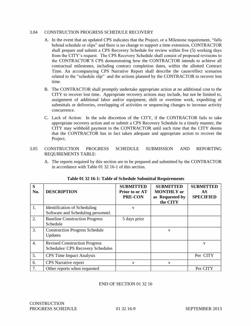
CONSTRUCTION
PROGRESS SCHEDULE 01 32 16-9 SEPTEMBER 2013
3.04 CONSTRUCTION PROGRESS SCHEDULE RECOVERY
A. In the event that an updated CPS indicates that the Project, or a Milestone requirement, “falls
behind schedule or slips” and there is no change to support a time extension, CONTRACTOR
shall prepare and submit a CPS Recovery Schedule for review within five (5) working days
from the CITY’s request. The CPS Recovery Schedule shall consist of proposed revisions to
the CONTRACTOR’S CPS demonstrating how the CONTRACTOR intends to achieve all
contractual milestones, including contract completion dates, within the allotted Contract
Time. An accompanying CPS Narrative Report shall describe the cause/effect scenarios
related to the “schedule slip” and the actions planned by the CONTRACTOR to recover lost
time.
B. The CONTRACTOR shall promptly undertake appropriate action at no additional cost to the
CITY to recover lost time. Appropriate recovery actions may include, but not be limited to,
assignment of additional labor and/or equipment, shift or overtime work, expediting of
submittals or deliveries, overlapping of activities or sequencing changes to increase activity
concurrence.
C. Lack of Action: In the sole discretion of the CITY, if the CONTRACTOR fails to take
appropriate recovery action and or submit a CPS Recovery Schedule in a timely manner, the
CITY may withhold payment to the CONTRACTOR until such time that the CITY deems
that the CONTRACTOR has in fact taken adequate and appropriate action to recover the
Project.
3.05 CONSTRUCTION PROGRESS SCHEDULE SUBMISSION AND REPORTING
REQUIREMENTS TABLE:
A. The reports required by this section are to be prepared and submitted by the CONTRACTOR
in accordance with Table 01 32 16-1 of this section.
Table 01 32 16-1: Table of Schedule Submittal Requirements
END OF SECTION 01 32 16
S
No.
DESCRIPTION
SUBMITTED
Prior to or AT
PRE-CON
SUBMITTED
MONTHLY or
as Requested by
the CITY
SUBMITTED
AS
SPECIFIED
1. Identification of Scheduling
Software and Scheduling personnel.
v
2. Baseline Construction Progress
Schedule
5 days prior
3. Construction Progress Schedule
Updates
v
4. Revised Construction Progress
Schedules/ CPS Recovery Schedules
v
5. CPS Time Impact Analysis Per CITY
6. CPS Narrative report v v
7. Other reports when requested Per CITY

CONSTRUCTION
PROGRESS SCHEDULE 01 32 16-10 SEPTEMBER 2013
THIS PAGE INTENTIONALLY LEFT BLANK

SUBMITTALS 01 33 00-1 OCTOBER 2014
SECTION 01 33 00
SUBMITTALS
PART 1 - GENERAL
1.01 SECTION INCLUDES
A. Scope
B. CONTRACTOR’s Responsibilities
C. Categories of Submittals
D. Transmittal Procedure
E. Review Procedure
F. Effect of Review of CONTRACTOR’s Submittals
1.02 RELATED SECTIONS
A. Project Meetings are included in Section 01 31 19.
B. Operating and Maintenance Information is included in Section 01 78 23.
1.03 SCOPE
A. Submittals covered by these requirements include manufacturers’ information, shop drawings,
test procedures, test results, samples, requests for substitutions, and miscellaneous work-related
submittals.
B. Submittals shall also include, but not be limited to, all mechanical, electrical and electronic
equipment and systems, materials, reinforcing steel, fabricated items, and piping and conduit
details.
C. The CONTRACTOR shall furnish all drawings, specifications, descriptive data, certificates,
samples, tests, methods, schedules, and manufacturer's installation and other instructions as
specifically required in the Contract Documents and as required by the CITY, to demonstrate
fully that the materials and equipment to be furnished and the methods of work comply with the
provisions and intent of the Contract Documents.
D. Where a Submittal is required by the Contract Documents, any related Work performed by
CONTRACTOR prior to the CITY's review and approval of the Submittal shall be at the sole
expense and responsibility of CONTRACTOR.
1.04 CONTRACTOR’s RESPONSIBILITIES
A. The CONTRACTOR shall be responsible for the accuracy and completeness of the information
contained in each Submittal and shall assure that the material, equipment or method of work
shall be as described in the Submittal. Data shown on the Submittal shall be complete with
respect to quantities, dimensions, specified performance and design criteria, materials and
similar data. Samples shall be accompanied by sufficient information to identify the supplier and

SUBMITTALS 01 33 00-2 OCTOBER 2014
pertinent data such as catalog numbers.
B. As one of its initial submittals, to be provided at the pre-construction meeting, the
CONTRACTOR shall completely review the specifications and prepare a comprehensive
submittal register, listing the required submittals by specification section. This list shall be
submitted for approval, and once approved, will serve as the baseline for all ensuing
submissions. The register shall be updated on a monthly basis with current status of each
submittal and any proposed modifications to the submission schedule. Monthly updates shall be
submitted along with the monthly schedule updates.
The following Construction Submittal Register is a list of submittals that shall be reviewed and
updated by the Contractor as applicable to this project and be submitted to the City in accordance
with responsibilities of paragraph 1.04 B.
Construction Submittal Register
Submittal Specification Reference Due Date
Contractor’s Temporary
Bypass Plan
Section 01 14 00 Control of Work Two Weeks following
Notice of Award
Construction Progress
Schedule
Section 01 32 16 – Construction
Progress Schedule
Five days prior to
Preconstruction Meeting
Site Safety Plan Section 01 31 21 Site Safety Plan,
Project Meetings 01 31 19
Three days prior to
Preconstruction Meeting
Shop drawings Section 01 78 39 Record
Documents
Prior to delivery to project
site
C. The CONTRACTOR shall include with each submittal a copy of the appropriate Specification,
with Addendum updates included, and all referenced and applicable sections with Addendum
updates included, with each paragraph check-marked to indicate Specification compliance or
marked to indicate requested deviations from Specification requirements. Check-marks (√) shall
denote full compliance with a paragraph as a whole. If deviations from the Specifications are
indicated and, therefore requested by the CONTRACTER, each deviation shall be underlined
and denoted by a number in the margin to the right of the identified paragraph. The remaining
portions of the paragraph not underlined will signify compliance on the part of the
CONTRACTER with the Specifications. The submittal shall be accompanied by a detailed,
written justification for each deviation. Failure to include a copy of the marked-up Specification
sections, along with justification(s) for any requested deviations to the Specification
requirements, with the submittal shall be sufficient cause for rejection of the entire submittal
with no further consideration.
D. The CONTRACTOR shall verify that all features of all products identified in Submittals
conform to the specified requirements.
E. Submittal documents shall be clearly edited to indicate only those items, models, or series of
equipment, which are being submitted for review.
F. All extraneous materials shall be crossed out or otherwise obliterated from Submittals.
G. The CONTRACTOR shall ensure that there is no conflict with other Submittals and notify the

SUBMITTALS 01 33 00-3 OCTOBER 2014
CITY in each case where a Submittal may affect the Work of another CONTRACTOR or the
CITY.
H. The CONTRACTOR shall coordinate Submittals with the Work so that the Work will not be
delayed. CONTRACTOR shall coordinate and schedule different categories of Submittals, so
that one will not be delayed for lack of coordination with another. No extension of time will be
allowed because of failure to properly schedule Submittals.
I. The CONTRACTOR shall not proceed with Work related to a Submittal until the Submittal
process is complete. This requires that Submittals for review and comment shall be returned
from the CITY to the CONTRACTOR stamped “No Exceptions Taken” or “Make Corrections
Noted.”
J. The CONTRACTOR shall certify on each Submittal document that CONTRACTOR has
reviewed the Submittal, verified field conditions, and complied with the Contract Documents.
CONTRACTOR shall also determine and verify:
1. All field measurements, quantities, dimensions, specified performance and design criteria,
installation requirements, materials, catalog numbers and similar information;
2. The suitability of all materials with respect to the intended use, fabrication, shipping,
handling, storage, assembly and installation pertaining to the performance of the Work; and
3. All information relative to CONTRACTOR's means, methods, techniques, sequences and
procedures of construction and safety precautions and programs incident thereto.
K. The CONTRACTOR may authorize in writing a material or equipment supplier to deal directly
with the CITY with regard to a Submittal. These dealings shall be limited to interpretations of
the Contract Documents to clarify and expedite the Work.
L. CONTRACTOR shall submit to the CITY all Operation and Maintenance manuals and
related Product Data and Submittal information required in all applicable Specification
Sections a minimum of three (3) weeks prior to arrival of delivered equipment to the Plant
Site. No payment for equipment will be released to the CONTRACTOR until Operation and
Maintenance manuals and other specified Product Data and Submittal information are
received, and complete, based on the contract document requirements, by the CITY.
PART 2 - PRODUCTS
NOT USED
PART 3 - EXECUTION
3.01 CATEGORIES OF SUBMITTALS
A. GENERAL: Submittals fall into two (2) general categories; submittals for review and comment,
and submittals which are primarily for information only. Submittals which are for information
only are generally specified as PRODUCT DATA in Part 2 of applicable Specification Sections.
CONTRACTOR shall provide two (2) separate lists: submittals for review and comment and
product data (submittals) for information only.
B. SUBMITTALS FOR REVIEW AND COMMENT: All submittals except where specified to be

SUBMITTALS 01 33 00-4 OCTOBER 2014
submitted as product data for information only shall be submitted by the CONTRACTOR to the
CITY or the CITY’s representative for review and comment.
C. SUBMITTALS (PRODUCT DATA) FOR INFORMATION ONLY: Where specified, the
CONTRACTOR shall furnish submittals (product data) to the CITY or the CITY’s
representative for Information only. Submittal requirements for operation and maintenance
manuals, which are included in this category, are specified in Section 01 78 23 Operating and
Maintenance Information.
3.02 TRANSMITTAL PROCEDURE
A. GENERAL: In addition to the Contractor Submittal Cover Sheet, unless otherwise specified,
Submittals regarding material and equipment shall be accompanied by O & M Transmittal Form
in Reference Forms, specified in Section 01 33 19. Submittals for operation and maintenance
manuals, information and data shall be accompanied by Transmittal Form 01 78 23-A specified
in Reference Forms, Section 01 33 19. A separate form shall be used for each specific item,
class of material, equipment, and items specified in separate, discrete sections, for which the
Submittal is required. Submittal documents common to more than one piece of equipment shall
be identified with all the appropriate equipment numbers. Submittals for various items shall be
made with a single form when the items taken together constitute a manufacturer's package or
are so functionally related that expediency indicates checking or review of the group or package
as a whole.
B. SUBMITTAL NUMBER: A unique number, sequentially assigned, shall be noted on the
transmittal form accompanying each item submitted. Original Submittal numbers shall have the
following format: “XXX”; where “XXX” is the sequential number assigned by the
CONTRACTOR. Resubmittals shall have the following format: “XXX-Y”; where “XXX” is
the originally assigned Submittal number and "Y" is a sequential letter assigned for resubmittals,
i.e., A, B, or C being the 1st, 2nd, and 3rd resubmittals, respectively. Submittal 25B, for
example, is the second resubmittal of submittal 25.
C. DEVIATION FROM CONTRACT: If the CONTRACTOR proposes to provide material,
equipment, or method of work which deviates from the Contract Documents, the
CONTRACTOR shall indicate so under “deviations” on the transmittal form accompanying the
Submittal copies.
D. SUBMITTAL COMPLETENESS: Submittals which do not have all the information required to
be submitted, including deviations, are not acceptable and will be returned without review.
E. DOCUMENT CONTROL. All Submittals shall be transmitted to MSD Document Control.
Document Control will log and distribute submittals.
3.03 REVIEW PROCEDURE
A. GENERAL: Submittals are specified for those features and characteristics of materials,
equipment, and methods of operation which can be selected based on the CONTRACTOR’s
judgment of their conformance to the specified requirements. Other features and
characteristics are specified in a manner which enables the CONTRACTOR to determine
acceptable options without Submittals. The review procedure is based on the
CONTRACTOR’s guarantee that all features and characteristics not requiring Submittals
conform as specified. Review shall not extend to means, methods, techniques, sequences or
procedures of construction, or to verifying quantities, dimensions, weights or gages, or

SUBMITTALS 01 33 00-5 OCTOBER 2014
fabrication processes (except where specifically indicated or required by the Contract
Documents) or to safety precautions or programs incident thereto. Review of a separate item,
as such, will not indicate approval of the assembly in which the item functions. When the
Contract Documents require a Submittal, the CONTRACTOR shall submit the specified
information as follows:
1. One (1) copy in electronic PDF format or an original copy shall be submitted to MSD
Document Control. When requested by the CITY, the CONTRACTOR shall also submit
one (1) CD containing the “native files” of electronic software used to generate the
submittal.
B. SUBMITTALS FOR REVIEW AND COMMENT: Unless otherwise specified, within thirty
five (35) calendar days after receipt of a Submittal for review and comment, the CITY or CITY’s
representative shall review the Submittal and return electronic copies reflecting all review
comments. The reproducible original will be retained by the CITY. The returned Submittal
shall indicate one of the following actions:
1. If the review indicates that the material, equipment or work method complies with the
Contract Documents, Submittal copies will be marked “NO EXCEPTIONS TAKEN.” In
this event, the CONTRACTOR may begin to implement the Work method or incorporate
the material or equipment covered by the Submittal.
2. If the review indicates limited corrections are required, copies will be marked “MAKE
CORRECTIONS NOTED.” The CONTRACTOR may begin implementing the work
method or incorporating the material and equipment covered by the Submittal in accordance
with the noted corrections. Where Submittal information will be incorporated in O&M data,
a corrected copy shall be provided.
3. If the review reveals that the Submittal is insufficient or contains incorrect data, copies will
be marked “AMEND AND RESUBMIT.” Except at his own risk, the CONTRACTOR
shall not undertake Work covered by this Submittal until it has been revised, resubmitted
and returned marked either “NO EXCEPTIONS TAKEN” or “MAKE CORRECTIONS
NOTED.”
4. If the review indicates that the material, equipment, or work method does not comply with
the Contract Documents, copies of the Submittal will be marked “REJECTED - SEE
REMARKS.” Submittals with deviations which have not been identified clearly may be
rejected. Except at his own risk, the CONTRACTOR shall not undertake the Work covered
by such Submittals until a new Submittal is made and returned marked either “NO
EXCEPTIONS TAKEN” or “MAKE CORRECTIONS NOTED.”
C. SUBMITTALS (PRODUCT DATA) FOR INFORMATION ONLY: Such information is not
subject to Submittal review procedures and shall be provided as part of the Work under the
Contract Documents and its acceptability determined under normal inspection procedures.
D. RESUBMITTAL PROCEDURES: CONTRACTOR shall make corrections required by the
CITY or CITY's representative and shall return the required number of corrected copies of the
Submittal to CITY for review. CONTRACTOR shall direct specific attention in writing to
revisions other than the corrections called for by the CITY or CITY's representative on previous
Submittals.
3.04 EFFECT OF REVIEW OF CONTRACTOR’S SUBMITTALS

SUBMITTALS 01 33 00-6 OCTOBER 2014
A. Review of Contract Documents, including the drawings, methods of work, or information
regarding materials or equipment the CONTRACTOR proposes to provide, shall not relieve the
CONTRACTOR of responsibility for errors therein and shall not be regarded as an assumption
of risks or liability by the CITY or the CITY’s representative, or by any officer or employee
thereof, and the CONTRACTOR shall have no claim under the Contract Documents on account
of the failure, or partial failure, of the method of work, material, or equipment so reviewed.
B. A mark of “NO EXCEPTIONS TAKEN” or “MAKE CORRECTIONS NOTED” shall mean
that the CITY has no objection to the CONTRACTOR, upon his own responsibility, using the
plan or method of work proposed, or providing the materials or equipment proposed.
END OF SECTION 01 33 00

REFERENCE FORMS 01 33 19-1 SEPTEMBER 2013
SECTION 01 33 19
REFERENCE FORMS
The forms listed below and included in this section are referenced from other sections of the project manual:
Form No. Title
01 26 00-A
01 26 00-B
01 26 00-C
01 26 00-D
01 31 19-A
Work Directive Change Form
Request for Information
Field Order
Request for Proposal
Cut-in Schedule Form
01 33 00-A Submittal Transmittal Form
01 75 03-A Equipment Test Report Form
01 78 23-A Operation and Maintenance Transmittal Form
01 78 23-B Equipment Record Form
01 78 23-C Equipment Record Form
26 00 00-A Cable Test Data Form
26 00 00-B Wire and Cable Resistance Test Data Form
26 00 00-C Installed Motor Test Data Form
26 00 00-D Dry Transformer Test Data Form
26 00 00-E Motor Control Center Test Form
26 00 00-F Circuit Breaker Schedule
40 00 00-A Loop Wiring and Insulation Resistance Test Data Form
40 00 00-B Control Circuit Piping Leak Test Form
40 00 00-C Controller Calibration Test Data Form
40 00 00-D Calibration Sheet
40 00 00-E Miscellaneous Instrument Calibration Test Data Form
40 00 00-F Individual Loop Test Data Form
40 00 00-G Loop Commissioning Test Data Form
44 00 00-A Manufacturer's Installation Certification Form
44 00 00-B Manufacturer's Instruction Certification Form
44 00 00-C Unit Responsibility Certification Form
44 00 00-D Motor Data Form

REFERENCE FORMS 01 33 19-2 SEPTEMBER 2013
FORM INSTRUCTIONS
Work Directive Change (WDC) Form
These instructions offer step-by-step directions, including definition of terms, for
completing the above referenced form. Please fill out the form legibly or enter the data
directly into the document. Completed form must be submitted to Document Control.
Purpose of Form
Use the Work Directive Change form to direct
the Contractor to complete work for unforeseen
conditions or as a directive for changed work
provided prior to issuance of a Change Order.
Specific Instructions Fill out the form using the following guidelines
for each area listed below.
Preparer – Authorized Representative of the CITY
completing the form.
Contractor – Enter the name of contracting company
performing the construction work (Standard Entry).
Project Name & Number – Enter the MSD Project
name and number. The project number can be
obtained from the MSD Document Control if not
readily available.
Date – The date the form is being completed should
be entered here.
WDC# - The WDC number will be assigned by
Document Control to this specific form. Typically
the number will include the Project number and a
sequential WDC number from the previous submittal
(i.e., 10170780- WDC-0001, 10170780- WDC-0002,
and so on).
SUBJECT - The Preparer should provide a brief
description of the work and location. For Example,
IR WINDOWS IN THE MCC’S
BODY OF FORM - The Preparer shall provide a
thorough summary of the description and purpose of
the work. All back up documentation, e.g. Drawings
or Proposed Contract Modification Forms shall be
attached or included with the form for transmittal to
the Contractor.
Routing – Routing of the form will be dependent on
the Preparer or reason as follows:
Field Personnel – Providing the document for
unforeseen site conditions or emergency. The
Authorized Representative of the CITY will
issue the WDC directly to the Contractor.
However, prior to providing the WDC to the
Contractor, Document Control shall be contacted
to provide a WDC number.
All WDC’s issued in the field shall be provided
to Document Control within the following
business day.
Construction Manager/Project Manager –
Providing the WDC to issue additional work
prior to the generation of a Change Order.
Document Control will distribute the WDC to
the Contractor. Additionally the document(s)
will be uploaded to SharePoint and/or distributed
to all applicable MSD personnel, PMC Change
Management, and the Consulting Engineer.
How to Submit
After completion of the WDC form, the preparer
should ensure they have signed the Title Block
“Issued By.”
Please include any supporting documentation (i.e.,
proposed costs, drawings, etc) with the Work
Directive Change. If the WDC is based on T&M all
supporting documentation shall be obtained from the
Contractor and submitted to Document Control on a
regular basis.
When the WDC is submitted to the Contractor it is
expected that the Contractor is to sign and date the
document. A copy of the Contractor signed WDC
shall be provided to Document Control.
Please direct any questions regarding this form to
Document Control at the following address:

REFERENCE FORMS 01 33 19-3 SEPTEMBER 2013
WDC – 001
WORK DIRECTIVE CHANGE
CONTRACTOR
PROJECT NAME & NO.
DATE
SUBJECT: In accordance with the Contract Documents detailing the Work Directive Change requirements,
you are directed to perform the following work:
Daily time sheets are to be submitted for verification by the CITY’s inspection personnel at the
end of each day on which the work is performed. A sample Daily Time Sheet is attached for your
reference. Please note this WDC is not to exceed $ and the CITY shall be
notified when the proposed total equals 75% of the not to exceed amount. Feel free to call (513)
244-5180 if you have any questions or comments. Upon completion of the work a Change Order
will be negotiated in accordance with the Contract Documents.
Attachments: Sample Daily Time Sheet
cc: MSD DOCUMENT CONTROL
MSD CONSTRUCTION MANAGER
MSD PROJECT MANAGER
Please acknowledge receipt of this memorandum by signing and returning one copy.
CONTRACTOR'S RECEIPT
MSD CONSTRUCTION RECEIVED BY:
ISSUED BY:
TITLE:
TITLE:
DATE: TIME:
REVIEWED: (MSD)

REFERENCE FORMS 01 33 19-4 SEPTEMBER 2013
REQUEST FOR INFORMATION
Date: Project Number: Contract Number:
RFI Number:
10230070-RFI-
To: MSDGC 1600 Gest Street Cincinnati, Ohio 45204
Attn: Document Control
From: Originator:
Reference or Affected Design Document(s):
Spec. Section:
Dwg. No.:
Subject:
Description of Request:
Additional information attached Yes No
Response needed by: Submitted by:
Designer Response:
Prepared by: Company: Date:

REFERENCE FORMS 01 33 19-5 SEPTEMBER 2013
RFI Number: 10230070-RFI-
MSD WWT Response:
Prepared by: Company: Date:
Project Manager Response:
Prepared by: Company: Date:
1. Response Resolution Required Yes No
2. Propose to Change Contract Drawings Yes No
3. Additional Information Attached Yes No
Distribution (following disposition)
Project Manager Field Designer Contractor Document Control

REFERENCE FORMS 01 33 19-6 SEPTEMBER 2013
FORM INSTRUCTIONS
Field Order (FO) Form
These instructions offer step-by-step directions, including definition of terms, for
completing the above referenced form. Please fill out the form legibly or enter the data
directly into the document. Completed form must be submitted to Document Control.
Purpose of Form
A written order issued which orders minor
changes in the work but which does not
involve a change in the contract price or the
contract time.
Specific Instructions Fill out the form using the following guidelines
for each area listed below.
Preparer – Authorized Representative of the CITY.
Date – The date the form is being completed should
be entered here.
To – Enter the name of contracting company
performing the construction work (Standard Entry).
Project Number – Enter the MSD Project number
associated with the Project site.
Contract Number – Enter the MSD contract number
associated with the Project name. This number can
be obtained from the MSD Document Control if not
readily available.
From – The form should always come from MSDGC.
This field should remain unchanged.
Originator – see “Preparer” above.
FO# - The Field Order number will be assigned by
Document Control to this specific form. Typically
the number will be the Project Number followed by
sequential order from the previous FO (i.e.,
10170780- FO-0001 and so on).
Subject - The Preparer should provide a brief
description of the work and location. For Example,
DELETE IR WINDOWS IN THE MCC
Description - The preparer shall provide a thorough summary of the work to be completed by the
Contractor. In addition any supporting contract
requirements should be included.
Routing – Distribution of the form will be dependant
on the preparer or reason as follows:
Field Personnel – Providing the document for
clarification of field discussion or issues. The
Authorized Representative of the CITY will
issue the FO directly to the Contractor.
All FO’s issued in the field shall be provided
to Document Control within the following
business day, Document Control will number
and distribute to all applicable personnel.
Consulting Engineer/Project Manager –
Providing the FO as a clarification to
correspondence from the Contractor.
Document Control will distribute the FO to the
Contractor. Additionally the document(s) will
be uploaded to SharePoint and distributed to
all applicable including; MSD personnel, PMC
Change Management, and the Consulting
Engineer.
How to Submit
After completion of the Field Order form, the
preparer should ensure they have signed the Title
Block “Issued By”.
Please include any supporting documentation (i.e.,
proposed costs, drawings, etc) with the Field Order.
When the Field Order is submitted to the Contractor
it is expected that the Contractor is to sign and date
the document. A copy of the Contractor signed Field
Order shall be provided to Document Control.
Please direct any questions regarding this form to
Document Control at the following address:
REFERENCE FORMS 01 33 19-7 SEPTEMBER 2013
FIELD ORDER
Date: Project Number: Contract Number:
Number: <Inserted by Doc. Control>
<Insert Project No.> -FO-
To:
From: MSDGC 1600 Gest Street Cincinnati, Ohio 45204
Originator:
Reference or Affected Design Document(s):
Spec. Section:
Dwg. No.:
The Field Order is issued in accordance with Contract Documents for the purpose of: interpret/clarify the Contract requirements, order minor changes in the Work and/or document trade-off agreements. MSDGC and the Contractor hereby agree that the work described by this Field Order is to be accomplished without change in Contract Price or Contract Time or claims of other costs. Contractor is to execute this Field Order and return it to the Construction Manager for execution within 24 hours of the time of receipt. Subject (for tracking purposes):
Description:
Distribution (following disposition) Project Manager Field Designer Contractor Document Control
Please acknowledge receipt of this memorandum by signing and returning one copy.
CONTRACTOR'S RECEIPT
MSDGC RECEIVED BY:
ISSUED BY:
TITLE:
TITLE:
DATE:
REVIEWED:

REFERENCE FORMS 01 33 19-8 SEPTEMBER 2013
FORM INSTRUCTIONS
Request for (Contractor) Proposal (RFP) Form
These instructions offer step-by-step directions, including definition of terms, for
completing the above referenced form. Please fill out the form legibly or enter the data
directly into the document. Completed form must be submitted to Document Control for
routing to the Contractor.
Purpose of Form
Use the Request for Proposal form to request a
written proposal from the Contractor for changes
in the work.
Specific Instructions Fill out the form using the following guidelines
for each area listed below.
Preparer – Individual or entity completing the form
typically the Project Manager.
Contractor – Enter the name of contracting company
performing the construction work.
Contract Number – Enter the MSD contract number
associated with the Project name. This number can
be obtained from the MSD Document Control if not
readily available.
Date – The date the form is being completed should
be entered here.
RFP# - The RFP number will be assigned by
Document Control to this specific form. Typically
the number will be the Project Number followed by
sequential order from the previous RFP (i.e.,
10170780- RFP-0001, 10170780- RFP-0002 and so
on).
SUBJECT - The Preparer should provide a brief
description of the work and location. For Example,
IR WINDOWS IN THE MCC’S
BODY OF FORM - This section of the document
shall provide a thorough summary of the description
and purpose of the work. All back up documentation,
e.g. Drawings or Proposed Contract Modification
Forms. shall be attached or included with the form
for transmittal to the Contractor.
Routing – The Preparer will send the completed
document to MSD Document Control for
distribution. Upon receipt of the Contractor’s
proposal or other response, Document Control will
upload the document to SharePoint and distribute the
documents to applicable MSD personnel, PMC
Change Management, and the Consulting Engineer.
How to Submit
After completion of the RFP form, the preparer
should ensure they have signed the Title Block –
“Issued By.”
Please include any supporting documentation (i.e.,
proposed costs, drawings, etc) with the Request for
Proposal. The Contractor should be informed the
RFP is to be submitted to Document Control.
Next, the document, and any supporting
documentation, should be provided to MSD
Document Control for distribution.
The Contractor may be advised that if they have any
questions regarding the form, they may contact
Document Control at the following address:

REFERENCE FORMS 01 33 19-9 SEPTEMBER 2013
REQUEST FOR PROPOSAL
CONTRACTOR
PROJECT NAME & NO.
DATE
SUBJECT: In accordance with the Contract Documents you are requested to provide a proposal for the
following:
The Contractor’s proposal shall include the following information:
1. Labor required
2. Equipment required.
3. Products required.
a. Recommended source of purchase and unit cost
b. Quantities required.
4. Any insurance, and bonds costs.
5. Credit for work deleted from Contract, similarly documented.
6. Overhead and profit.
7. Justification for any change in Contract Time.
The Contractor’s proposal is due twenty one (21) days after the CITY issues this FRP. Upon
MSD’s -receipt of the proposal a negotiation meeting will be scheduled. Please feel free to call
me at (513) 244-5180 if you have any questions.
cc: MSD DOCUMENT CONTROL
MSD CONSTRUCTION MANAGER
Please acknowledge receipt of this memorandum by signing and returning one copy.
CONTRACTOR'S RECEIPT
MSD PROJECT MANAGER RECEIVED BY:
ISSUED BY:
TITLE:
TITLE:
DATE: TIME:
REVIEWED: (MSD)

REFERENCE FORMS 01 33 19-10 SEPTEMBER 2013
Form 01 31 19-A
Metropolitan Sewer District of Greater Cincinnati
(Identify Project)
Contract No.________________________
CUT-IN SCHEDULE NO. _____________
Contractor:___________________________________________________________________
Description of Work:___________________________________________________________
______________________________________________________________________________
______________________________________________________________________________
Description of Operations to be Interrupted: _______________________________________
______________________________________________________________________________
______________________________________________________________________________
Method of Work: ______________________________________________________________
______________________________________________________________________________
Starting Date: ______________________ Starting Time: ______________________
Estimated Duration: __________ Days__________ Hours______________
_____________________________________________________________________________
APPROVALS
__________________________________ _________________________________________
Contractor Date The CITY’s Field Rep. Date
__________________________________ _________________________________________
The CITY Date Date
REFERENCE FORMS 01 33 19-11 SEPTEMBER 2013
CONTRACTOR SUBMITTAL COVER SHEET Metropolitan Sewer District of Greater Cincinnati
To: Attn:
Plans Procedures Shop Drawings Supplier’s Data Samples
Other____________________
Submittal No.
Spec Section Sequence No. Rev.
From:
Date:
New Submittal Resubmitted
Project ID No.:
Contract No.:
No. of Copies
Spec and Paragraph No.
Drawing Brochure
No.
TITLE/DESCRIPTION (Use a separate cover sheet for each submittal)
Items are transmitted as checked below: For information only For review & comment Other:
Contractor’s Remark/Comments ____________________________________________________________ __________________________________________________________________________________________ __________________________________________________________________________________________ __________________________________________________________________________________________ __________________________________________________________________________________________ __________________________________________________________________________________________ __________________________________________________________________________________________ This certifies that all items submitted herewith have been checked by the Contractor, and are in conformance with the requirements of the Contract Documents.
Signature: _______________________________ Title: ___________________________________ Company: ___________________________________
Deviations/Variations/(if yes attach additional comments to explain) Yes No
Consultant Recommended Action Code
NET
MCN
A&R
R
Signature: _________________ _____________ Date:____________________
MSD WWT Action Code Concurrence
NET
MCN
A&R
R
Signature: _________________________________ Date:____________________
MSD PM Action Code Concurrence
NET
MCN
A&R
R
Signature:______________________________ Date:________________
ACTION CODES NET – NO EXCEPTION TAKEN MCN – MAKE CORRECTIONS NOTED A&R – AMEND AND RESUBMIT R - REJECTED – SEE REMARKS
Form 01 33 00-A. See section 01 33 00 for action code descriptions and guidance.

REFERENCE FORMS 01 33 19-12 SEPTEMBER 2013
EQUIPMENT TEST REPORT FORM Form 01 75 03-A Page 1 of 4
NOTE: This example equipment test report is provided for the benefit of the CONTRACTOR and is not
specific to any piece of equipment to be installed as a part of this project. The example is
furnished as a means of illustrating the level of detail required for the preparation of equipment
test report forms for this project.
(INSERT PROJECT TITLE)
[This 4-page form needs review and rework.]
________________________________ , CONTRACTOR
EQUIPMENT TEST REPORT
Equipment Name:
Equipment Number:
Specification Ref:
Location:
CONTRACTOR Engineer
Verified Date Verified Date
PREOPERATIONAL CHECKLIST
Mechanical
Lubrication
Alignment
Anchor bolts
Seal water system operational
Equipment rotates freely
Safety guards
Valves operational
Hopper purge systems operational
Sedimentation tank/hopper clean
O&M manual information complete
Manufacturer's installation certificate
complete

REFERENCE FORMS 01 33 19-13 SEPTEMBER 2013
Form 01 75 03-A Page 2 of 4
CONTRACTOR Engineer
Verified Date Verified Date
Electrical (circuit ring-out and high-pot tests)
Circuits:
Power to MCC
Control to HOA
Indicators at MCC:
Red (running)
Green (power)
Amber (auto)
Indicators
at local control panel
Wiring labels complete
Nameplates:
MCC
Control station
Control panel
Equipment bumped for rotation
Piping Systems
Cleaned and flushed:
Suction
Discharge
Pressure tests
Temp.piping screens in place
Instrumentation and Controls
Flowmeter calibration
Calibration Report No.__________
Flow recorder calibrated
against transmitter
VFD speed indicator calibrated against
independent reference
Discharge overpressure shutdown
switch calibration
Simulate discharge overpressure
Shutdown
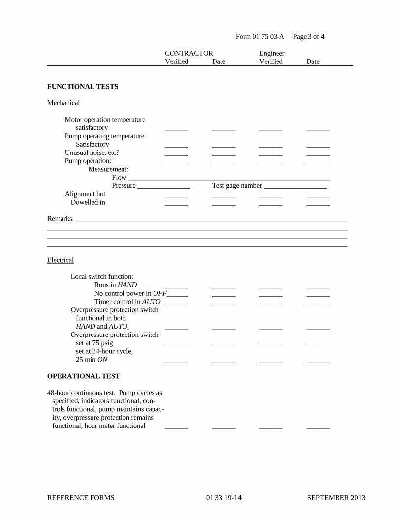
REFERENCE FORMS 01 33 19-14 SEPTEMBER 2013
Form 01 75 03-A Page 3 of 4
CONTRACTOR Engineer
Verified Date Verified Date
FUNCTIONAL TESTS
Mechanical
Motor operation temperature
satisfactory
Pump operating temperature
Satisfactory
Unusual noise, etc?
Pump operation:
Measurement:
Flow
Pressure _______________ Test gage number __________________
Alignment hot
Dowelled in
Remarks:
Electrical
Local switch function:
Runs in HAND
No control power in OFF
Timer control in AUTO
Overpressure protection switch
functional in both
HAND and AUTO
Overpressure protection switch
set at 75 psig
set at 24-hour cycle,
25 min ON
OPERATIONAL TEST
48-hour continuous test. Pump cycles as
specified, indicators functional, con-
trols functional, pump maintains capac-
ity, overpressure protection remains
functional, hour meter functional

REFERENCE FORMS 01 33 19-15 SEPTEMBER 2013
01 75 03-A Page 4 of 4
RECOMMENDED FOR BENEFICIAL OCCUPANCY
Engineer Date
ACCEPTED FOR BENEFICIAL OCCUPANCY
The CITY’s Representative Date

REFERENCE FORMS 01 33 19-16 SEPTEMBER 2013
01 78 23-A. OPERATION AND MAINTENANCE TRANSMITTAL FORM:
Date: Submittal No:1
To: Contract No:
Spec. Section:
Submittal Description:
From:
Attention:
CONTRACTOR Engineer
Checklist Satisfactory N/A Accept Deficient
1. Table of contents
2. Equipment record forms
3. Manufacturer information
4. Vendor information
5. Safety precautions
6. Operator prestart
7. Start-up, shutdown, and postshutdown procedures
8. Normal operations
9. Emergency operations
10. Operator service requirements
11. Environmental conditions
12. Lubrication data
13. Preventive maintenance plan and schedule
14. Troubleshooting guides and diagnostic techniques
15. Wiring diagrams and control diagrams
16. Maintenance and repair procedures
17. Removal and replacement instructions
18. Spare parts and supply list
19. Corrective maintenance man-hours
20. Parts identification
21. Warranty information
22. Personnel training requirements
23. Testing equipment and special tool information
Remarks:
CONTRACTOR’s Signature
1See paragraph 01 33 00, Transmittal Procedure.

REFERENCE FORMS 01 33 19-17 SEPTEMBER 2013
01 78 23-B. EQUIPMENT RECORD FORM:
EQUIP DESCRIP EQUIP LOC
EQUIP NO. SHOP DWG NO. DATE INST COST
MFR MFR CONTACT
MFR ADDRESS PHONE
VENDOR VENDOR CONTACT
VENDOR ADDRESS PHONE
MAINTENANCE REQUIREMENTS D W M Q S A Hours
LUBRICANTS: RECOMMENDED:
ALTERNATIVE:
MISC. NOTES:
RECOMMENDED SPARE PARTS ELECTRICAL NAMEPLATE DATA
PART
NO.
QUAN
.
PART NAME COST EQUIP
MAKE
SERIAL NO. ID NO.
MODEL NO. FRAME NO.
HP V AMP HZ
PH RPM SF DUTY
CODE INSL. CL DES TYPE
NEMA
DES
C AMB TEMP RISE RATING
MISC.
MECHANICAL NAMEPLATE DATA
EQUIP
MAKE
SERIAL NO. ID NO.
MODEL NO. FRAME NO.
HP RPM CAP SIZE
TDH IMP SZ BELT NO. CFM
PSI ASSY NO. CASE NO.
MISC

REFERENCE FORMS 01 33 19-18 SEPTEMBER 2013
01 78 23-C. EQUIPMENT RECORD FORM:
EQUIP DESCRIP EQUIP LOC
EQUIP NO. SHOP DWG NO. DATE INST COST
MFR MFR CONTACT
MFR ADDRESS PHONE
VENDOR VENDOR CONTACT
VENDOR ADDRESS PHONE
MAINTENANCE REQUIREMENTS D W M Q S A Hours

REFERENCE FORMS 01 33 19-19 SEPTEMBER 2013
26 00 00-A, CABLE TEST DATA FORM
Project and Location _____________________ Project No.______________________
Circuit Designation ______________________ Date______________________
Application of Test Voltage
The initially applied direct-current voltage shall be not greater than 3.0 times the rated alternating-current
voltage. The rate of increase from the initially applied voltage to the specified test voltage shall be not over 100
percent in 10 seconds nor less than 100 percent in 60 seconds. The duration of the direct-current voltage test
shall be 15 minutes for shielded cables and 5 minutes for non shielded cables.
Test Curve
Current
in
Microamperes
1 2 3 4 5 6 7 8 9 10 11 12 13 14
Time in Minutes After 100% Test Voltage is Applied
NOTES:
1. Plot results of test on all three phases on this graph.
2. Assign and indicate values for each division on the microamperes scale as required for the circuit being tested.
DC TEST DATA
Time in
Minutes After
100% Test
Voltage is
Applied
Current pA
Phase A Phase B Phase C
1
2
3
4
5
6
7
8
9
10
11
12
13
14
15
kV dc after 1 min
Decay
Project No. _______________________________
Date: _______________________________
DC Test Voltage ___________________________
Cable Installation New ____ Used ____ Years ____
Cable Size ______________ Length _____________
Open kv _____ Grounded _____ Ungrounded _____
Rated Cable Voltage
____________________________
Insulation Wall ________________________________
(Type & Thickness)
Conductor Jacket Wall __________________________
(Type & Thickness)
Shield _______________________________________
(Type)
Cable Manufacturer ____________________________
Temperature _____________ Humidity ___________
Type of Termination ___________________________
Type of Splice & Location _______________________
_____________________________________________
Remarks _____________________________________

REFERENCE FORMS 01 33 19-20 SEPTEMBER 2013
26 00 00-B. WIRE AND CABLE RESISTANCE TEST DATA FORM:
Wire or Cable No.: Temperature, oF
Insulation
Resistance,
Location of Test megohms
1.
2.
3.
4.
5.
6.
7.
CERTIFIED Date
CONTRACTOR’s Representative
WITNESSED Date
The CITY’s Representative

REFERENCE FORMS 01 33 19-21 SEPTEMBER 2013
26 00 00-C. INSTALLED MOTOR TEST FORM:
Motor Equipment Number Date of test Equipment Driven MCC Location
Ambient temp _______oF
Resistance:
Insulation resistance phase-to-ground, megohms:
Phase A , Phase B , Phase C Current at Full Load:
Phase Current, amps
Phase Current, amps
Phase Current, amps Thermal Overload Device: Manufacturer/catalog # Amperes
Circuit breaker (MCP) setting:
Motor Nameplate Markings:
Mfr Mfr type __ Frame ______ HP_____
Volts _______ Phase _______ RPM _______ **Service factor ________
Amps ______ Freq ______ Ambient temp rating _______ oC
Time rating **Design letter
(NEMA 1-10.35) (NEMA MG-1.16)
Code letter Insulation class
**Required for 3-phase squirrel cage induction motors only.
CERTIFIED Date
CONTRACTOR’s Representative
WITNESSED Date
The CITY’s Representative

REFERENCE FORMS 01 33 19-22 SEPTEMBER 2013
26 00 00-D. DRY TRANSFORMER TEST DATA FORM:
Equipment No. Temperature
Location
Winding: Primary Secondary
A. INSULATION-RESISTANCE TEST:
The test shall be made with a megohmmeter at the test voltage for a period of 1 minute.
Test results (megohms)
Voltage rating Test voltage Phase Phase
0-600 1000 A-GRD _____ A-B ____
601-5000 2500 B-GRD _____ B-C ____
5000+ 5000 C-GRD _____ C-A ____
Resistance readings less than the manufacturer's recommended value or less than 10 megohms shall immediately be brought to the attention of the Engineer.
B. DIELECTRIC-ABSORPTION TEST:
The test shall be made with a megohmmeter at the test voltage for a period of 10 minutes.
1. TEST RESULTS: Phase Phase
(megohms) A-GRD _____ A-B _____ B-GRD _____ B-C _____
C-GRD _____ C-A _____
2. POLARIZATION INDEX:
(from paragraph “A” above)
Phase Phase
A-GRD _____ A-B ____
B-GRD _____ B-C ____
C-GRD _____ C-A ____
Polarization index values less than 2 shall be immediately brought to the attention of the Engineer.
CERTIFIED Date
CONTRACTOR’s Representative
WITNESSED Date
The CITY’s Representative
index onpolarizati = reading minute 1
reading minute 10
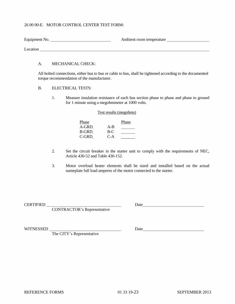
REFERENCE FORMS 01 33 19-23 SEPTEMBER 2013
26 00 00-E. MOTOR CONTROL CENTER TEST FORM:
Equipment No. Ambient room temperature
Location
A. MECHANICAL CHECK:
All bolted connections, either bus to bus or cable to bus, shall be tightened according to the documented
torque recommendation of the manufacturer.
B. ELECTRICAL TESTS:
1. Measure insulation resistance of each bus section phase to phase and phase to ground
for 1 minute using a megohmmeter at 1000 volts.
Test results (megohms)
Phase Phase
A-GRD A-B
B-GRD B-C
C-GRD C-A
2. Set the circuit breaker in the starter unit to comply with the requirements of NEC,
Article 430-52 and Table 430-152.
3. Motor overload heater elements shall be sized and installed based on the actual
nameplate full load amperes of the motor connected to the starter.
CERTIFIED Date
CONTRACTOR’s Representative
WITNESSED Date
The CITY’s Representative
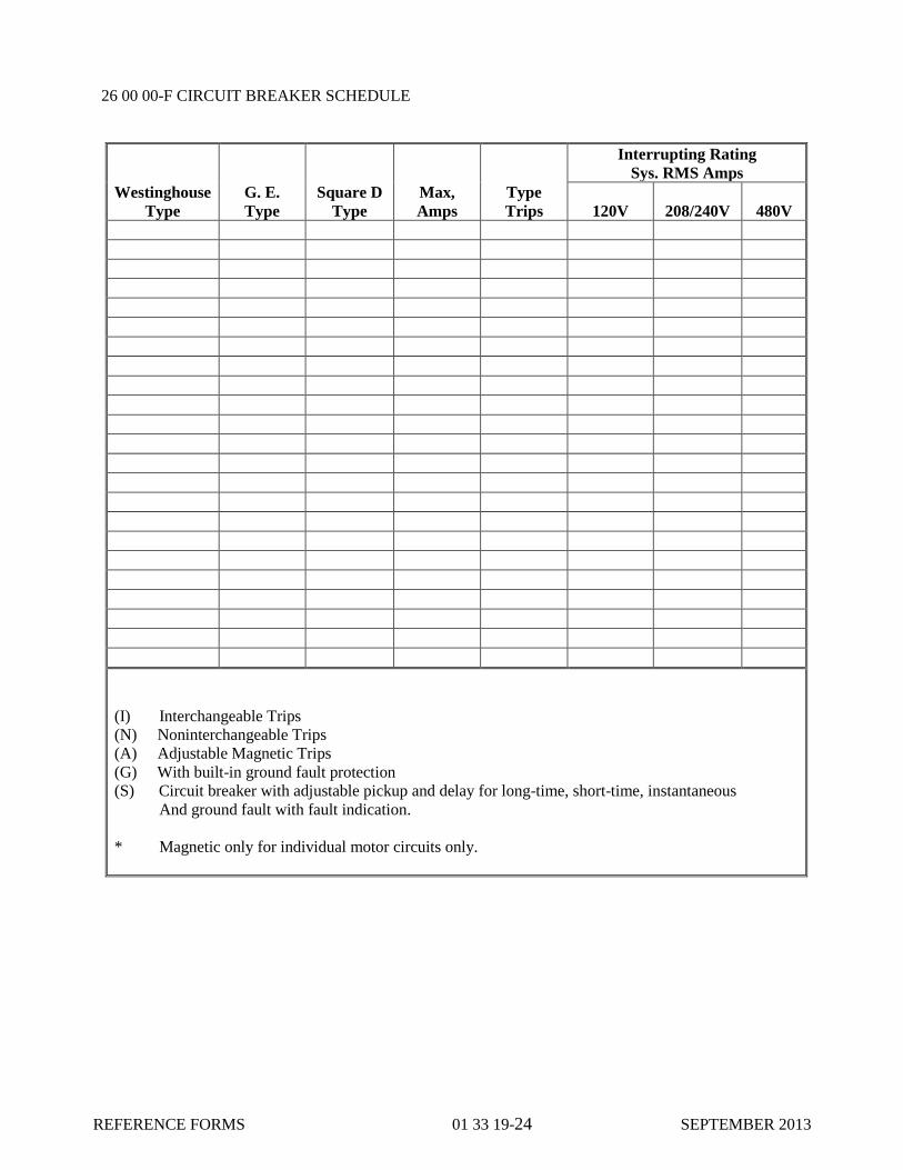
REFERENCE FORMS 01 33 19-24 SEPTEMBER 2013
26 00 00-F CIRCUIT BREAKER SCHEDULE
Westinghouse
Type
G. E.
Type
Square D
Type
Max,
Amps
Type
Trips
Interrupting Rating
Sys. RMS Amps
120V
208/240V
480V
(I) Interchangeable Trips
(N) Noninterchangeable Trips
(A) Adjustable Magnetic Trips
(G) With built-in ground fault protection
(S) Circuit breaker with adjustable pickup and delay for long-time, short-time, instantaneous
And ground fault with fault indication.
* Magnetic only for individual motor circuits only.

REFERENCE FORMS 01 33 19-25 SEPTEMBER 2013
40 00 00-A. LOOP WIRING AND INSULATION RESISTANCE TEST DATA FORM:
Loop No.:
List all wiring associated with a loop in table below. Make applicable measurements as indicated after
disconnecting wiring.
Continuity
Resistance a Insulation Resistance
b
Wire Panel Field Cond./ Cond./ Shield/ Shield/ Cond./ Shield/
No. Tie TB Cond. Shield Gnd. Cond. Gnd. Shield
A -- (A/SH)
B (A/B) --
C (A/C) --
D (A/D) --
(Etc.)
a. Continuity Test. Connect ohmmeter leads between wires A and B and jumper
opposite ends together. Record resistance in table. Repeat procedure between A
and C, A and D, etc. Any deviation of +2 ohms between any reading and the
average of a particular run indicates a poor conductor, and corrective action shall be
taken before continuing with the loop test.
b. Insulation Test. Connect one end of a 500 volt megger to the panel ground bus and
the other sequentially to each completely disconnected wire and shield. Test the
insulation resistance and record each reading.
CERTIFIED Date
CONTRACTOR’s Representative
WITNESSED Date
The CITY’s Representative

REFERENCE FORMS 01 33 19-26 SEPTEMBER 2013
40 00 00-B. CONTROL CIRCUIT PIPING LEAK TEST FORM:
Loop No.:
List tubing associated with loop in table below. Make applicable measurements after isolating any air
consuming pilots from circuit.
Tube No.
Tubing Equivalent
Length of 1/4-Inch
Coppera
Test Period
(seconds)
Permitted Pressure
Drop (psi)b
Measured
Pressure Drop
(psi)
A
B
C
D
(Etc.)
a. Convert actual tubing and air motor volume to equivalent 1/4-inch copper tubing.
b. Pressure drop shall not exceed 1 psi per hundred feet 1/4-inch tubing per 5 seconds.
CERTIFIED Date
CONTRACTOR’s Representative
WITNESSED Date
The CITY’s Representative

REFERENCE FORMS 01 33 19-27 SEPTEMBER 2013
40 00 00-C. CONTROLLER CALIBRATION TEST DATA FORM:
Tag No. and Description:
Make and Model No.:________________________________ Serial No.:________________________
Input:_________________________________ Process Variable (PV) Scale: _______________________
Output:________________________________ Output Scale: ___________________________________
PV Scale Calibration
Expected Actual
% of Range Input Reading Reading % Deviation
0
50
100
% Deviation Allowed:
Connect output to PV for following tests:
Set Point (SP) Indicator Accuracy Output Meter Accuracy Controller Accuracy
SP
PV
Reading
Expected
% Dev.
Actual
Reading
Expected
Reading
Actual
% Dev. Output Output % Dev.
(0%)
(50%)
(100%)
%Dev. Allowed: __________ % Dev. Allowed:___________ % Dev. Allowed:___________
CERTIFIED Date
CONTRACTOR’s Representative
WITNESSED Date
The CITY’s Representative
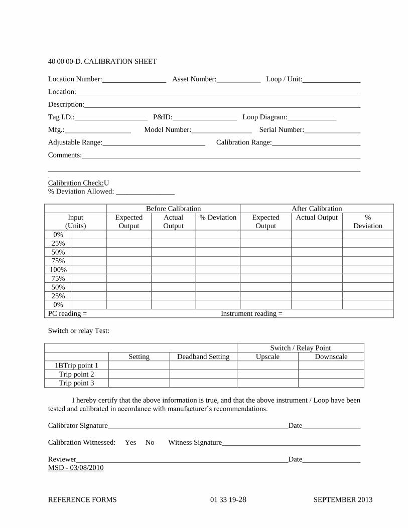
REFERENCE FORMS 01 33 19-28 SEPTEMBER 2013
40 00 00-D. CALIBRATION SHEET
Location Number: Asset Number: Loop / Unit:
Location:
Description:
Tag I.D.: P&ID: Loop Diagram:
Mfg.: Model Number: Serial Number:
Adjustable Range: Calibration Range:
Comments:
0BU
Calibration Check:U
% Deviation Allowed: ________________
Before Calibration After Calibration
Input
(Units)
Expected
Output
Actual
Output
% Deviation Expected
Output
Actual Output %
Deviation
0%
25%
50%
75%
100%
75%
50%
25%
0%
PC reading = Instrument reading =
Switch or relay Test:
Switch / Relay Point
Setting Deadband Setting Upscale Downscale
1BTrip point 1
Trip point 2
Trip point 3
I hereby certify that the above information is true, and that the above instrument / Loop have been
tested and calibrated in accordance with manufacturer’s recommendations.
Calibrator Signature Date
Calibration Witnessed: Yes No Witness Signature
Reviewer Date
MSD - 03/08/2010
REFERENCE FORMS 01 33 19-29 SEPTEMBER 2013
40 00 00-E. MISCELLANEOUS INSTRUMENT CALIBRATION TEST DATA FORM:
(For instruments not covered by any of the preceding test forms, the CONTRACTOR shall create a form
containing all necessary information and calibration procedures.)
CERTIFIED Date
CONTRACTOR’s Representative
WITNESSED Date
The CITY’s Representative

REFERENCE FORMS 01 33 19-30 SEPTEMBER 2013
40 00 00-F. INDIVIDUAL LOOP TEST DATA FORM:
Loop No.:
Description: (Give complete description of loop's function using tag numbers where appropriate.)
P&ID No.: (Attach copy of P&ID.)
a. Wiring tested:
(Attach test form 13000-A)
b. Instrumentation tubing/piping tested:
(Attach test form 13000-B)
c. Instruments calibrated:
(Attach test forms 13000-C through I)
d. List step-by-step procedures for testing loop parameters. Test loop with instruments,
including transmitters and control valves, connected and functioning. If it is not possible to
produce a real process variable, then a simulated signal may be used with the Engineer’s
approval.
CERTIFIED Date
CONTRACTOR’s Representative
WITNESSED Date
The CITY’s Representative

REFERENCE FORMS 01 33 19-31 SEPTEMBER 2013
40 00 00-G. LOOP COMMISSIONING TEST DATA FORM:
Loop No.:
a. Loop tested:
(Attach test form 13000-J)
b. Controlled or connected equipment tests confirmed:
c. Give complete description of loop's interface with process.
d. With associated equipment and process in operation, provide annotated chart trace of loop
response to changes in set points for verification of performance. This chart should
demonstrate 1/4-amplitude damping as output adjusts to set point change. Show set points,
starting and finishing times on chart, as well as any other pertinent data.
Connect 2-pen recorder to process variable (PV) and to controller output. Use 1 inch/second
chart speed.
Pen 1 – PV – Connections:
Pen 2 – Output – Connections:
CERTIFIED_______________________________ Date ____________________
CONTRACTOR’s Representative
WITNESSED ______________________________ Date: _____________________
The CITY’s Representative

REFERENCE FORMS 01 33 19-32 SEPTEMBER 2013
44 00 00-A. MANUFACTURER'S INSTALLATION CERTIFICATION FORM:
Contract No: Specification Section:
Equipment name:
CONTRACTOR:
Manufacturer of equipment item:
The undersigned manufacturer of the equipment item described above hereby certifies that he has
checked the installation of the equipment and that the equipment, as specified in the Contract Documents, has
been provided in accordance with the manufacturer's recommendations, and that the trial operation of the
equipment item has been satisfactory.
Comments:
Date Manufacturer
Signature of Authorized Representative
Date CONTRACTOR
Signature of Authorized Representative

REFERENCE FORMS 01 33 19-33 SEPTEMBER 2013
44 00 00-B. MANUFACTURER'S INSTRUCTION CERTIFICATION FORM:
Contract No: Specification section: __________________
Equipment name:
CONTRACTOR:
Manufacturer of equipment item:
The undersigned manufacturer certifies that a service engineer has instructed the designated the City
personnel in the proper maintenance and operation of the equipment designated herein.
Operations Check List (check appropriate spaces)
Start-up procedure reviewed
Shutdown procedure reviewed
Normal operation procedure reviewed
Others:
Maintenance Check List (check appropriate spaces)
Described normal oil changes (frequency)
Described special tools required
Described normal items to be reviewed for wear
Described preventive maintenance instructions
Described greasing frequency
Others:
Date Manufacturer
Signature of Authorized Representative
Date Signature of the CITY’s Representative
Date Signature of CONTRACTOR’s Representative

REFERENCE FORMS 01 33 19-34 SEPTEMBER 2013
44 00 00-C. UNIT RESPONSIBILITY CERTIFICATION FORM
(Job Title)
CERTIFICATE OF UNIT RESPONSIBILITY
for Specification Section
(Section title)
In accordance with the contract documents, the undersigned manufacturer
accepts unit responsibility for all components of equipment furnished under
specification Section . We hereby certify that these components are
compatible and comprise a functional unit suitable for the specified performance
and design requirements.
Notary Public Name of Corporation
Commission expiration date Address
Seal: By:
Duly Authorized Official
Legal Title of Official
Date:

REFERENCE FORMS 01 33 19-35 SEPTEMBER 2013
44 00 00-D. MOTOR DATA FORM:
Equipment Name Equipment No. (s)
Site Location
Nameplate Markings
Mfr Mfr Model Frame HP
Volts Phase RPM Service factor
FLA LRA Freq Amb temp rating ______degrees C
Time rating Design letter
(NEMA MG1-10.35) (NEMA MG-1.16)
KVA code letter Insulation class
The following information is required for explosion proof motors only:
A. Approved by UL for installation in Class _____, Div _______
B. UL frame temperature code ______; Group _______ Atmosphere
(NEC Tables 500-2 and 500-2(b))
The following information is required for all motors 1/2 horsepower and larger:
A. Guaranteed minimum efficiency
(paragraph 11060-2.04 G)
B. Nameplate or nominal efficiency
Data Not Necessarily Marked on Nameplate
Type of enclosure Enclosure material
Temp rise degrees C (NEMA MG1-12.41,42)
Space heater included?_______ Yes _______ No; If Yes: ______watts ______volts
Type of motor winding overtemperature protection, if specified:
Use the space below to provide additional information on other motor modifications, if specified:

REFERENCE FORMS 01 33 19-36 SEPTEMBER 2013
THIS PAGE INTENTIONALLY LEFT BLANK

INSTALLATION AND
ERECTION DATA 01 33 23-1 SEPTEMBER 2013
SECTION 01 33 23
INSTALLATION AND ERECTION DATA
PART 1 - GENERAL
1.01 SECTION INCLUDES
A. Scope
B. Submission
1.02 RELATED SECTIONS
A. Drawings and general provisions of the Contract Documents, including General Conditions and
Division 1 Specification Sections including Specification Section 01 35 00 – Special Provisions,
apply to this Section.
B. Submittals are included in Section 01 33 00.
1.03 SCOPE
A. Installation and erection data are defined written instructions; drawings; illustrative, wiring and
schematic diagrams; diagrams identifying external connections, terminal block numbers and
internal wiring; and all other information pertaining to installation and erection of materials and
equipment that is not specifically to be furnished with the Submittals. Included are the installation
of storage instructions that are usually attached to equipment by the manufacturer upon shipment
and for which approval by the CITY is not required.
B. The original instructions which are shipped with the equipment shall be removed and transferred
to the CONTRACTOR's field office as soon as the equipment is delivered or uncrated.
1.04 SUBMISSION
A. Within five days after receipt of such information, the CONTRACTOR shall submit three (3)
copies of all such data to the CITY for each piece of equipment for which the manufacturer
supplies such information. Data shall be acceptably identified and accompanied with a letter of
transmittal.
PART 2 - PRODUCTS
NOT USED
PART 3 - EXECUTION
NOT USED
END OF SECTION 01 33 23

INSTALLATION AND
ERECTION DATA 01 33 23-2 SEPTEMBER 2013
THIS PAGE INTENTIONALLY LEFT BLANK

SPECIAL PROVISIONS 01 35 00-1 SEPTEMBER 2013
SECTION 01 35 00
SPECIAL PROVISIONS
PART 1 - GENERAL
1.01 SECTION INCLUDES
A. Installation of Equipment.
B. Grease, Oil and Fuel.
C. Tools.
D. Spare Parts.
1.02 RELATED SECTIONS
A. Submittals are included in Section 01 33 00.
B. Equipment Operating and Maintenance Manual Information is included in Section 01 78 23.
1.03 INSTALLATION OF EQUIPMENT
A. CONTRACTOR shall coordinate installation of all equipment and appurtenances required for a
complete functioning, including, but not limited to:
1. Raw Sewage Pump Station
2. Influent Screens
3. Grit Removal Structure and System
4. Aeration Basins
5. Secondary Clarifier Splitter Box
6. Secondary Clarifiers
7. Aerobic Digesters
8. Operations Building
9. Influent and Effluent Sampling
10. Drains and Drain Pump System and
11. Effluent Flow Measurement
12. SCADA System Software Alarms
B. Special care shall be taken to ensure proper alignment of all equipment with particular reference to
the pumps and electric drives. All equipment shall be carefully aligned on their foundations by
qualified millwrights after their sole plates have been shimmed to true alignment at the anchor
bolts. The anchor bolts shall be set in place and the nuts tightened against the shims. After the

SPECIAL PROVISIONS 01 35 00-2 SEPTEMBER 2013
foundation alignments have been approved by the CITY, the bedplates or wing feet of the
equipment shall be securely bolted in place. The alignment of equipment shall be further checked
after securing to the foundations, and after conformation of all alignments, the sole plates shall be
finally grouted in place. The CONTRACTOR shall be responsible for the exact alignment of
equipment with associated piping and under no circumstances, will "pipe springing" be allowed.
C. All wedges, shims, filling pieces, keys, packing, grout, or other materials necessary to properly
align, level and secure apparatus in place shall be furnished by the CONTRACTOR. All parts
intended to be plumb or level must be proven exactly so. Perform all grinding necessary to bring
parts to proper bearing after erection.
1.04 GREASE, OIL AND FUEL
A. All grease, oil and fuel required for testing of equipment shall be furnished with the respective
equipment. The CONTRACTOR shall furnish to the CITY a year's supply of required lubricants
including grease and oil of the type recommended by the manufacturer with each item of
equipment supplied under Divisions 2 through 48 in the quantity recommended for storage by the
manufacturer.
1.05 TOOLS
A. Any special tools (including grease guns or other lubricating devices) which may be necessary for
the adjustment, operation and maintenance of any equipment shall be furnished by
CONTRACTOR to the CITY with the respective equipment.
B. Tools shall be furnished by CONTRACTOR in heavy steel tool boxes complete with lock and
duplicate keys.
1.06 SPARE PARTS
A. Where spare parts are specified in the Contract Documents, CONTRACTOR shall furnish all
spare parts recommended by the manufacturer or system supplier for one year of service. In
addition, CONTRACTOR shall furnish all spare parts itemized in each Specification Section.
B. CONTRACTOR shall collect and store all spare parts in an area to be designated by the CITY.
CONTRACTOR shall furnish the CITY with an inventory listing all spare parts, the equipment
they are associated with, the name and address of the supplier and the delivered cost of each item.
Copies of actual invoices for each item shall be furnished by CONTRACTOR with the inventory
to substantiate the delivery cost.
C. Spare parts shall be packed in cartons, properly labeled with indelible markings with complete
descriptive information including manufacturer, part number, part name and equipment for which
the part is to be used and shall be properly treated for one year of storage.
1.07 WEATHER PROTECTION
A. In the event of inclement weather, the CONTRACTOR, and his subcontractors, shall protect the
Work and materials from damage or injury from the weather. If, in the opinion of the CITY, any
portion of the Work or materials has been damaged by reason of failure on the part of the
CONTRACTOR, or his subcontractors, to so protect the Work, such Work and materials shall be
removed and replaced with new materials and Work to the satisfaction of the CITY.

SPECIAL PROVISIONS 01 35 00-3 SEPTEMBER 2013
2 PART 2 – PRODUCTS
NOT USED
3 PART 3 – EXECUTION
NOT USED
END OF SECTION 01 35 00

SPECIAL PROVISIONS 01 35 00-4 SEPTEMBER 2013
THIS PAGE INTENTIONALLY LEFT BLANK

APPLICABLE CODES 01 42 19-1 SEPTEMBER 2013
SECTION 01 42 19
APPLICABLE CODES
PART 1 - GENERAL
1.01 SECTION INCLUDES
A. Scope.
1.02 SCOPE
A. All materials, equipment, products and construction procedures used during the execution of the
Contract Documents or incorporated in the Work shall comply with the latest provisions of
applicable codes, regulations, and standards. A partial listing includes the following:
1. Ohio Basic Building Code.
2. Local Building Codes.
3. National Fire Codes.
4. Regulations and Standards of the Occupational Safety and Health Act (OSHA), of the U.S.
Department of Labor, and of the State.
5. National Electrical Code.
6. Underwriter's Laboratories, Inc.
7. National Electrical Manufacturer's Association.
8. American National Standards Institute.
9. American Society for Testing Materials.
10. American Society of Heating, Refrigerating and Air Conditioning Engineers.
11. American Society of Mechanical Engineers.
12. Institute of Electrical and Electronics Engineers.
13. All other applicable codes, regulations listed in the Specifications, and standards of utility
companies.
B. Specific provisions of codes, regulations and standards may be referenced in the Contract
Documents to assist the CONTRACTOR and identify options selected for the design of the
Project. Such references do not relieve the CONTRACTOR from compliance with other
applicable provisions of the codes, regulations and standards not specifically referenced in the
Contract Documents.
C. In case of discrepancy, applicable codes shall govern over the Contract Documents. The
CONTRACTOR shall notify the CITY in writing of any discrepancy(ies) noted before proceeding
with the related Work.

APPLICABLE CODES 01 42 19-2 SEPTEMBER 2013
PART 2 - PRODUCTS
NOT USED
PART 3 – EXECUTION
NOT USED
END OF SECTION 01 42 19

CONTRACTOR QUALITY CONTROL 01 45 16-1 OCTOBER 2014
SECTION 01 45 16
CONTRACTOR QUALITY CONTROL
PART 1 - GENERAL
1.01 SECTION INCLUDES:
A. Related Sections
B. Definable Features of Work
C. Three Phases of Quality Control Inspection
D. Quality Control Organization
E. Quality Testing and Inspection
F. Quality Reporting
1.02 RELATED SECTIONS
A. Submittals (01 33 00)
B. Request for Substitution (Material and Installation Method)
C. Request for Information
D. Commissioning (01 75 00 – 01 75 06)
E. Testing Laboratory Services (01 45 29)
1.03 DEFINABLE FEATURES OF WORK (DFOW)
A. A DFOW results in a physical product, can be identified by a unique trade or a set of
coordinated trades, and requires a distinct set of quality control activities.
B. The CONTRACTOR is required to prepare a list of DFOW for the project.
C. DFOW Selection Process:
1. Begin developing the DFOW list by looking at each technical specification section.
2. Add to or replace general category task with tasks that meet the following criteria:
a. It requires quality controls such as inspections
b. It has operations, work crews, or disciplines unique to the task
c. It is a critical path activity on the schedule
d. It is monitored by inspection personnel
D. For Construction Projects which require Commissioning, at a minimum DFOWs shall align
with Specification Section 01 75 00 through 01 75 06.
1.04 THREE PHASES OF QUALITY CONTROL INSPECTION
A. GENERAL
1. Contractor Quality Control (CQC) is the means by which the CONTRACTOR ensures
that the construction, including that of subcontractors and suppliers, complies with the
requirements of the contract.
CONTRACTOR QUALITY CONTROL 01 45 16-2 OCTOBER 2014
2. The core of the CQC Plan is the implementation of Three Phases of Quality Control
Inspection to be conducted by the Quality Control Manager and designated Quality
Control Specialists for each DFOW.
B. THREE PHASES OF QUALITY CONTROL INSPECTION
1. PREPARATORY
a. This phase shall be performed PRIOR TO BEGINNING work on each DFOW, after
all required documents and materials are approved/accepted, and after copies are at
the work site.
b. The QUALITY CONTROL MANAGER shall conduct a Preparatory Phase
Meeting attended by the Construction Superintendent, other QC Specialists,
Foreman (Subcontractor), City Construction Management, City Safety, and other
pertinent CITY representatives.
c. The following items are discussed at the Preparatory Phase Meeting as prompted by
the Preparatory Phase Meeting Checklist:
(1) Review of each paragraph of applicable specifications, reference codes, and
standards.
(2) Review of Contract Drawings
(3) Verify submittal(s) approval
(4) Physical examination of material and equipment based on shop drawings and
approved submittals.
(5) Discussion of procedures for construction:
(a). Review of the detailed sequence of the execution of the work.
(b). Review testing plan
(6) Examination of the work area to assure that all required preliminary work has
been completed and is in compliance with the contract.
(7) Review of applicable Safety requirements
d. Meeting Minutes shall be recorded and attached to the QC Daily Report.
e. Repeat Preparatory meeting and initial inspection if:
(1) Deficiencies persist
(2) Work on a DFOW resumes after a long pause
(3) Large turnover in construction crew
2. INITIAL
a. This phase shall be performed at the beginning of each DFOW and repeated for
each new workman or crews assigned to work on site or when level of
workmanship is not being met.
b. The QUALITY CONTROL MANAGER shall conduct an Initial Phase Meeting
attended by the Construction Superintendent, other QC Specialists, Foreman
(Subcontractor), City Construction Management, City Safety, and other pertinent
CITY representatives.
c. Meeting Minutes shall be recorded and attached to the QC Daily Report.
d. The following items are discussed at the Initial Phase meeting as prompted by the
Initial Phase Checklist:
(1) Review the minutes of the Preparatory Meeting and verify that the work
complies with the design documents (i.e. submittals, specifications and/or shop

CONTRACTOR QUALITY CONTROL 01 45 16-3 OCTOBER 2014
drawings)
(2) Check all Preliminary work is done
(3) Resolve all differences and deficiencies
(4) Establish quality required to ensure full contract compliance
(5) Ensure testing is performed
(6) Review approved Safety Plan – check for enforcement
(7) Provide documentation of the previous inspection of the work area.
(8) Re-examine the work area for compliance.
3. FOLLOW-UP
a. Daily checks performed by Contractor Quality Control personnel during progress of
the DFOW.
b. Performed to assure continuing compliance with contract requirements, including
control testing, until completion of the particular work activity.
(1) Ensure testing reports are submitted
(2) Ensure reworks are completed
c. CQC personnel continually refer back to standards set in Preparatory Meeting and
Initial Inspection.
d. Control safety and workmanship of testing until completion of DFOW
e. Final follow-up checks shall be conducted, and all noted deficiencies corrected,
prior to the start of additional features of work that may be affected by the deficient
work.
f. The checks shall be made a matter of record in the Contractor QC Daily Report.
1.05 QUALITY CONTROL ORGANIZATION
A. CONTRACTOR’S RESPONSIBILITY
1. The CONTRACTOR is responsible for the quality of all materials and Work including
the Work of its Subcontractors, vendors and suppliers; and for assuring that the quality
of Work specified in the Contract Documents is achieved.
2. The CONTRACTOR shall provide evidence/documentation that all items have been
submitted, tested, inspected, accepted, etc. and that each step was conducted in the
appropriate time frame to control work as it progresses.
1.06 CONTRACTOR QUALITY CONTROL ORGANIZATION
A. It is the CITY’s intent that the workforce supplied by the CONTRACTOR, Subcontractors,
Suppliers, Manufacturers and Independent Testing Agencies for the Project meets or
exceeds certain minimum experience qualifications, and that this experience can be
documented based on other previous projects similar in size and scope to the Project. The
CONTRACTOR shall provide evidence to demonstrate compliance with the minimum
experience qualifications required herein upon request of the CITY. Whenever the Contract
Documents use the terms listed below, CONTRACTOR shall ensure that the minimum
experience qualifications stated below shall be met or exceeded by CONTRACTOR,
Subcontractors, and Suppliers.
B. Minimum Personnel and Experience Requirements:
1. QUALITY CONTROL MANAGER – Confirm on resume at least 5 years of related

CONTRACTOR QUALITY CONTROL 01 45 16-4 OCTOBER 2014
experience in quality control inspection on construction projects.
2. QUALITY CONTROL SPECIALISTS – Confirm on resume at least 2 years of related
experience under the direction of a Project Manager, Construction Superintendent, or
Quality Control Manager.
3. CONSTRUCTION SUPERINTENDENT – Confirm on resume either a degreed
graduate of engineering, architecture or construction management with 5 years of
related experience or 10 years of relevant experience.
4. PROJECT MANAGER – Confirm on resume either a degreed graduate of engineering,
architecture or construction management with 5 years of related experience or 10 years
of relevant experience.
5. SITE SAFETY MANAGER – Confirm on resume at least 5 years of related experience.
6. FOREMAN – Confirm on resume at least 5 years of related experience.
7. INSTALLERS/LABORERS - Confirm on resume at least 2 years of related experience
working under the direction of a Project Manager or Construction Superintendent.
Provide copy of current license and/or certification to drive/operate the type of
vehicle/equipment which they drive/operate either on-site or off-site.
8. MANUFACTURERS - Provide documentation of having a minimum of 5 years’
experience in manufacture and successful start-up of the specified equipment/design
demonstrated by submitting at list of 5 similar projects completed within the last 5 years
including project names, addresses, contact names, addresses & telephone numbers of
owners and any other type of information specified or requested by the CITY.
9. INDEPENDENT TESTING AGENCIES - Provide documentation of having a
minimum of 5 years’ experience performing the specified independent testing required
by the Contract Documents for review and approval by the CITY. Submit a list of 5
similar projects completed within the last 5 years including project names, addresses,
contact names, addresses & telephone numbers of owners and any other type of
information specified or requested by the CITY.
C. Quality Control Manager
1. The Quality Control (QC) Manager will be responsible for overseeing overall
implementation of the Quality Control Plan and will coordinate all project testing,
inspections and reporting matters directly with the Project Manager. The QC Manager
has the authority to intercede directly and stop unsatisfactory work and control further
processing, delivery or installation of non-conforming material.
2. Responsibilities include but are not limited to:
a. Preparation, approval and implementation of the CQC Plan
b. Verification of materials as per project plans and specifications
c. Development of means and methods to store and protect materials
d. Preparation of acceptable documentation of CQC activities
e. Maintain documentation of inspection status of materials
f. Maintain documentation for material and administrative approvals
g. Ensure that all materials and construction are in accordance with the requirements
for the completeness, accuracy and constructability in accordance with applicable
building codes
h. Carry out and participate in weekly progress and QC meetings.

CONTRACTOR QUALITY CONTROL 01 45 16-5 OCTOBER 2014
i. Maintain documentation of inspection of work executed by subcontractors
j. Stopping Work
D. The CONTRACTOR shall maintain the CQC staff at full strength at all times. When it is
necessary to make changes to the CQC staff, the CONTRACTOR shall revise the CQC plan
reflecting the organizational changes and submit to the CITY for acceptance.
1.07 QUALITY CONTROL TESTING AND INSPECTION
A. The CONTRACTOR shall perform inspections, tests, and other services as required by the
Contract Documents, the approved CQC Program, and in accordance with laws, codes,
rules, and regulations and document the results on checklists as described herein.
B. CONTRACTOR shall provide written notice three (3) days prior to any on Site tests so that
the CITY may witness the CONTRACTOR and/or Subcontractors on Site tests. The CITY’s
witnessing of tests does not relieve the CONTRACTOR and/or Subcontractors of their
obligation to comply with the requirements of the Contract Documents.
C. The CONTRACTOR shall develop an inspection and test schedule identifying all required
inspections and tests as indicated in the Contract Documents and the approved CQC
Program. The CONTRACTOR shall provide one copy of test and inspection results to the
CITY’s representative witnessing the test, and retain, file and turnover the original
inspection and test results in accordance with Section 01 45 29 Testing Laboratory Services.
D. The CONTRACTOR shall maintain control over construction and installation processes to
assure compliance with specified requirements. In-process and final inspection and testing
of the Work shall be performed in accordance with written quality control, testing, and
inspection procedures to assure that the requirements of the Contract Documents have been
met.
E The results of all inspections shall be recorded on inspection checklists developed by the
CONTRACTOR and approved in writing by the CITY.
1.08 SUBMITTALS
A. Submittals, if needed, shall be made as specified in section 01 33 00.
B. The CONTRACTOR is responsible for certifying that all submittals and deliverables are in
compliance with the contract requirements.
PART 2 – PRODUCTS
2.01 DELIVERABLES
A. CQC Plan
B. All quality records that are to be developed and turned over to the CITY in accordance with
Specification Section 01 77 00 Contract Closeout.
PART 3 – EXECUTION
3.01 CONTRACTOR QUALITY CONTROL PLAN
A. A required MSD CQC Plan template is available at http://www.msdgc.org/customer_care/forms_and_documents/capital_project_resource_library/index.html
CONTRACTOR QUALITY CONTROL 01 45 16-6 OCTOBER 2014
B. The CONTRACTOR shall develop and maintain a CONTRACTOR’S Quality Control
(CQC) Plan that is responsive to the requirements of this Specification Section, and includes
procedures necessary to assure compliance with the requirements of the Contract
Documents.
C. The CQC Plan and implementing procedures for quality control of Work, including but not
limited to each identified DFOW, shall be submitted to the CITY for written approval prior
to commencement of the Work but no later than thirty (30) days following receipt of the
Notice to Proceed, whichever occurs first.
D. The CQC Program shall explain the CONTRACTOR’S approach to on-site quality control,
off-site quality control, the CQC organization, documentation of the CONTRACTOR and
its Subcontractors quality control activities, and provide all other information necessary to
demonstrate to the CITY that the CONTRACTOR, its Subcontractors, vendors and
suppliers will provide quality control services that ensure compliance of the Work with the
Contract Documents.
E. The CQC Plan shall include, as a minimum, the following to cover all construction
operations, both on-site and offsite, including work by subcontractors, fabricators, suppliers
and purchasing agents:
1. Introduction
a. Background
b. Purpose of CQC Plan
2. Project Organization, Responsibility, and Points of Contact
a. Description of quality control organization
b. Organization Chart
c. Resumes/Certifications/Documentation
d. Quality Control Manager Delegation of Authority Letter
List of responsibilities
Stop work authorization
3. List of Definable Features of Work
4. Submittals
5. Testing
a. Control, verification, and acceptance testing procedures for each specific test to
include the test name, specification paragraph requiring test, feature of work to be
tested, test frequency, and person responsible for each test.
b. Testing plan and log
6. Inspection
a. Procedures for tracking and recording preparatory, initial, and follow-up phases
7. Documentation
8. Nonconformance
a. Procedures for tracking construction deficiencies
9. Quality Control Forms
a. Testing
b. Contractor Quality Control Report

CONTRACTOR QUALITY CONTROL 01 45 16-7 OCTOBER 2014
c. Receiving Material Inspection Report
d. Preparatory Meeting Checklist
e. Initial Inspection Checklist
f. Contractor’s Quality Control Report
g. Construction Punch List
h. Non-Conformance Report
i. Weekly QA/QC Meeting Minutes
j. Material Stamps
3.02 WEEKLY QUALITY CONTROL REPORT
A. The CONTRACTOR shall deliver a weekly quality control report to the CITY. This report
shall address:
1. Status of the CQC Program, including procedure development.
2. Contractor’s Daily Quality Control Reports
3. The number of inspections/tests performed during the week and results.
4. Any quality problems experienced.
5. Testing agency schedule updates.
6. Non-Conformance Reports
7. Construction Punch List
8. Weekly QA/QC Meeting Minutes
9. Preparatory Meeting/Initial Inspection Checklists
10. Receiving Material inspection Reports
END OF SECTION 01 45 16

CONTRACTOR QUALITY CONTROL 01 45 16-8 OCTOBER 2014
THIS PAGE INTENTIONALLY LEFT BLANK

TESTING LABORATORY SERVICES 01 45 29-1 SEPTEMBER 2013
SECTION 01 45 29
TESTING LABORATORY SERVICES
PART 1 - GENERAL
1.01 SECTION INCLUDES
A. Scope.
B. Description
C. Contractor’s Responsibilities.
D. Submittals
1.02 SCOPE
A. This section addresses the requirements and responsibilities of the General CONTRACTOR and
the CITY, with respect to testing laboratory services, and associated field testing services,
including testing required for Special Inspections, for materials used on the Project (the
"Materials"). Drawings and general provisions of the Contract Documents, including General
Conditions, Special Provisions, and other Division 1 Specification Sections. Use of the term
“CONTRACTOR” within this Specification will refer solely to the GENERAL CONTRACTOR.
1.03 DESCRIPTION
A. All Materials must conform to Work requirements in the Contract Documents. The
CONTRACTOR has the obligation to demonstrate that all Materials conform to the requirements
of the Contract Documents.
B. All Materials are subject to sampling, inspection and testing. CONTRACTOR shall provide and
deliver, at no additional cost to the CITY, any samples needed for testing. Include samples in the
Work if suitable and applicable.
C. CONTRACTOR shall submit Certification of Material Compliance for any Material before
incorporating in the Work. Such certification shall include, at a minimum, the following:
1. Project Name.
2. Material Description.
3. Material Supplier including address, phone number and contact.
4. Intended use of Material.
5. Location and date of Material Production.
6. Applicable standards, tests and results thereof
7. Statements declaring the Material conforms to the Contract Requirements.
D. The CONTRACTOR shall obtain the services of an approved independent testing laboratory to

TESTING LABORATORY SERVICES 01 45 29-2 SEPTEMBER 2013
perform and report the tests listed below:
1. Concrete material and mix designs.
2. Grout material, masonry units, and mix designs.
3. Asphaltic concrete materials and mix designs.
4. Embedded, fill and backfill materials.
5. Repeat tests required because of the CONTRACTOR's negligence or nonperformance.
6. Tests made for the CONTRACTOR's convenience.
E. At the discretion of the CITY, the CONTRACTOR will perform or obtain the services of an
approved independent testing laboratory to perform and report the tests listed below. The testing
allowance will be used to pay for these tests. These services shall include both laboratory servicess
and associated field testing services.
1. Bedding and backfill material analysis.
2. Soils compaction.
3. Concrete strength, slump, entrained air content, and unit weight.
4. Additional testing, if any, required by the Structural Drawings for Special Inspections.
5. Specific testing listed in individual specification sections to use the testing allowance.
F. The CONTRACTOR shall pay for all testing listed in 1.03 above except that testing performed for
Item 1.03E shall be performed on a Time and Materials (Force Account) basis against the
allowance established for such in Section 01 20 00 Measurement and Payment. Repeat tests
requested by the CITY which do not indicate the CONTRACTOR's negligence or noncompliance
with requirements of the Contract Documents shall be paid for by the CITY.
G. The testing laboratory shall be acceptable to CITY and shall be the same throughout the Project
unless a change is requested in writing by the CONTRACTOR and approved by the CITY, or a
change is requested in writing by the CITY.
H. Three (3) printed copies of all test reports shall be submitted to the CITY as soon as is practical
following the completion of each test. Concurrently, one (1) additional copy of each test report
shall be submitted electronically to the CITY in PDF format.
I. The testing laboratory shall be available to attend Project progress meetings when requested in
order to provide their input and opinions regarding construction procedures or problems.
J. The testing laboratory is not authorized to approve or accept any portion of the Work; rescind,
alter or augment the requirements of the Contract Documents; or perform any duties of the
CONTRACTOR not outlined in this section.
K. The work of the testing laboratory shall in no way relieve the CONTRACTOR of any obligation
to perform work in accord with the Contract Documents.
L. The CITY will provide Special Inspection Services. However, the CONTRACTOR will provide
assistance as required during Special Inspections. This will not be included under the Testing
Allowance.

TESTING LABORATORY SERVICES 01 45 29-3 SEPTEMBER 2013
1.04 CONTRACTOR'S RESPONSIBILITIES
A. The CONTRACTOR shall provide reasonable notice (at least 48 hours) to the CITY prior to
expected time for any testing.
B. Cooperate with laboratory personnel; provide access to Work Site, processes and to manufacturer's
operations.
C. Provide to laboratory, preliminary representative samples of Materials to be tested, in required
quantities, and properly identified and dated.
D. Furnish copies of mill test reports.
E. Furnish labor and facilities:
1. To provide access to Work to be tested.
2. To obtain and handle samples at the Site.
3. To facilitate and coordinate inspections and tests.
4. For laboratory's exclusive use for storage and curing of test samples.
5. Forms for preparing concrete test beams and cylinders.
F. Notify laboratory and the CITY sufficiently in advance of testing operations to allow for
assignment of personnel and scheduling of tests.
G. Arrange with laboratory and pay for, additional samples and tests required for CONTRACTOR's
convenience.
1.05 SUBMITTALS
A. The CONTRACTOR shall furnish complete identification and qualification information to the
CITY, for consideration of approval, regarding the proposed testing laboratory. Such information
shall include current staffing, testing equipment, inventory and calibration data, and shall be
sufficient to demonstrate the laboratory's ability to perform all tests required by the Contract
Documents.
PART 2 - PRODUCTS
NOT USED
PART 3 - EXECUTION
NOT USED
END OF SECTION 01 45 29

TESTING LABORATORY SERVICES 01 45 29-4 SEPTEMBER 2013
THIS PAGE INTENTIONALLY LEFT BLANK

TEMPORARY FACILITIES 01 50 00-1 SEPTEMBER 2013
SECTION 01 50 00
TEMPORARY FACILITIES
PART 1 - GENERAL
1.01 SECTION INCLUDES
A. Scope.
B. Temporary Light and Power.
C. Maintenance.
D. Temporary Heat.
E. Weather Protection.
F. Temporary Air, Steam and Water.
G. Temporary Sanitary Facilities.
H. Fire Extinguishers.
1.02 SCOPE
A. CONTRACTOR’s temporary offices shall be established on the job Site where approved or
directed by the CITY, adequately furnished, and maintained in a clean, orderly condition by the
CONTRACTOR. The CONTRACTOR or an authorized representative shall be present in the
field office at all times while Work is in progress. Instructions received there from the CITY shall
be considered as delivered to the CONTRACTOR.
B. In addition to CONTRACTOR’s temporary office, General CONTRACTOR shall provide a
suitable temporary office, either adjacent to or partitioned-off within CONTRACTOR’s temporary
office for use of, CITY’s Inspector and/or CITY’s representative. The CITY’s temporary office
shall include but not limited to the following items or criteria:
1. Minimum two hundred (200) square feet of usable floor space.
2. Minimum seven (7) foot ceiling height.
3. Minimum two (2) telephones. For all telephones specified, provide the telephone itself, all
wiring necessary to connect the phone and computers or fax machines to phone company
system and a working phone for each phone number.
4. One (1) fax machine with separate phone line.
5. One (1) copy machine.
6. One (1) calculator with tape.
7. One (1) desk and chair set
8. One (1) two-drawer metal file cabinet for desk and chair set
TEMPORARY FACILITIES 01 50 00-2 SEPTEMBER 2013
9. 30”x72” Work table
10. One (1) four-drawer legal filing cabinet
11. One (1) plan rack
12. One (1) storage locker with lock suitable for surveying equipment.
13. One (1) portable fire extinguisher.
14. Four (4)all-weather parking spaces
15. Maintaining a room temperature between 68 and 75 degrees Fahrenheit.
16. Furnish cold potable water.
17. Provide unisex toilet facilities.
C. The General CONTRACTOR is responsible for establishing utilities, including power, phone, and
Internet access if required by the CITY.
1.03 TEMPORARY LIGHT AND POWER
A. The Electrical CONTRACTOR shall provide connections to existing facilities sized to provide
service required for power and lighting.
B. Where adequate electric service and lighting from the CITY’s facilities is not available or
adequate for CONTRACTOR needs, the Electrical CONTRACTOR shall furnish temporary light
and power, including 220 Volt service for welding, complete with wiring, lamps and similar
equipment as required to adequately light all work areas and with sufficient power capacity to
meet the reasonable needs of all subcontractors. Make all necessary arrangements with the local
electric company for temporary electric service and pay all expenses in connection therewith.
C. The Electrical CONTRACTOR shall install circuit(s) and branch wiring with area distribution
boxes located so that power and lighting is available throughout the Site by use of construction
type power cords where existing plant service is not available or where lighting is necessary.
D. The Electrical CONTRACTOR shall provide properly configured NEMA polarized outlets to
prevent insertion of 110-120 Volt plugs into higher voltage outlets. For connection of power tools
and equipment, provide outlets equipped with ground-fault circuit interrupters, reset button and
pilot light.
E. The Electrical CONTRACTOR shall provide grounded extension cords. Use "hard-service" cords
where exposed to abrasion and traffic. Provide waterproof connectors to connect separate lengths
of electric cords if more than one length is required.
F. The Electrical CONTRACTOR shall provide general service incandescent lamps as required for
adequate illumination where necessary. Provide guard cages or tempered glass enclosures where
exposed to breakage. Provide exterior fixtures where exposed to moisture.
1.04 WEATHER PROTECTION
A. The General CONTRACTOR shall furnish, install and maintain temporary heat and enclosures to
provide adequate working areas for personnel during the months of November through March.

TEMPORARY FACILITIES 01 50 00-3 SEPTEMBER 2013
B. The General CONTRACTOR shall furnish temporary heating units that shall have been tested and
labeled by UL, FM, or other recognized association related to the type of fuel being used, and
maintain reasonable temperatures within the temporary enclosure.
1.05 TEMPORARY AIR, STEAM AND WATER
A. The General CONTRACTOR shall provide all air, steam and water, including temporary piping
and appurtenances required for cleaning and testing pipelines and equipment. Remove temporary
piping and appurtenances upon approval of equipment being tested.
1.06 TEMPORARY SANITARY FACILITIES
A. The General CONTRACTOR shall provide self-contained, single occupant toilet units of the
chemical, aerated recirculation, or combustion type, properly vented and fully enclosed in a
fiberglass or other approved non-absorbent shell.
B. The General CONTRACTOR is responsible for maintaining temporary sanitary facilities,
including coordinating and paying for periodic disposal of contents, and removing it at Final
Completion.
C. If the existing restroom in the Control Building will be out of service for more than three months
or during the summer, before the proposed restroom in the new Operations Building is functional,
the General CONTRACTOR shall provide portable toilet and wash facilities specifically for the
CITY’s use.
1.07 FIRE EXTINGUISHERS
A. The General CONTRACTOR shall provide portable UL-rated, Class A fire extinguishers for
temporary offices and similar spaces. In other locations, provide portable UL-rated Class ABC dry
chemical extinguishers or a combination of NFPA recommended Classes for the exposure.
Comply with NFPA 10 and 241 for classification, extinguishing agent and size required by
location and class of fire exposure.
PART 2 – PRODUCTS
NOT USED
PART 3 – EXECUTION
NOT USED
END OF SECTION 01 50 00

TEMPORARY FACILITIES 01 50 00-4 SEPTEMBER 2013
THIS PAGE INTENTIONALLY LEFT BLANK

TEMPORARY BYPASS PUMPING 01 51 43-1 SEPTEMBER 2013
SECTION 01 51 43
TEMPORARY BYPASS PUMPING
PART 1 - GENERAL
1.01 SCOPE
A. This Section covers furnishing, maintaining, and operating a temporary bypass pumping system
during construction. The CONTRACTOR shall furnish all materials, labor, equipment, power,
maintenance, etc., to implement a temporary pumping and control system for the purpose of
diverting the existing flow around the work area.
B. Design and installation of these systems shall be the CONTRACTOR’s responsibility subject to
Engineer’s approval as specified.
1.02 GENERAL
A. The design, installation and operation of the temporary pumping system shall be the
CONTRACTOR’s responsibility. The CONTRACTOR shall employ the services of a
Specialty Firm (Firm) who can demonstrate to the CITY that it specializes in the design and
operation of temporary bypass pumping systems. The Firm shall provide at least five
references of projects of a similar size and complexity as this Project performed by his
company within the past three years. The bypass system shall meet the requirements of all
codes and regulatory agencies having jurisdiction.
1.03 SUBMITTALS
A. The CONTRACTOR shall prepare with the Firm a specific, detailed description of the
proposed pumping system(s) required for each location and submit it along with the Firm’s
references within one month following Notice to Proceed.
B. The CONTRACTOR shall submit detailed plans and descriptions outlining all provisions and
precautions to be taken by the CONTRACTOR regarding the handling of existing wastewater
flows in accordance with the submittal section. This plan must be specific and complete,
including such items as schedules, locations, elevations, capacities of equipment, pump and
drive control selection and design, materials and all other incidental items necessary and/or
required to insure proper protection of the facilities. The plan shall include but not be limited
to details of the following:
1. Staging areas for pumps.
2. Structure bulkheading or plugging method and types of plugs.
3. Number, size, material, location and method of installation of suction piping.
4. Number, size, material, location and method of installation of discharge piping.
5. Bypass pump sizes, capacity, and number of each size to be on site and power
requirements.
6. Motor control package design, including wiring diagrams, voltage and amperage
requirements, control logic description.
7. Calculations of static lift, friction losses, and flow velocity (pump curves showing pump
operating range shall be submitted).

TEMPORARY BYPASS PUMPING 01 51 43-2 SEPTEMBER 2013
8. Standby power provisions.
9. Thrust and restraint block sizes and locations if applicable.
10. Any temporary pipe supports and anchoring required.
11. Design plans and access provisions to bypass pumping and generator fueling locations
indicated on the Drawings.
12. Calculations for selection of bypass pumping pipe size.
13. Schedule for installation and maintenance of bypass pumping lines.
14. Continuous monitoring, operating and emergency response plan.
PART 2 – PRODUCTS
2.01 DESIGN AND PERFORMANCE REQUIREMENTS
A. The CONTRACTOR shall provide all pumps of adequate size to handle the flow events and
temporary piping to ensure that the total flow can be safely diverted around the work area.
B. CONTRACTOR shall have adequate standby equipment available onsite and ready for
immediate operation and use in the event of an emergency or breakdown.
C. The design, installation and operation of the temporary pumping system shall be the
CONTRACTOR’s responsibility. The bypass system shall meet the requirements of all codes
and regulatory agencies having jurisdiction.
D. The CONTRACTOR shall provide all necessary means to safely convey the sewage past the
work area. The CONTRACTOR will not be permitted to stop or impede the main flows
under any circumstances.
E. The CONTRACTOR shall protect water resources wetlands and other natural resources.
F. The CONTRACTOR shall provide standby power to all electric pumping units in the event of
power loss.
PART 3 – EXECUTION
3.01 FIELD QUALITY CONTROL AND MAINTENANCE
A. The CONTRACTOR shall perform leakage and pressure tests of the bypass pumping
discharge piping using treated plant effluent (NPW) prior to actual operation.
B. The CONTRACTOR shall inspect the bypass pumping system every two hours to ensure that
the system is working correctly.
C. The CONTRACTOR shall insure that the temporary pumping system is properly maintained
and that a responsible operator shall be on hand at all times when pumps are operating.
D. The CONTRACTOR shall submit a plan for the replacement of malfunctioning equipment.
E. Spare parts for pumps and piping shall be kept on site as required.
F. Adequate hoisting equipment for each pump and accessories shall be maintained on the site.
3.02 INSTALLATION AND OPERATION
A. The CONTRACTOR shall coordinate temporary bypass pumping with Wastewater

TEMPORARY BYPASS PUMPING 01 51 43-3 SEPTEMBER 2013
Treatment Plant personnel and perform bypass pumping only after receiving the consent of
the Plant personnel.
B. The CONTRACTOR shall install the bypass pipelines to minimize any disturbance to
existing utilities and shall obtain approval of the pipeline locations from the CITY. Routing
of bypass pipelines shall not impede plant traffic flow.
C. The CONTRACTOR shall protect the temporary pumping station and piping from damage
during construction.
D. CONTRACTOR shall provide all fuel and power for the temporary pumping facility.
CONTRACTOR shall make arrangements for a power meter and pay all associated fees.
END OF SECTION 01 51 43

TEMPORARY BYPASS PUMPING 01 51 43-4 SEPTEMBER 2013
THIS PAGE INTENTIONALLY LEFT BLANK
DELIVERY, STORAGE AND HANDLING 01 60 00-1 SEPTEMBER 2013
SECTION 01 60 00
DELIVERY, STORAGE AND HANDLING
1.01 PART 1 – GENERAL
1.01 SECTION INCLUDES
A. Scope.
B. Transportation and Delivery.
C. Storage and Protection.
1.02 RELATED SECTIONS
A. Material and Equipment is provided in Section 01 66 00.
1.03 SCOPE
A. This Specification Section specifies the general requirements for the delivery, handling, storage
and protection for all items required for the performance of the Work. Specific requirements, if
any, are specified with the related item.
1.04 TRANSPORTATION AND DELIVERY
A. Transport and handle items in accordance with manufacturer's instructions.
B. Schedule delivery to reduce long term on-site storage prior to installation and/or operation. Under
no circumstances shall equipment be delivered to the site more than one (1) month prior to
installation without written authorization from the CITY.
C. Coordinate delivery with installation to ensure minimum holding time for items that are
hazardous, flammable, easily damaged or sensitive to deterioration.
D. Deliver products to the Site in manufacturer's original sealed containers or other packing systems,
complete with instructions for handling, storing, unpacking, protecting and installing.
E. All items delivered to the Site shall be unloaded and placed in a manner which will not hamper
the CONTRACTOR's normal construction operation or those of subcontractors and other
contractors and will not interfere with the flow of necessary traffic.
F. Provide necessary equipment and personnel to unload all items delivered to the Site.
G. Promptly inspect shipment to assure that products comply with requirements, quantities are correct
and items are undamaged. For items furnished by others (i.e. the CITY, other contractors),
perform inspection in the presence of the CITY. Notify the CITY verbally, and in writing, of any
problems.
1.05 STORAGE AND PROTECTION
A. Store and protect products in accordance with the manufacturer's instructions, with seals and
DELIVERY, STORAGE AND HANDLING 01 60 00-2 SEPTEMBER 2013
labels intact and legible. Storage instruction shall be studied by the CONTRACTOR and
reviewed with the CITY or CITY’s representative, when requested. Instruction shall be carefully
followed and a written record of this kept by the CONTRACTOR. Arrange storage to permit
access for inspection.
B. Store loose granular materials on solid flat surfaces in a well-drained area. Prevent mixing with
foreign matter.
C. Cement and lime shall be stored under a roof and off the ground and shall be kept completely dry
at all times. All structural, miscellaneous and reinforcing steel shall be stored off the ground or
otherwise to prevent accumulations of dirt or grease and in a position to prevent accumulations of
standing water and to minimize rusting. Beams shall be stored with the webs vertical. Precast
concrete shall be handled and stored in a manner to prevent accumulations of dirt, standing water,
staining, chipping or cracking. Brick, block and similar masonry products shall be handled and
stored in a manner to reduce breakage, cracking and spalling to a minimum.
D. The requirements of this Section are in conjunction with the requirements contained within
individual technical equipment Specification Sections and according to the equipment
manufacturers. In the event of conflict, the more stringent requirement shall govern. All
mechanical and electrical equipment and instruments subject to corrosive damage by the
atmosphere if stored outdoors (even though covered by canvas) shall be stored in a weathertight
building to prevent injury. The building may be a temporary structure on the Site or elsewhere,
but it must be satisfactory to the CITY. Building shall be provided with adequate ventilation to
prevent condensation. Maintain temperature and humidity within range required by manufacturer.
1. All equipment shall be stored fully lubricated with oil, grease and other lubricants unless
otherwise instructed by the manufacturer.
2. Moving parts shall be rotated a minimum of once weekly to ensure proper lubrication and to
avoid metal-to-metal "welding". Upon installation of the equipment, the CONTRACTOR
shall start the equipment, at least half load, once weekly for an adequate period of time to
ensure that the equipment does not deteriorate from lack of use.
3. Lubricants shall be changed upon completion of installation and as frequently as required
thereafter during the period between installation and acceptance. New lubricants shall be put
into the equipment at the time of acceptance.
4. Prior to acceptance of the equipment, the CONTRACTOR shall have the manufacturer
inspect the equipment and certify that its condition has not been detrimentally affected by the
long storage period. Such certifications by the manufacturer shall be deemed to mean that the
equipment is judged by the manufacturer to be in a condition equal to that of equipment that
has been shipped, installed, tested and accepted in a minimum time period. As such, the
manufacturer will guaranty the equipment equally in both instances. This guarantee is in
addition to all other warranties and guarantees in the Contract Documents. If such a
certification is not given, the equipment shall be judged to be defective. It shall be removed
and replaced at the CONTRACTOR's expense.
2.01 PART 2 – PRODUCTS
NOT USED

DELIVERY, STORAGE AND HANDLING 01 60 00-3 SEPTEMBER 2013
3.01 PART 3 – EXECUTION
NOT USED
END OF SECTION 01 60 00

DELIVERY, STORAGE AND HANDLING 01 60 00-4 SEPTEMBER 2013
THIS PAGE INTENTIONALLY LEFT BLANK

MATERIAL AND EQUIPMENT 01 66 00-1 SEPTEMBER 2013
SECTION 01 66 00
MATERIAL AND EQUIPMENT
PART 1 – GENERAL
1.01 SECTION INCLUDES
A. Products.
B. Transportation and handling.
C. Storage and protection.
D. Product options.
E. Material and Equipment Checklist.
1.02 RELATED SECTIONS
A. Delivery, Storage and Handling is provided in Section 01 60 00.
1.03 PRODUCTS
A. For the purpose of standardization, equipment of any one type shall be products of one
manufacturer.
B. Do not use secondhand or salvaged materials and equipment whether removed from an
existing premises or from another source, except as specifically permitted by the Contract
Documents.
C. Provide interchangeable components of the same manufacture for components being
replaced.
1.04 NOISE CRITERIA
A. Unless otherwise specified, noise levels for all operating equipment shall not exceed 82 dB at
5 feet from the equipment when measured on the A scale of a calibrated sound level meter at
slow response.
B. Noise criteria shall be met without the use of special external barriers or enclosures.
1.05 TRANSPORTATION AND HANDLING
A. Transport and handle products in accordance with manufacturer's instructions.
B. Promptly inspect shipments to ensure that products comply with requirements, quantities are
correct, and products are undamaged.
C. Provide equipment and personnel to handle products by methods to prevent soiling,
disfigurement, or damage.
1.06 STORAGE AND PROTECTION
A. Store and protect products in accordance with manufacturers' instructions.
B. Store with seals and labels intact and legible.
C. Store sensitive products in weather tight, climate controlled, enclosures in an environment
favorable to product.

MATERIAL AND EQUIPMENT 01 66 00-2 SEPTEMBER 2013
D. For exterior storage of fabricated products, place on sloped supports above ground.
E. Cover products subject to deterioration with impervious sheet covering. Provide ventilation
to prevent condensation and degradation of products.
F. Store loose granular materials on solid flat surfaces in a well-drained area. Prevent mixing
with foreign matter.
G. Provide equipment and personnel to store products by methods to prevent soiling,
disfigurement, or damage.
H. Arrange storage of products to permit access for inspection. Periodically inspect to verify
products are undamaged and are maintained in acceptable condition.
I. Provide lubricants and perform initial lubrication and all subsequent lubrication until
Substantial Completion. Lubricants and lubrication shall be in accordance with equipment
manufacturer's instructions.
J. Limit size and maintain stockpiles of construction materials in such a manner that they will
not block existing drainage or be hazardous to pedestrian or vehicular traffic in any way. The
limitation relative to the stockpiling of construction materials shall be controlled by the
CITY. In the event CONTRACTOR fails to satisfactorily modify his operations relative to
the stockpiling of construction materials upon order of the CITY, all Work except cleanup
operations will be stopped, and remain stopped, until the order of the CITY has been
complied with.
1.07 PRODUCT OPTIONS
A. Products Specified by Reference Standards or by Description Only: Any product meeting
those standards or description.
B. Products Specified by Naming One or More Manufacturers: Products of manufacturers
named and meeting specifications, no options or substitutions allowed.
C. Products Specified by Naming One or More Manufacturers with a Provision for Or As
Approved: Submit a request for consideration of any manufacturer not named in accordance
with Article 6.05 of the General Conditions.
1.08 SCHEDULE
A. Manufacturer’s field services, including equipment installation checks and training, and
operation and maintenance manuals shall be provided for the items of equipment indicated in
the following schedule:
Spec. Section Type of Equip. Spare
Parts
Mfr’s. Field
Services
O&M
Manual
Training by
Mfr
22 30 00 Plumbing No No Yes No
23 34 00 Fans No No Yes No
23 81 26.19 Split System Air Conditioning
Unit
No No Yes No
23 82 39.23 Electric Heaters No No Yes No
26 05 86B Motors No No Yes No
26 24 19B Low Voltage Motor Control
Centers
Yes No Yes No
26 29 23.13B Variable Speed Drives No No Yes No

MATERIAL AND EQUIPMENT 01 66 00-3 SEPTEMBER 2013
Spec. Section Type of Equip. Spare
Parts
Mfr’s. Field
Services
O&M
Manual
Training by
Mfr
26 44 01 Self-Regulating Heat Tracing No No Yes No
35 20 16 Hydraulic Gates Yes Yes Yes Yes
40 05 23 Valves No No Yes No
40 91 00P Instrumentation Devices No Yes Yes Yes
40 92 43 Motorized Actuators Yes Yes Yes Yes
40 94 43 Programmable Logic Controllers Yes Yes Yes Yes
40 95 13 Control Panels No No Yes No
43 21 14 Recessed Impeller Pumps Yes Yes Yes Yes
43 21 39.19P Submersible Grinder Sample
Pumps
No Yes Yes Yes
43 21 40 Submersible Pumps No Yes Yes Yes
46 21 00 Mechanical Screen and
Compactor
Yes Yes Yes Yes
46 23 00 Grit Removal Equipment Yes Yes Yes Yes
46 33 00 Liquid Deicer Feed System Yes Yes Yes Yes
46 41 23 Submersible Mixers Yes Yes Yes Yes
46 43 21.19 Circular Clarifier Yes Yes Yes Yes
46 51 21.13 Coarse Bubble Aeration Systems Yes Yes Yes Yes
46 51 46 Membrane Diffused Aeration
System
Yes Yes Yes Yes
46 71 80 Floating Decanter Equipment No Yes Yes Yes
PART 2 - PRODUCTS
NOT USED
PART 3 - EXECUTION
NOT USED
END OF SECTION 01 66 00

MATERIAL AND EQUIPMENT 01 66 00-4 SEPTEMBER 2013
THIS PAGE INTENTIONALLY LEFT BLANK

FIELD ENGINEERING 01 71 23-1 SEPTEMBER 2013
SECTION 01 71 23
FIELD ENGINEERING
PART 1 - GENERAL
1.01 SECTION INCLUDES
A. Scope.
B. Description
C. Field Engineering.
1.02 SCOPE
A. This section addresses the requirements and responsibilities of the CONTRACTOR, with respect
to onsite engineering tasks performed during performance of the Work.
1.03 DESCRIPTION
A. Field tests required by this Section are additional to the start-up and field test services required
elsewhere in the Contract Documents.
1.04 FIELD ENGINEERING
A. CONTRACTOR shall employ and retain at the Site of the Work a field engineer capable of
performing all engineering tasks required of the CONTRACTOR. Engineering tasks shall
include:
1. Daily reports submitted each day when requested by the CITY with all pertinent information
pertaining to the Project including: numbers of employees, subcontractor employees,
breakdown of employees by trade, major equipment and materials installed, major
construction equipment utilized, location of all Work areas and materials and equipment
received.
2. Maintain field office files and drawings, record drawings, and coordinate engineering services
with subcontractors. Prepare layout and coordination drawings for construction purposes.
3. Review and coordinate work for conflicts and interferences and immediately advise the CITY
of all discrepancies noted.
4. Cooperate and participate with the CITY in field inspections as required and requested.
5. At Project start, set temporary markers to indicate the construction limits where the Work is in
process. Replace the markers as necessary throughout construction, and remove the markers
upon Final Completion of the Project.
6. Note the location of all field tile, utilities and other underground structures on a field set of
drawings, to be shown on the as-built drawings.

FIELD ENGINEERING 01 71 23-2 SEPTEMBER 2013
2.01 PART 2 - PRODUCTS
NOT USED
3.01 PART 3 - EXECUTION
NOT USED
END OF SECTION 01 71 23

RESTORATION OF IMPROVEMENTS 01 71 33-1 SEPTEMBER 2013
SECTION 01 71 33
RESTORATION OF IMPROVEMENTS
1.01 PART 1 - GENERAL
1.01 SECTION INCLUDES
A. Structures and Facilities.
B. Roads, Streets, and Other Paved Surfaces.
C. Cultivated Areas and Other Surface Improvements.
1.02 RELATED SECTIONS
A. Submittals are included in Section 01 33 00.
1.03 STRUCTURES AND FACILITIES
A. The CONTRACTOR shall take all precautions necessary to protect the integrity and
usefulness of all existing facilities. The CONTRACTOR may, with the approval of the
CITY, remove such existing structures, including but not limited to, curbs, gutters, conduits,
pipelines, vaults, manholes, cables and conduits and poles as may be necessary for the
performance of the Work, and shall re-build the structures thus removed in as good a
condition as found in accordance with the regulatory requirements and the Contract
Documents. The CONTRACTOR shall also repair existing structures which may be
damaged as a result of the Work under the Contract Documents, to the satisfaction of the
owner.
1.04 ROADS, STREETS, AND OTHER PAVED SURFACES
A. Unless otherwise specified, roads and streets in which the surface is removed, broken, or
damaged during the Work under the Contract Documents, shall be resurfaced and brought to
the original grade and section. Roadways used by the CONTRACTOR shall be cleaned and
repaired. Before resurfacing material is placed, edges of pavements shall be trimmed back
far enough to provide clean, solid, vertical faces, and shall be free of loose material. All
paved surfaces shall be cut with a pavement saw. Rough cuts are not allowed. Repair work
shall conform to the provisions of the Governing Agency, applicable specifications in Part 3
of this section and as directed by the CITY.
1.05 CULTIVATED AREAS AND OTHER SURFACE IMPROVEMENTS
A. Cultivated or planted areas and other surface improvements which are damaged by actions of
the CONTRACTOR shall be restored as nearly as possible to their original condition.
2.01 PART 2 – PRODUCTS
3.01 NOT USED
4.01 PART 3 - EXECUTION
3.01 INSTALLATION

RESTORATION OF IMPROVEMENTS 01 71 33-2 SEPTEMBER 2013
A. All restoration shall be completed in strict accordance with the appropriate items of the
Specifications, as directed by the CITY. All disturbed areas shall be restored as nearly as
practical to the condition they were prior to construction within thirty (30) days of pipe
installation, at the direction of the CITY. All drainage ditches disturbed by the
CONTRACTOR’s Work shall be restored, reshaped, and graded to drain properly. Sod,
erosion control mats, or other methods shall be used by the CONTRACTOR to ensure that
drainage ditches are restored to the pre-construction condition as much as practical.
B. Pavement restoration shall be in accordance with the “Typical Restoration Section” on the
Drawings and provisions of the Governing Agency responsible for the particular road, as
directed by the CITY.
C. The restoration of sunken trenches shall be the CONTRACTOR’s responsibility. Sunken
areas shall be backfilled and compacted to meet adjoining grades and the surface area
reseeded, or resurfaced with asphalt or concrete matching the existing surface. The
CONTRACTOR’s responsibility for this item shall be under the terms of, and for the duration
of, the guarantee defined in Section 00 72 00 General Conditions, Article 13.07 “Correction
Period”.
D. The CONTRACTOR shall restore unpaved areas by seeding and mulching in accordance
with Item 659 of the Ohio Department of Transportation Construction and Material
Specifications (ODOT CMS) unless otherwise noted herein. Commercial fertilizer shall be
used and shall have a chemical analysis of 10-20-10. The fertilizer shall be delivered to the
Project Site in manufacturer's containers, unopened. The container, or an attached tag, shall
have printed upon it the manufacturer's name and the chemical analysis of the contents.
E. All maintained residential yards shall be restored with shredded topsoil and fertilizer prior to
seeding and mulching, in accordance with Item 659 of the ODOT CMS. CONTRACTOR
shall remove all stones 1-inch and greater in any dimension. Shredded topsoil shall be placed
in loose lifts that construct a 4-inch compacted depth. Grass seed shall be twenty percent
(20%) Annual Ryegrass and eighty percent (80%) Finelawn Fescue.
F. For landscaping done in the summer months of June, July, and August, the CONTRACTOR
shall utilize temporary mulching and seeding. Temporary mulching shall then be removed as
necessary, with final seeding and mulching performed September 1 through September 15.
G. All driveways shall be constructed in kind in accordance with Item 627 of the City
Supplement to ODOT CMS.
H. Concrete walks shall be restored with a five (5) inch thick Plain Portland Cement Concrete
Walk (Item 608).
I. The cost of all restoration of streets, drives, walks, sod, curbs, etc., shall be included in the
various items of the Contract Documents. When restoring walks, curb ramps shall be
constructed at intersections where the existing walk has been disturbed. Contact the
jurisdictional agency for curb ramp requirements.
END OF SECTION 01 71 33

CUTTING AND PATCHING 01 73 29-1 SEPTEMBER 2013
SECTION 01 73 29
CUTTING AND PATCHING
PART 1 – GENERAL
1.01 SECTION INCLUDES
A. Scope.
B. Submittals
1.02 RELATED SECTIONS
A. Restoration of Improvements is included in Section 01 71 33.
B. Submittals are included in Section 01 33 00.
C. Cast-In-Place Concrete is included in Section 03 31 00.
1.03 SCOPE
A. Provide all cutting, fitting and patching, including attendant excavation and backfill, required to
complete the Work or to:
1. Make parts fit together properly.
2. Uncover portions of the Work as necessary or as directed by the CITY.
3. Remove and replace defective work.
4. Remove and replace Work not conforming to requirements of Contract Documents.
5. Remove samples of installed work as specified for testing.
6. Provide routine penetrations of non-structural surfaces for installation of piping and electrical
conduit.
1.04 SUBMITTALS
A. Submit, in accordance with Section 01 33 00, a written request well in advance of executing any
cutting or alteration which affects:
1. Work of the CITY or any separate CONTRACTOR.
2. Structural value or integrity of any element of the Project.
3. Integrity or effectiveness of weather-exposed or moisture-resistant elements or systems.
4. Efficiency, operational life, maintenance or safety of operational elements.
5. Visual qualities of sight-exposed elements.
B. Request shall include:

CUTTING AND PATCHING 01 73 29-2 SEPTEMBER 2013
1. Identification of the Project.
2. Description of affected Work.
3. The necessity for cutting, alteration or excavation.
4. Effect on Work of the CITY or any separate CONTRACTOR, or on structural or
weatherproof integrity of Project.
5. Description of proposed Work:
a. Scope of cutting, patching, alteration, or excavation.
b. Trades who will execute the Work.
c. Products proposed to be used and associated standards.
d. Extent of refinishing to be done.
6. Alternatives to cutting and patching.
7. Cost proposal, when applicable.
8. Written permission of any separate CONTRACTOR whose Work will be affected.
C. Submit written notice to the CITY designating the date and the time the Work will be performed.
2.01 PART 2 – PRODUCTS
2.01 MATERIALS
A. Comply with specifications and standards for each specific product involved.
3.01 PART 3 – EXECUTION
3.01 INSPECTION
A. Inspect existing conditions of Project, including elements subject to damage or to movement
during cutting and patching.
B. After uncovering work, inspect conditions affecting installation of products, or performance of
Work.
C. Report unsatisfactory or questionable conditions to the CITY in writing; do not proceed with
Work until the CITY or the CITY’s representative has provided further instructions.
3.02 PREPARATION
A. Provide adequate temporary support as necessary to assure structural value or integrity of affected
portion of Work.
B. Provide devices and methods to protect other portions of Project from damage.
C. Provide protection from elements for that portion of the Project which may be exposed by cutting
and patching work, and maintain excavations free from water.

CUTTING AND PATCHING 01 73 29-3 SEPTEMBER 2013
3.03 PERFORMANCE
A. Execute cutting and demolition by methods which will prevent damage to other Work and will
provide proper surfaces to receive installation of repairs.
B. Execute excavating and backfilling by methods which will prevent settlement or damage to other
Work.
C. Employ original installer or fabricator to perform cutting and patching for:
1. Weather-exposed or moisture-resistant elements.
2. Sight-exposed finished surfaces.
D. Execute fitting and adjustment of products to provide a finished installation to comply with
specified products, functions, tolerances and finishes.
E. Restore Work which has been cut or removed; install new products to provide completed Work in
accordance with requirements of Contract Documents.
F. Fit work airtight to pipes, sleeves, ducts, conduit and other penetrations through surfaces.
G. Refinish entire surfaces as necessary to provide an even finish to match adjacent finishes:
1. For continuous surfaces, refinish to nearest intersection.
2. For an assembly, refinish entire unit.
END OF SECTION 01 73 29

CUTTING AND PATCHING 01 73 29-4 SEPTEMBER 2013
THIS PAGE INTENTIONALLY LEFT BLANK

CLEANING 01 74 00-1 SEPTEMBER 2013
SECTION 01 74 00
CLEANING
1.01 PART 1 - GENERAL
1.01 SECTION INCLUDES
A. Scope.
1.02 SCOPE
A. CONTRACTOR shall keep the premises free from accumulations of waste materials and rubbish
at all times. CONTRACTOR shall provide adequate trash receptacles about the Site and shall
promptly empty the containers when filled, or as directed by the CITY.
B. Construction materials such as concrete forms and timbering shall be neatly stacked by
CONTRACTOR when not in use. CONTRACTOR shall promptly remove splattered concrete,
asphalt, oil, paint, corrosives, or cleaning solutions from surfaces to prevent marring or other
damage.
C. Wastes shall not be buried or burned on the Site, nor disposed of into storm drains, sanitary
sewers, streams or waterways. All wastes shall be removed from the Site and disposed of in a
manner complying with local ordinances and laws.
2.01 PART 2 - PRODUCTS
2.01 MATERIALS
A. Provide all required personnel, equipment, and materials needed to maintain cleanliness.
B. Use only the cleaning materials and equipment which are compatible with the surface being
cleaned, as recommended by the manufacturer of the material or as reviewed by the CITY.
3.01 PART 3 - EXECUTION
3.01 PROGRESS CLEANING
A. General: Retain all stored items in an orderly arrangement allowing maximum access, not
impeding drainage or traffic, and providing the required protection of materials. Do not allow the
accumulation of scrap, debris, waste material, and other items not required for performance of the
Work. Provide adequate storage for all items awaiting removal from job Site, observing all
requirements for fire protection and protection of the environment.
3.02 FINAL CLEANING
A. General: Prior to Final Completion of the Work, remove from the job Site all tools, surplus
materials, equipment, scrap, debris and waste.
B. Site: Unless otherwise specifically directed by the CITY, broom clean all paved areas on the Site

CLEANING 01 74 00-2 SEPTEMBER 2013
and all public paved areas directly adjacent to the Site. Completely remove all resultant debris.
C. Timing: Schedule final cleaning as approved by the CITY to enable the CITY to accept a
completely clean Project.
END OF SECTION 01 74 00

COMMISSIONING REQUIREMENTS
AND SEQUENCE 01 75 00-1 SEPTEMBER 2013
SECTION 01 75 00
COMMISSIONING REQUIREMENTS AND SEQUENCE
PART 1 - GENERAL
1.01 SECTION INCLUDES
A. Scope.
B. Submittals.
1.02 RELATED SECTIONS
A. Drawings and general provisions of the contract, including General Conditions, Special
Provisions, and other Division 1 Specification Sections apply to this Section.
B. Manufacturer Product Warranties are included in Section 01 78 36.
C. CONTRACTOR’s General Condition Warranty and Guarantee are included in the General
Conditions, Section 00 72 00, Article 6.19.
D. Equipment Factory Acceptance Testing, Section 01 75 01.
E. Equipment Startup and Checkout, Section 01 75 02.
F. System Functional Testing, Section 01 75 03.
G. Process Performance Testing, Section 01 75 04.
H. Operational Testing, Section 01 75 05.
I. 30-Day Commissioning Reliability Test, Section 01 75 06.
J. Equipment Technical Specifications
1.03 SCOPE
A. The CONTRACTOR shall follow procedures to assure that the correct equipment is installed, that
the equipment is properly installed, that all supporting documentation is complete and accurate,
and that all equipment, systems and processes operate as specified and submitted.
B. The procedures to be followed are outlined in the following sections:
1. Equipment Factory Acceptance Testing, Section 01 75 01.
2. Equipment Startup and Checkout, Section 01 75 02.
3. System Functional Testing, Section 01 75 03.
4. Process Performance Testing, Section 01 75 04.
5. Operational Testing, Section 01 75 05.
6. 30-Day Commissioning Reliability Test, Section 01 75 06.
C. The requirements and expectations for each of these sections are indicated in each respective
technical section.
D. The CONTRACTOR shall include adequate and itemized scheduling requirements for each of the
Startup and Verification tasks in the overall Construction Progress Schedule.
E. All Startup and Verification provisions in the Contract Documents shall be completed, and the

COMMISSIONING REQUIREMENTS
AND SEQUENCE 01 75 00-2 SEPTEMBER 2013
sequence shall follow the exact order in which these are listed in the Specifications. Each section
contains an Execution section and Documentation section, which shall be completed and
approved prior to the start of any subsequent Execution section or Documentation section. As
indicated in the subsequent sections, the CONTRACTOR shall actively coordinate and participate
with the CITY to complete these tasks in an efficient and timely manner.
F. Flow charts of the Commissioning Requirements and Sequence are included at the end of this
section.
G. A Master Commissioning Checklist is available from the CITY and is to be used in the
commissioning process.
1.04 SUBMITTALS
A. Commissioning Requirements and Sequence. The CONTRACTOR shall separately submit the
sections of the overall Construction Progress Schedule which are applicable to Commissioning
Requirements and Sequence.

COMMISSIONING REQUIREMENTS
AND SEQUENCE 01 75 00-3 SEPTEMBER 2013
1.05 FLOW CHARTS
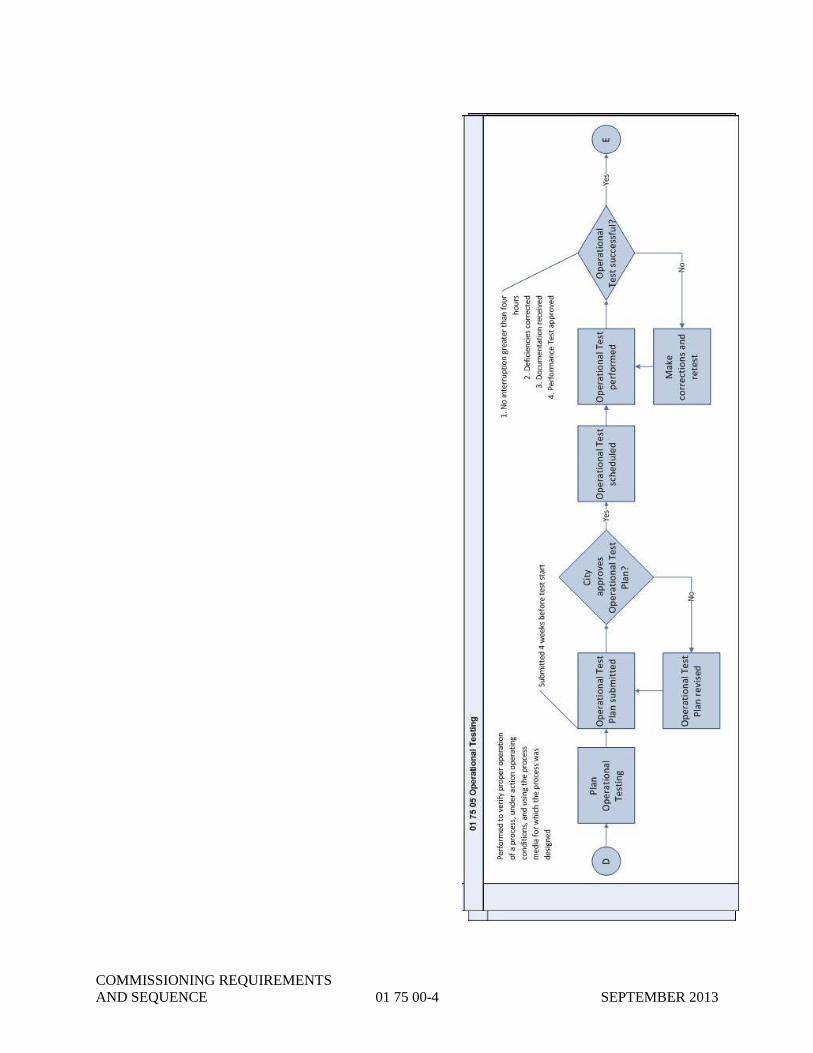
COMMISSIONING REQUIREMENTS
AND SEQUENCE 01 75 00-4 SEPTEMBER 2013

COMMISSIONING REQUIREMENTS
AND SEQUENCE 01 75 00-5 SEPTEMBER 2013
END OF SECTION 01 75 00

COMMISSIONING REQUIREMENTS
AND SEQUENCE 01 75 00-6 SEPTEMBER 2013
THIS PAGE INTENTIONALLY LEFT BLANK

EQUIPMENT FACTORY
ACCEPTANCE TESTING 01 75 01-1 SEPTEMBER 2013
SECTION 01 75 01
EQUIPMENT FACTORY ACCEPTANCE TESTING
PART 1 - GENERAL
1.01 SECTION INCLUDES
A. Scope.
B. Submittals.
1.02 RELATED SECTIONS
A. Drawings and requirements of the contract as put forth in the various portions of the Project
Manual, including General Conditions, any Special Provisions, and other Division 1 through
Division 46 Specification Sections and addenda apply to this Section. A partial list of
specification sections where Equipment Factory Acceptance Testing are indicated as being
required is presented for convenience in the table appearing below but this summary is not
guaranteed to be all inclusive of all references and related sections for Equipment Factory
Acceptance Testing that may appear elsewhere in the Contract Documents
(CONTRACTOR’s attention to any addenda modifications is of particular importance).
Specification
Reference Number
Title of Specification Section
23 34 00 Fans
23 81 26.19 Split System Air Conditioning Unit
23 82 39.23 Electric Heaters
35 20 16 Hydraulic Gates
40 05 23 Valves
40 91 00P Instrumentation Devices
40 92 43 Motorized Actuators
40 94 43 Programmable Logic Process Controllers
40 95 13 Control Panels
43 21 14 Recessed Impeller Pumps
43 21 39.19P Submersible Grinder Sample Pumps
43 21 40 Submersible Pumps
46 21 00 Mechanical Screen and Compactor
46 23 00 Grit Removal Equipment
46 33 00 Liquid Deicer Feed System
46 41 23 Submersible Mixers
46 43 21.19 Circular Clarifier
B. Manufacturer Product Warranties are included in Section 01 78 36.
C. CONTRACTOR’s General Condition Warranty and Guarantee are included in the General
Conditions, Section 00 72 00, Article 6.19.
D. Commissioning Requirements and Sequence, Section 01 75 00. (See PART 4 for the
Commissioning Requirements and Sequence flow chart associated with this Section.)
E. Equipment Startup and Checkout, Section 01 75 02.
F. System Functional Testing, Section 01 75 03.
EQUIPMENT FACTORY
ACCEPTANCE TESTING 01 75 01-2 SEPTEMBER 2013
G. Process Performance Testing, Section 01 75 04.
H. Operational Testing, Section 01 75 05.
I. 30-Day Commissioning Reliability Test, Section 01 75 06.
1.03 SCOPE
A. Equipment Factory Acceptance Testing ("FAT") shall be performed to verify proper
assembly, per the manufacturer’s documentation and technical specifications. Drawings by
the CONTRACTOR are also reviewed to verify accuracy and completeness.
B. Equipment FAT shall be performed by the CONTRACTOR. At the CITY’s discretion, some
or all Equipment FAT’s may be witnessed by the CITY.
C. Equipment FAT shall be performed for all fully assembled control panels, cabinets, and other
pertinent control systems and devices. Equipment FAT also includes static and dynamic
testing of wiring and devices, mechanical connections, and preliminary mechanical
functionality, as required by the Contract Documents.
D. Equipment FAT shall be performed at the location where the equipment or panel was
assembled, immediately prior to shipment to the CITY’s facility. Equipment FAT shall be
initiated and performed by the CONTRACTOR after the equipment or system has been
fabricated and assembled in the factory. Prior to Equipment FAT, all mechanical connections
shall have been completed, and all power and temporary wiring shall be terminated, as
applicable.
E. All Equipment FAT procedures and results shall be documented, indicating compliance with
the manufacturer’s recommendations and the requirements of the Contract Documents. The
accuracy and completeness of the drawings and documentation shall also be verified and
corrected as necessary.
F. In accordance with Commissioning Requirements and Sequence, Section 01 75 00,
Equipment FAT shall be successfully completed in compliance with Part 3 Execution and
approved prior to execution of all subsequent verification sections, including Equipment
Checkout and Startup, Section 01 75 02.
1.04 SUBMITTALS
A. Equipment FAT Plan. The CONTRACTOR shall submit all of the following documents to
the CITY for approval (referred to as the "Equipment FAT Plan"). Upon receipt of the
CITY’s approval, the CONTRACTOR shall coordinate Equipment FAT activities with the
CITY’s staff at least two (2) weeks prior to the proposed date Equipment FAT is to begin.
B. Submittal Documents.
1. Proposed start day of Equipment FAT tasks to be performed, including testing procedures
and what functionality or document detail is to be verified.
2. Examples of the forms to be used to document tasks, successful completion and
deficiencies.
3. Detailed panel layout drawing, including itemized bill of materials.
4. Control panel schematic diagrams.
5. PLC input and output (I/O) drawings.
6. Controls sequences and functional descriptions.

EQUIPMENT FACTORY
ACCEPTANCE TESTING 01 75 01-3 SEPTEMBER 2013
7. Digital network diagrams and riser diagrams.
8. PLC source files.
9. PLC documentation, complete, in PDF format, including all available aspects of the
project report available within the PLC programming software.
10. HMI documentation, in PDF format, including a full-page screenshots of every overview
and control screen, complete tag database, complete driver database and all custom
programming scripts.
11. Mechanical assembly documentation and drawings.
PART 2 - PRODUCTS
NOT USED
PART 3 - EXECUTION
3.01 PREPARATION
A. At least three (3) work days prior to Equipment FAT activities and arrival of the CITY, the
CONTRACTOR shall verify that the equipment is powered and ready for testing. All
installations shall be complete. All temporary connections shall be made, and all electrical
and mechanical aspects of each component and equipment are properly installed. Electrical
control power, uninterruptible power supplies, and reduced voltage power supplies shall be
energized and verified.
B. The CITY shall be notified immediately of any circumstances which may hinder, delay or
interrupt the Equipment FAT.
C. All test equipment and analysis instruments to be used for Equipment FAT verification shall
be calibrated and prepared for testing.
3.02 EXECUTION: EQUIPMENT FACTORY ACCEPTANCE TESTING
A. Equipment FAT may begin two (2) weeks after approval of each applicable Equipment FAT
Plan, subject to the following stipulations:
1. Refer to each applicable technical specification section for clarifications or additional
installation and Equipment FAT requirements or expectations.
2. All Equipment FAT activities shall be coordinated with the CITY, at least two (2) weeks
in advance. At the CITY’s discretion, the CITY may elect to witness some or all of these
activities.
3. Once started, Equipment FAT shall continue or be repeated until successful completion is
accomplished. All requests to interrupt, suspend, or restart Equipment FAT activities
shall be submitted to CITY for approval.
4. Equipment FAT shall be successfully completed and approved prior to shipment, as well
as Execution of all subsequent verification sections, including Equipment Checkout and
Startup, Section 01 75 02.
B. All details of all documents required for Submittal for this Section shall be verified. Each
word and marking on the documentation and drawings shall be visually inspected,
functionally tested, and highlighted to indicate accuracy.

EQUIPMENT FACTORY
ACCEPTANCE TESTING 01 75 01-4 SEPTEMBER 2013
C. Electrical Equipment FAT shall be performed, including the following, per the
manufacturer’s documentation and the technical specifications:
1. With power off, verify each detail of each drawing for completeness and accuracy.
Verify that all panel equipment, components and wires are properly labeled and tagged.
Verify terminal and tag lists. Verify physical layout and measurements.
2. Verify that the Bill of Materials adequately describes the equipment installed and that all
equipment meets the requirements of the design and approved Submittal documents per
each applicable technical section.
3. Record identification information of all parts with a Serial Number.
4. Verify that all installations of electrical equipment and conductors are per the
manufacturer’s recommendations, especially regarding proper sizing, grounding,
insulation, resistance and protection.
5. Verify wire routing and labels, including separation of AC and DC wiring.
6. Verify and record UL approval label identification.
7. With power applied, verify proper and functional circuit and motor protection equipment,
such as disconnects, breakers, fuses and overloads. Measure, verify and record the
current through each protected device.
8. Verify the functionality of each panel device.
D. Instrument and Control Equipment FAT shall be performed, including the following, per the
manufacturer’s documentation and the technical specifications:
1. Verify each point, one point at a time, applying the applicable voltage or current to each
field input termination point. Verify proper functionality of the hardware, software and
HMI indication. By making database adjustments, cause the proper signal to each field
output termination, then measure and record.
2. Perform functional tests of each algorithm described in the Functional Description. Use
simulation software or test assembly to simulate field devices.
3. Make connections to each field termination as necessary to simulate each Control
Sequence. Verify all outputs, PLC programming and HMI configurations.
4. Verify correct operation of each HMI element, including navigation, graphics, numerical
displays, controls, alarms and trends.
5. Verify program tag identifications, including PLC program and HMI configuration.
6. Perform fault tolerance (what-if) and failure recovery testing.
E. Mechanical Equipment FAT shall be performed, including the following, per the
manufacturer’s documentation and the technical specifications:
1. Verify that all equipment and components have been fully and properly installed.
2. Verify mechanical connections, fittings and mountings.
3. Verify equipment alignment.
4. Verify proper operation.
F. If any Equipment FAT cannot be completed successfully, necessary modifications,

EQUIPMENT FACTORY
ACCEPTANCE TESTING 01 75 01-5 SEPTEMBER 2013
adjustments, repairs or field engineering shall be performed as required for successful
completion. Equipment FAT shall continue or be repeated prior to submittal of any
completed documentation for approval, until successful completion is accomplished.
G. No equipment shall ship to the Project Site until all Equipment FAT is successfully
completed and approved.
H. Any proposed deviation from the approved plans or schedules shall require written
authorization by the CITY.
3.03 DOCUMENTATION
A. Only the forms and documents submitted to and approved by CITY shall be used to
document Equipment FAT. As each activity is completed, all related forms shall be
completed, dated and signed by the CONTRACTOR.
B. The CONTRACTOR shall maintain a list of Equipment FAT deficiencies, which shall be
updated and sent to the CITY at the end of each week during testing. All deficiencies shall be
corrected prior to submittal of any completed documentation for approval.
C. Upon completion of all Equipment FAT, all completed and witnessed documents shall be
compiled and formally submitted for approval.
PART 4 - FLOW CHART
Refer to 01 75 00 Section 2 for the Equipment Factory Acceptance Testing workflow.
END OF SECTION 01 75 01

EQUIPMENT FACTORY
ACCEPTANCE TESTING 01 75 01-6 SEPTEMBER 2013
THIS PAGE INTENTIONALLY LEFT BLANK

EQUIPMENT STARTUP
AND CHECKOUT 01 75 02-1 SEPTEMBER 2013
SECTION 01 75 02
EQUIPMENT STARTUP AND CHECKOUT
PART 1 - GENERAL
1.01 SECTION INCLUDES
A. Scope.
B. Submittals.
1.02 RELATED SECTIONS
A. Drawings and requirements of the contract as put forth in the various portions of the Project
Manual, including General Conditions, any Special Provisions, and other Division 1 through
Division 46 Specification Sections and addenda apply to this Section. A Partial list of
specification sections where Equipment Startup and Checkout are indicated as being required
is presented for convenience in the table appearing below but this summary is not guaranteed
to be all inclusive of all references and related sections for Equipment Startup and Checkout
that may appear elsewhere in the Contract Documents (CONTRACTOR’s attention to any
addenda modifications is of particular importance).
Specification
Reference Number
Title of Specification Section
22 30 00 Plumbing Equipment
23 34 00 Fans
23 81 26.19 Split System Air Conditioning Unit
23 82 39.23 Electric Heaters
26 05 86B Motors
26 24 16B Panelboards
26 24 19B Low Voltage Motor Control Centers
26 29 23.13B Variable Speed Drives
26 44 01 Self-Regulating Heat Tracing
26 52 00B Emergency Lighting Equipment
35 20 16 Hydraulic Gates
40 05 23 Valves
40 91 00P Instrumentation Devices
40 92 43 Motorized Actuators
40 94 43 Programmable Logic Controllers
40 95 13 Control Panels
43 21 14 Recessed Impeller Pumps
43 21 39.19P Submersible Grinder Sample Pumps
43 21 40 Submersible Pumps
46 21 00 Mechanical Screen and Compactor
46 23 00 Grit Removal Equipment
46 33 00 Liquid Deicer Feed System
46 41 23 Submersible Mixers
46 43 21.19 Circular Clarifier
46 51 21.13 Coarse Bubble Aeration Systems
46 51 46 Membrane Diffused Aeration System

EQUIPMENT STARTUP
AND CHECKOUT 01 75 02-2 SEPTEMBER 2013
Specification
Reference Number
Title of Specification Section
46 71 80 Floating Decanter Equipment
B. Manufacturer Product Warranties are included in Section 01 78 36.
C. CONTRACTOR’s General Condition Warranty and Guarantee are included in the General
Conditions, Section 00 72 00, Article 6.19.
D. Commissioning Requirements and Sequence, Section 01 75 00. (See Part 4 for the
Equipment Factory Acceptance Testing flow chart associated with this section.)
E. Equipment Factory Acceptance Testing, Section 01 75 01.
F. System Functional Testing, Section 01 75 03.Process Performance Testing, Section 01 75 04.
G. Operational Testing, Section 01 75 05.
H. 30-Day Commissioning Reliability Test, Section 01 75 06.
1.03 SCOPE
A. Equipment Startup shall be performed to verify proper installation and initial, powered
operation of equipment.
B. Equipment Startup shall be performed by the CONTRACTOR, as described by the
manufacturer’s documentation and recommendations. The services of factory field service
representatives shall be utilized, as directed in the technical specifications or recommended
by the manufacturer. Refer to each applicable technical specification section for
clarifications or additional installation and startup requirements or expectations.
C. After installation is completed, components and equipment shall be initially powered.
Electrical power feeds and supplies currents shall be measured and recorded. Rotating
equipment shall be tested, especially regarding proper rotation direction, alignment and
vibration.
D. All Equipment Startup procedures and results shall be documented, showing compliance with
the manufacturer’s recommendation, as well as the requirements of the technical
specifications.
E. All instrument and control signals shall be calibrated and verified for proper loop
performance. Instrument and control signals shall be simulated as necessary to test and verify
equipment functionality. All discrete signals shall be verified for proper activation and
continuity. All digital communications signals and devices shall be tested for proper
operation.
F. In accordance with Commissioning Requirements and Sequence, Section 01 75 00,
Equipment Startup and Checkout Execution shall be initiated only subsequent to all
successful Equipment Factory Acceptance Testing, Section 01 75 01.
G. Equipment Startup shall be successfully completed in compliance with Part 3, Execution and
approved prior to Execution of all subsequent verification sections, including Functional
Testing, Section 01 75 03.
1.04 SUBMITTALS
A. Equipment Startup Plan. A set of detailed Equipment Startup Plans shall be submitted for
approval. Each Equipment Startup Plan shall be specific to the equipment or system to be
EQUIPMENT STARTUP
AND CHECKOUT 01 75 02-3 SEPTEMBER 2013
tested. Markups and excerpts of the manufacturer’s operation and maintenance manuals are
acceptable. Each Equipment Startup Plan shall include detailed documentation, as follows:
B. Submittal Documents
1. A comprehensive list of the equipment or instruments to be factory calibrated, prior to
delivery.
2. A comprehensive list of the equipment or instruments to be calibrated by a factory field
service representative.
3. A comprehensive list of the equipment, instruments to be field calibrated by
CONTRACTOR authorized personnel.
4. Copies of detailed Equipment Startup reports and calibrations completed, signed and
dated by factory or factory authorized personnel who performed the Work.
5. A statement of qualifications for the CONTRACTOR personnel proposed to conduct
field Equipment Startup and calibrations. Documentation shall include experience and
attendance in applicable training courses.
6. Copies of calibration forms to be used. Forms shall be modified as necessary to reflect
any additional measurements or requirements indicated by the manufacturer’s
recommended calibration instructions. Each form shall be preprinted to the extent
possible prior to field startup and calibration. Each calibration form shall indicate the
maximum and minimum transmitted value, for each test point, required for successful
calibration.
7. A list of test and support equipment, temporary systems and other resources required to
complete Equipment Startup and calibrations.
8. Copies of certifications, which indicate the validity or recent calibration of all test
equipment and resources to be used.
9. An outline of specific resources to be provided by the CITY, such as the isolation of
systems or processes.
4 PART 2 - PRODUCTS
NOT USED
5 PART 3 – EXECUTION: EQUIPMENT STARTUP AND CHECKOUT
6 3.01 PREPARATION
A. Prior to startup, all structural and mechanical aspects of each component and equipment shall
be verified for complete and proper installation. All permissive, interlocks and safety devices
shall be verified to be in place and fully functional.
B. The CONTRACTOR shall assure that all preliminary and cursory installation reviews have
been performed and corrected, including inspections of connections, fittings and mountings.
All safeties, guards and interlocks shall be completed and placed in operation.
C. Electrical distribution, control power, uninterruptible power supplies, and reduced voltage
power supplies shall be energized, measured, verified and documented.

EQUIPMENT STARTUP
AND CHECKOUT 01 75 02-4 SEPTEMBER 2013
D. All test equipment and analysis instruments to be used for Equipment Startup verification
shall be calibrated and certified prior to testing. At the CITY’s discretion, test equipment or
analysis instruments may be subject to re-certification after completion of Equipment Startup.
3.02 EQUIPMENT STARTUP AND CHECKOUT
A. Equipment Startup may begin two (2) weeks after approval of each applicable Equipment
Startup Plan, subject to the following stipulations:
1. The CONTRACTOR shall notify the CITY at least eight (8) work hours prior to each
Equipment Startup or calibration activity. To minimize facility disruptions, all
Equipment Startup and calibration activities shall be coordinated with the CITY. At the
CITY’s discretion, the CITY may elect to witness some or all of these activities.
B. Instrument calibrations shall be performed per the manufacturer’s instructions and the
technical specifications.
C. Equipment Startup or calibrations, which are not performed and documented by the factory or
factory representative, shall be performed by the CONTRACTOR. Equipment setup in a
CONTRACTOR shop area shall be field verified after completion of permanent installation.
Field verification of transducers, meters, transmitters and analytical instruments shall be
performed by applying sample process conditions to the sensor. The use of factory
authorized simulators may be used to simulate the sensing device. Calibration procedures,
which only test the output transmitted signal are not sufficient for successful completion of
verification or calibration.
D. Loop testing shall not commence until all individual component calibration has been
successfully completed and documented. Each instrument loop shall be tested as an
integrated system. This test shall verify proper operation from the sensing device or switch to
all receiving components within the loop. For loop testing, signals may be injected at the
signal connection to the primary measuring elements. Loop testing, which includes an
interface to a programmable logic controller (PLC), shall include verification of the PLC
processor, the input/output (I/O) database and the I/O system. If any loop device fails to
operate or indicate properly, corrections shall be made, and the loop test repeated until all
devices operate properly. All loop tests shall be fully documented.
E. Record the identification information of each field device, including Model No. and Serial
Number. Verify that all installed field devices are per the requirements of the design and
approved submittal documents.
F. Verify each point, one point at a time, applying the applicable voltage or current to each field
input termination point. Verify proper functionality of the hardware, software and HMI
indication. By making database adjustments, cause the proper signal to each field output
termination, then measure and record.
G. Verify network and communications documentation, including parts inventories, labels, cable
terminations and testing certifications. All equipment configuration parameters and addresses
shall be set and recorded.
H. Make connections to each field termination as necessary to simulate each Control Sequence
and Functional Description. Verify all outputs, PLC programming and HMI configurations.
I. If any Equipment Startup or calibration is not completed successfully, necessary
modifications, adjustments, repairs or field engineering shall be performed as required for
successful completion. Equipment Startup shall continue or be repeated until successful
completion is accomplished.

EQUIPMENT STARTUP
AND CHECKOUT 01 75 02-5 SEPTEMBER 2013
J. At the discretion of the CITY, previously completed calibrations shall be repeated if
subsequent modifications may have altered the equipment or system, and to have logically
affected previous test results or observations.
K. Any proposed deviation from the approved plans or schedules shall require written
authorization by the CITY.
3.03 DOCUMENTATION
A. Only forms submitted and approved shall be used during field Equipment Startup or
calibration. As each activity is completed, all forms shall be completed, dated and signed by
the CONTRACTOR.
B. The CONTRACTOR shall maintain a list of Equipment Startup or calibration deficiencies,
which shall be updated and sent to the CITY at the end of each week. All deficiencies shall
be corrected prior to submittal of any forms for approval.
C. Upon completion of all Equipment Startup and calibrations, all completed and witnessed
documents shall be compiled and formally submitted for approval.
PART 4 – FLOW CHART
Refer to 01 75 00 Section 2 for the Equipment Startup and Checkout workflow.
END OF SECTION 01 75 02

EQUIPMENT STARTUP
AND CHECKOUT 01 75 02-6 SEPTEMBER 2013
THIS PAGE INTENTIONALLY LEFT BLANK

SYSTEM FUNCTIONAL TESTING 01 75 03-1 SEPTEMBER 2013
SECTION 01 75 03
SYSTEM FUNCTIONAL TESTING
PART 1 - GENERAL
1.01 SECTION INCLUDES
A. Scope.
B. Definitions
C. Submittals.
1.02 RELATED SECTIONS
Drawings and requirements of the contract as put forth in the various portions of the Project
Manual, including General Conditions, any Special Provisions, and other Division 1 through
Division 46 Specification Sections and addenda apply to this Section. A Partial list of
specification sections where System Functional Testing are indicated as being required is
presented for convenience in the table appearing below but this summary is not guaranteed to be
all inclusive of all references and related sections for System Functional Testing that may appear
elsewhere in the Contract Documents (CONTRACTORS’s attention to any addenda
modifications is of particular importance).
Specification
Reference Number
Title of Specification Section
22 30 00 Plumbing Equipment
23 34 00 Fans
23 81 26.19 Split System Air Conditioning Unit
23 82 39.23 Electric Heaters
26 05 86B Motors
26 24 16B Panelboards
26 24 19B Low Voltage Motor Control Centers
26 29 23.13B Variable Speed Drives
26 44 01 Self-Regulating Heat Tracing
26 52 00B Emergency Lighting Equipment
35 20 16 Hydraulic Gates
40 05 23 Valves
40 91 00P Instrumentation Devices
40 92 43 Motorized Actuators
40 94 43 Programmable Logic Controllers
40 95 13 Control Panels
43 21 14 Recessed Impeller Pumps
43 21 39.19P Submersible Grinder Sample Pumps
43 21 40 Submersible Pumps
46 21 00 Mechanical Screen and Compactor
46 23 00 Grit Removal Equipment
46 33 00 Liquid Deicer Feed System
46 41 23 Submersible Mixers
46 43 21.19 Circular Clarifier
46 51 21.13 Coarse Bubble Aeration Systems

SYSTEM FUNCTIONAL TESTING 01 75 03-2 SEPTEMBER 2013
Specification
Reference Number
Title of Specification Section
46 51 46 Membrane Diffused Aeration System
46 71 80 Floating Decanter Equipment
A. Drawings and general provisions of the contract, including General Conditions, Special
Provisions, and other Division 1 Specification Sections apply to this Section.
B. Manufacturer Product Warranties are included in Section 0178 36.
C. CONTRACTOR’s General Condition Warranty and Guarantee are included in the General
Conditions, Section 00 72 00, Article 6.19.
D. Commissioning Requirements and Sequence, Section 01 75 00. (See Part 4 for the
Commissioning Requirements and Sequence flow chart associated with this Section.)
E. Equipment Factory Acceptance Testing, Section 01 75 01.
F. Equipment Startup and Checkout, Section 01 75 02.
G. Process Performance Testing, Section 01 75 04.
H. Operational Testing, Section 01 75 05.
I. 30-Day Commissioning Reliability Test, Section 01 75 06.
1.02 SCOPE
A. Functional Testing shall be performed to verify proper powered operation of systems,
comprised of multiple equipment and components ("Systems"), typically prior to exposing
these to operating processes or conditions.
B. Functional Testing shall be performed by the CONTRACTOR, and witnessed by the CITY,
to verify proper integration, interaction and operation of component equipment, operating as
a system, as described by the manufacturer’s documentation and recommendations. Refer to
each appropriate technical specification section for clarifications or additional functional
requirements or expectations. Functional Testing shall also include preliminary verification
of each Functional Description, typically limited to dry testing.
C. Basic System operation and control System response shall be tested and verified. Instrument
and control signals shall be simulated as necessary to test and verify all equipment
functionality within the System.
D. A System may be obtained from a single vendor. Factory certified field service
representatives or technicians shall be utilized for Functional Testing of each single source
System. Single source Systems are identified as such in the technical specifications included
in the Contract Documents.
E. Each System comprised of equipment and components from multiple vendors shall be
assembled, integrated and functionally tested by the CONTRACTOR.
F. For each System, the CONTRACTOR shall plan, schedule, execute and document the
Functional Testing of the applicable and related System.
G. In accordance with Commissioning Requirements and Sequence, Section 01 75 00,
Functional Testing shall be initiated subsequent to all successful Equipment Start-Up, and
Checkout, Section 01 75 02.

SYSTEM FUNCTIONAL TESTING 01 75 03-3 SEPTEMBER 2013
H. System Functional Testing shall be successfully completed in compliance with Part 3,
Execution and approved prior to Execution of all subsequent verification sections, including
Process Performance Testing, Section 01 75 04.
1.03 DEFINITIONS
A. Successful Completion. All aspects of Functional Testing have been completed, and all
requirements listed in the specifications and in the Submittals have been proven to have been
met, within the specified constraints.
B. System. Regarding Functional Testing, a System shall include all components of equipment,
devices and appurtenances connected such that the operation or function of each
complements, protects or controls the operation or function of the others. For example, a
pumping system may be comprised of various equipment: motor, pump, gear reducer, piping,
instruments, controls, motor starter, wiring, etc. Other examples of Systems used in
wastewater facilities include power distribution, programmable controller, compressor, odor
control, centrifuge or boiler.
1.04 SUBMITTALS
A. Functional Testing Plan. A set of detailed Functional Testing Plans shall be submitted for
approval. The System Functional Testing may begin two (2) weeks after approval by the
City. Each Functional Testing Plan shall be specific to the equipment or System to be tested.
Markups and excerpts of the manufacturer’s operation and maintenance manuals are
acceptable. Each Functional Testing Plan shall include detailed descriptions of the
preparation, execution and documentation, as follows:
1. A detailed list of the equipment and Systems to which the Functional Testing procedures
will apply. This list shall include at least all applicable mechanical, electrical,
instrument, controls and HVAC equipment and Systems.
2. Complete descriptions of the preparation procedures necessary to achieve the desired test
conditions. Identify which items will require CITY action or participation.
3. A detailed list of procedures by which the CONTRACTOR plans to adequately and
completely perform each aspect of the Functional Testing.
4. A list of test and support equipment, temporary systems and other resources required to
complete the test plan.
5. A list of personnel, which will be used to perform Functional Testing. This list shall
indicate all subcontractors or representatives of manufacturers or vendors required to be
present for testing. At the CITY’s discretion, the qualifications of personnel shall be
documented and provided for approval upon request.
6. An outline of specific resources to be provided by the CITY during testing, such as the
isolation of systems or processes.
7. Verification of the validity or calibration of the test equipment or resources to be used.
8. A detailed outline of the specific results or observations, which will constitute acceptable
completion of each Functional Testing Plan.
9. Sample documentation to be used to record the procedures and results of each Functional
Testing Plan, including a sample of each form to be used. Samples of the format and
level of detail required for the documentation forms are available in Section 01 33 19
B. Functional Testing Schedule. A detailed Functional Testing Schedule shall be submitted for

SYSTEM FUNCTIONAL TESTING 01 75 03-4 SEPTEMBER 2013
approval. This Submittal shall accompany the Functional Testing Plan Submittal.
Requirements of the Functional Testing Schedule are as follows:
1. The proposed date that Functional Testing is to begin, and the estimated completion date.
2. A sequence, and relative daily schedule, by which the Functional Testing will be
executed.
3. The proposed Functional Test dates shall be indicated on and coordinated with the
CONTRACTOR’s Construction Progress Schedule specified in Section 01 32 16.
C. Functional Testing Documentation and Results. Upon completion of all aspects of Functional
Testing, all documentation indicating compliance with the requirements shall be signed and
dated by the CONTRACTOR for completeness and accuracy, and by the CITY as witness. A
copy of the project specific signed results shall be submitted to the CITY for consideration of
successful completion. Only upon approval of completion, by OWNER, shall the
CONTRACTOR begin the Execution phase of subsequent verification Sections.
PART 2 - PRODUCTS
NOT USED
PART 3 – EXECUTION: SYSTEM FUNCTIONAL TESTING
3.01 PREPARATION
A. The CONTRACTOR shall inform and coordinate the activities of all individuals required for
Functional Testing, including all subcontractors, vendors, suppliers, the CITY’s operations
and maintenance personnel, and other resources needed to implement the requirements of this
section.
B. The CONTRACTOR shall assure that all preliminary and cursory installation reviews have
been performed and mitigated, including inspections of connections, fittings, mountings,
leaks, pressures, temperatures, vibrations, electrical measurements, rotations and alarms. The
testing areas shall be cleaned and free of installation equipment and debris. All safeties,
guards and interlocks shall be completed and placed for operation.
C. All test equipment and analysis instruments to be used for Functional Testing shall be
calibrated and certified prior to Functional Testing. At the CITY’s discretion, test equipment
or analysis instruments may be subject to re-verification after completion of the Functional
Testing and prior to approval.
3.02 SCHEDULE
A. The approved Functional Testing Schedule shall be followed.
B. The schedule shall be updated and posted weekly, showing actual dates of test Work, and
indicating the status of each Functional Testing Plan. Functional Testing procedures and
Schedules shall be contiguous for each System, only interrupted for necessary modifications,
adjustments, repairs and field engineering, as required for successful completion. If any
interruption exceeds two (2) hours, the CONTRACTOR shall give twenty four (24) hours
notice to the CITY and all resources, prior to continuation or restart of the Functional Testing
Plan.
3.03 FUNCTIONAL TESTING

SYSTEM FUNCTIONAL TESTING 01 75 03-5 SEPTEMBER 2013
A. Functional Testing shall proceed under the direction of the CONTRACTOR. Only one
System and Functional Test Plan shall be executed at a time. All Functional Testing shall
follow the approved Plans and Schedules.
B. If any Functional Testing Plan is not completed successfully, necessary modifications,
adjustments, repairs or field engineering shall be performed as required for successful
completion. Functional Testing shall continue or be repeated until successful completion is
accomplished.
C. Verify each point, one point at a time, applying the applicable voltage or current to each field
input termination point. Verify proper functionality of the hardware, software and HMI
indication. By making database adjustments, cause the proper signal to each field output
termination, then measure and record. All equipment configuration parameters and addresses
shall be set and recorded.
D. At the discretion of the CITY, previously completed Functional Test Plans shall be repeated
if subsequent modifications may have altered the equipment or System, and to have logically
affected previous test results or observations.
E. Any proposed deviation from the approved Functional Testing Plans or Schedules shall
require written authorization by the CITY.
3.04 DOCUMENTATION
A. As each procedure is completed, the results shall be documented, dated and signed by the
CONTRACTOR. The CITY will also sign and date the documentation as witness.
B. The CONTRACTOR shall maintain a list of Functional Deficiencies, which shall be updated
and sent to the CITY at the end of each week.
C. Upon completion of all Functional Testing, all completed and witnessed documents shall be
compiled and formally submitted to the CITY for approval.
3.05 PROGRESS PAYMENTS
A. As a condition precedent to receiving progress payments in the period in advance of the date
the CONTRACTOR wishes to begin any testing work, the CONTRACTOR must have had
submitted all Functional Testing Plans required for the systematic field performance and
operational tests for all equipment and Systems installed under the Contract Documents.
Once the CITY has reviewed and taken no exception to the CONTRACTOR’s Functional
Testing Plans, the CONTRACTOR shall reproduce the Functional Testing Plans in sufficient
number for the CONTRACTOR’s purposes and an additional five (5) copies for delivery to
the CITY. No Functional Testing work shall begin until the CONTRACTOR has delivered
the specified number of approved Functional Testing Plans to the CITY.
PART 4 – FLOW CHART
Refer to 01 75 00 Section 2 for the System Functional Testing workflow.
END OF SECTION 01 75 03

SYSTEM FUNCTIONAL TESTING 01 75 03-6 SEPTEMBER 2013
THIS PAGE INTENTIONALLY LEFT BLANK

PROCESS PERFORMANCE TESTING 01 75 04-1 SEPTEMBER 2013
SECTION 01 75 04
PROCESS PERFORMANCE TESTING
PART 1 - GENERAL
1.01 SECTION INCLUDES
A. Scope.
B. Definitions.
C. Submittals.
1.02 RELATED SECTIONS
A. Drawings and requirements of the contract as put forth in the various portions of the Project
Manual, including General Conditions, any Special Provisions, and other Division 1 through
Division 46 Specification Sections and addenda apply to this Section. A Partial list of
specification sections where Process Performance Testing are indicated as being required is
presented for convenience in the table appearing below but this summary is not guaranteed to
be all inclusive of all references and related sections for Process Performance Testing that
may appear elsewhere in the Contract Documents (CONTRACTOR’s attention to any
addenda modifications is of particular importance).
Specification Reference
Number
Title of Specification Section
26 05 86B Motors
26 24 19B Low Voltage Motor Control Centers
26 29 23.13B Variable Speed Drives
40 91 00P Instrumentation Devices
40 92 43 Motorized Actuators
40 94 43 Programmable Logic Process Controllers
40 95 13 Control Panels
43 21 14 Recessed Impeller Pumps
43 21 39.19P Submersible Grinder Sample Pumps
43 21 40 Submersible Pumps
46 21 00 Mechanical Screen and Compactor
46 23 00 Grit Removal Equipment
46 33 00 Liquid Deicer Feed System
46 41 23 Submersible Mixers
46 43 21.19 Circular Clarifier
46 51 21.13 Coarse Bubble Aeration Systems
46 51 46 Membrane Diffused Aeration System
46 71 80 Floating Decanter Equipment
B. Drawings and general provisions of the contract, including General Conditions, Special
Provisions, and other Division 1 Specification Sections apply to this Section.
C. Manufacturer Product Warranties are included in Section 01 78 36.
D. CONTRACTOR’s General Condition Warranty and Guarantee are included in the General

PROCESS PERFORMANCE TESTING 01 75 04-2 SEPTEMBER 2013
Conditions, Section 00 72 00, Article 6.19.
E. Commissioning Requirements and Sequence, Section 01 75 00. (See Part 4 for the Process
Performance Testing flow chart associated with this Section.)
F. Equipment Factory Acceptance Testing, Section 01 75 01.
G. Equipment Startup and Checkout, Section 01 75 02.
H. System Functional Testing, Section 01 75 03.
I. Operational Testing, Section 01 75 05.
J. 30-Day Commissioning Reliability Test, Section 01 75 06.
1.03 SCOPE
A. Process Performance Testing shall be performed to verify proper powered operation of
equipment and Systems, as intended to perform a Process.
B. Performance Testing is performed as the process is initially exposed to operating or surrogate
media and conditions.
C. Performance Testing shall be performed by the CONTRACTOR to verify proper operation,
as described by the following items, as outlined in the technical specifications in the Contract
Documents. Refer to each appropriate technical Specification Section for the performance
requirements or expectations. Performance requirements may be specified for various media
conditions and levels of operation, including equipment, System and Process.
1. Specific performance parameters or expectations.
2. The Functional Description, complete.
3. The Sequence of Operation.
4. Alternative modes of operation.
5. Process functionality, using process or surrogate media as practical.
6. Process or System upsets and recovery:
D. For each of the items listed, the CONTRACTOR shall plan, schedule, execute and document
the Performance Testing of the applicable and related equipment, Systems and Processes.
E. In accordance with Section 01 75 00, Commissioning Requirements and Sequence,
Performance Testing shall be initiated subsequent to the approved Successful Completion of
Functional Testing, Section 01 75 03.
F. Performance Testing shall be performed by the CONTRACTOR, and witnessed by the CITY.
If specifically required by a technical specification included in the Contract Documents, or
otherwise at the CITY’s discretion, Certified Performance Tests may be required in lieu of an
CITY-Witnessed Performance Test.
G. The CONTRACTOR shall identify and utilize the services of a Testing Manager, to oversee
and directly supervise all aspects pertaining to Performance Testing and Operational Testing.
H. Performance Testing shall be successfully completed in compliance with Part 3, Execution
and approved prior to Execution of all subsequent verification sections, including Operational
Testing, Section 01 75 05.
1.04 DEFINITIONS

PROCESS PERFORMANCE TESTING 01 75 04-3 SEPTEMBER 2013
A. Successful Completion. All aspects of Performance Testing have been completed, and all
requirements listed in the specifications and in the submittals have been proven to have been
met, within the specified constraints.
B. Testing Manager. The person appointed by the CONTRACTOR to plan, schedule, manage,
coordinate, and supervise the CONTRACTOR’s Performance Testing and Operational
Testing programs, including Submittals, Execution and Documentation.
C. Certified Performance Testing. Tests performed and documented by factory authorized
personnel.
D. System. Regarding Performance Testing, a System shall include all items of equipment,
devices and appurtenances connected such that the operation or function of each
complements, protects or controls the operation or function of the others. The following are
examples of systems used in wastewater facilities: pumping, flow measurement,
programmable controller, level controls, compressor, centrifuge and boiler.
E. Process. Regarding Performance Testing, a Process shall include a collection or series of
Systems or equipment, which act together upon a fluid media to cause a separation or change
in properties, location or energy. The following are examples of wastewater processes: grit
removal, clarification, aeration, dewatering and incineration.
1.05 SUBMITTALS
A. Testing Manager. The CONTRACTOR shall propose the appointment of a Testing Manager
to execute the CONTRACTOR’s Performance Testing and Operational Testing programs.
Upon approval, the Testing Manager shall also develop all subsequent Submittals required by
the Performance Testing and Operational Testing Specification Sections. The Testing
Manager Submittal shall include detailed descriptions of the proposed Testing Manager’s
qualifications and experience in executing, managing and coordinating similar Performance
and Operational Testing programs. An Operations Engineer or equally qualified Operations
Specialist, is expected. Operations Engineers shall be graduates of a minimum 4-year
curriculum in mechanical, civil or equivalent engineering discipline. Operations Specialists
shall have relevant qualifications and experience in plant process operation and maintenance
activities. The submittal pertaining to the Testing Manager shall be approved by CITY prior
to the Testing Manager’s development of all subsequent Submittals in the Performance
Testing section.
B. Performance Testing Plan. A set of detailed Performance Testing Plans shall be submitted to
CITY for approval. The complete Performance Testing Plans shall be submitted no later than
two (2) weeks in advance of the proposed date testing is to begin. Each Performance Testing
Plan shall be specific to the equipment or System to be tested. Each Performance Testing
Plan shall include detailed descriptions of the preparation, execution and documentation, as
follows:
1. A detailed list of the equipment, systems and processes to which the Performance Testing
procedures will apply. This list shall include at least all applicable mechanical, electrical,
instrument, controls, HVAC and process equipment and systems. It shall be indicated
whether a Certified Performance Test or a CITY-Witnessed Performance Test is to be
performed for each equipment, System or Process.
2. Copies of all Functional Descriptions, Alternative Modes of Operation, Sequence of
Operations, and Outline of System Upsets and Recovery to be tested, simulated and
verified by the Performance Testing.
3. Complete descriptions of the preparation procedures necessary to achieve the desired test

PROCESS PERFORMANCE TESTING 01 75 04-4 SEPTEMBER 2013
conditions.
4. A detailed list of procedures by which the CONTRACTOR plans to adequately and
completely perform each aspect of the Performance Testing. The compiled list of the
Performance Testing procedures shall address all components of all descriptions -
Functional Description, Mode of Operation, Sequence of Operations or System Upset and
Recovery.
5. A list of test and support equipment, temporary systems and other resources required to
complete the test plan.
6. A list of personnel, which will be used to perform Performance Testing. This list shall
indicate all subcontractors or representatives of manufacturers or vendors required to be
present for testing. At the CITY’s discretion, the qualifications of personnel shall be
documented and provided upon request.
7. An outline of specific resources to be provided by the CITY, such as the isolation of
systems or processes.
8. Verification of the validity or calibration of the test equipment or resources to be used.
9. A detailed outline of the specific results or observations, which will constitute successful
completion of each Performance Testing plan.
10. Sample documentation to be used to record the procedures and results of each
Performance Testing plan, including a sample of each form to be used. Samples of the
format and level of detail required for the documentation forms are available in Section
01 33 19.
C. Performance Testing Schedule. A detailed Performance Testing Schedule shall be submitted
for approval. This submittal shall accompany the Performance Testing Plan submittal.
Requirements of the schedule are as follows:
1. The proposed date that Performance Testing is to begin, and the estimated completion
date.
2. A sequence, and relative daily schedule, by which the Performance Testing will be
executed.
3. The proposed Performance Test dates shall be indicated on and coordinated with the
CONTRACTOR’s Construction Progress Schedule specified in Section 01 32 16.
D. Performance Testing Documentation and Results. Upon completion of all aspects of
Performance Testing, all documentation indicating compliance with the requirements shall be
signed and dated by the Testing Manager for completeness and accuracy, and by the CITY as
witness. A copy of the signed results shall be submitted to the CITY for consideration of
Successful Completion. Only upon approval of this Submittal shall the CONTRACTOR
begin to execute subsequent verification Sections.
E. For items requiring only Certified Performance Testing, documentation of this certification
shall be submitted to the CITY for approval.
PART 2 - PRODUCTS
NOT USED
PART 3 – EXECUTION: PROCESS PERFORMANCE TESTING

PROCESS PERFORMANCE TESTING 01 75 04-5 SEPTEMBER 2013
3.01 PREPARATION
A. The Testing Manager shall inform and coordinate the activities of all individuals required for
Performance Testing, including the CONTRACTOR, all subcontractors, vendors, suppliers,
the CITY’s operations and maintenance personnel, and other resources needed to implement
the requirements of this Section.
B. The Testing Manager shall assure that all preliminary and cursory installation reviews have
been performed and mitigated, including inspections of connections, fittings, mountings,
leaks, pressures, temperatures, vibrations, electrical measurements, rotations and alarms. The
testing areas shall be cleaned and free of installation equipment and debris. All safeties,
guards and interlocks shall be completed and placed for operation. All temporary equipment
and configurations, including bypasses and jumpers, shall no longer be required and shall be
removed.
C. All test equipment and analysis instruments to be used for Performance Testing shall be
available. At the CITY’s discretion, test equipment or analysis instruments may be subject to
re-verification after completion of the Performance Testing.
3.02 SCHEDULE
A. The approved Performance Testing Schedule shall be followed.
B. The schedule shall be updated and posted weekly, showing actual dates of testing, and the
status of each test plan. Performance Testing procedures and schedules shall be contiguous,
only interrupted for necessary modifications, adjustments, repairs and field engineering, as
required for successful completion. If any interruption exceeds 4-hours, the Testing Manager
shall provide at least twenty four (24) hours notice to the CITY and all resources, prior to
continuation or restart of the test plan.
3.03 PERFORMANCE TESTING
A. Performance Testing shall proceed under the direction of the Testing Manager. Only one
process and one Performance Test plan shall be executed at a time. All Performance Testing
shall follow the approved plans and schedules.
B. If any test plan is not completed successfully, necessary modifications, adjustments, repairs
or field engineering shall be performed as required for successful completion. Performance
Testing shall continue or be repeated until successful completion is accomplished.
C. At the discretion of the CITY, previously completed Performance Test plans shall be repeated
if subsequent modifications may have altered the equipment, system or process, and to have
logically affected previous test results or observations.
D. Any proposed deviation from the approved plans or schedules shall require written
authorization by the CITY.
3.04 DOCUMENTATION
A. As each procedure is completed, the results shall be documented, dated and signed by the
Testing Manager. The CITY will also sign and date the documentation as witness.
B. The CONTRACTOR shall maintain a list of Performance Testing Deficiencies, which shall
be updated and sent to the CITY at the end of each week.
C. Upon completion of all Performance Testing, all completed and witnessed documents shall be
compiled and formally submitted for approval. Unless a waiver is granted in writing by the

PROCESS PERFORMANCE TESTING 01 75 04-6 SEPTEMBER 2013
CITY, partial submittals of individual equipment, systems or processes shall not be submitted
for review or considered for approval.
3.05 PROGRESS PAYMENTS
A. As a condition precedent to receiving progress payments in the payment period in advance of
the date the CONTRACTOR wishes to begin any testing work, the CONTRACTOR must
have had submitted all test plans required for the systematic field Performance Testing for all
equipment and Systems installed under the Contract Documents. Once the CITY has
reviewed and taken no exception to the CONTRACTOR’s test plans, the CONTRACTOR
shall reproduce the plans in sufficient number for the CONTRACTOR’s purposes and an
additional five (5) copies for delivery to the CITY. No test work shall begin until the
CONTRACTOR has delivered the specified number of final test plans to the CITY.
PART 4 – FLOW CHART
Refer to 01 75 00 Section 2 for the Process Performance Testing workflow.
END OF SECTION 01 75 04

OPERATIONAL TESTING 01 75 05-1 SEPTEMBER 2013
SECTION 01 75 05
OPERATIONAL TESTING
PART 1 - GENERAL
1.01 SECTION INCLUDES
A. Scope.
B. Definitions.
C. Submittals.
1.02 RELATED SECTIONS
A. Drawings and requirements of the contract as put forth in the various portions of the Project
Manual, including General Conditions, any Special Provisions, and other Division 1 through
Division 46 Specification Sections and addenda apply to this Section. A Partial list of
specification sections where Operational Testing are indicated as being required is presented
for convenience in the table appearing below but this summary is not guaranteed to be all
inclusive of all references and related sections for Operational Testing that may appear
elsewhere in the Contract Documents (CONTRACTOR’s attention to any addenda
modifications is of particular importance).
Specification Reference
Number
Title of Specification Section
26 05 86B Motors
26 24 19B Low Voltage Motor Control Centers
26 29 23.13B Variable Speed Drives
40 91 00P Instrumentation Devices
40 92 43 Motorized Actuators
40 94 43 Programmable Logic Process Controllers
40 95 13 Control Panels
43 21 14 Recessed Impeller Pumps
43 21 39.19P Submersible Grinder Sample Pumps
43 21 40 Submersible Pumps
46 21 00 Mechanical Screen and Compactor
46 23 00 Grit Removal Equipment
46 33 00 Liquid Deicer Feed System
46 41 23 Submersible Mixers
46 43 21.19 Circular Clarifier
46 51 21.13 Coarse Bubble Aeration Systems
46 51 46 Membrane Diffused Aeration System
46 71 80 Floating Decanter Equipment
B. Drawings and general provisions of the contract, including General Conditions, Special
Provisions, and other Division 1 Specification Sections apply to this Section.
C. Manufacturer Product Warranties are included in Section 0178 36.
D. CONTRACTOR’s General Condition Warranty and Guarantee are included in the General

OPERATIONAL TESTING 01 75 05-2 SEPTEMBER 2013
Conditions, Section 00 72 00, Article 6.19.
E. Commissioning Requirements and Sequence, Section 01 75 00. (See Part 4 for the
Operational Testing flow chart associated with this Section.)
F. Equipment Factory Acceptance Testing, Section 01 75 01.
G. Equipment Startup and Checkout, Section 01 75 02.
H. System Functional Testing, Section 01 75 03.
I. Process Performance Testing, Section 01 75 04.
J. 30-Day Commissioning Reliability Test, Section 01 75 06.
1.03 SCOPE
A. Operational Testing shall be performed to verify proper powered operation of a process,
under actual operating conditions, and using the process media for which the process was
designed.
B. Operational Testing shall be performed by the CONTRACTOR to verify proper operation, as
described by the following items, as outlined in the technical specifications. Refer to each
appropriate technical specification section for the operational requirements or expectations.
Operational requirements may be specified for various media conditions and levels of
operation, including equipment, system and process.
1. Specific operational parameters or expectations.
2. The Functional Description, complete.
3. The Sequence of Operation.
4. Alternative modes of operation.
5. Process functionality, using process or surrogate media as practical.
6. Process or system upsets and recovery.
C. For each of the items listed, the CONTRACTOR shall plan, schedule, execute and document
the Operational Testing of the applicable and related equipment, systems and processes.
D. In accordance with Section 01 75 00, Commissioning Requirements and Sequence,
Operational Testing shall be only initiated subsequent to the approved Successful Completion
of Process Performance Testing, Section 01 75 04.
E. Operational Testing shall be performed by the CONTRACTOR, and witnessed by the CITY.
F. The CONTRACTOR shall utilize the services of the Testing Manager, defined and approved
in the Performance Testing section. The Testing Manager shall oversee and directly
supervise all aspects pertaining to Operational Testing.
1.04 DEFINITIONS
A. Successful Completion. All aspects of Operational Testing have been completed, and all
requirements listed in the specifications and in the submittals have been proven to have been
met, within the specified constraints. Conformance to test plan requirement will be the
commissioning checklist.
B. Testing Manager. The person appointed by the CONTRACTOR to plan, schedule, manage,
coordinate, and supervise the CONTRACTOR’s Performance Testing and Operational
OPERATIONAL TESTING 01 75 05-3 SEPTEMBER 2013
Testing programs, including Submittals, Execution and Documentation.
C. System. Regarding Operational Testing, a system shall include all items of equipment,
devices and appurtenances connected such that the operation or function of each
complements, protects or controls the operation or function of the others. The following are
examples of systems used in wastewater facilities: pumping, flow measurement,
programmable controller, level controls, compressor, centrifuge and boiler.
D. Process. Regarding Operational Testing, a process shall include a collection or series of
systems or equipment, which act together upon a fluid media to cause a separation or change
in properties, location or energy. The following are examples of wastewater processes: grit
removal, clarification, aeration, dewatering and incineration.
1.05 SUBMITTALS
A. Testing Manager. The CONTRACTOR shall submit confirmation that the Testing Manager
appointed under the requirements of Performance Testing, Section 01 75 04, shall be the
same individual performing the Testing Manager tasks, outlined as follow. A proposed
change of Testing Manager shall be submitted for approval. The Testing Manager
confirmation shall be approved prior to the Testing Manager’s development of all subsequent
submittals in the Operational Testing section.
B. Operational Testing Plan. A set of detailed Operational Testing plans shall be submitted for
approval. The Operational Testing may begin 2 weeks after approval by the City. Each test
plan shall be specific to the process to be tested. Each test plan shall include detailed
descriptions of the preparation, execution and documentation, as follows:
1. A detailed list of the equipment, systems and processes to which the Operational Testing
procedures will apply. This list shall include at least all applicable mechanical, electrical,
instrument, controls, HVAC and process equipment and systems.
2. Copies of all Functional Descriptions, Alternative Modes of Operation, Sequence of
Operations, and Outline of System Upsets and Recovery to be tested, simulated and
verified by the Operational Testing.
3. Complete descriptions of the preparation procedures necessary to achieve the desired test
conditions.
4. A detailed list of procedures by which the CONTRACTOR plans to adequately and
completely perform each aspect of the Operational Testing. The compiled list of testing
procedure shall address all components of all descriptions - Functional Description, Mode
of Operation, Sequence of Operations or System Upset and Recovery.
5. A list of test and support equipment and other resources required to complete the test
plan.
6. A list of personnel, who will be used to perform Operational Testing. This list shall
indicate all subcontractors or representatives of manufacturers or vendors required to be
present for testing. At the CITY’s discretion, the qualifications of personnel shall be
documented and provided upon request.
7. An outline of specific resources to be provided by the CITY, such as the isolation of
systems or processes.
8. Verification of the validity or calibration of the test equipment or resources to be used.
9. A detailed outline of the specific results or observations, which will constitute successful
completion of each Operational Testing plan.

OPERATIONAL TESTING 01 75 05-4 SEPTEMBER 2013
10. Sample documentation to be used to record the procedures and results of each
Operational Testing plan, including a sample of each form to be used. Samples of the
format and level of detail required for the documentation forms are available in Section
01 33 19.
C. Operational Testing Schedule. A detailed Operational Testing Schedule shall be submitted
for approval. This submittal shall accompany the Operational Testing Plan submittal.
Requirements of the schedule are as follows:
1. The proposed date that Operational Testing is to begin, and the estimated completion
date.
2. A sequence, and relative daily schedule, by which the Operational Testing will be
executed.
3. The proposed Operational Test dates shall be indicated on and coordinated with the
CONTRACTOR’s construction schedule specified in Section 01 32 16.
D. Operational Testing Documentation and Results. Upon completion of all aspects of
Operational Testing, all documentation indicating compliance with the requirements shall be
signed and dated by the Testing Manager for completeness and accuracy, and by the CITY as
witness. A copy of the signed results shall be submitted to the CITY for consideration of
Successful Completion.
E. For items requiring only Certified Operational Testing, documentation of this certification
shall be submitted to the CITY for approval.
PART 2 - PRODUCTS
NOT USED
PART 3 – EXECUTION: OPERATIONAL TESTING
3.01 PREPARATION
A. The Testing Manager shall inform and coordinate the activities of all individuals required for
Operational Testing, including the CONTRACTOR, all subcontractors, vendors, suppliers,
the CITY’s operations and maintenance personnel, and other resources needed to implement
the requirements of this section.
B. The Testing Manager shall assure that all preliminary and cursory installation reviews have
been performed and mitigated, including inspections of connections, fittings, mountings,
leaks, pressures, temperatures, vibrations, electrical measurements, rotations and alarms. The
testing areas shall be cleaned and free of installation equipment and debris. All safeties,
guards and interlocks shall be completed and placed for operation. All temporary equipment
and configurations, including bypasses and jumpers, shall no longer be required and shall be
removed.
C. All test equipment and analysis instruments to be used for Operational Testing shall be
available. At the CITY’s discretion, test equipment or analysis instruments may be subject to
re-verification after completion of the Operational Testing.
3.02 SCHEDULE
A. The approved Operational Testing Schedule shall be followed.

OPERATIONAL TESTING 01 75 05-5 SEPTEMBER 2013
B. The schedule shall be updated and posted weekly, showing actual dates of testing, and the
status of each test plan. Operational Testing procedures and schedules shall be contiguous,
only interrupted for necessary modifications, adjustments, repairs and field engineering, as
required for successful completion. If any interruption exceeds 4-hours, the Testing Manager
shall provide at least 24 hours notice to the CITY and all resources, prior to continuation or
restart of the test plan.
3.03 OPERATIONAL TESTING
A. Operational Testing shall proceed under the direction of the Testing Manager. Only one
process and one Operational Test plan shall be executed at a time. All Operational Testing
shall follow the approved plans and schedules.
B. If any test plan is not completed successfully, necessary modifications, adjustments, repairs
or field engineering shall be performed as required for successful completion. Operational
Testing shall continue or be repeated until successful completion is accomplished.
C. At the discretion of the CITY, previously completed Operational Test plans shall be repeated
if subsequent modifications may have altered the equipment, system or process, and to have
logically affected previous test results or observations.
D. Any proposed deviation from the approved plans or schedules shall require written
authorization by the CITY.
3.04 DOCUMENTATION
A. As each procedure is completed, the results shall be documented, dated and signed by the
Testing Manager. The CITY will also sign and date the documentation as witness.
B. The CONTRACTOR shall maintain a list of Operational Testing Deficiencies, which shall be
updated and sent to the CITY at the end of each week.
C. Upon completion of all Operational Testing, all completed and witnessed documents shall be
compiled and formally submitted for approval. Unless a waiver is granted in writing by the
CITY, partial submittals of individual equipment, systems or processes shall not be submitted
for review or considered for approval..
PART 4 – FLOW CHART
Refer to 01 75 00 Section 2 for the Operational Testing workflow.
END OF SECTION 01 75 05

OPERATIONAL TESTING 01 75 05-6 SEPTEMBER 2013
THIS PAGE INTENTIONALLY LEFT BLANK

30-DAY COMMISSIONING
RELIABILITY TEST 01 75 06-1 SEPTEMBER 2013
SECTION 01 75 06
30-DAY COMMISSIONING RELIABILITY TEST
PART 1 - GENERAL
1.01 SECTION INCLUDES
A. Scope.
B. Submittals.
C. Quality Assurance.
1.02 RELATED SECTIONS
A. Drawings and requirements of the contract as put forth in the various portions of the Project
Manual, including General Conditions, any Special Provisions, and other Division 1 through
Division 46 Specification Sections and addenda apply to this Section. A Partial list of
specification sections where 30-Day Commissioning Reliability Testing are indicated as
being required is presented for convenience in the table appearing below but this summary is
not guaranteed to be all inclusive of all references and related sections for 30-Day
Commissioning Reliability Testing that may appear elsewhere in the Contract Documents
(CONTRACTOR’s attention to any addenda modifications is of particular importance).
Specification
Reference Number
Title of Specification Section
22 30 00 Plumbing Equipment
23 34 00 Fans
23 81 26.19 Split System Air Conditioning Unit
23 82 39.23 Electric Heaters
26 05 86B Motors
26 24 16B Panelboards
26 24 19B Low Voltage Motor Control Centers
26 29 23.13B Variable Speed Drives
26 44 01 Self-Regulating Heat Tracing
26 52 00B Emergency Lighting Equipment
35 20 16 Hydraulic Gates
40 05 23 Valves
40 91 00P Instrumentation Devices
40 92 43 Motorized Actuators
40 94 43 Programmable Logic Controllers
40 95 13 Control Panels
43 21 14 Recessed Impeller Pumps
43 21 39.19P Submersible Grinder Sample Pumps
43 21 40 Submersible Pumps
46 21 00 Mechanical Screen and Compactor
46 23 00 Grit Removal Equipment
46 33 00 Liquid Deicer Feed System
46 41 23 Submersible Mixers
46 43 21.19 Circular Clarifier
46 51 21.13 Coarse Bubble Aeration Systems
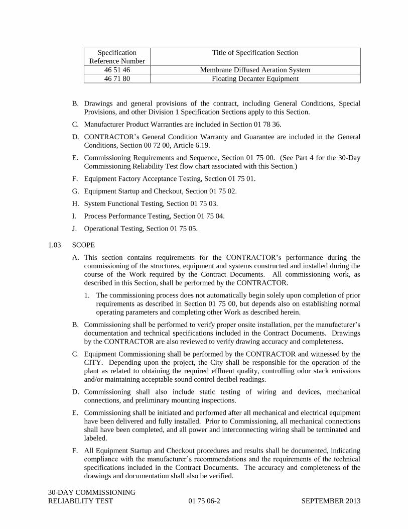
30-DAY COMMISSIONING
RELIABILITY TEST 01 75 06-2 SEPTEMBER 2013
Specification
Reference Number
Title of Specification Section
46 51 46 Membrane Diffused Aeration System
46 71 80 Floating Decanter Equipment
B. Drawings and general provisions of the contract, including General Conditions, Special
Provisions, and other Division 1 Specification Sections apply to this Section.
C. Manufacturer Product Warranties are included in Section 01 78 36.
D. CONTRACTOR’s General Condition Warranty and Guarantee are included in the General
Conditions, Section 00 72 00, Article 6.19.
E. Commissioning Requirements and Sequence, Section 01 75 00. (See Part 4 for the 30-Day
Commissioning Reliability Test flow chart associated with this Section.)
F. Equipment Factory Acceptance Testing, Section 01 75 01.
G. Equipment Startup and Checkout, Section 01 75 02.
H. System Functional Testing, Section 01 75 03.
I. Process Performance Testing, Section 01 75 04.
J. Operational Testing, Section 01 75 05.
1.03 SCOPE
A. This section contains requirements for the CONTRACTOR’s performance during the
commissioning of the structures, equipment and systems constructed and installed during the
course of the Work required by the Contract Documents. All commissioning work, as
described in this Section, shall be performed by the CONTRACTOR.
1. The commissioning process does not automatically begin solely upon completion of prior
requirements as described in Section 01 75 00, but depends also on establishing normal
operating parameters and completing other Work as described herein.
B. Commissioning shall be performed to verify proper onsite installation, per the manufacturer’s
documentation and technical specifications included in the Contract Documents. Drawings
by the CONTRACTOR are also reviewed to verify drawing accuracy and completeness.
C. Equipment Commissioning shall be performed by the CONTRACTOR and witnessed by the
CITY. Depending upon the project, the City shall be responsible for the operation of the
plant as related to obtaining the required effluent quality, controlling odor stack emissions
and/or maintaining acceptable sound control decibel readings.
D. Commissioning shall also include static testing of wiring and devices, mechanical
connections, and preliminary mounting inspections.
E. Commissioning shall be initiated and performed after all mechanical and electrical equipment
have been delivered and fully installed. Prior to Commissioning, all mechanical connections
shall have been completed, and all power and interconnecting wiring shall be terminated and
labeled.
F. All Equipment Startup and Checkout procedures and results shall be documented, indicating
compliance with the manufacturer’s recommendations and the requirements of the technical
specifications included in the Contract Documents. The accuracy and completeness of the
drawings and documentation shall also be verified.
30-DAY COMMISSIONING
RELIABILITY TEST 01 75 06-3 SEPTEMBER 2013
G. All required training must be completed prior to the start of the 30-Day Commissioning
Reliability Test.
H. In accordance with the requirements of Commissioning Requirements and Sequence, Section
01 75 00, the procedure in the Execution section of the 30-Day Commissioning Reliability
Test Specification shall be initiated only subsequent to all prior work being approved.
1.04 SUBMITTALS
A. All Shop Drawings and Operations and Maintenance Manuals are submitted in advance of the
Commissioning Plan submittal.
B. Commissioning Plan. The CONTRACTOR shall submit all of the following documents
listed to the CITY for approval (collectively referred to as the “Commissioning Plan”. Upon
receipt of the CITY’s approval of these documents, the CONTRACTOR shall coordinate the
activities with the CITY’s staff and start the field 30-Day Commissioning Reliability Testing
no sooner than two (2) weeks.
C. Submittal Documents: the following information shall be submitted to the CITY in
accordance within the provisions of Submittals, Section 01 33 00 and shall be field verified
prior to submission:
1. Written verification that all installation tasks of the equipment to be included in the
Equipment Commissioning activities have been totally completed, per the requirements
of the design and approved Submittal documents. This document shall also indicate that
all permanent field equipment labels and tags are installed.
2. Motor Control Center wiring diagrams, marked and updated to identify field wiring
connections and final circuit breaker assignments.
3. Control panel schematic diagrams, updated to include field wiring identification.
4. PLC input and output (I/O) drawings, updated to include field wiring identification.
5. Control panel interconnection diagrams, updated to include all field wiring.
6. Process and Instrument Diagrams (P&ID’s), updated to reflect any changes or
clarifications made during installation.
7. Instrument loop diagrams, updated to include specific terminal and wire label
identifications.
8. Digital network diagrams and riser diagrams, updated to reflect all device identification
and cable labels.
9. A detailed certification procedure for verification of all digital network cables, including
testing under static and dynamic conditions.
10. The CONTRACTOR’s plan for providing a Commissioning Team during the
commissioning period. The plan shall be complete with a daytime staffing plan and
names, qualifications, and telephone numbers of those assigned to off-hour standby duty.
11. A schedule and subsequent updates, presenting the CONTRACTOR’s plan for
commissioning systems installed under the Contract Documents. The schedule shall
establish the expected time period (calendar dates) when the CONTRACTOR plans to
commence commissioning of the completed equipment and systems. The schedule shall
coincide with the CONTRACTOR’s Construction Progress schedule required in Section
01 32 16.

30-DAY COMMISSIONING
RELIABILITY TEST 01 75 06-4 SEPTEMBER 2013
1.05 QUALITY ASSURANCE
A. CLEANUP: Following completion of the operational testing period, the CONTRACTOR shall
remove, clean, and replace all permanent and temporary filters and strainers in all pipeline
systems; replace all HVAC filters; dewater and clean all sumps; and dewater all process units for
final inspection as a condition precedent to commissioning.
B. COMMISSIONING TEAM: The CONTRACTOR shall assemble a commissioning team
under the direction of the Quality Assurance Manager. The CONTRACTOR shall appoint an
operations engineer or equally qualified operations specialist as the Quality Assurance
Manager to manage, coordinate, and supervise the CONTRACTOR’s quality assurance
program. The Quality Assurance Manager shall be duly authorized to commit the
CONTRACTOR’s personnel and resources to respond to requests for assistance on the part of
the CITY. The commissioning team shall consist of representatives of the CONTRACTOR’s
mechanical, electrical, and instrumentation subcontractors, and others as appropriate (the
"Commissioning Team"). The Commissioning Team shall be available at the site of the work
during normal working hours (8 hours a day, 5 days a week, Saturdays, Sundays, and legal
holidays excepted) and shall be available within two (2) hours notice at all other times upon
notice by telephone. The Commissioning Team shall at all times be equipped and ready to
provide for emergency repairs, adjustments, and corrections to the equipment and systems
installed and modified as a part of the Contract Documents.
PART 2 - PRODUCTS
2.01 GENERAL
A. Working with representatives of the CITY, the CONSULTANT shall develop and produce a
detailed, written plan for operation, under actual operating conditions and actual process
fluids and materials, of the equipment and systems installed and constructed under the
Contract Documents. The written plan for operation document, after acceptance by the
CITY, shall serve as the CONTRACTOR’S guidance manual for the commissioning process
and procedures.
PART 3 - EXECUTION: 30-DAY COMMISSIONING RELIABILITY TEST
3.01 PREPARATION
A. Prior to Commissioning Execution, all structural and mechanical aspects of each component
and equipment shall be verified for complete and proper installation. All permissive,
interlocks and safety devices shall be verified to be in place and fully functional.
B. Commissioning shall commence only after all normal operating process parameters are
established, including flow, pressure, temperature, etc., and all ancillary equipment is
completely installed, calibrated and available for routine use. Commissioning will be
authorized only with written notice from the CITY that the equipment and systems did meet
all test requirements and that commissioning may proceed. The commissioning period for
each modified or new major equipment or new unit process system shall be a minimum of
thirty (30) days. The CONTRACTOR shall remove all temporary appurtenances and other
alterations to the permanent systems that may have been needed during the performance and
operational testing and shall perform the tasks necessary to make the improvements
constructed under the Contract Documents fully operational. The CONTRACTOR shall
complete all punch list items designated by the CITY as necessary for commissioning prior to
beginning the commissioning period.

30-DAY COMMISSIONING
RELIABILITY TEST 01 75 06-5 SEPTEMBER 2013
C. The CONTRACTOR shall assure that all preliminary and cursory installation reviews have
been performed and corrected, including inspections of connections, fittings and mountings.
All safeties, guards and interlocks shall be completed and placed in operation.
D. The CONTRACTOR shall be available at all times during commissioning periods to provide
immediate assistance in case of failure of any portion of the equipment or system being
constructed. At the end of the commissioning period and when all corrections required by the
CITY to assure a reliable and completely operational facility are complete, the CITY shall
issue a completion certificate. All equipment and each system shall have been issued a
completion certificate as a condition precedent to the final acceptance of the Work under the
Contract Documents.
E. Proper installation of electrical equipment and conductors shall be verified per the
manufacturer’s recommendations, especially regarding proper sizing, grounding, insulation,
resistance and protection.
F. All test equipment and analysis instruments to be used for Commissioning verification shall
be calibrated and certified prior to testing. At the CITY’s discretion, test equipment or
analysis instruments may be subject to re-certification after completion of Commissioning.
G. Refer to each applicable technical specification section in the Contract Documents for
clarifications or additional installation and commissioning requirements or expectations.
H. Electrical Equipment Commissioning shall be performed, including the following, per the
manufacturer’s documentation and the technical specifications:
1. Check and correct all items used during installation to temporarily defeat the designed
operation of equipment and systems, including undocumented jumpers and non-
terminated wires.
2. Verify field equipment labels and tags, including the identification of the breaker, from
which each device is fed.
3. Verify proper and functional circuit and motor protection equipment, such as disconnects,
breakers, fuses and overloads.
4. Verify that all installations of electrical equipment and conductors are per the
manufacturer’s recommendations, especially regarding proper sizing, grounding,
insulation, resistance and protection.
5. Verify proper and functional personnel protection equipment, such as disconnect handles,
lockout devices, machine guards, safety protection & emergency stop switches, gas
detectors, and signaling devices. Verify that all protection devices are in place and
enabled.
I. Instrument and Controls Equipment Commissioning shall be performed, including the
following, per the manufacturer’s documentation and the technical specifications:
1. Verify all field wire terminations, per I/O drawings and interconnect drawings. Drawings
shall be updated to include specific terminal identification.
2. Verify wire routing and labels, including separation of AC and DC wiring.
3. Verify the labels on all panels, field devices, and process equipment for consistency and
completeness of all documents.
4. Verify and document network physical integrity. Refer to the technical specifications in
the Contract Documents for detailed requirements.

30-DAY COMMISSIONING
RELIABILITY TEST 01 75 06-6 SEPTEMBER 2013
J. Mechanical Equipment Commissioning shall be performed, including the following, per the
manufacturer’s documentation and the technical specifications:
1. Verify that all equipment and components have been fully and properly installed.
2. Verify mechanical connections, fittings and mountings.
3. Verify equipment alignment.
3.02 COMMISSIONING
A. Commissioning may begin two (2) weeks after approval of each applicable Commissioning
Plan, subject to the following stipulations:
1. In accordance with Commissioning Requirements and Sequence, Section 01 75 00,
Commissioning shall only be initiated subsequent to all prior work being approved.
2. The CONTRACTOR shall notify the CITY at least eight (8) work hours prior to each
Commissioning activity. To minimize facility disruptions, all Commissioning activities
shall be coordinated in advance with the CITY. At the CITY’s discretion, the CITY may
elect to witness some or all of these activities.
3. Once started, Commissioning shall continue or be repeated until successful completion is
accomplished. All requests to interrupt, suspend or restart Commissioning activities shall
be submitted for approval.
B. Commissioning of completed systems shall be in accordance with the scheduling
requirements of Testing Laboratory Services, Sections 01 45 29 and Commissioning, as
described in this Section. As such, it shall be necessary to perform multiple commissioning
periods.
C. The CITY’s operation and maintenance personnel will be responsible for operation of the
equipment and systems to be commissioned. The portion of the Work to be commissioned
shall be fully operational, performing all functions for which it was designed.
D. During the commissioning period, the CITY shall be responsible for all normal operational
costs and the CONTRACTOR shall bear the costs of all necessary repairs or replacements,
including labor and materials, required to keep the portion of the plant being commissioned,
operational.
E. The date on which the commissioning period is successfully completed shall be noted by the
CITY in writing to the CONTRACTOR.
F. If any Equipment Commissioning cannot be completed successfully, necessary modifications,
adjustments, repairs or field engineering shall be performed as required for successful
completion. Equipment Commissioning shall continue or be repeated until successful
completion is accomplished.
G. Any proposed deviation from the approved plans or schedules shall require written
authorization by the CITY.
3.03 DOCUMENTATION
A. Only the forms and documents submitted to and approved by CITY shall be used to
document field Equipment Commissioning. As each activity is completed, all forms shall be
completed, dated and signed by the CONTRACTOR.
B. The CONTRACTOR shall maintain a list of Commissioning deficiencies, which shall be
updated and sent to the CITY at the end of each week during Commissioning. All

30-DAY COMMISSIONING
RELIABILITY TEST 01 75 06-7 SEPTEMBER 2013
deficiencies shall be corrected prior to submittal of any completed documentation for
approval.
C. Upon completion of all Commissioning, all completed and witnessed documents shall be
compiled and formally submitted for approval.
PART 4 – FLOW CHART
Refer to 01 75 00 Section 2 for the 30-Day Commissioning Reliability Test workflow.
END OF SECTION 01 75 06

30-DAY COMMISSIONING
RELIABILITY TEST 01 75 06-8 SEPTEMBER 2013
THIS PAGE LEFT BLANK INTENTIONALLY

CONTRACT CLOSEOUT 01 77 00-1 SEPTEMBER 2013
SECTION 01 77 00
CONTRACT CLOSEOUT
PART 1 – GENERAL
1.01 SECTIONS INCLUDES
A. Closeout Procedures.
1.02 RELATED SECTIONS
A. Substantial Completion is included in Section 01 77 19.
B. Warranties and Bonds are included in Section 01 78 36.
C. Record Documents are included in Section 01 78 39.
1.03 CLOSEOUT PROCEDURES
A. Upon Substantial Completion, as determined in accordance with section 01 77 19 of the
specifications, the CITY will issue to the CONTRACTOR a written punch list of minor work
required as a condition of final acceptance. The CITY’s punch list will stipulate a reasonable
time, if different than 30 days, to complete the required work. Failure of the CONTRACTOR
to complete the punch list items by the stipulated term, normally 30 days, will result in an
administrative fee of $100 per calendar day for every day beyond the stipulated time period
the punch list work remains incomplete.
B. CONTRACTOR shall submit written certification that Contract Documents have been reviewed,
Work has been inspected and that Work is complete in accordance with Contract Documents and
ready for CITY inspection. The CITY will inspect the improvement, and if items remain which
the CONTRACTOR must complete or remedy, perform the work immediately. When the
CONTRACTOR corrects such items, the CITY will make final inspection. The work must pass
final inspection before the CITY will accept it.
C. Provide submittals to the CITY or the CITY’s representative that are required by governing or
other authorities.
D. Submit Application for Final Payment, in accordance with Article 14.07 of Section 00 72 00
General Conditions. Application for Final Payment shall include all Record Documents in
accordance with Section 01 78 39 of the Specifications, and identify total adjusted Contract Sum,
previous payments and sum remaining due.
E. CONTRACTOR shall repair defective land, areas, or Work during the Correction Period in
accordance with Article 13.07 of Section 00 72 00 General Conditions and as stipulated in
Contract Documents.
PART 2 – PRODUCTS
NOT USED

CONTRACT CLOSEOUT 01 77 00-2 SEPTEMBER 2013
PART 3 – EXECUTION
NOT USED
END OF SECTION 01 77 00

SUBSTANTIAL COMPLETION 01 77 19-1 SEPTEMBER 2013
SECTION 01 77 19
SUBSTANTIAL COMPLETION
PART 1 - GENERAL
1.01 SECTION INCLUDES
A. Scope.
B. Partial Utilization.
C. Final Completion
1.02 RELATED SECTIONS
A. Summary of Project is included in Section 01 11 00.
B. Cleaning is included in Section 01 74 00.
C. Measurement and Payment is included in Section 01 20 00.
D. Contract Closeout is included in Section 01 77 00.
E. Equipment and System Performance and Operational Testing is included in Section 01 75 03.
F. Reliability Testing is included in Section 01 75 04.
G. System Functional Testing is included in Section 01 75 03.
H. Process Performance Testing is included in Section 01 75 04.
1.03 SCOPE
A. When CONTRACTOR considers the entire Work ready for its intended use, CONTRACTOR
shall, in writing to CITY, certify that the entire Work is Substantially Complete as defined
below and request that CITY issue a letter or Certificate of Substantial Completion. Within
fourteen (14) calendar days after receipt of such notice from the CONTRACTOR, CITY and
the CONTRACTOR shall make an inspection of the Work to determine the status of the
Work. If CITY does not consider the Work Substantially Complete, CONTRACTOR will be
notified in writing giving reasons therefore. If CITY considers the Work Substantially
Complete, a letter or Certificate of Substantial Completion will be prepared by the CITY
which shall fix the date of Substantial Completion. There shall be attached to the letter or
Certificate of Substantial Completion, a final list of items to be completed or corrected before
Final Completion and final payment. If appropriate, CITY will deliver to the
CONTRACTOR a written recommendation as to division of responsibilities pending final
payment between CITY and CONTRACTOR with respect to security, operation, safety,
maintenance, heat, utilities and insurance.
B. Substantial Completion occurs when all startup and testing has been performed on the Project
in accordance with the Contract Documents or the CITY has beneficial occupancy of the
Project, whichever comes later. Substantial Completion shall also mean that all elements of
the Project, including all systems incorporated into the Project, are operational and will
perform as specified in the Contract Documents; that the Project, including all systems
incorporated into the Project, will in no way become a public nuisance; that the Project,
including all systems incorporated into the Project, in no way will adversely affect the public
health, welfare or safety; that the operation of the system Project, including all systems
SUBSTANTIAL COMPLETION 01 77 19-2 SEPTEMBER 2013
incorporated into the Project, may be conducted in a safe and efficient manner; and that safe,
all-weather access be assured in order that any equipment necessary for the normal activities
associated with operation of the Project, including all systems incorporated into the Project,
may have free continual ingress and egress. In addition, all O&M manuals and “as-built”
drawings shall have been received and approved and any training that is required by the
Contract Documents shall have been provided. In addition, all elements of the Work to be
automated shall operate automatically as a complete system under automated control.
C. The inspection to verify Substantial Completion shall include, but not be limited to:
1. All Work performed under the original Contract Documents and any additional Work
performed in accordance with approved changes to the Contract Documents.
2. All equipment and systems tested and shown operational in the presence of the CITY
and/or the CITY’s designated representatives and stakeholders.
D. CITY shall have the right to exclude items from the Work after the date of Substantial
Completion, but CITY shall allow CONTRACTOR reasonable access to complete or correct
items on the list attached to the letter or Certificate of Substantial Completion.
CONTRACTOR shall also have reasonable access to make corrections during the one (1)
year Correction Period in accordance with Paragraph 13.07 of the General Conditions
included in the Contract Documents.
1.04 PARTIAL UTILIZATION
A. Prior to Substantial Completion of all the Work, CITY may request CONTRACTOR in
writing to permit CITY to use a specified part of the Work which CITY believes to be
Substantially Complete and which may be used without significant interference with Work of
the other parts of the Project. If CONTRACTOR agrees, he will certify to CITY that said
part of the Work is Substantially Complete and request CITY to issue a letter or Certificate of
Substantial Completion for that part of the Work. Within fourteen (14) calendar days of this
request by the CONTRACTOR, the CITY and CONTRACTOR shall make an inspection of
that part of the Work to determine its status of completion and shall issue a letter or
Certificate of Substantial Completion as described in Paragraph 1.03.A in this Specification
Section.
B. In lieu of the issuance of a letter or Certificate of Substantial Completion as to part of the
Work, CITY may take over operation of a facility constituting part of the Work whether or
not it is Substantially Complete if such facility is functional and separately useable; provided
that prior to any such take over, the CITY and CONTRACTOR have agreed as to the division
of responsibilities for security, operation, safety, maintenance, correction period, heat,
utilities and insurance with respect to such facility. The Correction Period, described in
Article 13.07 of the General Conditions, shall be interrupted if the equipment is out of service
for repairs during the Correction Period.
1.05 FINAL COMPLETION
A. Final completion occurs at a point in time after Substantial Completion has been attained. At
Final Completion any contractual obligation, outstanding at Substantial Completion, has been
satisfied; all punch list items have been satisfactorily completed to the CiITY’s’s
requirements; and all restoration, seeding, final cleaning, and site demobilization have
occurred.
B. At Final Completion, all closeout submittals, final adjustment of accounts, and the final
payment request have been submitted and approved in accordance with Section 01 77 00

SUBSTANTIAL COMPLETION 01 77 19-3 SEPTEMBER 2013
Contract Closeout.
PART 2 - PRODUCTS
NOT USED
PART 3 - EXECUTION
3.01 EQUIPMENT CHECKLIST
A. Refer to Project Equipment Checklist, Table 01 77 19-1, for a list of required operational
equipment to be included in Substantial Completion Inspection:
Table 01 77 19-1: Minimum System Requirements for Substantial Completion
SYSTEM OR
SUBSYSTEM
OR
STRUCTURE
P&ID or
Drawing or
Spec
Reference
EQUIPMENT O&M
MANUAL
REQUIRED
TRAINING
REQUIRED
PERFORMANCE
AND
OPERATIONAL
TESTING
RELIABILITY
TESTING
Plumbing 22 30 00 Plumbing Equipment Yes No No Yes
HVAC
22 34 00 Fans Yes No No Yes
23 81 26.19 Split System Air
Conditioning Unit Yes No No Yes
23 82 39.23 Electric Heaters Yes No No Yes
Electrical and
Instrumentation
26 05 86B Motors Yes No Yes Yes
26 24 16B Panelboards No No Yes
26 24 19B Low Voltage Motor
Control Center Yes No Yes Yes
26 29 23.13B Variable Speed Drives Yes No Yes Yes
26 44 01 Self-Regulating Heat
Tracing Yes No No Yes
40 91 00 Instrumentation
Devices Yes Yes Yes Yes
40 94 43 Programmable Logic
Controllers Yes Yes Yes Yes
40 95 13 Control Panels Yes No Yes Yes
Valves and
Gates
35 20 16 Hydraulic Gates Yes Yes No Yes
40 05 23 Valves Yes No No Yes
40 92 43 Motorized Actuators Yes Yes Yes Yes
Sample Pumps 43 21 39.19P Submersible Grinder
Sample Pumps Yes Yes Yes Yes

SUBSTANTIAL COMPLETION 01 77 19-4 SEPTEMBER 2013
SYSTEM OR
SUBSYSTEM
OR
STRUCTURE
P&ID or
Drawing or
Spec
Reference
EQUIPMENT O&M
MANUAL
REQUIRED
TRAINING
REQUIRED
PERFORMANCE
AND
OPERATIONAL
TESTING
RELIABILITY
TESTING
Influent PS 43 21 40 Submersible Pumps Yes Yes Yes Yes
Screens and Grit
43 21 14 Recessed Impeller
Pumps Yes Yes Yes Yes
46 21 00 Mechanical Screen and
Compactor Yes Yes Yes Yes
46 23 00 Grit Removal
Equipment Yes Yes Yes Yes
Aeration
46 33 00
Liquid Deicer Feed
System
Yes Yes Yes Yes
46 41 23 Submersible Mixers Yes Yes Yes Yes
46 51 21.13 Coarse Bubble
Aeration Systems Yes Yes Yes Yes
46 51 46 Membrane Diffused
Aeration System Yes Yes Yes Yes
Clarifiers 46 43 21.19 Circular Clarifier Yes Yes Yes Yes
Digesters 46 71 80 Floating Decanter
Equipment Yes Yes Yes Yes
3.02 INSPECTION
A. If the inspection by CITY and CONTRACTOR confirms that the Work is Substantially
Complete, the CITY or the CITY’s representative shall:
1. Prepare, and submit to the CONTRACTOR, a list of items (punch list) to be completed or
corrected, as determined by the inspection, along with the designated timeframe for
completion.
2. Prepare and issue a letter or Certificate of Substantial Completion, containing:
a. The date of substantial completion.
b. A list of items (punch list) to be completed or corrected by the CONTRACTOR.
c. The timeframe within which the CONTRACTOR shall complete or correct the Work
of the above listed items.
d. The time and date the CITY will assume possession of the Work or designated
portion thereof.
e. The responsibilities of the CONTRACTOR for:
i. Operation of mechanical, electrical and other systems.
ii. Maintenance and cleaning.
iii. Security.
f. The signature of the:

SUBSTANTIAL COMPLETION 01 77 19-5 SEPTEMBER 2013
i. CITY
ii. CONTRACTOR
END OF SECTION 01 77 19

SUBSTANTIAL COMPLETION 01 77 19-6 SEPTEMBER 2013
THIS PAGE INTENTIONALLY LEFT BLANK

OPERATING AND 01 78 23-1 SEPTEMBER 2013
MAINTENANCE INFORMATION
SECTION 01 78 23
EQUIPMENT OPERATING AND MAINTENANCE MANUAL INFORMATION
1 PART 1 - GENERAL
1.01 SECTION INCLUDES
A. Scope.
B. Definitions.
C. CONTRACTOR Responsibilities.
D. Schedule of Submittals.
E. Types of Information Required.
1.02 RELATED SECTIONS
A. Submittals are included in Section 01 33 00.
B. A partial list of specifications sections where Operating and Maintenance Manuals are
required is presented for convenience in the table appearing below, but this summary is not
guaranteed to be all inclusive of all references and related sections.
Specification
Reference Number
Title of Specification Section
22 30 00 Plumbing Equipment
23 34 00 Fans
23 81 26.19 Split System Air Conditioning Unit
23 82 39.23 Electric Heaters
26 05 86B Motors
26 24 19B Low Voltage Motor Control Centers
26 29 23.13B Variable Speed Drives
26 44 01 Self-Regulating Heat Tracing
35 20 16 Hydraulic Gates
40 05 23 Valves
40 91 00P Instrumentation Devices
40 92 43 Motorized Actuators
40 94 43 Programmable Logic Controllers
40 95 13 Control Panels
43 21 14 Recessed Impeller Pumps
43 21 39.19P Submersible Grinder Sample Pumps
43 21 40 Submersible Pumps
46 21 00 Mechanical Screen and Compactor
46 23 00 Grit Removal Equipment
46 33 00 Liquid Deicer Feed System
46 41 23 Submersible Mixers
46 43 21.19 Circular Clarifier
46 51 21.13 Coarse Bubble Aeration Systems
46 51 46 Membrane Diffused Aeration System
46 71 80 Floating Decanter Equipment

OPERATING AND 01 78 23-2 SEPTEMBER 2013
MAINTENANCE INFORMATION
1.03 SCOPE
A. Equipment Operation and Maintenance (O&M) Manuals shall be provided in accordance
with this section and Contract Documents. O&M Manuals shall be provided for each
maintainable piece of equipment, equipment assembly or subassembly, and material provided
or modified under the Contract Documents.
B. O&M Manuals must be submitted and accepted before on-site training may start.
1.04 DEFINITIONS
A. Preliminary Operation and Maintenance Manual: The Preliminary O&M Manual will be
provided by the CONTRACTOR. The Preliminary O&M Manual will incorporate the
Submittal review comments and contain the necessary preventive maintenance tasks,
assembly/disassembly procedures, parts lists, special tools, storage requirements, emergency
start-up and shutdown procedures, and wiring diagrams to service the equipment and order
replacement parts until the Final O&M Manual is compiled.
B. Final Operation and Maintenance Manual: The Final O&M Manual shall be produced by the
CONTRACTOR upon completion and approval of all field testing. Distribution of the Final
O&M Manual shall be withheld until the product warranty documents, field test records, and
as-built information have been completed, submitted to the CITY, approved and inserted into
the Final O&M Manual.
1.05 CONTRACTOR RESPONSIBILITES
A. Operation and Maintenance Manuals as defined in Paragraph 1.04 above will be compiled by the
CONTRACTOR. The CONTRACTOR shall furnish to the CITY electronic and hard copies of
the O&M Manuals to the CITY as specified in 1.04 of this section.
1.06 SCHEDULE OF SUBMITTALS
A. Preliminary O&M Manual Information: Within thirty (30) days after approval of any
equipment Submittal by the CITY, the CONTRACTOR shall submit six (6) preliminary hard
copies, one (1) electronic copy (pdf) and one (1) electronic copy (native file) of the
Preliminary O&M Manual information to the CITY for approval.
B. The CITY will review the Preliminary O&M Manual information and will return one copy
with pertinent comments to the CONTRACTOR, as defined in 01 33 00 – Submittals, for
inclusion in the Final O&M Manual.
C. Final O&M Manual: Distribution of Final O&M Manual shall be withheld until the
Preliminary O&M Manual information has been accepted and the CONTRACTOR has
provided all field test records, and as-built information has been completed by the
CONTRACTOR and approved by the CITY for insertion in the Final O&M Manuals, and the
manufacturer’s product warranties are active. The CONTRACTOR shall submit six (6) hard
copies, one (1) electronic copy (pdf), and one (1) electronic copy (native) of the Final O&M
Manual to the CITY.
1.07 TYPES OF INFORMATION REQUIRED
A. GENERAL: O&M information shall contain the names, addresses, and telephone numbers of
the manufacturer, the nearest representative(s) of the manufacturer, and the nearest
supplier(s) of the manufacturer's equipment and parts. In addition, one or more of the
following items of information shall be provided as applicable.

OPERATING AND 01 78 23-3 SEPTEMBER 2013
MAINTENANCE INFORMATION
B. OPERATING INSTRUCTIONS: Specific instructions, procedures, and illustrations shall be
provided for the following phases of operations:
1. SAFETY PRECAUTIONS: List personnel hazards for equipment, personal protective
equipment (PPE), and list safety precautions for all operating conditions.
2. OPERATOR PRESTART: Provide requirements to set up and prepare each system for
use.
3. START-UP, SHUTDOWN, AND POST-SHUTDOWN PROCEDURES: Provide a
control sequence for each of these operations.
4. NORMAL OPERATIONS: Provide control diagrams with data to explain operation and
control of systems and specific equipment.
5. EMERGENCY OPERATIONS: Provide emergency procedures for equipment
malfunctions to permit a short period of continued operation or to shut down the
equipment to prevent further damage to systems and equipment. Include emergency
shutdown instructions for fire, explosion, spills, or other foreseeable contingencies.
Provide guidance on emergency operations of all utility systems including valve locations
and portions of systems controlled.
6. OPERATOR SERVICE REQUIREMENTS: Provide instructions for services to be
performed by the operator such as lubrication, adjustments, and inspection.
7. ENVIRONMENTAL CONDITIONS: Provide a list of environmental conditions
(temperature, humidity, and other relevant data) which are best suited for each product or
piece of equipment and describe conditions under which equipment should not be
allowed to run.
8. LOCK-OUT AND TAG-OUT REQUIREMENTS: Provide detailed instructions that
others can employ to ensure that equipment and systems are isolated from all energy
sources. Where stored or residual energy may be encountered, identify and document
type(s) of stored or residual energy, and appropriate methods of dissipating or restraining
each type of stored or residual energy. Stored or residual energy may be encountered in a
variety of equipment or systems including but not limited to capacitors; springs; elevated
machine members; rotating flywheels; hydraulic systems; and air, gas, steam, or water
pressure; etc.
C. PREVENTIVE MAINTENANCE: The following information shall be provided for
preventive and scheduled maintenance to minimize corrective maintenance and repair:
1. LUBRICATION DATA: Provide lubrication data as required below.
a. A table showing recommended lubricants for specific temperature ranges and
applications;
b. Charts with a schematic diagram of the equipment showing lubrication points,
recommended types and grades of lubricants, and capacities; and
c. A lubrication schedule showing service interval frequency.
2. PREVENTIVE MAINTENANCE PLAN AND SCHEDULE: Provide manufacturer's
schedule for routine preventive maintenance, inspections, tests, and adjustments required
to ensure proper and economical operation and to minimize corrective maintenance and
repair. Provide manufacturer's projection of preventive maintenance man-hours on a
daily, weekly, monthly, and annual basis including craft requirements by type of craft.
D. CORRECTIVE MAINTENANCE: Manufacturer’s recommendations shall be provided on

OPERATING AND 01 78 23-4 SEPTEMBER 2013
MAINTENANCE INFORMATION
procedures and instructions for correcting problems and making repairs.
1. TROUBLESHOOTING GUIDES AND DIAGNOSTIC TECHNIQUES: Provide step-
by-step procedures to promptly isolate the cause of typical malfunctions. Describe
clearly why the checkout is performed and what conditions are to be sought. Identify
tests or inspections and test equipment required to determine whether parts and
equipment may be reused or require replacement.
2. WIRING DIAGRAMS AND CONTROL DIAGRAMS: Wiring diagrams and control
diagrams shall be point-to-point drawings of wiring and control circuits including
factory-field interfaces. Provide a complete and accurate depiction of the actual job-
specific wiring and control work. On diagrams, number electrical and electronic wiring
and pneumatic control tubing and the terminals for each type identically to actual
installation numbering.
3. MAINTENANCE AND REPAIR PROCEDURES: Provide instructions and list tools
required to restore product or equipment to proper condition or operating standards.
4. REMOVAL AND REPLACEMENT INSTRUCTIONS: Provide step-by-step
procedures and list required tools and supplies for removal, replacement, disassembly,
and assembly of components, assemblies, subassemblies, accessories, and attachments.
Provide tolerances, dimensions, settings, and adjustments required. Instructions shall
include a combination of test and illustrations.
5. Provide replacement cost information for all equipment included in the O&M Manual.
6. SPARE PARTS AND SUPPLY LISTS: Provide lists of spare parts and supplies required
for maintenance and repair to ensure continued service or operation without unreasonable
delays. Special consideration is required for facilities at remote locations. List spare
parts and supplies that have a long lead time to obtain. Provide list of recommended
spare parts on separate sheet in O&M Manual. Provide price and availability information
for spare parts.
7. Provide a spare parts table including part description, part number, reorder information,
cost, lead time, supplier contact information, and reference to assembly drawing for all
equipment included in the O&M Manual.
8. CORRECTIVE MAINTENANCE MANHOURS: Provide manufacturer’s projection of
corrective maintenance man-hours including craft requirements by type of craft.
Corrective maintenance that requires participation of the equipment manufacturer shall be
identified and tabulated separately.
E. APPENDICES: The following information shall be provided. Include information not
specified in the preceding paragraphs but pertinent to the maintenance or operation of the
product or equipment.
1. PARTS IDENTIFICATION: Provide identification and coverage for all parts of each
component, assembly, subassembly, and accessory of the end items subject to
replacement. Include special hardware requirements, such as the requirement to use
high-strength bolts and nuts. Identify parts by make, model, serial number, and source of
supply to allow reordering without further identification. Provide clear and legible
illustrations, drawings, and exploded views to enable easy identification of the items.
When illustrations omit the part numbers and description, both the illustrations and
separate listings shall show the index, reference, or key number which will cross-
reference the illustrated part to the listed part. Parts shown in the listings shall be
grouped by components, assemblies, and subassemblies.

OPERATING AND 01 78 23-5 SEPTEMBER 2013
MAINTENANCE INFORMATION
2. WARRANTY INFORMATION: List and explain the various product warranties and
include the servicing and technical precautions prescribed by the manufacturers or
Contract Documents to keep warranties in force.
3. PERSONNEL TRAINING REQUIREMENTS: Provide information available from the
manufacturers to use in training designated personnel to operate and maintain the
equipment and systems properly.
4. TESTING EQUIPMENT AND SPECIAL TOOL INFORMATION: Provide information
on test equipment required to perform specified tests and on special tools needed for the
operation, maintenance, and repair of components.
2 PART 2 - PRODUCTS
NOT USED
3 PART 3 - EXECUTION
3.01 TRANSMITTAL PROCEDURE
A. Unless otherwise specified, O&M Manuals, information, and data shall be transmitted in
accordance with Section 01 33 00 accompanied by Transmittal Form 01 78 23-A and
Equipment Record Forms 01 78 23-B and/or 01 78 23-C, as appropriate, all as specified in
Section 01 33 19. The transmittal form shall be used as a checklist to ensure the O&M
Manual is complete. Only complete sets of O&M Manuals will be reviewed for acceptance.
Operation and maintenance manuals shall be comprised of equipment manufacturers’ original
printed material and literature. No reproductions will be accepted except as required to
reduce the original documents to the specified size.
B. For ease of identification, each manufacturer’s brochure and manual shall be appropriately
labeled with the equipment name and equipment number as it appears in the Contract
Documents. The information shall be organized in numerical order by the equipment
numbers assigned in the Contract Documents.
C. If manufacturers’ standard brochures and manuals are used to describe O&M procedures,
such brochures and manuals shall be modified to reflect only the model or series of
equipment used on the Project. Extraneous material shall be crossed out neatly or otherwise
annotated or eliminated.
3.02 FIELD CHANGES
A. Following the acceptable installation and operation of an equipment item, the item’s
instructions and procedures shall be modified and supplemented by the CONTRACTOR to
reflect any field changes or information requiring field data. These changes will be
incorporated into the Final O&M Manual as required by paragraph 1.06.C, Schedule of
Submittals above.
END OF SECTION 01 78 23

OPERATING AND 01 78 23-6 SEPTEMBER 2013
MAINTENANCE INFORMATION
THIS PAGE INTENTIONALLY LEFT BLANK

MANUFACTURER PRODUCT WARRANTIES 01 78 36-1 SEPTEMBER 2013
SECTION 01 78 36
MANUFACTURER PRODUCT WARRANTIES
PART 1 - GENERAL
1.01 SECTION INCLUDES
A. Scope.
B. Submittals.
C. Schedule of Warranties.
D. Warranty Requirements.
E. Manufacturer’s Certifications.
F. Definitions
1.02 RELATED SECTIONS
A. Refer to the General Conditions, including Article 6 for the general requirements relating to
warranties.
B. General Closeout or Contract Closeout requirements are included in Section 01 77 00.
C. Substantial Completion is included in Section 01 77 19.
D. A list of required manufacturer product warranties listed below is for CONTRACTOR
convenience. The CONTRACTOR is responsible for any additional requirements for warranties
for the Work and products and installations that are specified to be warranted elsewhere in the
Contract Documents.
Specification Reference
Number
Title of Specification Section
07 41 13.16 Standing-Seam Metal Roof Panels
07 41 13.23 Insulated Metal Roof Panels
07 42 13.19 Insulated Metal Wall Panels
07 42 13.53 Metal Soffit Panels
08 11 16 Aluminum Flush Doors
08 12 16 Fiberglass Reinforced Plastic (FRP) Doors and Aluminum Frames
08 31 13 Floor Doors
08 33 23 Overhead Coiling Doors
08 39 19 Watertight Doors
08 51 13 Aluminum Windows
08 71 00 Door Hardware
08 80 00 Glazing
10 28 00 Toilet and Bath Accessories
10 44 16 Fire Extinguishers
12 32 16 Manufactured Plastic-Laminate-Faced Casework
22 30 00 Plumbing Equipment
MANUFACTURER PRODUCT WARRANTIES 01 78 36-2 SEPTEMBER 2013
Specification Reference
Number
Title of Specification Section
23 34 00 Fans
23 81 13 Packaged Terminal Air Conditioning Unit
23 81 26.19 Split System Air Conditioning Unit
23 82 39.23 Electric Heaters
26 05 86B Motors
26 24 16B Panelboards
26 24 19B Low Voltage Motor Control Centers
26 29 23.13B Variable Speed Drives
26 44 01 Self-Regulating Heat Tracing
26 50 00B Lighting Fixtures
26 52 00B Emergency Lighting Equipment
35 20 16 Hydraulic Gates
40 05 23 Valves
40 91 00P Instrumentation Devices
40 92 43 Motorized Actuators
40 94 43 Programmable Logic Process Controllers
40 95 13 Control Panels
43 21 14 Recessed Impeller Pumps
43 21 39.19P Submersible Grinder Sample Pumps
43 21 40 Submersible Pumps
46 21 00 Mechanical Screen and Compactor
46 23 00 Grit Removal Equipment
46 33 00 Liquid Deicer Feed System
46 41 23 Submersible Mixers
46 43 21.19 Circular Clarifier
46 51 21.13 Coarse Bubble Aeration Systems
46 51 46 Membrane Diffused Aeration System
46 71 80 Floating Decanter Equipment
1.03 SCOPE
A. This Section specifies general administrative and procedural requirements for manufacturer
warranties required by the Contract Documents, including manufacturer’s standard product and
equipment warranties ("Standard Product Warranties") and special product and equipment
warranties from manufacturers ("Special Product Warranties").
B. All products and equipment shall be warranted by the manufacturer in accordance with Section
1.05 A of this Specification.
C. This Section shall in no way limit the CONTRACTOR's general warranty obligations specified in
Article 6 of the General Conditions of the Contract Documents.
1.04 SUBMITTALS
A. Submit written product and equipment warranties to the CITY prior to Substantial Completion.
B. When a Special Product Warranty is required to be executed by the CONTRACTOR, or the
CONTRACTOR and a subcontractor, supplier or manufacturer, prepare a written document that

MANUFACTURER PRODUCT WARRANTIES 01 78 36-3 SEPTEMBER 2013
contains appropriate terms and identification, ready for execution by the required parties. Submit
a draft to the CITY for approval prior to final execution.
C. Refer to individual Sections of these Specifications for specific content requirements, and
particular requirements for Submittals of Special Product Warranties.
D. When operating and maintenance manuals are required for warranted construction, provide
additional copies of each required warranty, as necessary, for inclusion in each required manual.
Coordinate this work with the requirements of Section 01 78 23.
1.05 SCHEDULE OF WARRANTIES
A. All products and equipment shall be warranted by the manufacturer from the time of Substantial
Completion to a period of 12-months following Substantial Completion of the Project. If a
Standard Product Warranty from a product or equipment manufacturer does not meet this
requirement, CONTRACTOR shall provide, at no additional cost to the CITY, extended
warranties for products and equipment to meet the warranty requirements in this Section. The
manufacturer warranties are in addition to all other warranties included in the Contract
Documents.
B. CONTRACTOR shall provide extended warranties for products and equipment, as needed, so that
all warranties comply with this Section. This cost shall be included in the cost of the Work in the
Schedule of Values.
C. Refer to technical requirements found elsewhere in the Contract Documents for the products and
equipment to be warranted by the manufacturer.
1.06 MANUFACTURER WARRANTY REQUIREMENTS
A. Related Damages and Losses: When correcting Work warranted by a manufacturer that has failed,
CONTRACTOR and/or the manufacturer shall remove and replace other Work that has been
damaged as a result of such failure or that must be removed and replaced to provide access for
correction of warranted Work.
B. Reinstatement of a Manufacturer's Product Warranty: When Work covered by either a Standard
or Special Product Warranty has failed and has been corrected by replacement or rebuilding, the
CONTRACTOR and the manufacturer shall reinstate the warranty by written endorsement from
the CONTRACTOR and the manufacturer to the CITY. The reinstated warranty shall be equal to
the original warranty in duration and coverage.
C. Replacement Cost: Upon determination that Work covered by a either a Standard or Special
Product Warranty has failed within the warranty period, CONTRACTOR and/or manufacture
shall replace or rebuild the Work to an acceptable condition complying with requirements of
Contract Documents. The CONTRACTOR is responsible for the entire cost of replacing or
rebuilding defective work regardless of whether the CITY has benefited from use of the Work
through a portion of its anticipated useful service life.
D. CITY’s Recourse: Written Standard or Special Product Warranties made to the CITY are in
addition to CONTRACTOR's other warranty obligations included in the Contract Documents and
implied warranties, and shall not limit the duties, obligations, rights and remedies otherwise
available under the law, nor shall warranty periods be interpreted as limitations on time in which
the CITY can enforce such other warranties, duties, obligations, rights, or remedies.

MANUFACTURER PRODUCT WARRANTIES 01 78 36-4 SEPTEMBER 2013
E. Rejection of Warranties: The CITY will consider the warranty provisions in reviewing the product
Submittals and reserves the right to reject Submittals based solely upon the warranties’
compliance to the Contract Documents. The CITY also reserves the right to limit selections to
products with warranties not in conflict with requirements of the Contract Documents.
F. Disclaimers and Limitations: Manufacturer's disclaimers and limitations on product Standard or
Special Product Warranties do not relieve the CONTRACTOR of the warranty on the Work that
incorporates the products, nor does it relieve suppliers, manufacturers and subcontractors required
to countersign Special Product Warranties with the CONTRACTOR.
1.07 LIMITED “EXTENDED MUNICIPAL WARRANTY”
A. Where required by reference in other specification sections, an Extended Municipal Warranty
shall be provided and shall conform to requirements as put forth in this section. The Municipal
Warranty shall run from a period starting 12-months after Substantial Completion of the Project to
60-months following the Substantial Completion of the Project.
B. The Extended Municipal Warranty shall be a pro rata limited warranty wherein the equipment
supplier shall pay the following share of the cost of replacement of repair parts:
Months following project
Substantial Completion
Date
12-18 months 19-39 months 40-60 months
Maximum hours of
operation 3000 hours 6500 hours 10,000 hours
Coverage of replacement or
repair parts 100% 50% 25%
C. Warranty for the period from project Substantial Completion to 12 months following the
Substantial Completion of the project shall conform to requirements of Section 1.05 A of this
specification.
D. When Work covered by this Extended Municipal Warranty has failed and has been corrected by
replacement or rebuilding, the manufacturer shall reinstate the warranty by written endorsement
from the manufacturer to the CITY. The reinstated warranty shall be equal to the original
Extended Municipal Warranty in remaining duration and coverage as per table in Section 1.07 B
of this specification.
1.08 MANUFACTURERS’ CERTIFICATIONS
A. Where required, the CONTRACTOR shall supply evidence, satisfactory to the CITY, that the
CONTRACTOR can obtain manufacturers’ certifications as to the CONTRACTOR’s installation
of equipment.
1.09 DEFINITIONS
A. Standard Product Warranties are preprinted written warranties published by individual
manufacturers for particular products and are specifically endorsed by the CONTRACTOR and/or
Subcontractor, Supplier or manufacturer to the CITY.
B. Special Product Warranties are written warranties required by or incorporated in the Contract
Documents, either to extend time limits provided by Standard Product Warranties or to provide
MANUFACTURER PRODUCT WARRANTIES 01 78 36-5 SEPTEMBER 2013
greater rights for the CITY as required by the Contract Documents.
PART 2 - PRODUCTS
NOT USED
PART 3 - EXECUTION
NOT USED
END OF SECTION 01 78 36

MANUFACTURER PRODUCT WARRANTIES 01 78 36-6 SEPTEMBER 2013
THIS PAGE INTENTIONALLY LEFT BLANK

RECORD DOCUMENTS 01 78 39-1 SEPTEMBER 2013
SECTION 01 78 39
RECORD DOCUMENTS
PART 1 - GENERAL.
1.01 SECTION INCLUDES
A. Scope.
B. Description.
1.02 RELATED SECTIONS
A. Contract Closeout is included in Section 01 77 00.
1.03 SCOPE
A. This section addresses the requirements and responsibilities of the CONTRACTOR, with respect
to record documents to be maintained in the field by the CONTRACTOR. Drawings and general
provisions of the Contract Documents, including General Conditions, and Division 1 Specification
Sections, including Section 01 35 00 – Special Provisions, apply to this Section.
1.04 DESCRIPTION
A. CONTRACTOR shall maintain and provide the CITY with record documents as specified as
follows, except as otherwise specified or modified in Divisions 2 through 48 of the Specifications.
B. Maintenance of Record Documents:
1. Maintain in clean, dry legible condition the following: Contract Drawings, Specification,
Addenda, Approved Shop Drawings and Submittals, Change Orders, other Modifications of
Contract, Progress Meeting Minutes, Test Records, Survey Data, and all other documents
pertinent to the Work of the CONTRACTOR (collectively referred to as the "Record
Documents").
2. Provide for proper storage and easy access. File in accordance with filing format acceptable
to the CITY.
3. Make documents available at all times for inspection by the CITY.
4. Record Documents shall not be used for any other purpose and shall not be removed from the
Project Site without the approval of the CITY.
C. Marking System: Provide and maintain colored pencils for making changes, revisions, additions
and deletions, to the record set of Contract Drawings. Document and maintain a consistent color
code.
D. Recording:
1. Label each document "PROJECT RECORD" in 2 inch high printed letters.
2. Keep record documents current.

RECORD DOCUMENTS 01 78 39-2 SEPTEMBER 2013
3. All pertinent and required information shall be collected and recorded before the related work
becomes inaccessible.
4. Contract Drawings: Legibly mark to record actual Work including:
a. Depths of various elements of foundation in relation to datum.
b. Horizontal and vertical location of underground utilities and appurtenances referenced to
permanent surface improvements.
c. Location of internal utilities and appurtenances concealed in Work referenced to visible
and accessible features of structure.
d. Field verifications and changes of dimension and detail.
e. Changes made by Change Order or Field Order.
f. Pertinent details not on original Contract Drawings.
5. Specification and Addenda: Legibly mark up each Section to record:
a. Manufacturer, trade name, catalog number, and supplier of each product and item of
equipment actually installed.
b. Changes made by Change Order or Field Order.
c. Other installation additions or changes not originally specified.
6. Submittals: Maintain Submittals, including shop drawings, as Record Documents and legibly
annotate drawings to record changes made after review and after installation.
E. Submittals:
1. At completion of Project, submit Record Documents to the CITY in accordance with the
requirements of Section 01 33 00.
2. Accompany Submittal with transmittal letter containing:
a. Date of Submittal.
b. Project identification, including title, Project ID (Number), and sewer number (if
applicable).
c. CONTRACTOR's identification, including name and address.
d. Title and document identification number for each Record Document provided.
e. Certification that each Record Document as submitted is complete and accurate.
f. Signature of CONTRACTOR, or authorized representative.
PART 2 - PRODUCTS
NOT USED
PART 3 - EXECUTION
NOT USED
END OF SECTION 01 78 39

SPARE PARTS AND
MAINTENANCE MATERIALS 01 78 43-1 SEPTEMBER 2013
SECTION 01 78 43
SPARE PARTS AND MAINTENANCE MATERIALS
PART 1 - GENERAL
1.01 SECTION INCLUDES
A. Scope.
1.02 RELATED SECTIONS
A. Operating and Maintenance information is included in Section 01 78 23.
1.03 SCOPE
A. CONTRACTOR shall furnish spare parts and maintenance materials as specified in the individual
Sections and in accordance with the requirements of the approved O & M manual.
B. CONTRACTOR shall furnish a master spare parts list to the CITY once preliminary O&M
manuals are completed. The master spare parts list shall include the specification reference
section for each spare part and where the equipment is used.
C. Parts and materials shall be furnished in manufacturer's unopened cartons, boxes, crates or other
protective covering suitable for preventing corrosion or deterioration for the maximum length of
storage which may be normally anticipated. They shall be clearly marked and identified as to their
contents and storage instructions including manufacture part number and reorder number.
D. Parts and materials shall be delivered to the CITY upon completion of the Work or when the
CITY assumes Partial Utilization in accordance with Specification Section 01 77 19.
E. Provide a letter of transmittal including the following information for turnover to the City:
1. Date of letter and transfer of spare parts and material.
2. Contract title and sewer number.
3. CONTRACTOR's name and address.
4. A complete inventory of the parts and material listing the applicable Specification Section for
each.
5. Manufacture part number.
6. Reorder number.
7. Part description.
8. Manufacture drawings or cut sheets. For example, an exploded view showing all parts with
labels.
9. Equipment reference and/or location numbers of where the spare parts will be used. Example:
a. Location number - MLC-H-51.0001

SPARE PARTS AND
MAINTENANCE MATERIALS 01 78 43-2 SEPTEMBER 2013
b. Equipment number - 001234
c. Reference identification number on drawing – RSP-001, Raw Sewage pump #1
10. No parts maybe turned over to the City until all parts shown on list are present.
11. A place for the CITY to sign and signify receipt of the parts and materials.
F. CONTRACTOR shall be fully responsible for loss or damage to parts and materials until they are
received by the CITY.
PART 2 - PRODUCTS
2.01 SPARE PARTS NOT REQUIRED OR ACCEPTED
A. The following spare parts are typically not required unless otherwise specifically requested:
1. Fuses
2. Relays
3. Terminal blocks
4. Breakers
5. Lights
6. Indicator lights
7. Push buttons
8. Electrical switches
9. Control transformers
10. Bearings
11. Pump seals
12. Oil seals
13. Fasteners
14. Gaskets
15. Lubricants
PART 3 - EXECUTION
3.01 EXAMPLE SPARE PARTS TURNOVER TABLE
Part
Description
Manufacturer
Part Number
Reorder Part
Number
Manufacturer Supplying
Vendor
Vendor
Contract
Equipment or
location used
Reference Project
Drawing No.

SPARE PARTS AND
MAINTENANCE MATERIALS 01 78 43-3 SEPTEMBER 2013
END OF SECTION 01 78 43

SPARE PARTS AND
MAINTENANCE MATERIALS 01 78 43-4 SEPTEMBER 2013
THIS PAGE INTENTIONALLY LEFT BLANK

TRAINING 01 79 00-1 SEPTEMBER 2013
SECTION 01 79 00
TRAINING
PART 1 - GENERAL
1.01 SECTION INCLUDES
A. Scope.
B. Quality Assurance.
C. Submittals.
D. Minimum Training Requirements.
1.02 RELATED SECTIONS
A. Example: Submittals are included in Section 01 33 00
1.03 SCOPE
A. This section contains requirements for training the CITY’s personnel, by persons retained by
the CONTRACTOR specifically for the purpose, in the proper operation and maintenance of
the equipment and systems installed under the Contract Documents.
1.04 QUALITY ASSURANCE
A. Where required by the Contract Documents, the CONTRACTOR shall provide on-the-job
training of the CITY’s personnel. The training sessions shall be conducted by qualified,
experienced, factory-trained representatives of the various equipment manufacturers.
Training shall include instruction in both operation and maintenance of the subject
equipment.
1.05 SUBMITTALS
A. The following information shall be submitted to the CITY or the CITY’s representative in
accordance with the provisions of Section 01 33 00-Submittals. The materials shall be
reviewed and accepted by the CITY or the CITY’s representative as a condition precedent to
receiving progress payments in excess of 50 percent of the Contract Sum and not less than
three (3) weeks prior to performing the training.
1. Lesson plans for each training session, to be conducted by the manufacturer's
representative.
2. Training documents, including manuals, handouts, visual aids, and other reference
materials as recommended and needed.
3. Subject, date and time of each training session.
4. Identity and qualifications of each individual to be conducting the training session.

TRAINING 01 79 00-2 SEPTEMBER 2013
1.06 TRAINING REQUIREMENTS
A. Training shall be required on the following equipment, as a minimum:
Spec Section Equipment/Item
35 20 16 Hydraulic Gates
40 91 00P Instrumentation Devices
40 92 43 Motorized Actuators
40 94 43 Programmable Logic Process Controllers
43 21 14 Recessed Impeller Pumps
43 21 39.19P Submersible Grinder Sample Pumps
43 21 40 Submersible Pumps
46 21 00 Mechanical Screen and Compactor
46 23 00 Grit Removal Equipment
46 33 00 Liquid Deicer Feed System
46 41 23 Submersible Mixers
46 43 21.19 Circular Clarifier
46 51 21.13 Coarse Bubble Aeration Systems
46 51 46 Membrane Diffused Aeration System
46 71 80 Floating Decanter Equipment
B. Unless listed specifically in the individual equipment section, duration of training shall be as
recommended by the manufacturer.
C. Training and startup are not to occur at the same time.
2 PART 2 - PRODUCTS
2.01 GENERAL
A. Where specified, the CONTRACTOR shall conduct training sessions for the CITY’s
personnel to instruct the staff on the proper operation, care, and maintenance of the
equipment and systems installed under the Contract Documents. Training shall take place at
the location of the Work and under the conditions specified in the following paragraphs.
Training shall be scheduled and provided to accommodate each of the operation and
maintenance shifts of the CITY – a minimum of one training session for each shift for each
system or equipment item requiring training. Unless approved by the CITY, each training
session shall be presented in its entirety, in a contiguous time frame. Preliminary operation
and maintenance manuals shall be available at least thirty (30) days prior to the date
scheduled for the first individual training session.
2.02 LOCATION
A. Preferably, training sessions shall take place at or near the Project Site, or at an alternative
location mutually agreeable to the CONTRACTOR and CITY.
2.03 LESSON PLANS
A. Formal written lesson plans shall be prepared for each training session. Lesson plans shall
contain an outline of the material to be presented along with a description of visual aids to be
utilized during the session. Each plan shall contain a time allocation for each subject. Time

TRAINING 01 79 00-3 SEPTEMBER 2013
shall also be allocated for brief breaks.
B. One complete set of originals of the lesson plans, training manuals, handouts, visual aids, and
reference material shall be the property of the CITY and shall be suitably bound for proper
organization and easy reproduction. The CONTRACTOR shall furnish ten (10) copies of
necessary training manuals, handouts, visual aids and reference materials at least one (1)
week prior to each training session.
2.04 FORMAT AND CONTENT
A. Each training session shall be comprised of time spent both in the classroom and at the
specific location of the subject equipment or system. Attendee interaction and open dialogue
with the instructor shall be expected and accommodated. As a minimum, training session
shall cover the following subjects for each item of equipment or system:
1. Familiarization
a. Review catalog, parts lists, drawings, etc., which have been previously provided for
the plant files and operation and maintenance manuals.
b. Check out the installation of the specific equipment items.
c. Demonstrate the unit and indicate how all parts of the specifications are met.
d. Answer questions.
2. Safety
a. Using material previously provided, review safety references.
b. Discuss proper precautions around equipment.
3. Operation
a. Using material previously provided, review reference literature.
b. Explain all modes of operation (including emergency).
c. Check out the CITY’s personnel on proper use of the equipment.
4. Preventive Maintenance
a. Using material previously provided, review Preventive Maintenance ("PM") lists
including:
1) Reference material.
2) Daily, weekly, monthly, quarterly, semiannual, and annual jobs.
b. Demonstrate and discuss Preventive Maintenance procedures.
c. Demonstrate and discuss possible indications of equipment problems.
5. Corrective Maintenance
a. List possible problems.
b. Discuss repairs--point out usual and unique problems.
c. Disassemble equipment and demonstrate procedures, where practical.
6. Parts
a. Show how to use previously provided parts list and order parts.
b. Verify and check over spare parts on hand. Make recommendations regarding
additional parts that should be available, or which usually incur extensive lead times.

TRAINING 01 79 00-4 SEPTEMBER 2013
7. Local Representatives
a. Where to order parts: name, address, telephone.
b. Service problems:
1) Who to call.
2) How to get emergency help.
8. Operation and Maintenance Manuals
a. Review any other material submitted.
b. Update material, as required.
2.05 AUDIO/VIDEO RECORDING:
A. The CITY intends to retain the services of a commercial audio/video (A/V) recording service
to record each training session. After recording, the material will be edited and supplemented
with professionally produced graphics to provide a permanent record. The CONTRACTOR
shall advise all manufacturers providing training sessions that the training sessions will be
recorded. The CONTRACTOR shall assure that each manufacturer representative shall
optimally utilize, facilitate and accommodate the recording production equipment, as well as
coordinate with the persons responsible for the recording of the session. The manufacturer’s
representative shall provide contact information to the recording service, and shall respond to
specific requests for clarification, as necessary during post production.
3 PART 3 - EXECUTION
3.01 DESCRIPTION
A. Training shall be conducted in conjunction with the operational testing and commissioning
periods. Classes shall be scheduled such that classroom sessions are interspersed with field
instruction in logical sequence. Training sessions for each shift, as required in 01 79 00,
Paragraph 2.01, shall be identical in content and method. The CONTRACTOR shall arrange
to have the training conducted with no more than four (4) hours of sessions scheduled for any
one day. Concurrent classes shall not be allowed. Training shall be certified on Form 44 00
00-B - Manufacturer's Instruction Certification Form, as specified in Section 01 33 19.
B. Training and startup are not to occur at the same time.
C. Training shall be conducted through a minimum of two sessions in one of the following
weekday formats:
1. Tuesdays and Wednesdays (to be the same day each week) on consecutive weeks, from
7:30 a.m. – 11:30 a.m.
2. Tuesday or Wednesday, and Thursday during the same week, from 7:30 a.m. – 11:30
a.m.
C. CONTRACTOR shall provide acceptable preliminary operation and maintenance manuals for
the specific equipment to the CITY prior to the start of any training. Audio/video recording
shall take place concurrently with all training sessions.
D. The following services shall be provided for each item of equipment or system as required in
individual specification sections. Additional services shall be provided, where specifically

TRAINING 01 79 00-5 SEPTEMBER 2013
required in individual Specification Sections.
3. At a minimum, classroom equipment and system training for operations personnel will
include:
a. Slides, drawings, presentations and discussions of the specific location in the facility
of the equipment or system, as well as an operational overview.
b. Present and discuss the purpose and functions of the equipment or systems.
c. Present a working knowledge of the operating theory of the equipment or systems.
d. Start-up, shutdown, normal operation, and emergency operating procedures,
including detailed discussions of the system integration and electrical interlocks, if
applicable.
e. Identify and discuss safety items and procedures.
f. Routine Preventative Maintenance, including specific details on lubrication and
maintenance of corrosion protection of the equipment and ancillary components.
g. Operator detection, without test instruments, of specific equipment trouble symptoms
and recommended correction procedures.
h. Required equipment exercise procedures and intervals.
i. Routine disassembly and assembly of equipment or system, if applicable, (as judged
by the CITY on a case-by-case basis) for purposes such as operator inspection of
equipment.
j. Manufacturer Warranty requirements and expectations.
4. As a minimum, hands-on equipment training for operations personnel will include:
a. Identify location of equipment and systems, and review the purpose.
b. Identify piping and flow options.
c. Identify valves and their purpose.
d. Identify instrumentation:
1) Location of primary element.
2) Location of instrument readout.
3) Discuss purpose, basic operation, and information interpretation.
e. Discuss, demonstrate, and perform standard operating procedures and round checks.
f. Discuss and perform the Preventative Maintenance procedures.
g. Discuss and perform start-up and shutdown procedures.
h. Perform the required equipment exercise procedures.
i. Perform routine disassembly and assembly of equipment and systems if applicable.
j. Identify and review safety items and perform safety procedures, if feasible.
5. Classroom equipment training for the maintenance and repair personnel will include:
a. Theory of operation.
b. Description and function of equipment.
c. Start-up and shutdown procedures.
d. Normal and major repair procedures.
e. Equipment and system inspection, problem indications and troubleshooting
procedures including the use of applicable test instruments and the "pass" and "no
pass" test instrument readings.
TRAINING 01 79 00-6 SEPTEMBER 2013
f. Routine and long-term calibration procedures.
g. Safety procedures.
h. Preventative Maintenance such as lubrication; normal maintenance such as belt, seal,
and bearing replacement; and up to major repairs such as replacement of major
equipment part(s) with the use of special tools, bridge cranes, welding jigs, etc.
i. Manufacturer Warranty requirements and expectations.
6. Hands-on equipment training for maintenance and repair personnel shall include:
a. Locate and identify equipment or system components.
b. Review the equipment or system function and theory of operation.
c. Review normal repair procedures.
d. Perform start-up and shutdown procedures.
e. Review and perform the safety procedures.
f. Perform the CITY approved practice maintenance and repair procedures, including
mechanical and electrical adjustments, and calibration, problem identification,
troubleshooting and correction procedures.
END OF SECTION 01 79 00

SUBSURFACE CONDITIONS 02 30 00-1 SEPTEMBER 2013
SECTION 02 30 00
SUBSURFACE CONDITIONS
1.01 PART 1 - GENERAL
1.01 DESCRIPTION
A. Soil boring logs inside the project area are shown in the report entitled “Geotechnical
Engineering Report”, dated December 10, 2012. This report was prepared by Terracon and
includes soil boring logs at select locations in the project site. This information, as well as prior
geotechnical reports and boring logs, may be obtained upon request from the CITY.
B. This soil investigation information is offered as an aid in bidding only and is not a part of the
Contract Documents. The boring logs are available for the CONTRACTOR's information, but
are not a warranty of subsurface conditions. The CITY, ENGINEER and geotechnical engineer
assume no responsibility for any variation between materials encountered during construction
and those indicated on the boring logs, nor for any variation between the location of the water
table encountered and that indicated on the boring logs at the date borings were taken.
C. Additional Investigation: The CONTRACTOR shall visit the site and become acquainted with
site conditions. Prior to bidding, prospective CONTRACTORs may make their own site and
subsurface investigations to satisfy themselves with site and subsurface conditions as long as
they have obtained prior written permission to do so. The CONTRACTOR shall be responsible
for obtaining approval from the CITY for site and subsurface investigation and shall assume all
responsibility for any damage to property caused as a result of the CONTRACTOR's
investigation.
D. Location of Borings: CONTRACTORs shall be responsible for making their own determination
of the location of the soil borings on this Project.
2.01 PART 2 - PRODUCTS
NOT USED
3.01 PART 3 - EXECUTION
NOT USED
END OF SECTION 02 30 00

SUBSURFACE CONDITIONS 02 30 00-2 SEPTEMBER 2013
THIS PAGE INTENTIONALLY LEFT BLANK

Salvaged Equipment Turn-Over Form
Submit to MSDGC in accordance with specification section 01 33 00 Submittals
Form No. 02 41 00 Page 1 of 1 Revision 02/21/2014
Date:
Project ID: Project Name:
Contract No: MSDGC Staff Requesting Salvage:
Print Name
Equipment
Manufacturer:
Model No.: Serial No.:
Description:
Special Handling/Preparation Procedures:
Hazardous Materials (list): Attach supporting MSDGC MSDS Documentation that is in addition to Construction Contract requirements.
Additional Special Instructions (i.e. drain, wrap, seal):
Current Location Storage Location Facility: Facility:
Building: Building:
Process/Room: Process/Room:
Treatment Superintendent/Designee (Ryan Welsh) Concurrence:
Print Name Signature Date
Completed Actions:
Contractor submitted disposal plan: Yes / No
If yes, identify actions and completion date. If no, state reason.
Contractor:
Print Name Signature Date
Construction Manager:
Print Name Signature Date

Salvaged Equipment Turn-Over Form
Submit to MSDGC in accordance with specification section 01 33 00 Submittals
Form No. 02 41 00 Page 1 of 1 Revision 02/21/2014
THIS PAGE INTENTIONALLY LEFT BLANK

DEMOLITION OF EXISTING
FACILITIES 02 41 01-1 SEPTEMBER 2013
SECTION 02 41 01
DEMOLITION OF EXISTING FACILITIES
PART 1 – GENERAL
1.01 SCOPE
A. The work in this section consists of furnishing all material and equipment and performing all labor
necessary for demolishing and disposing of designated facilities indicated on the Drawings.
1.02 SUBMITTALS
The CONTRACTOR shall submit a written request, to include a detailed demolition procedure, to the
CITY for approval at least 10 days before demolition is started. The demolition procedure shall include a
detailed description of the methods and equipment to be used for each operation and the sequence of
work. The demolition procedures shall provide for safe conduct of work, protection of the property,
which is to remain undisturbed, and coordination with other work or operation which may be in progress.
PART 2 – PRODUCTS
NOT USED
PART 3 – EXECUTION
3.01 DEMOLITION
A. All material shall be removed as necessary for construction, or in any event, to a minimum depth of
three feet below finished grades as shown on the Drawings.
B. Any structure, or part thereof, remaining below grade shall be mechanically fractured so that
subsurface water will freely pass through the slab or floor of the structure, and so that no void will
remain after backfilling the work site to grade as shown on the Drawings.
C. The CONTRACTOR shall be responsible for removing all existing service connections to the
buildings or site and permanently plugging the pipes where required in accordance with requirements
of the utility companies concerned.
D. The CONTRACTOR will be responsible for any damage caused to other structures, and shall be
held liable for any and all repairs, replacement of parts or renovations required to restore any
structure, portion of structure, equipment or items, not intended for demolition. The
CONTRACTOR shall restore any damaged facilities to their condition prior to demolition provided
the damage was result of the demolition. If the CONTRACTOR does not repair any such damage
immediately, or if the repairs are not suitable to the CITY, the CITY reserves the right to have such
repairs made by another party and deduct the cost of required repairs from money due
CONTRACTOR.
E. Dust-tight, weathertight partitions shall be erected to protect existing facilities from dust and weather
while wrecking is in progress and until such time as closures have been made. Partitions may be
constructed of wood and shall have a covering of tarred roofing felt on the weather side.

DEMOLITION OF EXISTING
FACILITIES 02 41 01-2 SEPTEMBER 2013
F. All salvageable metal materials shall remain the property of the CITY and shall be cleaned and
stored on the CITY's property as directed by the CITY.
3.02 DISPOSAL
A. All materials, which are not delivered to the CITY as specified above, shall become the property of
the CONTRACTOR, and shall be demolished, moved or otherwise disposed of at the option of the
CONTRACTOR by a method approved by the CITY.
B. All demolished structures, equipment and materials shall be removed from the Work site by the
CONTRACTOR.
C. All demolished structures, equipment and materials which are either left in place or removed to the
disposal site shall be in a non-hazardous condition.
END OF SECTION 02 41 00

SALVAGE 02 41 13-1 OCTOBER 2014
SECTION 02 41 13
SALVAGE
PART 1—GENERAL
1.01 DESCRIPTION
This section specifies demolition, salvage, cutting, and patching.
1.02 RELATED SECTIONS
A. Submittals Section 01 33 00
B. Construction Sequence 01 12 16
C. Restoration of Improvements 01 71 33
D. Cutting and Patching 01 73 29
E. Demolition of Existing Facilities 02 41 01
F. Electrical Demolition 02 41 19.23
G. Removal of Existing Equipment and Piping 02 42 00
H. General Conditions Section 00 72 00: Article 4.06 Hazardous Environmental Conditions at
Site, Article 6.14 Safety Representative, Article 6.15 Hazard Communication Program.
1.03 SUBMITTALS
A. The following shall be submitted in accordance with Section 01 33 00:
1. Plan for disposal for demolition debris and materials.
2. Salvage Equipment Turn-Over Form: Form No. 02 41 00
1.04 SALVAGE DISPOSITION, STORAGE, AND HANDLING
A. GENERAL:
The CONTRACTOR shall salvage items, designated for CITY salvage, as a unit. Removal
of salvaged equipment shall be done in a manner that protects adjacent equipment and piping.
Clean, list, and tag for storage. Protect from damage and deliver to locations designated by
the ENGINEER. Salvage each item with auxiliary systems or associated equipment required
for operation.
The CONTRACTOR shall Not salvage any items for turnover to CITY until the CITY
receives the CONTRACTOR signed Salvage Equipment Turn-Over Form: Form No. 02 41
00. The City shall prepare the Salvage Equipment Turn-Over Form for CONTRACTOR’S
signature of acknowledgement. CONTRACTOR must submit the signed form to CITY as a
Construction Submittal in accordance with Submittals Section 01 33 00 prior to starting
salvage work.
B. ITEMS DESIGNATED FOR SALVAGE:
Items designated for salvage to CITY are identified in table below. These items shall be
removed, cleaned, labeled and delivered to a location to be designated by the CITY.
SALVAGE 02 41 13-2 OCTOBER 2014
INDIAN CREEK WWTP - CITY SALVAGE LIST
ITEM EXISTING LOCATION
C. DISPOSAL:
Dispose of items or materials not designated for the CITY’S salvage or reuse. Promptly
remove from site. Do not store or sell CONTRACTOR salvaged items or materials on site.
PART 2—MATERIALS & PERFORMANCE REQUIREMENTS
A. Comply with ODOT Item 202, the City Supplement, and this Section, unless otherwise noted
on the plans or directed by the CITY.
B. Compacted granular fill (No. 304 aggregate or CITY approved equal) or Controlled Low
Strength Mortar (CLSM).
C. Accurately show locations of abandoned utilities or subsurface obstructions remaining on site
on as-built record drawings.
PART 3—EXECUTION
3.01 GENERAL
The CONTRACTOR shall notify the CITY prior to beginning any salvage work so that the
proper salvage items are verified and the condition of the salvage item and adjacent equipment,
piping, and structures can be documented. The CITY may elect to have any items on the salvage
list removed and disposed of by the CONTRACTOR, rather than being salvaged.
3.02 OPERATION PROCEDURES
Start and complete work in order of precedence as established by Section 01 12 16 and the
approved schedule. Operational procedures and sequence of work are optional with
CONTRACTOR, provided they do not infringe upon or violate schedule.
Execute work to protect occupants from injury and discomfort. Provide protection to persons and
property. Conduct operations to ensure minimum interference with roads, walks, entrances, exits,
and other adjacent occupied facilities.
Where temporary partitions are required in plant staff or public areas, construct partitions of
clean, painted, minimum 1/2-inch (12 mm) thick, plywood.
Provide covered passageways where necessary to ensure safe passage of persons in or near areas
of work. Provide substantial barricades and safety lights as required. Provide temporary dust-
proof partitions where indicated or necessary to prevent infiltration of dust into occupied areas.
Provide temporary weather protection as necessary to prevent damage to existing facilities and
discomfort to persons in occupied areas.
3.03 CUTTING AND REMOVAL
SALVAGE 02 41 13-3 OCTOBER 2014
Neatly cut and remove materials, and prepare all openings to receive new work.
Remove masonry or concrete in small sections.
Provide shoring, bracing, and other supports to prevent movement, settlement, or collapse of
remaining or adjacent wall areas, structure, or facilities. Arrange shoring, bracing, and supports
to prevent overloading of structure.
Take all precautions necessary to prevent damage to existing remaining work or to adjacent
facilities. Execute work using methods which will prevent interference with use of remaining and
adjacent facilities by the CITY.
Salvaged items shall be properly disconnected to retain their full salvage value, removed from
their foundations and carefully stored at a location on the plant site as directed by the CITY.
3.04 UTILITIES
Determine whether there are utilities in demolition areas that are needed for continued service to
other facilities. Relocate, test and make functional such utilities before demolition work begins.
Notify CITY of utilities that must be turned off before isolation and demolition are started.
Utilities serving facilities to be demolished shall be isolated as directed by the CTIY. Isolation
shall occur at a point closest to the remaining active portion of the utility.
3.05 MATCHING AND PATCHING
Where items are removed from existing walls, ceilings, floors, or partitions to remain,
CONTRACTOR shall repair wall, ceiling, floor, or partition disturbed by removal.
Where walls, ceilings, floors, or partitions are removed, CONTRACTOR shall repair abutting
walls, ceilings, or floors disturbed by removal.
Where existing construction is cut or otherwise disturbed to permit installation of new work,
CONTRACTOR shall match and patch existing disturbed construction.
Use methods and materials similar in appearance, and equal in quality to areas or surfaces being
repaired. See Section 09 91 00 for repairing coated surfaces damaged by the work.
Methods, materials, and finished work are subject to review and approval by the ENGINEER.
Remove areas, surfaces, or items which cannot be satisfactorily matched and patched. Replace at
no additional expense to the CITY.
Unless otherwise called for on the plans; all equipment bases and pads are also to be removed
where the equipment is shown or otherwise called to be removed on the drawings or in the
specifications.
3.06 CLEANUP
Cleanup of demolition activities shall be performed in accordance with Section 01 71 33.
3.07 ABANDON EXISTING PIPELINES
Pipe lines that are designated to be abandoned shall be plugged or sealed. Pipe less than 1-inch
diameter shall be sealed by grouting unless otherwise shown on the drawings. Pipe between 1-
inch and 6-inches shall be sealed by the installation of a mechanical plug a distance of either two
inches or equal to the diameter of the pipe whichever is greater, and grouted flush using a non-
shrink, non-metallic grout. Pipe less than 12-inches but greater than 6-inches in diameter shall be
sealed by the installation of a suitable precast concrete or vitrified clay stopper, properly

SALVAGE 02 41 13-4 OCTOBER 2014
cemented into place.
Pipe 12-inches and larger shall be filled, sealed, and abandoned in accordance with the method
described in Section 202.041 of the Cincinnati Supplement to the State of Ohio, Department of
Transportation, Construction and Material Specification. The material used for filling the
existing pipe shall be Controlled Density Fill, when the pipe is located in pavement areas.
3.08 OPERATION OF EXISTING FACILITIES
A. The CONTRACTOR shall perform all work in a manner so that MSDGC can keep the
existing wastewater treatment plant and influent pump station in continuous dependable
operation.
B. Temporary pumping may be required during construction in order to avoid raw sewage
bypasses.
C. The CONTRACTOR shall furnish and operate any temporary pumping equipment required to
maintain the wastewater flow around the construction operations so that pumping will be
continuous and not out of service.
D. The CONTRACTOR shall notify MSD-Inspector a minimum of (72) hours before the
temporary pumping equipment is to be started. This is needed so the inspector can notify the
Supervisor of Maintenance of this change. The contact for the Indian Creek WWTP is Mr.
Rick Meade. His phone number is 513-557-5947.
E. The CONTRACTOR shall have an employee on call 24 hours per day if an electrical pump
system is used for raw sewage pumping to assure that no bypasses will occur due to plugging
or circuit failure. If an engine powered pump system is utilized, an employee must be in
attendance 24 hours a day, unless approved by the CITY.
F. CONTRACTOR shall inform MSD Supervisor of Maintenance if CONTRACTOR’S
equipment fails leading to wastewater bypass event of sewage or SBU (Sewer Back Up)
report from homeowners near pump station. Contact must be made within 24 hours.
G. CONTRACTOR shall install (auto dialer system) to report equipment failure.
CONTRACTOR shall report any equipment failures leading to down time of pumping
operation or bypass events of sewage
H. Power to electric motor driven pumps shall be paid for by the CITY. Fuel for engine driven
pumps shall be provided by the CONTRACTOR (including fuel and delivery charges).
Temporary wiring, piping and circuit protection shall be the responsibility of the
CONTRACTOR.
I. The CONTRACTOR shall keep the CITY informed of any work which will interfere with the
operation of the treatment facility and/or influent pump station. Any necessary shut-down of
the facility shall be scheduled in advance with the CITY. All shut-down periods shall be
scheduled so that the capacity requirements of the facility can be maintained. The CITY shall
have the authority to order work stopped or prohibited which would, in the CITY’s opinion,
unreasonably result in stopping the necessary function of the facilities.
J. Whenever it is necessary during the period of construction to shut-down parts of the facility,
the CONTRACTOR shall be required to make every effort to minimize the time any unit is
out of service. When all equipment, labor and materials necessary to begin and complete the
work required during the shut-down time are on-site and ready, the shut-down period may
commence. The CONTRACTOR shall give the CITY a minimum of 72 hours notice when
the work requires a shut-down.

SALVAGE 02 41 13-5 OCTOBER 2014
K. CONTRACTOR shall inform Supervisor of Maintenance 24 hours before shutdown of
equipment to prevent emergency response of Pump Station or Treatment Plant Staff to power
loss alarms.
L. The CITY reserves the right to determine the exact time of shut-down and may determine that
the work will have to be performed on a Sunday, holiday or at night, at no additional cost to
the CITY.
M. The operation of all equipment and valves owned by the CITY shall be performed by CITY.
3.09 PREPARATION
A. Provide, erect, and maintain temporary barriers and security devices.
B. CONTRACTOR shall remove all equipment, piping, electrical, and appurtenances.
Material to be salvaged shall be thoroughly cleaned, inside and out, and left in a satisfactory
operating condition and ready for new paint, and shall be delivered to the Mill Creek
Treatment Plant and placed in storage as directed by the CITY. See Section 1.04 B: Items For
Salvage listing.
3.10 TANK CLEANING
A. It shall be the responsibility of the CONTRACTOR to remove all grit and organic solids from
the various treatment tanks and prepare them for work or decommissioning. Care shall be taken
to perform the operations such that hydrostatic pressures will not structurally damage the tanks.
Grit, sludge, and other organic solids removed from the tanks shall be disposed of in a manner
approved by the CITY. Unless otherwise specified, this material shall be hauled to the Mill
Creek Treatment Plant for disposal. The Mill Creek Treatment Plant is located at 1600 Gest
Street, Cincinnati, OH 45204. At least 48 hours prior to dumping, contact Terry Gray at the
Mill Creek Treatment Plant at (513) 244-5545 to coordinate the delivery. All costs for hauling
and disposal shall be included under this Item.
3.11 SALVAGE EXISTING EQUIPMENT
A. Existing equipment shall be removed to the limits shown on the plans. See Section 1.04 B for
list of items to be salvaged and delivered to the Mill Creek Treatment Plant.
B. Pumps salvaged shall be salvaged with entire set of electrical cables. If any of the cables are
damaged or cut by the CONTRACTOR, the CONTRACTOR shall purchase new cables
appropriate for the equipment and deliver to the CITY.
C. A demolition schedule shall be prepared by the CONTRACTOR and submitted to the CITY.
The schedule shall include the proposed methods and sequence of operations and include
coordination for shut-off, capping and continuation of utility services as required, together
with details for dust and noise control protection.
D. In lieu of totally removing the entire concrete structures, the Contractor may cut and remove
the top sections to a point two (2) feet below the finished grade. The bottom of each structure
shall be punctured sufficiently with 3 to 4 inch diameter holes to provide adequate drainage
prior to abandonment. Inspection by CITY will determine the location and amount of holes
needed in each tank. Concrete pavement shall be broken-up and removed.
E. As soon as demolition work has been completed and approved by the Engineer, filling shall be
performed. Final grading of the site shall meet with the existing surrounding grade and
graded to drain naturally.
F. Do not burn or bury materials on site. Leave site in clean condition.

SALVAGE 02 41 13-6 OCTOBER 2014
G. NOTE: Entrance into the wet well and other portions of the pump station shall be considered
a confined space entry and shall be treated as such according to OSHA’s Regulation 29CFR-
1910.14-6.
END OF SECTION 02 41 13

ELECTRICAL DEMOLITION 02 41 19.23-1 SEPTEMBER 2013
SECTION 02 41 19.23
ELECTRICAL DEMOLITION
PART 1 - GENERAL
1.01 SCOPE
A. The electrical demolition work commences with the point where indicated on the Drawings and
includes furnishing all equipment, materials and labor to accommodate new work.
B. Scheduling: Coordinate all demolition and modification work with the requirements of
Division 01 of these Specifications.
C. The methods of demolition work shall provide for a safe conduct of work and for the protection
of property which is to remain in-service and undisturbed.
1.02 SUBMITTALS
Submit to the CITY for review a written detailed procedure and method for each structure to be
demolished or modified. The submittal shall include approximate dates and times of the de-
energization of services.
PART 2 – PRODUCTS
NOT USED
PART 3 - EXECUTION
3.01 DEMOLITION
A. Coordinate and schedule all demolition work and outages of existing services prior to starting
work.
B. Existing services and facilities damaged or otherwise interrupted by the CONTRACTOR
through negligence or through the use of faulty materials or workmanship shall be promptly
repaired, replaced, or otherwise restored by the CONTRACTOR without additional cost to the
CITY.
C. Interruptions of service necessary for the connection to or modification of existing systems or
facilities shall occur only at pre-arranged times approved by the CITY. Interruptions shall only
occur after the provision of all necessary temporary work and the availability of adequate labor
and materials have been assured that the duration of the interruption will not exceed the time
agreed upon.
D. Existing materials shall remain the property of the CITY and shall be stored at a location and in
a manner as directed by the CITY. If classified by the CITY as unsuitable for further use,
existing materials shall become the property of the CONTRACTOR and shall be removed from
the site.

ELECTRICAL DEMOLITION 02 41 19.23-2 SEPTEMBER 2013
E. All underground ductbank and conduits which are not in conflict with the new work shall be
abandoned.
F. All exposed conduits in structures or buildings to be removed, shall be cut and plugged flush
with structure or floor.
G. All wiring to be removed shall be disconnected at distribution panels or MCCs. All wiring
which serves equipment to be removed shall be removed.
H. Schedule: Demolish electrical equipment from structures as indicated or as required to
facilitate the installation of new equipment and work.
I. All wiring, conduit or equipment designated on the Demolition Plans shall be disposed of in a
safe manner in accordance with all applicable local, state, and federal environmental agencies.
END OF SECTION 02 41 19.23

REMOVAL OF EXISTING EQUIPMENT
AND PIPING 02 42 00-1 SEPTEMBER 2013
SECTION 02 42 00
REMOVAL OF EXISTING EQUIPMENT AND PIPING
PART 1 - GENERAL
1.01 SCOPE
A. The work covered under this Section includes furnishing all labor, equipment and material
required to remove, handle, store and dispose of all materials from existing structures and
piping as shown on the Drawings, directed by the CITY or required for the completion of the
work, including all necessary excavation and backfilling.
B. The CONTRACTOR shall remove from existing structures, store and turn over to the City as
directed, or dispose of in an approved manner, valves, piping, mechanical equipment, electrical
equipment, heating and ventilating equipment, and associated materials and elements which are
not to remain in service in the finished work, whether or not shown on the Drawings and/or
specified herein.
C. The work specified herein and shown on the Drawings is intended to give a general idea of the
scope of this work but must not be construed as covering it entirely. The CONTRACTOR shall
visit the site and judge the amount of work required and the problems CONTRACTOR might
encounter in the performance of the work.
1.02 EQUIPMENT AND PIPING TO BE REMOVED
A. The existing equipment and piping to be removed and stored or otherwise disposed of, as
directed by the CITY, shall include, but not be limited to, the following:
1. Influent Pump Station—Pump No. 1 and discharge piping; existing sluice gate stems;
access hatch lid
2. Influent Screens—building enclosure; grating; dumpster enclosure; stop plates;
screenings compactor
3. Grit Removal Structure—stop plates; dumpster enclosure; grit slurry pump, grit screen
and associated piping
4. Aeration Basin No. 1—drain valve and vault
5. Aeration Basin No. 2—aeration process equipment
6. Clarifier No’s 1 and 2—scraper mechanisms
7. Clarifier Splitter Box—fixed weir plates
8. Post Aeration Tanks—stop plates; grating; guardrail
9. Drain Pump Station—pumps, valves and partial force main
10. Control Building —MCC sections; restroom; sludge piping

REMOVAL OF EXISTING EQUIPMENT
AND PIPING 02 42 00-2 SEPTEMBER 2013
PART 2 - PRODUCTS
2.01 MATERIALS
All concrete, mortar, grout, steel reinforcement and backfill used in patching, plugging or repairing
shall comply in all respects with the applicable material requirements of these Specifications.
PART 3 - EXECUTION
3.01 REMOVAL
A. The CONTRACTOR shall exercise full care and shall use such methods and equipment during
removal as will maintain the usefulness of the various materials and equipment removed. The
sequence and order of removal and the method of storing and disposal of removed equipment
and piping shall be at all times subject to the direction and approval of the CITY.
B. Any damage done to structures or equipment during removal and any patching, plugging of
holes or repairs necessitated because of removal of equipment and piping shall be repaired as
directed by, and to the satisfaction of, the CITY and the cost thereof shall be included in the
Contract Price.
C. Equipment specified to be removed shall be removed completely, including all related
accessories and concrete bases. Any embedded items such as anchor bolts, steel reinforcement,
conduit and piping shall be cut off 1-inch below adjacent finished surfaces. The surface shall
then be repaired to match adjacent surfaces in finish and appearance.
D. Prior to removing any electrical equipment, all power to the equipment shall be shut off and
properly locked out. All power and control wiring for the equipment shall then be disconnected
at the starter or circuit breaker, as applicable, and removed from the conduit. Unused conduits
shall be plugged.
E. Blemishes or unsightly areas on walls and floors left after removal of equipment shall be
cleaned and refinished as necessary to match adjacent surfaces.
F. All holes and openings left after removal of equipment shall be filled or plugged to provide a
neat and workmanlike appearance.
G. Where piping designated for removal passes through concrete walls, the openings shall be
suitably plugged or capped. Wall pipes and wall sleeves shall be sealed with blind flanges or
mechanical joint plugs. Steel pipe sleeves shall be filled with nonshrink grout.
H. Where equipment or piping designated for removal serves to support other equipment or piping
designated to remain in service, the CONTRACTOR shall provide permanent supports in place
of the removed equipment and piping. Where it is necessary to temporarily remove other
equipment, piping or electrical work in order to gain access to an item of equipment or piping
designated for removal, the CONTRACTOR shall restore all such equipment, piping or
electrical work to its original condition.
I. Abandoned Piping: Existing vitrified clay, concrete, PVC, cast iron and steel piping to be
abandoned shall be cut and plugged or capped at each end. Where existing piping interferes
with new piping or construction, it shall be removed beyond the limits required for the proper
completion of the work and the open ends plugged or capped. Unless otherwise shown, lines
REMOVAL OF EXISTING EQUIPMENT
AND PIPING 02 42 00-3 SEPTEMBER 2013
shall be plugged or capped at least 1-inch behind or below finished building surfaces and at
least 12-inches below outside grade surfaces.
J. Piping and Valving Reinstallation: The CONTRACTOR shall include in the Contract Price the
cost of removing, refitting, and reinstalling certain pipe, fittings and valves as shown on the
Drawings or as deemed by the CITY to be satisfactory for reuse.
K. Removal of Existing Concrete and Masonry: Existing concrete and masonry shall be removed
and disposed of in accordance with the requirements of Section 02 42 01 of these
Specifications.
L. Storage: All materials removed shall remain the property of the CITY unless otherwise
designated by the CITY and shall be carefully moved and stored on the plant site where
directed by the CITY. Mechanical and electrical equipment shall be stored indoors. If the
equipment is too large to store indoors, it shall be stored outdoors above ground and under
cover.
M. Disposal: The CITY will direct the CONTRACTOR to assume ownership of and dispose of
off site any removed equipment, piping and materials which the CITY elects not to retain. The
cost of disposing of any or all of the removed equipment, piping and materials shall be included
in the lump sum prices bid and no separate payment will be made therefor.
END OF SECTION 02 42 00

REMOVAL OF EXISTING EQUIPMENT
AND PIPING 02 42 00-4 SEPTEMBER 2013
THIS PAGE INTENTIONALLY LEFT BLANK

REMOVAL OF EXISTING CONCRETE 02 42 01-1 SEPTEMBER 2013
SECTION 02 42 01
REMOVAL OF EXISTING CONCRETE
PART 1 - GENERAL
1.01 SCOPE
A. The work described in this Section includes furnishing all labor, equipment and materials to
demolish, remove, handle and dispose of all existing concrete, both plain and reinforced, from
existing structures as shown on the Drawings, directed by the CITY or required for the proper
completion of the work, including all excavation and backfilling.
B. Where concrete is cut from existing structures under this Section to permit setting or inserting
pipes, flumes, equipment or appurtenances, or the lowering of existing walls, etc. to facilitate
new work, the work shall include all re-concreting, dressing and finishing of openings, or other
cut areas, to the required lines and dimensions or as necessary for the placing and fixing of
inserts, or to support new construction.
1.02 RELATED DOCUMENTS
Should conflicts arise between information shown in this Section and Section 03 01 30.71, the
information in Section 03 01 30.71 shall take precedence; except in all cases the most stringent
requirements shall govern.
PART 2 - PRODUCTS
2.01 MATERIALS
All concrete, grout, steel reinforcement, backfill and other materials furnished in conjunction with
this work shall conform in all respects to the applicable material requirements of these
Specifications.
PART 3 - EXECUTION
3.01 MODIFICATION TO EXISTING CONCRETE
A. Existing concrete to be removed as a part of structural modifications to existing facilities, shall
be broken by air hammer and chisel in such manner as to leave adjoining portions of the
structure in an undisturbed condition. Blasting shall not, under any circumstances, be used in
the removal of concrete. Refer to Section 03 01 30.71 for additional information including
restrictions of the size of pneumatic jack-hammer equipment which may be used for certain
aspects of concrete excavation work.
B. In removing existing concrete, special care shall be taken to cut it as closely as possible to the
required shape and with no projection into the neat outside line of new work. The surfaces of
all concrete shall be sufficiently rough to bond well with the new work. Existing concrete
surfaces on which new work is to be constructed, bonded, or otherwise supported shall be
sound and free of loose, fractured, delaminated or otherwise deteriorated or damaged concrete,

REMOVAL OF EXISTING CONCRETE 02 42 01-2 SEPTEMBER 2013
including being free of micro-cracking caused by improper jack-hammering equipment or
techniques.
C. The CONTRACTOR shall take every precaution not to disturb the walls, floors, foundations
and footings of existing structures when necessary to remove existing concrete adjacent thereto.
This shall be done by bracing, needling, shoring and installation of other supports as necessary
to assure the safety of the structures which are to remain.
D. All walls, footings, floor slabs, columns and other items of existing work directly adjoining new
work to be installed at levels lower than existing conditions at locations where designated on
the Drawings or directed by the ENGINEER shall be underpinned as required for safety and by
conditions at the site. Responsibility for the adequacy and safety of all underpinning, shoring
and bracing shall rest solely upon the CONTRACTOR and this work shall be done in such a
manner as will positively prevent settlement of or damage to existing work that is to remain.
3.02 PREPARATION FOR BONDING TO NEW WORK
Refer to Specification Section 03 01 30.71.
3.03 DISPOSAL OF MATERIAL
Unless otherwise directed by the CITY, all materials removed under this Section shall be removed
from the site and disposed of at the CONTRACTOR's expense. Point of disposal shall be subject to
approval of the CITY and the local jurisdiction responsible for the issuance of dumping permits.
END OF SECTION 02 42 01

CONCRETE WORK 03 00 00-1 SEPTEMBER 2013
SECTION 03 00 00
CONCRETE WORK
PART 1 - GENERAL
1.01 SCOPE
A. Furnish and install cast-in-place concrete as shown and indicated on the Drawings and as
specified in this Section, complete.
B. All formwork, reinforcing, sleeves, inserts, piping, hangers, anchors, frames, and other items to
be built into the concrete work shall be correctly positioned, secured and inspected by the
CONTRACTOR and ENGINEER prior to placing concrete.
C. Where the term ENGINEER is used in the section, it shall mean “the CITY’s Structural
ENGINEER”.
1.02 RELATED DOCUMENTS
A. Should conflicts arise between information shown in this Section and Section 03 01 30.71,
the information in Section 03 01 30.71 shall take precedence.
B. All ACI, or other, referenced documents shall mean the latest version accepted under the
current addition of the Ohio Building Code (OBC) shall be used unless specifically indicated
otherwise.
1.03 SUBMITTALS
Submit concrete design mix and shop drawings on reinforcing, admixtures, waterstops and curing
compound for the ENGINEER's review prior to any work.
1.04 STORAGE AND PROTECTION
All materials shall be stored and protected in accordance with the requirements of Section 01 60 00
of these Specifications.
1.05 QUALITY ASSURANCE
All concrete work shall be in accordance with the provisions of the American Concrete Institute's
“Building Code Requirements for Reinforced Concrete” (ACI 318), unless specified or noted
otherwise.
PART 2 - PRODUCTS
2.01 MATERIALS AND CONSTRUCTION
A. Materials for use in concrete work including admixtures, aggregates, cement, form material,
reinforcing and water shall be in accordance with the following:
1. Cement: All cement shall be Type I/II and meet the requirements of ASTM C 150. One

CONCRETE WORK 03 00 00-2 SEPTEMBER 2013
bag of Portland cement shall be considered to weigh 94 pounds. Air-entraining cement is
not permitted.
2. Aggregates: Aggregates shall conform to requirements of ASTM C 33.
3. Water: Mixing water for concrete shall be fresh, clean and potable.
4. Admixtures: Refer to Specification 03 01 30.71.
5. Formwork
a. Form Material: Forms shall be of plywood or architectural type steel panel forms.
b. Form Oil: Form oil shall be non-staining, paraffin base type oil equal to “Chevron K
Pale 40” as manufactured by Standard Oil Company.
c. Form Ties: Form ties shall have a minimum working strength of at least 3,000 pounds
when fully assembled and shall be of the snap or break type with a water stop in the
center. Ties shall be free of cones, washers or other devices which will leave a hole
larger than 7/8-inch diameter in the exposed surface of the concrete. Ties shall be such
that when forms are removed no metal shall be within 2-inches of the finished surface.
d. Chamfer Strips: Chamfer strips shall be placed in forms for exposed corners of
columns and exposed edges of beams, slabs, walls and curbs. Chamfer strips shall
have a minimum dimension of 1-inch.
6. Reinforcing Steel: Reinforcing steel shall be properly supported and secured in position
before concrete is placed.
a. Reinforcement Bars: Bar reinforcing steel shall conform to the requirements of ASTM
A 615 Grade 60. The reinforcement shall be bent cold to the shapes indicated on the
Drawings. This shall be done in the shop, before shipment, and not in the field, unless
otherwise noted on the Drawings or directed by the ENGINEER. Reinforcing steel
shall be non-epoxy coated accept for locations, if any, specifically shown otherwise on
the drawings.
b. Wire Fabric: Wire fabric for concrete reinforcement, shall conform to the requirements
of ASTM A 185.
c. Bending: Hooks of 90 degrees shall have a radius of bend on the axis of the bar of not
less than six bar diameters plus an extension of 12 bar diameters at the free end.
7. Waterstops: If required at expansion joints or in construction joints between two segments
of new concrete, or between a segment of new concrete and a segment of existing concrete,
waterstops shall be either polyvinyl chloride (PVC) or hydrophilic rubber (HR) as indicated
on the Drawings. The (PVC) waterstop shall incorporate a galvanized steel wire along both
edges which shall be used to secure the waterstop in position during concrete placement. It
shall be sized as noted on the Drawings. Unless otherwise noted on the Drawings the PVC
waterstop between two segments of new concrete shall be equal to Wirestop CR-6380, and
the PVC waterstop between a segment of existing concrete and a segment of new concrete
shall be equal to the Greenstreak 609 Retrofit Waterstop with “Tee-shaped” PVC
configuration, or (if so indicated by the Drawings) equal to Greenstreak 655 Retrofit
Waterstop with “L-shaped” configuration, adhered to existing concrete by an epoxy gel
and by pre-drilled stainless steel batten bars with stainless steel anchor bolts. Unless shown
otherwise on the Drawings the HR waterstop shall be equal to the HR waterstops permitted
in Section 03 15 00, Concrete Accessories.

CONCRETE WORK 03 00 00-3 SEPTEMBER 2013
At both waterstop applications (new concrete to new concrete, and new concrete to existing
concrete) and for either type of waterstop (PVC or HR) the waterstop shall extend the
entire length of the joint and all splices shall be made and tested in accordance with the
manufacturer's written instructions. (PVC splices shall be heat welded.) Prior to the
installation of the Retrofit PVC waterstop the entire area of the existing concrete onto
which the waterstop system is to adhere shall be cleaned by high pressure water-blasting
and as additionally required by the manufacturer. The waterstop system (PVC or HR) shall
only be installed to existing concrete that is sound, clean and dry. Repair all existing
concrete as required to make this condition.
All work shall be performed in strict accordance with the manufacturer’s written
instructions. A technically competent manufacturer’s representative, not associated with the
installation crew, shall be on site before and during the first significant installation of
waterstop, for each application (new-to-new and new-to-existing) and for each waterstop
type (“straight” PVC, “tee-shaped” PVC, or HR). For the installation of the “tee-shaped”
PVC system, the “L-shaped” PVC system, or the HR system the waterstop shall not be
adhered in-place until the manufacturer’s representative has reviewed and approved the
cleaned and prepared existing concrete surface. The manufacturer’s representative shall
also be on site for at least the first occurrence of heat welding splices of the PVC material.
If, in the opinion of the CITY, it is necessary for the manufacturer’s representative to be on
site for more extensive periods than just stated the CONTRACTOR shall comply with this
request at no additional cost to the CITY.
Refer to Section 03 15 00, Concrete Accessories, for additional requirements regarding
waterstops. Where conflicts arise between Section 03 00 00 and Section 03 15 00, this
Section 03 00 00 shall take precedence except in all cases the most stringent requirements
shall govern.
8. Non-Shrink Grout
a. All grout shall be non-metallic, non-shrink type suitable for exterior exposure with
severe freeze-thaw potential. It shall further be suitable to exposure to hydrogen
sulfide. Cement shall be Type III. Grout shall meet the following requirements:
Criteria Test Method Result
Workability ASTM C 191 Initial set time not less than 60 minutes
Compressive Strength ASTM C 109
(restrained condition)
One day - 3,000 psi
Shrinkage ASTM C 827
and CRD 621
No shrinkage after placement or
shrinkage after set
b. The CONTRACTOR shall furnish independent laboratory test results as evidence of
full compliance with these requirements.
c. The CONTRACTOR shall provide the services of a technical representative of the
grout manufacturer to instruct the CONTRACTOR's personnel and insure compliance
with the grout manufacturer's recommendations.
d. All grout not specifically indicated as grout which does not require the characteristics
of non-shrink or high-strength material shall be considered “non-shrink grout” whether
so indicated or not.

CONCRETE WORK 03 00 00-4 SEPTEMBER 2013
9. Epoxy Bonding Compound: Refer to Specification Section 03 01 30.71.
10. Expansion Joint Filler: Refer to Specification Section 03 01 30.71.
11. Curing Compound: Curing compound, if permitted, shall be an acrylic based compound
conforming to ASTM C 309, Type I, Class B. The curing compound shall form a moisture
impermeable film which retains a minimum of 95 percent of the mixing water beyond the
required curing time. Curing compound shall be equal to Meadows Sealtight CS-309.
PART 3 - EXECUTION
3.01 PLACING AND FASTENING OF REINFORCING
A. Unless otherwise called for, provisions of the American Concrete Institute's “Building Code
Requirements for Reinforced Concrete” (ACI 318) shall be strictly followed.
B. All reinforcement shall be furnished in full length as indicated on the Drawings. No splicing of
bars, except where shown on the Drawings, will be permitted.
C. Splices which are permitted shall have a lap of not less than forty times the diameter of the bar,
unless otherwise shown. Splices shall be well distributed or otherwise located at points of low
tensile stress.
3.02 CONCRETE COMPOSITION AND MIXING
A. Refer to Specification Section03 01 30.71.
B. Admixtures
1. Air-entraining and chemical admixtures shall be charged into the mixer as a solution and
shall be dispensed by an automatic dispenser or similar metering device. Powdered
admixtures shall be weighed or measured by volume as recommended by the manufacturer.
The accuracy of measurement of any admixture shall be within + three percent.
2. Addition of retarding admixtures shall not be significantly delayed after the addition of the
cement.
3.03 PLACING
A. Before concrete is placed, steel forms shall be uniformly coated with form oil and wood forms
shall be thoroughly wetted.
B. Concrete shall be placed to avoid the segregation or separation of aggregates, and displacement
of reinforcing. Concrete shall not be allowed to drop freely more than four feet.
C. All concrete shall be placed in daylight, the placing of concrete in any portion of the work shall
not be begin if such work cannot be completed during daylight.
D. Concrete shall not be placed when the atmospheric temperature is below 40 degrees F. If after
placing concrete the temperature drops below 40 degrees F, the CONTRACTOR shall enclose,
heat and protect the work in a manner to keep the air surrounding the fresh concrete at a
temperature of not less than 45 degrees F for a period of five days after concrete is placed.

CONCRETE WORK 03 00 00-5 SEPTEMBER 2013
E. Concrete shall be compacted by the use of mechanical internal vibrating equipment
supplemented by hand spading. Vibrating shall not be used to transport concrete within forms.
Internal vibrators shall maintain a speed of at least 5,000 impulses per minute when submerged
in concrete.
F. Keys shall be formed in all construction joints as indicated on the Drawings and as directed by
the ENGINEER.
G. Waterstops shall be used where shown on the Drawings and in all joints buried or submerged
on one side and exposed on the other.
3.04 FINISHING
A. All exterior concrete surfaces shall be finished to 12-inches below finish grade. Interior
concrete surfaces within buildings, and other such surfaces exposed to view shall be finished.
B. The interior of basins shall be finished to a level not less than 12-inches below overflow level.
Concrete not exposed to view, therefore not specified to be finished, shall have rough edges
tooled off and shall be pointed and spot finished to fill irregularities.
1. Vertical Surfaces
a. Forms and form ties shall be carefully removed after concrete has set sufficiently. All
depressions resulting from removal of form ties and all other holes and rough places
shall be thoroughly wetted with water and pointed with sand cement grout.
b. After pointed surfaces have set sufficiently to permit, all surfaces specified to be
finished shall be kept wetted with water and rubbed with a carborundum stone of
medium fineness or other equally good abrasive, to bring the surface to a smooth
texture and to remove all form and tie marks.
2. Slabs
a. After the concrete has been placed, struck off, consolidated and leveled, it shall not be
worked further until ready for floating. Floating shall begin when the water sheen has
disappeared and the mix has hardened sufficiently that the weight of a person standing
on it leaves only a slight imprint on the surface. The surface shall then be consolidated
by handfloating with wood floats.
b. After floating, interior surfaces shall be steel troweled until the surface is free from
trowel marks or other imperfections, uniform in texture and appearance and true to
plane.
c. Immediately after the floating has been completed, exterior surfaces shall be given a
coarse transverse scored texture by drawing a broom or burlap belt across the surface.
3.05 CURING
Refer to Specification 03 01 30.71.
3.06 TESTING
A. Testing shall be performed by an independent laboratory, approved by the CITY, and
performed on a Time and Materials Basis (Force Account), against the Allowance
established for such in Section 01 20 00 Measurement and Payment.

CONCRETE WORK 03 00 00-6 SEPTEMBER 2013
B. Required Tests: The following tests of materials and concrete are required to be conducted in
accordance with the current ASTM Standards.
1. Test Cylinders: Cylinders shall be made and cured in accordance with ASTM C 31. One
set of eight cylinders (6” diameter x 12” long) from the same batch of concrete shall be
made for each day's placing of concrete.
2. Two cylinders from each set shall be broken at three days, two at seven days and two at 28
days in accordance with ASTM C 39. The test results shall be the average of the strengths
of the cylinders tested at 28 days. Two cylinders shall be held as a spare to be broken at 56
days in the event that cylinders broken at 28 days do not meet specified values.
3. All sampling, molding, transporting, storing, curing, preparation for breaking and testing of
cylinders shall be the responsibility of the laboratory and shall be performed by qualified
laboratory personnel. The CONTRACTOR shall supply wheelbarrows, shovels, mixing
boards and shaded area for molding cylinders, and similar equipment required by the
laboratory representative for molding test cylinders.
4. Slump Tests: At least two slump tests shall be made on each day that concrete is placed.
One slump test shall be made at the time cylinders are made for compression tests. Tests
shall meet ASTM C 143.
5. Air-Entrainment Test: All exterior concrete shall be tested for the proper quantity of
entrained-air.
6. Test Results: The laboratory shall send one copy of all reports to the CITY, one copy to
the ENGINEER, one copy to the CONTRACTOR and one to the ready mix plant. Concrete
test reports shall include slump tests and state where the concrete was used in the structure.
The test reports shall also state the concrete temperature and the ambient temperatures and
other pertinent information.
3.07 IMPERFECT OR DAMAGED WORK
Defective or damaged work, or any work damaged before final acceptance, shall be satisfactorily
removed and replaced in accordance with the requirements of the Drawings and Specifications.
Removal and replacement of concrete work shall be done in such a manner that the strength of the
structure will not be impaired. All testing required to verify compliance with the Specifications and
ACI Code shall be paid for by the CONTRACTOR. All removing and replacing of concrete is
subject to inspection by the ENGINEER.
3.08 CLEANING
Upon completion of the work, all forms, equipment, protective coverings and rubbish resulting
therefrom shall be removed from the premises. Finished surfaces shall be left in a condition
satisfactory to the CITY.
END OF SECTION 03 00 00
REHABILITATION OF CAST-IN
PLACE CONCRETE 03 01 30.71-1 SEPTEMBER 2013
SECTION 03 01 30.71
REHABILITATION OF CAST-IN-PLACE CONCRETE
PART 1 - GENERAL
1.01 DEFINITIONS
A. Where the term “the ENGINEER” is used in this Section it shall mean “the CITY’s Structural
Engineer”.
B. Cementitious Materials: Portland cement alone or in combination with fly ash or silica fume.
1.02 SCOPE
A. The work under this Section generally includes, but is not limited to, providing all labor,
equipment, materials and tools necessary to identify areas of localized concrete deterioration
and to repair same. Specifically, the work includes, but is not necessarily limited to the
following elements.
1. At all existing wall, beam or slab elements, etc. that are to support, or to be connected to,
new construction, visually review, supplemented by hammer and chain sounding, all
exposed concrete surfaces for signs of spalls, delaminations or otherwise deteriorated
concrete. Outline all deteriorated areas with approved marking medium and review with
the ENGINEER prior to commencing repairs. This shall include review of horizontal
concrete surfaces (slabs, etc.) within four feet either side of planned new vertical
elements that are to be supported by, or in contact with, the existing horizontal concrete
surfaces. This shall further include review of vertical concrete elements (walls, columns,
etc.) that are to support, or to be in contact with, new construction. For existing vertical
concrete review the full exposed height of the elements for the region directly below, or
within four feet of, the new construction to be supported by, or in contact with, the new
construction. Existing concrete beam elements shall be similarly reviewed. Concrete
deterioration observed on-site is known to have resulted from two causes, 1) freeze-thaw
deterioration of the concrete and, 2) corrosive deterioration of the internal reinforcing
steel within the concrete. At some locations both deterioration mechanisms are
occurring together. Significant deterioration is not anticipated.
2. After the ENGINEER’s review of outlined areas, execute concrete repairs as required by
the Contract Documents. The concrete repairs shall be performed on a Time and
Materials (Force Account) basis against an Allowance amount established for such
occurrences. Refer to Section 01 20 00 Measurement and Payment for the Allowance
amount that is to be included as part of the Lump Sum Base Bid. Review of existing
concrete and outlining for repair shall be part of the Lump Sum Base Bid without Time
and Materials adjustment. Areas of repair which are specifically designated by the
Documents shall be performed as part of the Lump Sum Base Bid without Time and
Material adjustment. Generally such non-Time and Material items are typical concrete
conditions which have an additional component of specific work (such as the removal
and replacement of significant equipment or hardware) associated with it. Some
relatively minor items of ancillary work (like the temporary removal and replacement of
portions of the guard rail system, or the temporary support or reattachment of piping

REHABILITATION OF CAST-IN
PLACE CONCRETE 03 01 30.71-2 SEPTEMBER 2013
elements, etc.) which must be performed to properly execute work specifically identified
on the Drawings may occur. Where such work is identified, specifically or in general, it
shall be performed as part of the Lump Sum Price without additional compensation.
3. At locations where work such as non-designated shoring or non-designated temporary
removal and replacement of heavy equipment is required in order to facilitate the
concrete repairs such work shall be performed on a Time and Materials (Force Account)
basis against an Allowance amount established for such occurrences. Refer to Section
01 20 00 Measurement and Payment for the Allowance amount that is to be included as
part of the Lump Sum Base Bid.
4. Core, or otherwise cut, holes through concrete members (floors, beams or walls, etc.), as
shown on the Drawings for the removal of existing piping or sleeve elements, or for the
installation of new piping or sleeve elements or for the installation, by others, or new
mechanical elements or components. The installation and grouting of sleeve elements,
where shown on the Drawings, shall be part of this work as shall the patching of
identified abandoned holes through concrete members.
5. At locations designated by the ENGINEER in the field, repair cracks in otherwise sound
concrete by means of epoxy-injection or urethane-injection. This shall include work on
building structures, tank structures, or other concrete structures on site. Such work shall
be performed on a Time and Materials (Force Account) basis against an Allowance
amount established for such occurrences. Refer to Section 01 20 00 Measurement and
Payment for the Allowance amount to be included as part of the Lump Sum Base Bid.
6. At all interior sludge storage tank, grit tank and weir surfaces clean the existing concrete
by high-pressure water-blasting and apply an approved disinfectant to the cleaned
concrete.
7. Perform other work associated with the rehabilitation of concrete as designated by the
documents.
1.03 RELATED DOCUMENTS
A. Drawings and general provisions of the Contract, including but not limited to, General and
Supplementary Conditions apply to this Section. Related Sections include, but are not
necessarily limited to, the following. Should conflicts arise between information shown in
this Section 03 01 30.71 and the following related Sections, the information in Section 03 01
30.71 shall take precedence; except in all cases the most stringent requirements shall govern.
1. 00 41 02 Unit Price Sheet
2. 01 20 00 Measurement and Payment
3. 03 00 00 Concrete Work
4. 03 15 00 Concrete Accessories
5. 03 15 19 Concrete Anchoring Systems
6. 03 20 00 Concrete Reinforcement
7. 03 30 00 Cast-in-Place Concrete

REHABILITATION OF CAST-IN
PLACE CONCRETE 03 01 30.71-3 SEPTEMBER 2013
8. 03 31 00 Concrete Formwork
1.04 SUBMITTALS
A. Do not proceed with the work utilizing products or mixes associated with the following
submittals until all submittals have been received, reviewed, and approved for use by the
ENGINEER.
B. Manufacturer’s product information: For each type of manufactured material and product
indicated include specifications, test data, and instructions for mixing, application and
curing.
C. Mix Design: Submit mix design to the ENGINEER for review at least 14 days prior to first
intended use of Ready-Mixed concrete. Mix design shall include strength history as required
by ACI 301. For each concrete mix, include alternate mix designs when characteristics of
materials, Project conditions, weather, test results, or other circumstances that warrant
adjustments. Indicate amounts of mix water to be withheld for later addition at Project site.
D. Material Certificates: Signed by manufacturers certifying that each of the following items
complies with requirements:
1. Cementitious materials and aggregates.
2. Form materials and form-release agents.
3. Steel reinforcement and reinforcement accessories.
4. Admixtures.
5. Curing materials.
6. Bonding agents.
7. Adhesives.
8. Joint fillers.
9. Repair materials.
E. Submit material safety data sheets for all products used or stored on the site and utilized in
performing the work of this Section.
1.05 QUALITY ASSURANCE
A. Installer Qualifications: An experienced installer who has completed concrete repair work
similar in material, design, and extent to that indicated for this Project and whose work has
resulted in construction with a record of successful in-service performance.
B. Prior to commencing any work, installer shall meet with General Contractor and ENGINEER
to review all requirements and all proposed installation materials and methods.
C. Use adequate numbers of skilled workmen thoroughly trained and experienced in the
necessary crafts and completely familiar with the specified requirements and methods needed
for proper and timely performance of the work of this Section.

REHABILITATION OF CAST-IN
PLACE CONCRETE 03 01 30.71-4 SEPTEMBER 2013
D. Ready Mix Manufacturer Qualifications: A firm experienced in manufacturing ready-mixed
concrete complying with ASTM C 94 requirements for production facilities and equipment.
Manufacturer must be certified according to the National Ready Mixed Concrete
Association’s Certification of Ready Mixed Concrete Production Facilities.
E. Testing Agency Qualifications: An independent testing agency, acceptable to authorities
having jurisdiction, qualified according to ASTM C 1077 and ASTM E 329 to conduct the
testing indicated, as documented according to ASTM E 548. Personnel conducting field tests
shall be qualified as ACI Concrete Field Testing Technician, Grade 1, according to ACI CP-
1 or an equivalent certification program.
F. Source Limitations: Obtain each type or class of cementitious material of the same brand
from the same manufacturer’s plant, each aggregate from one source, and each admixture
from the same manufacturer. Use all concrete admixtures including silica fume admixture
from the same manufacturer.
G. ACI Publications: Comply with the following publications (editions current at the time of
bidding) unless more stringent provisions are given by the Contract Documents. The
CONTRACTOR shall have the appropriate publications on site.
1. ACI 301, Specification for Structural Concrete.
2. ACI 318, Building Code Requirements for Structural Concrete.
3. ACI 305R, Hot Weather Concreting.
4. ACI 306R, Cold Weather Concreting.
1.06 GUARANTEE
A. Unless more stringent requirements are given elsewhere in the Contract Documents the
following shall be the minimum warranty period and requirements for the various elements
associated with the concrete rehabilitation work. The warranties shall be for all aspects of
the entire in-place system and shall apply to defects in both labor and material. The
complete system shall be guaranteed jointly by both the CONTRACTOR and the material
manufacturer, on a single document, beginning with the Date of Substantial Completion of
the entire Project.
1. Concrete patching repairs – two year warranty period.
2. Epoxy, or urethane, injection – three year warranty period.
3. Urethane joint sealant work – five year warranty period.
4. Any aspect of the work not covered by another specific warranty – one year warranty
period.
5. Waterstops – seven year warranty period.
PART 2 - PRODUCTS
2.01 MATERIALS
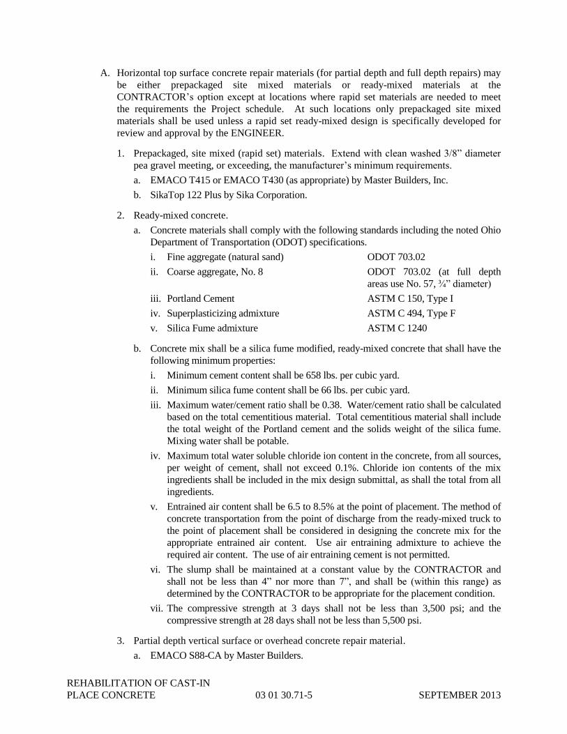
REHABILITATION OF CAST-IN
PLACE CONCRETE 03 01 30.71-5 SEPTEMBER 2013
A. Horizontal top surface concrete repair materials (for partial depth and full depth repairs) may
be either prepackaged site mixed materials or ready-mixed materials at the
CONTRACTOR’s option except at locations where rapid set materials are needed to meet
the requirements the Project schedule. At such locations only prepackaged site mixed
materials shall be used unless a rapid set ready-mixed design is specifically developed for
review and approval by the ENGINEER.
1. Prepackaged, site mixed (rapid set) materials. Extend with clean washed 3/8” diameter
pea gravel meeting, or exceeding, the manufacturer’s minimum requirements.
a. EMACO T415 or EMACO T430 (as appropriate) by Master Builders, Inc.
b. SikaTop 122 Plus by Sika Corporation.
2. Ready-mixed concrete.
a. Concrete materials shall comply with the following standards including the noted Ohio
Department of Transportation (ODOT) specifications.
i. Fine aggregate (natural sand) ODOT 703.02
ii. Coarse aggregate, No. 8 ODOT 703.02 (at full depth
areas use No. 57, ¾” diameter)
iii. Portland Cement ASTM C 150, Type I
iv. Superplasticizing admixture ASTM C 494, Type F
v. Silica Fume admixture ASTM C 1240
b. Concrete mix shall be a silica fume modified, ready-mixed concrete that shall have the
following minimum properties:
i. Minimum cement content shall be 658 lbs. per cubic yard.
ii. Minimum silica fume content shall be 66 lbs. per cubic yard.
iii. Maximum water/cement ratio shall be 0.38. Water/cement ratio shall be calculated
based on the total cementitious material. Total cementitious material shall include
the total weight of the Portland cement and the solids weight of the silica fume.
Mixing water shall be potable.
iv. Maximum total water soluble chloride ion content in the concrete, from all sources,
per weight of cement, shall not exceed 0.1%. Chloride ion contents of the mix
ingredients shall be included in the mix design submittal, as shall the total from all
ingredients.
v. Entrained air content shall be 6.5 to 8.5% at the point of placement. The method of
concrete transportation from the point of discharge from the ready-mixed truck to
the point of placement shall be considered in designing the concrete mix for the
appropriate entrained air content. Use air entraining admixture to achieve the
required air content. The use of air entraining cement is not permitted.
vi. The slump shall be maintained at a constant value by the CONTRACTOR and
shall not be less than 4” nor more than 7”, and shall be (within this range) as
determined by the CONTRACTOR to be appropriate for the placement condition.
vii. The compressive strength at 3 days shall not be less than 3,500 psi; and the
compressive strength at 28 days shall not be less than 5,500 psi.
3. Partial depth vertical surface or overhead concrete repair material.
a. EMACO S88-CA by Master Builders.

REHABILITATION OF CAST-IN
PLACE CONCRETE 03 01 30.71-6 SEPTEMBER 2013
b. SikaTop 123 Plus by Sika.
4. Bonding agent: Sika Armatec 110 EpoCem by Sika Corporation.
5. Curing compound:
a. Masterkure 100W by Master Builders, Inc.
b. Horsey-Set WDE by Watson-Bowman Acme Corp.
c. L&M Cure by L&M Construction Chemicals, Inc.
6. Evaporation reducer.
a. Confilm by Master Builders, Inc.
b. Sikafilm by Sika Corporation.
7. Reinforcing steel: Deformed reinforcing bars, size as required, ASTM A615, 60 ksi
yield.
8. Concrete reinforcing dowel anchor adhesive.
a. HIT-HY 200 Adhesive by Hilti Fastening Systems, Inc.
b. Sikadur 31, Hi-Mod Gel by Sika Corporation.
9. Concrete Expansion anchors: Kwik Bolt 3, by Hilti Fastening Systems, Inc.
10. Zinc rich epoxy primer.
a. PorterZinc 3000 Zinc Rich Epoxy Primer by Porter Coatings.
b. EPO Coat Zinc-Rich Primer by Dynamis Corp.
11. Dry pack grout for bearing elements, if required, or pipe sleeve attachment: Approved
5,000 psi (minimum), non-shrink, shrinkage compensating (both before and after set),
non-metallic, rapid setting, premixed grout suitable for exterior usage with excellent
resistance to freeze-thaw cyclical damage under extreme exposure. Comply with Corps
of Engineers CRD-C621.
B. Joint Sealant and Accessories. Joint sealant shall be a multi-component, polyurethane
having a Shore A Hardness of 28-35. The sealant manufacture shall submit, on the
manufacturer’s letterhead, a document stating that the material is not only suitable for an
exterior exposure but also is suitable for a continuously submerged condition of waste water
as is used in the waste water treatment tanks at this site. The sealant material shall be
capable of a minimum compression or extension of 25% of the nominal joint width without
adhesive or cohesive failure in a properly prepared, primed and sealed joint. Unless
indicated otherwise on the Drawings, the joint shall have a width to depth ratio of 1.5 to 2.0
with the use of bond breaker, or backer rod in the bottom of the joint. The backer rod
material shall be closed-cell polyethylene in sizes appropriate for the depth and width of the
joint. Pending the manufacturer’s suitability document as required above, the following
sealant materials are approved for use on this Project.
1. Sikaflex 2C NS or SL by Sika Corp.
2. LymTal 420NS or LymTal 420 SL by LymTal International.
3. Sonolastic NP1 or NP2 by Sonneborn.

REHABILITATION OF CAST-IN
PLACE CONCRETE 03 01 30.71-7 SEPTEMBER 2013
C. Epoxy Injection Resin and Urethane Injection Material: Injection pressure shall not exceed
75 psi without the approval of the ENGINEER. The following injection products are
approved for use on this Project. Urethane injection materials shall be approved by the
ENGINEER. Neatly grind off all surface seals from the injected crack.
1. Prime Rez 1100 by Prime Resins.
2. Sikadur 52 by Sika Corp.
3. SCB Concresive 1360 by Master Builders, Inc.
4. Denepox I-300, by DeNeef Construction Chemical Inc.
PART 3 - EXECUTION
3.01 GENERAL
A. Refer to the Drawings for repair details, and for concrete excavation and preparation
requirements. Refer to the Drawings, and the Scope paragraph of this Specification Section,
for information regarding the determination of deteriorated concrete to be repaired.
B. Do not damage existing reinforcing steel within the excavated areas. Do not strike existing
reinforcing with chipping hammers during concrete removal. Repair damage caused by
improper concrete removal techniques at no cost to the CITY.
C. Cold-Weather Concrete Placement: Comply with ACI 306.1 and as follows. Protect
concrete work from physical damage or reduced strength that could be caused by frost,
freezing actions, or low temperatures.
1. When air temperature has fallen to, or is expected to fall to, below 40 deg. F., uniformly
heat water and aggregates before mixing to obtain a concrete mixture temperature of not
less than 50 deg. F. and not more than 80 deg. F. at point of placement. The concrete
mixture, however, shall not have a temperature beyond the range permitted by ACI for
the temperature differential between the mixed concrete and the surface of the material
(existing concrete or formwork, etc.) against which it is to be placed. Heat existing
material if necessary to make this requirement.
2. Do not use frozen materials containing ice or snow. Do not place concrete on frozen
subgrade or on subgrade containing frozen materials.
3. Do not use calcium chloride, salt, or other materials containing antifreeze agents or
chemical accelerators, unless otherwise specified and approved in mix designs.
D. Hot-Weather Concrete Placement: Place concrete according to recommendations in ACI
305R and as follows, when hot-weather conditions exist.
1. Cool ingredients before mixing to maintain temperature below 85 deg. F. at time of
placement. Chilled mixing water or chopped ice may be used to control temperature,
provided that water equivalent of ice is calculated as part of the total amount of mixing
water. Using liquid to cool concrete is CONTRACTOR’s option.
2. Cover steel reinforcement with water-soaked burlap so steel temperature will not exceed
ambient air temperature at the time of concrete placement.

REHABILITATION OF CAST-IN
PLACE CONCRETE 03 01 30.71-8 SEPTEMBER 2013
3. Fog-spray forms, steel reinforcement, existing concrete and subgrade, etc. just before
placing concrete. Keep concrete excavations, formwork and subgrade, etc., moisture
uniform without standing water, soft spots, or dry areas. Do not wet areas previously
covered by bonding agent.
3.02 FINISHING AND CURING
A. Finish concrete to match existing conditions.
B. Continuously wet cure with wet burlap and polyethylene, wet burlene, or by soaker hoses
covered by polyethylene after proper finishing. Check curing material at least daily
throughout the entire curing period and re-dampen material or modify the curing technique to
ensure a continuously wet cure. Unless more stringent requirement are given elsewhere in
the Contract Documents, or by the prepackaged repair material manufacturer, or except as
stated in 3.03 D., all concrete shall be continuously wet cured for a minimum of three full
days (72 hours). At vertical surface, or soffit, repairs curing material shall be held in contact
with concrete as required.
C. Protect newly applied material from direct sunlight, wind, rain, and frost.
D. Water based curing compounds may be used in accordance with ASTM C309 but must be
submitted and approved by ENGINEER, and only when wet curing is determined by the
ENGINEER to be impractical or detrimental.
3.03 PROTECTION
A. Provide protections as necessary to prevent damage to existing building elements and to
prevent spread of dust, debris, and other contaminants from work.
B. Provide shoring, bracing, or support to prevent uncontrolled movement, settlement, or
collapse of structure or structure elements being worked on. Unless provided for elsewhere
in the Contract Documents the means and methods of safely supporting structure or structure
elements during work is responsibility of CONTRACTOR.
C. Entire area being repaired shall not be subjected to any vehicular or any other heavy load for
a 2-week period commencing with completing of repair, unless specifically permitted
otherwise, on a case-by-case basis, by the ENGINEER. Coordinate with OWNER.
3.04 FIELD QUALITY CONTROL
A. Site testing is not required for approved, prepackaged, site mixed concrete provided that the
manufacturer’s technically competent representative is present for mixing, placing and
curing of the first instance of significant use. The ENGINEER may require compressive
strength, and other, testing of material from this first significant use. If required, such testing
shall be arranged and coordinated by the CONTRACTOR and performed by an independent
laboratory, approved by the CITY, and performed on a Time and Materials Basis (Force
Account), against the Allowance established for such in Section 01 20 00 Measurement and
Payment.
B. Ready-mixed concrete shall be tested as required by Specification Section 03 30 00. The
CONTRACTOR shall arrange, coordinate and pay for all testing. The testing agency shall
provide timely written test reports to the CITY, ENGINEER, CONTRACTOR and ready-mix

REHABILITATION OF CAST-IN
PLACE CONCRETE 03 01 30.71-9 SEPTEMBER 2013
supplier. The cost for the testing, except as required elsewhere in the Contract Documents,
shall be charged, on a Time and Material Basis (Force Account), against the Allowance
established for such in Section 01 20 00 Measurement and Payment.
C. If the CITY or the ENGINEER suspect that concrete materials used, or the repair techniques
performed, are out of compliance with the Contract Documents they may direct that the
CONTRACTOR arrange for additional testing. If this testing confirms repairs that are not in
compliance then the CONTRACTOR shall pay the costs of the testing as well as the costs to
repair, or remove and replace, the defective material or condition, as determined by
CITY/ENGINEER. If the testing shows the material or condition in question to be in
conformance with the Contract Documents then the CITY will pay for the testing.
END OF SECTION 03 01 30.71

REHABILITATION OF CAST-IN
PLACE CONCRETE 03 01 30.71-10 SEPTEMBER 2013
THIS PAGE INTENTIONALLY LEFT BLANK

CONCRETE ACCESSORIES 03 15 00-1 SEPTEMBER 2013
SECTION 03 15 00
CONCRETE ACCESSORIES
PART 1 - GENERAL
1.01 SCOPE
A. The work under this Section includes, but is not necessarily limited to, furnishing and installing
all concrete accessories as indicated on the Drawings, herein specified, and as necessary for the
progress and complete performance of this work.
B. Where the term ENGINEER is used in the section, it shall mean “the CITY’s Structural
ENGINEER”.
1.02 RELATED DOCUMENTS
Should conflicts arise between information shown in this Section and Section 03 01 30.71, the
information in Section 03 01 30.71 shall take precedence.
1.03 SUBMITTALS
A. The waterstop manufacturer shall submit documented test results demonstrating that the
waterstop will not permit water leakage when subjected to pressure and joint movement.
B. Submit certification from the waterstop manufacturer for each person responsible for waterstop
installation stating that such person is certified and trained to install waterstop per manufacturer’s
written requirements.
C. The Vapor Barrier and Retarder manufacturer shall submit samples and literature of the product
and instructions for placement, seaming and pipe installation.
D. Control and construction joint plate dowel manufacturer for slab-on-grade construction shall
submit literature of the products, design information and installation instructions.
E. Submit manufacturer’s product literature, with application and installation instructions for all
miscellaneous products specified in this Specification.
F. Submit for approval a drawing showing the proposed location of all waterstops and the specific
type of waterstop to be installed at each location.
1.04 QUALITY ASSURANCE
The waterstop manufacturer shall demonstrate five years (minimum) continuous, successful
experience in production of waterstops. A technically competent representative of the waterstop
manufacturer, not associated with the installation crew, shall be on site before and during a portion of
the waterstop installation as required by Section 03 00 00 Concrete Work.
1.05 STORAGE AND PROTECTION
Store waterstops under tarps to protect from oil, dirt, and sunlight. Hydrophilic Rubber (HR)
waterstops shall be protected against contact with moisture while in storage and while in its installed
position prior to placement of concrete.
PART 2 - PRODUCTS
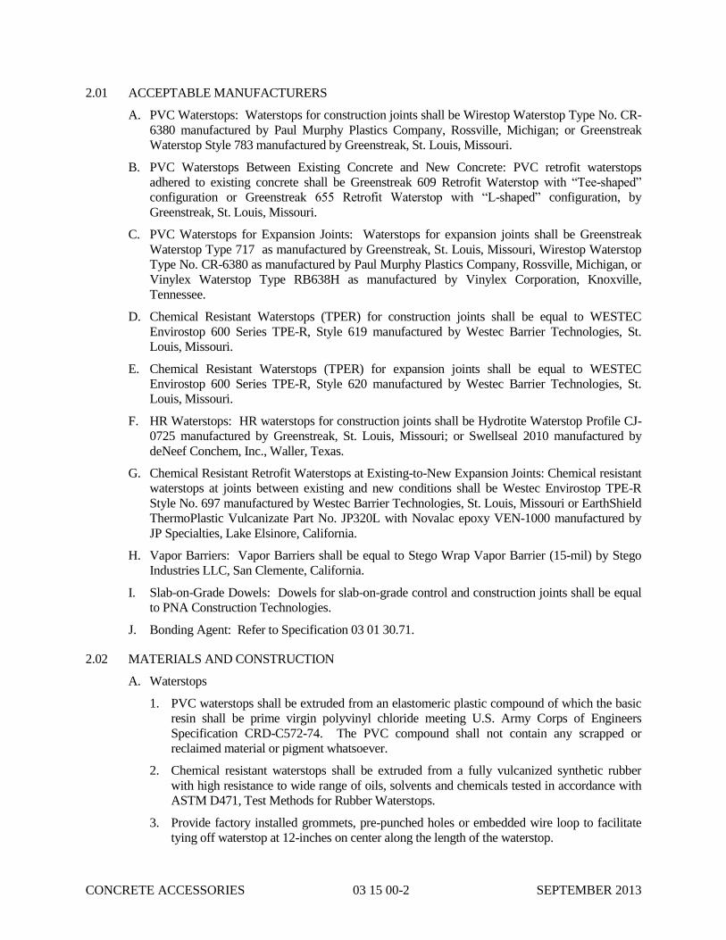
CONCRETE ACCESSORIES 03 15 00-2 SEPTEMBER 2013
2.01 ACCEPTABLE MANUFACTURERS
A. PVC Waterstops: Waterstops for construction joints shall be Wirestop Waterstop Type No. CR-
6380 manufactured by Paul Murphy Plastics Company, Rossville, Michigan; or Greenstreak
Waterstop Style 783 manufactured by Greenstreak, St. Louis, Missouri.
B. PVC Waterstops Between Existing Concrete and New Concrete: PVC retrofit waterstops
adhered to existing concrete shall be Greenstreak 609 Retrofit Waterstop with “Tee-shaped”
configuration or Greenstreak 655 Retrofit Waterstop with “L-shaped” configuration, by
Greenstreak, St. Louis, Missouri.
C. PVC Waterstops for Expansion Joints: Waterstops for expansion joints shall be Greenstreak
Waterstop Type 717 as manufactured by Greenstreak, St. Louis, Missouri, Wirestop Waterstop
Type No. CR-6380 as manufactured by Paul Murphy Plastics Company, Rossville, Michigan, or
Vinylex Waterstop Type RB638H as manufactured by Vinylex Corporation, Knoxville,
Tennessee.
D. Chemical Resistant Waterstops (TPER) for construction joints shall be equal to WESTEC
Envirostop 600 Series TPE-R, Style 619 manufactured by Westec Barrier Technologies, St.
Louis, Missouri.
E. Chemical Resistant Waterstops (TPER) for expansion joints shall be equal to WESTEC
Envirostop 600 Series TPE-R, Style 620 manufactured by Westec Barrier Technologies, St.
Louis, Missouri.
F. HR Waterstops: HR waterstops for construction joints shall be Hydrotite Waterstop Profile CJ-
0725 manufactured by Greenstreak, St. Louis, Missouri; or Swellseal 2010 manufactured by
deNeef Conchem, Inc., Waller, Texas.
G. Chemical Resistant Retrofit Waterstops at Existing-to-New Expansion Joints: Chemical resistant
waterstops at joints between existing and new conditions shall be Westec Envirostop TPE-R
Style No. 697 manufactured by Westec Barrier Technologies, St. Louis, Missouri or EarthShield
ThermoPlastic Vulcanizate Part No. JP320L with Novalac epoxy VEN-1000 manufactured by
JP Specialties, Lake Elsinore, California.
H. Vapor Barriers: Vapor Barriers shall be equal to Stego Wrap Vapor Barrier (15-mil) by Stego
Industries LLC, San Clemente, California.
I. Slab-on-Grade Dowels: Dowels for slab-on-grade control and construction joints shall be equal
to PNA Construction Technologies.
J. Bonding Agent: Refer to Specification 03 01 30.71.
2.02 MATERIALS AND CONSTRUCTION
A. Waterstops
1. PVC waterstops shall be extruded from an elastomeric plastic compound of which the basic
resin shall be prime virgin polyvinyl chloride meeting U.S. Army Corps of Engineers
Specification CRD-C572-74. The PVC compound shall not contain any scrapped or
reclaimed material or pigment whatsoever.
2. Chemical resistant waterstops shall be extruded from a fully vulcanized synthetic rubber
with high resistance to wide range of oils, solvents and chemicals tested in accordance with
ASTM D471, Test Methods for Rubber Waterstops.
3. Provide factory installed grommets, pre-punched holes or embedded wire loop to facilitate
tying off waterstop at 12-inches on center along the length of the waterstop.

CONCRETE ACCESSORIES 03 15 00-3 SEPTEMBER 2013
4. Provide factory made PVC waterstop fabrications for all changes of direction, intersections
and transitions, leaving only straight butt joint splices for the field. For 90 degree corners,
waterstop shall be continuous and “radiused” around corner provided waterstop can
maintain at least 2-inches clear from all reinforcing steel.
5. Provide factory made TPER waterstop fabrications for all changes of direction, intersections
and transitions, leaving only straight butt joint splices in the field. For 90 degree corners,
waterstop shall be continuous and “radiused” around corner provided waterstop can
maintain at least 6-inches clear from all reinforcing steel.
6. Hydrophilic rubber (HR) waterstops shall be coextruded hydrophilic rubber consisting of a
combination of chloroprene rubber and chloroprene rubber modified to impart hydrophilic
properties.
7. Hydrophilic rubber (HR) waterstops shall have a delay coating to inhibit initial expansion
due to moisture present in fresh concrete.
8. Minimum profile dimensions of HR waterstop shall be 1/4 x 1-inch.
9. HR waterstop shall not contain any bentonite.
B. Dovetail Slots
1. No. 22 gauge, galvanized steel, 1-inch wide back.
2. Crimped anchors shall be furnished by other trades whose work abuts concrete.
C. Inserts for General Trades
1. Malleable iron, strength as required.
2. Include bolts, nuts, and washers.
D. Expansion Joint Filler: Refer to Specification 03 01 30.71.
E. Construction Joint Dowels for Floor Slabs-on-Grade: Diamond dowel system as manufactured
by PNA ConstructionTechnologies.
F. Control Joint Dowels for Floor Slabs-on-Grade: Flat, tapered PD3 plate dowels and basket
system as manufactured by PNA Construction Technologies.
G. Vapor Barriers and Retarders
1. Water Containment Structures: Vapor retarder shall be polyethylene sheeting, minimum 6
mil thickness, conforming to ATSM C171. Sheeting shall be drilled with ½-inch holes at 6
inches on center each way.
2. Interior Slabs-on-Grade without Floor Coverings: Vapor retarder shall be polyethylene
sheeting, minimum 10 mil thickness, conforming to ASTM C171.
3. Interior Slabs-on-Grade with Floor Coverings: Vapor barriers shall have a composite
sheeting of plastic and resins, minimum 15 mil thickness and permeance of less than 0.01
perms, comforming to ASTM F1249 or ASTM E96 and conforming to ASTM C1745 Class
A.
H. Vapor Barrier and Retarder Accessories
1. Seam Tape with permeance less than 0.3 perms per ASTM F1249 or ASTM E96.
2. Vapor Proofing Mastic with permeance less than 0.3 perms per ASTM F1249 or ASTM
E96.

CONCRETE ACCESSORIES 03 15 00-4 SEPTEMBER 2013
3. Pipe boots constructed from vapor barrier or retarder material, pressure sensitive tape and/or
mastic per manufacturer’s instructions.
I. Flashing Reglet: 26 gauge galvanized steel. Coordinate with waterproofing subcontractor.
2.03 OTHER MATERIALS
All other materials not specifically described, but required for a complete and proper installation of
concrete accessories, shall be as selected by the CONTRACTOR subject to the approval of the
ENGINEER.
PART 3 - EXECUTION
3.01 INSTALLATION
A. General: Install concrete accessories in accordance with manufacturer’s written instructions, as
indicated on the Drawings, specified in these Specifications, in various other Sections and as
necessary for the proper and complete performance of this work.
B. Waterstops
1. Waterstops shall be installed in all construction joints in walls and slabs which are to hold
water and also where shown on the Drawings. The waterstop shall extend the entire length
of the joint and all splices shall be installed and tested in accordance with the manufacturer's
recommendations.
2. Waterstops for all joints shall be continuous around all corners and intersections.
Waterstops shall be located as near as possible to the center of the joint. For PVC and TPER
waterstops, provide factory formed corners and intersections where angle intersections
occur, and only straight splices shall be made in the field. Splices shall be made in
accordance with the manufacturer's recommendations and shall be subject to the approval of
the ENGINEER.
3. Field butt splices shall be heat fused welded using a Teflon coated thermostatically
controlled waterstop splicing iron. Follow approved manufacturer recommendations.
Lapping of waterstop, use of adhesives, or solvents shall not be permitted.
4. No holes will be permitted in waterstops.
5. PVC waterstops shall be securely fastened to formwork or reinforcing steel every 12-inches
or less on both edges as required for concrete placement.
6. Hydrophilic rubber (HR) waterstops shall be spliced using cyanoacrylate adhesive (super
glue) and a band-aid seal of hydrophilic polyurethane sealant.
7. Cut coil ends of HR waterstops square (or at proper angle for mitered corners) with shears or
sharp blade to fit splices together without overlaps.
8. Joinery between PVC and HR waterstops shall be sealed using hydrophilic polyurethane
sealant.
9. The concrete surface under the hydrophilic rubber (HR) waterstop shall be smooth and
uniform. The concrete shall be ground smooth if needed.
10. Existing surfaces to receive a retrofit waterstop shall be clean and free from any loose or
foreign material. Surface shall be cleaned by sandblasting or grinding the surface to assure a
solid, clean surface prior to application of epoxy and waterstop. Retrofit waterstops shall be
set in a bed of epoxy with stainless steel batten bars and 1/4-inch diameter stainless steel

CONCRETE ACCESSORIES 03 15 00-5 SEPTEMBER 2013
anchors at 6-inches on center, staggered, and in accordance with manufacturer’s written
instructions.
C. Piping, Mechanical and Electrical Equipment Support
1. Inserts for hangers shall be supplied by the trade whose work is supported.
2. Locations of the inserts shall be given to the CONTRACTOR by the various trades.
3. Installation of the cast-in-place inserts shall be by the CONTRACTOR.
D. Vapor Barriers and Retarders
1. Preparation
a. Ensure that subsoil is approved by GEOTECH ENGINEER prior to placement of vapor
barrier and retarder.
b. Level and tamp or roll aggregate, sand or granular base.
2. Installation
a. Unroll vapor barrier with the longest dimension parallel with the direction of the
concrete pour.
b. Lap vapor barrier over footings and/or seal to foundation walls.
c. Overlap joints 6 inches and seal with manufacturer’s tape.
d. Seal all penetrations (including pipes) per manufacturer’s instructions.
e. No penetration of the vapor barrier is allowed except for reinforcing steel and permanent
utilities.
f. Repair damaged areas by cutting patches of vapor barrier, overlapping damaged area 6
inches and securing all four sides with tape.
3.02 INSPECTION
Inspect all the work in accordance with Section 03 30 00 of these Specifications.
END OF SECTION 03 15 00

CONCRETE ACCESSORIES 03 15 00-6 SEPTEMBER 2013
THIS PAGE INTENTIONALLY LEFT BLANK

CONCRETE ANCHORING SYSTEMS 03 15 19-1 SEPTEMBER 2013
SECTION 03 15 19
CONCRETE ANCHORING SYSTEMS
PART 1 - GENERAL
1.01 SCOPE
A. The work covered by this Section includes furnishing all labor, materials and equipment required
to furnish and install post-installed concrete anchoring systems, cast-in-place concrete anchoring
systems, and concrete masonry unit anchoring systems and related work as specified herein
and/or shown on the Drawings.
B. Post-installed Anchoring Systems: Refer to Specification 03 01 30.71.
C. Cast-in-place anchoring systems shall include threaded rods (with a tack welded nut) and
embedded plates or angles with headed studs.
D. Adhesive Type Anchor Systems: Refer to Specification 03 01 30.71.
E. Mechanical anchor rods shall be installed when anchoring to existing concrete where indicated
on the Drawings or where recommended by the equipment manufacturer. Mechanical anchoring
into concrete masonry units is not permitted.
F. Cast-in-place anchor rods shall be installed in all new concrete construction where indicated on
the Drawings or as recommended by the equipment manufacturers.
G. Embedded plates or angles with headed studs shall be installed in new concrete construction
where indicated on the Drawings or in the Specifications or where recommended by the
equipment manufacturers.
H. Where the term ENGINEER is used in the section, it shall mean “the CITY’s Structural
ENGINEER”.
1.02 RELATED DOCUMENTS
Should conflicts arise between information shown in this Section and Section 03 01 30.71, the
information in Section 03 01 30.71 shall take precedence; except in all cases the most stringent
requirements shall govern.
1.03 MATERIAL STORAGE
All material shall be stored in a manner which will protect the material from dirt, deterioration and
damage.
1.04 SUBMITTALS
A. Shop Drawings: Cast-in-place anchors and embedded plates/studs shall be submitted indicating
fabrication details. Reproduction of the Drawings for use as shop drawings is not permitted.
B. Product Data: Manufacturer’s specifications, material specifications, technical data and
installation instructions shall be submitted for adhesive anchor rods, adhesives, and mechanical
anchors. Anchor and adhesive load data shall also be included.
C. Manufacturer’s Literature: The CONTRACTOR shall submit manufacturer’s ICC-ES Code
report information.
D. Manufacturer Training Reports: The CONTRACTOR shall submit the training records for the

CONCRETE ANCHORING SYSTEMS 03 15 19-2 SEPTEMBER 2013
required manufacturer’s training.
E. Submittals shall be submitted in accordance with the requirements of Section 01 33 00 of these
Specifications.
1.05 QUALITY ASSURANCE
A. The preparation and installation of all adhesive anchors shall be included in the Special
Inspection Plan.
B. Installations made under continuous special inspection must be performed with the special
inspector on the jobsite continuously during anchor installation to verify the hole drilling method
is in accordance with manufacturer’s printed installation instructions, hole location, hole
diameter and depth, hole cleaning in accordance with manufacturer’s printed installation
instructions, anchor type, anchor diameter and length, anchor embedment, adhesive
identification and expiration date, adhesive installation in accordance with manufacturer’s
printed installation instructions, edge distances(s), anchor spacing(s), concrete type, concrete
compressive strength, age of concrete, concrete thickness and installation torque.
C. Installations made under periodic special inspection must be performed with the special
inspector on the jobsite initially during anchor installation to verify the hole drilling method is in
accordance with manufacturer’s printed installation instructions, hole location, hole diameter and
depth, hole cleaning in accordance with manufacturer’s printed installation instructions, anchor
type, anchor diameter and length, anchor embedment, adhesive identification and expiration
date, adhesive installation in accordance with manufacturer’s printed installation instructions,
edge distances(s), anchor spacing(s), concrete type, concrete compressive strength, age of
concrete, concrete thickness and installation torque. The special inspector must verify the initial
installations of each type and size of anchor by construction personnel on site. Subsequent
installations of the same type and size of anchor, by the same construction personnel is permitted
to be performed in the absence of the special inspector. Any change in the anchor product being
installed or the personnel performing the installation must require an initial inspection. For
ongoing installations over an extended period of time, the special inspector must make regular
inspections to confirm correct handling and installation the product.
D. For anchor rods specified on the Structural Drawings and installed in cracked concrete, or
concrete that has the potential to crack, the anchor shall have been tested in accordance with
ICC-ES AC308 (adhesive anchors) and ICC-ES AC193 (mechanical anchors).
E. CONTRACTORS installing anchor systems shall be trained, certified or otherwise qualified by
the anchor manufacturer verifying that the necessary training has been provided to install the
manufacturer’s products. Training shall consist of a review of the complete installation process,
to include but not limited to: hole drilling procedure, hole preparation and cleaning technique,
adhesive injection for adhesive anchors, rod (or rebar), preparation and installation, torquing the
anchor as specified. An anchor manufacturer’s representative shall provide the training to all
contractor installers. If additional installers are added throughout the Project, they shall be
trained/certified prior to installing anchors.
F. An anchor manufacturer’s representative shall initially demonstrate anchor installation using the
procedure described in the manufacturer’s published installation instructions to all installers. All
subsequent anchor installations shall be done by the installer using the same procedure as
demonstrated by the anchor manufacturer. The CONTRACTOR shall be responsible to contact
the anchor manufacturer.
1.06 DELIVERY, STORAGE AND HANDLING

CONCRETE ANCHORING SYSTEMS 03 15 19-3 SEPTEMBER 2013
A. Deliver materials undamaged in Manufacturer’s clearly labeled, unopened containers, identified
with brand, type, and ICC-ES Evaluation Report number.
B. Coordinate delivery of materials with scheduled installation date, minimizing storage time at job-
site.
C. Store materials under cover and protect from weather and damage in compliance with
manufacturer’s requirements, including temperature restrictions.
D. Do not use damaged or expired materials.
E. Comply with recommended procedures, precautions, or remedies described in material safety
data sheets as applicable.
1.07 PROJECT CONDITIONS
A. Verify existing conditions before starting work. Correct unsatisfactory conditions before
proceeding.
B. Do not proceed with installation of adhesive anchoring systems at temperatures not described by
the manufacturer’s recommended range for installation printed on product instructions, product
data sheet and ICC-ES report.
C. Drilled hole condition must comply with the applicable ICC-ES report and manufacturers
provided written product instruction.
D. Do not install anchors in hollow concrete masonry units.
E. All concrete shall be considered “cracked” for anchoring purposes except where the Structural
ENGINEER of Record identifies, determines or verifies “un-cracked” concrete conditions in
writing.
PART 2 - PRODUCTS
2.01 ADHESIVE ANCHORING SYSTEMS (POST-INSTALLED ANCHORS):
Refer to Specification 03 01 30.71.
2.02 MECHANICAL ANCHOR RODS (POST-INSTALLED ANCHORS)
A. Stainless steel drilled in expansion anchor rods shall have a stainless steel body conforming to
AISI 304 and a stainless steel sleeve conforming to AISI 316. Nuts shall be stainless steel and
conform to the requirements of ASTM F 594 Alloy Group I, Condition CW. Washers shall be
stainless steel (AISI 304) and shall meet dimensional requirements of ASTM F 436.
B. Carbon steel drilled-in expansion anchor rods shall be zinc electroplated in accordance with
ASTM B 633, Type III to a minimum thickness of 5 µm. expansion sleeves (wedges) shall
conform to AISI 316. Nuts shall conform to ASTM A563, Grade A, Hex. Washers shall meet
the dimensional requirements of ASTM F844.
C. Expansion anchor rods shall conform to the applicable requirements of Federal Specifications A-
A 1923A, Type 4.
D. Expansion Anchors: Refer to Specification 03 01 30.71.
E. Screw Anchors: Refer to Specification 03 01 30.71.
F. Internally Threaded Insert Anchors: Refer to Specification 03 01 30.71.

CONCRETE ANCHORING SYSTEMS 03 15 19-4 SEPTEMBER 2013
2.03 CAST-IN-PLACE ANCHOR RODS
A. Cast-in-place anchor rods, except those used for equipment anchoring, shall be carbon steel
unless noted otherwise on the Drawings or Specifications. Cast-in-place anchor rods used for
anchoring equipment shall be stainless steel. Tack weld one heavy hex nut at end of anchor rod.
B. Carbon steel anchor rods less than 1” in diameter shall meet the requirements of ASTM F1554
Grade 36 unless noted otherwise on the Drawings; rods 1” in diameter or larger shall be Grade
55. Carbon steel nuts shall be heavy hex and meet the requirements of ASTM A563. Carbon
steel washers shall be hardened and meet the requirements of ASTM F436. Carbon steel
material shall be considered uncoated.
C. Hot-dip galvanized carbon steel anchor rods shall conform to ASTM A153. Nuts shall conform
to A563, Grade A, heavy hex.
D. Stainless steel anchor rods shall be continuously threaded (all thread) and meet the requirements
of ASTM A193 Grade B8M (AISI 316). Stainless steel nuts shall be heavy hex and meet the
requirements of ASTM F594, Alloy Group I, Condition CW. Stainless steel washers shall meet
the requirements of ASTM A240 and dimensional requirements of ANSI B18.22.1, Type A
Plain.
2.04 EMBEDDED PLATES OR ANGLES WITH HEADED STUDS (CAST-IN-PLACE)
A. Carbon steel embedded plates and angles shall meet ASTM A36. Carbon steel headed studs
shall meet ASTM A108. All headed stud to plate/angle welds shall meet the requirements of
AWS D1.1 Chapter 10.
B. Stainless steel embedded plates and angles shall meet ASTM A 240 and A 276, respectively.
Stainless steel headed studs shall meet ASTM A 593. All headed stud to plate/angle welds shall
meet the requirements of AWS D1.6.
2.05 DEFORMED REINFORCING BAR (REBAR)
Deformed reinforcing steel dowels specified to be epoxy set into hardened concrete shall be installed
in accordance with the adhesive anchoring system for sizes between No. 4 and No. 8. Reinforcing
steel shall conform to ASTM A 615.
PART 3 - EXECUTION
3.01 PREPARATION
A. Examine areas and conditions under which work is to be performed and identify conditions
detrimental to proper or timely completion.
B. Verify that conditions are in accordance with the design requirements and product specific ICC-
ES AC308 and ICC-ES AC193 report.
C. Do not proceed until satisfactory conditions have been corrected.
3.02 ADHESIVE ANCHORING SYSTEM INSTALLATION
A. Installation of adhesive anchors shall be in conformance with the manufacturer's published
installation instructions and under the supervision of a manufacturer's field representative. This
includes as a minimum, but not limited to, drilling of the hole, cleaning the hole, dispensing of
adhesive, anchor rod installation and curing.
B. Do not disturb, bolt up, or apply load to adhesive anchors prior to the full cure of the adhesive.

CONCRETE ANCHORING SYSTEMS 03 15 19-5 SEPTEMBER 2013
Refer to manufacturer’s instructions on curing including cure time.
C. All anchor rods shall be clean and free of cutting oils, grease, dirt, dust, and other foreign
material.
D. Adhesive anchors should not be installed in concrete that is less than 21 days old, regardless of
the strength of the concrete. When inserting threaded rod, turn rod continuously until rod is fully
embedded.
E. Drilled Holes: Holes for adhesive anchors shall be drilled with a rotary percussion hammer drill
with a carbide tipped masonry drill bit conforming to ANSI B94.12. The anchor hole diameter
shall be as specified by the manufacturer. Core drilling for adhesive anchors is not permitted.
F. The hole shall be drilled perpendicular to the concrete surface unless noted otherwise on the
Drawings.
G. Hole Cleaning and Preparation: After drilling, dust and fragments shall be cleared out as
specified in accordance with the manufacturer's published installation instructions. As a
minimum, the hole shall be blown out for a period of 4 seconds with an 80 psi compressed air
hose. After blowing out debris, the hole shall be brushed with a nylon brush for 4 times, and
then blown out a second time with the 80 psi compressed air hose for 4 seconds. The hole may
be damp (unless prohibited by the manufacturer) but all water must be blown out. Air used for
blow outs shall be clean and dry.
H. Adhesive Installation: After the hole is properly cleaned the adhesive shall be installed in strict
accordance with the manufacturer's published installation instructions. Care shall be taken so as
to not allow any air pockets in the hole.
I. Minimum anchor embedment depth, anchor spacing, anchor finish, and minimum anchor edge
distance shall be as specified on the Drawings. In no case shall the anchor embedment be less
than twelve times the anchor diameter. Minimum distance between center of any adhesive
anchor and an edge or exterior corner of concrete shall not be less than 6 times the anchor
diameter.
J. Anchor Installation: Immediately after adhesive installation, the anchor shall be installed in
accordance with the manufacturer's published installation instructions.
K. Curing: Anchor shall be unloaded and allowed to cure for manufacturer's recommended curing
time.
3.03 MECHANICAL ANCHOR ROD INSTALLATION
A. Drill expansion bolt holes into concrete through item being supported or locate by a template.
Drill all holes with a tool designed by or approved by the expansion anchor manufacturer.
B. Installation of mechanical anchors shall be in conformance with the manufacturer's published
installation instructions and under the supervision of a manufacturer's field representative. This
includes as a minimum, but not limited to, drilling of the hole, cleaning the hole, and anchor
installation.
C. Drill holes for mechanical anchors with carbide-tipped drill bits meeting the diameter
requirements of the manufacturer's published installation instructions. Rotary hammer drills,
with light, high frequency impact are recommended for drilling holes in concrete. Core drilling
for anchors in concrete shall not be permitted. Core drilling is required for anchors in hollow
masonry.
D. Minimum anchor embedment depth, anchor spacing, anchor finish, and minimum anchor edge
distance shall be as specified on the Drawings. Minimum distance between center of any

CONCRETE ANCHORING SYSTEMS 03 15 19-6 SEPTEMBER 2013
expansion anchor and an edge or exterior corner of concrete shall not be less than 6 times the
anchor diameter.
3.04 CAST-IN-PLACE ANCHOR ROD INSTALLATION
A. Anchor rods with tack welded nut shall be shipped to the Project site.
B. Anchor rods shall be properly located and built into connecting work. Anchor rods shall be
preset by the use of templates or such other methods as may be required to locate the anchor
bolts accurately.
3.05 EMBEDDED PLATE OR ANGLE WITH HEADED STUDS INSTALLATION
A. Embedded plate and stud assembly shall be shop fabricated and shipped to the Project site.
B. Embedded plate and stud assembly shall be secured in place prior to casting new concrete.
END OF SECTION 03 15 19

CONCRETE REINFORCEMENT 03 20 00-1 SEPTEMBER 2013
SECTION 03 20 00
CONCRETE REINFORCEMENT
PART 1 - GENERAL
1.01 SCOPE
A. The work included in this Section consists of furnishing all labor, materials, and equipment
necessary to provide and properly fabricate and place all concrete reinforcement steel, welded
wire fabric, couplers, and inserts for use in the reinforced concrete construction. This includes
all wires, clips, supports, chairs, spacers and other accessories.
B. The furnishing, fabrication and construction of the concrete reinforcement shall be in
accordance with ACI 301, ACI 315, CRSI and as shown and indicated on the Drawings and
specified in this Section.
C. Where the term ENGINEER is used in the section, it shall mean “the CITY’s Structural
ENGINEER”.
1.02 RELATED DOCUMENTS
Should conflicts arise between information shown in this Section and Section 03 01 30.71, the
information in Section 03 01 30.71 shall take precedence.
1.03 SUBMITTALS
A. Shop Drawings
1. All shop drawings shall be of the same size. Reproductions of the Drawings for use as
shop drawings are not permitted. Shop drawings shall include placing drawings, bending
details, splice locations, and bar lists with bar marks. All details and notes appearing on the
Drawings, giving information for the placing of reinforcing steel, shall be shown on the
shop drawings. Shop drawings will not be reviewed without such information.
2. Shop drawings shall comply with ACI 315, Details and Detailing of Concrete
Reinforcement and CRSI Manual of Standard Practice, showing bar schedules,
arrangement of reinforcement, stirrup spacing, layout of splices, layout of ties, and
diagrams of bent bars. Shop drawings shall include special reinforcement required, such as
corner bars and openings through concrete structures.
3. Wall reinforcing shall be shown in elevation.
4. Show location and size of all penetrations greater than 6-inches in diameter or across the
opening with the corresponding added reinforcing around the penetrations.
5. Submittals shall be complete for each structure. Partial submittals are not permitted and
will be returned unmarked. Each submittal shall clearly indicate the structure and Drawing
numbers for which the work applies. The identifying numbers of the shop drawings for
each structure shall be in numerical order with a unique designation for each structure.
6. Location and arrangement of accessories shall be clearly indicated.

CONCRETE REINFORCEMENT 03 20 00-2 SEPTEMBER 2013
7. All shop drawings shall be checked by the fabricator and CONTRACTOR before being
submitted to the ENGINEER.
8. Any revised shop drawings re-submitted for review shall have all changes clouded with a
revision number that is associated with the date of the revision.
B. Mill tests of reinforcing steel shall be submitted prior to use for each 15 tons or less shipped to
the site. Tests shall be conducted in conformance with ASTM A 615, and methods prescribed
therein.
1. Cost of mill tests shall be borne by CONTRACTOR.
2. Three copies of each test report stating whether the material meets the requirements of the
ASTM specifications shall be submitted to the ENGINEER.
3. Certified copies of the mill tests may be considered evidence of compliance provided such
tests are regularly conducted by the reinforcement supplier by experienced, competent
personnel using adequate testing equipment. In case of doubt as to the adequacy or
accuracy of the mill tests, the ENGINEER may require the CONTRACTOR to furnish, at
no additional cost to the CITY, test results from an independent testing laboratory
acceptable to the ENGINEER on mill samples or delivered steel reinforcement.
C. Manufacturer’s Literature and Certifications: The CONTRACTOR shall submit
manufacturer’s literature for all accessories which contains written instructions and
recommendations for installation and certified test reports to verify load capacity where
applicable.
PART 2 - PRODUCTS
2.01 BAR REINFORCEMENT
A. Bar reinforcement shall be deformed-type bars conforming to ASTM A 615. Reinforcement
shall be manufactured from new billet steel of American manufacture, Grade 60.
1. Actual yield strength of reinforcement, based on mil tests, shall not exceed 78,000 psi.
2. The ratio of the actual tensile strength to the actual yield strength of reinforcement, based
on mil tests, shall be greater than or equal to 1.25.
B. Bar reinforcement shall be shop fabricated to shapes and dimensions indicated on the Drawings
and in compliance with applicable provisions of ACI 315 and ACI 318.
C. Bars shall be bent cold. Bars shall be pre-fabricated to detail and delivered on the job plainly
tagged and ready to set.
2.02 DEFORMED BAR ANCHORS
A. Deformed bar anchors shall be manufactured from cold-rolled, deformed-type bars conforming
to the requirements of AWS D1.1 and ASTM A 496 with a minimum yield strength of 70 ksi
and tensile strength of 80 ksi.
B. Deformed bar anchors shall be manufactured by Nelson Stud Welding, Inc., Elyria, Ohio or
Stud Welding Associates, Inc., Strongsville, Ohio.

CONCRETE REINFORCEMENT 03 20 00-3 SEPTEMBER 2013
2.03 ACCESSORIES
A. Supports for Reinforcement: Provide supports for reinforcement in compliance with CRSI
Manual of Standard Practice, including bolsters, chairs, spacers, and other devices for spacing,
supporting, and fastening reinforcing bars and welded wire reinforcing in place.
B. All chairs, spacers, bolsters and other devices shall have plastic-covered or galvanized steel legs
at formed slabs and beams, and plastic-covered for all walls and liquid containment structures.
For slabs on grade concrete bricks may be used as an alternate to coated chairs unless required
otherwise on the drawings.
C. Mechanical Couplers: Mechanical couplers shall be provided where indicated and where
approved by the ENGINEER. The couplers shall be ICC-ES certified and shall develop a
tensile strength that exceeds 125 percent of the yield strength of the reinforcement bars being
spliced at each splice. Splice locations shall be staggered.
PART 3 - EXECUTION
3.01 STORAGE OF MATERIALS
Reinforcing steel delivered to the site, not immediately placed in forms, shall be protected from
mud and excessive rust-producing conditions by storing in a well-drained area and supported off the
ground. All reinforcing shall be properly tagged with their bar marks and location in the structure
clearly noted.
3.02 TOLERANCES
A. Allowable tolerances shall be in accordance with the latest edition of ACI 117, except as
indicated.
B. Allowable tolerances for fabricating steel reinforcement shall be as follows:
Item Maximum Tolerance, Inches
Sheared Length of Bars +1 -1
Depth of Truss Bars +0.0 -1/2
Outside Dimensions of Stirrups, Ties and Spirals +1/2 -1/2
Location of Bends +1 -1
C. Allowable tolerances for placing steel reinforcement shall be as follows:
Item Maximum Tolerance, Inches
Concrete Cover from Outside of Bar to Finished
Surface
+1/4 -0.0
Lateral Spacing of Bars in Plane of Reinforcement in
Beams and Joists
+1/4 -0.0
Lateral Spacing of Bars in Plane of Reinforcement in +3/4 -3/4

CONCRETE REINFORCEMENT 03 20 00-4 SEPTEMBER 2013
Item Maximum Tolerance, Inches
Slabs and Walls
Spacing of Stirrups, Ties and Spirals Along
Longitudinal Axis of Member
+1/2 -1/4
Height of Bottom Bars in Slabs, Beams and Joists +1/4 -1/4
Height of Top Bars in Slabs, Beams and Joists
Depth 8" and Less
Depth 9" and Greater
+1/4
+1/2
+3/4
-1/4
-1/2
-3/4
3.03 FABRICATION
A. Field fabrication of reinforcing steel is not permitted.
B. Reinforcing steel shall be accurately fabricated to the dimensions shown.
C. Reinforcing bars shall be bent cold and shall not be bent in a manner which will damage the
material.
3.04 PLACEMENT AND ANCHORAGE
A. Space metal chairs, bolsters, spacers and hangers in accordance with ACI 315.
B. Reinforcement and other metalwork to be in contact with concrete shall be thoroughly cleaned
of all dirt, grease, loose scale, form release agent, rust, mortar or other foreign substances or
coatings immediately before concrete is placed. Bars with kinks or bends not shown on the
plans shall not be used.
C. Reinforcement shall be accurately placed in accordance with the Drawings and shall be
adequately secured in position with not less than 16 gauge annealed wire or suitable clips at
intersections. Set wire ties so that ends are directed into the member and not toward the face of
the concrete. Reinforcement shall be held securely in position, at the required distance from the
forms, during concrete placement. Nails shall not be driven into outside forms to support
reinforcement. Tack welding may not be used to secure reinforcement.
D. Install welded wire reinforcement for concrete slabs on ground and as otherwise indicated. Lap
all joints 12-inches and wire securely. Extend mesh to within 2-inches of sides and ends of
slabs. Sheets that do not lay flat when in their intended position will be rejected. Tags
designating the wire size and spacing shall be left on each sheet until ready for use. Tuck ends
of welded mesh well down into edge of beams or walls. Do not leave unreinforced border
strips. Welded wire reinforcement shall not contain loose rust. All welded wire reinforcement
shall be supported and tied in its proper location. The construction practice of placing welded
wire reinforcement on the ground and hooking it into place in the freshly placed concrete shall
not be permitted. Supports shall be spaced not more than 3-feet on center in any direction.
E. Conduits: Where conduits are permitted in slabs as noted on the Drawings, low conduit shall
be wired to the upper side of bottom reinforcing in the transverse direction and top conduit shall
be wired to lower side of top reinforcing in the transverse direction. Where parallel conduits
occur, they shall be separated from reinforcing and each other by at least 2-inches clear.

CONCRETE REINFORCEMENT 03 20 00-5 SEPTEMBER 2013
F. Reinforcement partially embedded in concrete shall not be bent in the field unless permitted by
the ENGINEER.
G. Weld deformed bar anchors to A36 steel plates in accordance with Chapter 7 of AWS D1.1
using a stud welding gun.
H. Properly cap all vertical reinforcement steel.
3.05 CONCRETE COVER
Unless otherwise shown on the Drawings, the following concrete cover shall be provided for
reinforcement:
Bottom and Sides of Footing 3-inches
Walls 2"
Slabs (Framed)
Bottom
Top
3/4-inch
1-inch
Beams (Stirrups)
Bottom and Sides
Top
1-1/2-inches
2-inches
Columns (Ties, Spirals) 2-inches
Slabs on Grade - Liquid Containment Structures
Bottom and Sides
Top
3-inches
See Drawings
Slabs on Grade - Other Structures See Drawings
3.06 SPLICING
A. Splicing of reinforcement shall be as shown and indicated on the Drawings. Splices not shown
on the Drawings shall be Class "B" splice, in accordance with ACI 318. Any changes to the
location and type of splices desired by the CONTRACTOR must be specifically requested and
must meet with the acceptance of the ENGINEER before they can be used.
B. Splices shall not be made at point of maximum stress and shall provide sufficient lap to transfer
stress between bars by bond.
C. Mechanical splices may be used instead of lap splices provided that their location and type
meets with the acceptance of the ENGINEER.
D. Welded splices are not permitted.
E. Couplers which are located at a joint face shall be the type which can be set either flush or
recessed from the face as indicated. The couplers shall be sealed during concrete placement to
completely eliminate concrete or cement paste from entering. Couplers intended for future

CONCRETE REINFORCEMENT 03 20 00-6 SEPTEMBER 2013
connections (form savers) shall be recessed a minimum of 1/2-inch from the concrete surface.
After the concrete is placed, the coupler shall be plugged with plastic plugs which have an O-
ring seal and recess filled with sealant to prevent any contact with water or other corrosive
materials.
3.07 INSPECTION
Inspect all the work in accordance with Section 03 30 00 of these Specifications.
END OF SECTION 03 20 00
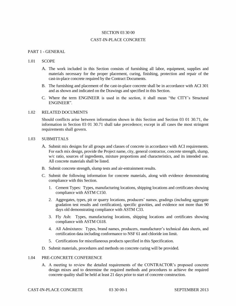
CAST-IN-PLACE CONCRETE 03 30 00-1 SEPTEMBER 2013
SECTION 03 30 00
CAST-IN-PLACE CONCRETE
PART 1 - GENERAL
1.01 SCOPE
A. The work included in this Section consists of furnishing all labor, equipment, supplies and
materials necessary for the proper placement, curing, finishing, protection and repair of the
cast-in-place concrete required by the Contract Documents.
B. The furnishing and placement of the cast-in-place concrete shall be in accordance with ACI 301
and as shown and indicated on the Drawings and specified in this Section.
C. Where the term ENGINEER is used in the section, it shall mean “the CITY’s Structural
ENGINEER”.
1.02 RELATED DOCUMENTS
Should conflicts arise between information shown in this Section and Section 03 01 30.71, the
information in Section 03 01 30.71 shall take precedence; except in all cases the most stringent
requirements shall govern.
1.03 SUBMITTALS
A. Submit mix designs for all groups and classes of concrete in accordance with ACI requirements.
For each mix design, provide the Project name, city, general contractor, concrete strength, slump,
w/c ratio, sources of ingredients, mixture proportions and characteristics, and its intended use.
All concrete materials shall be listed.
B. Submit concrete strength, slump tests and air-entrainment results.
C. Submit the following information for concrete materials, along with evidence demonstrating
compliance with this Section.
1. Cement Types: Types, manufacturing locations, shipping locations and certificates showing
compliance with ASTM C150.
2. Aggregates, types, pit or quarry locations, producers’ names, gradings (including aggregate
gradation test results and certification), specific gravities, and evidence not more than 90
days old demonstrating compliance with ASTM C33.
3. Fly Ash: Types, manufacturing locations, shipping locations and certificates showing
compliance with ASTM C618.
4. All Admixtures: Types, brand names, producers, manufacturer’s technical data sheets, and
certification data including conformance to NSF 61 and chloride ion limit.
5. Certifications for miscellaneous products specified in this Specification.
D. Submit materials, procedures and methods on concrete curing will be provided.
1.04 PRE-CONCRETE CONFERENCE
A. A meeting to review the detailed requirements of the CONTRACTOR’s proposed concrete
design mixes and to determine the required methods and procedures to achieve the required
concrete quality shall be held at least 21 days prior to start of concrete construction.

CAST-IN-PLACE CONCRETE 03 30 00-2 SEPTEMBER 2013
B. The CONTRACTOR shall require responsible representatives of all parties involved in the
concrete work to attend the conference, including but not limited to the following:
1. CONTRACTOR’s representative
2. Testing laboratory representative
3. Concrete subcontractor and finisher
4. Reinforcing steel subcontractor (if required)
5. Concrete supplier
6. Admixture manufacturer’s representative
C. The conference shall be held at a mutually agreed upon time and place. The Engineer shall be
notified no less than 10 days prior to the scheduled date of the conference.
D. Minutes of the meeting shall be recorded, typed, printed and distributed by the CONTRACTOR
to all parties concerned within five days of the meeting. One copy shall also be sent to the
ENGINEER and Special Inspector.
PART 2 - PRODUCTS
2.01 CEMENT
A. Cement shall be standard Portland cement, of American manufacture, conforming to ASTM C
150, Type I/II. Do not use air-entrainment cement. Only one brand of commercial Portland
cement shall be used in the exposed concrete of the structure. Cement reclaimed by cleaning
bags or from leaking containers shall not be used in this work. Each bag shall weigh
approximately 94 pounds and contain one cubic foot.
B. Cement in liquid containment structures shall be standard Portland cement, of American
manufacture, conforming to ASTM C150, Type I/II and certified to NSF/ANSI Standard 61,
Drinking Water System Components – Health Effects.
2.02 COARSE AGGREGATES
A. Coarse aggregate shall be crushed stone having clean, hard, durable, uncoated particles
conforming to ASTM C 33. Aggregate for lightweight concrete shall conform to ASTM C 330.
B. Coarse aggregate shall not contain clay, mud, loam, or foreign matter. Its maximum size shall be
no larger than 1/5 of the narrowest dimension between sides of forms, 1/3 of the depth of slabs,
or 3/4 of the minimum clear spacing between individual reinforcing bars or bundles of bars.
C. Combined aggregate gradation for slabs-on-grade and walls 12-inch or less shall be 8% - 18%
for large size aggregate (1-1/2”) and 8%-22% for smaller top size aggregates (1” or 3/4”)
retained on each sieve below the top size and above the No. 100.
2.03 FINE AGGREGATES
A. Fine aggregate shall be sand having clean, hard, durable, uncoated grains and free from
deleterious substances and shall conform to ASTM C 33.
B. When tested in accordance with ASTM D2419, the sand equivalency shall not be less than 75
percent for an average of 3 samples, nor less than 70 percent for an individual test. Gradation of
fine aggregate shall conform to ASTM C33 when tested in accordance with ASTM C136 for the
fineness modulus of the sand used, including the optional grading in Section 6.2. The fineness

CAST-IN-PLACE CONCRETE 03 30 00-3 SEPTEMBER 2013
modulus of sand used shall not be over 3.1.
C. When tested in accordance with ASTM C33, the fine aggregate shall produce a color in the
supernatant liquid no darker than the reference standard color solution.
2.04 WATER
Water used in mixing concrete shall be potable, clean and free from deleterious amounts of acids,
alkalis or organic materials and conform to ASTM C1602.
2.05 ADMIXTURES
When required or permitted, admixtures shall meet the requirements of the following:
A. Admixtures in water containment structures shall conform to NSF/ANSI Standard 61.
B. Water reducing admixture shall conform to ASTM C 494, Type A.
C. Water reducing, retarding admixture shall conform to ASTM C 494, Type D.
D. Non-Corrosive, Non-Chloride Accelerator: The admixture shall conform to ASTM C 494, Type
C.
E. Air entraining admixture shall conform to ASTM C 260.
F. Fly ash shall conform to ASTM C 618, Type F.
G. High range water reducer (HRWR) shall conform to ASTM C 494, Type F or G and shall be one
of the following:
1. Rheobuild 1000 and Glenium 3030 NS, manufactured by Master Builders
2. Daracem 100, manufactured by W.R. Grace
3. Sikament 320, manufactured by Sika Corporation
4. Eucon 37, manufactured by Euclid Chemical Company
H. Chloride: Calcium chloride or admixtures containing more than 0.1 percent chloride ions are not
permitted.
I. Evaporation Retardant: Consists of a thin, continuous film which prevents rapid moisture loss
from the concrete surface. Use Eucober by the Euclid Chemical Company or Confilm by Master
Builders (BASF). Evaporation retarders shall not be used as finishing aids or otherwise worked
into the surface of fresh concrete.
J. Cementitious Crystalline Waterproofing Admixture: Xypex Admix C-1000 (no dye)
manufactured by Xypex Chemical Corporation, Krystol Internal Membrane (KIM)
manufactured by Kryton International Inc., Penetron Admix manufactured by ICS/Penetron
International Ltd. Dosage rate shall be 2% by weight of Portland cement of Xypex, 2% of total
cementitious material for KIM, and 1% by weight of Portland cement for Penetron Admix. Do
not reduce the amount of cement in the mix. Cementitious Crystalline Waterproofing Admixture
shall meet the following standards:
1. U.S. Army Corps of Engineers CRD C 48-92, “Standard Test Method for Water
Permeability of Concrete”. Requirement: No water penetration (leakage) after 28 days
under hydrostatic pressure of 200 psi (460 feet of head).
2. NSF “Standard Water System Component Health Effects”. Requirement: Certified for use
in potable water in accordance with ANSI/NSF Standard 61.

CAST-IN-PLACE CONCRETE 03 30 00-4 SEPTEMBER 2013
3. Chemical Resistance Testing based on ASTM C 266.
4. Crack Bridging Capability based on ASTM C 856 “Standard Practice for Petrographic
Examination of Hardened Concrete”. Requirement: Admixture shall be capable of sealing
static cracks up to 1/64 inch.
5. ASTM C 39 “Standard Test Method for Compressive Strength of Cylindrical Concrete
Specimens”. Requirement: After 28 days, concrete tests containing permeability retarding
admixture shall have an increase in compressive strength (ASTM C 39) by at least 10%
compared to samples prepared without admixture having equal proportions, slump and air
content.
6. Product storage, application, dosing methods, usage, mixing and any special precautions
shall be in compliance with manufacturer’s recommendations.
2.06 EXPANSION JOINT FILLER
See Section 03 15 00 of these Specifications for expansion joint filler.
2.07 WATERSTOPS
See Section 03 00 00 and Section 03 15 00 of these Specifications for waterstops.
2.08 VAPOR BARRIERS AND RETARDERS
See Section 03 15 00 of these Specifications for vapor barriers and retarders.
2.09 CURING AND SEALING COMPOUNDS
A. Curing compound, if permitted, shall be acrylic based, conforming to ASTM C309 Type I.
When curing compound must be removed for grouting or finishes, it shall be of a dissipating
type.
B. Curing compound shall be one of the following:
1. Kure-n-Seal 30, manufactured by Sonneborn
2. Dress and Seal 30, manufactured by L&M Construction Chemicals, Inc.
3. Super Rez Seal, manufactured by Euclid Chemical Company
C. Sealing compound shall be: Sikaguard 701W, manufactured by Sika Corporation
2.10 PRODUCT CERTIFICATION
All products shall be NSF 61 certified if included in concrete mix and which will be in contact with
raw or treated process water. This applies to, but not limited to, liquid containment structures,
concrete pipe for water transmission, concrete lining for tunnels used to transmit raw water and
concrete caissons used for raw water collection.
2.11 CONCRETE QUALITY
A. In general, the concrete mix shall be designed to produce a concrete capable of being deposited
so as to obtain maximum density, maximum strength, minimum shrinkage, and where deposited
in forms, to have good consolidation properties and maximum smoothness of surface. In liquid
containing structures, concrete’s mix shall provide the required liquid tightness.
B. Refer to Specification 03 01 30.71.

CAST-IN-PLACE CONCRETE 03 30 00-5 SEPTEMBER 2013
2.12 MIX DESIGNS
A. For mix designs for Ready-Mixed concrete to be used for repair of existing concrete refer so
Specification Section 03 01 30.71.
B. Mix design shall be proportioned in accordance with ACI 211.1 making maximum use of the
coarse aggregate. The proportioning shall be based on the requirements of a well-graded, high
density plastic, workable mix within the slump range and strengths required. Pumping
equipment, if used, shall be of sufficient size and design to pump the mix designed for
conventional conveyance.
C. Submit samples in adequate quantities for each mix design and verification of all concrete
materials to be used on the Project to the designated testing laboratory. Do not use any concrete
in this work without acceptance and verification of design mix by the testing laboratory and the
approval of the ENGINEER.
D. If trial batches are used, the testing laboratory shall make strength tests from trial batches in the
laboratory using materials and mix designs proposed for use by the CONTRACTOR. The
testing laboratory shall prepare trial batches in accordance with ACI 211.1.
E. If field experience method is selected, the proposed mix design shall be accompanied by
complete standard deviation analysis and at least 30 consecutive strength tests that represent the
proposed mix.
F. The proposed mix design and supporting data shall be submitted, in triplicate, to the testing
laboratory for their review and comments at least 21 days prior to the expected start of
concreting operations. The testing laboratory will forward two copies of the submittal to the
ENGINEER with their comments. The ENGINEER will review the submittal and return one
copy to the CONTRACTOR with the ENGINEER's comments.
G. Compression test specimens made to verify the mixes shall be made in accordance with ASTM
C 192. All compression test specimens shall be tested in accordance with ASTM C 39.
H. Water Cement Ratio: Water cement ratio is given for aggregates in saturated-surface dry
condition, and total moisture of all aggregates, calculated by ASTM C566, less the absorption of
the aggregate as calculated by ASTM C127 and C128, shall represent total free moisture in the
aggregate to determine the water/cement ratio. Total free moisture of aggregates shall be added
to batch water to estimate water content of concrete.
I. The concrete shall have the following minimum characteristics.
1. Minimum Compressive Strength at 28-days .............................. 4,500 psi
2. Minimum Cement Content ......................................................... 658 lbs/CY
3. Maximum Water to Cement Ration (W/C) ................................ 0.40
4. Maximum Course Aggregate Size .............................................. ¾” Diameter
5. Entrained Air Content ............................................................... 5% to 7%.
PART 3 - EXECUTION
3.01 PLANT MIXING
A. For mix proportioning for Ready-Mixed concrete to be used for repairs of existing concrete refer
to Specification Section 03 01 30.71.

CAST-IN-PLACE CONCRETE 03 30 00-6 SEPTEMBER 2013
B. Proportioning Concrete
1. Proportions shall be in compliance with approved design mix for each class of concrete.
2. The mixing plant shall be provided with adequate equipment and facilities for accurate
measurement and control of the quantities of material and water used in the concrete.
3. Concrete materials shall be measured by weight except that admixtures shall be measured by
volume.
C. Batching
1. Provide all necessary equipment to accurately determine and control actual amount of
materials entering into the concrete mix. Individual ingredients shall be weighted separately
for each batch. Accumulative weighing will be allowed if equipment is in acceptable
working order as determined by the testing laboratory and approved by the ENGINEER.
Accuracy of all weighing devices shall be such that successive quantities can be measured to
within one percent of the desired amount.
2. Completely discharge contents of the mixer before each new batch is loaded. Use of
retempered concrete is not permitted.
3. Ready-mixed concrete shall be mixed and delivered in accordance with requirements of
ASTM C 94 and the following:
a. A separate water metering device (not truck tank) shall be used for measuring water
added to the original batch.
b. Use of wash water as a portion of the mixing water is not permitted. Wash water added
to empty drums after discharging shall be dumped before a new batch is received.
c. Centrally mixed concrete shall be mixed for the length of time specified herein, not
“shrink-mixed”.
d. Mixing drums shall be watertight.
e. Concrete shall be discharged within one and one-half hours (90 minutes) from the time
concrete was mixed, if centrally mixed, or from time the original water was added, if
transit-mixed. Concrete shall be discharged in less than 90 minutes during severe
weather conditions per Article 3.05 below.
f. Furnish delivery ticket with each load of concrete delivered under these Specifications.
Delivery ticket shall show clearly the class and strength of concrete, size of coarse
aggregate, water per cubic yard, its slump, quantities of all admixtures, the date and time
of departure from the batching plant, and the time of placement.
3.02 DELIVERY AND PROTECTION OF MATERIALS
A. Deliver ready mixed concrete in compliance with requirements of ASTM C 94.
B. The following tests shall be made at the work site prior to placement of concrete unless noted
otherwise:
1. Slump Tests: ASTM C 143 (tested at batch plant prior to HRWR added and at the point of
discharge after HRWR added for Group I Class A concrete. Tested at point of discharge for
all other Groups of concrete.)
2. Entrained Air Content
3. Test Cylinders: 6” diameter x 12” cylinders per ASTM C 31
C. Each load of concrete arriving at the Project site shall be accompanied by a delivery ticket that

CAST-IN-PLACE CONCRETE 03 30 00-7 SEPTEMBER 2013
shall be collected by the CONTRACTOR and submitted to the ENGINEER and shall contain the
following minimum information (but not limited to):
1. The design mix number, strength of concrete, and other key parameters being delivered.
2. The exact time the cement, aggregate, and water were discharged into the delivery truck.
3.03 CONVEYING EQUIPMENT
A. If concrete is to be transported in carts or buggies, the carts or buggies shall be equipped with
pneumatic tires.
B. Equipment for chuting or other methods of conveying concrete shall be of such size and design
as to insure a practically continuous flow of concrete at delivery without segregation of concrete.
3.04 CONVEYING
A. Concrete shall be conveyed from mixer to place of final placement by methods which will
prevent separation or loss of the material.
B. Runway supports shall not bear upon reinforcing steel or fresh concrete.
C. All conveying equipment shall be thoroughly cleaned before each run of concrete is begun. No
aluminum materials shall be used in conveying any concrete.
D. Pumping
1. If the pumped concrete does not produce satisfactory end results, the CONTRACTOR shall
discontinue the pumping operation and proceed with the placing of concrete using
conventional methods.
2. The pumping equipment shall have two cylinders and be designed to operate with one
cylinder in case the other one is not functioning. In lieu of this requirement, the
CONTRACTOR may have a standby pump on the site during pumping.
3. The minimum diameter of hose conduits shall be in accordance with ACI 304.
4. Concrete samples for slump, air content and test cylinders shall be taken at the placement
end of the hose.
5. Care shall be taken during pumping operations that displacement of reinforcement does not
result. If such displacement does occur the pumping operation shall cease until the
reinforcing steel is repositioned in its proper location and is sufficiently tied to prevent
recurrence. Removal and replacement of concrete and reinforcing steel resulting from such
remedial activity shall be at no cost to the CITY.
3.05 SEVERE WEATHER PROVISIONS
A. Hot Weather Concreting: Protect in accordance with ACI 305R except as modified herein.
1. Provide adequate methods of lowering temperature of concrete ingredients so that the
temperature of concrete when placed does not exceed 90 degrees F.
2. Concrete shall not be placed when the air temperature is expected to exceed 100 degrees F
within 12 hours after casting.
3. When the air temperature is 75 degrees F and above, forms and reinforcing shall be
thoroughly wetted with water so that the concrete will be placed against wet and cooled
surfaces. All excess water shall be removed before casting the concrete. For slabs-on-grade,
the base coarse shall be dampened.

CAST-IN-PLACE CONCRETE 03 30 00-8 SEPTEMBER 2013
4. During hot weather or under conditions that contribute to rapid setting of concrete, a shorter
mixing time than that specified in ASTM C94 may be required. When the air temperature is
between 85 degrees and 90 degrees F, reduce the mixing and delivery time from 1-1/2 hours
to 75 minutes; when the air temperature is above 90 degrees F, reduce the mixing time to 60
minutes.
5. Protection and Curing - Slabs (On Grade and Formed)
a. Protect slabs from damage due to dry winds and high temperatures.
b. Protect slabs from direct sun at temperatures of 85 degrees F and above.
c. Refer to Specification 03 01 30.71.
6. Protection and Curing - Formed Surfaces: As soon as the concrete has set, wet the forms
and keep the forms wet during the curing period. Provide for keeping the top of the walls,
and other top surfaces, moist during the curing period.
B. Cold-Weather Concreting: Protect in accordance with ACI 306R except as modified herein.
1. Provide adequate equipment for heating concrete materials and protecting concrete from
damage during freezing or near-freezing weather. No frozen materials, or materials
containing ice, shall be used.
2. All concrete materials and all reinforcement, forms, fillers and ground with which concrete
is to come into contact shall be free from frost.
3. Whenever the temperature of the surrounding air is below 40 degrees F and falling, all
concrete placed in the forms shall have a temperature of between 70 and 80 degrees F, and
adequate means shall be provided for maintaining a temperature of not less than 70 degrees
F for three days, or 50 degrees F for five days, or for as much more time as is necessary to
insure proper curing of the concrete. If high early strength concrete is used, the requirement
for maintenance of 50 degrees F may be reduced to three days.
4. Use only the specified non-chloride accelerator. Calcium chloride or admixtures containing
more than 0.1 percent chloride ions are not permitted.
5. Housing, covering or other protection used in connection with curing shall remain in place
and intact at least 24 hours after the artificial heat is discontinued.
C. When high evaporative conditions necessitate protection of concrete immediately after placing
or finishing, the CONTRACTOR shall make provisions in advance of concrete placement for
wind-breaks, shading, fogging, sprinkling, ponding, or wet covering. Liquid evaporation
retarders shall also be used when appropriate. However, the evaporation retarders shall not be
used as finishing aids and shall not be worked into the concrete surface by any means.
3.06 CONSTRUCTION JOINTS, CONTROL JOINTS AND EXPANSION JOINTS
A. Formed Construction Joints in Containment Structures and Where Otherwise Shown: Prior to
placing concrete next to the joint, the joint surface shall be thoroughly cleaned and dampened
with water. Remove all free water so that the surface of the joint shows signs of drying before
placing the adjacent concrete.
B. Construction Joints in Beams, Girders and Elevated Slabs where Waterstops are not Specified or
Shown to be Installed: location of these joints shall be approved by the ENGINEER before they
are bulkheaded. These joints shall be roughened and thoroughly cleaned of all foreign matter
and laitance and dampened with water. Remove all free water and slush with a coat of neat
cement grout just before placing the adjacent concrete. Place the adjacent concrete before the
neat cement grout takes its initial set. In lieu of use of neat cement grout a bonding agent per

CAST-IN-PLACE CONCRETE 03 30 00-9 SEPTEMBER 2013
Section 03 01 30.71 may be used. The bonding agent shall have not set or dried at the time of
placement of concrete. Refer to Section 03 01 30.71 for other bonding agent requirements.
C. Construction Joints in Beams, Girders and Elevated Slabs where Waterstops are specified or
shown to be installed. These joints shall be treated as specified in Paragraph A above.
D. Construction Joints in Columns: These joints, unless otherwise shown on the Drawings, shall be
located at the bottom of the girder, beam or slab it receives, and at the top of slabs when the
column continues through a slab level. These joints shall be treated as specified in Paragraph B
above.
E. Expansion Joints: Expansion joints shall be installed where shown on the Drawings.
F. Construction or Control Joints (sawed) in Floor Slabs-on-Grade: Construction and control joints
(sawed joints) shall be installed in slabs-on-grade at locations shown on the Drawings. Unless
indicated otherwise on the drawings all joints shall include a plate dowel to transfer slab loads
across the joint. Plate dowels shall be in accordance with the Drawings. Immediately after final
trowel of an area, all joints shall be tooled unless permitted otherwise by the Engineer.
3.07 WATERSTOPS
Waterstops shall be provided where specified and as indicated and noted on Drawings and shall be
made continuous throughout their length.
3.08 INSPECTION OF WORK BEFORE PLACING CONCRETE
A. Inspect the area to receive concrete for any deficiencies which would prevent proper placing of
concrete. Do not proceed with placing concrete until such deficiencies are corrected.
B. Do not place in the concrete any item that is not required to be in the concrete by the Drawings
and Specifications. Insert all the items shown on the Drawings or specified properly positioned
and secured. Openings other than those which are facilitated by sleeves shall be properly formed
and positioned.
C. Remove hardened, or partially hardened, concrete on forms or reinforcement before placing
concrete.
D. Do not place concrete on earth until the fill or excavation has been prepared as set forth under
applicable Sections of the Specifications for that work.
E. Give the ENGINEER at least 48 hours notice before any concrete is to be placed. Concrete shall
not be placed until the Resident Inspector has signed a Concrete Preplacement Sign-Off Card
completed by the CONTRACTOR. The Concrete Pre-placement Sign-Off Card certifies that the
formwork, reinforcing, and all inserts required for mechanical and electrical work,
instrumentation, plumbing, process piping, metal embeds, and any other inserts or miscellaneous
specialties required for the work are supported in their proper position; that the formed enclosure
is clean, and the surfaces to receive concrete are prepared as specified. A sample of the Concrete
Pre-Placement Sign-Off Card is attached to this Section.
3.09 PLACING
A. Place concrete as nearly as practicable in its final position to avoid segregation due to re-
handling or flowing. Do not subject concrete to any procedure that will cause segregation. Do
not place concrete on work that has partially hardened or been contaminated by foreign material,
and do not use re-tempered concrete.
B. Concrete shall be placed in a manner to avoid the displacement of reinforcing, and coating or

CAST-IN-PLACE CONCRETE 03 30 00-10 SEPTEMBER 2013
spattering the reinforcing steel. The placing of concrete within formwork shall be regulated so
that the pressure within formwork does not exceed the design pressure. In placing concrete, each
layer shall be placed following the preceding layer to prevent lines of separation or “cold joints”
in the work. After the concrete reaches it initial set, jarring the formwork or placing strain or
vibration on the ends of projecting reinforcing bars shall be avoided.
C. Concrete shall not be dropped more than 4-feet. All concrete placed over waterstops shall drop
no more than 6-inches until there is at least one foot of concrete above the waterstop, at which
point the drop distances may be increased to those noted above unless indicated otherwise by
waterstop manufacturer literature.. Use special devices extending down to the point of
placement.
D. Once concrete placing has started, it shall be carried on as a continuous operation until placing of
the concrete between construction joints is completed.
E. Concrete shall be placed in layers thick enough to prevent fresh concrete being placed on
concrete that has hardened enough to cause the formation of seams or weakened planes within
the section. If a section cannot be placed continuously, provide construction joints as specified.
F. Deposit concrete in forms in horizontal layers no deeper than 24-inches and in a manner that
avoids inclined construction joints.
G. Each layer of concrete shall be consolidated with the aid of mechanical internal-vibrating
equipment supplemented by hand spading. The proper use and selection of vibrators to
consolidate concrete shall be in accordance with ACI 309R. Vibrators shall in no case be used to
transport or move concrete and shall not be applied until concrete is of sufficient depth. Use of
form vibrators is not permitted. Internal vibrators shall maintain a speed of not less than that
specified in ACI 301 Table 5.3.2.5. At least one spare working vibrator shall be on the job site
as a back-up. At each insertion, limit the duration of vibration to the time necessary to
satisfactory consolidate the concrete without causing objectionable segregation. Vibrator shall
not be lowered into courses that have begun to set. Apply vibrator at uniformly close and spaced
points, not further apart than the visible effectiveness of the machine in a systematic manner to
ensure that all concrete is adequately consolidated. The vibrator shall be inserted and withdrawn
vertically or perpendicular to the concrete surface. Vibrators shall be inserted quickly and
withdrawn slowly to remove entrapped air. Do not drag vibrators horizontally. All workers shall
be experienced in the use of vibrators and the proper techniques. The type and use of vibrators
shall be in accordance with ACI 301.
H. Care shall be used in placing concrete around waterstops. The concrete shall be carefully
worked by rodding and vibrating to make sure that all air and rock pockets have been eliminated.
Concrete surrounding the waterstops shall be given additional vibration over and above that used
for adjacent concrete placement to assure embedment of the waterstop in the concrete.
I. Casting New Concrete Against Old Concrete: In cases where reinforcing steel is not continuous
through a joint and new (fresh) concrete is cast against old concrete (hardened), the surface of
the old concrete (more than 60 days old) shall be thoroughly cleaned and roughened by hydro-
blasting or sandblasting to expose aggregate. The joint surface shall be coated with a bonding
agent, per Specification Section 03 01 30.71, unless indicated otherwise by the ENGINEER.
Where the surface of the old concrete is prepared by grinding such shall be followed by hydro-
lasting or sandblasting to ensure that the pores of the exposed concrete are open at the time of
placement of new concrete. Final preparation by hydro-blasting or sandblasting shall not be
performed sooner than 24 hours prior to planned placement of new concrete. Re-blast if existing
concrete becomes contaminated or if the period of time between blasting and placement becomes
longer than 24 hours, unless permitted otherwise by the ENGINEER. Bonding agent shall have
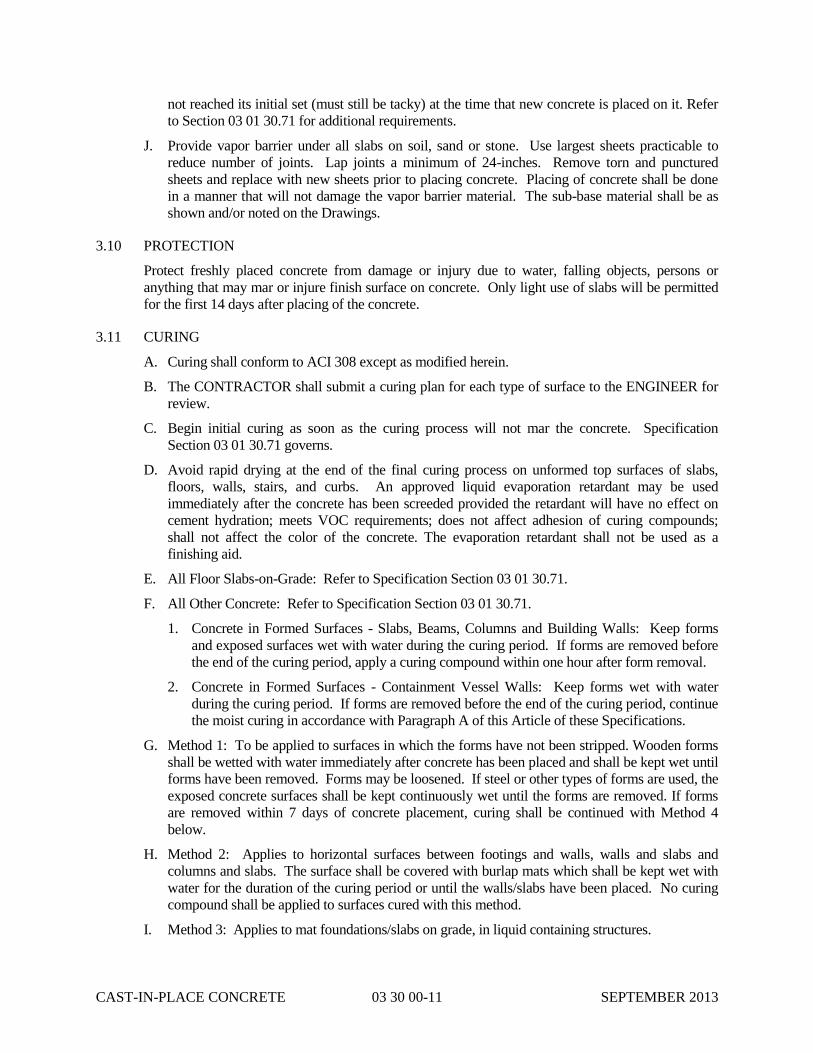
CAST-IN-PLACE CONCRETE 03 30 00-11 SEPTEMBER 2013
not reached its initial set (must still be tacky) at the time that new concrete is placed on it. Refer
to Section 03 01 30.71 for additional requirements.
J. Provide vapor barrier under all slabs on soil, sand or stone. Use largest sheets practicable to
reduce number of joints. Lap joints a minimum of 24-inches. Remove torn and punctured
sheets and replace with new sheets prior to placing concrete. Placing of concrete shall be done
in a manner that will not damage the vapor barrier material. The sub-base material shall be as
shown and/or noted on the Drawings.
3.10 PROTECTION
Protect freshly placed concrete from damage or injury due to water, falling objects, persons or
anything that may mar or injure finish surface on concrete. Only light use of slabs will be permitted
for the first 14 days after placing of the concrete.
3.11 CURING
A. Curing shall conform to ACI 308 except as modified herein.
B. The CONTRACTOR shall submit a curing plan for each type of surface to the ENGINEER for
review.
C. Begin initial curing as soon as the curing process will not mar the concrete. Specification
Section 03 01 30.71 governs.
D. Avoid rapid drying at the end of the final curing process on unformed top surfaces of slabs,
floors, walls, stairs, and curbs. An approved liquid evaporation retardant may be used
immediately after the concrete has been screeded provided the retardant will have no effect on
cement hydration; meets VOC requirements; does not affect adhesion of curing compounds;
shall not affect the color of the concrete. The evaporation retardant shall not be used as a
finishing aid.
E. All Floor Slabs-on-Grade: Refer to Specification Section 03 01 30.71.
F. All Other Concrete: Refer to Specification Section 03 01 30.71.
1. Concrete in Formed Surfaces - Slabs, Beams, Columns and Building Walls: Keep forms
and exposed surfaces wet with water during the curing period. If forms are removed before
the end of the curing period, apply a curing compound within one hour after form removal.
2. Concrete in Formed Surfaces - Containment Vessel Walls: Keep forms wet with water
during the curing period. If forms are removed before the end of the curing period, continue
the moist curing in accordance with Paragraph A of this Article of these Specifications.
G. Method 1: To be applied to surfaces in which the forms have not been stripped. Wooden forms
shall be wetted with water immediately after concrete has been placed and shall be kept wet until
forms have been removed. Forms may be loosened. If steel or other types of forms are used, the
exposed concrete surfaces shall be kept continuously wet until the forms are removed. If forms
are removed within 7 days of concrete placement, curing shall be continued with Method 4
below.
H. Method 2: Applies to horizontal surfaces between footings and walls, walls and slabs and
columns and slabs. The surface shall be covered with burlap mats which shall be kept wet with
water for the duration of the curing period or until the walls/slabs have been placed. No curing
compound shall be applied to surfaces cured with this method.
I. Method 3: Applies to mat foundations/slabs on grade, in liquid containing structures.

CAST-IN-PLACE CONCRETE 03 30 00-12 SEPTEMBER 2013
1. Until the concrete surface is covered with curing compound, the entire surface shall be kept
damp by applying water using nozzles that atomize the flow so that the surface is not marred
or washed. The concrete shall be given a coat of curing compound in accordance with
Method 5 below. Not less than one hour or more than 4 hours after the curing compound
has been applied, the surface shall be wetted with water delivered through a fog nozzle, and
concrete-curing blankets shall be placed on the slabs. The curing blankets shall be
polyethylene sheet, polyethylene-coated waterproof paper sheeting, or polyethylene-coated
burlap. The blankets shall be laid with the edges butted together and with the joints between
strips sealed with 2-inch wide strips of sealing tape or with edges lapped not less than 3-
inches and fastened together with a waterproof cement to form a continuous watertight joint.
2. The curing blankets shall be left in place during the 7-day curing period and shall not be
removed until after the concrete for adjacent work has been placed. If the curing blankets
become torn or otherwise ineffective, the CONTRACTOR shall replace damaged sections.
During the first 3-days of the curing period, no traffic of any nature, and no depositing,
temporary or otherwise, of any materials shall be permitted on the curing blankets. During
the remainder of the curing period, foot traffic and temporary depositing of materials that
impose light pressure will be permitted only on top of plywood sheets 5/8-inch minimum
thickness, laid over the curing blanket. The CONTRACTOR shall add water under the
curing blanket as often as necessary to maintain damp surfaces at all times.
J. Method 4: Applies to walls (with forms removed), elevated floors, and floor slabs-on-grade.
1. The concrete shall be kept continuously wet by the application of water for a minimum
period of at least 7 consecutive days beginning immediately after the concrete is placed. If
forms have been removed before 7 days other approved methods of curing shall be applied
to allow curing for the full 7 days.
2. Until the concrete surface is covered with the curing medium, the entire surface shall be kept
damp by applying water using nozzles that atomize the flow so that the surface is not marred
or washed.
3. Heavy curing mats shall be used as a curing medium to retain the moisture during the curing
period. The curing period shall be weighted or otherwise held substantially in contact with
the concrete surface to prevent being dislodged by wind or any other causes. Edges shall be
continuously held in place.
4. The curing blankets and concrete shall be kept continuously wet by the use of sprinklers or
other means both during and after normal working hours.
5. Immediately after the application of water has terminated at the end of the curing period, the
curing medium shall be removed, the entire concrete surface shall be wetted, and curing
compound shall be immediately applied to the entire surface in accordance with Method 5
below.
6. The CONTRACTOR shall dispose of excess water from the curing operation to avoid
damage to the work.
K. Method 5: The surface shall be sprayed or rolled with a liquid curing compound.
1. The curing compound shall be applied in accordance with the manufacturers’ printed
instructions at a maximum coverage of 200 square feet per gallon and in such a manner as to
cover the surface with a uniform seal that will seal thoroughly.
2. Curing compound shall be applied as soon as the concrete has hardened enough to prevent
marring on unformed surfaces and within two hours after removal of forms. Repairs to
formed surfaces shall be made within the 2 hour period; provided, however, that any such

CAST-IN-PLACE CONCRETE 03 30 00-13 SEPTEMBER 2013
repairs which cannot be made within the said 2 hour period shall be delayed until after the
curing compound has been applied. When repairs are to be made to an area on which curing
compound has been applied, the area involved shall first be wet-sandblasted to remove the
curing compound.
3. At locations where concrete is placed adjacent to a panel which has been coated with curing
compound, the panel shall have curing compound reapplied to an area within 6-feet of the
joint and to any other location where the curing membrane has been disturbed.
4. Prior to final acceptance of the work, all visible traces of curing compound shall be removed
from all surfaces in such a manner that does not damage the surface finish.
3.12 PATCHING
A. As determined by the ENGINEER, any concrete which is out of alignment or level has a
defective surface or has defects which reduce its structural adequacy, shall be considered as not
conforming with the Drawings and Specifications and shall be rejected.
B. Do not take any remedial action on concrete with any defect without the permission of the
ENGINEER.
C. Unless the ENGINEER grants permission to patch the rejected concrete, remove the rejected
concrete and replace it with concrete that conforms to the Drawings and Specifications. The
location of cut lines and the extent of removal will be determined by the ENGINEER.
D. If the ENGINEER grants permission to patch the rejected concrete, it shall be done in
accordance with the following, or as shown in Section 03 01 30.71 if, in the opinion of the
ENGINEER, such requirements are more applicable to the situation.
1. Permission to patch rejected concrete will not be a waiver of the ENGINEER's right to
require complete removal of the rejected concrete if the patching does not, in the
ENGINEER's judgment, restore the concrete to the requirements of the Specifications and
Drawings.
2. Patching shall be accomplished after the curing is completed.
3. Defective areas shall be chipped away to a depth of not less than 1-inch, in all cases to sound
concrete, with edges perpendicular to the surface. Feather edges will not be permitted.
Remove all loose material and thoroughly clean the chipped surfaces with a high pressure air
hose delivering air at 100 psi. The area to be patched and an area at least 6-inches wide
surrounding it shall be dampened. A bonding grout shall be prepared using a mix of
approximately one part cement to one part fine sand passing a No. 30 mesh sieve, mixed to
the consistency of thick cream, and then well brushed into the surfaces as noted below in
Paragraph 5.
4. The patching mixture shall be made of the same materials and of approximately the same
portions as used for the original concrete, except that the coarse aggregate shall be omitted
and the mortar shall consist of not more than one part cement to two and one-half parts sand
by damp, loose volume. White Portland cement shall be substituted for a part of the gray
Portland cement to produce a color matching the color of the surrounding concrete, as
determined by a trial patch. The quantity of mixing water shall be no more than necessary
for handling and placing. The patching mortar shall be mixed in advance and allowed to
stand with frequent manipulation with a trowel, without addition of water, until it has
reached the stiffest consistency that will permit placing.
5. After surface water has evaporated from the area to be patched, the bond coat shall be well
brushed into the surface. When the bond coat begins to lose the water sheen, the premixed
CAST-IN-PLACE CONCRETE 03 30 00-14 SEPTEMBER 2013
patching mortar shall be applied. The mortar shall be thoroughly consolidated into place and
struck off so as to leave the patch slightly higher than the surrounding surface. To permit
initial shrinkage, it shall be left undisturbed for at least one hour before being finally
finished. The patched area shall be kept damp for seven days. Finishing tools that produce a
finish matching the surrounding shall be used.
E. Tie holes left by withdrawal of rods or the holes left by removal of ends of wall ties shall be
filled solid with mortar after first being wetted. For holes passing through the wall, a
plunger-type grout gun shall be used to force the mortar through the wall starting at the back
face. A piece of burlap or canvas shall be held over the hole on the outside and when the hole is
filled, the excess mortar shall be struck off with the cloth flush with the surface. Holes not
passing through the walls shall be filled with a small tool that will permit packing the hole solid
with mortar. Any excess mortar at the surface of the wall shall be struck off flush with a cloth.
Mortar shall consist of one part cement, two and one-half parts sand and no more water than
necessary for handling and packing.
F. For liquid containing walls, full depth tie holes shall first be plugged with the specified plug
(refer to Specification Section 03 15 00) and the patching defined in Paragraph E (above) shall
be applied.
3.13 FINISHES ON FORMED SURFACES
Refer to Specification 03 01 30.71.
3.14 TESTING LABORATORY
A. The CONTRACTOR shall arrange, coordinate, and pay for all testing. The testing agency shall
provide timely written test reports to the CITY, ENGINEER, CONTRACTOR, and ready-mix
supplier. The cost for the testing, except as required elsewhere in the Contract Documents, shall
be charged, on a Time and Material Basis (Force Account) against the Allowance established for
such in Section 01 20 00 Measurement and Payment.
B. The testing laboratory shall have access to all places where concrete materials and concretes are
manufactured, stored, proportioned, mixed, placed and tested. Duties shall include, but not
necessarily be limited to the following:
1. Make, store, transport, cure and test compression specimens made during placing of
concrete. Compression test specimens shall be tested in accordance with ASTM C 39. Test
reports shall show all pertinent data, such as class of concrete, exact location of pour, air
temperature, date of pour, time of pour, truck number for ready-mixed concrete, date on
which specimen was broken, age of specimen, compressive strength of specimen, concrete
slump test results and air content of concrete from which the specimen was made. One copy
each of all tests shall be sent to the CONTRACTOR, one copy each to the CITY, and one
copy each to the ENGINEER.
2. Each strength test requires seven standard test cylinders.
3. Samples for strength tests of each class of concrete placed each day shall be taken not less
than once a day, nor less than once for each 100 cubic yards of concrete, nor less than once
for each 5,000 square feet of surface area for slabs or walls. For silica-fume enhanced,
ready-mixed concrete used for structural repairs testing shall be more frequently than once
for each 100 cubic yards of concrete. Refer to Section 03 01 30.71 the for testing
requirements for repair concrete.
4. Each class of concrete shall be tested with at least seven strength tests.

CAST-IN-PLACE CONCRETE 03 30 00-15 SEPTEMBER 2013
5. From each set of seven cylinders, two shall be tested at 28 days and shall comprise a strength
test under the definition of these Specifications. Two cylinders shall be broken at three days
and two cylinders shall be broken at seven days and will be used as an aid in determining the
early strength of the concrete and the 28 day strength, and one cylinder retained in reserve
for later testing if required.
6. Test for unit weight of concrete when the first load of each class of concrete is delivered and
thereafter at the discretion of the testing laboratory.
C. Periodically inspect the batching plant and file a report with the CITY and ENGINEER stating
whether the supplier's equipment and methods meet the requirements of these Specifications.
D. Temperature and Placing Record: Temperature record shall be made each day during the
concreting operations. Records shall also include location, quantity and starting and finishing
time of placement for all concrete work. Copy distribution shall be as specified above for test
reports.
E. Drying shrinkage tests shall be performed in accordance with ASTM C157 for the trial batches,
the first placement of each class of structural concrete, and during construction to insure
continued compliance with these Specifications. If the required shrinkage limitation is not met
during construction, the CONTRACTOR shall take any or all of the following actions to
reestablish compliance. These actions may include changing the source of aggregates, cement
and/or admixtures, reducing water/cement ratio; washing coarse or fine aggregate to reduce
fines, increasing the number of construction joints; modifying the curing methods, or other
actions designed to minimize shrinkage or the effects of shrinkage.
3.15 EVALUATION OF COMPRESSION TESTS
A. Evaluation of compression test results shall be as follows: For each class of concrete,
compression-strength tests for laboratory-cured cylinders shall be considered satisfactory if the
averages of the results of all sets of three consecutive compression-strength tests equal or exceed
the 28 day design compression-strength specified; and, no individual cylinder strength test falls
below the required compression strength by more than 500 psi. Strength tests of specimens
cured under field conditions may be required by the ENGINEER to check the adequacy of
curing and protecting of the concrete placed. Specimens shall be molded by the field testing
laboratory at the same time and from the same samples as the laboratory-cured specimens.
B. Faulty Concrete: Failure to comply with any of the specified conditions shall constitute faulty
concrete. Unless otherwise directed by the ENGINEER, faulty concrete shall be removed and
replaced with concrete as specified, at no expense to the CITY.
C. Additional Test: If permitted by the ENGINEER, additional tests shall be subject to the approval
of the ENGINEER and at no expense to the CITY. Load tests, if permitted by the ENGINEER,
shall be conducted in accordance with the loading criteria as required by the design of the
structure, as determined by the ENGINEER.
D. Neither the results of laboratory verification tests nor any provision in the Contract Documents
shall relieve the CONTRACTOR of the obligation to furnish concrete of the class and strength
specified.
3.16 INSPECTION
A. Inspect all the work in accordance with Section 01 45 29 of these Specifications, in addition to
the following:
1. Quality and proportions of concrete materials.

CAST-IN-PLACE CONCRETE 03 30 00-16 SEPTEMBER 2013
2. Construction and removal of forms and reshoring.
3. Significant construction loadings on completed floors, members or walls.
4. General progress of work.
END OF SECTION 03 30 00

CAST-IN-PLACE CONCRETE 03 30 00-17 SEPTEMBER 2013
CONCRETE PREPLACEMENT SIGN-OFF CARD
Project:
Inspection Date: Concrete Placement Date:
Expected Time of Concrete Placement:
Estimated Quantity:
Mix Design Strength:
Location of Structure:
Member (walls, beams, etc.):
Weather Conditions:
Method of Pour: Chute _______________ Bucket_____________ Pump
Conveyor ____________ Other _ _________________________________
Status
Work Ready N/A Signature Date
Formwork
Reinforcing
Mechanical
Electrical
Instrumentation
Plumbing
Process
Metal Embeds
Miscellaneous
Specialties
Clean-Up/OK to Place
The CONTRACTOR certifies that the above work to be cast is prepared in accordance with the Contract
Documents.
CONTRACTOR (Superintendent): Date:
Resident Inspector: Date:

CAST-IN-PLACE CONCRETE 03 30 00-18 SEPTEMBER 2013
THIS PAGE INTENTIONALLY LEFT BLANK

CONCRETE FORMWORK 03 31 00-1 SEPTEMBER 2013
SECTION 03 31 00
CONCRETE FORMWORK
PART 1 - GENERAL
1.01 SCOPE
A. The work included in this Section consists of the design, furnishing and construction of all
necessary concrete formwork and falsework to produce cast-in-place concrete in the finished
structure(s).
B. The design, furnishing and construction of the concrete formwork and falsework shall comply
with industry standards including but not limited to the latest edition of ACI 301 and 347 and as
indicated on the Drawings and specified in this Section.
C. Where the term ENGINEER is used in the section, it shall mean “the CITY’s Structural
ENGINEER”.
1.02 RELATED DOCUMENTS
Should conflicts arise between information shown in this Section and Section 03 01 30.71, the
information in Section 03 01 30.71 shall take precedence; except in all cases the most stringent
requirements shall govern.
1.03 FORMWORK DESIGN
Provide the design by an engineer registered in the Project’s state of all formwork, including
shoring and reshoring, for this work. Formwork shall comply with ANSI A10.9 and OSHA
Construction Standards, Part 1926, Subpart Q, Concrete, Concrete Forms, and Shoring. In addition,
the formwork design shall meet the requirements of the latest edition of ACI 347.
1.04 SUBMITTALS
A. Do not submit formwork shop drawings or structural design calculations. However, a written
statement (signed and stamped by the registered engineer providing the formwork design)
attesting to the fact that the requirements of Article 1.03 have been met shall be submitted.
B. Form Tie Assemblies: Manufacturer's product data sheets fully describing the form tie
assemblies, including the taper tie plugs.
C. Form Releasing Agent: Manufacturer's product data sheets fully describing the form coating.
Manufacturer’s certification that the form releasing agent meets the specified standard for
liquid containment vessels in water treatment plants.
D. Plywood Panels: Certification that the plywood panels for use on this work meet the specified
standard.
E. Pan joist form layouts showing all joists and connecting beam and/or wall supports. Review
and comments will be for layout only.
F. Construction and control joint proposed locations if different from those indicated in the

CONCRETE FORMWORK 03 31 00-2 SEPTEMBER 2013
Contract Documents.
1.05 RESPONSIBILITIES
The CONTRACTOR is fully responsible for the design and construction of all forms, falsework
and shoring to be in compliance with all applicable OSHA requirements, ACI requirements and the
requirements of all agencies having jurisdiction on the Project. The submission of any design
details for falsework, forms and shoring is for information only.
1.06 STORAGE AND PROTECTION
All form materials and accessories shall be stored above ground on framework or blocking, shall be
protected from precipitation and shall have adequate air circulation and ventilation.
PART 2 - PRODUCTS
2.01 FORM MATERIAL
A. Smooth Form Finish: Forms for this finish shall be applied to surfaces specified in Section 03
30 00 of these Specifications. Some of these surfaces will receive a brushed surface coating as
specified in Section 03 30 00 of these Specifications.
1. Form facing material shall produce a smooth, dense, uniform texture on the concrete. Form
facing shall be one of the following:
a. Plywood, meeting the requirements of U.S. Department of Commerce Product
Standard (PS). PS 1 - Construction and Industrial Plywood, B-B Concrete Form
Panels. The arrangement of the facing material shall be orderly with the number of
seams kept to a practical minimum.
b. Patented forms may be used, subject to acceptance by the ENGINEER, provided they
produce a smooth, even surface. This acceptance is for the finish these forms will
leave on the contact surfaces and will not relieve the CONTRACTOR of the
responsibility for the design and structural soundness of the forms. Patented forms
shall be lined with the specified plywood. Plywood panels and form liners shall not be
used more than three times unless further use is acceptable to the ENGINEER.
B. Rough Form Finish: Forms for this finish shall be applied to the surfaces specified in Section
03 30 00 of these Specifications. Forms for this finish may be the same as specified for the
Smooth Form Finish or may be constructed of used plywood panels, unlined steel forms or
straight dressed lumber.
2.02 ACCESSORIES
A. Form ties for use in all liquid containment structure walls shall be selected to prevent form
deflection. Form ties shall be as follows:
1. Standard one-piece crimped snap ties with a 1-inch snapback. Ties shall be provided with
smooth rods, and plastic cones, or other means for forming a conical cone to insure that the
form tie is broken off back of the concrete face. The cone-shaped depressions at the
surface of the concrete shall be at least 1-inch out diameter to allow filling and patching
with the specified grout. Ties shall be provided with an intregal waterstop at the center

CONCRETE FORMWORK 03 31 00-3 SEPTEMBER 2013
which tightly fits the form tie so that they cannot be moved from the mid-point of the tie.
2. All of the assemblies shall permit tightening of the forms and be of such type that leaves no
tie metal, or any other tie material, within 1-1/2-inch of the surface after use.
B. Form ties for use in all other walls shall be one of the assemblies specified in Article 2.02,
Paragraph A, except that waterstops are not required.
C. Form releasing agent for liquid containment vessels in water treatment plants shall be non-toxic
and leave no residue on or in the concrete unless safe for potable water (certified as compliant
with NSF 61).
D. Form releasing agents for liquid containment vessels in water treatment plants shall be equal to
Sealtight Duogard by W.R. Meadows.
E. Form releasing agents shall permit coating the concrete surface without additional surface
preparation.
F. Form releasing agents shall be a non-staining form coating compound.
PART 3 - EXECUTION
3.01 FORM CONSTRUCTION
A. Formwork shall be designed, erected, and removed in accordance with the latest edition of ACI
347 and as follows:
1. Construct forms complying with ACI 347 and ACI SP-4 to the sizes, shape, lines, and
dimensions of members as indicated on the Drawings. Forms shall be properly braced or
tied together so as to maintain position and shape. Plumb and string lines shall be installed
before concrete placement and shall be maintained during placement. During concrete
placement, the CONTRACTOR shall monitor plumb and string lines form positions and
immediately correct deficiencies.
2. Forms shall be substantial and sufficiently rigid and tight to prevent leakage of water,
cement and fines during placing and vibrating the concrete. Specifically, the bottom of
wall forms that rest on concrete footings or slabs shall be provided with a gasket to prevent
loss of fines and concrete paste during placement and vibration of concrete.
3. Construct forms so that they can be easily removed without hammering or prying against
the concrete surfaces. Provide crush plates or wrecking plates where stripping may damage
cast concrete surfaces. Forms for exposed concrete shall be carefully made and accurately
placed to obtain correct shape and lines.
4. Joints shall be butted tight. Arrangements of panels shall be orderly and symmetrical, and
use of small pieces shall be avoided. Unless otherwise indicated, forms shall be chamfered
3/4-inch for external corners and edges of concrete, including top of walls, which will be
exposed to view in the finished work.
5. The CONTRACTOR shall be fully responsible for the adequacy of the formwork in its
entirety and any forms that are unsafe or inadequate in any respect shall promptly be
removed from the work and replaced. Forms shall be securely braced against lateral

CONCRETE FORMWORK 03 31 00-4 SEPTEMBER 2013
deflection and instability to safely support the loads they will sustain and to maintain their
dimensional and surface correctness to produce members required by the Drawings. Form
ties shall be spaced close enough to avoid bulges and variations in the required
cross-sectional dimensions shown on the Drawings for the members being cast.
6. CONTRACTOR may reuse forms only if in good condition. Reused forms shall be
thoroughly cleaned and may require light sanding between uses to obtain a uniform surface
texture on all exposed concrete surface. Forms shall not be reused if they have developed
defects that would affect the surface texture of exposed concrete. Split, frayed, dented,
worn, delaminated or otherwise damaged form facing material will not be acceptable. Do
not use patched forms for exposed concrete surfaces or liquid containing structures. In the
case of forms for the inside wall surfaces of liquid containing structures, unused tie rod
holes in forms shall be covered with metal caps.
7. Holes left by the removal of form tie cones shall be reamed with suitable toothed reamers
so as to leave the surface of the holes clean and rough before being filled with mortar.
Wire ties for holding forms are not permitted. No form-tying device or part thereof, other
than metal, shall be left embedded in concrete. Ties shall not be removed in such manner
as to leave a hole extending through the interior of the concrete members. The use of snap
ties, which cause spalling of the concrete upon form stripping or tie removal, will not be
permitted. If steel panel forms are used, rubber grommets shall be provided where the ties
pass through the form in order to prevent loss of cement paste. Where metal tie rods
extending through the concrete are used to support or strengthen forms, the rods shall
remain embedded and shall terminate not less than 1-inch back from the formed face or
faces of concrete.
8. Box out for chases, recesses or other openings required in the completed work.
9. Install all the items (sleeves, inserts, hangers, anchors, etc.), to be supported by the
formwork as required by the work.
10. Install pipe sleeves, wall pipes and wall sleeves, as shown or specified, for all piping
penetrating walls and slabs. The use of block-outs in walls is prohibited. Pipe sleeves shall
be used in slabs for plumbing pipes and wiring conduits.
11. Inspect formwork and remove deleterious material immediately before concrete is placed.
Provide a sufficient number of temporary cleanout openings at the base of wall and column
formwork to facilitate cleaning, inspection and the application of grout to the column bases.
12. The use of reinforcing steel, partially embedded in concrete, as toe pins or form spacers is
prohibited.
3.02 FALSEWORK
A. The CONTRACTOR shall be responsible for the design, engineering, construction,
maintenance and safety of all falsework, including staging, walkways, forms, ladders, and
similar appurtenances, which shall equal or exceed the applicable requirements of the
provisions of the OSHA Safety and health Standard of Construction, and the requirements
herein.
B. The CONTRACTOR shall design and construct falsework to provide the necessary rigidity and
to support the loads. Falsework for the support of the superstructure shall be designed to

CONCRETE FORMWORK 03 31 00-5 SEPTEMBER 2013
support the loads that would be imposed if the entire superstructure were placed at one time.
C. The CONTRACTOR shall place falsework upon a solid footing, safe against undermining, and
protected against softening.
3.03 TOLERANCES FOR FORMED SURFACES
Tolerances shall be limited to the criteria in the latest edition of ACI 117, except as indicated.
A. Deviation from Plumb
1. In the Lines and Surfaces of Columns, Piers, Walls:
a. In any 10 Feet of Height: 1/4-inch (walls 1/2-inch).
b. Maximum for the Entire Height: 1-inch.
2. For Exposed Corner Columns, Construction and Expansion Joint Grooves and Other
Conspicuous Lines:
a. In any 20 Foot Height: 1/4-inch.
b. Maximum for the Entire Height: 1/2-inch.
B. Deviation from the Level or from the Grades Shown on the Drawings
1. In Slab Soffits, Beam Soffits and Tops of Slabs, Measured Before Removal of Supporting
Shores:
a. In any 10 Foot Length: 1/4-inch.
b. In any Bay or in any 20 Foot Length: 3/8-inch.
c. Maximum for the Entire Length: 3/4-inch.
d. Except where FF and FL values are more stringent as indicated in Specification Section
03 30 00 or on the Drawings.
2. In Exposed Lintels, Sills, Parapets, Horizontal Grooves and Other Conspicuous Lines:
a. In any Bay or in any 20 Foot Length: 1/4-inch.
b. Maximum for the Entire Length: 1/2-inch.
C. Deviation of the Linear Building Lines from Established Position in Plan and Related Position
of Columns, Walls and Partitions
1. In any Bay: 1/2-inch.
2. In any 20 Foot Length: 1/2-inch.
3. Maximum for the Entire Length: 1-inch.
D. Deviation in the Sizes and Location of Sleeves for Plumbing Pipes and Electrical Conduits,
Floor Openings and Wall Openings: +1/4-inch.
E. Deviation in Cross-Sectional Dimensions of Columns and Beams and in the Thickness of Slabs
and Walls: -1/4-inch, +1/2-inch.
F. Deviation in Sizes of Pipe Sleeves, Wall Pipes and Wall Sleeves: None.
G. Deviation in Location of Pipe Sleeves, Wall Pipes and Wall Sleeves: +1/8-inch.
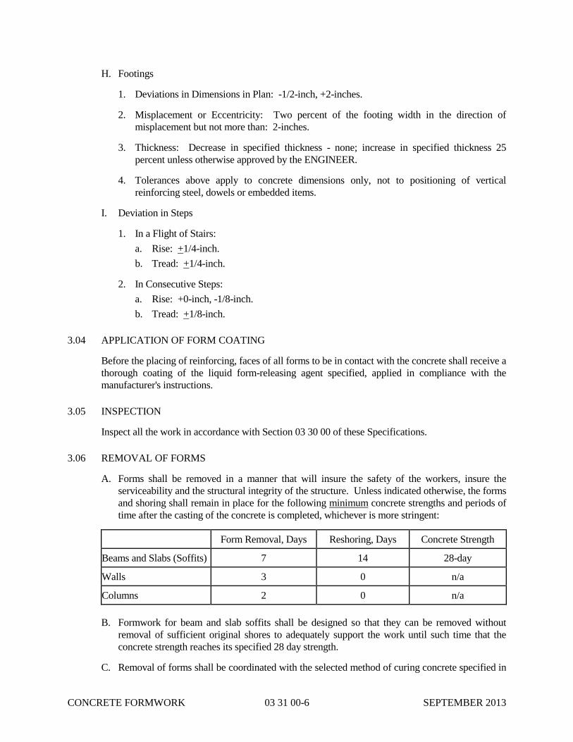
CONCRETE FORMWORK 03 31 00-6 SEPTEMBER 2013
H. Footings
1. Deviations in Dimensions in Plan: -1/2-inch, +2-inches.
2. Misplacement or Eccentricity: Two percent of the footing width in the direction of
misplacement but not more than: 2-inches.
3. Thickness: Decrease in specified thickness - none; increase in specified thickness 25
percent unless otherwise approved by the ENGINEER.
4. Tolerances above apply to concrete dimensions only, not to positioning of vertical
reinforcing steel, dowels or embedded items.
I. Deviation in Steps
1. In a Flight of Stairs:
a. Rise: +1/4-inch.
b. Tread: +1/4-inch.
2. In Consecutive Steps:
a. Rise: +0-inch, -1/8-inch.
b. Tread: +1/8-inch.
3.04 APPLICATION OF FORM COATING
Before the placing of reinforcing, faces of all forms to be in contact with the concrete shall receive a
thorough coating of the liquid form-releasing agent specified, applied in compliance with the
manufacturer's instructions.
3.05 INSPECTION
Inspect all the work in accordance with Section 03 30 00 of these Specifications.
3.06 REMOVAL OF FORMS
A. Forms shall be removed in a manner that will insure the safety of the workers, insure the
serviceability and the structural integrity of the structure. Unless indicated otherwise, the forms
and shoring shall remain in place for the following minimum concrete strengths and periods of
time after the casting of the concrete is completed, whichever is more stringent:
Form Removal, Days Reshoring, Days Concrete Strength
Beams and Slabs (Soffits) 7 14 28-day
Walls 3 0 n/a
Columns 2 0 n/a
B. Formwork for beam and slab soffits shall be designed so that they can be removed without
removal of sufficient original shores to adequately support the work until such time that the
concrete strength reaches its specified 28 day strength.
C. Removal of forms shall be coordinated with the selected method of curing concrete specified in

CONCRETE FORMWORK 03 31 00-7 SEPTEMBER 2013
Section 03 30 00.
D. Wood forms shall be completely removed from all the work to avoid termite infestation.
E. All elevated concrete shall be shored and/or reshored to the foundation until the structure is
complete and the concrete has reached its 28-day strength.
END OF SECTION 03 31 00

CONCRETE FORMWORK 03 31 00-8 SEPTEMBER 2013
THIS PAGE INTENTIONALLY LEFT BLANK
PRECAST CONCRETE 03 40 00-1 SEPTEMBER 2013
SECTION 03 40 00
PRECAST CONCRETE
PART 1 – GENERAL
1.01 DESCRIPTION
A. SCOPE:
1. This section specifies the materials and labor required for the manufacture and erection of
precast concrete box, or vault, type precast concrete structures.
B. TYPE:
1. This section includes precast concrete Valve Chambers.
2. This section includes precast concrete Effluent Flow Meter Vault.
1.02 QUALITY ASSURANCE
A. GENERAL:
1. The CONTRACTOR shall provide certification from the precast concrete manufacturer that
the materials and manufacture of precast work supplied conforms to these specifications.
The certification shall be signed by an officer of the manufacturer's corporation.
2. The responsibility for furnishing and installing precast concrete conforming to the
specifications is solely that of the CONTRACTOR.
3. The Manufacturer shall retain a licensed professional engineer who shall be responsible for
the design, manufacture, and inspection of the precast units and their connections. The
Engineer shall be licensed in the State of Ohio.
B. TESTING LABORATORY:
1. All testing shall be performed by recognized independent laboratories specializing in the
particular test to be performed, and conforming to the requirements of the National Bureau
of Standards and ASTM E329.
C. REFERENCE STANDARDS:
Reference Title
ACI 318 Building Code Requirements for Reinforced Concrete
AWS D1.1 Structural Welding Code - Steel
AASHTO Standard Specification for Highway Bridges
MNL-116 Prestressed Concrete Institute's Manual for Quality Control for Plants and
Production of Precast and Prestressed Concrete Products, third edition

PRECAST CONCRETE 03 40 00-2 SEPTEMBER 2013
1.03 SUBMITTALS
In accordance with specification Section 01 33 00 and in addition to the requirements of that section,
the following submittals shall be provided:
A. CONCRETE MIX:
1. Prior to casting any precast elements, concrete mix design shall be submitted to the CITY
for acceptance.
B. SHOP DRAWINGS:
1. Shop drawings shall be provided showing product location, fabrication details, number
identification marks, reinforcement, connection details including field installed anchor sizes
and locations, if required, openings, loose or embedded items and inserts, dimensions and
relationship to adjacent materials in sufficient detail to cover manufacture, handling, and
erection. Shop drawings shall be accompanied by a letter signed by a Professional Engineer
registered in the State of Ohio, certifying that the shop drawings submitted represent
construction which meets or exceeds the requirements of the Contract Documents and the
requirements of codes and agencies having jurisdiction over the Work.
1.04 LABELING
A. Each panel or member shall have an identification mark indicating its location in the structure as
shown on the placing diagrams and date of casting.
1.05 HANDLING AND STORAGE
A. Unless specified otherwise herein, fabrication, handling and erection of precast elements shall be
in accordance with the recommendations made by ACI 318 and ACI Committee 533.
B. Precast elements shall be properly supported off the ground to avoid damage during curing,
storage, handling and hauling. Lateral support shall be sufficient to prevent bowing, warping, or
permanent set due to creep. Edges of the units shall be adequately protected by padding or other
means to prevent staining, chipping or spalling of concrete. Lifting devices shall have a
minimum safety factor of 4.
PART 2 – PRODUCTS
2.01 PERFORMANCE AND DESIGN REQUIREMENTS
A. Concrete mix design and compressive strength shall meet or exceed that as specified in Section
03 00 00.
B. Design precast units for Valve Chambers to support the wheel load from an AASHTO HS20-44
vehicle.
C. Design units to not float up under flood conditions of up to 15’-0” of head. The CONTRACTOR
shall furnish the precast supplier with locations and loads of mechanical equipment. The precast
units shall be designed for the actual mechanical equipment to be supplied.
D. Unless more explicit design criteria is given in the Drawings, design units for an Equivalent
Hydrostatic Fluid Pressure of 65 pcf, and an Allowable Soil Bearing Pressure of 1500 psf.. The

PRECAST CONCRETE 03 40 00-3 SEPTEMBER 2013
Manufacturer’s GEOTECHNICAL ENGINEER may develop different design criteria based on
data from the actual site conditions. The Manufacturer’s GEOTECHNICAL ENGINEER shall
be a Professional Engineer licensed in the State of Ohio.
2.02 PRECAST CONCRETE MATERIALS
A. CEMENT:
1. Concrete in contact with soil or liquids shall be formulated using Type II or Type V Portland
Cement conforming to ASTM C150. Concrete not in contact with soil or liquids may be
formulated using Type I or Type III Portland Cement. Cement shall contain less than .60
percent alkalis and shall be from one source throughout the entire project.
B. AGGREGATES:
1. Aggregates for normal weight concrete shall conform to ASTM C33 with a maximum size
of 3/4 inch.
C. WATER:
1. Water shall be clean, potable, free from injurious amounts of oil, alkalis, organic materials
and other deleterious substances.
D. ADMIXTURE:
1. Admixture shall be Pozzolith 300-R manufactured by Master Builders, Plastiment
manufactured by Sika Chemical Corp., or equal. Admixture shall be used in strict
accordance with manufacturer's recommendations. Calcium chloride or any admixture
containing calcium chloride shall not be used.
E. REINFORCING STEEL:
1. Reinforcing steel shall conform to ASTM A615, including supplementary requirements, and
shall be Grade 60 except that bars to be welded shall be Grade 40 or ASTM A706.
F. EMBEDDED ITEMS AND ANCHORAGE DEVICES:
1. All embedded items, inserts, and anchorage devices exposed to view, moisture or weather
shall be hot-dipped galvanized steel. Anchorage devices shall be fabricated from ASTM
A36 steel.
G. PENETRATIONS:
1. All required penetrations and openings larger than 6-inches in diameter or 6-inches square
shall be formed in place at the time of casting. Additional reinforcing shall be added where
required to meet loading requirements. Openings and penetrations smaller than 6-inches
may be core drilled.
H. MOLDS:
1. Material from which molds are to be fabricated shall be steel, concrete, fiberglass, reinforced
plastic or wood. The selection of materials for molds shall be at the manufacturer's option,
except that wood shall not be used without the express approval of the CITY. All elements
shall be cast in molds of rigid construction, accurate in detail with precise corners and arises,
and designed to provide a close control of dimensions and details as indicated on the

PRECAST CONCRETE 03 40 00-4 SEPTEMBER 2013
Drawings.
2. Prior to casting of precast elements, molds shall have all surface joints, radii, corners, etc.,
filled, ground, filed, straightened or otherwise removed to provide a finished concrete
surface that is smooth and dense, free of honeycombing, large air pockets, offsets, sinkages,
or other irregularities.
I. PARTING COMPOUND:
1. All molds shall be coated with parting compound to facilitate removal of elements from
molds. Parting compound shall be non-petroleum, nonstaining and shall be of a nature and
composition not deleterious to concrete.
2.03 PRODUCT DATA
The following information shall be provided:
A. LABORATORY TEST REPORTS:
Before delivery of materials, three copies of the reports of the tests specified herein shall be
provided. Test reports on previously tested materials shall be accompanied by the
manufacturer's statement that the previously tested material is the same type, quality,
manufacture, and make as that proposed for use in this project. Test reports are required for the
following:
1. Cement
2. Aggregates
3. Pozzolan
4. Admixtures
5. Curing compounds
6. Waterstops
7. Concrete mix designs
PART 3 – EXECUTION
3.01 INSTALLATION
A. CASTING:
1. Casting shall be accomplished by methods and equipment that are in conformance with
generally acceptable systems for this type of Work. All precast concrete shall be
manufactured by a plant thoroughly experienced in this type of Work. The manufacturer
shall meet all production schedules. Surfaces on which units are cast shall be level and free
from any imperfections detrimental to the surface appearance of the finished units. Parting
compound shall be applied evenly as per manufacturer's recommendations.
2. Concrete shall be so handled as to prevent segregation of materials and shall be continuously
vibrated during casting, either internally or externally, to achieve proper compaction, finish

PRECAST CONCRETE 03 40 00-5 SEPTEMBER 2013
and distribution of concrete. All precautions must be taken to keep the reinforcing steel in
the proper location during placing and consolidation of the concrete. Unless shown
otherwise and except at concrete faces exposed to soil or liquids, all reinforcing steel shall
have a minimum cover of ¾ inch. At concrete faces exposed to soil or liquids, cover shall
be 1-1/2 inches minimum. Embedded items shall be accurately placed and maintained in
their proper location during the casting operation. Special inserts or other devices for
handling of panels for the convenience of the manufacturer shall not be exposed to view
after members are erected. Embedded anchors, inserts, plates, angles and other cast-in items
shall have sufficient anchorage and embedment for design requirements.
3. Casting, bowing, warpage and dimensional tolerances shall be in accordance with
MNL-116, third edition.
B. CURING:
1. All precast units shall be steam cured for a period of at least 12 hours. Fog spraying may be
used when reviewed by the ENGINEER. Precast elements shall not be removed from
molds for a minimum period of 12 hours after casting, or until concrete has attained a
minimum compressive strength of 3500 pounds per square inch, whichever governs. After
removal from the forms, curing by steam or fog spraying shall be continued until concrete
has attained specified strength and confirmed by standard tests. Curing procedures shall be
consistent and uniform throughout the entire project.
C. WELDING:
1. The quality of material and fabrication of all welded connections shall conform to the latest
AISC "Specification for the Design, Fabrication and Erection of Structural Steel for
Buildings." All weldments shall be made in accordance with the applicable provisions of
AWS. All welding, other than tacks, shall be done by certified welders. All units shall be
protected from damage by field welding or cutting operations. Noncombustible shields shall
be provided as necessary for this purpose.
D. JOINTS AND JOINT SEALANTS:
1. In all instances, the edges of precast concrete units and of adjacent material shall be sound,
smooth, clean and free of all contaminants prior to joint treatment.
2. Sealant and primer shall be supplied by the same manufacturer and the primer, when
required, shall be as recommended for the particular sealant used. All sealant compounds
shall be delivered to the job in the manufacturer's original sealed containers with labels intact
and shall be applied in strict accordance with the manufacturer's recommendations.
3.02 ERECTION
A. Any errors or misalignment in the structure which would prevent the proper setting of the
elements shall be corrected by the CONTRACTOR before the erection is commenced. Erection
shall be supervised and performed by workmen skilled in this type of Work. Each element shall
be set in the proper position, carefully plumbed and anchored securely to the structural frame.
Adjustments or changes in connections which could involve additional stresses in the products
or connections shall not be permitted without approval of the ENGINEER. All bearing
surfaces shall be true to line and grade. Erection tolerances shall be in accordance with
MNL-116. All joints shall be uniform and straight.

PRECAST CONCRETE 03 40 00-6 SEPTEMBER 2013
3.03 CLEANING AND REPAIRING
A. After installation, precast elements shall be protected from all damage until final acceptance by
the CITY. Precast units with cracks, spalls, and other defects shall be subject to rejection. Units
reviewed for repair shall be repaired to the satisfaction of the CITY.
3.04 ALTERNATIVE DESIGN
A. The CONTRACTOR may offer an alternative design for any precast element. Such design shall
be comparable in terms of strength, deflection, finish and all other design criteria indicated.
Complete drawings prepared and sealed by a Professional Engineer registered in the State of
Ohio shall be submitted to the CITY and ENGINEER for his review in accordance with
specification Section 01 33 00 of this project manual. No alternative design will be permitted
unless it has been specifically accepted in writing by the ENGINEER. If an alternative
design is accepted, all expenses resulting there from shall be borne by the CONTRACTOR.
END OF SECTION 03 40 00

MISCELLANEOUS METALS 05 50 00-1 SEPTEMBER 2013
SECTION 05 50 00
MISCELLANEOUS METALS
PART 1 - GENERAL
1.01 SCOPE
The work under this Section includes, but is not necessarily limited to, the furnishing and
installation of all miscellaneous metals and related items as indicated on the Drawings, herein
specified and as necessary for the proper and complete performance of this work.
1.02 SUBMITTALS
A. Make all submittals in accordance with Section 01 33 00 of these Specifications.
B. Shop Drawings
1. Submit shop drawings of all items to be furnished.
2. Submit plan locating embedded connections in masonry and cast-in-place concrete.
1.03 DIVISION OF WORK
A. General: The following list of items to be furnished under this Section is placed here to aid the
various trades in estimating their portion of the work. It is not a full and complete list and does
not relieve the CONTRACTOR from providing a totally complete Project including all
miscellaneous items.
B. Miscellaneous Metal Items
1. Loose angle and wide flange lintels.
2. Stairs and landings including posts, bearing plates, and integral support beams.
3. Beams, angles and other supporting grating over pipe trenches including embedded
connections.
4. Embedded connections and plates in masonry and cast-in-place concrete for precast plank
and tees.
5. Bumper posts and sleeves.
6. Bearing plates for other items specified herein.
7. Railings.
8. Edge angles cast-in-concrete.
1.04 QUALITY ASSURANCE
A. Qualifications: For fabrication and erection of the work of this Section, use only personnel
completely trained and experienced in the type of work being performed and thoroughly

MISCELLANEOUS METALS 05 50 00-2 SEPTEMBER 2013
familiar with the original design and the approved shop drawings.
B. Codes and Standards: In addition to complying with all pertinent codes and regulations,
comply with applicable standards for materials design and construction of the following:
1. American Society for Testing Materials
2. American Institute of Steel Construction
3. American Iron and Steel Institutes "Specifications for the Design of Light Gage Cold
Formed Steel Structural Members"
4. Occupational Safety and Health Act
5. American Welding Society
6. National Association of Architectural Metal Manufacturers
C. Conflicting Requirements: In the event of conflict between pertinent codes and regulations and
the requirements of the referenced standards or these Specifications, the provisions of the more
stringent shall govern.
PART 2 - PRODUCTS
2.01 MATERIALS
A. General: Materials shall be new, top quality of their respective kinds, standard sizes and
fabricated in a shop whose principal business is manufacturing the items specified in this
Section. Materials shall be free of defect impairing strength, durability or appearance.
Miscellaneous anchors, plates, clips, bolts, nuts and the like shall be provided as necessary to
complete the work, whether or not they appear on the Drawings or in the Specifications.
B. Steel shall conform to ASTM A 36 for non w-shapes and ASTM A 992 for w-shapes.
C. Cast iron shall be soft, gray iron, true to pattern, smooth and straight, free from defects
impairing strength, durability or appearance.
D. Malleable iron shall be high grade white iron castings, fully annealed and of uniform ductile
structure throughout.
E. Aluminum alloys shall be of uniform quality and free from injurious defects and meet the
properties and applicable specifications of the Aluminum Company of America.
F. Bird screen shall be stainless steel wire cloth, minimum wire diameter 0.063-inch.
G. All other materials not specifically described but required for a complete and proper installation
of the work of this Section, shall be new, first quality of their respective kinds and as selected
by the CONTRACTOR subject to approval of the ENGINEER.
2.02 FABRICATION
A. General
1. Workmanship: Install items square and level, accurately fitted and free from distortion and

MISCELLANEOUS METALS 05 50 00-3 SEPTEMBER 2013
defects.
2. Temporary Bracing: Make provision for erection stresses by temporary bracing; keep work
in alignment.
3. Welding: Welding shall be continuous along entire area of contact. Welding shall be in
accordance with "Code for Welding in Building Construction" of the American Welding
Society. Grind exposed welds smooth and flush with adjacent finished surfaces.
4. Painting: Prime paint metal fabrications in accordance with Section 09 91 00 of these
Specifications.
5. Items fabricated from structural steel members which are to be architecturally exposed shall
be given special attention for material selection with respect to rolling tolerances, surface
finish and straightness.
6. Normal structural steel fabrication tolerances will not be acceptable where in conflict with
the intent and requirements of this Section.
7. Straightness tolerance, additive to deflection, shall not exceed +1/16-inch to 10 feet.
8. All cope, mitre, and butt caps on exposed surfaces shall be made to the closest possible
tolerances consistent with metal shop equipment and practice in order to provide a pleasing
appearance.
9. Galvanizing: Items specified to be hot-dip galvanized shall be coated after fabrication.
10. Fastenings shall be concealed where practicable. Thickness or metal and details of
assembly and supports shall give ample strength and stiffness. Joints exposed to weather
shall be formed to exclude water. Provide holes and connections for the work of other
trades.
B. Aluminum Ladder: Meet OSHA requirements.
PART 3 - EXECUTION
3.01 GENERAL
A. Workmanship: Install items square and level, accurately fitted and free from distortion and
defects.
B. Coordination: Supply to appropriate trades, items requiring to be cast into concrete, embedded
in masonry, complete with necessary setting templates.
C. Touch-Up: After installation, touch-up field welds and scratched and damaged surfaces.
D. Protection: Where required, provide approved protection against galvanic action between
contacts of dissimilar metals or situations that will cause deterioration of metals in contact or
associated in any way.
3.02 PAINTING
Painting shall be in accordance with Section 09 91 00 of these Specifications.

MISCELLANEOUS METALS 05 50 00-4 SEPTEMBER 2013
3.03 CLEANING
Prior to acceptance of the work of this Section, thoroughly clean all installed materials and related
areas in accordance with Section 01 74 00 of these Specifications.
END OF SECTION 05 50 00
WELDED ALUMINUM HANDRAILS 05 52 13.10-1 SEPTEMBER 2013
SECTION 05 52 13.10
WELDED ALUMINUM HANDRAILS
PART 1 - GENERAL
1.01 SCOPE
A. The work covered by this Section includes furnishing all labor, equipment and materials
required to furnish and install aluminum handrail for walkways, stairs, and openings, including
all fittings, anchors, sleeves and accessories, as shown on the Drawings or specified herein.
B. Unless specifically designated otherwise on the Drawings, all handrails shall be aluminum pipe
handrail.
C. Handrails shall be furnished and installed where shown on the Drawings and at the edge of all
walking or working surfaces where the distance from the surface to the adjacent floor, ground
or slab exceeds four feet.
D. Handrails shall be furnished with a 4-inch aluminum toeboard. Toeboards will not be required
on the railings for stairs or where concrete curbs are provided.
1.02 DESIGN REQUIREMENTS
A. Railings shall be designed and constructed in strict compliance with the requirements of OSHA
and OBC.
B. The Railing system shall be designed by a Professional Engineer, registered in the State of
Ohio, employed by the CONTRACTOR. Submit stamped calculations for the ENGINEER’S
review if requested.
C. Aluminum handrail shall be designed for a minimum safe working load of 50 pounds per linear
foot applied horizontally to the top rail or a concentrated load of 200 pounds applied in any
direction at any point on the railing, whichever is greater. All handrail sections and
components shall withstand the design loads with a minimum factor of safety of 1.5 based on
the ultimate strength of the alloy used.
1.03 SUBMITTALS
A. Submit complete shop drawings and engineering data in accordance with the requirements of
Section 01 33 00 of these Specifications.
B. Submit supplier's recommendations and procedures for maintaining and repairing handrail,
including methods, cleaning materials, refinishing materials and precautions as to the use of
materials which may be detrimental to handrail finish.
1.04 STORAGE AND PROTECTION
A. Provide storage and protection for aluminum handrail in accordance with the requirements of
Section 01 60 00 of these Specifications.
B. Keep handling to a minimum and maintain protective covering on handrail until the work is

WELDED ALUMINUM HANDRAILS 05 52 13.10-2 SEPTEMBER 2013
complete.
1.05 QUALITY ASSURANCE
The CONTRACTOR shall provide the ENGINEER with written certification that the aluminum
handrail and accessories are in conformance with the material and mechanical requirements
specified herein. Certified copies of independent laboratory test results or mill test results from the
aluminum handrail supplier may be considered evidence of compliance, provided such tests are
performed in accordance with the appropriate ASTM testing standards by experienced, competent
personnel. In case of doubt as to the accuracy or adequacy of mill tests, the ENGINEER may
require that the CONTRACTOR furnish test reports from an independent testing laboratory on
certified samples of handrail stock. Cost of this testing to be borne by the CONTRACTOR.
PART 2 - PRODUCTS
2.01 MATERIALS AND CONSTRUCTION
A. Aluminum Handrail
1. Aluminum tubing shall be, as a minimum, 1-1/2-inch nominal diameter, Schedule 40 for all
horizontal elements and Schedule 80 for all Vertical elements, 6061-T6 aluminum tubing
meeting the requirements of ASTM B 429.
2. Handrail shall be fabricated by welding. All weld joints shall be ground smooth and
polished.
3. Handrail shall meet all OSHA requirements and shall be uniform throughout the work.
4. All aluminum railing components shall be satin clear anodized with 0.07+, R215-R1 finish
on all exposed surfaces. Railing components shall be individually wrapped in paper or
plastic film sleeves to protect the finish during shipment and installation.
5. All handrail installations shall provide for draining of entrapped water from the railing
system by minimum 15/64-inch diameter weep holes or other approved means.
B. Toeboards: Toeboards shall be of the same material and finish as the rails and posts and
furnished where required by OSHA.
PART 3 - EXECUTION
3.01 INSTALLATION
A. Aluminum railings shall be erected plumb, straight and true at the locations and elevations
shown on the Drawings. Prefabricated aluminum handrail shall be assembled and installed in
strict compliance with the manufacturer's instructions.
B. Aluminum handrail coming into contact with concrete or dissimilar metals shall be coated with
bituminous protective coating or installed with a vinyl isolation gasket.
C. All rails at splice joints to be fabricated 1/2-inch longer in the shop to permit cutting to fit in the
field. Adequate provisions for expansion and contraction are to be incorporated in the rails.

WELDED ALUMINUM HANDRAILS 05 52 13.10-3 SEPTEMBER 2013
Handrail shall not be continuous across concrete expansion joints. Posts shall be fixed as
shown on the Drawings. Open rail ends shall be closed by terminal end fittings. Provide toe
plate where required to meet OSHA regulations.
D. Shop-applied coatings which are damaged during transit, storage and/or handling shall be
repaired to the satisfaction of the ENGINEER.
E. All defective, damaged or otherwise improperly installed handrail shall be removed and
replaced with material that satisfies the requirements of this Section.
3.02 CLEANING
A. Following installation, aluminum handrail shall be cleaned using soap and clean water. Acid
solutions, steel wool or harsh abrasives shall not be used. If stains remain after cleaning,
remove finish and restore in accordance with the manufacturer's recommendations.
B. Prior to acceptance of the work of this Section, thoroughly clean all install materials and related
areas in accordance with the requirements of Section 01 74 00 of these Specifications.
END OF SECTION 05 52 13.10

WELDED ALUMINUM HANDRAILS 05 52 13.10-4 SEPTEMBER 2013
THIS PAGE INTENTIONALLY LEFT BLANK
ALUMINUM WEIR PLATES 05 59 00-1 SEPTEMBER 2013
SECTION 05 59 00
ALUMINUM WEIR PLATES
PART 1 - GENERAL
1.01 SCOPE
A. The work within this Section includes providing all labor, equipment and materials required to
install the weir plates shown on the Drawings and/or specified herein.
B. Thicknesses shown on the Drawings are minimums for use in construction. Details are to
provide a guide to the manufacturer. The manufacturer shall be responsible for structural
integrity of the system based on the manufacturer's standard manufacturing techniques and
practices.
1.02 SUBMITTALS
A. Submittals shall comply with the requirements of Section 01 33 00 of these Specifications and
shall include product data to show compliance with this Section.
B. Shop drawing submittals shall be signed and sealed by a structural engineer registered in the
state of Ohio if required or directed by the ENGINEER.
1.03 STORAGE AND PROTECTION
A. Weir plates and accessories shall be stored and protected in accordance with the requirements
of Section 01 60 00 of these Specifications.
B. Weir plates and appurtenances shall be manufacturer packaged and shipped for normal
handling and storage. Precautions shall be taken by the CONTRACTOR to prevent bending
and deformation during on-site storage.
1.04 WASTEWATER/WATER INFORMATION
A. Origin: Wastewater Plant Influent
B. pH: 6.5 to 7.5
C. Abrasiveness: Moderate
D. Temperature: Ambient
PART 2 - PRODUCTS
2.01 MATERIALS AND CONSTRUCTION
A. Troughs, weir plates, flanges, angles and structural plates shall be made from 1/4-inch
minimum thickness 6061-T6 or 6061-T651 aluminum, ASTM B 209. Structural pipe shall
meet the requirements of ASTM A 429 and be 6061-T6 and sized as shown on the Drawings.
ALUMINUM WEIR PLATES 05 59 00-2 SEPTEMBER 2013
Pipe shall be a minimum of Schedule 40. Troughs shall be flat-bottomed as shown on the
Drawings.
B. Weir plates shall be either flat or V-notch with as shown on the Drawings. Edges and V-
notches shall be made by shearing or mechanically cutting. Torch cutting shall not be
permitted. Edges and V-notches shall be free of burrs. Gaskets shall be 1/8-inch thick
neoprene gaskets and be permanently bonded to the weir plates to seal between weir plate and
supporting structure.
C. Weir plates may utilize forming or weldments for construction. All weldments shall utilize
inert gas or resistance welding techniques. All welds shall be ground smooth and shall be flush
where component parts or flanges mate or join. Components that mate or join shall not rely
upon gaskets to cover or fill in weldment irregularities. All weldments shall be free of burrs
and smooth to the touch.
D. Bolts, nuts and washers shall be 300 series stainless steel. The manufacturer shall provide all
bolts, nuts and washers used to assemble weir components and subparts. Anchor bolts and
washers used to mount weir components or supports to the structure shall be 300 series
stainless steel and shall be provided by the CONTRACTOR.
PART 3 - EXECUTION
3.01 INSTALLATION
A. Install weir plates per the manufacturer's instructions and locations and elevations as shown on
the Drawings.
B. Weir plate shall be installed such that the top of weir is perfectly level.
END OF SECTION 05 59 00

FIRE RETARDANT TREATMENT FOR
SHOP-FABRICATED WOOD TRUSSES 06 17 53-1 DECEMBER 2013
SECTION 06 17 53
FIRE-RETARDANT TREATMENT FOR SHOP-FABRICATED WOOD TRUSSES
PART 1 - GENERAL
1.01 RELATED DOCUMENTS
A. Drawings and general provisions of the Contract, including General and Supplementary Con-
ditions and Division 01 Specification Sections, apply to this Section.
1.02 SUMMARY
A. Section Includes:
1. Fire-retardant Treatment for Wood roof trusses.
1.03 ACTION SUBMITTALS
A. Product Data: For fire-retardant-treated lumber.
1. Include data for fire-retardant treatment from chemical treatment manufacturer and certi-
fication by treating plant that treated materials comply with requirements. Include physi-
cal properties of treated materials based on testing by a qualified independent testing
agency.
2. For fire-retardant treatments, include physical properties of treated lumber both before
and after exposure to elevated temperatures, based on testing by a qualified independent
testing agency according to ASTM D 5664.
3. Include copies of warranties from chemical treatment manufacturers for each type of
treatment.
B. Delegated-Design Submittal: For metal-plate-connected wood trusses indicated to comply
with performance requirements and design criteria, including analysis data signed and sealed
by the qualified professional engineer responsible for their preparation.
1.04 INFORMATIONAL SUBMITTALS
A. Evaluation Reports: For the following, from ICC-ES:
1. Fire-retardant-treated wood.
1.05 QUALITY ASSURANCE
A. Testing Agency Qualifications: For testing agency providing classification marking for fire-
retardant treated material, an inspection agency acceptable to authorities having jurisdiction
that periodically performs inspections to verify that the material bearing the classification
marking is representative of the material tested.
PART 2 - PRODUCTS

FIRE RETARDANT TREATMENT FOR
SHOP-FABRICATED WOOD TRUSSES 06 17 53-2 DECEMBER 2013
2.01 FIRE-RETARDANT-TREATED WOOD
A. General: Where fire-retardant-treated materials are indicated, use materials complying with
requirements in this article, that are acceptable to authorities having jurisdiction, and with
fire-test-response characteristics specified as determined by testing identical products per test
method indicated by a qualified testing agency.
B. Fire-Retardant-Treated Lumber by Pressure Process: Products with a flame-spread index of
25 or less when tested according to ASTM E 84, and with no evidence of significant progres-
sive combustion when the test is extended an additional 20 minutes, and with the flame front
not extending more than 10.5 feet (3.2 m) beyond the centerline of the burners at any time
during the test.
1. Use treatment that does not promote corrosion of metal fasteners.
2. Interior Type A: Treated materials shall have a moisture content of 28 percent or less
when tested according to ASTM D 3201 at 92 percent relative humidity. Use where exte-
rior type is not indicated.
3. Design Value Adjustment Factors: Treated lumber shall be tested according to
ASTM D 5664 and design value adjustment factors shall be calculated according to
ASTM D 6841. For enclosed roof framing, framing in attic spaces, and where high-
temperature fire-retardant treatment is indicated, provide material with adjustment factors
of not less than 0.85 modulus of elasticity and 0.75 for extreme fiber in bending for Pro-
ject's climatological zone.
C. Kiln-dry lumber after treatment to a maximum moisture content of 19 percent.
D. Identify fire-retardant-treated wood with appropriate classification marking of testing and in-
specting agency acceptable to authorities having jurisdiction.
E. Application: Treat all trusses unless otherwise indicated.
END OF SECTION 06 17 53

FIBERGLASS REINFORCED
PLASTIC (FRP) FABRICATIONS 06 75 13-1 SEPTEMBER 2013
SECTION 06 75 13
FIBERGLASS REINFORCED PLASTIC (FRP) FABRICATIONS
PART 1 - GENERAL
1.01 SCOPE
The work covered by this Section includes furnishing all labor, materials and equipment required to
fabricate and install all fiberglass reinforced plastic (FRP) items, with all appurtenances,
accessories and incidentals necessary to produce a complete, operable and serviceable
installation as shown on the Contract Drawings and as specified herein, and in accordance with
the requirements of the Contract Documents. All fiberglass products herein specified shall be
furnished with ultraviolet protective agents.
1.02 DESIGN REQUIREMENTS
A. FRP components, including their fasteners and anchors, shall be designed and constructed in
strict compliance with the requirements of OSHA, the 2006 International Building Code and
the Contract Documents under the supervision of a registered professional engineer licensed in
the state in which the Project is located.
B. FRP grating shall be designed for the following:
1. Dead loads including self weight.
2. Uniform live load as indicated on the Drawings, but not less than 100 pounds per square
foot.
3. Concentrated live loads as indicated on the Drawings but not less than 1,000 lbs. applied at
mid-span.
4. Uniform and concentrated live loads shall not be applied simultaneously.
5. Under either condition of uniform or concentrated load, live load deflection of FRP grating
shall not exceed 1/180 of span or 0.25 inch, whichever is smaller and total load deflection
shall not exceed 1/240 of span or 0.38 inch, whichever is smaller.
C. FRP handrail and guardrail shall be designed for the following:
1. A minimum safe working load of 50 pounds per linear foot applied in any direction to the
top rail and to transfer this load throughout the supports to the supporting structure.
2. A single concentrated load of 200 pounds applied in any direction at any point on the top
railing, and to transfer this load throughout the assembly to the supporting structure. This
load need not be assumed to act concurrently with the loads specified in Article 1.02
Paragraph C.1 of this section of these Specifications.
3. Intermediate rails and fillers shall be designed to withstand a horizontally applied normal
load of 50 pounds on an area equal to one-square foot, including openings and space
between rails. This load need not be assumed to act concurrently with loads specified in
Article 1.02 Paragraph C.1 or Article 1.02 Paragraph C.2 of this section of these

FIBERGLASS REINFORCED
PLASTIC (FRP) FABRICATIONS 06 75 13-2 SEPTEMBER 2013
Specifications.
4. Handrail and guardrail assemblies shall be designed in accordance with the allowable stress
design provisions.
D. FRP ladder system shall be designed for the following:
1. Ladder rungs shall be designed to withstand a concentrated service load of 300 pounds plus
30 percent impact applied at midspan of the rung. Maximum rung deflection shall not
exceed L/360 based on the above load (where L = run width, inches). The design load shall
be applied at the center of the rung on a 4-inch wide area.
2. Ladder rungs shall be designed for an ultimate concentrated load of 1,200 pounds applied
at midspan of the rung.
3. Ladder side rails shall be designed to withstand a minimum live load of two 250 pound
loads plus 30 percent impact concentrated between any two consecutive attachments.
E. FRP structural platform, landings, stair stringers and component support framing shall be
designed for the following:
1. Dead loads including self weight.
2. Uniform live loads as indicated on the Drawings but not less than 100 psf.
3. Concentrated loads from equipment as shown or indicated on the Drawings.
4. All seismic and wind loads required by the referenced code and as shown on the Drawings.
5. All other loads not listed but applicable from the referenced codes or as shown or indicated
on the Drawings.
6. Live load deflections shall be limited to 1/180 of the span, and total load deflections shall
be limited to 1/240 of the span. The 10-year wind lateral drift shall be limited to 1/240 of
the height and the inelastic seismic drift shall be limited to 1/100 of the height. Lateral
drifts shall include P-delta effects.
F. Stair Treads shall be designed for the following:
1. Dead loads including self weight.
2. Uniform live loads as indicated on the Drawings but not less than 100 psf.
3. Concentrated load of 300 lbs. or as indicated on the Drawings. Concentrated load placed at
centerline of the tread, over a width of 4-inches and a depth of 6-inches, starting at the
nosing edge to simulate the landing of a foot.
4. Under either condition of uniform or concentrated load, live load deflection of FRP stair
treads shall not exceed 0.25 inch.
G. FRP solid-plank gratings shall be designed for the following:
1. Dead loads including self weight.
2. Uniform live loads as indicated on the Drawings but not less than 100 psf.

FIBERGLASS REINFORCED
PLASTIC (FRP) FABRICATIONS 06 75 13-3 SEPTEMBER 2013
3. Concentrated loads from equipment as shown or indicated on the Drawings.
5. All other loads not listed but applicable from the referenced codes or as shown or indicated
on the Drawings.
6. Live load deflections shall be limited to 1/180 of the span, and total load deflections shall
be limited to 1/240 of the span.
H. Splice joints shall be designed and constructed to provide strength equivalent to a straight
section of FRP material.
I. FRP design shall be based on elastic behavior and allowable stress design.
J. Compression flanges of platform beams shall be stabilized by suitable struts and/or bracing as
required for design. The use of the grating to support compression flanges is prohibited.
K. The use of grating to act as a diaphragm to resist or transfer lateral forces is prohibited.
1.03 SUBMITTALS
A. Submit complete shop drawings, engineering calculations and engineering data for all FRP
components in accordance with the requirements of Section 01 33 00 of these Specifications.
B. Submit samples of FRP grating proposed for use on the Project.
C. Shop drawings shall clearly indicate the material sizes, types, styles, part or catalog numbers,
complete details for the fabrication and erection of components including, but not limited to,
location, lengths, type and sizes of fasteners, clip angles, member sizes and connection details.
Only the general dimensions and elevations are shown on the Drawings. The shop drawings
shall provide a fully dimensioned detailed layout of all platform framing, including stairs and
structural framing.
D. Shop drawings, engineering calculations and manufacturer’s published literature shall be
sealed, signed and dated by a registered professional engineer licensed in the state in which the
Project is located.
E. Submit the manufacturer’s published literature including structural design data, structural
properties data, grating load/deflection tables, corrosion resistance tables, certificates of
compliance, test reports as applicable, concrete anchor systems and their allowable load
tables, and design calculations for all systems and components not sized or designed in the
Contract Documents.
F. Data and design information shall clearly illustrate the stair profile, layout and loads
considered. Submit all information concurrently with the shop drawings.
G. Ladder manufacturer shall provide supporting test data for the rung capacity.
H. Submit warranty copies in accordance with Article 1.04.
1.04 QUALITY ASSURANCE
A. All items to be provided under this Section shall be furnished only by manufacturers having
a minimum of 10 years experience in the design and manufacture of similar products and
systems. Additionally, if requested, a record of at least five previous, separate, similar

FIBERGLASS REINFORCED
PLASTIC (FRP) FABRICATIONS 06 75 13-4 SEPTEMBER 2013
successful installations in the last five years shall be provided.
B. Manufacturer shall offer a 3 year limited warranty on all FRP products against defects in
materials and workmanship.
C. Manufacturer shall be certified to the ISO 9001-2000 standard.
D. Manufacturer shall provide proof of certification from at least two other quality assurance
programs for its facilities or products (UL, DNV, ABS, USCG, AARR).
1.05 PRODUCT DELIVERY AND STORAGE
A. Delivery of Materials: manufactured Manufactured materials shall be delivered in original,
unbroken pallets, packages, containers, or bundles bearing the label of the manufacturer.
Adhesives, resins, and their catalysts and hardeners shall be crated or boxed separately and
noted as such to facilitate their movement to a dry indoor facility.
B. Storage of Products: All materials shall be carefully handled to prevent them from abrasion,
cracking, chipping, twisting, other deformations, and other types of damage. Store items in
an enclosed area and free from contact with soil and water. Store adhesives, resins and their
catalysts and hardeners in dry indoor storage facilities between 70 and 85 degrees Fahrenheit
until they are required.
PART 2 - PRODUCTS
2.01 ACCEPTABLE MANUFACTURERS
A. Subject to compliance with requirements, available manufacturers offering products that may
be incorporated into the Work include, but are not limited to the following:
1. Fibergrate Composite Structures
2. Ohio Gratings
3. Strongwell.
B. Component FRP ladder system shall be “Dynarail Safety Ladder System” as manufactured by
Fibergrate Composite Structures, Inc. of Dallas, Texas, (800) 527-4043.
2.02 GENERAL
A. All FRP items furnished under this Section shall be composed of fiberglass reinforcement and
resins in qualities, quantities, properties, arrangements, and dimensions necessary to meet the
design requirements and dimensions as specified in the Contract Documents.
B. All finished surfaces of FRP items and fabrications shall be smooth (except for grit top
surfaces), resin-rich, free of voids and without dry spots, cracks, crazes, unreinforced areas
and visual defects such as foreign inclusions, delaminations, blisters, resin burns, air bubbles
and pits. All glass fibers shall be well covered with resin to protect against their exposure
due to wear or weathering.
C. Resins shall be a premium grade vinyl ester unless noted otherwise herein or on the Drawings
with chemical formulation necessary to provide the corrosion resistance, strength and other

FIBERGLASS REINFORCED
PLASTIC (FRP) FABRICATIONS 06 75 13-5 SEPTEMBER 2013
physical properties as required.
D. All FRP items, components and fabrications shall be further protected from ultraviolet (UV)
attack with integral UV inhibitors in the resin and a synthetic surfacing veil to help produce a
resin rich surface.
E. All FRP items, components and fabrications shall have a tested flame spread of 25 or less per
ASTM E-84 Tunnel Test. Gratings and stair treads shall also have tested burn time of less than
30 seconds and an extent of burn rate of less than or equal to 10 millimeters per ASTM D635.
Test data performed only on the resin shall not be accepted.
F. Color Gray or as specified by the City.
G. All shop fabricated and field fabricated cut and machined edges, holes and abrasions shall be
sealed with a resin compatible with the resin used in the manufacture of the product and in
strict accordance with manufacturer’s recommendations.
2.03 OPEN MOLDED FRP GRATING
A. Fiberglass reinforcement for open molded FRP grating shall be reinforced with continuous
glass strand roving of equal number of layers in each direction and in sufficient quantities as
needed by the application and/or physical properties required and constructed to provide
complete wetting of the glass by the resin. A premium grade vinyl ester resin shall be used.
B. All molded FRP grating shall have square mesh pattern providing bi-directional strengths with
minimum dimensions of 2-inches x 2-inches x 2-inches deep unless noted otherwise on the
Drawings. The grating shall be molded of single piece construction such that reinforcing glass
of bearing bars are interwoven with the cross bar glass and tops and bottoms of bearing and
cross bars are in the same plane.
C. After molding, no dry glass fibers shall be visible on any surface of bearing or cross bars. All
bars shall be smooth and uniform with no evidence of fiber orientation irregularities,
interlaminar voids, porosity, resin rich or resin starved areas.
D. Grating bar intersections are to be filleted to a maximum radius of 1/16-inch to eliminate local
stress concentrations and the possibility of resin cracking at these locations.
E. The top layer of reinforcement shall be no more than 1/8-inch below the top surface of the tread
so as to provide maximum stiffness and prevent resin shipping of unreinforced surfaces.
F. Length and width shall equal required dimensions within 1/4-inch. Diagonal dimensions of any
square shall be equal within 1/4-inch.
G. The tops of all bars and members shall be in the same plane.
H. All grating walking surfaces shall have anti-skid surfaces. Angular silica particles shall be
integrally embedded in laminate in all walking surfaces.
I. Grating shall be easily installed and cleaned, non-sparking and self-draining. Grating shall be
capable of field fabrication with a masonry saw.
J. Manufacturer shall provide openings and holes where required on the Drawings. Grating
openings which fit around protrusions (pipes, equipment, etc.) shall be discontinuous at
approximately the centerline of the opening so each section of grating is readily removable.

FIBERGLASS REINFORCED
PLASTIC (FRP) FABRICATIONS 06 75 13-6 SEPTEMBER 2013
K. Grating shall meet the dimensional requirements and tolerances as shown or specified. The
Contractor shall provide and/or verify measurements in field for work fabricated to fit existing
conditions.
L. Grating panels for sump pits and narrow trenches shall be simply supported by FRP angles on
all sides of the opening. The gratings shall be of the type that can be made in panels of the
widths and lengths appropriate to the openings shown on the Drawings. Panels shall be
furnished in sizes that are easily handled.
M. The top surface of all grating shall be flush and all gratings shall lie flat with no tendency to
rock when installed. Cross bars and edge bars of adjacent panels shall align for neatness. All
bearing bars shall be parallel. Cross bars shall be cut off flush with outside face of side bars.
N. All mechanical hold-down grating clips shall be manufactured of Type 316 stainless steel and
shall be spaced a maximum of three feet apart with a minimum of four per piece of grating,
unless a closer spacing is recommended by the manufacturer.
2.04 OPEN PULTRUDED FRP GRATING
A. The open pultruded FRP grating shall be manufactured by the pultrusion process.
B. Fiberglass reinforcement for pultruded FRP grating components shall be reinforced with
continuous glass strand roving and continuous glass strand mat in sufficient quantities as need
by the application and /or physical properties required and constructed to provide complete
wetting of the glass by the resin. A premium grade vinyl ester resin shall be used.
C. All pultruded FRP grating shall have 1-inch deep minimum bearing bars spaced 1-1/2 –inches
maximum with cross rods spaced 6-inches maximum, unless noted otherwise on the Drawings.
D. Bearing bars shall be interlocked and epoxied in place with a two piece cross rod system to
provide a mechanical and chemical lock. Cross rods should be below the walking surface of the
grating.
E. After molding, no dry glass fibers shall be visible on any surface of bearing or cross bars. All
bars shall be smooth and uniform with no evidence of fiber orientation irregularities, inter-
laminar voids, porosity, resin rich or resin starved areas.
F. The top layer of reinforcement shall be no more than 1/8-inch below the top surface of the tread
so as to provide maximum stiffness and prevent resin shipping of unreinforced surfaces.
G. Length and width shall equal required dimensions within 1/4-inch. Diagonal dimensions of any
square shall be equal within 1/4-inch.
H. All grating walking surfaces shall have anti-skid surfaces. Angular silica particles shall be
integrally embedded in laminate in all walking surfaces.
I. Grating shall be easily installed and cleaned, non-sparking and self-draining. Grating shall be
capable of field fabrication with a masonry saw.
J. Manufacturer shall provide openings and holes where required on the Drawings. Grating
openings which fit around protrusions (pipes, equipment, etc.) shall be discontinuous at
approximately the centerline of the opening so each section of grating is readily removable.
K. Grating shall meet the dimensional requirements and tolerances as shown or specified. The
FIBERGLASS REINFORCED
PLASTIC (FRP) FABRICATIONS 06 75 13-7 SEPTEMBER 2013
Contractor shall provide and/or verify measurements in field for work fabricated to fit existing
conditions.
L. Grating panels for sump pits and narrow trenches shall be simply supported by FRP angles on
all sides of the opening. The gratings shall be of the type that can be made in panels of the
widths and lengths appropriate to the openings shown on the Drawings. Panels shall be
furnished in sizes that are easily handled.
M. The top surface of all grating shall be flush and all gratings shall lie flat with no tendency to
rock when installed. Cross bars and edge bars of adjacent panels shall align for neatness. All
bearing bars shall be parallel. Cross bars shall be cut off flush with outside face of side bars.
N. All mechanical hold-down grating clips shall be manufactured of Type 316 stainless steel and
shall be spaced a maximum of four feet apart with a minimum of four per piece of grating,
unless a closer spacing is recommended by the manufacturer.
2.05 FRP SHELF ANGLES
A. Main bearing bars of grating shall be supported by FRP shelf angles of the size and thickness
required to obtain flush surfaces for gratings, angle frames and surfaces in which the angle
frame is embedded. There shall not be more than 1/4-inch clearance between the ends of the
grating panels and the inside vertical face of the shelf angle.
B. Unless otherwise shown, openings to be covered with grating shall be bound on all four sides
with a continuous shelf angle frame having FRP welded corners and sufficient strap anchors for
anchorage into the concrete.
C. Where changes in channel direction, openings for gates, ends of grating runs, etc., prohibit
adequate support for grating, additional FRP cross angles shall be provided by the
CONTRACTOR for additional seating surface.
2.06 FRP LEDGERS, PLATFORM FRAMING AND SUPPORTS
A. All components shall be manufactured of FRP structural shapes. Hand lay-up field fabricated
structural members are not permitted.
B. Stringers shall be FRP channels or rectangular tube shapes. Stringers shall be of sufficient
depth such that tread widths are maintained within the stringer depth proper without edge
protrusion.
C. Ledgers for treads shall be minimum 2-inches x 2-inches x 1/4-inch thick equal leg angles.
Ledgers shall be bolted to the stringer using 3/8-inch diameter, 316 stainless steel hex nuts and
hex bolts. FRP threaded rods and square nuts may be used. If FRP threaded rods and nuts are
used, each rod end shall be sawed flush with the nut after nuts have been torqued. After sawing
the rod flush, the square nuts shall be re-torqued. End of rods, edges of FRP square nuts and
ledger edges shall be enclosed with resin. Torque applied shall be as recommended by the
manufacturer.
D. Where platforms are shown on the Drawings to be FRP, all members shall be structural shapes
fabricated from either wide flange or channel shapes. Platform members shall be bolted
together using 1/2-inch minimum diameter 316 stainless steel hex nuts, bolts, flat washers and
lock washers. Standard FRP structural angles and components shall be used to join the

FIBERGLASS REINFORCED
PLASTIC (FRP) FABRICATIONS 06 75 13-8 SEPTEMBER 2013
structural members.
E. Platform support posts for FRP framing shown on the Drawings to be FRP shall be wide flange
shapes or square tube. All support posts shall be provided with baseplates and pre-drilled holes
to accept recommended anchor rod sizes, quantity and spacing designed by the FRP engineer.
F. Ends of all structural shapes shall be enclosed with resin.
G. Where FRP grating requires a support structure, grating support framing shall be FRP. All
members shall be structural shapes fabricated from either wide flange or channel shapes.
Framing members shall be bolted together using 1/2-inch minimum diameter Type 316 stainless
steel hex nuts, bolts, flat washers and lock washers. Standard FRP structural angles and
components shall be used to join the structural members.
2.07 FRP HANDRAILS, GUARDRAILS AND TOE PLATES
A. Handrails, guardrails and vertical members shall be 2-inch square FRP shapes with radiused
edges. Shapes shall have a minimum thickness of 0.156-inch. Top rails and center rails shall
be contained within the width of the vertical members. Side attachment of center rails and top
rails to vertical members is not permitted.
B. Handrail and guardrail members shall be joined using FRP plugs, dowels and pins. FRP/epoxy
plugs shall be insert type, completely filling the internal area of the handrail/guardrail openings.
The plugs shall be bonded to the interior of the handrail/guardrail by use of resin/epoxy
adhesives. Dowels shall be used to attach handrail/guardrail joints via holes drilled into the
handrail plugs. Dowels shall have helical grooves to assure adhesive distribution and
component bonding.
C. All handrail and guardrail turns shall be of mitered construction and shall be smooth to the
touch. No exposed glass fibers or burrs are permitted.
D. Vertical handrail and guardrail members shall have FRP baseplates where handrails/guardrails
are top surface mounted to stringers, platform or concrete members. Side mounted
handrail/guardrail vertical members shall be plugged and pre-drilled to accept 1/2-inch diameter
anchors or bolting.
E. Toeplates shall be 4-inches high x 1/2-inch corrugated configurations having a minimum
weight of 0.65 pounds per linear foot. Toeplates shall be mounted to vertical handrail members
using 316 stainless steel drive rivets. Toeplates shall be horizontal and mounted a maximum
spacing of 1/4-inch to the walking surfaces. Toeplates shall be provided with all handrails.
F. All FRP handrail and guardrail systems shall be 42-inches in height above the walking surfaces
and shall have a top rail and three intermediate rails. Top rails and intermediate rails shall be
equally spaced. Handrail and guardrail system shall comply with OSHA loading requirements.
2.08 FRP LADDERS
A. All ladder side rails, rungs, ladder mounting brackets and cage straps are to be FRP structural
shapes manufactured by the pultrusion process. Cage hoops and brackets, where specified on
the Drawings, shall be produced by the open molded hand lay-up method. All structural shapes
shall be composed of fiberglass reinforcement and resin in quantities, qualities, properties,
arrangements and dimensions as necessary to meet the design requirements and dimensions as

FIBERGLASS REINFORCED
PLASTIC (FRP) FABRICATIONS 06 75 13-9 SEPTEMBER 2013
specified in the Contract Documents.
B. Fiberglass reinforcement shall be a combination of continuous roving, continuous strand mat,
bi-directional roving mat and surfacing veil in sufficient quantities as needed by the application
and/or physical properties required.
C. Ladder rails shall be 2-inch square FRP tube shapes with radiused edges. Shapes shall have a
minimum thickness of 0.25-inch.
D. Ladders shall be anchored to the structure at the top and bottom.
E. Fall Prevention: Where the floor-to-floor vertical distance exceeds eight feet, provide a fall
prevention system as follows: Fall prevention cage from “Dynarail Safety Ladder System” as
manufactured by Fibergrate Composite Structures, Inc. of Dallas, Texas, (800) 527-4043.
F. Materials and Construction
1. Fall Prevention: The ladder cage vertical bars shall be 1.5” wide by 5/8” pultruded I-beam
shapes to offer protection to workers from exposed hardware. Cage hoops and cage
brackets shall be manufactured by the open mold hand lay-up process. All cage hoops shall
be 2” wide by ¼” thick minimum.
2. Ladder Rungs: Rungs shall be designed to provide a non-slip power grip surface with a flat
minimum 1-1/4-inch wide serrated top surface and a semi-circular bottom. The straight
sides and semicircular bottom shall have striations at approximately 5/16-inch centers for
gripping surface. All rungs shall penetrate the wall of the tube side rails and shall be
connected to the rails with both epoxy and stainless steel rivets to provide both a chemical
and mechanical lock, respectively.
3. Fasteners: Ladder system shall be assembled using components that make rigid joints.
Joints shall be assembled using Type 316 stainless steel fasteners. Rivets will be Type 316
stainless steel. No pop riveted, glued systems or welded ladders will be allowed.
G. All ladder and cage components are to be integrally pigmented yellow.
2.09 FRP COMPONENT SUPPORTS
Where shown on the Drawings, CONTRACTOR shall provide tube-shaped, wide flange or angle
shaped FRP shapes for component supports. Applicable loads for all component supports shall be
as specified in Article 1.02. The CONTRACTOR shall include the design of the component
support anchorage to the concrete. Component supports shall be designed, fabricated and erected
by the CONTRACTOR. FRP component supports shall be UV resistant.
2.10 FABRICATION
Where FRP stringers and components are mounted to buildings, concrete or other constructed
surfaces, extra lengths of point-to-point joining members shall be provided for field cutting and fit.
PART 3 - EXECUTION
3.01 INSTALLATION

FIBERGLASS REINFORCED
PLASTIC (FRP) FABRICATIONS 06 75 13-10 SEPTEMBER 2013
A. The CONTRACTOR shall furnish FRP products as herein specified, installed by persons
familiar with, and experienced in the installation of FRP gratings, stairs, treads, supports and
handrails.
B. FRP products shall be assembled and installed in strict accordance with the manufacturer's
recommendations and instructions.
C. FRP products shall have no tendency to shift, rock or rattle and shall not exceed deflection
limits under specified loading.
D. CONTRACTOR shall install gratings in accordance with manufacturer’s assembly drawings.
Fasten grating panels securely in place with hold-down fasteners as specified herein. Field cut
and drill fiberglass reinforced plastic products with carbide and diamond tipped bits and blades.
Seal cut or drilled surfaces in accordance with manufacturer’s instructions. Follow
manufacturer’s instructions when cutting or drilling fiberglass products or using resin products;
provide adequate ventilation.
END OF SECTION 06 75 13

THERMAL INSULATION 07 21 00-1 SEPTEMBER 2013 SEPTEMBER 2013
SECTION 07 21 00
THERMAL INSULATION
PART 1 - GENERAL
1.01 RELATED DOCUMENTS
A. Drawings and general provisions of the Contract, including General and Supplementary Con-
ditions and Division 01 Specification Sections, apply to this Section.
1.02 SUMMARY
A. Section Includes:
1. Spray polyurethane foam insulation.
2. Glass-fiber board insulation.
3. Vapor retarders.
1.03 ACTION SUBMITTALS
A. Product Data: For each type of product indicated.
B. Product test reports.
C. Research/evaluation reports.
1.04 INFORMATIONAL SUBMITTALS
A. Product Test Reports: Based on evaluation of comprehensive tests performed by a qualified
testing agency, for each product.
1.05 QUALITY ASSURANCE
A. Surface-Burning Characteristics: As determined by testing identical products according to
ASTM E 84 by a qualified testing agency. Identify products with appropriate markings of ap-
plicable testing agency.
1.06 DELIVERY, STORAGE, AND HANDLING
A. Protect insulation materials from physical damage and from deterioration due to moisture,
soiling, and other sources. Store inside and in a dry location. Comply with manufacturer's
written instructions for handling, storing, and protecting during installation.
PART 2 - PRODUCTS
2.01 SPRAY POLYURETHANE FOAM INSULATION
A. Closed-Cell Polyurethane Foam Insulation: ASTM C 1029, Type II, with maximum flame-
spread and smoke-developed indexes of 75 and 450, respectively, per ASTM E 84 for exteri-

THERMAL INSULATION 07 21 00-2 SEPTEMBER 2013 SEPTEMBER 2013
or use.
1. Manufacturers: Subject to compliance with requirements, available manufacturers offer-
ing products that may be incorporated into the Work include, but are not limited to, the
following:
a. BASF Corporation.
b. BaySystems NorthAmerica, LLC.
c. Dow Chemical Company (The).
d. Gaco Western Inc.
e. NCFI; Division of Barnhardt Mfg. Co.
f. SWD Urethane Company.
g. Volatile Free, Inc.
2. Minimum density of 1.5 lb/cu. ft. (24 kg/cu. m), thermal resistivity of 6.2 deg F x h x sq.
ft./Btu x in. at 75 deg F (43 K x m/W at 24 deg C).
2.02 GLASS-FIBER BOARD INSULATION
A. Glass-fiber Board Insulation:.
1. Manufacturers: Subject to compliance with requirements, available manufacturers offer-
ing products that may be incorporated into the Work include, but are not limited to, the
following:
a. BASF Corporation.
b. BaySystems NorthAmerica, LLC.
c. Dow Chemical Company (The).
d. Gaco Western Inc.
e. NCFI; Division of Barnhardt Mfg. Co.
f. SWD Urethane Company.
g. Volatile Free, Inc.
2. ASTM C 612, Type 1A; foil faced, with maximum flamespread and smoke-developed
indexes of 25 and 50, respectively, per ASTM E 84; passing ASTM E 136 for combus-
tion characteristics.
a. Nominal density of 3 lb/cu. Ft. (48 kg/cu. M), thermal resistivity of 4.3 deg F x h x
sq. ft./Btu x in. at 75 deg F (29.8 K x m/W at 24 deg C).
2.03 GLASS-FIBER BLANKET INSULATION
A. Manufacturers: Subject to compliance with requirements, available manufacturers offering
products that may be incorporated into the Work include, but are not limited to, the follow-
ing:
1. CertainTeed Corporation.
2. Guardian Building Products, Inc.
3. Johns Manville.
4. Knauf Insulation.

THERMAL INSULATION 07 21 00-3 SEPTEMBER 2013 SEPTEMBER 2013
5. Owens Corning.
B. Foil-Faced, Glass-Fiber Blanket Insulation: ASTM C 665, Type III (reflective faced), Class B
(faced surface with a flame-propagation resistance of 0.12 W/sq. cm); Category 1 (membrane
is a vapor barrier), faced with foil scrim, foil-scrim kraft, or foil-scrim polyethylene.
C. Eave Ventilation Troughs: Preformed, rigid fiberboard or plastic sheets designed and sized to
fit between roof framing members and to provide cross ventilation between insulated attic
spaces and vented eaves.
2.04 VAPOR RETARDERS
A. Polyethylene Vapor Retarders: ASTM D 4397, 10 mils (0.25 mm) thick, with maximum
permeance rating of 0.13 perm (7.5 ng/Pa x s x sq. m).
B. Vapor-Retarder Tape: Pressure-sensitive tape of type recommended by vapor-retarder manu-
facturer for sealing joints and penetrations in vapor retarder.
PART 3 - EXECUTION
3.01 PREPARATION
A. Clean substrates of substances that are harmful to insulation or that interfere with insulation
attachment.
3.02 INSTALLATION, GENERAL
A. Comply with insulation manufacturer's written instructions applicable to products and appli-
cations indicated.
B. Install insulation that is undamaged, dry, and unsoiled and that has not been left exposed to
ice, rain, or snow at any time.
C. Extend insulation to envelop entire area to be insulated. Cut and fit tightly around obstruc-
tions and fill voids with insulation. Remove projections that interfere with placement.
D. Provide sizes to fit applications indicated and selected from manufacturer's standard thick-
nesses, widths, and lengths. Apply single layer of insulation units to produce thickness indi-
cated unless multiple layers are otherwise shown or required to make up total thickness.
3.03 INSTALLATION OF INSULATION FOR CONCRETE SUBSTRATES
A. Install board insulation on concrete substrates by adhesively attached, spindle-type insulation
anchors as follows:
1. Fasten insulation anchors to concrete substrates with insulation anchor adhesive accord-
ing to anchor manufacturer's written instructions. Space anchors according to insulation
manufacturer's written instructions for insulation type, thickness, and application indicat-
ed.
2. Apply insulation standoffs to each spindle to create cavity width indicated between con-
crete substrate and insulation.

THERMAL INSULATION 07 21 00-4 SEPTEMBER 2013 SEPTEMBER 2013
3. After adhesive has dried, install board insulation by pressing insulation into position over
spindles and securing it tightly in place with insulation-retaining washers, taking care not
to compress insulation below indicated thickness.
4. Where insulation will not be covered by other building materials, apply capped washers
to tips of spindles.
3.04 INSTALLATION OF INSULATION FOR FRAMED CONSTRUCTION
A. Apply insulation units to substrates by method indicated, complying with manufacturer's
written instructions. If no specific method is indicated, bond units to substrate with adhesive
or use mechanical anchorage to provide permanent placement and support of units
3.05 INSTALLATION OF VAPOR RETARDERS
A. Place vapor retarders on side of construction indicated on Drawings. Extend vapor retarders
to extremities of areas to protect from vapor transmission. Secure vapor retarders in place
with adhesives or other anchorage systems as indicated. Extend vapor retarders to cover mis-
cellaneous voids in insulated substrates, including those filled with loose-fiber insulation.
B. Seal joints caused by pipes, conduits, electrical boxes, and similar items penetrating vapor re-
tarders with vapor-retarder tape to create an airtight seal between penetrating objects and va-
por retarders.
C. Repair tears or punctures in vapor retarders immediately before concealment by other work.
Cover with vapor-retarder tape or another layer of vapor retarders.
3.06 PROTECTION
A. Protect installed insulation from damage due to harmful weather exposures, physical abuse,
and other causes. Provide temporary coverings or enclosures where insulation is subject to
abuse and cannot be concealed and protected by permanent construction immediately after
installation.
END OF SECTION 07 21 00

INSULATED METAL ROOF PANELS 07 41 13.23-1 DECEMBER 2013
SECTION 07 41 13.23
INSULATED METAL ROOF PANELS
PART 1 - GENERAL
1.01 SUMMARY
A. Section includes insulated metal roof panels.
1.02 PREINSTALLATION MEETINGS
A. Preinstallation Conference: Conduct conference at Project site.
1.03 ACTION SUBMITTALS
A. Product Data: For each type of product.
B. Shop Drawings: Include fabrication and installation layouts of metal panels; details of edge
conditions, joints, panel profiles, corners, anchorages, attachment system, trim, flashings,
closures, and accessories; and special details.
C. Samples: For each type of metal panel indicated.
1.04 INFORMATIONAL SUBMITTALS
A. Product test reports.
B. Warranties: Samples of special warranties.
1.05 CLOSEOUT SUBMITTALS
A. Maintenance data.
1.06 QUALITY ASSURANCE
A. Installer Qualifications: An entity that employs installers and supervisors who are trained and
approved by manufacturer.
1.07 WARRANTY
A. Special Warranty: Manufacturer's standard form in which manufacturer agrees to repair or
replace components of metal panel systems that fail in materials or workmanship within
specified warranty period.
1. Warranty Period: Two years from date of Substantial Completion.
B. Special Warranty on Panel Finishes: Manufacturer's standard form in which manufacturer
agrees to repair finish or replace metal panels that show evidence of deterioration of factory-
applied finishes within specified warranty period.
1. Finish Warranty Period: 20 years from date of Substantial Completion.
C. Other warranty requirements can be found in Section 01 78 36.
PART 2 - PRODUCTS
2.01 PERFORMANCE REQUIREMENTS

INSULATED METAL ROOF PANELS 07 41 13.23-2 DECEMBER 2013
A. Solar Reflectance Index: Not less than 78 when calculated according to ASTM E 1980 based
on testing identical products by a qualified testing agency.
B. Energy Performance: Provide roof panels that are listed on the EPA/DOE's ENERGY STAR
"Roof Product List" for low-slope roof products.
C. Energy Performance: Provide roof panels according to one of the following when tested
according to CRRC-1:
1. Three-year, aged solar reflectance of not less than 0.55 and emissivity of not less than
0.75.
2. Three-year, aged Solar Reflectance Index of not less than 64 when calculated according
to ASTM E 1980.
D. Structural Performance: Provide metal panel systems capable of withstanding the effects of
the following loads, based on testing according to ASTM E 72:
1. Wind Loads: Design for wind load of 90 MPH or as required by local codes if greater
than 90 MPH.
2. Deflection Limits: For wind loads, no greater than 1/180 of the span.
E. Air Infiltration: Air leakage of not more than 0.06 cfm/sq. ft. (0.3 L/s per sq. m) when tested
according to ASTM E 1680 at the following test-pressure difference:
1. Test-Pressure Difference: 6.24 lbf/sq. ft. (300 Pa).
F. Water Penetration under Static Pressure: No water penetration when tested according to
ASTM E 1646 at the following test-pressure difference:
1. Test-Pressure Difference: 6.24 lbf/sq. ft. (300 Pa).
G. Wind-Uplift Resistance: Provide metal roof panel assemblies that comply with UL 580 for
wind-uplift-resistance class required by code.
H. FM Global Listing: Provide metal roof panels and component materials that comply with
requirements in FM Global 4471 as part of a panel roofing system and that are listed in FM
Global's "Approval Guide" for Class 1 or noncombustible construction, as applicable.
Identify materials with FM Global markings.
I. Thermal Movements: Allow for thermal movements from ambient and surface temperature
changes by preventing buckling, opening of joints, overstressing of components, failure of
joint sealants, failure of connections, and other detrimental effects. Base calculations on
surface temperatures of materials due to both solar heat gain and nighttime-sky heat loss.
1. Temperature Change (Range): 120 deg F (67 deg C), ambient; 180 deg F (100 deg C),
material surfaces.
2.02 FOAMED-INSULATION-CORE METAL ROOF PANELS
A. General: Provide factory-formed and -assembled metal roof panels fabricated from two sheets
of metal with insulation core foamed in place during fabrication with joints between panels
designed to form weathertight seals. Include accessories required for weathertight
installation.
1. Panel Performance:
a. Flatwise Tensile Strength: 30 psi (200 kPa) when tested according to
ASTM C 297/C 297M.

INSULATED METAL ROOF PANELS 07 41 13.23-3 DECEMBER 2013
b. Humid Aging: Volume increase not greater than 6.0 percent and no delamination or
metal corrosion when tested for seven days at 140 deg F (60 deg C) and 100 percent
relative humidity according to ASTM D 2126.
c. Heat Aging: Volume increase not greater than 2.0 percent and no delamination,
surface blistering, or permanent bowing when tested for seven days at 200 deg F (93
deg C) according to ASTM D 2126.
d. Cold Aging: Volume decrease not more than 1.0 percent and no delamination,
surface blistering, or permanent bowing when tested for seven days at minus 20
deg F (29 deg C) according to ASTM D 2126.
e. Fatigue: No evidence of delamination, core cracking, or permanent bowing when
tested to a 20-lbf/sq. ft. (958-kPa) positive and negative wind load and with
deflection of L/180 for 2 million cycles.
f. Autoclave: No delamination when exposed to 2-psi (13.8-kPa) pressure at a
temperature of 212 deg F (100 deg C) for 2-1/2 hours.
g. Fire-Test-Response Characteristics: Class A according to ASTM E 108.
2. Insulation Core: Modified isocyanurate or polyurethane foam using a non-CFC blowing
agent, with maximum flame-spread and smoke-developed indexes of 25 and 450,
respectively.
a. Closed-Cell Content: 90 percent when tested according to ASTM D 6226.
b. Density: 2.0 to 2.6 lb/cu. ft. (32 to 42 kg/cu. m) when tested according to
ASTM D 1622.
c. Compressive Strength: Minimum 20 psi (140 kPa) when tested according to
ASTM D 1621.
d. Shear Strength: 26 psi (179 kPa) when tested according to ASTM C 273.
B. Standing-Seam-Profile, Foamed-Insulation-Core Metal Roof Panels: Formed with vertical
tongue-and-groove ribs at panel edges and intermediate stiffening ribs symmetrically spaced
between ribs; designed for sequential installation by interlocking tongue-and-groove panel
edges and mechanically attaching panels to supports using concealed clips located between
panels and engaging edges of adjacent panels, and mechanically seaming panels together.
1. Manufacturers: Subject to compliance with requirements, available manufacturers
offering products that may be incorporated into the Work include, but are not limited to,
the following:
a. Butler Manufacturing; a BlueScope Steel company.
b. IPS - Insulated Panel Systems; an NCI company.
c. Metl-Span.
2. Metallic-Coated Steel Sheet: Facings of aluminum-zinc alloy-coated steel sheet
complying with ASTM A 792/A 792M, Class AZ50 (Class AZM150) coating
designation; structural quality. Prepainted by the coil-coating process to comply with
ASTM A 755/A 755M.
a. Nominal Thickness: 0.028 inch (0.71 mm).
b. Exterior Finish: Two-coat fluoropolymer.
i. Color: As selected by City’s Representative from manufacturer's full range.
c. Interior Finish: Siliconized polyester.
i. Color: As selected by City’s Representative from manufacturer's full range.

INSULATED METAL ROOF PANELS 07 41 13.23-4 DECEMBER 2013
3. Joint Type: As standard with manufacturer.
4. Panel Coverage: 36 inches (914 mm).
5. Panel Thickness: 2.5 inches (64 mm).
6. Thermal-Resistance Value (R-Value): R = 17 according to ASTM C 1363.
2.03 MISCELLANEOUS MATERIALS
A. Provide wood structural panel sheathing (1/2” thick) bonded with exterior glue, with edges
supported by blocking, tongue-and-groove joints or other approved type of edge support, or
equivalent material beneath all Insulated Metal Roof panels.
B. Miscellaneous Metal Subframing and Furring: ASTM C 645, cold-formed, metallic-coated
aluminum sheet ASTM A 792/A 792M, Class AZ50 (Class AZM150) coating designation
unless otherwise indicated. Provide manufacturer's standard sections as required for support
and alignment of metal panel system.
C. Panel Accessories: Provide components required for a complete, weathertight panel system
including trim, copings, fasciae, mullions, sills, corner units, clips, flashings, sealants,
gaskets, fillers, closure strips, and similar items. Match material and finish of metal panels
unless otherwise indicated.
1. Closures: Provide closures at eaves and ridges, fabricated of same metal as metal panels.
2. Backing Plates: Provide metal backing plates at panel end splices, fabricated from
material recommended by manufacturer.
3. Closure Strips: Closed-cell, expanded, cellular, rubber or crosslinked, polyolefin-foam or
closed-cell laminated polyethylene; minimum 1-inch- (25-mm-) thick, flexible closure
strips; cut or premolded to match metal panel profile. Provide closure strips where
indicated or necessary to ensure weathertight construction.
D. Flashing and Trim: Provide flashing and trim formed from same material as exterior facings
of metal panels as required to seal against weather and to provide finished appearance.
Locations include, but are not limited to, eaves, rakes, corners, bases, framed openings,
ridges, fasciae, and fillers. Finish flashing and trim with same finish system as adjacent metal
panels.
E. Gutters and Downspouts: Formed from same material, finish, and color as exterior facings of
panels according to SMACNA's "Architectural Sheet Metal Manual." Finish to match metal
roof panels.
F. Roof Curbs: Fabricated from same material, finish, and color as exterior facings of roof
panels, 0.048-inch (1.2-mm) nominal thickness; with bottom of skirt profiled to match roof
panel profiles and with welded top box and integral full-length cricket. Fabricate curb
subframing of 0.060-inch- (1.52-mm-) nominal thickness, angle-, C-, or Z-shaped steel sheet.
Fabricate curb and subframing to withstand indicated loads of size and height indicated.
Finish roof curbs to match metal roof panels.
G. Panel Fasteners: Self-tapping screws designed to withstand design loads. Provide exposed
fasteners with heads matching color of metal panels by means of plastic caps or factory-
applied coating. Provide EPDM, PVC, or neoprene sealing washers for exposed fasteners.
H. Panel Sealants: Provide sealant types recommended by manufacturer that are compatible with
panel materials, are nonstaining, and do not damage panel finish.
1. Sealant Tape: Pressure-sensitive, 100 percent solids, gray polyisobutylene compound

INSULATED METAL ROOF PANELS 07 41 13.23-5 DECEMBER 2013
sealant tape with release-paper backing. Provide permanently elastic, nonsag, nontoxic,
nonstaining tape 1/2 inch (13 mm) wide and 1/8 inch (3 mm) thick.
2. Joint Sealant: ASTM C 920; elastomeric polyurethane or silicone sealant; of type, grade,
class, and use classifications required to seal joints in metal panels and remain
weathertight; and as recommended in writing by metal panel manufacturer.
3. Butyl-Rubber-Based, Solvent-Release Sealant: ASTM C 1311.
2.04 FABRICATION
A. General: Fabricate and finish metal panels and accessories at the factory, by manufacturer's
standard procedures and processes, as necessary to fulfill indicated performance requirements
demonstrated by laboratory testing. Comply with indicated profiles and with dimensional and
structural requirements.
B. Provide panel profile, including major ribs and intermediate stiffening ribs, if any, for full
length of panel.
C. Fabricate metal panel joints with factory-installed captive gaskets or separator strips that
provide a weathertight seal and prevent metal-to-metal contact, and that minimize noise from
movements.
D. Sheet Metal Flashing and Trim: Fabricate flashing and trim to comply with manufacturer's
recommendations and recommendations in SMACNA's "Architectural Sheet Metal Manual"
that apply to design, dimensions, metal, and other characteristics of item indicated.
2.05 FINISHES
A. Exterior Facings and Accessories:
1. Two-Coat Fluoropolymer: AAMA 621. Fluoropolymer finish containing not less than 70
percent PVDF resin by weight in color coat. Prepare, pretreat, and apply coating to
exposed metal surfaces to comply with coating and resin manufacturers' written
instructions.
B. Interior Facings:
1. Siliconized Polyester: Epoxy primer and silicone-modified, polyester-enamel topcoat;
with a dry film thickness of not less than 0.2 mil (0.005 mm) for primer and 0.8 mil (0.02
mm) for topcoat.
PART 3 - EXECUTION
3.01 EXAMINATION
3.02 PREPARATION
A. Miscellaneous Supports: Install subframing, furring, and other miscellaneous panel support
members and anchorages according to ASTM C 754 and metal panel manufacturer's written
recommendations.
3.03 METAL PANEL INSTALLATION
A. Lap-Seam, Foamed-Insulation-Core Metal Roof Panels: Fasten insulated metal roof panels to
supports with fasteners at each lapped joint at location and spacing recommended by
manufacturer.

INSULATED METAL ROOF PANELS 07 41 13.23-6 DECEMBER 2013
1. Lap ribbed or fluted sheets one full-rib corrugation. Apply panels and associated items
for neat and weathertight enclosure. Avoid "panel creep" or applications not true to line.
2. Provide metal-backed washers under heads of exposed fasteners bearing on weather side
of insulated metal roof panels.
3. Locate and space exposed fasteners in uniform vertical and horizontal alignment. Use
proper tools to obtain controlled uniform compression for positive seal without rupture of
washer.
4. Provide sealant tape at lapped joints of insulated metal roof panels and between panels
and protruding equipment, vents, and accessories.
5. Apply a continuous ribbon of sealant tape to panel side laps and elsewhere as needed to
weatherproof panels.
6. Apply snap-on battens to seams of insulated metal roof panels to conceal fasteners.
B. Standing-Seam, Foamed-Insulation-Core Metal Roof Panels: Fasten insulated metal roof
panels to supports with concealed clips at each standing-seam joint at location, spacing, and
with fasteners recommended in writing by manufacturer.
1. Install clips to supports with self-tapping fasteners.
2. Seamed Joint: Crimp standing seams with manufacturer-approved, motorized seamer tool
so cleat, insulated metal roof panel, and factory-applied side-lap sealant are completely
engaged.
C. Accessory Installation: Install accessories with positive anchorage to building and
weathertight mounting, and provide for thermal expansion. Coordinate installation with
flashings and other components.
D. Flashing and Trim: Comply with performance requirements, manufacturer's written
installation instructions, and SMACNA's "Architectural Sheet Metal Manual." Provide
concealed fasteners where possible, and set units true to line and level. Install work with laps,
joints, and seams that are permanently watertight and weather resistant.
3.04 CLEANING
A. Remove temporary protective coverings and strippable films, if any, as metal panels are
installed, unless otherwise indicated in manufacturer's written installation instructions. On
completion of metal panel installation, clean finished surfaces as recommended by metal
panel manufacturer. Maintain in a clean condition during construction.
END OF SECTION 07 41 13.23

INSULATED METAL WALL PANELS 07 42 13.19-1 DECEMBER 2013
SECTION 07 42 13.19
INSULATED METAL WALL PANELS
PART 1 - GENERAL
1.01 RELATED DOCUMENTS
A. Drawings and general provisions of the Contract, including General Conditions and
Division 01 Specification Sections, apply to this Section.
1.02 SUMMARY
A. Section Includes:
1. Mineral Wool-insulation-core metal wall panels.
1.03 PREINSTALLATION MEETINGS
A. Preinstallation Conference: Conduct conference at Project site.
1.04 ACTION SUBMITTALS
A. Product Data: For each type of product.
B. Shop Drawings: Include fabrication and installation layouts of metal panels; details of edge
conditions, joints, panel profiles, corners, anchorages, attachment system, trim, flashings,
closures, and accessories; and special details.
C. Samples: For each type of metal panel indicated.
1.05 INFORMATIONAL SUBMITTALS
A. Product test reports.
B. Warranties: Samples of special warranties.
1.06 CLOSEOUT SUBMITTALS
A. Maintenance data.
1.07 WARRANTY
A. Special Warranty: Manufacturer's standard form in which manufacturer agrees to repair or
replace components of metal panel systems that fail in materials or workmanship within
specified warranty period.
1. Warranty Period: Two years from date of Substantial Completion.
B. Special Warranty on Panel Finishes: Manufacturer's standard form in which manufacturer
agrees to repair finish or replace metal panels that show evidence of deterioration of factory-
applied finishes within specified warranty period.
1. Finish Warranty Period: 20 years from date of Substantial Completion.
C. Other warranty requirements can be found in Section 01 78 36.
PART 2 - PRODUCTS

INSULATED METAL WALL PANELS 07 42 13.19-2 DECEMBER 2013
2.01 PERFORMANCE REQUIREMENTS
A. Structural Performance: Provide metal panel systems capable of withstanding the effects of
the following loads, based on testing according to ASTM E 72:
1. Wind Loads: Design for wind load of 90 MPH or as required by local codes if greater
than 90 MPH.
2. Deflection Limits: For wind loads, no greater than 1/180 of the span.
B. Air Infiltration: Air leakage of not more than 0.06 cfm/sq. ft. (0.3 L/s per sq. m) when tested
according to ASTM E 283 at the following test-pressure difference:
1. Test-Pressure Difference: 6.24 lbf/sq. ft. (300 Pa).
C. Water Penetration under Static Pressure: No water penetration when tested according to
ASTM E 331 at the following test-pressure difference:
1. Test-Pressure Difference: 6.24 lbf/sq. ft. (300 Pa).
D. Thermal Movements: Allow for thermal movements from ambient and surface temperature
changes by preventing buckling, opening of joints, overstressing of components, failure of
joint sealants, failure of connections, and other detrimental effects. Base calculations on
surface temperatures of materials due to both solar heat gain and nighttime-sky heat loss.
1. Temperature Change (Range): 120 deg F (67 deg C), ambient; 180 deg F (100 deg C),
material surfaces.
E. Fire-Test-Response Characteristics: Provide metal wall panels and system components with
the following fire-test-response characteristics, as determined by testing identical panels and
system components per test method indicated below by UL or another testing and inspecting
agency acceptable to authorities having jurisdiction. Identify products with appropriate
markings of applicable testing agency.
1. Fire-Resistance Characteristics: Provide materials and construction tested for fire
resistance per ASTM E 119.
2. Radiant Heat Exposure: No ignition when tested according to NFPA 268.
3. Potential Heat: Acceptable level when tested according to NFPA 259.
4. Surface-Burning Characteristics: Provide wall panels with a flame-spread index of 25 or
less and a smoke-developed index of 450 or less, per ASTM E 84.
2.02 MINERAL WOOL-INSULATION-CORE METAL WALL PANELS
A. General: Provide factory-formed and -assembled metal wall panels fabricated from two metal
facing sheets and insulation core mineral wool in place during fabrication, and with joints
between panels designed to form weathertight seals. Include accessories required for
weathertight installation.
1. Panel Performance:
a. Flatwise Tensile Strength: 30 psi (207 kPa) when tested according to
ASTM C 297/C 297M.
b. Humid Aging: Volume increase not greater than 6.0 percent and no delamination or
metal corrosion when tested for seven days at 140 deg F (60 deg C) and 100 percent
relative humidity according to ASTM D 2126.
c. Heat Aging: Volume increase not greater than 2.0 percent and no delamination,

INSULATED METAL WALL PANELS 07 42 13.19-3 DECEMBER 2013
surface blistering, or permanent bowing when tested for seven days at 200 deg F (93
deg C) according to ASTM D 2126.
d. Cold Aging: Volume decrease not more than 1.0 percent and no delamination,
surface blistering, or permanent bowing when tested for seven days at minus 20
deg F (29 deg C) according to ASTM D 2126.
e. Fatigue: No evidence of delamination, core cracking, or permanent bowing when
tested to a 20-lbf/sq. ft. (958-kPa) positive and negative wind load and with
deflection of L/180 for 2 million cycles.
f. Autoclave: No delamination when exposed to 2-psi (13.8-kPa) pressure at a
temperature of 212 deg F (100 deg C) for 2-1/2 hours.
2. Insulation Core: Mineral wool, and shall meet the requirements of a one (1)-hour fire
resistance rating for a non-bearing wall in accordance with UL263 per (UL design U050,
ASTM E 119..
a. Compressive Strength: Minimum 20 psi (140 kPa) when tested according to
ASTM D 1621.
b. Shear Strength: 26 psi (179 kPa) when tested according to ASTM C 273/C 273M.
B. Concealed-Fastener, Mineral wool-Insulation-Core Metal Wall Panels: Formed with tongue-
and-groove panel edges; designed for sequential installation by interlocking panel edges and
mechanically attaching panels to supports using concealed clips or fasteners.
1. Products: Subject to compliance with requirements, available products that may be
incorporated into the Work include, but are not limited to, the following:
a. CENTRIA Architectural Systems; Wall Panel.
b. IPS - Insulated Panel Systems, an NCI company; Wall Panel.
c. Kingspan; Wall Panel.
d. MBCI, a division of NCI Building Systems, L.P.; Wall Panel.
e. Metl-Span LLC; Insulated Metal Wall Panel.
2. Metallic-Coated Steel Sheet: Facings of zinc-coated (galvanized) steel sheet complying
with ASTM A 653/A 653M, G90 (Z275) coating designation, or aluminum-zinc alloy-
coated steel sheet complying with ASTM A 792/A 792M, Class AZ50 (Class AZM150)
coating designation; structural quality. Prepainted by the coil-coating process to comply
with ASTM A 755/A 755M.
a. Nominal Thickness: 0.028 inch (0.71 mm).
b. Exterior Finish: Two-coat fluoropolymer.
i. Color: As selected by City’s Representative from manufacturer's full range.
c. Interior Finish: Two-coat fluoropolymer.
i. Color: As selected by City’s Representative from manufacturer's full range.
3. Snap-on Batten: Same material, finish, and color as exterior facings of wall panels.
4. Panel Coverage: 36 inches (914 mm) nominal.
5. Panel Thickness: 2.5 inches (64 mm).
6. Thermal-Resistance Value (R-Value): R = 14 according to ASTM C 1363.
2.03 MISCELLANEOUS MATERIALS
A. Miscellaneous Metal Subframing and Furring: ASTM C 645, cold-formed, metallic-coated

INSULATED METAL WALL PANELS 07 42 13.19-4 DECEMBER 2013
steel aluminum, ASTM A 792/A 792M,Class AZ50 (Class AZM150) aluminum-zinc-alloy
coating designation unless otherwise indicated. Provide manufacturer's standard sections as
required for support and alignment of metal panel system.
B. Panel Accessories: Provide components required for a complete, weathertight panel system
including trim, copings, fasciae, mullions, sills, corner units, clips, flashings, sealants,
gaskets, fillers, closure strips, and similar items. Match material and finish of metal panels
unless otherwise indicated.
1. Closures: Provide closures at eaves and rakes, fabricated of same metal as metal panels.
2. Backing Plates: Provide metal backing plates at panel end splices, fabricated from
material recommended by manufacturer.
3. Closure Strips: Closed-cell, expanded, cellular, rubber or crosslinked, polyolefin-foam or
closed-cell laminated polyethylene; minimum 1-inch- (25-mm-) thick, flexible closure
strips; cut or premolded to match metal panel profile. Provide closure strips where
indicated or necessary to ensure weathertight construction.
C. Flashing and Trim: Provide flashing and trim formed from same material as metal panels as
required to seal against weather and to provide finished appearance. Locations include, but
are not limited to, bases, drips, sills, jambs, corners, endwalls, framed openings, rakes,
fasciae, parapet caps, soffits, reveals, and fillers. Finish flashing and trim with same finish
system as adjacent metal panels.
D. Panel Fasteners: Self-tapping screws designed to withstand design loads. Provide exposed
fasteners with heads matching color of metal panels by means of plastic caps or factory-
applied coating. Provide EPDM or PVC sealing washers for exposed fasteners.
E. Panel Sealants: Provide sealant type recommended by manufacturer that are compatible with
panel materials, are nonstaining, and do not damage panel finish.
1. Sealant Tape: Pressure-sensitive, 100 percent solids, gray polyisobutylene compound
sealant tape with release-paper backing; 1/2 inch (13 mm) wide and 1/8 inch (3 mm)
thick.
2. Joint Sealant: ASTM C 920; as recommended in writing by metal panel manufacturer.
3. Butyl-Rubber-Based, Solvent-Release Sealant: ASTM C 1311.
2.04 FABRICATION
A. General: Fabricate and finish metal panels and accessories at the factory, by manufacturer's
standard procedures and processes, as necessary to fulfill indicated performance requirements
demonstrated by laboratory testing. Comply with indicated profiles and with dimensional and
structural requirements.
B. Provide panel profile, including major ribs and intermediate stiffening ribs, if any, for full
length of panel.
C. Fabricate metal panel joints with factory-installed captive gaskets or separator strips that
provide a weathertight seal and prevent metal-to-metal contact, and that minimize noise from
movements.
D. Sheet Metal Flashing and Trim: Fabricate flashing and trim to comply with manufacturer's
recommendations and recommendations in SMACNA's "Architectural Sheet Metal Manual"
that apply to design, dimensions, metal, and other characteristics of item indicated.

INSULATED METAL WALL PANELS 07 42 13.19-5 DECEMBER 2013
2.05 FINISHES
A. Panels and Accessories:
1. Two-Coat Fluoropolymer: AAMA 621. Fluoropolymer finish containing not less than 70
percent PVDF resin by weight in color coat. Prepare, pretreat, and apply coating to
exposed metal surfaces to comply with coating and resin manufacturers' written
instructions.
2. Siliconized Polyester: Epoxy primer and silicone-modified, polyester-enamel topcoat;
with a dry film thickness of not less than 0.2 mil (0.005 mm) for primer and 0.8 mil (0.02
mm) for topcoat.
3. Concealed Finish: Apply pretreatment and manufacturer's standard white or light-colored
acrylic or polyester backer finish consisting of prime coat and wash coat with a minimum
total dry film thickness of 0.5 mil (0.013 mm).
PART 3 - EXECUTION
3.01 PREPARATION
A. Miscellaneous Supports: Install subframing, furring, and other miscellaneous panel support
members and anchorages according to ASTM C 754 and metal panel manufacturer's written
recommendations.
3.02 INSULATED METAL WALL PANEL INSTALLATION
A. General: Apply continuous ribbon of sealant to panel joint on concealed side of insulated
metal wall panels as vapor seal; apply sealant to panel joint on exposed side of panels for
weather seal.
1. Fasten foamed-insulation-core metal wall panels to supports with fasteners at each lapped
joint at location and spacing and with fasteners recommended by manufacturer.
2. Apply panels and associated items true to line for neat and weathertight enclosure. Avoid
"panel creep" or application not true to line.
3. Provide metal-backed washers under heads of exposed fasteners on weather side of
insulated metal wall panels.
4. Locate and space exposed fasteners in uniform vertical and horizontal alignment. Use
proper tools to obtain controlled uniform compression for positive seal without rupture of
washer.
5. Provide sealant tape at lapped joints of insulated metal wall panels and between panels
and protruding equipment, vents, and accessories.
6. Apply a continuous ribbon of sealant tape to panel side laps and elsewhere as needed to
make panels weathertight.
7. Apply snap-on battens to exposed-fastener, insulated-core metal wall panel seams to
conceal fasteners.
B. Mineral wool-Insulation-Core Metal Wall Panels: Fasten metal wall panels to supports with
concealed clips at each joint at location and spacing and with fasteners recommended by
manufacturer. Fully engage tongue and groove of adjacent panels.
1. Install clips to supports with self-tapping fasteners.

INSULATED METAL WALL PANELS 07 42 13.19-6 DECEMBER 2013
C. Accessory Installation: Install accessories with positive anchorage to building and
weathertight mounting, and provide for thermal expansion. Coordinate installation with
flashings and other components.
D. Flashing and Trim: Comply with performance requirements, manufacturer's written
installation instructions, and SMACNA's "Architectural Sheet Metal Manual." Provide
concealed fasteners where possible, and set units true to line and level. Install work with laps,
joints, and seams that are permanently watertight.
3.03 CLEANING
A. Remove temporary protective coverings and strippable films, if any, as metal panels are
installed, unless otherwise indicated in manufacturer's written installation instructions. On
completion of metal panel installation, clean finished surfaces as recommended by metal
panel manufacturer. Maintain in a clean condition during construction.
END OF SECTION 07 42 13.19

METAL SOFFIT PANELS 07 42 13.53-1 SEPTEMBER 2013
SECTION 07 42 13.53
METAL SOFFIT PANELS
PART 1 - GENERAL
1.01 SUMMARY
A. Section includes metal soffit panels.
1.02 ACTION SUBMITTALS
A. Product Data: For each type of product.
B. Shop Drawings: Include fabrication and installation layouts of metal panels; details of edge
conditions, joints, panel profiles, corners, anchorages, attachment system, trim, flashings,
closures, and accessories; and special details.
C. Samples: For each type of metal panel indicated.
1.03 INFORMATIONAL SUBMITTALS
A. Product test reports.
B. Warranties: Samples of special warranties.
1.04 CLOSEOUT SUBMITTALS
A. Maintenance data.
1.05 WARRANTY
A. Refer to Section 01 78 36.
PART 2 - PRODUCTS
2.01 PERFORMANCE REQUIREMENTS
A. Structural Performance: Provide metal panel systems capable of withstanding the effects of
the following loads, based on testing according to ASTM E 1592:
1. Wind Loads: 90 mph or as required by Building Codes.
2. Deflection Limits: For wind loads, no greater than 1/180 of the span.
B. Air Infiltration: Air leakage of not more than 0.06 cfm/sq. ft. (0.3 L/s per sq. m) when tested
according to ASTM E 283 at the following test-pressure difference:
1. Test-Pressure Difference: 1.57 lbf/sq. ft. (75 Pa).
C. Thermal Movements: Allow for thermal movements from ambient and surface temperature
changes by preventing buckling, opening of joints, overstressing of components, failure of

METAL SOFFIT PANELS 07 42 13.53-2 SEPTEMBER 2013
joint sealants, failure of connections, and other detrimental effects. Base calculations on
surface temperatures of materials due to both solar heat gain and nighttime-sky heat loss.
1. Temperature Change (Range): 120 deg F (67 deg C), ambient; 180 deg F (100 deg C),
material surfaces.
2.02 METAL SOFFIT PANELS
A. Aluminum Sheet: Coil-coated sheet, ASTM B 209 (ASTM B 209M), alloy as standard with
manufacturer, with temper as required to suit forming operations and structural performance
required.
1. Thickness: 0.032 inch (0.81 mm).
2. Surface: Smooth, flat finish.
3. Color: Match wall panels.
2.03 MISCELLANEOUS MATERIALS
A. Miscellaneous Metal Subframing and Furring: ASTM C 645, cold-formed, metallic-coated
steel sheet, ASTM A 653/A 653M, G90 (Z275 hot-dip galvanized) coating designation or
ASTM A 792/A 792M, Class AZ50 (Class AZM150) aluminum-zinc-alloy coating
designation unless otherwise indicated. Provide manufacturer's standard sections as required
for support and alignment of metal panel system.
B. Panel Accessories: Provide components required for a complete, weathertight panel system
including trim, clips, flashings, sealants, gaskets, fillers, closure strips, and similar items.
Match material and finish of metal panels unless otherwise indicated.
1. Closure Strips: Closed-cell, expanded, cellular, rubber or crosslinked, polyolefin-foam or
closed-cell laminated polyethylene; minimum 1-inch- (25-mm-) thick, flexible closure
strips; cut or premolded to match metal panel profile. Provide closure strips where
indicated or necessary to ensure weathertight construction.
C. Flashing and Trim: Provide flashing and trim formed from same material as metal panels as
required to seal against weather and to provide finished appearance. Finish flashing and trim
with same finish system as adjacent metal panels.
D. Panel Fasteners: Self-tapping screws designed to withstand design loads. Provide exposed
fasteners with heads matching color of metal panels by means of plastic caps or factory-
applied coating. Provide EPDM or PVC sealing washers for exposed fasteners.
E. Panel Sealants: Provide sealant types recommended by manufacturer that are compatible
with panel materials, are nonstaining, and do not damage panel finish.
1. Sealant Tape: Pressure-sensitive, 100 percent solids, gray polyisobutylene compound
sealant tape with release-paper backing; 1/8 inch (3 mm) thick.
2. Joint Sealant: ASTM C 920; as recommended in writing by metal panel manufacturer.
3. Butyl-Rubber-Based, Solvent-Release Sealant: ASTM C 1311.
2.04 FABRICATION

METAL SOFFIT PANELS 07 42 13.53-3 SEPTEMBER 2013
A. General: Fabricate and finish metal panels and accessories at the factory, by manufacturer's
standard procedures and processes, as necessary to fulfill indicated performance requirements
demonstrated by laboratory testing. Comply with indicated profiles and with dimensional
and structural requirements.
B. On-Site Fabrication: Subject to compliance with requirements of this Section, metal panels
may be fabricated on-site using UL-certified, portable roll-forming equipment if panels are of
same profile and warranted by manufacturer to be equal to factory-formed panels. Fabricate
according to equipment manufacturer's written instructions and to comply with details shown.
C. Provide panel profile, including major ribs and intermediate stiffening ribs, if any, for full
length of panel.
2.05 FINISHES
A. Panels and Accessories: Concealed Finish: White or light-colored acrylic or polyester
backer finish.
PART 3 - EXECUTION
3.01 PREPARATION
A. Miscellaneous Supports: Install subframing, furring, and other miscellaneous panel support
members and anchorages according to ASTM C 754 and metal panel manufacturer's written
recommendations.
1. Soffit Framing: Wire tie or clip furring channels to supports, as required to comply with
requirements for assemblies indicated.
3.02 METAL PANEL INSTALLATION
A. Metal Soffit Panels: Fasten metal panels to supports with fasteners at each lapped joint at
location and spacing recommended by manufacturer.
1. Apply panels and associated items true to line for neat and weathertight enclosure.
2. Provide metal-backed washers under heads of exposed fasteners bearing on weather side
of metal panels.
3. Locate and space exposed fasteners in uniform vertical and horizontal alignment. Use
proper tools to obtain controlled uniform compression for positive seal without rupture of
washer.
4. Install screw fasteners with power tools having controlled torque adjusted to compress
washer tightly without damage to washer, screw threads, or panels. Install screws in
predrilled holes.
B. Watertight Installation:
1. Apply a continuous ribbon of sealant or tape to seal lapped joints of metal panels, using
sealant or tape as recommend by manufacturer on side laps of nesting-type panels and
elsewhere as needed to make panels watertight.
METAL SOFFIT PANELS 07 42 13.53-4 SEPTEMBER 2013
2. Provide sealant or tape between panels and protruding equipment, vents, and accessories.
3. At panel splices, nest panels with minimum 6-inch (152-mm) end lap, sealed with sealant
and fastened together by interlocking clamping plates.
C. Accessory Installation: Install accessories with positive anchorage to building and
weathertight mounting, and provide for thermal expansion. Coordinate installation with
flashings and other components.
D. Flashing and Trim: Comply with performance requirements, manufacturer's written
installation instructions, and SMACNA's "Architectural Sheet Metal Manual." Provide
concealed fasteners where possible, and set units true to line and level as indicated. Install
work with laps, joints, and seams that are permanently watertight.
3.03 CLEANING
A. Remove temporary protective coverings and strippable films, if any, as metal panels are
installed unless otherwise indicated in manufacturer's written installation instructions. On
completion of metal panel installation, clean finished surfaces as recommended by metal
panel manufacturer. Maintain in a clean condition during construction.
END OF SECTION 07 42 13.53

ROOF SPECIALTIES 07 71 00-1 SEPTEMBER 2013
SECTION 07 71 00
ROOF SPECIALTIES
PART 1 - GENERAL
1.01 SUMMARY
A. Section Includes:
1. Copings.
2. Roof-edge specialties.
3. Roof-edge drainage systems.
4. Reglets and counterflashings.
B. Preinstallation Conference: Conduct conference at Project site.
1.02 ACTION SUBMITTALS
A. Product Data: For each type of product.
B. Samples: For each type of roof specialty and for each color and texture specified.
1.03 INFORMATIONAL SUBMITTALS
A. Product Test Reports: For tests performed by a qualified testing agency.
B. Sample warranty.
1.04 CLOSEOUT SUBMITTALS
A. Maintenance Data: For roofing specialties to include in maintenance manuals.
1.05 QUALITY ASSURANCE
A. Manufacturer Qualifications: A qualified manufacturer offering products meeting
requirements that are FM Approvals listed for specified class.
1.06 WARRANTY
A. Roofing-System Warranty: Roof specialties are included in warranty provisions in Section 07
41 13.16 "Standing Seam Metal Roof Panels ".
B. Refer to Section 01 78 36 for additional requirements.
PART 2 - PRODUCTS
2.01 PERFORMANCE REQUIREMENTS
A. FM Approvals' Listing: Manufacture and install roof-edge specialties that are listed in FM
Approvals' "RoofNav" and approved for windstorm classification, Class 1-90. Identify
materials with FM Approvals' markings.
B. SPRI Wind Design Standard: Manufacture and install roof-edge specialties tested according
to SPRI ES-1 and capable of resisting the following design pressures:

ROOF SPECIALTIES 07 71 00-2 SEPTEMBER 2013
1. Design Pressure: as required by Building Codes.
C. Thermal Movements: Allow for thermal movements from ambient and surface temperature
changes to prevent buckling, opening of joints, hole elongation, overstressing of components,
failure of joint sealants, failure of connections, and other detrimental effects. Provide clips
that resist rotation and avoid shear stress as a result of thermal movements. Base calculations
on surface temperatures of materials due to both solar heat gain and nighttime-sky heat loss.
1. Temperature Change (Range): 120 deg F (67 deg C), ambient; 180 deg F (100 deg C),
material surfaces.
2.02 ROOF-EDGE SPECIALTIES
A. Roof-Edge Fascia: Manufactured, two-piece, roof-edge fascia consisting of snap-on metal
fascia cover in section lengths not exceeding 12 feet (3.6 m) and a continuous metal receiver
with integral drip-edge cleat to engage fascia cover. Provide matching corner units.
1. Manufacturers: Subject to compliance with requirements, available manufacturers
offering products that may be incorporated into the Work include, but are not limited to,
the following:
a. Hickman Company, W. P.
b. Metal-Era, Inc.
c. Metal-Fab Manufacturing, LLC.
d. Perimeter Systems; a division of Southern Aluminum Finishing Company, Inc.
2. Formed Aluminum Sheet Fascia Covers: Aluminum sheet, 0.063 inch (1.60 mm) thick.
a. Surface: Smooth, flat finish.
b. Finish: Clear anodic.
3. Receiver: Aluminum sheet, 0.050 inch (1.27 mm) thick.
4. Fascia Accessories: Fascia extenders with continuous hold-down cleats Soffit trim.
2.03 ROOF-EDGE DRAINAGE SYSTEMS
A. Manufacturers: Subject to compliance with requirements, available manufacturers offering
products that may be incorporated into the Work include, but are not limited to, the
following:
1. Architectural Products Company.
2. ATAS International, Inc.
3. Berger Building Products, Inc.
4. Castle Metal Products.
5. Cheney Flashing Company.
6. CopperCraft by FABRAL; a Euramax company.
7. Hickman Company, W. P.
8. Merchant & Evans, Inc.
9. Metal-Era, Inc.
10. Metal-Fab Manufacturing, LLC.

ROOF SPECIALTIES 07 71 00-3 SEPTEMBER 2013
11. Perimeter Systems; a division of Southern Aluminum Finishing Company, Inc.
B. Gutters: Manufactured in uniform section lengths not exceeding 12 feet (3.6 m), with
matching corner units, ends, outlet tubes, and other accessories. Elevate back edge at least 1
inch (25 mm) above front edge. Furnish flat-stock gutter straps, gutter brackets, expansion
joints, and expansion-joint covers fabricated from same metal as gutters.
1. Aluminum Sheet: 0.040 inch (1.02 mm) thick.
2. Gutter Profile: Quarter round according to SMACNA's "Architectural Sheet Metal
Manual."
3. Corners: Factory mitered and soldered.
4. Gutter Supports: Gutter brackets with finish matching the gutters.
5. Gutter Accessories: Continuous hinged leaf guard of solid metal designed to shed leaves.
C. Downspouts: Plain round complete with smooth-curve elbows, manufactured from the
following exposed metal. Furnish with metal hangers, from same material as downspouts, and
anchors.
1. Formed Aluminum: 0.040 inch (1.02 mm) thick.
D. Conductor Heads: Manufactured conductor heads, each with flanged back and stiffened top
edge, and of dimensions and shape indicated, complete with outlet tube that nests into upper
end of downspout, exterior flange trim, and built-in overflow.
1. Formed Aluminum: 0.032 inch (0.81 mm) thick.
E. Aluminum Finish: Clear anodic.
2.04 MATERIALS
A. Aluminum Sheet: ASTM B 209 (ASTM B 209M), alloy as standard with manufacturer for
finish required, with temper to suit forming operations and performance required.
2.05 MISCELLANEOUS MATERIALS
A. Fasteners: Manufacturer's recommended fasteners, suitable for application and designed to
meet performance requirements. Furnish the following unless otherwise indicated:
1. Exposed Penetrating Fasteners: Gasketed screws with hex washer heads matching color
of sheet metal.
2. Fasteners for Copper Sheet: Copper, hardware bronze, or passivated Series 300 stainless
steel.
3. Fasteners for Aluminum: Aluminum or Series 300 stainless steel.
4. Fasteners for Stainless-Steel Sheet: Series 300 stainless steel.
5. Fasteners for Zinc-Coated (Galvanized) Steel Sheet: Series 300 stainless steel or hot-dip
zinc-coated steel according to ASTM A 153/A 153M or ASTM F 2329.
B. Elastomeric Sealant: ASTM C 920, elastomeric silicone polymer sealant of type, grade, class,
and use classifications required by roofing-specialty manufacturer for each application.
C. Butyl Sealant: ASTM C 1311, single-component, solvent-release butyl rubber sealant;
polyisobutylene plasticized; heavy bodied for hooked-type joints with limited movement.

ROOF SPECIALTIES 07 71 00-4 SEPTEMBER 2013
PART 3 - EXECUTION
3.01 INSTALLATION, GENERAL
A. General: Install roof specialties according to manufacturer's written instructions. Anchor roof
specialties securely in place, with provisions for thermal and structural movement. Use
fasteners, solder, protective coatings, separators, underlayments, sealants, and other
miscellaneous items as required to complete roof-specialty systems.
1. Install roof specialties level, plumb, true to line and elevation; with limited oil-canning
and without warping, jogs in alignment, buckling, or tool marks.
2. Provide uniform, neat seams with minimum exposure of solder and sealant.
3. Install roof specialties to fit substrates and to result in weathertight performance. Verify
shapes and dimensions of surfaces to be covered before manufacture.
4. Torch cutting of roof specialties is not permitted.
5. Do not use graphite pencils to mark metal surfaces.
B. Metal Protection: Protect metals against galvanic action by separating dissimilar metals from
contact with each other or with corrosive substrates by painting contact surfaces with
bituminous coating or by other permanent separation as recommended by manufacturer.
1. Coat concealed side of uncoated aluminum roof specialties with bituminous coating
where in contact with wood, ferrous metal, or cementitious construction.
2. Bed flanges in thick coat of asphalt roofing cement where required by manufacturers of
roof specialties for waterproof performance.
C. Expansion Provisions: Allow for thermal expansion of exposed roof specialties.
1. Space movement joints at a maximum of 12 feet (3.6 m) with no joints within 18 inches
(450 mm) of corners or intersections unless otherwise indicated on Drawings.
2. When ambient temperature at time of installation is between 40 and 70 deg F (4 and 21
deg C), set joint members for 50 percent movement each way. Adjust setting
proportionately for installation at higher ambient temperatures.
D. Fastener Sizes: Use fasteners of sizes that penetrate substrate not less than recommended by
fastener manufacturer to achieve maximum pull-out resistance.
E. Seal concealed joints with butyl sealant as required by roofing-specialty manufacturer.
F. Seal joints as required for weathertight construction. Place sealant to be completely concealed
in joint. Do not install sealants at temperatures below 40 deg F (4 deg C).
3.02 ROOF-EDGE SPECIALITIES INSTALLATION
A. Install cleats, cants, and other anchoring and attachment accessories and devices with
concealed fasteners.
B. Anchor roof edgings with manufacturer's required devices, fasteners, and fastener spacing to
meet performance requirements.
3.03 ROOF-EDGE DRAINAGE-SYSTEM INSTALLATION
A. General: Install components to produce a complete roof-edge drainage system according to
manufacturer's written instructions. Coordinate installation of roof perimeter flashing with
ROOF SPECIALTIES 07 71 00-5 SEPTEMBER 2013
installation of roof-edge drainage system.
B. Gutters: Join and seal gutter lengths. Allow for thermal expansion. Attach gutters to firmly
anchored gutter supports spaced not more than 24 inches (610 mm) apart. Attach ends with
rivets and solder to make watertight. Slope to downspouts.
1. Install gutter with expansion joints at locations indicated but not exceeding 50 feet
(15.2 m) apart. Install expansion-joint caps.
2. Install continuous leaf guards on gutters with noncorrosive fasteners, hinged to swing
open for cleaning gutters.
C. Downspouts: Join sections with manufacturer's standard telescoping joints. Provide hangers
with fasteners designed to hold downspouts securely to walls and 1 inch (25 mm) away from
walls; locate fasteners at top and bottom and at approximately 60 inches (1500 mm) o.c.
1. Provide elbows at base of downspouts at grade to direct water away from building.
D. Conductor Heads: Anchor securely to wall with elevation of conductor top edge 1 inch (25
mm) below gutter discharge.
3.04 CLEANING AND PROTECTION
A. Clean exposed metal surfaces of substances that interfere with uniform oxidation and
weathering.
B. Clean and neutralize flux materials. Clean off excess solder and sealants.
C. Remove temporary protective coverings and strippable films as roof specialties are installed.
END OF SECTION 07 71 00

ROOF SPECIALTIES 07 71 00-6 SEPTEMBER 2013
THIS PAGE INTENTIONALLY LEFT BLANK

SEALANTS 07 90 00-1 SEPTEMBER 2013
SECTION 07 90 00
SEALANTS
PART 1 - GENERAL
1.01 SCOPE
The work covered by this Section consists of furnishing all labor, equipment and material required
to apply all sealants and related work as described herein and/or shown on the Drawings.
1.02 SUBMITTALS
Complete engineering and product data shall be submitted to the CITY in accordance with the
requirements of Section 01 33 00 of these Specifications. Color samples shall be submitted for
approval by the CITY.
1.03 STORAGE AND DELIVERY
A. Materials shall be stored in strict conformance with the manufacturer's instructions and in
accordance with the requirements of Section 01 60 00 of these Specifications.
B. Materials shall be delivered to the job site in sealed containers, with the manufacturer's original
labels attached and accompanied by written certification indicating compliance with the
requirements of these Specifications.
1.04 QUALITY ASSURANCE
The manufacturer shall provide the Engineer with written certification that all products furnished
comply with all applicable requirements of these Specifications.
1.05 WARRANTY
A. Provide a warranty against defective materials and workmanship in accordance with the
requirements of Sections 01 78 36 and 03 01 30.71 of these Specifications.
B. The following types of failures will be considered defective work requiring replacement:
leakage, hardening, cracking, crumbling, melting, shrinking or running of caulking compound
or staining of adjacent work by caulking compound.
PART 2 - PRODUCTS
2.01 ACCEPTABLE MANUFACTURERS
A. Specified Manufacturer: Pecora Corporation.
B. Acceptable Manufacturers: Sika Corporation, Tremco Incorporated, Dow Chemical
Corporation and General Electric Company.
C. Minimize the number of sealant manufacturers providing sealant for this Project.

SEALANTS 07 90 00-2 SEPTEMBER 2013
2.02 MATERIALS
A. Floors: Sealant shall be "Dynatred", a two-part, non-sag traffic grade polyurethane sealant with
25% sealant movement capability conforming to ASTM C-920, ASTM D-1850, and ASTM C-
1247.
B. Interior joints to be painted: Sealant shall be “Dynatred”.
C. Interior joints not to be painted: Sealant shall be “Dynatrol ll”, a two-part, non-sag
polyurethane sealant with 50% sealant movement capability conforming to ASTM C-920.
D. Submerged Joints: Sealant shall be “Synthacalk GC2+”, a two-part, non-sag polysulfide sealant
with 25% sealant movement capability conforming to ASTM C-920 and NSF 61, Section 6.
Provide primer “P53” to both sides of joint prior to installing sealant.
E. Exterior Joints: Unless noted otherwise, sealant shall be "864", a one-part, neutral curing, low
modulus, silicone sealant with 50% sealant movement capability conforming to ASTM C-920.
F. Fire Rated Joints: At all penetrations, openings, windows, doors, and fire dampers in fire rated
surfaces, sealant shall be “Dynatrol II” with “Ultra Block” backer rod. Maximum joint width is
¾-inch. Install in accordance with manufacturer’s written instructions.
G. Primers: Primers shall be provided as recommended by the Sealant Manufacturer.
H. Backer Rods: Backer rods shall be a closed-cell polyethylene and/or Denver foam
polyurethane as recommended by the Sealant Manufacturer and shall conform to ASTM C-920.
Application shall be in accordance with sizes listed below:
Joint Size, inches Rod Diameter, inches
3/16 1/4
¼ 3/8
3/8 1/2
1/2 5/8
5/8 3/4
3/4 1
I. Color of sealant shall be as selected by the CITY from the manufacturer's standard and special
colors.
J. Sealant shall have a minimum life expectancy of 20 years and shall be resistant to the effects of
sunlight, abrasion, oils, mild chemicals, cleaning agents and immersion in water.
PART 3 - EXECUTION
3.01 PREPARATION
A. All joints or channels shall be cleaned and free of dirt, oil, grease, moisture, old paint, loose

SEALANTS 07 90 00-3 SEPTEMBER 2013
mortar and other foreign matter.
B. Metal surfaces shall be wiped with material equal to Zylol or Mek and then dried.
C. Masonry surfaces shall be cleaned with a wire brush and then blown clean. Any waterproofing
treatments contaminating the joint must be completely removed.
D. Surface of concrete, masonry, or any other surface shall be primed in accordance with the
manufacturer's printed instructions.
3.02 APPLICATION
A. Seal all joints in similar materials and all joints between dissimilar materials. Seal both sides of
all items in wall openings such as, but not limited to door frames, window frames, louvers, fans,
grilles, and conduit and pipe penetrations. Seal all exterior joints to make the structure
weathertight. Thresholds shall be set in a full bed of sealant.
B. Floor Joints: Unless noted otherwise, seal all joints in concrete floors which have a joint filler
or premolded expansion joint material (PEJ). Joint filler or PEJ shall be raked down so that the
top of the sealant is aligned even with the floor surface while maintaining the manufacturer's
recommended sealant width to depth ratio.
C. Apply sealant with hand or air gun under sufficient pressure and through nozzle openings of
such a diameter so that a full bead of sealant is run into the joint and fills the opening
completely.
D. Apply joint backer with a blunt rounded tool in accordance with manufacturer's instructions so
it will not stain the sealant.
E. All beads should be tooled immediately after application to insure firm and full contact with the
interface of the joint.
F. Work shall be of highest quality and in accordance with the manufacturer's current printed
instructions.
G. Sealant shall be applied and allowed to cure "only" during times when dust is not present. If
dust is embedded in the face of the sealant, the existing sealant shall be completely removed
and the joint shall be resealed.
H. Ensure that sealant has cured a minimum of 5 days prior to painting.
I. Sealant joint depth shall be ½ the joint width with a maximum depth of ½-inch.
J. Apply a small neat bead of silicone sealant on the joint between the door frame and the inside
face of the applied door stop on aluminum door frames. Color of sealant shall match color of
door frame.
3.03 CLEANING
Remove all excess material and smears adjacent to joint as work progresses.
END OF SECTION 07 90 00

SEALANTS 07 90 00-4 SEPTEMBER 2013
THIS PAGE INTENTIONALLY LEFT BLANK

ALUMINUM FLUSH DOORS 08 11 16-1 SEPTEMBER 2013
SECTION 08 11 16
ALUMINUM FLUSH DOORS
PART 1 GENERAL
1.01 SECTION INCLUDES
A. Aluminum flush doors with aluminum frames.
1.02 RELATED SECTIONS
A. Section 08 71 00 - Door Hardware.
1.03 REFERENCES
A. ASTM B 209 - Aluminum and Aluminum-Alloy Sheet and Plate.
B. ASTM B 221 - Aluminum-Alloy Extruded Bars, Rods, Wire, Profiles, and Tube.
C. ASTM D 1621 - Compressive Properties of Rigid Cellular Plastics.
D. ASTM D 1623 - Tensile and Tensile Adhesion Properties of Rigid Cellular Plastics.
E. ASTM D 2126 - Response of Rigid Cellular Plastics to Thermal and Humid Aging.
F. ASTM E 283 - Determining the Rate of Air Leakage Through Exterior Windows, Curtain Walls,
and Doors Under Specified Pressure Differences Across the Specimen.
G. ASTM E 330 - Structural Performance of Exterior Windows, Curtain Walls, and Doors by
Uniform Static Air Pressure Difference.
1.04 PERFORMANCE REQUIREMENTS
A. General: Provide door assemblies that have been designed and fabricated to comply with
specified performance requirements, as demonstrated by testing manufacturer's corresponding
standard systems.
B. Air Infiltration: For a single door, test specimen shall be tested in accordance with ASTM E 283
at pressure differential of 6.27 psf. Door shall not exceed 0.18 cfm per square foot.
C. Uniform Structural Load: For a single door, test specimen shall be tested in accordance with
ASTM E 330: Plus or minus 240 pounds per square foot.
D. Compressive Modulus, Foam Core, Nominal Value, ASTM D 1621: 370 psi.
E. Tensile Adhesion, Foam Core, Nominal Value, ASTM D 1623: 45.3 psi.
F. Thermal and Humid Aging, Nominal Value, 158 Degrees F and 100 Percent Humidity for 14
Days, ASTM D 2126: Minus 5.14 percent volume change.
1.05 SUBMITTALS

ALUMINUM FLUSH DOORS 08 11 16-2 SEPTEMBER 2013
A. Product Data: Submit manufacturer's product data, including description of materials,
components, fabrication, finishes, and installation.
B. Shop Drawings: Submit manufacturer's shop drawings, including elevations, sections, and details,
indicating dimensions, tolerances, materials, fabrication, doors, panels, framing, hardware
schedule, finish, options, and accessories.
C. Samples: Door: Submit manufacturer's sample of door showing face sheets, core, framing, finish,
and accessories.
D. Test Reports: Submit certified test reports from qualified independent testing agency indicating
doors comply with specified performance requirements.
E. Maintenance Manual: Submit manufacturer's maintenance and cleaning instructions for doors,
including maintenance and operating instructions for hardware.
F. Warranty: Submit manufacturer's standard warranty.
1.06 QUALITY ASSURANCE
A. Manufacturer's Qualifications:
1. Continuously engaged in manufacturing of doors of similar type to that specified, with a
minimum of 20 years successful experience.
2. Door and frame components from same manufacturer or verified compatibility between
products.
1.07 DELIVERY, STORAGE, AND HANDLING
A. Delivery: Deliver materials to site in manufacturer's original, unopened containers and packaging,
with labels clearly identifying opening door mark and manufacturer.
B. Storage: Store materials in clean, dry area indoors in accordance with manufacturer's instructions.
C. Handling: Protect materials and finish from damage during handling and installation.
1.08 WARRANTY
A. Warrant doors, frames, and factory hardware against failure in materials and workmanship,
including excessive deflection, faulty operation, defects in hardware installation, and deterioration
of finish or construction in excess of normal weathering.
B. Warranty Period: Ten years starting on date of shipment. In addition, a limited lifetime (while the
door is in its specified application in its original installation) warranty covering: failure of corner
joinery, core deterioration, delamination or bubbling of door skin.
C. Refer to Section 01 78 36 for additional requirements.
PART 2 PRODUCTS
2.01 MANUFACTURER

ALUMINUM FLUSH DOORS 08 11 16-3 SEPTEMBER 2013
A. Manufacturers: Subject to compliance with requirements, provide products by one of the
following available manufacturers offering products that may be incorporated into the Work
include, but are not limited to, the following:
1. Arcadia, Inc.
2. Arch Aluminum & Glass Co., Inc.
3. CMI Architectural.
4. Commercial Architectural Products, Inc.
5. EFCO Corporation.
6. Kawneer North America.
7. Leed Himmel Industries, Inc.
8. Oldcastle BuildingEnvelope.
9. Pittco Architectural Metals, Inc.
10. Special-Lite, Inc., Decatur, MI 49045
11. TRACO.
12. Tubelite.
13. United States Aluminum.
14. YKK AP America Inc.
2.02 ALUMINUM FLUSH DOORS
A. Model: SL-16 aluminum flush doors with aluminum frames.
B. Door Opening Size: As indicated on the Drawings.
C. Construction:
1. Door Thickness: 1-3/4 inches.
2. Stiles and Rails: Aluminum extrusions made from prime-equivalent billet that is produced
from 100% reprocessed 6063-T6 alloy recovered from industrial processes, minimum of 2-
5/16-inch depth.
3. Corners: Mitered.
4. Provide joinery of 3/8-inch diameter full-width tie rods through extruded splines top and
bottom integral to standard tubular shaped stiles and rails reinforced to accept hardware as
specified.
5. Securing Internal Door Extrusions: 3/16-inch angle blocks and locking hex nuts for joinery.
Welds, glue, or other methods are not acceptable.
6. Furnish extruded stiles and rails with integral reglets to accept face sheets. Lock face sheets
into place to permit flush appearance.
ALUMINUM FLUSH DOORS 08 11 16-4 SEPTEMBER 2013
7. Rail caps or other face sheet capture methods are not acceptable.
8. Extrude top and bottom rail legs for interlocking continuous weather bar.
9. Meeting Stiles: Pile brush weatherseals. Extrude meeting stile to include integral pocket to
accept pile brush weatherseals.
10. Bottom of Door: Install bottom weather bar with nylon brush weatherstripping into extruded
interlocking edge of bottom rail.
11. Glue: Use of glue to bond sheet to core or extrusions is not acceptable
D. Face Sheet:
1. Material: 0.062-inch thick aluminum.
2. Texture: Smooth.
E. Core:
1. Material: Poured-in-place polyurethane foam.
2. Density: Minimum of 5 pounds per cubic foot.
3. R-Value: Minimum of 9.
F. Cutouts:
1. Manufacture doors with cutouts for required vision lites, louvers, and panels.
2. Factory install vision lites, louvers, and panels.
G. Hardware:
1. Premachine doors in accordance with templates from specified hardware manufacturers and
hardware schedule.
2. Factory install hardware.
2.03 MATERIALS
A. Aluminum Members:
1. Aluminum extrusions made from prime-equivalent billet that is produced from 100%
reprocessed 6063-T6 alloy recovered from industrial processes: ASTM B 221.
2. Sheet and Plate: ASTM B 209.
3. Alloy and Temper: As required by manufacturer for strength, corrosion resistance,
application of required finish, and control of color.
B. Components: Door and frame components from same manufacturer.
C. Fasteners:
1. Material: Aluminum, 18-8 stainless steel, or other non-corrosive metal.
ALUMINUM FLUSH DOORS 08 11 16-5 SEPTEMBER 2013
2. Compatibility: Compatible with items to be fastened.
3. Exposed Fasteners: Screws with finish matching items to be fastened.
2.04 FABRICATION
A. Sizes and Profiles: Required sizes for door and frame units, and profile requirements shall be as
indicated on the Drawings.
B. Coordination of Fabrication: Field measure before fabrication and show recorded measurements
on shop drawings.
C. Assembly:
1. Complete cutting, fitting, forming, drilling, and grinding of metal before assembly.
2. Remove burrs from cut edges.
D. Welding: Welding of doors or frames is not acceptable.
E. Fit:
1. Maintain continuity of line and accurate relation of planes and angles.
2. Secure attachments and support at mechanical joints with hairline fit at contacting members.
2.05 ALUMINUM DOOR FRAMING SYSTEMS
A. Tubular Framing:
1. Size and Type: As indicated on the Drawings.
2. Materials: Aluminum extrusions made from prime-equivalent billet that is produced from
100% reprocessed 6063-T6 alloy recovered from industrial processes, 1/8-inch minimum wall
thickness.
3. Applied Door Stops: 0.625-inch high, with screws and weatherstripping. Doorstop shall
incorporate pressure gasketing for weathering seal. Counterpunch fastener holes in door stop
to preserve full metal thickness under fastener head.
4. Frame Members: Box type with 4 enclosed sides. Open-back framing is not acceptable.
5. Caulking: Caulk joints before assembling frame members.
6. Joints:
a. Secure joints with fasteners.
b. Provide hairline butt joint appearance.
7. Field Fabrication: Field fabrication of framing using stick material is not acceptable.
8. Applied Stops: For side, transom, and borrowed lites and panels. Applied stops shall
incorporate pressure gasketing for weathering seal. Reinforce with solid bar stock fill for
frame hardware attachments.
9. Hardware:

ALUMINUM FLUSH DOORS 08 11 16-6 SEPTEMBER 2013
a. Premachine and reinforce frame members for hardware in accordance with manufacturer's
standards and hardware schedule.
b. Factory install hardware.
10. Anchors:
a. Anchors appropriate for wall conditions to anchor framing to wall materials.
b. Doorjamb and header mounting holes shall be spaced no more than 24 inches apart.
c. Secure head and sill members of transom, side lites, and similar conditions.
11. Side Lites:
a. Factory preassemble side lites to greatest extent possible.
b. Mark frame assemblies according to location.
2.06 HARDWARE
A. Premachine doors in accordance with templates from specified hardware manufacturers and
hardware schedule.
B. Factory install hardware.
C. Finish: Clear.
2.07 VISION LITES
A. Factory Glazing: 1-inch glass insulating units.
B. Lites in Exterior Doors: Allow for thermal expansion.
C. Rectangular Lites:
1. Size: As indicated on the Drawings.
2. Factory glazed with screw-applied aluminum stops anodized to match perimeter door rails.
2.08 ALUMINUM FINISHES
A. Anodized Finish: Class I finish, 0.7 mils thick.
1. Clear 215 R1, AA-M10C12C22A41, Class I, 0.7 mils thick.
PART 3 - EXECUTION
3.01 EXAMINATION
A. Examine areas to receive doors. Notify Architect of conditions that would adversely affect
installation or subsequent use. Do not proceed with installation until unsatisfactory conditions are
corrected.
3.02 PREPARATION
A. Ensure openings to receive frames are plumb, level, square, and in tolerance.

ALUMINUM FLUSH DOORS 08 11 16-7 SEPTEMBER 2013
3.03 INSTALLATION
A. Install doors in accordance with manufacturer's instructions.
B. Install doors plumb, level, square, true to line, and without warp or rack.
C. Anchor frames securely in place.
D. Separate aluminum from other metal surfaces with bituminous coatings or other means approved
by Architect.
E. Set thresholds in bed of mastic and backseal.
F. Install exterior doors to be weathertight in closed position.
G. Repair minor damages to finish in accordance with manufacturer's instructions and as approved by
Architect.
H. Remove and replace damaged components that cannot be successfully repaired as determined by
Architect.
3.04 ADJUSTING
A. Adjust doors, hinges, and locksets for smooth operation without binding.
3.05 CLEANING
A. Clean doors promptly after installation in accordance with manufacturer's instructions.
B. Do not use harsh cleaning materials or methods that would damage finish.
3.06 PROTECTION
A. Protect installed doors to ensure that, except for normal weathering, doors will be without damage
or deterioration at time of substantial completion.
END OF SECTION 08 11 16

ALUMINUM FLUSH DOORS 08 11 16-8 SEPTEMBER 2013
THIS PAGE INTENTIONALLY LEFT BLANK
FIBERGLASS REINFORCED
PLASTIC (FRP) DOORS AND
ALUMINUM FRAMES 08 12 16-1 SEPTEMBER 2013
SECTION 08 12 16
FIBERGLASS REINFORCED PLASTIC (FRP) DOORS AND ALUMINUM FRAMES
PART 1 - GENERAL
1.01 SUMMARY
A. Section includes the following:
1. Aluminum frames for doors.
2. Fiberglass Reinforced Plastic (FRP) Doors.
1.02 RELATED SECTIONS
A. Division 8 – Finish Hardware
B. Division 8 – Glazing.
1.03 ACTION SUBMITTALS
A. Product Data: For each type of product indicated.
B. Shop Drawings:
1. For aluminum frames. Include plans, elevations, sections, details, and attachments to
other work.
2. For fiberglass reinforced plastic (FRP) doors. Include door elevations
C. Samples: For each exposed product and for each color and texture specified, 12 inches (300
mm) long in size.
D. Schedule: For aluminum frames. Coordinate with door hardware schedule and glazing.
E. Manufacturer’s product literature, fabrication descriptions and installation instructions.
1.04 CLOSEOUT SUBMITTALS
A. Maintenance data.
1.05 QUALITY ASSURANCE
A. Manufacturer Qualifications: A company specialized in manufacture of fiberglass reinforced
plastic (FRP) doors with stainless steel frames as specified herein with a minimum of 20
years documented experience and with a record of successful in-service performance for the
applications as required for this project.
B. Installer Qualifications: An experienced installer who has completed fiberglass door and
frame installations similar in material design, and extent to those indicated and whose work
has resulted in construction with a record of successful in-service performance
C. Source Limitations:
1. Obtain fiberglass reinforced plastic doors and stainless steel frames through one source
fabricated from a single manufacturer or confirm compatibility between products.
2. Hardware and accessories for all FRP doors as specified in Section 08 71 00 should be
provided and installed by the fiberglass door manufacturer.

FIBERGLASS REINFORCED
PLASTIC (FRP) DOORS AND
ALUMINUM FRAMES 08 12 16-2 SEPTEMBER 2013
3. Glass for windows in doors shall be furnished and installed by door manufacturer in
accordance with related section, Division 8, Glazing.
D. Pre-installation Conference: Conduct conference at location selected by the Owner.
1.06 DELIVERY, STORAGE, AND HANDLING
A. Packing, Shipping, Handling and Unloading: Package door opening assemblies in
manufacturer’s standard containers.
B. Store door assemblies in manufacturer’s standard containers, on end, to prevent damage to
face, corners and edges.
1.07 WARRANTY
A. Manufacturer’s Warranty: Manufacturer’s 10-year warranty against failure due to corrosion
from specified environment.
B. Refer to Section 01 78 36 for additional requirements.
PART 2 - PRODUCTS
2.01 MANUFACTURERS
A. Manufacturers: Subject to compliance with requirements, available manufacturers offering
products that may be incorporated into the Work include, but are not limited to, the
following:
1. Special-Life, Inc.; Decatur, Michigan. Telephone: (800) 821-7610. Website:
www.special-lite.com.
2. Commercial Door Systems: Telephone: (215) 244-9080. Website:
www.commercialdoorsystems.com.
3. Extrude Art: Telephone: (718) 291-5600/ Website: www.dddoors.com.
4. Kawneer Company, Inc.: Telephone: (770) 449-5555. Website: www.kawneer.com.
5. Manko Window systems, Inc.: telephone: (800) 642-1488. Website:
www.mankowindows.com.
6. Chase Doors. Telephone: (800) 543-4455. Website: www.chasedoors.com.
7. Aurora Custom Fiberglass Exterior Doors, Jeld-Wen Windows & Doors. Telephone:
(541)880-7229. Website: www.jeld-wen.com.
8. Tiger Door FRP by Overly Door Company. Telephone: (800) 979-7300. Website:
http://tiger.overly.com.
9. Weiland, Inc., Madison, Nebraska. Telephone: (402) 454-2106. Website:
www.weilanddoors.com.
2.02 COMPONENTS
A. Standard door panel to consist of a wood frame and 1-1/4” of foamed in place, 2 pcf
polyurethane insulation between two sheets of 1/8” thick plywood. The unit is then overlaid
with 0.125” thick polyester resin impregnated with 30-40% fiberglass. A finish coat of high
gloss gel coat of specified color is chemically bonded to finish the process. Finished doors
shall be 1-3/4” thick and of flush construction and have no seams or cracks.

FIBERGLASS REINFORCED
PLASTIC (FRP) DOORS AND
ALUMINUM FRAMES 08 12 16-3 SEPTEMBER 2013
B. Aluminum Framing: ASTM B 221 (ASTM B 221M), Alloy 6063-T5 or alloy and temper
required to suit structural and finish requirements, not less than 0.062 inch (1.6 mm) thick.
C. Door Frames: Extruded aluminum, reinforced for hinges, strikes, and closers.
1. Jamb Depth: 5” standard. Widths over/under 5” available upon request, refer to frame
schedule for sizes.
2. Face Dimension: 2” standard. Headers 2” standard.
3. Corner Miter: Head and Jamb members shall be standard 45 degree miter, providing a
neatly mitered corner connection.
D. Trim: Extruded aluminum, not less than 0.062 inch (1.6 mm) thick, with removable snap-in
casing trim, glazing stops, and door stops without exposed fasteners.
2.03 ACCESSORIES
A. Fasteners: Aluminum, nonmagnetic, stainless-steel or other noncorrosive metal fasteners
compatible with frames, stops, panels, reinforcement plates, hardware, anchors, and other
items being fastened.
B. Door Silencers: Manufacturer's standard continuous mohair, wool pile, or vinyl seals.
C. Glazing Gaskets: Manufacturer's standard extruded or molded plastic, to accommodate
glazing thickness indicated.
D. Glazing: Comply with requirements in Division 8 "Glazing."
E. Hardware: Comply with requirements in Section 08 71 00 "Door Hardware".
2.04 FABRICATION
A. Provide concealed corner reinforcements and alignment clips for accurately fitted hairline
joints at butted or mitered connections.
B. Factory prepare interior aluminum frames to receive templated mortised hardware; include
cutouts, reinforcements, mortising, drilling, and tapping, according to the Door Hardware
Schedule and templates furnished as specified in Section 08 71 00 "Door Hardware."
C. Fabricate frames for glazing with removable stops to allow glazing replacement without
dismantling frame.
1. Locate removable stops on the inside of spaces accessed by keyed doors.
D. Fabricate components to allow secure installation without exposed fasteners.
2.05 ALUMINUM FINISHES
A. Clear Anodic Finish: AAMA 611, AA-M12C22A31, Class II, 0.010 mm or thicker.
PART 3 - EXECUTION
3.01 INSTALLATION
A. General: Install interior aluminum frames plumb, rigid, properly aligned, and securely
fastened in place; comply with manufacturer's written instructions.
B. Set frames accurately in position and plumbed, aligned, and securely anchored to substrates.

FIBERGLASS REINFORCED
PLASTIC (FRP) DOORS AND
ALUMINUM FRAMES 08 12 16-4 SEPTEMBER 2013
C. Install frame components in the longest possible lengths; components up to 72 inches (1830
mm) long must be one piece.
D. Clean exposed frame surfaces promptly after installation, using cleaning methods
recommended by frame manufacturer and according to AAMA 609 & 610.
E. Touch up marred frame surfaces so touchup is not visible from a distance of 48 inches (1220
mm). Remove and replace frames with damaged finish that cannot be satisfactorily repaired.
3.02 ADJUSTING
A. Adjust doors in accordance with door manufacturer’s maintenance instructions to swing open
and shut without binding and to remain in place at any angle without being moved by
gravitational influence.
B. Adjust door hardware to operate correctly in accordance with hardware manufacturer’s
maintenance instructions.
3.03 CLEANING
A. Clean surfaces of door opening assemblies and exposed door hardware in accordance with
respective manufacturer’s maintenance instructions.
3.04 PROTECTION OF INSTALLED PRODUCTS
A. Protect door opening assemblies and door hardware from damage by subsequent construction
activities until final inspection.
END OF SECTION 08 12 16

FLOOR DOORS 08 31 13-1 OCTOBER 2014
SECTION 08 31 13
FLOOR DOORS
PART 1 - GENERAL
1.01 SCOPE
The work covered by this section consists of furnishing all labor, equipment and materials required
to furnish and install aluminum floor doors as shown on the Drawings and/or specified herein.
1.02 DESIGN REQUIREMENTS
A. Interior floor doors shall be designed for a live load of not less than 150 pounds per square foot
at an extreme fiber stress in bending of not more than 33 percent of the minimum yield strength
of the material.
B. Exterior floor doors shall be designed for a live load of not less than 300 pounds per square foot
at an extreme fiber stress in bending of not more than 33 percent of the minimum yield strength
of the material.
1.03 SUBMITTALS
Complete shop drawings and engineering data shall be submitted in accordance with the
requirements of Section 01 33 00 of these Specifications.
1.04 STORAGE AND PROTECTION
Floor doors shall be stored and protected in accordance with the requirements of Section 01 60 00
of these Specifications.
1.05 WARRANTY
Refer to Section 01 78 36.
PART 2 - PRODUCTS
2.01 INTERIOR FLOOR DOORS
A. Interior floor doors shall be constructed of aluminum with a diamond pattern tread or other
acceptable raised non-slip surface.
B. Frames shall be 1/4-inch extruded aluminum with built-in neoprene cushion and with strap
anchors bolted to exterior or with extruded anchor flange.
C. Door leaf shall be minimum 1/4-inch aluminum diamond plate reinforced with aluminum
stiffeners as required. Stainless steel hinges shall be bolted to underside and pivot on stainless
steel torsion bars that counterbalance the door for easy operation. The door shall open to 90
degrees and lock automatically in that position. A vinyl grip handle shall be provided on the
door interior to release and close cover with one hand. Doors shall be equipped with an outside

FLOOR DOORS 08 31 13-2 OCTOBER 2014
flush lifting handle and hold back safety chains. All hardware shall be stainless steel.
D. Factory finish for aluminum floor doors shall be lacquer with bituminous coating applied to all
surfaces in contact with concrete.
E. Interior floor doors shall be single-leaf or double-leaf as shown on the Drawings and shall be
Bilco Type K or KD or approved equal.
2.02 EXTERIOR FLOOR DOORS
A. Exterior floor doors shall be constructed of aluminum with a diamond pattern tread or other
acceptable raised non-slip surface. Doors shall be watertight and of the sizes shown on the
Drawings.
B. Frames shall be 1/4-inch extruded aluminum formed to a channel gutter approximately 3-inches
wide, with an anchor flange around the perimeter. Containing frames shall be neatly made.
Sufficient anchors shall be attached to the frames for proper anchoring into the concrete. Clear
opening must not be reduced. A 1-1/2-inch drainage coupling for plumber's connection shall be
provided in the low corner of the channel frame located as indicated on the Drawings.
C. Doors shall be provided with a minimum of two heavy forged bronze hinges with stainless steel
pins. Doors shall be equipped with an outside flush lifting handle, hold back safety chains,
spring operators for easy operation and an automatic hold-open arm with vinyl grip release
handle.
D. Factory finish for exterior floor doors shall be mill finish with bituminous coating applied to all
surfaces in contact with concrete.
E. Floor doors shall be furnished with all stainless steel hardware.
F. Exterior floor doors shall be single-leaf or double-leaf as shown on the Drawings and shall be
Bilco Type J or JD or approved equal.
2.03 FLOODTIGHT FLOOR DOORS
A. Door: aluminum, 1/4" diamond plate, mill finish with a live load of 625 psf with a maximum
deflection of L/160
B. Frame: aluminum, 1/4" extrusion, mill finish
C. Hinges, pressure lock latches, hold-open arm and hardware: type 316 stainless steel
D. Hold open arm with red vinyl grip handle
E. Water tight gasket: epdm, around entire hatch
F. Horizontal stainless steel springs for easy opening.
G. Bituminous coating on frame surface in contact with concrete.
F. Certifications: tested to be water tight under applied pressure of a 10 foot column of water.
G. Flood tight floor doors shall be by Nystrom, USF Fabrication, or approved equal.

FLOOR DOORS 08 31 13-3 OCTOBER 2014
2.04 RETROFIT FLOOR DOORS
A. The retrofit floor door for the influent pumping station shall be as specified in Section 43 21 40
of these specifications.
PART 3 - EXECUTION
3.01 INSTALLATION
A. All floor doors shall be completely assembled in the containing frames prior to their delivery to
the Project. The exterior of the frames and anchors, or those portions coming in contact with
the concrete shall be painted with a heavy coating of asphalt or other bituminous material prior
to their installation.
B. All sidewalk door frames shall be installed so they will project slightly above the elevation of
the surrounding concrete. No door shall be at an elevation lower than the adjacent concrete
construction. They shall present a uniform, level surface with no indentations or projections.
All hinged sidewalk doors shall operate freely and without binding.
C. Gutters shall be connected to plant drain piping as shown on the Drawings.
END OF SECTION 08 31 13

FLOOR DOORS 08 31 13-4 OCTOBER 2014
THIS PAGE INTENTIONALLY LEFT BLANK

OVERHEAD COILING DOORS 08 33 23-1 SEPTEMBER 2013
SECTION 08 33 23
OVERHEAD COILING DOORS
PART 1 - GENERAL
1.01 SUMMARY
A. Section Includes:
1. Insulated service doors.
1.02 SUBMITTALS
A. Product Data: For each type and size of overhead coiling door and accessory.
B. Shop Drawings: For each installation and for special components not dimensioned or detailed
in manufacturer's product data.
1. Include points of attachment and their corresponding static and dynamic loads
imposed on structure.
2. Temperature-Rise Limit: provide doors that have a maximum transmitted temperature
end point of not more than 450 deg F (250 deg C) above ambient after 30 minutes of
standard fire-test exposure.
C. Maintenance Information.
1.03 WARRANTY
A. Special Warranty: Manufacturer's standard form in which manufacturer agrees to repair or
replace components of overhead coiling door systems that fail in materials or workmanship
within specified warranty period.
1. Warranty Period: Minimum of three years from date of Substantial Completion or a
minimum of 20,000 cycles.
B. Special Warranty on Panel Finishes: Manufacturer's standard form in which manufacturer
agrees to repair finish or replace metal panels that show evidence of deterioration of factory-
applied finishes within specified warranty period.
1. Finish Warranty Period: 20 years from date of Substantial Completion.
C. Other warranty requirements can be found in Section 01 78 36.
PART 2 - PRODUCTS
2.01 PERFORMANCE REQUIREMENTS
A. Structural Performance, Exterior Doors: Capable of withstanding the design wind loads.
1. Design Wind Load: Uniform pressure (velocity pressure) of 20 lbf/sq. ft. (960 Pa),
acting inward and outward.
2. Testing: According to ASTM E 330.
B. Windborne-Debris Impact Resistance: Provide overhead coiling doors that pass missile-
impact and cyclic-pressure tests according to ASTM E 1996 for Wind Zone 1.
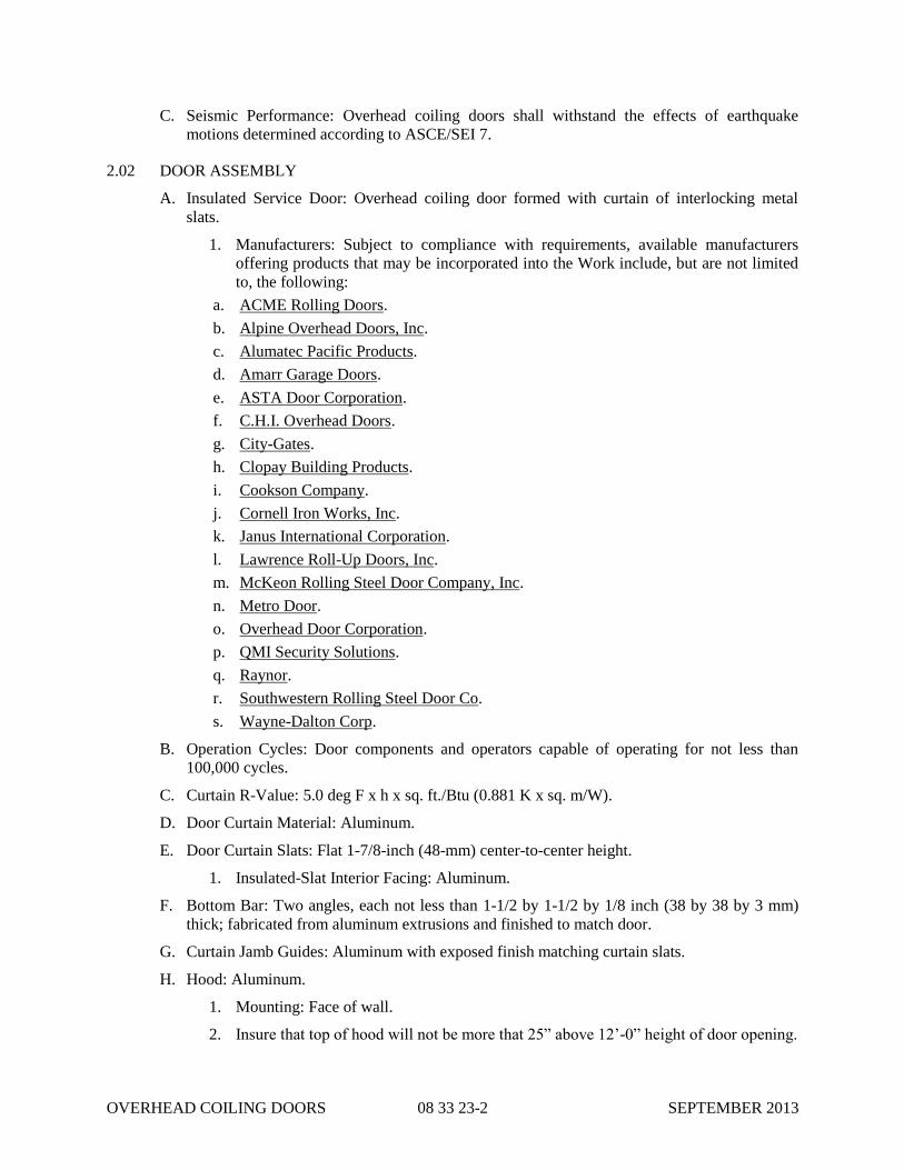
OVERHEAD COILING DOORS 08 33 23-2 SEPTEMBER 2013
C. Seismic Performance: Overhead coiling doors shall withstand the effects of earthquake
motions determined according to ASCE/SEI 7.
2.02 DOOR ASSEMBLY
A. Insulated Service Door: Overhead coiling door formed with curtain of interlocking metal
slats.
1. Manufacturers: Subject to compliance with requirements, available manufacturers
offering products that may be incorporated into the Work include, but are not limited
to, the following:
a. ACME Rolling Doors.
b. Alpine Overhead Doors, Inc.
c. Alumatec Pacific Products.
d. Amarr Garage Doors.
e. ASTA Door Corporation.
f. C.H.I. Overhead Doors.
g. City-Gates.
h. Clopay Building Products.
i. Cookson Company.
j. Cornell Iron Works, Inc.
k. Janus International Corporation.
l. Lawrence Roll-Up Doors, Inc.
m. McKeon Rolling Steel Door Company, Inc.
n. Metro Door.
o. Overhead Door Corporation.
p. QMI Security Solutions.
q. Raynor.
r. Southwestern Rolling Steel Door Co.
s. Wayne-Dalton Corp.
B. Operation Cycles: Door components and operators capable of operating for not less than
100,000 cycles.
C. Curtain R-Value: 5.0 deg F x h x sq. ft./Btu (0.881 K x sq. m/W).
D. Door Curtain Material: Aluminum.
E. Door Curtain Slats: Flat 1-7/8-inch (48-mm) center-to-center height.
1. Insulated-Slat Interior Facing: Aluminum.
F. Bottom Bar: Two angles, each not less than 1-1/2 by 1-1/2 by 1/8 inch (38 by 38 by 3 mm)
thick; fabricated from aluminum extrusions and finished to match door.
G. Curtain Jamb Guides: Aluminum with exposed finish matching curtain slats.
H. Hood: Aluminum.
1. Mounting: Face of wall.
2. Insure that top of hood will not be more that 25” above 12’-0” height of door opening.

OVERHEAD COILING DOORS 08 33 23-3 SEPTEMBER 2013
I. Locking Devices: Equip door with locking device assembly and chain lock keeper.
1. Locking Device Assembly: Cremone type, both jamb sides locking bars, operable
from inside and outside with cylinders.
J. Manual Door Operator: Chain-hoist operator.
K. Curtain Accessories: Equip door with weatherseals, push/pull handles, pull-down strap.
L. Door Finish:
1. Aluminum Finish: Clear anodized.
2. Interior Curtain-Slat Facing: Match finish of exterior curtain-slat face.
2.03 LOCKING DEVICES
A. Slide Bolt: Fabricate with side-locking bolts to engage through slots in tracks for locking by
padlock, located on both left and right jamb sides, operable from coil side.
B. Locking Device Assembly: Fabricate with cylinder lock, spring-loaded dead bolt, operating
handle, cam plate, and adjustable locking bars to engage through slots in tracks.
1. Lock Cylinders: Cylinders standard with manufacturer and keyed to building keying
system.
2. Keys: Three for each cylinder.
C. Chain Lock Keeper: Suitable for padlock.
2.04 CURTAIN ACCESSORIES
A. Weatherseals for Exterior Doors: Equip each exterior door with weather-stripping gaskets
fitted to entire exterior perimeter of door for a weather-resistant installation unless otherwise
indicated.
B. Push/Pull Handles: Equip each push-up-operated or emergency-operated door with lifting
handles on each side of door, finished to match door.
C. Pull-Down Strap: Provide pull-down straps for doors more than 84 inches (2130 mm) high.
2.05 COUNTERBALANCING MECHANISM
A. General: Counterbalance doors by means of manufacturer's standard mechanism with an
adjustable-tension, steel helical torsion spring mounted around a steel shaft and contained in a
spring barrel connected to top of curtain with barrel rings. Use grease-sealed bearings or self-
lubricating graphite bearings for rotating members.
B. Brackets: Manufacturer's standard mounting brackets of either cast iron or cold-rolled steel
plate.
2.06 MANUAL DOOR OPERATORS
A. General: Equip door with manual door operator by door manufacturer.
B. Push-up Door Operation: Lift handles and pull rope for raising and lowering doors, with
counterbalance mechanism designed so that required lift or pull for door operation does not
exceed 25 lbf (111 N).
C. Chain-Hoist Operator: Consisting of endless steel hand chain, chain-pocket wheel and guard,
and gear-reduction unit with a maximum 25-lbf (111-N) force for door operation. Provide

OVERHEAD COILING DOORS 08 33 23-4 SEPTEMBER 2013
alloy-steel hand chain with chain holder secured to operator guide.
PART 3 - EXECUTION
3.01 INSTALLATION
A. Install overhead coiling doors and operating equipment complete with necessary hardware,
anchors, inserts, hangers, and equipment supports; according to manufacturer's written
instructions and as specified.
B. Adjust hardware and moving parts to function smoothly so that doors operate easily, free of
warp, twist, or distortion. Lubricate bearings and sliding parts as recommended by
manufacturer Adjust seals to provide tight fit around entire perimeter.
END OF SECTION 08 33 23

WATERTIGHT DOORS 08 39 19-1 SEPTEMBER 2013
SECTION 08 39 19
WATERTIGHT DOORS
PART 1 - GENERAL
1.01 SECTION INCLUDES
A. Hinged Flood Barrier with frame and hardware.
1.02 RELATED SECTIONS
A. Section 03 30 00 - Cast-In-Place Concrete.
1.03 REFERENCES
A. ASTM B 209 - Standard Specification for Aluminum and Aluminum-Alloy Sheet and Plate.
B. ASTM B 211 - Standard Specification for Aluminum and Aluminum-Alloy Bar, Rod, and
Wire.
C. Aluminum Association - Specification for Aluminum Structures, 7th Edition.
D. ASME Structural Welding Code Section IX.
E. FEMA Technical Bulletin 3-93 - Non-Residential Flood Proofing.
F. SEI/ASCE 7-02 - Minimum Design Loads for Buildings and Other Structures.
G. AWS D1.2 - Structural Welding Code - Aluminum.
H. Aluminum Structures - A Guide to Their Specifications and Design.
1.04 DESIGN / PERFORMANCE REQUIREMENTS
A. Design watertight doors to perform under hydrostatic loads (and hydrodynamic or other loads
as specified) to control short-term load pressures indicated. All water pressure loads and
operating loads are transferred to the building structure.
B. Standard loading: Standard Flood Shields are designed for hydrostatic loading, and have no
additional allowances included for hydrodynamic loads, wave loads or debris impact loads.
C. Design Safety Factor for all watertight door Flood Shield Models of a minimum 2:1. Based
on material ultimate yield strengths.
D. Design Safety Factor for Anchors, minimum of 4:1 for cast-in-place concrete, or minimum of
6:1 for concrete masonry unit construction.
1.05 SUBMITTALS
A. Product Data : Manufacturer's data sheets on each product to be used, including:
1. Preparation instructions and recommendations.
2. Storage and handling requirements and recommendations.
3. Installation instructions.
B. Shop Drawings: Provide shop drawings showing layout, profiles, and product components,
including anchorage, hardware, and finishes. Include dimensional plans, applicable material
specifications, elevations and sections detailing mounting and connections, and load

WATERTIGHT DOORS 08 39 19-2 SEPTEMBER 2013
diagrams.
C. Calculations: Submit calculations approved by a qualified engineer, to verify the flood
shield's ability to withstand the design loading.
D. Closeout Submittals: Provide Operation and Maintenance data to include methods for
maintaining installed products, precautions against cleaning materials and methods
detrimental to finishes and performance.
E. Manufacturer's Certificates: Certify products meet or exceed specified requirements.
1.06 QUALITY ASSURANCE
A. Manufacturer Qualifications: Manufacturer must demonstrate a minimum of five years
successful experience in design and manufacture of similar flood related closures. Upon
request, provide supporting evidence including list of installations, descriptions, name and
method of contact.
B. Welder Qualifications: Welders Certified in accordance with American Welding Society
Procedures: AWS-1-GMAW-S, WPS No. B2.004.90 for applicable material used in
production of specified product.
1.07 DELIVERY, STORAGE, AND HANDLING
A. Store products in manufacturer's unopened packaging container with identification labels
intact until ready for installation.
B. Protect materials from exposure to moisture.
C. Store materials in a dry, warm, ventilated weathertight location. If outdoor storage is
required, block materials to store at an incline, to prevent pooling of any moisture and
promote runoff. Tarp materials in a tent-like arrangement, elevated above the product with
open sides to allow airflow. Store all other hardware in a dry controlled environment.
D. Use caution when unloading and handling product to avoid bending, denting, crushing, or
other damage to the product.
E. When using forklifts, use forks of proper length to fully support product being moved.
Consult shop drawings or consult with factory for proper lift points.
1.08 PROJECT CONDITIONS
A. Maintain environmental conditions (temperature, humidity, and ventilation) within limits
recommended by manufacturer for optimum results. Do not install products under
environmental conditions outside manufacturer's absolute limits.
1.09 COORDINATION
A. Coordinate Work with other operations and installation of adjacent materials to avoid
damage.
1.10 WARRANTY
Refer to Section 01 78 36.
PART 2 - PRODUCTS

WATERTIGHT DOORS 08 39 19-3 SEPTEMBER 2013
2.01 MANUFACTURERS
A. Acceptable Manufacturers: Subject to compliance with requirements, available
manufacturers offering products that may be incorporated into the Work include, but are not
limited to, the following:
1. PS DOORS, which is located at: 1150 S. 48th Street, Grand Forks, ND 58201; Toll Free
Tel: 800-284-0623; Tel: 701-746-4519; Fax: 701-746-8340; Email:
[email protected]; Web: www.flooddoors.com.
2. PRESRAY CORPORATION Critical Containment Solutions; PO Box 200, Wassaic, NY
12592; Phone: (845) 373-9300; www.presray.com.
3. Walz & Krenzer, Inc.; 91 Willenbrock Rd., Unit B4; Oxford, CT 06478; Phone: (203)
267-5712; [email protected]
4. Standard Equipment Company, Inc.; 75 Beauregard Street, Mobile, AL 36602; Phone:
(800) 239-3442; www.standardequipmentclosures.com
5. JUNIPER INDUSTRIES, INC.; 72-15 Metropolitan Avenue; PO Box 148; Middle
Village, NY 11379; Phone: (718) 326-2546; www.juniperind.com
B. Hinged Pedestrian Flood Door
C. Obtain all watertight doors and flood shields assemblies from single manufacturer.
2.02 EQUIPMENT
A. Watertight Doors: Provide the following doors:
1. Hinged Swing Flood Shield, Single Swing.
B. Products Details:
1. Sealing Requirements: Flood Shield and gasket design shall provide an effective barrier
against short-term high water situations, to above opening height.
2. Operation: Provide with latching operable from both sides.
3. Mounting/Load Transfer: Anchor to existing structure. Flood Shield designed for
specified hydrostatic pressure (and other loads as specified) and will transfer loads to
adjacent structure.
4. Frames to be anchored utilizing mechanical, chemical or other anchor types.
Manufacturer to include all anchors, water-stop, and sealants.
5. Loading Direction Selection: Positive Pressure Loading: (Direction of loading against
flood shield so as to further compress gaskets against flood shield frame-"seating").
6. Provide rectangular door opening with square corners to facilitate easy passage.
7. Provide compression gasket which requires no inflation.
2.03 MATERIALS
A. Flood Shield:
1. Steel: Structural or formed steel shapes conforming to ASTM A 36; tubing conforming
to ASTM A 500 Grade B, ASTM A 513; bars conforming to ASTM A 36, M1020; of
appropriate size and strength with welded construction.
2. Aluminum: 6063 alloy conforming to ASTM B 211.

WATERTIGHT DOORS 08 39 19-4 SEPTEMBER 2013
B. Panel Sheeting: Flood Shield to be sheeted with steel sheeting or plate, Commercial Quality-
Low Carbon ASTM-A-569, ASTM-A-366, ASTM-A-36 welded in place. Optional materials
include Stainless Steel (304 or 316) or Aluminum (6061).
1. Aluminum: 6063 alloy conforming to ASTM B 209
C. Gaskets to be factory mounted to flood shield assembly. Gaskets to be compressible rubber
type, typically EPDM unless otherwise noted, and to be field replaceable.
D. Frame to include jamb, head, and sill members for field locating and installation on structure.
Jamb members to be designed and fabricated with appropriate material as required for the
loading.
1. Aluminum: 6063 alloy conforming to ASTM B 26.
2. Aluminum: 6061 alloy ASTM B 209.
E. Threshold:
1. Aluminum: 6063 alloy conforming to ASTM B 26.
2. Aluminum: 6061 alloy ASTM B 209.
F. Frame Mounting Hardware: Provide anchors, sealant, and water stop, as required.
G. Operating Hardware: Provide hardware sized for the size and weight of the flood shield and
loads. Hardware to be factory located on jambs and shield panels, as practical. All loads are
transferred to building structure. Latching hardware to be as indicated on Drawings. Flood
shield panel to be factory prepared for applicable latching devices.
H. Labeling: Each watertight door and frame will be individually identified for matched
installation.
I. Instruction Placard: Provide pictorial and written operation instruction placards on flood
shield.
2.04 FABRICATION
A. Fit and shop assemble items in largest practical sections, for delivery to site.
B. Fabricate items with joints tightly fitted and secured.
C. Supply components required for anchorage of fabrications. Fabricate anchors and related
components of same material and finish as fabrication, except where specifically noted
otherwise.
PART 3 - EXECUTION
3.01 EXAMINATION
A. Do not begin installation until substrates have been properly prepared.
B. If substrate preparation is the responsibility of another installer, notify Architect of
unsatisfactory preparation before proceeding.
3.02 PREPARATION
A. Clean surfaces thoroughly prior to installation.
B. Prepare surfaces using the methods recommended by the manufacturer for achieving the best

WATERTIGHT DOORS 08 39 19-5 SEPTEMBER 2013
result for the substrate under the Project conditions.
3.03 INSTALLATION
A. Install in accordance with manufacturer's installations instructions, approved shop drawings,
shipping, handling, and storage instructions, and product carton instructions for installation.
B. Frames shall be installed level, square, plumb, and rigid.
C. Sealants, water-stop, and grouting to be applied per product application directions and in
accordance with manufacturer's instructions.
D. Field Grouting to be completed by appropriate personnel, and in accordance with product
application directions and manufacturer's instructions.
E. Tolerances: All dimensional requirements must be in accordance with manufacturer's
installation instructions and shop drawings.
F. Field Testing:
1. Perform visual dry test for gasket alignment, continuity contact and pre-compression.
2. Construct temporary water barrier and test installed flood barrier.
3.04 FIELD QUALITY CONTROL
A. Manufacturers representative to verify that installation of assembly and that the perimeter
conditions are in conformance to the manufacturer's recommendations.
B. Products to be operated and field verified including the sealing surfaces to assure that they
maintain contact at the correct sealing points.
C. Verify that hinging and latching assemblies operate freely and correctly.
D. Verify all anchorage is in accordance with manufacture's installation instructions and
applicable data sheets.
3.05 CLEANING
A. Repair or replace damaged installed products or components.
B. Clean all sealing surfaces.
C. Touch up damaged finish.
3.06 PROTECTION
A. Protect installed products until completion of Project.
B. Touch-up, repair or replace damaged products before Substantial Completion.
END OF SECTION 08 39 19

WATERTIGHT DOORS 08 39 19-6 SEPTEMBER 2013
THIS PAGE INTENTIONALLY LEFT BLANK

ALUMINUM WINDOWS 08 51 13-1 SEPTEMBER 2013
SECTION 08 51 13
ALUMINUM WINDOWS
PART 1 - GENERAL
1.01 SUMMARY
A. Section includes aluminum windows for exterior locations.
1.02 ACTION SUBMITTALS
A. Product Data: For each type of product.
B. Shop Drawings: Include plans, elevations, sections, hardware, accessories, insect screens,
operational clearances, and details of installation, including anchor, flashing, and sealant
installation.
C. Samples: For each exposed product and for each color specified, 2 by 4 inches (50 by 100
mm) in size.
D. Product Schedule: For aluminum windows. Use same designations indicated on Drawings.
1.03 INFORMATIONAL SUBMITTALS
A. Product test reports.
B. Sample warranties.
1.04 WARRANTY
A. Manufacturer's Warranty: Manufacturer agrees to repair or replace aluminum windows that
fail in materials or workmanship within specified warranty period.
1. Warranty Period:
a. Window: 10 years from date of Substantial Completion.
b. Glazing Units: Five years from date of Substantial Completion.
c. Aluminum Finish: 10 years from date of Substantial Completion.
B. Refer to Section 01 78 36 for additional requirements.
PART 2 - PRODUCTS
2.01 MANUFACTURERS
A. Manufacturers: Subject to compliance with requirements, available manufacturers offering
products that may be incorporated into the Work include, but are not limited to, the
following:
1. All Seasons Window & Door Mfg., Inc.; All Seasons Commercial Division, Inc.
2. Boyd Aluminum Manufacturing.
3. Custom Window Company.
4. DeSCo Architectural Inc.

ALUMINUM WINDOWS 08 51 13-2 SEPTEMBER 2013
5. EFCO Corporation; a Pella company.
6. EXTECH Exterior Technologies, Inc.
7. Fleetwood Windows & Doors.
8. Gerkin Windows and Doors.
9. Graham Architectural Products Corp.
10. Kawneer North America; an Alcoa company.
11. Mannix Exterior Wall Systems, Inc.
12. Peerless Products Inc.
13. Quaker Windows Products Co.
14. Thermal Windows, Inc.
15. TRACO.
16. Wausau Window and Wall Systems.
17. Winco.
18. YKK AP America Inc.
2.02 WINDOW PERFORMANCE REQUIREMENTS
A. Product Standard: AAMA/WDMA/CSA 101/I.S.2/A440.
1. Minimum Performance Class: AW.
2. Minimum Performance Grade: 50.
B. Thermal Transmittance: NFRC 100 maximum whole-window U-factor of 0.42 Btu/sq. ft. x h
x deg F (3.43 W/sq. m x K).
C. Solar Heat-Gain Coefficient (SHGC): NFRC 200 maximum whole-window SHGC of 0.30.
D. Condensation-Resistance Factor (CRF): Provide aluminum windows tested for thermal
performance according to AAMA 1503, showing a CRF of minimum 60 frame and 69 glass.
2.03 ALUMINUM WINDOWS
A. Frames: Thermally broken aluminum extrusions complying with
AAMA/WDMA/CSA 101/I.S.2/A440.
B. Insulating-Glass Units: ASTM E 2190.
1. Glass: ASTM C 1036, Type 1, Class 1, q3.
a. Tint: Gray.
b. Kind: Fully tempered where indicated on Drawings.
2. Lites: Two.
3. Filling: Fill space between glass lites with argon.
4. Low-E Coating: Pyrolytic on second surface.
C. Glazing System: Manufacturer's standard factory-glazing system that produces weathertight
seal.
1. AAiirr IInnffiillttrraattiioonn:: mmeeeett AAAAMMAA 110011 ssttaannddaarrdd ooff mmaaxxiimmuumm ..11 ccffmm//ssqquuaarree ffoooott wwhheenn tteesstteedd

ALUMINUM WINDOWS 08 51 13-3 SEPTEMBER 2013
ppeerr AASSTTMM EE 228833--0044 aatt aa ssttaattiicc aaiirr pprreessssuurree ddiiffffeerreennccee ooff 66..2244 ppssff..
2. WWaatteerr PPeenneettrraattiioonn:: nnoo uunnccoonnttrroolllleedd wwaatteerr lleeaakkaaggee wwhheenn tteesstteedd ppeerr AASSTTMM EE 333311--0000 aatt aa
ssttaattiicc aaiirr pprreessssuurree ddiiffffeerreennccee ooff 1122 ppssff..
3. UUnniiffoorrmm DDeefflleeccttiioonn:: nnoo mmoorree tthhaann LL//117755 wwhheenn tteesstteedd ppeerr AASSTTMM EE 333300--0022 aatt aa ssttaattiicc aaiirr
pprreessssuurree ddiiffffeerreennccee ooff 110000 ppssff..
4. UUnniiffoorrmm SSttrruuccttuurraall LLooaadd:: nnoo ggllaassss bbrreeaakkaaggee oorr ppeerrmmaanneenntt ddaammaaggee ttoo ffaasstteenneerrss,, aanndd
mmaaxxiimmuumm ..22%% ppeerrmmaanneenntt ddeeffoorrmmaattiioonn ooff tthhee ssppaann ooff aannyy ffrraammee mmeemmbbeerr wwhheenn tteesstteedd ppeerr
AASSTTMM EE 333300--0022 aatt aa ssttaattiicc aaiirr pprreessssuurree ddiiffffeerreennccee ooff 115500 ppssff..
D. Weather Stripping: Provide full-perimeter weather stripping for each operable sash unless
otherwise indicated.
E. Fasteners: Noncorrosive and compatible with window members, trim, hardware, anchors, and
other components.
1. Exposed Fasteners: Do not use exposed fasteners to the greatest extent possible. For
application of hardware, use fasteners that match finish hardware being fastened.
2.04 ACCESSORIES
A. Subsills: Thermally broken, extruded-aluminum subsills in configurations indicated on
Drawings.
B. Column Covers: Extruded-aluminum profiles in sizes and configurations indicated on
Drawings.
C. Interior Trim: Extruded-aluminum profiles in sizes and configurations indicated on Drawings.
D. Panning Trim: Extruded-aluminum profiles in sizes and configurations indicated on
Drawings.
E. Receptor System: Two-piece, snap-together, thermally broken, extruded-aluminum receptor
system that anchors windows in place.
2.05 FABRICATION
A. Fabricate aluminum windows in sizes indicated. Include a complete system for assembling
components and anchoring windows.
B. Glaze aluminum windows in the factory.
C. Provide weep holes and internal passages to conduct infiltrating water to exterior.
D. Provide mullions and cover plates, matching window units, complete with anchors for
support to structure and installation of window units. Allow for erection tolerances and
provide for movement of window units due to thermal expansion and building deflections, as
indicated. Provide mullions and cover plates capable of withstanding design wind loads of
window units.
E. Complete fabrication, assembly, finishing, hardware application, and other work in the
factory to greatest extent possible. Disassemble components only as necessary for shipment
and installation.
2.06 ALUMINUM FINISHES
A. Anodic Finish: Class I complying with AAMA 611.

ALUMINUM WINDOWS 08 51 13-4 SEPTEMBER 2013
1. Color: Clear.
PART 3 - EXECUTION
3.01 INSTALLATION
A. Comply with manufacturer's written instructions for installing windows, hardware,
accessories, and other components. For installation procedures and requirements not
addressed in manufacturer's written instructions, comply with installation requirements in
ASTM E 2112.
B. Install windows level, plumb, square, true to line, without distortion or impeding thermal
movement, anchored securely in place to structural support, and in proper relation to wall
flashing and other adjacent construction to produce weathertight construction.
C. Install windows and components to drain condensation, water penetrating joints, and moisture
migrating within windows to the exterior.
D. Separate aluminum and other corrodible surfaces from sources of corrosion or electrolytic
action at points of contact with other materials.
E. Adjust operating sashes and hardware for a tight fit at contact points and weather stripping for
smooth operation and weathertight closure.
F. Clean exposed surfaces immediately after installing windows. Avoid damaging protective
coatings and finishes. Remove excess sealants, glazing materials, dirt, and other substances.
G. Remove and replace glass that has been broken, chipped, cracked, abraded, or damaged
during construction period.
END OF SECTION 08 51 13

DOOR HARDWARE 08 71 00-1 SEPTEMBER 2013
SECTION 08 71 00
DOOR HARDWARE
PART 1 - GENERAL
1.01 SUMMARY
A. Section includes:
1. Mechanical door hardware for the following:
a. Swinging doors.
2. Cylinders for door hardware specified in other Sections.
3. Electrified door hardware.
B. Products furnished, but not installed, under this Section include the products listed below.
Coordinating and scheduling the purchase and delivery of these products remain requirements
of this Section.
1. Pivots, thresholds, weather stripping, lock cylinders to be installed under other Sections.
1.02 ACTION SUBMITTALS
A. Product Data: For each type of product indicated.
B. Shop Drawings: Details of electrified door hardware.
C. Samples: For each exposed product and for each color and texture specified.
D. Other Action Submittals:
1. Door Hardware Schedule: Prepared by or under the supervision of Installer, detailing
fabrication and assembly of door hardware, as well as installation procedures and
diagrams. Coordinate final door hardware schedule with doors, frames, and related work
to ensure proper size, thickness, hand, function, and finish of door hardware.
a. Format: Use same scheduling sequence and format and use same door numbers as in
the Contract Documents.
b. Content: Include the following information:
i. Identification number, location, hand, fire rating, size, and material of each door
and frame.
ii. Locations of each door hardware set, cross-referenced to Drawings on floor plans
and to door and frame schedule.
iii. Complete designations, including name and manufacturer, type, style, function,
size, quantity, function, and finish of each door hardware product.
iv. Description of electrified door hardware sequences of operation and interfaces
with other building control systems.
2. Keying Schedule: Prepared by or under the supervision of Installer, detailing Owner's
final keying instructions for locks.
1.03 MAINTENANCE MATERIAL SUBMITTALS
A. Furnish extra materials that match products installed and that are packaged with protective
covering for storage and identified with labels describing contents.

DOOR HARDWARE 08 71 00-2 SEPTEMBER 2013
1. Door Hardware.
2. Electrical Parts.
1.04 QUALITY ASSURANCE
A. Installer Qualifications: Supplier of products and an employer of workers trained and
approved by product manufacturers and an Architectural Hardware Consultant who is
available during the course of the Work to consult with Contractor, Architect, and Owner
about door hardware and keying.
B. Architectural Hardware Consultant Qualifications: A person who is experienced in providing
consulting services for door hardware installations that are comparable in material, design,
and extent to that indicated for this Project and who is currently certified by DHI as follows:
1. For door hardware, an Architectural Hardware Consultant (AHC) who is also an
Electrified Hardware Consultant (EHC).
C. Source Limitations: Provide electrified door hardware from same manufacturer as mechanical
door hardware, unless otherwise indicated. Manufacturers that perform electrical
modifications and that are listed by a testing and inspecting agency acceptable to authorities
having jurisdiction are acceptable.
1. Air Leakage Rate: Maximum air leakage of 0.3 cfm/sq. ft. (3 cu. m per minute/sq. m) at
the tested pressure differential of 0.3-inch wg (75 Pa) of water.
D. Electrified Door Hardware: Listed and labeled as defined in NFPA 70, Article 100, by a
testing agency acceptable to authorities having jurisdiction.
E. Means of Egress Doors: Latches do not require more than 15 lbf (67 N) to release the latch.
Locks do not require use of a key, tool, or special knowledge for operation.
F. Accessibility Requirements: For door hardware on doors in an accessible route, comply with
the U.S. Architectural & Transportation Barriers Compliance Board's ADA-ABA
Accessibility Guidelines.
1. Provide operating devices that do not require tight grasping, pinching, or twisting of the
wrist and that operate with a force of not more than 5 lbf (22.2 N).
2. Comply with the following maximum opening-force requirements:
a. Interior, Non-Fire-Rated Hinged Doors: 5 lbf (22.2 N) applied perpendicular to door.
b. Fire Doors: Minimum opening force allowable by authorities having jurisdiction.
3. Bevel raised thresholds with a slope of not more than 1:2. Provide thresholds not more
than 1/2 inch (13 mm) high.
4. Adjust door closer sweep periods so that, from an open position of 70 degrees, the door
will take at least 3 seconds to move to a point 3 inches (75 mm) from the latch, measured
to the leading edge of the door.
G. Keying Conference: Conduct conference at Project site.
1.05 DELIVERY, STORAGE, AND HANDLING
A. Deliver keys to manufacturer of key control system for subsequent delivery to CITY.
1.06 WARRANTY
A. Special Warranty: Manufacturer's standard form in which manufacturer agrees to repair or

DOOR HARDWARE 08 71 00-3 SEPTEMBER 2013
replace components of door hardware that fail in materials or workmanship within specified
warranty period.
1. Warranty Period: Three years from date of Substantial Completion, unless otherwise
indicated.
a. Electromagnetic Locks: Five years from date of Substantial Completion.
b. Exit Devices: Two years from date of Substantial Completion.
c. Manual Closers: 10 years from date of Substantial Completion.
B. Refer to Section 01 78 36 for additional requirements.
PART 2 - PRODUCTS
2.01 SCHEDULED DOOR HARDWARE
A. Provide door hardware for each door as scheduled in Part 3 "Door Hardware Schedule"
Article to comply with requirements in this Section.
1. Door Hardware Sets: Provide quantity, item, size, finish or color indicated, and products
equivalent in function and comparable in quality to named products.
2. Sequence of Operation: Provide electrified door hardware function, sequence of
operation, and interface with other building control systems indicated.
B. Designations: Requirements for design, grade, function, finish, size, and other distinctive
qualities of each type of door hardware are indicated in Part 3 "Door Hardware Schedule"
Article. Products are identified by using door hardware designations, as follows:
1. Named Manufacturers' Products: Manufacturer and product designation are listed for
each door hardware type required for the purpose of establishing minimum requirements.
Manufacturers' names are abbreviated in Part 3 "Door Hardware Schedule" Article.
2.02 HINGES
A. Hinges: BHMA A156.1. Provide template-produced hinges for hinges installed on hollow-
metal or aluminum doors and hollow-metal or aluminum frames.
1. Manufacturers: Subject to compliance with requirements, available manufacturers
offering products that may be incorporated into the Work include, but are not limited to,
the following:
a. Baldwin Hardware Corporation.
b. Bommer Industries, Inc.
c. Cal-Royal Products, Inc.
d. Hager Companies.
e. IVES Hardware; an Ingersoll-Rand company.
f. Lawrence Hardware Inc.
g. McKinney Products Company; an ASSA ABLOY Group company.
h. PBB, Inc.
i. Stanley Commercial Hardware; Div. of The Stanley Works.
2.03 MECHANICAL LOCKS AND LATCHES
A. Strikes: Provide manufacturer's standard strike for each lock bolt or latchbolt complying with

DOOR HARDWARE 08 71 00-4 SEPTEMBER 2013
requirements indicated for applicable lock or latch and with strike box and curved lip
extended to protect frame; finished to match lock or latch.
1. Aluminum-Frame Strike Box: Manufacturer's special strike box fabricated for aluminum
framing.
B. Mortise Locks: BHMA A156.13; Operational Grade 1; stamped steel case with steel or brass
parts; Series 1000.
1. Manufacturers: Subject to compliance with requirements, available manufacturers
offering products that may be incorporated into the Work include, but are not limited to,
the following]:
a. Accurate Lock & Hardware Co.
b. Adams Rite Manufacturing Co.; an ASSA ABLOY Group company.
c. Arrow USA; an ASSA ABLOY Group company.
d. Best Access Systems; Div. of Stanley Security Solutions, Inc.
e. Cal-Royal Products, Inc.
f. Corbin Russwin Architectural Hardware; an ASSA ABLOY Group company.
g. Falcon Lock; an Ingersoll-Rand company.
h. Marks USA.
i. PDQ Manufacturing.
j. SARGENT Manufacturing Company; an ASSA ABLOY Group company.
k. Schlage Commercial Lock Division; an Ingersoll-Rand company.
l. Yale Security Inc.; an ASSA ABLOY Group company.
2.04 SELF-CONTAINED ELECTRONIC LOCKS
A. Self-Contained Electronic Locks: BHMA A156.25, mortise; with internal, battery-powered,
self-contained electronic locks; consisting of complete lockset, motor-driven lock
mechanism, and actuating device; enclosed in zinc-dichromate-plated, wrought-steel case,
and strike that suits frame. Provide key override, low-battery detection and warning, LED
status indicators, and ability to program at the lock.
1. Manufacturers: Subject to compliance with requirements, available manufacturers
offering products that may be incorporated into the Work include, but are not limited to,
the following:
a. Best Access Systems; Div. of Stanley Security Solutions, Inc.
b. Kaba Ilco Corp.; a Kaba Group company.
c. Marks USA.
d. SARGENT Manufacturing Company; an ASSA ABLOY Group company.
e. Schlage Commercial Lock Division; an Ingersoll-Rand company.
f. Yale Security Inc.; an ASSA ABLOY Group company.
2.05 EXIT DEVICES AND AUXILIARY ITEMS
A. Exit Devices and Auxiliary Items: BHMA A156.3.
1. Manufacturers: Subject to compliance with requirements, available manufacturers
offering products that may be incorporated into the Work include, but are not limited to,
the following:

DOOR HARDWARE 08 71 00-5 SEPTEMBER 2013
a. Adams Rite Manufacturing Co.; an ASSA ABLOY Group company.
b. Arrow USA; an ASSA ABLOY Group company.
c. Cal-Royal Products, Inc.
d. Corbin Russwin Architectural Hardware; an ASSA ABLOY Group company.
e. Detex Corporation.
f. Door Controls International, Inc.
g. DORMA Architectural Hardware; Member of The DORMA Group North America.
h. Dor-O-Matic; an Ingersoll-Rand company.
i. K2 Commercial Hardware; a Black & Decker Corp. company.
j. Monarch Exit Devices & Panic Hardware; an Ingersoll-Rand company.
k. Precision Hardware, Inc.; Division of Stanley Security Solutions, Inc.
l. Rutherford Controls Int'l. Corp.
m. SARGENT Manufacturing Company; an ASSA ABLOY Group company.
n. Von Duprin; an Ingersoll-Rand company.
o. Yale Security Inc.; an ASSA ABLOY Group company.
2.06 LOCK CYLINDERS
A. Lock Cylinders: Tumbler type, constructed from brass or bronze, stainless steel, or nickel
silver.
1. Manufacturer: Same manufacturer as for locking devices.
2. Manufacturers: Subject to compliance with requirements, available manufacturers
offering products that may be incorporated into the Work include, but are not limited to,
the following:
a. Arrow USA; an ASSA ABLOY Group company.
b. ASSA, Inc.; An ASSA ABLOY Group Company.
c. Best Access Systems; Div. of Stanley Security Solutions, Inc.
d. Corbin Russwin Architectural Hardware; an ASSA ABLOY Group company.
e. Falcon Lock; an Ingersoll-Rand company.
f. Medeco Security Locks, Inc.; an ASSA ABLOY Group company.
g. SARGENT Manufacturing Company; an ASSA ABLOY Group company.
h. Schlage Commercial Lock Division; an Ingersoll-Rand company.
i. Yale Security Inc.; an ASSA ABLOY Group company.
B. Construction Master Keys: Provide cylinders with feature that permits voiding of
construction keys without cylinder removal. Provide 10 construction master keys.
2.07 KEYING
A. Keying System: Factory registered, complying with guidelines in BHMA A156.28,
Appendix A. Incorporate decisions made in keying conference.
1. Master Key System: Change keys and a master key operate cylinders.
B. Keys: Brass.
1. Stamping: Permanently inscribe each key with a visual key control number and include
the following notation:

DOOR HARDWARE 08 71 00-6 SEPTEMBER 2013
a. Notation: Information to be furnished by Owner.
2. Quantity: In addition to one extra key blank for each lock, provide the following:
a. Cylinder Change Keys: Three.
b. Master Keys: Five.
2.08 OPERATING TRIM
A. Operating Trim: BHMA A156.6; aluminum, unless otherwise indicated.
1. Manufacturers: Subject to compliance with requirements, available manufacturers
offering products that may be incorporated into the Work include, but are not limited to,
the following:
a. Burns Manufacturing Incorporated.
b. Don-Jo Mfg., Inc.
c. Forms + Surfaces.
d. Hager Companies.
e. Hiawatha, Inc.
f. IVES Hardware; an Ingersoll-Rand company.
g. Rockwood Manufacturing Company.
h. Trimco.
2.09 SURFACE CLOSERS
A. Surface Closers: BHMA A156.4; rack-and-pinion hydraulic type with adjustable sweep and
latch speeds controlled by key-operated valves and forged-steel main arm. Comply with
manufacturer's written recommendations for size of door closers depending on size of door,
exposure to weather, and anticipated frequency of use. Provide factory-sized closers,
adjustable to meet field conditions and requirements for opening force.
1. Manufacturers: Subject to compliance with requirements, available manufacturers
offering products that may be incorporated into the Work include, but are not limited to,
the following:
a. Arrow USA; an ASSA ABLOY Group company.
b. Corbin Russwin Architectural Hardware; an ASSA ABLOY Group company.
c. DORMA Architectural Hardware; Member of The DORMA Group North America.
d. Dor-O-Matic; an Ingersoll-Rand company.
e. K2 Commercial Hardware; a Black & Decker Corp. company.
f. LCN Closers; an Ingersoll-Rand company.
g. Norton Door Controls; an ASSA ABLOY Group company.
h. Rixson Specialty Door Controls; an ASSA ABLOY Group company.
i. SARGENT Manufacturing Company; an ASSA ABLOY Group company.
j. Yale Security Inc.; an ASSA ABLOY Group company.
2.10 MECHANICAL STOPS AND HOLDERS
A. Wall- and Floor-Mounted Stops: BHMA A156.16; aluminum base metal.
1. Manufacturers: Subject to compliance with requirements, available manufacturers
offering products that may be incorporated into the Work include, but are not limited to,

DOOR HARDWARE 08 71 00-7 SEPTEMBER 2013
the following:
a. Architectural Builders Hardware Mfg., Inc.
b. Baldwin Hardware Corporation.
c. Burns Manufacturing Incorporated.
d. Cal-Royal Products, Inc.
e. Don-Jo Mfg., Inc.
f. Door Controls International, Inc .
g. Hager Companies.
h. Hiawatha, Inc.
i. IVES Hardware; an Ingersoll-Rand company.
j. Rockwood Manufacturing Company.
k. Stanley Commercial Hardware; Div. of The Stanley Works.
l. Trimco.
2.11 DOOR GASKETING
A. Door Gasketing: BHMA A156.22; air leakage not to exceed 0.50 cfm per foot (0.000774 cu.
m/s per m) of crack length for gasketing other than for smoke control, as tested according to
ASTM E 283; with resilient or flexible seal strips that are easily replaceable and readily
available from stocks maintained by manufacturer.
1. Manufacturers: Subject to compliance with requirements, available manufacturers
offering products that may be incorporated into the Work include, but are not limited to,
the following:
a. Hager Companies.
b. M-D Building Products, Inc.
c. National Guard Products.
d. Pemko Manufacturing Co.; an ASSA ABLOY Group company.
e. Reese Enterprises, Inc.
f. Sealeze; a unit of Jason Incorporated.
g. Zero International.
2.12 THRESHOLDS
A. Thresholds: BHMA A156.21; fabricated to full width of opening indicated.
1. Manufacturers: Subject to compliance with requirements, available manufacturers
offering products that may be incorporated into the Work include, but are not limited to,
the following:
a. Hager Companies.
b. M-D Building Products, Inc.
c. National Guard Products.
d. Pemko Manufacturing Co.; an ASSA ABLOY Group company.
e. Reese Enterprises, Inc.
f. Rixson Specialty Door Controls; an ASSA ABLOY Group company.
g. Sealeze; a unit of Jason Incorporated.
h. Zero International.

DOOR HARDWARE 08 71 00-8 SEPTEMBER 2013
2.13 FABRICATION
A. Fasteners: Provide door hardware manufactured to comply with published templates prepared
for machine, wood, and sheet metal screws. Provide screws that comply with commercially
recognized industry standards for application intended, except aluminum fasteners are not
permitted. Provide Phillips flat-head screws with finished heads to match surface of door
hardware, unless otherwise indicated.
1. Spacers or Sex Bolts: For through bolting of hollow-metal doors.
2. Gasketing Fasteners: Provide noncorrosive fasteners.
2.14 FINISHES
A. Provide finishes complying with BHMA A156.18 as indicated in door hardware schedule.
B. Protect mechanical finishes on exposed surfaces from damage by applying a strippable,
temporary protective covering before shipping.
PART 3 - EXECUTION
3.01 INSTALLATION
A. Aluminum Doors and Frames: For surface applied door hardware, drill and tap doors and
frames according to ANSI/SDI A250.6.
B. Mounting Heights: Mount door hardware units at heights indicated on Drawings unless
otherwise indicated or required to comply with governing regulations.
1. Standard Steel/Aluminum Doors and Frames: ANSI/SDI A250.8.
2. Custom Steel/Aluminum Doors and Frames: HMMA 831.
C. Install each door hardware item to comply with manufacturer's written instructions. Where
cutting and fitting are required to install door hardware onto or into surfaces that are later to
be painted or finished in another way, coordinate removal, storage, and reinstallation of
surface protective trim units with finishing work. Do not install surface-mounted items until
finishes have been completed on substrates involved.
1. Set units level, plumb, and true to line and location. Adjust and reinforce attachment
substrates as necessary for proper installation and operation.
2. Drill and countersink units that are not factory prepared for anchorage fasteners. Space
fasteners and anchors according to industry standards.
D. Hinges: Install types and in quantities indicated in door hardware schedule but not fewer than
the number recommended by manufacturer for application indicated or one hinge for every
30 inches (750 mm) of door height, whichever is more stringent, unless other equivalent
means of support for door, such as spring hinges or pivots, are provided.
E. Lock Cylinders: Install construction cores to secure building and areas during construction
period.
1. Replace construction cores with permanent cores as directed by Owner.
F. Thresholds: Set thresholds for exterior doors and other doors indicated in full bed of sealant
complying with requirements specified in Section 079200 "Joint Sealants."
G. Stops: Provide floor stops for doors unless wall or other type stops are indicated in door

DOOR HARDWARE 08 71 00-9 SEPTEMBER 2013
hardware schedule. Do not mount floor stops where they will impede traffic.
H. Perimeter Gasketing: Apply to head and jamb, forming seal between door and frame.
I. Meeting Stile Gasketing: Fasten to meeting stiles, forming seal when doors are closed.
J. Door Bottoms: Apply to bottom of door, forming seal with threshold when door is closed.
K. Adjustment: Adjust and check each operating item of door hardware and each door to ensure
proper operation or function of every unit. Replace units that cannot be adjusted to operate as
intended. Adjust door control devices to compensate for final operation of heating and
ventilating equipment and to comply with referenced accessibility requirements.
3.02 DOOR HARDWARE SCHEDULE
A. Aluminum Doors and Frames: For surface applied door hardware, drill and tap doors and
frames according to ANSI/SDI A250.6.
04-SCREENINGS BUILDING:
HARDWARE SET #02-01:
DOOR NUMBER:
101A
ROLL-UP DOOR – ALL HARDWARE FROM DOOR MANUFACTURER
HARDWARE SET #02-02:
DOOR NUMBER:
102A
1EA PADLOCK
4EA HINGE A5112 – Stainless Steel 4-1/2x4-1/2
HARDWARE SET #02-03:
DOOR NUMBER:
103A
WATERPROOF DOOR – ALL HARDWARE FROM DOOR MANUFACTURER
HARDWARE SET #02-04:
DOOR NUMBER:
301A, 301B
1SET SEAL 5050C HEAD & JAMB CHA NGP
1EA THRESHOLD 896S 628 NGP
1EA KICK PLATE 8400 12x1-1/2 LDW X B4E 630 IVE
1EA SURFACE CLOSER 4041-EDA 689 LCN
1EA ENTRANCE LOCK L9453 629 SCH
1EA EXIT DEVICE 9875 629 VON
1EA KEYPAD DL2700WP 26D TRI
3EA SILENCER SR64 GRY IVE
4EA HINGE A5112 – Stainless Steel 4-1/2x4-1/2 629 IVE

DOOR HARDWARE 08 71 00-10 SEPTEMBER 2013
08-OPERATIONS BUILDING:
HARDWARE SET #08-01:
DOOR NUMBER:
101A
1SET SEAL 5050C HEAD & JAMB CHA NGP
1EA THRESHOLD 896S 628 NGP
1EA KICK PLATE 8400 12x1-1/2 LDW X B4E 630 IVE
1EA SURFACE CLOSER 4041-EDA 689 LCN
1EA ENTRANCE LOCK L9453 629 SCH
1EA EXIT DEVICE 9875 629 VON
1EA KEYPAD DL2700WP 26D TRI
3EA SILENCER SR64 GRY IVE
4EA HINGE A5112 – Stainless Steel 4-1/2x4-1/2 629 IVE
HARDWARE SET #08-02:
DOOR NUMBER:
102
1EA KICK PLATE 8400 12x1-1/2 LDW X B4E 630 IVE
1EA BATH PRIVACY LOCK L9040 (ANSI F22) 629 SCH
3EA SILENCER SR64 GRY IVE
4EA HINGE A5112 – Stainless Steel 4-1/2x4-1/2 629 IVE
HARDWARE SET #08-03:
DOOR NUMBER:
103A
1EA STOREROOM LATCH L9465 629 SCH
6EA SILENCER SR64 GRY IVE
8EA HINGE A5112 – Stainless Steel 4-1/2x4-1/2 629 IVE
END OF SECTION 08 71 00

GLAZING 08 80 00-1 SEPTEMBER 2013
SECTION 08 80 00
GLAZING
PART 1 - GENERAL
1.01 SUMMARY
A. Section includes glazing for the following products and applications, including those
specified in other Sections where glazing requirements are specified by reference to this
Section:
1. Windows.
2. Doors.
1.02 PERFORMANCE REQUIREMENTS
A. Vertical Glazing: For glass surfaces sloped 15 degrees or less from vertical, design glass to
resist design wind pressure based on glass type factors for short-duration load.
B. Differential Shading: Design glass to resist thermal stresses induced by differential shading
within individual glass lites.
1.03 PRECONSTRUCTION TESTING
A. Preconstruction Adhesion and Compatibility Testing: Test each glazing material type, tape
sealant, gasket, glazing accessory, and glass-framing member for adhesion to and
compatibility with elastomeric glazing sealants.
1. Testing will not be required if data are submitted based on previous testing of current
sealant products and glazing materials matching those submitted.
1.04 ACTION SUBMITTALS
A. Product Data: For each glass product and glazing material indicated.
B. Glass Samples: For each type of glass product other than clear monolithic vision glass; 12
inches (300 mm) square.
C. Glazing Schedule: List glass types and thicknesses for each size opening and location. Use
same designations indicated on Drawings.
D. Delegated-Design Submittal: For glass indicated to comply with performance requirements
and design criteria, including analysis data signed and sealed by the qualified professional
engineer responsible for their preparation.
1.05 INFORMATIONAL SUBMITTALS
A. Preconstruction adhesion and compatibility test report.
1.06 QUALITY ASSURANCE
A. Glazing Publications: Comply with published recommendations of glass product
manufacturers and organizations below, unless more stringent requirements are indicated.
Refer to these publications for glazing terms not otherwise defined in this Section or in
referenced standards.

GLAZING 08 80 00-2 SEPTEMBER 2013
1. GANA Publications: GANA's "Laminated Glazing Reference Manual" and GANA's
"Glazing Manual."
2. IGMA Publication for Insulating Glass: SIGMA TM-3000, "North American Glazing
Guidelines for Sealed Insulating Glass Units for Commercial and Residential Use."
B. Safety Glazing Labeling: Where safety glazing labeling is indicated, permanently mark
glazing with certification label of the SGCC or another certification agency acceptable to
authorities having jurisdiction, or the manufacturer. Label shall indicate manufacturer's name,
type of glass, thickness, and safety glazing standard with which glass complies.
C. Insulating-Glass Certification Program: Permanently marked either on spacers or on at least
one component lite of units with appropriate certification label of IGCC.
1.07 WARRANTY
A. Manufacturer's Special Warranty for Coated-Glass Products: Manufacturer's standard form in
which coated-glass manufacturer agrees to replace coated-glass units that deteriorate within
specified warranty period. Deterioration of coated glass is defined as defects developed from
normal use that are not attributed to glass breakage or to maintaining and cleaning coated
glass contrary to manufacturer's written instructions. Defects include peeling, cracking, and
other indications of deterioration in coating.
1. Warranty Period: 10 years from date of Substantial Completion.
B. Manufacturer's Special Warranty on Laminated Glass: Manufacturer's standard form in which
laminated-glass manufacturer agrees to replace laminated-glass units that deteriorate within
specified warranty period. Deterioration of laminated glass is defined as defects developed
from normal use that are not attributed to glass breakage or to maintaining and cleaning
laminated glass contrary to manufacturer's written instructions. Defects include edge
separation, delamination materially obstructing vision through glass, and blemishes
exceeding those allowed by referenced laminated-glass standard.
1. Warranty Period: 10 years from date of Substantial Completion.
C. Manufacturer's Special Warranty on Insulating Glass: Manufacturer's standard form in which
insulating-glass manufacturer agrees to replace insulating-glass units that deteriorate within
specified warranty period. Deterioration of insulating glass is defined as failure of hermetic
seal under normal use that is not attributed to glass breakage or to maintaining and cleaning
insulating glass contrary to manufacturer's written instructions. Evidence of failure is the
obstruction of vision by dust, moisture, or film on interior surfaces of glass.
1. Warranty Period: 10 years from date of Substantial Completion.
D. Refer to Section 01 78 36 for additional requirements.
PART 2 - PRODUCTS
2.01 GLASS PRODUCTS, GENERAL
A. Thickness: Where glass thickness is indicated, it is a minimum. Provide glass lites in
thicknesses as needed to comply with requirements indicated.
B. Strength: Where float glass is indicated, provide annealed float glass, Kind HS heat-treated
float glass, or Kind FT heat-treated float glass[ as needed to comply with "Performance
Requirements" Article]. Where heat-strengthened glass is indicated, provide Kind HS heat-
treated float glass or Kind FT heat-treated float glass as needed to comply with "Performance

GLAZING 08 80 00-3 SEPTEMBER 2013
Requirements" Article. Where fully tempered glass is indicated, provide Kind FT heat-treated
float glass.
C. Windborne-Debris-Impact Resistance: Provide exterior glazing that passes basic-protection
testing requirements in ASTM E 1996 forWind Zone 1 when tested according to
ASTM E 1886. Test specimens shall be no smaller in width and length than glazing indicated
for use on the Project and shall be installed in same manner as glazing indicated for use on
the Project.
1. Large-Missile Test: For glazing located within 30 feet (9.1 m) of grade.
2. Small-Missile Test: For glazing located more than 30 feet (9.1 m) above grade.
D. Thermal and Optical Performance Properties: Provide glass with performance properties
specified, as indicated in manufacturer's published test data, based on procedures indicated
below:
1. U-Factors: Center-of-glazing values, according to NFRC 100 and based on LBL's
WINDOW 5.2 computer program, expressed as Btu/sq. ft. x h x deg F (W/sq. m x K).
2. Solar Heat-Gain Coefficient and Visible Transmittance: Center-of-glazing values,
according to NFRC 200 and based on LBL's WINDOW 5.2 computer program.
3. Visible Reflectance: Center-of-glazing values, according to NFRC 300.
2.02 GLASS PRODUCTS
A. Float Glass: ASTM C 1036, Type I, Quality-Q3, Class I (clear) unless otherwise indicated.
B. Ultraclear Float Glass: ASTM C 1036, Type I, Quality-Q3, Class I, complying with other
requirements specified and with visible light transmission not less than 91 percent.
1. Products: Subject to compliance with requirements, available products that may be
incorporated into the Work include, but are not limited to, the following:
a. AFG Industries, Inc.; Krystal Klear.
b. Guardian Industries Corp.; Ultrawhite.
c. Pilkington North America; Optiwhite.
d. PPG Industries, Inc.; Starphire.
C. Heat-Treated Float Glass: ASTM C 1048; Type I; Quality-Q3; Class I (clear) unless
otherwise indicated; of kind and condition indicated.
D. Pyrolytic-Coated, Self-Cleaning, Low-Maintenance Glass: Clear float glass with a coating on
first surface having both photocatalytic and hydrophilic properties that act to loosen dirt and
to cause water to sheet evenly over the glass instead of beading.
1. Products: Subject to compliance with requirements, available products that may be
incorporated into the Work include, but are not limited to, the following:
a. AFG Industries, Inc.; Spotless Ti.
b. Cardinal Glass Industries; LoE2 Plus.
c. Pilkington North America; Activ.
d. PPG Industries, Inc.; SunClean.
2.03 INSULATING GLASS
A. Insulating-Glass Units: Factory-assembled units consisting of sealed lites of glass separated

GLAZING 08 80 00-4 SEPTEMBER 2013
by a dehydrated interspace, qualified according to ASTM E 2190, and complying with other
requirements specified.
1. Sealing System: Dual seal.
2. Spacer: Manufacturer's standard spacer material and construction.
2.04 GLAZING GASKETS
A. Dense Compression Gaskets: Molded or extruded gaskets of profile and hardness required to
maintain watertight seal, made from[ one of] the following:
1. Neoprene complying with ASTM C 864.
2. EPDM complying with ASTM C 864.
3. Silicone complying with ASTM C 1115.
4. Thermoplastic polyolefin rubber complying with ASTM C 1115.
2.05 GLAZING SEALANTS
A. General:
1. Compatibility: Provide glazing sealants that are compatible with one another and with
other materials they will contact, including glass products, seals of insulating-glass units,
and glazing channel substrates, under conditions of service and application, as
demonstrated by sealant manufacturer based on testing and field experience.
2. Suitability: Comply with sealant and glass manufacturers' written instructions for
selecting glazing sealants suitable for applications indicated and for conditions existing at
time of installation.
3. Sealants used inside the weatherproofing system, shall have a VOC content of not more
than 250 g/L when calculated according to 40 CFR 59, Subpart D (EPA Method 24).
4. Sealants used inside the weatherproofing system shall comply with the testing and
product requirements of the California Department of Health Services' "Standard Practice
for the Testing of Volatile Organic Emissions from Various Sources Using Small-Scale
Environmental Chambers."
B. Glazing Sealant: Neutral-curing silicone glazing sealant complying with ASTM C 920,
Type S, Grade NS, Class 100/50, Use NT.
C. Glazing Sealants for Fire-Rated Glazing Products: Products that are approved by testing
agencies that listed and labeled fire-resistant glazing products with which they are used for
applications and fire-protection ratings indicated.
2.06 GLAZING TAPES
A. Back-Bedding Mastic Glazing Tapes: Preformed, butyl-based, 100 percent solids elastomeric
tape; nonstaining and nonmigrating in contact with nonporous surfaces; with or without
spacer rod as recommended in writing by tape and glass manufacturers for application
indicated; and complying with ASTM C 1281 and AAMA 800 for products indicated below:
1. AAMA 806.3 tape, for glazing applications in which tape is subject to continuous
pressure.
2. AAMA 807.3 tape, for glazing applications in which tape is not subject to continuous
pressure.
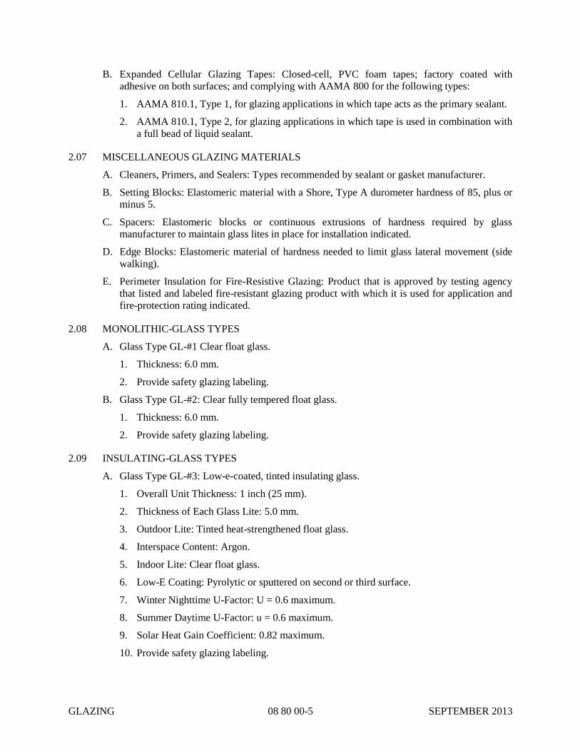
GLAZING 08 80 00-5 SEPTEMBER 2013
B. Expanded Cellular Glazing Tapes: Closed-cell, PVC foam tapes; factory coated with
adhesive on both surfaces; and complying with AAMA 800 for the following types:
1. AAMA 810.1, Type 1, for glazing applications in which tape acts as the primary sealant.
2. AAMA 810.1, Type 2, for glazing applications in which tape is used in combination with
a full bead of liquid sealant.
2.07 MISCELLANEOUS GLAZING MATERIALS
A. Cleaners, Primers, and Sealers: Types recommended by sealant or gasket manufacturer.
B. Setting Blocks: Elastomeric material with a Shore, Type A durometer hardness of 85, plus or
minus 5.
C. Spacers: Elastomeric blocks or continuous extrusions of hardness required by glass
manufacturer to maintain glass lites in place for installation indicated.
D. Edge Blocks: Elastomeric material of hardness needed to limit glass lateral movement (side
walking).
E. Perimeter Insulation for Fire-Resistive Glazing: Product that is approved by testing agency
that listed and labeled fire-resistant glazing product with which it is used for application and
fire-protection rating indicated.
2.08 MONOLITHIC-GLASS TYPES
A. Glass Type GL-#1 Clear float glass.
1. Thickness: 6.0 mm.
2. Provide safety glazing labeling.
B. Glass Type GL-#2: Clear fully tempered float glass.
1. Thickness: 6.0 mm.
2. Provide safety glazing labeling.
2.09 INSULATING-GLASS TYPES
A. Glass Type GL-#3: Low-e-coated, tinted insulating glass.
1. Overall Unit Thickness: 1 inch (25 mm).
2. Thickness of Each Glass Lite: 5.0 mm.
3. Outdoor Lite: Tinted heat-strengthened float glass.
4. Interspace Content: Argon.
5. Indoor Lite: Clear float glass.
6. Low-E Coating: Pyrolytic or sputtered on second or third surface.
7. Winter Nighttime U-Factor: U = 0.6 maximum.
8. Summer Daytime U-Factor: u = 0.6 maximum.
9. Solar Heat Gain Coefficient: 0.82 maximum.
10. Provide safety glazing labeling.

GLAZING 08 80 00-6 SEPTEMBER 2013
PART 3 - EXECUTION
3.01 GLAZING, GENERAL
A. Comply with combined written instructions of manufacturers of glass, sealants, gaskets, and
other glazing materials, unless more stringent requirements are indicated, including those in
referenced glazing publications.
B. Adjust glazing channel dimensions as required by Project conditions during installation to
provide necessary bite on glass, minimum edge and face clearances, and adequate sealant
thicknesses, with reasonable tolerances.
C. Protect glass edges from damage during handling and installation. Remove damaged glass
from Project site and legally dispose of off Project site. Damaged glass is glass with edge
damage or other imperfections that, when installed, could weaken glass and impair
performance and appearance.
D. Apply primers to joint surfaces where required for adhesion of sealants, as determined by
preconstruction testing.
E. Install setting blocks in sill rabbets, sized and located to comply with referenced glazing
publications, unless otherwise required by glass manufacturer. Set blocks in thin course of
compatible sealant suitable for heel bead.
F. Do not exceed edge pressures stipulated by glass manufacturers for installing glass lites.
G. Provide spacers for glass lites where length plus width is larger than 50 inches (1270 mm).
H. Provide edge blocking where indicated or needed to prevent glass lites from moving sideways
in glazing channel, as recommended in writing by glass manufacturer and according to
requirements in referenced glazing publications.
3.02 TAPE GLAZING
A. Position tapes on fixed stops so that, when compressed by glass, their exposed edges are flush
with or protrude slightly above sightline of stops.
B. Install tapes continuously, but not necessarily in one continuous length. Do not stretch tapes
to make them fit opening.
C. Cover vertical framing joints by applying tapes to heads and sills first and then to jambs.
Cover horizontal framing joints by applying tapes to jambs and then to heads and sills.
D. Place joints in tapes at corners of opening with adjoining lengths butted together, not lapped.
Seal joints in tapes with compatible sealant approved by tape manufacturer.
E. Apply heel bead of elastomeric sealant.
F. Center glass lites in openings on setting blocks and press firmly against tape by inserting
dense compression gaskets formed and installed to lock in place against faces of removable
stops. Start gasket applications at corners and work toward centers of openings.
G. Apply cap bead of elastomeric sealant over exposed edge of tape.
3.03 GASKET GLAZING (DRY)
A. Cut compression gaskets to lengths recommended by gasket manufacturer to fit openings
exactly, with allowance for stretch during installation.
B. Insert soft compression gasket between glass and frame or fixed stop so it is securely in place

GLAZING 08 80 00-7 SEPTEMBER 2013
with joints miter cut and bonded together at corners.
C. Installation with Drive-in Wedge Gaskets: Center glass lites in openings on setting blocks and
press firmly against soft compression gasket by inserting dense compression gaskets formed
and installed to lock in place against faces of removable stops. Start gasket applications at
corners and work toward centers of openings. Compress gaskets to produce a weathertight
seal without developing bending stresses in glass. Seal gasket joints with sealant
recommended by gasket manufacturer.
D. Installation with Pressure-Glazing Stops: Center glass lites in openings on setting blocks and
press firmly against soft compression gasket. Install dense compression gaskets and pressure-
glazing stops, applying pressure uniformly to compression gaskets. Compress gaskets to
produce a weathertight seal without developing bending stresses in glass. Seal gasket joints
with sealant recommended by gasket manufacturer.
E. Install gaskets so they protrude past face of glazing stops.
3.04 SEALANT GLAZING (WET)
A. Install continuous spacers, or spacers combined with cylindrical sealant backing, between
glass lites and glazing stops to maintain glass face clearances and to prevent sealant from
extruding into glass channel and blocking weep systems until sealants cure. Secure spacers or
spacers and backings in place and in position to control depth of installed sealant relative to
edge clearance for optimum sealant performance.
B. Force sealants into glazing channels to eliminate voids and to ensure complete wetting or
bond of sealant to glass and channel surfaces.
C. Tool exposed surfaces of sealants to provide a substantial wash away from glass.
3.05 CLEANING AND PROTECTION
A. Protect exterior glass from damage immediately after installation by attaching crossed
streamers to framing held away from glass. Do not apply markers to glass surface. Remove
nonpermanent labels and clean surfaces.
B. Protect glass from contact with contaminating substances resulting from construction
operations. If, despite such protection, contaminating substances do come into contact with
glass, remove substances immediately as recommended in writing by glass manufacturer.
C. Examine glass surfaces adjacent to or below exterior concrete and other masonry surfaces at
frequent intervals during construction, but not less than once a month, for buildup of dirt,
scum, alkaline deposits, or stains; remove as recommended in writing by glass manufacturer.
D. Remove and replace glass that is broken, chipped, cracked, or abraded or that is damaged
from natural causes, accidents, and vandalism, during construction period.
END OF SECTION 08 80 00

GLAZING 08 80 00-8 SEPTEMBER 2013
THIS PAGE INTENTIONALLY LEFT BLANK

GYPSUM BOARD 09 29 00-1 SEPTEMBER 2013
SECTION 09 29 00
GYPSUM BOARD
PART 1 – GENERAL
1.01 SUMMARY
A. Section Includes: Interior gypsum board.
1.02 ACTION SUBMITTALS
A. Product Data: For each type of product.
PART 2 - PRODUCTS
2.01 INTERIOR GYPSUM BOARD
A. Products: Subject to compliance with requirements, available products that may be
incorporated into the Work include, but are not limited to the following:
1. American Gypsum Company
2. CertainTeed Corporation
3. Georgia-Pacific Gypsum LLC.
4. Lafarge North America Inc.
5. National Gypsum Company
6. PABCO Gypsum.
7. Temple-Inland, Inc.
8. USG Corporation.
B. Gypsum Wallboard: ASTM C 1396/C 1396M.
1. Thickness: 1/2 inch (12.7 mm).
2. Long Edges: Tapered.
C. Foil-Backed Gypsum Board: ASTM C 1396/C 1396M.
1. Core: 1/2 inch (12.7 mm), regular type.
2. Long Edges: Tapered.
D. Moisture- and Mold-Resistant Gypsum Board: ASTM C 1396/C 1396M. With moisture-
and mold-resistant core and paper surfaces.
1. Core: 1/2 inch (12.7 mm), regular type.

GYPSUM BOARD 09 29 00-2 SEPTEMBER 2013
2. Long Edges: Tapered.
3. Mold Resistance: ASTM D 3273, score of 10 as rated according to ASTM D 3274.
2.02 TRIM ACCESSORIES
A. Interior Trim: ASTM C 1047.
1. Material: Galvanized or aluminum-coated steel sheet, rolled zinc, plastic, or paper-faced
galvanized steel sheet.
B. Aluminum Trim: ASTM B 221 (ASTM B 221M), Alloy 6063-T5.
2.03 JOINT TREATMENT MATERIALS
A. General: Comply with ASTM C 475/C 475M.
B. Joint Tape: Interior Gypsum Board: Paper.
C. Joint Compound for Interior Gypsum Board: For each coat use formulation that is
compatible with other compounds applied on previous or for successive coats.
2.04 AUXILIARY MATERIALS
A. Laminating Adhesive: Adhesive or joint compound recommended for directly adhering
gypsum panels to continuous substrate.
B. Steel Drill Screws: ASTM C 1002, unless otherwise indicated.
C. Sound Attenuation Blankets: ASTM C 665, Type I (blankets without membrane facing).
1. Recycled Content of Blankets: Postconsumer recycled content plus one-half of
preconsumer recycled content not less than <Insert number> percent.
D. Thermal Insulation: As specified in Section 07 21 00 "Thermal Insulation."
E. Vapor Retarder: As specified in Section 07 21 00 "Thermal Insulation."
PART 3 - EXECUTION
3.01 APPLYING AND FINISHING PANELS
A. Comply with ASTM C 840.
B. Examine panels before installation. Reject panels that are wet, moisture damaged, and mold
damaged.
C. Isolate perimeter of gypsum board applied to non-load-bearing partitions at structural
abutments, except floors. Provide 1/4- to 1/2-inch- (6.4- to 12.7-mm-) wide spaces at these
locations and trim edges with edge trim where edges of panels are exposed. Seal joints
between edges and abutting structural surfaces with acoustical sealant.
D. Install trim with back flanges intended for fasteners, attach to framing with same fasteners
used for panels. Otherwise, attach trim according to manufacturer's written instructions.

GYPSUM BOARD 09 29 00-3 SEPTEMBER 2013
1. Control Joints: Install control joints according to ASTM C 840 and in specific locations
approved by Owner’s Representative for visual effect.
E. Apply joint tape over gypsum board joints, except for trim products specifically indicated as
not intended to receive tape.
F. Gypsum Board Finish Levels: Finish panels to levels indicated below and according to
ASTM C 840:
1. Level 4: At panel surfaces that will be exposed to view unless otherwise indicated.
a. Primer and its application to surfaces are specified in Section 09 91 23 "Interior
Painting."
G. Protect adjacent surfaces from drywall compound and texture finishes and promptly remove
from floors and other non-drywall surfaces. Repair surfaces stained, marred, or otherwise
damaged during drywall application.
H. Remove and replace panels that are wet, moisture damaged, and mold damaged.
END OF SECTION 09 29 00

GYPSUM BOARD 09 29 00-4 SEPTEMBER 2013
THIS PAGE INTENTIONALLY LEFT BLANK

ACOUSTICAL TILE CEILINGS 09 51 23-1 SEPTEMBER 2013
SECTION 09 51 23
ACOUSTICAL TILE CEILINGS
PART 1 - GENERAL
1.01 SUMMARY
A. Section includes acoustical tiles and concealed suspension systems for ceilings.
1.02 ACTION SUBMITTALS
A. Product Data: For each type of product.
1. Department of Health Services' "Standard Practice for the Testing of Volatile Organic
Emissions from Various Sources Using Small-Scale Environmental Chambers."
B. Samples: For each exposed product.
1.03 INFORMATIONAL SUBMITTALS
A. Product test reports.
B. Evaluation reports.
C. Field quality-control reports.
1.04 CLOSEOUT SUBMITTALS
A. Maintenance data.
1.05 QUALITY ASSURANCE
A. Testing Agency Qualifications: Qualified according to NVLAP.
PART 2 - PRODUCTS
2.01 PERFORMANCE REQUIREMENTS
A. Seismic Performance: Acoustical ceiling shall withstand the effects of earthquake motions
determined according to ASCE/SEI 7.
B. Surface-Burning Characteristics: Comply with ASTM E 84; testing by a qualified testing
agency. Identify products with appropriate markings of applicable testing agency.
1. Flame-Spread Index: Comply with ASTM E 1264 for Class A materials.
2. Smoke-Developed Index: 50 or less.
2.02 ACOUSTICAL TILE CEILINGS, GENERAL
A. Acoustical Tile Standard: Comply with ASTM E 1264.
B. Metal Suspension System Standard: Comply with ASTM C 635.
C. Attachment Devices: Size for five times the design load indicated in ASTM C 635, Table 1,
"Direct Hung," unless otherwise indicated. Comply with seismic design requirements.
2.03 ACOUSTICAL TILES

ACOUSTICAL TILE CEILINGS 09 51 23-2 SEPTEMBER 2013
A. Manufacturers: Subject to compliance with requirements, available manufacturers offering
products that may be incorporated into the Work include, but are not limited to, the
following:
1. Armstrong World Industries, Inc.
2. CertainTeed Corp.
3. USG Interiors, Inc.; Subsidiary of USG Corporation.
B. Classification: Drop Panels, Fiberglass, Textured, Commercial
C. Color: White.
D. LR: 0.75 (White).
E. NRC: 0.55, Type E-400 mounting according to ASTM E 795.
F. CAC: 35.
G. Edge/Joint Detail: Square.
H. Thickness: 3/4 inch (19 mm).
I. Modular Size: 24 by 48 inches (610 by 1220 mm).
2.04 METAL SUSPENSION SYSTEM
A. Manufacturers: Subject to compliance with requirements, available manufacturers offering
products that may be incorporated into the Work include, but are not limited to, the
following:
1. Armstrong World Industries, Inc.
2. CertainTeed Corp.
3. USG Interiors, Inc.; Subsidiary of USG Corporation.
B. Structural Classification: Intermediate-duty system.
C. Access: Upward.
D. Roll-Formed, Sheet-Metal Edge Moldings and Trim: Manufacturer's standard moldings for
edges and penetrations complying with seismic design requirements; formed from sheet metal
of same material, finish, and color as that used for exposed flanges of suspension-system
runners.
2.05 WARRANTY
A. Special Warranty: Manufacturer's standard form in which manufacturer agrees to repair or
replace components of metal panel systems that fail in materials or workmanship within
specified warranty period.
1. Warranty Period: Ten years from date of Substantial Completion.
B. Other warranty requirements can be found in Section 01 78 36.
PART 3 - EXECUTION
3.01 INSTALLATION
A. Install acoustical tile ceilings to comply with ASTM C 636/C 636M and seismic design
requirements indicated, according to manufacturer's written instructions and CISCA's
ACOUSTICAL TILE CEILINGS 09 51 23-3 SEPTEMBER 2013
"Ceiling Systems Handbook."
B. Measure each ceiling area and establish layout of acoustical tiles to balance border widths at
opposite edges of each ceiling. Avoid using less-than-half-width tiles at borders, and comply
with layout shown on reflected ceiling plans.
C. Arrange directionally patterned acoustical tiles as indicated on reflected ceiling plans.
END OF SECTION 09 51 23

ACOUSTICAL TILE CEILINGS 09 51 23-4 SEPTEMBER 2013
THIS PAGE INTENTIONALLY LEFT BLANK

RESILIENT SHEET FLOORING 09 65 16-1 SEPTEMBER 2013
SECTION 09 65 16
RESILIENT SHEET FLOORING
PART 1 - GENERAL
1.01 SUMMARY
A. Section includes vinyl sheet flooring.
1.02 ACTION SUBMITTALS
A. Product Data: For each type of product.
B. Shop Drawings: For each type of flooring. Include flooring layouts, locations of seams,
edges, columns, doorways, enclosing partitions, built-in furniture, cabinets, and cutouts.
1. Show details of special patterns.
C. Samples: For each exposed product and for each color and texture specified in manufacturer's
standard size, but not less than 6-by-9-inch (150-by-230-mm) sections.
1. For heat-welding bead, manufacturer's standard-size Samples, but not less than 9 inches
(230 mm) long, of each color required.
1.03 CLOSEOUT SUBMITTALS
A. Maintenance data.
PART 2 - PRODUCTS
2.01 PERFORMANCE REQUIREMENTS
A. Fire-Test-Response Characteristics: For resilient sheet flooring, as determined by testing
identical products according to ASTM E 648 or NFPA 253 by a qualified testing agency.
1. Critical Radiant Flux Classification: Class I, not less than 0.45 W/sq. cm.
B. FloorScore Compliance: Resilient sheet flooring shall comply with requirements of
FloorScore certification.
C. Low-Emitting Materials: Flooring system shall comply with the testing and product
requirements of the California Department of Public Health's "Standard Method for the
Testing and Evaluation of Volatile Organic Chemical Emissions from Indoor Sources Using
Environmental Chambers."
2.02 UNBACKED VINYL SHEET FLOORING
A. Products: Subject to compliance with requirements, products that may be incorporated into
the Work include, but are not limited to, the following:
1. Armstrong World Industries, Inc
2. Forbo Industries, Inc
3. Gerflor
4. Johnsonite; A Tarkett Company

RESILIENT SHEET FLOORING 09 65 16-2 SEPTEMBER 2013
5. Mannington Mills, Inc>.
6. Polyflor, Ltd., Distributed by Gerbert Limited
B. Product Standard: ASTM F 1913.
C. Thickness: 0.080 inch (2.0 mm)
D. Wearing Surface: Smooth.
E. Sheet Width: As standard with manufacturer.
F. Seamless-Installation Method: Chemically bonded.
G. Colors and Patterns: As selected by CITY from full range of industry colors.
2.03 INSTALLATION MATERIALS
A. Trowelable Leveling and Patching Compounds: Latex-modified, portland cement based or
blended hydraulic-cement-based formulation provided or approved by resilient sheet flooring
manufacturer for applications indicated.
B. Adhesives: Water-resistant type recommended by flooring and adhesive manufacturers to suit
resilient sheet flooring and substrate conditions indicated.
1. Adhesives shall have a VOC content of 50g/L or less.
2. Adhesives shall comply with the testing and product requirements of the California
Department of Public Health's "Standard Method for the Testing and Evaluation of
Volatile Organic Chemical Emissions from Indoor Sources Using Environmental
Chambers."
C. Seamless-Installation Accessories:
1. Chemical-Bonding Compound: Manufacturer's product for chemically bonding seams.
a. Bonding compound shall have a VOC content of 510 g/L or less.
b. Bonding compound shall comply with the testing and product requirements of the
California Department of Public Health's "Standard Method for the Testing and
Evaluation of Volatile Organic Chemical Emissions from Indoor Sources Using
Environmental Chambers."
D. Integral-Flash-Cove-Base Accessories:
1. Cove Strip: 1-inch (25-mm) radius provided or approved by resilient sheet flooring
manufacturer.
2. Corners: Metal inside and outside corners and end stops provided or approved by resilient
sheet flooring manufacturer.
E. Floor Polish: Provide protective, liquid floor-polish products recommended by resilient sheet
flooring manufacturer.
PART 3 - EXECUTION
3.01 PREPARATION
A. Prepare substrates according to resilient sheet flooring manufacturer's written instructions to
ensure adhesion of resilient sheet flooring.
B. Concrete Substrates: Prepare according to ASTM F 710.

RESILIENT SHEET FLOORING 09 65 16-3 SEPTEMBER 2013
1. Verify that substrates are dry and free of curing compounds, sealers, and hardeners.
2. Remove substrate coatings and other substances that are incompatible with adhesives and
that contain soap, wax, oil, or silicone, using mechanical methods recommended by
resilient sheet flooring manufacturer. Do not use solvents.
3. Alkalinity and Adhesion Testing: Perform tests recommended by resilient sheet flooring
manufacturer. Proceed with installation only after substrate alkalinity falls within range
on pH scale recommended by manufacturer in writing, but not less than 5 or more than 9
pH.
4. Moisture Testing: Proceed with installation only after substrates pass testing according to
resilient sheet flooring manufacturer's written recommendations, but not less stringent
than the following:
a. Perform anhydrous calcium chloride test according to ASTM F 1869. Proceed with
installation only after substrates have maximum moisture-vapor-emission rate of 3 lb
of water/1000 sq. ft. (1.36 kg of water/92.9 sq. m) in 24 hours.
b. Perform relative humidity test using in situ probes according to ASTM F 2170.
Proceed with installation only after substrates have a maximum 75 percent relative
humidity level.
C. Fill cracks, holes, and depressions in substrates with trowelable leveling and patching
compound; remove bumps and ridges to produce a uniform and smooth substrate.
D. Do not install resilient sheet flooring until it is the same temperature as the space where it is
to be installed.
E. Immediately before installation, sweep and vacuum clean substrates to be covered by resilient
sheet flooring.
3.02 RESILIENT SHEET FLOORING INSTALLATION
A. Comply with manufacturer's written instructions for installing resilient sheet flooring.
B. Unroll resilient sheet flooring and allow it to stabilize before cutting and fitting.
C. Lay out resilient sheet flooring as follows:
1. Maintain uniformity of flooring direction.
2. Minimize number of seams; place seams in inconspicuous and low-traffic areas, at least 6
inches (152 mm) away from parallel joints in flooring substrates.
3. Match edges of flooring for color shading at seams.
4. Avoid cross seams.
D. Scribe and cut resilient sheet flooring to butt neatly and tightly to vertical surfaces, permanent
fixtures, and built-in furniture including cabinets, pipes, outlets, and door frames.
E. Extend resilient sheet flooring into toe spaces, door reveals, closets, and similar openings.
F. Maintain reference markers, holes, and openings that are in place or marked for future cutting
by repeating on resilient sheet flooring as marked on substrates. Use chalk or other
nonpermanent marking device.
G. Install resilient sheet flooring on covers for telephone and electrical ducts and similar items in
installation areas. Maintain overall continuity of color and pattern between pieces of flooring
installed on covers and adjoining flooring. Tightly adhere flooring edges to substrates that

RESILIENT SHEET FLOORING 09 65 16-4 SEPTEMBER 2013
abut covers and to cover perimeters.
H. Adhere resilient sheet flooring to substrates using a full spread of adhesive applied to
substrate to produce a completed installation without open cracks, voids, raising and
puckering at joints, telegraphing of adhesive spreader marks, and other surface imperfections.
I. Seamless Installation:
1. Heat-Welded Seams: Comply with ASTM F 1516. Rout joints and heat weld with
welding bead to permanently fuse sections into a seamless flooring. Prepare, weld, and
finish seams to produce surfaces flush with adjoining flooring surfaces.
2. Chemically Bonded Seams: Bond seams with chemical-bonding compound to
permanently fuse sections into a seamless flooring. Prepare seams and apply compound
to produce tightly fitted seams without gaps, overlays, or excess bonding compound on
flooring surfaces.
J. Integral-Flash-Cove Base: Cove resilient sheet flooring 6 inches (152 mm) up vertical
surfaces. Support flooring at horizontal and vertical junction with cove strip.
1. Install metal corners at inside and outside corners.
3.03 CLEANING AND PROTECTION
A. Comply with manufacturer's written instructions for cleaning and protecting resilient sheet
flooring.
B. Floor Polish: Remove soil, adhesive, and blemishes from flooring surfaces before applying
liquid floor polish.
1. Apply one coat.
C. Cover resilient sheet flooring until Substantial Completion.
END OF SECTION 09 65 16

PROTECTIVE COATINGS 09 91 00-1 OCTOBER 2014
SECTION 09 91 00
PROTECTIVE COATINGS
PART 1 - GENERAL
1.01 DESCRIPTION
A. Scope
1. Furnish all labor, materials, equipment and incidentals required for coating and lining
work as shown and specified.
2. The extent of coating and lining work is shown in the Schedules and as specified herein.
3. The work includes the surface preparation, coating and lining application and finishing of
all interior and exterior items and surfaces throughout this Contract and existing items
and surfaces as described herein, except as otherwise shown or specified. Surface
preparation, priming and coats of paint specified are in addition to shop priming and
surface treatment specified under this and other sections of the work.
4. The term "paint" as used herein means all coating and lining systems materials, which
include the following:
a. Pretreatments.
b. Primers.
c. Intermediate Coats.
d. Finish Coats.
e. Sealers and fillers.
f. Other applied materials whether used as prime, intermediate or finish coats.
5. Paint all exposed surfaces whether or not designated in any schedule except where the
natural finish of the material is specifically intended as a surface not to be painted.
6. The term "exposed" as used herein means all items not covered with concrete, plaster,
fireproofing or similar material.
7. Ducts, conduits and other materials with corrosion resistant surfaces which are in
chases, above finished ceilings, or other inaccessible areas do not require field
painting.
8. Where items or surfaces are not specifically mentioned, paint these the same as
adjacent similar materials or areas.
9. If color or finish is not designated, the CITY will select from standard colors available
for the materials systems specified.
10. Provide only a primer coat for structural and miscellaneous metals covered with
concrete, plaster, fireproofing or similar material.
11. The term "Submerged" refers to materials that may be under water under normal
operating conditions and extends to a convenient point at least twelve (12) inches
above the maximum water level.

PROTECTIVE COATINGS 09 91 00-2 OCTOBER 2014
12. Provide pipe markers as shown and specified herein.
13. Paint concrete and masonry surfaces in interior locations where specified.
B. Coordination
1. Review installation procedures under other Sections and coordinate the installation of
items that must be field painted in this Section.
2. Coordinate the painting of areas that are inaccessible once equipment has been
installed.
3. Provide finish coats which are compatible with the primer paints used.
4. Primers specified under other Sections must be compatible with the finish painting and
meet the requirements of this Section.
5. Review other Sections of these Specifications to ensure compatibility of the total
coatings system for the various substrates.
6. CONTRACTOR is responsible for the compatibility of all shop primed and field
painted items in this Contract.
7. Furnish information on the characteristics of the finish materials proposed for use, to
ensure that compatible prime coats are used.
8. Remove and reprime as required to avoid incompatible primer and finish coats.
9. Notify the CITY in writing of anticipated problems using the coating systems as
specified with substrates primed by others.
10. The CONTRACTOR is responsible for coordinating the shop painting of major
equipment items, and notifying the CITY to schedule shop inspections of the surface
preparation and coating application if desired. The CITY shall be notified at least
three (3) weeks in advance of the scheduled shop painting. The CONTRACTOR shall
secure a list from the CITY of major equipment items for which shop inspection is
desired.
11. Equipment on which the factory paint has been damaged shall require complete
repainting or spot painting as directed by the CITY.
12. Air quality permits and requirements and all other permits and standards are the
responsibility of the CONTRACTOR. Copies of permits shall be attached to the Field
Superintendent's copy of the specifications and shall be on the job site at all times.
C. Coating of Elements Exposed to Hydrogen Sulfide Splash or Vapors: The coating systems
to be used for steel, concrete and CMU elements that will be potentially exposed to
hydrogen sulfide vapors or splash are categorized into two systems:
1. HB-1 and HP-2: High-Build Coating systems as specified in Paragraphs 2.06 and 2.07
of this specification. Elements to be coated with this system are those which may
potentially be exposed to hydrogen sulfide vapors but not in close proximity to
hydrogen sulfide splash. Elements to be coated with this material include the
following:

PROTECTIVE COATINGS 09 91 00-3 OCTOBER 2014
a. All structural steel elements per Paragraph 2.06. The exterior surfaces shall be
painted, as a minimum, according to the requirements elsewhere in this
specification. Exposed structural steel lintels in CMU walls, per 1.01, C.1.b, shall
also be coated with the High-build system.
b. The entire vertical surfaces of the concrete walls and the concrete floor in the
dumpster pit shall be coated as specified in Paragraph 2.07.
2. VHB: Very-High-Build Coating system as specified in Paragraph 2.08 of this
specification. Elements to be coated with this system are those which may be exposed
not only to hydrogen sulfide vapors but also in close proximity to splashing material.
Elements to be coated with this material include the following:
a. All channels (influent and effluent) in and around the Screening and Grit Facility.
3. HPWR: Silane Penetrating Water Repellent as specified in Paragraph 2.09 of this
specification. Elements to be coated with this system are those horizontal and vertical
surfaces which are not exposed directly to hydrogen sulfide vapors and are within
interior spaces. Elements to be coated with this material include the following:
a. Interior floor slabs in the Screenings & Grit Facility (not including the floor slabs
in Dumpster Room #101.
b. Interior exposed concrete and CMU walls in the Screening & Grit Facility.
c. Exterior exposed concrete walls in the Screening & Grit Facility.
4. EP-2: Epoxy Deck Coating (Slip-Resistant) as specified in Paragraph 2.10 of this
specification. Elements to be coated with this system are those horizontal surfaces that
are located outside the building and exposed to weather. Elements to be coated with
this material include the following:
a. Exterior floor slabs accessible to foot traffic.
5. PT: Paint Coating as specified in SCHEDULE 09 9100_2 PAINTING SYSTEMS
LIST. Primer: P-8; Finish: F-10. Use the same manufacturer for primer and finish
systems. :
a. Interior walls as noted on drawings & finish schedules.
D. Painting Not Included: The following categories of Work are not included as part of the
field-applied finish Work:
1. Shop Priming: Shop priming of structural metal, miscellaneous metal fabrications,
other metal items and such fabricated components as shop-fabricated or factory-built
equipment.
2. Prefinished Items:
a. Painting of items furnished with factory finish such as baked-on enamel, porcelain,
polyvinyl fluoride or other similar finish is not required, unless otherwise shown or
specified. Typical items are as follows:
1) Finished mechanical and electrical equipment.
b. Touch up factory finished items with paint supplied by the item manufacturer.
c. Field paint damaged prefinished items as reviewed by the CITY.
3. Concrete unless otherwise noted.

PROTECTIVE COATINGS 09 91 00-4 OCTOBER 2014
4. Fiberglass items unless otherwise shown or specified.
5. Metal surfaces of aluminum, stainless steel, chromium, copper, bronze, brass,
monelmetal, lead and similar materials unless shown or specified.
6. Operating Parts and Labels:
a. Moving parts of operating units, mechanical and electrical parts, such as valve and
damper operators, linkages, sensing devices, motor and fan shafts do not require
finish painting unless otherwise specified.
b. Do not paint over labels, code stamps, equipment identification, performance
rating, name or nomenclature plates.
c. Remove all paint, coating or splatter inadvertently placed on these surfaces.
7. Interior electrical conduit, unless noted.
1.02 DEFINITIONS
A. Abrasive: Material used for blast-cleaning, such as steel, grit, garnet, aluminum oxide,
staturolite or slag.
B. Anchor Pattern: Profile or texture of surface, as a result of abrasive blasting. Also referred
to as anchor profile or blast profile.
C. ASTM: American Society for Testing Material.
D. AWWA: American Water Works Association.
E. Barrier Coating: Protective film isolating substrate or previous coat from environment.
F. Binder: Resin; polymer; film forming portion of paint.
G. Blast Cleaning: Cleaning by abrasive propelled at high speed.
H. Brush Off Blast: Blast cleaning to remove loose material, equal to NACE No. 4 or SSPC
SP-7.
I. Coating Manufacturer: The manufacturer and source of the coatings and linings products
furnished for this Contract.
J. Coatings and Linings: The term "coatings and/or linings" as used herein means all
protective coating systems and materials, which include surface preparations and all
pretreatments, primers, inorganic zinc, organic zinc, epoxies, polyurethanes, epoxy
phenolic, acrylics, phenolics, elastomeric polyurethane and other applied materials whether
used as prime, base, seal, mist, intermediate, or finish coats. As a general rule, linings are
for interior wet immersion, splash zone and wet duty exposures and coatings are for
atmospheric and other exposures.
K. Coating Superintendent: That employee of the coating and lining CONTRACTOR who is
designated by the coating and lining CONTRACTOR as the supervisor of all coating and
lining work and as the official representative of the coating and lining CONTRACTOR at
any project meetings or discussions.
L. Coating Supplier: The coating and/or lining manufacturer’s agent or technical
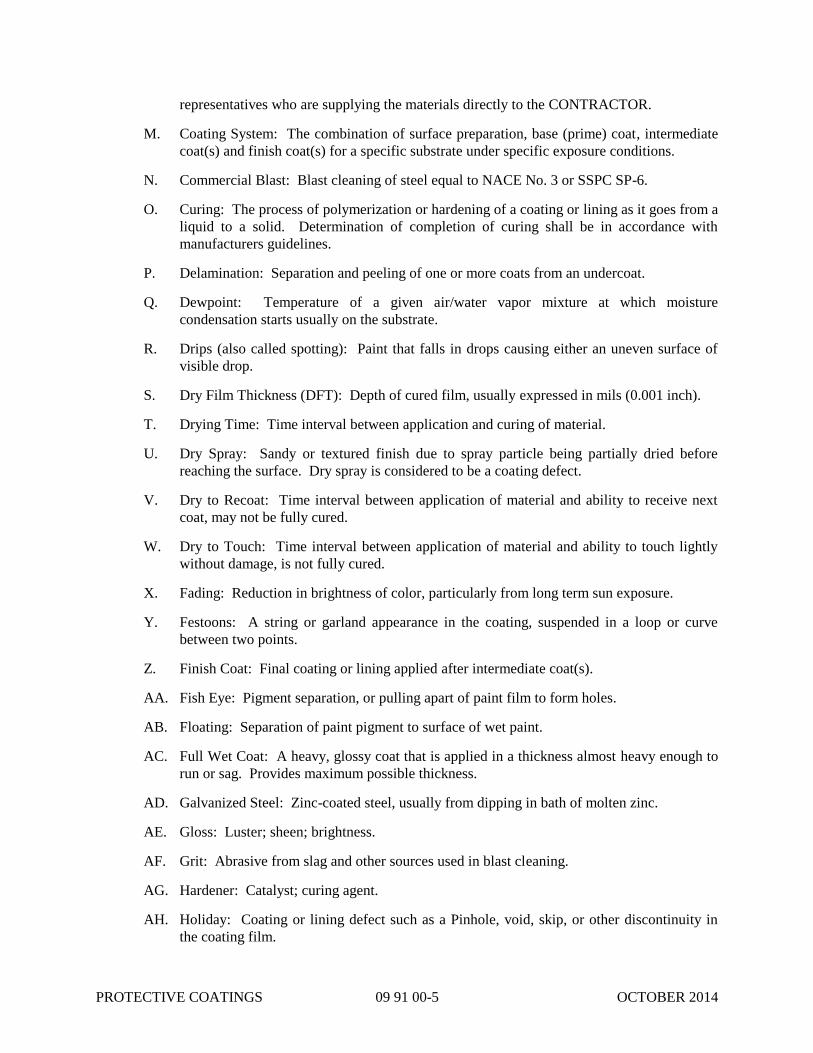
PROTECTIVE COATINGS 09 91 00-5 OCTOBER 2014
representatives who are supplying the materials directly to the CONTRACTOR.
M. Coating System: The combination of surface preparation, base (prime) coat, intermediate
coat(s) and finish coat(s) for a specific substrate under specific exposure conditions.
N. Commercial Blast: Blast cleaning of steel equal to NACE No. 3 or SSPC SP-6.
O. Curing: The process of polymerization or hardening of a coating or lining as it goes from a
liquid to a solid. Determination of completion of curing shall be in accordance with
manufacturers guidelines.
P. Delamination: Separation and peeling of one or more coats from an undercoat.
Q. Dewpoint: Temperature of a given air/water vapor mixture at which moisture
condensation starts usually on the substrate.
R. Drips (also called spotting): Paint that falls in drops causing either an uneven surface of
visible drop.
S. Dry Film Thickness (DFT): Depth of cured film, usually expressed in mils (0.001 inch).
T. Drying Time: Time interval between application and curing of material.
U. Dry Spray: Sandy or textured finish due to spray particle being partially dried before
reaching the surface. Dry spray is considered to be a coating defect.
V. Dry to Recoat: Time interval between application of material and ability to receive next
coat, may not be fully cured.
W. Dry to Touch: Time interval between application of material and ability to touch lightly
without damage, is not fully cured.
X. Fading: Reduction in brightness of color, particularly from long term sun exposure.
Y. Festoons: A string or garland appearance in the coating, suspended in a loop or curve
between two points.
Z. Finish Coat: Final coating or lining applied after intermediate coat(s).
AA. Fish Eye: Pigment separation, or pulling apart of paint film to form holes.
AB. Floating: Separation of paint pigment to surface of wet paint.
AC. Full Wet Coat: A heavy, glossy coat that is applied in a thickness almost heavy enough to
run or sag. Provides maximum possible thickness.
AD. Galvanized Steel: Zinc-coated steel, usually from dipping in bath of molten zinc.
AE. Gloss: Luster; sheen; brightness.
AF. Grit: Abrasive from slag and other sources used in blast cleaning.
AG. Hardener: Catalyst; curing agent.
AH. Holiday: Coating or lining defect such as a Pinhole, void, skip, or other discontinuity in
the coating film.

PROTECTIVE COATINGS 09 91 00-6 OCTOBER 2014
AI. Immersion Interior: Areas of a tank in contact or potentially in contact with the liquid
contained. Also reference interior wet area.
AJ. Incompatibility: Inability of a coating to perform well over another or substrate coating
because of bleeding, poor bonding, or lifting of old coating; or inability of a coating to
perform well on a substrate.
AK. Induction Time: Time interval between mixing of components and chemical crosslinking
for satisfactory application of multi-component coatings and linings. Also referred to as
"sweat in" time.
AL. Inorganic Coating: Coating with inorganic binder (e.g., silicate or phosphate) rather than
organic (e.g., of petroleum, animal, or plant origin). Commonly inorganic zinc (IOZ).
AM. Interior Wet Area: Refers to all interior surfaces of the water holding vessel and wet riser
surfaces when such risers are greater than 24 inches in diameter. The entire tank area
whether actually immersed or in the attic space is included. The terms interior wet and
immersion are used interchangeably.
AN. Intermediate Coat(s): Coat(s) applied after prime or base coat and prior to finish coat(s).
AO. Laitance: White or gray weakened material floated to the surface of new concrete. This
layer is not dense sound concrete and requires removal prior to application of high
performance coatings and especially linings.
AP. Lifting: Softening and raising of an undercoat by solvent in applied topcoat.
AQ. Livered: The progressive, irreversible increase in consistency of a pigment-vehicle
combination. Livering in the majority of cases arises from a chemical reaction to the
vehicle with the solid dispersed materials, but it may also result from polymerization of the
vehicle. The irreversible character of the changes in the livered material distinguishes it
from thixotropic "build-up", which is reversible.
AR. Mil: 0.001 inch.
AS. Mill Scale: The heavy oxide layer formed during hot fabrication or heat treatment of
metals. Cathodic to its steel substrate.
AT. Mist Coat: A partially complete coat applied with a more rapid gun motion than a full wet
coat. The mist coat should displace the air in porous coatings such as inorganic zinc
primer.
AU. NACE International: National Association of Corrosion Engineers.
AV. Near White Blast: A good grade of abrasive blast cleaning of steel, equal to NACE No. 2
or SSPC-SP10.
AW. NSF: National Sanitation Foundation.
AX. NWS: National Welding Society.
AY. Orange Peel: Hills and valleys in paint resembling the skin of an orange.
AZ. Overspray: Dry spray, particularly such paint that failed to strike the intended surface and
adheres to adjacent or other surfaces.

PROTECTIVE COATINGS 09 91 00-7 OCTOBER 2014
BA. Peeling: Paint curling or stripping from substrate.
BB. Pigment: Solid, opaque, frequently colored component of paint.
BC. Pinhole: Film defect characterized by small pore-like flaws in a coating which extends
entirely through the applied film and have the general appearance of pin pricks when
viewed by reflecting light. The term is rather generally applied to holes caused by solvent
bubbling, moisture, other volatile products, or the presence of extraneous particles in the
applied film.
BD. Pot Life: Time interval after mixing of components during which the coating can be
satisfactorily applied.
BE. Primer or Prime Coat: First coat applied to a substrate usually containing inhibitive
pigments when formulated for metals.
BF. Profile: Surface texture, particularly of abrasive blast cleaned steel.
BG. Quality Assurance Representative (QAR): An individual qualified to inspect the work,
release hold points and perform the required quality assurance of the project.
BH. Ropiness: Forming sticky glutinous strings or threads resembling ropes.
BI. Run: Sag; curtain; associated with too heavy of a wet application of a paint film.
BJ. Sag: Run; curtain.
BK. Seal Coat: Coat applied to a prime coat for the purpose of sealing to prevent adverse
affects of gasification.
BL. Shelf Life: Maximum storage time for which a material may be stored without losing its
usefulness.
BM. Shop Coat: Coat of paint applied in fabricating shop.
BN. Skip Weld: A non-continuous weld bead pattern which repeats for the length of the metal
connection. Sometimes referred to as a stitch weld.
BO. Spreading Rate: Area covered by a unit volume of paint at a specific thickness.
BP. SSPC: The Society for Protective Coatings, formerly Steel Structures Painting Council.
BQ. Tack Coat: A light thinned coat applied to the surface by roller or spray and then allowed
to flash off until it is just tacky usually taking a matter of minutes. The full wet coat is
then applied which provides for thicker film build.
BR. Thinner: Reducer; solvent added to reduce paint viscosity for easier application.
BS. Thorough Drying: Curing of paint film through entire thickness as opposed to drying only
on the surface.
BT. Tiecoat: An adhesive coat applied to a coating to enhance the bonding of a topcoat.
BU. TCLP: Toxicity Characteristic Leaching Procedure. A standard test used to determine if a
solid waste is considered a hazardous waste by virtue of its toxicity. It is intended to
simulate the leaching of toxic constituents that would take place in a landfill.

PROTECTIVE COATINGS 09 91 00-8 OCTOBER 2014
BV. TPC: Technical Practices Committee of NACE.
BW. TSR: Technical Service Representative.
BX. UL: Underwriters Laboratory.
BY. Vehicle: Liquid portion of coating materials; resin and solvent components of the coating.
BZ. Weld Spatter: Beads of metal scattered near seam during welding.
CA. White Metal Abrasive Blast: Highest level of abrasive blast cleaning of steel, NACE No. 1
or SSPC-SP5.
1.03 QUALITY ASSURANCE
A. Applicator Qualifications
1. Submit the name and experience record of the painting applicator.
2. Include list of utility or industrial installations painted, responsible officials, architects,
or engineers concerned with the Project and the approximate Contract price.
B. Manufacturer. All paint products shall be supplied by the same manufacturer unless
otherwise approved.
C. Reference Standards
1. OSHA 1910.144, Safety Color Code for Marking Physical Hazards.
2. SSPC Volume 2, Systems and Specifications, Surface Preparation Guide and Paint
Application Specifications.
D. Compatibility
1. It is the CONTRACTOR's responsibility to ensure that the shop applied coatings are
compatible with the field applied coatings. In cases where shop-applied primers and
coatings on materials and equipment furnished by suppliers are products different from
those described in the Specifications, the CONTRACTOR shall verify compatibility
with the specified field applied coating system. If requested by the CITY, "pull-off
strength" tests conforming to ASTM D3359, Measuring Adhesion by Tape Test or
ASTM D4541, Pull off Strength of Coatings Using Portable Adhesion Tester, shall be
performed to establish compatibility.
1.04 SUBMITTALS
A. Samples
1. Submit paint samples for review of color and texture only.
2. Provide a listing of the material and application for each coat of each finish sample.
3. Submit sample of each type of marker and sign specified.
B. Shop Drawings

PROTECTIVE COATINGS 09 91 00-9 OCTOBER 2014
1. Submit copies of manufacturer's technical information, including paint label analysis
and application instructions for each material proposed for use.
a. Include anchor pattern required for each base coat or prime coat product.
b. Include complete jobsite mixing and preparation procedures, including straining
instructions.
c. Include manufacturer's standard product data sheets for each coating.
d. Include solids percentage (by volume) content for each coating.
e. Include volatile organic content (VOC) in pounds/gallon for each coating.
f. Include manufacturer's recommended dry film thickness ranges for each coating.
g. Include manufacturer's maximum and minimum recommended times between coats
or topcoating with another product for each coating.
h. Include MSDS for all coatings, linings and thinners.
2. List each material and cross-reference to the specific paint and finish system and
application. Identify by manufacturer's catalog number and general classification.
3. Submit copies of manufacturer's complete color charts for each coating system.
4. Provide certifications from manufacturers verifying that the factory applied prime
coats are compatible with specified finish coatings.
5. Pipe Markers:
a. Copies of manufacturer's technical brochure.
b. "Standard" and "Custom" color charts.
c. List of standard signs and available color combinations.
d. Color and/or text selection criteria for non-standard or "custom made" pipe
markers required to comply with the standard piping color and legend guide for the
CITY’s wastewater treatment plants. (See Schedule 09940-3).
6. Provide completed copies of the CITY’s Paint and Protective Coating Inspection Log
for each major equipment piece (sample included at end of this Section).
7. In cases where paint products of a manufacturer other than those listed in Painting
Systems List are proposed for this project, furnish to the CITY a certificate from
proposed manufacturer stating that his products are equal to those specified. In
addition, sufficient information shall be submitted to enable CITY to determine that
the proposed coatings are equivalent to those named. Requests for review of
equivalency will be accepted only from the CONTRACTOR, and will be considered
only after the contract has been awarded.
C. Painting Lists and Schedules
1. Provide detailed and complete list of every surface to be painted under this Contract in
accordance with Subparagraph 2-3.C. of this Section.
a. Arrange list in a logical order by building, then area or room, the specific surface
within each area or room.
b. Piping color code list shall be included, but does not need to follow the above
room-by-room format.

PROTECTIVE COATINGS 09 91 00-10 OCTOBER 2014
c. List shall include the condition of each surface prior to field painting (e.g., new,
primed; new, unprimed; new, galvanized; existing, painted); the proposed painting
system including surface preparation; and the intended color the surface is to be
painted.
2. Provide detailed and complete list of all proposed applications techniques for all
product and substrate conditions. Include specific materials and methods for each
location.
3. Submit detailed pipe legend schedule and information regarding piping markers or tags
for each type of service. Include text, lettering size, pipe diameter (with insulation if
applicable), lettering and background colors, banding information, and method of
fastening to the pipe.
D. Operation and Maintenance Data
1. Submit a detailed maintenance manual including the following information:
a. Product name and number.
b. Name, address and telephone number of manufacturer and local distributor.
c. Detailed procedures for routine maintenance and cleaning.
d. Detailed procedures for light repairs such as scratches and staining.
1.05 PRODUCT DELIVERY, STORAGE AND HANDLING.
A. Delivery of Materials
1. Deliver all materials to the job site in original, unopened packages and containers
bearing manufacturer's name and label, including the following information:
a. Name or title of material.
b. Manufacturer's stock number and date of manufacture.
c. Manufacturer's name.
d. Contents by volume, for major pigment and vehicle constituents.
e. Thinning instructions where recommended.
f. Application instructions.
g. Color name and number.
B. Storage of Materials
1. Store only acceptable project materials on site in a suitable location. Keep area clean
and accessible. Restrict storage to paint materials and related equipment.
2. Temperature of storage area shall be kept between 65oF and 90
oF at all times.
3. Comply with health and fire regulations including the Occupational Safety and Health
Act of 1970.
1.06 JOB CONDITIONS
A. Existing Conditions
PROTECTIVE COATINGS 09 91 00-11 OCTOBER 2014
1. Thoroughly clean and remove excessive dust before painting is started in any area.
2. Thoroughly clean and remove oil, grease, dust, dirt, and other foreign matter from all
walls and piping prior to painting.
3. Clean areas where painting operations have started using only commercial vacuum
equipment.
B. Environmental Requirements
1. Apply water-base paints only when the temperature of surfaces to be painted and the
surrounding air temperatures are between 55oF and 90
oF unless otherwise permitted by
the paint manufacturer's printed instructions.
2. Apply other paints only when the temperature of surfaces to be painted and the
surrounding air temperatures are between 65oF and 95
oF, unless otherwise permitted
by the paint manufacturer's printed instructions.
3. Apply no paint to surfaces damp or wet from snow, rain, fog or mist, or when the
relative humidity exceeds 85 percent.
4. Painting may be continued during inclement weather only when areas and surfaces to
be painted are enclosed and heated during application and drying periods to within the
paint manufacturer's recommended temperature limits.
5. Provide adequate illumination and ventilation in all areas where painting operations
are in progress.
C. Protection
1. Cover or otherwise protect finished Work of other trades and surfaces not being
painted concurrently or not to be painted.
2. Take precautions necessary to prevent dust and dirt from coming in contact with
surfaces cleaned for painting and with surfaces freshly painted.
PART 2 - PRODUCTS
2.01 MATERIAL QUALITY
A. Provide best grade coatings suitable for use in wastewater treatment plants. Materials not
displaying the manufacturer's identification as a standard, best-grade product will not be
acceptable.
B. Provide primers produced by the same manufacturer as the finish coats. Use only paint
manufacturer's recommended thinners to recommended limits.
C. Provide durable and washable paints, pipe marker and safety signs. Use materials which
will withstand normal washing as required to remove grease, oil, chemicals, etc., without
showing discoloration, loss of gloss, staining, or other damage.
2.02 SUBSTITUTIONS

PROTECTIVE COATINGS 09 91 00-12 OCTOBER 2014
A. Substitutions that decrease the film thickness, the number of coats, or the quality of the
surface preparation or the generic type of coating specified will not be considered.
B. Approved manufacturers must furnish the same color selection including accent colors in
all coating systems as the manufacturers specified.
2.03 COLORS AND FINISHES
A. Refer to Schedule 09 91 00-2 for surface preparation and paint systems.
B. Color Selection: Colors not specified in the Contract Documents will be selected at the
time of shop drawing submittal. Piping colors shall conform to the standard piping color
and legend guide for the CITY’s wastewater treatment plants. (See Schedule 09 91 00-3).
C. Prior to commencing any work under this Section, the CONTRACTOR shall submit for
approval a detailed list of each and every surface to be painted. Associated with each
surface shall be noted the paint system proposed for use and the color (from the
manufacturer's color chart) intended. Where colors are indicated in this section the
CONTRACTOR shall fill in the proposed color. Where colors are not indicated, the
CONTRACTOR shall leave blanks and the CITY will fill in these colors. Complete color
charts shall be a part of this submittal.
D. Use representative colors when preparing samples for review. Final acceptance of colors
will be from samples submitted and approved.
E. Color Pigments: Pure, nonfading, applicable types to suit the substrates and service
indicated. Lead content shall not exceed amount permitted by federal, state and local
government laws and regulations.
F. Piping, Equipment and Marker Color Code: (See Schedule 09 91 00-3).
1. Piping and marker color codes are listed in the standard piping color and legend guide
for the CITY’s wastewater treatment plants, and include piping color, banding color(s),
and marker background and letter color for the most common piping services and
equipment at the wastewater plant.
a. If a color or finish is not designated, the CITY will select from the paint
manufacturer's standard or custom colors, or select a non-standard color
formulation.
b. Pipe bands shall be 1 inch wide, and double or triple bands shall be 1 inch apart.
c. Pipe bands shall be located next to each piping marker; next to all pipe fitting(s)
where a change in direction or elevation in the pipeline occurs; and at 25-foot
intervals along long straight runs of piping.
2. Pipe hangers and supports shall, in general, be painted the same color as the pipe.
a. Large pipe supports such as steel beams, posts, columns, etc., may be painted a
different color if so selected by the CITY.
b. Large posts, columns, supports, etc. which are unavoidable in the finished
construction and which obstruct walkways, limit safe headroom, or are otherwise
deemed potentially hazardous by the CITY shall be painted a high-visibility color
or striped colors, as directed by the CITY.
c. Pipe hangers or supports which are common to piping of more than one service

PROTECTIVE COATINGS 09 91 00-13 OCTOBER 2014
shall be painted gray.
3. As used for this Contract, the terms "Piping, Equipment and Marker Color Code",
"Piping Color Code" and "Color Code" shall be interpreted as applying to and
including all valves, and similar items contained within the limits of the piping system
and which are components of the piping system's service function.
4. All existing exposed and in-plant piping shall be SSPC-SP3 power tool cleaned and
color code painted same as required for new piping.
G. In general, and unless otherwise indicated, the finish color coat of paint shall be gloss or
semigloss on metal work and matte finish or flat on masonry work.
2.04 PAINTING SYSTEMS
A. Refer to Schedule 09 91 00-2 at the end of this Section for the Painting Systems List and
also as outlined in Paragraphs 2.06, 2.07 and 2.08 of this Section.
2.05 PIPING MARKERS
A. Manufacturer. Provide products produced by one of the following:
1. W.H. Brady Company.
2. Seton Name Plate Corporation.
3. Or approved equal.
B. General
1. Piping markers shall be formed from laminated plastic. All printing shall be sealed
with a formed butyrate plastic film. Letter and background color shall conform to
standard piping color and legend guide for the CITY’s wastewater treatment plants or
ordered by the CITY.
a. Markers for piping up to 6-inch inside diameter shall be preformed to completely
wrap around the pipe requiring no adhesive, straps or springs.
b. Markers for pipes over 6-inch inside diameter shall be preformed to the contour of
the pipe and attached with Type 316 stainless steel spring fasteners.
1) A minimum of two (2) spring fasteners shall be provided for each marker.
2) Large markers, or markers for larger diameter pipes, shall require additional
spring fasteners in order to assure that the markers lay flat and smooth on the
pipe surface and that they are held securely in place.
3) Springs shall be correctly sized for each pipe and marker combination and
shall provide a tight fit of the marker around the pipe while the spring is
stretched approximately one-half of its total range. Overstretched or loose
springs will be rejected.
4) All miscellaneous hardware, including screws, grommets, etc., for these
markers and fasteners shall be Type 316 stainless steel.
c. All pipe markers shall be securely held to the pipe surface, so that accidental
contact or jostling, or normal equipment vibrations or impact, does not dislodge or
misalign the marker.
PROTECTIVE COATINGS 09 91 00-14 OCTOBER 2014
2. For pipes under 3/4-inch outside diameter: Provide Type 316 stainless steel tags, 1-1/2
inch diameter, with depressed 1/4-inch high black filled letters above 1/2-inch high
black filled numbers. Attach tags to pipes with circlets of stranded Type 316 stainless
steel wire rope or clear nylon straps.
3. Each marker shall consist, in general, of two lines of legend, and a directional flow
arrow.
a. Legend shall be descriptive of the pipe contents and function, and shall indicate
the approximate operating temperature and pressure of the contents, if different
from ambient.
b. Legends given in piping color and legend guide are given as a guide only as to
what may be directed by the CITY for primary service names.
4. The size of lettering and marker shall conform to ANSI A13.1.
5. Location of Markers:
a. Adjacent to each valve and "TEE" or "WYE" connection.
b. At each branch and riser take-off.
c. On both sides of a pipe as it passes through a wall, floor or ceiling.
d. On all horizontal and vertical pipe runs at 15-foot intervals.
6. All piping installed, or relocated, under this Contract shall be marked as, or tagged as,
described above.
7. All pipe markers shall be located so as to be readable from a normal viewing position
from the floor below the pipe.
8. Prior to the marking of any pipelines, the CONTRACTOR shall submit to the CITY, a
detailed pipe legend schedule which shall include the following information for each
type of service:
a. Brief narrative description.
b. Primary Name (line one).
c. Secondary Name (Line two).
d. Lettering size and pipeline outside diameter.
e. Lettering and background colors and pipe banding information.
f. Contents of pipe which are above ambient temperature or pressure shall be
identified as such in the legend.
2.06 HB-1: STRUCTURAL STEEL – (HIGH BUILD COATING)
A. All Structural Steel elements shall be coated by one of the three following coating systems.
The exposed portions of steel lintels in the interior of CMU walls shall also be coated. For
each system the coating thickness shown (mils) shall mean Dry Film Thickness (DFT).
1. System No. 1, by Tnemec to consist of the following. Total system thickness of 12.5 to
23.5 mils.
a. Prime Coat – Omnithane Series 1; 2.5 to 3.5 mils thick. Contact manufacturer’s
representative to discuss anchor pattern of blast and recoat window of prime.
b. Intermediate Coat – Perma-Shield Series 446; 5.0 to 10.0 mils thick.

PROTECTIVE COATINGS 09 91 00-15 OCTOBER 2014
c. Finish Coat – Perma-Shield Series 446; 5.0 to 10.0 mils thick.
2. System No. 2, by Carboline to consist of the following. Total system thickness of 18.0
to 24.0 mils.
a. Prime Coat – Carboguard 60; 3.0 to 4.0 mils thick for shop coated steel. Primer not
required for field applications. Contact manufacturer’s representative to discuss
anchor pattern of blast and recoat window of prime.
b. Finish Coat – Plasite 4500 S; 15.0 to 20.0 mils thick.
3. System No. 3, by Sherwin-Williams to consist of the following. Total system thickness
of 16.0 to 20.0 mils.
a. Prime Coat – Sher-Glass FF; 8.0 to 10.0 mils thick. Contact manufacturer’s
representative to discuss anchor pattern of blast and recoat window of prime.
b. Finish Coat – Sher- Glass FF: 8.0 to 10.0 mils thick.
2.07 HB-2: SELECTED CONCRETE AND CMU WALLS, EXPOSED TO HYDROGEN SULFIDE
VAPORS – (HIGH BUILD COATING)
A. The interior surfaces of the concrete walls of the dumpster pit, shall be coated by one of the
three following systems. For each system the coating thickness shown (mils) shall mean Dry
Film Thickness (DFT).
a. System No. 1, by Tnemec to consist of the following. Total system thickness of 12.0
to 21.0 mils.
i. Prime Coat – Omnithane Series 1; 2.0 to 3.0 mils thick.
ii. Intermediate Coat – Perma-Shield Series 446; 6.0 to 9.0 mils thick.
iii. Finish Coat – Perma-Shield Series 446; 6.0 to 9.0 mils thick.
b. System No. 2, by Carboline to consist of the following. Total system thickness of
20.0 to 40.0 mils.
i. Prime Coat – Sanitile 600; 5.0 to 20.0 mils dry film thickness depending on
porosity of the CMU until obtaining a pinhole free surface.
ii. Finish Coat – Plasite 4500 S; 15.0 to 20.0 mils thick.
c. System No. 3, by Sherwin-Williams to consist of the following. Total system
thickness of 16.0 to 20.0 mils.
i. Prime Coat – Kem Cati-Coat; 8.0 to 10.0 mils thick.
ii. Finish Coat – Sher- Glass FF: 8.0 to 10.0 mils thick.
2.08 VHB: CONCRETE WALLS AND CHANNELS EXPOSED TO HYDROGEN SULFIDE
VAPORS AND SPLASH – (VERY HIGH BUILD COATING)
A. The concrete surfaces outlined in 1.01.C.2 shall be coated by one of the three following
coating systems. For each system the coating thickness shown (mils) shall mean Dry Film
Thickness (DFT).
1. System No.1, by Tnemec to consist of the following. Total system thickness of 54.0 to
86.0 mils, in addition to first coat as needed.
a. First Coat – Mortar-Clad Series 218 or 215 surfacing epoxy to fill and create a

PROTECTIVE COATINGS 09 91 00-16 OCTOBER 2014
pinhole free substrate.
b. Second Coat – Epoxoprime Series 201 applied at 4.0 to 6.0 mils (100% solids
modified polyamine epoxy).
c. Third Coat – Perma-Shield Series 436 applied at 50.0 to 80.0 mils (100% solids
fiber-reinforced modified polyamine epoxy).
2. System No. 2, by Sherwin-Williams to consist of the following. Total system thickness
of 44.0 to 131.0 mils in addition to first coat as needed.
a. First Coat – General Polymers TPM #723 Vertical Repair Mortar to fill all voids and
imperfections. b. Second Coat – Dura-Plate 235 applied at 4.0 to 6.0 mils
(100% solids epoxy).
b. Third Coat – Cor-Cote SC Plus applied at 40.0 to 125.0 mils (100% solids epoxy).
3. System No.3, by Carboline to consist of the following. Total system thickness of 40.0 to
66.0 mils dry film thickness.
a. First Coat – Carboguard 510 applied up to 2” to flush out smooth the surface of the
substrate; Fill shrinkage cracks with Surfacing Epoxy Carboguard 501 (Carboguard
501 is a cementitious repair mortar.)
b. Second Coat – Apply Phenoline 311 at 4.0-6.0 mils dry film thickness (only required
if the concrete is moist).
c. Third Coat – Apply Plasite 4500S at 40.0 – 60.0 mils dry film thickness.
2.09 HPWR: CONCRETE WALLS AND FLOORS NOT EXPOSED DIRECTLY TO HYDROGEN
SULFIDE SPLASH
A. The concrete surfaces not exposed directly to hydrogen sulfide splash (identified in Section
09 91 00b Schedule_3 as HPWR) shall be sprayed with Hydrozo Silane in accordance with
specifications and directions in Section 07 19 00 Water Repellents..
2.10 EXTERIOR CONCRETE SLABS
A. For exterior concrete slabs provide an epoxy coating with the following physical
characteristics:
1. Viscosity: 55-60 k.u.
2. Wet Film Thickness: Maximum 6 mils wet per coat.
3. Dry Film Thickness: Minimum 4 mils dry in two or more coats.
4. Weight Solids: 34-38%.
5. Volume Solids: 29-31%
6. VOC: 550 grams per liter, maximum
7. Provide approved grit medium as required by manufacturer to provide a slip resistant
surface in the finished top coat, but not less than four (4) pounds of grit per 100 square
feet of coating.
8. Surface Preparation: Surface to be treated must be free of all dirt, grease, and foreign
material and properly prepared per manufacturer’s instructions. Etch with an Etching

PROTECTIVE COATINGS 09 91 00-17 OCTOBER 2014
Cleaner acceptable to manufacturer. Provide self-priming on concrete in two or more
coats.
PART 3 – EXECUTION
3.01 EXAMINATION AND VERIFICATION OF CONDITION
A. CONTRACTOR shall examine the areas and conditions under which the work is to be
performed and notify the CITY in writing of conditions detrimental to the proper and
timely completion of the Work. Do not proceed with the Work until conditions are
suitable.
B. Do not coat over chalk, dust, dirt, rust, scale, moisture, oil, surface contaminants, coatings
that have exceeded the manufacturer's re-coat guidelines, or conditions otherwise
detrimental to the formation of a durable, high quality coating system.
C. The CONTRACTOR is responsible for proper surface preparation. If improper adhesions
or surface occur, the surface shall be corrected at no additional cost to the CITY.
3.02 SAFETY AND REGULATORY COMPLIANCE
A. The CITY's rules, policies and safety requirements shall be followed including:
1. Hard hats are required to be worn in the work place.
2. Safety shoes and safety goggles/glasses are required to be worn in the work place.
3. Smoking within the buildings is strictly prohibited.
4. Site parking shall be designated by the CITY.
5. Confined space entry.
B. Comply with the bid documents and the Metropolitan Sewer District (MSD) of Greater
Cincinnati Safety Program and Guidelines. Safety coordination shall be through the MSD
Safety Officer.
C. CONTRACTOR shall ensure that all workers and others coming in contact with abrasive
blasted and coated surfaces shall always wear clean gloves, clothing and shoe covering.
These measures are to prevent contamination of the abrasive blasted and coated surfaces.
Compliance with all other measures to prevent contamination that may lead to premature
coating and lining failure is the CONTRACTOR's responsibility.
D. Coatings for surfaces in contact with wastewater being treated shall not impart any organic
or inorganic content in excess of the maximum contaminant level established by applicable
laws or regulations. Revise painting system specified herein to provide manufacturer's
regulatory agency approved coating system where required.
E. Provide fire extinguishers and post caution signs warning against smoking and open flame
when working with flammable materials.
F. Display prominent warning signs indicating "WARNING - PAINTING AND ABRASIVE
BLASTING WORK UNDERWAY" throughout the job site wherever surface preparation
PROTECTIVE COATINGS 09 91 00-18 OCTOBER 2014
or coating and lining operations are underway. Signs shall be at clearly visible locations
near all points of access by person or vehicle to the job site and immediate work area.
1. Six (6) signs shall be provided by the CONTRACTOR, located where directed by the
QAR.
2. These signs shall be no less than 3' x 3' in size, and shall be placed at clearly visible
locations near all points of access by person or vehicle to the work area(s). Signs shall
be bright orange background with stenciled or neatly painted white letters.
3.03 GENERAL PREPARATION
A. Delivery of Materials
1. Deliver all coating and lining materials, thinners and solvents to the job site in original,
new and unopened packages and containers bearing manufacturer's name and label,
and the following information.
a. Name or title of material.
b. Manufacturer's stock number, batch number, and date of manufacture.
c. Manufacturer's name.
d. Contents by volume, for major pigment, binder (or resin) and vehicle constituents.
e. Thinning instructions where recommended.
f. Application instructions.
g. Color name and number.
h. Shelf life expiration date.
i. Pot life, at various ambient temperatures.
j. Material safety data sheet.
k. Volume and weight of container.
2. Deliver all cleaners in unopened containers which are labeled to indicate manufacturer,
product and MSDS data.
3. Deliver all brushes and rollers in unopened packages which are labeled to indicate
manufacturer and product.
4. Delivery of abrasive in bulk transfer trucks or abrasive manufacturer’s bags or bulk
nylon sacks, bearing the manufacturer's name, label and the following information:
a. Name of material.
b. Manufacturer's name.
c. Contents and net weight of the contents.
d. Mesh size of material.
e. Impurities or contaminants.
B. Storage of Materials
1. Store only materials which have been previously approved for this Project on the job
site.
2. Store all materials in a clean, dry, lighted and environmentally controlled area, such as

PROTECTIVE COATINGS 09 91 00-19 OCTOBER 2014
a storage trailer, which shall be furnished and maintained by the CONTRACTOR.
3. Maintain coating and lining material storage area between 60oF and 90
oF at all times.
4. In the event the storage area temperature drops to 40oF or below, all paint and coating
materials shall be inspected by the coating manufacturer’s representative to determine
suitability of its use and compliance with project bid documents. Any unacceptable
material shall be immediately removed from the job site and replaced by the
CONTRACTOR at no additional cost to the CITY.
5. Do not store coatings or lining materials in CITY's buildings or structures unless the
CITY’s permission is granted in writing.
C. Handling of Materials
1. Handle materials carefully to prevent inclusion of foreign materials, including abrasive
dust and abrasives.
2. Do not open containers or mix components until necessary preparatory Work has been
completed, the appropriate inspection performed and the inspection hold point
released. Application shall immediately follow proper mixing and induction if
required.
D. Protection
1. Protect private and public facilities from overspray, overblast and dust. Protection
shall include, but not be limited to, residences, businesses, churches and vehicles
including private and government vehicles frequenting the jobsite.
2. Cover or protect all surfaces and equipment not scheduled to be coated or painted.
Remove protective coverings at the conclusion of the Project.
3. Take precautions necessary to prevent dust, dirt and moisture from coming in contact
with surfaces cleaned for coating and lining and with surfaces freshly painted.
4. The CONTRACTOR shall provide 6 mil containment ground barriers covered with
tarps under all equipment and coating mixing areas, which is located on the CITY’s
property. All organic compounds, solvents, oil or contaminants spilled on the CITY’s
property shall be immediately cleaned up, removed and disposed of in a responsible
manner to the satisfaction of the CITY by the CONTRACTOR.
5. Remove all hardware, hardware accessories, hatches, nameplates, lighting fixtures,
electrical cover plates, and similar items in order to facilitate the complete coating of
the items and/or the adjacent surfaces. Tape and masking protection will be acceptable
only where it is not possible to remove the hardware or fixture mentioned.
a. Following completion of coating of each area, clean and properly reinstall the
removed items.
b. Replace all lost and missing items removed for coating work.
c. Replace all ferrous metal fasteners and washers with similar size stainless steel
fasteners.
3.04 PRECLEANING AND SURFACE PREPARATION - METAL SURFACES

PROTECTIVE COATINGS 09 91 00-20 OCTOBER 2014
A. General
1. The CONTRACTOR shall provide all labor, material and equipment to thoroughly
preclean the interior and exterior substrates as scheduled. The precleaning is to
include all substrates and equipment to be coated.
2. Perform all precleaning and surface preparation procedures in strict accordance with
the coating manufacturer's instructions for each particular substrate and environmental
condition.
B. Precleaning
1. Preclean all interior and exterior surfaces, of all oil, grease, dirt, chalk, wastewater
treatment residues, contaminants and other foreign matter in accordance with SSPC-
SP1, Solvent Cleaning and SSPC-SP12 Water Jetting as follows:
a. Using 190oF to 210
oF hot water from a pressure washer with chemical injector,
apply a cleaning solution at a rate of 10 to 12 ounces concentrated solution per
gallon of water applied. This heated solution shall be applied to the surface at the
minimum pressure of the pressure washer. Allow a minimum contact time of 2 to
3 minutes.
b. The cleaning shall continue by power washing with Turbo nozzles at pressures of
4,000 psi minimum.
c. Cleaned areas shall be triple rinsed with 190oF to 210
oF water at 4,000 psi
minimum with approved nozzles.
d. Cleaned surfaces shall be equal to WJ-4.
e. Surface cleanliness shall be equal to SC-1.
2. The cleaned surface will be inspected by the Quality Assurance Representative for
removal of iron residue, magnesium residue, calcium, chalk, dirt and contaminants.
Contaminants listed under SSPC-SP12, SC-1 including water-soluble chlorides, iron-
soluble salts and sulfates shall be removed. The surface shall have neutrality in the
range of 7.0 to 7.5 pH. The surface shall be free of any chlorides, chalk, dirt, debris,
oil, contaminants and any other foreign matter.
NOTE: Cleaning solution may be applied with an airless pump at the specified
concentration.
C. Surface Preparation
1. General:
a. The following surface preparation industry standards shall be used for this Project:
NACE Number SSPC Number Cleaning Description
SP 1 Solvent
SP 3 Power Tool Cleaning
No. 1 SP 5 White Metal Abrasive Blast
No. 2 SP 10 Near-White Metal Abrasive Blast
No. 3 SP 6 Commercial Abrasive Blast
No. 4 SP 7 Brush-Off Blast
SP 11 Power Tool Cleaning to Bare Metal

PROTECTIVE COATINGS 09 91 00-21 OCTOBER 2014
No. 5 SP 12 Water Jetting
2. Power Tool Surface Preparation:
a. All precleaned surfaces which have passed inspection shall be power tool cleaned
as the intermediate surface preparation. Power tool cleaning shall be as follows:
1) Power tool cleaning shall be in accordance with SSPC-SP3 or SSPC-SP11.
2) The power tools shall be operated to remove weld spatter and to radius or
dress rough welds and to radius edges to 1/8 inch.
3) Areas to be abrasive blasted to bare metal shall be power tool cleaned to
remove weld spatter, laminations, slivers to contour rough welds and to radius
edges to 1/8-inch by grinding.
4) All areas that are cleaned with power tools not scheduled for abrasive blasting
shall be blown down with oil free/moisture free air, vacuum cleaned or
brushed off to remove all dust and contamination that occurs during power tool
cleaning.
5) Substrates scheduled to be power tool cleaned and dusted off shall be spot
primed and not permitted to be left uncoated. Interior power tool cleaning
shall be used to remove and feather out peeling or chipped paint, rust, runs or
other imperfections.
3. Abrasive Blast Surface Preparation:
a. Blast cleaning shall comply with the NACE, SSPC and ASTM standards and
guidelines.
b. Dry abrasive blast cleaning techniques shall be utilized.
c. The abrasives shall be maintained free from oil, dust, moisture, chemicals, salts
and other impurities.
d. The type and size of abrasive for a particular substrate shall be selected to give a
properly prepared surface consistent with the anchor profile and cleanliness of the
scheduled coating system.
1) Prior to prime coat application, the Quality Assurance Representative will
verify anchor pattern depth by measurement with Testex replica tape. These
measurements will be taken following blow down and/or vacuum cleaning.
e. The compressed air supply used for blasting shall be free of oil, water, or other
contaminants. Adequate separator traps and filters shall be provided, and shall be
purged of oil and water throughout the blasting operation.
f. All compressed air shall be diverted through a fan cooled after-cooler prior to
abrasive blasting pots, conventional air spray equipment, pneumatic tools or other
pneumatic devices.
g. Compressed air shall be filtered to remove all oil.
h. Abrasive grit shall be discharged at a pressure of 100 psi, measured at the nozzle.
In no case shall the discharge pressure at the nozzle fall below 90 psi. Nozzle
pressures from 100 psi to 130 psi are acceptable.
i. Abrasive blasting nozzles shall be the long venturi type. Nozzles shall be regularly
inspected and shall be replaced when wear reaches one additional nozzle size.
j. Abrasive blasting shall not be conducted when the surface temperatures are less
than 5oF above the dew point, or when the relative humidity of the surrounding air

PROTECTIVE COATINGS 09 91 00-22 OCTOBER 2014
is greater than 85%. Abrasive blasting may continue in controlled environments
that comply with the specified conditions.
k. Abrasive blasted surfaces shall be coated as soon after the blasting work is
completed as possible. In no case shall blast cleaned surfaces be allowed to stand
overnight without being coated unless the affected area is dehumidified.
l. Abrasive blasting shall not be permitted on any surfaces in close proximity to other
surfaces which have recently been coated.
m. For job site abrasive blasting, protect all adjacent areas, surfaces and equipment
not to be blast cleaned from blast overspray, overblast, grit and dust resulting from
the blasting operations.
1) Protect adjacent areas and all work areas using containment netting around the
surface undergoing blast cleaning.
2) Protect electrical enclosures, electrical conduit, wiring, antennas, cables and
apparatus from dust, debris and paint.
3) Clean up all dust, grit, blasting residue and debris at the end of each workday.
n. Abrasive blasted surfaces shall be blown down with dry, oil-free, filtered air,
followed by vacuum cleaning and be inspected by the Quality Assurance
Representative and checked with cellophane tape and replica tape test procedures.
The surface shall be free of all residue, dust or other contamination that
jeopardizes maximum adhesion of the coating.
4. Surfaces shall be primed and/or treated, as specified, as soon after completion of
surface preparation as practicable, but in any event before any visible or detrimental
corrosion or contamination occurs. A prepared surface, which becomes corroded or
contaminated, shall be prepared again before treating and/or priming at no additional
cost to the CITY.
5. Before application of first field coat, abraded areas of the shop coat on metal surfaces
shall be touched up with paint of the same type as the shop coat, even to the extent of
applying the entire coat if necessary. Such touch-up coats shall be in addition to, and
not considered as the first field coat. Deteriorated surfaces shall be cleaned to bare
metal per SP-6 or SP-10 as applicable before applying the touch-up coat.
3.05 CONTAINMENT AND WASTE DISPOSAL
A. Waste material generated by abrasive blasting operations is a solid waste and shall be
handled in the following order:
1. Contained.
2. Collected.
3. Stored.
4. Evaluated.
5. Properly disposed.
B. Laws, Regulations and Ordinances: It is the responsibility of the CONTRACTOR to
comply with applicable laws governing the containment, collection, storage and disposal of

PROTECTIVE COATINGS 09 91 00-23 OCTOBER 2014
waste material generated during this project.
C. Existing paint being removed contains lead. The CONTRACTOR shall bear all
responsibility to assure that workers take proper safety precautions when working in a lead
abatement environment.
D. All equipment shall be parked on ground covers free of cuts, tears or holes to prevent
contamination of pavement or soil and to protect area under and around equipment.
E. Containment Enclosure
1. The CONTRACTOR shall erect an enclosure to completely surround (around and
under) the blasting, priming and coating operations. The ground cannot be used as the
bottom of the enclosure unless completely covered with suitable containment material
that retains 100% of the residue.
2. The enclosure shall be constructed of flexible materials such as containment screens
(specifically designed for this purpose). The floor may be containment screening or of
rigid materials such as overlapping plywood fastened in place.
3. All materials shall be maintained free of tears, cuts or holes.
4. All seams shall be overlapped a minimum of 6" and fastened together at 12" centers, or
fastened and overlapped in a manner that insures a seal which does not allow openings
between the screens in the containment.
5. The sides of the enclosure shall extend past the top of and enclose the structure.
6. Design and operation of the containment enclosure shall be equal to the TEPE system.
7. A top bonnet is required to contain dust, debris and coating materials being removed.
F. Debris Collection
1. All debris collected by this operation, removed from equipment or filters, or that has
fallen to the ground shall be collected and stored at the site for testing, evaluation and
ultimately disposal.
2. If not practical, an alternate storage location shall be mutually agreed upon by the
CITY and CONTRACTOR.
3. A centralized cleaning station for recyclable steel grit (if used) shall be set up at a
location mutually agreed upon by the CITY and CONTRACTOR.
4. Storage shall be in covered steel containers. Containers shall be parked, secured and
stored on wooden 6" x 6" timbers so containers are not in contact with the ground.
G. Chain of Custody
1. Follow all local, state and federal regulations.
2. A Chain of Custody Form must also accompany all composite samples.
a. Included in this document shall be the name of the person taking the sample, the
Company for which he works, the date and time which the sample was taken, the
tank from which it was taken, the Township and Municipality where the tank is

PROTECTIVE COATINGS 09 91 00-24 OCTOBER 2014
located and signatures of all persons involved in the Chain of Custody, including
dates possessed and relinquished.
H. Hazardous Waste
1. If the tests reveal that the maximum concentration of TCLP lead exceeds 5.0
milligrams per liter, the waste shall be treated as a hazardous waste per RCRA and the
steel containers shall be labeled as a hazardous waste.
2. The CONTRACTOR shall abide by all local, state and federal regulations as they
pertain to hazardous waste.
3. All containers of waste material which have been classified as hazardous shall be
stored in a secured location until proper disposal.
4. The CONTRACTOR shall arrange for hauling, disposal, and payment of all hazardous
waste.
5. All hazardous waste shall be disposed of after the CITY has obtained a generator
number from the state regulatory authority.
6. All hazardous waste shall be disposed of within 60 days after it is generated.
a. Any fines or liens accessed by any governmental agency which has jurisdiction
over the disposal of this material shall be the responsibility of the
CONTRACTOR.
b. The hauling and disposal shall be by a firm licensed by U.S. EPA and who shall
also be responsible for providing the Uniform Hazardous Waste Manifest.
7. The CONTRACTOR shall decontaminate or dispose of all collection/containment
equipment in accordance with EPA guidelines.
8. The CONTRACTOR shall obtain and provide the CITY with a receipt documenting
disposal of waste material at the approved landfill.
9. The CONTRACTOR shall obtain and provide the CITY with a receipt documenting
the quantity of material disposed.
I. Non-Hazardous Solid Waste.
1. If the waste is determined to be non-hazardous as verified by test results which have
been reviewed by the CITY, it shall be hauled and disposed of at a facility which is
licensed to accept “special” non-hazardous solid waste.
2. Prior to disposal of any material, the CONTRACTOR shall submit the test results and
the name and address of the proposed disposal facility to the CITY for approval.
3. The CONTRACTOR shall obtain and provide the CITY with a receipt documenting
disposal of waste material at the approved landfill.
4. The CONTRACTOR shall obtain and provide the CITY with a receipt documenting
the quantity of material disposed.
3.06 WELD AND METAL SURFACE REPAIR

PROTECTIVE COATINGS 09 91 00-25 OCTOBER 2014
A. General
1. The CONTRACTOR shall repair all surfaces, especially pits, welds, and edges so that
the surfaces are smoothly contoured and will not compromise the integrity or adhesion
of the coating systems.
2. Remove all new or existing weld splatter, slivers, flux deposits, unevenness, sharp
projections, etc., by a systematic and uniform method by grinding or power sanding in
accordance with SSPC-SP3 to smooth welds to enhance adhesion of the coating.
Welds shall comply with NACE RPO 178 butt and fillet weld designation "C".
Designation of other weld types shall be approved by the CITY.
3. Fill all weld holes, voids and sharp indentations with additional weld material, and
grind the surface smooth.
4. Welds which are specified to be continuous shall be truly continuous, and skip, tack or
stitch welding techniques will not be permitted.
5. All weld area imperfections shall be corrected prior to abrasive blasting.
6. Steel plate areas without welds shall be equal to NACE No. 1, flush and smooth.
7. If imperfections are discovered after abrasive blasting, they shall be corrected and re-
blasted prior to coating application.
B. Pit and Seam Repairs
1. Repair of pitting and weld seam repairs shall be in accordance with AWS Guidelines.
a. The CITY shall designate areas to be repaired upon completion of pre-cleaning and
abrasive blasting, but prior to application of primer.
b. Pits with a depth greater than 25 mils and less than 125 mils require the specified
surface preparation and application of epoxy filler followed by application of a
stripe coat and finishing.
c. Pits deeper than 125 mils shall be repaired by welding in accordance with AWWA,
API and AWS.
d. Pits in clusters greater than 6 inches in diameter shall be plated over with 0.250
inch steel plate and seal welded to surface prior to surface preparation and coating
application. Removal of splatter and radiused welds and edges shall be included.
2. Seam welding, pit welding or plating as required shall be included in the unit pricing
stated on the bid form.
3.07 FILLERS AND SEALANTS
A. Apply sealants, seam fillers and epoxy fillers in accordance with the coating
manufacturer’s written instructions when in immersion, wet atmosphere, high
condensation, or atmospheric exposures.
B. Provide sealant in the following types of joints:
1. Interior and exterior metal to metal joints or connections that are not continuous or seal
welded (skip welds).

PROTECTIVE COATINGS 09 91 00-26 OCTOBER 2014
2. Exterior metal to concrete joints including the wet riser and base plates to the concrete
footers.
3. Dissimilar metal joints or connections.
4. Dissimilar material joints or connections.
C. Inspect the surfaces to be sealed or filled and notify the CITY of any detrimental
conditions.
D. Surface Preparation:
1. Clean surfaces immediately before sealant installation.
2. Remove dirt, moisture and contamination which would interfere with adhesive bonds.
3. Prepare metal and concrete joints by abrasive blasting.
4. Clean joints by pressurized air blow down with oil- free, moisture-free compressed air.
E. Apply primer to all joint surfaces required by the sealant manufacturer.
1. Allow primer to dry prior to application of sealant.
2. Protect adjoining surfaces from spillage or migration of primer.
3. Apply masking tape to create clean, sharp edges prior to primer.
F. Install in accordance with sealant and filler manufacturer's written instructions.
1. Thoroughly power-mix the sealant and filler components in accordance with the
manufacturer's written instructions.
2. Add entire contents of activator and base. No mixing of partial units is permitted.
3. Continue mixing components at 300 rpm or less for a minimum of 5 minutes and until
thoroughly mixed as determined by the QAR.
G. Install backer rod or bond breaker tape as required by the sealant manufacturer’s joint
design.
H. Install sealants and fillers as recommended and to depths recommended by the
manufacturer.
1. Employ techniques which will ensure that sealants and fillers will be deposited in
uniform, continuous ribbons or beads without gaps or air pockets. Ensure complete
“wetting” of joint bond surfaces.
2. Fill sealant rabbet to a slightly concave surface.
3. Joints between horizontal and vertical surfaces shall be filled to form a slight cove so
that joint does not trap moisture and dirt.
4. Remove excess and spillage of compounds promptly as the work progresses.
5. Cure sealants and fillers in compliance with the manufacturer’s instructions and
recommendations to obtain high early bond strength, internal cohesive strength and

PROTECTIVE COATINGS 09 91 00-27 OCTOBER 2014
surface durability.
6. Leave all finish work in a neat and clean condition.
3.08 PREPARATION AND MIXING OF COATING MATERIALS
A. Mix coating material only in containers which have been placed in suitably sized non-
ferrous (plastic) or new metal containers. Protect concrete and the ground from splashes or
spills during mixing of coating materials. Mix and store open containers and thinner on
absorbent drop cloths or tarps over reinforced 6 mil polyethylene.
B. Mix coating and lining materials only from properly stored containers bearing accurate
product name and batch numbers of material being mixed or applied.
C. Coating material which has livered, gelled, or otherwise deteriorated during storage shall
not be used; however, thixotropic materials which must be stirred to obtain normal
consistency are acceptable.
D. Coating products with more than one component or part shall have each separate part
thoroughly mixed prior to combining, mixing, and allowing for induction of the combined
coating. Where several units of the finish materials are prepared for application at the
same time, "boxing" of the several units is required.
E. All stirring, mixing, boxing and induction shall be witnessed by the Quality Assurance
Representative and documented. Coating mixes not inspected and documented will not be
approved for application.
F. All coating materials shall be thoroughly mixed using a power mixer for sufficient time to
thoroughly blend all components.
1. Mixers shall be kept clean and free of dried or hardened coating and/or lining
materials. Build-up of dried coating shall be removed prior to use.
G. Only thinners specified by the coating manufacturer shall be used. Thinning directions
furnished by the coating manufacturer shall be strictly followed.
1. Adjust coating or lining material to the proper viscosity at ambient temperature and
humidity in accordance with manufacturer’s recommendations.
2. Thinning must be done at the initiation of roller, brush or spray application.
3. Thinning of materials well into the pot life is strictly prohibited.
4. Thinning in excess of VOC limits NSF or UL guidelines for interior lining material is
strictly prohibited.
H. Coating materials requiring the addition of a catalyst shall have the pot life clearly stated
on the label. The pot life must be shown for the humidity and temperature ranges
allowable under these specifications and shall not be exceeded. When the pot life limit is
reached, the coating application container must be emptied, the material discarded, the
equipment cleaned and new material mixed and/or inducted. Mixing of partial units of two
component materials is strictly prohibited.
I. Following induction, remix all materials before application to produce a mixture of

PROTECTIVE COATINGS 09 91 00-28 OCTOBER 2014
uniform density. Mix as required during the application of the materials to maintain a
uniform density.
J. Do not stir any residue into newly mixed coating material.
K. Coatings containing heavy or metallic pigments such as zinc primers that have a tendency
to settle must be kept in suspension by a continuous agitating device.
L. Powdered zinc components shall be screened (sieved) through a 60 mesh hardware cloth.
Material not passing the screen shall be discarded.
M. Mixed and inducted coating materials shall be strained prior to application. The coating
manufacturer's recommended strainer size shall be used. Strainers shall be submitted for
approval by the CITY. The coating manufacturer's detailed mixing and application
instructions shall be followed.
N. Store materials in use in covered containers. Maintain all containers used in the storage,
mixing, and application of coatings in a clean condition, free of foreign materials, dust and
residue.
O. Mixed coatings shall be covered during induction and during use to the greatest extent
possible.
P. Empty containers shall be stored until inventoried and approved for removal and disposal
by the CITY.
3.09 APPLICATION OF COATING AND LINING MATERIALS TO IMMERSED AND SPLASH
ZONE SUBSTRATES
A. General
1. Unless otherwise noted in painting schedule, all materials and work which are
customarily painted shall be painted with one prime coat and two finished coats of the
appropriate paint on unpainted surfaces. In case of shop coated surfaces, before
application of first field coat, abraded areas of the shop coat on metal surfaces shall be
touched up with the paint of the same type as the shop coat, even to the extent of
applying the entire coat if necessary. Such touch-up coats shall be in addition to, and
not considered as the first field coat. The touched up surface shall then be painted with
two finish coats of the appropriate paint unless otherwise noted in the painting
schedule.
2. Any surface to be coated shall be dust-free prior to the application of coating material.
This shall be accomplished using oil-free, moisture-free, blowdown air followed by
commercial vacuum cleaning.
3. Neatly draw all color and break lines when required.
4. Stripe coat all edges, corners, crevices, welds, rivets and bolts by brush application.
Ferrous metal shall be striped with the primer material prior to application of the
complete prime coat. There is no acceptable alternate or substitute for brush applied
striping. All striping shall extend approximately 1" from the edge, corner, weld, bolt
or crevice. Striping material may be thinned to a maximum of 25%.

PROTECTIVE COATINGS 09 91 00-29 OCTOBER 2014
5. Allow sufficient time between successive coats to permit proper drying. Drying and
curing of each coat and the entire coating system shall strictly follow the requirements
of the coating manufacturer.
6. Apply additional coats when undercoats, stains or other conditions show through the
final coat of paint, until the film is of uniform finish, color and appearance. Insure that
all surfaces, including edges, corners, crevices, welds and exposed fasteners receive
film thickness equivalent to that required on flat surfaces.
7. Mechanical Applicators: Use of mechanical methods (such as airless rollers or pump
rollers) for paint application shall be used only when specifically approved by the
CITY.
B. Environmental Requirements
1. The CONTRACTOR is responsible for all ventilation, heating, electrical and plumbing
requirements and connections.
a. All electrical connections between the power source and equipment shall be
furnished by CONTRACTOR.
b. Before placement or operation of any ventilation equipment, a site plan shall be
submitted to and approved by the CITY showing the location and the description
of all ventilation equipment and power sources including propane tanks if used.
2. The total ventilation system should include auxiliary blowers, heaters and/or dust
collectors as the CONTRACTOR or the CITY deems necessary to provide adequate
ventilation and nuisance dust control. The ventilation system must also provide
adequate air movement and displacement to maintain solvent vapor levels below ten
percent (10%) of LEL.
3. When dehumidification is specified the ventilation and heating system shall control
humidity to a relative humidity of 40 percent or less and add a minimum of 1,000,000
BTU/Hr of auxiliary heat when required.
3.10 APPLICATION OF EXTERIOR AND ATMOSPHERICALLY EXPOSED COATING
A. General
1. Unless otherwise noted in the painting schedule, all materials and work which are
customarily painted shall be painted with one prime coat and two finished coats of the
appropriate paint on unpainted surfaces. In case of shop coated surfaces, before
application of first field coat, abraded areas of the shop coat on metal surfaces shall be
touched up with the paint of the same type as the shop coat, even to the extent of
applying the entire coat if necessary. Such touch-up coats shall be in addition to, and
not considered as the first field coat. The touched up surface shall then be painted with
two finished coats of the appropriate paint unless otherwise noted in the painting
schedule.
2. Any surface to be coated shall be rendered dust-free prior to the application of coating
material. This shall be accomplished using oil-free, moisture-free, blowdown air.
3. Apply coating materials by brush, roller or spray in strict accordance with the
manufacturer's detailed instructions and recommendations of Paint Application

PROTECTIVE COATINGS 09 91 00-30 OCTOBER 2014
Specifications No. 1 in SSPC Vol. 2, where applicable. Use brushes rollers or spray
application systems best suited for the type of material being applied. Application
shall be verified for the most desirable finish.
4. Exterior precleaned and power tool cleaned or blast-cleaned surfaces shall be coated
with the products specified within 4 hours of completion of surface preparation (or
shorter time limits as may be required by the environmental conditions). However,
initial or prime coating of such surfaces shall always be accomplished prior to the end
of the workday and 4 hours prior to the substrate going into dew point conditions.
Materials subject to weathering shall be prime coated as quickly as possible. Surfaces
of exposed members that will be inaccessible after erection shall be cleaned and
painted before erection.
5. The total paint film thickness required is the same regardless of the application
method. Do not apply succeeding coats until the previous coat has dried, and has been
inspected and approved.
6. Apply each material at not less than the coating manufacturer's recommended
spreading rate and provide the total dry film thickness specified in Schedule 09940-2.
Apply additional coats, if required, to obtain the specified dry film thickness of each
coat and total dry film thickness.
7. Application shall be by qualified applicators. Applicators shall frequently check wet
film thickness (WFT) with approved gauges. The gauges shall be Nordson, SGP or an
approved machined gage.
8. Brush-out and work all brush coats into the surfaces to provide an even film.
Undercoats shall be thoroughly and uniformly sanded with No. 00 sandpaper or equal
to remove defects. Cloudiness, spotting, holidays, laps, brush marks, runs, sags, dry
spray, dry overspray or other surface imperfection will not be acceptable.
9. Neatly draw all color and break lines.
10. Stripe Coat all edges, corners, crevices, welds, rivets, and bolts by brush application.
Ferrous metal shall be striped with the primer or intermediate coat material prior to
application of the complete prime or intermediate coat. There is no acceptable
alternate or substitute for brush applied striping. All striping shall extend a minimum
of one inch from the edge, corner, weld, bolt or crevice. Striping material may be
thinned to a maximum of 25% or less when so indicated by the Coating Manufacturer's
product data or detailed instructions.
11. Allow sufficient time between successive coats to permit proper drying. Drying and
curing of each coat and the entire coating system shall strictly follow the requirements
of the coating manufacturer.
12. Apply additional coats when undercoats, stains, or other conditions show through the
final coat of paint, until the film is of uniform finish, color and appearance. Insure that
all surfaces, including edges, corners, crevices, welds and exposed fasteners receive
film thickness equivalent to that required on flat surfaces.
13. Mechanical Applicators: Use of mechanical methods (such as airless rollers or pump
rollers) for paint application shall be used only when specifically approved by the
specifier.

PROTECTIVE COATINGS 09 91 00-31 OCTOBER 2014
B. Environmental Requirements
1. Apply water-base paints only when temperatures of the surface to be coated and the
surrounding air temperature are in accordance with manufacturer's recommendations
but in no case less than 60oF.
2. Apply coatings and linings other than water-based materials only when the temperature
of surfaces to be painted and the surrounding air temperatures are in accordance with
manufacturer's recommendations but in no case less than 60oF for conventional
products and 40oF for temperature tolerant products.
3. Do not apply paint, coatings or linings to surfaces which have temperatures that are
less than 5oF above the dew point.
3.11 TECHNICAL SERVICE REPRESENTATIVE (TSR)
A. Responsibility
1. On a weekly basis during surface preparation, coating and lining work, the Coating
Manufacturer's Technical service representative shall visit the site on a scheduled basis
to advise on suitability of surface preparation, materials, installation and finishing
techniques. The weekly visit shall include a memorandum to the CITY, which
summarizes the Representative's findings and recommendations.
2. The CONTRACTOR shall provide a TSR specializing in the application of plural
component; heated linings during mobilization, set up and application of plural
component elastomeric polyurethane.
3.12 FIELD QUALITY ASSURANCE - QUALITY ASSURANCE REPRESENTATIVE
A. The CITY intends for a Quality Assurance Representative (QAR) to monitor the
CONTRACTOR's work. An outline of the entire inspection and quality control process is
given below. Some items are the responsibility of the CONTRACTOR and some are the
responsibility of the QAR, as listed below. Costs for full compliance and cooperation with
all inspection steps shall be included in the Contract Price.
B. Accessibility to work shall be arranged by the CONTRACTOR. The necessary rigging and
hoisting shall be provided by the CONTRACTOR to make all areas of work available to
the QAR for inspection. The CONTRACTOR shall make every reasonable attempt to
accommodate the QAR in the performance of the tests involved. The CONTRACTOR
shall also have the applicator or superintendent available to interface with and assist with
the inspection process.
C. The QAR shall not allow coating or lining work over oil, dirt, rust, rust scale, mill scale,
grease, moisture, or other contaminants detrimental to the formation and adhesion of a
durable coating film or lining.
D. The QAR shall not allow coating over previous coats that have not sufficiently dried or
that have exceeded the re-coat window as defined by the coating manufacturer's product
data.
E. Quality Assurance/Quality Control shall conform to the NACE International Coating
Inspectors Program.

PROTECTIVE COATINGS 09 91 00-32 OCTOBER 2014
F. Coating Inspection Logs shall be completed as part of the coating work.
G. Quality Assurance/Quality Control inspection shall include the following Hold Points for
the CONTRACTOR. Coating and lining work may not proceed until conditions are
checked and approved by the QAR at each Hold Point, including environmental and
ambient conditions.
1. Hold Point 1: Following Precleaning
2. Hold Point 2: Prior to Abrasive Blast Cleaning
3. Hold Point 3: Following Abrasive Blast Cleaning
4. Hold Point 4: Prior to Prime Coat
5. Hold Point 5: Prior to Intermediate Coat (or prior to each coat)
6. Hold Point 6: Prior to Sealant Application
7. Hold Point 7: Prior to Final Coat
H. Inspection includes but is not limited to the following:
1. Pre-Surface Preparation:
a. Emulsified high pressure cleaning, removal of the residual emulsion followed by
pressure rinsing three or more times for protective coating and lining work.
Emulsion cleaning in accordance with SSPC-SP1.
b. Emulsified cleaning, power scrubbing, and rinsing for interior work as specified.
c. Surface neutrality.
d. Chlorides.
e. Ferrous salts.
2. Ambient Conditions:
a. Psychrometer.
b. Humidity.
c. Dew point.
d. Surface temperature.
e. Ambient temperature.
f. Wind speed.
g. Wind direction.
h. Maximum/minimum substrate temperature.
i. Maximum/minimum material storage area temperature.
3. Surface Preparation - Abrasive Blasting:
a. Blotter test.
b. Nozzle bore/nozzle aperture.
c. Nozzle pressure.
d. Correct Abrasive Submitted:
1) Shop drawing submittal, abrasive sample verified with materials delivered.

PROTECTIVE COATINGS 09 91 00-33 OCTOBER 2014
2) Mesh size.
3) Abrasive Vial Test.
e. NACE surface preparation visual comparison standards.
f. Visual comparison to the sample work piece.
g. Anchor pattern by testex tape.
h. Cellophane tape cleanliness verification of all cleaned surfaces.
i. Protective gloves, clothing and shoe covering worn by all individuals entering the
prepared and coated storage tanks.
4. Weld Grinding: NACE visual comparison standards RPO 178.
5. Coating Applications:
a. Ambient conditions as specified above.
b. Coating verification is compared with specifications and submittals.
c. Coating container numbers.
d. Coating batch numbers.
e. Coating mixing.
f. Coating induction time.
g. Coating temperature.
h. Moisture in porous substrates.
i. Coating application equipment.
j. Approval of substrate for coating.
k. Duration between power washing, rinsing and coating application.
l. Coating application.
m. Wet Film Thickness (WFT) (sample work piece, calibration work provided by
CONTRACTOR).
n. Wet Film thickness of actual application.
o. Coating dryness.
p. Coating cure.
q. Dry Film Thickness (DFT) of the work piece in accordance with SSPC PA-2.
r. Suitability for additional coat/coats.
s. Progressive total DFT.
6. Completed Work:
a. Final Cure: A satisfactory degree of cure is determined by solvent sensitivity
testing and other recommendations of the coating/lining manufacturer. Thick film
cure is determined by impression hardness.
b. Coating and lining cure verified.
c. Low voltage holiday detection.
d. High voltage holiday detection.
e. Adhesion testing if required by CITY. Repairs of damage by adhesion or other
testing is the responsibility of the CONTRACTOR and shall be completed at no
additional cost to the CITY.
PROTECTIVE COATINGS 09 91 00-34 OCTOBER 2014
f. Total DFT in accordance with specifications.
g. Correct imperfections including but not limited to the following:
1) Pinholes/holidays/voids.
2) Overspray.
3) DFT too thin or thick.
4) Defects cited.
h. Thorough clean up completed.
i. Punch list including touch up or final repairs completed.
j. Documentation completed.
7. Final:
a. Confirm completion of all punch list items.
b. Confirm corrections, repairs, and clean up is completed.
c. Verify compliance with the specifications.
I. Defects. All defects found during inspections shall be corrected by the CONTRACTOR at
no additional cost to the CITY.
3.13 CLEANUP
A. During the progress of Work, remove from the work site and work areas all discarded
materials, abrasive bags, rubbish and rags at the end of each work day. This material may
be stored in a covered container (dumpster) for removal weekly or at the frequency
required to keep the site clean, neat and orderly.
B. Proper containment, removal and disposal of coatings, linings paints and thinners are the
CONTRACTOR's responsibility. Paint spots, oil or stains upon adjacent surfaces shall be
removed. Any damage to work of other trades or equipment caused from painting shall be
made good at no expense to the CITY.
END OF SECTION 09 91 00

Page 1 of 6
COATING INSPECTION LOG LOG NO. FACILITY . CONTRACT NO. EQUIPMENT . COATING SPEC NO. LOCATION . DATES THROUGH . SUBSTRATE MATL . CONTRACTOR INSPECTOR/S . JOB SHOP NAME . ADDRESS . PHONE FAX . RESPONSIBLE SUPERVISOR . PRE-SURFACE PREPARATION INDOORS OUTDOORS . DATE TIME . MATERIALS USED . REMOVAL OF OIL , GREASE , DIRT , DUST , CORROSION . WELD SPATTER REMOVED & ACCEPTABLE: YES NO . METHOD SSPC-SP . WELD PREPARATION COMPLIES WITH NACE RD0178-89: YES NO . PREPARATION ACCEPTABLE: YES NO INSPECTOR . COMMENTS . SURFACE PREPARATION INDOORS OUTDOORS . DATE TIME . SURFACE PREPARATION SPEC . ABRASIVES USED . DRY BULB TEMP OF WET BULB TEMP OF RELATIVE HUMIDITY % DEW POINT . ABRASIVE BLASTING NOZZLE TYPE MFG . NOZZLE MEASUREMENT PRESSURE AT NOZZLE . BLOTTER TEST APPROVED: YES NO . ABRASIVE MFG . ABRASIVE AS SPECIFIED:YES NO . ABRASIVE SIZE . VIAL TEST APPROVED YES NO .
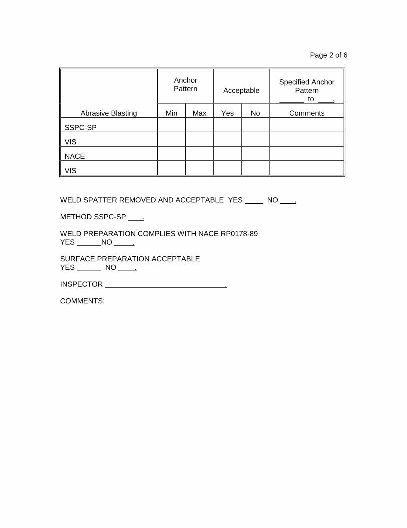
Page 2 of 6
Anchor Pattern
Acceptable
Specified Anchor
Pattern to .
Abrasive Blasting
Min
Max
Yes
No
Comments
SSPC-SP
VIS
NACE
VIS
WELD SPATTER REMOVED AND ACCEPTABLE YES NO . METHOD SSPC-SP . WELD PREPARATION COMPLIES WITH NACE RP0178-89 YES NO . SURFACE PREPARATION ACCEPTABLE YES NO . INSPECTOR . COMMENTS:

Page 3 of 6
FIRST (BASE) OR PRIME COAT
INDOORS OUTDOORS . COATING MFG NAME AND PRODUCT DESCRIPTION . COATING MFG DATE SHIPPING DATE STORAGE DATE . BATCH NO. COLOR . INDUCTION REQUIRED . APPLICATION METHOD . APPLICATION EQUIPMENT INSPECTED AND APPROVED YES NO . DATE TIME HOURS SINCE SURF. PREP. . DRY BULB TEMP OF WET BULB TEMP OF RELATIVE HUMIDITY % SUBSTRATE TEMP OF DEW POINT . SURFACE DRY YES NO . CLEAN YES NO . REMOVAL OF OIL , GREASE , DIRT , DUST , CORROSION . APPROVAL OF SUBSTRATE FOR COATING YES NO . INSPECTOR . 1ST COAT MATERIALS . OBSERVED MIXING YES NO . THINNER ADDED YES NO . TYPE OF THINNER AMOUNT ADDED . OZ/GAL % TEMP OF COATING OF INDUCTION TIME MIN POT LIFE HRS-MIN MIXING APPROVED YES NO . WFT TO MILS INSPECTOR . COMMENTS . DATE TIME DFT TO . ACCEPTABLE YES NO . RUNS, SAGS, BLISTERS, BUBBLES, CURTAINS, CRATERING, MUD CRACKING, ALLIGATORING, FISH EYES; VARIATIONS IN COLOR, GLOSS AND TEXTURE; EXCESSIVE FILM BUILD; FOREIGN CONTAMINANTS; AND DRY OVERSPRAY; OR OTHER DEFECTS YES NO . DEFECTS CORRECTED YES NO . INSPECTOR . COMMENTS .

Page 4 of 6
SECOND (INTERMEDIATE) COAT INDOORS OUTDOORS . COATING MFG NAME AND PRODUCT DESCRIPTION . COATING MFG DATE SHIPPING DATE STORAGE DATE . BATCH NO. COLOR . INDUCTION REQUIRED . APPLICATION METHOD . APPLICATION EQUIPMENT INSPECTED AND APPROVED YES NO . DATE TIME HOURS SINCE SURF. PREP. . DRY BULB TEMP OF WET BULB TEMP OF RELATIVE HUMIDITY % SUBSTRATE TEMP OF DEW POINT . SURFACE DRY YES NO . CLEAN YES NO . REMOVAL OF OIL , GREASE , DIRT , DUST , CORROSION . APPROVAL OF SUBSTRATE FOR COATING YES NO . INSPECTOR . 2ND COAT MATERIALS . OBSERVED MIXING YES NO . THINNER ADDED YES NO . TYPE OF THINNER AMOUNT ADDED . OZ/GAL % TEMP OF COATING OF INDUCTION TIME MIN POT LIFE HRS-MIN MIXING APPROVED YES NO . WFT TO MILS INSPECTOR . COMMENTS . DATE TIME DFT TO . ACCEPTABLE YES NO . RUNS, SAGS, BLISTERS, BUBBLES, CURTAINS, CRATERING, MUD CRACKING, ALLIGATORING, FISH EYES; VARIATIONS IN COLOR, GLOSS AND TEXTURE; EXCESSIVE FILM BUILD; FOREIGN CONTAMINANTS; AND DRY OVERSPRAY; OR OTHER DEFECTS YES NO . DEFECTS CORRECTED YES NO . INSPECTOR . COMMENTS .

Page 5 of 6
THIRD (FINISH) COAT INDOORS OUTDOORS . COATING MFG NAME AND PRODUCT DESCRIPTION . COATING MFG DATE SHIPPING DATE STORAGE DATE . BATCH NO. COLOR . INDUCTION REQUIRED . APPLICATION METHOD . APPLICATION EQUIPMENT INSPECTED AND APPROVED YES NO . DATE TIME HOURS SINCE SURF. PREP. . DRY BULB TEMP OF WET BULB TEMP OF RELATIVE HUMIDITY % SUBSTRATE TEMP OF DEW POINT . SURFACE DRY YES NO . CLEAN YES NO . REMOVAL OF OIL , GREASE , DIRT , DUST , CORROSION . APPROVAL OF SUBSTRATE FOR COATING YES NO . INSPECTOR . 3RD COAT MATERIALS . OBSERVED MIXING YES NO . THINNER ADDED YES NO . TYPE OF THINNER AMOUNT ADDED . OZ/GAL %
TEMP OF COATING O
F INDUCTION TIME MIN
POT LIFE HRS-MIN . MIXING APPROVED YES NO . WFT TO MILS INSPECTOR . COMMENTS . DATE TIME DFT TO . ACCEPTABLE YES NO . RUNS, SAGS, BLISTERS, BUBBLES, CURTAINS, CRATERING, MUD CRACKING, ALLIGATORING, FISH EYES; VARIATIONS IN COLOR, GLOSS AND TEXTURE; EXCESSIVE FILM BUILD; FOREIGN CONTAMINANTS; AND DRY OVERSPRAY; OR OTHER DEFECTS YES NO . DEFECTS CORRECTED YES NO . INSPECTOR . COMMENTS .

Page 6 of 6
FINAL INSPECTION DFT SPECIFIED . DFT RANGE TO MIL HOLIDAYS YES NO . OTHER DEFECTS & COMMENTS . RUNS, SAGS, BLISTERS, BUBBLES, CURTAINS, CRATERING, MUD CRACKING, ALLIGATORING, FISH EYES; VARIATIONS IN COLOR, GLOSS AND TEXTURE; EXCESSIVE FILM BUILD; FOREIGN CONTAMINANTS; AND DRY OVERSPRAY; OR OTHER DEFECTS YES NO . DEFECTS CORRECTED YES NO . REPAIR AND TOUCH UP COMPLETED IN ACCORDANCE WITH NACE STANDARD RF-01-84 ITEM NO. 5305 YES NO . OTHER DEFECTS & COMMENTS . COATING INSPECTOR PROJECT INSPECTOR Signature Date Signature Date

SCHEDULE 09 91 00_1
PAINTING SCHEDULE
Except as otherwise called for in these Specifications, the following surfaces shall be painted in
accordance with the appropriate exposure condition, as called for in the Painting Systems List:
1. NEW SURFACES.
A. Iron and Steel. All exposed, encased, submerged or splash zone iron and
steel surfaces, and buried steel surface.
1. Stainless steel shall be painted only where shown or ordered.
B. Galvanized Steel. All exposed, encased, submerged or splash zone
galvanized surfaces except:
1. Grating and floor plates.
2. For Conduit see H.
C. Copper Pipe. All exposed copper piping except soft temper.
D. Aluminum:
1. Aluminum shall be painted only where shown or ordered.
2. For conduit see H.
E. Concrete and Masonry:
1. Interior: All exposed concrete, precast concrete, concrete brick and
block, including ceilings, beams, columns and walls. Concrete floor
surfaces, equipment bases, and stair treads and risers shall not be
painted, unless noted otherwise.
2. Exterior: All concrete and precast concrete shall not be painted
except as specified and scheduled.
F. Wood. All exposed exterior and interior surfaces.
G. Plastics. All exposed plastic and fiberglass pipe, fittings, valves, tanks and
equipment, except as noted. Do not paint submerged plastic surfaces.
H. Electrical Conduit:
1. Interior: No painting required.
2. Exterior:
a. Galvanized - Paint with appropriate system.
b. Aluminum - Paint only where shown or ordered.
I. Stainless Steel Insulation Jacket. Do not paint except bands and legend.
J. Pipe Insulation. All exposed nonmetallic surfaces.
K. Gypsum Walls and Ceilings. All exposed.
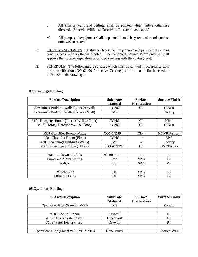
L. All interior walls and ceilings shall be painted white, unless otherwise
directed. (Sherwin-Williams "Pure White", or approved equal.)
M. All pumps and equipment shall be painted to match system color code, unless
otherwise directed.
2. EXISTING SURFACES. Existing surfaces shall be prepared and painted the same as
new surfaces, unless otherwise noted. The Technical Service Representative shall
approve the surface preparation prior to proceeding with the coating work.
3. SCHEDULE. The following are surfaces which shall be painted in accordance with
these specifications (09 91 00 Protective Coatings) and the room finish schedule
indicated on the drawings.
02 Screenings Building
Surface Description Substrate
Material
Surface
Preparation
Surface Finish
Screenings Building Walls (Exterior Wall) CONC CL HPWR
Screenings Building Walls (Exterior Wall) IMP Factory
#101 Dumpster Room (Interior Wall & Floor) CONC CL HB-1
#102 Storage (Interior Wall & Floor) CONC CL HPWR
#201 Classifier Room (Walls) CONC/IMP CL/-- HPWR/Factory
#201 Classifier Room (Floor) CONC -- EP-2
#301 Screenings Building (Walls) IMP -- Factory
#301 Screenings Building (Floor) CONC/FRP CL EP-2/Factory
Hand Rails/Guard Rails Aluminum -- --
Pump and Motor Casing Iron SP 5 F-3
Valves Iron SP 5 F-3
Influent Line DI SP 5 F-3
Effluent Drains DI SP 5 F-3
08 Operations Building
Surface Description Substrate
Material
Surface
Preparation
Surface Finish
Operations Bldg (Exterior Wall) IMP Factpru
#101 Control Room Drywall PT
#102 Unisex Toilet Room Blueboard PT
#103 Water Heater Closet Drywall PT
Operations Bldg (Floor) #101, #102, #103 Conc/Vinyl Factory/Wax

Refer to Schedule 09 91 00_2, Painting Systems List, for process piping, equipment, and other
surfaces not specifically listed herein for surface preparation and finishes.
SCHEDULE LEGEND
BO BY OTHERS
BR BRICK
CMU CONCRETE MASONRY UNITS
CONC CONCRETE
SCFT STRUCTURAL CLAY FACING TILE
CS CONCRETE SEALER
EP-1 EPOXY (SEE SCHED 2 – P-2 & F-1)
EP-2 EPOXY DECK COATING (SLIP RESISTANT)
EXP EXPOSED
F FACTORY FINISH
FC FINISH COMPOUND
IMP INSULATED METAL PANEL
PCM SURFACE PREP PER COATING MANUFACTURER
PT PAINT (SEE SCHED 2 – P-8 & F-10)
RES RESILIENT SHEET FLOORING
RB RESILIENT WALL BASE
RD METAL ROOF DECK
VHB VERY HIGH BUILD COATING
HB-1 HIGH BUILD COATING – STEEL
HB-2 HIGH BUILD COATING – CONCRETE
HPWR HIGH PERFORMANCE WATER REPELLENT
CL WASH-DOWN CLEAN & REPAIR EXISTING MATERIALS
4. SURFACES NOT PAINTED.
A. The following surfaces shall NOT be painted:
1. Equipment nameplates.
2. Stainless steel.
3. Factory finish equipment except as otherwise noted and scheduled.
4. Interior conduit.
B. Should any of the above surfaces be painted, the Contractor shall remove the
coating and restore the surface to original condition.
END OF SCHEDULE 09 91 00_1

THIS PAGE INTENTIONALLY LEFT BLANK

SCHEDULE 09 91 00_2
PAINTING SYSTEMS LIST
Exposure Description System Surface Prep.
Pre-treatment or Primer/ Dry Mils
Finish Coats/ Dry Mils
Total Dry Mil
Thickness No. 1 No. 2 No.3
IRON & MILD STEEL
A. SUBMERGED
1. Potable S1 SP-5 P-3 / 6 F-1 / 6 F-2 / 8 12
2. Nonpotable(a) S2 SP-5 F-2 / 8 F-2 / 8 19
3. Galvanized SP-1 & SP-7
P-1 / 4-6 P-1 / 4-6 F-3 / 4-6 12-18
B. NOT SUBMERGED
1. New (interior and exterior)
SP-10 P-1 / 3 F-5 / 5 F-3 (gloss) /
2
10
2. Existing (interior and exterior)
SP-11 or SP-10(i)
P-2(b) / 2 F-5(c) / 5 F-3 (gloss) /
2
9
3. Humid or Chemical Exposure (existing or new, interior or exterior only where called for)
SP-10(d) P-5 / 3 F-5 / 5
Mist & Body Coats
F-3 (gloss) /
2
10
4. High Temp – A (150oF -250oF)
SP-10 P-1 / 3 F-5 / 5 F-5 / 5 13
5. High Temp – B (250oF -750oF)
SP-10 - F-7 / 3 F-4 / 1 4

Exposure Description System Surface Prep.
Pre-treatment or Primer/ Dry Mils
Finish Coats/ Dry Mils
Total Dry Mil
Thickness No. 1 No. 2
6. High Temp – C (750oF -1200oF)
SP-10 - F-4 / 1 F-4 / 1 2
7. Encased(e) (in masonry, concrete or insulation)
SP-6 P-1 / 3 F-5 / 4 - 7
8. Galvanized SP-1 & SP-7
P-1 / 4-6 F-5 / 4-6 F-3 (gloss) /
3-5
11-17
9. Exist. Fence SP-12 F-8 / 1-2 F-10 / 2-3
F-10 / 2-3
5-8
STAINLESS STEEL S10 SP-10 P-1(f) / 3-5 F-3(flat) / 2-3
F-3 (gloss) /
2-3
7-11
COPPER (All Exposure)
C1 SP-1 P-1(f) / 3-5 F-3(flat) / 2-3
F-3 (gloss) /
2-3
7-11
ALUMINUM (In contact with dissimilar metals)
A1 Clean F-5 / 4-6 F-5 / 4-6 F-5 / 4-6 12-18
CONCRETE & MASONRY
A. NOT SUBMERGED(g) (New and existing repaint work)
1. Interior, porous
M1 Sec. 3-5 P-4 / 10-12 F-5 / 4-6 F-3 (gloss) /
2-3
16-21
2. Interior, non-porous
Sec. 3-5 F-5 / 3-5 F-3(flat) / 2-3
F-3 (gloss) /
2-3
7-11
3. Exterior, non-porous
Sec. 3-5 F-5 / 3-5 F-3(flat) / 2-3
F-3 (satin) /
2-3
7-11
Exposure Description System Surface Prep.
Pre-treatment
Finish Coats/ Dry Mils
Total Dry Mil

or Primer/ Dry Mils
No. 1 No. 2 Thickness
4. Floors Sec. 3-5 F-11, nonslip(h) 30
WOOD
1. Interior (color) Clean P-7 / 1 F-9 / 3 F-9 / 3 7
2. Exterior (color) Clean P-8 / 2 F-10 / 3 F-10 / 3 7
3. Interior (clear) Clean - V-1 V-2
PLASTICS (including fiberglass)
P1 Clean per mfg. recomm.
- F-5 / 3-5 F-3 (gloss) /
2-3
5-8
INSULATED PIPE
1. Canvas Cover Cement coating under
the pipe item
F-10 / 2-3 F-10 / 2-3
F-10 / 2-3
6-9
2. PVC Jacket Clean per mfg. recomm.
F-10 / 2-3 F-10 / 2-3
F-10 / 2-3
6-9
GYPSUM WALLS D1 Clean as directed
P-1 / 3-5 F-10 / 2-3
F-10 / 2-3
7-11

(a) Includes surfaces buried in ground or exposed to digester gas.
(b) Spot prime bare metal surfaces not covered with existing paint.
(c) Finish coat no. 1 must be fully cured prior to applying finish coat no. 2, otherwise use primer P-1.
(d) Remove all existing coatings to SP-10.
(e) To 250oF.
(f) Surface shall be sandblasted or abraded to create anchor pattern sufficient to insure bonding of primer.
(g) Pinholes shall be filled.
(h) Broadcast silica sand to saturation when coating is wet, minimum 2 applications.
(i) The default surface prep for new and existing iron and steel surfaces shall be to bare metal by either power tool or blasting. Blasting will only be permitted if the work area can be properly isolated to contain the blasting debris without interfering in the facility operation. If the existing surface is in sound condition and cleaning to bare metal is not warranted, Contractor shall submit RFI requesting deviation from specs and proposed surface prep. Such request shall also include a proposed credit to the Owner when less work is involved.
PAINTING SYSTEMS LIST LEGEND
1. SURFACE PREPARATIONS:
Mark Description
SP-1 Solvent Cleaning
SP-2 Hand Tool Cleaning
SP-3 Power Tool Cleaning
SP-5 White Metal Blast Cleaning
SP-6 Commercial Blast Cleaning
SP-7 Brush-off Blast Cleaning
SP-8 Pickling
SP-10 Near White Blast Cleaning
SP-11 Power Tool Cleaning to Bare Metal
The above surface preparations shall be performed in accordance with the recommendations of the Society for Protective Coatings (SSPC), 40, 24th Street, Pittsburgh, Pennsylvania 15222 and in accordance with Sec. 22.4.

2. PRIMERS:
Mark Generic Type Manufacturers
P-1 Polyamide epoxy Carboline: Carboguard 60
Sherwin Williams: Macropoxy 646
Tnemec: Series 69 Hi-Build Epoxoline II
P-2
(Do not use if finish coat is to be F-2, prime
with F-2.)
Epoxy Carboline: Rustbond
Sherwin Williams: Duraplate 235
Tnemec: Series 27 Typoxy
P-3 Polyamide epoxy (potable water)
Carboline: Carboguard 61
Sherwin Williams: Tank Clad HS
Tnemec: Series N140 Pota-Pox Plus
P-4 Block filler Carboline: Sanitile 100
Sherwin Williams: CEMENT PLEX Heavy Duty Block Filler
Tnemec: Series 130 Envirofill
P-5 Inorganic zinc-rich primer
Carboline: Carbo Zinc 11
Sherwin Williams: Zinc Clad II HS
Tnemec: Tnemec-Zinc 90-96
P-7 Enamel Carboline: Sanitile 120
Sherwin Williams: A-100 Exterior Primer
Tnemec: Series 36-603 Undercoater
P-8 Acrylic Carboline : Carbocrylic 3359
Sherwin Williams: DTM Acrylic B66 Series
Tnemec: Series 30 Acrylic

3. FINISH PAINTS:
Mark Generic Type Manufacturers
F-1 Polyamide epoxy (potable water)
Carboline: Carboguard 61
Sherwin Williams: Tank Clad HS
Tnemec: Series N140 Pota-Pox Plus
F-2 Coal tar epoxy Carboline: Bitumastic 300M
Sherwin Williams: Hi Mil Sher Tar Epoxy
Tnemec: Series 46H-413 Hi-Build Tneme-Tar
F-3 Aliphatic urethane* with leveling additive**
Carboline: Carbothane 134HG (gloss) / Carbothane 133LH (semigloss)
Sherwin Williams: High Solids Polyurethane
Tnemec: Series 1074 and 1075 Endura-Shield
F-4 Silicone aluminum Carboline: Thermaline 4700
Sherwin Williams: KEM Hi-Temp No. 1500 series
Tnemec: Series 39 Silicone Aluminum
F-5 Polyamide epoxy Carboline: Carboguard 60
Sherwin Williams: Macropoxy 646
Tnemec: Series 69 Hi-Build Epoxoline II
F-6 Silicone Tnemec: Silicone Water Repellent
F-7 Ethyl silicate inorganic zinc
Carboline: Carbo Zinc 11
Sherwin Williams: Zinc Clad II HS
Tnemec: 90 96 Tneme Zinc

Mark Generic Type Manufacturers
F-8 Rust-inhibitive primer
Carboline: Rustbond
F-9 Alkyd enamel Carboline: Carboguard 8215
Sherwin Williams: Industrial Enamel B54 Series
Tnemec: 2H Hi Build Tneme Gloss
F-10 Acrylic
i) Flat Carboline: Carbocrylic 3350
Sherwin Williams: Weather Perfect Acrylic Latex Series B-36
Tnemec: Series 6 Tneme-Cryl
ii) Satin Gloss Carboline : Carbocrylic 3359
Sherwin Williams: DTM Acrylic Coating B66-100
Tnemec: Series 7 Tenem-Cryl SG
F-11 Self-Leveling Epoxy (heavy-duty floor coating)
Sherwin Williams: Armorseal 650SL System (nonslip) including Armorseal Crack Filler, Armorseal 33 Epoxy Primer/Sealer, Armorseal 650 SL). Color: Haze Gray
Carboline: Sanitile 944HB System (non-slip) including Carboguard 510 Crack Filler; Sanitile 900 Primer/Sealer; Sanitile 944HB (colors: Light Gray (Q700), Medium Gray (Q701), Dark Gray,(Q702), Khaki (Q200), Brick Red (Q500), Blue (Q100), Green (Q300), and Beige (Q201))

Mark Generic Type Manufacturers
Alkyd varnish (clear gloss)
Devoe: Glidden Woodmaster Polyurethane Clear Finish High Gloss No. 81
Sherwin Williams: Polyurethane Varnish A67V1
Alkyd varnish (clear satin)
Devoe: Glidden Woodmaster Polyurethane Clear Finish Satin Sheen No. 82
Sherwin Williams: Polyurethane Varnish A67F1
* Aliphatic urethane shall be an aliphatic, polyester/acrylic resin, polyurethane. No epoxy resin based polyurethanes will be acceptable.
** A leveling additive shall be incorporated with this finish coat and the application shall be made in such a manner as to achieve a very smooth, uniform, "automotive" or "wet-look" surface finish. Dull, orange-peel areas will not be acceptable. A sample panel, minimum 2'-0" x 3'-0" flat plate of 3'-0" long by 6" diameter shall be submitted for finish approval prior to finish painting of any surfaces for this contract.
END OF SCHEDULE 09 91 00_2

SCHEDULE 09 91 00_3
PIPING COLORS
Painting Color Selection Guide for Piping
System No.
Piping Name Selected Color Legend Equal to Sherwin-Williams Number
1 Ash Slurry Light Blue Ash
2 Centrate Light Gray Centrate SW4026
3 Centrifuge Sludge Feed Dark Brown Cent No X Sl Fd SW4001
4 Chemicals Yellow w/Green Bands (Chemical Name) SW4084/SW4085
5 Chlorine Yellow Chlorine SW4084
6 City Non-Potable Water Orange w/Black Bands City NPW SW4083
7 Compressed Air Green Comp Air SW4085
8 Condensate To match walls, ceilings, etc. w/Black Bands
Condensate -
9 Dewatered Solids Feed Dark Brown DSF
10 Effluent Sample Orange w/White Bands Eff Sample SW4083
11 Exhaust Gas Ref 11920 Sec 2-14-03 EG
12 Fluidizing Air Ref 11920 Sec 2-14-03 FA
13 Fuel Oil Fill Red w/Black Bands Fuel Oil SW4081
14 Fuel Oil Supply Red w/Green Bands FOS SW4081/SW4085

Painting Color Selection Guide for Piping
System No.
Piping Name Selected Color Legend Equal to Sherwin-Williams Number
15 Fuel Oil Return Red w/Brown Bands FOR SW4081/SW4001
16 Influent Sample Dark Gray w/White Bands Inf Sample SW4018
17 Hot Water Return Safety Green Hot Wat Return SW4085
18 Hot Water Supply Safety Yellow Hot Wat Supply SW4084
19 Instrument Air Safety Green with Black Information and Bands
Instr Air SW4085
20
Mixed Thickened Excess Activated Sludge and Thickened Primary Sludge
Dark Brown Mix TPS/TEAS SW4001
21 Natural Gas Red w/White Bands Nat Gas SW4081
22 Non-Potable Water Orange NPW SW4083
23 Odor Control Duct Odor Control
24 Pilot Gas Red w/Brown Bands Pilot Gas SW4081/SW4084
25 Polymer Safety Yellow with Safety Green Information and Bands
Polymer SW4084/4085
26 Potable Water Blue Potable Water SW4079
27 Preheat Air Green PHA
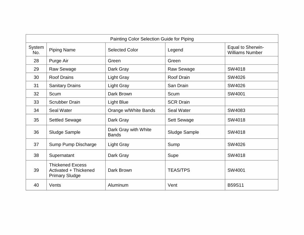
Painting Color Selection Guide for Piping
System No.
Piping Name Selected Color Legend Equal to Sherwin-Williams Number
28 Purge Air Green Green
29 Raw Sewage Dark Gray Raw Sewage SW4018
30 Roof Drains Light Gray Roof Drain SW4026
31 Sanitary Drains Light Gray San Drain SW4026
32 Scum Dark Brown Scum SW4001
33 Scrubber Drain Light Blue SCR Drain
34 Seal Water Orange w/White Bands Seal Water SW4083
35 Settled Sewage Dark Gray Sett Sewage SW4018
36 Sludge Sample Dark Gray with White Bands
Sludge Sample SW4018
37 Sump Pump Discharge Light Gray Sump SW4026
38 Supernatant Dark Gray Supe SW4018
39 Thickened Excess Activated + Thickened Primary Sludge
Dark Brown TEAS/TPS SW4001
40 Vents Aluminum Vent B59S11

Painting Color Selection Guide for Piping
System No.
Piping Name Selected Color Legend Equal to Sherwin-Williams Number
41 Waste Activated Sludge Dark Brown WAS SW4001
42 Waste Mixed Liquor Dark Gray Waste Mix Liquor SW4018
END OF SCHEDULE 09 91 00_3