Rapidly-exploring roadmaps: Weighing exploration vs. refinement in optimal motion planning
Upload
khangminh22Category
view
0download
0
Process Automation
Products for Weighing Technology
Answers for industry.
CatalogWT 10
Edition2014
01_Umschlag_WT10_2014_en.indd 301_Umschlag_WT10_2014_en.indd 3 02.06.2014 13:43:1202.06.2014 13:43:12
© Siemens AG 2014

Process Automation MP 31SIPART Controllers and Software
PDF/e-book (E86060-K6031-A100-B6-7600)
Process Automation FI 01Field Instruments for Process Automation
E86060-K6201-A101-B6-7600
Process Automation PA 01Process Analytical Instruments
PDF/e-book (E86060-K3501-A101-A9-7600)
Process Automation PA 11Components for system integration
PDF/e-book (E86060-K3511-A100-B2-7600)
SIMATIC Ident ID 10Industrial Identification Systems
E86060-K8310-A101-A9-7600
Industrial Communication IK PISIMATIC NET
E86060-K6710-A101-B7-7600
SIMATIC ST 70Products forTotally Integrated Automation
E86060-K4670-A101-B4-7600
SIMATIC ST 70 NProducts forTotally Integrated Automation and Micro Automation
E86060-K4670-A151-A6-7600
SITRAIN ITCTraining for Industry
Only available in German
E86060-K6850-A101-C4
Products for Automation and Drives CA 01Interactive Catalog, DVD
E86060-D4001-A510-D3-7600
Industry Mall Information and Ordering Platformin the Internet:
www.siemens.com/industrymall
Related catalogs
WT10_2014_U2_en.fm Seite 1 Montag, 2. Juni 2014 1:06 13
© Siemens AG 2014

Introduction 1
Weighing Electronics 2
Load Cells 3
Belt Scales 4
Weighfeeders 5
Solids Flowmeters 6
Appendix 7
Products for Weighing Technology
Process Automation
Catalog WT 10 · 2014
Supersedes:Catalog WT 10 · 2012
Refer to the Industry Mall for current updates of this catalog:www.siemens.com/industrymall
The products contained in this catalog can also be found in the Interactive Catalog CA 01.Article No.: E86060-D4001-A510-D3-7600
Please contact your local Siemens branch.
© Siemens AG 2014
Printed on paper from sustainably managed forests and controlled sources.
www.pefc.org
The products and systems described in this catalog are manufactured/distributed under application of a certified quality management system in accordance with DIN EN ISO 9001. The certificate is recog-nized by all IQNet countries.
© Siemens AG 2015

2 Siemens WT 10 · 2014
© Siemens AG 2015

3Siemens WT 10 · 2014
Answers for industry.
Integrated technologies, vertical market expertise and services
for greater productivity, energy efficiency, and flexibility.
The Siemens Industry Sector is the world's leading supplier of innovative and environmentally friendly products and solutions for industrial companies. End-to-end automation technology and industrial software, solid market exper-tise, and technology-based services are the levers we use to increase our cus-tomers’ productivity, efficiency and flexibility. With a global workforce of more than 100 000 employees, the Industry Sector comprises the Industry Automation, Drive Technolo-gies, and Customer Services divisions, as well as the Metals Technologies Business Unit.
We consistently rely on integrated tech-nologies and, thanks to our bundled portfolio, we can respond more quickly and flexibly to our customers' wishes. With our globally unmatched range of automation technology, industrial control and drive technology as well as industrial software, we equip compa-nies with exactly what they need over their entire value chain – from product design and development to production, sales and service. Our industrial custom-ers benefit from our comprehensive portfolio, which is tailored to their market and their needs.
Market launch times can be reduced by up to 50% due to the combination of powerful automation technology and intelligent industrial software from Siemens Industry. At the same time, the costs for energy or waste water for a manufacturing company can be reduced significantly. In this way, we increase our customers’ competitive strength and make an important contri-bution to environmental protection with our energy-efficient products and solutions.
© Siemens AG 2015

4 Siemens WT 10 · 2014
Setting standards in productivity and competitiveness.Totally Integrated Automation.
© Siemens AG 2015

5Siemens WT 10 · 2014
Thanks to Totally Integrated Automation, Siemens provides
an integrated basis for the implementation of customized
automation solutions – in all industries from inbound to
outbound.
TIA is characterized by its unique continuity.
It provides maximum transparency at all levels with reduced interfacing requirements – covering the field level, production control level, up to the corporate management level. With TIA you also profit throughout the complete life cycle of your plant – starting with the initial planning steps through operation up to modernization, where we offer a high measure of investment security re-sulting from continuity in the further development of our products and from reducing the number of interfaces to a minimum.
The unique continuity is already a defined characteristic at the development stage of our products and systems.
The result: maximum interoperability – covering the controller, HMI, drives, up to the process control system. This reduces the complexity of the automation solution in your plant. You will experience this, for example, in the engineering phase of the automation solution in the form of reduced time requirements and cost, or during operation using the continuous diagnostics facili-ties of Totally Integrated Automation for increas-ing the availability of your plant.
© Siemens AG 2015

6 Siemens WT 10 · 2014
© Siemens AG 2015

Siemens WT 10 · 2014
11/2 Weighing products with proven reliability
1/3 Experience you can trust
1/4 Products1/4 Platform scales1/4 Hopper weighing1/4 Conveyor scales1/5 Batch system1/5 Filling machines1/5 Checkweighing1/6 Solids flowmeter1/6 Loss-in-weight1/6 Weighfeeding
Weighing Technology
© Siemens AG 2015

1/2 Siemens WT 10 · 2014
Weighing products with proven reliability
Quality, costs, and time are crucial factors for all production com-
panies – especially in today’s competitive environment. Accurate
and dependable weighing and controlling equipment helps man-
age these factors by optimizing formulations, reducing waste,
and increasing production. In the end, improved processes mean
profitability increases.
Weighing and batching systems play a growing role in produc-
tion within various industries. Siemens weighing equipment
offers reliable, accurate and integrated results that are cost-
effective and long-term.
As a leader in automation and weighing for more than 50 years,
Siemens is the only company that offers a complete range of
weighing products that fit the rigorous demands of our custom-
ers. That’s why manufacturers as well as end customers use
Siemens weighing products. You will find us in almost any indus-
try that involves the handling of bulk materials, from mining,
aggregates, and cement, to food processing, chemicals or phar-
maceuticals.
© Siemens AG 2015

1/3Siemens WT 10 · 2014
Experience you can trust
With more than 50 years of weighing experience, Siemens is the
right partner for your application. With Siemens, you benefit
from:
• Specialized weighing products with a broad range of function
and flexibility
• Legal-for-trade products
• Seamless integration in Siemens’ world-class automation
systems – SIMATIC S7 and PCS7
• Versatile and flexible systems that allow you to expand as your
needs change
• A global company that provides worldwide support whenever,
wherever you need it
• The best cost of ownership available through highly accurate
and reliable products
© Siemens AG 2015

1/4 Siemens WT 10 · 2014
Not just about products …
Platform scales
Platform scales are the most common scale in industry. No matter what your load is, a truck, a bin, a bucket or raw material. Siemens provides you with a broad range of load cells and weighing electronics to build cost-effective plat-form scales.
Use SIWAREX load cells to measure loads ranging from 5 kg to 1 000 t with an accuracy class up to C3 according to OIML R60.
Weighing data is easy to process with SIWAREX weighing processors. Use SIWAREX U, WP231 or WP321 for sim-ple applications and SIWAREX FTA for legal-for-trade applications.
• SIWAREX load cells and mounting units
• SIWAREX WP231 weighing electronics
• SIWAREX WP321 weighing electronics
• SIWAREX CS weighing electronics
• SIWAREX U weighing electronics
• SIWAREX FTA weighing electronics
Hopper weighing
Liquids, powders, solids, and gases are stored or produced in a wide variety of tanks and bins. It is essential to know the precise levels of stored materials to ensure product availability for process-ing.
With Siemens weighing solutions, you can measure the level, no matter what kind of material is stored – whether it is corrosive, foamy, high or low dielectric, or dusty.
Using SIWAREX mounting units avoids incorrect measurement due to the transmission of secondary forces (e.g. through tank restraint or pipes). These devices make installation of the load cells quick and easy.
• SIWAREX load cells and mounting units
• SIWAREX WP231 weighing electronics
• SIWAREX WP321 weighing electronics
• SIWAREX CS weighing electronics
• SIWAREX U weighing electronics
• SIWAREX FTA weighing electronics
Conveyor scales
Belt scales help maximize the use of raw materials, control inventories, and aid in the consistent manufacturing. Siemens conveyor belt scales combine simple, drop-in installation, low main-tenance (no moving parts) and repeat-able accuracy for productive operation. They show minimal hysteresis and su-perior linearity, and ignore side load-ing. All load cells feature overload pro-tection. With hazardous and trade approvals, Siemens belt scales can be used in almost any industrial environ-ment or application. Combined with a Milltronics BW500 integrator, or SIWAREX FTC, Siemens conveyor scales offer field proven technology for reli-able performance. High accuracy, light-loading and heavy-duty models are available.
• Milltronics belt scales
• Speed sensors
• Milltronics BW500 and BW500/L integrators
• SIWAREX FTC weighing electronics
• SIWAREX WP241 weighing electronics
© Siemens AG 2015

1/5Siemens WT 10 · 2014
… but about solving problems.
Batch system
Successful, high quality products de-pend on precise dosing of components. High quality measuring equipment ensures precise dosing.
SIWAREX weighing electronics and load cells achieve best results for accurately and quickly controlling coarse and fine material flow, as well as filling and emptying. Due to SIWAREX‘s high scal-ability and integration in SIMATIC, it is easy to automate single or multiple dosing units with one SIMATIC automa-tion station.
• SIWAREX load cells and mounting units
• SIWAREX FTA weighing electronics
Filling machines
Filling, sack filling, and big bag ma-chines are used in a wide range of in-dustries. The filling of solid or liquid goods like cement has to be completed quickly and accurately.
In this case, SIWAREX FTA is an excel-lent choice. It provides a resolution of 16 million intervals, comes with a high accuracy of 3x6 000 d and is legal for trade. With switching of dosing signals below 1 ms, the FTA works well even on the fastest applications. SIWAREX FTA seamlessly integrates into Siemens au-tomation systems S7 or PCS7 ensuring proper communication of the weighing system with the automation environ-ment.
• SIWAREX load cells and mounting units
• SIWAREX FTA weighing electronics
Checkweighing
Checkweighing assures the correct weight of the product package. The electronics are essential to the func-tionality of the checkweigher along with the proper mechanical construc-tion.
SIWAREX FTA is a state-of-the art weighing electronic, providing high resolution of 16 million intervals and a high accuracy of 3x6 000 d. It is pro-grammable and applicable for a broad spectrum of checkweighers. SIWAREX FTA seamlessly integrates into Siemens SIMATIC automation system. With SIWAREX FTA, it is easy to establish a control station for the complete check-weighing loop based on the SIWAREX weighing module, including machine vision, proximity switches or motion control.
• SIWAREX load cells and mounting units
• SIWAREX FTA weighing electronics
© Siemens AG 2015

1/6 Siemens WT 10 · 2014
At the best cost of ownership!
Solids flowmeter
Solids flowmeters enhance process control, contributing to improved qual-ity of your end product. These heavy-duty, low-maintenance, impact type solids flowmeters provide continuous in-line weighing of dry bulk solids, free-flowing powders, or granular material. A stand-alone SF500 integrator or SIWAREX FTC completes the system, processing sensor signals into operat-ing data for flow measurement.
All models produce accurate, repeat-able results and may be used for critical functions such as batch load-out and blending. Safe overload protection is a standard feature. All models are totally enclosed and dust-tight, and are con-structed of painted mild steel. Stainless steel and hazardous area versions are also available.
• SITRANS WF100 flowmeter
• SITRANS WF200 flowmeters
• SITRANS WF300 flowmeters
• SITRANS WFS300 sensing heads
• Milltronics SF500 integrator
• SIWAREX FTC weighing electronics
Loss-in-weight
A loss-in-weight system can help you to achieve the needed level of accuracy in continuous dosing applications. With SIWAREX FTC weighing modules, you can set up and integrate the loss-in-weight system easily. Here the auto-setup functionality helps you in the commissioning of the scale. The elec-tronics determine the most important settings like output, PID or stability pa-rameter. While processing SIWAREX FTC steadily optimizes these settings.
SIWAREX FTC provides high measure-ment resolution, real-time signal pro-cessing, detection and filtering of sig-nals that enables extremely high proportioning accuracy. Via HMI, PC connection or the control system, the operator has the option to manually control the system.
• SIWAREX load cells andmounting units
• SIWAREX FTC weighing electronics
Weighfeeding
A weighfeeder system is an engi-neered-to-order conveyor integrated with a belt weigh bridge and speed sensor. A variable speed drive allows the flow of material to be controlled by a given setpoint chosen in the BW500 integrator or with a PLC through SIWAREX FTC. This allows the weigh-feeder to provide precision weighing accuracies, and to improve blend con-sistencies, accountability and record keeping. Weighfeeders are indispens-able when automated production pro-cesses require continuous in-line weighing and feeding. Their virtually maintenance-free construction prom-ises unmatched performance. Belt widths and conveyor lengths are made to measure for the required applica-tion.
• SITRANS weighfeeders
• Milltronics BW500 integrator
• SIWAREX FTC weighing electronics
© Siemens AG 2015

Siemens WT 10 · 2014
22/2 Stand-alone integrators2/2 Introduction2/3 Milltronics BW500 and BW500/L2/8 Milltronics SF5002/39 SIWAREX WP2312/43 SIWAREX WP241
2/12 Accessories for stand-alone integrators
2/12 Dolphin Plus Software2/13 SITRANS RD1002/15 SITRANS RD2002/19 SITRANS RD3002/23 SITRANS RD5002/28 SmartLinx
2/29 SIWAREX – PLC-basedweighing electronics
2/29 Introduction2/35 SIWAREX WP3212/39 SIWAREX WP2312/43 SIWAREX WP2412/47 SIWAREX CS2/50 SIWAREX U2/54 SIWAREX FTA2/60 SIWAREX FTC
2/66 Force measurements2/66 SIWAREX CF2/69 SIWAREX FTC
2/70 Accessories for PLC-based weighing electronics
2/70 SIWAREX IS Ex-Interface
Weighing Electronics
© Siemens AG 2015
2/2 Siemens WT 10 · 2014
Weighing ElectronicsStand-alone integrators
Introduction
2
■ Overview
Integrators process sensor signals into operating data for con-tinuous in-line weighing. They can take over basic control func-tions traditionally handled by other devices, like PID and batch control.
■ Mode of operation
Milltronics integrators from Siemens incorporate proven elec-tronic load cell balancing to perform basic and sophisticated level and flow control functions. Integrators process the speed or load signal from the sensor and perform functions to convert the data into rate or totalization. The integrator displays primary speed and load values, as well as derived values of rate and to-tal on the LCD, or outputs the information as analog mA output, alarm relay, or remote totalizer.
The Milltronics BW500/L offers standard control functions for use with belt scales. It offers multiple language selections and indus-trial communication options. It can be used with a maximum of two load cell style belt scales.
The Milltronics BW500 are versatile integrators for use with a wide range of belt scales. It is NTEP and Measurement Canada certified as legal-for-trade when used with an MMI-2 belt scale and WS series speed sensor.
The Milltronics BW500 and SF500 offer online calibration so the process does not need to be shut down to calibrate the integra-tor. Both models also offer linearization, PID and batch control, multi-span and auto zero.
Definitions
PID – Proportional, Integral, Derivative – The PID control function combines proportion, integral reset, and derivative rate to con-sistently control systems.
A proportioning band creates an area around a set-point where the controller is controlling the process. If the band is too narrow, the reading will center around the set-point. If the band is too wide, the control values will take a long time to settle and will be slow to respond adequately to upset conditions. An integral re-set corrects for any difference between the desired set-point and variables altered during the process. A derivative rate prevents the control from shifting too dramatically on process upsets or startups.
Batch Control – A predetermined quantity of material is accumu-lated, and the integrator will alarm, notifying that the batch pro-cess is completed.
Linearization – Locations where the ideal belt scale or flowmeter location has been compromised or where there is a high variety in belt tension or flow cause the belt scale or flowmeter to report non-linearly. The integrator linearization function smooths out the result to provide an accurate report of the process.
Multi-span – The integrator can be calibrated for up to 8 different feed conditions that would produce varying load or rate charac-teristics. A span correction is added to the measurement to real-ize maximum accuracy.
Differential Speed Detection – Dual point belt speed sensing is used for monitoring speed at two different points in the system. The two speed sensors are typically applied on belt conveyors to give an alarm if excessive slip between the head pulley and tail pulley is detected (BW500 only).
Incline Compensation – By receiving a mA signal proportional to conveyor slope, the conveyor loading can be re-calculated to compensate for changes in angle (BW500 only).
Moisture Compensation – By receiving a mA signal proportional to moisture content, the conveyor load or rate can be re-calcu-lated to read dry weight (BW500 or SF500 only).
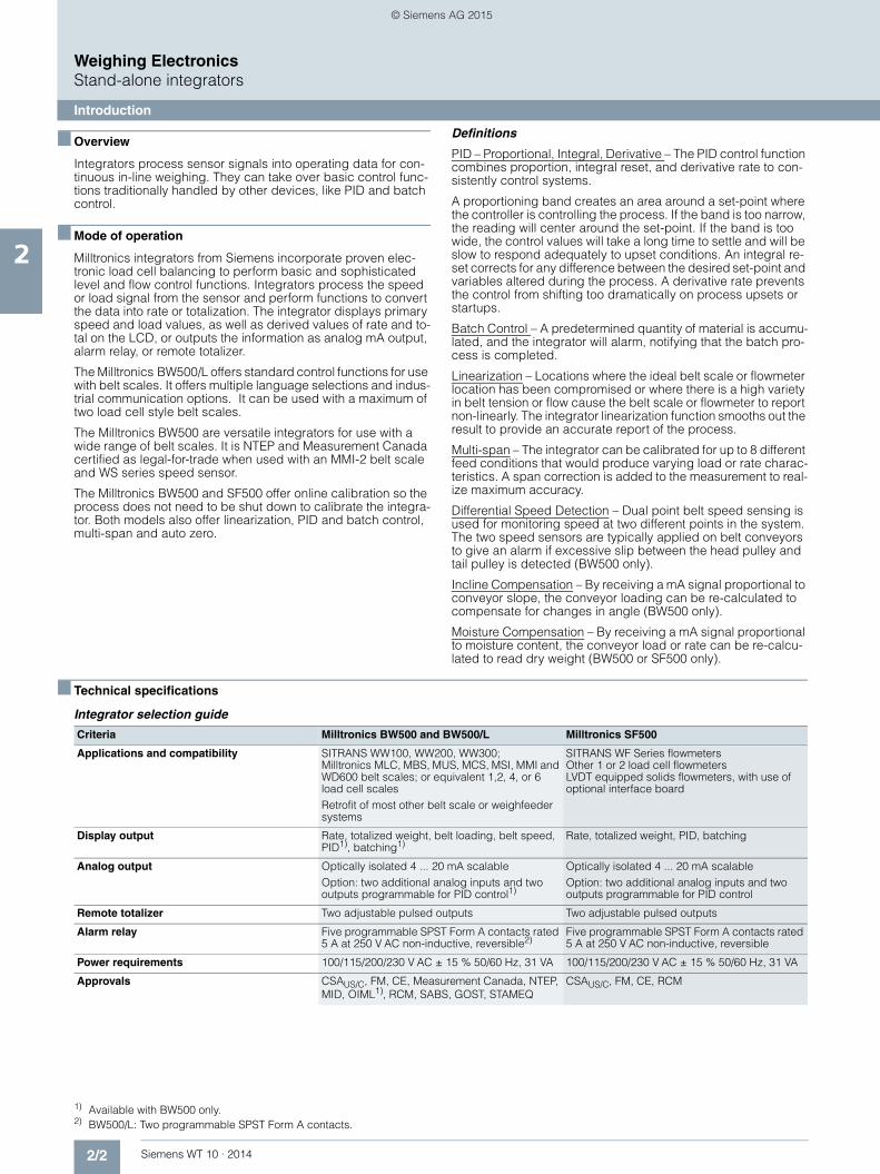
■ Technical specifications 1) 2)
Integrator selection guide
1) Available with BW500 only.2) BW500/L: Two programmable SPST Form A contacts.
Criteria Milltronics BW500 and BW500/L Milltronics SF500
Applications and compatibility SITRANS WW100, WW200, WW300; Milltronics MLC, MBS, MUS, MCS, MSI, MMI and WD600 belt scales; or equivalent 1,2, 4, or 6 load cell scales Retrofit of most other belt scale or weighfeeder systems
SITRANS WF Series flowmetersOther 1 or 2 load cell flowmetersLVDT equipped solids flowmeters, with use of optional interface board
Display output Rate, totalized weight, belt loading, belt speed, PID1), batching1)
Rate, totalized weight, PID, batching
Analog output Optically isolated 4 ... 20 mA scalableOption: two additional analog inputs and two outputs programmable for PID control1)
Optically isolated 4 ... 20 mA scalableOption: two additional analog inputs and two outputs programmable for PID control
Remote totalizer Two adjustable pulsed outputs Two adjustable pulsed outputs
Alarm relay Five programmable SPST Form A contacts rated 5 A at 250 V AC non-inductive, reversible2)
Five programmable SPST Form A contacts rated 5 A at 250 V AC non-inductive, reversible
Power requirements 100/115/200/230 V AC ± 15 % 50/60 Hz, 31 VA 100/115/200/230 V AC ± 15 % 50/60 Hz, 31 VA
Approvals CSAUS/C, FM, CE, Measurement Canada, NTEP, MID, OIML1), RCM, SABS, GOST, STAMEQ
CSAUS/C, FM, CE, RCM
© Siemens AG 2015

2/3Siemens WT 10 · 2014
Weighing ElectronicsStand-alone integrators
Milltronics BW500 and BW500/L
2
■ Overview
Milltronics BW500 is a full feature integrator for use with both belt scales and weighfeeders.
Milltronics BW500/L is an integrator for use in basic belt scale or weighbelt applications.
■ Benefits
• Automatic zero and electronic span calibration• Alarms for rate, load, speed, or diagnostic error• On-board Modbus, optional PROFIBUS DP, ProfiNet,
Modbus TCP/IP, EtherNet/IP, and DeviceNet• Comprehensive weighfeeder control functions• PID control and on-line calibration with optional analog
I/O card • Differential speed detection with second speed sensor• Moisture meter input with optional analog I/O card for calcula-
tion of dry weight• Inclinometer input with optional analog I/O card to compen-
sate for conveyor slope• Suitable for belt scale custody approval• Measurement Canada, OIML, MID, GOST,
and NTEP approved
■ Application
Milltronics BW500 and BW500/L operate with a belt scale and a speed sensor. Belt load and speed signals are processed for ac-curate flow rate and totalized weight of bulk solids.
BW500 can take on lower level control functions traditionally handled by other devices, and it supports popular industrial communication buses. Its proven load cell balance function eliminates matching of load cells.
The PID function may be used for rate control on shearing weigh-feeders - where belt loading is constant - but can also control pre-feeding devices. Operating in tandem with two or more weighfeeders, the BW500 may be used for ratio blending and controlling additives. Batching, load out, and alarm functions are also provided by the BW500.
Dolphin Plus software may be used for programming the unit on a PC.
Integrator selection guide 1)
1) mA input/output for BW500 is based on I/O card.
BW500(advanced feature set)
BW500/L(basic feature set)
PID control With optional I/O card N/A
Differential speed detection Standard N/A
Online calibration Standard N/A
Trade approval(OIML, MID, Measurement Canada,GOST, NTEP)
Optional N/A
SmartLinx communications(DeviceNET, ProfiNet, Modbus, TCP/IP, EtherNet/IP, and Profibus DP)
Optional Optional
Modbus Standard Standard
Ratio Blending and Batching Standard N/A
Moisture and incline compensation • With optional I/O card, or • Parameter set
Parameter set
Multi Span Standard N/A
RD500 connectivity Standard Standard
Relay output 5 2
Time/date stamped printing Standard N/A
mA output 31) 1
mA input 21) 0
© Siemens AG 2015
2/4 Siemens WT 10 · 2014
Weighing ElectronicsStand-alone integrators
Milltronics BW500 and BW500/L
2
■ Technical specifications1)
1) BW500 only.
Milltronics BW500 and BW500/L
Mode of operation
Measuring principle Belt scale integrator
Typical application • Compatible with Milltronics belt scales or equivalent 1, 2, 41), or 61) load cell scales
• Compatible with LVDT equipped scales, with use of optional inter-face board (remotely mounted)
Inputs
Load cell 0 ... 45 mV DC per load cell
Speed sensor
• Pulse train • 0 ... 5 V low, 5 ... 15 V high 1 ... 3 000 Hz, or
• Open collector switch, or • Relay dry contact
Auto zero Dry contact from external device
mA See optional mA I/O board1)
Auxiliary 5 discrete inputs for external con-tacts, each programmable foreither: display scrolling, totalizer 1 reset, zero, span, multi-span, print, batch reset, PID function or online calibration, 2nd speed sen-sor
Outputs (load and speed)
mA Programmable 0/4 ... 20 mA, for rate, optically isolated, 0.1 % of 20 mA resolution, 750 Ω load max. (see optional mA I/O board)
Load cell 10 V DC compensated excitation for strain gauge type, 6 cells max, 150 mA max.
Speed sensor(s) 12 V DC, 150 mA max. excitation
Remote totalizer 1 Contact closure 10 ... 300 ms duration, open collector switch rated 30 V DC, 100 mA max.
Remote totalizer 2 Contact closure 10 ... 300 ms duration, open collector switch rated 240 V AC/DC, 100 mA max.
Relay output 5 alarm/control relays, 1 SPST Form A relay contact per relay, rated 5 A at 250 V AC, non-induc-tive or 30 V DC
Measuring accuracy
Resolution 0.02 % of full scale
Accuracy 0.1 % of full scale
Rated operating conditions
Ambient conditions
Location Indoor/outdoor
Ambient temperature -20 ... +50 °C (-5 … +122 °F)
Relative humidity/ingress protec-tion
Suitable for outdoor/Type 4X/NEMA 4X/IP65
Installation category II
Pollution degree 4
Design
Material (enclosure) Polycarbonate
Dimensions 209 W x 285 H x 92 D mm (8.2 W x 11.2 H x 3.6 D inch)
Weight 2.6 kg (5.7 lb)
Power supply
Standard 100/115/200/230 V AC ± 15 %, 50/60 Hz, 31 VA Fuse, FU1: 2AG, Slo Blo, 2 A, 250 V or equivalent
Controls and displays
Displays Illuminated 5x7 dot matrix liquid crystal display with 2 lines of 40 characters each
Programming Via local keypad and/or Dolphin Plus interface
Memory Program and parameters stored in non-volatile Flash memory,upgradeable via Dolphin Plus interface
Communications • Two RS 232 ports • One RS 485 port • SmartLinx compatible
mA I/O board
Inputs 2 programmable 0/4 … 20 mA for PID control and on-line calibration, optically isolated, 0.1 % of 20 mA resolution, 200 Ω input impedance
Outputs 2 programmable 0/4 … 20 mA for PID control, rate, load and speed output, optically isolated, 0.1 % of 20 mA resolution, 750 Ω load max
Output supply Isolated 24 V DC at 50 mA, short circuit protected
Approvals
BW500 CE, CSAUS/C, FM, Measurement Canada, NTEP, MID, OIML, RCM, , GOST-R, SABS, STAMEQ
BW500/L CE, CSAUS/C, FM, RCM, GOST-R
Options • Speed sensor: MD-36/36A, MD-256, SITRANS WS100, WS300, TASS, or RBSS, or compatible
• Dolphin Plus: Windows based software interface. Refer to asso-ciated product documentation.
• SmartLinx Modules: protocol spe-cific modules for interface with popular industrial communica-tions systems. Refer to product documentation.
• LVDT interface card: for interface with LVDT based scales
Milltronics BW500 and BW500/L
© Siemens AG 2015

2/5Siemens WT 10 · 2014
Weighing ElectronicsStand-alone integrators
Milltronics BW500 and BW500/L
2
■ Selection and ordering data1) 2) 3) 4) 5) 6) Article No. Order Code
We can offer shorter delivery times for configurations designated with the Quick Ship Symbol.
1) Required for PID control and online calibration, available with Feature Software option A only.2) Available with Auxiliary I/O option A, and Trade approval stickers A, B only.3) Required for industrial communications.4) Requires use with applicable certified MSI or MMI.5) Complete specification data sheet on page 4/3 and submit with order.6) Available with Feature Software option A only.
Milltronics BW500 and BW500/LA full-feature, powerful integrator designed for use with both belt scales and weighfeeders
7MH7152-
77777 - 777
Click on the Article No. for the online configuration in the PIA Life Cycle Portal.
Input voltage
AC voltage 1
Auxiliary input/output board
None A
Board with 2 analog inputs and 2 analog outputs1) B
Feature software
BW500, 1 ... 6 load cell input (advanced feature set)
A
BW500/L, 1... 2 load cell input2) (basic feature set) B
Auxiliary memory
None 0
Data communications3)
SmartLinx ready 0
SmartLinx PROFIBUS DP module 2
SmartLinx DeviceNet module 3
SmartLinx ProfiNet module 4
SmartLinx EtherNet I/P module 5
SmartLinx MODBUS TCP I/P module 6
Enclosures
Standard enclosure, no entry holes 1
Standard enclosure, 4 entries, for M20 glands 2
Trade approval stickers
No trade approval sticker A
Not legal for Canadian and EU trade sticker B
Legal for Canadian trade4)5)6) C
Legal for U.S. trade (NTEP)4)5)6) D
Legal for World trade (OIML), European trade (MID)4)5)6)
E
Approvals
CE, CSAUS/C, FM, RCM A
Further designs
Please add "-Z" to article no. and specify order code(s).
Stainless steel tag (69 x 50 mm), Measuring-point number/identification (max 27 characters), specify in plain text.
Y15
Manufacturer's test certificate: According to EN 10204-2.2
C11
OIML/MID approval additional nameplate (submit application data with order)
Y77
NTEP approval additional nameplate (submit application data with order)
Y78
Stainless steel, sun/weather shield357 x 305 x 203 mm (14 x12 x 8 inch) (finished unit is field mounted with enclosure)
S50
Stainless steel enclosure, 304 (1.4301), [406 x 305 x 152 mm (16 x12 x 6 inch), Nema/Type 4X, IP66 (finished unit is mounted inside enclosure)]
• With window A11
• Without window A12
Painted mild steel, [406 x 305 x 152 mm (16 x 12 x 6 inch), Nema/Type 4, IP65; finished unit is mounted inside enclosure]
• With window A13
• Without window A14
Painted mild steel, anti-vibration enclosure with viewing window 406 x 305 x 203 mm (16 x 12 x 8 inch), Nema/Type 4, IP66; finished unit is mounted inside enclosure
A15
Painted mild steel, heated enclosure with viewing window for use down to -50°C (-58 °F); finished unit is mounted inside enclosure 483 x 584 x 203 mm (19 x 23 x 8 inch)
A35
© Siemens AG 2015

2/6 Siemens WT 10 · 2014
Weighing ElectronicsStand-alone integrators
Milltronics BW500 and BW500/L
2
■ Selection and ordering data Article No. Article No.
Milltronics BW500 and BW500/LInstruction manuals
BW500 and BW500/L, English 7ML1998-5DK05
BW500 and BW500/L, German 7ML1998-5DK35
BW500, French 7ML1998-5DK12
BW500, SpanishNote: The instruction manual should be ordered as a separate item on the order.
7ML1998-5DK23
Additional instruction manuals
LVDT Conditioner Card Instruction Manuals, English
7ML1998-5EF01
LVDT Conditioner Card Instruction Manuals, German
7ML1998-5EF31
SmartLinx PROFIBUS DP, English 7ML1998-1AQ03
SmartLinx PROFIBUS DP, German 7ML1998-1AQ33
SmartLinx PROFIBUS DP, French 7ML1998-1AQ12
SmartLinx DeviceNet, EnglishNote: The appropriate SmartLinx instruction manual should be ordered as a separate line on the order.
7ML1998-1BH02
This device is shipped with the Siemens Milltronics manual DVD containing the complete instruction manual library.
Optional equipment
Auxiliary I/O cards spare 7MH7723-1BJ
LVDT Conditioners in Nema 4 enclosure (to interface LVDT belt scale without internal pre-amplifier)
7MH7723-1AJ
Supply voltage regulators, 120 V AC, 60 Hz 7MH7726-1AN
SITRANS RD100 Remote displays,see RD100 on page 2/13
SITRANS RD200 Remote displays, see RD200 on page 2/15
SITRANS RD300 Remote displays, see RD300 on page 2/19
SITRANS RD500 web, datalogging, alarming, Ethernet, and modem support for instrumentation, see page 2/23
7ML5750-1AA00-0
Large LED display, 150 mm (6 inch) high characters
A5E31871009
SIMATIC Touch panel 277, 6 inch 6AV6643-0AA01-1AX0
SIMATIC Touch panel TP277B, 6 inch 6AV6642-0BA01-1AX1
SIMATIC Multi-panel MP277, 8 inch 6AV6643-0CB01-1AX1
Programmed MMC for SIMATIC panel TP277 7MH7726-1AW
Programmed MMC for SIMATIC panel TP177B 7MH7726-1AX
Programmed MMC for SIMATIC panel MP277 7MH7726-1AY
Spare parts
Display card 7MH7723-1AF
Motherboard 7MH7723-1AH
Batteries, 3 V, lithium 7MH7723-1ES
Fuses, 2 A, 250 V, BW500, BW500/L, and SF500, spare
7MH7723-1DG
Lid with overlay and keypad for BW500 and BW500/L
7MH7723-1AK
Lid with overlay and keypad for trade approved BW500
7MH7723-1HN
Cables to connect BW500, BW500/L, and SF500 keypad to motherboard
7MH7723-1CB
Keypads spare for BW500, BW500/L, and SF500 7MH7723-1CD
PROFIBUS DP module 7ML1830-1HR
DeviceNet module 7ML1830-1HT
ProfiNet IO module 7ML1830-1PM
Modbus TCP I/P, EtherNet I/P module 7ML1830-1PN
© Siemens AG 2015

2/7Siemens WT 10 · 2014
Weighing ElectronicsStand-alone integrators
Milltronics BW500 and BW500/L
2
■ Dimensional drawings
Milltronics BW500 and BW500/L dimensions in mm (inch)
■ Schematics
Milltronics BW500 and BW500/L connections
Conduit entry
Non-metallic enclosure does not provide grounding between connections. Use grounding type bushings and jumpers.
Lid
Enclosure
Customer supplied mounting screws
Mounting hole (4 places)
Lid screws (6 places) 92 (3.6)172 (6.8)
209 (8.2)16 (0.6)
285
(11.
2)26
7 (1
0.5)
Non-sensing: Belden 8404, 4 wire shielded, 20 AWG (0.5 mm2) or equivalent, 150 m (500 ft) max.One load cell:•-
Sensing: Belden 9260, 6 wire shielded, 20 AWG (0.5 mm2) or equivalent, 300 m (1 000 ft) max.-
Non-sensing: Belden 9260, 6 wire shielded, 20 AWG (0.5 mm2) or equivalent, 150 m (500 ft) max.Two/four/six1) load cells:•
Speed sensor: Belden 8770, 3 wire shielded, 18 AWG (0.75 mm2) or equivalent, 300 m (1 000 ft)•Auto zero: Belden 8760, 1 pair, twisted/shielded, 18 AWG (0.75 mm2) or equivalent, 300 m (1 000 ft) max.•Remote total: Belden 8760, 1 pair, twisted/shielded, 18 AWG (0.75 mm2) or equivalent, 300 m (1 000 ft) max.•
For four/six load cell scale, run two separate cables of two load cell configuration1)
-Sensing: Belden 8418, 8 wire shielded, 20 AWG (0.5 mm2) or equivalent, 300 m (1 000 ft) max.-
Cable
Spe
ed s
enso
r
Load
cel
l inp
uts Lo
ad c
ell
exci
tatio
n
LCA+
LCA-
10
9
8
7
6
5
4
3
2
1
SHLD
LCD+
LCD-
LCC-
LCC+
SHLD
LCB-
LCB+
A - Z
COM
AUX5
AUX4
AUX3
AUX2
AUX1
SHLD
MA-
MA+
30
29
28
27
26
25
24
23
22
21
SHLD
+EX
CNST
COM
SHLD
V-
S-
S+
V+
20
19
18
17
16
15
14
13
12
11
SHLD
T2-
T2+
SHLD
T1-
T1+
SHLD
RX
COM
RS
-232
RS
-485
TX
40
39
38
37
36
35
34
33
32
31
50
49
48
47
46
45
44
43
42
41
RLY2
RLY1
SHLD
+
-
COM
+
-
SIG.RLY5
RLY4
RLY3
60
59
58
57
56
55
54
53
52
51
SHLD
L1
L2/N
© Siemens AG 2015
2/8 Siemens WT 10 · 2014
Weighing ElectronicsStand-alone integrators
Milltronics SF500
2
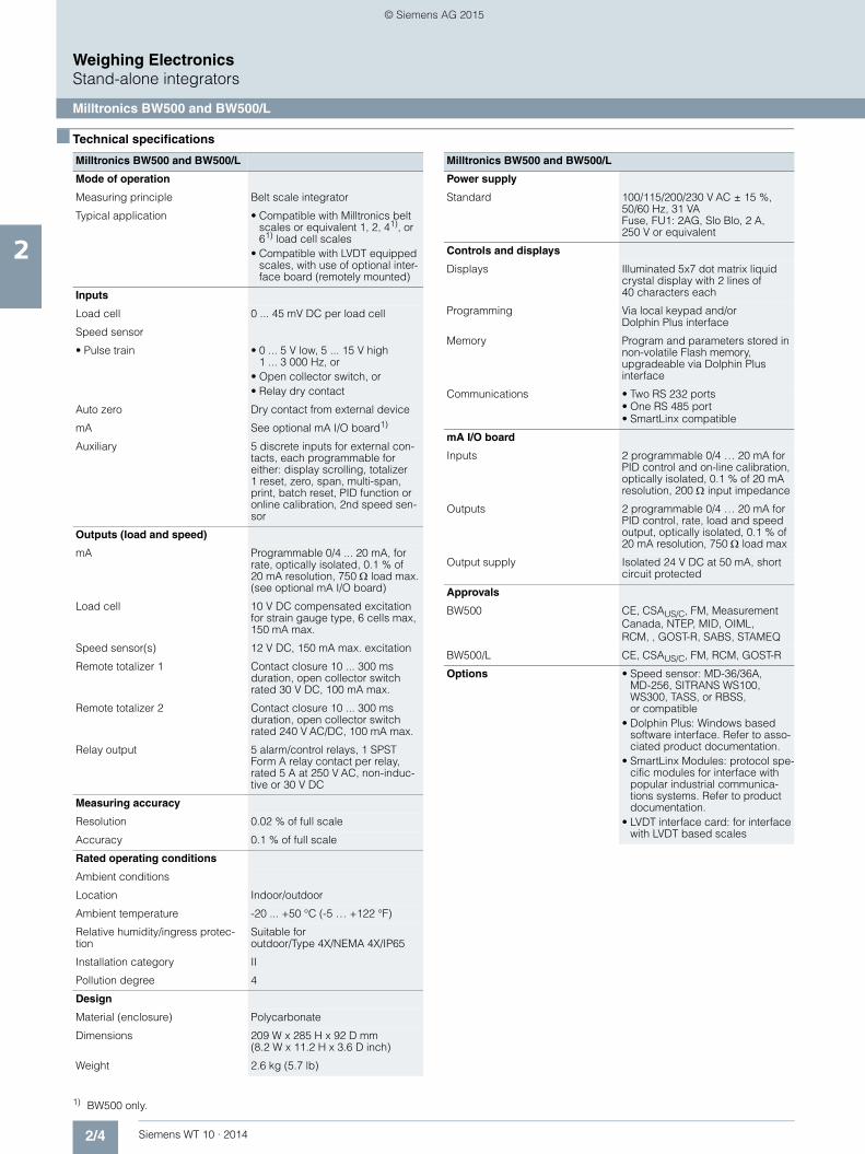
■ Overview
Milltronics SF500 is a full feature integrator for use with solids flowmeters.
■ Benefits
• Automatic zero and electronic span calibration • Alarms for rate or diagnostic error • On-board Modbus, optional PROFIBUS DP, ProfiNet, Modbus
TCP/IP, EtherNet/IP, and DeviceNet• On-line calibration and dual PID control with optional analog
I/O card • Multi-point linearizer for high turn down accuracy • Up to 8 multi-spans for application of more than one flow
condition and/or material • Moisture meter input with optional analog I/O card for
calculation of dry weight
■ Application
Milltronics SF500 operates with any solids flowmeter with up to two strain gauge load cells or LVDT sensor. The SF500 pro-cesses sensor signals for accurate flow rate and totalized weight of bulk solids. It can take on lower level control functions tradi-tionally handled by other devices, and it supports popular indus-trial communication buses. Its proven load cell balance function eliminates matching of load cells.
The PID function may be used for rate control of pre-feeding de-vices and/or control of additives with two internal PID controllers. Operating in tandem with two or more solids flowmeters or weighfeeders, the SF500 may be used for ratio blending and controlling additives. Batching, load out, and alarm functions are also provided by the SF500.
Dolphin Plus software may be used for programming the unit with a PC.
© Siemens AG 2015

2/9Siemens WT 10 · 2014
Weighing ElectronicsStand-alone integrators
Milltronics SF500
2
■ Technical specificationsMilltronics SF500
Mode of operation
Measuring principle Flowmeter integrator
Typical application • Compatible with SITRANS solids flowmeters or equivalent 1 or 2 load cell models
• Compatible with LVDT equipped solids flowmeters, with use of op-tional interface board (remotely mounted)
Input
Load cell/LVDT 0 … 45 mV DC per load cell or LVDT interface card
Auto zero Dry contact from external device
mA See optional mA I/O board
Auxiliary 5 discrete inputs for external con-tacts, each programmable for either: display scrolling, totalizer 1 reset, zero, span, multi-span, print, batch reset, PID function, or on-line calibration
Output
mA Programmable 0/4 ... 20 mA, for rate, optically isolated, 0.1 % of 20 mA resolution, 750 Ω load max. (see optional mA I/O board)
Load cell/LVDT conditioner card 10 V DC compensated excitation for strain gauge type, 2 cells max., 150 mA max.
Remote totalizer 1 Contact closure 10 … 300 ms duration, open collector switch rated 30 V DC, 100 mA max.
Remote totalizer 2 Contact closure 10 … 300 ms duration, open collector switch rated 240 V AC/DC, 100 mA max.
Relay output 5 alarm/control relays, 1 SPST Form A relay contact per relay, rated 5 A at 250 V AC, non-induc-tive or 30 V DC
Measuring accuracy
Resolution 0.02 % of full scale
Accuracy 0.1 % of full scale
Rated operating conditions
Ambient conditions
Location Indoor/outdoor
Ambient temperature -20 … +50 °C (-5 … +122 °F)
Relative humidity/ingress protection
Suitable for outdoor/Type 4X/NEMA 4X/IP65
Installation category II
Pollution degree 4
Design
Material (enclosure) Polycarbonate
Dimensions 209 W x 285 H x 92 D mm (8.2 W x 11.2 H x 3.6 D inch)
Weight 2.6 kg (5.7 lb)
Power supply
Standard 100/115/200/230 V AC ± 15 %, 50/60 Hz, 31 VAFuse, FU1: 2AG, Slo Blo, 2 A, 250 V or equivalent
Controls and displays
Display Illuminated 5 x 7 dot matrix liquid crystal display with 2 lines of 40 characters each
Programming Via local keypad and/or Dolphin Plus interface
Memory • Program stored in non-volatile FLASH ROM, upgradeable via Dolphin Plus interface
• Parameters stored in battery backed RAM, 3 V NEDA 5003LC or equivalent, 10 year life
Communications Two RS 232 portsOne RS 485 portSmartLinx compatible
Approvals CE, CSAUS/C, FM, RCM
Options • Dolphin Plus: Windows based software interface. Refer to associated product docu-mentation.
• SmartLinx modules: protocol spe-cific modules for interface with popular industrial communica-tions systems. Refer to associated product documentation.
• LVDT interface card: for interface with LVDT based solids flowme-ters
• mA I/O board - Inputs: 2 programmable
0/4 … 20 mA for PID control or online calibration, optically iso-lated, 0.1 % … 20 mA resolu-tion, 200 Ω input impedance
- Outputs: 2 programmable 0/4 … 20 mA for PID control or rate output, optically isolated, 0.1 % of 20 mA resolution, 750 Ω load max
- Output supply: isolated 24 V DC at 50 mA, short circuit protected
Milltronics SF500
© Siemens AG 2015

2/10 Siemens WT 10 · 2014
Weighing ElectronicsStand-alone integrators
Milltronics SF500
2
■ Selection and ordering data 1) 2) Article No. Article No.
1) Required for PID control and online calibration.2) Required for industrial communications.
Milltronics SF500A full feature, powerful integrator designed for use with solids flowmeters
7MH7156-
77777 - 777
Click on the Article No. for the online configuration in the PIA Life Cycle Portal.
Input voltage
AC voltage 1
Auxiliary input/output boards1)
None A
Board with 2 analog inputs and 2 analog outputs B
Feature software
Standard A
Auxiliary memory
None 0
Data communications2)
SmartLinx Ready 0
SmartLinx PROFIBUS DP module 2
SmartLinx DeviceNet module 3
SmartLinx ProfiNet module 4
SmartLinx EtherNet I/P module 5
SmartLinx MODBUS TCP I/P module 6
Enclosures
Standard enclosure, no entry holes 1
Standard enclosure, 4 entries, for M20 glands 2
Trade approval stickers
No trade approval sticker A
Not legal for Canadian and EU trade sticker B
Approvals
CE, CSAUS/C, FM, RCM A
Further designs Order Code
Please add "-Z" to article no. and specify order code(s).
Stainless steel tag (69 mm x 50 mm), Measuring-point number/identification (max 27 characters), specify in plain text.
Y15
Stainless steel, sun/weather shield357 x 305 x 203 mm (14 x12 x 8 inch) (finished unit is field mounted with enclosure)
S50
Manufacturer's test certificate: According to EN 10204-2.2 C11
Stainless steel enclosure, 304 (1.4301), [406 x 305 x 152 mm (16 x 12 x 6 inch), Type 4X, IP66 (finished unit is mounted inside enclosure)]
• With window A11
• Without window A12
Painted mild steel, [406 x 305 x 152 mm (16 x 12 x 6 inch), Type 4, IP65 (finished unit is mounted inside enclosure)]
• With window A13
• Without window A14
Painted mild steel, anti-vibration enclosure with viewing window 406 x 305 x 203 mm (16 x 12 x 8 inch), Nema/Type 4, IP66 (finished unit is mounted inside enclosure)
A15
Painted mild steel, heated enclosure with viewing window for use down to -50°C (-58 °F) (finished unit is mounted inside enclosure) 483 X 584 X 203 mm (19 x 23 x 8 inch)
A35
Instruction manuals
SF500, English 7ML1998-5CN02
SF500, French 7ML1998-5CN11
SF500, GermanNote: The instruction manual should be ordered as a separate item on the order.
7ML1998-5CN31
Additional instruction manuals
SmartLinx PROFIBUS DP, English 7ML1998-1AQ03
SmartLinx PROFIBUS DP, German 7ML1998-1AQ33
SmartLinx PROFIBUS DP, French 7ML1998-1AQ12
SmartLinx DeviceNet, EnglishNote: The appropriate SmartLinx instruction manual should be ordered as a separate line on the order.
7ML1998-1BH02
LVDT Conditioner Card Manuals, English 7ML1998-5EF01
LVDT Conditioner Card Manuals, German 7ML1998-5EF31
This device is shipped with the Siemens Milltronics manual DVD containing the complete instruction manual library.
Optional equipment
Milltronics analog I/O cards 7MH7723-1BJ
LVDT Conditioners in NEMA 4 enclosure (to interface LVDT belt scale without internal pre-amplifier)
7MH7723-1AJ
SITRANS RD100 Remote displays - see RD100 on page 2/13
SITRANS RD200 Remote displays - see RD200 on page 2/15
SITRANS RD300 Remote displays - see RD300 on page 2/19
SITRANS RD500 web, datalogging, alarming, eth-ernet, and modem support for instrumentation - see on page 2/23
7ML5750-1AA00-0
Spare parts
Display card 7MH7723-1AF
Lids with overlay and keypad 7MH7723-1AG
Motherboard 7MH7723-1AH
Batteries, 3 V, lithium 7MH7723-1ES
Fuses, 2 A, 250 V, BW500, BW500/L, and SF500, spare
7MH7723-1DG
LVDT Conditioners in Nema 4 enclosure (to interface LVDT belt scale without internal pre-amplifier)
7MH7723-1AJ
Auxiliary I/O cards spare 7MH7723-1BJ
Cables to connect BW500/SF500 keypad to moth-erboard
7MH7723-1CB
Keypads spare for BW500, BW500/L, and SF500 7MH7723-1CD
PROFIBUS DP module 7ML1830-1HR
DeviceNet module 7ML1830-1HT
ProfiNet IO module 7ML1830-1PM
Modbus TCP I/P, EtherNet I/P module 7ML1830-1PN
© Siemens AG 2015

2/11Siemens WT 10 · 2014
Weighing ElectronicsStand-alone integrators
Milltronics SF500
2
■ Dimensional drawings
Milltronics SF500 dimensions in mm (inch)
■ Schematics
Milltronics SF500 connections
Conduit entry
Non-metallic enclosure does not provide grounding between connections. Use grounding type bushings and jumpers.
Lid
Enclosure
Customer supplied mounting screws
Mounting hole (4 places)
Lid screws (6 places) 92 (3.6)172 (6.8)
209 (8.2)16 (0.6)
285
(11.
2)26
7 (1
0.5)
Non-sensing: Belden 8404, 4 wire shielded, 20 AWG (0.5 mm2) or equivalent, 150 m (500 ft) max.One load cell input for single load cell or LVDT application:•-
Sensing: Belden 9260, 6 wire shielded, 20 AWG (0.5 mm2) or equivalent, 300 m (1 000 ft) max.-
Non-sensing: Belden 9260, 6 wire shielded, 20 AWG (0.5 mm2) or equivalent, 150 m (500 ft) max.Two load cells:•
Auto zero: Belden 8760, 1 pair, twisted/shielded, 18 AWG (0.75 mm2) or equivalent, 300 m (1 000 ft) max.•Remote total: Belden 8760, 1 pair, twisted/shielded, 18 AWG (0.75 mm2) or equivalent, 300 m (1 000 ft) max.•
-Sensing: Belden 8418, 8 wire shielded, 20 AWG (0.5 mm2) or equivalent, 300 m (1 000 ft) max.-
Cable
Spe
ed s
enso
r
Load
cel
l inp
uts Lo
ad c
ell
exci
tatio
n
LCA+
LCA-
10
9
8
7
6
5
4
3
2
1
SHLD
LCD+
LCD-
LCC-
LCC+
SHLD
LCB-
LCB+
A - Z
COM
AUX5
AUX4
AUX3
AUX2
AUX1
SHLD
MA-
MA+
30
29
28
27
26
25
24
23
22
21
SHLD
+EX
CNST
COM
SHLD
V-
S-
S+
V+
20
19
18
17
16
15
14
13
12
11
SHLD
T2-
T2+
SHLD
T1-
T1+
SHLD
RX
COM
RS
-232
RS
-485
TX
40
39
38
37
36
35
34
33
32
31
50
49
48
47
46
45
44
43
42
41
RLY2
RLY1
SHLD
+
-
COM
+
-
SIG.RLY5
RLY4
RLY3
60
59
58
57
56
55
54
53
52
51
SHLD
L1
L2/N
© Siemens AG 2015

2/12 Siemens WT 10 · 2014
Weighing ElectronicsAccessories for stand-alone integrators
Dolphin Plus Software
2
■ Overview
Dolphin Plus is instrument configuration software that allows you to quickly and easily configure, monitor, tune and diagnose sev-eral Siemens weighing devices remotely. Remote access is available using your desktop PC or connected directly in the field using a laptop.
■ Benefits
• Real-time monitoring and adjustment of parameters • On-screen visualization of process values • Copying of data for programming several devices • Fast setup and commissioning of device • Generation of configuration reports in seconds
Note:
The Dolphin Plus software is only available in English.
Compatibility
Dolphin Plus works with a wide range of Siemens products, including:• Milltronics BW500 and BW500/L• Milltronics SF500
Connection to a Siemens instrument may be a direct RS 232 serial connection or via an RS 485 converter or Siemens infrared ComVerter, depending on the instrument being configured.
Meets VDE 2187 user interface requirements.
■ Application
Dolphin Plus is easy to install and use. Just load the software from the CD. In minutes, you’re ready to set up or modify com-plete parameter configurations for one or more devices.
Following configuration, you can alter parameters, upload and download parameter sets to and from a disk, and use parameter sets saved from other instruments.
■ Selection and ordering data Article No.
Dolphin PlusInstrument configuration software to quickly and easily configure, monitor, tune and diagnose most Siemens Milltronics devices remotely, from your desktop PC or connected directly in the field using a laptop.Dolphin Plus Software includes a software CD, and a nine pin adapter with a 2.1 m (82.7 inch) cable for connection to a PC serial port.
7ML1841-
7A A 0 7
Click on the Article No. for the online configuration in the PIA Life Cycle Portal.
RS 485 to RS 232 converters
No 0
Yes 1
ComVerter
No 0
Yes 1
Instruction manuals
Connection manual, English:Included on Dolphin Plus CD and available at www.siemens.com/processautomation
Spare parts
Converters, RS 485 to RS 232 (D-Sub) 7ML1830-1HA
Kits containing one 9-pin D-Sub to RJ11 adapter and one 2.1 m (82.7 ft) telephone cable with two male jacks
7ML1830-1MC
ComVerter, Infrared link 7ML1830-1MM
© Siemens AG 2015

2/13Siemens WT 10 · 2014
Weighing ElectronicsAccessories for stand-alone integrators
SITRANS RD100
2
■ Overview
The SITRANS RD100 is a 2-wire loop powered, NEMA 4X enclosed remote digital display for process instrumentation.
■ Benefits
• Easy setup• Approved for hazardous locations• NEMA 4X, IP67 impact-resistant enclosure• Simple two-step calibration• Two modes of input allow for easy servicing, with no interrup-
tion of loop required
■ Application
The RD100 is very versatile. It can be installed indoors or out-doors, in hot or cold environments, and in safe or hazardous ar-eas.It has been approved by FM and CSA as Intrinsically Safe and non-incendive, and operates from -40 to +85 ºC (-40 to +185 ºF), adding only 1 V to the loop.
The RD100 has a large 1 inch (2.54 cm) high display making it easy to read.
Calibration consists of a quick two-step process involving the adjustment of only two non-interacting potentiometers.• Key Applications: Remotely displays process variables in
level, flow, pressure, temperature and weighing applications, in a 4 to 20 mA loop.
■ Technical specifications
■ Selection and ordering data Article No.
We can offer shorter delivery times for configurations designated with the Quick Ship Symbol .
} Available ex stock when configured with the following options only: Input voltage: 1, Transmitter supply: B, Output: A, Communication: 0.
SITRANS RD100
Mode of operation
• Measuring principle Analog to digital conversion
• Measuring range 4 … 20 mA
• Measuring points 1 instrument only
Accuracy ± 0.1 % of span ± 1 count
Rated operating conditions
Ambient conditions
Operating temperature range -40 … +85 ºC (-40 … +185 ºF)
Design
Weight 340 g (12 oz)
Material (enclosure) Impact-resistant glass filled poly-carbonate body and clear polycar-bonate cover
Degree of protection NEMA 4X, IP67
Power supply
External loop power supply 30 V DC max.
Display • 1.0 inch (2.54 cm) high LCD
• Numeric range from -1 000 … +1 999
Certificates and approvals
Hazardous
• Intrinsically Safe • CSA/FM Class I, II, III, Div. 1, Groups A, B, C, D, E, F, G T4
• CSA/FM Class I, Zone 0, Group IIC
• Non-incendive • CSA/FM Class I, Div. 2, Groups A, B, C, D
• CSA/FM Class II and III, Div. 2, Groups F and G
Options
Mounting • 2 inch (5.08 cm) pipe mounting kit (zinc plated or stainless steel)
• Panel mounting kit
SITRANS RD100A 2-wire loop powered, NEMA 4X enclosed remote digital display for process instrumenta-tion.
7ML5741-
7 A A 0 0 - 0
Click on the Article No. for the online configuration in the PIA Life Cycle Portal.
Conduit hole location (½ inch)
None } 1
Bottom } 2
Rear 3
Top 4
Instruction manuals
English 7ML1998-5JU01
French 7ML1998-5JU11
GermanNote: The instruction manual should be ordered as a separate line item.
7ML1998-5JU31
This device is shipped with the Siemens Milltronics manual DVD containing ATEX Quick Starts and instruction manuals.
Accessories
Panel mount kits 7ML1930-1BN
2 inch (5.08 cm) pipe mounting kit (zinc plated seal)
7ML1930-1BP
2 inch (5.08 cm) pipe mounting kit (stainless steel, Type 304, EN 1.4301)
7ML1930-1BQ
SITRANS RD100
© Siemens AG 2015

2/14 Siemens WT 10 · 2014
Weighing ElectronicsAccessories for stand-alone integrators
SITRANS RD100
2
■ Dimensional drawings
SITRANS RD100 dimensions in mm (inch)
■ Schematics
SITRANS RD100 connections
RD100 - front view RD100 - side view
Wall mounting holes beneath cover screws
C: 60 (2.36) E: 65 (2.56)D: 120 (4.72) F: 20 (0.79)B: 140 (5.51)
A: 80 (3.15)
D
A
B
C
EF
The display PCB may be removed from the enclosure for bench calibration. Loop jumper must be installed on input signal PCB to maintain loop. Refer to RD100 instruction manual for more details.
Calibrated current source
Display PCB component side
Field wiring is made to the Input Signal PCB which is mounted to the base of the enclosure.
Transmitter
Power supply
Loop jumper
Input signal PCB
Input signal PCB(mounted to base of enclosure)
Red
Black
LO calibration control
Balance control (factory adjust only)
HI calibration control
Display PCB component side (may be removed for bench calibration)
Control loop connected to input signal PCB
Calibrator connected to display PCB
Calibrator connected to input signal PCB
Loop jumper(remove when display PCB is connected)
Calibrated current source
+ -
+ +-
-
DP2DP3
DP1
S-S+S+S-
DP2DP3
DP1S+ S+S- S-
4-20 mA
S+
S+
S-
S-
© Siemens AG 2015

2/15Siemens WT 10 · 2014
Weighing ElectronicsAccessories for stand-alone integrators
SITRANS RD200
2
■ Overview
The SITRANS RD200 is a universal input, panel mount remote digital display for process instrumentation.
■ Benefits
• Easy setup and programming via front panel buttons or re-motely using RD software
• Display readable in sunlight • Universal input: accepts current, voltage, thermocouple and
RTD signals • Single or dual 24 V DC transmitter power supply • Serial communication using built in protocol or Modbus RTU • Two optional relays for alarm indication or process control ap-
plications • Linear or square root function supported • Meter Copy feature to reduce setup time, cost or errors • RD software supporting remote configuration, monitoring and
logging for up to 100 displays • Other features include: 4 to 20 mA analog output option, sup-
ports pump alternation control, and optional NEMA 4 and 4X FIELD ENCLOSURES
• 2X option for 30.5 mm (1.2 inch) high, red LED display
■ Application
The RD200 is a universal remote display for level, flow, pressure, temperature, weighing, and other process instruments.
Data can be remotely collected, logged and presented from as many as 100 displays on your local computer using the free downloadable RD Software.
The display accepts a single input of current, voltage, thermo-couple, and RTD. This makes the RD200 an ideal fit for use with most field instruments.
The RD200 can be set up as a standard panel mount, or com-bined with optional enclosures to allow it to house up to 6 displays.
Key Applications
tank farms, pump alternation control, local or remote display of level, temperature, flow, pressure and weighing instrument val-ues, PC monitoring and data logging with RD Software.
© Siemens AG 2015

2/16 Siemens WT 10 · 2014
Weighing ElectronicsAccessories for stand-alone integrators
SITRANS RD200
2
■ Technical specifications
SITRANS RD200
Mode of operation
• Measuring principle Analog to digital conversion
• Measuring points • 1 instrument • Remote monitoring of
100 instruments with PC and RD software
Input
Measuring range
• Current • 4 … 20 mA, 0 … 20 mA
• Voltage • 0 V DC … 10 V DC, 1 … 5 V, 0 … 5 V
• Thermocouple temperature • Type J: -50 … +750 °C (- 58 … +1 382 °F)
• Type K: - 50 … +1 260 °C (-58 … +2 300 °F)
• Type E: - 50 … +870 °C (-58 … +1 578 °F)
• Type T: - 180 … +371 °C (-292 … +700 °F)
• Type T, 0.1 resolution: -180.0 … +371 °C (-199.9 … +700 °F)
• RTD temperature • 100 Ω RTD: -200 … +750 ºC (-328 … +1 382 ºF)
Output signal
• Output • PDC output • 4 … 20 mA (optional) • Modbus RTU
• Relays 2 SPDT Form C relays, rated 3 A at 30 V DC or 3 A at 250 V AC, non-inductive, auto-initializing (optional)
• Communications • RS 232 with PDC or Modbus RTU • RS 422/485 with PDC or
Modbus RTU
Accuracy
• 4 … 20 mA optional output ± 0.1 % FS ± 0.004 mA
• Process input ± 0.05 % of span ± 1 count, square root: 10 … 100 % FS
• Thermocouple temperature input • Type J: ± 1 °C (± 2 °F) • Type K: ± 1 °C (± 2 °F) • Type E: ± 1 °C (± 2 °F) • Type T: ± 1 °C (± 2 °F) • Type T, 0.1° Resolution:
± 1 °C (± 1.8 °F)
• RTD temperature input • 100 Ω RTD: ± 1 °C (± 1 °F)
Rated operating conditions
• Ambient conditions
• Storage temperature range -40 … +85 °C (-40 … +185 °F)
• Operating temperature range 0 … 65 °C (32 … 149 °F)
Design
Weight 269 g (9.5 oz) (including options)
Material (enclosure) • 1/8 DIN, high impact plastic, UL94V-0, color: gray
• Optional plastic, steel and stain-less steel (Type 304, EN 1.4301) NEMA 4 enclosures
Degree of protection Type 4X, NEMA 4X, IP65 (front cover); panel gasket provided
Electrical connection
• mA output signal 2-core copper conductor, twisted, shielded, 0.82 … 3.30 mm² (18 … 12 AWG), Belden 8 760 or equivalent is acceptable
• Electrical connection and relay connection
Copper conductor according to local requirements, rated 3 A at 250 V AC
Power supply
Input voltage option 1 85 … 265 V AC, 50/60 Hz; 90 … 265 V DC, 20 W max.
Input voltage option 2 12 … 36 V DC; 12 … 24 V AC, 6 W max.
Transmitter power supply One or two isolated transmitter power supplies (optional)
• Single power supply: One 24 V DC ± 10 % at 200 mA max.
• Dual power supplies: Two 24 V DC ± 10 % at 200 mA and 40 mA max.
External loop power supply 35 V DC max.
Output loop resistance • 24 V DC, 10 … 700 Ω max. • 35 V DC (external),
100 … 1 200 Ω max.
Displays and controls
• Display • 14 mm (0.56 inch) high LED• 2X option for 30.5 mm (1.2 inch)
high, red LED• Numeric range from
-1 999 … +9 999 • Four digits, automatic lead zero
blanking • Eight intensity levels
• Memory • Non-volatile • Stores settings for minimum of
10 years if power is lost
• Programming • Primary: front panel • Secondary: meter copy or PC with
SITRANS RD software
Certificates and approvals CE, UL, CUL
Options
• Enclosures Plastic, steel and stainless steel (Type 304, EN 1.4301) NEMA 4 and 4X enclosures
• Mounting • 2 inch (5.08 cm) pipe mounting kit (zinc plated seal)
• 2 inch (5.08 cm) pipe mounting kit (stainless steel, Type 304, EN 1.4301)
SITRANS RD200
© Siemens AG 2015

2/17Siemens WT 10 · 2014
Weighing ElectronicsAccessories for stand-alone integrators
SITRANS RD200
2
■ Selection and ordering data1) 2) Article No. Article No.
We can offer shorter delivery times for configurations designated with the Quick Ship Symbol .
} Available ex stock when configured with the following options only: Input voltage: 1, Transmitter supply: B, Output: A, Communication: 0.
1) Available with input voltage option 1 only.2) Available with output option C only.
SITRANS RD200A universal input, panel mount remote digital display for process instrumentation.
7ML5740-
777 77 - 7A
Click on the Article No. for the online configuration in the PIA Life Cycle Portal.
Input voltage
85 ... 265 V AC, 50/60 Hz; 90 ... 265 V DC, 20 W max.
} 1
12 ... 36 V DC; 12 ... 24 V AC, 6 W max. 2
Transmitter supply
None A
Single 24 V DC transmitter supply1)} B
Dual 24 V DC transmitter supply1)2) C
Output
None } A
2 relays B
4 ... 20 mA output C
Communication
Modbus enabled } 0
Approvals
CE, UL, CUL 1
Display size
Standard } 0
2X } 1
Instruction manuals
English 7ML1998-5JS01
French 7ML1998-5JS11
Spanish 7ML1998-5JS21
German 7ML1998-5JS31
Note: The instruction manual should be ordered as a separate line item.
This device is shipped with the Siemens Milltronics manual DVD containing ATEX Quick Starts and instruction manuals.
Other Instruction manuals
SITRANS RD enclosures, English 7ML1998-5JX01
SITRANS RD enclosures, German 7ML1998-5JX31
SITRANS RD serial adapters, English A5E31979195
SITRANS RD serial adapters, German A5E31979197
SITRANS RD software, English 7ML1998-5JW01
SITRANS RD software, German 7ML1998-5JW31
Accessories
SITRANS RD200 copy cables 2.1 m (7 ft) 7ML1930-1BR
SITRANS RD200 RS 232 serial adapters (copy cable included)
7ML1930-1BS
SITRANS RD200 RS 422/485 serial adapters (copy cable included)
7ML1930-1BT
RS 232 to RS 422/485 isolated converters 7ML1930-1BU
RS 232 to RS 422/485 non-isolated converters 7ML1930-1BV
SITRANS RD200 RS 232 and RS 485 isolated multi-input adapter boards
7ML1930-1BW
USB to RS 422/485 isolated converters 7ML1930-1BX
USB to RS 422/485 non-isolated converters 7ML1930-1BY
USB to RS 232 converter 7ML1930-6AK
RD Software CD for 1 ... 100 displays 7ML1930-1CC
Low cost polycarbonate plastic enclosures for 1 display
7ML1930-1CF
2 inch (5.08 cm) pipe mounting kit (zinc plated seal) only available with 7ML19301CF
7ML1930-1BP
2 inch (5.08 cm) pipe mounting kit (stainless steel, Type 304, EN 1.4301) only available with 7ML19301CF
7ML1930-1BQ
Thermoplastic enclosures
For use with 1 display 7ML1930-1CG
For use with 2 displays 7ML1930-1CH
For use with 3 displays 7ML1930-1CJ
For use with 4 displays 7ML1930-1CK
For use with 5 displays 7ML1930-1CL
For use with 6 displays 7ML1930-1CM
Stainless steel enclosures (Type 304, EN 1.4301)
For use with 1 display 7ML1930-1CN
For use with 2 displays 7ML1930-1CP
For use with 3 displays 7ML1930-1CQ
For use with 4 displays 7ML1930-1CR
For use with 5 displays 7ML1930-1CS
For use with 6 displays 7ML1930-1CT
Steel enclosures
For use with 1 display 7ML1930-1CU
For use with 2 displays 7ML1930-1CV
For use with 3 displays 7ML1930-1CW
For use with 4 displays 7ML1930-1CX
For use with 5 displays 7ML1930-1CY
For use with 6 displays 7ML1930-1DA
© Siemens AG 2015

2/18 Siemens WT 10 · 2014
Weighing ElectronicsAccessories for stand-alone integrators
SITRANS RD200
2
■ Dimensional drawings
SITRANS RD200, dimensions in mm (inch)
■ Schematics
SITRANS RD200 connections
Screw terminalconnector[0.5 Nm (4.5 lb/in)tightening torque]
RD200 - t op viewRD200 - side view
64 (2
.5)
119 (4.68)
92(3.61)
91 (3.6)
62 (2
.45)
15(0.59)
81 (3.2)
45(1.76)
RD200 connector labeling
2-wire 4 ... 20 mA transmitter
P2+P1+ P1- P2-1+234 156
1-
SERIALSIGNAL
P-P+
12Relay 2 Relay 1
COMNCNCNO NOCOM
POWER24V OUT
Remote display, chart recorder
24 V outmA out
RTDsensorSwitch
positionSwitch position
Signal connector Signal connector Signal connector
4 ... 20 mA output and input signal powered by meterThree-wire RTD input connections
Thermocouple input connections
RTD TC RTD TC
54321 54321
TC
COMT+EXCmA+V+ COMT+EXCmA+V+
54321COMT+EXCmA+V+
54321COMT+EXCmA+V+
+ -
+
- + -
+ -
RTD TC
121256 34
RTDTC
SWITCH
© Siemens AG 2015

2/19Siemens WT 10 · 2014
Weighing ElectronicsAccessories for stand-alone integrators
SITRANS RD300
2
■ Overview
The SITRANS RD300 is a panel mount remote digital display for process instrumentation and acts as a multi-purpose, easy to use, rate/totalizer ideal for flow rate, total, and control applica-tions.
■ Benefits
• Easy setup and programming via front panel buttons or remotely using RD software
• Display readable in sunlight • Input: accepts current and voltage• Single or dual 24 V DC transmitter power supply• Serial communication using built in protocol or Modbus RTU• Supports up to 8 relays and 8 digital I/O for process control
and alarming• 32-Point linearization, square root or exponential linearization• Multi-pump alternation control• Supports total, grand total or non-resettable grand total• 9-digit totalizer with total overflow feature• Large dual-line, 6-digit display• Configure, monitor, and datalog from a PC• Dual-input option with math functions: addition, difference, av-
erage, multiplication, division, minimum, maximum, weighted average, ratio, concentration
■ Application
The RD300 is a remote display for level, flow, pressure, weigh-ing, and other process instruments. This display also acts as a multi-purpose, easy to use rate/totalizer ideal for flow rate, total, and control applications.
Data can be remotely collected, logged and presented on your local computer using the free downloadable RD Software.The display accepts a single or dual input of current and voltage. This makes the RD300 an ideal fit for use with most field instru-ments.
The RD300 can be set up as a standard panel mount, or com-bined with optional enclosures to allow it to house up to 6 dis-plays.
Key Applications
Tank farms, pump alternation control, local or remote display of level, flow, pressure and weighing instrument values, PC moni-toring and data logging with RD Software.
© Siemens AG 2015

2/20 Siemens WT 10 · 2014
Weighing ElectronicsAccessories for stand-alone integrators
SITRANS RD300
2
■ Technical specifications
SITRANS RD300
Mode of operation
Measuring points 1 or 2 instruments
Input
Measuring range
• Current 4 ... 20 mA, 0 ... 20 mA
• Voltage 0 V DC ... +10 V DC, 1 ... 5 V,0 ... 5 V
Output signal
Output • 4 ... 20 mA (optional)
• Modbus RTU
Relays 2 or 4 SPDT (Form C) internaland/or 4 SPST (Form A) external;rated 3 A at 30 V DC and 125/250 V AC resistive load; 1/14 HP (50 W) at 125/250 V AC for inductive loads (optional)
Communications • RS 232 with Modbus RTU
• RS 422/485 with Modbus RTU
Accuracy
4 ... 20 mA optional output ± 0.1 % FS ± 0.004 mA
Process input ± 0.05 % of span ± 1 count,square root: 10 ... 100 % FS
Rated operating conditions
Ambient conditions
Storage temperature range -40 ... +85 °C (-40 ... +185 °F)
Operating temperature range 0 ... 65 °C (32 ... 149 ºF)
Design
Weight 269 g (9.5 oz) (including options)
Material (enclosure) • 1/8 DIN, high impact plastic,UL94V-0, color: gray
• Optional plastic, steel and stain-less steel (Type 304, EN 1.4301)NEMA 4 enclosures
Degree of protection Type 4X, NEMA 4X, IP65 (frontcover); panel gasket provided
Electrical connection
mA output signal 2-core copper conductor, twisted,shielded, 0.82 ... 3.30 mm² (18 ...12 AWG), Belden 8 760 or equivalent is acceptable
Electrical connection and relay connection
Copper conductor according tolocal requirements, rated 3 A at 250 V AC
Power supply
Input voltage option 85 ... 265 V AC, 50/60 Hz;90 ... 265 V DC, 20 W max. or jumper selectable 12/24 V DC± 10 %, 15 W max
Transmitter power supply Terminals P+ & P-: 24 V DC± 10 %, 12/24 V DC powered models selectable for 24, 10, or 5 V DC supply (internal jumper J4),85 ... 265 V AC models rated at200 mA max, 12/24 V DC powered models rated at 100 mA max, at 50 mA max for 5 or 10 V DC supply.
External loop power supply 35 V DC max.
Output loop resistance • 24 V DC, 10 ... 700 Ω max.
• 35 V DC (external), 100 ... 1 200 Ω max.
Displays and controls
Main display 0.6 inch (15 mm) high, red LEDs
Second display 0.46 inch (12 mm) high, redLEDs, 6-digits: each (-99 999 ... 999 999)
Memory • Non-volatile
• Stores settings for minimum of10 years if power is lost
Programming • Primary: front panel
• Secondary: Meter Copy or PCwith SITRANS RD Software
Certificates and approvals CE, UL, CUL
Options
Enclosures Plastic, steel and stainless steel(Type 304, EN 1.4301) NEMA 4and 4X enclosures
SITRANS RD300
© Siemens AG 2015

2/21Siemens WT 10 · 2014
Weighing ElectronicsAccessories for stand-alone integrators
SITRANS RD300
2
■ Dimensional drawings
SITRANS RD300 dimensions
Selection and ordering data Article No.
SITRANS RD300Dual line remote digital display compatible with PI instruments
7ML5744
77777 - 0 A
Click on the Article No. for the online configuration in the PIA Life Cycle Portal.
Input voltage
85 ... 265 V AC, 50/60 Hz;90 ... 265 V DC, 20 W max.
1
12 ... 36 V DC; 12 ... 24 V AC, 6 W max. 2
Output
None A
2 relays B
4 relays C
4 ... 20 mA output D
2 relays and 4 ... 20 mA output E
4 relays and 4 ... 20 mA output F
Type
Single input process and flow R/T Mtr A
Dual input process Mtr B
Display
Standard 0
SunBright 1
Approvals
UL & C-UL & CE 0
Selection and ordering data Article No.
Operating instructions
Single input process and flow R/T Mtr
English A5E31917845
French A5E31948924
German A5E31948919
Dual input process Mtr
English A5E33481367
German A5E33481387
Note: The operating instructions should be ordered as a separate line on the order.
Other operating instructions
SITRANS RD DIN-rail mounting kit, English A5E31979181
SITRANS RD DIN-rail mounting kit, German A5E31979184
SITRANS RD expansion modules, English A5E31979173
SITRANS RD expansion modules, German A5E31979176
SITRANS RD serial communications accessories, English
A5E31979195
SITRANS RD serial communications accessories, German
A5E31979197
Accessories
DIN-rail mounting kit 7ML1930-6AB
4 Relays expansion module 7ML1930-6AC
4 Digital I/O Module 7ML1930-6AD
Dual output 4 ... 20 mA expansion module for dual input meter
7ML1930-6AP
Meter copy cable 7ML1930-6AE
RS 232 serial adapter 7ML1930-6AF
RS 422/485 serial adapter 7ML1930-6AG
RD300 USB serial adapter 7ML1930-6AJ
USB to RS 232 converter 7ML1930-6AK
Snubber 7ML1930-6AL
Plastic enclosure for 1 Meter 7ML1930-6AM
Plastic enclosure for 2 Meters 7ML1930-6AN
Plastic enclosure for 4 Meters 7ML1930-1CK
Plastic enclosure for 5 Meters 7ML1930-1CL
Plastic enclosure for 6 Meters 7ML1930-1CM
Optional connectors installed
152 (6) Clearance
44.5(1.76)
15(0.59)
121(4.77)
62(2.45)
(5.05)128
106(4.17)
119 (4.68)
NO NCNCC NOCNO NCNCC NOC+ -R
91.5 (3.61)
© Siemens AG 2015

2/22 Siemens WT 10 · 2014
Weighing ElectronicsAccessories for stand-alone integrators
SITRANS RD300
2
■ Schematics
SITRANS RD300 connections
DW1815
RI- I+
13 2
+ -P- COMP+ V+ mA+3 41 2 5
C NO NC C
4 36 5 2 1
C NONO NC NC C
4 36 5 2 1
1 2 3 4 5 6 7 8
21
F46
+ -
-
+ - +
P- COMP+ V+ mA+3 41 2 5
F46
P- COMP+ V+ mA+3 41 2 5
F46
-++ -
P- COMP+ V+ mA+3 41 2 5
F46
P- COMP+ V+ mA+3 41 2 5
F46
-++-
P- COMP+ V+ mA+3 41 2 5
F46
P- COMP+ V+ mA+3 41 2 5
F46
ExternalPowerSupply
2-Wire4 ... 20 mATransmitter
2-Wire 4 ... 20 mA Self-Powered
Transmitter
3-Wire 4 ... 20 mA Transmitter
2-Wire4 ... 20 mATransmitter
VoltageSignal
3-Wire Voltage Transducer
Connector labeling for fully loaded single input meter
Transmitter powered by external supply or self-powered
Transmitter powered by internal supply
Voltage Input Connections
INPUT SIGNAL INPUT SIGNAL
INPUT SIGNALINPUT SIGNAL
INPUT SIGNAL INPUT SIGNAL
MA OUT
POWERSIGNAL M-LINK
RELAY4 RELAY3 RELAY2 RELAY1
NO NC
Signal
Signal
© Siemens AG 2015
2/23Siemens WT 10 · 2014
Weighing ElectronicsAccessories for stand-alone integrators
SITRANS RD500
2
■ Overview
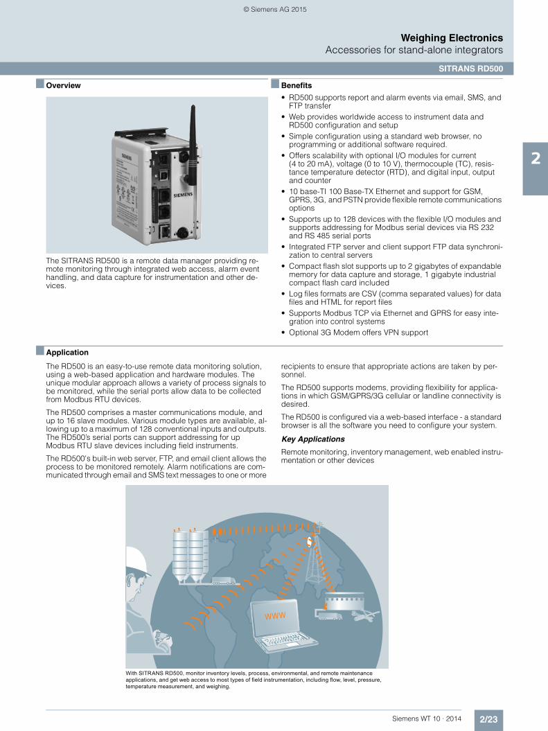
The SITRANS RD500 is a remote data manager providing re-mote monitoring through integrated web access, alarm event handling, and data capture for instrumentation and other de-vices.
■ Benefits
• RD500 supports report and alarm events via email, SMS, and FTP transfer
• Web provides worldwide access to instrument data and RD500 configuration and setup
• Simple configuration using a standard web browser, no programming or additional software required.
• Offers scalability with optional I/O modules for current (4 to 20 mA), voltage (0 to 10 V), thermocouple (TC), resis-tance temperature detector (RTD), and digital input, output and counter
• 10 base-TI 100 Base-TX Ethernet and support for GSM, GPRS, 3G, and PSTN provide flexible remote communications options
• Supports up to 128 devices with the flexible I/O modules and supports addressing for Modbus serial devices via RS 232 and RS 485 serial ports
• Integrated FTP server and client support FTP data synchroni-zation to central servers
• Compact flash slot supports up to 2 gigabytes of expandable memory for data capture and storage, 1 gigabyte industrial compact flash card included
• Log files formats are CSV (comma separated values) for data files and HTML for report files
• Supports Modbus TCP via Ethernet and GPRS for easy inte-gration into control systems
• Optional 3G Modem offers VPN support
■ Application
The RD500 is an easy-to-use remote data monitoring solution, using a web-based application and hardware modules. The unique modular approach allows a variety of process signals to be monitored, while the serial ports allow data to be collected from Modbus RTU devices.
The RD500 comprises a master communications module, and up to 16 slave modules. Various module types are available, al-lowing up to a maximum of 128 conventional inputs and outputs. The RD500’s serial ports can support addressing for up Modbus RTU slave devices including field instruments.
The RD500's built-in web server, FTP, and email client allows the process to be monitored remotely. Alarm notifications are com-municated through email and SMS text messages to one or more
recipients to ensure that appropriate actions are taken by per-sonnel.
The RD500 supports modems, providing flexibility for applica-tions in which GSM/GPRS/3G cellular or landline connectivity is desired.
The RD500 is configured via a web-based interface - a standard browser is all the software you need to configure your system.
Key Applications
Remote monitoring, inventory management, web enabled instru-mentation or other devices
With SITRANS RD500, monitor inventory levels, process, environmental, and remote maintenance applications, and get web access to most types of field instrumentation, including flow, level, pressure, temperature measurement, and weighing.
WWW
© Siemens AG 2015

2/24 Siemens WT 10 · 2014
Weighing ElectronicsAccessories for stand-alone integrators
SITRANS RD500
2
■ Technical specifications
SITRANS RD500
Mode of operation
• Measuring principle Remote data monitor
• Measuring points • Up to 128 standard input/outputs • Addressing for Modbus serial
devices
Input See table on page 2/25
Output See table on page 2/25
Accuracy See table on page 2/25
Rated operating conditions
Storage temperature range -30 … +70 ºC (-22 … +158 ºF)
Operating temperature 0 … 50 ºC (32 … 122 ºF)
Operating and storage humidity 80 % max relative humidity, non-condensing, from 0 … 50 °C (32 … 122 °F)
Design
Material (enclosure) High impact plastic and stainless steel
Installation category I
Pollution degree 2
Weight 456.4 g (15.1 oz)
Mounting Snaps onto standard DIN style top hat (T) profile mounting rails according to EN 50022 – 35 x 7.5 and – 35 x 15
Power 24 V DC ± 10 %400 mA min. (1 module)3.5 Amps max. (16 modules)Must use Class 2 or SELV-rated power supply
Display
Status LEDs • STS - status LED indicates condi-tion of master
• TX/RX - transmit/receive LEDs show serial activity
• Ethernet - link and activity LEDs • CF - CompactFlash LED indicates
card status and read/write activity
Memory
On-board user memory 4 Mbytes of non-volatile Flash memory
On-board SDRAM 2 Mbytes
Memory card CompactFlash Type II slot for Type I and Type II cards; 1 Gbyte (optional 2 Gbytes)
Certificates and approvals
• Safety • UL listed to U.S. and Canadian safety standards for use in Class I, II and III, Division 1 and 2 hazardous locations
• CE, RCM
Communication
• USB/PG port Adheres to USB specifications 1.1. Device only using Type B connec-tion.
• Serial ports Format and baud rates for each port are individually software pro-grammable up to 115, 200 baud
• RS 232/PG port RS 232 port via RJ12
• Comms ports RS 422/485 port via RJ45 and RS 232 port via RJ12
• Ethernet port 10 BASE-T/100 BASE-TX; RJ45 jack is wired as a NIC (Network Interface Card)
SITRANS RD500
© Siemens AG 2015

2/25Siemens WT 10 · 2014
Weighing ElectronicsAccessories for stand-alone integrators
SITRANS RD500
2
SITRANS RD500 Module Specifications
Note
To ensure the secure operation of a plant or machine it is neces-sary to take additional, suitable preventive action (e.g. cell pro-tection concept) and to integrate the automation and drive com-ponents into a state-of-the-art holistic industrial security concept for the entire plant or machine. Please find further information at: http://www.siemens.com/industrialsecurity
8 inputs, 6 solid state outputs
8 inputs, 6 relay outputs
8 channel, 4 … 20 mA
8 channel ± 10 V 6 channel, RTD 8 channel thermo-couple module
Article No. 7ML1930-1ES 7ML1930-1ER 7ML1930-1EP 7ML1930-1EQ 7ML1930-1ET 7ML1930-1EU
Application 8 inputs, 6 outputs used to monitor contact or sensor inputs
8 inputs, 6 outputs used to monitor contact or sensor inputs
16 bit analog input module provides high density signal measurement for data monitoring applications and accepts 0/4 … 20 mA pro-cess signals
16 bit analog input module provides high density signal measurement for data monitoring applications and accepts ± 10 V pro-cess signals
16 bit analog input module provides high-density signal measurement for data acquisition applications and accepts various RTD inputs
16 bit thermocouple input module pro-vides high density signal measurement for data acquisition applications and accepts wide range of thermocouple types
Accuracy Not applicable Not applicable ± 0.1 % of span ± 0.1 % of span ± (0.2 % of span, 1 °C) 0 … 50 °C (32 … 122 °F);± (0.1 % of span, 1 °C) 18 … 28 °C (64 … 82 °F); includes NIST con-formity, A/D conver-sion errors, temperature coeffi-cient and lineariza-tion conformity at 23 °C after 20 minutes warm-up
± (0.3 % of span, 1 °C); includes NIST con-formity, cold junc-tion effect, A/D conversion errors, temperature coeffi-cient and lineariza-tion conformity at 23 °C after 20 minute warm-up
Mounting Snaps onto standard DIN style top hat (T) profile mounting rails according to EN50022 – 35 x 7.5 and – 35 x 15
Inputs Dip switch select-able for sink or source
Dip switch select-able for sink or sourceMax. voltage: 30 V DC, reverse polarity protectedOff voltage: < 1.2 VOn voltage: > 3.8 VInput frequency:• Filter switch on:
50 Hz• Filter switch off:
300 Hz
8 single-endedranges: 0 … 20 mA or 4 … 20 mAResolution: full16-bitSample time: 50 … 400 ms depending on num-ber of enabled inputs
8 single-endedranges: 0 … 10 V DC or ± 10 V DCResolution: full 16-bitSample time: 50 … 400 ms depending on num-ber of enabled inputs
6 single-endedresolution: full 16-bitSample time: 67 … 400 ms depending on num-ber of enabled inputs
8 single-endedresolution: full 16-bitSample time: 50 … 400 ms depending on num-ber of enabled inputs
Outputs Solid state output, switched DC, contact rating 1 A DC max.
Form A, NOpairs share common terminals: 1&2, 3&4, 5&6Current rating by pair: 3 Amps at 30 V DC /125 V AC resistive 1/10 HP at 125 V AC
Not applicable Not applicable Not applicable Not applicable
© Siemens AG 2015

2/26 Siemens WT 10 · 2014
Weighing ElectronicsAccessories for stand-alone integrators
SITRANS RD500
2
■ Selection and ordering data1) 2) Article No. Article No.
We can offer shorter delivery times for configurations designated with the Quick Ship Symbol
■ Dimensional drawings
SITRANS RD500, dimensions in mm (inch)
1) Configuration limited to 16 modules.2) Antenna, power cord, and cable included.
SITRANS RD500The SITRANS RD500 is a remote data manager providing integrated web access, alarm event han-dling and data capture for instrumentation.
7ML5750
77 A 0 0 - 0
Click on the Article No. for the online configuration in the PIA Life Cycle Portal.
Communications connection
Ethernet1) 1
Digital communications to instruments
RS 485 Modbus RTU A
Input configuration modulesNote: one RD500 supports 16 input modules
RD500 8 channel 0/4 ... 20 mA input module 7ML1930-1EP
RD500 8 channel ± 10 V input module 7ML1930-1EQ
RD500 8 digital inputs, 6 relay outputs module 7ML1930-1ER
RD500 8 digital inputs, 6 solid state outputs module1)
7ML1930-1ES
RD500 6 channel input, RTD module 7ML1930-1ET
RD500 8 channel thermocouple module 7ML1930-1EU
Operating Instructions
Application manual, English 7ML1998-5MA01
Application manual, GermanNote: Additional Operating Instructions should be ordered as a separate line item.
7ML1998-5MA31
This device is shipped with the Siemens Milltronics manual DVD containing Quick Starts and Operat-ing Instructions.
Other Operating Instructions
RD500 Remote Data Manager manual, English: web access, alarm event handling, and data capture
7ML1998-5MK01
RD500 Remote Data Manager manual, German: web access, alarm event handling, and data capture
7ML1998-5MK31
RD500 8 channel 0/4 ... 20 mA input module man-ual, English
7ML1998-5MB01
RD500 8 channel 0/4 ... 20 mA input module man-ual, German
7ML1998-5MB31
RD500 8 channel ± 10 V input module manual, English
7ML1998-5MC01
RD500 8 channel ± 10 V input module manual, German
7ML1998-5MC31
RD500 8 inputs, 6 relay outputs module manual, English
7ML1998-5MD01
RD500,8 inputs, 6 relay outputs module manual, German
7ML1998-5MD31
RD500 8 inputs, 6 solid state outputs module man-ual, English
7ML1998-5ME01
RD500 8 inputs, 6 solid state outputs module man-ual, German
7ML1998-5ME31
RD500 6 channel input, RTD module manual, English
7ML1998-5MF01
RD500 6 channel input, RTD module manual, German
7ML1998-5MF31
RD500 8 channel thermocouple module manual, English
7ML1998-5MJ01
RD500, 8 channel thermocouple module manual, German
7ML1998-5MJ31
Accessories
Multitech GPRS modem, external 7ML1930-1EX
Industrial CompactFlash card, 2 Gbyte 7ML1930-1FB
Industrial CompactFlash card, 1 Gbyte 7ML1930-1FC
RJ11 serial to terminal block RS 232 7ML1930-1FD
RJ45 serial to terminal block RS 485 7ML1930-1FE
GPRS Modem antenna 7ML1930-1FF
RD500 Spare Module base 7ML1930-1FG
RD500 Spare End terminator 7ML1930-1FH
5’ Ethernet Cat 5e Red X/O cable for configuration 7ML1930-1FM
USB cable type A to B 7ML1930-1FN
3G external ethernet modem MTCBA-H4-EN2-P12) 7ML1930-1GJ
Dimensions
Mounting
DIN rail
Depress
24.5 (1) min. clearance
24.5 (1) min. clearance
105.4 (4.15)
134.
7 (5
.30)
78.5 (3.09)
3
4
4
© Siemens AG 2015

2/27Siemens WT 10 · 2014
Weighing ElectronicsAccessories for stand-alone integrators
SITRANS RD500
2
■ Schematics
SITRANS RD500 connections
ENTERCLEARRESETTOTAL
ALTDISP
RUN PAR ZERO SPAN
MA
MILLTRONICS BW500
or
Standard ethernet cable
Power connection
Communication ports Configuration ports
Ethernet connection (Port 3)
RD500 port pin outs RS 422/485 4-wire connections
RS 485 2-wire connections
Common +24 V DC
green/amber LED
yellow LED
green/amber LED
yellow LED
Expansion port
Power connector
GREEN/AMBER LEDYELLOWLED
RS232/PG PORT
COMMS PORT
COMMS PORT
COMMON
RS 232
RS 485
TxB
5V
TxA
GND
TxEN (OC)
130K
130K
Tx/RxTx
Rx
TxB
TxA
TxEN (OC)
GND
RxB
RxA
5V
130K
130K
5V
130K
130K
7
1
8
2
4
3
6
5
7
1
8
2
5
6COMM+24N/C
USB/PGCOMM
TxRTS
RxCOMM
CTS
COMM
TxATxB
RxA
RS
232
RS
485
RxB
TxATxB
12 24 VDC ± 10 %3 N/C
COMMRxCTS (PIN 1)
TxCOMM
RTS (PIN 6)
USB/PG
RxA
TxB (PIN 1)TxA
COMM
RS
232
RS
485
RxB
TxBTxA (PIN 8)
COMMRxCTS (PIN 1)
TxCOMM
RTS (PIN 6)
RS
232
ETHERNET (NIC)
TxEN
Ethernet (crossover)
© Siemens AG 2015

2/28 Siemens WT 10 · 2014
Weighing ElectronicsAccessories for stand-alone integrators
SmartLinx
2
■ Overview
SmartLinx modules provide direct digital connection to popular industrial communications buses with true plug-and-play com-patibility with products manufactured by Siemens.
■ Benefits
• Fast, easy installation • Direct connection: no additional installation required • Scalable application layer allows for optimized network
bandwidth and memory requirements • Modules available for PROFIBUS DP, ProfiNet, Modbus
TCP/IP, EtherNet/IP and DeviceNet
■ Application
Many Siemens Milltronics products include Modbus communi-cations. For additional communication modules, SmartLinx cards are the answer.
They are fast and easy to install, and can be added at any time. The module simply plugs into the socket on any SmartLinx-en-abled product. They require no secondary private buses or gate-ways and no separate wiring. There are no extra boxes to con-nect to your network so there’s a minimum load on engineering and maintenance staff.
SmartLinx provides all data from the instrument, including mea-surement and status, and allows changes to operation parame-ters to be done over the bus. The user can select which data in the application layer to transfer over the bus. This selection saves bandwidth and memory and optimizes data throughput and speeds up the network, enabling you to connect more instruments to your network.
■ Technical specifications
■ Selection and ordering data Article No.
SmartLinx modules
Module type PROFIBUS DP
Interface RS 485 (PROFIBUS standard)
Transmission rate All valid PROFIBUS DP rates from 9 600 kbps to 12 Mbps
Rack address 0 … 99
Connection Slave
SmartLinx module compatibility • Milltronics BW500 • Milltronics SF500
Module type DeviceNet
Interface DeviceNet physical layer
Transmission rate 125, 250, 500 kbps
Rack address 0 … 63
Connection Slave (group 2)
SmartLinx module compatibility • Milltronics BW500 • Milltronics SF500
Module type ProfiNet IO module
Interface RJ 45 female
Transmission rate 10/100 Mbit/s
Address IP address through dip switches or via DCP or DHCP
Connection Slave/server
SmartLinx module compatibility • Milltronics BW500 • Milltronics SF500
Module type Modbus TCP/IP, EtherNet/IP
Interface RJ 45 female
Transmission rate 10/100 Mbit/s
Address IP address through dip switches or via DCP or DHCP
Connection Slave/server
SmartLinx module compatibility • Milltronics BW500 • Milltronics SF500
SmartLinx modules
PROFIBUS DP modules 7ML1830-1HR
DeviceNet modules 7ML1830-1HT
ProfiNet IO module 7ML1830-1PM
Modbus TCP I/P, EtherNet I/P 7ML1830-1PN
Instruction manuals
PROFIBUS communications module
English 7ML1998-1AQ03
French 7ML1998-1AQ12
German 7ML1998-1AQ32
DeviceNet, English 7ML1998-1BH02
© Siemens AG 2015

2/29Siemens WT 10 · 2014
Weighing ElectronicsSIWAREX - PLC-based weighing electronics
Introduction
2
■ Overview
Automation with integral weighing and proportioning technology
In addition to the accuracy when weighing and proportioning, in-corporation of weighing technology into modern automation sys-tems serves to increase the sustained success of a company.
Requirements on scales in industrial processes
The weighing and proportioning system is of significant impor-tance in many industrial processes, where many different weigh-ing tasks have to be handled. Both programmable controllers (PLC) and process control systems (PCS) are used to automate production processes.
There are many different types of scales that work together with automation systems, depending on requirements.
Production automation places the following demands on weigh-ing technology: • Flexibility with respect to typical scale functions• Simple expansion of the weighing system• adaptability to the automation task, and• Integrated communications concept
Scales that are able to satisfy these demands can be classified as part of the automation system. In this sense, the scale is an intelligent automation object comprising:• sensor technology,• controller and• actuator technology
and carries out its tasks according to the definitions of the con-trol system.
Weighing electronics SIWAREX WP321 incorporated in SIMATIC ET 200SP
Distribution of weighing functions within automation system
The distribution of weighing functions within automation systems has been subject to constant change in recent years. The rea-sons for this can be found in the search for an efficient solution for weighing tasks in the automation environment. The perfor-mance of hardware components is no longer the only reason for deciding to use a specific solution architecture. The demands placed on a modern weighing solution include the following scale-related requirements:• High operational reliability• Simple operation• Very good reproducibility• High accuracy
as well as the requirements associated with the following auto-mation properties:• Integration (hardware/software)• Flexibility• Standardization
Hardware configuration TIA portal with weighing electronics SIWAREX WP321
Application-compatible implementation leads to the following three aspects:• The demands for accuracy and reproducibility require the use
of special, high-quality function units for signal recording, sig-nal adaptation, A/D conversion and preprocessing, as well as open-loop and closed-loop control functions. The task means that the weighing signals must be resolved in up to 16 million digitization steps. During proportioning and filling, material flows must be controlled over binary scale signals with a time resolution of up to less than one millisecond.
• A range of other application-specific functions are also re-quired to perform the overall task. It is therefore essential to take into account the complete value chain in the production process. These might include the automatic filling of supply hoppers or the unloading of the final product - so that a system is required that supports simple implementation of the neces-sary functions.
• It is also necessary to ensure full integration of the weighing systems into the total automation technology wherever possi-ble. This covers not only communication, but also requires functional integration and the engineering of all automation functions using standard tools.
© Siemens AG 2015

2/30 Siemens WT 10 · 2014
Weighing ElectronicsSIWAREX - PLC-based weighing electronics
Introduction
2
These aspects result in the following solution, which easily satis-fies all requirements:• Function modules for weighing systems that contain the re-
quired hardware and firmware as standard, in order to satisfy the high accuracy requirements and time-critical tasks. These function modules contain all the features of the standard auto-mation system and are therefore completely compatible.
• Use of standard automation systems for the implementation of application-specific tasks. This not only enables the use of the standards already generally applied for engineering, visual-ization, archiving etc., but also supports full integration into the total automation technology without the need for any further adaptation. Sector-specific and application-specific solutions can be implemented particularly flexibly in this case. Special weighing and process methods or recipes can be protected from access by third-parties by means of software protection (know-how protected).
• This concept sees the weighing system as an automation ob-ject integrated in the total automation solution. The aforemen-tioned total compatibility means that the standard automation functions and the weighing functions combine to form a ho-mogenous entity for the user and meet the demands for uni-formity, ease of use and flexibility on the basis of existing stan-dards.
• This solution means that the component architecture can be central or distributed. The advantage of a central architecture is the time-optimized interaction between control CPU and weighing processor. With a distributed architecture, i.e. with integration of the components into the scale, the weighing sys-tem is easily transformed into an autonomous "field device" connected to the automation technology through the open PROFIBUS or PROFINET.
Curve display of proportioning, recorded over the weighing electronics using SIWAREX FTA
SIWAREX weighing systems in automation
Totally Integrated Automation plays an essential role in SIWAREX weighing systems.
A key feature is the total integration of SIWAREX into the SIMATIC world.
This means:• Implementation of central automation concepts by direct inte-
gration in SIMATIC S7• Implementation of distributed automation concepts by direct
integration in SIMATIC NET • Integration in the SIMATIC PCS 7 process control system• Operator control and monitoring through SIMATIC HMI • Uniform configuring and programming through SIMATIC soft-
ware.
Material parameters
Sample material parameters in SIMATIC HMI
SIWAREX - weighing electronics - uniform SIMATIC system basis
By investing in SIWAREX weighing modules, you are investing in the uniform SIMATIC system basis on which the automation components of the entire production process can build – from in-coming goods (upstream area) to the production process (main-stream area) down to the filling machine at the end of the pro-duction chain (downstream area) – a system basis which encompasses all hierarchic levels from the human-machine in-terface to the PROFIBUS DP or PROFINET fieldbus. Why use specialized technology for each weighing or proportioning prob-lem when a uniform basis is available for all individual problem solutions? With SIWAREX, Siemens has created this uniform ba-sis.
© Siemens AG 2015

2/31Siemens WT 10 · 2014
Weighing ElectronicsSIWAREX - PLC-based weighing electronics
Introduction
2
Applications of SIWAREX weighing technology in the production process
Integrated automation solutions with weighing technology
SIWAREX weighing modules are ideally suited to integrated automation solutions using weighing technology. SIWAREX can be used for every SIMATIC solution regardless of whether it is in-tegrated into the SIMATIC S7 automation system in the form of a module or used as a distributed I/O with the SIMATIC S7 or C7.
The highlight: SIWAREX modules are integrated into the automa-tion system with the same engineering tools as all other automa-tion components. This is an excellent solution which reduces en-gineering costs and training expenses!
The ET 200 I/O station is designed as a modular system. The weighing electronics are selected from the module catalog and placed in the rack of the modular I/O station. The software ad-dresses the weighing electronics as if they were modules plugged into the central controller of an automation system.
With the use of standard hardware (SIMATIC components) and standard software (STEP 7), freely programmable, modular weighing systems are available which can be inexpensively adapted to specific plant requirements, e.g. by means of:• Additional SIMATIC digital outputs for controlling a mixer,
heater, agitator, etc.• Additional functions implemented in STEP 7 for determining
and controlling the material flow or for correcting the setpoint based on material moisture.
The advantages of direct integration at a glance:• Low-cost system integration because no additional coupling
modules are required• Low configuration costs due to the integrated system design• System-compatible module behavior (diagnostics interrupts,
hardware interrupts, command output disables, etc.)• Tailor-made, low-cost weighing systems due to expansion with
standard SIMATIC components• High plant availability• Easy installation thanks to snap-on technique• Low space requirements due to compact design
Scales can also be adjusted without an automation system
High plant availability – to ensure that production does not come to a halt
Apart from the advantage that configuration know-how is only re-quired for a single system, there are also enormous advantages in terms of plant availability.
In the SIMATIC S7, for example, faults (measuring range ex-ceeded, proportioning fault, sensor fault, etc.) are reported to the automation system via diagnostic interrupts without the need to input a single line of programming code.
Error messages from the weighing electronics are automatically transferred to the automation system. The diagnostic information enables easy location of the module from which the message originated.
Using a programmer or the plant visualization, operating person-nel are then able to localize the fault, display its cause and, if necessary, replace the defective module.
When the correct bus modules are used, the SIWAREX U, SIWAREX CS, SIWAREX FTA, SIWAREX FTC and SIWAREX CF weighing electronics can even be replaced under power. A re-placed module is automatically detected by the automation sys-tem. Thanks to the transparent data management, the scales pa-rameters saved in the automation system can then be transferred to the new weighing electronics. The scales are im-mediately available again for weighing tasks – no need to read-just with control weights (except for applications that require le-gal-for-trade certification).
Because SIWAREX weighing systems are made solely of stan-dard components (e.g. SIWAREX weighing modules, SIMATIC digital input/outputs, etc.), spare parts inventories are very easy to handle.
SIWAREX FTAreceiving scale
SIWAREX CS or SIWAREX U
SIWAREX WP231SIWAREX WP321
stock
SIWAREX FTA batching scale
Incoming goods
Batching plant Process Storage Delivery
Conti processesSIWAREX FTC
SIWAREX WP241
SIWAREX CS or
SIWAREX USIWAREX WP231SIWAREX WP321
fill weight scale
SIWAREX FTA filling machine load
scale
© Siemens AG 2015

2/32 Siemens WT 10 · 2014
Weighing ElectronicsSIWAREX - PLC-based weighing electronics
Introduction
2
Scale faceplate of a differential proportioning weigher
Standard programming in the SIMATIC PCS 7 process control system as in the SIMATIC S7 automation system
While the weighing modules used with the SIMATIC S7 automa-tion system are usually integrated into the system with the typical PLC programming languages; STL (Statement List), LAD (Lad-der diagram) or FBD (Function Block Diagram), configuration in the SIMATIC PCS 7 process control system is usually imple-mented by means of graphic interconnection in the CFC (Con-tinuous Function Chart). Configuration is used instead of pro-gramming.
The scales are displayed in the ES (engineering system) as "technology blocks" in the CFC. At the OS (operator station), however, faceplates are used to display the scales in the WinCC visualization system.
The faceplates can be used to monitor the weight values and op-erate the scales.
Scales displayed in the ES engineering system (on the left) and on the OS operator station (on the right)
© Siemens AG 2015

2/33Siemens WT 10 · 2014
Weighing ElectronicsSIWAREX - PLC-based weighing electronics
Introduction
2
SIWAREX application table 1)
1) Suitable for applications that require legal-for-trade certification.
Application Examples Selection
Static weight measurements Platform scales, container weighers, vehicle scales, silos
SIWAREX WP231 for S7-1200SIWAREX WP321 for ET 200SPSIWAREX FTA1), max. resolution 16 million partsSIWAREX U for S7 300 and ET 200MSIWAREX CS for ET 200S
Force measurements Rolling mills, monitoring of loads and belt ten-sions, overload protection, torque measure-ments
SIWAREX WP231 for S7-1200SIWAREX WP321 for ET 200SPSIWAREX FTC for S7-300 und ET200MSIWAREX CF for ET 200S
Dosing Batching plants, batch processes, proportioning recipes, single-scale and multi-scale systems
SIWAREX FTA1) (OIML R-51)
Dosing Batching plants, in continuous operation, pro-portioning recipes, single-scale and multi-scale systems
SIWAREX FTC (operating mode - differential proportioning weigher)
Filling, fast filling Filling machines, weighing and sack filling machines, big bag
SIWAREX FTA1) (OIML R-61)
Loading, high-speed loading Loading scales for receiving and load opera-tions
SIWAREX FTA1) (OIML R-107)
Static quantity control Automatic weight control in static mode, e.g. following filling
SIWAREX FTA1) (OIML R-51)
Flow measurement Bulk flow meter (baffle plate) SIWAREX FTC (operating mode - flow meter)
Conveyor scale Measurement of belt load, conveyed quantity, loading according to setpoint
SIWAREX FTC (conveyor scale operating mode)SIWAREX WP241 for S7-1200
© Siemens AG 2015

2/34 Siemens WT 10 · 2014
Weighing ElectronicsSIWAREX - PLC-based weighing electronics
Introduction
2
Legal-for-trade
Fast weight value processing
This questionnaire is only a guideline. For special configurations refer to your Siemens contact person.
Special application requirements
Retrofit of an old installationDrawing availablePictures available
Required precision:
Diagnostics
Load cells quantity: Number of support points:
Dead load :
Type of material:
Force measurement
Loss in weight dosing scale
Weighfeeder
Total maximum weight:
Load cells
Type:SIMATIC S7-300/400 with bus
SIMATIC S7-300 directly
SIMATIC S7-1200 directly
CPU integration
Lift up protectionGuide elements required?Vibration (Motor, Mixer, etc.)
Ex ProtectionHigh measuring rateHigh overload protection
Preventive diagnostics
Error control and logging
Zone type/number:With Ex approval
Recording of weighing sequence
Basic weighing functions
Requested features
Solid flow meter
Dosing scale
Belt scale
Checkweigher
www.siemens.com/weighingtechnology
Automatic filling/Big Bag scale
Truck/Wagon scale static
Vessel/Silo/level measurement
Truck scale
Platform Scale
Non Automatic Weighing Instrument
Date:
Notes on application:
Prepared by:
Fax:
Country:
Phone:
Application type
Customer information
E-mail:
Zip/Postal Code:
City:
Address:
Company:
Contact:
SIWAREX Mechanic
Electronics
Questionnaire SIWAREX
Stainless steelrequired ?
( ) ( )
Please send by fax: +49 (721) 595 2901
Name:
Other
WINCC flex Version:
Version:SIMATIC PCS7
Siemens AG©
SIMATIC S7-1500
© Siemens AG 2015

2/35Siemens WT 10 · 2014
Weighing ElectronicsSIWAREX - PLC-based weighing electronics
SIWAREX WP321
2
■ Overview
SIWAREX WP321 is a versatile and flexible weighing module for the seamless integration of a static scale into the SIMATIC auto-mation environment.
The electronic weighing system is integrated in the SIMATIC ET 200SP series and uses all the features of a modern automation system, such as integrated communication, operator control and monitoring, the diagnostic system and configuration tools in the TIA Portal, SIMATIC Step 7 and WinCC flexible.
■ Benefits
The electronic weighing system described here is characterized by decisive advantages:• Uniform modular design and integrated communication in
SIMATIC ET200SP• Parameterization of the scales via the control panel, CPU or
PC• Flexible configuration options in SIMATIC TIA Portal and
SIMATIC STEP 7• Measuring of weights and forces with a resolution of up to
+/- 2 million parts• 100 Hz/120 Hz measurement rate (efficient 50/60 Hz interfer-
ence frequency suppression)• Internal scale monitoring of freely definable limit values• Easy commissioning using the "SIWATOOL" software • Automatic calibration is possible without the need for calibra-
tion weights• Modules can be replaced without recalibrating the scale• Direct use in ATEX Zone 2 possible• Wide range of status and diagnostic information• "Ready-for-use" sample program
■ Application
SIWAREX WP321 is the optimum solution wherever strain gage sensors, such as load cells, force sensors or torque measuring shafts, are used for measuring tasks.
The SIWAREX WP321 is suitable for the following applications:• Non-automatic scales, e.g. platform scales• Fill-level monitoring of silos and hoppers• Measuring of crane and cable loads• Force measurements• Monitoring of belt tensions• Setup of scales in hazardous areas
■ Design
SIWAREX WP321 is a technology module (TM) of the SIMATIC ET 200SP series and is thus linked to the controller in a distrib-uted manner by means of an ET 200SP interface module (Profibus/Profinet).
The following BaseUnits (Type A0) can be used for integration:
For opening a new potential group:
BU15P-16+A10+2D (6ES7193-6BP20-0DA0)
BU15P-16+A0+2D (6ES7193-6BP00-0DA0)
For continuing the potential group:
BU15P-16+A10+2B (6ES7193-6BP20-0BA0)
BU15P-16+A0+2B (6ES7193-6BP00-0BA0)
The load cells or force sensors are connected to the terminals of the BaseUnit. This means that modules can be replaced quickly, easily and without any wiring work.
© Siemens AG 2015

2/36 Siemens WT 10 · 2014
Weighing ElectronicsSIWAREX - PLC-based weighing electronics
SIWAREX WP321
2
■ Function
The primary task of the weighing electronics is to determine the current weight and force values on the basis of the signals sup-plied by the connected sensors. Thanks to the seamless integra-tion into the SIMATIC environment, values can be processed di-rectly and in any available programming language of the CPU.
If the freely selectable and internally monitored values are ex-ceeded or undershot, this is reported directly to the controller.
A variety of status and diagnostic information can also be read out and evaluated in the CPU without difficulty.
The SIWAREX WP321 is calibrated in the factory. This not only permits automatic calibration of the scales (without the need for calibration weights), but also the replacement of modules with-out the need for recalibration.
Via the integral RS 485 port, a PC can be connected for setting the parameters of the weighing electronics using the "SIWATOOL" software. A USB RS 485 interface converter is re-quired for this purpose.
Thanks to its seamless integration into the SIMATIC environment, the use of SIWAREX weighing electronics requires no compli-cated or expensive communication drivers for the scales.
Programmable weighing applications tailored to any situation can be created and then adapted or extended at any time in combination with the functionalities of the TIA Portal and of the SIMATIC Manager and WinCC flexible.
Likewise, WP321 enables scales to be set up in hazardous ar-eas. Depending on the zone and the load cells used, the use of the SIWAREX IS Ex interface may also be necessary.
SIWAREX WP321 Ready for use
For an easy introduction to the integration of the module into the TIA Portal and SIMATIC Manager, a "Ready for use" sample proj-ect is available free of charge. This project demonstrates the in-tegration of the module into the hardware configuration and con-tains the function block for communication between the CPU and SIWAREX. It also contains a ready-made data block that contains all the parameters for the scales. The "Ready for use" project is rounded off with a touch panel configuration feature, which not only permits complete commissioning of the scales from the panel, but also includes an "operator view" that can be used as an example for the normal operation of the scales.
SIWAREX WP321 SIWATOOL
SIWATOOL is a service software tool which enables you to cali-brate the module quickly and efficiently on site, set or reset pa-rameters, or perform diagnostics in the event of a fault. Further-more, complete backup files can be created for the scales, which can be uploaded to a new module with a few mouse clicks, so that the module continues to operate exactly as it did before the backup, without the need for any recalibration. It is even possible to upload configuration files that were created offline, or to read out the error buffer. No special SIMATIC knowl-edge is required to use SIWATOOL. It is connected via the RS 485 port of the module which requires the use of a USB RS 485 interface converter. Please refer to the WP321 manual for further recommendations.
© Siemens AG 2015

2/37Siemens WT 10 · 2014
Weighing ElectronicsSIWAREX - PLC-based weighing electronics
SIWAREX WP321
2
■ Technical specifications 1)
.
1) The S7 standard modules may not be operated at temperatures below 0 °C. For operating conditions below 0 °C, SIMATIC modules from the SIPLUS series must be used.
SIWAREX WP321
Integration in automation systems
SIMATIC S7-300, S7-400, S7-1200 and S7-1500
Via SIMATIC ET 200SP interface module(PROFIBUS or PROFINET)
Other manufacturers (with restrictions)
Via SIMATIC ET 200SP interface module(PROFIBUS or PROFINET)
Communication interfaces • SIMATIC ET 200SP backplane bus
• RS485 (SIWATOOL, Siebert remote indicator)
Optional remote weight indicator (via RS 485)
Siebert S102
Commissioning options for the scale
• using SIWATOOL (PC software)• using CPU / Touch Panel
Measuring accuracy
according to DIN 1319-1 of full-scale value at 20 °C ± 10 K
0.05 %
Internal resolution up to ± 2 million parts
Number of measurements/second (internal)
100 / 120 Hz
Digital filter Variable adjustable low-pass and average filter
Typical applications • Non-automatic scales• Force measurements• Fill-level monitoring• Belt tension monitors
Weighing functions
Weight values • Gross• Net• Tare
Limits • Min/max• Empty
Zeroing function Via command by controller or HMI
Tare function Via command by controller or HMI
External tare specification Via command by controller or HMI
Calibration commands Via command by controller or HMI
Load cells Strain gauges in 4-wire or 6-wire system
Load cell excitation
Supply voltage (value applies at sensor, cable-related voltage drops of up to 5 V are controlled)
4.85 V DC ±2 %
Permissible load resistance
• RLmin > 40 Ω
• RLmax < 4 100 Ω
With SIWAREX IS Ex interface
• RLmin > 50 Ω
• RLmax < 4 100 Ω
Load cell characteristic 1 … 4 mV/V
Permissible range of measuring signal
-21.3 ... +21.3 mV
Max. distance of load cells 1000 m (459.32 ft)
Connection to load cells in Ex zone 1
Optionally via SIWAREX IS Ex inter-face (compatibility of the load cells must be checked)
Approvals • ATEX Zone 2 (manufacturer declaration)
• UL available soon• FM available soon
Max. cable length 1 000 m
Transmission rate 9 600 … 115 000 bit/s
Auxiliary power supply
Rated voltage 24 V DC
Max. power consumption typ. 0.1 A @ 24 V DC (0.2 A max.)
Max. power consumption SIMATIC Bus
30 mA
IP degree of protection to DIN EN 60529; IEC 60529
IP20
Climatic requirements Tmin (IND) ... Tmax (IND) (operating temperature)
Vertical installation in SIMATIC S71)
-25 ... +60 °C (-13 ... 140 °F)
Horizontal installation in SIMATIC S71)
-25 ... +60 °C (-13 ... 140 °F)
EMC requirements according to IEC 61000-6-2, IEC 61000-6-4, OIML-R76-1
Dimensions (width) 15 mm (2.76 inch)
SIWAREX WP321
© Siemens AG 2015

2/38 Siemens WT 10 · 2014
Weighing ElectronicsSIWAREX - PLC-based weighing electronics
SIWAREX WP321
2
■ Selection and ordering data Article No. Article No.
SIWAREX WP321Single-channel weighing elec-tronics for scales in SIMATIC ET200SP
7MH4138-6AA00-0BA0
SIWAREX WP321 manual
Available in a range of languages
Free download from the Internet at:
www.siemens.com/weighing-technology
SIWAREX WP321 "Ready for Use"TIA Portal and SIMATIC Manager sample configuration
Free download from the Internet at:
www.siemens.com/weighing-technology
SIWAREX WP321 configura-tion package on CD-ROM
7MH4138-1AK01
• "Ready for use" software for op-erating a scale with SIWAREX WP321 and a touch panel (in many different lan-guages)
• SIWATOOL V7.0 calibration tool
• Device manuals (PDF files in a variety of languages)
Accessories (mandatory)
BaseUnit (Type A0 – one BaseUnit required for each WP321)
• For opening a new potential group
- BU15P-16+A0+2D or 6ES7193-6BP00-0DA0
- BU15P-16+A10+2D 6ES7193-6BP20-0DA0
• For continuing the potential group
- BU15P-16+A0+2B 6ES7193-6BP00-0BA0
- BU15P-16+A10+2B 6ES7193-6BP20-0BA0
Shielded connection for BaseUnit (5 units / for 5 scales)For laying the load cell cable
6ES7193-6SC00-1AM0
Accessories (optional)
SIWAREX JB junction box, aluminum housing
7MH4710-1BA
For connecting up to 4 load cells in parallel, and for connecting several junction boxes, see page 3/66
SIWAREX JB junction box, stainless steel housing
7MH4710-1EA
For connecting up to 4 load cells in parallel, see page 3/68
SIWAREX JB junction box, stainless steel housing (ATEX)
7MH4710-1EA01
For parallel connection of up to 4 load cells(for zone allocation, see manual or type-examination certificate)
Ex interface, type SIWAREX IS
With ATEX approval, but without UL and FM approvals, for intrin-sically-safe connection of load cells, including device manual
Suitable for the SIWAREX U, CS, MS, FTA, FTC, M, CF, WP231 and WP321 weighing modules
Approved for use in the EU
• Short-circuit current < 199 mA DC
7MH4710-5BA
• Short-circuit current < 137 mA DC
7MH4710-5CA
Cables (optional)
Cables Li2Y 1 x 2 x 0.75 ST + 2 x (2 x 0.34 ST) – CY,orange sheath
7MH4702-8AG
To connect SIWAREX U, CS, MS, FTA, FTC, M, CF, WP231, WP241 and WP321 to the junction box (JB), extension box (EB) and Ex interface (Ex I) or between two JBs, for fixed laying, occasional bending permitted, approx. 10.8 mm (0.43") outer diameter, for ambient temperature -40 to +80 °C (-104 to +176 °F)
Cable Li2Y 1 x 2 x 0.75 ST + 2 x (2 x 0.34 ST) – CY,blue sheath
7MH4702-8AF
To connect SIWAREX U, CS, MS, FTA, FTC, M, CF, WP231, WP241 and WP321 to the junction box (JB), extension box (EB) and Ex interface (Ex I) or between two JBs, for fixed laying, occasional bending permitted, approx. 10.8 mm (0.43") outer diameter, for ambient temperature -40 to +80 °C (-104 to +176 °F)
RS485/USB converter
Commercial converter with FTDI chip, e.g. USB-Nano from CTI. See under:
http://www.cti-shop.com/RS485-Konverter/USB-Nano-485
Remote display
The Siebert S102 and S302 remote digital displays can be directly connected to the SIWAREX FTA via an RS 485 interface.Siebert Industrieelektronik GmbHP.O. Box 1180D-66565 Eppelborn Tel.: +49 6806/980-9Fax: +49 6806/980-999Internet: http://www.siebert.deDetailed information is available from manufacturer.
© Siemens AG 2015

2/39Siemens WT 10 · 2014
Weighing ElectronicsSIWAREX - PLC-based weighing electronics
SIWAREX WP231
2
■ Overview
SIWAREX WP231 is a versatile weighing module for all simple weighing and force measuring tasks. The compact module is easy to install in the SIMATIC S7-1200 automation system. It can also be operated without a SIMATIC CPU.
■ Benefits
SIWAREX WP231 offers the following key advantages:• Uniform design technology and consistent communication in
SIMATIC S7-1200 • Uniform configuration with TIA Portal • Operation without SIMATIC CPU possible• Direct connection of an operator panel via Ethernet• Direct connection of a remote display via RS 485 interface • Modbus TCP/IP interface• Modbus RTU interface• Four digital inputs and outputs, one analog output• Measurement of weight or force with a high resolution of up to
± 4 million parts and an accuracy of 0.05%• Simple adjustment of scale using the SIWATOOL V7 program
via the Ethernet interface • Recovery-point for the simple restoration of all parameters• Supports automatic adjustment without adjustment weights • Supports replacement of module without renewed adjustment
of scale • Use in hazardous area zone 2
■ Application
SIWAREX WP231 is the optimum solution wherever strain gauge sensors, such as load cells, force sensors or torque measuring shafts, are used for measuring tasks. The following are typical SIWAREX WP231 applications:• Non-automatic weighing machines • Fill level monitoring of silos and bunkers • Measuring of crane and cable loads • Load measuring for industrial lifts and rolling mills • Scales in zone 2 hazardous areas • Force measuring, container weighing, platform scales and
crane scales
■ Design
SIWAREX WP231 is a compact technology module in SIMATIC S7-1200 and allows direct connection to S7-1200 components via a sliding connector. The rail mounting of the 70 mm (2.76 inch) wide weighing module means that it is extremely easy to mount/wire.
The power supply, load cells, the RS 485, digital input/outputs and the analog output are connected via the screw connector of the weighing module. A RJ45 connector is used for the Ethernet connection.
■ Function
The primary task of SIWAREX WP231 is the measurement and conversion of sensor voltage into a weight value. Up to three in-terpolation points are used for the weight calculation. The signal can also be digitally filtered if required.
Weighing functions
There are commands available for zeroing and taring. Up to three different tare default values can be activated for this.SIWAREX WP231 is factory-calibrated. This means the scale can be automatically adjusted without adjustment weights, and modules can be replaced without the need to readjust the scale.
Monitoring and control of the scale signals and states
In addition to weight determination, the SIWAREX WP231 moni-tors two freely programmable limits (optionally min/max) as well as the empty range. It signals violations of the limits.Consistent and uniform communication between all system components enables fast, reliable and cost-effective integration and diagnostics in process plants.
© Siemens AG 2015

2/40 Siemens WT 10 · 2014
Weighing ElectronicsSIWAREX - PLC-based weighing electronics
SIWAREX WP231
2
Integration in the plant environment
SIWAREX WP231 is directly integrated into the SIMATIC S7-1200 via the SIMATIC bus. All scale parameters can be read and ed-ited by the CPU. Therefore a complete commissioning of the scales by the CPU or by a connected HMI device is possible.
A wide variety of connection options are provided via the RS 485 and Ethernet interface: • Via Modbus TCP/IP or Modbus RTU, control panels can be
connected and it is also possible to communicate with various automation systems.
• A remote display can also be connected to the RS 485.• A PC for configuring the SIWAREX WP231 can be connected
to the Ethernet interface.
Weight value, status, tare, commands and messages are trans-mitted via the SIMATIC I/O area. The parameters of the data re-cords can be set via SIWATOOL or with an operator panel con-nected directly to the weighing electronics.
SIWAREX WP231 can be integrated into the plant software with the aid of a ready-made function block. In contrast to serially linked weighing electronics, SIWAREX WP231 does not need costly additional modules to link it to SIMATIC.
Used in conjunction with SIWAREX WP231, it is possible to con-figure freely programmable, modular weighing systems in SIMATIC, which can be adapted to company-specific require-ments as needed.
In addition to the configuration package, a fully-featured SIWAREX WP231 "Ready for use" software is also available free-of-charge. It shows beginners how to integrate the module in a STEP 7 program and offers a basis for application programming. This allows you to connect the scale either directly to the SIMATIC CPU or to an operator panel connected directly to the SIWAREX WP231.
Software
SIWATOOL V7 is a special program for commissioning and ser-vicing and runs with Windows operating systems.
The program enables the user to perform scale adjustment with-out requiring automation engineering skills. During servicing, the technician can use a PC to analyze and test the procedures in the scale. Reading the diagnostics buffer from the SIWAREX WP231 is extremely helpful when analyzing events.
The following are just some of the tasks that can be carried out using SIWATOOL V7:• Parameterization and adjustment of the scale • Testing of scale properties • Recording and analysis of weighing sequence
SIWATOOL V7 calibration software, layout of the individual program windows
It is also extremely helpful to analyze the diagnostics buffer which can be saved together with the parameters following reading out from the module.
Trace mode is provided to optimize the weighing sequences in the SIWAREX WP231 weighing module. The recorded weight values and associated states can be displayed as trends using SIWATOOL V7 and MS Excel.
Upgrading firmware
An additional program function can be used to download a new firmware version onto the SIWAREX WP231 on site. This means that firmware upgrades can be carried out on site as required anywhere in the world.
© Siemens AG 2015

2/41Siemens WT 10 · 2014
Weighing ElectronicsSIWAREX - PLC-based weighing electronics
SIWAREX WP231
2
■ Technical specifications
SIWAREX WP231
Integration in automation systems
S7-1200 Directly via SIMATIC bus
• Operator panel • Automation systems from other
manufacturers (possible with limitations)
Via Ethernet (Modbus TCP/IP) or RS 485 (Modbus RTU)
Communication interfaces • SIMATIC S7-1200 backplane bus • RS 485• Ethernet
Connection of remote displays(via RS 485)
Display for weight value
Adjustment of scale settings PC configuration software SIWATOOL (Ethernet) or directly connected operator panel (Modbus)
Measuring accuracy
Error limit according to DIN 1319-1 of full-scale value at 20 °C ± 10 K (68 °F ± 10 K)
0.05 %
Internal resolution Up to ± 4 million parts
Number of measurements/second
100 / 120 Hz
Filters • Low-pass filter 0.1 ... 50 Hz• Mean value filter
Weighing functions
Weight values • Gross• Net• Tare
Limits • Min/max• Empty
Zeroing function Per command
Tare function Per command
Tare specification Per command
Load cells Strain gauges in 4-wire or 6-wire system
Load cell excitation
Supply voltage (regulated via feedback)
4.85 V DC
Permissible load resistance
• RLmin > 40 Ω
• RLmax < 4 100 Ω
With SIWAREX IS Ex interface
• RLmin > 50 Ω
• RLmax < 4 100 Ω
Load cell characteristic 1 … 4 mV/V
Permissible range of the measurement signal
-21.3 ... +21.3 mV
Max. distance of load cells 500 m (229.66 ft)
Connection to load cells in Ex zone 1
Optionally via SIWAREX IS Ex interface
Ex approvals • ATEX Zone 2• UL• FM available soon
Auxiliary power supply
Rated voltage 24 V DC
Max. power consumption 200 mA
Max. power consumption SIMATIC Bus
3 mA
IP degree of protection to DIN EN 60529; IEC 60529
IP20
Climatic requirements Tmin (IND) ... Tmax (IND) (operating temperature)
Vertical installation -10 ... +55 °C (14 ... 131 °F)
Horizontal installation -10 ... +40 °C (14 ... 104 °F)
EMC requirements according to EN 45501
Dimensions 70 x 75 x 100 mm (2.76 x 2.95 x 3.94 inches)
SIWAREX WP231
© Siemens AG 2015

2/42 Siemens WT 10 · 2014
Weighing ElectronicsSIWAREX - PLC-based weighing electronics
SIWAREX WP231
2
■ Selection and ordering data Article No. Article No.
SIWAREX WP231Weighing electronics for scales in SIMATIC S7-1200
7MH4960-2AA01
SIWAREX S7-1200 device manual
Available in a range of languages
Free download on the Internet at:
www.siemens.com/weighing-technology
SIWAREX WP231 "Ready for Use"
Complete software package for non-automatic scale (for S7-1200 and a directly connected opera-tor panel) Free download from Internet at:
www.siemens.com/weighing-technology
Configuration package SIWAREX WP231 on CD-ROM for TIA Portal V11
7MH4960-2AK01
• "Ready for use" software for op-erating a scale with SIWAREX WP231 and a touch panel (in a variety of languages)
• SIWATOOL V7.0 calibration tool
• Device manuals (PDF files in a variety of languages)
Ethernet cable patch cord 2 m (7 ft)
6XV1850-2GH20
For connecting SIWAREX WP231 to a PC (SIWATOOL), SIMATIC CPU, panel, etc.
Remote display (optional)
The digital remote displays can be connected directly to the SIWAREX WP231 via the RS 485 interface.Suitable remote display: S102Siebert Industrieelektronik GmbHP.O. Box 1180D-66565 Eppelborn, GermanyTel.: +49 6806/980-0Fax: +49 6806/980-999Internet: http://www.siebert.deDetailed information is available from manufacturer.
Accessories
SIWAREX JB junction box, aluminum housing
7MH4710-1BA
For connecting up to 4 load cells in parallel, and for connecting several junction boxes, see page 3/66
SIWAREX JB junction box, stainless steel housing
7MH4710-1EA
For connecting up to 4 load cells in parallel, see page 3/68
Ex interface, type SIWAREX IS
With ATEX approval, but without UL and FM approvals, for intrin-sically-safe connection of load cells, including device manual
Suitable for the SIWAREX U, CS, MS, FTA, FTC, M, CF and WP231 weighing modules
Approved for use in the EU
• Short-circuit current < 199 mA DC
7MH4710-5BA
• Short-circuit current < 137 mA DC
7MH4710-5CA
Cables (optional)
Cables Li2Y 1 x 2 x 0.75 ST + 2 x (2 x 0.34 ST) – CY,orange sheath
7MH4702-8AG
To connect SIWAREX U, CS, MS, FTA, FTC, M, CF, WP231, WP241 and WP321 to the junction box (JB), extension box (EB) and Ex interface (Ex I) or between two JBs, for fixed laying, occasional bending permitted, approx. 10.8 mm (0.43 inch) outer diame-ter, for ambient temperature -40 ... +80 °C (-104 ... +176 °F)
Cable Li2Y 1 x 2 x 0.75 ST + 2 x (2 x 0.34 ST) – CY,blue sheath
7MH4702-8AF
To connect SIWAREX U, CS, MS, FTA, FTC, M, CF, WP231, WP241 and WP321 to the junction box (JB), extension box (EB) and Ex interface (Ex I) or between two JBs, for fixed laying, occasional bending permitted, approx. 10.8 mm (0.43 inch) outer diame-ter, for ambient temperature -40 ... +80 °C (-104 ... +176 °F)
Ground terminal for connecting the load cell cable shield to the grounded DIN rail
6ES5728-8MA11
© Siemens AG 2015

2/43Siemens WT 10 · 2014
Weighing ElectronicsSIWAREX - PLC-based weighing electronics
SIWAREX WP241
2
■ Overview
SIWAREX WP241
SIWAREX WP241 is a flexible weighing module for belt scales. The compact module is easy to install in the SIMATIC S7-1200 automation system. It can also be operated as a standalone module, i.e. without a SIMATIC CPU.
■ Benefits
SIWAREX WP241 offers the following key advantages:• Uniform design technology and consistent communication in
SIMATIC S7-1200 • Uniform configuration with TIA Portal • Operation without SIMATIC CPU possible• Direct connection of an operator panel via Ethernet• Four digital inputs and outputs, one analog output• Measurement of weight with a high resolution of up to
± 4 million parts• Calibration approval MID in accordance with OIML R50
(available soon)• Simple adjustment of belt scales using the SIWATOOL V7 pro-
gram via the Ethernet interface - even without knowledge of SIMATIC
• Replacement of module possible without renewed calibration of the scale
• Use in hazardous area zone 2• Different calibration methods: With test weights, test chain,
automatically or via material batch.• Specification of belt inclination angle• 6 totalization memories• Simulation of speed and belt load for test purposes• Comprehensive diagnostics functions• Logging/log book
■ Application
SIWAREX WP241 is the optimal solution wherever belt scales are used that demand high accuracy, high user-friendliness, and flexible system integration. The typical applications of the SIWAREX WP241 are determining the current material flow rate, belt load and belt speed. Furthermore, 6 totalizers are available for evaluating the amount of material conveyed.
■ Design
SIWAREX WP241 is a compact technology module in the SIMATIC S7-1200, and it allows direct connection to S7-1200 components via a sliding connector. Thanks to standard rail mounting, the installation and wiring outlay for the 70 mm-wide (2.76 inch) weighing module are very low.
The power supply, load cells, RS 485, digital input/outputs, and analog output are connected via the screw connector of the weighing module. An RJ45 connector is used for the Ethernet connection.
■ Function
The primary task of the SIWAREX WP241 is to measure the speed of the belt, to measure and convert the sensor voltage to a weight value, and to precisely calculate the amount of material conveyed or material flow rate.
The volume of material conveyed can be recorded in 6 totaliza-tion memories: The accumulated totalization memory deter-mines the conveyed material over the entire operating time of the scale (can only be reset by loading the factory settings), the main total is used in applications that need to be officially cali-brated (available soon). The four remaining totalization memo-ries are freely available, e.g. for recording the daily or weekly totals.
Four different options are available for rapid commissioning:• Automatic calibration
The calibration is calculated automatically using the load cell parameters entered. Only the zero point has to be calculated on the actual plant.
• Calibration with calibration weights or test weightsTest weights are secured to the weighing equipment and the conveyor belt is started. The calibration values are calculated while the belt is running. The zero point must also be calcu-lated.
• Calibration with test chainInstead of test weights, a chain of a known weight can be placed on the measuring points of the belt. The calibration val-ues are calculated as for calibration with test weights.
• Calibration via material testThis method can be used if a volume of material is available, but neither test weights nor a chain are available. The material can either be preweighed or weighed afterwards. The material is passed over the belt scale, and the weighing module calcu-lates the calibration characteristic automatically.
If "Automatic set to zero" is active, the electronic weighing sys-tem automatically executes a "set to zero" procedure when the belt reaches the "set to zero" area.
© Siemens AG 2015

2/44 Siemens WT 10 · 2014
Weighing ElectronicsSIWAREX - PLC-based weighing electronics
SIWAREX WP241
2
Extensive diagnostics functions are available. Diagnostic mes-sages are output to the different interfaces. In simulation mode, both the speed and the belt load can be specified by the user, i.e. simulated. This makes it possible to test many functions in advance without operating belt scales. The digital inputs/out-puts and the analog output can also be simulated for testing pur-poses. The "Trace" function is very helpful for optimizing the plant or when troubleshooting. This records the weighing history stored in the internal module memory (including material flow rate, belt load, speed) and exports it to Excel in a graphical for-mat.
Monitoring of the scale signals and states
The SIWAREX WP241 monitors the belt load, the material flow rate, and the belt speed, and it signals if the limits are exceeded. The respective limits can be parameterized as required.
Consistent and uniform communication between all system components enables fast, reliable and cost-effective integration and diagnosis in industrial processes.
Integration in the plant environment
SIWAREX WP241 can be directly integrated into the SIMATIC S7-1200 via the SIMATIC bus. Standalone operation without SIMATIC is also possible.
A wide variety of connection options are provided via the RS 485 and Ethernet interface. Via Modbus TCP/IP or Modbus RTU, control panels can be connected and it is also possible to com-municate with various automation systems. A PC for program-ming the SIWAREX WP241 via SIWATOOL can be connected to the Ethernet interface.
SIWAREX WP241 can be integrated into the system software us-ing all standard PLC programming languages from the TIA Por-tal. In contrast to serially linked electronic weighing systems, SIWAREX WP241 does not need costly additional modules to link it to SIMATIC.
Used in conjunction with SIWAREX WP241, it is possible to con-figure freely programmable, modular weighing systems in SIMATIC, which can be adapted to company-specific require-ments as needed.
SIWAREX WP241 "Ready for use"
In addition to the configuration package, fully-featured SIWAREX WP241 "Ready for use" software is also available free-of-charge. It shows beginners how to integrate the module in a STEP 7 program and offers a basis for application programming. This allows you to connect the scale either directly to the SIMATIC CPU or to an operator panel connected directly to the SIWAREX WP241.
Software
There is also the option of using a Windows PC for commission-ing and servicing. The program SIWATOOL enables the belt scales to be set without prior knowledge of the automation sys-tem, as required. During servicing, the technician can use a PC to quickly and simply analyze and test the procedures in the scale.
The following are just some of the tasks that can be carried out using SIWATOOL V7:• Parameterization and calibration of the scale• Testing/Simulation of scale properties• Recording, analysis and export of scale traces ("Trace")• Creation of backup files for rapidly replacing modules without
calibration
SIWATOOL commissioning software
It is also extremely helpful to analyze the diagnostics buffer which can be saved together with the parameters following reading out from the module.Trace mode is provided to optimize the weighing sequences in the SIWAREX WP241 weighing module. The recorded weight values and associated states can be displayed as trends using SIWATOOL V7 and MS Excel.
Upgrading firmware
An additional program function can be used to download a new firmware version onto the SIWAREX WP241 on site. This means that firmware upgrades can be carried out on site as required anywhere in the world.
© Siemens AG 2015

2/45Siemens WT 10 · 2014
Weighing ElectronicsSIWAREX - PLC-based weighing electronics
SIWAREX WP241
2
■ Technical specifications
SIWAREX WP241
Integration in automation systems
S7-1200 Directly via SIMATIC bus
• Operator Panel (not from the SIMATIC Basic series)
• Automation systems from other manufacturers (possible with limitations)
Via Ethernet (Modbus TCP/IP) or RS 485 (Modbus RTU)
Communication interfaces • SIMATIC S7-1200 backplane bus • RS 485 (Modbus RTU)• Ethernet (Modbus TCP/IP &
SIWATOOL)
Commissioning of the scale PC configuration software SIWATOOL (Ethernet) or Operator Panel (Modbus / S7-1200)
Calibration approval MID according to OIML R50 (available soon)
Internal resolution Up to ± 4 million parts
Number of measurements/sec-ond (internal)
100 / 120 Hz
Updating time for material flow rate
100 ms
Filter for conveyor load Low-pass filter (limit frequency 0.05 ... 50 Hz)
Filter for belt speed Low-pass filter (limit frequency 0.05 ... 50 Hz)
Weighing functions
Readout data • Weight• Belt load• Material flow rate• Accumulated total• Main total• Free totals 1 … 4• Belt speed
Limits (min/max) • Belt load• Material flow rate• Belt speed
Zeroing function On command or automatic zero tracking
Load cells Strain gauges in 4-wire or 6-wire system
Load cell excitation
Supply voltage (regulated via feedback)
4.85 V DC
Permissible load resistance
• RLmin > 40 Ω
• RLmax < 4100 Ω
With SIWAREX IS Ex interface
• RLmin > 50 Ω
• RLmax < 4100 Ω
Load cell characteristic 1 … 4 mV/V
Permissible measurement signal range
-21.3 ... +21.3 mV
Max. distance of load cells 500 m (229.66 ft)
Connection to load cells in Ex zone 1
Optionally via SIWAREX IS Ex interface
Ex approvals, Zone 2 • ATEX Zone 2• UL• FM available soon
Auxiliary power supply
Rated voltage 24 V DC
Max. power consumption 200 mA
Max. power consumption SIMATIC Bus
3 mA
IP degree of protection to DIN EN 60529; IEC 60529
IP20
Climatic requirements Tmin (IND) ... Tmax (IND) (operating temperature)
Vertical installation -10 ... +55 °C (14 ... 131 °F)
Horizontal installation -10 ... +40 °C (14 ... 104 °F)
EMC requirements according to EN 45501
Dimensions 70 x 75 x 100 mm (2.76 x 2.95 x 3.94 inches)
SIWAREX WP241
© Siemens AG 2015

2/46 Siemens WT 10 · 2014
Weighing ElectronicsSIWAREX - PLC-based weighing electronics
SIWAREX WP241
2
■ Selection and ordering data Article No. Article No.
SIWAREX WP241Electronic weighing system for scales in SIMATIC S7-1200
7MH4960-4AA01
SIWAREX S7-1200 device manual
Available in a range of languagesFree download on the Internet at:
http://www.siemens.com/weighing-technology
SIWAREX WP241 "Ready for Use"
Complete software package for belt scales (for S7-1200 and a directly connected operator panel) Free download on the Internet at:
http://www.siemens.com/weighing-technology
Configuration package SIWAREX WP241 on CD-ROM for TIA Portal V12
7MH4960-4AK01
• "Ready for Use" software for op-erating a scale with SIWAREX WP241 and a touch panel (in a variety of languag-es)
• SIWATOOL V7.0 calibration tool
• Device manuals (PDF files in a variety of languages)
Ethernet cable patch cord 2 m (7 ft)
6XV1850-2GH20
For connecting SIWAREX WP241 to a PC (SIWATOOL), SIMATIC CPU, panel, etc.
Accessories
SIWAREX JB junction box, aluminum housing
7MH4710-1BA
For connecting up to 4 load cells in parallel, and for connecting several junction boxes, see page 3/66
SIWAREX JB junction box, stainless steel housing
7MH4710-1EA
For connecting up to 4 load cells in parallel, see page 3/68
Ex interface, type SIWAREX IS
With ATEX approval, but without UL and FM approvals, for intrin-sically-safe connection of load cells, including device manual
Suitable for the SIWAREX U, CS, MS, FTA, FTC, M, CF and WP231 weighing modules
Approved for use in the EU
• Short-circuit current < 199 mA DC
7MH4710-5BA
• Short-circuit current < 137 mA DC
7MH4710-5CA
Cables (optional)
Cables Li2Y 1 x 2 x 0.75 ST + 2 x (2 x 0.34 ST) – CY,orange sheath
7MH4702-8AG
To connect SIWAREX U, CS, MS, FTA, FTC, M, CF and SIWAREX WP231 to the junction box (JB), extension box (EB) or Ex interface (Ex I) or between two JBs, for fixed laying, occa-sional bending is possible, approx. 10.8 mm (0.43 inch) outer diameter, for ambient tem-perature -40 ... +80 °C (-104 ... +176 °F)
Cable Li2Y 1 x 2 x 0.75 ST + 2 x (2 x 0.34 ST) – CY,blue sheath
7MH4702-8AF
To connect the junction box (JB) or extension box (EB) in a poten-tially explosive atmosphere to the Ex interface (Ex I), for fixed lay-ing, occasional bending permit-ted, blue PVC insulating sheath, approx. 10.8 mm (0.43 inch) outer diameter, for ambient tem-perature -40 ... +80 C (-104 ... +176 °F)
Ground terminal for connect-ing the load cell cable shield to the grounded DIN rail
6ES5728-8MA11
© Siemens AG 2015

2/47Siemens WT 10 · 2014
Weighing ElectronicsSIWAREX - PLC-based weighing electronics
SIWAREX CS
2
■ Overview
SIWAREX CS is a versatile weighing module for all simple weigh-ing and force measuring tasks. The compact module is easy to install in all SIMATIC automation systems. Data can be accessed directly in the SIMATIC.
■ Benefits
SIWAREX CS offers the following key advantages:• Uniform design technology and consistent communication in
SIMATIC• Uniform configuration with SIMATIC• Use in distributed plant concept through connection to
PROFIBUS DP or PROFINET via ET 200S• Measurement of weight or force with a high resolution of
65 000 parts and an accuracy of 0.05 %• Direct connection of a remote display to the TTY interface• Simple adjustment of scale using the SIWATOOL CS program
via the RS 232 interface• Supports theoretical adjustment without adjustment weights• Supports replacement of module without renewed adjustment
of scale• For use in Ex zone 2, intrinsically-safe load cell powering for
zone 1 using Ex interface.
■ Application
SIWAREX CS is the optimum solution wherever strain gauge sen-sors, such as load cells, force sensors or torque measuring shafts, are used for measuring tasks. The following are typical SIWAREX CS applications:• Non-automatic weighing machines• Fill level monitoring of silos and bunkers• Measuring of crane and cable loads• Load measuring of industrial lifts and roll trains• Weighing in potentially explosive areas (zone 2 direct, zone 1
using Ex interface SIWAREX IS)• Monitoring of belt tension• Force measuring, container weighers, platform scales and
crane scales
■ Design
SIWAREX CS is a compact function module (FM) in the SIMATIC ET 200S and can be plugged directly into a terminal module. The power supply is connected through a power module and the internal power rail.
The load cells and the serial interfaces are connected through the terminals of the terminal module. Using the terminal module enables the module to be replaced without disconnecting the connecting cables.
■ Function
The primary task of SIWAREX CS is the measurement of sensor voltage and the conversion of this measurement into a weight value. Up to 3 interpolation points are used for the weight calcu-lation. The signal can also be digitally filtered if required.
As well as determining weights, the SIWAREX CS monitors two freely programmable limits (min./max. as required) and notifies SIMATIC if these values are exceeded.
The SIWAREX CS comes factory-calibrated. This means that theoretical adjustment of the scale is possible without adjust-ment weights, and that modules can be replaced without the need to readjust the scale.
Consistent and uniform communication between all system components enables fast, reliable and cost-effective integration and diagnostics in industrial processes.
Reading of the process data from the SIWAREX CS via the dis-tributed I/O is possible with all head modules. In the case of PROFIBUS head modules that support the DP V1 protocol and PROFINET head modules the data record communication can additionally be used for reading out the data and performing set-tings.
Group diagnostics and hardware interrupts are possible with all PROFIBUS head modules with DP V1 and PROFINET modules. Head modules with DP V0 support group diagnostics, but not the hardware interrupts.
The SIWAREX CS has two serial interfaces. The TTY interface serves to connect digital remote displays. The remote displays can show the weight value with status information.
To parameterize the SIWAREX CS, a PC can be connected over the RS 232 interface.
SIWAREX CS can be integrated in the plant software using the classic PLC programming languages; STL (Statement List), LD (Ladder Diagram) SFC (Sequential Function Chart) or SCL (Structured Control Language).
In contrast to serially linked weighing electronics, SIWAREX CS does not need costly additional modules to link it to SIMATIC.
Used in conjunction with SIWAREX CS, it is possible to configure freely programmable, modular weighing systems in SIMATIC.
© Siemens AG 2015

2/48 Siemens WT 10 · 2014
Weighing ElectronicsSIWAREX - PLC-based weighing electronics
SIWAREX CS
2
Scale faceplate in the SIWAREX CS "Getting started" software
In addition to the configuration package, the ready-made SIWAREX CS "Getting started" software is available free-of-charge and shows beginners how to integrate the module into a STEP 7 program and offers a basis for application programming. A SIWAREX CS scale can then be simply implemented in SIMATIC together with a touch panel (TP/OP/MP) as the operator panel.
Using the SIWATOOL CS software, the SIWAREX weighing mod-ules offer Windows convenience and are quick to get into oper-ation. Screen forms allow all user-definable parameters of the weighing modules to be specified, saved and printed for plant documentation.
The diverse diagnostics options provided by SIWATOOL CS en-sure fast fault locating in online mode.
The SIWAREX CS weighing module can be used in potentially explosive areas (zone 2). Zone 1 - It can also be used in zone 1 by implementing an optional Ex interface, whereby SIWAREX CS must be installed in a safe area.
■ Technical specifications
SIWAREX CS
Integration in automation systems
• S7-400, S7-300, C7 Through ET 200S
• IM151-7 CPU Through backplane bus
• Automation systems from other manufacturers (possible with limi-tations)
Through ET 200S
Communication interfaces SIMATIC S7 (ET 200S backplane bus), RS 232, TTY
Connection of remote display(via serial TTY interface)
Display for weight value
Adjustment of scales settings Using SIMATIC S7/C7 IM151-7 CPU or SIWATOOL CS PC parame-ter assignment software (RS 232)
Measuring accuracy
Error limit to DIN 1319-1 of full-scale value at 20 °C ± 10 K
0.05 %
Internal resolutionData format of weight values
65 535 2 byte (fixed-point)
Number of measurements/second
50
Digital filter 0.05 ... 5 Hz (in 7 steps), mean value filter
Weighing functions
Weight values Gross, net
Limit values 2 (min./max.)
Zero setting function Per command
Tare function Per command
Tare specification Per command
Load cells Strain gages in 4-wire or 6-wire system
Load cell powering
Supply voltage Us (rated value) 6 V DC typ.
Max. supply current ≤ 68 mA
Permissible load impedance
• RLmin > 87 Ω
• RLmax < 4 010 Ω
With SIWAREX IS Ex interface:
• RLmin > 87 Ω
• RLmax < 4010 Ω
Load cell characteristic 1 mV/V to 4 mV/V
Permissible range of measuring signal (at greatest set character-istic value)
-2.4 ... +26.4 mV
Max. distance of load cells 1 000 m
Intrinsically-safe load cell powering
Optional (SIWAREX IS Ex interface)
External load cell powering Possible up to 24 V
Connection to load cells in Ex zone 1
Optionally via SIWAREX IS Ex interface
Ex approvals zone 2 and safety ATEX 95, FM, cULUS Haz. Loc.
Auxiliary power supply
Rated voltage 24 V DC
Max. current consumption 150 mA
IP degree of protection to EN 60529; IEC 60529
IP20
Climatic requirementsTmin (IND) to Tmax (IND)) (operating temperature)
• Vertical installation -10 ... +60 °C (14 … 140 °F)
• Horizontal installation -10 ... +40 °C (14 … 104 °F)
EMC requirements according to EN 61326, EN 45501NAMUR NE21, Part 1
Dimensions 80 x 125 x 130 mm (3.15 x 4.92 x 5.12 inch)
SIWAREX CS
© Siemens AG 2015

2/49Siemens WT 10 · 2014
Weighing ElectronicsSIWAREX - PLC-based weighing electronics
SIWAREX CS
2
■ Selection and ordering data Article No. Article No.
SIWAREX CS
Weighing electronics for scales in SIMATIC ET 200S
7MH4910-0AA01
SIWAREX CS Manual
Available in a range of languagesFree download on the Internet at:
http://www.siemens.com/weighing-technology
SIWAREX CS "Getting started"Sample software shows begin-ners how to program the scales in STEP 7.Free download on the Internet at:
http://www.siemens.com/weighing-technology
Configuration package SIWAREX CS on CD-ROM for TIA portal and STEP 7
7MH4910-0AK02
• Software for SIWATOOL CS scale adjustment (in a range of languages)
• Manuals available on CD (in a range of languages)
• SIWAREX CS "Getting started"
SIWATOOL cable from SIWAREX U/CS with serial PC interface, for 9-pin PC interfaces (RS 232), length 3 m (9.84 ft)
7MH4607-8CA
Installation material (mandatory)
Terminal module 6ES7193-4CG20-0AA0
TM-E 30 mm (1.18 inch) wide (required for each SIWAREX module)
or compatible
Shield contact element 6ES7193-4GA00-0AA0
Contents 5 items, sufficient for 5 cables
Shield connection terminal 6ES7193-4GB00-0AA0
Contents: 5 items, sufficient for 5 cables
Note: one shield connection ter-minal is required each for the
• scales connection and
• TTY interface or
• RS 232 interface
N busbar, galvanized 8WA2842
3 x 10 mm (0.12 x 0.39 inch), 1.0 m (3.28 ft) long
Feeder terminal for N busbar 8WA2868
Remote displays (option)
The digital remote displays can be connected directly to the SIWAREX CS through the TTY interface.The following remote display can be used:S102Siebert Industrieelektronik GmbHP.O. Box 1180D-66565 EppelbornTel.: +49 6806/980-0Fax: +49 6806/980-999Internet: http://www.siebert.deDetailed information available from manufacturer.
Accessories
SIWAREX JB junction box, aluminium housingFor connecting up to 4 load cells in parallel, and for connecting several junction boxes, see page 3/66
7MH4710-1BA
SIWAREX JB junction box, stainless steel housingFor connecting up to 4 load cells in parallel, see page 3/68
7MH4710-1EA
Ex interface, type SIWAREX IS
With ATEX approval, but without UL or FM approvalfor intrinsically-safe connection of load cells,including manual, suitable for the SIWAREX U, CS, MS, FTA, FTC and CF weighing modules,Approved for use in the EU.
• With short-circuit current < 199 mA DC
7MH4710-5BA
• With short-circuit current < 137 mA DC
7MH4710-5CA
Cables (optional)
Cable Li2Y 1 x 2 x 0.75 ST + 2 x (2 x 0.34 ST) - CY, orange sheath
7MH4702-8AG
for connecting SIWAREX U, CS, MS, FTA, FTC and CF to the junc-tion box (JB), extension box (EB) or Ex interface (Ex-I) or between two JBs, for fixed laying, occa-sional bending permitted, 10.8 mm (0.43 inch) outer diame-ter, for ambient temperature -40 ... +80 °C (-40 ... +176 °F)
Cable Li2Y 1 x 2 x 0.75 ST + 2 x (2 x 0.34 ST) - CY, blue sheath
7MH4702-8AF
To connect the junction box (JB) or extension box (EB) in a poten-tially explosive atmosphere to the Ex interface (Ex I), for fixed lay-ing, occasional bending permit-ted, blue PVC insulating sheath, approx. 10.8 mm (0.43 inch) outer diameter, for ambient tem-perature -40 ... +80 °C (-40 ... +176 °F)
Cable LiYCY 4 x 2 x 0.25 mm² 7MH4407-8BD0
For TTY (connect 2 pairs of con-ductors in parallel), for connec-tion of a remote display
© Siemens AG 2015

2/50 Siemens WT 10 · 2014
Weighing ElectronicsSIWAREX - PLC-based weighing electronics
SIWAREX U
2
■ Overview
SIWAREX U is a versatile weighing module for all simple weigh-ing and force measuring tasks. The compact module can be in-tegrated into SIMATIC automation systems without any prob-lems. Complete data access is possible via the SIMATIC.
■ Benefits
SIWAREX U offers the following key advantages:• Uniform design technology and consistent communication in
SIMATIC• Use in distributed plant concept through connection to
PROFIBUS DB/PROFINET using ET 200M• Measurement of weight or force with a high resolution of
65 000 parts and an accuracy of 0.05 %• Space saving through use of two-channel version for two
scales• Direct connection of a remote display to the TTY interface• Simple adjustment of scale using the SIWATOOL U program• Supports theoretical adjustment without adjustment weights• Supports replacement of module without renewed adjustment
of scale• Can be used in Ex applications
■ Application
SIWAREX U is the optimum solution wherever strain gage sen-sors, such as load cells, force sensors or torque measuring shafts, are used for measuring tasks. The typical applications of SIWAREX U are:• Fill level monitoring of silos and bunkers• Monitoring of loads on cranes and cables• Measuring the loading on conveyor belts• Overload protection of industrial elevators or rolling mills• Balances in hazardous areas (using an Ex interface)• Monitoring of belt tension
■ Design
The SIWAREX U is a compact function module (FM) of the SIMATIC S7-300 and can be snapped directly onto the SIMATIC S7-300 or ET 200M backplane bus. Assembly and wir-ing are also greatly simplified by using rails with snap-on tech-nology.
The load cells, the power supply and the serial interfaces are connected through the 20-pin standard front plug.
Operation of the SIWAREX U in SIMATIC means that complete integration of the weighing technology into the automation sys-tem is provided.
■ Function
SIWAREX U is available with either one or two measuring chan-nels. One measuring channel is required for each set of scales.
The primary task of SIWAREX U is the measurement of sensor voltage and the conversion of this measurement into a weight value. The signal can also be digitally filtered if required.
As well as determining weights, the SIWAREX MS monitors two freely programmable limits (min./max. as required).
The SIWAREX U comes factory-calibrated. This means that the-oretical adjustment of the scale is possible without adjustment weights, and that modules can be replaced without the need to readjust the scale. When using "active bus modules", replace-ment is also possible during operation.
Consistent and uniform communication between all system components enables fast, reliable and cost-effective integration and diagnosis in industrial processes.
The SIWAREX U has two serial interfaces. The TTY interface serves to connect up to four digital remote displays. In addition to the two weight values of weighing channels 1 and 2, another two values can be set via SIMATIC and indicated on the remote displays.
A PC for adjusting the scale can be connected through the RS 232 interface.
SIWAREX U can not only be integrated in the plant software us-ing the classic PLC programming languages; STL (Statement List), LD (Ladder Diagram) SFC (Sequential Function Chart) or SCL (Structured Control Language), it can also be integrated by means of graphical configuration with CFCs (Continuous Func-tion Chart), where faceplates are provided in PCS 7 for visualiza-tion of the scales.
In contrast to serially linked weighing electronics, SIWAREX U does not need costly additional modules to link it to SIMATIC.
Integration in SIMATIC produces freely-programmable, modular weighing systems which can be modified according to opera-tional requirements.
Using the SIWATOOL U software, the SIWAREX weighing mod-ules can be set up with the convenience of Windows indepen-dently of the automation system. Input masks allow all parame-ters for the weighing modules to be specified, saved and printed for plant documentation.
The diverse diagnostic options provided by SIWATOOL U ensure fast fault locating in online mode.
The SIWAREX U weighing module can be used for potentially ex-plosive areas (zone 2). The load cells can be provided with an intrinsically-safe power supply through an optional Ex interface.
© Siemens AG 2015

2/51Siemens WT 10 · 2014
Weighing ElectronicsSIWAREX - PLC-based weighing electronics
SIWAREX U
2
■ Technical specifications 1) 2)
1) Load cell supply changed to 6 V DC as compared to 7MH4601-1AA01 or ... 1BA01.2) Up to 1000 m possible under certain conditions, provided the recommended cable is used (see Accessories).
SIWAREX U
Integration in automation sys-tems
• S7-300 Direct integration
• S7-400 (H) Through ET 200M
• PCS 7 (H) Through ET 200M
• C7 Through IM or ET 200M
• Automation systems from other vendors
Through ET 200M
• Stand-alone (without SIMATIC CPU)
Possible with IM 153-1
Communication interfaces • SIMATIC S7 (P bus)• RS 232• TTY
Connection of remote displays(through TTY serial interface)
Gross, channel 1, 2 or default value 1, 2
Adjustment of scales settings Through SIMATIC (P bus) or PC using SIWATOOL U (RS 232)
Measuring properties
Error limit to DIN 1319-1 of full-scale value at 20 °C ± 10 K
0.05 %
Internal resolution ADCData format of weight values
65535 2 byte (fixed-point)
Number of measurements/sec-ond
50
Digital filter 0.05 ... 5 Hz (in 7 steps), mean value filter
Weighing functions
Weight values Gross
Limit values 2 (min./max.)
Zero setting function Per command
Load cells Strain gages in 4-wire or 6-wire system
Load cell powering
Supply voltage Us (rated value) 6 V DC1)
Max. supply current ≤ 150 mA per channel
Permissible load impedance
• RLmin > 40 Ω per channel
• RLmax < 4010 Ω
With Ex(i) interface:
• RLmin > 87 Ω per channel
• RLmax < 4010 Ω
Permissible load cell character-istic
Up to 4 mV/V
Max. distance of load cells 500 m2)
150/500 m for gas group IIC500 m2) for gas group IIB (see SIWAREX IS Manual)
Intrinsically-safe load cell powering
Optional (Ex interface) with SIWAREX IS
Auxiliary power supply
Rated voltageMax. current consumptionCurrent consumption on back-plane bus
24 V DC150 mA (single-channel) / 240 mA (two-channel)≤ 100 mA
Certification ATEX 95, FM, cULUS Haz. Loc.
IP degree of protection to DIN EN 60529; IEC 60529
IP20
Climatic requirementsTmin (IND) to Tmax (IND)) (operating temperature)
• Vertical installation 0 ... +60 °C (32 ... 140 °F)
• Horizontal installation 0 ... +40 °C (32 ... 104 °F)
EMC requirements according to NAMUR NE21, Part 1EN 61326
Dimensions 40 x 125 x 130 mm (1.58 x 4.92 x 5.12 inch)
SIWAREX U
© Siemens AG 2015
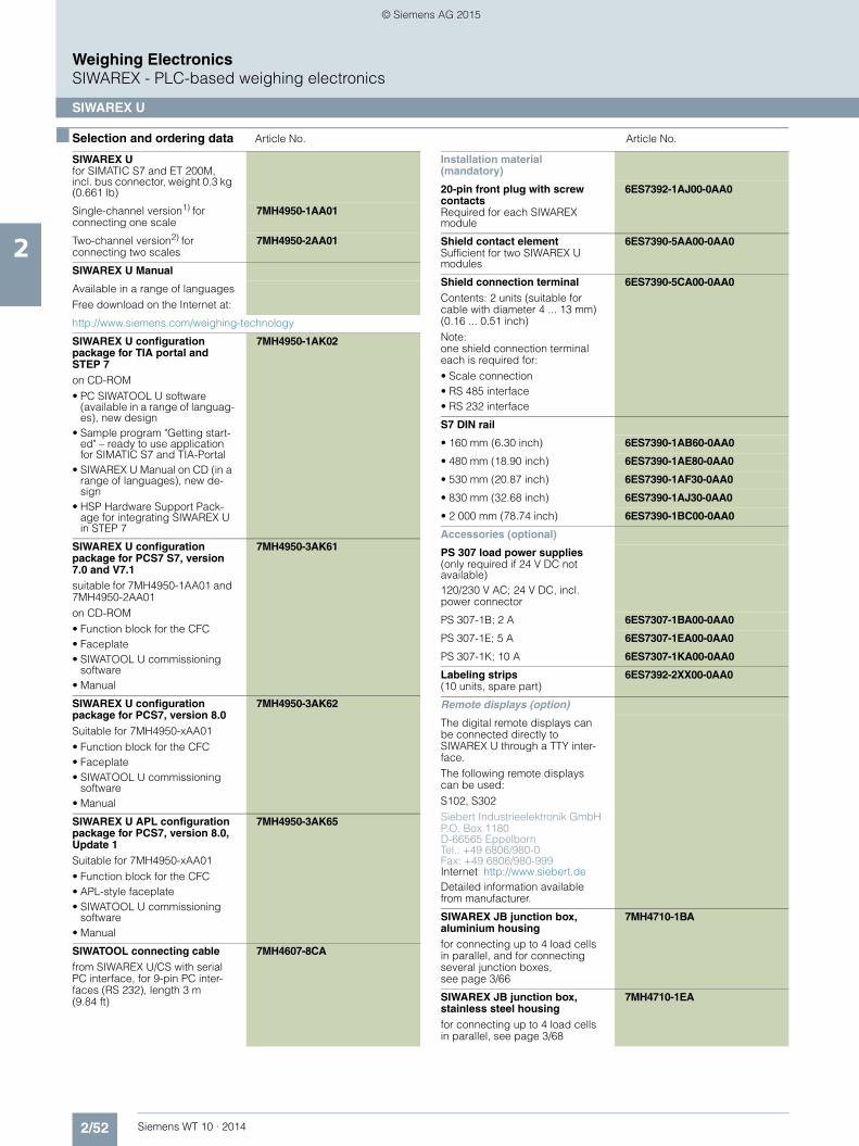
2/52 Siemens WT 10 · 2014
Weighing ElectronicsSIWAREX - PLC-based weighing electronics
SIWAREX U
2
■ Selection and ordering data Article No. Article No.
SIWAREX Ufor SIMATIC S7 and ET 200M, incl. bus connector, weight 0.3 kg (0.661 lb)
Single-channel version1) for connecting one scale
7MH4950-1AA01
Two-channel version2) for connecting two scales
7MH4950-2AA01
SIWAREX U Manual
Available in a range of languagesFree download on the Internet at:
http://www.siemens.com/weighing-technology
SIWAREX U configuration package for TIA portal and STEP 7on CD-ROM• PC SIWATOOL U software
(available in a range of languag-es), new design
• Sample program "Getting start-ed" – ready to use application for SIMATIC S7 and TIA-Portal
• SIWAREX U Manual on CD (in a range of languages), new de-sign
• HSP Hardware Support Pack-age for integrating SIWAREX U in STEP 7
7MH4950-1AK02
SIWAREX U configuration package for PCS7 S7, version 7.0 and V7.1suitable for 7MH4950-1AA01 and 7MH4950-2AA01on CD-ROM• Function block for the CFC• Faceplate• SIWATOOL U commissioning
software• Manual
7MH4950-3AK61
SIWAREX U configuration package for PCS7, version 8.0Suitable for 7MH4950-xAA01• Function block for the CFC• Faceplate• SIWATOOL U commissioning
software• Manual
7MH4950-3AK62
SIWAREX U APL configuration package for PCS7, version 8.0, Update 1Suitable for 7MH4950-xAA01• Function block for the CFC• APL-style faceplate• SIWATOOL U commissioning
software• Manual
7MH4950-3AK65
SIWATOOL connecting cable from SIWAREX U/CS with serial PC interface, for 9-pin PC inter-faces (RS 232), length 3 m (9.84 ft)
7MH4607-8CA
Installation material (mandatory)
20-pin front plug with screw contactsRequired for each SIWAREX module
6ES7392-1AJ00-0AA0
Shield contact elementSufficient for two SIWAREX U modules
6ES7390-5AA00-0AA0
Shield connection terminalContents: 2 units (suitable for cable with diameter 4 ... 13 mm) (0.16 ... 0.51 inch)Note:one shield connection terminal each is required for:• Scale connection• RS 485 interface• RS 232 interface
6ES7390-5CA00-0AA0
S7 DIN rail
• 160 mm (6.30 inch) 6ES7390-1AB60-0AA0
• 480 mm (18.90 inch) 6ES7390-1AE80-0AA0
• 530 mm (20.87 inch) 6ES7390-1AF30-0AA0
• 830 mm (32.68 inch) 6ES7390-1AJ30-0AA0
• 2 000 mm (78.74 inch) 6ES7390-1BC00-0AA0
Accessories (optional)
PS 307 load power supplies(only required if 24 V DC not available)120/230 V AC; 24 V DC, incl. power connector
PS 307-1B; 2 A 6ES7307-1BA00-0AA0
PS 307-1E; 5 A 6ES7307-1EA00-0AA0
PS 307-1K; 10 A 6ES7307-1KA00-0AA0
Labeling strips(10 units, spare part)
6ES7392-2XX00-0AA0
Remote displays (option)
The digital remote displays can be connected directly to SIWAREX U through a TTY inter-face.The following remote displays can be used:S102, S302Siebert Industrieelektronik GmbHP.O. Box 1180D-66565 EppelbornTel.: +49 6806/980-0Fax: +49 6806/980-999Internet: http://www.siebert.deDetailed information available from manufacturer.
SIWAREX JB junction box, aluminium housingfor connecting up to 4 load cells in parallel, and for connecting several junction boxes, see page 3/66
7MH4710-1BA
SIWAREX JB junction box, stainless steel housingfor connecting up to 4 load cells in parallel, see page 3/68
7MH4710-1EA
© Siemens AG 2015

2/53Siemens WT 10 · 2014
Weighing ElectronicsSIWAREX - PLC-based weighing electronics
SIWAREX U
2
1) 2)
Article No.
Ex interface, type SIWAREX ISWith ATEX approval, but without UL and FM approvals, for intrin-sically-safe connection of load cells, including manual,suitable for the SIWAREX U, CS, MS, FTA, FTC and CF weighing modules.Approved for use in the EU.
• With short-circuit current < 199 mA DC
7MH4710-5BA
• With short-circuit current < 137 mA DC
7MH4710-5CA
Cables (optional)
Cable Li2Y 1 x 2 x 0.75 ST + 2 x (2 x 0.34 ST) - CY, orange sheathfor connecting SIWAREX U, CS, MS, FTA, FTC and CF to the junc-tion box (JB), extension box (EB) or Ex interface (Ex-I) or between two JBs, for fixed laying, occa-sional bending permitted, 10.8 mm (0.43 inch) outer diame-ter, for ambient temperature -40 ... +80 °C (-40 ... +176 °F)
7MH4702-8AG
Cable Li2Y 1 x 2 x 0.75 ST + 2 x (2 x 0.34 ST) - CY, blue sheathTo connect the junction box (JB) or extension box (EB) in a poten-tially explosive atmosphere to the Ex interface (Ex I), for fixed lay-ing, occasional bending permit-ted, blue PVC insulating sheath, approx. 10 8 mm (0.43 inch) outer diameter, for ambient tem-perature -40 ... +80 °C (-40 ... +176 °F)
7MH4702-8AF
Cable LiYCY 4 x 2 x 0.25 mm² for TTY (connect 2 pairs of con-ductors in parallel), for connec-tion of a remote display
7MH4407-8BD0
1) Compatible with 7MH4601-1AA01; supply of load cells changed to 6 V DC.
2) )Compatible with 7MH4601-1BA01; supply of load cells changed to 6 V DC.
© Siemens AG 2015

2/54 Siemens WT 10 · 2014
Weighing ElectronicsSIWAREX - PLC-based weighing electronics
SIWAREX FTA
2
■ Overview
The SIWAREX FTA (Flexible Technology, Automatic Weighing In-strument) is a versatile and flexible weighing module for indus-trial use. It can be used in both non-automatic and automatic weighing operation, for example the production of mixtures, and for filling, loading, monitoring and bag filling.
It has the corresponding scale approvals and is also suitable for legal-for-trade weighing systems.
The SIWAREX FTA function module is integrated in SIMATIC S7/PCS7, and uses the features of this modern automation sys-tem, such as integrated communication, diagnostics and config-uration tools.
■ Benefits
SIWAREX FTA is characterized by the following features:• Uniform design, and totally integrated communication in
SIMATIC S7 and SIMATIC PCS 7• Standardized configuration with SIMATIC • Direct use in the SIMATIC automation system• Use in the distributed plant concept through the connection to
PROFIBUS DP/PROFINET via ET 200M• Measurement of weight or force with high resolution of 16 mil-
lion intervals• High accuracy 3 x 6 000d, legal-for-trade high accuracy• Use with analog strain-gage load cells of types SIWAREX R
and SIWAREX WL200• Alternative option of connecting individual load cells from the
manufacturers METTLER TOLEDO, Wipotec and PESA• Legal-for-trade display with SIMATIC standard operator
panels• Stepless or stepped dosing control • Exact switching of dosing signals (< 1 ms)• Parameterizable inputs and outputs• Parameterizable for highly versatile applications • Flexible adaptation to different requirements with SIMATIC• Simple adjustment of scale using the SIWATOOL FTA program• Theoretical adjustment without adjustment weights• Replacement of module without renewed adjustment of scale• Recording of the weighing process • Legal-for-trade alibi memory• Can be used in Ex applications
■ Application
The SIWAREX FTA weighing module is the optimum solution wherever high demands are placed on accuracy and speed.
Thanks to its outstanding measuring properties, weights can be measured with extreme accuracy in up to three ranges.
SIWAREX FTA can be used to design legal-for-trade dosing sys-tems, such as filling plants, loading stations, bagging stations, rotopackers, mixers or test stations.
Typical fields of application include:• Filling of liquids• Bagging of solid matter (also big bag)• Proportioning as deduction weighing or fill weighing• Checking of individual quantities• Loading or receiving of materials• Static checkweigher• Check weigher (in combination with Wipotec load cells)
■ Design
The SIWAREX FTA is a function module of the SIMATIC S7-300 and can be snapped directly onto the SIMATIC S7-300 or ET 200M backplane bus. The installation/cabling requirements of the 80-mm wide weighing module are extremely low as a re-sult of the DIN rail assembly and snap-on technique.
A standard 40-pin front plug is used to connect the load cells, the RS 485 serial interface, the analog output and the digital in-puts/outputs, a 9-pin Sub-D plug to connect the PC (RS 232), and a separate 2-pin plug to connect the power supply.
Operation of the SIWAREX FTA in SIMATIC means that complete integration of the weighing technology into the automation sys-tem is guaranteed.
■ Function
The main tasks of the SIWAREX FTA are the high-precision mea-surement of the current weight in up to three measuring ranges, and exact control of the weighing procedures.
The weighing module controls the weighing procedures fully au-tomatically. However, integration in SIMATIC means that it is also possible to directly influence the weighing procedures using a PLC program. This means that the tasks can be sensibly di-vided: the very fast weighing functions are implemented in the SIWAREX FTA , the interlocking and logic functions in the SIMATIC CPU.
© Siemens AG 2015

2/55Siemens WT 10 · 2014
Weighing ElectronicsSIWAREX - PLC-based weighing electronics
SIWAREX FTA
2
Weighing functions
The SIWAREX FTA is easy to parameterize according to the var-ious automatic weighing functions.
The following weighing functions can be parameterized:• NSW (Non Automatic Weighing Instrument) according to
OIML R76• SWA (Automatic Gravimetric Filling Instrument) according to
OIML R61• SWE (Automatic Catchweighing Instrument) according to
OIML R51• SWT (Discontinuous Totalizing Automatic Weighing Instru-
ment (Totalizing Hopper Weigher)) according to OIML R107
Monitoring and control of the load cell signals and statuses
During the weighing procedure, the SIWAREX FTA weighing module monitors and controls the load cell signals and statuses. The optimized exchange of data within SIMATIC permits direct evaluation of the load cell signals and statuses in the PLC pro-gram.
Influencing of the weighing sequences by the PLC means that the SIWAREX FTA can be easily adapted to any modifications in system technology.
The SIWAREX FTA is already factory-calibrated. This means that the theoretical adjustment of the scale is possible without adjust-ment weights, and that modules can be replaced without read-justment of the scale. When using "active bus modules", replace-ment is also possible during operation.
Integration in SIMATIC
SIWAREX FTA is completely integrated into the SIMATIC S7 and SIMATIC PCS 7. Users can freely configure their automation solution – including the weighing application.
The right combination of SIMATIC components can produce optimum solutions for small, medium-size and large plants. The scales are operated and monitored using SIMATIC standard operator panels. These operator panels (also touch panels such as the TP177B) can also be simultaneously used for the opera-tion and monitoring of the plant.
Customized or sector-specific solutions can be developed ex-tremely quickly using the configuration package and example applications for SIMATIC. The following Figure shows a typical configuration of a medium-size plant.
The ready-to-use function blocks for the automation system and the faceplates for the operator station are used for the configu-ration in SIMATIC PCS 7.
SIMATIC S7/PCS 7 configuration with SIWAREX FTA
Software
SIWATOOL FTA commissioning software
SIWATOOL FTA is a special program for commissioning and ser-vicing and runs with Windows operating systems.
The program enables the scales to be set without the need for prior knowledge of the automation system. When servicing, the technician can use a PC to analyze and test the procedures in the scale. Reading out the diagnostics buffer from the SIWAREX FTA is extremely helpful when analyzing events.
The following are just some of the tasks that can be carried out using SIWATOOL FTA:• Parameterization and adjustment of the scale• Testing of scale properties• Saving and printing scale data• Recording and analysis of weighing sequence
Settings in SIWAREX FTA software
SIWAREX in ET 200M
SIWAREX in SIMATIC S7-300
SIWAREX in ET 200M
Operator Station
Engineering Station
SIMATIC S7/SIMATIC PCS 7 SIWAREX FTA
Industrial Ethernet
SIMATIC S7-400
PROFIBUS DP
SIMATIC S7-400
© Siemens AG 2015

2/56 Siemens WT 10 · 2014
Weighing ElectronicsSIWAREX - PLC-based weighing electronics
SIWAREX FTA
2
Fast advanced parameterization of the module can be carried out using the "Fast parameterization" function. Answering just a few questions approximately presets the parameters.
It is also extremely helpful to analyze the diagnostics buffer which can be saved together with the parameters following reading out from the module.
The SIWAREX FTA weighing module includes a trace mode for optimization of weighing sequences. The recorded weight val-ues and associated statuses can be displayed as traces using SIWATOOL FTA and MS Excel.
Upgrading of firmware
A further program function can be used to download a new firm-ware version onto the SIWAREX FTA on site. This means that firmware upgrades can be carried out on site as required any-where in the world.
Reading out of weighing reports
The weighing reports are saved on an MMC (Micro Memory Card) inserted in the SIWAREX FTA for the duration specified by the weights and measures act. If complaints are received con-cerning a particular weighing procedure, the associated data can be read out of the MMC using SIWATOOL.
SIWAREX FTA – simple configuration
Integration in SIMATIC results in freely-programmable, modular weighing systems which can be modified according to opera-tional requirements.
The ready-to-use SIWAREX FTA software "Getting started" is also available free-of-charge and shows beginners how to integrate the module into a STEP 7 program and offers a basis for appli-cation programming. A SIWAREX FTA scale can then be simply implemented in SIMATIC together with a touch panel (TP/OP/MP) as the operator panel - even for legal-for-trade ap-plications.
Scale faceplate in the SIWAREX FTA "Getting started" software
In addition, the STEP 7 programs SIWAREX FTA Multiscale and SIWAREX FTA Multifill provide a professional basis for imple-mentation of batching plants or filling plants.
■ Technical specificationsSIWAREX FTA
Use in automation systems
S7-300 Directly or through ET 200M
S7-400 (H) Through ET 200M
PCS 7 (H) Through ET 200M
Communication interfaces
S7 Through backplane bus
RS 232 For SIWATOOL or printer connection
RS 485 For remote display or digital load cell
Module parameterization Using SIMATIC S7
Using SIWATOOL FTA software (RS 232)
Measuring properties
EU type approval as non-auto-matic weighing machine, trade class III
3 x 6 000 d ≥ 0.5 μV/e
Internal resolution 16 million parts
Internal/external updating rate 400/100 Hz
Several parameterizable digital filters
Critically dampened, Bessel, Butterworth (0.05 ... 20 Hz), mean-value filter
Weighing functions
Non-automatic weighing machine OIML R76
Automatic weighing machine OIML R51, R61, R107
Load cells Strain gages in 4-wire or 6-wire system
3 characteristic value ranges 1, 2 or 4 mV/V
Load cell powering
Supply voltage US (rated value) 10.3 V DC
Max. supply current 184 mA
Permissible load cell resistance
• RLmin > 56 Ω> 87 Ω with Ex interface
• RLmax ≤ 4 010 Ω
Max. distance of load cells
When using the recommended cable:
Standard 1 000 m (3 280 ft)
In hazardous area1)
• For gases of group IIC 300 m (984 ft)
• For gases of group IIB 1 000 m (3 280 ft)
Connection to load cells in Ex zone 1
Optionally via SIWAREX IS Ex interface
Ex approvals zone 2 and safety ATEX 95, FM, cULUS Haz. Loc.
Auxiliary power supply
Rated voltage 24 V DC
Max. power consumption 500 mA
Current consumption from back-plane bus
Typ. 55 mA
© Siemens AG 2015

2/57Siemens WT 10 · 2014
Weighing ElectronicsSIWAREX - PLC-based weighing electronics
SIWAREX FTA
2
1)
Inputs/outputs
Digital inputs 7 DI electrically isolated
Digital outputs 8 DO electrically isolated
Counter input Up to 10 kHz
Analog output
• Current range 0/4 ... 20 mA
• Updating rate 100 Hz
Approvals EU type approval (CE, OIML R76)
EU prototype test to MID (OIML R51, R61, R107)
Degree of protection according to EN 60529; IEC 60529
IP20
Climatic requirementsTmin (IND) ... Tmax (IND) (operating temperature)
• Vertical installation -10 ... 60 °C (14 ... 140 °F)
• Horizontal installation -10 ... 40 °C (14 ... 104 °F)
EMC requirements EN 61326, EN 45501, NAMUR NE21, Part 1
Dimensions 80 x 125 x 130 mm (3.15 x 4.92 x 5.12 inch)
Weight 600 g (0.44 lb)
1) For further details, see Ex interface, type SIWAREX IS.
SIWAREX FTA
© Siemens AG 2015

2/58 Siemens WT 10 · 2014
Weighing ElectronicsSIWAREX - PLC-based weighing electronics
SIWAREX FTA
2
■ Selection and ordering data Article No. Article No.
SIWAREX FTA Legal-for-trade weighing elec-tronics for automatic scales for S7-300 and ET 200M.EU type approval 3 x 6 000 d Applications: proportioning, fill-ing, bagging, loading.Note: Observe approval condi-tions for applications with obliga-tion of verification. We recommend using our calibration set and contacting our SIWAREX hotline.
7MH4900-2AA01
SIWAREX FTA ManualAvailable in a range of languagesFree download from the Internet at:
http://www.siemens.com/weighing-technology
SIWAREX FTA "Getting started"Sample software shows begin-ners how to program the scales in STEP 7.Free download from the Internet at:
http://www.siemens.com/weighing-technology
SIWAREX FTA configuration package for TIA portal and STEP 7, on CD-ROM• HSP Hardware Support Pack-
age for integrating SIWAREX FTA/FTC in STEP 7
• SIWAREX FTA "Getting started" • SIWATOOL FTA commissioning
software • Flexible software for legal-for-
trade display in WinCC• Manual
7MH4900-2AK02
SIWAREX FTA configuration package for PCS 7 V7.0 on CD-ROM• HSP hardware support package
for integrating SIWAREX FTA/FTC in STEP 7
• Function block for CFC• Faceplate• SIWATOOL FTA commissioning
software• Manual
7MH4900-2AK62
SIWAREX FTA configuration package for SIMATIC PCS 7, Version 8.0 on CD-ROM• HSP hardware support package
for integrating SIWAREX FTA/FTC in STEP 7
• Function block for the CFC• Faceplate• SIWATOOL FTA commissioning
software• Manual
7MH4900-2AK63
SIWAREX FTA APL configura-tion package for SIMATIC PCS 7, Version 8.0, Update 1 on CD-ROM• HSP hardware support package
for integrating SIWAREX FTA/FTC in STEP 7
• Function block for the CFC• APL-style faceplate• SIWATOOL FTA commissioning
software• Manual
7MH4900-2AK65
Calibration set for SIWAREX FTAFor verification of up to 5 scales comprising:• 3 x inscription foil for labeling• 1 x protection foil• 10 x EU verification marks
(black M on green background)• Guidelines for verification, verifi-
cation certificates and approv-als, adaptable label, SIWAREX FTA Manual on CD-ROM
7MH4900-2AY10
SIWAREX MultiscaleSTEP 7 software for SIWAREX FTA.Control of one or more scales for a scalable number of compo-nents and any number of recipes.Applications: batching plants, mixers in production process, CD-ROM
7MH4900-2AL01
SIWAREX MultifillSTEP 7 software for SIWAREX FTA. Control of filling and bagging pro-cesses for one or more filling sta-tions and any number of materials, CD-ROM
7MH4900-2AM01
SIWATOOL cable from SIWAREX FTA with serial PC interface, for 9-pin PC interfaces (RS 232)
• 2 m long (6.56 ft) 7MH4702-8CA
• 5 m long (6.56 ft) 7MH4702-8CB
Front connector, 40-pinRequired for each SIWAREX module
• With screw contacts 6ES7392-1AM00-0AA0
• With spring-loaded terminals 6ES7392-1BM01-0AA0
Shield contact elementSufficient for one SIWAREX FTA module
6ES7390-5AA00-0AA0
Shield connection terminalContents: 2 units (suitable for cable with diameter 4 ... 13 mm (0.16 ... 0.51 inch))Note:one shield connection terminal each is required for:• Scale connection• RS 485 interface• RS 232 interface
6ES7390-5CA00-0AA0
© Siemens AG 2015

2/59Siemens WT 10 · 2014
Weighing ElectronicsSIWAREX - PLC-based weighing electronics
SIWAREX FTA
2
Article No.
S7 DIN rail
• 160 mm (6.30 inch) 6ES7390-1AB60-0AA0
• 480 mm (18.90 inch) 6ES7390-1AE80-0AA0
• 530 mm (20.87 inch) 6ES7390-1AF30-0AA0
• 830 mm (32.68 inch) 6ES7390-1AJ30-0AA0
• 2 000 mm (78.74 inch) 6ES7390-1BC00-0AA0
PS 307 load power supply(only required if 24 V DC is not available)120/230 V AC; 24 V DC
• PS 307-1B; 2 A 6ES7307-1BA00-0AA0
• PS 307-1E; 5 A 6ES7307-1EA00-0AA0
• PS 307-1K; 10 A 6ES7307-1KA00-0AA0
MMC memoryFor data recording up to 16 Mbyte, only for legal-for-trade applications R76, R51 and R107
7MH4900-2AY20
Remote displays (option)
The Siebert S102 and S302 remote digital displays can be directly connected to the SIWAREX FTA via an RS 485 interface.Siebert Industrieelektronik GmbHP.O. Box 1180D-66565 EppelbornTel.: +49 6806/980-0Fax: +49 6806/980-999Internet: http://www.siebert.deDetailed information available from manufacturer.
SIWAREX JB junction box, alu-minium housingFor connecting up to 4 load cells in parallel, and for connecting several junction boxes, see page 3/66
7MH4710-1BA
SIWAREX JB junction box, stainless steel housingfor connecting up to 4 load cells in parallel, see page 3/68
7MH4710-1EA
Ex interface, type SIWAREX IS
With ATEX approval, but without UL or FM approvalfor intrinsically-safe connection of load cells,including manual, suitable for the SIWAREX U, CS, MS, FTA, FTC and CF weighing modules.Approved for use in the EU.
• With short-circuit current < 199 mA DC
7MH4710-5BA
• With short-circuit current < 137 mA DC
7MH4710-5CA
Cables (optional) Article No.
Cable Li2Y 1 x 2 x 0.75 ST + 2 x (2 x 0.34 ST) - CY, orange sheath
7MH4702-8AG
for connecting SIWAREX U, CS, MS, FTA, FTC and CF to the junc-tion box (JB), extension box (EB) or Ex interface (Ex-I) or between two JBs, for fixed laying, occa-sional bending permitted, 10.8 mm (0.43 inch) outer diame-ter, for ambient temperature -40 ... +80 °C (-40 ... +176 °C)
Cable Li2Y 1 x 2 x 0.75 ST + 2 x (2 x 0.34 ST) - CY, blue sheath
7MH4702-8AF
To connect the junction box (JB) or extension box (EB) in a poten-tially explosive atmosphere to the Ex interface (Ex I), for fixed lay-ing, occasional bending permit-ted, blue PVC insulating sheath, approx. 10.8 mm (0.43 inch) outer diameter, for ambient tem-perature -40 ... +80 °C (-40 ... +176 °C)
Cable LiYCY 4 x 2 x 0.25 mm² 7MH4407-8BD0
For TTY (connect 2 pairs of con-ductors in parallel), for connec-tion of a remote display
© Siemens AG 2015

2/60 Siemens WT 10 · 2014
Weighing ElectronicsSIWAREX - PLC-based weighing electronics
SIWAREX FTC
2
■ Overview
The SIWAREX FTC (Flexible Technology for Continuous Weigh-ing) is a versatile and flexible weighing module for conveyor scales, differential proportioning weighers and bulk flow meters. It can also be used to record weights and measure force. The SIWAREX FTC function module is integrated in SIMATIC S7/PCS7, and uses the features of this modern automation sys-tem, such as integral communication, diagnostics and configu-ration tools.
■ Benefits
SIWAREX FTC is characterized by the following features: • Uniform design, and totally integrated communication in
SIMATIC S7 and SIMATIC PCS 7• Uniform configuration with SIMATIC• Direct use in the SIMATIC automation system• Use in distributed plant concept through connection to
PROFIBUS DP/PROFINET using ET 200M• Measurement of weight or force with high resolution of
16 million intervals • High accuracy 3 x 6 000 d• Use with analog strain-gage load cells of types SIWAREX R
and SIWAREX WL200• Alternative option of connecting individual load cells from the
manufacturers METTLER TOLEDO, WIPOTEC and PESA• Display with SIMATIC standard operator panels• Parameterizable inputs and outputs • Parameterizable for highly versatile applications• Flexible adaptation to different requirements with SIMATIC• Simple adjustment of scale using the SIWATOOL FTC
program• Theoretical adjustment without adjustment weights• Replacement of module without renewed adjustment of scale• Recording of weighing sequence• 8 totalization memories with different digit intervals• Can be used in Ex applications
■ Application
The SIWAREX FTC weighing module is the optimum solution wherever high demands are placed on continuous weighing pro-cedures. Thanks to its outstanding measuring properties, weights can be measured with extreme accuracy in up to three ranges. In the case of force measurements, the value can be measured bidirectionally.
Typical applications for SIWAREX FTC include:• Flowrate/flow measurement• Volume measurement• Material loading, summation• Flowrate/flow control• Belt load measurement• Belt scale/weighfeeder• Loss-in-weight scale• Force measurement
■ Design
The SIWAREX FTC is a function module of the SIMATIC S7-300 and can be snapped directly onto the SIMATIC S7-300 or ET 200M backplane bus. The installation/cabling requirements of the 80-mm wide weighing module are extremely low as a re-sult of the DIN rail assembly and snap-on technique.
A standard 40-pin front plug is used to connect the load cells, the RS 485 serial interface, the analog output and the digital in-puts/outputs, a 9-pin Sub-D plug to connect the PC (RS 232), and a separate 2-pin plug to connect the power supply.
Operation of the SIWAREX FTC in SIMATIC means that complete integration of the conveyor scale into the automation system is guaranteed.
■ Function
The main tasks of SIWAREX FTC are the high-precision mea-surement of the actual weight in up to three measuring ranges, and the exact calculation of the conveyed quantity and flow. In "Force measurement" mode, the force is measured bidirection-ally.
The conveyed quantity can be recorded in 8 totalization memo-ries. Through integration in SIMATIC it is also possible to directly control scale operation by means of a PLC program. This means that the tasks can be sensibly divided: the weighing functions are implemented in the SIWAREX FTC, the interlocking and logic functions for the plant control in the SIMATIC CPU.
Weighing functions
The following operating modes can be set:
Weight measurement and force measurement
In this operating mode, the weight value/force is determined, processed in the PLC and then displayed.
For this purpose, the configuration package can be selected.
Conveyor scale / weighfeeder
The functions of a conveyor scale are implemented in this oper-ating mode. Calculations are performed for the typical process values; belt load, flowrate and belt speed. Commands can be used to control the belt and display the required values. A weighfeeder can be implemented by activating the SIMATIC PID controller.
© Siemens AG 2015

2/61Siemens WT 10 · 2014
Weighing ElectronicsSIWAREX - PLC-based weighing electronics
SIWAREX FTC
2
Scale faceplate of a conveyor scale
Differential proportioning weigher - Loss-in-weight
The functions of a differential proportioning weigher are imple-mented in this operating mode. The actual weight of the con-tainer is measured and the flowrate is regulated according to the preset setpoint.
Application-specific parameters, such as proportioning param-eters, device and material characteristics, can be set directly in SIWAREX FTC. Various commands are available that have been fine-tuned to the requirements of the differential proportioning weigher, such as proportioning (manual, automatic, gravimetric, volumetric), filling and emptying.
The high measurement resolution, real-time signal processing, detection and filtering of signals in the weighing electronics en-able extremely high proportioning accuracy.
Scale faceplate of a differential proportioning weigher
Bulk flow meter
The functions of a bulk flow meter are implemented in this oper-ating mode. The calculations for the typical process values; flow and conveyed quantity, are performed in the SIWAREX module. Application-specific parameters for setting the scales and com-mands for their operation are also available.
View of a bulk flow meter
Monitoring and control of the load cell signals and statuses
The SIWAREX FTC weighing module monitors the statuses dur-ing the weighing process, and informs the operator of any irreg-ularities. The optimized exchange of data within SIMATIC per-mits direct evaluation of the load cell signals in the PLC program.
Influencing of the weighing sequences by the PLC means that the SIWAREX FTC can be easily adapted to any modifications in system technology.
A module can be replaced without recalibrating the scales. When using "active bus modules", replacement is also possible during operation.
Applications of SIWAREX FTC
Integration in SIMATIC
SIWAREX FTC is completely integrated into the SIMATIC S7 and SIMATIC PCS 7. Users can freely configure their automation so-lution – including the weighing application.
The right combination of SIMATIC components can produce optimum solutions for small, medium-size and large plants. The scales are operated and monitored using SIMATIC standard operator panels. Needless to say, these operator panels can also be simultaneously used for the operator control and moni-toring of the plant.
© Siemens AG 2015

2/62 Siemens WT 10 · 2014
Weighing ElectronicsSIWAREX - PLC-based weighing electronics
SIWAREX FTC
2
Customized or sector-specific solutions can be developed ex-tremely quickly using the configuration package and example applications for SIMATIC.
SIMATIC S7/PCS 7 configuration with SIWAREX FTC (medium-sized plants)
Software
Adjustment of the scale using SIWATOOL FTC
SIWATOOL FTC is a special program for adjusting and servicing the scale and runs with Windows operating systems.
The program enables the scales to be commissioned without the need for prior knowledge of the automation system. When ser-vicing, the technician can use a PC to analyze and test the pro-cedures in the scale. Reading out the diagnostics buffer from the SIWAREX FTC is extremely helpful when analyzing events.
The following are just some of the tasks that can be carried out using SIWATOOL FTC:• Parameterization and adjustment of the scale • Testing of scale properties • Saving and printing scale data • Recording and analysis of weighing sequence
Settings in SIWAREX FTC software
It is also extremely helpful to analyze the diagnostics buffer which can be saved together with the parameters following reading out from the module.
The SIWAREX FTC weighing module includes a trace mode for checking of weighing sequences. The recorded weight values and associated statuses can be displayed as traces using SI-WATOOL FTC and MS Excel.
Upgrading of firmware
A further program function can be used to download a new firm-ware version onto the SIWAREX FTC on site. This means that firmware upgrades can be carried out on site as required any-where in the world.
Reading out of weighing reports
The totalization memories can be saved on a MMC (Micro Mem-ory Card) inserted into the SIWAREX FTC.
SIWAREX FTC – simple configuring
Integration in SIMATIC can result in freely-programmable, mod-ular weighing systems for conveyor scales, bulk flow meters and differential proportioning weighers, which can be modified to meet operational requirements.
A free version of the ready-to-use SIWAREX FTC software "Get-ting started" is also available respectively for the conveyor scale, bulk flow meter and loss-in-weight feeder modes. It shows be-ginners how to integrate the module into a STEP 7 program and provides a basis for application programming. A SIWAREX FTC conveyor scale can then be easily implemented in SIMATIC to-gether with a touch panel (TP/OP/MP) as the operator panel.
Scale faceplate in the SIWAREX FTC "Getting started" software
SIWAREX in ET 200M
SIWAREX in SIMATIC S7-300
SIWAREX in ET 200M
Operator Station
Engineering Station
SIMATIC S7/SIMATIC PCS 7 SIWAREX FTC
Industrial Ethernet
SIMATIC S7-400
PROFIBUS DP
SIMATIC S7-400
© Siemens AG 2015

2/63Siemens WT 10 · 2014
Weighing ElectronicsSIWAREX - PLC-based weighing electronics
SIWAREX FTC
2
■ Technical specifications 1)
1) For further details, see Ex interface, type SIWAREX IS.
SIWAREX FTC
Use in automation systems
S7-300 Directly or via ET 200M
S7-400 (H) Through ET 200M
PCS 7 (H) Through ET 200M
Communication interfaces
S7 Through backplane bus
RS 232 For SIWATOOL or printer connec-tion
RS 485 For remote display or digital load cell
Module parameterization
Using SIMATIC S7
Using SIWATOOL FTC software (RS 232)
Measuring properties
Accuracy to EN 45501 3 x 6 000 d ≥ 0.5 μV/e
Internal resolution ± 8 million parts
Internal/external updating rate 400/100 Hz
Several parameterizable digital filters
Critically dampened, Bessel, Butterworth (0.05 ... 20 Hz), mean-value filter
Weighing functions
• Non-automatic weighing ma-chine, force measurement
• Conveyor scale
• Differential proportioning weigher
• Bulk flow meter
Load cells Strain gages in 4-wire or 6-wire system
3 characteristic value ranges 1, 2 or 4 mV/V
Load cell powering
Supply voltage US (rated value) 10.3 V DC
Max. supply current 184 mA
Permissible load cell resistance
• RLmin > 56 Ω> 87 Ω with Ex interface
• RLmax ≤ 4 010 Ω
Max. distance of load cells
When using the recommended cable:
Standard 1 000 m (3280 ft)
In hazardous area1)
• For gases of group IIC 300 m (984 ft)
• For gases of group IIB 1 000 m (3280 ft)
Connection to load cells in Ex zone 1
Optionally via SIWAREX IS Ex interface
Ex approvals zone 2 and safety ATEX 95, FM, cULUS Haz. Loc.
Auxiliary power supply
Rated voltage 24 V DC
Max. power consumption 500 mA
Current consumption from backplane bus
Typ. 55 mA
Inputs/outputs
Digital inputs 7, electrically isolated
Digital outputs 8, electrically isolated
Counter input Up to 10 kHz
Analog output
• Current range 0/4 ... 20 mA
• Updating rate 100 Hz
Degree of protection according to EN 60529; IEC 60529
IP20
Climatic requirementsTmin (IND) ... Tmax (IND) (operating temperature)
• Vertical installation -10 ... 60 °C (14 ... 140 °F)
• Horizontal installation -10 ... 40 °C (14 ... 104 °F)
EMC requirements EN 61326, EN 45501, NAMUR NE21, Part 1
Dimensions 80 x 125 x 130 mm (3.15 x 4.92 x 5.12 inch)
Weight 600 g (0.44 lb)
SIWAREX FTC
© Siemens AG 2015

2/64 Siemens WT 10 · 2014
Weighing ElectronicsSIWAREX - PLC-based weighing electronics
SIWAREX FTC
2
■ Selection and ordering data Article No. Article No.
SIWAREX FTCWeighing electronics for S7-300 and ET 200M.Applications: Conveyor scales, force measurement, differential proportioning weighers and bulk flow meters
7MH4900-3AA01
SIWAREX FTC_B Manual for conveyor scales
Available in a range of languagesFree-of-charge download from the Internet at:
http://www.siemens.com/weighing-technology
SIWAREX FTC_L Manual for bulk flow meters and differential proportioning weighers
Available in a range of languagesFree-of-charge download from the Internet at:
http://www.siemens.com/weighing-technology
SIWAREX FTC "Getting started" for conveyor scales
Sample software shows begin-ners how to program the scales in STEP 7 for conveyor scale modeFree download from the Internet at:
http://www.siemens.com/weighing-technology
SIWAREX FTC "Getting started" for solids flowmeters
Sample software shows begin-ners how to program the scales in STEP 7 for bulk flow meter modeFree download from the Internet at:
http://www.siemens.com/weighing-technology
SIWAREX FTC "Getting started" for differential proportioning weighers
Sample software shows begin-ners how to program the scales in STEP 7 for differential proportion-ing weigher modeFree download from the Internet at:
http://www.siemens.com/weighing-technology
SIWAREX FTC_B configuration package, for TIA portal and STEP 7, on CD-ROM (conveyor scale)• HSP Hardware Support Pack-
age for integrating SIWAREX FTA/FTC in STEP 7
• "Getting started" for conveyor scales
• Commissioning software SIWATOOL FTC_B for conveyor scales
• Manual
7MH4900-3AK03
SIWAREX FTC_L configuration package for TIA portal and STEP 7, on CD-ROM (bulk flow meter, loss-in-weight feeder)• HSP hardware support package
for integrating SIWAREX FTA/FTC in STEP 7
• "Getting started" for solids flow meters
• "Getting started" for loss-in-weight feeders
• Commissioning software SIWATOOL_L for bulk flow me-ters and loss-in-weight feeders
• Manual
7MH4900-3AK04
SIWAREX FTC_B configuration package for PCS 7 Version V7.0 and V7.1 on CD-ROM (conveyor scale)• HSP hardware support package
for integrating SIWAREX FTA/FTC in STEP 7
• Function block for CFC• Faceplate• Commissioning software
SIWATOOL FTC_B for conveyor scales
• Manual
7MH4900-3AK63
SIWAREX FTC_B configuration package for PCS 7 Version V8.0 on CD-ROM (conveyor scale)• HSP hardware support package
for FTA/FTC package• Function block for the CFC• Faceplate• SIWATOOL commissioning soft-
ware• Manual
7MH4900-3AK65
SIWAREX FTC_L configuration package for PCS 7 V7.0 and V7.1 on CD-ROM (loss-in-weight scale)• HSP hardware support package
for integrating SIWAREX FTA/FTC in STEP 7
• Function block for the CFC• Faceplate• Commissioning software
SIWATOOL FTC_L for bulk flow meters and loss-in-weight feed-ers
• Manual
7MH4900-3AK64
SIWATOOL cable from SIWAREX FTC with serial PC interface, for 9-pin PC interfaces (RS 232)
• 2 m long (6.56 ft) 7MH4702-8CA
• 5 m long (16.40 ft) 7MH4702-8CB
© Siemens AG 2015

2/65Siemens WT 10 · 2014
Weighing ElectronicsSIWAREX - PLC-based weighing electronics
SIWAREX FTC
2
Article No.
40-pin front plug with screw contactsRequired for each SIWAREX module
• With screw contacts 6ES7392-1AM00-0AA0
• With spring-loaded terminals 6ES7392-1BM01-0AA0
Shield contact elementSufficient for one SIWAREX FTC module
6ES7390-5AA00-0AA0
Shield connection terminalContents: 2 units (suitable for cable with diameter 4 ... 13 mm)Note:one shield connection terminal each is required for:• Scale connection• RS 485 interface• RS 232 interface
6ES7390-5CA00-0AA0
S7 DIN rail
• 160 mm (6.30 inch) 6ES7390-1AB60-0AA0
• 480 mm (18.90 inch) 6ES7390-1AE80-0AA0
• 530 mm (20.87 inch) 6ES7390-1AF30-0AA0
• 830 mm (32.68 inch) 6ES7390-1AJ30-0AA0
• 2 000 mm (78.74 inch) 6ES7390-1BC00-0AA0
PS 307 load power supply(only required if DC 24 V is not available)120/230 V AC; 24 V DC
• PS 307-1B; 2 A 6ES7307-1BA00-0AA0
• PS 307-1E; 5 A 6ES7307-1EA00-0AA0
• PS 307-1K; 10 A 6ES7307-1KA00-0AA0
Remote display (option)
The Siebert S102 and S302 remote digital display can be directly connected to the SIWAREX FTC via an RS 485 interface. (not suitable for mode "Conveyor scale")Siebert Industrieelektronik GmbHP.O. Box 1180D-66565 EppelbornTel.: +49 6806/980-0Fax: +49 6806/980-999Internet: http://www.siebert.deDetailed information available from manufacturer.
Article No.
SIWAREX JB junction box, aluminium housingFor connecting up to 4 load cells in parallel, and for connecting several junction boxes, see page 3/66
7MH4710-1BA
SIWAREX JB junction box, stainless steel housingFor connecting up to 4 load cells in parallel, see page 3/68
7MH4710-1EA
Ex interface, type SIWAREX IS
With ATEX approval, but without UL or FM approvalfor intrinsically-safe connection of load cells,including manual, suitable for the SIWAREX U, CS, MS, FTA, FTC and CF weighing modules,Approved for use in the EU.
• With short-circuit current < 199 mA DC
7MH4710-5BA
• With short-circuit current < 137 mA DC
7MH4710-5CA
Cables (optional)
Cable Li2Y 1 x 2 x 0.75 ST + 2 x (2 x 0.34 ST) - CY, orange sheath
7MH4702-8AG
for connecting SIWAREX U, CS, MS, FTA, FTC and CF to the junc-tion box (JB), extension box (EB) or Ex interface (Ex-I) or between two JBs, for fixed laying, occa-sional bending permitted, 10.8 mm (0.43 inch) outer diame-ter, for ambient temperature -40 ... +80 °C (-40 ... +176 °F)
Cable Li2Y 1 x 2 x 0.75 ST + 2 x (2 x 0.34 ST) - CY, blue sheath
7MH4702-8AF
To connect the junction box (JB) or extension box (EB) in a poten-tially explosive atmosphere to the Ex interface (Ex I), for fixed lay-ing, occasional bending permit-ted, blue PVC insulating sheath, approx. 10.8 mm (0.43 inch) outer diameter, for ambient tem-perature -40 ... +80 °C (-40 ... +176 °F)
Cable LiYCY 4 x 2 x 0.25 mm² 7MH4407-8BD0
For TTY (connect 2 pairs of con-ductors in parallel), for connec-tion of a remote display
© Siemens AG 2015

2/66 Siemens WT 10 · 2014
Weighing ElectronicsForce measurements
SIWAREX CF
2
■ Overview
Automation with integral force measuring technology
In addition to accuracy when measuring force, incorporating force measuring technology in modern automation systems is also a significant feature.
Similar to the weighing modules, the force measuring modules form the basis of the identical concept for measuring technology and incorporating automation. The description concerning this is found in chapter "Weighing electronics".
SIWAREX CF is a transmitter for connecting strain-gauge sen-sors for tasks such as measuring force and torque. The compact module is easy to install in all SIMATIC automation systems. Complete data access to the current measured values is then possible via the SIMATIC.
■ Benefits
SIWAREX CF offers the following key advantages:• Uniform design technology and consistent communication
thanks to integration in SIMATIC• Uniform configuration with SIMATIC• Use in distributed plant concept through connection to
PROFIBUS DP/PROFINET using ET 200S• Bidirectional measuring with a resolution of 16 000 parts and
accuracy of 0.15 %
■ Application
SIWAREX CF is the optimum solution wherever strain-gauge sensors, such as load cells, force sensors or torque measuring shafts, are used for measuring tasks. The following are typical SIWAREX CF applications:• Monitoring of crane and cable loads• Measurement of load of conveyor belts• Overload protection in rolling mills• Monitoring of belt tension• Force measurement in testing machines • Torque and pressure measuring
■ Design
SIWAREX CF is a compact function module (FM) of the SIMATIC S7 and can be snapped direct onto the SIMATIC ET 200S backplane bus. Assembly and wiring are also greatly simplified by using rails with snap-on technology.
The sensors and the power supply are connected via the stan-dard connection block.
■ Function
SIWAREX CF provides the voltage supply required by the EMS. The force produces a corresponding measuring signal, which is then further processed in the SIWAREX CF module.
The signal is amplified, coarse-filtered, and then converted to a digital value. A connectable digital filter can additionally reduce noise on the measuring signal.
The digital value is available to the user internally in SIMATIC and can be processed in the control program. For example, the user could further suppress noise through averaging in the SIMATIC CPU or perform a conversion to physical units. The result can be displayed on an operator panel according to requirements.
Consistent and uniform communication between all system components enables fast, reliable and cost-effective integration and diagnosis in industrial processes.
SIWAREX CF can be integrated into the plant software using the classic PLC programming languages; STL (Statement List), LAD (Ladder Diagram) FBD (Function Block Diagram) or SCL (Struc-tured Control Language).
Integration into SIMATIC can result in freely-programmable, modular force measuring systems which can be modified ac-cording to operational requirements. The ready-to-use SIWAREX CF software "Getting started" is available free-of-charge and shows beginners how to integrate the module into a STEP 7 pro-gram and offers a basis for application programming. This sup-ports the display of the measured values in a SIMATIC panel (TP/OP/MP).
Measured values from three modules in the SIWAREX CF "Getting start-ed" software
In contrast to analog or digitally connected transmitters, SIWAREX M does not need costly additional modules to link it to SIMATIC.
After the module has been configured in SIMATIC and installed, it is ready for immediate operation. An additional parameteriza-tion tool is not required.
The current data are read into the SIMATIC via the I/O area.
© Siemens AG 2015

2/67Siemens WT 10 · 2014
Weighing ElectronicsForce measurements
SIWAREX CF
2
■ Technical specifications
SIWAREX CF
Integration in automation systems
S7-400, S7-300, C7 Through ET 200S
Automation systems from other vendors
Possible through ET 200S with IM 151-1
Communication interfaces SIMATIC S7 (ET 200S backplane bus), 8 bytes I/O area
Module parameterization Not required (module is pre-parameterized)
Measuring properties
Error limit to DIN 1319-1 of full-scale value at 20 °C ± 10 K
≤ 0.15 %
Signal resolution 14 bitsplus 1 bit sign
Number of measurements/second
50
Low-pass filter Without or 2 Hz
Sensors In accordance with the principle of expansion measurement (full bridge), 4-wire connection
Sensor feed
Supply voltage, short-circuit-proof 6 V DC ± 5 %
Permissible sensor resistance
• RLmin > 250 Ω
• RLmax < 4010 Ω
Permissible sensor cell coefficient
Up to 4 mV/V
Permissible range of the measuring signal
-25.2 ... +25.2 mV
Auxiliary power supply
Rated voltage 24 V DC
Max. current consumption 150 mA
Current consumption on back-plane bus
Typ. 10 mA
Connection to sensors in Ex zone 1
Optionally via SIWAREX IS Ex interface
Ex approval zone 2 and safety ATEX 95, cULus Haz. Loc.
IP degree of protection to EN 60529; IEC 60529
IP20
Climatic requirementsTmin (IND) to Tmax (IND) (operating temperature)
• Vertical installation 0 ... +60 °C
• Horizontal installation 0 ... +40 °C
EMC requirements according to NAMUR NE21, Part 189/386/EEC
Dimensions 30 x 80 x 50 mm (1.18 x 3.15 x 1.97 inch)
SIWAREX CF
© Siemens AG 2015

2/68 Siemens WT 10 · 2014
Weighing ElectronicsForce measurements
SIWAREX CF
2
■ Selection and ordering data Article No. Article No.
SIWAREX CF 7MH4920-0AA01
Weighing module for strain-gauge sensors in SIMATIC ET 200S(SIWAREX CF configuring pack-age not required)
SIWAREX CF manual
• German• EnglishFree download on the Internet at:
http://www.siemens.com/weighing-technology
SIWAREX CF "Getting started"
Sample software for easy acquaintance with programming in STEP 7.Free download on the Internet at:
http://www.siemens.com/weighing-technology
Installation material (mandatory)
Terminal module 6ES7193-4CG20-0AA0
TM-E 30 mm (1.18 inch) wide (required for each SIWAREX module)
or compatible
Shield contact element 6ES7193-4GA00-0AA0
Contents 5 items, sufficient for 5 cables
Shield connection terminal 6ES7193-4GB00-0AA0
Contents: 5 items, sufficient for 5 cables
One shield terminal element is required per sensor cable
N busbar, galvanized 8WA2842
3 mm x 10 mm (0.12 in. x 0.39 in.), 1.5 m (4.92 ft.) long
Feeder terminal for N busbar 8WA2868
Accessories
SIWAREX EB extension boxfor extending sensor cables
7MH4710-2AA
Ex interface, type SIWAREX ISWith ATEX approval, but without UL or FM approvals, for intrinsi-cally-safe connection of load cells, including manual,suitable for the SIWAREX U, CS, MS, FTA, FTC and CF weighing modules.Approved for use in the EU.
• With short-circuit current < 199 mA DC
7MH4710-5BA
• With short-circuit current < 137 mA DC
7MH4710-5CA
Cables (optional)
Cable Li2Y 1 x 2 x 0.75 ST + 2 x (2 x 0.34 ST) - CY, orange sheath
7MH4702-8AG
For connecting SIWAREX U, CS, MS, FTA, FTC and CF to the junc-tion box (JB), extension box (EB) or Ex interface (Ex-I) or between two JBs, for fixed laying, occa-sional bending permitted, 10.8 mm (0.43 in.) outer diameter, for ambient temperature -40 to +80 °C (-40 ... +176 °F)
© Siemens AG 2015

2/69Siemens WT 10 · 2014
Weighing ElectronicsForce measurements
SIWAREX FTC
2
■ Overview
The SIWAREX FTC (Flexible Technology for Continuous Weigh-ing) can be flexibly used for a wide variety of purposes in com-plex weighing tasks. The SIWAREX FTC module becomes a force measurement module by simply setting the operating mode. The SIWAREX FTC function module is integrated in SIMATIC S7/PCS7, and uses the features of this modern automa-tion system, such as integral communication, diagnostics and configuration tools.
■ Benefits
• Uniform design and totally integrated communication in SIMATIC S7 and SIMATIC PCS 7
• Uniform configuration with SIMATIC• Direct use in the SIMATIC automation system• Use in distributed plant concept through connection to
PROFIBUS DP/PROFINET using ET 200M• Bidirectional force measurement with ±8 million parts at a
measuring rate of 100 measurement per second• Display with SIMATIC standard operator panels• Parameterizable inputs and outputs • Can be parameterized for a huge range of situations• Flexible adaptation to different requirements with SIMATIC• Simple adjustment using the SIWATOOL FTC program• Supports replacement of module without renewed adjustment• Recording of measuring sequence• Can be used in Ex applications
■ Application
The SIWAREX FTC module is the optimum solution wherever high demands are placed on force measurement. As a result of its exceptional measuring properties, bidirectional force can be measured at high accuracy.
■ More information
You can find more detailed description and additional technical specifications on SIWAREX FTC on page 2/60.
© Siemens AG 2015

2/70 Siemens WT 10 · 2014
Weighing ElectronicsAccessories for PLC-based weighing electronics
SIWAREX IS Ex interface
2
■ Overview
As well as the weighing modules and load cells, further parts are also required to configure a scale. We offer a range of terminal boxes for connecting cables and special interface modules for scales used in Ex zones.
The recommended cables and connecting cables are listed to-gether with the weighing modules.
The SIWAREX IS Ex interface can be used for the SIWAREX U, CS, MS, FTA, FTC, M and CF weighing modules. It contains 6 safety barriers and has the designation to ATEX and EN 5001U 2D/ II(2)G[EEx ib] IIC. The Ex interface must be installed outside the potentially explosive area. It should be accommodated in the switchgear cabinet, preferably underneath the weighing elec-tronics, and is secured using a 35-mm rail to EN 50 022.
The SIWAREX IS only interferes with the load cell signal to a very small extent and is therefore approved for scales requiring veri-fication.
The connection is made at the front using two clamp-type plugs. A separate screw terminal is available for connection of the equi-potential bonding conductor (EBC).
■ Function
Principle of operation
The safety barriers limit current and voltage in the power, sensor and measuring signal lines of load cells installed in the poten-tially explosive area.
Function chart
■ Technical specifications
Sensor for supply voltage
Measuring signal
Supply voltage
Voltage limiting
Current limiting, active
Voltage limiting
Current limiting, passive
Potentially explosive
atmosphere
Voltage limiting
Current limiting, passive
Ex interface, type SIWAREX IS
Standard Low-current version
Non-intrinsically-safe circuits
Load cell powering
Rated voltage Un1 10 V DC
Permissible error voltage 250 V AC
Internal resistance of the load cells
≥ 87 Ω ≥ 180 Ω
Total < 4 010 Ω
Sensor line
Rated voltage Un2 10 V DC
Permissible error voltage 250 V AC
Measuring signal line
Rated voltage Un3 10 ... 40 mV DC
Permissible error voltage 250 V AC
Power current intrinsically safe
Load cell powering
No-load voltage U01 ≤ 13.1 V DC
Voltage against equipotential bonding cond.
≤ 6.6 V DC
Short-circuit current IK1 ≤ 120 mA ≤ 58 mA
Sensor line
No-load voltage U02 ≤ 14.4 V DC
Voltage against equipotential bonding cond.
≤ 7.2 V DC
Short-circuit current IK2 ≤ 25 mA
Measuring signal line
No-load voltage U03 ≤ 12.8 V DC
Voltage against equipotential bonding cond.
≤ 6.4 V DC
Short-circuit current IK3 ≤ 54 mA
Total connection values(when circuits are connected together)
No-load voltage U0 ≤ 14.4 V DC
Short-circuit current IK ≤ 199 mA ≤ 137 mA
Power PO ≤ 1.835 W ≤ 1.025 W
For gas group II C
Max. permissible external capacitance Ca3
500 nF 450 nF
Max. permissible external inductance La
0.15 mH 0.5 mH
For gas group II B
Max. permissible external capacitance Ca3
2 000 nF
Max. permissible external inductance La
1 mH 2 mH
General data
Housing dimensions See dimensional drawings
Weight, approx. 500 g
UL/CSA certification Available soon
Permissible ambient temperature
• During operation -10 ... +60 °C (14 ... 140 °F)(for vertical mounting)
© Siemens AG 2015

2/71Siemens WT 10 · 2014
Weighing ElectronicsAccessories for PLC-based weighing electronics
SIWAREX IS Ex interface
2
■ Selection and ordering data Article No.
■ Dimensional drawings
SIWAREX IS Ex interface, dimensions in mm (inch)
• During operation for legal-for-trade medium accuracy weighing machines
-10 ... +40 °C (14 ... 104 °F)(for vertical mounting)
• During transportation and storage
-40 ... +85 °C (-40 ... +185 °F)
Permissible relative humidity ≤ 95 %
Degree of protection IP20
Type of explosion protection Intrinsic safety "i"[EEx ib] II C to ATEX
Ex interface, type SIWAREX IS
• With short-circuit current < 199 mA DC
7MH4710-5BA
• With short-circuit current < 137 mA DC
7MH4710-5CA
With ATEX approval, but without UL or FM approval.For intrinsically-safe connection of load cells,including manual, suitable for the SIWAREX U, CS, MS, FTA, FTC and CF weighing modules,Approved for use in the EU.
Cables (optional)
Cable Li2Y 1 x 2 x 0.75 ST + 2 x (2 x 0.34 ST) - CY, orange sheathFor connecting SIWAREX U, CS, MS, FTA, FTC and CF to the junc-tion box (JB), extension box (EB) or Ex interface (Ex-I) or between two JBs, for fixed laying, occa-sional bending permitted, 10.8 mm (0.43 inch) outer diame-ter, for ambient temperature -40 ... +80 °C (-40 ... +176 °F)
7MH4702-8AG
Cable Li2Y 1 x 2 x 0.75 ST + 2 x (2 x 0.34 ST) - CY, blue sheathTo connect the junction box (JB) or extension box (EB) in a poten-tially explosive atmosphere to the Ex interface (Ex I), for fixed lay-ing, occasional bending permit-ted, blue PVC insulating sheath, approx. 10 8 mm (0.43 inch) outer diameter, for ambient tem-perature -40 ... +80 °C (-40 ... +176 °F)
7MH4702-8AF
Ex interface, type SIWAREX IS
Standard Low-current version
PAL connection
123 (4.84)75 (2.95)
105
(4.1
3)
© Siemens AG 2015

2/72 Siemens WT 10 · 2014
Weighing Electronics
Notes
2
■
© Siemens AG 2015

Siemens WT 10 · 2014
33/2 Introduction
3/8 SIWAREX WL260 SP-S AA3/8 Load cell
3/9 SIWAREX WL260 SP-S AB3/9 Load cell
3/10 SIWAREX WL260 SP-S SA3/10 Load cell
3/11 SIWAREX WL260 SP-S SB3/11 Load cell
3/12 SIWAREX WL260 SP-S SC3/12 Load cell
3/14 SIWAREX WL250 ST-S SA3/14 Load cell
3/16 SIWAREX WL230 BB-S SA3/16 Load cell3/18 Base plate with overload protection3/19 Elastomer bearing3/20 Compact mounting unit
3/21 SIWAREX WL230 SB-S SA3/21 Load cell3/23 Compact mounting unit3/24 Base plate and Elastomer bearing
3/26 SIWAREX WL270 CP-S SA3/26 Load cell3/28 Pressure piece set and
adapter plates3/29 Compact mounting unit
3/31 SIWAREX WL270 CP-S SB3/31 Load cell3/33 Pressure piece set3/34 Compact mounting unit
3/35 SIWAREX WL270 K-S CA3/35 Load cell3/39 Self-aligning bearing
3/41 SIWAREX WL280 RN-S SA3/41 Load cell3/50 Self-aligning bearing3/52 Elastomer bearing3/54 Compact mounting unit3/56 Guide element for compact mounting
unit
3/57 SIWAREX R3/57 Introduction3/58 Platform and bending beam load cells3/60 Shear beam load cells3/62 Bending ring load cells3/64 Compression load cells
3/66 Accessories3/66 SIWAREX JB junction box with
aluminium housing3/68 SIWAREX JB junction box with
stainless steel housing3/69 SIWAREX EB extension box3/71 Grounding cable
3/72 Configuration examples3/72 Introduction3/73 Configuration example 13/74 Configuration example 23/75 Configuration example 3
Load Cells
© Siemens AG 2015

3/2 Siemens WT 10 · 2014
Load CellsIntroduction
3
■ Overview 1)
Siemens offers two load cell series: SIWAREX R and SIWAREX WL200. Both series are equipped with strain gauges. They are used for static and dynamic weight measurements.
The different load cell series cover rated loads from 3 kg to 280 t.
The variety of modules available and their characteristics, including• use of stainless steel to provide a high degree of corrosion
protection (not with SIWAREX R series K, SIWAREX WL260 SP-S AA and SP-S AB)
• hermetically sealed housing for use even in harsh and aggres-sive environments (not with SIWAREX R series K)
• compact modules for easy installation
make SIWAREX load cells suitable for virtually all applications in industrial weighing, e.g. container and hopper scales, platform scales, vehicle scales, hybrid scales etc.
All series have been approved for use with Class III legal-for-trade commercial scales in accordance with EN 45501 and con-form to OIML R601).
Load cells can also be supplied for other rated loads, higher accuracy, and/or with EEx (i) approval.
1) This does not apply for SIWAREX R series K and SIWAREX WL270 CP-S SC. Approvals for the types SIWAREX WL230 BB-S SA 10 kg, SIWAREX WL230 SB-S SA 5t, SIWAREX WL260 SP-S AB and SIWAREX WL260 SP-S SA will be available soon.
© Siemens AG 2015

3/3Siemens WT 10 · 2014
Load CellsIntroduction
3
Type Platform
Possible applications
Small platform scales, small conveyor scales
Example picture
Series WL260 SP-S AA R, SP WL260 SP-S AB
Rated load Emax 3, 5, 10 kg (6.61, 11.02, 22.05 lb)
20, 50 kg (44.09, 110.23 lb)
100 kg (220.46 lb) 6.12 kg (13.22, 26.45 lb)
50 ... 500 kg (110.23 ... 1 102.31 lb)
Accuracy class C39) C3 C33)
Max. load cell verifi-cation interval (nIC)
3 000 3 000 3 000
Min. load cell verifi-cation interval (Vmin)
Emax/15 000 Emax/7 500 Emax/12 000 Emax/12 000 Emax/10 000
Supply voltage (Usr) 5 ... 12 V 5 ... 15 V 5 ... 12 V
Rated characteristic value
2 mV/V 2 mV/V 2 mV/V
Degree of protection IP65 IP66/IP68 IP65
Material Aluminum Aluminum Stainless steel Aluminum
Ex protection according to ATEX (optional)
- 4) -
Type Platform
Possible applications
Platform scales, small conveyor scales
Example picture
Series WL260 SP-S SA WL260 SP-S SB WL260 SP-S SC
Rated load Emax 5 ... 200 kg (11.02 ... 440.92 lb) 6 ... 60 kg (13.23 ... 132.28 lb) 10 ... 500 kg (22.05 ... 1 102.31 lb)
Accuracy class C33) C3 C3, C3 MR, C4 MR
Max. load cell verifi-cation interval (nIC)
3 000 3 000 3 000
Min. load cell verifi-cation interval (Vmin)
Emax/9 000 Emax/15 000 Emax/10 000 at C3Emax/20 000 at C3 MREmax/40 000 at C4 MR
Supply voltage (Usr) 5 ... 12 V 5 ... 12 V 5 ... 12 V
Rated characteristic value
2 mV/V 2 mV/V 2 mV/V
Degree of protection IP67 IP68 IP68, IP69K
Material Stainless steel Stainless steel Stainless steel
Ex protection according to ATEX (optional)
II1 G EX IA IIC T4II1 D EX IAD 20 T73GRAD C II 3G EX NL IIC T4
- -
© Siemens AG 2015

3/4 Siemens WT 10 · 2014
Load CellsIntroduction
3
Type Bending beam Shear beam
Possible applications
Container, conveyor and platform scales Container, conveyor, overhead rail and platform scales
Example picture
Series WL230 BB-S SA R, BB WL230 SB-S SA R, SB
Rated load Emax 101) ... 100 kg (22.05 ... 220.46 lb)
200 kg (440.92 lb)500 kg (1 102.31 lb)
10 ... 350 kg (22.05 ... 771.62 lb)
500 kg (1 102.31 lb)
1 t (0.98 tn. L), 2 t (1.97 tn. L), 5 t (4.92 tn. L)2)
0.5 ... 5 t (0.49 ... 4.92 tn. L)
Accuracy class C37) C3 C3 C3
Max. load cell verifi-cation interval (nIC)
3 000 3 000 3 000 3 000
Min. load cell verifi-cation interval (Vmin)
Emax/15 000 Emax/6 000 Emax/15 000 Emax/10 000 Emax/15 000 Emax/10 000
Supply voltage (Usr) 5 ... 10 V 5 ... 15 V 5 ... 12 V 5 ... 18 V
Rated characteristic value
2 mV/V 2 mV/V 2 mV/V 2 mV/V
Degree of protection IP68 IP68 IP68 IP66/IP68 IP66/IP68
Material Stainless steel Stainless steel Stainless steel Stainless steel
Ex protection according to ATEX (optional)
6) 4) 6) 4)
Type Bending ring S-Type
Possible applications
Container, conveyor and platform scales Tension and pressure applications, suspended scales, tanks, container weighers, hybrid scales
Example picture
Series R, RN WL250 ST-S SA
Rated load Emax 60 ... 280 kg (132.28 ... 617. 29 lb)
0.5 ... 10 t (0.49 ... 9.84 tn. L)
13 ... 60 t (12.79 ... 59.05 tn. L)
50 ... 100 kg (110.23 ... 220.46 lb)
0.25 ... 2.46 t (0.24 ... 59.05 tn. L)
5 ... 10 t (4.92 ... 9.84 tn. L)
Accuracy class C3 C3
Max. load cell verifi-cation interval (nIC)
3 000 3 000
Min. load cell verifi-cation interval (Vmin)
Emax/17 500 Emax/10 000 Emax/17 500 Emax/7 000 Emax/10 000 Emax/12 000
Supply voltage (Usr) 5 ... 30 V 5 ... 12 V
Rated characteristic value
1 mV/V 2 mV/V 3 mV/V
Degree of protection IP66/IP68 IP67
Material Stainless steel Stainless steel
Ex protection according to ATEX (optional)
4) 6)
© Siemens AG 2015

3/5Siemens WT 10 · 2014
Load CellsIntroduction
3
1) 2) 3) 4) 5) 6) 7) 8) 9)
Type Compression cell
Possible applications
Container, hopper and vehicle scales
Example picture
Series WL270 CP-S SA WL270 CP-S SB WL270 K-S CA R, CC
Rated load Emax 2, 5, 10, 20, 30, 50 t (1.97, 4.42, 9.84, 19.68, 29.53, 49.21 tn. L)
100 t (98.42 tn. L) 2.8 … 500 t (2.76 … 492.10 tn. L.)
10 ... 60 t (9.84 ... 59.05 tn. L)
100 t (98.42 tn. L)
Accuracy class C38) 0.1 % C3 C1
Max. load cell verifi-cation interval (nIC)
3 000 3 000 (not calibratable) 3 000 1 000
Min. load cell verifi-cation interval (Vmin)
Emax/10 000 Emax/12 000 (not calibratable) Emax/12 500 Emax/10 000
Supply voltage (Usr) 5 ... 12 V 5 ... 12 V 6 ... 12 V 5 ... 25 V
Rated characteristic value
2 mV/V 2 mV/V 1.5 mV/V 2 mV/V 2 mV/V
Degree of protection IP68 IP68 IP65 IP66/IP68
Material Stainless steel Stainless steel Painted steel Stainless steel Stainless steel
Ex protection acc. to ATEX (optional)
6) - 5)
Type Compression cell (continued) Ring-torsion load cell
Possible applications
Container, hopper and vehicle scales Container, conveyor, platform and roller table scales
Example picture
Series R, K WL280 RN-S SA
Rated load Emax 2.8 ... 280 t (2.75 ... 275.58 tn. L) 60 … 280 kg (132.28 … 1617.29 lb)
0.5 … 10 t (0.49 … 9.84 tn. L.)
13 … 60 t (12.80 … 59.05 tn. L)
Accuracy class 0.1 % C3
Max. load cell verifi-cation interval (nIC)
- 3 000
Min. load cell verifi-cation interval (Vmin)
- Emax/16 000 Emax/17 500 Emax/25 000
Supply voltage (Usr) 6 ... 12 V 5 ... 30 V
Rated characteristic value
1.5 mV/V 1 mV/V 2 mV/V 2 mV/V
Degree of protection IP65 IP66/IP68
Material Steel, painted Stainless steel
Ex protection acc. to ATEX (optional)
- 4)
1) OIML type approval for type SIWAREX WL230 BB-S SA 10 kg (22.04 lb) available soon.2) OIML type approval for type SIWAREX WL230 SB-S SA 5 t (4.92 tn. L) now available as well.3) OIML type approval for type SIWAREX WL260 SP-S AB and SIWAREX WL260 SP-S SA available soon.4) II 2 G EEx ib IIC T6/T4 II 3 G, EEx nA/nL IIC T6/T4, II 1D/2D/3D T 70 °C.5) II 2 G EEx ib IIC T6/T4 II 3 G, EEx nA/nL IIC T6/T4, II 1D/2D/3D T 70 II 2 G EEx ib IIC T6/T4, II 3 G EEx nA /nL IIC T6/T4, II 1D / 2D / 3D T 70 °C.6) II 1G Ex ia IIC T4 Ta= -20 °C ... +40 °C; II 3G Ex nL IIC T4 Ta= -20 °C ... +40 °C; II 1D Ex iaD 20 IP6x T 73 °C.7) Accuracy class C4 with Y=15 000 is available on request.8) 2 t and 5 t versions are not calibratable.9) Accuracy class C4 with Y=20 000 is available on request.
© Siemens AG 2015

3/6 Siemens WT 10 · 2014
Load CellsIntroduction
3
■ Design
Load cells are sensors that convert a mechanical variable (i.e. weight) into an electrical signal, usually a voltage.
They work with different measuring principles. Siemens load cells in the SIWAREX WL200 and SIWAREX R series use so-called strain gauges. These are specially formed electrical con-ductors which are insulated by means of a suitable material. The strain gauges are attached to the basic element, a specially formed spring body, by friction locking.
Under the influence of a weight force F, the spring body is de-formed (see schematic presentation) and as a result the strain gauge deforms elastically. Due to the change in the external shape of the strain gauge, the ohmic resistance of its conductor also changes. The top left and bottom right strain gauges are compressed, their resistance films are shortened and the ohmic resistance is reduced accordingly. The top right and bottom left strain gauges are stretched, their resistance films are extended and the ohmic resistance is increased.
For each load cell, at least 4 strain gauges are connected to-gether to form a complete Wheatstone bridge. The stretched or compressed strain gauges are connected so that the positive or negative resistance changes are added together to form a total imbalance in the bridge.
On one bridge diagonal, the power voltage is applied (with 6-conductor technique, also the sensor voltage, SENSE) and on the other diagonal, the measured voltage is tapped.
With a constant power voltage (EXC), the measured voltage (SIG) changes proportionally to the introduced load.
Principle of a bending load cell, unloaded and loaded
Principle of a Wheatstone bridge
compressed SG
stretched SG
compressed SG
stretched SG
F
SG stretched
SG compressed
SG compressed
SG stretched
G_W
T01_
XX
_100
91
EXC+
SIG- SIG+
SENSE+
SENSE-EXC-
© Siemens AG 2015

3/7Siemens WT 10 · 2014
Load CellsIntroduction
3
Legal-for-trade
Fast weight value processing
This questionnaire is only a guideline. For special configurations refer to your Siemens contact person.
Special application requirements
Retrofit of an old installationDrawing availablePictures available
Required precision:
Diagnostics
Load cells quantity: Number of support points:
Dead load :
Type of material:
Force measurement
Loss in weight dosing scale
Weighfeeder
Total maximum weight:
Load cells
Type:SIMATIC S7-300/400 with bus
SIMATIC S7-300 directly
SIMATIC S7-1200 directly
CPU integration
Lift up protectionGuide elements required?Vibration (Motor, Mixer, etc.)
Ex ProtectionHigh measuring rateHigh overload protection
Preventive diagnostics
Error control and logging
Zone type/number:With Ex approval
Recording of weighing sequence
Basic weighing functions
Requested features
Solid flow meter
Dosing scale
Belt scale
Checkweigher
www.siemens.com/weighingtechnology
Automatic filling/Big Bag scale
Truck/Wagon scale static
Vessel/Silo/level measurement
Truck scale
Platform Scale
Non Automatic Weighing Instrument
Date:
Notes on application:
Prepared by:
Fax:
Country:
Phone:
Application type
Customer information
E-mail:
Zip/Postal Code:
City:
Address:
Company:
Contact:
SIWAREX Mechanic
Electronics
Questionnaire SIWAREX
Stainless steelrequired ?
( ) ( )
Name:
Other
WINCC flex Version:
Version:SIMATIC PCS7
Siemens AG©
SIMATIC S7-1500
© Siemens AG 2015

3/8 Siemens WT 10 · 2014
Load CellsSIWAREX WL260 SP-S AA
Load cell
3
■ Overview
The load cell is suitable for small platform scales with one load cell (max. platform size 400 x 400 mm (15.75 x 15.75 inch)) as well as for use in medium accuracy weighing machines of Class III with a max. scale verification intervals nmax = 3 000d.
■ Design
The measuring element is hermetically encapsulated and has a calibrated output current.
■ Technical specifications
■ Selection and ordering data Article No.
■ Dimensional drawings
Load cell SIWAREX WL 260 SP-S AA, dimensions in mm (inch)
SIWAREX WL260 SP-S AA
Possible applications • Platform scales
• Small conveyor scales
Type Platform load cell
Loads
Rated load Emax. • 3 kg (6.61 lb)
• 5 kg (11.02 lb)
• 10 kg (22.05 lb)
• 20 kg (44.09 lb)
• 50 kg (110.23 lb)
• 100 kg (220.46 lb)
Min. initial loading Emin 0 % Emax
Max. working load Lu 150 % Emax
Break load Ld 300 % Emax
Max. lateral load Llq 100 % Emax
Measurement characteristic values
Rated measuring path hn at Emax < 0.6 mm
Rated characteristic value Cn 2.0 ± 0.2 mV/V
Tolerance D0 of zero signal < ± 2 % Cn
Max. scale interval nIc 3 000
Min. scale interval Vmin
• Emax = 3, 5, 10 kg (6.61, 11.02, 22.05 lb) Emax/12 000
• Emax = 20, 50 kg (44.0, 110.23 lb) Emax/12 000
• Emax = 100 kg (220.46 lb) Emax/12 000
Combined error Fcomb ± 0.02 % Cn
Deviation Fv ± 0.017 % Cn
Creepage error Fcr
30 min ± 0.02 % Cn
Electrical characteristic values
Recommended reference voltage Uref DC 5 … 12 V
Input resistance Re 409 Ω ± 6 Ω
Output resistance Ra 350 Ω ± 3 Ω
Insulation resistance Ris 5 000 MΩ at 50 V DC
Temperature coefficient
• Zero signal TKo 0.017 % Cn/5 K
• Characteristic value TKc 0.014 % Cn/5 K
Connection and ambient conditions
Sensor material (DIN) Aluminum
Max. tightening torque of fixing screws 15 ... 20 Nm
Function Color
• EXC + (supply +) Red
• EXC – (supply -) Black
• SIG + (measured signal +) Green
• SIG – (measured signal -) White
• Sense + (sensor line +) Blue
• Sense - (sensor line -) brown
• Shield Transparent
Rated temperature range Btn -10 ... +40 °C (14 ... 104 °F)
Operating temperature range Btu -35 ... +65 °C (-31 ... +149 °F)
Storage temperature range Bts -35 ... +65 °C (-31 ... +149 °F)
Degree of protection to DIN EN 60529; IEC 60529
IP65
Certificates and approvals
Accuracy class according to OIML R60
C3
Load cell type WL260 SP-S AA 7MH5102-
Legal-for-trade according to OIML R60 to 3 000d, connection cable 3 m (9.84 ft)
■ ■ D 0 0
Click on the Article No. for the online configuration in the PIA Life Cycle Portal.
Rated load
• 3 kg (6.61 lb) 1 K
• 5 kg (11.02 lb) 1 P
• 10 kg (22.05 lb) 2 A
• 20 kg (44.09 lb) 2 G
• 50 kg (110.23 lb) 2 P
• 100 kg (220.46 lb) 3 A
SIWAREX WL260 SP-S AA
1
1
1
Threaded hole M6, depth 15 (0.59)1
5.8 (0.23)
5.8 (0.23)
38.6
(1.5
2)
34 (1.34)
150 (5.91)19
(0.75)
25 (0
.98)
11
(0.4
3)
40 (1
.57)
31 (1.22)
19 (0.75)
19
(0.7
5)
© Siemens AG 2015

3/9Siemens WT 10 · 2014
Load CellsSIWAREX WL260 SP-S AB
Load cell
3
■ Overview
The load cell is suitable for small to medium platform scales with one load cell (max. platform size 600 x 600 mm (23.62 x 23.62 inch)) as well as for use in medium accuracy weighing machines of Class III with a max. verification interval nmax = 3 000 d.
■ Design
The measuring element is hermetically encapsulated and has a calibrated output current.
■ Technical specifications 1)■ Selection and ordering data Article No.
■ Dimensional drawings
Load cell SIWAREX WL 260 SP-S AB, dimensions in mm (inch)
1) OIML type approval for SIWAREX WL260 SP-S AB available soon.
SIWAREX WL260 SP-S AB
Possible applications • Platform scales• Conveyor scales
Type Platform load cell
Rated Loads Emax. • 50 kg (110.23 lb)
• 75 kg (165.35 lb)
• 100 kg (220.46 lb)
• 150 kg (330.69 lb)
• 200 kg (440.92 lb)
• 300 kg (661.37 lb)
• 500 kg (1 102.31 lb)
Min. initial loading Emin 0 % Emax
Max. working load Lu 150 % Emax
Break load Ld 300 % Emax
Max. lateral load ALlq 100 % Emax
Measurement characteristic values
Rated measuring path hn at Emax < 1.22 mm (0.05 inch)
Rated characteristic value Cn 2.0 ± 0.2 mV/V
Tolerance D0 of zero signal < ± 2 % Cn
Max. scale interval nIc 3 000
Min. scale interval Vmin Emax/10 000
Combined error Fcomb ± 0.02 % Cn
Deviation Fv ± 0.017 % Cn
Creepage error Fcr
30 min ± 0.02 % Cn
Temperature coefficient
• Zero signal TKo 0.017 % Cn/5 K
• Characteristic value TKc 0.014 % Cn/5 K
Electrical characteristic values
Recommended reference voltage Uref DC 5 … 12 V
Input resistance Re 409 Ω ± 6 Ω
Output resistance Ra 350 Ω ± 3 Ω
Insulation resistance Ris 5 000 MΩ at 50 V DC
Connection and ambient conditions
Sensor material (DIN) Aluminum
Max. tightening torque of fixing screws 35 ... 40 Nm
Rated temperature range Btn -10 ... +40 °C (14 ... 104 °F)
Operating temperature range Btu -35 ... +65 °C (-31 ... +149 °F)
Storage temperature range Bts -35 ... +65 °C (-31 ... +149 °F)
Degree of protection to DIN EN 60529; IEC 60529
IP65
Connection cable
Function Color
• EXC + (supply +) Red
• EXC – (supply -) Black
• SIG + (measured signal +) Green
• SIG – (measured signal -) White
• Sense + (sensor line +) Blue
• Sense - (sensor line -) brown
• Shield Transparent
Certificates and approvals
Accuracy class according to OIML R60
C31)
Load cell type WL260 SP-S AB 7MH5103-
Connecting cable 3 m (9.84 ft) ■ ■ D 0 0
Click on the Article No. for the online configuration in the PIA Life Cycle Portal.
Rated load
• 50 kg (110.23 lb) 2 P
• 75 kg (165.35 lb) 2 S
• 100 kg (220.46 lb) 3 A
• 150 kg (330.69 lb) 3 E
• 200 kg (440.92 lb) 3 G
• 300 kg (661.37 lb) 3 K
• 500 kg (1 102.31 lb) 3 P
SIWAREX WL260 SP-S AB
1
1
Threaded hole M8, depth 151
7.8 (0.31)
7.8 (0.31)
40 (1.57)
76 (2
.99)
60 (2
.36)
75 (2
.95)
191 (7.52)
25 (0.98)
40 (1.57) 25 (0.98)
© Siemens AG 2015

3/10 Siemens WT 10 · 2014
Load CellsSIWAREX WL260 SP-S SA
Load cell
3
■ Overview
The load cell is suitable for small to medium platform scales with one load cell (max. platform size 400 x 400 mm) as well as for use in medium accuracy weighing machines of Class III with a max. scale interval number nmax = 3 000d.
It is made of stainless steel and therefore also suitable for use in harsh environments.
■ Design
The measuring element is hermetically encapsulated and has a calibrated output current.
■ Technical specifications 1)
■ Selection and ordering data Article No.
■ Dimensional drawings
Load cell SIWAREX WL 260 SP-S SA, dimensions in mm (inch)
1) OIML type approval for SIWAREX WL 260 SP-S SA available soon.
SIWAREX WL260 SP-S SA
Possible applications • Platform scales
• Small conveyor scales
Type Platform load cell
Loads
Rated load Emax. • 5 kg (11.02 lb)
• 10 kg (22.05 lb)
• 20 kg (44.09 lb)
• 50 kg (110.23 lb)
• 100 kg (220.46 lb)
• 200 kg (440.92 lb)
Min. initial loading Emin 0 % Emax
Max. working load Lu 150 % Emax
Break load Ld 300 % Emax
Max. lateral load Llq 100 % Emax
Measurement characteristic values
Rated measuring path hn at Emax 0.27 ± 0.05 mm (0.01 ± 0.002 inch)
Rated characteristic value Cn 2.0 ± 0.2 mV/V
Tolerance D0 of zero signal < ± 1.0 % Cn
Max. scale interval nIc 3 000
Min. scale interval Vmin Emax/9 000
Combined error Fcomb ± 0.02 % Cn
Deviation Fv ± 0.017 % Cn
Creepage error Fcr 30 min ± 0.02 % Cn
Temperature coefficient
• Zero signal TKo 0.017 % Cn/5 K
• Characteristic value TKc 0.014 % Cn/5 K
Electrical characteristic values
Recommended reference voltage Uref DC 5 … 12 V
Input resistance Re 383 Ω ± 6 Ω
Output resistance Ra 351 Ω ± 3 Ω
Insulation resistance Ris 5 000 MΩ at 50 V DC
Connections/ambient conditions
Sensor material (DIN) Stainless steel
Max. torque fixing screws
• Emax = 3, 5, 10, 20, 50, 100 kg (6.61, 11.02, 22.05, 44.09, 110.23, 220.46 lb)
14 Nm
• Emax = 200 kg (440.92 lb) 16 Nm
Rated temperature range Btn -10 ... +40 °C (14 ... 104 °F)
Operating temperature range Btu -35 … +65 °C (-31 ... +149 °F)
Storage temperature range Bts -40 … +70 °C (-40 ... +158 °F)
Degree of protection to DIN EN 60529; IEC 60529
IP67
Function Color
• EXC + (supply +) Green
• EXC – (supply -) Black
• SIG + (measured signal +) White
• SIG – (measured signal -) Red
• Sense + (sensor line +) Blue
• Sense - (sensor line -) Yellow
• Shield Transparent
Certificates and approvals
Accuracy class according to OIML R60
C31)
Load cell type WL260 SP-S SA 7MH5104-
Legal-for-trade according to OIML R60 to 3 000d, connection cable 3 m (9.84 ft)
■ ■ D 0 ■
Click on the Article No. for the online configuration in the PIA Life Cycle Portal.
Rated load
• 5 kg (11.02 lb) 1 P
• 10 kg (22.05 lb) 2 A
• 20 kg (44.09 lb) 2 G
• 50 kg (110.23 lb) 2 P
• 100 kg (220.46 lb) 3 A
• 200 kg (440.92 lb) 3 G
Explosion protection
Without 0
Explosion protection for zones 0, 1, 2, 20, 21, 22 1
SIWAREX WL260 SP-S SA
1
1
Threaded hole M6, thread depth 15, hole depth 181
150 (5.91)
19 (0.75)
40 (1
.57)
31 (1
.22)
38 (1
.50)
38 (1
.50)
25
(0.9
8)
25 (0.98) 25 (0.98)19 (0.75)
34 (1.34)
© Siemens AG 2015

3/11Siemens WT 10 · 2014
Load CellsSIWAREX WL260 SP-S SB
Load cell
3
■ Overview
The platform load cell SIWAREX WL260 SP-S SB is excellently suited for use in platform scales with dimensions up to and in-cluding 350 x 350 mm (13.78 x 13.78 inch). It is approved for use in Class III commercial scales with maximum divisions of nmax to 3 000d.
■ Design
The measuring element is made of stainless steel, hermetically sealed and has a calibrated output current. The load cell meets the IP68 degree of protection.
■ Technical specifications
■ Selection and ordering data Article No.
■ Dimensional drawings
SIWAREX WL260 SP-S SB, dimensions in mm (inch)
SIWAREX WL260 SP-S SB
Possible applications • Platform scales• Small conveyor scales
Type Platform load cell
Loads
Rated load Emax • 6 kg (13.23 lb)• 12 kg (26.46 lb)• 30 kg (66.14 lb)• 60 kg (132.28 lb)
Min. initial loading Emin 0 % Emax
Max. working load Lu 150 % Emax
Break load Ld 300 % Emax
Max. lateral load Llq 100 % Emax
Measurement characteristic values
Rated measuring path hn at
• Emax = 6 kg (13.23 lb) 0.24 ± 0.02 mm (0.009 ± 0.0008 inch)
• Emax = 12 kg (26.46 lb) 0.19 ± 0.01 mm (0.008 ± 0.0004 inch)
• Emax = 30 kg (66.14 lb) 0.15 ± 0.01 mm (0.006 ± 0.0004 inch)
• Emax = 60 kg (123.28 lb) 0.22 ± 0.03 mm (0.009 ± 0.0011 inch)
Rated characteristic value Cn 2.0 ± 0.2 mV/V
Tolerance D0 of zero signal < ± 2.0 % Cn
Max. scale interval nlc 3 000
Min. scale interval Vmin at
• Emax = 6, 12, 30, 60 kg (13.23, 26.46, 66.14, 132.28 lb)
Emax/15 000
Combined error Fcomb ≤ ± 0.02 % Cn
Deviation Fv ≤ ± 0.02 % Cn
Creepage error Fcr
30 min ≤ ± 0.025 % Cn
Temperature coefficient
• Zero signal TKo 0.009 % Cn/10 °C
• Characteristic value TKc 0.009 % Cn/10 °C
Electrical characteristic values
Recommended reference voltage Uref DC 5 … 12 V
Input resistance Re 400 Ω ± 20 Ω
Output resistance Ra 350 Ω ± 3.5 Ω
Insulation resistance Ris 5 000 MΩ at 50 V DC
Connections and ambient conditions
Sensor material (DIN) Stainless steel
Max. tightening torque of fixing screws 10 Nm
Rated temperature range Btn -10 ... +40 °C (14 ... 104 °F)
Operating temperature range Btu -35 … +65 °C (-31 ... +149 °F)
Storage temperature range Bts -35 … +65 °C (-31 ... +149 °F)
Degree of protection to DIN EN 60529; IEC 60529
IP68
Connection cable
Function Color
• EXC + (supply +) Green
• EXC – (supply -) Black
• SIG + (measured signal +) White
• SIG – (measured signal -) Red
• Sense + (sensor line +) Yellow
• Sense - (sensor line -) Blue
• Shield (not connected to housing) Transparent
Certificates and approvals
Accuracy class according to OIML R60
C3
Load cell type WL260 SP-S SB 7MH5117-
Legal-for-trade according to OIML R60 to 3 000d, connection cable 6 m (19.69 ft)
■ ■ D 0 0
Click on the Article No. for the online configuration in the PIA Life Cycle Portal.
Rated load
• 6 kg (13.23 lb) 1 Q
• 12 kg (26.45 lb) 2 B
• 30 kg (66.14 lb) 2 K
• 60 kg (132.28 lb) 2 Q
SIWAREX WL260 SP-S SB
M6 depth 8 (0.31)(10x)
107.5 (4.23)
13.5 (0.53)
22.5 (0.89)
97.5 (3.84)
116.5 (4.59)
Central load axis
18.5 (0.73) 18.5 (0.73) 18.5 (0.73) 23.5 (0.93)
Rated load[kg (lb)]
50 (1
.97)
24
(0.9
5)
A
20
(0.7
9)
32,5(1.28)
13
(0.5
1) 1
3 (0
.51)
25(0.98)
130 (5.12)
6 (13.23) 12 (26.46) 30 (66.14) 60 (132.28)
A [mm (inch)]
© Siemens AG 2015

3/12 Siemens WT 10 · 2014
Load CellsSIWAREX WL260 SP-S SC
Load cell
3
■ Overview
The platform load cell SIWAREX WL260 SP-S SC is excellently suited for use in platform scales with dimensions up to and in-cluding 800 x 800 mm (31.50 x 31.50 inches). It is approved for use in Class III commercial scales with maximum divisions of nmax to 4 000d. An C4 MR variant with a Y = 40 000 is available for high-precision applications.
The use of stainless steel and the IP68/IP69K high degree pro-tection make the SIWAREX WL260 SP-S SC highly suitable for use in the food, beverages and tobacco industries or pharma-ceutical industry.
■ Design
The measuring element is made of stainless steel, hermetically sealed and has a calibrated output current.
■ Technical specifications 1) 2)
1) Only with 10, 20 and 50 kg variants.2) Valid for accuracy class C3.
SIWAREX WL260 SP-S SC
Possible applications • Platform scales
• Small conveyor scales
Type Platform load cell
Loads
Rated load Emax. • 10 kg (22.05 lb)
• 20 kg (44.09 lb)
• 50 kg (110.23 lb)
• 100 kg (220.46 lb)
• 200 kg (440.92 lb)
• 300 kg (661.39 lb)
• 400 kg (881.85 lb)
• 500 kg (1 102.31 lb)
Min. initial loading Emin 0 % Emax
Max. working load Lu 150 % Emax
Break load Ld 300 % Emax
Max. lateral load Llq 100 % Emax
Measurement characteristic values
Rated measuring path snom at
• 10 kg (22.05 lb) 0.03 mm (0.001 inch)
• 20 kg (44.09 lb) 0.08 mm (0.003 inch)
• 50 kg (110.23 lb) 0.15 mm (0.006 inch)
• 100 kg (220.46 lb) 0.12 mm (0.005 inch)
• 200 kg (440.92 lb) 0.15 mm (0.006 inch)
• 300 kg (661.39 lb) 0.18 mm (0.007 inch)
• 400 kg (881.85 lb) 0.17 mm (0.007 inch)
• 500 kg (1 102.31 lb) 0.19 mm (0.008 inch)
Rated characteristic value Cn 2.0 ± 0.2 mV/V
Tolerance D0 of zero signal < ± 2.0 % Cn
Max. scale interval nlc 3 0002)
Min. scale interval Vmin at
• Emax = 10, 20, 50, 100, 200, 300, 400, 500 kg (22.05, 44.09, 110.23, 220.46, 440.92, 661.39, 881.85, 1 102.31 lb)
C3: Emax/10 000C3 MR: Emax/20 000
• Emax = 10, 20, 50 kg (22.05, 44.09, 110.23 lb)
C4 MR: Emax/40 000
Combined error Fcomb ≤ ± 0.02 % Cn
Deviation Fv ≤ ± 0.02 % Cn
Creepage error Fcr
30 min ≤ ± 0.025 % Cn
Temperature coefficient
• Zero signal TKo 0.014 % Cn/10 °C
• Characteristic value TKc 0.01 % Cn/10 °C
Electrical characteristic values
Recommended reference voltage Uref
DC 5 … 12 V
Input resistance Re at
• 10, 20, 50 kg (22.05, 44.09, 110.23 lb)
380 Ω ± 15 Ω
• 100, 200, 300, 400, 500 kg (220.46, 440.92, 661.39, 881.85, 1 102.31 lb)
350 Ω ± 3.5 Ω
Output resistance Ra 350 Ω ± 3.5 Ω
Insulation resistance Ris 5 000 MΩ at 50 V DC
Connections and ambient conditions
Sensor material (DIN) Stainless steel
Max. tightening torque of fixing screws at
• 10, 20, 50 kg (22.05, 44.09, 110.23 lb)
10 Nm
• 100, 200, 300, 400, 500 kg (220.46, 440.92, 661.39, 881.85, 1 102.31 lb)
20 Nm
Rated temperature range Btn -10 ... +40 °C (14 ... 104 °F)
Operating temperature range Btu -35 … +65 °C (-31 ... +149 °F)
Storage temperature range Bts -35 … +65 °C (-31 ... +149 °F)
Degree of protection to DIN EN 60529; IEC 60529
IP68, IP69K
Connection cable
Function Color
• EXC + (supply +) Red
• EXC – (supply -) Black
• SIG + (measured signal +) Green
• SIG – (measured signal -) White
• Sense + (sensor line +) Blue1)
• Sense - (sensor line -) Yellow1)
• Shield (not connected to housing) Transparent
Certificates and approvals
Accuracy class according to OIML R60
C3
SIWAREX WL260 SP-S SC
© Siemens AG 2015

3/13Siemens WT 10 · 2014
Load CellsSIWAREX WL260 SP-S SC
Load cell
3
■ Selection and ordering data Article No. ■ Dimensional drawings
SIWAREX WL260 SP-S SC (10 … 50 kg (22.05 … 110.23 lb), dimensions in mm (inch)
SIWAREX WL260 SP-S SC (100 … 500 kg (220.46 … 1 102.31 lb), dimensions in mm (inch)
Load cell type WL260 SP-S SC 7MH5118 -
Legal-for-trade according to OIML R60 to 3 000d, con-nection cable 3 m (9.84 ft)
■ ■ ■ ■ 0
Click on the Article No. for the online configuration in the PIA Life Cycle Portal.
Rated load
• 10 kg (22.05 lb) 2 A D 0
• 20 kg (44.09 lb) 2 G D 0
• 50 kg (110.23 lb) 2 P D 0
• 100 kg (220.46 lb) 3 A D 0
• 200 kg (440.92 lb) 3 G D 0
• 300 kg (661.91 lb) 3 K D 0
• 400 kg (881.85 lb) 3 M D 0
• 500 kg (1 102.31 lb) 3 P D 0
Options
C3 MRLegal-for-trade according to OIML R60 to 3 000d andVmin = Emax/20 000
D 5
C4 MRLegal-for-trade according to OIML R60 to 4 000d and Vmin = Emax/40 000; only for Emax = 10, 20, 50 kg (22.05, 44.09, 110.23 lb)
E 5 1
9.1
(0.7
5)
M6 x 0.5
M6 depth 12 (0.47) (7x)
75 (2.95)
40 (1
.57)
100 (3.94)
150 (5.91)
19 (0.75)
6(0.24)
19 (0.75)
25
(0.9
8)
M8 depth 22 (0.87) (8x)
30
(1.8
1)
18 (0.71)
62 (2
.44)
62 (2
.44)
45 (1
.77)
32 (1.26)
174 (6.85)
64 (2
.51)
43 (1.69) (2 x)
19 (0.75) (2x)
7 (0.28) (2x)
© Siemens AG 2015

3/14 Siemens WT 10 · 2014
Load CellsSIWAREX WL250 ST-S SA
Load cell
3
■ Overview
The load cell is ideal for use in tank weighing, hybrid scales or suspended container weighing. It is made of stainless steel and therefore also suitable for use in harsh environments.
The SIWAREX WL250 ST-S SA load cell is usable for pulling forces and pressure forces. The preferred measuring direction is pulling, i.e the load cell is calibrated ex factory for that direction. When employing the load cell to measure pressure the rated val-ues and error limits stated in the technical specifications cannot be guaranteed.
■ Design
The measuring element is hermetically encapsulated and has a calibrated output current.
■ Technical specifications
SIWAREX WL250 ST-S SA
Possible applications • Tension and pressure applica-tions
• Suspended scales
• Container scales
• Hybrid scales
Type S-Type
Loads
Rated load Emax. • 50 kg (110.23 lb)
• 100 kg (220.46 lb)
• 250 kg (551.16 lb)
• 500 kg (1 102.31 lb)
• 1 t (0.98 tn. L.)
• 2.5 t (2.46 tn. L)
• 5 t (4.92 tn. L)
• 10 t (9.84 tn. L)
Min. initial loading Emin 0 % Emax
Max. working load Lu 150 % Emax
Break load Ld 300 % Emax
Max. lateral load Llq 100 % Emax
Measurement characteristic values
Rated measuring path hn at Emax
• Emax = 50, 100 kg (110.23, 220.46 lb)
0.18 mm (0.01 inch)
• Emax = 250, 500 kg (551.16, 1 102.31 lb)
0.24 mm (0.01 inch)
• Emax = 1 t (0.98 tn. L.) 0.37 mm (0.01 inch)
• Emax = 2.5, 5 t (2.46, 4.92 tn. L.) 0.8 mm (0.03 inch)
• Emax = 10 t (9.84 tn. L.) 0.57 mm (0.02 inch)
Rated characteristic value Cn 3.0 ± 0.008 mV/V
Tolerance D0 of zero signal < ± 1.0 % Cn
Max. scale interval nIc 3 000
Min. scale interval Vmin
• Emax = 50, 100 kg (110.23, 220.46 lb)
Emax/7 000
• Emax = 0.25, 0.5, 1.2.5 t (0.25, 0.49, 0.98, 2.46 tn. L.)
Emax/10 000
• Emax = 5, 10 t (4.92, 9.84 tn. L.) Emax/12 000
Combined error Fcomb ± 0.02 % Cn
Deviation Fv ± 0.02 % Cn
Creepage error Fcr
• 30 min ± 0.02 % Cn
Temperature coefficient
• Zero signal TKo 0.017 % Cn/5 K
• Characteristic value TKc 0.014 % Cn/5 K
Electrical characteristic values
Recommended reference voltage Uref
DC 5 … 12 V
Input resistance Re 430 Ω ± 4 Ω
Output resistance Ra 350 Ω ± 3.5 Ω
Insulation resistance Ris 5 000 MΩ at 50 V DC
Connection and ambient conditions
Sensor material (DIN) Stainless steel
Max. tightening torque of fixing screws
• Emax = 3, 5, 10, 20, 50, 100 kg (6.61, 11.02, 22.05, 44.09, 110.23, 220.46 lb)
14 Nm
• Emax = 200 kg (440.92 lb) 16 Nm
Rated temperature range Btn -10 ... +40 °C (14 ... 104 °F)
Operating temperature range Btu -35 … +65 °C (-31 ... +149 °F)
Storage temperature range Bts -35 … +65 °C (-31 ... +149 °F)
Degree of protection to DIN EN 60529; IEC 60529
IP67
Connection cable
Function Color
• EXC + (supply +) Red
• EXC – (supply -) Black
• SIG + (measured signal +) Green
• SIG – (measured signal -) White
• Shield Transparent
Certificates and approvals
Accuracy class according to OIML R60
C3
SIWAREX WL250 ST-S SA
© Siemens AG 2015

3/15Siemens WT 10 · 2014
Load CellsSIWAREX WL250 ST-S SA
Load cell
3
■ Selection and ordering data Article No. ■ Dimensional drawings
Load cell SIWAREX WL 250 ST-S SA, dimensions in mm (inch)
Load cell type WL250 ST-S SA 7MH5105-
Legal-for-trade according to OIML R60 to 3 000d, connection cable 6 m (19.69 ft)
■ ■ D 0 ■
Click on the Article No. for the online configuration in the PIA Life Cycle Portal.
Rated load
• 50 kg (110.23 lb) 2 P
• 100 kg (220.46 lb) 3 A
• 250 kg (551.16 lb) 3 H
• 500 kg (1 102.31 lb) 3 P
• 1 t (0.98 tn. L.) 4 A
• 2.5 t (2.46 tn. L.) 4 H
• 5 t (4.92 tn. L.) 4 P
• 10 t (9.84 tn. L.) 5 A
Explosion protection
Without 0
Explosion protection for zones 0, 1, 2, 20, 21, 22 1
Rated load[kg]
Rated load[t]
50.8(2.00)50.8(2.00)
1
2.5
5.0
10
M12
M20 x 1.5
M20 x 1.5
M30 x 2
60.96(2.40)60.96(2.40)
11.68(0.46)18.03(0.71)
15.06(0.59)21.41(0.84)
50.8(2.00)76.2(3.00)74.68(2.94)112.78(4.44)
60.96(2.40)99.06(3.90)99.06(3.90)177.8(7.00)
24.38(0.96)24.38(0.96)30.74(1.21)42.93(1.69)
27.76(1.09)27.76(1.09)34.12(1.34)46.31(1.82)
B
bM
H
L
M
50 … 100
250 … 500
L H b B M
M8
M12
L H b B M
© Siemens AG 2015
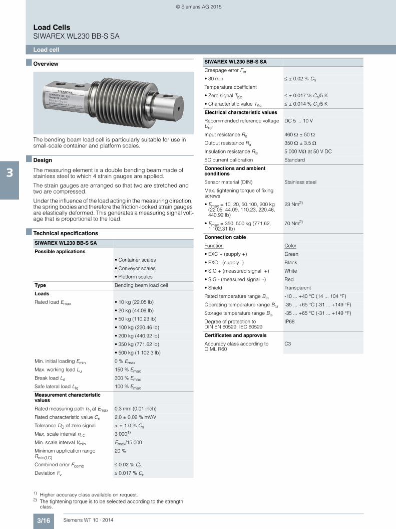
3/16 Siemens WT 10 · 2014
Load CellsSIWAREX WL230 BB-S SA
Load cell
3
■ Overview
The bending beam load cell is particularly suitable for use in small-scale container and platform scales.
■ Design
The measuring element is a double bending beam made of stainless steel to which 4 strain gauges are applied.
The strain gauges are arranged so that two are stretched and two are compressed.
Under the influence of the load acting in the measuring direction, the spring bodies and therefore the friction-locked strain gauges are elastically deformed. This generates a measuring signal volt-age that is proportional to the load.
■ Technical specifications 1) 2)
1) Higher accuracy class available on request.2) The tightening torque is to be selected according to the strength
class.
SIWAREX WL230 BB-S SA
Possible applications
• Container scales
• Conveyor scales
• Platform scales
Type Bending beam load cell
Loads
Rated load Emax • 10 kg (22.05 lb)
• 20 kg (44.09 lb)
• 50 kg (110.23 lb)
• 100 kg (220.46 lb)
• 200 kg (440.92 lb)
• 350 kg (771.62 lb)
• 500 kg (1 102.3 lb)
Min. initial loading Emin 0 % Emax
Max. working load Lu 150 % Emax
Break load Ld 300 % Emax
Safe lateral load LIq 100 % Emax
Measurement characteristic values
Rated measuring path hn at Emax 0.3 mm (0.01 inch)
Rated characteristic value Cn 2.0 ± 0.02 % mV/V
Tolerance DO of zero signal < ± 1.0 % Cn
Max. scale interval nLC 3 0001)
Min. scale interval Vmin Emax/15 000
Minimum application range Rmin(LC)
20 %
Combined error Fcomb ≤ 0.02 % Cn
Deviation Fv ≤ 0.017 % Cn
Creepage error Fcr
• 30 min ≤ ± 0.02 % Cn
Temperature coefficient
• Zero signal TKo ≤ ± 0.017 % Cn/5 K
• Characteristic value TKc ≤ ± 0.014 % Cn/5 K
Electrical characteristic values
Recommended reference voltage Uref
DC 5 ... 10 V
Input resistance Re 460 Ω ± 50 Ω
Output resistance Ra 350 Ω ± 3.5 Ω
Insulation resistance Ris 5 000 MΩ at 50 V DC
SC current calibration Standard
Connections and ambient conditions
Sensor material (DIN) Stainless steel
Max. tightening torque of fixing screws
• Emax = 10, 20, 50.100, 200 kg (22.05, 44.09, 110.23, 220.46, 440.92 lb)
23 Nm2)
• Emax = 350, 500 kg (771.62, 1 102.31 lb)
70 Nm2)
Connection cable
Function Color
• EXC + (supply +) Green
• EXC - (supply -) Black
• SIG + (measured signal +) White
• SIG - (measured signal -) Red
• Shield Transparent
Rated temperature range Btn -10 ... +40 °C (14 ... 104 °F)
Operating temperature range Btu -35 ... +65 °C (-31 ... +149 °F)
Storage temperature range Bts -35 ... +65 °C (-31 ... +149 °F)
Degree of protection to DIN EN 60529; IEC 60529
IP68
Certificates and approvals
Accuracy class according to OIML R60
C3
SIWAREX WL230 BB-S SA
© Siemens AG 2015

3/17Siemens WT 10 · 2014
Load CellsSIWAREX WL230 BB-S SA
Load cell
3
■ Selection and ordering data Article No. ■ Dimensional drawings
Load cell SIWAREX WL230 BB-S SA, dimensions in mm (inch)
Load cell type WL230 BB-S SA 7MH5106-
Legal-for-trade according to OIML R60 to 3 000d, connection cable 3 m (9.84 ft)
■ ■ D 0 ■
Click on the Article No. for the online configuration in the PIA Life Cycle Portal.
Rated load
• 10 kg (22.05 lb) 2 A
• 20 kg (44.09 lb) 2 G
• 50 kg (110.23 lb) 2 P
• 100 kg (220.46 lb) 3 A
• 200 kg (440.92 lb) 3 G
• 350 kg (771.62 lb) 3 L
• 500 kg (1 102.31 lb) 3 P
Explosion protection
Without 0
Explosion protection for zones 0, 1, 2, 20, 21, 22 1 Rated load [kg]10, 20, 50, 100, 200
350, 500
Ød 8.2 (0.32)
10.3 (0.41)
ØD 23 (0.91)
24 (0.95)
H20 (0.79)
19 (0.75)
HØ
D
ØdØd
10 (0.39)
82 (3.23)18 (0.71)
39 (1
.54)
20
(0.7
9)
120 (4.72)42 (1.65) 21
(0.83)
© Siemens AG 2015

3/18 Siemens WT 10 · 2014
Load CellsSIWAREX WL230 BB-S SA
Base plate with overload protection
3
■ Overview
The base plate with integral overload protection for load cells of the SIWAREX WL230 BB-S SA series ensures easy, correct in-stallation of the load cell.
■ Design
The integrated overload protection ensures that the load cell is not damaged by static overloading with vertical forces of up to 5 kN.
The load cells can be installed on the base plate and aligned even before final installation of the scales. This ensures that the permissible spring excursion of the load cell is precisely set, up to contact with the overload protection.
The load cell is not included in the scope of delivery of the base plate with overload protection.
■ Selection and ordering data 1) 2) Article No.
■ Dimensional drawings
Elastomer bearing and base plate with overload protection for load cells SIWAREX WL230 BB-S SA, 10 ... 200 kg (22.05 … 440.92 lb), dimensions in mm (inch)
1) The load cell is not included in the scope of delivery.2) It is highly recommendable to use a grounding cable
(7MH3701-1AA1) in order to protect the load cell.
Base plate with overload protectionFor load cells of series SIWAREX WL230 BB-S SA
Material: Stainless steel
For load cells with a rated load of1)2)
• 10 ... 200 kg (22.05 ... 440.92 lb) 7MH4133-3DG11
• 350 kg (771.62 lb), 500 kg (1 102.31 lb) 7MH4133-3KG11
Ø8.5 (0.33) (4x)
10(0.39)
80 (3
.15)
60 (2
.36)
100 (3.94)120 (4.72)
30 (1
.18)
(59)
(2.3
2)
10(0
.39)
© Siemens AG 2015

3/19Siemens WT 10 · 2014
Load CellsSIWAREX WL230 BB-S SA
Elastomer bearing
3
■ Overview
The self-centering elastomer bearing for load cells of the SIWAREX WL230 BB-S SA series is the ideal load introduction element for scales without guide elements. It serves to damp vibrations and shocks.
■ Design
Elastomer bearings are rubber-metal composites made of neo-prene and stainless steel. They ensure large spring excursions (i.e. a high degree of damping) despite small dimensions.
If the load support is displaced by more than 4 mm (0.16 in.) in the horizontal direction, measures for restricting sideways play (e.g. stops) must be provided in the construction of the load bearing implement.
In combination with the base plate and integral overload protec-tion, it is ensured that the load cell is not damaged by static over-loading with vertical forces of up to 5 kN.
The load cell and the base plate are not included in the scope of delivery of the elastomer bearing.
■ Selection and ordering data 1) 2) Article No.
■ Dimensional drawings
Elastomer bearings for load cells SIWAREX WL230 BB S SA, 10 kg … 200 kg (22.05 … 440.92 lb), dimensions in mm (inch)
1) The load cell is not included in the scope of delivery.2) It is highly recommendable to use a grounding cable
(7MH3701-1AA1) in order to protect the load cell.
Elastomer bearingFor load cells of series SIWAREX WL230 BB-S SA
Material: Stainless steel
For load cells with a rated load of1)2)
• 10 ... 50 kg (22.05 ... 110.23 lb) 7MH4133-2KE11
• 100 ... 200 kg (220.46 ... 440.92 lb) 7MH4133-3DE11
• 500 kg (1 102.31 lb) On request
Ø8.5 (3.35) (4x)
10 (0.39)
100
(3.9
4)
59 (2
.32)
30 (1
.18)
30 (1
.18)
80 (3
.15)
60 (2
.36)
10 (0
.39)
M10Ø50 (1.97)
100 (3.94)
120 (4.72)
10 (0
.39)
© Siemens AG 2015
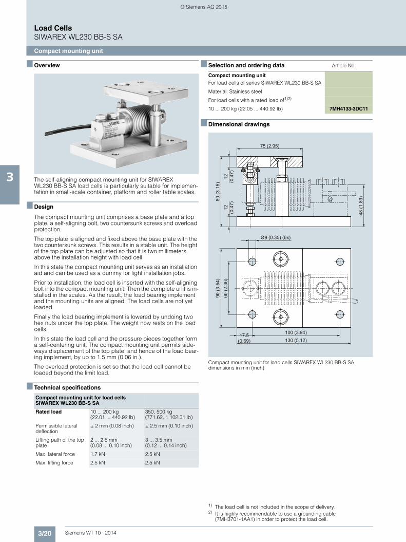
3/20 Siemens WT 10 · 2014
Load CellsSIWAREX WL230 BB-S SA
Compact mounting unit
3
■ Overview
The self-aligning compact mounting unit for SIWAREX WL230 BB-S SA load cells is particularly suitable for implemen-tation in small-scale container, platform and roller table scales.
■ Design
The compact mounting unit comprises a base plate and a top plate, a self-aligning bolt, two countersunk screws and overload protection.
The top plate is aligned and fixed above the base plate with the two countersunk screws. This results in a stable unit. The height of the top plate can be adjusted so that it is two millimeters above the installation height with load cell.
In this state the compact mounting unit serves as an installation aid and can be used as a dummy for light installation jobs.
Prior to installation, the load cell is inserted with the self-aligning bolt into the compact mounting unit. Then the complete unit is in-stalled in the scales. As the result, the load bearing implement and the mounting units are aligned. The load cells are not yet loaded.
Finally the load bearing implement is lowered by undoing two hex nuts under the top plate. The weight now rests on the load cells.
In this state the load cell and the pressure pieces together form a self-centering unit. The compact mounting unit permits side-ways displacement of the top plate, and hence of the load bear-ing implement, by up to 1.5 mm (0.06 in.).
The overload protection is set so that the load cell cannot be loaded beyond the limit load.
■ Technical specifications
■ Selection and ordering data 1) 2) Article No.
■ Dimensional drawings
Compact mounting unit for load cells SIWAREX WL230 BB-S SA, dimensions in mm (inch)
Compact mounting unit for load cells SIWAREX WL230 BB-S SA
Rated load 10 ... 200 kg (22.01 ... 440.92 lb)
350, 500 kg (771.62, 1 102.31 lb)
Permissible lateral deflection
± 2 mm (0.08 inch) ± 2.5 mm (0.10 inch)
Lifting path of the top plate
2 ... 2.5 mm (0.08 ... 0.10 inch)
3 ... 3.5 mm (0.12 ... 0.14 inch)
Max. lateral force 1.7 kN 2.5 kN
Max. lifting force 2.5 kN 2.5 kN
1) The load cell is not included in the scope of delivery.2) It is highly recommendable to use a grounding cable
(7MH3701-1AA1) in order to protect the load cell.
Compact mounting unitFor load cells of series SIWAREX WL230 BB-S SA
Material: Stainless steel
For load cells with a rated load of1)2)
10 ... 200 kg (22.05 ... 440.92 lb) 7MH4133-3DC11
17.5 (0.69)
90 (3
.54)
60 (2
.36)
Ø9 (0.35) (6x)
48 (1
.89)
75 (2.95)
80 (3
.15)
12
(0.4
7)
100 (3.94)130 (5.12)
12
(0.4
7)
© Siemens AG 2015

3/21Siemens WT 10 · 2014
Load CellsSIWAREX WL230 SB-S SA
Load cell
3
■ Overview
The shear beam load cell is particularly suitable for implementa-tion in container, overhead rail conveyor and platform scales.
■ Design
The measuring element is a shear tension spring made of stain-less steel to which strain gauges are applied. The strain gauges are arranged at 45° to the longitudinal axis on the side of the spring body and are therefore subject to shear forces. Under the influence of the load acting in the measuring direction, the spring bodies and therefore the friction-locked strain gauges are elastically deformed. This generates a measuring signal voltage that is proportional to the load.
■ Technical specifications 1) 2)
1) OIML type approval for SIWAREX WL230 SB-S SA 5 t available soon.2) The tightening torque is to be selected according to the strength
class.
SIWAREX WL230 SB-S SA
Possible applications • Container scales
• Conveyor scales
• Overhead rail scales
• Platform scales
Type Shear beam load cell
Loads
Rated load Emax • 0.5 t (0.49 tn. L.)
• 1 t (0.98 tn. L.)
• 2 t (1.97 tn. L.)
• 5 t (4.92 tn. L.)
Min. initial loading Emin 0 % Emax
Max. working load Lu 150 % Emax
Break load Ld 300 % Emax
Max. lateral load LIq 100 % Emax
Measurement characteristic values
Rated measuring path hn at Emax
• Emax = 0.5 t (0.49 tn. L.) 0.13 mm (0.005 inch)
• Emax = 1 t (0.98 tn. L.) 0.21 mm (0.008 inch)
• Emax = 2 t (1.97 tn. L.) 0.29 mm (0.011 inch)
• Emax = 5 t (4.92 tn. L.) 0.38 mm (0.014 inch)
Rated characteristic value Cn 2.0 ± 0.02 % mV/V
Tolerance DO of zero signal ≤ ± 1.0 % Cn
Max. scale interval nLC 3 000
Min. scale interval Vmin
• Emax = 0.5 t (0.49 tn. L.) Emax/10 000
• Emax = 1, 2, 5 t (0.98, 1.97, 4.92 tn. L.)1)
Emax/15 000
Minimum application range Rmin(LC)
• Emax = 0.5 t (0.49 tn. L.) 30 %
• Emax = 1, 2, 5 t (0.98, 1.97, 4.92 tn. L.)
20 %
Combined error Fcomb ± 0.02 % Cn
Deviation Fv ± 0.02 % Cn
Creepage error Fcr
• 30 min ≤ ± 0.02 % Cn
Temperature coefficient
• Zero signal TKo ≤ ± 0.023 % Cn/5 K
• Characteristic value TKc ≤ ± 0.017 % Cn/5 K
Electrical characteristic values
Recommended reference voltage Uref
DC 5 ... 12 V
Input resistance Re 1 000 Ω ± 10 Ω
Output resistance Ra 1 004 Ω ± 5 Ω
Insulation resistance Ris 5 000 MΩ at 50 V DC
Connections and ambient conditions
Sensor material (DIN) Stainless steel
Max. tightening torque of fixing screws
• Emax = 0.5, 1, 2 t 150 Nm2)
• Emax = 5 t 550 Nm2)
Rated temperature range Btn -10 ... +40 °C (14 ... 104 °F)
Operating temperature range Btu -35 ... +65 °C (-31 ... +149 °F)
Storage temperature range Bts -35 ... +65 °C (-31 ... +149 °F)
Degree of protection to DIN EN 60529; IEC 60529
IP68
Connection
Function Color
• EXC + (supply +) Green
• EXC - (supply -) Black
• SIG + (measured signal +) White
• SIG - (measured signal -) Red
• Shield Transparent
Certificates and approvals
Accuracy class according to OIML R60
C31)
SIWAREX WL230 SB-S SA
© Siemens AG 2015

3/22 Siemens WT 10 · 2014
Load CellsSIWAREX WL230 SB-S SA
Load cell
3
■ Selection and ordering data Article No. ■ Dimensional drawings
Load cell SIWAREX WL230 SB-S SA, dimensions in mm (inch)
Load cell type WL230 SB-S SA 7MH5107-
Legal-for-trade according to OIML R60 to 3 000d, connection cable 3 m (9.84 ft) at 500 kg (1 102.31 lb) to 1 t (0.98 tn. L.), connection cable 6 m (19.68 ft) at 2 t (1.97 tn. L.) to 5 t (4.92 tn. L.)
■ ■ D 0 ■
Click on the Article No. for the online configuration in the PIA Life Cycle Portal.
Rated load
• 500 kg (1 102.31 lb) 3 P
• 1 t (0.98 tn. L.) 4 A
• 2 t (1.97 tn. L.) 4 G
• 5 t (4.92 tn. L.) 4 P
Explosion protection
Without 0
Explosion protection for zones 0, 1, 2, 20, 21, 22 1
Rated load[t]
Rated load[t]
2.8
(0.1
1) Ø3.2 (0.13)
25.4(1.00)25.4(1.00)25.4(1.00)38.1(1.50)
13(0.51)13(0.51)13(0.51)20.5(0.81)
0.5
1
2
5
20.5(0.81)20.5(0.81)20.5(0.81)30.2(1.89)
0.5
1
2
5
E
B C D
K
ØG
A
JH
ML
ØF
A
130(5.12)130(5.12)130(5.12)172(6.77)
B
16(0.63)16(0.63)16(0.63)19(0.63)
C D
76(2.99)76(2.99)76(2.99)95(3.74)
ØFE
32(1.26)32(1.26)32(1.26)38(1.50)
ØG H
14(0.55)14(0.55)14(0.55)20(0.79)
J
26(1.02)28(1.10)32(1.26)40(1.57)
K
32(1.26)32(1.26)36(1.42)44(1.73)
M
M12
M12
M12
M20
L
57(2.24)57(2.24)57(2.24)76(2.99)
© Siemens AG 2015

3/23Siemens WT 10 · 2014
Load CellsSIWAREX WL230 SB-S SA
Compact mounting unit
3
■ Overview
The self-aligning compact mounting unit for SIWAREX WL230 SB-S SA load cells is particularly suitable for implemen-tation in container, platform and roller table scales
■ Design
The compact mounting unit comprises a base plate and a top plate, a self-aligning bolt and two countersunk screws.
The top plate is aligned and fixed above the base plate with the two countersunk screws. This results in a stable unit. The height of the top plate is adjusted so that it is three millimeters above the installation height with load cell.
In this state the compact mounting unit serves as an installation aid and can be used as a dummy for light installation jobs.
Prior to installation, the load cell is inserted with the self-aligning bolt into the compact mounting unit. Then the complete unit is in-stalled in the scales. As the result, the load bearing implement and the mounting units are aligned. The load cells are not yet loaded.
Finally the load bearing implement is lowered by undoing two hex nuts under the top plate. The weight now rests on the load cells.
In this state the load cell and the pressure pieces together form a self-centering unit. The compact mounting unit permits side-ways displacement of the top plate, and hence of the load bear-ing implement, by up to three millimeters.
■ Technical specifications
■ Selection and ordering data 1) 2) Article No.
■ Dimensional drawings
Compact mounting unit for load cells SIWAREX WL230 SB-S SA, dimensions in mm (inch)
Compact mounting unit for load cells of type SIWAREX WL230 SB-S SA
Rated load 0.5, 1, 2 t (0.49, 0.98, 1.97 tn. L)
5 t (4.92 tn. L)
Maximum lateral deflec-tion with load cell
± 3 mm (0.12 inch) ± 3 mm (0.12 inch)
Lifting path of top plate 3 mm (0.12 inch) 3 mm (0.12 inch)
Return force per mm lat-eral deflection of top plate, in percent of load applied to load cell
13 %/mm 10 %/mm
Permissible support load with anchored top plate
25 kN 35 kN
Permissible lifting force at top plate
25 kN 50 kN
Permissible lateral force at top plate when top plate is anchored
3 kN 5 kN
1) The load cell is not included in the scope of delivery.2) It is highly recommendable to use a grounding cable
(7MH3701-1AA1) in order to protect the load cell.
Compact mounting unit 7MH5707-
For load cells of series SIWAREX WL230 SB-S SA Material: Stainless steelFor load cells with a rated load of:1)2)
4 ■ A 0 0
Click on the Article No. for the online configuration in the PIA Life Cycle Portal.
• 500 kg (1 102.31 lb), 1 t (0.98 tn. L.) A
• 2 t (1.97 tn. L.) G
• 5 t (4.92 tn. L.) P
Rated load[t]
Rated load[t]
22.4(0.88)31.6(1.24)
11(4.33)13.5(0.53) G
_WT0
1_X
X_1
0092
B
F
H
MLK
JI
A
DE
C
ØG (6x)
A
80(3.15)105(4.13)
B C
15(0.59)20(0.79)
D
76(2.99)108(4.25)
F
60(2.36)80(3.15)
E
15(0.59)25(0.98)
ØG H
120(4.72)150(5.91)
I
80(3.14)100(3.94)
J
90(3.54)110(4.33)
s
3(0.12)3 (0.12)
M
140(5.51)185(7.28)
K
110(4.33)145(5.71)
L
15(0.59)20(0.79)
0,5 ... 2
5
0,5 ... 2
5
© Siemens AG 2015

3/24 Siemens WT 10 · 2014
Load CellsSIWAREX WL230 SB-S SA
Base plate and elastomer bearing
3
■ Overview
The base plate and the elastomer bearing form a self-centering bearing unit together with the load cells of the SIWAREX WL230 SB-S SA series. It suppresses oscillations and shocks to a certain extent.
■ Design
Elastomer bearings are rubber-metal composites made of neo-prene and stainless steel. Their special design means that lat-eral movement of the load bearing implement does not result in high transverse force on the load cell.
If the load bearing implement is displaced by more than 4 mm (0.16 inch) in the horizontal direction, measures for restricting sideways play (e.g. stops) must be provided in the construction of the load bearing implement.
The base plate of stainless steel is used for suitable fixing of the load cell on the base.
The load cell is not included in the scope of delivery of the base plate or elastomer bearing.
■ Selection and ordering data Article No.
■ Technical specifications
1) 2)
Base plate 7MH5707-
For load cells of series SIWAREX WL230 SB-S SA Material: Stainless steelFor load cells with a rated load of:1)2)
4 ■ ■ 0 0
Click on the Article No. for the online configuration in the PIA Life Cycle Portal.
• 500 kg (1 102.31 lb), 1 t (0.98 tn. L.) A B
• 2 t (1.97 tn. L.) G B
• 5 t (4.92 tn. L.) P B
Elastomer bearing
For load cells of series SIWAREX WL230 SB-S SA Material: neoprene, stainless steelFor load cells with a rated load of:1)2)
• 500 kg (1 102.31 lb), 1 t (0.98 tn. L.) A C
Base plate and the elastomer bearing for load cells of type SIWAREX WL230 SB-S SA
Rated load 500 kg (0.49 tn. L) 1 t (0.98 tn. L) 2 t (1.97 tn. L) 5 t (4.92 tn. L)
Maximum permitted lateral deflection
± 4 mm (0.16 in) ± 4 mm (0.16 in) ± 4 mm (0.16 in) ± 4 mm (0.16 in)
Vertical stiffness 5.9 kN/mm 5.9 kN/mm 29.98 kN/mm 29,98 kN/mm
Horizontal stiffness 0.16 kN/mm 0.16 kN/mm 0.54 kN/mm 0.54 kN/mm
Deflection at rated load 0.68 mm (0.037 in) 1.28 mm (0.050 in) 0.62 mm (0.024 in) 1.46 mm (0.057 in)
1) The load cell is not included in the scope of delivery.2) It is highly recommendable to use a grounding cable
(7MH3701-1AA1) in order to protect the load cell.
© Siemens AG 2015

3/25Siemens WT 10 · 2014
Load CellsSIWAREX WL230 SB-S SA
Base plate and elastomer bearing
3
■ Dimensional drawings
Base plate and Elastomer bearings for load cells SIWAREX WL230 SB-S SA, dimensions in mm (inch)
Rated load [t]
Rated load [t]
11 (0.43)
11 (0.43)
13.5 (0.53)
117.4 (4.62)
117.4 (4.62)
153.1 (6.03)
K
LH
G
M
D
F
E
6 (0
.24)
50 (1
.97)
ØC
ØJØ11 (0.43)
NA B
75 (2.95)
90 (3.54)
90 (3.54)
100 (3.94)
120 (4.72)
120 (4.72)
0,5, 1
2
5
A øC
85 (3.35)
100 (3.94)
100 (3.94)
D F
140 (5.51)
140 (5.51)
185 (7.28)
E
120 (4.72)
120 (4.72)
150 (5.91)
15 (0.59)
15 (0.59)
20 (0.79)
G
110 (4.33)
110 (4.33)
145 (5.71)
B
90 (3.54)
90 (3.54)
110 (4.33)
0,5, 1
2
5
H øJ
15 (0.59)
15 (0.59)
25 (0.98)
K M
47 (1.85)
51 (2.01)
69 (2.72)
L
108 (4.25)
112 (4.41)
134 (5.28)
N
G_W
T01_
XX
_101
33
© Siemens AG 2015

3/26 Siemens WT 10 · 2014
Load CellsSIWAREX WL270 CP-S SA
Load cell
3
■ Overview
The compression load cell is particularly suitable for implemen-tation in container, hopper and vehicle scales.
■ Design
The measuring element is a solid cylinder made of stainless steel to which 4 strain gauges are applied.
The load which acts centrally in the measuring direction causes the spring bodies and therefore the friction-locked strain gauges to be elastically deformed. This generates a measuring signal voltage that is proportional to the load.
■ Technical specifications1) 2)
■ Selection and ordering data Article No.
1) SIWAREX WL270 CP-S SA 2 t and 5 t are not released for „legal-for-trade“ applications.
2) SIWAREX WL270 CP-S SA 2 t and 5 t are not available in explosion-protected versions.
SIWAREX WL270 CP-S SA
Possible applications • Container scales
• Overhead rail scales
• Vehicle scales
Type Compression load cell
Loads
Rated load Emax • 2 t (1.97 tn. L.)
• 5 t (4.42 tn. L.)
• 10 t (9.84 tn. L.)
• 20 t (19.68 tn. L.)
• 30 t (29.53 tn. L.)
• 50 t (49.21 tn. L.)
Min. initial loading Emin 0 % Emax
Max. working load Lu 150 % Emax
Break load Ld 300 % Emax
Max. lateral load LIq 75 % Emax
Measurement characteristic values
Rated measuring path hn at Emax 0.5 mm (0.02 inch)
Rated characteristic value Cn 2.0 ± 0.02 % mV/V
Tolerance DO of zero signal ≤ ± 1.0 % Cn
Max. scale interval nLC 3 000
Min. scale interval Vmin
Emax = 2, 5, 10, 20, 50 t (1.97, 4.92, 9.84, 19.68, 49.21 tn. L.)
Emax/10 000
Minimum application range Rmin(LC)
30 %
Combined error Fcomb ± 0.02 % Cn
Creepage error Fcr
• 30 min ≤ ± 0.023 % Cn
Temperature coefficient
• Zero signal TKo ≤ ± 0.023 % Cn/5 K
• Characteristic value TKc ≤ ± 0.017 % Cn/5 K
Electrical characteristic values
Recommended reference voltage Uref
DC 5 ... 12 V
Input resistance Re 700 Ω ± 7 Ω
Output resistance Ra 700 Ω ± 7 Ω
Insulation resistance Ris 5 000 MΩ at 50 V DC
Connection and ambient conditions
Rated temperature range Btn -10 ... +40 °C (14 ... 104 °F)
Operating temperature range Btu -35 ... +65 °C (-31 ... +149 °F)
Storage temperature range Bts -35 ... +65 °C (-31 ... +149 °F)
Degree of protection to DIN EN 60529; IEC 60529
IP68
Sensor material (DIN) Stainless steel
Connection
Function Color
• EXC + (supply +) Red
• EXC - (supply -) Black
• SIG + (measured signal +) Green
• SIG - (measured signal -) White
• Shield Transparent
Certificates and approvals
Accuracy class according to OIML R60
C31)
Load cell type WL270 CP-S SA 7MH5108-
Legal-for-trade according to OIML R60 to 3 000d, connection cable 15 m (49.21 ft)
■ ■ D 0 ■
Click on the Article No. for the online configuration in the PIA Life Cycle Portal.
Rated load
• 2 t (1.97 tn. L.)1) 4 G
• 5 t (4.92 tn. L.)1) 4 P
• 10 t (9.84 tn. L.) 5 A
• 20 t (19.68 tn. L.) 5 G
• 30 t (29.63 tn. L.) 5 K
• 50 t (49.21 tn. L.) 5 P
Explosion protection
Without 0
Explosion protection for zones 0, 1, 2, 20, 21, 222) 1
SIWAREX WL270 CP-S SA
© Siemens AG 2015

3/27Siemens WT 10 · 2014
Load CellsSIWAREX WL270 CP-S SA
Load cell
3
■ Dimensional drawings
Load cell SIWAREX WL270 CP-S SA, dimensions in mm (inch)
Rated load[t]
H
ØD
Ø89 (3.50)ØE 16
(0
.63)
119
(4.6
9)33
(1
.30)
Ø50
(1.9
7)35
(1.3
8)
49 (1.93)
R5 (0.20)
70 (2.76)
SR
F
SR
G
ØD
40(1.57)50(1.97)
ØE
40(1.57)50(1.97)
F
38(1.50)200(7.87)
G
150(5.91)200(7.87)
H
22(8.67)27(1.06)
2, 5, 10, 20, 30
50
© Siemens AG 2015

3/28 Siemens WT 10 · 2014
Load CellsSIWAREX WL270 CP-S SA
Pressure piece set and adapter plates
3
■ Overview
In combination with a pressure piece set and adapter plate the SIWAREX WL270 CP-S SA produces a self-centering self-align-ing bearing. This unit is particularly suitable for installation in container, hopper and vehicle scales.
■ Design
The pressure piece set consists of an upper and lower pressure piece. Together with the load cell the pressure piece set forms a self-centering unit with integrated torsion guard. Two adapter plates serve to hold the pressure pieces and round off the unit into a self-aligning bearing. The adapter plates can be bolted by means of the existing holes directly to the load bearing imple-ment.
The self-centering, self-aligning bearing thus formed allows the load bearing implement to follow horizontal displacements (e.g. due to temperature fluctuations). In this case the construction of the self-aligning bearing creates a restoring force which is de-pendent on the size of the displacement and the applied load.
If the load bearing implement is displaced by more than 3 mm in the lateral direction, measures for restricting sideways play must be provided in the construction of the load bearing implement (e.g. stops or guide elements). Lifting of the load support must be prevented by suitable measures provided in the construction of the load bearing implement.
The load cell must be ordered separately.
The adapter plate package item consists of one unit.
■ Technical specifications
■ Selection and ordering data 1) 2) 3) Article No.
■ Dimensional drawings
Pressure piece set and adapter plates for load cells SIWAREX WL270 CP-S SA (mounting condition), dimensions in mm (inch), valid for all load classes
Pressure piece set and adapter plate
Rated load 2, 5, 10, 20, 30 t (1.97, 4.42, 9.84, 19.68, 29.53 tn. L)
50 t (49.21 tn. L)
Maximum lateral deflection with load cell
± 3 mm (0.12 inch) ± 3 mm (0.12 inch)
Return force per mm lateral deflection of top plate, in percent of load applied to load cell
0.5 %/mm 2 %/mm
1) The principles of general mechanical engineering and safety must be observed.
2) It is highly recommendable to use a grounding cable (7MH3701-1AA1) in order to protect the load cell.
3) The load cell is not included in the scope of delivery.
Pressure piece set1) 7MH5708-
For individual installation of load cells of series SIWAREX WL270 CP-S SAMaterial: Stainless steelFor load cells with a rated load of:2)3)
5 ■ D 0 0
Click on the Article No. for the online configuration in the PIA Life Cycle Portal.
• 2, 5, 10, 20, 30 t (1.97, 4.42, 9.84, 19.68, 29.53 tn. L.) K
• 50 t (49.21 tn. L.) P
Adapter plate 7MH5708-
Adapter for SIWAREX WL270 CP-S SA The package includes one plate.Material: Stainless steelFor load cells with a rated load of:2)3)
5 ■ B 0 0
2 … 50 t (1.97 … 49.21 tn. L.) P
Ø22
(0.8
7)
120
(4.7
2)20
3 ±
1 (7
.99
± 0.
04)
160 (6.30)
© Siemens AG 2015

3/29Siemens WT 10 · 2014
Load CellsSIWAREX WL270 CP-S SA
Compact mounting unit
3
■ Overview
The self-aligning compact mounting unit for SIWAREX WL270 CP-S SA load cells is particularly suitable for implemen-tation in container, platform, vehicle and roller table scales.
■ Design
The compact mounting unit comprises a base plate and a top plate, two pressure pieces, two clamping pieces and two coun-tersunk screws. There are threaded holes in the base plate and top plate for the subsequent flange-fitting of guide elements.
The top plate is aligned and fixed above the base plate with the two countersunk screws. This results in a stable unit. The height of the top plate is adjusted so that it is three millimeters above the installation height with load cell.
Two pressure pieces are used to mount the load cell. They are fastened flush with the head plate and base plate using the clamping pieces.
In this state the compact mounting unit serves as an installation aid and can be used as a dummy for light installation jobs.
Prior to installation, the load cell is inserted into the compact mounting unit. Then the complete unit is installed in the scales. As the result, the load bearing implement and the mounting units are aligned. The load cells are not yet loaded.
Finally the load bearing implement is lowered by undoing two hex nuts under the top plate. The weight now rests on the load cells.
In this state the load cell and the pressure pieces together form a self-centering unit. The compact mounting unit permits side-ways displacement of the top plate, and hence of the load bear-ing implement, by up to three millimeters in all directions. The countersunk screws prevent the load bearing implement from being lifted off or toppling off.
Using the compact mounting unit as an installation aid results in optimum alignment of the load cells. This is essential for the load cells to perform at their best in terms of accuracy.
For maintenance or troubleshooting purposes the load cell can be relieved again by screwing up the hex nuts. Replacement of the load cell is then easy after the clamping pieces are released.
■ Technical specifications
■ Selection and ordering data 1) 2) Article No.
Compact mounting unit for load cells SIWAREX WL270 CP-S SA
Rated load 2, 5, 10, 20, 30 t (1.97, 4.42, 9.84, 19.68, 29.53 tn. L.)
50 t (49.21 tn. L)
Maximum lateral deflection with load cell ± 3 mm (0.12 inch) ± 3 mm (0.12 inch)
Lifting path of top plate 3 mm (0.12 inch) 3 mm (0.12 inch)
Return force per mm lateral deflection of top plate, in percent of load applied to load cell
0.5 %/mm 2 %/mm
Permissible support load with anchored top plate
70 kN 70 kN
Permissible lifting force at top plate 70 kN 70 kN
Permissible lateral force at top plate when top plate is anchored
30 kN 30 kN
1) The load cell is not included in the scope of delivery.2) It is highly recommendable to use a grounding cable
(7MH3701-1AA1) in order to protect the load cell.
Compact mounting unit 7MH5708-
For load cells of series SIWAREX WL270 CP-S SAMaterial: Stainless steelFor load cells with a rated load of:1)2)
5 ■ A 0 0
Click on the Article No. for the online configuration in the PIA Life Cycle Portal.
• 2, 5, 10, 20, 30 t (1.97, 4.42, 9.84, 19.68, 29.53 tn. L.) K
• 50 t (49.21 tn. L.) P
© Siemens AG 2015

3/30 Siemens WT 10 · 2014
Load CellsSIWAREX WL270 CP-S SA
Compact mounting unit
3
■ Dimensional drawings
Compact mounting unit for load cells SIWAREX WL270 CP-S SA, dimensions in mm (inch)
165.
5 ±1
(6.5
2 ±0
.04)
20 (0
.79)
20 (0
.79)
240 (9.45)
160 (6.30)
27 ±
1
(1.0
6 ±
0.04
)
100
(3.9
4)
Ø22(0.87)
145
(5.7
1)
130 (5.12)
© Siemens AG 2015

3/31Siemens WT 10 · 2014
Load CellsSIWAREX WL270 CP-S SB
Load cell
3
■ Overview
The compression load cell is particularly suitable for implemen-tation in container, hopper and vehicle scales.
■ Design
The measuring element is a solid cylinder made of stainless steel to which 4 strain gauges are applied.
The load which acts centrally in the measuring direction causes the spring bodies and therefore the friction-locked strain gauges to be elastically deformed. This generates a measuring signal voltage that is proportional to the load.
■ Technical specifications
■ Selection and ordering data Article No.SIWAREX WL270 CP-S SB
Possible applications Container scales
Type Compression load cell
Loads
Rated load Emax 100 t (98.42 tn. L.)
Min. initial loading Emin 0 % Emax
Max. working load Lu 150 % Emax
Break load Ld 300 % Emax
Max. lateral load LIq 10 % Emax
Measurement characteristic values
Rated measuring path hn at Emax 0.36 mm (0.01 inch)
Rated characteristic value Cn 2.0 ± 0.02 % mV/V
Tolerance DO of zero signal ≤ ± 1.0 % Cn
Max. scale interval nLC 3 000
Min. scale interval Vmin
Emax = 100 t (98.42 tn. L.) Emax/9 000
Minimum application range Rmin(LC)
33 %
Combined error Fcomb ± 0.02 % Cn
Deviation Fv ± 0.02 % Cn
Creepage error Fcr
• 30 min ≤ ± 0.023 % Cn
Temperature coefficient
• Zero signal TKo ≤ ± 0.023 % Cn/5 K
• Characteristic value TKc ≤ ± 0.017 % Cn/5 K
Electrical characteristic values
Recommended reference voltage Uref
DC 5 ... 12 V
Input resistance Re 700 Ω ± 7 Ω
Output resistance Ra 700 Ω ± 7 Ω
Insulation resistance Ris 5 000 MΩ at 50 V DC
Connections and ambient conditions
Sensor material (DIN) Stainless steel
Rated temperature range Btn -10 ... +40 °C (14 ... 104 °F)
Operating temperature range Btu -35 ... +65 °C (-31 ... +149 °F)
Storage temperature range Bts -35 ... +65 °C (-31 ... +149 °F)
Degree of protection to DIN EN 60529; IEC 60529
IP68
Connection cable
Function Color
• EXC + (supply +) Green
• EXC - (supply -) Black
• SIG + (measured signal +) White
• SIG - (measured signal -) Red
• Sense + (sensor line +) Yellow
• Sense – (sensor line -) Blue
• Shield Transparent
Certificates and approvals
Accuracy class according to OIML R60
C3
Load cell type WL270 CP-S SB 7MH5110-
Legal-for-trade according to OIML R60 to 3 000d, connection cable 20 m (65.62 ft)
■ ■ D 0 ■
Click on the Article No. for the online configuration in the PIA Life Cycle Portal.
Rated load
100 t (98.42 tn. L.) 6 A
Explosion protection
• Without 0
• Explosion protection for zones 0, 1, 2, 20, 21, 22 1
SIWAREX WL270 CP-S SB
© Siemens AG 2015

3/32 Siemens WT 10 · 2014
Load CellsSIWAREX WL270 CP-S SB
Load cell
3
■ Dimensional drawings
Load cell SIWAREX WL 270 CP-S SB, dimensions in mm (inch)
260
(10.
24)
31
(1.2
2)
SR
400
(15.
75)
76 (2.99)
32 (1.26)
R6 (0.24)
Ø50
(1
.97)
Ø68 (2.68)Ø64 (2.52)
Ø93 (3.66)
Ø68 (2.68)
Ø64 (2.52)
SR
400
(15.
75)
12
(0.4
7)
4 (0
.16)
66 (2
.60)
120
(4.7
2)
128
(5.0
4)
© Siemens AG 2015
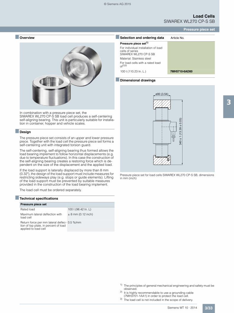
3/33Siemens WT 10 · 2014
Load CellsSIWAREX WL270 CP-S SB
Pressure piece set
3
■ Overview
In combination with a pressure piece set, the SIWAREX WL270 CP-S SB load cell produces a self-centering self-aligning bearing. This unit is particularly suitable for installa-tion in container, hopper and vehicle scales.
■ Design
The pressure piece set consists of an upper and lower pressure piece. Together with the load cell the pressure piece set forms a self-centering unit with integrated torsion guard.
The self-centering, self-aligning bearing thus formed allows the load bearing implement to follow horizontal displacements (e.g. due to temperature fluctuations). In this case the construction of the self-aligning bearing creates a restoring force which is de-pendent on the size of the displacement and the applied load.
If the load support is laterally displaced by more than 8 mm (0.32"), the design of the load support must include measures for restricting sideways play (e.g. stops or guide elements). Lifting of the load support must be prevented by suitable measures provided in the construction of the load bearing implement.
The load cell must be ordered separately.
■ Technical specifications
■ Selection and ordering data 1) 2)Article No. 3)
■ Dimensional drawings
Pressure piece set for load cells SIWAREX WL270 CP-S SB, dimensions in mm (inch)
Pressure piece set
Rated load 100 t (98.42 tn. L)
Maximum lateral deflection with load cell
± 8 mm (0.12 inch)
Return force per mm lateral deflec-tion of top plate, in percent of load applied to load cell
0.5 %/mm
1) The principles of general mechanical engineering and safety must be observed.
2) It is highly recommendable to use a grounding cable (7MH3701-1AA1) in order to protect the load cell.
3) The load cell is not included in the scope of delivery.
Pressure piece set1)
For individual installation of load cells of series SIWAREX WL270 CP-S SBMaterial: Stainless steelFor load cells with a rated load of2)3)
100 t (110.23 tn. L.) 7MH5710-6AD00
ø90 (3.54)
340
± 1
(13.
39 ±
0.0
3)
© Siemens AG 2015

3/34 Siemens WT 10 · 2014
Load CellsSIWAREX WL270 CP-S SB
Compact mounting unit
3
■ Overview
The self-centering compact mounting unit for SIWAREX WL270 CP-S SA load cells is particularly suitable for implementation in container scales.
■ Design
The top plate is aligned and fixed above the base plate with the two centering sleeves. This results in a stable unit. The height of the top plate is adjusted so that it is five millimeters above the in-stallation height with load cell.
Two pressure pieces are used to mount the load cell. They are fastened flush with the head plate and base plate using the clamping pieces.
In this state the compact mounting unit serves as an installation aid and can be used as a dummy for light installation jobs.
Prior to installation, the load cell is inserted into the compact mounting unit. Then the complete unit is installed in the scales. As the result, the load bearing implement and the mounting units are aligned. The load cells are not yet loaded.
Finally the load bearing implement is lowered by undoing two hex nuts under the centering sleeves. The weight now rests on the load cells.
In this state the load cell and the pressure pieces together form a self-centering unit. The compact mounting unit permits side-ways displacement of the top plate, and hence of the load bear-ing implement, by up to eight millimeters in all directions. Two countersunk screws prevent the load bearing implement from being lifted off or toppling off.
Using the compact mounting unit as an installation aid results in optimum alignment of the load cells. This is essential for the load cells to perform at their best in terms of accuracy.
For maintenance or troubleshooting purposes the load cell can be relieved again by screwing up the hex nuts. Replacement of the load cell is then easy after the clamping pieces are released.
■ Technical specifications
■ Selection and ordering data 1) 2)Article No.
■ Dimensional drawings
Compact mounting unit for load cells SIWAREX WL270 CP-S SB (mounting condition), dimensions in mm (inch)
Compact mounting unit for load cells SIWAREX WL270 CP-S SB
Rated load 100 t (98.42 tn. L)
Maximum lateral deflection with load cell
± 8 mm (0.12 inch)
Lifting path of top plate 3 ... 5 mm (0.12 ... 0.20 inch)
Return force per mm lateral deflec-tion of top plate, in percent of load applied to load cell
0.5 %/mm
Permissible support load with anchored top plate
140 kN
Permissible lifting force at top plate 140 kN
Permissible lateral force at top plate when top plate is anchored
50 kN
1) The load cell is not included in the scope of delivery.2) It is highly recommendable to use a grounding cable
(7MH3701-1AA1) in order to protect the load cell.
Compact mounting unitFor load cells of series SIWAREX WL270 CP-S SBMaterial: Stainless steelFor load cells with a rated load of:1)2)
100 t (98.42 tn. L.) 7MH5710-6AA00
Compact mounting unit for load cells SIWAREX WL270 CP-S SB
27.5
±1
(1.0
8 ±0
.04)
37.5
±1
(1.4
8 ±0
.04)
Ø22 (0.87)
30 (1
.18)
345
± 1
(13.
58 ±
0.0
4)
30 (1
.18)
380 (14.96)340 (13.39)
160 (6.30)
145
(6.3
0)
100
(6.3
0)
© Siemens AG 2015

3/35Siemens WT 10 · 2014
Load CellsSIWAREX WL270 K-S CA
Load cell
3
■ Overview
The compression force load cell is particularly suitable for use in container and bin weighing equipment.
■ Design
The measuring element is a cylinder made of stainless steel to which 4 strain gauges are applied.
The load which acts centrally in the measuring direction elasti-cally deforms the spring body and thus the force-fitted strain gauges. This generates a measuring signal voltage that is pro-portional to the load. The load cell's rated measuring path de-pends on the rated load and is between 0.23 and 3.11 mm (0.01 and 0.12 inch).
An enclosure made from painted steel protects the strain gauge from environmental influences. The load cell is fitted with a heat-resistant cable as standard.
Heavy load versions
Heavy load versions with a rated load of 350 and 500 t (344.47 and 492.10 tn. L.) are available for extreme require-ments.
Option: High temperature range
A high-temperature range option is available for all SIWAREX WL270 K load cells. Specially developed strain gauges are deployed here. They can be used in temperatures ranging from -30 °C to 250 °C (-22 °F to 482 °F) without being damaged. Accuracy is only minimally affected.
Cables and accessory parts are also specially adapted to suit this extended temperature range.
Option: Two measuring circuits for your plant safety
In especially sensitive applications such as cranes, enhanced safety is required. This is also true of measurement plants. Using double bridges in load cells achieves the equivalent of a redun-dant configuration. Both measuring bridges supply consistent measured values. If one bridge fails, the other takes over.
These options can be ordered for load classes from 13 t (12.79 tn. L.). Double bridge and high temperature options can also be ordered together.
■ Technical specificationsSIWAREX WL270 K-S CA
Possible applications • Container scales
• Bin weighing equipment
Type Compression load cell
Loads
Rated load Emax • 2.8 t (2.76 tn. L.)
• 6 t (5.91 tn. L.)
• 13 t (12.79 tn. L.)
• 28 t (27.56 tn. L.)
• 60 t (59.05 tn. L.)
• 130 t (127.95 tn. L.)
• 280 t (275.58 tn. L.)
• 350 t (344.47 tn. L.)
• 500 t (492.10 tn. L.)
Min. initial loading Emin 0 % Emax
Max. working load Lu 120 % Emax
Break load Ld 300 % Emax
Max. lateral load LIq 10 % Emax
Measurement characteristic values
Rated measuring path hn at Emax
• 2.8 t (2.76 tn. L.) 0.23 mm (0.009 inch)
• 6 t (5.91 tn. L.) 0.38 mm (0.015 inch)
• 13 t (12.79 tn. L.) 0.54 mm (0.02 inch)
• 28 t (27.56 tn. L.) 0.82 mm (0.03 inch)
• 60 t (59.05 tn. L.) 1.19 mm (0.05 inch)
• 130 t (127.95 tn. L.) 1.81 mm (0.07 inch)
• 280 t (275.58 tn. L.) 2.66 mm (0.10 inch)
• 350 t (344.47 tn. L.) 2.73 mm (0.11 inch)
• 500 t (492.10 tn. L.) 3.11 mm (0.12 inch)
Rated characteristic value Cn 1.5 mV/V
Tolerance DO of zero signal ≤ ± 1.5 % Cn
Tolerance Dc of characteristic value ± 0.5 %
Combined error Fcomb ≤ ± 0.1 %
Deviation Fv ≤ ± 0.1 %
Creepage error FCR
• 30 min ≤ ± 0.06 %
Temperature coefficient
• Zero signal TKo ≤ ± 0.25 % Cn/5 K
• Characteristic value TKc ≤ ± 0.25 % Cn/5 K
Electrical characteristic values
Recommended reference voltage Uref
DC 6 ... 12 V
Supply voltage Usr (reference value)
6 V
Input resistance Re
SIWAREX WL270 K-S CA
© Siemens AG 2015

3/36 Siemens WT 10 · 2014
Load CellsSIWAREX WL270 K-S CA
Load cell
3
High temperature versions
Some technical data of the high temperature versions change over the temperature range. For this reason the values are given for three partial temperature ranges.
• 2.8, 6, 13, 28, 60, 130, 280 t (2.76, 5.91, 12.79, 27.56, 59.05, 127.95, 275.58 tn. L.)
275 Ω ± 50 Ω
• 350, 500 t (344.47, 492.10 tn. L.) 450 Ω ± 4.5 Ω
Output resistance Ra
• 2.8, 6, 13, 28, 60, 130, 280 t (2.76, 5.91, 12.79, 27.56, 59.05, 127.95, 275.58 tn. L.)
245 Ω ± 0.2 Ω
• 350, 500 t (344.47, 492.10 tn. L.) 480 Ω ± 4.8 Ω
Insulation resistance Ris ≥ 5000 MΩ
Connections and ambient condi-tions
Sensor material (DIN) Steel, painted
Rated temperature range Btn -10 ... +60 °C (+14 ... +140 °F)
Operating temperature range Btu -20 ... +70 °C (-4 ... +158 °F)
Storage temperature range Bts -30 ... +80 °C (-22 ... +176 °F)
Degree of protection to DIN EN 60529; IEC 60529
IP66
Accuracy class 0.1 %
SIWAREX WL270 K-S CA
Connection cable
Function Color
• EXC + (supply +) Red
• EXC - (supply -) White
• SIG + (measured signal +) Black
• SIG - (measured signal -) Blue
• Shield Transparent
SIWAREX WL270 K-S CA
SIWAREX WL270 K-S CA, high temperature versions
-30 ... +150 °C (-22 ... +238 °F)
150 ... 180 °C (238 ... 356 °F)
180 ... 250 °C (356 ... 482 °F)
Rated characteristic value Cn 1.5 ± 0.02 mV/V 1.5 ± 0.1 mV/V 1.5 ± 0.1 mV/V
Tolerance DO of zero signal ≤ ± 1.0 % Cn ≤ ± 1.5 % Cn ≤ ± 3 % Cn
Measurement characteristic values
Combined error Fcomb ≤ ± 0.3 % ≤ ± 0.5 % ≤ ± 5 %
Deviation Fv ≤ ± 0.3 % ≤ ± 0.5 % ≤ ± 5 %
Creepage error FCR
30 min ≤ ± 0.3 % ≤ ± 0.4 % ≤ ± 4 %
Temperature coefficient
• Zero signal TKo ≤ ± 0.25 % Cn/5 K ≤ ± 0.25 % Cn/5 K ≤ ± 0.5 % Cn/5 K
• Characteristic value TKc ≤ ± 0.25 % Cn/5 K ≤ ± 0.5 % Cn/5 K ≤ ± 0.5 % Cn/5 K
Electrical characteristic values
Input resistance Re
• 2.8, 6, 13, 28, 60, 130, 280 t (2.76, 5.91, 12.79, 27.56, 59.05, 127.95, 275.58 tn. L.)
275 Ω ± 7 Ω 275 Ω ± 15 Ω 275 Ω ± 15 Ω
• 350, 500 t (344.47, 492.10 tn. L.) 450 Ω ± 4.5 Ω 450 Ω ± 10 Ω 450 Ω ± 10 Ω
Output resistance Ra
• 2.8, 6, 13, 28, 60, 130, 280 t (2.76, 5.91, 12.79, 27.56, 59.05, 127.95, 275.58 tn. L.)
245 Ω ± 0.5 Ω 245 Ω ± 1 Ω 245 Ω ± 1 Ω
• 350, 500 t (344.47, 492.10 tn. L.) 480 Ω ± 4.8 Ω 480 Ω ± 10 Ω 480 Ω ± 10 Ω
Insulation resistance Ris ≥ 5000 MΩ
Connections and ambient conditions
Rated temperature range Btn -30 ... +180 °C (-22 ... +356 °F)
Operating temperature range Btu -30 ... +250 °C (-22 ... +482 °F)
Storage temperature range Bts -30 ... +250 °C (-22 ... +482 °F)
© Siemens AG 2015

3/37Siemens WT 10 · 2014
Load CellsSIWAREX WL270 K-S CA
Load cell
3
■ Selection and ordering data 1) 2) Article No. Article No.
■ Dimensional drawings
Load cell SIWAREX WL270 K-S CA, dimensions in mm (inch)
1) Heat-resistant cable: -60 ... +180 °C (-76 ... +356 °F). The cable for high temperature versions is heat resistant up to 250 °C (238 °F).2) Can be ordered from 13 t (12.79 tn. L.).
Load cell type SIWAREX WL270 K-S CA 7MH5114-
Accuracy class 0.1 %, without explosion protection.Heat resistant connecting cable1)
■ ■ L 0 0
Click on the Article No. for the online configuration in the PIA Life Cycle Portal.
Rated load Cable length
• 2.8 t (2.76 tn. L.) 6 m (19.68 ft) 4 J
• 6 t (5.91 tn. L.) 6 m (19.68 ft) 4 Q
• 13 t (12.79 tn. L.) 15 m (49.21 ft) 5 D
• 28 t (27.56 tn. L.) 15 m (49.21 ft) 5 J
• 60 t (59.05 tn. L.) 15 m (49.21 ft) 5 Q
• 130 t (127.95 tn. L.) 20 m (65.62 ft) 6 D
• 280 t (275.58 tn. L.) 20 m (65.62 ft) 6 J
• 350 t (244.47 tn. L.) 20 m (65.62 ft) 6 L
• 500 t (292.10 tn. L.) 20 m (65.62 ft) 6 P
Load cell type SIWAREX WL270 K-S CA 7MH5114-
Accuracy class 0.1 %, without explosion protection.Heat resistant connecting cable1)
■ ■ L ■ 0
Options
Double bridge2)
Load cell, redundant design, without explosion protection6
High temperatureTemperature range -30 °C … +250 °C (-22 °F … +482 °F), accuracy varies over temperature range, cables and components designed for temperature range, without explosion protection
7
Double bridge and high temperature2)
Redundant design load cell, temperature range -30 °C … +250 °C (-22 °F … +482 °F), accuracy varies over temperature range, cables and components designed for temperature range, without explosion protection
8
Rated load [t (tn. L.)]
40.5(1.59)45.5(1.79)48(1.89)63(2.48)78.5(3.09)100.5(3.96)127(5.00)1445.67)
16.7(0.65)24.5(0.96)36(1.41)52.7(2.07)77,5(3.05)114(4.48)132(5.20)155(6.10)
k
F
aa
HL
ØD
Ød
2xR
8(0.31)12(0.47)14(0.55)20(0.78)26(1.02)45(1.77)40(1.58)47(1.85)
2,8, 6 (2.76, 5.91)13 (12.79)28 (27.56)60 (59.05)130 (127.95)280 (275.58)350 (344.47)500 (492.10)
a ød øD
45(1.77)55(2.16)64(2.51)90(3.54)121(4.76)165(6.5)202(7.95)236(9.29)
H
40(1.57)44(1.73)46(1.81)50(1.96)64(2.51)80(3.14)160(6.30)181(7.13)
F
20(0.59)20(0.59)20(0.59)20(0.59)20(0.59)20(0.59)50(1.97)50(1.97)
L
56(2.2)68(2.67)74(2.91)90(3.54)116(4.56)170(6.7)240(9.45)275(10.83)
R
50(1.96)66(2.6)72(2.83)100(3.93)125(4.92)183(7.2)325(12.80)450(17.72)
k
© Siemens AG 2015

3/38 Siemens WT 10 · 2014
Load CellsSIWAREX WL270 K-S CA
Load cell
3
Load cell SIWAREX WL270 K-S CA with double bridge, dimensions in mm (inch)
24.5(0.96)36(1.41)52.7(2.07)77.5(3.05)114(4.48)132(5.20)155(6.10)
Rated load [t (tn.L.)]
12(0.47)14(0.55)20(0.78)26(1.02)45(1.77)40(1.58)47(1.85)
13 (12.79)
28 (27.56)
60 (59.05)
130 (127.95)
280 (275.58)
350 (344.47)
500( 492.10)
a ød øD
55(2.16)64(2.51)90(3.54)121(4.76)165(6.5)202(7.95)236(9.29)
H
44(1.73)46(1.81)50(1.96)64(2.51)80(3.14)160(6.30)181(7.13)
F
20(0.79)20(0.79)20(0.79)20(0.79)20(0.79)50(1.97)50(1.97)
k
45,5(1.79)48(1.88)63(2.48)78,5(3.09)100,5(3.96)127(5.00)144(5.67)
L
68(2.67)74(2.91)90(3.54)116(4.56)170(6.7)240(9.45)275(10.83)
R
66(2.6)72(2.83)100(3.93)125(4.92)183(7.2)325(12.80)450(17.72)
Ø18
(0.7
1)
2xR
Ød
ØD
L Ha
a
F
k
© Siemens AG 2015

3/39Siemens WT 10 · 2014
Load CellsSIWAREX WL270 K-S CA
Self-aligning bearing
3
■ Overview
The self-centering self-aligning bearing for SIWAREX WL270 K-S CA load cells is particularly suitable for use in container and hopper scales.
■ Design
The self-aligning bearing comprises two pressure plates.
Together with the load cell, the pressure plates form a self-cen-tering unit. This allows the top plate, and thus the load bearing implement, to accommodate horizontal displacements (e.g. due to temperature fluctuations). The design of the self-aligning bearing creates a restoring force which is dependent on the size of the displacement and the applied load.
If the load bearing implement is displaced by more than value s (see dimensional drawing table) in the horizontal direction, mea-sures for restricting sideways play (e.g. stops) must be provided in the construction of the load bearing implement. Lifting of the load bearing implement must be prevented by suitable mea-sures provided in the construction of the load bearing imple-ment.
The load cell is not included in the scope of delivery of the self-aligning bearing.
Heavy load versions
Suitable mounting units are also available for heavy load cells with 350 and 500 t (344.47 and 492.10 tn. L.) rated loads. These are also designed as self-centering, self-aligning bearings.
■ Technical specifications
■ Selection and ordering data 1) 2)Article No.
Self-aligning bearing for load cells of type SIWAREX WL270 K-S CA
Rated load t (tn. L)
2.8 (2.76) 6 (5.91) 13 (12.80) 28 (27.56) 60 (59.10) 130 (127.95) 280 (275.88)
Permissible lat-eral deflection mm (inch)
2 (0.08) 2 (0.08) 2.5 (0.10) 2.5 (0.10) 3 (0.12) 4 (0.16) 6 (0.24)
Rated measur-ing path hn at Emax mm (inch)
0.23 (0.009) 0.35 (0.014) 0.53 (0.021) 0.80 (0.032) 1.22 (0.048) 1.85 (0.073) 2.67 (0.11)
1) The load cell is not included in the scope of delivery.2) It is highly recommendable to use a grounding cable
(7MH3701-1AA1) in order to protect the load cell.
Pressure plate1)2)
For SIWAREX WL270 K-S CA load cells .2 pressure plates are required to set up a self-aligning bearing, one each at the top and bottom respectively.
Material: Painted steel
For load cells with a rated load of
• 2.8, 6 t (2.76, 5.91 tn. L.) 7MH3115-3AA1
• 13 t (12.79 tn. L.) 7MH3115-1BA1
• 28 t (27.56 tn. L.) 7MH3115-2BA1
• 60 t (59.05 tn. L.) 7MH3115-3BA1
• 130 t (127.95 tn. L.) 7MH3115-1CA1
• 280 t (275.58 tn. L.) 7MH3115-2CA1
• 350 t (344.47 tn. L.) 7MH5714-6LD10
• 500 t (492.10 tn. L.) 7MH5714-6PD10
© Siemens AG 2015

3/40 Siemens WT 10 · 2014
Load CellsSIWAREX WL270 K-S CA
Self-aligning bearing
3
■ Dimensional drawings
Self-aligning bearing for load cells SIWAREX WL270 K-S CA, dimensions in mm (inch)
Ø6,5
100 ± 0,5/-1
120 ± 0,5/-1
136 ± 0,5/-1
174 ± 0,5/-1
220 ± 0,5/-1
300 ± 0,6/-1,2
390 (15.35)
490 (19.29)
2 (0.08)
2.5 (0.98)
2.5 (0.98)
3 (0.12)
4 (0.16)
6 (0.24)
6 (0.24)
6 (0.24)
Rated load [t]
Rated load [t]
s (allowed sideways displacement)
Øa
Øc
de
h
Øg
k
Øb
63 (2.48)
73 (2.87)
84 (3.31)
112 (4.41)
148 (5.83)
190 (7.48)
200 (7.87)
240 (9.45)
87 (3.43)
97 (3.82)
108 (4.25)
137 (5.39)
176 (6.93)
226 (8.90)
240 (9.45)
280 (11.02)
2,8, 6
13
28
60
130
280
350
500
øa øc
11 (0.43)
11 (0.43)
11 (0.43)
11 (0.43)
11 (0.43)
14 (0.55)
26 (1.02)
26 (1.02)
d
14 (0.55)
21 (0.83)
-
-
-
-
-
-
e
25 (0.98)
32 (1.26)
28 (1.10)
42 (1.65)
52 (2.05)
65 (2.56)
30 (1.18)
45 (1.77)
18 (0.71)
18 0.71)
-
-
-
-
-
-
2,8, 6
13
28
60
130
280
350
500
øg h k
øb
2 x 180°
2 x 180°
2 x 180°
4 x 90°
4 x 90°
2 x 180°
2 x 180°
2 x 180°
© Siemens AG 2015

3/41Siemens WT 10 · 2014
Load CellsSIWAREX WL280 RN-S SA
Load cell
3
■ Overview
The ring torsion load cell is particularly suitable for use in con-tainer, conveyor, platform and roller table scales.
■ Design
The measurement element is a ring torsion spring made of stain-less steel. Two strain-gage spirals (DMS) are applied to the up-per and lower faces of the ring respectively. The spring element is deformed by the load acting centrically in the measurement direction. This compresses the strain-gage of the upper face of the ring and extends the strain-gage on the lower face of the ring. This causes a change in the electrical resistance of the force-locked strain-gage, which is detected by means of a bridge circuit.
All load cells with a rated load of up to 13 t are equipped with an integral overload protection
■ Technical specifications
SIWAREX WL280 RN-S SA
Possible applications • Container scales
• Conveyor scales
• Platform scales
• Roller table scales
Type Ring-torsion load cell
Loads
• 60 kg (132.28 lb) • 0.5 t (0.49 tn. L.) • 13 t (12.80 tn. L.)
Rated load Emax • 130 kg (286.60 lb) • 1 t (0.98 tn. L.) • 28 t (27.56 tn. L.)
• 280 kg (617.29 lb) • 2 t (1.97 tn. L.) • 60 t (59.05 tn. L.)
• 3.5 t (3.45 tn. L.)
• 5 t (4.92 tn. L.)
• 10 t (9.84 tn. L.)
Min. initial loading Emin ≥ 0 % Emax ≥ 0 % Emax ≥ 0 % Emax
Max. working load Lu 200 % Emax 150 % Emax 150 % Emax
Break load Ld 500 % Emax 300 % Emax 300 % Emax
Max. lateral load LIq 75 % Emax 100 % Emax 75 % Emax
Measurement characteristic values
Rated measuring path hn at Emax 0.07 mm (0.003 inch) 0.1 ± 0.02 mm (0.04 ± 0.0008 inch)
0.11 … 0.2 mm (0.004 … 0.008 inch)
Rated characteristic value Cn 1 mV/V 2 mV/V 2 mV/V
Tolerance D0 of zero signal ≤ ± 1.0 % Cn ≤ ± 1.0 % Cn ≤ ± 1.0 % Cn
Max. scale interval nLC 3 000 3 000 3 000
Min. load cell verification intervals Vmin Emax/16 000 Emax/17 500 Emax/17 500
Minimum application range Rmin(LC) 19 % 17 % 17 %
Combined error Fcomb ≤ ± 0.02 % Cn ≤ ± 0.02 % Cn ≤ ± 0.02 % Cn
Deviation Fv ≤ ± 0.01 % Cn ≤ ± 0.01 % Cn ≤ ± 0.01 % Cn
Return of zero signal ≤ ± 0.0167 % Cn2) ≤ ± 0.0167 % Cn
2) ≤ ± 0.0167 % Cn2)
Creepage error Fcr
• 30 min ≤ ± 0.0245 % Cn2) ≤ ± 0.0245 % Cn
2) ≤ ± 0.0245 % Cn2)
• 20 … 30 min ≤ ± 0.0053 % Cn2) ≤ ± 0.0053 % Cn
2) ≤ ± 0.0053 % Cn2)
Temperature coefficient
• Zero signal TKo ≤ ± 0.004 % Cn/5K ≤ ± 0.004 % Cn/5K ≤ ± 0.004 % Cn/5K
• Characteristic value TKc ≤ ± 0.004 % Cn/5K ≤ ± 0.004 % Cn/5K ≤ ± 0.004 % Cn/5K
© Siemens AG 2015

3/42 Siemens WT 10 · 2014
Load CellsSIWAREX WL280 RN-S SA
Load cell
3
1) 2) 3)
Electrical characteristic values
Overload protection integrated integrated integrated at 13 t (12.80 tn. L.)
Recommended reference voltage Uref 5 … 30 V 5 … 30 V 5 … 30 V
Supply voltage Usr (reference value) 15 V 10 V 15 V
Tolerance Dc of characteristic value 0.01 mV/V 0.1 mV/V 0.1 mV/V
Input resistance Re 60 kg (132.28 lb), 130 kg (286.60 lb): 1 260 Ω ± 100 Ω280 kg (617.29 lb): 1 260 Ω ± 250 Ω
1 100 Ω ± 100 Ω 13 t (11.61 tn. L.): 1 200 Ω ± 100 Ω28 t (25.00 tn. L.): 1 075 Ω ± 100 Ω60 t (53.57 tn. L.): 1 350 Ω ± 200 Ω
Output resistance Ra 1 020 Ω ± 0.5 Ω 1 025 Ω ± 25 Ω 13 t (11.61 tn. L.): 1 000 Ω ± 0.5 Ω28 t (25.00 tn. L.): 930 Ω ± 0.5 Ω60 t (53.57 tn. L.): 1 175 Ω ± 0.5 Ω
Insulation resistance Ris ≥ 20 MΩ ≥ 5 000 MΩ ≥ 20 MΩ
SC current calibration3) Standard Standard Standard
Connection and ambient conditions
Sensor material (DIN) Stainless steel, mat. no. 14542 Stainless steel, mat. no. 14542 Stainless steel, mat. no. 14542
Recommended tightening torque of the fixing screws 8 Nm 10 Nm -
Rated temperature range Btn -10 ... +40 °C (14 ... 158 °F) -10 ... +40 °C (14 ... 158 °F) -10 ... +40 °C (14 ... 158 °F)
Operating temperature range Btu -35 … +70 °C (95 ... 104 °F) -35 … +70 °C (95 ... 104 °F) -35 … +70 °C (95 ... 104 °F)
Storage temperature range Bts -50 … +90 °C (122 ... 194 °F) -50 … +90 °C (122 ... 194 °F) -50 … +90 °C (122 ... 194 °F)
Degree of protection to DIN EN 60529; IEC 60529 IP66/68 IP66/68 IP66/68
Connection
Function Color Color Color
• EXC + (supply +) pink pink pink
• EXC - (supply -) gray gray gray
• SIG + (measured signal +) brown brown brown
• SIG - (measured signal -) white white white
• Shield transparent transparent transparent
Certificates and approvals
Accuracy class according to OIML R60 C31) C31) C31)
Ex protection to ATEX (optional) available soon available soon available soon
SIWAREX WL280 RN-S SA
1) OIML R60 test certificate available soon.2) For rated temperature -10 ... +40 °C (14 ... 104 °F).3) Current calibration: rated characteristic value and output resistance
are adjusted so that the output current is calibrated within 0.05% of a reference value. This makes it easier to connect several load cells in parallel.
© Siemens AG 2015

3/43Siemens WT 10 · 2014
Load CellsSIWAREX WL280 RN-S SA
Load cell
3
■ Selection and ordering data 1) 2) Article No.
1) OIML R60 test certificate available soon.2) ATEX certification available soon.
Load cell SIWAREX WL280 RN-S SA 7MH5113-
Stainless steel, low mounting height, IP66/68, accuracy class C3 according to OIML R601)
■ ■ D 0 ■
Click on the Article No. for the online configuration in the PIA Life Cycle Portal.
Rated load Cable length
• 60 kg (132.28 lb) 3 m (9.84 ft) 2 Q
• 130 kg (286.60 lb) 3 m (9.84 ft) 3 D
• 280 kg (617.29 lb) 3 m (9.84 ft) 3 J
• 500 kg (1 102.31 lb) 3 m (9.84 ft) 3 P
• 1 t (0.98 tn. L.) 3 m (9.84 ft) 4 A
• 2 t (1.97 tn. L.) 6 m (19.68 ft) 4 G
• 3.5 t (3.44 tn. L.) 6 m (19.68 ft) 4 L
• 5 t (4.92 tn. L.) 6 m (19.68 ft) 4 P
• 10 t (9.84 tn. L.) 15 m (49.21 ft) 5 A
• 13 t (12.79 tn. L.) 15 m (49.21 ft) 5 D
• 28 t (27.56 tn. L.) 15 m (49.21 ft) 5 J
• 60 t (59.05 tn. L.) 15 m (49.21 ft) 5 Q
Explosion protection2)
Without 0
Explosion protection for zones 1, 2, 20, 21, 22 1
© Siemens AG 2015

3/44 Siemens WT 10 · 2014
Load CellsSIWAREX WL280 RN-S SA
Load cell
3
■ Dimensional drawings
Load cell SIWAREX WL280 RN-S SA (60 kg, 130 kg, 280 kg (132.28, 286.60, 617.29 lb)), dimensions in mm (inch)
Ø15.1 (0.59)
3.2 (1.2)
Ø55.5 (2.18)
Ø54 (2.12)
Ø53 (2.08)
Ø63
(2.4
8)
60 (2.36)A
A
3xM5 8 (0.32)
8 (0.31)
M6 45°
3x120°
10
(0.3
9)
11
(0.4
3)22 (0
.86)
6 (0
.23)
© Siemens AG 2015

3/45Siemens WT 10 · 2014
Load CellsSIWAREX WL280 RN-S SA
Load cell
3
Load cell SIWAREX WL280 RN-S SA (0.5 t, 1 t (0.49, 0.98 tn. L.)), dimensions in mm (inch)
12.5
(0.4
9)
10
(0.4
)
3 x M6 8 (0.32)
Ø70 (2.75)
3 x
120°
Ø69
(2.7
1)
Ø71
(2.8
)
Ø80
(3.1
5)
25 (0
.98)
A
A
65 (2.56)
1 (0
.04)
18 (0
.7)
24 (0
.94)
M10
Ø25 (0.98)
Ø19 (0.75)
© Siemens AG 2015

3/46 Siemens WT 10 · 2014
Load CellsSIWAREX WL280 RN-S SA
Load cell
3
Load cell SIWAREX WL280 RN-S SA (2 t, 3 t, 5 t (1.97, 2.95, 4.92 tn. L.)), dimensions in mm (inch)
12.5
(0.4
9)
10
(0.3
9)
Ø71
(2.8
0)
Ø69
(2.7
2)
Ø80
(3.1
5)
65 (2.56)
18
(0.7
1)
24 (0
.94)
Ø25 (0.98)
Ø19 (0.75)
3 x M6 8 (0.32)
3 x
120°
30 (1
.18)
A
A
6 (0
.23)
Ø15(0.59)
© Siemens AG 2015

3/47Siemens WT 10 · 2014
Load CellsSIWAREX WL280 RN-S SA
Load cell
3
Load cell SIWAREX WL280 RN-S SA (10 t (9.84 tn. L.)), dimensions in mm (inch)
12.5
(0.4
9)
31.2
(1.2
)
20.7
(0.8
2)40 (1
.57)
Ø26 (1.02)
Ø29 (1.14)
3 x M6 8 (0.32)
Ø83 (3.27)
3 x
120°
Ø75
(2.9
5)
Ø72
(2.8
4)
Ø95
(3.7
4)
35 (1
.38)
A
A
72 (2.83)
© Siemens AG 2015

3/48 Siemens WT 10 · 2014
Load CellsSIWAREX WL280 RN-S SA
Load cell
3
Load cell SIWAREX WL280 RN-S SA (13 t (12.79 tn. L.)), dimensions in mm (inch)
31.2
(1.2
2)
Ø79.5 (3.12)
Ø24.9 (0.98)
Ø76.5 (3)
A
A
20
(0.7
8)
35 (1
.37)
20 (0
.78)
40 (1
.57)
45°
M6
Ø95 (3.74)
Ø29 (1.14)
Ø26 (1.02)
85 (3.35)
8 (0.31)
© Siemens AG 2015
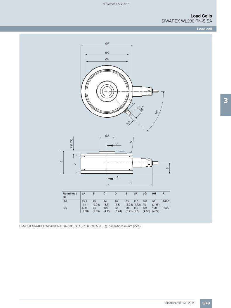
3/49Siemens WT 10 · 2014
Load CellsSIWAREX WL280 RN-S SA
Load cell
3
Load cell SIWAREX WL280 RN-S SA (28 t, 60 t (27.56, 59.05 tn. L.)), dimensions in mm (inch)
Rated load[t]
35.9(1.41)47.9(1.88)
C
A
A
ØF
8(3.14)
M6
40°
D
E
B
ØG
ØH
7 (0
.27)
ØA
28
60
øA B
25(0.98)34(1.33)
C
94(3.7)105(4.13)
D
46(1.8)62(2.44)
E
53(2.08)69(2.71)
øF
120(4.72)140(5.5)
øG
102(4)124(4.88)
øH
98(3.85)120(4.72)
R
R400
R600
© Siemens AG 2015

3/50 Siemens WT 10 · 2014
Load CellsSIWAREX WL280 RN-S SA
Self-aligning bearing
3
■ Overview
The self-centering self-aligning bearing for SIWAREX WL280 RN-S SA load cells is particularly suitable for container and platform scales due to its low mounting height.
■ Design
The self-aligning bearing comprises a self-aligning bolt, a top plate (self-aligning bearing, top part) and a base plate (self-aligning bearing, base part).
The self-centering, self-aligning bolt allows the top plate, and thus the load support, to accommodate horizontal displace-ments (e.g. due to temperature fluctuations). The design of the self-aligning bolt creates a restoring force, which is dependent on the size of the displacement and the applied load.
The design of the load support must be such as to limit the lateral play (e.g. with limit stops), if the load support is displaced hori-zontally by the following values:• > 4 mm (0.16") (up to 5 t (4.92 tn. l.) rated load)• > 7 mm (0.28") (up to 13 t (12.80 tn. l.) rated load)• > 10 mm (0.39") (up to 60 t (59.05 tn. l.) rated load)
Lifting of the load support must be prevented by suitable mea-sures provided in the construction of the load bearing imple-ment.
The load cell is not included in the scope of delivery of the self-aligning bearing.
■ Technical specifications
■ Selection and ordering data Article No. Article No.
1) 2)
Self-aligning bearing for load cells SIWAREX WL280 RN-S SA
Rated load t (tn L.) 0.06 ... 5 (0.06 ... 4.92) 10 ... 13 (9.84 ... 12.80) 28 ... 60 (27.56 ... 59.02)
Permissible lateral deflection mm (inch)
± 4 mm (0.16) ± 7 mm (0.28) ± 10 mm (0.39)
Self-aligning bearing top part1)2)
For SIWAREX WL280 RN-S SA load cells comprising: Top plate with seal holder and sealing ring, top plate pressure piece, self-aligning bolt, cell pressure piece (not for 28 t (27.56 tn. L.) and 60 t (59.05 tn. L.))
Material: Stainless steel
For load cells with a rated load of
• 60, 130, 280 kg (132.28, 286.60, 617.29 lb)
7MH4115-3DB11
• 0.5, 1 t (0.49, 0.98 tn. L.) 7MH4132-4AK11
• 2, 3.5, 5 t (1.97, 3.45, 4.92 tn. L.) 7MH4132-4KK11
• 10, 13 t (9.84, 12.80 tn. L.) 7MH4115-5BB11
• 28 t (27.56 tn. L.) 7MH4115-5DB11
• 60 t (59.05 tn. L.) 7MH4115-5GB11
Self-aligning bearing base part1)
For SIWAREX WL280 RN-S SA load cells comprising: Base plate, 3 tension pins
Material: Stainless steel
For load cells with a rated load of
• 60, 130, 280 kg (132.28, 286.60, 617.29 lb)
7MH4115-3DC11
• 0.5, 1, 2, 3.5, 5 t (0.49, 0.98, 1.97, 3.45, 4.92 tn. L.)
7MH4132-4AG11
• 10, 13 t (9.84, 12.80 tn. L.) 7MH4115-5BC11
• 28 t (27.56 tn. L.) 7MH4115-5DC11
• 60 t (59.05 tn. L.) 7MH4115-5GC11
Accessories
Pressure piece set
for load cells of type SIWAREX WL280 RN-S SA. The set consists of pressure piece and self-align-ing support. Use this set to facili-tate your own customer-specific installation. Material: Stainless steelFor load cells exhibiting a rated load of:
• 60, 130, 280 kg (132.28, 286.60, 617.29 lb)
7MH5713-3JD00
• 0.5; 1 t (0.49; 0.98 tn. L.) 7MH5713-4AD00
1) The load cell is not included in the scope of delivery.2) The self-aligning bearing base part is not included in delivery.
© Siemens AG 2015

3/51Siemens WT 10 · 2014
Load CellsSIWAREX WL280 RN-S SA
Self-aligning bearing
3
■ Dimensional drawings
Self-aligning bearing for load cells SIWAREX WL280 RN-S SA, 0.06 … 13 t (0.07 … 14.33 tn. L.), dimensions in mm (inch)
Self-aligning bearing for load cells SIWAREX WL280 RN-S SA, 28 … 60 t (27.56 … 59.05 tn. L.), dimensions in mm (inch)
Pressure piece set WL280 RN-S SA for 0.5; 1 t (0.49; 0.98 tn. L.)
Pressure piece set WL280 RN-S SA for 60, 130, 280 kg (132.28, 286.60, 617.29 lb)
60 ... 280 kg
0.5 t, 1 t
2 t, 3.5 t, 5 t
10 t, 13 t
60 ... 280 kg
0.5 t, 1 t
2 t, 3.5 t, 5 t
10 t, 13 t
11(0.43)10(0.39)8.5(0.33)20(0.79)
52(2.05)79(3.11)79(3.11)121.2(4.77)
Rated load
Rated load
A
C
M
EK
F
A BB
ØD
ØD
ØL
ØL
80(3.15)100(3.94)100(3.94)120(4.72)
A B C E
8(0.31)15(0.59)15(0.59)20(0.79)
F K
9(0.35)11(0.43)11(0.43)14(0.55)
sM
12(0.47)25(0.98)25(0.98)40(1.57)
60(2.36)75(2.95)75(2.95)90(3.54)
63(2.48)80(3.15)80(3.15)95(3.74)
22(0.87)25(0.98)30(1.18)35(1.97)
ØL
G_W
T01_
XX
_101
22
4(0.16)4(0.16)4(0.16)7(0.28)
Rated load[t]
G_W
T01_
XX
_101
18
A
C
B
160(6.30)200(7.87)
28
60
A B
120(4.72)140(5.51)
s
10(0.39)10(0.39)
C
203(7.99)254(10.00)
G_W
T01_
XX
_101
38
2x45
°16
25.2
55
0.2
Ø19 D10
G_W
T01_
XX
_101
39
22.2
39
7
0.2
Ø15 D10
© Siemens AG 2015

3/52 Siemens WT 10 · 2014
Load CellsSIWAREX WL280 RN-S SA
Elastomer bearing
3
■ Overview
Elastomer bearing for load cells type SIWAREX WL280 RN-S SA, 60 ... 280 kg (132.28 … 617.29 lb)
Elastomer bearing for load cells type SIWAREX WL280 RN-S SA, 0.5 ... 13 t (0.49 … 12.80 tn. L.)
Used in combination with the self-aligning bearing base part, the self-centering elastomer bearing for SIWAREX WL280 RN-S SA load cells is the ideal load introduction element for scales with-out guide elements. It is used in container, platform and roller ta-ble scales and dampens vibrations and shocks.
■ Design
Elastomer bearings are rubber-metal composites made of neo-prene and stainless steel. They ensure large spring excursions (i.e. a high degree of damping) despite small dimensions.
If the load support is horizontally displaced by more than 4 mm (0.16") or 6 mm (0.24") for a rated load of 10 t (9.84 tn. L.) and 13 t (12.80 tn. L.), the design of the load support must include measures to restrict lateral play (e.g. limit stops). Lifting of the load support must be prevented by suitable measures provided in the construction of the load bearing implement.
The load cell and the self-aligning bearing bottom part are not included in the scope of delivery of the elastomer bearing.
■ Technical specifications
■ Selection and ordering data 1) Article No.
Elastomer bearing for load cells type SIWAREX WL280 RN-S SA
Rated load t (tn. L) 0.06 ... 5 (0.06 ... 4.92) 10 ... 13 (9.84 ... 12.80)
Permissible lateral deflection mm (inch)
± 4 mm (0.16) ± 6 mm (0.24)
1) The load cell and the self-aligning bearing base are not included in the scope of delivery.
Elastomer bearing1)
for load cells of type SIWAREX WL280 RN-S SA, com-prising: Elastomer package with fixing plate, force transfer, seal
Material: Stainless steel and neoprene
For load cells with a rated load of
• 60, 130, 280 kg (132.28, 286.60, 617.29 lb)
7MH4130-3EE11
• 0.5, 1 t (0.49, 0.98 tn. L.) 7MH4130-4AE11
• 2, 3.5, 5 t (1.97, 3.44, 4.92 tn. L.) 7MH4130-4KE11
• 10, 13 t (9.84, 12.80 tn. L.) 7MH4130-5CE11
© Siemens AG 2015

3/53Siemens WT 10 · 2014
Load CellsSIWAREX WL280 RN-S SA
Elastomer bearing
3
■ Dimensional drawings
Elastomer bearings for load cells SIWAREX WL280 RN-S SA, 60 … 280 kg (132.28 … 617.30 lb), dimensions in mm (inch)
Elastomer bearings for load cells SIWAREX WL280 RN-S SA, 0.5 … 13 t (0.49 … 12.80 tn. L.), dimensions in mm (inch)
60 (2.36)80 (3.15)
60 (2
.36)
80 (3
.15)
8 (0
.32)
67 (2
.64)
Ø9
(0.35
)
Ø50 (1.97)M10 10
(0.3
9)30
(1.1
8)22
(0.8
7)
Rated load[t]
Rated load [t]
9.5(0.37)
8.5(0.34)
G_W
T01_
XX
_101
20
50(1
.97)
N
FBA HK
BA
CG
ØD
ØM
ØL
HK
E
10, 13
2, 3,5, 5
0,5, 1
E F
100(3.94)
75(2.95)
97(3.82)
85(3.35)
25(0.98)
15(0.59)
120(4.72)
90(3.54)
102(4.02)
100(3.94)
30(1.18)
15(0.59)
120(4.72)
90(3.54)
120(4.72)
100(3.94)
35(1.38)
20(0.79)
A B C ØD
10, 13
2, 3,5, 5
0,5, 1
sN
6(0.24)
100(3.94)
75(2.95)
11(0.43)
11(0.43)
6(0.24)
100(3.94)
75(2.95)
11(0.43)
11(0.43)
6(0.24)
120(4.72)
90(3.54)
11(0.43)
14(0.55)
20(0.79)
G H K ØMØL
4(0.16)
4(0.16)
6(0.24)
© Siemens AG 2015

3/54 Siemens WT 10 · 2014
Load CellsSIWAREX WL280 RN-S SA
Compact mounting unit
3
■ Overview
The self-aligning compact mounting unit for SIWAREX WL280 RN-S SA load cells is particularly suitable for implemen-tation in container, platform and roller table scales due to its low constructional height.
■ Design
The compact mounting unit comprises a self-aligning bolt, a top plate and a base plate and one or two countersunk screws that serve as oscillation limitation and a protection against raising up.
The self-centering, self-aligning bolt allows the top plate, and thus the load support, to accommodate horizontal displace-ments (e.g. due to temperature fluctuations). The design of the self-aligning bolt creates a restoring force, which is dependent on the size of the displacement and the applied load. The oscil-lation limitation prevents excessive lateral displacement, thus protecting the load cell against damage. It can accommodate a maximum horizontal force of Fh = 10 kN. The max. lateral dis-placement is ± 3 mm (0.12") (60 kg ... 5 t (132.28 lb … 4.92 tn. L.)) or ± 4.5 mm (10 t (9.84 tn. L.), 13 t (12.80 tn. L.)).
The protection against raising up prevents the load support from lifting against a maximum vertical force of Fv = 25 kN.
The load cell is not included in the scope of delivery of the com-pact mounting unit.
■ Technical specifications
■ Selection and ordering data 1) 2)Article No.
Compact mounting unit for load cells of type SIWAREX WL280 RN-S SA
Rated load t (tn. L) 0.06 ... 5 (0.06 ... 4.92) 10 ... 13 (9.84 ... 12.80)
Permissible lateral deflection mm (inch) ± 3 mm (0.16) ± 4.5 mm (0.18)
Lifting path of the top plate mm (inch) 3 ... 4 (0.12 ... 0.16) 4.5 ... 5.5 (0.18... 0.22)
Max. lateral force 10 kN 25 kN
1) The load cell is not included in the scope of delivery.2) It is highly recommendable to use a grounding cable
(7MH3701-1AA1) in order to protect the load cell.
Compact mounting unit1)2)
for load cells of type SIWAREX WL280 RN-S SA
Material: Stainless steel
For load cells with a rated load of
• 60, 130, 280 kg (132.28, 286.60, 617.29 lb)
7MH4125-3DA11
• 0.5, 1 t (0.49, 0.98 tn. L.) 7MH4132-4AC11
• 2, 3.5, 5 t (1.97, 3.44, 4.92 tn. L.) 7MH4132-4KC11
• 10, 13 t (9.84, 12.80 tn. L.) 7MH4125-5BA11
© Siemens AG 2015

3/55Siemens WT 10 · 2014
Load CellsSIWAREX WL280 RN-S SA
Compact mounting unit
3
■ Dimensional drawings
Compact mounting unit for load cells SIWAREX WL280 RN-S SA, 60 … 280 kg (132.28 … 617.30 lb), dimensions in mm (inch)
Compact mounting unit for load cells SIWAREX WL280 RN-S SA, 2 … 13 t (1.97 … 12.80 tn. L.), dimensions in mm (inch)
Rated load
Rated load
10(0.39)
12.5(0.49) G
_WT0
1_X
X_1
0124
KJ
L
FØG
BC
CA
H
Ø6(0.24)
ØD
E
80(3.15)
100(3.94)
A B C ØD E
57(2.24)
68(2.68)
F ØG H J
8(0.31)
15(0.59)
118(4.65)
145 (5.71)
9(0.35)
11(0.43)
60(2.36)
75(2.95)
40(1.57)
50(1.97)
K
12(0.47)
25(0.98)
s
3(0.12)
3(0.12)
L
52(2.05)
79(3.11)
39(1.54)
48(1.89)
60,130,280 kg
0,5, 1 t
60, 130,280 kg
0,5, 1 t
Rated load[t]
Rated load[t]
79(3.11)121.2(4.77)
3(0,12)4.5(0,18) G
_WT0
1_X
X_1
0119
FF
CK
JL
Ø6(0.24) ØG
BC
A
100(3.94)120(4.72)
A B C øD E
68(2.68)77,5(3.05)
F øG H
-
-
J
15(0.59)20(0.79)
190(7.48)210(8.27)
11(0.43)14(0.55)
75(2.95)90(3.54)
-
-
K
25(0.98)40(1.57)
sL
48(5.71)45(1.77)
2, 3,5, 5
10, 13
2, 3,5, 5
10, 13
© Siemens AG 2015

3/56 Siemens WT 10 · 2014
Load CellsSIWAREX WL280 RN-S SA
Guide element for compact mounting unit
3
■ Overview
The guide element can be used as an addition to the compact mounting unit of the SIWAREX WL280 RN-S SA load cells. It is used if unwanted horizontal forces occur during the weighing process, e.g. caused by mixer operation in the case of container weighing or by acceleration of the goods to be weighed on con-veyor belts.
■ Design
The guide element consists of two ball-joints, a connecting piece and two flanges for mounting to the compact mounting unit.
The ancillary guide element can also be retrofitted to compact mounting units, in case lateral forces arise unexpectedly when operating the scales and the compact mounting unit is mounted according to the requirements.
The guide element conducts lateral forces of up to 1.7 kN into the foundation, thereby minimizing the influences on the load cells and mounted components.
The load cell and the compact mounting unit are not included in the scope of delivery of the guide element.
■ Selection and ordering data 1) Article No.
■ Dimensional drawings
Guide element for compact mounting unit of load cells SIWAREX WL280 RN-S SA, dimensions in mm (inch)
1) The load cell and the compact mounting unit are not included in the scope of delivery.
Guide element for compact mounting unit1)
for load cells of type SIWAREX WL280 RN-S SA
Comprising: 2 flanges, 2 ball-joints, 1 connecting piece, fixings
Material: Stainless steel
For load cells with a rated load of
• 0.5 t, 1 t (0.49, 0.98 tn. L.) 7MH4132-4AQ12
• 2 t, 3.5 t, 5 t (1.97, 3.44, 4.92 tn. L.)
7MH4132-4KQ12
• 10 t, 13 t (9.84, 12.80 tn. L.) 7MH4134-5BQ12
Rat. load [t]0,5, 1
A B C ØD H J15
K25
L79
M14012,51175145100
(0.59) (0.98) (3.11) (5.51)(0.49)(0.43)(2.95)(5.71)(3.94)
(0.59) (0.98) (3.11) (5.51)(2.26)(0.43)(2.95)(7.48)(3.94)
(0.79) (1.57) (4.77) (6.30)(2.36)(0.55)(3.54)(8.27)(4.72)
2, 3,5, 5 15 25 79 14057,51175190100
10, 13 20 40 121.2 160601490210120
Section A - FPlan view (rated load 2 ... 13 t)
F
A
AH C
JK
L
M
ØD (4x)
ØD (4x)
B
318 (12.52)
© Siemens AG 2015

3/57Siemens WT 10 · 2014
Load CellsSIWAREX R
Introduction
3
■ Overview
SIWAREX R load cells are equipped with strain gauges (DMS). They can be used for static and dynamic weight measurements. The various series cover rated load ranges from 10 kg (22.05 lb) to 280 t (275.58 tn. L.).
© Siemens AG 2015

3/58 Siemens WT 10 · 2014
Load CellsSIWAREX R
Platform and bending beam load cells
3
■ Overview 1)
1) Installation accessories: On request.
Design Platform Bending beam
Possible applications Small platform scalesSmall conveyor scales
Container, conveyor and platform scales
Series SP BB
Pictures
Rated load Emax • 6 kg (13.23 lb)• 12 kg (26.46 lb)
• 10 kg (22.05 lb)• 20 kg (44.09 lb)• 50 kg (110.23 lb)• 100 kg (220.46 lb)• 200 kg (440.92 lb)• 350 kg (771.72 lb)1)
Accuracy class C3 C3
Max. load cell verification interval (nIC)
3 000 3 000
Min. load cell verification interval (Vmin)
Emax/12 000 Emax/15 000
Supply voltage (Usr) 5 ... 15 V 5 ... 15 V
Rated characteristic value 2 mV/V 2 mV/V
Degree of protection IP66/IP68 IP66/IP68
Material Stainless steel Stainless steel
Ex protection according to ATEX (optional)
II 2 G EEx ib IIC T6/T4 II 3 G EEx nA/nL IIC T6/T4 II 1D/2D/3D T 70 °C (158 °F)
II 2 G EEx ib IIC T6/T4 II 3 G EEx nA/nL IIC T6/T4 II 1D/2D/3D T 70 °C (158 °F)
Mounting units - • Base plate with overload protection• Elastomer bearings• Combination mounting units
© Siemens AG 2015

3/59Siemens WT 10 · 2014
Load CellsSIWAREX R
Platform and bending beam load cells
3
■ Selection and ordering data 1) 2) 3) 4)
1) Length tolerance ± 100 mm (3.94 inch).2) Installation accessories on request.3) The load cell is not included in the scope of delivery.4) It is highly recommendable to use a grounding cable (7MH3701-1AA1) in order to protect the load cell.
Platform Article No.
SP seriesLegal-for-trade according to OIML R60 up to 3 000 d, connecting cable 7 m1)
7MH4107-
■ ■ C ■ 1
Rated load
• 6 kg (13.22 lb) 1 L
• 12 kg (26.46 lb) 2 B
Explosion protection
Without 0
Explosion protection for zones 1, 2, 20, 21, 22 1
Bending beam Article No.
BB seriesLegal-for-trade according to OIML R60 up to 3 000 d, connecting cable 3 m1)
7MH4103-
■ ■ C ■ 1
Rated load
• 10 kg (22.05 lb) 2 A
• 20 kg (44.09 lb) 2 D
• 50 kg (110.23 lb) 2 K
• 100 kg (220.46 lb) 3 A
• 200 kg (440.92 lb) 3 D
• 350 kg (771.72 lb)2) 3 G
Explosion protection
Without 0
Explosion protection for zones 1, 2, 20, 21, 22 1
Base plate with overload protectionfor load cells in the BB series3)4)
Material: Stainless steelFor load cells with a rated load of:
10 … 200 kg (22.05 … 440.92 lb) 7MH4133-3DG11
Elastomer bearingsfor load cells in the BB series3)
Material: Stainless steelFor load cells with a rated load of:
• 10 … 50 kg (22.05 … 110.23 lb) 7MH4133-2KE11
• 100 … 200 kg (220.46 … 440.92 lb) 7MH4133-3DE11
Combination mounting unitsfor load cells in the BB series3)4)
Material: Stainless steelFor load cells with a rated load of:
10 … 200 kg (22.05 … 440.92 lb) 7MH4133-3DC11
Accessories
Grounding cable made of copperFor discharging parasitic currents, length 400 mm (15.75 inch), see page 3/71
7MH3701-1AA1
SIWAREX EB extension box, aluminum housingFor extending the connection cables of load cells, see page 3/69
7MH4710-2AA
© Siemens AG 2015

3/60 Siemens WT 10 · 2014
Load CellsSIWAREX R
Shear beam load cells
3
■ Overview
Design Shear beam
Possible applications Container, conveyor, overhead rail and platform scales
Series SB
Picture
Rated load Emax • 500 kg (1 102.31 lb)• 1 t (0.98 tn. L.)• 2 t (1.97 tn. L.)• 5 t (4.92 tn. L.)
Accuracy class C3
Max. load cell verification interval (nIC)
3 000
Min. load cell verification interval (Vmin)
Emax/10 000
Supply voltage (Usr) 5 ... 18 V
Rated characteristic value 2 mV/V
Degree of protection IP66/IP68
Material Stainless steel
Ex protection according to ATEX (optional)
II 2 G EEx ib IIC T6/T4 II 3 G, EEx nA/nL IIC T6/T4, II 1D/2D/3D T 70 °C (158 °F)
Mounting units • Base plate with overload protection• Elastomer bearings• Combination mounting units• Guide element for combination mounting units
© Siemens AG 2015

3/61Siemens WT 10 · 2014
Load CellsSIWAREX R
Shear beam load cells
3
■ Selection and ordering data 1) 2) 3)
1) Length tolerance ± 100 mm (3.94 inch)2) The load cell is not included in the scope of delivery.3) It is highly recommendable to use a grounding cable (7MH3701-1AA1) in order to protect the load cell.
Shear beam Article No.
SB seriesLegal-for-trade according to OIML R60 up to 3 000 d, connecting cable 5 m1)
7MH4105-
■ ■ C ■ 1
Rated load
• 500 kg (1 102.31 lb) 3 K
• 1 t (0.98 tn. L.) 4 A
• 2 t (1.97 tn. L.) 4 D
• 5 t (4.92 tn. L.) 4 K
Explosion protection
Without 0
Explosion protection for zones 1, 2, 20, 21, 22 1
Base plate with overload protectionfor load cells in the SB series2)3)
Material: Stainless steelFor load cells with a rated load of:
• 0.5, 1, 2 t (0.49, 0.98, 1.97 tn. L.) 7MH4135-4DG11
• 5 t (4.92 tn. L.) 7MH4135-4KG11
Elastomer bearingsfor load cells in the SB series2)
Material: Stainless steelFor load cells with a rated load of:
• 500 kg (1 102.31 lb), 1 t (0.98 tn. L.) 7MH4135-4AE11
• 2 t (1.97 tn. L.) 7MH4135-4DE11
• 5 t (4.92 tn. L.) 7MH4135-4KE11
Combination mounting unitfor load cells in the SB series2)3)
Material: Stainless steelFor load cells with a rated load of:
• 0.5, 1, 2 t (0.49, 0.98, 1.97 tn. L.) 7MH4135-4DC11
• 5 t (4.92 tn. L.) 7MH4135-4KC11
Guide element for combination mounting unitfor load cells in the SB series2)
Material: Stainless steelFor load cells with a rated load of:
• 0.5, 1, 2 t (0.49, 0.98, 1.97 tn. L.) 7MH4135-4DQ12
• 5 t (4.92 tn. L.) 7MH4135-4KQ12
Accessories
Grounding cable made of copperFor discharging parasitic currents, length 400 mm (15.75 inch), see page 3/71
7MH3701-1AA1
SIWAREX EB extension box, aluminum housingFor extending the connection cables of load cells, see page 3/69
7MH4710-2AA
© Siemens AG 2015

3/62 Siemens WT 10 · 2014
Load CellsSIWAREX R
Bending ring load cells
3
■ Overview
■ Selection and ordering data
Design Bending ring
Possible applications Container, conveyor and platform scales
Series RN
Picture
Rated load Emax • 60 kg (132.28 lb)• 130 kg (286.60 lb)• 280 kg (617.29 lb)
• 500 kg (1 102.31 lb)• 1 t (0.98 tn. L.)• 2 t (1.97 tn. L.)• 3.5 t (3.45 tn. L.)• 5 t (4.92 tn. L.)• 10 t (9.84 tn. L.)
• 13 t (12.80 tn. L.)• 28 t (27.56 tn. L.)• 60 t (59.05 tn. L.)
Accuracy class C3 C3 C3
Max. load cell verification interval (nIC)
3 000 3 000 3 000
Min. load cell verification interval (Vmin)
Emax/17 500 Emax/10 000 Emax/17 500
Supply voltage (Usr) 5 … 30 V 5 … 30 V 5 … 30 V
Rated characteristic value 1 mV/V 2 mV/V 2 mV/V
Degree of protection IP66/IP68 IP66/IP68 IP66/IP68
Material Stainless steel Stainless steel Stainless steel
Ex protection according to ATEX (optional)
II 2 G EEx ib IIC T6/T4 II 3 G EEx nA/nL IIC T6/T4 II 1D/2D/3D T 70 °C (158 °F)
II 2 G EEx ib IIC T6/T4 II 3 G EEx nA/nL IIC T6/T4 II 1D/2D/3D T 70 °C (158 °F)
II 2 G EEx ib IIC T6/T4 II 3 G EEx nA/nL IIC T6/T4 II 1D/2D/3D T 70 °C (158 °F)
Mounting units • Elastomer bearing• Combination mounting unit• Guide element for combination mounting units• Self-aligning bearings
Bending ring Article No.
RN seriesLegal-for-trade according to OIML R60 up to 3 000 d, connecting cable 10 m1)
7MH5101-
■ ■ D 0 ■
Rated load Cable length
• 60 kg (132.28 lb) 3 m (9.84 inch) 2 Q
• 130 kg (286.60 lb) 3 m (9.84 inch) 3 D
• 280 kg (617.29 lb) 3 m (9.84 inch) 3 J
• 500 kg (1 102.31 lb) 3 m (9.84 inch) 3 P
• 1 t (0.98 tn. L.) 3 m (9.84 inch) 4 A
• 2 t (1.97 tn. L.) 5 m (16.40 inch) 4 G
• 3.5 t (3.45 tn. L.) 5 m (16.40 inch) 4 L
• 5 t (4.92 tn. L.) 5 m (16.40 inch) 4 P
• 10 t (9.84 tn. L.) 5 m (16.40 inch) 5 A
• 13 t (12.80 tn. L.) 10 m (32.81 inch) 5 D
• 28 t (27.56 tn. L.) 10 m (32.81 inch) 5 J
• 60 t (59.05 tn. L.) 10 m (32.81 inch) 5 Q
Explosion protection
Without 0
Explosion protection for zones 1, 2, 20, 21, 22 1
© Siemens AG 2015

3/63Siemens WT 10 · 2014
Load CellsSIWAREX R
Bending ring load cells
3
1) 2) 3) 4)
Self-aligning bearing top part2)4)
for load cells in the RN seriesConsisting of: Top plate with seal holder and sealing ring, top plate pressure piece, self-aligning bolt, cell pressure piece (not for 28 t (27.56 tn. L.) and 60 t (59.05 tn. L.))Material: Stainless steelFor load cells with a rated load of:
• 60, 130, 280 kg (132.28, 286.60, 617.29 lb) 7MH4115-3DB11
• 0.5, 1 t (0.49, 0.98 tn. L.) 7MH4132-4AK11
• 2, 3.5, 5 t (1.97, 3.45, 4.92 tn. L.) 7MH4132-4KK11
• 10, 13 t (9.84, 12.80 tn. L.) 7MH4115-5BB11
• 28 t (27.56 tn. L.) 7MH4115-5DB11
• 60 t (59.05 tn. L.) 7MH4115-5GB11
Self-aligning bearing base partfor load cells in the RN seriesConsisting of: Base plate, 3 tension pinsMaterial: Stainless steelFor load cells with a rated load of:
• 60, 130, 280 kg (132.28, 286.60, 617.29 lb) 7MH4115-3DC11
• 0,5, 1; 2, 3.5, 5 t (0.49, 0.98; 1.97, 3.45, 4.92 tn. L.) 7MH4132-4AG11
• 10, 13 t (9.84, 12.80 tn. L.) 7MH4115-5BC11
• 28 t (27.56 tn. L.) 7MH4115-5DC11
• 60 t (59.05 tn. L.) 7MH4115-5GC11
Elastomer bearingsfor load cells in the RN series2)4)
Material: Stainless steelFor load cells with a rated load of:
• 60, 130, 280 kg (132.28, 286.60, 617.29 lb) 7MH4130-3EE11
• 0.5, 1 t (0.49, 0.98 tn. L.) 7MH4130-4AE11
• 2, 3.5, 5 t (1.97, 3.45, 4.92 tn. L.) 7MH4130-4KE11
• 10, 13 t (9.84, 12.80 tn. L.) 7MH4130-4CE11
Combination mounting unitfor load cells in the RN series2)3)
Material: Stainless steelFor load cells with a rated load of:
• 60, 130, 280 kg (132.28, 286.60, 617.29 lb) 7MH4125-3DA11
• 0.5, 1 t (0.49, 0.98 tn. L.) 7MH4132-4AC11
• 2, 3.5, 5 t (1.97, 3.45, 4.92 tn. L.) 7MH4132-4KC11
• 10, 13 t (9.84, 12.80 tn. L.) 7MH4125-5BA11
Guide element for combination mounting unitfor load cells in the RN series2)
Material: Stainless steelFor load cells with a rated load of:
• 0.5, 1 t (0.49, 0.98 tn. L.) 7MH4132-4AQ12
• 2, 3.5, 5 t (1.97, 3.45, 4.92 tn. L.) 7MH4132-4KQ12
• 10, 13 t (9.84, 12.80 tn. L.) 7MH4134-5BQ12
Accessories
Grounding cable made of copperFor discharging parasitic currents, length 400 mm (15.75 inch), see page 3/71
7MH3701-1AA1
SIWAREX EB extension box, aluminum housingFor extending the connection cables of load cells, see page 3/69
7MH4710-2AA
Bending ring Article No.
1) Length tolerance ± 100 mm (3.94 inch).2) The load cell is not included in the scope of delivery.3) It is highly recommendable to use a grounding cable (7MH3701-1AA1) in
order to protect the load cell.4) The self-aligning bearing base part is not included in the scope of delivery.
© Siemens AG 2015

3/64 Siemens WT 10 · 2014
Load CellsSIWAREX R
Compression load cells
3
■ Overview
Design Compression cell
Possible applications Container, hopper and vehicle scales Container, hopper and vehicle scales
Series CC K
Pictures
Rated load Emax • 10 t (9.84 tn. L.)• 25 t (24.61 tn. L.)• 40 t (39.37 tn. L.)• 60 t (59.05 tn. L.)
• 100 t (98.42 tn. L.) • 2.8 t (2.76 tn. L.)• 6 t (5.91 tn. L.)• 13 t (12.80 tn. L.)• 28 t (27.56 tn. L.)• 60 t (59.05 tn. L.)• 130 t (127.95 tn. L.)• 280 t (275.58 tn. L.)
Accuracy class C3 C1 0.1 %
Max. load cell verification interval (nIC)
3 000 1 000 -
Min. load cell verification interval (Vmin)
Emax/12 500 Emax/10 000 -
Supply voltage (Usr) 5 … 25 V 6 … 12 V
Rated characteristic value 2 mV/V 1.5 mV/V
Degree of protection IP66/IP68 IP65
Material Stainless steel Steel, painted
Ex protection according to ATEX (optional)
II 2 G EEx ib IIC T6/T4 II 3 G EEx nA/nL IIC T6/T4II 1D/2D/3D T 70 II 2 G EEx ib IIC T6/T4 II 3 G EEx nA /nL IIC T6/T4, II 1D / 2D / 3D T 70°C (158 °F)
-
Mounting units • Combination mounting units• Self-aligning bearings
• Self-aligning bearings • Self-aligning bearings
© Siemens AG 2015

3/65Siemens WT 10 · 2014
Load CellsSIWAREX R
Compression load cells
3
■ Selection and ordering data
1) The load cell is not included in the scope of delivery.2) It is highly recommendable to use a grounding cable (7MH3701-1AA1) in
order to protect the load cell.3) Pressure pieces made of tool steel.4) Length tolerance ± 100 mm (3.94 inch).
5) Length tolerance ± 300 mm (11.81 inch).6) Heat-resistant cable: -60 … +180 °C (-76 … +356 °C).
Compression cell Article No.
CC seriesLegal-for-trade according to OIML R60 up to 3 000 d
7MH4106-
■ ■ ■ ■ 1
Rated load Cable length
• 10 t (9.84 tn. L.) 10 m (32.81 inch)4) 5 A C
• 25 t (24.61 tn. L.) 20 m (65.62 inch)5) 5 E C
• 40 t (39.37 tn. L.) 20 m (65.62 inch)5) 5 H C
• 60 t (59.05 tn. L.) 20 m (65.62 inch)5) 5 L C
• 100 t (98.42 tn. L.) 20 m (65.62 inch)5) 6 A A
Explosion protection
Without 0
Explosion protection for zones 1, 2, 20, 21, 22 1
Self-aligning bearingsfor load cells in the CC series1)2)
Comprising a top plate, base plate and 3 pressure piecesMaterial: Stainless steel3)
For load cells with a rated load of:
• 10, 25 t (9.84, 24.61 tn. L.) 7MH4136-5EA11
• 40, 60 t (39.37, 59.05 tn. L.) 7MH4136-5LA11
• 100 t (98.42 tn. L.) 7MH4136-6AA11
Combination mounting unitfor load cells in the CC series1)2). Material: Stainless steel3) . For load cells with a rated load of:
• 10, 25 t (9.84, 24.61 tn. L.) 7MH4136-5EC11
• 40, 60 t (39.37, 59.05 tn. L.) 7MH4136-5LC11
Compression cell Article No.
K seriesAccuracy class 0.2 without explosion protection
7MH3105-
■ ■ C 0
Click on the Article No. for the online configuration in the PIA Life Cycle Portal.
Rated load Cable length4) 6)
• 2.8 t (2.76 tn. L.) 5 m (16.40 inch) 2 A
• 6 t (5.91 tn. L.) 5 m (16.40 inch) 3 A
• 13 t (12.80 tn. L.) 10 m (32.81 inch) 1 B
• 28 t (27.56 tn. L.) 10 m (32.81 inch) 2 B
• 60 t (59.05 tn. L.) 10 m (32.81 inch) 3 B
• 130 t (127.95 tn. L.) 10 m (32.81 inch) 1 C
• 280 t (275.58 tn. L.) 10 m (32.81 inch) 2 C
Pressure platefor load cells in the K series1)2)
To set up a self-aligning bearing, 2 pressure plates are required,one each at the top and bottom respectively Scope of supply: 1 pressure plateMaterial: Steel, paintedFor load cells with a rated load of:
• 2.8. 6 t (2.76, 5.91 tn. L.) 7MH3115-3AA1
• 13 t (12.80 tn. L.) 7MH3115-1BA1
• 28 t (27.56 tn. L.) 7MH3115-2BA1
• 60 t (59.05 tn. L.) 7MH3115-3BA1
• 130 t (127.95 tn. L.) 7MH3115-1CA1
• 280 t (275.58 tn. L.) 7MH3115-2CA1
© Siemens AG 2015

3/66 Siemens WT 10 · 2014
Load CellsAccessories
SIWAREX JB junction box with aluminium housing
3
■ Overview
The aluminum JB junction box is required for parallel connection of load cells. A maximum of 4 load cells can be connected in parallel in one junction box.
If more than 4 load cells are to be connected, a second junction box must be connected in parallel via a cross connection. The junction box can be used in potentially explosive areas (grounded, intrinsically-safe circuits).
■ Design
The junction box made of die-cast aluminum consists of a base section and a cover. The housing is sealed against penetration of dust and splashed water in accordance with IP 66 degree of protection. The cables enter the casing via metric cable glands. In the housing, there are 28 terminals with spring-mounted con-tacts. The spring-mounted system results in vibration-resistant, maintenance-free connections.
The internal resistance, characteristic value and nominal load of all load cells connected in parallel must be identical. The values of these variables are not limited by the junction box. Load cells can be connected using a four-wire or six-wire system.
With the four-wire system, two jumpers must be set in addition.
Connection examples
4 load cells:
LC: Load cell JB: Aluminum junction box
8 load cells:
LC: Load cell JB: Aluminum junction box
■ Technical specifications
SIWAREX weighing system
Max. cable length: see technical specifications of weighing module
LC
LC
LC
LC
6
4/6
JB
SIWAREX JB junction box, aluminum housing
Cable glands
• Load cells 4 x M16
• Electronics 2 x M20
Permissible ambient temperature
• During operation -30 … +85 °C (-22 … +185 °F)
• During operation for legal-for-trade medium accuracy weigh-ing machine
-10 … +40 °C (-14 … +104 °F)
• During transportation and storage
-40 … +90 °C (-40 … +194 °F)
Degree of protection IP66 to EN 60529
Vibration resistance of terminals to DIN VDE 0611 11/77
12 Hz and 50 Hz, amplitude 1 mm (0.04 inch)
Insulation resistance of terminals ≥ 1012 Ω
SIWAREX weighing system
LC
LC
LC
LC
LC
LC
LC
LC
6
6
4/6
JB
JB
© Siemens AG 2015

3/67Siemens WT 10 · 2014
Load CellsAccessories
SIWAREX JB junction box with aluminium housing
3
■ Selection and ordering data Article No. ■ Dimensional drawings
SIWAREX JB junction box in aluminum (7MH4710-1BA), dimensions in mm (inch)
SIWAREX JB junction box, aluminum housingfor connecting up to 4 load cells in parallel, and for connecting several junction boxes
7MH4710-1BA
Cables (optional)
Cable Li2Y 1 x 2 x 0.75 ST + 2 x (2 x 0.34 ST) - CY, orange sheathto connect SIWAREX U, CS, MS, FTA, FTC, M and CF to the junc-tion box (JB), extension box (EB) or Ex interface (Ex-I) or between two JBs, for fixed laying, occa-sional bending permitted, 10.8 mm outer diameter, for ambi-ent temperature -40 to +80 °C
7MH4702-8AG
Cable Li2Y 1 x 2 x 0.75 ST + 2 x (2 x 0.34 ST) - CY, blue sheathto connect the junction box (JB) or extension box (EB) in a poten-tially explosive atmosphere to the Ex interface (Ex-I), for fixed lay-ing, occasional bending permit-ted, blue PVC insulating sheath, approx. 10.8 mm outer diameter, for ambient temperature -40 ... +80 °C
7MH4702-8AF
1
1
Drilled holes for mounting of housing1
154.5 (6.08)
Ø10
.5 (0
.41)
120
(4.7
2)44
(1
.73)
26 (1
.02)
220 (8.66)
11+2 (0.43+0.08)
20 (0.79)
82 (3
.23)
Ø7
(0.2
8)204 (8.03)81 (3.19)
8 (0.31)
18
(0.7
1)32 (1.26)
22±2
(0
.87±
0.08
)
© Siemens AG 2015

3/68 Siemens WT 10 · 2014
Load CellsAccessories
SIWAREX JB junction box with stainless steel housing
3
■ Overview
The stainless steel JB junction box is required for parallel con-nection of load cells. A maximum of 4 load cells can be con-nected in parallel in one junction box.
■ Design
The stainless steel junction box consists of a base section and a cover. The housing is sealed against penetration of dust and splashed water in accordance with IP 66 degree of protection. The cables enter the casing via metric EMC cable glands (brass, nickel-plated). In the housing, there are 18 terminals with spring-mounted contacts. The spring-mounted system results in vibra-tion-resistant, maintenance-free connections.
The internal resistance, characteristic value and nominal load of all load cells connected in parallel must be identical. The values of these variables are not limited by the junction box. Load cells can be connected using a four-wire or six-wire system.
With the four-wire system, two jumpers must be set in addition.
Connection example
LC: Load cell JB: Stainless steel junction box
■ Technical specifications
■ Selection and ordering data Article No.
■ Dimensional drawings
SIWAREX JB junction box in stainless steel (7MH4710-1EA), dimensions in mm (inch)
SIWAREX JB junction box, stainless steel housing
Cable glands
• Load cells 4 x M16
• Electronics 1 x M20
Permissible ambient temperature
• During operation -30 ... +85 °C (-22 … +185 °F)
• During operation for legal-for-trade medium accuracy weigh-ing machine
-10 ... +40 °C (-14 … +104 °F)
• During transportation and storage
-40 ... +90 °C (-40 … +194 °F)
SIWAREX weighing system
Max. cable length: see technical specifications of weighing module
LC
LC
LC
LC
6
4/6
JB
Degree of protection IP66 to EN 60529
Vibration resistance of terminals to DIN VDE 0611 11/77
12 Hz and 50 Hz, amplitude 1 mm
Insulation resistance of terminals ≥ 1012 Ω cm
SIWAREX JB junction box, stainless steel housingfor connecting up to 4 load cells in parallel
7MH4710-1EA
SIWAREX JB junction box, stainless steel housing, ATEXfor connecting up to 4 load cells in parallel. EX protection for zones 1, 2, 20, 21, 22
7MH4710-1EA01
Cables (optional)
Cable Li2Y 1 x 2 x 0.75 ST + 2 x (2 x 0.34 ST) - CY, orange sheathto connect SIWAREX U, CS, MS, FTA, FTC, M and CF to the junc-tion box (JB), extension box (EB) or Ex interface (Ex-I) or between two JBs, for fixed laying, occa-sional bending permitted, 10.8 mm outer diameter, for ambi-ent temperature -40 to +80 °C
7MH4702-8AG
Cable Li2Y 1 x 2 x 0.75 ST + 2 x (2 x 0.34 ST) - CY, blue sheathto connect the junction box (JB) or extension box (EB) in a poten-tially explosive atmosphere to the Ex interface (Ex-I), for fixed lay-ing, occasional bending permit-ted, blue PVC insulating sheath, approx. 10.8 mm outer diameter, for ambient temperature -40 to +80 °C
7MH4702-8AF
SIWAREX JB junction box, stainless steel housing
Ø10
(0
.39)
M6
63 (2
.48)
100
(3.9
4)54
(2.1
3)
194 (7.64)176 (6.93)
150 (5.91)
© Siemens AG 2015

3/69Siemens WT 10 · 2014
Load CellsAccessories
SIWAREX EB extension box
3
■ Overview
The extension box EB is used to lengthen the connection cable of load cells.
Load cells can be connected using 4-wire and 6-wire systems. The cable connection to the weighing module or to the junction box JB must always be made using a 6-wire system. The SIWAREX cable 7MH4 702-8AG or ...-8AF is recommended.
If load cell cables are extended to a junction box JB, the cable glands M16 x 1.5 must be replaced. The following are required per load cell:• 1 EMC cable gland M20 x 1.5• 1 extension M16 x 1.5 male thread to M20 x 1.5 female thread.
The extension box can be used in potentially explosive areas (grounded, intrinsically-safe circuits).
■ Design
The extension box has a housing made of die-cast aluminum. The housing is sealed against penetration of dust and splashed water in accordance with IP66. The cables enter the casing via metric EMC cable glands and are connected to spring-mounted terminals. The spring-mounted system results in vibration-resis-tant, maintenance-free connections.
When connecting load cells with a 4-wire system, two jumper el-ements are inserted for feedback of the sense signal.
Connection examples
Connection of one load cell:
LC: Load cell EB: Extension box
Connection of several load cells:
LC: Load cell EB: Extension box JB: Junction box
■ Technical specifications
■ Selection and ordering data Article No.
SIWAREX Weighing system
LC64/6
EB
SIWAREX EB extension box
Cable glands
• of load cell cable M16 x 1.5
• of signal cable M20 x 1.5
Permissible ambient temperature
• During operation -30 … +85 °C (-22 … +185 °F)
• During operation for legal-for-trade medium accuracy weighing machine
-10 … +40 °C (-14 … +104 °F)
• During transportation and storage -40 … +90 °C (-40 … +194 °F)
Degree of protection to EN 60529 IP66
Vibration resistance of terminals to DIN VDE 0611 11/77
12 Hz and 50 Hz, amplitude 1 mm (0.04 inch)
Insulation resistance of the terminals
≥ 1012 Ω
Dimensions (H x W x D) in mm 80 x 75 x 57 (3.15 x 2.95 x 2.24)
SIWAREX EB extension box, aluminum housingto extend the connection cables of load cells
7MH4710-2AA
Cable (optional)
Cable Li2Y 1 x 2 x 0.75 ST + 2 x (2 x 0.34 ST) - CY, orange sheath
7MH4702-8AG
to connect SIWAREX U, M, P, FTA, FTC and CS to the junction box (JB), extension box (EB) or Ex interface (Ex-I) or between two JBs, for fixed laying, occa-sional bending is possible, 10.8 mm outer diameter, for ambient temperature –40 to +80 °C
Cable Li2Y 1 x 2 x 0.75 ST + 2 x (2 x 0.34 ST) - CY, blue sheath
7MH4702-8AF
to connect the junction box (JB) or extension box (EB) in a poten-tially explosive atmosphere to the Ex interface (Ex-I), for fixed lay-ing, occasional bending is possi-ble, blue PVC insulating sheath, approx. 10.8 mm outer diameter, for ambient temperature –40 to +80 °C
SIWAREX Weighing system
LC
LC
LC
LC
6
4/6EB
EB
EB
EB
JB
© Siemens AG 2015

3/70 Siemens WT 10 · 2014
Load CellsAccessories
SIWAREX EB extension box
3
■ Dimensional drawings
SIWAREX EB expansion box (7MH4710-2AA), dimensions in mm (inch)
1
Fastening hole1
Ø4.8 (0.19)
57 (2
.24)
25 (0
.98)
10
(0.3
9)
52 (2.05)
63 (2
.48)
80 (3.15)
Ø8 (0.31)
23 ± 2 (0.91 ± 0.08)
24 (0
.94)
29 (1
.14)
75 (2
.95)
© Siemens AG 2015

3/71Siemens WT 10 · 2014
Load CellsAccessories
Grounding cable
3
■ Overview
The highly flexible grounding cable is used to discharge para-sitic currents.
■ Design
The grounding cable is 400 mm long and corresponds to an electrical bypass.
It protects the load cell from undesirable voltages which can oc-cur e.g. when welding or as a result of lightning.
We recommend using one grounding cable for each load cell.
The load cell and/or other mounting elements are not included in the scope of delivery of the grounding cable.
■ Selection and ordering data Article No.
■ Dimensional drawings
Grounding cable, dimensions in mm (inch)
Grounding cable made of copperfor discharging parasitic currents
Length 400 mm 7MH3701-1AA1
Ø10.6 (0.42)
2 (0.08) thick
400 (15.75)
© Siemens AG 2015

3/72 Siemens WT 10 · 2014
Load CellsConfiguration examples
Introduction
3
■ Overview
Number of load cells
The three-point bearing is statically determined and offers a stable setup for any application.
If there are more than three bearing points, the load is likely to be unevenly positioned and, in extreme cases, that two diagonally positioned load cells would have to accommodate the entire load. Three-point bearing should therefore be used wherever possible.
To exclude the possibility of an uneven base, in the case of a bearing with more than three load cells, the prevailing weight distribution on the relevant load cells should be checked and a height adjustment performed if necessary. This can be achieved by using a suitable support to raise the load cells carrying less weight.
Force bypass
Force bypasses are produced if a partial load is transferred past the load cells into the base. There are various reasons for a force bypass (e.g. third-party supports, frictional forces, stresses, etc.).
Force bypasses must be avoided at all costs as they lead to measuring errors.
Rated load of load cells
The rated load is selected under maximum load, taking into account centers of gravity and load distribution on the individual load cells. The rated load is generally selected according to the most heavily loaded load cell. A check also needs to be performed to check if any dynamic forces are superimposed on the static load of the load cell. In this case, the rated load of the load cell must be calculated from the sum of the static load and the peak dynamic force.
The 4 load cells are each loaded with 0.75 t (0.74 tn. L.) in order to ensure even load distribution. During configuration and selection of load cells, approx. 20 % should be added to the calculated rated load for safety reasons. This produces a required load cell rated load of 0.75 t × 1.2 = 0.9 t (0.74 tn. L. x 1.2 = 0.89 tn. L.)
It therefore follows that it is necessary to select the next highest rated load level, with 1 t (0.98 tn. L.).
Example (please also refer to configuration example 1)Even load distribution without dynamic influences
Number of load cellsEmpty weight of containerMaximum capacity
41.2 t (1.18 tn. L.)1.8 t (1.77 tn. L.)
Total load 3 t (2.95 tn. L.)
© Siemens AG 2015

3/73Siemens WT 10 · 2014
Load CellsConfiguration examples
Configuration examplel 1
3
■ Overview
Example 1: Container weighing
The total center of gravity S of the suspended container lies above the level of the load cells.
It is supported on 4 brackets (container manufacturer specifi-cation), has an empty weight (i.e. dead load) of 1.2 t (1.18 tn. L.) and a maximum capacity of 1.8 t (1.77 tn. L.). The load is evenly distributed across all 4 load cells.
Note
The three-point bearing of the container is statically determined and represents a stable state (see comment in the introduction).
Selection of load cells and mounting components
The determination of the rated load, as described in the intro-duction, leads to a rated load of 1 t (0.98 tn. L.).
Container on SIWAREX WL280 RN-S SA load cells and compact mounting units
For the above example, 4 SIWAREX WL280 RN-S SA load cells were used with a rated load of 1 t ((0.98 tn. L.) because the high-quality precision RN load cells have an extremely low construc-tional height.
Self-centering compact mounting units are used as mounting components as, in addition to their oscillation function and oscil-lation limitation, they are also fitted with a protection against raising up. The protection against raising up can handle a maximum vertical force of 10 kN. In the event of greater lifting forces (e.g due to wind load), the container must be safeguarded with additional catastrophe protection.
Configurator for container weighing (basic configuration)
FG
S
Z 3 : 1
Z
Item Description Article No. Selection criterion Amount needed in example
1 SIWAREX WL280 RN-S SA, rated load 1 t (0.98 tn. L.), C3
7MH5113-4AD00 High-quality ring-torsion load cell with low constructional height, ideal for container weighing
4
2 Compact mounting unit for SIWAREX WL280 RN-S SA load cell, rated load 1 t (0.98 tn. L.),Material: Stainless steel
7MH4132-4AC11 Ensures not only the oscillation function with oscillation limitation, but also the protection against raising up function
4
3 Grounding cable 7MH3701-1AA1 For discharging undesirable currents
4
© Siemens AG 2015

3/74 Siemens WT 10 · 2014
Load CellsConfiguration examples
Configuration example 2
3
■ Overview
Example 2: Container weighing
The total center of gravity S of the suspended container lies below the level of the load cells.
It is supported on 3 brackets, has an empty weight (i.e. dead load) of 1.2 t and a maximum capacity of 1.8 t. The container has a diameter of 1 m (3.3 ft). Weighing of the individual components produces a chemical reaction that raises the temperature of the container with contents from approx. 18°C to approx. 55° C (131° C).
Selection of load cells and mounting components
We recommend using 3 SIWAREX WL280 RN-S SA load cells with a rated load of 2 t (1.97 tn. L.) (for determination of the rated load: please refer to introduction, page Seite 66). Due to its low constructional height, the WL280 RN load cell was used.
Container weighing with SIWAREX WL280 RN-S SA load cell and self-aligning bearing
Self-centering self-aligning bearings are used as mounting components as the container is suspended and cannot lift up from the self-aligning bearing.
The 37 K temperature rise will cause the diameter of the container to increase by 0.4 mm (0.02 inch).
The self-aligning bearing permits a maximum oscillation path of ± 4 mm (0.16 inch) and is therefore able to accommodate the temperature expansion of the container.
An oscillation limitation is not necessary because there is a small gap of b = 3 mm (0.12 inch) between the container and the platform. In this case, the platform acts as an oscillation limitation.
If the width of the gap is larger in other applications, it may be necessary to install compact mounting units (instead of the self-aligning bearing) or alternatively, external oscillation limiters (see configuration example 4).
Configurator for container weighing (basic configuration)
FG
S
Z
Z 3 : 1
b
Item Description Article No. Selection criterion Amount needed in example
1 SIWAREX WL280 RN-S SA, rated load 2 t (1.97 tn. L.), C3
7MH5113-4GD00 High-quality ring-torsion load cell with low constructional height, ideal for container weighing
3
2 Self-aligning bearing base part for SIWAREX WL280 RN-S SA load cell, rated load 2 t (1.97 tn. L.) Material: Stainless steel
7MH4132-4AG11 Supports accommodation of temperature expansion, without transferring interfering reaction forces to the load cell
3
3 Self-aligning bearing top part for SIWAREX WL280 RN-S SA load cell, rated load 2 t (1.97 tn. L.) Material: Stainless steel
7MH4132-4KK11 3
4 Grounding cable 7MH3701-1AA1 For discharging undesirable currents
3
© Siemens AG 2015

3/75Siemens WT 10 · 2014
Load CellsConfiguration examples
Configuration example 3
3
■ Additional info
Example 3: Mixer weighing
The total center of gravity S of the suspended container lies below the level of the load cells.
It is supported on 3 brackets, has an empty weight (i.e. dead load) of 2.8 t (2.76 tn. L.) and a maximum capacity of 4.5 t (4.43 tn. L.).
To improve mixing of the individual components, an agitator is mounted on the container which also operates during the weighing process.
Selection of load cells and mounting components
We recommend using 3 SIWAREX WL280 RN-S SA load cells with a rated load of 3.5 t (3.45 tn. L.) because the high-quality precision WL280 RN load cell has an extremely low construc-tional height (for determination of rated load: please refer to introduction, page Seite 66)
Container with agitator on SIWAREX WL280 RN-S SA load cell and elastomer bearing
Self-centering elastomer bearings are used as the mounting components to minimize the vibrations caused by the mixer.
The elastomer bearing permits a maximum oscillation path of ± 4 mm (0.16 inch).
An oscillation limitation is not necessary because there is a small gap of b = 3 mm (0.12 inch) between the container and the platform.
If the width of the gap is larger in other applications, limit stops or external oscillation limiters must be provided.
Configurator for mixer weighing (basic configuration)
FG
S
Z
Z 3 : 1
b
Item Description Article No. Selection criterion Amount needed in example
1 SIWAREX WL280 RN-S SA, rated load 3.5 t , C3, without EEx
7MH5113-4LD00 High-quality ring-torsion load cell with low constructional height, ideal for container weighing
3
2 Self-aligning bearing base part for SIWAREX WL280 RN-S SA load cell, rated load 2 t (1.97 tn. L.) Material: Stainless steel
7MH4132-4AG11 3
3 Elastomer bearing for SIWAREX WL280 RN-S SA load cell, rated load 2 t (1.97 tn. L.) Material: Neoprene and stainless steel
7MH4130-4KE11 For vibration damping to minimize the effects on the load cell
3
4 Grounding cable 7MH3701-1AA1 For discharging undesirable currents
3
© Siemens AG 2015

3/76 Siemens WT 10 · 2014
Load Cells
Notes
3
■
© Siemens AG 2015

Siemens WT 10 · 2014
44/2 Milltronics belt scales4/2 Introduction4/5 Milltronics MLC4/10 Milltronics MBS4/14 Milltronics MUS4/19 Milltronics MCS4/24 Milltronics MSI and MMI4/32 Milltronics WD600
4/35 Speed sensors4/35 Milltronics TASS4/37 Milltronics RBSS4/40 SITRANS WS1004/45 SITRANS WS3004/50 Milltronics bend pulleys
4/54 Belt scales accessories4/54 Milltronics MWL weight lifter4/59 Milltronics flat bar calibration weights4/60 Milltronics test chains4/68 Milltronics test chain storage reels4/67 Milltronics belt scale peripherals
Belt Scales
© Siemens AG 2015

4/2 Siemens WT 10 · 2014
Belt ScalesMilltronics belt scales
Introduction
4
■ Overview
Belt scales help maximize the use of raw materials, control in-ventories, and aid in the manufacturing of a consistent product. Milltronics belt scales from Siemens are easy to install, and require little maintenance. They produce repeatable, accurate results. These belt scales show minimal hysteresis and superior linearity, and ignore side loading. Load cell overload protection is a feature of the belt scale design.
Typical system
A typical belt scale system has a weigh bridge structure sup-ported on load cells, an electronic integrator, and a belt speed sensor. The load cells measure the material weight on the belt, and send a signal to the integrator. The integrator also receives input in the form of electrical pulses from a belt speed sensor connected to a tail or bend pulley. Using these two sources of data, the integrator calculates the rate of material transferred along the belt using the equation weight x speed = rate.
Belt scale operation
■ Mode of operation
Siemens Milltronics belt scales only measure the vertical com-ponent of the applied force. As material moves down the con-veyor belt and travels over the belt scale, it exerts a force pro-portional to the material load through the suspended idler directly to the load cells. The resulting force applied in each load cell is sensed by its strain gauges. When the strain gauges are excited by voltage from the electronic integrator, they produce an electrical signal proportional to belt loading, which is then ap-plied to the integrator.
The vertical movement of the load cells is limited by the positive overload stop incorporated into the design of the belt scale or load cells. The stops protect the load cells from failure in the event of extreme overload forces.
Installation tips
Position the scale
Locate the scale close to the tail section of the conveyor belt where tension is minimal and more consistent. Mount the scale on rigid mountings, away from equipment that may produce measurement disturbing vibrations. Avoid variable tension points, transition points, or slope change. The ideal location is a horizontal, even belt section, but you can achieve good results on slopes if the idlers are properly aligned. If the conveyor curves, locate the scale a proper distance from the tangent points of the curve. For concave curved conveyors, the recom-mended minimum distance is 12 m (40 ft) from the tangent points of the curve. With convex conveyors, the minimum dis-tance is 6 m (20 ft) on the approach side, and 12 m (40 ft) on the retreat side. Be sure to install the scale a sufficient distance from the infeed section (at least one idler space) so the material has time to settle properly on the belt.
Reduce variable belt tension
With temperature variations, load, and other circumstances, the belt tension will change. To maintain proper tension, a gravity take-up is recommended. This is a weight designed to take up slack on the belt. A gravity take-up should move freely and place consistent tension on the belt. The use of screw take-ups should be limited to conveyors with pulley centers to 18.3 m (60 ft) or less. The amount of weight should conform to the conveyor de-sign specifications.
Align the idlers
Precise idler alignment is essential. At least two idlers on each side of the scale should be aligned with the belt scale; use three or more for high accuracy applications. To check alignment, use wire, string, or fishing line across the top outer edges of the roll-ers and tighten enough to eliminate sag. Adjust the height of the rollers with shims until they are all even, or at least within ± 0.8 mm (1/32 inch). All of the scale-area idlers should be the same type (size, diameter, style, trough angle, and manufacture) and should be spaced at equal distances. Locate training idlers a minimum of 9 m (30 ft) from the belt scale idler.
Install speed sensors
The speed sensor should be attached to the tail pulley or bend pulley shaft so the connection does not slip. It is important that the speed sensor be properly mounted as described in the op-erating instructions and free of excessive vibration. Whenever possible, mount the speed sensor on a solid face pulley. The use of wing- or beater-type pulleys is not recommended.
Wheel driven speed sensors, that are applied to the return strand of the belt, should be located close to a return idler to en-sure a stable drive surface.
Wire the scale
Follow good instrumentation wiring practices to protect the load cell and speed sensor signals from radio frequency interference and induction. Use terminal blocks, shielded cable, and grounded metal conduit for all wiring. 1
2
3
3
1
2
Speed sensor
Belt scale
Weighing idler
Material load
Belt travel
Remotetotaloutput
Analogoutput
SpeedLoadTotalRate
Speed
Load
Integrator
© Siemens AG 2015

4/3Siemens WT 10 · 2014
Belt ScalesMilltronics belt scales
Introduction
4
■ Application
Belt Scale Application Questionnaire
Remote totalizer
Integrator Requirements
Idler spacing:
Tail pulley diameter:
Belt width:
Trough angle:
Idler diameter:
Pulley to pulley length:
IdlerDia.
Trough Angle
Belt speed:
CurvedVariable Incline DegreesDegreesIncline / DeclineHorizontal
Electrical classification at scale location:
NoYesConstant feed rate:
Accuracy required:
maximum
minimum t/hr or kg/hr or lb/hr or LTPH or STPH
Legal for tradeBlendingControlLoad out
ModerateHighCorrosive state of material:
Date:
Notes on the Application:
Prepared By:
E-mail:
State/Province:
City: Country:
Address:
Company:
Contact:
Feed rate:
4 ... 20 mA
RS 232/RS 485 Modbus
DeviceNet
PROFIBUS DP
Sketch attached(Supply sketch where possible)
Material
mm/inch
mm/inch
mm/inch
mm/inch
m/ft.
maximum m/sec. or ft/min.
minimum m/sec. or ft/min.
Degrees
mm/Inch/meshParticle size:
Inventory
Material being measured:
Application:
Profile:
Customer information
Zip/Postal Code:
Belt Scale Application Questionnaire
Phone: Fax: ( )( )
Not corrosive
Conveyor
t/hr or kg/hr or lb/hr or LTPH or STPH
Preferred Belt Scale Model:
Products suggested:
Relays (#):
Load Cells (#):
Inputs required: Outputs required: Communications:
(indicate all that apply) Power available:
Galvanized mild steel316 SS304 SSPainted mild steelPreferred Construction:
4 ... 20 mA (specify)
mm/inchmm/inch
mm/inch
Distance to infeed:Distance to discharge:
m/ft.m/ft.
Quantity required:
www.siemens.com/processautomation© Siemens Milltronics Process Instruments Inc. Form# 2-406R17
WD600MBS MSI MLCMMIMCSMUS
%+/-
PIDPID
Y =A =
W =
A
Y
W
SIMATIC
Modbus TCP/IP
ProfiNet
EtherNet/IP
© Siemens AG 2015

4/4 Siemens WT 10 · 2014
Belt ScalesMilltronics belt scales
Introduction
4
■ Technical specifications 1)
1) Accuracy subject to: On factory approved installations the belt scale system's totalized weight will be within the specified accuracy when compared to a known weighed material test sample. The test rate must be within the specified range of the design capacity and held constant for the duration of the test. The minimum material test sample must be equivalent to a sample obtained at the test flow rate for three revolutions of the belt or at least ten minutes running time, whichever is greater.
Accuracy1)
Criteria Typical industries
Typical applications
Maximum capacity
Maximum belt speed
Loading range Value Specified range
Approvals
MilltronicsMLC
• Animal feed• Fertilizers • Food
processing• Tobacco
• Secondary industries
50 t/h (55 STPH) at max. belt speed
2.0 m/s (400 fpm)
Light ± 0.5 ... 1 % 25 ... 100 % CE, RCM,GOST-R
MilltronicsMBS
• Aggregates• Mining • Animal feed
• Aggregates• Medium-duty
1 500 t/h (1 650 STPH) at max. belt speed
3.0 m/s (600 fpm)
Moderate ± 1 % 33 ... 100 % CE, RCM, GOST-R
MilltronicsMUS
• Aggregates• Agricultural• Mining• Cement
• Aggregates• Medium- to
heavy-duty
5 000 t/h (5 500 STPH) at max. belt speed
3.0 m/s (600 fpm)
Light to heavy ± 0.5 ... 1 % 25 ... 100 % CE, RCM, GOST-R
MilltronicsMCS
• Aggregates • Mobile crushers
• Aggregates• Screening
plants• Heavy-duty
2 400 t/h (2 640 STPH) at max. belt speed
3.0 m/s (600 fpm)
Light to heavy ± 0.5 ... 1 % 25 ... 100 % CE, CSA/FM, ATEX, IECEx,RCM,GOST-R
MilltronicsMSI
• Cement• Chemicals• Coal• Food
processing• Mineral
processing• Mining
• Industrial heavy-duty
• Custody transfer
12 000 t/h (13 200 STPH) at max. belt speed
5.0 m/s (984 fpm)
Moderate to heavy
± 0.5 % or better
20 ... 100 % SABS, MID,OIML, MeasurementCanada,CE,CSA/FM,ATEX, IECEx,RCM, GOST-R
MilltronicsMMI
• Cement • Chemicals
coal• Food
processing • Mineral
processing• Mining
• Industrial heavy-duty
• Custody transfer
12 000 t/h (13 200 STPH) at max. belt speed
5.0 m/s (984 fpm)
Moderate to heavy
MMI-2 (2 idler):± 0.25 % or better
MMI-3 (3 idler):± 0.125 % or better
20 ... 100 %
25 ... 10 %
NTEP, MID,OIML, MeasurementCanada,CE,CSA/FM,ATEX, IECEx,RCM, GOST-R
WD600 • Food • Pharmaceuti-
cal and tobacco industries
• Process and load-out control
• Light- to medium-duty
Up to 100 t/h 2.0 m/s (400 fpm) maximum
Light to moderate
± 0.5 … 1 % 25 ... 100 % CE, meets FDA/USDA requirements for food processors, RCM, GOST-R
© Siemens AG 2015
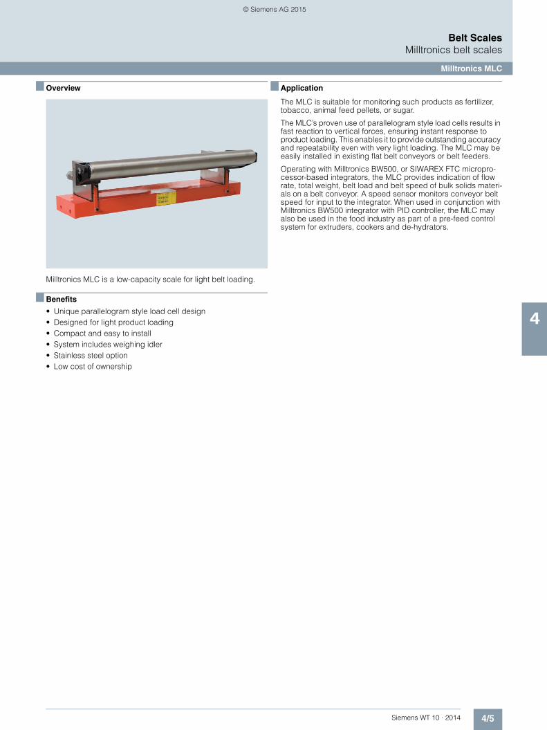
4/5Siemens WT 10 · 2014
Belt ScalesMilltronics belt scales
Milltronics MLC
4
■ Overview
Milltronics MLC is a low-capacity scale for light belt loading.
■ Benefits
• Unique parallelogram style load cell design • Designed for light product loading • Compact and easy to install • System includes weighing idler • Stainless steel option • Low cost of ownership
■ Application
The MLC is suitable for monitoring such products as fertilizer, tobacco, animal feed pellets, or sugar.
The MLC’s proven use of parallelogram style load cells results in fast reaction to vertical forces, ensuring instant response to product loading. This enables it to provide outstanding accuracy and repeatability even with very light loading. The MLC may be easily installed in existing flat belt conveyors or belt feeders.
Operating with Milltronics BW500, or SIWAREX FTC micropro-cessor-based integrators, the MLC provides indication of flow rate, total weight, belt load and belt speed of bulk solids materi-als on a belt conveyor. A speed sensor monitors conveyor belt speed for input to the integrator. When used in conjunction with Milltronics BW500 integrator with PID controller, the MLC may also be used in the food industry as part of a pre-feed control system for extruders, cookers and de-hydrators.
© Siemens AG 2015

4/6 Siemens WT 10 · 2014
Belt ScalesMilltronics belt scales
Milltronics MLC
4
■ Technical specifications1) 2)
1) Accuracy subject to: On factory approved installations the belt scale system’s totalized weight will be within the specified accuracy when compared to a known weighed material test sample. The test rate must be within the specified range of the design capacity and held constant for the duration of the test. The minimum material test sample must be equivalent to a sample obtained at the test flow rate for three revolutions of the belt or at least ten minutes running time, whichever is greater.
2) Contact Siemens application engineering ([email protected]) for consideration of higher belt speeds.
Milltronics MLC
Mode of operation
Measuring principle Strain gauge load cell measuring load on flat belt conveyor idler
Typical application Monitor fertilizer, tobacco, animal feed pellets, sugar, cereal
Performance
Accuracy1) ± 0.5 … 1.0 % of totalization over 25 … 100 % operating range
Medium conditions
Max. material temperature 85 °C (185 °F)
Belt design
Belt width • 450 … 1 200 mm • 18 … 48 inch
Belt speed 2.0 m/s (400 fpm) maximum2)
Capacity Up to 50 t/h (55 STPH)
Conveyor incline • ± 20° from horizontal, fixed incline
• Up to ± 30° with reduced accuracy
Idlers
Conveyor idler Horizontal
Idler diameter 50 or 60 mm (1.90 or 2.30 inch)
Idler spacing 0.5 … 1.5 m (1.6 … 5.0 ft)
Load cell
Construction 17-4 PH (1.4568) stainless steel construction with 304 (1.4301) stainless steel cover
Degree of protection IP67
Cable length 3 m (10 ft)
Excitation 10 V DC nominal, 15 V DC maximum
Output 2 mV/V excitation at rated load cell capacity
Non-linearity 0.03 % of rated output
Hysteresis 0.05 % of rated output
Non-repeatability 0.03 % of rated output
Capacity 10 or 20 lb
Overload 150 % of rated capacity, ultimate 300 % of rated capacity
Temperature • -40 … +85 °C (-40 ... +185 °F) operating range
• -10 … +60 °C (14 … 140 °F) compensated
Mounting dimensions Identical for all capacities
Hazardous locations Consult the factory
Approvals CE, RCM, GOST-R
Milltronics MLC
© Siemens AG 2015

4/7Siemens WT 10 · 2014
Belt ScalesMilltronics belt scales
Milltronics MLC
4
■ Selection and ordering data1) 2) 3) 4) Article No. Article No.
1) Only for quotation purposes, not a valid ordering option.2) Available with Belt width/Scale construction options 1G ... 1M and 2G ... 2M only.3) Available with Belt width/Scale construction options 1G ... 1M only.4) Available with Belt width/Scale construction options 1A ... 1F and 2A ... 2F only.
Milltronics MLC belt scaleLow-capacity scale for light belt loading that comes complete with a weighing idler.
7MH7126-
7777
Click on the Article No. for the online configuration in the PIA Life Cycle Portal.
Belt width/Scale construction
Polyester painted mild steel
18 inch (457 mm) 1 A
24 inch (610 mm) 1 B
30 inch (762 mm) 1 C
36 inch (914 mm) 1 D
42 inch (1067 mm) 1 E
48 inch (1219 mm) 1 F
500 mm (20 inch) 1 G
650 mm (26 inch) 1 H
800 mm (32 inch) 1 J
1000 mm (39 inch) 1 K
1200 mm (47 inch) 1 L
450 mm (18 inch) 1 M
Stainless steel 304 (1.4301), bead blast finish (1 ... 6 µm, 40 ... 240 µin)
18 inch (457 mm) 2 A
24 inch (610 mm) 2 B
30 inch (762 mm) 2 C
36 inch (914 mm) 2 D
42 inch (1067 mm) 2 E
48 inch (1219 mm) 2 F
500 mm (20 inch) 2 G
650 mm (26 inch) 2 H
800 mm (32 inch) 2 J
1000 mm (39 inch) 2 K
1200 mm (47 inch) 2 L
450 mm (18 inch) 2 M
Load cell capacity
10 lb (4.55 kg) A
20 lb (9.09 kg) B
Not specified1) X
Weighing idler dimensions
50 mm (1.96 inch)2) 1
60 mm (2.40 inch)3) 2
1.90 inch (48.2 mm)4) 5
Further designs Order Code
Please add "-Z" to article no. and specify order code(s).
Stainless steel tag [69 x 38 mm (2.7 x 1.5 inch)], Measuring-point number / identification (max 27 characters), specify in plain text.
Y15
Manufacturer's test certificate: According to EN 10204-2.2 C11
FDA compliant version. Conduit and fittings designed for food applications conforming to FDA/USDA standards
K01
Operating instructions Article No.
• English 7ML1998-5FF01
• German A5E32007529
Belt Scale Application Guidelines
• English 7ML1998-5GA01
• French 7ML1998-5GA11
• German 7ML1998-5GA31
• Spanish 7ML1998-5GA21
Note: The operating instructions should be ordered as a separate item on the order.This device is shipped with the Siemens Milltronics manual DVD containing the complete operating instructions library.
Spare parts
Load cell, 10 lb (4.55 kg), 17-4 PH (1.4568) stainless steel construction with 304 (1.4301) stainless steel cover, includes hardware
7MH7725-1AA
Load cell, 20 lb (9.09 kg), 17-4 PH (1.4568) stainless steel construction with 304 (1.4301) stainless steel cover, includes hardware
7MH7725-1AB
Conduit replacement kit 7MH7723-1NA
FDA conduit replacement kit 7MH7723-1QL
Milltronics MLC calibration weight [Stainless Steel 304 (1.4301)]
For scales with belt width of 18 inch or 500 mm or 450 mm
1.05 lb (0.47 kg) 7MH7724-1AL
1.63 lb (0.73 kg) 7MH7724-1AM
2.35 lb (1.06 kg) 7MH7724-1AN
3.21 lb (1.45 kg) 7MH7724-1AP
For scales with belt width of 24 inch or 650 mm
1.38 lb (0.62 kg) 7MH7724-1AQ
2.15 lb (0.97 kg) 7MH7724-1AR
3.11 lb (1.41 kg) 7MH7724-1AS
4.24 lb (1.91 kg) 7MH7724-1AT
For scales with belt width of 30 inch or 800 mm
1.72 lb (0.77 kg) 7MH7724-1AU
2.67 lb (1.21 kg) 7MH7724-1AV
3.85 lb (1.73 kg) 7MH7724-1AW
5.26 lb (2.37 kg) 7MH7724-1AX
For scales with belt width of 36 inch or 1 000 mm
2.05 lb (0.92 kg) 7MH7724-1AY
3.19 lb (1.44 kg) 7MH7724-1BA
4.56 lb (2.07 kg) 7MH7724-1BB
6.29 lb (2.83 kg) 7MH7724-1BC
For scales with belt width of 42 inch or 1 000 mm
2.38 lb (1.07 kg) 7MH7724-1BD
3.71 lb (1.67 kg) 7MH7724-1BE
5.35 lb (2.41 kg) 7MH7724-1BF
7.31 lb (3.29 kg) 7MH7724-1BG
For scales with belt width of 48 inch or 1 200 mm
2.72 lb (1.22 kg) 7MH7724-1BH
4.23 lb (1.92 kg) 7MH7724-1BJ
6.06 lb (2.75 kg) 7MH7724-1BK
8.34 lb (3.75 kg) 7MH7724-1BL
Note: Calibration accessories should be ordered asa separate item on the order
© Siemens AG 2015

4/8 Siemens WT 10 · 2014
Belt ScalesMilltronics belt scales
Milltronics MLC
4
■ Dimensional drawings
MLC dimensions in mm (inch)
For pan supported belts, the belt should be cut out to allow the MLC and at least two (preferably four) other idlers to be installed.
'E' dimension'D' dimension'C' dimension'B' dimension'A' roller widthScale sizeMetric designs [dimensions in mm (inch)]
'E' dimension'D' dimension'C' dimension'B' dimension'A' roller widthScale sizeImperial designs [dimensions in inch (mm)]
Front View
Plan View
Installation
20.6
(0
.81)
Idler diameter C (location of removed idler)
MLC belt scale
1.90 (48.3)1.90 (48.3)1.90 (48.3)1.90 (48.3)1.90 (48.3)1.90 (48.3)
1)
B
A
E
96 (3.78)158 (6.22)60 (2.36)1 250 (49.21)1 200 (47.24)1 200 (47.24)96 (3.78)158 (6.22)60 (2.36)1 050 (41.34)1 000 (39.37)1 000 (39.37)96 (3.78)158 (6.22)50 (1.97)850 (33.46)
D
800 (31.50)800 (31.50)96 (3.78)158 (6.22)50 (1.97)700 (27.56)650 (25.59)650 (25.59)96 (3.78)158 (6.22)50 (1.97)550 (21.65)500 (19.69)
1)
500 (19.69)96 (3.78)158 (6.22)50 (1.97)500 (19.69)450 (17.72)450 (17.72)
49 (1 245)48 (1 219)48 (1 219)43 (1 092)
64 (2.5)
42 (1 067)42 (1 067)37 (940)36 (914)36 (914)31 (787)30 (762)30 (762)25 (635)24 (610)24 (610)19 (483)18 (457)18 (457)
4 x Ø11 (0.44)
3.5 (89)6.19 (157)3.5 (89)6.19 (157)3.5 (89)6.19 (157)3.5 (89)6.19 (157)3.5 (89)6.19 (157)3.5 (89)6.19 (157)
© Siemens AG 2015

4/9Siemens WT 10 · 2014
Belt ScalesMilltronics belt scales
Milltronics MLC
4
■ Schematics
MLC connections
Customer junction box
To integrator
Shi
eld
'B'
Shi
eld
'A'
Gre
en 'B
'
Gre
en 'A
'
Red
'B'
Red
'A'
Whi
te 'B
'
Whi
te 'A
'
Bla
ck 'B
'B
lack
'A'
Shi
eld
Load cell 'A'
Load cell 'B'
Note:Conduit and cable arrangement may differ from example shown.
Conduit and box connector
A 5 : 1
A
+ S
IG 'A
'
- SIG
'A'
+ S
IG 'B
'
- SIG
'B'
+ E
XC
- EX
C
© Siemens AG 2015

4/10 Siemens WT 10 · 2014
Belt ScalesMilltronics belt scales
Milltronics MBS
4
■ Overview
Milltronics MBS is a basic, modular, medium-duty belt scale pro-viding dynamic weighing information for process indication. Idler not included with belt scale.
■ Benefits
• Unique modular design • Simple installation • Low cost • Easy retrofit
■ Application
Milltronics MBS is used with aggregates, sand, or minerals, ani-mal feeds or grains, providing basic continuous in-line weighing at a minimal cost. With no cross bridge, this versatile unit will fit most conveyor widths and standard idlers, and product buildup is reduced.
The construction and easy assembly of the MBS ensure quick delivery to meet even the tightest of schedules. Where scales are moved from conveyor to conveyor, the MBS also provides unmatched flexibility.
Operating with Milltronics BW500, or SIWAREX FTC micropro-cessor-based integrators, the MBS provides indication of flow rate, total weight, belt load, and speed of bulk solids materials on a belt conveyor. A speed sensor monitors conveyor belt speed for input to the integrator.
© Siemens AG 2015

4/11Siemens WT 10 · 2014
Belt ScalesMilltronics belt scales
Milltronics MBS
4
■ Technical specifications 1) 2) 3)
1) Accuracy subject to: On factory approved installations the belt scale system’s totalized weight will be within the specified accuracy when compared to a known weighed material test sample. The test rate must be within the specified range of the design capacity and held constant for the duration of the test. The minimum material test sample must be equivalent to a sample obtained at the test flow rate for three revolutions of the belt or at least ten minutes running time, whichever is greater.
2) Contact Siemens application engineering ([email protected]) for consideration of higher belt speeds.3) Review by Siemens application engineer required.
Milltronics MBS
Mode of operation
Measuring principle Heavy duty strain gauge load cells measuring load on belt conveyor idlers
Typical applications • Monitor feed rates of fractionated stone, sand, animal feeds, grains
• Track daily production totals
Performance
Accuracy1) ± 1 % of totalization over 33 … 100 % operating range, application dependent
Medium conditions
Max. material temperature 70 °C (158 °F)
Belt design
Belt width • Standard duty up to 1 000 mm (CEMA width up to 42 inch)
• Refer to dimensional drawing
Belt speed Up to 3.0 m/s (600 fpm)2)
Capacity Up to 1 500 t/h (1 650 STPH) at maximum belt speed
Conveyor incline • ± 20° from horizontal, fixed incline
• Up to ± 30° with reduced accuracy3)
Idlers
Idler profile • Flat to 35° • To 45° with reduced accuracy3)
50 … 150 mm (2 … 6 inch)
Idler diameter 50 … 150 mm (2 … 6 inch)
Idler spacing 0.6 … 1.5 m (2.0 … 5.0 ft)
Load cell
Construction Aluminum
Degree of protection IP66
Cable length 3 m (10 ft)
Excitation 10 V DC nominal, 15 V DC max.
Output 2 ± 0.02 mV/V excitation at rated load cell capacity
Non-repeatability 0.01 % of rated output
Non-linearity 0.02 % of rated output
Hysteresis 0.02 % of rated output
Capacity 30, 50, 100 kg (66, 110, 220 lb)
Overload 150 % of rated capacity, ultimate 200 % of rated capacity
Temperature • -30 … +70 °C (-22 … +158 °F) operating range
• -10 … +40 °C (15 … 105 °F) compensated
Weight 12 kg (26 lb), 6 kg (13 lb) per side
Interconnection wiring (to integrator)
• < 150 m (500 ft) 18 AWG (0.75 mm²) 6 conductor shielded cable
• > 150 m (500 ft) to 300 m (1 000 ft) 18 … 22 AWG (0.75 … 0.34 mm²) 8 conductor shielded cable
Hazardous locations Consult the factory
Approvals CE, RCM, GOST-R
Milltronics MBS
© Siemens AG 2015

4/12 Siemens WT 10 · 2014
Belt ScalesMilltronics belt scales
Milltronics MBS
4
■ Selection and ordering data 1) Article No. Article No.
1) Only for quotation purposes, not a valid ordering option.
Milltronics MBS belt scaleA basic, modular, medium-duty belt scaleproviding dynamic weighing information for process indication.
7MH7121-
7777 0
Standard [up to 1 000 mm (42 inch) belt width] 1
Load cell capacity
30 kg (66 lb) A B
50 kg (110 lb) A C
100 kg (220 lb) A E
Not specified1) X X
Fabrication
Polyester painted mild steel 1
Polyester painted mild steel, for use with flat bar or MWL calibration
2
Further designs Order Code
Please add "-Z" to article no. and specify order code(s).
Stainless steel tag [69 x 38 mm (2.7 x 1.5 inch)], Measuring-point number / identification (max 27 characters), specify in plain text.
Y15
Manufacturer's test certificate: According to EN 10204-2.2
C11
Operating instructions Article No.
• English 7ML1998-5JN01
• French 7ML1998-5JN11
• German A5E32007525
Belt Scale Application Guidelines
• English 7ML1998-5GA01
• French 7ML1998-5GA11
• German 7ML1998-5GA31
• Spanish 7ML1998-5GA21
Note: The operating instructions and application guidelines manual should be ordered as separate lines on the order.
This device is shipped with the Siemens Milltronics manual DVD containing the complete operating instructions library.
Spare parts
Load cell, 30 kg (66 lb), aluminum 7MH7725-1BK
Load cell, 50 kg (110 lb), aluminum 7MH7725-1BL
Load cell, 100 kg (220 lb), aluminum 7MH7725-1BM
Conduit replacement kit 7MH7723-1NA
Calibration weights
Flat bar/MWL retrofit kit 7MH7723-1HA
Calibration test arm assembly, c/w one 8.2 kg (18 lb) calibration weight
7MH7723-1FR
Calibration test arm assembly, c/w two 8.2 kg (18 lb) calibration weights
7MH7723-1FS
MBS/MCS calibration arm c/w idler clip (holds up to two 8.2 kg (18 lb) weights
7MH7726-1AD
Calibration weight, 8.2 kg (18 lb) 7MH7724-1AA
Calibration weight, 6.0 lb (2.7 kg) 7MH7724-1AB
Milltronics flat bar calibration weights, see page 4/59.
Note: The calibration arm and weights should be ordered as separate lines on the order.
© Siemens AG 2015

4/13Siemens WT 10 · 2014
Belt ScalesMilltronics belt scales
Milltronics MBS
4
■ Dimensional drawings
MBS dimensions in mm (inch)
■ Schematics
MBS connections
Based on CEMA sizes3)
Not recommended for declined conveyor applications4)
2 approach and 2 retreat idlers should be aligned with the weigh idler to within 0.8 mm (1/32 inch) to 0 mm (0 inch). Call your Siemens representative for more information.
Notes:1)
Test weights (customer supplied), may be hung on the M8 bolts. If this method is chosen, equal mass should be applied to each weigh beam, and the test weights should hang free of the fixed structure.
2)
Optional flat bar weight arm4)
Apply optional flat bar weight
Standard base (CEMA) idler, or equivalent
(customer supplied)
Existing conveyor stringers
Belt width + 230 (9)3) (or to suit)
Front View
Shipping brackets (must be removed after MBS is installed)
M8 mounting bolt for optional hanging test
weight2)
Ø14.5 (0.57) mounting holes (two per weigh beam)
M12 mounting bolts
Weigh idler
Side View
Direction of belt travel for all flat or inclined conveyors
146.05(5.75)
76 (3.0)
20 (0.79)
116 (4.57)
83 (3.28)
182 (7.17)250 (9.84)
129 (5.06)162 (6.38)
30 (1.18)
95
(3.7
4)Load cells, complete with 3 m (10 ft) cable in
flexible conduit with M20 panel connector
Belt travel
Customer junction box
Shi
eld
'A'
Shi
eld
'B'
Gre
en 'A
'
Gre
en 'B
'
Red
'A'
Red
'B'
Whi
te 'A
'
Whi
te 'B
'
Bla
ck 'A
'B
lack
'B'
Shi
eld
Conduit and box connector
+ S
IG 'A
'
- SIG
'A'
+ S
IG 'B
'
- SIG
'B'
+ E
XC
- EXC
'B' 'A'
Z 3 : 1
Z
© Siemens AG 2015
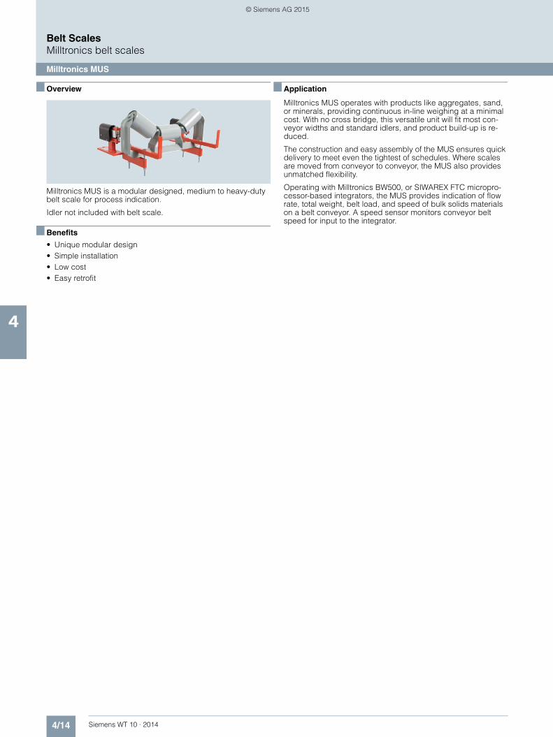
4/14 Siemens WT 10 · 2014
Belt ScalesMilltronics belt scales
Milltronics MUS
4
■ Overview
Milltronics MUS is a modular designed, medium to heavy-duty belt scale for process indication.
Idler not included with belt scale.
■ Benefits
• Unique modular design • Simple installation • Low cost • Easy retrofit
■ Application
Milltronics MUS operates with products like aggregates, sand, or minerals, providing continuous in-line weighing at a minimal cost. With no cross bridge, this versatile unit will fit most con-veyor widths and standard idlers, and product build-up is re-duced.
The construction and easy assembly of the MUS ensures quick delivery to meet even the tightest of schedules. Where scales are moved from conveyor to conveyor, the MUS also provides unmatched flexibility.
Operating with Milltronics BW500, or SIWAREX FTC micropro-cessor-based integrators, the MUS provides indication of flow rate, total weight, belt load, and speed of bulk solids materials on a belt conveyor. A speed sensor monitors conveyor belt speed for input to the integrator.
© Siemens AG 2015

4/15Siemens WT 10 · 2014
Belt ScalesMilltronics belt scales
Milltronics MUS
4
■ Technical specifications 1) 2) 3)
1) Accuracy subject to: On factory approved installations the belt scale system’s totalized weight will be within the specified accuracy when compared to a known weighed material test sample. The test rate must be within the specified range of the design capacity and held constant for the duration of the test. The minimum material test sample must be equivalent to a sample obtained at the test flow rate for three revolutions of the belt or at least ten minutes running time, whichever is greater.
2) Contact Siemens application engineering ([email protected]) for consideration of higher belt speeds.3) Review by Siemens application engineer required.
Milltronics MUS
Mode of operation
Measuring principle Heavy duty strain gauge load cells measuring load on belt conveyor idlers
Typical applications • Monitor fractionated stone on secondary surge belts and recirculating loads
• Track daily production totals
Measurement accuracy
Accuracy1) ± 0.5 … 1 % of totalization over 25 … 100 % operating range, application dependent
Medium conditions
Max. material temperature 65 °C (150 °F)
Belt design
Belt width • Standard duty up to 1 000 mm (CEMA width up to 42 inch)
• Heavy-duty up to 1 524 mm(CEMA width up to 60 inch)
• Refer to dimensional drawing
Belt speed Up to 3.0 m/s (600 fpm)2)
Capacity Up to 5 000 t/h at maximum belt speed
Conveyor incline • ± 20° from horizontal, fixed incline
• Up to ± 30° with reduced accuracy3)
Idlers
Idler profile • Flat to 35° • To 45 ° with reduced accuracy3)
Idler diameter 50 … 180 mm (2 … 7 inch)
Idler spacing 0.6 … 1.5 m (2.0 … 5.0 ft)
Load cell
Construction Nickel plated alloy steel
Degree of protection IP66
Cable length 3 m (10 ft)
Excitation 10 V DC nominal, 15 V DC max.
Output 2 mV/V excitation at rated load cell capacity
Non-linearity and hysteresis 0.02 % of rated output
Non-repeatability 0.01 % of rated output
Capacity
• Standard duty ranges 20, 30, 50, 75, 100 kg (44, 66, 110, 165, 220 lb)
• Heavy-duty ranges 50, 100, 150, 200, 500 kg (110, 220, 330, 440, 1 100 lb)
Overload 150 % of rated capacity, ultimate 200 % of rated capacity
Temperature • -40 ... +65 °C (-40 ... +150 °F) op-erating range
• -10 ... +40 °C (15 ... +105 °F) compensated
Weight Standard duty up to 44 lb (20 kg), 22 lb (10 kg) per sideHeavy-duty up to 64 lb (30 kg), 32 lb (15 kg) per side
Interconnection wiring (to integrator)
• < 150 m (500 ft) 18 AWG (0.75 mm²) 6 conductor shielded cable
• > 150 m … 300 m (500 … 1 000 ft) 18 … 22 AWG (0.75 … 0.34 mm²) 8 conductor shielded cable
Hazardous locations Consult the factory
Approvals CE, RCM, GOST-R, CMC
Milltronics MUS
© Siemens AG 2015

4/16 Siemens WT 10 · 2014
Belt ScalesMilltronics belt scales
Milltronics MUS
4
■ Selection and ordering data1) 2) 3) Article No. Order Code
1) For use with scale construction option 1 only.2) Only for quotation purposes, not a valid ordering option.3) For use with scale construction option 2 only.
Milltronics MUS belt scaleModular design, medium- to heavy-duty scale for process indication.Flat bar calibration weights are optional and should be ordered as separate items, see page 4/59.
7MH7123-
7777 0
Click on the Article No. for the online configuration in the PIA Life Cycle Portal.
Scale construction
Standard for belt width up to 1 000 mm (42 inch), nickel plated steel load cells
1
Heavy-duty for belt width up to 1 524 mm (60 inch), nickel plated steel load cells
2
Load cell capacity
Standard Duty Scale Load Cell
20 kg (44.1 lb)1) A A
30 kg (66.1 lb)1) A B
50 kg (110.2 lb)1) A C
75 kg (165.3 lb)1) A D
100 kg (220.4 lb)1) A E
Not specified2) X X
Heavy-Duty Scale Load Cell
50 kg (110.2 lb)3) B A
100 kg (220.4 lb)3) B B
150 kg (330.7 lb)3) B C
200 kg (440.9 lb)3) B D
300 kg (661.4 lb)3) B E
500 kg (1102.3 lb)3) B F
Fabrication
Polyester painted mild steel 1
Further designs
Please add "-Z" to article no. and specify order code(s).
Stainless steel tag [69 x 38 mm (2.7 x 1.5 inch)], Measuring-point number / identification (max. 27 characters), specify in plain text.
Y15
Manufacturer's test certificate: According to EN 10204-2.2
C11
Operating instructions Article No.
• English 7ML1998-5CQ02
• French 7ML1998-1CQ11
• Spanish 7ML1998-1CQ21
• German A5E32015599
• Dutch 7ML1998-1CQ41
Belt Scale Application Guidelines
• English 7ML1998-5GA01
• French 7ML1998-5GA11
• Spanish 7ML1998-5GA21
• German 7ML1998-5GA31
Note: The operating instructions and application guidelines manual should be ordered as separate items on the order.
This device is shipped with the Siemens Milltronics manual DVD containing the complete operating instructions library.
Spare parts
Standard Duty Scale Load Cell
20 kg (44.1 lb) 7MH7725-1CP
30 kg (66.1 lb) 7MH7725-1CQ
50 kg (110.2 lb) 7MH7725-1CR
75 kg (165.3) 7MH7725-1CS
100 kg (220.5 lb) 7MH7725-1CT
Heavy-Duty Scale Load Cell
50 kg (110.2 lb) 7MH7725-1CU
100 kg (220.5 lb) 7MH7725-1CV
150 kg (330.7 lb) 7MH7725-1CW
200 kg (440.9 lb) 7MH7725-1CX
300 kg (661.4 lb) 7MH7725-1CY
500 kg (1120.3 lb) 7MH7725-1DA
Rock Guard, MUS Standard Duty Scale, spare 7MH7723-1DM
Conduit replacement kit 7MH7723-1NA
Calibration weights
Milltronics flat bar calibration weights, see page 4/59
Note: Calibration accessories should be ordered as a separate item on the order
© Siemens AG 2015

4/17Siemens WT 10 · 2014
Belt ScalesMilltronics belt scales
Milltronics MUS
4
■ Dimensional drawings
MUS dimensions in mm (inch)
Side view Side view
Standard duty
Front view Front view
Note:(2) approach and (2) retreat idlers should be aligned withthe weigh idler to within 0.8 (+1/3) to 0 (0).
M12 (½")mounting bolts
Belt direction for all flat or inclined conveyors
Shippingbrackets
Calibrationbar support(test weight)
Shipping brackets
Standard base CEMAidler or equivalent
(customer supplied)
Existing conveyor stringers
Belt width + 230 (9)(or to suit)
Heavy duty
Note:(2) approach and (2) retreat idlers should be aligned withthe weigh idler to within 0.8 (+1/3) to 0 (0).
Shipping brackets
Weigh idler
Calibrationbar support
(test weight)Shippingbrackets
M12 (½")mounting bolts
Standard base CEMAidler or equivalent
(customer supplied)
Existing conveyor stringers
Belt width + 230 (9)(or to suit)
Weigh idler
Belt direction for all flat or inclined conveyors
122(4.81)
76(3.00)
19 (0.75)
203(8.00)
159(6.25)
616(24.25)
143(5.62)
89(3.50)
184 (7.25)
186 (7.310)
19(0.75)
168(6.63)
140(5.50)
522(20.56)
© Siemens AG 2015

4/18 Siemens WT 10 · 2014
Belt ScalesMilltronics belt scales
Milltronics MUS
4
■ Schematics
MUS connections
Belt travel
Load cells, complete with 3 m (10 ft) cablein flexible conduit with M20 panel connector
Customer junction boxShield
Shield'A'
Shield'B'
'B' 'A'
+SIG
'A'
-SIG
'A'
+SIG
'B'
-SIG
'B'
-EX
C
+EX
C
'A''B'
© Siemens AG 2015

4/19Siemens WT 10 · 2014
Belt ScalesMilltronics belt scales
Milltronics MCS
4
■ Overview
Milltronics MCS is a compact, rugged, modular, heavy-duty belt scale for use in mobile crushers and aggregate screening plants.
Idler not included with belt scale.
■ Benefits
• Rugged design • Low profile • Easy retrofit • Low cost • Stainless steel load cells
■ Application
Milltronics MCS provides continuous, in-line weighing at minimal cost. The stainless steel load cells ensure long-term, consistent, reliable measurement. The modular construction and easy as-sembly of the MCS ensures quick delivery to meet even the tight-est of schedules.
Operating with Milltronics BW500, or SIWAREX FTC micropro-cessor-based integrators, the MCS provides indication of flow rate, total weight, belt load, and belt speed of bulk solids mate-rials on a belt conveyor.
To complete the weighing system, include a speed sensor to monitor conveyor belt speed for input to the integrator. On mo-bile crushing equipment, the TASS speed sensor is a compact, rugged speed sensor designed for use with the MCS.
© Siemens AG 2015

4/20 Siemens WT 10 · 2014
Belt ScalesMilltronics belt scales
Milltronics MCS
4
■ Technical specifications 1) 2) 3)
1) Accuracy subject to: On factory approved installations the belt scale system’s totalized weight will be within the specified accuracy when compared to a known weighed material test sample. The test rate must be within the specified range of the design capacity and held constant for the duration of the test. The minimum material test sample must be equivalent to a sample obtained at the test flow rate for three revolutions of the belt or at least ten minutes running time, whichever is greater.
2) Contact Siemens application engineering ([email protected]) for consideration of higher belt speeds.3) Review by Siemens application engineer required.
Milltronics MCS
Mode of operation
Measuring principle Strain gauge load cells measuring load on belt conveyor idlers
Typical application Mobile crusher systems
Measurement accuracy
Accuracy1) • ± 0.5 … 1 % of totalization over 25 … 100 % operating range, ap-plication dependent
• ± 2 % of totalization over 25 … 100 % operating range on mobile crusher applications
Belt design
Belt width • Up to 1 600 mm (60 inch CEMA) width
• Refer to the dimensional drawing
Belt speed Up to 4 m/s (800 fpm)2)
Capacity Up to 2 400 t/h (2 640 STPH) at maximum belt speed
Conveyor incline • ± 20° from horizontal, fixed incline
• Up to ± 30° with reduced accuracy3)
Idlers
Idler profile • Flat to 35° • To 45° with reduced accuracy3)
Idler diameter 100 … 150 mm (4 … 6 inch)
Idler spacing 0.6 … 1.2 m (2.0 … 4.0 ft)
Load cell
Construction 17-4 PH (1.4568) stainless steel construction with 304 (1.4301) stainless steel cover
Degree of protection IP67, IP65 on hazardous approved models
Cable length 3 m (10 ft)
Excitation 10 V DC nominal, 15 V maximum
Output 2 mV/V excitation at rated load cell capacity
Non-linearity and hysteresis 0.02 % of rated output
Non-repeatability 0.01 % of rated output
Capacity 25, 50, 100, 250, 500 lb stainless steel
Overload 150 % of rated capacity, ultimate 300 % of rated capacity
Temperature • -50 … +75 °C (-58 … +167 °F) operating range
• -40 … +65 °C (-40 … +150 °F) compensated
Weight Up to 20 kg (44 lb), 10 kg (22 lb) per side
Interconnection wiring (to integrator)
• < 150 m (500 ft) 18 AWG (0.75 mm²) 6 conductor shielded cable
• > 150 m (500 ft) to 300 m (1 000 ft) 18 … 22 AWG (0.75 … 0.34 mm²), 8 conductor shielded cable
Approvals • CSA/FM Class II, Div. 1, Groups E,F,G and Class III
• ATEX II 2D, Ex tD A21 IP65 T90 ºC
• GOST-R Ex • IEC Ex, Ex tD A21 IP65 T90 ºC • CE, RCM, GOST-R, RTN
Milltronics MCS
© Siemens AG 2015

4/21Siemens WT 10 · 2014
Belt ScalesMilltronics belt scales
Milltronics MCS
4
■ Selection and ordering data 1) Article No. Article No.
We can offer shorter delivery times for configurations designated with the Quick Ship Symbol
1) Only for quotation purposes, not a valid ordering option.
Milltronics MCS belt scaleA compact, rugged, modular, heavy-duty belt scale for use in mining and aggregate screening plants
7MH7125-
7777 0
Click on the Article No. for the online configuration in the PIA Life Cycle Portal.
Scale construction
Standard duty, CE, RCM 1
Hazardous Duty CSA/FM Class II, Div. 1, Groups E,F,G and Class III, ATEX II 2D, IECEx, CE, RCM
2
Load cell capacity
50 lb (22.7 kg) (use not recommended for mobile crushers)
A A
100 lb (45.5 kg) (use not recommended for mobile crushers)
A B
250 lb (113.6 kg) A C
500 lb (226.8 kg) A D
25 lb (11.3 kg) (use not recommended for mobile crushers)
A E
Not specified1) B B
Fabrication
Polyester painted mild steel 1
Polyester painted mild steel, for use with flat bar or MWL calibration
2
Further designs Order Code
Please add "-Z" to article no. and specify order code(s).
Stainless steel tag [69 x 38 mm (2.7 x 1.5 inch)], Measuring-point number / identification (max 27 characters), specify in plain text.
Y15
Manufacturer's test certificate: According to EN 10204-2.2
C11
Operating instructions
MCS belt scale, multi-language A5E33071768
Belt Scale Application Guidelines
• English 7ML1998-5GA01
• French 7ML1998-5GA11
• German 7ML1998-5GA31
• Spanish 7ML1998-5GA21
Hazardous location certificates 7ML1998-5KH81
Note: The operating instructions should be ordered as a separate item on the order.
This device is shipped with the Siemens Milltronics manual DVD containing the complete operating instructions library.
Spare parts
Stainless steel load cell [17-4 PH (1.4568) stainless steel construction with 304 (1.4301) stainless steel cover]
25 lb (11.3 kg) 7MH7725-1DR
50 lb (22.7 kg) 7MH7725-1DH
100 lb (45.4 kg) 7MH7725-1DJ
250 lb (113.4 kg) 7MH7725-1DK
500 lb (226.8 kg) 7MH7725-1DS
25 lb (11.3 kg), CSA/FM/ATEX/IECEx 7MH7725-1DQ
50 lb (22.7 kg), CSA/FM/ATEX/IECEx 7MH7725-1DL
100 lb (45.4 kg), CSA/FM/ATEX/IECEx 7MH7725-1DM
250 lb (113.4 kg), CSA/FM/ATEX/IECEx 7MH7725-1DN
500 lb (226.8 kg), CSA/FM/ATEX/IECEx 7MH7725-1DP
Conduit replacement kit 7MH7723-1NA
Calibration weights
Flat bar/MWL retrofit kit 7MH7723-1HA
Calibration test arm assembly, c/w one 8.2 kg (18 lb) calibration weight
7MH7723-1FR
Calibration test arm assembly, c/w two 8.2 kg (18 lb) calibration weights
7MH7723-1FS
MBS/MCS calibration arm c/w idler clip (holds up to two 8.2 kg (18 lb) weights
7MH7726-1AD
Calibration weight, 18 lb (8.2 kg) 7MH7724-1AA
Calibration weight, 6 lb (2.7 kg) 7MH7724-1AB
Milltronics flat bar calibration weights, see page 4/59.
Note: Calibration accessories should be ordered as a separate item on the order.
© Siemens AG 2015

4/22 Siemens WT 10 · 2014
Belt ScalesMilltronics belt scales
Milltronics MCS
4
■ Dimensional drawings
MCS dimensions in mm (inch)
Belt direction
View A-AView A-A
Mounting flangeIdler clamp
to suitup to 1 600 (60) belt width
Shipping brackets
Customersuppliedstringer
Standard base CEMA idler orequivalent (customer supplied)
Plan View
Side View
Front View
1) Not recommended for inclined conveyorapplications
Note:A minimum of 2 approach and 2 retreat idlersshould be aligned with the weigh idler to within0.75 (+1/32) to 0 (0).
Apply optionalflat bar weight
Optional flat barweigh arm1)
75(2.95)150
(5.91)
AA
16(0.63)
101(3.98)
300(11.81)
124(4.9)
75(2.95)
160(6.30)
146.05(5.75)
150(5.91)
© Siemens AG 2015

4/23Siemens WT 10 · 2014
Belt ScalesMilltronics belt scales
Milltronics MCS
4
■ Schematics
MCS connections
Belt travel
Load cell A Load cell B
Load cell BLoad cell A
See detail A
Stringer mounted junction box(by customer)
Conduit and boxconnector
Detail A
Note:Conduit and connector not provided on hazardous approved option
Red
Red
Bla
ckW
hite
Gre
en
Bla
ckW
hite
Gre
en
Shi
eld
Shi
eld
+ EX
C- E
XC
+ SIG
A- S
IG B
+ SIG
BS
hield
- SIG A
© Siemens AG 2015

4/24 Siemens WT 10 · 2014
Belt ScalesMilltronics belt scales
Milltronics MSI and MMI
4
■ Overview
Milltronics MSI is a heavy-duty, high accuracy full-frame single idler belt scale used for process and load-out control. Idler not included with belt scale.
Milltronics MMI is a heavy-duty, high accuracy multiple idler belt scale used for critical process and load-out control. Idler not in-cluded with belt scale.
■ Benefits
Milltronics MSI belt scale• Outstanding accuracy and repeatability • Unique parallelogram style load cell design • Fast reaction to product loading; capable of monitoring fast
moving belts • Rugged construction • SABS approval (South Africa), OIML, MID, and Measurement
Canada
Milltronics MMI belt scale• Exceptional accuracy and repeatability • Unique parallelogram style load cell design • Suitable for uneven or light product loading • Capable of monitoring fast moving belts • Low cost of ownership • NTEP, OIML, MID and Measurement Canada approved
■ Application
Milltronics MSI belt scale
Milltronics MSI belt scale provides continuous in-line weighing on a variety of products in primary and secondary industries. It is proven in a wide range of tough applications from extraction (in mines, quarries and pits), to power generation, iron and steel, food processing and chemicals. The MSI is suitable for monitor-ing such diverse products as sand, flour, coal, or sugar.
The MSI’s proven use of parallelogram-style load cells results in fast reaction to vertical forces, ensuring instant response to product loading. This enables it to provide outstanding accuracy and repeatability even with uneven loading and fast belt speeds.
Operating with Milltronics BW500, or SIWAREX FTC micropro-cessor-based integrators, the MSI provides indication of flow rate, totalized weight, belt load, and belt speed of bulk solid ma-terials. A speed sensor monitors conveyor belt speed for input to the integrator.
The MSI is installed in a simple drop-in operation and may be se-cured with just four bolts. An existing idler is then attached to the MSI dynamic beam. With no moving parts, maintenance is kept to a minimum, with just periodic calibration checks required.
Milltronics MMI belt scale
Milltronics MMI belt scale consists of two or more MSI single idler belt scales installed in series. It provides high accuracy continuous in-line weighing on a variety of products in primary and secondary industries. The MMI system is proven in a wide range of tough applications from extraction to power generation, iron and steel, food processing and chemicals. The MMI is suit-able for monitoring such diverse products as fertilizer, sand, grain, flour, coal, or sugar.
The MMI’s proven use of parallelogram-style load cells results in fast reaction to vertical forces, ensuring instant response to product loading. This enables it to provide outstanding accuracy and repeatability even with uneven or light loading, short idler spacing and fast belt speeds. Operating with Milltronics BW500 or SIWAREX FTC integrator (for custody transfer applications), the MMI provides indication of flow rate, total weight, belt load and belt speed of bulk solids materials on a belt conveyor. A speed sensor monitors conveyor belt speed for input to the in-tegrator.
The MMI is installed in a simple drop-in operation and may be secured with just eight bolts and existing idler sets, secured to the dynamic beam. With no moving parts, maintenance is kept to a minimum, with just periodic calibration checks required.
© Siemens AG 2015
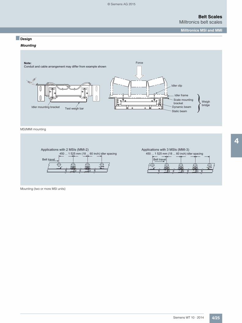
4/25Siemens WT 10 · 2014
Belt ScalesMilltronics belt scales
Milltronics MSI and MMI
4
■ Design
Mounting
MSI/MMI mounting
Mounting (two or more MSI units)
Note:Conduit and cable arrangement may differ from example shown
Idler mounting bracket Test weigh bar
Idler clip
Force
Idler frameScale mountingbracket
Dynamic beamStatic beam
Weighbridge}
Applications with 2 MSIs (MMI-2)450 ... 1 525 mm (18 ... 60 inch) idler spacing
Belt travel
450 ... 1 525 mm (18 ... 60 inch) idler spacing
Belt travel
Applications with 3 MSIs (MMI-3)
© Siemens AG 2015
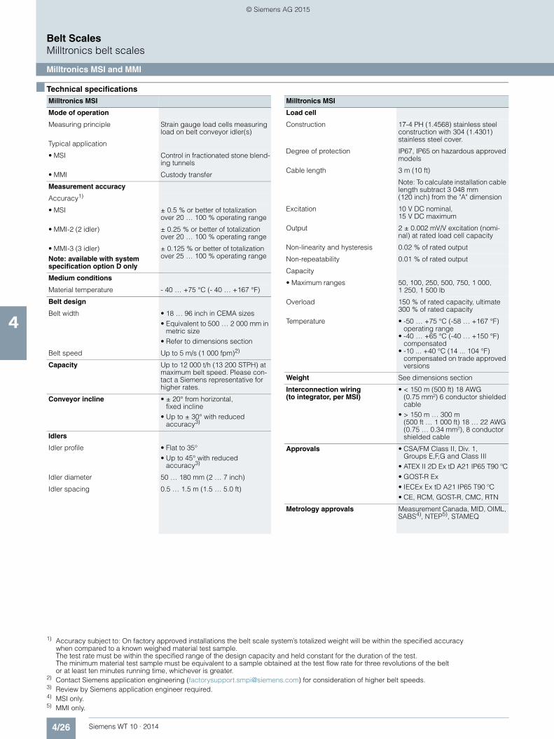
4/26 Siemens WT 10 · 2014
Belt ScalesMilltronics belt scales
Milltronics MSI and MMI
4
■ Technical specifications 1) 2) 3) 4) 5)
1) Accuracy subject to: On factory approved installations the belt scale system’s totalized weight will be within the specified accuracy when compared to a known weighed material test sample. The test rate must be within the specified range of the design capacity and held constant for the duration of the test. The minimum material test sample must be equivalent to a sample obtained at the test flow rate for three revolutions of the belt or at least ten minutes running time, whichever is greater.
2) Contact Siemens application engineering ([email protected]) for consideration of higher belt speeds.3) Review by Siemens application engineer required.4) MSI only.5) MMI only.
Milltronics MSI
Mode of operation
Measuring principle Strain gauge load cells measuring load on belt conveyor idler(s)
Typical application
• MSI Control in fractionated stone blend-ing tunnels
• MMI Custody transfer
Measurement accuracy
Accuracy1)
• MSI ± 0.5 % or better of totalization over 20 … 100 % operating range
• MMI-2 (2 idler) ± 0.25 % or better of totalization over 20 … 100 % operating range
• MMI-3 (3 idler) Note: available with system specification option D only
± 0.125 % or better of totalization over 25 … 100 % operating range
Medium conditions
Material temperature - 40 … +75 °C (- 40 … +167 °F)
Belt design
Belt width • 18 … 96 inch in CEMA sizes • Equivalent to 500 … 2 000 mm in
metric size • Refer to dimensions section
Belt speed Up to 5 m/s (1 000 fpm)2)
Capacity Up to 12 000 t/h (13 200 STPH) at maximum belt speed. Please con-tact a Siemens representative for higher rates.
Conveyor incline • ± 20° from horizontal, fixed incline
• Up to ± 30° with reduced accuracy3)
Idlers
Idler profile • Flat to 35° • Up to 45° with reduced
accuracy3)
Idler diameter 50 … 180 mm (2 … 7 inch)
Idler spacing 0.5 … 1.5 m (1.5 … 5.0 ft)
Load cell
Construction 17-4 PH (1.4568) stainless steel construction with 304 (1.4301) stainless steel cover.
Degree of protection IP67, IP65 on hazardous approved models
Cable length 3 m (10 ft)
Note: To calculate installation cable length subtract 3 048 mm (120 inch) from the "A" dimension
Excitation 10 V DC nominal, 15 V DC maximum
Output 2 ± 0.002 mV/V excitation (nomi-nal) at rated load cell capacity
Non-linearity and hysteresis 0.02 % of rated output
Non-repeatability 0.01 % of rated output
Capacity
• Maximum ranges 50, 100, 250, 500, 750, 1 000, 1 250, 1 500 lb
Overload 150 % of rated capacity, ultimate 300 % of rated capacity
Temperature • -50 … +75 °C (-58 … +167 °F) operating range
• -40 … +65 °C (-40 … +150 °F) compensated
• -10 ... +40 °C (14 ... 104 °F) compensated on trade approved versions
Weight See dimensions section
Interconnection wiring (to integrator, per MSI)
• < 150 m (500 ft) 18 AWG (0.75 mm²) 6 conductor shielded cable
• > 150 m … 300 m (500 ft … 1 000 ft) 18 … 22 AWG (0.75 … 0.34 mm²), 8 conductor shielded cable
Approvals • CSA/FM Class II, Div. 1, Groups E,F,G and Class III
• ATEX II 2D Ex tD A21 IP65 T90 ºC• GOST-R Ex • IECEx Ex tD A21 IP65 T90 ºC • CE, RCM, GOST-R, CMC, RTN
Metrology approvals Measurement Canada, MID, OIML, SABS4), NTEP5), STAMEQ
Milltronics MSI
© Siemens AG 2015

4/27Siemens WT 10 · 2014
Belt ScalesMilltronics belt scales
Milltronics MSI and MMI
4
■ Selection and ordering data Article No. Article No.
Milltronics MSI belt scaleA heavy-duty, high-accuracy single idler belt scale for process and load-out control.For Milltronics MMI belt scale system, two or more MSI belt scales are required. Calibration weights are required and ordered as separate items.
7MH7122-
77777 - 77
Click on the Article No. for the online configuration in the PIA Life Cycle Portal.
Scale construction
Standard duty, CE, RCM 1
Hazardous Duty CSA/FM Class II, Div. 1, Groups E,F,G and Class III, ATEX II 2D, IECEx, CE, RCM
2
Belt width and 'A' dimension
18 inch, 'A' = 27 inch (686 mm) A A
19 inch, 'A' = 28 inch (711 mm) A B
20 inch, 'A' = 29 inch (737 mm) A C
21 inch, 'A' = 30 inch (762 mm) A D
22 inch, 'A' = 31 inch (787 mm) A E
23 inch, 'A' = 32 inch (813 mm) A F
24 inch, 'A' = 33 inch (838 mm) A G
25 inch, 'A' = 34 inch (864 mm) A H
26 inch, 'A' = 35 inch (889 mm) A J
27 inch, 'A' = 36 inch (914 mm) A K
28 inch, 'A' = 37 inch (940 mm) A L
29 inch, 'A' = 38 inch (965 mm) A M
30 inch, 'A' = 39 inch (991 mm) A N
31 inch, 'A' = 40 inch (1 016 mm) A P
32 inch, 'A' = 41 inch (1 041 mm) A Q
33 inch, 'A' = 42 inch (1 067 mm) A R
34 inch, 'A' = 43 inch (1 092 mm) A S
35 inch, 'A' = 44 inch (1 118 mm) A T
36 inch, 'A' = 45 inch (1 143 mm) A U
37 inch, 'A' = 46 inch (1 168 mm) A V
38 inch, 'A' = 47 inch (1 194 mm) AW
39 inch, 'A' = 48 inch (1 219 mm) B A
40 inch, 'A' = 49 inch (1 245 mm) B B
41 inch, 'A' = 50 inch (1 270 mm) B C
42 inch, 'A' = 51 inch (1 295 mm) B D
43 inch, 'A' = 52 inch (1 321 mm) B E
44 inch, 'A' = 53 inch (1 346 mm) B F
45 inch, 'A' = 54 inch (1 372 mm) B G
46 inch, 'A' = 55 inch (1 397 mm) B H
47 inch, 'A' = 56 inch (1 422 mm) B J
48 inch, 'A' = 57 inch (1 448 mm) B K
49 inch, 'A' = 58 inch (1 473 mm) B L
50 inch, 'A' = 59 inch (1 499 mm) B M
51 inch, 'A' = 60 inch (1 524 mm) B N
52 inch, 'A' = 61 inch (1 549 mm) B P
53 inch, 'A' = 62 inch (1 575 mm) B Q
54 inch, 'A' = 63 inch (1 600 mm) B R
55 inch, 'A' = 64 inch (1 626 mm) B S
56 inch, 'A' = 65 inch (1 651 mm) B T
57 inch, 'A' = 66 inch (1 676 mm) B U
58 inch, 'A' = 67 inch (1 702 mm) B V
59 inch, 'A' = 68 inch (1 727 mm) BW
60 inch, 'A' = 69 inch (1 753 mm) C A
61 inch, 'A' = 70 inch (1 778 mm) C B
62 inch, 'A' = 71 inch (1 803 mm) C C
63 inch, 'A' = 72 inch (1 829 mm) C D
64 inch, 'A' = 73 inch (1 854 mm) C E
65 inch, 'A' = 74 inch (1 880 mm) C F
66 inch, 'A' = 75 inch (1 905 mm) C G
67 inch, 'A' = 76 inch (1 930 mm) C H
68 inch, 'A' = 77 inch (1 956 mm) C J
69 inch, 'A' = 78 inch (1 981 mm) C K
70 inch, 'A' = 79 inch (2 007 mm) C L
71 inch, 'A' = 80 inch (2 032 mm) CM
72 inch, 'A' = 81 inch (2 057 mm) C N
73 inch, 'A' = 82 inch (2 083 mm) C P
74 inch, 'A' = 83 inch (2 108 mm) C Q
75 inch, 'A' = 84 inch (2 134 mm) C R
76 inch, 'A' = 85 inch (2 159 mm) C S
77 inch, 'A' = 86 inch (2 184 mm) C T
78 inch, 'A' = 87 inch (2 210 mm) C U
79 inch, 'A' = 88 inch (2 235 mm) C V
80 inch, 'A' = 89 inch (2 261 mm) CW
81 inch, 'A' = 90 inch (2 286 mm) D A
82 inch, 'A' = 91 inch (2 311 mm) D B
83 inch, 'A' = 92 inch (2 337 mm) D C
84 inch, 'A' = 93 inch (2 362 mm) D D
85 inch, 'A' = 94 inch (2 388 mm) D E
86 inch, 'A' = 95 inch (2 413 mm) D F
87 inch, 'A' = 96 inch (2 438 mm) D G
88 inch, 'A' = 97 inch (2 464 mm) D H
89 inch, 'A' = 98 inch (2 489 mm) D J
90 inch, 'A' = 99 inch (2 515 mm) D K
91 inch, 'A' = 100 inch (2 540 mm) D L
92 inch, 'A' = 101 inch (2 565 mm) DM
93 inch, 'A' = 102 inch (2 591 mm) D N
94 inch, 'A' = 103 inch (2 616 mm) D P
95 inch, 'A' = 104 inch (2 642 mm) D Q
96 inch, 'A' = 105 inch (2 667 mm) D R
Load cell capacity
Not specified1) 0
50 lb (22.7 kg) 1
100 lb (45.4 kg) 2
250 lb (113.4 kg) 3
500 lb (226.8 kg) 4
750 lb (340.2 kg) 5
1 000 lb (453.6 kg) 6
1 250 lb (567 kg)2) 7
1 500 lb (680.4 kg)2) 8
Milltronics MSI belt scaleA heavy-duty, high-accuracy single idler belt scale for process and load-out control.For Milltronics MMI belt scale system, two or more MSI belt scales are required. Calibration weights are required and ordered as separate items.
7MH7122-
77777 - 77
© Siemens AG 2015

4/28 Siemens WT 10 · 2014
Belt ScalesMilltronics belt scales
Milltronics MSI and MMI
4
■ Selection and ordering data Article No. Order Code
Milltronics MSI belt scaleA heavy-duty, high-accuracy single idler belt scale for process and load-out control. For Milltronics MMI belt scale system, two or more MSI belt scales are required. Calibration weights are required and ordered as separate items.
7MH7122-
7777 - 77
Fabrication
Polyester painted mild steel 1 1
Electro-galvanized mild steel:
18 ... 29 inch (457.2 ... 736.6 mm) 1 2
30 ... 41 inch (762 ... 1 041.4 mm) 1 3
42 ... 53 inch (1 066.8 ... 1 346.2 mm) 1 4
54 ... 65 inch (1 371.6 ... 1 651 mm) 1 5
66 ... 77 inch (1 676.4 ... 1 955.8 mm) 1 6
78 ... 89 inch (1 981.2 ... 2 260.6 mm) 1 7
90 ... 96 inch (2 786 ... 2 438.4 mm) 1 8
Stainless steel 304 (1.4301), bead blast finish (1 ... 6 µm, 40 ... 240 µin) for belt width scales:
18 ... 29 inch (457.2 ... 736.6 mm) 2 1
30 ... 41 inch (762 ... 1 041.4 mm) 2 2
42 ... 53 inch (1 066.8 ... 1 346.2 mm) 2 3
54 ... 65 inch (1 371.6 ... 1 651 mm) 2 4
66 ... 77 inch (1 676.4 ... 1 955.8 mm) 2 5
78 ... 89 inch (1 981.2 ... 2 260.6 mm) 2 6
90 ... 96 inch (2 786 ... 2 438.4 mm) 2 7
Stainless steel 316 (1.4401), bead blast finish (1 ... 6 µm, 40 ... 240 µin) for belt width scales:
18 ... 29 inch (457.2 ... 736.6 mm) 3 1
30 ... 41 inch (762 ... 1 041.4 mm) 3 2
42 ... 53 inch (1 066.8 ... 1 346.2 mm) 3 3
54 ... 65 inch (1 371.6 ... 1 651 mm) 3 4
66 ... 77 inch (1 676.4 ... 1 955.8 mm) 3 5
78 ... 89 inch (1 981.2 ... 2 260.6 mm) 3 6
90 ... 96 inch (2 786 ... 2 438.4 mm) 3 7
Polyester painted mild steel (compatible with MWL or flat bar weight calibration system)
4 1
Galvanized, for belt width scales:(compatible with MWL or flat bar weight system)
18 ... 29 inch (457.2 ... 736.6 mm) 4 2
30 ... 41 inch (762 ... 1 041.4 mm) 4 3
42 ... 53 inch (1 066.8 ... 1 346.2 mm) 4 4
54 ... 65 inch (1 371.6 ... 1 651 mm) 4 5
66 ... 77 inch (1 676.4 ... 1 955.8 mm) 4 6
78 ... 89 inch (1 981.2 ... 2 260.6 mm) 4 7
90 ... 96 inch (2 786 ... 2 438.4 mm) 4 8
System specification
Standard MSI and MMI A
NTEP Certified MMI3)4)5) B
OIML/MID Certified4)5) C
MSI for MMI-3 ±0.125% accuracy6) D
Further designs
Please add "-Z" to article no. and specify order code(s).
Stainless steel tag [69 x 38 mm (2.7 x 1.5 inch)], Measuring-point number / identification (max 27 characters), specify in plain text.
Y15
Manufacturer's test certificate: According to EN 10204-2.2
C11
Factory calibration certificate Y33
OIML/MID approval additional nameplate (submit application data with order)5)
Y77
NTEP approval additional nameplate (submit application data with order)5)
Y78
Extended cable length (For spare part pricing and part number consult factory) Load cell with 15 m (49.2 ft) cable length [standard is 3 m (9.8 ft)]
A08
High temp load cell (For spare part pricing and part number consult factory)Load cell suitable for high temp up to 175 °C (347 °F) [standard is 75 °C (167 °F)]7)
T50
Load cell with 316 (1.4401) cover (For spare part pricing and part number consult factory)Load cell cover is constructed from 316 (1.4401) stainless steel [standard is 304 (1.4301)]
H53
FDA compliant versionConduit and fittings designed for food applications conforming to FDA/USDA standards
K01
Operating instructions Article No.
MSI Manuals
• English 7ML1998-5CY04
• German A5E32007535
• French 7ML1998-1CY13
• Spanish 7ML1998-1CY23
MMI Manuals
• English 7ML1998-5DR03
• German 7ML1998-5DR34
• French 7ML1998-5DR14
• Spanish 7ML1998-5DR24
Belt Scale Application Guidelines
• English 7ML1998-5GA01
• German 7ML1998-5GA31
• French 7ML1998-5GA11
• Spanish 7ML1998-5GA21
• Hazardous location certificates 7ML1998-5KH81
Multi-language Quick Start manual 7ML1998-5XK81
Note: The operating instructions and application guidelines manual should be ordered as separate items on the order.
This device is shipped with the Siemens Milltronics manual DVD containing the complete operating instructions library.
© Siemens AG 2015

4/29Siemens WT 10 · 2014
Belt ScalesMilltronics belt scales
Milltronics MSI and MMI
4
■ Selection and ordering data Article No.
We can offer shorter delivery times for configurations designated with the Quick Ship Symbol
1) 2) 3) 4) 5) 6) 7)
Spare parts
Flat bar/MWL retrofit kit 7MH7723-1FW
Conduit replacement kit 7MH7723-1NA
FDA conduit replacement kit 7MH7723-1QL
MWL calibration weight support brackets galvanized 7MH7723-1JT
Stainless steel load cell [17-4 PH (1.4568) stainless steel construction with 304 (1.4301) stainless steel cover]
50 lb (22.7 kg) 7MH7725-1AC
100 lb (45.4 kg) 7MH7725-1AD
250 lb (113.4 kg) 7MH7725-1AE
500 lb (226.8 kg) 7MH7725-1AF
750 lb (340.2 kg) 7MH7725-1AG
1 000 lb (453.6 kg) 7MH7725-1AH
1 250 lb (567 kg) 7MH7725-1EA
1 500 lb (680.4 kg) 7MH7725-1EB
100 lb (45.4 kg), NTEP, OIML/MID 7MH7725-1DB
250 lb (113.4 kg), NTEP, OIML/MID 7MH7725-1DC
500 lb (226.8 kg), NTEP, OIML/MID 7MH7725-1DD
750 lb (340.2 kg), NTEP, OIML/MID 7MH7725-1DE
1 000 lb (453.6 kg), NTEP, OIML/MID 7MH7725-1DF
50 lb (22.7 kg), CSA/FM/ATEX/IECEx 7MH7725-1DT
100 lb (45.4 kg), CSA/FM/ATEX/IECEx 7MH7725-1DU
250 lb (113.4 kg), CSA/FM/ATEX/IECEx 7MH7725-1DV
500 lb (226.8 kg), CSA/FM/ATEX/IECEx 7MH7725-1DW
750 lb (340.2 kg), CSA/FM/ATEX/IECEx 7MH7725-1DX
1 000 lb (453.6 kg), CSA/FM/ATEX/IECEx 7MH7725-1DY
1 250 lb (567 kg), CSA/FM/ATEX/IECEx 7MH7725-1EE
1 500 lb (680.4 kg), CSA/FM/ATEX/IECEx 7MH7725-1EF
Idler clips
5 inch (127 mm) for 27 ... 62 inch (686 ... 1 575 mm) 'A' dimensions
7MH7723-1BT
7 inch (178 mm) for 63 ... 74 inch (1 600 ... 1 880 mm) 'A' dimensions
7MH7723-1DF
Calibration weights
6.0 lb / 2.7 kg 7MH7724-1AB
18 lb / 8.2 kg 7MH7724-1AA
18 lb/ 8.2 kg certified weight A5E32423812
Milltronics flat bar calibration weights, see page 4/59.
Note: Calibration accessories should be ordered asa separate item on the order
1) Only for quotation purposes, not a valid ordering option.2) Available with Fabrication options 11 ... 18 and 41 ... 48 only, and with
System specification option A only.3) Two MSI are required to make the NTEP approved MMI.4) Approval available with load cell options 2 ... 6 only and applicable BW500.5) Complete specification data sheet on page 4/3 and submit
with order "legal for trade" version.6) Includes metrological approved load cells.7) Not available with construction option 2, or system specification option
B, C, D.
© Siemens AG 2015

4/30 Siemens WT 10 · 2014
Belt ScalesMilltronics belt scales
Milltronics MSI and MMI
4
■ Dimensional drawings
MSI dimensions
Other widths available - check configuration information. Sizes are from 18 inch (457 mm) to 96 inch (2 438 mm) in 1 inch (25.4 mm) increments. All sizes are nominal.
Note: Dimension B must be approx. 3/8 inch or 10 mm less than Y dimension of the conveyor (see Application Questionnaire on page 4/3).
Note: Conduit and cable arrangement may differ from example shown
Conveyor belt width
Mounting scale width A
Minimum drop-inwidth B
C D E Weight (approx.)
18 inch (457 mm)
27 inch (686 mm)
23.25 inch (591 mm)
9.5 inch(241 mm)
5.5 inch (140 mm)
7 inch (178 mm)
82 lb(37 kg)
20 inch(508 mm)
29 inch(737 mm)
25.25 inch(641 mm)
9.5 inch(241 mm)
5.5 inch (140 mm)
7 inch (178 mm)
85 lb(39 kg)
24 inch (610 mm)
33 inch(838 mm)
29.25 inch (743 mm)
9.5 inch(241 mm)
5.5 inch (140 mm)
7 inch (178 mm)
90 lb(41 kg)
30 inch(762 mm)
39 inch (991 mm)
35.25 inch(895 mm)
9.5 inch(241 mm)
5.5 inch(140 mm)
7 inch (178 mm)
99 lb(45 kg)
36 inch (914 mm)
45 inch (1 143 mm)
41.25 inch (1 048 mm)
9.5 inch(241 mm)
5.5 inch(140 mm)
7 inch (178 mm)
107 lb(49 kg)
42 inch (1 067 mm)
51 inch (1 295 mm)
47.25 inch (1 200 mm)
9.5 inch(241 mm)
5.5 inch(140 mm)
7 inch (178 mm)
116 lb(53 kg)
48 inch (1 219 mm)
57 inch (1 448 mm)
53.25 inch (1 353 mm)
9.5 inch(241 mm)
5.5 inch(140 mm)
7 inch (178 mm)
125 lb(57 kg)
54 inch (1 372 mm)
63 inch (1 600 mm)
59.25 inch (1 505 mm)
12 inch (305 mm)
8 inch (203 mm)
7 inch(178 mm)
175 lb(79 kg)
60 inch (1 524 mm)
69 inch (1 753 mm)
65.25 inch (1 657 mm)
12 inch (305 mm)
8 inch(203 mm)
7 inch(178 mm)
193 lb (88 kg)
66 inch (1 676 mm)
75 inch (1 905 mm)
71.25 inch (1 810 mm)
12 inch (305 mm)
8 inch(203 mm)
8 inch(203 mm)
229 lb(104 kg)
72 inch (1 829 mm)
81 inch (2 057 mm)
77.25 inch (1 962 mm)
12 inch (305 mm)
8 inch(203 mm)
8 inch (203 mm)
247 lb (112 kg)
© Siemens AG 2015

4/31Siemens WT 10 · 2014
Belt ScalesMilltronics belt scales
Milltronics MSI and MMI
4
■ Schematics
MSI/MMI connections
■ More information
NTEP/Measurement Canada/OIML & MID Specification Data
Load cell A
Load cell A
Load cell B
Load cell B
Belt direction
Conduit and boxconnector
See detail A
Detail A
Customerjunction box
Notes:Conduit and cable arrangement maydiffer from example shown.
To maintain NEMA or IP rating, useonly approved conduit and conduit fittings or cable glands.
For hazardous area installations, useonly approved junction boxes, metalconduit and conduit fittings or cableglands.
Conduit and connector not provided on hazardous approved versions.
To integrator
Red
AR
ed B
Blk
AB
lk B
Grn
A
Grn
B
Wht
A
Wht
B
Shl
d A
Shl
d B
+ E
XC
- EXC
- SIG
A
- SIG
B
+ S
IG B
Shl
d
+ S
IG A
Please complete and submit the rele-vant details listed below when order-ing NTEP, Measurement Canada, or OIML & MID approval options
Value
NTEP
Maximum rated capacity (TPH)
Minimum rated capacity (TPH)
Belt speed (FPM)
Scale division (tons)
Maximum loading (lb/ft)
Measurement Canada
Rate
Speed (min/max m/s, FPM)
Test load (kg/m, lb/ft)
OIML & MID
Totalization scale interval (tonnes)
Belt speed max/min (m/s)
Maximum flow rate (MTPH)
Minimum flow rate (MTPH)
Minimum totalized load (tonnes)
Product to be weighed
Maximum capacity (tonnes)
Weigh length (m)
Ratio between minimum net load and maximum capacity
Zero testing should have a duration of at least (____) revolutions
Please complete and submit the rele-vant details listed below when order-ing NTEP, Measurement Canada, or OIML & MID approval options
Value
© Siemens AG 2015
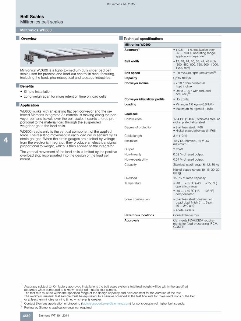
4/32 Siemens WT 10 · 2014
Belt ScalesMilltronics belt scales
Milltronics WD600
4
■ Overview
Milltronics WD600 is a light- to-medium-duty slider bed belt scale used for process and load-out control in manufacturing, including the food, pharmaceutical and tobacco industries.
■ Benefits
• Simple installation • Long weigh span for more retention time on load cells
■ Application
WD600 works with an existing flat belt conveyor and the se-lected Siemens integrator. As material is moving along the con-veyor belt and travels over the belt scale, it exerts a force pro-portional to the material load through the suspended weighbridge to the load cells.
WD600 reacts only to the vertical component of the applied force. The resulting movement in each load cell is sensed by its strain gauges. When the strain gauges are excited by voltage from the electronic integrator, they produce an electrical signal proportional to weight, which is then applied to the integrator.
The vertical movement of the load cells is limited by the positive overload stop incorporated into the design of the load cell mount.
■ Technical specifications 1) 2) 3)
1) Accuracy subject to: On factory approved installations the belt scale system’s totalized weight will be within the specified accuracy when compared to a known weighed material test sample. The test rate must be within the specified range of the design capacity and held constant for the duration of the test. The minimum material test sample must be equivalent to a sample obtained at the test flow rate for three revolutions of the belt or at least ten minutes running time, whichever is greater.
2) Contact Siemens application engineering ([email protected]) for consideration of higher belt speeds.3) Review by Siemens application engineer required.
Milltronics WD600
Accuracy1) • ± 0.5 … 1 % totalization over 25 … 100 % operating range, application dependent
Belt width • 12, 18, 24, 30, 36, 42, 48 inch (300, 450, 600, 750, 900, 1 000, 1 200 mm)
Belt speed • 2.0 m/s (400 fpm) maximum2)
Capacity Up to 100 t/h
Conveyor incline • ± 20 ° from horizontal, fixed incline
• Up to ± 30 ° with reduced accuracy3)
Conveyor idler/slider profile • Horizontal
Loading • Minimum 1.0 kg/m (0.6 lb/ft) • Maximum 76 kg/m (51 lb/ft)
Load cell
Construction 17-4 PH (1.4568) stainless steel or nickel plated alloy steel
Degree of protection • Stainless steel: IP68 • Nickel plated alloy steel: IP66
Cable length 3 m (10 ft)
Excitation 10 V DC nominal, 15 V DC maximum
Output 2 mV/V
Non-linearity 0.02 % of rated output
Non-repeatability 0.01 % of rated output
Capacity Stainless steel range: 6, 12, 30 kg
Nickel-plated range: 10, 15, 20, 30, 50 kg
Overload 150 % of rated capacity
Temperature • -40 … +65 °C (-40 … +150 °F) operating range
• -10 … +40 °C (15 … 105 °F) compensated
Scale construction • Stainless steel construction, bead blast finish (1 ... 6 µm, 40 ... 240 µin)
• Acetal sliders
Hazardous locations Consult the factory
Approvals CE, meets FDA/USDA require-ments for food processing, RCM, GOST-R
© Siemens AG 2015

4/33Siemens WT 10 · 2014
Belt ScalesMilltronics belt scales
Milltronics WD600
4
■ Selection and ordering data Article No. Article No.
Milltronics WD600A low- to medium- capacity scale for light to medium belt loading.304 stainless steel construction with Delrin sliders. Load cells are available in nickel plated, or stain-less steel. Two calibration weights are required and are ordered as separate line item. Refer to Calibra-tion weights.
7MH7185-
77A0
Click on the Article No. for the online configuration in the PIA Life Cycle Portal.
Belt width
12 inch (300 mm) 1
18 inch (450 mm) 2
24 inch (600 mm) 3
30 inch (750 mm) 4
36 inch (900 mm) 5
42 inch (1 000 mm) 6
48 inch (1 200 mm) 7
Load cell capacity
Nickel plated
10 kg (22 lb) D
15 kg (33.1 lb) E
20 kg (44 lb) F
30 kg (66.2 lb) G
50 kg (110 lb) L
Stainless steel
6 kg (13.2 lb) H
12 kg (26.4 lb) J
30 kg (66.2 lb) K
Further designs Order Code
Please add "-Z" to article no. and specify order code(s).
Stainless steel tag [69 x 38 mm (2.7 x 1.5 inch)], Measuring-point number / identification (max 27 characters), specify in plain text.
Y15
Manufacturer's test certificate: According to EN 10204-2.2
C11
Operating instructions
• English 7ML1998-5KM03
• German A5E32015601
• French A5E32862113
• Spanish A5E32862157
Belt Scale Application Guidelines
• English 7ML1998-5GA01
• French 7ML1998-5GA11
• German 7ML1998-5GA31
• Spanish 7ML1998-5GA21
Note: The operating instructions should be ordered as a separate line on the order.
This device is shipped with the Siemens Milltronics manual DVD containing the complete operating instructions library.
Spare parts
Load cells
Stainless steel
6 kg (13.2 lb) 7MH7725-1EG
12 kg (26.4 lb) 7MH7725-1EH
30 kg (66.2 lb) 7MH7725-1EJ
Nickel plated
10 kg (22 lb) 7MH7725-1EK
15 kg (33.1 lb) 7MH7725-1EL
20 kg (44 lb) 7MH7725-1EM
30 kg (66.2 lb) 7MH7725-1EN
50 kg (110 lb) 7MH7725-1EP
Slider bar middle UHMW PE (for old style WD600) 7MH7723-1KF
Slider bar side UHMW PE (for old style WD600) 7MH7723-1KE
Slider bar acetal 7MH7723-1KG
Test chain 1.62 lb/ft (2.41 kg/m), 60 inch 7MH7723-1NF
Calibration Hanger Weights
200 g (0.4 lb) 7MH7724-1AF
500 g (1.1 lb) 7MH7724-1AG
1 000 g (2.2 lb) 7MH7724-1AH
2 000 g (4.4 lb) 7MH7724-1AJ
3 500 g (7.7 lb) 7MH7724-1BQ
5 000 g (11 lb) 7MH7724-1AK
7 500 g (16.5 lb) 7MH7724-1BR
8 500 g (18.7 lb) 7MH7724-1BS
10 000 g (22 lb) 7MH7724-1BT
12 000 g (26.5 lb) 7MH7724-1BU
15 000 g (33.1 lb) 7MH7724-1BV
Note: Calibration accessories should be ordered as a separate item on the order
© Siemens AG 2015

4/34 Siemens WT 10 · 2014
Belt ScalesMilltronics belt scales
Milltronics WD600
4
■ Dimensional drawings
WD600, dimensions in inch (mm):
■ Schematics
WD600 connections
A
B
Belt width A B (min.) B (max.)
12 (300) 14.25 (362) 15 (381) 16.5 (419)
18 (450) 20.25 (514) 21 (533) 22.5 (572)
24 (600) 26.25 (667) 27 (686) 28.5 (724)
30 (750) 32.25 (819) 33 (838) 34.5 (876)
36 (900) 38.25 (972) 39 (991) 40.5 (1 029)
42 (1 000) 44.25 (1 124) 45 (1 143) 46.5 (1 181)
48 (1 200) 50.25 (1 276) 51 (1 295) 52.5 (1 334)
Belt travel
Customer junction box
To integrator
Shi
eld
'B'
Shi
eld
'A'
Gre
en 'B
'
Gre
en 'A
'
Red
'B'
Red
'A'
Whi
te 'B
'
Whi
te 'A
'
Bla
ck 'B
'B
lack
'A'
Shi
eld
Load cell 'A'
Load cell 'B'
Load cell 'A'Load cell 'B'
+ S
IG 'B
'
- SIG
'B'
+ S
IG 'A
'
- SIG
'A'
+ E
XC
- EX
C
© Siemens AG 2015

4/35Siemens WT 10 · 2014
Belt ScalesSpeed sensors
Milltronics TASS
4
■ Overview
Milltronics TASS is a compact low-profile, wheel-driven return belt speed sensor, ideal for use on mobile crushers and in con-stricted spaces.
■ Benefits
• Rugged design • Easy, low cost installation • Compact, low-profile speed sensor • IP67 rated
■ Application
Milltronics TASS speed sensor operates in conjunction with a conveyor belt scale, providing signals to an integrator (Milltronics BW500, or SIWAREX FTC) which computes the rate of material being conveyed. The trailing arm speed sensor mon-itors conveyor belt speed, with the output signal transmitted by cable connection to the integrator.
Easily installed close to the belt scale assembly, the TASS pro-vides a signal generated as the wheel rotates on the return belt. Pulses are generated by the internal proximity switch detecting the rotation of the five spoked wheel. The TASS is mounted to the static beam of the belt scale or to a structural cross member via a pivoting bracket assembly.
The TASS is a compact, low-profile, rugged speed sensor, most often used on mobile crusher applications where space is lim-ited. The TASS output can be applied to any Milltronics belt scale integrator.
■ Design
Installation
TASS Installation
■ Technical specifications
Note:The TASS can be mounted to a conveyor cross member or to a non-weighing idler frame.
TASS
Milltronics TASS
Mode of operation
Measuring principle Proximity sensor provides pulse to integrator
Typical application Mobile crusher
Input • Bi-directional wheel rotation • 25 … 350 rpm
Output • Inductive proximity sensor • Open collector, NPN,
sinking output, max. 200 mA • Pulses: 5 per revolution • 9.947 pulses/m, 3.03 pulses/ft
Rated operating conditions
Operating temperature -25 … +70 °C (-13 … +158 °F)
Degree of protection IP67
Design
Trailing arm assembly Painted mild steel
Wheel 160 mm (6.3 inch) diameter cast aluminum with polyurethane tread
Power supply 10 … 35 V DC, 15 mA at 24 V DC maximum
Wiring
Brown + Excitation (10 … 35 V DC)
Black + Signal
Blue - Common
Interconnection wiring (to integrator)
• 5 m, 3 conductor shielded PVC cable, 3 x 0.25 mm² (23 AWG), protected with 1 000 mm of flexi-ble conduit
• 300 m (1 000 ft) maximum cable run
Approvals CE, RCM, GOST-R
© Siemens AG 2015

4/36 Siemens WT 10 · 2014
Belt ScalesSpeed sensors
Milltronics TASS
4
■ Selection and ordering data Article No.
■ Dimensional drawings
TASS dimensions in mm (inch)
Milltronics TASS speed sensorCompact, low-profile, wheel driven return belt speed sensor for belt conveyors; ideal for use on mobile crushers and in constricted spaces.
7MH7131-
7777 0
Click on the Article No. for the online configuration in the PIA Life Cycle Portal.
Model
5 pulses per revolution 1
Fabrication
Standard, polyester painted mild steel A
Stainless steel 304 (1.4301), bead blast finish (1 ... 6 µm, 40 ... 240 µin)
B
Note: Wheel is aluminum for all versions
Mounting options
Complete with standard mounting kit A
Approvals
CE, RCM 1
Further designs Order Code
Please add "-Z" to article no. and specify order code(s).
Stainless steel tag [69 x 38 mm (2.7 x 1.5 inch)]Measuring-point number / identification (max 27 characters), specify in plain text.
Y15
Manufacturer's test certificate: According to EN 10204-2.2
C11
Operating instructions Article No.
TASS Operating instructions, multi-languageNote: The operating instructions should be ordered as a separate item on the order.
7ML1998-5HL61
This device is shipped with the Siemens Milltronics manual DVD containing the complete operating instructions library.
Spare parts
TASS wheel 7MH7723-1AN
TASS proximity switch 7MH7723-1AP
TASS wheel, stainless steel sealed bearing 7MH7723-1GW
Conduit replacement kit 7MH7723-1NA
Mounting Bracket
12 (0.48), 2 places
9 (0.35), 2 places
Conduit fitting 1/2" NPT
120 (4.72)
105 (4.13)
40 (1.57)
25 (0.89)
20 (0.79)
60 (2.36)48 (1.89)
53 (2
.09)
66 (2
.6)
158
(6.2
2)
508
(20)
50 (1.97)
534
(21.
02)
567
(22.
32)
TASS
40 (1
.57)
6 (0.24)
Ø160 (6.3)
© Siemens AG 2015

4/37Siemens WT 10 · 2014
Belt ScalesSpeed sensors
Milltronics RBSS
4
■ Overview
Milltronics RBSS is a high resolution, wheel-driven return belt speed sensor.
■ Benefits
• Rugged design• IP67 rated• Easy, low cost installation• Accurate belt speed detection
■ Application
Milltronics RBSS monitors conveyor belt speed, with the output signal transmitted by cable connection to the integrator (Milltronics BW500, or SIWAREX FTC).
Easily installed close to the belt scale assembly, the RBSS pro-vides a signal generated as the wheel on the sensor rotates on the return belt. To secure this cost-effective unit in place, position a cross bar between stringers - either just before or after a return belt idler, or use the optional mounting bracket. The weight of the RBSS ensures positive rotation of the wheel in the middle of the return belt, and pulses from the magnetic sensor are generated by the rotation of the 60 toothed speed sprocket driven by the wheel.
The RBSS output can be applied to any Milltronics belt scale in-tegrator.
■ Design
Installation
RBSS installation
Pin clip
RBSS Standard Mounting
Return belt travel
24 (1) washers, 2 places (customer-supplied)
24 (1) dia. cross bar (customer-supplied)
Stringer
Wheel Belt
CableStringer
RBSS
RBSS
© Siemens AG 2015

4/38 Siemens WT 10 · 2014
Belt ScalesSpeed sensors
Milltronics RBSS
4
■ Technical specifications 1) 2) 3) ■ Selection and ordering data Article No. 4) 5) 6)
We can offer shorter delivery times for configurations designated with theQuick Ship Symbol .
1) EMC performance available upon request.2) Approvals for RBSS IS are based on internally mounted NAMUR
slotted proximity switch (Pepperl+Fuchs #NJ0.8-5GM-N) and use of suitable IS switch isolator (amplifier). Please see RBSS operating instructions for more information.
3) Approval ratings for the proximity switch and IS switch isolator are the property of Pepperl+Fuchs. Copies of these Approval Certificates may be obtained at http://www.siemens.com/processautomation.
Milltronics RBSS
Mode of operation
Measuring principle Proximity sensor provides pulse to integrator
Typical application Aggregate belt conveyors
Input Wheel rotation 2 … 450 rpm, bi-directional
Output • 60 pulses per revolution, 2 … 450 Hz, 150.4 pulses/m (45.8 pulses/ft)
• RBSS: open collector, NPN sinking output, max. 17 mA
• RBSS IS: NAMUR NC, load current, 0 … 15 mA
Rated operating conditions
Ambient temperature • RBSS: -40 … +105 °C (-40 … +220 °F)
• RBSS IS: -25 … +100 °C (-14 … +212 °F)
Degree of protection IP67
Design
Trailing arm Painted mild steel
Sensor wheel 127 mm (5 inch) diameter, polyurethane tread
Power supply • RBSS: 4.5 … 28 V DC, 16 mA • RBSS IS: 5 … 25 V DC from IS
switch isolator
Interconnection wiring (to integrator)
• RBSS: 3 m, 3 conductor 22 AWG shielded cable - 300 m (1 000 ft) maximum
cable run • RBSS IS: 2 m, 2 conductor
26 AWG PVC covered cable - 300 m (1 000 ft) maximum
cable run to IS switch isolator - 300 m (1 000 ft) maximum
cable run from IS switch isolator and integrator
Approvals
RBSS CE, RCM1)
RBSS IS (with suitable IS switch isolator or switch amplifier)2)
• ATEX II 1G Ex ia IIC T6 • ATEX II 1D Ex iaD 20 T 108 °C • CSA/UL: Class I, Div. 1, Groups A,
B, C, and D; Class II, Div. 1, Groups E, F, and G; Class III, Div. 1
• CE, RCM2)
Proximity switch approval ratings (Pepperl+Fuchs #NJ0.8-5GM-N)
• ATEX II 1G Ex ia IIC T6 • ATEX II 1D Ex iaD 20 T 108 °C • CE, CSA, UL2)
Optional switch isolator (required for RBSS IS)3)
• Pepperl+Fuchs #KFA5-SOT2-Ex2 or #KFA6-SOT2-Ex2
• ATEX II (1) G [Ex ia] IIC • CSA/UL: Class 1, Div. 1,
Groups A, B, C, and D. Class II, Div. 1, Groups E, F, and G, Class III
• CE2)
4) Required with RBSS IS.5) For use with old style RBSS PBD-51033452.6) Switch isolator required.
Milltronics RBSS speed sensorA high resolution wheel-driven return belt speed sensor
7MH7134-
77777
Click on the Article No. for the online configuration in the PIA Life Cycle Portal.
Model
60 pulses per revolution 2
Fabrication
Standard, polyester painted mild steel A
Mounting options
With mounting kit B
Approvals
CE, RCM, ATEX II 1G, Ex ia IIC T6, ATEX II 1D Ex iaD 20 T108 °C, CSA/UL Class I, Div. 1, Groups A, B, C, and D; Class II, Div. 1, Groups E, F, and G; Class III, Div. 16)
2
CE, RCM 3
Switch isolator
Not required 0
115 V AC4) 1
230 V AC4) 2
Further designs Order Code
Please add "-Z" to article no. and specify order code(s).
Stainless steel tag [69 x 38 mm (2.7 x 1.5 inch)], Measuring-point number / identification (max 27 characters), specify in plain text.
Y15
Manufacturer's test certificate: According to EN 10204-2.2
C11
Operating instructions Article No.
RBSS Operating instructions, multi-languageNote: The operating instructions should be ordered as a separate item on the order.
7ML1998-5GX63
This device is shipped with the Siemens Milltronics manual DVD containing the complete operating instructions library.
Spare parts
Wheel, 127 dia-polyurethane, sealed bearing 7MH7723-1FX
Magnetic proximity switch 7MH7723-1GA
Switch, inductive, NJ0.8-5GM-N (approvals option 2)4)
7MH7723-1AS
P & F switch isolator, 115 V AC4) 7MH7723-1EB
P & F switch isolator, 230 V AC4) 7MH7723-1EC
Wheel and shaft, 152 mm dia.5) 7MH7723-1EN
60 tooth gear5) 7MH7723-1EQ
Bearing (two required)5) 7MH7723-1ER
Accessories
Conduit kit 7MH7723-1NA
© Siemens AG 2015

4/39Siemens WT 10 · 2014
Belt ScalesSpeed sensors
Milltronics RBSS
4
■ Dimensional drawings
RBSS dimensions in mm (inch)
Cable for RBSS (IS, 5 ... 25 V) and RBSS (CE, 10 ... 30 V) is 2 m (6.5 ft).Dimension equals 102 (4) if manufactured in Canada.Dimension equals 51 (2) if manufactured in Canada.
1)
2)
3)
60 tooth gear
3 m (10 ft) shielded cable1)
Sensor
Ø11 (0.44), 2 places
Ø25 (1) Through both sides
Mounting Bracket
114 (4.5) ref.
Ø25 (1) Through both walls
Through hole for cable gland 22 (0.88)
RBSS
51 (2)
114
(4.5
)
29 (1.13)
57 (2.25)
25
(1)
648
(25.
5)
100 (3.94)2)
50 (1.97)3)
Ø127 (5)
105 (4.13) 5 (0.19)
610
(24)
38
(1
.5)
25
(1)
25 (1)
© Siemens AG 2015

4/40 Siemens WT 10 · 2014
Belt ScalesSpeed sensors
SITRANS WS100
4
■ Overview
SITRANS WS100 speed sensor is a compact, medium-resolu-tion, pulley shaft-driven belt speed sensor with magnetic mount-ing. It is ideal for aggregate and mineral processing industries.
■ Benefits
• Small, light-weight• Good resolution for accurate measurement, suitable for vary-
ing shaft speeds• Long bearing life
■ Application
SITRANS WS100 speed sensor operates in conjunction with a conveyor belt scale, providing a signal to an integrator (Milltronics BW500, or SIWAREX FTC module) which computes the rate of material being conveyed. It is lightweight at 1.22 kg (2.68 lb) and durable, for easy installation and prolonged bear-ing life.
The WS100 converts shaft rotation into a pulse train of 8 pulses per revolution. These pulses are typically fed into a Milltronics belt scale integrator. The integrator interprets the pulses and uses them in the calculation of belt speed, flow rate, and material totalization. In non-belt scale applications, the WS100 can be used to monitor rotational speed when directly connected to a PLC.
The WS100 IS (intrinsically safe) version contains an inductive proximity switch which transmits the pulses via a switch isolator for hazardous area locations.
■ Design
The input shaft on the SITRANS WS100 is coupled to the rotating shaft on a belt-driven pulley with a tapped hole, and is externally supported. The unit’s flexible arresting strap stops it from rotat-ing with the shaft, without causing bearing stress, and can be fit-ted to any rigid member close to the sensor.
When mounting, ensure the unit and the pulley shaft are concen-tric to avoid stresses on the unit’s bearings.
For mounting using the magnetic connector, ensure the face of the rotating shaft on the belt driven pulley is flat, and has no burrs or damage that may prevent flush mounting of the mag-netic connector. Attach the SITRANS WS100 speed sensor to the shaft; the magnetic connector will center itself as the belt driven pulley rotates.
© Siemens AG 2015

4/41Siemens WT 10 · 2014
Belt ScalesSpeed sensors
SITRANS WS100
4
WS100 installation
Arrestor strapBelt
Conveyor structure for arrestor strap
Conveyor stringer
Restraining bracket (mounted off bearing)
Arrestor strap (mounted to restraining bracket)
Cable
Belt
Mounting to a Bend or Snub Pulley
Mounting to a Tail Pulley
SITRANS WS100
SITRANS WS100
Z
Z
© Siemens AG 2015

4/42 Siemens WT 10 · 2014
Belt ScalesSpeed sensors
SITRANS WS100
4
■ Technical specifications 1) 2) 3)
1) EMC performance available upon request.2) Approvals for RBSS IS are based on internally mounted NAMUR slotted proximity switch (Pepperl+Fuchs #NJ0.8-5GM-N)
and use of suitable IS switch isolator (Amplifier). Please see RBSS Operating instructions for more information.3) Approval ratings for the proximity switch and IS switch isolator are the property of Pepperl+Fuchs.
Copies of these approval certificates may be obtained at http://www.siemens.com/processautomation.
SITRANS WS100
Mode of operation
Measuring principle Proximity sensor provides pulse to integrator
Typical application Aggregate belt conveyors
Input Shaft rotation 15 … 1 500 rpm, bi-directional
Shaft rotation 15 … 300 rpm, bi-directional with magnetic con-nector
Output • 8 pulses per revolution • 0 … 200 Hz, 0 … 40 Hz
with magnetic connection • WS100 standard: open collector,
NPN, sinking output, 25 mA • WS100 IS: NAMUR NC,
load current, 0 … 15 mA • Integrator minimum usable
frequency 2 Hz
Rated operating conditions
Standard -40 … +110 °C (-40 … +230 °F)
Intrinsically Safe -25 … +100 °C (-14 … +212 °F)
Degree of protection IP67
Enclosure Polypropylene base and target enclosure with 304 (1.4301) stain-less steel access cover
304 (1.4301) stainless steel shaft, bearings and hardware
Power
Standard 4.5 … 28 V DC, 16 mA
Intrinsically Safe 5 … 25 V DC from IS switch isolator
Cable
Standard • 3 m (10 ft), 3 conductor 22 AWG (0.324 mm²), PVC shielded cable
• 300 m (1 000 ft) maximum cable run
Intrinsically Safe • 2 m (6.5 ft), 2 conductor 26 AWG (0.129 mm²), PVC covered cable
• 300 m (1 000 ft) maximum cable run to IS switch isolator
• 300 m (1 000 ft) maximum cable run from IS switch isolator and integrator
Approvals
WS100 CE, GOST-R, RCM1)
WS100 IS (with suitable IS switch isolator or switch amplifier)2)
• ATEX II 1G EEx ia IIC T6 • ATEX II 1D Ex iaD 20 T 108 °C • CSA/UL: Class I, Div. 1, Groups A,
B, C, and D; Class II, Div. 1, Groups E, F, and G; Class III, Div. 1
• CE, RCM2)
Proximity Switch Approval Ratings (Pepperl+Fuchs #NCN4- 12GM35-N0)
• ATEX II 1G EEx ia IIC T6 • ATEX II 1D Ex iaD 20 T 108 °C • CSA, UL• CE2)
Optional Switch isolator (required for WS100 IS)3)
• Pepperl+Fuchs #KFA5-SOT2-Ex2 or #KFA6-SOT2-Ex2
• ATEX II (1) G [EEX ia] IIC • CSA/UL: Class 1, Div. 1,
Groups A, B, C, and D. Class II, Div. 1, Groups E, F, and G, Class III
• CE2)
SITRANS WS100
© Siemens AG 2015

4/43Siemens WT 10 · 2014
Belt ScalesSpeed sensors
SITRANS WS100
4
■ Selection and ordering data1) Article No.
1) Switch isolator required.
SITRANS WS100 speed sensorA compact, medium-resolution, pulley shaft-driven belt speed sensor with magnetic mounting; ideal for aggregate and mineral processing industries.
7MH7176-
77777
Click on the Article No. for the online configuration in the PIA Life Cycle Portal.
Model
8 PPR 1
Fabrication
Polycarbonate construction with 304 stainless steel sensor cover
A
Mounting
M12 x 1.75 threaded shaft A
Magnetic connector B
Approvals
Standard CE, RCM 0
CE, RCM, ATEX II 1G, EEx ia IIC T6, ATEX II 1D Ex iaD 20 T 108 °C, and CSA/UL Class I, Div. 1, Groups A, B, C and D; Class II, Div. 1, Groups E, F and, G; Class III, Div. 11)
1
Switch isolator
Not required 0
115 V AC (required with IS option 1) 1
230 V AC (required with IS option 1) 2
Further designs Order Code
Please add "-Z" to article no. and specify order code(s).
Stainless steel tag [69 x 38 mm (2.7 x 1.5 inch)], Measuring-point number / identification (max 27 characters), specify in plain text.
Y15
Manufacturer's test certificate: According to EN 10204-2.2
C11
Operating instructions Article No.
SITRANS WS100, English 7ML1998-5LU02
SITRANS WS100, GermanNote: The operating instructions should be ordered as a separate item on the order.
7ML1998-5LU31
This device is shipped with the Siemens Milltronics manual DVD containing the complete operating instructions library.
Spare parts
Magnetic proximity switch 7MH7723-1GA
Switch, inductive, NCN4-12GM35-N0 for Approvals option 1
7MH7726-1AS
WS100 magnetic connector 7MH7723-1GF
P & F switch isolator, 115 V AC, required for approvals option 1
7MH7723-1EB
P & F switch isolator, 230 V AC, required for approvals option 1
7MH7723-1EC
© Siemens AG 2015

4/44 Siemens WT 10 · 2014
Belt ScalesSpeed sensors
SITRANS WS100
4
■ Dimensional drawings
WS100 dimensions in mm (inch)
Dimensions
Magnetic shaft connector option
Male shaft connector option
M12 x 1.75 male shaft connector
Magnetic shaft connector
Arrestor strapCable
Stainless steel sensor cover
Arrestor strap
M20 (½" NPT) diameter hole for conduit adaptor (use flexible conduit)
Polypropylene sealed housing for ferrous targets
53
(2.1
0)31
(1
.24) Ø44
(1.75)51 (2.00) 203 (8.00) 222 (8.75)
Ø89
(3.5
0) 20
(0
.79)
36
(1.4
3)
15
(0.6
0)
22
(0.8
5)
© Siemens AG 2015

4/45Siemens WT 10 · 2014
Belt ScalesSpeed sensors
SITRANS WS300
4
■ Overview
SITRANS WS300 is a low- to high-resolution shaft-driven speed sensor.
■ Benefits
• Compact and economical • Easy, low-cost installation • Accurate belt speed detection • Optional resolutions for measurement over a range of belt
speeds • Corrosion resistant
■ Application
SITRANS WS300 speed sensor operates in conjunction with a conveyor belt scale, providing a signal to an integrator which computes the rate of material being conveyed. At only 1.22 kg (2.68 lb), it is one of the lightest and most durable units ever de-veloped for monitoring conveyor belt speed. With its rugged cast aluminum housing, it is suitable for outdoor installation, and its low weight prolongs bearing life.
It is directly coupled to a rotating tail or bend pulley shaft to en-sure accurate belt-travel readout, eliminating problems caused by belt slippage or material build-up. The WS300 converts shaft rotation into a pulse train of 32, 256, 1 000, or 2 000 pulses per revolution using a high precision rotary optical encoder. The dig-ital signal is transmitted as speed input to any Siemens integra-tor for calculation of belt speed, flow rate and totalized weight.
This low- to high-resolution speed sensor provides a frequency signal proportional to the shaft speed, enabling a range of speeds to be read accurately. The quadrature type shaft en-coder prevents erroneous speed signals due to vibration or shaft oscillation. The WS300 is easily mounted and is bi-directional for either clockwise or counter-clockwise belt travel.
The IS version uses an inductive proximity switch detecting ro-tating targets.
© Siemens AG 2015

4/46 Siemens WT 10 · 2014
Belt ScalesSpeed sensors
SITRANS WS300
4
■ Design
Mounting:
WS300 mounting
Mounting using optional threaded shaft coupling:
WS300 mounting using threaded shaft coupling
When mounting to a bend or a snub pulley only, a 10 mm (0.39 inch) drilled hole is required for the arrestor rod.
Distance ‘d’ is the take-up travel on the tail pulley.When adjusting the belt take-up, ensure that there is play on the arrestor rod. If the arrestor rod is pushed against the end of its travel slot, premature bearing wear may result.
Notes:
Notes:
Pulley bearing
Bend or snub pulley
10 (0.39) drilled hole
Arrestor rod (cut to suit)
Arrestor rod (cut to suit)
Flexible conduit
Flexible conduit
Belt
belt
Tension spring (supplied)
Tension spring (supplied)Tension spring (supplied)
Tension spring (supplied)
Stringer
Mounting to a Bend or Snub Pulley
Mounting to a Tail Pulley
Angle bracket slotted for
arrestor rod
Stringer
Angle bracket slotted for
arrestor rod
WS300
WS30089
(3
.5)
≥ 10
(0.3
9)
d
89
(3.5
)
1) Use adhesive when installing threaded shaft coupling (e.g. Loctite).
0.254 (0.01)
M12
x 1
.75 M12
x 1
.751)
Set screw
25 (1.0)25 (1.0)95 (3.75)
A
A
© Siemens AG 2015

4/47Siemens WT 10 · 2014
Belt ScalesSpeed sensors
SITRANS WS300
4
■ Technical specifications 1) 2) 3)
1) Approvals for WS300 IS are based on internally mounted NAMUR proximity switch (Pepperl+Fuchs #NJ0.8-5GM-N) and use of suitable IS switch isolator (amplifier). Please see WS300 operating instructions for more information.
2) Approvals for WS300 IS are based on internally mounted NAMUR slotted proximity switch (Pepperl+Fuchs #NJ0.8-5GM-N) and use of suitable IS switch isolator (amplifier). Please see WS300 operating instructions for more information.
3) Approval ratings for the proximity switch and IS switch isolator are the property of Pepperl+Fuchs. Copies of these approval certificates may be obtained at http://www.siemens.com/processautomation.
SITRANS WS300
Mode of operation
Measuring principle Standard: pulse from shaft rotation using high precision rotary optical encoder
IS: pulse from inductive proximity switch
Typical application When a low- to high-resolution speed sensor is required
Input Shaft rotation 0.3 … 2 000 rpm, bi-directional, resolution dependent
Output • Unidirectional open collector, NPN, sinking output
• Standard: 10 … 30 V DC, 25 mA max.
• IS: NAMUR NC, load current, 0 … 15 mA
• 32, 256, 1 000, or 2 000 pulses per revolution (ppr)
• 32 ppr: 2 000 max. rpm, 1 066 Hz • 256 ppr: 2 000 max. rpm,
8 530 Hz • 1 000 ppr: 900 max. rpm,
15 000 Hz • 2 000 ppr: 450 max. rpm,
15 000 Hz
Rated operating conditions
Ambient temperature • Standard:-40 … +55 °C (-40 … +131 °F)
• IS:-25 … +100 °C (-13 … +212 °F)
Degree of protection NEMA 4X, Type 4X, IP65
Design
Enclosure • Rated NEMA 4X, Type 4X, IP65 • Painted aluminum • Stainless steel (optional)
Power supply • Standard: 10 … 30 V DC, 60 mA max.
• IS: 5 … 16 V DC, 25 mA max. (from IS switch isolator)
Cable
Recommended • Standard: 3-wire shielded, 0.82 mm² (18 AWG)
• IS: 2-wire shielded 0.324 mm² (22 AWG)
• Max. run 305 m (1 000 ft)
Approvals
WS300 Standard
General • CE, RCM, GOST-R
Hazardous • CSA/FM Class II, Div. 1, Groups E, F, G; Class III
• ATEX II 2D Ex tD A21 IP65 T70 ° • GOST-R Ex, RTN • IEC Ex, Ex tD A21 IP65 T70 °C
WS300 IS (with suitable IS switch isolator or switch amplifier)1)
• ATEX II 1G EEx ia IIC T6 • ATEX II 1D Ex iaD 20 T 108 °C • CSA/UL: Class I, Div. 1, Groups A,
B, C and D; Class II, Div. 1, Groups E, F and G; Class III, Div. 1
• CE, RCM2)
Proximity switch approval ratings (Pepperl+Fuchs #NJ0.8-5GM-N)
• ATEX II 1G EEx ia IIC T6 • ATEX II 1D Ex iaD 20 T 108 °C • CSA, UL• CE2)
Optional switch isolator (required for WS300 IS)3)
• Pepperl+Fuchs #KFA5-SOT2-Ex2 or #KFA6-SOT2-Ex2
• ATEX II (1) G [EEX ia] IIC • CSA/UL: Class 1, Div. 1,
Groups A, B, C, and D. Class II, Div. 1, Groups E, F, and G, Class III
• CE2)
SITRANS WS300
© Siemens AG 2015

4/48 Siemens WT 10 · 2014
Belt ScalesSpeed sensors
SITRANS WS300
4
■ Selection and ordering data1) 2) 3) 4) Article No. Article No.
We can offer shorter delivery times for configurations designated with the Quick Ship Symbol
1) Available with Approval option D only.2) The Approval Ratings for the Proximity Switch and the IS switch isolator are the property of Pepperl+Fuchs.
For current approvals, go to: http://www.am.pepperl-fuchs.com.3) Approval option B requires use of switch isolator to interface with the belt scale integrator,
and is available with Resolution option 1, and Connections option 1 only.4) For use with IS approval option B.
SITRANS WS300 speed sensorA medium- to high-resolution shaft-driven speed sensor used with Milltronics belt scales.
7MH7177-
77777 0
Click on the Article No. for the online configuration in the PIA Life Cycle Portal.
Resolution (pulses per revolution)
32 1
256 2
1 000 3
2 0001) 4
Enclosure
Polyester painted aluminum, NEMA 4X A
304 (1.4301) stainless steel, vibra finish NEMA 4X B
Approvals
CSA/FM Class II, Div. 1, Groups E, F, G Class IIIATEX II 2D, Ex tD A21 IP65 T70 °C, CE, RCM, IECEx, Ex tD A21 IP65 T70 °C
A
CSA/UL Class I, Div. 1, Groups A, B, C, and D; Class II, Div. 1, Groups E, F, and G; Class III, Div. 1, ATEX II 1G, EEx ia IIC T6, ATEX II 1D Ex iaD 20 T108 °C, CE, RCM2)3)
B
CE, RCM D
Connections
Standard, up to 2 integrators 1
Multiple, up to 10 integrators 2
Switch isolator
Not required 0
115 V AC4) 1
230 V AC4) 2
Further designs Order Code
Please add "-Z" to article no. and specify order code(s).
Acrylic coated, stainless steel tag [13 x 45 mm (0.5 x 1.75 inch)]: Measuring-point number/identifi-cation (max. 16 characters), specify in plain text
Y17
Manufacturer's test certificate: According to EN 10204-2.2
C11
Operating instructions
• English 7ML1998-5ML01
• German 7ML1998-5ML31
Note: The operating instructions should be ordered as a separate item on the order.
Spare parts
Circuit card 32 PPR, up to 2 integrators 7MH7723-1GK
Circuit card 32 PPR, up to 10 integrators 7MH7723-1GL
Circuit card 256 PPR, up to 2 integrators 7MH7723-1GM
Circuit card 256 PPR, up to 10 integrators 7MH7723-1GN
Circuit card 1 000 PPR, up to 2 integrators 7MH7723-1GP
Circuit card 1 000 PPR, up to 10 integrators 7MH7723-1GQ
Circuit card 2 000 PPR, up to 2 integrators 7MH7723-1JL
Circuit card 2 000 PPR, up to 10 integrators 7MH7723-1JM
Circuit card 32 PPR, IS 7MH7723-1HC
Rubber coupling 7MH7723-1CM
Coupling hub for 32, 256 PPR versions 7MH7723-1CN
Coupling hub for 1 000, 2 000 PPR versions 7MH7723-1GR
Enclosure cover 7MH7723-1CJ
Enclosure bearing assembly 7MH7723-1CK
Enclosure cover, stainless steel 7MH7723-1GS
Enclosure bearing assembly, stainless steel 7MH7723-1GT
Threaded shaft coupling 7MH7723-1GH
Arrestor rod 7MH7723-1FV
Arrester rod tension spring 7MH7723-1CP
WS300 mounting bracket for MD-36 retrofit 7MH7723-1NB
WS300 mounting bracket SS for MD-36 retrofit 7MH7723-1NC
Cable for speed sensor connection to termination box 3 cond, 18G (order per meter)
7MH7723-1JP
Cable for IS speed sensor connection to termina-tion box 3 cond, 22G (order per meter)
7MH7723-1JQ
Pepperl+Fuchs IS switch isolator, 115 V AC 7MH7723-1EB
Pepperl+Fuchs IS switch isolator, 230 V AC 7MH7723-1EC
© Siemens AG 2015

4/49Siemens WT 10 · 2014
Belt ScalesSpeed sensors
SITRANS WS300
4
■ Dimensional drawings
WS300 dimensions in mm (inch)
■ Schematics
Connections (Standard)
• Determine the pulley shaft rotation on the end of the pulley shaft to which the WS300 is attached.
• If the pulley shaft is rotating clockwise, connect the appropri-ate wire to terminal 2. If the pulley shaft is rotating counter-clockwise, connect the appropriate wire to terminal 3.
• Do not connect terminals 2 and 3 at the same time. • Connection between the WS300 standard unit and the integra-
tor should be made with three-wire shielded, 0.82 mm2
(18 AWG) cable. • Ground shield of cable at integrator only. • Connect shield to appropriate terminal at the integrator.
Terminal Connections to Siemens Milltronics Integrators
Terminal Connections to SIWAREX FTC Integrator
Connections (IS)
• Only terminals 1 and 2 are required; rotation in a clockwise or counter-clockwise direction is not required.
• To connect the switch isolator, use two-wire shielded 0.324 mm2 (22 AWG) cable. Use the same cable to connect the switch isolator to the integrator.
• Ground shield of cable at integrator only. • Connect shield to appropriate terminal at the integrator.
Terminal Connections to Siemens Milltronics Integrators
Terminal Connections to SIWAREX FTC Integrator
Connect CI- to Common
½" NPT conduit entrance(optional M20 adapter available)
Rod
Shaft
15.9
(0.6
3)
89 (3
.5)
60 (2
.38)
8 (0
.31)
305 (12)131 (5.16)
102 (4.00)
50 (1.96)
102
(4.0
0)11
1 (4
.36)
159
(6.2
5)
Description Terminal
+10 ... +30 V DC 1
Speed out-CW 2
Speed out-CCW 3
Common 4
Ground GND
WS300 1+V
2CW
3CCW
4Cmn
GND
Milltronics BW500
19 16 16 17 N/C
WS300 1+V
2CW
3CCW
4Cmn
GND
SIWAREX FTC
24 V(back-plane bus)
X1.9(CI+)
X1.9(CI+)
X1.10(CI- andCommon)
N/C
Description Terminal
+5 ... +16 V DC, 25 mA max.(from IS switch isolator)
1
Speed out 2
Ground GND
W300 IS IS switch isolatorTerminal
Integrator
1 1
2 3
7 Speed signal input
8 - Excitation
W300 IS IS switch isolatorTerminal
Integrator
1 1
2 3
7 CI+
8 IL+
© Siemens AG 2015

4/50 Siemens WT 10 · 2014
Belt ScalesSpeed sensors
Milltronics bend pulleys
4
■ Overview
Return belt driven pulley provides rotation for shaft-driven speed sensors. 4.5 inch size is self-cleaning.
■ Benefits
• Heavy-duty design for high belt tension• Self-cleaning 114 mm (4.5 inch) diameter option• Steel drum 152 mm (6 inch) diameter option• Steel drum 152 mm (6 inch) with 6 mm (¼ inch) rubber lagged
option• Spherical self-aligning pillow block bearings• Fast installation, easy maintenance
■ Application
Milltronics bend pulleys provide constant belt contact for use with Siemens speed sensors. Designed for use in rugged oper-ating environments common to mining, aggregates, cement, minerals, and other process industries. They ensure concentric speed sensor rotation to reduce pre-mature bearing failure. The use of a bend pulley driven speed sensor ensures no modifica-tion is required on any existing conveyor shaft. Options include stainless steel construction, epoxy painting, polymer bearings, self-cleaning style, and lagged style.
■ Technical specifications
Milltronics bend pulleys
Typical application Mining, aggregates, cement, min-erals, and other process industries
Medium conditions
Operating temperature -40 … +110 °C (-40 … +230 °F)
Shaft material Mild steel316 (1.4401) stainless steel, option
Pulleys
Self-cleaning rubber disc style 114 mm (4.5 inch) diameter
Steel drum 152 mm (6 inch) diameter
Steel drum 152 mm (6 inch) diameter with 6 mm (¼ inch) rubber lagged option
Bearings • Heavy-duty self-aligning pillow block bearings, standard
• Polymer self-aligning pillow block bearings option
Belt speed
Self-cleaning 1.79 m/s (350 fpm) max.
Drum 3 m/s (600 fpm)
Approvals CE, RCM
© Siemens AG 2015
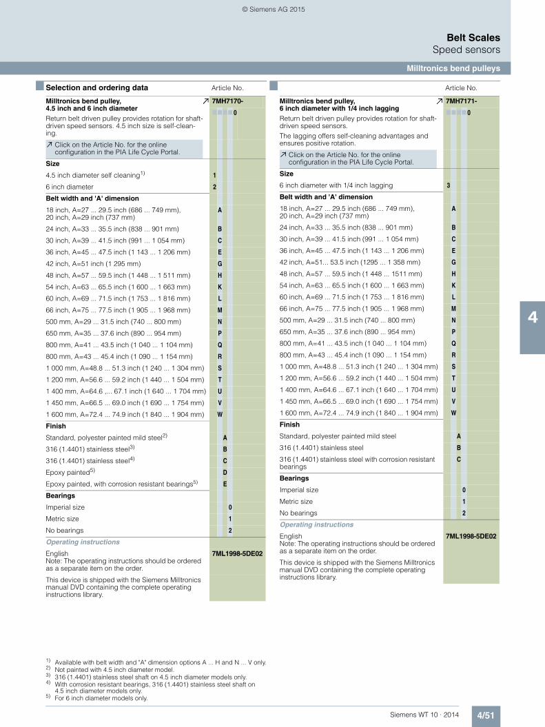
4/51Siemens WT 10 · 2014
Belt ScalesSpeed sensors
Milltronics bend pulleys
4
■ Selection and ordering data1) 2) 3) 4) 5) Article No. ■ Article No.
1) Available with belt width and "A" dimension options A ... H and N ... V only.2) Not painted with 4.5 inch diameter model.3) 316 (1.4401) stainless steel shaft on 4.5 inch diameter models only. 4) With corrosion resistant bearings, 316 (1.4401) stainless steel shaft on
4.5 inch diameter models only.5) For 6 inch diameter models only.
Milltronics bend pulley, 4.5 inch and 6 inch diameterReturn belt driven pulley provides rotation for shaft-driven speed sensors. 4.5 inch size is self-clean-ing.
7MH7170-
7777 0
Click on the Article No. for the online configuration in the PIA Life Cycle Portal.
Size
4.5 inch diameter self cleaning1) 1
6 inch diameter 2
Belt width and 'A' dimension
18 inch, A=27 ... 29.5 inch (686 ... 749 mm), 20 inch, A=29 inch (737 mm)
A
24 inch, A=33 ... 35.5 inch (838 ... 901 mm) B
30 inch, A=39 ... 41.5 inch (991 ... 1 054 mm) C
36 inch, A=45 ... 47.5 inch (1 143 ... 1 206 mm) E
42 inch, A=51 inch (1 295 mm) G
48 inch, A=57 ... 59.5 inch (1 448 ... 1 511 mm) H
54 inch, A=63 ... 65.5 inch (1 600 ... 1 663 mm) K
60 inch, A=69 ... 71.5 inch (1 753 ... 1 816 mm) L
66 inch, A=75 ... 77.5 inch (1 905 ... 1 968 mm) M
500 mm, A=29 ... 31.5 inch (740 ... 800 mm) N
650 mm, A=35 ... 37.6 inch (890 ... 954 mm) P
800 mm, A=41 ... 43.5 inch (1 040 ... 1 104 mm) Q
800 mm, A=43 ... 45.4 inch (1 090 ... 1 154 mm) R
1 000 mm, A=48.8 ... 51.3 inch (1 240 ... 1 304 mm) S
1 200 mm, A=56.6 ... 59.2 inch (1 440 ... 1 504 mm) T
1 400 mm, A=64.6 ,... 67.1 inch (1 640 ... 1 704 mm) U
1 450 mm, A=66.5 ... 69.0 inch (1 690 ... 1 754 mm) V
1 600 mm, A=72.4 ... 74.9 inch (1 840 ... 1 904 mm) W
Finish
Standard, polyester painted mild steel2) A
316 (1.4401) stainless steel3) B
316 (1.4401) stainless steel4) C
Epoxy painted5) D
Epoxy painted, with corrosion resistant bearings5) E
Bearings
Imperial size 0
Metric size 1
No bearings 2
Operating instructions
EnglishNote: The operating instructions should be ordered as a separate item on the order.
7ML1998-5DE02
This device is shipped with the Siemens Milltronics manual DVD containing the complete operating instructions library.
Milltronics bend pulley, 6 inch diameter with 1/4 inch laggingReturn belt driven pulley provides rotation for shaft-driven speed sensors.The lagging offers self-cleaning advantages and ensures positive rotation.
7MH7171-
7777 0
Click on the Article No. for the online configuration in the PIA Life Cycle Portal.
Size
6 inch diameter with 1/4 inch lagging 3
Belt width and 'A' dimension
18 inch, A=27 ... 29.5 inch (686 ... 749 mm), 20 inch, A=29 inch (737 mm)
A
24 inch, A=33 ... 35.5 inch (838 ... 901 mm) B
30 inch, A=39 ... 41.5 inch (991 ... 1 054 mm) C
36 inch, A=45 ... 47.5 inch (1 143 ... 1 206 mm) E
42 inch, A=51... 53.5 inch (1295 ... 1 358 mm) G
48 inch, A=57 ... 59.5 inch (1 448 ... 1511 mm) H
54 inch, A=63 ... 65.5 inch (1 600 ... 1 663 mm) K
60 inch, A=69 ... 71.5 inch (1 753 ... 1 816 mm) L
66 inch, A=75 ... 77.5 inch (1 905 ... 1 968 mm) M
500 mm, A=29 ... 31.5 inch (740 ... 800 mm) N
650 mm, A=35 ... 37.6 inch (890 ... 954 mm) P
800 mm, A=41 ... 43.5 inch (1 040 ... 1 104 mm) Q
800 mm, A=43 ... 45.4 inch (1 090 ... 1 154 mm) R
1 000 mm, A=48.8 ... 51.3 inch (1 240 ... 1 304 mm) S
1 200 mm, A=56.6 ... 59.2 inch (1 440 ... 1 504 mm) T
1 400 mm, A=64.6 ... 67.1 inch (1 640 ... 1 704 mm) U
1 450 mm, A=66.5 ... 69.0 inch (1 690 ... 1 754 mm) V
1 600 mm, A=72.4 ... 74.9 inch (1 840 ... 1 904 mm) W
Finish
Standard, polyester painted mild steel A
316 (1.4401) stainless steel B
316 (1.4401) stainless steel with corrosion resistant bearings
C
Bearings
Imperial size 0
Metric size 1
No bearings 2
Operating instructions
EnglishNote: The operating instructions should be ordered as a separate item on the order.
7ML1998-5DE02
This device is shipped with the Siemens Milltronics manual DVD containing the complete operating instructions library.
© Siemens AG 2015

4/52 Siemens WT 10 · 2014
Belt ScalesSpeed sensors
Milltronics bend pulleys
4
■ Selection and ordering data Article No. ■ Article No.
Milltronics bend pulley, 8 inch diameter Belt driven pulley for WS Series speed sensors.
7MH7187-
7777 0
Click on the Article No. for the online configuration in the PIA Life Cycle Portal.
Size
8 inch diameter 4
Belt width and 'A' dimension
48 inch, A=57 ... 59.5 inch (1 447.8 ...1 511 mm) A
54 inch, A=63 ... 65.5 inch (1 600.2 ... 1 663 mm) B
60 inch, A=69 ... 71.5 inch (1 752.6 ... 1 816 mm) C
66 inch, A=75 ... 77.5 inch (1 905 ... 1 968 mm) E
72 inch, A=81 ... 83.5 inch (2 057 ... 2 121 mm) G
78 inch, A=87 ... 89.5 inch (2 210 ... 2 273 mm) H
84 inch, A=93 ... 95.5 inch (2 362 ... 2 426 mm) J
90 inch, A=99 ... 101.5 inch (2 515 ... 2 578 mm) K
96 inch, A=105 ... 107.5 inch (2667 ... 2731 mm) L
1 200 mm, A=56.6 ... 59.2 inch (1 440 ... 1 504 mm) M
1 400 mm, A=64.6 ... 67.1 inch (1 640 ... 1 704 mm) N
1 450 mm, A=66.5 ... 69.0 inch (1 690 ... 1 754 mm) P
1 600 mm, A=72.4 ... 74.9 inch (1 840 ... 1 904 mm) Q
1 800 mm, A=80.3 ... 82.8 inch (2 040 ... 2 104 mm) R
2 000 mm, A=88.2 ... 90.7 inch (2 240 ... 2 304 mm) S
2 200 mm, A=96.1 ... 98.6 inch (2 440 ... 2 504 mm) T
2 400 mm, A=103.9 ... 106.4 inch (2 640 ... 2 704 mm) U
2 500 mm, A=107.9 ... 110.4 inch (2 740 ... 2 804 mm) V
Finish
Standard, polyester painted mild steel A
316 (1.4401) stainless steel B
316 (1.4401) stainless steel with corrosion resistant bearings
C
Epoxy painted D
Epoxy painted with corrosion resistant bearings E
Bearings
Imperial size 0
Metric size 1
No bearings 2
Operating instructions
EnglishNote: The operating instructions should be ordered as a separate item on the order.
7ML1998-5DE02
This device is shipped with the Siemens Milltronics manual DVD containing the complete operating instructions library.
Milltronics bend pulley, 8 inch diameter with 1/4 inch lagging Belt driven pulley for WS Series speed sensors.The lagging offers self-cleaning advantages and ensures positive rotation.
7MH7188-
7777 0
Click on the Article No. for the online configuration in the PIA Life Cycle Portal.
Size
8 inch diameter with 1/4 inch lagging 5
Belt width and 'A' dimension
48 inch, A=57 ... 59.5 inch (1 447.8 ...1 511 mm) A
54 inch, A=63 ... 65.5 inch (1 600.2 ... 1 663 mm) B
60 inch, A=69 ... 71.5 inch (1 752.6 ... 1 816 mm) C
66 inch, A=75 ... 77.5 inch (1 905 ... 1 968 mm) E
72 inch, A=81 ... 83.5 inch (2 057 ... 2 121 mm) G
78 inch, A=87 ... 89.5 inch (2 210 ... 2 273 mm) H
84 inch, A=93 ... 95.5 inch (2 362 ... 2 426 mm) J
90 inch, A=99 ... 101.5 inch (2 515 ... 2 578 mm) K
96 inch, A=105 ... 107.5 inch (2 667 ... 2 731 mm) L
1 200 mm, A=56.6 ... 59.2 inch (1 440 ... 1 504 mm) M
1 400 mm, A=64.6 ... 67.1 inch (1 640 ... 1 704 mm) N
1 450 mm, A=66.5 ... 69.0 inch (1 690 ... 1 754 mm) P
1 600 mm, A=72.4 ... 74.9 inch (1 840 ... 1 904 mm) Q
1 800 mm, A=80.3 ... 82.8 inch (2 040 ... 2 104 mm) R
2 000 mm, A=88.2 ... 90.7 inch (2 240 ... 2 304 mm) S
2 200 mm, A=96.1 ... 98.6 inch (2 440 ... 2 504 mm) T
2 400 mm, A=103.9 ... 106.4 inch (2 640 ... 2 704 mm) U
2 500 mm, A=107.9 ... 110.4 inch (2 740 ... 2 804 mm) V
Finish
Standard, polyester painted mild steel A
316 (1.4401) stainless steel B
316 (1.4401) stainless steel with corrosion resistant bearings
C
Bearings
Imperial size 0
Metric size 1
No bearings 2
Operating instructions
EnglishNote: The operating instructions should be ordered as a separate item on the order.
7ML1998-5DE02
This device is shipped with the Siemens Milltronics manual DVD containing the complete operating instructions library.
© Siemens AG 2015

4/53Siemens WT 10 · 2014
Belt ScalesSpeed sensors
Milltronics bend pulleys
4
■ Dimensional drawings
Bend pulley dimensions in mm (inch)
Belt size
Standard Version
Lagged
Ø16.0 (0.630)Ø16.1 (0.634)
M8 x 1.25 thru to hole
Ø16.0 (0.630)Ø16.1 (0.634)
M8 x 1.25 thru to hole
Ø152 (6.0) or 203 (8.0)Ø165 (6.5) or 216 (8.50)
LA FE
E ± 6 (0.25)A
L114 (4.5)
F
L
A 114 (4.5)
B
B
1 676 mm (66 inch)2 131 mm (83.9 inch)1 940 mm (76.4 inch)1 600 mm1 527 mm (60.1 inch)1 892 mm (74.5 inch)1 702 mm (67 inch)1 450 mm1 476 mm (58.1 inch)1 842 mm (72.5 inch)1 650 mm (65 inch)1 400 mm1 275 mm (50.2 inch)1 730 mm (68.1 inch)1 540 mm (60.6 inch)1 200 mm (47.2 inch)1 200 mm1 052 mm (41.4 inch)1 430 mm (56.3 inch)1 240 mm (48.8 inch)1 000 mm (39.4 inch)1 000 mm851 mm (33.5 inch)1 283 mm (50.5 inch)1 090 mm (43 inch)800 mm (31.5 inch)800 mm851 mm (33.5 inch)1 232 mm (48.5 inch)1 040 mm (41 inch)800 mm (31.5 inch)800 mm701 mm (27.6 inch)1 080 mm (42.5 inch)890 mm (35 inch)650 mm (25.6 inch)650 mm551 mm (21.7 inch)927 mm (36.5 inch)737 mm (29 inch)500 mm (19.7 inch)500 mm69 inch (1 752 mm)82.5 inch (2 096 mm)75 inch (1 905 mm)66 inch63 inch (1 600 mm)76.5 inch (1 943 mm)69 inch (1 753 mm)60 inch57 inch (1 448 mm)70.5 inch (1 791 mm)63 inch (1 600 mm)54 inch51 inch (1 296 mm)64.5 inch (1 638 mm)57 inch (1 448 mm)48 inch (1 220 mm)48 inch44 inch (1 118 mm)58.5 inch (1 486 mm)51 inch (1 295 mm)42 inch (1 066 mm)42 inch38 inch (965 mm)52.5 inch (1 334 mm)45 inch (1 143 mm)36 inch (915 mm)36 inch32 inch (812 mm)46.5 inch (1 181 mm)39 inch (991 mm)30 inch (762 mm)30 inch26 inch (660 mm)40.5 inch (1 029 mm)33 inch (838 mm)24 inch (610 mm)24 inch
20 inch (508 mm)34.5 inch (876 mm)27 inch (686 mm), 29 inch (737 mm)
18 inch (460 mm)18 inch, 20 inch
101.4 inch (2 575 mm)115.4 inch (2 930 mm)107.9 inch (2 740 mm)2 500 mm97.4 inch (2 475 mm)111.9 inch (2 830 mm)103.9 inch (2 640 mm)2 400 mm89.6 inch (2 275 mm)103.5 inch (2 630 mm)96.1 inch (2 440 mm)2 200 mm81.7 inch (2 075 mm)95.7 inch (2 430 mm)88.2 inch (2 240 mm)2 000 mm73.8 inch (1 875 mm)87.8 inch (2 230 mm)80.3 inch (2 040 mm)1 800 mm
© Siemens AG 2015

4/54 Siemens WT 10 · 2014
Belt ScalesBelt scales accessories
Milltronics MWL weight lifter
4
■ Overview
Milltronics MWL weight lifter is a mechanical calibration weight lifter for MBS, MCS, MSI, MMI, and MUS belt scales.
■ Benefits
• Safe and easy application of belt scale reference weights with the operator remaining external to the conveyor
• Modular construction, easily adaptable to different conveyor widths
• Low profile allowing easy fit into belt conveyor• Easy to install and apply• Easy to store drive handle that can be applied to left or right
side of MWL• Security pin used to ensure safe storage of weight• Can be used with new and existing applications
■ Application
Milltronics MWL mechanically raises and lowers the static weights and then stores the weights securely above the belt scale calibration arms, and allows the operator to lower and ap-ply them safely without having to lean into the conveyor. The MWL is manually operated, and uses a high mechanical advan-tage to enable weights up to 340 kg (750 lb) to be applied with very limited effort. The crank handle uses twelve rotations for full range of motion, and can be removed and stored for safety with the locking ball-pin which secures the MWL when it is not in use.
Two lifting arms support a base-bar weight above the calibration (test) weight brackets of the belt scale: either flat bar or round bar style calibration weights are applicable. Locating notches in the base-bar weight engage the calibration weights securely on the lifting arms in the stored position, and the gear drive locks the lifting arms in place.
Installation is easy, just four bolt holes to drill after locating the MWL gear modules (LH and RH) on the conveyor with respect to the belt scale. After running the MWL empty to ensure proper alignment, and then tightening mounting bolts, you are ready for the loading of the calibration weights. This is the last time that they will have to be lifted by hand.
The motorized option allows for local or remote calibration of belt scales. Proximity sensors mounted to the MWL provide indica-tion of storage or application of the test weight(s). The optional control panel features local control and indication of calibration as well as interfaces for remote calibration through a control sys-tem.
■ Technical specifications
Milltronics MWL weight lifter
Mode of operation
Principle of operation Mechanical gear drive
Typical application Belt scale calibration
Medium conditions
Max. ambient temperature 75 °C (167 °F)
Belt design
Belt width • MBS: up to 1 000 mm (42 inch) CEMA width
• MCS: up to 1 600 mm (60 inch) CEMA width
• MUS-STD standard duty: up to 1 000 mm (42 inch) CEMA width
• MUS-HD heavy-duty: up to 1 600 mm (60 inch) CEMA width
• MSI: 18 … 96 inch CEMA belt width
Conveyor incline ± 15° from horizontal
Idlers 20° or more troughed idlers
Idler spacing Minimum of 610 mm (24 inch)
Calibration weight capacity Up to 340 kg (750 lb)
Crank arm
Mechanical advantage 20:1
Number of revolutions required for raising or lowering
12
Motorized (option) Motor - 0.75 HP (0.55 kW) IP55, integral 24 V DC brake, insulation class F, 220 ... 240/ 380 ... 460 V AC 3 pH 50/60 Hz or 575 V AC 3 pH 60 Hz
Controller panel (option) 208 ... 240, 380 ... 420, 380 ... 480, 575 ... 600 V AC, Nema/Type 4, IP65
Mounting dimensions See reverse for standard and heavy-duty MUS, MBS, MCS, andMSI/MMI belt scales
Approvals The MWL is in compliance with directive 98/37/EC, CE, RCM
Motorized option CE, RCM, CSAC/US
© Siemens AG 2015

4/55Siemens WT 10 · 2014
Belt ScalesBelt scales accessories
Milltronics MWL weight lifter
4
■ Selection and ordering data Article No. Article No.
Milltronics MWL weight lifterA mechanical calibration weight lifter for MSI, MMI, MBS, MCS, and MUS belt scale1)
For use with MSI, ensure MSI fabrication option 4 1 is selected.
7MH7218-
77777 - 7
Click on the Article No. for the online configuration in the PIA Life Cycle Portal.
Actuation
Manually 1
Motorized 220 ... 240/380 ... 460 V AC 3 pH 50/60 Hz2) 2
Motorized 575 V AC 3 pH 60 Hz2) 3
Belt width and 'A' dimension
18 inch, 'A' =27 inch (686 mm) A A
19 inch, 'A' =28 inch (711 mm) A B
20 inch, 'A' =29 inch (737 mm) A C
21 inch, 'A' =30 inch (762 mm) A D
22 inch, 'A' =31 inch (787 mm) A E
23 inch, 'A' =32 inch (813 mm) A F
24 inch, 'A' =33 inch (838 mm) A G
25 inch, 'A' =34 inch (864 mm) A H
26 inch, 'A' =35 inch (889 mm) A J
27 inch, 'A' =36 inch (914 mm) A K
28 inch, 'A' =37 inch (940 mm) A L
29 inch, 'A' =38 inch (965 mm) A M
30 inch, 'A' =39 inch (991 mm) A N
31 inch, 'A' =40 inch (1 016 mm) A P
32 inch, 'A' =41 inch (1 041 mm) A Q
33 inch, 'A' =42 inch (1 067 mm) A R
34 inch, 'A' =43 inch (1 092 mm) A S
35 inch, 'A' =44 inch (1 118 mm) A T
36 inch, 'A' =45 inch (1 143 mm) A U
37 inch, 'A' =46 inch (1 168 mm) A V
38 inch, 'A' =47 inch (1 194 mm) AW
39 inch, 'A' =48 inch (1 219 mm) B A
40 inch, 'A' =49 inch (1 245 mm) B B
41 inch, 'A' =50 inch (1 270 mm) B C
42 inch, 'A' =51 inch (1 295 mm) B D
43 inch, 'A' =52 inch (1 321 mm) B E
44 inch, 'A' =53 inch (1 346 mm) B F
45 inch, 'A' =54 inch (1 372 mm) B G
46 inch, 'A' =55 inch (1 397 mm) B H
47 inch, 'A' =56 inch (1 422 mm) B J
48 inch, 'A' =57 inch (1 448 mm) B K
49 inch, 'A' =58 inch (1 473 mm) B L
50 inch, 'A' =59 inch (1 499 mm) B M
51 inch, 'A' =60 inch (1 524 mm) B N
52 inch, 'A' =61 inch (1 549 mm) B P
53 inch, 'A' =62 inch (1 575 mm) B Q
54 inch, 'A' =63 inch (1 600 mm) B R
55 inch, 'A' =64 inch (1 626 mm) B S
56 inch, 'A' =65 inch (1 651 mm) B T
57 inch, 'A' =66 inch (1 676 mm) B U
58 inch, 'A' =67 inch (1 702 mm) B V
59 inch, 'A' =68 inch (1 727 mm) BW
60 inch, 'A' =69 inch (1 753 mm) C A
61 inch, 'A' =70 inch (1 778 mm) C B
62 inch, 'A' =71 inch (1 803 mm) C C
63 inch, 'A' =72 inch (1 829 mm) C D
64 inch, 'A' =73 inch (1 854 mm) C E
65 inch, 'A' =74 inch (1 880 mm) C F
66 inch, 'A' =75 inch (1 905 mm) C G
67 inch, 'A' =76 inch (1 930 mm) C H
68 inch, 'A' =77 inch (1 956 mm) C J
69 inch, 'A' =78 inch (1 981 mm) C K
70 inch, 'A' =79 inch (2 007 mm) C L
71 inch, 'A' =80 inch (2 032 mm) CM
72 inch, 'A' =81 inch (2 057 mm) C N
73 inch, 'A' =82 inch (2 083 mm) C P
74 inch, 'A' =83 inch (2 108 mm) C Q
75 inch, 'A' =84 inch (2 134 mm) C R
76 inch, 'A' =85 inch (2 159 mm) C S
77 inch, 'A' =86 inch (2 184 mm) C T
78 inch, 'A' =87 inch (2 210 mm) C U
79 inch, 'A' =88 inch (2 235 mm) C V
80 inch, 'A' =89 inch (2 261 mm) CW
81 inch, 'A' =90 inch (2 286 mm) D A
82 inch, 'A' =91 inch (2 311 mm) D B
83 inch, 'A' =92 inch (2 337 mm) D C
84 inch, 'A' =93 inch (2 362 mm) D D
85 inch, 'A' =94 inch (2 388 mm) D E
86 inch, 'A' =95 inch (2 413 mm) D F
87 inch, 'A' =96 inch (2 438 mm) D G
88 inch, 'A' =97 inch (2 464 mm) D H
89 inch, 'A' =98 inch (2 489 mm) D J
90 inch, 'A' =99 inch (2 515 mm) D K
91 inch, 'A' =100 inch (2 540 mm) D L
92 inch, 'A' =101 inch (2 565 mm) DM
93 inch, 'A' =102 inch (2 591 mm) D N
94 inch, 'A' =103 inch (2 616 mm) D P
95 inch, 'A' =104 inch (2 642 mm) D Q
96 inch, 'A' =105 inch (2 667 mm) D R
No width parts3) X X
Weight type
None 0 0
For use with flat bar weights (weights not included) 1 1
Width's based on belt width
3 inch integrated round bar weight (18 ... 29 inch, 15.9 ... 22.7 kg)
3 1
3 inch integrated round bar weight (30 ... 41 inch, 26.8 ... 33.6 kg)
3 2
3 inch integrated round bar weight(42 ... 53 inch, 37.7 ... 44.5 kg)
3 3
3 inch integrated round bar weight (54 ... 65 inch, 48.6 ... 58.6 kg)
3 4
3 inch integrated round bar weight(66 ... 77 inch, 59.5 ... 69.5 kg)
3 5
3 inch integrated round bar weight (78 ... 89 inch, 70.4 ... 80.4 kg)
3 6
3 inch integrated round bar weight(90 ... 96 inch, 81.3 ... 86.8 kg)
3 7
4 inch integrated round bar weight(18 ... 29 inch, 23.3 ... 34.3 kg)
4 1
Milltronics MWL weight lifterA mechanical calibration weight lifter for MSI, MMI, MBS, MCS, and MUS belt scale1)
For use with MSI, ensure MSI fabrication option 4 1 is selected.
7MH7218-
77777 - 7
© Siemens AG 2015

4/56 Siemens WT 10 · 2014
Belt ScalesBelt scales accessories
Milltronics MWL weight lifter
4
■ Selection and ordering data (continued) Article No.1) 2) 3) Order Code
1) One MWL is required for each scale (MMI-2 requires 2 MWL).2) Select motor mounting, order code option M30 or M31.3) Available with weight type option 00 only.
Milltronics MWL weight lifterA mechanical calibration weight lifter for MSI, MMI, MBS, MCS, and MUS belt scale1)
For use with MSI, ensure MSI fabrication option 4 1 is selected.
7MH7218-
77777 - 7
4 inch integrated round bar weight (30 ... 41 inch, 42.7 ... 53.7 kg)
4 2
4 inch integrated round bar weight (42 ... 53 inch, 62.1 ... 73.1 kg)
4 3
4 inch integrated round bar weight (54 ... 65 inch, 81.5 ... 99.3 kg)
4 4
4 inch integrated round bar weight(66 ... 77 inch, 100.9 ... 118.6 kg)
4 5
4 inch integrated round bar weight (78 ... 89 inch, 120.3 ... 138.0 kg)
4 6
4 inch integrated round bar weight (90 ... 96 inch, 139.6 ... 149.3 kg)
4 7
5 inch integrated round bar weight (18 ... 29 inch, 32.9 ... 49.3 kg)
5 1
5 inch integrated round bar weight (30 ... 41 inch, 63.2 ... 79.6 kg)
5 2
5 inch integrated round bar weight (42 ... 53 inch, 93.5 ... 109.9 kg)
5 3
5 inch integrated round bar weight (54 ... 65 inch, 123.7 ... 151.5 kg)
5 4
5 inch integrated round bar weight (66 ... 77 inch, 154.0 ... 181.8 kg)
5 5
5 inch integrated round bar weight (78 ... 89 inch, 184.3 ... 212.1 kg)
5 6
5 inch integrated round bar weight (90 ... 96 inch, 214.6 ... 229.7 kg)
5 7
6 inch integrated round bar weight (18 ... 29 inch, 44.5 ... 67.6 kg)
6 1
6 inch integrated round bar weight (30 ... 41 inch, 88.2 ... 111.2 kg)
6 2
6 inch integrated round bar weight (42 ... 53 inch, 131.8 ... 154.8 kg)
6 3
6 inch integrated round bar weight (54 ... 65 inch, 175.4 ... 215.3 kg)
6 4
6 inch integrated round bar weight (66 ... 77 inch, 219.0 ... 258.9 kg)
6 5
6 inch integrated round bar weight (78 ... 89 inch, 262.6 ... 302.5 kg)
6 6
6 inch integrated round bar weight (90 ... 96 inch, 306.2 ... 328.0 kg)
6 7
Fabrication
Standard, polyester painted mild steel Other materials available upon request.
1
Electro galvanized mild steel 2
Further designs
Please add "-Z" to article no. and specify order code(s).
Stainless steel tag [69 x 38 mm (2.7 x 1.5 inch)], Measuring-point number / identification (max 27 characters), specify in plain text.
Y15
Manufacturer's test certificate: According to EN 10204-2.2
C11
Right side mounted motor (facing the MWL’s weight’s back)
M30
Left side mounted motor (facing the MWL’s weight’s back)
M31
Motorized MWL control panel: local or remote interface with up, down button/indicator, NEMA/Type 4, IP65, 15.75 x 19.68 x 8.27 inch (400 x 500 x 210 mm)
A10
Operating instructions Article No.
• English 7ML1998-5CR03
• French 7ML1998-5CR12
• Spanish 7ML1998-5CR22
• GermanNote: The operating instructions should be ordered as a separate line on the order.
7ML1998-5CR33
Spare parts
MWL handle shaft extension, 3.75 inch (95 mm) 7MH7726-1AM
MWL module LH unit 7MH7723-1GU
MWL module RH unit 7MH7723-1GV
MWL handle 7MH7723-1GX
MWL retrofit kit (for Milltronics MSI, MMI belt scales)
7MH7723-1FW
MWL retrofit kit galvanized (for Milltronics MSI, MMI belt scales)
7MH7723-1JT
MWL retrofit kit (for Milltronics MBS, MCS belt scales)
7MH7723-1HA
MWL handle shaft extension galvanized [3.75 inch (95 mm)]
7MH7223-1JS
MWL motorized control panel 7MH7223-1JV
MWL module LH unit galvanized 7MH7723-1HK
MWL module RH unit galvanized 7MH7723-1HL
MWL handle galvanized 7MH7723-1HM
Proximity switches for motorized MWL 7MH7723-1KH
Gearmotor 220 ... 240/380 ... 460 V AC 3 pH 50/60 Hz
7MH7723-1KJ
Gearmotor 575 V AC 3 pH 60 Hz 7MH7723-1KK
© Siemens AG 2015

4/57Siemens WT 10 · 2014
Belt ScalesBelt scales accessories
Milltronics MWL weight lifter
4
■ Dimensional drawings
MWL dimensions in mm (inch)
Base-bar weight centered on lifting arm
Bel
t wid
th +
229
(9)
or to
sui
t (A
dim
ensi
on)
Belt Belt
MWL with MUS - HD Heavy Duty Belt Scale
MWL with MBS Belt Scale
10 (0.38) minimum clearance from vertical
arm to weights
Bel
t wid
th +
229
(9)
or to
sui
t (A
dim
ensi
on)
Bel
t wid
th +
229
(9)
or to
sui
t (A
dim
ensi
on)
Bel
t wid
th +
229
(9)
or to
sui
t (A
dim
ensi
on)
14 (0.56) dia. holes (typ.)
14 (0.56) dia. holes (typ.)
MWL with MUS - STD Standard Duty Belt Scale
BeltBase-bar weight centered on lifting arm
10 (0.38) minimum clearance from vertical
arm to weights
Belt
Base-bar weight centered on lifting arm
10 (0.38) minimum clearance from vertical arm to weights
Belt
Bel
t wid
th +
229
(9)
or to
sui
t (A
dim
ensi
on)
Bel
t wid
th +
229
(9)
or to
sui
t (A
dim
ensi
on)
14 (0.56) dia. holes (typ.)
608 (23.92)
246 (9.67)
133 (5.22)
214 (8.43)
522 (20.55)
133 (5.22)
214 (8.43)
525 (20.67)
133 (5.22)
© Siemens AG 2015

4/58 Siemens WT 10 · 2014
Belt ScalesBelt scales accessories
Milltronics MWL weight lifter
4
MWL dimensions in mm (inch)
14 (0.56) dia.holes (typ.)
Base-bar weight centered on lifting arm
Belt
Belt
Base-bar weight centered on lifting arm
12.5 (0.5) minimum clearancefrom vertical arm to base bar
MWL with MCS belt scale MWL with MSI/MMI belt scale
14 (0.56) dia.holes (typ.)
belt
Belt
10 (0.38) minimum clearancefrom vertical arm to weights
Belt width + 229 (9) or to suit
(A dimension)
Belt width + 229 (9) or to suit
(A dimension)Belt width + 229 (9) or to suit
(A dimension)
Belt width + 229 (9) or to suit
(A dimension)
MWL electronic version
Proximity sensor junction box
AC gearmotor
Motor junction box
133 (5.22)
265 (10.42)
133 (5.22)
214 (8.43)
257 (10.12)
214.4 (8.44)
430.9(16.96)
© Siemens AG 2015

4/59Siemens WT 10 · 2014
Belt ScalesBelt scales accessories
Milltronics flat bar calibration weights
4
■ Selection and ordering data Article No.
Milltronics flat bar calibration weightsDesigned for use with Milltronics belt scales. Length of bar weight is A dimension minus 3 inch (76 mm). Listed weight is an approximation.
7MH7127-
7777
Click on the Article No. for the online configuration in the PIA Life Cycle Portal.
Bar width, belt width and A dimension, weight
3 inch, 18 inch, A=27 inch (686 mm), 4.63 kg 1 A A
3 inch, 24 inch, A=33 inch (838 mm), 5.78 kg 1 A G
3 inch, 30 inch, A=39 inch (991 mm), 6.94 kg 1 A N
3 inch, 36 inch, A=45 inch (1 143 mm), 8.10 kg 1 A U
3 inch, 42 inch, A=51 inch (1 295 mm), 9.25 kg 1 B D
3 inch, 48 inch, A=57 inch (1 448 mm), 10.41 kg 1 B K
3 inch, 54 inch, A=63 inch (1 600 mm), 11.57 kg 1 B R
3 inch, 60 inch, A=69 inch (1 753 mm), 12.73 kg 1 C A
3 inch, 66 inch, A=75 inch (1 905 mm), 13.89 kg 1 C G
3 inch, 72 inch, A=81 inch (2 057 mm), 15.05 kg 1 C N
3 inch, 78 inch, A=87 inch (2 210 mm), 16.21 kg 1 C U
3 inch, 84 inch, A=93 inch (2 362 mm), 17.37 kg 1 D D
3 inch, 90 inch, A=99 inch (2 515 mm), 18.53 kg 1 D K
3 inch, 96 inch, A=105 inch (2 667 mm), 19.69 kg 1 D R
4 inch, 18 inch, A=27 inch (686 mm), 6.17 kg 2 A A
4 inch, 24 inch, A=33 inch (838 mm), 7.71 kg 2 A G
4 inch, 30 inch, A=39 inch (991 mm), 9.26 kg 2 A N
4 inch, 36 inch, A=45 inch (1 143 mm), 10.80 kg 2 A U
4 inch, 42 inch, A=51 inch (1 295 mm), 12.34 kg 2 B D
4 inch, 48 inch, A=57 inch (1 448 mm), 13.89 kg 2 B K
4 inch, 54 inch, A=63 inch (1 600 mm), 15.42 kg 2 B R
4 inch, 60 inch, A=69 inch (1 753 mm), 16.97 kg 2 C A
4 inch, 66 inch, A=75 inch (1 905 mm), 18.52 kg 2 C G
4 inch, 72 inch, A=81 inch (2 057 mm), 20.07 kg 2 C N
4 inch, 78 inch, A=87 inch (2 210 mm), 21.62 kg 2 C U
4 inch, 84 inch, A=93 inch (2 362 mm), 23.17 kg 2 D D
4 inch, 90 inch, A=99 inch (2 515 mm), 24.72 kg 2 D K
4 inch, 96 inch, A=105 inch (2 667 mm), 26.27 kg 2 D R
Fabrication
Standard, polyester painted mild steel 1
© Siemens AG 2015

4/60 Siemens WT 10 · 2014
Belt ScalesBelt scales accessories
Milltronics test chains
4
■ Overview
Roller test chains are used for belt scale calibration when mate-rial tests are not practical. All test chains are bushed. Minimum length is 4 feet (1.2 m).
■ Benefits
• Heavy-duty design for rugged applications and long life• Precision machined components for accurate calibration• Bushed rollers to ensure rotation during calibration• Alternative to material tests when they are not possible
■ Application
Milltronics calibration test chains provide simulated material flow on a conveyor belt for use with belt scale calibration. Designed for use in environments where material tests cannot be per-formed, test chains come in a variety of capacity options for use in any application. They ensure constant and uniform belt load-ing similar to material being conveyed, and can be stored on a storage reel for quick and easy application. The use of a calibra-tion test chain ensures that production totals are guaranteed.
■ Technical specifications
Milltronics calibration test chains
Mode of operation
Principle of operation Rides on carrying side of belt to simulate material loading
Medium conditions
Max. ambient temperature 65 °C (150 °F)
Design
Belt loading to meet any application
5 lb/ft (7.4 kg/m) … 100 lb/ft (148.8 kg/m)
Length Made to suit conveyor design
Idler Flat to 45° troughed idlers
Max belt speed 5 m/s 1 000 fpm
Mounting Connected to conveyor at start and end of chain at both sides for uni-form loading. Storage and application with test chain storage reel.
Approvals CE, RCM
© Siemens AG 2015
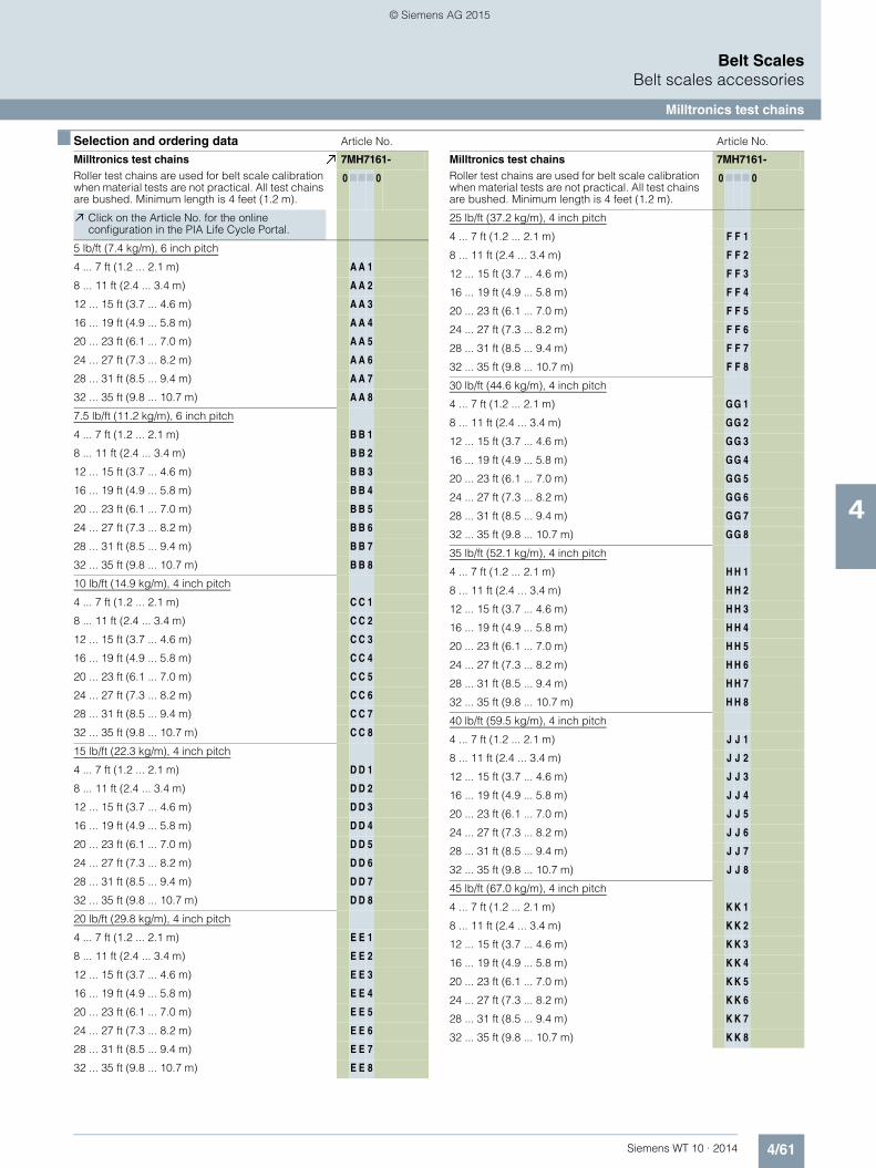
4/61Siemens WT 10 · 2014
Belt ScalesBelt scales accessories
Milltronics test chains
4
■ Selection and ordering data Article No. Article No.
Milltronics test chainsRoller test chains are used for belt scale calibration when material tests are not practical. All test chains are bushed. Minimum length is 4 feet (1.2 m).
7MH7161-
0 777 0
Click on the Article No. for the online configuration in the PIA Life Cycle Portal.
5 lb/ft (7.4 kg/m), 6 inch pitch
4 ... 7 ft (1.2 ... 2.1 m) A A 1
8 ... 11 ft (2.4 ... 3.4 m) A A 2
12 ... 15 ft (3.7 ... 4.6 m) A A 3
16 ... 19 ft (4.9 ... 5.8 m) A A 4
20 ... 23 ft (6.1 ... 7.0 m) A A 5
24 ... 27 ft (7.3 ... 8.2 m) A A 6
28 ... 31 ft (8.5 ... 9.4 m) A A 7
32 ... 35 ft (9.8 ... 10.7 m) A A 8
7.5 lb/ft (11.2 kg/m), 6 inch pitch
4 ... 7 ft (1.2 ... 2.1 m) B B 1
8 ... 11 ft (2.4 ... 3.4 m) B B 2
12 ... 15 ft (3.7 ... 4.6 m) B B 3
16 ... 19 ft (4.9 ... 5.8 m) B B 4
20 ... 23 ft (6.1 ... 7.0 m) B B 5
24 ... 27 ft (7.3 ... 8.2 m) B B 6
28 ... 31 ft (8.5 ... 9.4 m) B B 7
32 ... 35 ft (9.8 ... 10.7 m) B B 8
10 lb/ft (14.9 kg/m), 4 inch pitch
4 ... 7 ft (1.2 ... 2.1 m) C C 1
8 ... 11 ft (2.4 ... 3.4 m) C C 2
12 ... 15 ft (3.7 ... 4.6 m) C C 3
16 ... 19 ft (4.9 ... 5.8 m) C C 4
20 ... 23 ft (6.1 ... 7.0 m) C C 5
24 ... 27 ft (7.3 ... 8.2 m) C C 6
28 ... 31 ft (8.5 ... 9.4 m) C C 7
32 ... 35 ft (9.8 ... 10.7 m) C C 8
15 lb/ft (22.3 kg/m), 4 inch pitch
4 ... 7 ft (1.2 ... 2.1 m) D D 1
8 ... 11 ft (2.4 ... 3.4 m) D D 2
12 ... 15 ft (3.7 ... 4.6 m) D D 3
16 ... 19 ft (4.9 ... 5.8 m) D D 4
20 ... 23 ft (6.1 ... 7.0 m) D D 5
24 ... 27 ft (7.3 ... 8.2 m) D D 6
28 ... 31 ft (8.5 ... 9.4 m) D D 7
32 ... 35 ft (9.8 ... 10.7 m) D D 8
20 lb/ft (29.8 kg/m), 4 inch pitch
4 ... 7 ft (1.2 ... 2.1 m) E E 1
8 ... 11 ft (2.4 ... 3.4 m) E E 2
12 ... 15 ft (3.7 ... 4.6 m) E E 3
16 ... 19 ft (4.9 ... 5.8 m) E E 4
20 ... 23 ft (6.1 ... 7.0 m) E E 5
24 ... 27 ft (7.3 ... 8.2 m) E E 6
28 ... 31 ft (8.5 ... 9.4 m) E E 7
32 ... 35 ft (9.8 ... 10.7 m) E E 8
25 lb/ft (37.2 kg/m), 4 inch pitch
4 ... 7 ft (1.2 ... 2.1 m) F F 1
8 ... 11 ft (2.4 ... 3.4 m) F F 2
12 ... 15 ft (3.7 ... 4.6 m) F F 3
16 ... 19 ft (4.9 ... 5.8 m) F F 4
20 ... 23 ft (6.1 ... 7.0 m) F F 5
24 ... 27 ft (7.3 ... 8.2 m) F F 6
28 ... 31 ft (8.5 ... 9.4 m) F F 7
32 ... 35 ft (9.8 ... 10.7 m) F F 8
30 lb/ft (44.6 kg/m), 4 inch pitch
4 ... 7 ft (1.2 ... 2.1 m) G G 1
8 ... 11 ft (2.4 ... 3.4 m) G G 2
12 ... 15 ft (3.7 ... 4.6 m) G G 3
16 ... 19 ft (4.9 ... 5.8 m) G G 4
20 ... 23 ft (6.1 ... 7.0 m) G G 5
24 ... 27 ft (7.3 ... 8.2 m) G G 6
28 ... 31 ft (8.5 ... 9.4 m) G G 7
32 ... 35 ft (9.8 ... 10.7 m) G G 8
35 lb/ft (52.1 kg/m), 4 inch pitch
4 ... 7 ft (1.2 ... 2.1 m) H H 1
8 ... 11 ft (2.4 ... 3.4 m) H H 2
12 ... 15 ft (3.7 ... 4.6 m) H H 3
16 ... 19 ft (4.9 ... 5.8 m) H H 4
20 ... 23 ft (6.1 ... 7.0 m) H H 5
24 ... 27 ft (7.3 ... 8.2 m) H H 6
28 ... 31 ft (8.5 ... 9.4 m) H H 7
32 ... 35 ft (9.8 ... 10.7 m) H H 8
40 lb/ft (59.5 kg/m), 4 inch pitch
4 ... 7 ft (1.2 ... 2.1 m) J J 1
8 ... 11 ft (2.4 ... 3.4 m) J J 2
12 ... 15 ft (3.7 ... 4.6 m) J J 3
16 ... 19 ft (4.9 ... 5.8 m) J J 4
20 ... 23 ft (6.1 ... 7.0 m) J J 5
24 ... 27 ft (7.3 ... 8.2 m) J J 6
28 ... 31 ft (8.5 ... 9.4 m) J J 7
32 ... 35 ft (9.8 ... 10.7 m) J J 8
45 lb/ft (67.0 kg/m), 4 inch pitch
4 ... 7 ft (1.2 ... 2.1 m) K K 1
8 ... 11 ft (2.4 ... 3.4 m) K K 2
12 ... 15 ft (3.7 ... 4.6 m) K K 3
16 ... 19 ft (4.9 ... 5.8 m) K K 4
20 ... 23 ft (6.1 ... 7.0 m) K K 5
24 ... 27 ft (7.3 ... 8.2 m) K K 6
28 ... 31 ft (8.5 ... 9.4 m) K K 7
32 ... 35 ft (9.8 ... 10.7 m) K K 8
Milltronics test chainsRoller test chains are used for belt scale calibration when material tests are not practical. All test chains are bushed. Minimum length is 4 feet (1.2 m).
7MH7161-
0 777 0
© Siemens AG 2015

4/62 Siemens WT 10 · 2014
Belt ScalesBelt scales accessories
Milltronics test chains
4
■ Selection and ordering data Article No. Article No.
Milltronics test chainsRoller test chains are used for belt scale calibration when material tests are not practical. All test chains are bushed. Minimum length is 4 feet (1.2 m).
7MH7161-
0 777 0
Click on the Article No. for the online configuration in the PIA Life Cycle Portal.
50 lb/ft (74.4 kg/m), 4 inch pitch
4 ... 7 ft (1.2 ... 2.1 m) L L 1
8 ... 11 ft (2.4 ... 3.4 m) L L 2
12 ... 15 ft (3.7 ... 4.6 m) L L 3
16 ... 19 ft (4.9 ... 5.8 m) L L 4
20 ... 23 ft (6.1 ... 7.0 m) L L 5
24 ... 27 ft (7.3 ... 8.2 m) L L 6
28 ... 31 ft (8.5 ... 9.4 m) L L 7
32 ... 35 ft (9.8 ... 10.7 m) L L 8
60 lb/ft (89.3 kg/m), 6 inch pitch
4 ... 7 ft (1.2 ... 2.1 m) N N 1
8 ... 11 ft (2.4 ... 3.4 m) N N 2
12 ... 15 ft (3.7 ... 4.6 m) N N 3
16 ... 19 ft (4.9 ... 5.8 m) N N 4
20 ... 23 ft (6.1 ... 7.0 m) N N 5
24 ... 27 ft (7.3 ... 8.2 m) N N 6
28 ... 31 ft (8.5 ... 9.4 m) N N 7
32 ... 35 ft (9.8 ... 10.7 m) N N 8
70 lb/ft (104.2 kg/m), 6 inch pitch
4 ... 7 ft (1.2 ... 2.1 m) P P 1
8 ... 11 ft (2.4 ... 3.4 m) P P 2
12 ... 15 ft (3.7 ... 4.6 m) P P 3
16 ... 19 ft (4.9 ... 5.8 m) P P 4
20 ... 23 ft (6.1 ... 7.0 m) P P 5
24 ... 27 ft (7.3 ... 8.2 m) P P 6
28 ... 31 ft (8.5 ... 9.4 m) P P 7
32 ... 35 ft (9.8 ... 10.7 m) P P 8
80 lb/ft (119.1 kg/m), 6 inch pitch
4 ... 7 ft (1.2 ... 2.1 m) Q Q 1
8 ... 11 ft (2.4 ... 3.4 m) Q Q 2
12 ... 15 ft (3.7 ... 4.6 m) Q Q 3
16 ... 19 ft (4.9 ... 5.8 m) Q Q 4
20 ... 23 ft (6.1 ... 7.0 m) Q Q 5
24 ... 27 ft (7.3 ... 8.2 m) Q Q 6
28 ... 31 ft (8.5 ... 9.4 m) Q Q 7
32 ... 35 ft (9.8 ... 10.7 m) Q Q 8
90 lb/ft (133.9 kg/m), 6 inch pitch
4 ... 7 ft (1.2 ... 2.1 m) R R 1
8 ... 11 ft (2.4 ... 3.4 m) R R 2
12 ... 15 ft (3.7 ... 4.6 m) R R 3
16 ... 19 ft (4.9 ... 5.8 m) R R 4
20 ... 23 ft (6.1 ... 7.0 m) R R 5
24 ... 27 ft (7.3 ... 8.2 m) R R 6
28 ... 31 ft (8.5 ... 9.4 m) R R 7
32 ... 35 ft (9.8 ... 10.7 m) R R 8
100 lb/ft (148.8 kg/m), 6 inch pitch
4 ... 7 ft (1.2 ... 2.1 m) S S 1
8 ... 11 ft (2.4 ... 3.4 m) S S 2
12 ... 15 ft (3.7 ... 4.6 m) S S 3
16 ... 19 ft (4.9 ... 5.8 m) S S 4
20 ... 23 ft (6.1 ... 7.0 m) S S 5
24 ... 27 ft (7.3 ... 8.2 m) S S 6
28 ... 31 ft (8.5 ... 9.4 m) S S 7
32 ... 35 ft (9.8 ... 10.7 m) S S 8
Further models Order Code
Please add "-Z" to article no. and specify order codes(s)
Total length
Enter the total length in plain text description:Y01: Total length ... mm (must be equivalent to whole feet, e.g. 1 foot = 304.8 mm)
Y01
Operating instructions Article No.
• English A5E32310082
• German 7ML1998-5JD31
Note: The operating instructions should be ordered as a separate item on the order.
This device is shipped with the Siemens Milltronics manual DVD containing the complete operating instructions library.
Milltronics test chainsRoller test chains are used for belt scale calibration when material tests are not practical. All test chains are bushed. Minimum length is 4 feet (1.2 m).
7MH7161-
0 777 0
© Siemens AG 2015

4/63Siemens WT 10 · 2014
Belt ScalesBelt scales accessories
Milltronics test chains
4
■ Dimensional drawings
Milltronics test chain dimensions
Chain length to center line of last roller
Chain length to center line of last roller
Rol
ler d
iam
eter
Rol
ler d
iam
eter
Sha
ft le
ngth
Sha
ft le
ngth
Roller pin ST. STL.
Washer
Roller shaft (removable)
Roller pin ST. STL.Roller shaft (removable)
Pitch
Pitch
Test chain link
WasherTest chain link
Test chain shackle
Test chain roller
Test chain shackle
Test chain roller
Single roller
Double roller
© Siemens AG 2015

4/64 Siemens WT 10 · 2014
Belt ScalesBelt scales accessories
Milltronics test chain storage reels
4
■ Overview
Test chain storage reels are used to store roller test chains. All test chain storage reels come with a geared brake motor.
■ Benefits
• Mounts to existing conveyor structure above belt• Motorized application and retraction of test chains for calibra-
tion• Fast and easy calibration
■ Application
Milltronics calibration test chain storage reels provide motorized application and retraction of test chains. Complete with an AC motorized storage reel, test chain reels ensure safe and quick use of calibration test chains. Designed for use in environments where material tests cannot be performed, test chain storage reels are available in any belt width to meet existing customer conveyor geometry. For linearity tests dual compartment reels are available for different chain weight calibration. Test chain storage reels have a brake integral to the motor ensuring that test chains do not un-reel during power outages or material run-ning.
■ Technical specifications
■ Selection and ordering data Article No.
Milltronics calibration test chain storage reels
Medium conditions
Operating temperature -10 ... +60 °C (14 ... 140 °F)
Design • Polyester painted structural steel • 10 mm (3/8 inch) galvanized rope
provided for chain spooling • Self-aligning pillow block
bearings
Reel Up to 1 524 mm (60 inch)Chain application at 7 ... 10 RPM
Drive motor TEFC, AC, three phase motor with shaft mounted helical bevel gear reducer
Approvals CE, RCM
Milltronics test chain storage reelsTest chain storage reels are used to store roller test chains. All test chain storage reels come with a geared brake motor.
7MH7163-
77777 - 77
Click on the Article No. for the online configuration in the PIA Life Cycle Portal.
Compartment size
5 inch (127 mm) for chain sizes: 5 lb/ft (7.4 kg/m), 10 lb/ft (14.9 kg/m)
0
6 inch (152 mm) for chain sizes: 7.5 lb/ft (11.2 kg/m) 1
7 inch (178 mm) for chain sizes: 15 lb/ft (22.3 kg/m), 20 lb/ft (29.8 kg/m), 25 lb/ft (37.2 kg/m)
2
8 inch (203 mm) for chain sizes: 30 lb/ft (44.6 kg/m), 35 lb/ft (52.1 kg/m)
3
11 inch (279 mm) for chain sizes: 40 lb/ft (59.5 kg/m), 45 lb/ft (67.0 kg/m), 50 lb/ft (74.4 kg/m)
4
12 inch (305 mm) for chain sizes:55 lb/ft (81.9 kg/m), 60 lb/ft (89.3 kg/m)
5
13 inch (330 mm) for chain sizes: 70 lb/ft (104.2 kg/m)
6
14 inch (356 mm) for chain sizes:80 lb/ft (119.1 kg/m), 100 lb/ft (148.8 kg/m)
7
16 inch (406 mm) for chain sizes:90 lb/ft (133.9 kg/m)
8
C dimension
25 inch (635 mm) A A
26 inch (660 mm) A B
27 inch (686 mm) A C
28 inch (711 mm) A D
29 inch (737 mm) A E
30 inch (762 mm) A F
31 inch (787 mm) A G
32 inch (813 mm) A H
33 inch (838 mm) A J
34 inch (864 mm) A K
35 inch (889 mm) A L
36 inch (914 mm) AM
37 inch (940 mm) A N
38 inch (965 mm) A P
39 inch (991 mm) A Q
40 inch (1 016 mm) A R
41 inch (1 041 mm) A S
42 inch (1 067 mm) A T
43 inch (1 092 mm) A U
44 inch (1 118 mm) A V
45 inch (1 143 mm) AW
46 inch (1 168 mm) B A
47 inch (1 194 mm) B B
48 inch (1 219 mm) B C
49 inch (1 245 mm) B D
50 inch (1 270 mm) B E
51 inch (1 295 mm) B F
52 inch (1 321 mm) B G
53 inch (1 346 mm) B H
54 inch (1 372 mm) B J
55 inch (1 397 mm) B K
© Siemens AG 2015

4/65Siemens WT 10 · 2014
Belt ScalesBelt scales accessories
Milltronics test chain storage reels
4
56 inch (1 422 mm) B L
57 inch (1 448 mm) B M
58 inch (1 473 mm) B N
59 inch (1 499 mm) B P
60 inch (1 524 mm) B Q
61 inch (1 549 mm) B R
62 inch (1 575 mm) B S
63 inch (1 600 mm) B T
64 inch (1 626 mm) B U
65 inch (1 651 mm) B V
66 inch (1 676 mm) BW
67 inch (1 702 mm) C A
68 inch (1 727 mm) C B
69 inch (1 753 mm) C C
70 inch (1 778 mm) C D
71 inch (1 803 mm) C E
72 inch (1 829 mm) C F
73 inch (1 854 mm) C G
74 inch (1 880 mm) C H
75 inch (1 905 mm) C J
76 inch (1 930 mm) C K
77 inch (1 956 mm) C L
78 inch (1 981 mm) C M
79 inch (2 007 mm) C N
80 inch (2 032 mm) C P
81 inch (2 057 mm) C Q
82 inch (2 083 mm) C R
83 inch (2 108 mm) C S
84 inch (2 134 mm) C T
85 inch (2 159 mm) C U
86 inch (2 184 mm) C V
87 inch (2 210 mm) CW
88 inch (2 235 mm) D A
89 inch (2 261 mm) D B
90 inch (2 286 mm) D C
91 inch (2 311 mm) D D
92 inch (2 337 mm) D E
93 inch (2 362 mm) D F
94 inch (2 388 mm) D G
95 inch (2 413 mm) D H
96 inch (2 438 mm) D J
97 inch (2 464 mm) D K
98 inch (2 489 mm) D L
99 inch (2 515 mm) D M
100 inch (2 540 mm) D N
101 inch (2 565 mm) D P
102 inch (2 591 mm) D Q
103 inch (2 616 mm) D R
104 inch (2 642 mm) D S
105 inch (2 667 mm) D T
Milltronics test chain storage reelsTest chain storage reels are used to store roller test chains. All test chain storage reels come with a geared brake motor.
7MH7163-
77777 - 77
3 Phase motor voltage
230/460 V 60 Hz 1
200/400 V 50 Hz 2
575 V 60 Hz 3
190/380 V 50 Hz 4
190/380 V 60 Hz 5
220 V 60 Hz 6
415 V 50 Hz 7
Reel type
Single compartment for 1 calibration test chain 0
Double compartment for 2 calibration test chains 1
Reel diameter/motor mount location
36 inch (914 mm) / right hand access 0
42 inch (1 067 mm) / right hand access 1
48 inch (1 219 mm) / right hand access 2
60 inch (1 372 mm) / right hand access 3
36 inch (914 mm) / left hand access 4
42 inch (1 067 mm) / left hand access 5
48 inch (1 219 mm) / left hand access 6
60 inch (1 372 mm) / left hand access 7
Motor power
0.75 HP (0.56 kW) A
1 HP (0.75 kW) B
1.5 HP (1.12 kW) C
2 HP (1.5 kW) D
3 HP (2.24 kW) E
5 HP (3.73 kW) F
7.5 HP (5.59 kW) G
10 HP (7.5 kW) H
15 HP (11.19 kW) J
20 HP (14.91 kW) K
Operating instructions
• English 7ML1998-5JD01
• German 7ML1998-5JD31
Note: The operating instructions should be ordered as a separate item on the order.
This device is shipped with the Siemens Milltronics manual DVD containing the complete operating instructions library.
Accessories
Local operator station: forward, reverse, e-stop, off/onNote: Motor starter and voltage transformer required for use with controller, 120 V AC required for controller
7MH7723-1JY
Milltronics test chain storage reelsTest chain storage reels are used to store roller test chains. All test chain storage reels come with a geared brake motor.
7MH7163-
77777 - 77
© Siemens AG 2015

4/66 Siemens WT 10 · 2014
Belt ScalesBelt scales accessories
Milltronics test chain storage reels
4
■ Dimensional drawings
Milltronics test chain storage reel dimension in mm (inch)
Reel Ø B E915 (36) 520 (20.5) 340 (13.25)1 070 (42) 600 (23.5) 340 (13.25)1 220 (48) 670 (26.5) 340 (13.25)1 520 (60) 830 (32.5) 450 (17.75)
By Siemens Milltronics
By customer
Belt line
D dimension to
center line of belt scale
Reel Ø
Eyebolt for chain restraint
Gusset (by customer)
To suit
By Siemens
Milltronics
By customer
Conveyor
Conveyor stringer
Connecting bracket by customer
Pillow block bearings
Structural angle frame
254 (10) x 320.4 kg/m (20 lb/ft)
101.5 (4) shed 40 pipe
Motor mounted for right hand access based on belt scale
location
View Z
Z
A
C
BB
E
© Siemens AG 2015

4/67Siemens WT 10 · 2014
Belt ScalesBelt scales accessories
Milltronics belt scale peripherals
4
■ Selection and ordering dataArticle No.
Totalizer
150 x 150 x 100DNema 4 /IP65 enclosure
7MH7723-1GG
Panel mount totalizer 7MH7726-1AU
Ticket printers
Ticket printerTM-U295, 100 … 240 V
7MH7726-1AK
Ribbon Ink EPSON TM-U295
7MH7723-1GE
Printer cables
Printer cables for TM-U295and TMU220B, RS 232, DB25 … open end
7MH7726-1AH
RS 485 … RS 232 DB25male converters for TMU295 and TMU220B printer
7MH7726-1AJ
Roll printer
Roll printer, TMU220B, 100 … 240 V (required for German and Spanish printing)
7MH7726-1AT
Chart recorder
Totalizer with Hi/Low alarm lights, 584 x 483 x 203D Nema 4 /IP65 enclosure
7MH7726-1AL
SIREC D200 display recorder
7ND4121-1AA01-1AA2
Article No.
Terminal box 1, 2 or, 4 load cell(s) / speed sen-sor, 150 x 200 x 100 NEMA 4/IP65 enclosure
Mild steel 7MH7723-1ND
Stainless steel 7MH7723-1NE
Termination board spare A5E03623963
Note: for MMI-3, 2 termi-nal boxes are required
Belt scale connection cable, 6 cond, 20 G (order per meter)Note: for use with 1 or 2 load cell belt scales, for 4 or 6 load cell belt scales use 2 cables. This cable is intended for less than 150 m (500 ft)
7MH7723-1JR
Belt scale installation kitNote: comes with idler shims, alignment wire, and spacer blocks for idler alignment
7MH7723-1KC
Inclinometer
Celesco model IT9420 7MH7726-1AP
Belt scale spare load cells For Milltronics Torque shaft belt scale (MTS), model CD or CFT, mount-ing hardware included
50 lb (22.7 kg) 7MH7725-1BA
75 lb (34 kg) 7MH7725-1BB
100 lb (45.4 kg) 7MH7725-1BC
150 lb (68 kg) 7MH7725-1BD
300 lb (136.1 kg) 7MH7725-1BE
500 lb (226.8 kg) 7MH7725-1BF
750 lb (340.2 kg) 7MH7725-1BG
1 000 lb (453.6 kg) 7MH7725-1BH
1 500 lb (680.4 kg) 7MH7725-1BJ
© Siemens AG 2015

4/68 Siemens WT 10 · 2014
Belt ScalesBelt scales accessories
Milltronics belt scale peripherals
4
Article No.
Belt scale spare load cells For MSI belt scale with round static beam, low-profile, mounting hard-ware included, model 60048-XXX-0137 or 60048-XXX-0129
25 lb (11.3 kg) 7MH7725-1AJ
50 lb (22.7 kg) 7MH7725-1AK
100 lb (45.4 kg) 7MH7725-1AL
200 lb (90.7 kg) 7MH7725-1AM
400 lb (181.4 kg) 7MH7725-1AN
500 lb (226.8 kg) 7MH7725-1AP
1 000 lb (453.6 kg) 7MH7725-1AQ
Belt scale spare load cells For retrofitting current and older version of MSI with Group 4, mounting hardware included, sensortronics60048-xxx-0138, or RTI. Model 6500
50 lb (22.7 kg) 7MH7725-1AC
100 lb (45.4 kg) 7MH7725-1AD
250 lb (113.4 kg) 7MH7725-1AE
500 lb (226.8 kg) 7MH7725-1AF
750 lb (340.2 kg) 7MH7725-1AG
1 000 lb (453.6 kg) 7MH7725-1AH
Belt scale spare load cells For retrofitting older ver-sion of MSI C462 (trans-ducers incorporated), mounting hardware included
50 lb (22.7 kg) PBD-23900005
100 lb (45.4 kg) PBD-23900010
250 lb (113.4 kg) PBD-23900012
Belt scale spare load cells For retrofitting older MMW & MCS belt scales that do not have a con-duit adaptor, belt scale mounting hardware included
50 lb 7MH7725-1BN
100 lb 7MH7725-1BP
250 lb 7MH7725-1BQ
Article No.
Belt scale spare load cells For retrofitting older MIC belt scale, mounting hardware included
25 lb Replace with 50 lb
50 lb (22.7 kg) PBD-61009735
100 lb (45.4 kg) PBD-61009731
250 lb (113.4 kg) PBD-61009732
500 lb (226.8 kg) PBD-61009733
1 000 lb (453.6 kg) PBD-61009734
Kit, 2 idler cable suspension
PBD-61010081
Kit, 2 idler cable suspension, heavy duty
PBD-61010082
Kit, 4 idler cable suspension, heavy duty
PBD-61010742
Kit, 4 idler cable suspension, magnum
PBD-61010743
Kit, 4 idler cable suspension, standard
PBD-61010741
Shock washers PBD-54000161
Bearing flange 1 3/16 PBD-20250015
Belt scale spare load cells For MUS HD aluminum model 7MH71202, mounting hardware included
50 kg (110.2 lb) 7MH7725-1BW
100 kg (220.4 lb) 7MH7725-1BX
150 kg (330.7 lb) 7MH7725-1BY
200 kg (440.9 lb) 7MH7725-1CA
300 kg (661.4 lb) 7MH7725-1CB
500 kg (1 102.3 lb) 7MH7725-1CC
Belt scale spare load cells For WD600 model 7MH7185
25 lb (11.3 kg) PBD-23900224
50 lb (22.7 kg) PBD-23900225
© Siemens AG 2015

Siemens WT 10 · 2014
55/2 Introduction
5/5 SITRANS WW1005/5 Introduction5/8 Ordering data5/11 Dimensional drawings and schematics
5/13 SITRANS WW2005/13 Introduction5/16 Open style5/25 Enclosed style5/43 Accessories and spare parts5/47 Dimensional drawings and schematics
5/49 SITRANS WW3005/49 Introduction5/51 8 inch pulley, open style5/54 8 inch pulley, enclosed style5/57 10 inch pulley, open style5/60 10 inch pulley, enclosed style5/64 12 inch pulley, open style5/67 12 inch pulley, enclosed style5/71 14 inch pulley, open style5/75 14 inch pulley, enclosed style5/79 Accessories and spare parts5/81 Dimensional drawings and schematics
5/83 SITRANS WW3105/83 Introduction5/84 8 inch pulley, open style5/87 8 inch pulley, enclosed style5/90 12 inch pulley, open style5/93 12 inch pulley, enclosed style5/96 Accessories and spare parts5/98 Dimensional drawings and schematics
5/101 SITRANS weighfeeder peripherals
SITRANS Weighfeeders
© Siemens AG 2015

5/2 Siemens WT 10 · 2014
SITRANS WeighfeedersIntroduction
5
■ Overview
SITRANS weighfeeders from Siemens can improve the accuracy of processing, blend consistencies, accountability, and record keeping. All weighfeeders come standard with a belt weigh bridge and speed sensor. An integrator is required to complete the system.
■ Mode of operation
The weighfeeder is used to deliver an accurate mass flow rate of material. In the majority of applications, material is profiled by an adjustable mechanical shear gate, which fixes the correct mate-rial bed depth for a given particle size.
The feed rate is then maintained and adjusted by varying the speed of the belt. However, in some cases the belt speed is con-stant with rate control (if any) done by a pre-feeding device.
The system consists of three components: weight and speed sensing, integration and control, and the mechanical conveying system. Using the belt load and the belt speed signals, small in-cremental totals of weight per time are measured by the integra-tor and then the flow rate is calculated. The measured flowrate is compared against the desired flowrate and the on-board PID controller makes necessary corrections to the belt speed.
Weighfeeder operation
■ Design and Applications
SITRANS WW100
The platform weigh bridge mounts directly to a corrosion-resis-tant platform load cell. The direct load design eliminates all inter-mediate mechanical suspension and allows material weight to be directly applied to the load cell.
This design minimizes zero drift normally caused by intermedi-ary suspension components and allows for the use of a very sen-sitive precision platform load cell. Load cell size and construc-tion are chosen for each specific application.
SITRANS WW200
A stainless steel platform weighdeck with a Delrin slider bar as-sembly mounts directly to two corrosion-resistant, sealed plat-form load cells. The direct load design eliminates all intermedi-ate mechanical suspension and allows material weight to be directly applied to the load cells. The frame of the WW200 is sturdy and rigid, ensuring stable and repeatable results, maxi-mizing resolution and weighing accuracy.
SITRANS WW300
SITRANS WW300 suspends a single weigh idler on platform load cells. Its design eliminates all moving parts in the weighingprocess and subsequent maintenance and replacement prob-lems. There are no links or flexures. Two corrosion-resistant pre-cision strain gauge load cells provide weight sensing signals to an integrator. This design feature minimizes zero drift and maxi-mizes resolution and weighing accuracy.
SITRANS WW310
A modular design with external access to all bearings, speed sensors and load cells the WW310 is easy to maintain. Two cor-rosion resistant single point platform load cells mounted directly to a rugged idler ensure consistent weighing accuracy.
M
Display
Motor speed controller (optional)
TotalRate
LoadSpeedAnalog outputPID inputRemote total output
PID outputTail
pulley
Speed sensor
Head pulleyShear gate
Infeed
Belt travel
Speed
Load
Integrator
Belt scale or weighbridge
© Siemens AG 2015

5/3Siemens WT 10 · 2014
SITRANS WeighfeedersIntroduction
5
■ Technical specifications 1)
1) Accuracy subject to: On factory approved installations the weigh feeder system’s totalized weight will be within the specified accuracy when compared to a known weighed material test sample. The test rate must be within the specified range of the design capacity and held constant for the duration of the test. The minimum material test sample must be equivalent to a sample obtained at the test flow rate for three revolutions of the belt or at least ten minutes running time, whichever is greater.
Criteria SITRANS WW100
SITRANS WW200
SITRANS WW300
SITRANS WW310
Typical industries Bulk chemicals, tobacco, food, water treatment
Bulk chemicals, tobacco, food, recycling
Cement, mineral processing, coal, mining, pulp and paper
Cement, mineral processing, coal, mining, pulp and paper
Typical applications High-accuracy, low-capac-ity for minor ingredient addi-tives
Low- to medium-capacity for minor ingredient additives
Medium- to high-capacity for macro ingredient additives
Medium- to high-capacity for macro ingredient additives
Design rate range 45 kg/h ... 18 t/h (100 lb/h ... 20 STPH)
0.45 ... 100 t/h (1 000 lb/h ... 110 STPH)
4.5 ... 800 t/h(5 ... 880 STPH)
4.5 ... 270 t/h (5 ... 300 STPH)
Belt speed 0.005 ... 0.36 m/s(1 ... 70 fpm)
0.005 ... 0.36 m/s(1 ... 70 fpm)
0.005 ... 0.36 m/s(1 ... 70 fpm)
0.005 ... 0.36 m/s (1 ... 70 fpm)
Accuracy1) ± 0.25 ... 0.5 % ± 0.5 % or better ± 0.5 % or better ± 0.5 % or better
Specified range 10 ... 100 % based on speed 10 ... 100 % based on speed 10 ... 100 % based on speed 10 ... 100 % based on speed
Sensing element Long length platform weigh bridgeSingle load cell
Platform weigh bridgeDual load cells
Single idler scaleDual load cells
Single idler scale Dual load cells
Approvals CE, RCMStainless steel options meet USDA and FDA require-ments for food processing
Stainless steel options meet USDA and FDA require-ments for food processing
© Siemens AG 2015

5/4 Siemens WT 10 · 2014
SITRANS WeighfeedersIntroduction
5
■ Application
Weighfeeder Application Questionnaire
Weighfeeder Application Questionnaire
Preferred Weighfeeder Model:
Options:
Open options: Enclosedoptions:
316 SSWW100 WW200 WW300 304 SSPainted mild steelPreferred Construction:
Belt tracking switches
Discharge dust hood Bottom covers
Skirtboard coversSkirtboard covers
Dust tight seals
Dust extraction port
Plugged discharge chute switch
Drag chain clean out conveyor
Safety pull cord switches
Shear curtain Belt cleaning brush
Secondary speed sensor Start, stop, speed, controller
Gravity tensioned belt tracker (WW100/WW300)
WW310
Remote totalizer
Installation Power available for motor: volts Hz(indicate all that apply)
4 ... 20 mA
RS-232 / RS-485 Modbus
DeviceNet PROFIBUS DP SIMATIC S7 PLCRelays (#):
Inputs required: Outputs required: Communications:4 ... 20 mA PID PID
EtherNet/IP
Modbus TCP/IPProfiNet
Weighfeeder
Space limitations:Construction:
Requested belt width:Quantity required: Access side looking in direction of belt travel:
length: width:
Inlet dimensions: L × W: mm/inch Centerline length: mm/inchinlet to discharge
height: mm/inch mm/inch
left rightenclosedopen
Hopper size:
Feed rate:
Accuracy required: Hazardous classification at scale location:
Condition of operating environment:
Ratio controlled blendingBatch Control
ft³/m³
t/hr, kg/hr, lb/hr, LTPH, or STPH
Duty cycle: Material free fall height onto belt:hours per day
min.
%+/-
max. nominal
Feed type:
Sketch attached(Supply sketch where possible)
Load, speed, rate, and totalApplication:
Pre-feed
OtherScrew Bin, hopper, or siloVibratory pan
NormalWash down CorrosiveSanitary
BeltRotary valve
Continuous conveying Discontinuous conveying
sticky powder corrosive fluidizeshighly abrasive
Kg/m³ or lb/cu. ft. or t/m³
degrees degrees
Bulk density:
Temperature:
Moisture content:
Angle of repose:
Material characteristics:Surcharge angle:
Material
mm/inch/meshParticle size:Material being measured:
%
ºC/ºF
Date:
Notes on the Application:
Prepared By:
E-mail:
State/Province:
City: Country:
Address:
Company:
Contact:
Customer information
Zip/Postal Code:
Phone: ( ) Fax: ( )
www.siemens.com/processautomation© Siemens Milltronics Process Instruments Form# 2-773R3
© Siemens AG 2015
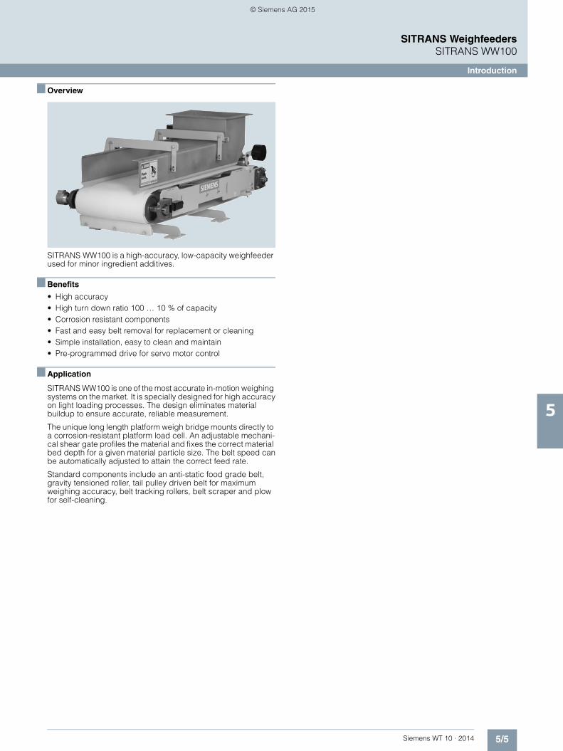
5/5Siemens WT 10 · 2014
SITRANS WeighfeedersSITRANS WW100
Introduction
5
■ Overview
SITRANS WW100 is a high-accuracy, low-capacity weighfeeder used for minor ingredient additives.
■ Benefits
• High accuracy • High turn down ratio 100 … 10 % of capacity • Corrosion resistant components • Fast and easy belt removal for replacement or cleaning • Simple installation, easy to clean and maintain • Pre-programmed drive for servo motor control
■ Application
SITRANS WW100 is one of the most accurate in-motion weighing systems on the market. It is specially designed for high accuracyon light loading processes. The design eliminates material buildup to ensure accurate, reliable measurement.
The unique long length platform weigh bridge mounts directly to a corrosion-resistant platform load cell. An adjustable mechani-cal shear gate profiles the material and fixes the correct material bed depth for a given material particle size. The belt speed canbe automatically adjusted to attain the correct feed rate.
Standard components include an anti-static food grade belt, gravity tensioned roller, tail pulley driven belt for maximumweighing accuracy, belt tracking rollers, belt scraper and plow for self-cleaning.
© Siemens AG 2015

5/6 Siemens WT 10 · 2014
SITRANS WeighfeedersSITRANS WW100
Introduction
5
■ Technical specifications 1)
1) Accuracy subject to: On factory approved installations the weigh feeder system’s totalized weight will be within the specified accuracy when compared to a known weighed material test sample. The test rate must be within the specified range of the design capacity and held constant for the duration of the test. The minimum material test sample must be equivalent to a sample obtained at the test flow rate for three revolutions of the belt or at least ten minutes running time, whichever is greater.
SITRANS WW100
Mode of operation
Measuring principle Strain gauge load cell and digital speed sensor
Typical application Control and monitor feed rates and blending in bulk chemicals, tobacco, food, and water treatment
Measuring accuracy
Accuracy1) ± 0.25 … 0.5 %
Specified range 10 … 100 % based on speed
Design rate range 45 kg/h … 18 t/h (100 lb/h … 20 STPH)
Max volumetric flow 45 m3/h (1 568 ft3/h)
Medium conditions
Operating temperature -10 … +55 °C (10 … 131 °F)
Material Mild steel or stainless steel [304 (1.4301) or 316 (1.4401)], bead blast finish (1 ... 6 µm, 40 ... 240 µin)
Load cells
Construction 17-4 PH (1.4568) stainless steel or nickel plated alloy steel
Degree of protection • Stainless steel: IP68• Nickel plated alloy steel: IP66
Excitation 10 V DC nominal, 15 V DC maximum
Output 2 mV/V
• Non-linearity ± 0.02 % of rated output
• Non-repeatability ± 0.01 % of rated output
Capacity • Stainless steel range: 6, 12, 30 kg• Nickel-plated range: 10, 15, 20,
30 kg
Overload 150 % of rated capacity
Temperature • Operating range: -40 … +65 °C (-40 … +149 °F)
• Compensated: -10 … +40 °C (14 … 104 °F)
Speed sensors
Optical encoder output • RS 422 (TTL) 5 V DC, 150 mA max.
• 500, 1 000, or 2 000 pulses per revolution (ppr)
Degree of protection • Standard: IP64• Stainless steel: IP66
Temperature • -10 … +70 °C (14 … 158 °F)
Framework • Precision machined, stainless [304 (1.4301) or 316 (1.4401)] or mild steel
• Cantilevered design for easy belt replacement
Pulleys 115 mm (4.5 inch) diameter, crowned and lagged
Bearings • 4-bolt flange mount on drive pulley
• 2-bolt threaded base pillow block on driven pulley
Belt speed 0.005 … 0.36 m/s (1 … 70 fpm)
Belt support Slider bed frame
Belting • Polyester carcass with polyure-thane top cover and static control with vulcanized endless finger splice for max. weighing consis-tency (standard)
• Maximum rated material tempera-ture of 82 °C (180 °F)
• Low capacity thermoplastic belt rated for max. material temp. of 100 °C (212 °F)
Belt tension • Counter-weighted stainless steel [304 (1.4301) or 316 (1.4401)] tensioning idler for consistent ten-sion, required for high accuracy weighing
• Screw type, telescoper module with 25 mm (1 inch) travel, mild or stainless steel 304 (1.4301)
Belt cleaning • UHMW blade type with counter-weight at the head pulley for cleaning product side of belt
• Return plow • Cleaning brush, optional
Drive motor • 0.24 kW (0.32 HP) TEFC, 10:1 CT inverter duty, servo drive motor with direct coupled flange mounted hollow bore worm CAF28 gear reducer 45.6 Nm (404 lb), 2.1 service factor mini-mum (standard)
• 0.55 kW (0.75 HP), TEFC, 10:1CT inverter duty, AC drive motor with direct coupled flange mount-ed hollow bore worm CAF28 gear reducer 81 Nm (717 in. lb), 3.12 service factor minimum (optional)
Variable frequency drive: SINAMICS S110 servo motor controller (included with supply of WW100 based on ordering options)
• 1 ph, 200 ... 240 V or 3 ph, 380 … 480 V
• MMC with Factory loaded pro-gram for fast installation and com-missioning
• BOP for local control • External 24 V DC power supply • RS 232 connection port • 4 DI, D0 • Profibus DP • Starter software & connection
drawings provided with docu-mentation
Shipping weight 91 kg (200 lb) … 181 kg (400 lb) maximum
Approvals CE, RCMStainless steel options meet USDA and FDA requirements for food processing
SITRANS WW100
© Siemens AG 2015

5/7Siemens WT 10 · 2014
SITRANS WeighfeedersSITRANS WW100
Introduction
5
Reduction ratio selection table
Reduction(X:1)
Speed 60 Hzfpm
60 Hzm/s
50 Hzfpm
50 Hzm/s
372:1 max.min.
5.540.55
0.0280.003
4.590.45
0.0230.002
303.36:1 max.min.
6.800.68
0.0350.003
5.630.56
0.0290.003
248:1 max.min.
8.310.83
0.0420.004
6.890.69
0.0350.003
202.24:1 max.min.
10.191.02
0.0520.005
8.450.84
0.0430.004
155:1 max.min.
13.301.33
0.0680.007
11.021.10
0.0560.006
126.4:1 max.min.
16.311.63
0.0830.008
13.511.35
0.0690.007
93:1 max.min.
22.172.22
0.1130.011
18.371.84
0.0930.009
75.84:1 max.min.
27.182.72
0.1380.014
22.522.25
0.1140.011
62:1 max.min.
33.253.33
0.1690.017
27.552.76
0.1400.014
50.56:1 max.min.
40.784.08
0.2070.021
33.793.38
0.1720.017
46.5:1 max.min.
44.344.43
0.2250.023
36.743.67
0.1870.019
37.92:1 max.min.
55.444.37
0.2760.028
45.054.50
0.2290.023
31:1 max.min.
66.516.65
0.3380.034
55.105.51
0.2800.028
25.28:1 max.min.
81.558.16
0.4140.041
67.576.76
0.3430.034
© Siemens AG 2015

5/8 Siemens WT 10 · 2014
SITRANS WeighfeedersSITRANS WW100
Ordering data
5
■ Selection and ordering data Article No. Article No.
SITRANS WW100High accuracy solids weighfeeder for low capacity applications. Compact unit improves processing, increases efficiency and provides significant cost savings.
7MH7180-
77777 - 7777
Click on the Article No. for the online configuration in the PIA Life Cycle Portal.
Add order code Y71 ... Y73 for all models to specify design data
Frame and enclosure construction
Painted mild steel open style 0 A
304 stainless steel open style 0 B
316 stainless steel open style 0 D
Painted mild steel enclosed style with painted mild steel enclosure
1 A
304 stainless steel enclosed style with painted mild steel enclosure
1 B
304 stainless steel enclosed style with 304 stainless steel enclosure
1 D
316 stainless steel enclosed style with painted mild steel enclosure
1 G
316 stainless steel enclosed style with 304 stainless steel enclosure
1 J
316 stainless steel enclosed style with 316 stainless steel enclosure
1 M
Material containment construction
Add order code Y74 and plain text: "Arc radius in inches …XX.XXX inch" for options A ... H
Shear gate inlet and skirtboards 304 stainless steel A
Shear gate inlet and skirtboards 304 stainless steel with cover
B
Shear gate inlet and skirtboards 304 stainless steel, #4 polished
C
Shear gate inlet and skirtboards 304 stainless steel, #4 polished with cover
D
Shear gate inlet and skirtboards 316 stainless steel E
Shear gate inlet and skirtboards 316 stainless steel with cover
F
Shear gate inlet and skirtboards 316 stainless steel, #4 polished
G
Shear gate inlet and skirtboards 316 stainless steel, #4 polished with cover
H
Horseshoe inlet 304 stainless steel1) J
Horseshoe inlet 304 stainless steel, #4 polished1) K
Horseshoe inlet 316 stainless steel1) L
Horseshoe inlet 316 stainless steel, #4 polished1) M
Load cell
10 kg (22 lb) nickel plated steel 0
15 kg (33 lb) nickel plated steel 1
20 kg (44 lb) nickel plated steel 2
30 kg (66 lb) nickel plated steel 3
6 kg (13.2 lb) stainless steel, hermetically sealed 4
12 kg (26.5 lb) stainless steel, hermetically sealed 5
30 kg (66.1 lb) stainless steel, hermetically sealed 6
SITRANS WW100High accuracy solids weighfeeder for low capacity applications. Compact unit improves processing, increases efficiency and provides significant cost savings.
7MH7180-
77777 - 7777
Speed sensor
500 PPR shaft mounted optical encoder 0
1 000 PPR shaft mounted optical encoder 1
2 500 PPR shaft mounted optical encoder 2
500 PPR shaft mounted optical encoder, stainless steel
3
1 000 PPR shaft mounted optical encoder, stainless steel
4
2 500 PPR shaft mounted optical encoder, stainless steel
5
Drive configurationSINAMICS servo motor and drive
200 ... 240 V1 ph2) 0 A
380 ... 480 V 3 ph2) 0 B
200 ... 240 V 1 ph, with 5 m (16.4 ft) communication and power cables
1 A
380 ... 480 V 3 ph, with 5 m (16.4 ft) communication and power cables
1 B
200 ... 240 V 1 ph, with 10 m (33 ft) communication and power cables
2 A
380 ... 480 V 3 ph, with 10 m (33 ft) communication and power cables
2 B
200 ... 240 V 1 ph, with 25 m (82 ft) communication and power cables
3 A
380 ... 480 V 3 ph, with 25 m (82 ft) communication and power cables
3 B
200 ... 240 V 1 ph, with 50 m (164 ft) communication and power cables
4 A
380 ... 480 V 3 ph, with 50 m (164 ft) communication and power cables
4 B
200 ... 240 V 1 ph, with 100 m (328 ft) communication and power cables
5 A
380 ... 480 V 3 ph, with 100 m (328 ft) communication and power cables
5 B
Standard AC motor without drive (Drive required for desired belt speed)
Add order code Y75 reduction ratio in plain text: "X:1" for options 6A ... 7B, see "Reduction Ratio Selection Table" on page 5/7.
220 ... 240/380 ... 480 V 3 ph 50/60 Hz AC 6 A
575 V 3 ph 60 Hz AC 6 B
Food grade epoxy coated AC motor without drive (Drive required for desired belt speed)
220 ... 240/380 ... 480 V 3 ph 50/60 Hz AC epoxy coated gearmotor
7 A
575 V 3 ph 60 Hz AC epoxy coated gearmotor 7 B
Calibration Method
None A
1 calibration chain strand 2.41 kg/m (1.62 lb/ft) B
2 calibration chain strands 4.82 kg/m (3.24 lb/ft) C
3 calibration chain strands 7.23 kg/m (4.86 lb/ft) D
Belt change access side (looking from inlet to discharge)
Left hand 0
Right hand 1
© Siemens AG 2015

5/9Siemens WT 10 · 2014
SITRANS WeighfeedersSITRANS WW100
Ordering data
5
■ Selection and ordering data Order Code Article No.
Further designs
Please add "-Z" to article no. and specify order code(s).
Shear gate arc radius: Enter shear gate arc radius in inches (xxx.xx inch)3)
Y74
Enter design units (TPH, MTPH, lb/h, kg/h) Y71
Enter design speed (ft/m, m/s) Y72
Enter design capacity/rate Y73
AC gearmotor reduction ratio: Enter reduc-tion ratio in plain text (X:1) (see "Reduction Ratio Selection Table" on page 5/7).
Y75
Plastic shear curtain to control dust at the infeed for floodable materials and dusty applications3)
G11
Pointek CLS100 Capacitance switch for plugged discharge chute detection
G12
Siemens start/stop, auto/manual, speed control, local operator station
G13
Belt cleaner, stainless steel, nylon brush, mounted under belt plow, cleaning dirty side of belt
G14
Low weight belt for light loading, low rate applications (recommended for under 1 t/h). Thermo-plastic, 1 ply, anti-static, FDA, USDA approved
G15
High temp belt for material temperatures above 82 °C (180 °F)
G17
Manufacturer's test certificate: According to EN 10204-2.2
C11
Stainless steel tag [69 x 50 mm (2.71 x 1.97 inch)]: Measuring-point num-ber/identification (max. 27 characters) specify in plain text
Y15
Discharge dust hood, painted mild steel with de-dust port1)
H50
Discharge dust hood, 304 stainless steel with de-dust port1)
H51
Discharge dust hood, 316 stainless steel with de-dust port1)
H52
Custom designSpecify quote reference when ordering
Y99
Operating instructions Article No.
• English A5E33560618
Note: The operating instructions should be ordered as a separate item on the order. This device is shipped with the Siemens Milltronics manual DVD containing the com-plete operating instructions library.
Spare parts
6 kg (13.2 lb) stainless steel load cell 7MH7725-1EG
12 kg (26.4 lb) stainless steel load cell 7MH7725-1EH
30 kg (66.2 lb) stainless steel load cell 7MH7725-1EJ
10 kg (22 lb) nickel plated steel load cell 7MH7725-1EK
15 kg (33.1 lb) nickel plated steel load cell 7MH7725-1EL
20 kg (44 lb) nickel plated steel load cell 7MH7725-1EM
30 kg (66.2 lb) nickel plated steel load cell 7MH7725-1EN
500 PPR optical encoder4) 6FX2001-2PA50
1 000 PPR optical encoder4) 6FX2001-2PB00
2 500 PPR optical encoder4) 6FX2001-2PC50
500 PPR optical encoder 6FX2001-4QA50
1 000 PPR optical encoder 6FX2001-4QB00
2 500 PPR optical encoder 6FX2001-4QC50
Optical encoder connector 6FX2003-0SU12
Optical encoder connector with 20 ft (6 m) of cable5)
7MH7723-1KM
WW100 standard belt low capacity A5E30320090
Optical encoder connector with 20 ft (6 m) of cable6)
7MH7723-1KD
500 PPR optical encoder, stainless steel (connector included)
7MH7723-1HG
1 000 PPR optical encoder, stainless steel (connector included)
7MH7723-1HH
2 500 PPR optical encoder, stainless steel (connector included)
7MH7723-1HJ
1 calibration chain strand 2.41 kg/m (1.62 lb/ft) with mount and spacers (Corrosion resistant)
7MH7723-1HP
2 calibration chain strands 4.82 kg/m (3.24 lb/ft) with mount and spacers (Corrosion resistant)
7MH7723-1HQ
3 calibration chain strands 7.23 kg/m (4.86 lb/ft) with mount and spacers (Corrosion resistant)
7MH7723-1HR
S110 Control Unit 6SL3040-0JA00-0AA0
S110 basic operator panel (BOP) 6SL3055-0AA00-4BA0
S110 input choke 380...480 V AC 6SE6400-3CC00-2AD3
S110 power module 200...240 V AC 1 ph 6SL321-01SB12-3UA0
S110 power module 380...480 V AC 3 ph 6SL321-01SE11-3UA0
S110 memory card 200...240 V AC 1 ph 7MH7723-1JH
S110 memory card 380...480 V AC 3 ph 7MH7723-1JJ
S110 power cable to servo gearmotor, 5 m (16.4 ft)
6FX5002-5CG01-1AF0
S110 communications cable to servo gearmotor, 5 m (16.4 ft)
6FX500-22DC10-1AF0
S110 power cable to servo gearmotor, 10 m (32.8 ft)
6FX50-025CG01-1BA0
S110 communications cable to servo gearmotor, 10 m (32.8 ft)
6FX500-22DC10-1BA0
S110 power cable to servo gearmotor, 25 m (82 ft)
6FX500-25CG01-1CF0
S110 communications cable to servo gearmotor, 25 m (82 ft)
6FX500-22DC10-1CF0
S110 power cable to servo gearmotor, 50 m (164 ft)
6FX500-25CG01-1FA0
S110 communications cable to servo gearmotor, 50 m (164 ft)
6FX500-22DC10-1FA0
S110 power cable to servo gearmotor, 100 m (328 ft)
6FX5002-5CG01-2AA0
S110 communications cable to servo gearmotor, 100 m (328 ft)
6FX5002-2DC10-2AA0
Servo gearmotor 1FK7032-5AK71-1UU7-Z E07 + G57 + H11 + Q90
© Siemens AG 2015

5/10 Siemens WT 10 · 2014
SITRANS WeighfeedersSITRANS WW100
Ordering data
5
■ Selection and ordering data1)
2)
3)
4)
5)
6)
7) Article No. Article No.
1) Available with Frame Construction options 0A ... 0D only.2) Communication and power cables required.3) Available with Material Containment options A ... H only.4) For use with 5 V DC supply from RS 422 circuit card.5) For use with PPR optical encoders: 6FX20012PA50, 6FX20012PB00, 6FX20012PC50.6) For use with PPR optical encoders: 6FX20014QA50, 6FX20014QB00, 6FX20014QC5.7) Specify Y75 reduction ratio on the order.
AC 220 ... 240/380 ... 480 V standard gearmotor7)
A5E02796139
AC 575 V standard gearmotor7) A5E02798953
AC 220 ... 240/380 ... 480 V epoxy coated gearmotor7)
A5E02798968
AC 575 V epoxy coated gearmotor7) A5E02798955
Belt 7MH7723-1JG
Termination box mild steel 7MH7723-1ND
Further designs
Please add "-Z" to article no. and specify order code(s).
Termination box stainless steel 7MH7723-1NE
Bearing replacement kit mild steel (includes 1 tail bearing, 2 head bearings)
7MH7723-1HU
Bearing replacement kit stainless steel (includes 1 tail bearing, 2 head bearings)
7MH7723-1HV
Belt contact replacement kit (includes 1 belt scraper blade, 2 belt plow blades, 2 belt guide rollers, 1 belt tension roller, belt skirtboard seal strips)
7MH7723-1HW
Pulley replacement kit mild steel (includes 1 drive pulley, 1 driven pulley)
7MH7723-1HX
Pulley replacement kit 304 stainless steel (includes 1 drive pulley, 1 driven pulley)
7MH7723-1HY
Accessories
Start, Stop, Hand/Off/Auto, speed pot local operator station
7MH7723-1JA
E-stop push button, enclosed style 3SB3801-0DF3
24 V Power supply, 4 A 6EP1332-1SH52
Power transformer 600 ... 480 V AC 3 ph 7MH7726-1AV
Discharge dust hood mild steel for open style units only
7MH7723-1JB
Discharge dust hood 304 stainless steel for open style units only
7MH7723-1JC
Discharge dust hood 316 stainless steel for open style units only
7MH7723-1JD
CLS100 plugged discharge chute retrofit kit (includes CLS100, material hood)
7MH7723-1JE
Siemens, MM420, 0.75 HP 0.55 kW,380 ... 480 V 3 ph 50/60 Hz
6SE6420-2UD15-5AA1
Siemens, MM440, 0.75 HP 0.55 kW,380 ... 480 V 3 ph 50/60 Hz
6SE6440-2UD15-5AA1
Siemens, MM440, 1 HP 0.75 kW,500 ... 600 V 3 ph 60 Hz
6SE6440-2UE17-5CA1
Siemens, MM420/440, Bop keypad 6SE6400-0BP000AA1
Siemens, G120, 0.75 HP 0.55 kW,380 ... 480 V 3 ph
6SL3224-BE155UA0
Siemens Control unit G120, STD RS 485 6SL3244-0BA10-0BA0
VFC, Siemens, G120, Bop keypad 6SL3255-0AA00-4BA1
© Siemens AG 2015

5/11Siemens WT 10 · 2014
SITRANS WeighfeedersSITRANS WW100
Dimensional drawings and schematics
5
■ Dimensional drawings
SITRANS WW100 dimensions in mm (inch)
Open Horseshoe Inlet
Open Construction
Inlet
Discharge
Inlet
Discharge
368 (14.5)216 (8.5)172 (6.8) 406 (16)
450
(17.
7)
838 (33)
368 (14.5)216 (8.5)172 (6.8) 406 (16)
838 (33)
416.
6 (1
6)
317.5 (12.5)
917.5 (36.1)
1 056.5 (41.6)
317.5 (12.5)
917.5 (36.1)
1 056.5 (41.6)
© Siemens AG 2015
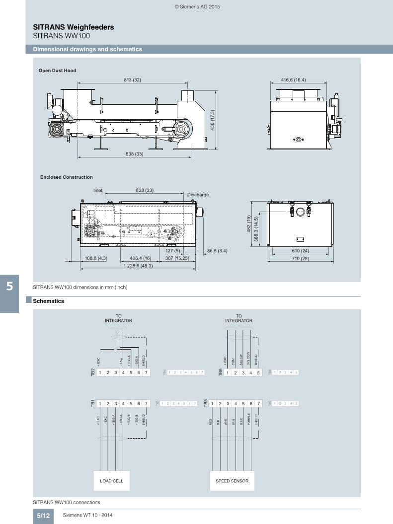
5/12 Siemens WT 10 · 2014
SITRANS WeighfeedersSITRANS WW100
Dimensional drawings and schematics
5 SITRANS WW100 dimensions in mm (inch)
■ Schematics
SITRANS WW100 connections
Enclosed Construction
Open Dust Hood
InletDischarge
416.6 (16.4)
406.4 (16)86.5 (3.4)
108.8 (4.3)1 225.6 (48.3)
368.
3 (1
4.5)
838 (33)
813 (32)
610 (24)
710 (28)
438
(17.
3)
838 (33)
387 (15.25)127 (5)
482
(19)
S
1 12 23 34 45 56 67 7 11 2
S
2 33 44 55
1 12 23 34 45 56 67 7 1 12 23 34 45 56 7TB1
TB3
TB4
TB5
TB7
TB2
+ E
XC
+ E
XC
BLK
+ EX
C
- EX
C
- EX
C
PU
RP
LE
CO
M
+ S
IG A
+ S
IG A
+ S
IG B
RE
D
WH
T
IG C
W
- SIG
A
- SIG
A
- SIG
B
BLU
E
BRN
SIG
CC
W
SH
IELD
SH
IELD
HIE
LDSH
IELD
TB6
TB8
TO INTEGRATOR
TO INTEGRATOR
LOAD CELL SPEED SENSOR
© Siemens AG 2015

5/13Siemens WT 10 · 2014
SITRANS WeighfeedersSITRANS WW200
Introduction
5
■ Overview
SITRANS WW200 is a low-to-medium capacity weighfeeder used for minor ingredient additives.
■ Benefits
• High accuracy • Ideal for low-to-medium capacity loads • Fast installation, easy to clean and maintain • Flexible, rugged design allows configurations to suit many
applications • Quick delivery on standard units • Outboard mounted load cells with protective cover
■ Application
SITRANS WW200 has been field tested and proven in hundreds of applications.
The unit can be customized to meet exact application needs. Stainless or mild steel units are available in open or enclosed styles. Custom lengths, belt types, inlet configurations, drives, and other options are available to meet your requirements.
The MS (mild steel) model is ideal for use with chemicals, pow-ders, or any granular product in applications not requiring wash-down. The SD (sanitary duty) model is designed for the food in-dustry where high pressure wash-down is required. It meets all USDA and FDA requirements.
Its cantilevered mechanical design provides for quick belt re-moval and easy maintenance. It is designed to eliminate material build-up, ensuring high accuracy and reliability. The unique weigh system reduces dead load and applies live load directly to two platform load cells. Load cells are externally mounted for easy access and maintenance.
Standard components include an anti-static food grade belt op-tion, horizontal slider bars for self-cleaning and minimal productbuild up, belt tracking rollers, belt scraper, and plow for self-cleaning.
■ Technical specifications
SITRANS WW200
Mode of operation
Measuring principle Strain gauge load cells and digital speed sensor
Typical application Control and monitor feed rates and blending of minerals or powdered additives into a process
Measuring accuracy
Accuracy1) ± 0.5 % or better
Specified range 10 … 100 % based on speed
Design rate range 0.45 … 100 t/h (1 000 lb/h … 110 STPH)
Max volumetric flow 220 m3/h (7 700 ft3/h)
Medium conditions
Operating temperature -10 … +55 °C (14 … 131 °F)
Material Mild steel or stainless steel [304 (1.4301) or 316 (1.4401)], bead blast finish (1 ... 6 μm, 40 ... 240 μin)
Load cells
Construction 17-4 PH (1.4568) stainless steel or nickel plated alloy steel
Degree of protection • Stainless steel: IP68• Nickel plated alloy steel: IP66
Excitation 10 V DC nominal, 15 V DC maximum
Output 2 mV/V
• Non-linearity ± 0.02 % of rated output
• Non-repeatability ± 0.01 % of rated output
Capacity • Stainless steel range: 6, 12, 30 kg• Nickel-plated range: 10, 15, 20,
30, 50 kg
Overload 150 % of rated capacity
Temperature • Operating range: -40 … +65 °C (-40 … +150 °F)
• Compensated: -10 … +40 °C (15 … 105 °F)
Speed sensor
Optical encoder output RS 422 (TTL) 5 V DC, 150 mAmax. 500, 1 000, or 2 000 ppr
Temperature -10 … +70 °C (14 … 158 °F)
Degree of protection • Standard: IP64• Stainless steel: IP66
C-flange mounted magnetic pulse generator output
Open collector, NPN, sinking out-put, max. 17 mA, 60 ppr
Temperature -40 … +105 °C (-40 … +220 °F)
Degree of protection IP67
Belt tracking switch
Aluminum spring rod (un-wired) • 1 NO, 1 NC switch blocks• Rated operating voltage
600 V AC max.
Temperature -30 ... +85 °C (-22 ... +185 °F)
Degree of protection IP67
Framework • Precision machined, stainless [304 (1.4301) or 316 (1.4401)] or mild steel
• Cantilevered design for easy belt replacement
Pulleys 152 mm (6 inch) diameter with 6 mm (¼ inch) neoprene lagging
Belt speed 0.005 … 0.36 m/s (1 … 70 fpm)
Belt support Edge of flat bar eliminates material buildup
Bearings • 2-bolt flange mount on drive pulley
• 2-bolt threaded base pillow block on driven pulley
SITRANS WW200
© Siemens AG 2015

5/14 Siemens WT 10 · 2014
SITRANS WeighfeedersSITRANS WW200
Introduction
5
1)
1
SITRANS WW200
Belting • Static control with vulcanized endless finger splice for maxi-mum weighing consistency (stan-dard)
• Maximum rated material tempera-ture 82 °C (180 °F)
• Silicone HT belt rated for max. material temp. of 177 °C (350 °F)
• Nitrile belt rated for a max. materi-al temp. of 121 °C (250 °F)
Belt tension Screw type, telescoper module with 150 mm (6 inch) travel - mild or stainless steel 304 (1.4301)
Belt cleaning • UHMW blade type with spring tensioning at head pulley
• Return plow • Cleaning brush, optional
Drive motor AC, TEFC, 10:1 CT inverter duty, drive motor with direct coupled flange mounted hollow bore CAF48 gear reducer ,1.2 service factor min.
Shipping weight 280 kg (600 lb) minimum
Approvals • Stainless steel options meet USDA and FDA requirements for food processing
• CE on all electrical components Hazardous approvals per config-uration options
Note: Weighfeeder as a whole is not approved for hazardous loca-tions only electrical components.
1) Accuracy subject to: On factory approved installations the weigh feeder system’s totalized weight will be within the specified accuracy when com-pared to a known weighed material test sample. The test rate must be within the specified range of the design capacity and held constant for the duration of the test. The minimum material test sample must be equivalent to a sample obtained at the test flow rate for three revolutions of the belt or at least ten minutes running time, whichever is greater.
© Siemens AG 2015

5/15Siemens WT 10 · 2014
SITRANS WeighfeedersSITRANS WW200
Introduction
5
Reduction ratio selection table
Reduction (X:1) Speed 60 Hz fpm 50 Hz fpm 60 Hz m/s 50 Hz m/s
1059:1 max.min.
2.890.29
2.410.24
0.0150.002
0.0120.001
937:1 max.min.
3.270.33
2.720.27
0.0170.002
0.0140.001
865:1 max.min.
3.540.35
2.950.30
0.0180.002
0.0150.002
745:1 max.min.
4.110.41
3.430.34
0.0210.002
0.0170.002
677:1 max.min.
4.520.45
3.770.38
0.0230.002
0.0190.002
615:1 max.min.
4.980.50
4.150.42
0.0250.003
0.0210.002
558:1 max.min.
5.490.55
4.570.46
0.0280.003
0.0230.002
508:1 max.min.
6.030.60
5.020.50
0.0310.003
0.0260.003
449:1 max.min.
6.820.68
5.680.57
0.0350.004
0.0290.003
414:1 max.min.
7.400.74
6.170.62
0.0380.004
0.0310.003
357:1 max.min.
8.580.86
7.150.72
0.0440.004
0.0360.004
324:1 max.min.
9.450.95
7.880.79
0.0480.005
0.0400.004
320.67:1 max.min.
9.550.96
7.960.80
0.0490.005
0.0400.004
284.7:1 max.min.
10.761.08
8.970.90
0.0550.006
0.0460.005
249.6:1 max.min.
12.271.23
10.231.02
0.0620.006
0.0520.005
223.36:1 max.min.
13.711.37
11.431.14
0.0700.007
0.0580.006
198.25:1 max.min.
15.451.55
12.881.29
0.0790.008
0.0650.007
173.73:1 max.min.
17.631.76
14.691.47
0.0900.009
0.0750.008
152.75:1 max.min.
20.052.01
16.711.67
0.1020.010
0.0850.009
138:1 max.min.
22.202.22
18.501.85
0.1130.011
0.0940.009
120.25:1 max.min.
25.472.55
21.232.12
0.1300.013
0.1080.011
108:1 max.min.
28.362.84
23.632.36
0.1440.014
0.1200.012
97.5:1 max.min.
31.423.14
26.182.62
0.1600.016
0.1330.013
88.4:1 max.min.
34.653.47
28.872.89
0.1760.018
0.1470.015
80.44:1 max.min.
38.083.81
31.733.17
0.1930.019
0.1610.016
71.12:1 max.min.
43.074.31
35.893.59
0.2190.022
0.1820.018
65.68:1 max.min.
46.644.66
38.863.89
0.2370.024
0.1970.020
56.55:1 max.min.
54.175.42
45.144.51
0.2750.028
0.2290.023
51.41:1 max.min.
59.585.96
49.654.97
0.3030.030
0.2520.025
46.93:1 max.min.
65.276.53
54.395.44
0.3320.033
0.2760.028
42:1 max.min.
72.937.29
60.776.08
0.3710.037
0.3090.031
37.28:1 max.min.
82.168.22
68.476.85
0.4170.042
0.3480.035
© Siemens AG 2015

5/16 Siemens WT 10 · 2014
SITRANS WeighfeedersSITRANS WW200
Open style
5
■ Selection and ordering data Article No. Article No.
SITRANS WW200, open styleHigh accuracy solids weighfeeder for low to medium capacity applications. Improves process-ing, increases efficiency and provides significant cost savings.
7MH7300-
77777 - 7777
Click on the Article No. for the online configuration in the PIA Life Cycle Portal.
Add order code Y71 ... Y73 for all models to specify design data
Painted mild steel, open style, with C/L infeed to C/L discharge
12 inch (305 mm) belt width
52 inch (1 321 mm) 0 A
60 inch (1 524 mm) 0 B
68 inch (1 727 mm) 0 C
76 inch (1 930 mm) 0 D
84 inch (2 134 mm) 0 E
92 inch (2 337 mm) 0 F
100 inch (2 540 mm) 0 G
108 inch (2 743 mm) 0 H
116 inch (2 946 mm) 0 J
18 inch (457 mm) belt width
52 inch (1 321 mm) 1 A
60 inch (1 524 mm) 1 B
68 inch (1 727 mm) 1 C
76 inch (1 930 mm) 1 D
84 inch (2 134 mm) 1 E
92 inch (2 337 mm) 1 F
100 inch (2 540 mm) 1 G
108 inch (2 743 mm) 1 H
116 inch (2 946 mm) 1 J
24 inch (610 mm) belt width
52 inch (1 321 mm) 2 A
60 inch (1 524 mm) 2 B
68 inch (1 727 mm) 2 C
76 inch (1 930 mm) 2 D
84 inch (2 134 mm) 2 E
92 inch (2 337 mm) 2 F
100 inch (2 540 mm) 2 G
108 inch (2 743 mm) 2 H
116 inch (2 946 mm) 2 J
30 inch (762 mm) belt width
52 inch (1 321 mm) 3 A
60 inch (1 524 mm) 3 B
68 inch (1 727 mm) 3 C
76 inch (1 930 mm) 3 D
84 inch (2 134 mm) 3 E
92 inch (2 337 mm) 3 F
100 inch (2 540 mm) 3 G
108 inch (2 743 mm) 3 H
116 inch (2 946 mm) 3 J
36 inch (914 mm) belt width
52 inch (1 321 mm) 4 A
60 inch (1 524 mm) 4 B
68 inch (1 727 mm) 4 C
76 inch (1 930 mm) 4 D
84 inch (2 134 mm) 4 E
92 inch (2 337 mm) 4 F
100 inch (2 540 mm) 4 G
108 inch (2 743 mm) 4 H
116 inch (2 946 mm) 4 J
42 inch (1 067 mm) belt width
52 inch (1 321 mm) 5 A
60 inch (1 524 mm) 5 B
68 inch (1 727 mm) 5 C
76 inch (1 930 mm) 5 D
84 inch (2 134 mm) 5 E
92 inch (2 337 mm) 5 F
100 inch (2 540 mm) 5 G
108 inch (2 743 mm) 5 H
116 inch (2 946 mm) 5 J
48 inch (1 219 mm) belt width
52 inch (1 321 mm) 6 A
60 inch (1 524 mm) 6 B
68 inch (1 727 mm) 6 C
76 inch (1 930 mm) 6 D
84 inch (2 134 mm) 6 E
92 inch (2 337 mm) 6 F
100 inch (2 540 mm) 6 G
108 inch (2 743 mm) 6 H
116 inch (2 946 mm) 6 J
SITRANS WW200, open styleHigh accuracy solids weighfeeder for low to medium capacity applications. Improves process-ing, increases efficiency and provides significant cost savings.
7MH7300-
77777 - 7777
© Siemens AG 2015

5/17Siemens WT 10 · 2014
SITRANS WeighfeedersSITRANS WW200
Open style
5
■ Selection and ordering data Article No. Article No.
SITRANS WW200, open styleHigh accuracy solids weighfeeder for low to medium capacity applications. Improves process-ing, increases efficiency and provides significant cost savings.
7MH7300-
77777 - 7777
Material containment construction
None A
Add order code Y74 and plain text: "Arc radius in inches …XX.XXX inch" for options B ... L
Shear gate inlet
Skirtboards AR400 steel B
Skirtboards AR400 steel with cover C
Skirtboards 304 stainless steel D
Skirtboards 304 stainless steel, with cover E
Skirtboards 304 stainless steel, #4 polished F
Skirtboards 304 stainless steel, #4 polished with cover
G
Skirtboards 316 stainless steel H
Skirtboards 316 stainless steel, with cover J
Skirtboards 316 stainless steel, #4 polished K
Skirtboards 316 stainless steel, #4 polished with cover
L
Horseshoe inlet
304 stainless steel M
304 stainless steel, #4 polished N
316 stainless steel P
316 stainless steel, #4 polished Q
Load cell
Nickel plated steel
10 kg (22 lb) 0
15 kg (33 lb) 1
20 kg (44 lb) 2
30 kg (66 lb) 3
50 kg (110 lb) 4
Stainless steel, hermetically sealed
6 kg (13.2 lb) 5
12 kg (26.5 lb) 6
30 kg (66.1 lb) 7
Speed sensor
Shaft mounted
500 PPR optical encoder 0
1 000 PPR optical encoder 1
2 500 PPR optical encoder 2
500 PPR optical encoder, stainless steel
3
1 000 PPR optical encoder, stainless steel
4
2 500 PPR optical encoder, stainless steel
5
Motor mounted
60 PPR magnetic p/u 6
Drive configurationAdd order code Y75 reduction ratio in plain text: “X:1”. See table on page 5/15 for further info.
Standard AC motor
0.25 HP (0.19 kW) 220 … 240/380 … 480 V 3 ph 50/60 Hz
0 A
0.25 HP (0.19 kW) 575 V 3 ph 60 Hz 0 B
0.5 HP (0.37 kW) 220 … 240/380 … 480 V 3 ph 50/60 Hz
0 C
0.5 HP (0.37 kW) 575 V 3 ph 60 Hz 0 D
0.75 HP (0.56 kW) 220 … 240/380 … 480 V 3 ph 50/60 Hz
0 E
0.75 HP (0.56 kW) 575 V 3 ph 60 Hz 0 F
1 HP (0.75 kW) 220 … 240/380 ... 480 V 3 ph 50/60 Hz
0 G
1 HP (0.75 kW) 575 V 3 ph 60 Hz 0 H
Food grade epoxy coated AC motor
0.25 HP (0.19 kW) 220 … 240/380 … 480 V 3 ph 50/60 Hz
1 A
0.25 HP (0.19 kW) 575 V 3 ph 60 Hz 1 B
0.5 HP (0.37 kW) 220 … 240/380 … 480 V 3 ph 50/60 Hz
1 C
0.5 HP (0.37 kW) 575 V 3 ph 60 Hz 1 D
1 HP (0.75 kW) 220 … 240/380 … 480 V 3 ph 50/60 Hz
1 E
1 HP (0.75 kW) 575 V 3 ph 60 Hz 1 F
Stainless steel AC motor
0.33 HP (0.25 kW) 220 … 240/380 … 480 V 3 ph 50/60 Hz
2 A
0.5 HP (0.37 kW) 220 … 240/380 … 480 V3 ph 50/60 Hz
2 C
1 HP (0.75 kW) 220 … 240/380 … 480 V 3 ph 50/60 Hz
2 E
Belting
Polyurethane anti static 57 PIW
2 ply FDA/USDA approved A
2 ply with B-section flange walls FDA/USDA approved
B
2 ply with 2 inch (50 mm) corrugated side walls FDA/USDA approved
C
Silicone anti static 45 PIW
2 ply FDA/USDA approved HT 177 °C (350 °F) D
Nitrile 135 PIW
3 ply G
3 ply with B-section flange walls H
3 ply with 2 inch (50 mm) corrugated side walls J
Belt change access side (looking from inlet to discharge)
Left hand 0
Right hand 1
SITRANS WW200, open styleHigh accuracy solids weighfeeder for low to medium capacity applications. Improves process-ing, increases efficiency and provides significant cost savings.
7MH7300-
77777 - 7777
© Siemens AG 2015

5/18 Siemens WT 10 · 2014
SITRANS WeighfeedersSITRANS WW200
Open style
5
■ Selection and ordering data Order Code1) 2) 3) Article No.
1) Available with material containment options B ... L only.2) 575 V versions meet 4:1 ct inverter rating, all other voltages meet 10:1.3) Available with drive configuration standard motor options only, all
motors suitable for 400 V operation only.
Further designs
Please add "-Z" to article no. and specify order code(s).
Shear gate arc radius: Enter shear gate arc radius in inches (xxx.xx inch)1)
Y74
Enter design units (TPH, MTPH, lb/h, kg/h) Y71
Enter design speed (ft/m, m/s) Y72
Enter design capacity/rate Y73
AC gearmotor reduction ratio: Enter reduction ratio in plain text (X:1) (see "Reduction Ratio Selection Table" on page 5/7).
Y75
Custom length: Select next longest option and specify infeed CL to discharge CL in plain text (indicated inches or millimeters)
Y01
Class I, Div. 1, Group C&D; Class II, Div. 1, Group F&G approved electrical components Note: Weighfeeder does not carry hazardous approval, only components, not available with speed sensor options 3 ... 6, load cell options 0 ... 4 or with motor options 1A ... 2E2)
E90
ATEX II 2D approved electrical components Note: Weighfeeder does not carry hazardous approval, only components, approval not available with speed sensor options 0, 3, 4, 5, 6, load cell options 0 ... 4 or motor options 1A ... 2E3)
E91
Plastic shear curtain to control dust at the infeed for floodable materials and dusty applications1)
G11
Pointek CLS100 Capacitance switch for plugged discharge chute detection
G12
Siemens start/stop, auto/manual, speed control, hand held operator
G13
Belt cleaner, stainless steel, nylon brush, mounted under belt plow, cleaning dirty side of belt
G14
Secondary speed detection for differential monitor-ing: 60 PPR motor mounted magnetic p/u (available with speed sensor options 0 ... 5 only)
G16
Manufacturer's test certificate: According to EN 10204-2.2
C11
Stainless steel tag [69 x 50 mm (2.71 x 1.97 inch)]: Measuring-point number/identification (max. 27 characters) specify in plain text
Y15
Discharge dust hood, painted mild steel with de-dust port
H50
Discharge dust hood, 304 stainless steel with de-dust port
H51
Discharge dust hood, 316 stainless steel with de-dust port
H52
Custom designSpecify quote reference when ordering
Y99
Operating instructions
• English A5E33560618
Note: The operating instructions should be ordered as a separate item on the order. This device is shipped with the Siemens Milltronics manual DVD contain-ing the complete operating instructions library.
© Siemens AG 2015

5/19Siemens WT 10 · 2014
SITRANS WeighfeedersSITRANS WW200
Open style
5
■ Selection and ordering data Article No. Article No..
SITRANS WW200, open styleHigh accuracy solids weighfeeder for low to medium capacity applications. Improves process-ing, increases efficiency and provides significant cost savings.
7MH7301-
77777 - 7777
Click on the Article No. for the online configuration in the PIA Life Cycle Portal.
Add order code Y71 ... Y73 for all models to specify design data
304 stainless steel, open style, with C/L infeed to C/L discharge
12 inch (305 mm) belt width
52 inch (1 321 mm) 0 A
60 inch (1 524 mm) 0 B
68 inch (1 727 mm) 0 C
76 inch (1 930 mm) 0 D
84 inch (2 134 mm) 0 E
92 inch (2 337 mm) 0 F
100 inch (2 540 mm) 0 G
108 inch (2 743 mm) 0 H
116 inch (2 946 mm) 0 J
18 inch (457 mm) belt width
52 inch (1 321 mm) 1 A
60 inch (1 524 mm) 1 B
68 inch (1 727 mm) 1 C
76 inch (1 930 mm) 1 D
84 inch (2 134 mm) 1 E
92 inch (2 337 mm) 1 F
100 inch (2 540 mm) 1 G
108 inch (2 743 mm) 1 H
116 inch (2 946 mm) 1 J
24 inch (610 mm) belt width
52 inch (1 321 mm) 2 A
60 inch (1 524 mm) 2 B
68 inch (1 727 mm) 2 C
76 inch (1 930 mm) 2 D
84 inch (2 134 mm) 2 E
92 inch (2 337 mm) 2 F
100 inch (2 540 mm) 2 G
108 inch (2 743 mm) 2 H
116 inch (2 946 mm) 2 J
30 inch (762 mm) belt width
52 inch (1 321 mm) 3 A
60 inch (1 524 mm) 3 B
68 inch (1 727 mm) 3 C
76 inch (1 930 mm) 3 D
84 inch (2 134 mm) 3 E
92 inch (2 337 mm) 3 F
100 inch (2 540 mm) 3 G
108 inch (2 743 mm) 3 H
116 inch (2 946 mm) 3 J
36 inch (914 mm) belt width
52 inch (1 321 mm) 4 A
60 inch (1 524 mm) 4 B
68 inch (1 727 mm) 4 C
76 inch (1 930 mm) 4 D
84 inch (2 134 mm) 4 E
92 inch (2 337 mm) 4 F
100 inch (2 540 mm) 4 G
108 inch (2 743 mm) 4 H
116 inch (2 946 mm) 4 J
42 inch (1 067 mm) belt width
52 inch (1 321 mm) 5 A
60 inch (1 524 mm) 5 B
68 inch (1 727 mm) 5 C
76 inch (1 930 mm) 5 D
84 inch (2 134 mm) 5 E
92 inch (2 337 mm) 5 F
100 inch (2 540 mm) 5 G
108 inch (2 743 mm) 5 H
116 inch (2 946 mm) 5 J
48 inch (1 219 mm) belt width
52 inch (1 321 mm) 6 A
60 inch (1 524 mm) 6 B
68 inch (1 727 mm) 6 C
76 inch (1 930 mm) 6 D
84 inch (2 134 mm) 6 E
92 inch (2 337 mm) 6 F
100 inch (2 540 mm) 6 G
108 inch (2 743 mm) 6 H
116 inch (2 946 mm) 6 J
SITRANS WW200, open styleHigh accuracy solids weighfeeder for low to medium capacity applications. Improves process-ing, increases efficiency and provides significant cost savings.
7MH7301-
77777 - 7777
© Siemens AG 2015

5/20 Siemens WT 10 · 2014
SITRANS WeighfeedersSITRANS WW200
Open style
5
■ Selection and ordering data Article No. Article No.
SITRANS WW200, open styleHigh accuracy solids weighfeeder for low to medium capacity applications. Improves process-ing, increases efficiency and provides significant cost savings.
7MH7301-
77777 - 7777
Material containment construction
None A
Add order code Y74 and plain text: "Arc radius in inches …XX.XXX"" for options D ... L
Shear gate inlet
Skirtboards 304 stainless steel DSkirtboards 304 stainless steel, with cover E
Skirtboards 304 stainless steel, #4 polished F
Skirtboards 304 stainless steel, #4 polished with cover
G
Skirtboards 316 stainless steel HSkirtboards 316 stainless steel, with cover J
Skirtboards 316 stainless steel, #4 polished K
Skirtboards 316 stainless steel, #4 polished with cover
L
Horseshoe inlet
304 stainless steel M
304 stainless steel, #4 polished N
316 stainless steel P
316 stainless steel, #4 polished Q
Load cell
6 kg (13.2 lb) stainless steel, hermetically sealed 5
12 kg (26.5 lb) stainless steel, hermetically sealed 6
30 kg (66.1 lb) stainless steel, hermetically sealed 7
Speed sensor
Shaft mounted
500 PPR optical encoder 0
1 000 PPR optical encoder 1
2 500 PPR optical encoder 2
500 PPR optical encoder, stainless steel 3
1 000 PPR optical encoder, stainless steel 4
2 500 PPR optical encoder, stainless steel 5
Motor mounted
60 PPR magnetic p/u 6
Drive configurationAdd order code Y75 reduction ratio in plain text: “X:1”. See table on page 5/15 for further info.
Standard AC motor
0.25 HP (0.19 kW) 220 … 240/380 … 480 V 3 ph 50/60 Hz
0 A
0.25 HP (0.19 kW) 575 V 3 ph 60 Hz 0 B
0.5 HP (0.37 kW) 220 … 240/380 … 480 V 3 ph 50/60 Hz
0 C
0.5 HP (0.37 kW) 575 V 3 ph 60 Hz 0 D
0.75 HP (0.56 kW) 220 … 240/380 … 480 V 3 ph 50/60 Hz
0 E
0.75 HP (0.56 kW) 575 V 3 ph 60 Hz 0 F
1 HP (0.75 kW) 220 … 240/380 ... 480 V 3 ph 50/60 Hz
0 G
1 HP (0.75 kW) 575 V 3 ph 60 Hz 0 H
Food grade epoxy coated AC motor
0.25 HP (0.19 kW) 220 … 240/380 … 480 V 3 ph 50/60 Hz
1 A
0.25 HP (0.19 kW) 575 V 3 ph 60 Hz 1 B
0.5 HP (0.37 kW) 220 … 240/380 … 480 V 3 ph 50/60 Hz
1 C
0.5 HP (0.37 kW) 575 V 3 ph 60 Hz 1 D
1 HP (0.75 kW) 220 … 240/380 … 480 V 3 ph 50/60 Hz
1 E
1 HP (0.75 kW) 575 V 3 ph 60 Hz 1 F
Stainless steel AC motor
0.33 HP (0.25 kW) 220 … 240/380 … 480 V 3 ph 50/60 Hz
2 A
0.5 HP (0.37 kW) 220 … 240/380 … 480 V 3 ph 50/60 Hz
2 C
1 HP (0.75 kW) 220 … 240/380 … 480 V 3 ph 50/60 Hz
2 E
Belting
Polyurethane anti static 57 PIW
2 ply FDA/USDA approved A
2 ply with B-section flange walls FDA/USDA approved
B
2 ply with 2 inch (50 mm) corrugated side walls FDA/USDA approved
C
Silicone anti static 45 PIW
2 ply FDA/USDA approved HT 177 °C (350 °F) D
Belt change access side (looking from inlet to discharge)
Left hand 0
Right hand 1
SITRANS WW200, open styleHigh accuracy solids weighfeeder for low to medium capacity applications. Improves process-ing, increases efficiency and provides significant cost savings.
7MH7301-
77777 - 7777
© Siemens AG 2015

5/21Siemens WT 10 · 2014
SITRANS WeighfeedersSITRANS WW200
Open style
5
■ Selection and ordering data Order Code1) 2) 3) Article No.
1) Available with material containment options D ... L only.2) 575 V versions meet 4:1 ct inverter rating, all other voltages meet 10:1.3) Available with Drive Configuration standard motor options only, all motors suitable for 400 V operation only.
Further designs
Please add "-Z" to article no. and specify order code(s).
Shear gate arc radius: Enter shear gate arc radius in inches (xxx.xx inch)
Y74
Enter design units (TPH, MTPH, lb/h, kg/h) Y71
Enter design speed (ft/m, m/s) Y72
Enter design capacity/rate Y73
AC gearmotor reduction ratio: Enter reduction ratio in plain text (X:1) (see "Reduction Ratio Selection Table" on page 5/7).
Y75
Custom length: Select next longest option and specify infeed CL to discharge CL in plain text (indicated inches or millimeters)
Y01
Class I, Div. 1, Group C&D; Class II, Div. 1, Group F&G approved electrical components Note: Weighfeeder does not carry hazardous approval, only components, not available with speed sensor options 3 ... 6, load cell options 0 ... 4 or with motor options 1A ... 2E2)
E90
ATEX II 2D approved electrical componentsNote: Weighfeeder does not carry hazardous approval, only components, approval not available with speed sensor options 0, 3, 4, 5, 6, load cell options 0 ... 4 or motor options 1A ... 2E3)
E91
Plastic shear curtain to control dust at the infeed for floodable materials and dusty applications1)
G11
Pointek CLS100 Capacitance switch for plugged discharge chute detection
G12
Siemens start/stop, auto/manual, speed control, hand held operator
G13
Belt cleaner, stainless steel, nylon brush, mounted under belt plow, cleaning dirty side of belt
G14
Secondary speed detection for differential monitor-ing: 60 PPR motor mounted magnetic p/u (Available with speed sensor options 0 ... 5 only)
G16
Manufacturer's test certificate: According to EN 10204-2.2
C11
Stainless steel tag [69 x 50 mm (2.71 x 1.97 inch)]: Measuring-point number/identification (max. 27 characters) specify in plain text
Y15
Discharge dust hood, painted mild steel with de-dust port
H50
Discharge dust hood, 304 stainless steel with de-dust port
H51
Discharge dust hood, 316 stainless steel with de-dust port
H52
Custom designSpecify quote reference when ordering
Y99
Operating instructions
• English A5E33560654
Note: The operating instructions should be ordered as a separate item on the order. This device is shipped with the Siemens Milltronics manual DVD containing the complete operating instructions library.
© Siemens AG 2015
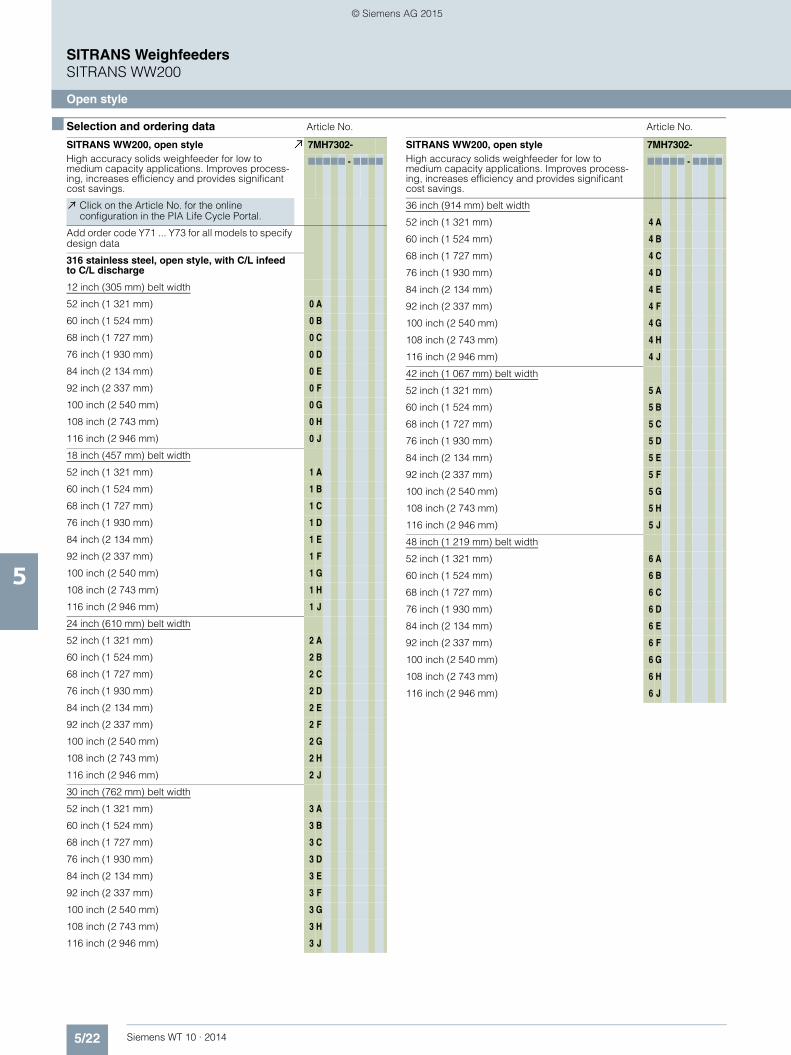
5/22 Siemens WT 10 · 2014
SITRANS WeighfeedersSITRANS WW200
Open style
5
■ Selection and ordering data Article No. Article No.
SITRANS WW200, open styleHigh accuracy solids weighfeeder for low to medium capacity applications. Improves process-ing, increases efficiency and provides significant cost savings.
7MH7302-
77777 - 7777
Click on the Article No. for the online configuration in the PIA Life Cycle Portal.
Add order code Y71 ... Y73 for all models to specify design data
316 stainless steel, open style, with C/L infeed to C/L discharge
12 inch (305 mm) belt width
52 inch (1 321 mm) 0 A
60 inch (1 524 mm) 0 B
68 inch (1 727 mm) 0 C
76 inch (1 930 mm) 0 D
84 inch (2 134 mm) 0 E
92 inch (2 337 mm) 0 F
100 inch (2 540 mm) 0 G
108 inch (2 743 mm) 0 H
116 inch (2 946 mm) 0 J
18 inch (457 mm) belt width
52 inch (1 321 mm) 1 A
60 inch (1 524 mm) 1 B
68 inch (1 727 mm) 1 C
76 inch (1 930 mm) 1 D
84 inch (2 134 mm) 1 E
92 inch (2 337 mm) 1 F
100 inch (2 540 mm) 1 G
108 inch (2 743 mm) 1 H
116 inch (2 946 mm) 1 J
24 inch (610 mm) belt width
52 inch (1 321 mm) 2 A
60 inch (1 524 mm) 2 B
68 inch (1 727 mm) 2 C
76 inch (1 930 mm) 2 D
84 inch (2 134 mm) 2 E
92 inch (2 337 mm) 2 F
100 inch (2 540 mm) 2 G
108 inch (2 743 mm) 2 H
116 inch (2 946 mm) 2 J
30 inch (762 mm) belt width
52 inch (1 321 mm) 3 A
60 inch (1 524 mm) 3 B
68 inch (1 727 mm) 3 C
76 inch (1 930 mm) 3 D
84 inch (2 134 mm) 3 E
92 inch (2 337 mm) 3 F
100 inch (2 540 mm) 3 G
108 inch (2 743 mm) 3 H
116 inch (2 946 mm) 3 J
36 inch (914 mm) belt width
52 inch (1 321 mm) 4 A
60 inch (1 524 mm) 4 B
68 inch (1 727 mm) 4 C
76 inch (1 930 mm) 4 D
84 inch (2 134 mm) 4 E
92 inch (2 337 mm) 4 F
100 inch (2 540 mm) 4 G
108 inch (2 743 mm) 4 H
116 inch (2 946 mm) 4 J
42 inch (1 067 mm) belt width
52 inch (1 321 mm) 5 A
60 inch (1 524 mm) 5 B
68 inch (1 727 mm) 5 C
76 inch (1 930 mm) 5 D
84 inch (2 134 mm) 5 E
92 inch (2 337 mm) 5 F
100 inch (2 540 mm) 5 G
108 inch (2 743 mm) 5 H
116 inch (2 946 mm) 5 J
48 inch (1 219 mm) belt width
52 inch (1 321 mm) 6 A
60 inch (1 524 mm) 6 B
68 inch (1 727 mm) 6 C
76 inch (1 930 mm) 6 D
84 inch (2 134 mm) 6 E
92 inch (2 337 mm) 6 F
100 inch (2 540 mm) 6 G
108 inch (2 743 mm) 6 H
116 inch (2 946 mm) 6 J
SITRANS WW200, open styleHigh accuracy solids weighfeeder for low to medium capacity applications. Improves process-ing, increases efficiency and provides significant cost savings.
7MH7302-
77777 - 7777
© Siemens AG 2015

5/23Siemens WT 10 · 2014
SITRANS WeighfeedersSITRANS WW200
Open style
5
■ Selection and ordering data Article No. Article No.
SITRANS WW200, open styleHigh accuracy solids weighfeeder for low to medium capacity applications. Improves process-ing, increases efficiency and provides significant cost savings.
7MH7302-
77777 - 7777
Material containment construction
None A
Add order code Y74 and plain text: "Arc radius in inches …XX.XXX inch" for options H ... L
Shear gate inlet
Skirtboards 316 stainless steel H
Skirtboards 316 stainless steel, with cover J
Skirtboards 316 stainless steel, #4 polished K
Skirtboards 316 stainless steel, #4 polished with cover
L
Horseshoe inlet
316 stainless steel P
316 stainless steel, #4 polished Q
Load cell
6 kg (13.2 lb) stainless steel, hermetically sealed 5
12 kg (26.5 lb) stainless steel, hermetically sealed 6
30 kg (66.1 lb) stainless steel, hermetically sealed 7
Speed sensor
Shaft mounted
500 PPR optical encoder 0
1 000 PPR optical encoder 1
2 500 PPR optical encoder 2
500 PPR optical encoder, stainless steel 3
1 000 PPR optical encoder, stainless steel 4
2 500 PPR optical encoder, stainless steel 5
Motor mounted
60 PPR magnetic p/u 6Drive configurationAdd order code Y75 reduction ratio in plain text: “X:1”. See table on page 5/15 for further info.
Standard AC motor
0.25 HP (0.19 kW) 220 … 240/380 … 480 V 3 ph 50/60 Hz
0 A
0.25 HP (0.19 kW) 575 V 3 ph 60 Hz 0 B0.5 HP (0.37 kW) 220 … 240/380 … 480 V 3 ph 50/60 Hz
0 C
0.5 HP (0.37 kW) 575 V 3 ph 60 Hz 0 D0.75 HP (0.56 kW) 220 … 240/380 … 480 V 3 ph 50/60 Hz
0 E
0.75 HP (0.56 kW) 575 V 3 ph 60 Hz 0 F1 HP (0.75 kW) 220 … 240/380 ... 480 V 3 ph 50/60 Hz
0 G
1 HP (0.75 kW) 575 V 3 ph 60 Hz 0 H
Food grade epoxy coated AC motor
0.25 HP (0.19 kW) 220 … 240/380 … 480 V 3 ph 50/60 Hz
1 A
0.25 HP (0.19 kW) 575 V 3 ph 60 Hz 1 B0.5 HP (0.37 kW) 220 … 240/380 … 480 V 3 ph 50/60 Hz
1 C
0.5 HP (0.37 kW) 575 V 3 ph 60 Hz 1 D1 HP (0.75 kW) 220 … 240/380 … 480 V 3 ph 50/60 Hz
1 E
1 HP (0.75 kW) 575 V 3 ph 60 Hz 1 F
Stainless steel AC motor
0.33 HP (0.25 kW) 220 … 240/380 … 480 V 3 ph 50/60 Hz
2 A
0.5 HP (0.37 kW) 2 C
1 HP (0.75 kW) 220 … 240/380 … 480 V 3 ph 50/60 Hz
2 E
Belting
Polyurethane anti static 57 PIW
2 ply FDA/USDA approved A
2 ply with B-section flange walls FDA/USDA approved
B
2 ply with 2 inch (50 mm) corrugated side walls FDA/USDA approved
C
Silicone anti static 45 PIW
2 ply FDA/USDA approved HT 177 °C (350 °F) D
Belt change access side (looking from inlet to discharge)
Left hand 0
Right hand 1
SITRANS WW200, open styleHigh accuracy solids weighfeeder for low to medium capacity applications. Improves process-ing, increases efficiency and provides significant cost savings.
7MH7302-
77777 - 7777
© Siemens AG 2015

5/24 Siemens WT 10 · 2014
SITRANS WeighfeedersSITRANS WW200
Open style
5
■ Selection and ordering data Order Code1) 2) 3) Article No.
1) Available with material containment options D... L only.2) 575 V versions meet 4:1 ct inverter rating, all other voltages meet 10:1.3) Available with Drive Configuration standard motor options only,
all motors suitable for 400 V operation only.
Further designs
Please add "-Z" to article no. and specify order code(s).
Shear gate arc radius: Enter shear gate arc radius in inches (xxx.xx inch)1)
Y74
Enter design units (TPH, MTPH, lb/h, kg/h) Y71
Enter design speed (ft/m, m/s) Y72
Enter design capacity/rate Y73
AC gearmotor reduction ratio: Enter reduction ratio in plain text (X:1) (see "Reduction Ratio Selection Table" on page 5/7).
Y75
Custom length: Select next longest option and specify infeed CL to discharge CL in plain text (indicated inches or millimeters)
Y01
Class I, Div. 1, Group C&D; Class II, Div. 1, Group F&G approved electrical components Note: Weighfeeder does not carry hazardous approval, only components, not available with speed sensor options 3 ... 6, load cell options 0 ... 4 or with motor options 1A ... 2E2)
E90
ATEX II 2D approved electrical components Note: Weighfeeder does not carry hazardous approval, only components, approval not available with speed sensor options 0, 3, 4, 5, 6, load cell options 0 ... 4 or motor options 1A ... 2E3)
E91
Plastic shear curtain to control dust at the infeed for floodable materials and dusty applications1)
G11
Pointek CLS100 Capacitance switch for plugged discharge chute detection
G12
Siemens start/stop, auto/manual, speed control, hand held operator
G13
Belt cleaner, stainless steel, nylon brush, mounted under belt plow, cleaning dirty side of belt
G14
Secondary speed detection for differential monitor-ing: 60 PPR motor mounted magnetic p/u (available with speed sensor options 0 ... 5 only)
G16
Manufacturer's test certificate: According to EN 10204-2.2
C11
Stainless steel tag [69 x 50 mm (2.71 x 1.97 inch)]:Measuring-point number/identification (max. 27 characters) specify in plain text
Y15
Discharge dust hood, painted mild steel with de-dust port
H50
Discharge dust hood, 304 stainless steel with de-dust port
H51
Discharge dust hood, 316 stainless steel with de-dust port
H52
Custom designSpecify quote reference when ordering
Y99
Operating instructions
• English A5E33560654
Note: The operating instructions should be ordered as a separate item on the order. This device is shipped with the Siemens Milltronics manual DVD contain-ing the complete operating instructions library.
© Siemens AG 2015

5/25Siemens WT 10 · 2014
SITRANS WeighfeedersSITRANS WW200
Enclosed style
5
■ Selection and ordering data Article No. Article No.
SITRANS WW200, enclosed styleHigh accuracy solids weighfeeder for low to medium capacity applications. Improves process-ing, increases efficiency and provides significant cost savings.
7MH7303-
77777 - 7777
Click on the Article No. for the online configuration in the PIA Life Cycle Portal.
Add order code Y71 ... Y73 for all models to specify design data
Painted mild steel frame with painted mild steel enclosure style with C/L infeed to C/L discharge
12 inch (305 mm) belt width
52 inch (1 321 mm) 0 A
60 inch (1 524 mm) 0 B
68 inch (1 727 mm) 0 C
76 inch (1 930 mm) 0 D
84 inch (2 134 mm) 0 E
92 inch (2 337 mm) 0 F
100 inch (2 540 mm) 0 G
108 inch (2 743 mm) 0 H
116 inch (2 946 mm) 0 J
18 inch (457 mm) belt width
52 inch (1 321 mm) 1 A
60 inch (1 524 mm) 1 B
68 inch (1 727 mm) 1 C
76 inch (1 930 mm) 1 D
84 inch (2 134 mm) 1 E
92 inch (2 337 mm) 1 F
100 inch (2 540 mm) 1 G
108 inch (2 743 mm) 1 H
116 inch (2 946 mm) 1 J
24 inch (610 mm) belt width
52 inch (1 321 mm) 2 A
60 inch (1 524 mm) 2 B
68 inch (1 727 mm) 2 C
76 inch (1 930 mm) 2 D
84 inch (2 134 mm) 2 E
92 inch (2 337 mm) 2 F
100 inch (2 540 mm) 2 G
108 inch (2 743 mm) 2 H
116 inch (2 946 mm) 2 J
30 inch (762 mm) belt width
52 inch (1 321 mm) 3 A
60 inch (1 524 mm) 3 B
68 inch (1 727 mm) 3 C
76 inch (1 930 mm) 3 D
84 inch (2 134 mm) 3 E
92 inch (2 337 mm) 3 F
100 inch (2 540 mm) 3 G
108 inch (2 743 mm) 3 H
SITRANS WW200, enclosed styleHigh accuracy solids weighfeeder for low to medium capacity applications. Improves process-ing, increases efficiency and provides significant cost savings.
7MH7303-
77777 - 7777
52 inch (1 321 mm) 4 A
60 inch (1 524 mm) 4 B
68 inch (1 727 mm) 4 C
76 inch (1 930 mm) 4 D
84 inch (2 134 mm) 4 E
92 inch (2 337 mm) 4 F
100 inch (2 540 mm) 4 G
108 inch (2 743 mm) 4 H
116 inch (2 946 mm) 4 J
42 inch (1 067 mm) belt width
52 inch (1 321 mm) 5 A
60 inch (1 524 mm) 5 B
68 inch (1 727 mm) 5 C
76 inch (1 930 mm) 5 D
84 inch (2 134 mm) 5 E
92 inch (2 337 mm) 5 F
100 inch (2 540 mm) 5 G
108 inch (2 743 mm) 5 H
116 inch (2 946 mm) 5 J
48 inch (1 219 mm) belt width
52 inch (1 321 mm) 6 A
60 inch (1 524 mm) 6 B
68 inch (1 727 mm) 6 C
76 inch (1 930 mm) 6 D
84 inch (2 134 mm) 6 E
92 inch (2 337 mm) 6 F
100 inch (2 540 mm) 6 G
108 inch (2 743 mm) 6 H
116 inch (2 946 mm) 6 J
© Siemens AG 2015

5/26 Siemens WT 10 · 2014
SITRANS WeighfeedersSITRANS WW200
Enclosed style
5
■ Selection and ordering data Article No. Article No.
SITRANS WW200, enclosed styleHigh accuracy solids weighfeeder for low to medium capacity applications. Improves process-ing, increases efficiency and provides significant cost savings.
7MH7303-
77777 - 7777
Material containment construction
Add order code Y74 and plain text: "Arc radius in inches …XX.XXX inch" for options B ... L
Shear gate inlet
Skirtboards AR400 steel B
Skirtboards AR400 steel with cover C
Skirtboards 304 stainless steel D
Skirtboards 304 stainless steel, with cover E
Skirtboards 304 stainless steel, #4 polished F
Skirtboards 304 stainless steel, #4 polished with cover
G
Skirtboards 316 stainless steel H
Skirtboards 316 stainless steel, with cover J
Skirtboards 316 stainless steel, #4 polished K
Skirtboards 316 stainless steel, #4 polished with cover
L
Load cell
Nickel plated steel
10 kg (22 lb) 0
15 kg (33 lb) 1
20 kg (44 lb) 2
30 kg (66 lb) 3
50 kg (110 lb) 4
Stainless steel
6 kg (13.2 lb) hermetically sealed 5
12 kg (26.5 lb) hermetically sealed 6
30 kg (66.1 lb) hermetically sealed 7
Speed sensor
Shaft mounted
500 PPR optical encoder 0
1 000 PPR optical encoder 1
2 500 PPR optical encoder 2
500 PPR optical encoder, stainless steel 3
1 000 PPR optical encoder, stainless steel 4
2 500 PPR optical encoder, stainless steel 5
Motor mounted
60 PPR motor mounted magnetic p/u 6
SITRANS WW200, enclosed styleHigh accuracy solids weighfeeder for low to medium capacity applications. Improves process-ing, increases efficiency and provides significant cost savings.
7MH7303-
77777 - 7777
Drive configurationAdd order code Y75 reduction ratio in plain text: “X:1”. See table on page 5/15 for further info.
Standard AC motor
0.25 HP (0.19 kW) 220 … 240/380 … 480 V 3 ph 50/60 Hz
0 A
0.25 HP (0.19 kW) 575 V 3 ph 60 Hz 0 B
0.5 HP (0.37 kW) 220 … 240/380 … 480 V 3 ph 50/60 Hz
0 C
0.5 HP (0.37 kW) 575 V 3 ph 60 Hz 0 D
0.75 HP (0.56 kW) 220 … 240/380 … 480 V 3 ph 50/60 Hz
0 E
0.75 HP (0.56 kW) 575 V 3 ph 60 Hz 0 F
1 HP (0.75 kW) 220 … 240/380 ... 480 V 3 ph 50/60 Hz
0 G
1 HP (0.75 kW) 575 V 3 ph 60 Hz 0 H
Food grade epoxy coated AC motor
0.25 HP (0.19 kW) 220 … 240/380 … 480 V 3 ph 50/60 Hz
1 A
0.25 HP (0.19 kW) 575 V 3 ph 60 Hz 1 B
0.5 HP (0.37 kW) 220 … 240/380 … 480 V 3 ph 50/60 Hz
1 C
0.5 HP (0.37 kW) 575 V 3 ph 60 Hz 1 D
1 HP (0.75 kW) 220 … 240/380 … 480 V 3 ph 50/60 Hz
1 E
1 HP (0.75 kW) 575 V 3 ph 60 Hz 1 F
Stainless steel AC motor
0.33 HP (0.25 kW) 220 … 240/380 … 480 V 3 ph 50/60 Hz
2 A
0.5 HP (0.37 kW) 220 … 240/380 … 480 V 3 ph 50/60 Hz
2 C
1 HP (0.75 kW) 220 … 240/380 … 480 V 3 ph 50/60 Hz
2 E
Belting
Polyurethane anti static 57 PIW
2 ply FDA/USDA approved A
2 ply with B-section flange walls FDA/USDA approved
B
2 ply with 2 inch (50 mm) corrugated side walls FDA/USDA approved
C
Silicone anti static 45 PIW
2 ply FDA/USDA approved HT 177 °C (350 °F) D
Nitrile 135 PIW
3 ply G
3 ply with B-section flange walls H
3 ply with 2 inch (50 mm) corrugated side walls J
Belt change access side (looking from inlet to discharge)
Left hand 0
Right hand 1
© Siemens AG 2015

5/27Siemens WT 10 · 2014
SITRANS WeighfeedersSITRANS WW200
Enclosed style
5
■ Selection and ordering data Order Code1) 2) 3) Article No.
1) Available with material containment options D... L only.2) 575 V versions meet 4:1 ct inverter rating, all other voltages meet 10:1.3) Available with Drive Configuration standard motor options only,
all motors suitable for 400 V operation only.
Further designs
Please add "-Z" to article no. and specify order code(s).
Shear gate arc radius: Enter shear gate arc radius in inches (xxx.xx inch)1)
Y74
Enter design units (TPH, MTPH, lb/h, kg/h) Y71
Enter design speed (ft/m, m/s) Y72
Enter design capacity/rate Y73
AC gearmotor reduction ratio: Enter reduction ratio in plain text (X:1) (see "Reduction Ratio Selection Table" on page 5/7).
Y75
Custom length: Select next longest option and specify infeed CL to discharge CL in plain text (indicated inches or millimeters)
Y01
Class I, Div. 1, Group C&D; Class II, Div. 1, Group F&G approved electrical components Note: Weighfeeder does not carry hazardous approval, only components, not available with speed sensor options 3 ... 6, load cell options 0 ... 4 or with motor options 1A ... 2E2)
E90
ATEX II 2D approved electrical components Note: Weighfeeder does not carry hazardous approval, only components, approval not available with speed sensor options 0, 3, 4, 5, 6, load cell options 0 ... 4 or motor options 1A ... 2E3)
E91
Plastic shear curtain to control dust at the infeed for floodable materials and dusty applications1)
G11
Pointek CLS100 Capacitance switch for plugged discharge chute detection
G12
Siemens start/stop, auto/manual, speed control, hand held operator
G13
Belt cleaner, stainless steel, nylon brush, mounted under belt plow, cleaning dirty side of belt
G14
Secondary speed detection for differential monitoring: 60 PPR motor mounted magnetic p/u (Available with speed sensor options 0 ... 5 only)
G16
Manufacturer's test certificate: According to EN 10204-2.2
C11
Stainless steel tag [69 x 50 mm (2.71 x 1.97 inch)]: Measuring-point number/identification (max. 27 characters) specify in plain text
Y15
Custom designSpecify quote reference when ordering
Y99
Operating instructions
• English A5E33560654
Note: The operating instructions should be ordered as a separate item on the order. This device is shipped with the Siemens Milltronics manual DVD contain-ing the complete operating instructions library.
© Siemens AG 2015

5/28 Siemens WT 10 · 2014
SITRANS WeighfeedersSITRANS WW200
Enclosed style
5
■ Selection and ordering data Article No. Article No.
SITRANS WW200, enclosed styleHigh accuracy solids weighfeeder for low to medium capacity applications. Improves process-ing, increases efficiency and provides significant cost savings.
7MH7304-
77777 - 7777
Click on the Article No. for the online configuration in the PIA Life Cycle Portal.
Add order code Y71 ... Y73 for all models to specify design data
304 stainless steel frame with painted mild steel enclosure style with C/L infeed to C/L discharge
12 inch (305 mm) belt width
52 inch (1 321 mm) 0 A
60 inch (1 524 mm) 0 B
68 inch (1 727 mm) 0 C
76 inch (1 930 mm) 0 D
184 inch (2 134 mm) 0 E
92 inch (2 337 mm) 0 F
100 inch (2 540 mm) 0 G
108 inch (2 743 mm) 0 H
116 inch (2 946 mm) 0 J
18 inch (457 mm) belt width
52 inch (1 321 mm) 1 A
60 inch (1 524 mm) 1 B
68 inch (1 727 mm) 1 C
76 inch (1 930 mm) 1 D
84 inch (2 134 mm) 1 E
92 inch (2 337 mm) 1 F
100 inch (2 540 mm) 1 G
108 inch (2 743 mm) 1 H
116 inch (2 946 mm) 1 J
24 inch (610 mm) belt width
52 inch (1 321 mm) 2 A
60 inch (1 524 mm) 2 B
68 inch (1 727 mm) 2 C
76 inch (1 930 mm) 2 D
84 inch (2 134 mm) 2 E
92 inch (2 337 mm) 2 F
100 inch (2 540 mm) 2 G
108 inch (2 743 mm) 2 H
116 inch (2 946 mm) 2 J
30 inch (762 mm) belt width
52 inch (1 321 mm) 3 A
60 inch (1 524 mm) 3 B
68 inch (1 727 mm) 3 C
76 inch (1 930 mm) 3 D
84 inch (2 134 mm) 3 E
92 inch (2 337 mm) 3 F
100 inch (2 540 mm) 3 G
108 inch (2 743 mm) 3 H
116 inch (2 946 mm) 3 J
36 inch (914 mm) belt width
52 inch (1 321 mm) 4 A
60 inch (1 524 mm) 4 B
68 inch (1 727 mm) 4 C
76 inch (1 930 mm) 4 D
84 inch (2 134 mm) 4 E
92 inch (2 337 mm) 4 F
100 inch (2 540 mm) 4 G
108 inch (2 743 mm) 4 H
116 inch (2 946 mm) 4 J
42 inch (1 067 mm) belt width
52 inch (1 321 mm) 5 A
60 inch (1 524 mm) 5 B
68 inch (1 727 mm) 5 C
76 inch (1 930 mm) 5 D
84 inch (2 134 mm) 5 E
92 inch (2 337 mm) 5 F
100 inch (2 540 mm) 5 G
108 inch (2 743 mm) 5 H
116 inch (2 946 mm) 5 J
48 inch (1 219 mm) belt width
52 inch (1 321 mm) ) 6 A
60 inch (1 524 mm) 6 B
68 inch (1 727 mm) 6 C
76 inch (1 930 mm) 6 D
84 inch (2 134 mm) 6 E
92 inch (2 337 mm) 6 F
100 inch (2 540 mm) 6 G
108 inch (2 743 mm) 6 H
116 inch (2 946 mm) 6 J
SITRANS WW200, enclosed styleHigh accuracy solids weighfeeder for low to medium capacity applications. Improves process-ing, increases efficiency and provides significant cost savings.
7MH7304-
77777 - 7777
© Siemens AG 2015

5/29Siemens WT 10 · 2014
SITRANS WeighfeedersSITRANS WW200
Enclosed style
5
■ Selection and ordering data Article No. Article No.
SITRANS WW200, enclosed styleHigh accuracy solids weighfeeder for low to medium capacity applications. Improves process-ing, increases efficiency and provides significant cost savings.
7MH7304-
77777 - 7777
Material containment construction
Add order code Y74 and plain text: "Arc radius in inches …XX.XXX inch" for options D ... L
Shear gate inlet
Skirtboards AR400 steel B
Skirtboards AR400 steel with cover C
Skirtboards 304 stainless steel D
Skirtboards 304 stainless steel, with cover E
Skirtboards 304 stainless steel, #4 polished F
Skirtboards 304 stainless steel, #4 polished with cover
G
Skirtboards 316 stainless steel H
Skirtboards 316 stainless steel, with cover J
Skirtboards 316 stainless steel, #4 polished K
Skirtboards 316 stainless steel, #4 polished with cover
L
Load cell
6 kg (13.2 lb) stainless steel, hermetically sealed 5
12 kg (26.5 lb) stainless steel, hermetically sealed 6
30 kg (66.1 lb) stainless steel, hermetically sealed 7
Speed sensor
Shaft mounted
500 PPR optical encoder 0
1 000 PPR optical encoder 1
2 500 PPR optical encoder 2
500 PPR optical encoder, stainless steel 3
1 000 PPR optical encoder, stainless steel 4
2 500 PPR optical encoder, stainless steel 5
Motor mounted
60 PPR magnetic p/u 6
Drive configurationAdd order code Y75 reduction ratio in plain text: “X:1”. See table on page 5/15 for further info
Standard AC motor
0.25 HP (0.19 kW) 220 … 240/380 … 480 V 3 ph 50/60 Hz
0 A
0.25 HP (0.19 kW) 575 V 3 ph 60 Hz 0 B
0.5 HP (0.37 kW) 220 … 240/380 … 480 V 3 ph 50/60 Hz
0 C
0.5 HP (0.37 kW) 575 V 3 ph 60 Hz 0 D
0.75 HP (0.56 kW) 220 … 240/380 … 480 V 3 ph 50/60 Hz
0 E
0.75 HP (0.56 kW) 575 V 3 ph 60 Hz 0 F
1 HP (0.75 kW) 220 … 240/380 ... 480 V 3 ph 50/60 Hz
0 G
1 HP (0.75 kW) 575 V 3 ph 60 Hz 0 H
Food grade epoxy coated AC motor
0.25 HP (0.19 kW) 220 … 240/380 … 480 V 3 ph 50/60 Hz
1 A
0.25 HP (0.19 kW) 575 V 3 ph 60 Hz 1 B
0.5 HP (0.37 kW) 220 … 240/380 … 480 V 3 ph 50/60 Hz
1 C
0.5 HP (0.37 kW) 575 V 3 ph 60 Hz 1 D
1 HP (0.75 kW) 220 … 240/380 … 480 V 3 ph 50/60 Hz
1 E
1 HP (0.75 kW) 575 V 3 ph 60 Hz 1 F
Stainless steel AC motor
0.33 HP (0.25 kW) 220 … 240/380 … 480 V 3 ph 50/60 Hz
2 A
0.5 HP (0.37 kW) 220 … 240/380 … 480 V 3 ph 50/60 Hz
2 C
1 HP (0.75 kW) 220 … 240/380 … 480 V 3 ph 50/60 Hz
2 E
Belting
Polyurethane anti static 57 PIW, 2 ply FDA/USDA approved
A
Polyurethane anti static 57 PIW, 2 ply with B-section flange walls FDA/USDA approved
B
Polyurethane anti static 57 PIW, 2 ply with 2 inch (50 mm) corrugated side walls FDA/USDA approved
C
Silicone anti static 45 PIW, 2 ply FDA/USDA approved HT 177 °C (350 °F)
D
Belt change access side (looking from inlet to discharge)
Left hand 0
Right hand 1
SITRANS WW200, enclosed styleHigh accuracy solids weighfeeder for low to medium capacity applications. Improves process-ing, increases efficiency and provides significant cost savings.
7MH7304-
77777 - 7777
© Siemens AG 2015

5/30 Siemens WT 10 · 2014
SITRANS WeighfeedersSITRANS WW200
Enclosed style
5
■ Selection and ordering data Order Code Article No.1) 2) 3)
1) Available with material containment options B... L only.2) 575 V versions meet 4:1 ct inverter rating, all other voltages meet 10:1.3) Available with Drive Configuration standard motor options only,
all motors suitable for 400 V operation only.
Further designs
Please add "-Z" to article no. and specify order code(s).
Shear gate arc radius: Enter shear gate arc radius in inches (xxx.xx inch)1)
Y74
Enter design units (TPH, MTPH, lb/h, kg/h) Y71
Enter design speed (ft/m, m/s) Y72
Enter design capacity/rate Y73
AC gearmotor reduction ratio: Enter reduction ratio in plain text (X:1) (see "Reduction Ratio Selection Table" on page 5/7).
Y75
Custom length: Select next longest option and specify infeed CL to discharge CL in plain text (indicated inches or millimeters)
Y01
Class I, Div. 1, Group C&D; Class II, Div. 1, Group F&G approved electrical components Note: Weighfeeder does not carry hazardous approval, only components, not available with speed sensor options 3 ... 6, load cell options 0 ... 4 or with motor options 1A ... 2E2)
E90
ATEX II 2D approved electrical components Note: Weighfeeder does not carry hazardous approval, only components, approval not available with speed sensor options 0, 3, 4, 5, 6, load cell options 0 ... 4 or motor options 1A ... 2E3)
E91
Plastic shear curtain to control dust at the infeed for floodable materials and dusty applications1)
G11
Pointek CLS100 Capacitance switch for plugged discharge chute detection
G12
Siemens start/stop, auto/manual, speed control, hand held operator
G13
Belt cleaner, stainless steel, nylon brush, mounted under belt plow, cleaning dirty side of belt
G14
Secondary speed detection for differential monitoring: 60 PPR motor mounted magnetic p/u (available with speed sensor options 0 ... 5 only)
G16
Manufacturer's test certificate: According to EN 10204-2.2
C11
Stainless steel tag [69 x 50 mm (2.71 x 1.97 inch)]: Measuring-point number/identification (max. 27 characters) specify in plain text
Y15
Custom designSpecify quote reference when ordering
Y99
Operating instructions
• English A5E33560654
Note: The operating instructions should be ordered as a separate item on the order. This device is shipped with the Siemens Milltronics manual DVD contain-ing the complete operating instructions library.
© Siemens AG 2015

5/31Siemens WT 10 · 2014
SITRANS WeighfeedersSITRANS WW200
Enclosed style
5
■ Selection and ordering data Article No. Article No.
SITRANS WW200, enclosed styleHigh accuracy solids weighfeeder for low to medium capacity applications. Improves process-ing, increases efficiency and provides significant cost savings.
7MH7305-
77777 - 7777
Click on the Article No. for the online configuration in the PIA Life Cycle Portal.
Add order code Y71 ... Y73 for all models to specify design data
304 stainless steel frame with 304 stainless steel enclosure style with C/L infeed to C/L discharge
12 inch (305 mm) belt width
52 inch (1 321 mm) 0 A
60 inch (1 524 mm) 0 B
68 inch (1 727 mm) 0 C
76 inch (1 930 mm) 0 D
84 inch (2 134 mm) 0 E
92 inch (2 337 mm) 0 F
100 inch (2 540 mm) 0 G
108 inch (2 743 mm) 0 H
116 inch (2 946 mm) 0 J
18 inch (457 mm) belt width
52 inch (1 321 mm) 1 A
60 inch (1 524 mm) 1 B
68 inch (1 727 mm) 1 C
76 inch (1 930 mm) 1 D
84 inch (2 134 mm) 1 E
92 inch (2 337 mm) 1 F
100 inch (2 540 mm) 1 G
108 inch (2 743 mm) 1 H
116 inch (2 946 mm) 1 J
24 inch (610 mm) belt width
52 inch (1 321 mm) 2 A
60 inch (1 524 mm) 2 B
68 inch (1 727 mm) 2 C
76 inch (1 930 mm) 2 D
84 inch (2 134 mm) 2 E
92 inch (2 337 mm) 2 F
100 inch (2 540 mm) 2 G
108 inch (2 743 mm) 2 H
116 inch (2 946 mm) 2 J
30 inch (762 mm) belt width
52 inch (1 321 mm) 3 A
60 inch (1 524 mm) 3 B
68 inch (1 727 mm) 3 C
76 inch (1 930 mm) 3 D
84 inch (2 134 mm) 3 E
92 inch (2 337 mm) 3 F
100 inch (2 540 mm) 3 G
108 inch (2 743 mm) 3 H
116 inch (2 946 mm) 3 J
SITRANS WW200, enclosed styleHigh accuracy solids weighfeeder for low to medium capacity applications. Improves process-ing, increases efficiency and provides significant cost savings.
7MH7305-
77777 - 7777
36 inch (914 mm) belt width
52 inch (1 321 mm) 4 A
60 inch (1 524 mm) 4 B
68 inch (1 727 mm) 4 C
76 inch (1 930 mm) 4 D
84 inch (2 134 mm) 4 E
92 inch (2 337 mm) 4 F
100 inch (2 540 mm) 4 G
108 inch (2 743 mm) 4 H
116 inch (2 946 mm) 4 J
42 inch (1 067 mm) belt width
52 inch (1 321 mm) 5 A
60 inch (1 524 mm) 5 B
68 inch (1 727 mm) 5 C
76 inch (1 930 mm) 5 D
84 inch (2 134 mm) 5 E
92 inch (2 337 mm) 5 F
100 inch (2 540 mm) 5 G
108 inch (2 743 mm) 5 H
116 inch (2 946 mm) 5 J
48 inch (1 219 mm) belt width
52 inch (1 321 mm) 6 A
60 inch (1 524 mm) 6 B
68 inch (1 727 mm) 6 C
76 inch (1 930 mm) 6 D
84 inch (2 134 mm) 6 E
92 inch (2 337 mm) 6 F
100 inch (2 540 mm) 6 G
108 inch (2 743 mm) 6 H
116 inch (2 946 mm) 6 J
© Siemens AG 2015

5/32 Siemens WT 10 · 2014
SITRANS WeighfeedersSITRANS WW200
Enclosed style
5
■ Selection and ordering data Article No. Article No.
SITRANS WW200, enclosed styleHigh accuracy solids weighfeeder for low to medium capacity applications. Improves process-ing, increases efficiency and provides significant cost savings.
7MH7305-
77777 - 7777
Material containment construction
Add order code Y74 and plain text: "Arc radius in inches …XX.XXX inch" for options D ... L
Shear gate inlet
Skirtboards 304 stainless steel D
Skirtboards 304 stainless steel, with cover E
Skirtboards 304 stainless steel, #4 polished F
Skirtboards 304 stainless steel, #4 polished with cover
G
Skirtboards 316 stainless steel H
Skirtboards 316 stainless steel, with cover J
Skirtboards 316 stainless steel, #4 polished K
Skirtboards 316 stainless steel, #4 polished with cover
L
Load cell
6 kg (13.2 lb) stainless steel, hermetically sealed 5
12 kg (26.5 lb) stainless steel, hermetically sealed 6
30 kg (66.1 lb) stainless steel, hermetically sealed 7
Speed sensor
Shaft mounted
500 PPR optical encoder 0
1 000 PPR optical encoder 1
2 500 PPR optical encoder 2
500 PPR optical encoder, stainless steel 3
1 000 PPR optical encoder, stainless steel 4
2 500 PPR optical encoder, stainless steel 5
Motor mounted
60 PPR magnetic p/u 6
Drive configurationAdd order code Y75 reduction ratio in plain text: “X:1”. See table on page 5/15 for further info.
Standard AC motor
0.25 HP (0.19 kW) 220 … 240/380 … 480 V 3 ph 50/60 Hz
0 A
0.25 HP (0.19 kW) 575 V 3 ph 60 Hz 0 B
0.5 HP (0.37 kW) 220 … 240/380 … 480 V 3 ph 50/60 Hz
0 C
0.5 HP (0.37 kW) 575 V 3 ph 60 Hz 0 D
0.75 HP (0.56 kW) 220 … 240/380 … 480 V 3 ph 50/60 Hz
0 E
0.75 HP (0.56 kW) 575 V 3 ph 60 Hz 0 F
1 HP (0.75 kW) 220 … 240/380 ... 480 V 3 ph 50/60 Hz
0 G
1 HP (0.75 kW) 575 V 3 ph 60 Hz 0 H
SITRANS WW200, enclosed styleHigh accuracy solids weighfeeder for low to medium capacity applications. Improves process-ing, increases efficiency and provides significant cost savings.
7MH7305-
77777 - 7777
Food grade epoxy coated AC motor
0.25 HP (0.19 kW) 220 … 240/380 … 480 V 3 ph 50/60 Hz
1 A
0.25 HP (0.19 kW) 575 V 3 ph 60 Hz 1 B
0.5 HP (0.37 kW) 220 … 240/380 … 480 V 3 ph 50/60 Hz
1 C
0.5 HP (0.37 kW) 575 V 3 ph 60 Hz 1 D
1 HP (0.75 kW) 220 … 240/380 … 480 V 3 ph 50/60 Hz
1 E
1 HP (0.75 kW) 575 V 3 ph 60 Hz 1 F
Stainless steel AC motor
0.33 HP (0.25 kW) 220 … 240/380 … 480 V 3 ph 50/60 Hz
2 A
0.5 HP (0.37 kW) 220 … 240/380 … 480 V 3 ph 50/60 Hz
2 C
1 HP (0.75 kW) 220 … 240/380 … 480 V 3 ph 50/60 Hz
2 E
Belting
Polyurethane anti static 57 PIW
2 ply FDA/USDA approved A
2 ply with B-section flange walls FDA/USDA approved
B
2 ply with 2 inch (50 mm) corrugated side walls FDA/USDA approved
C
Silicone anti static 45 PIW
2 ply FDA/USDA approved HT 177 °C (350 °F) D
Belt change access side (looking from inlet to discharge)
Left hand 0
Right hand 1
© Siemens AG 2015

5/33Siemens WT 10 · 2014
SITRANS WeighfeedersSITRANS WW200
Enclosed style
5
■ Selection and ordering data Order Code1) 2) 3) Article No.
1) Available with material containment options D ... L only.2) 575 V versions meet 4:1 ct inverter rating, all other voltages meet 10:1.3) Available with Drive Configuration standard motor options only,
all motors suitable for 400 V operation only.
Further designs
Please add "-Z" to article no. and specify order code(s).
Shear gate arc radius: Enter shear gate arc radius in inches (xxx.xx inch)1)
Y74
Enter design units (TPH, MTPH, lb/h, kg/h) Y71
Enter design speed (ft/m, m/s) Y72
Enter design capacity/rate Y73
AC gearmotor reduction ratio: Enter reduction ratio in plain text (X:1) (see "Reduction Ratio Selection Table" on page 5/7).
Y75
Custom length: Select next longest option and specify infeed CL to discharge CL in plain text (indicated inches or millimeters)
Y01
Class I, Div. 1, Group C&D; Class II, Div. 1, Group F&G approved electrical components Note: Weighfeeder does not carry hazardous approval, only components, not available with speed sensor options 3 ... 6, load cell options 0 ... 4 or with motor options 1A ... 2E2)
E90
ATEX II 2D approved electrical components Note: Weighfeeder does not carry hazardous approval, only components, approval not available with speed sensor options 0, 3, 4, 5, 6, load cell options 0 ... 4 or motor options 1A ... 2E3)
E91
Plastic shear curtain to control dust at the infeed for floodable materials and dusty applications1)
G11
Pointek CLS100 Capacitance switch for plugged discharge chute detection
G12
Siemens start/stop, auto/manual, speed control, hand held operator
G13
Belt cleaner, stainless steel, nylon brush, mounted under belt plow, cleaning dirty side of belt
G14
Secondary speed detection for differential monitoring: 60 PPR motor mounted magnetic p/u (Available with speed sensor options 0 ... 5 only)
G16
Manufacturer's test certificate: According to EN 10204-2.2
C11
Stainless steel tag [69 x 50 mm (2.71 x 1.97 inch)]: Measuring-point number/identification (max. 27 characters) specify in plain text
Y15
Custom designSpecify quote reference when ordering
Y99
Operating instructions
• English A5E33560654
Note: The operating instructions should be ordered as a separate item on the order. This device is shipped with the Siemens Milltronics manual DVD contain-ing the complete operating instructions library.
© Siemens AG 2015

5/34 Siemens WT 10 · 2014
SITRANS WeighfeedersSITRANS WW200
Enclosed style
5
■ Selection and ordering data Article No. Article No.
SITRANS WW200, enclosed styleHigh accuracy solids weighfeeder for low to medium capacity applications. Improves processing, increases efficiency and provides significant cost savings.
7MH7306-
77777 - 7777
Click on the Article No. for the online configuration in the PIA Life Cycle Portal.
Add order code Y71 ... Y73 for all models to specify design data
316 stainless steel frame with painted mild steel enclosure style with C/L infeed to C/L discharge
12 inch (305 mm) belt width
52 inch (1 321 mm) 0 A
60 inch (1 524 mm) 0 B
68 inch (1 727 mm) 0 C
76 inch (1 930 mm) 0 D
84 inch (2 134 mm) 0 E
92 inch (2 337 mm) 0 F
100 inch (2 540 mm) 0 G
108 inch (2 743 mm) 0 H
116 inch (2 946 mm) 0 J
18 inch (457 mm) belt width
52 inch (1 321 mm) 1 A
60 inch (1 524 mm) 1 B
68 inch (1 727 mm) 1 C
76 inch (1 930 mm) 1 D
84 inch (2 134 mm) 1 E
92 inch (2 337 mm) 1 F
100 inch (2 540 mm) 1 G
108 inch (2 743 mm) 1 H
116 inch (2 946 mm) 1 J
24 inch (610 mm) belt width
52 inch (1 321 mm) 2 A
60 inch (1 524 mm) 2 B
68 inch (1 727 mm) 2 C
76 inch (1 930 mm) 2 D
84 inch (2 134 mm) 2 E
92 inch (2 337 mm) 2 F
100 inch (2 540 mm) 2 G
108 inch (2 743 mm) 2 H
116 inch (2 946 mm) 2 J
30 inch (762 mm) belt width
52 inch (1 321 mm) 3 A
60 inch (1 524 mm) 3 B
68 inch (1 727 mm) 3 C
76 inch (1 930 mm) 3 D
84 inch (2 134 mm) 3 E
92 inch (2 337 mm) 3 F
100 inch (2 540 mm) 3 G
108 inch (2 743 mm) 3 H
116 inch (2 946 mm) 3 J
36 inch (914 mm) belt width
52 inch (1 321 mm) 4 A
60 inch (1 524 mm) 4 B
68 inch (1 727 mm) 4 C
76 inch (1 930 mm) 4 D
84 inch (2 134 mm) 4 E
92 inch (2 337 mm) 4 F
100 inch (2 540 mm) 4 G
108 inch (2 743 mm) 4 H
116 inch (2 946 mm) 4 J
42 inch (1 067 mm) belt width
52 inch (1 321 mm) 5 A
60 inch (1 524 mm) 5 B
68 inch (1 727 mm) 5 C
76 inch (1 930 mm) 5 D
84 inch (2 134 mm) 5 E
92 inch (2 337 mm) 5 F
100 inch (2 540 mm) 5 G
108 inch (2 743 mm) 5 H
116 inch (2 946 mm) 5 J
48 inch (1 219 mm) belt width
52 inch (1 321 mm) 6 A
60 inch (1 524 mm) 6 B
68 inch (1 727 mm) 6 C
76 inch (1 930 mm) 6 D
84 inch (2 134 mm) 6 E
92 inch (2 337 mm) 6 F
100 inch (2 540 mm) 6 G
108 inch (2 743 mm) 6 H
116 inch (2 946 mm) 6 J
SITRANS WW200, enclosed styleHigh accuracy solids weighfeeder for low to medium capacity applications. Improves processing, increases efficiency and provides significant cost savings.
7MH7306-
77777 - 7777
© Siemens AG 2015
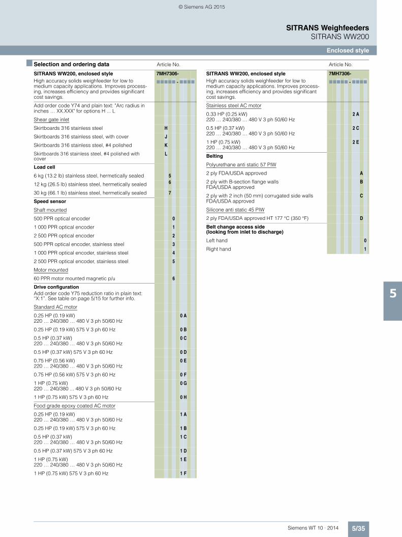
5/35Siemens WT 10 · 2014
SITRANS WeighfeedersSITRANS WW200
Enclosed style
5
■ Selection and ordering data Article No. Article No.
SITRANS WW200, enclosed styleHigh accuracy solids weighfeeder for low to medium capacity applications. Improves process-ing, increases efficiency and provides significant cost savings.
7MH7306-
77777 - 7777
Add order code Y74 and plain text: "Arc radius in inches … XX.XXX" for options H ... L
Shear gate inlet
Skirtboards 316 stainless steel H
Skirtboards 316 stainless steel, with cover J
Skirtboards 316 stainless steel, #4 polished K
Skirtboards 316 stainless steel, #4 polished with cover
L
Load cell
6 kg (13.2 lb) stainless steel, hermetically sealed 5
12 kg (26.5 lb) stainless steel, hermetically sealed 6
30 kg (66.1 lb) stainless steel, hermetically sealed 7
Speed sensor
Shaft mounted
500 PPR optical encoder 0
1 000 PPR optical encoder 1
2 500 PPR optical encoder 2
500 PPR optical encoder, stainless steel 3
1 000 PPR optical encoder, stainless steel 4
2 500 PPR optical encoder, stainless steel 5
Motor mounted
60 PPR motor mounted magnetic p/u 6
Drive configurationAdd order code Y75 reduction ratio in plain text: “X:1”. See table on page 5/15 for further info.
Standard AC motor
0.25 HP (0.19 kW) 220 … 240/380 … 480 V 3 ph 50/60 Hz
0 A
0.25 HP (0.19 kW) 575 V 3 ph 60 Hz 0 B
0.5 HP (0.37 kW) 220 … 240/380 … 480 V 3 ph 50/60 Hz
0 C
0.5 HP (0.37 kW) 575 V 3 ph 60 Hz 0 D
0.75 HP (0.56 kW) 220 … 240/380 … 480 V 3 ph 50/60 Hz
0 E
0.75 HP (0.56 kW) 575 V 3 ph 60 Hz 0 F
1 HP (0.75 kW) 220 … 240/380 ... 480 V 3 ph 50/60 Hz
0 G
1 HP (0.75 kW) 575 V 3 ph 60 Hz 0 H
Food grade epoxy coated AC motor
0.25 HP (0.19 kW) 220 … 240/380 … 480 V 3 ph 50/60 Hz
1 A
0.25 HP (0.19 kW) 575 V 3 ph 60 Hz 1 B
0.5 HP (0.37 kW) 220 … 240/380 … 480 V 3 ph 50/60 Hz
1 C
0.5 HP (0.37 kW) 575 V 3 ph 60 Hz 1 D
1 HP (0.75 kW) 220 … 240/380 … 480 V 3 ph 50/60 Hz
1 E
1 HP (0.75 kW) 575 V 3 ph 60 Hz 1 F
Stainless steel AC motor
0.33 HP (0.25 kW) 220 … 240/380 … 480 V 3 ph 50/60 Hz
2 A
0.5 HP (0.37 kW) 220 … 240/380 … 480 V 3 ph 50/60 Hz
2 C
1 HP (0.75 kW) 220 … 240/380 … 480 V 3 ph 50/60 Hz
2 E
Belting
Polyurethane anti static 57 PIW
2 ply FDA/USDA approved A
2 ply with B-section flange walls FDA/USDA approved
B
2 ply with 2 inch (50 mm) corrugated side walls FDA/USDA approved
C
Silicone anti static 45 PIW
2 ply FDA/USDA approved HT 177 °C (350 °F) D
Belt change access side (looking from inlet to discharge)
Left hand 0
Right hand 1
SITRANS WW200, enclosed styleHigh accuracy solids weighfeeder for low to medium capacity applications. Improves process-ing, increases efficiency and provides significant cost savings.
7MH7306-
77777 - 7777
© Siemens AG 2015

5/36 Siemens WT 10 · 2014
SITRANS WeighfeedersSITRANS WW200
Enclosed style
5
■ Selection and ordering data Order Code1) 2) 3)
1) Available with material containment options D ... L only.2) 575 V versions meet 4:1 ct inverter rating, all other voltages meet 10:1.3) Available with Drive Configuration standard motor options only,
all motors suitable for 400 V operation only.
Further designs
Please add "-Z" to article no. and specify order code(s).
Shear gate arc radius: Enter shear gate arc radius in inches (xxx.xx inch)1)
Y74
Enter design units (TPH, MTPH, lb/h, kg/h) Y71
Enter design speed (ft/m, m/s) Y72
Enter design capacity/rate Y73
AC gearmotor reduction ratio: Enter reduction ratio in plain text (X:1) (see "Reduction Ratio Selection Table" on page 5/7).
Y75
Custom length: Select next longest option and specify infeed CL to discharge CL in plain text (indicated inches or millimeters)
Y01
Class I, Div. 1, Group C&D; Class II, Div. 1, Group F&G approved electrical components Note: Weighfeeder does not carry hazardous approval, only components, not available with speed sensor options 3 ... 6, load cell options 0 ... 4 or with motor options 1A ... 2E2)
E90
ATEX II 2D approved electrical components Note: Weighfeeder does not carry hazardous approval, only components, approval not available with speed sensor options 0, 3, 4, 5, 6, load cell options 0 ... 4 or motor options 1A ... 2E3)
E91
Plastic shear curtain to control dust at the infeed for floodable materials and dusty applications1)
G11
Pointek CLS100 Capacitance switch for plugged discharge chute detection
G12
Siemens start/stop, auto/manual, speed control, hand held operator
G13
Belt cleaner, stainless steel, nylon brush, mounted under belt plow, cleaning dirty side of belt
G14
Secondary speed detection for differential monitoring: 60 PPR motor mounted magnetic p/u (Available with speed sensor options 0 ... 5 only)
G16
Manufacturer's test certificate: According to EN 10204-2.2
C11
Stainless steel tag [69 x 50 mm (2.71 x 1.97 inch)]: Measuring-point number/identification (max. 27 characters) specify in plain text
Y15
Custom designSpecify quote reference when ordering
Y99
Operating instructions Article No.
• English A5E33560654
Note: The operating instructions should be ordered as a separate item on the order. This device is shipped with the Siemens Milltronics manual DVD containing the complete operating instructions library.
© Siemens AG 2015
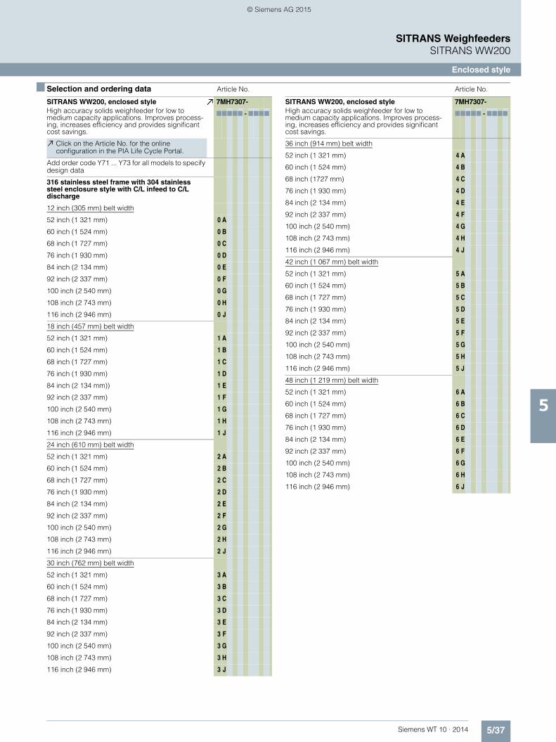
5/37Siemens WT 10 · 2014
SITRANS WeighfeedersSITRANS WW200
Enclosed style
5
■ Selection and ordering data Article No. Article No.
SITRANS WW200, enclosed styleHigh accuracy solids weighfeeder for low to medium capacity applications. Improves process-ing, increases efficiency and provides significant cost savings.
7MH7307-
77777 - 7777
Click on the Article No. for the online configuration in the PIA Life Cycle Portal.
Add order code Y71 ... Y73 for all models to specify design data
316 stainless steel frame with 304 stainless steel enclosure style with C/L infeed to C/L discharge
12 inch (305 mm) belt width
52 inch (1 321 mm) 0 A
60 inch (1 524 mm) 0 B
68 inch (1 727 mm) 0 C
76 inch (1 930 mm) 0 D
84 inch (2 134 mm) 0 E
92 inch (2 337 mm) 0 F
100 inch (2 540 mm) 0 G
108 inch (2 743 mm) 0 H
116 inch (2 946 mm) 0 J
18 inch (457 mm) belt width
52 inch (1 321 mm) 1 A
60 inch (1 524 mm) 1 B
68 inch (1 727 mm) 1 C
76 inch (1 930 mm) 1 D
84 inch (2 134 mm)) 1 E
92 inch (2 337 mm) 1 F
100 inch (2 540 mm) 1 G
108 inch (2 743 mm) 1 H
116 inch (2 946 mm) 1 J
24 inch (610 mm) belt width
52 inch (1 321 mm) 2 A
60 inch (1 524 mm) 2 B
68 inch (1 727 mm) 2 C
76 inch (1 930 mm) 2 D
84 inch (2 134 mm) 2 E
92 inch (2 337 mm) 2 F
100 inch (2 540 mm) 2 G
108 inch (2 743 mm) 2 H
116 inch (2 946 mm) 2 J
30 inch (762 mm) belt width
52 inch (1 321 mm) 3 A
60 inch (1 524 mm) 3 B
68 inch (1 727 mm) 3 C
76 inch (1 930 mm) 3 D
84 inch (2 134 mm) 3 E
92 inch (2 337 mm) 3 F
100 inch (2 540 mm) 3 G
108 inch (2 743 mm) 3 H
116 inch (2 946 mm) 3 J
SITRANS WW200, enclosed styleHigh accuracy solids weighfeeder for low to medium capacity applications. Improves process-ing, increases efficiency and provides significant cost savings.
7MH7307-
77777 - 7777
36 inch (914 mm) belt width
52 inch (1 321 mm) 4 A
60 inch (1 524 mm) 4 B
68 inch (1727 mm) 4 C
76 inch (1 930 mm) 4 D
84 inch (2 134 mm) 4 E
92 inch (2 337 mm) 4 F
100 inch (2 540 mm) 4 G
108 inch (2 743 mm) 4 H
116 inch (2 946 mm) 4 J
42 inch (1 067 mm) belt width
52 inch (1 321 mm) 5 A
60 inch (1 524 mm) 5 B
68 inch (1 727 mm) 5 C
76 inch (1 930 mm) 5 D
84 inch (2 134 mm) 5 E
92 inch (2 337 mm) 5 F
100 inch (2 540 mm) 5 G
108 inch (2 743 mm) 5 H
116 inch (2 946 mm) 5 J
48 inch (1 219 mm) belt width
52 inch (1 321 mm) 6 A
60 inch (1 524 mm) 6 B
68 inch (1 727 mm) 6 C
76 inch (1 930 mm) 6 D
84 inch (2 134 mm) 6 E
92 inch (2 337 mm) 6 F
100 inch (2 540 mm) 6 G
108 inch (2 743 mm) 6 H
116 inch (2 946 mm) 6 J
© Siemens AG 2015

5/38 Siemens WT 10 · 2014
SITRANS WeighfeedersSITRANS WW200
Enclosed style
5
■ Selection and ordering data Article No. Article No.
SITRANS WW200, enclosed styleHigh accuracy solids weighfeeder for low to medium capacity applications. Improves process-ing, increases efficiency and provides significant cost savings.
7MH7307-
77777 - 7777
Material containment construction
Add order code Y74 and plain text: "Arc radius in inches …XX.XXX inch" for options H ... L
Shear gate inlet and skirtboards 316 stainless steel H
Shear gate inlet and skirtboards 316 stainless steel, with cover
J
Shear gate inlet and skirtboards 316 stainless steel, #4 polished
K
Shear gate inlet and skirtboards 316 stainless steel, #4 polished with cover
L
Load cell
6 kg (13.2 lb) stainless steel, hermetically sealed 5
12 kg (26.5 lb) stainless steel, hermetically sealed 6
30 kg (66.1 lb) stainless steel, hermetically sealed 7
Speed sensor
500 PPR shaft mounted optical encoder 0
1 000 PPR shaft mounted optical encoder 1
2 500 PPR shaft mounted optical encoder 2
500 PPR shaft mounted optical encoder, stainless steel
3
1 000 PPR shaft mounted optical encoder, stainless steel
4
2 500 PPR shaft mounted optical encoder, stainless steel
5
60 PPR motor mounted magnetic p/u 6
Drive configurationAdd order code Y75 reduction ratio in plain text: “X:1”. See table on page 5/15 for further info.
Standard AC motor
0.25 HP (0.19 kW) 220 … 240/380 … 480 V 3 ph 50/60 Hz
0 A
0.25 HP (0.19 kW) 575 V 3 ph 60 Hz 0 B
0.5 HP (0.37 kW) 220 … 240/380 … 480 V 3 ph 50/60 Hz
0 C
0.5 HP (0.37 kW) 575 V 3 ph 60 Hz 0 D
0.75 HP (0.56 kW) 220 … 240/380 … 480 V 3 ph 50/60 Hz
0 E
0.75 HP (0.56 kW) 575 V 3 ph 60 Hz 0 F
1 HP (0.75 kW) 220 … 240/380 ... 480 V 3 ph 50/60 Hz
0 G
1 HP (0.75 kW) 575 V 3 ph 60 Hz 0 H
Food grade epoxy coated AC motor
0.25 HP (0.19 kW) 220 … 240/380 … 480 V 3 ph 50/60 Hz
1 A
0.25 HP (0.19 kW) 575 V 3 ph 60 Hz 1 B
0.5 HP (0.37 kW) 220 … 240/380 … 480 V 3 ph 50/60 Hz
1 C
0.5 HP (0.37 kW) 575 V 3 ph 60 Hz 1 D
1 HP (0.75 kW) 220 … 240/380 … 480 V 3 ph 50/60 Hz
1 E
1 HP (0.75 kW) 575 V 3 ph 60 Hz 1 F
SITRANS WW200, enclosed styleHigh accuracy solids weighfeeder for low to medium capacity applications. Improves process-ing, increases efficiency and provides significant cost savings.
7MH7307-
77777 - 7777
Stainless steel AC motor
0.33 HP (0.25 kW) 220 … 240/380 … 480 V 3 ph 50/60 Hz
2 A
0.5 HP (0.37 kW) 220 … 240/380 … 480 V 3 ph 50/60 Hz
2 C
1 HP (0.75 kW) 220 … 240/380 … 480 V 3 ph 50/60 Hz
2 E
Belting
Polyurethane anti static 57 PIW, 2 ply FDA/USDA approved
A
Polyurethane anti static 57 PIW, 2 ply with B-section flange walls FDA/USDA approved
B
Polyurethane anti static 57 PIW, 2 ply with 2 inch (50 mm) corrugated side walls FDA/USDA approved
C
Silicone anti static 45 PIW, 2 ply FDA/USDA approved HT 177 °C (350 °F)
D
Belt change access side (looking from inlet to discharge)
Left hand 0
Right hand 1
© Siemens AG 2015

5/39Siemens WT 10 · 2014
SITRANS WeighfeedersSITRANS WW200
Enclosed style
5
■ Selection and ordering data 1) 2) 3) Order Code Article No.
1) Available with material containment options D ... L only.2) 575 V versions meet 4:1 ct inverter rating, all other voltages meet 10:1.3) Available with Drive Configuration standard motor options only,
all motors suitable for 400 V operation only.
Further designs
Please add "-Z" to article no. and specify order code(s).
Shear gate arc radius: Enter shear gate arc radius in inches (xxx.xx inch)1)
Y74
Enter design units (TPH, MTPH, lb/h, kg/h) Y71
Enter design speed (ft/m, m/s) Y72
Enter design capacity/rate Y73
AC gearmotor reduction ratio: Enter reduction ratio in plain text (X:1) (see "Reduction Ratio Selection Table" on page 5/7).
Y75
Custom length: Select next longest option and specify infeed CL to discharge CL in plain text (indicated inches or millimeters)
Y01
Class I, Div. 1, Group C&D; Class II, Div. 1, Group F&G approved electrical components Note: Weighfeeder does not carry hazardous approval, only components, not available with speed sensor options 3 ... 6, load cell options 0 ... 4 or with motor options 1A ... 2E2)
E90
ATEX II 2D approved electrical components Note: Weighfeeder does not carry hazardous approval, only components, approval not available with speed sensor options 0, 3, 4, 5, 6, load cell options 0 ... 4 or motor options 1A ... 2E3)
E91
Plastic shear curtain to control dust at the infeed for floodable materials and dusty applications1)
G11
Pointek CLS100 Capacitance switch for plugged discharge chute detection
G12
Siemens start/stop, auto/manual, speed control, hand held operator
G13
Belt cleaner, stainless steel, nylon brush, mounted under belt plow, cleaning dirty side of belt
G14
Secondary speed detection for differential monitoring: 60 PPR motor mounted magnetic p/u (Available with speed sensor options 0 ... 5 only)
G16
Manufacturer's test certificate: According to EN 10204-2.2
C11
Stainless steel tag [69 x 50 mm (2.71 x 1.97 inch)]: Measuring-point number/identification (max. 27 characters) specify in plain text
Y15
Custom designSpecify quote reference when ordering.
Y99
Operating instructions
• English A5E33560654
Note: The operating instructions should be ordered as a separate item on the order. This device is shipped with the Siemens Milltronics manual DVD contain-ing the complete operating instructions library.
© Siemens AG 2015

5/40 Siemens WT 10 · 2014
SITRANS WeighfeedersSITRANS WW200
Enclosed style
5
■ Selection and ordering data Article No. Article No.
SITRANS WW200, enclosed styleHigh accuracy solids weighfeeder for low to medium capacity applications. Improves process-ing, increases efficiency and provides significant cost savings.
7MH7308-
77777 - 7777
Click on the Article No. for the online configuration in the PIA Life Cycle Portal.
Add order code Y71 ... Y73 for all models to specify design data
316 stainless steel frame with 316 stainless steel enclosure style with C/L infeed to C/L discharge
12 inch (305 mm) belt width
52 inch (1 321 mm) 0 A
60 inch (1 524 mm) 0 B
68 inch (1 727 mm) 0 C
76 inch (1 930 mm) 0 D
84 inch (2 134 mm) 0 E
92 inch (2 337 mm) 0 F
100 inch (2 540 mm) 0 G
108 inch (2 743 mm) 0 H
116 inch (2 946 mm) 0 J
18 inch (457 mm) belt width
52 inch (1 321 mm) 1 A
60 inch (1 524 mm) 1 B
68 inch (1 727 mm) 1 C
76 inch (1 930 mm) 1 D
84 inch (2 134 mm) 1 E
92 inch (2 337 mm) 1 F
100 inch (2 540 mm) 1 G
108 inch (2 743 mm) 1 H
116 inch (2 946 mm) 1 J
24 inch (610 mm) belt width
52 inch (1 321 mm) 2 A
60 inch (1 524 mm) 2 B
68 inch (1 727 mm) 2 C
76 inch (1 930 mm) 2 D
84 inch (2 134 mm) 2 E
92 inch (2 337 mm) 2 F
100 inch (2 540 mm) 2 G
108 inch (2 743 mm) 2 H
116 inch (2 946 mm) 2 J
30 inch (762 mm) belt width
52 inch (1 321 mm) 3 A
60 inch (1 524 mm) 3 B
68 inch (1 727 mm) 3 C
76 inch (1 930 mm) 3 D
84 inch (2 134 mm) 3 E
92 inch (2 337 mm) 3 F
100 inch (2 540 mm) 3 G
108 inch (2 743 mm) 3 H
116 inch (2 946 mm) 3 J
36 inch (914 mm) belt width
52 inch (1 321 mm) 4 A
60 inch (1 524 mm) 4 B
68 inch (1 727 mm) 4 C
76 inch (1 930 mm) 4 D
84 inch (2 134 mm) 4 E
92 inch (2 337 mm) 4 F
100 inch (2 540 mm) 4 G
108 inch (2 743 mm) 4 H
116 inch (2 946 mm) 4 J
42 inch (1 067 mm) belt width
52 inch (1 321 mm) 5 A
60 inch (1 524 mm) 5 B
68 inch (1 727 mm) 5 C
76 inch (1 930 mm) 5 D
84 inch (2 134 mm) 5 E
92 inch (2 337 mm) 5 F
100 inch (2 540 mm) 5 G
108 inch (2 743 mm) 5 H
116 inch (2 946 mm) 5 J
48 inch (1 219 mm) belt width
52 inch (1 321 mm) 6 A
60 inch (1 524 mm) 6 B
68 inch (1 727 mm) 6 C
76 inch (1 930 mm) 6 D
84 inch (2 134 mm) 6 E
92 inch (2 337 mm) 6 F
100 inch (2 540 mm) 6 G
108 inch (2 743 mm) 6 H
116 inch (2 946 mm) 6 J
SITRANS WW200, enclosed styleHigh accuracy solids weighfeeder for low to medium capacity applications. Improves process-ing, increases efficiency and provides significant cost savings.
7MH7308-
77777 - 7777
© Siemens AG 2015

5/41Siemens WT 10 · 2014
SITRANS WeighfeedersSITRANS WW200
Enclosed style
5
■ Selection and ordering data Article No. Article No.
SITRANS WW200, enclosed styleHigh accuracy solids weighfeeder for low to medium capacity applications. Improves process-ing, increases efficiency and provides significant cost savings.
7MH7308-
77777 - 7777
Material containment construction
Add order code Y74 and plain text: "Arc radius in inches …XX.XXX inch" for options H ... L
Shear gate inlet
Skirtboards 316 stainless steel H
Skirtboards 316 stainless steel, with cover J
Skirtboards 316 stainless steel, #4 polished K
Skirtboards 316 stainless steel, #4 polished with cover
L
Load cell
6 kg (13.2 lb) stainless steel, hermetically sealed 5
12 kg (26.5 lb) stainless steel, hermetically sealed 6
30 kg (66.1 lb) stainless steel, hermetically sealed 7
Speed sensor
Shaft mounted
500 PPR optical encoder 0
1 000 PPR optical encoder 1
2 500 PPR optical encoder 2
500 PPR optical encoder, stainless steel 3
1 000 PPR optical encoder, stainless steel 4
2 500 PPR optical encoder, stainless steel 5
Motor mounted
60 PPR magnetic p/u 6
Drive configurationAdd order code Y75 reduction ratio in plain text: “X:1”. See table on page 5/15 for further info.
Standard AC motor
0.25 HP (0.19 kW) 220 … 240/380 … 480 V 3 ph 50/60 Hz
0 A
0.25 HP (0.19 kW) 575 V 3 ph 60 Hz 0 B
0.5 HP (0.37 kW) 220 … 240/380 … 480 V 3 ph 50/60 Hz
0 C
0.5 HP (0.37 kW) 575 V 3 ph 60 Hz 0 D
0.75 HP (0.56 kW) 220 … 240/380 … 480 V 3 ph 50/60 Hz
0 E
0.75 HP (0.56 kW) 575 V 3 ph 60 Hz 0 F
1 HP (0.75 kW) 220 … 240/380 ... 480 V 3 ph 50/60 Hz
0 G
1 HP (0.75 kW) 575 V 3 ph 60 Hz 0 H
Food grade epoxy coated AC motor
0.25 HP (0.19 kW) 220 … 240/380 … 480 V 3 ph 50/60 Hz
1 A
0.25 HP (0.19 kW) 575 V 3 ph 60 Hz 1 B
0.5 HP (0.37 kW) 220 … 240/380 … 480 V 3 ph 50/60 Hz
1 C
0.5 HP (0.37 kW) 575 V 3 ph 60 Hz 1 D
1 HP (0.75 kW) 220 … 240/380 … 480 V 3 ph 50/60 Hz
1 E
1 HP (0.75 kW) 575 V 3 ph 60 Hz 1 F
Stainless steel AC motor
0.33 HP (0.25 kW) 220 … 240/380 … 480 V 3 ph 50/60 Hz
2 A
0.5 HP (0.37 kW) 220 … 240/380 … 480 V 3 ph 50/60 Hz
2 C
1 HP (0.75 kW) 220 … 240/380 … 480 V 3 ph 50/60 Hz
2 E
Belting
Polyurethane anti static 57 PIW, 2 ply FDA/USDA approved
A
Polyurethane anti static 57 PIW, 2 ply with B-section flange walls FDA/USDA approved
B
Polyurethane anti static 57 PIW, 2 ply with 2 inch (50 mm) corrugated side walls FDA/USDA approved
C
Silicone anti static 45 PIW, 2 ply FDA/USDA approved HT 177 °C (350 °F)
D
Belt change access side (looking from inlet to discharge)
Left hand 0
Right hand 1
SITRANS WW200, enclosed styleHigh accuracy solids weighfeeder for low to medium capacity applications. Improves process-ing, increases efficiency and provides significant cost savings.
7MH7308-
77777 - 7777
© Siemens AG 2015

5/42 Siemens WT 10 · 2014
SITRANS WeighfeedersSITRANS WW200
Enclosed style
5
■ Selection and ordering data Order Code1) 2) 3) Article No.
1) Available with material containment options D ... L only.2) 575 V versions meet 4:1 ct inverter rating, all other voltages meet 10:1.3) Available with Drive Configuration standard motor options only,
all motors suitable for 400 V operation only.
Further designs
Please add "-Z" to article no. and specify order code(s).
Shear gate arc radius: Enter shear gate arc radius in inches (xxx.xx inch)1)
Y74
Enter design units (TPH, MTPH, lb/h, kg/h) Y71
Enter design speed (ft/m, m/s) Y72
Enter design capacity/rate Y73
AC gearmotor reduction ratio: Enter reduction ratio in plain text (X:1) (see "Reduction Ratio Selection Table" on page 5/7).
Y75
Custom length: Select next longest option and specify infeed CL to discharge CL in plain text (indicated inches or millimeters)
Y01
Class I, Div. 1, Group C&D; Class II, Div. 1, Group F&G approved electrical components Note: Weighfeeder does not carry hazardous approval, only components, not available with speed sensor options 3 ... 6, load cell options 0 ... 4 or with motor options 1A ... 2E2)
E90
ATEX II 2D approved electrical components Note: Weighfeeder does not carry hazardous approval, only components, approval not available with speed sensor options 0, 3, 4, 5, 6, load cell options 0 ... 4 or motor options 1A ... 2E3)
E91
Plastic shear curtain to control dust at the infeed for floodable materials and dusty applications1)
G11
Pointek CLS100 Capacitance switch for plugged discharge chute detection
G12
Siemens start/stop, auto/manual, speed control, hand held operator
G13
Belt cleaner, stainless steel, nylon brush, mounted under belt plow, cleaning dirty side of belt
G14
Secondary speed detection for differential monitor-ing: 60 PPR motor mounted magnetic p/u (Available with speed sensor options 0 ... 5 only)
G16
Manufacturer's test certificate: According to EN 10204-2.2
C11
Stainless steel tag [69 x 50 mm (2.71 x 1.97 inch)]: Measuring-point number/identification (max. 27 characters) specify in plain text
Y15
Custom designSpecify quote reference when ordering.
Y99
Operating instructions
• English A5E33560654
Note: The operating instructions should be ordered as a separate item on the order. This device is shipped with the Siemens Milltronics manual DVD contain-ing the complete operating instructions library.
© Siemens AG 2015

5/43Siemens WT 10 · 2014
SITRANS WeighfeedersSITRANS WW200
Accessories and spare parts
5
■ Selection and ordering data Article No. Article No.
Accessories
Test chain 1.62 lb/ft, 2.41 kg/m - 60 inches long 7MH7723-1NF
Start, Stop, Hand/Off/Auto, speed pot local operator station
7MH7723-1JA
E-stop push button, enclosed style 3SB38010DF3
CLS100 plugged discharge chute retrofit kit (includes CLS100, material hood)
7MH7723-1JE
Siemens, MM420, 0.5 HP 0.37 kW, 380 ... 480 V 3 ph 50/60 Hz
6SE64202UD137AA1
Siemens, MM420, 0.75 HP 0.56 kW, 380 ... 480 V 3 ph 50/60 Hz
6SE64202UD155AA1
Siemens, MM420,1 HP 0.75 kW, 380 ... 480 V 3 ph 50/60 Hz
6SE64202UD175AA1
Siemens, MM440,1 HP 0.75 kW, 500 ... 600 V 3 ph 60 Hz
6SE64402UE175CA
Siemens,MM420/440, Bop keypad 6SE64000BP000AA1
Calibration hanger weights
200 g (0.4 lb) 7MH7724-1AF
500 g (1.1 lb) 7MH7724-1AG
1 000 g (2.2 lb) 7MH7724-1AH
2 000 g (4.4 lb) 7MH7724-1AJ
3 500 g (7.7 lb) 7MH7724-1BQ
5 000 g (11 lb) 7MH7724-1AK
7 500 g (16.5 lb) 7MH7724-1BR
8 500 g (18.7 lb) 7MH7724-1BS
10 000 (22 lb) 7MH7724-1BT
12 000 g (26.5 lb) 7MH7724-1BU
15 000 g (33.1 lb) 7MH7724-1BV
Note: Calibration accessories should be ordered as a separate item on the order
Spare parts
6 kg (13.2 lb) stainless steel load cell 7MH7725-1EG
12 kg (26.4 lb) stainless steel load cell 7MH7725-1EH
30 kg (66.2 lb) stainless steel load cell 7MH7725-1EJ
10 kg (22 lb) nickel plated steel load cell 7MH7725-1EK
15 kg (33.1 lb) nickel plated steel load cell 7MH7725-1EL
20 kg (44 lb) nickel plated steel load cell 7MH7725-1EM
30 kg (66.2 lb) nickel plated steel load cell 7MH7725-1EN
50 kg (110.2 lb) nickel plated steel load cell 7MH7725-1EP
Slider bar Delrin 7MH7723-1KG
500 PPR optical encoder 6FX20012PA50
1 000 PPR optical encoder 6FX20012PB00
2 500 PPR optical encoder 6FX20012PC50
Optical encoder connector 6FX20030SU12
Siemens Encoder connector with 20 ft cable 7MH7723-1KM
Encoder, EPC 802 Stainless steel, 500 PPR 7MH7723-1HG
Encoder, EPC 802 Stainless steel, 1 000 PPR 7MH7723-1HH
Encoder, EPC 802 Stainless steel, 2 500 PPR 7MH7723-1HJ
Magnetic proximity switch 7MH7723-1GA
Motor mounted sensor flange 56C 7MH7723-1RB
Belt tracking switch 3SE5112-0CR01
Termination box 1,2,4 load cell and speed sensor, mild steel
7MH7723-1ND
Termination box 1,2,4 load cell and speed sensor, stainless steel
7MH7723-1NE
Head bearing replacement kit mild steel (includes 2 bearings)
7MH7723-1QM
Tail bearing replacement kit mild steel (includes 2 bearings)
7MH7723-1QN
Head bearing replacement kit stainless steel (includes 2 bearings)
7MH7723-1QP
Tail bearing replacement kit stainless steel (includes 2 bearings)
7MH7723-1QQ
Skirtboard seal replacement kit 7MH7723-1QR
Enclosure latches (includes 5 latches) 7MH7723-1QS
Enclosure latches stainless steel (includes 5 latches)
7MH7723-1QT
Motor, 0.25 HP (0.19 kW) STD, 200/400 V – 50 Hz 3 ph, 230/460 V – 60 Hz 3 ph
7MH7723-1NG
Motor, 0.5 HP (0.37 kW) STD, 200/400 V – 50 Hz 3 ph, 230/460 V – 60 Hz 3 ph
7MH7723-1NH
Motor, 0.75 HP (0.56 kW) STD, 200/400 V – 50 Hz 3 ph, 230/460 V – 60 Hz 3 ph
7MH7723-1NJ
Motor, 1 HP (0.75 kW) STD, 200/400 V – 50 Hz 3 ph, 230/460 V – 60 Hz 3 ph
7MH7723-1NK
Motor, 0.25 HP (0.19 kW) STD, 575 V – 50 Hz 3 ph
7MH7723-1NL
Motor, 0.5 HP (0.37 kW) STD, 575 V – 50 Hz 3 ph
7MH7723-1NM
Motor, 0.75 HP (0.56 kW) STD, 575 V – 50 Hz 3 ph
7MH7723-1NN
Motor, 1 HP (0.75 kW) STD, 575 V – 50 Hz 3 ph
7MH7723-1NP
Motor, 0.25 HP (0.19 kW) epoxy coated, 200/400 V – 50 Hz 3 ph, 230/460 V – 60 Hz 3 ph
7MH7723-1NQ
Motor, 0.5 HP (0.37 kW) epoxy coated, 200/400 V – 50 Hz 3 ph, 230/460 V – 60 Hz 3 ph
7MH7723-1NR
Motor, 1 HP (0.75 kW) epoxy coated, 200/400 V – 50 Hz 3 ph, 230/460 V – 60 Hz 3 ph
7MH7723-1NS
Motor, 0.25 HP (0.19 kW) epoxy coated, 575 V – 50 Hz 3 ph
7MH7723-1NT
Motor, 0.5 HP (0.37 kW) epoxy coated, 575 V – 50 Hz 3 ph
7MH7723-1NU
Motor, 1 HP (0.75 kW) epoxy coated, 575 V – 50 Hz 3 ph
7MH7723-1NW
Motor, 0.33 HP (0.25 kW) stainless steel, 200/400 V – 50 Hz 3 ph, 230/460 V – 60 Hz 3 ph
7MH7723-1NX
Motor, 0.5 HP (0.37 kW) stainless steel, 200/400 V – 50 Hz 3 ph, 230/460 V – 60 Hz 3 ph
7MH7723-1NY
Motor, 1 HP (0.75 kW) stainless steel, 200/400 V – 50 Hz 3 ph, 230/460 V – 60 Hz 3 ph
7MH7723-1PA
Belt See 7MH7201
Gear reducer See 7MH7200
© Siemens AG 2015

5/44 Siemens WT 10 · 2014
SITRANS WeighfeedersSITRANS WW200
Accessories and spare parts
5
■ Selection and ordering data Article No. Article No.
1) 2)
Hazardous rated electrical spare parts
Load cells
6 kg (13.2 lb) stainless steel load cell, ATEX II 2D/Class I Div. 1, groups C&D, Class II Div. 1, groups F&G
7MH7725-1EQ
12 kg (26.4 lb) stainless steel load cell, ATEX II 2D/Class I Div. 1, groups C&D, Class II Div. 1, groups F&G
7MH7725-1ER
30 kg (66.2 lb) stainless steel load cell, ATEX II 2D/Class I Div. 1, groups C&D, Class II Div. 1, groups F&G
7MH7725-1ES
Optical encoders
500 PPR optical encoder, Class I Div. 1, groups C&D, Class II Div. 1, groups F&G
7MH7723-1QU
1 000 PPR optical encoder, Class I Div. 1, groups C&D, Class II Div. 1, groups F&G
7MH7723-1QV
2 500 PPR optical encoder, Class I Div. 1, groups C&D, Class II Div. 1, groups F&G
7MH7723-1QW
1 000 PPR optical encoder, ATEX II 2D 7MH7723-1QX
2 500 PPR optical encoder, ATEX II 2D 7MH7723-1QY
Motors
Motor, 0.25 HP 0.19 kW, Class I Div. 1, groups C&D, Class II Div. 1, groups F&G, 230/460 V – 60 Hz 3 ph
7MH7723-1PB
Motor, 0.5 HP 0.37 kW, Class I Div. 1, groups C&D, Class II Div. 1, groups F&G, 230/460 V – 60 Hz 3 ph
7MH7723-1PC
Motor, 0.75 HP 0.56 kW, Class I Div. 1, groups C&D, Class II Div. 1, groups F&G, 230/460 V – 60 Hz 3 ph
7MH7723-1PD
Motor, 1 HP 0.75 kW, Class I Div. 1, groups C&D, Class II Div. 1, groups F&G, 230/460 V – 60 Hz 3 ph
7MH7723-1NV
Motor, 0.25 HP 0.19 kW, Class I Div. 1, groups C&D, Class II Div. 1, groups F&G, 575 V – 50 Hz 3 ph
7MH7723-1QA
Motor, 0.5 HP 0.37 kW, Class I Div. 1, groups C&D, Class II Div. 1, groups F&G, 575 V – 50 Hz 3 ph
7MH7723-1QB
Motor, 0.75 HP 0.56 kW, Class I Div. 1, groups C&D, Class II Div. 1, groups F&G, 575 V – 50 Hz 3 ph
7MH7723-1QC
Motor, 1 HP 0.75 kW, Class I Div. 1, groups C&D, Class II Div. 1, groups F&G, 575 V – 50 Hz 3 ph
7MH7723-1QD
Motor, 0.25 HP 0.19 kW, ATEX II 2D, 400 V – 50 Hz 3 ph
1LA90734KA94-Z
Motor, 0.5 HP 0.37 kW, ATEX II 2D, 400 V – 50 Hz 3 ph
1LA90834KA94-Z
Motor, 0.75 HP 0.56 kW, ATEX II 2D, 400 V – 50Hz 3 ph
1LA90904KA94-Z
Motor, 1 HP 0.75 kW, ATEX II 2D, 400 V – 50 Hz 3 ph
1LA90964KA94-Z
Belt tracking switch, ATEX II 2D/Class I Div. 1,groups C&D, Class II Div. 1, groups F&G
7MH7723-1RA
1) Select order code A06.2) Select order code A04.
SITRANS WW200 gear reducerHelical worm gear reducer for use with WW200 weighfeeders CAF48 style for use with 7MH7300 - 7MH7308, Y75 order code info indicates reduction ratio on weighfeeder
7MH7200-
7777 000000
Construction
Painted mild steel 000000 00000
Food grade epoxy painted mild steel with food grade oil
000001 00000
Reduction Ratio (X:1)
1 059 00000A 00000A
937 00000A 00000B
865 00000A 00000C
745 00000A 00000D
677 00000A 00000E
615 00000A 00000F
558 00000A 00000G
508 00000A 00000H
449 00000A 00000J
414 00000A 00000K
357 00000A 00000L
324 00000A 00000M
320.67 00000B 00000A
284.7 00000B 00000B
249.6 00000B 00000C
223.36 00000B 00000D
198.25 00000B 00000E
173.73 00000B 00000F
152.75 00000B 00000G
138 00000B 00000H
120.25 00000B 00000J
108 00000B 00000K
97.5 00000B 00000L
88.4 00000B 00000M
80.44 00000B 00000N
71.12 00000B 00000P
65.68 00000B 00000Q
56.55 00000B 00000R
51.41 00000B 00000S
46.93 00000B 00000T
42 00000B 00000U
37.28 00000B 00000V
Type
Standard1)000000
For use with ATEX rated 0.25 HP (0.18 kW) motor2)000001
For use with ATEX rated 0.5 HP (0.37 kW) motor2)000002
For use with ATEX rated 0.75 HP (0.56 kW) motor2)000003
For use with ATEX rated 1 HP (0.75 kW) motor2)000004
Further designs Order Code
Please add "-Z" to article no. and specify order code(s).
Motor
Standard A06
For use with ATEX rated motor A04
© Siemens AG 2015

5/45Siemens WT 10 · 2014
SITRANS WeighfeedersSITRANS WW200
Accessories and spare parts
5
■ Selection and ordering data Article No. Article No.
SITRANS WW200 beltEndless belt for use with WW200 weighfeeders For use with 7MH7300, pulley CL data based on telescoper in fully retracted position.
7MH7201-
777 000000
Click on the Article No. for the online configuration in the PIA Life Cycle Portal.
12 inch (305 mm) belt width
52 inch (1 321 mm) C/L Infeed to C/L Discharge, 54.5 inch (1 384 mm) pulley C/L to C/L per weigh-feeder
000000 00000A
60 inch (1 524 mm) C/L Infeed to C/L Discharge, 62.5 inch (1 588 mm) pulley C/L to C/L per weigh-feeder
000000 00000B
68 inch (1 727 mm) C/L Infeed to C/L Discharge, 70.5 inch (1 791 mm) pulley C/L to C/L per weigh-feeder
000000 00000C
76 inch (1 930 mm) C/L Infeed to C/L Discharge, 78.5 inch (1 994 mm) pulley C/L to C/L per weigh-feeder
000000 00000D
84 inch (2 134 mm) C/L Infeed to C/L Discharge, 86.5 inch (2 197 mm) pulley C/L to C/L per weigh-feeder
000000 00000E
92 inch (2 337 mm) C/L Infeed to C/L Discharge, 94.5 inch (2 400 mm) pulley C/L to C/L per weigh-feeder
000000 00000F
100 inch (2 540 mm) C/L Infeed to C/L Discharge, 102.5 inch (2 604 mm) pulley C/L to C/L per weigh-feeder
000000 00000G
108 inch (2 743 mm) C/L Infeed to C/L Discharge, 110.5 inch (2 807 mm) pulley C/L to C/L per weigh-feeder
000000 00000H
116 inch (2 946 mm) C/L Infeed to C/L Discharge, 118.5 inch (3 010 mm) pulley C/L to C/L per weigh-feeder
000000 00000J
18 inch (457 mm) belt width
52 inch (1 321 mm) C/L Infeed to C/L Discharge, 54.5 inch (1 384 mm) pulley C/L to C/L per weigh-feeder
000001 00000A
60 inch (1 524 mm) C/L Infeed to C/L Discharge, 62.5 inch (1 588 mm) pulley C/L to C/L per weigh-feeder
000001 00000B
68 inch (1 727 mm) C/L Infeed to C/L Discharge, 70.5 inch (1 791 mm) pulley C/L to C/L per weigh-feeder
000001 00000C
76 inch (1 930 mm) C/L Infeed to C/L Discharge, 78.5 inch (1 994 mm) pulley C/L to C/L per weigh-feeder
000001 00000D
84 inch (2 134 mm) C/L Infeed to C/L Discharge, 86.5 inch (2 197 mm) pulley C/L to C/L per weigh-feeder
000001 00000E
92 inch (2 337 mm) C/L Infeed to C/L Discharge, 94.5 inch (2 400 mm) pulley C/L to C/L per weigh-feeder
000001 00000F
100 inch (2 540 mm) C/L Infeed to C/L Discharge, 102.5 inch (2 604 mm) pulley C/L to C/L per weigh-feeder
000001 00000G
108 inch (2 743 mm) C/L Infeed to C/L Discharge, 110.5 inch (2 807 mm) pulley C/L to C/L per weigh-feeder
000001 00000H
116 inch (2 946 mm) C/L Infeed to C/L Discharge, 118.5 inch (3 010 mm) pulley C/L to C/L per weigh-feeder
000001 00000J
SITRANS WW200 beltEndless belt for use with WW200 weighfeeders For use with 7MH7300, pulley CL data based on telescoper in fully retracted position.
7MH7201-
777 000000
24 inch (610 mm) belt width
52 inch (1 321 mm) C/L Infeed to C/L Discharge, 54.5 inch (1 384 mm) pulley C/L to C/L per weigh-feeder
000002 00000A
60 inch (1 524 mm) C/L Infeed to C/L Discharge, 62.5 inch (1 588 mm) pulley C/L to C/L per weigh-feeder
000002 00000B
68 inch (1 727 mm) C/L Infeed to C/L Discharge, 70.5 inch (1 791 mm) pulley C/L to C/L per weigh-feeder
000002 00000C
76 inch (1 930 mm) C/L Infeed to C/L Discharge, 78.5 inch (1 994 mm) pulley C/L to C/L per weigh-feeder
000002 00000D
84 inch (2 134 mm) C/L Infeed to C/L Discharge, 86.5 inch (2 197 mm) pulley C/L to C/L per weigh-feeder
000002 00000E
92 inch (2 337 mm) C/L Infeed to C/L Discharge, 94.5 inch (2 400 mm) pulley C/L to C/L per weigh-feeder
000002 000G
108 inch (2 743 mm) C/L Infeed to C/L Discharge, 110.5 inch (2 807 mm) pulley C/L to C/L per weigh-feeder
000002 00000H
116 inch (2 946 mm) C/L Infeed to C/L Discharge, 118.5 inch (3 010 mm) pulley C/L to C/L per weigh-feeder
000002 00000J
30 inch (762 mm) belt width
52 inch (1 321 mm) C/L Infeed to C/L Discharge, 54.5 inch (1 384 mm) pulley C/L to C/L per weigh-feeder
000003 00000A
60 inch (1 524 mm) C/L Infeed to C/L Discharge, 62.5 inch (1 588 mm) pulley C/L to C/L per weigh-feeder
000003 00000B
68 inch (1 727 mm) C/L Infeed to C/L Discharge, 70.5 inch (1 791 mm) pulley C/L to C/L per weigh-feeder
000003 00000C
76 inch (1 930 mm) C/L Infeed to C/L Discharge, 78.5 inch (1 994 mm) pulley C/L to C/L per weigh-feeder
000003 00000D
84 inch (2 134 mm) C/L Infeed to C/L Discharge, 86.5 inch (2 197 mm) pulley C/L to C/L per weigh-feeder
000003 00000E
92 inch (2 337 mm) C/L Infeed to C/L Discharge, 94.5 inch (2 400 mm) pulley C/L to C/L per weigh-feeder
000003 00000F
100 inch (2 540 mm) C/L Infeed to C/L Discharge, 102.5 inch (2 604 mm) pulley C/L to C/L per weigh-feeder
000003 00000G
108 inch (2 743 mm) C/L Infeed to C/L Discharge, 110.5 inch (2 807 mm) pulley C/L to C/L per weigh-feeder
000003 00000H
116 inch (2 946 mm) C/L Infeed to C/L Discharge, 118.5 inch (3 010 mm) pulley C/L to C/L per weigh-feeder
000004 00000A
© Siemens AG 2015

5/46 Siemens WT 10 · 2014
SITRANS WeighfeedersSITRANS WW200
Accessories and spare parts
5
■ Selection and ordering data Article No. Article No.
SITRANS WW200 beltEndless belt for use with WW200 weighfeeders For use with 7MH7300, pulley CL data based on telescoper in fully retracted position.
7MH7201-
777 000000
36 inch (914 mm) belt width
60 inch (1 524 mm) C/L Infeed to C/L Discharge, 62.5 inch (1 588 mm) pulley C/L to C/L per weigh-feeder
000004 00000B
68 inch (1 727 mm) C/L Infeed to C/L Discharge, 70.5 inch (1 791 mm) pulley C/L to C/L per weigh-feeder
000004 00000C
76 inch (1 930 mm) C/L Infeed to C/L Discharge, 78.5 inch (1 994 mm) pulley C/L to C/L per weigh-feeder
000004 00000D
84 inch (2 134 mm) C/L Infeed to C/L Discharge, 86.5 inch (2 197 mm) pulley C/L to C/L per weigh-feeder
000004 00000E
92 inch (2 337 mm) C/L Infeed to C/L Discharge, 94.5 inch (2 400 mm) pulley C/L to C/L per weigh-feeder
000004 00000F
100 inch (2 540 mm) C/L Infeed to C/L Discharge, 102.5 inch (2 604 mm) pulley C/L to C/L per weigh-feeder
000004 00000H
116 inch (2 946 mm) C/L Infeed to C/L Discharge, 118.5 inch (3 010 mm) pulley C/L to C/L per weigh-feeder
000004 00000J
42 inch (1 067 mm) belt width
52 inch (1 321 mm) C/L Infeed to C/L Discharge, 54.5 inch (1 384 mm) pulley C/L to C/L per weigh-feeder
000005 00000A
60 inch (1 524 mm) C/L Infeed to C/L Discharge, 62.5 inch (1 588 mm) pulley C/L to C/L per weigh-feeder
000005 00000B
68 inch (1 727 mm) C/L Infeed to C/L Discharge, 70.5 inch (1 791 mm) pulley C/L to C/L per weigh-feeder
000005 00000C
76 inch (1 930 mm) C/L Infeed to C/L Discharge, 78.5 inch (1 994 mm) pulley C/L to C/L per weigh-feeder
000005 00000D
84 inch (2 134 mm) C/L Infeed to C/L Discharge, 86.5 inch (2 197 mm) pulley C/L to C/L per weigh-feeder
000005 00000E
92 inch (2 337 mm) C/L Infeed to C/L Discharge, 94.5 inch (2 400 mm) pulley C/L to C/L per weigh-feeder
000005 00000F
100 inch (2 540 mm) C/L Infeed to C/L Discharge, 102.5 inch (2 604 mm) pulley C/L to C/L per weigh-feeder
000005 00000G
108 inch (2 743 mm) C/L Infeed to C/L Discharge, 110.5 inch (2 807 mm) pulley C/L to C/L per weigh-feeder
000005 00000H
116 inch (2 946 mm) C/L Infeed to C/L Discharge, 118.5 inch (3 010 mm) pulley C/L to C/L per weigh-feeder
000005 00000J
48 inch (1 219 mm) belt width
52 inch (1 321 mm) C/L Infeed to C/L Discharge, 54.5 inch (1 384 mm) pulley C/L to C/L per weigh-feeder
000006 00000A
60 inch (1 524 mm) C/L Infeed to C/L Discharge, 62.5 inch (1 588 mm) pulley C/L to C/L per weigh-feeder
000006 00000B
68 inch (1 727 mm) C/L Infeed to C/L Discharge, 70.5 inch (1 791 mm) pulley C/L to C/L per weigh-feeder
000006 00000C
76 inch (1 930 mm) C/L Infeed to C/L Discharge, 78.5 inch (1 994 mm) pulley C/L to C/L per weigh-feeder
000006 00000D
SITRANS WW200 beltEndless belt for use with WW200 weighfeeders For use with 7MH7300, pulley CL data based on telescoper in fully retracted position.
7MH7201-
777 000000
84 inch (2 134 mm) C/L Infeed to C/L Discharge, 86.5 inch (2 197 mm) pulley C/L to C/L per weigh-feeder
000006 00000E
92 inch (2 337 mm) C/L Infeed to C/L Discharge, 94.5 inch (2 400 mm) pulley C/L to C/L per weigh-feeder
000006 00000F
100 inch (2 540 mm) C/L Infeed to C/L Discharge, 102.5 inch (2 604 mm) pulley C/L to C/L per weigh-feeder
000006 00000G
108 inch (2 743 mm) C/L Infeed to C/L Discharge, 110.5 inch (2 807 mm) pulley C/L to C/L per weigh-feeder
000006 00000H
116 inch (2 946 mm) C/L Infeed to C/L Discharge, 118.5 inch (3 010 mm) pulley C/L to C/L per weigh-feeder
000006 00000J
Belting
Polyurethane anti static 57 PIW
2 ply FDA/USDA approved A
2 ply with B-section flange walls FDA/USDA approved
B
2 ply with 2 inch (50 mm) corrugated side walls FDA/USDA approved
C
Silicone anti static 45 PIW
2 ply FDA/USDA approved HT 177 °C (350 °F) D
Nitrile 135 PIW
3 ply G
3 ply with B-section flange walls H
3 ply with 2 inch (50 mm) corrugated side walls J
Further designs Order Code
Please add "-Z" to article no. and specify order code(s).
Custom length
Select next longest option and specify infeed CL to Discharge CL per weighfeeder in plain text (indi-cated inches or millimeters)
Y01
Note: Y01 order code info indicates special length on weighfeeder.
© Siemens AG 2015
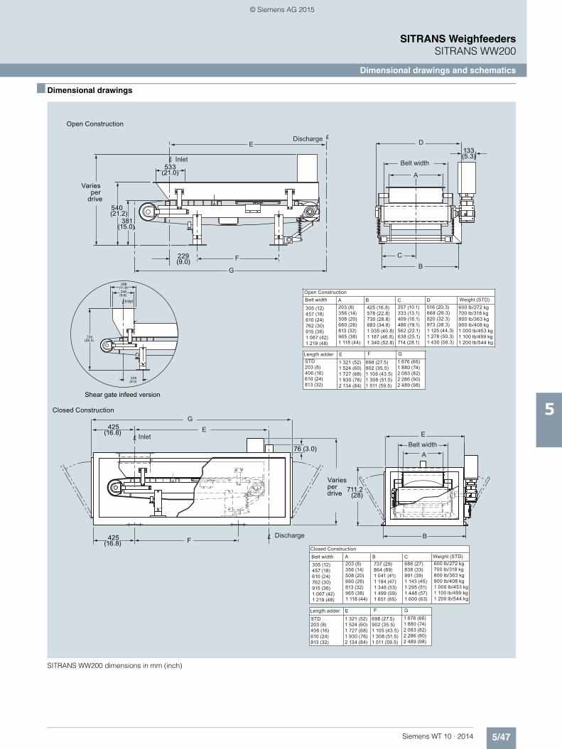
5/47Siemens WT 10 · 2014
SITRANS WeighfeedersSITRANS WW200
Dimensional drawings and schematics
5
■ Dimensional drawings
SITRANS WW200 dimensions in mm (inch)
Open Construction
Discharge
Inlet Belt width
Inlet
Shear gate infeed version
Closed Construction
Discharge
Inlet
Open ConstructionBelt width Weight (STD)
Length adder
Varies per
drive
Varies per drive
Length adder
Belt widthClosed Construction
Weight (STD)
Belt width
257 (10.1)333 (13.1)409 (16.1)486 (19.1)562 (22.1)638 (25.1)714 (28.1)
540 (21.2)
381(15.0)
229 (9.0)
133 (5.3)
533 (21.0)
E
F
G
D
A
C
B
298(11.8) 248
(9.8)
724(28.5)
229(9.0)
A B C
E F G
D305 (12)457 (18)610 (24)762 (30)915 (36)1 067 (42)1 219 (48)
203 (8)356 (14)508 (20)660 (26)813 (32)965 (38)1 118 (44)
425 (16.8)578 (22.8)730 (28.8)883 (34.8)1 035 (40.8)1 187 (46.8)1 340 (52.8)
516 (20.3)668 (26.3)820 (32.3)973 (38.3)1 125 (44.3)1 278 (50.3)1 430 (56.3)
600 lb/272 kg700 lb/318 kg800 lb/363 kg900 lb/408 kg1 000 lb/453 kg1 100 lb/499 kg1 200 lb/544 kg
STD203 (8)406 (16)610 (24)813 (32)
1 321 (52)1 524 (60)1 727 (68)1 930 (76)2 134 (84)
698 (27.5)902 (35.5)1 105 (43.5)1 308 (51.5)1 511 (59.5)
1 676 (66)1 880 (74)2 083 (82)2 286 (90)2 489 (98)
425(16.8)
GE
76 (3.0)
F 425(16.8)
E
A
B
686 (27)838 (33)991 (39)1 143 (45)1 295 (51)1 448 (57)1 600 (63)
A B C
E F G
305 (12)457 (18)610 (24)762 (30)915 (36)1 067 (42)1 219 (48)
203 (8)356 (14)508 (20)660 (26)813 (32)965 (38)1 118 (44)
737 (29)864 (89)1 041 (41)1 194 (47)1 346 (53)1 499 (59)1 651 (65)
600 lb/272 kg700 lb/318 kg800 lb/363 kg900 lb/408 kg1 000 lb/453 kg1 100 lb/499 kg1 200 lb/544 kg
STD203 (8)406 (16)610 (24)813 (32)
1 321 (52)1 524 (60)1 727 (68)1 930 (76)2 134 (84)
698 (27.5)902 (35.5)1 105 (43.5)1 308 (51.5)1 511 (59.5)
1 676 (66)1 880 (74)2 083 (82)2 286 (90)2 489 (98)
711.2 (28)
© Siemens AG 2015

5/48 Siemens WT 10 · 2014
SITRANS WeighfeedersSITRANS WW200
Dimensional drawings and schematics
5
■ Schematics
SITRANS WW200 connections
1
1 1
1
1
12
2 2
2
2
23
3 3
3
3
34
4 4
4
4
45
5 5
5
5
56
6 6
667
7 7
77
1
1
2
2
3
3
4
4
5
5TB1
TB4
TB3
TB5
TB7
TB2
+ E
XC
+ E
XC
BLK
+ EX
C
- EX
C
- EX
C
PU
RP
LE
CO
M
+ S
IG A
+ S
IG B
+ S
IG A
+ S
IG B
RE
D
WH
T
SIG
CW
- SIG
A
- SIG
B
- SIG
A
- SIG
B
BLU
E
BR
N
SIG
CC
W
SH
IELD
SH
IELD
SH
IELD
SH
IELD
TB6
TB8
LOAD CELL"A"
LOAD CELL"B"
TOINTEGRATOR
TOINTEGRATOR
SPEED SENSOR
© Siemens AG 2015

5/49Siemens WT 10 · 2014
SITRANS WeighfeedersSITRANS WW300
Introduction
5
■ Overview
SITRANS WW300 is a medium- to high-capacity weighfeeder used for macro ingredient additives.
■ Benefits
• Rugged, durable design for heavy-duty applications • Handles medium- to high-capacity loads • Standard mild steel open or enclosed construction • Heavy-duty 102 mm (4 inch) diameter idlers • Large 203 mm (8 inch) minimum diameter head and tail
pulleys for maximum traction • Patented design • Easy to replace endless belt • Gravity tensioned belt cleaner • Fast installation, easy to clean and maintain• Outboard mounted load cells with protective cover
■ Application
SITRANS WW300 is designed for industrial applications such as mining, cement, chemical processing, pulp and paper, and other heavy-duty industries.
Field tested and proven in hundreds of applications, it enhances profitability by ensuring accuracy, enhancing blend consistency, reducing downtime, and improving accountability and record keeping. The unique weigh system reduces dead load and ap-plies live load directly to load cells for accurate measurement. The dual load cells are externally mounted for easy access and maintenance.
It is available in a variety of lengths from 1.6 m (63 inch), belt widths from under 0.5 m (18 inch) to 1.8 m (72 inch), several dif-ferent inlet configurations and materials of construction. It can be configured to suit various applications.
Standard components include CEMA C rated idlers, belt track-ing rollers, hinged access panels on enclosed units, integral lift-ing points for easy installation, a belt scraper and plow for self-cleaning.
© Siemens AG 2015

5/50 Siemens WT 10 · 2014
SITRANS WeighfeedersSITRANS WW300
Introduction
5
■ Technical specifications 1)
1) Accuracy subject to: On factory approved installations, the weighfeeder system’s totalized weight will be within the specified accuracy when compared to a known weighed material test sample. The test rate must be within the specified range of the design capacity and held constant for the duration of the test. The minimum material test sample must be equivalent to a sample obtained at the test flow rate for three revolutions of the belt or at least ten minutes running time, whichever is greater.
SITRANS WW300
Mode of operation
Measuring principle Strain gauge load cells and digital speed sensor
Typical application Industrial and process applications in feeding, blending or rationing in gypsum manufacturing
Measuring accuracy
Accuracy1) ± 0.5 % or better
Specified range 10 ... 100 % based on speed
Design rate range 4.5 ... 800 t/h (5 ... 880 STPH)
Max volumetric flow 1 284 m3/h (44 800 ft3/h)
Medium conditions
Operating temperature -10 ... +55 °C (14 ... 131 °F)
Material Mild steel with stainless steel [304 (1.4301) or 316 (1.4401)], bead blast finish (1 ... 6 μm, 40 ... 240 μin) or abrasion resistant contact parts optional
Load cells
Construction 17-4 PH (1.4568) stainless steel or nickel plated alloy steel
Degree of protection • Stainless steel: IP67• Nickel plated alloy steel: IP66
Excitation 10 V DC nominal, 15 V DC maximum
Output 2 mV/V
Non-linearity ± 0.02 % of rated output
Non-repeatability ± 0.01 % of rated output
Capacity • Stainless steel range: 25, 50, 100, 250, 500 lb
• Nickel-plated range: 10, 15, 20, 30, 50, 75, 100 kg
Overload 150 % of rated capacity
Temperature • Operating range: -40 … +65 °C (-40 … +150 °F)
• Compensated: -10 … +40 °C (15 … 105 °F)
Speed sensor
Optical encoder output RS 422 (TTL) 5 V DC, 150 mA max., 500, 1 000, or 2 000 ppr
Temperature -10 … +70 °C (14 … 158 °F)
Degree of protection IP64
WS300 Output See page 4/45 (optional)
C-flange mounted magnetic pulse generator output
Open collector, NPN, sinking out-put, max. 17 mA, 60 ppr
Temperature -40 … +105 °C (-40 … +220 °F)
Degree of protection IP67
Belt tracking switch
Aluminum spring rod (un-wired) • 1 NO, 1 NC switch blocks• Rated operating voltage
600 V AC max.
Temperature -30 ... +85 °C (-22 ... +185 °F)
Degree of protection IP67
Framework • Painted structural steel • Cantilevered design for easy belt
replacement
Pulleys 200 mm (8 inch) minimum, 508 mm (20 inch) maximum, pulley diameter crowned with 6 mm (¼ inch) rubber lagging on drive pulley for maximum traction
Idlers Heavy-duty 100 mm (4 inch) CEMA C with precision ground ball bearings and triple labyrinth seals for longer life, CEMA D, E IMPACT where required
Belt speed 0.005 ... 0.36 m/s (1 ... 70 fpm)
Bearings 4 bolt flange style
Belting • Black rubber, 150 ... 440 PIW 2 ply vulcanized endless with 'B' section (standard)
• Up to 127 mm (5 inch) corrugat-ed sidewalls (optional)
• Maximum rated material tempera-ture of 107 °C (225 °F)
• Butyl HT belt rated for max material temp of 204 °C (400 °F)
• Nitrile belt rated for max materialtemp of 121 °C (250 °F)
Belt tension • Screw type, telescoper module with 150 mm (6 inch) minimum travel
• Gravity tensioned self-steering belt tracker (optional)
Belt cleaning • Gravity tensioned UHMW blade at head pulley
• Return plow at tail pulley
Drive motor AC, TEFC, 10:1 CT inverter duty, drive motor with direct coupled flange mounted hollow bore KAF gear reducer, 1.2 service factor min.
Shipping weight 410 kg (900 lb) minimum
Approvals • CE on all electrical components• Hazardous approvals per config-
uration options.Note: Weighfeeder as a whole is not approved for hazardous loca-tions, only electrical components.
SITRANS WW300
Pulley diameter Shaft diameter Bearing diameter Telescoper stroke Infeed length Skirtboard height
8 inch 2 ... 15/16 inch 1 ... 15/16 inch 6 inch 16 inch 8 inch
10 inch 3 ... 7/16 inch 2 ... 7/16 inch 6 inch 24 inch 10 inch
12 inch 3 ... 15/16 inch 2 ... 15/16 inch 9 inch 30 inch 12 inch
14 inch 4 ... 7/16 inch 3 ... 7/16 inch 9 inch 36 inch 14 inch
© Siemens AG 2015

5/51Siemens WT 10 · 2014
SITRANS WeighfeedersSITRANS WW300
8 inch pulley, open style
5
■ Selection and ordering data Article No. Article No.
SITRANS WW300, 8 inch pulley, open styleHigh accuracy solids weighfeeder for medium to high capacity applications. Improves processing, increases efficiency and provides significant cost savings.
7MH7400-
77777 - 7777
Click on the Article No. for the online configuration in the PIA Life Cycle Portal.
Add order code Y71 ... Y75 for all models to specify design data and add 1 of order code series G30 ... 37 gear reducer.
Painted mild steel, open style, with C/L infeed to C/L discharge
18 inch (457 mm) belt width
63 inch (1 600 mm) 0 A
75 inch (1 905 mm) 0 B
87 inch (2 210 mm) 0 C
99 inch (2 515 mm) 0 D
111 inch (2 819 mm) 0 E
123 inch (3 124 mm) 0 F
135 inch (3 429 mm) 0 G
147 inch (3 734 mm) 0 H
159 inch (4 039 mm) 0 J
171 inch (4 343 mm) 0 K
183 inch (4 648 mm) 0 L
195 inch (4 953 mm) 0 M
24 inch (610 mm) belt width
63 inch (1 600 mm) 1 A
75 inch (1 905 mm) 1 B
87 inch (2 210 mm) 1 C
99 inch (2 515 mm) 1 D
111 inch (2 819 mm) 1 E
123 inch (3 124 mm) 1 F
135 inch (3 429 mm) 1 G
147 inch (3 734 mm) 1 H
159 inch (4 039 mm) 1 J
171 inch (4 343 mm) 1 K
183 inch (4 648 mm) 1 L
195 inch (4 953 mm) 1 M
30 inch (762 mm) belt width
63 inch (1 600 mm) 2 A
75 inch (1 905 mm) 2 B
87 inch (2 210 mm) 2 C
99 inch (2 515 mm) 2 D
111 inch (2 819 mm) 2 E
123 inch (3 124 mm) 2 F
135 inch (3 429 mm) 2 G
147 inch (3 734 mm) 2 H
159 inch (4 039 mm) 2 J
171 inch (4 343 mm) 2 K
183 inch (4 648 mm) 2 L
195 inch (4 953 mm) 2 M
36 inch (914 mm) belt width
63 inch (1 600 mm) 3 A
75 inch (1 905 mm) 3 B
87 inch (2 210 mm) 3 C
99 inch (1 905 mm) 3 D
111 inch (2 819 mm) 3 E
123 inch (3 124 mm) 3 F
135 inch (3 429 mm) 3 G
147 inch (3 734 mm) 3 H
159 inch (4 039 mm) 3 J
171 inch (4 343 mm) 3 K
183 inch (4 648 mm) 3 L
195 inch (4 953 mm) 3 M
42 inch (1 067 mm) belt width
63 inch (1 600 mm) 4 A
75 inch (1 905 mm) 4 B
87 inch (2 210 mm) 4 C
99 inch (2 515 mm) 4 D
111 inch (2 819 mm) 4 E
123 inch (3 124 mm) 4 F
135 inch (3 429 mm) 4 G
147 inch (3 734 mm) 4 H
159 inch (4 039 mm) 4 J
171 inch (4 343 mm) 4 K
183 inch (4 648 mm) 4 L
195 inch (4 953 mm) 4 M
48 inch (1 219 mm) belt width
63 inch (1 600 mm) 5 A
75 inch (1 905 mm) 5 B
87 inch (2 210 mm) 5 C
99 inch (2 515 mm) 5 D
111 inch (2 819 mm) 5 E
123 inch (3 124 mm) 5 F
135 inch (3 429 mm) 5 G
147 inch (3 734 mm) 5 H
159 inch (4 039 mm) 5 J
171 inch (4 343 mm) 5 K
183 inch (4 648 mm) 5 L
195 inch (4 953 mm) 5 M
54 inch (1 372 mm) belt width
63 inch (1 600 mm) 6 A
75 inch (1 905 mm) 6 B
87 inch (2 210 mm) 6 C
99 inch (2 515 mm) 6 D
111 inch (2 819 mm) 6 E
123 inch (3 124 mm) 6 F
135 inch (3 734 mm) 6 G
147 inch (3 734 mm) 6 H
159 inch (4 039 mm) 6 J
171 inch (4 343 mm) 6 K
183 inch (4 648 mm) 6 L
195 inch (4 953 mm) 6 M
SITRANS WW300, 8 inch pulley, open styleHigh accuracy solids weighfeeder for medium to high capacity applications. Improves processing, increases efficiency and provides significant cost savings.
7MH7400-
77777 - 7777
© Siemens AG 2015

5/52 Siemens WT 10 · 2014
SITRANS WeighfeedersSITRANS WW300
8 inch pulley, open style
5
■ Selection and ordering data Article No. Article No.
SITRANS WW300, 8 inch pulley, open styleHigh accuracy solids weighfeeder for medium to high capacity applications. Improves processing, increases efficiency and provides significant cost savings.
7MH7400-
77777 - 7777
Load cell
Nickel plated steel
10 kg (22 lb) A
15 kg (33 lb) B
20 kg (44 lb) C
30 kg (66 lb) D
50 kg (110 lb) E
75 kg (165 lb) F
100 kg (220 lb) G
MCS, Class II, Div. 1 Groups E, F, and G, Class III/ Atex II 2D Ex tD A21 IP65 T70 °C
25 lb (11 kg) H
50 lb (23 kg) J
100 lb (45 kg) K
250 lb (113 kg) L
500 lb (227 kg) M
Material containment construction
None 0
Add order code Y74 and plain text: "Arc radius in inches …XX.XXX inch"
Shear gate inlet
Mild steel (no skirtboards) 1
AR400 steel (no skirtboards) 2
304 stainless steel (no skirtboards) 3
Skirtboards mild steel 4
Skirtboards AR400 steel 5
Skirtboards 304 stainless steel 6
Speed sensor
Shaft mounted
500 PPR optical encoder 0
1 000 PPR optical encoder 1
2 500 PPR optical encoder 2
32 PPR WS300, Class II, Div. 1 Groups E, F, and G, Class III/ Atex II 2D Ex tD A21 IP65 T70 °C
3
256 PPR WS300, Class II, Div. 1 Groups E, F, and G, Class III/ Atex II 2D Ex tD A21 IP65 T70 °C
4
1 000 PPR WS300, Class II, Div. 1 Groups E, F, and G, Class III/ Atex II 2D Ex tD A21 IP65 T70 °C
5
2 000 PPR WS300 6
Motor mounted
60 PPR magnetic p/u 7
Drive configurationAdd order code Y75 reduction ratio in plain text: “X:1”.Standard AC motor
0.25 HP (0.19 kW) 220 … 240/380 … 480 V 3 ph 50/60 Hz
0 A
0.25 HP (0.19 kW) 575 V 3 ph 60 Hz 0 B
0.5 HP (0.37 kW) 220 … 240/380 … 480 V 3 ph 50/60 Hz
0 C
0.5 HP (0.37 kW) 575 V 3 ph 60 Hz 0 D
0.75 HP (0.56 kW) 220 … 240/380 … 480 V 3 ph 50/60 Hz
0 E
0.75 HP (0.56 kW) 575 V 3 ph 60 Hz 0 F
1 HP (0.75 kW) 220 … 240/380 ... 480 V 3 ph 50/60 Hz
0 G
1 HP (0.75 kW) 575 V 3 ph 60 Hz 0 H
1.5 HP (1.12 kW) 220 … 240/380 ... 480 V 3 ph 50/60 Hz
0 J
1.5 HP (1.12 kW) 575 V 3 ph 60 Hz 0 K
3 HP (2.24 kW) 220 … 240/380 ... 480 V 3 ph 50/60 Hz
0 L
3 HP (2.24 kW) 575 V 3 ph 60 Hz 0 M
5 HP (3.73 kW) 220 … 240/380 ... 480 V 3 ph 50/60 Hz
0 N
5 HP (3.73 kW) 575 V 3 ph 60 Hz 0 P
Class I, Div. 1, Groups C and D, Class II, Div. 1, Groups F and G, AC motor
0.25 HP (0.19 kW) 220 … 240/380 … 480 V 3 ph 50/60 Hz
1 A
0.25 HP (0.19 kW) 575 V 3 ph 60 Hz 1 B
0.5 HP (0.37 kW) 220 … 240/380 … 480 V 3 ph 50/60 Hz
1 C
0.5 HP (0.37 kW) 575 V 3 ph 60 Hz 1 D
0.75 HP (0.56 kW) 220 … 240/380 … 480 V 3 ph 50/60 Hz
1 E
0.75 HP (0.56 kW) 575 V 3 ph 60 Hz 1 F
1 HP (0.75 kW) 220 … 240/380 … 480 V 3 ph 50/60 Hz
1 G
1 HP (0.75 kW) 575 V 3 ph 60 Hz 1 H
1.5 HP (1.12 kW) 220 … 240/380 … 480 V 3 ph 50/60 Hz
1 J
1.5 HP (1.12 kW) 575 V 3 ph 60 Hz 1 K
3 HP (2.24 kW) 220 … 240/380 … 480 V 3 ph 50/60 Hz
1 L
3 HP (2.24 kW) 575 V 3 ph 60 Hz 1 M
5 HP (3.73 kW) 220 … 240/380 … 480 V 3 ph 50/60 Hz
1 N
5 HP (3.73 kW) 575 V 3 ph 60 Hz 1 P
ATEX II 2D, AC motor
0.25 HP (0.19 kW) 400 V 3 ph 50/60 Hz 2 A
0.5 HP (0.37 kW) 400 V 3 ph 50/60 Hz 2 B
0.75 HP (0.56 kW) 400 V 3 ph 50/60 Hz 2 C
1 HP (0.75 kW) 400 V 3 ph 50/60 Hz 2 D
1.5 HP (1.12 kW) 400 V 3 ph 50/60 Hz 2 E
3 HP (2.24 kW) 400 V 3 ph 50/60 Hz 2 F
5 HP (3.73 kW) 400 V 3 ph 50/60 Hz 2 G
SITRANS WW300, 8 inch pulley, open styleHigh accuracy solids weighfeeder for medium to high capacity applications. Improves processing, increases efficiency and provides significant cost savings.
7MH7400-
77777 - 7777
© Siemens AG 2015
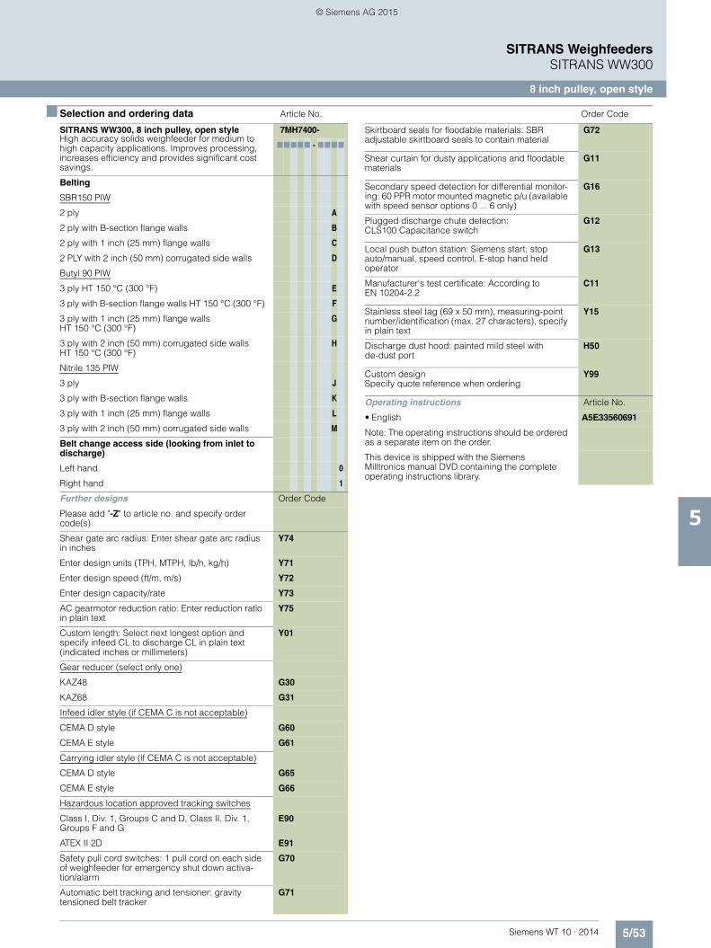
5/53Siemens WT 10 · 2014
SITRANS WeighfeedersSITRANS WW300
8 inch pulley, open style
5
■ Selection and ordering data Article No. Order Code
SITRANS WW300, 8 inch pulley, open styleHigh accuracy solids weighfeeder for medium to high capacity applications. Improves processing, increases efficiency and provides significant cost savings.
7MH7400-
77777 - 7777
Belting
SBR150 PIW
2 ply A
2 ply with B-section flange walls B
2 ply with 1 inch (25 mm) flange walls C
2 PLY with 2 inch (50 mm) corrugated side walls D
Butyl 90 PIW
3 ply HT 150 °C (300 °F) E
3 ply with B-section flange walls HT 150 °C (300 °F) F
3 ply with 1 inch (25 mm) flange walls HT 150 °C (300 °F)
G
3 ply with 2 inch (50 mm) corrugated side walls HT 150 °C (300 °F)
H
Nitrile 135 PIW
3 ply J
3 ply with B-section flange walls K
3 ply with 1 inch (25 mm) flange walls L
3 ply with 2 inch (50 mm) corrugated side walls M
Belt change access side (looking from inlet to discharge)
Left hand 0
Right hand 1
Further designs Order Code
Please add "-Z" to article no. and specify order code(s).
Shear gate arc radius: Enter shear gate arc radius in inches
Y74
Enter design units (TPH, MTPH, lb/h, kg/h) Y71
Enter design speed (ft/m, m/s) Y72
Enter design capacity/rate Y73
AC gearmotor reduction ratio: Enter reduction ratio in plain text
Y75
Custom length: Select next longest option and specify infeed CL to discharge CL in plain text (indicated inches or millimeters)
Y01
Gear reducer (select only one)
KAZ48 G30
KAZ68 G31
Infeed idler style (if CEMA C is not acceptable)
CEMA D style G60
CEMA E style G61
Carrying idler style (if CEMA C is not acceptable)
CEMA D style G65
CEMA E style G66
Hazardous location approved tracking switches
Class I, Div. 1, Groups C and D, Class II, Div. 1, Groups F and G
E90
ATEX II 2D E91
Safety pull cord switches: 1 pull cord on each side of weighfeeder for emergency shut down activa-tion/alarm
G70
Automatic belt tracking and tensioner: gravity tensioned belt tracker
G71
Skirtboard seals for floodable materials: SBR adjustable skirtboard seals to contain material
G72
Shear curtain for dusty applications and floodable materials
G11
Secondary speed detection for differential monitor-ing: 60 PPR motor mounted magnetic p/u (available with speed sensor options 0 ... 6 only)
G16
Plugged discharge chute detection: CLS100 Capacitance switch
G12
Local push button station: Siemens start, stop auto/manual, speed control, E-stop hand held operator
G13
Manufacturer's test certificate: According to EN 10204-2.2
C11
Stainless steel tag (69 x 50 mm), measuring-point number/identification (max. 27 characters), specify in plain text
Y15
Discharge dust hood: painted mild steel with de-dust port
H50
Custom designSpecify quote reference when ordering
Y99
Operating instructions Article No.
• English A5E33560691
Note: The operating instructions should be ordered as a separate item on the order.
This device is shipped with the Siemens Milltronics manual DVD containing the complete operating instructions library.
© Siemens AG 2015

5/54 Siemens WT 10 · 2014
SITRANS WeighfeedersSITRANS WW300
8 inch pulley, enclosed style
5
■ Selection and ordering data Article No. Article No.
SITRANS WW300, 8 inch pulley, enclosed styleHigh accuracy solids weighfeeder for medium to high capacity applications. Improves processing, increases efficiency and provides significant cost savings.
7MH7401-
77777 - 7777
Click on the Article No. for the online configuration in the PIA Life Cycle Portal.
Add order code Y71 ... Y75 for all models to specify design data and add 1 of order code series G30 ... 37 gear reducer
Painted mild steel enclosed style with C/L infeed to C/L discharge
18 inch (457 mm) belt width
63 inch (1 600 mm) 0 A
75 inch (1 905 mm) 0 B
87 inch (2 210 mm) 0 C
99 inch (2 515 mm) 0 D
111 inch (2 819 mm) 0 E
123 inch (3 124 mm) 0 F
135 inch (3 429 mm) 0 G
147 inch (3 734 mm) 0 H
159 inch (4 039 mm) 0 J
171 inch (4 343 mm) 0 K
183 inch (4 648 mm) 0 L
195 inch (4 953 mm) 0 M
24 inch (610 mm) belt width
63 inch (1 600 mm) 1 A
75 inch (1 905 mm) 1 B
87 inch (2 210 mm) 1 C
99 inch (2 515 mm) 1 D
111 inch (2 819 mm) 1 E
123 inch (3 124 mm) 1 F
135 inch (3 429 mm) 1 G
147 inch (3 734 mm) 1 H
159 inch (4 039 mm) 1 J
171 inch (4 343 mm) 1 K
183 inch (4 648 mm) 1 L
195 inch (4 953 mm) 1 M
30 inch (762 mm) belt width
63 inch (1 600 mm) 2 A
75 inch (1 905 mm) 2 B
87 inch (2 210 mm) 2 C
99 inch (2 515 mm) 2 D
111 inch (2 819 mm) 2 E
123 inch (3 124 mm) 2 F
135 inch (3 429 mm) 2 G
147 inch (3 734 mm) 2 H
159 inch (4 039 mm) 2 J
171 inch (4 343 mm) 2 K
183 inch (4 648 mm) 2 L
195 inch (4 953 mm) 2 M
36 inch (914 mm) belt width
63 inch (1 600 mm) 3 A
75 inch (1 905 mm) 3 B
87 inch (2 210 mm) 3 C
99 inch (1 905 mm) 3 D
111 inch (2 819 mm) 3 E
123 inch (3 124 mm) 3 F
135 inch (3 429 mm) 3 G
147 inch (3 734 mm) 3 H
159 inch (4 039 mm) 3 J
171 inch (4 343 mm) 3 K
183 inch (4 648 mm) 3 L
95 inch (4 953 mm) 3 M
42 inch (1 067 mm) belt width
63 inch (1 600 mm) 4 A
75 inch (1 905 mm) 4 B
87 inch (2 210 mm) 4 C
99 inch (2 515 mm) 4 D
111 inch (2 819 mm) 4 E
123 inch (3 124 mm) 4 F
135 inch (3 429 mm) 4 G
147 inch (3 734 mm) 4 H
159 inch (4 039 mm) 4 J
171 inch (4 343 mm) 4 K
183 inch (4 648 mm) 4 L
195 inch (4 953 mm) 4 M
48 inch (1 219 mm) belt width
63 inch (1 600 mm) 5 A
75 inch (1 905 mm) 5 B
87 inch (2 210 mm) 5 C
99 inch (2 515 mm) 5 D
111 inch (2 819 mm) 5 E
123 inch (3 124 mm) 5 F
135 inch (3 429 mm) 5 G
147 inch (3 734 mm) 5 H
159 inch (4 039 mm) 5 J
171 inch (4 343 mm) 5 K
183 inch (4 648 mm) 5 L
195 inch (4 953 mm) 5 M
54 inch (1 372 mm) belt width
63 inch (1 600 mm) 6 A
75 inch (1 905 mm) 6 B
87 inch (2 210 mm) 6 C
99 inch (2 515 mm) 6 D
111 inch (2 819 mm) 6 E
123 inch (3 124 mm) 6 F
135 inch (3 734 mm) 6 G
147 inch (3 734 mm) 6 H
159 inch (4 039 mm) 6 J
171 inch (4 343 mm) 6 K
183 inch (4 648 mm) 6 L
195 inch (4 953 mm) 6 M
SITRANS WW300, 8 inch pulley, enclosed styleHigh accuracy solids weighfeeder for medium to high capacity applications. Improves processing, increases efficiency and provides significant cost savings.
7MH7401-
77777 - 7777
© Siemens AG 2015

5/55Siemens WT 10 · 2014
SITRANS WeighfeedersSITRANS WW300
8 inch pulley, enclosed style
5
■ Selection and ordering data Article No. Article No.
SITRANS WW300, 8 inch pulley, enclosed styleHigh accuracy solids weighfeeder for medium to high capacity applications. Improves processing, increases efficiency and provides significant cost savings.
7MH7401-
77777 - 7777
Load cell
Nickel plated steel
10 kg (22 lb) A
15 kg (33 lb) B
20 kg (44 lb) C
30 kg (66 lb) D
50 kg (110 lb) E
75 kg (165 lb) F
100 kg (220 lb) G
MCS, Class II, Div. 1 Groups E, F, and G, Class III/Atex II 2D Ex tD A21 IP65 T70 °C
25 lb (11 kg) H
50 lb (23 kg) J
100 lb (45 kg) K
250 lb (113 kg) L
500 lb (227 kg) M
Material containment construction
None 0
Add order code Y74 and plain text: "Arc radius in inches …XX.XXX inch"
Shear gate inlet
Mild steel (no skirtboards) 1
AR400 steel (no skirtboards) 2
304 stainless steel (no skirtboards) 3
Skirtboards mild steel 4
Skirtboards AR400 steel 5
Skirtboards 304 stainless steel 6
Speed sensor
Shaft mounted
500 PPR optical encoder 0
1 000 PPR optical encoder 1
2 500 PPR optical encoder 2
32 PPR WS300, Class II, Div. 1 Groups E, F, and G, Class III/ Atex II 2D Ex tD A21 IP65 T70 °C
3
256 PPR WS300, Class II, Div. 1 Groups E, F, and G, Class III/ Atex II 2D Ex tD A21 IP65 T70 °C
4
1 000 PPR WS300, Class II, Div. 1 Groups E, F, and G, Class III/ Atex II 2D Ex tD A21 IP65 T70 °C
5
2 000 PPR WS300 6
Motor mounted
60 PPR magnetic p/u 7
Drive configurationAdd order code Y75 reduction ratio in plain text: “X:1”.Standard AC motor
0.25 HP (0.19 kW) 220 … 240/380 … 480 V 3 ph 50/60 Hz
0 A
0.25 HP (0.19 kW) 575 V 3 ph 60 Hz 0 B
0.5 HP (0.37 kW) 220 … 240/380 … 480 V 3 ph 50/60 Hz
0 C
0.5 HP (0.37 kW) 575 V 3 ph 60 Hz 0 D
0.75 HP (0.56 kW) 220 … 240/380 … 480 V 3 ph 50/60 Hz
0 E
0.75 HP (0.56 kW) 575 V 3 ph 60 Hz 0 F
1 HP (0.75 kW) 220 … 240/380 ... 480 V 3 ph 50/60 Hz
0 G
1 HP (0.75 kW) 575 V 3 ph 60 Hz 0 H
1.5 HP (1.12 kW) 220 … 240/380 ... 480 V 3 ph 50/60 Hz
0 J
1.5 HP (1.12 kW) 575 V 3 ph 60 Hz 0 K
3 HP (2.24 kW) 220 … 240/380 ... 480 V 3 ph 50/60 Hz
0 L
5 HP (3.73 kW) 220 … 240/380 ... 480 V 3 ph 50/60 Hz
0 M
5 HP (3.73 kW) 575 V 3 ph 60 Hz 0 N
5 HP (3.73 kW) 575 V 3 ph 60 Hz 0 P
Class I, Div. 1, Groups C and D, Class II, Div. 1, Groups F and G, AC motor
0.25 HP (0.19 kW) 220 … 240/380 … 480 V 3 ph 50/60 Hz
1 A
0.25 HP (0.19 kW) 575 V 3 ph 60 Hz 1 B
0.5 HP (0.37 kW) 220 … 240/380 … 480 V 3 ph 50/60 Hz
1 C
0.5 HP (0.37 kW) 575 V 3 ph 60 Hz 1 D
0.75 HP (0.56 kW) 220 … 240/380 … 480 V 3 ph 50/60 Hz
1 E
0.75 HP (0.56 kW) 575 V 3 ph 60 Hz 1 F
1 HP (0.75 kW) 220 … 240/380 … 480 V 3 ph 50/60 Hz
1 G
1 HP (0.75 kW) 575 V 3 ph 60 Hz 1 H
1.5 HP (1.12 kW) 220 … 240/380 … 480 V 3 ph 50/60 Hz
1 J
1.5 HP (1.12 kW) 575 V 3 ph 60 Hz 1 K
3 HP (2.24 kW) 220 … 240/380 … 480 V 3 ph 50/60 Hz
1 L
3 HP (2.24 kW) 575 V 3 ph 60 Hz 1 M
5 HP (3.73 kW) 220 … 240/380 … 480 V 3 ph 50/60 Hz
1 N
5 HP (3.73 kW) 575 V 3 ph 60 Hz 1 P
ATEX II 2D, AC motor
0.25 HP (0.19 kW) 400 V 3 ph 50/60 Hz 2 A
0.5 HP (0.37 kW) 400 V 3 ph 50/60 Hz 2 B
0.75 HP (0.56 kW) 400 V 3 ph 50/60 Hz 2 C
1 HP (0.75 kW) 400 V 3 ph 50/60 Hz 2 D
1.5 HP (1.12 kW) 400 V 3 ph 50/60 Hz 2 E
3 HP (2.24 kW) 400 V 3 ph 50/60 Hz 2 F
5 HP (3.73 kW) 400 V 3 ph 50/60 Hz 2 G
SITRANS WW300, 8 inch pulley, enclosed styleHigh accuracy solids weighfeeder for medium to high capacity applications. Improves processing, increases efficiency and provides significant cost savings.
7MH7401-
77777 - 7777
© Siemens AG 2015

5/56 Siemens WT 10 · 2014
SITRANS WeighfeedersSITRANS WW300
8 inch pulley, enclosed style
5
■ Selection and ordering data Article No. Order Code
SITRANS WW300, 8 inch pulley, enclosed styleHigh accuracy solids weighfeeder for medium to high capacity applications. Improves processing, increases efficiency and provides significant cost savings.
7MH7401-
77777 - 7777
Belting
SBR,150 PIW
2 ply A
2 ply with B-section flange walls B
2 ply with 1 inch (25 mm) flange walls C
2 ply with 2 inch (50 mm) corrugated side walls D
Butyl, 90 PIW
3 ply HT 150 °C (300 °F) E
3 ply with B-section flange walls HT 150 °C (300 °F) F
3 ply with 1 inch (25 mm) flange walls HT 150 °C (300 °F)
G
3 ply with 2 inch (50 mm) corrugated side walls HT 150 °C (300 °F)
H
Nitrile 135 PIW
3 ply J
3 ply with B-section flange walls K
3 ply with 1 inch (25 mm) flange walls L
3 ply with 2 inch (50 mm) corrugated side walls M
Belt change access side (looking from inlet to discharge)
Left hand 0
Right hand 1
Further designs Order Code
Please add "-Z" to article no. and specify order code(s).
Shear gate arc radius: Enter shear gate arc radius in inches
Y74
Enter design units (TPH, MTPH, lb/h, kg/h) Y71
Enter design speed (ft/m, m/s) Y72
Enter design capacity/rate Y73
AC gearmotor reduction ratio: Enter reduction ratio in plain text
Y75
Custom length: Select next longest option and specify infeed CL to discharge CL in plain text (indicated inches or millimeters)
Y01
Gear reducer (select only one)
KAZ48 G30
KAZ68 G31
Bottom covers and dust tight seals
18 inch belt width G40
24 inch belt width G41
30 inch belt width G42
36 inch belt width G43
42 inch belt width G44
48 inch belt width G50
54 inch belt width G51
Carry idler style (if CEMA C is not acceptable) only one option per configuration
CEMA D style G65
CEMA E style G66
Hazardous location approved tracking switches
Class I, Div. 1, Groups C and D, Class II, Div. 1, Groups F and G
E90
ATEX II 2D E91
Drag chain clean-out conveyor
18 inch belt width G80
24 inch belt width G81
30 inch belt width G82
36 inch belt width G83
42 inch belt width G84
48 inch belt width G85
54 inch belt width G86
Safety pull cord switches: 1 pull cord on each side of weighfeeder for emergency shut down activa-tion/alarm
G70
Automatic belt tracking and tensioner: gravity tensioned belt tracker
G71
Skirtboard seals for floodable materials: SBR adjustable skirtboard seals to contain material
G72
Shear curtain for dusty applications and floodable materials
G11
Secondary speed detection for differential monitor-ing: 60 PPR motor mounted magnetic p/u (available with speed sensor options 0 ... 6 only)
G16
Plugged discharge chute detection: CLS100 Capacitance switch
G12
Local push button station: Siemens start, stop auto/manual, speed control, E-stop hand held operator
G13
Manufacturer's test certificate: According to EN 10204-2.2
C11
Stainless steel tag (69 x 50 mm), measuring-point number/identification (max. 27 characters), specify in plain text.
Y15
Custom designSpecify quote reference when ordering.
Y99
Operating instructions Article No.
English A5E33560691
Note: The operating instructions should be ordered as a separate item on the order.
This device is shipped with the Siemens Milltronics manual DVD containing the complete operating instructions library.
© Siemens AG 2015

5/57Siemens WT 10 · 2014
SITRANS WeighfeedersSITRANS WW300
10 inch pulley, open style
5
■ Selection and ordering data Article No. Article No.
SITRANS WW300, 10 inch pulley, open styleHigh accuracy solids weighfeeder for medium to high capacity applications. Improves processing, increases efficiency and provides significant cost savings.
7MH7402-
77777 - 7777
Click on the Article No. for the online configuration in the PIA Life Cycle Portal.
Add order code Y71 ... Y75 for all models to specify design data and add 1 of order code series G30 ... 37 gear reducer
Painted mild steel, open style, C/L infeed to C/L discharge
18 inch (457 mm) belt width
75 inch (1 905 mm) 0 B
87 inch (2 210 mm) 0 C
99 inch (2 515 mm) 0 D
111 inch (2 819 mm) 0 E
123 inch (3 124 mm) 0 F
135 inch (3 429 mm) 0 G
147 inch (3 734 mm) 0 H
159 inch (4 039 mm) 0 J
171 inch (4 343 mm) 0 K
183 inch (4 648 mm) 0 L
195 inch (4 953 mm) 0 M
24 inch (610 mm) belt width
75 inch (1 905 mm) 1 B
87 inch (2 210 mm) 1 C
99 inch (2 515 mm) 1 D
111 inch (2 819 mm) 1 E
123 inch (3 124 mm) 1 F
135 inch (3 429 mm) 1 G
147 inch (3 734 mm) 1 H
159 inch (4 039 mm) 1 J
171 inch (4 343 mm) 1 K
183 inch (4 648 mm) 1 L
195 inch (4 953 mm) 1 M
30 inch (762 mm) belt width
75 inch (1 905 mm) 2 B
87 inch (2 210 mm) 2 C
99 inch (2 515 mm) 2 D
111 inch (2 819 mm) 2 E
123 inch (3 124 mm) 2 F
135 inch (3 429 mm) 2 G
147 inch (3 734 mm) 2 H
159 inch (4 039 mm) 2 J
171 inch (4 343 mm) 2 K
183 inch (4 648 mm) 2 L
195 inch (4 953 mm) 2 M
36 inch (914 mm) belt width
75 inch (1 905 mm) 3 B
87 inch (2 210 mm) 3 C
99 inch (1 905 mm) 3 D
111 inch (2 819 mm) 3 E
123 inch (3 124 mm) 3 F
135 inch (3 429 mm) 3 G
147 inch (3 734 mm) 3 H
159 inch (4 039 mm) 3 J
171 inch (4 343 mm) 3 K
183 inch (4 648 mm) 3 L
195 inch (4 953 mm) 3 M
42 inch (1 067 mm) belt width
75 inch (1 905 mm) 4 B
87 inch (2 210 mm) 4 C
99 inch (2 515 mm) 4 D
111 inch (2 819 mm) 4 E
123 inch (3 124 mm) 4 F
135 inch (3 429 mm) 4 G
147 inch (3 734 mm) 4 H
159 inch (4 039 mm) 4 J
171 inch (4 343 mm) 4 K
183 inch (4 648 mm) 4 L
195 inch (4 953 mm) 4 M
48 inch (1 219 mm) belt width
75 inch (1 905 mm) 5 B
87 inch (2 210 mm) 5 C
99 inch (2 515 mm) 5 D
111 inch (2 819 mm) 5 E
123 inch (3 124 mm) 5 F
135 inch (3 429 mm) 5 G
147 inch (3 734 mm) 5 H
159 inch (4 039 mm) 5 J
171 inch (4 343 mm) 5 K
183 inch (4 648 mm) 5 L
195 inch (4 953 mm) 5 M
54 inch (1 372 mm) belt width
75 inch (1 905 mm) 6 B
87 inch (2 210 mm) 6 C
99 inch (2 515 mm) 6 D
111 inch (2 819 mm) 6 E
123 inch (3 124 mm) 6 F
135 inch (3 734 mm) 6 G
147 inch (3 734 mm) 6 H
159 inch (4 039 mm) 6 J
171 inch (4 343 mm) 6 K
183 inch (4 648 mm) 6 L
195 inch (4 953 mm) 6 M
SITRANS WW300, 10 inch pulley, open styleHigh accuracy solids weighfeeder for medium to high capacity applications. Improves processing, increases efficiency and provides significant cost savings.
7MH7402-
77777 - 7777
© Siemens AG 2015

5/58 Siemens WT 10 · 2014
SITRANS WeighfeedersSITRANS WW300
10 inch pulley, open style
5
■ Selection and ordering data Article No. Article No.
SITRANS WW300, 10 inch pulley, open styleHigh accuracy solids weighfeeder for medium to high capacity applications. Improves processing, increases efficiency and provides significant cost savings.
7MH7402-
77777 - 7777
Load cell
Nickel plated steel
10 kg (22 lb) A
15 kg (33 lb) B
20 kg (44 lb) C
30 kg (66 lb) D
50 kg (110 lb) E
75 kg (165 lb) F
100 kg (220 lb) G
MCS, Class II, Div. 1 Groups E, F, and G, Class III/ Atex II 2D Ex tD A21 IP65 T70 °C
25 lb (11 kg) H
50 lb (23 kg) J
100 lb (45 kg) K
250 lb (113 kg) L
500 lb (227 kg) M
Material containment construction
None 0
Add order code Y74 and plain text: "Arc radius in inches …XX.XXX inch"
Shear gate inlet
Mild steel (no skirtboards) 1
AR400 steel (no skirtboards) 2
304 stainless steel (no skirtboards) 3
Skirtboards mild steel 4
Skirtboards AR400 steel 5
Skirtboards 304 stainless steel 6
Speed sensor
Shaft mounted
500 PPR optical encoder 0
1 000 PPR optical encoder 1
2 500 PPR optical encoder 2
32 PPR WS300, Class II, Div. 1 Groups E, F, and G, Class III/ Atex II 2D Ex tD A21 IP65 T70 °C
3
256 PPR WS300, Class II, Div. 1 Groups E, F, and G, Class III/ Atex II 2D Ex tD A21 IP65 T70 °C
4
1 000 PPR WS300, Class II, Div. 1 Groups E, F, and G, Class III/ Atex II 2D Ex tD A21 IP65 T70 °C
5
2 000 PPR WS300 6
Motor mounted
60 PPR magnetic p/u 7
Drive configurationAdd order code Y75 reduction ratio in plain text: “X:1”.Standard AC motor
0.25 HP (0.19 kW) 220 … 240/380 … 480 V 3 ph 50/60 Hz
0 A
0.25 HP (0.19 kW) 575 V 3 ph 60 Hz 0 B
0.5 HP (0.37 kW) 220 … 240/380 … 480 V 3 ph 50/60 Hz
0 C
0.5 HP (0.37 kW) 575 V 3 ph 60 Hz 0 D
0.75 HP (0.56 kW) 220 … 240/380 … 480 V 3 ph 50/60 Hz
0 E
0.75 HP (0.56 kW) 575 V 3 ph 60 Hz 0 F
1 HP (0.75 kW) 220 … 240/380 ... 480 V 3 ph 50/60 Hz
0 G
1 HP (0.75 kW) 575 V 3 ph 60 Hz 0 H
1.5 HP (1.12 kW) 220 … 240/380 ... 480 V 3 ph 50/60 Hz
0 J
1.5 HP (1.12 kW) 575 V 3 ph 60 Hz 0 K
3 HP (2.24 kW) 220 … 240/380 ... 480 V 3 ph 50/60 Hz
0 L
3 HP (2.24 kW) 575 V 3 ph 60 Hz 0 M
5 HP (3.73 kW) 220 … 240/380 ... 480 V 3 ph 50/60 Hz
0 N
5 HP (3.73 kW) 575 V 3 ph 60 Hz 0 P
7.5 HP (5.59 kW) 220 ... 240/380 ... 480 V 3 ph 50/60 Hz
0 Q
7.5 HP (5.59 kW) 575 V 3 ph 60 Hz 0 R
10 HP (7.46 kW) 220 ... 240/380 ... 480 V 3 ph 50/60 Hz
0 S
10 HP (7.46 kW) 575 V 3 ph 60 Hz 0 T
15 HP (11.19 kW) 220 ... 240/380 ... 480 V 3 ph 50/60 Hz
0 U
15 HP (11.19 kW) 575 V 3 ph 60 Hz 0 V
Class I, Div. 1, Groups C and D, Class II, Div. 1, Groups F and G, AC motor
0.25 HP (0.19 kW) 220 … 240/380 … 480 V 3 ph 50/60 Hz
1 A
0.25 HP (0.19 kW) 575 V 3 ph 60 Hz 1 B
0.5 HP (0.37 kW) 220 … 240/380 … 480 V 3 ph 50/60 Hz
1 C
0.5 HP (0.37 kW) 575 V 3 ph 60 Hz 1 D
0.75 HP (0.56 kW) 220 … 240/380 … 480 V 3 ph 50/60 Hz
1 E
0.75 HP (0.56 kW) 575 V 3 ph 60 Hz 1 F
1 HP (0.75 kW) 220 … 240/380 … 480 V 3 ph 50/60 Hz
1 G
1 HP (0.75 kW) 575 V 3 ph 60 Hz 1 H
1.5 HP (1.12 kW) 220 … 240/380 … 480 V 3 ph 50/60 Hz
1 J
1.5 HP (1.12 kW) 575 V 3 ph 60 Hz 1 K
SITRANS WW300, 10 inch pulley, open styleHigh accuracy solids weighfeeder for medium to high capacity applications. Improves processing, increases efficiency and provides significant cost savings.
7MH7402-
77777 - 7777
© Siemens AG 2015
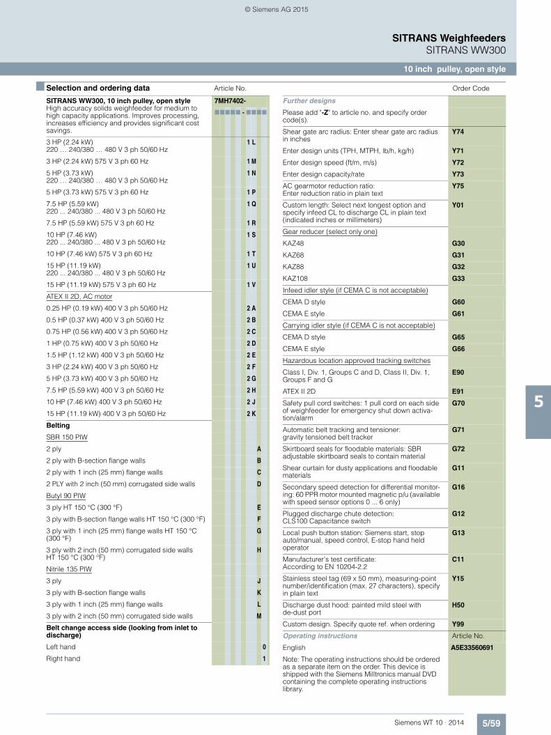
5/59Siemens WT 10 · 2014
SITRANS WeighfeedersSITRANS WW300
10 inch pulley, open style
5
■ Selection and ordering data Article No. Order Code
SITRANS WW300, 10 inch pulley, open styleHigh accuracy solids weighfeeder for medium to high capacity applications. Improves processing, increases efficiency and provides significant cost savings.
7MH7402-
77777 - 7777
3 HP (2.24 kW) 220 … 240/380 … 480 V 3 ph 50/60 Hz
1 L
3 HP (2.24 kW) 575 V 3 ph 60 Hz 1 M
5 HP (3.73 kW) 220 … 240/380 … 480 V 3 ph 50/60 Hz
1 N
5 HP (3.73 kW) 575 V 3 ph 60 Hz 1 P
7.5 HP (5.59 kW) 220 ... 240/380 ... 480 V 3 ph 50/60 Hz
1 Q
7.5 HP (5.59 kW) 575 V 3 ph 60 Hz 1 R
10 HP (7.46 kW) 220 ... 240/380 ... 480 V 3 ph 50/60 Hz
1 S
10 HP (7.46 kW) 575 V 3 ph 60 Hz 1 T
15 HP (11.19 kW) 220 ... 240/380 ... 480 V 3 ph 50/60 Hz
1 U
15 HP (11.19 kW) 575 V 3 ph 60 Hz 1 V
ATEX II 2D, AC motor
0.25 HP (0.19 kW) 400 V 3 ph 50/60 Hz 2 A
0.5 HP (0.37 kW) 400 V 3 ph 50/60 Hz 2 B
0.75 HP (0.56 kW) 400 V 3 ph 50/60 Hz 2 C
1 HP (0.75 kW) 400 V 3 ph 50/60 Hz 2 D
1.5 HP (1.12 kW) 400 V 3 ph 50/60 Hz 2 E
3 HP (2.24 kW) 400 V 3 ph 50/60 Hz 2 F
5 HP (3.73 kW) 400 V 3 ph 50/60 Hz 2 G
7.5 HP (5.59 kW) 400 V 3 ph 50/60 Hz 2 H
10 HP (7.46 kW) 400 V 3 ph 50/60 Hz 2 J
15 HP (11.19 kW) 400 V 3 ph 50/60 Hz 2 K
Belting
SBR 150 PIW
2 ply A
2 ply with B-section flange walls B
2 ply with 1 inch (25 mm) flange walls C
2 PLY with 2 inch (50 mm) corrugated side walls D
Butyl 90 PIW
3 ply HT 150 °C (300 °F) E
3 ply with B-section flange walls HT 150 °C (300 °F) F
3 ply with 1 inch (25 mm) flange walls HT 150 °C (300 °F)
G
3 ply with 2 inch (50 mm) corrugated side walls HT 150 °C (300 °F)
H
Nitrile 135 PIW
3 ply J
3 ply with B-section flange walls K
3 ply with 1 inch (25 mm) flange walls L
3 ply with 2 inch (50 mm) corrugated side walls M
Belt change access side (looking from inlet to discharge)
Left hand 0
Right hand 1
Further designs
Please add "-Z" to article no. and specify order code(s).
Shear gate arc radius: Enter shear gate arc radius in inches
Y74
Enter design units (TPH, MTPH, lb/h, kg/h) Y71
Enter design speed (ft/m, m/s) Y72
Enter design capacity/rate Y73
AC gearmotor reduction ratio: Enter reduction ratio in plain text
Y75
Custom length: Select next longest option and specify infeed CL to discharge CL in plain text (indicated inches or millimeters)
Y01
Gear reducer (select only one)
KAZ48 G30
KAZ68 G31
KAZ88 G32
KAZ108 G33
Infeed idler style (if CEMA C is not acceptable)
CEMA D style G60
CEMA E style G61
Carrying idler style (if CEMA C is not acceptable)
CEMA D style G65
CEMA E style G66
Hazardous location approved tracking switches
Class I, Div. 1, Groups C and D, Class II, Div. 1, Groups F and G
E90
ATEX II 2D E91
Safety pull cord switches: 1 pull cord on each side of weighfeeder for emergency shut down activa-tion/alarm
G70
Automatic belt tracking and tensioner: gravity tensioned belt tracker
G71
Skirtboard seals for floodable materials: SBR adjustable skirtboard seals to contain material
G72
Shear curtain for dusty applications and floodable materials
G11
Secondary speed detection for differential monitor-ing: 60 PPR motor mounted magnetic p/u (available with speed sensor options 0 ... 6 only)
G16
Plugged discharge chute detection: CLS100 Capacitance switch
G12
Local push button station: Siemens start, stop auto/manual, speed control, E-stop hand held operator
G13
Manufacturer's test certificate: According to EN 10204-2.2
C11
Stainless steel tag (69 x 50 mm), measuring-point number/identification (max. 27 characters), specify in plain text
Y15
Discharge dust hood: painted mild steel with de-dust port
H50
Custom design. Specify quote ref. when ordering Y99
Operating instructions Article No.
English A5E33560691
Note: The operating instructions should be ordered as a separate item on the order. This device is shipped with the Siemens Milltronics manual DVD containing the complete operating instructions library.
© Siemens AG 2015
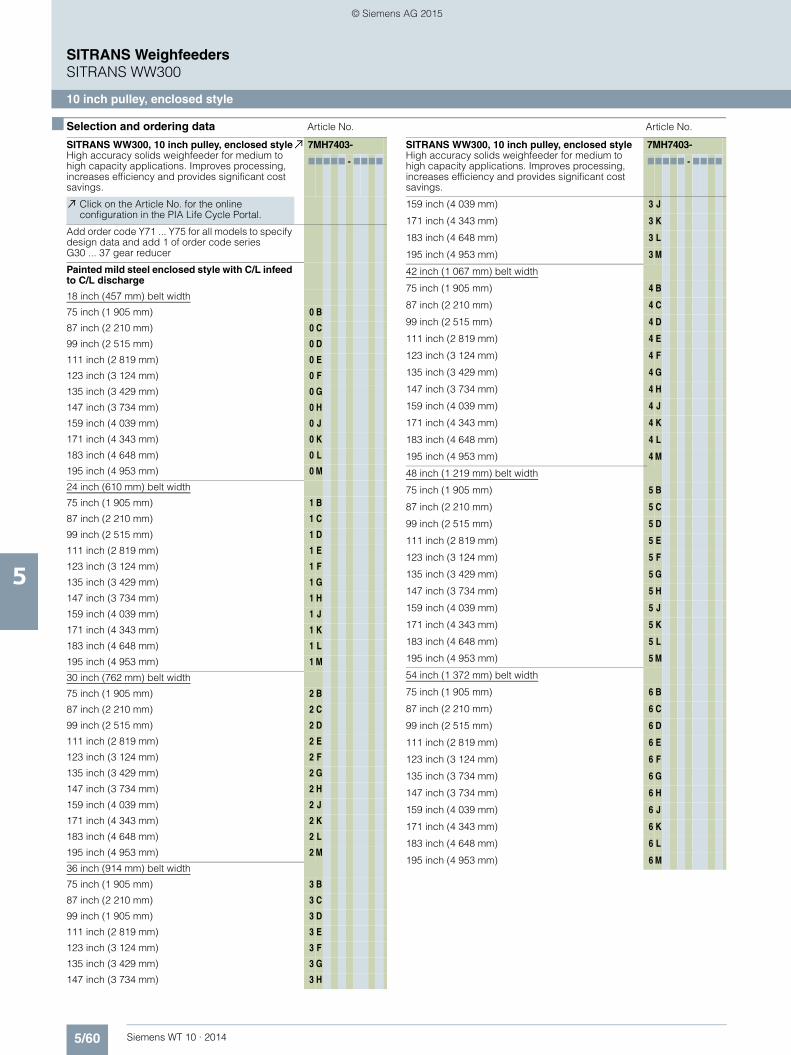
5/60 Siemens WT 10 · 2014
SITRANS WeighfeedersSITRANS WW300
10 inch pulley, enclosed style
5
■ Selection and ordering data Article No. Article No.
SITRANS WW300, 10 inch pulley, enclosed styleHigh accuracy solids weighfeeder for medium to high capacity applications. Improves processing, increases efficiency and provides significant cost savings.
7MH7403-
77777 - 7777
Click on the Article No. for the online configuration in the PIA Life Cycle Portal.
Add order code Y71 ... Y75 for all models to specify design data and add 1 of order code series G30 ... 37 gear reducer
Painted mild steel enclosed style with C/L infeed to C/L discharge
18 inch (457 mm) belt width
75 inch (1 905 mm) 0 B
87 inch (2 210 mm) 0 C
99 inch (2 515 mm) 0 D
111 inch (2 819 mm) 0 E
123 inch (3 124 mm) 0 F
135 inch (3 429 mm) 0 G
147 inch (3 734 mm) 0 H
159 inch (4 039 mm) 0 J
171 inch (4 343 mm) 0 K
183 inch (4 648 mm) 0 L
195 inch (4 953 mm) 0 M
24 inch (610 mm) belt width
75 inch (1 905 mm) 1 B
87 inch (2 210 mm) 1 C
99 inch (2 515 mm) 1 D
111 inch (2 819 mm) 1 E
123 inch (3 124 mm) 1 F
135 inch (3 429 mm) 1 G
147 inch (3 734 mm) 1 H
159 inch (4 039 mm) 1 J
171 inch (4 343 mm) 1 K
183 inch (4 648 mm) 1 L
195 inch (4 953 mm) 1 M
30 inch (762 mm) belt width
75 inch (1 905 mm) 2 B
87 inch (2 210 mm) 2 C
99 inch (2 515 mm) 2 D
111 inch (2 819 mm) 2 E
123 inch (3 124 mm) 2 F
135 inch (3 429 mm) 2 G
147 inch (3 734 mm) 2 H
159 inch (4 039 mm) 2 J
171 inch (4 343 mm) 2 K
183 inch (4 648 mm) 2 L
195 inch (4 953 mm) 2 M
36 inch (914 mm) belt width
75 inch (1 905 mm) 3 B
87 inch (2 210 mm) 3 C
99 inch (1 905 mm) 3 D
111 inch (2 819 mm) 3 E
123 inch (3 124 mm) 3 F
135 inch (3 429 mm) 3 G
147 inch (3 734 mm) 3 H
159 inch (4 039 mm) 3 J
171 inch (4 343 mm) 3 K
183 inch (4 648 mm) 3 L
195 inch (4 953 mm) 3 M
42 inch (1 067 mm) belt width
75 inch (1 905 mm) 4 B
87 inch (2 210 mm) 4 C
99 inch (2 515 mm) 4 D
111 inch (2 819 mm) 4 E
123 inch (3 124 mm) 4 F
135 inch (3 429 mm) 4 G
147 inch (3 734 mm) 4 H
159 inch (4 039 mm) 4 J
171 inch (4 343 mm) 4 K
183 inch (4 648 mm) 4 L
195 inch (4 953 mm) 4 M
48 inch (1 219 mm) belt width
75 inch (1 905 mm) 5 B
87 inch (2 210 mm) 5 C
99 inch (2 515 mm) 5 D
111 inch (2 819 mm) 5 E
123 inch (3 124 mm) 5 F
135 inch (3 429 mm) 5 G
147 inch (3 734 mm) 5 H
159 inch (4 039 mm) 5 J
171 inch (4 343 mm) 5 K
183 inch (4 648 mm) 5 L
195 inch (4 953 mm) 5 M
54 inch (1 372 mm) belt width
75 inch (1 905 mm) 6 B
87 inch (2 210 mm) 6 C
99 inch (2 515 mm) 6 D
111 inch (2 819 mm) 6 E
123 inch (3 124 mm) 6 F
135 inch (3 734 mm) 6 G
147 inch (3 734 mm) 6 H
159 inch (4 039 mm) 6 J
171 inch (4 343 mm) 6 K
183 inch (4 648 mm) 6 L
195 inch (4 953 mm) 6 M
SITRANS WW300, 10 inch pulley, enclosed styleHigh accuracy solids weighfeeder for medium to high capacity applications. Improves processing, increases efficiency and provides significant cost savings.
7MH7403-
77777 - 7777
© Siemens AG 2015

5/61Siemens WT 10 · 2014
SITRANS WeighfeedersSITRANS WW300
10 inch pulley, enclosed style
5
■ Selection and ordering data Article No. Article No.
SITRANS WW300, 10 inch pulley, enclosed styleHigh accuracy solids weighfeeder for medium to high capacity applications. Improves processing, increases efficiency and provides significant cost savings.
7MH7403-
77777 - 7777
Load cell
Nickel plated steel
10 kg (22 lb) A
15 kg (33 lb) B
20 kg (44 lb) C
30 kg (66 lb) D
50 kg (110 lb) E
75 kg (165 lb) F
100 kg (220 lb) G
MCS, Class II, Div. 1 Groups E, F, and G, Class III/ Atex II 2D Ex tD A21 IP65 T70 °C
25 lb (11 kg) H
50 lb (23 kg) J
100 lb (45 kg) K
250 lb (113 kg) L
500 lb (227 kg) M
Material containment construction
None 0
Add order code Y74 and plain text: "Arc radius in inches …XX.XXX inch"
Shear gate inlet
Mild steel (no skirtboards) 1
AR400 steel (no skirtboards) 2
304 stainless steel (no skirtboards) 3
Skirtboards mild steel 4
Skirtboards AR400 steel 5
Skirtboards 304 stainless steel 6
Speed sensor
Shaft mounted
500 PPR optical encoder 0
1 000 PPR optical encoder 1
2 500 PPR optical encoder 2
32 PPR WS300, Class II, Div. 1 Groups E, F, and G, Class III/ Atex II 2D Ex tD A21 IP65 T70 °C
3
256 PPR WS300, Class II, Div. 1 Groups E, F, and G, Class III/ Atex II 2D Ex tD A21 IP65 T70 °C
4
1 000 PPR WS300, Class II, Div. 1 Groups E, F, and G, Class III/ Atex II 2D Ex tD A21 IP65 T70 °C
5
2 000 PPR WS300 6
Motor mounted
60 PPR magnetic p/u 7
Drive configurationAdd order code Y75 reduction ratio in plain text: “X:1“Standard AC motor
0.25 HP (0.19 kW) 220 … 240/380 … 480 V 3 ph 50/60 Hz
0 A
0.25 HP (0.19 kW) 575 V 3 ph 60 Hz 0 B
0.5 HP (0.37 kW) 220 … 240/380 … 480 V 3 ph 50/60 Hz
0 C
0.5 HP (0.37 kW) 575 V 3 ph 60 Hz 0 D
0.75 HP (0.56 kW) 220 … 240/380 … 480 V 3 ph 50/60 Hz
0 E
0.75 HP (0.56 kW) 575 V 3 ph 60 Hz 0 F
1 HP (0.75 kW) 220 … 240/380 ... 480 V 3 ph 50/60 Hz
0 G
1 HP (0.75 kW) 575 V 3 ph 60 Hz 0 H
1.5 HP (1.12 kW) 220 … 240/380 ... 480 V 3 ph 50/60 Hz
0 J
1.5 HP (1.12 kW) 575 V 3 ph 60 Hz 0 K
3 HP (2.24 kW) 220 … 240/380 ... 480 V 3 ph 50/60 Hz
0 L
3 HP (2.24 kW) 575 V 3 ph 60 Hz 0 M
5 HP (3.73 kW) 220 … 240/380 ... 480 V 3 ph 50/60 Hz
0 N
5 HP (3.73 kW) 575 V 3 ph 60 Hz 0 P
7.5 HP (5.59 kW) 220 ... 240/380 ... 480 V 3 ph 50/60 Hz
0 Q
7.5 HP (5.59 kW) 575 V 3 ph 60 Hz 0 R
10 HP (7.46 kW) 220 ... 240/380 ... 480 V 3 ph 50/60 Hz
0 S
10 HP (7.46 kW) 575 V 3 ph 60 Hz 0 T
15 HP (11.19 kW) 220 ... 240/380 ... 480 V 3 ph 50/60 Hz
0 U
15 HP (11.19 kW) 575 V 3 ph 60 Hz 0 V
Class I, Div. 1, Groups C and D, Class II, Div. 1, Groups F and G, AC motor
0.25 HP (0.19 kW) 220 … 240/380 … 480 V 3 ph 50/60 Hz
1 A
0.25 HP (0.19 kW) 575 V 3 ph 60 Hz 1 B
0.5 HP (0.37 kW) 220 … 240/380 … 480 V 3 ph 50/60 Hz
1 C
0.5 HP (0.37 kW) 575 V 3 ph 60 Hz 1 D
0.75 HP (0.56 kW) 220 … 240/380 … 480 V 3 ph 50/60 Hz
1 E
0.75 HP (0.56 kW) 575 V 3 ph 60 Hz 1 F
1 HP (0.75 kW) 220 … 240/380 … 480 V 3 ph 50/60 Hz
1 G
1 HP (0.75 kW) 575 V 3 ph 60 Hz 1 H
1.5 HP (1.12 kW) 220 … 240/380 … 480 V 3 ph 50/60 Hz
1 J
1.5 HP (1.12 kW) 575 V 3 ph 60 Hz 1 K
3 HP (2.24 kW) 220 … 240/380 … 480 V 3 ph 50/60 Hz
1 L
3 HP (2.24 kW) 575 V 3 ph 60 Hz 1 M
5 HP (3.73 kW) 220 … 240/380 … 480 V 3 ph 50/60 Hz
1 N
5 HP (3.73 kW) 575 V 3 ph 60 Hz 1 P
7.5 HP (5.59 kW) 220 ... 240/380 ... 480 V 3 ph 50/60 Hz
1 Q
7.5 HP (5.59 kW) 575 V 3 ph 60 Hz 1 R
10 HP (7.46 kW) 220 ... 240/380 ... 480 V 3 ph 50/60 Hz
1 S
10 HP (7.46 kW) 575 V 3 ph 60 Hz 1 T
15 HP (11.19 kW) 220 ... 240/380 ... 480 V 3 ph 50/60 Hz
1 U
15 HP (11.19 kW) 575 V 3 ph 60 Hz 1 V
SITRANS WW300, 10 inch pulley, enclosed styleHigh accuracy solids weighfeeder for medium to high capacity applications. Improves processing, increases efficiency and provides significant cost savings.
7MH7403-
77777 - 7777
© Siemens AG 2015

5/62 Siemens WT 10 · 2014
SITRANS WeighfeedersSITRANS WW300
10 inch pulley, enclosed style
5
■ Selection and ordering data Article No. Order Code
SITRANS WW300, 10 inch pulley, enclosed styleHigh accuracy solids weighfeeder for medium to high capacity applications. Improves processing, increases efficiency and provides significant cost savings.
7MH7403-
77777 - 7777
ATEX II 2D, AC motor
0.25 HP (0.19 kW) 400 V 3 ph 50/60 Hz 2 A
0.5 HP (0.37 kW) 400 V 3 ph 50/60 Hz 2 B
0.75 HP (0.56 kW) 400 V 3 ph 50/60 Hz 2 C
1 HP (0.75 kW) 400 V 3 ph 50/60 Hz 2 D
1.5 HP (1.12 kW) 400 V 3 ph 50/60 Hz 2 E
3 HP (2.24 kW) 400 V 3 ph 50/60 Hz 2 F
5 HP (3.73 kW) 400 V 3 ph 50/60 Hz 2 G
7.5 HP (5.59 kW) 400 V 3 ph 50/60 Hz 2 H
10 HP (7.46 kW) 400 V 3 ph 50/60 Hz 2 J
15 HP (11.19 kW) 400 V 3 ph 50/60 Hz 2 K
Belting
SBR,150 PIW
2 ply A
2 ply with B-section flange walls B
2 ply with 1 inch (25 mm) flange walls C
2 ply with 2 inch (50 mm) corrugated side walls D
Butyl, 90 PIW
3 ply HT 150 °C (300 °F) E
3 ply with B-section flange walls HT 150 °C (300 °F) F
3 ply with 1 inch (25 mm) flange walls HT 150 °C (300 °F)
G
3 ply with 2 inch (50 mm) corrugated side walls HT 150 °C (300 °F)
H
Nitrile 135 PIW
3 ply J
3 ply with B-section flange walls K
3 ply with 1 inch (25 mm) flange walls L
3 ply with 2 inch (50 mm) corrugated side walls M
Belt change access side (looking from inlet to discharge)
Left hand 0
Right hand 1
Further designs Order Code
Please add "-Z" to article no. and specify order code(s).
Shear gate arc radius: Enter shear gate arc radius in inches
Y74
Enter design units (TPH, MTPH, lb/h, kg/h) Y71
Enter design speed (ft/m, m/s) Y72
Enter design capacity/rate Y73
AC gearmotor reduction ratio: Enter reduction ratio in plain text
Y75
Custom length: Select next longest option and specify infeed CL to discharge CL in plain text (indicated inches or millimeters)
Y01
Gear reducer (select only one)
KAZ48 G30
KAZ68 G31
KAZ88 G32
KAZ108 G33
Bottom covers and dust tight seals
18 inch belt width G40
24 inch belt width G41
30 inch belt width G42
36 inch belt width G43
42 inch belt width G44
48 inch belt width G50
54 inch belt width G51
Infeed idler style (if CEMA C is not acceptable)
CEMA D style G60
CEMA E style G61
Carrying idler style (if CEMA C is not acceptable)
CEMA D style G65
CEMA E style G66
Hazardous location approved tracking switches
Class I, Div. 1, Groups C and D, Class II, Div. 1, Groups F and G
E90
ATEX II 2D E91
Drag chain clean-out conveyor
18 inch belt width G80
24 inch belt width G81
30 inch belt width G82
36 inch belt width G83
42 inch belt width G84
48 inch belt width G85
54 inch belt width G86
Safety pull cord switches: 1 pull cord on each side of weighfeeder for emergency shut down activa-tion/alarm
G70
Automatic belt tracking and tensioner: gravity tensioned belt tracker
G71
Shear curtain for dusty applications and floodable materials
G11
Skirtboard seals for floodable materials: SBR adjustable skirtboard seals to contain material
G72
Secondary speed detection for differential monitor-ing: 60 PPR motor mounted magnetic p/u (available with speed sensor options 0 ... 6 only)
G16
Plugged discharge chute detection: CLS100 Capacitance switch
G12
Local push button station: Siemens start, stop auto/manual, speed control, E-stop hand held operator
G13
Manufacturer's test certificate: According to EN 10204-2.2
C11
Stainless steel tag (69 x 50 mm), measuring-point number/identification (max. 27 characters), specify in plain text
Y15
Custom designSpecify quote reference when ordering
Y99
© Siemens AG 2015

5/63Siemens WT 10 · 2014
SITRANS WeighfeedersSITRANS WW300
10 inch pulley, enclosed style
5
■ Selection and ordering data Article No.
Operating instructions
English A5E33560691
Note: The operating instructions should be ordered as a separate item on the order. This device is shipped with the Siemens Milltronics manual DVD containing the complete operating instructions library
© Siemens AG 2015

5/64 Siemens WT 10 · 2014
SITRANS WeighfeedersSITRANS WW300
12 inch pulley, open style
5
■ Selection and ordering data Article No. Article No.
SITRANS WW300, 12 inch pulley, open styleHigh accuracy solids weighfeeder for medium to high capacity applications. Improves processing, increases efficiency and provides significant cost savings.
7MH7404-
77777 - 7777
Click on the Article No. for the online configuration in the PIA Life Cycle Portal.
Add order code Y71 ... Y75 for all models to specify design data and add 1 of order code series G30 ... 37 gear reducer
Painted mild steel, open style, with C/L infeed to C/L discharge
18 inch (457 mm) belt width
87 inch (2 210 mm) 0 C
99 inch (2 515 mm) 0 D
111 inch (2 819 mm) 0 E
123 inch (3 124 mm) 0 F
135 inch (3 429 mm) 0 G
147 inch (3 734 mm) 0 H
159 inch (4 039 mm) 0 J
171 inch (4 343 mm) 0 K
183 inch (4 648 mm) 0 L
195 inch (4 953 mm) 0 M
24 inch (610 mm) belt width
87 inch (2 210 mm) 1 C
99 inch (2 515 mm) 1 D
111 inch (2 819 mm) 1 E
123 inch (3 124 mm) 1 F
135 inch (3 429 mm) 1 G
147 inch (3 734 mm) 1 H
159 inch (4 039 mm) 1 J
171 inch (4 343 mm) 1 K
183 inch (4 648 mm) 1 L
195 inch (4 953 mm) 1 M
30 inch (762 mm) belt width
87 inch (2 210 mm) 2 C
99 inch (2 515 mm) 2 D
111 inch (2 819 mm) 2 E
123 inch (3 124 mm) 2 F
135 inch (3 429 mm) 2 G
147 inch (3 734 mm) 2 H
159 inch (4 039 mm) 2 J
171 inch (4 343 mm) 2 K
183 inch (4 648 mm) 2 L
195 inch (4 953 mm) 2 M
36 inch (914 mm) belt width
87 inch (2 210 mm) 3 C
99 inch (1 905 mm) 3 D
111 inch (2 819 mm) 3 E
123 inch (3 124 mm) 3 F
135 inch (3 429 mm) 3 G
147 inch (3 734 mm) 3 H
159 inch (4 039 mm) 3 J
171 inch (4 343 mm) 3 K
183 inch (4 648 mm) 3 L
195 inch (4 953 mm) 3 M
42 inch (1 067 mm) belt width
87 inch (2 210 mm) 4 C
99 inch (2 515 mm) 4 D
111 inch (2 819 mm) 4 E
123 inch (3 124 mm) 4 F
135 inch (3 429 mm) 4 G
147 inch (3 734 mm) 4 H
159 inch (4 039 mm) 4 J
171 inch (4 343 mm) 4 K
183 inch (4 648 mm) 4 L
195 inch (4 953 mm) 4 M
48 inch (1 219 mm) belt width
87 inch (2 210 mm) 5 C
99 inch (2 515 mm) 5 D
111 inch (2 819 mm) 5 E
123 inch (3 124 mm) 5 F
135 inch (3 429 mm) 5 G
147 inch (3 734 mm) 5 H
159 inch (4 039 mm) 5 J
171 inch (4 343 mm) 5 K
183 inch (4 648 mm) 5 L
195 inch (4 953 mm) 5 M
54 inch (1 372 mm) belt width
87 inch (2 210 mm) 6 C
99 inch (2 515 mm) 6 D
111 inch (2 819 mm) 6 E
123 inch (3 124 mm) 6 F
135 inch (3 734 mm) 6 G
147 inch (3 734 mm) 6 H
159 inch (4 039 mm) 6 J
171 inch (4 343 mm) 6 K
183 inch (4 648 mm) 6 L
195 inch (4 953 mm) 6 M
SITRANS WW300, 12 inch pulley, open styleHigh accuracy solids weighfeeder for medium to high capacity applications. Improves processing, increases efficiency and provides significant cost savings.
7MH7404-
77777 - 7777
© Siemens AG 2015

5/65Siemens WT 10 · 2014
SITRANS WeighfeedersSITRANS WW300
12 inch pulley, open style
5
■ Selection and ordering data Article No. Article No.
SITRANS WW300, 12 inch pulley, open styleHigh accuracy solids weighfeeder for medium to high capacity applications. Improves processing, increases efficiency and provides significant cost savings.
7MH7404-
77777 - 7777
Load cell
Nickel plated steel
10 kg (22 lb) A
15 kg (33 lb) B
20 kg (44 lb) C
30 kg (66 lb) D
50 kg (110 lb) E
75 kg (165 lb) F
100 kg (220 lb) G
MCS, Class II, Div. 1 Groups E, F, and G, Class III/ Atex II 2D Ex tD A21 IP65 T70 °C
25 lb (11 kg) H
50 lb (23 kg) J
100 lb (45 kg) K
250 lb (113 kg) L
500 lb (227 kg) M
Material containment construction
None 0
Add order code Y74 and plain text: "Arc radius in inches …XX.XXX inch"
Shear gate inlet
Mild steel (no skirtboards) 1
AR400 steel (no skirtboards) 2
304 stainless steel (no skirtboards) 3
Skirtboards mild steel 4
Skirtboards AR400 steel 5
Skirtboards 304 stainless steel 6
Speed sensor
Shaft mounted
500 PPR optical encoder 0
1 000 PPR optical encoder 1
2 500 PPR optical encoder 2
32 PPR WS300, Class II, Div. 1 Groups E, F, and G, Class III/ Atex II 2D Ex tD A21 IP65 T70 °C
3
256 PPR WS300, Class II, Div. 1 Groups E, F, and G, Class III/ Atex II 2D Ex tD A21 IP65 T70 °C
4
1 000 PPR WS300, Class II, Div. 1 Groups E, F, and G, Class III/ Atex II 2D Ex tD A21 IP65 T70 °C
5
2 000 PPR WS300 6
Motor mounted
60 PPR magnetic p/u 7
Drive configurationAdd order code Y75 reduction ratio in plain text: “X:1”.Standard AC motor
0.25 HP (0.19 kW) 220 … 240/380 … 480 V 3 ph 50/60 Hz
0 A
0.25 HP (0.19 kW) 575 V 3 ph 60 Hz 0 B
0.5 HP (0.37 kW) 220 … 240/380 … 480 V 3 ph 50/60 Hz
0 C
0.5 HP (0.37 kW) 575 V 3 ph 60 Hz 0 D
0.75 HP (0.56 kW) 220 … 240/380 … 480 V 3 ph 50/60 Hz
0 E
0.75 HP (0.56 kW) 575 V 3 ph 60 Hz 0 F
1 HP (0.75 kW) 220 … 240/380 ... 480 V 3 ph 50/60 Hz
0 G
1 HP (0.75 kW) 575 V 3 ph 60 Hz 0 H
1.5 HP (1.12 kW) 220 … 240/380 ... 480 V 3 ph 50/60 Hz
0 J
1.5 HP (1.12 kW) 575 V 3 ph 60 Hz 0 K
3 HP (2.24 kW) 220 … 240/380 ... 480 V 3 ph 50/60 Hz
0 L
3 HP (2.24 kW) 575 V 3 ph 60 Hz 0 M
5 HP (3.73 kW) 220 … 240/380 ... 480 V 3 ph 50/60 Hz
0 N
5 HP (3.73 kW) 575 V 3 ph 60 Hz 0 P
7.5 HP (5.59 kW) 220 ... 240/380 ... 480 V 3 ph 50/60 Hz
0 Q
7.5 HP (5.59 kW) 575 V 3 ph 60 Hz 0 R
10 HP (7.46 kW) 220 ... 240/380 ... 480 V 3 ph 50/60 Hz
0 S
10 HP (7.46 kW) 575 V 3 ph 60 Hz 0 T
15 HP (11.19 kW) 220 ... 240/380 ... 480 V 3 ph 50/60 Hz
0 U
15 HP (11.19 kW) 575 V 3 ph 60 Hz 0 V
Class I, Div. 1, Groups C and D, Class II, Div. 1, Groups F and G, AC motor
0.25 HP (0.19 kW) 220 … 240/380 … 480 V 3 ph 50/60 Hz
1 A
0.25 HP (0.19 kW) 575 V 3 ph 60 Hz 1 B
0.5 HP (0.37 kW) 220 … 240/380 … 480 V 3 ph 50/60 Hz
1 C
0.5 HP (0.37 kW) 575 V 3 ph 60 Hz 1 D
0.75 HP (0.56 kW) 220 … 240/380 … 480 V 3 ph 50/60 Hz
1 E
0.75 HP (0.56 kW) 575 V 3 ph 60 Hz 1 F
1 HP (0.75 kW) 220 … 240/380 … 480 V 3 ph 50/60 Hz
1 G
1 HP (0.75 kW) 575 V 3 ph 60 Hz 1 H
1.5 HP (1.12 kW) 220 … 240/380 … 480 V 3 ph 50/60 Hz
1 J
1.5 HP (1.12 kW) 575 V 3 ph 60 Hz 1 K
SITRANS WW300, 12 inch pulley, open styleHigh accuracy solids weighfeeder for medium to high capacity applications. Improves processing, increases efficiency and provides significant cost savings.
7MH7404-
77777 - 7777
© Siemens AG 2015

5/66 Siemens WT 10 · 2014
SITRANS WeighfeedersSITRANS WW300
12 inch pulley, open style
5
■ Selection and ordering data Article No. Order Code
SITRANS WW300, 12 inch pulley, open styleHigh accuracy solids weighfeeder for medium to high capacity applications. Improves processing, increases efficiency and provides significant cost savings.
7MH7404-
77777 - 7777
3 HP (2.24 kW) 220 … 240/380 … 480 V 3 ph 50/60 Hz
1 L
3 HP (2.24 kW) 575 V 3 ph 60 Hz 1 M
5 HP (3.73 kW) 220 … 240/380 … 480 V 3 ph 50/60 Hz
1 N
5 HP (3.73 kW) 575 V 3 ph 60 Hz 1 P
7.5 HP (5.59 kW) 220 ... 240/380 ... 480 V 3 ph 50/60 Hz
1 Q
7.5 HP (5.59 kW) 575 V 3 ph 60 Hz 1 R
10 HP (7.46 kW) 220 ... 240/380 ... 480 V 3 ph 50/60 Hz
1 S
10 HP (7.46 kW) 575 V 3 ph 60 Hz 1 T
15 HP (11.19 kW) 220 ... 240/380 ... 480 V 3 ph 50/60 Hz
1 U
15 HP (11.19 kW) 575 V 3 ph 60 Hz 1 V
ATEX II 2D, AC motor
0.25 HP (0.19 kW) 400 V 3 ph 50/60 Hz 2 A
0.5 HP (0.37 kW) 400 V 3 ph 50/60 Hz 2 B
0.75 HP (0.56 kW) 400 V 3 ph 50/60 Hz 2 C
1 HP (0.75 kW) 400 V 3 ph 50/60 Hz 2 D
1.5 HP (1.12 kW) 400 V 3 ph 50/60 Hz 2 E
3 HP (2.24 kW) 400 V 3 ph 50/60 Hz 2 F
5 HP (3.73 kW) 400 V 3 ph 50/60 Hz 2 G
7.5 HP (5.59 kW) 400 V 3 ph 50/60 Hz 2 H
10 HP (7.46 kW) 400 V 3 ph 50/60 Hz 2 J
15 HP (11.19 kW) 400 V 3 ph 50/60 Hz 2 K
Belting
SBR 150 PIW
2 ply A
2 ply with B-section flange walls B
2 ply with 1 inch (25 mm) flange walls C
2 PLY with 2 inch (50 mm) corrugated side walls D
Butyl 90 PIW
3 ply HT 150 °C (300 °F) E
3 ply with B-section flange walls HT 150 °C (300 °F) F
3 ply with 1 inch (25 mm) flange walls HT 150 °C (300 °F)
G
3 ply with 2 inch (50 mm) corrugated side walls HT 150 °C (300 °F)
H
Nitrile 135 PIW
3 ply J
3 ply with B-section flange walls K
3 ply with 1 inch (25 mm) flange walls L
3 ply with 2 inch (50 mm) corrugated side walls M
Belt change access side (looking from inlet to discharge)
Left hand 0
Right hand 1
Further designs
Please add "-Z" to article no. and specify order code(s).
Shear gate arc radius: Enter shear gate arc radius in inches
Y74
Enter design units (TPH, MTPH, lb/h, kg/h) Y71
Enter design speed (ft/m, m/s) Y72
Enter design capacity/rate Y73
AC gearmotor reduction ratio: Enter reduction ratio in plain text
Y75
Custom length: Select next longest option and specify infeed CL to discharge CL in plain text (indicated inches or millimeters)
Y01
Gear reducer (select only one)
KAZ48 G30
KAZ68 G31
KAZ88 G32
KAZ108 G33
Infeed idler style (if CEMA C is not acceptable)
CEMA D style G60
CEMA E style G61
Carrying idler style (if CEMA C is not acceptable)
CEMA D style G65
CEMA E style G66
Hazardous location approved tracking switches
Class I, Div. 1, Groups C and D, Class II, Div. 1, Groups F and G
E90
ATEX II 2D E91
Safety pull cord switches: 1 pull cord on each side of weighfeeder for emergency shut down activa-tion/alarm
G70
Automatic belt tracking and tensioner: gravity tensioned belt tracker
G71
Skirtboard seals for floodable materials: SBR adjustable skirtboard seals to contain material
G72
Shear curtain for dusty applications and floodable materials
G11
Secondary speed detection for differential monitor-ing: 60 PPR motor mounted magnetic p/u (available with speed sensor options 0 ... 6 only)
G16
Plugged discharge chute detection: CLS100 Capacitance switch
G12
Local push button station: Siemens start, stop auto/manual, speed control, E-stop hand held operator
G13
Manufacturer's test certificate: According to EN 10204-2.2
C11
Stainless steel tag (69 x 50 mm), measuring-point number/identification (max. 27 characters), specify in plain text
Y15
Discharge dust hood: painted mild steel with de-dust port
H50
Custom design. Specify quote ref. when ordering Y99
Operating instructions Article No.
• English A5E33560691
Note: The operating instructions should be ordered as a separate item on the order. This device is shipped with the Siemens Milltronics manual DVD containing the complete operating instructions library.
© Siemens AG 2015

5/67Siemens WT 10 · 2014
SITRANS WeighfeedersSITRANS WW300
12 inch pulley, enclosed style
5
■ Selection and ordering data Article No. Article No.
SITRANS WW300, 12 inch pulley, enclosed styleHigh accuracy solids weighfeeder for medium to high capacity applications. Improves processing, increases efficiency and provides significant cost savings.
7MH7405-
77777 - 7777
Click on the Article No. for the online configuration in the PIA Life Cycle Portal.
Add order code Y71 ... Y75 for all models to specify design data and add 1 of order code series G30 ... 37 gear reducer
Painted mild steel enclosed style with C/L infeed to C/L discharge
18 inch (457 mm) belt width
87 inch (2 210 mm) 0 C
99 inch (2 515 mm) 0 D
111 inch (2 819 mm) 0 E
123 inch (3 124 mm) 0 F
135 inch (3 429 mm) 0 G
147 inch (3 734 mm) 0 H
159 inch (4 039 mm) 0 J
171 inch (4 343 mm) 0 K
183 inch (4 648 mm) 0 L
195 inch (4 953 mm) 0 M
24 inch (610 mm) belt width
87 inch (2 210 mm) 1 C
99 inch (2 515 mm) 1 D
111 inch (2 819 mm) 1 E
123 inch (3 124 mm) 1 F
135 inch (3 429 mm) 1 G
147 inch (3 734 mm) 1 H
159 inch (4 039 mm) 1 J
171 inch (4 343 mm) 1 K
183 inch (4 648 mm) 1 L
195 inch (4 953 mm) 1 M
30 inch (762 mm) belt width
87 inch (2 210 mm) 2 C
99 inch (2 515 mm) 2 D
111 inch (2 819 mm) 2 E
123 inch (3 124 mm) 2 F
135 inch (3 429 mm) 2 G
147 inch (3 734 mm) 2 H
159 inch (4 039 mm) 2 J
171 inch (4 343 mm) 2 K
183 inch (4 648 mm) 2 L
195 inch (4 953 mm) 2 M
36 inch (914 mm) belt width
87 inch (2 210 mm) 3 C
99 inch (1 905 mm) 3 D
111 inch (2 819 mm) 3 E
123 inch (3 124 mm) 3 F
135 inch (3 429 mm) 3 G
147 inch (3 734 mm) 3 H
159 inch (4 039 mm) 3 J
171 inch (4 343 mm) 3 K
183 inch (4 648 mm) 3 L
195 inch (4 953 mm) 3 M
42 inch (1 067 mm) belt width
87 inch (2 210 mm) 4 C
99 inch (2 515 mm) 4 D
111 inch (2 819 mm) 4 E
123 inch (3 124 mm) 4 F
135 inch (3 429 mm) 4 G
147 inch (3 734 mm) 4 H
159 inch (4 039 mm) 4 J
171 inch (4 343 mm) 4 K
183 inch (4 648 mm) 4 L
195 inch (4 953 mm) 4 M
48 inch (1 219 mm) belt width
87 inch (2 210 mm) 5 C
99 inch (2 515 mm) 5 D
111 inch (2 819 mm) 5 E
123 inch (3 124 mm) 5 F
135 inch (3 429 mm) 5 G
147 inch (3 734 mm) 5 H
159 inch (4 039 mm) 5 J
171 inch (4 343 mm) 5 K
159 inch (4 039 mm) 5 J
171 inch (4 343 mm) 5 K
183 inch (4 648 mm) 5 L
195 inch (4 953 mm) 5 M
54 inch (1 372 mm) belt width
87 inch (2 210 mm) 6 C
99 inch (2 515 mm) 6 D
111 inch (2 819 mm) 6 E
123 inch (3 124 mm) 6 F
135 inch (3 734 mm) 6 G
147 inch (3 734 mm) 6 H
159 inch (4 039 mm) 6 J
171 inch (4 343 mm) 6 K
183 inch (4 648 mm) 6 L
195 inch (4 953 mm) 6 M
SITRANS WW300, 12 inch pulley, enclosed styleHigh accuracy solids weighfeeder for medium to high capacity applications. Improves processing, increases efficiency and provides significant cost savings.
7MH7405-
77777 - 7777
© Siemens AG 2015

5/68 Siemens WT 10 · 2014
SITRANS WeighfeedersSITRANS WW300
12 inch pulley, enclosed style
5
■ Selection and ordering data Article No. Article No.
SITRANS WW300, 12 inch pulley, enclosed styleHigh accuracy solids weighfeeder for medium to high capacity applications. Improves processing, increases efficiency and provides significant cost savings.
7MH7405-
77777 - 7777
Load cell
Nickel plated steel
10 kg (22 lb) A
15 kg (33 lb) B
20 kg (44 lb) C
30 kg (66 lb) D
50 kg (110 lb) E
75 kg (165 lb) F
100 kg (220 lb) G
MCS, Class II, Div. 1 Groups E, F, and G, Class III/ Atex II 2D Ex tD A21 IP65 T70 °C
25 lb (11 kg) H
50 lb (23 kg) J
100 lb (45 kg) K
250 lb (113 kg) L
500 lb (227 kg) M
Material containment construction
None 0
Add order code Y74 and plain text: "Arc radius in inches …XX.XXX inch"
Shear gate inlet
Mild steel (no skirtboards) 1
AR400 steel (no skirtboards) 2
304 stainless steel (no skirtboards) 3
Skirtboards mild steel 4
Skirtboards AR400 steel 5
Skirtboards 304 stainless steel 6
Speed sensor
Shaft mounted
500 PPR optical encoder 0
1 000 PPR optical encoder 1
2 500 PPR optical encoder 2
32 PPR WS300, Class II, Div. 1 Groups E, F, and G, Class III/ Atex II 2D Ex tD A21 IP65 T70 °C
3
256 PPR WS300, Class II, Div. 1 Groups E, F, and G, Class III/ Atex II 2D Ex tD A21 IP65 T70 °C
4
1 000 PPR WS300, Class II, Div. 1 Groups E, F, and G, Class III/ Atex II 2D Ex tD A21 IP65 T70 °C
5
2 000 PPR WS300 6
Motor mounted
60 PPR magnetic p/u 7
Drive configurationAdd order code Y75 reduction ratio in plain text: “X:1”Standard AC motor
0.25 HP (0.19 kW) 220 … 240/380 … 480 V 3 ph 50/60 Hz
0 A
0.25 HP (0.19 kW) 575 V 3 ph 60 Hz 0 B
0.5 HP (0.37 kW) 220 … 240/380 … 480 V 3 ph 50/60 Hz
0 C
0.5 HP (0.37 kW) 575 V 3 ph 60 Hz 0 D
0.75 HP (0.56 kW) 220 … 240/380 … 480 V 3 ph 50/60 Hz
0 E
0.75 HP (0.56 kW) 575 V 3 ph 60 Hz 0 F
1 HP (0.75 kW) 220 … 240/380 ... 480 V 3 ph 50/60 Hz
0 G
1 HP (0.75 kW) 575 V 3 ph 60 Hz 0 H
1.5 HP (1.12 kW) 220 … 240/380 ... 480 V 3 ph 50/60 Hz
0 J
1.5 HP (1.12 kW) 575 V 3 ph 60 Hz 0 K
3 HP (2.24 kW) 220 … 240/380 ... 480 V 3 ph 50/60 Hz
0 L
3 HP (2.24 kW) 575 V 3 ph 60 Hz 0 M
5 HP (3.73 kW) 220 … 240/380 ... 480 V 3 ph 50/60 Hz
0 N
5 HP (3.73 kW) 575 V 3 ph 60 Hz 0 P
7.5 HP (5.59 kW) 220 ... 240/380 ... 480 V 3 ph 50/60 Hz
0 Q
7.5 HP (5.59 kW) 575 V 3 ph 60 Hz 0 R
10 HP (7.46 kW) 220 ... 240/380 ... 480 V 3 ph 50/60 Hz
0 S
10 HP (7.46 kW) 575 V 3 ph 60 Hz 0 T
15 HP (11.19 kW) 220 ... 240/380 ... 480 V 3 ph 50/60 Hz
0 U
15 HP (11.19 kW) 575 V 3 ph 60 Hz 0 V
Class I, Div. 1, Groups C and D, Class II, Div. 1, Groups F and G, AC motor
0.25 HP (0.19 kW) 220 … 240/380 … 480 V 3 ph 50/60 Hz
1 A
0.25 HP (0.19 kW) 575 V 3 ph 60 Hz 1 B
0.5 HP (0.37 kW) 220 … 240/380 … 480 V 3 ph 50/60 Hz
1 C
0.5 HP (0.37 kW) 575 V 3 ph 60 Hz 1 D
0.75 HP (0.56 kW) 220 … 240/380 … 480 V 3 ph 50/60 Hz
1 E
0.75 HP (0.56 kW) 575 V 3 ph 60 Hz 1 F
1 HP (0.75 kW) 220 … 240/380 … 480 V 3 ph 50/60 Hz
1 G
1 HP (0.75 kW) 575 V 3 ph 60 Hz 1 H
1.5 HP (1.12 kW) 220 … 240/380 … 480 V 3 ph 50/60 Hz
1 J
1.5 HP (1.12 kW) 575 V 3 ph 60 Hz 1 K
3 HP (2.24 kW) 220 … 240/380 … 480 V 3 ph 50/60 Hz
1 L
3 HP (2.24 kW) 575 V 3 ph 60 Hz 1 M
5 HP (3.73 kW) 220 … 240/380 … 480 V 3 ph 50/60 Hz
1 N
5 HP (3.73 kW) 575 V 3 ph 60 Hz 1 P
7.5 HP (5.59 kW) 220 ... 240/380 ... 480 V 3 ph 50/60 Hz
1 Q
7.5 HP (5.59 kW) 575 V 3 ph 60 Hz 1 R
10 HP (7.46 kW) 220 ... 240/380 ... 480 V 3 ph 50/60 Hz
1 S
10 HP (7.46 kW) 575 V 3 ph 60 Hz 1 T
15 HP (11.19 kW) 220 ... 240/380 ... 480 V 3 ph 50/60 Hz
1 U
15 HP (11.19 kW) 575 V 3 ph 60 Hz 1 V
SITRANS WW300, 12 inch pulley, enclosed styleHigh accuracy solids weighfeeder for medium to high capacity applications. Improves processing, increases efficiency and provides significant cost savings.
7MH7405-
77777 - 7777
© Siemens AG 2015

5/69Siemens WT 10 · 2014
SITRANS WeighfeedersSITRANS WW300
12 inch pulley, enclosed style
5
■ Selection and ordering data Article No. Order Code
SITRANS WW300, 12 inch pulley, enclosed styleHigh accuracy solids weighfeeder for medium to high capacity applications. Improves processing, increases efficiency and provides significant cost savings.
7MH7405-
77777 - 7777
ATEX II 2D, AC motor
0.25 HP (0.19 kW) 400 V 3 ph 50/60 Hz 2 A
0.5 HP (0.37 kW) 400 V 3 ph 50/60 Hz 2 B
0.75 HP (0.56 kW) 400 V 3 ph 50/60 Hz 2 C
1 HP (0.75 kW) 400 V 3 ph 50/60 Hz 2 D
1.5 HP (1.12 kW) 400 V 3 ph 50/60 Hz 2 E
3 HP (2.24 kW) 400 V 3 ph 50/60 Hz 2 F
5 HP (3.73 kW) 400 V 3 ph 50/60 Hz 2 G
7.5 HP (5.59 kW) 400 V 3 ph 50/60 Hz 2 H
10 HP (7.46 kW) 400 V 3 ph 50/60 Hz 2 J
15 HP (11.19 kW) 400 V 3 ph 50/60 Hz 2 K
Belting
SBR,150 PIW
2 ply A
2 ply with B-section flange walls B
2 ply with 1 inch (25 mm) flange walls C
2 ply with 2 inch (50 mm) corrugated side walls D
Butyl, 90 PIW
3 ply HT 150 °C (300 °F) E
3 ply with B-section flange walls HT 150 °C (300 °F) F
3 ply with 1 inch (25 mm) flange walls HT 150 °C (300 °F)
G
3 ply with 2 inch (50 mm) corrugated side walls HT 150 °C (300 °F)
H
Nitrile 135 PIW
3 ply J
3 ply with B-section flange walls K
3 ply with 1 inch (25 mm) flange walls L
3 ply with 2 inch (50 mm) corrugated side walls M
SBR, 220 PIW
2 ply N
2 ply with B-section flange walls P
2 ply with 1 inch (25 mm) flange walls Q
2 ply with 2 inch (50 mm) corrugated side walls R
Butyl, 220 PIW
2 ply HT 200 °C (400 °F) S
2 ply with B-section flange walls HT 200 °C (400 °F) T
2 ply with 1 inch (25 mm) flange walls HT 200 °C (400 °F)
U
2 ply with 2 inch (50 mm) corrugated side walls HT 200 °C (400 °F)
V
Belt change access side (looking from inlet to discharge)
Left hand 0
Right hand 1
Further designs
Please add "-Z" to article no. and specify order code(s).
Shear gate arc radius: Enter shear gate arc radius in inches
Y74
Enter design units (TPH, MTPH, lb/h, kg/h) Y71
Enter design speed (ft/m, m/s) Y72
Enter design capacity/rate Y73
AC gearmotor reduction ratio: Enter reduction ratio in plain text
Y75
Custom length: Select next longest option and specify infeed CL to discharge CL in plain text (indicated inches or millimeters)
Y01
Gear reducer (select only one)
KAZ68 G31
KAZ88 G32
KAZ108 G33
KAZ128 G34
Bottom covers and dust tight seals
18 inch belt width G40
24 inch belt width G41
30 inch belt width G42
36 inch belt width G43
42 inch belt width G44
48 inch belt width G50
54 inch belt width G51
Infeed idler style (if CEMA C is not acceptable)
CEMA D style G60
CEMA E style G61
Carrying idler style (if CEMA C is not acceptable)
CEMA D style G65
CEMA E style G66
Hazardous location approved tracking switches
Class I, Div. 1, Groups C and D, Class II, Div. 1, Groups F and G
E90
ATEX II 2D E91
Drag chain clean-out conveyor
18 inch belt width G80
24 inch belt width G81
30 inch belt width G82
36 inch belt width G83
42 inch belt width G84
48 inch belt width G85
54 inch belt width G86
Safety pull cord switches: 1 pull cord on each side of weighfeeder for emergency shut down activa-tion/alarm
G70
Automatic belt tracking and tensioner: gravity ten-sioned belt tracker
G71
Shear curtain for dusty applications and floodable materials
G11
© Siemens AG 2015

5/70 Siemens WT 10 · 2014
SITRANS WeighfeedersSITRANS WW300
12 inch pulley, enclosed style
5
■ Selection and ordering data Order Code
Skirtboard seals for floodable materials: SBR adjustable skirtboard seals to contain material
G72
Secondary speed detection for differential monitor-ing: 60 PPR motor mounted magnetic p/u (available with speed sensor options 0 ... 6 only)
G16
Plugged discharge chute detection: CLS100 Capacitance switch
G12
Local push button station: Siemens start, stop auto/manual, speed control, E-stop hand held operator
G13
Manufacturer's test certificate: According to EN 10204-2.2
C11
Stainless steel tag (69 x 50 mm), measuring-point number/identification (max. 27 characters), specify in plain text
Y15
Custom design. Specify quote ref. when ordering Y99
Operating instructions Article No.
English A5E33560691
Note: The operating instructions should be ordered as a separate item on the order. This device is shipped with the Siemens Milltronics manual DVD containing the complete operating instructions library.
© Siemens AG 2015

5/71Siemens WT 10 · 2014
SITRANS WeighfeedersSITRANS WW300
14 inch pulley, open style
5
■ Selection and ordering data Article No. Article No.
SITRANS WW300, 14 inch pulley, open styleHigh accuracy solids weighfeeder for medium to high capacity applications. Improves processing, increases efficiency and provides significant cost savings.
7MH7406-
77777 - 7777
Click on the Article No. for the online configuration in the PIA Life Cycle Portal.
Add order code Y71 ... Y75 for all models to specify design data and add 1 of order code series G30 ... 37 gear reducer
Painted mild steel, open style, with C/L infeed to C/L discharge
18 inch (457 mm) belt width
99 inch (2 515 mm) 0 D
111 inch (2 819 mm) 0 E
123 inch (3 124 mm) 0 F
135 inch (3 429 mm) 0 G
147 inch (3 734 mm) 0 H
159 inch (4 039 mm) 0 J
171 inch (4 343 mm) 0 K
183 inch (4 648 mm) 0 L
195 inch (4 953 mm) 0 M
24 inch (610 mm) belt width
99 inch (2 515 mm) 1 D
111 inch (2 819 mm) 1 E
123 inch (3 124 mm) 1 F
135 inch (3 429 mm) 1 G
147 inch (3 734 mm) 1 H
159 inch (4 039 mm) 1 J
171 inch (4 343 mm) 1 K
183 inch (4 648 mm) 1 L
195 inch (4 953 mm) 1 M
30 inch (762 mm) belt width
99 inch (2 515 mm) 2 D
111 inch (2 819 mm) 2 E
123 inch (3 124 mm) 2 F
135 inch (3 429 mm) 2 G
147 inch (3 734 mm) 2 H
159 inch (4 039 mm) 2 J
171 inch (4 343 mm) 2 K
183 inch (4 648 mm) 2 L
195 inch (4 953 mm) 2 M
36 inch (914 mm) belt width
99 inch (1 905 mm) 3 D
111 inch (2 819 mm) 3 E
123 inch (3 124 mm) 3 F
135 inch (3 429 mm) 3 G
147 inch (3 734 mm) 3 H
159 inch (4 039 mm) 3 J
171 inch (4 343 mm) 3 K
183 inch (4 648 mm) 3 L
195 inch (4 953 mm) 3 M
42 inch (1 067 mm) belt width
99 inch (2 515 mm) 4 D
111 inch (2 819 mm) 4 E
123 inch (3 124 mm) 4 F
135 inch (3 429 mm) 4 G
147 inch (3 734 mm) 4 H
159 inch (4 039 mm) 4 J
171 inch (4 343 mm) 4 K
183 inch (4 648 mm) 4 L
195 inch (4 953 mm) 4 M
48 inch (1 219 mm) belt width
99 inch (2 515 mm) 5 D
111 inch (2 819 mm) 5 E
123 inch (3 124 mm) 5 F
135 inch (3 429 mm) 5 G
147 inch (3 734 mm) 5 H
159 inch (4 039 mm) 5 J
171 inch (4 343 mm) 5 K
183 inch (4 648 mm) 5 L
195 inch (4 953 mm) 5 M
54 inch (1 372 mm) belt width
99 inch (2 515 mm) 6 D
111 inch (2 819 mm) 6 E
123 inch (3 124 mm) 6 F
135 inch (3 734 mm) 6 G
147 inch (3 734 mm) 6 H
159 inch (4 039 mm) 6 J
171 inch (4 343 mm) 6 K
183 inch (4 648 mm) 6 L
195 inch (4 953 mm) 6 M
SITRANS WW300, 14 inch pulley, open styleHigh accuracy solids weighfeeder for medium to high capacity applications. Improves processing, increases efficiency and provides significant cost savings.
7MH7406-
77777 - 7777
© Siemens AG 2015

5/72 Siemens WT 10 · 2014
SITRANS WeighfeedersSITRANS WW300
14 inch pulley, open style
5
■ Selection and ordering data Article No. Article No.
SITRANS WW300, 14 inch pulley, open styleHigh accuracy solids weighfeeder for medium to high capacity applications. Improves processing, increases efficiency and provides significant cost savings.
7MH7406-
77777 - 7777
Load cell
Nickel plated steel
10 kg (22 lb) A
15 kg (33 lb) B
20 kg (44 lb) C
30 kg (66 lb) D
50 kg (110 lb) E
75 kg (165 lb) F
100 kg (220 lb) G
MCS, Class II, Div. 1 Groups E, F, and G, Class III/ Atex II 2D Ex tD A21 IP65 T70 °C
25 lb (11 kg) H
50 lb (23 kg) J
100 lb (45 kg) K
250 lb (113 kg) L
500 lb (227 kg) M
Material containment construction
None 0
Add order code Y74 and plain text: "Arc radius in inches …XX.XXX inch"
Shear gate inlet
Mild steel (no skirtboards) 1
AR400 steel (no skirtboards) 2
304 stainless steel (no skirtboards) 3
Skirtboards mild steel 4
Skirtboards AR400 steel 5
Skirtboards 304 stainless steel 6
Speed sensor
Shaft mounted
500 PPR optical encoder 0
1 000 PPR optical encoder 1
2 500 PPR optical encoder 2
32 PPR WS300, Class II, Div. 1 Groups E, F, and G, Class III/ Atex II 2D Ex tD A21 IP65 T70 °C
3
256 PPR WS300, Class II, Div. 1 Groups E, F, and G, Class III/ Atex II 2D Ex tD A21 IP65 T70 °C
4
1 000 PPR WS300, Class II, Div. 1 Groups E, F, and G, Class III/ Atex II 2D Ex tD A21 IP65 T70 °C
5
2 000 PPR WS300 6
Motor mounted
60 PPR magnetic p/u 7
Drive configurationAdd order code Y75 reduction ratio in plain text: “X:1”.Standard AC motor
0.25 HP (0.19 kW) 220 … 240/380 … 480 V 3 ph 50/60 Hz
0 A
0.25 HP (0.19 kW) 575 V 3 ph 60 Hz 0 B
0.5 HP (0.37 kW) 220 … 240/380 … 480 V 3 ph 50/60 Hz
0 C
0.5 HP (0.37 kW) 575 V 3 ph 60 Hz 0 D
0.75 HP (0.56 kW) 220 … 240/380 … 480 V 3 ph 50/60 Hz
0 E
0.75 HP (0.56 kW) 575 V 3 ph 60 Hz 0 F
1 HP (0.75 kW) 220 … 240/380 ... 480 V 3 ph 50/60 Hz
0 G
1 HP (0.75 kW) 575 V 3 ph 60 Hz 0 H
1.5 HP (1.12 kW) 220 … 240/380 ... 480 V 3 ph 50/60 Hz
0 J
1.5 HP (1.12 kW) 575 V 3 ph 60 Hz 0 K
3 HP (2.24 kW) 220 … 240/380 ... 480 V 3 ph 50/60 Hz
0 L
3 HP (2.24 kW) 575 V 3 ph 60 Hz 0 M
5 HP (3.73 kW) 220 … 240/380 ... 480 V 3 ph 50/60 Hz
0 N
5 HP (3.73 kW) 575 V 3 ph 60 Hz 0 P
7.5 HP (5.59 kW) 220 ... 240/380 ... 480 V 3 ph 50/60 Hz
0 Q
7.5 HP (5.59 kW) 575 V 3 ph 60 Hz 0 R
10 HP (7.46 kW) 220 ... 240/380 ... 480 V 3 ph 50/60 Hz
0 S
10 HP (7.46 kW) 575 V 3 ph 60 Hz 0 T
15 HP (11.19 kW) 220 ... 240/380 ... 480 V 3 ph 50/60 Hz
0 U
15 HP (11.19 kW) 575 V 3 ph 60 Hz 0 V
Class I, Div. 1, Groups C and D, Class II, Div. 1, Groups F and G, AC motor
0.25 HP (0.19 kW) 220 … 240/380 … 480 V 3 ph 50/60 Hz
1 A
0.25 HP (0.19 kW) 575 V 3 ph 60 Hz 1 B
0.5 HP (0.37 kW) 220 … 240/380 … 480 V 3 ph 50/60 Hz
1 C
0.5 HP (0.37 kW) 575 V 3 ph 60 Hz 1 D
0.75 HP (0.56 kW) 220 … 240/380 … 480 V 3 ph 50/60 Hz
1 E
0.75 HP (0.56 kW) 575 V 3 ph 60 Hz 1 F
1 HP (0.75 kW) 220 … 240/380 … 480 V 3 ph 50/60 Hz
1 G
1 HP (0.75 kW) 575 V 3 ph 60 Hz 1 H
1.5 HP (1.12 kW) 220 … 240/380 … 480 V 3 ph 50/60 Hz
1 J
1.5 HP (1.12 kW) 575 V 3 ph 60 Hz 1 K
SITRANS WW300, 14 inch pulley, open styleHigh accuracy solids weighfeeder for medium to high capacity applications. Improves processing, increases efficiency and provides significant cost savings.
7MH7406-
77777 - 7777
© Siemens AG 2015

5/73Siemens WT 10 · 2014
SITRANS WeighfeedersSITRANS WW300
14 inch pulley, open style
5
■ Selection and ordering data Article No. Article No.
SITRANS WW300, 14 inch pulley, open styleHigh accuracy solids weighfeeder for medium to high capacity applications. Improves processing, increases efficiency and provides significant cost savings.
7MH7406-
77777 - 7777
3 HP (2.24 kW) 220 … 240/380 … 480 V 3 ph 50/60 Hz
1 L
3 HP (2.24 kW) 575 V 3 ph 60 Hz 1 M
5 HP (3.73 kW) 220 … 240/380 … 480 V 3 ph 50/60 Hz
1 N
5 HP (3.73 kW) 575 V 3 ph 60 Hz 1 P
7.5 HP (5.59 kW) 220 ... 240/380 ... 480 V 3 ph 50/60 Hz
1 Q
7.5 HP (5.59 kW) 575 V 3 ph 60 Hz 1 R
10 HP (7.46 kW) 220 ... 240/380 ... 480 V 3 ph 50/60 Hz
1 S
10 HP (7.46 kW) 575 V 3 ph 60 Hz 1 T
15 HP (11.19 kW) 220 ... 240/380 ... 480 V 3 ph 50/60 Hz
1 U
15 HP (11.19 kW) 575 V 3 ph 60 Hz 1 V
ATEX II 2D, AC motor
0.25 HP (0.19 kW) 400 V 3 ph 50/60 Hz 2 A
0.5 HP (0.37 kW) 400 V 3 ph 50/60 Hz 2 B
0.75 HP (0.56 kW) 400 V 3 ph 50/60 Hz 2 C
1 HP (0.75 kW) 400 V 3 ph 50/60 Hz 2 D
1.5 HP (1.12 kW) 400 V 3 ph 50/60 Hz 2 E
3 HP (2.24 kW) 400 V 3 ph 50/60 Hz 2 F
5 HP (3.73 kW) 400 V 3 ph 50/60 Hz 2 G
7.5 HP (5.59 kW) 400 V 3 ph 50/60 Hz 2 H
10 HP (7.46 kW) 400 V 3 ph 50/60 Hz 2 J
15 HP (11.19 kW) 400 V 3 ph 50/60 Hz 2 K
Belting
SBR 150 PIW
2 ply A
2 ply with B-section flange walls B
2 ply with 1 inch (25 mm) flange walls C
2 PLY with 2 inch (50 mm) corrugated side walls D
Butyl 90 PIW
3 ply HT 150 °C (300 °F) E
3 ply with B-section flange walls HT 150 °C (300 °F) F
3 ply with 1 inch (25 mm) flange walls HT 150 °C (300 °F)
G
3 ply with 2 inch (50 mm) corrugated side walls HT 150 °C (300 °F)
H
Nitrile 135 PIW
3 ply J
3 ply with B-section flange walls K
3 ply with 1 inch (25 mm) flange walls L
3 ply with 2 inch (50 mm) corrugated side walls M
SBR, 220 PIW
2 ply N
2 ply with B-section flange walls P
2 ply with 1 inch (25 mm) flange walls Q
2 ply with 2 inch (50 mm) corrugated side walls R
SITRANS WW300, 14 inch pulley, open styleHigh accuracy solids weighfeeder for medium to high capacity applications. Improves processing, increases efficiency and provides significant cost savings.
7MH7406-
77777 - 7777
Butyl, 220 PIW
2 ply HT 200 °C (400 °F) S
2 ply with B-section flange walls HT 200 °C (400 °F) T
2 ply with 1 inch (25 mm) flange walls HT 200 °C (400 °F)
U
2 ply with 2 inch (50 mm) corrugated side walls HT 200 °C (400 °F)
V
Belt change access side (looking from inlet to discharge)
Left hand 0
Right hand 1
Further designs Order Code
Please add "-Z" to article no. and specify order code(s).
Shear gate arc radius: Enter shear gate arc radius in inches
Y74
Enter design units (TPH, MTPH, lb/h, kg/h) Y71
Enter design speed (ft/m, m/s) Y72
Enter design capacity/rate Y73
AC gearmotor reduction ratio: Enter reduction ratio in plain text
Y75
Custom length: Select next longest option and specify infeed CL to discharge CL in plain text (indicated inches or millimeters)
Y01
Gear reducer (select only one)
KAZ88 G32
KAZ108 G33
KAZ128 G34
KAZ148 G35
Infeed idler style (if CEMA C is not acceptable)
CEMA D style G60
CEMA E style G61
Carrying idler style (if CEMA C is not acceptable)
CEMA D style G65
CEMA E style G66
Hazardous location approved tracking switches
Class I, Div. 1, Groups C and D, Class II, Div. 1, Groups F and G
E90
ATEX II 2D E91
Safety pull cord switches: 1 pull cord on each side of weighfeeder for emergency shut down activa-tion/alarm
G70
Automatic belt tracking and tensioner: gravity tensioned belt tracker
G71
Skirtboard seals for floodable materials: SBR adjustable skirtboard seals to contain material
G72
Shear curtain for dusty applications and floodable materials
G11
Secondary speed detection for differential monitor-ing: 60 PPR motor mounted magnetic p/u (available with speed sensor options 0 ... 6 only)
G16
Plugged discharge chute detection: CLS100 Capacitance switch
G12
© Siemens AG 2015

5/74 Siemens WT 10 · 2014
SITRANS WeighfeedersSITRANS WW300
14 inch pulley, open style
5
■ Selection and ordering data Order Code
Local push button station: Siemens start, stop auto/manual, speed control, E-stop hand held operator
G13
Manufacturer's test certificate: According to EN 10204-2.2
C11
Stainless steel tag (69 x 50 mm), measuring-point number/identification (max. 27 characters), specify in plain text
Y15
Discharge dust hood: painted mild steel with de-dust port
H50
Custom design. Specify quote ref. when ordering Y99
Operating instructions Article No.
• English A5E33560691
Note: The operating instructions should be ordered as a separate item on the order.
This device is shipped with the Siemens Milltronics manual DVD containing the complete operating instructions library.
© Siemens AG 2015

5/75Siemens WT 10 · 2014
SITRANS WeighfeedersSITRANS WW300
14 inch pulley, enclosed style
5
■ Selection and ordering data Article No. Article No.
SITRANS WW300, 14 inch pulley, enclosed styleHigh accuracy solids weighfeeder for medium to high capacity applications. Improves processing, increases efficiency and provides significant cost savings.
7MH7407-
77777 - 7777
Click on the Article No. for the online configuration in the PIA Life Cycle Portal.
Add order code Y71 ... Y75 for all models to specify design data and add 1 of order code series G30 ... 37 gear reducer
Painted mild steel enclosed style with C/L infeed to C/L discharge
18 inch (457 mm) belt width
99 inch (2 515 mm) 0 D
111 inch (2 819 mm) 0 E
123 inch (3 124 mm) 0 F
135 inch (3 429 mm) 0 G
147 inch (3 734 mm) 0 H
159 inch (4 039 mm) 0 J
171 inch (4 343 mm) 0 K
183 inch (4 648 mm) 0 L
195 inch (4 953 mm) 0 M
24 inch (610 mm) belt width
99 inch (2 515 mm) 1 D
111 inch (2 819 mm) 1 E
123 inch (3 124 mm) 1 F
135 inch (3 429 mm) 1 G
147 inch (3 734 mm) 1 H
159 inch (4 039 mm) 1 J
171 inch (4 343 mm) 1 K
183 inch (4 648 mm) 1 L
195 inch (4 953 mm) 1 M
30 inch (762 mm) belt width
99 inch (2 515 mm) 2 D
111 inch (2 819 mm) 2 E
123 inch (3 124 mm) 2 F
135 inch (3 429 mm) 2 G
147 inch (3 734 mm) 2 H
159 inch (4 039 mm) 2 J
171 inch (4 343 mm) 2 K
183 inch (4 648 mm) 2 L
195 inch (4 953 mm) 2 M
36 inch (914 mm) belt width
99 inch (1 905 mm) 3 D
111 inch (2 819 mm) 3 E
123 inch (3 124 mm) 3 F
135 inch (3 429 mm) 3 G
147 inch (3 734 mm) 3 H
159 inch (4 039 mm) 3 J
171 inch (4 343 mm) 3 K
183 inch (4 648 mm) 3 L
195 inch (4 953 mm) 3 M
42 inch (1 067 mm) belt width
99 inch (2 515 mm) 4 D
111 inch (2 819 mm) 4 E
123 inch (3 124 mm) 4 F
135 inch (3 429 mm) 4 G
147 inch (3 734 mm) 4 H
159 inch (4 039 mm) 4 J
171 inch (4 343 mm) 4 K
183 inch (4 648 mm) 4 L
195 inch (4 953 mm) 4 M
48 inch (1 219 mm) belt width
99 inch (2 515 mm) 5 D
111 inch (2 819 mm) 5 E
123 inch (3 124 mm) 5 F
135 inch (3 429 mm) 5 G
147 inch (3 734 mm 5 H
159 inch (4 039 mm) 5 J
171 inch (4 343 mm) 5 K
183 inch (4 648 mm) 5 L
195 inch (4 953 mm) 5 M
54 inch (1 372 mm) belt width
99 inch (2 515 mm) 6 D
111 inch (2 819 mm) 6 E
123 inch (3 124 mm) 6 F
135 inch (3 734 mm) 6 G
147 inch (3 734 mm) 6 H
159 inch (4 039 mm) 6 J
171 inch (4 343 mm) 6 K
183 inch (4 648 mm) 6 L
195 inch (4 953 mm) 6 M
SITRANS WW300, 14 inch pulley, enclosed styleHigh accuracy solids weighfeeder for medium to high capacity applications. Improves processing, increases efficiency and provides significant cost savings.
7MH7407-
77777 - 7777
© Siemens AG 2015

5/76 Siemens WT 10 · 2014
SITRANS WeighfeedersSITRANS WW300
14 inch pulley, enclosed style
5
■ Selection and ordering data Article No. Article No.
SITRANS WW300, 14 inch pulley, enclosed styleHigh accuracy solids weighfeeder for medium to high capacity applications. Improves processing, increases efficiency and provides significant cost savings.
7MH7407-
77777 - 7777
Load cell
Nickel plated steel
10 kg (22 lb) A
15 kg (33 lb) B
20 kg (44 lb) C
30 kg (66 lb) D
50 kg (110 lb) E
75 kg (165 lb) F
100 kg (220 lb) G
MCS, Class II, Div. 1 Groups E, F, and G, Class III/ Atex II 2D Ex tD A21 IP65 T70 °C
25 lb (11 kg) H
50 lb (23 kg) J
100 lb (45 kg) K
250 lb (113 kg) L
500 lb (227 kg) M
Material containment construction
None 0
Add order code Y74 and plain text: "Arc radius in inches …XX.XXX inch"
Shear gate inlet
Mild steel (no skirtboards) 1
AR400 steel (no skirtboards) 2
304 stainless steel (no skirtboards) 3
Skirtboards mild steel 4
Skirtboards AR400 steel 5
Skirtboards 304 stainless steel 6
Speed sensor
Shaft mounted
500 PPR optical encoder 0
1 000 PPR optical encoder 1
2 500 PPR optical encoder 2
32 PPR WS300, Class II, Div. 1 Groups E, F, and G, Class III/ Atex II 2D Ex tD A21 IP65 T70 °C
3
256 PPR WS300, Class II, Div. 1 Groups E, F, and G, Class III/ Atex II 2D Ex tD A21 IP65 T70 °C
4
1 000 PPR WS300, Class II, Div. 1 Groups E, F, and G, Class III/ Atex II 2D Ex tD A21 IP65 T70 °C
5
2 000 PPR WS300 6
Motor mounted
60 PPR magnetic p/u 7
Drive configurationAdd order code Y75 reduction ratio in plain text: “X:1”Standard AC motor
0.25 HP (0.19 kW) 220 … 240/380 … 480 V 3 ph 50/60 Hz
0 A
0.25 HP (0.19 kW) 575 V 3 ph 60 Hz 0 B
0.5 HP (0.37 kW) 220 … 240/380 … 480 V 3 ph 50/60 Hz
0 C
0.5 HP (0.37 kW) 575 V 3 ph 60 Hz 0 D
0.75 HP (0.56 kW) 220 … 240/380 … 480 V 3 ph 50/60 Hz
0 E
0.75 HP (0.56 kW) 575 V 3 ph 60 Hz 0 F
1 HP (0.75 kW) 220 … 240/380 ... 480 V 3 ph 50/60 Hz
0 G
1 HP (0.75 kW) 575 V 3 ph 60 Hz 0 H
1.5 HP (1.12 kW) 220 … 240/380 ... 480 V 3 ph 50/60 Hz
0 J
1.5 HP (1.12 kW) 575 V 3 ph 60 Hz 0 K
3 HP (2.24 kW) 220 … 240/380 ... 480 V 3 ph 50/60 Hz
0 L
3 HP (2.24 kW) 575 V 3 ph 60 Hz 0 M
5 HP (3.73 kW) 220 … 240/380 ... 480 V 3 ph 50/60 Hz
0 N
5 HP (3.73 kW) 575 V 3 ph 60 Hz 0 P
7.5 HP (5.59 kW) 220 ... 240/380 ... 480 V 3 ph 50/60 Hz
0 Q
7.5 HP (5.59 kW) 575 V 3 ph 60 Hz 0 R
10 HP (7.46 kW) 220 ... 240/380 ... 480 V 3 ph 50/60 Hz
0 S
10 HP (7.46 kW) 575 V 3 ph 60 Hz 0 T
15 HP (11.19 kW) 220 ... 240/380 ... 480 V 3 ph 50/60 Hz
0 U
15 HP (11.19 kW) 575 V 3 ph 60 Hz 0 V
Class I, Div. 1, Groups C and D, Class II, Div. 1, Groups F and G, AC motor
0.25 HP (0.19 kW) 220 … 240/380 … 480 V 3 ph 50/60 Hz
1 A
0.25 HP (0.19 kW) 575 V 3 ph 60 Hz 1 B
0.5 HP (0.37 kW) 220 … 240/380 … 480 V 3 ph 50/60 Hz
1 C
0.5 HP (0.37 kW) 575 V 3 ph 60 Hz 1 D
0.75 HP (0.56 kW) 220 … 240/380 … 480 V 3 ph 50/60 Hz
1 E
0.75 HP (0.56 kW) 575 V 3 ph 60 Hz 1 F
1 HP (0.75 kW) 220 … 240/380 … 480 V 3 ph 50/60 Hz
1 G
1 HP (0.75 kW) 575 V 3 ph 60 Hz 1 H
1.5 HP (1.12 kW) 220 … 240/380 … 480 V 3 ph 50/60 Hz
1 J
1.5 HP (1.12 kW) 575 V 3 ph 60 Hz 1 K
3 HP (2.24 kW) 220 … 240/380 … 480 V 3 ph 50/60 Hz
1 L
3 HP (2.24 kW) 575 V 3 ph 60 Hz 1 M
5 HP (3.73 kW) 220 … 240/380 … 480 V 3 ph 50/60 Hz
1 N
5 HP (3.73 kW) 575 V 3 ph 60 Hz 1 P
7.5 HP (5.59 kW) 220 ... 240/380 ... 480 V 3 ph 50/60 Hz
1 Q
7.5 HP (5.59 kW) 575 V 3 ph 60 Hz 1 R
10 HP (7.46 kW) 220 ... 240/380 ... 480 V 3 ph 50/60 Hz
1 S
10 HP (7.46 kW) 575 V 3 ph 60 Hz 1 T
15 HP (11.19 kW) 220 ... 240/380 ... 480 V 3 ph 50/60 Hz
1 U
15 HP (11.19 kW) 575 V 3 ph 60 Hz 1 V
SITRANS WW300, 14 inch pulley, enclosed styleHigh accuracy solids weighfeeder for medium to high capacity applications. Improves processing, increases efficiency and provides significant cost savings.
7MH7407-
77777 - 7777
© Siemens AG 2015

5/77Siemens WT 10 · 2014
SITRANS WeighfeedersSITRANS WW300
14 inch pulley, enclosed style
5
■ Selection and ordering data Article No. Order Code
SITRANS WW300, 14 inch pulley, enclosed styleHigh accuracy solids weighfeeder for medium to high capacity applications. Improves processing, increases efficiency and provides significant cost savings.
7MH7407-
77777 - 7777
ATEX II 2D, AC motor
0.25 HP (0.19 kW) 400 V 3 ph 50/60 Hz 2 A
0.5 HP (0.37 kW) 400 V 3 ph 50/60 Hz 2 B
0.75 HP (0.56 kW) 400 V 3 ph 50/60 Hz 2 C
1 HP (0.75 kW) 400 V 3 ph 50/60 Hz 2 D
1.5 HP (1.12 kW) 400 V 3 ph 50/60 Hz 2 E
3 HP (2.24 kW) 400 V 3 ph 50/60 Hz 2 F
5 HP (3.73 kW) 400 V 3 ph 50/60 Hz 2 G
7.5 HP (5.59 kW) 400 V 3 ph 50/60 Hz 2 H
10 HP (7.46 kW) 400 V 3 ph 50/60 Hz 2 J
15 HP (11.19 kW) 400 V 3 ph 50/60 Hz 2 K
Belting
SBR,150 PIW
2 ply A
2 ply with B-section flange walls B
2 ply with 1 inch (25 mm) flange walls C
2 ply with 2 inch (50 mm) corrugated side walls D
Butyl, 90 PIW
3 ply HT 150 °C (300 °F) E
3 ply with B-section flange walls HT 150 °C (300 °F) F
3 ply with 1 inch (25 mm) flange walls HT 150 °C (300 °F)
G
3 ply with 2 inch (50 mm) corrugated side walls HT 150 °C (300 °F)
H
Nitrile 135 PIW
3 ply J
3 ply with B-section flange walls K
3 ply with 1 inch (25 mm) flange walls L
3 ply with 2 inch (50 mm) corrugated side walls M
SBR, 220 PIW
2 ply N
2 ply with B-section flange walls P
2 ply with 1 inch (25 mm) flange walls Q
2 ply with 2 inch (50 mm) corrugated side walls R
Butyl, 220 PIW
2 ply HT 200 °C (400 °F) S
2 ply with B-section flange walls HT 200 °C (400 °F) T
2 ply with 1 inch (25 mm) flange walls HT 200 °C (400 °F)
U
2 ply with 2 inch (50 mm) corrugated side walls HT 200 °C (400 °F)
V
Belt change access side (looking from inlet to discharge)
Left hand 0
Right hand 1
Further designs
Please add "-Z" to article no. and specify order code(s).
Shear gate arc radius: Enter shear gate arc radius in inches
Y74
Enter design units (TPH, MTPH, lb/h, kg/h) Y71
Enter design speed (ft/m, m/s) Y72
Enter design capacity/rate Y73
AC gearmotor reduction ratio: Enter reduction ratio in plain text
Y75
Custom length: Select next longest option and specify infeed CL to discharge CL in plain text (indicated inches or millimeters)
Y01
Gear reducer (select only one)
KAZ88 G32
KAZ108 G33
KAZ128 G34
KAZ148 G35
Bottom covers and dust tight seals
18 inch belt width G40
24 inch belt width G41
30 inch belt width G42
36 inch belt width G43
42 inch belt width G44
48 inch belt width G50
54 inch belt width G51
Infeed idler style (if CEMA C is not acceptable)
CEMA D style G60
CEMA E style G61
Carrying idler style (if CEMA C is not acceptable)
CEMA D style G65
CEMA E style G66
Hazardous location approved tracking switches
Class I, Div. 1, Groups C and D, Class II, Div. 1, Groups F and G
E90
ATEX II 2D E91
Drag chain clean-out conveyor
18 inch belt width G80
24 inch belt width G81
30 inch belt width G82
36 inch belt width G83
42 inch belt width G84
48 inch belt width G85
54 inch belt width G86
Safety pull cord switches: 1 pull cord on each side of weighfeeder for emergency shut down activa-tion/alarm
G70
Automatic belt tracking and tensioner: gravity tensioned belt tracker
G71
© Siemens AG 2015

5/78 Siemens WT 10 · 2014
SITRANS WeighfeedersSITRANS WW300
14 inch pulley, enclosed style
5
■ Selection and ordering data Order Code
Shear curtain for dusty applications and floodable materials
G11
Skirtboard seals for floodable materials: SBR adjustable skirtboard seals to contain material
G72
Secondary speed detection for differential monitor-ing: 60 PPR motor mounted magnetic p/u (available with speed sensor options 0 ... 6 only)
G16
Plugged discharge chute detection: CLS100 Capacitance switch
G12
Local push button station: Siemens start, stop auto/manual, speed control, E-stop hand held operator
G13
Manufacturer's test certificate: According to EN 10204-2.2
C11
Stainless steel tag (69 x 50 mm), measuring-point number/identification (max. 27 characters), specify in plain text
Y15
Custom design. Specify quote ref. when ordering Y99
Operating instructions Article No.
• English A5E33560691
Note: The operating instructions should be ordered as a separate item on the order. This device is shipped with the Siemens Milltronics manual DVD containing the complete operating instructions library.
© Siemens AG 2015

5/79Siemens WT 10 · 2014
SITRANS WeighfeedersSITRANS WW300
Accessories and spare parts
5
■ Selection and ordering data Article No. Article No.
Accessories
Start, Stop, Hand/Off/Auto, speed pot local operator station
7MH7723-1JA
E-stop push button, enclosed style 3SB38010DF3
Calibration hanger weights
200 g (0.4 lb) 7MH7724-1AF
500 g (1.1 lb) 7MH7724-1AG
1 000 g (2.2 lb) 7MH7724-1AH
2 000 g (4.4 lb) 7MH7724-1AJ
3 500 g (7.7 lb) 7MH7724-1BQ
5 000 g (11 lb) 7MH7724-1AK
7 500 g (16.5 lb) 7MH7724-1BR
8 500 g (18.7 lb) 7MH7724-1BS
10 000 g (22 lb) 7MH7724-1BT
12 000 g (26.5 lb) 7MH7724-1BU
15 000 g (33.1 lb) 7MH7724-1BV
Note: Calibration accessories should be ordered as a separate item on the order
Spare parts
10 kg (22 lb) nickel plated steel load cell 7MH7725-1EK
15 kg (33.1 lb) nickel plated steel load cell 7MH7725-1EL
20 kg (44 lb) nickel plated steel load cell 7MH7725-1EM
30 kg (66.2 lb) nickel plated steel load cell 7MH7725-1EN
50 kg (110.2 lb) nickel plated steel load cell 7MH7725-1EP
75 kg (165 lb) nickel plated steel load cell 7MH7725-1CS
100 kg (220 lb) nickel plated steel load cell 7MH7725-1CT
11 kg (25 lb) stainless steel load cell 7MH7725-1DQ
23 kg (50 lb) stainless steel load cell 7MH7725-1DL
45 kg (100 lb) stainless steel load cell 7MH7725-1DM
113 kg (250 lb) stainless steel load cell 7MH7725-1DN
227 kg (500 lb) stainless steel load cell 7MH7725-1DP
500 PPR optical encoder 6FX20012PA50
1 000 PPR optical encoder 6FX20012PB00
2 500 PPR optical encoder 6FX20012PC50
Optical encoder connector 6FX20030SU12
Siemens encoder connector with 20 ft cable 7MH7723-1KM
32 PPR WS300 speed sensor 7MH7177-1AA100
256 PPR WS300 speed sensor 7MH7177-2AA100
1 000 PPR WS300 speed sensor 7MH7177-3AA100
2 000 PPR WS300 speed sensor 7MH7177-4AD100
Magnetic proximity switch 7MH7723-1GA
Motor mounted sensor flange 56C 7MH7723-1RB
Motor mounted sensor flange 145TC 7MH7723-1RC
Motor mounted sensor flange 182TC 184TC 7MH7723-1RD
Motor mounted sensor flange 213TC 215TC 7MH7723-1RE
Motor mounted sensor flange 254TC 256TC 7MH7723-1RF
Belt tracking switch 3SE5112-0CR01
Pull cord switch 3SE7120-2DD01
Pull cord switch cable 3SE7910-3AA
Pull cord switch cable clamp 3SE7941-1AC
Termination box 1, 2, 4 load cell and speed sensor, mild steel
7MH7723-1ND
Termination box 1, 2, 4 load cell and speed sensor, stainless steel
7MH7723-1NE
Motor, 0.25 HP (0.19 kW) STD, 200/400 V – 50 Hz 3 ph, 230/460 V – 60 Hz 3 ph
7MH7723-1NG
Motor, 0.5 HP (0.37 kW) STD, 200/400 V – 50 Hz 3 ph, 230/460 V – 60 Hz 3 ph
7MH7723-1NH
Motor, 0.75 HP (0.56 kW) STD, 200/400 V – 50 Hz 3 ph, 230/460 V – 60 Hz 3 ph
7MH7723-1NJ
Motor, 1 HP (0.75 kW) STD, 200/400 V – 50 Hz 3 ph, 230/460 V – 60 Hz 3 ph
7MH7723-1NK
Motor,1.5 HP (1.12 kW) STD, 200/400 V – 50 Hz 3 ph, 230/460 V – 60 Hz 3 ph
7MH7723-1PF
Motor, 3 HP (2.24 kW) STD, 200/400 V – 50 Hz 3 ph, 230/460 V – 60 Hz 3 ph
7MH7723-1PG
Motor, 5 HP (3.73 kW) STD, 200/400 V – 50 Hz 3 ph, 230/460 V – 60 Hz 3 ph
7MH7723-1PH
Motor, 7.5 HP (5.59 kW) STD, 200/400 V – 50 Hz 3 ph, 230/460 V – 60 Hz 3 ph
7MH7723-1PJ
Motor, 10 HP (7.46 kW) STD, 200/400 V – 50 Hz 3 ph, 230/460 V – 60 Hz 3 ph
7MH7723-1PK
Motor, 15 HP (11.19 kW) STD, 200/400 V – 50 Hz 3 ph, 230/460 V – 60 Hz 3 ph
7MH7723-1PL
Motor, 0.25 HP (0.19 kW) STD, 575 V – 50 Hz 3 ph
7MH7723-1NL
Motor, 0.5 HP (0.37 kW) STD, 575 V – 50 Hz 3 ph
7MH7723-1NM
Motor, 0.75 HP (0.56 kW) STD, 575 V – 50 Hz 3 ph
7MH7723-1NN
Motor, 1 HP (0.75 kW) STD, 575 V – 50 Hz 3 ph
7MH7723-1NP
Motor, 1.5 HP (1.12 kW) STD, 575 V – 50 Hz 3 ph
7MH7723-1PM
Motor, 3 HP (2.24 kW) STD, 575 V – 50 Hz 3 ph
7MH7723-1PN
Motor, 5 HP (3.73 kW) STD, 575 V – 50 Hz 3 ph
7MH7723-1PP
Motor, 7.5 HP (5.95 kW) STD, 575 V – 50 Hz 3 ph
7MH7723-1PQ
Motor, 10 HP (7.46 kW) STD, 575 V – 50 Hz 3 ph
7MH7723-1PR
Motor, 15 HP (11.19 kW) STD, 575 V – 50 Hz 3 ph
7MH7723-1PS
© Siemens AG 2015

5/80 Siemens WT 10 · 2014
SITRANS WeighfeedersSITRANS WW300
Accessories and spare parts
5
■ Selection and ordering data Article No. Article No.
Hazardous rated electrical spare parts
Load cells
Load cell, 25 lb (11.3 kg), stainless steel, CSA/FM/ATEX/IEC EX
7MH7725-1DQ
Load cell, 50 lb (22.7 kg), stainless steel, CSA/FM/ATEX/IEC EX
7MH7725-1DL
Load cell, 100 lb (45.4 kg), stainless steel, CSA/FM/ATEX/IEC EX
7MH7725-1DM
Load cell, 250 lb (113.4 kg), stainless steel, CSA/FM/ATEX/IEC EX
7MH7725-1DN
Load cell, 500 lb (226.8 kg), stainless steel, CSA/FM/ATEX/IEC EX
7MH7725-1DP
WS300 speed sensors
32 PPR CSA/FM/ATEX/IEC EX
7MH7177-1AA100
256 PPR CSA/FM/ATEX/IEC EX
7MH7177-2AA100
1 000 PPR CSA/FM/ATEX/IEC EX
7MH7177-3AA100
Motors
Motor, 0.25 HP (0.19 kW), Class I Div. 1, groups C&D, Class II Div. 1, groups F&G, 230/460 V – 60 Hz 3 ph
7MH7723-1PB
Motor, 0.5 HP (0.37 kW), Class I Div. 1, groups C&D, Class II Div. 1, groups F&G, 230/460 V – 60 Hz 3 ph
7MH7723-1PC
Motor, 0.75 HP (0.56 kW), Class I Div. 1, groups C&D, Class II Div. 1, groups F&G, 230/460 V – 60 Hz 3 ph
7MH7723-1PD
Motor, 1 HP (0.75 kW), Class I Div. 1, groups C&D, Class II Div. 1, groups F&G, 230/460 V – 60 Hz 3 ph
7MH7723-1NV
Motor,1.5 HP (1.12 kW), Class I Div. 1, groups C&D, Class II Div. 1, groups F&G, 230/460 V – 60 Hz 3 ph
7MH7723-1PT
Motor, 3 HP (2.24 kW), Class I Div. 1, groups C&D, Class II Div. 1, groups F&G, 230/460 V – 60 Hz 3 ph
7MH7723-1PU
Motor, 5 HP (3.73 kW), Class I Div. 1, groups C&D, Class II Div. 1, groups F&G, 230/460 V – 60 Hz 3 ph
7MH7723-1PV
Motor, 7.5 HP (5.59 kW), Class I Div. 1, groups C&D, Class II Div. 1, groups F&G, 230/460 V – 60 Hz 3 ph
7MH7723-1PW
Motor, 10 HP (7.46 kW), Class I Div. 1, groups C&D, Class II Div. 1, groups F&G, 230/460 V – 60 Hz 3 ph
7MH7723-1PX
Motor, 15 HP (11.19 kW), Class I Div. 1, groups C&D, Class II Div. 1, groups F&G, 230/460 V – 60 Hz 3 ph
7MH7723-1PY
Motor, 0.25 HP (0.19 kW), Class I Div. 1, groups C&D, Class II Div. 1, groups F&G, 575 V – 50 Hz 3 ph
7MH7723-1QA
Motor, 0.5 HP (0.37 kW), Class I Div. 1, groups C&D, Class II Div. 1, groups F&G, 575 V – 50 Hz 3 ph
7MH7723-1QB
Motor, 0.75 HP (0.56 kW), Class I Div. 1, groups C&D, Class II Div. 1, groups F&G, 575 V – 50 Hz 3 ph
7MH7723-1QC
Motor, 1 HP (0.75 kW), Class I Div. 1, groups C&D, Class II Div. 1, groups F&G, 575 V – 50 Hz 3 ph
7MH7723-1QD
Motor, 1.5 HP (1.12 kW), Class I Div. 1, groups C&D, Class II Div. 1, groups F&G, 575 V – 50 Hz 3 ph
7MH7723-1QE
Motor, 3 HP (2.24 kW), Class I Div. 1, groups C&D, Class II Div. 1, groups F&G, 575 V – 50 Hz 3 ph
7MH7723-1QF
Motor, 5 HP (3.73 kW), Class I Div. 1, groups C&D, Class II Div. 1, groups F&G, 575 V – 50 Hz 3 ph
7MH7723-1QG
Motor, 7.5 HP (5.95 kW), Class I Div. 1, groups C&D, Class II Div. 1, groups F&G, 575 V – 50 Hz 3 ph
7MH7723-1QH
Motor, 10 HP (7.46 kW), Class I Div. 1, groups C&D, Class II Div. 1, groups F&G, 575 V – 50 Hz 3 ph
7MH7723-1QJ
Motor, 15 HP (11.19 kW), Class I Div. 1, groups C&D, Class II Div. 1, groups F&G, 575 V – 50 Hz 3 ph
7MH7723-1QK
Motor, 0.25 HP (0.19 kW), ATEX II 2D400 V – 50 Hz 3 ph
1LA90734KA94-Z
Motor, 0.5 HP (0.37 kW), ATEX II 2D400 V – 50 Hz 3 ph
1LA90834KA94-Z
Motor, 0.75 HP (0.56 kW), ATEX II 2D400 V – 50 Hz 3 ph
1LA90904KA94-Z
Motor, 1 HP (0.75 kW), ATEX II 2D400 V – 50 Hz 3 ph
1LA90964KA94-Z
Motor,1.5 HP (1.12 kW), ATEX II 2D400 V – 50 Hz 3 ph
1LA91064KA94-Z
Motor, 3 HP (2.24 kW), ATEX II 2D400 V – 50 Hz 3 ph
1LA91134KA94-Z
Motor, 5 HP (3.73 kW), ATEX II 2D400 V – 50 Hz 3 ph
1LA91334KA94-Z
Motor, 7.5 HP (5.59 kW), ATEX II 2D400 V – 50 Hz 3 ph
1LA91634KA94-Z
Motor, 10 HP (7.46 kW), ATEX II 2D400 V – 50 Hz 3 ph
1LA91664KA94-Z
Motor, 15 HP (11.19 kW), ATEX II 2D400 V – 50 Hz 3 ph
1LG61834AA94-Z
Belt tracking switch, ATEX II 2D/Class I Div. 1,groups C&D, Class II Div. 1, groups F&G
7MH7723-1RA
© Siemens AG 2015

5/81Siemens WT 10 · 2014
SITRANS WeighfeedersSITRANS WW300
Dimensional drawings and schematics
5
■ Dimensional drawings
SITRANS WW300 dimensions in mm (inch)
Belt width
Enclosed Construction
Open Construction
1 289 (50.75)565 (22.25)
1 600 (63)2 692 (106)
D
B
D
B
819 (32.25)
565 (22.25)
1 289 (50.75)565 (22.25)
1 600 (63)819 (32.25)
565 (22.25)78
4 (3
1)78
4 (3
1)
2 743 (108)
B D
1 683 (66.25) 1 632 (64.25)1 524 (60) 1 835 (72.25) 1 784 (70.25)1 676 (66) 1 988 (78.25) 1 937 (76.25)1 829 (72) 2 140 (84.25) 2 089 (82.25)
1 226 (48.25) 1 175 (46.25)1 067 (42) 1 378 (54.25) 1 327 (52.25)1 219 (48) 1 530 (60.25) 1 480 (58.25)1 372 (54)
768 (30.25) 718 (28.25)610 (24) 921 (36.25) 870 (34.25)762 (30) 1 073 (42.25) 1 022 (40.25)914 (36)
457 (18)
© Siemens AG 2015

5/82 Siemens WT 10 · 2014
SITRANS WeighfeedersSITRANS WW300
Dimensional drawings and schematics
5
■ Schematics
SITRANS WW300 connections
1
1 1
1
1
12
2 2
2
2
23
3 3
3
3
34
4 4
4
4
45
5 5
5
5
56
6 6
667
7 7
77
1
1
2
2
3
3
4
4
5
5TB1
TB4
TB3
TB5
TB7
TB2
+ E
XC
+ E
XC
BLK
+ EX
C
- EX
C
- EX
C
PU
RP
LE
CO
M
+ S
IG A
+ S
IG B
+ S
IG A
+ S
IG B
RE
D
WH
T
SIG
CW
- SIG
A
- SIG
B
- SIG
A
- SIG
B
BLU
E
BR
N
SIG
CC
W
SH
IELD
SH
IELD
SH
IELD
SH
IELD
TB6
TB8
LOAD CELL"A"
LOAD CELL"B"
TOINTEGRATOR
TOINTEGRATOR
SPEED SENSOR
© Siemens AG 2015
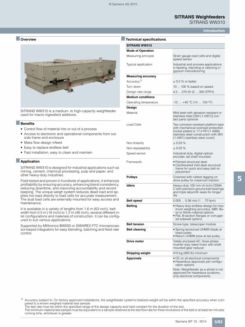
5/83Siemens WT 10 · 2014
SITRANS WeighfeedersSITRANS WW310
Introduction
5
■ Overview 1)
SITRANS WW310 is a medium- to high-capacity weighfeeder used for macro ingredient additives.
■ Benefits
• Control flow of material into or out of a process• Access to electronic and operational components from out-
side frame and enclosure• Mass flow design infeed • Easy to replace endless belt• Fast installation, easy to clean and maintain
■ Application
SITRANS WW310 is designed for industrial applications such as mining, cement, chemical processing, pulp and paper, and other heavy-duty industries.
Field tested and proven in hundreds of applications, it enhances profitability by ensuring accuracy, enhancing blend consistency, reducing downtime, and improving accountability and record keeping. The unique weigh system reduces dead load and ap-plies live load directly to load cells for accurate measurement. The dual load cells are externally mounted for easy access and maintenance.
It is available in a variety of lengths from 1.6 m (63 inch), belt width from 0.5 m (18 inch) to 1.2 m (48 inch), several different in-let configurations and materials of construction. It can be config-ured to suit various applications.
Supported by Milltronics BW500 or SIWAREX FTC microproces-sor-based integrators for easy blending, batching and feed rate control.
■ Technical specifications
1) Accuracy subject to: On factory approved installations, the weighfeeder system’s totalized weight will be within the specified accuracy when com-pared to a known weighed material test sample. The test rate must be within the specified range of the design capacity and held constant for the duration of the test. The minimum material test sample must be equivalent to a sample obtained at the test flow rate for three revolutions of the belt or at least ten minutes running time, whichever is greater.
SITRANS WW310
Mode of Operation
Measuring principle Strain gauge load cells and digital speed sensor
Typical application Industrial and process applications in feeding, blending or rationing in gypsum manufacturing
Measuring accuracy
Accuracy1) ± 0.5 % or better
Turn down 10 ... 100 % based on speed
Design rate range 4.5 ... 270 t/h (5 ... 300 STPH)
Medium conditions
Operating temperature -10 … +40 °C (14 … 104 °F)
Design
Material Mild steel with abrasion resistant or stainless steel [304 (1.4301)] con-tact parts optional
Load Cells Two corrosion-resistant platform type with mechanical overload protection [nickel plated or 17-4 PH (1.4568) stainless steel construction with 304 (1.4301) stainless steel cover]
Non-linearity ± 0.03 %
Non-repeatability ± 0.02 %
Speed sensor Industrial duty, digital optical encoder, tail shaft mounted
Framework • Painted structural steel• Cantilevered mild steel structural
frame for quick and easy belt re-placement
Pulleys Crowned with rubber lagging on drive pulley for maximum traction
Idlers Heavy-duty 100 mm (4 inch) CEMA C with precision ground ball bearings and triple labyrinth seals for longer life
Belt speed 0.005 ... 0.36 m/s (1 ... 70 fpm)
Belting • Heavy duty endless design for max-imum weighing accuracy. SBR, Bu-tyl or Nitrile material options
• Flat, B-section flanges or corrugat-ed sidewall options
Belt tension Screw type, telescoper module
Belt cleaning • Spring tensioned UHMW blade at head pulley
• Return UHMW plow at tail pulley
Drive motor Totally enclosed AC, three phase inverter duty rated motor with shaft mounted gear reducer
Shipping weight 410 kg (900 lb) minimum
Approvals • CE on all electrical components• Hazardous approvals per configu-
ration optionsNote: Weighfeeder as a whole is not approved for hazardous locations, only electrical components.
© Siemens AG 2015
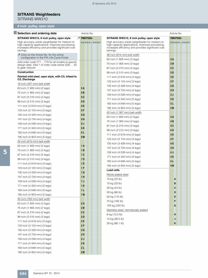
5/84 Siemens WT 10 · 2014
SITRANS WeighfeedersSITRANS WW310
8 inch pulley, open style
5
■ Selection and ordering data Article No. Article No.
SITRANS WW310, 8 inch pulley, open styleHigh accuracy solids weighfeeder for medium to high capacity applications. Improves processing, increases efficiency and provides significant cost savings.
7MH7550-
77777 - 7777
Click on the Article No. for the online configuration in the PIA Life Cycle Portal.
Add order code Y71 ... Y75 for all models to specify design data. Add 1 of order code series G30 ... 34 to gear reducer
Construction
Painted mild steel, open style, with C/L Infeed to C/L Discharge
18 inch (457 mm) belt width
63 inch (1 600 mm) (2 legs) 0 A
75 inch (1 905 mm) (2 legs) 0 B
87 inch (2 210 mm) (2 legs) 0 C
99 inch (2 515 mm) (3 legs) 0 D
111 inch (2 819 mm) (3 legs) 0 E
123 inch (3 124 mm) (3 legs) 0 F
135 inch (3 429 mm) (4 legs) 0 G
147 inch (3 734 mm) (4 legs) 0 H
159 inch (4 039 mm) (4 legs) 0 J
171 inch (4 343 mm) (5 legs) 0 K
183 inch (4 648 mm) (5 legs) 0 L
195 inch (4 953 mm) (5 legs) 0 M
24 inch (610 mm) belt width
63 inch (1 600 mm) (2 legs) 1 A
75 inch (1 905 mm) (2 legs) 1 B
87 inch (2 210 mm) (2 legs) 1 C
99 inch (2 515 mm) (3 legs) 1 D
111 inch (2 819 mm) (3 legs) 1 E
123 inch (3 124 mm) (3 legs) 1 F
135 inch (3 429 mm) (4 legs) 1 G
147 inch (3 734 mm) (4 legs) 1 H
159 inch (4 039 mm) (4 legs) 1 J
171 inch (4 343 mm) (5 legs) 1 K
183 inch (4 648 mm) (5 legs) 1 L
195 inch (4 953 mm) (5 legs) 1 M
30 inch (762 mm) belt width
63 inch (1 600 mm) (2 legs) 2 A
75 inch (1 905 mm) (2 legs) 2 B
87 inch (2 210 mm) (2 legs) 2 C
99 inch (2 515 mm) (3 legs) 2 D
111 inch (2 819 mm) (3 legs) 2 E
123 inch (3 124 mm) (3 legs) 2 F
135 inch (3 429 mm) (4 legs) 2 G
147 inch (3 734 mm) (4 legs) 2 H
159 inch (4 039 mm) (4 legs) 2 J
171 inch (4 343 mm) (5 legs) 2 K
183 inch (4 648 mm) (5 legs) 2 L
195 inch (4 953 mm) (5 legs) 2 M
SITRANS WW310, 8 inch pulley, open styleHigh accuracy solids weighfeeder for medium to high capacity applications. Improves processing, increases efficiency and provides significant cost savings.
7MH7550-
77777 - 7777
36 inch (914 mm) belt width
63 inch (1 600 mm) (2 legs) 3 A
75 inch (1 905 mm) (2 legs) 3 B
87 inch (2 210 mm) (2 legs) 3 C
99 inch (2 515 mm) (3 legs) 3 D
111 inch (2 819 mm) (3 legs) 3 E
123 inch (3 124 mm) (3 legs) 3 F
135 inch (3 429 mm) (4 legs) 3 G
147 inch (3 734 mm) (4 legs) 3 H
159 inch (4 039 mm) (4 legs) 3 J
171 inch (4 343 mm) (5 legs) 3 K
183 inch (4 648 mm) (5 legs) 3 L
195 inch (4 953 mm) (5 legs) 3 M
42 inch (1 067 mm) belt width
63 inch (1 600 mm) (2 legs) 4 A
75 inch (1 905 mm) (2 legs) 4 B
87 inch (2 210 mm) (2 legs) 4 C
99 inch (2 515 mm) (3 legs) 4 D
111 inch (2 819 mm) (3 legs) 4 E
123 inch (3 124 mm) (3 legs) 4 F
135 inch (3 429 mm) (4 legs) 4 G
147 inch (3 734 mm) (4 legs) 4 H
159 inch (4 039 mm) (4 legs) 4 J
171 inch (4 343 mm) (5 legs) 4 K
183 inch (4 648 mm) (5 legs) 4 L
195 inch (4 953 mm) (5 legs) 4 M
Load cells
Nickel plated steel
10 kg (22 lb) A
15 kg (33 lb) B
20 kg (44 lb) C
30 kg (66 lb) D
50 kg (110 lb) E
75 kg (165 lb) F
100 kg (220 lb) G
Stainless steel, hermetically sealed
6 kg (13.2 lb) H
12 kg (26.5 lb) J
30 kg (66.1 lb) K
© Siemens AG 2015

5/85Siemens WT 10 · 2014
SITRANS WeighfeedersSITRANS WW310
8 inch pulley, open style
5
■ Selection and ordering data Article No. Article No.
SITRANS WW310, 8 inch pulley, open styleHigh accuracy solids weighfeeder for medium to high capacity applications. Improves processing, increases efficiency and provides significant cost savings.
7MH7550-
77777 - 7777
Material containment construction
None 0
Add order code Y74 and plain text: “Arc radius in inches …XX.XXX inch”
Shear gate inlet
Mild steel (no skirtboards) 1
AR400 steel (no skirtboards) 2
304 stainless steel (no skirtboards) 3
Skirtboards mild steel 4
Skirtboards AR400 steel 5
Skirtboards 304 stainless steel 6
Speed sensor
Shaft mounted
500 PPR optical encoder 0
1 000 PPR optical encoder 1
2 500 PPR optical encoder 2
32 PPR WS300, CSA/FM/ATEX/IEC Ex 3
256 PPR WS300, CSA/FM/ATEX/IEC Ex 4
1 000 PPR shaft mounted WS300, CSA/FM/ATEX/IEC Ex
5
2 000 PPR WS300 6
Motor mounted
60 PPR magnetic p/u 7
Drive Configuration
Add order code Y75 reduction ratio in plain text: “X:1”.
Standard AC motor
0.25 HP (0.19 KW) 220 … 240/380 … 480 V 3 ph 50/60 Hz
0 A
0.25 HP (0.19 KW) 575 V 3 ph 60 Hz 0 B
0.5 HP (0.37 KW) 220 … 240/380 … 480 V 3 ph 50/60 Hz
0 C
0.5 HP (0.37 KW) 575 V 3 ph 60 Hz 0 D
0.75 HP (0.56 KW) 220 … 240/380 … 480 V 3 ph 50/60 Hz
0 E
0.75 HP (0.56 KW) 575 V 3 ph 60 Hz 0 F
1 HP (0.75 KW) 220 … 240/380 … 480 V 3 ph 50/60 Hz
0 G
1 HP (0.75 KW) 575 V 3 ph 60 Hz 0 H
1.5 HP (1.12 KW) 220 … 240/380 … 480 V 3 ph 50/60 Hz
0 J
1.5 HP (1.12 KW) 575 V 3 ph 60 Hz 0 K
3 HP (2.24 KW) 220 … 240/380 … 480 V 3 ph 50/60 Hz
0 L
3 HP (2.24 KW) 575 V 3 ph 60 Hz 0 M
5 HP (3.73 KW) 220 … 240/380 … 480 V 3 ph 50/60 Hz
0 N
5 HP (3.73 KW) 575 V 3 ph 60 Hz 0 P
SITRANS WW310, 8 inch pulley, open styleHigh accuracy solids weighfeeder for medium to high capacity applications. Improves processing, increases efficiency and provides significant cost savings.
7MH7550-
77777 - 7777
Class I, Div. 1, Groups C and D, Class II, Div. 1, Groups F and G, AC motor
0.25 HP (0.19 KW) 220 … 240/380 … 480 V 3 ph 50/60 Hz
1 A
0.25 HP (0.19 KW) 575 V 3 ph 60 Hz 1 B
0.5 HP (0.37 KW) 220 … 240/380 … 480 V 3 ph 50/60 Hz
1 C
0.5 HP (0.37 KW) 575 V 3 ph 60 Hz 1 D
0.75 HP (0.56 KW) 220 … 240/380 … 480 V 3 ph 50/60 Hz
1 E
0.75 HP (0.56 KW) 575 V 3 ph 60 Hz 1 F
1 HP (0.75 KW) 220 … 240/380 … 480 V 3 ph 50/60 Hz
1 G
1 HP (0.75 KW) 575 V 3 ph 60 Hz 1 H
1.5 HP (1.12 KW) 220 … 240/380 … 480 V 3 ph 50/60 Hz
1 J
1.5 HP (1.12 KW) 575 V 3 ph 60 Hz 1 K
3 HP (2.24 KW) 220 … 240/380 … 480 V 3 ph 50/60 Hz
1 L
3 HP (2.24 KW) 575 V 3 ph 60 Hz 1 M
5 HP (3.73 KW) 220 … 240/380 … 480 V 3 ph 50/60 Hz
1 N
5 HP (3.73 KW) 575 V 3 ph 60 Hz 1 P
ATEX II 2D, AC motor
0.25 HP (0.19 KW) 220 … 240/380 … 480 V 3 ph 50/60 Hz
2 A
0.5 HP (0.37 KW) 220 … 240/380 … 480 V 3 ph 50/60 Hz
2 B
0.75 HP (0.56 KW) 220 … 240/380 … 480 V 3 ph 50/60 Hz
2 C
1 HP (0.75 KW) 220 … 240/380 … 480 V 3 ph 50/60 Hz
2 D
1.5 HP (1.12 KW) 220 … 240/380 … 480 V 3 ph 50/60 Hz
2 E
3 HP (2.24 KW) 220 … 240/380 … 480 V 3 ph 50/60 Hz
2 F
5 HP (3.73 KW) 220 … 240/380 … 480 V 3 ph 50/60 Hz
2 G
Belting
SBR,150 PIW
2 ply A
2 ply with B-section flange walls B
2 ply with 1 inch (25 mm) flange walls C
2 ply with 2 inch (50 mm) corrugated side walls D
Butyl, 90 PIW
3 ply HT 150 °C (300 °F) E
3 ply with B-section flange walls HT 150 °C (300 °F) F
3 ply with 1 inch (25 mm) flange walls HT 150 °C (300 °F)
G
3 ply with 2 inch (50 mm) corrugated side walls HT 150 °C (300 °F)
H
© Siemens AG 2015

5/86 Siemens WT 10 · 2014
SITRANS WeighfeedersSITRANS WW310
8 inch pulley, open style
5
■ Selection and ordering data Article No. Order Code
SITRANS WW310, 8 inch pulley, open styleHigh accuracy solids weighfeeder for medium to high capacity applications. Improves processing, increases efficiency and provides significant cost savings.
7MH7550-
77777 - 7777
Nitrile, 135 PIW
3 ply J
3 ply with B-section flange walls K
3 ply with 1 inch (25 mm) flange walls L
3 ply with 2 inch (50 mm) corrugated side walls M
Belt change access Side (From inlet to discharge)
Left hand 0
Right hand 1
Further designs Order Code
Please add "-Z" to article no. and specify order code(s).
Shear gate arc radius
Shear gate arc radius: Enter shear gate arc radius in inches (xxx.xx inch)
Y74(xxx.xx inch)
Application data
Enter design units (TPH, MTPH, lb/h, kg/h) Y71
Enter design speed (ft/m, m/s) Y72
Enter design capacity/rate Y73
AC gearmotor reduction ratio
AC gearmotor reduction ratio: Enter reduction ratio in plain text (X:1)
Y75 (X:1)
Custom length
Select next longest option and specify infeed CL to discharge CL in plain text (indicated inches or milli-meters)
Y01
Gear reducer (select only one)
KAZ48 G30
KAZ68 G31
Infeed idler style (if CEMA C is not acceptable) only one option per configuration
CEMA D style G60
CEMA E style G61
Carrying idler style (if CEMA C is not acceptable) only one option per configuration
CEMA D style G65
CEMA E style G66
Hazardous location approved tracking switches
Class I, Div. 1, groups C and D, Class II, Div. 1, groups F and G
E90
ATEX II 2D E91
Safety pull cord switches
1 pull cord on each side of weighfeeder for emergency shut down activation/alarm
G70
Skirtboard seals for floodable materials
SBR adjustable skirtboard seals to contain material G72
Shear curtain for dusty applications and floodable materials
G11
Secondary speed detection for differential monitoring
60 PPR motor mounted magnetic p/u (available with speed sensor options 0 ... 6 only)
G16
Plugged discharge chute detection
CLS100 Capacitance switch G12
Local push button station
Siemens Start, stop, auto/manual, speed control, E-stop hand held operator
G13
Factory test
2.2 test Certificate C11
Tagging
Stainless steel, laser engraved mounted name-plate, enter data to appear on nameplate
Y15
Discharge dust hood
Painted mild steel with de-dust port H50
Custom designSpecify quote reference when ordering
Y99
Operating instructions Article No.
• English A5E33490433
Note: The operating instructions should be ordered as a separate item on the order. This device is shipped with the Siemens Milltronics manual DVD containing the complete operating instructions library.
© Siemens AG 2015

5/87Siemens WT 10 · 2014
SITRANS WeighfeedersSITRANS WW310
8 Inch pulley, enclosed style
5
■ Selection and ordering data Article No. Article No.
SITRANS WW310, 8 inch pulley, enclosed styleHigh accuracy solids weighfeeder for medium to high capacity applications. Improves processing, increases efficiency and provides significant cost savings.
7MH7551-
77777 - 7777
Click on the Article No. for the online configuration in the PIA Life Cycle Portal.
Add order code Y71 ... Y75 for all models to specify design data. Add 1 of order code series G30 ... 34 to gear reducer
Construction
Painted mild steel enclosed style with C/L Infeed to C/L Discharge
18 inch (457 mm) belt width
63 inch (1 600 mm) (2 legs) 0 A
75 inch (1 905 mm) (2 legs) 0 B
87 inch (2 210 mm) (2 legs) 0 C
99 inch (2 515 mm) (3 legs) 0 D
111 inch (2 819 mm) (3 legs) 0 E
123 inch (3 124 mm) (3 legs) 0 F
135 inch (3 429 mm) (4 legs) 0 G
147 inch (3 734 mm) (4 legs) 0 H
159 inch (4 039 mm) (4 legs) 0 J
171 inch (4 343 mm) (5 legs) 0 K
183 inch (4 648 mm) (5 legs) 0 L
195 inch (4 953 mm) (5 legs) 0 M
24 inch (610 mm) belt width
63 inch (1 600 mm) (2 legs) 1 A
75 inch (1 905 mm) (2 legs) 1 B
87 inch (2 210 mm) (2 legs) 1 C
99 inch (2 515 mm) (3 legs) 1 D
111 inch (2 819 mm) (3 legs) 1 E
123 inch (3 124 mm) (3 legs) 1 F
135 inch (3 429 mm) (4 legs) 1 G
147 inch (3 734 mm) (4 legs) 1 H
159 inch (4 039 mm) (4 legs) 1 J
171 inch (4 343 mm) (5 legs) 1 K
183 inch (4 648 mm) (5 legs) 1 L
195 inch (4 953 mm) (5 legs) 1 M
30 inch (762 mm) belt width
63 inch (1 600 mm) (2 legs) 2 A
75 inch (1 905 mm) (2 legs) 2 B
87 inch (2 210 mm) (2 legs) 2 C
99 inch (2 515 mm) (3 legs) 2 D
111 inch (2 819 mm) (3 legs) 2 E
123 inch (3 124 mm) (3 legs) 2 F
135 inch (3 429 mm) (4 legs) 2 G
147 inch (3 734 mm) (4 legs) 2 H
159 inch (4 039 mm) (4 legs) 2 J
171 inch (4 343 mm) (5 legs) 2 K
183 inch (4 648 mm) (5 legs) 2 L
195 inch (4 953 mm) (5 legs) 2 M
SITRANS WW310, 8 inch pulley, enclosed styleHigh accuracy solids weighfeeder for medium to high capacity applications. Improves processing, increases efficiency and provides significant cost savings.
7MH7551-
77777 - 7777
36 inch (914 mm) belt width
63 inch (1 600 mm) (2 legs) 3 A
75 inch (1 905 mm) (2 legs) 3 B
87 inch (2 210 mm) (2 legs) 3 C
99 inch (2 515 mm) (3 legs) 3 D
111 inch (2 819 mm) (3 legs) 3 E
123 inch (3 124 mm) (3 legs) 3 F
135 inch (3 429 mm) (4 legs) 3 G
147 inch (3 734 mm) (4 legs) 3 H
159 inch (4 039 mm) (4 legs) 3 J
171 inch (4 343 mm) (5 legs) 3 K
183 inch (4 648 mm) (5 legs) 3 L
195 inch (4 953 mm) (5 legs) 3 M
42 inch (1067 mm) belt width
63 inch (1 600 mm) (2 legs) 4 A
75 inch (1 905 mm) (2 legs) 4 B
87 inch (2 210 mm) (2 legs) 4 C
99 inch (2 515 mm) (3 legs) 4 D
111 inch (2 819 mm) (3 legs) 4 E
123 inch (3 124 mm) (3 legs) 4 F
135 inch (3 429 mm) (4 legs) 4 G
147 inch (3 734 mm) (4 legs) 4 H
159 inch (4 039 mm) (4 legs) 4 J
171 inch (4 343 mm) (5 legs) 4 K
183 inch (4 648 mm) (5 legs) 4 L
195 inch (4 953 mm) (5 legs) 4 M
Load cells
Nickel plated steel
10 kg (22 lb) A
15 kg (33 lb) B
20 kg (44 lb) C
30 kg (66 lb) D
50 kg (110 lb) E
75 kg (165 lb) F
100 kg (220 lb) G
Stainless steel, hermetically sealed
6 kg (13.2 lb) H
12 kg (26.5 lb) J
30 kg (66.1 lb) K
© Siemens AG 2015

5/88 Siemens WT 10 · 2014
SITRANS WeighfeedersSITRANS WW310
8 Inch pulley, enclosed style
5
■ Selection and ordering data Article No. Article No.
SITRANS WW310, 8 inch pulley, enclosed styleHigh accuracy solids weighfeeder for medium to high capacity applications. Improves processing, increases efficiency and provides significant cost savings.
7MH7551-
77777 - 7777
Material containment construction
None 0
Add order code Y74 and plain text: “Arc radius in inches …XX.XXX inch”
Shear gate inlet
Mild steel (no skirtboards) 1
AR400 steel (no skirtboards) 2
304 stainless steel (no skirtboards) 3
Skirtboards mild steel 4
Skirtboards AR400 steel 5
Skirtboards 304 stainless steel 6
Speed sensor
Shaft mounted
500 PPR optical encoder 0
1 000 PPR optical encoder 1
2 500 PPR optical encoder 2
32 PPR WS300, CSA/FM/ATEX/IEC Ex 3
256 PPR WS300, CSA/FM/ATEX/IEC Ex 4
1 000 PPR WS300, CSA/FM/ATEX/IEC Ex 5
2 000 PPR WS300 6
Motor mounted
60 PPR magnetic p/u 7
Drive Configuration
Add order code Y75 reduction ratio in plain text: “X:1”.
Standard AC motor
0.25 HP (0.19 KW) 220 … 240/380 … 480 V 3 ph 50/60 Hz
0 A
0.25 HP (0.19 KW) 575 V 3 ph 60 Hz 0 B
0.5 HP (0.37 KW) 220 … 240/380 … 480 V 3 ph 50/60 Hz
0 C
0.5 HP (0.37 KW) 575 V 3 ph 60 Hz 0 D
0.75 HP (0.56 KW) 220 … 240/380 … 480 V 3 ph 50/60 Hz
0 E
0.75 HP (0.56 KW) 575 V 3 ph 60 Hz 0 F
1 HP (0.75 KW) 220 … 240/380 … 480 V 3 ph 50/60 Hz
0 G
1 HP (0.75 KW) 575 V 3 ph 60 Hz 0 H
1.5 HP (1.12 KW) 220 … 240/380 … 480 V 3 ph 50/60 Hz
0 J
1.5 HP (1.12 KW) 575 V 3 ph 60 Hz 0 K
3 HP (2.24 KW) 220 … 240/380 … 480 V 3 ph 50/60 Hz
0 L
3 HP (2.24 KW) 575 V 3 ph 60 Hz 0 M
5 HP (3.73 KW) 220 … 240/380 … 480 V 3 ph 50/60 Hz
0 N
5 HP (3.73 KW) 575 V 3 ph 60 Hz 0 P
Class I, Div. 1, Groups C and D, Class II, Div. 1, Groups F and G, AC motor
0.25 HP (0.19 KW) 220 … 240/380 … 480 V 3 ph 50/60 Hz
1 A
0.25 HP (0.19 KW) 575 V 3 ph 60 Hz 1 B
SITRANS WW310, 8 inch pulley, enclosed styleHigh accuracy solids weighfeeder for medium to high capacity applications. Improves processing, increases efficiency and provides significant cost savings.
7MH7551-
77777 - 7777
0.5 HP (0.37 KW) 220 … 240/380 … 480 V 3 ph 50/60 Hz
1 C
0.5 HP (0.37 KW) 575 V 3 ph 60 Hz 1 D
0.75 HP (0.56 KW) 220 … 240/380 … 480 V 3 ph 50/60 Hz
1 E
0.75 HP (0.56 KW) 575 V 3 ph 60 Hz 1 F
1 HP (0.75 KW) 220 … 240/380 … 480 V 3 ph 50/60 Hz
1 G
1 HP (0.75 KW) 575 V 3 ph 60 Hz 1 H
1.5 HP (1.12 KW) 220 … 240/380 … 480 V 3 ph 50/60 Hz
1 J
1.5 HP (1.12 KW) 575 V 3 ph 60 Hz 1 K
3 HP (2.24 KW) 220 … 240/380 … 480 V 3 ph 50/60 Hz
1 L
3 HP (2.24 KW) 575 V 3 ph 60 Hz 1 M
5 HP (3.73 KW) 220 … 240/380 … 480 V 3 ph 50/60 Hz
1 N
5 HP (3.73 KW) 575 V 3 ph 60 Hz 1 P
ATEX II 2D, AC motor
0.25 HP (0.19 KW) 220 … 240/380 … 480 V 3 ph 50/60 Hz
2 A
0.5 HP (0.37 KW) 220 … 240/380 … 480 V 3 ph 50/60 Hz
2 B
0.75 HP (0.56 KW) 220 … 240/380 … 480 V 3 ph 50/60 Hz
2 C
1 HP (0.75 KW) 220 … 240/380 … 480 V 3 ph 50/60 Hz
2 D
1.5 HP (1.12 KW) 220 … 240/380 … 480 V 3 ph 50/60 Hz
2 E
3 HP (2.24 KW) 220 … 240/380 … 480 V 3 ph 50/60 Hz
2 F
5 HP (3.73 KW) 220 … 240/380 … 480 V 3 ph 50/60 Hz
2 G
Belting
SBR,150 PIW
2 ply A
2 ply with B-section flange walls B
2 ply with 1 inch (25 mm) flange walls C
2 ply with 2 inch (50 mm) corrugated side walls D
Butyl, 90 PIW
3 ply HT 150 °C (300 °F) E
3 ply with B-section flange walls HT 150 °C (300 °F) F
3 ply with 1 inch (25 mm) flange walls HT 150 °C (300 °F)
G
3 ply with 2 inch (50 mm) corrugated side walls HT 150 °C (300 °F)
H
Nitrile, 135 PIW
3 ply J
3 ply with B-section flange walls K
3 ply with 1 inch (25 mm) flange walls L
3 ply with 2 inch (50 mm) corrugated side walls M
Belt change access Side (From inlet to discharge)
Left hand 0
Right hand 1
© Siemens AG 2015

5/89Siemens WT 10 · 2014
SITRANS WeighfeedersSITRANS WW310
8 Inch pulley, enclosed style
5
■ Selection and ordering data Order Code Order Code
Further designs
Please add "-Z" to article no. and specify order code(s).
Shear gate arc radius
Shear gate arc radius: Enter shear gate arc radius in inches (xxx.xx inch)
Y74(xxx.xx inch)
Application data
Enter design units (TPH, MTPH, lb/h, kg/h) Y71
Enter design speed (ft/m, m/s) Y72
Enter design capacity/rate Y73
AC gearmotor reduction ratio
AC gearmotor reduction ratio: Enter reduction ratio in plain text (X:1)
Y75 (X:1)
Custom length
Select next longest option and specify infeed CL to discharge CL in plain text (indicated inches or millimeters)
Y01
Gear reducer (select only one)
KAZ48 G30
KAZ68 G31
Bottom covers
18 inch Belt width G40
24 inch Belt width G41
30 inch Belt width G42
36 inch Belt width G43
42 inch Belt width G44
Infeed idler style (if CEMA C is not acceptable) only one option per configuration
CEMA D style G60
CEMA E style G61
Carrying idler style (if CEMA C is not acceptable) only one option per configuration
CEMA D style G65
CEMA E style G66
Hazardous location approved tracking switches
Class I, Div. 1, groups C and D, Class II, Div. 1, groups F and G
E90
ATEX II 2D E91
Safety pull cord switches
1 pull cord on each side of weighfeeder for emergency shut down activation/alarm
G70
Skirtboard seals for floodable materials
SBR adjustable skirtboard seals to contain material G72
Shear curtain for dusty applications and floodable materials
G11
Secondary speed detection for differential monitoring
60 PPR motor mounted magnetic p/u (available with speed sensor options 0 ... 6 only)
G16
Plugged discharge chute detection
CLS100 Capacitance switch G12
Local push button station
Siemens Start, stop, auto/manual, speed control, E-stop hand held operator
G13
Factory test
2.2 test Certificate C11
Tagging
Stainless steel, laser engraved mounted nameplate, enter data to appear on nameplate
Y15
Custom designSpecify quote reference when ordering
Y99
Operating instructions Article No.
• English A5E33490433
Note: The operating instructions should be ordered as a separate item on the order. This device is shipped with the Siemens Milltronics manual DVD containing the complete operating instructions library.
© Siemens AG 2015
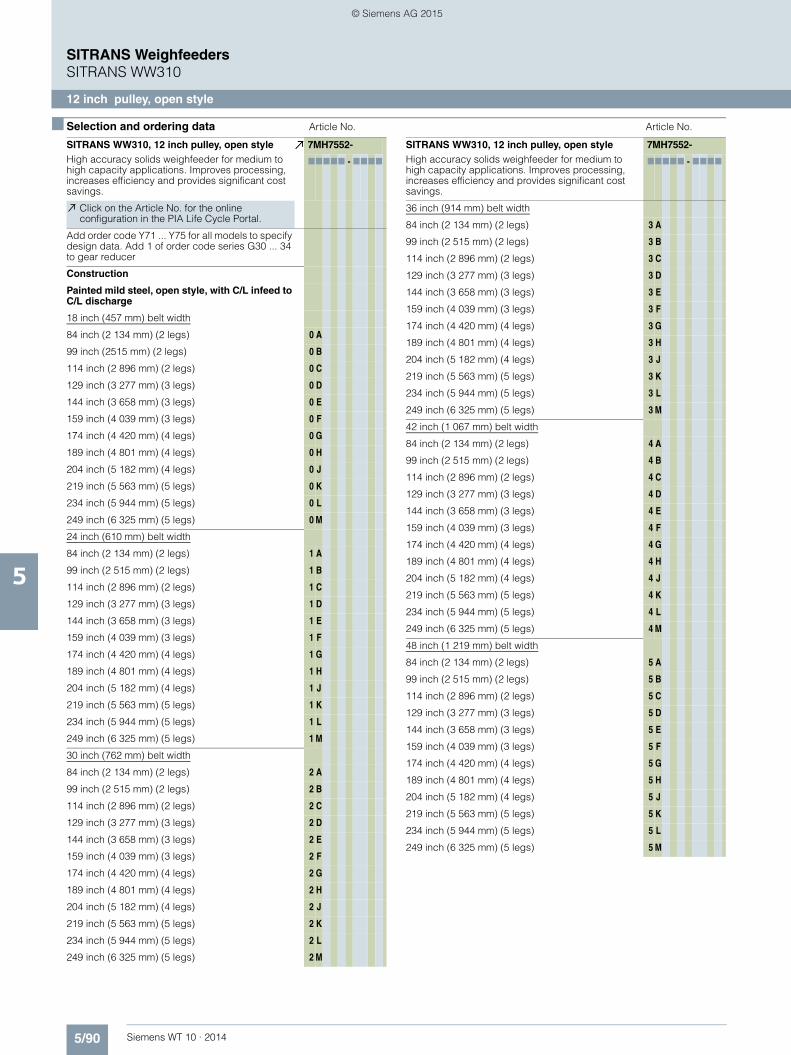
5/90 Siemens WT 10 · 2014
SITRANS WeighfeedersSITRANS WW310
12 inch pulley, open style
5
■ Selection and ordering data Article No. Article No.
SITRANS WW310, 12 inch pulley, open styleHigh accuracy solids weighfeeder for medium to high capacity applications. Improves processing, increases efficiency and provides significant cost savings.
7MH7552-
77777 - 7777
Click on the Article No. for the online configuration in the PIA Life Cycle Portal.
Add order code Y71 ... Y75 for all models to specify design data. Add 1 of order code series G30 ... 34 to gear reducer
Construction
Painted mild steel, open style, with C/L infeed to C/L discharge
18 inch (457 mm) belt width
84 inch (2 134 mm) (2 legs) 0 A
99 inch (2515 mm) (2 legs) 0 B
114 inch (2 896 mm) (2 legs) 0 C
129 inch (3 277 mm) (3 legs) 0 D
144 inch (3 658 mm) (3 legs) 0 E
159 inch (4 039 mm) (3 legs) 0 F
174 inch (4 420 mm) (4 legs) 0 G
189 inch (4 801 mm) (4 legs) 0 H
204 inch (5 182 mm) (4 legs) 0 J
219 inch (5 563 mm) (5 legs) 0 K
234 inch (5 944 mm) (5 legs) 0 L
249 inch (6 325 mm) (5 legs) 0 M
24 inch (610 mm) belt width
84 inch (2 134 mm) (2 legs) 1 A
99 inch (2 515 mm) (2 legs) 1 B
114 inch (2 896 mm) (2 legs) 1 C
129 inch (3 277 mm) (3 legs) 1 D
144 inch (3 658 mm) (3 legs) 1 E
159 inch (4 039 mm) (3 legs) 1 F
174 inch (4 420 mm) (4 legs) 1 G
189 inch (4 801 mm) (4 legs) 1 H
204 inch (5 182 mm) (4 legs) 1 J
219 inch (5 563 mm) (5 legs) 1 K
234 inch (5 944 mm) (5 legs) 1 L
249 inch (6 325 mm) (5 legs) 1 M
30 inch (762 mm) belt width
84 inch (2 134 mm) (2 legs) 2 A
99 inch (2 515 mm) (2 legs) 2 B
114 inch (2 896 mm) (2 legs) 2 C
129 inch (3 277 mm) (3 legs) 2 D
144 inch (3 658 mm) (3 legs) 2 E
159 inch (4 039 mm) (3 legs) 2 F
174 inch (4 420 mm) (4 legs) 2 G
189 inch (4 801 mm) (4 legs) 2 H
204 inch (5 182 mm) (4 legs) 2 J
219 inch (5 563 mm) (5 legs) 2 K
234 inch (5 944 mm) (5 legs) 2 L
249 inch (6 325 mm) (5 legs) 2 M
SITRANS WW310, 12 inch pulley, open styleHigh accuracy solids weighfeeder for medium to high capacity applications. Improves processing, increases efficiency and provides significant cost savings.
7MH7552-
77777 - 7777
36 inch (914 mm) belt width
84 inch (2 134 mm) (2 legs) 3 A
99 inch (2 515 mm) (2 legs) 3 B
114 inch (2 896 mm) (2 legs) 3 C
129 inch (3 277 mm) (3 legs) 3 D
144 inch (3 658 mm) (3 legs) 3 E
159 inch (4 039 mm) (3 legs) 3 F
174 inch (4 420 mm) (4 legs) 3 G
189 inch (4 801 mm) (4 legs) 3 H
204 inch (5 182 mm) (4 legs) 3 J
219 inch (5 563 mm) (5 legs) 3 K
234 inch (5 944 mm) (5 legs) 3 L
249 inch (6 325 mm) (5 legs) 3 M
42 inch (1 067 mm) belt width
84 inch (2 134 mm) (2 legs) 4 A
99 inch (2 515 mm) (2 legs) 4 B
114 inch (2 896 mm) (2 legs) 4 C
129 inch (3 277 mm) (3 legs) 4 D
144 inch (3 658 mm) (3 legs) 4 E
159 inch (4 039 mm) (3 legs) 4 F
174 inch (4 420 mm) (4 legs) 4 G
189 inch (4 801 mm) (4 legs) 4 H
204 inch (5 182 mm) (4 legs) 4 J
219 inch (5 563 mm) (5 legs) 4 K
234 inch (5 944 mm) (5 legs) 4 L
249 inch (6 325 mm) (5 legs) 4 M
48 inch (1 219 mm) belt width
84 inch (2 134 mm) (2 legs) 5 A
99 inch (2 515 mm) (2 legs) 5 B
114 inch (2 896 mm) (2 legs) 5 C
129 inch (3 277 mm) (3 legs) 5 D
144 inch (3 658 mm) (3 legs) 5 E
159 inch (4 039 mm) (3 legs) 5 F
174 inch (4 420 mm) (4 legs) 5 G
189 inch (4 801 mm) (4 legs) 5 H
204 inch (5 182 mm) (4 legs) 5 J
219 inch (5 563 mm) (5 legs) 5 K
234 inch (5 944 mm) (5 legs) 5 L
249 inch (6 325 mm) (5 legs) 5 M
© Siemens AG 2015

5/91Siemens WT 10 · 2014
SITRANS WeighfeedersSITRANS WW310
12 inch pulley, open style
5
■ Selection and ordering data Article No. Article No.
SITRANS WW310, 12 inch pulley, open styleHigh accuracy solids weighfeeder for medium to high capacity applications. Improves processing, increases efficiency and provides significant cost savings.
7MH7552-
77777 - 7777
Load cells
23 kg (50 lb) stainless steel, MSI, Class II, Div. 1 Groups E, F, and G, Class III/ Atex II 2D Ex tD A21 IP65 T70 °C
A
45 kg (100 lb) stainless steel, MSI, Class II, Div. 1 Groups E, F, and G, Class III/ Atex II 2D Ex tD A21 IP65 T70 °C
B
113 kg (250 lb) stainless steel, MSI, Class II, Div. 1 Groups E, F, and G, Class III/ Atex II 2D Ex tD A21 IP65 T70 °C
C
Material containment construction
None 0
Add order code Y74 and plain text: “Arc radius in inches …XX.XXX inch”
Shear gate inlet
Mild steel (no skirtboards) 1
AR400 steel (no skirtboards) 2
304 stainless steel (no skirtboards) 3
Skirtboards mild steel 4
Skirtboards AR400 steel 5
Skirtboards 304 stainless steel 6
Speed sensor
Shaft mounted
500 PPR optical encoder 0
1 000 PPR optical encoder 1
2 500 PPR optical encoder 2
32 PPR WS300, CSA/FM/ATEX/IEC Ex 3
256 PPR WS300, CSA/FM/ATEX/IEC Ex 4
1 000 PPR WS300, CSA/FM/ATEX/IEC Ex 5
2 000 PPR WS300 6
Motor mounted
60 PPR magnetic p/u 7
Drive Configuration
Add order code Y75 reduction ratio in plain text: “X:1”.
Standard AC motor
0.25 HP (0.19 KW) 220 … 240/380 … 480 V 3 ph 50/60 Hz
0 A
0.25 HP (0.19 KW) 575 V 3 ph 60 Hz 0 B
0.5 HP (0.37 KW) 220 … 240/380 … 480 V 3 ph 50/60 Hz
0 C
0.5 HP (0.37 KW) 575 V 3 ph 60 Hz 0 D
0.75 HP (0.56 KW) 220 … 240/380 … 480 V 3 ph 50/60 Hz
0 E
0.75 HP (0.56 KW) 575 V 3 ph 60 Hz 0 F
1 HP (0.75 KW) 220 … 240/380 … 480 V 3 ph 50/60 Hz
0 G
1 HP (0.75 KW) 575 V 3 ph 60 Hz 0 H
1.5 HP (1.12 KW) 220 … 240/380 … 480 V 3 ph 50/60 Hz
0 J
1.5 HP (1.12 KW) 575 V 3 ph 60 Hz 0 K
SITRANS WW310, 12 inch pulley, open styleHigh accuracy solids weighfeeder for medium to high capacity applications. Improves processing, increases efficiency and provides significant cost savings.
7MH7552-
77777 - 7777
3 HP (2.24 KW) 220 … 240/380 … 480 V 3 ph 50/60 Hz
0 L
3 HP (2.24 KW) 575 V 3 ph 60 Hz 0 M
5 HP (3.73 KW) 220 … 240/380 … 480 V 3 ph 50/60 Hz
0 N
5 HP (3.73 KW) 575 V 3 ph 60 Hz 0 P
Class I, Div. 1, Groups C and D, Class II, Div. 1, Groups F and G, AC motor
0.25 HP (0.19 KW) 220 … 240/380 … 480 V 3 ph 50/60 Hz
1 A
0.25 HP (0.19 KW) 575 V 3 ph 60 Hz 1 B
0.5 HP (0.37 KW) 220 … 240/380 … 480 V 3 ph 50/60 Hz
1 C
0.5 HP (0.37 KW) 575 V 3 ph 60 Hz 1 D
0.75 HP (0.56 KW) 220 … 240/380 … 480 V 3 ph 50/60 Hz
1 E
0.75 HP (0.56 KW) 575 V 3 ph 60 Hz 1 F
1 HP (0.75 KW) 220 … 240/380 … 480 V 3 ph 50/60 Hz
1 G
1 HP (0.75 KW) 575 V 3 ph 60 Hz 1 H
1.5 HP (1.12 KW) 220 … 240/380 … 480 V 3 ph 50/60 Hz
1 J
1.5 HP (1.12 KW) 575 V 3 ph 60 Hz 1 K
3 HP (2.24 KW) 220 … 240/380 … 480 V 3 ph 50/60 Hz
1 L
3 HP (2.24 KW) 575 V 3 ph 60 Hz 1 M
5 HP (3.73 KW) 220 … 240/380 … 480 V 3 ph 50/60 Hz
1 N
5 HP (3.73 KW) 575 V 3 ph 60 Hz 1 P
ATEX II 2D, AC motor
0.25 HP (0.19 KW) 220 … 240/380 … 480 V 3 ph 50/60 Hz
2 A
0.5 HP (0.37 KW)220 … 240/380 … 480 V 3 ph 50/60 Hz
2 B
0.75 HP (0.56 KW) 220 … 240/380 … 480 V 3 ph 50/60 Hz
2 C
1 HP (0.75 KW) 220 … 240/380 … 480 V 3 ph 50/60 Hz
2 D
1.5 HP (1.12 KW) 220 … 240/380 … 480 V 3 ph 50/60 Hz
2 E
3 HP (2.24 KW) 220 … 240/380 … 480 V 3 ph 50/60 Hz
2 F
5 HP (3.73 KW) 220 … 240/380 … 480 V 3 ph 50/60 Hz
2 G
© Siemens AG 2015

5/92 Siemens WT 10 · 2014
SITRANS WeighfeedersSITRANS WW310
12 inch pulley, open style
5
■ Selection and ordering data Article No. Order Code
SITRANS WW310, 12 inch pulley, open styleHigh accuracy solids weighfeeder for medium to high capacity applications. Improves processing, increases efficiency and provides significant cost savings.
7MH7552-
77777 - 7777
Belting
SBR,150 PIW
2 ply A
2 ply with B-section flange walls B
2 ply with 1 inch (25 mm) flange walls C
2 ply with 2 inch (50 mm) corrugated side walls D
Butyl, 90 PIW
3 ply HT 150 °C (300 °F) E
3 ply with B-section flange walls HT 150 °C (300 °F) F
3 ply with 1 inch (25 mm) flange walls HT 150 °C (300 °F)
G
3 ply with 2 inch (50 mm) corrugated side walls HT 150 °C (300 °F)
H
Nitrile 135 PIW
3 ply J
3 ply with B-section flange walls K
3 ply with 1 inch (25 mm) flange walls L
3 ply with 2 inch (50 mm) corrugated side walls M
SBR, 220 PIW
2 ply N
2 ply with B-section flange walls P
2 ply with 1 inch (25 mm) flange walls Q
2 ply with 2 inch (50 mm) corrugated side walls R
Butyl, 220 PIW
2 ply HT 200 °C (400 °F) S
2 ply with B-section flange walls HT 200 °C (400 °F) T
2 ply with 1 inch (25 mm) flange walls HT 200 °C (400 °F)
U
2 ply with 2 inch (50 mm) corrugated side walls HT 200 °C (400 °F)
V
Belt change access Side (from inlet to discharge)
Left hand 0
Right hand 1
Further designs Order Code
Please add "-Z" to article no. and specify order code(s).
Shear gate arc radius
Shear gate arc radius: Enter shear gate arc radius in inches (xxx.xx inch)
Y74(xxx.xx inch)
Application data
Enter design units (TPH, MTPH, lb/h, kg/h) Y71
Enter design speed (ft/m, m/s) Y72
Enter design capacity/rate Y73
AC gearmotor reduction ratio
AC gearmotor reduction ratio: Enter reduction ratio in plain text (X:1)
Y75 (X:1)
Custom length
Select next longest option and specify infeed CL to discharge CL in plain text (indicated inches or milli-meters)
Y01
Gear reducer (select only one)
KAZ68 G31
KAZ88 G32
KAZ108 G33
KAZ128 G34
Infeed idler style (if CEMA C is not acceptable) only one option per configuration
CEMA D style G60
CEMA E style G61
Carrying idler style (if CEMA C is not acceptable) only one option per configuration
CEMA D style G65
CEMA E style G66
Hazardous location approved tracking switches
Class I, Div. 1, groups C and D, Class II, Div. 1, groups F and G
E90
ATEX II 2D E91
Safety pull cord switches
1 pull cord on each side of weighfeeder for emer-gency shut down activation/alarm
G70
Skirtboard seals for floodable materials
SBR adjustable skirtboard seals to contain material G72
Shear curtain for dusty applications and floodable materials
G11
Secondary speed detection for differential monitoring
60 PPR motor mounted magnetic p/u (available with speed sensor options 0 ... 6 only)
G16
Plugged discharge chute detection
CLS100 Capacitance switch G12
Local push button station
Siemens Start, stop, auto/manual, speed control, E-stop hand held operator
G13
Factory test
2.2 test Certificate C11
Tagging
Stainless steel, laser engraved mounted nameplate, enter data to appear on nameplate
Y15
Discharge dust hood
Painted mild steel with de-dust port H50
Custom designSpecify quote reference when ordering
Y99
Operating instructions Article No.
• English A5E33490433
Note: The operating instructions should be ordered as a separate item on the order. This device is shipped with the Siemens Milltronics manual DVD containing the complete operating instructions library.
© Siemens AG 2015

5/93Siemens WT 10 · 2014
SITRANS WeighfeedersSITRANS WW310
12 inch pulley, enclosed style
5
■ Selection and ordering data Article No. Article No.
SITRANS WW310, 12 inch pulley, enclosed styleHigh accuracy solids weighfeeder for medium to high capacity applications. Improves processing, increases efficiency and provides significant cost savings.
7MH7553-
77777 - 7777
Click on the Article No. for the online configuration in the PIA Life Cycle Portal.
Add order code Y71 ... Y75 for all models to specify design data. Add 1 of order code series G30 ... 34 to gear reducer
Construction
Painted mild steel enclosed style with C/L infeed to C/L discharge
18 inch (457 mm) belt width
84 inch (2 134 mm) (2 legs) 0 A
99 inch (2 515 mm) (2 legs) 0 B
114 inch (2 896 mm) (2 legs) 0 C
129 inch (3 277 mm) (3 legs) 0 D
144 inch (3 658 mm) (3 legs) 0 E
159 inch (4 039 mm) (3 legs) 0 F
174 inch (4 420 mm) (4 legs) 0 G
189 inch (4 801 mm) (4 legs) 0 H
204 inch (5 182 mm) (4 legs) 0 J
219 inch (5 563 mm) (5 legs) 0 K
234 inch (5 944 mm) (5 legs) 0 L
249 inch (6 325 mm) (5 legs) 0 M
24 inch (610 mm) belt width
84 inch (2 134 mm) (2 legs) 1 A
99 inch (2 515 mm) (2 legs) 1 B
114 inch (2 896 mm) (2 legs) 1 C
129 inch (3 277 mm) (3 legs) 1 D
144 inch (3 658 mm) (3 legs) 1 E
159 inch (4 039 mm) (3 legs) 1 F
174 inch (4 420 mm) (4 legs) 1 G
189 inch (4 801 mm) (4 legs) 1 H
204 inch (5 182 mm) (4 legs) 1 J
219 inch (5 563 mm) (5 legs) 1 K
234 inch (5 944 mm) (5 legs) 1 L
249 inch (6 325 mm) (5 legs) 1 M
30 inch (762 mm) belt width
84 inch (2 134 mm) (2 legs) 2 A
99 inch (2 515 mm) (2 legs) 2 B
114 inch (2 896 mm) (2 legs) 2 C
129 inch (3 277 mm) (3 legs) 2 D
144 inch (3 658 mm) (3 legs) 2 E
159 inch (4 039 mm) (3 legs) 2 F
174 inch (4 420 mm) (4 legs) 2 G
189 inch (4 801 mm) (4 legs) 2 H
204 inch (5 182 mm) (4 legs) 2 J
219 inch (5 563 mm) (5 legs) 2 K
234 inch (5 944 mm) (5 legs) 2 L
249 inch (6 325 mm) (5 legs) 2 M
SITRANS WW310, 12 inch pulley, enclosed styleHigh accuracy solids weighfeeder for medium to high capacity applications. Improves processing, increases efficiency and provides significant cost savings.
7MH7553-
77777 - 7777
36 inch (914 mm) belt width
84 inch (2 134 mm) (2 legs) 3 A
75 inch (1 905 mm) (2 legs) 3 B
87 inch (2 210 mm) (2 legs) 3 C
99 inch (2 515 mm) (3 legs) 3 D
111 inch (2 819 mm) (3 legs) 3 E
123 inch (3 124 mm) (3 legs) 3 F
135 inch (3 429 mm) (4 legs) 3 G
147 inch (3 734 mm) (4 legs) 3 H
159 inch (4 039 mm) (4 legs) 3 J
171 inch (4 343 mm) (5 legs) 3 K
183 inch (4 648 mm) (5 legs) 3 L
195 inch (4 953 mm) (5 legs) 3 M
42 inch (1067 mm) belt width
63 inch (1 600 mm) (2 legs) 4 A
75 inch (1 905 mm) (2 legs) 4 B
87 inch (2 210 mm) (2 legs) 4 C
99 inch (2 515 mm) (3 legs) 4 D
111 inch (2 819 mm) (3 legs) 4 E
123 inch (3 124 mm) (3 legs) 4 F
135 inch (3 429 mm) (4 legs) 4 G
147 inch (3 734 mm) (4 legs) 4 H
159 inch (4 039 mm) (4 legs) 4 J
171 inch (4 343 mm) (5 legs) 4 K
183 inch (4 648 mm) (5 legs) 4 L
195 inch (4 953 mm) (5 legs) 4 M
48 inch (1 219 mm) belt width
84 inch (2 134 mm) (2 legs) 5 A
99 inch (2 515 mm) (2 legs) 5 B
114 inch (2 896 mm) (2 legs) 5 C
129 inch (3 277 mm) (3 legs) 5 D
144 inch (3 658 mm) (3 legs) 5 E
159 inch (4 039 mm) (3 legs) 5 F
174 inch (4 420 mm) (4 legs) 5 G
189 inch (4 801 mm) (4 legs) 5 H
204 inch (5 182 mm) (4 legs) 5 J
219 inch (5 563mm) (5 legs) 5 K
234 inch (5 944 mm) (5 legs) 5 L
249 inch (6 325 mm) (5 legs) 5 M
© Siemens AG 2015

5/94 Siemens WT 10 · 2014
SITRANS WeighfeedersSITRANS WW310
12 inch pulley, enclosed style
5
■ Selection and ordering data Article No. Article No.
SITRANS WW310, 12 inch pulley, enclosed styleHigh accuracy solids weighfeeder for medium to high capacity applications. Improves processing, increases efficiency and provides significant cost savings.
7MH7553-
77777 - 7777
Load cells
23 kg (50 lb) stainless steel, MSI, Class II, Div. 1 Groups E, F, and G, Class III/ Atex II 2D Ex tD A21 IP65 T70 °C
A
45 kg (100 lb) stainless steel, MSI, Class II, Div. 1 Groups E, F, and G, Class III/ Atex II 2D Ex tD A21 IP65 T70 °C
B
113 kg (250 lb) stainless steel, MSI, Class II, Div. 1 Groups E, F, and G, Class III/ Atex II 2D Ex tD A21 IP65 T70 °C
C
Material containment construction
None 0
Add order code Y74 and plain text: “Arc radius in inches …XX.XXX inch”
Shear gate inlet
Mild steel (no skirtboards) 1
AR400 steel (no skirtboards) 2
304 stainless steel (no skirtboards) 3
Skirtboards mild steel 4
Skirtboards AR400 steel 5
Skirtboards 304 stainless steel 6
Speed sensor
Shaft mounted
500 PPR optical encoder 0
1 000 PPR optical encoder 1
2 500 PPR optical encoder 2
32 PPR WS300, CSA/FM/ATEX/IEC Ex 3
256 PPR WS300, CSA/FM/ATEX/IEC Ex 4
1 000 PPR WS300, CSA/FM/ATEX/IEC Ex 5
2 000 PPR WS300 6
Motor mounted
60 PPR magnetic p/u 7
Drive Configuration
Add order code Y75 reduction ratio in plain text: “X:1”.
Standard AC motor
0.25 HP (0.19 KW) 220 … 240/380 … 480 V 3 ph 50/60 Hz
0 A
0.25 HP (0.19 KW) 575 V 3 ph 60 Hz 0 B
0.5 HP (0.37 KW) 220 … 240/380 … 480 V 3 ph 50/60 Hz
0 C
0.5 HP (0.37 KW) 575 V 3 ph 60 Hz 0 D
0.75 HP (0.56 KW) 220 … 240/380 … 480 V 3 ph 50/60 Hz
0 E
0.75 HP (0.56 KW) 575 V 3 ph 60 Hz 0 F
1 HP (0.75 KW) 220 … 240/380 … 480 V 3 ph 50/60 Hz
0 G
1 HP (0.75 KW) 575 V 3 ph 60 Hz 0 H
1.5 HP (1.12 KW) 220 … 240/380 … 480 V 3 ph 50/60 Hz
0 J
1.5 HP (1.12 KW) 575 V 3 ph 60 Hz 0 K
SITRANS WW310, 12 inch pulley, enclosed styleHigh accuracy solids weighfeeder for medium to high capacity applications. Improves processing, increases efficiency and provides significant cost savings.
7MH7553-
77777 - 7777
3 HP (2.24 KW) 220 … 240/380 … 480 V 3 ph 50/60 Hz
0 L
3 HP (2.24 KW) 575 V 3 ph 60 Hz 0 M
5 HP (3.73 KW) 220 … 240/380 … 480 V 3 ph 50/60 Hz
0 N
5 HP (3.73 KW) 575 V 3 ph 60 Hz 0 P
Class I, Div. 1, Groups C and D, Class II, Div. 1, Groups F and G, AC motor
0.25 HP (0.19 KW) 220 … 240/380 … 480 V 3 ph 50/60 Hz
1 A
0.25 HP (0.19 KW) 575 V 3 ph 60 Hz 1 B
0.5 HP (0.37 KW) 220 … 240/380 … 480 V 3 ph 50/60 Hz
1 C
0.5 HP (0.37 KW) 575 V 3 ph 60 Hz 1 D
0.75 HP (0.56 KW) 220 … 240/380 … 480 V 3 ph 50/60 Hz
1 E
0.75 HP (0.56 KW) 575 V 3 ph 60 Hz 1 F
1 HP (0.75 KW) 220 … 240/380 … 480 V 3 ph 50/60 Hz
1 G
1 HP (0.75 KW) 575 V 3 ph 60 Hz 1 H
1.5 HP (1.12 KW) 220 … 240/380 … 480 V 3 ph 50/60 Hz
1 J
1.5 HP (1.12 KW) 575 V 3 ph 60 Hz 1 K
3 HP (2.24 KW) 220 … 240/380 … 480 V 3 ph 50/60 Hz
1 L
3 HP (2.24 KW) 575 V 3 ph 60 Hz 1 M
5 HP (3.73 KW) 220 … 240/380 … 480 V 3 ph 50/60 Hz
1 N
5 HP (3.73 KW) 575 V 3 ph 60 Hz 1 P
ATEX II 2D, AC motor
0.25 HP (0.19 KW) 220 … 240/380 … 480 V 3 ph 50/60 Hz
2 A
0.5 HP (0.37 KW) 220 … 240/380 … 480 V 3 ph 50/60 Hz
2 B
0.75 HP (0.56 KW) 220 … 240/380 … 480 V 3 ph 50/60 Hz
2 C
1 HP (0.75 KW) 220 … 240/380 … 480 V 3 ph 50/60 Hz
2 D
1.5 HP (1.12 KW) 220 … 240/380 … 480 V 3 ph 50/60 Hz
2 E
3 HP (2.24 KW) 220 … 240/380 … 480 V 3 ph 50/60 Hz
2 F
5 HP (3.73 KW) 220 … 240/380 … 480 V 3 ph 50/60 Hz
2 G
© Siemens AG 2015

5/95Siemens WT 10 · 2014
SITRANS WeighfeedersSITRANS WW310
12 inch pulley, enclosed style
5
■ Selection and ordering data Order Code Order Code
Further designs
Please add "-Z" to article no. and specify order code(s).
Shear gate arc radius
Shear gate arc radius: Enter shear gate arc radius in inches (xxx.xx inch)
Y74(xxx.xx inch)
Application data
Enter design units (TPH, MTPH, lb/h, kg/h) Y71
Enter design speed (ft/m, m/s) Y72
Enter design capacity/rate Y73
AC gearmotor reduction ratio
AC gearmotor reduction ratio: Enter reduction ratio in plain text (X:1)
Y75 (X:1)
Custom length
Select next longest option and specify infeed CL to discharge CL in plain text (indicated inches or milli-meters)
Y01
Gear reducer (select only one)
KAZ68 G31
KAZ88 G32
KAZ108 G33
KAZ128 G34
Bottom covers
18 inch Belt width G40
24 inch Belt width G41
30 inch Belt width G42
36 inch Belt width G43
42 inch Belt width G44
48 inch Belt width G50
Infeed idler style (if CEMA C is not acceptable) only one option per configuration
CEMA D style G60
CEMA E style G61
Carrying idler style (if CEMA C is not acceptable) only one option per configuration
CEMA D style G65
CEMA E style G66
Hazardous location approved tracking switches
Class I, Div. 1, Groups C and D, Class II, Div. 1, Groups F and G
E90
ATEX II 2D E91
Safety pull cord switches
1 pull cord on each side of weighfeeder for emer-gency shut down activation/alarm
G70
Skirtboard seals for floodable materials
SBR adjustable skirtboard seals to contain material G72
Shear curtain for dusty applications and floodable materials
G11
Secondary speed detection for differential monitoring
60 PPR motor mounted magnetic p/u (available with speed sensor options 0 ... 6 only)
G16
Plugged discharge chute detection
CLS100 Capacitance switch G12
Drag chain clean-out conveyor
18 inch belt width G80
24 inch belt width G81
30 inch belt width G82
36 inch belt width G83
42 inch belt width G84
48 inch belt width G85
Local push button station
Siemens Start, stop, auto/manual, speed control, E-stop hand held operator
G13
Factory test
2.2 test Certificate C11
Tagging
Stainless steel, laser engraved mounted nameplate, enter data to appear on nameplate
Y15
Custom designSpecify quote reference when ordering
Y99
Operating instructions Article No.
• English A5E33490433
Note: The operating instructions should be ordered as a separate item on the order. This device is shipped with the Siemens Milltronics manual DVD containing the complete operating instructions library.
© Siemens AG 2015

5/96 Siemens WT 10 · 2014
SITRANS WeighfeedersSITRANS WW310
Accessories and spare parts
5
■ Selection and ordering data Article No. Article No.
Calibration accessories
Calibration hanger weights
200 g (0.4 lb) 7MH7724-1AF
500 g (1.1 lb) 7MH7724-1AG
1 000 g (2.2 lb) 7MH7724-1AH
2 000 g (4.4 lb) 7MH7724-1AJ
3 500 g (7.7 lb) 7MH7724-1BQ
5 000 g (11 lb) 7MH7724-1AK
7 500 g (16.5 lb) 7MH7724-1BR
8 500 g (18.7 lb) 7MH7724-1BS
10 000 g (22 lb) 7MH7724-1BT
12 000 g (26.5 lb) 7MH7724-1BU
15 000 g (33.1 lb) 7MH7724-1BV
Note: Calibration accessories should be ordered as a separate item on the order
Spare parts
Nickel plated steel load cell
10 kg (22 lb) 7MH7725-1EK
15 kg (33.1 lb) 7MH7725-1EL
20 kg (44 lb) 7MH7725-1EM
30 kg (66.2 lb) 7MH7725-1EN
50 kg (110.2 lb) 7MH7725-1EP
75 kg (165 lb) 7MH7725-1CS
100 kg (220 lb) 7MH7725-1CT
Stainless steel load cell
6 kg (13.2 lb) 7MH7725-1EG
12 kg (26.5 lb) 7MH7725-1EH
30 kg (66.1 lb) 7MH7725-1EJ
24 kg (50 lb), CSA/FM/ATEX/IEC EX 7MH7725-1DT
45 kg (100 lb), CSA/FM/ATEX/IEC EX 7MH7725-1DU
113 kg (250 lb), CSA/FM/ATEX/IEC EX 7MH7725-1DV
Optical encoder
500 PPR 6FX20012PA50
1 000 PPR 6FX20012PB00
2 500 PPR 6FX20012PC50
Optical encoder connector 6FX20030SU12
Siemens encoder connector with 20 ft cable 7MH7723-1KM
WS300 speed sensor
32 PPR 7MH7177-1AA100
256 PPR 7MH7177-2AA100
1 000 PPR 7MH7177-3AA100
2 000 PPR 7MH7177-4AD100
Magnetic proximity switch 7MH7723-1GA
Motor mounted sensor flange 56C 7MH7723-1RB
Motor mounted sensor flange 145TC 7MH7723-1RC
Motor mounted sensor flange 182TC 184TC 7MH7723-1RD
Motor mounted sensor flange 213TC 215TC 7MH7723-1RE
Belt tracking switch 3SE5112-0CR01
Pull cord switch 3SE7120-2DD01
Pull cord switch cable 3SE7910-3AA
Pull cord switch cable clamp 3SE7941-1AC
Bearing, flange, NTN, UCF2, 1 ... 15/16 inch, 4-bolt A5E01213250
Bearing, flange, NTN, UCF2, 2 ... 15/16 inch, 4-bolt A5E03856041
Bearing, PB, UCP, 1 ... 7/16 inch A5E01213243
Bearing, PB, UCP, 2 ... 7/16 inch PBD-24191273
Termination box 1, 2, 4 load cell and speed sensor, Mild steel
7MH7723-1ND
Termination box 1, 2, 4 load cell and speed sensor, Stainless steel
7MH7723-1NE
Motor, 0.25 HP (0.19 kW), STD, 200/400 V – 50 Hz 3 ph, 230/460 V – 60 Hz 3 ph
7MH7723-1NG
Motor, 0.5 HP (0.37 kW), STD, 200/400 V – 50 Hz 3 ph, 230/460 V – 60 Hz 3 ph
7MH7723-1NH
Motor, 0.75 HP (0.56 kW) STD, 200/400 V – 50 Hz 3 ph, 230/460 V – 60 Hz 3 ph
7MH7723-1NJ
Motor, 1 HP (0.75 kW), STD, 200/400 V – 50 Hz 3 ph, 230/460 V – 60 Hz 3 ph
7MH7723-1NK
Motor, 1.5 HP (1.12 kW), STD, 200/400 V – 50 Hz 3 ph, 230/460 V – 60 Hz 3 ph
7MH7723-1PF
Motor, 3HP (2.24 kW), STD, 200/400 V – 50 Hz 3 ph, 230/460 V – 60 Hz 3 ph
7MH7723-1PG
Motor, 5 HP (3.73 kW), STD, 200/400 V – 50 Hz 3 ph, 230/460 V – 60 Hz 3 ph
7MH7723-1PH
Motor, 0.25 HP (0.19 kW), STD, 575 V – 50 Hz 3 ph
7MH7723-1NL
Motor, 0.5 HP (0.37 kW), STD, 575 V – 50 Hz 3 ph
7MH7723-1NM
Motor, 0.75 HP (0.56 kW), STD, 575 V – 50 Hz 3 ph
7MH7723-1NN
Motor, 1 HP (0.75 kW), STD, 575 V – 50 Hz 3 ph
7MH7723-1NP
Motor, 1.5 HP (1.12 kW), STD, 575 V – 50 Hz 3 ph
7MH7723-1PM
Motor, 3 HP (2.24 kW), STD, 575 V – 50 Hz 3 ph
7MH7723-1PN
Motor, 5 HP (3.73 kW), STD, 575 V – 50 Hz 3 ph
7MH7723-1PP
Accessories
Start stop controller 7MH7723-1JA
E-stop push button, enclosed style 3SB38010DF3
© Siemens AG 2015

5/97Siemens WT 10 · 2014
SITRANS WeighfeedersSITRANS WW310
Accessories and spare parts
5
■ Selection and ordering data Article No. Article No.
Hazardous rated electrical spare parts
WS300 speed sensors
32 PPR CSA/FM/ATEX/IEC EX
7MH7177-1AA100
256 PPR CSA/FM/ATEX/IEC EX
7MH7177-2AA100
1 000 PPR CSA/FM/ATEX/IEC EX
7MH7177-3AA100
Motors
Motor, 0.25 HP (0.19 kW), Class I Div. 1, groups C&D, Class II Div. 1, groups F&G, 230/460 V – 60 Hz 3 ph
7MH7723-1PB
Motor, 0.5 HP (0.37 kW), Class I Div. 1, groups C&D, Class II Div. 1, groups F&G, 230/460 V – 60 Hz 3 ph
7MH7723-1PC
Motor, 0.75 HP (0.56 kW), Class I Div. 1, groups C&D, Class II Div. 1, groups F&G, 230/460 V – 60 Hz 3 ph
7MH7723-1PD
Motor, 1 HP (0.75 kW), Class I Div. 1, groups C&D, Class II Div. 1, groups F&G, 230/460 V – 60 Hz 3 ph
7MH7723-1NV
Motor,1.5 HP (1.12 kW), Class I Div. 1, groups C&D, Class II Div. 1, groups F&G, 230/460 V – 60 Hz 3 ph
7MH7723-1PT
Motor, 3 HP (2.24 kW), Class I Div. 1, groups C&D, Class II Div. 1, groups F&G, 230/460 V – 60 Hz 3 ph
7MH7723-1PU
Motor, 5 HP (3.73 kW), Class I Div. 1, groups C&D, Class II Div. 1, groups F&G, 230/460 V – 60 Hz 3 ph
7MH7723-1PV
Motor, 0.25 HP (0.19 kW), Class I Div. 1, groups C&D, Class II Div. 1, groups F&G, 575 V – 50 Hz 3 ph
7MH7723-1QA
Motor, 0.5 HP (0.37 kW), Class I Div. 1, groups C&D, Class II Div. 1, groups F&G, 575 V – 50 Hz 3 ph
7MH7723-1QB
Motor, 0.75 HP (0.56 kW), Class I Div. 1, groups C&D, Class II Div. 1, groups F&G, 575 V – 50 Hz 3 ph
7MH7723-1QC
Motor, 1 HP (0.75 kW), Class I Div. 1, groups C&D, Class II Div. 1, groups F&G, 575 V – 50 Hz 3 ph
7MH7723-1QD
Motor, 1.5 HP (1.12 kW), Class I Div. 1, groups C&D, Class II Div. 1, groups F&G, 575 V – 50 Hz 3 ph
7MH7723-1QE
Motor, 3 HP (2.24 kW), Class I Div. 1, groups C&D, Class II Div. 1, groups F&G, 575 V – 50 Hz 3 ph
7MH7723-1QF
Motor, 5 HP (3.73 kW), Class I Div. 1, groups C&D, Class II Div. 1, groups F&G, 575 V – 50 Hz 3 ph
7MH7723-1QG
Motor, 0.25 HP (0.19 kW), ATEX II 2D400 V – 50 Hz 3 ph
1LA90734KA94-Z
Motor, 0.5 HP (0.37 kW), ATEX II 2D400 V – 50 Hz 3 ph
1LA90834KA94-Z
Motor, 0.75 HP (0.56 kW), ATEX II 2D400 V – 50 Hz 3 ph
1LA90904KA94-Z
Motor, 1 HP (0.75 kW), ATEX II 2D400 V – 50 Hz 3 ph
1LA90964KA94-Z
Motor,1.5 HP (1.12 kW), ATEX II 2D400 V – 50 Hz 3 ph
1LA91064KA94-Z
Motor, 3 HP (2.24 kW), ATEX II 2D400 V – 50 Hz 3 ph
1LA91134KA94-Z
Motor, 5 HP (3.73 kW), ATEX II 2D400 V – 50 Hz 3 ph
1LA91334KA94-Z
Belt tracking switch, ATEX II 2D/Class I Div. 1,groups C&D, Class II Div. 1, groups F&G
7MH7723-1RA
© Siemens AG 2015

5/98 Siemens WT 10 · 2014
SITRANS WeighfeedersSITRANS WW310
Dimensional drawings and schematics
5
■ Dimensional drawings
SITRANS WW310, dimensions in mm (inch)
A (nominal)Belt width
DischargeInlet
Discharge
8 inch pulley, open construction
8 inch pulley, enclosed construction View A-A
A (nominal)
Belt width
View A-A
Open unitBelt width
Enclosed unitBelt width
Inlet
C127 (28.25) 897 (35.31) A
A
2 438 (96)
1 600(63)
610 (24)
A
718 (28.25)
A C
BB/2
A B C457 (18)610 (24)762 (30)914 (36)1 067 (42)
1 143 (45)1 295 (51)1 448 (57)1 600 (63)1 753 (69)
406 (16)482 (19)558 (22)635 (25)711 (28)
813 (32)965 (38)1 118 (44)1 270 (50)1 423 (56)
A B C457 (18)610 (24)762 (30)914 (36)1 067 (42)
1 143 (45)1 295 (51)1 448 (57)1 600 (63)1 753 (69)
914 (36)1 066 (42)1 219 (48)1 371 (54)711 (28)
813 (32)965 (38)1 118 (44)1 270 (50)1 423 (56)
897 (35.31)
C/2
B
1 600(63)
718(28.25)
© Siemens AG 2015

5/99Siemens WT 10 · 2014
SITRANS WeighfeedersSITRANS WW310
Dimensional drawings and schematics
5
SITRANS WW310, dimensions in mm (inch)
C
C
C
C
12 inch pulley, open construction
12 inch pulley, enclosed construction
Discharge
Inlet Discharge
Belt width
Open unitBelt width
Enclosed unitBelt width
Inlet
Belt width
A
1 140 (45)
1 035 (40.75)
2 134 (84)
123 (4.84) 1 524
(60)
1 035 (40.75)
3 664 (144.25)2 134 (84)
745 (29.33)
1 524 (60)
C
B/2B
A
A B
457 (18)610 (24)762 (30)914 (36)1 067 (42)1 219 (48)
1 092 (43)1 245 (49)1 397 (55)1 549 (61)1 702 (67)1 854 (73)
838 (33)991 (39)
1 143 (45)1 295 (51)1 448 (57)1 600 (63)
A B
457 (18)610 (24)762 (30)914 (36)1 067 (42)1 219 (48)
1 092 (43)1 245 (49)1 397 (55)1 549 (61)1 702 (67)1 854 (73)
838 (33)991 (39)
1 143 (45)1 295 (51)1 448 (57)1 600 (63)
B/2B
© Siemens AG 2015

5/100 Siemens WT 10 · 2014
SITRANS WeighfeedersSITRANS WW310
Dimensional drawings and schematics
5
■ Schematics
SITRANS WW310, connections
1
1 1
1
1
12
2 2
2
2
23
3 3
3
3
34
4 4
4
4
45
5 5
5
5
56
6 6
667
7 7
77
1
1
2
2
3
3
4
4
5
5TB1
TB4
TB3
TB5
TB7
TB2
+ E
XC
+ E
XC
BLK
+ EX
C
- EX
C
- EX
C
PU
RP
LE
CO
M
+ S
IG A
+ S
IG B
+ S
IG A
+ S
IG B
RE
D
WH
T
SIG
CW
- SIG
A
- SIG
B
- SIG
A
- SIG
B
BLU
E
BR
N
SIG
CC
W
SH
IELD
SH
IELD
SH
IELD
SH
IELD
TB6
TB8
LOAD CELL"A"
LOAD CELL"B"
TOINTEGRATOR
TOINTEGRATOR
SPEED SENSOR
© Siemens AG 2015

5/101Siemens WT 10 · 2014
SITRANS WeighfeedersSITRANS weighfeeder peripherals
5
■ Selection and ordering data 1)
1) For aluminum model, use nickel plated alloy steel.
Milltronics Weighfeeder 400, 600, and 800SITRANS WW200, WW3001) spare load cells
Article No.
Nickel plated
10 kg (22 lb) 7MH7725-1EK
15 kg (33.1 lb) 7MH7725-1EL
20 kg (44 lb) 7MH7725-1EM
30 kg (66.2 lb) 7MH7725-1EN
Stainless steel
6 kg (13.2 lb) 7MH7725-1EG
12 kg (26.4 lb) 7MH7725-1EH
30 kg (66.2 lb) 7MH7725-1EJ
25 lb (11.3 kg) PBD-23900224
50 lb (22.7 kg) PBD-23900225
100 lb (45.4 kg) PBD-23900242
Milltronics Weighfeeder 1200/ SITRANS WW300 spare load cells
Article No.
Nickel plated
50 kg (110.2 lb) 7MH7725-1CU
100 kg (220.5 lb) 7MH7725-1CV
150 kg (330.7 lb) 7MH7725-1CW
200 kg (440.9 lb) 7MH7725-1CX
Stainless steel
Stainless steel load cell [17-4 PH (1.4568) stainless steel construction with 304 (1.4301) stainless steel cover
50 lb (22.7 kg) 7MH7725-1AC
100 lb (45.4 kg) 7MH7725-1AD
250 lb (113.4 kg) 7MH7725-1AE
500 lb (226.8 kg) 7MH7725-1AF
Calibration hanger weights
200 g (0.4 lb) 7MH7724-1AF
500 g (1.1 lb) 7MH7724-1AG
1 000 g (2.2 lb) 7MH7724-1AH
2 000 g (4.4 lb) 7MH7724-1AJ
3 500 g (7.7 lb) 7MH7724-1BQ
5 000 g (11 lb) 7MH7724-1AK
7 500 g (16.5 lb) 7MH7724-1BR
8 500 g (18.7 lb) 7MH7724-1BS
10 000 g (22 lb) 7MH7724-1BT
12 000 g (26.5 lb) 7MH7724-1BU
15 000 g (33.1 lb) 7MH7724-1BV
© Siemens AG 2015

5/102 Siemens WT 10 · 2014
SITRANS Weighfeeders
Notes
5
■
© Siemens AG 2015

Siemens WT 10 · 2014
66/2 Introduction
6/6 LVDT flowmeters6/6 SITRANS WF1006/11 SITRANS WF200 series6/16 SITRANS WF300 series
6/26 Sensing heads6/26 SITRANS WFS300 series sensing heads
6/33 Sensing plates6/33 SITRANS flowmeter sensing plates
6/34 Solids flowmeters peripherals
Solids Flowmeters
© Siemens AG 2015

6/2 Siemens WT 10 · 2014
Solids FlowmetersIntroduction
6
■ Overview
SITRANS WF solids flowmeters monitor the rate of bulk material flow in a process. They continuously measure the impact force of the material under gravity feed conditions, and convert this signal into a flow rate used to control the rate into a process or blending operation. Solids flowmeters can function in stand-alone measuring operations, or they can interface to a facility’s process control system using industry standard protocols.
Applications
SITRANS WF flowmeters measure any dry material from pow-ders to granulates. Material densities range from puffed wheat to iron ore, while fluidity covers the spectrum from fluidized powder, such as fly-ash, to sluggish flowing material such as lathe turn-ings. Typical materials monitored include cement, gravel, coke, coal, minerals, wood chips, cereals, seeds, grains, soybean and rice hulls, unshelled peanuts, starch, sugar, potato flakes, grain tailings and screenings, and plastic pellets.
Solids flowmeter with sensing plate detail
■ Mode of operation
Flowmeters are installed in a gravity fed process. Entering the flowmeter through the flowguide, the material flow produces a mechanical deflection as it strikes the flowmeter’s sensing plate. The SITRANS WF flowmeter converts the deflection into an elec-trical signal that feeds into an accompanying integrator, which instantaneously provides the flow rate and totalizes the weight.
SITRANS WF flowmeters measure only the horizontal force com-ponent of material flow striking the sensing plate. The horizontal force is dependent on particle mass and velocity, angle of parti-cle impact against the plate, and the energy absorbing charac-teristics of the particle. The flowmeters respond to the mass or weight of the material striking the plate.
Because SITRANS WF flowmeter measures only the horizontal force, they are unaffected by vertical force changes caused by material buildup on the non-impact area of the sensing plate. Consequently, there is no zero drift, which in turn eliminates the need for frequent recalibration.
Siemens SITRANS WF product portfolio includes two basic types of impact flowmeters: the linear variable differential trans-former (LVDT), and the strain gauge load cell. Each uses a dif-ferent sensor to convert the horizontal force on the sensing plate to flow rate.
The totally enclosed design of SITRANS WF heavy-duty solids flowmeters eliminates product waste or contamination, and re-duces plant maintenance. The dust-tight design creates a healthier work environment, especially when monitoring hazard-ous substances.
Mode of operation
Material flow
Flowguide Sensing plate
Impact force
© Siemens AG 2015

6/3Siemens WT 10 · 2014
Solids FlowmetersIntroduction
6
■ Application
Solids Flowmeter Application Questionnaire
Solids Flowmeter Application Questionnaire
Products suggested:
Rev. 8
Material being measured:
Feed rate:
Accuracy required:
Pre-feed type:
Bulk density:
Material temperature:
Material flow characteristics: Smooth
Rotary valve
t/hr or kg/hr or lb/hr or LTPH or STPH
t/hr or kg/hr or lb/hr or LTPH or STPH
maximum
minimum
kg/m or lb/ft %
°C/°F
3
Particle size:
Moisture content:
mm/inch/mesh
mm/inch
Sluggish
Belt
Sticky/Clumping
Screw Vibratory pan
Aerated gravity conveyor
+/- %
Flow rate: Constant Variable Pulsing
Sensing plate subjected to air flow:
Estimated distance from pre-feed discharge to flowmeter:
None Some
Material Information
Application Information (Supply sketch where possible showing pre-feed and out-feed device dimensions) Sketch attached
Power available:Integrator Requirements (indicate all that apply)
Communications:
PROFIBUS DP
DeviceNet
RS 232/RS 485 Modbus
Outputs required:4 ... 20 mA
Remote totalizer
PID
Relays (#):
Inputs required:4 ... 20 mA
LVDT
Load Cells (#):
PID
Siemens Milltronics Process Instruments Inc.© www.siemens.com/processautomation
t/hr or kg/hr or lb/hr or LTPH or STPHnormal
NoIs material aerated?degreesAngle of repose: Yes
Material properties: Hygroscopic Corrosive Easily aerated Abrasive Other
Other
Material test can be performed: Yes No
Flowmeter will discharge into:
Headroom available: ft/m Temperature at flowmeter: °C/°FMax. Min.
(specify)
3
Bucketelevator
Other (specify)
Preferred Construction :(flowguide and sensing plate enclosure) Painted mild steel 304 SS 316 SS Other (specify)
Electrical classification in flowmeter environment:
Contact:
Company:
Address:
Phone: ( )
Country:City:
Customer informationPrepared By:
Notes on the Application:
Date:
( )Fax:State/Province: Zip/Postal Code:
E-mail:
Quantity required:
EtherNet/IP
Modbus TCP/IP
ProfiNet
SIMATIC
© Siemens AG 2015

6/4 Siemens WT 10 · 2014
Solids FlowmetersIntroduction
6
■ Technical specifications 1)
Solids flowmeter selection guide
1) Accuracy subject to: On factory approved installations the flowmeter system’s totalized weight will be within the specified accuracy when compared to a known weighed material test sample. The test rate must be within the specified range of the design capacity and held constant for the duration of the test. The minimum material test sample must be equivalent to a sample obtained at the test flow rate for at least ten minutes running time.
Criteria SITRANS WF100 SITRANS WF200 SITRANS WF250 SITRANS WF330 SITRANS WF340 SITRANS WF350
Typical industries Food, grain, milling, animal feed, plastics, glass
Aggregates, grain, cement
Cement, mineral processing
Food, grain, milling, animal feed, chemi-cals, plastics, glass, cement, mineral processing
Food, grain, milling, animal feed, chemi-cals, plastics, glass, cement, mineral processing
Cement, mineral processing, mining
Typical applications
Monitoring offood ingredients,pet food blending, plastic pellet pro-duction, silica sand in glass making
Grinding mill rejects in cement, load-out of grains and seeds
Cement in aerated gravity conveyor
Fly-ash, lime dos-ing, cement flow and control in min-ing, flour stream monitoring
Fly-ash load-out, lime dosing, gypsum flow
Powders and granu-lates conveyed by aerated gravity conveyors, fly-ash load-out, precipitator dust
Typical capacity 1 … 200 t/h(4 … 220 STPH)
200 … 900 t/h(220 … 990 STPH)
200 … 900 t/h(220 … 990 STPH)
Sensing element dependent, see 'Sensing element' chart below.
Sensing element dependent, see 'Sensing element' chart below.
Sensing element dependent, see 'Sensing element' chart below.
Volumetric capacity
90 m3/h (3 178 ft3/h) 500 m3/h (17 657 ft3/h)
600 m3/h (21 189 ft3/h)
40 t/h: 90 m3/h (3 178 ft3/h)300 t/h: 290 m3/h (10 241 ft3/h)
40 t/h: 96 m3/h (3 390 ft3/h)300 t/h: 230 m3/h (8 122 ft3/h)
40 t/h: 178 m3/h (6 286 ft3/h)300 t/h: 545 m3/h (19 246 ft3/h)
Maximum particle size
13 mm (0.5 inch) 25 mm (1 inch) 25 mm (1 inch) Sensing element dependent, see 'Sensing element' chart, page 6/5.
Sensing element dependent, see 'Sensing element' chart, page 6/5.
Sensing element dependent, see 'Sensing element' chart, page 6/5.
Ambient temperature
-20 ... +65 ºC (-4 ... +150 ºF)
-40 ... +65 ºC (-40 ... +150 ºF)
-40 ... +65 ºC (-40 ... +150 ºF)
-40 ... +60 ºC (-40 ... +140 ºF)
-40 ... +60 ºC (-40 ... +140 ºF)
-40 ... +60 ºC (-40 ... +140 ºF)
Maximum process temperature
65 ºC (150 ºF) 100 ºC (212 ºF) 100 ºC (212 ºF) 232 °C (450 °F) 232 °C (450 °F) 232 °C (450 °F)
Inlet sizes 100 … 250 mm(4 … 10 inch) in universal ANSI/DIN flanges
305 x 533 mm(12 x 21 inch)305 x 635 mm(12 x 26 inch)
406 x 635 mm(16 x 25 inch)508 x 940 mm(20 x 37 inch)
Sensing element dependent, see 'Sensing element' chart, page 6/5.
Sensing element dependent, see 'Sensing element' chart, page 6/5.
Sensing element dependent, see 'Sensing element' chart, page 6/5.
Accuracy1) ± 1 % (33 … 100 % of rate)
± 1 % (33 … 100 % of rate)
± 1 % (33 … 100 % of rate)
± 1 % (33 … 100 % of rate)
± 1 % (33 … 100 % of rate)
± 1 % (33 … 100 % of rate)
Repeatability ± 0.2 % ± 0.2 % ± 0.2 % ± 0.2 % ± 0.2 % ± 0.2 %
Options 304 or 316 stain-less steel, bead blast finish (1 ... 6 μin, 4 ... 240 μin) construction (meets FDA and USDA require-ments for food pro-cessing)
304 or 316 stain-less steel, bead blast finish (1 ... 6 μin, 4 ... 240 μin) construction (meets FDA and USDA requirements for food processing)
304 or 316 stain-less steel, bead blast finish (1 ... 6 μin, 4 ... 240 μin) construction (meets FDA and USDA requirements for food processing)
• 304 or 316 stain-less steel, bead blast finish (1 ... 6 μin, 4 ... 240 μin) con-struction (meets FDA and USDA requirements for food processing)
• Food grade epoxy coating on Sens-ing head
• 304 or 316 stain-less steel, bead blast finish (1 ... 6 μin, 4 ... 240 μin) con-struction (meets FDA and USDA requirements for food processing)
• Food grade epoxy coating on Sens-ing head
• 304 or 316 stain-less steel, bead blast finish (1 ... 6 μin, 4 ... 240 μin) con-struction (meets FDA and USDA requirements for food processing)
• Food grade epoxy coating on Sens-ing head
Sensingelement
One triple beamparallelogramstyle, stainlesssteel, straingauge load cell
Two triple beamparallelogramstyle, stainlesssteel, straingauge load cells
Two triple beamparallelogramstyle, stainlesssteel, straingauge load cells
Deflection measure-ment using LVDT (linear variable dif-ferential trans-former)
Deflection measure-ment using LVDT (linear variable dif-ferential trans-former)
Deflection measure-ment using LVDT (linear variable dif-ferential trans-former)
Sensing plate • 304 stainless steel • Option: 316 stain-
less steel
• 304 stainless steel • Option: 316 stain-
less steel
• 304 stainless steel • Option: 316 stain-
less steel
• 304 stainless steel • Option: 316 stain-
less steel
• 304 stainless steel • Option: 316 stain-
less steel
• 304 stainless steel • Option: 316 stain-
less steel
Liners • PTFE • Polyurethane
• Polyurethane • Alumina ceramic
• Polyurethane • Alumina ceramic
• Plasma A/R • PTFE • Polyurethane • Alumina ceramic
• Plasma A/R • PTFE • Polyurethane • Alumina ceramic
• Plasma A/R • PTFE • Polyurethane • Alumina ceramic
Approvals CE, RCM, CSA, FM, ATEX, IEC Ex, GOST
CE, RCM, CSA, FM, ATEX, IEC Ex, GOST
CE, RCM, CSA, FM, ATEX, IEC Ex, GOST
CE, RCM,GOST
CE, RCM, GOST CE, RCM, GOST
© Siemens AG 2015

6/5Siemens WT 10 · 2014
Solids FlowmetersIntroduction
6
Sensing element
Common flowmeter infeed types
A solids flowmeter’s performance will be as repeatable and con-sistent as the flow of material it is measuring. The following ar-rangements are typical of pre-feed chute configurations used to ensure consistent flow patterns. Arrangements will vary depend-ing on the upstream equipment or chute work. Applications should be reviewed by a Siemens solids flowmeter specialist to achieve best results. During initial setup, use pre-weighing or post-weighing of material samples to calibrate the flowmeter and verify accuracy using the material sample weights.
Dimensions in mm (inch)
SITRANS WF330 SITRANS WF340 SITRANS WF350
Capacity range
• SITRANS WFS300 0.2 … 40 t/h (0.2 … 44 STPH) 0.2 … 40 t/h (0.2 … 44 STPH) 0.2 … 40 t/h (0.2 … 44 STPH)
• SITRANS WFS320 20 … 300 t/h (22 … 330 STPH) 20 … 300 t/h (22 … 330 STPH) 20 … 300 t/h (22 … 330 STPH)
Particle size (max.)
• SITRANS WFS300 12 mm (0.5 inch) 12 mm (0.5 inch) 3 mm (0.13 inch)
• SITRANS WFS320 25 mm (1 inch) 25 mm (1 inch) 3 mm (0.13 inch)
Inlet sizes
• SITRANS WFS300 50 … 250 mm (2 … 10 inch)(ASME or DIN flanges)
• 76 x 152 mm (3 x 6 inch) • 102 x 254 mm (4 x 10 inch) • 127 x 305 mm (5 x 12 inch)
• 203 x 203 mm (8 x 8 inch) • 203 x 305 mm (8 x 12 inch)
• SITRANS WFS320 150 … 400 mm (6 … 16 inch)(ASME or DIN flanges)
• 127 x 406 mm (5 x 16 inch) • 152 x 508 mm (6 x 20 inch)
• 305 x 254 mm (12 x 10 inch) • 305 x 356 mm (12 x 14 inch) • 305 x 508 mm (12 x 20 inch)
Bucket Elevator
Max
. 100
0 (3
9)
Baffle plate
Material discharge
baffle
Feeder / Flowguide Transition
DoglegShort Fall Chute
Dead Box
Conveyor Belts
© Siemens AG 2015

6/6 Siemens WT 10 · 2014
Solids FlowmetersLVDT flowmeters
SITRANS WF100
6
■ Overview
SITRANS WF100 flowmeter is a low to medium capacity flowme-ter for various product sizes, densities, and fluidities in restricted spaces.
■ Benefits
• Flowrates from 3 to 200 t/h (4 to 220 STPH) • Continuous monitoring of the material flow without interrupting
the process • Dust-tight construction: suitable for use in hazardous areas
and in washdown applications that require frequent cleaning • Minimal maintenance or recalibration after the initial installa-
tion and material tests
■ Application
WF100 is unaffected by corrosive, abrasive, or hot materials. Handling various product sizes, densities, and fluidities includ-ing fine powders such as sugar, the WF100 helps to improve fi-nal product, increase operating efficiency, and realize significant cost savings.
Dry bulk solids enter the flow guide producing a mechanical de-flection as they strike the flowmeter sensing plate before con-tinuing through the process un-hindered. The WF100 converts the deflection into an electrical signal that feeds into an accom-panying integrator, which instantaneously displays the flow rate and totalizes the weight.
Key applications• Cement • Wood chips • Cereals• Seeds• Grains• Soybean and rice hulls • Unshelled peanuts • Starch • Sugar, • Potato flakes• Grain tailings and screenings• Plastic pellets
© Siemens AG 2015

6/7Siemens WT 10 · 2014
Solids FlowmetersLVDT flowmeters
SITRANS WF100
6
■ Selection and ordering data Article No. Article No.
SITRANS WF100Impact solids flowmeter for low to medium capacity applications. Low cost compact unit improves pro-cessing, increases efficiency and provides signifi-cant cost savings.
7MH7186-
77777 - 7A
Click on the Article No. for the online configuration in the PIA Life Cycle Portal.
Flowguide size (Universal flat-faced flange fits ASME/DIN flanges)
4 inch (100 mm)Available with fabrication options A ... E and sensing plate options 10 ... 15 only
1
6 inch (150 mm)Available with fabrication options F ... K and sensing plate options 20 ... 25 only
2
8 inch (200 mm)Available with fabrication options L ... Q and sensing plate options 30 ... 35 only
3
10 inch (250 mm)Available with fabrication options R ... V and sensing plate options 40 ... 45 only
4
Fabrication
Mild steel, painted 4 inch (100 mm) flowguide A
AISI 304 stainless steel 4 inch (100 mm) flowguide B
AISI 304 stainless steel with PTFE coated infeed 4 inch (100 mm) flowguide
C
AISI 316 stainless steel 4 inch (100 mm) flowguide D
AISI 316 stainless steel with PTFE coated infeed 4 inch (100 mm) flowguide
E
Mild steel, painted 6 inch (150 mm) flowguide F
AISI 304 stainless steel 6 inch (150 mm) flowguide G
AISI 304 stainless steel with PTFE coated infeed 6 inch (150 mm) flowguide
H
AISI 316 stainless steel 6 inch (150 mm) flowguide J
AISI 316 stainless steel with PTFE coated infeed 6 inch (150 mm) flowguide
K
Mild steel, painted 8 inch (200 mm) flowguide L
AISI 304 stainless steel 8 inch (200 mm) flowguide M
AISI 304 stainless steel with PTFE coated infeed 8 inch (200 mm) flowguide
N
AISI 316 stainless steel 8 inch (200 mm) flowguide P
AISI 316 stainless steel with PTFE coated infeed 8 inch (200 mm) flowguide
Q
Mild steel, painted 10 inch (250 mm) flowguide R
AISI 304 stainless steel 10 inch (250 mm) flowguide S
AISI 304 stainless steel with PTFE coated infeed 10 inch (250 mm) flowguide
T
AISI 316 stainless steel 10 inch (250 mm) flowguide U
AISI 316 stainless steel with PTFE coated infeed 10 inch (250 mm) flowguide
V
Load cell, stainless steel [17-4 PH (1.4568) construction with 304 (1.4301) stainless steel cover]
2 Ib (0.9 kg) A
5 Ib (2.3 kg) B
10 Ib (4.5 kg) C
20 Ib (9.1 kg) D
Not specified (Only for quotation purposes, not a valid ordering option)
X
Sensing plate fabrication
4 inch (100 mm) AISI 304 stainless steel 1 0
4 inch (100 mm) AISI 304 stainless steel with PTFE coating
1 1
4 inch (100 mm) AISI 304 stainless steel with polyurethane coating
1 2
4 inch (100 mm) AISI 316 stainless steel 1 3
4 inch (100 mm) AISI 316 stainless steel with PTFE coating
1 4
4 inch (100 mm) AISI 316 stainless steel with polyurethane coating
1 5
6 inch (150 mm) AISI 304 stainless steel 2 0
6 inch (150 mm) AISI 304 stainless steel with PTFE coating
2 4
6 inch (150 mm) AISI 304 stainless steel with polyurethane coating
2 5
6 inch (150 mm) AISI 316 stainless steel 2 0
6 inch (150 mm) AISI 316 stainless steel with PTFE coating
2 4
6 inch (150 mm) AISI 316 stainless steel with polyurethane coating
2 5
8 inch (200 mm) AISI 304 stainless steel 3 0
8 inch (200 mm) AISI 304 stainless steel with PTFE coating
3 1
8 inch (200 mm) AISI 304 stainless steel with polyurethane coating
3 2
8 inch (200 mm) AISI 316 stainless steel 3 3
8 inch (200 mm) AISI 316 stainless steel with PTFE coating
3 4
8 inch (200 mm) AISI 316 stainless steel with polyurethane coating
3 5
10 inch (250 mm) AISI 304 stainless steel 4 0
10 inch (250 mm) AISI 304 stainless steel with PTFE coating
4 1
10 inch (250 mm) AISI 304 stainless steel with polyurethane coating
4 2
10 inch (250 mm) AISI 316 stainless steel 4 3
10 inch (250 mm) AISI 316 stainless steel with PTFE coating
4 4
10 inch (250 mm) AISI 316 stainless steel with polyurethane coating
4 5
Approvals
Standard: CE, RCM 0
CSA/FM Class II, Div. 1, Groups E, F, G and Class III, ATEX II 2D, Ex tD A21 IP65 T70 °C, CE, RCM, IECEx, Ex tD A21 IP65 T70 °C
1
SITRANS WF100Impact solids flowmeter for low to medium capacity applications. Low cost compact unit improves pro-cessing, increases efficiency and provides signifi-cant cost savings.
7MH7186-
77777 - 7A
© Siemens AG 2015

6/8 Siemens WT 10 · 2014
Solids FlowmetersLVDT flowmeters
SITRANS WF100
6
■ Selection and ordering data Order Code Article No.
Further designs
Please add "-Z" to article no. and specify order code(s).
Stainless steel tag [69 x 38 mm (2.7 x 1.5 inch)], Measuring-point number/identification (max 27 characters), specify in plain text.
Y15
Manufacturer's test certificate: According to EN 10204-2.2
C11
Inspection certificate type 3.1 per EN 10204Not available with fabrication options A, F, L, R
C12
Instruction manuals Article No.
• English 7ML1998-5NB01
• GermanNote: The instruction manual should be ordered as a separate item on the order.
7ML1998-5NB31
Additional instruction manuals
• Solids Flowmeter Application Guide, English 7ML1998-5GK01
• Solids Flowmeter Application Guide, German 7ML1998-5GK31
This device is shipped with the Siemens Milltronics manual DVD containing the complete instruction manual library.
Calibration hanger weights
20 g (0.04 lb) 7MH7724-1AC
50 g (0.1 lb) 7MH7724-1AD
100 g (0.2 lb) 7MH7724-1AE
200 g (0.4 lb) 7MH7724-1AF
500 g (1.1 lb) 7MH7724-1AG
1 000 g (2.2 lb) 7MH7724-1AH
2 000 g (4.4 lb) 7MH7724-1AJ
5 000 g (11 lb) 7MH7724-1AK
Note: Calibration accessories should be ordered as a separate item on the order.
Spare parts
WF100 4 inch (100 mm) sensing plate304 standard
7MH7723-1KN
WF100 6 inch (150 mm) sensing plate304 standard
7MH7723-1KP
WF100 8 inch (200 mm) sensing plate304 standard
7MH7723-1KQ
WF100 10 inch (250 mm) sensing plate304 standard
7MH7723-1KR
WF100 4 inch (100 mm) sensing plate316 standard
7MH7723-1KS
WF100 6 inch (150 mm) sensing plate316 standard
7MH7723-1KT
WF100 8 inch (200 mm) sensing plate316 standard
7MH7723-1KU
WF100 10 inch (250 mm) sensing plate316 standard
7MH7723-1KV
WF100 4 inch (100 mm) sensing plate304 PTFE lined
7MH7723-1KW
WF100 6 inch (150 mm) sensing plate304 PTFE lined
7MH7723-1KX
WF100 8 inch (200 mm) sensing plate304 PTFE lined
7MH7723-1KY
WF100 10 inch (250 mm) sensing plate304 PTFE lined
7MH7723-1LA
WF100 4 inch (100 mm) sensing plate316 PTFE lined
7MH7723-1LB
WF100 6 inch (150 mm) sensing plate316 PTFE lined
7MH7723-1LC
WF100 8 inch (200 mm) sensing plate316 PTFE lined
7MH7723-1LD
WF100 10 inch (250 mm) sensing plate316 PTFE lined
7MH7723-1LE
WF100 4 inch (100 mm) sensing plate304 polyurethane lined
7MH7723-1LF
WF100 6 inch (150 mm) sensing plate304 polyurethane lined
7MH7723-1LG
WF100 8 inch (200 mm) sensing plate304 polyurethane lined
7MH7723-1LH
WF100 10 inch (250 mm) sensing plate304 polyurethane lined
7MH7723-1LJ
WF100 4 inch (100 mm) sensing plate316 polyurethane lined
7MH7723-1LK
WF100 6 inch (150 mm) sensing plate316 polyurethane lined
7MH7723-1LL
WF100 8 inch (200 mm) sensing plate316 polyurethane lined
7MH7723-1LM
WF100 10 inch (250 mm) sensing plate316 polyurethane lined
7MH7723-1LN
WF100 load cell spare 2 lb 7MH7723-1LP
WF100 load cell spare 5 lb 7MH7723-1LQ
WF100 load cell spare 10 lb 7MH7723-1LR
WF100 load cell spare 20 lb 7MH7723-1LS
WF100 load cell spare 2 lb CSA, FM, ATEX, IEC Ex
7MH7725-1EU
WF100 load cell spare 5 lb CSA, FM, ATEX, IEC Ex
7MH7725-1EV
WF100 load cell spare 10 lb CSA, FM, ATEX, IEC Ex
7MH7725-1EW
WF100 load cell spare 20 lb CSA, FM, ATEX, IEC Ex
7MH7725-1EX
WF calibration pulley with hardware and cable spare 7MH7723-1LT
© Siemens AG 2015

6/9Siemens WT 10 · 2014
Solids FlowmetersLVDT flowmeters
SITRANS WF100
6
■ Dimensional drawings
WF100 dimensions
D
8 inch (203.2 mm)
14 inch (355.6 mm)16 inch (406.4 mm)
23.5 inch(596.9 mm)33 inch(838.2 mm)46 inch(1 168.4 mm)52 inch(1 320.8 mm)
21.87 inch(555.5 mm)31.12 inch(790.4 mm)42.62 inch(1 082.5 mm)
(flange)
48.74 inch(1 238.1 mm)
11.25 inch(285.8 mm)13.35 inch(339.1 mm)16.5 inch(419.1 mm)19 inch(482.6 mm)
4 inch (100 mm)6 inch (150 mm)8 inch (200 mm)10 inch (250 mm)
10 inch (254 mm)
Ø ASME 4 inchDIN 100 mmØ ASME 6 inchDIN 150 mmØ ASME 8 inchDIN 200 mmØ ASME 10 inchDIN 250 mm
Ø 0.43 inch(11 mm)Ø 0.43 inch(11 mm)Ø 0.43 inch(11 mm)Ø 0.43 inch(11 mm)
60°
A
BC
A B C E F (x 8)
E
E
© Siemens AG 2015

6/10 Siemens WT 10 · 2014
Solids FlowmetersLVDT flowmeters
SITRANS WF100
6
■ Schematics
WF100 connections
Load cell
Customerjunctionbox
To integrator
Conduit and boxconnector
Note: Conduit and cable arrangementmay differ from example shown. Conduit and connector not provided on hazardous option
Shld
Shld
Red
Blk
Wht
Grn
+EXC
-EXC
-SIG
+SI
G
© Siemens AG 2015
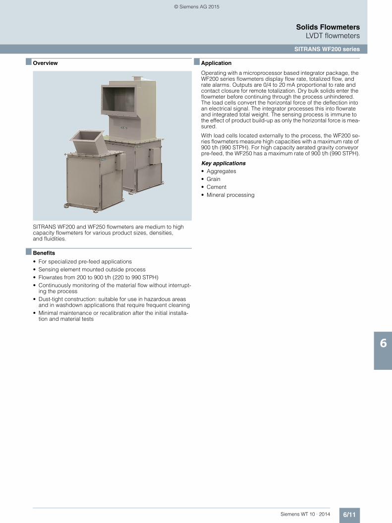
6/11Siemens WT 10 · 2014
Solids FlowmetersLVDT flowmeters
SITRANS WF200 series
6
■ Overview
SITRANS WF200 and WF250 flowmeters are medium to high capacity flowmeters for various product sizes, densities, and fluidities.
■ Benefits
• For specialized pre-feed applications • Sensing element mounted outside process • Flowrates from 200 to 900 t/h (220 to 990 STPH) • Continuously monitoring of the material flow without interrupt-
ing the process • Dust-tight construction: suitable for use in hazardous areas
and in washdown applications that require frequent cleaning • Minimal maintenance or recalibration after the initial installa-
tion and material tests
■ Application
Operating with a microprocessor based integrator package, the WF200 series flowmeters display flow rate, totalized flow, and rate alarms. Outputs are 0/4 to 20 mA proportional to rate and contact closure for remote totalization. Dry bulk solids enter the flowmeter before continuing through the process unhindered. The load cells convert the horizontal force of the deflection into an electrical signal. The integrator processes this into flowrate and integrated total weight. The sensing process is immune to the effect of product build-up as only the horizontal force is mea-sured.
With load cells located externally to the process, the WF200 se-ries flowmeters measure high capacities with a maximum rate of 900 t/h (990 STPH). For high capacity aerated gravity conveyor pre-feed, the WF250 has a maximum rate of 900 t/h (990 STPH).
Key applications• Aggregates• Grain • Cement • Mineral processing
© Siemens AG 2015

6/12 Siemens WT 10 · 2014
Solids FlowmetersLVDT flowmeters
SITRANS WF200 series
6
■ Selection and ordering data 1) Article No. Article No.
1) Not available with construction option A.
SITRANS WF200 series flowmetersSITRANS WF200 and WF250 flowmeters are medium to high capacity flowmeters for various product sizes, densities, and fluidities. WF250 features aer-ated style designed for air slide gravity conveyors.
7MH7115-
77777 - 0
Click on the Article No. for the online configuration in the PIA Life Cycle Portal.
Model
SITRANS WF200
500 t/h maximum design capacity 1
900 t/h maximum design capacity 2
SITRANS WF250, aerated style
500 t/h maximum design capacity 3
900 t/h maximum design capacity 4
Construction
Painted mild steel A
304 stainless steel for model option 1 B
304 stainless steel for model option 2 C
304 stainless steel for model option 3 D
304 stainless steel for model option 4 E
316 stainless steel for model option 1 F
316 stainless steel for model option 2 G
316 stainless steel for model option 3 H
316 stainless steel for model option 4 J
Sensing plate liner
None (standard 304 stainless steel, 316 for construc-tion options F to J)
A
Polyurethane
For model options 1 and 3 B
For model options 2 and 4 C
Alumina ceramic tiles
For model options 1 and 3 D
For model options 2 and 4 E
Load cell
50 lb 1
100 lb 2
Not specified (for quotation purposes only, not a valid ordering option)
0
Approvals
CE, RCM 1
CE, RCM, CSA/FM Class II, Div. 1, Groups E, F, G and Class III ATEX II 2D, Ex tD A21 IP65 T70 °C, CE, RCM, IECEx, Ex tD A21 IP65 T70 °C
2
Further designs Order Code
Please add "-Z" to article no. and specify order code(s).
Stainless steel tag [69 x 38 mm (2.7 x 1.5 inch)], Measuring-point number/identification (max 27 characters), specify in plain text.
Y15
Manufacturer's test certificate: According to EN 10204-2.2
C11
Inspection certificate type 3.1 per EN 102041) C12
Instruction manuals Article No.
• English 7ML1998-5NC01
• GermanNote: The instruction manual should be ordered as a separate item on the order.
7ML1998-5NC31
Additional instruction manuals
• Solids Flowmeter Application Guide, English 7ML1998-5GK01
• Solids Flowmeter Application Guide, German 7ML1998-5GK31
This device is shipped with the Siemens Milltronics manual DVD containing the complete instruction manual library.
Calibration hanger weights
20 g (0.04 lb) 7MH7724-1AC
50 g (0.1 lb) 7MH7724-1AD
100 g (0.2 lb) 7MH7724-1AE
200 g (0.4 lb) 7MH7724-1AF
500 g (1.1 lb) 7MH7724-1AG
1 000 g (2.2 lb) 7MH7724-1AH
2 000 g (4.4 lb) 7MH7724-1AJ
5 000 g (11 lb) 7MH7724-1AK
Note: Calibration accessories should be ordered as a separate item on the order.
Spare parts
Load cell, 50 lb, stainless steel 7MH7725-1AC
Load cell, 100 lb, stainless steel 7MH7725-1AD
Load cell, 50 lb, stainless steel, CSA/FM/ATEX/IEC EX 7MH7725-1DT
Load cell, 100 lb, stainless steel, CSA/FM/ATEX/IEC EX 7MH7725-1DU
WF calibration pulley with hardware and cable spare 7MH7723-1LT
WF200 series bearing with plate mount shaft, standard, spare
7MH7723-1LU
WF200 series bearing with plate mount shaft, stainless steel, spare
7MH7723-1LV
WF200 series sensing plate support cables, spare 7MH7723-1LW
WF250 series sensing plate support cables, spare 7MH7723-1LX
WF200 sensing plate 500 TPH 304, standard 7MH7723-1LY
WF200 sensing plate 900 TPH 304, standard 7MH7723-1MA
WF250 sensing plate 500 TPH 304, standard 7MH7723-1MB
WF250 sensing plate 900 TPH 304, standard 7MH7723-1MC
WF200 sensing plate 500 TPH 304, polyurethane lined 7MH7723-1MD
WF200 sensing plate 900 TPH 304, polyurethane lined 7MH7723-1ME
WF250 sensing plate 500 TPH 304, polyurethane lined 7MH7723-1MF
WF250 sensing plate 900 TPH 304, polyurethane lined 7MH7723-1MG
WF200 sensing plate 500 TPH 304, ceramic lined 7MH7723-1MH
WF200 sensing plate 900 TPH 304, ceramic lined 7MH7723-1MJ
WF250 sensing plate 500 TPH 304, ceramic lined 7MH7723-1MK
WF250 sensing plate 900 TPH 304, ceramic lined 7MH7723-1ML
WF200 sensing plate 500 TPH 316, standard 7MH7723-1MM
WF200 sensing plate 900 TPH 316, standard 7MH7723-1MN
WF250 sensing plate 500 TPH 316, standard 7MH7723-1MP
WF250 sensing plate 900 TPH 316, standard 7MH7723-1MQ
WF200 sensing plate 500 TPH 316, polyurethane lined 7MH7723-1MR
WF200 sensing plate 900 TPH 316, polyurethane lined 7MH7723-1MS
WF250 sensing plate 500 TPH 316, polyurethane lined 7MH7723-1MT
WF250 sensing plate 900 TPH 316, polyurethane lined 7MH7723-1MU
WF200 sensing plate 500 TPH 316, ceramic lined 7MH7723-1MV
WF200 sensing plate 900 TPH 316, ceramic lined 7MH7723-1MW
WF250 sensing plate 500 TPH 316, ceramic lined 7MH7723-1MX
WF250 sensing plate 900 TPH 316, ceramic lined 7MH7723-1MY
© Siemens AG 2015

6/13Siemens WT 10 · 2014
Solids FlowmetersLVDT flowmeters
SITRANS WF200 series
6
■ Dimensional drawings
WF200 dimensions in inch (mm)
25.0 (635.0)
44.6
8 (1
134
.9)
1.00
(25.
4) 41.5 (1054.1)
0.88 (22.2)
23.0 (584.2)
16.5
0(4
19.1
)
12.0
(304
.8)
Ø 0.47 (11.9)
Ø 0.56 (14.2)
1.0 (25.4)2.0 (50.8)
1.25
(31.
8)2.
25 (2
7.15
)
0.88
(22.
2)
2.18
(55.
37)
2.18 (55.37)37.50 (952.5)33.14 (841.8)7.13 (181.0)
21.0 (533.4)
5.75 (146.1), × 4
12.0 (304.8) 12.0 (304.8)
64.0 (1 625.6)
11.97 (304.1) 14.86 (377.4)
59.0 (1498.6)
35.13 (892.2)29.13 (739.8)
40.68 (1 033.3) 46.68 (1 185.7)
6.63 (168.3), × 6
6.75 (171.5),× 5
31.14 (791.0) 37.14 (943.4)
41.5 (1 054.1)35.5 (901.7)
30.0 (762.0)
26.0 (660.4)
7.0 (177.8), × 4
16.5 (419.1)16.5 (419.1)
500 t/h 900 t/h
A
B
C
D
E
F
I
J
K
L
H
G
A
B
C
C D EI
JK L
H
F
G
60º
© Siemens AG 2015

6/14 Siemens WT 10 · 2014
Solids FlowmetersLVDT flowmeters
SITRANS WF200 series
6
WF250 dimensions in inch (mm)
1.0
(25,
4)
45º
39.7
5 (1
009
.65)
4.0
(101
.6)
42.5 (1 079.5)
23.0 (584.2)
1.0 (25.4)2.14 (54.36)
14.5 (368.3)
Ø0.56 (14.2)
Ø0.56 (14.22)
2.19 (55.63)
40.0
(1 0
16.0
)
0.88
(22.
2)
0.88 (22.2)
2.19
(55.
63)
35.6
3 (9
04.9
)
6.31
(1 6
0.3)
29.37 (746.0) 41.27 (1 048.2)
25.10 (637.5) 37.0 (939.8)
4.56 (115.9), × 6
6.56 (166.62), × 6
0.74 (18.8) 0.94 (23.8)
3.13 (79.5) 3.19 (81.03)
22.38 (568.3) 26.38 (669.9)
16.13 (409.8) 20.0 (508.0)
5.13 (130.2), × 4
6.13 (155.6), × 4
Ø0.75 (19.1),× 8
Ø0.88 (22.2),× 8
Ø4.07 (103.4) Ø6.07 (154.1)
Ø9.0 (228.6) Ø11.0 (279.4)
40.0 (1 016.0) 52.0 (1 320.8)
35.63 (904.9) 47.63 (1 209.7)
6.31 (160.3), × 6
7.13 (181.0),× 7
45.18 (1 147.6) 57.18 (1 452.4)
33.0 (838.2) 45.0 (1 143.0)
81.88 (2 079.75) 91.0 (2 311.4)
A
A
I
I
J
J
K
K
B
B
C
C
H
H
D
D
G
G
E
E
F
F
L
L
M
M
N
N
P
PQ
Q
R
R
900 t/h900 t/h500 t/h 500 t/h
© Siemens AG 2015

6/15Siemens WT 10 · 2014
Solids FlowmetersLVDT flowmeters
SITRANS WF200 series
6
■ Schematics
WF200 and WF250 connections
Load cellA
Load cellB
Junctionbox
To integrator
Note: conduit and cable arrangementmay differ from example shown. Conduit and connector not provided on hazardous option
Red
AR
ed B
Bla
ck A
Bla
ck B
Whi
te A
Whi
te B
Gre
en B
Gre
en A
Shi
eld
Shi
eld
Shi
eld
+ E
XC
- EX
C
- SIG
A
- SIG
B
+ S
IG A
+ S
IG B
A B
© Siemens AG 2015

6/16 Siemens WT 10 · 2014
Solids FlowmetersLVDT flowmeters
SITRANS WF300 series
6
■ Overview
SITRANS WF300 series are low to medium capacity flowmeters for various product sizes, densities, and fluidities.
■ Benefits
• For specialized pre-feed applications• Sensing element mounted outside process• Flowrates from 0.2 to 300 t/h (0.2 to 330 STPH)• Continuously monitoring of the material flow without interrupt-
ing the process• Dust-tight construction: suitable for use in hazardous areas
and in washdown applications that require frequent cleaning• Minimal maintenance or recalibration after the initial installa-
tion and material tests
■ Application
With weighing mechanics located externally, the WF300 series solids flowmeters are unaffected by corrosive, abrasive, or hot materials. Handling a wide range of product sizes, densities, and fluidities including fine powders such as cement, they oper-ate at process temperatures to 230 °C (450 °F). The flowmeters help to improve final product, increase operating efficiency, and realize significant cost savings.
Operating with the appropriate SITRANS WFS sensing head and a micro-processor-based integrator package, the WF300 series flowmeters provide a display of the flow rate, totalized flow, and alarms. Outputs are 0/4 to 20 mA proportional to rate, and open collector output for remote totalization.
Dry bulk solids enter the flow guide producing a mechanical de-flection as they strike the flowmeter sensing plate before con-tinuing through the process unhindered. The LVDT in the sens-ing head converts the deflection of the horizontal force into an electrical signal. The integrator processes this signal into a dis-play of flowrate and integrated total weight. The weighing pro-cess is immune to the effect of product build-up as only the hor-izontal force is measured.
SITRANS WF330 flowmeters are totally enclosed, with external weighing mechanics, operating with corrosive, abrasive or hot materials. SITRANS WF350 series operates with aerated gravity conveyors, and includes integral vents and baffles for air sepa-ration. For applications with little available headroom, the SITRANS WF340 series flowmeters provide the answer.
© Siemens AG 2015

6/17Siemens WT 10 · 2014
Solids FlowmetersLVDT flowmeters
SITRANS WF300 series
6
■ Characteristic curves
SITRANS WF330 series
SITRANS WF330 series flowguide capacity chart
SITRANS WF340 series
SITRANS WF340 series flowguide capacity chart
Flowrate in STPH or t/h (use highest applicable flowrate for size selection)Example: 25 t/h of material at 1.4 t/m3, the selection is a 150 mm flowguide.Dimensions are provided as examples only.
Flowrate in STPH or t/h
Bul
k D
ensi
ty
Bul
k D
ensi
ty
WF330 Series Flowguide Capacity ChartWF330 Series Flowguide Capacity Chart
2.24
1.92
1.60
1.28
0.96
0.64
0.32
2.56
lb/ft
3
t/m3
140
120
100
80
60
40
20
0
160
1 10 100 4000
400
(16)
305
(14)
300
(12)
250
(10)
200
(8)
150 (6)50 (2) 100 (4)
Should the material bulk density and flowrate be near a flowguide upper limit, choose the next larger flowguide.
Flowrate in tons per hour
Bul
k de
nsity
Bul
k de
nsity
WF340 Series Flowguide Capacity Chart
2.24
1.92
1.60
1.28
0.96
0.64
0.32
2.56
lb/ft
3
t/m3
140
120
100
80
60
40
20
0
160
1 10 100 4000
3x6
6x20
5x12
4x10
5x16
© Siemens AG 2015
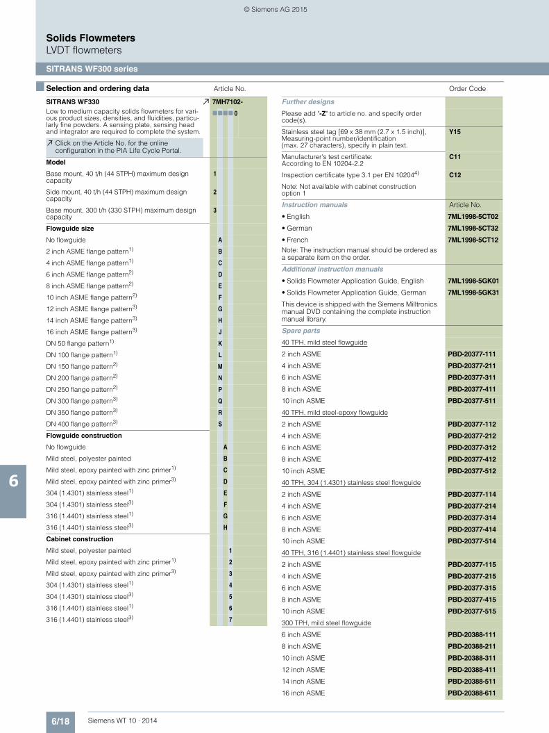
6/18 Siemens WT 10 · 2014
Solids FlowmetersLVDT flowmeters
SITRANS WF300 series
6
■ Selection and ordering data Article No. Order Code
SITRANS WF330Low to medium capacity solids flowmeters for vari-ous product sizes, densities, and fluidities, particu-larly fine powders. A sensing plate, sensing head and integrator are required to complete the system.
7MH7102-
7777 0
Click on the Article No. for the online configuration in the PIA Life Cycle Portal.
Model
Base mount, 40 t/h (44 STPH) maximum design capacity
1
Side mount, 40 t/h (44 STPH) maximum design capacity
2
Base mount, 300 t/h (330 STPH) maximum design capacity
3
Flowguide size
No flowguide A
2 inch ASME flange pattern1) B
4 inch ASME flange pattern1) C
6 inch ASME flange pattern2) D
8 inch ASME flange pattern2) E
10 inch ASME flange pattern2) F
12 inch ASME flange pattern3) G
14 inch ASME flange pattern3) H
16 inch ASME flange pattern3) J
DN 50 flange pattern1) K
DN 100 flange pattern1) L
DN 150 flange pattern2) M
DN 200 flange pattern2) N
DN 250 flange pattern2) P
DN 300 flange pattern3) Q
DN 350 flange pattern3) R
DN 400 flange pattern3) S
Flowguide construction
No flowguide A
Mild steel, polyester painted B
Mild steel, epoxy painted with zinc primer1) C
Mild steel, epoxy painted with zinc primer3) D
304 (1.4301) stainless steel1) E
304 (1.4301) stainless steel3) F
316 (1.4401) stainless steel1) G
316 (1.4401) stainless steel3) H
Cabinet construction
Mild steel, polyester painted 1
Mild steel, epoxy painted with zinc primer1) 2
Mild steel, epoxy painted with zinc primer3) 3
304 (1.4301) stainless steel1) 4
304 (1.4301) stainless steel3) 5
316 (1.4401) stainless steel1) 6
316 (1.4401) stainless steel3) 7
Further designs
Please add "-Z" to article no. and specify order code(s).
Stainless steel tag [69 x 38 mm (2.7 x 1.5 inch)], Measuring-point number/identification (max. 27 characters), specify in plain text.
Y15
Manufacturer's test certificate: According to EN 10204-2.2
C11
Inspection certificate type 3.1 per EN 102044) C12
Note: Not available with cabinet construction option 1
Instruction manuals Article No.
• English 7ML1998-5CT02
• German 7ML1998-5CT32
• FrenchNote: The instruction manual should be ordered as a separate item on the order.
7ML1998-5CT12
Additional instruction manuals
• Solids Flowmeter Application Guide, English 7ML1998-5GK01
• Solids Flowmeter Application Guide, German 7ML1998-5GK31
This device is shipped with the Siemens Milltronics manual DVD containing the complete instruction manual library.
Spare parts
40 TPH, mild steel flowguide
2 inch ASME PBD-20377-111
4 inch ASME PBD-20377-211
6 inch ASME PBD-20377-311
8 inch ASME PBD-20377-411
10 inch ASME PBD-20377-511
40 TPH, mild steel-epoxy flowguide
2 inch ASME PBD-20377-112
4 inch ASME PBD-20377-212
6 inch ASME PBD-20377-312
8 inch ASME PBD-20377-412
10 inch ASME PBD-20377-512
40 TPH, 304 (1.4301) stainless steel flowguide
2 inch ASME PBD-20377-114
4 inch ASME PBD-20377-214
6 inch ASME PBD-20377-314
8 inch ASME PBD-20377-414
10 inch ASME PBD-20377-514
40 TPH, 316 (1.4401) stainless steel flowguide
2 inch ASME PBD-20377-115
4 inch ASME PBD-20377-215
6 inch ASME PBD-20377-315
8 inch ASME PBD-20377-415
10 inch ASME PBD-20377-515
300 TPH, mild steel flowguide
6 inch ASME PBD-20388-111
8 inch ASME PBD-20388-211
10 inch ASME PBD-20388-311
12 inch ASME PBD-20388-411
14 inch ASME PBD-20388-511
16 inch ASME PBD-20388-611
© Siemens AG 2015

6/19Siemens WT 10 · 2014
Solids FlowmetersLVDT flowmeters
SITRANS WF300 series
6
■ Selection and ordering data Article No. Article No.
1) 2) 3) 4)
300 TPH, mild steel-epoxy flowguide
6 inch ASME PBD-20388-112
8 inch ASME PBD-20388-212
10 inch ASME PBD-20388-312
12 inch ASME PBD-20388-412
14 inch ASME PBD-20388-512
16 inch ASME PBD-20388-612
300 TPH, 304 (1.4301) stainless steel flowguide
6 inch ASME PBD-20388-114
8 inch ASME PBD-20388-214
10 inch ASME PBD-20388-314
12 inch ASME PBD-20388-414
14 inch ASME PBD-20388-514
16 inch ASME PBD-20388-614
300 TPH, 316 (1.4401) stainless steel flowguide
6 inch ASME PBD-20388-115
8 inch ASME PBD-20388-215
10 inch ASME PBD-20388-315
12 inch ASME PBD-20388-415
14 inch ASME PBD-20388-515
16 inch ASME PBD-20388-615
40 TPH, mild steel flowguide
2 inch DIN PBD-20377-121
4 inch DIN PBD-20377-221
6 inch DIN PBD-20377-321
8 inch DIN PBD-20377-421
10 inch DIN PBD-20377-521
40 TPH, mild steel-epoxy flowguide
2 inch DIN PBD-20377-122
4 inch DIN PBD-20377-222
6 inch DIN PBD-20377-322
8 inch DIN PBD-20377-422
10 inch DIN PBD-20377-522
40 TPH, 304 (1.4301) stainless steel flowguide
2 inch DIN PBD-20377-124
4 inch DIN PBD-20377-224
6 inch DIN PBD-20377-324
8 inch DIN PBD-20377-424
10 inch DIN PBD-20377-524
40 TPH, 316 (1.4401) stainless steel flowguide
2 inch DIN PBD-20377-125
4 inch DIN PBD-20377-225
6 inch DIN PBD-20377-325
8 inch DIN PBD-20377-425
10 inch DIN PBD-20377-525
300 TPH, mild steel flowguide
6 inch DIN PBD-20388-121
8 inch DIN PBD-20388-221
10 inch DIN PBD-20388-321
12 inch DIN PBD-20388-421
14 inch DIN PBD-20388-521
16 inch DIN PBD-20388-621
300 TPH, mild steel-epoxy flowguide
6 inch DIN PBD-20388-122
8 inch DIN PBD-20388-222
10 inch DIN PBD-20388-322
12 inch DIN PBD-20388-422
14 inch DIN PBD-20388-522
16 inch DIN PBD-20388-622
300 TPH, 304 (1.4301) stainless steel flowguide
6 inch DIN PBD-20388-124
8 inch DIN PBD-20388-224
10 inch DIN PBD-20388-324
12 inch DIN PBD-20388-424
14 inch DIN PBD-20388-524
16 inch DIN PBD-20388-624
300 TPH, 316 (1.4401) stainless steel flowguide
6 inch DIN PBD-20388-125
8 inch DIN PBD-20388-225
10 inch DIN PBD-20388-325
12 inch DIN PBD-20388-425
14 inch DIN PBD-20388-525
16 inch DIN PBD-20388-625
Gasketing
40 TPH, gasket PBD-22600493
300 TPH, gasket PBD-22600494
1) For versions 1 and 2 only.2) For versions 1, 2 or 3.3) For version 3 only.4) Not available with cabinet construction options 1, 2, 3.
© Siemens AG 2015

6/20 Siemens WT 10 · 2014
Solids FlowmetersLVDT flowmeters
SITRANS WF300 series
6
■ Selection and ordering data 1) 2) 3) Article No. Article No.
1) For versions 1 and 2 only.2) For version 3 only.3) Not available with cabinet construction option 1.
SITRANS WF340Compact vertical flow, low to medium-capacity solid flowmeters for various product sizes, densities, and flu-idities, particularly fine powders. A sensing plate, sensing head and integrator are required to complete the system.
7MH7104-
7777 0
Click on the Article No. for the online configuration in the PIA Life Cycle Portal.
Version
Base mount, 40 t/h (44 STPH) max. design capacity 1
Side mount, 40 t/h (44 STPH) max. design capacity 2
Base mount, 300 t/h (330 STPH) max. design capacity
3
Flowguide size
No flowguide (5 x 16 inch model) A
3 x 6 inch (76 x 152 mm)1) B
4 x 10 inch (102 x 254 mm)1) C
5 x 12 inch (127 x 305 mm)1) D
5 x 16 inch (127 x 406 mm)2) E
6 x 20 inch (152 x 508 mm)2) F
No flowguide (WF340-300 6 x 20 inch model) G
Flowguide construction
No flowguide A
Mild steel, polyester painted B
304 (1.4301) stainless steel1) C
304 (1.4301) stainless steel2) D
316 (1.4401) stainless steel1) E
316 (1.4401) stainless steel2) F
Mild steel, polyester painted with PTFE liner G
Mild steel, polyester painted with abrasion resistant liner
H
304 (1.4301) stainless steel, with PTFE liner1) J
304 (1.4301) stainless steel, with PTFE liner2) K
Mild steel, epoxy paint with zinc primer1) L
Mild steel, epoxy paint with zinc primer2)
Other flowguide materials available upon requestM
Cabinet construction
Mild steel, painted 1
304 (1.4301) stainless steel1) 2
304 (1.4301) stainless steel2) 3
316 (1.4401) stainless steel1) 4
316 (1.4401) stainless steel2) 5
Mild steel, epoxy paint with zinc primer1) 6
Mild steel, epoxy paint with zinc primer2) 7
Further designs Order Code
Please add "-Z" to article no. and specify order code(s).
Stainless steel tag [69 x 38 mm (2.7 x 1.5 inch)], Measuring-point number/identification (max 27 characters), specify in plain text.
Y15
Manufacturer's test certificate: According to EN 10204-2.2
C11
Inspection certificate type 3.1 per EN 102043) C12
Instruction manual
• English 7ML1998-5CU02
• GermanNote: The instruction manual should be ordered as a separate line on the order.
7ML1998-5CU32
Additional instruction manuals
• Solids Flowmeter Application Guidelines, English 7ML1998-5GK01
• Solids Flowmeter Application Guidelines, German 7ML1998-5GK31
This device is shipped with the Siemens Milltronics manual DVD containing the complete instruction manual library.
Spare parts
40 TPH, mild steel flowguide
3 x 6 inch PBD-20401-100
4 x 10 inch PBD-20395-100
5 x 12 inch PBD-20405-100
40 TPH, mild steel-epoxy flowguide
3 x 6 inch PBD-20401-200
4 x 10 inch PBD-20395-200
5 x 12 inch PBD-20405-200
40 TPH, 304 (1.4301) stainless steel flowguide
3 x 6 inch PBD-20401-300
4 x 10 inch PBD-20395-300
5 x 12 inch PBD-20405-300
40 TPH. 316 (1.4401) stainless steel flowguide
3 x 6 inch PBD-20401-400
4 x 10 inch PBD-20395-400
5 x 12 inch PBD-20405-400
40 TPH, mild steel-PTFE flowguide
3 x 6 inch PBD-20401-500
4 x 10 inch PBD-20395-500
5 x 12 inch PBD-20405-500
40 TPH, 304 (1.4301) stainless steel-PTFE flowguide
3 x 6 inch PBD-20401-600
4 x 10 inch PBD-20395-600
5 x 12 inch PBD-20405-600
40 TPH, mild steel-AR flowguide
3 x 6 inch PBD-20401-700
4 x 10 inch PBD-20395-700
5 x 12 inch PBD-20405-700
300 TPH, mild steel flowguide
5 x 16 inch PBD-20455-10
6 x 20 inch PBD-20458-10
300 TPH, mild steel-epoxy flowguide
5 x 16 inch PBD-20455-20
6 x 20 inch PBD-20458-20
© Siemens AG 2015

6/21Siemens WT 10 · 2014
Solids FlowmetersLVDT flowmeters
SITRANS WF300 series
6
■ Selection and ordering data Article No.
300 TPH, 304 (1.4301) stainless steel flowguide
5 x 16 inch PBD-20455-30
6 x 20 inch PBD-20458-30
300 TPH, 304 (1.4301) stainless steel-PTFEflowguide
5 x 16 inch PBD-20455-40
6 x 20 inch PBD-20458-40
300 TPH, 316 (1.4401) stainless steel flowguide
5 x 16 inch PBD-20455-50
6 x 20 inch PBD-20458-50
300 TPH, mild steel-PTFE flowguide
5 x 16 inch PBD-20455-60
6 x 20 inch PBD-20458-60
300 TPH, mild steel-AR flowguide
5 x 16 inch PBD-20455-70
6 x 20 inch PBD-20458-70
Gasketing
40 TPH, gasket PBD-22600495
300 TPH, gasket
• 5 x 16 inch PBD-45000969
• 6 x 20 inch PBD-45000970
© Siemens AG 2015

6/22 Siemens WT 10 · 2014
Solids FlowmetersLVDT flowmeters
SITRANS WF300 series
6
■ Selection and ordering data Article No. Article No.
SITRANS WF350Low to medium capacity flowmeters for powders conveyed by aerated gravity conveyors. A sensing plate, sensing head and integrator are required to complete the system.
7MH7106-
77777
Click on the Article No. for the online configuration in the PIA Life Cycle Portal.
Version
40 t/h (44 STPH) maximum design capacity 1
300 t/h (330 STPH) maximum design capacity 2
Flowguide size
8 inch (203 mm), 40 t/h (0.2 to 44 STPH) version B
10 inch (254 mm), 300 t/h C
12 inch (305 mm), 40 t/h (0.2 to 44 STPH) version D
14 inch (356 mm), 300 t/h E
20 inch (508 mm), 300 t/h F
Flowguide construction
Mild steel, polyester painted B
304 (1.4301) stainless steel D
316 (1.4401) stainless steel E
Cabinet construction
Mild steel, polyester painted 1
304 (1.4301) stainless steel 3
316 (1.4401) stainless steel 4
Venting flange
ASME flange pattern 1
DIN flange pattern 2
Further designs Order Code
Please add "-Z" to article no. and specify order code(s).
Stainless steel tag [69 x 38 mm (2.7 x 1.5 inch)], Measuring-point number/identification (max. 27 characters), specify in plain text.
Y15
Manufacturer's test certificate: According to EN 10204-2.2
C11
Inspection certificate type 3.1 per EN 10204Not available with cabinet construction option 1.
C12
Instruction manuals Article No.
English 7ML1998-5CV02
GermanNote: The instruction manual should be ordered as a separate item on the order.
7ML1998-5CV32
Additional instruction manuals
• Solids Flowmeter Application Guide, English 7ML1998-5GK01
• Solids Flowmeter Application Guide, German 7ML1998-5GK31
This device is shipped with the Siemens Milltronics manual DVD containing the complete instruction manual library.
Spare parts
40 TPH, mild steel flowguide
8 inch PBD-22520-1A0
12 inch PBD-22520-2A0
40 TPH, 304 (1.4301) stainless steel flowguide
8 inch PBD-22520-1B0
12 inch PBD-22520-2B0
40 TPH, 316 (1.4401) stainless steel flowguide
8 inch PBD-22520-1C0
12 inch PBD-22520-2C0
300 TPH. mild steel flowguide
10 inch PBD-22519-1A0
14 inch PBD-22519-2A0
20 inch PBD-22519-3A0
300 TPH, 304 (1.4301) stainless steel flowguide
10 inch PBD-22519-1B0
14 inch PBD-22519-2B0
20 inch PBD-22519-3B0
40 TPH, 316 (1.4401) stainless steel flowguide
10 inch PBD-22519-1C0
14 inch PBD-22519-2C0
20 inch PBD-22519-3C0
Gasketing
40 TPH, gasket PBD-45000972
300 TPH, gasket PBD-45005013
© Siemens AG 2015
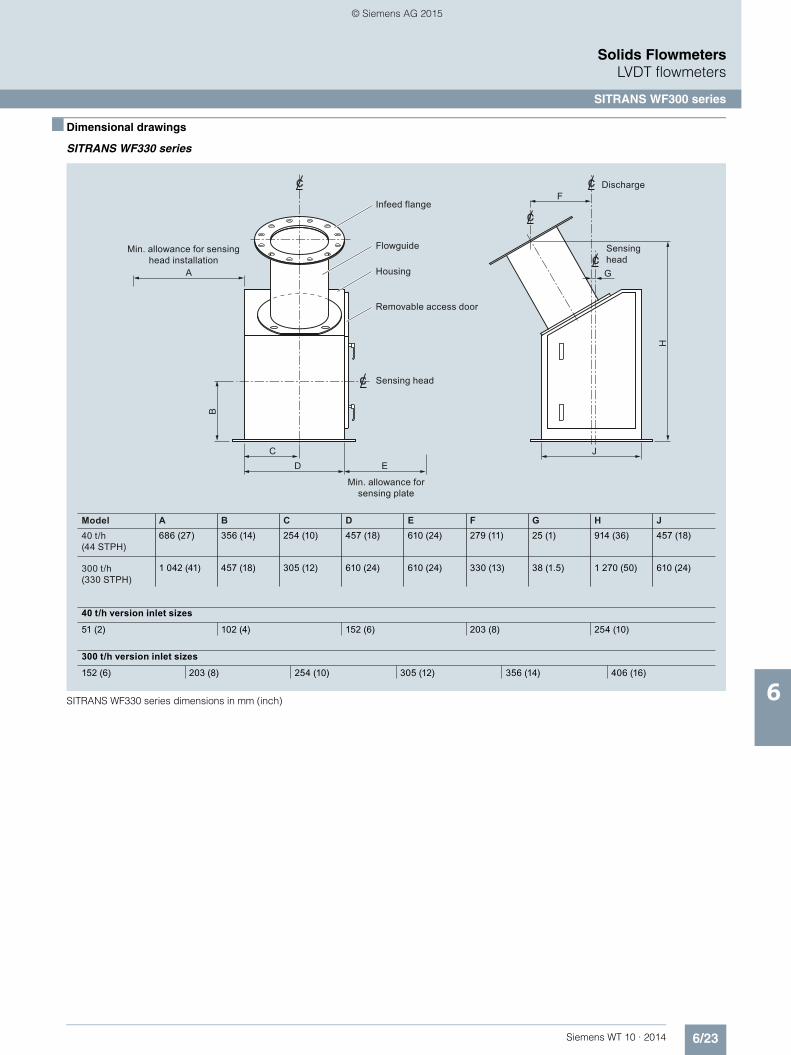
6/23Siemens WT 10 · 2014
Solids FlowmetersLVDT flowmeters
SITRANS WF300 series
6
■ Dimensional drawings
SITRANS WF330 series
SITRANS WF330 series dimensions in mm (inch)
Model
40 t/h version inlet sizes
300 t/h version inlet sizes
Discharge
Sensing head
Infeed flange
Flowguide
Housing
Removable access door
Sensing head
Min. allowance for sensing plate
Min. allowance for sensing head installation
F
G
H
JED
C
B
A
40 t/h(44 STPH)
A B C D E F G H J686 (27) 457 (18)914 (36)25 (1)279 (11)610 (24)457 (18)254 (10)356 (14)
254 (10)51 (2) 203 (8)152 (6)102 (4)
300 t/h(330 STPH)
1 042 (41) 610 (24)1 270 (50)38 (1.5)330 (13)610 (24)610 (24)305 (12)457 (18)
356 (14)152 (6) 305 (12)254 (10)203 (8) 406 (16)
© Siemens AG 2015

6/24 Siemens WT 10 · 2014
Solids FlowmetersLVDT flowmeters
SITRANS WF300 series
6
SITRANS WF340 series
SITRANS WF340 series dimensions in mm (inch)
Size
DischargeSensing head
Flowguide
Housing
Sensing head
Min. allowance for sensing plate
Access and bolt holes to suit sensing head
Access door
SQ.E
C
D
G
HJ
KF
A
B
25 (1)
40 t/h (44 STPH)
40 t/h (44 STPH)
40 t/h (44 STPH)
A B C D E F G H J
152 (6) 508 (20)203 (8)76 (3)457 (18)508 (20)254 (10)304 (12)686 (27)
254 (10) 508 (20)
K
254 (10)
254 (10)203 (8)102 (4)457 (18)508 (20)254 (10)304 (12)686 (27)
305 (12) 508 (20) 254 (10)203 (8)127 (5)457 (18)508 (20)254 (10)304 (12)686 (27)
300 t/h (330 STPH)
300 t/h (330 STPH)
406 (16) 610 (24) 330 (13)254 (10)127 (5)762 (30)610 (24)305 (12)343 (13.5)1 041 (41)
508 (20) 610 (24) 381 (15)254 (10)152 (6)762 (30)711 (28)356 (14)343 (13.5)1 041 (41)
© Siemens AG 2015

6/25Siemens WT 10 · 2014
Solids FlowmetersLVDT flowmeters
SITRANS WF300 series
6
SITRANS WF350 series
SITRANS WF350 series dimensions in mm (inch)
Size
Size
Sensing head
Flowguide
Housing
Sensing head
Min. allowance forsensing plate
installation
Removable access door
Min. allowance forsensing plate
installation
K
A
J
F GØH
L
MN
PRQ
D EC
B
40 t/h (44 STPH)40 t/h (44 STPH)
A B C D E F G H203 (8) 102 (4)203 (8)127 (5)711 (28)254 (10)305 (12)686 (27)305 (12) 102 (4)203 (8)127 (5)711 (28)254 (10)305 (12)686 (27)
300 t/h (330 STPH) 254 (10) 152 (6)229 (9)191 (7.5)889 (35)356 (14)406 (16)1 041 (41)300 t/h (330 STPH) 356 (14) 152 (6)229 (9)191 (7.5)889 (35)356 (14)406 (16)1 041 (41)300 t/h (330 STPH) 508 (20) 152 (6)229 (9)191 (7.5)889 (35)356 (14)406 (16)1 041 (41)
40 t/h (44 STPH)40 t/h (44 STPH)
J K L M N P Q R229 (9) 330 (13)229 (9)229 (9)305 (12)914 (36)76 (3)203 (8)229 (9) 330 (13)229 (9)229 (9)305 (12)914 (36)102 (4)203 (8)
300 t/h (330 STPH) 254 (10) 406 (16)356 (14)330 (13)419 (16.5)1 168 (46)127 (5)305 (12)300 t/h (330 STPH) 254 (10) 406 (16)356 (14)330 (13)419 (16.5)1 168 (46)152 (6)305 (12)300 t/h (330 STPH) 254 (10) 406 (16)356 (14)330 (13)419 (16.5)1 168 (46)178 (7)305 (12)
© Siemens AG 2015

6/26 Siemens WT 10 · 2014
Solids FlowmetersSensing heads
SITRANS WFS300 series sensing heads
6
■ Overview
SITRANS WFS300 and WFS320 sensing heads are out-of-the process sensing elements for SITRANS WF300 series solids flowmeters.
■ Benefits
• Easy installation with modular assembly• ± 1 % accuracy (or better) with high repeatability• Totally enclosed, dust-tight, flow metering of bulk solids• Sensing mechanism is outside the process, protected from
contamination• No zero drift, due to unique sensing mechanism• Low maintenance; only the sensing plate is in the process• No restriction of product flow
■ Application
SITRANS WFS300 and WFS320 sensing heads are used in ap-plications such as product rationing, batch load-out, and pro-cess feed rate control, the WFS series of sensing heads has been field-proven in thousands of applications with some units providing over a quarter century of reliable performance.The WFS sensing heads use only the horizontal force created by impact of product upon the sensing plate and then apply the horizontal deflection to a highly reliable linear variable differential transformer (LVDT).
Friction-less pivots exclude the vertical force from the sensing process and the LVDT travel range is controlled by a coil spring selected for the specified full-scale flow rate. A viscous fluid damper provides mechanical damping in the event of pulsating flows.
The LVDT converts the horizontal movement, proportional to the impact forces into an electrical signal, which is converted by the integrator to time-based flow rate indication and totaling. This method of sensing material flow has been proven best in thou-sands of applications all over the world.
© Siemens AG 2015

6/27Siemens WT 10 · 2014
Solids FlowmetersSensing heads
SITRANS WFS300 series sensing heads
6
■ Technical specifications 1)
1) Accuracy subject to: On factory approved installations the flowmeter system’s totalized weight will be within the specified accuracy when compared to a known weighed material test sample. The test rate must be within the specified range of the design capacity and held constant for the duration of the test. The minimum material test sample must be equivalent to a sample obtained at the test flow rate for at least ten minutes running time.
WFS300 WFS320
Mode of operation
Measuring principle Deflection measurement using LVDT (linear variable differential transformer)
Typical application For use in all WF300 series flowmeters
Flow input
Maximum particle size 13 mm (0.5 inch) 25 mm (1 inch)
Minimum flow rate 0 … 0.2 t/h (0 … 0.2 STPH) 0 … 20 t/h (0 … 22 STPH)
Maximum flow rate 0 … 40 t/h (0 … 44 STPH) 0 … 300 t/h (0 … 330 STPH)
Performance
Accuracy1) ± 1 % or better of full scale, higher accuracy with linearizing features offered by integrators
Repeatability ± 0.2 %
Specified range 33 … 100 %
Medium conditions
Ambient temperature
• Without internally mounted LVDT card -40 … +60 °C (-40 … +140 °F) -40 … +60 °C (-40 … +140 °F)
• With optional internally mounted LVDT card -40 … +50 °C (-40 … +122 °F) -40 … +50 °C (-40 … +122 °F)
Maximum product temperature 232 °C (450 °F) 232 °C (450 °F)
Design IP64 aluminum body, fiberglass cover, 304 (1.4306) stainless steel sensing plate
Options • Epoxy paint coating of external aluminum casting surfaces• Internally mounted LVDT conditioner card for use with SF500 integrator• Externally mounted LVDT conditioner card in NEMA 4 (IP65) enclosure for use with
Milltronics SF500 or SIWAREX FTC integrator when sensing head is mounted in hazardous areas or with high ambient temperatures
Approvals CE, RCM, CSA, FM, GOST, ATEX, IEC Ex CE, RCM, CSA, FM, GOST, ATEX, IEC Ex
© Siemens AG 2015

6/28 Siemens WT 10 · 2014
Solids FlowmetersSensing heads
SITRANS WFS300 series sensing heads
6
■ Selection and ordering data 1) 2) Article No. Order Code
1) For use with Compu Series integrators or when externally mounted LVDT conditioner required.
2) Applicable for mounting options 0 and 1 only.
SITRANS WFS300 sensing head 7MH7110-
Out-of-the-process sensing element for 40 t/h (44 STPH) solids flowmeters. A flowguide, sensing plate and integrator are required to complete the system. Order flowguide, sensing plate and inte-grator separately.
77777
Click on the Article No. for the online configuration in the PIA Life Cycle Portal.
Mounting
Base 0
Side 1
Base, CSA/FM Class I, Div. 1 Groups C and D; Class II, Div. 1 Groups E, F and G, ATEX II 3G, Ex nA IIC T6 Gc, ATEX II 2D - Ex tb IIIC T70 ºC Db IP64, IECEx FMG 13.0016X, Ex nA IIC T6 Gc, Ex tb IIIC T70 ºC Db IP64
3
Side, CSA/FM Class I, Div. 1 Groups C and D; Class II, Div. 1 Groups E, F and G, ATEX II 3G, Ex nA IIC T6 Gc, ATEX II 2D - Ex tb IIIC T70 ºC Db IP64, IECEx FMG 13.0016X, Ex nA IIC T6 Gc, Ex tb IIIC T70 ºC Db IP64
4
Note: Externally mounted LVDT Conditioner in NEMA 4 enclosure required for use with SF500 or SIWAREX FTC and mounting option 3 and 4. See optional equipment.
Range (Range spring size/leaf spring thickness/ viscosity of damping fluid)
C2/A2/1 000 A
C3/A2/1 000 B
C4/A2/1 000 C
C5/A2/1 000 D
C6/A2/1 000 E
C7/A2/1 000 F
C8/A2/3 000 G
C9/A2/3 000 H
C10/A2/3 000 J
C11/A3/5 000 K
C12/A3/5 000 L
C13/A3/5 000 M
C14/A3/5 000 N
C0/A2/500 P
C0/A3/500 Q
C10/A3/3 000 R
Gasketing
Silicone A
Silicone, light duty B
PTFE E
Coating (process side only)
None, standard aluminum 0
Epoxy - white/aluminum, external castings only 1
Sensing head mounted LVDT conditioner
None1) 0
Included, required for use with SF500 or SIWAREX FTC integrator2)
1
Further designs
Please add "-Z" to article no. and specify order code(s).
Stainless steel tag [69 x 38 mm (2.7 x 1.5 inch)], Measuring-point number/identification (max. 27 characters), specify in plain text.
Y15
Manufacturer's test certificate: According to EN 10204-2.2
C11
Instruction manuals Article No.
• English A5E32880243
• Solids flowmeter Application Guidelines, English 7ML1998-5GK01
• Solids flowmeter Application Guidelines, GermanNote: The instruction manual should be ordered as a separate item on the order.
7ML1998-5GK31
This device is shipped with the Siemens Milltronics manual DVD containing the complete instruction manual library.
Calibration hanger weights
20 g (0.04 lb) 7MH7724-1AC
50 g (0.1 lb) 7MH7724-1AD
100 g (0.2 lb) 7MH7724-1AE
200 g (0.4 lb) 7MH7724-1AF
500 g (1.1 lb) 7MH7724-1AG
1 000 g (2.2 lb) 7MH7724-1AH
2 000 g (4.4 lb) 7MH7724-1AJ
5 000 g (11 lb) 7MH7724-1AK
Note: Calibration accessories should be ordered as a separate item on the order.
© Siemens AG 2015

6/29Siemens WT 10 · 2014
Solids FlowmetersSensing heads
SITRANS WFS300 series sensing heads
6
■ Selection and ordering data Article No.
Spare parts
LDVT conditioner in NEMA 4 enclosure (to interface SF500 or SIWAREX FTC and LVDT sensor)
7MH7723-1AJ
Silicone inner diaphragm 7MH7723-1DN
Silicone outer diaphragm 7MH7723-1DP
PTFE inner diaphragm 7MH7723-1AL
PTFE outer diaphragm 7MH7723-1AM
LVDT transformer and core, standard spare 7MH7723-1DS
Encapsulated LVDT replacement kit 7MH7723-1DE
Damping fluid, 1 000 CS, 1 lb bottle 7MH7723-1EU
Damping fluid, 3 000 CS, 1 lb bottle 7MH7723-1EV
Damping fluid, 5 000 CS, 1 lb bottle 7MH7723-1EW
Range spring assembly, C2 7MH7723-1EX
Range spring assembly, C3 7MH7723-1EY
Range spring assembly, C4 7MH7723-1FA
Range spring assembly, C5 7MH7723-1FB
Range spring assembly, C6 7MH7723-1FC
Range spring assembly, C7 7MH7723-1FD
Range spring assembly, C8 7MH7723-1FE
Range spring assembly, C9 7MH7723-1FF
Range spring assembly, C10 7MH7723-1FG
Range spring assembly, C11 7MH7723-1FH
Range spring assembly, C12 7MH7723-1FJ
Range spring assembly, C13 7MH7723-1FK
Range spring assembly, C14 7MH7723-1FL
Leaf spring, A2, kit 7MH7723-1BN
Leaf spring, A3, kit 7MH7723-1BP
WFS300 calibration wheel kit 7MH7723-1KB
Circuit card, LVDT, conditioner 7MH7723-1ET
WFS300 replacement O-ring kit 7MH7723-1DC
© Siemens AG 2015
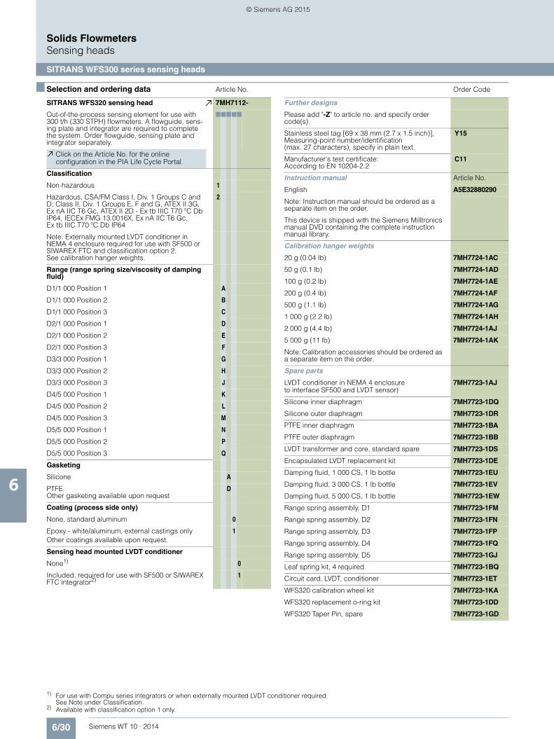
6/30 Siemens WT 10 · 2014
Solids FlowmetersSensing heads
SITRANS WFS300 series sensing heads
6
■ Selection and ordering data 1) 2) Article No. Order Code
1) For use with Compu series integrators or when externally mounted LVDT conditioner required. See Note under Classification.
2) Available with classification option 1 only.
SITRANS WFS320 sensing head 7MH7112-
Out-of-the-process sensing element for use with 300 t/h (330 STPH) flowmeters. A flowguide, sens-ing plate and integrator are required to complete the system. Order flowguide, sensing plate and integrator separately.
77777
Click on the Article No. for the online configuration in the PIA Life Cycle Portal.
Classification
Non-hazardous 1
Hazardous, CSA/FM Class I, Div. 1 Groups C and D; Class II, Div. 1 Groups E, F and G, ATEX II 3G, Ex nA IIC T6 Gc, ATEX II 2D - Ex tb IIIC T70 ºC Db IP64, IECEx FMG 13.0016X, Ex nA IIC T6 Gc, Ex tb IIIC T70 ºC Db IP64
2
Note: Externally mounted LVDT conditioner in NEMA 4 enclosure required for use with SF500 or SIWAREX FTC and classification option 2. See calibration hanger weights.
Range (range spring size/viscosity of damping fluid)
D1/1 000 Position 1 A
D1/1 000 Position 2 B
D1/1 000 Position 3 C
D2/1 000 Position 1 D
D2/1 000 Position 2 E
D2/1 000 Position 3 F
D3/3 000 Position 1 G
D3/3 000 Position 2 H
D3/3 000 Position 3 J
D4/5 000 Position 1 K
D4/5 000 Position 2 L
D4/5 000 Position 3 M
D5/5 000 Position 1 N
D5/5 000 Position 2 P
D5/5 000 Position 3 Q
Gasketing
Silicone A
PTFEOther gasketing available upon request
D
Coating (process side only)
None, standard aluminum 0
Epoxy - white/aluminum, external castings onlyOther coatings available upon request.
1
Sensing head mounted LVDT conditioner
None1) 0
Included, required for use with SF500 or SIWAREX FTC integrator2)
1
Further designs
Please add "-Z" to article no. and specify order code(s).
Stainless steel tag [69 x 38 mm (2.7 x 1.5 inch)], Measuring-point number/identification (max. 27 characters), specify in plain text.
Y15
Manufacturer's test certificate: According to EN 10204-2.2
C11
Instruction manual Article No.
English A5E32880290
Note: Instruction manual should be ordered as a separate item on the order.
This device is shipped with the Siemens Milltronics manual DVD containing the complete instruction manual library.
Calibration hanger weights
20 g (0.04 lb) 7MH7724-1AC
50 g (0.1 lb) 7MH7724-1AD
100 g (0.2 lb) 7MH7724-1AE
200 g (0.4 lb) 7MH7724-1AF
500 g (1.1 lb) 7MH7724-1AG
1 000 g (2.2 lb) 7MH7724-1AH
2 000 g (4.4 lb) 7MH7724-1AJ
5 000 g (11 lb) 7MH7724-1AK
Note: Calibration accessories should be ordered as a separate item on the order.
Spare parts
LVDT conditioner in NEMA 4 enclosure to interface SF500 and LVDT sensor)
7MH7723-1AJ
Silicone inner diaphragm 7MH7723-1DQ
Silicone outer diaphragm 7MH7723-1DR
PTFE inner diaphragm 7MH7723-1BA
PTFE outer diaphragm 7MH7723-1BB
LVDT transformer and core, standard spare 7MH7723-1DS
Encapsulated LVDT replacement kit 7MH7723-1DE
Damping fluid, 1 000 CS, 1 lb bottle 7MH7723-1EU
Damping fluid, 3 000 CS, 1 lb bottle 7MH7723-1EV
Damping fluid, 5 000 CS, 1 lb bottle 7MH7723-1EW
Range spring assembly, D1 7MH7723-1FM
Range spring assembly, D2 7MH7723-1FN
Range spring assembly, D3 7MH7723-1FP
Range spring assembly, D4 7MH7723-1FQ
Range spring assembly, D5 7MH7723-1GJ
Leaf spring kit, 4 required 7MH7723-1BQ
Circuit card, LVDT, conditioner 7MH7723-1ET
WFS320 calibration wheel kit 7MH7723-1KA
WFS320 replacement o-ring kit 7MH7723-1DD
WFS320 Taper Pin, spare 7MH7723-1GD
© Siemens AG 2015

6/31Siemens WT 10 · 2014
Solids FlowmetersSensing heads
SITRANS WFS300 series sensing heads
6
■ Dimensional drawings
WFS300 series sensing head dimensions in mm (inch)
Ensure outer gasket seals dust tight to flowmeter housing wall.Sensing head support plate should be rigid and independent of flowmeter housing.Refer to flowmeter drawing for sensing head mounting hole to flowguide centerline dimension.
Notes:1)
2)
3)
As required
Outer gasket
Fiberglass cover
16 (0.63) dia. (4 levelling rods)
10 (0.38) dia.(4 levelling rods)
Support plate (by customer)
Support plate (by customer)
As requiredSee note
Outer gasketConduit entry
1/2" NPT (internal)
WFS320 Sensing Head
8 (0.31) dia., 18 bolts on 360 (14.17) B.C.D
Sensing plate
Sensing plate
Fiberglass cover
WFS300 Sensing Head
1)
See note
Conduit entry1/2" NPT (internal)
8 (0.31) dia.,18 bolts on
460 (18.11) B.C.D1)
490
(19.
29)
340
(13.
34)
380 (14.96)
40 (1
.57)
560 (22.05)500 (19.64)70 (2.76)
420 (16.54)300 (11.81)
60 (2
.36)
318
(12.
52)
180 (7.09)
260
(10.
25)
385
(15.
12)
560
(22.
05)
70 (2.76)
30 (1.18)
90 (3.54)
290 (11.5)
280
(11)
256
(10.
06)
50 (1
.97)
© Siemens AG 2015

6/32 Siemens WT 10 · 2014
Solids FlowmetersSensing heads
SITRANS WFS300 series sensing heads
6
■ Schematics
WFS300 series, connections
To the LVDT conditioner card (internally or externally mounted) and Milltronics SF500/Siwarex FTC integrator
Consult Siemens representative for hazardous rated versions.
To LVDT
Flowmeter terminal
Collar
© Siemens AG 2015

6/33Siemens WT 10 · 2014
Solids FlowmetersSensing plates
SITRANS flowmeter sensing plates
6
■ Overview
The sensing plate transfers the impact force to the sensing head of the flowmeter.
■ Selection and ordering data 1) 2) 3) 4) 5) 6) Article No. 7) 8) 9)
1) See 7MH7102, page 6/18.2) See 7MH7106, page 6/22.3) See 7MH7104, page 6/20.4) Available as spare part only.5) Available with flowmeter version 1 ... 4 and 8 only.6) Available with flowmeter version 5 ... 7 only.7) Available with flowmeter version 1 ... 4 only.8) Available with flowmeter version 1, 2 and 3 only.9) Maximum material temperature: +85 °C (+185 °F).
SITRANS flowmeter sensing platesThe sensing plate transfers the impact force to the sensing head of the flowmeter.
7MH7114-
7777 0
Click on the Article No. for the online configuration in the PIA Life Cycle Portal.
VersionWF330, 40 t/h, base mount or side mount 1
WF340, 40 t/h, base mount or side mount 3
WF350, 40 t/h, base mount or side mount 4
WF330, 300 t/h 5
WF340, 300 t/h 6
WF350, 300 t/h 7
C-40 8
Plate size18 x 10 inch (457.2 x 254 mm), for version option 1 with 2, 4 or 6 inch (50.8, 101.6 or 152.4 mm) flowguide1)
A
20 x 12 inch (508 x 304.8 mm), for version option 1 with 8 inch (203.2 mm) flowguide1)
B
20 x 14 inch (508 x 355.6 mm), for version option 1 with 10 inch(254 mm) flowguide1)
C
22 x 12 inch (558.8 x 304.8 mm), for version option 5 with 6 or 8 inch (152.4 or 203.2 mm) flowguide1)
D
24 x 16 inch (609.6 x 406.4 mm), for version option 5 with 10 or 12 inch (254 or 304.8 mm) flowguide1)
E
24 x 20 inch (609.6 x 508 mm), for version option 5 with 14 or 16 inch (355.6 or 406.4 mm) flowguide1)
F
12 x 12 inch (304.8 x 304.8 mm), for version option 4 with 8 inch (203.2 mm) flowguide2)
G
16 x 14 inch (406.4 x 355.6 mm), for version option 4 with 12 inch (304.8 mm) flowguide2)
H
14 x 18 inch (355.6 x 457.2 mm), for version option 7 with 10 inch (254 mm) flowguide2)
J
18 x 20 inch (457.2 x 508 mm), for version option 7 with 14 inch (355.6 mm) flowguide2)
K
24 x 22 inch (609.6 x 558.8 mm), for version option 7 with 20 inch (508 mm) flowguide2)
L
12 x 10 inch (304.8 x 254 mm), for version option 3 with 3 x 6 inch (76.2 x 152.4 mm) flowguide3)
M
14 x 14 inch (355.6 x 355.6 mm), for version option 3 with 4 x 10 inch (101.6 x 254 mm) flowguide3)
N
16 x 16 inch (406.4 x 406.4 mm), for version option 3 with 5 x 12 inch (127 x 304.8 mm) flowguide3)
P
18 x 20 inch (457.2 x 508 mm), for version option 6 with 5 x 16 inch (127 x 406.4 mm) flowguide3)
Q
20 x 24 inch (508 x 609.6 mm), for version option 6 with 6 x 20 inch (152.4 x 508 mm) flowguide3)
R
12 x 12 inch (304.8 x 304.8 mm), for C-40 with 6 inch (152.4 mm) flowguide4)
S
12 x 14 inch (304.8 x 355.6 mm), for C-40 with 10 inch (254 mm) flowguide4)
T
Plate material
304 (1.4301) stainless steel5) A
304 (1.4301) stainless steel6) B
316 (1.4401) stainless steel7) C
316 (1.4401) stainless steel6) D
304 (1.4301) stainless steel, heavy-duty7) E
304 (1.4301) stainless steel, heavy-duty6) F
316 (1.4401) stainless steel, light-duty8) G
316 (1.4401) stainless steel, heavy-duty7) H
316 (1.4401) stainless steel, heavy-duty6) J
Plate liner
No liner 1
Polyurethane7) 2
Polyurethane6) 9) 3
PTFE7) 4
PTFE6) 5
Alumina ceramic tiles7) 6
Alumina ceramic tiles6) 7
Plasma A/R7) 8
Plasma A/R6) 0
Further designs Order Code
Please add "-Z" to article no. and specify order code(s).
Inspection certificate type 3.1 per EN 10204 C12
Instruction manuals Article No.
• Solids Flowmeter Application Guidelines, English 7ML1998-5GK01
• Solids Flowmeter Application Guidelines, German 7ML1998-5GK31
Note: Instruction manual should be ordered as a separate item on the order. This device is shipped with the Siemens Milltronics manual DVD contain-ing the complete instruction manual library.
SITRANS flowmeter sensing platesThe sensing plate transfers the impact force to the sensing head of the flowmeter.
7MH7114-
7777 0
© Siemens AG 2015

6/34 Siemens WT 10 · 2014
Solids FlowmetersSolids flowmeters peripherals
6
■ Selection and ordering data
Flowmeter spare load cells
Millflo flowmeters stainless steel, with hardware
Article No.
1 lb (0.5 kg) Replace with 2 lb
2 lb (0.9 kg) PBD-23900176
5 lb (2.3 kg) PBD-23900177
10 lb (4.6 kg) 7MH7725-1AA
20 lb (9.2 kg) 7MH7725-1AB
Millflo L, M, and MA series flowmeters stainless steel, with hardware
50 lb (22.7 kg) 7MH7725-1AC
100 lb (45.4 kg) 7MH7725-1AD
Millflo 304 stainless steel sensing plates
100 mm (4 inch) PBD-25570-1AA0
150 mm (6 inch) PBD-25570-2AA0
200 mm (8 inch) PBD-25570-3AA0
250 mm (10 inch) PBD-25570-4AA0
250 mm (10 inch) light duty
PBD-25570-5AA0
300 mm (12 inch) PBD-25570-6AA0
Millflo 304 stainless steel, PTFE coated sensing plates
100 mm (4 inch) PBD-25570-1BA0
150 mm (6 inch) PBD-25570-2BA0
200 mm (8 inch) PBD-25570-3BA0
250 mm (10 inch) PBD-25570-4BA0
250 mm (10 inch) light duty
PBD-25570-5BA0
300 mm (12 inch) PBD-25570-6BA0
p_wt02_xx_02384g
Flowmeter spare load cells
Millflo 304 stainless steel, polyurethane lined sensing plates
Article No.
100 mm (4 inch) PBD-51027413
150 mm (6 inch) PBD-51027371
200 mm (8 inch) PBD-51027463
250 mm (10 inch) PBD-51027486
300 mm (12 inch) PBD-51027369
Millflo 316L stainless steel sensing plates
100 mm (4 inch) PBD-25570-1AB0
150 mm (6 inch) PBD-25570-2AB0
200 mm (8 inch) PBD-25570-3AB0
250 mm (10 inch) PBD-25570-4AB0
250 mm (10 inch) light duty
PBD-25570-5AB0
300 mm (12 inch) PBD-25570-6AB0
Millflo 316L stainless steel, PTFE coated sensing plates
100 mm (4 inch) PBD-25570-1BB0
150 mm (6 inch) PBD-25570-2BB0
200 mm (8 inch) PBD-25570-3BB0
250 mm (10 inch) PBD-25570-4BB0
250 mm (10 inch) light duty
PBD-25570-5BB0
300 mm (12 inch) PBD-25570-6BB0
© Siemens AG 2015

Siemens WT 10 · 2014
77/2 Siemens Industry Training
7/3 Siemens automation cooperates with education
7/5 Partners at Siemens Industry Automation and Drives Technologies
7/5 Solution partners
7/7 Online services
7/9 Industry services
7/14 Software licenses
7/16 Index
7/17 Article number index
7/28 Terms and conditions of sale and delivery
Appendix
© Siemens AG 2015

7/2 Siemens WT 10 · 2014
AppendixSiemens Industry Training
7
■ Faster and more applicable know-how: Hands-on training from the manufacturer
Siemens Industry Training provides you with comprehensive support in solving your tasks.
Training by the market leader in the industry enables you to make independent decisions with confidence. Especially where the optimum and efficient use of products and plants are con-cerned. You can eliminate deficiencies in existing plants, and exclude expensive faulty planning right from the beginning.
First-class know-how directly pays for itself: In shorter startup times, high-quality end products, faster troubleshooting and re-duced downtimes. In other words, increased profits and lower costs.
Achieve more with Siemens Industry Training• Shorter times for startup, maintenance and servicing• Optimized production operations• Reliable configuration and startup• Minimization of plant downtimes• Flexible plant adaptation to market requirements• Compliance with quality standards in production• Increased employee satisfaction and motivation• Shorter familiarization times following changes in technology
and staff
■ Contact
Visit our site on the Internet at:
www.siemens.com/sitrain
or let us advise you personally.
Siemens Industry Training Customer Support Germany:
Phone: +49 (911) 895-7575
Fax: +49 (911) 895-7576
E-Mail: [email protected]
■ Highlights Siemens Industry Training
Top trainers
Our trainers are skilled teachers with direct practical experience. Course developers have close contact with product develop-ment, and directly pass on their knowledge to the trainers.
Practical experience
The practical experience of our trainers enables them to teach theory effectively. But since theory can be pretty drab, we attach great importance to practical exercises which can comprise up to half of the course time. You can therefore immediately imple-ment your new knowledge in practice. We train you on state-of-the-art methodically/didactically designed training equipment. This training approach will give you all the confidence you need.
Wide variety
With a total of about 300 local attendance courses, we train the complete range of Siemens Industry products as well as interac-tion of the products in systems.
Tailor-made training
We are only a short distance away. You can find us at more than 50 locations in Germany, and in 62 countries worldwide. You wish to have individual training instead of one of our 300 courses? Our solution: We will provide a program tailored exactly to your personal requirements. Training can be carried out in our Training Centers or at your company.
The right mixture: Blended learning
"Blended learning" is a combination of various training media and sequences. For example, a local attendance course in a Training Center can be optimally supplemented by a teach-your-self program as preparation or follow-up. Additional effect: Reduced traveling costs and periods of absence.
© Siemens AG 2015

7/3Siemens WT 10 · 2014
AppendixSiemens Automation cooperates with education
Applicable practical know-how
7
■ Comprehensive teaching support for educational institutions
Siemens Automation cooperates with education (SCE) offers a global system for sustained support of technical skills. SCE supports educational institutions in their teaching assignment in the industrial automation sector and offers added value in the form of partnerships, technical expertise, and know-how. As the technological leader, our comprehensive range of services can support you in the knowledge transfer for Industry 4.0.
Our services at a glance• Training curriculums for your lessons• Trainer packages for hands-on learning• Courses convey up-to-date, specialist knowledge• Support for your projects/textbooks• Complete didactic solutions from our partners• Personal contact for individual support
Training curriculums for your lessons
Use our profound industrial know-how for practice-oriented and individual design of your course. We offer you more than 100 didactically prepared training curriculums on the topics of automation and drives technology free of charge. These materials are perfectly matched to your curricula and sylla-buses, and optimally suited for use with our trainer packages. This takes into account all aspects of a modern industrial solution: installation, configuration, programming, and commis-sioning. All documents, including projects, can be individually matched to your specific requirements.
Particular highlights: • With the new SIMATIC PCS 7 curriculums and trainer
packages, you can pass on basic, practice-oriented PCS 7 knowledge at universities within about 60 hours (= 1 semester), using plant simulation.
• The new TIA Portal training materials for SIMATIC S7-1200 are available in English, German, French, Italian, Spanish and Chinese for download.
www.siemens.com/sce/documents
Trainer packages for hands-on learning
Our SCE trainer packages offer a specific combination of original industrial components which are perfectly matched to your requirements and can be conveniently used in your course. These price reduced bundles available exclusively to schools include innovative and flexible hardware and software packages. SCE can currently offers more than 90 SCE trainer packages including related equipment. These cover both the factory and process automation sectors. You can use them to impart the complete course contents on industrial automation at a very low cost.
Trainer packages are available for:• Introduction to automation technology with LOGO! logic
module and SIMATIC S7-1200 compact controller• PLC engineering with SIMATIC S7 hardware and STEP 7
software (S7-300, S7-1500 and TIA Portal)• Operator control and monitoring with SIMATIC HMI• Industrial networking over bus systems with SIMATIC NET
(PROFINET, PROFIBUS, IO-Link)• Sensor systems with VISION, RFID and SIWAREX• Process automation with SIMATIC PCS 7• Power Monitoring Devices SENTRON PAC 4200 • Motor Management SIMOCODE• Networked drive and motion technologies with SINAMICS/
SIMOTION• CNC programming with SinuTrain
Important ordering notes:
Only the following institutions are authorized to obtain trainer packages: vocational schools, Colleges and Universities, in-house vocational training departments, non commercial research institutions and non commercial training departments.
To purchase a trainer package, you require a specific end-use certificate, which you can obtain from your regional sales office.
www.siemens.com/sce/tp
© Siemens AG 2015

7/4 Siemens WT 10 · 2014
AppendixSiemens Automation cooperates with education
Applicable practical know-how
7
■ Comprehensive teaching support for educational institutions (continued)
Courses convey up-to-date specialist knowledge
Profit from our excellent know-how as the leader in industrial technologies. We offer you specific courses for automation and drive technology worldwide. These support you in the practice-oriented transferring of product and system know-how, are in conformance with curriculums, and derived from the training fields. Compact technical courses especially for use at univer-sities are also available.
Our range of courses comprises a wide variety of training modules based on the principle of Totally Integrated Automation (TIA). The focus is on the same subject areas as with the SCE trainer packages.
Every PLC and drive course is oriented on state-of-the-art technology. Your graduates can thus be prepared optimally for their future professional life.
In some countries we are offering classes based on our training curriculums. Please inquire with your SCE contact partner.
www.siemens.com/sce/contact
Support for your projects/textbooks
Automation and drive technology is characterized by continuous and rapid developments. Service and Support therefore play an important role.
We can provide you with consulting for selected projects and support from your personal SCE contact as well as our web based and regional Customer Support.
As a particular service, SCE supports technical authors with our know-how as well as with intensive technical consulting. Siemens library of special textbooks covering the industrial automation sector provides an additional resource for you and your students. These can be found at the SCE web site.
www.siemens.com/sce/contact www.siemens.com/sce/books
Complete didactic solutions
Our partners for learning systems offer a wide range of training systems and solutions for use in your courses or laboratory.
These models have been designed based on our trainer packages and thus save you the time and cost of self-construction of individual components. The Partner systems provide you with simple and effective help in the fulfillment of your teaching assignment.
www.siemens.com/sce/partner
Contact for individual support
You can find your personal SCE contact on our Internet site. Your local SCE Promoter will answer all your questions concerning the complete SCE offering, and provide you with timely and competent information about innovations. When you encounter challenges, you can profit from our global team of excellence.
If a direct SCE contact is not listed for your country, please contact your local Siemens office.
www.siemens.com/sce/contact
SCE Support Finder for your Internet request
You are an educator and need support on the topic of industry automation? Send us your request:
www.siemens.com/sce/supportfinder
© Siemens AG 2015

7/5Siemens WT 10 · 2014
AppendixPartners at Industry Automation and Drive Technologies
7
At Siemens Industry Automation and Drive Technologies, more than 85 000 people are resolutely pursuing the same goal: long-term improvement of your competitive ability. We are committed to this goal. Thanks to our commitment, we continue to set new standards in automation and drive technology. In all industries – worldwide.
At your service locally, around the globe for consulting, sales, training, service, support, spare parts ... on the entire Industry Automation and Drive Technologies range.
Your personal contact can be found in our Contacts Database at:www.siemens.com/automation/partner
You start by selecting a• Product group, • Country, • City, • Service.
© Siemens AG 2015

7/6 Siemens WT 10 · 2014
AppendixPartner at Industry Automation and Drive Technologies
Siemens Solution Partner Automation
7
■ Overview
Siemens Solution Partner Automation
Solution Partner: Highest quality - guaranteed
The products and systems from Siemens Industry Automation and Drive Technologies offer the ideal platform for all automation applications.
Under the name of Siemens Solution Partner Automation, selected system integrators around the world act as uniformly qualified solution providers for the Siemens range of products and services in the fields of automation and drives. Day after day, they utilize their qualified product and system know-how as well as their excellent industry expertise to your advantage – for all requirements.
The partner emblem is the guarantee and indicator of proven quality. The basis for this are defined quality features that identify Solution Partners as reliable and competent solution providers:• Solution quality
Always a good result with tried and tested solutions expertise. • Expert quality
Certified technical competence ensures maximum efficiency. • Project quality
With proven project experience straight to the target.• Portfolio quality
Comprehensive portfolio for state-of-the-art solutions from a single source.
Solution Partner Finder
The Siemens Solution Partner Program helps you to find the optimum partner for your specific requirements.
Support is provided by the Solution Partner Finder, a compre-hensive online platform that showcases the profiles of all our solution partners. You can convince yourself of the competence of the respective Solution Partner by means of the references provided. Various search criteria are available for this purpose.
Once you have located a partner, you are only one small step away from contacting them.
Find the right partner here for your specific task and convince yourself of the solution competence provided:
www.siemens.com/automation/partnerfinder
Additional information on the Siemens Solution Partner Program is available online at:
www.siemens.com/automation/solutionpartner
© Siemens AG 2015

7/7Siemens WT 10 · 2014
AppendixOnline services
Information and ordering in the Internet and on DVD
7
■ Siemens Industry Automation and Drive Technologies in the WWW
A detailed knowledge of the range of products and services available is essential when planning and configuring automation systems. It goes without saying that this information must always be fully up-to-date.
Siemens Industry Automation and Drive Technologies has therefore built up a comprehensive range of information in the World Wide Web, which offers quick and easy access to all data required.
Under the address
www.siemens.com/industry
you will find everything you need to know about products, sys-tems and services.
■ Product Selection Using the Interactive Catalog CA 01 of Industry
Detailed information together with convenient interactive functions: The interactive catalog CA 01 covers more than 80 000 products and thus provides a full summary of the Siemens Industry Auto-mation and Drive Technologies product base.
Here you will find everything that you need to solve tasks in the fields of automation, switchgear, installation and drives. All information is linked into a user interface which is easy to work with and intuitive.
After selecting the product of your choice you can order at the press of a button, by fax or by online link.
Information on the interactive catalog CA 01 can be found in the Internet under
www.siemens.com/automation/ca01
or on DVD.
■ Easy Shopping with the Industry Mall
The Industry Mall is the virtual department store of Siemens AG on the Internet. Here you have access to a huge range of prod-ucts presented in electronic catalogs in an informative and at-tractive way.
Data transfer via EDIFACT allows the whole procedure from selection through ordering to tracking of the order to be carried out online via the Internet.
Numerous functions are available to support you.
For example, powerful search functions make it easy to find the required products, which can be immediately checked for avail-ability. Customer-specific discounts and preparation of quotes can be carried out online as well as order tracking and tracing.
Please visit the Industry Mall on the Internet under:
www.siemens.com/industrymall
© Siemens AG 2015

7/8 Siemens WT 10 · 2014
AppendixOnline services
Information and Download Center, Social Media, Mobile Media
7
■ Downloading Catalogs
In addition to numerous other useful documents, you can also find the catalogs listed on the back inside cover of this catalog in the Information and Download Center. Without having to reg-ister, you can download these catalogs in PDF format or increas-ingly as digital page-turning e-books.
The filter dialog box above the first catalog displayed makes it possible to carry out targeted searches. If you enter “MD 3” for example, you will find both the MD 30.1 and MD 31.1 catalogs. If you enter “ST 70” both the ST 70 catalog and the associated news or add-ons are displayed.
Visit us on the web at:
www.siemens.com/industry/infocenter
■ Social Media
Connect with Siemens through social media: visit our social net-working sites for a wealth of useful information, demos on prod-ucts and services, the opportunity to provide feedback, to ex-change information and ideas with customers and other Siemens employees, and much, much more. Stay in the know and follow us on the ever-expanding global network of social media.
Connect with Siemens Industry at our central access point:
www.siemens.com/industry/socialmedia
Or via our product pages at:
www.siemens.com/automation
or
www.siemens.com/drives
To find out more about Siemens' current social media activities visit us at:
www.siemens.com/socialmedia
■ Mobile Media
Discover the world of Siemens.
We are also constantly expanding our offering of cross-platform apps for smartphones and tablets. You will find the current Sie-mens apps at the app store (iOS) or at Google Play (Android).
The Siemens app, for example, tells you all about the history, lat-est developments and future plans of the company – with infor-mative pictures, fascinating reports and the most recent press releases.
© Siemens AG 2015

7/9Siemens WT 10 · 2014
AppendixIndustry services
Your machines and plant can do more – with Industry services
7
Whether it is production or process industry - in view of rising cost pressure, growing energy costs, and increasingly stringent environmental regulations, services for industry are a crucial competitive factor in manufacturing as well as in process indus-tries.
All over the world Siemens supports its customers with product, system, and application-related services throughout the entire life cycle of a plant. Right from the earliest stages of planning, engineering, and building, all the way to operation and modern-ization. These services enable customers to benefit from the Siemens experts’ unique technological and product knowledge and industry expertise.
Thus downtimes are reduced and the utilization of resources is optimized. The bottom line: increased plant productivity, flexibil-ity, and efficiency, plus reduced overall costs.
Discover all advantages of our service portfolio: www.siemens.com/industry-services
Siemens supports its clients with technology based Services across a plants entire life cycle.
G_DA65_EN_00270
Online SupportTechnical Support
Spare PartsRepair ServicesField Services
Training
Engineer & Build
Operation
Modernization
PlanningPlanning
Modernization
Operation
Engineer & Build
© Siemens AG 2015

7/10 Siemens WT 10 · 2014
AppendixIndustry services
Industry services for the entire life cycle
7
Online Support
Online support is a comprehensive information system for all questions relating to products, systems, and solutions that Siemens has developed for industry over time. With more than 300,000 documents, examples and tools, it offers users of auto-mation and drive technology a way to quickly find up-to-date in-formation. The 24-hour service enables direct, central access to detailed product information as well as numerous solution exam-ples for programming, configuration and application.
The content, in six languages, is increasingly multimedia-based – and now also available as a mobile app. Online support’s “Technical Forum” offers users the opportunity to share informa-tion with each other. The “Support Request” option can be used to contact Siemens’ technical support experts. The latest con-tent, software updates, and news via newsletters and Twitter en-sure that industry users are always up to date.
www.siemens.com/industry/onlinesupport
Online Support App
Using the Online Support app, you can access over 300,000 documents covering all Siemens industrial products - anywhere, any time. Regardless of whether you need help implementing your project, fault-finding, expanding your system or are plan-ning a new machine.
You have access to FAQs, manuals, certificates, characteristics curves, application examples, product notices (e.g. announce-ments of new products) and information on successor products in the event that a product is discontinued.
Just scan the product code printed on the product directly using the camera of your mobile device to immediately see all techni-cal information available on this product at a glance. The graph-ical CAx information (3D model, circuit diagrams or EPLAN mac-ros) is also displayed. You can forward this information to your workplace using the e-mail function.
The search function retrieves product information and articles and supports you with a personalized suggestion list. You can find your favorite pages – articles you need frequently – under “mySupport”. You also receive selected news on new functions, important articles or events in the News section.
The app is available free of charge from the Apple App Store (iOS) or from Google Play (Android).
www.siemens.com/industry/onlinesupportapp
Technical Support
The ability to quickly analyze system and error messages and take appropriate action are key factors in ensuring that plants run safely and efficiently. Questions can arise at any time and in any industry, whether it’s an individual product or a complete au-tomation solution. Siemens technical support offers individual technical assistance in matters related to functionality, how to operate, applications, and fault clearance in industrial products and systems – at any time and globally, over the phone, by e-mail, or via remote access. Experienced experts from Siemens answer incoming questions promptly. Depending on the require-ments, they first consult specialists in the areas of development, on-site services, and sales. Technical support is also available for discontinued products that are no longer available. Using the support request number, any inquiry can be clearly identified and systematically tracked.
Scan the QR code for information on our Online Support app.
© Siemens AG 2015

7/11Siemens WT 10 · 2014
AppendixIndustry services
Industry services for the entire life cycle
7
Spare Parts
Drive and automation systems must be available at all times. Even a single missing spare part can bring the entire plant to a standstill – and result in substantial financial losses for the oper-ator. The spare parts services from Siemens protects against such losses – with the aid of quickly available, original spare parts that ensure smooth interaction with all other system com-ponents. Spare parts are kept on hand for up to ten years; de-fective parts can be returned. For many products and solutions, individual spare parts packages ensure a preventive stock of spare parts on-site. The spare parts services is available around the world and around the clock. Optimum supply chain logistics ensure that replacement components reach their destination as quickly as possible. Siemens’ logistics experts take care of plan-ning and management as well as procurement, transportation, customs handling, warehousing, and complete order manage-ment for spare parts.
Repair Services
Reliable electrical and electronic equipment is crucial for oper-ating continuous processes. That is why it is essential that mo-tors and converters always undergo highly specialized repair and maintenance. Siemens offers complete customer and repair services – on site and in repair centers – as well as technical emergency services worldwide. The repair services include all measures necessary to quickly restore the functionality of defec-tive units. In addition, services such as spare parts logistics, spare parts storage and rapid manufacturing are available to plant operators in all verticals. With a global network of certified repair shops operated by Siemens as well as third parties, Sie-mens handles the maintenance and overhaul of motors, convert-ers, and other devices as an authorized service partner.
Field Services
It’s a top priority in all industries: the availability of plants and equipment. Siemens offers specialized maintenance services such as inspection and upkeep as well as rapid fault clearance in industrial plants – worldwide, continuously, and even with emergency services as needed. The services include startup as well as maintenance and fault clearance during operation. The startup service includes checking the installation, function tests, parameterization, integration tests for machines and plants, trial operation, final acceptance, and employee training. All services, including remote maintenance of drives, are also available as el-ements of customized service contracts.
© Siemens AG 2015

7/12 Siemens WT 10 · 2014
AppendixIndustry services
Industry services for the entire life cycle
7
Training
Increasingly, up-to-date knowledge is becoming a determining factor in success. One of the key resources of any company is well-trained staff that can make the right decision at the right mo-ment and take full advantage of the potential. With SITRAIN – Training for Industry, Siemens offers comprehensive advanced training programs. The technical training courses convey exper-tise and practical knowledge directly from the manufacturer. SITRAIN covers Siemens’ entire product and system portfolio in the field of automation and drives. Together with the customer, Siemens determines the company’s individual training needs and then develops an advanced training program tailored to the desired requirements. Additional services guarantee that the knowledge of all Siemens partners and their employees is al-ways up-to-date.
Technical Consulting & Engineering Support
The efficiency of plants and processes leads to sustainable eco-nomic success. Individual services from Siemens help save sub-stantial time and money while also guaranteeing maximum safety. Technical consulting covers the selection of products and systems for efficient industrial plants. The services include plan-ning, consulting, and conceptual design as well as product training, application support, and configuration verification – in all phases of a plant’s lifecycle and in all questions related to product safety. Engineering support offers competent assis-tance throughout the entire project, from developing a precise structure for startup to product-specific preparation for imple-mentation as well as support services in areas such as prototype development, testing and acceptance.
Energy & Environmental Services
Efficient energy use and resource conservation – these top sus-tainability concerns pay off – both for the environment and for companies. Siemens offers integrated solutions that unlock all technical and organizational potential for successful environ-mental management. Customized consulting services are aimed at sustainably lowering the cost of energy and environmental protection and thus increasing plant efficiency and availability. The experts provide support in the conceptual design and im-plementation of systematic solutions in energy and environmen-tal management, enabling maximum energy efficiency and opti-mized water consumption throughout the entire company. Improved data transparency makes it possible to identify sav-ings potential, reduce emissions, optimize production pro-cesses, and thereby noticeably cut costs.
© Siemens AG 2015

7/13Siemens WT 10 · 2014
AppendixIndustry services
Industry services for the entire life cycle
7
Modernization & Optimization Services
High machine availability, expanded functionality and selective energy savings – in all industries, these are decisive factors for increasing productivity and lowering costs. Whether a company wants to modernize individual machines, optimize drive sys-tems, or upgrade entire plants, Siemens’ experts support the projects from planning to commissioning.
Expert consulting and project management with solution respon-sibility lead to security and make it possible to specifically iden-tify savings potential in production. This secures investments over the long term and increases economic efficiency in opera-tion.
Plant Maintenance & Condition Monitoring
Modern industrial plants are complex and highly automated. They must operate efficiently in order to ensure the company’s competitive strength. In addition, the steadily increasing net-working of machines and plants require consistent security con-cepts. Maintenance and status monitoring as well as the imple-mentation of integrated security concepts by Siemens’ experts support optimum plant use and avoid downtime. The services in-clude maintenance management as well as consulting on main-tenance concepts, including the complete handling and execu-tion of the necessary measures. Complete solutions also cover remote services, including analysis, remote diagnosis, and re-mote monitoring. These are based on the Siemens Remote Ser-vices platform with certified IT security.
Service Contracts
Making maintenance costs calculable, reducing interfaces, speeding up response times, and unburdening the company’s resources – the reduced downtimes that these measures achieve increase the productivity of a plant. Service contracts from Siemens make maintenance and repairs more cost-effec-tive and efficient. The service packages include local and re-mote maintenance for a system or product group in automation and drive technology. Whether you need extended service peri-ods, defined response times, or special maintenance intervals, the services are compiled individually and according to need. They can be adjusted flexibly at any time and used indepen-dently of each other. The expertise of Siemens’ specialists and the capabilities of remote maintenance thus ensure reliable and fast maintenance processes throughout a plant’s entire lifecycle.
© Siemens AG 2015

7/14 Siemens WT 10 · 2014
AppendixIndustry services
Software Licenses
7
■ Overview
Software typesSoftware requiring a license is categorized into types.The following software types have been defined:• Engineering software• Runtime software
Engineering softwareThis includes all software products for creating (engineering) user software, e.g. for configuring, programming, parameteriz-ing, testing, commissioning or servicing. Data generated with engineering software and executable programs can be duplicated for your own use or for use by third-parties free-of-charge.
Runtime softwareThis includes all software products required for plant/machine operation, e.g. operating system, basic system, system expan-sions, drivers, etc.The duplication of the runtime software and executable pro-grams created with the runtime software for your own use or for use by third-parties is subject to a charge. You can find information about license fees according to use in the ordering data (e.g. in the catalog). Examples of categories of use include per CPU, per installation, per channel, per instance, per axis, per control loop, per variable, etc.Information about extended rights of use for parameteriza-tion/configuration tools supplied as integral components of the scope of delivery can be found in the readme file supplied with the relevant product(s).
License typesSiemens Industry Automation & Drive Technologies offers vari-ous types of software license:• Floating license• Single license• Rental license• Rental floating license• Trial license• Demo license• Demo floating license
Floating licenseThe software may be installed for internal use on any number of devices by the licensee. Only the concurrent user is licensed. The concurrent user is the person using the program. Use begins when the software is started. A license is required for each concurrent user.
Single licenseUnlike the floating license, a single license permits only one installation of the software per license. The type of use licensed is specified in the ordering data and in the Certificate of License (CoL). Types of use include for example per instance, per axis, per channel, etc. One single license is required for each type of use defined.
Rental licenseA rental license supports the "sporadic use" of engineering software. Once the license key has been installed, the software can be used for a specific period of time (the operating hours do not have to be consecutive). One license is required for each installation of the software.
Rental floating licenseThe rental floating license corresponds to the rental license, except that a license is not required for each installation of the software. Rather, one license is required per object (for example, user or device).
Trial licenseA trial license supports "short-term use" of the software in a non-productive context, e.g. for testing and evaluation purposes. It can be transferred to another license.
Demo licenseThe demo license support the "sporadic use" of engineering soft-ware in a non-productive context, for example, use for testing and evaluation purposes. It can be transferred to another license. After the installation of the license key, the software can be operated for a specific period of time, whereby usage can be interrupted as often as required.One license is required per installation of the software.
Demo floating licenseThe demo floating license corresponds to the demo license, except that a license is not required for each installation of the software. Rather, one license is required per object (for example, user or device).
Certificate of license (CoL)The CoL is the licensee's proof that the use of the software has been licensed by Siemens. A CoL is required for every type of use and must be kept in a safe place.
DowngradingThe licensee is permitted to use the software or an earlier ver-sion/release of the software, provided that the licensee owns such a version/release and its use is technically feasible.
Delivery versionsSoftware is constantly being updated.The following delivery versions• PowerPack• Upgradecan be used to access updates.Existing bug fixes are supplied with the ServicePack version.
PowerPackPowerPacks can be used to upgrade to more powerful software.The licensee receives a new license agreement and CoL (Certificate of License) with the PowerPack. This CoL, together with the CoL for the original product, proves that the new soft-ware is licensed. A separate PowerPack must be purchased for each original license of the software to be replaced.
UpgradeAn upgrade permits the use of a new version of the software on the condition that a license for a previous version of the product is already held.The licensee receives a new license agreement and CoL with the upgrade. This CoL, together with the CoL for the previous product, proves that the new version is licensed.A separate upgrade must be purchased for each original license of the software to be upgraded.
© Siemens AG 2015

7/15Siemens WT 10 · 2014
AppendixIndustry services
Software Licenses
7
■ Overview
ServicePackServicePacks are used to debug existing products. ServicePacks may be duplicated for use as prescribed accord-ing to the number of existing original licenses.
License keySiemens Industry Automation & Drive Technologies supplies software products with and without license keys.The license key serves as an electronic license stamp and is also the "switch" for activating the software (floating license, rental license, etc.).The complete installation of software products requiring license keys includes the program to be licensed (the software) and the license key (which represents the license).
Software Update Service (SUS)As part of the SUS contract, all software updates for the respec-tive product are made available to you free of charge for a period of one year from the invoice date. The contract will automatically be extended for one year if it is not canceled three months before it expires.The possession of the current version of the respective software is a basic condition for entering into an SUS contract.
You can download explanations concerning license conditions fromwww.siemens.com/automation/salesmaterial-as/catalog/en/ terms_of_trade_en.pdf
© Siemens AG 2015

7/16 Siemens WT 10 · 2014
AppendixIndex
7
A Answers for industry ....................................... 1/3
BBase plate and elastomer bearing for SIWAREX WL230 SB-S SA .......................... 3/24
Base plate for SIWAREX WL230 BB-S SA .... 3/18Batch Control .................................................. 2/2Belt scale accessories.................................. 4/67Belt scale spare load cells............................ 4/67Belt scales ...................................................... 4/2Bend pulleys ................................................. 4/50
CCompact mounting unit for • SIWAREX WL230 BB-S SA ....................... 3/20• SIWAREX WL230 SB-S SA ....................... 3/23• SIWAREX WL270 CP-S SA ....................... 3/29• SIWAREX WL270 CP-S SB ....................... 3/34• SIWAREX WL280 RN-S SA....................... 3/54Conditions of sale and delivery .................... 7/24Configuration examples for load cells .......... 3/72Conveyor belt speed monitoring .................. 4/37
DDifferential speed detection............................ 2/2Dolphin Plus software ..................................... 2/3Drag chain clean-out conveyor .......... 5/56, 5/62, ................................................... 5/69, 5/77, 5/95
EElastomer bearing for • SIWAREX WL230 BB-S SA ....................... 3/19• SIWAREX WL230 SB-S SA ....................... 3/24• SIWAREX WL280 RN-S SA....................... 3/52Elastomer bearing and base plate forSIWAREX WL230 BB-S SA .......................... 3/18
Energy & environmental services ................. 7/12Extension box ............................................... 3/69
FField Services ............................................... 7/11Flowmeters...................................................... 6/2
GGrounding cable........................................... 3/71Guide element for SIWAREX WL280 RN-S SA.......................... 3/56
IIncline compensation...................................... 2/2Inclinometer .................................................. 4/67Interactive catalog CA 01 ............................... 7/7
JJunction box ................................................. 3/68
LLinearization.................................................... 2/2Load cells ....................................................... 3/2Load cells for flowmeters.............................. 6/34
MMillflo flowmeters .......................................... 6/34Milltronics belt scales ..................................... 4/2Milltronics bend pulleys ................................ 4/50Milltronics BW500 ........................................... 2/3Milltronics BW500/L ........................................ 2/3Milltronics flat bar calibration weights .......... 4/59Milltronics integrators...................................... 2/2Milltronics MBS ............................................. 4/10Milltronics MCS ............................................. 4/19Milltronics MLC ............................................... 4/5Milltronics MMI.............................................. 4/24Milltronics MSI............................................... 4/24Milltronics MUS ............................................. 4/14
Milltronics MWL weight lifter..........................4/54Milltronics RBSS ............................................4/37Milltronics SF500 .............................................2/8Milltronics TASS.............................................4/35Milltronics WD600..........................................4/32Mobile Media...................................................7/8Modernization & optimization services .........7/13Moisture compensation...................................2/2Multi-span........................................................2/2MWL weight lifter...........................................4/54
OOnline support...............................................7/10
PPlant Maintenance & Condition Monitoring...7/13PLC-based weighing modules......................2/29Pressure piece set and adapter plate for SIWAREX WL270 CP-S SA...........................3/28
Pressure piece set for SIWAREX WL270 CP-S SB...........................3/33
Printer cables ................................................4/67
RRepair services .............................................7/11Return belt driven pulley ...............................4/50Roll printer .....................................................4/67Roller test chains...........................................4/60
SSelf-aligning bearing for • SIWAREX WL270 K-S CA..........................3/39• SIWAREX WL280 RN-S SA .......................3/50Sensing heads ..............................................6/26Sensing plates...............................................6/33Service contracts ..........................................7/13Siemens Automation Cooperates with Education.......................................................7/3
Siemens Industry Training...............................7/2Siemens solution partner Automation .............7/6SITRANS RD100............................................2/13SITRANS RD200............................................2/15SITRANS RD300............................................2/19SITRANS RD500............................................2/23SITRANS weighfeeders...................................5/2SITRANS WF flowmeters .................................6/2SITRANS WF100 .............................................6/6SITRANS WF300 ...........................................6/16SITRANS WF330 ..................................6/17, 6/18SITRANS WF340 ..................................6/17, 6/20SITRANS WF350 ...........................................6/22SITRANS WFS300 .........................................6/26SITRANS WFS320 .........................................6/26SITRANS WS100 ...........................................4/40SITRANS WS300 ...........................................4/45SITRANS WW100 ............................................5/5SITRANS WW200 ..........................................5/13SITRANS WW300 ..........................................5/49SITRANS WW310 ..........................................5/83SIWAREX.........................................................3/2SIWAREX CF .................................................2/66SIWAREX CS .................................................2/47SIWAREX EB extension box ..........................3/69SIWAREX FTA................................................2/54SIWAREX FTC ......................................2/60, 2/69SIWAREX IS Ex interface...............................2/70SIWAREX JB junction box • aluminum housing.....................................3/66• stainless steel housing..............................3/68SIWAREX R • BB series...................................................3/59• CC series ..................................................3/65
• K series..................................................... 3/65• RN series .................................................. 3/62• SB series .................................................. 3/61• SP series................................................... 3/59SIWAREX U................................................... 2/50SIWAREX WL230 BB-S SA ........................... 3/16SIWAREX WL230 SB-S SA............................ 3/21SIWAREX WL250 ST-S SA............................. 3/14SIWAREX WL260 SP-S AA.............................. 3/8SIWAREX WL260 SP-S AB.............................. 3/9SIWAREX WL260 SP-S SA............................ 3/10SIWAREX WL260 SP-S SB............................ 3/11SIWAREX WL260 SP-S SC............................ 3/12SIWAREX WL270 CP-S SA ........................... 3/26SIWAREX WL270 CP-S SB ........................... 3/31SIWAREX WL270 K-S CA ............................. 3/35SIWAREX WL280 RN-S SA ........................... 3/41SIWAREX WP231 .......................................... 2/39SIWAREX WP241 .......................................... 2/43SIWAREX WP321 .......................................... 2/35SIWATOOL........................................... 2/36, 2/40SmartLinx...................................................... 2/28Social media ................................................... 7/8Software licenses.......................................... 7/14Solids flowmeters............................................ 6/2Solution partner finder .................................... 7/6Spare parts ................................................... 7/11Stand-alone integrators .................................. 2/8
TTechnical consulting & engineering support.................................... 7/12
Technical support ......................................... 7/10Terminal boxes.............................................. 4/67Test chain storage reels................................ 4/64Ticket printers ............................................... 4/67Totalizer......................................................... 4/67Totally Integrated Automation ......................... 1/4Trainer packages for hands-on learning......... 7/3Training ........................................................... 7/2
WWeighfeeders.................................................. 5/2Weighing electronics ...................................... 2/2Weight lifter ................................................... 4/54Wheatstone bridge ......................................... 3/6
© Siemens AG 2015

7/17Siemens WT 10 · 2014
AppendixArticle number index
7
1LA91LA90734KA94-Z ....................... 5/44, 5/80, 5/971LA90834KA94-Z ....................... 5/44, 5/80, 5/971LA90904KA94-Z ....................... 5/44, 5/80, 5/971LA90964KA94-Z ....................... 5/44, 5/80, 5/971LA91064KA94-Z ................................ 5/80, 5/971LA91134KA94-Z ................................ 5/80, 5/971LA91334KA94-Z ................................ 5/80, 5/971LA91634KA94-Z ......................................... 5/801LA91664KA94-Z ......................................... 5/80
1LG61LG61834AA94-Z ......................................... 5/80
3SB33SB3801-0DF3.............................................. 5/103SB38010DF3............................. 5/43, 5/79, 5/96
3SE53SE5112-0CR01 ......................... 5/43, 5/79, 5/96
3SE73SE7120-2DD01 .................................. 5/79, 5/963SE7910-3AA....................................... 5/79, 5/963SE7941-1AC ...................................... 5/79, 5/96
6AV66AV6642-0BA01-1AX1.................................... 2/66AV6643-0AA01-1AX0.................................... 2/66AV6643-0CB01-1AX1.................................... 2/6
6EP16EP1332-1SH52............................................ 5/10
6ES56ES5728-8MA11 .................................. 2/42, 2/46
6ES76ES7193-4CG20-0AA0 ........................ 2/49, 2/686ES7193-4GA00-0AA0 ........................ 2/49, 2/686ES7193-4GB00-0AA0 ........................ 2/49, 2/686ES7193-6BP00-0BA0.................................. 2/386ES7193-6BP00-0DA0.................................. 2/386ES7193-6BP20-0BA0.................................. 2/386ES7193-6BP20-0DA0.................................. 2/386ES7193-6SC00-1AM0 ................................. 2/386ES7307-1BA00-0AA0................ 2/52, 2/59, 2/656ES7307-1EA00-0AA0................ 2/52, 2/59, 2/656ES7307-1KA00-0AA0................ 2/52, 2/59, 2/656ES7390-1AB60-0AA0................ 2/52, 2/59, 2/656ES7390-1AE80-0AA0................ 2/52, 2/59, 2/656ES7390-1AF30-0AA0 ................ 2/52, 2/59, 2/656ES7390-1AJ30-0AA0 ................ 2/52, 2/59, 2/656ES7390-1BC00-0AA0 ............... 2/52, 2/59, 2/656ES7390-5AA00-0AA0................ 2/52, 2/58, 2/656ES7390-5CA00-0AA0 ............... 2/52, 2/58, 2/656ES7392-1AJ00-0AA0 .................................. 2/526ES7392-1AM00-0AA0 ........................ 2/58, 2/656ES7392-1BM01-0AA0 ........................ 2/58, 2/656ES7392-2XX00-0AA0 .................................. 2/52
6FX26FX2001-2PA50 .............................................. 5/96FX20012PA50 ........................... 5/43, 5/79, 5/966FX2001-2PB00 .............................................. 5/96FX20012PB00 ........................... 5/43, 5/79, 5/966FX2001-2PC50.............................................. 5/96FX20012PC50 ........................... 5/43, 5/79, 5/966FX2001-4QA50 ............................................. 5/96FX2001-4QB00 ............................................. 5/96FX2001-4QC50 ............................................. 5/96FX2003-0SU12.............................................. 5/96FX20030SU12 ........................... 5/43, 5/79, 5/96
6FX56FX500-22DC10-1AF0 ....................................5/96FX500-22DC10-1BA0....................................5/96FX500-22DC10-1CF0 ....................................5/96FX500-22DC10-1FA0 ....................................5/96FX5002-2DC10-2AA0....................................5/96FX5002-5CG01-1AF0 ....................................5/96FX50-025CG01-1BA0....................................5/96FX500-25CG01-1CF0....................................5/96FX500-25CG01-1FA0 ....................................5/96FX5002-5CG01-2AA0....................................5/9
6SE66SE6400-0BP000AA1 ...................................5/106SE64000BP000AA1.....................................5/436SE6400-3CC00-2AD3 ...................................5/96SE64202UD137AA1 ....................................5/436SE6420-2UD15-5AA1..................................5/106SE64202UD155AA1 ....................................5/436SE64202UD175AA1 ....................................5/436SE6440-2UD15-5AA1..................................5/106SE64402UE175CA ......................................5/436SE6440-2UE17-5CA1..................................5/10
6SL36SL3040-0JA00-0AA0.....................................5/96SL3055-0AA00-4BA0 ....................................5/96SL321-01SB12-3UA0 ....................................5/96SL321-01SE11-3UA0 ....................................5/96SL3224-BE155UA0 .....................................5/106SL3244-0BA10-0BA0 ..................................5/106SL3255-0AA00-4BA1 ..................................5/10
6XV16XV1850-2GH20 ..................................2/42, 2/46
7MH37MH3105-......................................................3/657MH3115-1BA1....................................3/39, 3/657MH3115-1CA1....................................3/39, 3/657MH3115-2BA1....................................3/39, 3/657MH3115-2CA1....................................3/39, 3/657MH3115-3AA1....................................3/39, 3/657MH3115-3BA1....................................3/39, 3/657MH3701-1AA1..................3/59, 3/61, 3/63, 3/71
7MH47MH4103-......................................................3/597MH4105-......................................................3/617MH4106-......................................................3/657MH4107-......................................................3/597MH4115-3DB11..................................3/50, 3/637MH4115-3DC11 .................................3/50, 3/637MH4115-5BB11..................................3/50, 3/637MH4115-5BC11..................................3/50, 3/637MH4115-5DB11..................................3/50, 3/637MH4115-5DC11 .................................3/50, 3/637MH4115-5GB11 .................................3/50, 3/637MH4115-5GC11 .................................3/50, 3/637MH4125-3DA11..................................3/54, 3/637MH4125-5BA11..................................3/54, 3/637MH4130-3EE11 ..................................3/52, 3/637MH4130-4AE11 ..................................3/52, 3/637MH4130-4CE11...........................................3/637MH4130-4KE11 ..................................3/52, 3/637MH4130-5CE11...........................................3/527MH4132-4AC11..................................3/54, 3/637MH4132-4AG11 .................................3/50, 3/637MH4132-4AK11..................................3/50, 3/637MH4132-4AQ12 .................................3/56, 3/637MH4132-4KC11..................................3/54, 3/63
7MH4132-4KK11 ................................. 3/50, 3/637MH4132-4KQ12................................. 3/56, 3/637MH4133-2KE11 ................................. 3/19, 3/597MH4133-3DC11................................. 3/20, 3/597MH4133-3DE11 ................................. 3/19, 3/597MH4133-3DG11................................. 3/18, 3/597MH4133-3KG11.......................................... 3/187MH4134-5BQ12................................. 3/56, 3/637MH4135-4AE11 .......................................... 3/617MH4135-4DC11.......................................... 3/617MH4135-4DE11 .......................................... 3/617MH4135-4DG11.......................................... 3/617MH4135-4DQ12.......................................... 3/617MH4135-4KC11 .......................................... 3/617MH4135-4KE11 .......................................... 3/617MH4135-4KG11.......................................... 3/617MH4135-4KQ12.......................................... 3/617MH4136-5EA11 .......................................... 3/657MH4136-5EC11 .......................................... 3/657MH4136-5LA11........................................... 3/657MH4136-5LC11 .......................................... 3/657MH4136-6AA11 .......................................... 3/657MH4138-1AK01 .......................................... 2/387MH4138-6AA00-0BA0 ................................ 2/387MH4407-8BD0 ................. 2/49, 2/53, 2/59, 2/657MH4607-8CA ..................................... 2/49, 2/527MH4702-8AF................... 2/38, 2/42, 2/46, 2/49,
........................................ 2/53, 2/59, 2/65, 2/71,
.................................................. 3/67, 3/68, 3/697MH4702-8AG.................. 2/38, 2/42, 2/46, 2/49,
........................................ 2/53, 2/59, 2/65, 2/68,
......................................... 2/71, 3/67, 3/68, 3/697MH4702-8CA ..................................... 2/58, 2/647MH4702-8CB ..................................... 2/58, 2/647MH4710-1BA .................. 2/38, 2/42, 2/46, 2/49,
......................................... 2/52, 2/59, 2/65, 3/677MH4710-1EA .................. 2/38, 2/42, 2/46, 2/49,
......................................... 2/52, 2/59, 2/65, 3/687MH4710-1EA01 .......................................... 2/387MH4710-2AA .......... 2/68, 3/59, 3/61, 3/63, 3/697MH4710-5BA .................. 2/38, 2/42, 2/46, 2/49,
................................ 2/53, 2/59, 2/65, 2/68, 2/717MH4710-5CA .................. 2/38, 2/42, 2/46, 2/49,
................................ 2/53, 2/59, 2/65, 2/68, 2/717MH4900-2AA01 .......................................... 2/587MH4900-2AK02 .......................................... 2/587MH4900-2AK62 .......................................... 2/587MH4900-2AK63 .......................................... 2/587MH4900-2AK65 .......................................... 2/587MH4900-2AL01........................................... 2/587MH4900-2AM01.......................................... 2/587MH4900-2AY10........................................... 2/587MH4900-2AY20........................................... 2/597MH4900-3AA01 .......................................... 2/647MH4900-3AK03 .......................................... 2/647MH4900-3AK04 .......................................... 2/647MH4900-3AK63 .......................................... 2/647MH4900-3AK64 .......................................... 2/647MH4900-3AK65 .......................................... 2/647MH4910-0AA01 .......................................... 2/497MH4910-0AK02 .......................................... 2/497MH4920-0AA01 .......................................... 2/687MH4950-1AA01 .......................................... 2/527MH4950-1AK02 .......................................... 2/527MH4950-2AA01 .......................................... 2/527MH4950-3AK61 .......................................... 2/527MH4950-3AK62 .......................................... 2/527MH4950-3AK65 .......................................... 2/527MH4960-2AA01 .......................................... 2/427MH4960-2AK01 .......................................... 2/42
© Siemens AG 2015

7/18 Siemens WT 10 · 2014
AppendixArticle number index
7
7MH4960-4AA01 .......................................... 2/467MH4960-4AK01 .......................................... 2/46
7MH57MH5101- ..................................................... 3/627MH5102- ....................................................... 3/87MH5103- ....................................................... 3/97MH5104- ..................................................... 3/107MH5105- ..................................................... 3/157MH5106- ..................................................... 3/177MH5107- ..................................................... 3/227MH5108- ..................................................... 3/267MH5110- ..................................................... 3/317MH5113- ..................................................... 3/437MH5114- ..................................................... 3/377MH5117- ..................................................... 3/117MH5118 - .................................................... 3/137MH5707- ............................................ 3/23, 3/247MH5708- ............................................ 3/28, 3/297MH5710-6AA00 .......................................... 3/347MH5710-6AD00 .......................................... 3/337MH5713-3JD00........................................... 3/507MH5713-4AD00 .......................................... 3/507MH5714-6LD10........................................... 3/397MH5714-6PD10 .......................................... 3/39
7MH77MH7102- ..................................................... 6/187MH7104- ..................................................... 6/207MH7106- ..................................................... 6/227MH7110- ..................................................... 6/287MH7112- ..................................................... 6/307MH7114- ..................................................... 6/337MH7115- ..................................................... 6/127MH7121- ..................................................... 4/127MH7122- ............................................ 4/27, 4/287MH7123- ..................................................... 4/167MH7125- ..................................................... 4/217MH7126- ....................................................... 4/77MH7127- ..................................................... 4/597MH7131- ..................................................... 4/367MH7134- ..................................................... 4/387MH7152- ....................................................... 2/57MH7156- ..................................................... 2/107MH7161- ............................................ 4/61, 4/627MH7163- ..................................................... 4/647MH7170- ..................................................... 4/517MH7171- ..................................................... 4/517MH7176- ..................................................... 4/437MH7177- ..................................................... 4/487MH7177-1AA100 ............. 5/79, 5/80, 5/96, 5/977MH7177-2AA100 ............. 5/79, 5/80, 5/96, 5/977MH7177-3AA100 ............. 5/79, 5/80, 5/96, 5/977MH7177-4AD100 ............................... 5/79, 5/967MH7180- ....................................................... 5/87MH7185- ..................................................... 4/337MH7186- ....................................................... 6/77MH7187- ..................................................... 4/527MH7188- ..................................................... 4/527MH7200- ..................................................... 5/447MH7201- ............................................ 5/45, 5/467MH7218- ............................................ 4/55, 4/567MH7223-1JS ............................................... 4/567MH7223-1JV ............................................... 4/567MH7300- ............................................ 5/16, 5/177MH7301- ............................................ 5/19, 5/207MH7302- ............................................ 5/22, 5/237MH7303- ............................................ 5/25, 5/267MH7304- ............................................ 5/28, 5/29
7MH7305-.............................................5/31, 5/327MH7306-.............................................5/34, 5/357MH7307-.............................................5/37, 5/387MH7308-.............................................5/40, 5/417MH7400-....................................5/51, 5/52, 5/537MH7401-....................................5/54, 5/55, 5/567MH7402-....................................5/57, 5/58, 5/597MH7403-....................................5/60, 5/61, 5/627MH7404-....................................5/64, 5/65, 5/667MH7405-....................................5/67, 5/68, 5/697MH7406-....................................5/71, 5/72, 5/737MH7407-....................................5/75, 5/76, 5/777MH7550-....................................5/84, 5/85, 5/867MH7551-.............................................5/87, 5/887MH7552-....................................5/90, 5/91, 5/927MH7553-.............................................5/93, 5/947MH7723-1HP.................................................5/97MH7723-1HQ ................................................5/97MH7723-1HR.................................................5/97MH7723-1AF ........................................2/6, 2/107MH7723-1AG ..............................................2/107MH7723-1AH........................................2/6, 2/107MH7723-1AJ ......................2/6, 2/10, 6/29, 6/307MH7723-1AK.................................................2/67MH7723-1AL ...............................................6/297MH7723-1AM ..............................................6/297MH7723-1AN...............................................4/367MH7723-1AP ...............................................4/367MH7723-1AS ...............................................4/387MH7723-1BA...............................................6/307MH7723-1BB...............................................6/307MH7723-1BJ ........................................2/6, 2/107MH7723-1BN...............................................6/297MH7723-1BP ...............................................6/297MH7723-1BQ ..............................................6/307MH7723-1BT ...............................................4/297MH7723-1CB........................................2/6, 2/107MH7723-1CD .......................................2/6, 2/107MH7723-1CJ ...............................................4/487MH7723-1CK...............................................4/487MH7723-1CM ..............................................4/487MH7723-1CN ..............................................4/487MH7723-1CP...............................................4/487MH7723-1DC ..............................................6/297MH7723-1DD ..............................................6/307MH7723-1DE......................................6/29, 6/307MH7723-1DF ...............................................4/297MH7723-1DG .......................................2/6, 2/107MH7723-1DM ..............................................4/167MH7723-1DN ..............................................6/297MH7723-1DP...............................................6/297MH7723-1DQ ..............................................6/307MH7723-1DR...............................................6/307MH7723-1DS......................................6/29, 6/307MH7723-1EB .............................4/38, 4/43, 4/487MH7723-1EC.............................4/38, 4/43, 4/487MH7723-1EN...............................................4/387MH7723-1EQ...............................................4/387MH7723-1ER ...............................................4/387MH7723-1ES ........................................2/6, 2/107MH7723-1ET ......................................6/29, 6/307MH7723-1EU......................................6/29, 6/307MH7723-1EV ......................................6/29, 6/307MH7723-1EW .....................................6/29, 6/307MH7723-1EX ...............................................6/297MH7723-1EY ...............................................6/297MH7723-1FA ...............................................6/297MH7723-1FB ...............................................6/29
7MH7723-1FC .............................................. 6/297MH7723-1FD .............................................. 6/297MH7723-1FE............................................... 6/297MH7723-1FF ............................................... 6/297MH7723-1FG .............................................. 6/297MH7723-1FH .............................................. 6/297MH7723-1FJ ............................................... 6/297MH7723-1FK............................................... 6/297MH7723-1FL ............................................... 6/297MH7723-1FM .............................................. 6/307MH7723-1FN .............................................. 6/307MH7723-1FP............................................... 6/307MH7723-1FQ .............................................. 6/307MH7723-1FR...................................... 4/12, 4/217MH7723-1FS...................................... 4/12, 4/217MH7723-1FV............................................... 4/487MH7723-1FW..................................... 4/29, 4/567MH7723-1FX............................................... 4/387MH7723-1GA.......... 4/38, 4/45, 5/43, 5/79, 5/967MH7723-1GD.............................................. 6/307MH7723-1GE .............................................. 4/677MH7723-1GF .............................................. 4/437MH7723-1GG ............................................. 4/677MH7723-1GH.............................................. 4/487MH7723-1GJ .............................................. 6/307MH7723-1GK.............................................. 4/487MH7723-1GL .............................................. 4/487MH7723-1GM ............................................. 4/487MH7723-1GN.............................................. 4/487MH7723-1GP .............................................. 4/487MH7723-1GQ ............................................. 4/487MH7723-1GR.............................................. 4/487MH7723-1GS .............................................. 4/487MH7723-1GT .............................................. 4/487MH7723-1GU.............................................. 4/567MH7723-1GV .............................................. 4/567MH7723-1GW ............................................. 4/367MH7723-1GX .............................................. 4/567MH7723-1HA ............................ 4/12, 4/21, 4/567MH7723-1HC.............................................. 4/487MH7723-1HG....................................... 5/9, 5/437MH7723-1HH....................................... 5/9, 5/437MH7723-1HJ........................................ 5/9, 5/437MH7723-1HK .............................................. 4/567MH7723-1HL .............................................. 4/567MH7723-1HM ............................................. 4/567MH7723-1HN................................................ 2/67MH7723-1HU.............................................. 5/107MH7723-1HV .............................................. 5/107MH7723-1HW ............................................. 5/107MH7723-1HX .............................................. 5/107MH7723-1HY .............................................. 5/107MH7723-1JA.................... 5/10, 5/43, 5/79, 5/967MH7723-1JB............................................... 5/107MH7723-1JC............................................... 5/107MH7723-1JD............................................... 5/107MH7723-1JE ...................................... 5/10, 5/437MH7723-1JG .............................................. 5/107MH7723-1JH................................................. 5/97MH7723-1JJ ................................................. 5/97MH7723-1JL ............................................... 4/487MH7723-1JM .............................................. 4/487MH7723-1JP ............................................... 4/487MH7723-1JQ .............................................. 4/487MH7723-1JR............................................... 4/677MH7723-1JT ...................................... 4/29, 4/567MH7723-1JY ............................................... 4/657MH7723-1KA .............................................. 6/30
© Siemens AG 2015

7/19Siemens WT 10 · 2014
AppendixArticle number index
7
7MH7723-1KB .............................................. 6/297MH7723-1KC .............................................. 4/677MH7723-1KD ................................................ 5/97MH7723-1KE............................................... 4/337MH7723-1KF............................................... 4/337MH7723-1KG..................................... 4/33, 5/437MH7723-1KH .............................................. 4/567MH7723-1KJ ............................................... 4/567MH7723-1KK .............................................. 4/567MH7723-1KM..................... 5/9, 5/43, 5/79, 5/967MH7723-1KN ................................................ 6/87MH7723-1KP................................................. 6/87MH7723-1KQ................................................ 6/87MH7723-1KR ................................................ 6/87MH7723-1KS................................................. 6/87MH7723-1KT................................................. 6/87MH7723-1KU ................................................ 6/87MH7723-1KV................................................. 6/87MH7723-1KW................................................ 6/87MH7723-1KX................................................. 6/87MH7723-1KY................................................. 6/87MH7723-1LA................................................. 6/87MH7723-1LB................................................. 6/87MH7723-1LC................................................. 6/87MH7723-1LD................................................. 6/87MH7723-1LE ................................................. 6/87MH7723-1LF ................................................. 6/87MH7723-1LG ................................................ 6/87MH7723-1LH................................................. 6/87MH7723-1LJ ................................................. 6/87MH7723-1LK................................................. 6/87MH7723-1LL ................................................. 6/87MH7723-1LM ................................................ 6/87MH7723-1LN................................................. 6/87MH7723-1LP ................................................. 6/87MH7723-1LQ ................................................ 6/87MH7723-1LR................................................. 6/87MH7723-1LS ................................................. 6/87MH7723-1LT......................................... 6/8, 6/127MH7723-1LU............................................... 6/127MH7723-1LV ............................................... 6/127MH7723-1LW .............................................. 6/127MH7723-1LX ............................................... 6/127MH7723-1LY ............................................... 6/127MH7723-1MA.............................................. 6/127MH7723-1MB.............................................. 6/127MH7723-1MC.............................................. 6/127MH7723-1MD.............................................. 6/127MH7723-1ME .............................................. 6/127MH7723-1MF .............................................. 6/127MH7723-1MG ............................................. 6/127MH7723-1MH.............................................. 6/127MH7723-1MJ .............................................. 6/127MH7723-1MK.............................................. 6/127MH7723-1ML .............................................. 6/127MH7723-1MM ............................................. 6/127MH7723-1MN.............................................. 6/127MH7723-1MP .............................................. 6/127MH7723-1MQ ............................................. 6/127MH7723-1MR.............................................. 6/127MH7723-1MS .............................................. 6/127MH7723-1MT .............................................. 6/127MH7723-1MU.............................................. 6/127MH7723-1MV .............................................. 6/127MH7723-1MW ............................................. 6/127MH7723-1MX .............................................. 6/127MH7723-1MY .............................................. 6/12
7MH7723-1NA.....................4/7, 4/12, 4/16, 4/21, ...................................................4/29, 4/36, 4/38
7MH7723-1NB...............................................4/487MH7723-1NC ..............................................4/487MH7723-1ND ..........4/67, 5/10, 5/43, 5/79, 5/967MH7723-1NE...........4/67, 5/10, 5/43, 5/79, 5/967MH7723-1NF ......................................4/33, 5/437MH7723-1NG ............................5/43, 5/79, 5/967MH7723-1NH ............................5/43, 5/79, 5/967MH7723-1NJ .............................5/43, 5/79, 5/967MH7723-1NK.............................5/43, 5/79, 5/967MH7723-1NL .............................5/43, 5/79, 5/967MH7723-1NM ............................5/43, 5/79, 5/967MH7723-1NN ............................5/43, 5/79, 5/967MH7723-1NP.............................5/43, 5/79, 5/967MH7723-1NQ ..............................................5/437MH7723-1NR...............................................5/437MH7723-1NS...............................................5/437MH7723-1NT ...............................................5/437MH7723-1NU ..............................................5/437MH7723-1NV.............................5/44, 5/80, 5/977MH7723-1NW..............................................5/437MH7723-1NX...............................................5/437MH7723-1NY...............................................5/437MH7723-1PA ...............................................5/437MH7723-1PB .............................5/44, 5/80, 5/977MH7723-1PC.............................5/44, 5/80, 5/977MH7723-1PD.............................5/44, 5/80, 5/977MH7723-1PF ......................................5/79, 5/967MH7723-1PG......................................5/79, 5/967MH7723-1PH......................................5/79, 5/967MH7723-1PJ................................................5/797MH7723-1PK ...............................................5/797MH7723-1PL ...............................................5/797MH7723-1PM .....................................5/79, 5/967MH7723-1PN......................................5/79, 5/967MH7723-1PP ......................................5/79, 5/967MH7723-1PQ...............................................5/797MH7723-1PR ...............................................5/797MH7723-1PS ...............................................5/797MH7723-1PT ......................................5/80, 5/977MH7723-1PU......................................5/80, 5/977MH7723-1PV ......................................5/80, 5/977MH7723-1PW ..............................................5/807MH7723-1PX ...............................................5/807MH7723-1PY ...............................................5/807MH7723-1QA ............................5/44, 5/80, 5/977MH7723-1QB ............................5/44, 5/80, 5/977MH7723-1QC ............................5/44, 5/80, 5/977MH7723-1QD ............................5/44, 5/80, 5/977MH7723-1QE......................................5/80, 5/977MH7723-1QF......................................5/80, 5/977MH7723-1QG .....................................5/80, 5/977MH7723-1QH ..............................................5/807MH7723-1QJ ...............................................5/807MH7723-1QK ..............................................5/807MH7723-1QL........................................4/7, 4/297MH7723-1QM..............................................5/437MH7723-1QN ..............................................5/437MH7723-1QP...............................................5/437MH7723-1QQ ..............................................5/437MH7723-1QR ..............................................5/437MH7723-1QS...............................................5/437MH7723-1QT...............................................5/437MH7723-1QU ..............................................5/447MH7723-1QV...............................................5/447MH7723-1QW..............................................5/447MH7723-1QX...............................................5/44
7MH7723-1QY .............................................. 5/447MH7723-1RA ............................ 5/44, 5/80, 5/977MH7723-1RB ............................ 5/43, 5/79, 5/967MH7723-1RC ..................................... 5/79, 5/967MH7723-1RD ..................................... 5/79, 5/967MH7723-1RE ..................................... 5/79, 5/967MH7723-1RF............................................... 5/797MH7724-1AA ............................ 4/12, 4/21, 4/297MH7724-1AB ............................ 4/12, 4/21, 4/297MH7724-1AC ..................... 6/8, 6/12, 6/28, 6/307MH7724-1AD ..................... 6/8, 6/12, 6/28, 6/307MH7724-1AE ..................... 6/8, 6/12, 6/28, 6/307MH7724-1AF................... 4/33, 5/43, 5/79, 5/96,
................................ 5/101, 6/8, 6/12, 6/28, 6/307MH7724-1AG.................. 4/33, 5/43, 5/79, 5/96,
................................ 5/101, 6/8, 6/12, 6/28, 6/307MH7724-1AH .................. 4/33, 5/43, 5/79, 5/96,
................................ 5/101, 6/8, 6/12, 6/28, 6/307MH7724-1AJ................... 4/33, 5/43, 5/79, 5/96,
................................ 5/101, 6/8, 6/12, 6/28, 6/307MH7724-1AK .................. 4/33, 5/43, 5/79, 5/96,
................................ 5/101, 6/8, 6/12, 6/28, 6/307MH7724-1AL................................................. 4/77MH7724-1AM................................................ 4/77MH7724-1AN ................................................ 4/77MH7724-1AP ................................................ 4/77MH7724-1AQ................................................ 4/77MH7724-1AR ................................................ 4/77MH7724-1AS ................................................ 4/77MH7724-1AT ................................................. 4/77MH7724-1AU ................................................ 4/77MH7724-1AV................................................. 4/77MH7724-1AW................................................ 4/77MH7724-1AX ................................................ 4/77MH7724-1AY................................................. 4/77MH7724-1BA ................................................ 4/77MH7724-1BB ................................................ 4/77MH7724-1BC ................................................ 4/77MH7724-1BD ................................................ 4/77MH7724-1BE ................................................ 4/77MH7724-1BF................................................. 4/77MH7724-1BG................................................ 4/77MH7724-1BH ................................................ 4/77MH7724-1BJ................................................. 4/77MH7724-1BK ................................................ 4/77MH7724-1BL................................................. 4/77MH7724-1BQ........ 4/33, 5/43, 5/79, 5/96, 5/1017MH7724-1BR ........ 4/33, 5/43, 5/79, 5/96, 5/1017MH7724-1BS ........ 4/33, 5/43, 5/79, 5/96, 5/1017MH7724-1BT......... 4/33, 5/43, 5/79, 5/96, 5/1017MH7724-1BU ........ 4/33, 5/43, 5/79, 5/96, 5/1017MH7724-1BV ........ 4/33, 5/43, 5/79, 5/96, 5/1017MH7725-1AA ....................................... 4/7, 6/347MH7725-1AB ....................................... 4/7, 6/347MH7725-1AC ........ 4/29, 4/68, 5/101, 6/12, 6/347MH7725-1AD ........ 4/29, 4/68, 5/101, 6/12, 6/347MH7725-1AE .......................... 4/29, 4/68, 5/1017MH7725-1AF........................... 4/29, 4/68, 5/1017MH7725-1AG..................................... 4/29, 4/687MH7725-1AH ..................................... 4/29, 4/687MH7725-1AJ............................................... 4/687MH7725-1AK .............................................. 4/687MH7725-1AL............................................... 4/687MH7725-1AM.............................................. 4/687MH7725-1AN .............................................. 4/687MH7725-1AP .............................................. 4/687MH7725-1AQ.............................................. 4/687MH7725-1BA .............................................. 4/677MH7725-1BB .............................................. 4/67
© Siemens AG 2015

7/20 Siemens WT 10 · 2014
AppendixArticle number index
7
7MH7725-1BC .............................................. 4/677MH7725-1BD .............................................. 4/677MH7725-1BE............................................... 4/677MH7725-1BF............................................... 4/677MH7725-1BG.............................................. 4/677MH7725-1BH .............................................. 4/677MH7725-1BJ ............................................... 4/677MH7725-1BK .............................................. 4/127MH7725-1BL............................................... 4/127MH7725-1BM.............................................. 4/127MH7725-1BN .............................................. 4/687MH7725-1BP............................................... 4/687MH7725-1BQ.............................................. 4/687MH7725-1BW.............................................. 4/687MH7725-1BX............................................... 4/687MH7725-1BY............................................... 4/687MH7725-1CA .............................................. 4/687MH7725-1CB .............................................. 4/687MH7725-1CC .............................................. 4/687MH7725-1CP .............................................. 4/167MH7725-1CQ.............................................. 4/167MH7725-1CR .............................................. 4/167MH7725-1CS ............................ 4/16, 5/79, 5/967MH7725-1CT............................. 4/16, 5/79, 5/967MH7725-1CU ................................... 4/16, 5/1017MH7725-1CV ................................... 4/16, 5/1017MH7725-1CW .................................. 4/16, 5/1017MH7725-1CX ................................... 4/16, 5/1017MH7725-1CY .............................................. 4/167MH7725-1DA .............................................. 4/167MH7725-1DB .............................................. 4/297MH7725-1DC .............................................. 4/297MH7725-1DD .............................................. 4/297MH7725-1DE .............................................. 4/297MH7725-1DF............................................... 4/297MH7725-1DH .............................................. 4/217MH7725-1DJ............................................... 4/217MH7725-1DK .............................................. 4/217MH7725-1DL............................. 4/21, 5/79, 5/807MH7725-1DM............................ 4/21, 5/79, 5/807MH7725-1DN ............................ 4/21, 5/79, 5/807MH7725-1DP ............................ 4/21, 5/79, 5/807MH7725-1DQ............................ 4/21, 5/79, 5/807MH7725-1DR .............................................. 4/217MH7725-1DS .............................................. 4/217MH7725-1DT............................. 4/29, 5/96, 6/127MH7725-1DU ............................ 4/29, 5/96, 6/127MH7725-1DV ..................................... 4/29, 5/967MH7725-1DW ............................................. 4/297MH7725-1DX .............................................. 4/297MH7725-1DY .............................................. 4/297MH7725-1EA............................................... 4/297MH7725-1EB............................................... 4/297MH7725-1EE............................................... 4/297MH7725-1EF ............................................... 4/297MH7725-1EG .......... 4/33, 5/9, 5/43, 5/96, 5/1017MH7725-1EH .......... 4/33, 5/9, 5/43, 5/96, 5/1017MH7725-1EJ ........... 4/33, 5/9, 5/43, 5/96, 5/1017MH7725-1EK..................... 4/33, 5/9, 5/43, 5/79, .......................................................... 5/96, 5/101
7MH7725-1EL ..................... 4/33, 5/9, 5/43, 5/79, .......................................................... 5/96, 5/101
7MH7725-1EM .................... 4/33, 5/9, 5/43, 5/79, .......................................................... 5/96, 5/101
7MH7725-1EN .................... 4/33, 5/9, 5/43, 5/79, .......................................................... 5/96, 5/101
7MH7725-1EP.................... 4/33, 5/43, 5/79, 5/967MH7725-1EQ .............................................. 5/447MH7725-1ER............................................... 5/44
7MH7725-1ES ...............................................5/447MH7725-1EU.................................................6/87MH7725-1EV .................................................6/87MH7725-1EW ................................................6/87MH7725-1EX .................................................6/87MH7726-1AD......................................4/12, 4/217MH7726-1AH...............................................4/677MH7726-1AJ ...............................................4/677MH7726-1AK...............................................4/677MH7726-1AL ...............................................4/677MH7726-1AM ..............................................4/567MH7726-1AN.................................................2/67MH7726-1AP ...............................................4/677MH7726-1AS ...............................................4/437MH7726-1AT................................................4/677MH7726-1AU...............................................4/677MH7726-1AV ...............................................5/107MH7726-1AW ................................................2/67MH7726-1AX .................................................2/67MH7726-1AY .................................................2/6
7ML17ML1830-1HA ...............................................2/127ML1830-1HR ...............................2/6, 2/10, 2/287ML1830-1HT................................2/6, 2/10, 2/287ML1830-1MC...............................................2/127ML1830-1MM ..............................................2/127ML1830-1PM ...............................2/6, 2/10, 2/287ML1830-1PN ...............................2/6, 2/10, 2/287ML1841- ......................................................2/127ML1930-1BN ...............................................2/137ML1930-1BP.......................................2/13, 2/177ML1930-1BQ ......................................2/13, 2/177ML1930-1BR ...............................................2/177ML1930-1BS................................................2/177ML1930-1BT................................................2/177ML1930-1BU ...............................................2/177ML1930-1BV................................................2/177ML1930-1BW...............................................2/177ML1930-1BX................................................2/177ML1930-1BY................................................2/177ML1930-1CC ...............................................2/177ML1930-1CF................................................2/177ML1930-1CG...............................................2/177ML1930-1CH ...............................................2/177ML1930-1CJ................................................2/177ML1930-1CK ......................................2/17, 2/217ML1930-1CL.......................................2/17, 2/217ML1930-1CM......................................2/17, 2/217ML1930-1CN ...............................................2/177ML1930-1CP ...............................................2/177ML1930-1CQ...............................................2/177ML1930-1CR ...............................................2/177ML1930-1CS ...............................................2/177ML1930-1CT................................................2/177ML1930-1CU ...............................................2/177ML1930-1CV ...............................................2/177ML1930-1CW ..............................................2/177ML1930-1CX ...............................................2/177ML1930-1CY ...............................................2/177ML1930-1DA ...............................................2/177ML1930-1EP................................................2/267ML1930-1EQ ...............................................2/267ML1930-1ER................................................2/267ML1930-1ES................................................2/267ML1930-1ET ................................................2/267ML1930-1EU ...............................................2/267ML1930-1EX................................................2/26
7ML1930-1FB ............................................... 2/267ML1930-1FC ............................................... 2/267ML1930-1FD ............................................... 2/267ML1930-1FE ............................................... 2/267ML1930-1FF................................................ 2/267ML1930-1FG............................................... 2/267ML1930-1FH ............................................... 2/267ML1930-1FM............................................... 2/267ML1930-1FN ............................................... 2/267ML1930-1GJ ............................................... 2/267ML1930-6AB............................................... 2/217ML1930-6AC............................................... 2/217ML1930-6AD............................................... 2/217ML1930-6AE ............................................... 2/217ML1930-6AF ............................................... 2/217ML1930-6AG .............................................. 2/217ML1930-6AJ ............................................... 2/217ML1930-6AK...................................... 2/17, 2/217ML1930-6AL ............................................... 2/217ML1930-6AM .............................................. 2/217ML1930-6AN............................................... 2/217ML1930-6AP ............................................... 2/217ML1998-1AQ03 .......................... 2/6, 2/10, 2/287ML1998-1AQ12 .......................... 2/6, 2/10, 2/287ML1998-1AQ32 .......................................... 2/287ML1998-1AQ33 ................................... 2/6, 2/107ML1998-1BH02........................... 2/6, 2/10, 2/287ML1998-1CQ11 .......................................... 4/167ML1998-1CQ21 .......................................... 4/167ML1998-1CQ41 .......................................... 4/167ML1998-1CY13........................................... 4/287ML1998-1CY23........................................... 4/287ML1998-5CN02 .......................................... 2/107ML1998-5CN11 .......................................... 2/107ML1998-5CN31 .......................................... 2/107ML1998-5CQ02 .......................................... 4/167ML1998-5CR03........................................... 4/567ML1998-5CR12........................................... 4/567ML1998-5CR22........................................... 4/567ML1998-5CR33........................................... 4/567ML1998-5CT02 ........................................... 6/187ML1998-5CT12 ........................................... 6/187ML1998-5CT32 ........................................... 6/187ML1998-5CU02 .......................................... 6/207ML1998-5CU32 .......................................... 6/207ML1998-5CV02........................................... 6/227ML1998-5CV32........................................... 6/227ML1998-5CY04........................................... 4/287ML1998-5DE02.................................. 4/51, 4/527ML1998-5DK05............................................. 2/67ML1998-5DK12............................................. 2/67ML1998-5DK23............................................. 2/67ML1998-5DK35............................................. 2/67ML1998-5DR03........................................... 4/287ML1998-5DR14........................................... 4/287ML1998-5DR24........................................... 4/287ML1998-5DR34........................................... 4/287ML1998-5EF01 .................................... 2/6, 2/107ML1998-5EF31 .................................... 2/6, 2/107ML1998-5FF01.............................................. 4/77ML1998-5GA01 ................ 4/7, 4/12, 4/16, 4/21,
........................................................... 4/28, 4/337ML1998-5GA11 ................ 4/7, 4/12, 4/16, 4/21,
........................................................... 4/28, 4/337ML1998-5GA21 ................ 4/7, 4/12, 4/16, 4/21,
........................................................... 4/28, 4/337ML1998-5GA31 ................ 4/7, 4/12, 4/16, 4/21,
........................................................... 4/28, 4/33
© Siemens AG 2015

7/21Siemens WT 10 · 2014
AppendixArticle number index
7
7ML1998-5GK01................. 6/8, 6/12, 6/18, 6/20, ................................................... 6/22, 6/28, 6/33
7ML1998-5GK31................. 6/8, 6/12, 6/18, 6/20, ................................................... 6/22, 6/28, 6/33
7ML1998-5GX63........................................... 4/387ML1998-5HL61 ........................................... 4/367ML1998-5JD01 ........................................... 4/657ML1998-5JD31 .................................. 4/62, 4/657ML1998-5JN01 ........................................... 4/127ML1998-5JN11 ........................................... 4/127ML1998-5JS01............................................ 2/177ML1998-5JS11............................................ 2/177ML1998-5JS21............................................ 2/177ML1998-5JS31............................................ 2/177ML1998-5JU01 ........................................... 2/137ML1998-5JU11 ........................................... 2/137ML1998-5JU31 ........................................... 2/137ML1998-5JW01........................................... 2/177ML1998-5JW31........................................... 2/177ML1998-5JX01............................................ 2/177ML1998-5JX31............................................ 2/177ML1998-5KH81.................................. 4/21, 4/287ML1998-5KM03 .......................................... 4/337ML1998-5LU02 ........................................... 4/437ML1998-5LU31 ........................................... 4/437ML1998-5MA01 .......................................... 2/267ML1998-5MA31 .......................................... 2/267ML1998-5MB01 .......................................... 2/267ML1998-5MB31 .......................................... 2/267ML1998-5MC01 .......................................... 2/267ML1998-5MC31 .......................................... 2/267ML1998-5MD01 .......................................... 2/267ML1998-5MD31 .......................................... 2/267ML1998-5ME01........................................... 2/267ML1998-5ME31........................................... 2/267ML1998-5MF01........................................... 2/267ML1998-5MF31........................................... 2/267ML1998-5MJ01 ........................................... 2/267ML1998-5MJ31 ........................................... 2/267ML1998-5MK01 .......................................... 2/267ML1998-5MK31 .......................................... 2/267ML1998-5ML01........................................... 4/487ML1998-5ML31........................................... 4/487ML1998-5NB01............................................. 6/87ML1998-5NB31............................................. 6/87ML1998-5NC01........................................... 6/127ML1998-5NC31........................................... 6/127ML1998-5XK81 ........................................... 4/28
7ML57ML5740-...................................................... 2/177ML5741-...................................................... 2/137ML5744 ....................................................... 2/217ML5750 ....................................................... 2/267ML5750-1AA00-0................................. 2/6, 2/10
7ND47ND4121-1AA01-1AA2................................. 4/67
8WA28WA2842.............................................. 2/49, 2/688WA2868.............................................. 2/49, 2/68
A5E0A5E01213243 ............................................... 5/96A5E01213250 ............................................... 5/96A5E02796139 ............................................... 5/10A5E02798953 ............................................... 5/10A5E02798955 ............................................... 5/10A5E02798968 ............................................... 5/10A5E03623963 ............................................... 4/67
A5E03856041................................................5/96
A5E3A5E30320090..................................................5/9A5E31871009..................................................2/6A5E31917845................................................2/21A5E31948919................................................2/21A5E31948924................................................2/21A5E31979173................................................2/21A5E31979176................................................2/21A5E31979181................................................2/21A5E31979184................................................2/21A5E31979195.......................................2/17, 2/21A5E31979197.......................................2/17, 2/21A5E32007525................................................4/12A5E32007529..................................................4/7A5E32007535................................................4/28A5E32015599................................................4/16A5E32015601................................................4/33A5E32310082................................................4/62A5E32423812................................................4/29A5E32862113................................................4/33A5E32862157................................................4/33A5E32880243................................................6/28A5E32880290................................................6/30A5E33071768................................................4/21A5E33481367................................................2/21A5E33481387................................................2/21A5E33490433.....................5/86, 5/89, 5/92, 5/95A5E33560618.........................................5/9, 5/18A5E33560654....................5/21, 5/24, 5/27, 5/30, ..........................................5/33, 5/36, 5/39, 5/42
A5E33560691....................5/53, 5/56, 5/59, 5/63, ..........................................5/66, 5/70, 5/74, 5/78
PBDPBD-20250015 ..............................................4/68PBD-20377-111.............................................6/18PBD-20377-112.............................................6/18PBD-20377-114.............................................6/18PBD-20377-115.............................................6/18PBD-20377-121.............................................6/19PBD-20377-122.............................................6/19PBD-20377-124.............................................6/19PBD-20377-125.............................................6/19PBD-20377-211.............................................6/18PBD-20377-212.............................................6/18PBD-20377-214.............................................6/18PBD-20377-215.............................................6/18PBD-20377-221.............................................6/19PBD-20377-222.............................................6/19PBD-20377-224.............................................6/19PBD-20377-225.............................................6/19PBD-20377-311.............................................6/18PBD-20377-312.............................................6/18PBD-20377-314.............................................6/18PBD-20377-315.............................................6/18PBD-20377-321.............................................6/19PBD-20377-322.............................................6/19PBD-20377-324.............................................6/19PBD-20377-325.............................................6/19PBD-20377-411.............................................6/18PBD-20377-412.............................................6/18PBD-20377-414.............................................6/18PBD-20377-415.............................................6/18PBD-20377-421.............................................6/19PBD-20377-422.............................................6/19PBD-20377-424.............................................6/19PBD-20377-425.............................................6/19PBD-20377-511.............................................6/18
PBD-20377-512 ............................................ 6/18PBD-20377-514 ............................................ 6/18PBD-20377-515 ............................................ 6/18PBD-20377-521 ............................................ 6/19PBD-20377-522 ............................................ 6/19PBD-20377-524 ............................................ 6/19PBD-20377-525 ............................................ 6/19PBD-20388-111 ............................................ 6/18PBD-20388-112 ............................................ 6/19PBD-20388-114 ............................................ 6/19PBD-20388-115 ............................................ 6/19PBD-20388-121 ............................................ 6/19PBD-20388-122 ............................................ 6/19PBD-20388-124 ............................................ 6/19PBD-20388-125 ............................................ 6/19PBD-20388-211 ............................................ 6/18PBD-20388-212 ............................................ 6/19PBD-20388-214 ............................................ 6/19PBD-20388-215 ............................................ 6/19PBD-20388-221 ............................................ 6/19PBD-20388-222 ............................................ 6/19PBD-20388-224 ............................................ 6/19PBD-20388-225 ............................................ 6/19PBD-20388-311 ............................................ 6/18PBD-20388-312 ............................................ 6/19PBD-20388-314 ............................................ 6/19PBD-20388-315 ............................................ 6/19PBD-20388-321 ............................................ 6/19PBD-20388-322 ............................................ 6/19PBD-20388-324 ............................................ 6/19PBD-20388-325 ............................................ 6/19PBD-20388-411 ............................................ 6/18PBD-20388-412 ............................................ 6/19PBD-20388-414 ............................................ 6/19PBD-20388-415 ............................................ 6/19PBD-20388-421 ............................................ 6/19PBD-20388-422 ............................................ 6/19PBD-20388-424 ............................................ 6/19PBD-20388-425 ............................................ 6/19PBD-20388-511 ............................................ 6/18PBD-20388-512 ............................................ 6/19PBD-20388-514 ............................................ 6/19PBD-20388-515 ............................................ 6/19PBD-20388-521 ............................................ 6/19PBD-20388-522 ............................................ 6/19PBD-20388-524 ............................................ 6/19PBD-20388-525 ............................................ 6/19PBD-20388-611 ............................................ 6/18PBD-20388-612 ............................................ 6/19PBD-20388-614 ............................................ 6/19PBD-20388-615 ............................................ 6/19PBD-20388-621 ............................................ 6/19PBD-20388-622 ............................................ 6/19PBD-20388-624 ............................................ 6/19PBD-20388-625 ............................................ 6/19PBD-20395-100 ............................................ 6/20PBD-20395-200 ............................................ 6/20PBD-20395-300 ............................................ 6/20PBD-20395-400 ............................................ 6/20PBD-20395-500 ............................................ 6/20PBD-20395-600 ............................................ 6/20PBD-20395-700 ............................................ 6/20PBD-20401-100 ............................................ 6/20PBD-20401-200 ............................................ 6/20PBD-20401-300 ............................................ 6/20PBD-20401-400 ............................................ 6/20PBD-20401-500 ............................................ 6/20PBD-20401-600 ............................................ 6/20
© Siemens AG 2015

7/22 Siemens WT 10 · 2014
AppendixArticle number index
7
PBD-20401-700 ............................................ 6/20PBD-20405-100 ............................................ 6/20PBD-20405-200 ............................................ 6/20PBD-20405-300 ............................................ 6/20PBD-20405-400 ............................................ 6/20PBD-20405-500 ............................................ 6/20PBD-20405-600 ............................................ 6/20PBD-20405-700 ............................................ 6/20PBD-20455-10 .............................................. 6/20PBD-20455-20 .............................................. 6/20PBD-20455-30 .............................................. 6/21PBD-20455-40 .............................................. 6/21PBD-20455-50 .............................................. 6/21PBD-20455-60 .............................................. 6/21PBD-20455-70 .............................................. 6/21PBD-20458-10 .............................................. 6/20PBD-20458-20 .............................................. 6/20PBD-20458-30 .............................................. 6/21PBD-20458-40 .............................................. 6/21PBD-20458-50 .............................................. 6/21PBD-20458-60 .............................................. 6/21PBD-20458-70 .............................................. 6/21PBD-22519-1A0 ............................................ 6/22PBD-22519-1B0 ............................................ 6/22PBD-22519-1C0............................................ 6/22PBD-22519-2A0 ............................................ 6/22PBD-22519-2B0 ............................................ 6/22PBD-22519-2C0............................................ 6/22PBD-22519-3A0 ............................................ 6/22PBD-22519-3B0 ............................................ 6/22PBD-22519-3C0............................................ 6/22PBD-22520-1A0 ............................................ 6/22PBD-22520-1B0 ............................................ 6/22PBD-22520-1C0............................................ 6/22PBD-22520-2A0 ............................................ 6/22PBD-22520-2B0 ............................................ 6/22PBD-22520-2C0............................................ 6/22PBD-22600493.............................................. 6/19PBD-22600494.............................................. 6/19PBD-22600495.............................................. 6/21PBD-23900005.............................................. 4/68PBD-23900010.............................................. 4/68PBD-23900012.............................................. 4/68PBD-23900176.............................................. 6/34PBD-23900177.............................................. 6/34PBD-23900224................................... 4/68, 5/101PBD-23900225................................... 4/68, 5/101PBD-23900242............................................ 5/101PBD-24191273.............................................. 5/96PBD-25570-1AA0.......................................... 6/34PBD-25570-1AB0.......................................... 6/34PBD-25570-1BA0.......................................... 6/34PBD-25570-1BB0.......................................... 6/34PBD-25570-2AA0.......................................... 6/34PBD-25570-2AB0.......................................... 6/34PBD-25570-2BA0.......................................... 6/34PBD-25570-2BB0.......................................... 6/34PBD-25570-3AA0.......................................... 6/34PBD-25570-3AB0.......................................... 6/34PBD-25570-3BA0.......................................... 6/34PBD-25570-3BB0.......................................... 6/34PBD-25570-4AA0.......................................... 6/34PBD-25570-4AB0.......................................... 6/34PBD-25570-4BA0.......................................... 6/34PBD-25570-4BB0.......................................... 6/34PBD-25570-5AA0.......................................... 6/34PBD-25570-5AB0.......................................... 6/34PBD-25570-5BA0.......................................... 6/34
PBD-25570-5BB0 ..........................................6/34PBD-25570-6AA0 ..........................................6/34PBD-25570-6AB0 ..........................................6/34PBD-25570-6BA0 ..........................................6/34PBD-25570-6BB0 ..........................................6/34PBD-45000969 ..............................................6/21PBD-45000970 ..............................................6/21PBD-45000972 ..............................................6/22PBD-45005013 ..............................................6/22PBD-51027369 ..............................................6/34PBD-51027371 ..............................................6/34PBD-51027413 ..............................................6/34PBD-51027463 ..............................................6/34PBD-51027486 ..............................................6/34PBD-54000161 ..............................................4/68PBD-61009731 ..............................................4/68PBD-61009732 ..............................................4/68PBD-61009733 ..............................................4/68PBD-61009734 ..............................................4/68PBD-61009735 ..............................................4/68PBD-61010081 ..............................................4/68PBD-61010082 ..............................................4/68PBD-61010741 ..............................................4/68PBD-61010742 ..............................................4/68PBD-61010743 ..............................................4/68
© Siemens AG 2015

7/23Siemens WT 10 · 2014
Appendix
Notes
7
■
© Siemens AG 2015

7/24 Siemens WT 10 · 2014
Appendix
Notes
7
■
© Siemens AG 2015

7/25Siemens WT 10 · 2014
Appendix
Notes
7
■
© Siemens AG 2015

7/26 Siemens WT 10 · 2014
Appendix
Notes
7
■
© Siemens AG 2015

7/27Siemens WT 10 · 2014
Appendix
Notes
7
■
© Siemens AG 2015

7/28 Siemens WT 10 · 2014
AppendixConditions of sale and delivery
7
■ 1. General provisions
By using this catalog you can acquire hardware and software products described therein from Siemens AG subject to the following Terms and Conditions of Sale and Delivery (hereinafter referred to as "T&C"). Please note that the scope, the quality and the conditions for supplies and services, including software products, by any Siemens entity having a registered office outside Germany, shall be subject exclusively to the General Terms and Conditions of the respective Siemens entity. The following T&C apply exclusively for orders placed with Siemens Aktiengesellschaft, Germany.
1.1 For customers with a seat or registered office in GermanyFor customers with a seat or registered office in Germany, the following applies subordinate to the T&C:• the "General Terms of Payment"1) and,• for software products, the "General License Conditions for
Software Products for Automation and Drives for Customers with a Seat or Registered Office in Germany"1) and,
• for other supplies and services, the "General Conditions for the Supply of Products and Services of the Electrical and Electronics Industry"1).
1.2 For customers with a seat or registered office outside GermanyFor customers with a seat or registered office outside Germany, the following applies subordinate to the T&C:• the "General Terms of Payment"1) and,• for software products, the "General License Conditions for
Software Products for Automation and Drives for Customers with a Seat or Registered Office outside of Germany"1) and
• for other supplies and/or services, the "General Conditions for Supplies of Siemens Industry for Customers with a Seat or Registered Office outside of Germany"1).
■ 2. Prices
The prices are in € (Euro) ex point of delivery, exclusive of packaging.The sales tax (value added tax) is not included in the prices. It shall be charged separately at the respective rate according to the applicable statutory legal regulations.Prices are subject to change without prior notice. We will charge the prices valid at the time of delivery.To compensate for variations in the price of raw materials (e.g. silver, copper, aluminum, lead, gold, dysprosium and neodym), surcharges are calculated on a daily basis using the so-called metal factor for products containing these raw materials. A surcharge for the respective raw material is calculated as a supplement to the price of a product if the basic official price of the raw material in question is exceeded.The metal factor of a product indicates the basic official price (for those raw materials concerned) as of which the surcharges on the price of the product are applied, and with what method of calculation. An exact explanation of the metal factor can be downloaded at:www.siemens.com/automation/salesmaterial-as/catalog/en/ terms_of_trade_en.pdfTo calculate the surcharge (except in the cases of dysprosium and neodym), the official price from the day prior to that on which the order was received or the release order was effected is used.To calculate the surcharge applicable to dysprosium and neodym ("rare earths"), the corresponding three-month basic average price in the quarter prior to that in which the order was received or the release order was effected is used with a one-month buffer (details on the calculation can be found in the explanation of the metal factor).
■ 3. Additional Terms and Conditions
The dimensions are in mm. In Germany, according to the German law on units in measuring technology, data in inches apply only to devices for export.Illustrations are not binding.Insofar as there are no remarks on the individual pages of this catalog - especially with regard to data, dimensions and weights given - these are subject to change without prior notice.
■ 4. Export regulations
We shall not be obligated to fulfill any agreement if such fulfillment is prevented by any impediments arising out of national or international foreign trade or customs requirements or any embargoes and/or other sanctions.Export of goods listed in this catalog may be subject to licensing requirements. We will indicate in the delivery details whether licenses are required under German, European and US export lists. Goods labeled with "AL" not equal to "N" are subject to European or German export authorization when being exported out of the EU. Goods labeled with "ECCN" not equal to "N" are subject to US re-export authorization. The export indications can be viewed in advance in the description of the respective goods on the Industry Mall, our online catalog system. Only the export labels "AL" and "ECCN" indicated on order confirmations, delivery notes and invoices are authoritative.Even without a label, or with label "AL:N" or "ECCN:N", authori-zation may be required i .a. due to the final disposition and intended use of goods.If you transfer goods (hardware and/or software and/or technology as well as corresponding documentation, regardless of the mode of provision) delivered by us or works and services (including all kinds of technical support) performed by us to a third party worldwide, you must comply with all applicable national and international (re-)export control regulations.If required for the purpose of conducting export control checks, you (upon request by us) shall promptly provide us with all infor-mation pertaining to the particular end customer, final dispo-sition and intended use of goods delivered by us respectively works and services provided by us, as well as to any export control restrictions existing in this relation.The products listed in this catalog may be subject to European/German and/or US export regulations. Any export requiring approval is therefore subject to authorization by the relevant authorities.Errors excepted and subject to change without prior notice.
1) The text of the Terms and Conditions of Siemens AG can be downloaded atwww.siemens.com/automation/salesmaterial-as/catalog/en/ terms_of_trade_en.pdf
© Siemens AG 2015

CatalogsIndustry Automation, Drive Technologies and Low-Voltage Power Distribution
Further information can be obtained from our branch officeslisted at www.siemens.com/automation/partner
System Solutions for Industry Interactive Catalog on DVD
Catalog
Products for Automation and Drives, Low-Voltage Power Distribution and Electrical Installation Technology
CA 01
Building ControlGAMMA Building Control ET G1
Drive SystemsSINAMICS G130 Drive Converter Chassis Units SINAMICS G150 Drive Converter Cabinet Units
D 11
SINAMICS GM150, SINAMICS SM150 Medium-Voltage Converters
D 12
SINAMICS PERFECT HARMONY GH180 Medium-Voltage Air-Cooled Drives Germany Edition
D 15.1
SINAMICS G180 Converters – Compact Units, Cabinet Systems, Cabinet Units Air-Cooled and Liquid-Cooled
D 18.1
SINAMICS S120 Chassis Format Units and Cabinet Modules SINAMICS S150 Converter Cabinet Units
D 21.3
SINAMICS DCM Converter Units D 23.1SINAMICS DCM Cabinet D 23.2SINAMICS and Motors for Single-Axis Drives D 31Three-Phase Induction Motors SIMOTICS HV, SIMOTICS TN• Series H-compact• Series H-compact PLUS
D 84.1
Asynchronous Motors Standardline D 86.1Synchronous Motors with Permanent-Magnet Technology, HT-direct
D 86.2
DC Motors DA 12SIMOREG DC MASTER 6RA70 Digital Chassis Converters
DA 21.1
SIMOREG K 6RA22 Analog Chassis Converters DA 21.2Digital: SIMOREG DC MASTER 6RM70 Digital
Converter Cabinet UnitsDA 22
SIMOVERT PM Modular Converter Systems DA 45SIEMOSYN Motors DA 48MICROMASTER 420/430/440 Inverters DA 51.2MICROMASTER 411/COMBIMASTER 411 DA 51.3SIMOVERT MASTERDRIVES Vector Control DA 65.10SIMOVERT MASTERDRIVES Motion Control DA 65.11Synchronous and asynchronous servomotors for SIMOVERT MASTERDRIVES
DA 65.3
SIMODRIVE 611 universal and POSMO DA 65.4
Note: Additional catalogs on SIMODRIVE or SINAMICS drive systems and SIMOTICS motors with SINUMERIK and SIMOTION can be found under Motion Control
Low-Voltage Three-Phase-MotorsSIMOTICS Low-Voltage Motors D 81.1MOTOX Geared Motors D 87.1SIMOGEAR Geared Motors MD 50.1SIMOGEAR Gearboxes with adapter MD 50.11
Mechanical Driving MachinesFLENDER Standard Couplings MD 10.1FLENDER High Performance Couplings MD 10.2FLENDER SIG Standard industrial gear unit MD 30.1FLENDER SIP Standard industrial planetary gear units MD 31.1
Process Instrumentation and AnalyticsField Instruments for Process Automation FI 01Digital: SIPART Controllers and Software MP 31Products for Weighing Technology WT 10Digital: Process Analytical Instruments PA 01Digital: Process Analytics,
Components for the System IntegrationPA 11
Digital: These catalogs are only available as a PDF and/or as an e-book.
Low-Voltage Power Distribution and Electrical Installation Technology
Catalog
SENTRON · SIVACON · ALPHA Protection, Switching, Measuring and Monitoring Devices, Switchboards and Distribution Systems
LV 10
Standards-Compliant Components for Photovoltaic Plants
LV 11
3WT Air Circuit Breakers up to 4000 A LV 353VT Molded Case Circuit Breakers up to 1600 A LV 36Digital: SIVACON System Cubicles, System Lighting
and System Air-ConditioningLV 50
Digital: ALPHA Distribution Systems LV 51ALPHA FIX Terminal Blocks LV 52SIVACON S4 Power Distribution Boards LV 56Digital: SIVACON 8PS Busbar Trunking Systems LV 70Digital: DELTA Switches and Socket Outlets ET D1
Motion ControlSINUMERIK & SIMODRIVE Automation Systems for Machine Tools
NC 60
SINUMERIK & SINAMICS Equipment for Machine Tools
NC 61
SINUMERIK 840D sl Type 1B Equipment for Machine Tools
NC 62
SINUMERIK 808 Equipment for Machine Tools
NC 81.1
SINUMERIK 828 Equipment for Machine Tools
NC 82
SIMOTION, SINAMICS S120 & SIMOTICS Equipment for Production Machines
PM 21
Drive and Control Components for Cranes CR 1
Power SupplyPower supply SITOP KT 10.1
Safety IntegratedSafety Technology for Factory Automation SI 10
SIMATIC HMI/PC-based AutomationHuman Machine Interface Systems/PC-based Automation
ST 80/ ST PC
SIMATIC IdentIndustrial Identification Systems ID 10
SIMATIC Industrial Automation SystemsProducts for Totally Integrated Automation ST 70SIMATIC PCS 7 Process Control System System components
ST PCS 7
SIMATIC PCS 7 Process Control System Technology components
ST PCS 7 T
Add-ons for the SIMATIC PCS 7 Process Control System
ST PCS 7 AO
SIMATIC NETIndustrial Communication IK PI
SIRIUS Industrial Controls SIRIUS Industrial Controls IC 10
Information and Download Center
Digital versions of the catalogs are available on the Internet at:www.siemens.com/industry/infocenter There you’ll find additional catalogs in other languages.
Please note the section “Downloading catalogs” on page “Online services” in the appendix of this catalog.
U3_IADT-LP_en_4f.fm Seite 2 Montag, 2. Juni 2014 1:08 13
© Siemens AG 2014

Technical Support
www.siemens.com/automation/support-request
In America:Tel.: +1 800 333 7421 (Toll-Free)
In Asia:Tel.: +86 1064757575
The information provided in this catalog contains merely general descriptions or characteristics of performance which in case of actual use do not always apply as described or which may change as a result of further development of the products. An obligation to provide the respective characteristics shall only exist if expressly agreed in the terms of contract. Availability and technical specifications are subject to change without notice.All product designations may be trademarks or product names of Siemens AG or supplier companies whose use by third parties for their own purposes could violate the rights of the owners
Token fee: 4.00 €
Siemens AGIndustry SectorSensors and CommunicationPostfach 48 4890026 NÜRNBERGDEUTSCHLAND
Subject to change without prior noticeArticle No. E86060-K6410-A101-A4-7600DR.PN.SC.14.XXKG.95.14 / Dispo 09511KG 0514 4. S 392 EnPrinted in Germany © Siemens AG 2014
www.siemens.com/automation
Security information
Siemens provides products and solutions with industrial security functions that support the secure operation of plants, solutions, machines, equipment and/or networks. They are important components in a holistic industrial security concept. With this in mind, Siemens’ products and solutions undergo continuous development. Siemens recommends strongly that you regularly check for product updates.
For the secure operation of Siemens products and solutions, it is necessary to take suitable preventive action (e.g. cell protection concept) and integrate each component into a holistic, state-of-the-art industrial security concept. Third-party products that may be in use should also be considered. For more information about industrial security, visithttp://www.siemens.com/industrialsecurity.
To stay informed about product updates as they occur, sign up for a product-specific newsletter. For more information, visithttp://support.automation.siemens.com
01_Umschlag_WT10_2014_en.indd 201_Umschlag_WT10_2014_en.indd 2 02.06.2014 13:43:0302.06.2014 13:43:03
© Siemens AG 2014
Copyright © 2022 FDOKUMEN