
Multi Function Weighing Indicator
144
ふ Multi Function Weighing Indicator WM : PD4000243
Transcript of Multi Function Weighing Indicator

ふ
Multi Function Weighing Indicator
WM : PD4000243

This is a hazard alert mark.
This mark informs you about the operation of the product.
Note This manual is subject to change without notice at any time to improve the product. No partof this manual may be photocopied, reproduced, or translated into another languagewithout the prior written consent of the A&D Company.
Product specifications are subject to change without any obligation on the part of themanufacture.

©A&D Co. ltd., AD-4402 Instruction ManualInternational Version 1875-1A-IE 200105
Contents1. Compliance........................................................................................ 4
1.1.1. Compliance with FCC rules....................................................... 41.1.2. Compliance with European Directive......................................... 4
2. Outline and Features ......................................................................... 52.1. Precaution ..................................................................................... 62.2. Front Panel .................................................................................... 7
2.2.1. Keys .......................................................................................... 72.2.2. Symbols .................................................................................... 8
2.3. Rear Panel................................................................................... 10
3. Installation........................................................................................ 113.1. Mounting Indicator ....................................................................... 113.2. Connecting Loadcell Cable.......................................................... 12
3.2.1. Verifying Loadcell Output and Input Sensitivity ....................... 133.3. Wiring Power Cord ...................................................................... 143.4. Installing Options ......................................................................... 15
4. Basic Operation ............................................................................... 164.1. Key Operation Examples............................................................. 16
4.1.1. Standby Mode ......................................................................... 164.1.2. Cursor Operation..................................................................... 164.1.3. Inputting Characters ................................................................ 164.1.4. The Way of Calling a Code ..................................................... 174.1.5. The Way of Entering a Correction Mode ................................. 174.1.6. The Way of Entering Menu...................................................... 18
4.2. Status Chart (Mode map) ............................................................ 19
5. Calibration........................................................................................ 205.1. Actual Load Calibration (using Mass) .......................................... 215.2. Digital Span (Calibration without Mass)....................................... 225.3. Gravity Acceleration Correction ................................................... 23
5.3.1. Gravity Acceleration Reference............................................... 235.4. Calibration Error .......................................................................... 24
6. Applications ..................................................................................... 256.1. Hopper Scale with Material Code ................................................ 25
6.1.1. Definition of Material Code ...................................................... 256.1.2. Recalling Material Code .......................................................... 256.1.3. Editing Principle Parameters of Material Code........................ 266.1.4. Referring next Material Code................................................... 266.1.5. Editing Full Parameters of Material Code................................ 27
6.2. Simple Hopper Scale with Recipe Code...................................... 306.2.1. Definition of Recipe Code (Formal Function)........................... 306.2.2. Using a Recipe Code .............................................................. 316.2.3. Construction of Recipe Code................................................... 316.2.4. Recalling a Recipe Code......................................................... 316.2.5. Arranging Material Code in Recipe Code ................................ 326.2.6. Editing Full Parameters of Recipe Code ................................. 32

Page 2 AD-4402
6.3. System Design of Hopper Scale.................................................. 346.3.1. Operation and I/O Design........................................................ 346.3.2. Design Example ...................................................................... 34
7. Weighing Mode................................................................................ 357.1.1. Contents of Batch Weighing Mode .......................................... 35
7.2. Batch Weighing Mode ................................................................. 367.2.1. Selection of Batch Weighing.................................................... 37
7.3. Sequential Weighing Mode.......................................................... 387.3.1. Normal Batching of Sequential Weighing ................................ 387.3.2. Loss-in Weight of Sequential Mode......................................... 417.3.3. Compensation Sequence ........................................................ 437.3.4. Entrance Sequence................................................................. 457.3.5. Discharge Sequence ............................................................... 477.3.6. Plain Recipe Sequence ........................................................... 497.3.7. Automatic Selection of Supplying Mat ..................................... 517.3.8. Nozzle Control Sequence (vacuum cleaner) ........................... 527.3.9. Mixture Sequence ................................................................... 537.3.10. Safety Check Function ............................................................ 557.3.11. Pause and Emergency Stop.................................................... 557.3.12. Restart Sequences from Pause............................................... 567.3.13. Automatic Free Fall Compensation ......................................... 577.3.14. Real Time Free Fall Compensation......................................... 58
7.4. Customer Programmed Control (Comparison Output)............................... 597.4.1. Normal Batching of Comparison Function............................... 607.4.2. Loss-in Weight of Comparison Function.................................. 62
7.5. Other Functions ........................................................................... 647.5.1. Re-Zero Operation .................................................................. 647.5.2. Zero Tracking Function ........................................................... 647.5.3. Tare......................................................................................... 657.5.4. Preset Tare (Fixed Tare Function) .......................................... 657.5.5. Customizing Function Key (Key Design) ................................. 657.5.6. Customizing Sub Display ........................................................ 667.5.7. Graphic Display ....................................................................... 677.5.8. Accumulation Operation .......................................................... 687.5.9. Undoing Accumulation Operation............................................ 687.5.10. Clearing (Deleting) Accumulation Data ................................... 687.5.11. Error Message and Alarm ....................................................... 697.5.12. Graphic Status Indicator.......................................................... 717.5.13. Memory Backup ...................................................................... 71
8. Interface........................................................................................... 728.1. Control I/O Function .................................................................... 72
8.1.1. Interface circuit ........................................................................ 728.1.2. Timing Chart............................................................................ 73
8.2. Built-in RS-485 Interface ............................................................. 748.2.1. Connection .............................................................................. 748.2.2. Settings of Parameters............................................................ 758.2.3. Timing Chart............................................................................ 768.2.4. General Data Format............................................................... 778.2.5. A&D Data Format .................................................................... 788.2.6. Address ................................................................................... 788.2.7. Command List ......................................................................... 79
AD-4402 Page 3
8.3. Built-in Current Loop Output ........................................................ 828.3.1. Connection .............................................................................. 828.3.2. Communication Modes............................................................ 828.3.3. Data Format ............................................................................ 83
8.4. BCD Output of Option, OP-01 ..................................................... 838.5. Relay Output of Option, OP-02.................................................... 878.6. RS-422/485 Interface of Option, OP-03....................................... 888.7. RS-232C Interface of Option, OP-04 ........................................... 918.8. Parallel I/O of Option, OP-05....................................................... 928.9. Analog Output of Option, OP-07.................................................. 93
9. Maintenance .................................................................................... 949.1.1. Basic Operation....................................................................... 94
9.2. Monitor Mode............................................................................... 949.2.1. Monitoring Control I/O Function............................................... 949.2.2. Monitoring Built-in RS-485 Interface........................................ 949.2.3. Monitoring Built-in Current Loop Output .................................. 959.2.4. Monitoring A/D Converter........................................................ 959.2.5. Monitoring BCD Output of OP-01 ............................................ 959.2.6. Monitoring Relay Output of OP-02 .......................................... 959.2.7. Monitoring RS-422/485 Interface of OP-03 ............................. 969.2.8. Monitoring RS-232C Interface of OP-04.................................. 969.2.9. Monitoring Parallel I/O of OP-05.............................................. 969.2.10. Monitoring Analog Output of OP-07 ........................................ 96
9.3. Test Mode.................................................................................... 979.3.1. Testing Control I/O Function ................................................... 979.3.2. Testing Built-in RS-485 Interface............................................. 979.3.3. Testing Built-in Current Loop Output ....................................... 979.3.4. Testing A/D Converter............................................................. 989.3.5. Testing BCD Output of OP-01................................................. 989.3.6. Testing Relay Output of OP-02 ............................................... 989.3.7. Testing RS-422/485 Interface of OP-03 .................................. 989.3.8. Testing RS-232C Interface of OP-04....................................... 999.3.9. Testing Parallel I/O of OP-05................................................... 999.3.10. Testing Analog Output of OP-07 ............................................. 99
9.4. Initializing Parameters ............................................................... 1009.5. Remote Operation ..................................................................... 102
10. Function List .................................................................................. 10310.1.1. Operation Keys...................................................................... 10310.1.2. Outline of the Function List.................................................... 104
10.2. Referring Parameters ................................................................ 10510.3. Parameter Settings.................................................................... 10510.4. Parameter List ........................................................................... 106
11. Specifications................................................................................. 13211.1. Dimensions................................................................................ 13511.2. Accessories ............................................................................... 135
12. References .................................................................................... 13612.1. Abbreviation............................................................................... 13612.2. ASCII Code for AD-4402 ........................................................... 13712.3. Index.......................................................................................... 138

Page 4 AD-4402
1.1.1.1. ComplianceComplianceComplianceCompliance1.1.1.1.1.1.1.1.1.1.1.1. Compliance with FCC rulesCompliance with FCC rulesCompliance with FCC rulesCompliance with FCC rules
Please note that this equipment generates, uses and can radiate radio frequencyenergy. This equipment has been tested and has been found to comply with the limitsof a Class a computing device pursuant to Subpart J of Part 15 of FCC rules. Theserules are designed to provide reasonable protection against interference when thisequipment is operated in a commercial environment. If this unit is operated in aresidential area it may cause some interference and under these circumstances theuser would be required to take, at his own expense, whatever measures arenecessary to eliminate the interference.(FCC = Federal Communications Commission in the U.S.A.)
1.1.2.1.1.2.1.1.2.1.1.2. Compliance with Compliance with Compliance with Compliance with European DirectiveEuropean DirectiveEuropean DirectiveEuropean DirectiveThis appliance complies with the statutory EMC (Electromagnetic Compatibility)directive 89/336/EEC and the Low Voltage Directive 73/23/EEC for safety of electricalequipment designed for certain voltages.
Note: The displayed value may be adversely affected under extreme electromagneticinfluences.

AD-4402 Page 5
2.2.2.2. Outline and FeatureOutline and FeatureOutline and FeatureOutline and FeaturessssThe AD-4402 is the multi-function weighing indicator for batch weighing and fillingweighing. This indicator has control I/O for weighing sequence and options.
Large displayThis indicator has blue vacuum fluorescent display (VFD).The character height of the main display is 18 mm.Current weighing data, material names, comparison references and accumulationdata are displayed in the same time.Material names and recipe
Operation guidanceMessage that assists current operation are displayed in the front panel, anyone couldoperate the indicator without instruction manuals.
Full weighing sequencesThe AD-4402 can combine plural materials and the plain mixture function is equipped.Filling nozzle and agitation sequence is equipped.Using the forecast control function, the flow control can be performed that isequivalent to A/D conversion of 1000 times per second.
RS-485 interface32 indicators can be connected to a programmable controller or a personal computer.These protocols are according to public formats.
OptionsThere are built-in options of AC 250 V direct drive relay, serial interface, parallelinterface, analog output and etc.There are built-in options of CC-Link, DeviceNet, PROFIBUS.There are three expansion slots to install options.
Check mode during operationThe monitor mode can confirm system situation during operation.The test mode can test Input / Output interface.Even if there is not monitor instrument, interface can be confirmed.
Recipes and raw material data stored in the indicatorThe recipe is described a combination of material codes and weights.The material code is described the weighing sequence parameters for a raw material.
Water-resistant panelThe classification code of the front panel is equivalent to IP-65 of IEC 529 usingaccessory rubber packing. The "IP-65" code is explained as follows:IP: International Protection.6: Against ingress of solid foreign objects.
Dust-tight. No ingress of dust.5: Against ingress of water with harmful effects.
Protected against water jets (no powerful jets). Water projected in jets againstthe enclosure from any direction shall have no harmful effects.

Page 6 AD-4402
2.1.2.1.2.1.2.1. PrecautionPrecautionPrecautionPrecautionBefor any use, confirm the following articles for the safty operation.
Grounding the indicatorGround the indicator certainly. The earth terminal is the rear panel.Separate this earth line from other ground line like a motor, inverter or a power source.Unless the indicator is grounded, it may cause to receive an electric shock, behappen operation error or catch fire
Use adaptable power cordConfirm the AC voltage and current of the power cord. If the voltage range of cord islower than power line voltage, it may cause of a leak or catching fire. Usecompression terminals to connect the power cord to the terminal of the rear panel.
FuseThe fuse is installed to prevent the indicator from catching fire.The indicator is equipped many safety circuits. Therefore, the fuse is not broken innormal operation. If the fuse is broken, do not replace the fuse and contact your localor A&D dealer. This trouble may cause of an electric discharge of thunder.
Splashing waterThe indicator is not water-resistant. When the indicator is mounted to panel withaccessory rubber, the front panel is equivalent to IP-65.
Flammability gasDo not install the indicator in any flammable gas.
Radiation of the indicatorSpace out instruments to radiate heat sufficiently.
Removing the coverRemove the power cord terminals in the side of the power source before removing thecover to avoid receiving an electric shock.Do not touch the internal circuit within 10 seconds after turning off the indicatorbecause of receiving an electric shock.

AD-4402 Page 7
2.2.2.2.2.2.2.2. Front PanelFront PanelFront PanelFront Panel
2.2.1.2.2.1.2.2.1.2.2.1. KeysKeysKeysKeys
Pressing this key, the key works as the F1 key.Pressing the SHIFT key and this key, the key works as the F3 key.
Pressing this key, the key works as the F2 key.Pressing the SHIFT key and this key, the key works as the F4 key.
The key to select a function of the key.
The key to open the material code or recipe code.Pressing the SHIFT key and this key, the key works as the materialcode edit key.Pressing the ENTER key and this key, the key works as the recipecode edit key.
Main displayWeighing data is displayed. Status indicator
Graphic status indicator
Unit indicatorSub-displayMaterials, Accumulation data, parametersand operation guidance are displayed.
Standby indicator

Page 8 AD-4402
The key to move the cursor or scroll the function number.Press and hold the SHIFT key and press the key is used todecrease the code number.The key to select alphabetical keys, upper keys, lower keys ornumerical keys.
Alphanumeric keys.
The escape key. Pressing and holding the key above three secondsin normal weighing mode, the display is turned off (standby mode).The ESC key is used to undo the last key and to return to the lastmode.The ENTER key for parameter settings.The key to be turned on the display.Pressing the key and this key, the key works as the menu key.
The key to select net or gross
The tare key. The key is displayed the net value that subtracts tareweight from a current weighing.
The zero key to zero current weighing display.
2.2.2.2.2.2.2.2.2.2.2.2. SymbolsSymbolsSymbolsSymbols
Main display Gross or net is displayed.
Sub display Code numbers, operation guidance, graph, comparison parameterand other are displayed selectively.
Unit indicator The indicator is displayed that the weighing unit is selected in thecalibration mode. Refer to section "5. Calibration".
Status indicator The current weighing status is displayed.The classification number is displayed, when occurred an error orinformed an alarm.
Graphic statusindicator
The current weighing situation is displayed with symbols.
STABLE Lighting the sign, the current weighing display is stable.
GROSS Displaying the gross data in the main display, the sign is lighted.

AD-4402 Page 9
NET Displaying the net data in the main display, the sign is lighted.
TARE ENT Tare entered.Storing the net value, the sign is lighted.
HOLD Fixing the main display, the sign is lighted.
CZ Center of zero.When the gross weight is in the center of the zero point, the sign islighted.
ZR.ERR Zero error.Error message for zeroing the gross data of the main display.
SQ.ERR The sequence error sign.A message for weighing sequence error.
ALARM 1 An error sign for over load or emergency stop mode.
ALARM 2 A fatal error sign. Example: The wire form loadcell is broken.
Standby indicator In the standby mode, all interfaces are turned off and internal circuitworks only.
FULL When the gross data exceeds the full limit, the sign is lighted.
Z. BAND The zero band sign.When the gross data is within the range of the zero band (aroundthe zero point), the sign is lighted.
F.FLOW The full flow gate sign.
M.FLOW The medium flow gate sign.
D.FLOW The dribble flow gate sign.
FINISH The finish sign.

Page 10 AD-4402
2.3.2.3.2.3.2.3. Rear PanelRear PanelRear PanelRear Panel
Loadcell terminal.Eight pieces of 350Ω loadcellcan connect in parallel.
Built-in RS-485 terminal.The possibility: to read weighing data,write parameters, connect 32 units of theindicator with the multi-drop connection,
Mainpowerswitch
PowercordterminalAC85V~ 250V
Option slot to connectmaximum three options.Example: BCD output, Relayoutput, Analog output and fieldbus.
Built-in current loop outputUse to connect A&Dexternal monitor
Control I/O to connect toexternal control units.11 input terminals,11 output terminals,An input common terminalAn output common terminal

AD-4402 Page 11
3.3.3.3. InstallationInstallationInstallationInstallationCaution
Remove the power cord before installing the indicator and other.Build in the option before installing the indicator.
3.1.3.1.3.1.3.1. Mounting IndicatorMounting IndicatorMounting IndicatorMounting IndicatorThe indicator can mount on the panel using the slide rail.If the accessory packing rubber is used, the front panel is equivalent to IP-65 of IEC 529.

Page 12 AD-4402
3.2.3.2.3.2.3.2. Connecting Loadcell CableConnecting Loadcell CableConnecting Loadcell CableConnecting Loadcell Cable
CautionShare the loadcell cable from noise-generating device and these power linesbeacuse loadcell signal is sensitive.
We recommend you to use the 6 wire shielded cable to prevent loss of weighingprecision.The loadcell cable length is shorter than 5 m, you may be use a 4 wire shielded cablewith terminals 1 & 2 shorted (EXC+ & SEN+ shorted) and terminals 3 & 4 shorted(EXC- & SEN- shorted).
Adaptable Compression Terminal PartsUse the adaptable compression terminal parts to the cables
Loadcell Output Adjustment for Zero Calibration (Zero Point)When a message "CERR2" is displayed, zero point of zero calibration is too large.When a message "CERR3" is displayed, zero point of zero calibration is too small.Use the resister more than 50 kΩ with low (good) temperature coefficient, whenadding a resister to adjust the loadcell output to indicator terminals.
In Case of Too Lage Output In Case of Too Small Output

AD-4402 Page 13
3.2.1.3.2.1.3.2.1.3.2.1. VerifyingVerifyingVerifyingVerifying Loadcell Output and Input Sensitivity Loadcell Output and Input Sensitivity Loadcell Output and Input Sensitivity Loadcell Output and Input SensitivityThe input sensitivity of the indicator is 0.3µV/division or more. Adapt to the followinginequality, when you design a weighing instrument using the indicator and loadcell(s).
CautionA change in input voltage sensitivity is equivalent to a one division change ofthe display. Select as large an input voltage sensitivity voltage as possible sothat the weighing interval becomes stable.Consider the leverage if a lever is used.
Weighing instrumentusing one loadcell. A
DBE3.0 ∗∗≤
Weighing instrumentusing multi-loadcell NA
DBE3.0∗
∗∗≤
A: Rated capacity of loadcell [kg]B: Rated output [mV/V]D:Weighing interval [kg]E: Excitation voltage [mV]N:Number of loadcells
Verification ExampleVerification ExampleVerification ExampleVerification ExampleDesign:Loadcell N=1
Rated capacity A=750 [kg]Rated output B=3 [mV/V]Excitation voltage E=5000 [mV]
Weighing interval D=0.05 [kg]Weighing capacity 300 [kg]
3.01750
05.035000 ≥=∗∗ . Therefore,
regard the instrument as a good design.

Page 14 AD-4402
3.3.3.3.3.3.3.3. Wiring Power CordWiring Power CordWiring Power CordWiring Power Cord
CautionGorund the indicator with terminal E to avoid receiving an electric shock andan error due to discharge a static electricity.Share the ground wire from electrical device that generats noise.Do not use unstable power source.Share the power cord form the moter system (as noise-generating device) toavoid operation error.
The power source can use AC 85V to AC 250V with 50 Hz or 60 Hz.
Adaptable Compression Terminal Parts

AD-4402 Page 15
3.4.3.4.3.4.3.4. Installing OptionsInstalling OptionsInstalling OptionsInstalling Options
CautionRemove the power cord before operation to install the option.Do not touch an inside parts within ten seconds after removing the power cordbecause you may receive an electric shock.Do not forget to tighten the screw. If the screw is not tightened, it may causeshort circuit or an error due to noise.
Three option boards can install in the slots.Initialize the RAM data in accordance with section 9.4. Initializing Parameters.

Page 16 AD-4402
4.4.4.4. Basic OperationBasic OperationBasic OperationBasic Operation4.1.4.1.4.1.4.1. Key Operation ExamplesKey Operation ExamplesKey Operation ExamplesKey Operation Examples
This section is described the way of key operation.
4.1.1.4.1.1.4.1.1.4.1.1. Standby ModeStandby ModeStandby ModeStandby ModeOFF Press and hold the OFF key above three seconds in the
weighing mode. Then the indicator enters the standby modeand displays standby indicator.In the standby mode, All interface is turned off and internalcircuit works only.
ON The ON key is used to turn on the indicator.
4.1.2.4.1.2.4.1.2.4.1.2. CursorCursorCursorCursor Operation Operation Operation OperationThere is the cursor on a segment (an item) that is turned on and off.
The key is used to move the cursor forward.SHIFT + Press and hold the SHIFT key and press the key is used to
move the cursor backward.ENTER The ENTER key is used to enter the selected item.ESC The ESC key is used to return to the last mode and to undo the
last key operation.
4.1.3.4.1.3.4.1.3.4.1.3. InputtingInputtingInputtingInputting Characters Characters Characters CharactersThe character can be input in a current segment (an item) in adaptable mode.
A/a The A/a key is used to change numerical key, upper keys, lowerkeys and alphabetical key.
Alphanumerical The alphanumerical keys and the ENTER key is used to enterthe parameters and to select a code number directly.
ENTER The ENTER key is used to specify the alphanumerical data.ESC The ESC key is used to undo the last key operation and to
return to the last mode.
AD-4402 Page 17
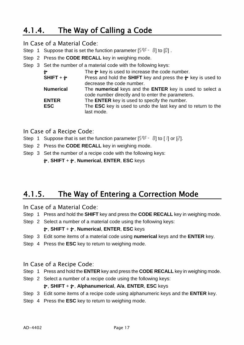
4.1.4.4.1.4.4.1.4.4.1.4. The Way of Calling a CodeThe Way of Calling a CodeThe Way of Calling a CodeThe Way of Calling a CodeIn Case of a Material Code:Step 1 Suppose that is set the function parameter [5qf- 8] to [0] .Step 2 Press the CODE RECALL key in weighing mode.Step 3 Set the number of a material code with the following keys:
The key is used to increase the code number.SHIFT + Press and hold the SHIFT key and press the key is used to
decrease the code number.Numerical The numerical keys and the ENTER key is used to select a
code number directly and to enter the parameters.ENTER The ENTER key is used to specify the number.ESC The ESC key is used to undo the last key and to return to the
last mode.
In Case of a Recipe Code:Step 1 Suppose that is set the function parameter [5qf- 8] to [1] or [2].Step 2 Press the CODE RECALL key in weighing mode.Step 3 Set the number of a recipe code with the following keys:
, SHIFT + , Numerical, ENTER, ESC keys
4.1.5.4.1.5.4.1.5.4.1.5. The Way of Entering a Correction ModeThe Way of Entering a Correction ModeThe Way of Entering a Correction ModeThe Way of Entering a Correction ModeIn Case of a Material Code:Step 1 Press and hold the SHIFT key and press the CODE RECALL key in weighing mode.Step 2 Select a number of a material code using the following keys:
, SHIFT + , Numerical, ENTER, ESC keysStep 3 Edit some items of a material code using numerical keys and the ENTER key.Step 4 Press the ESC key to return to weighing mode.
In Case of a Recipe Code:Step 1 Press and hold the ENTER key and press the CODE RECALL key in weighing mode.Step 2 Select a number of a recipe code using the following keys:
, SHIFT + , Alphanumerical, A/a, ENTER, ESC keysStep 3 Edit some items of a recipe code using alphanumeric keys and the ENTER key.Step 4 Press the ESC key to return to weighing mode.

Page 18 AD-4402
4.1.6.4.1.6.4.1.6.4.1.6. The Way of Entering MenuThe Way of Entering MenuThe Way of Entering MenuThe Way of Entering MenuStep 1 Press and hold the ENTER key and press the key in weighing mode.
Then the first layer of menu is display.Step 2 Use the following keys in the menu :
, SHIFT, Alphanumerical, A/a , ENTER, ESC keysStep 3 Press the ESC key to return to weighing mode several times.

AD-4402 Page 19
4.2.4.2.4.2.4.2. Status Chart (Mode mapStatus Chart (Mode mapStatus Chart (Mode mapStatus Chart (Mode map))))

Page 20 AD-4402
5.5.5.5. CalibrationCalibrationCalibrationCalibrationThe indicator, which is connected loadcell unit, can weigh the "weight" value on theloadcell pan and display its "mass" value. The calibration function is used to adjustthe weighing value (displaying value) so that the weighing system can weighcorrectly.There are two way of the calibration. The "actual load calibration" uses a ratedmass and zero output from the loadcell. The "digital span" inputs arbitrary values(calculated by hand). These methods are selected in the calibration procedure.There is a compensation function of the "gravity acceleration correction".This function is used, when a calibrated weighing system is moved to other place.These calibration parameters are stored in the indicator without any power supply.
Common Calibration ItemsUnit The "g", "kg" and "t" or "lb" can be selected.Decimal point The decimal point can be selected form "not used" to "four
decimal places".Minimum division The minimum division of the weighing display.Weighing capacity The maximum display of the weighing display.
Items for the "Actual Load Calibration"Common items Unit, decimal point, minimum division and weighing capacityZero point adjustment A zero point output is used from the loadcell unit.Span adjustment Rated mass is place on the weighing pan and is weighed.
The sensitivity is adjusted. This sensitivity is the same as "sensitivity " of digital span.
Items for "Digital Span"Common items Unit, decimal point, minimum division and weighing capacityZero point output The numerical data is input as zero point output of loadcell
unit.Rated capacity The rated capacity of the loadcell is input.
The sensitivity of the loadcell is input.
CautionWhen the CAL switch on the A/D board is "DISABLE", any calibration can notperform.Do not perform any calibration during a weighing sequnce operation.Entering calibration mode during a weighing sequnce operation, the weighingsequnce operation is terminated. Calibrate the weighing system, when aweighing sequnce operation does not workThe accuracy of the "Digital Span (Calibration without Mass)" is 1/1000.Do not use a "loadcell summing box", the "digital span" is performed.It is necessary that the loadcell sensitivity is exactly known, if the "digitalspan" is used.

AD-4402 Page 21
5.1.5.1.5.1.5.1. Actual Load Calibration (using Mass)Actual Load Calibration (using Mass)Actual Load Calibration (using Mass)Actual Load Calibration (using Mass)ESC key If you want to return to the weighing mode during the
calibration mode, press the ESC key anytime. And it haseffect until the last displayed parameter.Example: zero adjustment only, etc.
ENTER key When the key is pressed, the procedure stores a currentparameter and proceeds to next step.
Step 1 Press and hold the ENTER key and press the key to display themenu in a weighing mode.
Step 2 Press the key twice to select the menu CAL.Press the ENTER key to enter the calibration mode.
Step 3 Press the ENTER key to enter the menu CAL.Step 4 Select a unit using the numerical keys and press the ENTER key
to store it.Step 5 Select a decimal point using the numerical keys and press the
ENTER key to store it.Step 6 Select a minimum division using the numerical keys and press the
ENTER key to store it.Step 7 Select a weighing capcity using the numerical keys and press the
ENTER key to store it.Step 8 Perform the zero point adjustment.
Place nothing on the weighing pan and press the ENTER key tostore it after the STABLE indicator is displayed.Whether the STABLE indicator is displayed or not, if you want tostore it, wait for ten seconds and press the ENTER key.
Step 9 Specify a total mass value to place on the weighing pan using thenumerical keys and press the ENTER key to store it.
Step 10 Place the specifyed mass on the weighing pan and press theENTER key to store it after the STABLE indicator is displayed.Whether the STABLE indicator is displayed or not, if you want tostore it, wait for ten seconds and press the ENTER key.
Step 11 Press the ESC key to return the weighing mode.

Page 22 AD-4402
5.2.5.2.5.2.5.2. Digital Span (Calibration without Mass)Digital Span (Calibration without Mass)Digital Span (Calibration without Mass)Digital Span (Calibration without Mass)ESC key If you want to return to the weighing mode during the
calibration mode, press the ESC key anytime. And it haseffect until the last displayed parameter.Example: zero adjustment only, etc.
ENTER key When the key is pressed, the procedure stores a currentparameter and proceeds to next step.
Step 1 Press and hold the ENTER key and press the key to display themenu in a weighing mode.
Step 2 Press the key twice to select the menu CAL.Press the ENTER key to enter the calibration mode.
Step 3 Press the ENTER key to enter the menu CAL.Step 4 Select a unit using the numerical keys and press the ENTER key
to store it.Step 5 Select a decimal point using the numerical keys and press the
ENTER key to store it.Step 6 Select a minimum division using the numerical keys and press the
ENTER key to store it.Step 7 Select a weighing capcity using the numerical keys and press the
ENTER key to store it.Step 8 Press the F1 key to proceed to the digital span procedure.Step 9 Input the zero point value using the numerical keys and press the
ENTER key to store it.Step 10 Input the rated capacity of a loadcell using the numerical keys and
press the ENTER key to store it.Step 11 Input the sensitivity of the loadcell in the unit of mV/V using the
numerical keys and press the ENTER key to store it.Step 12 Press the ESC key to return the weighing mode.
Advise The digital span can be used for trimming of the actual load calibration using mass.

AD-4402 Page 23
5.3.5.3.5.3.5.3. Gravity Acceleration CorrectionGravity Acceleration CorrectionGravity Acceleration CorrectionGravity Acceleration CorrectionThe function compensates the weighing error due to the difference of gravity acceleration.G1 The place where the weighing system is calibrated.G2 The place where the weighing system is used.
ESC key If you want to return to the weighing mode during thecalibration mode, press the ESC key anytime.
ENTER key When the key is pressed, the procedure stores a currentparameter and proceeds to next step.
Step 1 Press and hold the ENTER key and press the key to display the menu in aweighing mode.
Step 2 Press the key twice to select the menu CAL. Press the ENTER key to enter thecalibration mode.
Step 3 Select the menu G with the key. Press the ENTER key to enter it.Step 4 Input the gravity acceleration at G1 using the numerical keys and press the
ENTER key to store it.Step 4 Input the gravity acceleration at G2 using the numerical keys and press the
ENTER key to store it.Step 5 Press the ESC key to return the weighing mode.
5.3.1.5.3.1.5.3.1.5.3.1. Gravity Acceleration ReferenceGravity Acceleration ReferenceGravity Acceleration ReferenceGravity Acceleration ReferenceAmsterdam 9.813 m/s2 Manila 9.784 m/s2
Athens 9.800 m/s2 Melbourne 9.800 m/s2
Auckland NZ 9.799 m/s2 Mexico City 9.779 m/s2
Bangkok 9.783 m/s2 Milan 9.806 m/s2
Birmingham 9.813 m/s2 New York 9.802 m/s2
Brussels 9.811 m/s2 Oslo 9.819 m/s2
Buenos Aires 9.797 m/s2 Ottawa 9.806 m/s2
Calcutta 9.788 m/s2 Paris 9.809 m/s2
Chicago 9.803 m/s2 Rio de Janeiro 9.788 m/s2
Copenhagen 9.815 m/s2 Rome 9.803 m/s2
Cyprus 9.797 m/s2 San Francisco 9.800 m/s2
Djakarta 9.781 m/s2 Singapore 9.781 m/s2
Frankfurt 9.810 m/s2 Stockholm 9.818 m/s2
Glasgow 9.816 m/s2 Sydney 9.797 m/s2
Havana 9.788 m/s2 Tainan 9.788 m/s2
Helsinki 9.819 m/s2 Taipei 9.790 m/s2
Kuwait 9.793 m/s2 Tokyo 9.798 m/s2
Lisbon 9.801 m/s2 Vancouver, BC 9.809 m/s2
London (Greenwich) 9.812 m/s2 Washington DC 9.801 m/s2
Los Angeles 9.796 m/s2 Wellington NZ 9.803 m/s2
Madrid 9.800 m/s2 Zurich 9.807 m/s2

Page 24 AD-4402
5.4.5.4.5.4.5.4. Calibration ErrorCalibration ErrorCalibration ErrorCalibration ErrorError Code Treatment and SituationCERR1 Resolution (Weighing capacity / minimum division) is exceeds the limitation.
Increase minimum division or decrease weighing capacity.CERR2 The initial load (no load output) is larger than 2mV/V.
Confirm the loadcell cable.CERR3 Negative loadcell output value. Check wiring.
Confirm the loadcell cable.CERR4 Mass value exceeds the weighing capacity.
Use a mass within the weighing capacity. (Decrease mass value)CERR5 Mass value is too light for the calibration.
Increase mass value.CERR6 The loadcell output to be equivalent to minimum division is too small.
Use more rough minimum division.CERR7 The polarity of loadcell output is inversed.
Confirm the loadcell cable.CERR8 The mass value of the weighing capacity exceeds 3.2 mV/V.
Confirm the mass and weighing capacity.CERR9 Gravity acceleration is out of range.
Correct the value within the range of 9.770 ~ 9.835 m/s2.CERR10 Zero output of loadcell unit is out of range.
Trim the zero output within 0.0 ~ 2.0 mV/V.CERR11 The loadcell output to be equivalent to minimum division is out of range.
Trim the output within 0.0 ~ 3.2 mV/V.
AD-4402 Page 25
6.6.6.6. ApplicationsApplicationsApplicationsApplications6.1.6.1.6.1.6.1. Hopper Scale with Material CodeHopper Scale with Material CodeHopper Scale with Material CodeHopper Scale with Material Code
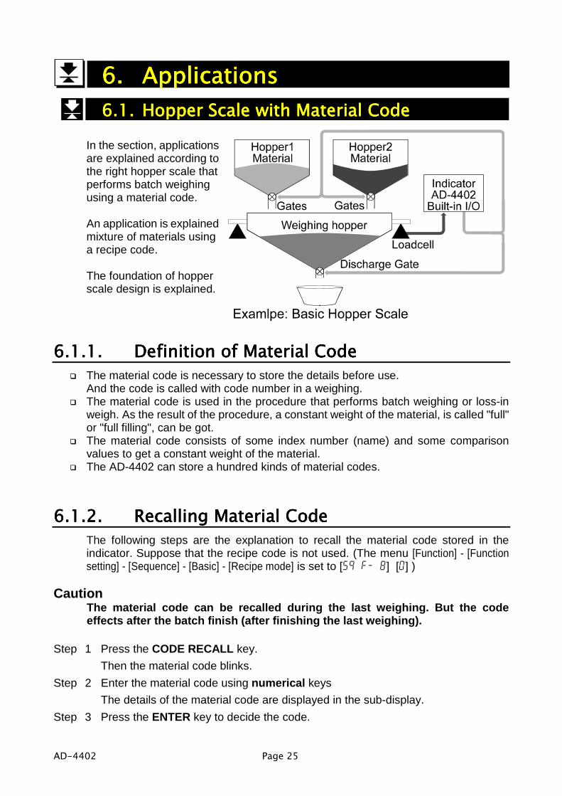
In the section, applicationsare explained according tothe right hopper scale thatperforms batch weighingusing a material code.
An application is explainedmixture of materials usinga recipe code.
The foundation of hopperscale design is explained.
6.1.1.6.1.1.6.1.1.6.1.1. Definition of Material CodeDefinition of Material CodeDefinition of Material CodeDefinition of Material CodeThe material code is necessary to store the details before use.And the code is called with code number in a weighing.The material code is used in the procedure that performs batch weighing or loss-inweigh. As the result of the procedure, a constant weight of the material, is called "full"or "full filling", can be got.The material code consists of some index number (name) and some comparisonvalues to get a constant weight of the material.The AD-4402 can store a hundred kinds of material codes.
6.1.2.6.1.2.6.1.2.6.1.2. RecallingRecallingRecallingRecalling MMMMaterial aterial aterial aterial CCCCodeodeodeodeThe following steps are the explanation to recall the material code stored in theindicator. Suppose that the recipe code is not used. (The menu [Function] - [Functionsetting] - [Sequence] - [Basic] - [Recipe mode] is set to [5q f- 8] [0] )
CautionThe material code can be recalled during the last weighing. But the codeeffects after the batch finish (after finishing the last weighing).
Step 1 Press the CODE RECALL key.Then the material code blinks.
Step 2 Enter the material code using numerical keysThe details of the material code are displayed in the sub-display.
Step 3 Press the ENTER key to decide the code.

Page 26 AD-4402
6.1.3.6.1.3.6.1.3.6.1.3. Editing Principle Parameters of Material CodeEditing Principle Parameters of Material CodeEditing Principle Parameters of Material CodeEditing Principle Parameters of Material CodeYou can edit the parameters of target weight, free fall and etc. displayed on the sub-display during a weighing. And items of sub-display can be selected at the menu[Function] - [Function setting] - [General] - [Sub-display].
CautionIf the flash memory is selected for memory backup (0tHf-110tHf-110tHf-110tHf-11), a currentsequential weighing is stopped.
Step 1 Press and hold the SHIFT key and press the CODE RECALL key.Then the material code blinks.
Step 2 Enter the material code using numerical keysThe details of the material code are displayed in the sub-display.
Step 3 Press the ENTER key to decide the code.Step 4 Select a parameter using the key on the sub-display.Step 5 Enter the parameter using numerical keys and press the ENTER key to store it.Step 6 If you continue the change, proceed step 4 and 5.Step 7 If you want to finish the change, press the ESC key to return to weighing mode
several times.
6.1.4.6.1.4.6.1.4.6.1.4. ReferrReferrReferrReferringinginging next Material Code next Material Code next Material Code next Material CodeYou can refer to next material code in the sequential mode that uses plural materialcodes. Suppose that the recipe code is not used. (The menu [Function] - [Functionsetting] - [Sequence] - [Basic] - [Recipe mode] is set to [5q f- 8] [0])
Step 1 Press the CODE RECALL key.Then principle parameters of the next material code are displayed in the sub-display.
Step 2 Press the ESC key to return to current mode.

AD-4402 Page 27
6.1.5.6.1.5.6.1.5.6.1.5. Editing Full Parameters of Material CodeEditing Full Parameters of Material CodeEditing Full Parameters of Material CodeEditing Full Parameters of Material CodeA material code consists of the following parameters.
Name Display Name DisplaySymbol
DisplayExample Memory
Material Code Code Code 11Material name Mat Name grainMaterial Hopper No. Mat Hopper Hopper 1Final Final Final 10.00 kgFree Fall Free Fall FFall 0.01 kgPreliminary Preliminary Plm 1.00 kgOptional Preliminary OP.Preliminary OPPlm 2.00 kgOver Over Over 0.10 kgUnder Undr Undr 0.10 kgZero Band Zero Band 0Band 0.02 kgFull Full Full 0.05 kgTare Tare Tare 5.00 kgSupplementary Flow Open Timer SF open timer SFOT 0.00 sSupplementary Flow Close Timer SF close SFCT 0.00 sAutomatic Free Fall Range AFFC range AFFC 0.00 kgInitial Dribble Flow Initial DF IDF 0.00 kgInitial Medium Flow Initial MF IMF 0.00 kg
Backed upRAM( factorysetting)orflashmemory
Total Weight Tot Tot 10.00 kgTotal Counts Tot# Tot# 1
Backed upRAM
These parameters are stored in backup memory without power supply.Refer to the backup method [0tHf-11] of the function list.
CautionIf the flash memory is selected for memory backup [0tHf-110tHf-110tHf-110tHf-11], a currentsequential weighing is stopped.
Edit Material CodeStep 1 Press and hold the ENTER key and press the key.
Then menu MatEdit blinks.Step 2 Press the ENTER key to enter the material code edit. Then menu Edit blinks.Step 3 Press the ENTER key to enter menu edit.Step 4 Select the material code using numerical keys and press the ENTER.Step 5 Enter the material name using alpanumerical keys and press the ENTER key.Step 5 Edit other parameters using numerical keys, ENTER key and key.Step 6 If you want to finish the change, press the ESC key to return to weighing mode
several times.

Page 28 AD-4402
Search Material CodeUse this menu to search blank material code.
Step 1 Press and hold the ENTER key and press the key.Then menu MatEdit blinks.
Step 2 Press the key to select menu Search. And press the ENTER key.Step 3 Then the message is displayed.Step 4 Press the ENTER key to prceed next step.
Then the result is displayed.Step 5 Press the ESC key to return to weighing mode several times.
Delete Material CodeThe parameter of the material code can be reset in the following menu.
Total valueSetpointsTotal of a material codeAll material codeAll total
Example of Deleting Total ValueStep 1 Press and hold the ENTER key and press the key.
Then menu MatEdit blinks.Step 2 Press the key to select menu Delete. And press the ENTER key.Step 3 Select menu Total using the key. And press the ENTER key.Step 4 Enter the material code using numerical keys and press the ENTER key.Step 5 Press the ESC key to return to weighing mode several times.
Copy Material CodeThe parameters of material code are copied. This copy includes a total weight valueand times of accumulation.
Step 1 Press and hold the ENTER key and press the key.Then menu MatEdit blinks.
Step 2 Press the key to select menu Copy. And press the ENTER key.Step 4 Specify a original code number using numerical keys and press the ENTER key.Step 5 Specify a duplicated code number using numerical keys and press the ENTER key.Step 6 Press the ESC key to return to weighing mode several times.

AD-4402 Page 29
Tare of Material CodeUse to copy current tare to the preset tare.Set a preset tare function [gebf-12 ] of the function list.[gebf-12] [0] If the preset tare of the code is zero, the last tare value effects.
(factory settings)[gebf-12] [1] If the preset tare of the code is zero, tare value is reset.
Step 1 Press and hold the ENTER key and press the key.Then menu MatEdit blinks.
Step 2 Press the key to select menu Tare. And press the ENTER key.Step 4 Specify a code number using numerical keys and press the ENTER key.
Then current tare value is copied to preset tare.Step 5 Press the ESC key to return to weighing mode several times.

Page 30 AD-4402
6.2.6.2.6.2.6.2. Simple Hopper Scale with Recipe CodeSimple Hopper Scale with Recipe CodeSimple Hopper Scale with Recipe CodeSimple Hopper Scale with Recipe CodeThe section explains for recipe code (another name: formal function). The recipecode is used on a simple hopper scale to mix several materials that are preset targetvalue. "The simple hopper scale" means that does not control the ratio and a weightof ingredient, but simply accumulates the preset target weight of the material code.Therefore, the recipe code is a code to accumulate the preset target weight of thematerial code.
6.2.1.6.2.1.6.2.1.6.2.1. Definition of Recipe Code (Definition of Recipe Code (Definition of Recipe Code (Definition of Recipe Code (FormalFormalFormalFormal Function) Function) Function) Function)A recipe code consists of plural preset material codes.Maximum ten material codes can be stored in a recipe code.A recipe code is described in order to accumulate target weight of the material code.The indicator AD-4402 can store a hundred recipe codes.The recipe code is necessary to store the details before use.And the code is called with code number in a weighing.The recipe code is a code to accumulate the preset target weight of the material code.If a recipe code is used in the batch weighing (or loss-in weight), you can get a weightthat is accumulated the preset target weight of the material code.The recipe sequence that is used recipe code calls formula sequence, too.

AD-4402 Page 31
6.2.2.6.2.2.6.2.2.6.2.2. Using a Recipe CodeUsing a Recipe CodeUsing a Recipe CodeUsing a Recipe CodeSet the menu [Function] - [Function setting] - [Sequence] - [Basic] - [Recipe mode] tosequential mode ( [5q f- 8] to [1] or [2] ), when the recipe code is used.[5q f- 8] [1] Semi-automatic mixture sequence[5q f- 8] [2] Automatic mixture sequence
6.2.3.6.2.3.6.2.3.6.2.3. Construction of Recipe CodeConstruction of Recipe CodeConstruction of Recipe CodeConstruction of Recipe CodeThe indicator AD-4402 can store a hundred recipe codes.A recipe code can store maximum ten material codes in order of accumulating them.These parameters are stored in backup memory without power supply.Refer to the backup method [0tHf-11] of the function list.
CautionIf the flash memory is selected for memory backup [0tHf-110tHf-110tHf-110tHf-11], a currentsequential weighing is stopped.
Name Display Symbol & Example MemoryRecipe code rCodeRecipe name Blend coffee
Material codes of maximum ten codes.It is stored in order to accumlate them. Code 1
Backed up RAM( factory setting)
orflash memory
Accumulated Weight for recipe code Total Weight
10.00 kg
Accumulation Counts for recipe code Total Counts
10.00 kg
Backed up RAM
6.2.4.6.2.4.6.2.4.6.2.4. RecallingRecallingRecallingRecalling a Recipe Codea Recipe Codea Recipe Codea Recipe CodeThe following steps are the explanation to recall the recipe code stored in theindicator. Suppose that the recipe code is used (The menu [Function] - [Function setting]- [Sequence] - [Basic] - [Recipe mode] is set to [5q f- 8] [1] or [2]). .
CautionThe code can be recalled during the last weighing. But the code effects afterthe butch finish (after finishing the last weighing).
Step 1 Press the CODE RECALL key.Then the recipe code blinks.
Step 2 Enter the material code using numerical keysThe details of the recipe code are displayed in the sub-display.
Step 3 Press the ENTER key to decide the code.

Page 32 AD-4402
6.2.5.6.2.5.6.2.5.6.2.5. Arranging Material Code in Recipe CodeArranging Material Code in Recipe CodeArranging Material Code in Recipe CodeArranging Material Code in Recipe CodeThe way of arranging material code described in a recipe code.
Step 1 Press and hold the ENTER key and press the CODE RECALL key.Step 2 Select a recipe code number using numerical keys and press the ENTER key.
Then first material code blinks.Step 3 Select a material code using the following keys.
key, numerical keys and SHIFT keyStep 4 Press the ENTER key to store it. Then the next code blinks.Step 5 Continue step 3 and 4 until the last material code is stored.Step 6 Press the ESC key to return to weighing mode several times.
6.2.6.6.2.6.6.2.6.6.2.6. Editing Full Parameters of Recipe CodeEditing Full Parameters of Recipe CodeEditing Full Parameters of Recipe CodeEditing Full Parameters of Recipe CodeAll parameters of the recipe code can be edited in this menu.
Edit Name of Recipe CodeStep 1 Press and hold the ENTER key and press the key.
Press the key. Then menu RecipeEDIT blinks.Step 2 Press the ENTER key to enter the recipe code edit. Then menu edit blinks.Step 3 Press the ENTER key to enter menu edit.Step 4 Select a recipe code using numerical keys and press the ENTER.Step 5 Name a recipe code using alpanumerical keys and press the ENTER key.Step 6 If you want to finish the change, press the ESC key to return to weighing mode
several times.
Search of Recipe CodeUse this menu to search blank material code.
Step 1 Press and hold the ENTER key and press the key.Press the key. Then menu RecipeEDIT blinks.
Step 2 Press the key to select menu Search. And press the ENTER key.Step 3 Then the message is displayed.Step 4 Press the ENTER key to prceed next step.
Then the result is displayed.Step 5 Press the ESC key to return to weighing mode several times.
Delete of Recipe CodeThe parameter of the recipe code can be reset in the following menu.

AD-4402 Page 33
Total valueRecipe total valueAll total valueAll Recipes
Example of Deleting Total ValueStep 1 Press and hold the ENTER key and press the key.
Then menu RecipeEDIT blinks.Step 2 Press the key to select menu Delete. And press the ENTER key.Step 3 Select menu Total using the key.
And press the ENTER key.Step 4 Enter the recipe code using numerical keys and press the ENTER key.Step 5 Press the ESC key to return to weighing mode several times.
Copy of Recipe CodeThe parameters of recipe code are copied. This copy includes a total weight valueand times of accumulation.Set a preset tare function [ genf-12 ] of the function list.[genf-12] [0] If the preset tare of the code is zero, the last tare value effects.
(factory settings)[genf-12] [1] If the preset tare of the code is zero, tare value is reset.
Step 1 Press and hold the ENTER key and press the key.Then menu RecipeEDIT blinks.
Step 2 Press the key to select menu Copy. And press the ENTER key.Step 4 Specify a original code number using numerical keys and press the ENTER key.Step 5 Specify a duplicated code number using numerical keys and press the ENTER key.Step 6 Press the ESC key to return to weighing mode several times.
Page 34 AD-4402
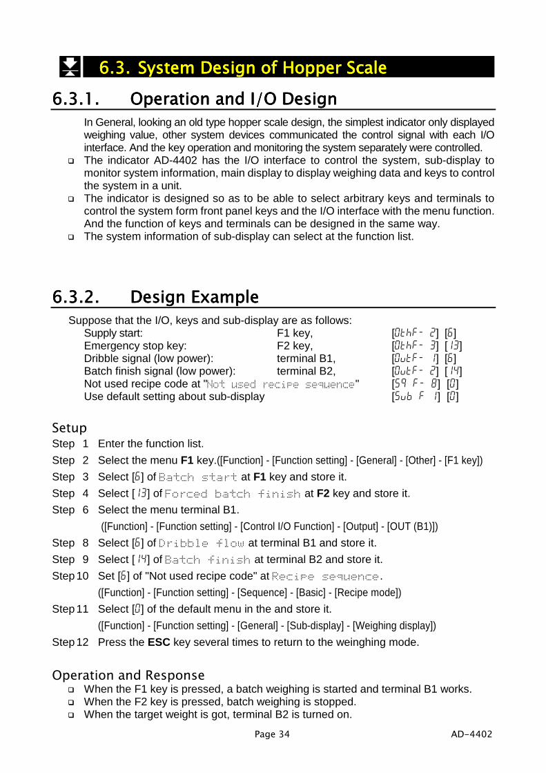
6.3.6.3.6.3.6.3. System Design of Hopper ScaleSystem Design of Hopper ScaleSystem Design of Hopper ScaleSystem Design of Hopper Scale6.3.1.6.3.1.6.3.1.6.3.1. Operation and I/O DesignOperation and I/O DesignOperation and I/O DesignOperation and I/O Design
In General, looking an old type hopper scale design, the simplest indicator only displayedweighing value, other system devices communicated the control signal with each I/Ointerface. And the key operation and monitoring the system separately were controlled.The indicator AD-4402 has the I/O interface to control the system, sub-display tomonitor system information, main display to display weighing data and keys to controlthe system in a unit.The indicator is designed so as to be able to select arbitrary keys and terminals tocontrol the system form front panel keys and the I/O interface with the menu function.And the function of keys and terminals can be designed in the same way.The system information of sub-display can select at the function list.
6.3.2.6.3.2.6.3.2.6.3.2. DesignDesignDesignDesign Example Example Example ExampleSuppose that the I/O, keys and sub-display are as follows:
Supply start: F1 key, [0thf- 2] [6]Emergency stop key: F2 key, [0thf- 3] [13]Dribble signal (low power): terminal B1, [0utf- 1] [6]Batch finish signal (low power): terminal B2, [0utf- 2] [14]Not used recipe code at "Not used recipe sequence" [5q f- 8] [0]Use default setting about sub-display [5ub f 1] [0]
SetupStep 1 Enter the function list.Step 2 Select the menu F1 key.([Function] - [Function setting] - [General] - [Other] - [F1 key])Step 3 Select [6] of Batch start at F1 key and store it.Step 4 Select [13] of Forced batch finish at F2 key and store it.Step 6 Select the menu terminal B1.
([Function] - [Function setting] - [Control I/O Function] - [Output] - [OUT (B1)])Step 8 Select [6] of Dribble flow at terminal B1 and store it.Step 9 Select [14] of Batch finish at terminal B2 and store it.Step 10 Set [6] of "Not used recipe code" at Recipe sequence.
([Function] - [Function setting] - [Sequence] - [Basic] - [Recipe mode])Step 11 Select [0] of the default menu in the and store it.
([Function] - [Function setting] - [General] - [Sub-display] - [Weighing display])Step 12 Press the ESC key several times to return to the weinghing mode.
Operation and ResponseWhen the F1 key is pressed, a batch weighing is started and terminal B1 works.When the F2 key is pressed, batch weighing is stopped.When the target weight is got, terminal B2 is turned on.

AD-4402 Page 35
7.7.7.7. Weighing ModeWeighing ModeWeighing ModeWeighing Mode7.1.1.7.1.1.7.1.1.7.1.1. Contents of Contents of Contents of Contents of BatchBatchBatchBatch Weighing Mode Weighing Mode Weighing Mode Weighing ModeBatch Weighing
Normal Batching Section 7.2Normal Batching using Sequential Weighing Mode Section 7.3.1Normal Batching using Customer Programmed Control Section 7.4.1
Loss-in weight Section 7.2Loss-in weight using Sequential Weighing Mode Section 7.4.1Loss-in weight using Customer Programmed Control Section 7.4.2
Selection of Batch Weighing Section 7.2.1
Controlled Output SignalsThe type of the signal output to control gates (valves) in the batch weighing.Sequential Weighing Mode (built-in automatic program mode) Section 7.3Customer Programmed Control (Comparison Output) Section 7.4
Partial Sequence of Sequential Weighing ModeCompensation Sequence Section 7.3.3Approach Sequence Section 7.3.4Discharge Sequence Section 7.3.5Plain Recipe Sequence Section 7.3.6Automatic Selection of Supplying Mat Section 7.3.7Nozzle Operation (vacuum cleaner) Section 7.3.8Mixture Sequence Section 7.3.9Safety Check Function Section 7.3.10Pause and Emergency Stop Section 7.3.11Restart Sequence Section 7.3.12Automatic Free Fall Compensation Section 7.3.13Real Time Free Fall Compensation Section 7.3.14

Page 36 AD-4402
7.2.7.2.7.2.7.2. BatchBatchBatchBatch Weighing Mode Weighing Mode Weighing Mode Weighing ModeThe mode is used to get a (constant) target weight from a supplying Mat for thehopper scale and filling machine. And the mode can be classified to normal batchweighing and loss-in weight.There are two control methods of the customer programmed control and sequentialcontrol (built-in automatic program mode).
Normal BatchingNormal batch weighing weighs the material charged into the hopper.The control gates (valves) can be used. (The full flow, medium flow and dribble flow)
Loss-in-weightLoss-in weight weighs the material discharged form the hopper.The control gates (valves) can be used. (The full flow, medium flow and dribble flow)
CautionUse the PLC (programmable logic controller unit) to supply material into theweighing hopper and monitor the bulk of material of the hopper.

AD-4402 Page 37
7.2.1.7.2.1.7.2.1.7.2.1. Selection of Batch WeighingSelection of Batch WeighingSelection of Batch WeighingSelection of Batch WeighingSelection of Normal Batching or Loss-in-weight
The mode can be selected at Loss-in weight at the Function list.([Function] - [Function setting] - [Sequence] - [Basic] - [Current weighing])[5q f- 3] [0] Normal batch weighing[5q f- 3] [1] Loss-in weight[5q f- 3] [2] External selection (Normal batch weighing or Loss-in weight)
External Selection (Normal batch weighing or Loss-in weight)Normal batch weighing and Loss-in weight can be selected by a signal of the inputterminal that is set to [9] of External switch control.(The menu [Function] - [Function setting] - [Control I/O Function] - [Input] )Example of use: The material of 100 kg is supplied to the hopper in first step. It issubdivided into material of 10kg.
AdviseIf the mode is switched concerning a specified material only, set the hopper no. in thematerial code, short the hopper no. output line and the supply/discharge switch inputline. Set the delay timer [5q f-32] to "above 0.1sec.".

Page 38 AD-4402
7.3.7.3.7.3.7.3. SequentialSequentialSequentialSequential Weighing Mode Weighing Mode Weighing Mode Weighing ModeThe sequential weighing mode (built-in automatic program mode) directly outputscontrol signals (example: medium flow valve, batch finish) without the PLC.The sequential weighing mode can include several partial sequences like anapproach sequence, mixture sequence and etc. into basic sequential weighing.The power of the control I/O signal output is too small to drive a large valve directly.Use option relay output ( OP-02 ) to drive them.If the number of the control I/O terminals is not enough, use option parallel I/O ( OP-05 ).
Forecast Control FunctionThe function forecasts a timing to close the dribble flow (valve) and realizes moreprecision weighing. The forecast method calculates the weighing value at somepoints between sampling data and compares it with the dribble setpoint. The effect isequivalent to use a high speed A/D converter. The sampling rate of this indicator is100 [times/second]. But the ratio is equivalent to 1000 [times/second], when thefunction is used.
CautionIf prual supplying mat is used (the recipe code is used), the mode can not use.Relation section is " 7.3.7. Automatic Selection of Supplying Mat".Use the high speed high precision valve like a direct voltage solenoid valve.Design the mechanical valve so as to minimize the delay time.
7.3.1.7.3.1.7.3.1.7.3.1. NNNNormal ormal ormal ormal BBBBatching of Sequentialatching of Sequentialatching of Sequentialatching of Sequential Weighing Weighing Weighing WeighingNormal batch weighing weighs the material charged into the hopper.The control gates (valves) can be used. (The full flow, medium flow and dribble flow)
Concerning Parameters of the FunctionSelecting normal batching of sequential weighing.[5q f- 1] [2] Sequential weighing
[Function] - [Function setting] - [Sequence] - [Basic] - [Weighing mode][5q f- 3] [0] Normal batch weighing
[Function] - [Function setting] - [Sequence] - [Basic] - [Loss-in weight]
Making zero display automatically when starting the sequence.[5q f-11] [Function] - [Function setting] - [Sequence] - [Control] - [Batch start settings]
Preventing vibration due to gate operation.[5q f-33] [Function] - [Function setting] - [Sequence] - [Timer] - [Full flow comparison
interrupt timer][5q f-34] [Function] - [Function setting] - [Sequence] - [Timer] - [Medium flow
comparison interrupt timer][5q f-35] [Function] - [Function setting] - [Sequence] - [Timer] - [Dribble flow
comparison interrupt timer]

AD-4402 Page 39
Making alarm when the sequence is time over.[5q f-31] Maximum weighing time between start and batch finish can be set.
Error code [SQ.ERR 4] is displayed, when an error occurs.[Function] - [Function setting] - [Sequence] - [Timer] - [Batch monitoringtimer]
Removing "stable" from comparison condition.[5q f-13] [Function] - [Function setting] - [Sequence] - [Control] - [Eval condition]
Changing the timing of comparison.[5q f-37] [Function] - [Function setting] - [Sequence] - [Timer] - [Eval delay timer]
Changing accuracy of comparison.[5q f-48] The time to average weighing value at batch finish can be set. The
timing of batch finish delays for the time.[Function] - [Function setting] - [Sequence] - [Timer] - [Average Eval time]
Changing the pulse width of weighing finish output.[5q f-43] If zero is set to this, the output leaves until next start signal.
[Function] - [Function setting] - [Sequence] - [Timer] - [Batch finish outputon]
Mixing it at weighing finish.[5q f-14] [Function] - [Function setting] - [Sequence] - [Control] - [Batch finish action]
Discharging it at weighing finish.[5q f-15] [Function] - [Function setting] - [Sequence] - [Control] - [Discharge finish
action]
Using customer programmed control for hi signal, go signal and low signal.[5q f- 5] [Function] - [Function setting] - [Sequence] - [Basic] - [Comparison]

Page 40 AD-4402
Drawing: Normal Batching of Sequential Weighing
0
Weighing value
Start command, Input
Dribble flow, Output
Batch finish, Output
Over weight, Output
Discharge gate close timer
Under weight, Output
Medium flow, Output
Full flow, Output
Nearly zero, Output
Material code, Input
Batch start delay timer
Batch monitoring timer
Dribble flow comparison interrupt timer
Medium flow comparison interrupt timer
Full flow comparison interrupt timer
Eval delay timer
Stable, Output
OK, Output
Discharge start delay timer
Discharge monitoring timer
Discharge, Output
Discharge start, Input
Discharge finish, Output
Net weight
Gross weight
The active code is only read ateach start. And keep it.
5qf-43Batch finish outputon
5qf-32
5qf-31
5qf-37
5qf-33
5qf-35
5qf-34
The whole time tosupply it
If discharge sequence,set the function.
Free fall
Preliminary
Optional preliminaryZero band
Select a modeat 5qf-05
Comparison According to 5qf-37 and stable.5qf-13 can be set.
Tare
Time until supplying it
10
Final value - Free fall
Final value (Target weight)
Final value - Preliminary
Final value - Optional preliminary

AD-4402 Page 41
7.3.2.7.3.2.7.3.2.7.3.2. LLLLoss-inoss-inoss-inoss-in W W W Weight of Sequentialeight of Sequentialeight of Sequentialeight of Sequential Mode Mode Mode ModeLoss-in weight weighs the material discharged form the hopper.The control gates (valves) can be used. (The full flow, medium flow and dribble flow)
Concerning Parameters of the FunctionSelecting normal batching of sequential weighing.[5q f- 1] [1] Sequential weighing
[Function] - [Function setting] - [Sequence] - [Basic] - [Weighing mode][5q f- 3] [0] Normal batch weighing
[Function] - [Function setting] - [Sequence] - [Basic] - [Loss-in weight]
Making zero display automatically when starting the sequence.[5q f-11] [Function] - [Function setting] - [Sequence] - [Control] - [Batch start settings]
Switching normal batching and loss-in weight from the I/O interface.[5q f- 3] [2] External exchange
Set an input terminal to switch the mode at the I/O interface. Materialcan be supplied to the hopper with three gates (valves).[Function] - [Function setting] - [Sequence] - [Basic] - [Loss-in weight]
Checking whether is there the remainder weight for one batch weighting.[5q f-55] [1] When the remainder weight decreases under target weight + nearly
zero, the signal "nearly zero" is output.[Function] - [Function setting] - [Sequence] - [Setpoint (Compared value)] -[Add final value and zero band]
[5q f-56] [1] If this is set, when the hopper is filled fully, the signal "Full" is output.[Function] - [Function setting] - [Sequence] - [Setpoint (Compared value)] -[Add final value and full value]

Page 42 AD-4402
Drawing: Loss-in Weight of Sequential Weighing
0
Weighing value
Start command, Input
Dribble flow, Output
Batch finish, Output
Over weight, Output
Under weight, Output
Medium flow, Output
Full flow, Output
Material code, Input
Start delay timer
Batch monitoring timer
Dribble flow comparison interrupt timer
Medium flow comparison interrupt timer
Full flow comparison interrupt timer
Eval delay timer
Stable, Output
Acceptable, Output
5qf-31
5qf-37
5qf-33
5qf-35
5qf-34
Tare command, Input
Final value
Enable to use automatic tare
Comparison
Select a modeat 5qf-05
Gross weight
Full filling
Zero band
Net weight
Optional preliminaryPreliminary
Free fall
5qf-32
The active code is only read ateach start. And keep it.
Monitor to supply it
Time until supplying it
5qf-43batch finish outputon
- Final valueor -Target weight
- Final value + Free fall
- Final value + Preliminary
- Final value + Optional preliminary
Full filling value

AD-4402 Page 43
7.3.3.7.3.3.7.3.3.7.3.3. CCCCompensation ompensation ompensation ompensation SSSSequenceequenceequenceequenceThe compensation sequence is used to make up (add) the material automatically,when the result of current batch weighing is under weight.
Concerning Parameters of the FunctionStoring a maximum repeat counts of compensation sequence.[5q f-18] If number is zero, this sequence is canceled. When the result is
under weight after the sequence, An error SQ.ERR 2 is displayed.[Function] - [Function setting] - [Sequence] - [Control] - [Maximum numberof compensation]
Setting the time to open the dribble gate.Set the time at each material code.[Function] - [Function setting] - [MatEDIT] - [Edit] - [Compensation flow opentimer]
Setting the time to close the dribble gate.Set the time at each material code.When the weighing value is stable and under weight, thecompensation is repeated. Take a longer time closing gate, if it doesnot use a stable signal.[Function] - [Function setting] - [Material Edit] - [Edit.] - [Compensation flowclose timer]
Removing the nozzle at this sequence, when the nozzle operation is used.[5q f-12] [2] Nozzle contact stop sequence
Factory setting is "not used". When it is necessary to shift up thenozzle to reduce a weighing error, use this parameter of [5q f-12].[Function] - [Function setting] - [Sequence] - [Control] - [Nozzle control]

Page 44 AD-4402
Drawing: Compensation Sequential
0
Final value (Target weight)
Start command, Input
Dribble flow, Output
Batch finish, Output
Over weight, Output
Under weight, Output
Medium flow, Output
Full flow, Output
Material code, Input
Batch monitoring timer
Stable, Out
Acceptable, Output
5qf-31
Weighing valueUnder weight
Compensation flow open timer
Compensation flow close timer
Eval delay timer5qf-37
Comparison
Free fallPreliminary
Optional preliminary
Net weight
Batch start delay timer5qf-32
Time until supplying it
Set maximum counts ofcompensation at 5qf-18
The whole time tosupply it

AD-4402 Page 45
7.3.4.7.3.4.7.3.4.7.3.4. Entrance SEntrance SEntrance SEntrance SequenceequenceequenceequenceThe entrance sequence is used to prevent the material form scattering before thebatch weighing when a liquid or powder is weighed. When the sequence starts,dribble gate is opened at first, medium gate is opened next and full gate is opened atlast. The parameter can be set in each material code.
Concerning Parameters of the FunctionUsing this sequence to prevent the material form scatting.
Set the following parameters in each material code.Medium supply effective bandwidthDribble supply effective bandwidth
Editing these parameters.Edit the parameters in the function mode.[Function] - [Function setting] - [MatEDIT] - [Edit]
Inhibiting the comparison during the sequence.[5q f-35] Store the time of the dribble flow comparison inhibit timer.
[Function] - [Function setting] - [Sequence] - [Timer] - [Dribble flowcomparison interrupt timer]
[5q f-34] Store the time of the medium flow comparison inhibit timer.[Function] - [Function setting] - [Sequence] - [Timer] - [Medium flowcomparison interrupt timer]

Page 46 AD-4402
Drawing: Entrance Sequence
0
Weighing value
Start command, Input
Dribble flow, Output
Batch finish, Output
Over weight, Output
Under weight, Output
Medium flow, Output
Full flow, Output
Material code, Input
Batch start delay timer
Batch monitoring timer
Dribble flow comparison interrupt timer
Medium flow comparison interrupt timer
Full flow comparison interrupt timer
Eval delay timer
Stable, Output
Acceptable, Output
5qf-32
5qf-31
5qf-37
5qf-33
5qf-35
5qf-34
Medium supply at entrance
Dribble supply at entrance
Comparison
Gross weight
Free fall
Dribble
Preliminary
Net weight
Time until supplying itThe whole time tosupply it
Final value (Target weight)

AD-4402 Page 47
7.3.5.7.3.5.7.3.5.7.3.5. DischargeDischargeDischargeDischarge SSSSequenceequenceequenceequenceThe discharge sequence is used to discharge the material form the hopper and clearthe hopper after finishing a batch weighing.
Concerning Parameters of the FunctionStoring the time between receiving start command and opening the discharge gate.[5q f-38] [Function] - [Function setting] - [Sequence] - [Timer] - [Discharge start
delay timer]
Using the alarm for the discharge time limit.[5q f-39] If it is over, an error SQ.ERR 7 is displayed.
[Function] - [Function setting] - [Sequence] - [Timer] - [Dischargemonitoring timer]
Storing the time between cleared hopper and closed the gate.[5q f-40] [Function] - [Function setting] - [Sequence] - [Timer] - [Discharge gate
close delay timer]
Discharging it automatically when finished the weighing.[5q f-14] When the finish signal is turned off, the discharge start timer starts.
[Function] - [Function setting] - [Sequence] - [Control] - [Batch finishaction]
Discharging it automatically when finished the mixture weighing.[5q f-17] When the finish signal is turned off, the discharge start timer starts.
[Function] - [Function setting] - [Sequence] - [Control] - [Recipe finishaction]

Page 48 AD-4402
Drawing: Discharge Sequence
0
Start command, Input
Dribble flow, Output
Batch finish, Output
Discharge gate close delay timer
Medium flow, Output
Full flow, Output
Nearly zero, Output
Start delay timer
Criteria waiting timer
Stable, Output
Discharge start delay timer
Discharge monitoring timer
Discharge, Output
Discharge start, Input
Discharge finish, Output
5qf-38
5qf-39
5qf-40
Gross value crosseszero band.
Comparison
Gross weight
Net weight
Weighing value
Zero band
Automatic dischargeoperation can selectat 5qf-14.
Zero band.
When weighing valuereaches to zero band,the timer works.
5qf-44Discharge finish output on
When weighing value isnot reach to zero banduntil the timer stops, Anerror code SQ.ERR7 isdisplayed.

AD-4402 Page 49
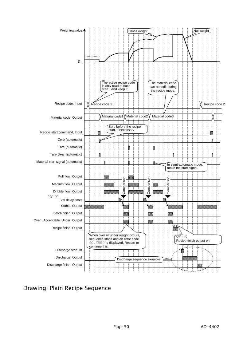
7.3.6.7.3.6.7.3.6.7.3.6. PPPPlain lain lain lain RRRRecipe ecipe ecipe ecipe SSSSequenceequenceequenceequenceThe plain recipe sequence mixes preset target weights of plural materials that arestored in a recipe code. A hundred recipe codes can be stored in the indicator. Arecipe code can store ten material codes and the order to mix them.There are the following two modes that can select at Recipe mode.Semi-automatic [5qf- 8] [1] The mode that uses (external) start command for
each material.Automatic [5qf- 8] [2] The mode that does not need each start command.
When the under weight occurs in a material, anerror code SQ.ERR 2 is displayed and sequencestops.
Concerning Parameters of the FunctionSelecting normal batching of sequential weighing.[5q f- 8] Recipe mode[5q f- 8] [1] Semi-automatic mode, or[5q f- 8] [2] Automatic mode
[Function] - [Function setting] - [Sequence] - [Basic] - [Recipe mode]
Making zero display automatically when starting the recipe sequence.[5q f-16] [Function] - [Function setting] - [Sequence] - [Control] - [Recipe start action]
Clearing tare value, mixing them and discharging them when finishing the recipesequence.[5q f- 17] [Function] - [Function setting] - [Sequence] - [Control] - [Recipe finish action]
Changing the width of the finish signal output of the recipe sequence.[5q f-45] [Function] - [Function setting] - [Sequence] - [Timer] - [Recipe finish output
on]
Calculating totals in each recipe code.[5q f-62] [Function] - [Function setting] - [Sequence] - [Accumulation] - [Automatic
recipe code total]
Weighing a single material code during a recipe sequenceWhen it have to weigh the material code temporarily during a recipe sequence, useformulation (recipe) prohibition command of the external I/O or OP-05. When theprohibition works, the material code can be used and total of the recipe is notaccumulated.Setting of the I/O.[1n f-nn] [49] Prohibition of recipe sequence.
nn: terminal number of I/O.[Function] - [Function setting] - [Control I/O] - [Input]
Page 50 AD-4402
Drawing: Plain Recipe Sequence
0
Weighing value
Material start signal (automatic)
Dribble flow, Output
Batch finish, Output
Over , Acceptable, Under, Output
Medium flow, Output
Full flow, Output
Material code, Output
Stable, Output
Discharge start, In
Discharge, Output
Recipe finish, Output
Discharge finish, Output
Recipe start command, Input
Recipe code, Input
Tare (automatic)
Tare clear (automatic)
Zero (automatic)
Eval delay timer
Com
paris
on
Material code1 Material code2 Material code3
Recipe code 1 Recipe code 2
5qf-45Recipe finish output on
When over or under weight occurs,sequence stops and an error codeSQ.ERR2 is displayed. Restart tocontinue this.
Zero before the recipestart, if necessary
The material codecan not edit duringthe recipe mode.
The active recipe codeis only read at eachstart. And keep it.
Gross weight Net weight
In semi-automatic mode,make the start signal.
5qf-37
Com
paris
on
Com
paris
on
Discharge sequence example

AD-4402 Page 51
7.3.7.7.3.7.7.3.7.7.3.7. Automatic Selection of Supplying MatAutomatic Selection of Supplying MatAutomatic Selection of Supplying MatAutomatic Selection of Supplying MatWhen there are plural supplying mats of materials, the indicator has to control thesegates. There are the following two method to control them.
Case 1: Direct Gate ControlThe method is that connects each gate control
lines of supplying mats to the I/O terminals of the indicator and the indicator directlycontrols them.Three kinds of gates can be used in a supplying hopper. (Full, medium, dribble gate)Number of supplying hopper: Ten hoppers can be used.Preset material codes and recipe codes can be used.The selection of the supplying mat is [MatEDIT] - [Material code] - [Material hopper].The selection of the I/O terminals is [Function] - [Function setting] - [Control I/O Function] - [Output].Even if a code is recalled during the sequence, the code does not work until thesequence finishes.When number of the I/O terminals is not enough, use options of relay output (OP-02)and parallel I/O (OP-05).
Case 2: Gate Control with Supplying Mat SelectionThe method:
Make gate-lines that gates of a kind in each supplying mat are connected to theI/O terminal of the indicator in parallel.Make Hop-lines that lines identified each mat are connected to the I/O terminal.The indicator can control any gate which the gate-line and mat-line is active.(logical AND gate)
Three kinds of gates can be used in a supplying hopper. (Full, medium, dribble gate)Number of supplying hopper: Twenty hoppers can be used.Preset material codes and recipe codes can be used.The selection of the supplying mat is [MatEDIT] - [Material code] - [Material hopper].The selection of the I/O terminals is [Function] - [Function setting] - [Control I/O function] - [Output].When number of the I/O terminals is not enough, use options of relay output (OP-02)and parallel I/O (OP-05).

Page 52 AD-4402
7.3.8.7.3.8.7.3.8.7.3.8. Nozzle Control Sequence (Nozzle Control Sequence (Nozzle Control Sequence (Nozzle Control Sequence (vacuum cleanervacuum cleanervacuum cleanervacuum cleaner))))The nozzle is used for filling liquid or powder to bottle. The procedure is that insertsthe nozzle to the bottle automatically using the signal "nozzle down" before theweighing, weighs it and removes the nozzle when dribble flow is finished. Therefore,the result (comparison) of weighing is not affected.
AdviseIn case of using the nozzle control sequence[5q f-12] [Function] - [Function setting] - [Sequence] - [Control] - [Nozzle control]
In case of using the timer to ready nozzle.[5q f-32] [Function] - [Function setting] - [Sequence] - [Timer - [Batch start delay
timer]
In case of using the nozzle down[0utf-nn] Nozzle down
nn: terminal number of the I/O.[Function] - [Function setting] - [Control I/O] - [Output]
In case of compare it after shifting up nozzle[5q f-12] [Function] - [Function setting] - [Sequence] - [Control] - [Nozzle control]
Start command, Input
Dribble flow, Output
Criteria waiting timer
Start delay timer
Medium flow, Output
Full flow, Output
0
Weighing value
Inserting nozzle, Output
Stable, Output
Batch finish, Output
Comparison
Removing nozzle when dribble finish
Insert nozzle when receiving start signal

AD-4402 Page 53
7.3.9.7.3.9.7.3.9.7.3.9. Mixture SequenceMixture SequenceMixture SequenceMixture SequenceThe mixture sequence is used to mix or stir it. The signal is output from the I/Oterminal set to mixing. The timing of weighing finish, discharge finish and mixturefinish can be selected.
Concerning Parameters of the FunctionUsing the mixture sequence[0utf-nn] [12] Mixture
nn: terminal number of I/O.[Function] - [Function setting] - [Control I/O] - [Output]Relay output (OP-02), parallel I/O (OP-05) can be used.
Mixing it at weighing finish[5q f-14] [Function] - [Function setting] - [Sequence] - [Control] - [Batch finish
action]
Mixing it after discharge[5q f-15] [Function] - [Function setting] - [Sequence] - [Control] - [Discharge finish
action]
Mixing it after formula[5q f-17] [Function] - [Function setting] - [Sequence] - [Control] - [Recipe finish
action]
Storing the time of mixture[5q f-47] [Function] - [Function setting] - [Sequence] - [Timer] - [Mixing time output
on]
Safety check during mixture[5q f-74] [Function] - [Function setting] - [Sequence] - [Safety] - [Mixing safety
check]
AdviseSafety check during mixtureWhen the specified input terminals at [5q f-74] are all ON, it supposes that thesequence is safety and is continued. If a terminal of them is OFF, an error code isoutput and sequence is stopped.

Page 54 AD-4402
Recipe start command, Input
Dribble flow, Output
Batch finish, Output
Recipe finish, Output
Mixing timer
Mixing, Output
Medium flow, Output
Full flow, Output
Discharge, Output
0material 1
Weighing value
material 2 material 3
Output timer of mix finish
Mix finish, Output
Gross weight
Net weight
5qf-47
5qf-46
5qf-17Set "automatic mixing start"to continue the mixing.
5qf-17Set "automatic discharge start" tocontinue the discharge.

AD-4402 Page 55
7.3.10.7.3.10.7.3.10.7.3.10. SafetySafetySafetySafety Check Check Check Check Function Function Function FunctionThe function is used to stop the sequence when an error or an emergency happens.When the function works, an error code is displayed and an error signal is output formpreset I/O terminal that weighing sequence error [22] is selected at [Function]- [Function setting] - [Control I/O ] - [Output].The control inputs of the function use the preset I/O terminals or OP-05 terminals thatselect safety confirmation.In maximum, eight input terminals can use.The kind of the safety check functions is as follows:Code Classification Action5qf-71 Condition of the start5qf-72 Condition of the discharge5qf-73 Condition of the recipe (compound)5qf-74 Condition of the mix5qf-75 Condition of the whole sequence
Specify the safety confirmationinputs on the I/O or OP-05.When all inputs are not ON(active), the sequence is stopped,an error code is displayed.
7.3.11.7.3.11.7.3.11.7.3.11. Pause and Pause and Pause and Pause and EmergencyEmergencyEmergencyEmergency Stop Stop Stop StopThe pause input is used to stop the sequence temporarily.When the sequence pauses, SQ.ERR 0 is displayed and an error code is output.The emergency stop input is used to stop the sequence.When the sequence is stopped, the alarm1 sounds and No. alarm 19 is displayed.When the emergency stop is canceled, the status move to the pause (temporary stop).Refer to section "7.5.11.Error Message and Alarm" for the details.The I/O terminal and OP-05 terminal can be assigned to the pause input andemergency input.
Concerning Parameters of the FunctionSelecting the I/O terminal as the pause input or the emergency input.[1n f-nn] [22] Pause (Temporary stop)[1n f-nn] [13] Emergency Stop
nn: terminal number of I/O.[Function] - [Function setting] - [Control I/O Function] - [Input]
Selecting the OP-05 terminal as the pause input or the emergency input.[05 f-nn] [22] Pause (Temporary stop)[05 f-nn] [13] Emergency Stop
nn: terminal number of I/O.[Function] - [Function setting] - [slot kk]kk: The slot number installed OP-05.

Page 56 AD-4402
7.3.12.7.3.12.7.3.12.7.3.12. Restart Sequences from PauseRestart Sequences from PauseRestart Sequences from PauseRestart Sequences from PauseThe restart input is used to start from the point that is stopped the last sequence.The control inputs of the function use the preset I/O terminals or OP-05 terminals thatselect Restart.The action of the function is as follows:When stopped it Before the restart Action of the restartDuring dribble supply ofentrance sequence
Start from dribble supply ofentrance. sequence
During preliminary supplyof entrance sequence
Start from preliminary supply ofentrance sequence
During optional preliminary Start from optional preliminaryDuring preliminary Start from preliminaryDuring dribble
All gates are closed
Start from dribbleWaiting batch finish signal Waiting batch finish signalDuring compensation Start from compensationDuring nozzle operation Stopping the operation Start from nozzle operationWhen mixing them Stopping the mix Start from the mixDuring discharge Stopping discharge Start from dischargeDuring recipe sequence According to above list According to above list

AD-4402 Page 57
7.3.13.7.3.13.7.3.13.7.3.13. Automatic Free Fall CompensationAutomatic Free Fall CompensationAutomatic Free Fall CompensationAutomatic Free Fall CompensationThe function arranges the free fall parameter using value averaged the last fourweighing values so as to get more precision weighing.
Concerning Parameters of the FunctionUsing the automatic free fall compensation[5q f-20] [1] Average of last four times free fall.
[Function] - [Function setting] - [Sequence] - [Control] - [Free fallcompensation]
Using the automatic free fall effective bandwidth[Function] - [Function setting] - [MatEDIT] - [Code No.] - [AFFC range]Refer to section 6.1.5.Editing Full Parameters of Material Code.
Using the normal free fall[5q f-20] [0] No (Not used)
When using the signal form the I/O terminal to control free fall, use this.[Function] - [Function setting] - [Sequence] - [Control] - [Free fallcompensation]
Storing the result of the automatic free fall compensation of each material.[5q f- 9] [1] Change free fall value
When using the flash memory, set to [0tHf-11] [2].[Function] - [Function setting] - [Sequence] - [Basic] - [Material code, freefall value]
AdviseWhen the automatic free fall compensation can not work.
Check the flux of dribble flow.When the error (| result - final value |) of weighing value is bigger than thisparameter, the function does not work.Check that dribble flow timer is shorter.When the timer is shorter than dribble flow auto-free fall overridetime [5q f-36], the function does not work.
When the accuracy does not improve, even if automatic free fall compensation isused.
Check the stability of the dribble flow.When the dribble flow is unstable and dribble flow timer is shorter, the function cannot work correctly.
When the result becomes over, even if automatic free fall compensation is used.Remove between preliminary and free fallWhen the value of preliminary and free fall are near, medium flow only works toreach to final value and the dribble flow can not work.

Page 58 AD-4402
7.3.14.7.3.14.7.3.14.7.3.14. Real Time Free Fall CompensationReal Time Free Fall CompensationReal Time Free Fall CompensationReal Time Free Fall CompensationThe function arranges the free fall parameter to get more precision weighing duringthe sequence (in real-time calculation).Example: this function fits a liquid weighing (water, cement, tar) that flow rate is notconstant due to temperature, viscosity and the remains.
Concerning Parameters of the FunctionUsing the real time free fall compensation.[5q f-20] [2] Real time Free Fall compensation
[Function] - [Function setting] - [Sequence] - [Control] - [Free fallcompensation]
Using the automatic free fall effective bandwidth[Function] - [Function setting] - [MatEDIT] - [Code No.] - [AFFC range]Refer to section 6.1.5.Editing Full Parameters of Material Code.
Storing the result of the automatic free fall compensation of each material.[5q f- 9] [1] Store
When using the flash memory, set to [0tHf-11] [2].[Function] - [Function setting] - [Sequence] - [Basic] - [Memory of free fallvalue by material code]
AdviseWhen the accuracy does not improve, even if automatic free fall compensation isused.Check the stability of the dribble flow.If material includes big lump, when the dribble flow is unstable and irregular and whendribble flow timer is shorter, this function can not work correctly.
When the dribble flow timer is shorter than dribble flow unstable time [5q f-36].When the timer is used default value of each material code.

AD-4402 Page 59
7.4.7.4.7.4.7.4. CCCCustomer ustomer ustomer ustomer PPPProgramrogramrogramrogrammedmedmedmed CCCControlontrolontrolontrol (C (C (C (Comparison omparison omparison omparison OutputOutputOutputOutput))))
The "customer programmed control" simply outputs the comparison result of thesetpoints and weighing value.The setpoint : It means the preset standard value to compare the weighing value.The comparison and output of the result are performed at every sampling time.If the function is used, the PLC (programmable logic controller unit) needs for a batchweighing on the hopper scale.The power of the control I/O signal output is too small to drive a large valve directly.Use option relay output ( OP-02 ) to drive them.If the number of the control I/O terminals is not enough, use option parallel I/O ( OP-05 ).
CautionApproach sequence and compensation sequence can not use in the the"customer programmed control"
AdviseAutomatic free fall compensation and Accumulation functionIf the start key is used, in the same as sequential mode, when three gates are closed,criteria timer has worked and weighing value becomes stable, the batch finish signal canoutput.The start key is not necessary to compare weighing value basically.

Page 60 AD-4402
7.4.1.7.4.1.7.4.1.7.4.1. Normal Batching of ComparisonNormal Batching of ComparisonNormal Batching of ComparisonNormal Batching of Comparison Function Function Function FunctionThe function outputs the gate control signals that are compared setpoint and weighingdata that is accumulated materials to hopper.When the weight increases above the setpoint, the gate control signal turns off.When the weight decreases under the setpoint, the gate control signal turns on.There is not direction for the weighing sequence in this function. Therefore, thecomparison is repeatable (reversible).
Concerning Parameters of the FunctionUsing the normal batching of comparison function[5qf- 1] [1] Costomer programmed control[5qf- 3] [0] Normal batch weighing
[Function] - [Function setting] - [Sequence] - [Basic]
Changing waiting time of judgment[5qf-37] Eval delay timer
[Function] - [Function setting] - [Sequence] - [Timer]
Changing the pulse width of batch finish output[5qf-43] Batch finish output on
The arbitrary width can be set.If zero is set, the output keeps until next start.[Function] - [Function setting] - [Sequence] - [Timer]
Using signals of "over", "acceptable" and "under" in the comparison function.[5qf- 5] Comparison
[Function] - [Function setting] - [Sequence] - [Basic]
Changing the accuracy of the comparison[5qf-48] Averaging Eval time
The average time of batch finish output is set. The output of batchfinish delays by the average time.[Function] - [Function setting] - [Sequence] - [Timer]
Using the manual compensation[1n f-nn] [10] Manual free fall compensation[05 f-nn] [10] Manual free fall compensation
nn: terminal number of the I/O.The input to control free fall by the external PLC.[Function] - [Function setting] - [Control I/O] - [Input]

AD-4402 Page 61
Drawing: Normal Batching of Comparison Function
0
Weighing value
Dribble flow, Output
Batch finish, Output
Over weight, Output
Under weight, Output
Medium flow, Output
Full flow, Output
Material code, Input
Stable, Output
Acceptable, Output
The active recipe code is onlyread at each start. And keep it.
Free fall
Dribble
Preliminary
Zero band
ComparisoStart command, Input
These gates workwithout the start input.
Gross weightNet weight
Full filling value
Dribble flow comparison interrupt timer
Medium flow comparison interrupt timer
Full flow comparison interrupt timer5qf-33
5qf-35
5qf-34
If the start key is used,automatic accumulation andcomparison can be used.
Eval delay timer5qf-37
5qf-43Batch finish outputon
Waiting timer and stable.Set the condition at 5qf-13
Select this mode at5qf-05

Page 62 AD-4402
7.4.2.7.4.2.7.4.2.7.4.2. Loss-in Weight of ComparisonLoss-in Weight of ComparisonLoss-in Weight of ComparisonLoss-in Weight of Comparison Function Function Function FunctionThe function outputs the gate control signals that are compared setpoint and weighingdata that is discharged materials from hopper.When the weight decreases above the setpoint, the gate control signal turns off.When the weight increases under the setpoint, the gate control signal turns on.There is not direction for the weighing sequence in this function. Therefore, thecomparison is repeatable (reversible).
Concerning Parameters of the FunctionUsing the loss-in weight of comparison function[5qf- 1] [1] Constomer programmed control[5qf- 3] [1] Loss-in weight
[Function] - [Function setting] - [Sequence] - [Basic]
Using the external control switch for normal batch and loss-in weight.[5qf- 3] [2] External exchange
If the external switch is used, connect to the I/O terminal. This modecan use three gates.[Function] - [Function setting] - [Sequence] - [Basic]
Checking the remains of the hopper whether is there the weight of the last operation.[5qf-55] Add final value and zero band
When the remains reach under the final value + zero band, thezero band signal is output.[Function] - [Function setting] - [Sequence] - [Setpoint (Compared value)]
Using the external switch[1n f-nn] [9] Supply swicth control
nn: terminal number of the I/O.[Function] - [Function setting] - [Control I/O] - [Input]
Checking the remains of the hopper whether is there the weight of the last operation.[5qf-56] Add final value and full value
When the final value + full filling value is negative, the full fillingsignal is output.[Function] - [Function setting] - [Sequence] - [Setpoint (Compared value)]
Changing the accuracy of the comparison[5qf-48] Average time at criteria
The average time of batch finish output is set. The output of batchfinish delays by the average time.[Function] - [Function setting] - [Sequence] - [Timer]
Using the manual compensation[1n f-nn] [10] Manual free fall compensation[05 f-nn] [10] Manual free fall compensation
nn: terminal number of the I/O.The input to control free fall by the external PLC.[Function] - [Function setting] - [Control I/O Function] - [Input]

AD-4402 Page 63
AdviseUsing the automatic switch of normal batch and loss-in weight.Specify the output terminal for the hopper number in the material code on the I/O.Specify the input terminal to change the mode on the I/O. [1n f-nn] [9]Connect the output terminal to the input terminal.Connect the output common terminal to the input common terminal.Set the delay time above 0.1 second at [5qf-32] Batch start delay timer.
0
Weighing value
Dribble flow, Output
Batch finish, Output
Over weight, Output
Under weight, Output
Medium flow, Output
Full flow, Output
Material code, Input
Eval delay timer
Stable, Output
Acceptable, Output
Net weight
Gross weight
5qf-37
Free fall
Preliminary
Optional preliminary
Zero band
Tare command, Input
Final value
Full filling
ComparisonStart command, Input Waiting timer
and stable.Set the conditionat 5qf-13
If this command isused, accumulationand comparison canbe used.
Full filling value
- Final value + Optional preliminary
- Final value + Preliminary
- Final value + Free fall
- Final valueor -Target weight The active code is
only read at eachstart. And keep it.
Dribble flow comparison interrupt timer
Medium flow comparison interrupt timer
Full flow comparison interrupt timer5qf-33
5qf-35
5qf-34
5qf-43Batch finish outputon
Select a modeat 5qf-05

Page 64 AD-4402
7.5.7.5.7.5.7.5. Other FunctionsOther FunctionsOther FunctionsOther Functions7.5.1.7.5.1.7.5.1.7.5.1. Re-ZeroRe-ZeroRe-ZeroRe-Zero Operation Operation Operation Operation
Performing the function, a gross display is zeroed and an current weighing value isused as a standard point.The operation of the function can perform form the front key, the input terminal of theI/O and command input.The adjustable range is based on the zero calibration and Zero range [genf- 6] ofthe function list. The range is displayed in the unit of percentage of the weighingcapacity.The re-zero data is stored in the memory without power supply.Resetting the re-zero data, use the I/O terminal or the F1 ~ F4 key that is set to Zeroclear [1n f-nn] [2].
nn: terminal number of I/O.
CautionWhen the internal A/D converter is out of range, the re-zero operation be notperformed and the error code ZR.ERRZR.ERRZR.ERRZR.ERR is displayed.
Concerning Parameters of the FunctionChanging the range to do the re-zero operation.[genf- 6] Zero range
The maximum range is 30% of the capacity.[Function] - [Function setting] - [General] - [Weighing]
Using the prohibition of the re-zero operation in the unstable condition.[genf- 9] Tare and zero compensation at unstable status
[Function] - [Function setting] - [General] - [Weighing]
Turning on the display, the re-zero function is used.[genf-13] Clear mode at power ON
[Function] - [Function setting] - [General] - [Weighing]
7.5.2.7.5.2.7.5.2.7.5.2. Zero Tracking FunctionZero Tracking FunctionZero Tracking FunctionZero Tracking FunctionThe function automatically traces the weighing deviation at nearly zero point andkeeps zero display of gross display.
Concerning Parameters of the FunctionChanging the time of zero tracking[genf- 7] Zero tacking time
[Function] - [Function setting] - [General] - [Weighing]
Changing the range of zero tracking[genf- 8] Zero tacking band width
[Function] - [Function setting] - [General] - [Weighing]

AD-4402 Page 65
7.5.3.7.5.3.7.5.3.7.5.3. TareTareTareTareThe relation of display is as follows:Net = Gross - Tare
Concerning Parameters of the FunctionProhibiting tare during unstable weighing[genf- 9] Tare and zero compensation at unstable status
[Function] - [Function setting] - [General] - [Weighing]
Prohibiting tare during negative weighing[genf-10] Tare at negative GROSS weight
[Function] - [Function setting] - [General] - [Weighing]
Resetting tare at turning on the indicator[genf-13] Clear mode at power ON
[Function] - [Function setting] - [General] - [Weighing]
7.5.4.7.5.4.7.5.4.7.5.4. Preset Tare (Fixed Tare Function)Preset Tare (Fixed Tare Function)Preset Tare (Fixed Tare Function)Preset Tare (Fixed Tare Function)The preset tare can store in each material code.
Concerning Parameters of the FunctionUsing preset tare[genf-11] Preset tare
[Function] - [Function setting] - [General] - [Weighing]
Using preset tare for partial material code[genf-12] Preset tare=0
[Function] - [Function setting] - [General] - [Weighing]
Classifying normal tare and preset tare on the serial data[genf-16] Activiation of fixed tare action
[Function] - [Function setting] - [General] - [Weighing]
7.5.5.7.5.5.7.5.5.7.5.5. Customizing Function Key (Key DesignCustomizing Function Key (Key DesignCustomizing Function Key (Key DesignCustomizing Function Key (Key Design))))Refer to 2.2.1. Keys of Front panel regarding key operation.Refer to 10.4. Parameter List of Function list regarding key function.
Concerning Parameters of the FunctionSetting F1, F2, F3 and F4 keys[0tHf- 2] to [0tHf- 5]
[Function] - [Function setting] - [General] - [Other]

Page 66 AD-4402
7.5.6.7.5.6.7.5.6.7.5.6. Customizing Sub DisplayCustomizing Sub DisplayCustomizing Sub DisplayCustomizing Sub DisplayUse default sub-display pattern, if you want to reset it.Refer to 10.4. Parameter List of Function list regarding items.
5ub f 1Sub F1-3 [name]
hopper /row/col/figure 19 0 16 5
Row and Colum Address0 1 2 3 4 5 6 7 8 9 10 11 12 13 14 15 16 17 18 19 20 21 22 23 24 25 26
0123
Row 0 and 2 is dot matrix display for alphanumerical charactor.Row 1 and 3 is 7-segment display for numerical charactor.
Items to append to sub-displayNumber Name and Number to Display the Item Row size Columsize Figures
0 Not displayed1 Material2 Hopper3 Target value or final value4 Free fall5 Preliminary6 Optional preliminary7 Over8 Under9 Zero Band10 Full filling11 Tare12 Supplementary flow open timer13 Supplementary flow close timer
0 to 3 0 to26 1 to12
Item index number to be displayed. 32 items ofname and number can be set in maximum.At odd: Input the name of the selected item
using alphanumeric characters.At even: Input the number concerning the item.
Resize the item selected.
Information ofkey operation
Name ofthe item
Items to append to sub-display

AD-4402 Page 67
Number Name and Number to Display the Item Row size Columsize Figures14 Automatic Free Fall Compensation15 Internal reserved16 Internal reserved17 Dribble supply at entrance18 Medium supply at entrance19 Accumulated weight20 Accumulation counts21 Recipe , rCode22 Accumulated weight for recipe mode23 Accumulation counts for recipe mode
Concerning Parameters of the FunctionSetting sub-display[5ubf- 1] [1] Weighing display
[Function] - [Function setting] - [General] - [Sub-display]
7.5.7.7.5.7.7.5.7.7.5.7. Graphic DisplayGraphic DisplayGraphic DisplayGraphic DisplayUse to display a bar-graph in the sub-display.Example:
Concerning Parameters of the FunctionUsing bar graph display[5ubf- 3] Bar graph location
[Function] - [Function setting] - [General] - [Sub-display]
Selecting ratio of graph display[5ubf- 4] Ratio of graph display
[Function] - [Function setting] - [General] - [Sub-display]
75.00kgmaterial total countCset12 1500.841 150 % 0 50 100
Bar graph

Page 68 AD-4402
7.5.8.7.5.8.7.5.8.7.5.8. AccumulationAccumulationAccumulationAccumulation Operation Operation Operation OperationAccumulate weight data and weighing count of each material code or recipe code.
Concerning Parameters of the FunctionUsing F1 ~ F4 key for accumulation[0tHf- 2] to [0tHf- 5]
[Function] - [Function setting] - [General] - [Other]
Using the I/O terminals for accumulation[1n f-nn] nn: terminal number of the I/O.
[Function] - [Function setting] - [Control I/O] - [Input]
Using parallel terminals for accumulation[05 f-nn] nn: terminal number of the option.
n: slot number installed the option.[Function] - [Function setting] - [slot n] - [OP-05]
7.5.9.7.5.9.7.5.9.7.5.9. Undoing Accumulation OperationUndoing Accumulation OperationUndoing Accumulation OperationUndoing Accumulation OperationAssign a operation input to undo the last result.
Refer to 10.4. Parameter List of Function list regarding key function.
7.5.10.7.5.10.7.5.10.7.5.10. Clearing (Deleting) Accumulation DataClearing (Deleting) Accumulation DataClearing (Deleting) Accumulation DataClearing (Deleting) Accumulation DataAccumulation data can delete (clear) using preset operation input.There are four types of clearing the data.Assign a operation input to undo the last result on the function list.Refer to 10.4. Parameter List of Function list regarding key function.

AD-4402 Page 69
7.5.11.7.5.11.7.5.11.7.5.11. Error MessageError MessageError MessageError Message and Alarm and Alarm and Alarm and AlarmWhen the indicator detects an error in the weighing system, an error message isdisplayed.When the indicator becomes to preset condition, it is announced with the presetalarm.
Kind of Alarm and ErrorThere is the following priority.Weighing sequence error < Zero error < Alarm 1 < Alarm 2SQ.ERR ZR.ERR ALARM 1 ALARM 2
Kind No. DescriptionWhen the weighing can not continue, message is displayed and thesequence is stoped. Cope with cause and restart the weighing.
0 The weighing sequencei stoped.Cope with cause and restart the sequence.
1 Safety check can not complete.Check the safety.
2 Under weight or over weight.Compensate weight and restart.
3 There is conflict in setpointCheck setpoint
4 Time over of batch weighing.Check the gate and remains of hopper mat.
5 Time over of discharge.Check the discharge gate.
6 The remain is not enough to weigh it.Add the material.
7 When the batch is started, the weight is full already.
8 Nozzle is touched to hopper.Check the nozzle.
WeighingsequenceerrorSQ.ERR
9 There is not tare (vessel) on the weighing pan.
SQ.ERRSQ.ERRSQ.ERRSQ.ERRALARM 1ALARM 1ALARM 1ALARM 1
Out of range
SQ.ERRSQ.ERRSQ.ERRSQ.ERR
Over or underamount in theresult
Error message is displayed Stop key
Alarm 1Weighing errorError no.Kind of error
Principle alarm links, whenplural alarm is active.
Error no. Error no.

Page 70 AD-4402
Kind No. DescriptionWhen weighing value can not set to zero with re-zero or tare,message is displayed.
0 Dispaly can not be zeroed by zero compensation.Zero errorZR.ERR
1 Dispaly can not be zeroed by tare operation.When weighing value is outof range and emergency stop isperformed, the symbol is displayed.
1 Weighing value is out of range.Alarm 1ALARM 1
9 Emergency stop is performing.It can not wegh. Check the weighing system.Example: loadcell cable, connctors.
1 A/D converter is positve over counts.Check the loadcell cable.
2 A/D converter is negative orver counts.Check the loadcell cable.
Alarm 2ALARM 2
4 RAM error.Check backup battery

AD-4402 Page 71
7.5.12.7.5.12.7.5.12.7.5.12. Graphic Status IndicatorGraphic Status IndicatorGraphic Status IndicatorGraphic Status IndicatorThe indicator can display weighing status, result on the graphic indicator.
Concerning Parameters of the FunctionUsing graphic indicator[5ubf- 5] Activity indicator
[Function] - [Function setting] - [General] - [Sub display]
7.5.13.7.5.13.7.5.13.7.5.13. MemoryMemoryMemoryMemory Backup Backup Backup BackupThe indicator has two kinds of memory.Flash memory The memory is used to store the important data without power
supply that the count of re-writing them is few.Life of re-writing them is approximately 100,000 times or more.Data example: Calibration data, Function data
Backuped RAM The memory is used to store temporary data that the count of re-writing them is many.Life of battery is approximately 10 years at 25 , normal useData example: Tare value, accumulation data, re-zero data
When re-writing data, the sequence is stopped.
Material code and recipe code can store in flash memory or backup RAM.
Concerning Parameters of the FunctionSelecting the memory for material code or recipe code[0tHf-11] Save data
[Function] - [Function setting] - [General] - [Other]
Graphic indicator
Over
Under
Acceptable
Full flow
Medium flow
Dribble flow

Page 72 AD-4402
8.8.8.8. InterfaceInterfaceInterfaceInterface8.1.8.1.8.1.8.1. Control I/O FunctionControl I/O FunctionControl I/O FunctionControl I/O Function
Input terminals 11 lines that can select the functionOutput terminals 11 lines that can select the function
Open corrctor transister
Input terminalMaximum typ.
Input open valtage 14V DC 8 V DCInput drive current 5 mA 3 mASaturation tralance voltage 2 V DC
Output terminalMaximum
Output valtage 40 V DCOutput current 50 mASaturation trelance voltage 1.5 V at 50 mA
8.1.1.8.1.1.8.1.1.8.1.1. Interface circuitInterface circuitInterface circuitInterface circuit
Max. 5 mA
Max. 50 mA
Max. 8 ~ 14V
A12Input common terminal
A1 ~ A 11Input terminal
or
or
Recommend you to use :Mechanical switch orOpen collector transistor.Vsat < 2 V
Max. 40V DC
Recommend you to use :Mechanical relay with surge diode orPhoto coupler.B12
Output common terminal
B1 ~ B 11Output terminal
Use surge diode to protectnoise for solenoid and relay.
Interface circuit inthe indicator
Vsat < 1.5 V at 50 mA

AD-4402 Page 73
The function assigned to terminalsThe function of the terminal can assign arbitrarily. Refer to 10.4. Parameter list of theFunction list
8.1.2.8.1.2.8.1.2.8.1.2. Timing ChartTiming ChartTiming ChartTiming ChartCaution
Keep the delay time to avoid mis-operation and noise.
Set the Communication mode in [01 f- 3] [without 5].The transmission of BCD data synchronizes with displaying it in the following modes.Stream mode, auto print mode, manual print mode and accumulation print.
Exmaple
Strobe signalData output
Hold input command
Max. 50 ms delaytime until holding data
Max. 50 ms delay time torelease the hold command.
Approx. 10 ms from newdata edge to strobe signal.
10ms/div
Approx. 20 ms width

Page 74 AD-4402
8.2.8.2.8.2.8.2. Built-in RS-485 InterfaceBuilt-in RS-485 InterfaceBuilt-in RS-485 InterfaceBuilt-in RS-485 InterfaceThe RS-485 interface can use command to control the indicator. The interface canread weighing data or parameters or store parameter to the indicator.The interface can connect max. 32 units and a personal computer in a communicationcable.These unit is specified by address appended to the command.
Transmission system EIA RS-485, Asynchronous, bi-directional, half-duplexData length 7 bis ot 8 bitsStart bit 1 bitParity bit Odd, Even, not usedStop bits 1 bit, 2 bitsBaud rate 600 bps, 12000 bps, 2400 bps, 4800 bps, 9600 bps, 19200
bps, 38400 bpsLine 2 wires (2-balanced wires)Connection Max. 32 unitsCharacter code ASCII codeTerminator CR, CR LF
The way of Use and NoteWhen use terminator, connect between SDA and SDB terminals with accessoryresister.If there is not signal ground at host computer, it is not necessry to use the SGterminal.If the shield cable is used, connect the FG teminal to shield line.When connecting to RS-232C, Use AD-7491 or converter of RS-232C/ RS-485 onmarket.Use multi-droped connection for command mode.Do not use multi-droped connection in stream mode or jet stream mode.
8.2.1.8.2.1.8.2.1.8.2.1. ConnectionConnectionConnectionConnection
Terminals Interface Circuit
SDARS-485
A
B
SG
C.LOOP
FG
SDB
SG
Shield
AD-4402 Inside
AB
SGRE/DE

AD-4402 Page 75
System Connections
8.2.2.8.2.2.8.2.2.8.2.2. Settings of ParametersSettings of ParametersSettings of ParametersSettings of ParametersRefer to the 10.4. Parameter list of Function list.
SDASDB
SGFG
AD-4402Address 1
SDASDB
SGFG
Host computer
SDASDB
SGFG
AD-4402Address 2
SDASDB
SGFG
AD-4402Address 32
Terminator resistor100 ~ 120Ω 1/2W
Terminator resistor100 ~ 120Ω 1/2W
Connect terminator resistor at aindicator where is longest distancefrom the host computer.
The host computer may includethe terminator resistor.
The host computer may haveinverse polarity terminals.
Use twist-pair wire.Use shield cable, if it needs.

Page 76 AD-4402
8.2.3.8.2.3.8.2.3.8.2.3. Timing ChartTiming ChartTiming ChartTiming ChartKeep delay time above 0.5 ms between last response and next command.Set response time (tr). [r5 f- 9] < tr < [r5 f- 9] + 50 msMake long delay time, when there is noise.Hi-Z: Hi impedance
Communication ModesThere are the following modes.
Stream ModeThe data is output at every update of display. If the data can not output due to slowbaud rate completely, data is output at next update.
Auto Print ModeThe data is printed at batch finish and recipe finish automatically.
Accumulation Print ModeWhen accumulating it or canceling the last result, the result of batch finish and recipefinish is printed.
Manual Print ModeWhen the preset print key or terminal is pressed, data is output.
Command ModeThe mode is used to control the indicator, to store parameters and to read data orparameter.
Jet Steam ModeThe weighing data and state is output on 100 time/s. Data is gross or net value. Theformat is the same as command RGRS or RNET.Set baud rate to 38400 bps.When slow baud rate is 1/2n times 38400 bps, the same data is output 2n times
AD-4402Address 1
Host computer @01RWCR
LF
@01ST,NT,+0123.45kgCR
LF
@02RWCR
LF
AD-4402Address 2
Hi-Z
@02ST,NT,+0123.45kgCR
LF
Hi-Z
Hi-Z
Hi-Z
Hi-Z
Waiting time unitl nextcommand: td > 0.5 ms
Waiting time from command toresponse: tr. Set tr at [r5 f- 9].
Hi-Z
Waiting time from command toresponse: tr. Set tr at [r5 f- 9].

AD-4402 Page 77
8.2.4.8.2.4.8.2.4.8.2.4. General Data FormatGeneral Data FormatGeneral Data FormatGeneral Data FormatThis format is used at command mode and jet stream mode.
1 2 3 4 5 6 7 8 9 10 11 12 13 14 15 16 17 18 19 20 21 22 23 24 25 26 27 28
R G R S 0 0 9 9 , 1 2 3 4 5 6 7 , 1 2 3 4 5 6 7 8 9 CR
LF
HeaderCommand is replayed. The replayed command is 4 characters
CodeMaterial code or recipe code number. The code is 4 characters
Weighing dataData uses BCD code, is 7 figures and is not include decimal point.When data is negative, minus sign is appended to the head.
System Monitor
TerminatorCR or CR + LF CR: 0Dh, LF: 0Ah
Header Code Weighing data
System Monitor
Terminator
20: Stable21: Zero band22: Full filling23: Full flow
1 2 8 976543
20: Medium flow21: Dribble flow22: Over23: Acceptable
20: Discharge gate21: Weighing finish22: Recipe finish23: Discharge finish
20: Under21: Internal reservation22: Internal reservation23: Mixture
20: Mixture finish21: Nozzle down22: Online23: During weighing sequence 20: Internal reservation
21: Weighing error22: Alarm 123: Alarm 220: Zero error
21: Out of range22: Buzzer23: During tare 20: Center of zero
21: Gross display22: net display23: During holdInternal reservation
Example: 23 22 21 20
1 0 1 0 = AhASCII code = 3Ah.Upper 4 bits are 3h always.

Page 78 AD-4402
8.2.5.8.2.5.8.2.5.8.2.5. A&D Data FormatA&D Data FormatA&D Data FormatA&D Data FormatThe format is used for stream mode, auto print mode and accumulation print.The format is compatible to the indicator AD-4325.
1 2 3 4 5 6 7 8 9 10 11 12 13 14 15 16 17 18S T , N T , + 0 0 1 2 . 3 4 k g CR LF
Header 1ST StableUS UnstableLO Out of range
Header 2GS Gross valueNT Net valueTR Tare value
Weighing dataData uses BCD code, is 7 figures and is include decimal point.When data is negative, minus sign is appended to the head.When data is out of range, all numerical characters are space (20h).
UnitKg, g or t
TerminatorCR or CR + LF CR: 0Dh, LF: 0Ah
8.2.6.8.2.6.8.2.6.8.2.6. AddressAddressAddressAddressSet the address in [r5 f- 8].32 indicators can connect to a computer.There is not relation between communication mode [r5 f- 2] and address [r5 f- 8].
Broadcast AddressWhen address @oo is used, send a command to all indicators in the same time.Exmaple:
@ 0 0 C T A R CR LF
Header 1 Header 2 Weighing data Unit Terminator
Address

AD-4402 Page 79
8.2.7.8.2.7.8.2.7.8.2.7. Command ListCommand ListCommand ListCommand ListMonitor Commands
Name Code DescriptionRDSPRead weighing value RW
Read gross data RGRSRead net value RNETRead Tare value RTAR
RFINRead weighing result RF #1RSPTxxxxRSPT####Read setpint or
Read comparison parameters RSxx #1Read material code RCODxxxx To read the details of the code. # 1Read recipe code RRCDxxxx To read the details of the code. # 1Read accumulation dataof material code RTTLxxxx
Read accumulation dataof recipe code RRTLxxxx
Read error code RERR
xxxx: Material code or recipe code.#1: Compatible command to AD4401, AD-4403 and AD4325.
Write CommandsName Code Description
WSPTxxxxWSPT%%%%SSxx #1Store setpoints
Store comparison parametersSA To store optional preliminary and zero
band. #1Store material code WCODxxxx To store all parameters of the code.Store recipe code WRCDxxxx To store all parameters of the code.
xxxx: Material code or recipe code.####: When reading an active material code or recipe code during the sequence,
place four space codes (ASCII 20h).%%%%: When storing new parameters to material code or recipe code that is recalled
as next code in the sequence, place four space codes (ASCII 20h).#1: Compatible command to AD4401, AD-4403 and AD4325.

Page 80 AD-4402
Control CommandsName Code Description
CZERMake zero display MZ #1Make zero clear CCZR
CTARTare MT #1CCTRTare clear CT #1CGRSChange to gross display MG #1CENTChange to net display MN #1CCODxxxxCall material code CCxx #1
Call recipe code CRCDxxxxCACCAccumulation command AM #1CCACCancel the last result CA #1CBATBatch start BB #1CDSCDischarge start BD #1
Recipe start CBLDMixture start CMIXRe-start CRESStop CHLT
CSTPEmergency stop HB #1CDTLxxxx Accumulation data is set to 0.Clear accumulation data
of material code DTxx Accumulation data is set to 0. #1CETL All accumulation data is set to 0.Clear accumulation data
of all material code ET All accumulation data is set to 0. #1Clear accumulation dataof recipe code CDRTxxxx Accumulation data is set to 0.
Clear accumulation dataof all recipe code CERT All accumulation data is set to 0.
Reset an error CRERNo operation CNOP
xxxx: Material code or recipe code.#1: Compatible command to AD4401, AD-4403 and AD4325.

AD-4402 Page 81
Response Error CodeResponse Description Note?E The format of command is not correct.VE The data of command is not correct.IE Indicator is busy.
When address is used,address is appended to theresponse, too.
ASCII Code for AD-4402The characters are special code for the name of material code and recipe code.Therefor, some characters are not the same as U.S. code.
Lower bits0 1 2 3 4 5 6 7
0 Space 0 @ P Space p1 ! 1 A Q a q2 " 2 B R b r3 # 3 C S c s4 $ 4 D T d t5 % 5 E U e u6 & 6 F V f v7 ' 7 G W g w8 ( 8 H X h x9 ) 9 I Y i yA LF * : J Z j zB + ; K [ k C , < L l |D CR - = M ] m E . > N ^ n
Upper bits
F / ? O _ o

Page 82 AD-4402
8.3.8.3.8.3.8.3. Built-in Current LoopBuilt-in Current LoopBuilt-in Current LoopBuilt-in Current Loop Output Output Output OutputTransmission system EIA RS-232C, Asynchronous, bi-directional, half-duplexCurrent 1 = 20mA, 0 = 0 mA, external DC current sourceData length 7 bisStart bit 1 bitParity bit EvenStop bits 1 bitBaud rate 600 bps, 12000 bps, 2400 bpsCode ASCII code
8.3.1.8.3.1.8.3.1.8.3.1. ConnectionConnectionConnectionConnection
The current loop output has not polarity.Use an external DC current source.Connect the FG terminal when using the shield cable.
8.3.2.8.3.2.8.3.2.8.3.2. Communication ModesCommunication ModesCommunication ModesCommunication ModesThere are the following modes.
Stream ModeThe data is output at every update of display. If the data can not output due to slowbaud rate completely, data is output at next update.
Auto Print ModeThe data is printed at batch finish and recipe finish automatically.
Manual Print ModeWhen the preset print key or terminal is pressed, data is output.
Accumulation Print ModeWhen accumulating it or canceling the last result, the result of batch finish and recipefinish is printed. When canceling the last result, the inverse polarity data is output.
Current loop Output
RS-485A
B
SG
C.LOOP
FGShield
Current loop Output
AD-4402 inside
The CURRENTLOOP terminalshave not polarity.

AD-4402 Page 83
8.3.3.8.3.3.8.3.3.8.3.3. Data FormatData FormatData FormatData FormatThe format is the same as A&D format of the built-in RS-485.
8.4.8.4.8.4.8.4. BCD OutputBCD OutputBCD OutputBCD Output of Option, OP-01 of Option, OP-01 of Option, OP-01 of Option, OP-01Output circuit Open collector transistorOutput voltage 40 V DC max.Output saturation voltage 0.8 V at 25 mAInput control Contact to groundInput open voltage 5 V DC 5%Input current 5 mA max.Threshold voltage 1.5 V max.
Connection
A20
B1
B20
A1
5V±5%
AD-4402,OP-01 inside
HoldB18
max.5mA
OutputA1 to A18B1 to B17
A19、B19Common terminals
Recommend to usePLC or Photo coupler.
25mA max.
max.DC40V
Vsat < 0.8Vat 25mA

Page 84 AD-4402
TerminalsWhen weighing display, gross display, net display and tare display [01f- 1] [1,2, 3, 4] is used, the function of terminals are as follows:
A1 1 B1 2 Unit Unit 1 Unit 2A2 4 B2 8 blank 0 0A3 10 B3 20 kg 0 0A4 40 B4 80 t 0 1A5 100 B5 200 g 1 1A6 400 B6 800A7 1,000 B7 2,000A8 4,000 B8 8,000A9 10,000 B9 80,000A10 40,000 B10 80,000A11 100,000 B11 200,000A12 400,000 B12 800,000A13 Over B13 Positive polarityA14 Stable B14 NetA15 Decimal point 0.0 B15 Decimal point 0.0A16 Decimal point 000.0 B16 Decimal point 000.0A17 Unit 1 B17 Unit 2A18 Strobe B18 Hold inputA19 Common ground B19 Common groundA20 Frame ground B20 Frame ground
When accumulation weight and accumulation counts [01f- 1] [5, 6, 7, 8] is used,the function of terminals are as follows:.
A1 1 B1 2A2 4 B2 8A3 10 B3 20A4 40 B4 80A5 100 B5 200A6 400 B6 800A7 1,000 B7 2,000A8 4,000 B8 8,000A9 10,000 B9 80,000A10 40,000 B10 80,000A11 100,000 B11 200,000A12 400,000 B12 800,000A13 1,000,000 B13 2,000,000A14 4,000,000 B14 8,000,000A15 10,000,000 B15 20,000,000A16 40,000,000 B16 80,000,000A17 Over B17 Positive polarityA18 Strobe B18 Hold inputA19 Common ground B19 Common groundA20 Frame ground B20 Frame ground

AD-4402 Page 85
When recipe code and material code [01f- 1] [9] is used, the function of terminalsare as follows:.
A1 1 B1 2A2 4 B2 8A3 10 B3 20A4
Material code atweighingsequence
40 B4
Material code atweighing sequence
80A5 1 B5 2A6 4 B6 8A7 10 B7 20A8
Referredmaterial code
40 B8
Referred material code
80A9 1 B9 2A10 4 B10 8A11 10 B11 20A12
Recipe code atweighingsequence
40 B12
Recipe code atweighing sequence
80A13 1 B13 2A14 4 B14 8A15 10 B15 20A16
Referred recipecode
40 B16
Referred recipe code
80A17 B17A18 Strobe B18 Hold inputA19 Common ground B19 Common groundA20 Frame ground B20 Frame ground
When Error and alarm [01f- 1] [10] is used, the function of terminals are as follows:.A1 1 B1 2A2 4 B2 8A3 Error B3A4
Sequence errornumber
B4
Sequence errornumber
A5 1 B5 2A6 4 B6 8A7 Error B7A8
Zero errornumber
B8
Zero error number
A9 1 B9 2A10 4 B10 8A11 Error B11A12
Alarm 1 number
B12
Alarm 1 number
A13 1 B13 2A14 4 B14 8A15 Error B15A16
Alarm 2 number
B16
Alarm 2 number
A17 B17A18 Strobe B18 Hold inputA19 Common ground B19 Common groundA20 Frame ground B20 Frame ground

Page 86 AD-4402
Communication ModesThere are the following modes.
Stream ModeThe data is output at every update of display. If the data can not output due to slowbaud rate completely, data is output at next update.
Auto Print ModeThe data is printed at batch finish and recipe finish automatically.
Manual Print ModeWhen the preset print key or terminal is pressed, data is output.
Accumulation Print ModeWhen accumulating it or canceling the last result, the result of batch finish and recipefinish is printed. When canceling the last result, the inverse polarity data is output.
Jet Steam ModeThe weighing data and state is output on 100 time/s. Data is gross or net value. Theformat is the same as command RGRS or RNET.Set baud rate to 38400 bps.When slow baud rate is 1/2n times 38400 bps, the same data is output 2n times
Timing ChartWhen normal output [01f- 3] [without 5] is used
When normal output [01f- 3] [without 5] is used
StrobeData Output
Hold input
50 ms of delaytime to hold it.
50 ms of delay timeto release itApprox. 20 ms of
pulse width.Approx. 10 ms from datainput to strobe
10ms/div
StrobeData Output
Hold input
Ignored holdsignal
Approx. 2 ms of pulsewidth.
Approx. 1 ms fromdata input to strobe
2ms/div

AD-4402 Page 87
8.5.8.5.8.5.8.5. Relay OutputRelay OutputRelay OutputRelay Output of Option, OP-02 of Option, OP-02 of Option, OP-02 of Option, OP-02Rated load 250 V AC, 3 A
30 V DC, 3 A
Current at common terminal Max. 10A DC
Minimum load 100 mV 100 µA
Life 20,000,000 times or more at no load100,000 times or more at rated load
Connection
Terminal ListRefer to 10.4. Parameter list of the function list.
AD-4402 OP-02 inside
1 Output terminal
6 common terminal 1
2345
7 Output
11 common terminal 2
8910
Group 1
Group 2

Page 88 AD-4402
8.6.8.6.8.6.8.6. RS-422/485 Interface of Option, OP-03RS-422/485 Interface of Option, OP-03RS-422/485 Interface of Option, OP-03RS-422/485 Interface of Option, OP-03The RS-422/485 interface can use command to control the indicator. The interfacecan read weighing data or parameters or store parameter to the indicator.The interface can connect max. 32 units and a personal computer in a communicationcable.These unit is specified by address appended to the command.TS-485 can use 2-wire or 4- wire.The command and format is the same as the built-in RS-485.
Transmission system EIA RS-422 / 485,Asynchronous, bi-directional, half-duplex
Data length 7 bis ot 8 bitsStart bit 1 bitParity bit Odd, Even, not usedStop bits 1 bit, 2 bitsBaud rate 600 bps, 12000 bps, 2400 bps, 4800 bps, 9600 bps, 19200
bps, 38400 bps(Jet stream mode)Line RS-422: 4 wires
RS-485: 2 wires or 4 wiresConnection Max. 32 unitsCharacter code ASCII codeTerminator CR, CR LF
CautionThe option can install either OP-03 or OP-04
Connection
SDA
Terminator switch
SDBRDARDBSGFG
AD-4402OP-03 inside
3 RDA
4 RDB
5 SG
DE/RE
422/485
FG
1 SDA
2 SDB
6 FG
TERMINATOR100Ω
SD
RD

AD-4402 Page 89
RS-422 ConnectionsSettings RS-422 [03 f-11] [1]
Address Number 0 [03 f- 8] [0].
RS-485 4 Wire ConnectionsSettings RS-422 [03 f-11] [1]
Address Number [03 f- 8] [without 0].
Host computer
RDA 3RDB 4
SG 5FG 6
SDA 1SDB 2
AD-4402 TERMINATORONOFF
Terminator resistor100 ~ 120Ω 1/2W
Turn on terminatorswitch
The host computer may includethe terminator resistor.
The host computer may haveinverse polarity terminals.
Use twist-pair wire.Use shield cable, if it needs.RDA 3
RDB 4SG 5FG 6
SDA 1SDB 2
AD-4402No.1
Host computer
Terminator resistor100 ~ 120Ω 1/2W
The host computer mayinclude the terminatorresistor.
The host computer may haveinverse polarity terminals.
Use twist-pair wire.Use shield cable, if it needs.TERMINATOR
ONOFF
AD-4402No.32
TERMINATORONONONON
OFF
Connect terminator resistorat a indicator where islongest distance from thehost computer.
RDARDB
SGFG
SDASDB
RDARDB
SGFG
SDASDB
RDARDB
SGFG
SDASDB

Page 90 AD-4402
RS-485 2 Wire ConnectionsSettings RS-485 [03 f-11] [2]
Settings of ParametersRefer to 10.4. Parameter list of the function list.
Timing ChartKeep delay time above 0.5 ms between last response and next command.Set response time (tr). [03 f- 9] < tr < [03 f- 9] + 50 msMake long delay time, when there is noise.Make 4 ms or more from output finish to receiveing next commandHi-Z: Hi impedance
AD-4402No.1
AB
FG
Host computer
Terminator resistor100 ~ 120Ω 1/2W
The host computer may includethe terminator resistor.
The host computer may haveinverse polarity terminals.
Use twist-pair wire.Use shield cable, if it needs.
2 (SDA) and 3 (SDB)connect nothing.
TERMINATOR
ON
OFFOFFOFFOFF
AD-4402No.32
TERMINATOR
ONONONON
OFF
Connect terminator resistorat a indicator where islongest distance from thehost computer.
Turn onterminator switch
RDARDB
SGFG
SDASDB
RDARDB
SGFG
SDASDB
AD-4402Address 1
Host computer @01RWCR
LF
@01ST,NT,+0123.45kgCR
LF
@02RWCR
LF
AD-4402Address 2
Hi-Z
@02ST,NT,+0123.45kgCR
LF
Hi-Z
Hi-Z
Hi-Z
Hi-Z
Waiting time unitl nextcommand: td > 4 ms
Waiting time from command toresponse: tr. Set tr at [03 f- 9].
Hi-Z
Waiting time fromcommand to response: tr.Set tr at [03 f- 9].

AD-4402 Page 91
8.7.8.7.8.7.8.7. RS-232C Interface of Option, OP-04RS-232C Interface of Option, OP-04RS-232C Interface of Option, OP-04RS-232C Interface of Option, OP-04The RS-232C is used to connect to the DEC (modem).The command and parameters of RS-232C is the same as the built-in RS-485.
Transmission system EIA RS-232C,Asynchronous, bi-directional, half-duplex
Data length 7 bis ot 8 bitsStart bit 1 bitParity bit Odd, Even, not usedStop bits 1 bit, 2 bitsBaud rate 600 bps, 12000 bps, 2400 bps, 4800 bps, 9600 bps,
19200 bps
CautionThe option can install either OP-03 or OP-04
Connection
Settings of ParametersRefer to 10.4. Parameter list of the function list.
13
14
25
1
FG1
2
3
4
5
6
7
20SG
AD-4402OP-04 inside FG
TXD
RXD
RTS
CTS
DSR
SG
DTR

Page 92 AD-4402
8.8.8.8.8.8.8.8. Parallel I/O of Option, OP-05Parallel I/O of Option, OP-05Parallel I/O of Option, OP-05Parallel I/O of Option, OP-05Use the option to extend I/O terminalsThe function, settings, interface circuit and timing chart of the option is the same asbuit-in I/O terminal.
Input control Contact to groundInput open voltage 7 ~ 11 V DCInput current 5 mA max.Input threshold voltage 2 V max.Output circuit Open collector transistorOutput voltage 40 V DC max.Output saturation voltage 1.5 V at 50 mA
Connection
A1 ~ A16 Input terminalsA17A18A19
Input common
A20 Frame groundB1 ~ B16 Output terminalsB17B18B19
Output common
B20 Frame ground
Terminal ListRefer to 10.4. Parameter list of the function list.
CautionDo not assign the same function to plural input teminals and keys.
A20
B1
B20
A1
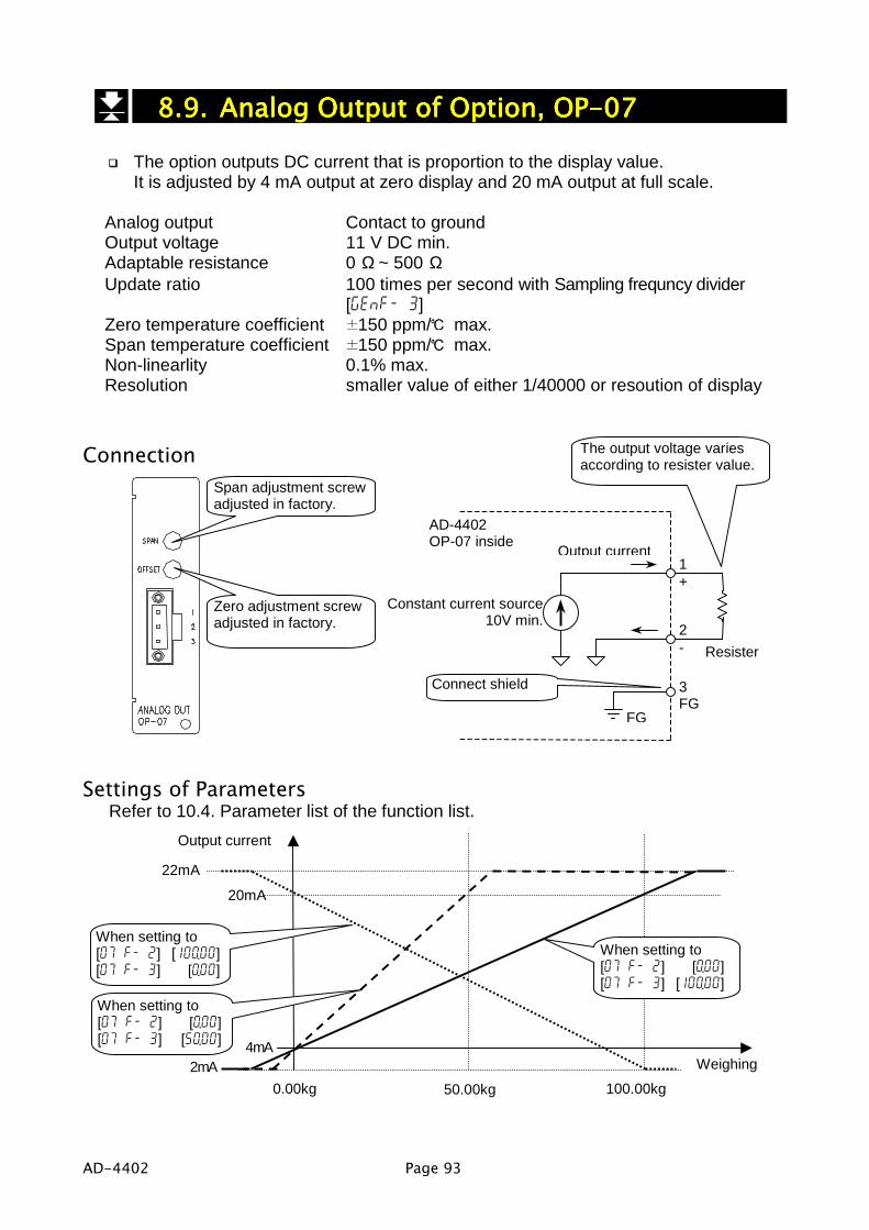
AD-4402 Page 93
8.9.8.9.8.9.8.9. Analog Output of Option, OP-07Analog Output of Option, OP-07Analog Output of Option, OP-07Analog Output of Option, OP-07The option outputs DC current that is proportion to the display value.It is adjusted by 4 mA output at zero display and 20 mA output at full scale.
Analog output Contact to groundOutput voltage 11 V DC min.Adaptable resistance 0 Ω ~ 500 ΩUpdate ratio 100 times per second with Sampling frequncy divider
[genf- 3]Zero temperature coefficient 150 ppm/ max.Span temperature coefficient 150 ppm/ max.Non-linearlity 0.1% max.Resolution smaller value of either 1/40000 or resoution of display
Connection
Settings of ParametersRefer to 10.4. Parameter list of the function list.
Span adjustment screwadjusted in factory.
Zero adjustment screwadjusted in factory.
AD-4402OP-07 inside
2
Constant current source10V min.
FG
3FG
1
The output voltage variesaccording to resister value.
Output current
Resister
+
-
Connect shield
100.00kg
When setting to[07 f- 2] [0.00][07 f- 3] [100.00]
0.00kg
20mA
4mA
2mA
22mA
When setting to[07 f- 2] [100.00][07 f- 3] [0.00]
Weighing
Output current
50.00kg
When setting to[07 f- 2] [0.00][07 f- 3] [50.00]

Page 94 AD-4402
9.9.9.9. MaintenanceMaintenanceMaintenanceMaintenance9.1.1.9.1.1.9.1.1.9.1.1. Basic OperationBasic OperationBasic OperationBasic Operation
To enter the maintenance Press and hold the ENTER key and press the key in weighing mode.Select menu maintenance using the key andthe ENTER key.
To select an address of the parameter The , SHIFT + , ENTER, ESC keys.
To change the parameter The , SHIFT + , Alphanumerical, ENTER,ESC keys.
To exit the mode The ESC key.(To return to weighing mode)
9.2.9.2.9.2.9.2. Monitor ModeMonitor ModeMonitor ModeMonitor ModeThe monitor mode is used to check the indicator during the weighing sequence.
9.2.1.9.2.1.9.2.1.9.2.1. Monitoring Control I/O FunctionMonitoring Control I/O FunctionMonitoring Control I/O FunctionMonitoring Control I/O FunctionUse to monitor the status of the I/O terminals.
9.2.2.9.2.2.9.2.2.9.2.2. Monitoring Built-in RS-485 InterfaceMonitoring Built-in RS-485 InterfaceMonitoring Built-in RS-485 InterfaceMonitoring Built-in RS-485 InterfaceThe current communication data are displayed.
123 kgCONTROL 00010001000 a11 a1 I/O 00110100001 b11 b1
Input terminal A1
Output terminal B1
When [genf- 1] is slow, itmay not display all data.
Sent data
123 kg RNET
RNET0099,1234567,123456789r5-485 rcu and 5nd
Received dataParity: pFraming:f

AD-4402 Page 95
9.2.3.9.2.3.9.2.3.9.2.3. Monitoring Built-in Current Loop OutputMonitoring Built-in Current Loop OutputMonitoring Built-in Current Loop OutputMonitoring Built-in Current Loop OutputThe current communication data are displayed.
9.2.4.9.2.4.9.2.4.9.2.4. Monitoring A/D ConverterMonitoring A/D ConverterMonitoring A/D ConverterMonitoring A/D ConverterThe current A/D converter data are displayed.
9.2.5.9.2.5.9.2.5.9.2.5. Monitoring BCD Output of OP-01Monitoring BCD Output of OP-01Monitoring BCD Output of OP-01Monitoring BCD Output of OP-01The current BCD output data are displayed.
9.2.6.9.2.6.9.2.6.9.2.6. Monitoring Relay Output of OP-02Monitoring Relay Output of OP-02Monitoring Relay Output of OP-02Monitoring Relay Output of OP-02The status of the current relay outputs is displayed.
Sent data
123 kg RNET
ST,NT,+012.345kgCurrent loop 5nd
Received dataParity: pFraming:f
16.001 kg
Int.Count CAL:DS 160008Internal count
DS: EnableEN: Disable
12345 kgOP-01 001111000100011011 a18 a1 001001000001010000 b18 b1
A1
B1
A18
B18
123 kg
OP-02 0001 10100 10 7 5 1
Output terminal1 ~ 5
Output terminal7 ~ 10
When [genf- 1] is slow, itmay not display all data.

Page 96 AD-4402
9.2.7.9.2.7.9.2.7.9.2.7. Monitoring RS-422/485 Interface of OP-03Monitoring RS-422/485 Interface of OP-03Monitoring RS-422/485 Interface of OP-03Monitoring RS-422/485 Interface of OP-03The current communication data are displayed.
9.2.8.9.2.8.9.2.8.9.2.8. Monitoring RS-232C Interface of OP-04Monitoring RS-232C Interface of OP-04Monitoring RS-232C Interface of OP-04Monitoring RS-232C Interface of OP-04The current communication data are displayed.
9.2.9.9.2.9.9.2.9.9.2.9. Monitoring Parallel I/O of OP-05Monitoring Parallel I/O of OP-05Monitoring Parallel I/O of OP-05Monitoring Parallel I/O of OP-05The status of current parallel I/O is displayed.
9.2.10.9.2.10.9.2.10.9.2.10. Monitoring Analog Output of OP-07Monitoring Analog Output of OP-07Monitoring Analog Output of OP-07Monitoring Analog Output of OP-07The current communication data are displayed.
Sent data
123 kg RNET
RNET0099,1234567,1234567890p-03 rcu and 5nd
Received dataParity: pFraming:f
Sent data
123 kg RNET
RNET0099,1234567,1234567890p-04 rcu and 5nd
Received dataParity: pFraming:f
123 kgOP-05 1001000010001000 a16 a1 0101100110100001 b16 b1
Input terminal A1
Output terminal B1When [genf- 1] is slow, itmay not display all data.
96.27 kgOP-07
19.403 mAAnalog output

AD-4402 Page 97
9.3.9.3.9.3.9.3. Test ModeTest ModeTest ModeTest ModeThe test mode is used to check the indicator and weighing system with test signaloutput.When the test mode is used, the weighing sequence is stopped.
CautionThe test mode outputs the test signal. Therfore, the devices connected tosystem are influenced and it may cause mis-operation.
9.3.1.9.3.1.9.3.1.9.3.1. Testing Control I/O FunctionTesting Control I/O FunctionTesting Control I/O FunctionTesting Control I/O FunctionTest the output of the I/O terminal. An active output of level "1" shifts for eachterminal.
9.3.2.9.3.2.9.3.2.9.3.2. Testing Built-in RS-485 InterfaceTesting Built-in RS-485 InterfaceTesting Built-in RS-485 InterfaceTesting Built-in RS-485 InterfaceWhen pressing the ENTER key each time, a test data "ST,GS,+0000000kg CR LF" isoutput.
9.3.3.9.3.3.9.3.3.9.3.3. Testing Built-in Current Loop OutputTesting Built-in Current Loop OutputTesting Built-in Current Loop OutputTesting Built-in Current Loop OutputWhen pressing the ENTER key each time, a test data "ST,GS,+0000000kg CR LF" isoutput.
123 kgCONTROL 00010001000 a11 a1 I/O 00100000000 b11 b1
Input terminal A1
Output terminal B1
Sent data
123 kg RNET
ST,GS,+0000000kg←↓r5-485 rcu and 5nd
Received data
Sent data
123 kg RNET
ST,GS,+0000000kg←↓Current loop 5nd
Received data

Page 98 AD-4402
9.3.4.9.3.4.9.3.4.9.3.4. Testing A/D ConverterTesting A/D ConverterTesting A/D ConverterTesting A/D ConverterThe A/D converter data is displayed.When pressing the ENTER key, a test voltage can be input to the A/D converter.
9.3.5.9.3.5.9.3.5.9.3.5. Testing BCD Output of OP-01Testing BCD Output of OP-01Testing BCD Output of OP-01Testing BCD Output of OP-01Test the output of the terminal. An active output of level "1" shifts for each terminal.
9.3.6.9.3.6.9.3.6.9.3.6. Testing Relay Output of OP-02Testing Relay Output of OP-02Testing Relay Output of OP-02Testing Relay Output of OP-02Test the output of the terminal. An active output of level "1" shifts for each terminal.
9.3.7.9.3.7.9.3.7.9.3.7. Testing RS-422/485 Interface of OP-03Testing RS-422/485 Interface of OP-03Testing RS-422/485 Interface of OP-03Testing RS-422/485 Interface of OP-03When pressing the ENTER key each time, a test data "ST,GS,+0000000kg CR LF" isoutput.
16.001 kgA/D Count L/C Output(mV/V) 964583 3.103872Int.Count Test Input 160008 0ff
A/D converter output
Internal count
Loadcell output
Test input
12345 kgOP-01 000000000000000000 a18 a1 000001000000000000 b18 b1
A1
B1
A18
B18
123 kg
OP-02 0001 00000 10 7 5 1
Output terminal1 ~ 5
Output terminal7 ~ 10
Sent data
123 kg RNET
ST,GS,+0000000kg←↓0p-03 rcu and 5nd
Received dataParity: pFraming:f

AD-4402 Page 99
9.3.8.9.3.8.9.3.8.9.3.8. Testing RS-232C Interface of OP-04Testing RS-232C Interface of OP-04Testing RS-232C Interface of OP-04Testing RS-232C Interface of OP-04When pressing the ENTER key each time, a test data "ST,GS,+0000000kg CR LF" isoutput.
9.3.9.9.3.9.9.3.9.9.3.9. Testing Parallel I/O of OP-05Testing Parallel I/O of OP-05Testing Parallel I/O of OP-05Testing Parallel I/O of OP-05Test the output of the terminal. An active output of level "1" shifts for each terminal.
9.3.10.9.3.10.9.3.10.9.3.10. Testing Analog Output of OP-07Testing Analog Output of OP-07Testing Analog Output of OP-07Testing Analog Output of OP-07When pressing the 1 key, output current is increases.When pressing the 2 key, output current is decreases.
Sent data
123 kg RNET
ST,GS,+0000000kg←↓0p-04 rcu and 5nd
Received dataParity: pFraming:f
123 kgOP-05 0000000000000000 a16 a1 0001000000000000 b16 b1
Input terminal A1
Output terminal B1
96.27 kgOP-07
20 mAAnalog output

Page 100 AD-4402
9.4.9.4.9.4.9.4. Initializing ParametersInitializing ParametersInitializing ParametersInitializing ParametersThe function initializes the parameters stored in the indicator.The parameters are stored in the flash memory and backup RAM.
CautionThere are the kinds of reset function that must re-calibrate the indicatorNote the parameters where is stored in.
Kinds of intialization modeKinds of intialization Description
Initializing RAM The backup RAM is reset. Zero point of gross display, tarevalue zeroes.
Initializing material code orrecipe code Material code and recipe code is reset.
Initializing function list It is reset parameters of function list in the flash memory.
Initializing caribration data It is reset parameters of calibration data in the flashmemory. If this function is used, calibrate the indicator.
Initializing all parameters It resets all parameters.
The location of the parameters and objects of intialization modeMaterial
codeRecipecode
Zero
Tare
Mat
eria
l cod
e
Accu
mul
atio
n da
ta
Rec
ipe
code
Accu
mul
atio
n da
ta
Func
tion
list
Cal
ibra
tion
data
Backup RAM o o o o o oLocation
Flash memory o o o o
Initializing RAM o o
Initializing material code orrecipe code o o o o
Initializing function list o
Initializing caribration data o
Intia
lizat
ion
mod
e
Initializing all parameters o o o o o o o o

AD-4402 Page 101
PrucedureCaution
Do not intialize them while any operation. Cut off the power supply of othersystem. When initializing the indicator, the output may change.When intializing the indicator, do not turn off it before it is resetted.
To enter intializationStep 1 Press and hold the ENTER key and press the key to display the
menu in a weighing mode.Step 2 Select the menu "Initialization" using the key, ENTER key and
ESC key. Category address: [Maintenance] - [Initialization]
To enter intializationStep 1 Select the menu intialization using the key, ENTER key and
ESC key.Menu: RAM / Code / Function / CAL / All
Step 2 Select "yes" to initialize them using the key, ENTER key.Step 3 Wait for the indicator resetted.

Page 102 AD-4402
9.5.9.5.9.5.9.5. Remote OperationRemote OperationRemote OperationRemote OperationThe mode can read and write the parameters of function list, data of material codeand recipe code and calibration data.The build-in RS-485, RS-422/485 (OP-03) or RS-232C (OP-04) is used for theremote operation.It is necessary to install the remote setup program in the computer or controllerbefore use. Refer to http://www.aandd.co.jpRefer to the instruction manual for the details of the program.
CautionDo not down load data during a weighing operation.Remove all connections to prevent a irregular operation.Maintain the power supply during the remote operation.
Entering to the Remote Operation ModeStep 1 Press and hold the ENTER key and press the key.Step 2 Press the key to select menu remote operation. And press the ENTER
key.
AdviseThe following RS-232C to RS-485 converter can use.AD-7491, other converter on the market.

AD-4402 Page 103
10.10.10.10. Function ListFunction ListFunction ListFunction ListThe function list stores parameters to control the indicator.The parameter is stored in an item without power supply.An item is classified by a category address, and is classified by an item number.Refer to " 10.1.2. Outline of the Function List".The category address has a symbol for the 7-segments displayThere are two kind of the function mode to operate the function list.
Parameter settings The mode is used to change the parameter.Referring Parameters The mode is used to refer the parameter in the
weighing sequence.
Example of an item:Category address: [Function] - [Function setting] - [General] - [Weighing]
genf- 1 Display update rate
1 5 times per second
CautionWhen entering Parameter settings of the function mode, the currentweighing sequence are stopped.
10.1.1.10.1.1.10.1.1.10.1.1. Operation KeysOperation KeysOperation KeysOperation KeysTo enter the function list Press and hold the ENTER key and press the
key in weighing mode.Select menu Function using the key and theENTER key.
To select an address of the parameter The , SHIFT + , ENTER, ESC keys.
To change the parameter The , SHIFT + , Alphanumerical, ENTER,ESC keys.
To store it and exit the function list The ESC key.(To return to weighing mode)
Item number
Category address symbol
Meaning of the address
An Item Parameter
Address
Meaning of the parameter

Page 104 AD-4402
10.1.2.10.1.2.10.1.2.10.1.2. Outline of the Function ListOutline of the Function ListOutline of the Function ListOutline of the Function List Category Address Start Item
FunctionFunction reference
General
Weight genf- 1Sub display 5ub f 1Other othf- 1
Sequence
Basic 5) f- 1Control 5) f-11Timer 5) f-31Setpoint (Compared value) 5) f-51Tall (Accumulation) 5) f-61Safety 5) f-71
Control I/O function
Input 1n f- 1Output 0utf- 1
Serial interface
Current Loop Cl f- 1RS-485 r5 f- 1
Option
Slot1
Slot2
Slot3
Refer to Options in this page.
Function setting
The same as the " Function reference".
Options Category Address Start Item
Option
Slot nn nn: Slot number to be installed the optionBCD output, OP-01 01 f- 1Relay output, OP-02 02 f- 1RS-422/485, OP-03 03 f- 1RS-232C, OP-04 04 f- 1Parallel output, OP-05 05 f- 1Analog output, OP-07 07 f- 1
AD-4402 Page 105
10.2.10.2.10.2.10.2. ReferringReferringReferringReferring Parameters Parameters Parameters ParametersUse the mode to refer the parameter in the weighing sequence.The mode can change the parameters concerning the digital filter and weighingsequence timers in the weighing sequence.[genf- 2] Digital filtering
[Function] - [Function setting] - [General] - [Weighing]
[genf- 3] Sampling frequency divider proportion[Function] - [Function setting] - [General] - [Weighing]
[5q f-31] to [5q f-48]Weighing sequence timers[Function] - [Function setting] - [Sequence] - [Timer]
10.3.10.3.10.3.10.3. Parameter SettingsParameter SettingsParameter SettingsParameter SettingsUse the mode to change the parameter.The weighing sequence and the I/O interfaces are stopped and closed during thismode.New parameters have effective after returning to weighing mode.

Page 106 AD-4402
10.4.10.4.10.4.10.4. Parameter ListParameter ListParameter ListParameter List
Category address: [Function] - [Function setting] - [General] - [Weighing]Categoryaddresssymbol
Name DescriptionsRange
andchoices
Default
genf- 1 Display refresh rate 1: five times per second2: ten times per second 1 to 2 2
genf- 2 Digital filter
0: Not used1: 11 Hz2: 8.0 Hz3: 5.6 Hz4: 4.0 Hz5: 2.8 Hz6: 2.0 Hz7: 1.4 Hz8: 1.0 Hz9: 0.7 Hz
Select 3dB band for twolow pass filters.
0 to 99
4 8
genf- 3Samplingfreqeuncy divider
Use to decrease the cut-off frequency ofdigital filter. 0 to 10 1
genf- 4Stability detectiontime
0.0 to9.9 s 1.0 s
genf- 5Stability detectionband width
The detection condition concerningsatblility.0.0 : stable at anytime. 0.0 to
9.9 d 2.0 d
genf- 6 Zero RangeThe range to zero gross display.Center of range is zero calibration.Unit: percentage of weighing capacity.
0 to 30 % 5 %
genf- 7 Zero tracking time 0.0 to9.9 s 0.0 s
genf- 8Zero tracking bandwidth
The function automatically traces theweighing deviation at nearly zeropoint and keeps zero display of grossdisplay.
0.0 to9.9 d 0.0 d
genf- 9Tare and zerocompensation atunstable status
When unstable weghinng, whether zeroor tare command is used.0 :Disabled1 :Enabled
0 to 1 1
genf-10Tare at negativeGROSS weight
When negative weghinng, whether tarecommand is used.0 :Prohibition to tare.1 :Permission to tare.
0 to 1 1
genf-11 Preset tarePreset tare of material code0 :Not used1 :Use
0 to 1 1
genf-12Preset tare =0choice
1: If tare value of material code is zero,the last tare value is used.
2: If tare value of material code is zero,Tare is set to zero.
1 to 2 1
First filter
Second filter
A/D converter

AD-4402 Page 107
Categoryaddresssymbol
Name DescriptionsRange
andchoices
Default
genf-13Clear mode atpower ON
The action at turning on indicator.First bit: ZeroSecond bit: Zero clearThird bit: TareFourth bit: Tare clear
0: Not used1: Use
0000 to1111 0000
genf-14 Hold function1: Hold2: Hold at batch finish3: Hold at recipe finish
1 to 3 1
s : secondd: digit

Page 108 AD-4402
Category address: [Function] - [Function setting] - [General] - [Sub-display]Categoryaddresssymbol
Name DescriptionsRange
andchoices
Default
5Ubf- 1 Weighing display 0: Basic format1: Custom format 0 to 1 0
When arranged format is used (When [5Ubf- 1] [1] ), set items to be displayed in thesub-display.
5ub f 1Sub F1-3 [name]
hopper /row/col/digits 19 0 16 5
Number Name and Number to Display the Item Row size Columsize Figures0 Not displayed1 Material2 Hopper3 Final4 Free fall5 Preliminary6 Optional preliminary7 Over8 Under9 Zero Band10 Full (full filling)11 Tare12 Supplementary flow open timer13 Supplementary flow close timer14 Automatic Free Fall Compensation15 Internal reserved16 Internal reserved17 IDF at entrance sequence18 MDF at entrance sequence19 Accumulated weight20 Accumulation counts21 Recipe , rCode22 Accumulated weight for recipe mode23 Accumulation counts for recipe mode
0 to 3 0 to26 1 to12
Item index number to be displayed. 32 items of name and number can be set in maximum.At odd: Input the name of the selected item using alphanumeric characters.At even: Input the number concerning the item.
Resize the item selected.
Information ofkey operation
Name ofthe item

AD-4402 Page 109
Category address: [Function] - [Function setting] - [General] - [Sub-display]Categoryaddresssymbol
Name DescriptionsRange
andchoices
Default
5Ubf- 2 Recipe display 0: Basic format1: Custom format 0 to 1 0
When arranged format is used (When [5Ubf- 2] [1] ), set items to be displayed in thesub-display.
5ub f 2Sub F2-3 [name]
rTotal /row/col/digits 22 0 16 5
Number Name and Number to Display the Item Row size Columsize Figures0 Not displayed22 Total weight for recipe mode23 Total counts for recipe mode
0 to 3 0 to26 1 to12
Item index number to be displayed. 32 items of name and number can be set in maximum.At odd: Input the name of the selected item using alphanumeric characters.At even: Input the number concerning the item.
Resize the item selected.
Information ofkey operation
Name ofthe item
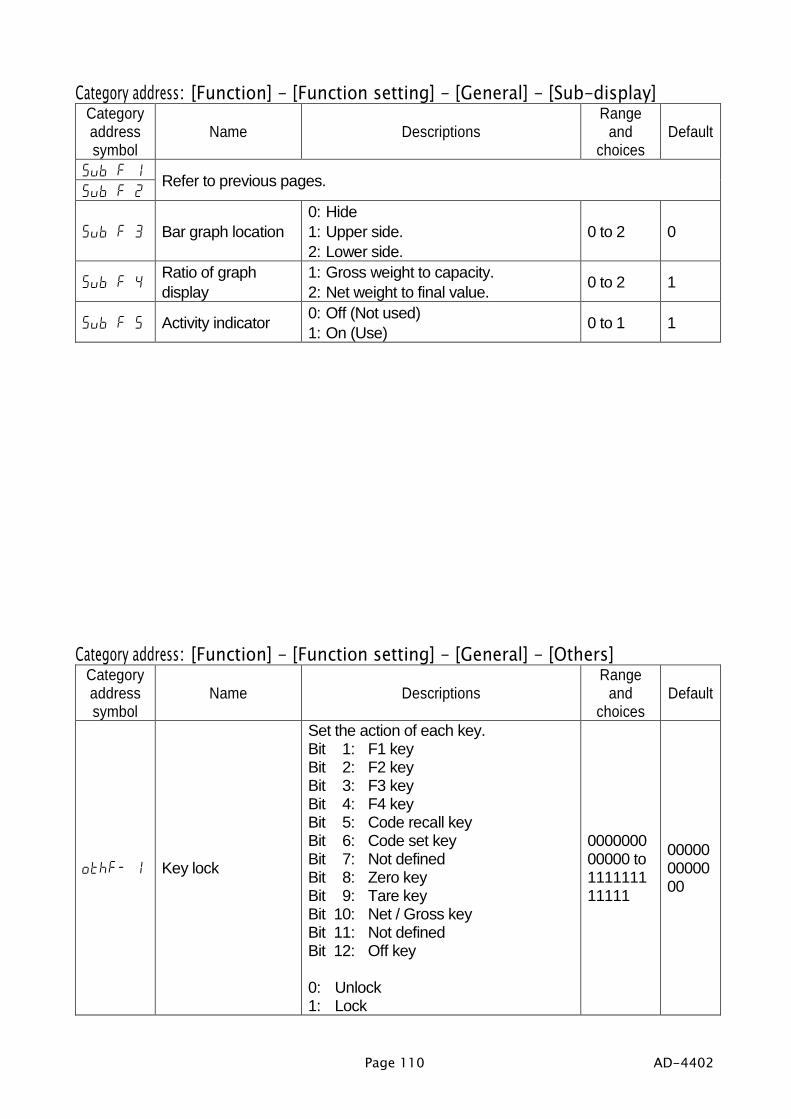
Page 110 AD-4402
Category address: [Function] - [Function setting] - [General] - [Sub-display]Categoryaddresssymbol
Name DescriptionsRange
andchoices
Default
5ub f 15ub f 2
Refer to previous pages.
5ub f 3 Bar graph location0: Hide1: Upper side.2: Lower side.
0 to 2 0
5ub f 4Ratio of graphdisplay
1: Gross weight to capacity.2: Net weight to final value. 0 to 2 1
5ub f 5 Activity indicator 0: Off (Not used)1: On (Use) 0 to 1 1
Category address: [Function] - [Function setting] - [General] - [Others]Categoryaddresssymbol
Name DescriptionsRange
andchoices
Default
othf- 1 Key lock
Set the action of each key.Bit 1: F1 keyBit 2: F2 keyBit 3: F3 keyBit 4: F4 keyBit 5: Code recall keyBit 6: Code set keyBit 7: Not definedBit 8: Zero keyBit 9: Tare keyBit 10: Net / Gross keyBit 11: Not definedBit 12: Off key
0: Unlock1: Lock
000000000000 to111111111111
000000000000

AD-4402 Page 111
Categoryaddresssymbol
Name DescriptionsRange
andchoices
Default
othf- 2 F1 key function
othf- 3 F2 key function
othf- 4 F3 key function
othf- 5 F4 key function
0: Not used1: Display exchange (current weighing / recipe)2: Manual print3: Hold4: Zero clear ( to be zero)5: Tare clear ( to be zero)6: Batch start7: Recipe start8: Discharge9: Mixture10: Pause11: Internal reseved12: Restart13: Forced batch finish14: Forced recipe finish15: Forced discharge finish16: Total command17: Manual free fall compensation18: Cancel the last result19: Error reset20: Clear the total weight and counts for
each material code.21: Clear the total weight and counts for
each recipe code.22: Clear all total data for material codes.23: Clear all total data for recipe codes.24: Clear all total data of material code
and recipe code.
0 to 24 0
othf- 6 Parallel I/O Buzzer
Buzzer output is 2 s. Beep is 0.2 s.It is used in Contolol I/O, OP-02, OP-05.Bit 1: Beep (Click sound)Bit 2: OverBit 3: OKBit 4: UnderBit 5: Zero bandBit 6: Bach finishBit 7: Discharge finishBit 8: Recipe finishBit 9: Mixture finishBit 10: Weighing sequence in processBit 11: Full (Full filling)Bit 12: Stable conditionBit 13: Weighing sequence errorBit 14: Alarm 1Bit 15: Alarm 2Bit 16: Zero error
0: Off (Not used: Open)1: On (Use: Short or Open)
0000000000000000to1111111111111111
1000000000000000

Page 112 AD-4402
Categoryaddresssymbol
Name DescriptionsRange
andchoices
Default
othf- 7 Tare Header
Use for the current loop out put or RS-485 of serial interface.This parameter can not be used incommand mode and stream mode.0: All header of tare is "TR"1: Use "PT" of preset tare header and
"T" of tare header
0 to 1 0
othf- 8Preset tare printingwith net weight
Use for the current loop output or RS-485 interface at net display.This parameter can not use incommand mode and stream mode.0: No (Not output preset tare)1: Yes (To output preset tare)
0 to 1 0
othf- 9Printing whenunstable condition
Use for the current loop output or RS-485 interface at "out of range" or"unstable condition".0: No1: Yse
0 to 1 0
othf-10 Repeat lock
The function to avoid key operationerror.Bit 0: TotalBit 1: Manual print operaton
0: Unlock1: Lock (Cancel duplicated command
input)
00 to 11 00
othf-11 Save data
Select a backup method of materialcode and recipe code.0: Store in RAM1: Store in flash memory
1 to 2 1

AD-4402 Page 113
Category address: [Function] - [Function setting] - [Sequence] - [Basic]Categoryaddresssymbol
Name DescriptionsRange
andchoices
Default
5q f- 1 Weighing mode 1: Constomer programmed control2: Sequential weighing 1 to 2 2
5q f- 3 Loss-in weight0: Normal batch weighing1: Loss-in weight2: External exchange
0 to 2 0
5q f- 4Setpointcomparison
0: Comparison with internal count1: Comparison with display count 1 to 2 1
5q f- 5 Comparison0: Always output1: Stable condition2: At batch finish
0 to 2 2
5q f- 7 Output of zero band 0: Gross <= Zero band1: | Gross | <= Zero band 1 to 2 1
5q f- 8 Recipe mode0: Not used recipe sequence1: Semi-automatic mode2: Automatic mode
0 to 2 0
5q f- 9Material code, freefall value
The selection to store free fall value onthe automatic free fall compensationor realtime free fall compensation.
0: No changeEven if automatic free fallcompensation is used, parameterof the free fall stored in the materialcode is not changed.
1: Change free fall valueThe result is memorized to theparameter of the free fall in thematerial code.
0 to 1 0

Page 114 AD-4402
Category address: [Function] - [Function setting] - [Sequence] - [Control]Categoryaddresssymbol
Name DescriptionsRange
andchoices
Default
5q f-11 Batch start settings
Select a action at starting the weighingsequence.Bit 1: When loading it above zero
band, start the sequence.Bit 2: Not usedBit 3: Automatic tare at the starting
sequence
0: No (Not worked)1: Yes (work)
000 to111 000
5q f-12 Nozzle control
Bit 1: Use nozzle control."Nozzle down" operation signalis output at starting thesequence.
Bit 2: Nozzle contact stop sequenceUse start delay timer to preventweighing error at touching tohopper.
Bit 3: "Nozzle up" after compensate.
0: No (Not used)1: Yes (Use)
000 to111 000
5q f-13 Eval conditions
After dribble flow, select the stablilitycondition of comparison. Refer to Evaldelay timer [5qf-37].0: Timer is up
Compare when time is up.1: Stable and timer is up
Compare when weighing is stableand the time is up.
2: Stable or timer is upCompare when weighing is stable orthe time is up.
0 to 2 1

AD-4402 Page 115
Category address: [Function] - [Function setting] - [Sequence] - [Control]Categoryaddresssymbol
Name DescriptionsRange
andchoices
Default
5q f-14 Batch finish actions
Select a action at batch finish.Bit 1: Auto-start mixing
(Mixture start automatically)Bit 2: Auto-start discharge
(Discharge start automatically)
0: No (Not used)1: Yes (Use)
00to11
00
5q f-15Discharge finishactions
Select a action at discharge finish.Bit 1: Auto-clear tare
(Tare clear automatically)Bit 2: Start mixing
(Mixture start automatically)
0: No (Not used)1: Yes (Use)
00to11
00
5q f-16 Recipe start actionsSelection of rezeroing it at recipe start.0: No (Not used)1: Yes (Use)
0 to 1 1
5q f-17Recipe finishactions
Select a action at recipe finish.Bit 1: Auto-clear tare
(Clear tare automatically)Bit 2: Auto-start mixing
(Start mixture automatically)Bit 3: Auto-start discharge.
(Start discharge automatically)
0: No (Not used)1: Yes (Use)
000to111
000
5q f-18Maximum numberof compensation
Set the number of compensation flow.When 0 is set, there is not flow.
0 to255 0
5q f-19Comparison flowEval
Set the condition with compensationclose timer and stability.0: Timer is up
Comparison when compensationclose timer is up.
1: Stable and timer is up.Comparison after stable mark andcompensation close timer is up.
2: Stable or timer is up.Comparison after stable mark orcompensation close timer is up.
0 to 2 0
5q f-20Free fallcompensation
0: No (Not used)1: Average of last four times free fall.2: Real time free fall compensation
0 to 2 0
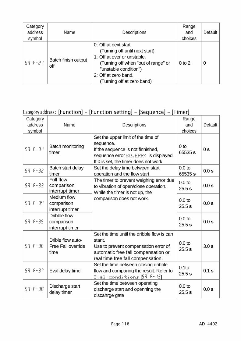
Page 116 AD-4402
Categoryaddresssymbol
Name DescriptionsRange
andchoices
Default
5q f-21Batch finish outputoff
0: Off at next start(Turning off until next start)
1: Off at over or unstable.(Turning off when "out of range" or"unstable condition")
2: Off at zero band.(Turning off at zero band)
0 to 2 0
Category address: [Function] - [Function setting] - [Sequence] - [Timer]Categoryaddresssymbol
Name DescriptionsRange
andchoices
Default
5q f-31Batch monitoringtimer
Set the upper limit of the time ofsequence.If the sequence is not finnished,sequence error SQ.ERR4 is displayed.If 0 is set, the timer does not work.
0 to65535 s 0 s
5q f-32Batch start delaytimer
Set the delay time between startoperation and the flow start
0.0 to65535 s 0.0 s
5q f-33Full flowcomparisoninterrupt timer
0.0 to25.5 s 0.0 s
5q f-34Medium flowcomparisoninterrupt timer
0.0 to25.5 s 0.0 s
5q f-35Dribble flowcomparisoninterrupt timer
The timer to prevent weighing error dueto vibration of open/close operation.While the timer is not up, thecomparison does not work.
0.0 to25.5 s 0.0 s
5q f-36Drible flow auto-Free Fall overridetime
Set the time until the dribble flow is canstant.Use to prevent compensation error ofautomatic free fall compensation orreal time free fall compensation.
0.0 to25.5 s 3.0 s
5q f-37 Eval delay timerSet the time between closing dribbleflow and comparing the result. Refer toEval conditions [5q f-13]
0.1to25.5 s 0.1 s
5q f-38Discharge startdelay timer
Set the time between operatingdischarge start and openning thediscahrge gate
0.0 to25.5 s 0.0 s

AD-4402 Page 117
Categoryaddresssymbol
Name DescriptionsRange
andchoices
Default
5q f-39Dischargemonitoring timer
Set the time limit to discarge itWhen time is up and weighing value isnot zero band, sequence errorSQ.ERR5 is displayed.If 0 is set, the timer does not work.
0 to65535 s 0 s
5q f-40Discharge gateclose delay timer
Set the wating time from reacheing tozero band to closing discharge gate forgross.
0.1 to25.5 s 0.1 s
5q f-43Batch finish outputon
Set the active (ON) time of batch finishsignal. If 0 is set, output is kept until nextsequence.
0.00 to2.55 s 0.00 s
5q f-44Discharge finishoutput on
Set the time to keep the ON fordischarge signal.
0.00 to2.55 s 0.00 s
5q f-45Recipe finish outputon
Set the time to keep the ON for recipefinish signal.
0.00 to2.55 s 0.00 s
5q f-46Mixing finish outputon
Set the time to keep the ON for mixturefinish signal.
0.00 to2.55 s 0.00 s
5q f-47Mixing time outputon
Set the time to keep the ON for mixturetime signal.
0 to255 s 0 s
5q f-48 Averaging Eval time
Set the time to average the result. Thistime controls precision of the result.Refer to Eval delay timer [5qf-37] and Eval conditions [5qf-13].
00.0 to2.55 s 0.00 s
s : secondd: digit

Page 118 AD-4402
Category address: [Function] - [Function setting] - [Sequence] - [Setpoint]Categoryaddresssymbol
Name DescriptionsRange
andchoices
Default
5q f-51 Code recall method
1: Key operation (including serialinterface, field bus)
2: Parallel interface (Digital switch)3: External switch
1 to 3 1
5q f-53Hide elements ofmaterial code
Select the parameter to hide of materialcode.Bit 1: Free fallBit 2: PreliminaryBit 3: Optional preliminaryBit 4: OverBit 5: UnderBit 6: Zero bandBit 7: Full fillingBit 8: TareBit 9: Compensation flow open timerBit 10: Compensation flow close timerBit 11: AFFC rangeBit 12: Dribble supply at entranceBit 13: Medium supply at entrance
0: Show1: Hide
0000000000000to1111111111111
0000000000000
5q f-55Add Final value andzero band
0: No (Not added)1: Yes (Add) 0 to 1 1
5q f-56Add Final value andFull value
0: No (Not added)1: Yes (Add) 0 to 1 1
Category address: [Function] - [Function setting] - [Sequence] - [Total]Categoryaddresssymbol
Name DescriptionsRange
andchoices
Default
5q f-61Automaic materialcode total
0: Not totaled automatically1: Auto-total OK results
To total OK result automatically2: Auto-total all results
To total all result automatically
0 to 2 0
5q f-62Automaic recipecode total
0: No (Not totaled)1: Yes (Total the result) 0 to 1 0

AD-4402 Page 119
Category address: [Function] - [Function setting] - [Sequence] - [Safety]Categoryaddresssymbol
Name DescriptionsRange
andchoices
Default
5q f-71 to 5q f-75
The maximum eight inputs for safty check are assigned to theI/O or OP-05. If an input be inactive, the sequence is stoppedand displays sequence error. Refet to 7.5.11. Error Messageand Alarm. These safety checks can use during thesequence.
Bits mapBit 1: Safety input 1Bit 2: Safety input 2Bit 3: Safety input 3Bit 4: Safety input 4Bit 5: Safety input 5Bit 6: Safety input 6Bit 7: Safety input 7Bit 8: Safety input 8
0: No (Not used)1: Yes (Use)
5q f-71Batching safetycheck
If the assigned input is inactive duringthe weighing sequence, it occurs ansequence error.
5q f-72Discharge safetycheck
If the assigned input is inactive duringthe discharge sequence, it occurs ansequence error.
5q f-73Recipe safetycheck
If the assigned input is inactive duringthe recipe sequence, it occurs ansequence error.
5q f-74 Mixing safety checkIf the assigned input is inactive duringthe mixture sequence, it occurs ansequence error.
5q f-75General safetycheck
If the assigned input is inactive duringthe all sequence, it occurs an sequenceerror.
00000000to11111111
00000000

Page 120 AD-4402
Category address: [Function] - [Function setting] - [Control I/O Function] - [Input]
The list to assign the function for the input terminal of the I/ONo. Function description Read No. Function description Read
0 No function - 26 Clear totals of active recipecode
Edge
1 Zero Edge 27 Clear totals of all recipe code Edge2 Zero clear Edge 28 Safety check input 1 Level3 Tare Edge 29 Safety check input 2 Level4 Tare clear Edge 30 Safety check input 3 Level5 Batch start Edge 31 Safety check input 4 Level6 Recipe start Edge 32 Safety check input 5 Level7 Discharge start Edge 33 Safety check input 6 Level8 Mixtire start Edge 34 Safety check input 7 Level
9External switch control0: Normal bach1: Loss-in weight
Level 35 Safety check input 8 Level
10 Manual free fall compensation Edge 36 Foced batch finish Edge11 Accumulation command Edge 37 Foced recipe finish Edge12 Cancel the last result Edge 38 Foced discharge finish Edge13 Emergency stop Level 39 Manual full flow Level
14 Material / Recipe code,BCD 1
Level 40 Manual medium flow Level
15 Material / Recipe code,BCD 2
Level 41 Mnaual dribble flow Level
16 Material / Recipe code,BCD 4
Level 42 Manual discharge Level
17 Material / Recipe code,BCD 8
Level 43 Manual mixture Level
18 Material / Recipe code,BCD 10
Level 44 Error reset Edge
19 Material / Recipe code,BCD 20
Level 45 Hold Level
20 Material / Recipe code,BCD 40
Level 46 Key unlock Level
21 Material / Recipe code,BCD 80
Level 47 Manual print command Edge
22 Pause Edge 48 Code recall external switch controlOFF: key, ON: digital switch
Level
23 Restart Edge 49 Recipe interrupt Level
24 Clear totals of active materialcode
Edge 50 Net / gross Edge
25 Clear totals of all material code Edge

AD-4402 Page 121
Input terminals of the I/O and default functionsCategoryaddresssymbol
Terminal name Default choices Default No.
1n f- 1 Input terminal A1 Zero 11n f- 2 Input terminal A2 Tare 31n f- 3 Input terminal A3 Tare clear 41n f- 4 Input terminal A4 Batch start 51n f- 5 Input terminal A5 Emergency stop 13
1n f- 6 Input terminal A6 Material / Recipe code,BCD 1 14
1n f- 7 Input terminal A7 Material / Recipe code,BCD 2 15
1n f- 8 Input terminal A8 Material / Recipe code,BCD 4 16
1n f- 9 Input terminal A9 Pause 221n f-10 Input terminal A10 Restart 231n f-11 Input terminal A11 Error reset 44

Page 122 AD-4402
Category address: [Function] - [Function setting] - [Control I/O Function] - [Output]
The list to assign the function for the output terminal of the I/ONo. Function description No. Function description No. Function description0 No function 30 Gross display 60 Material hopper 2 DF1 Stable 31 Net display 61 Material hopper 3 FF2 Zero band 32 During hold 62 Material hopper 3 MF3 FUll (Full filling) 33 Internal reservation 63 Material hopper 3 DF4 Full flow 34 Internal reservation 64 Material hopper 4 FF5 Medium flow 35 Material hopper 1 65 Material hopper 4 MF6 Dribble flow 36 Material hopper 2 66 Material hopper 4 DF7 Over 37 Material hopper 3 67 Material hopper 5 FF8 OK 38 Material hopper 4 68 Material hopper 5 MF9 Under 39 Material hopper 5 69 Material hopper 5 DF
10 Internal reservation 40 Material hopper 6 70 Material hopper 6 FF11 Internal reservation 41 Material hopper 7 71 Material hopper 6 MF12 Mixture 42 Material hopper 8 72 Material hopper 6 DF13 Discharge (Open the dscharge gate) 43 Material hopper 9 73 Material hopper 7 FF14 Batch finish 44 Material hopper 10 74 Material hopper 7 MF15 Recipe finish 45 Material hopper 11 75 Material hopper 7 DF16 Discharge finish 46 Material hopper 12 76 Material hopper 8 FF17 Mixture finish 47 Material hopper 13 77 Material hopper 8 MF18 Nozzle down 48 Material hopper 14 78 Material hopper 8 DF
19Online. If sequence isenable, 0.5 sec. pulse isoutput.
49 Material hopper 15 79 Material hopper 9 FF
20 Weighing sequence inprocess
50 Material hopper 16 80 Material hopper 9 MF
21Input acknowledge.If there is a input signal, 0.5sec. pulse is output.
51 Material hopper 17 81 Material hopper 9 DF
22 Weighing sequence error 52 Material hopper 18 82 Material hopper10 FF23 Alram 1 53 Material hopper 19 83 Material hopper10 MF24 Alram 2 54 Material hopper 20 84 Material hopper10 DF25 Zero error 55 Material hopper 1 FF
26 Capacity exceeded(Out of range)
56 Material hopper 1 MF
27 Buzzer 57 Material hopper 1 DF28 During tare 58 Material hopper 2 FF29 Center of zero 59 Material hopper 2 MF
Full flow: FFMedium flow: MFDrrible flow: DF

AD-4402 Page 123
Output terminals of the I/O and default functionsCategoryaddresssymbol
Terminal name Default choices Default No.
0utf- 1 Output terminal B1 Zero band 20utf- 2 Output terminal B2 Full flow 40utf- 3 Output terminal B3 Medium flow 50utf- 4 Output terminal B4 Dribble flow 60utf- 5 Output terminal B5 Over 70utf- 6 Output terminal B6 OK 80utf- 7 Output terminal B7 Under 90utf- 8 Output terminal B8 Batch finish 140utf- 9 Output terminal B9 Weighing sequence error 220utf-10 Output terminal B10 Alarm 1 230utf-11 Output terminal B11 Alarm 2 24

Page 124 AD-4402
Category address: [Function] - [Function setting] - [Serial] - [RS-485]Categoryaddresssymbol
Name DescriptionsRange
andchoices
Default
r5 f- 1 Output data
When jet stream mode of Comunicationmode [r5 f- 2] is used, the 1, 2, 3 canselect. And if freeze mode is used in jetstream mode, output is stoped.1: Displayed value2: Gross value2: Net value4: Tare value5: Gross value/ Net value/ Tare value6: Weighing value with material code7: Gross value with material code8: Net value with material code9: Tare value with material code10: Gross value/ Net value/ Tare value
with material code
1 to 10 1
r5 f- 2Comunicationmode
1: Stream mode2: Auto print mode3: Manual print mode4: Print at total5: Jet stream mode6: Command mode
1 to 6 6
r5 f- 3 Baud rate
1: 600 bps2: 12000 bps3: 2400 bps4: 4800 bps5: 9600 bps6: 19200 bps7: 38400 bps (Common mode can not
select)
1 to 7 5
r5 f- 4 Parity check0: Not used1: Odd2: Even
0 to 2 0
r5 f- 5 Character length 7: 7 bits8: 8 bits 7, 8 8
r5 f- 6 Stop bits 1: 1 bit2: 2:bits 1 to 2 1
r5 f- 7 Terminator 1: CR CR: 0Dh2: CR LF LF: 0Ah 1 to 2 2
r5 f- 8 Address 0: Address not used1 to 99: Address used 0 to 99 0
r5 f- 9 Response timer Set the waiting timer from receivingcommand to transmitting a response.
0.0 to25.5 s 0.0 s
s: Second

AD-4402 Page 125
Category address: [Function] - [Function setting] - [Serial] - [Current loop]Categoryaddresssymbol
Name DescriptionsRange
andchoices
Default
Cl f- 1 Output data
1: Weighing value2: Gross value2: Net value4: Tare value5: Gross value/ Net value/ Tare value6: Weighing value with material code7: Gross value with material code8: Net value with material code9: Tare value with material code10: Gross value/ Net value/ Tare value
with material code
1 to 10 1
Cl f- 2Comunicationmode
1: Stream mode2: Auto print mode3: Manual print mode4: Print at accumulation5: Jet Stream mode
1 to 4 1
Cl f- 3 Baud rate1: 600 bps2: 12000 bps3: 2400 bps
1 to 3 3
Cl f- 4Burst rate ofcontinuous output
Set the burst time when gross, net ortare is output continuously.Stream mode uses 0.0 s.
0.00 to2.55 s 0.00 s
s: Second

Page 126 AD-4402
Category address: [Function] - [Function setting] - [Option] - [slotn] - [OP-01]OP-01: Option BCD Output
slot n : slot number
Categoryaddresssymbol
Name DescriptionsRange
andchoices
Default
01 f- 1 Out put data
1: Weighing value2: Gross value2: Net value4: Tare value5: Current material code total6: Current material code total #7: Current recipe code total8: Current recipe code total #9: Current material code and recipe
code10: Error alarm No.
1 to 10 1
01 f- 3Communicationmode
1: Stream mode2: Auto print mode3: Manual print mode4: Print at total5: Jet stream mode (each sampling)
1 to 5 1
01 f- 4 Output logic 1: Positive logic2: Negative logic 1 to 2 2

AD-4402 Page 127
Category address: [Function] - [Function setting] - [Option] - [slotn] - [OP-02]OP-02: Option Output Relay Output
slot n : slot number
Categoryaddresssymbol
Name DescriptionsRange
andchoices
Default
02 f- 1 Output terminal 1 Material hopper 1 Medium flow 0 to 84 5602 f- 2 Output terminal 2 Material hopper1 Drrible flow 0 to 84 5702 f- 3 Output terminal 3 Material hopper 2 Medium flow 0 to 84 5902 f- 4 Output terminal 4 Material hopper 2 Drrible flow 0 to 84 6002 f- 5 Output terminal 5 Material hopper 3 Medium flow 0 to 84 6202 f- 7 Output terminal 7 Material hopper 3 Drrible flow 0 to 84 6302 f- 8 Output terminal 8 Material hopper 4 Medium flow 0 to 84 6502 f- 9 Output terminal 9 Material hopper 4 Drrible flow 0 to 84 6602 f-10 Output terminal 10 Material hopper 5 Medium flow 0 to 84 69
Default parameters are set to double gates hopper

Page 128 AD-4402
Category address: [Function] - [Function setting] - [Option] - [slotn] - [OP-03] or [Function] - [Function setting] - [Option] - [slotn] - [OP-04]
OP-03: Option RS-422 / 485 Serial InterfaceOP-04: Option RS-232C Serial Interface
slot n : slot numberCategoryaddresssymbol
Name DescriptionsRange
andchoices
Default
03 f- 104 f- 1
Output data
When jet stream mode of Coumnicationmode [r5 f- 2] is used, the 1, 2, 3 canselect. And if freeze mode is used in jetstream mode, output is stoped.1: Weighing value2: Gross value2: Net value4: Tare value5: Gross value/ Net value/ Tare value6: Weighing value with material code7: Gross value with material code8: Net value with material code9: Tare value with material code10: Gross value/ Net value/ Tare value
with material code
1 to 10 1
03 f- 204 f- 2
Comunicationmode
1: Stream mode2: Auto print mode3: Manual print mode4: Print at total5: Jet stream mode6: Command mode
1 to 6 6
03 f- 304 f- 3
Baud rate
1: 600 bps2: 12000 bps3: 2400 bps4: 4800 bps5: 9600 bps6: 19200 bps7: 38400 bps (Command mode can not
select)
1 to 7 5
03 f- 404 f- 4
Parity check0: Not used1: Odd2: Even
0 to 2 0
03 f- 504 f- 5
Charactor length 7: 7 bits8: 8 bits 7, 8 8
03 f- 604 f- 6
Stop bits 1: 1 bit2: 2:bits 1 to 2 1
03 f- 704 f- 7
Terminator 1: CR CR: 0Dh2: CR LF LF: 0Ah 1 to 2 2

AD-4402 Page 129
Categoryaddresssymbol
Name DescriptionsRange
andchoices
Default
03 f- 804 f- 8
Address 0: Address is not used1 to 99: Address is used 0 to 99 0
03 f- 9 Response timer Set the waiting timer from receivingcommand to transmitting a response.
0.00 to2.55 s 0.00 s
03 f-11RS-422 / 485switch
1: RS-4222: RS-485 1 to 2 1
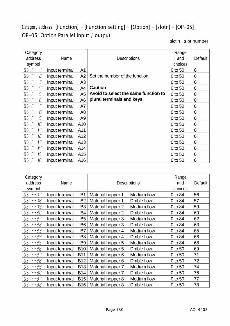
Page 130 AD-4402
Category address: [Function] - [Function setting] - [Option] - [slotn] - [OP-05]OP-05: Option Parallel input / output
slot n : slot number
Categoryaddresssymbol
Name DescriptionsRange
andchoices
Default
05 f- 1 Input terminal A1 0 to 50 005 f- 2 Input terminal A2 0 to 50 005 f- 3 Input terminal A3 0 to 50 005 f- 4 Input terminal A4 0 to 50 005 f- 5 Input terminal A5 0 to 50 005 f- 6 Input terminal A6 0 to 50 005 f- 7 Input terminal A7 0 to 50 005 f- 8 Input terminal A8 0 to 50 005 f- 9 Input terminal A9 0 to 50 005 f-10 Input terminal A10 0 to 50 005 f-11 Input terminal A11 0 to 50 005 f-12 Input terminal A12 0 to 50 005 f-13 Input terminal A13 0 to 50 005 f-14 Input terminal A14 0 to 50 005 f-15 Input terminal A15 0 to 50 005 f-16 Input terminal A16
Set the number of the function.
CautionAvoid to select the same function toplural terminals and keys.
0 to 50 0
Categoryaddresssymbol
Name DescriptionsRange
andchoices
Default
05 f-17 Input terminal B1 Material hopper 1 Medium flow 0 to 84 5605 f-18 Input terminal B2 Material hopper 1 Drrible flow 0 to 84 5705 f-19 Input terminal B3 Material hopper 2 Medium flow 0 to 84 5905 f-20 Input terminal B4 Material hopper 2 Drrible flow 0 to 84 6005 f-21 Input terminal B5 Material hopper 3 Medium flow 0 to 84 6205 f-22 Input terminal B6 Material hopper 3 Drrible flow 0 to 84 6305 f-23 Input terminal B7 Material hopper 4 Medium flow 0 to 84 6505 f-24 Input terminal B8 Material hopper 4 Drrible flow 0 to 84 6605 f-25 Input terminal B9 Material hopper 5 Medium flow 0 to 84 6805 f-26 Input terminal B10 Material hopper 5 Drrible flow 0 to 50 6905 f-27 Input terminal B11 Material hopper 6 Medium flow 0 to 50 7105 f-28 Input terminal B12 Material hopper 6 Drrible flow 0 to 50 7205 f-29 Input terminal B13 Material hopper 7 Medium flow 0 to 50 7405 f-30 Input terminal B14 Material hopper 7 Drrible flow 0 to 50 7505 f-31 Input terminal B15 Material hopper 8 Medium flow 0 to 50 7705 f-32 Input terminal B16 Material hopper 8 Drrible flow 0 to 50 78

AD-4402 Page 131
Category address: [Function] - [Function setting] - [Option] - [slotn] - [OP-07]OP-07: Option Analog Output
slot n : slot number
Categoryaddresssymbol
Name DescriptionsRange
andchoices
Default
07 f- 1 Out put data1: Displayed value2: Gross value3: Net value
1 to 3 1
07 f- 2 Weight at 4 mASet the weighit value when 4 mA isoutput.
-999999 to 9999999
0
07 f- 3 Weight at 20 mASet the weighit value when 20 mA isoutput.
-999999 to 9999999
16000

Page 132 AD-4402
11.11.11.11. SpecificationsSpecificationsSpecificationsSpecificationsGeneral
Power supply 85 to250 VAC, 50 or 60Hz, (Stable power source)Power consumption Approximately 30 VAPysical dimensions 192 (W) x 96 (H) x 135 (D) mmWeight Approximately 1.8 kgPanel cutout size 186 x 92 mmOperation temperature -5 to 40 Battery life of backup RAM typ. 10 years at 25 . 5 years at 40 .
Analog to Digital UnitInput sensitivity Up to 0.3 µV / digitZero adjustment range 0 to 2 mV /V (0 to 20 mV)Measuerment range 0 to 3.2 mV /V (0 to 32 mV)Input impedance 10 MΩLoadcell excitation voltage 10 V DC 5%Maximum loadcells 8 pieces in pallel with 350Ω loadcellSpan temperature coefficient 8 ppm/ Zero temperature coefficient 0.2 µV + 8 ppm/ of dead load typ.Non-linearity 0.01 % of F. S.Input noise Below 0.3 µVp-pA/D conversion ∆-Σ conversionA/D resolution Approximately 1/1,000,000Maximum display 16000 (to be able cancel limitation)Sampling rate 100 times per secondDigital span function loLoadcell offset, calibration using key operation to enter
the sensitivity, resolution 1/1000Re-calibration at A/D board repacement
Omissible (resolution 1/500)Backup method A/D data: EEPROM
Calibration: Flash memoryFunction: Flash memoryMaterial code data: Backup RAM or flash memoryRecipe code data Backup RAM or flash memory
DisplayMain display Fluorescent display, cobalt blue, height: 18mm, 7seg., 7 figuresSub-display Fluorescent display, cobalt blue, height: 5mm,
7seg., 54 figures and 5x7 dots, 54 figuresState indicator Fluorescent display, cobalt blue, 8 pieces, 10 symbols, 5x7 dotsUnit indicator Fluorescent display, cobalt blue, height: 11mm, 5x7 dots, 2 figuresSymbols Fluorescent display, cobalt blue, height: 11mm, 5x7 dots, 2 figures

AD-4402 Page 133
WeighingWeighing mode Batch Weighing Mode:
Normal batch weighing, loss-in weightSequential Weighing Mode:
Normal batch weighing, loss-in weight
Element of sequential weighing modeCompensation SequenceApproach SequenceDischarge SequencePlain Recipe SequenceAutomatic Selection of Supplying MatNozzle Control Sequence (vacuum cleaner)Mixture SequenceSafety Check FunctionPause and Emergency StopRestart SequenceAutomatic Free Fall CompensationReal Time Free Fall Compensation
Code dataMax. number of material code 100 codesElement of material code Name, hopper No., Target value, free fall, preliminary,
optional preliminary, over, under, accumulation count,accumulation weight, tare value, compensation opentimer, compensation close timer
Max. number of recipe code 100 codesElement of recipe code Name, material codes (max. 10, in mixture order),
accumulation count, accumulation weight
Connectors and interfacesPower supply terminal, Loadcell terminal, Standard I/O terminal, Standard RS-485interface, Current loop, keys and display

Page 134 AD-4402
Standard I/O terminalRefer to "8.1. Control I/O Function".
Standard RS-485 interfaceRefer to "8.2. Built-in RS-485 Interface".
Current loopRefer to "8.3. Built-in Current Loop Output".
BCD Output of Option, OP-01Refer to "8.4. BCD Output of Option, OP-01".
Relay Output of Option, OP-02Refer to "8.5. Relay Output of Option, OP-02".
RS-422/485 Interface of Option, OP-03Refer to "8.6. RS-422/485 Interface of Option, OP-03".
RS-232C Interface of Option, OP-04Refer to "8.7. RS-232C Interface of Option, OP-04".
Parallel I/O of Option, OP-05Refer to "8.8. Parallel I/O of Option, OP-05".
Analog Output of Option, OP-07Refer to "8.9. Analog Output of Option, OP-07".
CC Link interface of Option, OP-20Refer to OP-20 instruction manual regarding the details.
DeviceNet interface of Option, OP-21Refer to OP-21 instruction manual regarding the details.
PROFIBUS interface of Option, OP-22Refer to OP-22 instruction manual regarding the details.

AD-4402 Page 135
11.1.11.1.11.1.11.1. DimensionsDimensionsDimensionsDimensions
Panel cutout size
11.2.11.2.11.2.11.2. AccessoriesAccessoriesAccessoriesAccessoriesCapacity label ......................................................1I/O connector .......................................................1I/O connector cover .............................................1RS-485, terminator resister 100 Ω ......................1Cover of power supply terminal ...........................1Cover of RS-485 and current loop .......................1Cover of loadcell teminal .....................................1Rubber packing for mounting to panel .................1

Page 136 AD-4402
12.12.12.12. ReferencesReferencesReferencesReferences12.1.12.1.12.1.12.1. AbbreviationAbbreviationAbbreviationAbbreviation
# counts TC Tare clear#Tot total count RTot recipe total0Band zero band RTot# recipe total count
0T tare is not used SF supplemental flow(compensation flow)
ADC Analog to digital converter SFOT Supplementary FlowOpen Timer
AFFC active free fall compensation SFCT Supplementary FlowClose Timer
Brate baud rate T tareCZ center of zero TC Tare clearD division Tot Total WeightDFlow dribble flow Tot# Total CountsEval evaluation, (criteria) TR tareFFall free fall w/ withFFlow full flow w/0 with zeroFNC function WGT weightGS gross WGTTot weight totalHop. Hopper ZR zeroI/O input / outputIDF initial dribble flowIFF initial medium flowL loadcellLC loadcellMCode material codeMFlow medium flowNeg negativeNT netNWT net weightOp. optionalOPPlm Optional PreliminaryP I/O parallel I/OPlm PreliminaryPLC programmable logic controller unitPT preset tareRTot recipe totalRTot# recipe total countSF supplemental flow (compensation flow)SFOT Supplementary Flow Open Timer
SFCT Supplementary Flow Close Timer
T tare

AD-4402 Page 137
12.2.12.2.12.2.12.2. ASCII CodeASCII CodeASCII CodeASCII Code for AD-4402 for AD-4402 for AD-4402 for AD-4402The characters are special code for the name of material code and recipe code.Therefor, some characters are not the same as U.S. code.
Lower bits0 1 2 3 4 5 6 7
0 Space 0 @ P Space p1 ! 1 A Q a q2 " 2 B R b r3 # 3 C S c s4 $ 4 D T d t5 % 5 E U e u6 & 6 F V f v7 ' 7 G W g w8 ( 8 H X h x9 ) 9 I Y i yA LF * : J Z j zB + ; K [ k C , < L l |D CR - = M ] m E . > N ^ n
Upper bits
F / ? O _ o

Page 138 AD-4402
12.3.12.3.12.3.12.3. IndexIndexIndexIndex#.....................................................................137#Tot ............................................................137[Control I/O] - [Input] ..........................................121[Control I/O] - [Output] .......................................123[General] - [Others] ...........................................111[General] - [Sub-display] ....................................109[General] - [Weighing]........................................107[OP-01] ............................................................127[OP-02] ............................................................128[OP-03] ............................................................129[OP-04] ............................................................129[OP-05] ............................................................131[OP-07] ............................................................132[Sequence] - [Basic] ..........................................114[Sequence] - [Control]........................................115[Sequence] - [Safety] .........................................120[Sequence] - [Setpoint] .......................................119[Sequence] - [Timer] ..........................................117[Sequence] - [Total]............................................119[Serial] - [Current loop].......................................126[Serial] - [RS-485] .............................................125
key .............................................................8
, CODE RECALL key...........................17
, ENTER key..............................8, 21, 22
, ESC key........................................8, 21, 22
, F1 key, F3 key .............................7, 112
, F2 key, F4 key .............................7, 112
, SHIFT key............................................7. Standby indicator ..........................................9
, tare key................................................8
, zero key ...............................................801 f ...............................................................12702 f ...............................................................12803 f ...............................................................12904 f ...............................................................12905 f ...............................................................13107 f ...............................................................1320Band .........................................................1370T..................................................................1371n f ...............................................................1222 wires ........................................................75, 894 wires ..............................................................89
accumulation ....................................................69accumulation print mode ..................77, 83, 87
actual load calibration ...................................20ADC ...............................................................137AFFC ............................................................137alarm ................................................................70analog output............................................94, 132ASCII code .....................................................138auto print mode ................................. 77, 83, 87automatic program mode .................................38backuped RAM.................................................72batch weighing ...........................................25, 35baud rate ....................................... 75, 83, 89, 92BCD output...............................................84, 127BCD terminals ..................................................85Brate .........................................................137buzzer..............................................................112calibration .........................................................20capacity ......................................................13, 20category address............................................105CERR1 ...........................................................24CERR10.........................................................24CERR11.........................................................24CERR2 ...........................................................24CERR3 ...........................................................24CERR4 ...........................................................24CERR6 ...........................................................24CERR7 ...........................................................24CERR8 ...........................................................24CERR9 ...........................................................24Cl f................................................................126clear..................................................................69command mode..............................................77communication modes .....................................77comparison.................................................61, 63comparison output............................................60compensation .............................................58, 59compensation sequence ..................................43Consumer programmed control .....................114current loop ......................................................83customer programmed control ...................35, 60CZ...............................................................9, 137D.....................................................................137D.FLOW .............................................................9data length..................................... 75, 83, 89, 92decimal point ....................................................20delete................................................................69DFlow .........................................................137digital span .....................................................20discharge sequence .........................................47division .............................................................20earth terminal .....................................................6emergency........................................................56emergency stop................................................56entrance sequence...........................................45error code .........................................................24error message ..................................................70error signal .......................................................56Eval ............................................................137EXC-.................................................................12EXC+................................................................12
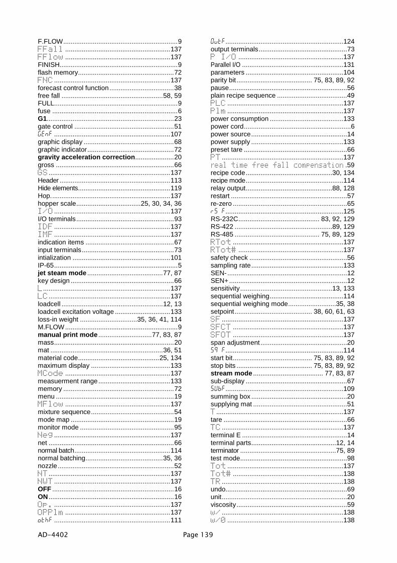
AD-4402 Page 139
F.FLOW..............................................................9FFall .........................................................137FFlow .........................................................137FINISH................................................................9flash memory....................................................72FNC ...............................................................137forecast control function...................................38free fall .......................................................58, 59FULL...................................................................9fuse ....................................................................6G1.....................................................................23gate control ......................................................51genf ...............................................................107graphic display .................................................68graphic indicator...............................................72gravity acceleration correction.....................20gross ................................................................66GS..................................................................137Header ............................................................113Hide elements..................................................119Hop.................................................................137hopper scale...................................25, 30, 34, 36I/O ...............................................................137I/O terminals.....................................................93IDF ...............................................................137IMF ...............................................................137indication items ................................................67input terminals..................................................73intialization .....................................................101IP-65...................................................................5jet steam mode .........................................77, 87key design ........................................................66L.....................................................................137LC..................................................................137loadcell .......................................................12, 13loadcell excitation voltage ..............................133loss-in weight ...............................35, 36, 41, 114M.FLOW.............................................................9manual print mode .............................77, 83, 87mass.................................................................20mat .............................................................36, 51material code............................................25, 134maximum display ...........................................133MCode .........................................................137measuerment range.......................................133memory ............................................................72menu ................................................................19MFlow .........................................................137mixture sequence.............................................54mode map ........................................................19monitor mode ...................................................95Neg ...............................................................137net ....................................................................66normal batch....................................................114normal batching..........................................35, 36nozzle...............................................................52NT..................................................................137NWT ...............................................................137OFF ..................................................................16ON ....................................................................16Op. ...............................................................137OPPlm .........................................................137othf ...............................................................111
0utf................................................................124output terminals................................................73P I/O .........................................................137Parallel I/O .......................................................131parameters .....................................................104parity bit ......................................... 75, 83, 89, 92pause................................................................56plain recipe sequence ......................................49PLC ...............................................................137Plm ...............................................................137power consumption ........................................133power cord..........................................................6power source....................................................14power supply ..................................................133preset tare ........................................................66PT ..................................................................137real time free fall compensation .59recipe code...............................................30, 134recipe mode.....................................................114relay output...............................................88, 128restart ...............................................................57re-zero ..............................................................65r5 f................................................................125RS-232C............................................ 83, 92, 129RS-422 .....................................................89, 129RS-485 .............................................. 75, 89, 129RTot ............................................................137RTot# .........................................................137safety check .....................................................56sampling rate..................................................133SEN-.................................................................12SEN+................................................................12sensitivity..................................................13, 133sequential weighing........................................114sequential weighing mode..........................35, 38setpoint.......................................... 38, 60, 61, 63SF ..................................................................137SFCT ............................................................137SFOT ............................................................137span adjustment ...............................................205q f................................................................114start bit........................................... 75, 83, 89, 92stop bits ......................................... 75, 83, 89, 92stream mode ...................................... 77, 83, 87sub-display .......................................................675Ubf................................................................109summing box ....................................................20supplying mat ...................................................51T.....................................................................137tare ...................................................................66TC ..................................................................137terminal E .........................................................14terminal parts..............................................12, 14terminator ....................................................75, 89test mode..........................................................98Tot ...............................................................137Tot# ............................................................138TR ..................................................................138undo..................................................................69unit....................................................................20viscosity............................................................59w/ ..................................................................138w/0 ...............................................................138

Page 140 AD-4402
water-resistant panel..........................................5weighing status ................................................72weight ...............................................................20WGT ...............................................................138WGTTot ......................................................138Z. BAND .............................................................9
zero point adjustment.......................................20zero range ......................................................133zero tracking.....................................................65ZR ..................................................................138ZR.ERR ..............................................................9

ページ 1
[ Blank page ]

!"# $% &'( )* !"# $% &'("++ ,,---.//.0.1,
234 56786558679 86:;&&& <0=/ >? <+ =. '&& @.A.. !# $"% (& )* !# $"%('
234 86B56 C4;@+ ,( D0 / E / D / F* FG >H @+/ I/ !# $&% && )* !# $&% &&"&
J7 K LD A+ ( ( ) M+,< & NOP<H !'# $('% & )* !'# $('% &&
234 B5: ; C4; >- A++ + A+ + & @APQ !(# $"% "& )* !(# $"% "&'
234 RK52 C"+ ) <++ D/. ( H// H/ A IFPO !"# $% " )* !"# $% ""