PIG-SIG® V - Scraper Passage Indicator
19
-
Upload
khangminh22 -
Category
Documents
-
view
0 -
download
0
Transcript of PIG-SIG® V - Scraper Passage Indicator


North & South America: +1 918 447 5000 Europe / Africa / Middle East: +32 67 28 3611 Asia Pacific: +65 6364 8520 www.tdwilliamson.comData subject to change without notice. / Dimensions not for construction unless certified. / ® Registered trademark of T.D. Williamson, Inc. in the United States and other countries. / TM Trademark of T.D. Williamson, Inc. in the United States and other countries. / © Copyright 2015 All rights reserved. T.D. Williamson, Inc.
Available options:
Flag Indicator with Manual Reset
Electrical Indicator with Auto Reset
Flag/Electrical Indicator combined
Extended models, for installation on buried
pipelines, are available in all configurations
Special materials and O-ring seals
Isolation Ball Valve (upon request)
Unit can be thread-mounted to
THREAD-O-RING nipple or flange-mounted
“Build your own” PIG-SIG V assembly
from the charts on the pages
of this product bulletin
T.D. Williamson is committed to providing you
with the right product to assist you in planning,
budgeting and meeting the specifications for your
individual application needs.
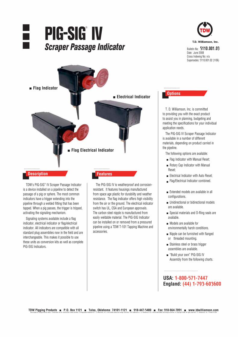
Features
TDW’s PIG-SIG V Scraper Passage Indicator
is a device installed at prescribed intervals on
pipelines to detect the passage of a scraper or
sphere. This unique product functions by
extending an omnidirectional trigger into the
pipeline through a welded fitting: the trigger is
tripped by the passage of a scraper/sphere.
The TDW PIG-SIG V Scraper Passage Indicator
is easy to install, compatible with all standard
THREAD-O-RING nipples, as well as flanged fittings,
and all but eliminates trigger breakage.
Signaling systems available with the
PIG-SIG V device include a flag indicator,
an electrical indicator or a flag/electrical
indicator. It is compatible with all standard
THREAD-O-RING nipples previously sold by
TDW and are interchangeable. This makes it
possible to order the PIG-SIG V unit as an
upgrade conversion kit without nipple, or as
a new installation kit complete with nipple.
The PIG-SIG V device can also be provided in
a flange-mounted configuration per the required
pipeline pressure class (up to 2500 lb.).
Standard PIG-SIG V Passage Indicators are
built to withstand the most severe offshore/
onshore environments. Each PIG-SIG V device
is weatherproof and corrosion-resistant. All
components exposed to pipeline products are
completely sealed to prevent leakage Components
exposed to the atmosphere are all 316 stainless
steel — except on electrical models, where the
MICRO SWITCH™ is aluminum with a protective
powder coating
(unless stainless steel is specially requested). The
MICRO SWITCH flag indicator offers high visibility.
Because the triggering toggle that extends into
a pipe is omnidirectional, it does not require
adjustments after it is set. This means the flag
can be oriented to face any desired direction. The
carbon steel nipple is manufactured from easily
weldable material. All PIG-SIG indicators can
be installed on or removed from a pressurized
pipeline by using a TDW T-101 Tapping Machine
and accessories.
Description
Options
Bulletin No: Bulletin 5110.003.Version: 1Supersedes: 5110.003.0Supersedes: ( .2015)
The PIG-SIG®
V is patented in the U.S. (7861665) and
other countries.
Viton® , Teflon® , Buna-N® and Kalrez ® are trademarks
of E.I DuPont de Nemours Company.
MICRO SWITCHTM is a trademark of Honeywell
International, Inc.
AFLAS® is a trademark of Asahi Glass Co., Ltd.
Electrical Indicator
Flag/Electrical
Indicator
PIG-SIG®
VScraper Passage Indicator

North & South America: +1 918 447 5000 Europe / Africa / Middle East: +32 67 28 3611 Asia Pacific: +65 6364 8520 www.tdwilliamson.comData subject to change without notice. / Dimensions not for construction unless certified. / ® Registered trademark of T.D. Williamson, Inc. in the United States and other countries. / TM Trademark of T.D. Williamson, Inc. in the United States and other countries. / © Copyright 2015 All rights reserved. T.D. Williamson, Inc.
Plug Assembly
THREAD-O-RING™ Nipple-Mounted
0 = 316 Stainless Steel Omnidirectional
1*= Naval Brass
Order Information
0 4 - X X X X - X X X X - S u f f i x
This example is a PIG-SIG V indicator with a THREAD-O-RING nipple and a nipple-mounted
flag indicator, 12 in. extended shaft for 6 in. and larger pipe with .250 in. to .500 in. wall.
Indicator Assembly
Indicator Option
0 Flag with Manual Reset
1 Electrical with Auto Reset
2 Flag/Electrical Combined
3* Electrical with Auto Reset (Stainless Steel Switch Housing)
4* Flag/Electrical Combined (Stainless Steel Switch Housing)
Class Options
Class* Pipe Sizes Mounting
9550 2 – 4-inch (50 – 100 mm) TOR† Nipple-Mounted
9548 5-inch (125 mm) and Larger TOR† Nipple-Mounted
4400 150 # RF Flange-Mounted
4410 300 # RF Flange-Mounted
4420 600 # RF Flange-Mounted
4430 600 # RTJ Flange-Mounted
4440 900 / 1500 # RF Flange-Mounted
4450 900 / 1500 # RTJ Flange-Mounted
4460 2500 # RF Flange-Mounted
Example: 04-9548-0100-51
5110.003. - p2PIG-SIG®
V Scraper Passage Indicator
Extended Indicator
Flag Indicator Assembly Electrical Indicator Assembly
Shaft Assembly
Extension Length
0 None None
1 12” 304.8 mm
2* 24” 609.6 mm
3* 36” 914.4 mm
4* 48” 1219.2 mm
5 60” 1524.0 mm
6 72” 1828.8 mm
7* 84” 2133.6 mm
8 96” 2438.4 mm
9* 108” 2743.2 mm
A* 120” 3048.0 mm
Flag/Electrical Indicator Assembly
* All Ratings are ANSI Class † TOR = THREAD-O-RINGT M
* Special options available upon request. Factory lead times may vary.
* Special options available upon request. Factory lead times may vary.
* Special options available upon request. Factory lead times may vary.
Flange -Mounted THREAD-O-RINGTM Material
0 A105 & A350 LF2 CL1 Dual Certification
1 A105 & A350 LF2 CL1 Dual Certification
2 A182 F316 w/EN-10204 3.1 Certification
3 A 182 F316 w/EN-10204 3.2 Certification
4 A 694 F52 w/EN-10204 3.1 Certification
0
1
2
3†
4†
5
6†
7†
8†
9†

North & South America: +1 918 447 5000 Europe / Africa / Middle East: +32 67 28 3611 Asia Pacific: +65 6364 8520 www.tdwilliamson.comData subject to change without notice. / Dimensions not for construction unless certified. / ® Registered trademark of T.D. Williamson, Inc. in the United States and other countries. / TM Trademark of T.D. Williamson, Inc. in the United States and other countries. / © Copyright 2015 All rights reserved. T.D. Williamson, Inc.
Order Information
0 4 - X X X X - X X X X - S u f f i x *
5 in. & Smaller Pipe 6 in. & Larger Pipe
Length Length
5110.003. - p3
THREAD-O-RING™ Nipple part number: 00-1023-0333-SUFFIX
THREAD-O-RING™ Nipple-Mounted Options
Nom. Pipe Size Wall Thickness Nipple Length
2 50 0.125 - 0.188 3.175 - 4.775 4.250 108.0 11
2 50 0.189 - 0.375 4.801 - 9.525 4.125 104.8 07
2.5 65 0.125 - 0.188 3.175 - 4.775 4.250 108.0 10
2.5 65 0.189 - 0.375 4.801 - 9.525 4.125 104.8 06
3 80 0.062 - 0.125 1.575 - 3.175 4.375 111.1 24
3 80 0.125 - 0.188 3.175 - 4.775 4.250 108.0 09
3 80 0.189 - 0.375 4.801 - 9.525 4.125 104.8 05
3 80 0.376 - 0.562 9.550 - 14.275 3.938 100.0 18
3.5 90 0.125 - 0.188 3.175 - 4.775 4.250 108.0 08
3.5 90 0.189 - 0.375 4.801 - 9.525 4.125 104.8 04
3.5 90 0.563 - 0.750 14.300 - 19.050 3.750 95.3 19
4 100 0.125 - 0.188 3.175 - 4.775 4.250 108.0 03
4 100 0.189 - 0.375 4.801 - 9.525 4.120 104.8 01
4 100 0.376 - 0.562 9.550 - 14.275 3.938 100.0 17
4 100 0.400 - 0.587 10.160 -14.910 3.913 99.4 22
4 100 0.563 - 0.750 14.300 - 19.050 3.750 95.3 21
5 125 0.125 - 0.188 3.175 - 4.775 4.250 108.0 13
5 125 0.189 - 0.375 4.801 - 9.525 4.125 104.8 12
5 125 0.563 - 0.750 14.300 - 19.050 3.750 95.3 20
6 & up 150 & up 0.250 - 0.500 6.350 - 12.700 4.000 101.6 51
6 & up 150 & up 0.501 - .0750 12.725 - 19.050 3.750 95.3 52
6 & up 150 & up 0.751 - 1.000 19.075 - 25.400 3.500 88.9 53
6 & up 150 & up 1.001 - 1.250 25.425 - 31.750 3.250 82.6 54
6 & up 150 & up 1.251 - 1.500 31.775 - 38.125 3.000 76.2 55
6 & up 150 & up 1.501 - 1.750 38.125 - 44.450 2.750 69.9 56
6 & up 150 & up 0.125 - 0.249 3.175 - 6.375 4.250 108.0 64
Less Nipple 99
* Please indicate if protection for environmentally harsh conditions is required.
Flange-Mounted
Assembly Options
Contact your
TDW representative
with pipe size, wall
thickness, desired
extension length
and flange type
to determine
the appropriate
4-digit suffix.
O P T I O N
† Special options available upon request. Factory lead times may vary.
Option
A105 & A350 LF2 CL1 Dual Certification w/EN-10204 3.1
A105 & A350 LF2 CL1 Dual Certification w/EN-10204 3.2
O-Ring Material
Explosive Decompression
& Extrusion Resistant Viton®
Buna-N (Low Temp.)
Neoprene
EPDM
Kalrez®
Buna
Viton ® GF
Teflon ®
Explosive DecompressionResistant AFLAS®
Viton ® (Low Temp.)

North & South America: +1 918 447 5000 Europe / Africa / Middle East: +32 67 28 3611 Asia Pacific: +65 6364 8520 www.tdwilliamson.comData subject to change without notice. / Dimensions not for construction unless certified. / ® Registered trademark of T.D. Williamson, Inc. in the United States and other countries. / TM Trademark of T.D. Williamson, Inc. in the United States and other countries. / © Copyright 2015 All rights reserved. T.D. Williamson, Inc.
Specifications
THREAD-O-RING™ Nipple Material
Size & Grade: 2 NPS XXS ASTM A 333 Grade 6 seamless steel pipe
Tensile Requirements: 35,000 psi SMYS - 60,000 psi SMTS
Impact Requirements: 13 ft-lbf min. avg. three specimens
10 ft-lbf min. one specimen only
Impact Temperature -50° F
Chemical Requirements: Composition, % - Carbon 0.30 max, Manganese 0.29-1.06
Phosphorus 0.025 max., Sulfur 0.025 max., Silicon 0.10 min.
Test Report: Certified Test Reports furnished per ASTM A 530
THREAD-O-RING™ Flange Material
Grade: A105 / A694 F52 / A350 LF2 triple certified
Tensile Requirements: Yield 360 N/mm2, Tensile 485 N/mm2
Impact Requirements: -46° C, 27 J avg. three specimen, 20 J minimum one specimen
Chemical Requirements: C 0.26% max., Mn 1.35 % max., P 0.025% max., S 0.025% max., Si 1% max.
Test Report: EN 10204 3.1
THREAD-O-RING™ Pressure Temperature Ratings Pressures are in pounds per square inch, gage (psig). Temperatures are in Fahrenheit.
Piping Code B31.3 B31.4 B31.8
Temp. ° F F =.72 F =.72 F =.60 F =.50 F =.40
-50 3159
-20 to 250 3159 3743 3743 3120 2600 2080
300 3159 3620 3017 2514 2011
350 3159 3493 2911 2425 1940
400 3159 3369 2808 2340 1872
450 3072 3246 2246 1872 1497
500 2985
PIG-SIG®
V Scraper Passage Indicator 5110.003. - p4
Pressures do not include allowance for corrosion. O-Ring material selection must be suitable for service fluids and temperature requirements.
Due to magnet degradation, the temperature for the plug assembly is limited to 200º F (93º C)
THREAD-O-RING™ Pressure Temperature Ratings Pressures are in bar. Temperatures are in Celsius.
Piping Code B31.3 B31.4 B31.8
Temp. ° C F =.72 F =.72 F =.60 F =.50 F =.40
-46 218
-29 to 116 218 258 258 215 179 143
149 218 250 208 173 139
177 218 241 201 167 134
204 218 232 194 161 129
232 212 224 155 129 103
260 206

North & South America: +1 918 447 5000 Europe / Africa / Middle East: +32 67 28 3611 Asia Pacific: +65 6364 8520 www.tdwilliamson.comData subject to change without notice. / Dimensions not for construction unless certified. / ® Registered trademark of T.D. Williamson, Inc. in the United States and other countries. / TM Trademark of T.D. Williamson, Inc. in the United States and other countries. / © Copyright 2015 All rights reserved. T.D. Williamson, Inc.
Specifications
PIG-SIG®
V Scraper Passage Indicator 5110.003. - p5
The basic indicator includes:
2 in. (50 mm) THREAD-O-RING™ nipple,
plug assembly and indicator assembly.
The extended indicator includes the
same items, as well as an extended
length indicator assembly.
A B C Weight
Inch mm Inch mm Inch mm Lb. Kg. Part Number
Extended:
48 1200 25 11.5 04-9548-0400*
72 1800 34 15.5 04-9548-0600
96 2500 44 20.5 04-9548-0800
* Special options available upon request. Factory lead times may vary.
A B C Weight
Inch mm Inch mm Inch mm Lb. Kg. Part Number
Extended:
48 1200 30 14.0 04-9548-2400*
72 1800 40 18.0 04-9548-2600
96 2500 50 23.0 04-9548-2800
* Special options available upon request. Factory lead times may vary.
Flag Indicator with Manual Reset
Flag Indicator with Manual Reset - Electrical Indicator with Auto Reset Combined
A
A
C
C
B
B
The basic indicator includes: 2 in.
(50 mm) THREAD-O-RING nipple,
plug assembly and flag/electrical indicator
assembly. The electrical indicator consists
of a weatherproof, explosion-proof, ATEX
Certified MICRO SWITCH™ (LSX, double-
pole, double-throw).
The extended indicator includes the
same items, as well as an extended length
indicator assembly.

North & South America: +1 918 447 5000 Europe / Africa / Middle East: +32 67 28 3611 Asia Pacific: +65 6364 8520 www.tdwilliamson.comData subject to change without notice. / Dimensions not for construction unless certified. / ® Registered trademark of T.D. Williamson, Inc. in the United States and other countries. / TM Trademark of T.D. Williamson, Inc. in the United States and other countries. / © Copyright 2015 All rights reserved. T.D. Williamson, Inc.
5110.003. - p6
Dimensions and Part Numbers
PIG-SIG®
V Scraper Passage Indicator
The basic indicator includes:
2 in. (50 mm) THREAD-O-RING™ nipple,
plug assembly and electrical indicator
assembly. The electrical indicator consists
of a weatherproof, explosion-proof, ATEX
Certified MICRO SWITCH™ (LSX, double-
pole, double-throw).
The extended indicator includes the
same items, as well as an extended length
indicator assembly.
Electrical Indicator with Auto Reset
AC
B
A B C Weight
Inch mm Inch mm Inch mm Lb. Kg. Part Number
Extended:
48 1200 30 14.0 04-9548-1400*
72 1800 40 18.0 04-9548-1600
96 2500 50 23.0 04-9548-1800
* Special options available upon request. Factory lead times may vary.

North & South America: +1 918 447 5000 Europe / Africa / Middle East: +32 67 28 3611 Asia Pacific: +65 6364 8520 www.tdwilliamson.comData subject to change without notice. / Dimensions not for construction unless certified. / ® Registered trademark of T.D. Williamson, Inc. in the United States and other countries. / TM Trademark of T.D. Williamson, Inc. in the United States and other countries. / © Copyright 2015 All rights reserved. T.D. Williamson, Inc.
Specifications
PIG-SIG®
V Scraper Passage Indicator
MICRO SWITCHTM Electrical Diagram
Electrical specifications:
Double-Pole
2 N.O., 2 N.C.
3/4 in. conduit
AC Volts - Pilot Duty: 600 VAC, 720VA
Amps at 0.35 Power Factor
Circuitry VAC Make Break
Double-Pole, Double-Throw 120 30 3
240 15 1.5
480 7.5 0.75
600 6 0.60
DC Volts - Pilot Duty: 240 VDC, 30 watts Make and Break Amps
Circuitry VDC Inductive Resistive
Double-Pole, Double-Throw 24 10 10
120 0.25 0.8
240 0.15 0.4
5110.003. - p7
Note: When a Flag Indicator is used in
combination with the electrical
switch, the switch will open or
close when the flag is reset.
MOMENTARY
3 7
4
6
51
2
8
Switch Specifications
Electrical Indicator Switch Specifications
MICRO SWITCH™ Weatherproof, explosion-proof switch BXC4L for use either indoors or outdoors in hazardous atmospheres
Temperature Range: -40º F (-40º C) to 185º F (85º C)
Housing Materials: Aluminum and Zinc (Optional: Stainless Steel)
Seals: Fluorosilicone
NEMA Standards: 1, 3, 4 , 4X, 6, 7, 9 and 13
UL listed (File No. E61730) and CSA certified (File No. LR57327):
Class I, Div. 1, Groups B, C, and D (Listings covered in Div. 1 are also covered in the same groups in Div. 2)
Class II, Div. 1, Groups E, F and G (IEC standards: EExd IICT6, IP67)
Electrical Ratings: 10 amps continuous carry. Circuits on any one pole must be the same polarity
ATEX Certification: EExd II T6 cateory II 2 GD, SIRA 00ATEX 1037X

North & South America: +1 918 447 5000 Europe / Africa / Middle East: +32 67 28 3611 Asia Pacific: +65 6364 8520 www.tdwilliamson.comData subject to change without notice. / Dimensions not for construction unless certified. / ® Registered trademark of T.D. Williamson, Inc. in the United States and other countries. / TM Trademark of T.D. Williamson, Inc. in the United States and other countries. / © Copyright 2015 All rights reserved. T.D. Williamson, Inc.
5110.003. - p8
Specifications
PIG-SIG®
V Scraper Passage Indicator
Recommended Spare Parts List Component Quantity in Assembly Part Number
O-ring, Plug 1 00-8440-0003-00
Backup Ring 1 00-1586-0066-00
O-ring, Cap 1 00-8144-0001-00
Set Screw 3 00-8176-0001-00
1-inch Hex Plug Holder* 1 00-8138-0000-00
1-inch Hex Bit † 1 00-8235-0001-00
Brush Magnet Adapter* 1 04-3998-0000-00
THREAD-O-RING™ Thread Chaser 1 05-0347-0000-00
Magnet Holder Assm. with Filter Pack 1 04-4133-0000-00
* If PIG-SIG V is to be installed or removed under pressure with removal tool, these component(s) will be required.
† If PIG-SIG V is to be installed with no pipeline pressure, these component(s) will be required.