STRUCTURAL PRODUCTS CATALOGUE
256
STRUCTURAL PRODUCTS CATALOGUE Better Technology Better Building 59 TH EDITION LIMIT STATES DESIGN CANADIAN EDITION
-
Upload
khangminh22 -
Category
Documents
-
view
1 -
download
0
Transcript of STRUCTURAL PRODUCTS CATALOGUE

STRUCTURAL PRODUCTS CATALOGUE
Better TechnologyBetter Building
59TH EDITION LIMIT STATES DESIGN
CANADIAN EDITION

SPECS. JUST A CLICK AWAY.DOWNLOAD THE ONLINE CATALOGUE & APP
→ Easy navigation to search structural connector products in this catalogue
→ Access product applications, instructions, fastening schedules and load ratings and reference numbers
→ Cross reference product specifications and look up on the fly
→ Email pages from the app on any mobile device
MITEK ONLINE CATALOGUE
ALWAYS AVAILABLE AND UP TO DATE View digital version of the printed catalogue at MiTek.ca/resources/product-catalogue. Bookmark it for the most current technical information.
Use the Advanced Product Search function on the home page to find detailed information on any MiTek product. Simply enter the product name, SKU number or reference number.
FREE DOWNLOAD
3
Copy
right
© 2
018
MiT
ek In
dust
ries,
Inc.
All
Righ
ts R
eser
ved
NEW PRODUCTS
Fasteners
Concrete & Masonry
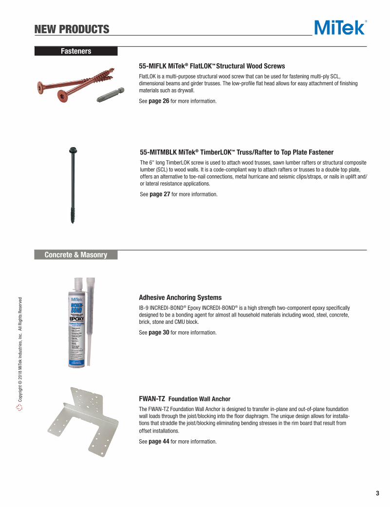
Adhesive Anchoring SystemsIB-9 INCREDI-BOND® Epoxy INCREDI-BOND® is a high strength two-component epoxy specifically designed to be a bonding agent for almost all household materials including wood, steel, concrete, brick, stone and CMU block.
See page 30 for more information.
55-MIFLK MiTek® FlatLOK™ Structural Wood ScrewsFlatLOK is a multi-purpose structural wood screw that can be used for fastening multi-ply SCL, dimensional beams and girder trusses. The low-profile flat head allows for easy attachment of finishing materials such as drywall.
See page 26 for more information.
55-MITMBLK MiTek® TimberLOK™ Truss/Rafter to Top Plate FastenerThe 6" long TimberLOK screw is used to attach wood trusses, sawn lumber rafters or structural composite lumber (SCL) to wood walls. It is a code-compliant way to attach rafters or trusses to a double top plate, offers an alternative to toe-nail connections, metal hurricane and seismic clips/straps, or nails in uplift and/or lateral resistance applications.
See page 27 for more information.
FWAN-TZ Foundation Wall Anchor
The FWAN-TZ Foundation Wall Anchor is designed to transfer in-plane and out-of-plane foundation wall loads through the joist/blocking into the floor diaphragm. The unique design allows for installa-tions that straddle the joist/blocking eliminating bending stresses in the rim board that result from offset installations.
See page 44 for more information.

4
Copyright © 2018 M
iTek Industries, Inc. All Rights Reserved
NEW PRODUCTS
Caps & Bases
BCS Post CapsOne-piece design for connecting 2-ply (BCS22-4) or 3-ply (BCS23-6) beams to the tops of 4x4 or 6x6 respectively. Slant nailing reduces the amount of nails required for the connector.
See page 76 for more information.
RPB Retrofit Post BaseRPB-TZ post base attaches 4x4 or larger wood post to concrete or wood surfaces after the post is in place. Can be installed with 1 or 2 RPB-TZ's (single or double). Post may also be installed on our CPB composite post base product which provides a 1" stand off as required in untreated wood installations. Installs with concrete screws, so no more mis-installed, mis-located, anchor bolts!
See page 66 for more information.
Concrete & Masonry
BLACKJACK 2.5 Adjustable Support Column
An upgrade from the telescopic double tube JP Adjustable Column, this single tube Structural Column assembly has a maximum height of 110" and a screw adjustable length of 4". Tube may be cut down for shorter height requirement.
See pages 49-50 for more information.
ARC Anchor Rod Chairs
ARC Anchor Rod Chairs allow for easy and precise placement of anchor rods prior to pouring concrete. The “chair” and nut are pre-assembled for quick installation.
See page 39 for more information.

5
Copy
right
© 2
018
MiT
ek In
dust
ries,
Inc.
All
Righ
ts R
eser
ved
NEW PRODUCTS
Hangers
Angles & Straps
LGUM / HGUM Masonry Girder HangersLGUM and HGUM Masonry Girder Hangers are high-capacity beam/girder hangers designed for installation to masonry or concrete walls and eliminate the need for constructing beam pockets.
See pages 140-141 for more information.
FWHBP Fire Wall Hangers, Beam and PurlinThe FWHBP Fire Wall Hangers for Beam and Purlins transfer loads into the supporting wall thru bearing on the top plates and directly attaching to the stud pack or post below.
See page 129 for more information.
FWHFM Fire Wall Hangers for Face Mount ApplicationsThe FWHFM Fire Wall Hangers for Face Mount Applications fasten to the wide face of a balloon framed SCL column thereby eliminating the additive perpendicular-to-grain bearing stresses in the wall top and bottom plates seen with platform framing.
See page 117 for more information.
TSP Stud Plate TieTSP stud plate ties connect single or double top plates or mud sill plates to wall studs. Optional diamond nail holes allow for various uplift capacities with Min and Max nailing configurations.
See pages 86 and 198-200 for more information.

6
Copyright © 2018 M
iTek Industries, Inc. All Rights Reserved
ADTT-TZ Adjustable Deck Tension TieAdjustable Deck Tension Tie designed to effectively transfer the out of plane lateral loads of the deck to the house structure.
See page 229 for more information.
KEGQ Glulam Beam Hangers WS Wood Screw fastening, heavy steel construction, and a continuous top flange allow the KEGQ products to have high load capacities.
See page 183 for more information.
VTT Valley Truss TieThe VTT is a Valley Truss Tie designed to transfer loads from a valley truss into the supporting structure below. It also resists the sliding forces from downward loads when the valley truss is set upon a sloped lower roof. The ability to resist the sliding force eliminates the need for support wedges under the valley truss bottom chord or special order valley roof trusses with a bevel-cut bottom chord.
See page 226 for more information.
Truss & Rafters
Decks & Fences
Glulam Beam Connectors
NEW PRODUCTS

7
Copy
right
© 2
018
MiT
ek In
dust
ries,
Inc.
All
Righ
ts R
eser
ved
Directory of Products
Corrosion Information . . . . . . . . . . . . . 12-17Design Notes . . . . . . . . . . . . . . . . . . . . 19-20Installation Notes. . . . . . . . . . . . . . . . . . . .20 New Products . . . . . . . . . . . . . . . . . . . . . 3-6Product Information . . . . . . . . . . . . . . . . .18Product Notes . . . . . . . . . . . . . . . . . . . . . .19Reference Number Index . . . . . . . . . . . 10-11MiTek index . . . . . . . . . . . . . . . . . . . . . . . 8-9
Angles & Straps . . . . . . . . . . . . . . . 82-102
Angles . . . . . . . . . . . . . . . . . . . 82-85, 90-91Clips . . . . . . . . . . . . . . . . . . . . . . . . . 83, 88Header Hangers. . . . . . . . . . . . . . . . . . . . .88Joist Anchors. . . . . . . . . . . . . . . . . . . . . .102 Lateral Joist Connectors . . . . . . . . . . . . . .89 Ornamental Connectors. . . . . . . . . . . . . . .93 Straps . . . . . . . . . . . . . . . . . . . . . . . . 92-102 Stud Plate Ties . . . . . . . . . . . . . . . . . .86-87
Caps & Bases . . . . . . . . . . . . . . . . . . 66-81
Column Bases . . . . . . . . . . . . . . . . . . . 71-73 Column Caps . . . . . . . . . . . . . . . . . . . . 79-81 Post Anchors . . . . . . . . . . . . . . 67-68, 70, 74Post Bases . . . . . . . . . . . . . . .66, 68-69, 78Post Caps . . . . . . . . . . . . . . . . . . . . . . 75-78
Concrete & Masonry . . . . . . . . . . . . 29-47
Adhesive Anchors . . . . . . . . . . . . . . . .29-30Anchor Bolts . . . . . . . . . . . . . . . . . . . .36-38Anchor Rod Chairs. . . . . . . . . . . . . . . . . . .39 Beam Seats. . . . . . . . . . . . . . . . . . . . . . . .46 Bearing Plates . . . . . . . . . . . . . . . . . . . . . .38Concrete Form Ties & Wedge . . . . . . . . . .40 Foundation Anchors. . . . . . . . . . . . . . . 41-45Hangers. . . . . . . . . . . . . . . . . . . . . . . . . . .47 Masonry Metals. . . . . . . . . . . . . . . . . . 32-35Mechanical Anchors . . . . . . . . . . . . . . 31-32Retro Plates. . . . . . . . . . . . . . . . . . . . . . . .39Wall Ties . . . . . . . . . . . . . . . . . . . . . . . . . .45
Structural Columns – Adjustable . . 48-51
Adjustable Support Columns . . . . . . . .48-50Column Caps . . . . . . . . . . . . . . . . . . . . . . .51Top Plates . . . . . . . . . . . . . . . . . . . . . . . . .51
Deck & Fences . . . . . . . . . . . . . . . .229-236
Angles . . . . . . . . . . . . . . . . . . . . . . . . . . .232Deck Connectors . . . . . . . . . . .229-230, 232 Fence Hardware . . . . . . . . . . . . . . .233-236Stair Angles. . . . . . . . . . . . . . . . . . . . . . .231
EWP Hangers . . . . . . . . . . . . . . . . . 146-179
Adjustable Connectors . . . . . . . . . . . . . .178 EWP Hanger Selector Guide . . . . . . . . . .146 EWP Installation . . . . . . . . . . . . . . . 147-148Face Mount Hangers . . . . . . . . . . . . 149-159 Top Mount Hangers . . . . . . . . . . . . . 160-177Slope/Skew Hangers . . . . . . . . . . . . . . .179
Fasteners . . . . . . . . . . . . . . . . . . . . . . 21-28
Nails . . . . . . . . . . . . . . . . . . . . . . . . . . 21-23Screws . . . . . . . . . . . . . . . . . . . . . . . . 24-28
General Hardware . . . . . . . . . . . . 237-245
Bridging. . . . . . . . . . . . . . . . . . . . . . 240-241 Closet Rods . . . . . . . . . . . . . . . . . . . . . . .244Corner Tie . . . . . . . . . . . . . . . . . . . . . . . .243 D.I.Y. Products . . . . . . . . . . . . . . . . . . . . .238 Drywall Clip . . . . . . . . . . . . . . . . . . . . . . .237 Insulation Supports . . . . . . . . . . . . . . . . .237Mending Plates . . . . . . . . . . . . . . . . . . . .245Nail Plates . . . . . . . . . . . . . . . . . . . . . . . .245 Plywood Clips . . . . . . . . . . . . . . . . . . . . .237Protection Plates . . . . . . . . . . . . . . . . . . .239Ridge Rafter Hanger . . . . . . . . . . . . . . . .243Shelf Brackets . . . . . . . . . . . . . . . . . . . . .244Step Flashing. . . . . . . . . . . . . . . . . . . . . .243 Stud Shoes . . . . . . . . . . . . . . . . . . . . . . .239Wall Bracing . . . . . . . . . . . . . . . . . . . . . .242
Glulam Beam Connectors . . . . . 180-188
Face Mount Hangers . . . . . . . . . . . . 180-182 Top Mount Hangers . . . . . . . . . . . . 183-188
Hangers . . . . . . . . . . . . . . . . . . . . . . 103-145
Face Mount Hangers . . . . . . . . . . . . 104-121Hangers Selector Guide . . . . . . . . . . . . . .103Masonry Hangers . . . . . . . . . . . . . . 139-145
Hangers (con't)
Panel & Purlin Hangers . . . . . . . . . . 135-138Slope/Skew Hangers . . . . . . . . . . . . 130-134Strap Hangers . . . . . . . . . . . . . . . . . . . . .130Top Mount Hangers . . . . . . . . . . . . 121-129Wall Ties . . . . . . . . . . . . . . . . . . . . . . . . .138
Holdowns . . . . . . . . . . . . . . . . . . . . . . 52-65
Concrete Angles . . . . . . . . . . . . . . . . . . . .65Foundation Straps . . . . . . . . . . . . . . . .60-63 Holdowns . . . . . . . . . . . . . . . . 52-53, 56-59 Purlin Anchors . . . . . . . . . . . . . . . . . . . . . .64 Tension Ties . . . . . . . . . . . . . . . . . . . .54-55
Lateral Systems . . . . . . . . . . . . . .252-254
Manufactured Housing . . . . . . . . . . . 251
Plated Truss . . . . . . . . . . . . . . . . .202-228
Alternate Installations . . . . . . . . . . . . . . .221Blocking Supports . . . . . . . . . . . . . . . . . .228Drag Strut Connectors . . . . . . . . . . . . . . .216Face Mount Hangers . . . . . . . . . . . . 202-207Girder Hangers . . . . . . . . . . . . . . . . 217-220Hip/Jack Connectors . . . . . . . . . . . . 214-216Skewed Nail Plate . . . . . . . . . . . . . . . . . .214Spacers/Braces . . . . . . . . . . . . . . . . 222-223Strap Hangers . . . . . . . . . . . . . . . . . 208-213Supplementary Bearing Plates. . . . . 223-224Truss Clips. . . . . . . . . . . . . . . . . . . .225-228
Specialty Options . . . . . . . . . . . .246-250
Face Mount Hanger . . . . . . . . . . . . . . . . .247Open Top Flange Hanger . . . . . . . . . . . . .248Solid Top Flange Hanger . . . . . . . . . 248-249Welded Top Flange Hanger . . . . . . . . . . .250
Truss & Rafter . . . . . . . . . . . . . . . 189-201
Angles . . . . . . . . . . . . . . . . . . . . . . . 194-195 Girder Tiedowns . . . . . . . .192-193, 196-197Moisture Barrier Plates . . . . . . . . . . . . . .189 Hurricane Ties . . . . . . . . . . . . . 195, 198-199 Truss Anchors . . . . . . . . . . . . . . . . . 189-191
WARRANTYMiTek USA, Inc. (“MiTek”) warrants its MiTek catalogue Products to be free from material defects in manufacture and design, and further warrants that they will perform within the design limitations of its published building code approvals for the applications described, when properly installed and maintained. These warranties do not cover Product deterioration due to environmental conditions, Products that have be modified or damaged, improperly installed or used outside of published design limitations or for other applications. In the event any Product is shown to not conform to these warranties, MiTek’s sole obligation, and Customer’s sole and exclusive remedy, shall be, at MiTek’s option, to replace the non-conforming product or refund the full purchase price paid by Customer to MiTek therefor. MiTek MAKES NO OTHER PRODUCT WARRANTIES, EXPRESS OR IMPLIED, OF ANY KIND, AND
PARTICULARLY EXCLUDES ANY IMPLIED WARRANTY OR MERCHANTABILITY OR FITNESS FOR A PARTICULAR PURPOSE. IN NO EVENT SHALL MiTek BE LIABLE FOR INCIDENTAL, CONSEQUENTIAL OR SPECIAL DAMAGES, REGARDLESS OF THE LEGAL THEORY OF RECOVERY, EVEN IF IT WAS AWARE OF THE POSSIBILITY OF SUCH DAMAGES. IN ANY CASE, MiTek’s MAXIMUM LIABILITY SHALL NOT EXCEED THE PURCHASE PRICE PAID BY CUSTOMER FOR THE NON-CONFORMING PRODUCT. Some states restrict consequential or other liability damage limitations, so some of the above limitations may not apply to you. MiTek reserves the right to change this warranty periodically. Consult MiTek’s website www.MiTek.ca or contact MiTek for a current warranty statement.

8
Copyright © 2018 M
iTek Industries, Inc. All Rights Reserved
55-MIFLK FlatLOK™ Screws . . . . . . . . 2655-MITMBLK TimberLOK™ Screw . . . . 27
A Angle Clip . . . . . . . . . . . . . . . . . . . . . 82AB Anchor Bolts . . . . . . . . . . . . . . . . . 38ABP Anchor Bolts . . . . . . . . . . . . . . . . . 38AC Angle Clips . . . . . . . . . . . . . . . . . . . 82ADTT Deck Tension Tie . . . . . . . 118, 229Alternate Installations . . . . . . . . . . 221ANJ Heavy Angles . . . . . . . . . . . . . . . . 90APB Post Bases . . . . . . . . . . . . . . . . . 68ARC Anchor Rod Chairs . . . . . . . . . . . . 39
B Corner Braces . . . . . . . . . . . . . . . . . 91BC Post Cap . . . . . . . . . . . . . . . . . . . . 76BCS Post Cap . . . . . . . . . . . . . . . . . . . 76BD Bolt Down . . . . . . . . . . . . . . . . . . 236BL Corner Braces . . . . . . . . . . . . . . . . 91BLACKJACK Adj. Support Columns . 49-50BN Breakfast Nook Hangers . . . . . . . 216BP Bearing Plates . . . . . . . . . . . . . . . . 38BPH Beam & Purlin Hangers . . . . . . . .161, 164-165, 167-171, 173-177
C Post Caps . . . . . . . . . . . . . . . . . . . . . 76CBE Column Bases . . . . . . . . . . . . . . . 73CBSQ Column Bases . . . . . . . . . . . . . . 72CIA-EA Epoxy Acrylate . . . . . . . . . . 29-30CIA-GEL Epoxy . . . . . . . . . . . . . . . . 29-30CMST Coiled Strapping . . . . . . . . . . . . 94CMSTC Coiled Strapping . . . . . . . . . . . 94CPB Composite Post Bases . . . . . . . . . 78CR Concrete Reinforcing Rod . . . . . . . . 33CRE Epoxy Coated Rebar . . . . . . . . . . . 35CRWFP Fluted Closet Rods . . . . . . . . 244CRWP Closet Rods . . . . . . . . . . . . . . 244CRZFP Fluted Closet Rods . . . . . . . . . 244 CRZP Closet Rods . . . . . . . . . . . . . . . 244CSH Concealed Stringer Hanger . . . . . . . . . . . . . . . . . . . . . . . . . . . . . 121, 230
D Post Anchors . . . . . . . . . . . . . . . . . . 74DC Deck Clip . . . . . . . . . . . . . . . . . . . 232 DC Drywall Clip . . . . . . . . . . . . . . . . . 237DSC Drag Strut Connectors . . . . . . . . 216DT Face Mount Joist Hangers . . . . . . . . . . . . . . . . . . . . . . . . . . . . . . . 104, 108-109DTB Deck Tie Bracket . . . . . 53, 119, 230DTUS Undersaddle Hanger . . . . . . . . . 137
EA Adhesive (CIA-EA) . . . . . . . . . . 29-30EBG Elevated Post Base . . . . . . . . . . . 69EPB Elevated Post Bases . . . . . . . . . . . 69EPBH Elevated Post Bases . . . . . . . . . 69EPCM End Post Caps . . . . . . . . . . . . . 75ERB Fence Bracket . . . . . . . . . . 120, 234EWP Hanger Selector Guide . . . . . . . 146EWP Installation . . . . . . . . . . . . .147-149
FA Foundation Anchors . . . . . . . . . 41-42FB Fence Brackets . . . . . . . . . . 120, 234FHD Panel Hanger . . . . . . . . . . . . . . . 138
FPH Fence Rail Hanger . . . . . . . . 119, 235 FRB Fence Brackets . . . . . . . . . 120, 234FT Concrete Form Ties . . . . . . . . . . . . 40FTC Floor Truss Clips . . . . . . . . . . . . 225FTCF Floor Truss Clips . . . . . . . . . . . . . 225FWAN Foundation Wall Anchor . . . . . . . 44FWH Fire Wall Hangers . . . . . . . . . 127-128FWHBP Fire Wall Hangers Beams & Purlin . . . . . . . . . . . . . . . . . . . . . . . . . . . . . . . 129FWHFM Fire Wall Hangers Face Mount . .117
GEL Epoxy (CIA-GEL Series) . . . . . 29-30GHF Glulam Face Mount Hangers . . 181-182GT Girder Truss Hangers . . . . . . 219-220GTD Girder Truss Hangers . . . . . 219-220GTQ/GTQM Girder Truss Hangers . . . 218 GTS Girder Truss Hangers . . . . . 219-220 GTWS Girder Truss Hangers . . . . . . . 217
Hanger Selector Guide . . . . . . . . . . 103Hardy Frame® Shear Walls . . . . . . . . 253Hardy Frame® Special Moment Frame . . . . . . . . . . . . . . . . . . . . . . . . . . . . . . . 252HBPH Top Mount Hangers . . . . . . . . . . . . . . . 161, 168-171, 173-177HBPS Bearing Plates . . . . . . . . . . . . . . 38HC Hurricane Ties . . . . . . . . . . . . 198-200HCPRS Hurricane Ties . . . . . . . . 198-200HD/HDIF Face Mount Hangers . . . . . . . . . . . 106-116, 152-153, 156-159HDO Top Mount Hangers . . . 122, 124-126HDQIF Inverted Flange Hangers . . . . . . . . . . . 106, 109-115, 152, 157-159HGA Hurricane Gusset Angles . . . . . . 195HGAM Hurricane Gusset Angles . . . . . 194HGU Girder Hanger . . . . . . . . . . 180-181HGUM Masonry Girder Hanger . . 140-141HH Header Hangers . . . . . . . . . . . . . . . 88HHC Hip/Hip Connectors . . . . . . 214-215HHCP Hurricane Ties . . . . . . . . . 198-200HJC Hip/Jack Connectors . . . . . 214-215HJHC Hip/Jack Connectors . . . . .214-215 HL Light Gauge Purlin Hangers . .121, 124HLBH Beam Hangers . . . . . . . . . . . . . . . 162, 167-170, 173-177HLPTA Truss Anchor . . . . . . . . . . . . . 190HPAHD Foundation Straps . . . . . . . . . 60HRS Strap Ties . . . . . . . . . . . . . . . 95-97HTC Heavy Truss Clip . . . . . . . . . . . . 228HTHJ Hip/Jack Connectors . . . . 214-215HTP Strap Ties . . . . . . . . . . . . . . . 95-96HTT Tension Ties . . . . . . . . . . . . . . . . . 55HTW Twist Straps . . . . . . . . . . . . 99-100HTWM Twist Straps . . . . . . . . . . . . . 102HUGT Girder Tiedowns . . . . . . . 193, 197HUS Slant Nail Hangers . . . 105, 107-109, 113-114, 153, 157, 203HWUH Top Flange Hangers . . . . 142-143
IB Incredi-Bond® Epoxy . . . . . . . . . 29-30ICPL Protection Plates . . . . . . . . . . 239
IHF Face Mount Hangers . . 150, 155-156IHFL Face Mount Hangers . 150, 155-156IS Insulation Supports . . . . . . . . . . . . 237
JA Joist Anchors . . . . . . . . . . . . . . . . 102 JA Framing Angles . . . . . . . . . . . . . . . 82JDS Purlin Hangers . . . . . . . . . . . . . . 136JH Multi-Purpose Joist Hangers . . . . 130JL Face Mount Joist Hangers . . . . . . . . . . . . . . . . . . . . . . 104, 107-108JLIF Inverted Flange Hangers . . . . . . . . . . . . . . . . . . . . . . 104, 107-108JN Power Nail Hangers . . . . . . . . . . . . . .251JNE Power Nail Hangers . . . . . . . . . . . . .251JNP Mending Plates . . . . . . . . . . . . . 245JP Adjustable Support Columns . . . . . . 48JPF Purlin Hangers . . . . . . . . . . . . . . 135JUS Slant Nail Joist Hangers . . 105, 107-114
KB Beam & Purlin Hangers . . 122, 124-126KCBQ Column Bases . . . . . . . . . . . . . . 71KCCQ Column Caps . . . . . . . . . . . . 79-81 KCCQC Column Caps . . . . . . . . . . . . . 81KCCQO Column Caps . . . . . . . . . . . . . 81KCCQOB Column Caps . . . . . . . . . . . . 81KCCQT Column Caps . . . . . . . . . . . . . . 81KECCQ End Column Caps . . . . . . . 79-81 KECCQL End Column Caps . . . . . . . . . 81KEG Glulam Beam Hangers . . . . 183-184KEGQ Glulam Beam Hangers . . . . . . . 183KGB Glulam Hangers . . . . . . . . . . . . . 185KGH Floor Girder Hangers . . . . . . . . . . 47KGLB Laminated Beam Seats . . . . . . . 46KGLBT Laminated Beam Seats . . . . . . 46KGLS Glulam Saddle Hangers . . 187-188KGLST Glulam Saddle Hangers . 187-188KGLT Glulam Beam Hangers . . . 186-187KHGB Glulam Hangers . . . . . . . . . . . 185KHGLB Laminated Beam Seats . . . . . . 46KHGLS Glulam Saddle Hangers . .187-188KHGLST Glulam Saddle Hangers .187-188KHGLT Glulam Beam Hangers . . 186-187KHHB Glulam Hangers . . . . . . . . . . . 185KHL Heavy Angles . . . . . . . . . . . . . 91, 93KHST Strap Tie . . . . . . . . . . . . . . . . . . 93 KHW Top Flange Hangers . . 123, 125-126KLB Beam & Purlin Hangers . . . 122, 124KLEG Glulam Beam Hangers . . . 183-184KMEG Glulam Beam Hangers . . 183-184KNS Protection Plate . . . . . . . . . . . . . 239KRPS Strap Ties . . . . . . . . . . . . . . . . . 98KSCT Corner Tie . . . . . . . . . . . . . . . . 243KST Strap Ties . . . . . . . . . . . . . . . 95-97KSTI Strap Ties . . . . . . . . . . . . . . . 95-97KTS Twist Straps . . . . . . . . . . . . . 99-100
L Straps . . . . . . . . . . . . . . . . . . . . . . . 93LBP Bearing Plates . . . . . . . . . . . . . . . 38LBPS Bearing Plates . . . . . . . . . . . . . . 38LDSC Drag Strut Connector . . . . . . . . 216
MiTek Alphabetical Product Index
Continued on next page
A
B
C
D
E
F
G
H
I
J
K
L

9
Copy
right
© 2
018
MiT
ek In
dust
ries,
Inc.
All
Righ
ts R
eser
ved
LFTA Strap . . . . . . . . . 99-100, 198-200LGU Girder Hanger . . . . . . . . . . 180-181LGUM Masonry Girder Hanger . . 140-141 LH Straps . . . . . . . . . . . . . . . . . . . . . . 93LJC Lateral Joist Connector . . . . . . . . 89LJQ Lateral Joist Connectors . . . . . . . 89LL LumberLok Screws . . . . . . . . . . . . 28 LPTA Embedded Truss Anchors . . . . 189LS Light Slope Hangers . . . . . . . . . . . 130LSSH Slope/Skew Hangers .131-132, 179LSTA Strap Ties . . . . . . . . . . . . . . 95-96LSTAD Foundation Straps . . . . . . . 61-62LSTI Strap Ties . . . . . . . . . . . . . . . 95-96LTS Tension Ties . . . . . . . . . . . . . . . . . 54LTTI Tension Tie . . . . . . . . . . . . . . . . . 54LTW Twist Straps . . . . . . . . . . . . 99-100LUGT Girder Tiedowns . . . . . . . 192, 196
MB Bridging . . . . . . . . . . . . . . . . . . . . 241MBG Bridging . . . . . . . . . . . . . . . . . . 241MGU Girder Hanger . . . . . . . . . . 180-181ML Angles . . . . . . . . . . . . . . . . . . 83, 232MP Framing Angles . . . . . . . . . 82, 84-85MPA Framing Angles . . . . . . . . . . . 84-85 MPF Multi-Lateral Plate Ties . . . . . 84-85MPH Masonry Hangers . . . . . . . 144-145MRT Power Nail Hangers . . . . . . . . . 251MSH Strap Hangers . . . . . . . . . . 208-209MSHA Adjustable Strap Skewed Hangers . . . . . . . . . . . . . . . . . . . . . . . . . . 211-212 MSHL/R Skewed Truss Hanger . . . . . 210MSSHL/R Skewed Hanger . . . . . . . . 213MSTA Strap Ties . . . . . . . . . . . . . . 95-96MSTAM Masonry Straps . . . . . . . . . . 101MSTC Strap Ties . . . . . . . . . . . . . . 95-97MSTCB Pre-Bent Strap . . . . . . . . . . . . 98MSTCM Masonry Straps . . . . . . . . . 101MTHF Power Nail Hangers . . . . . . . . 251MTW Twist Straps . . . . . . . . . . . . 99-100MUGT Girder Tiedown . . . . . . . . 193, 197MUS Slant Nail Joist Hangers . . . . . . . . . . . . . . . . . . . . . . . . . . . 105, 107, 203
N Bridging . . . . . . . . . . . . . . . . . . . . . 240N Nails . . . . . . . . . . . . . . . . . . . . . . 21-23 NA Nails . . . . . . . . . . . . . . . . . . . . 21-23NOP Moisture Barrier Plates . . . . . . . 189NP Mending Plates . . . . . . . . . . . . . . 245NSR Round Nail Stake . . . . . . . . . . . . . 35
O Bridging . . . . . . . . . . . . . . . . . . . . . 240Ornamental series . . . . . . . . . . . . . . . 93
PA Post Anchors . . . . . . . . . . . . . . . . . 67PA Purlin Anchors . . . . . . . . . . . . . . . . 64PAE Post Anchors . . . . . . . . . . . . . . . . 67PAHD Foundation Strap . . . . . . . . . . . . 60PAI Purlin Anchors . . . . . . . . . . . . . . . 64PAU Post Anchors . . . . . . . . . . . . . 67-68PB Post Caps . . . . . . . . . . . . . . . . . . . 77
PBC Post Beam Corner . . . . . . . . . . . . 78PBES Post Caps . . . . . . . . . . . . . . . . . 77PBS Post Caps . . . . . . . . . . . . . . . . . . 77PCM Post Caps . . . . . . . . . . . . . . . . . . 75PCP Plastic Post Caps . . . . . . . . . 77, 235PFM Screw-Bolt+ Anchors . . . . . . . . . . 31PHD Predeflected Holdowns . . . . . . . . 52PHDA Predeflected Holdowns . . . . . . . 52PHM Top Flange Hangers . . . . . . . . . . . . . . . . . . . . . . . . . . . . . . .163-166, 168-177PHXU Top Flange Hangers . . . . . . . . . . . 163-165, 167-171, 173-177PL Protection Plate . . . . . . . . . . . . . . 239Power-Stud® HD5 Anchors . . . . . . . . . 32PRT Pipe Rail Ties . . . . . . . . . . . . . . . 233PWFS Wood Foundation Strap . . . . . . 99
RBC Roof Boundary Clip . . . . . . . . . . . 83RC Plywood Clips . . . . . . . . . . . . . . . 237RCD Rod Chairs . . . . . . . . . . . . . . . . . . 34REDJACK Adj. Support Columns . . . . 49-50RFUS Uplift Girder Tie . . . . . . . . . . . . 191RP Retro Plate . . . . . . . . . . . . . . . . . . . 39RPB Retrofit Post Base . . . . . . . . . . . . 66RR Ridge Rafter . . . . . . . . . . . . . 131, 243RS Coiled Strapping . . . . . . . . . . . . . . 94RSCH Post Anchors . . . . . . . . . . . . . . . 74RSPT Stud Plate Ties . . . . . . . . . . . . . 86RT Hurricane Ties . . . . . . . . . . . . 198-200RTM Hurricane Retrofit Connector . . . 195RUSC Strap Connector . . . . . . . . . . . 201RWB Wall Bracing . . . . . . . . . . . . . . . 242
SAL Steel Angle Lintels . . . . . . . . . . . . 32SB Shelf Brackets . . . . . . . . . . . . . . . 244SBP Bearing Plates . . . . . . . . . . 223-224SCA Stair Angles . . . . . . . . . . . . . 90, 231SCH Safety Caps . . . . . . . . . . . . . . . . . 34SDJT Joist Tie . . . . . . . . . . . . . . . . . . . 92SDPT Strap Post Ties . . . . . . . . . . . . . 92SF Step Flashing . . . . . . . . . . . . . . . . 243SFA Foundation Anchor . . . . . . . . . . . . 45SFC Framing Clip . . . . . . . . . . . . . . . . . 88SFJA Foundation Anchor . . . . . . . . . . . 45SFP Fence Post Connectors . . . . . . . 236SHA Masonry Uplift Connectors . . . . 194SKH Skewed 45° Hangers . . . . . 132-134SKHH Skewed 45° Hangers . . . 132-134SMP Fence Post Connectors . . . . . . . 236SNP Skewed Nail Plate . . . . . . . . . . . 214Specialty Options . . . . . . . . . . 246-250SPT Stud Plate Ties . . . . . . . . . . . . 86-87SPTH Stud Plate Ties . . . . . . . . . . . . . 87SPTHW Stud Plate Ties . . . . . . . . . . . . 87ST Face Mount Joist Hangers . . . . . . . . . . . . . . . . . . . . . . . . . . . . . . . . . . . . . 104, 107-108 ST Foundation Anchors . . . . . . . . . . . . 43ST Strap Ties . . . . . . . . . . . . . 93, 95-96Stabilizer . . . . . . . . . . . . . . . . . . . . . . 222
STAD Foundation Straps . . . . . . . . 61-62STB Anchor Bolts . . . . . . . . . . . . . 36-37STBL Anchor Bolts . . . . . . . . . . . . 36-37STC Scissor Truss Clips . . . . . . . . . . . 227STS Stud Shoes . . . . . . . . . . . . . . . . 239SUH Joist Hangers . . . . . . .104, 107-116SW Top Flange Hangers . . . . . . 123-125SWH Top Flange Hangers . . . . . 123-126
T Straps . . . . . . . . . . . . . . . . . . . . . . . 93T2CC BLACKJACK / REDJACK Column Caps . . . . . . . . . . . . . . . . . . . . 51T2TP BLACKJACK / REDJACK Supplementary Top Plates . . . . . . . . . . 51TA Foundation Straps . . . . . . . . . . . . . 63TD Holdowns . . . . . . . . . . . . . . . . . 56-57TDL Concrete Angles . . . . . . . . . . . . . . 65TDX Holdowns . . . . . . . . . . . . . . . . 56-57TFI Top Mount Hangers . . . . . . . . . . . . . . . 160, 165-167, 169-171TFL Top Mount Hangers . . . 160, 165-166TH Straps . . . . . . . . . . . . . . . . . . . . . . 93THD Face Mount Truss Hangers . . . . . . . . . . . . . . . . . . . . . . . . . . . . . . . . . . 154, 158-159, 204THDH Face Mount Hangers . . . . . . . . . . . . . .154, 157-159, 205-206THDHQ Girder Truss Hangers . . . . . . . 207THDS Truss Hanger . . . . . . . . . . . . . . 202THF Face Mount Hangers . . . . . . 151, 156THFI Face Mount I-Joist Hangers . .149, 155THO Top Mount Hangers . . 160, 164-173THR Threaded Rods . . . . . . . . . . . . . . 35TMP Rafter-To-Plate Connectors . . . . 178TMPH Rafter-To-Plate Connectors . . 178TPP Mending Plates . . . . . . . . . . . . . 245TR Roof Truss Ties . . . . . . . . . . . . . . 227TS Truss Spacer . . . . . . . . . . . . . . . . 223TSP Stud Plate Tie . . . . . . . 86, 198-200TSX Truss Spacers . . . . . . . . . . . . . . 223TT D.Y.I. Products . . . . . . . . . . . . . . . . 238TUS Undersaddle Hanger . . . . . . . . . . 137TW Tie Wire . . . . . . . . . . . . . . . . . . . . . 33TWTT Tie Wire Tying Tool . . . . . . . . . . . 33
UMH Universal Masonry Hangers . . . 139 UPHD Holdowns . . . . . . . . . . . . . . . . . 58
VTT Valley Truss Tie . . . . . . . . . . . . . 226
WAS Wet Post Anchors . . . . . . . . . . . . 70WB Wall Bracing . . . . . . . . . . . . . . . . 242WBC Wall Bracing . . . . . . . . . . . . . . . 242WBT Wall Bracing . . . . . . . . . . . . . . . 242WE Wet Post Anchors . . . . . . . . . . . . . 70WG Concrete Form Wedge . . . . . . . . . 40WM Welded Wire Mesh . . . . . . . . . . . . 33 WS Wood Screws . . . . . . . . . . . . . 24-25WT Wall Ties . . . . . . . . . . . . . . . . 45, 138
Z4™ Tie-Down Systems . . . . . . . . . . . 254ZC Blocking Supports . . . . . . . . . . . . 228
MiTek Alphabetical Product Index
L
MR
S
T
W
UV
Z
N
O
P

10
Copyright © 2018 M
iTek Industries, Inc. All Rights Reserved
Reference Number Index
About the Reference NumbersReference numbers shown throughout the charts in this catalogue are part numbers which may be more familiar to customers in various regions. These are included for the convenience of our new customers who have recently switched from a competitor’s product line to MiTek.
The reference numbers in this catalogue are for general application comparison only and should not be used as a substitution tool. The user is responsible to compare specific load values, fastener schedules, material specifications, and other factors to determine suitability of use for any particular product.
A Angle . . . . . . . . . . . . . . . . . . . . . . . 65, 82, 91A34/A35 Anchor . . . . . . . . . . . . . . . . . . . . . . 85ABA/ABU Post Base . . . . . . . . . . . . . . . . .67-68ABL Anchor Bolt Locator . . . . . . . . . . . . . . . . 39AC/ACE Post Cap . . . . . . . . . . . . . . . . . . . . . 77B Hanger. . . . . . 124-126, 165, 169-170, 175-177BA Hanger . . . . . . . . . . 125, 164-165, 168-170BC Base . . . . . . . . . . . . . . . . . . . . . . . . . . . . .74BC Cap . . . . . . . . . . . . . . . . . . . . . . . . . . . . . 76BP Bearing Plate . . . . . . . . . . . . . . . . . . . . . . 38BPS Bearing Plate . . . . . . . . . . . . . . . . . . . . . 38BT Brick Tie . . . . . . . . . . . . . . . . . . . . . 45, 138CB Column Base . . . . . . . . . . . . . . . . . . . . . . 71CBQ Column Base . . . . . . . . . . . . . . . . . . . . . 71CBSQ Column Base. . . . . . . . . . . . . . . . . . . . 72CCQ Column Cap . . . . . . . . . . . . . . . . . . 79-80CMST Strap . . . . . . . . . . . . . . . . . . . . . . . . . 94CMSTC Coiled Strap . . . . . . . . . . . . . . . . . . . 94CPS Composite Standoff . . . . . . . . . . . . . . . 78CS Strap . . . . . . . . . . . . . . . . . . . . . . . . . . . . 94DBTZ Deck Tie . . . . . . . . . . . . . . . . . . . . . . 232 DGH Drywall Hanger . . . . . . . . . . . . . . . . . . 128DGB Drywall Hanger . . . . . . . . . . . . . . . . . 128DJT Deck Tie . . . . . . . . . . . . . . . . . . . . . . . . 92DPPC Decorative Post Cover . . . . . . . . . 77, 235DPT Deck Tie . . . . . . . . . . . . . . . . . . . . . . . . 92DS Drywall Stop . . . . . . . . . . . . . . . . . . . . . 237DSC Drag Strut Connector . . . . . . . . . . . . . 216DSP Double Stud Plate . . . . . . . . . . . . . . . . . 86DTC Roof Truss Clip . . . . . . . . . . . . . . . . . . 227DTT Deck Tension Tie . . . . . . 53, 118-119, 229ECCQ Column Cap . . . . . . . . . . . . . . . . . . . . 80EG Hanger . . . . . . . . . . . . . . . . . . . . . . . . . 184EGQ Hanger . . . . . . . . . . . . . . . . . . . . . . . . 183EPB Post Base . . . . . . . . . . . . . . . . . . . . . . . 69EPC Post Cap . . . . . . . . . . . . . . . . . . . . . . . . 75FB/FBR Fence Bracket . . . . . . . . . . . . 120, 234FC Framing Clip. . . . . . . . . . . . . . . . . . . . . . . 88FGTR Girder Tiedown . . . . . . . . . . . . . . . . . 191
FJA Anchor . . . . . . . . . . . . . . . . . . . . . . . . . . 45FPBB44 E-Z Base . . . . . . . . . . . . . . . . . . . 236FPBM44 E-Z Mender . . . . . . . . . . . . . . . . . 236FPBS44 E-Z Spike . . . . . . . . . . . . . . . . . . . 236FWANZ Foundation Wall Angle . . . . . . . . . . . 44FSC Strap . . . . . . . . . . . . . . . . . . . 53, 119, 230GA Angle . . . . . . . . . . . . . . . . . . . . . . . . . . . 82GB Hanger . . . . . . . . . . . . . . . . . . . . . . . . . 185GBC Gable Bracing . . . . . . . . . . . . . . . . . . . 199GH Hanger . . . . . . . . . . . . . . . . . . . . . . . . . . 47GLB/GLBT Beam Seat . . . . . . . . . . . . . . . . . 46GLS Hanger . . . . . . . . . . . . . . . . . . . . . . . . 188GLT Hanger . . . . . . . . . . . . . . . . . . . . . . . . 186GLTV Hanger . . . . . . . . .167-170, 173-177, 186H Hurricane Ties . . . . . . . . . . . . . . . . . 100, 199HB Hanger . . . . . . . . . . . . . . 168-171, 173-177HCP Hip Corner Plate . . . . . . . . . . . . . . . . . 199HD Holdown . . . . . . . . . . . . . . . . . . . . . . . . . 57HDB Holdown . . . . . . . . . . . . . . . . . . . . . . . . 57HDQ Holdown . . . . . . . . . . . . . . . . . . . . . . . . 58HDU Holdown . . . . . . . . . . . . . . . . . . . . . 52, 58HETAL Truss Anchor . . . . . . . . . . . . . . . . . . 191 HGA Gusset Angle . . . . . . . . . . . . . . . . . . . . 195 HGAM Gusset Angle . . . . . . . . . . . . . . . . . . 194HGB Hanger . . . . . . . . . . . . . . . . . . . . . . . . 185HGLB Beam Seat . . . . . . . . . . . . . . . . . . . . . 46HGLS Hanger . . . . . . . . . . . . . . . . . . . . . . . 188HGLT Hanger . . . . . . . . . . . . . . . . . . . . . . . 186HGLTV Hanger. . . . . . . . 168-170, 174-177, 186HGT Girder Tiedown . . . . . . . . . . . . . . 193, 197HGU Girder Hanger . . . . . . . . . . . . . . . . . . . 180HGUM Girder Hanger. . . . . . . . . . . . . . . . . . .141 HGUS Hanger . . . . . . . . . . . . 158-159, 205-206HGUQ Girder Truss Hanger . . . . . . . . . . . . . 207HH Hanger . . . . . . . . . . . . . . . . . . . . . . . . . . 88HHB Hanger . . . . . . . . . . . . . . . . . 125-126, 185HHDQ Holdown . . . . . . . . . . . . . . . . . . . . . . . 58HHUS Hanger . . . . . . . . . . . . . . . .158-159, 204HIT Hanger . . . . . . . . . . . . . . 166-167, 170-171HL Angle . . . . . . . . . . . . . . . . . . . . . . . . . . . 91HL Strap Tie . . . . . . . . . . . . . . . . . . . . . . . . . 93HM Hurricane Tie . . . . . . . . . . . . . . . . . . . . 195HRS Strap Tie . . . . . . . . . . . . . . . . . . . . . . . . 97HS Hurricane Tie . . . . . . . . . . . . . . . . . . . . 199HSUR/HSUL Hanger . . . . . . . . . . . . . . . 133-134HT Strap Tie . . . . . . . . . . . . . . . . . . . . . . . . . 93HTC Heavy Truss Clip . . . . . . . . . . . . . . . . . 228HTPZ Strap Tie . . . . . . . . . . . . . . . . . . . . . . . 96HTS Twist Strap . . . . . . . . . . . . . . . . . . . . . 100HTSM Twist Strap . . . . . . . . . . . . . . . . . . . 102HTT Tension Tie . . . . . . . . . . . . . . . . . . . . . . 55HTU Hanger . . . . . . . . . . . . . . . . . . . . . . . . 204HU/HUC Hanger . . . . . . 107-116, 156-159, 203
HUCQ Hanger . . . . . . . . . . . . .109-115, 157-159HUS/HUSC Hanger . . 107-109, 113-114, 157, 203HUSTF Hanger . . . . . . . . . . . . . . . . . . . 124-125HUITF/HUTF Hanger . . . . . . . . . . . . . . 124-125HW Hanger . . . . . . . . . . . . . . . . . . . . . . 125-126HWI Hanger . . . . . . . . . . . . . 168-171, 176-177HWU Hanger . . . . . . . . . . . . 167-170, 173-176IS Insulation Support . . . . . . . . . . . . . . . . . . 237ITS Hanger . . . . . . . . . . . . . . . . . . . . . .164-166IUS Hanger . . . . . . . . . . . . . . . . . . . . . . 154-156JB Hanger . . . . . . . . . . . . . . . . . . . . . . . . . .124JBA Hanger. . . . . . . . . . . . . . . . . . . . . . . . . .124L Angle . . . . . . . . . . . . . . . . . . . . . . . . . . . . . 82L Strap Tie . . . . . . . . . . . . . . . . . . . . . . . . . . 93LB Hanger . . . . . . . . . . . . . . . . . . . . . . . . . .124LBP Bearing Plate . . . . . . . . . . . . . . . . . . . . 38LBV Hanger . . . . . . . . . . . . . . . . . . . . . 164-173LCB Column Base . . . . . . . . . . . . . . . . . . . . 73LCE Post Cap . . . . . . . . . . . . . . . . . . . . . . . . 77LEG Hanger . . . . . . . . . . . . . . . . . . . . . . . . 184LF Hanger . . . . . . . . . . . . . . . . . . . . . . . 154-156LGT Girder Tiedown . . . . . . . . . . . . . . 192, 196LGU Girder Hanger . . . . . . . . . . . . . . . . . . . 180LGUM Girder Hanger . . . . . . . . . . . . . . 140-141LJS Hanger . . . . . . . . . . . . . . . . . . . . . . . . . 203LPC Post Cap . . . . . . . . . . . . . . . . . . . . . . . . 77LS Angle . . . . . . . . . . . . . . . . . . . . . . . . . . . . 82LSCZ Stringer Connector . . . . . . . . . . 121, 230LSSU Hanger . . . . . . . . . . . . . . . . . . . .132, 179LSTA Strap Tie . . . . . . . . . . . . . . . . . . . . . . . 96LSTI Strap Tie . . . . . . . . . . . . . . . . . . . . . . . 96LSTHD Holdown . . . . . . . . . . . . . . . . . . . . . . 61LSU Hanger . . . . . . . . . . . . . . . . . . . . .132, 179LT Hanger . . . . . . . . . . . . . . . . . . . . . . . 164-170LTA Truss Anchor . . . . . . . . . . . . . . . . . . . . 189LTB Bridging . . . . . . . . . . . . . . . . . . . . . . . 240LTHJA Hanger. . . . . . . . . . . . . . . . . . . . . . . 215LTP Framing Anchor . . . . . . . . . . . . . . . . . . . 85LTS Twist Strap . . . . . . . . . . . . . . . . . . . . . 100LTT/LTTI Tension Tie . . . . . . . . . . . . . . . . . . 54LU Hanger . . . . . . . . . . . . . . . . . . 107-108, 116LUC Hanger . . . . . . . . . . . . . . . . . . . . . 107-108LUS Hanger . . . . . . . . . . . . . . . . . . . . . 107-114MAB Mudsill Anchor . . . . . . . . . . . . . . . . . . . 43MASA Mudsill Anchor . . . . . . . . . . . . . . . . . . 42MBHU Masonry Hanger . . . . . . . . . . . . . . . 139MEG Hanger . . . . . . . . . . . . . . . . . . . . . . . . 184MGT Girder Tiedown . . . . . . . . . . . . . 193, 197MGU Girder Hanger . . . . . . . . . . . . . . . . . . 180MIT Hanger . . . . . . . . . . . . . . . . . . . . . 164-173MIU Hanger . . . . . . . . . . . . . . . . . . . . . 154-158ML Angles . . . . . . . . . . . . . . . . . . . . . . 83, 232MMH Hanger . . . . . . . . . . . . . . . . . . . . . . . 251
Continued on next page

11
Copy
right
© 2
018
MiT
ek In
dust
ries,
Inc.
All
Righ
ts R
eser
ved
Reference Number Index
MMLU/MMLUI Hanger . . . . . . . . . . . . . . . . 251 MP Mending Plate . . . . . . . . . . . . . . . . . . . 245MST Strap Tie . . . . . . . . . . . . . . . . . . . . . . . 97MSTA Strap Tie . . . . . . . . . . . . . . . . . . . . . . 96MSTAM Strap Tie . . . . . . . . . . . . . . . . . . . . 101MSTC Strap Tie . . . . . . . . . . . . . . . . . . . 96-97MSTCB Strap Tie . . . . . . . . . . . . . . . . . . . . . 98MSTCM Strap Tie . . . . . . . . . . . . . . . . . . . . 101MSTI Strap Tie . . . . . . . . . . . . . . . . . . . . . . . 97MTS Twist Strap . . . . . . . . . . . . . . . . . . . . . 100MTSM Twist Strap . . . . . . . . . . . . . . . . . . . 102MUS Hanger . . . . . . . . . . . . . . . . . . . . .107, 203Nails . . . . . . . . . . . . . . . . . . . . . . . . . . . . . . 22NCA Nailless Bridging . . . . . . . . . . . . . . . . 241NS Nail Stopper . . . . . . . . . . . . . . . . . . . . . 239OHA Hanger . . . . . . . . . . . . . . . . . . . . . . . . . 93OL/OT/OHL/OHT Hangers . . . . . . . . . . . . . . 93OS/OHS Hangers . . . . . . . . . . . . . . . . . . . . . 93PA Holdown . . . . . . . . . . . . . . . . . . . . . . . . . 63PA Purlin Anchor . . . . . . . . . . . . . . . . . . . . . 64PAI Purlin Anchor . . . . . . . . . . . . . . . . . . . . . 64PB/PBS Post Base . . . . . . . . . . . . . . . . . . . . 70PC Post Cap . . . . . . . . . . . . . . . . . . . . . . . . . 75PF Hanger . . . . . . . . . . . . . . . . . . . . . . . . . 135PFB/PFDB Hanger . . . . . . . . . . . . . . . . . . . 136PFDS Hanger. . . . . . . . . . . . . . . . . . . . . . . . 138PGT Pipe Grip Tie . . . . . . . . . . . . . . . . . . . . 233PGTIC Pipe Grip Tie . . . . . . . . . . . . . . . . . . 233PSCA Sheathing Clip . . . . . . . . . . . . . . . . . 237PSCL Sheathing Clip . . . . . . . . . . . . . . . . . . 237PSPNZ Protective Plate . . . . . . . . . . . . . . . 239PWFS Strap Tie . . . . . . . . . . . . . . . . . . . . . . 99RBC Roof Boundary Clip . . . . . . . . . . . . . . . . 83RCPS Post Base . . . . . . . . . . . . . . . . . . . . . . 69RCWB Wall Bracing. . . . . . . . . . . . . . . . . . . 242RFB Retrofit Bolt . . . . . . . . . . . . . . . . . . . . . . 35RP Retro Plate . . . . . . . . . . . . . . . . . . . . . . . 39RPBZ Retrofit Post Base . . . . . . . . . . . . . . . . 66RPS Strap Tie . . . . . . . . . . . . . . . . . . . . . . . . 98RR Connector . . . . . . . . . . . . . . . . . . . 132, 243RSP Stud Plate Tie . . . . . . . . . . . . . . . . . . . . 86RTA/RTB/RTC/RTF/RTR/RTU Rigid Tie . . 238SD Screw . . . . . . . . . . . . . . . . . . . . . . . . . . . 28SDS Screw . . . . . . . . . . . . . . . . . . . . . . . . . . 24SDW Multi-Ply Wood Screw . . . . . . . . . . . . . 26SP/SPH Stud Plate Tie . . . . . . . . . . . . . . 86-87SPECANGLE . . . . . . . . . . . . . . . . . . . . . . . . . 91SS Stud Shoe . . . . . . . . . . . . . . . . . . . . . . . 239SSP Single Stud Plate . . . . . . . . . . . . . . . . . 86SSTB Anchor Bolt . . . . . . . . . . . . . . . . . . . . . 37SSTBL Anchor Bolt . . . . . . . . . . . . . . . . . . . . 37ST Strap Tie . . . . . . . . . . . . . . . . . . . . . . 96-97STC Roof Truss Clip . . . . . . . . . . . . . . . . . . 227
STCT Roof Truss Clip. . . . . . . . . . . . . . . . . . 227STHD Holdown . . . . . . . . . . . . . . . . . . . . . . . 62SUR/SUL Hanger . . . . . . . . . . . . . . . . . 133-134T Strap Tie . . . . . . . . . . . . . . . . . . . . . . . . . . 93TA Staircase Angle . . . . . . . . . . . . . . . . 90, 231TB Tension Bridging . . . . . . . . . . . . . . . . . . 240TBE Truss Enhancer . . . . . . . . . . . . . . . . . . 224TBP Truss Seat . . . . . . . . . . . . . . . . . . . . . . 189TC Truss Connector . . . . . . . . . . . . . . . . . . 227THA/THAC/THAI Hanger . . . . . . . . . . . . . . 209THD Titen HD® Anchor . . . . . . . . . . . . . . . . . 31THAL/R Truss Hanger . . . . . . . . . . . . . . . . . 210THASR/L Truss Hanger . . . . . . . . . . . . . . . . 212THGB/THGBH Hanger . . . . . . . . . . . . . . . . 219THGQ/THGQH Hanger . . . . . . . . . . . . . . . . 218THJA Hanger . . . . . . . . . . . . . . . . . . . . . . . 215THJM Hanger . . . . . . . . . . . . . . . . . . . . . . . 216THJU Hanger . . . . . . . . . . . . . . . . . . . . . . . 215TJC Truss Connector . . . . . . . . . . . . . . . . . 214TP Tie Plate . . . . . . . . . . . . . . . . . . . . . . . . 245TS Twist Strap . . . . . . . . . . . . . . . . . . . . . . 100TSBR Truss Spacer . . . . . . . . . . . . . . . . . . 222TSF Truss Spacer . . . . . . . . . . . . . . . . . . . . 223TSP Stud Plate Tie . . . . . . . . . . . . . . . . 86, 199 TSS Truss Seat . . . . . . . . . . . . . . . . . . . . . . 189TWB Wall Bracing . . . . . . . . . . . . . . . . . . . 242U Hanger . . . . . . . . . . . . . . . 107-116, 155, 157VPA Connector . . . . . . . . . . . . . . . . . . . . . . 178VTCR Valley Truss Clip . . . . . . . . . . . . . . . . 226W Hanger . . . . . . . . . . . . . . . . . . . . . . . 124-125W Wedge . . . . . . . . . . . . . . . . . . . . . . . . . . . 40WA Wedge-All® Anchor . . . . . . . . . . . . . . . . . 32WB/WBC Wall Bracing . . . . . . . . . . . . . . . . 242WM Hanger . . . . . . . . . . . . . . . . . . . . . 144-145WMI Hanger . . . . . . . . . . . . . . . . . . . . . . . . 145WNP Hanger . . . . . . . . . . . . . . . . . . . . . 124-126WP Hanger . . . . . . . . . . . . . . 164-168, 172, 174WPI Hanger . . . . . . . . . . . . . 166-173, 175-176WPU Hanger . . . . . . . . . . . . . 164-165, 168-171WT Wedge Form Tie . . . . . . . . . . . . . . . . . . . 40Z Clip . . . . . . . . . . . . . . . . . . . . . . . . . . . . . 228
12
Copyright © 2018 M
iTek Industries, Inc. All Rights Reserved
Corrosion Information
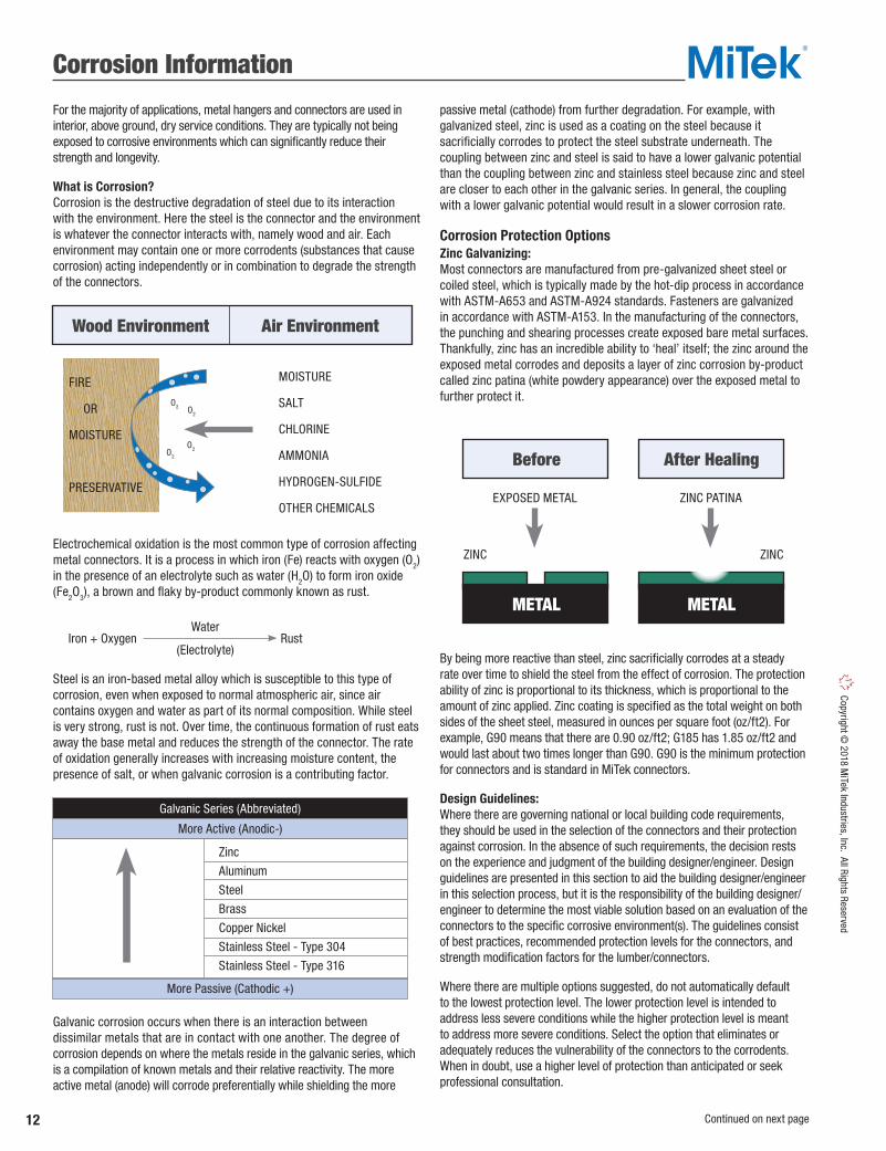
For the majority of applications, metal hangers and connectors are used in interior, above ground, dry service conditions. They are typically not being exposed to corrosive environments which can significantly reduce their strength and longevity.
What is Corrosion? Corrosion is the destructive degradation of steel due to its interaction with the environment. Here the steel is the connector and the environment is whatever the connector interacts with, namely wood and air. Each environment may contain one or more corrodents (substances that cause corrosion) acting independently or in combination to degrade the strength of the connectors.
Electrochemical oxidation is the most common type of corrosion affecting metal connectors. It is a process in which iron (Fe) reacts with oxygen (O2) in the presence of an electrolyte such as water (H2O) to form iron oxide (Fe2O3), a brown and flaky by-product commonly known as rust.
Steel is an iron-based metal alloy which is susceptible to this type of corrosion, even when exposed to normal atmospheric air, since air contains oxygen and water as part of its normal composition. While steel is very strong, rust is not. Over time, the continuous formation of rust eats away the base metal and reduces the strength of the connector. The rate of oxidation generally increases with increasing moisture content, the presence of salt, or when galvanic corrosion is a contributing factor.
Galvanic corrosion occurs when there is an interaction between dissimilar metals that are in contact with one another. The degree of corrosion depends on where the metals reside in the galvanic series, which is a compilation of known metals and their relative reactivity. The more active metal (anode) will corrode preferentially while shielding the more
passive metal (cathode) from further degradation. For example, with galvanized steel, zinc is used as a coating on the steel because it sacrificially corrodes to protect the steel substrate underneath. The coupling between zinc and steel is said to have a lower galvanic potential than the coupling between zinc and stainless steel because zinc and steel are closer to each other in the galvanic series. In general, the coupling with a lower galvanic potential would result in a slower corrosion rate.
Corrosion Protection OptionsZinc Galvanizing: Most connectors are manufactured from pre-galvanized sheet steel or coiled steel, which is typically made by the hot-dip process in accordance with ASTM-A653 and ASTM-A924 standards. Fasteners are galvanized in accordance with ASTM-A153. In the manufacturing of the connectors, the punching and shearing processes create exposed bare metal surfaces. Thankfully, zinc has an incredible ability to ‘heal’ itself; the zinc around the exposed metal corrodes and deposits a layer of zinc corrosion by-product called zinc patina (white powdery appearance) over the exposed metal to further protect it.
By being more reactive than steel, zinc sacrificially corrodes at a steady rate over time to shield the steel from the effect of corrosion. The protection ability of zinc is proportional to its thickness, which is proportional to the amount of zinc applied. Zinc coating is specified as the total weight on both sides of the sheet steel, measured in ounces per square foot (oz/ft2). For example, G90 means that there are 0.90 oz/ft2; G185 has 1.85 oz/ft2 and would last about two times longer than G90. G90 is the minimum protection for connectors and is standard in MiTek connectors.
Design Guidelines: Where there are governing national or local building code requirements, they should be used in the selection of the connectors and their protection against corrosion. In the absence of such requirements, the decision rests on the experience and judgment of the building designer/engineer. Design guidelines are presented in this section to aid the building designer/engineer in this selection process, but it is the responsibility of the building designer/engineer to determine the most viable solution based on an evaluation of the connectors to the specific corrosive environment(s). The guidelines consist of best practices, recommended protection levels for the connectors, and strength modification factors for the lumber/connectors.
Where there are multiple options suggested, do not automatically default to the lowest protection level. The lower protection level is intended to address less severe conditions while the higher protection level is meant to address more severe conditions. Select the option that eliminates or adequately reduces the vulnerability of the connectors to the corrodents. When in doubt, use a higher level of protection than anticipated or seek professional consultation.
Wood Environment
Before
METAL
After Healing
METAL
Air Environment
MOISTURE
SALT
CHLORINE
AMMONIA
HYDROGEN-SULFIDE
OTHER CHEMICALSEXPOSED METAL
ZINC ZINC
ZINC PATINA
FIRE
MOISTURE
PRESERVATIVE
O2 O2
O2O2
Iron + Oxygen RustWater
(Electrolyte)
Galvanic Series (Abbreviated)
More Active (Anodic-)
More Passive (Cathodic +)
Zinc
Aluminum
Steel
Brass
Copper Nickel
Stainless Steel - Type 304
Stainless Steel - Type 316
OR
Continued on next page

13
Copy
right
© 2
018
MiT
ek In
dust
ries,
Inc.
All
Righ
ts R
eser
ved
Corrosion Information
Continued on next page
Relative Corrosion Resistance Capability: The chart below ranks the available options in terms of their relative effectiveness against corrosion. As expected, the ability to resist corrosion increases with increasing zinc thickness, so G185 is the most durable pre-galvanized product available. Gold Coat offers enhanced protection compared to G185 while stainless steel offers the best protection for most applications.
Galvanic Corrosion: The simplest and most practical solution to minimize galvanic corrosion is to make sure that the components that are in direct contact with each other are made of the same material or coating. Once this is achieved, there is no net galvanic potential between the components and galvanic corrosion is eliminated or significantly reduced. For example, use galvanized nails for galvanized connectors and stainless steel nails for stainless steel connectors.
Wet Service Condition: For lumber, this refers to any service condition in which the average equilibrium moisture content is 15% or more over a year or may exceed 19% at any time. For lumber to get above 19% moisture, the relative humidity in the air needs to reach above 80%. Unfortunately, this is above the critical humidity level for the electrochemical oxidation of steel, which is around 70%. Beyond 70%, the rate of corrosion in the connectors increases rapidly due to the abundant availability of moisture.
G90 may not be suitable for use in wet service condition.
Preservative (Pressure) Treated Wood: There are many preservative wood treatment formulations available on the market today. The element that is common to most of them is the presence of copper in the formulation which can contribute to the corrosion of steel connectors and fasteners.
Of the copper based preservatives, the two types are micronized copper and soluble copper. Micronized copper formulations MCA (micronized copper azole) and MCQ (micronized copper quat) are sold under different brand names and are the most predominant formulation in today’s preservative treated wood industry. Soluble copper formulations CA (copper azole) and ACQ (alkaline copper quat) have also been very popular since they replaced CCA (chromated copper arsenate) which was phased out in 2004. Other “metal free” preservatives are still used for above ground and sill plate applications, but are not as common. One of the main criterion affecting the selection of one preservative treatment over another is the type of wood being treated and how well it can be penetrated by the treatment.
While many of the advanced wood treatment formulations containing copper used today have proven to be less corrosive to steel, especially micronized copper, MiTek recommends a higher level of corrosion protection for connectors in contact with copper based wood treatments.
Connectors and fasteners in contact with metal free wood preservatives do not require additional corrosion protection due to the preservative itself, however all factors that can create the corrosive environment should be considered when selecting the appropriate finish. If unsure as to whether a particular treatment is corrosive to steel fasteners, check with the supplier of the preservative treated wood product for their recommendation.
Fire Retardant Treated (FRT) Wood: Although most common FRT products are not corrosive to metal connectors, not all products are non-corrosive. Additionally, they typically require proprietary strength reductions applied to the lumber in accordance with the manufacturer’s specifications. Since the lumber strength is lower, the lateral and withdrawal resistance of nails must also be reduced accordingly. It is important to note that some fire retardants cause the wood to absorb more moisture from the air than untreated lumber. Consequently, the connector may be exposed to a higher level of moisture, resulting in more corrosion.
Swimming Pools: This is one of the most hazardous environments for steel connectors due to continuous exposure to high temperature, high moisture content, and corrosive chemicals such as chlorine, bromine, and other disinfectants. The combination of all these factors can lead to accelerated corrosion and premature structural failure. This environment is so corrosive that all possible preventive measures should be employed to prevent the hanger from being exposed to the pool water. These include the use of a vapor barrier and a ventilation system that does not take the air from the pool environment.
Additionally, it has been known that certain grades of stainless steel (304, 316, and others) are susceptible to a mode of structural failure known as stress corrosion cracking (SCC) when exposed to a swimming pool environment. SCC is usually localized near areas of high residual stress and small cracks can rapidly propagate and cause catastrophic failures. See warning below.
Gold Coat may be the best choice in this environment.
WARNINGStainless steel connectors and fasteners shall not be used for metal hangers over swimming pools due to stress corrosion cracking. SCC has been known to occur under the following conditions:• Use of certain grades of stainless steel (grades 304, 316
and others).• Structural members subjected to high tensile stress.• Presence of certain chemicals, including chlorine and bromine.
!
Relative Corrosion Resistance Capability:
G90 TZ HDG GC SS (G185) (Gold Coat)

14
Copyright © 2018 M
iTek Industries, Inc. All Rights Reserved
Corrosion Information
UC1 Interior construction, Continuously protected from General framing, Interior/Dry Above ground, weather or other sources of interior construction Untreated G90
Dry moisture UC2 Interior construction, Protected from weather, but may be Sill plates SBX-DOT, Organic G90
Interior/Damp Above ground, subject to sources of moisture ACQ-D (0.15), CA-B (0.10), Damp CA-C (0.06), MCQ (0.06),
μCA-C (0.05) UC3.1 Exterior construction, Exposed to all weather cycles, not Exposed exterior beams ACQ-D (0.25), MCQ (0.15), Above Ground Above ground, exposed to prolonged wetting or columns in an open, CA-B (0.10), CA-C (0.06), Protected Rapid water runoff covered structure μCA-C (0.05), Organic
UC3.2 Exterior construction, Exposed to all weather cycles, Deck beams and joists ACQ-D (0.25), MCQ (0.15), Above Ground Above ground, including prolonged wetting CA-B (0.10), CA-C (0.06), Exposed Poor water runoff μCA-C (0.05), Organic
UC4.1 Ground contact, Fresh Ground contact or fresh water ACQ-D (0.40), MCQ (0.23), Ground Contact water; includes above exposed to all weather cycles, CA-B (0.21), CA-C (0.15), General Use ground applications Normal exposure μCA-C (0.14) UC4.2 Exterior construction, Ground contact, fresh/salt water Permanent wood ACQ-D (0.60), MCQ (0.23), Ground Contact Ground contact, water splash exposed to all foundations, critical CA-B (0.31), CA-C (0.25), Heavy Duty Critical components weather cycles structural members μCA-C (0.23)
1) G90 and G-185 refer to galvanization requirements for ASTM A653 material. 2) Connectors galvanized to ASTM A123 may be used in place of either G90 or G185 coatings. 3) Other coating may be suitable for a given environment if the conditions are known and predictable. 4) For G185 connectors use fasteners galvanized per ASTM A153. For Gold Coat connectors, use Gold Coat fasteners and for stainless steel connectors, use stainless steel fasteners. 5) If the enviroment has the potential to contain elements which may make it more corrosive, the use of stainless steel is recommended. 6) MCQ is a micronized copper treatment such as Micro Pro by Koppers. μCA-C is a dispersed copper treatment manufactured by Arch Treatment Technologies. Organic preservatives include L3 from Arch Treatment Technologies and EcoLife II from Viance, LLC. 7) For wood treatments not shown, contact MiTek or the wood preservative manufacturer for recommended coatings. 8) Testing by MiTek has found that in interior applications where the treated wood will remain relatively dry during its service life the use of G90 connectors with MCQ or μCA-C treated wood is appropriate. 9) SBX/DOT= Sodium Borate; ACQ-D = Alkaline Copper Quat Type D; CA-B = Copper Azole Type B; CA-C = Copper Azole Type C; MCQ = Micronized Copper Quat; μCA-C = Dispersed Copper Azole Type C. The number listed in the parenthesis is the required retention level in pounds per cubic foot, or PCF.10) Deck joists and beams must be treated to Use Category UC4.1 when they are difficult to maintain, repair or replace and are critical to the performance and safety of the deck. 11) Users must perform periodic inspection and provide regular maintenance to ensure the satisfactory performance of the structure.
Stainless Steel
Structural Connectors Coating Recommendations
Triple Zinc (G-185)8,
HDG (post hot dipped),
Exterior Coat11
Triple Zinc (G-185),HDG (post hot dipped),
Exterior Coat11 orMiTek Gold Coat
Triple Zinc (G-185),HDG (post hot dipped),or MiTek Gold Coat
Triple Zinc (G-185),HDG (post hot dipped),
or MiTek Gold Coat5
Example Applications
Use Environment
Service Conditions
Use Category(CSA 080-08)
Preservatives and Retentions6,7,9
Minimum Coating Requirements1,2,3,4
Deck posts, beams and joists. Fresh water
docks10
The Structural Connectors Coating Recommendations chart below was developed by reviewing field service performance and accelerated corrosion test results. They are offered as general guidelines and are not intended to cover all possible service conditions. Additional consideration may also be needed for: wet service conditions preservation treated lumber fire retardant treated lumber strength reducing chemicals building near salt water coastal areas.
Additionally, the Corrosion Protection Guidelines to the right may also be used to assist in making the proper choice of corrosion protection.
The building designer/engineer has the ultimate responsibility of selecting the most viable protective coating based on knowledge of project specific corrosive environments and local building code requirements.
Corrosion Protection Guidelines:• MiTek recommends stainless steel connectors for the highest level of
corrosion protection. As an economical alternative to stainless steel our new Gold Coat connectors are specifically designed for exterior application when in contact with preservative treated wood.
• For connectors in contact with preservative treated wood, the Triple Zinc option provides the minimum G-185 coating thickness required by code and is an economical alternative for exterior applications.
• The use of correct fastener with the connector is critical. Stainless steel connectors require stainless steel fasteners. For exterior applications, hot-dip galvanized fasteners (HDG) or exterior coat (EXT) must be used with both Triple Zinc and hot-dip galvanized finishes. Gold Coat connectors require gold coat or hot-dip galvanized fasteners.
• MiTek’s zinc dichromate WS Wood Screws are not recommended for use with preservative or fire-retardant treated wood. Some wood screws are available in Gold Coat or exterior coat.
• MiTek clearly differentiates standard interior G90 connectors from the corrosion resistant connectors. Gold Coat connectors are distinguishable from other connectors due to their gold color.
Continued on next page

15
Copy
right
© 2
018
MiT
ek In
dust
ries,
Inc.
All
Righ
ts R
eser
ved
Corrosion Information
MiTek offers several corrosion resistant finishes to cover a range of corrosion performance. For products available in corrosion resistant finishes, reference the “Corrosion Finish” column in the charts and Corrosion Key located by the chart footnotes or pages 16-17 for a complete listing of corrosion resistant products.
CorrosionProtection Level Finish / Material Description
RequiredFastener Ordering
Primer Primer paint is used to protect steel during shipping and installation but is not considered a corrosion protection method when installed in corrosive environments.
Bright fasteners Stock number as listed in the chart
G90 Galvanizing Galvanizing provides a prefabrication coating of 0.90 ounces of zinc per square foot of surface area (both sides) measured in accordance with ASTM A 653.
Bright fasteners Stock number as listed in the chart
Triple Zinc (TZ) (G-185 Galvanizing)
TZ galvanizing provides a prefabrication coating of 1.85 (G-185) ounces of zinc per square foot of surface area (both sides) measured in accordance with ASTM A 653.
Hot-dip galvanized or Exterior Coat fasteners
To order, add TZ to stock number,
as in C44-TZ
Hot-Dip Galvanized (HDG)
HDG coating provides an after-fabrication hot-dipped zinc coating. The coating thickness is dependent on the connector material, but generally ranges from 1.2 to 2.3 ounces of zinc per square foot of surface area (both sides). Hot-dip products meet requirements set forth in ASTM A 123.
Hot-dip galvanized or Exterior Coat fasteners
To order, add HDG to stock number, as in KCC44-HDG
Gold Coat (GC) Gold Coat is a proprietary multi-layer protection system. It is comprised of an organic top coat barrier layer and a zinc layer placed over a steel substrate.
Gold Coat or Hot-dip galvanized fasteners
To order, add GC to stock number,
as in AC7-GC
Stainless Steel (SS)
Best option for corrosion protection. Quality stainless steel (316SS grade steel) is used to fabricate connectors. Although costs are higher, some applications may need the virtual corrosion proof quality of stainless steel.
Stainless Steel fasteners
To order, add SS to stock number, as in PBES44-SS
Yellow Zinc Stock number as listed in the chart
Hot-Dip Galvanized (HDG) Stock number as listed in the chart
Exterior Coat (EXT) Stock number as listed in the chart
Gold Coat (GC) Stock number as listed in the chart
Stainless Steel (SS) Stock number as listed in the chart
Updated product information is designated in blue font.
CONNECTORS
FASTENERS
HDG coating provides an after-fabrication hot-dipped zinc coating. The coating thickness is dependent on the connector material, but generally ranges from 1.2 to 2.3 ounces of zinc per square foot of surface area (both sides). Hot-dip products meet requirements set forth in ASTM A 123.
Gold Coat is a proprietary multi-layer protection system. It is comprised of an organic top coat barrier layer and a zinc layer placed over a steel substrate.
Best option for corrosion protection.
Zinc yellow chromate finish
EXT finish is a double barrier coating over zinc.
DISCLAIMER - The general information and guidelines provided in this MiTek Product Catalogue shall not be used as a substitute for competent professional examination and verification. It is the responsibility of the building designer/engineer to determine the applicability and suitability of the information provided. Anyone making use of this information assumes all responsibility and liability arising from such use.
EXTENDEDLIFE
GOLD COAT
EXTENDEDLIFE
GOLD COAT
EXTERIORUSE
G185-TZ
EXTERIORUSE
G185-TZ
EXTERIORUSE
G185-TZ
EXTERIORUSEHDG
EXTERIORUSE
G185-TZ
EXTERIORUSEHDG
INTERIORUSEG90
INTERIORUSE
YELLOW ZINC
INTERIORUSE
PRIMER
EXTREMELIFE
STAINLESS
EXTREMELIFE
STAINLESS
EXTERIORUSE
G185-TZ
EXTERIORUSEEXT

16
Copyright © 2018 M
iTek Industries, Inc. All Rights Reserved
Corrosion Resistant Product Offering
Corrosion Information
Corrosion Finish Stainless Steel Gold Coat Exterior Coat Triple Zinc
Corrosion Finish Stainless Steel Gold Coat Exterior Coat HDG Triple Zinc
Corrosion Finish Stainless Steel Gold Coat Exterior Coat Triple Zinc
MiTekStock No.
TripleZinc
G-185(TZ)
Hot-DipGalv.(HDG)
ExteriorCoat(EXT)
GoldCoat(GC)
Stain-lessSteel(SS)
MiTekStock No.
TripleZinc
G-185(TZ)
Hot-DipGalv.(HDG)
GoldCoat(GC)
Stain-lessSteel(SS)
MiTekStock No.
TripleZinc
G-185(TZ)
Hot-DipGalv.(HDG)
GoldCoat(GC)
Stain-lessSteel(SS)
AB1212-HDG BC400-TZ EPBH88 AB126-HDG BCS22-4 KCB44 AB128-HDG BCS23-6 KCB46 AB5812-HDG C44 KCB48 BP12 C46 KCB66 BP583 C46R KCB68 HBPS12 C66 KCB88 HBPS58 C66R KCB1010 LBP12-TZ EPCM4416 KCB1212 LBP58-TZ EPCM4616 KCBQ44 LBPS12-TZ EPCM6616 KCBQ46 LBPS58-TZ EPCM66 KCBQ66 LL915 KCCQ325-4 KCBQ88 LL930 KCCQ325-6 PA44E N10C KCCQ44 PA44 N10-GC KCCQ46 PA46E N16C KCCQ525-4 PA46 N8-GC KCCQ525-6 PA66E NA11 KCCQ64 PA66ER-TZ NA16D KCCQ66 PA66R NA20D KECCQ325-4 PA66 NA9D KECCQ325-6 PAU44 SSN10C KECCQ44 PAU46 SSN16C KECCQ46 PAU66 SSN8C KECCQ525-6 PAU88 SSNA10D KECCQ64 PAU1010 SSNA8D KECCQ66 PAU1010R THR1218-HDG PB44-6TZ PAU1212 THR1224-HDG PB66-6TZ PAU1212R THR1236-HDG PBC44-TZ RPB-TZ THR125-HDG PBC66-TZ RSCH44 THR126-HDG PBES44 RSCH46 THR128-HDG PBES66 WAS44 THR5812-HDG PBS44 WAS46 THR5816-HDG PBS66 WAS66 THR588-HDG PBS66R WE44 WS15 PCM44 WE46 WS3 PCM4416 WE66 WS45 PCM46 WS5 PCM4616 A3 WS6 PCM4816 AC5 WS8 PCM66 AC7
PCM6616 AC9 FA3 ANJ44S-HDG FA4 APB44 JA1 FWAN-TZ APB66 KHL33 LTS19-TZ CBSQ44-TZ KHL35 PA18 CBSQ46-TZ KHL37 PA23 CBSQ66-TZ KHL43 PA28 D44-TZ KHL46 RP6 D46 KHL55 ST1-TZ D46R-TZ KHL57 ST2-TZ D66 KHL76 STB16 D66R ML24-TZ STB20 EBG44-TZ ML26-TZ STB24 EPB4408 MP3 STB28 EPB4608 MP34 STB34 EPB6608 MP4F STBL24 EPBH44 MP5 STBL28 EPBH46R MP6F TDL5 EPBH66 MP7 TDX2-TZ EPBH66R MP9
Fasteners / Anchors Column / Post BasesColumn / Post Caps
Framing Plates & Angles
Column / Post BasesHoldowns / Foundation Anchors

17
Copy
right
© 2
018
MiT
ek In
dust
ries,
Inc.
All
Righ
ts R
eser
ved
Corrosion Resistant Product Offering
Corrosion Information
MiTekStock No.
TripleZinc
G-185(TZ)
Hot-DipGalv.(HDG)
GoldCoat(GC)
Stain-lessSteel(SS)
MiTekStock No.
TripleZinc
G-185(TZ)
Hot-DipGalv.(HDG)
GoldCoat(GC)
Stain-lessSteel(SS)
MiTekStock No.
TripleZinc
G-185(TZ)
Hot-DipGalv.(HDG)
GoldCoat(GC)
Stain-lessSteel(SS)
MPA1 HD46 SKHH46LIF RSPT6 HD46IF SKHH46R RSPT6-2 HD48 SKHH46RIF SPT22 HD48IF THD28-2 SPT24 HD610 THD410 SPT4 HD610IF THD46 SPT6 HD612 THD48 SPT8 HD612IF THDH412 SPTH4 HD68 SPTH6 HD68IF HHCP2 SPTH8 HDQ610IF HHCP4-TZ TSP HDQ612IF LFTA6
HUS210 RT10 LJC-TZ HUS210-2IF RT15 LJQ15-TZ HUS212-2 RT16-2 LJQ17-TZ HUS26 RT16A LJQ20-TZ HUS28 RT20 LJQ23-TZ HUS28-2IF RT3A LJQ25-TZ JL210IF-TZ RT4 LJQ35-TZ JL24IF-TZ RT5
JL26IF-TZ RT7 HTW20 JL28IF-TZ RT7A LTW12 JPF24 RT8A LTW18 JPF26 MTW12 JUS210 ADTT-TZ MTW16 JUS210-2 CSH-TZ MTW20 JUS210-3 DC50-TZ MTW30 JUS24 DTB-TZ
JUS24-2 ERB24-TZ HRS416-TZ JUS26 FB14-TZ HTP37-TZ JUS26-2 FB23-TZ KRPS22 JUS28 FB24-TZ KRPS28 JUS28-2 FB26-TZ KST227 JUS28-3 FPH24-TZ KST237 JUS36 FRB24-TZ KST248 JUS410 PRT15-TZ KST260 JUS44 PRT2H-TZ L6 JUS46 PRTIC2-TZ LH12 JUS48 SCA10-TZ LSTA36 LSSH15-TZ SCA9-TZ MSTA12 LSSH210 SDJT14-TZ MSTA15 LSSH31 SDPT5-TZ MSTA18 MSH422 SDPT7-TZ MSTA21 SKH210L MSTA24 SKH210L-2 ICPL516-TZ MSTA30 SKH210R ICPL58 MSTA36 SKH210R-2 TTA12-TZ MSTA9 SKH26L TTA2-TZ MSTAM24 SKH26R TTB22-TZ MSTAM36 SKH28L TTC24-TZ RS150 SKH28R TTC42-TZ T6 SKHH210L-2 TTF22-TZ TH12-HDG SKHH210L-2IF TTR-TZ
SKHH210R-2 TTU2-TZ HD210-2IF SKHH210R-2IF WT22 HD210-3IF SKHH410L WT22B-HDG HD28-2IF SKHH410LIF HD410 SKHH410R HD410IF SKHH410RIF HD412 SKHH414LIF HD412IF SKHH414RIF HD44IF SKHH46L
Hangers
Lateral Joist Connectors
Twist Straps
Straps
HangersStud Plate Ties Hangers
Hurricane Ties
Deck & Fences
General Hardware
Corrosion Finish Stainless Steel Gold Coat HDG Triple Zinc
Corrosion Finish Stainless Steel Gold Coat HDG Triple Zinc
Corrosion Finish Stainless Steel Gold Coat HDG Triple Zinc
18
Copyright © 2018 M
iTek Industries, Inc. All Rights Reserved
1/12 5 1/17 32/12 10 2/17 73/12 14 3/17 104/12 18 4/17 135/12 23 5/17 166/12 27 6/17 197/12 30 7/17 228/12 34 8/17 259/12 37 9/17 2810/12 40 10/17 3011/12 42 11/17 3312/12 45 12/17 35
1) Use this conversion table only for hip/valley rafters that are skewed 45° right or left. All other skews or dual pitch roofs will cause the slope to change from that listed above.
Rise / Run(inches)
Slope(degrees)
Rise / Run(inches)
Slope(degrees)
Product Information
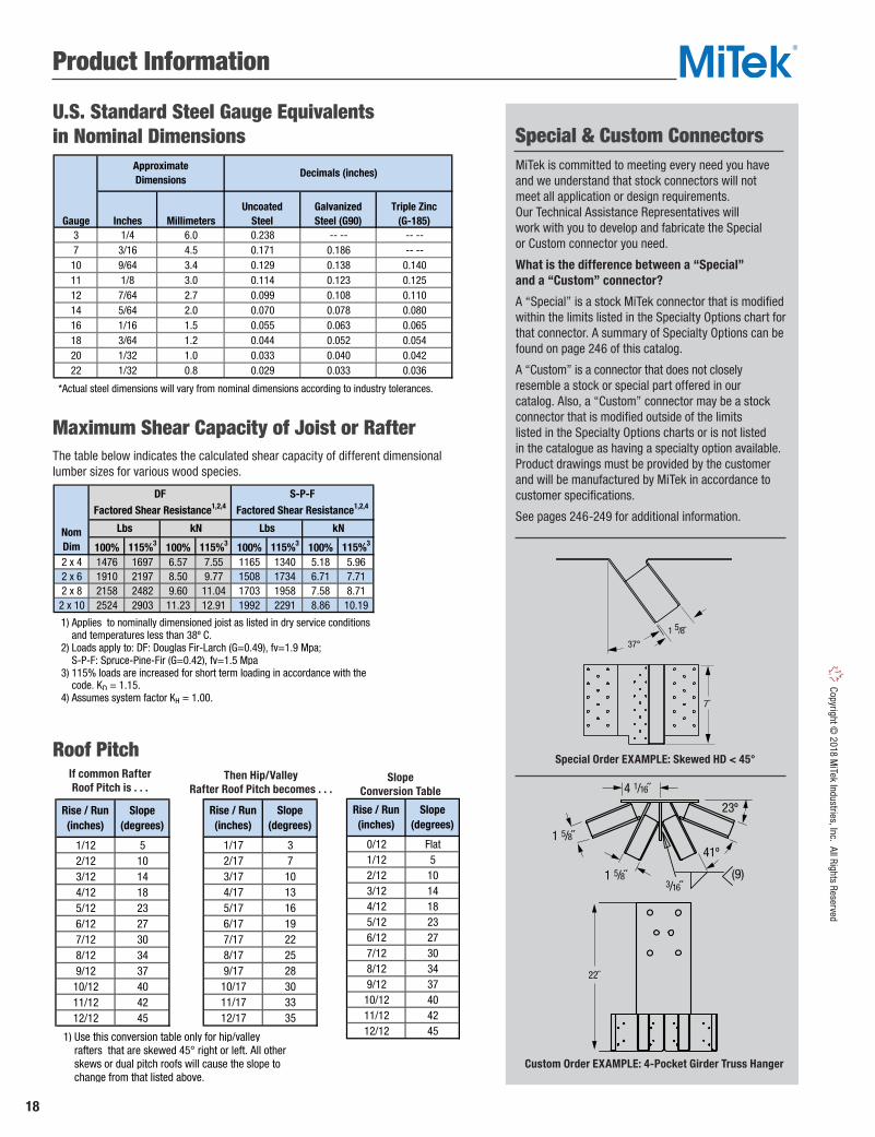
The table below indicates the calculated shear capacity of different dimensional lumber sizes for various wood species.
U.S. Standard Steel Gauge Equivalents in Nominal Dimensions
Maximum Shear Capacity of Joist or Rafter
Roof PitchIf common RafterRoof Pitch is . . .
SlopeConversion Table
Gauge Inches MillimetersUncoated
SteelGalvanized Steel (G90)
Triple Zinc (G-185)
3 1/4 6.0 0.238 -- -- -- -- 7 3/16 4.5 0.171 0.186 -- -- 10 9/64 3.4 0.129 0.138 0.14011 1/8 3.0 0.114 0.123 0.12512 7/64 2.7 0.099 0.108 0.11014 5/64 2.0 0.070 0.078 0.08016 1/16 1.5 0.055 0.063 0.06518 3/64 1.2 0.044 0.052 0.05420 1/32 1.0 0.033 0.040 0.04222 1/32 0.8 0.029 0.033 0.036
*Actual steel dimensions will vary from nominal dimensions according to industry tolerances.
Approximate Dimensions
Decimals (inches)
100% 115%3 100% 115%3 100% 115%3 100% 115%3
2 x 4 1476 1697 6.57 7.55 1165 1340 5.18 5.962 x 6 1910 2197 8.50 9.77 1508 1734 6.71 7.712 x 8 2158 2482 9.60 11.04 1703 1958 7.58 8.712 x 10 2524 2903 11.23 12.91 1992 2291 8.86 10.19
1) Applies to nominally dimensioned joist as listed in dry service conditions and temperatures less than 38º C. 2) Loads apply to: DF: Douglas Fir-Larch (G=0.49), fv=1.9 Mpa; S-P-F: Spruce-Pine-Fir (G=0.42), fv=1.5 Mpa 3) 115% loads are increased for short term loading in accordance with the code. KD = 1.15. 4) Assumes system factor KH = 1.00.
DFFactored Shear Resistance1,2,4
S-P-FFactored Shear Resistance1,2,4
NomDim
Lbs Lbs kNkN
1/12 5 1/17 32/12 10 2/17 73/12 14 3/17 104/12 18 4/17 135/12 23 5/17 166/12 27 6/17 197/12 30 7/17 228/12 34 8/17 259/12 37 9/17 2810/12 40 10/17 3011/12 42 11/17 3312/12 45 12/17 35
1) Use this conversion table only for hip/valley rafters that are skewed 45° right or left. All other skews or dual pitch roofs will cause the slope to change from that listed above.
Rise / Run(inches)
Slope(degrees)
Rise / Run(inches)
Slope(degrees)
0/12 Flat1/12 52/12 103/12 144/12 185/12 236/12 277/12 308/12 349/12 3710/12 4011/12 4212/12 45
Rise / Run(inches)
Slope(degrees)
MiTek is committed to meeting every need you have and we understand that stock connectors will not meet all application or design requirements. Our Technical Assistance Representatives will work with you to develop and fabricate the Special or Custom connector you need.
What is the difference between a “Special” and a “Custom” connector?
A “Special” is a stock MiTek connector that is modified within the limits listed in the Specialty Options chart for that connector. A summary of Specialty Options can be found on page 246 of this catalog.
A “Custom” is a connector that does not closely resemble a stock or special part offered in our catalog. Also, a “Custom” connector may be a stock connector that is modified outside of the limits listed in the Specialty Options charts or is not listed in the catalogue as having a specialty option available. Product drawings must be provided by the customer and will be manufactured by MiTek in accordance to customer specifications.
See pages 246-249 for additional information.
Special & Custom Connectors
37°
1 5/8˝
7˝
37°
1 5/8˝
7˝
Special Order EXAMPLE: Skewed HD < 45°
22˝
1 5/8˝
41º
(9)
23º
3/16˝
1 5/8˝
4 1/16˝
22˝
1 5/8˝
41º
(9)
23º
3/16˝
1 5/8˝
4 1/16˝
Custom Order EXAMPLE: 4-Pocket Girder Truss Hanger
Then Hip/Valley Rafter Roof Pitch becomes . . .

19
Copy
right
© 2
018
MiT
ek In
dust
ries,
Inc.
All
Righ
ts R
eser
ved
General Information
Product Notes
1) This catalogue reflects the most current information available at the time of printing. However, we are continually improving our products through better engineering design and development and recommend visiting our website for the latest on-line version of the catalog. MiTek reserves the right to change specifications, designs, and models at any time without notice and liability for such changes. This catalogue may not be reproduced in whole or in part without the prior written approval of MiTek.
2) This catalogue reflects changes to product design and factored resistance to some MiTek products. The information presented in this publication supersedes all previously published Product Catalogs and is valid until December 31, 2019.
3) This Product Catalogue was designed as a general reference for the MiTek Product Line. Various specialized publications have also been developed for design professionals, truss manufacturers, contractors, and building material distributors. Consequently, product information may vary from one publication to another due to product development testing and revisions to code evaluation report upgrades. We recommend visiting our website for the latest on-line version of these specialized publications.
4) The type and quantity of fasteners used to install MiTek products is critical to connector performance. To achieve the factored resistance presented in this catalog, all specified fasteners must be used and proper installation procedures observed. Verify that the dimensions of the supporting members are sufficient to receive the specified fasteners. All product modifications will void the warranty unless prior written consent from MiTek has been obtained.
5) Some connector models are listed more than once to indicate installation and/or fastener options.
6) New products or updated product information are designated in blue.
7) Throughout this catalog, dimensions are expressed in inches and loads in pounds unless specifically noted otherwise.
8) Some MiTek products show both nail fastening and bolt schedules. In those cases, specific loads for each has been identified. Nail and bolt values cannot be combined unless noted otherwise.
9) Load values for 8d, 10d, 16d, and 20d designations in the fastener schedules throughout this catalogue refer to common wire nails unless noted otherwise. Nails shall conform to a recognized national standard, such as ASTM F1667, as prescribed by the model building codes.
10) Diamond holes are for optional nailing for maximum listed capacity or for temporary hanger fastening during installation.
11) Fastener installation may cause wood to split and reduce a fastener’s ability to transfer loads into the supporting member. If wood splitting occurs, consider pre-drilling holes not exceeding 75% of the nail diameter.
12) Bolts specified in this catalogue are through-bolts and must conform to requirements for ASTM A 307 Grade A, or ASME SAE Grade 2, or better unless noted otherwise.
13) Anchor Bolts must conform to ASTM F 1554.
14) MiTek connectors listed in this catalogue are manufactured for specific sizes of standard dimensional lumber, plated trusses, or structural composite lumber. For applications involving unusual supporting conditions environments, contact MiTek. Wood shrinkage or expansion, caused by lack of moisture or excessive moisture, may adversely affect connector installation. Evaluate potential shrinkage or expansion to ensure proper connector installation and performance.
15) The load values listed in this catalogue are based on installation to wood with a moisture content of less than 19%, and used in dry service conditions. Load reductions, in accordance with the applicable local Building Code, shall be taken where wood moisture content is greater than 19% at the time of installation or where used in wet service conditions.
16) Unless otherwise noted, MiTek products may not be bent or cut for any reason unless prior written consent from MiTek has been obtained. Field alterations may significantly reduce the published factored resistances values in this catalog.
Design Notes
1) Factored resistances for more than one direction for a single connection cannot be added together. A design load which can be divided into components in the directions given must be evaluated as follows: Factored uplift / Factored uplift resistance + Factored parallel to plate / Factored parallel to plate resistance + Factored perpendicular to plate / Factored perpendicular to plate <= 1.0
2) Connector ratings may exceed the tensile strength or other aspects of the wood members involved in the connection. A qualified designer should verify wood member capacities when specifying connectors.
3) Verify that the size of the supporting member can accommodate the connector’s specified fasteners.
4) Some illustrations in this catalogue may not reflect additional mechanical reinforcements which may be required to reduce cross grain tension or wood member bending under loading. The design professional is responsible for determining if additional mechanical reinforcement is required.
5) MiTek recommends the hanger height be a minimum of 60% of the joist height for stability.
Limit States DesignThe factored resistance values presented in this catalogue are for Limit States Design (LSD) in accordance with the current National Building Code of Canada (NBCC). The values have been developed by either testing to CSA O86, or soft converted from working stress design. These procedures are summarized as follows:
Continued on next page

20
Copyright © 2018 M
iTek Industries, Inc. All Rights Reserved
General Information
(a) Testing to CSA O86 Products that have been evaluated to the CSA Standard are listed under the Codes heading in each product series section if applicable. Visit MiTek’s Web Site, MiTek.ca, or specific code agencies web site for current listing. Code evaluation numbers listed in this catalogue may not apply to all stock numbers or product series listed.
Standard term resistance values have been established by testing to ASTM and the CSA-O86 using the following criteria: • Lowest corrected ultimate load multiplied by 0.91 and a resistance
factor of 0.6.
• The average load at 1/8" deflection multiplied by 2.42 and a resistance factor of 0.6.
(b) Soft Conversion from Working Stress Design The soft converted values use the allowable working loads developed in the United States using the 2005 National Design Specification and the ICC-ES AC13 “Acceptance criteria for Joist Hangers and Similar Devices.” These allowable working loads are based on testing to ASTM D7147, D1761 and calculations on the fasteners and wood bearing using the NDS. They were soft converted by multiplying the floor load case (KD=1.0) by 1.44 to obtain standard term load resistance in Limit States Design.
The soft converted value of each bolted connector has been also compared to the calculated resistance of the bolts as given in CSA O86. The lower of the two values is given in the tables.
MaterialMiTek selects steel for its various products in accordance with application needs and steel properties, including tensile strength, ductility, corrosion resistance, gauge, and weldability. See specific code evaluations or consult MiTek for steel information on specific products. MiTek® are manufactured from steel which meets ASTM A 653, ASTM A 1011, or ASTM A 36.
Product Design LoadsFactored resistance values in this catalogue are given for standard term loading and/or short term loading as described below: (a) Standard term loading
This includes the effects of dead loads plus loads due to snow or use and occupancy in which the duration of load factor (KD) in CSA O86 is equal to 1.0. Therefore, connectors carrying roof or floor members should be selected using the standard term load resistance. In many tables this is designated as “vertical (100%)” or “bearing (100%)”. The 100% indicates that no duration of load increase is included.
(b) Short term loading This case refers to loading that will not exceed 7 days throughout the life of the structure and includes wind and earthquake loads. Short term loading has a duration of load factor (KD) of 1.15 included. In the tables short term loading resistance is also designated as “uplift (115%)”.
In some cases the strength of the steel governs the resistance values and therefore no increase for short term loading is included.
Installation Notes
1) Use proper safety equipment during connector installations. Always wear gloves when handling connectors.
2) All field welding should be done in accordance with CSA W59 Codes. Caution: Welding galvanized steel may produce harmful fumes and should only be performed in well-ventilated environments.
3) The type and quantity of fasteners used to install MiTek products is critical to connector performance. To achieve the factored resistance shown in this catalogue, install with the fasteners specified for that particular product. Some products allow for alternate nail installations. Refer to the “Optional Nails for Face Mount Hangers” chart on page 21 of this catalogue for load adjustments when using alternate nailing. All specified fasteners must be properly installed prior to applying load of any kind to the connection.
4) Drill bolt holes a minimum of 1⁄32" and a maximum of 1⁄16" larger than the diameter of the bolt to be installed. Per CSA O86-14 Clause 12.4.1.2.
5) Washers should always be used under the head or nut of a bolt when not in contact with the connector unless noted otherwise.
6) It is permissible to use nail guns to install connectors as long as the specified nails are installed through pre-punched nail holes and all specified nail holes are filled. MiTek recommends the use of nail guns featuring hole-locating mechanisms. Please note that many nail guns use fasteners smaller than the common nail size and load reductions will result. Contact MiTek or visit our Web Site for additional information. Caution: Always follow nail gun manufacturer’s safety guidelines.
7) Joists installed in hangers should bear fully on the connector seat and shall be cut to fit against the header with a gap no greater than 1⁄8" between the joist end and header face.
8) Multiple-ply members must be fastened securely together to act as one member.
9) Top mount hangers shall be installed with the face of the hanger tight to the face of the header
10) Top mount hangers installed in floor systems may produce unevenness. This may vary by the thickness of the hanger top flange steel and the nail heads. If a problem is anticipated, the effects can be mitigated by dapping the beam or cutting the subfloor at hanger locations. The use of face mount hangers will eliminate this problem.

21
Copy
right
© 2
018
MiT
ek In
dust
ries,
Inc.
All
Righ
ts R
eser
ved
Proper fasteners are a critical component in a sound wood frame structure. To ensure successful installations of its connectors, MiTek offers a full range of structurally-rated nails. All galvanized nails supplied by MiTek are Hot-dipped for greater corrosion resistance. Any MiTek connector requiring a NA16D-RS or NA20D nail is shipped with the nails attached to the connector in convenient poly bags.
N / NA Nails
Fasteners
Gun-Nails:
It is permissible to use nail guns to install connectors.
Note:1. Many nail guns use fasteners smaller than
the common nail size specified with MiTek product, factored resistance must be reduced accordingly.
2. Drive through pre‐punched nail holes only.3. Do not over drive.4. Recommend the use of guns featuring
hole‐locating mechanisms.
NA11 .131 x 1-1/2"
N8-GC .131 x 1-1/2"
NA9D .148 x 1-1/2"
N10-GC .148 x 1-1/2"
N10C .148 x 3"
N10C-GC .148 x 3"
NA16D-RS .148 x 3-1/2"
NA16D .162 x 2-1/2"
N16C .162 x 3-1/2"
N16C-GC .162 x 3-1/2"
NA20D .192 x 2-1/2"
8d spiral (0.110" x 2-1/2") 0.72 8d x 1-1/2 (0.131" x 1-1/2") 0.97
10d x 1-1/2 (0.148" x 1-1/2") 8d x 1-1/2 (0.131" x 1-1/2") 0.80 8d x 1-1/2 (0.131" x 1-1/2") 0.80 8d common (0.131" x 2-1/2") 0.80 10d spiral (0.122" x 3") 0.70 10d x 1-1/2 (0.148" x 1-1/2") 0.90 8d common (0.131" x 2-1/2") 0.67 10d common (0.148" x 3") 0.85 12d common (0.148" x 3-1/4") 0.85 10d spiral (0.122" x 3") 0.59 12d spiral (0.122" x 3-1/4") 0.59 16d spiral (0.152" x 3-1/2") 0.89 10d x 1-1/2 (0.148" x 1-1/2") 0.78 16d x 2-1/2 (0.162" x 2-1/2") 1.00
16d common (0.161" x 3-1/2")
ResistanceAdjustment
Factor
CatalogNail
ReplacementFastener
8d common (0.131" x 2-1/2")
10d common (0.148" x 3") 12d common (0.148" x 3-1/4")
1. This chart does not apply to custom hangers or hangers
modified to skew and/or slope.
2. This chart applies to metal side member of 10Ga or thinner. For steel thicker than 10Ga, contact MiTek for exceptions.
3. Resistance adjustment factor is the multiplier to the published factored resistance when a nail of different size and/or type is used in lieu of a Specified Nail.
4. Roofing nails shall not be substituted for any nail size or type.
5. Decking nails are not to be used as a substitution for any load carrying nails.
Optional Nails for Face Mount Hangers and Straight Straps(Does not apply to slant nail hangers: HUS, JDS, JH, JPF, JUS, MSH, MUS, THDH)
Continued on next page

22
Fast
ener
s Copyright ©
2018 MiTek Industries, Inc. All Rights Reserved
N / NA Nails
Fasteners
Nail Specification Table
Finish Size (in) Ref. No. Dia Length Unit 10 Ga 12 Ga 14 Ga 16 Ga 18 Ga 20 Ga 10 Ga 12 Ga 14 Ga 16 Ga 18 Ga 20 GaLbs 215 215 197 178 163 150 188 188 182 163 148 135kN 0.96 0.96 0.88 0.79 0.73 0.67 0.84 0.84 0.81 0.73 0.66 0.60Lbs 269 263 222 200 184 169 236 236 205 183 167 152kN 1.20 1.17 0.99 0.89 0.82 0.75 1.05 1.05 0.91 0.81 0.74 0.68Lbs 269 269 241 218 201 185 236 236 224 201 184 168kN 1.20 1.20 1.07 0.97 0.89 0.82 1.05 1.05 1.00 0.89 0.82 0.75Lbs 317 317 275 250 231 214 278 278 255 230 211 194kN 1.41 1.41 1.22 1.11 1.03 0.95 1.24 1.24 1.13 1.02 0.94 0.86Lbs 317 317 275 250 231 214 278 278 255 230 211 194kN 1.41 1.41 1.22 1.11 1.03 0.95 1.24 1.24 1.13 1.02 0.94 0.86Lbs 429 408 353 323 300 280 376 376 326 296 274 253kN 1.91 1.81 1.57 1.44 1.33 1.25 1.67 1.67 1.45 1.32 1.22 1.13Lbs 215 215 197 178 163 150 188 188 182 163 148 135kN 0.96 0.96 0.88 0.79 0.73 0.67 0.84 0.84 0.81 0.73 0.66 0.60Lbs 269 263 222 200 184 169 236 236 205 183 167 152kN 1.20 1.17 0.99 0.89 0.82 0.75 1.05 1.05 0.91 0.81 0.74 0.68Lbs 269 169 241 218 201 185 236 236 224 201 184 168kN 1.20 0.75 1.07 0.97 0.89 0.82 1.05 1.05 1.00 0.89 0.82 0.75Lbs 317 317 275 250 231 214 278 278 255 230 211 194kN 1.41 1.41 1.22 1.11 1.03 0.95 1.24 1.24 1.13 1.02 0.94 0.86Lbs 215 215 197 178 163 150 188 188 182 163 148 135kN 0.96 0.96 0.88 0.79 0.73 0.67 0.84 0.84 0.81 0.73 0.66 0.60Lbs 269 263 222 200 184 169 236 236 205 183 167 152kN 1.20 1.17 0.99 0.89 0.82 0.75 1.05 1.05 0.91 0.81 0.74 0.68Lbs 215 215 202 181 166 152 188 188 188 168 153 139kN 0.96 0.96 0.90 0.81 0.74 0.68 0.84 0.84 0.84 0.75 0.68 0.62Lbs 269 269 241 218 201 185 236 236 224 201 184 168kN 1.20 1.20 1.07 0.97 0.89 0.82 1.05 1.05 1.00 0.89 0.82 0.75Lbs 317 317 275 250 231 214 278 278 255 230 211 194kN 1.41 1.41 1.22 1.11 1.03 0.95 1.24 1.24 1.13 1.02 0.94 0.86Lbs 215 215 202 181 166 152 188 188 188 168 153 139kN 0.96 0.96 0.90 0.81 0.74 0.68 0.84 0.84 0.84 0.75 0.68 0.62Lbs 269 269 241 218 201 185 236 236 224 201 184 168kN 1.20 1.20 1.07 0.97 0.89 0.82 1.05 1.05 1.00 0.89 0.82 0.75Lbs 269 269 241 218 201 185 236 236 224 201 184 168kN 1.20 1.20 1.07 0.97 0.89 0.82 1.05 1.05 1.00 0.89 0.82 0.75Lbs 269 269 241 218 201 185 236 236 224 201 184 168kN 1.20 1.20 1.07 0.97 0.89 0.82 1.05 1.05 1.00 0.89 0.82 0.75Lbs 317 317 275 250 231 214 278 278 255 230 211 194kN 1.41 1.41 1.22 1.11 1.03 0.95 1.24 1.24 1.13 1.02 0.94 0.86Lbs 429 408 353 323 300 280 376 376 326 296 274 253kN 1.91 1.81 1.57 1.44 1.33 1.25 1.67 1.67 1.45 1.32 1.22 1.13Lbs 155 155 155 139 127 115 136 136 136 130 117 105kN 0.69 0.69 0.69 0.62 0.56 0.51 0.60 0.60 0.60 0.58 0.52 0.47Lbs 188 188 182 163 149 136 165 165 165 151 137 124kN 0.84 0.84 0.81 0.73 0.66 0.60 0.73 0.73 0.73 0.67 0.61 0.55Lbs 188 188 182 163 149 136 165 165 165 151 137 124kN 0.84 0.84 0.81 0.73 0.66 0.60 0.73 0.73 0.73 0.67 0.61 0.55Lbs 282 282 250 227 209 193 248 248 233 209 192 175kN 1.25 1.25 1.11 1.01 0.93 0.86 1.10 1.10 1.04 0.93 0.85 0.78
1) Factored shear resistance values determined in accordance with CSA O86-14 Clause 12.9; apply modification factors KD, KSF and KT where applicable. 2) Factored shear resistances assume full nail penetration into the main member. 3) Tabulated factored shear resistances assume a side plate tensile strength of 45 ksi (310 MPa). 4) HDG = Hot-Dip Galvanized; SS = Stainless Steel; GC = Gold Coat; Bright = No Finish. 5) Bright finish common, sinker, and spiral nails are listed for reference only. MiTek does not stock these type nails.
S-P-F Factored Shear Resistance per Nail (KD = 1.00)D.Fir-L Factored Shear Resistance per Nail (KD = 1.00)
Steel Side Plate Steel Side Plate
Metric (mm)
MiTekStock No.
8d (0.131) x 1-1/2
10d (0.148) x 1-1/2
10d (0.148) x 3
16d (0.162) x 2-1/2
16d (0.162) x 3-1/2
20d (0.192) x 2-1/2
8d (0.131) x 1-1/2
NA11
NA9D
N10C
NA16D
N16C
NA20D
N8-GC
N8
8d (0.110) x 2-1/2 Spiral Shank
10d (0.122) x 3 Spiral Shank
12d (0.122) x 3-1/4 Spiral Shank
16d (0.152) x 3-1/2 Spiral Shank
HDG
GC
SS
Bright
10d (0.148) x 3
16d (0.148) x 3-1/4
16d (0.148) x 3-1/2 Ring Shank
16d (0.162) x 3-1/2
20d (0.192) x 4
10d (0.148) x 1-1/2
8d (0.131) x 2-1/2
10d (0.148) x 3
16d (0.162) x 3-1/2
8d (0.131) x 2-1/2
10d (0.148) x 1-1/2
10d (0.148) x 3
16d (0.162) x 3-1/2
8d (0.131) x 1-1/2
3-1/2" Common Spiral
8d Common
10d Common
16d Sinker
NA16D-RS
16d Common
SSNA8D
SSNA10D
SSN8C
SSN10C
SSN16C
N10
10DHDG
N16, N16EG
16DHDG
SSN8
20d Common
2-1/2" Common Spiral
3" Common Spiral
3-1/4" Common Spiral
N10-GC
N10C-GC
N16C-GC
SSN10
SS8D
SS10D
SS16D
--
--
--
--
--
--
--
--
--
--
--
--
--
--
--
3.86
3.33
3.76
3.76
3.76
4.11
3.33
3.76
3.33
3.76
3.76
38.1
38.1
76.2
63.5
88.9
4.88
2.77
3.1
3.1
4.88
3.33
3.76
3.76
4.11
3.33
3.76
3.76
4.11
4.11
38.1
38.1
63.5
76.2
82.6
63.5
38.1
38.1
76.2
88.9
101.6
63.5
76.2
82.6
88.9
63.5
76.2
82.6
88.9
88.9
Continued on next page

Fasteners
23
Copy
right
© 2
018
MiT
ek In
dust
ries,
Inc.
All
Righ
ts R
eser
ved
Left skew
Drive nails at angle
Right skew
Use specified standard length common nails. 16d common
and 10d common nails are 3-1/2" and 3" long respectively.
N / NA Nails
Fasteners
Round Holes:Always fill all (normal-size)round nail holes, unlessotherwise noted.
When there are MIN and MAX values:MIN: fill all round nail holesMAX: fill all round and diamond holes
Large Round Holes:For concrete/masonry installation;no need to be filled when connected to wood.
Obround Holes:For ease of nailing at a tight location;always fill.
Dimple Holes:Guide double shear
nails into the joistand header at a
30° to 45° angle
Common Nailing Errors
Nail Too LongWhen using nails longer than MiTek’s recommended nails, bottom flange splitting may occur. Also, this can raise the wood I-Joist off the seat, resulting in uneven surfaces and squeaky floors along with reduced factored resistance.
Slant Nailingvia dimplenail holes
Seat Cleat® helps lock I-Joist into place for positive seating and nailing ease
Diamond holes(no need to fill in seat)
Typical I-Joist Nailing
Do not nail through the Seat Cleat®
Wrong AngleWhen a nail is driven into the bottom flange of the wood I-Joist parallel to the glue lines, separation of veneers can occur which substantially reduces the design loads of the connection.
Diamond Holes:Optional nailing for maximum listed capacity or for temporary hanger fastening during installation.
Bend-lineholes
Drive bend line nails into header at 45º to achieve listed loads

24
Fast
ener
s Copyright ©
2018 MiTek Industries, Inc. All Rights Reserved
WS Hex Head Structural Wood Screws
The WS Wood Screw is a self-drilling screw used for numerous framing applications. This screw features a reverse locking serration on the bottom of the screw head to help prevent over tightening against a steel plate.
Screw shear capacities are based on a diameter of 0.242". WS Wood Screws have a bending yield strength of 180,000 psi. For conditions not charted here, screw loads may be calculated in accordance with CSA 086-14 Clause 12.11.
Materials: 1/4" diameter Grade 5 steelFinish: See chartOptions: See chart for Corrosion Finish Options.
Installation:• Screws are self-drilling.• Install using a low speed clutch drill with 3/8" hex head driver.
The washer head should be flat to the surface and the serrations will oppose turning and release the clutch. Do not over-tighten the screws.
• Installing the screw at an angle may introduce additional bending and tension forces into the fastener if the screw head is not flat on the bearing surface. Care should be given to ensure the fastener is installed perpendicular to the plane of the side plate.
• For attaching multi-ply wood trusses or LVL or PSL members, or floor trusses, refer to Technical Bulletins MiTek.ca
WS(Yellow Zinc finish)
WS-EXT (Exterior Coat Finish)
WS15-GC(Gold Coat Finish)
Corrosion Finish Stainless Steel Gold Coat Exterior Coat Triple Zinc
Corrosion Finish Stainless Steel Gold Coat Exterior Coat Triple Zinc
Corrosion Finish Stainless Steel Gold Coat Exterior Coat Triple Zinc
in mm Ref. No. L SH T Finish1 UnitLbs -- -- 358 496 660 807 326 -- -- 332 471 635 692 248kN -- -- 1.59 2.21 2.93 3.59 1.45 -- -- 1.48 2.09 2.83 3.08 1.10Lbs -- -- 423 561 724 1033 456 -- -- 387 526 691 900 347kN -- -- 1.88 2.49 3.22 4.60 2.03 -- -- 1.72 2.34 3.07 4.00 1.54Lbs -- -- 487 625 789 1033 521 -- -- 443 582 746 900 396kN -- -- 2.17 2.78 3.51 4.60 2.32 -- -- 1.97 2.59 3.32 4.00 1.76Lbs 387 387 552 690 853 1033 521 332 332 498 637 801 900 396kN 1.72 1.72 2.46 3.07 3.80 4.60 2.32 1.48 1.48 2.21 2.83 3.56 4.00 1.76Lbs 452 452 616 754 918 1033 651 387 387 553 692 857 900 495kN 2.01 2.01 2.74 3.36 4.08 4.60 2.90 1.72 1.72 2.46 3.08 3.81 4.00 2.20Lbs 542 575 680 825 997 1033 781 480 498 618 763 890 900 595kN 2.41 2.56 3.02 3.67 4.44 4.60 3.47 2.14 2.22 2.75 3.40 3.96 4.00 2.65Lbs 542 575 680 825 997 1033 781 480 508 618 763 890 900 595kN 2.41 2.56 3.02 3.67 4.44 4.60 3.47 2.14 2.26 2.75 3.40 3.96 4.00 2.65Lbs 542 575 680 825 997 1033 1042 480 508 618 763 890 900 793kN 2.41 2.56 3.02 3.67 4.44 4.60 4.64 2.14 2.26 2.75 3.40 3.96 4.00 3.53Lbs 542 575 680 825 997 1033 781 480 508 618 763 890 900 595kN 2.41 2.56 3.02 3.67 4.44 4.60 3.47 2.14 2.26 2.75 3.40 3.96 4.00 2.65
1) Zinc = Yellow Zinc Dichromate. 2) Factored Resistance values determined in accordance with CSA O86-14 Clause 12.11; apply modification factors KD, KSF and KT where applicable. 3) Factored resistances assume full screw penetration into the main member. 4) Factored shear resistances for steel-to-wood connections assume a side plate tensile strength of 45 ksi (310 MPa) for 14 gauge and 10 gauge, 52 ksi (359 MPa) for 7 gauge, and 58 ksi (400 MPa) for 3 gauge. 5) Factored basic withdrawal resistance is 260 lb per inch (45.6 N/mm) of the threaded shank penetrated into a DF main member, and 198 lb per inch (34.7 N/mm) into a S-P-F main member. 6) Factored withdrawal resistances for steel-to-wood connections assume a side plate thickness of 1/4" or less. 7) Factored withdrawal resistances for wood-to-wood connections may be limited by the factored head pull-through resistance of 223 lb (991 N) for 1-1/2" thick wood side members, or 260 lb (1156 N) for 1-3/4" thick wood side members. New products or updated product information are designated in blue font.
Steel to Wood Steel to Wood
Shear4
With-
drawal5,6
Shear
1-1/2"Side
1-3/4"Side
DF
Factored Resistance (100%)2,3
S-P-F
Factored Resistance (100%)2,3
14 Ga 10 Ga 7 Ga 3 Ga 14 Ga 10 Ga 7 Ga 3 Ga
With-
drawal5,6
Shear
1-3/4"Side
Shear4
Wood-to-
Wood5,7
Wood-to-
Wood5,7
1-3/4 3
Zinc
1-1/2 1/4 1-1/4
2 1/4 1-3/4
2-1/2 1/4 2
3 3/4 2
6 1-3/4 4 6.1 x 152.4
1/4 x 2-1/2
1/4 x 3
1/4 x 3-1/2
1/4 x 4-1/2
1/4 x 6
6.1 x 88.9
6.1 x 114.3
6.1 x 63.5
6.1 x 76.2
1/4 x 5 6.1 x 127
WS6 SDS25600
WS5 Zinc SDS25500
Corr
osio
nFi
nish
SDS25412
SDS25112
SDS25200
Zinc
3-1/2 3/4 2-1/2
4-1/2 1-1/4 3
Zinc
5
Size Dimensions (in)
MiTekStock No.
1-1/2"Side
4-3/4 3 Zinc 1/4 x 8 6.1 x 203.2 WS8 SDS25800 8
1/4 x 2 Zinc
WS15 1/4 x 1-1/2
6.1 x 50.8
Zinc
Zinc
Zinc
6.1 x 38
WS2
WS25
WS3
WS35
WS45
SDS25212
SDS25300
SDS25312
T
L
SH
Serrations
1/4" beveled reamer on 2-1/2" or longer
wood screws
Cut threads
Self drilling point
3/8"
Fasteners
Continued on next page

Fasteners
25
Copy
right
© 2
018
MiT
ek In
dust
ries,
Inc.
All
Righ
ts R
eser
ved
WS Hex Head Structural Wood Screws
Fasteners
Finish Use Size (in)MiTek
Stock No. Box/Ctn QtyMiTek
Stock No. Box/Ctn Qty 1/4 x 1-1/2 WS15-EXTR25CAN 10-pack/25-ea -- --
1/4 x 3 WS3-EXTR25CAN 10-pack/25-ea WS3-EXTMBCAN 200-ea
1/4 x 4-1/2 WS45-EXTR12CAN 10-pack/12-ea WS45-EXTMBCAN 200-ea
1/4 x 5 WS5-EXTR12CAN 10-pack/12-ea -- --
1/4 x 6 WS6-EXTR12CAN 10-pack/12-ea WS6-EXTMBCAN 200-ea
1/4 x 8 WS8-EXTR12CAN 10-pack/12-ea -- --
Retail Box Offering Mini Bulk Offering
ExteriorCoat(EXT)
Exterior
Finish Use Size (in)MiTek
Stock No. Box/Ctn QtyMiTek
Stock No. Box/Ctn QtyMiTek
Stock No. Box Qty 1/4 x 1-1/2 WS15-R25 12-pack/25-ea WS15-MB 3-box/300-ea WS15-BP 1500-ea
1/4 x 2 WS2-R25 12-pack/25-ea WS2-MB 3-box/250-ea WS2-BP 1300-ea
1/4 x 2-1/2 WS25-R25 12-pack/25-ea WS25-MB 3-box/200-ea WS25-BP 1100-ea
1/4 x 3 WS3-R25 12-pack/25-ea WS3-MB 3-box/150-ea WS3-BP 950-ea
1/4 x 3-1/2 WS35-R10 12-pack/10-ea WS35-MB 3-box/125-ea WS35-BP 900-ea
1/4 x 4-1/2 WS45-R10 12-pack/10-ea WS45-MB 3-box/100-ea WS45-BP 800-ea
1/4 x 5 WS5-R10 12-pack/10-ea WS5-MB 3-box/100-ea WS5-BP 500-ea
1/4 x 6 WS6-R10 12-pack/10-ea WS6-MB 3-box/100-ea WS6-BP 600-ea
1/4 x 8 WS8-R10 12-pack/10-ea -- -- WS8-BP 400-ea
Retail Box Offering Mini Bulk Offering Bulk Offering
YellowZinc
Interior
Yellow Zinc(WS25 & WS6 Shown)
Exterior Coat(WS2-EXT & WS45-EXT Shown)
EXTENDEDLIFE
GOLD COAT
EXTERIORUSE
EXT
YELLOWZINC
EXTENDEDLIFE
GOLD COAT
EXTERIORUSE
EXT
YELLOWZINC
MiTek Pro Series Packaging Offering
Yellow Zinc Packaging Offering

26
Fast
ener
s Copyright ©
2018 MiTek Industries, Inc. All Rights Reserved
FlatLOK is a multi-purpose structural wood screw that can be used for fastening multi-ply SCL, dimensional beams and girder trusses. The low-profile flat head allows for easy attachment of finishing materials such as drywall.
The FlatLOK screw has a shank diameter of 0.227" and is stamped with head mark for easy length identification. The proprietary coating provides protection that exceeds the protection provided by HDG coatings conforming to ASTM A153. FlatLOK may be used for interior and exterior applications and in pressure treated (ACQ) wood.
The FlatLOK wood screw features a TORX® ttap®* drive system that maximizes bit fit, reducing the potential for stripping. The stability button allows for maximum penetration into the fastener and a wobble-free drive. A free TORX® ttap®* bit is included in every box.
Materials: Heat-treated carbon steelFinish: Proprietary coating
Installation:• Using an impact driver or high torque 1/2" variable speed drill (minimum 18V if cordless), bring
fastener flush with wood surface. Do not overdrive. No pre-drilling required when properly installed.• Screws may be installed through metal truss connector plates as approved by the Truss Designer.
(Pre-drilling required through the plate using a maximum 5/32" bit.)• For attaching Multi-Ply truss girders or Engineered Wood Beams, refer to Technical Bulletins MiTek.ca
Ref. No. Lbs kN Lbs kN Lbs kN
2-Ply SCL beams 55-MIFLK312 SDW22338 3-1/2 2 385 1.71 -- -- -- -- 3-Ply SCL beams 55-MIFLK005 SDW22500 5 2 520 2.31 -- -- -- -- 4-Ply SCL beams 55-MIFLK634 SDW22634 6-3/4 2 520 2.31 -- -- -- --
2-Ply Dimensional Lumber 55-MIFLK278 SDW22300 2-7/8 1-3/4 -- -- 295 1.31 255 1.13 3-Ply Dimensional Lumber 55-MIFLK412 SDW22458 4-1/2 2 -- -- 485 2.16 425 1.89 4-Ply Dimensional Lumber 55-MIFLK006 SDW22600 6 2 -- -- 485 2.16 425 1.89
2-Ply 3x2 Flatchord 55-MIFLK005 SDW22500 5 2 -- -- 600 2.67 520 2.31 2-Ply 4x2 Flatchord 55-MIFLK006 SDW22600 6 2 -- -- 600 2.67 530 2.36 2-Ply 4x2 Flatchord 55-MIFLK634 SDW22634 6-3/4 2 -- -- 600 2.67 540 2.40
Interior Corridor Ledgers 55-MIFLK004 -- 4 2 -- -- -- -- 415 1.85
1) Factored shear resistances determined in accordance with CSA O86-14 Clause 12.11. 2) Factored shear resistances apply to two-member single shear connections where both members are of the same specific gravity. Where the members are of different specific gravities, use the lower of the two. 3) Table values are for standard-term load duration, dry service condition, dry and untreated lumber. Apply KD, KSF and KT modification factors where applicable, per CSA O86-14 Clause 12.2.1, Clause 12.11.4. 4) Table values depicted assume the wood screws installed with the screw heads in the loaded ply and driven perpendicular to grain. 5) Table values are based on SCL with Specific Gravity of 0.50 and member thickness of 1-3/4". 6) Table values are based on member thickness of 1-1/2". 7) Table values are based on member thickness of 2-1/2" for 3x2 flat chord and 3-1/2" for 4x2 flat chord. 8) Table values are based on side member thickness of 1-1/2" and main member thickness of 2-1/2" or 3-1/2" . New products or updated product information are designated in blue font.
Flatchord Connection7
Ledger to Wall Stud8
DF Factored
Shear Resistance1,2,3,4
S-P-F Factored
Shear Resistance1,2,3,4
SCL Factored
Shear Resistance1,2,3,4
Wood-to-Wood Wood-to-Wood Wood-to-Wood
2x_ Truss Ply-to-Ply Connection6
1-3/4" SCL Ply-to-Ply Connection5
ScrewLength
(in)
ThreadLength
(in)Typical
ApplicationMiTek
Stock No.
55-MIFLK FlatLOK™ Structural Wood Screws
Fasteners
Spacing parallel to grain 4-in 4-1/2-in 3-3/4-in End distance parallel to grain 3-3/4-in 3-1/2-in 2-3/4-in Spacing perpendicular to grain 2-1/4-in 2-1/4-in 2-in Edge distance perpendicular to grain 1-3/4-in 1-1/4-in 1-in
1) When fastening is done in multiple rows, the rows must be staggered from each other by 1”. 2) Screws installed into the narrow face (edge-wise) of the 2x_ dimensional lumber must be installed along the centre line of the member in one (1) row only.
SCLDF
DimensionalLumber
S-P-FDimensional
Lumber
Minimum Screw Spacing Requirements
Order No. Box/Ctn Qty Order No. Box Qty 55-MIFLK278 F2.9FL 2-7/8 1-3/4 55-MIFLK278-B 6 Boxes/40 EA 55-MIFLK278-C 500 55-MIFLK312 F3.5FL 3-1/2 2 55-MIFLK312-B 6 Boxes/40 EA 55-MIFLK312-C 300 55-MIFLK004 F4.0FL 4 2 55-MIFLK004-B 6 Boxes/40 EA 55-MIFLK004-C 300 55-MIFLK412 F4.5FL 4-1/2 2 55-MIFLK412-B 6 Boxes/40 EA 55-MIFLK412-C 300
55-MIFLK005 F5.0FL 5 2 55-MIFLK005-B 6 Boxes/40 EA 55-MIFLK005-C 300
55-MIFLK006 F6.09FL 6 2 55-MIFLK006-B 6 Boxes/40 EA 55-MIFLK006-C 300
55-MIFLK634 F6.75FL 6-3/4 2 55-MIFLK634-B 6 Boxes/40 EA 55-MIFLK634-C 300
Retail Box Offering
Mini BulkOfferingMiTek
Stock No.Head
Marking
ScrewLength
(in)
ThreadLength
(in)
1) Factored shear resistances determined in accordance with CSA O86-14 Clause 12.11.
2) Factored shear resistances apply to two-member single shear connections where both members are of the same specific gravity. Where the members are of different specific gravities, use the lower of the two.
3) Table values are for standard-term load duration, dry service condition, dry and untreated lumber. Apply KD, KSF and KT modification factors where applicable, per CSA O86-14 Clause 12.2.1, Clause 12.11.4.
4) Table values depicted assume the wood screws installed with the screw heads in the loaded ply and driven perpendicular to grain.
5) Table values are based on SCL with Specific Gravity of 0.50 and member thickness of 1-3/4".
6) Table values are based on member thickness of 1-1/2".
7) Table values are based on member thickness of 2-1/2" for 3x2 flat chord and 3-1/2" for 4x2 flat chord.
8) Table values are based on side member thickness of 1-1/2" and main member thickness of 2-1/2" or 3-1/2" .
New products or updated product information are designated in blue font.
1) When fastening is done in multiple rows, the rows must be staggered from each other by 1".
2) Screws installed into the narrow face (edge-wise) of the 2x_ dimensional lumber must be installed along the center line of the member in one (1) row only.
Spacing Requirement Table
Packaging Table
*TORX® is registered trademark of Acument Intellectual Properties, LLC *ttap® is a registered trademark of Infast AS

Fasteners
27
Copy
right
© 2
018
MiT
ek In
dust
ries,
Inc.
All
Righ
ts R
eser
ved
The 6" long TimberLOK screw is used to attach wood trusses, sawn lumber rafters or structural composite lumber (SCL) to wood walls. It is a code-compliant way to attach rafters or trusses to a double top plate, offers an alternative to toe-nail connections, metal hurricane and seismic clips/straps, or nails in uplift and/or lateral resistance applications.
The TimberLOK screw has a shank diameter of 0.189", and is approved for use in interior and exterior conditions, and in ACQ pressure treated lumber.
There is no need to pre-drill with TimberLOK. Its sharp point and aggressive threads zip right in to the densest woods. It can be installed from inside the structure and after sheathing is applied. A free bit is included in every box.
Materials: Heat-treated carbon steelFinish: Proprietary coating
Installation:• Install using a high torque 1/2" variable speed drill (18V if cordless).• Where the truss/rafter is aligned directly over the wall stud, insert fastener point between the
bottom of the top plate and the top of the stud.• Where the truss/rafter is located between two studs, insert fastener point on bottom face of
the top plate no greater than ½" from the inside edge of the plate.• Drive one (1) 6" long TimberLOK screw upward through the underside of the double top plate
at an angle 22.5°±5° (i.e., ½ of 45°, from vertical) into the centre of the truss bottom chord/rafter edge. Ensure the entire threaded portion is fully embedded into the truss chord/rafter. Bring the fastener head flush with the wood surface.
• Truss chord/rafter shall be a minimum of 1-1/2" edge width.• Always refer to project-specific uplift and lateral load requirements. Consult a design
professional as needed for complex design conditions.
Unit Uplift4 Lateral5 Uplift4 Lateral5
Lbs 907 313 714 296kN 4.03 1.39 3.18 1.32
1) Table values apply to truss or rafter to double top plate tie-down connections. Side member thickness = 3.0". 2) Factored resistances have been increased 15% for short term loads such as wind and earthquake; no further increase allowed. 3) Table values depicted assume dry service condition and fasteners installed in untreated lumber. 4) Factored uplift resistance is based on the fastener installed at 22-1/2° to vertical. 5) Factored lateral resistance is based on loading perpendicular to grain. 6) Where a fastener is subjected to uplift and lateral loads simultaneously, apply interaction equation to evaluate the resistance of the connection. Consult a design professional as needed. New products or updated product information are designated in blue font.
DFFactored Resistance1,2,3,6
S-P-FFactored Resistance1,2,3,6Screw
Length(in)
ThreadLength
(in)Typical
ApplicationMiTek
Stock No.
Truss/Rafter to Double Top Plate 55-MITMBLK06 6 2
Ref. No. Order No. Box/Ctn Qty Order No. Box Qty 55-MITMBLK06 -- 6 2 55-MITMBLK06-B 6 Boxes/40 EA 55-MITMBLK06-C 300
Retail Box Offering
Mini BulkOfferingMiTek
Stock No.
ScrewLength
(in)
ThreadLength
(in)
55-MITMBLK TimberLOK™ Truss/Rafter to Top Plate Fastener
Fasteners
Packaging Table

28
Fast
ener
s Copyright ©
2018 MiTek Industries, Inc. All Rights Reserved
LL LumberLok Structural Connector Screws
The LumberLok Structural Connector Screw is a self-drilling screw that can be used with a number of MiTek and also for wood-to-wood applications. The screws feature a TORX® T20* drive head with integral washer and gimlet point for ease of installation. The twin-lead threads drive in twice as fast as the single lead threads significantly reducing installation time. The MiTek head stamp identifies the screw length for easy inspection.
Screw shear capacities are based on a diameter of 0.162" when the shear plane is on the screw shank (SH) and 0.109" when the shear plane is on the threads (T). MiTek LumberLok Structural Connector Screws have a bending yield strength of 180,000 psi.
Materials: Low carbon hardened steelFinish: Gold Coat
Installation:• Screws are self-drilling.• Install using a low speed clutch drill with TORX® T20* drive (not
included). The washer head should be flat to the surface. Do not over-tighten the screws.
• Installing the screw at an angle may introduce additional bending and tension forces into the fastener if the screw head is not flat to the bearing surface. Care should be given to ensure the fastener is installed perpendicular to the plane of the fastener hole.
• Impact drills are not recommended for use with LumberLok Screws
• Reference the list of MiTek connectors compatible with LumberLok screws at MiTek.ca.
Size Ref. No. L SH T Finish1 Unit Shear618 Ga 16 Ga Shear6
18 Ga 16 GaLbs -- 190 208 214 -- 173 191 163kN -- 0.85 0.93 0.95 -- 0.77 0.85 0.73Lbs 228 249 265 285 196 226 243 217kN 1.01 1.11 1.18 1.27 0.87 1.01 1.08 0.97
1) GC = Gold Coat over Clear Zinc Trivalent. 2) Factored Resistance values determined in accordance with CSA O86-14 Clause 12.11; apply modification factors KD, KSF and KT where applicable. 3) Factored resistances assume full screw penetration into the main member. 4) Factored shear resistances for steel-to-wood connections assume a side plate tensile strength of 45 ksi (310 MPa). 5) Factored withdrawal resistances for steel-to-wood connections assume a side plate thickness of 1/4" or less. 6) Factored shear resistances for wood-to-wood connections assume a wood side member thickness of 1-1/2". New products or updated product information are designated in blue font.
S-P-F
Factored Resistance (100%)2,3
Shear4
GC
Steel to Wood
Withdrawal5
GC
Wood to Wood
#9 x 2-7/8
#9 x 1-3/8 1-3/8 LL915
1-1/2
1-1/8
1-3/8
1/4
LL930
SD9112
SD9212 2-7/8
MiTekStock No.
Dimensions (in.) DF
Factored Resistance (100%)2,3
Steel to Wood
Shear4
Withdrawal5
Wood to Wood
LL915
MiTek name TORX® T20*
drive head
Screwlength
Twin-leadthreads
Sharp Gimlet point
SH
T
L
LL930
Fasteners
*TORX® is registered trademark of Acument Intellectual Properties, LLC * T20 is a trademark of Acument

Concrete & M
asonry
29
Copy
right
© 2
018
MiT
ek In
dust
ries,
Inc.
All
Righ
ts R
eser
ved
CIA-GEL 7000-C Epoxy
CIA-GEL 7000-C Epoxy is an adhesive designed to attach anchor rods into concrete that is, or may become, cracked due to cyclic loading from wind or earthquakes. It may also be used with fully grouted CMU construction. It is a low odor, solvent free, non-shrink, non-sag adhesive. The two-component (resin and hardener) epoxy is supplied in equal volume cartridges, which are combined in a 1:1 ratio when dispensed through the attached mixing nozzle. Either a hand powered or air-powered dispenser may be used. The cartridges are sealed with a D-plug which opens easily on the job-site and allows partially used cartridges to be saved for later use. The epoxy has a two year shelf life when stored in unopened containers at temperatures between 10ºC / 50°F and 25ºC/ 77°F.
Applications:• Anchors threaded rod or deformed rebar into cracked or uncracked concrete.• Anchoring All Thread Rod for holdowns into concrete for high seismic zones (IEFaSa(0.2) > 0.35).• Horizontal and overhead anchoring applications (requires special inspection).
MiTek Adhesive Anchor Design is powerful design software for CIA-GEL 7000-C that provides optimized epoxy connection solutions for threaded anchors post-installed into concrete. The software determines the required anchor rod steel grade, diameter and effective embedment depth based on applied factored tension, shear and moment loads. Get the free download at Mitek.ca/software/Adhesive-Anchor-Design/.
CIA-GEL 7000 Epoxy
CIA-GEL 7000 Epoxy is a structural adhesive specifically designed to attach anchor rods into fully grouted concrete masonry units (CMU) and has recently been evaluated for seismic, sustained load, elevated temperature and freeze-thaw suitability conditions. It can also be used to install anchor bolts into uncracked concrete and reinforced brick. It is a low odor, solvent free, non-shrink adhesive. The two-component (resin and hardener) epoxy is supplied in equal volume cartridges, which are combined in a 1:1 ratio when dispensed through the attached mixing nozzle. Either a hand powered or air-powered dispenser may be used. The cartridges are sealed with a D-plug which opens easily on the job-site and allows partially used cartridges to be saved for later use. The epoxy has a one year shelf life when stored in unopened containers at a temperature of 21ºC/ 70°F.
Applications: • Anchors All-Thread rod and deformed rebar into fully grouted CMU.• Brick veneer anchoring.• Crack injection of medium to wide cracks.• Anchors rebar and threaded steel rod into uncracked concrete.
Available Sizes:8.6 oz. – GEL7-10
21.2 oz. – GEL7-22
Concrete & Masonry
Adhesive Anchoring Systems
Available Sizes:8.5 oz. – GEL7C-10CAN
20.3 oz. – GEL7C-22CAN
Cracked / Uncracked Concrete Bonding / Repair
CIA-GEL 7000-C
Masonry
CIA-GEL 7000
DOT & General Purpose
CIA-GEL 6000-GP
Uncracked Concrete
CIA-EA IB-9
Product Offering Overview
Estimate how much epoxy your job needs. Quickly calculate the number of required cartridges using the Epoxy Quantity Estimator. Run our web application on your desktop, smart phone or tablet. The Estimator works with threaded rods or rebar. Enter the quantity, rod diameter and drilled hole depth, choose the epoxy type and the required number of cartridges is displayed. Mitek.ca/products/Builder-Products/Anchoring-Epoxy/.
Continued on next page

30
Conc
rete
& M
ason
ry Copyright ©
2018 MiTek Industries, Inc. All Rights Reserved
Available Sizes:21.2 oz. – GEL6GP-22
Adhesive Anchoring SystemsConcrete & Masonry
CIA-GEL 6000-GP Epoxy
CIA-GEL 6000-GP is a superior epoxy specifically designed for general purpose structural applications that require quick load times and for doweling applications. It is a two-component (1:1 ratio) adhesive epoxy with 100% solids and is solvent free, moisture insensitive, non-sag and has no odor. It provides exceptional strength in anchoring and doweling applications and can be used in temperatures between 1°C / 35°F and 45°C / 110°F. The epoxy has a two year shelf life when stored in unopened containers at temperatures between 4°C / 40°F and 35°C / 95°F.
Applications: • Doweling applications for rebar and tie bars for full depth concrete pavement repairs.• Anchoring and bracing for short term tensile load where dynamic, vibratory, wind or
intermittent loads exist.• Use in concrete, grout filled block and unreinforced masonry for general purpose
anchoring and doweling applications.• Concrete doweling road repairs where DOT approval is required.
CIA-EA Epoxy Acrylate
CIA-EA Adhesive Anchoring System is an epoxy acrylate specifically designed to be a high strength, fast cure structural adhesive for anchoring threaded rod and deformed rebar into uncracked concrete. It has the added advantage of being formulated to be used in colder temperatures 0°C / 32°F while maintaining excellent flowability. CIA-EA may also be used with fully grouted CMU and reinforced brick construction. It is a 2-component, 100% solids, moisture insensitive adhesive that is ideally suited for a wide range of applications. It is composed of a proprietary blend of solvent free epoxy acrylate resin and is backed by independent research and testing. The epoxy has a 15 month shelf life when stored in unopened containers at temperatures between 5°C / 41°F to 25°C / 77°F.
Applications: • Anchors All-Thread rod into concrete• May also be used to anchor rebar, starter bars and dowels• Applications requiring fast cure times• Cold weather applications• Can be used in horizontal anchoring applications• Can be used in overhead anchoring applications (requires special inspection)
IB-9 Incredi-Bond® Epoxy
Incredi-Bond® is a high strength two-component epoxy specifically designed to be a bonding agent for almost all household materials including wood, steel, concrete, brick, stone and CMU block. It is moisture insensitive and can also be used to fill cracks in concrete, block and stone. The epoxy has a 2 year shelf life when stored in unopened containers in dry conditions between 4°C / 40°F to 35°C / 95°F.
Applications: • Bonding applications for: Concrete • Brick • CMU block • Stone • Metal • Wood• Repair vertical and overhead cracks in concrete (non-structural)• Repair vertical and overhead spalls in concrete (5/8" deep & 3" diameter max)• Non-sag consistency makes this ideal for corner repairs to concrete and block walls• Repair and replace brick• Replace pool tile (no need to empty pool)• Fill holes and cracks• Not recommended for structural applications
Available Sizes:9.4 oz. – EA-10CAN
Available Sizes:8.6 oz. – IB-9

Concrete & M
asonry
31
Copy
right
© 2
018
MiT
ek In
dust
ries,
Inc.
All
Righ
ts R
eser
ved
Ref. No. Ref. No. PFM1411000 THDB25178H -- -- 1/4 x 1-1/4
PFM1411020 THD25134H -- -- 1/4 x 1-3/4
PFM1411060 THD25214H -- -- 1/4 x 2-1/4
PFM1411100 THDB25300H -- -- 1/4 x 3
PFM1411160 THD37134H -- -- 3/8 x 1-3/4
PFM1411220 THD37212H -- -- 3/8 x 2-1/2
PFM1411240 THD37300H -- -- 3/8 x 3
PFM1411280 THD37400H PFM1461280 THD37400HMG 3/8 x 4
PFM1411300 THD37500H PFM1461300 THD37500HMG 3/8 x 5
PFM1411320 THD37600H PFM1461320 THD37600HMG 3/8 x 6
PFM1411340 -- -- -- 1/2 x 2
PFM1411360 -- -- -- 1/2 x 2-1/2
PFM1411380 THD50300H -- -- 1/2 x 3
PFM1411420 THD50400H PFM1461420 THD50400HMG 1/2 x 4
PFM1411460 THD50500H PFM1461460 THD50500HMG 1/2 x 5
PFM1411480 THD50600H PFM1461480 THD50600HMG 1/2 x 6
PFM1411520 THD50800H PFM1461520 THD50800HMG 1/2 x 8
PFM1411540 -- -- -- 5/8 x 3
PFM1411580 THD62400H -- -- 5/8 x 4
PFM1411600 THD62500H PFM1461600 THD62500HMG 5/8 x 5
PFM1411640 THD62600H PFM1461640 THD62600HMG 5/8 x 6
PFM1411680 THD62800H PFM1461680 THD62800HMG 5/8 x 8
PFM1411700 -- -- -- 3/4 x 3
PFM1411720 THD75400H -- -- 3/4 x 4
PFM1411760 THD75500H -- -- 3/4 x 5
PFM1411800 THD75600H PFM1461800 THD75600HMG 3/4 x 6
PFM1411840 THD75812H -- -- 3/4 x 8
-- -- PFM1461850 THD75812HMG 3/4 x 8-1/2
PFM1411880 THD75100H -- -- 3/4 x 10
1) The anchor size includes the diameter and length of the anchor measured from under the head.New products or updated product information are designated in blue font.
5/8 15/16
1-1/8
Zinc Plated Finish Galvanized FinishAnchor
Size
(in)1
HoleSize(in)
MiTekStock No.
3/4
MiTekStock No.
3/8 9/16
1/2 3/4
1/4 7/16
SocketSize (in)
Concrete & Masonry
PFM Concrete Screw Anchors
Screw-Bolt+ anchors are a one-piece, heavy duty screw anchor with a finished hex head. The patented thread design, designed for use with standard ANSI drill bits, reduces installation torque and enhances productivity. The steel threads along the anchor body tap into the hole during installation to provide keyed engagement and allow for reduced edge and spacing distances.
Finish: Zinc Plated or Mechanically Galvanized
Installation:
Using the proper drill bit size, drill a hole into the base material to the required depth. The tolerances of the drill bit used should meet the requirements of ANSI standard B212.15
Remove dust and debris from hole during drilling (e.g. dust extractor, hollow bit) or following drilling (e.g. suction, forced air) to extract loose particles created during drilling.
Drive the anchor into the hole until the head of the anchor comes into contact with the fixture. The anchor must be snug after installation. Do not spin the hex socket off the anchor to disengage.
Select a torque wrench or powered impact wrench and do not exceed the maximum torque, Tinst, max or Timpact, max respectively for the selected anchor diameter and embedment. Attach an appropriate sized hex socket/driver to the impact wrench. Mount the screw anchor head into the socket.
1 2 3 4
Screw-BoltTM+ (zinc plated)
Hex Head Washer
Diameter and length identification mark
Serrated Underside

32
Conc
rete
& M
ason
ry Copyright ©
2018 MiTek Industries, Inc. All Rights Reserved
Ref. No. 7723HD5 WA50414MG 1/2 x 4-1/2 2-3/4
7724HD5 WA50512MG 1/2 x 5-1/2 3-3/4
7726HD5 WA50700MG 1/2 x 7 5-1/4
7733HD5 WA62500MG 5/8 x 5 3
7734HD5 WA62600MG 5/8 x 6 4
7738HD5 WA62812MG 5/8 x 8-1/2 6-1/2
7748HD5 WA75812MG 3/4 x 8-1/2 6
1) The anchor size includes the diameter and the overall length of the anchor.2) All anchors are packaged with nuts and washers.New products or updated product information are designated in blue font.
MiTekStock No.2
Anchor Size (in)1
ThreadLength (in)
Concrete & Masonry
Power-Stud® HD5 Wedge Expansion Anchors
The Power-Stud HD5 anchor is a fully threaded, torque-controlled, wedge expansion anchor. Suitable base materials include normal-weight concrete and structural sand-lightweight concrete. Nut and washer are included.
Materials: Anchor Body & Expansion Clip: Carbon Steel; Expansion Clip: Stainless Steel; Hex Nut: ASTM A 653; Washer: ASTM F 844Finish: Hot-dip galvanized
Steel Angle Lintels are used as support headers in door and window framing. For maximum allowable spans and minimum required bearing length check with applicable municipal, provincial or national building codes.
Materials: 3 gaugeFinish: Red primer
Typical SAL installation
Ref. No. W1 W2 L SAL36 -- 3 3-1/2 3-1/2 36 SAL42 -- 3 3-1/2 3-1/2 42 SAL48 -- 3 3-1/2 3-1/2 48 SAL60 -- 3 3-1/2 3-1/2 60 SAL72 -- 3 3-1/2 3-1/2 72 SAL91 -- 3 3-1/2 3-1/2 91
MiTekStock No.
SteelGauge
Dimensions (in)
SAL
LW1
W2
SAL Steel Angle Lintels
Power-Stud® HD5

Concrete & M
asonry
33
Copy
right
© 2
018
MiT
ek In
dust
ries,
Inc.
All
Righ
ts R
eser
ved
Welded wire adds strength and stability to concrete foundations.
Materials: 9 gauge carbon steel wireFinish: None
Concrete Reinforcing Rod provides added strength and stability for any concrete projects.
Materials: Carbon steel conforms to A615 SteelFinish: None
Typical WM installation
Typical CR installation
WM
CR
CR Concrete Reinforcing Rod
TW / TWTT Tie Wire
WM Welded Wire Mesh
Ref. No. W L WM48 -- 9 48 96 WM60 -- 9 60 600
MiTekStock No.
SteelGauge
Dimensions (in)
Ref. No. D L (in) CR12 -- 10 mm 12 CR24 -- 10 mm 24 CR36 -- 10 mm 36 CR48 -- 10 mm 48 CR72 -- 10 mm 72 CR96 -- 10 mm 96 CR120 -- 10 mm 120
New products or updated product information are designated in blue font.
MiTekStock No.
Dimensions
L
W
Concrete & Masonry
L
TW – Tie Wire is used to secure concrete reinforcing rods in place during concrete forming.
TWTT – Tie Wire Tying Tool.
Materials: See chartFinish: Black annealed iron wire
Typical TWTT installationTWTT
Typical TW installation
TW5
TW3
Ref. No. TW1 -- 18 1-in x 6-in TW3 -- 16 3-in x 340-ft/roll TW5-1000 -- 5-in x 1000-pc/roll TW5-2500 -- 5-in x 2500-pc/roll TW6-1000 -- 6-in x 1000-pc/roll TW6-2500 -- 6-in x 2500-pc/roll
New products or updated product information are designated in blue font.
MiTekStock No.
SteelGauge Dimensions
16
16

34
Conc
rete
& M
ason
ry Copyright ©
2018 MiTek Industries, Inc. All Rights Reserved
Rod chairs hold reinforcing bars for proper placement during the pouring or application of concrete.
Materials: Welded WireFinish: None
Brightly colored safety caps protect against injuries from vertical rebar.
Materials: Composite PlasticFinish: None
Typical RCD installation
Typical SCV installation
RCD
SCV
RCT
SCH
SCV / SCH Safety Caps
RCD / RCT Rod Chairs
Ref. No. Description RCD -- Double Rod Chair 6 RCT -- Triple Rod Chair 5
MiTekStock No.
Rod Spacing (in)
Typical RCT installation
Typical SCH installation
Ref. No. Description Dimensions (in) SCH -- Horizontal Safety Cap 2-3/8 x 2-1/2 x 2-1/2 SCV -- Vertical Safety Cap 3-1/4 x 3-3/4 x 3-3/4
MiTekStock No.
Concrete & Masonry
3"
6"
5"
5"
4-3/8"
4-7/8"
3"8"
12"

Concrete & M
asonry
35
Copy
right
© 2
018
MiT
ek In
dust
ries,
Inc.
All
Righ
ts R
eser
ved
Epoxy coated rebar provides maximum protection against corrosion.
Materials: A615 Steel Finish: Epoxy Dipped
Nail stakes are used to secure form boards to prevent movement and bowing.
Materials: SteelFinish: Black Primer
Installation:• Fastener holes will accommodate up to a 16d duplex nail.
Typical CRE installation
Typical NSR installation
CRE
NSR
NSR Round Nail Stake
CRE Epoxy Coated Rebar
Ref. No. Dia L (in) CRE12 -- 10 mm 12 CRE24 -- 10 mm 24 CRE36 -- 10 mm 36 CRE48 -- 10 mm 48
MiTekStock No.
Dimensions
Ref. No. Dia L NSR -- 3/4 18
MiTekStock No.
Dimensions (in)
THR Threaded Rods
MiTek has added longer length THR’s to support the new deck oriented code requirements for mechanically reinforced railing post and deck to house ledger board attachments.
Materials: ASTM A 36 Steel, also conforms to ASTM F 1554 Grade 36Finish: Hot-dip galvanized
Installation:• Install into wet concrete with nut embedded or drill minimum
1/16" – 1/8" oversized hole depending on rod size and secure with anchor epoxy. Nut and washer is included.
Ref. No. L THR125-HDG RFB#4X5HDG 1/2 5 THR126-HDG RFB#4X6HDG 1/2 6 THR128-HDG RFB#4X8HDG 1/2 8 THR1218-HDG -- 1/2 18 THR1224-HDG -- 1/2 24 THR1236-HDG -- 1/2 36 THR588-HDG RFB#5X8HDG 5/8 8 THR5812-HDG RFB#5X12HDG 5/8 12 THR5816-HDG RFB#5X16HDG 5/8 16
MiTekStock No. Co
rros
ion
Fini
shBoltDia
Dimensions (in)
Typical THR installation
Typical THR deck to ledger
installation
1/2" THR Threaded Rod
DTB-TZ page 230
THR
L
Concrete & Masonry
Corrosion Finish Stainless Steel Gold Coat HDG Triple Zinc
Corrosion Finish Stainless Steel Gold Coat HDG Triple Zinc
Corrosion Finish Stainless Steel Gold Coat HDG Triple Zinc
L
L

36
Conc
rete
& M
ason
ry Copyright ©
2018 MiTek Industries, Inc. All Rights Reserved
Embossed ends provide guides for embedment angle and depth. An embedment line is embossed on the shaft for easy installation. Features rolled threads for high tensile strength.STB – For monolithic slabs and concrete stem walls.STBL – Designed for use with 3x sill plates. Excellent choice for use
with taller holdown washers like those in the PHD series.
Materials: ASTM A 36 steel, also conforms to ASTM F1554 and ASTM A 307 requirements for bolts.Finish: NoneOptions: See Chart for Corrosion Finish Options on page 37.Codes: Load values are derived from data submitted to various North American building code evaluators.
Monolithic or Stem Wall Foundations – Prior to pour, install the STB or STBL in an upright position and at a 45° angle to the wall. Install one horizontal #4 rebar at a depth of 4" (minimum). (See illustrations.)
Concrete Block Applications – Prior to cell pour, install the STB or STBL in an upright position and at a 45° angle to the wall. (See illustrations.) Use the embossed angle guide on the end of the STB or STBL shaft as a guide. Install one horizontal #4 rebar at a depth of 4" and one vertical #4 rebar maximum 48" o.c. spacing. Fill all cells with concrete having a minimum 2,500 psi compressive strength.
Installation:• Select appropriate STB or STBL Anchor Bolt.• Use normal weight concrete with minimum compressive strength
of 2,500 psi.• Minimum center-to-center spacing between bolts is 3(E) for
anchors acting simultaneously in tension.• Match embedment depth with embedment line on the STB
or STBL shaft.• The STB or STBL does not need to be tied to the rebar.• Nuts and washers are not included.
STB / STBL Anchor Bolts
STB/STBLTypical STB Anchor Bolt installation
6" min for 5/8" dia anchor bolts
8" min for 7/8" dia anchor bolts
#4 rebar
1 3/4" min edge distance
Footing design by
others
3" to 6"
le
Mono Pour PHD2A TDX2-TZ LTS20B HTT45 HTT4 HTT16 PHD4A HTT45 TDX5 HTT45 HTT5 PHD5A PHD8 UPHD8 TD7 TD9 TD12
* Recommend installation of washer under nut of anchor bolt.1) STBL model are recommended for use with PHD and UPHD8 holdowns on (2) 2x and 3x sill plates.
MiTekStock No.
STB28STBL28
STB16STBL16
STB24STBL24
2x, 3x, (2) 2x Sill Plates1
STB20STBL20
Anchor Bolt Selection Table
Typical STB/STBLconcrete block installation
* Recommend installation of washer under nut of anchor bolt. 1) STBL model are recommended for use with PHD and UPHD8 holdowns on (2) 2x and 3x sill plates.
Concrete & Masonry
Identification Stamp on the bolt head showing embedment
angle and model
embedment line
H
L
E
Plan view of STB/STBLplacement in concrete stemwall
Corner installation
45°
45° 45°
Corner installation
135°Anchor bolt
(typ)
Non-corner installation135°/90°/45°
0°0° 0°
Outside edge of concrete
Continued on next page

Concrete & M
asonry
37
Copy
right
© 2
018
MiT
ek In
dust
ries,
Inc.
All
Righ
ts R
eser
ved
STB / STBL Anchor Bolts
Corrosion Finish Stainless Steel Gold Coat HDG Triple Zinc
Corrosion Finish Stainless Steel Gold Coat HDG Triple Zinc
Corrosion Finish Stainless Steel Gold Coat HDG Triple Zinc
Ref. No. Dia. L H Unit Midwall Corner End Wall Midwall Corner End Wall Midwall Corner End WallLbs 5920 5920 5920 6770 6770 6770 4935 4935 4935kN 26.33 26.33 26.33 30.12 30.12 30.12 21.95 21.95 21.95Lbs 7170 6635 6635 8185 6770 6770 5970 4975 4975kN 31.90 29.52 29.52 36.41 30.12 30.12 26.56 22.13 22.13Lbs 8385 8280 8280 9585 8910 8910 6985 6545 6545kN 37.30 36.83 36.83 42.64 39.64 39.64 31.07 29.11 29.11Lbs 14140 13285 13285 14575 14575 14575 10710 10710 10710kN 62.90 59.10 59.10 64.84 64.84 64.84 47.64 47.64 47.64Lbs 15980 14735 14350 18225 16840 15050 13320 12280 11060kN 71.09 65.55 63.83 81.07 74.91 66.95 59.25 54.63 49.20Lbs 15980 14735 14350 18225 16840 15050 13320 12280 11060kN 71.09 65.55 63.83 81.07 74.91 66.95 59.25 54.63 49.20Lbs 5920 5920 5920 6770 6770 6770 4935 4935 4935kN 26.33 26.33 26.33 30.12 30.12 30.12 21.95 21.95 21.95Lbs 7170 6635 6635 8185 6770 6770 5970 4975 4975kN 31.90 29.52 29.52 36.41 30.12 30.12 26.56 22.13 22.13Lbs 8385 8280 8280 9585 8910 8910 6985 6545 6545kN 37.30 36.83 36.83 42.64 39.64 39.64 31.07 29.11 29.11Lbs 14140 13285 13285 14575 14575 14575 10710 10710 10710kN 62.90 59.10 59.10 64.84 64.84 64.84 47.64 47.64 47.64
1) Loads may not be increased for short term loading. 2) Minimum center to center spacing between bolts is 3(E) for anchors acting in tension simultaneously. 3) Minimum edge distance is 1-3/4". 4) Concrete stemwall shall be a minimum of 6" thick for 5/8" anchor bolts and 8" for 7/8" anchor bolts. 5) End distance shall be no less than 5". 6) Connection is limited by lowest of bolt or holdown capacity. 7) Concrete block shall be minimum 10" block.
8
6
6
6
8
6
6
6
8
8
6-3/4
6-3/4
6-3/4
6-3/4
12-13/16
16-13/16
20-13/16
26
5/8
5/8
5/8
7/8
19-9/16
23-9/16
27-9/16
32-3/4
STBL16
STBL20
STBL24
STBL28
SSTBL16
SSTBL20
SSTBL24
SSTBL28
8
12-13/16
16-13/16
20-13/16
26
30
30
5
5
5
5
6
7/8
17-13/16
21-13/16
25-13/16
31
36
38
5/8
5/8
5/8
7/8
7/8
STB36
SSTB20
SSTB16
SSTB24
SSTB28
SSTB34
SSTB36
STB16
STB20
STB24
STB28
STB34
Seismic IeFaSa(0.2) ≥ 0.35
Corr
osio
nFi
nishMiTek
Stock No.
Seismic IeFaSa(0.2) < 0.35Min.
Embed. (E)
Factored Tensile Resistance1,2Dimensions (in)
StemwallWidth
Wind IeFaSa(0.2) < 0.35
Concrete & Masonry
Place STB angle diagonal in corner application
Install @ 45° from edge of stem wall and orientated away from end of stem wall
12" min return
5"
1-3/4 min1-3/4 min
#4 Rebar
locate approx. 45° from wall
2 x E min. rebar length
2 x E min. rebar length
2 x E min. rebar length
5"
Plan view along continuous stem wall installation
Plan view of End of Stem Wall installation
Plan view of corner of stem wall installation

38
Conc
rete
& M
ason
ry Copyright ©
2018 MiTek Industries, Inc. All Rights Reserved
Anchor bolts are used to secure wood plates to foundation walls. Washers are available in various package combinations.
Materials: Bolt: ASTM F 1554, Nut: ASTM A 563, Washers: ASTM F 844Finish: AB126-HDG, AB128-HDG, AB1212-HDG, AB5812-HDG – Hot-dip galvanized; All others – None
Installation:• Select appropriate AB or ABP Anchor Bolt.• Use concrete with minimum compressive strength of 2,500 psi
at 28 days.• Nuts and washers are included.• Anchor bolts intended for use to satisfy code prescribed anchoring
of mudsill plates, and shall be installed as defined in the code.• Factored resistance shall be derived in accordance with the code.
BP / LBP – Designed to meet code requirements for mudsill-to-foundation.
HBPS / LBPS – Offers anchor bolt adjustment slots.
Materials: See chartFinish: BP / HBPS – none; LBP / LBPS – G-185 galvanizingOptions: See Chart for Corrosion Finish Options
Installation:• Bolt holes are sized 1⁄16" larger than Bolt Dia. shown in chart.
AB / ABP Anchor Bolts
Typical Bearing Plate installation
BP / HBPS / LBP / LBPS Bearing Plates
Ref. No. AB126-HDG -- 1/2 6 AB128-HDG -- 1/2 8 AB1212-HDG -- 1/2 12 AB5812-HDG -- 5/8 12 AB6NW -- 1/2 6 AB8NW -- 1/2 8 ABP6NW -- 1/2 6 ABP8NW -- 1/2 8
MiTekStock No.
BoltDia (in)
L(in) Co
rros
ion
Fini
sh
Ref. No. W L
LBP12-TZ LBP1/2, LBP1/2Z
10 Ga 9/64 2 2 1/2
LBP58-TZ LBP5/8, LBP5/8Z
10 Ga 9/64 2 2 5/8
LBPS12-TZ LBPS1/2, LBPS1/2Z
10 Ga 9/64 3 3 1/2
LBPS58-TZ LBPS5/8, LBPS5/8Z
10 Ga 9/64 3 3 5/8
HBPS12 BPS1/2-3 3 Ga 1/4 3 3 1/2 HBPS34 BPS3/4-3 3 Ga 1/4 3 3 3/4 HBPS58 BPS5/8-3 3 Ga 1/4 3 3 5/8 BP12 BP1/2 7 Ga 3/16 2 2 1/2 BP582 BP5/8-2 7 Ga 3/16 2 2 5/8
BP583 BP5/8, BP5/8-3
3 Ga 1/4 3 3 5/8
BP343 BP3/4-3 3 Ga 1/4 3 3 3/4
MiTekStock No.
BoltDia.(in)
Dimensions (in)
PlateThickness (T) Co
rros
ion
Fini
sh
Typical AB128-HDGinstallation
Typical ABPinstallation
AB128-HDG ABP
BP/LBP Standard Bearing Plate
WL
T
WL
T
HBPS/LBPS Slotted Bearing Plate
L L
Concrete & Masonry
Corrosion Finish Stainless Steel Gold Coat HDG Triple Zinc
Corrosion Finish Stainless Steel Gold Coat HDG Triple Zinc
Corrosion Finish Stainless Steel Gold Coat HDG Triple Zinc
Corrosion Finish Stainless Steel Gold Coat HDG Triple Zinc
Corrosion Finish Stainless Steel Gold Coat HDG Triple Zinc
Corrosion Finish Stainless Steel Gold Coat HDG Triple Zinc

Concrete & M
asonry
39
Copy
right
© 2
018
MiT
ek In
dust
ries,
Inc.
All
Righ
ts R
eser
ved
When attached to the forms, the ARC allows for easy and precise placement of anchor rods prior to pouring concrete. The “chair” and nut are pre-assembled for quick installation.
Materials: Nut: Heavy hex; Chair: 16 gauge
Finish: Nut: None; Chair: Rolled Steel
Installation:• Installs with nails or screws. Threaded rod can then be
screwed in to desired depth.
ARC Anchor Rod Chairs
Corrosion Finish Stainless Steel Gold Coat HDG Triple Zinc
Corrosion Finish Stainless Steel Gold Coat HDG Triple Zinc
Corrosion Finish Stainless Steel Gold Coat HDG Triple Zinc
Uses heavy gauge HRPO steel and a large surface area to distribute seismic forces on masonry exteriors.
Materials: 3/8" plateFinish: PrimerOptions: See chart for Corrosion Finish Options
Installation:• Install with a 3/4" diameter steel threaded rod.
Ref. No.
RP6 RP6
Corr
osio
nFi
nish
MiTekStock No.
RP Retro Plate
6"
3"
6"
3"
RP6
Concrete & Masonry
Typical RP6 installation
3/4" dia. threaded rod
ARC6 Typical ARC installation
Ref. No. ARC4 ABL4-1 1/2 ARC5 ABL5-1 5/8 ARC6 ABL6-1 3/4 ARC7 ABL7-1 7/8 ARC8 ABL8-1 1 ARC9 ABL9-1 1-1/8 ARC10 ABL10-1 1-1/4 ARC11 -- 1-3/8 ARC12 -- 1-1/2 ARC14 -- 1-3/4 ARC16 -- 2
New products or updated product information are designated in blue font.
Dia.(in)
MiTekStock No.

40
Conc
rete
& M
ason
ry Copyright ©
2018 MiTek Industries, Inc. All Rights Reserved
FT / WG Concrete Form Ties & Wedge
FT – Connect 1x and 2x nominal form lumber in low foundation walls up to 4 feet high.
WG – V-shaped wedge assures rigidity and consistent form spacing.
Materials: FT – 18 gauge, WG – 14 gauge Finish: G90 galvanizing
Installation:• Use the Spacing Guide chart to determine spacing between
FT units. Each level in chart assumes 12" form boards. Wall thickness from 6" to 12".
• Install with “V” facing up.• Use (2) WG wedges for each tie. Insert wedge into inside slots
for 1x nominal forms and outside slots for 2x nominal forms.• No walers or stiff-backs are used.• Vertical ties to keep forms from separating are not included.• Form deflection may be substantial. Check deflection, if it is
critical, and move ties to compensate.• Forming lumber is assumed to have fb of 1,000 psi.• Not recommended for pours greater than 4 feet in height.
Ref. No. W L Qty Type FT6 WT6 18 5/8 10-5/8 2 WG 6 FT8 WT8 18 5/8 12-5/8 2 WG 8 FT10 WT10 18 5/8 14-5/8 2 WG 10 FT12 WT12 18 5/8 16-5/8 2 WG 12 WG W1 14 11/16 3-5/8 -- -- --
1) May be used with either 3/4-in or 1-1/2-in forming materials. 2) Breaking strength is approximately 775 pounds ultimate. Space as necessary to prevent form blow-out.
1x 2x 1x 2x 1x 2x 1x 2x 12 or Less 2' 6" 4' 0" -- -- -- -- -- -- 12 - 24 1' 6" 3' 0" 2' 6" 4' 0" -- -- -- -- 24 - 36 1' 0" 2' 0" 1' 6" 3' 0" 2' 6" 4' 0" -- -- 36 - 48 0' 9" 1' 6" 1' 0" 2' 0" 1' 6" 3' 0" 2' 6" 4' 0"
1) Factor of safety against tensile failure of tie is 1.5 or more.
Level 1 Level 2 Level 3 Level 4
MiTekStock No.
SteelGauge
Footing Widthor Wall Thickness (ft)
ConcreteLift Height (in)
Dimensions (in) Wedge
Spacing Guide Chart WG Wedgemust order separately
FT
Typical FT/WGinstallation
11/16"
3-5/8"
L
W
Concrete & Masonry
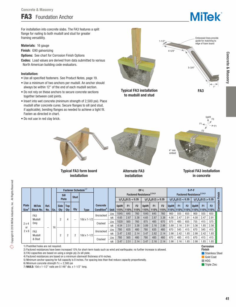
Concrete & M
asonry
41
Copy
right
© 2
018
MiT
ek In
dust
ries,
Inc.
All
Righ
ts R
eser
ved
Qty Type UnitLbs 1045 645 760 1045 645 760 900 555 655 900 555 655kN 4.65 2.87 3.38 4.65 2.87 3.38 4.00 2.47 2.91 4.00 2.47 2.91Lbs 1020 565 760 875 485 670 875 485 655 755 415 575kN 4.54 2.51 3.38 3.89 2.16 2.98 3.89 2.16 2.91 3.36 1.85 2.56Lbs 780 635 480 780 635 480 670 545 415 670 545 415kN 3.47 2.82 2.14 3.47 2.82 2.14 2.98 2.42 1.85 2.98 2.42 1.85Lbs 780 565 480 780 485 480 670 485 415 670 415 415kN 3.47 2.51 2.14 3.47 2.16 2.14 2.98 2.16 1.85 2.98 1.85 1.85
1) Predrilled holes are not required. 2) Factored resistances have been increased 15% for short-term loads such as wind and earthquake; no further increase is allowed. 3) FA3 capacities are based on using a single-ply 2x sill plate. 4) Factored resistances are based on a minimum stemwall thickness of 6-inches. 5) Minimum anchor spacing for full capacity is 8 inches. For spacing less than that reduce capacity proportionally. 6) Minimum concrete strength f'c = 2,500 psi 7) NAILS: 10d x 1-1/2" nails are 0.148" dia. x 1-1/2" long.
SillPlate
SideQty
TopQty
Uplift115%
F1115%
Stud
Uplift115%
F1115%
F2115%
F1115%
F2115%
F2115%
Uplift115%
F1115%
F2115%
Uplift115%
10d x 1-1/2--Uncracked
Cracked
10d x 1-1/22
PlateSize3 Ga.
2 x 4 or
2 x 6
MiTekStock No.
FA3 Mudsill Only
FA3 Mudsill & Stud
Ref. No.
-- 16
2 2
Fastener Schedule1,7
Cracked
Corr
osio
n Fi
nish
DF-L Factored Resistance2,3,4,5
ConcreteCondition6
Uncracked
S-P-F Factored Resistance2,3,4,5
IEFaSa(0.2) > 0.35 IEFaSa(0.2) < 0.35 IEFaSa(0.2) < 0.35 IEFaSa(0.2) > 0.35
2 4
FA3 Foundation Anchor
Corrosion Finish Stainless Steel Gold Coat HDG Triple Zinc
Corrosion Finish Stainless Steel Gold Coat HDG Triple Zinc
Corrosion Finish Stainless Steel Gold Coat HDG Triple Zinc
Typical FA3 installation to mudsill and stud
Typical FA3 form board installation
Alternate FA3 installation
Typical FA3 installation in concrete
For installation into concrete slabs. The FA3 features a split flange for nailing to both mudsill and stud for greater framing versatility.
Materials: 16 gaugeFinish: G90 galvanizingOptions: See chart for Corrosion Finish OptionsCodes: Load values are derived from data submitted to various North American building code evaluators.
Installation:• Use all specified fasteners. See Product Notes, page 19.• Use a minimum of two anchors per mudsill. An anchor should
always be within 12" of the end of each mudsill section.• Do not rely on these anchors to secure concrete sections
together between cold joints.• Insert into wet concrete (minimum strength of 2,500 psi). Place
mudsill after concrete cures. Secure flanges to sill (and stud, if applicable), bending flanges as needed to achieve a tight fit. Fasten as directed in chart.
• Do not use in red clay brick.
FA31"
5-3/4"
4-5/8"
1-1/2"Embossed lines provide guide for matching to edge of foam board
Concrete & Masonry
4" min. embed
F1F1
F3
F2
Uplift

42
Conc
rete
& M
ason
ry Copyright ©
2018 MiTek Industries, Inc. All Rights Reserved
FA4 Foundation Anchor
The FA4 foundation anchors can be installed as a replacement for the 5/8" diameter anchor bolts or also the commonly used 1/2" diameter anchor bolts while achieving the same load carrying capacity.
Materials: 16 gauge Finish: G90 galvanizingOptions: See chart for Corrosion Finish Options
Installation:• The FA4 can be mounted to the form board before placing the
concrete or inserted into the wet concrete after it is poured. See Detail A installation.
• Place the mudsill in position after the concrete cures. Secure the FA4 to the mudsill (and stud, if applicable) by bending the flanges as needed for a tight fit and nailing into place with the size and quantity of fasteners specified in the chart.
Qty Type Unit
Lbs 1615 2265 1825 990 1395 2035 1395 990 1450 2030 1635 885 1395 2030 1395 885
kN 7.18 10.08 8.12 4.40 6.21 9.05 6.21 4.40 6.45 9.03 7.27 3.94 6.21 9.03 6.21 3.94
Lbs 1340 1900 1340 975 1005 1425 1005 730 1340 1900 1340 885 1005 1425 1005 730
kN 5.96 8.45 5.96 4.34 4.47 6.34 4.47 3.25 5.96 8.45 5.96 3.94 4.47 6.34 4.47 3.25
Lbs 1395 1485 1915 780 1395 1485 1395 780 1250 1335 1915 700 1250 1335 1395 700
kN 6.21 6.61 8.52 3.47 6.21 6.61 6.21 3.47 5.56 5.94 8.52 3.11 5.56 5.94 6.21 3.11
Lbs 1340 1485 1340 780 1005 1425 1005 730 1250 1335 1340 700 1005 1335 1005 700
kN 5.96 6.61 5.96 3.47 4.47 6.34 4.47 3.25 5.56 5.94 5.96 3.11 4.47 5.94 4.47 3.11
1) Short-term load duration factor 115% for wind and earthquake has been taken into consideration; no further increased is allowed. 2) Factored resistances are based on a minimum stemwall thickness of 6-inches, minimum end distance of 5-1/2" and minimum spacing of 7 inches. 3) Minimum 28-day concrete compressive strength f'c = 2,500 psi (17.25 MPa). 4) Factored resistances are based on using a single-ply 2x sill plate. Sill plate may be treated lumber. 5) When loads in more than one direction are present, interaction effects shall be considered using the unity equation - Refer to MiTek Catalog Design Notes (1). 6) NAILS: 10d x 1-1/2" nails are 0.148" dia. x 1-1/2" long.
Fastener Schedule6
Ref. No.
PlateSize Ga.
Stud
TopQty
SideQty
SillPlate4
MiTekStock No.
10d x 1-1/2
3 3 10d x 1-1/2
2 x 4 or
2 x 6 MASA 16
FA4 Mudsill Only
FA4 Mudsill & Stud
--
3
3 6
Uncracked
Concrete3
S-P-F Factored Resistance1,2,5
DFFactored Resistance1,2,5
Wind and IEFaSa(0.2) < 0.35 IEFaSa(0.2) ≥ 0.35
Uplift115%
F1115%
Cracked
Uncracked
Cracked
F2115%
F3115%
Uplift115%
F1115% Co
rros
ion
Fini
shF2115%
F3115%
Uplift115%
F1115%
F2115%
Wind and IEFaSa(0.2) < 0.35 IEFaSa(0.2) ≥ 0.35
F3115%
Uplift115%
F1115%
F2115%
F3115%
Corrosion Finish Stainless Steel Gold Coat HDG Triple Zinc
Corrosion Finish Stainless Steel Gold Coat HDG Triple Zinc
Corrosion Finish Stainless Steel Gold Coat HDG Triple Zinc
Concrete & Masonry
3-1/2"
4-1/8"
5-3/16"
FA4
Typical FA4 form board installation
Detail A
Form board
Duplex nails
FA4
Detail B
Install FA4 with Tab against Form Board to Maintain Proper Angle of Embedment
Form Board
FA4
3-5/8"
Duplex Nail
Typical FA4 Mudsill & Stud installation
Typical FA4 Mudsill only installation
F1F1
F3
F2
Uplift

Concrete & M
asonry
43
Copy
right
© 2
018
MiT
ek In
dust
ries,
Inc.
All
Righ
ts R
eser
ved
ST Foundation Anchors
ST1-TZ – For installation into concrete slab or poured stemwalls. The ST1-TZ features a prebent base flange to assure proper anchoring into concrete.
ST2-TZ – For installation into concrete slab, poured stemwalls or concrete/masonry. The ST2-TZ features a prebent base flange to assure proper anchoring into concrete.
Materials: 18 gauge Finish: G-185 galvanizing Codes: Load values are derived from data submitted to various North American building code evaluators.
Installation:• Use all specified fasteners. See Product Notes, page 19.• Use a minimum of two anchors per mudsill. An anchor should always be within 12"
of the end of each mudsill section. • Space ST anchors at 4' (1.2m) to meet code prescribed ½" anchor bolt with standard
washer spaced at 7’-10" (2.4 m).• Do not rely on these anchors to secure concrete sections together between cold joints.• Spread sill flanges to mudsill width prior to insertion into wet concrete (minimum
strength of 2,500 psi, 17.25 MPa). Alternate installation is possible by inserting unbent flanges through 3/4" center hole predrilled in mudsill. Foundation anchors may also be attached to mudsill and then inserted into wet concrete. When installing ST2-TZ into concrete block, fill cells with grout with a minimum strength of 2,500 psi or 17.25 MPa. Concrete block edges may need to be beveled to facilitate installation.
• ST2-TZ in masonry construction shall be installed in the core of the block and grouted with concrete grout designed for that purpose. In no case, shall they be installed in a mortar joint.
• Do not use in red clay brick.
Ref. No. Type UnitLbs 1000 680 1005 855 585 860
kN 4.45 3.02 4.47 3.80 2.60 3.83
Lbs 1000 680 1005 855 585 860
kN 4.45 3.02 4.47 3.80 2.60 3.83
1) Short term load duration has been taken into consideration. No increase allowed. 2) NAILS: 8d x 1-1/2 nails are 0.131" diameter by 1-1/2" long.
Mudsill
SideQty
TopQty
4
48d x 1-1/2
HDG
8-1/2
16-1/2
4
4 2 x 4
or 2 x 6
Fastener Schedule2
Min.Embed (E)
(in)
DF
Factored Resistance1
PlateSize
MiTekStock No.
SteelGauge
ST1-TZ MAB15, MAB15Z
18 2 x 4
or 2 x 6
ST2-TZ MAB23, MAB23Z
8d x 1-1/2HDG
18
Corr
osio
nFi
nishUplift
115%F1
115%F2
115%Uplift115%
F1115%
F2115%
S-P-F
Factored Resistance1
DO NOT install ST1-TZ and ST2-TZwithout pre-bending sill flanges
in “Y” configuration
ST1-TZ ST2-TZ
Spread sill flanges to sill width prior to
insertion into wet concrete
10"18"
Alternate ST2-TZ installation with 3/4" center hole in mudsill
Alternate ST1-TZ installation with 3/4" center hole
Typical ST1-TZinstallation in concrete
Drill a 3/4" dia. hole into sill plate
Drill a 3/4" dia. hole into sill plate
Concrete & Masonry
Corrosion Finish Stainless Steel Gold Coat HDG Triple Zinc
Corrosion Finish Stainless Steel Gold Coat HDG Triple Zinc
Corrosion Finish Stainless Steel Gold Coat HDG Triple Zinc
Min embed 8-1/2"
E
F1F1
F2
F2
Uplift

44
Conc
rete
& M
ason
ry Copyright ©
2018 MiTek Industries, Inc. All Rights Reserved
FWAN Foundation Wall Anchor
MiTek’s FWAN-TZ Foundation Wall Anchor is designed to transfer in-plane and out-of-plane foundation wall loads imposed by soil through the joist/blocking into the floor diaphragm. The unique design allows for installations that straddle the joist/blocking eliminating bending stresses in the rim board that result from offset installations.
The FWAN-TZ offers two methods of installation: 1. Centered Installation• Compatible with joist/blocking up to 3-1/2 inches wide• Highest load capacities for transfer of out-of-plane
loads into floor framing • Rim board splices allowed anywhere along the wall2. Offset Installation• Installs in the space between the joists/blocking• Out-of-plane loads are transferred thru the rim board
into the floor framing • Offsets up to 4"
Materials: 16 gaugeFinish: G-185 galvanizing
Installation:• Centered Installation - Fill only triangle holes when nailing
to the rim board.• Offset Installation - Fill only diamond holes when nailing
to the rim board.• FWAN-TZ must be installed tight to the outside face of the rim board.• Minimum sill plate thickness is 1-1/2 inches. • Offset Installations require that the FWAN-TZ be installed within
4 inches of the joist/blocking.• For Offset Installations, install with two narrow tabs against rim board.
Splices in the rim board are not permitted in the space between the joist/blocking where the FWAN-TZ is installed.
• The designer must specify the anchor bolt size, spacing and embedment necessary to transfer the foundation loads into the sill plate. Stresses in the sill plate must be considered when determining the maximum spacing of the anchor bolts.
FWAN-TZ
Foundationwall
Foundationwall
FWAN-TZ
FWAN-TZ
Sill plate
Sill plate
Sill plate
Sill plate
Joist
Joist
Joist or Blocking
Joist
Rimboard
Rimboard
Rimboard
Rimboard
Outside view Inside view
Outside view Inside view
Centered Installation Typical FWAN-TZ centered on joist/blocking
Offset Installation Typical FWAN-TZ offset max 4" from joist/blocking
4"
2-1/16"
1"
4"
2-1/16"8-1/16"
4-1/2"
4-1/2"
Concrete & Masonry
Corrosion Finish Stainless Steel Gold Coat HDG Triple Zinc
Corrosion Finish Stainless Steel Gold Coat HDG Triple Zinc
Corrosion Finish Stainless Steel Gold Coat HDG Triple Zinc
Ref. No. Type Lbs kN Lbs kN Lbs kN Lbs kN
1-1/8" OSB 800 3.56 2065 9.19 745 3.31 1925 8.562x Rim 1005 4.47 2545 11.32 935 4.16 2375 10.56
1-3/4" LVL 1005 4.47 2545 11.32 935 4.16 2375 10.561-1/8" OSB 800 3.56 2770 12.32 745 3.31 2585 11.50
2x Rim 1005 4.47 3140 13.97 935 4.16 2930 13.031-3/4" LVL 1005 4.47 3140 13.97 935 4.16 2930 13.03
1-1/8" OSB 800 3.56 955 4.25 745 3.31 890 3.962x Rim 1005 4.47 1855 8.25 935 4.16 1725 7.67
1-3/4" LVL 1005 4.47 1855 8.25 935 4.16 1725 7.671-1/8" OSB 800 3.56 955 4.25 745 3.31 890 3.96
2x Rim 1005 4.47 1855 8.25 935 4.16 1725 7.671-3/4" LVL 1005 4.47 1855 8.25 935 4.16 1725 7.67
1) Factored Resistance has been increased by 15% for wind and earthquake; no further increase allowed. 2) F1 loads are parallel to the sill plate. 3) F2 loads are perpendicular toward the sill plate. 4) The designer must specify the type, size and spacing of fasteners connecting the sill plate to the foundation wall. 5) NAILS: 10d x 1-1/2 nails are 0.148" dia. x 1-1/2" long. New products or updated product information are designated in blue font.
2x4, 2-2x4,3x4, 4x4
8 4 10d x 1-1/2
2x6, 2-2x6,3x6, 4x6
12 4 10d x 1-1/2
Offset from Joist Blocking (Max Offset 4")
SillPlate
FWAN-TZ FWANZ
Centered on Joist/Blocking
2x4, 2-2x4,3x4, 4x4
8 4 10d x 1-1/2
MiTekStock No.
2x6, 2-2x6,3x6, 4x6
12 4 10d x 1-1/2
Fastener Schedule5
Rim Board
Material
DF Factored Resistance1 S-P-F Factored Resistance1
Corr
osio
nFi
nish
SillPlateQty
RimBoard
Qty
F1(115%)2
F2(115%)3
F1(115%)2
F2(115%)3
F2
F1
F1
F1
F1
F2

Concrete & M
asonry
45
Copy
right
© 2
018
MiT
ek In
dust
ries,
Inc.
All
Righ
ts R
eser
ved
SFA / SFJA Foundation Anchors
SFA – Mudsill anchors for retrofit applications. Features a slotted bend line for easy adjustment when foundation walls are slanted.
SFJA – Ties floor joists directly to foundations with bolt fastening.
Materials: 12 gauge Finish: G90 galvanizing
Installation:• Use all specified fasteners. See Product Notes, page 19. • A design professional must specify anchor bolt type, length,
and embedment. Anchor bolts are laterally loaded. Follow installation instructions for epoxy adhesive.
• Factored resistances assume a minimum concrete compressive strength of 2,500 psi.
Ref. No. Qty Dia (in) Qty Type Qty Dia. SFJA FJA 12 1 5/8 -- -- 2 5/8 -- 1620 -- 1360 SFA8 -- 12 2 1/2 7 10d x 1-1/2 -- -- 1085 -- 915 --
1) The 115% values are short-term loads such as wind and earthquake. 2) Bolts shall conform to ASTM A 307 or better. 3) NAILS: 10d x 1-1/2 nails are 0.148" dia. x 1-1/2" long.
Fastener Schedule
Anchor Bolts
DF
Factored Resistance1
S-P-F
Factored Resistance1
MiTekStock No.
SteelGauge
Nails3 Bolts2
Framing
F1115%
Uplift115%
F1115%
Uplift115%
Typical SFA8 installation
SFA8
F1F1
Typical SFJA installation
Uplift
8"6"
7"
1/2" max gap distance
SFJA
1-1/2"
1-1/2"
6-1/2"
6"
Concrete & Masonry
Typical WT22B-HDG installation WT22B-HDG
WT Wall Ties
Materials: 22 gaugeFinish: G90 galvanizing; WT22B-HDG – Hot-dip galvanizedOptions: See chart for Corrosion Finish options
Installation:• Use nails appropriate for intended use. See Product Notes, page 19.• The opposite end must be bonded in the mortar joint of brick facade.• Meets prescriptive requirements of CSA A370 for corrugated strip ties.
Ref. No. Qty Type WT17HD -- 22 2 10d
WT221 BTB 22 2 10d WT22B-HDG -- 22 1 #10 HDG wood screw
1) WT22 is bulk packed in 500 pieces. 2) NAILS: 10d nails are 0.148" dia. x 3" long.
MiTekStock No.
SteelGauge
Fastener Schedule2
Corr
osio
nFi
nish
Corrosion Finish Stainless Steel Gold Coat HDG Triple Zinc
Corrosion Finish Stainless Steel Gold Coat HDG Triple Zinc
Corrosion Finish Stainless Steel Gold Coat HDG Triple Zinc
Typical WT17HD/WT22 installation
WT17HD/WT22
6-3/4"
7/8"
1" space between brick and sheathing
7/8"
5/8"
3-1/8"

46
Conc
rete
& M
ason
ry Copyright ©
2018 MiTek Industries, Inc. All Rights Reserved
KGLB / KGLBT / KHGLB Laminated Beam Seats
KGLB – Single bolt, bearing only.
KGLBT – Double bolt with structural tee provides uplift and horizontal resistance.
KHGLB – Double bolt design provides uplift and horizontal resistance.
Materials: Flanges – 1/4" steel Bearing Plate – See chart for “T” dimension Anchor Dowels – 3⁄4" x 12" rebar
Finish: Primer Options: Consult MiTek for non-catalogue variations. Codes: Load values are derived from data submitted to various North American building code evaluators.
Installation:• Use all specified fasteners. See Product Notes, page 19.• Bolt holes shall be a minimum of 1⁄32" to a maximum of 1⁄16" larger
than the bolt diameter.• Concrete or masonry walls must be checked by a design professional for
adequacy to resist lateral or uplift loads transferred from the beam seat anchor.
F23,4
Ref. No. D L T Qty Unit 5-1/8 6-3/4 8-3/4 10-3/4 100% Uplift 115%3
Lbs 27000 16980 22355 28980 -- 9445 4045kN 120.11 75.53 99.44 128.91 -- 42.02 17.99Lbs 32400 20370 26825 34775 -- 9445 4045kN 144.13 90.61 119.33 154.69 -- 42.02 17.99Lbs 37800 23765 31300 40570 -- 9445 4045kN 168.15 105.72 139.23 180.47 -- 42.02 17.99Lbs 43200 27160 35770 46370 -- 9445 4045kN 192.17 120.82 159.12 206.27 -- 42.02 17.99Lbs 35640 18670 24595 31880 39170 9445 4045kN 158.54 83.05 109.41 141.81 174.24 42.02 17.99Lbs 42120 22070 29065 37680 46290 9445 4045kN 187.37 98.18 129.29 167.62 205.92 42.02 17.99Lbs 39170 18670 24595 31880 39170 9445 4045kN 174.24 83.05 109.41 141.81 174.24 42.02 17.99Lbs 46290 22070 29065 37680 46290 9445 4045kN 205.92 98.18 129.29 167.62 205.92 42.02 17.99Lbs 39170 18670 24595 31880 39170 9445 4045kN 174.24 83.05 109.41 141.81 174.24 42.02 17.99Lbs 46290 22070 29065 37680 46290 9445 4045kN 205.92 98.18 129.29 167.62 205.92 42.02 17.99
1) Beams must fully bear on plates. 2) Factored bearing resistances on concrete are based on factored bearing strength in compression perpendicular to grain (ɸ fcp) of 662 psi and actually beam width times beam bearing length. 3) The 115% values are short-term loads such as wind and earthquake and are based on bolt in wood values only. Factored resistances assume concrete or masonry structure is adequate to resist loads in those directions. 4) Factored resistances must be be reduced if the allowable lateral load (F2) for masonry or concrete column governs. 5) Designer shall specify minimum edge and spacing requirements in masonry or concrete structure.
Min. 3-1/8 Beam Width (W)
MiTekStock No.
RangeW
Dimensions (in)
Dia.(in)
On Concrete with
Beam Width1
2 3/4
2 3/4
2 3/4
2 3/4
2 3/4
2 3/4
3/4
2 3/4
2 3/4
KHGLBA
KHGLBB
KHGLBC
KHGLBD
10
8 10
3-1/4 to 9
3-1/4 to 9
3-1/4 to 9
3-1/4 to 9
5 10
6 10
7
3-1/4 to 15
3-1/4 to 15
HGLBA
HGLBB
HGLBC
HGLBD
KGLBT520
KGLBT620
GLBT512
GLBT612
GLBT516
GLBT616
GLBT520
GLBT620
KGLBT512
KGLBT612
KGLBT616
KGLBT516
3-1/4 to 19
6-1/2
12
12
16
16
20
20
5-1/2
6-1/2
5-1/2
6-1/2
5-1/2
3-1/4 to 19
3-1/4 to 11
3-1/4 to 11
1/3
3/8
Bolt Schedule
Factored Bearing Resistance1,5
Masonry@
375 psi
1/3
3/8
1/3
3/8
3/8
2 3/4
3/8
3/8
3/8
2
Ref. No. W L T D Qty Lbs kN Lbs kN KGLB5A GLB5A 5-1/4 7 1/4 5 1 5/8 16980 75.53 16980 75.53 KGLB5B GLB5B 5-1/4 7 3/8 6 1 5/8 20370 90.61 20370 90.61 KGLB5C GLB5C 5-1/4 7 3/8 7 1 5/8 23765 105.72 23765 105.72 KGLB5D GLB5D 5-1/4 7 3/8 8 1 5/8 27160 120.82 27160 120.82 KGLB7A GLB7A 6-7/8 9 1/4 5 1 3/4 22355 99.44 22355 99.44 KGLB7B GLB7B 6-7/8 9 3/8 6 1 3/4 26825 119.33 26825 119.33 KGLB7C GLB7C 6-7/8 9 3/8 7 1 3/4 31300 139.23 31300 139.23 KGLB7D GLB7D 6-7/8 9 3/8 8 1 3/4 35770 159.12 35770 159.12
1) Beams must fully bear on plates. 2) Factored bearing resistances are based on the bearing value listed times the bearing area equal to W x D. (Note that full bearing plate area is not used.) Factored bearing resistances shall be reduced where limited by wood bearing on the plate. 3) Factored bearing resistances on concrete are based on factored bearing strength in compression perpendicular to grain (ɸ fcp) of 662 psi and actually beam width times beam bearing length. 4) Designer shall specify minimum edge and spacing requirements in masonry or concrete structure. 5) Concrete or masonry support structure is assumed adequate to support loads listed.
Concrete3
Factored Bearing Resistance1,4,5Dimensions (in)
MiTekStock No.
Bolt Schedule
Dia.(in)
Masonry @ 375 psi2
1) Beams must fully bear on plates.2) Factored bearing resistances on
concrete are based on factored bearing strength in compression perpendicular to grain ( fcp) of 662 psi and actually beam width times beam bearing length.
3) The 115% values are short-term loads such as wind and earthquake and are based on bolt in wood values only. Factored resistances assume concrete or masonry structure is adequate to resist loads in those directions.
4) Factored resistances must be be reduced if the allowable lateral load (F2) for masonry or concrete column governs.
5) Designer shall specify minimum edge and spacing requirements in masonry or concrete structure.
Typical KGLB installation
Concrete & Masonry
KHGLB
KGLB
KGLBT
3" W
D
3-1/2"
L T
12"
3"
3"
1-1/2"
1-1/4"
T
2-1/2" 2-1/2"
L D
W
1/2" clearance
Bearing plate
Concrete pilaster
Rebar welded to bearing plate
Uplift
F2
Structural tee
12"
4"
3-1/2"
1-1/4"
T3"
L
D
3"
1-1/2"
W
F2

Concrete & M
asonry
47
Copy
right
© 2
018
MiT
ek In
dust
ries,
Inc.
All
Righ
ts R
eser
ved
KGH Floor Girder Hangers
Connects girder beams to foundation walls and eliminates the need to block out pockets or inserts while forming foundation.
Materials: 12 gaugeFinish: PrimerOptions: Consult MiTek for non-catalogue design variations.Codes: Load values are derived from data submitted to various North American building code evaluators.
Installation:• Use all specified fasteners. See Product Notes, page 19.• H dimension assumes 2x mudsill. For 3x or larger mudsill,
please contact factory.• The 1-1⁄2" hole, centered in the saddle, allows for installation
over any protruding foundation bolts. This is not required. • Placement of a wood sill over the top of the KGH top flange
is required to achieve factored resistance.
Specialty Options Chart – refer to Specialty Options pages 246, 248-249 for additional details.
Dimensions (in)
Ref. No. W L D S H Qty Type Lbs kN Lbs kN KGH46-6 GH46-6 12 3-9/16 5 3-1/4 6 4 4 16d 2975 13.23 2335 10.39 KGH46-8 GH46-8 12 3-9/16 5 3-1/4 8 4 4 16d 2975 13.23 2335 10.39 KGH48-6 GH48-6 12 3-9/16 5 3 6 6 4 16d 2975 13.23 2335 10.39 KGH48-8 GH48-8 12 3-9/16 5 3 8 6 4 16d 2975 13.23 2335 10.39 KGH66-6 GH66-6 12 5-1/2 6-1/4 3 6 4 4 16d 2955 13.14 2320 10.32 KGH66-8 GH66-8 12 5-1/2 6-1/4 3 8 4 4 16d 2955 13.14 2320 10.32 KGH68-6 GH68-6 12 5-1/2 6-1/4 3 6 6 4 16d 2955 13.14 2320 10.32 KGH68-8 GH68-8 12 5-1/2 6-1/4 3 8 6 4 16d 2955 13.14 2320 10.32
1) Factored download resistances shall not be increased for short-term load duration. 2) Placement of a wood sill over the top of the KGH top flange is required to achieve listed factored download resistances. 3) NAILS: 16d nails are 0.162" dia. x 3-1/2" long. New products or updated product information are designated in blue font.
4 x 6
4 x 8
6 x 6
6 x 8
SPFFactored Resistance
Fastener
Schedule3
GirderSize
MiTekStock No.
SteelGauge
DFFactored Resistance
Download 100%1,2 Download 100%1,2
Option Skewed1,2 Saddle
Range 1˚ to 45˚ --
1) Skewed hangers with skews greater than 15° may have all joist nailing on outside flange. 2) For skewed hangers, the required cut type (square or bevel) of joist member may vary based on skew angle and width of hanger. Some square cut hangers will require custom pricing due to welded back plate.
FactoredResistance
Ordering
100% of table load.100% of table load
per side.
Add SA, and saddlewidth required
to product number.Ex. KGH46-6_SA=5-1/2˝
Add SK , angle required,right (R ) or left (L ), and
square cut (SQ ) or bevel cut (BV )to product number.
Ex. KGH46-6_SK45R_BV
Typical KGH installation
KGH
S
1"
H
L
W D
KGH saddle
Concrete & Masonry

48
Stru
ctur
al C
olum
ns –
Adj
usta
ble
Copyright © 2018 M
iTek Industries, Inc. All Rights Reserved
JP Adjustable Support Columns Structural Columns – Adjustable
Adjustable Support Columns may be used to support carport roofs and beams carrying loads not more than two wood frame floors, where the length of joists carried by such beams does not exceed 16’ and a live load on any floor does not exceed 50 lbs/ft2.
Materials: 3 gauge steel plates (3-1/2" x 6"); 12 gauge outer tube (2-3⁄4" O.D); 11 gauge inner tube (2-1⁄2"O.D.) Finish: Grey Primer PaintCodes: Conforms to NBC 2010, Article 9.17.3.4.(1) and to CAN/CGSB-7.2-94.
Installation:• Elevate top tubing to approximate height and insert locking pin.
Rotate jack screw to desired height, then fasten top plate in position. Ensure top and bottom plates are properly fastened to supported beam members and properly aligned to the supported base footing. Always ensure product is installed 90º to beam and footing.
• Fasten the supported beam to the top plate with two (2) 1/4" x 2" lag screws.
Ref. No. in mm Lbs kN Lbs kN JP24 -- 17 - 24 432 - 610 8555 38.06 12320 54.80 JP36 -- 24 - 36 610 - 914 8555 38.06 12320 54.80 JP60 -- 36 - 60 914 - 1524 8555 38.06 12320 54.80 JP96 -- 60 - 96 1524 - 2438 8555 38.06 12320 54.80 JP108 -- 72 - 108 1829 - 2743 8177 36.37 11775 52.38
1) Allowable loads were established in accordance with CAN/CGSB-7.2-94. 2) The factored resistances given above were soft converted by multiplying the allowable loads by 1.44. 3) The bearing resistance of the supported beam should be checked by the building designer using the appropriate CSA standard.
MiTekStock No.
Allowable Load1,3 Factored Resistance2,3Adjustable Height
Description JPCP Setting Pin 1 JPSN Screw & Nut Assembly 1 JPSP 6" x 7" Steel Plate 15 JPSSN Screw & Nut Assembly 1 JPTP Top Plate 1
MiTekStock No.
Qty/Package
JP
JPSPJPSN JPSSN JPTPJPCP
Typical JP installation
Replacement Parts for Adjustable Support Columns
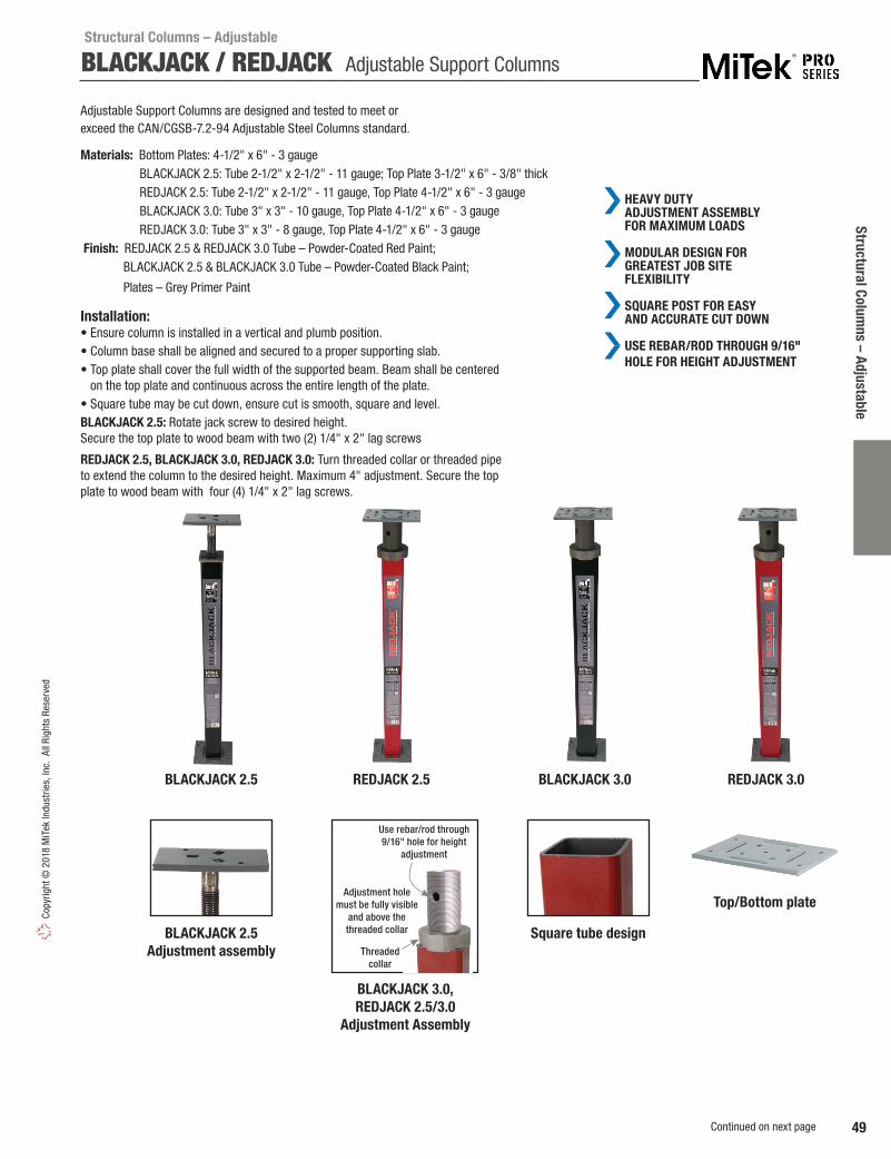
Structural Columns – Adjustable
49
Copy
right
© 2
018
MiT
ek In
dust
ries,
Inc.
All
Righ
ts R
eser
ved
BLACKJACK / REDJACK Adjustable Support Columns Structural Columns – Adjustable
Adjustable Support Columns are designed and tested to meet or exceed the CAN/CGSB-7.2-94 Adjustable Steel Columns standard.
Materials: Bottom Plates: 4-1/2" x 6" - 3 gauge BLACKJACK 2.5: Tube 2-1/2" x 2-1/2" - 11 gauge; Top Plate 3-1/2" x 6" - 3/8" thick REDJACK 2.5: Tube 2-1/2" x 2-1/2" - 11 gauge, Top Plate 4-1/2" x 6" - 3 gauge BLACKJACK 3.0: Tube 3" x 3" - 10 gauge, Top Plate 4-1/2" x 6" - 3 gauge REDJACK 3.0: Tube 3" x 3" - 8 gauge, Top Plate 4-1/2" x 6" - 3 gauge Finish: REDJACK 2.5 & REDJACK 3.0 Tube – Powder-Coated Red Paint; BLACKJACK 2.5 & BLACKJACK 3.0 Tube – Powder-Coated Black Paint;
Plates – Grey Primer Paint
Installation:• Ensure column is installed in a vertical and plumb position.• Column base shall be aligned and secured to a proper supporting slab.• Top plate shall cover the full width of the supported beam. Beam shall be centered
on the top plate and continuous across the entire length of the plate.• Square tube may be cut down, ensure cut is smooth, square and level.BLACKJACK 2.5: Rotate jack screw to desired height. Secure the top plate to wood beam with two (2) 1/4" x 2" lag screws
REDJACK 2.5, BLACKJACK 3.0, REDJACK 3.0: Turn threaded collar or threaded pipe to extend the column to the desired height. Maximum 4" adjustment. Secure the top plate to wood beam with four (4) 1/4" x 2" lag screws.
Top/Bottom plate
Square tube design
HEAVY DUTY ADJUSTMENT ASSEMBLY FOR MAXIMUM LOADS
MODULAR DESIGN FOR GREATEST JOB SITE FLEXIBILITY
SQUARE POST FOR EASY AND ACCURATE CUT DOWN
USE REBAR/ROD THROUGH 9/16" HOLE FOR HEIGHT ADJUSTMENT
REDJACK 2.5BLACKJACK 2.5 REDJACK 3.0BLACKJACK 3.0
BLACKJACK 2.5Adjustment assembly
BLACKJACK 3.0, REDJACK 2.5/3.0
Adjustment Assembly
Threaded collar
Use rebar/rod through 9/16" hole for height
adjustment
Adjustment hole must be fully visible
and above the threaded collar
Continued on next page

50
Stru
ctur
al C
olum
ns –
Adj
usta
ble
Copyright © 2018 M
iTek Industries, Inc. All Rights Reserved
in mm in mm lb kN kg lb kN kg
T2JP110 106 - 110 2692 - 2794 110 2794 10000 44 4536 14400 64 6532
in mm in mm lb kN kg lb kN kg
T2JPLD84 80 - 84 2032 - 2134 84 2134 16900 75 7665 26000 116 11815
T2JPLD88 84 - 88 2134 - 2235 88 2235 15500 69 7030 24300 108 11020
T2JPLD90 86 - 90 2184 - 2286 90 2286 15000 67 6805 23700 105 10750
T2JPLD96 92 - 96 2337 - 2438 96 2438 13600 60 6170 21800 97 9935
T2JPLD102 98 - 102 2489 - 2591 102 2591 12800 57 5805 20050 89 9095
T2JPLD108 104 - 108 2642 - 2743 108 2743 12200 54 5535 18400 82 8385
T2JPLD114 110 -114 2794 - 2896 114 2896 11500 51 5215 17000 76 7710
T2JPLD120 116 - 120 2946 - 3048 120 3048 10900 48 4945 15600 70 7120
in mm in mm lb kN kg lb kN kg
T2JPMD84 80 - 84 2032 - 2134 84 2134 30400 135 13790 41500 185 18825
T2JPMD88 84 - 88 2134 - 2235 88 2235 27600 123 12520 39600 176 17960
T2JPMD90 86 - 90 2184 - 2286 90 2286 26400 117 11975 38600 172 17510
T2JPMD96 92 - 96 2337 - 2438 96 2438 24000 107 10885 36100 161 16375
T2JPMD102 98 - 102 2489 - 2591 102 2591 22900 102 10385 33650 150 15265
T2JPMD108 104 - 108 2642 - 2743 108 2743 22300 99 10115 31400 140 14245
T2JPMD114 110 - 114 2794 - 2896 114 2896 22000 98 9980 29900 133 13560
T2JPMD120 116 - 120 2946 - 3048 120 3048 21900 97 9935 27200 121 12340
in mm in mm lb kN kg lb kN kg
T2JPHD84 80 - 84 2032 - 2134 84 2134 39600 176 17960 49900 222 22685 T2JPHD88 84 - 88 2134 - 2235 88 2235 36600 163 16600 47300 210 21455 T2JPHD90 86 - 90 2184 - 2286 90 2286 35500 158 16100 46400 206 21045 T2JPHD96 92 - 96 2337 - 2438 96 2438 32100 143 14560 43400 193 19730 T2JPHD102 98 - 102 2489 - 2591 102 2591 30000 133 13610 40300 179 18280 T2JPHD108 104 - 108 2642 - 2743 108 2743 28300 126 12835 37600 168 17105 T2JPHD114 110 -114 2794 - 2896 114 2896 27500 122 12475 35100 156 15920 T2JPHD120 116 - 120 2946 - 3048 120 3048 26800 119 12155 32700 145 14840
T2JPHD144 140 - 144 3556 - 3658 144 3658 21300 95 9660 24800 111 11250
1) The Allowable Load values have been determined thru testing standards prescribed in the National Research Council Evaluation Directive for Adjustable Steel Columns using a safety factor of 2.25. 2) The Factored Resistances of REDJACK 2.5, BLACKJACK 3.0 and REDJACK 3.0 columns are limited by the resistance of the tubes. The depicted values are established in accordance with CSA S16, Design of Steel Structures, using Resistance Factor Φ = 0.90. 3) The Factored Resistance of the BLACKJACK 2.5 column assembly is limited by the strength of the adjustable screw assembly. The depicted value is soft converted by multiplying the allowable load by 1.44. 4) The bearing resistance of the supported beam should be checked by the building designer using the appropriate CSA standard. New products or updated product information are designated in blue font.
REDJACK 2.5
Allowable Load1,4 Factored Resistance2,4
ExtendedLength
BLACKJACK 3.0
MiTekStock No.
AdjustableHeight
ExtendedLength
BLACKJACK 2.5
MiTekStock No.
AdjustableHeight
ExtendedLength Allowable Load1,4 Factored Resistance3,4
MiTekStock No.
AdjustableHeight
ExtendedLength
REDJACK 3.0
MiTekStock No.
AdjustableHeight
Allowable Load1,4 Factored Resistance2,4
Allowable Load1,4 Factored Resistance2,4
BLACKJACK / REDJACK Adjustable Support Columns Structural Columns – Adjustable

Structural Columns – Adjustable
51
Copy
right
© 2
018
MiT
ek In
dust
ries,
Inc.
All
Righ
ts R
eser
ved
T2TP79(T2TP527 similar)
T2CC35
Typical T2TP79 installation(T2TP527 similar)
Typical T2CC installation
T2TP BLACKJACK / REDJACK Supplementary Top PlatesStructural Columns – Adjustable
T2TP Supplementary Top Plates can be installed on top of the standard top plate supplied with BLACKJACK 3.0 / REDJACK 2.5/3.0 columns, and provide additional bearing for Structural Composite Lumber (SCL) beams and dimensional lumber.
T2TP527 – 5-1/4" bearing width (Typical: 3 ply 1-3/4" LVL or 6x beam)
T2TP79 – 7" bearing width (Typical: 4 ply 1-3/4" LVL or 8x beam)
Materials: 3 gauge ASTM A 36 steel Finish: Primer
Installation:• Place T2TP supplementary plate on top of standard BLACKJACK / REDJACK Top Plate.• Align holes of the two plates and install appropriate lag screws through the stacked plates
into bottom of the supported beam. • T2TP shall cover the full width of the supported beam. Beam shall be centered on the T2TP
and continuous across the entire length of the plate.
Ref. No. W L Qty Type Lbs kN Lbs kN
T2TP527 -- 3 5-1/4 7 4 1/4" x 2" Lag Screw 29300 131.3 22600 101.3 T2TP79 -- 3 7 9 4 1/4" x 2" Lag Screw 38500 172.6 34000 152.4
1) Factored resistances are for standard term loading; reduce or increase for other load durations in accordance with the code. 2) Bearing loads are based on compression perpendicular to grain values published in the Canadian Standards Association CSA-O86-14 and having the top plate in full contact with the supported member. 3) Factored resistances are based on lumber with a specific gravity of DF = 0.49 and S-P-F = 0.42 and a moisture content of 19% or less. 4) Lag Screws are not supplied. WS2 Wood Screws (1/4" dia. x 2" long) may be ordered separately and used in lieu of lag screws. 5) Beams shall be designed to support the required loads. Beam shear may limit loads to less than listed loads for device. 6) The factored resistance of the T2TP may exceed the column capacity. Refer to the BLACKJACK / REDJACK Column load tables for the maximum factored resistance based on column length.
Bearing (100%)
DFFactored Resistance
S-P-FFactored Resistance
MiTekStock No.
SteelGauge
Dimensions (in) Fastener Schedule
Bearing (100%)
T2CC BLACKJACK / REDJACK Column Caps
Cap only version for BLACKJACK 3.0 / REDJACK 2.5/3.0 Adjustable Structural Columns. Adds bearing capacity and resists beam rotation.
Materials: T2CC35: 7 gauge ASTM A1011; T2CC525, T2CC71: 3 gauge ASTM A 36 steelFinish: Primer
Installation:• Replaces standard BLACKJACK / REDJACK Top Plate.• Slide column cap tube into top of existing threaded pipe component. • WS3 Wood Screws, 1/4" dia. x 3" long, are supplied with T2CC Column Caps.• Beam shall be continuous across the entire length of the column cap.
Ref. No. W H L Qty Type Lbs kN Lbs kN T2CC35 -- 7 3-5/8 6-1/2 11 16 WS3 31270 139.1 23675 105.3 T2CC525 -- 3 5-1/4 8 13 16 WS3 54115 240.7 40970 182.2 T2CC71 -- 3 7-1/8 6-1/2 11 16 WS3 62540 278.2 47350 210.6
1) Factored resistances are for standard term loading; reduce or increase for other load durations in accordance with the code. 2) Bearing loads are based on compression perpendicular to grain values published in CSA O86-14 and having the bucket base in full contact with the supported member. 3) Factored resistances are based on lumber with a specific gravity of DF-L = 0.49 and S-P-F = 0.42 and a moisture content of 19% or less. 4) WS3 Wood Screws (1/4" dia. x 3" long) are included with T2CC Column Caps. 5) Beams shall be designed to support the required loads. Beam shear may limit loads to less than listed loads for device. 6) The factored resistance of the T2CC may exceed the column capacity. Refer to the BLACKJACK / REDJACK Column load tables for the maximum factored resistance based on column length.
MiTekStock No.
SteelGauge
Beam
Fastener Schedule4
Bearing (100%)
Dimensions (in)
Bearing (100%)
DF Factored Resistance
S-P-F Factored Resistance
W
L
WL
H

52
Hold
owns
Copyright © 2018 M
iTek Industries, Inc. All Rights Reserved
PHD / PHDA Predeflected Holdowns
Holdowns
Features the pre-deflected base, the PHD/PHDA holdowns minimize deflection while providing uplift resistance.
Materials: See chart.Finish: G90 galvanizingCodes: Load values are derived from data submitted to various North American building code evaluators.
Installation:• Use all specified fasteners. See Product Notes, page 19.• Place the PHD/PHDA over the anchor bolt. No washer is required.• Install with MiTek’s code evaluated WS3 (1/4" dia. x 3" long) Wood
Screws, which are provided with the holdown.• Tighten anchor bolt nuts finger tight to base plus 1/3 to 1/2 additional
turns with a wrench. • PHD/PHDA Predeflected Holdowns may be installed off sill plate
with no load reduction.• The design engineer may specify any alternate anchorage calculated to
resist the tension load for a specific application. Anchorage exposure length should take the bearing plate height of 1-5/8" into account, anchor bolt thread should visibly extend above nut.
• If used to anchor a built-up post, such as a double 2x4, the post component shall be designed to act as a single unit. Holdown fasteners specified shall not be considered to attach multiple plies together.
• For anchorage options see STB / STBL Anchor Bolt section on pages 36-37.
Ref. No. W H D CL6 Qty Dia (in) Qty Type Unit in mm
Lbs 3330 2795kN 14.81 12.43Lbs 5400 4535kN 24.02 20.17Lbs 6755 5670kN 30.05 25.22Lbs 8470 7115kN 37.68 31.65
1) Factored resistances have been increased 15% for short-term loads such as wind and earthquake; reduce for other load durations in accordance with the code. 2) The designer must specify anchor bolt type, length, and embedment. 3) The PHD/PHDA may be elevated off the sill and may increase deflection. 4) WS3 wood screws are 1/4" dia. x 3" long and are included with PHD/PHDA models. 5) Minimum post thickness is 3". Consult MiTek for installations less than 3". 6) "CL" denotes the distance between the post and center of the anchor bolt. New products or updated product information are designated in blue font.
0.159
0.140
0.138
0.069
4.04
3.56
3.51
1.75 PHD8 HDU8-SDS2.5
9-3/4 2-5/8 1-3/8
2-5/8 1-3/8
3-1/4 16-1/2
11-11/16
3 1-3/8
14
14
12
3
3
PHD4A HDU4-SDS2.5
PHD5A HDU5-SDS2.5 1 5/8 14 WS3
1 7/8 24 WS3
WS3
1 5/8 10 WS3
2-5/8 1-3/8 1 5/8 6 PHD2A HDU2-SDS2.5 14 3 7-3/4
Deflection at
Factored Resistance
Uplift
(115%)1,5
Uplift
(115%)1,5MiTek
Stock No.Steel
Gauge
Anchor
Bolts2
Wood
Screws4
D Fir-LFactored
Resistance
S-P-FFactored
Resistance
Dimensions (in) Fastener Schedule
Typical PHD5A installation
PHD8 PHD5AD
CL
H
W
1-5/8

53
Holdowns
Copy
right
© 2
018
MiT
ek In
dust
ries,
Inc.
All
Righ
ts R
eser
ved
DTB Holdown
Holdowns
DTB-TZ is a light-capacity holdown for single 2x installations.
Finish: G-185 galvanizing
Options: See chart for Corrosion Finish OptionsCodes: Load values are derived from data submitted to various North American building code evaluators.
Installation:• Use all specified fasteners. See Product Notes, page 19. • Install with MiTek’s THR 1/2" threaded rod or equivalent.• Position DTB-TZ on deck joist in a location where the 1/2"
threaded rod or bolt may be threaded through the bolt hole.• Drive WS15-EXT wood screws into joist. • Re-install threaded rod or anchor bolt. Secure with washer and nut. • Tighten anchor bolt nuts finger tight to base plus 1⁄3 to 1⁄2
additional turns with wrench.
CL
Ref. No. (in) Qty 100% 115%1 100% 115%1 100% 115%1 100% 115%1
DTB-TZ DTT2Z 14 1/2 1-1/8 8 WS15-EXT 2640 2640 11.74 11.74 2220 2220 9.88 9.88
1) Factored resistances have been increased 15% for short-term loads such as wind and earthquake; reduce for other load durations in accordance with the code. 2) WS15-EXT Wood Screws are 1/4" dia. x 1-1/2" long exterior coat screw and are included with DTB-TZ Deck Tie-Backs. New products or updated product information are designated in blue font.
Corr
osio
nFi
nishkNMiTek
Stock No.Wood
Screws
Rod / BoltAnchor Dia. (in)
LbsLbs
Fastener Schedule2
kNSteelGauge
DF Factored Resistance S-P-F Factored Resistance
DTB-TZ
6"
2-1/4"
CL
1-13/16"
Corrosion Finish Stainless Steel Gold Coat HDG Triple Zinc
Corrosion Finish Stainless Steel Gold Coat HDG Triple Zinc
Corrosion Finish Stainless Steel Gold Coat HDG Triple Zinc
Typical DTB-TZ installation

54
Hold
owns
Copyright © 2018 M
iTek Industries, Inc. All Rights Reserved
Corrosion Finish Stainless Steel Gold Coat HDG Triple Zinc
Corrosion Finish Stainless Steel Gold Coat HDG Triple Zinc
Corrosion Finish Stainless Steel Gold Coat HDG Triple Zinc
LTS / LTTI Tension Ties
Holdowns
Ref. No. Strap Plate W L D CL Qty Dia (in) Qty Type Lbs kN Lbs kN LTTI31 4 LTTI31 18 3 3-3/4 31 2-5/8 1-3/8 3 1 5/8 18 10d x 1-1/2 2905 12.92 2440 10.85
LTS19-TZ 4 LTT19 16 3 1-3/4 22-1/4 3 1-1/2 2-1/2 1 3/4 8 10d 1245 5.54 1045 4.6510 10d x 1-1/2 1140 5.07 960 4.2710 16d 1145 5.09 960 4.272 1/2" Bolt 1215 5.40 1020 4.54
1) Factored resistances have been increased 15% for short-term loads such as wind and earthquake; no further increase allowed. 2) 16d sinkers may be substituted for the specified 10d common nails with no load reduction. 3) The designer must specify anchor bolt type, length and embedment depth. 4) LTTI and LTS holdowns shall be installed tight to the sill plate. 5) LTS20B bolted installation requires a minimum 1-1/2" wood member thickness. 6) NAILS: 10d x 1-1/2" nails are 0.148" dia. x 1-1/2" long, 10d nails are 0.148" dia. x 3" long, 16d nails are 0.162" dia. x 3-1/2" long.
Corr
osio
n Fi
nishTensile 115%1
Dimensions (in)
3/42 20 3 1-1/2 1
DFFactored Resistance
S-P-FFactored Resistance
Tensile 115%1
Fastener Schedule
NailSpacing
(in)
AnchorBolt3
Steel Gauge
Strap2,5,6
MiTekStock No.
LTS20B LTT20B 12 3 3-3/4
LTTI131
Typical LTS installation
Typical LTTI131 installation
Hanger not shownLTS series – The LTS19 is designed for nail-on installation to 2x joists or studs, and the LTS20B provides a nail or bolt fastening option. The LTS20B will accommodate wood I-Joists if 10d x 1-1⁄2" nails are used instead of the specified 16d nails.
LTTI31 – An open web joist tension tie designed for use with masonry or concrete construction.
Materials: See chart
Finish: G90 galvanizing; LTS19-TZ — G-185 galvanizing Codes: Load values are derived from data submitted to various North American building code evaluators.
Installation:• Use all specified fasteners to attach the strap portion of the
connector to the side of stud, post, joist, purlin, or beam. Secure the base to the concrete or masonry wall with specified anchor bolt. A design professional shall specify the type, length, and embedment of the anchor bolt.
• Washers are not required on transfer plates that fit over the anchor bolt.
• LTTI31 and LTS connectors must be mounted flush to the mudsill.
• Factored resistances are based on either nail or bolt fastening; nail and bolt values cannot be combined.
• Tighten anchor bolt nuts finger tight to base plus 1/3 to 1/2 additional turns with a wrench.
LTS20BLTS19-TZ
1/4" transfer
plate
W
L
DCL
2-1/2"
1/4" transfer
plate
W
L
DCL
3-3/4"
6-1/4"
W
L
D
6-3/16"
3/8" Typ.
2-3/8"
11/16"
CL
6"

55
Holdowns
Copy
right
© 2
018
MiT
ek In
dust
ries,
Inc.
All
Righ
ts R
eser
ved
HTT16 HTT45
Typical HTT45 Max installation
Typical HTT16 installation
W
L
D
CL
W
L
Standard round nail holes for
minimum nailing
Additional diamond holes for maximum
nailing
D
CL
HTT Tension Ties
Secures multi-ply studs or posts to mudsills or foundation. Nail fastening makes for a convenient connection to studs or posts in cramped retrofit installations.
Materials: 10 gauge
Finish: G90 galvanizing Codes: Load values are derived from data submitted to various North American building code evaluators.
Installation:• Use all specified fasteners to attach the strap portion of the
connector to the side of stud, post, joist, purlin, or beam. Secure the base to the concrete or masonry wall with specified anchor bolt. A design professional shall specify the type, length, and embedment of the anchor bolt.
• HTT45 Max – Fill all round and diamond nail holes.• Washers are not required on transfer plates that fit over the
anchor bolt.• Tighten anchor bolt nuts finger tight to base plus 1/3 to 1/2
additional turns with a wrench.
Ref. No. W L D CL Qty Dia. (in) Qty Type Lbs kN Lbs kN
HTT16 HTT4 10 2-1/2 16 2 1-3/8 1-3/4 -- 1 5/8 18 10d 5355 23.82 3800 16.90
10d 5590 24.87 4905 21.82
16d x 2-1/2 6600 29.36 5780 25.71
10d 7280 32.38 6390 28.42
16d x 2-1/2 8255 36.72 7230 32.16
1) Factored resistances have been increased 15% for short-term loads such as wind and earthquake; no further increase allowed. 2) 16d sinkers may be substituted for the specified 10d common nails with no load reduction. 16d common nails may be substituted for the specified 16d x 2-1/2" nails with no load reduction. 3) The designer must specify anchor bolt type, length and embedment depth. 4) NAILS: 10d nails are 0.148" dia. x 3" long, 16d x 2-1/2" nails are 0.162" dia. x 2-1/2" long.
HTT45 10 HTT4, HTT5
Tensile 115%1
Dimensions (in)DF
Factored ResistanceS-P-F
Factored Resistance
Tensile 115%1
Fastener Schedule
Min/Max
Min
Max
MiTekStock No.
18
26
1-3/4
Steel Gauge
Strap2,4
2 1-3/8 1 5/82-1/2 16
NailSpacing
(in)
AnchorBolt3
Holdowns

56
Hold
owns
Copyright © 2018 M
iTek Industries, Inc. All Rights Reserved
TD / TDX Holdowns
TD – Different welded configurations and sizes achieve a great deal of versatility within the TD series.
TDX – The TDX2 and TDX5 feature formed designs, all others are welded. All are self-jigging.
All models, except TD2, TD5, and TD7, feature a self-jigging design with code required end distances built in.
Materials: See chartFinish: TDX2-TZ – G-185 galvanizing; All others – PrimerCodes: Load values are derived from data submitted to various North American building code evaluators.
Installation:• Use all specified fasteners. See Product Notes, page 19.• Do not use lag bolts. Washers are not required for anchor bolts or
between holdown and bolt hex head, but standard washers should be used against stud or post under the nut. See page 38 for BP/LBP Bearing Plates.
• Bolt holes should be a minimum of 1⁄32" to a maximum of 1⁄16" larger than the bolt diameter.
• See pages 36-37 for STB Anchor Bolt section for anchorage options. A design professional may specify alternate anchorage with conventional anchor bolts.
• A design professional shall determine the adequacy of the stud to resist published loads. Holdown fasteners specified shall not be considered to attach multiple plies together.
• Tighten anchor bolt nuts finger tight to base plus 1/3 to 1/2 additional turns with a wrench. Wood members may shrink over time; if possible, nut tightness should be checked periodically.
• If used to anchor a built-up post, such as a double 2x4, the post component shall be designed to act as a single unit.
Typical TDX2-TZinstallation
Typical TDX2-TZ back-to-backinstallation
Typical TD15installation
TDX2-TZ
TDX6
Typical TDX6installation
Moisture barrier may be required
Use bearing plates between nut and stud
End distance
Wall stud
Threaded rod
Washer required under anchor
bolt nut
TD15 = 3-3/8" TD9 & TD12 = 3-1/2"
Holdowns
Holdown installationbetween floors
H
DW
CL
3-1/2"
BH
9/16"
H
D
W
CL
3-1/2"
BH
9/16"
Continued on next page

57
Holdowns
Copy
right
© 2
018
MiT
ek In
dust
ries,
Inc.
All
Righ
ts R
eser
ved
TD / TDX Holdowns
Ref. No. W H D BH CL Qty Lbs kN Lbs kN1-1/2 1560 6.94 1230 5.47
3 3115 13.86 2460 10.943-1/2 3635 16.17 2870 12.775-1/2 5710 25.40 4510 20.061-1/2 2725 12.12 2150 9.56
3 5450 24.24 4300 19.133-1/2 6360 28.29 5020 22.335-1/2 9995 44.46 7890 35.10
3 6225 27.69 4915 21.863-1/2 7270 32.34 5740 25.534-1/2 9345 41.57 7375 32.815-1/2 11420 50.80 9015 40.10
3 8310 36.96 6555 29.163-1/2 9690 43.10 7645 34.014-1/2 12460 55.42 9835 43.755-1/2 15225 67.72 12025 53.49
3 10385 46.19 8195 36.453-1/2 12110 53.87 9560 42.524-1/2 15570 69.26 12295 54.695-1/2 19035 84.67 15025 66.831-1/2 1300 5.78 1025 4.56
3 2525 11.23 1795 7.983-1/2 2525 11.23 1795 7.985-1/2 2525 11.23 1795 7.981-1/2 1560 6.94 1230 5.47
3 3115 13.86 2460 10.943-1/2 3635 16.17 2870 12.775-1/2 5695 25.33 4510 20.061-1/2 1815 8.07 1440 6.41
3 3635 16.17 2870 12.773-1/2 4240 18.86 3345 14.885-1/2 6665 29.65 5260 23.401-1/2 2725 12.12 2150 9.56
3 5450 24.24 4300 19.133-1/2 6360 28.29 5020 22.335-1/2 9995 44.46 7890 35.101-1/2 3635 16.17 2870 12.77
3 7270 32.34 5740 25.533-1/2 8480 37.72 6695 29.785-1/2 13325 59.27 10515 46.771-1/2 4150 18.46 3275 14.57
3 8310 36.96 6555 29.163-1/2 9690 43.10 7645 34.015-1/2 15225 67.72 12025 53.49
1) Factored resistances have been increased 15% for short-term loads such as wind and earthquake; reduce for other load durations in accordance with the code. 2) The designer must specify stud or post to resist published factored resistance. 3) The designer must specify anchor bolt type, length, and embedment. 4) All models may be installed with greater than the required anchor end distance with no chart load reduction. 5) The designer shall consider the effect of compression, bearing, tension, and combined bending due to device eccentricity when applicable. 6) Holdowns raised off of the sill plate may have higher deflection values.
1 7
1
5/8
3/4
7/8
7/8
7/8
5-1/4
4-1/2
6-1/8
6-1/8
7
1 7
6-1/8
3/4 2 3/4 5-1/4
TD7 -- 3 3-3/8 11-7/8 3-5/8 2-1/8 1-1/8 3 7/8 6-1/83-3/8
MiTekStock No.
SteelGauge
TD5 -- 7 3 6-3/8 3-3/4 2-1/81-1/4
Dimensions (in) Fastener Schedule4
Min.RequiredBolt End
Distance5
(in)
AnchorBolt
Dia (in)
Bolts
Dia(in)
Length of Bolt in VerticalMember
(in)
DFFactored Tensile
Resistance (115%)1,2,3
S-P-FFactored Tensile
Resistance (115%)1,2,3
TD9 -- 3 3-3/8 16-1/2 4-1/4 2-1/8 1-1/8 34-1/8
TD15 HD19 3 3-1/2 25 4-3/8 2-1/8 1-1/4 54-1/4
TD12 HD12 3 3-1/2 20-1/2 4-1/4 2-1/8 1-1/8 44-1/8
TDX2-TZ HD3B 12 2-1/16 8-1/8 2-3/4 1-1/2 5/8 24-1/2
TDX5 -- 10 2-1/2 9-3/8 3-7/8 2 3/4 26
TDX6 HD5B 7 3-1/2 11-1/8 3-3/4 2 7/8 26-1/8
TDX8 -- 7 3-1/2 14-5/8 3-3/4 2 7/8 36-1/8
1 7
TDX10 HD7B 7 3-1/2 18-1/8 3-3/4 2 7/8 4
TDX14 HD9B 3 3-1/2 20-1/2 3-5/8 2-1/8 1 4
6-1/8
7Co
rros
ion
Fini
sh
Holdowns
Corrosion Finish Stainless Steel Gold Coat HDG Triple Zinc
Corrosion Finish Stainless Steel Gold Coat HDG Triple Zinc
Corrosion Finish Stainless Steel Gold Coat HDG Triple Zinc

58
Hold
owns
Copyright © 2018 M
iTek Industries, Inc. All Rights Reserved
UPHD Holdowns
Engineered for high capacity with minimum deflection and low eccentricity.
Materials: See chartFinish: PrimerCodes: Load values are derived from data submitted to various North American building code evaluators.
Installation:• Use all specified fasteners. See Product Notes, page 19.• Place holdown over anchor bolt and drive screws into post.• Tighten anchor bolt nuts finger tight to base plus 1/3 to 1/2 additional
turns with a wrench. • Holdown may be installed off of the plate with no load reduction.• If used to anchor a built-up post, such as a double 2x4, the post
component shall be designed to act as a single unit. Holdown fasteners specified shall not be considered to attach multiple plies together.
Typical UPHDinstallation
UPHD
Typical UPHDconcrete
wall installation
Ref. No. W H D CL Qty Qty Type Unit in mm
Lbs 13545 12100
kN 60.25 53.82
Lbs 16600 16510
kN 73.84 73.44
Lbs 21390 20130
kN 95.15 89.54
Lbs 24590 23570
kN 109.38 104.84
1) Short-term load duration factor KD = 1.15 has been taken into consideration; no further increase allowed. 2) The UPHD may be installed elevated off the sill and may increase deflection. 3) Where post is consisted of multiple 2x members, members must be fastened securely together to act as one member. 4) UPHD hold-down shall be installed centered along the width of the post. 5) The designer must specify anchor bolt type, length, and embedment. 6) WS3 wood screws are 1/4" dia. x 3" long and are included with UPHD models. New products or updated product information are designated in blue font.
D Fir-LFactored
Resistance
S-P-FFactored
Resistance
Deflection at
Factored Resistance
Uplift
115%1
Minimum Wood
Thickness
(in)3
Minimum Wood Width
(in)4MiTek
Stock No.Steel
Gauge
Anchor
Bolts5
Dimensions (in) Fastener Schedule
Wood
Screws6
10
10
7
7
1 UPHD8
UPHD9
UPHD11
UPHD14
HDQ8-SDS3
HDU11-SDS2.5
HHDQ11-SDS2.5
HDU14-SDS2.5, HHDQ14-SDS2.5
1 1 30 WS3
WS3
1 1 24 WS3
7/8 24
0.115 2.92
1-1/2
1-3/8
1-1/2
1-1/2
3
3
4-1/2
4-1/2
3-1/2
5-1/2
5-1/2
5-1/2
1 1
0.106 2.69
0.081 2.06
0.11 2.79
Uplift
115%1Dia.(in)
3
3
17-1/2
15-1/8 3-1/2
18-3/4 3-1/2
3-1/4 3
3-1/4 17-1/4 3-1/2
24 WS3
W
H
D
CL
Holdowns

59
Holdowns
Copy
right
© 2
018
MiT
ek In
dust
ries,
Inc.
All
Righ
ts R
eser
ved
Factored Resistances for holdowns such as TD, PHD, TDX, HTT and UPHD are based on installation with the anchor bolt aligned directly below the centerline of the holdown. The maximum tolerances for anchor bolt offset are described below.
Designer should consider that installation of a holdown raised above the sill plate may result in higher deflections. These deflections are different for every installation and should be calculated by a certified designer.
Installation:• Holdown installed at maximum of 2' above the bottom plate.• Anchor bolt installed at maximum 2" away from the centerline
of the holdown.• Threaded rod angle must not exceed 5 degrees or a pitch of 1/12. • A threaded coupler must be used at the anchor bolt connection
capable of developing 125% of strength of the rod.
Alternate installations: 1. Install additional full-height member(s) to the existing stud(s)
or post to reduce the horizontal distance between the anchor bolt and the vertical member(s). • Multi-ply studs/posts must be fastened together to act as
a single unit. Holdown fasteners must not be considered to contribute to fastening multiple members together.
• Added members shall be of equal or better wood species.
• Designer must consider any effect of additional eccentricity introduced on the connection.
2. Using a threaded rod epoxied into place at the proper location in lieu of cast-in anchor bolts. These can be installed after the rough framing is completed.
Holdown Offset Anchor Bolt NotesHoldowns
Full height stud or post per plan
MiTek holdown per plan
Threaded rod to match anchor bolt,
double-nut at holdown
Threaded coupler capable of developing
125% of strength of the rod
Foundation
Anchoring device
2"Max
2' Max
1
12

60
Hold
owns
Copyright © 2018 M
iTek Industries, Inc. All Rights Reserved
HPAHD / PAHD Foundation Straps
Designed to anchor wood framing to poured concrete foundations.
Materials: See chart Finish: G90 galvanizing Codes: Load values are derived from data submitted to various North American building code evaluators.
Installation:• Use all specified fasteners. See Product Notes, page 19 .• Bending the strap horizontally 90° to facilitate wall placement
may cause concrete behind the embedded strap to break away at the top edge (spalling). If the spall is 1" or less from the top edge of the concrete, no load reduction is necessary. If the spall is between 1" and 4", the factored resistance is 0.90 of the published chart load.
• When installing on lumber less than 3-1⁄2" wide, wood splitting may occur. To reduce splitting, use 10d x 1-1⁄2" nails or fill every other hole with 16d common nails. Reduce factored resistance in accordance with code requirements.
• Straps are to be installed at the edge of concrete. Install prior to pour by nailing to form. Drive temporary nails through lowest two nail holes into form. Concrete level should reach embedment line; minimum embedment depths are listed in chart.
• Do not rely on these straps to secure concrete sections together between cold joints; take other measures to transfer the load. If there is a cold joint between slab and foundation, the minimum embedment must be made into the foundation. Fastening opportunities may be reduced because the slab pour level may be higher than some nail holes. Using fewer fasteners will reduce factored resistance. Reduce factored resistance by the code capacity for each fastener not installed.
• Factored resistances based on a minimum concrete compressive strength of 2,500 psi at 28 days, with one #4 horizontal rebar in the shear cone. Rebar should be a minimum length of 2x embedment depth plus 12" (see chart for exceptions in corner installations).
• Where fewer fasteners are used in the structural wood member, reduce loads according to the code.
• There may be an increase in the amount of deflection if the strap is installed on the outside of the sheathing, versus directly to the framing members.
• Strap may be bent one complete cycle to aid installation.
Holdowns
Qty Type W L IE D Lbs kN Lbs kN
Uncracked 4780 21.26 4330 19.26Cracked 3345 14.88 3345 14.88
Uncracked 5345 23.78 4330 19.26Cracked 3745 16.66 3745 16.66
Uncracked 2555 11.37 2555 11.37Cracked 1785 7.94 1785 7.94
Uncracked 4675 20.80 3495 15.55Cracked 3275 14.57 3275 14.57
1) A 16d Common nail has a diameter of 0.162-in and a length of 3-1/2-in. 2) Predrilled holes are not required. 3) An edge distance of 1/2-in implies that the distance from the corner of the wall to the edge of the strap is no less than 1/2-in. 4) An edge distance of 1.5 x IE implies that the minimum distance from the corner of the wall to the centerline of the strap is no less than 1.5 times the embedment depth. 5) For edge distances between 1/2-in and 1.5 x lE calculate loads using straight line interpolation. 6) Minimum anchor spacing for full capacity is 2 x lE. For spacing less than that reduce capacity proportionally. 7) Factored resistances are based on lumber with a specific gravity of 0.49 for DF and 0.42 for S-P-F with a moisture content of 19% or less. 8) Minimum concrete strength f'c = 2,500 psi 9) Minimum 1-#4 rebar shall be installed in the shear cone
Fastener
MiTekStock No.
SteelGa.
HPAHD22 10 23 16d
16-5/8 8 PAHD42 12 15 16d
Dimensions (in)
2-1/16
2-1/16
-- 5-3/4
1.5 x IE
1.5 x IE
61/2
-- 24-3/4 9-1/2 4-1/8 61/2
Ref. No.
Schedule1,2DF
Factored TensileResistance (115%)
S-P-FFactored Tensile
Resistance (115%)
Concrete8,9
MinStemwallThickness
(in)
EdgeDistance3,4
(in)
Typical HPAHD22single pour edge installation
Typical HPAHD22single pour corner and
endwall installation
Typical HPAHD22single pour rim joist installation
HPAHD22 form boardinstallation
HPAHD
PAHD42
1/2" min from corner
(1) #4 rebar in shear cone
Nailed portion
13-1/2"
D
IE
W
Embedment line
H
D
IE
2x embedment length + 12" min rebar length
Install (1) #4 rebar in shear cone
12" min rebar length
1/2" min from corner
30" min rebar length
Install (1) #4 rebar in shear cone
H
W
D
Embedment line
IE

61
Holdowns
Copy
right
© 2
018
MiT
ek In
dust
ries,
Inc.
All
Righ
ts R
eser
ved
LSTAD / STAD Foundation Straps
The coined dimples below the embedment line allow for increased concrete bonding. These holdowns retain high uplift capacity even when installed at corners of foundation stemwalls. Ideal for use with built up 2x end posts.
RJ after the model indicates LSTAD or STAD for rim joist applications as in STAD8RJ. Rim joist models provide for a 17" clear span without the loss of strap nailing.
Materials: LSTAD - 14 gauge: STAD - 12 gauge
Finish: G90 galvanizingCodes: Load values are derived from data submitted to various North American building code evaluators.
Installation:• Use all specified fasteners. See Product Notes, page 19. The bottom (2) nails
are for form board attachment only and do not contribute to fastener schedule requirements.
• Embed holdown in concrete to the embedment line (bend line).• See illustrations for requirements on rebar, edge distances, and clear spans.• Bending the strap horizontally 90° to facilitate wall placement may cause
concrete behind the embedded strap to break away at the top edge (spalling). If the spall is 1" or less from the top edge of the concrete, no load reduction is necessary. If the spall is between 1" and 4" the factored resistance is 0.90 of the published chart load.
• When installing on lumber less than 3-1/2" wide, wood splitting may occur. To reduce splitting, use 10d x 1-1/2" nails or fill every other hole with 16d common nails. Reduce factored resistance per code requirements accordingly.
• These straps do not secure concrete sections together at cold joints; take other measures to transfer the load. If there is a cold joint between slab and foundation, the minimum embedment must be made into the foundation. Fastening opportunities may be reduced because the slab pour level may be higher than some nail holes. Using fewer fasteners will reduce factored resistance. Reduce factored resistance by the code capacity for each fastener not installed.
• To achieve full table loads the minimum center-to-center spacing is twice the embedment depth (IE) when resisting tension loads at the same time.
• Where fewer fasteners are used in the structural wood member, reduce loads according to the code.
• There may be an increase in the amount of deflection if the strap is installed on the outside of the sheathing, versus directly to the framing members.
• Strap may be bent one complete cycle to aid installation.
Ref. No. Qty Type lE Unit 1/2" 1-1/2" 8" 1/2" 1-1/2" 8" 1/2" 1-1/2" 8" 1/2" 1-1/2" 8" 1/2" 1-1/2" 8" 1/2" 1-1/2" 8"
Lbs 2765 2765 4000 2765 2765 4000 2765 2765 4000 2320 2320 3360 2320 2320 3360 2320 2320 3360kN 12.30 12.30 17.79 12.30 12.30 17.79 12.30 12.30 17.79 10.32 10.32 14.95 10.32 10.32 14.95 10.32 10.32 14.95Lbs 2765 2765 4000 2765 2765 4000 2765 2765 4000 2320 2320 3360 2320 2320 3360 2320 2320 3360kN 12.30 12.30 17.79 12.30 12.30 17.79 12.30 12.30 17.79 10.32 10.32 14.95 10.32 10.32 14.95 10.32 10.32 14.95Lbs 2765 2765 4000 2765 2765 4000 2765 2765 4000 2320 2320 3360 2320 2320 3360 2320 2320 3360kN 12.30 12.30 17.79 12.30 12.30 17.79 12.30 12.30 17.79 10.32 10.32 14.95 10.32 10.32 14.95 10.32 10.32 14.95Lbs 2765 2765 4000 2765 2765 4000 2765 2765 4000 2320 2320 3360 2320 2320 3360 2320 2320 3360kN 12.30 12.30 17.79 12.30 12.30 17.79 12.30 12.30 17.79 10.32 10.32 14.95 10.32 10.32 14.95 10.32 10.32 14.95
1) Factored resistances have been increased 15% for short-term load duration; no further increased is allowed. 2) 10d common (0.148" x 3" long) nails may be substituted with no load reduction. 3) Wood thickness shall be no less than 2-inch. 4) The 115% values are short-term loads such as wind and earthquake. 5) RJ after the model indicates LSTADs for rim joist applications as in LSTAD8RJ. 6) Interpolate allowable loads for edge distances between those listed. Nail quantities may be reduced for less than lE corner distance design loads, use the code allowable loads for fasteners in shear. 7) Where fewer fasteners are used in the structural wood member, reduce loads according to the code. 8) NAILS: 16d Sinker nails are 0.148" dia. x 3-1/4" long.
MiTek
Stock No.53,000 psi
Fastener
Schedule2,3,8
Edge Distance - Concrete
2,000 psi 2,500 psi
DF
Factored Resistance Uplift (115%)4
S-P-F
Factored Resistance Uplift (115%)4
3,000 psi
Edge Distance - Concrete
2,000 psi 2,500 psi
MinStemWall(in)
6
8
616d
Sinker
16dSinker
8
8
8
LSTAD8
LSTAD8RJ
LSTHD8
LSTHD8RJ 24
24
LSTAD8(LSTAD8RJ similar)
STAD_RJ
STAD
Holdowns
LSTAD8= 21-5/8" LSTAD8RJ = 35-1/8"
LSTAD8= 4-5/8" LSTAD8RJ = 18-1/8"
3"
8"
5"
3"
5"
L
CS
IE
3"
5"
L
CS
IE
Continued on next page

62
Hold
owns
Copyright © 2018 M
iTek Industries, Inc. All Rights Reserved
Wind and Wind and
Seismic Seismic Seismic Seismic
Ref. No. Qty Type L IE CS Concrete10,11Unit IEFaSa(0.2) < 0.35 IEFaSa(0.2) ≥ 0.35 IEFaSa(0.2) < 0.35 IEFaSa(0.2) ≥ 0.35
Lbs 3955 2965 3955 2965kN 17.59 13.19 17.59 13.19
Lbs 3320 2490 3320 2490kN 14.77 11.08 14.77 11.08
Lbs 6460 4405 6460 4405kN 28.74 19.60 28.74 19.60
Lbs 5540 4155 5540 4155kN 24.64 18.48 24.64 18.48
Lbs 3955 2965 3955 2965kN 17.59 13.19 17.59 13.19
Lbs 3320 2490 3320 2490kN 14.77 11.08 14.77 11.08
Lbs 6460 4405 6460 4405kN 28.74 19.60 28.74 19.60
Lbs 5540 4155 5540 4155kN 24.64 18.48 24.64 18.48
Lbs 5220 3915 5220 3915kN 23.22 17.42 23.22 17.42
Lbs 4230 3170 4230 3170kN 18.82 14.10 18.82 14.10
Lbs 7560 6105 6350 6105kN 33.63 27.16 28.25 27.16
Lbs 7465 5600 6320 5600kN 33.21 24.91 28.11 24.91Lbs 5220 3915 5220 3915kN 23.22 17.42 23.22 17.42Lbs 4230 3170 4230 3170kN 18.82 14.10 18.82 14.10
Lbs 7560 6105 6350 6105kN 33.63 27.16 28.25 27.16
Lbs 7465 5600 6320 5600kN 33.21 24.91 28.11 24.91
Lbs 7535 5540 6330 5540kN 33.52 24.64 28.16 24.64
Lbs 7910 5540 7580 5540kN 35.19 24.64 33.72 24.64
Lbs 7535 5975 6330 5975kN 33.52 26.58 28.16 26.58
Lbs 8765 5975 7580 5975kN 38.99 26.58 33.72 26.58
Lbs 7535 5540 6330 5540kN 33.52 24.64 28.16 24.64
Lbs 7910 5540 7580 5540kN 35.19 24.64 33.72 24.64
Lbs 7535 5975 6330 5975kN 33.52 26.58 28.16 26.58
Lbs 8765 5975 7580 5975kN 38.99 26.58 33.72 26.58
1) Predrilled holes are not required. 2) When 16d Sinker nails are specified, 10d common (0.148" diameter x 3" long) nails may be substituted with no load reduction. 3) Short-term load duration factor 115% for wind and earthquake has been taken into consideration; no further increase is allowed. 4) Wood thickness shall be no less than 3" (2 - 2x members). 5) Factored resistances are based on a minimum stemwall thickness of 6". 6) Corner strap location implies that the distance from the corner of the wall to the edge of the strap is no less than 1/2". 7) Middle strap location implies that the minimum distance from the corner of the wall to the centerline of the strap is no less than 1.5 times the embedment depth (IE). 8) For edge distances between 1/2-inch and 1.5 x lE calculate loads using straight line interpolation. 9) Minimum anchor spacing for full capacity is 2 x lE. For spacing less than that reduce capacity proportionally. 10) Minimum concrete strength f'c = 2,500 psi. 11) Minimum 1-#4 rebar shall be installed in the shear cone 12) NAILS: 16d Sinker nails are 0.148" dia. x 3-1/4" long.
D Fir-LFactored Tensile Resistance (115%)
S-P-FFactored Tensile Resistance (115%)
WoodConnection
Strength
WoodConnection
Strength
7560
MiTekStock No
Schedule1,2,12
16d Sinker
21-5/8 824
Dimensions(in)
4-5/8
Cracked
Uncracked
Cracked
Uncracked
Cracked
Cracked
Uncracked
Cracked
Uncracked
Cracked
Cracked
Uncracked
Uncracked
Cracked
Uncracked
Strap
Location6,7,8
Fastener
3816d
Sinker32-1/8
Corner
Middle
Corner
Middle
Corner
18-1/8
1-5/8
16-1/8
Middle
STAD14RJ
--
--
STHD10
STHD10RJ
STHD14
STHD14RJ
STAD10RJ
STAD14
STAD8
STAD8RJ
STAD10
3816d
Sinker39-5/8
2416d
Sinker35-1/8
2816d
Sinker21-5/8
2816d
Sinker36
7560
7535
6350
6350
6330
14
10
8
Corner
Middle
10
14
Corner
4-5/8
12-1/8
Middle
Uncracked
Uncracked
CrackedCorner
Uncracked
CrackedMiddle
Uncracked
Cracked
Uncracked
Cracked
LSTAD / STAD Foundation Straps
Typical STAD10 middle wall installation
Typical STAD10corner installation
Typical STAD14RJcorner rim joist installation
Holdowns
1) Predrilled holes are not required.2) When 16d Sinker nails are specified, 10d common (0.148" diameter x 3" long) nails may be substituted with no load reduction.3) Short-term load duration factor 115% for wind and earthquake has been taken into consideration; no further increase is allowed.4) Wood thickness shall be no less than 3 inches (2 - 2x members).5) Factored resistances are based on a minimum stemwall thickness of 6".6) Corner strap location implies that the distance from the corner of the wall to the edge of the strap is no less than 1/2".7) Middle strap location implies that the minimum distance from the corner of the wall to the centrel ine of the strap is no less than
1.5 times the embedment depth (Ie).
8) For edge distances between 1/2" and 1.5 x le calculate loads using straight line interpolation.
9) Minimum anchor spacing for full capacity is 2 x le. For spacing less than that reduce capacity proportionally.
10) Minimum concrete strength f'c = 2500 psi11) Minimum 1-#4 rebar shall be installed in the shear cone12) NAILS: 16d Sinker nails are 0.148" dia. x 3-1/4" long.
Edge distance 1/2" min from corner
Install (1) #4 rebar in shear cone
30" min rebar length
12" min. rebar length
Edge distance 1/2" min from corner
Nailed portion
CSInstall (1) #4 rebar in shear cone
30" min rebar length
12" min. rebar lengthInstall (1) #4 rebar
in shear cone
2x embedment length + 12" min. rebar length

63
Holdowns
Copy
right
© 2
018
MiT
ek In
dust
ries,
Inc.
All
Righ
ts R
eser
ved
TA Foundation Straps
Foundation Straps offer an economical, one-piece method of achieving a continuous load path from a 2 x 8, 2 x 10, 2 x 12, or 2 x 14 rim joist through concrete block to foundation. All models require a 6" embedment into concrete footings.
Materials: 12 gaugeFinish: G90 galvanizingOptions: See Chart for Corrosion Finish OptionsCodes: Load values are derived from data submitted to various North American building code evaluators.
Installation:• Use all specified fasteners. See Product Notes, page 19.• Factored resistances are based on either nail fastening or bolt
fastening; nail and bolt values cannot be combined.• Install by inserting product into footing’s wet concrete. All models
require a 6" embedment into concrete foundations. Courses of concrete block must be laid over connector. Notch mudsill at connector locations. Wrap strap over rim joist and fasten.
• Do not rely on these straps to secure concrete sections together between cold joints; take other measures to transfer the load. If there is a cold joint between block and foundation, the minimum embedment must be made into the foundation.
• Based on product embedment the exposed number of fastener holes may be reduced. Using fewer fasteners will reduce factored resistance. Reduce factored resistances by the code prescribed factored resistance per fastener, for each fastener not installed.
• Factored resistances are based on a minimum concrete compressive strength of 2,500 psi at 28 days.
Installation
W L L1 Qty Type Type Lbs kN Lbs kN
2 1/2 3335 14.84 2615 11.63
8 16d x 2-1/2 2770 12.32 1965 8.74
3 1/2 3680 16.37 2615 11.63
10 16d x 2-1/2 2770 12.32 1965 8.74
4 1/2 3680 16.37 2615 11.63
14 16d x 2-1/2 3635 16.17 2580 11.48
5 1/2 3680 16.37 2615 11.63
16 16d x 2-1/2 3635 16.17 2580 11.48
2 1/2 3335 14.84 2615 11.63
8 16d x 2-1/2 2770 12.32 1965 8.74
3 1/2 3680 16.37 2615 11.63
10 16d x 2-1/2 2770 12.32 1965 8.74
4 1/2 3680 16.37 2615 11.63
14 16d x 2-1/2 3635 16.17 2580 11.48
5 1/2 3680 16.37 2615 11.63
16 16d x 2-1/2 3635 16.17 2580 11.48
1) Bolt values are for 3" thick rim joist loaded perpendicular to grain. 2) Factored resistances have been increased 15% for short-term loads such as wind and earthquake; no further increase is allowed. 3) Factored uplift resistance for bolted connections based on upper most fastener 1-1/2-inch from top of rim board. 4) Nails: 16d x 2-1/2 nails are 0.162" diameter by 2-1/2" long.
S-P-FFactored Resistance1
Uplift 115%2,3
48-1/4 17-5/8
Fastener Schedule4Dimensions (in)
2 x 8
2 x 10
DFFactored Resistance1
Uplift 115%2,3
TA51 PA51 2-1/16
MiTekStock No. Ref. No.
2 x 12
2 x 14
2 x 8
2 x 10
2 x 12
2 x 14
TA71 PA68 2-1/16 68-1/4 22-1/8
TATypical TA installation
Holdowns
L
L1
W
2-1/4"
6" min.
Double 2 x 10 rim joist

64
Hold
owns
Copyright © 2018 M
iTek Industries, Inc. All Rights Reserved
PA series – For installation into poured concrete or concrete block walls and foundations.
PAI series – For wood I-Joist applications. An expanded 3" on-center nail spacing reduces splitting along I-Joist flange.
Materials: 12 gaugeFinish: G90 galvanizingOptions: See chart for Corrosion Finish OptionsCodes: Load values are derived from data submitted to various North American building code evaluators.
Installation:• Use all specified fasteners. See Product Notes, page 19.• Minimum concrete strength is 2,500 psi.• The factored resistance for bolts are based on parallel to grain loading with a 3" minimum member
thickness. Reduce load per code requirements when minimum member thickness is not achieved.• Minimum concrete edge distance is 4" for PA & PAI series.• Minimum concrete block edge distance is 20".• Designer may specify alternate fastening schedules. Refer to Nail Specification Table on
page 22 for nail shear values. Load values shall not exceed published factored resistances.• No anchor bolts are needed for achieving efficient stress transfer from framing to concrete
walls or foundations.
PA / PAI Purlin Anchors
1) Factored resistances have been increased 15% for short-term loads such as wind and earthquake; reduce for other load durations in accordance with the code.
2) Values for bolts are based on parallel-to-grain loading with 3" minimum member thickness.
3) Values are based on the use of either nails or bolts; nail and bolt values cannot be combined.
4) 16d sinkers or 10d common nails may be substituted for the specified 16d common nails at 0.85 of the table loads.
5) For alternate nail schedule and load values consult MiTek.
6) Minimum quantity of fasteners to be installed. Product may have additional fastener holes not needed to meet published factored resistance of product.
7) NAILS: 10d x 1-1/2" nails are 0.148" dia. x 1-1/2" long, 16d nails are 0.162" dia. x 3-1/2" long.
Typical PA holdown installation
Typical PA purlin installation
Typical PAI I-Joist purlin face installation
PA PAI
Corrosion Finish Stainless Steel Gold Coat HDG Triple Zinc
Corrosion Finish Stainless Steel Gold Coat HDG Triple Zinc
Corrosion Finish Stainless Steel Gold Coat HDG Triple Zinc
Ref. No. Type Lbs kN Lbs kN Lbs kN Lbs kN
12 16d 3200 14.23 3200 14.23 2685 11.94 2685 11.942 1/2 2340 10.41 2340 10.41 1965 8.74 1965 8.7415 16d 4175 18.57 3770 16.77 3505 15.59 3165 14.083 1/2 3380 15.04 3380 15.04 2840 12.63 2840 12.6315 16d 4175 18.57 3770 16.77 3505 15.59 3165 14.084 1/2 4185 18.62 3770 16.77 3515 15.64 3165 14.0815 16d 4175 18.57 3770 16.77 3505 15.59 3165 14.084 1/2 4185 18.62 3770 16.77 3515 15.64 3165 14.08
PAI18 PAI18 18-1/2 4 6 12 10d x 1-1/2 2565 11.41 2565 11.41 2155 9.59 2155 9.59 PAI23 PAI23 23-1/2 4 6 18 10d x 1-1/2 3845 17.10 3770 16.77 3230 14.37 3165 14.08 PAI28 PAI28 28-1/2 4 6 24 10d x 1-1/2 4595 20.44 3770 16.77 3860 17.17 3165 14.08 PAI35 PAI35 35-1/2 4 6 26 10d x 1-1/2 4595 20.44 3770 16.77 3860 17.17 3165 14.08
12 16d 3200 14.23 3200 14.23 2685 11.94 2685 11.942 1/2 2340 10.41 2340 10.41 1965 8.74 1965 8.7415 16d 4175 18.57 3770 16.77 3505 15.59 3165 14.083 1/2 3380 15.04 3380 15.04 2840 12.63 2840 12.6315 16d 4175 18.57 3770 16.77 3505 15.59 3165 14.084 1/2 4185 18.62 3770 16.77 3515 15.64 3165 14.0815 16d 4175 18.57 3770 16.77 3505 15.59 3165 14.084 1/2 4185 18.62 3770 16.77 3515 15.64 3165 14.08
PAI18 PAI18 18-1/2 4 6 12 10d x 1-1/2 2565 11.41 1925 8.56 2155 9.59 1615 7.18 PAI23 PAI23 23-1/2 4 6 18 10d x 1-1/2 3635 16.17 3635 16.17 3050 13.57 3050 13.57 PAI28 PAI28 28-1/2 4 6 24 10d x 1-1/2 4595 20.44 3770 16.77 3860 17.17 3165 14.08 PAI35 PAI35 35-1/2 4 6 26 10d x 1-1/2 4595 20.44 3770 16.77 3860 17.17 3165 14.08
12 16d 3200 14.23 3200 14.23 2685 11.94 2685 11.942 1/2 2340 10.41 2340 10.41 1965 8.74 1965 8.7415 16d 4175 18.57 3770 16.77 3505 15.59 3165 14.083 1/2 3380 15.04 3380 15.04 2840 12.63 2840 12.6315 16d 4175 18.57 3770 16.77 3505 15.59 3165 14.084 1/2 4185 18.62 3770 16.77 3515 15.64 3165 14.0815 16d 4175 18.57 3770 16.77 3505 15.59 3165 14.084 1/2 4185 18.62 3770 16.77 3515 15.64 3165 14.08
PAI18 PAI18 18-1/2 4 6 12 10d x 1-1/2 2355 10.48 1925 8.56 1975 8.79 1615 7.18 PAI23 PAI23 23-1/2 4 6 18 10d x 1-1/2 3205 14.26 3205 14.26 2690 11.97 2690 11.97 PAI28 PAI28 28-1/2 4 6 24 10d x 1-1/2 4595 20.44 3770 16.77 3860 17.17 3165 14.08 PAI35 PAI35 35-1/2 4 6 26 10d x 1-1/2 4595 20.44 3770 16.77 3860 17.17 3165 14.08
1) Factored resistances have been increased 15% for short-term loads such as wind and earthquake; reduce for other load durations in accordance with the code. 2) Values for bolts are based on parallel-to-grain loading with 3" minimum member thickness. 3) Values are based on the use of either nails or bolts; nail and bolt values cannot be combined. 4) 16d sinkers or 10d common nails may be substituted for the specified 16d common nails at 0.85 of the table loads. 5) For alternate nail schedule and load values consult USP. 6) Minimum quantity of fasteners to be installed. Product may have additional fastener holes not needed to meet published allowable load of product. 7) NAILS: 10d x 1-1/2" nails are 0.148" dia. x 1-1/2" long, 16d nails are 0.162" dia. x 3-1/2" long.
Corr
osio
nFi
nish
Maximum Capacity
2x & 3x Ledger
4x Ledger
PA35 35 4
6 PA28 PA28 29 4
PA35 PA35 35 4 6
6
PA23 PA23 23-3/4 4 6
PA18 PA18 18-1/2 4
PA18 PA18 18-1/2 4
PA18
PA23
PA28
PA35
PA18
6 PA35
PA28
PA35
PA28
4
PA28 29 4
35
23-3/4 4 6
6
6
PA23 PA23
4 6
MinimumEmbedment
Conc
rete
Mas
onry
18-1/2
23-3/4
29
4 6
4 6
6
PA23
DFFactored Resistance
S-P-FFactored Resistance
Fastener Schedule4,5,6
MiTekStock No.
L(in)
Min Qty7
Concrete MasonryMasonryConcrete
Tensile (115%)1,2,3 Tensile (115%)1,2,3
Holdowns
L
2-1/16"
1-1/2"
4-1/2"L
2-1/16"
Ledger
4" min. concrete or 20" min. concrete block
edge distance
#4 rebar min
4"

65
Holdowns
Copy
right
© 2
018
MiT
ek In
dust
ries,
Inc.
All
Righ
ts R
eser
ved
TDL Concrete Angles
These angles secure wood posts to concrete or wood floors in light-duty applications.
Materials: 12 gauge
Finish: G90 galvanizing
Options: See Chart for Corrosion Finish Options.Codes: Load values are derived from data submitted to various North American building code evaluators.
Installation:• Use all specified fasteners. See Product Notes, page 19.• The TDL10 can be embedded into concrete. Minimum
embedment depth is 4" to achieve factored resistances.• Moisture barrier may be required.
Corrosion Finish Stainless Steel Gold Coat HDG Triple Zinc
Corrosion Finish Stainless Steel Gold Coat HDG Triple Zinc
Corrosion Finish Stainless Steel Gold Coat HDG Triple Zinc
Anchor Bolts
Ref. No. W H D Qty Qty Lbs kN Lbs kN4 16d 975 4.34 840 3.741 1/2 1140 5.07 980 4.364 16d 975 4.34 840 3.741 1/2 1140 5.07 980 4.36
1) Factored resistances have been increased 15% for short-term loads such as wind and earthquake; reduce for other load durations in accordance with the code. 2) Values given are based on the use of either nails or bolts; nail and bolt values cannot be combined. 3) The bolt values are based on single shear with a minimum member thickness of 3-1/2-inch. 4) Designer must specify anchor bolt type, length, and embedment. 5) NAILS: 16d nails are 0.162" dia. x 3-1/2" long.
1 1/2
2-1/4
S-P-F
Factored Resistance1,2,3
Uplift 115%Uplift 115%
DF
Factored Resistance1,2,3
Corr
osio
nFi
nish
TDL10
A24
A311
12
12
SteelGauge
MiTekStock No.
Dimensions (in)
Dia.(in)
TDL5 2 5-3/16
2
1 1/2
Strap
Fastener Schedule4,5
Type
9-3/4 2-1/4
TDL10
Typical TDL10embedded interior
installation
Typical TDL5interior installation
4" min.embedment
H
D
W
Holdowns

66
Caps
& B
ases
Copyright © 2018 M
iTek Industries, Inc. All Rights Reserved
Ref. No. Qty Type Qty Type2,3 Uplift F2 F3 Uplift F2 F3
2 3/8" x 2-1/2" 2555 1165 915 2515 1165 7854 Tapper+ 1125 1070 830 1125 1070 710
2 3/8" x 2-1/2" 2555 1165 915 2515 1165 7854 Tapper+ 1325 1070 830 1325 1070 7104 3/8" x 2-1/2" 3850 1830 1830 3300 1565 15658 Tapper+ 2655 1830 1830 2655 1565 1565
1 4 WS15-EXT or WS3-EXT 4 WS15 1925 16502 8 WS15-EXT or WS3-EXT 8 WS15 3850 3300
1) Factored resistances are for wood posts of 4x4, 6x6 or larger. 2) Use DeWalt 3/8" x 2-1/2" Screw-Bolt+; or equal, installed in accordance with manufacturer's specification. Anchors are not supplied. See page 31 for anchor information. 3) Tapper+ refers to the Powers® 1/4" x 1-3/4" Tapper+ concrete screw anchor or equivalent product. 4) All fasteners must be installed per manufacturer's recommendations. 5) When installing connectors in pairs, the post must be a minimum of 2-1/2" from the edge of the concrete. 6) 15% increase for short-term loads such as wind and earthquake has been taken into consideration; no further increase allowed. 7) Concrete compressive strength shall be 2,500 psi or greater at 28 days. 8) Wood framing base shall be at least 1-1/2" thick. New products or updated product information are designated in blue font.
SteelGauge
Post BaseMiTekStock No.
Qty of RPB's
Fastener Schedule4
2 5 8 WS15-EXT or WS3-EXT
DF
Factored Resistance, 115% (Lbs.)1,6
SPF
Factored Resistance, 115% (Lbs.)1,6
1 4 WS15-EXT or WS3-EXT
Corr
osio
nFi
nish
Wood Base8
RPB-TZ RPBZ 12
Concrete Base with Post Flush to Corner7
1645 830 1410 710
4 WS15-EXT or WS3-EXT
Concrete Base with Post 2-1/2" from Concrete Edge7
1
RPB Retrofit Post Base
RPB-TZ post base attaches 4x4 or larger wood post to concrete or wood surfaces and the key feature is the ability for installation after the post is in place. Can be installed with 1 or 2 RPB-TZ's (single or double). Post may also be installed on our CPB composite post base product which provides a 1" stand off as required in untreated wood installations. Installs with concrete screws, so no more mis-installed, mis-located, anchor bolts!
Materials: 12 gaugeFinish: G-185 galvanizing
Installation: • WS-EXT wood screws and screw anchors
are not included with RPB bases. • Not recommended for fence posts or other
unrestrained (not fixed or fastened at top) applications. These anchors are not designed to resist overturning (moment) loads.
• Concrete Installation: 1. Place RPB-TZ over one corner of post flush
to both concrete and post surfaces and mark hole locations in concrete. Place aside.
2. Drill holes for concrete screws using appropriate bit and hammer drill.
3. Place RPB-TZ in position and install with specified screw anchors as listed in table below.
4. Repeat for RPB-TZ on other side of post for double installations.
• Wood-to-Wood Installation: 1. Place RPB-TZ over one corner of post flush
to wood base and post surfaces. 2. Install all specified WS-EXT wood screws as listed
in the table below. 3. Repeat for RPB-TZ on other side of post for
double installations.
Typical Double RPB-TZ installation with CPB composite post base
(CPB ordered separately)
Typical Double RPB-TZ wood-to wood
installation
Typical Double RPB-TZconcrete installation Min 2-1/2" from any
concrete edge (Top view)
Typical Single RPB-TZ installation at concrete
corner, flush to edge (Top view)
Typical Double RPB-TZconcrete installation
Corrosion Finish Stainless Steel Gold Coat HDG Triple Zinc
Corrosion Finish Stainless Steel Gold Coat HDG Triple Zinc
Corrosion Finish Stainless Steel Gold Coat HDG Triple Zinc
RPB-TZ
2-1/2"
2-1/4"
1-1/2"
5-1/8"
Uplift
RPB-TZ (2) 4x4
RPB-TZ
4x4
1" gapallowed
Smaller fastener holes for Tapper+ or wood screw installation
Larger fastener hole for Wedge Bolt +
installation
F3
F2

67
Caps & Bases
Copy
right
© 2
018
MiT
ek In
dust
ries,
Inc.
All
Righ
ts R
eser
ved
PA / PAE / PAU Post Anchors
Caps & Bases
Post Anchors are used to secure wood posts to concrete footings. These post anchors also provide moisture damage protection and feature a 1" stand-off plate to elevate wood posts above concrete surfaces.
Materials: See chartFinish: G90 galvanizing, PA66ER-TZ - G-185 galvanizingOptions: See chart for Corrosion Finish OptionsCodes: Load values are derived from data submitted to various North American building code evaluators.
Installation: • Use all specified fasteners. Install with supplied washer. • Anchor bolts and nails are not furnished.• Not recommended for fence posts or other unrestrained
(not fixed or fastened at top) applications. These anchors are not designed to resist overturning (moment) loads.
• Anchor bolt installation – place specified diameter anchor bolt at desired location with minimum 4" embedment into minimum 2,500 psi concrete. A minimum 2" edge distance from the outermost edge of the post base to the edge of the concrete is required to achieve factored resistances.
• For cured concrete or retrofit installations – use specified diameter threaded rod with MiTek's CIA-EA or CIA-GEL 7000-C adhesive epoxy, following installation instructions. Contact MiTek Engineering for further information on selecting the proper epoxy.
Ref. No. Base W H L Qty Qty Type Qty UnitLbs 8410 720 -- 5970 510 --kN 37.41 3.20 -- 26.56 2.27 --Lbs 11095 1655 -- 7875 1175 --kN 49.35 7.36 -- 35.03 5.23 --Lbs 10675 3730 3575 8065 3260 3085kN 47.48 16.59 15.90 35.87 14.50 13.72Lbs 8410 720 -- 5970 510 --kN 37.41 3.20 -- 26.56 2.27 --Lbs 10290 955 -- 7305 680 --kN 45.77 4.25 -- 32.49 3.02 --Lbs 19895 1025 -- 17110 880 --kN 88.50 4.56 -- 76.11 3.91 --Lbs 21775 3730 3575 16450 3260 3085kN 96.86 16.59 15.90 73.17 14.50 13.72Lbs 10290 955 -- 7305 680 --kN 45.77 4.25 -- 32.49 3.02 --Lbs 11385 785 -- 8085 555 --kN 50.64 3.49 -- 35.96 2.47 --Lbs 26215 1770 -- 18615 1255 --kN 116.61 7.87 -- 82.81 5.58 --Lbs 25225 3685 3575 19060 3225 3085kN 112.21 16.39 15.90 84.78 14.35 13.72Lbs 11385 785 -- 8085 555 --kN 50.64 3.49 -- 35.96 2.47 --Lbs 26215 1770 -- 18615 1255 --kN 116.61 7.87 -- 82.81 5.58 --Lbs 25225 2465 -- 19060 2465 --kN 112.21 10.96 84.78 10.96 --
1) Factored resistances have been increased 15% for short-term loads such as wind and earthquake; reduce for other load durations in accordance with the code. 2) Factored resistances are based on the use of either nails or bolts; nail and bolt values cannot be combined. 3) NAILS: 16d nails are 0.162" dia. x 3-1/2" long.
Steel Gauge
Stand-off
Plate
Post/Column
SizeMiTek
Stock No.
Dimensions (in) Fastener Schedule3
Nails Bolts Uplift1
Bearing100%
DF
Factored Resistance2
S-P-F
Factored Resistance2
Corr
osio
nFi
nish
AnchorBolt
Dia.(in)
Dia.(in)
Nails115%
Bolts115%
Nails115%
Bolts115%
Uplift1
Bearing100%
Post
PA44
PA44E
PAU44
4 x 4
18
18
12
16
1612 ABU44
--
-- 3-9/16 2-1/4 3-1/2 --
-- --
2 1/2
--
1 5/8 12 16d3-9/16 5-7/16 3
1 1/2 8 16d
3-9/16 3-1/2 3-1/2 1
4 x 4 Rough
4 x 6
4 x 6 Rough
6 x 6
1/2 6 16d
PA44R --
PA46 --
PA46E ABA46
18
14
12
10
12
12
18 12
18 12
3-1/2
14
PAU66 ABU66
PA66R --
PA66ER-TZ ABA66R
PAU46 ABU46
PA46R --
PA66 --
PA66E ABA66
18
18
10
12
12
10 12
18 12
--
1 1/2 14 16d -- --
1 1/2 12 16d --
--
1 5/8 12 16d 2 1/2
1 5/8 8 16d --
--
1 1/2 16 16d -- --
1 1/2 14 16d --
16dHDG
-- --
1 1/2 16 16d --
--
1 5/8 12 16d 2 1/2
1 5/8 8 16d --
5-1/2
5-1/25-1/2
5-1/2 6 5
5-1/2
2-1/2
2-1/4
3-1/2
4
5-1/2
5-1/2
6 5
63-1/2
2-7/8
4-1/16
3-9/16
3-9/16
3-9/16
4-1/16
1 5/8 1216d HDG
-- -- PAU66R-TZ ABU66RZ
6 x 6 Rough
3-1/4
3-1/4
6-1/16 6-1/16
5-1/26
10 12 6-1/16 5-3/4 5
--
1 5/8 8
Typical PA44E installation PAU cross-sectionTypical PA installation
PAU 2-sided design
PA 2-sided design
PAE 4-sided design
Base
Washer
Stand-off plate
WL
2-3/4"
2"
W WL
L
H
HH
Corrosion Finish Stainless Steel Gold Coat HDG Triple Zinc
Corrosion Finish Stainless Steel Gold Coat HDG Triple Zinc
Corrosion Finish Stainless Steel Gold Coat HDG Triple Zinc
Continued on next page

68
Caps
& B
ases
Copyright © 2018 M
iTek Industries, Inc. All Rights Reserved
PA / PAE / PAU Post Anchors
Allows height adjustments of post after installation. A maximum height adjustment of 4" can be achieved with this product. Adjustments may be required if original installation is not exact, if there is a greater slope on a deck than estimated, or if there is heaving or sinking of the post beyond the initial installation. Embed in concrete a minimum of 6". Useful for reducing moisture damage.
Materials: 16 gauge tube; 12 gauge steel U-bracketFinish: Hot-dip galvanized
Installation:• Use all specified fasteners. See Product Notes, page 19.• Not recommended for fence posts or other unrestrained (not
fixed or fastened at top) applications. These anchors are not designed to resist overturning (moment) loads
APBTypical APB installation
W L H1 H2 Qty Qty Type3 UnitLbs 7465 1490 975 1495 6400 1280 835 1285kN 33.21 6.63 4.34 6.65 28.47 5.69 3.71 5.72Lbs 7465 1490 975 1495 6400 1280 835 1285kN 33.21 6.63 4.34 6.65 28.47 5.69 3.71 5.72
1) Factored resistances have been increased 15% for short-term loads such as wind and earthquake; reduce for other load durations in accordance with the code. 2) Concrete compressive strength shall be 2,500 psi or greater at 28 days. 3) NAILS: 16d HDG nails are 0.162" dia. x 3-1/2" long and hot-dip galvanized per ASTM A 153.
6-3/4
1 7/8 416dHDG
1 7/8 416dHDG
16
3-1/2
5-1/2
3-3/8 2-5/8
5-3/8 2-7/86 x 6
APB44
APB66
--
--
MiTekStock
No.
Dimensions (in) Fastener Schedule
Ga.
4 x 4 16 6-3/4
PostSize
Ref. No.
Dia. (in) Co
rros
ion
Fini
sh
AnchorBolt
Post
Bearing100%
Uplift115%
F1115%
F2115%
Bearing100%
Uplift115%
F1115%
F2115%
DF
Factored Resistance1,2
S-P-F
Factored Resistance1,2
Ref. No. Base W H L Qty Qty Type UnitLbs 39255 5175 29685 4525kN 174.61 23.02 132.05 20.13Lbs 39255 5175 29685 4525kN 174.61 23.02 132.05 20.13Lbs 42710 2495 32265 2435kN 189.98 11.10 143.52 10.83Lbs 42710 2495 32265 2435kN 189.98 11.10 143.52 10.83Lbs 100910 1975 76235 1890kN 448.87 8.79 339.11 8.41Lbs 100910 1975 76235 1890kN 448.87 8.79 339.11 8.41
1) Factored resistances have been increased 15% for short-term loads such as wind and earthquake; reduce for other load durations in accordance with the code. 2) NAILS: 16d nails are 0.162" dia. x 3-1/2" long. New products or updated product information are designated in blue font.
2 1 18 16d 12 x 12 Rough
PAU1212R -- 12 16 12-1/8 6-7/8 12-1/8
16d 12 x 12 PAU1212 ABU1212 12 16 11-1/2 6-7/8 11-1/2 2 1 18
2 1 14 16d 10 x 10 Rough
PAU1010R -- 12 16 10-1/16 7-3/16 10
16d 10 x 10 PAU1010 ABU1010 12 16 9-1/2 7-3/16 9-1/2 2 1 14
2 5/8 14 16d 8 x 8 Rough
PAU88R ABU88R 12 12 8-1/16 6-15/16 7-1/16
16d 8 x 8 PAU88 ABU88 12 12 7-1/2 7-3/16 7-1/16 2 5/8 14
DF Factored Resistance
S-P-FFactored Resistance
Corr
osio
nFi
nish
AnchorBolt
Post/Column
Size
Stand-off
PlateBearing100%
Steel Gauge Dimensions (in) Fastener Schedule2
Post
Bearing100%
MiTekStock No.
Dia.(in)
Uplift1
115%Uplift1
115%
Caps & Bases
Corrosion Finish Stainless Steel Gold Coat HDG Triple Zinc
Corrosion Finish Stainless Steel Gold Coat HDG Triple Zinc
Corrosion Finish Stainless Steel Gold Coat HDG Triple Zinc
Corrosion Finish Stainless Steel Gold Coat HDG Triple Zinc
Corrosion Finish Stainless Steel Gold Coat HDG Triple Zinc
Corrosion Finish Stainless Steel Gold Coat HDG Triple Zinc
6-3/8"
H1
LW
H2
APB Height Adjustable Post Bases
PAU88W
L
H

69
Caps & Bases
Copy
right
© 2
018
MiT
ek In
dust
ries,
Inc.
All
Righ
ts R
eser
ved
EBG / EPB / EPBH Elevated Post Bases
Caps & Bases
These post bases allow installers to pre-align posts and preset post heights above concrete floors or footings. By eliminating post-to-concrete contact, moisture damage is reduced. Elevated post bases are ideal for building carports, decks or porches. All series feature convenient nail fastening to post.
Materials: EPB – 14 gauge tube; 12 gauge steel U-bracket EBG44 – 16 gauge tube; 16 gauge steel U-bracket EPBH – 12 gauge steel U-bracket Stem – 15 mm rebarFinish: EPB – Primer; EBG44-TZ – G-185 galvanizing, EPBH–Hot-dip galvanizedOptions: See chart for Corrosion Finish OptionsCodes: Load values are derived from data submitted to various North American building code evaluators.
Installation:• Use all specified fasteners. See Product Notes, page 19. • Not recommended for fence post or other fixed
post applications. These anchors are not designed to resist overturning (moment) loads.
Ref. No. W L H1 H2 Qty Type UnitLbs 3985 1740 3685 3785 3415 1490 3160 3245
kN 17.73 7.74 16.39 16.84 15.19 6.63 14.06 14.43
Lbs 7025 1830 1720 1485 6020 1570 1475 1275
kN 31.25 8.14 7.65 6.61 26.78 6.98 6.56 5.67
Lbs 4890 1830 3575 3455 4190 1570 3065 2965
kN 21.75 8.14 15.90 15.37 18.64 6.98 13.63 13.19
Lbs 4890 1830 3575 3455 4190 1570 3065 2965
kN 21.75 8.14 15.90 15.37 18.64 6.98 13.63 13.19
Lbs 7025 1830 1720 1485 6020 1570 1475 1275
kN 31.25 8.14 7.65 6.61 26.78 6.98 6.56 5.67
Lbs 7490 2455 3575 3455 6420 2105 3065 2965
kN 33.32 10.92 15.90 15.37 28.56 9.36 13.63 13.19
Lbs 7025 1830 1720 1485 6020 1570 1475 1275
kN 31.25 8.14 7.65 6.61 26.78 6.98 6.56 5.67
Lbs 7025 1830 1720 1485 6020 1570 1475 1275
kN 31.25 8.14 7.65 6.61 26.78 6.98 6.56 5.67
Lbs -- -- -- -- -- -- -- --
kN -- -- -- -- -- -- -- --
1) Factored lateral resistances (F1 and F2) are for conditions where pipe extends no more than 1" above the concrete surface. 2) Factored uplift and lateral resistances have taken short-term load duration factor 115% into consideration, no further increase is allowed. 3) NAILS: 16d nails are 0.162" dia. x 3-1/2" long. New products or updated product information are designated in blue font.
3-1/2 7 4 16d HDG 8 x 8 EPBH88 RCPS7.5HDG 7-3/8 7-9/16
F1115%1,2
F2115%1,2
Uplift115%2
F1115%1,2
F2115%1,2
Download100%
Uplift115%2
4
16d HDG
16d HDG
16d HDG
16d HDG
4
4
4
16d
Corr
osio
nFi
nish
S-P-F Wood ConnectionFactored Resistance
3
7
7
D Fir-L Wood ConnectionFactored Resistance
Dimensions (in) Fastener Schedule3
16d
3 3 8 8
5 3
Download100%
6-1/8 5-3/8 7
73
3 RCPS6HDG
PostSize
MiTekStock No.
4 x 6 Rough
6 x 6 Rough
EPBH44
EPBH46R
EPBH66
EPBH66R
4 x 6
EPB44, EPB44-12
EPB46, EPB46-12
EPB44PHDG, RCPS3.5HDG
3-3/8
3-9/16
2-3/4
5-9/16
RCPS5.5HDG 5-1/2 5-3/8
5-3/8
3-9/16
EPB4408
EPB4608
EPB6608
EBG44-TZ
EPB66, EPB66-12
RCPS46HDG 4-1/8
3-1/2
8 12
4 x 4
6 x 6
16d HDG2-3/4 2-3/8
3-3/16
7-1/2 8
5 8 12 16d
EPB44A
3-9/16
EBG44-TZ
Typical EBG44-TZ installation
Typical EPB installation
Corrosion Finish Stainless Steel Gold Coat HDG Triple Zinc
Corrosion Finish Stainless Steel Gold Coat HDG Triple Zinc
Corrosion Finish Stainless Steel Gold Coat HDG Triple Zinc
EPB
W
H1
L
H2
EPBH
Typical EPBH installation
W L
H2
H1
W L
H1
H2
1" max. elevation
1.5 x H2 (typical for all edges)
F1
F1
F2
F2
Uplift
Download
F1
F1
F2
F2
Uplift
Download
F1
F1
F2
F2
Uplift
Download

70
Caps
& B
ases
Copyright © 2018 M
iTek Industries, Inc. All Rights Reserved
Corrosion Finish Stainless Steel Gold Coat HDG Triple Zinc
Corrosion Finish Stainless Steel Gold Coat HDG Triple Zinc
Corrosion Finish Stainless Steel Gold Coat HDG Triple Zinc
Ref. No. Base Strap W1 W2 H1 H2 2 L Qty Type UnitLbs 1750 1415 1470 1505 1215 1265kN 7.78 6.29 6.54 6.69 5.40 5.63Lbs 1780 1135 1270 1530 975 1090kN 7.92 5.05 5.65 6.81 4.34 4.85Lbs 9755 3235 1750 1620 8390 2780 1505 1395kN 43.39 14.39 7.78 7.21 37.32 12.37 6.69 6.21Lbs 9755 3235 1760 1620 8390 2780 1515 1395kN 43.39 14.39 7.83 7.21 37.32 12.37 6.74 6.21Lbs 1750 1470 1415 1505 1265 1215kN 7.78 6.54 6.29 6.69 5.63 5.40Lbs 1750 1415 1470 1505 1215 1265kN 7.78 6.29 6.54 6.69 5.40 5.63Lbs 1780 1135 1270 1530 975 1090kN 7.92 5.05 5.65 6.81 4.34 4.85Lbs 19895 3235 1750 1620 17110 2780 1505 1395kN 88.50 14.39 7.78 7.21 76.11 12.37 6.69 6.21Lbs 19895 3235 1850 1620 17110 2780 1590 1395kN 88.50 14.39 8.23 7.21 76.11 12.37 7.07 6.21Lbs 1750 1470 1415 1505 1265 1215kN 7.78 6.54 6.29 6.69 5.63 5.40Lbs 2615 2790 2250 2400kN 11.63 12.41 10.01 10.68Lbs 23045 3420 2615 1915 19820 2940 2250 1645kN 102.51 15.21 11.63 8.52 88.17 13.08 10.01 7.32Lbs 23045 4530 2695 1915 19820 3895 2320 1645kN 102.51 20.15 11.99 8.52 88.17 17.33 10.32 7.32Lbs 2615 2790 2250 2400kN 11.63 12.41 10.01 10.68
1) Factored resistances have been increased 15% for short-term loads such as wind and earthquake; reduce for other load durations in accordance with the code. 2) H2 is mimimum embedment length of anchor into concrete. 3) Minimum concrete compressive strength shall be 2,500 psi at 28 days. 4) Factored resistances are based on the use of either nails or bolts; nail and bolt values cannot be combined. 5) NAILS: 16d nails are 0.162" dia. x 3-1/2" long.
----
-- --
--
--
--
--
--
--
--
--
--
--
5-1/2 5-1/2 6-3/4 5 2-1/4
6 -- 5 3-5/8 5-3/8 12 16d
2 1/2
12 16d PB66
PBS66
PB66R
4-3/4 3-3/8 3-1/4
16 14
12 12
3-9/16 3-1/2 6-3/4
12 12
12 12
12 12
12 14
12 12
3-1/2
6 x 6
6 x 6 Rough
WE44
WAS44
WE44R
WE46
WAS46
WE46R
WE66
WAS66
WE66R
4 x 6 Rough
--
2-1/4
14 16d
2 1/2
12 12 3-1/2 --
12 16d
14 16d
2 1/2
12
12 16d5-1/2 -- 4-3/4 3-3/8 3-1/4
4 x 6
Uplift115%1
F1 115%1
4 -- 5 3-5/8 3-3/8
PB44
PBS44A
PB44R
PB46
PBS46
Uplift115%1
F1 115%1
F2115%1
Download100%
Download100%
--
--
3-9/16 5-1/2 6-3/4 3-1/2
PostSize
MiTekStock No.
16d
12 16d
2 1/2
F2115%1
S-P-F Factored Resistance3,4
4 x 4
4 x 4 Rough
--
--
14 16d
2 1/2
Steel Gauge Dimensions (in) Fastener Schedule5
DF Factored Resistance3,4
Corr
osio
nFi
nish
12 12
2-1/4
6 -- 5 3-5/8 3-3/8
5-1/2 -- 5 3-5/8 5-3/8
--
--
WAS / WE Wet Post Anchors
Caps & Bases
WAS – A formed base providing a 1" stand-off with high bearing capacity.
WE – A formed, one-piece design. Includes embossing for additional lateral strength.
Materials: See chartFinish: G90 galvanizingOptions: See chart for Corrosion Finish OptionsCodes: Load values are derived from data submitted to various North American building code evaluators.
Installation:• Use all specified fasteners. See Product Notes, page 19.• Insert into wet concrete after the pour. For the WE, embed the
anchor so that the base plate is flush with the surface of the concrete. For the WAS, embed the anchor until the concrete surface meets the bottom edge of the stand off base legs. This will provide a 1" stand-off where required. A 2" minimum edge distance is required to achieve factored resistance.
• Not recommended for fence posts or other unrestrained (not fixed or fastened at top) applications. These anchors are not designed to resist overturning (moment) loads.
Typical WAS installation
Typical WE installation
WAS WE
W1L
H1
H2
H1
H2
W2
L W1
11-3/16"
1"
1" Stand-off plate
Min edge distance = 1.5 x H2
Min edge distance = 1.5 x H2
F1
F1
Uplift
Download
F1
F1
F2
F2
Uplift
Download
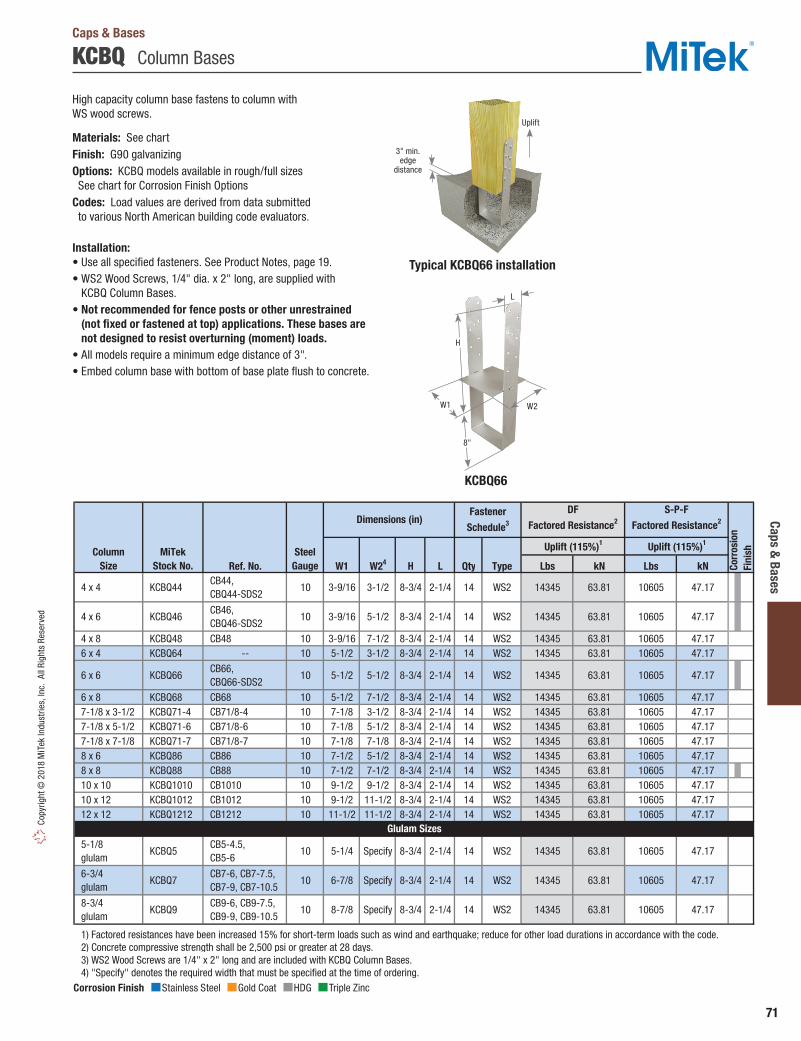
71
Caps & Bases
Copy
right
© 2
018
MiT
ek In
dust
ries,
Inc.
All
Righ
ts R
eser
ved
KCBQ Column Bases
Typical KCBQ66 installation
KCBQ66
High capacity column base fastens to column with WS wood screws.
Materials: See chartFinish: G90 galvanizingOptions: KCBQ models available in rough/full sizes See chart for Corrosion Finish OptionsCodes: Load values are derived from data submitted to various North American building code evaluators.
Installation:• Use all specified fasteners. See Product Notes, page 19.• WS2 Wood Screws, 1/4" dia. x 2" long, are supplied with
KCBQ Column Bases.• Not recommended for fence posts or other unrestrained
(not fixed or fastened at top) applications. These bases are not designed to resist overturning (moment) loads.
• All models require a minimum edge distance of 3".• Embed column base with bottom of base plate flush to concrete.
Ref. No. W1 W24 H L Qty Type Lbs kN Lbs kN
4 x 4 KCBQ44 CB44, CBQ44-SDS2
10 3-9/16 3-1/2 8-3/4 2-1/4 14 WS2 14345 63.81 10605 47.17
4 x 6 KCBQ46 CB46, CBQ46-SDS2
10 3-9/16 5-1/2 8-3/4 2-1/4 14 WS2 14345 63.81 10605 47.17
4 x 8 KCBQ48 CB48 10 3-9/16 7-1/2 8-3/4 2-1/4 14 WS2 14345 63.81 10605 47.17 6 x 4 KCBQ64 -- 10 5-1/2 3-1/2 8-3/4 2-1/4 14 WS2 14345 63.81 10605 47.17
6 x 6 KCBQ66 CB66, CBQ66-SDS2
10 5-1/2 5-1/2 8-3/4 2-1/4 14 WS2 14345 63.81 10605 47.17
6 x 8 KCBQ68 CB68 10 5-1/2 7-1/2 8-3/4 2-1/4 14 WS2 14345 63.81 10605 47.17 7-1/8 x 3-1/2 KCBQ71-4 CB71/8-4 10 7-1/8 3-1/2 8-3/4 2-1/4 14 WS2 14345 63.81 10605 47.17 7-1/8 x 5-1/2 KCBQ71-6 CB71/8-6 10 7-1/8 5-1/2 8-3/4 2-1/4 14 WS2 14345 63.81 10605 47.17 7-1/8 x 7-1/8 KCBQ71-7 CB71/8-7 10 7-1/8 7-1/8 8-3/4 2-1/4 14 WS2 14345 63.81 10605 47.17 8 x 6 KCBQ86 CB86 10 7-1/2 5-1/2 8-3/4 2-1/4 14 WS2 14345 63.81 10605 47.17 8 x 8 KCBQ88 CB88 10 7-1/2 7-1/2 8-3/4 2-1/4 14 WS2 14345 63.81 10605 47.17 10 x 10 KCBQ1010 CB1010 10 9-1/2 9-1/2 8-3/4 2-1/4 14 WS2 14345 63.81 10605 47.17 10 x 12 KCBQ1012 CB1012 10 9-1/2 11-1/2 8-3/4 2-1/4 14 WS2 14345 63.81 10605 47.17 12 x 12 KCBQ1212 CB1212 10 11-1/2 11-1/2 8-3/4 2-1/4 14 WS2 14345 63.81 10605 47.17
5-1/8 glulam
KCBQ5 CB5-4.5, CB5-6
10 5-1/4 Specify 8-3/4 2-1/4 14 WS2 14345 63.81 10605 47.17
6-3/4 glulam
KCBQ7 CB7-6, CB7-7.5, CB7-9, CB7-10.5
10 6-7/8 Specify 8-3/4 2-1/4 14 WS2 14345 63.81 10605 47.17
8-3/4 glulam
KCBQ9 CB9-6, CB9-7.5, CB9-9, CB9-10.5
10 8-7/8 Specify 8-3/4 2-1/4 14 WS2 14345 63.81 10605 47.17
1) Factored resistances have been increased 15% for short-term loads such as wind and earthquake; reduce for other load durations in accordance with the code. 2) Concrete compressive strength shall be 2,500 psi or greater at 28 days. 3) WS2 Wood Screws are 1/4" x 2" long and are included with KCBQ Column Bases. 4) "Specify" denotes the required width that must be specified at the time of ordering.
Glulam Sizes
DF
Factored Resistance2
S-P-F
Factored Resistance2Fastener
Schedule3Dimensions (in)
Corr
osio
nFi
nishColumn
SizeMiTek
Stock No.
Uplift (115%)1 Uplift (115%)1
Steel Gauge
Caps & Bases
Corrosion Finish Stainless Steel Gold Coat HDG Triple Zinc
Corrosion Finish Stainless Steel Gold Coat HDG Triple Zinc
Corrosion Finish Stainless Steel Gold Coat HDG Triple Zinc
3" min.edge
distance
Uplift
W2
8"
H
L
W1

72
Caps
& B
ases
Copyright © 2018 M
iTek Industries, Inc. All Rights Reserved
CBSQ Column Bases
These column bases install using WS2-EXT Wood Screws, reducing installation time and cost. Designed for high uplift in high wind or seismic applications. Includes a stand-off plate to protect the wood from ground contact moisture.
Materials: See chartFinish: G-185 galvanizingOptions: See chart for Corrosion Finish Options
Installation:• Use all specified fasteners. See Product Notes, page 19.• WS2-EXT Wood Screws, 1/4" dia. x 2" long, are supplied with CBSQ Bases.• Maintain 3" minimum edge distance between embedded tube and edge of concrete.• Embed the column base until the concrete surface meets the bottom edge
of the stand-off plate.• Not recommended for fence posts or other unrestrained (not fixed
or fastened at top) applications. These bases are not designed to resist overturning (moment) loads.
Typical CBSQ44-TZ installation
Ref. No. Strap Base W1 W2 H L Qty Type UnitLbs 9725 9895 8365 8510kN 43.26 44.02 37.21 37.86Lbs 19895 9895 17110 8510kN 88.50 44.02 76.11 37.86Lbs 23045 9895 19820 8510kN 102.51 44.02 88.17 37.86
1) Factored uplift resistances have been increased 15% for short-term loads such as wind and earthquake; reduce for other load durations in accordance with the code. 2) WS2-EXT Wood Screws are 1/4" x 2" and are included with CBSQ Column Bases. 3) Concrete compressive strength shall be 2,500 psi or greater at 28 days.
Corr
osio
nFi
nishColumn
SizeMiTek
Stock No.
Fastener
Schedule2Steel
GaugeDF Factored
Resistance3
S-P-F Factored
Resistance3Dimensions (in)
Bearing100%
Uplift
115%1Bearing 100%
Uplift
115%1
WS2-EXT
WS2-EXT
WS2-EXT
14
14
14
16
10 12
10 12
CBSQ44-SDS2
CBSQ46-SDS2
CBSQ66-SDS2
2-1/4
8-3/4 2-1/4
8-3/45-1/2 5-7/16 3
3-9/16
3-9/16 5-7/16
3-1/2 8-3/4104 x 4
4 x 6
6 x 6
CBSQ44-TZ
CBSQ46-TZ
CBSQ66-TZCorrosion Finish Stainless Steel Gold Coat HDG Triple Zinc
Corrosion Finish Stainless Steel Gold Coat HDG Triple Zinc
Corrosion Finish Stainless Steel Gold Coat HDG Triple Zinc
CBSQ46-TZ
Uplift
3" min. edge distance
1" standoff
Bearing
Caps & Bases
L
W2
W1
7-3/16"
H
1"

73
Caps & Bases
Copy
right
© 2
018
MiT
ek In
dust
ries,
Inc.
All
Righ
ts R
eser
ved
CBE Column Bases
12 gauge base for carports, patios, or other residential framing.
Materials: 12 gaugeFinish: G90 galvanizingCodes: Load values are derived from data submitted to various North American building code evaluators.
Installation:• Use all specified fasteners. See Product Notes, page 19.• Not recommended for fence posts or other unrestrained
(not fixed or fastened at top) applications. These bases are not designed to resist overturning (moment) loads.
• Bolted models feature diamond holes for temporary nail fastening to facilitate drilling and bolting.
• Embed column base with bottom of base plate flush to concrete.
Ref. No. W1 W2 H L Embedment 5 Qty Type Lbs kN Lbs kN2 1/2 6305 28.05 5420 24.1112 16d 4060 18.06 3490 15.522 1/2 6295 28.00 5415 24.0912 16d 4060 18.06 3490 15.522 1/2 6280 27.93 5400 24.0212 16d 4060 18.06 3490 15.52
1) Factored resistances have been increased 15% for short-term loads such as wind and earthquake; reduce for other load durations in accordance with the code. 2) All bolts shall meet or exceed the specifications of ASTM A 307. 3) Concrete compressive strength shall be 2,500 psi or greater at 28 days. 4) Factored resistances are based on the use of either nails or bolts; nail and bolt values cannot be combined. 5) CBE column base shall be embedded into concrete up to this depth. 6) NAILS: 16d nails are 0.162" dia. x 3-1/2" long. New products or updated product information are designated in blue font.
6-1/2
6-1/2
6-1/2
DF Factored Resistance
S-P-FFactored Resistance
Fastener
Schedule2,6Dimensions (in)
2
25-1/2 5-1/2 7-1/2
7-1/23-9/16 5-1/2
Column Size
MiTekStock No.
Uplift (115%)1,3,4 Uplift (115%)1,3,4
Steel Gauge
4 x 4 3-9/16 3-1/2 7-1/2 2 CBE44 LCB44 12
6 x 6 CBE66 LCB66 12
4 x 6 CBE46 LCB46 12
Caps & Bases
Typical CBEinstallation
CBE
1.5 x embedment (typical for all edges)
Uplift
3-3/16"
H
embedment
W1
W2
L
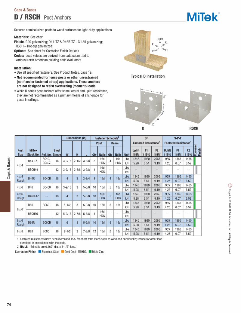
74
Caps
& B
ases
Copyright © 2018 M
iTek Industries, Inc. All Rights Reserved
Corrosion Finish Stainless Steel Gold Coat HDG Triple Zinc
Corrosion Finish Stainless Steel Gold Coat HDG Triple Zinc
Corrosion Finish Stainless Steel Gold Coat HDG Triple Zinc
Secures nominal sized posts to wood surfaces for light-duty applications.
Materials: See chartFinish: G90 galvanizing; D44-TZ & D46R-TZ - G-185 galvanizing; RSCH – Hot-dip galvanizedOptions: See chart for Corrosion Finish OptionsCodes: Load values are derived from data submitted to various North American building code evaluators.
Installation:• Use all specified fasteners. See Product Notes, page 19.• Not recommended for fence posts or other unrestrained
(not fixed or fastened at top) applications. These anchors are not designed to resist overturning (moment) loads.
• While D series post anchors offer some lateral and uplift resistance, they are not recommended as a primary means of anchorage for posts in railings.
D RSCH
D / RSCH Post Anchors
Ref. No. W H L Qty Nails Qty Nails UnitLbs 1345 1920 2065 955 1365 1465kN 5.98 8.54 9.19 4.25 6.07 6.52LbskNLbs 1345 1920 2065 955 1365 1465kN 5.98 8.54 9.19 4.25 6.07 6.52Lbs 1345 1920 2065 955 1365 1465kN 5.98 8.54 9.19 4.25 6.07 6.52Lbs 1345 1920 2065 955 1365 1465kN 5.98 8.54 9.19 4.25 6.07 6.52Lbs 1345 1920 2065 955 1365 1465kN 5.98 8.54 9.19 4.25 6.07 6.52LbskNLbs 1345 1920 2065 955 1365 1465kN 5.98 8.54 9.19 4.25 6.07 6.52Lbs 1345 1920 2065 955 1365 1465kN 5.98 8.54 9.19 4.25 6.07 6.52
1) Factored resistances have been increased 15% for short-term loads such as wind and earthquake; reduce for other load durations in accordance with the code. 2) NAILS: 16d nails are 0.162" dia. x 3-1/2" long.
-- -- -- -- -- --
Corr
osio
nFi
nishMiTek
Stock No.Steel
Gauge
Dimensions (in)
PostSize
Post
Fastener Schedule2
Beam
3-3/8 816d HDG
416d HDG
D44-TZ BC40, BC40Z
18 3-9/16 2-1/2
DF
Factored Resistance1
S-P-F
Factored Resistance1
Uplift115%
F1115%
F2115%
Uplift115%
F1115%
F2115%
6 x 6 Rough
8 x 8
RSCH44
D44R
D46
D46R-TZ
D66
RSCH66
D66R
D88
4 x 4
4 x 4 Rough
4 x 6
4 x 6 Rough
6 x 6
3-9/16
4 3
2-5/8 3-3/8
3-3/4
--
BC60R
BC80
12
18
18
18
18
12
18
18
--
BC40R
BC460
--
BC60
6 3
3
5-1/2
5-9/16 2-7/8
8 16d
16dHDG
16d
1016d HDG
7-1/2
3-9/16 3
3
3
4
7-3/8
5-3/8
5-3/8
5-3/8
5-3/8
5-3/8
12 16d 5 16d
10
4 16d
416dHDG
-- -- -- -- -- -- ----
5 16d
4 -- --
10 16d 5 16d
516d HDG
10 16d 5 16d
Typical D installation
Caps & Bases
H
W
L
F1
F1
F2
F2
Uplift

75
Caps & Bases
Copy
right
© 2
018
MiT
ek In
dust
ries,
Inc.
All
Righ
ts R
eser
ved
EPCM / PCM Post Caps
PCM – Provides a positive connection for medium-duty, post-to-beam applications.
EPCM – End column caps.
Materials: See chartFinish: G90 galvanizingOptions: See chart for Corrosion Finish OptionsCodes: Load values are derived from data submitted to various North American building code evaluators.
Installation:• Use all specified fasteners. See Product Notes, page 19.• PCM 16 gauge post caps should not be substituted for PCM 12
gauge post caps unless approved by the Engineer of Record.
Qty Type Qty Type PCM_16 PC_16 16 8 16d 12 16d PCM PC 12 8 16d 12 16d EPCM_16 EPC_16 16 8 16d 8 16d EPCM EPC 12 8 16d 8 16d
1) NAILS: 16d nails are 0.162" dia. x 3-1/2" long.
Ref. No. Beam Post W1 W2 H1 L1 L2 Uplift F1 F2 Uplift F1 F2 Uplift F1 F2 Uplift F1 F2
PCM4416 PC44-16 4x 4x 3-9/16 3-9/16 3-9/16 2-7/16 11 1140 1345 1530 5.07 5.98 6.81 960 1130 1285 4.27 5.03 5.72 PCM44 PC44 4x 4x 3-9/16 3-9/16 3-9/16 2-7/16 11 1965 1600 1915 8.74 7.12 8.52 1650 1345 1610 7.34 5.98 7.16 PCM46 PC46 4x 6x 3-9/16 5-9/16 3-9/16 2-7/16 13 1965 1600 1915 8.74 7.12 8.52 1650 1345 1610 7.34 5.98 7.16 PCM4616 PC46-16 4x 6x 3-9/16 5-9/16 3-9/16 2-7/16 13 1140 1345 1530 5.07 5.98 6.81 960 1130 1285 4.27 5.03 5.72 PCM4816 PC48-16 4x 8x 3-9/16 7-9/16 3-9/16 2-7/16 15 1140 1345 1530 5.07 5.98 6.81 960 1130 1285 4.27 5.03 5.72 PCM48 PC48 4x 8x 3-9/16 7-9/16 3-9/16 2-7/16 15 1965 1600 1915 8.74 7.12 8.52 1650 1345 1610 7.34 5.98 7.16 PCM6416 PC64-16 6x 4x 5-1/2 3-9/16 3-1/2 3-13/16 11 1160 1825 1825 5.16 8.12 8.12 975 1535 1535 4.34 6.83 6.83 PCM64 PC64 6x 4x 5-1/2 3-9/16 3-1/2 3-13/16 11 1860 2190 1970 8.27 9.74 8.76 1560 1840 1655 6.94 8.19 7.36 PCM6616 PC66-16 6x 6x 5-1/2 5-9/16 3-1/2 3-13/16 13 1160 1825 1825 5.16 8.12 8.12 975 1535 1535 4.34 6.83 6.83 PCM66 PC66 6x 6x 5-1/2 5-9/16 3-1/2 3-13/16 13 1860 2190 1970 8.27 9.74 8.76 1560 1840 1655 6.94 8.19 7.36 PCM6816 -- 6x 8x 5-1/2 7-9/16 3-1/2 3-13/16 15 1160 1825 1825 5.16 8.12 8.12 975 1535 1535 4.34 6.83 6.83 PCM68 PC68 6x 8x 5-1/2 7-9/16 3-1/2 3-13/16 15 1860 2190 1970 8.27 9.74 8.76 1560 1840 1655 6.94 8.19 7.36 PCM77 -- 7-1/8 7-1/8 7-1/8 7-1/8 3-11/16 5-5/8 14-9/16 1860 2190 1970 8.27 9.74 8.76 1560 1840 1655 6.94 8.19 7.36 PCM8416 -- 8x 4x 7-1/2 3-9/16 3-1/2 5-5/8 11 1160 1825 1825 5.16 8.12 8.12 975 1535 1535 4.34 6.83 6.83 PCM84 PC84 8x 4x 7-1/2 3-9/16 3-1/2 5-5/8 11 1860 2190 1970 8.27 9.74 8.76 1560 1840 1655 6.94 8.19 7.36 PCM8616 -- 8x 6x 7-1/2 5-9/16 3-3/8 5-5/8 13 1160 1825 1825 5.16 8.12 8.12 975 1535 1535 4.34 6.83 6.83 PCM86 PC86 8x 6x 7-1/2 5-9/16 3-1/2 5-5/8 13 1860 2190 1970 8.27 9.74 8.76 1560 1840 1655 6.94 8.19 7.36 PCM8816 -- 8x 8x 7-1/2 7-9/16 3-1/2 5-5/8 15 1160 1825 1825 5.16 8.12 8.12 975 1535 1535 4.34 6.83 6.83 PCM88 PC88 8x 8x 7-1/2 7-9/16 3-1/2 5-5/8 15 1860 2190 1970 8.27 9.74 8.76 1560 1840 1655 6.94 8.19 7.36
EPCM4416 EPC44-16 4x 4x 3-9/16 3-9/16 3-9/16 2-7/16 7-1/4 1140 1345 1530 5.07 5.98 6.81 960 1130 1285 4.27 5.03 5.72 EPCM44 EPC44 4x 4x 3-9/16 3-9/16 3-9/16 2-7/16 7-1/4 1965 1600 1915 8.74 7.12 8.52 1650 1345 1610 7.34 5.98 7.16 EPCM46 EPC46 4x 6x 3-9/16 5-9/16 3-9/16 2-7/16 9-1/4 1965 1600 1915 8.74 7.12 8.52 1650 1345 1610 7.34 5.98 7.16 EPCM4616 EPC46-16 4x 6x 3-9/16 5-9/16 3-9/16 2-7/16 9-1/4 1140 1345 1530 5.07 5.98 6.81 960 1130 1285 4.27 5.03 5.72 EPCM4816 EPC48-16 4x 8x 3-9/16 7-9/16 3-9/16 2-7/16 11-1/4 1140 1345 1530 5.07 5.98 6.81 960 1130 1285 4.27 5.03 5.72 EPCM48 EPC48 4x 8x 3-9/16 7-9/16 3-9/16 2-7/16 11-1/4 1965 1600 1915 8.74 7.12 8.52 1650 1345 1610 7.34 5.98 7.16 EPCM6416 EPC64-16 6x 4x 5-1/2 3-9/16 3-1/2 3-13/16 7-1/4 1160 1825 1825 5.16 8.12 8.12 975 1535 1535 4.34 6.83 6.83 EPCM64 EPC64 6x 4x 5-1/2 3-9/16 3-1/2 3-13/16 7-1/4 1860 1970 1970 8.27 8.76 8.76 1560 1655 1655 6.94 7.36 7.36 EPCM6616 EPC66-16 6x 6x 5-1/2 5-9/16 3-1/2 3-13/16 9-1/4 1160 1825 1825 5.16 8.12 8.12 975 1535 1535 4.34 6.83 6.83 EPCM66 EPC66 6x 6x 5-1/2 5-9/16 3-1/2 3-13/16 9-1/4 1860 1970 1970 8.27 8.76 8.76 1560 1655 1655 6.94 7.36 7.36 EPCM6816 -- -- 6x 8x 5-1/2 7-9/16 3-1/2 3-13/16 11-1/4 1160 1825 1825 5.16 8.12 8.12 975 1535 1535 4.34 6.83 6.83 EPCM68 EPC68 6x 8x 5-1/2 7-9/16 3-1/2 3-13/16 11-1/4 1860 1970 1970 8.27 8.76 8.76 1560 1655 1655 6.94 7.36 7.36 EPCM77 -- 7-1/8 7-1/8 7-1/8 7-1/8 3-11/16 5-5/8 10-13/16 1860 1970 1970 8.27 8.76 8.76 1560 1655 1655 6.94 7.36 7.36 EPCM8416 -- 8x 4x 7-1/2 3-9/16 3-1/2 5-5/8 7-1/4 1160 1825 1825 5.16 8.12 8.12 975 1535 1535 4.34 6.83 6.83 EPCM84 EPC84 8x 4x 7-1/2 3-9/16 3-1/2 5-5/8 7-1/4 1860 1970 1970 8.27 8.76 8.76 1560 1655 1655 6.94 7.36 7.36 EPCM8616 -- 8x 6x 7-1/2 5-9/16 3-3/8 5-5/8 9-1/4 1160 1825 1825 5.16 8.12 8.12 975 1535 1535 4.34 6.83 6.83 EPCM86 EPC86 8x 6x 7-1/2 5-9/16 3-1/2 5-5/8 9-1/4 1860 1970 1970 8.27 8.76 8.76 1560 1655 1655 6.94 7.36 7.36 EPCM8816 -- 8x 8x 7-1/2 7-9/16 3-1/2 5-5/8 11-1/4 1160 1825 1825 5.16 8.12 8.12 975 1535 1535 4.34 6.83 6.83 EPCM88 EPC88 8x 8x 7-1/2 7-9/16 3-1/2 5-5/8 11-1/4 1860 1970 1970 8.27 8.76 8.76 1560 1655 1655 6.94 7.36 7.36
1) Factored resistances have been increased 15% for short-term loads such as wind and earthquake; reduce for other load durations in accordance with the code.
End Column Caps
Centre Column Caps
Fastener Schedule1
Steel Gauge
MiTekSeries
Post
kN Lbs kN
Beam
MiTekStock No.
Lbs
Ref. Series
DFFactored Resistance (115%)1
S-P-FFactored Resistance (115%)1Dimensions (in)
Corr
osio
nFi
nish
Typical PCM46 center cap installation PCM
Typical EPCM end cap installation EPCML1
W2
H1
W1L2
3-3/4"
W1
W2L1
L2 H1
3-3/4"
Caps & Bases
Corrosion Finish Stainless Steel Gold Coat HDG Triple Zinc
Corrosion Finish Stainless Steel Gold Coat HDG Triple Zinc
Corrosion Finish Stainless Steel Gold Coat HDG Triple Zinc
F2
F2
F1
F1
Uplift
F2
F2
F1
F1
Uplift
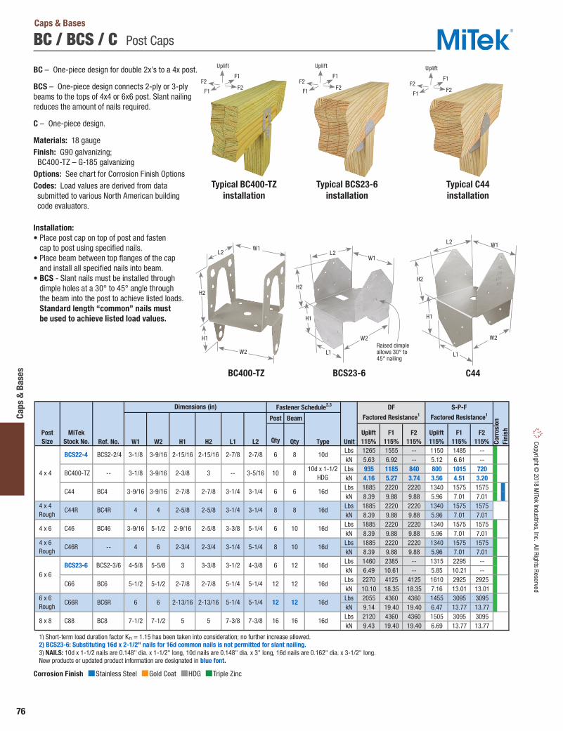
76
Caps
& B
ases
Copyright © 2018 M
iTek Industries, Inc. All Rights Reserved
Corrosion Finish Stainless Steel Gold Coat HDG Triple Zinc
Corrosion Finish Stainless Steel Gold Coat HDG Triple Zinc
Corrosion Finish Stainless Steel Gold Coat HDG Triple Zinc
BC / BCS / C Post Caps
BC – One-piece design for double 2x’s to a 4x post.
BCS – One-piece design connects 2-ply or 3-ply beams to the tops of 4x4 or 6x6 post. Slant nailing reduces the amount of nails required.
C – One-piece design.
Materials: 18 gaugeFinish: G90 galvanizing; BC400-TZ – G-185 galvanizingOptions: See chart for Corrosion Finish OptionsCodes: Load values are derived from data submitted to various North American building code evaluators.
Installation:• Place post cap on top of post and fasten
cap to post using specified nails. • Place beam between top flanges of the cap
and install all specified nails into beam.• BCS - Slant nails must be installed through
dimple holes at a 30° to 45° angle through the beam into the post to achieve listed loads. Standard length “common” nails must be used to achieve listed load values.
Post Beam
Ref. No. W1 W2 H1 H2 L1 L2 Qty Qty Type UnitLbs 1265 1555 -- 1150 1485 --kN 5.63 6.92 -- 5.12 6.61 --Lbs 935 1185 840 800 1015 720kN 4.16 5.27 3.74 3.56 4.51 3.20Lbs 1885 2220 2220 1340 1575 1575kN 8.39 9.88 9.88 5.96 7.01 7.01Lbs 1885 2220 2220 1340 1575 1575kN 8.39 9.88 9.88 5.96 7.01 7.01Lbs 1885 2220 2220 1340 1575 1575kN 8.39 9.88 9.88 5.96 7.01 7.01Lbs 1885 2220 2220 1340 1575 1575kN 8.39 9.88 9.88 5.96 7.01 7.01Lbs 1460 2385 -- 1315 2295 --kN 6.49 10.61 -- 5.85 10.21 --Lbs 2270 4125 4125 1610 2925 2925kN 10.10 18.35 18.35 7.16 13.01 13.01Lbs 2055 4360 4360 1455 3095 3095kN 9.14 19.40 19.40 6.47 13.77 13.77Lbs 2120 4360 4360 1505 3095 3095kN 9.43 19.40 19.40 6.69 13.77 13.77
1) Short-term load duration factor KD = 1.15 has been taken into consideration; no further increase allowed. 2) BCS23-6: Substituting 16d x 2-1/2" nails for 16d common nails is not permitted for slant nailing. 3) NAILS: 10d x 1-1/2 nails are 0.148" dia. x 1-1/2" long, 10d nails are 0.148" dia. x 3" long, 16d nails are 0.162" dia. x 3-1/2" long. New products or updated product information are designated in blue font.
10
6 12 16d4-5/8 5-5/8 3 3-3/8 3-1/2 4-3/8
2-3/4 5-1/4
3-9/16 2-9/165-1/2
C44
BCS2-3/6 BCS23-6 6 x 6
PostSize Co
rros
ion
Fini
sh
Dimensions (in)
MiTekStock No.
Fastener Schedule2,3
Uplift115%
F1115%
F2115%
DF Factored Resistance1
S-P-F Factored Resistance1
C44R
C46
C46R
C66
2-7/8 10d
6 6 16d
3-5/16
6 x 6 Rough
8 x 8
6 8
8 8
8 10
12 12
BCS2-2/4
BC4
4 x 4
4 x 4 Rough
4 x 6
4 x 6 Rough
12
BC8
BCS22-4
BC400-TZ -- 3-1/8 3-9/16
3-1/4
C66R
C88
BC4R
BC46
--
BC6
BC6R 16d
16 16 16d
16d
12 16d
16d
6 10 16d
5-1/4 5-1/4
2-5/8 3-3/8 5-1/4
3-1/4
F2115%
2-5/8 2-5/8 3-1/4 3-1/4
3-9/16 3-9/16 2-7/8 2-7/8 3-1/4
2-3/8 3 -- 810d x 1-1/2
HDG
3-1/8 3-9/16 2-15/16 2-15/16 2-7/8
Uplift115%
F1115%
4 4
7-3/8 7-3/8
2-3/4
2-7/85-1/2 5-1/2
4 6
6 6 2-13/16 2-13/16
7-1/2 7-1/2 5 5
2-7/8 5-1/4 5-1/4
Caps & Bases
Typical C44 installation
Typical BC400-TZ installation
Typical BCS23-6 installation
C44BC400-TZ BCS23-6
W2
W1L2
H2
H1Raised dimple allows 30° to 45° nailing
H1
H2
L2
L1
W1
W2
W1
W2
L2
L1
H2
H1
F1
F1
F2F2
Uplift
F1
F1
F2F2
Uplift
F1
F1
F2F2
Uplift

77
Caps & Bases
Copy
right
© 2
018
MiT
ek In
dust
ries,
Inc.
All
Righ
ts R
eser
ved
PB / PBES / PBS Post Caps
PB – Two-piece design.
PBES / PBS – Two-piece design with extended side plates and wrap around post design. Easy retrofit installations.
Materials: 18 gaugeFinish: G90 galvanizing; PB44-6TZ & PB66-6TZ – G-185 galvanizingOptions: See chart for Corrosion Finish OptionsCodes: Load values are derived from data submitted to various North American building code evaluators.
Installation:• Use all specified fasteners. See Product Notes, page 19.• These products are designed for single, solid-sawn beams
with matching post width. Multi-ply beams must have same width as post. Use shims as required.
• PB, PBES, PBS post caps are sold per piece and are to be installed in pairs to achieve factored resistances.
Ref. No. W H1 H2 L1 L2 Qty Type Qty Type UnitLbs 1210 1885 665 855 1340 470kN 5.38 8.39 2.96 3.80 5.96 2.09Lbs 5850 3800 2250 4150 2695 1600kN 26.02 16.90 10.01 18.46 11.99 7.12Lbs 4150 1915 1050 2950 1355 745kN 18.46 8.52 4.67 13.12 6.03 3.31Lbs 4150 1915 1050 2950 1355 745kN 18.46 8.52 4.67 13.12 6.03 3.31Lbs 1210 1885 665 855 1340 470kN 5.38 8.39 2.96 3.80 5.96 2.09Lbs 3480 2400 1685 2475 1700 1195kN 15.48 10.68 7.50 11.01 7.56 5.32Lbs 4295 3785 2190 3045 2685 1560kN 19.11 16.84 9.74 13.55 11.94 6.94Lbs 3480 2400 1685 2475 1700 1195kN 15.48 10.68 7.50 11.01 7.56 5.32
1) Factored resistances have been increased 15% for short-term loads such as wind and earthquake; reduce for other load durations in accordance with the code. 2) Factored resistances and nail schedules for two-piece models are per pair of post caps. 3) NAILS: 16d nails are 0.162" dia. x 3-1/2" long.
LPC4Z
LPC6Z
ACE4, LCE4
ACE6
AC4
AC4R
AC6
AC6R
2-3/4
2-1/8
3
2-5/16
2-5/16
2-3/16
2-3/16
1-1/2
1-1/4
1-1/2 2-1/8 1-1/2 --
1-1/2 2-1/2
1-1/2 2-3/8
1-1/2 2-3/8
1-7/16 2-5/16 2-13/16 3-9/16
2-5/16 4
3-1/4
5-1/2
--
6 x 6 Rough
14 16d 12 16d
10 16d 10 16d
PBS66
PBS66R
6 x 6
1-1/4 8-1/2
5-9/16
7
82-7/8 5-1/2
6
PBES66
PBS44
PBS44R
8 16d 8 16d
8 16d 8 16d
16d7
6-1/2
4-3/4
PostSize
DF Factored
Resistance1,2
S-P-F Factored
Resistance1,2
8
816dHDG
816dHDG
16d HDG
816d HDG
3-5/8 PB44-6TZ
PB66-6TZ
12 16d 12 16d
8 16d 8
PBES44
4 x 4 Rough
4 x 4
Corr
osio
nFi
nish
Dimensions (in)
MiTekStock No.
Post Beam
Fastener Schedule2,3
Uplift115%
F1115%
F2115%
Uplift115%
F1115%
F2115%
Corrosion Finish Stainless Steel Gold Coat HDG Triple Zinc
Corrosion Finish Stainless Steel Gold Coat HDG Triple Zinc
Corrosion Finish Stainless Steel Gold Coat HDG Triple Zinc
Typical PBS installation
PBS
Typical PBESinstallation
PBES
Typical PB-TZinstallation
PB44-6TZ
L2
W
H2
H1
L1
W1
L2
H2
H1
Caps & Bases
L1
W
L2
H2
H1
These seamless caps keep water off post tops, protecting wood from moisture damage. The PCP’s plastic construction is corrosion-proof and paintable. Not available in rough or full lumber sizes.
Materials: Hi-impact plasticFinish: Gray
Installation:• Fasten cap to post top with (1) 8d HDG or 10d HDG nail.
PCP Plastic Post Caps
Dimension (in)
Ref. No. W Color 4 x 4 PCP44 DPPC4BK 3-5/8 Gray 6 x 6 PCP66 DPPC6BK 5-5/8 Gray
1) Not available in rough or full lumber sizes.
Post/Column
Size1MiTek
Stock No.PCP66Typical PCP44
installation
W W
F2F2
Uplift
F1
F1
F2F2
Uplift
F1
F1
F2F2
Uplift
F1
F1

78
Caps
& B
ases
Copyright © 2018 M
iTek Industries, Inc. All Rights Reserved
PBC Post Beam Corner Connectors
The PBC series is a one-piece connector designed to secure two mitered beams on a corner post while providing uplift capacity.
Materials: 18 gaugeFinish: G-185 galvanizing
Installation:• Use all specified fasteners. See Product Notes, page 19.• Install PBC on outside corner of post forming tabs to inner side of post.• Assumes beam members are bevel cut at corner.
The CPB is made of corrosion resistant composite material compatible with preservative treated lumber. Provides code required 1" stand-off and can be used with rough lumber sizes.
Materials: High Strength composite
Installation:• Attach base to post with (4) 10d HDG nails.• Attach post to concrete using 1/2" diameter rod into concrete and
extend into wood member.• Not recommended for fence posts or other unrestrained (not fixed
or fastened at top) applications. These anchors are not designed to resist overturning (moment) loads.
Typical PBCinstallation PBC
CPB
Ref. No. W L Qty Type Qty Type UnitLbs 1800 900 900 1555 775 775kN 8.01 4.00 4.00 6.92 3.45 3.45Lbs 1800 900 900 1555 775 775kN 8.01 4.00 4.00 6.92 3.45 3.45
1) Factored resistances have been increased 15% for short-term loads such as wind and earthquake; reduce for other load durations in accordance with the code. 2) NAILS: 16d nails are 0.162" dia. x 3-1/2" long.
DF
Factored Resistance1
S-P-F
Factored Resistance1
PostSize
MiTekStock No.
SteelGauge
Dimensions (in) Fastener Schedule2
Post Beam
F1115%
F2115%
Uplift115%
F1115%
F2115%
Uplift115%
8 16d HDG 8 16d HDG
16d HDG 8 16d HDG
Corr
osio
nFi
nish
4 x 4
6 x 6
6-1/2
6-15/16 6-1/2
PBC44-TZ
PBC66-TZ
-- 18
-- 18
4-15/16 8
CPB Composite Post Bases
Ref. No. W1 W2 Qty Type Lbs kN Lbs kN 4 x 4 CPB44 CPS4 3-1/4 3-1/4 2.2 4 10d HDG 5235 23.29 6545 29.11 4 x 6 CPB46 CPS46 3-5/16 5-5/16 3.3 4 10d HDG 6810 30.29 9820 43.68 5 x 5 CPB55 CPS5 4-1/8 4-1/8 3.0 4 10d HDG 6295 28.00 8925 39.70 6 x 6 CPB66 CPS6 5-5/16 5-5/16 3.9 4 10d HDG 8570 38.12 11600 51.60 8 x 8 CPB88 CPS7 7-1/4 7-1/4 6.4 4 10d HDG 12490 55.56 19040 84.70
1) Loads shall not be increased for short-term loading. 2) Loads require a minimum 650 psi wood compressive strength. 3) Concrete Design Bearing Strength = Ø (0.85 f'C A1) with f'C = 2,500 psi. ACI 318-02, Section 10.17.1. 4) Design Bearing Strength has been increased assuming (A2 / A1)
0.5 per ACI 318-02, Section 10.17.1. 5) NAILS: 10d nails are 0.148" dia. x 3" long.
Post Size
Factored
Resistance1,2
Concrete Bearing
Strength3,4
BottomSurfaceBearing
AreaMiTek
Stock No.
Dimensions (in) Fastener
Schedule5
W1
W2
1"
Typical CPBinstallation
Caps & Bases
Corrosion Finish Stainless Steel Gold Coat HDG Triple Zinc
Corrosion Finish Stainless Steel Gold Coat HDG Triple Zinc
Corrosion Finish Stainless Steel Gold Coat HDG Triple Zinc
F2F2
Uplift
F1
F1
W
L
W

79
Caps & Bases
Copy
right
© 2
018
MiT
ek In
dust
ries,
Inc.
All
Righ
ts R
eser
ved
KCCQ / KECCQ Column Caps
Designed to be installed without the need to drill bolt holes, simplifying installation and maintaining the wood cross section. Installs with WS Wood Screws offering high uplift capacity.
KCCQ — Standard column cap.
KECCQ — End column cap.
Materials: See chartFinish: PrimerOptions: See chart for Corrosion Finish Options and Specialty Options on page 81.Codes: Load values are derived from data submitted to various North American building code evaluators.
Installation:• Use all specified fasteners. See Product Notes, page 19.• WS3 Wood Screws, 1/4" dia. x 3" long, are supplied with
Column Caps.• Beams shall be designed to support the required loads.
Beam shear may limit loads to less than listed loads for device. A design professional shall determine the adequacy of the stud to resist published loads.
Ref. No. W1 W2 H L Qty Type Qty Type Lbs kN Lbs kN Lbs kN Lbs kN
KCCQ325-4 CCQ3-4SDS2.5 7 3-1/4 3-5/8 6-1/2 11 16 WS3 14 WS3 30940 137.63 12920 57.47 21040 93.59 9170 40.79 KCCQ325-6 CCQ3-6SDS2.5 7 3-1/4 5-1/2 6-1/2 11 16 WS3 14 WS3 30940 137.63 12920 57.47 21040 93.59 9170 40.79 KCCQ44 CCQ44SDS2.5 7 3-5/8 3-5/8 6-1/2 11 16 WS3 14 WS3 34655 154.16 12575 55.94 23565 104.83 8930 40.79 KCCQ45 -- 7 3-5/8 5-3/8 6-1/2 11 16 WS3 14 WS3 34655 154.16 12575 55.94 23565 104.83 8930 40.79 KCCQ46 CCQ46SDS2.5 7 3-5/8 5-1/2 6-1/2 11 16 WS3 14 WS3 34655 154.16 12920 57.47 23565 104.83 9170 40.79 KCCQ47 -- 7 3-5/8 7-1/8 6-1/2 11 16 WS3 14 WS3 34655 154.16 12575 55.94 23565 104.83 8930 40.79 KCCQ47X -- 7 3-5/8 7-1/8 6-1/2 13 16 WS3 14 WS3 40955 182.18 12575 55.94 27850 123.89 8930 40.79 KCCQ48 CCQ48SDS2.5 7 3-5/8 7-1/2 6-1/2 11 16 WS3 14 WS3 34655 154.16 12920 57.47 23565 104.83 9170 40.79 KCCQ525-4 CCQ5-4SDS2.5 3 5-1/4 3-5/8 8 13 16 WS3 14 WS3 59960 266.73 12920 57.47 40775 181.38 9170 40.79 KCCQ525-6 CCQ5-6SDS2.5 3 5-1/4 5-1/2 8 13 16 WS3 14 WS3 59960 266.73 12920 57.47 40775 181.38 9170 40.79 KCCQ525-8 CCQ5-8SDS2.5 3 5-1/4 7-1/2 8 13 16 WS3 14 WS3 59960 266.73 12920 57.47 40775 181.38 9170 40.79 KCCQ57 -- 7 5-3/8 7-1/8 6-1/2 11 16 WS3 14 WS3 51975 231.21 12920 57.47 35345 157.23 9170 40.79 KCCQ64 CCQ64SDS2.5 7 5-1/2 3-5/8 6-1/2 11 16 WS3 14 WS3 54455 242.24 12920 57.47 37030 164.72 9170 40.79 KCCQ66 CCQ66SDS2.5 7 5-1/2 5-1/2 6-1/2 11 16 WS3 14 WS3 49125 218.52 12920 57.47 37205 165.50 10850 48.26 KCCQ67X CCQ6-7.13SDS2.5 7 5-1/2 7-1/8 6-1/2 11 16 WS3 14 WS3 54455 242.24 12920 57.47 37030 164.72 9170 40.79 KCCQ68 CCQ68SDS2.5 7 5-1/2 7-1/2 6-1/2 11 16 WS3 14 WS3 54455 242.24 12920 57.47 37030 164.72 9170 40.79
1) Factored resistances have been increased 15% for short-term loads such as wind and earthquake; reduce for other load durations in accordance with the code. 2) Bearing loads are based on compression perpendicular to grain values published in the 2001 NDS and soft converted to Limit States Design. 3) Factored resistances are based on lumber with a specific gravity of DF = 0.49 and S-P-F = 0.42 and a moisture content of 19% or less. 4) WS3 Wood Screws are 1/4" x 3" long and are included with KCCQ and KECCQ column caps. 5) Beams shall be designed to support the required loads. Beam shear may limit loads to less than listed loads for device. 6) The designer shall check post for required loads. 7) Spliced conditions must be detailed by the specifier to transfer tension loads between spliced members by means other than the column cap. 8) Uplift loads do not apply to splice conditions.
Ref. No. W1 W2 H L Qty Type Qty Type Lbs kN Lbs kN Lbs kN Lbs kN
KCCQ74 CCQ74SDS2.5 3 6-7/8 3-5/8 6-1/2 11 16 WS3 14 WS3 66825 297.26 12920 57.47 45440 202.14 9170 40.79 KCCQ76 CCQ76SDS2.5 3 6-7/8 5-1/2 6-1/2 11 16 WS3 14 WS3 66825 297.26 12920 57.47 45440 202.14 9170 40.79 KCCQ77 CCQ77SDS2.5 3 6-7/8 6-7/8 6-1/2 11 16 WS3 14 WS3 66825 297.26 12920 57.47 45440 202.14 9170 40.79 KCCQ78 CCQ78SDS2.5 3 6-7/8 7-1/2 6-1/2 11 16 WS3 14 WS3 66825 297.26 12920 57.47 45440 202.14 9170 40.79 KCCQ71-4 CCQ7.1-4SDS2.5 3 7-1/8 3-5/8 6-1/2 11 16 WS3 14 WS3 69300 308.27 12920 57.47 47125 209.63 9170 40.79 KCCQ71-6 CCQ7.1-6SDS2.5 3 7-1/8 5-1/2 6-1/2 11 16 WS3 14 WS3 69300 308.27 12920 57.47 47125 209.63 9170 40.79 KCCQ71-71 CCQ7.1-7.1SDS2.5 3 7-1/8 7-1/8 6-1/2 11 16 WS3 14 WS3 69300 308.27 12920 57.47 47125 209.63 9170 40.79 KCCQ71-8 CCQ7.1-8SDS2.5 3 7-1/8 7-1/2 6-1/2 11 16 WS3 14 WS3 69300 308.27 12920 57.47 47125 209.63 9170 40.79 KCCQ84 -- 7 7-1/2 3-5/8 6-1/2 11 16 WS3 14 WS3 74255 330.32 12920 57.47 50495 224.62 9170 40.79 KCCQ86 CCQ86SDS2.5 7 7-1/2 5-1/2 6-1/2 11 16 WS3 14 WS3 66990 297.98 12920 57.47 50735 225.68 10850 48.26 KCCQ88 CCQ88SDS2.5 7 7-1/2 7-1/2 6-1/2 11 16 WS3 14 WS3 74255 330.32 12920 57.47 50495 224.62 9170 40.79 KCCQ94 -- 7 8-7/8 3-5/8 6-1/2 11 16 WS3 14 WS3 86625 385.34 12920 57.47 58905 262.03 9170 40.79 KCCQ96 CCQ96SDS2.5 7 8-7/8 5-1/2 6-1/2 11 16 WS3 14 WS3 86625 385.34 12920 57.47 58905 262.03 9170 40.79 KCCQ98 CCQ98SDS2.5 7 8-7/8 7-1/2 6-1/2 11 16 WS3 14 WS3 86625 385.34 12920 57.47 58905 262.03 9170 40.79 KCCQ106 CCQ106SDS2.5 7 9-1/2 5-1/2 6-1/2 11 16 WS3 14 WS3 94055 418.39 12920 57.47 63960 284.52 9170 40.79
KECCQ325-4 ECCQ3-4SDS2.5 7 3-1/4 3-5/8 6-1/2 7-1/2 16 WS3 14 WS3 21095 93.84 11785 52.42 14340 63.79 8370 40.79 KECCQ325-6 ECCQ3-6SDS2.5 7 3-1/4 5-1/2 6-1/2 7-1/2 16 WS3 14 WS3 21095 93.84 11785 52.42 14340 63.79 8370 40.79 KECCQ44 ECCQ44SDS2.5 7 3-5/8 3-5/8 6-1/2 8-1/2 16 WS3 14 WS3 24430 108.67 13385 59.54 18210 81.01 9505 40.79 KECCQ45 -- 7 3-5/8 5-3/8 6-1/2 7-1/2 16 WS3 14 WS3 23625 105.09 13385 59.54 16065 71.46 9505 40.79 KECCQ46 ECCQ46SDS2.5 7 3-5/8 5-1/2 6-1/2 8-1/2 16 WS3 14 WS3 26775 119.11 11785 52.42 18210 81.01 8370 40.79 KECCQ47 -- 7 3-5/8 7-1/8 6-1/2 9-1/2 16 WS3 14 WS3 29925 133.12 13385 59.54 20345 90.50 9505 40.79 KECCQ47X -- 7 3-5/8 7-1/8 6-1/2 9-1/2 16 WS3 14 WS3 29925 133.12 13385 59.54 20345 90.50 9505 40.79 KECCQ48 ECCQ48SDS2.5 7 3-5/8 7-1/2 6-1/2 8-1/2 16 WS3 14 WS3 26775 119.11 11785 52.42 18210 81.01 8370 40.79 KECCQ525-4 ECCQ5-4SDS2.5 3 5-1/4 3-5/8 8 9-1/2 16 WS3 14 WS3 32155 143.04 11785 52.42 24350 108.32 8370 40.79 KECCQ525-6 ECCQ5-6SDS2.5 3 5-1/4 5-1/2 8 9-1/2 16 WS3 14 WS3 39310 174.87 11785 52.42 28985 128.94 8370 40.79 KECCQ525-8 ECCQ5-8SDS2.5 3 5-1/4 7-1/2 8 9-1/2 16 WS3 14 WS3 43820 194.93 11785 52.42 29795 132.54 8370 40.79 KECCQ57 -- 7 5-3/8 7-1/8 6-1/2 9-1/2 16 WS3 14 WS3 40160 178.65 11785 52.42 27310 121.49 8370 40.79 KECCQ64 ECCQ64SDS2.5 7 5-1/2 3-5/8 6-1/2 8-1/2 16 WS3 14 WS3 33890 150.76 11785 52.42 25605 113.90 8370 40.79 KECCQ66 ECCQ66SDS2.5 7 5-1/2 5-1/2 6-1/2 8-1/2 16 WS3 14 WS3 41630 185.19 11785 52.42 28615 127.29 8370 40.79 KECCQ67X ECCQ6-7.13SDS2.5 7 5-1/2 7-1/8 6-1/2 8-1/2 16 WS3 14 WS3 42075 187.17 11785 52.42 28615 127.29 8370 40.79 KECCQ68 ECCQ68SDS2.5 7 5-1/2 7-1/2 6-1/2 8-1/2 16 WS3 14 WS3 42075 187.17 11785 52.42 28615 127.29 8370 40.79 KECCQ74 ECCQ74SDS2.5 3 6-7/8 3-5/8 6-1/2 8-1/2 16 WS3 14 WS3 39550 175.93 11785 52.42 29665 131.96 8370 40.79 KECCQ76 ECCQ76SDS2.5 3 6-7/8 5-1/2 6-1/2 8-1/2 16 WS3 14 WS3 51640 229.72 11785 52.42 35115 156.21 8370 40.79 KECCQ77 ECCQ77SDS2.5 3 6-7/8 6-7/8 6-1/2 8-1/2 16 WS3 14 WS3 51640 229.72 11785 52.42 35115 156.21 8370 40.79 KECCQ78 ECCQ78SDS2.5 3 6-7/8 7-1/2 6-1/2 8-1/2 16 WS3 14 WS3 51640 229.72 11785 52.42 35115 156.21 8370 40.79 KECCQ71-4 ECCQ7.1-4SDS2.5 3 7-1/8 3-5/8 6-1/2 8-1/2 16 WS3 14 WS3 40665 180.89 11785 52.42 30455 135.48 8370 40.79 KECCQ71-6 ECCQ7.1-6SDS2.5 3 7-1/8 5-1/2 6-1/2 8-1/2 16 WS3 14 WS3 50810 226.02 11785 52.42 36420 162.01 8370 40.79 KECCQ71-71 ECCQ7.1-7.1SDS2.5 3 7-1/8 7-1/8 6-1/2 8-1/2 16 WS3 14 WS3 53555 238.23 11785 52.42 36420 162.01 8370 40.79 KECCQ71-8 ECCQ7.1-8SDS2.5 3 7-1/8 7-1/2 6-1/2 8-1/2 16 WS3 14 WS3 53555 238.23 11785 52.42 36420 162.01 8370 40.79 KECCQ84 -- 7 7-1/2 3-5/8 6-1/2 8-1/2 16 WS3 14 WS3 42890 190.79 11785 52.42 39015 173.55 8370 40.79 KECCQ86 ECCQ86SDS2.5 7 7-1/2 5-1/2 6-1/2 8-1/2 16 WS3 14 WS3 53840 239.50 11785 52.42 39015 173.55 8370 40.79 KECCQ88 ECCQ88SDS2.5 7 7-1/2 7-1/2 6-1/2 8-1/2 16 WS3 14 WS3 57375 255.23 11785 52.42 39015 173.55 8370 40.79 KECCQ94 -- 7 8-7/8 3-5/8 6-1/2 8-1/2 16 WS3 14 WS3 48375 215.19 11785 52.42 35940 159.88 8370 40.79 KECCQ96 ECCQ96SDS2.5 7 8-7/8 5-1/2 6-1/2 8-1/2 16 WS3 14 WS3 61385 273.06 11785 52.42 44395 197.49 8370 40.79 KECCQ98 ECCQ98SDS2.5 7 8-7/8 7-1/2 6-1/2 8-1/2 16 WS3 14 WS3 66940 297.78 11785 52.42 45520 202.49 8370 40.79 KECCQ106 ECCQ106SDS2.5 7 9-1/2 5-1/2 6-1/2 8-1/2 16 WS3 14 WS3 65895 293.13 11785 52.42 47520 211.39 8370 40.79
1) Factored resistances have been increased 15% for short-term loads such as wind and earthquake; reduce for other load durations in accordance with the code. 2) Bearing loads are based on compression perpendicular to grain values published in the 2001 NDS and soft converted to Limit States Design. 3) Factored resistances are based on lumber with a specific gravity of DF= 0.49 and S-P-F = 0.42 and a moisture content of 19% or less. 4) WS3 Wood Screws are 1/4" x 3" long and are included with KCCQ and KECCQ column caps. 5) Beams shall be designed to support the required loads. Beam shear may limit loads to less than listed loads for device. 6) The designer shall check post for required loads. 7) Spliced conditions must be detailed by the specifier to transfer tension loads between spliced members by means other than the column cap. 8) Uplift loads do not apply to splice conditions.
Corr
osio
nFi
nish
Centre Column Caps
Corr
osio
nFi
nish
Centre Column Caps
End Column Caps
Bearing100%2
Uplift 115%1,8
Bearing100%2
Uplift 115%1,8
DFFactored Resistance3
S-P-FFactored Resistance3
Dimensions (in)
MiTekStock No.
SteelGauge
Beam
Fastener Schedule4
Column or Post
Dimensions (in) Fastener Schedule4
BeamColumn or Post
DFFactored Resistance3
S-P-FFactored Resistance3
Uplift 115%1,8
Bearing100%2
MiTekStock No.
SteelGauge
Uplift 115%1,8
Bearing100%2
Corrosion Finish Stainless Steel Gold Coat HDG Triple Zinc
Corrosion Finish Stainless Steel Gold Coat HDG Triple Zinc
Corrosion Finish Stainless Steel Gold Coat HDG Triple Zinc
Typical KECCQ44end cap installation
Typical KCCQ44center cap installation
KECCQ44 KCCQ44
Caps & Bases
H
LW1
W2
H
L
W2
W1
Continued on next page

80
Caps
& B
ases
Copyright © 2018 M
iTek Industries, Inc. All Rights Reserved
KCCQ / KECCQ Column Caps
Ref. No. W1 W2 H L Qty Type Qty Type Lbs kN Lbs kN Lbs kN Lbs kN
KCCQ325-4 CCQ3-4SDS2.5 7 3-1/4 3-5/8 6-1/2 11 16 WS3 14 WS3 30940 137.63 12920 57.47 21040 93.59 9170 40.79 KCCQ325-6 CCQ3-6SDS2.5 7 3-1/4 5-1/2 6-1/2 11 16 WS3 14 WS3 30940 137.63 12920 57.47 21040 93.59 9170 40.79 KCCQ44 CCQ44SDS2.5 7 3-5/8 3-5/8 6-1/2 11 16 WS3 14 WS3 34655 154.16 12575 55.94 23565 104.83 8930 40.79 KCCQ45 -- 7 3-5/8 5-3/8 6-1/2 11 16 WS3 14 WS3 34655 154.16 12575 55.94 23565 104.83 8930 40.79 KCCQ46 CCQ46SDS2.5 7 3-5/8 5-1/2 6-1/2 11 16 WS3 14 WS3 34655 154.16 12920 57.47 23565 104.83 9170 40.79 KCCQ47 -- 7 3-5/8 7-1/8 6-1/2 11 16 WS3 14 WS3 34655 154.16 12575 55.94 23565 104.83 8930 40.79 KCCQ47X -- 7 3-5/8 7-1/8 6-1/2 13 16 WS3 14 WS3 40955 182.18 12575 55.94 27850 123.89 8930 40.79 KCCQ48 CCQ48SDS2.5 7 3-5/8 7-1/2 6-1/2 11 16 WS3 14 WS3 34655 154.16 12920 57.47 23565 104.83 9170 40.79 KCCQ525-4 CCQ5-4SDS2.5 3 5-1/4 3-5/8 8 13 16 WS3 14 WS3 59960 266.73 12920 57.47 40775 181.38 9170 40.79 KCCQ525-6 CCQ5-6SDS2.5 3 5-1/4 5-1/2 8 13 16 WS3 14 WS3 59960 266.73 12920 57.47 40775 181.38 9170 40.79 KCCQ525-8 CCQ5-8SDS2.5 3 5-1/4 7-1/2 8 13 16 WS3 14 WS3 59960 266.73 12920 57.47 40775 181.38 9170 40.79 KCCQ57 -- 7 5-3/8 7-1/8 6-1/2 11 16 WS3 14 WS3 51975 231.21 12920 57.47 35345 157.23 9170 40.79 KCCQ64 CCQ64SDS2.5 7 5-1/2 3-5/8 6-1/2 11 16 WS3 14 WS3 54455 242.24 12920 57.47 37030 164.72 9170 40.79 KCCQ66 CCQ66SDS2.5 7 5-1/2 5-1/2 6-1/2 11 16 WS3 14 WS3 49125 218.52 12920 57.47 37205 165.50 10850 48.26 KCCQ67X CCQ6-7.13SDS2.5 7 5-1/2 7-1/8 6-1/2 11 16 WS3 14 WS3 54455 242.24 12920 57.47 37030 164.72 9170 40.79 KCCQ68 CCQ68SDS2.5 7 5-1/2 7-1/2 6-1/2 11 16 WS3 14 WS3 54455 242.24 12920 57.47 37030 164.72 9170 40.79
1) Factored resistances have been increased 15% for short-term loads such as wind and earthquake; reduce for other load durations in accordance with the code. 2) Bearing loads are based on compression perpendicular to grain values published in the 2001 NDS and soft converted to Limit States Design. 3) Factored resistances are based on lumber with a specific gravity of DF = 0.49 and S-P-F = 0.42 and a moisture content of 19% or less. 4) WS3 Wood Screws are 1/4" x 3" long and are included with KCCQ and KECCQ column caps. 5) Beams shall be designed to support the required loads. Beam shear may limit loads to less than listed loads for device. 6) The designer shall check post for required loads. 7) Spliced conditions must be detailed by the specifier to transfer tension loads between spliced members by means other than the column cap. 8) Uplift loads do not apply to splice conditions.
Ref. No. W1 W2 H L Qty Type Qty Type Lbs kN Lbs kN Lbs kN Lbs kN
KCCQ74 CCQ74SDS2.5 3 6-7/8 3-5/8 6-1/2 11 16 WS3 14 WS3 66825 297.26 12920 57.47 45440 202.14 9170 40.79 KCCQ76 CCQ76SDS2.5 3 6-7/8 5-1/2 6-1/2 11 16 WS3 14 WS3 66825 297.26 12920 57.47 45440 202.14 9170 40.79 KCCQ77 CCQ77SDS2.5 3 6-7/8 6-7/8 6-1/2 11 16 WS3 14 WS3 66825 297.26 12920 57.47 45440 202.14 9170 40.79 KCCQ78 CCQ78SDS2.5 3 6-7/8 7-1/2 6-1/2 11 16 WS3 14 WS3 66825 297.26 12920 57.47 45440 202.14 9170 40.79 KCCQ71-4 CCQ7.1-4SDS2.5 3 7-1/8 3-5/8 6-1/2 11 16 WS3 14 WS3 69300 308.27 12920 57.47 47125 209.63 9170 40.79 KCCQ71-6 CCQ7.1-6SDS2.5 3 7-1/8 5-1/2 6-1/2 11 16 WS3 14 WS3 69300 308.27 12920 57.47 47125 209.63 9170 40.79 KCCQ71-71 CCQ7.1-7.1SDS2.5 3 7-1/8 7-1/8 6-1/2 11 16 WS3 14 WS3 69300 308.27 12920 57.47 47125 209.63 9170 40.79 KCCQ71-8 CCQ7.1-8SDS2.5 3 7-1/8 7-1/2 6-1/2 11 16 WS3 14 WS3 69300 308.27 12920 57.47 47125 209.63 9170 40.79 KCCQ84 -- 7 7-1/2 3-5/8 6-1/2 11 16 WS3 14 WS3 74255 330.32 12920 57.47 50495 224.62 9170 40.79 KCCQ86 CCQ86SDS2.5 7 7-1/2 5-1/2 6-1/2 11 16 WS3 14 WS3 66990 297.98 12920 57.47 50735 225.68 10850 48.26 KCCQ88 CCQ88SDS2.5 7 7-1/2 7-1/2 6-1/2 11 16 WS3 14 WS3 74255 330.32 12920 57.47 50495 224.62 9170 40.79 KCCQ94 -- 7 8-7/8 3-5/8 6-1/2 11 16 WS3 14 WS3 86625 385.34 12920 57.47 58905 262.03 9170 40.79 KCCQ96 CCQ96SDS2.5 7 8-7/8 5-1/2 6-1/2 11 16 WS3 14 WS3 86625 385.34 12920 57.47 58905 262.03 9170 40.79 KCCQ98 CCQ98SDS2.5 7 8-7/8 7-1/2 6-1/2 11 16 WS3 14 WS3 86625 385.34 12920 57.47 58905 262.03 9170 40.79 KCCQ106 CCQ106SDS2.5 7 9-1/2 5-1/2 6-1/2 11 16 WS3 14 WS3 94055 418.39 12920 57.47 63960 284.52 9170 40.79
KECCQ325-4 ECCQ3-4SDS2.5 7 3-1/4 3-5/8 6-1/2 7-1/2 16 WS3 14 WS3 21095 93.84 11785 52.42 14340 63.79 8370 40.79 KECCQ325-6 ECCQ3-6SDS2.5 7 3-1/4 5-1/2 6-1/2 7-1/2 16 WS3 14 WS3 21095 93.84 11785 52.42 14340 63.79 8370 40.79 KECCQ44 ECCQ44SDS2.5 7 3-5/8 3-5/8 6-1/2 8-1/2 16 WS3 14 WS3 24430 108.67 13385 59.54 18210 81.01 9505 40.79 KECCQ45 -- 7 3-5/8 5-3/8 6-1/2 7-1/2 16 WS3 14 WS3 23625 105.09 13385 59.54 16065 71.46 9505 40.79 KECCQ46 ECCQ46SDS2.5 7 3-5/8 5-1/2 6-1/2 8-1/2 16 WS3 14 WS3 26775 119.11 11785 52.42 18210 81.01 8370 40.79 KECCQ47 -- 7 3-5/8 7-1/8 6-1/2 9-1/2 16 WS3 14 WS3 29925 133.12 13385 59.54 20345 90.50 9505 40.79 KECCQ47X -- 7 3-5/8 7-1/8 6-1/2 9-1/2 16 WS3 14 WS3 29925 133.12 13385 59.54 20345 90.50 9505 40.79 KECCQ48 ECCQ48SDS2.5 7 3-5/8 7-1/2 6-1/2 8-1/2 16 WS3 14 WS3 26775 119.11 11785 52.42 18210 81.01 8370 40.79 KECCQ525-4 ECCQ5-4SDS2.5 3 5-1/4 3-5/8 8 9-1/2 16 WS3 14 WS3 32155 143.04 11785 52.42 24350 108.32 8370 40.79 KECCQ525-6 ECCQ5-6SDS2.5 3 5-1/4 5-1/2 8 9-1/2 16 WS3 14 WS3 39310 174.87 11785 52.42 28985 128.94 8370 40.79 KECCQ525-8 ECCQ5-8SDS2.5 3 5-1/4 7-1/2 8 9-1/2 16 WS3 14 WS3 43820 194.93 11785 52.42 29795 132.54 8370 40.79 KECCQ57 -- 7 5-3/8 7-1/8 6-1/2 9-1/2 16 WS3 14 WS3 40160 178.65 11785 52.42 27310 121.49 8370 40.79 KECCQ64 ECCQ64SDS2.5 7 5-1/2 3-5/8 6-1/2 8-1/2 16 WS3 14 WS3 33890 150.76 11785 52.42 25605 113.90 8370 40.79 KECCQ66 ECCQ66SDS2.5 7 5-1/2 5-1/2 6-1/2 8-1/2 16 WS3 14 WS3 41630 185.19 11785 52.42 28615 127.29 8370 40.79 KECCQ67X ECCQ6-7.13SDS2.5 7 5-1/2 7-1/8 6-1/2 8-1/2 16 WS3 14 WS3 42075 187.17 11785 52.42 28615 127.29 8370 40.79 KECCQ68 ECCQ68SDS2.5 7 5-1/2 7-1/2 6-1/2 8-1/2 16 WS3 14 WS3 42075 187.17 11785 52.42 28615 127.29 8370 40.79 KECCQ74 ECCQ74SDS2.5 3 6-7/8 3-5/8 6-1/2 8-1/2 16 WS3 14 WS3 39550 175.93 11785 52.42 29665 131.96 8370 40.79 KECCQ76 ECCQ76SDS2.5 3 6-7/8 5-1/2 6-1/2 8-1/2 16 WS3 14 WS3 51640 229.72 11785 52.42 35115 156.21 8370 40.79 KECCQ77 ECCQ77SDS2.5 3 6-7/8 6-7/8 6-1/2 8-1/2 16 WS3 14 WS3 51640 229.72 11785 52.42 35115 156.21 8370 40.79 KECCQ78 ECCQ78SDS2.5 3 6-7/8 7-1/2 6-1/2 8-1/2 16 WS3 14 WS3 51640 229.72 11785 52.42 35115 156.21 8370 40.79 KECCQ71-4 ECCQ7.1-4SDS2.5 3 7-1/8 3-5/8 6-1/2 8-1/2 16 WS3 14 WS3 40665 180.89 11785 52.42 30455 135.48 8370 40.79 KECCQ71-6 ECCQ7.1-6SDS2.5 3 7-1/8 5-1/2 6-1/2 8-1/2 16 WS3 14 WS3 50810 226.02 11785 52.42 36420 162.01 8370 40.79 KECCQ71-71 ECCQ7.1-7.1SDS2.5 3 7-1/8 7-1/8 6-1/2 8-1/2 16 WS3 14 WS3 53555 238.23 11785 52.42 36420 162.01 8370 40.79 KECCQ71-8 ECCQ7.1-8SDS2.5 3 7-1/8 7-1/2 6-1/2 8-1/2 16 WS3 14 WS3 53555 238.23 11785 52.42 36420 162.01 8370 40.79 KECCQ84 -- 7 7-1/2 3-5/8 6-1/2 8-1/2 16 WS3 14 WS3 42890 190.79 11785 52.42 39015 173.55 8370 40.79 KECCQ86 ECCQ86SDS2.5 7 7-1/2 5-1/2 6-1/2 8-1/2 16 WS3 14 WS3 53840 239.50 11785 52.42 39015 173.55 8370 40.79 KECCQ88 ECCQ88SDS2.5 7 7-1/2 7-1/2 6-1/2 8-1/2 16 WS3 14 WS3 57375 255.23 11785 52.42 39015 173.55 8370 40.79 KECCQ94 -- 7 8-7/8 3-5/8 6-1/2 8-1/2 16 WS3 14 WS3 48375 215.19 11785 52.42 35940 159.88 8370 40.79 KECCQ96 ECCQ96SDS2.5 7 8-7/8 5-1/2 6-1/2 8-1/2 16 WS3 14 WS3 61385 273.06 11785 52.42 44395 197.49 8370 40.79 KECCQ98 ECCQ98SDS2.5 7 8-7/8 7-1/2 6-1/2 8-1/2 16 WS3 14 WS3 66940 297.78 11785 52.42 45520 202.49 8370 40.79 KECCQ106 ECCQ106SDS2.5 7 9-1/2 5-1/2 6-1/2 8-1/2 16 WS3 14 WS3 65895 293.13 11785 52.42 47520 211.39 8370 40.79
1) Factored resistances have been increased 15% for short-term loads such as wind and earthquake; reduce for other load durations in accordance with the code. 2) Bearing loads are based on compression perpendicular to grain values published in the 2001 NDS and soft converted to Limit States Design. 3) Factored resistances are based on lumber with a specific gravity of DF= 0.49 and S-P-F = 0.42 and a moisture content of 19% or less. 4) WS3 Wood Screws are 1/4" x 3" long and are included with KCCQ and KECCQ column caps. 5) Beams shall be designed to support the required loads. Beam shear may limit loads to less than listed loads for device. 6) The designer shall check post for required loads. 7) Spliced conditions must be detailed by the specifier to transfer tension loads between spliced members by means other than the column cap. 8) Uplift loads do not apply to splice conditions.
Corr
osio
nFi
nish
Centre Column Caps
Corr
osio
nFi
nish
Centre Column Caps
End Column Caps
Bearing100%2
Uplift 115%1,8
Bearing100%2
Uplift 115%1,8
DFFactored Resistance3
S-P-FFactored Resistance3
Dimensions (in)
MiTekStock No.
SteelGauge
Beam
Fastener Schedule4
Column or Post
Dimensions (in) Fastener Schedule4
BeamColumn or Post
DFFactored Resistance3
S-P-FFactored Resistance3
Uplift 115%1,8
Bearing100%2
MiTekStock No.
SteelGauge
Uplift 115%1,8
Bearing100%2
Corrosion Finish Stainless Steel Gold Coat HDG Triple Zinc
Corrosion Finish Stainless Steel Gold Coat HDG Triple Zinc
Corrosion Finish Stainless Steel Gold Coat HDG Triple Zinc
Caps & Bases
Continued on next page

81
Caps & Bases
Copy
right
© 2
018
MiT
ek In
dust
ries,
Inc.
All
Righ
ts R
eser
ved
KCCQ / KECCQ Column Caps
Specialty Options:• KECCQ – Straps may be rotated 90° on special order
where the W2 dimension is less than or equal to the W1 dimension.
• KCCQO/KECCQO – Cap only, no strap design for field welding to pipe or other columns.
• KCCQOB – For cross beam connections. Any two buckets can be welded together for a wide variety of applications. Factored resistance shall be the lesser of the two components.
• KCCQT – For T beam intersections, consult MiTek. Specify beam/column conditions, dimensions, and loadingrequirements.
• KCCQC – For X beam intersections, consult MiTek. Specify beam/column conditions, dimensions, and loading requirements.
• KECCQLL/R – For L beam intersections, consult MiTek. Specify left (L) or right (R) beam/column conditions, dimensions, and loading requirements.
Dimension call-outs not shown in the table must be specified at time of ordering for specialty options, non-catalog, or rough/full size lumber sizes.
Refer to Options for Multiple-Beam Bolted Column Caps Special Order Worksheet for ordering instructions at MiTek.ca/products/caps-bases/column-caps/KCCQ%20/%20KECCQ/
Top View of Specialty Options Column Cap Configurations
KCCQT
KCCQO
KCCQC
Optional KECCQrotated straps 90°
KCCQOB
KECCQLLleft shown
L
H
W1
W1
W2
W4
W3
H2
H1
H3
4" Typ.
L
KECCQ left
KECCQLLrotated 90° left
KCCQ offset right
KECCQ right
KECCQLRrotated 90° right
KECCQrotated 45° left
KCCQ offset left
KECCQ offset left
KECCQ offset right
KECCQrotated 45° right
Caps & Bases
W1
W3
W2
H2H1H2
L
W3
W2
H1
W1
H
L
W1
L1
L2
H1
H2
W1
W2

82
Angl
es &
Str
aps
Copyright © 2018 M
iTek Industries, Inc. All Rights Reserved
A / AC / JA / MP Framing Angles
Angles & Straps
MP – 18 gauge. Field adjustable from 45° to 180° (flat).
A3 – 18 gauge. Eliminates toenailing and increases strength.
AC – 16 gauge. Features staggered nail patterns which reduces wood splitting and allows installation on both sides of the supported member.
JA – 14 or 16 gauge. Heavier capacity framing angle for joist support.
Materials: See chartFinish: G90 galvanizingOptions: See chart for Corrosion Finish OptionsCodes: Load values are derived from data submitted to various North American building code evaluators.
Installation:• Use all specified fasteners.
See Product Notes, page 19.• MP Framing Angles are fabricated at 100°
and may be field adjusted by hand from 45° to 180° (flat). Bend angle only once.
Ref. No. W1 W2 L Qty Type Qty Type 100% 115% 100% 115% 100% 115% 100% 115%F1 970 1115 4.31 4.96 690 792 3.07 3.52F2 985 1130 4.38 5.03 700 802 3.11 3.57
MP3 LS30 18 2-1/4 2-1/4 3-3/8 3 10d 3 10d F1 715 715 3.18 3.18 610 610 2.71 2.71 MP5 LS50 18 2-1/4 2-1/4 4-5/8 4 10d 4 10d F1 1010 1010 4.49 4.49 865 865 3.85 3.85 MP7 LS70 18 2-1/4 2-1/4 5-7/8 5 10d 5 10d F1 1315 1315 5.85 5.85 1125 1125 5.00 5.00 MP9 LS90 18 2-1/4 2-1/4 6-7/8 6 10d 6 10d F1 1410 1410 6.27 6.27 1210 1210 5.38 5.38
F1 995 1145 4.43 5.09 705 815 3.14 3.63F2 930 1070 4.14 4.76 660 760 2.94 3.38F1 1120 1285 4.98 5.72 795 910 3.54 4.05F2 1335 1535 5.94 6.83 950 1090 4.23 4.85F1 1860 2135 8.27 9.50 1320 1515 5.87 6.74F2 1335 1535 5.94 6.83 950 1090 4.23 4.85F1 421 484 1.87 2.15 299 344 1.33 1.53F2 562 647 2.50 2.88 399 459 1.78 2.04F1 963 1108 4.28 4.93 684 786 3.04 3.50F2 874 1005 3.89 4.47 620 713 2.76 3.17F1 1556 1790 6.92 7.96 1105 1271 4.91 5.65F2 1665 1915 7.41 8.52 1182 1360 5.26 6.05F1 3058 3517 13.60 15.64 2171 2497 9.66 11.11F2 2664 3064 11.85 13.63 1892 2176 8.42 9.68F1 3767 4333 16.76 19.27 2675 3076 11.90 13.68F2 2697 3102 12.00 13.80 1915 2202 8.52 9.80
1) Factored resistances are shown per angle, and may be doubled if installed in pairs. When using a single angle, joist must be constrained from rotation. 2) For 1-1/2" lumber where 10d nails are specified, use 10d x 1-1/2" nails and apply 0.90 adjustment factor to the table value. 3) NAILS: 10d x 1-1/2 nails are 0.148" dia. x 1-1/2" long, 10d nails are 0.148" dia. x 3" long, 16d nails are 0.162" dia. x 3-1/2" long. New products or updated product information are designated in blue font.
10d x 1-1/2
10d x 1-1/2
10
8
2-1/2 9 10
16d
8
JA9 -- 14 2-1/2 16d
JA7 -- 14 2-1/2 2-1/2 7 16d
JA5 -- 14 2-1/2 2-1/2 5 6 10d x 1-1/26
2
10d
4
2 10d x 1-1/2 10d x 1-1/2
10d x 1-1/2 JA3 -- 14 2-1/2 2-1/2 3 4 16d
JA1 A21 16 1-1/2 1-1/2 1-1/4
10d AC7 L70 16 1-5/16 2-3/8 6-15/16
AC9 L90 16 1-5/16 2-3/8 8-7/8
4 10d 4
5 10d 5
10d AC5 L50 16 1-5/16 10d32-3/8 4-7/8 3
Corr
osio
nFi
nishkNDirection
of Load
LbskN
10d x 1-1/2
MiTekStock No.
SteelGauge
Dimensions (in)
Lbs
Fastener Schedule2,3
Header Joist
10d x 1-1/2 41-7/16 2-3/4 4 A3 A23, GA1, GA2, L30
18 1-7/16
DF Factored Resistance1 S-P-F Factored Resistance1
Corrosion Finish Stainless Steel Gold Coat HDG Triple Zinc
Corrosion Finish Stainless Steel Gold Coat HDG Triple Zinc
Corrosion Finish Stainless Steel Gold Coat HDG Triple Zinc
Typical MP rafter support installation
Typical MP installation MP
Typical JA1 installation
JA3JA1
Typical JA7 installation
Typical AC installation
Typical A3 installation
AC
Adjust 45° to 180° (flat)
F1
L
2-1/4" 2-1/4"
A3
1-7/16
2-3/4
1-7/16
L
W1 W2
W2
W1
L W1 W2
L
F3
F3F2
F1
F1
F3
F2F3
F1
F1
F3
F3
F1
F1
F2

83
Angles & Straps
Copy
right
© 2
018
MiT
ek In
dust
ries,
Inc.
All
Righ
ts R
eser
ved
ML angles are multi-purpose angles that install easily with WS15 wood screws. The staggered fastener pattern allows for back-to-back installations.
Materials: 12 gau geFinish: G-185 galvanizing
Installation:• Use all specified fasteners. See Product Notes, page 19.• WS15 (1/4" dia. x 1-1/2" long) are not supplied with ML angles.
ML26-TZ(ML24-TZ similar)
RBC Roof Boundary Clip
Ref. No. W H Qty Type Qty Type Unit 100% 115% 100% 115%Lbs 1100 1265 780 900kN 4.89 5.63 3.47 4.00Lbs 1890 2175 1340 1545kN 8.41 9.68 5.96 6.87
1) Factored resistances have been increased 15% for short-term, duration loading; no further increase allowed. 2) WS15 Wood Screws are 1/4" diameter x 1-1/2" long and are not included with angles. 3) For exterior applications use WS15-EXT screws with the exterior coat finish.
MiTekStock No.
SteelGauge
Header Joist
Corr
osio
nFi
nish
DFFactored Resistance1
S-P-FFactored Resistance1
Dimensions (in) Fastener Schedule2,3
ML26-TZ
ML24Z
ML26Z
12 2
12 2
ML24-TZ
6
3
4
WS15
WS15 4 WS15
4 WS15 3
Typical ML26-TZinstallation
(ML24-TZ similar)
Framing plate designed to connect roof blocking to a wall top plate.
Materials: 20 gaugeFinish: G90 galvanizingCodes: Load values are derived from data submitted to various North American building code evaluators.
Installation:• Use all specified fasteners. See Product Notes, page 19.• Field adjustable from 0º to 90º.• Bend angle only once.
ML Angles
Angles & Straps
Ref. No. W H Qty Type2 Qty Type2 Lbs kN Lbs kNWood to Wood 6 10d x 1-1/2 6 10d x 1-1/2 990 4.40 615 2.74Wood to CMU 3 1/4" Tapcon 6 10d x 1-1/2 735 3.27 525 2.34
1) Loads shown are for a single roof boundary clip. 2) Use ITW Buildex 1/4" x 1-1/2" Tapcon fasteners; or equal, installed in accordance with manufacturer's specification. 3) NAILS: 10d x 1-1/2 nails are 0.148" diameter by 1-1/2" long.
SteelGauge
MiTekStock No.
Dimensions (in)
Top Plate Blocking
Fastener Schedule2,3
F1 115%F1 115%InstallationType
DFFactored Resistance1
S-P-FFactored Resistance1
RBC RBC 20 4-1/4 6
WW
H
F1
Typical ML26-TZinstallation
(ML24-TZ similar)
Typical RBC top-plate to outside of blocking installation
Typical RBCconcrete block wall to blocking installation
Typical RBC top-plate to inside of blocking installation
RBCTypical RBC
1" foamboard installation
F1
Up to 3/4" gap
WH
Up to 3/4" gap
Up to 3/4" gap
Up to 3/4" gap
Corrosion Finish Stainless Steel Gold Coat HDG Triple Zinc
Corrosion Finish Stainless Steel Gold Coat HDG Triple Zinc
Corrosion Finish Stainless Steel Gold Coat HDG Triple Zinc

84
Angl
es &
Str
aps
Copyright © 2018 M
iTek Industries, Inc. All Rights Reserved
MP34 – Framing angle without tabs.
MPA1 – Tabs enable two and three-way connections.
MP4F – Connects 2x framing with floor sheathing up to 5/8".
MP6F – Connects 3x framing with floor sheathing up to 3/4". Better choice for connections where floor sheathing is between sole plate and rim board.
Materials: See chartFinish: G90 galvanizingOptions: See chart for Corrosion Finish Options on page 85.Codes: Load values are derived from data submitted to various North American building code evaluators.
MP / MPA / MPF Multi-Purpose Framing Angles
MP34MPA1-GC
MPA1 Typical MP34 installation
Typical MPA1joist / header installation
Typical MPA1rafter / plate installation
Typical MPA1stud / plate installation
MPF
Typical MP34joist / header installation
2-1/2"
1-1/2"1-7/16"
Embossed plate lines
MP4F=1"MP6F= 1-3/4"
MP4F=3"MP6F= 3-3/4"
4-1/4"
Angles & Straps
Figure 1 Figure 3 Figure 2 Figure 4
Typical MPF installation
Type 1
Type 2
MP6FV
H
MP4F
MP4F
Sheathing
Type 1
Type 2
4-1/2"
1-7/16"1-1/2"
F3F2
F3
F1
F1
F3F2
F3
F1
F1
B1
C1
A1
B2
C2
A2
Continued on next page

85
Angles & Straps
Copy
right
© 2
018
MiT
ek In
dust
ries,
Inc.
All
Righ
ts R
eser
ved
MP / MPA / MPF Multi-Purpose Framing Angles
Ref. No. Qty Type Qty Type 100% 115%1 100% 115%1 100% 115%1 100% 115%1
6 8d x 1-1/2 6 8d x 1-1/2 F1 1115 1280 4.96 5.69 790 910 3.51 4.056 8d x 1-1/2 6 8d x 1-1/2 F2 1300 1300 5.78 5.78 925 925 4.11 4.116 8d x 1-1/2 3 8d x 1-1/2 A1 685 785 3.05 3.49 485 555 2.16 2.476 8d x 1-1/2 3 8d x 1-1/2 B1 510 585 2.27 2.60 360 415 1.60 1.856 8d x 1-1/2 3 8d x 1-1/2 C1 525 600 2.34 2.67 370 425 1.65 1.896 8d x 1-1/2 6 8d x 1-1/2 A2 830 955 3.69 4.25 590 675 2.62 3.006 8d x 1-1/2 6 8d x 1-1/2 B2 460 525 2.05 2.34 325 375 1.45 1.676 8d x 1-1/2 6 8d x 1-1/2 C2 610 705 2.71 3.14 435 500 1.94 2.224 8d x 1-1/2 4 8d x 1-1/2 F1 855 985 3.80 4.38 675 775 3.00 3.454 8d x 1-1/2 4 8d x 1-1/2 F2 1025 1175 4.56 5.23 805 925 3.58 4.114 8d x 1-1/2 4 8d x 1-1/2 F3 555 555 2.47 2.47 435 435 1.93 1.936 8d x 1-1/2 6 8d x 1-1/2 V 1380 1585 6.14 7.05 980 1125 4.36 5.006 8d x 1-1/2 6 8d x 1-1/2 H 1380 1585 6.14 7.05 980 1125 4.36 5.006 8d x 1-1/2 6 8d x 1-1/2 V 1380 1585 6.14 7.05 980 1125 4.36 5.006 8d x 1-1/2 6 8d x 1-1/2 H 1380 1585 6.14 7.05 980 1125 4.36 5.006 8d 6 8d V 1380 1585 6.14 7.05 980 1125 4.36 5.006 8d 6 8d H 1380 1585 6.14 7.05 980 1125 4.36 5.006 8d 6 8d V 1380 1585 6.14 7.05 980 1125 4.36 5.006 8d 6 8d H 1380 1585 6.14 7.05 980 1125 4.36 5.006 8d x 1-1/2 6 8d x 1-1/2 V 995 1145 4.43 5.09 705 815 3.14 3.636 8d x 1-1/2 6 8d x 1-1/2 H 995 1145 4.43 5.09 705 815 3.14 3.636 8d x 1-1/2 6 8d x 1-1/2 V 995 1145 4.43 5.09 705 815 3.14 3.636 8d x 1-1/2 6 8d x 1-1/2 H 995 1145 4.43 5.09 705 815 3.14 3.636 8d 6 8d V 995 1145 4.43 5.09 705 815 3.14 3.636 8d 6 8d H 995 1145 4.43 5.09 705 815 3.14 3.636 8d 6 8d V 995 1145 4.43 5.09 705 815 3.14 3.636 8d 6 8d H 995 1145 4.43 5.09 705 815 3.14 3.63
1) Factored resistances have been increased 15% for short-term loads such as wind and earthquake; no further increase allowed. 2) Refer to previous page for installation type and definition of the various load directions. 3) If installing MP4F or MP6F over plywood, use 8d common nails for 100% of table load. 4) Factored resistances shown are per angle. When using a single anchor, joist must be constrained from rotation. 5) NAILS: 8d x 1-1/2 nails are 0.131" dia. x 1-1/2" long, 8d nails are 0.131" x 2-1/2" long. New products or updated product information are designated in blue font.
MPA1 18
Figure 1
Figure 2
Figure 3
MiTekStock No.
Installation
Type2
LbsDirection
of Load2
LbsHeader or Stud Joist or PlateSteelGauge
kN
A34 18 Figure 4
kN
Fastener Schedule3,5 DF Factored Resistance3,4 S-P-F Factored Resistance3,4
A35
Corr
osio
nFi
nish
MP6F LTP5 20
Type 1
Type 2
Type 1
Type 2
MP4F LTP4 20
Type 1
Type 2
Type 1
Type 2
MP34
Corrosion Finish Stainless Steel Gold Coat HDG Triple Zinc
Corrosion Finish Stainless Steel Gold Coat HDG Triple Zinc
Corrosion Finish Stainless Steel Gold Coat HDG Triple Zinc
Installation:• Use all specified fasteners. See Product Notes, page 19.• Bend tabs only once.• MP4F connects 2x framing with floor sheathing up to 5⁄8".• MP6F connects 3x framing with floor sheathing up to 3⁄4".
Better choice for connections where floor sheathing is between sole plate and rim board.
Angles & Straps
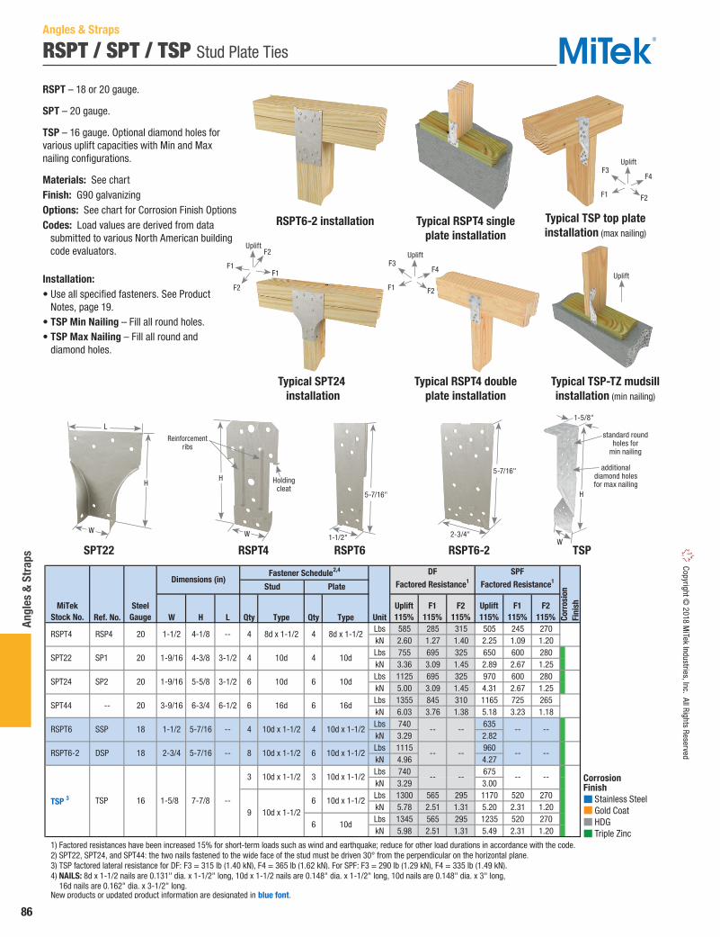
86
Angl
es &
Str
aps
Copyright © 2018 M
iTek Industries, Inc. All Rights Reserved
RSPT / SPT / TSP Stud Plate Ties
RSPT – 18 or 20 gauge.
SPT – 20 gauge.
TSP – 16 gauge. Optional diamond holes for various uplift capacities with Min and Max nailing configurations.
Materials: See chartFinish: G90 galvanizingOptions: See chart for Corrosion Finish OptionsCodes: Load values are derived from data submitted to various North American building code evaluators.
Installation:• Use all specified fasteners. See Product
Notes, page 19.• TSP Min Nailing – Fill all round holes.• TSP Max Nailing – Fill all round and
diamond holes.
Ref. No. W H L Qty Type Qty Type UnitLbs 585 285 315 505 245 270kN 2.60 1.27 1.40 2.25 1.09 1.20Lbs 755 695 325 650 600 280kN 3.36 3.09 1.45 2.89 2.67 1.25Lbs 1125 695 325 970 600 280kN 5.00 3.09 1.45 4.31 2.67 1.25Lbs 1355 845 310 1165 725 265kN 6.03 3.76 1.38 5.18 3.23 1.18Lbs 740 635kN 3.29 2.82Lbs 1115 960kN 4.96 4.27Lbs 740 675kN 3.29 3.00Lbs 1300 565 295 1170 520 270kN 5.78 2.51 1.31 5.20 2.31 1.20Lbs 1345 565 295 1235 520 270kN 5.98 2.51 1.31 5.49 2.31 1.20
1) Factored resistances have been increased 15% for short-term loads such as wind and earthquake; reduce for other load durations in accordance with the code. 2) SPT22, SPT24, and SPT44: the two nails fastened to the wide face of the stud must be driven 30° from the perpendicular on the horizontal plane. 3) TSP factored lateral resistance for DF: F3 = 315 lb (1.40 kN), F4 = 365 lb (1.62 kN). For SPF: F3 = 290 lb (1.29 kN), F4 = 335 lb (1.49 kN). 4) NAILS: 8d x 1-1/2 nails are 0.131" dia. x 1-1/2" long, 10d x 1-1/2 nails are 0.148" dia. x 1-1/2" long, 10d nails are 0.148" dia. x 3" long, 16d nails are 0.162" dia. x 3-1/2" long. New products or updated product information are designated in blue font.
-- --
10d x 1-1/2
6 10d
-- --
6 16d 6 16d
---- --
-- -- --
3 10d x 1-1/2 3 10d x 1-1/2
9 10d x 1-1/26
SPT44 -- 20 3-9/16 6-3/4
4 10d x 1-1/2 4 10d x 1-1/2 -- RSPT6 SSP 18 1-1/2 5-7/16
--
10d
8 10d x 1-1/2 6 10d x 1-1/2
4 10d 4 10d
6 10d 6
4 8d x 1-1/2 4 8d x 1-1/2
16 TSP
1-1/2
2-3/4
1-9/16
1-9/16
1-5/8
DSP
4-1/8
20
18 --
--
6-1/2
4-3/8 3-1/2
5-5/8 3-1/2
5-7/16
7-7/8
Corr
osio
nFi
nishPlate
Fastener Schedule2,4
Stud
DFFactored Resistance1
SPFFactored Resistance1
Uplift115%
F1115%
F2115%
F1115%
F2115%
Uplift115%
RSPT6-2
TSP 3
Dimensions (in)
SteelGauge
MiTekStock No.
SPT24 SP2
RSPT4
SPT22
RSP4
SP1
20
20
--
--
Corrosion Finish Stainless Steel Gold Coat HDG Triple Zinc
Corrosion Finish Stainless Steel Gold Coat HDG Triple Zinc
Corrosion Finish Stainless Steel Gold Coat HDG Triple Zinc
Angles & Straps
Typical SPT24 installation
RSPT6-2 installation Typical RSPT4 single plate installation
Typical RSPT4 double plate installation
RSPT4
H
W
Reinforcementribs
Holding cleat
H
L
W
5-7/16"
1-1/2"
5-7/16"
2-3/4"
H
1-5/8"
W
additional diamond holes for max nailing
standard round holes for
min nailing
Typical TSP top plate installation (max nailing)
Typical TSP-TZ mudsill installation (min nailing)
UpliftF1
F1
F2
F2
Uplift
F3
F2
F4
F1
Uplift
F3
F2
F4
F1
Uplift
SPT22 RSPT6-2RSPT6 TSP

87
Angles & Straps
Copy
right
© 2
018
MiT
ek In
dust
ries,
Inc.
All
Righ
ts R
eser
ved
SPT / SPTH / SPTHW Stud Plate Ties
SPT – 20 gauge. Ties single and double plates to studs.
SPTH – Heavier 18 gauge version of SPT.
SPTHW – 18 gauge. Attaches plate to studs over 1/2" sheathing.
Materials: See chartFinish: G90 galvanizingOptions: See chart for Corrosion Finish OptionsCodes: Load values are derived from data submitted to various North American building code evaluators.
Installation:• Use all specified fasteners. See Product Notes, page 19.
Ref. No. W H Qty Type Lbs kN Lbs kN SPT4 SP4 20 3-9/16 6-7/8 6 10d x 1-1/2 960 4.27 825 3.67 SPTH4 SPH4 18 3-9/16 8-5/8 12 10d x 1-1/2 1275 5.67 1095 4.87 SPTHW4 SPH4R 18 4-1/16 8-3/8 12 10d x 1-1/2 1275 5.67 1095 4.87 SPT6 SP6 20 5-9/16 7-5/8 6 10d x 1-1/2 960 4.27 825 3.67 SPTH6 SPH6 18 5-9/16 9-3/8 12 10d x 1-1/2 1275 5.67 1095 4.87 SPTHW6 SPH6R 18 6-1/16 9-1/8 12 10d x 1-1/2 1275 5.67 1095 4.87 SPT8 SP8 20 7-5/16 8-1/2 6 10d x 1-1/2 960 4.27 825 3.67 SPTH8 SPH8 18 7-5/16 8-1/2 12 10d x 1-1/2 1275 5.67 1095 4.87
1) Factored resistances have been increased 15% for short-term loads such as wind and earthquake; reduce for other load durations in accordance with the code. 2) NAILS: 10d x 1-1/2" nails are 0.148" dia. x 1-1/2" long.
Corr
osio
nFi
nishUplift 115%1Uplift 115%1
DFFactored Resistance
S-P-FFactored Resistance
4x
6x
8x
Fastener
Schedule2Dimensions (in)
SteelGauge
StudSize
MiTekStock No.
Corrosion Finish Stainless Steel Gold Coat HDG Triple Zinc
Corrosion Finish Stainless Steel Gold Coat HDG Triple Zinc
Corrosion Finish Stainless Steel Gold Coat HDG Triple Zinc
SPTHW SPTH
Typical SPT4 installation
SPT
Angles & Straps
H
W
1-1/4"
H
W
1-1/4"W
H
1-1/4"

88
Angl
es &
Str
aps
Copyright © 2018 M
iTek Industries, Inc. All Rights Reserved
SFC Framing Clips
Framing clips replace end cripples under window sills.
Materials: 16 gaugeFinish: G90 galvanizing
Installation:• Use all specified fasteners. See Product Notes, page 19.
Header Hangers support headers in door and window framing. Helps to eliminate cracks in drywall, plaster, or stucco over windows and doors. These products also provide anchorage and support for heavy fence rails, struts, or gate post cross brackets.
Materials: 16 gaugeFinish: G90 galvanizingCodes: Load values are derived from data submitted to various North American building code evaluators.
Installation:• Use all specified fasteners. See Product Notes, page 19.
HH Header Hangers
Ref. No. W H D Qty Type Qty Type 100% 115% 100% 115%
SFC6 FC6 16 5-1/2 2-1/2 2-1/2 5 16d 5 16d 775 995 1145 650 835 960
1) Factored resistances have been increased 15% for short-term loads such as wind and earthquake; reduce for other load durations in accordance with the code. 2) NAILS: 16d nails are 0.162" dia. x 3-1/2" long.
Fastener Schedule2
Uplift115%
Uplift115%
F1
DF
Factored Resistance1
SPF
Factored Resistance1
MiTekStock No.
SteelGauge
Dimensions (in)
F1
Header Joist
Ref. No. W H Qty Type Qty Type UnitLbs 1785 915 850 1500 590 715kN 7.94 4.07 3.78 6.67 2.62 3.18Lbs 2385 1365 1365 2000 885 1150kN 10.61 6.07 6.07 8.90 3.94 5.12
1) Factored resistances have been increased 15% for short-term loads such as wind and earthquake; reduce for other load durations in accordance with the code. 2) NAILS: 16d nails are 0.162" dia. x 3-1/2" long.
3-9/16 3-1/4
5-1/2 5-1/4
F1100%
4 16d 9 16d
6 16d 12 16d
HH44
HH66
HH4
HH6
16
16
S-P-FFactored Resistance1
F2115%
F3115%
F1100%
F2115%
F3115%
DFFactored Resistance1
MiTekStock No.
SteelGauge
Dimensions (in)
Header Stud
Fastener Schedule2
Typical SFC6 installation
HH44
SFC6
Typical HH44 installation
2"W
H
3-3/4"
W
DH
Angles & Straps
Uplift
F1
F4
F4F2
F3
F1

89
Angles & Straps
Copy
right
© 2
018
MiT
ek In
dust
ries,
Inc.
All
Righ
ts R
eser
ved
LJC / LJQ Lateral Joist Connectors
The LJC-TZ and LJQ-TZ Lateral Joist Connectors transfer lateral loads at the top foundation to the floor joists. The fastening patterns meet I-joist manufacturer recommendations.
LJC-TZ – fastens the top side of the sill plate to the underside of the floor joist preventing splitting of the bottom chord flanges, and can be installed after the floor system has been installed. The product is load rated for use with dimension lumber floor joists as well as I-joist. It can also be used with cantilevered floor joists.
LJQ-TZ – is a higher capacity connector designed for higher loads. It is similar in design to a joist hanger with a seat for the floor joist to bear against and utilizes wood screws to fasten to the sill plate. WS15-EXT Wood Screws (included) provide quick installation without the need to predrill holes.
Materials: See chartFinish: G-185 galvanizingCodes: Load values are derived from data submitted to various North American building code evaluators.
Installation:• Use all specified fasteners. See Product Notes, page 19.• LJC-TZ – Installs after the floor joist has been placed with a
minimum of (12) 8d x 1-1/2" HDG nails.• LJQ-TZ – Installs with (4) WS15-EXT Wood Screws.
WS15-EXT Wood Screws are 1/4" diameter x 1-1/2" long and are included with LJQ-TZ connectors.
Ref. No. W L D Qty Type Lbs kN Lbs kN Lbs kN Lbs kN LJC-TZ -- 18 3-3/16 8 -- 12 8d x 1-1/2 HDG 1310 5.83 1310 5.83 930 4.14 930 4.14 LJQ15-TZ -- 16 1-9/16 3 1-1/2 4 WS15-EXT 1880 8.36 1880 8.36 1335 5.94 1335 5.94 LJQ17-TZ -- 16 1-13/16 3 1-1/2 4 WS15-EXT 1880 8.36 1880 8.36 1335 5.94 1335 5.94 LJQ20-TZ -- 16 2-1/8 3 1-1/2 4 WS15-EXT 1880 8.36 1880 8.36 1335 5.94 1335 5.94 LJQ23-TZ -- 16 2-5/16 3 1-1/2 4 WS15-EXT 1880 8.36 1880 8.36 1335 5.94 1335 5.94 LJQ25-TZ -- 16 2-9/16 3 1-1/2 4 WS15-EXT 1880 8.36 1880 8.36 1335 5.94 1335 5.94 LJQ35-TZ -- 16 3-9/16 3 1-1/2 4 WS15-EXT 2205 9.81 2205 9.81 1565 6.96 1565 6.96
1) WS15-EXT wood screws are 1/4" x 1/2" and are included with LJQ-TZ connector. 2) NAILS: 8d x 1-1/2 nails are 0.131" dia. x 1-1/2" long.
Corr
osio
nFi
nishMiTek
Stock No.Steel
Gauge
FastenerSchedule1,2
I-Joist2x I-Joist 2x
DFFactored Resistance (100%)
S-P-FFactored Resistance (100%)
Dimensions (in)
LJC-TZ LJQ-TZ
Typical LJC-TZ installation
Typical LJQ-TZ installation
L
D
W
F2F2
Angles & Straps
Corrosion Finish Stainless Steel Gold Coat HDG Triple Zinc
Corrosion Finish Stainless Steel Gold Coat HDG Triple Zinc
Corrosion Finish Stainless Steel Gold Coat HDG Triple Zinc
W
L
1/2"
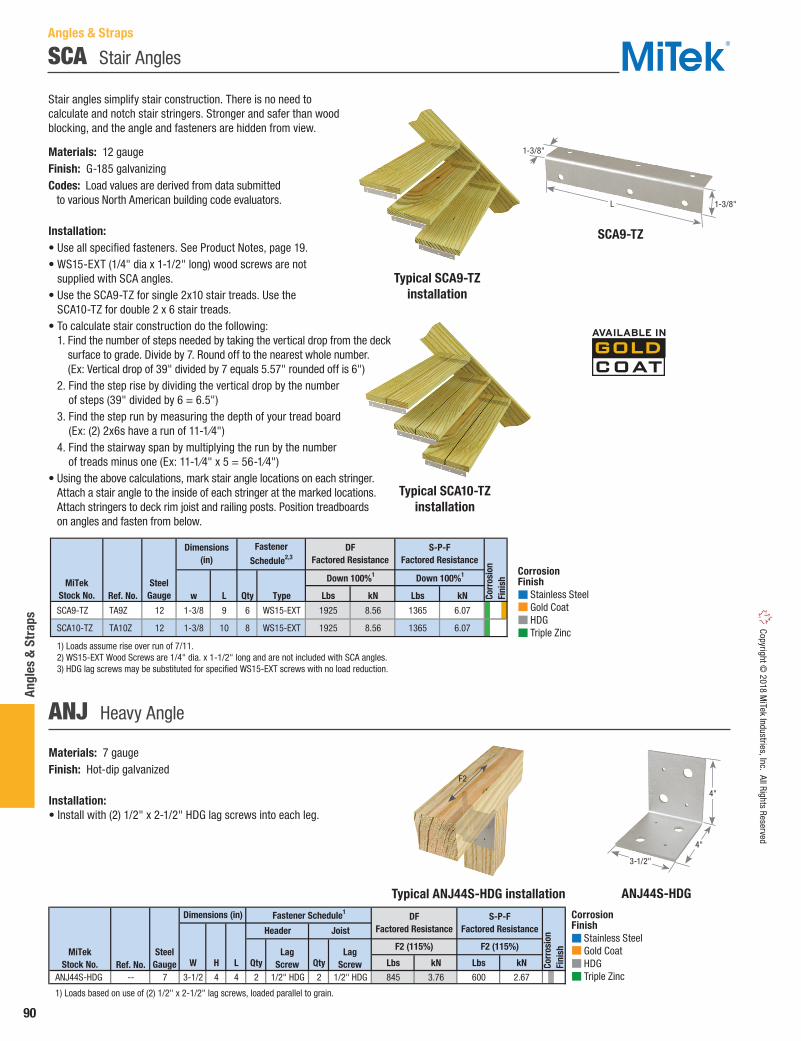
90
Angl
es &
Str
aps
Copyright © 2018 M
iTek Industries, Inc. All Rights Reserved
Typical SCA9-TZ installation
SCA9-TZ
Typical SCA10-TZ installation
SCA Stair Angles
Stair angles simplify stair construction. There is no need to calculate and notch stair stringers. Stronger and safer than wood blocking, and the angle and fasteners are hidden from view.
Materials: 12 gaugeFinish: G-185 galvanizingCodes: Load values are derived from data submitted to various North American building code evaluators.
Installation:• Use all specified fasteners. See Product Notes, page 19.• WS15-EXT (1/4" dia x 1-1/2" long) wood screws are not
supplied with SCA angles.• Use the SCA9-TZ for single 2x10 stair treads. Use the
SCA10-TZ for double 2 x 6 stair treads. • To calculate stair construction do the following:
1. Find the number of steps needed by taking the vertical drop from the deck surface to grade. Divide by 7. Round off to the nearest whole number. (Ex: Vertical drop of 39" divided by 7 equals 5.57" rounded off is 6")
2. Find the step rise by dividing the vertical drop by the number of steps (39" divided by 6 = 6.5")
3. Find the step run by measuring the depth of your tread board (Ex: (2) 2x6s have a run of 11-1⁄4")
4. Find the stairway span by multiplying the run by the number of treads minus one (Ex: 11-1⁄4" x 5 = 56-1⁄4")
• Using the above calculations, mark stair angle locations on each stringer. Attach a stair angle to the inside of each stringer at the marked locations. Attach stringers to deck rim joist and railing posts. Position treadboards on angles and fasten from below.
Ref. No. w L Qty Type Lbs kN Lbs kN
SCA9-TZ TA9Z 12 1-3/8 9 6 WS15-EXT 1925 8.56 1365 6.07
SCA10-TZ TA10Z 12 1-3/8 10 8 WS15-EXT 1925 8.56 1365 6.07
1) Loads assume rise over run of 7/11. 2) WS15-EXT Wood Screws are 1/4" dia. x 1-1/2" long and are not included with SCA angles. 3) HDG lag screws may be substituted for specified WS15-EXT screws with no load reduction.
Corr
osio
nFi
nishMiTek
Stock No.Steel
Gauge
Down 100%1 Down 100%1
DFFactored Resistance
S-P-FFactored Resistance
Fastener
Schedule2,3Dimensions
(in)
L 1-3/8"
1-3/8"
Materials: 7 gaugeFinish: Hot-dip galvanized
Installation:• Install with (2) 1/2" x 2-1/2" HDG lag screws into each leg.
ANJ Heavy Angle
Ref. No. W H L Qty Qty Lbs kN Lbs kN
ANJ44S-HDG -- 7 3-1/2 4 4 2 1/2" HDG 2 1/2" HDG 845 3.76 600 2.67
1) Loads based on use of (2) 1/2" x 2-1/2" lag screws, loaded parallel to grain.
Corr
osio
nFi
nishF2 (115%)
DFFactored Resistance
S-P-FFactored Resistance
MiTekStock No.
SteelGauge
Header Joist
Fastener Schedule1
Lag Screw
Lag Screw
Dimensions (in)
F2 (115%)
ANJ44S-HDGTypical ANJ44S-HDG installation
4"
4"
3-1/2"
Corrosion Finish Stainless Steel Gold Coat HDG Triple Zinc
Corrosion Finish Stainless Steel Gold Coat HDG Triple Zinc
Corrosion Finish Stainless Steel Gold Coat HDG Triple Zinc
Corrosion Finish Stainless Steel Gold Coat HDG Triple Zinc
Corrosion Finish Stainless Steel Gold Coat HDG Triple Zinc
Corrosion Finish Stainless Steel Gold Coat HDG Triple Zinc
F2
Angles & Straps

91
Angles & Straps
Copy
right
© 2
018
MiT
ek In
dust
ries,
Inc.
All
Righ
ts R
eser
ved
KHL Heavy Angles
Designed for heavy-duty reinforcement of 90° framing intersections.
Materials: See chartFinish: PrimerOptions: See chart for Corrosion Finish Options
Installation:• Use all specified fasteners. See Product Notes, page 19.• Connectors are not load rated.
Typical KHL35 installation KHL55
These multi-purpose braces are designed to provide reinforcement for 90° wood-to-wood connections.
Materials: 12 gaugeFinish: G90 galvanizing
Installation:• Use all specified fasteners.
B / BL Corner Braces
Gussets
Ref. No. W1 W2 L D1 D2 D3 D4 Qty Dia (in) Qty KHL33 HL33 7 3-1/4 3-1/4 2-1/2 1-1/4 -- 2 -- 2 5/8 -- KHL35 HL35 7 3-1/4 3-1/4 5 1-1/4 2-1/2 2 -- 4 5/8 -- KHL35G HL35G 7 3-1/4 3-1/4 5 1-1/4 2-1/2 2 -- 4 5/8 1 KHL37 HL37 7 3-1/4 3-1/4 7-1/2 1-1/4 2-1/2 2 -- 6 5/8 -- KHL335 SPECANGLE 3 3-1/2 5-1/4 3-1/2 -- -- -- -- 4 1/2 -- KHL43 HL43 3 4-1/4 4-1/4 3 1-1/2 -- 2-3/4 -- 2 3/4 -- KHL46 HL46 3 4-1/4 4-1/4 6 1-1/2 3 2-3/4 -- 4 3/4 -- KHL49 HL49 3 4-1/4 4-1/4 9 1-1/2 3 2-3/4 -- 6 3/4 -- KHL53 HL53 7 5-3/4 5-3/4 2-1/2 1-1/4 -- 2 2-1/2 4 5/8 -- KHL55 HL55 7 5-3/4 5-3/4 5 1-1/4 2-1/2 2 2-1/2 8 5/8 -- KHL57 HL57 7 5-3/4 5-3/4 7-1/2 1-1/4 2-1/2 2 2-1/2 12 5/8 -- KHL73 HL73 3 7-1/4 7-1/4 3 1-1/2 -- 2-3/4 3 4 3/4 -- KHL76 HL76 3 7-1/4 7-1/4 6 1-1/2 3 2-3/4 3 8 3/4 -- KHL79 HL79 3 7-1/4 7-1/4 9 1-1/2 3 2-3/4 3 12 3/4 --
1) All bolts shall meet or exceed the specifications of ASTM A 307.
Corr
osio
nFi
nish
Dimensions (in)
Bolts1MiTek
Stock No.Steel
Gauge
Fastener Schedule
Ref. No. W L Qty Type Qty Dia (in) B23 -- 12 2 2-5/8 6 16d -- -- B24 -- 12 2 3-5/8 8 16d -- -- BL3 A33 12 1-1/4 3-1/16 8 16d -- -- BL4 A44 12 1-1/4 4-13/16 10 16d -- -- BL6 -- 12 1-1/4 6-9/16 12 16d -- -- BL8 -- 12 1-1/4 8-5/16 14 16d -- -- B66 A66 12 1-1/2 6 -- -- 4 3/8 B88 A88 12 2 8 -- -- 6 3/8
1) Bolts shall conform to ASTM A 307 or better. 2) NAILS: 16d nails are 0.162" dia. x 3-1/2" long.
Dimensions (in)
MiTekStock No.
SteelGauge
Bolts1Nails2
Fastener Schedule
Some model designs may vary from
illustration shown
Corrosion Finish Stainless Steel Gold Coat HDG Triple Zinc
Corrosion Finish Stainless Steel Gold Coat HDG Triple Zinc
Corrosion Finish Stainless Steel Gold Coat HDG Triple Zinc
KHL335
KHL35G
Gusset
B66 B23
Typical B66installation
BL4
L
W
L
L
L
W
L
W1
W2
D2 D1
D3
D4
Angles & Straps

92
Angl
es &
Str
aps
Copyright © 2018 M
iTek Industries, Inc. All Rights Reserved
SDPT Strap Post Ties
Angles & Straps
Connects 2x4 stair posts and 4x4 posts to deck rim joist or stair stringers.
Materials: 14 gaugeFinish: G-185 galvanizing
Installation:• Use all specified fasteners. See Product Notes, page 19. • Install units in pairs on 2x4 (SDPT5-TZ) or 4x4 (SDPT7-TZ)
post. Space the connectors 5" apart from center to center on the post. Use through bolts to fasten connectors to rim joist or stringer. Do not use lag bolts. Fasten to post with specified nails (see chart).
Ref. No. Qty Type Qty Type 2 x 4 SDPT5-TZ DPT5Z 14 5 10d x 1-1/2 HDG 2 3/8 HDG 4 x 4 SDPT7-TZ DPT7Z 14 5 10d x 1-1/2 HDG 2 3/8 HDG
1) Bolts shall conform to ASTM A 307 or better. 2) NAILS: 10d x 1-1/2" nails are 0.148" dia. x 1-1/2" long.
PostSize
MiTekStock No.
SteelGauge
Fastener Schedule1,2
Corr
osio
nFi
nish
SDPT7-TZ
SDPT5-TZ
Typical SDPT7-TZinstallation
1-1/2"
1-1/2"
3-1/2"
3-1/2"
3-1/2"
3-1/2"
Corrosion Finish Stainless Steel Gold Coat HDG Triple Zinc
Corrosion Finish Stainless Steel Gold Coat HDG Triple Zinc
Corrosion Finish Stainless Steel Gold Coat HDG Triple Zinc
Typical SDJT14-TZinstallation
SDJT Joist Tie
Secures 2x joists to posts.
Materials: 14 gaugeFinish: G-185 galvanizing
Installation:• Use all specified fasteners. See Product Notes, page 19. • Use with 2x lumber for joists (minimum height is 2x4).
Install with either specified nails or through bolts. Do not use lag bolts. To ease installation, attach to 4x4 post first.
Post Size Ref. No. Qty Type Unit 100% 100%Lbs 1615 1355kN 7.18 6.03Lbs 2015 1695kN 8.96 7.54
1) Bolts shall conform to ASTM A 307 or better. 2) NAILS: 16d nails are 0.162" dia. x 3-1/2" long.
Corr
osio
nFi
nish
SDJT14-TZ 4 x 48
DJT14Z16d HDG
2 3/8 HDG14
MiTekStock No.
SteelGauge
Fastener Schedule1,2 DF Factored Resistance
S-P-F Factored Resistance
SDJT14-TZ
Corrosion Finish Stainless Steel Gold Coat HDG Triple Zinc
Corrosion Finish Stainless Steel Gold Coat HDG Triple Zinc
Corrosion Finish Stainless Steel Gold Coat HDG Triple Zinc
2-3/4"
3-1/8"
3-1/8"

93
Angles & Straps
Copy
right
© 2
018
MiT
ek In
dust
ries,
Inc.
All
Righ
ts R
eser
ved
Ornamental notching provides architectural appearance for exposed applications.
Materials: See chartFinish: Primer
Installation:• Use all specified fasteners. See Product Notes, page 19.• Connectors are not load rated.
L12-0
KHL33-O
T1212-0
Ornamental
L / T – 14 gauge medium-capacity straps fasten with either nails or bolts.
LH / TH – 7 gauge heavy-capacity bolt-on strap.
Materials: See chartFinish: G90 galvanizing; LH / TH – Primer; TH12-HDG – Hot-dip galvanized.Options: See chart for Corrosion Finish Options. Available for special order in black primer coated finish.
Installation:• Use all specified fasteners. See Product Notes, page 19.• Straps are not load rated.
L / LH / T / TH Straps
Some model designs may vary from
illustration shown
Description Ref. No. W H L Qty Dia (in) KHL33-O OHA33 7 3-1/4 -- 2-1/2 2 5/8 KHL36-O OHA36 7 3-1/4 -- 6 4 5/8 KHST64-O OHS135 7 6 -- 13-1/2 4 3/4 ST12-O OS 12 2 -- 12 4 1/2 L12-O OL 12 2-1/2 11-7/8 11-7/8 5 1/2 LH12-O OHL 7 2-1/2 11-7/8 11-7/8 5 5/8 T1212-O OT 12 2-1/2 11-7/8 14-1/2 6 1/2 TH12-O OHT 7 2-1/2 11-7/8 11-1/8 4 5/8 TH16-O -- 7 2-1/2 11-7/8 16-1/8 6 5/8
1) All bolts shall meet or exceed the specifications of ASTM A 307.
'T' Strap
MiTekStock No.
SteelGauge
Dimensions (in) Bolt Schedule1
Heavy Angle
Strap Tie
'L' Strap
Ref. No. W H L Qty Dia (in) Qty Type T6 66T 14 1-1/2 5 6 3 1/2 12 16d T8 -- 14 2 8 8-1/2 3 1/2 12 16d T12 128T 14 2 8 12 3 1/2 12 16d T1212 1212T 14 2 12 12 3 1/2 12 16d L6 66L 14 1-1/2 6 6 2 1/2 8 16d L8 88L 14 2 8 8 2 1/2 8 16d L12 1212L 14 2 12 12 3 1/2 12 16d
TH12-HDG 1212HT, 1212HTHDG
7 2-1/2 12 12 6 5/8 -- --
TH16 1616HT 7 2-1/2 16 16-1/4 6 5/8 -- -- LH12 1212HL 7 3 12 12 5 5/8 -- -- LH16 1616HL 7 2-1/2 16 16 7 5/8 -- --
1) All bolts shall meet or exceed the specifications of ASTM A 307. 2) NAILS: 16d nails are 0.162" dia. x 3-1/2" long.
Corr
osio
nFi
nish
Dimensions (in)
MiTekStock No.
SteelGauge
Nails2Bolts1
Fastener Schedule
Corrosion Finish Stainless Steel Gold Coat HDG Triple Zinc
Corrosion Finish Stainless Steel Gold Coat HDG Triple Zinc
Corrosion Finish Stainless Steel Gold Coat HDG Triple Zinc L
H
W
2-1/2"
3-1/4"
3-1/4"
H
L
W
L6
LH12
T6
TH16
H
L
W
H
L
W
Angles & Straps

94
Angl
es &
Str
aps
Copyright © 2018 M
iTek Industries, Inc. All Rights Reserved
CMST / CMSTC / RS Coiled Strapping
Coiled strapping enables cut-to-length convenience for a variety of immediate job site needs.
CMST – 3" wide strapping features diamond nail holes to provide nailing options and reduce wood splitting.
CMSTC – 3" wide strapping is designed for high load conditions. Engineered to reduce wood splitting.
RS – 1-1⁄4" wide strapping packaged in cartons containing 25-foot or longer coils.
Materials: See chartFinish: G90 galvanizingOptions: See chart for Corrosion Finish OptionsCodes: Load values are derived from data submitted to various North American building code evaluators.
Installation:• Use all specified fasteners. See Product Notes, page 19. • For safety, always wear gloves when handling
or cutting coiled strapping. • CMST installations: Install to a minimum 2 ply 2x edge.
Increase nail spacing if wood begins to split.• Designer may specify alternate nailing schedules. Refer to
Nail Specification Table on page 22 for nail shear values. Load values shall not exceed published factored resistance.
Ref. No. Qty Type 100% 115% 100% 115% 100% 115% 100% 115% Clear Span + 42 21 1-1/2 Clear Span + 84 42 3 Clear Span + 56 28 64 16d 1-3/4 9945 9945 44.24 44.24 8960 9945 39.86 44.24 Clear Span + 136 68 3-1/2 Clear Span + 268 134 7 Clear Span + 80 40 88 16d 1-3/4 13975 13975 62.17 62.17 12320 13975 54.80 62.17 Clear Span + 184 92 3-1/2 Clear Span + 368 184 7 Clear Span + 12 6 16 10d 1-1/2 1390 6.18 Clear Span + 14 7 18 8d 1-1/2 1295 5.76 Clear Span + 12 6 16 10d 1-1/2 1390 6.18 Clear Span + 14 7 18 8d 1-1/2 1295 5.76 Clear Span + 14 7 18 10d 1-1/2 1595 7.10 Clear Span + 16 8 20 8d 1-1/2 1500 6.67 Clear Span + 14 7 18 10d 1-1/2 1595 7.10 Clear Span + 16 8 20 8d 1-1/2 1500 6.67 Clear Span + 16 8 20 10d 1-1/2 2010 8.94 Clear Span + 18 9 24 8d 1-1/2 2010 8.94 Clear Span + 16 8 20 10d 1-1/2 2010 8.94 Clear Span + 18 9 24 8d 1-1/2 2010 8.94 Clear Span + 16 8 20 10d 1-1/2 2010 8.94 Clear Span + 18 9 24 8d 1-1/2 2010 8.94 Clear Span + 18 9 24 10d 1-1/2 2645 11.77 Clear Span + 22 11 28 8d 1-1/2 2610 11.61 Clear Span + 18 9 24 10d 1-1/2 2645 11.77 Clear Span + 22 11 28 8d 1-1/2 2610 11.61 Clear Span + 24 12 30 10d 1-1/2 3565 15.86 Clear Span + 30 15 38 8d 1-1/2 3605 16.04 Clear Span + 24 12 30 10d 1-1/2 3565 15.86 Clear Span + 30 15 38 8d 1-1/2 3605 16.04
1) Factored resistances have been increased 15% for short-term loads such as wind and earthquake; no further increase allowed. 2) Fasteners to be installed with equal fasteners at each end of the connection. 3) 16d sinker nails may be substituted for 10d nails with no load reduction. 4) NAILS: 8d nails are 0.131" dia. x 2-1/2" long, 10d nails are 0.148" dia. x 3" long, 16d nails are 0.162" dia. x 3-1/2" long.
RS14-R CS14-R 14 25
RS14-100 CS14 14 100
RS16-R CS16-R 16 25
2100 9.34 9.34
2645 2645 11.77 11.77
Corr
osio
nFi
nish
RS150 CS16 16 150
RS22-R CS22-R 22 25
RS20-R CS20-R 20 25
RS18-R CS18-R 18 25
RS250 CS20 20 250
RS200 CS18 18 200
RS100 CS18S 18 100
RS300 CS22 22 300
13975 13975 62.17 62.17 12355 CMST12 CMST12 12 40
29.60 31.457070
104 10d
44.24 44.24 903010d 9945 9945
54.96 62.1713975
Tensile (kN)End
Length(in)
DF Factored Resistance1
S-P-FFactored Resistance1
CoilLength
(ft)
6655
CMST14 CMST14 14 52-1/276
10d 7070 7070 31.45 31.45 CMSTC16 CMSTC16 16 54 56
9945 40.17 44.24
CutLength (in)
Rim Joist Installation Fastener Schedule2,3,4 Nail
SpacingO.C. (in)
MiTekStock No.
SteelGauge
Tensile (Lbs) Tensile (kN) Tensile (Lbs)
1595 1595 7.10 7.10
1595 1595 7.10 7.10
1415 1415 6.29 6.29
1415 1415 6.29 6.29
2100 2100 9.34 9.34
2100 2100 9.34 9.34
3920 3920 17.44 17.44
2100
1415
1415
1595
1595
2100
2100
2100
2645
2645
3920
3920
2645 2645 11.77 11.77
3920 3920 17.44 17.44
17.44
9.34
9.34
11.77
11.77
17.44
6.29
6.29
7.10
7.10
9.34
Corrosion Finish Stainless Steel Gold Coat HDG Triple Zinc
Corrosion Finish Stainless Steel Gold Coat HDG Triple Zinc
Corrosion Finish Stainless Steel Gold Coat HDG Triple Zinc
Typical RSrim joist installation
CMST similar
RS CMSTC16 CMST
3/4"
1/2"
3/8"
1-1/4"
1"
1-1/2"
3"
1-3/4"
3-1/2"
1-1/2"
1" min.
Cut length
End length
Optional nails (wood shrinkage may occur and cause strap to
buckle outward)
Clear span
3"
2-1/4"
3/4"
3"1-1/2
Angles & Straps
End length

95
Angles & Straps
Copy
right
© 2
018
MiT
ek In
dust
ries,
Inc.
All
Righ
ts R
eser
ved
HRS / HTP / KST / KSTI / LSTA / LSTI / MSTA / MSTC / ST Strap Ties
HRS – 12 gauge, 1-3/8" or 3-1/4" wide strapping.
LSTA – 20 or 18 gauge, light-capacity 1-1/4" wide strapping.
LSTI – 3-3/4" wide strap ties provide tension load path for truss top chords. The nail pattern accommodates open web trusses with double top chord.
MSTA – 18 or 16 gauge, medium-capacity 1-1/4" wide strapping.
HTP – 16 gauge, medium-capacity 3" wide strapping.
ST – 16 gauge, medium-capacity 1-1/4" wide strapping.
MSTC – 3" wide strapping. Slotted hole design allows for higher load capacities and reduces splitting of lumber when attached to multiple 2x members.
KST – 3/4", 1-3/4", or 2-1/16" wide strapping. Straps can be fastened using either nails or bolts. Some KST straps install only with nails.
KSTI – 2-1/16" wide strapping. Straps are designed for installation to wood I-Joist flanges.
Some model designs may vary from
illustration shown
Angles & Straps
KST scalloped
design
LSTA/MSTA KSTI MSTC LSTI KST116 ST
KSTstraight edge
design
HRS
1-3/8"
L HRS1
2HR
S8HR
S6
HTP37-TZ HRS416-TZ
16"
3-1/4"
3"
7"
W
KST2
9 9
-7/1
6"KS
T213
12-
11/1
6"KS
T216
15-
15/1
6"KS
T218
19-
3/16
"KS
T224
22-
7/16
"KS
T234
32-
3/16
"
2-1/16"
1-1/2"
KST2
27 2
7"KS
T237
37-
1/2"
KST2
48 4
8"KS
T260
60"
KST2
72 7
2"
4-1/2"
1-1/2"
1-1/4"
LSTA
/MST
A 9
"LS
TA/M
STA
12"
LSTA
/MST
A 1
5"LS
TA/M
STA
18"
LSTA
/MST
A 2
1"LS
TA/M
STA
24"
LSTA
/MST
A 3
0"LS
TA/M
STA
36"
MST
A 4
8" s
imila
r
2-1/16"
KSTI
226
26"
KSTI
236
36"
KSTI
248
48"
KSTI
260
60"
KSTI
272
72"
3"1-1/2"
MST
C28
28-
1/4"
MST
C40
40-
1/4"
MST
C52
52-1
/4"
MST
C66
65-
3/4"
MST
C78
77-
3/4"
16-5/16"
3/4"
1-3/4"
ST9
9"ST
12 1
1-5/
8"ST
18 1
7-3/
4"ST
22 2
1-5/
8"
1-1/4"
Continued on next page
3-3/4"2"
LSTI
49 4
9"LS
TI73
73"
3"
3/8"typ

96
Angl
es &
Str
aps
Copyright © 2018 M
iTek Industries, Inc. All Rights Reserved
HRS / HTP / KST / KSTI / LSTA / LSTI / MSTA / MSTC / ST Strap Ties
Materials: See chartFinish: G90 galvanizingOptions: See chart for Corrosion Finish OptionsCodes: Load values are derived from data submitted to various North American building code evaluators.
Installation:• Use all specified fasteners. See Product Notes, page 19.• Designer may specify alternate nailing schedules. Refer
to Nail Specification Table on page 22 for nail shear values. Load values shall not exceed published factored resistance.
• The quantity of nails installed shall be equally distributed to both ends of the strap.
Ref. No. W L Type Lbs kN Lbs kN KST116 ST2115 20 3/4 16-5/16 10 8 16d 995 4.43 940 4.18 LSTA9 LSTA9 20 1-1/4 9 8 8 10d 1085 4.83 775 3.45 LSTA12 LSTA12 20 1-1/4 12 10 10 10d 1355 6.03 970 4.31 LSTA15 LSTA15 20 1-1/4 15 12 12 10d 1630 7.25 1165 5.18 LSTA18 LSTA18 20 1-1/4 18 14 14 10d 1855 8.25 1360 6.05 LSTA21 LSTA21 20 1-1/4 21 16 16 10d 1855 8.25 1555 6.92 LSTA24 LSTA24 20 1-1/4 24 18 16 10d 1855 8.25 1555 6.92 KST29 ST292 20 1-3/4 9-7/16 14 14 16d 1320 5.87 940 4.18 KST213 ST2122 20 1-3/4 12-11/16 18 18 16d 2680 11.92 2110 9.39 KST216 ST2215 20 1-3/4 15-15/16 22 18 16d 2680 11.92 2110 9.39 LSTA30 LSTA30 18 1-1/4 30 22 22 10d 2460 10.94 2140 9.52 LSTA36 LSTA36 18 1-1/4 36 26 22 10d 2460 10.94 1945 8.65 MSTA9 MSTA9 18 1-1/4 9 8 8 10d 1085 4.83 775 3.45 MSTA12 MSTA12 18 1-1/4 12 10 10 10d 1355 6.03 970 4.31 MSTA15 MSTA15 18 1-1/4 15 12 12 10d 1630 7.25 1165 5.18 MSTA18 MSTA18 18 1-1/4 18 14 14 10d 1900 8.45 1360 6.05 MSTA21 MSTA21 18 1-1/4 21 16 16 10d 2170 9.65 1555 6.92 MSTA24 MSTA24 18 1-1/4 24 18 18 10d 2445 10.88 1750 7.78 LSTI49 LSTI49 18 3-3/4 49 32 32 10d x 1-1/2 4340 19.31 3090 13.75 LSTI73 LSTI73 18 3-3/4 73 48 48 10d x 1-1/2 6515 28.98 4635 20.62 ST9 ST9 16 1-1/4 9 8 8 16d 1325 5.89 1100 4.89 ST12 ST12 16 1-1/4 11-5/8 10 10 16d 1655 7.36 1375 6.12 ST18 ST18 16 1-1/4 17-3/4 14 14 16d 2095 9.32 1925 8.56 ST22 ST22 16 1-1/4 21-5/8 18 18 16d 2095 9.32 2095 9.32 MSTA30 MSTA30 16 1-1/4 30 22 22 10d 2985 13.28 2140 9.52 MSTA36 MSTA36 16 1-1/4 36 26 26 10d 3100 13.79 2525 11.23 MSTA48 MSTA49 16 1-1/4 48 32 26 10d 3070 13.66 2525 11.23 KST218 ST6215 16 1-3/4 19-3/16 26 26 16d 2640 11.74 1875 8.34 KST224 ST6224 16 1-3/4 22-7/16 30 30 16d 4440 19.75 3520 15.66 HTP37-TZ HTP37Z 16 3 7 20 20 10d x 1-1/2 2330 10.36 2110 9.39
36 36 10d 4380 19.48 3110 13.8336 34 16d 6295 28.00 4435 19.7352 52 10d 6570 29.23 4665 20.7552 46 16d 7795 34.68 6305 28.0570 60 10d 7795 34.68 6220 27.6770 52 16d 7795 34.68 7795 34.68
KST234 ST6236 14 1-3/4 32-3/16 42 36 16d 5665 25.20 4225 18.7988 72 10d 9945 44.24 8165 36.3288 62 16d 9945 44.24 9945 44.24104 76 10d 9945 44.24 8550 38.03104 66 16d 9945 44.24 9945 44.24
1) Factored resistances have been increased 15% for short-term loads such as wind and earthquake; reduce for other load durations in accordance with the code. 2) Total number of nail and/or bolt holes provided in the strap. 3) Minimum quantity of fasteners to be installed with equal fasteners at each end of the connection. Strap may have additional nail holes not needed to meet published factored resistance of strap. 4) NAILS: 10d x 1-1/2 nails are 0.148" dia. x 1-1/2" long, 10d nails are 0.148" dia. x 3" long, 16d nails are 0.162" dia. x 3-1/2" long.
Ref. No. W L Type Lbs kN Lbs kN HRS6 HRS6 12 1-3/8 6 6 6 10d 815 3.63 580 2.58 HRS8 HRS8 12 1-3/8 8 10 10 10d 1355 6.03 970 4.31 HRS12 HRS12 12 1-3/8 12 14 14 10d 1900 8.45 1355 6.03 KST227 MST27 12 2-1/16 27 34 26 16d 4290 19.08 3050 13.57 KST237 MST37 12 2-1/16 37-1/2 48 38 16d 6270 27.89 4455 19.82 KST248 MST48 12 2-1/16 48 62 50 16d 8110 36.08 5865 26.09 KSTI226 MSTI26 12 2-1/16 26 26 22 10d x 1-1/2 3415 15.19 3000 13.35 KSTI236 MSTI36 12 2-1/16 36 36 32 10d x 1-1/2 4970 22.11 4360 19.40 KSTI248 MSTI48 12 2-1/16 48 48 44 10d x 1-1/2 6830 30.38 5995 26.67 KSTI260 MSTI60 12 2-1/16 60 60 56 10d x 1-1/2 7720 34.34 7630 33.94 KSTI272 MSTI72 12 2-1/16 72 72 58 10d x 1-1/2 7720 34.34 7720 34.34 HRS416-TZ HRS416Z 12 3-1/4 16 16 16 WS15-EXT 4057 18.05 3329 14.81 KST260 MST60 10 2-1/16 60 72 64 16d 10560 46.98 7505 33.39 KST272 MST72 10 2-1/16 72 72 64 16d 10605 47.18 8445 37.57
1) Factored resistances have been increased 15% for short-term loads such as wind and earthquake; reduce for other load durations in accordance with the code. 2) Total number of nail and/or bolt holes provided in the strap. 3) Minimum quantity of fasteners to be installed with equal fasteners at each end of the connection. Strap may have additional nail holes not needed to meet published factored resistance of strap. 4) WS15-EXT Wood Screws are 1/4" dia. x 1-1/2" long. 5) NAILS: 10d x 1-1/2 nails are 0.148" dia. x 1-1/2" long, 10d nails are 0.148" dia. x 3" long, 16d nails are 0.162" dia. x 3-1/2" long. New products or updated product information are designated in blue font.
Corr
osio
nFi
nish
Tensile 115%1Tensile 115%1
Corr
osio
nFi
nish
S-P-F Factored Resistance
DF Factored Resistance S-P-F Factored Resistance
Tensile 115%1 Tensile 115%1
DF Factored Resistance
3
MSTC52
40-1/4
MSTC52 16 3
MSTC40
52-1/4
MSTC40 16
Dimensions (in) Fastener Schedule4
MSTC28 MSTC28
MiTekStock No.
SteelGauge
TotalQty2
Min Qty3
16 3 28-1/4
Fastener Schedule4,5
MiTekStock No.
SteelGauge
TotalQty2
MSTC66 MSTC66 14 3
Min Qty3
65-3/4
Dimensions (in)
77-3/4 MSTC78 MSTC78 14 3
Typical LSTA/MSTA I-Joist on ridge beam
installation
Typical LSTI open web truss
installation
LTW twist strap pages 99-100
Angles & Straps
Corrosion Finish Stainless Steel Gold Coat HDG Triple Zinc
Corrosion Finish Stainless Steel Gold Coat HDG Triple Zinc
Corrosion Finish Stainless Steel Gold Coat HDG Triple Zinc
Continued on next page

97
Angles & Straps
Copy
right
© 2
018
MiT
ek In
dust
ries,
Inc.
All
Righ
ts R
eser
ved
Corrosion Finish Stainless Steel Gold Coat HDG Triple Zinc
Corrosion Finish Stainless Steel Gold Coat HDG Triple Zinc
Corrosion Finish Stainless Steel Gold Coat HDG Triple Zinc
HRS / HTP / KST / KSTI / LSTA / LSTI / MSTA / MSTC / ST Strap Ties
Qty Type Lbs kN Lbs kN18 12 10d 1630 7.30 1155 5.1016 16 10d 2170 9.70 1540 6.9018 28 10d 3800 16.90 2700 12.0016 32 10d 4345 19.30 3085 13.7018 44 10d 5970 26.60 4240 18.9016 48 10d 6515 29.00 4625 20.6018 62 10d 8415 37.40 5975 26.6016 64 10d 8685 38.60 6165 27.4018 64 10d 8685 38.60 6165 27.4016 66 10d 8960 39.90 6360 28.3018 20 16d 3295 14.70 2340 10.4016 22 16d 3625 16.10 2575 11.5018 32 16d 5275 23.50 3745 16.7016 34 16d 5605 24.90 3980 17.7018 46 16d 7580 33.70 5380 23.9016 48 16d 7910 35.20 5615 25.0018 46 16d 7580 33.70 5380 23.9016 48 16d 7910 35.20 5615 25.0018 14 10d x 1-1/2 2175 9.68 1910 8.5016 16 10d x 1-1/2 2485 11.05 2180 9.7018 26 10d x 1-1/2 4035 17.95 3545 15.7716 28 10d x 1-1/2 4345 19.33 3815 16.9718 38 10d x 1-1/2 5900 26.25 5180 23.0416 40 10d x 1-1/2 6210 27.62 5450 24.2418 50 10d x 1-1/2 7720 34.34 6815 30.3216 52 10d x 1-1/2 7720 34.34 7085 31.52
1) Factored resistances have been increased 15% for short-term loads such as wind and earthquake; reduce for other load durations in accordance with the code. 2) NAILS: 10d x 1-1/2 nails are 0.148" dia. x 1-1/2" long, 10d nails are 0.148" dia. x 3" long, 16d nails are 0.162" dia. x 3-1/2" long. New products or updated product information are designated in blue font.
KSTI272
KSTI236
KSTI248
KSTI260
MSTC28
MiTekStock No.
ClearSpan
KST272
KST260
KST248
MSTC40
MSTC66
MSTC78
MSTC52
KST237
DFFactored Resistance
S-P-FFactored Resistance
Uplift (115%)1 Uplift (115%)1
Fasteners
Total2
Clear Span Chart
Ref. No. W L Type Lbs kN Lbs kN KST116 ST2115 20 3/4 16-5/16 10 8 16d 995 4.43 940 4.18 LSTA9 LSTA9 20 1-1/4 9 8 8 10d 1085 4.83 775 3.45 LSTA12 LSTA12 20 1-1/4 12 10 10 10d 1355 6.03 970 4.31 LSTA15 LSTA15 20 1-1/4 15 12 12 10d 1630 7.25 1165 5.18 LSTA18 LSTA18 20 1-1/4 18 14 14 10d 1855 8.25 1360 6.05 LSTA21 LSTA21 20 1-1/4 21 16 16 10d 1855 8.25 1555 6.92 LSTA24 LSTA24 20 1-1/4 24 18 16 10d 1855 8.25 1555 6.92 KST29 ST292 20 1-3/4 9-7/16 14 14 16d 1320 5.87 940 4.18 KST213 ST2122 20 1-3/4 12-11/16 18 18 16d 2680 11.92 2110 9.39 KST216 ST2215 20 1-3/4 15-15/16 22 18 16d 2680 11.92 2110 9.39 LSTA30 LSTA30 18 1-1/4 30 22 22 10d 2460 10.94 2140 9.52 LSTA36 LSTA36 18 1-1/4 36 26 22 10d 2460 10.94 1945 8.65 MSTA9 MSTA9 18 1-1/4 9 8 8 10d 1085 4.83 775 3.45 MSTA12 MSTA12 18 1-1/4 12 10 10 10d 1355 6.03 970 4.31 MSTA15 MSTA15 18 1-1/4 15 12 12 10d 1630 7.25 1165 5.18 MSTA18 MSTA18 18 1-1/4 18 14 14 10d 1900 8.45 1360 6.05 MSTA21 MSTA21 18 1-1/4 21 16 16 10d 2170 9.65 1555 6.92 MSTA24 MSTA24 18 1-1/4 24 18 18 10d 2445 10.88 1750 7.78 LSTI49 LSTI49 18 3-3/4 49 32 32 10d x 1-1/2 4340 19.31 3090 13.75 LSTI73 LSTI73 18 3-3/4 73 48 48 10d x 1-1/2 6515 28.98 4635 20.62 ST9 ST9 16 1-1/4 9 8 8 16d 1325 5.89 1100 4.89 ST12 ST12 16 1-1/4 11-5/8 10 10 16d 1655 7.36 1375 6.12 ST18 ST18 16 1-1/4 17-3/4 14 14 16d 2095 9.32 1925 8.56 ST22 ST22 16 1-1/4 21-5/8 18 18 16d 2095 9.32 2095 9.32 MSTA30 MSTA30 16 1-1/4 30 22 22 10d 2985 13.28 2140 9.52 MSTA36 MSTA36 16 1-1/4 36 26 26 10d 3100 13.79 2525 11.23 MSTA48 MSTA49 16 1-1/4 48 32 26 10d 3070 13.66 2525 11.23 KST218 ST6215 16 1-3/4 19-3/16 26 26 16d 2640 11.74 1875 8.34 KST224 ST6224 16 1-3/4 22-7/16 30 30 16d 4440 19.75 3520 15.66 HTP37-TZ HTP37Z 16 3 7 20 20 10d x 1-1/2 2330 10.36 2110 9.39
36 36 10d 4380 19.48 3110 13.8336 34 16d 6295 28.00 4435 19.7352 52 10d 6570 29.23 4665 20.7552 46 16d 7795 34.68 6305 28.0570 60 10d 7795 34.68 6220 27.6770 52 16d 7795 34.68 7795 34.68
KST234 ST6236 14 1-3/4 32-3/16 42 36 16d 5665 25.20 4225 18.7988 72 10d 9945 44.24 8165 36.3288 62 16d 9945 44.24 9945 44.24104 76 10d 9945 44.24 8550 38.03104 66 16d 9945 44.24 9945 44.24
1) Factored resistances have been increased 15% for short-term loads such as wind and earthquake; reduce for other load durations in accordance with the code. 2) Total number of nail and/or bolt holes provided in the strap. 3) Minimum quantity of fasteners to be installed with equal fasteners at each end of the connection. Strap may have additional nail holes not needed to meet published factored resistance of strap. 4) NAILS: 10d x 1-1/2 nails are 0.148" dia. x 1-1/2" long, 10d nails are 0.148" dia. x 3" long, 16d nails are 0.162" dia. x 3-1/2" long.
Ref. No. W L Type Lbs kN Lbs kN HRS6 HRS6 12 1-3/8 6 6 6 10d 815 3.63 580 2.58 HRS8 HRS8 12 1-3/8 8 10 10 10d 1355 6.03 970 4.31 HRS12 HRS12 12 1-3/8 12 14 14 10d 1900 8.45 1355 6.03 KST227 MST27 12 2-1/16 27 34 26 16d 4290 19.08 3050 13.57 KST237 MST37 12 2-1/16 37-1/2 48 38 16d 6270 27.89 4455 19.82 KST248 MST48 12 2-1/16 48 62 50 16d 8110 36.08 5865 26.09 KSTI226 MSTI26 12 2-1/16 26 26 22 10d x 1-1/2 3415 15.19 3000 13.35 KSTI236 MSTI36 12 2-1/16 36 36 32 10d x 1-1/2 4970 22.11 4360 19.40 KSTI248 MSTI48 12 2-1/16 48 48 44 10d x 1-1/2 6830 30.38 5995 26.67 KSTI260 MSTI60 12 2-1/16 60 60 56 10d x 1-1/2 7720 34.34 7630 33.94 KSTI272 MSTI72 12 2-1/16 72 72 58 10d x 1-1/2 7720 34.34 7720 34.34 HRS416-TZ HRS416Z 12 3-1/4 16 16 16 WS15-EXT 4057 18.05 3329 14.81 KST260 MST60 10 2-1/16 60 72 64 16d 10560 46.98 7505 33.39 KST272 MST72 10 2-1/16 72 72 64 16d 10605 47.18 8445 37.57
1) Factored resistances have been increased 15% for short-term loads such as wind and earthquake; reduce for other load durations in accordance with the code. 2) Total number of nail and/or bolt holes provided in the strap. 3) Minimum quantity of fasteners to be installed with equal fasteners at each end of the connection. Strap may have additional nail holes not needed to meet published factored resistance of strap. 4) WS15-EXT Wood Screws are 1/4" dia. x 1-1/2" long. 5) NAILS: 10d x 1-1/2 nails are 0.148" dia. x 1-1/2" long, 10d nails are 0.148" dia. x 3" long, 16d nails are 0.162" dia. x 3-1/2" long. New products or updated product information are designated in blue font.
Corr
osio
nFi
nish
Tensile 115%1Tensile 115%1
Corr
osio
nFi
nish
S-P-F Factored Resistance
DF Factored Resistance S-P-F Factored Resistance
Tensile 115%1 Tensile 115%1
DF Factored Resistance
3
MSTC52
40-1/4
MSTC52 16 3
MSTC40
52-1/4
MSTC40 16
Dimensions (in) Fastener Schedule4
MSTC28 MSTC28
MiTekStock No.
SteelGauge
TotalQty2
Min Qty3
16 3 28-1/4
Fastener Schedule4,5
MiTekStock No.
SteelGauge
TotalQty2
MSTC66 MSTC66 14 3
Min Qty3
65-3/4
Dimensions (in)
77-3/4 MSTC78 MSTC78 14 3
Angles & Straps
Typical KST237 floor-to-floor installation
Optional nails (wood shrinkage may occur and cause strap to buckle outward)
End length
End length
1" min.
Clear span

98
Angl
es &
Str
aps
Copyright © 2018 M
iTek Industries, Inc. All Rights Reserved
KRPS Strap Ties
Designed for notched plates where plumbing, heating, or other pipes are placed in partitions.
Materials: 16 gaugeFinish: G90 galvanizingOptions: See chart for Corrosion Finish Options
Installation:• Use all specified fasteners. See Product Notes, page 19.• Install one strap tie for each 2x plate.
Typical KRPSinstallation
Ref. No. W L Qty Type Lbs kN Lbs kN KRPS18 RPS18 16 1-1/2 18-5/16 < 5-1/2 12 16d 1375 6.12 1185 5.27 KRPS22 RPS22 16 1-1/2 22-5/16 < 5-1/2 16 16d 1785 7.94 1535 6.83 KRPS28 RPS28 16 1-1/2 28-5/16 < 12 16 16d 1785 7.94 1535 6.83
1) Factored resistances have been increased 15% for short-term loads such as wind and earthquake; no further increase allowed. 2) NAILS: 16d nails are 0.162" dia. x 3-1/2" long.
MiTekStock No.
SteelGauge
NotchWidth
(in)
Fastener
Schedule2DF
Factored ResistanceS-P-F
Factored Resistance
Tensile 115%1 Tensile 115%1
Dimensions (in)
Corr
osio
nFi
nish
MSTCB Pre-Bent Straps
The MSTCB Pre-Bent Strap is designed to fasten vertical studs to a beam or ridge beam member below where the beam depth will not allow complete fastener attachments with a standard product.
Materials: 14 gaugeFinish: G90 galvanizing
Installation:• Use all specified fasteners. See Product Notes, page 19.
Ref. No. W L B W D Qty Type Qty Type Qty Type UnitLbs 7185 5100kN 31.96 22.69Lbs 7185 5100kN 31.96 22.69
1) Factored resistances have been increased 15% for short-term loads such as wind and earthquake; no further increase allowed. 2) Minimum strap length on stud/post for quantity of nails is 19" for MSTC48B3 and 22" for MSTC66B3. 3) Fewer fasteners in the stud/post than listed will reduce the capacity of the connection. 4) Nails in the stud/post to be installed symmetrically in pairs starting a minimum of 1-1/2" from the end. 5) NAILS: 10d nails are 0.148" dia. x 3" long.
S-P-FFactored
Resistance
MiTekStock No.
SteelGauge
Face
Tensile115%1
Tensile115%1
Min. BeamDimensions (in)
Dimensions (in)Fastener Schedule5
Beam
BottomStud/Post2,3,4
DF Factored
Resistance
24 10d
14 10d 4 10d 24 10d
12 10d 4 10d MSTC48B3
MSTC66B3
MSTC48B3
MSTC66B3 11-1/4
44-7/8 2-7/8
62-7/8 2-7/814
3
3
3
3
14 9-1/4
Corrosion Finish Stainless Steel Gold Coat HDG Triple Zinc
Corrosion Finish Stainless Steel Gold Coat HDG Triple Zinc
Corrosion Finish Stainless Steel Gold Coat HDG Triple Zinc
KRPS
Angles & Straps
Typical MSTC66B3 installation
MSTCBSideview
W
B
L
3" minimum bearing area
Minimum(2) 2x or 4x
Minimum Length 22˝
StudFastening
No NailsRequired
Face Nailing3˝ MinimumBearing Area
Face nailing
No nails required
Minimum length 22"
Minimum (2) 2x or 4x
Stud fastening
KRPS
18 &
KRP
S22
5-1
/2"
KRPS
28 1
2"
W
L

99
Angles & Straps
Copy
right
© 2
018
MiT
ek In
dust
ries,
Inc.
All
Righ
ts R
eser
ved
PWFS Permanent Wood Foundation Strap
Connects permanent wood foundation studs to rim joist to resist lateral loads produced from ground pressure. The high load values and positive placement nail gun installation make the PWFS24 practical for manufactured homes as well as site built homes.
Materials: 20 gaugeFinish: G90 galvanizing
Installation:• Use all specified fasteners. See Product Notes, page 19.• Center strap on top plate over the stud.• Attach center nail and bend inside end of strap downward.• Install nails on inside of wall.• Install floor system or place manufactured home on foundation.• Form outside end of strap up the outside of rim and install nails.
Twist straps tie framing members to resist tension forces.
LFTA6 – 16 gauge.
LTW – 18 gauge, light-capacity.
MTW – 16 gauge, medium-capacity.
KTS – 16 gauge, medium-capacity with angled twist.
HTW – 14 gauge, heavy-capacity.
Materials: See chartFinish: G90 galvanizingOptions: See chart for Corrosion Finish OptionsCodes: Load values are derived from data submitted to various North American building code evaluators.
Installation:• Use all specified fasteners. See Product Notes, page 19.• Consult I-Joist manufacturer for web stiffener requirements,
and uplift limitations on joist and application.
HTW / KTS / LFTA / LTW / MTW Twist Straps
Ref. No. W L Qty Type Lbs kN Lbs kN PWFS24 PWF24 20 1-1/2 24 9 8d 1115 4.96 930 4.14
1) For installations where the strap does not fall behind joist, the designer shall be responsible to determine suitability of rim to resist the load. 2) NAILS: 8d nails are 0.131" dia. x 2-1/2" long.
MiTekStock No.
SteelGauge
Fastener
Schedule2DF
Factored ResistanceS-P-F
Factored Resistance
Tensile 100%1 Tensile 100%1
Dimensions (in)
Typical LFTA6 stud-to-rim joist installation
Typical LTW12 / MTW12stud-to-rim joist installation
LTW12/MTW12 LFTA6
19-1/8"
6-1/2"
2-1/4"
8-3/8"
Typical PWFS24installation
PWFS24
Load direction
L
W
Typical LFTA6 truss-to-top
plate installation
Typical LFTA6 stud-to-topplate installation
Typical LTW12 / MTW12truss-to-top plate
installation
UpliftUplift
Equal number of specified fasteners
at each end
Place strap so all nail holes align with rim joist
Angles & Straps
L1
L2
1-1/4"
1" Typ
F1
Continued on next page

100
Angl
es &
Str
aps
Copyright © 2018 M
iTek Industries, Inc. All Rights Reserved
Ref. No. W L L1 L2 Qty Type Lbs kN Lbs kN
12 10d x 1-1/2 1465 6.52 1040 4.6312 10d 1465 6.52 1040 4.6312 10d x 1-1/2 1465 6.52 1040 4.6312 10d 1465 6.52 1040 4.6312 10d x 1-1/2 1465 6.52 1040 4.6312 10d 1465 6.52 1040 4.6312 10d x 1-1/2 1465 6.52 1040 4.6312 10d 1465 6.52 1040 4.63
KTS9 TS9 16 1-1/4 9 -- -- 8 16d 915 4.07 785 3.49 KTS12 TS12 16 1-1/4 11-1/2 -- -- 10 16d 1145 5.09 985 4.38
14 10d x 1-1/2 2250 10.01 1595 7.1014 10d 2250 10.01 1595 7.1014 10d x 1-1/2 2250 10.01 1595 7.1014 10d 2250 10.01 1595 7.10
KTS17 TS18 16 1-1/4 17-1/2 -- -- 14 16d 1370 6.09 1175 5.2314 10d x 1-1/2 2250 10.01 1595 7.1014 10d 2250 10.01 1595 7.1016 8d 1265 5.63 1075 4.7816 8d x1-1/2 1265 5.63 1075 4.7814 10d x 1-1/2 2250 10.01 1595 7.1014 10d 2250 10.01 1595 7.10
KTS24 TS22 16 1-1/4 21-3/4 -- -- 18 16d 1580 7.03 1580 7.0314 10d x 1-1/2 2250 10.01 1595 7.1014 10d 2250 10.01 1595 7.1014 10d x 1-1/2 2250 10.01 1595 7.1014 10d 2250 10.01 1595 7.1014 10d x 1-1/2 2250 10.01 1595 7.1014 10d 2250 10.01 1595 7.1014 10d x 1-1/2 2250 10.01 1595 7.1014 10d 2250 10.01 1595 7.1016 10d x 1-1/2 2340 10.41 1660 7.3816 10d 2340 10.41 1660 7.3824 10d x 1-1/2 2880 12.81 2045 9.1020 10d 2880 12.81 2045 9.1024 10d x 1-1/2 2880 12.81 2045 9.1020 10d 2880 12.81 2045 9.1024 10d x 1-1/2 2880 12.81 2045 9.1020 10d 2880 12.81 2045 9.1024 10d x 1-1/2 2880 12.81 2045 9.1020 10d 2880 12.81 2045 9.1024 10d x 1-1/2 2880 12.81 2045 9.1020 10d 2880 12.81 2045 9.10
1) Factored resistances have been increased 15% for short-term loads such as wind and earthquake; reduce for other load durations in accordance with the code. 2) 16d sinker nails may be substituted for 10d common nails with no reduction in load. 3) Fasteners shall be distributed equally on each end of the connection. 4) C after the model number designates center twist as in MTW30C. 5) LFTA6: F1 is 870 lbs DF-L and 775 lbs S-P-F. To achieve F1 lateral loads, three nails must be installed on each side on the strap located closest to the bend line. Lateral F1 load direction does not apply to roof truss-to-top plate installations. 6) NAILS: 8d x 1-1/2" nails are 0.131" dia. x 1-1/2" long, 8d nails are 0.131" dia. x 2-1/2" long, 10d x 1-1/2" nails are 0.148" dia. x 1-1/2" long, 10d nails are 0.148" dia. x 3" long, 16d nails are 0.162" dia. x 3-1/2" long.
Uplift (115%)1Uplift (115%)1
Dimensions (in)Fastener
Schedule 2,3,6
DFFactored Resistance
S-P-FFactored Resistance
4-1/2
8-5/16
10-7/16
12-7/16
18-9/16
10-7/16
12-7/16
6-1/2
7-1/2 7-1/2
4-1/2
6-1/2
4-1/2
8-1/2
MiTek
Stock No.4Steel
Gauge
LTS20
MTW12 MTS12
MTW16 MTS16
LTW20
LTW16 LTS16
LTW18 LTS18
LTW12
HTW30C HTS30C
LTS12 18
18
18
18
16
16
16
HTW24 HTS24
HTW28 HTS28
HTW30 HTS30
MTW30C MTS30C
HTW16 HTS16
HTW20 HTS20
MTW18 MTS18
16
16
16
16
14
28
30
16
18
20
30
24
28
14
14
14
14
7-1/8
1-1/4
1-1/4
13-7/16
1-1/4
1-1/4
1-1/4
1-1/4
1-1/4
1-1/4
1-1/4
1-1/4
1-1/4
1-1/4
1-1/4
1-1/4
12
16
18
20
--
17-1/4
12-1/812-1/8
7
11-1/8 11-1/8
8-1/2
8-1/2
5-1/8 5-1/8
4-1/2
6-1/2 6-1/2
7-1/2 7-1/2
8-1/2
1-1/4
1-1/4
1-1/4
3014
12
16
Corr
osio
nFi
nish
LFTA6 5 H6 16 2-1/4
13-7/16
7-1/8
9-1/8 9-1/8
19-1/8 8-3/8 6-1/2
1-1/4
30
16
20
24
MTW20 MTS20
MTW30 MTS30
MTW24C MTS24C
MTW28C
1) Factored resistances have been increased 15% for short-term loads such as wind and earthquake; reduce for other load durations in accordance with the code.
2) 16d sinker nails may be substituted for 10d common nails with no reduction in load.
3) Fasteners shall be distributed equally on each end of the connection.
4) C after the model number designates center twist as in MTW30C.
5) LFTA6: F1 is 870 lbs DF-L and 775 lbs S-P-F. To achieve F1 lateral loads, three nails must be installed on each side on the strap located closest to the bend line. Lateral F1 load direction does not apply to roof truss-to-top plate installations.
6) NAILS: 8d x 1-1/2" nails are 0.131" dia. x 1-1/2" long, 8d nails are 0.131" dia. x 2-1/2" long, 10d x 1-1/2" nails are 0.148" dia. x 1-1/2" long, 10d nails are 0.148" dia. x 3" long, 16d nails are 0.162" dia. x 3-1/2" long.
HTW / KTS / LFTA / LTW / MTW Twist Straps
Corrosion Finish Stainless Steel Gold Coat HDG Triple Zinc
Corrosion Finish Stainless Steel Gold Coat HDG Triple Zinc
Corrosion Finish Stainless Steel Gold Coat HDG Triple Zinc
LTW18/MTW18other models similar
Typical MTW30installation
KTSMTW30/HTW30
MTW30CTypical MTW20I-Joist rafter installation
L1
L2
Angles & Straps
1-1/4"
L2
L1
1-1/4"
L
L
1-1/4"
1" Typ.

101
Angles & Straps
Copy
right
© 2
018
MiT
ek In
dust
ries,
Inc.
All
Righ
ts R
eser
ved
MSTAM / MSTCM Masonry Straps
The MSTAM and MSTCM Strap Ties are designed to connect a wood structure above to a masonry wall below.
Materials: See chartFinish: G90 galvanizingOptions: See chart for Corrosion Finish Options
Installation:• Use all specified fasteners. See Product Notes, page 19.
Ref. No. W L Qty Type Qty Type Qty Type Lbs kN Lbs kN MSTAM24 MSTAM24 18 1-1/4 24 5 1/4" Tapcon 5 1/4" Tapcon 9 10d 2315 10.30 2315 10.30 MSTAM36 MSTAM36 16 1-1/4 36 8 1/4" Tapcon 8 1/4" Tapcon 10 10d 2920 12.99 2820 12.54
24 10d22 16d24 10d22 16d
1) Factored Resistances are derived from tests performed using hollow C90 concrete block. 2) Use ITW Buildex 1/4" x 2-1/4" Tapcon fasteners; or equal, installed in accordance with manufacturer's specification. 3) NAILS: 10d nails are 0.148" dia. x 3" long, 16d nails are 0.162" dia. x 3-1/2" long.
Fastener Schedule DFFactored Resistance1
S-P-FFactored Resistance1Dimensions (in)
Corr
osio
nFi
nishMiTek
Stock No.Steel
Gauge
Tensile 115% Tensile 115%
CMU2 Concrete2 Nails3
21.8214 30.72 MSTCM60 MSTCM60 16 3 60 69051/4" Tapcon 14 1/4" Tapcon 4905
MSTCM40 MSTCM40 16 3 40-1/4 30.72 4905 21.8214 1/4" Tapcon 14 1/4" Tapcon 6905
Qty Type Qty Type Qty Type Lbs kN Lbs kN16 5 1/4" Tapcon 5 1/4" Tapcon 8 10d 1825 8.12 1445 6.4318 5 1/4" Tapcon 5 1/4" Tapcon 7 10d 1825 8.12 1445 6.4316 14 1/4" Tapcon 14 1/4" Tapcon 14 16d 4700 20.91 4380 19.4818 14 1/4" Tapcon 14 1/4" Tapcon 14 16d 4700 20.91 4380 19.4816 14 1/4" Tapcon 14 1/4" Tapcon 22 16d 6905 30.72 4905 21.8218 14 1/4" Tapcon 14 1/4" Tapcon 22 16d 6905 30.72 4905 21.82
1) Use ITW Buildex 1/4" x 2-1/4" Tapcon fasteners; or equal, installed in accordance with the manufacturer's specification. 2) Factored resistances are derived from tests performed using hollow C90 concrete block. 3) NAILS: 10d nails are 0.148" dia. x 3" long, 16d nails are 0.162" dia. x 3-1/2" long.
MSTAM36
MSTCM60
Tensile 115%MiTekStock No.
ClearSpan
MSTCM40
Tensile 115%
Fastener Schedule
CMU1 Concrete1 Nails3
DFFactored Resistance2
S-P-FFactored Resistance2
Clear Span Chart
Corrosion Finish Stainless Steel Gold Coat HDG Triple Zinc
Corrosion Finish Stainless Steel Gold Coat HDG Triple Zinc
Corrosion Finish Stainless Steel Gold Coat HDG Triple Zinc
Typical MSTCM40installation
MSTCM40 MSTAM36Typical MSTAM36installation
12-1/2" minimum
3" minimum 3"
minimum3"
5/8"
3"
1-1/2"
1-1/2"
W
L
14" minimum
L
W
Angles & Straps

102
Angl
es &
Str
aps
Copyright © 2018 M
iTek Industries, Inc. All Rights Reserved
HTWM Masonry Twist Straps
The HTWM Twist Straps are designed for truss to concrete or masonry connections. Offer uplift resistance with variable heel height and positioning applications.
Materials: 14 gaugeFinish: G90 galvanizingCodes: Load values are derived from data submitted to various North American building code evaluators.
Installation:• Use all specified fasteners. See Product Notes, page 19 .• Strap may be attached to either side of grouted masonry or concrete wall with
a minimum of (1) 15M horizontal rebar.• Drill hole in concrete or masonry with manufacturer's prescribed 1/4" masonry
drill. Install fasteners into concrete or masonry per manufacturer’s specification.• Grout or concrete compressive strength shall be 2,500 psi at 28 days.• Twist straps do not have to be wrapped over the truss to achieve the factored resistance.• Moisture barrier may be required.
Ref. No. W L L1 Qty Qty Qty UnitLbs 1520 1335kN 6.76 5.94Lbs 1520 1335kN 6.76 5.94
1) Factored resistances have been increased 15% for short-term loads such as wind and earthquake; reduce for other load durations in accordance with the code. 2) Use DeWalt 1/4" x 1-3/4" Screw-Bolt+; or equal, installed in accordance with manufacturer's specification. 3) DeWalt 1/4" x 1-3/4" Screw-Bolt+ are not supplied with HTWM straps. See page 31 for anchor information. 4) NAILS: 10d x 1-1/2 nails are 0.148" dia. x 1-1/2" long. New products or updated product information are designated in blue font.
MiTekStock No.
SteelGauge
Nail
Type4
Screw
Anchor2,3
14 1-1/4 5-3/416 4 1/4" x 1-3/4"
Screw
Anchor2,3
4 81/4" x 1-3/4" 10d x 1-1/2
14
HTSM16, MTSM16
HTSM20, MTSM20
HTWM16
HTWM20
Tensile115%
Dimensions (in)
Truss/RafterCMU Concrete
DF Factored
Resistance1
S-P-FFactored
Resistance1
Fastener Schedule
1-1/4 7-3/420 4
Tensile115%
1/4" x 1-3/4" 1/4" x 1-3/4" 8 10d x 1-1/24
JA Joist Anchors
The JA Joist Anchor is designed to laterally connect a joist to a concrete wall. The anchor is embedded into the wall at one end and nailed to the joist at the strap end, typically used where there is a fire separation wall such as in town houses.
JA Joist Anchor is not designed to carry gravity load or to resist uplift force. Vertical loads (gravity and/or uplift) shall be accommodated by other means.
Materials: 7 gaugeFinish: None
Installation:• The “L” end of the anchor is to be embedded into a poured concrete wall.• Minimum embedment is 6" which measures from the embedded end to the
end of the twist.• Deeper embedment may be required to allow for code required 2-1/2" end distance
for the first joist fastener depending on joist anchor size and header thickness.• Fasten the strap portion of the JA Joist Anchor to the horizontal joist using all
specified nails.• Connectors are not load rated.
Ref. No. W L D Qty Type JA1212 -- 7 1-1/4 12 1-1/4 2 10d JA1218 -- 7 1-1/4 18 1-1/4 3 10d JA1224 -- 7 1-1/4 24 1-1/4 5 10d JA1236 -- 7 1-1/4 36 1-1/4 8 10d
1) NAILS: 10d nails are 0.148" dia. x 3" long.
MiTekStock No.
Dimensions (in)SteelGauge
Fastener Schedule1
JA1224
D
W
90° twist
6"
Typical JA1224 installation
2-1/2" min. end distance
Typical HTWM installation
HTWM
Angles & Straps
L
L
L1
L1
W
W

103
Hangers Co
pyrig
ht ©
201
8 M
iTek
Indu
strie
s, In
c. A
ll Ri
ghts
Res
erve
d
Hanger Selector Guide
HANGERS
HangerType
MiTekSeries
SteelGauge I-
Jois
t
I-Jo
ist
Trus
s (2
x)
Floo
r Tru
ss 4
x
Glul
am
Strin
ger
SPFMasonry SPF
DFMasonry DF
JL 20 • • • • • -- 740 - 2,335 -- 940 - 2,975
FB 18 • • -- 390 - 550 -- 550 - 780
JUS 18 • • • • • • • -- 1,240 - 4,055 -- 1,580 - 5,170
CSH 18 • • • • • -- 1,030 -- 1,455
MUS 18 • • • • • • • • • -- 2,825 - 3,830 -- 2,845 - 3,855
JLIF 18 • • • • • -- 765 - 2,810 -- 840 - 3,135
SUH 16 • • • • • • -- 1,090 - 5,055 -- 1,390 - 6,435
16 -- 4,305 - 7,085 -- 5,480 - 9,030
14 -- 1,670 - 4,985 -- 2,130 - 6,345
HD 14 • • • • • • • • • -- 1,255 - 6,965 -- 1,455 - 7,715
ADTT 14 • • • • • -- 1,085 -- 1,285 - 1,305
DTB 14 • • • • • -- 2,220 -- 2,640
HDQIF 14 • • • • • • • • • • -- 4,460 - 7,385 -- 4,975 - 8,460
FWHFM 12 • • • • • • • -- 8,640 -- 7,585
HL 18 • • • • • • • -- 1,635 -2,040 -- 2,085 - 2,600
JH 18 • • • • • -- 3,730 -- 4,750
KLB 14 • • • • • -- 3,030 - 3,120 -- 3,300 - 3,895
FWH 14 • • • • • • • • • • • • -- 2,550 - 2,990 -- 2,890 - 3,810
FWHBP 12 • • • • • • • -- 8,330 -- 6,855
KB 12 • • • • • • -- 5,110 - 5,180 -- 6,510 - 6,535
HDO 12 • • • • • • -- 2,475 - 8,025 -- 3,150 - 10,220
SW 12 • • • • • • -- 2,980 - 3,240 -- 3,590 - 3,900
SWH7 - Top Flange
12 - Stirrup• • • • • • -- 4,250 -- 5,120
KHW3 - Top Flange
10 - Stirrup• • • • • • • -- 6,785 - 6,810 -- 8,200 - 8,575
RR 18 • • • • • • -- 465 - 500 -- 590 - 705
LS 18 • • • • • • -- 1,460 - 1,760 -- 1,860 - 2,245
18 -- 1,015 - 2,110 -- 1,295 - 2,685
16 -- 2,270 - 3,980 -- 2,895 - 5,065
16 -- 635 - 3,895 -- 805 - 4,960
14 -- 1,980 - 6,845 -- 2,520 - 8,720
SKHH 14 • • • • • • • • -- 2,270 - 5,790 -- 2,895 - 7,380
JPF 20 • • • • • -- 1,755 - 1,995 -- 1,380 - 1,565
DTUS 20 • • • • • • -- 770 -- 980
TUS 20 • • • • • • -- 770 -- 980
JDS 18 • • • • • • -- 655 - 3,335 -- 655 - 2,645
FHD 18 • • • • -- 1,235 -- 1,575
MPH 12 • • • • • • 3,695 - 4,880 -- 4,705 - 6,215 --
LGUM 12 • • • • 10,840 - 16,225 -- 8,745 - 13,085 --
HGUM 7 • • • • • 20,780 -- 26,165 --
HWUH1/4"- Top Flange,
7 - Stirrup • • • • • • • •
3,930 - 6,775 -- 5,010 - 8,625 --
UMH1 1/4" • • • • • 10,655 -- 11,875 --
1) UMH factored resistance values are based upon 2,500 psi. • Represents common applications and product configurations. Consult MiTek for additional applications and/or optional product configurations. New products or updated product information are designated in blue font.
• • • ••
100% Factored Resistance (Lbs.) Range
Masonry
HUS
Beam
/Joi
st/R
afte
r(r
ect s
hape
s)
SKH
Slopeand
Skew
LSSH
Header Material
Beam
/Joi
st/R
afte
r(r
ect s
hape
s)
TopMount
Panel and
Purlin
• •
• •• • •
• • • • •
• ••
•
•
•
Supported / Joist Member
Supporting /Header Member
Rim
Joi
st
Trus
s (2
x)
Floo
r Tru
ss 4
x
Glul
am
Naile
r
Wal
l
Post
• •

104
Hang
ers
Copyright © 2018 M
iTek Industries, Inc. All Rights Reserved
DT / JL / JLIF / ST / SUH Face Mount Joist Hangers
Hangers
MiTek offers a wide variety of light-gauge face mount joist hangers to accommodate application and installation preferences.
ST series – 22 gauge, 2x dimensional joist hangers.
DT series – 22 gauge, (2) 2x dimensional joist hangers.
JL series – 20 gauge, 2x dimensional joist hangers.
JLIF series – 18 gauge, 2x dimensional joist hangers. For installation at end of post or beam or where inverted flange is needed.
SUH series – 16 gauge steel construction for more demanding applications and light truss support.
Materials: See chartFinish: G90 galvanizing; JLIF – G-185 galvanizingOptions: See chart for Corrosion Finish Options. See SUH Specialty Options Chart.Codes: Load values are derived from data submitted to various North American building code evaluators.
Installation:• Use all specified fasteners.
See Product Notes, page 19.
Option4 Skewed1,3 Sloped Seat2,3 Sloped / Skewed1,2,3
1) Skewed hangers with skews greater than 15° may have all joist nailing on outside flange. 2) Sloped or sloped / skewed hangers with slopes greater than 15° may have additional joist nails. 3) For skewed hangers, the required cut type (square or bevel) of joist member may vary based on skew angle and width of hanger. Some square cut hangers will require custom pricing due to welded back plate. 4) SUH option hangers may be manufactured as welded products to achieve listed loads. Welded products will have primer finish.
Range
Ordering
FactoredResistance
100% of table load
1˚ to 45˚
Add SK angle required,right (R) or left (L), and
square cut (SQ ) or bevel cut (BV )to product number.
Ex. SUH210_SK45R_SQ
Add SL, slope required,and up (U) or down (D),
to product number.Ex. SUH210_SL30D
See Sloped Seat and Skewed.Ex. SUH210_SK45R_SQ_SL30D
See Sloped Seat and Skewed1˚ to 67-1/2˚
when width is 1-3/4" or less.1˚ to 50˚ on all others.
100% of table load.75% of uplift load
on skews greater than 15˚.
80% of table load.75% of uplift load
on skews greater than 15˚.
Typical SUH26-2installation
Typical STinstallation
ST DT
Typical JL26installation
Typical JL210IF-TZ inverted flange
installation
Typical DT installation
SUH Specialty Options Chart Refer to Specialty Options pages 246-247 for additional details.
SUH26-2 JLIF JL26
DDD
A
A
DD
AA
W WW
WW
H
H
HH
H

105
Hangers Co
pyrig
ht ©
201
8 M
iTek
Indu
strie
s, In
c. A
ll Ri
ghts
Res
erve
d
HUS / JUS / MUS Slant Nail Face Mount Joist Hangers
Hangers
The HUS, JUS and MUS hanger series offers double shear nailing. MiTek’s dimple allows for 30° to 45° nailing through the joist into the header resulting in higher loads and less nailing. Slant nailing allows for higher load values, fewer nails, and faster installation.
Materials: JUS - 18 gauge; MUS - 18 gauge; HUS - 14 or 16 gaugeFinish: G90 galvanizingOptions: See chart for Corrosion Finish Options. See HUS Specialty Options Chart.Codes: Load values are derived from data submitted to various North American building code evaluators.
Installation:• Use all specified fasteners. See Product Notes, page 19.• Joist nails must be driven at a 30° to 45° angle through the joist
or truss into the header to achieve listed loads. Slant / double shear nails must be used to achieve listed load values.
• JUS / MUS - 16d sinkers (0.148" dia. x 3-1⁄4") may be used where 10d commons are specified with no load reduction.
Option Inverted Flange
Not available inwidths less than 2-1/4".
100% of table load.65% of table load whennailing into the support
members end grain.
Add IFto product number.
Ex. HUS410_IFOrdering
FactoredResistance
Range
HUS Specialty Options Chart Refer to Specialty Options pages 246-247 for additional details.
Typical JUS26 installation
Typical HUS46installation
Typical HUS410IF inverted flange
installation
MUS
HUS28-2
Double shear nail designfeatures fewer nails and
faster installation
Uses standard length common nails
JUS28
Dimple allows 30° to 45°
nailing
AA
A
H H
H
D
DD
W W
W

106
Hang
ers
Copyright © 2018 M
iTek Industries, Inc. All Rights Reserved
HD Heavy-Duty Face Mount Hangers
HD hangers are heavy-duty face mount hangers utilizing round and diamond holes to achieve design flexibility and maximum loads for use with headers, joists, and trusses.
Materials: 14 gaugeFinish: G90 galvanizingOptions: See chart for Corrosion Finish Options. All nominal lumber sizes are available rough/full size lumber. See Specialty Options Chart.Codes: Load values are derived from data submitted to various North American building code evaluators.
Installation:• Use all specified fasteners. See Product Notes, page 19.• Min Nailing – Fill all round nail holes.• Max Nailing – Fill all round and diamond nail holes.• 16d sinkers (0.148" dia. x 3-1/4" long) may be used at
0.85 of the table load where 16d commons are specified.
Option Skewed1,3 Sloped Seat2,3 Sloped / Skewed1,2,3 Inverted Flange
1) Skewed hangers with skews greater than 15° may have all joist nailing on outside flange. 2) Sloped or sloped / skewed hangers with slopes greater than 15° may have additional joist nails. 3) For skewed hangers, the required cut type (square or bevel) of joist member may vary based on skew angle and width of hanger. Some square cut hangers will require custom pricing due to welded back plate. 4) HD option hangers may be manufactured as welded products to achieve listed loads. Welded products will have primer interior finish. New products or updated product information are designated in blue font.
OrderingAdd IF,
to product number.Example: HD410_IF
Add SK, angle required,right (R) or left (L), and
square cut (SQ) or bevel cut (BV)to product number.
Example: HD410_SK45R_SQ
Add SL, slope required,and up (U) or down (D),
to product number.Example: HD410_SL30D
See Sloped Seat and Skewed
Example:HD410_SK45R_SQ_SL30D
Range
FactoredResistance
See Sloped Seat and Skewed
100% of table load.75% of uplift load on
skews greater than 15˚.
100% of table load.65% of table load when nailing into the support
members end grain.
1˚ to 67-1/2˚when width is 1-3/4" or less.
1˚ to 50˚ on all others.
2-1/4" widths or greater(Widths < 2-1/4" may be available as a Custom,
contact MiTek)
100% of table load
1˚ to 45˚
80% of table load. 75% of uplift load on
skews greater than 15˚.
Specialty Options Chart Refer to Specialty Options pages 246-247 for additional details.
HDQIF inverted flange hangers install with wood screws eliminating the need to drill bolt holes, simplifying installation.
Materials: 14 gaugeFinish: G90 galvanizingOptions: See chart for Corrosion Finish OptionsCodes: Load values are derived from data submitted to various North American building code evaluators.
Installation:• Use all specified fasteners. See Product Notes, page 19.• WS15 (1/4" dia. x 1-1/2" long) and WS3 (1/4" dia. x 3" long)
Wood Screws are supplied with HDQIF hangers.
HDQIF Inverted Flange Face Mount Hangers
Typical HD3212glulam installation
Typical HD210-2IF inverted flange
installation
HD51135
Typical HD610installation
Typical HD210-2installation
H
A
W D
Hangers
Typical HDQIFinverted flange installation
HDQIF
H
A
3"W
HD610
A
H
DW
additional diamond holes for max nailing
standard round holes for
min nailing
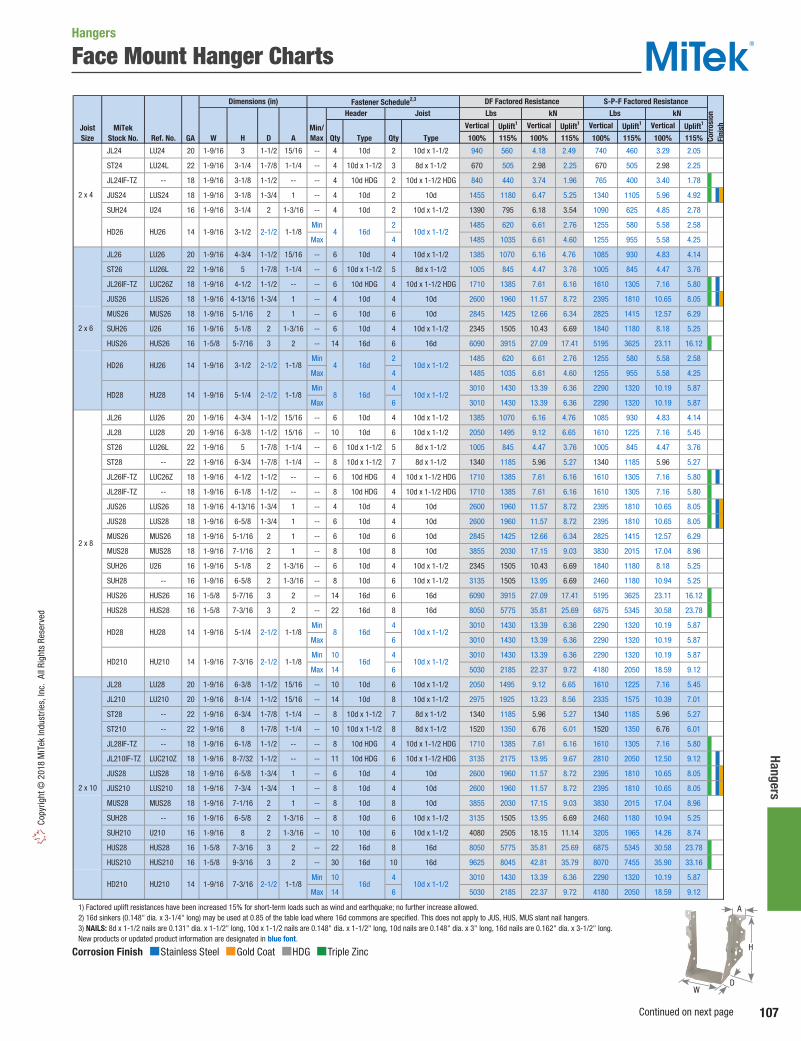
107
Hangers Co
pyrig
ht ©
201
8 M
iTek
Indu
strie
s, In
c. A
ll Ri
ghts
Res
erve
d
Face Mount Hanger Charts
Vertical Uplift1 Vertical Uplift1 Vertical Uplift1 Vertical Uplift1
Ref. No. W H D A Qty Type Qty Type 100% 115% 100% 115% 100% 115% 100% 115%
JL24 LU24 20 1-9/16 3 1-1/2 15/16 -- 4 10d 2 10d x 1-1/2 940 560 4.18 2.49 740 460 3.29 2.05
ST24 LU24L 22 1-9/16 3-1/4 1-7/8 1-1/4 -- 4 10d x 1-1/2 3 8d x 1-1/2 670 505 2.98 2.25 670 505 2.98 2.25
JL24IF-TZ -- 18 1-9/16 3-1/8 1-1/2 -- -- 4 10d HDG 2 10d x 1-1/2 HDG 840 440 3.74 1.96 765 400 3.40 1.78
JUS24 LUS24 18 1-9/16 3-1/8 1-3/4 1 -- 4 10d 2 10d 1455 1180 6.47 5.25 1340 1105 5.96 4.92
SUH24 U24 16 1-9/16 3-1/4 2 1-3/16 -- 4 10d 2 10d x 1-1/2 1390 795 6.18 3.54 1090 625 4.85 2.78
Min 2 1485 620 6.61 2.76 1255 580 5.58 2.58
Max 4 1485 1035 6.61 4.60 1255 955 5.58 4.25
JL26 LU26 20 1-9/16 4-3/4 1-1/2 15/16 -- 6 10d 4 10d x 1-1/2 1385 1070 6.16 4.76 1085 930 4.83 4.14
ST26 LU26L 22 1-9/16 5 1-7/8 1-1/4 -- 6 10d x 1-1/2 5 8d x 1-1/2 1005 845 4.47 3.76 1005 845 4.47 3.76
JL26IF-TZ LUC26Z 18 1-9/16 4-1/2 1-1/2 -- -- 6 10d HDG 4 10d x 1-1/2 HDG 1710 1385 7.61 6.16 1610 1305 7.16 5.80
JUS26 LUS26 18 1-9/16 4-13/16 1-3/4 1 -- 4 10d 4 10d 2600 1960 11.57 8.72 2395 1810 10.65 8.05
MUS26 MUS26 18 1-9/16 5-1/16 2 1 -- 6 10d 6 10d 2845 1425 12.66 6.34 2825 1415 12.57 6.29
SUH26 U26 16 1-9/16 5-1/8 2 1-3/16 -- 6 10d 4 10d x 1-1/2 2345 1505 10.43 6.69 1840 1180 8.18 5.25
HUS26 HUS26 16 1-5/8 5-7/16 3 2 -- 14 16d 6 16d 6090 3915 27.09 17.41 5195 3625 23.11 16.12
Min 2 1485 620 6.61 2.76 1255 580 5.58 2.58
Max 4 1485 1035 6.61 4.60 1255 955 5.58 4.25
Min 4 3010 1430 13.39 6.36 2290 1320 10.19 5.87
Max 6 3010 1430 13.39 6.36 2290 1320 10.19 5.87
JL26 LU26 20 1-9/16 4-3/4 1-1/2 15/16 -- 6 10d 4 10d x 1-1/2 1385 1070 6.16 4.76 1085 930 4.83 4.14
JL28 LU28 20 1-9/16 6-3/8 1-1/2 15/16 -- 10 10d 6 10d x 1-1/2 2050 1495 9.12 6.65 1610 1225 7.16 5.45
ST26 LU26L 22 1-9/16 5 1-7/8 1-1/4 -- 6 10d x 1-1/2 5 8d x 1-1/2 1005 845 4.47 3.76 1005 845 4.47 3.76
ST28 -- 22 1-9/16 6-3/4 1-7/8 1-1/4 -- 8 10d x 1-1/2 7 8d x 1-1/2 1340 1185 5.96 5.27 1340 1185 5.96 5.27
JL26IF-TZ LUC26Z 18 1-9/16 4-1/2 1-1/2 -- -- 6 10d HDG 4 10d x 1-1/2 HDG 1710 1385 7.61 6.16 1610 1305 7.16 5.80
JL28IF-TZ -- 18 1-9/16 6-1/8 1-1/2 -- -- 8 10d HDG 4 10d x 1-1/2 HDG 1710 1385 7.61 6.16 1610 1305 7.16 5.80
JUS26 LUS26 18 1-9/16 4-13/16 1-3/4 1 -- 4 10d 4 10d 2600 1960 11.57 8.72 2395 1810 10.65 8.05
JUS28 LUS28 18 1-9/16 6-5/8 1-3/4 1 -- 6 10d 4 10d 2600 1960 11.57 8.72 2395 1810 10.65 8.05
MUS26 MUS26 18 1-9/16 5-1/16 2 1 -- 6 10d 6 10d 2845 1425 12.66 6.34 2825 1415 12.57 6.29
MUS28 MUS28 18 1-9/16 7-1/16 2 1 -- 8 10d 8 10d 3855 2030 17.15 9.03 3830 2015 17.04 8.96
SUH26 U26 16 1-9/16 5-1/8 2 1-3/16 -- 6 10d 4 10d x 1-1/2 2345 1505 10.43 6.69 1840 1180 8.18 5.25
SUH28 -- 16 1-9/16 6-5/8 2 1-3/16 -- 8 10d 6 10d x 1-1/2 3135 1505 13.95 6.69 2460 1180 10.94 5.25
HUS26 HUS26 16 1-5/8 5-7/16 3 2 -- 14 16d 6 16d 6090 3915 27.09 17.41 5195 3625 23.11 16.12
HUS28 HUS28 16 1-5/8 7-3/16 3 2 -- 22 16d 8 16d 8050 5775 35.81 25.69 6875 5345 30.58 23.78
Min 4 3010 1430 13.39 6.36 2290 1320 10.19 5.87
Max 6 3010 1430 13.39 6.36 2290 1320 10.19 5.87
Min 10 4 3010 1430 13.39 6.36 2290 1320 10.19 5.87
Max 14 6 5030 2185 22.37 9.72 4180 2050 18.59 9.12
JL28 LU28 20 1-9/16 6-3/8 1-1/2 15/16 -- 10 10d 6 10d x 1-1/2 2050 1495 9.12 6.65 1610 1225 7.16 5.45
JL210 LU210 20 1-9/16 8-1/4 1-1/2 15/16 -- 14 10d 8 10d x 1-1/2 2975 1925 13.23 8.56 2335 1575 10.39 7.01
ST28 -- 22 1-9/16 6-3/4 1-7/8 1-1/4 -- 8 10d x 1-1/2 7 8d x 1-1/2 1340 1185 5.96 5.27 1340 1185 5.96 5.27
ST210 -- 22 1-9/16 8 1-7/8 1-1/4 -- 10 10d x 1-1/2 8 8d x 1-1/2 1520 1350 6.76 6.01 1520 1350 6.76 6.01
JL28IF-TZ -- 18 1-9/16 6-1/8 1-1/2 -- -- 8 10d HDG 4 10d x 1-1/2 HDG 1710 1385 7.61 6.16 1610 1305 7.16 5.80
JL210IF-TZ LUC210Z 18 1-9/16 8-7/32 1-1/2 -- -- 11 10d HDG 6 10d x 1-1/2 HDG 3135 2175 13.95 9.67 2810 2050 12.50 9.12
JUS28 LUS28 18 1-9/16 6-5/8 1-3/4 1 -- 6 10d 4 10d 2600 1960 11.57 8.72 2395 1810 10.65 8.05
JUS210 LUS210 18 1-9/16 7-3/4 1-3/4 1 -- 8 10d 4 10d 2600 1960 11.57 8.72 2395 1810 10.65 8.05
MUS28 MUS28 18 1-9/16 7-1/16 2 1 -- 8 10d 8 10d 3855 2030 17.15 9.03 3830 2015 17.04 8.96
SUH28 -- 16 1-9/16 6-5/8 2 1-3/16 -- 8 10d 6 10d x 1-1/2 3135 1505 13.95 6.69 2460 1180 10.94 5.25
SUH210 U210 16 1-9/16 8 2 1-3/16 -- 10 10d 6 10d x 1-1/2 4080 2505 18.15 11.14 3205 1965 14.26 8.74
HUS28 HUS28 16 1-5/8 7-3/16 3 2 -- 22 16d 8 16d 8050 5775 35.81 25.69 6875 5345 30.58 23.78
HUS210 HUS210 16 1-5/8 9-3/16 3 2 -- 30 16d 10 16d 9625 8045 42.81 35.79 8070 7455 35.90 33.16
Min 10 4 3010 1430 13.39 6.36 2290 1320 10.19 5.87
Max 14 6 5030 2185 22.37 9.72 4180 2050 18.59 9.12
1) Factored uplift resistances have been increased 15% for short-term loads such as wind and earthquake; no further increase allowed. 2) 16d sinkers (0.148" dia. x 3-1/4" long) may be used at 0.85 of the table load where 16d commons are specified. This does not apply to JUS, HUS, MUS slant nail hangers. 3) NAILS: 8d x 1-1/2 nails are 0.131" dia. x 1-1/2" long, 10d x 1-1/2 nails are 0.148" dia. x 1-1/2" long, 10d nails are 0.148" dia. x 3" long, 16d nails are 0.162" dia. x 3-1/2" long. New products or updated product information are designated in blue font.
2-1/2 1-1/8 8 16d 10d x 1-1/2
2-1/2 1-1/8 10d x 1-1/28 16d HD28 HU28 14 1-9/16 5-1/4
HU26 HD26 14
2 x 6
3-1/2
1-9/16 3-1/2
HD28 HU28 14 1-9/16 5-1/4
MiTekStock No. GA
Joist Size
14 1-9/16
2 x 4
HD26 HU26
Corr
osio
nFi
nish
S-P-F Factored ResistanceDimensions (in)
Header Joist Lbs
DF Factored Resistance
kNFastener Schedule2,3
Min/Max
2-1/2 1-1/8
Lbs kN
2-1/2 1-1/8
HD210
2 x 8
2 x 10
1-1/82-1/27-3/161-9/1614
1-1/82-1/2
HU210 HD210
7-3/161-9/1614 HU210 16d 10d x 1-1/2
16d 10d x 1-1/2
4 16d 10d x 1-1/2
4 16d 10d x 1-1/2
Corrosion Finish Stainless Steel Gold Coat HDG Triple Zinc
Corrosion Finish Stainless Steel Gold Coat HDG Triple Zinc
Corrosion Finish Stainless Steel Gold Coat HDG Triple Zinc
A
D
H
W
Hangers
Continued on next page

108
Hang
ers
Copyright © 2018 M
iTek Industries, Inc. All Rights Reserved
Face Mount Hanger Charts
Vertical Uplift1 Vertical Uplift1 Vertical Uplift1 Vertical Uplift1
Joist Size Ref. No. W H D A Qty Type Qty Type 100% 115% 100% 115% 100% 115% 100% 115%
JL210 LU210 20 1-9/16 8-1/4 1-1/2 15/16 -- 14 10d 8 10d x 1-1/2 2975 1925 13.23 8.56 2335 1575 10.39 7.01
ST210 -- 22 1-9/16 8 1-7/8 1-1/4 -- 10 10d x 1-1/2 8 8d x 1-1/2 1520 1350 6.76 6.01 1520 1350 6.76 6.01
JL210IF-TZ LUC210Z 18 1-9/16 8-7/32 1-1/2 -- -- 11 10d HDG 6 10d x 1-1/2 HDG 3135 2175 13.95 9.67 2810 2050 12.50 9.12
JUS210 LUS210 18 1-9/16 7-3/4 1-3/4 1 -- 8 10d 4 10d 2600 1960 11.57 8.72 2395 1810 10.65 8.05
SUH210 U210 16 1-9/16 8 2 1-3/16 -- 10 10d 6 10d x 1-1/2 4080 2505 18.15 11.14 3205 1965 14.26 8.74
HUS210 HUS210 16 1-5/8 9-3/16 3 2 -- 30 16d 10 16d 9625 8045 42.81 35.79 8070 7455 35.90 33.16
Min 10 4 3010 1430 13.39 6.36 2290 1320 10.19 5.87
Max 14 6 5030 2185 16.99 9.72 4180 2050 18.59 9.12
Min 14 6 2185 9.72 2050 9.12
Max 20 10 2775 12.34 2600 11.57
HD212IF HUC212 14 1-9/16 9-1/4 2 -- -- 16 16d 6 10d x 1-1/2 4545 2005 20.22 8.92 3565 1575 15.86 7.01
SUH214 U214 16 1-9/16 10 2 1-1/8 -- 12 10d 8 10d x 1-1/2 4105 2505 18.26 11.14 3225 1965 14.35 8.74
Min 14 6 2185 9.72 2050 9.12
Max 20 10 2775 12.34 2600 11.57
HD212IF HUC212 14 1-9/16 9-1/4 2 -- -- 16 16d 6 10d x 1-1/2 4545 2005 20.22 8.92 3565 1575 15.86 7.01
Min 16 8 5030 2185 22.37 9.72 4180 2050 18.59 9.12
Max 24 12 5585 2775 24.84 12.34 4710 2600 20.95 11.57
Min 18 8 5030 2775 22.37 12.34 4180 2600 18.59 11.57
Max 26 12 5585 3495 24.84 15.55 4710 3270 20.95 14.55
JUS24-2 LUS24-2 18 3-1/8 3-7/16 2 1 -- 4 16d 2 16d 1445 1180 6.43 5.25 1330 1105 5.92 4.92
SUH24-2 U24-2 16 3-1/8 3-1/8 2 1-1/8 -- 6 10d 2 10d 1910 825 8.50 3.67 1500 650 6.67 2.89
HD24-2 HU24-2 14 3-1/8 3-1/2 2-1/2 1-1/8 -- 4 16d 2 10d 1455 635 6.47 2.82 1340 565 5.96 2.51
HUS24-2 -- 14 3-1/8 3-7/16 2 1 -- 4 16d 2 16d 1670 1490 7.43 6.63 1285 1375 5.72 6.12
HUS24-2IF -- 14 3-1/8 3-7/16 2 1 -- 4 16d 2 16d 1670 1490 7.43 6.63 1285 1375 5.72 6.12
DT26 -- 22 3-1/16 5 2 1-1/4 -- 8 16d x 2-1/2 5 8d x 1-1/2 1385 845 6.16 3.76 1385 845 6.16 3.76
JUS26-2 LUS26-2 18 3-1/8 5-1/4 2 1 -- 4 16d 4 16d 2090 2445 9.30 10.88 1920 2245 8.54 9.99
SUH26-2 U26-2 16 3-1/8 5-1/16 2 1-1/8 -- 8 10d 4 10d 3135 1665 13.95 7.41 2460 1310 10.94 5.83
HUS26-2 HUS26-2 14 3-1/8 5-1/4 2 1 -- 4 16d 4 16d 3175 1955 14.12 8.70 2570 1850 11.43 8.23
HUS26-2IF HUSC26-2 14 3-1/8 5-1/4 2 -- -- 4 16d 4 16d 3175 1955 14.12 8.70 2570 1850 11.43 8.23
Min 8 4 3010 1430 13.39 6.36 2290 1320 10.19 5.87
Max 12 6 4355 2460 19.37 10.94 3550 2200 15.79 9.79
Min 8 4 3010 1430 13.39 6.36 2290 1320 10.19 5.87
Max 12 6 4355 2460 19.37 10.94 3550 2200 15.79 9.79
DT26 -- 22 3-1/16 5 2 1-1/4 -- 8 16d x 2-1/2 5 8d x 1-1/2 1385 845 6.16 3.76 1385 845 6.16 3.76
DT28 -- 22 3-1/16 6-3/4 2 1-1/4 -- 10 16d x 2-1/2 7 8d x 1-1/2 1510 1185 6.72 5.27 1510 1185 6.72 5.27
JUS26-2 LUS26-2 18 3-1/8 5-1/4 2 1 -- 4 16d 4 16d 2090 2445 9.30 10.88 1920 2245 8.54 9.99
JUS28-2 LUS28-2 18 3-1/8 7-1/8 2 1 -- 6 16d 4 16d 3960 2445 17.61 10.88 3200 2245 14.23 9.99
SUH26-2 U26-2 16 3-1/8 5-1/16 2 1-1/8 -- 8 10d 4 10d 3135 1665 13.95 7.41 2460 1310 10.94 5.83
SUH28-2 -- 16 3-1/8 6-1/4 2 1-1/8 -- 10 10d 4 10d 3135 1665 13.95 7.41 2460 1310 10.94 5.83
HUS26-2 HUS26-2 14 3-1/8 5-1/4 2 1 -- 4 16d 4 16d 3175 1955 14.12 8.70 2570 1850 11.43 8.23
HUS26-2IF HUSC26-2 14 3-1/8 5-1/4 2 -- -- 4 16d 4 16d 3175 1955 14.12 8.70 2570 1850 11.43 8.23
HUS28-2 HUS28-2 14 3-1/8 7-1/8 2 1 -- 6 16d 6 16d 3175 4665 14.12 20.75 2570 4310 11.43 19.17
HUS28-2IF HUSC28-2 14 3-1/8 7-1/8 2 -- -- 6 16d 6 16d 3175 4665 14.12 20.75 2570 4310 11.43 19.17
Min 8 4 3010 1430 13.39 6.36 2290 1320 10.19 5.87
Max 12 6 4355 2460 19.37 10.94 3550 2200 15.79 9.79
Min 8 4 3010 1430 13.39 6.36 2290 1320 10.19 5.87
Max 12 6 4355 2460 19.37 10.94 3550 2200 15.79 9.79
Min 10 4 3010 1730 13.39 7.70 2290 1545 10.19 6.87
Max 14 6 5030 2460 22.37 10.94 4180 2200 18.59 9.79
Min 10 4 3010 1730 13.39 7.70 2290 1545 10.19 6.87
Max 14 6 5030 2460 22.37 10.94 4180 2200 18.59 9.79
1) Factored uplift resistances have been increased 15% for short-term loads such as wind and earthquake; no further increase allowed. 2) 16d sinkers (0.148" dia. x 3-1/4" long) may be used at 0.85 of the table load where 16d commons are specified. This does not apply to JUS, HUS, MUS slant nail hangers. 3) WS3 Wood Screws are 1/4" x 3" long and are included with HDQ hangers. 4) NAILS: 8d x 1-1/2 nails are 0.131" dia. x 1-1/2" long, 10d x 1-1/2 nails are 0.148" dia. x 1-1/2" long, 10d nails are 0.148" dia. x 3" long, 16d nails are 0.162" dia. x 3-1/2" long, 16d x 2-1/2 nails are 0.162" dia. x 2-1/2" long. New products or updated product information are designated in blue font.
10d x 1-1/2
16d 10d x 1-1/21-1/87-3/161-9/16
7-1/8 2-1/2 -- 16d
16d
16d
10d
16d 10d
16d 10d
1-1/8
1-1/8
2-1/2
2-1/2
16d
16d 10d2-1/2
2-1/2 1-1/8
1-1/8
14 HU210
1-1/8
2-1/2
2-1/2 HU212 9-13/161-9/1614
7-1/8
14
14
HU26-2
HU28-2
5-1/43-1/814 HUC26-2
3-1/8
1-9/16
16d 10d
5-1/4 10d
10d x 1-1/2
16d 10d x 1-1/2
1-9/16
1-9/16 1-1/8
1-1/810-13/16 2-1/2
12-3/4 2-1/2
5-1/4
5-1/4
1-1/82-1/2
HD26-2
HD26-2IF
(2) 2 x 6
HD26-2
3-1/8
3-1/814
14 HU26-2
HUC26-2
(2) 2 x 8
HD28-2IF HUC28-2 14 3-1/8
HD26-2IF
HD28-2 3-1/8
MiTekStock No. GA
(2) 2 x 4
14
2 x 14
2 x 16
14
14 HU214
HU216
HD214
HD216
HD212 HU212
HD214 HU214 14
2 x 12
HD210
HD212
Dimensions (in) DF Factored Resistance S-P-F Factored Resistance
Corr
osio
nFi
nish
Header Joist Lbs kN Lbs kNFastener Schedule2,3,4
Min/Max
10-13/16 1-1/82-1/2 16d 10d x 1-1/2
1-9/16 9-13/16 2-1/2 1-1/8 16d 10d x 1-1/2
2-1/2 16d 10d x 1-1/2 HD212 HU212 14 1-9/16 1-1/89-13/16
5030 22.37 4180 18.59
5030 22.37 4180 18.59
5030 22.37 4180 18.59
Corrosion Finish Stainless Steel Gold Coat HDG Triple Zinc
Corrosion Finish Stainless Steel Gold Coat HDG Triple Zinc
Corrosion Finish Stainless Steel Gold Coat HDG Triple Zinc
A
D
H
W
Hangers
Continued on next page

109
Hangers Co
pyrig
ht ©
201
8 M
iTek
Indu
strie
s, In
c. A
ll Ri
ghts
Res
erve
d
Face Mount Hanger Charts
Vertical Uplift1 Vertical Uplift1 Vertical Uplift1 Vertical Uplift1
Joist Size Ref. No. W H D A Qty Type Qty Type 100% 115% 100% 115% 100% 115% 100% 115%
DT28 -- 22 3-1/16 6-3/4 2 1-1/4 -- 10 16d x 2-1/2 7 8d x 1-1/2 1510 1185 6.72 5.27 1510 1185 6.72 5.27
DT210 -- 22 3-1/16 7-7/8 2 1-1/4 -- 12 16d x 2-1/2 8 8d x 1-1/2 1640 1350 7.30 6.01 1640 1350 7.30 6.01
JUS28-2 LUS28-2 18 3-1/8 7-1/8 2 1 -- 6 16d 4 16d 3960 2445 17.61 10.88 3200 2245 14.23 9.99
JUS210-2 LUS210-2 18 3-1/8 9-1/8 2 1 -- 8 16d 6 16d 3960 4615 17.61 20.53 3200 4245 14.23 18.88
SUH28-2 -- 16 3-1/8 6-1/4 2 1-1/8 -- 10 10d 4 10d 3135 1665 13.95 7.41 2460 1310 10.94 5.83
SUH210-2 U210-2 16 3-1/8 8-9/16 2 1-1/8 -- 16 10d 6 10d 6435 2920 28.62 12.99 5055 2290 22.49 10.19
HUS28-2 HUS28-2 14 3-1/8 7-1/8 2 1 -- 6 16d 6 16d 3175 4665 14.12 20.75 2570 4310 11.43 19.17
HUS28-2IF HUSC28-2 14 3-1/8 7-1/8 2 -- -- 6 16d 6 16d 3175 4665 14.12 20.75 2570 4310 11.43 19.17
Min 10 4 3010 1730 13.39 7.70 2290 1545 10.19 6.87
Max 14 6 5030 2460 22.37 10.94 4180 2200 18.59 9.79
Min 10 4 3010 1730 13.39 7.70 2290 1545 10.19 6.87
Max 14 6 5030 2460 22.37 10.94 4180 2200 18.59 9.79
HUS210-2 HUS210-2 14 3-1/8 9-1/8 2 1 -- 8 16d 8 16d 4755 4665 21.15 20.75 3860 4310 17.17 19.17
HUS210-2IF HUSC210-2 14 3-1/8 9-1/8 2 -- -- 8 16d 8 16d 4755 4665 21.15 20.75 3860 4310 17.17 19.17
Min 14 6 5030 2460 22.37 10.94 4180 2200 18.59 9.79
Max 20 10 5870 4070 26.11 18.10 4625 3640 20.57 16.19
Min 14 6 5030 2460 22.37 10.94 4180 2200 18.59 9.79
Max 20 10 5870 4070 26.11 18.10 4625 3640 20.57 16.19
HDQ210-2IF HUCQ210-2-SDS 14 3-1/4 9 3 1-1/2 -- 12 WS3 6 WS3 8460 4970 37.63 22.11 7385 4335 32.85 19.28
DT210 -- 22 3-1/16 7-7/8 2 1-1/4 -- 12 16d x 2-1/2 8 8d x 1-1/2 1640 1350 7.30 6.01 1640 1350 7.30 6.01
JUS210-2 LUS210-2 18 3-1/8 9-1/8 2 1 -- 8 16d 6 16d 3960 4615 17.61 20.53 3200 4245 14.23 18.88
SUH210-2 U210-2 16 3-1/8 8-9/16 2 1-1/8 -- 16 10d 6 10d 6435 2920 28.62 12.99 5055 2290 22.49 10.19
HUS210-2 HUS210-2 14 3-1/8 9-1/8 2 1 -- 8 16d 8 16d 4755 4665 21.15 20.75 3860 4310 17.17 19.17
HUS210-2IF HUSC210-2 14 3-1/8 9-1/8 2 -- -- 8 16d 8 16d 4755 4665 21.15 20.75 3860 4310 17.17 19.17
Min 14 6 5030 2460 22.37 10.94 4180 2200 18.59 9.79
Max 20 10 5870 4070 26.11 18.10 4625 3640 20.57 16.19
Min 14 6 5030 2460 22.37 10.94 4180 2200 18.59 9.79
Max 20 10 5870 4070 26.11 18.10 4625 3640 20.57 16.19
HUS212-2 HUS212-2 14 3-1/8 11-1/8 2 1 -- 10 16d 10 16d 5820 6375 25.89 28.36 4775 6375 21.24 28.36
HUS212-2IF HUSC212-2 14 3-1/8 11-1/8 2 -- -- 10 16d 10 16d 5820 6375 25.89 28.36 4775 6375 21.24 28.36
Min 16 8 5030 2460 22.37 10.94 4180 2200 18.59 9.79
Max 24 12 7540 4070 33.54 18.10 6965 3640 30.98 16.19
Min 16 8 5030 2460 22.37 10.94 4180 2200 18.59 9.79
Max 24 12 7540 4070 33.54 18.10 6965 3640 30.98 16.19
HDQ210-2IF HUCQ210-2-SDS 14 3-1/4 9 3 1-1/2 -- 12 WS3 6 WS3 8460 4970 37.63 22.11 7385 4335 32.85 19.28
JUS210-2 LUS210-2 18 3-1/8 9-1/8 2 1 -- 8 16d 6 16d 3960 4615 17.61 20.53 3200 4245 14.23 18.88
JUS214-2 LUS214-2 18 3-1/8 13-1/8 2 1 -- 12 16d 6 16d 4685 4615 20.84 20.53 4055 4245 18.04 18.88
SUH210-2 U210-2 16 3-1/8 8-9/16 2 1-1/8 -- 16 10d 6 10d 6435 2920 28.62 12.99 5055 2290 22.49 10.19
HUS210-2 HUS210-2 14 3-1/8 9-1/8 2 1 -- 8 16d 8 16d 4755 4665 21.15 20.75 3860 4310 17.17 19.17
HUS210-2IF HUSC210-2 14 3-1/8 9-1/8 2 -- -- 8 16d 8 16d 4755 4665 21.15 20.75 3860 4310 17.17 19.17
Min 14 6 5030 2460 22.37 10.94 4180 2200 18.59 9.79
Max 20 10 5870 4070 26.11 18.10 4625 3640 20.57 16.19
Min 14 6 5030 2460 22.37 10.94 4180 2200 18.59 9.79
Max 20 10 5870 4070 26.11 18.10 4625 3640 20.57 16.19
HUS212-2 HUS212-2 14 3-1/8 11-1/8 2 1 -- 10 16d 10 16d 5820 6375 25.89 28.36 4775 6375 21.24 28.36
HUS212-2IF HUSC212-2 14 3-1/8 11-1/8 2 -- -- 10 16d 10 16d 5820 6375 25.89 28.36 4775 6375 21.24 28.36
Min 16 8 5030 2460 22.37 10.94 4180 2200 18.59 9.79
Max 24 12 7540 4070 33.54 18.10 6965 3640 30.98 16.19
Min 16 8 5030 2460 22.37 10.94 4180 2200 18.59 9.79
Max 24 12 7540 4070 33.54 18.10 6965 3640 30.98 16.19
Min 18 8 5030 2775 22.37 12.34 4180 2600 18.59 11.57
Max 26 12 7540 4070 33.54 18.10 6965 3640 30.98 16.19
HDQ210-2IF HUCQ210-2-SDS 14 3-1/4 9 3 1-1/2 -- 12 WS3 6 WS3 8460 4970 37.63 22.11 7385 4335 32.85 19.28
1) Factored uplift resistances have been increased 15% for short-term loads such as wind and earthquake; no further increase allowed. 2) 16d sinkers (0.148" dia. x 3-1/4" long) may be used at 0.85 of the table load where 16d commons are specified. This does not apply to JUS, HUS, MUS slant nail hangers. 3) WS15 are 1/4" x 1-1/2" long, WS3 Wood Screws are 1/4" x 3" long and are included with HDQ hangers. 4) NAILS: 8d x 1-1/2 nails are 0.131" dia. x 1-1/2" long, 10d nails are 0.148" dia. x 3" long, 16d nails are 0.162" dia. x 3-1/2" long, 16d x 2-1/2 nails are 0.162" dia. x 2-1/2" long. New products or updated product information are designated in blue font.
(2) 2 x 10
HD210-2 HU210-2 2-1/2
2-1/2 --
16d 10d
16d
16d 10d
16d 10d
7-1/83-1/8
11 10d
1-1/8
--
3-1/8 9
10d
1-1/8
16d 10d
16d 10d2-1/2 --
HD210-2IF HUC210-2 14 3-1/8 9 16d
14
Corr
osio
nFi
nish
Header Joist Lbs kN Lbs kN
DF Factored Resistance S-P-F Factored ResistanceFastener Schedule2,3,4
Min/MaxGA
Dimensions (in)
(2) 2 x 12
HD210-2 HU210-2 14 3-1/8 9 2-1/2 1-1/8
HD210-2IF HUC210-2 14
2-1/2
2-1/2
3-1/8 9
HD212-2 HU212-2 14 3-1/8 11
HD212-2IF HUC212-2 14 3-1/8
MiTekStock No.
10d HD28-2IF HUC28-2 14 3-1/8 7-1/8 2-1/2 -- 16d
1-1/82-1/214 HU28-2 HD28-2
HUC210-2 14 3-1/8
10d
16d 10d
3-1/8 914
2-1/2
HU210-2
10d
1-1/8
--
1-1/8
10d
16d 10d
2-1/2
2-1/2
2-1/2 16d
(2) 2 x 14
2-1/2
9
HD212-2 HU212-2 14 3-1/8 11
16d
16d
HD212-2IF HUC212-2
HD214-2 HU214-2
14 3-1/8
1-1/8
--
11
14 3-1/8 13
HD210-2
HD210-2IF
Corrosion Finish Stainless Steel Gold Coat HDG Triple Zinc
Corrosion Finish Stainless Steel Gold Coat HDG Triple Zinc
Corrosion Finish Stainless Steel Gold Coat HDG Triple Zinc
A
D
H
W
Hangers
Continued on next page
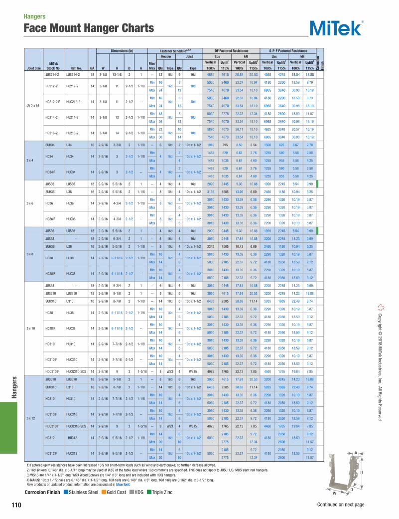
110
Hang
ers
Copyright © 2018 M
iTek Industries, Inc. All Rights Reserved
Face Mount Hanger Charts
Vertical Uplift1 Vertical Uplift1 Vertical Uplift1 Vertical Uplift1
Joist Size Ref. No. W H D A Qty Type Qty Type 100% 115% 100% 115% 100% 115% 100% 115%
JUS214-2 LUS214-2 18 3-1/8 13-1/8 2 1 -- 12 16d 6 16d 4685 4615 20.84 20.53 4055 4245 18.04 18.88
Min 16 8 5030 2460 22.37 10.94 4180 2200 18.59 9.79
Max 24 12 7540 4070 33.54 18.10 6965 3640 30.98 16.19
Min 16 8 5030 2460 22.37 10.94 4180 2200 18.59 9.79
Max 24 12 7540 4070 33.54 18.10 6965 3640 30.98 16.19
Min 18 8 5030 2775 22.37 12.34 4180 2600 18.59 11.57
Max 26 12 7540 4070 33.54 18.10 6965 3640 30.98 16.19
Min 22 10 5870 4070 26.11 18.10 4625 3640 20.57 16.19
Max 30 14 7540 4070 33.54 18.10 6965 3640 30.98 16.19
SUH34 U34 16 2-9/16 3-3/8 2 1-1/8 -- 6 10d 2 10d x 1-1/2 1910 795 8.50 3.54 1500 625 6.67 2.78
Min 2 1485 620 6.61 2.76 1255 580 5.58 2.58
Max 4 1485 1035 6.61 4.60 1255 955 5.58 4.25
Min 2 1485 620 6.61 2.76 1255 580 5.58 2.58
Max 4 1485 1035 6.61 4.60 1255 955 5.58 4.25
JUS36 LUS36 18 2-9/16 5-5/16 2 1 -- 4 16d 4 16d 2090 2445 9.30 10.88 1920 2245 8.54 9.99
SUH36 U36 16 2-9/16 5-5/16 2 1-1/8 -- 8 10d 4 10d x 1-1/2 3135 1505 13.95 6.69 2460 1180 10.94 5.25
Min 4 3010 1430 13.39 6.36 2290 1320 10.19 5.87
Max 6 3010 1430 13.39 6.36 2290 1320 10.19 5.87
Min 4 3010 1430 13.39 6.36 2290 1320 10.19 5.87
Max 6 3010 1430 13.39 6.36 2290 1320 10.19 5.87
JUS36 LUS36 18 2-9/16 5-5/16 2 1 -- 4 16d 4 16d 2090 2445 9.30 10.88 1920 2245 8.54 9.99
JUS38 -- 18 2-9/16 6-3/4 2 1 -- 6 16d 4 16d 3960 2445 17.61 10.88 3200 2245 14.23 9.99
SUH36 U36 16 2-9/16 5-5/16 2 1-1/8 -- 8 10d 4 10d x 1-1/2 2345 1505 10.43 6.69 2460 1180 10.94 5.25
Min 10 4 3010 1430 13.39 6.36 2290 1320 10.19 5.87
Max 14 6 5030 2185 22.37 9.72 4180 2050 18.59 9.12
Min 10 4 3010 1430 13.39 6.36 2290 1320 10.19 5.87
Max 14 6 5030 2185 22.37 9.72 4180 2050 18.59 9.12
JUS38 -- 18 2-9/16 6-3/4 2 1 -- 6 16d 4 16d 3960 2445 17.61 10.88 3200 2245 14.23 9.99
JUS310 LUS310 18 2-9/16 9-1/8 2 1 -- 8 16d 6 16d 3960 4615 17.61 20.53 3200 4245 14.23 18.88
SUH310 U310 16 2-9/16 8-7/8 2 1-1/8 -- 14 10d 6 10d x 1-1/2 6435 2505 28.62 11.14 5055 1965 22.49 8.74
Min 10 4 3010 1430 13.39 6.36 2290 1320 10.19 5.87
Max 14 6 5030 2185 22.37 9.72 4180 2050 18.59 9.12
Min 10 4 3010 1430 13.39 6.36 2290 1320 10.19 5.87
Max 14 6 5030 2185 22.37 9.72 4180 2050 18.59 9.12
Min 10 4 3010 1430 13.39 6.36 2290 1320 10.19 5.87
Max 14 6 5030 2185 22.37 9.72 4180 2050 18.59 9.12
Min 10 4 3010 1430 13.39 6.36 2290 1320 10.19 5.87
Max 14 6 5030 2185 22.37 9.72 4180 2050 18.59 9.12
HDQ310IF HUCQ310-SDS 14 2-9/16 9 3 1-3/16 -- 8 WS3 4 WS15 4975 1765 22.13 7.85 4460 1765 19.84 7.85
JUS310 LUS310 18 2-9/16 9-1/8 2 1 -- 8 16d 6 16d 3960 4615 17.61 20.53 3200 4245 14.23 18.88
SUH310 U310 16 2-9/16 8-7/8 2 1-1/8 -- 14 10d 6 10d x 1-1/2 6435 2505 28.62 11.14 5055 1965 22.49 8.74
Min 10 4 3010 1430 13.39 6.36 2290 1320 10.19 5.87
Max 14 6 5030 2185 22.37 9.72 4180 2050 18.59 9.12
Min 10 4 3010 1430 13.39 6.36 2290 1320 10.19 5.87
Max 14 6 5030 2185 22.37 9.72 4180 2050 18.59 9.12
HDQ310IF HUCQ310-SDS 14 2-9/16 9 3 1-3/16 -- 8 WS3 4 WS15 4975 1765 22.13 7.85 4460 1765 19.84 7.85
Min 14 6 2185 9.72 2050 9.12
Max 20 10 2775 12.34 2600 11.57
Min 14 6 2185 9.72 2050 9.12
Max 20 10 2775 12.34 2600 11.57
1) Factored uplift resistances have been increased 15% for short-term loads such as wind and earthquake; no further increase allowed. 2) 16d sinkers (0.148" dia. x 3-1/4" long) may be used at 0.85 of the table load where 16d commons are specified. This does not apply to JUS, HUS, MUS slant nail hangers. 3) WS15 are 1/4" x 1-1/2" long, WS3 Wood Screws are 1/4" x 3" long and are included with HDQ hangers. 4) NAILS: 10d x 1-1/2 nails are 0.148" dia. x 1-1/2" long, 10d nails are 0.148" dia. x 3" long, 16d nails are 0.162" dia. x 3-1/2" long. New products or updated product information are designated in blue font.
5030
5030
22.37
22.37
4180
4180
18.59
18.59
16d 10d x 1-1/2
Corr
osio
nFi
nishMin/
Max
Header Joist Lbs kN
16d 10d x 1-1/2
Lbs kN
10d x 1-1/2
10d x 1-1/2
16d 10d x 1-1/2
16d 10d x 1-1/2
16d 10d x 1-1/2
16d 10d x 1-1/2
16d 10d x 1-1/28
8
MiTekStock No. GA
Dimensions (in) Fastener Schedule2,3,4 DF Factored Resistance S-P-F Factored Resistance
16d 10d
HD212-2IF HUC212-2 14 3-1/8 11 2-1/2 -- 16d
HD212-2 HU212-2 14 3-1/8 11 2-1/2 1-1/8
10d
HD214-2 HU214-2 14 3-1/8 13 2-1/2 1-1/8 16d 10d
1-1/8 16d 10d
3 x 4 HD34 HU34 14 2-9/16 3 2-1/2
HD216-2 HU216-2 14 3-1/8 14 2-1/2
(2) 2 x 16
1-1/8 4 16d 10d x 1-1/2
HD34IF HUC34 14 2-9/16 3 2-1/2 -- 4 16d 10d x 1-1/2
3 x 6
3 x 8 HD38 HU38 14 2-9/16 6-11/16 2-1/2 1-1/8 16d 10d x 1-1/2
HD38IF HUC38 14 2-9/16 6-11/16 2-1/2 -- 16d 10d x 1-1/2
3 x 10
HD38 HU38 14 2-9/16 6-11/16 2-1/2 1-1/8 16d
HD38IF HUC38 14 2-9/16 6-11/16 2-1/2 -- 16d
HD310 HU310 14 2-9/16
3 x 12
7-7/16 2-1/2 1-1/8
HD310IF HUC310 14 2-9/16 7-7/16 2-1/2 --
HD312IF HUC312 14 2-9/16 9-5/16 2-1/2 --
14 2-9/16 9-5/16 2-1/2 1-1/8 HD312
HD36 HU36 14 2-9/16 4-3/4 2-1/2 1-1/8
14 2-9/16 4-3/4 2-1/2 -- HD36IF HUC36
HU312 10d x 1-1/216d
HD310 HU310 14 2-9/16
7-7/16 2-1/2 1-1/8
HD310IF HUC310 14 2-9/16 7-7/16 2-1/2 --
Corrosion Finish Stainless Steel Gold Coat HDG Triple Zinc
Corrosion Finish Stainless Steel Gold Coat HDG Triple Zinc
Corrosion Finish Stainless Steel Gold Coat HDG Triple Zinc
A
D
H
W
Hangers
Continued on next page
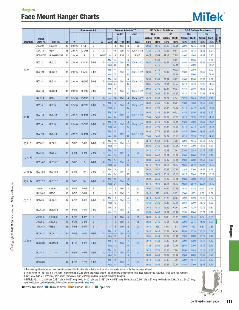
111
Hangers Co
pyrig
ht ©
201
8 M
iTek
Indu
strie
s, In
c. A
ll Ri
ghts
Res
erve
d
Face Mount Hanger Charts
Vertical Uplift1 Vertical Uplift1 Vertical Uplift1 Vertical Uplift1
Joist Size Ref. No. W H D A Qty Type Qty Type 100% 115% 100% 115% 100% 115% 100% 115%
JUS310 LUS310 18 2-9/16 9-1/8 2 1 -- 8 16d 6 16d 3960 4615 23.00 16.61 3200 4245 18.04 13.03
SUH314 U314 16 2-9/16 10-9/16 2 1-1/8 -- 16 10d 6 10d x 1-1/2 4320 2145 19.22 9.54 3720 1845 16.55 8.21
HDQ310IF HUCQ310-SDS 14 2-9/16 9 3 1-3/16 -- 8 WS3 4 WS15 4975 1765 22.13 7.85 4460 1765 19.84 7.85
Min 14 6 2185 9.72 2050 9.12
Max 20 10 2775 12.34 2600 11.57
Min 14 6 2185 9.72 2050 9.12
Max 20 10 2775 12.34 2600 11.57
Min 16 8 5030 2185 22.37 9.72 4180 2050 18.59 9.12
Max 24 12 5585 3495 24.84 15.55 4710 3270 20.95 14.55
Min 16 8 5030 2185 22.37 9.72 4180 2050 18.59 9.12
Max 24 12 5585 3495 24.84 15.55 4710 3270 20.95 14.55
SUH314 U314 16 2-9/16 10-9/16 2 1-1/8 -- 16 10d 6 10d x 1-1/2 4320 2145 19.22 9.54 3720 1845 16.55 8.21
Min 16 8 5030 2185 22.37 9.72 4180 2050 18.59 9.12
Max 24 12 5585 3495 24.84 15.55 4710 3270 20.95 14.55
Min 16 8 5030 2185 22.37 9.72 4180 2050 18.59 9.12
Max 24 12 5585 3495 24.84 15.55 4710 3270 20.95 14.55
Min 18 8 5030 2775 22.37 12.34 4180 2600 18.59 11.57
Max 26 12 5585 3495 24.84 15.55 4710 3270 20.95 14.55
Min 18 8 5030 2775 22.37 12.34 4180 2600 18.59 11.57
Max 26 12 5585 3495 24.84 15.55 4710 3270 20.95 14.55
Min 10 4 3010 1730 13.39 7.70 2290 1545 10.19 6.87
Max 14 6 5030 2460 22.37 10.94 4180 2200 18.59 9.79
Min 10 4 3010 1730 13.39 7.70 2290 1545 10.19 6.87
Max 14 6 5030 2460 22.37 10.94 4180 2200 18.59 9.79
Min 14 6 5030 2460 22.37 10.94 4180 2200 18.59 9.79
Max 20 10 5870 4070 26.11 18.10 4625 3640 20.57 16.19
Min 16 8 5030 2460 22.37 10.94 4180 2200 18.59 9.79
Max 24 12 5870 4070 26.11 18.10 4625 3640 20.57 16.19
Min 16 8 5030 2460 22.37 10.94 4180 2200 18.59 9.79
Max 24 12 5870 4070 26.11 18.10 4625 3640 20.57 16.19
JUS26-3 LUS26-3 18 4-5/8 4-1/2 2 1 -- 4 16d 4 16d 2090 2445 9.30 10.88 1920 2245 8.54 9.99
SUH26-3 U26-3 16 4-5/8 5-1/4 2 1 -- 8 10d 2 10d 1910 825 8.50 3.67 1500 650 6.67 2.89
Min 8 4 3010 1430 13.39 6.36 2290 1320 10.19 5.87
Max 12 6 4355 2460 19.37 10.94 3550 2200 15.79 9.79
Min 8 4 3010 1430 13.39 6.36 2290 1320 10.19 5.87
Max 12 6 4355 2460 19.37 10.94 3550 2200 15.79 9.79
JUS26-3 LUS26-3 18 4-5/8 4-1/2 2 1 -- 4 16d 4 16d 2090 2445 9.30 10.88 1920 2245 8.54 9.99
JUS28-3 LUS28-3 18 4-5/8 6-3/8 2 1 -- 6 16d 4 16d 3960 2445 17.61 10.88 3200 2245 14.23 9.99
SUH26-3 U26-3 16 4-5/8 5-1/4 2 1 -- 8 10d 2 10d 1910 825 8.50 3.67 1500 650 6.67 2.89
Min 8 4 3010 1430 13.39 6.36 2290 1320 10.19 5.87
Max 12 6 4355 2460 19.37 10.94 3550 2200 15.79 9.79
Min 8 4 3010 1430 13.39 6.36 2290 1320 10.19 5.87
Max 12 6 4355 2460 19.37 10.94 3550 2200 15.79 9.79
Min 10 4 3010 1730 13.39 7.70 2290 1545 10.19 6.87
Max 14 6 5030 2460 22.37 10.94 4180 2200 18.59 9.79
Min 10 4 3010 1730 13.39 7.70 2290 1545 10.19 6.87
Max 14 6 5030 2460 22.37 10.94 4180 2200 18.59 9.79
1) Factored uplift resistances have been increased 15% for short-term loads such as wind and earthquake; no further increase allowed. 2) 16d sinkers (0.148" dia. x 3-1/4" long) may be used at 0.85 of the table load where 16d commons are specified. This does not apply to JUS, HUS, MUS slant nail hangers. 3) WS15 are 1/4" x 1-1/2" long, WS3 Wood Screws are 1/4" x 3" long and are included with HDQ hangers. 4) NAILS: 8d x 1-1/2 nails are 0.131" dia. x 1-1/2" long, 10d x 1-1/2 nails are 0.148" dia. x 1-1/2" long, 10d nails are 0.148" dia. x 3" long, 16d nails are 0.162" dia. x 3-1/2" long. New products or updated product information are designated in blue font.
Corr
osio
nFi
nishMiTek
Stock No. GA
Header Joist Lbs kN Lbs kN
Dimensions (in) DF Factored Resistance S-P-F Factored ResistanceFastener Schedule2,3,4
Min/Max
3 x 14
(3) 2 x 6
16d HD314 HU314 14 2-9/16 11-5/16 10d x 1-1/22-1/2 1-1/8
16d 10d x 1-1/2
HD312IF HUC312 14 2-9/16 9-5/16 2-1/2 -- 16d 10d x 1-1/2
HD312 HU312 14 2-9/16 9-5/16 2-1/2 1-1/8
HD314IF HUC314 14 2-9/16 11-5/16 2-1/2 -- 16d 10d x 1-1/2
2-1/2 1-1/8 16d 10d x 1-1/2
HD314IF HUC314 14 2-9/16 11-5/16 2-1/2 -- 16d 10d x 1-1/2
HD314 HU314 14 2-9/16 11-5/16
5-1/8 6-1/8
2-1/2 1-1/8 16d 10d x 1-1/2
HD316IF HUC316 14 2-9/16 13-5/16 2-1/2 -- 16d 10d x 1-1/2
HD316 HU316 14 2-9/16 13-5/16
1-1/8 16d 10d
HD310-2 HU310-2 14 5-1/8 8
2-1/2 1-1/8 16d 10d
HD38-2 HU38-2 14 5-1/8 6-1/8 2-1/2 1-1/8 16d 10d
HD38-2 HU38-2 14
2-1/2 1-1/8 16d 10d
3 x 16
(2) 3 x 8
(2) 3 x 10
(2) 3 x 12
(2) 3 x 14 HD312-2 HU312-2 14 5-1/8 10
2-1/2 1-1/8 16d 10d
HD312-2 HU312-2 14 5-1/8 10 2-1/2
2-1/2 1-1/8 16d 10d
HD26-3IF HUC26-3 14 4-5/8 4-1/2 2-1/2 -- 16d 10d
HD26-3 HU26-3 14 4-5/8 4-1/2
14 4-5/8 6-3/8
2-1/2 1-1/8 16d 10d
HD26-3IF HUC26-3 14 4-5/8 4-1/2 2-1/2 -- 16d 10d
HD26-3 HU26-3 14 4-5/8 4-1/2
5030 22.37 4180 18.59
5030 22.37 4180 18.59
(3) 2 x 8
2-1/2 1-1/8 16d 10d
HD28-3IF -- 14 4-5/8 6-3/8 2-1/2 -- 16d 10d
HD28-3 --
Corrosion Finish Stainless Steel Gold Coat HDG Triple Zinc
Corrosion Finish Stainless Steel Gold Coat HDG Triple Zinc
Corrosion Finish Stainless Steel Gold Coat HDG Triple Zinc
A
D
H
W
Hangers
Continued on next page

112
Hang
ers
Copyright © 2018 M
iTek Industries, Inc. All Rights Reserved
Face Mount Hanger Charts
Vertical Uplift1 Vertical Uplift1 Vertical Uplift1 Vertical Uplift1
Joist Size Ref. No. W H D A Qty Type Qty Type 100% 115% 100% 115% 100% 115% 100% 115%
JUS28-3 LUS28-3 18 4-5/8 6-3/8 2 1 -- 6 16d 4 16d 3960 2445 17.61 10.88 3200 2245 14.23 9.99
JUS210-3 LUS210-3 18 4-5/8 8-3/8 2 1 -- 8 16d 6 16d 3960 4615 17.61 20.53 3200 4245 14.23 18.88
SUH210-3 U210-3 16 4-5/8 8-3/8 2 1 -- 14 10d 6 10d 6435 2920 28.62 12.99 5055 2290 22.49 10.19
Min 10 4 3010 1730 13.39 7.70 2290 1545 10.19 6.87
Max 14 6 5030 2460 22.37 10.94 4180 2200 18.59 9.79
Min 10 4 3010 1730 13.39 7.70 2290 1545 10.19 6.87
Max 14 6 5030 2460 22.37 10.94 4180 2200 18.59 9.79
Min 14 6 5030 2460 22.37 10.94 4180 2200 18.59 9.79
Max 20 10 5870 4070 26.11 18.10 4625 3640 20.57 16.19
Min 14 6 5030 2460 22.37 10.94 4180 2200 18.59 9.79
Max 20 10 5870 4070 26.11 18.10 4625 3640 20.57 16.19
HDQ210-3IF HUCQ210-3-SDS 14 4-5/8 9 3 1-1/2 -- 12 WS3 6 WS3 8460 4970 37.63 22.11 7385 4335 32.85 19.28
JUS210-3 LUS210-3 18 4-5/8 8-3/8 2 1 -- 8 16d 6 16d 3960 4615 17.61 20.53 3200 4245 14.23 18.88
SUH210-3 U210-3 16 4-5/8 8-3/8 2 1 -- 14 10d 6 10d 6435 2920 28.62 12.99 5055 2290 22.49 10.19
Min 14 6 5030 2460 22.37 10.94 4180 2200 18.59 9.79
Max 20 10 5870 4070 26.11 18.10 4625 3640 20.57 16.19
Min 14 6 5030 2460 22.37 10.94 4180 2200 18.59 9.79
Max 20 10 5870 4070 26.11 18.10 4625 3640 20.57 16.19
HDQ210-3IF HUCQ210-3-SDS 14 4-5/8 9 3 1-1/2 -- 12 WS3 6 WS3 8460 4970 37.63 22.11 7385 4335 32.85 19.28
Min 16 8 5030 2460 22.37 10.94 4180 2200 18.59 9.79
Max 24 12 5870 4070 26.11 18.10 4625 3640 20.57 16.19
Min 16 8 5030 2460 22.37 10.94 4180 2200 18.59 9.79
Max 24 12 5870 4070 26.11 18.10 4625 3640 20.57 16.19
JUS210-3 LUS210-3 18 4-5/8 8-3/8 2 1 -- 8 16d 6 16d 3960 4615 17.61 20.53 3200 4245 14.23 18.88
SUH210-3 U210-3 16 4-5/8 8-3/8 2 1 -- 14 10d 6 10d 6435 2920 28.62 12.99 5055 2290 22.49 10.19
HDQ210-3IF HUCQ210-3-SDS 14 4-5/8 9 3 1-1/2 -- 12 WS3 6 WS3 8460 4970 37.63 22.11 7385 4335 32.85 19.28
Min 16 8 5030 2460 22.37 10.94 4180 2200 18.59 9.79
Max 24 12 5870 4070 26.11 18.10 4625 3640 20.57 16.19
Min 16 8 5030 2460 22.37 10.94 4180 2200 18.59 9.79
Max 24 12 5870 4070 26.11 18.10 4625 3640 20.57 16.19
Min 18 8 5030 2775 22.37 12.34 4180 2600 18.59 11.57
Max 26 12 5870 4070 26.11 18.10 4625 3640 20.57 16.19
Min 16 8 5030 2460 22.37 10.94 4180 2200 18.59 9.79
Max 24 12 5870 4070 26.11 18.10 4625 3640 20.57 16.19
Min 16 8 5030 2460 22.37 10.94 4180 2200 18.59 9.79
Max 24 12 5870 4070 26.11 18.10 4625 3640 20.57 16.19
Min 18 8 5030 2775 22.37 12.34 4180 2600 18.59 11.57
Max 26 12 5870 4070 26.11 18.10 4625 3640 20.57 16.19
Min 22 10 5870 4070 26.11 18.10 4625 3640 20.57 16.19
Max 30 14 7715 4070 34.32 18.10 6535 3640 29.07 16.19
Min 10 4 3010 1590 13.39 7.07 2290 1505 10.19 6.69
Max 14 6 5030 2460 22.37 10.94 4180 2200 18.59 9.79
Min 14 6 2460 10.94 2200 9.79
Max 18 8 3745 16.66 3480 15.48
Min 14 6 2460 10.94 2200 9.79
Max 18 8 3745 16.66 3480 15.48
Min 14 6 2460 10.94 2200 9.79
Max 18 8 3745 16.66 3480 15.48
JUS44 LUS44 18 3-5/8 3-1/4 2 1 -- 4 16d 2 16d 1245 1180 5.54 5.25 1145 1105 5.09 4.92
SUH44 U44 16 3-9/16 2-7/8 2 1-1/8 -- 6 10d 2 10d 1910 825 8.50 3.67 1500 650 6.67 2.89
HD44 HU44 14 3-9/16 3-5/16 2-1/2 1-1/8 -- 4 16d 2 10d 1455 865 6.47 3.85 1340 775 5.96 3.45
HD44IF HUC44 14 3-9/16 3-5/16 2-1/2 -- -- 4 16d 2 10d 1455 865 6.47 3.85 1340 775 5.96 3.45
1) Factored uplift resistances have been increased 15% for short-term loads such as wind and earthquake; no further increase allowed. 2) 16d sinkers (0.148" dia. x 3-1/4" long) may be used at 0.85 of the table load where 16d commons are specified. This does not apply to JUS, HUS, MUS slant nail hangers. 3) WS3 Wood Screws are 1/4" x 3" long and are included with HDQ hangers. 4) NAILS: 10d nails are 0.148" dia. x 3" long, 16d nails are 0.162" dia. x 3-1/2" long. New products or updated product information are designated in blue font.
2-1/2 -- 16d 10d HD212-3IF HUC212-3 14 4-5/8 10-1/4
2-1/2 -- 16d 10d
HD212-3 HU212-3 14 4-5/8 10-1/4 2-1/2 1-1/8 16d 10d
HD210-3IF HUC210-3 14 4-5/8 8-1/4
HD210-3 HU210-3 14 4-5/8 8-1/4 2-1/2 1-1/8 16d 10d
10d
HD28-3IF -- 14 4-5/8 6-3/8
2-1/2 -- 16d 10d HD210-3IF HUC210-3 14 4-5/8 8-1/4
(4) 2 x 8
(3) 2 x 12
(3) 2 x 10
6-3/8 2-1/2 1-1/8 16d 10d HD28-3 -- 14 4-5/8
2-1/2 -- 16d 10d
HD210-3 HU210-3 14 4-5/8 8-1/4 2-1/2 1-1/8 16d
MiTekStock No. GA
Dimensions (in)
4 x 4
HD212-3 HU212-3 14 4-5/8 10-1/4 2-1/2
2-1/2 1-1/8
1-1/8
(3) 2 x 16
HD28-4 HU28-4 14 6-1/8
2-1/2 1-1/8
(4) 2 x 10
(4) 2 x 12
(4) 2 x 14 HD210-4
DF Factored Resistance
Corr
osio
nFi
nish
Header Joist Lbs kN Lbs kN
S-P-F Factored ResistanceFastener Schedule2,3,4
Min/Max
16d 10d
(3) 2 x 14
HD214-3 HU214-3 14 4-5/8 12-1/4
1-1/8 16d 10d
HD212-3IF HUC212-3 14 4-5/8 10-1/4 2-1/2 -- 16d 10d
16d 10d
HD212-3IF HUC212-3 14 4-5/8 10-1/4 2-1/2 -- 16d 10d
HD212-3 HU212-3 14 4-5/8 10-1/4 2-1/2
16d 10d
HD216-3 HU216-3 14 4-5/8 13-1/4 2-1/2 1-1/8 16d 10d
HD214-3 HU214-3 14 4-5/8 12-1/4
7 2-1/2 1-3/4 16d 16d
16d HD210-4 HU210-4 14 6-1/8 9-1/4 2-1/2 2 16d
HU210-4 14 6-1/8 9-1/4 2-1/2 2 16d 16d
HD210-4 HU210-4 14 6-1/8 9-1/4 2-1/2 2 16d 16d
5030 22.37 4180 18.59
5030 22.37 4180 18.59
5030 22.37 4180 18.59
Corrosion Finish Stainless Steel Gold Coat HDG Triple Zinc
Corrosion Finish Stainless Steel Gold Coat HDG Triple Zinc
Corrosion Finish Stainless Steel Gold Coat HDG Triple Zinc
A
D
H
W
Hangers
Continued on next page

113
Hangers Co
pyrig
ht ©
201
8 M
iTek
Indu
strie
s, In
c. A
ll Ri
ghts
Res
erve
d
Face Mount Hanger Charts
Vertical Uplift1 Vertical Uplift1 Vertical Uplift1 Vertical Uplift1
Joist Size Ref. No. W H D A Qty Type Qty Type 100% 115% 100% 115% 100% 115% 100% 115% JUS46 LUS46 18 3-5/8 5 2 1 -- 4 16d 4 16d 2090 2445 9.30 10.88 1920 2245 8.54 9.99
SUH44 U44 16 3-9/16 2-7/8 2 1-1/8 -- 6 10d 2 10d 1910 825 8.50 3.67 1500 650 6.67 2.89
SUH46 U46 16 3-9/16 4-13/16 2 1-1/8 -- 8 10d 4 10d 4080 1665 18.15 7.41 3205 1310 14.26 5.83
HUS46 HUS46 14 3-5/8 5 2 1 -- 4 16d 4 16d 3175 1955 14.12 8.70 2570 1850 11.43 8.23
HUS46IF HUSC46 14 3-5/8 5 2 -- -- 4 16d 4 16d 3175 1955 14.12 8.70 2570 1850 11.43 8.23
Min 8 4 3010 1430 13.39 6.36 2290 1320 10.19 5.87
Max 12 6 4355 2460 19.37 10.94 3550 2200 15.79 9.79
Min 8 4 3010 1430 13.39 6.36 2290 1320 10.19 5.87
Max 12 6 4355 2460 19.37 10.94 3550 2200 15.79 9.79
JUS46 LUS46 18 3-5/8 5 2 1 -- 4 16d 4 16d 2090 2445 9.30 10.88 1920 2245 8.54 9.99
JUS48 LUS48 18 3-5/8 6-7/8 2 1 -- 6 16d 4 16d 3960 2445 17.61 10.88 3200 2245 14.23 9.99
SUH46 U46 16 3-9/16 4-13/16 2 1-1/8 -- 8 10d 4 10d 4080 1665 18.15 7.41 3205 1310 14.26 5.83
HUS46 HUS46 14 3-5/8 5 2 1 -- 4 16d 4 16d 3175 1955 14.12 8.70 2570 1850 11.43 8.23
HUS46IF HUSC46 14 3-5/8 5 2 -- -- 4 16d 4 16d 3175 1955 14.12 8.70 2570 1850 11.43 8.23
HUS48 HUS48 14 3-5/8 7 2 1 -- 6 16d 6 16d 3175 4665 14.12 20.75 2570 4310 11.43 19.17
HUS48IF HUSC48 14 3-5/8 7 2 1 -- 6 16d 6 16d 3175 4665 14.12 20.75 2570 4310 11.43 19.17
Min 8 4 3010 1430 13.39 6.36 2290 1320 10.19 5.87
Max 12 6 4355 2460 19.37 10.94 3550 2200 15.79 9.79
Min 8 4 3010 1430 13.39 6.36 2290 1320 10.19 5.87
Max 12 6 4355 2460 19.37 10.94 3550 2200 15.79 9.79
Min 10 4 3010 1730 13.39 7.70 2290 1545 10.19 6.87
Max 14 6 5030 2460 22.37 10.94 4180 2200 18.59 9.79
Min 10 4 3010 1730 13.39 7.70 2290 1545 10.19 6.87
Max 14 6 5030 2460 22.37 10.94 4180 2200 18.59 9.79
JUS48 LUS48 18 3-5/8 6-7/8 2 1 -- 6 16d 4 16d 3960 2445 17.61 10.88 3200 2245 14.23 9.99
JUS410 LUS410 18 3-5/8 8-7/8 2 1 -- 8 16d 6 16d 3960 4615 17.61 20.53 3200 4245 14.23 18.88
SUH410 U410 16 3-9/16 8-3/8 2 1-1/8 -- 14 10d 6 10d 6330 2920 28.16 12.99 4970 2290 22.11 10.19
HUS48 HUS48 14 3-5/8 7 2 1 -- 6 16d 6 16d 3175 4665 14.12 20.75 2570 4310 11.43 19.17
HUS48IF HUSC48 14 3-5/8 7 2 1 -- 6 16d 6 16d 3175 4665 14.12 20.75 2570 4310 11.43 19.17
Min 10 4 3010 1730 13.39 7.70 2290 1545 10.19 6.87
Max 14 6 5030 2460 22.37 10.94 4180 2200 18.59 9.79
Min 10 4 3010 1730 13.39 7.70 2290 1545 10.19 6.87
Max 14 6 5030 2460 22.37 10.94 4180 2200 18.59 9.79
HUS410 HUS410 14 3-5/8 8-7/8 2 1 -- 8 16d 8 16d 4755 4665 21.15 20.75 3860 4310 17.17 19.17
HUS410IF HUSC410 14 3-5/8 8-7/8 2 -- -- 8 16d 8 16d 4755 4665 21.15 20.75 3860 4310 17.17 19.17
Min 14 6 5030 2460 22.37 10.94 4180 2200 18.59 9.79
Max 20 10 5870 4070 26.11 18.10 4625 3640 20.57 16.19
Min 14 6 5030 2460 22.37 10.94 4180 2200 18.59 9.79
Max 20 10 5870 4070 26.11 18.10 4625 3640 20.57 16.19
HDQ410IF HUCQ410-SDS 14 3-9/16 9 3 1-1/2 -- 12 WS3 6 WS3 8460 4970 37.63 22.11 7385 4335 32.85 19.28
JUS410 LUS410 18 3-5/8 8-7/8 2 1 -- 8 16d 6 16d 3960 4615 17.61 20.53 3200 4245 14.23 18.88
SUH410 U410 16 3-9/16 8-3/8 2 1-1/8 -- 14 10d 6 10d 6330 2920 28.16 12.99 4970 2290 22.11 10.19
HUS410 HUS410 14 3-5/8 8-7/8 2 1 -- 8 16d 8 16d 4755 4665 21.15 20.75 3860 4310 17.17 19.17
HUS410IF HUSC410 14 3-5/8 8-7/8 2 -- -- 8 16d 8 16d 4755 4665 21.15 20.75 3860 4310 17.17 19.17
Min 14 6 5030 2460 22.37 10.94 4180 2200 18.59 9.79
Max 20 10 5870 4070 26.11 18.10 4625 3640 20.57 16.19
Min 14 6 5030 2460 22.37 10.94 4180 2200 18.59 9.79
Max 20 10 5870 4070 26.11 18.10 4625 3640 20.57 16.19
HDQ410IF HUCQ410-SDS 14 3-9/16 9 3 1-1/2 -- 12 WS3 6 WS3 8460 4970 37.63 22.11 7385 4335 32.85 19.28
HUS412 HUS412 14 3-5/8 10-7/8 2 1 -- 10 16d 10 16d 5820 6375 25.89 28.36 4775 6375 21.24 28.36
HUS412IF HUSC412 14 3-5/8 10-7/8 2 -- -- 10 16d 10 16d 5820 6375 25.89 28.36 4775 6375 21.24 28.36
Min 16 8 5030 2460 22.37 10.94 4180 2200 18.59 9.79
Max 24 12 7540 4070 33.54 18.10 6965 3640 30.98 16.19
Min 16 8 5030 2460 22.37 10.94 4180 2200 18.59 9.79
Max 24 12 7540 4070 33.54 18.10 6965 3640 30.98 16.19
HDQ412IF HUCQ412-SDS 14 3-9/16 11 3 1-1/2 -- 14 WS3 6 WS3 8135 5220 36.19 23.22 6545 4965 29.11 22.09
1) Factored uplift resistances have been increased 15% for short-term loads such as wind and earthquake; no further increase allowed. 2) 16d sinkers (0.148" dia. x 3-1/4" long) may be used at 0.85 of the table load where 16d commons are specified. This does not apply to JUS, HUS, MUS slant nail hangers. 3) WS3 Wood Screws are 1/4" x 3" long and are included with HDQ hangers. 4) NAILS: 10d nails are 0.148" dia. x 3" long, 16d nails are 0.162" dia. x 3-1/2" long. New products or updated product information are designated in blue font.
2-1/2 1-1/8 16d 10d
HD48IF HUC48 14 3-9/16 6-15/16 2-1/2 -- 16d 10d
HD48 HU48 14 3-9/16 6-15/16
3-9/16 5-1/16 2-1/2 -- 16d 10d
HD46 HU46 14 3-9/16 5-1/16 2-1/2 1-1/8 16d 10d
HD46IF
10d
HD46IF HUC46 14 3-9/16 5-1/16 2-1/2 -- 16d 10d
3-9/16 5-1/16 2-1/2 1-1/8 16d HD46 HU46 14
2-1/2 -- 16d 10d HD410IF HUC410 14 3-9/16 8-13/16
2-1/2 -- 16d 10d
HD410 HU410 14 3-9/16 8-13/16 2-1/2 1-1/8 16d 10d
HD48IF HUC48 14 3-9/16 6-15/16
6-15/16 2-1/2 1-1/8 16d 10d HD48 HU48 14 3-9/16
MiTekStock No. GA
4 x 12
HD410 HU410 14
HD412 HU412 14
4 x 10
4 x 6
HUC46 14
4 x 8
Dimensions (in) DF Factored Resistance S-P-F Factored Resistance
Corr
osio
nFi
nish
Header Joist Lbs kN Lbs kN
Min/Max
Fastener Schedule2,3,4
10d
HD410IF HUC410 14 3-9/16 8-13/16 2-1/2 -- 16d 10d
3-9/16 8-13/16 2-1/2 1-1/8 16d
10d
HD412IF HUC412 14 3-9/16 10-13/16 2-1/2 -- 16d 10d
3-9/16 10-13/16 2-1/2 1-1/8 16d
Corrosion Finish Stainless Steel Gold Coat HDG Triple Zinc
Corrosion Finish Stainless Steel Gold Coat HDG Triple Zinc
Corrosion Finish Stainless Steel Gold Coat HDG Triple Zinc
A
D
H
W
Hangers
Continued on next page

114
Hang
ers
Copyright © 2018 M
iTek Industries, Inc. All Rights Reserved
Face Mount Hanger Charts
Vertical Uplift1 Vertical Uplift1 Vertical Uplift1 Vertical Uplift1
Joist Size Ref. No. W H D A Qty Type Qty Type 100% 115% 100% 115% 100% 115% 100% 115% JUS414 LUS414 18 3-5/8 12-7/8 2 1 -- 12 16d 6 16d 3960 4615 17.61 20.53 3200 4245 14.23 18.88
SUH414 U414 16 3-9/16 10-1/16 2 1-1/8 -- 16 10d 6 10d 6330 2920 28.16 12.99 4970 2290 22.11 10.19
Min 14 6 5030 2460 22.37 10.94 4180 2200 18.59 9.79
Max 20 10 5870 4070 26.11 18.10 4625 3640 20.57 16.19
Min 14 6 5030 2460 22.37 10.94 4180 2200 18.59 9.79
Max 20 10 5870 4070 26.11 18.10 4625 3640 20.57 16.19
HDQ410IF HUCQ410-SDS 14 3-9/16 9 3 1-1/2 -- 12 WS3 6 WS3 8460 4970 37.63 22.11 7385 4335 32.85 19.28
HUS412 HUS412 14 3-5/8 10-7/8 2 1 -- 10 16d 10 16d 5820 6375 25.89 28.36 4775 6375 21.24 28.36
HUS412IF HUSC412 14 3-5/8 10-7/8 2 -- -- 10 16d 10 16d 5820 6375 25.89 28.36 4775 6375 21.24 28.36
Min 16 8 5030 2460 22.37 10.94 4180 2200 18.59 9.79
Max 24 12 7540 4070 33.54 18.10 6965 3640 30.98 16.19
Min 16 8 5030 2460 22.37 10.94 4180 2200 18.59 9.79
Max 24 12 7540 4070 33.54 18.10 6965 3640 30.98 16.19
Min 18 8 5030 2775 22.37 12.34 4180 2600 18.59 11.57
Max 26 12 7540 4070 33.54 18.10 6965 3640 30.98 16.19
Min 18 8 5030 2775 22.37 12.34 4180 2600 18.59 11.57
Max 26 12 7540 4070 33.54 18.10 6965 3640 30.98 16.19
HDQ412IF HUCQ412-SDS 14 3-9/16 11 3 1-1/2 -- 14 WS3 6 WS3 8135 5220 36.19 23.22 6545 4965 29.11 22.09
JUS414 LUS414 18 3-5/8 12-7/8 2 1 -- 12 16d 6 16d 3960 4615 17.61 20.53 3200 4245 14.23 18.88
SUH414 U414 16 3-9/16 10-1/16 2 1-1/8 -- 16 10d 6 10d 6330 2920 28.16 12.99 4970 2290 22.11 10.19
Min 16 8 5030 2460 22.37 10.94 4180 2200 18.59 9.79
Max 24 12 7540 4070 33.54 18.10 6965 3640 30.98 16.19
Min 16 8 5030 2460 22.37 10.94 4180 2200 18.59 9.79
Max 24 12 7540 4070 33.54 18.10 6965 3640 30.98 16.19
HDQ412IF HUCQ412-SDS 14 3-9/16 11 3 1-1/2 -- 14 WS3 6 WS3 8135 5220 36.19 23.22 6545 4965 29.11 22.09
Min 18 8 5030 2775 22.37 12.34 4180 2600 18.59 11.57
Max 26 12 7540 4070 33.54 18.10 6965 3640 30.98 16.19
Min 18 8 5030 2775 22.37 12.34 4180 2600 18.59 11.57
Max 26 12 7540 4070 33.54 18.10 6965 3640 30.98 16.19
Min 22 10 5870 4070 26.11 18.10 4625 3640 20.57 16.19
Max 30 14 7210 4070 32.07 18.10 6660 3640 29.63 16.19
Min 22 10 5870 4070 26.11 18.10 4625 3640 20.57 16.19
Max 30 14 7210 4070 32.07 18.10 6660 3640 29.63 16.19
Min 18 8 5030 2775 22.37 12.34 4180 2600 18.59 11.57
Max 26 12 7540 4070 33.54 18.10 6965 3640 30.98 16.19
Min 18 8 5030 2775 22.37 12.34 4180 2600 18.59 11.57
Max 26 12 7540 4070 33.54 18.10 6965 3640 30.98 16.19
Min 22 10 5870 4070 26.11 18.10 4625 3640 20.57 16.19
Max 30 14 7210 4070 32.07 18.10 6660 3640 29.63 16.19
Min 22 10 5870 4070 26.11 18.10 4625 3640 20.57 16.19
Max 30 14 7210 4070 32.07 18.10 6660 3640 29.63 16.19
HD418 -- 14 3-9/16 16-1/2 2-1/2 1-1/4 -- 28 16d 8 10d 7540 3930 33.54 17.48 6965 3515 30.98 15.64
SUH66 U66 16 5-1/2 5 2 1 -- 8 10d 4 10d 3135 1665 13.95 7.41 2460 1310 10.94 5.83
Min 8 4 3010 1590 13.39 7.07 2290 1505 10.19 6.69
Max 12 6 4355 2460 19.37 10.94 3550 2200 15.79 9.79
Min 8 4 3010 1590 13.39 7.07 2290 1505 10.19 6.69
Max 12 6 4355 2460 19.37 10.94 3550 2200 15.79 9.79
SUH66 U66 16 5-1/2 5 2 1 -- 8 10d 4 10d 3135 1665 13.95 7.41 2460 1310 10.94 5.83
Min 8 4 3010 1590 13.39 7.07 2290 1505 10.19 6.69
Max 12 6 4355 2460 19.37 10.94 3550 2200 15.79 9.79
Min 8 4 3010 1590 13.39 7.07 2290 1505 10.19 6.69
Max 12 6 4355 2460 19.37 10.94 3550 2200 15.79 9.79
Min 10 4 3010 1730 13.39 7.70 2290 1545 10.19 6.87
Max 14 6 5030 2460 22.37 10.94 4180 2200 18.59 9.79
Min 10 4 3010 1730 13.39 7.70 2290 1545 10.19 6.87
Max 14 6 5030 2460 22.37 10.94 4180 2200 18.59 9.79
1) Factored uplift resistances have been increased 15% for short-term loads such as wind and earthquake; no further increase allowed. 2) 16d sinkers (0.148" dia. x 3-1/4" long) may be used at 0.85 of the table load where 16d commons are specified. This does not apply to JUS, HUS, MUS slant nail hangers. 3) WS3 Wood Screws are 1/4" x 3" long and are included with HDQ hangers. 4) NAILS: 10d nails are 0.148" dia. x 3" long, 16d nails are 0.162" dia. x 3-1/2" long. New products or updated product information are designated in blue font.
3-9/16 12-13/16 2-1/2 1-1/8 16d
HD412IF HUC412 14 3-9/16 10-13/16 2-1/2 --
-- 16d 10d HD414IF HUC414 14 3-9/16 12-13/16 2-1/2
16d
16d 16d
HD68IF HUC68 14 5-1/2 5-15/16 2-1/2 -- 16d
HD68 HU68 14
16d
HD66IF HUC66 14 5-1/2 4-1/16 2-1/2
4 x 14
2-1/2 1-1/8 16d 10d
HD410IF HUC410
-- 16d 16d
10d
HD410 HU410 14 3-9/16 8-13/16
14
4 x 18
6 x 8
HD66 HU66 14 5-1/2 4-1/16
16d
HD66IF HUC66 14 5-1/2 4-1/16 2-1/2 -- 16d 16d
5-1/2 5-15/16 2-1/2 1-1/8
2-1/2 1-1/8 16d
6 x 6 HD66 HU66 14 5-1/2 4-1/16 2-1/2 1-1/8 16d
HD416IF HUC416 14 3-9/16 14-13/16 2-1/2 -- 16d 10d
HD416 HU416 14 3-9/16 14-13/16 2-1/2 1-1/8 16d 10d
2-1/2 1-1/8 16d 10d
HD414IF HUC414 14 3-9/16 12-13/16 2-1/2
HD414 HU414 14 3-9/16 12-13/16
-- 16d 10d
10d
HD416IF HUC416 14 3-9/16 14-13/16 2-1/2 -- 16d 10d
10d
HD414IF HUC414 14 3-9/16 12-13/16 2-1/2 --
HD414 HU414 14 3-9/16 12-13/16 2-1/2
16d 10d
10d
HD412IF HUC412 14 3-9/16 10-13/16 2-1/2 -- 16d 10d
4 x 16
HD412 HU412 14 3-9/16 10-13/16 2-1/2 1-1/8 16d
1-1/8 16d
HD416 HU416 14 3-9/16 14-13/16 2-1/2 1-1/8 16d
HD412 HU412 14 3-9/16 10-13/16
10d
kN
MiTekStock No. GA
Lbs
3-9/16 8-13/16 2-1/2 -- 16d
2-1/2 1-1/8 16d 10d
16d 10d
HD414 HU414 14
Dimensions (in) Fastener Schedule2,3,4 DF Factored Resistance S-P-F Factored Resistance
Corr
osio
nFi
nishMin/
Max
Header Joist Lbs kN
Corrosion Finish Stainless Steel Gold Coat HDG Triple Zinc
Corrosion Finish Stainless Steel Gold Coat HDG Triple Zinc
Corrosion Finish Stainless Steel Gold Coat HDG Triple Zinc
A
D
H
W
Hangers
Continued on next page

115
Hangers Co
pyrig
ht ©
201
8 M
iTek
Indu
strie
s, In
c. A
ll Ri
ghts
Res
erve
d
Face Mount Hanger Charts
Vertical Uplift1 Vertical Uplift1 Vertical Uplift1 Vertical Uplift1
Joist Size Ref. No. W H D A Qty Type Qty Type 100% 115% 100% 115% 100% 115% 100% 115%
SUH610 U610 16 5-1/2 9 2 1 -- 14 10d 6 10d 6435 2920 28.62 12.99 5055 2290 22.49 10.19
Min 10 4 3010 1730 13.39 7.70 2290 1545 10.19 6.87
Max 14 6 5030 2460 22.37 10.94 4180 2200 18.59 9.79
Min 10 4 3010 1730 13.39 7.70 2290 1545 10.19 6.87
Max 14 6 5030 2460 22.37 10.94 4180 2200 18.59 9.79
Min 14 6 5030 2460 22.37 10.94 4180 2200 18.59 9.79
Max 20 10 5870 4070 26.11 18.10 4625 3640 20.57 16.19
Min 14 6 5030 2460 22.37 10.94 4180 2200 18.59 9.79
Max 20 10 5870 4070 26.11 18.10 4625 3640 20.57 16.19
HDQ610IF HUCQ610-SDS 14 5-1/2 9 3 1-1/2 -- 12 WS3 6 WS3 8460 4970 37.63 22.11 7385 4335 32.85 19.28
SUH610 U610 16 5-1/2 9 2 1 -- 14 10d 6 10d 6435 2920 28.62 12.99 5055 2290 22.49 10.19
Min 14 6 5030 2460 22.37 10.94 4180 2200 18.59 9.79
Max 20 10 5870 4070 26.11 18.10 4625 3640 20.57 16.19
Min 14 6 5030 2460 22.37 10.94 4180 2200 18.59 9.79
Max 20 10 5870 4070 26.11 18.10 4625 3640 20.57 16.19
HDQ610IF HUCQ610-SDS 14 5-1/2 9 3 1-1/2 -- 12 WS3 6 WS3 8460 4970 37.63 22.11 7385 4335 32.85 19.28
Min 16 8 5030 2460 22.37 10.94 4180 2200 18.59 9.79
Max 24 12 5870 4070 26.11 18.10 4625 3640 20.57 16.19
Min 16 8 5030 2460 22.37 10.94 4180 2200 18.59 9.79
Max 24 12 5870 4070 26.11 18.10 4625 3640 20.57 16.19
HDQ612IF HUCQ612-SDS 14 5-1/2 11 3 1-1/2 -- 14 WS3 6 WS3 8135 5220 36.19 23.22 6545 4965 29.11 22.09
Min 18 8 5030 3745 22.37 16.66 4180 3480 18.59 15.48
Max 26 12 7670 4070 34.12 18.10 6430 3640 28.60 16.19
Min 18 8 5030 3745 22.37 16.66 4180 3480 18.59 15.48
Max 26 12 7670 4070 34.12 18.10 6430 3640 28.60 16.19
Min 16 8 5030 2460 22.37 10.94 4180 2200 18.59 9.79
Max 24 12 5870 4070 26.11 18.10 4625 3640 20.57 16.19
Min 16 8 5030 2460 22.37 10.94 4180 2200 18.59 9.79
Max 24 12 5870 4070 26.11 18.10 4625 3640 20.57 16.19
HDQ612IF HUCQ612-SDS 14 5-1/2 11 3 1-1/2 -- 14 WS3 6 WS3 8135 5220 36.19 23.22 6545 4965 29.11 22.09
Min 18 8 5030 3745 22.37 16.66 4180 3480 18.59 15.48
Max 26 12 7670 4070 34.12 18.10 6430 3640 28.60 16.19
Min 18 8 5030 3745 22.37 16.66 4180 3480 18.59 15.48
Max 26 12 7670 4070 34.12 18.10 6430 3640 28.60 16.19
Min 22 10 5870 4070 26.11 18.10 4625 3640 20.57 16.19
Max 30 14 7715 3885 34.32 17.28 6535 3615 29.07 16.08
Min 22 10 5870 4070 26.11 18.10 4625 3640 20.57 16.19
Max 30 14 7715 3885 34.32 17.28 6535 3615 29.07 16.08
Min 18 8 5030 3745 22.37 16.66 4180 3480 18.59 15.48
Max 26 12 7670 4070 34.12 18.10 6430 3640 28.60 16.19
Min 18 8 5030 3745 22.37 16.66 4180 3480 18.59 15.48
Max 26 12 7670 4070 34.12 18.10 6430 3640 28.60 16.19
Min 22 10 5870 4070 26.11 18.10 4625 3640 20.57 16.19
Max 30 14 7715 3885 34.32 17.28 6535 3615 29.07 16.08
Min 22 10 5870 4070 26.11 18.10 4625 3640 20.57 16.19
Max 30 14 7715 3885 34.32 17.28 6535 3615 29.07 16.08
1) Factored uplift resistances have been increased 15% for short-term loads such as wind and earthquake; no further increase allowed. 2) 16d sinkers (0.148" dia. x 3-1/4" long) may be used at 0.85 of the table load where 16d commons are specified. This does not apply to JUS, HUS, MUS slant nail hangers. 3) WS3 Wood Screws are 1/4" x 3" long and are included with HDQ hangers. 4) NAILS: 10d nails are 0.148" dia. x 3" long, 16d nails are 0.162" dia. x 3-1/2" long. New products or updated product information are designated in blue font.
16d
HD68IF HUC68 14 5-1/2 5-15/16 2-1/2 -- 16d 16d
HD68 HU68 14 5-1/2 5-15/16 2-1/2 1-1/8 16d
16d 16d
HD610IF HUC610 14 5-1/2 7-13/16 2-1/2 --
HD610 HU610 14 5-1/2 7-13/16 2-1/2
16d 16d
6 x 12
HD610 HU610 14 5-1/2 7-13/16 2-1/2 1-1/8
6 x 10
HD612 HU612 14 5-1/2 9-13/16 2-1/2 1-1/8
1-1/8
16d 16d
HD610IF HUC610 14 5-1/2 7-13/16 2-1/2 -- 16d 16d
16d 16d
-- 16d 16d HD612IF HUC612 14 5-1/2 9-13/16 2-1/2
Corr
osio
nFi
nish
Header Joist Lbs kN Lbs kN
MiTekStock No. GA
Dimensions (in) DF Factored Resistance S-P-F Factored ResistanceFastener Schedule2,3,4
Min/Max
HD612 16d
16d
6 x 14
HD614IF
2-1/2
HUC612 14 5-1/2 9-13/16
1-1/8 16d HU612 14 5-1/2 9-13/16
2-1/2 -- 16d HUC614 14 5-1/2 11-13/16
2-1/2 -- 16d 16d
HD614 HU614 14 5-1/2 11-13/16 2-1/2 1-1/8 16d 16d
HD612IF
2-1/2 1-1/8 16d 16d
HD612IF HUC612 14 5-1/2 9-13/16 2-1/2 -- 16d 16d
HD612 HU612 14 5-1/2 9-13/16
1-1/8 16d 16d
HD614IF HUC614 14 5-1/2 11-13/16 2-1/2 -- 16d 16d
HD614 HU614 14 5-1/2 11-13/16 6 x 16
HD614 HU614 14 5-1/2
2-1/2 1-1/8 16d 16d
HD616IF HUC616 14 5-1/2 13-13/16 2-1/2 -- 16d 16d
HD616 HU616 14 5-1/2 13-13/16
2-1/2
HUC614 14 5-1/2 11-13/16
11-13/16 2-1/2 1-1/8 16d 16d
2-1/2 -- 16d 16d
6 x 18
HD616IF HUC616 14 5-1/2 13-13/16
2-1/2 -- 16d 16d
HD616 HU616 14 5-1/2 13-13/16 2-1/2 1-1/8 16d 16d
HD614IF
Corrosion Finish Stainless Steel Gold Coat HDG Triple Zinc
Corrosion Finish Stainless Steel Gold Coat HDG Triple Zinc
Corrosion Finish Stainless Steel Gold Coat HDG Triple Zinc
A
D
H
W
Hangers
Continued on next page

116
Hang
ers
Copyright © 2018 M
iTek Industries, Inc. All Rights Reserved
Face Mount Hanger Charts
Vertical Uplift1 Vertical Uplift1 Vertical Uplift1 Vertical Uplift1
Joist Size Ref. No. W H D A Qty Type Qty Type 100% 115% 100% 115% 100% 115% 100% 115%
Min 8 1590 7.07 1505 6.69
Max 10 1730 7.70 1545 6.87
HD86IF -- 14 7-1/2 5-1/8 2-1/2 1-1/2 -- 10 16d 4 16d 3010 1730 13.39 7.70 2290 1545 10.19 6.87
Min 10 4 3010 1730 13.39 7.70 2290 1545 10.19 6.87
Max 14 6 5030 2460 22.37 10.94 4180 2200 18.59 9.79
Min 10 4 3010 1730 13.39 7.70 2290 1545 10.19 6.87
Max 14 6 5030 2460 22.37 10.94 4180 2200 18.59 9.79
Min 14 6 2460 10.94 2200 9.79
Max 18 8 3745 16.66 3480 15.48
Min 14 6 2460 10.94 2200 9.79
Max 18 8 3745 16.66 3480 15.48
Min 16 6 5030 2460 22.37 10.94 4180 2200 18.59 9.79
Max 22 8 5585 3930 24.84 17.48 4710 3515 20.95 15.64
Min 16 6 5030 2460 22.37 10.94 4180 2200 18.59 9.79
Max 22 8 5585 3930 24.84 17.48 4710 3515 20.95 15.64
Min 18 8 5030 3745 22.37 16.66 4180 3480 18.59 15.48
Max 24 12 5585 4070 24.84 18.10 4710 3640 20.95 16.19
Min 18 8 5030 3745 22.37 16.66 4180 3480 18.59 15.48
Max 24 12 5585 4070 24.84 18.10 4710 3640 20.95 16.19
Min 20 8 5030 3745 22.37 16.66 4180 3480 18.59 15.48
Max 26 12 7670 4070 34.12 18.10 6430 3640 28.60 16.19
HD816IF HUC816 14 7-1/2 13-5/8 2-1/2 -- -- 26 16d 12 16d 7670 4070 34.12 18.10 6430 3640 28.60 16.19
2 x 8 - 10 SUH28R LU28R-18 16 2 6-7/16 2 1-1/8 -- 8 10d 6 10d x 1-1/2 3135 1505 13.95 6.69 2460 1180 10.94 5.25
2 x 14 - 16 SUH214R -- 16 2 9-13/16 2 1-1/8 -- 12 10d 6 10d x 1-1/2 4105 2505 18.26 11.14 3225 1965 14.35 8.74
4 x 4 SUH44R U44R 16 4 2-11/16 2 1-1/8 -- 6 10d 2 16d 1910 825 8.50 3.67 1500 650 6.67 2.89
4 x 6 - 8 SUH46R U46R 16 4 4-11/16 2 1-1/8 -- 8 10d 4 16d 4080 1665 18.15 7.41 3205 1310 14.26 5.83
4 x 10 SUH410R U410R 16 4 8-3/16 2 2 -- 14 10d 6 16d 6330 2920 28.16 12.99 4970 2290 22.11 10.19
6 x 8 SUH66R U66R 16 6 5 2 1 -- 8 10d 4 16d 3135 1665 13.95 7.41 2460 1310 10.94 5.83
6 x 10 - 14 SUH610R U610R 16 6 9 2 1 -- 14 10d 6 16d 6435 2920 28.62 12.99 5055 2290 22.49 10.19
Min 16 6 5030 2460 22.37 10.94 4180 2200 18.59 9.79
Max 22 10 5870 4070 26.11 18.10 4625 3640 20.57 16.19
Min 18 8 5030 2775 22.37 12.34 4180 2600 18.59 11.57
Max 26 12 7670 4070 34.12 18.10 6430 3640 28.60 16.19
Min 16 8 5030 2460 22.37 10.94 4180 2200 18.59 9.79
Max 24 12 5870 4070 26.11 18.10 4625 3640 20.57 16.19
Min 20 10 5870 26.11 4625 20.57
Max 28 14 7690 34.21 6510 28.96
1) Factored uplift resistances have been increased 15% for short-term loads such as wind and earthquake; no further increase allowed. 2) 16d sinkers (0.148" dia. x 3-1/4" long) may be used at 0.85 of the table load where 16d commons are specified. This does not apply to JUS, HUS, MUS slant nail hangers. 3) NAILS: 10d nails are 0.148" dia. x 3" long, 16d nails are 0.162" dia. x 3-1/2" long. New products or updated product information are designated in blue font.
16d
16d
16d 16d
16d 16d
16d
16d
16d
16d
16d
HD86 -- 14 7-1/2 4-15/16 1-1/2 16d 16d
1-1/2 16d 16d HD88 HU88 14 7-1/2 6-13/16
4 8 x 6
8 x 8
8 x 10
2-1/2
2-1/2
16d 16d
16d 16d
5-1/8 x 14-1/2 - 21
HD51135 HU5.125/13.5 14 5-1/4 12-15/16 2-1/2 1-1/8
16d 10d
5-1/8 x 10-1/2 - 19-1/2
HD5112 HU5.125/12 14 5-1/4 9-15/16 2-1/2 1-1/8
16d 10d
3-1/8 x 12 - 21 HD3212 HU3.25/12 14 3-1/4 11-7/8 2-1/2 1-1/8
2505
GLULAM SIZES
3-1/8 x 10-1/2 - 19-1/2
HD32105 HU3.25/10.5 14 3-1/4 9-15/16 2-1/2 1-1/8
18.15 11.14 3205 1965 14.26-- 10 10d 6 10d x 1-1/2 4080 2 x 10 - 14 SUH210R LU210R-18, U210R
16 2 7-13/16 2 1-1/8
23451-3/16 -- 6 10d 4 10d x 1-1/2 2 x 6 - 8 SUH26R LU26R-18, U26R
16 2 4-15/16 2
10d x 1-1/2 13902 1-1/8 -- 4 10d 2
HD816 HU816 14 7-1/2 12-13/16
ROUGH LUMBER SIZES
2 x 4 SUH24R LU24R-18, U24R
16 2 3-1/16
8 x 16
625 4.85 2.78795 6.18 3.54 1090
2-1/2 1-1/2 16d 16d
HD814IF HUC814 14 7-1/2 11-13/16 2-1/2 --
8 x 14
HD814 HU814 14 7-1/2 11-13/16 2-1/2 1-1/2
HD812IF HUC812 14 7-1/2 10-1/2 2-1/2 --
8 x 12
HD812 HU812 14 7-1/2 10-1/2 2-1/2 1-1/2
HD810IF HUC810 14 7-1/2 8-9/16 2-1/2 -- 16d
16d
HD810 HU810 14 7-1/2 8-9/16 2-1/2 1-1/2 16d
HD88IF HUC88 14 7-1/2 6-13/16 2-1/2 --
Lbs kN
MiTekStock No. GA
Dimensions (in) Fastener Schedule2,3 DF Factored Resistance S-P-F Factored Resistance
Min/Max
Header Joist Lbs kN
4070 18.10 3640 16.19
3010 13.39 2290 10.19
5030 22.37 4180 18.59
5030 22.37 4180 18.59
8.18 5.251505 10.43 6.69 1840 1180
8.74
A
D
H
W
Hangers

117
Hangers Co
pyrig
ht ©
201
8 M
iTek
Indu
strie
s, In
c. A
ll Ri
ghts
Res
erve
d
FWHFM Fire Wall Hangers for Face Mount Applications
Hangers
The FWHFM hanger fastens to the wide face of a balloon framed SCL column thereby eliminating the additive perpendicular-to-grain bearing stresses in the wall top and bottom plates seen with platform framing. As with the FWH hanger, the advanced design allows you to install the hangers before the gypsum wall-board (drywall) is attached, allowing your project to be completely framed-up and weather-tight before the gypsum wallboard sheathing shows up on site.
Features and Benefits:• Face mount hanger design installs with nails• Attaches to the wide face of columns • Hanger web accommodates 2-plies of 5/8" gypsum wallboard• Achieve full table loads with or without drywall installation
Materials: 12 gau geFinish: Primer
Installation:• Install the face of hanger flanges tight to SCL column/framing. • The end of the truss/joist should measure 1-5/8" from
the face of the supporting column. • The truss/joist should bear fully on the FWH seat with a gap no
greater than 1/8" between the end of the supported member and the hanger.
• Gypsum Wallboard Installation - Use the FWH-T template to slot cut the gypsum wallboard. See FWH-T Template Sequence. Slide the gypsum wallboard into position and fasten to the framing members meeting the minimum requirements specified by code.
W1 W2 H1 H2 A Lbs kN Lbs kN Lbs kN Lbs kN 3-1/2 x 9-1/4 FWHFM35925 9-1/16 13-9/16 3-1/2 x 9-1/2 FWHFM3595 9-5/16 13-13/16 3-1/2 x 11-7/8 FWHFM35118 11-11/16 16-3/16 3-1/2 x 14 FWHFM3514 13-13/16 18-5/16 3-1/2 x 16 FWHFM3516 15-13/16 20-5/16 3-1/2 x 18 FWHFM3518 17-13/16 22-5/16 3-1/2 x 20 FWHFM3520 19-13/16 24-5/16 3-1/2 x 22 FWHFM3522 21-13/16 26-5/16 3-1/2 x 24 FWHFM3524 23-13/16 28-5/16 4 - 4-3/16 x 9-1/4 FWHFM42925 9-1/16 13-9/16 4 - 4-3/16 x 9-1/2 FWHFM4295 9-5/16 13-13/16 4 - 4-3/16 x 11-7/8 FWHFM42118 11-7/16 15-15/16 4 - 4-3/16 x 14 FWHFM4214 13-5/8 18-1/8 4 - 4-3/16 x 16 FWHFM4216 15-5/8 20-1/8 4 - 4-3/16 x 18 FWHFM4218 17-5/8 22-1/8 4 - 4-3/16 x 20 FWHFM4220 19-5/8 24-1/8 4 - 4-3/16 x 22 FWHFM4222 21-5/8 26-1/8 4 - 4-3/16 x 24 FWHFM4224 23-5/8 28-1/8 5-1/4 x 9-1/4 FWHFM52925 9-1/16 13-9/16 5-1/4 x 9-1/2 FWHFM5295 9-5/16 13-13/16 5-1/4 x 11-7/8 FWHFM52118 11-5/8 16-1/8 5-1/4 x 14 FWHFM5214 13-13/16 18-5/16 5-1/4 x 16 FWHFM5216 15-13/16 20-5/16 5-1/4 x 18 FWHFM5218 17-13/16 22-5/16 5-1/4 x 20 FWHFM5220 19-23/28 24-5/16 5-1/4 x 22 FWHFM5222 21-13/16 26-5/16 5-1/4 x 24 FWHFM5224 23-13/16 28-5/16 7 x 11-7/8 FWHFM71118 11-11/16 16-3/16 7 x 14 FWHFM7114 13-13/16 18-5/16 7 x 16 FWHFM7116 15-13/16 20-5/16 7 x 18 FWHFM7118 17-13/16 22-5/16 7 x 20 FWHFM7120 19-13/16 24-5/16 7 x 22 FWHFM7122 21-13/16 26-5/16 7 x 24 FWHFM7124 23-13/16 28-5/16
1) Factored download resistance is for attachment to the wide face of a supporting column. 2) Factored uplift resistances have been increased 15% for short-term loads such as wind and earthquake; reduce for other load durations in accordance with the code. 3) NAILS: 10d x 1-1/2 nails are 0.148" dia. x 1-1/2" long, 10d nails are 0.148" dia. x 3" long. New products or updated product information are designated in blue font.
2-3/8
18
18
JoistHeader
Type
10d
10d
10d
10d3-7/8 10d x 1-1/2
-- 12 40
38.43
5-3/8
8640 38.43
8640 38.43
4-3/16 5-5/16
6-1/2 3 40
18 10d x 1-1/2
21.82
5590 24.87 7585 33.74 4905 21.82
4905 21.82
24.87
7585 33.7424.875590
5590
SPF Factored Resistance
Download
100%1
Uplift
115%2
24.87
DF Factored Resistance
Download
100%1
Uplift
115%2
5590
8640
7585 33.74 4905 21.82
7585 33.74 4905
Dimensions (in) Fastener Schedule3
JoistSize (in)
MiTekStock No.
Ref.No.
SteelGauge
FaceQty
-- 12 3-9/16
Qty Type
10d x 1-1/22-1/16 40 184-11/16
-- 12
-- 12 7-1/8 8640 38.43
10d x 1-1/2
8-1/4 40
FWHFM Typical FWHFM installation
balloon framed SCL column
2x stud wall framing
supported beam
FWHFM hanger
2-layers 5/8" gypsum
wallboard
2) Rotate the template and press down on the end to engage the corner prongs
3) Run the gypsum wallboard cutter down the template to cut the slot
FWH-T Template Installation Sequence
1) Align the FWH-Template slot with the mark in the gypsum wallboard and engage the prongs into edge of gypsum wallboard
Edge Prong
Corner Prong
A
2"W1
H1
4-1/2"
H2
W2
FWH-T template (must be ordered
separately)
13-1/16"

118
Hang
ers
Copyright © 2018 M
iTek Industries, Inc. All Rights Reserved
Deck collapses are often caused by failure of the connection where the deck is attached to the main structure due to little or no lateral capacity. ADTT-TZ is an Adjustable Deck Tension Tie designed to effectively transfer the out of plane lateral loads of the deck to the house structure.
Features: • Adjustable design allows lag screw installation at variable
distance below deck joist. • 2-hole break-out washer (BO-W) will work with multiple
screw sizes.• Blocking extensions not required.
Materials: 14 gau ge
Finish: G-185 galvanizing
Installation: • Install with WS8-EXT wood screw or 3/8" HDG lag screw.
WS8-EXT or 3/8"HDG lag screws may be installed adjacent or up to 4-3/8" below deck joist (see Figure A).
• Drive screw horizontally and aligned vertically with the deck joist into the wall top plate of the main (house) structure.
• Install four (4) of the specified joist fasteners into vertical legs. (Two (2) on each side of deck joist).
• Secure front brace with six (6) specified joist fasteners.• Re-tighten the WS8-EXT or 3/8" HDG lag screw as needed to
fully engage with the ADTT-TZ. DO NOT OVERDRIVE. Note: Minimum 3" thread penetration required for proper installation of WS8-EXT or lag screw.
• For detailed installation instructions refer to www.MiTek.ca.
Front Brace
Vertical legs
ADTT-TZ ready for installation
Ref. No. W L D CL Qty Type2,3,4 Qty Type5,7 100% 115%1 100% 115%1 100% 115%1 100% 115%1
1 3/8" HDG Lag Screw 1285 1285 5.72 5.72 1090 4.851 WS8-EXT 1305 1305 5.80 5.80 1105 4.921 3/8" HDG Lag Screw 1285 1285 5.72 5.72 1090 4.851 WS8-EXT 1305 1305 5.80 5.80 1105 4.92
ADTT-TZKT5 DTT1Z-KT 14 1-9/16 10-1/2 15/16 3/8 1 WS8-EXT 10 LL915 1305 1305 5.80 5.80 1085 1105 4.83 4.92
1) Factored resistances have been increased 15% for short-term loads such as wind and earthquake; no further increase allowed. 2) WS8-EXT Wood Screw is 1/4" dia. x 8" long double barrier coated screw and must be ordered seperately. 3) 3/8" HDG Lag is an ASTM A307 Grade A lag screw with a thread diameter of 3/8-inch and is hot-dip galvanized to ASTM A153 standards. Lag screws are available at your local hardware store and must be purchased seperately. 4) Check with your siding manufacturer for recommendations for fastening through your siding material. 5) LL915 denotes a LumberLok Screw, #9 x 1-3/8" long and must be ordered seperately if not purchasing the kit. 6) ADTT-TZKT is a kit with (4) ADTT-TZ packaged with WS8-EXT screws and LL915 LumberLok screws. 7) NAILS: 10d x 1-1/2 nails are 0.148" dia. x 1-1/2" long. New products or updated product information are designated in blue font.
Corr
osio
nFi
nish
10d x 1-1/215/16 3/8
10 LL915
kN
10 1085 4.83
1085 4.83 ADTT-TZ DTT1Z 14 1-9/16 10-1/2
MiTekStock No.
LbsLbs kNSteelGauge
Fastener Schedule
Wall Joist
Dimensions (in)DF
Factored ResistanceS-P-F
Factored Resistance
ADTT-TZ out of box
L
Front brace
Vertical legs
Hole for aligned BO-W and WS8-EXT
or HDG lag screw installation
2-hole break-out washer(BO-W)
W
D
CL
Washer Detail
Ledger Deck joist
Figure A
ADTT-TZ4-3/8"
Adjustability
Interior Framing
WS8-EXT or 3/8" HDG Lag screw
Wall Top Plate
Min 3"
ADTT-TZ Adjustable Deck Tension Tie
Hangers
Corrosion Finish Stainless Steel Gold Coat HDG Triple Zinc
Corrosion Finish Stainless Steel Gold Coat HDG Triple Zinc
Corrosion Finish Stainless Steel Gold Coat HDG Triple Zinc
Typical ADTT-TZ full extension installation
Typical ADTT-TZ flush installation

119
Hangers Co
pyrig
ht ©
201
8 M
iTek
Indu
strie
s, In
c. A
ll Ri
ghts
Res
erve
d
Deck Tie Back reinforces the connection of rail posts to a deck. Also provides lateral strength of deck-to-ledger attachment by securing deck to house framing.
Materials: 14 gau geFinish: G-185 galvanizingOptions: See chart for Corrosion Finish OptionsCodes: Load values are derived from data submitted to various North American building code evaluators.
Installation:• Use all specified fasteners. See Product Notes, page 19. • Install with MiTek’s THR 1/2" threaded rod or equivalent.• Drive WS15-EXT wood screws into joist. • Re-install threaded rod or anchor bolt. Secure with
washer and nut. • Tighten anchor bolt nuts finger tight snug to base plus
1⁄3 to 1⁄2 additional turns with wrench.
DTB Deck Tie Back
CL
Ref. No. (in) Qty 100% 115%1 100% 115%1 100% 115%1 100% 115%1
DTB-TZ DTT2Z, FSC
14 1/2 1-1/8 8 WS15-EXT 2640 2640 11.74 11.74 2220 2220 9.88 9.88
1) Factored resistances have been increased 15% for short-term loads such as wind and earthquake; reduce for other load durations in accordance with the code. 2) WS15-EXT Wood Screws are 1/4" dia. x 1-1/2" long exterior coat screw and are included with DTB-TZ Deck Tie-Backs. New products or updated product information are designated in blue font.
Corr
osio
nFi
nishkNMiTek
Stock No.Wood
Screws
Rod / BoltAnchor Dia. (in)
LbsLbs
Fastener Schedule2
kNSteelGauge
DF Factored Resistance S-P-F Factored Resistance
DTB-TZTypical DTB-TZ Deck to ledger
installation
Typical DTB-TZrail post installation
6"
1-13/16"
CL
2-1/4"
FPH Fence Rail Hanger
Typical FPH24-TZ installation
FPH24-TZ
The FPH24-TZ attaches 2x4 fence rails to wood posts. The Triple Zinc (G-185) galvanized finish offers superior corrosion resistance in outdoor applications and/or with treated wood.
Materials: 18 gaugeFinish: G-185 galvanizing
Installation:• Use all specified fasteners. See Product Notes, page 19.• Fasteners need to be Hot-Dip Galvanized for outdoor
applications and for use with preservative treated wood.
Bearing Uplift1 Bearing Uplift1 Bearing Uplift1 Bearing Uplift1
Ref. No. Qty Type Qty Type 100% 115% 100% 115% 100% 115% 100% 115%3 8d x 1-1/2 HDG 3 8d x 1-1/2 HDG 410 545 1.82 2.42 350 465 1.56 2.073 10d x 1-1/2 HDG 3 10d x 1-1/2 HDG 485 560 2.16 2.49 420 485 1.87 2.16
1) Factored resistances have been increased 15% for short-term loads such as wind and earthquake; reduce for other load durations in accordance with the code. 2) NAILS: 8d x 1-1/2 nails are 0.131" dia. x 1-1/2" long, 10d x 1-1/2 nails are 0.148" dia. x 1-1/2" long.
2 x 4 FPH24-TZ -- 18
JoistSize
MiTekStock No.
SteelGauge Co
rros
ion
Fini
sh
Fastener Schedule2
kN
DF Factored Resistance S-P-F Factored Resistance
kNLbsLbsHeader Joist
3"
1-15/16"
1-9/16"
Bearing
Uplift
Hangers
Corrosion Finish Stainless Steel Gold Coat HDG Triple Zinc
Corrosion Finish Stainless Steel Gold Coat HDG Triple Zinc
Corrosion Finish Stainless Steel Gold Coat HDG Triple Zinc
Corrosion Finish Stainless Steel Gold Coat HDG Triple Zinc
Corrosion Finish Stainless Steel Gold Coat HDG Triple Zinc
Corrosion Finish Stainless Steel Gold Coat HDG Triple Zinc

120
Hang
ers
Copyright © 2018 M
iTek Industries, Inc. All Rights ReservedHangers
ERB / FB / FRB Fence Brackets
ERB24 – Designed to mount prefabricated fence sections and works with 2x4 horizontal section rails.
FB26 – Secures 2x6 rails to wood posts.
FRB24 – Secures continuous 2x4 rails to wood posts. Pre-punched holes allow installers to splice 2x4 rail ends within the bracket.
Materials: See chartFinish: G-185 galvanizing
Installation:• Use all specified fasteners. See Product
Notes, page 19.
Ref. No W H Qty Rail Qty Post Unit Down F1 Down F1 1 x 4 FB14-TZ -- 20 3/4 3-1/2 3 14 ga. x 3/4 HDG 2 8d x 1-1/2 HDG -- -- -- -- -- 2 x 3 FB23-TZ -- 20 1-9/16 2-3/8 3 8d x 1-1/2 HDG 4 8d x 1-1/2 HDG -- -- -- -- --
ERB24-TZ -- 18 1-1/2 3-9/16 4 8d x 1-1/2 HDG 3 8d HDG -- -- -- -- --
FRB24-TZ -- 18 1-9/16 3-9/16 2 10d x 1-1/2 HDG 4 10d HDG -- -- -- -- --Lbs 550 700 390 495kN 2.45 3.11 1.73 2.20Lbs 780 715 550 505kN 3.47 3.18 2.45 2.25
1) Factored resistances have been increased 15% for short-term loading such as wind and earthquake; no further increase is permitted. 2) NAILS: 8d x 1-1/2 nails are 0.131" dia. x 1-1/2" long, 8d nails are 0.131" dia. x 2-1/2" long, 10d x 1-1/2 nails are 0.148" dia. x 1-1/2" long, 10d nails are 0.148" dia. x 3" long, LL915 denotes a LumberLok Screw, #9 x 1-3/8" long. New products or updated product information are designated in blue font.
4 LL915
Fastener Schedule2
4 10d x 1-1/2 HDG 4 10d x 1-1/2 HDG
3 8d x 1-1/2 HDG20 1-9/16 3-3/8
4 LL915 2 x 6 FB26-TZ FB26 18 1-9/16 5
Rail Size
2 8d HDG -- --
MiTekStock No.
SteelGauge
Dimensions (in) DFFactored Resistance1
S-P-FFactored Resistance1
---- -- 2 x 4 FB24-TZ FB24Z, FBR24, FBR24Z
Corr
osio
nFi
nish
Corrosion Finish Stainless Steel Gold Coat HDG Triple Zinc
Corrosion Finish Stainless Steel Gold Coat HDG Triple Zinc
Corrosion Finish Stainless Steel Gold Coat HDG Triple Zinc
FB24-TZ
FB26-TZ
FB14-TZ
Typical FB24-TZ installation
Typical FB26-TZinstallation
FB23-TZ
ERB24-TZ
FRB24-TZ
Typical ERB24-TZinstallation
Typical FRB24-TZinstallation
W
H
W 1-3/16"
1-9/16"
H
H
W H
3/4"
W
DownloadF1
F1

121
Hangers Co
pyrig
ht ©
201
8 M
iTek
Indu
strie
s, In
c. A
ll Ri
ghts
Res
erve
dHangers
The CSH-TZ concealed stringer hanger provides a method of connecting a stair stringer with a hidden hanger. The seat of the hanger is adjustable to match the slope of the stair stringer.
The reversible design allows the connector to be used on the left, right, or interior stringers. The CSH-TZ may be used with MiTek’s SCA Stair Angles for a complete, easy-to-use stair framing solution.
Materials: 18 gaugeFinish: G-185 galvanizingCodes: Load values are derived from data submitted to various North American building code evaluators.
Installation:• Use all specified fasteners. See Product Notes, page 19. • Bend angle only once.
Steps:1. Attach CSH-TZ to header with tabs positioned towards the inside of
the stringer member. 2. Adjust the seat of the CSH-TZ to match the slope of the stringer
member. Diamond shaped holes in the connector allow temporary installation of wood screws to aid in installation of the CSH-TZ.
3. Install 10d x 1-1/2" HDG nails into the stringer and rim band/joist.
CSH Concealed Stringer Hanger
Vertical Uplift1 Vertical Uplift1 Vertical Uplift1 Vertical Uplift1
Ref. No. Qty Type Type 100% 115% 100% 115% 100% 115% 100% 115% CSH-TZ LSCZ 18 8 10d x 1-1/2 HDG 4 1 10d x 1-1/2 HDG 1455 545 6.47 2.42 1030 385 4.58 1.71
1) Factored resistances have been increased 15% for short-term loads such as wind and earthquake; no further increase is allowed. 2) NAILS: 10d x 1-1/2 nails are 0.148" dia. x 1-1/2" long. New products or updated product information are designated in blue font.
Fastener Schedule2
kN
DF Factored Resistance S-P-F Factored Resistance
Corr
osio
nFi
nish
kN
WideFace Qty
NarrowFace Qty
MiTekStock No.
SteelGauge
Lbs LbsRim/Band Joist Stringer
Typical CSH-TZinstallation
CSH-TZ
Adjustable5"
5"
1-7/16"
1-1/2"
Corrosion Finish Stainless Steel Gold Coat HDG Triple Zinc
Corrosion Finish Stainless Steel Gold Coat HDG Triple Zinc
Corrosion Finish Stainless Steel Gold Coat HDG Triple Zinc
These top mount hangers are designed for supporting floor joists or 2x dimensional lumber. The top mount style allows builders to drop in joists or purlins quickly.
Materials: 18 gaugeFinish: G90 galvanizingCodes: Load values are derived from data submitted to various North American building code evaluators.
Installation:• Use all specified fasteners. See Product Notes, page 19.
HL Light Gauge Purlin Hangers
HL210Typical HL210 installation
DW
TF
Speed prongs elimate need for joist nails
H
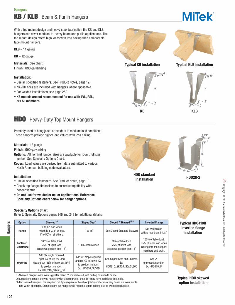
122
Hang
ers
Copyright © 2018 M
iTek Industries, Inc. All Rights Reserved
KB / KLB Beam & Purlin Hangers
With a top mount design and heavy steel fabrication the KB and KLB hangers can cover medium-to-heavy beam and purlin applications. The top mount design offers high loads with less nailing than comparable face mount hangers.
KLB – 14 gauge
KB – 12 gauge
Materials: See chartFinish: G90 galvanizing
Installation:• Use all specified fasteners. See Product Notes, page 19.• NA20D nails are included with hangers where applicable.• For welded installations, see page 250.• KB models are not recommended for use with LVL, PSL,
or LSL members.
Primarily used to hang joists or headers in medium load conditions. These hangers provide higher load values with less nailing.
Materials: 12 gaugeFinish: G90 galvanizingOptions: All nominal lumber sizes are available for rough/full size lumber. See Specialty Options Chart.Codes: Load values are derived from data submitted to various North American building code evaluators.
Installation:• Use all specified fasteners. See Product Notes, page 19.• Check top flange dimensions to ensure compatibility with
header widths.• Do not use for welded or nailer applications. Reference
Specialty Options chart below for hanger options.
HDO Heavy-Duty Top Mount Hangers
Option Skewed1,3 Sloped Seat2 Sloped / Skewed1,2,3 Inverted Flange
1) Skewed hangers with skews greater than 15° may have all joist nailing on outside flange. 2) Sloped or sloped / skewed hangers with slopes greater than 15° may have additional joist nails. 3) For skewed hangers, the required cut type (square or bevel) of joist member may vary based on skew angle and width of hanger. Some square cut hangers will require custom pricing due to welded back plate.
Not available inwidths less than 3-1/8"
Add IFto product number.
Ex. HDO610_IF
FactoredResistance
Ordering
100% of table load.75% of uplift load
on skews greater than 15˚.100% of table load
80% of table load.75% of uplift load
on skews greater than 15˚.
100% of table load.65% of table load whennailing into the support
members end grain.
Add SK, angle required,right (R) or left (L), and
square cut (SQ ) or bevel cut (BV )to product number.
Ex. HDO210_SK45R_SQ
1˚ to 67-1/2˚ when width is 1-3/4" or less.1˚ to 50˚ on all others.
1˚ to 45˚ See Sloped Seat and Skewed
See Sloped Seat and Skewed.Ex.
HDO210_SK45R_SQ_SL30D
Add SL, slope required,and up (U) or down (D),
to product number.Ex. HDO210_SL30D
Range
Specialty Options Chart Refer to Specialty Options pages 246 and 248 for additional details.
Typical KB installation
KB
Typical KLB installation
KLB
H
DDWW
TFTF
H
HDO28-2
Typical HDO skewed option installation
HDO standard installation
Typical HDO410IFinverted flange
installation
Hangers
DW
H
TF
1-1/4"

123
Hangers Co
pyrig
ht ©
201
8 M
iTek
Indu
strie
s, In
c. A
ll Ri
ghts
Res
erve
d
KHW / SW / SWH Welded Top Flange Hangers
SW – Light-duty hanger.
SWH – Medium-duty hanger.
KHW – Heavy-duty hanger installs with NA20D nails for higher load capacities.
Materials: SW top flange - 12 gauge; stirrup - 12 gauge; SWH top flange - 7 gauge; stirrup - 12 gauge; KHW top flange - 3 gauge; stirrup - 10 gaugeFinish: PrimerOptions: All nominal lumber sizes are available for rough/full size lumber. See Specialty Options below.Codes: Load values are derived from data submitted to various North American building code evaluators.
Installation:• Use all specified fasteners. See Product Notes, page 19.• NA20D nails are supplied with KHW hangers.• For welded installations see page 250.• KHW models are not recommended for use with LVL, PSL,
or LSL headers.
Nailer Installation Chart Chart represents maximum factored resistance for hangers used on wood nailers. Reference page 148.
Specialty Options Chart – Refer to Specialty Options pages 246, 248-249 for additional details.
Qty Type Qty Type Lbs kN Lbs kN2X 2 10d x 1-1/2 2 10d x 1-1/2 1635 7.27 1240 5.523x 2 16d x 2-1/2 2 10d x 1-1/2 3900 17.35 3105 13.81
(2) 2x 2 16d x 2-1/2 2 10d x 1-1/2 3900 17.35 3105 13.814x 2 16d x 2-1/2 2 10d x 1-1/2 3900 17.35 3105 13.812X 2 10d x 1-1/2 2 10d 2600 -- 1970 --3X 2 16d x 2-1/2 2 10d 3350 -- 2535 --
(2) 2x 2 16d x 2-1/2 2 10d x 1-1/2 2600 -- 1970 --4x 2 16d x 2-1/2 2 10d x 1-1/2 2600 -- 1970 --
KHW 3X 4 16d x 2-1/2 2 10d 5180 23.04 3925 17.46
1) Listed loads shall not be increased. 2) The nailer must be sized to fit the supported width and be of sufficient thickness to satisfy specified top flange nailing requirements. A design professional must specify nailer attachment to steel beams. 3) NAILS: 10d x 1-1/2 nails are 0.148" dia. x 1-1/2" long, 10d nails are 0.148" dia. x 3" long, 16d x 2-1/2 nails are 0.162" dia. x 2-1/2" long. New products or updated product information are designated in blue font.
MiTekStock No.
Vertical (100%)1 Vertical (100%)1
SW
SWH
Fastener Schedule3 DF Factored Resistance
S-P-FFactored Resistance
Nailer
Size2
Header Joist
Option Skewed1,3 Sloped Seat2 Sloped / Skewed1,2,3 Sloped Top Flange4 Saddle Ridge
1) Skewed hangers with skews greater than 15° may have all joist nailing on outside flange. 2) Sloped or sloped / skewed hangers with slopes greater than 15° may have additional joist nails. 3) For skewed hangers, the required cut type (square or bevel) of joist member may vary based on skew angle and width of hanger. Some square cut hangers will require custom pricing due to welded back plate. 4) Sloped top flanges with greater than 15° may have additional header nails.
Add DA, angle required
to product number.Ex. SW212_DA30
Top Flange Offset
Add OS, andright (R) or left (L),to product number.
Ex. SW212_OSL
% of table load:
60%75%85%
100% of table loadper side
Hanger Width3-1/2" or less
3-9/16" to 5-1/2"5-9/16" to 7-1/2"
100% of table load
0° to 45° -- -- -- --
Add SA,and saddlewidth required
to product number.Ex. SW212_SA=5-1/2"
See Sloped Seat and Skewed
Add SK, angle required,right (R ) or left (L ), and
square cut (SQ ) or bevel cut (BV )
to product number.Ex. SW212_SK45R_SQ
Add SL, slope required,and up (U) or down (D),
to product number.Ex. SW212_SL30D
See Sloped Seat and Skewed.
Ex. SW212_SK45R_SQ_SL30D
Add SF, angle required,and right (R) or left (L),
to product number.Ex. SW212_SF30L
100% of table load 100% of table load 100% of table load
1˚ to 45˚ 0° to 35°Range
FactoredResistance
Ordering
1˚ to 84˚
100% of table load
Typical SW210 installationTypical KHW46 installation
SWH410
D
TF L
H
W
Hangers
SW210KHW46
DW
H
2-1/2"
L
D
H
W
LTF

124
Hang
ers
Copyright © 2018 M
iTek Industries, Inc. All Rights Reserved
Top Mount Hanger Charts
Download Uplift1,2 Download Uplift1,2 Download Uplift1,2 Download Uplift1,2
Ref. No. W H D L TF Top Face Type Qty Type 100% 115% 100% 115% 100% 115% 100% 115%
2 x 4 HDO24 HU24TF 12 1-9/16 3-7/16 2-1/4 -- 2-1/2 4 2 16d 2 10d x 1-1/2 3150 595 14.01 2.65 2475 465 11.01 2.07
HL26 JB26 18 1-9/16 5-3/8 1-1/2 -- 1-5/16 2 4 16d 2 prongs 2085 -- 9.27 -- 1635 -- 7.27 --
KLB26 LB26 14 1-9/16 5-3/8 1-1/2 -- 1-3/8 2 4 16d 2 10d x 1-1/2 3895 665 17.33 2.96 3120 610 13.88 2.71
SW26 W26 12 1-9/16 5-3/8 2-1/2 6-1/2 2-1/2 2 -- 10d 2 10d x 1-1/2 3590 270 15.97 1.20 2980 225 13.26 1.00
HDO26 HU26TF 12 1-9/16 5-3/8 2-1/4 -- 2-1/2 4 6 16d 4 10d x 1-1/2 4195 1580 18.66 7.03 3295 1240 14.66 5.52
HL28 JB28 18 1-9/16 7-5/16 1-3/4 -- 1-5/16 2 4 16d 2 prongs 2395 -- 10.65 -- 1880 -- 8.36 --
KLB28 LB28 14 1-9/16 7-1/4 1-3/4 -- 1-3/8 2 4 16d 2 10d x 1-1/2 3895 665 17.33 2.96 3120 610 13.88 2.71
SW28 W28 12 1-9/16 7-1/8 2-1/2 6-1/2 2-1/2 2 -- 10d 2 10d x 1-1/2 3590 270 15.97 1.20 2980 225 13.26 1.00
HDO28 HU28TF 12 1-9/16 7-1/8 2-1/4 -- 2-1/2 4 6 16d 4 10d x 1-1/2 4590 1420 20.42 6.32 3600 1115 16.01 4.96
HL210 JB210A 18 1-9/16 9-5/16 2 -- 1-5/16 2 4 16d 2 prongs 2395 -- 10.65 -- 1880 -- 8.36 --
KLB210 LB210A 14 1-9/16 9-1/4 2 -- 1-3/8 2 4 16d 2 10d x 1-1/2 3895 665 17.33 2.96 3120 610 13.88 2.71
SW210 W210 12 1-9/16 9-1/8 2-1/2 6-1/2 2-1/2 2 -- 10d 2 10d x 1-1/2 3590 270 15.97 1.20 2980 225 13.26 1.00
HDO210 HU210TF 12 1-9/16 9-1/8 2-1/4 -- 2-1/2 4 8 16d 4 10d x 1-1/2 4790 1365 21.31 6.07 3760 1070 16.73 4.76
HL212 JB212A 18 1-9/16 11-1/4 2-1/8 -- 1-5/16 2 4 16d 2 prongs 2600 -- 11.57 -- 2040 -- 9.07 --
KLB212 LB212A 14 1-9/16 11-1/8 2 -- 1-3/8 2 4 16d 2 10d x 1-1/2 3300 665 14.68 2.96 3030 610 13.48 2.71
SW212 W212 12 1-9/16 11-1/8 2-1/2 6-1/2 2-1/2 2 -- 10d 2 10d x 1-1/2 3590 270 15.97 1.20 2980 225 13.26 1.00
HDO212 HU212TF 12 1-9/16 11 2-1/4 -- 2-1/2 4 10 16d 6 10d x 1-1/2 3855 2495 17.15 11.10 3025 1955 13.46 8.70
SW214 W214 12 1-9/16 13-1/8 2-1/2 6-1/2 2-1/2 2 -- 10d 2 10d x 1-1/2 3590 270 15.97 1.20 2980 225 13.26 1.00
HDO214 HU214TF 12 1-9/16 13 2-1/4 -- 2-1/2 4 12 16d 6 10d x 1-1/2 6345 1980 28.22 8.81 4980 1555 22.15 6.92
SW216 W216 12 1-9/16 15-1/8 2-1/2 6-1/2 2-1/2 2 -- 10d 2 10d x 1-1/2 3590 270 15.97 1.20 2980 225 13.26 1.00
3 x 4 HDO34 HU34TF 12 2-9/16 3-7/16 2-1/2 -- 2-1/2 4 4 16d 2 10d x 1-1/2 3870 595 17.21 2.65 3040 465 13.52 2.07
SW36 W36 12 2-9/16 5-3/8 2-1/2 6-1/2 2-1/2 2 -- 10d 2 10d x 1-1/2 3900 270 17.35 1.20 3240 225 14.41 1.00
HDO36 HU36TF 12 2-9/16 5-3/8 2-1/2 -- 2-1/2 4 6 16d 4 10d x 1-1/2 4850 1580 21.57 7.03 3805 1240 16.93 5.52
SW38 W38 12 2-9/16 7-1/8 2-1/2 6-1/2 2-1/2 2 -- 10d 2 10d x 1-1/2 3900 270 17.35 1.20 3240 225 14.41 1.00
SW310 W310 12 2-9/16 9-1/8 2-1/2 6-1/2 2-1/2 2 -- 10d 2 10d x 1-1/2 3900 270 17.35 1.20 3240 225 14.41 1.00
SWH312 WNP312 7/12 2-9/16 11-1/8 2-1/2 7 2-1/2 2 -- 16d 2 10d x 1-1/2 5120 270 22.77 1.20 4250 225 18.90 1.00
SWH314 WNP314 7/12 2-9/16 13-1/8 2-1/2 7 2-1/2 2 -- 16d 2 10d x 1-1/2 5120 270 22.77 1.20 4250 225 18.90 1.00
SWH316 WNP316 7/12 2-9/16 15-1/8 2-1/2 7 2-1/2 2 -- 16d 2 10d x 1-1/2 5120 270 22.77 1.20 4250 225 18.90 1.00
(2) 2 x 4 HDO24-2 HU24-2TF 12 3-1/8 3-7/16 2-1/4 -- 2-1/2 4 4 16d 2 10d 4005 880 17.82 3.91 3145 690 13.99 3.07
SWH26-2 WNP26-2 7/12 3-1/8 5-3/8 2-1/2 7 2-1/2 2 -- 16d 2 10d 5120 270 22.77 1.20 4250 225 18.90 1.00
HDO26-2 HU26-2TF, HUS26-2TF
12 3-1/8 5-3/8 2-1/4 -- 2-1/2 4 6 16d 4 10d 4995 1975 22.22 8.79 3920 1550 17.44 6.89
1) Factored uplift resistances have been increased 15% for short-term loads such as wind and earthquake; reduce for other load durations in accordance with the code. 2) HL and SW products do not provide uplift resistance, except for the HL214. 3) Refer to the respective Nailer Options chart on page 123 for hangers installed on wood nailers. 4) NAILS: 10d x 1-1/2 nails are 0.148" dia. x 1-1/2" long, 10d nails are 0.148" dia. x 3" long, 16d nails are 0.162" dia. x 3-1/2" long. New products or updated product information are designated in blue font.
22.89 11.036555 3160 29.16 14.06 5145 248014 16d 8 10d x 1-1/2
2040 460 9.07 2.056 16d 2 10d x 1-1/2 2600 585
(2) 2 x 6
3 x 6
3 x 8
3 x 14
HL214 JB214A, LB214A
18 2 --1-9/16 13-1/8
2-1/4 -- HDO216 HU216TF, LB216
12 1-9/16 15
HDO38 B38, HU38TF
12 2-9/16 7-1/8 2-1/2
2 x 6
2 x 8
2 x 10
2 x 12
2 x 14
2 x 16
Qty Lbs kN
2-1/2 2 11.57 2.60
2-1/2 4
Lbs kN
Beam/Joist Size
MiTekStock No. Ga.
Dimensions (in) Fastener Schedule4 DFFactored Resistance (Lbs.)3
S-P-FFactored Resistance (Lbs.)3
Header Joist
-- 2-1/2 4 8 16d 4 10d x 1-1/2 5235 1420 23.29 6.32 4110 1115 18.28 4.96
3 x 10 HDO310
B310, HU310TF
12 4 10 16d 6 10d x 1-1/22-9/16 9-1/8 2-1/2 -- 2-1/2 6820 2340 30.34 10.41 5355 1840 23.82 8.18
3 x 12 HDO312
B312, HU312TF
12 2-9/16 11 2-1/2 -- 2-1/2 4 12 16d 6 10d x 1-1/2 7165 2480 31.87 11.03 5625 1945 25.02 8.65
HDO314 B314, HU314TF
12 2-9/16 13 2-1/2 -- 2-1/2 4
32.94
14 16d 8 10d x 1-1/2 7165 2480 31.87 11.03 5625
11.03
1945 25.02 8.65
3 x 16 HDO316
B316, HU316TF
12 2-9/16 15 2-1/2 -- 2-1/2 4 16 16d 8 10d x 1-1/2 9430 3160 41.95 14.06 7405 2480
Hangers
D
H
W
LTF
Continued on next page
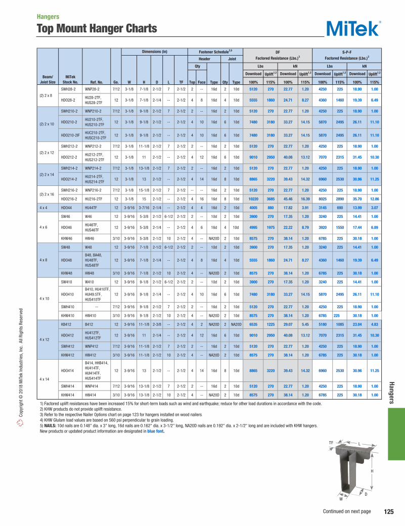
125
Hangers Co
pyrig
ht ©
201
8 M
iTek
Indu
strie
s, In
c. A
ll Ri
ghts
Res
erve
d
Top Mount Hanger Charts
Download Uplift1,2 Download Uplift1,2 Download Uplift1,2 Download Uplift1,2
Ref. No. W H D L TF Top Face Type Qty Type 100% 115% 100% 115% 100% 115% 100% 115%
SWH28-2 WNP28-2 7/12 3-1/8 7-1/8 2-1/2 7 2-1/2 2 -- 16d 2 10d 5120 270 22.77 1.20 4250 225 18.90 1.00
HDO28-2 HU28-2TF, HUS28-2TF
12 3-1/8 7-1/8 2-1/4 -- 2-1/2 4 8 16d 4 10d 5555 1860 24.71 8.27 4360 1460 19.39 6.49
SWH210-2 WNP210-2 7/12 3-1/8 9-1/8 2-1/2 7 2-1/2 2 -- 16d 2 10d 5120 270 22.77 1.20 4250 225 18.90 1.00
HDO210-2 HU210-2TF, HUS210-2TF
12 3-1/8 9-1/8 2-1/2 -- 2-1/2 4 10 16d 6 10d 7480 3180 33.27 14.15 5870 2495 26.11 11.10
HDO210-2IF HUC210-2TF, HUSC210-2TF
12 3-1/8 9-1/8 2-1/2 -- 2-1/2 4 10 16d 6 10d 7480 3180 33.27 14.15 5870 2495 26.11 11.10
SWH212-2 WNP212-2 7/12 3-1/8 11-1/8 2-1/2 7 2-1/2 2 -- 16d 2 10d 5120 270 22.77 1.20 4250 225 18.90 1.00
HDO212-2 HU212-2TF, HUS212-2TF
12 3-1/8 11 2-1/2 -- 2-1/2 4 12 16d 6 10d 9010 2950 40.08 13.12 7070 2315 31.45 10.30
SWH214-2 WNP214-2 7/12 3-1/8 13-1/8 2-1/2 7 2-1/2 2 -- 16d 2 10d 5120 270 22.77 1.20 4250 225 18.90 1.00
HDO214-2 HU214-2TF, HUS214-2TF
12 3-1/8 13 2-1/2 -- 2-1/2 4 14 16d 8 10d 8865 3220 39.43 14.32 6960 2530 30.96 11.25
SWH216-2 WNP216-2 7/12 3-1/8 15-1/8 2-1/2 7 2-1/2 -- -- 16d 2 10d 5120 270 22.77 1.20 4250 225 18.90 1.00
HDO216-2 HU216-2TF 12 3-1/8 15 2-1/2 -- 2-1/2 4 16 16d 8 10d 10220 3685 45.46 16.39 8025 2890 35.70 12.86
4 x 4 HDO44 HU44TF 12 3-9/16 3-7/16 2-1/4 -- 2-1/2 4 4 16d 2 10d 4005 880 17.82 3.91 3145 690 13.99 3.07
SW46 W46 12 3-9/16 5-3/8 2-1/2 6-1/2 2-1/2 2 -- 10d 2 10d 3900 270 17.35 1.20 3240 225 14.41 1.00
HDO46 HU46TF, HUS46TF
12 3-9/16 5-3/8 2-1/4 -- 2-1/2 4 6 16d 4 10d 4995 1975 22.22 8.79 3920 1550 17.44 6.89
KHW46 HW46 3/10 3-9/16 5-3/8 2-1/2 10 2-1/2 4 -- NA20D 2 10d 8575 270 38.14 1.20 6785 225 30.18 1.00
SW48 W48 12 3-9/16 7-1/8 2-1/2 6-1/2 2-1/2 2 -- 10d 2 10d 3900 270 17.35 1.20 3240 225 14.41 1.00
HDO48 B48, BA48, HU48TF, HUS48TF
12 3-9/16 7-1/8 2-1/4 -- 2-1/2 4 8 16d 4 10d 5555 1860 24.71 8.27 4360 1460 19.39 6.49
KHW48 HW48 3/10 3-9/16 7-1/8 2-1/2 10 2-1/2 4 -- NA20D 2 10d 8575 270 38.14 1.20 6785 225 30.18 1.00
SW410 W410 12 3-9/16 9-1/8 2-1/2 6-1/2 2-1/2 2 -- 10d 2 10d 3900 270 17.35 1.20 3240 225 14.41 1.00
HDO410 B410, HU410TF, HUI49.5TF, HUS410TF
12 3-9/16 9-1/8 2-1/4 -- 2-1/2 4 10 16d 6 10d 7480 3180 33.27 14.15 5870 2495 26.11 11.10
SWH410 -- 7/12 3-9/16 9-1/8 2-1/2 7 2-1/2 2 -- 16d 2 10d 5120 270 22.77 1.20 4250 225 18.90 1.00
KHW410 HW410 3/10 3-9/16 9-1/8 2-1/2 10 2-1/2 4 -- NA20D 2 10d 8575 270 38.14 1.20 6785 225 30.18 1.00
KB412 B412 12 3-9/16 11-1/8 2-3/8 -- 2-1/2 4 2 NA20D 2 NA20D 6535 1225 29.07 5.45 5180 1085 23.04 4.83
HDO412 HU412TF, HUS412TF
12 3-9/16 11 2-1/4 -- 2-1/2 4 12 16d 6 10d 9010 2950 40.08 13.12 7070 2315 31.45 10.30
SWH412 WNP412 7/12 3-9/16 11-1/8 2-1/2 7 2-1/2 2 -- 16d 2 10d 5120 270 22.77 1.20 4250 225 18.90 1.00
KHW412 HW412 3/10 3-9/16 11-1/8 2-1/2 10 2-1/2 4 -- NA20D 2 10d 8575 270 38.14 1.20 6785 225 30.18 1.00
HDO414
B414, HHB414, HU414TF, HUI414TF, HUS414TF
12 3-9/16 13 2-1/2 -- 2-1/2 4 14 16d 8 10d 8865 3220 39.43 14.32 6960 2530 30.96 11.25
SWH414 WNP414 7/12 3-9/16 13-1/8 2-1/2 7 2-1/2 2 -- 16d 2 10d 5120 270 22.77 1.20 4250 225 18.90 1.00
KHW414 HW414 3/10 3-9/16 13-1/8 2-1/2 10 2-1/2 4 -- NA20D 2 10d 8575 270 38.14 1.20 6785 225 30.18 1.00
1) Factored uplift resistances have been increased 15% for short-term loads such as wind and earthquake; reduce for other load durations in accordance with the code. 2) KHW products do not provide uplift resistance. 3) Refer to the respective Nailer Options chart on page 123 for hangers installed on wood nailers. 4) KHW Glulam load values are based on 560 psi perpendicular to grain loading. 5) NAILS: 10d nails are 0.148" dia. x 3" long, 16d nails are 0.162" dia. x 3-1/2" long, NA20D nails are 0.192" dia. x 2-1/2" long and are included with KHW hangers. New products or updated product information are designated in blue font.
Dimensions (in) Fastener Schedule3,5 DFFactored Resistance (Lbs.)3
S-P-FFactored Resistance (Lbs.)3
Header Joist
Qty Lbs kN Lbs kN
4 x 6
4 x 14
MiTekStock No. Ga.
4 x 8
4 x 10
4 x 12
Beam/Joist Size
(2) 2 x 8
(2) 2 x 10
(2) 2 x 12
(2) 2 x 14
(2) 2 x 16
Hangers
D
H
W
LTF
Continued on next page
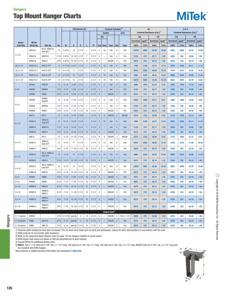
126
Hang
ers
Copyright © 2018 M
iTek Industries, Inc. All Rights Reserved
Top Mount Hanger Charts
Download Uplift1,2 Download Uplift1,2 Download Uplift1,2 Download Uplift1,2
Ref. No. W H D L TF Top Face Type Qty Type 100% 115% 100% 115% 100% 115% 100% 115%
HDO416 B416, HHB416, HU416TF
12 3-9/16 15 2-1/2 -- 2-1/2 4 16 16d 8 10d 10220 3685 45.46 16.39 8025 2890 35.70 12.86
SWH416 WNP416 7/12 3-9/16 15-1/8 2-1/2 7 2-1/2 2 -- 16d 2 10d 5120 270 22.77 1.20 4250 225 18.90 1.00
KHW416 HW416 3/10 3-9/16 15-1/8 2-1/2 10 2-1/2 4 -- NA20D 2 10d 8575 270 38.14 1.20 6785 225 30.18 1.00
(3) 2 x 10 HDO210-3 HU210-3TF 12 4-11/16 9-1/8 2-1/2 -- 2-1/2 4 10 16d 6 16d 7480 3180 33.27 14.15 5870 2495 26.11 11.10
(3) 2 x 12 HDO212-3 HU212-3TF 12 4-11/16 11 2-1/2 -- 2-1/2 4 12 16d 6 16d 9010 2950 40.08 13.12 7070 2315 31.45 10.30
(3) 2 x 14 HDO214-3 HU214-3TF 12 4-11/16 13 2-1/2 -- 2-1/2 4 14 16d 8 16d 8865 3220 39.43 14.32 6960 2530 30.96 11.25
(3) 2 x 16 HDO216-3 HU216-3TF 12 4-11/16 15 2-1/2 -- 2-1/2 4 16 16d 8 16d 10220 3685 45.46 16.39 8025 2890 35.70 12.86
HDO66 HU66TF 12 5-1/2 5-3/8 2-1/2 -- 2-1/2 4 6 16d 4 16d 4995 1975 22.22 8.79 3920 1550 17.44 6.89
SWH66 WNP66 7/12 5-1/2 5-3/8 2-1/2 7 2-1/2 2 -- 16d 2 10d 5120 270 22.77 1.20 4250 225 18.90 1.00
KHW66 HW66 3/10 5-1/2 5-3/8 2-1/2 10 2-1/2 4 -- NA20D 2 10d 8575 270 38.14 1.20 6785 225 30.18 1.00
SWH68 WNP68 7/12 5-1/2 7-1/8 2-1/2 7 2-1/2 2 -- 16d 2 10d 5120 270 22.77 1.20 4250 225 18.90 1.00
KHW68 HW68 3/10 5-1/2 7-1/8 2-1/2 10 2-1/2 4 -- NA20D 2 10d 8575 270 38.14 1.20 6785 225 30.18 1.00
KB610 B610 12 5-1/2 9-1/4 2-3/8 -- 2-1/2 4 6 NA20D 2 NA20D 6510 1225 28.96 5.45 5110 1085 22.73 4.83
HDO610 HHB610, HU610TF
12 5-1/2 9-1/8 2-1/2 -- 2-1/2 4 10 16d 6 16d 7480 3180 33.27 14.15 5870 2495 26.11 11.10
SWH610 WNP610 7/12 5-1/2 9-1/8 2-1/2 7 2-1/2 2 -- 16d 2 10d 5120 270 22.77 1.20 4250 225 18.90 1.00
KHW610 HW610 3/10 5-1/2 9-1/8 2-1/2 10 2-1/2 4 -- NA20D 2 10d 8575 270 38.14 1.20 6785 225 30.18 1.00
KB612 B612 12 5-1/2 11-1/8 2-3/8 -- 2-1/2 4 6 NA20D 2 NA20D 6510 1225 28.96 5.45 5110 1085 22.73 4.83
HDO612 HHB612, HU612TF
12 5-1/2 11 2-1/2 -- 2-1/2 4 12 16d 6 16d 9010 2950 40.08 13.12 7070 2315 31.45 10.30
KHW612 HW612 3/10 5-1/2 11-1/8 2-1/2 10 2-1/2 4 -- NA20D 2 10d 8575 270 38.14 1.20 6785 225 30.18 1.00
HDO614 B614, HHB614, HU614TF
12 5-1/2 13 2-1/2 -- 2-1/2 4 14 16d 8 16d 8865 3220 39.43 14.32 6960 2530 30.96 11.25
KHW614 HW614 3/10 5-1/2 13-1/8 2-1/2 10 2-1/2 4 -- NA20D 2 10d 8575 270 38.14 1.20 6785 225 30.18 1.00
HDO616 B616, HHB616, HU616TF
12 5-1/2 15 2-1/2 -- 2-1/2 4 16 16d 8 16d 10220 3685 45.46 16.39 8025 2890 35.70 12.86
KHW616 HW616 3/10 5-1/2 15-1/8 2-1/2 10 2-1/2 4 -- NA20D 2 10d 8575 270 38.14 1.20 6785 225 30.18 1.00
8 x 6 KHW86 HW86 3/10 7-1/2 5-3/8 2-1/2 10 2-1/2 4 -- NA20D 2 10d 8575 270 38.14 1.20 6785 225 30.18 1.00
8 x 8 KHW88 HW88 3/10 7-1/2 7-1/8 2-1/2 10 2-1/2 4 -- NA20D 2 10d 8575 270 38.14 1.20 6785 225 30.18 1.00
8 x 10 KHW810 HW810 3/10 7-1/2 9-1/8 2-1/2 10 2-1/2 4 -- NA20D 2 10d 8575 270 38.14 1.20 6785 225 30.18 1.00
2-1/2 glulam KHW26 -- 3/10 2-11/16 specify 4 10 2-1/2 4 -- NA20D 2 10d x 1-1/2 8200 270 36.48 1.20 6810 225 30.29 1.00
3-1/8 glulam KHW3 HW3.25 3/10 3-1/4 specify 3 10 2-1/2 4 -- NA20D 2 10d 8575 270 38.14 1.20 6785 225 30.18 1.00
5-1/8 glulam KHW5 HW5.25 3/10 5-1/4 specify 2-1/2 10 2-1/2 4 -- NA20D 2 10d 8575 270 38.14 1.20 6785 225 30.18 1.00
1) Factored uplift resistances have been increased 15% for short-term loads such as wind and earthquake; reduce for other load durations in accordance with the code. 2) KHW products do not provide uplift resistance. 3) Refer to the respective Nailer Options chart on page 123 for hangers installed on wood nailers. 4) KHW Glulam load values are based on 560 psi perpendicular to grain loading. 5) Consult MiTek for additional Glulam sizes. 6) NAILS: 10d x 1-1/2 nails are 0.148" dia. x 1-1/2" long, 10d nails are 0.148" dia. x 3" long, 16d nails are 0.162" dia. x 3-1/2" long, NA20D nails are 0.192" dia. x 2-1/2" long and are included with KHW hangers. New products or updated product information are designated in blue font.
6 x 16
8 x 12 KHW812 HHB812, HW812
3/10
6 x 8
Lbs kN
Beam/Joist Size
MiTekStock No. Ga.
6 x 10
6 x 12
6 x 14
16d 5555 1860 24.71 8.27 4360-- 2-1/2 4 8
Dimensions (in) Fastener Schedule3,5 DF
Factored Resistance (Lbs.)3S-P-F
Factored Resistance (Lbs.)3Header Joist
Qty Lbs kN
16d 4 HDO68 HHB68, HU68TF
12 5-1/2 7-1/8 2-1/2
7-1/2 11-1/8 2-1/2 10 2-1/2 4 -- NA20D 2
1460 19.39 6.49
38.14 1.20 6785 225 30.18 1.0010d 8575 270
38.14 1.202-1/2 10 2-1/2 4 -- NA20D 2 10d 8575 270 8 x 14 KHW814 HHB814, HW814
3/10 7-1/2 13-1/8
KHW816 HHB816, HW816
3/10 7-1/2 15-1/8
4 x 16
6785 225 30.18 1.00
Glulam Sizes5
6 x 6
2 10d 8575 270 38.14 1.202-1/2 10 2-1/2 4 -- NA20D
6785 225 30.18 1.00
8 x 16
Hangers
D
H
W
LTF

127
Hangers Co
pyrig
ht ©
201
8 M
iTek
Indu
strie
s, In
c. A
ll Ri
ghts
Res
erve
d
FWH Fire Wall Hangers
The Fire Wall Hanger is designed for attaching truss, I-joist, solid sawn lumber, or engineered wood floor framing members to double wall top plates or minimum 2-ply 2x solid sawn header fire rated wood frame walls. The advanced design allows the installation of the FWH before the 5/8" gypsum wallboard (drywall) is attached and permits the building project to be completely framed-up, and weather-tight before the gypsum wallboard sheathing work starts.
Materials: 14 gauge Finish: G90 galvanizingCodes: Factored resistances are derived from data submitted to various North American building code evaluatorsOptions: See Specialty Options chart on page 128.
Installation:• Install the face of hanger flanges tight to stud wall framing.• For wall framing, hangers do NOT need to be installed at
stud locations for full design values.• The end of the truss/joist should measure 1-5/8" from
the face of the supporting wall. See Figure 1.• The truss/joist should bear fully on the FWH seat with a
gap no greater than 1/8" between the end of the supported member and the hanger. See Figure 1.
• Gypsum Wallboard Installation - Use the FWH-T template to slot cut the gypsum wallboard. See FWH-T Template Installation Sequence on page 128. Slide the gypsum wallboard into position and fasten to the framing members meeting minimum requirements specified by code.
Hangers
Typical FWH stud wall with (2) layers of 5/8" gypsum wallboard installation
Typical FWHstud wall installation
Typical FWHsolid sawn header installation
1/8"1-5/8"
Figure 1
Typical FWHSide View
Type Qty Type UnitLbs 3250 330 2890 280 2555 270 2550 260kN 14.46 1.47 12.86 1.25 11.37 1.20 11.34 1.16Lbs 3810 685 2890 590 2990 560 2550 545kN 16.95 3.05 12.86 2.62 13.30 2.49 11.34 2.42Lbs 3250 330 2890 280 2555 270 2550 260kN 14.46 1.47 12.86 1.25 11.37 1.20 11.34 1.16Lbs 3810 685 2890 590 2990 560 2550 545kN 16.95 3.05 12.86 2.62 13.30 2.49 11.34 2.42Lbs 3250 330 2890 280 2555 270 2550 260kN 14.46 1.47 12.86 1.25 11.37 1.20 11.34 1.16Lbs 3810 685 2890 590 2990 560 2550 545kN 16.95 3.05 12.86 2.62 13.30 2.49 11.34 2.42Lbs 3250 330 2890 280 2555 270 2550 260kN 14.46 1.47 12.86 1.25 11.37 1.20 11.34 1.16Lbs 3810 685 2890 590 2990 560 2550 545kN 16.95 3.05 12.86 2.62 13.30 2.49 11.34 2.42Lbs 3250 330 2890 280 2555 270 2550 260kN 14.46 1.47 12.86 1.25 11.37 1.20 11.34 1.16Lbs 3810 685 2890 590 2990 560 2550 545kN 16.95 3.05 12.86 2.62 13.30 2.49 11.34 2.42
1) Factored uplift resistances have been increased 15% for short-term loads such as wind and earthquake; reduce for other load durations in accordance with the code. 2) NAILS: 10d x 1-1/2 nails are 0.148" dia. x 1-1/2" long, 10d nails are 0.148" dia. x 3" long. New products are designated in blue font.
After (1) layer of 5/8-in gypsum wallboard is installed
After (2) layers of 5/8-in gypsum wallboard are installed
Two-sided after (2) layers of 5/8-in gypsum wallboard are installed (min. 2x6 wall)
After (1) layer of structural sheathing & (1) layer of 5/8-in gypsum wallboard is installed 6
6
6
6
2 10d 6 10d x 1-1/2
6 -- 10d 6 10d x 1-1/2
2 10d 6 10d x 1-1/2
6 -- 10d 6 10d x 1-1/2
2 10d 6 10d x 1-1/2
6 -- 10d 6 10d x 1-1/2
2 10d 6 10d x 1-1/2
6 -- 10d 6 10d x 1-1/2
Fastener Schedule2 DF Factored Resistance SPF Factored Resistance
Header Joist 2-Ply, 2x Wall Top Plate
2-Ply, 2x Wall Top Plate
Solid Sawn Header
Solid SawnHeader
Without 5/8-in gypsum wallboard or structural sheathing
--
2
Uplift115%1
Download100%
InstallationType
TopQty
FaceQty
Download100%
Uplift115%1
Download100%
6
6
10d 6 10d x 1-1/2
Uplift115%1
10d 6 10d x 1-1/2
Uplift115%1
Download100%
Continued on next page

128
Hang
ers
Copyright © 2018 M
iTek Industries, Inc. All Rights Reserved
FWH Fire Wall Hangers
Hangers
Option Skewed1
Range 1˚ to 70˚
1) Skewed hangers with skews greater than 15° may have all joist nailing on outside flange. New products or updated product information are designated in blue font.
FactoredResistance
Ordering
80% of table load on skews up to 45°.70% of table load on skews 46° to 70°.
Add SK, angle required, right (R) or left (L), and square cut (SQ) to product number.
Ex. FWH3514_SK45R_SQ
Specialty Options Chart – Refer to Specialty Options pages 246 and 248 for additional details.
Ref. No. W H 2 x 8 FWH28 -- 1-9/16 7-1/8 2 x 10 FWH210 -- 1-9/16 9-1/8 2 x 12 FWH212 -- 1-9/16 11-1/8 1-3/4 x 9-1/2 FWH1795 DGHF1.81/9.5 1-13/16 9-7/16 1-3/4 x 11-7/8 FWH17118 DGHF1.81/11.88 1-13/16 11-13/16 1-3/4 x 14 FWH1714 DGHF1.81/14 1-13/16 13-15/16 1-3/4 x 16 FWH1716 DGHF1.81/16 1-13/16 15-15/16 2 - 2-1/8 x 9-1/2 FWH2095 DGHF2.1/9.5 2-1/8 9-7/16 2 - 2-1/8 x 11-7/8 FWH20118 DGHF2.1/11.88 2-1/8 11-13/16 2 - 2-1/8 x 14 FWH2014 DGHF2.1/14 2-1/8 13-15/16 2 - 2-1/8 x 16 FWH2016 DGHF2.1/16 2-1/8 15-15/16 2-5/16 x 9-1/2 FWH2395 DGHF2.37/9.5 2-3/8 9-7/16 2-5/16 x 11-7/8 FWH23118 DGHF2.37/11.88 2-3/8 11-13/16 2-5/16 x 14 FWH2314 DGHF2.37/14 2-3/8 13-15/16 2-5/16 x 16 FWH2316 DGHF2.37/16 2-3/8 15-15/16 2-5/16 x 18 FWH2318 DGHF2.37/18 2-3/8 17-15/16 2-5/16 x 20 FWH2320 DGHF2.37/20 2-3/8 19-15/16 2-1/2 x 9-1/2 FWH2595 DGHF2.56/9.5 2-9/16 9-7/16 2-1/2 x 11-7/8 FWH25118 DGHF2.56/11.88 2-9/16 11-13/16 2-1/2 x 14 FWH2514 DGHF2.56/14 2-9/16 13-15/16 2-1/2 x 16 FWH2516 DGHF2.56/16 2-9/16 15-15/16 2-1/2 x 18 FWH2518 DGHF2.56/18 2-9/16 17-15/16 2-1/2 x 20 FWH2520 DGHF2.56/20 2-9/16 19-15/16 3-1/2 x 9-1/2 FWH3595 DGHF3.62/9.5 3-9/16 9-7/16 3-1/2 x 11-7/8 FWH35118 DGHF3.62/11.88 3-9/16 11-13/16 3-1/2 x 14 FWH3514 DGHF3.62/14 3-9/16 13-15/16 3-1/2 x 16 FWH3516 DGHF3.62/16 3-9/16 15-15/16 3-1/2 x 18 FWH3518 DGHF3.62/18 3-9/16 17-15/16 3-1/2 x 20 FWH3520 DGHF3.62/20 3-9/16 19-15/16 3-1/2 x 22 FWH3522 DGHF3.62/22 3-9/16 21-15/16 3-1/2 x 24 FWH3524 DGHF3.62/24 3-9/16 23-15/16
-- FWH-T -- 5-3/4 13
MiTekStock No.
JoistSize
Dimensions (in)
Edge Prong
Corner Prong
1) Align the FWH-Template slot with the mark in the gypsum wallboard and engage the prongs into edge of gypsum wallboard
2) Rotate the template and press down on the end to engage the corner prongs
3) Run the gypsum wallboard cutter down the template to cut the slot
FWH-T template installation sequence
FWH-T Template (must be ordered separately)
5-3/4"
8"
13"
FWH
H
2"
2-5/8"
W
FWH hangers are tested per ASTM E814 standards. When installed on one side of a maximum 2 hour fire-rated wall assembly, the penetration of the MiTek FWH Fire Wall Hanger through the gypsum wallboard will not reduce the fire resistive rating of the 2 hour fire resistive assembly.
2 Hour Fire-Rating

129
Hangers Co
pyrig
ht ©
201
8 M
iTek
Indu
strie
s, In
c. A
ll Ri
ghts
Res
erve
d
FWHBP Fire Wall Hangers for Beams and Purlins
MiTek has expanded the FWH Fire Wall Hanger series to include the higher load carrying capacity FWHBP, the Fire Wall Hanger for Beams and Purlins. The FWHBP transfers the load into the supporting wall thru bearing on the top plates and directly attaching to the stud pack or post below. As with the FWH hanger, the advanced design allows you to install the hangers before the gypsum wallboard (drywall) is attached, allowing your project to be completely framed-up and weather-tight before the gypsum wallboard sheathing shows up on site.
Materials: 12 gaugeFinish: Primer
Installation:• Install the face of hanger flanges tight to stud wall framing.• The end of the truss/joist should measure 1-5/8"
from the face of the supporting wall. • The truss/joist should bear fully on the FWH
seat with a gap no greater than 1/8" between the end of the supported member and the hanger.
• Gypsum Wallboard Installation - Use the FWH-T template to slot cut the gypsum wallboard. See FWH-T Template Sequence. Slide the gypsum wallboard into position and fasten to the framing members meeting the minimum requirements specified by code.
FWHBP Hanger FHWBP Stud Pack Width
Hangers
Header Joist
W1 W23 H L Lbs kN Lbs kN Lbs kN Lbs kN 3-1/2 x 11-7/8 FWHBP35118 11-7/8 3-1/2 x 14 FWHBP3514 13-15/16 3-1/2 x 16 FWHBP3516 15-15/16 3-1/2 x 18 FWHBP3518 17-15/16 3-1/2 x 20 FWHBP3520 19-15/16 3-1/2 x 22 FWHBP3522 21-15/16 3-1/2 x 24 FWHBP3524 23-15/16 5-1/4 x 11-7/8 FWHBP52118 11-7/8 5-1/4 x 14 FWHBP5214 13-15/16 5-1/4 x 16 FWHBP5216 15-15/16 5-1/4 x 18 FWHBP5218 17-15/16 5-1/4 x 20 FWHBP5220 19-15/16 5-1/4 x 22 FWHBP5222 21-15/16 5-1/4 x 24 FWHBP5224 23-15/16 7 x 11-7/8 FWHBP71118 11-7/8 7 x 14 FWHBP7114 13-15/16 7 x 16 FWHBP7116 15-15/16 7 x 18 FWHBP7118 17-15/16 7 x 20 FWHBP7120 19-15/16 7 x 22 FWHBP7122 21-15/16 7 x 24 FWHBP7124 23-15/16
1) Factored download resistance is for a 2-Ply Top Plate with stud pack (or post) below without wall and floor sheathing attached. 2) Factored uplift resistances have been increased 15% for short-term loads such as wind and earthquake; reduce for other load durations in accordance with the code. 3) "Specify" denotes required stud pack/post width must be specified when ordering. Minimum 3". 4) NAILS: 10d nails are 0.148" dia. x 3" long. New products or updated product information are designated in blue font.
4905 21.82
4905 21.82
SPF Factored Resistance
Download (100%)
2-Ply 2x Wall Top Plate1
Uplift
115%2
4905 21.8230.49
30.49
30.496855
6855
6855
24.878330 37.05 5590
37.05 5590
37.05 5590
18
18
Download (100%)
2-Ply 2x Wall Top Plate1
Uplift
115%2
24.87
24.87
10d
8330
8330
Dimensions (in)
JoistSize (in)
--
--
Ref.No.
MiTekStock No.
SteelGauge
12
12 7-1/8 Specify
10d12
189-11/16 10d
6
--
6 4 16
4 16
6 4 16
Specify
5-3/8 Specify
3-9/16 7-1/8
7-15/16
DF Factored Resistance
QtyTopQty
FaceQty
StudQty
Fastener Schedule4
Type
1) Align the FWH-Template slot with the mark in the gypsum wallboard and engage the prongs into edge of gypsum wallboard
FWH-T Template Installation SequenceEdge prong
L
2-5/8"
H
2"W1
2x Stud wall framing
Supported beam
FWHBP hanger
Stud pack or post
2-Layers 5/8"
gypsum wallboard
2x Stud wall framingSupported
beamFWHBP hanger
Stud pack or post
(Min. 2-ply 2x or 3")
2-Layers 5/8"
gypsum wallboard
W2
3) Run the gypsum wallboard cutter down the template to cut the slot
2) Rotate the template and press down on the end to engage the corner prongs
Corner prong
FWH-T template (must be ordered separately)
Typical FWHBP attachment to top plate/beam and stud pack/post

130
Hang
ers
Copyright © 2018 M
iTek Industries, Inc. All Rights Reserved
JH Multi-Purpose Joist Hanger
These strap-style hangers are designed to support trusses, joists, or purlins. JH models may be bent along the flange allowing builders to use the hangers in top mount, face mount, or combination applications.
Materials: 18 gaugeFinish: G90 galvanizingCodes: Load values are derived from data submitted to various North American building code evaluators.
Installation:• Use all specified fasteners. See Product Notes, page 19.• Joist nails must be driven at a 30° to 45° angle through the joist
or truss into the header to achieve listed loads. Slant / double shear nails must be used to achieve listed load values.
• If installing in top mount configuration, field bend top flange over header.
• 16d sinkers (0.148" dia x 3-1/4") may be used where 10d common are specified with no load reduction.
Header
W H D B TF Size Type Qty Type UnitLbs 4750 2415 3730 1900kN 21.13 10.74 16.59 8.45Lbs 4750 2415 3730 1900kN 21.13 10.74 16.59 8.45Lbs 4750 2415 3730 1900kN 21.13 10.74 16.59 8.45Lbs 4750 2415 3730 1900kN 21.13 10.74 16.59 8.45
1) Factored uplift resistances have been increased 15% for short-term loads such as wind and earthquake; no further increase allowed. 2) Nails must be driven at a 30° to 45˚ angle through the joist or truss into header to achieve the table loads. 3) NAILS: 10d nails are 0.148" dia. x 3" long. 16d sinkers (0.148" dia. x 3-1/4" long) may be used where 10d commons are specified with no reduction in load. New products or updated product information are designated in blue font.
Download100%
Uplift1
115%
S-P-FFactored Resistance
1-9/16
-- 2 x 12
6
12 10d 6
6
2 x 10 2
Fastener Schedule2,3
JoistHeader
Download100%
Uplift1
115%
Dimensions (in) DFFactored Resistance
8 10d2 x 8
2 4 10d
TopQty
FaceQty
10d10-1/16 2-1/4 5-1/8
-- 14 10d 6 10d
10d
1-3/16
1-7/16
7/16
2 x 6 10d
2 JH20 -- 18
MiTekStock No. Ga.
Ref. No.
A field-adjustable seat gives the LS hanger application flexibility.
The LS hanger slopes from 0° to 30° down (0 to 7:12 pitch down).
Materials: 18 gaugeFinish: G90 galvanizingCodes: Load values are derived from data submitted to various North American building code evaluators.
Installation:• Use all specified fasteners. See Product Notes, page 19.• The LS can be field adjusted to slopes from 0° to 30° down.
LS Light Slope Rafter Hangers
Ref. No. W H Qty Type Qty Type
LS268 -- 18 1-9/16 5-1/2 7 16d 7 10d x 1-1/2 1860 1270 8.27 5.65 1460 1000 6.49 4.45 LS210 -- 18 1-9/16 7-7/8 9 16d 9 10d x 1-1/2 2245 1950 9.99 8.67 1760 1530 7.83 6.81
1) Factored resistances have been increased 15% for short-term loads such as wind and earthquake; no further increase allowed. 2) NAILS: 10d x 1-1/2 nails are 0.148" dia. x 1-1/2" long, 16d nails are 0.162" dia. x 3-1/2" long. New products or updated product information are designated in blue font.
Uplift1
115%Vertical100%
Vertical100%
Vertical100%
Uplift1
115%Uplift1
115%Uplift1
115%
Dimensions (in)
LbsHeader
MiTekStock No.
SteelGauge
Vertical100%
kNLbsJoist
Fastener Schedule2
kN
DF Factored Resistance S-P-F Factored Resistance
Typical LS268 installation LS268
W Slope down 0° to 30 °
3"
H
Hangers
Double shear nail design features
fewer nails and faster installation
Uses standard length nails
Typical JH20 installation
JH20
H
DW
B

131
Hangers Co
pyrig
ht ©
201
8 M
iTek
Indu
strie
s, In
c. A
ll Ri
ghts
Res
erve
d
RR Ridge Rafter Hanger
The RR Ridge Rafter supports rafter pitches up to 7:12 (30°). Nesting top flange for back-to-back installation on 2x support beams.
Materials: 18 gaugeFinish: G90 galvanizing
Installation:• Use all specified fasteners. See Product Notes, page 19.• The rafter end at the ridge must be plumb cut to achieve
published loads.• Optional diamond nail holes can be used to fasten RR to
end of rafter before setting rafter into place.
Download Uplift Download UpliftRef. No. Qty Type Qty Type Unit 100% 115% 100% 115%
Lbs 590 380 465 300kN 2.67 1.80 1.89 1.29Lbs 705 345 500 245kN 3.14 1.53 2.22 1.09
1) Factored resistances have been increased 15% for short-term loads such as wind and earthquake; no further increase allowed. 2) NAILS: 10d x 1-1/2 nails are 0.148" dia. x 1-1/2" long, LL915 denotes a LumberLok Screw, #9 x 1-3/8" long. New products or updated product information are designated in blue font.
RR
MiTekStock No.
SteelGauge
Header Rafter
10d x 1-1/2
LL91518 2 x 6
MinRafterSize
Fastener Schedule2 DFFactored Resistance1
S-P-FFactored Resistance1
4 RR
4 4LL915
10d x 1-1/2 4
LSSH Slope/Skew Hangers
The LSSH series connects rafters to ridge beams in vaulted roof structures. This series is field adjustable to meet a variety of skew and/or slope applications. Slopes and skews 0° to 45°.
Materials: See chartFinish: G90 galvanizing; LSSH15-TZ – G-185 GalvanizingOptions: See Chart for Corrosion Finish OptionsCodes: Factored resistances are derived from data submitted to various North American building code evaluators.
Installation:• Use all specified fasteners. See Product Notes, page 19.
Steps: 1. Position LSSH connector against plumb-cut end of joist. Fasten
joist side flanges on both sides with 10d (0.148") x 1-1/2" nails. Bend seat up to fit against joist bottom and drive (1) 10d (0.148") x 1-1/2" nail through bottom seat into rafter bottom. Drive (2) 10d (0.148") x 1-1/2" nails at downward angle through dimpled nailing guides.
2. Lean connector and rafter end against ridge beam at desired position. Install specified 10d (0.148" x 3") or 16d (0.162" x 3-1/2") nails through nail holes into ridge beam at right 90° angle. If skewing the rafter, only drive nails into ridge beam on inside flange.
3. Bend flange to desired angle. 4. Hammer outside flange until edge touches header. Fasten
outside flange to ridge by driving specified 10d (0.148" x 3") or 16d (0.162" x 3-1/2") nails through nail holes.
• Web stiffeners are required for all wood I-Joist installations.• Designer may consider adding a tension restraint for the supported
member for roof slopes exceeding 6/12. Refer to pages 95-96.
Uplift
RR1-9/16"
1" 4"
3-3/8"
Typical RRinstallation
Typical LSSH179installation
LSSH35
W2 W1 W2
2
Skew to 45° maximum
LSSH210
LSSH15-TZ = 5-1/16" All other sizes = 8-7/8"
W2W1
W2
3"
3"
Slope to 45° up or down
Slope to 45° up or down
3 & 4
18-7/8"
Hangers
Continued on next page

132
Hang
ers
Copyright © 2018 M
iTek Industries, Inc. All Rights Reserved
LSSH Slope/Skew Hangers
Vertical Uplift1 Vertical Uplift1 Vertical Uplift1 Vertical Uplift1
Ref. No. W1 W2 H Qty Type Qty Type 100% 115% 100% 115% 100% 115% 100% 115%
1-1/2 LSSH15-TZ LSU26, LSU26Z, LSSU28, LSSU28Z
18 1-9/16 1-3/4 5-1/16 610dHDG
710d x 1-1/2
HDG1590 1175 7.07 5.23 1250 925 5.56 4.11
1-1/2 LSSH210 LSSU210 18 1-9/16 1-3/4 8-13/16 10 10d 7 10d x 1-1/2 2685 1695 11.94 7.54 2110 1330 9.39 5.92 1-3/4 LSSH179 LSSUI25 18 1-13/16 1-5/8 8-13/16 10 10d 7 10d x 1-1/2 2685 1695 11.94 7.54 2110 1330 9.39 5.92
2 - 2-1/8 LSSH20 LSSUI2.06, LSSU2.1
18 2-1/8 2-1/2 8-13/16 10 10d 7 10d x 1-1/2 2535 1555 11.28 6.92 1990 1220 8.85 5.43
2-1/2 LSSH25 LSSUH310 16 2-9/16 2-3/4 8-13/16 18 16d 12 10d x 1-1/2 4125 1895 18.35 8.43 3240 1490 14.41 6.63 2-5/8 LSSH26 -- 16 2-11/16 2-5/8 8-13/16 18 16d 12 10d x 1-1/2 4125 1895 18.35 8.43 3240 1490 14.41 6.63 3 LSSH31 LSSU210-2 16 3-1/8 3-3/4 8-13/16 18 16d 12 10d x 1-1/2 5065 2515 22.53 11.19 3980 1975 17.70 8.79 3-1/2 LSSH35 LSSU410 16 3-9/16 3-1/2 8-13/16 18 16d 12 10d x 1-1/2 5065 2515 22.53 11.19 3980 1975 17.70 8.79
1-1/2 LSSH15-TZ LSU26, LSU26Z, LSSU28, LSSU28Z
18 1-9/16 1-3/4 5-1/16 610dHDG
710d x 1-1/2
HDG1295 1175 5.76 5.23 1015 925 4.51 4.11
1-1/2 LSSH210 LSSU210 18 1-9/16 1-3/4 8-13/16 10 10d 7 10d x 1-1/2 2685 1695 11.94 7.54 2110 1330 9.39 5.92 1-3/4 LSSH179 LSSUI25 18 1-13/16 1-5/8 8-13/16 10 10d 7 10d x 1-1/2 2685 1695 11.94 7.54 2110 1330 9.39 5.92
2 - 2-1/8 LSSH20 LSSUI2.06, LSSU2.1
18 2-1/8 2-1/2 8-13/16 10 10d 7 10d x 1-1/2 2535 1555 11.28 6.92 1990 1220 8.85 5.43
2-1/2 LSSH25 LSSUH310 16 2-9/16 2-3/4 8-13/16 14 16d 12 10d x 1-1/2 2895 1895 12.88 8.43 2270 1490 10.10 6.63 2-5/8 LSSH26 -- 16 2-11/16 2-5/8 8-13/16 14 16d 12 10d x 1-1/2 2895 1895 12.88 8.43 2270 1490 10.10 6.63 3 LSSH31 LSSU210-2 16 3-1/8 3-3/4 8-13/16 14 16d 12 10d x 1-1/2 3045 2515 13.55 11.19 2390 1975 10.63 8.79 3-1/2 LSSH35 LSSU410 16 3-9/16 3-1/2 8-13/16 14 16d 12 10d x 1-1/2 3045 2515 13.55 11.19 2390 1975 10.63 8.79
1) Factored resistances have been increased 15% for short-term loads such as wind and earthquake; no further increase allowed. 2) NAILS: 10d x 1-1/2 nails are 0.148" dia. x 1-1/2" long, 10d nails are 0.148" dia. x 3" long, 16d nails are 0.162" dia. x 3-1/2" long. New products or updated product information are designated in blue font.
8.85 5.431555 11.28 6.92 1990 1220
1990 1220 8.85 5.43
2-1/4 - 2-5/16
LSSH23 LSSUI35 18 2-5/16 2-3/8 8-13/16 10 10d 7 10d x 1-1/2 2535
10d x 1-1/2 2535 1555 11.28 6.922-3/8 8-13/16 10 10d 7 2-1/4 - 2-5/16
LSSH23 LSSUI35 18 2-5/16
Corr
osio
nFi
nish
SLOPED ONLY HANGERS
SKEWED HANGERS or SLOPED & SKEWED HANGERS
MiTekStock No.
SteelGauge
Dimensions (in)
Lbs Lbs
Fastener Schedule2
Rafter Width (in)
Header Rafter kN kN
DF Factored Resistance S-P-F Factored Resistance
SKH26Rright skew
SKH26L left skew
SKH – Standard 45° skew hanger allows for a 40° to 50° skew range, without hanger modification.
SKHH – For heavier applications.
Materials: 14 or 16 gaugeFinish: G90 galvanizingOptions: See chart for Corrosion Finish OptionsCodes: Load values are derived from data submitted to various North American building code evaluators.
Installation:• Use all specified fasteners. See Product Notes, page 19.• The hangers listed are for standard sizes and will accommodate a
40° to 50° skew range. • Most sizes do not require a bevel cut for installation. Refer to chart
footnote identified with an asterisk.• Illustrations show left and right skews. (SKH_L = skewed left;
SKH_R = skewed right)• For I-Joist installations, web stiffeners are required.• Refer to illustration for staggered I-Joist application for double 2", 2-5/16",
and 2-1/2" models.• For double I-Joist installations, web stiffeners between I-Joists are required.
SKH / SKHH Skewed 45° Hangers
Corrosion Finish Stainless Steel Gold Coat HDG Triple Zinc
Corrosion Finish Stainless Steel Gold Coat HDG Triple Zinc
Corrosion Finish Stainless Steel Gold Coat HDG Triple Zinc
Hangers
Continued on next page

133
Hangers Co
pyrig
ht ©
201
8 M
iTek
Indu
strie
s, In
c. A
ll Ri
ghts
Res
erve
d
SKH / SKHH Skewed 45° Hangers
Vertical Uplift1 Vertical Uplift1 Vertical Uplift1 Vertical Uplift1
Ref. No. W H D Qty Type Qty Type 100% 115% 100% 115% 100% 115% 100% 115% 2 x 4 SKH24L/R SUR/L24 16 1-9/16 3-1/4 1-7/8 4 16d 4 10d x 1-1/2 805 1030 3.58 4.58 635 810 2.82 3.60
SKH26L/R SUR/L26 16 1-9/16 5-1/4 1-7/8 6 16d 6 10d x 1-1/2 1415 2480 6.29 11.03 1110 1945 4.94 8.65 SKHH26L/R -- 16 1-5/8 5-1/8 3-1/4 18 16d 12 10d x 1-1/2 3040 1615 13.52 7.18 2495 1285 11.10 5.72 SKH28L/R -- 16 1-9/16 7-1/4 1-7/8 10 16d 8 10d x 1-1/2 2325 2480 10.34 11.03 1825 1945 8.12 8.65 SKHH28L/R -- 16 1-5/8 7 3-1/4 26 16d 16 10d x 1-1/2 4280 2225 19.04 9.90 3365 1745 14.97 7.76
SKH210L/R SUR/L210, SUR/L214
16 1-9/16 9-1/4 1-7/8 14 16d 10 10d x 1-1/2 2845 2855 12.66 12.70 2230 2240 9.92 9.96
SKHH210L/R -- 16 1-5/8 9 4-1/4 34 16d 20 10d x 1-1/2 4505 2780 20.04 12.37 3655 2180 16.26 9.70 1-3/4 x 9-1/4 - 14
SKH1720L/R SUR/L1.81/9 16 1-13/16 9-1/8 1-7/8 14 10d 10 10d x 1-1/2 3440 2855 15.30 12.70 2700 2240 12.01 9.96
1-3/4 x 11-1/4 - 18
SKH1724L/R SUR/L1.81/11, SUR/L1.81/14 16 1-13/16 11-1/8 1-7/8 16 10d 10 10d x 1-1/2 4640 2855 20.64 12.70 3645 2240 16.21 9.96
2 - 2-1/8 x 9-1/4 - 14
SKH2020L/R SUR/L2.06/9, SUR/L2.1/9 16 2-1/8 9 1-7/8 14 10d 10 10d x 1-1/2 3440 2855 15.30 12.70 2700 2240 12.01 9.96
2 - 2-1/8 x 11-1/4 - 18
SKH2024L/R SUR/L2.06/11, SUR/L2.1/11 16 2-1/8 11 1-7/8 16 10d 10 10d x 1-1/2 4640 2855 20.64 12.70 3645 2240 16.21 9.96
2-1/4 - 2-5/16 x 9-1/4 - 14
SKH2320L/R SUR/L2.37/9 16 2-3/8 8-7/8 1-7/8 14 10d 10 10d x 1-1/2 3440 2855 15.30 12.70 2700 2240 12.01 9.96
2-1/4 - 2-5/16 x 11-1/4 - 18
SKH2324L/R SUR/L2.37/11, SUR/L2.37/14 16 2-3/8 10-7/8 1-7/8 16 10d 10 10d x 1-1/2 4640 2855 20.64 12.70 3645 2240 16.21 9.96
3 x 6-8 SKH36L/R -- 16 2-9/16 4-3/4 1-3/8 6 16d 6 10d x 1-1/2 1590 2855 7.07 12.70 1250 2240 5.56 9.96 3 x 8-12 SKH38L/R -- 16 2-9/16 6-3/4 1-3/8 10 16d 8 10d x 1-1/2 2515 2855 11.19 12.70 1970 2240 8.76 9.96 3 x 10-14 SKH310L/R -- 16 2-9/16 8-3/4 1-3/8 14 16d 10 10d x 1-1/2 3465 2855 15.41 12.70 2720 2240 12.10 9.96 3 x 12 - 14 - 16 SKH312L/R -- 16 2-9/16 10-3/4 1-3/8 16 16d 10 10d x 1-1/2 3890 2855 17.30 12.70 3055 2240 13.59 9.96 2-1/2 x 9-1/4 - 14
SKH2520L/R SUR/L2.56/9 16 2-9/16 8-5/8 1-7/8 14 10d 10 10d x 1-1/2 3440 2855 15.30 12.70 2700 2240 12.01 9.96
2-1/2 x 11-1/4 - 16
SKH2524L/R SUR/L2.56/11, SUR/L2.56/14 16 2-9/16 10-3/4 1-7/8 16 10d 10 10d x 1-1/2 4640 2855 20.64 12.70 3645 2240 16.21 9.96
2-5/8 x 9-1/4 - 14
SKH2620L/R -- 16 2-11/16 8-11/16 1-7/8 14 10d 10 10d x 1-1/2 3440 2855 15.30 12.70 2700 2240 12.01 9.96
2-5/8 x 11-1/4 - 16
SKH2624L/R -- 16 2-11/16 10-11/16 1-7/8 16 10d 10 10d x 1-1/2 4640 2855 20.64 12.70 3645 2240 16.21 9.96
SKH26L/R-2 * SUR/L26-2 16 3-1/16 4-1/2 1-3/8 6 16d 6 10d 1760 2480 7.83 11.03 1380 1945 6.14 8.65 SKHH26L/R-2 HSUR/L26-2 14 3-1/16 5-1/4 2 12 16d 4 16d x 2-1/2 2895 1615 12.88 7.18 2270 1285 10.10 5.72 SKHH26L/R-2IF HSUR/LC26-2 14 3-1/16 5-1/4 2 12 16d 4 16d x 2-1/2 2895 1615 12.88 7.18 2270 1285 10.10 5.72
(2) 2 x 8-12 SKH28L/R-2 * -- 16 3-1/16 6-1/2 1-3/8 10 16d 8 10d 3900 2480 17.35 11.03 3060 1945 13.61 8.65
1) Factored resistances have been increased 15% for short-term loads such as wind and earthquake; no further increase allowed. 2) NAILS: 10d x 1-1/2 nails are 0.148" dia. x 1-1/2" long, 10d nails are 0.148" dia. x 3" long, 16d nails are 0.162" dia. x 3-1/2" long, 16d x 2-1/2 nails are 1.162" dia. x 2-1/2" long. * Bevel cut required on end of joist to achieve design loads. New products or updated product information are designated in blue font.
Corr
osio
nFi
nishSteel
Gauge
Fastener Schedule2Dimensions (in)
Header Joist
DF Factored Resistance S-P-F Factored Resistance
kNkN LbsLbs
MiTekStock No.
2 x 6-8
2 x 8-12
2 x 10-14
(2) 2 x 6-8
Beam /Joist Size
Typical SKH26Linstallationleft skew
Corrosion Finish Stainless Steel Gold Coat HDG Triple Zinc
Corrosion Finish Stainless Steel Gold Coat HDG Triple Zinc
Corrosion Finish Stainless Steel Gold Coat HDG Triple Zinc
SKH210LSKH210R
W W
H
DD
H
Left skew
Drive nails at angle
Right skew
Hangers
Continued on next page

134
Hang
ers
Copyright © 2018 M
iTek Industries, Inc. All Rights Reserved
Vertical Uplift1 Vertical Uplift1 Vertical Uplift1 Vertical Uplift1
Ref. No. W H D Qty Type Qty Type 100% 115% 100% 115% 100% 115% 100% 115% SKH210L/R-2 * SUR/L210-2 16 3-1/16 8-1/2 1-3/8 14 16d 10 10d 4960 2855 22.06 12.70 3895 2240 17.33 9.96
SKHH210L/R-2 HSUR/L210-2, HSUR/L214-2
14 3-1/16 8-1/2 2 20 16d 6 16d x 2-1/2 5350 3800 23.80 16.90 4200 2985 18.68 13.28
SKHH210L/R-2IF HSUR/LC210-2 14 3-1/16 8-1/2 2 20 16d 6 16d x 2-1/2 5350 3800 23.80 16.90 4200 2985 18.68 13.28 (2) 2 x 12-16 SKH212L/R-2 * SUR/L214-2 16 3-1/16 10-1/2 1-3/8 16 16d 10 10d 4825 2855 21.46 12.70 3790 2240 16.86 9.96 3-1/2 x 8-14 SKH410L/R * SUR/L410 14 3-9/16 8-1/2 2-1/2 16 16d 10 16d 4130 2855 18.37 12.70 3240 2240 14.41 9.96 3-1/2 x 12-18 SKH414L/R * SUR/L414 14 3-9/16 12-1/2 2-1/2 22 16d 10 16d 8720 2855 38.79 12.70 6845 2240 30.45 9.96
SKH46L/R * SUR/L46 14 3-9/16 4-3/4 2-1/2 10 16d 6 16d 2520 2480 11.21 11.03 1980 1945 8.81 8.65 SKHH46L/R HSUR/L46 14 3-9/16 5-1/4 2-1/2 12 16d 6 16d 2895 1615 12.88 7.18 2270 1285 10.10 5.72 SKHH46L/RIF HSUR/LC46 14 3-9/16 5-1/4 2-1/2 12 16d 6 16d 2895 1615 12.88 7.18 2270 1285 10.10 5.72 SKH410L/R * SUR/L410 14 3-9/16 8-1/2 2-1/2 16 16d 10 16d 4130 2855 18.37 12.70 3240 2240 14.41 9.96 SKHH410L/R HSUR/L410 14 3-9/16 8-1/2 2-1/2 20 16d 10 16d 5350 3800 23.80 16.90 4200 2985 18.68 13.28 SKHH410L/RIF HSUR/LC410 14 3-9/16 8-1/2 2-1/2 20 16d 10 16d 5350 3800 23.80 16.90 4200 2985 18.68 13.28 SKH414L/R * SUR/L414 14 3-9/16 12-1/2 2-1/2 22 16d 10 16d 8720 2855 38.79 12.70 6845 2240 30.45 9.96 SKHH414L/R HSUR/L414 14 3-9/16 12-1/2 2-1/2 26 16d 10 16d 7380 3800 32.83 16.90 5790 2985 25.76 13.28 SKHH414L/RIF HSUR/LC414 14 3-9/16 12-1/2 2-1/2 26 16d 10 16d 7380 3800 32.83 16.90 5790 2985 25.76 13.28
(2) 2 - 2-1/8 x 9-1/4 - 14
SKH2020L/R-2 * HSUR/L4.12/9, HSUR/L4.28/9 14 4-3/16 9-1/4 3-1/2 14 10d 10 10d 5320 3490 23.66 15.52 4175 2740 18.57 12.19
(2) 2 - 2-1/8 x 11-1/4 - 18
SKH2024L/R-2 *
HSUR/L4.12/11, HSUR/L4.12/14, HSUR/L4.12/16, HSUR/L4.28/11
14 4-3/16 11-1/4 3-1/2 16 10d 10 10d 4950 3485 22.02 15.50 3885 2735 17.28 12.17
(2) 2-5/16 x 9-1/4 - 14
SKH2320L/R-2 * HSUR/L4.75/9 14 4-7/8 9-1/4 3-1/2 14 10d 10 10d 5320 3490 23.66 15.52 4175 2740 18.57 12.19
(2) 2-5/16 x 11-1/4 - 18
SKH2324L/R-2 * HSUR/L4.75/11, HSUR/L4.75/14, HSUR/L4.75/16
14 4-7/8 11-1/4 3-1/2 16 10d 10 10d 4950 3485 22.02 15.50 3885 2735 17.28 12.17
(2) 2-1/2 x 9-1/4 - 14
SKH2520L/R-2 * HSUR/L5.12/9 14 5-1/8 9-1/4 3-1/2 14 10d 10 10d 5320 3490 23.66 15.52 4175 2740 18.57 12.19
(2) 2-1/2 x 11-1/4 - 16
SKH2524L/R-2 * HSUR/L5.12/11, HSUR/L5.12/14, HSUR/L5.12/16
14 5-1/8 11-1/4 3-1/2 16 10d 10 10d 4950 3485 22.02 15.50 3885 2735 17.28 12.17
1) Factored resistances have been increased 15% for short-term loads such as wind and earthquake; no further increase allowed. 2) NAILS: 10d nails are 0.148" dia. x 3" long, 16d nails are 0.162" dia. x 3-1/2" long, 16d x 2-1/2 nails 0.162" dia. x 2-1/2" long. * Bevel cut required on end of joist to achieve design loads. New products or updated product information are designated in blue font.
4 x 6-8
4 x 10-14
4 x 14-18
(2) 2 x 10-14
DF Factored Resistance S-P-F Factored Resistance
Corr
osio
nFi
nish
Header
Beam /Joist Size
MiTekStock No.
SteelGauge
Dimensions (in) Fastener Schedule2
Joist Lbs kN Lbs kN
SKH / SKHH Skewed 45° Hangers
Corrosion Finish Stainless Steel Gold Coat HDG Triple Zinc
Corrosion Finish Stainless Steel Gold Coat HDG Triple Zinc
Corrosion Finish Stainless Steel Gold Coat HDG Triple Zinc
Typical SKH2520R-2staggered I-Joist installation
right skew
SKHH210L
SKH2520R-2 SKHH210L-2 SKHH46LIF
W
H
Hangers
D
H
W
D
H
W
DD
H
W

135
Hangers Co
pyrig
ht ©
201
8 M
iTek
Indu
strie
s, In
c. A
ll Ri
ghts
Res
erve
d
JPF Purlin Hangers
Materials: 20 gaugeFinish: G90 galvanizingOptions: See chart for Corrosion Finish OptionsCodes: Load values are derived from data submitted to various North American building code evaluators.
Installation:• Use all specified fasteners. See Product Notes, page 19.• Diamond holes allow optional header nailing.• Joist nails must be driven at a 30° to 45° angle through the purlin
into the header to achieve listed loads. Slant / double shear nails must be used to achieve listed load values.
• 16d sinkers (0.148" dia. x 3-1/4") may be used where 10d commons are specified with no load reduction.
Ref. No. W H TF Type Qty Type UnitLbs 1755 675 1380 530kN 7.81 3.00 6.14 2.36Lbs 1995 890 1565 695kN 8.87 3.96 6.96 3.09Lbs 1755 675 1380 530kN 7.81 3.00 6.14 2.36Lbs 1995 890 1565 695kN 8.87 3.96 6.96 3.09
1) Factored resistances have been increased 15% for short-term loads such as wind and earthquake; reduce for other load durations in accordance with the code. 2) JPF cannot be used back to back on a single ply header when optional nailing is used. 3) NAILS: 10d nails are 0.148" dia. x 3" long. New products or updated product information are designated in blue font.
Corr
osio
nFi
nish
DF Factored Resistance
S-P-FFactored Resistance
Min
Max
2 2 10d
2 2 10d
Vertical100%
Vertical100%
Uplift1
115%Uplift1
115%
2
Dimensions (in)Header2 Joist
2 -- 10d 2 10d
TopQty
FaceQty
Fastener Schedule3
Min/Max
Min
Max
10d20
1-9/16 1-1/163-3/8
1-9/16 5-3/8 1-1/16
202 10d
-- 10d 2 10d
PurlinSize
MiTekStock No.
SteelGauge
2
2 x 6
JPF24
JPF26
PF24
PF26
2 x 4
Double shear nail designfeatures fewer nails and
faster installation
Uses standard length nails
Corrosion Finish Stainless Steel Gold Coat HDG Triple Zinc
Corrosion Finish Stainless Steel Gold Coat HDG Triple Zinc
Corrosion Finish Stainless Steel Gold Coat HDG Triple Zinc
JPF24
Typical JPF24installation
Typical JPF24back-to-back installation
TF
H
W1-1/2"
Raised dimple allows 30° to 45° nailing
Hangers
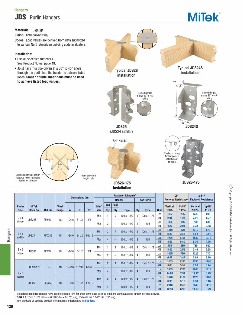
136
Hang
ers
Copyright © 2018 M
iTek Industries, Inc. All Rights Reserved
JDS Purlin Hangers
Top Face
Ref. No. W H TF Qty Qty Type Qty Type UnitLbs 655 285 655 285kN 2.91 1.27 2.91 1.27Lbs 960 655 760 535kN 4.27 2.91 3.38 2.38Lbs 1310 570 1310 570kN 5.83 2.54 5.83 2.54Lbs 1925 1305 1520 1070kN 8.56 5.80 6.76 4.76Lbs 785 580 785 580kN 3.49 2.58 3.49 2.58Lbs 1455 780 1325 710kN 6.47 3.47 5.89 3.16Lbs 1805 1330 1750 1290kN 8.03 5.92 7.78 5.74Lbs 3335 1785 2645 1415kN 14.83 7.94 11.77 6.29Lbs 1570 1160 1570 1160kN 6.98 5.16 6.98 5.16Lbs 2910 1555 2645 1415kN 12.94 6.92 11.77 6.29
1) Factored uplift resistances have been increased 15% for short-term loads such as wind and earthquake; no further increase allowed. 2) NAILS: 10d x 1-1/2 nails are 0.148" dia. x 1-1/2" long, 10d nails are 0.148" dia. x 3" long. New products or updated product information are designated in blue font.
DF Factored Resistance
S-P-F Factored Resistance
Vertical100%
Uplift1
115%Vertical100%
Uplift1
115%
PFD26B 18 1-9/164 -- 10d x 1-1/2
10d x 1-1/2 4 10d x 1-1/2
10d x 1-1/2 10d4
5-1/2 1-9/16
10d x 1-1/2
2 -- 10d x 1-1/2
2 x 6 saddle
4 --
2 4 10d x 1-1/2 4 10d x 1-1/2
4 10d
Min
Max
Min
Max JDS26-175
JDS26
-- 182 4
1-9/16 5-7/16 1-3/4
10d
2 4 10d x 1-1/2 2 10d x 1-1/2
4 -- 10d x 1-1/2 2 10d
1 2 10d x 1-1/2 41-9/16 5-1/2
1-9/16 3-1/2
3/4
1-9/16
4
Min
Max
Min
Max
Each Purlin
1 2 10d x 1-1/2 2 10d x 1-1/2
Min/Max
Min18
Dimensions (in)Header
Fastener Schedule2
Max 10d1-9/16 3-1/2 3/4
2 -- 10d x 1-1/2 2
Purlin Size
2 x 4 single
2 x 6single
JDS24S
JDS24
JDS26S
MiTekStock No.
SteelGauge
18
182 x 4
saddle
PF24B
PFD24B
PF26B
Materials: 18 gaugeFinish: G90 galvanizingCodes: Load values are derived from data submitted to various North American building code evaluators.
Installation:• Use all specified fasteners.
See Product Notes, page 19.• Joist nails must be driven at a 30° to 45° angle
through the purlin into the header to achieve listed loads. Slant / double shear nails must be used to achieve listed load values.
Hangers
JDS24S
JDS26-175installation
Typical JDS24Sinstallation
JDS26-175
Typical JDS26installation
Raised dimpleallows 30˚ to 45˚
nailing
1-3/4" Header
JDS26 (JDS24 similar)
Starburst prong for temporary attachment
to truss
Raised dimpleallows 30˚ to 45˚
nailing
H
W
TF
Double shear nail designfeatures fewer nails and
faster installation
Uses standard length nails

137
Hangers Co
pyrig
ht ©
201
8 M
iTek
Indu
strie
s, In
c. A
ll Ri
ghts
Res
erve
d
TUS – For a single ply purlin.
DTUS – For a single ply purlin with a 2-ply saddle dimension.
Materials: 20 gaugeFinish: G90 galvanizing
Installation:• Use all specified fasteners. See Product
Notes, page 19.• Attaches with standard 1-1/2" joist hanger
nails that can be installed with a positive placement nail gun or be hand driven.
• Other 1-1/2" fasteners with a shear value equal or greater than a 10d nail may be used.
TUS / DTUS Undersaddle Hangers
Download Uplift1 F21 Download Uplift1 F21
W H Face Bottom Type Face Bottom Type Unit 100% 115% 115% 100% 115% 115%Lbs 980 955 385 770 750 275kN 4.36 4.25 1.71 3.43 3.34 1.22Lbs 980 955 385 770 750 275kN 4.36 4.25 1.71 3.43 3.34 1.22Lbs 980 955 385 770 750 275kN 4.36 4.25 1.71 3.43 3.34 1.22Lbs 980 955 1120 770 750 795kN 4.36 4.25 4.98 3.43 3.34 3.54Lbs 980 955 1120 770 750 795kN 4.36 4.25 4.98 3.43 3.34 3.54Lbs 980 955 1120 770 750 795kN 4.36 4.25 4.98 3.43 3.34 3.54Lbs 980 955 1120 770 750 795kN 4.36 4.25 4.98 3.43 3.34 3.54Lbs 980 955 1120 770 750 795kN 4.36 4.25 4.98 3.43 3.34 3.54Lbs 980 955 1120 770 750 795kN 4.36 4.25 4.98 3.43 3.34 3.54
1) Factored uplift resistances have been increased 15% for short-term loads such as wind and earthquake; no further increase allowed. 2) NAILS: 8d x 1-1/2 nails are 0.131" dia. x 1-1/2" long, 10d x 1-1/2 nails are 0.148" dia. x 1-1/2" long, LL915 denotes a LumberLok Screw, #9 x 1-3/8" long. New products or updated product information are designated in blue font.
LL915
8d x 1-1/2
10d x 1-1/2
LL915
2 x 4 - 6saddle
2 x 4 - 6saddle
TUS24
DTUS24
--
--
20 1-9/16
20 1-9/16
8d x 1-1/2
10d x 1-1/2
LL915
8d x 1-1/2
10d x 1-1/2
DFFactored Resistance
S-P-FFactored Resistance
10d x 1-1/2
3
4 1
4 1
4 1
8d x 1-1/2
10d x 1-1/2
LL915
3
4 1
4 1
8d x 1-1/2 8d x 1-1/2
Fastener Schedule2
Joist
Qty
LL915 LL915
Joist Size
MiTekStock
No. Ga.
10d x 1-1/2
Header
Qty
32 x 4 - 6single
--
Dimensions(in)
4 1 TUS24S 20 1-9/16
Ref.No.
DTUS24TUS24TUS24S
H
WW
3-1/4"
H
H
WW
Hangers
Typical DTUS24installation
BottomView
Typical TUS24installation
Uplift
F2
F2F2
F2

138
Hang
ers
Copyright © 2018 M
iTek Industries, Inc. All Rights Reserved
Typical WT22B-HDG installation
WT22B-HDG
WT Wall Ties
Materials: 22 gaugeFinish: G90 galvanizing; WT22B-HDG – Hot-dip galvanizedOptions: See chart for Corrosion Finish options
Installation:• Use nails appropriate for intended use. See Product Notes,
page 19.• The opposite end must be bonded in the mortar joint
of brick facade.• Check local codes for spacing requirements.• Meets prescriptive requirements of CSA A370 for
corrugated strip ties.
Ref. No. Qty Type WT17HD -- 22 2 10d
WT221 BTB 22 2 10d WT22B-HDG -- 22 1 #10 HDG wood screw
1) WT22 is bulk packed in 500 pieces. 2) NAILS: 10d nails are 0.148" dia. x 3" long.
MiTekStock No.
SteelGauge
Fastener Schedule2
Corr
osio
nFi
nish
Corrosion Finish Stainless Steel Gold Coat HDG Triple Zinc
Corrosion Finish Stainless Steel Gold Coat HDG Triple Zinc
Corrosion Finish Stainless Steel Gold Coat HDG Triple Zinc
FHD Panel Hangers
The FHD26 hanger straddles the header and receives a joist from both sides.
Materials: 18 gaugeFinish: G90 galvanizing
Installation:• Use all specified fasteners. See Product Notes, page 19.• In panelized construction, installers are allowed to nail through
both the sheathing and the hanger top flange with (1) 10d nail. The nail should be centered in the top flange and be no closer than 1/4" from the back or front edge of the top flange.
Top Face
Ref. No. W H D Qty Qty Type Qty Type UnitLbs 1575 335 1235 260kN 7.01 1.49 5.49 1.16
1) Loads listed are per side. 2) Factored resistances have been increased 15% for short-term loads such as wind and earthquake; reduce for other load durations in accordance with the code. 3) NAILS: 10d x 1-1/2 nails are 0.148" dia. x 1-1/2" long, 16d nails are 0.162" dia. x 3-1/2" long. 10d x 1-1/2 nails may be substituted for 16d header nails with a maximum load of 960 lbs. New products or updated product information are designated in blue font.
Joist Size
MiTekStock No.
SteelGauge
10d x 1-1/222 x 6 FHD26 PFDS26 18 1-9/16 5-3/8 1-1/2 2 2 16d
Header
Dimensions (in)
Vertical100%
DF
Factored Resistance1
S-P-F
Factored Resistance1
Vertical100%
Uplift
115%2
Joist
Fastener Schedule3
Uplift
115%2
Typical WT17HD/WT22 installation
WT17HD/WT22
Hangers
1" space between brick and sheathing
Typical FHD26 installation
FHD26
W
7/8"
5/8"
3-1/8"3-3/4"
H
D
6-3/4"
7/8"
3-1/8"

139
Hangers Co
pyrig
ht ©
201
8 M
iTek
Indu
strie
s, In
c. A
ll Ri
ghts
Res
erve
d
UMH Universal Masonry Hangers
A versatile solution for hanging beams from masonry walls. Face mount design allows hanger to be used with beam heights from 16" to 24". Available in a variety of widths for solid sawn, glulam, or engineered lumber beams.
Materials: 1/4" steelFinish: PrimerCodes: Load values are derived from data submitted to various North American building code evaluators.
Installation:• Use all specified fasteners. See Product Notes, page 19.• Fully grouted and reinforced concrete block or cast-in-
place concrete with a minimum of (1) #5 rebar continuous to footing with standard hook at bolt locations.
• Minimum joist width is 3-1/2".
Ref. No. Qty Qty Type UnitLbs 6610 4390 9455 7770 6610 4390 7445 6785kN 29.40 19.53 42.06 34.56 29.40 19.53 33.12 30.18Lbs 6610 4390 9455 7770 6610 4390 7445 6785kN 29.40 19.53 42.06 34.56 29.40 19.53 33.12 30.18Lbs 6610 4390 9455 7770 6610 4390 7445 6785kN 29.40 19.53 42.06 34.56 29.40 19.53 33.12 30.18Lbs 6610 4390 9455 7770 6610 4390 7445 6785kN 29.40 19.53 42.06 34.56 29.40 19.53 33.12 30.18Lbs 6610 4390 9455 7770 6610 4390 7445 6785kN 29.40 19.53 42.06 34.56 29.40 19.53 33.12 30.18
1) Factored resistances have been increased 15% for short-term loads such as wind and earthquake; no further increase allowed. 2) Fasten UMH hanger to concrete structure with (2) 3/4" dia. DeWalt Screw-Bolt+ screw anchors or equal with 5" minimum embedment. Screw anchors shall be installed in masonry with grouted cells in accordance with manufacturer's installation specifications. 3) NAILS: 16d nails are 0.162" dia. x 3-1/2" long. New products or updated product information are designated in blue font.
3/4"
3/4"
16 16d
16 16d
16 16d
16 16d
3/4"
3/4"
5-5/8
7-1/8
2
2
2
2
4-5/8
5-3/8
UMH458
UMH538
UMH558
UMH718
3
3
3
3
MBHU5.50/16KT, MBHU5.50/18KT
--
--
--
S-P-F Factored Resistance
MiTekStock No.
SteelGauge
W(in)
Fastener Schedule
Header2 Joist3
DF Factored Resistance
Masonry2,500 psi
Cast-in-PlaceConcrete 3,000 psi
Masonry2,500 psi
Uplift1
115%Vertical100%
Vertical100%
Vertical100%
Vertical100%
Cast-in-PlaceConcrete 3,000 psi
ScrewAnchor
UMH358 3 3-5/8 2 3/4" 16 16d MBHU3.56/16KT, MBHU3.56/18KT
Uplift1
115%Uplift1
115%Uplift1
115%
Hangers
Typical UMHinstallation
UMH
15-1/2"
5"W
3-1/2" min joist width
5-1/4" min edge distance
2-3/4" screw anchors
(see footnote 2)
Bond beam with (1) #5 rebar continuous

140
Hang
ers
Copyright © 2018 M
iTek Industries, Inc. All Rights Reserved
LGUM / HGUM Masonry Girder Hangers
Hangers
LGUM and HGUM Masonry Girder Hangers are high-capacity beam/girder hangers designed for installation to masonry or concrete walls. The LGUM and HGUM hangers use WS screws (supplied) to attach the beam to hanger and screw anchors (supplied) to attach to the masonry or concrete wall. These hangers eliminate the need for constructing beam pockets.
Materials: LGUM - 12 gauge; HGUM - 7 gaugeFinish: G90 galvanizingOptions: See Specialty Options chart on page 141.
Installation:• WS3 structural screws and screw anchors are supplied with hangers.
Substituting other fasteners may reduce capacity.• Beams comprised of multiple plies must be adequately fastened
to act as a single member.• Beam height dimension (H) must be specified when ordering
HGUM hangers.• Moisture barrier between beam and wall may be required by
local jurisdiction.
Typical LGUM installation
LGUM
Typical HGUM installation
Min. 4" distance to top of wall (13" min for max uplift)
HGUM W
4-3/4"
5"
1"
Specify (Min=11-1/4")
W
4"
3/4"
2-3/8"
H
Ref. No. W H3 D Qty Qty Unit
Lbs 10840 3485 3485 8745 2810 2810
kN 48.22 15.50 15.50 38.90 12.50 12.50
Lbs 13120 4540 4540 10580 3660 3660
kN 58.36 20.19 20.19 47.06 16.28 16.28
Lbs 16225 5490 5490 13085 4425 4425
kN 72.17 24.42 24.42 58.20 19.68 19.68
Lbs 10840 3485 3485 8745 2810 2810
kN 48.22 15.50 15.50 38.90 12.50 12.50
Lbs 13120 4540 4540 10580 3660 3660
kN 58.36 20.19 20.19 47.06 16.28 16.28
Lbs 16225 5490 5490 13085 4425 4425
kN 72.17 24.42 24.42 58.20 19.68 19.68
1) Factored resistances have been increased 15% for short-term loads such as wind and earthquake; no further increase allowed. 2) Masonry compressive strength shall be minimum 1,500 psi. 3) Minimum concrete strength f'c = 2,000 psi. 4) "Specify" denotes the required supported beam height that must be specified at the time of ordering. 5) Use DeWalt Screw-Bolt+ (included); or equal, installed in accordance with manufacturer's specification. 6) WS3 Wood Screws are 1/4" x 3" long and are included with hangers. New products or updated product information are designated in blue font.
.
Ref. No. W H3 D Qty Qty Unit
Lbs 10840 3485 3485 8745 2810 2810
kN 48.22 15.50 15.50 38.90 12.50 12.50
Lbs 13120 4540 4540 10580 3660 3660
kN 58.36 20.19 20.19 47.06 16.28 16.28
Lbs 16225 5490 5490 13085 4425 4425
kN 72.17 24.42 24.42 58.20 19.68 19.68
Lbs 10840 3485 3485 8745 2810 2810
kN 48.22 15.50 15.50 38.90 12.50 12.50
Lbs 13120 4540 4540 10580 3660 3660
kN 58.36 20.19 20.19 47.06 16.28 16.28
Lbs 16225 5490 5490 13085 4425 4425
kN 72.17 24.42 24.42 58.20 19.68 19.68
Lbs 26165 7010 15890 20780 5570 12620
kN 116.39 31.18 70.68 92.43 24.78 56.14
Lbs 26165 7010 15890 20780 5570 12620
kN 116.39 31.18 70.68 92.43 24.78 56.14
Lbs 26165 7010 15890 20780 5570 12620
kN 116.39 31.18 70.68 92.43 24.78 56.14
Lbs 26165 7010 15890 20780 5570 12620
kN 116.39 31.18 70.68 92.43 24.78 56.14
Lbs 26165 7010 15890 20780 5570 12620
kN 116.39 31.18 70.68 92.43 24.78 56.14
1) Factored resistances have been increased 15% for short-term loads such as wind and earthquake; no further increase allowed. 2) Masonry compressive strength shall be minimum 1,500 psi. 3) Minimum concrete strength f'c = 2,000 psi. 4) "Specify" denotes the required supported beam height that must be specified at the time of ordering. 5) Use DeWalt Screw-Bolt+ (included); or equal, installed in accordance with manufacturer's specification. 6) WS3 Wood Screws are 1/4" x 3" long and are included with hangers. New products or updated product information are designated in blue font.
MiTekStock No.
SteelGauge
ScrewAnchor4
WSScrews5
S-P-F Factored Resistance
CMU/Concrete
Joist
CMU/Concrete2,3
100%
Uplift (115%)1
CMU/Concrete2,3
100%
Uplift (115%)1
CMU / Concrete2,3 CMU / Concrete2,3
4" Min.to Topof Wall
13" Min.to Topof Wall
4" Min.to Topof Wall
13" Min.to Topof Wall
Double 2x Sizes
Fastener ScheduleDimensions(in) CMU/
ConcreteJoist
DF Factored Resistance S-P-F Factored Resistance
CMU/Concrete2,3
100%
Uplift (115%)1
CMU/Concrete2,3
100%
Uplift (115%)1
CMU / Concrete2,3 CMU / Concrete2,3
4" Min.to Topof Wall
13" Min.to Topof Wall
4" Min.to Topof Wall
13" Min.to Topof Wall
ScrewAnchor4
WSScrews5
SteelGauge
MiTekStock No.
6-9/16 7-3/16
6-9/16 9-3/16
3-5/8 4-7/8
3-5/8 6-7/8
3-5/8 8-7/8
Engineered Wood & Structural Lumber Sizes (Heavy Duty)
24 WS3
5 8 5/8" x 5" 24 WS3
4 8 3/8" x 4" 8
Specify11-1/4
to30
5-1/2
7-1/4
7
9 HGUM900 HGUM9.00-SDS 7
5-1/4
HGUM700 HGUM7.00-SDS 7
HGUM725 HGUM7.25-SDS 7
HGUM525 HGUM5.25-SDS 7
HGUM550 HGUM5.50-SDS 7
LGUM28-4 LGUM28-4-SDS 12
5 8 5/8" x 5"
5 8 5/8" x 5"
4 6 3/8" x 4" LGUM48 LGUM48-SDS 12
LGUM410 LGUM410-SDS 12
LGUM210-4 LGUM210-4-SDS 12
LGUM46 LGUM46-SDS 12
24 WS3
5 8 5/8" x 5" 24 WS3
5 8 5/8" x 5" 24 WS3
WS3
6 WS3
4 4 3/8" x 4" 4 WS3
4 8 3/8" x 4" 8 WS3
4x Sizes
7-1/4
9-1/4
4 4 3/8" x 4"
4 8 3/8" x 4" 8
Quadruple 2x Sizes
LGUM28-3 LGUM28-3-SDS 12 4-15/16
LGUM210-3 LGUM210-3-SDS
LGUM26-4 LGUM26-4-SDS 12 6-9/16 5-7/16
Dimensions(in)
Fastener Schedule DF Factored Resistance
WS3
4 6 3/8" x 4" 6 WS3
4 WS3
4 6 3/8" x 4" 6 WS3
WS312 4-15/16
4
4
LGUM26-3 LGUM26-3-SDS 12 4-15/16 5-1/2 4
3-5/16
3-5/16
Triple 2x Sizes
6 3/8" x 4" 6 WS3
8 3/8" x 4" 8 WS3
4 3/8" x 4" 4
4 4 3/8" x 4" 4 WS35-7/16
7-3/16
9-3/16 LGUM210-2
LGUM26-2-SDS
LGUM28-2-SDS
LGUM210-2-SDS
12
12
12
LGUM26-2
LGUM28-2
3-5/16
H
Continued on next page

141
Hangers Co
pyrig
ht ©
201
8 M
iTek
Indu
strie
s, In
c. A
ll Ri
ghts
Res
erve
d
Option Inverted Flange1
One Inverted-Flange option
50% of table download75% of table uplift load
Ordering
Add IF and right (R) or left (L)to product number.
Ex. HGUM525_H=18_IFL
FactoredResistance
Range
Specialty Options Chart – Refer to Specialty Options pages 246-247 for additional details.
Ref. No. W H3 D Qty Qty Unit
Lbs 10840 3485 3485 8745 2810 2810
kN 48.22 15.50 15.50 38.90 12.50 12.50
Lbs 13120 4540 4540 10580 3660 3660
kN 58.36 20.19 20.19 47.06 16.28 16.28
Lbs 16225 5490 5490 13085 4425 4425
kN 72.17 24.42 24.42 58.20 19.68 19.68
Lbs 10840 3485 3485 8745 2810 2810
kN 48.22 15.50 15.50 38.90 12.50 12.50
Lbs 13120 4540 4540 10580 3660 3660
kN 58.36 20.19 20.19 47.06 16.28 16.28
Lbs 16225 5490 5490 13085 4425 4425
kN 72.17 24.42 24.42 58.20 19.68 19.68
1) Factored resistances have been increased 15% for short-term loads such as wind and earthquake; no further increase allowed. 2) Masonry compressive strength shall be minimum 1,500 psi. 3) Minimum concrete strength f'c = 2,000 psi. 4) "Specify" denotes the required supported beam height that must be specified at the time of ordering. 5) Use DeWalt Screw-Bolt+ (included); or equal, installed in accordance with manufacturer's specification. 6) WS3 Wood Screws are 1/4" x 3" long and are included with hangers. New products or updated product information are designated in blue font.
.
Ref. No. W H3 D Qty Qty Unit
Lbs 10840 3485 3485 8745 2810 2810
kN 48.22 15.50 15.50 38.90 12.50 12.50
Lbs 13120 4540 4540 10580 3660 3660
kN 58.36 20.19 20.19 47.06 16.28 16.28
Lbs 16225 5490 5490 13085 4425 4425
kN 72.17 24.42 24.42 58.20 19.68 19.68
Lbs 10840 3485 3485 8745 2810 2810
kN 48.22 15.50 15.50 38.90 12.50 12.50
Lbs 13120 4540 4540 10580 3660 3660
kN 58.36 20.19 20.19 47.06 16.28 16.28
Lbs 16225 5490 5490 13085 4425 4425
kN 72.17 24.42 24.42 58.20 19.68 19.68
Lbs 26165 7010 15890 20780 5570 12620
kN 116.39 31.18 70.68 92.43 24.78 56.14
Lbs 26165 7010 15890 20780 5570 12620
kN 116.39 31.18 70.68 92.43 24.78 56.14
Lbs 26165 7010 15890 20780 5570 12620
kN 116.39 31.18 70.68 92.43 24.78 56.14
Lbs 26165 7010 15890 20780 5570 12620
kN 116.39 31.18 70.68 92.43 24.78 56.14
Lbs 26165 7010 15890 20780 5570 12620
kN 116.39 31.18 70.68 92.43 24.78 56.14
1) Factored resistances have been increased 15% for short-term loads such as wind and earthquake; no further increase allowed. 2) Masonry compressive strength shall be minimum 1,500 psi. 3) Minimum concrete strength f'c = 2,000 psi. 4) "Specify" denotes the required supported beam height that must be specified at the time of ordering. 5) Use DeWalt Screw-Bolt+ (included); or equal, installed in accordance with manufacturer's specification. 6) WS3 Wood Screws are 1/4" x 3" long and are included with hangers. New products or updated product information are designated in blue font.
MiTekStock No.
SteelGauge
ScrewAnchor4
WSScrews5
S-P-F Factored Resistance
CMU/Concrete
Joist
CMU/Concrete2,3
100%
Uplift (115%)1
CMU/Concrete2,3
100%
Uplift (115%)1
CMU / Concrete2,3 CMU / Concrete2,3
4" Min.to Topof Wall
13" Min.to Topof Wall
4" Min.to Topof Wall
13" Min.to Topof Wall
Double 2x Sizes
Fastener ScheduleDimensions(in) CMU/
ConcreteJoist
DF Factored Resistance S-P-F Factored Resistance
CMU/Concrete2,3
100%
Uplift (115%)1
CMU/Concrete2,3
100%
Uplift (115%)1
CMU / Concrete2,3 CMU / Concrete2,3
4" Min.to Topof Wall
13" Min.to Topof Wall
4" Min.to Topof Wall
13" Min.to Topof Wall
ScrewAnchor4
WSScrews5
SteelGauge
MiTekStock No.
6-9/16 7-3/16
6-9/16 9-3/16
3-5/8 4-7/8
3-5/8 6-7/8
3-5/8 8-7/8
Engineered Wood & Structural Lumber Sizes (Heavy Duty)
24 WS3
5 8 5/8" x 5" 24 WS3
4 8 3/8" x 4" 8
Specify11-1/4
to30
5-1/2
7-1/4
7
9 HGUM900 HGUM9.00-SDS 7
5-1/4
HGUM700 HGUM7.00-SDS 7
HGUM725 HGUM7.25-SDS 7
HGUM525 HGUM5.25-SDS 7
HGUM550 HGUM5.50-SDS 7
LGUM28-4 LGUM28-4-SDS 12
5 8 5/8" x 5"
5 8 5/8" x 5"
4 6 3/8" x 4" LGUM48 LGUM48-SDS 12
LGUM410 LGUM410-SDS 12
LGUM210-4 LGUM210-4-SDS 12
LGUM46 LGUM46-SDS 12
24 WS3
5 8 5/8" x 5" 24 WS3
5 8 5/8" x 5" 24 WS3
WS3
6 WS3
4 4 3/8" x 4" 4 WS3
4 8 3/8" x 4" 8 WS3
4x Sizes
7-1/4
9-1/4
4 4 3/8" x 4"
4 8 3/8" x 4" 8
Quadruple 2x Sizes
LGUM28-3 LGUM28-3-SDS 12 4-15/16
LGUM210-3 LGUM210-3-SDS
LGUM26-4 LGUM26-4-SDS 12 6-9/16 5-7/16
Dimensions(in)
Fastener Schedule DF Factored Resistance
WS3
4 6 3/8" x 4" 6 WS3
4 WS3
4 6 3/8" x 4" 6 WS3
WS312 4-15/16
4
4
LGUM26-3 LGUM26-3-SDS 12 4-15/16 5-1/2 4
3-5/16
3-5/16
Triple 2x Sizes
6 3/8" x 4" 6 WS3
8 3/8" x 4" 8 WS3
4 3/8" x 4" 4
4 4 3/8" x 4" 4 WS35-7/16
7-3/16
9-3/16 LGUM210-2
LGUM26-2-SDS
LGUM28-2-SDS
LGUM210-2-SDS
12
12
12
LGUM26-2
LGUM28-2
3-5/16
LGUM / HGUM Masonry Girder Hangers
Typical HGUM one inverted flange,
left shown

142
Hang
ers
Copyright © 2018 M
iTek Industries, Inc. All Rights Reserved
HWUH Heavy-Duty Welded Universal Hangers
W H Qty Type Qty TypeWood 6 10d 4 10d x 1-1/2 6700 995 29.80 4.43 5260 780 23.40 3.47
Masonry 2 1/2" x 6" J-Bolt 4 10d x 1-1/2 5010 2035 22.29 9.05 3930 1595 17.48 7.09Wood 6 10d 4 10d x 1-1/2 6700 995 29.80 4.43 5260 780 23.40 3.47
Masonry 2 1/2" x 6" J-Bolt 4 10d x 1-1/2 5010 2035 22.29 9.05 3930 1595 17.48 7.09Wood 6 10d 4 10d x 1-1/2 6700 995 29.80 4.43 5260 780 23.40 3.47
Masonry 2 1/2" x 6" J-Bolt 4 10d x 1-1/2 5010 2035 22.29 9.05 3930 1595 17.48 7.09Wood 6 10d 4 10d x 1-1/2 6700 995 29.80 4.43 5260 780 23.40 3.47
Masonry 2 1/2" x 6" J-Bolt 4 10d x 1-1/2 5010 2035 22.29 9.05 3930 1595 17.48 7.09Wood 6 10d 4 10d x 1-1/2 6700 995 29.80 4.43 5260 780 23.40 3.47
Masonry 2 1/2" x 6" J-Bolt 4 10d x 1-1/2 5010 2035 22.29 9.05 3930 1595 17.48 7.09Wood 6 10d 4 10d x 1-1/2 6700 995 29.80 4.43 5260 780 23.40 3.47
Masonry 2 1/2" x 6" J-Bolt 4 10d x 1-1/2 5010 2035 22.29 9.05 3930 1595 17.48 7.09Wood 6 10d 4 10d 6700 995 29.80 4.43 5260 780 23.40 3.47
Masonry 2 1/2" x 6" J-Bolt 4 10d 5010 2035 22.29 9.05 3930 1595 17.48 7.09Wood 6 10d 4 10d 6700 995 29.80 4.43 5260 780 23.40 3.47
Masonry 2 1/2" x 6" J-Bolt 4 10d 5010 2035 22.29 9.05 3930 1595 17.48 7.09Wood 6 10d 4 10d 6700 995 29.80 4.43 5260 780 23.40 3.47
Masonry 2 1/2" x 6" J-Bolt 4 10d 5010 2035 22.29 9.05 3930 1595 17.48 7.09Wood 6 10d 4 10d 6700 995 29.80 4.43 5260 780 23.40 3.47
Masonry 2 1/2" x 6" J-Bolt 4 10d 5010 2035 22.29 9.05 3930 1595 17.48 7.09Wood 6 10d 4 10d 6700 995 29.80 4.43 5260 780 23.40 3.47
Masonry 2 1/2" x 6" J-Bolt 4 10d 5010 2035 22.29 9.05 3930 1595 17.48 7.09Wood 6 10d 4 10d 6700 995 29.80 4.43 5260 780 23.40 3.47
Masonry 2 1/2" x 6" J-Bolt 4 10d 5010 2035 22.29 9.05 3930 1595 17.48 7.09Wood 6 10d 4 10d 6700 995 29.80 4.43 5260 780 23.40 3.47
Masonry 2 1/2" x 6" J-Bolt 4 10d 5010 2035 22.29 9.05 3930 1595 17.48 7.09Wood 6 10d 4 10d 6700 995 29.80 4.43 5260 780 23.40 3.47
Masonry 2 1/2" x 6" J-Bolt 4 10d 5010 2035 22.29 9.05 3930 1595 17.48 7.09Wood 6 10d 4 10d 6700 995 29.80 4.43 5260 780 23.40 3.47
Masonry 2 1/2" x 6" J-Bolt 4 10d 5010 2035 22.29 9.05 3930 1595 17.48 7.09Wood 6 10d 4 10d 6700 995 29.80 4.43 5260 780 23.40 3.47
Masonry 2 1/2" x 6" J-Bolt 4 10d 5010 2035 22.29 9.05 3930 1595 17.48 7.09
1) Factored uplift resistances have been increased 15% for short-term loads such as wind and earthquake; no further increase allowed. 2) NAILS: 10d x 1-1/2 nails are 0.148" dia. x 1-1/2" long, 10d nails are 0.148" dia. x 3" long. New products or updated product information are designated in blue font.
11
HWUH210-2 --
(2) 2 x 12 HWUH212-2
1-5/8
1-5/8
1-5/8
1-5/8
1-5/8
2-5/8
2-5/8
--
(2) 2 x 6 HWUH26-2 --
(2) 2 x 8 HWUH28-2 --
3 x 6 HWUH36 --
3 x 8 HWUH38
3 x 14 HWUH314 --
3 x 16
3 x 10 HWUH310 --
3 x 12 HWUH312 --
(2) 2 x 10
2 x 8 HWUH28 --
Beam/Joist Size
MiTekStock No.
2 x 4 - 6 --
HWUH316 --
HWUH26
HWUH210 --
2 x 12 HWUH212 --
2 x 10
2 x 14 HWUH214 --
2 x 16 HWUH216 --
--
3-1/8
3-1/8
Dimensions(in)
DF Factored Resistance S-P-F Factored Resistance
kN Lbs kN
5-3/8
7-1/8
9-1/8
5-3/8
11
Lbs
Fastener Schedule2
1-5/8
13
5-3/8
7-1/8
9-1/8
16
11
13
16
2-5/8
InstallType
Ref. No.
Vertical100%
Vertical100%
Uplift1
115%
2-5/8
3-1/8
3-1/8
7-1/8
9-1/8
Uplift1
115%Vertical100%
Uplift1
115%Vertical100%
Uplift1
115%
Header Joist
2-5/8
2-5/8
Versatile heavy-duty top flange hanger attaches to both wood and masonry. Unique design allows builders to use one style hanger on the job when the structure has a variety of support materials.
Materials: Top Flange – 1/4" steel; Stirrup – 7 gaugeFinish: PrimerOptions: See Specialty Options Chart on page 143.
Installation:• Use all specified fasteners. See Product Notes, page 19.• NA21 nails are included with hangers where specified.• NA21 nails are not recommended for use with LVL, PSL,
or LSL headers.• Masonry design load values apply to both solid concrete tie beams
and grout-filled CMU walls.• Alternate installation – Use (2) 1/2" x 4" DeWalt Screw-Bolts
or equal for loads up to 3455 lbs. when attaching to CMU. Loads shall not exceed table loads.
Hangers
Typical HWUH410wood-to-masonry installation
HWUH
Typical HWUH410wood-to-wood installation
H
W
3-1/2"
3-1/2"3-1/2"
10"
Continued on next page

143
Hangers Co
pyrig
ht ©
201
8 M
iTek
Indu
strie
s, In
c. A
ll Ri
ghts
Res
erve
d
HWUH Heavy-Duty Welded Universal Hangers
Specialty Options Chart Refer to Specialty Options pages 246, 248-249 for additional details.
W H Qty Type Qty TypeWood 6 10d 4 10d 6700 995 29.80 4.43 5260 780 23.40 3.47
Masonry 2 1/2" x 6" J-Bolt 4 10d 5010 2035 22.29 9.05 3930 1595 17.48 7.09Wood 6 10d 4 10d 6700 995 29.80 4.43 5260 780 23.40 3.47
Masonry 2 1/2" x 6" J-Bolt 4 10d 5010 2035 22.29 9.05 3930 1595 17.48 7.09Wood 6 NA21 4 10d 8625 705 38.37 3.14 6775 555 30.14 2.47
Masonry 2 1/2" x 6" J-Bolt 4 10d 5010 2035 22.29 9.05 3930 1595 17.48 7.09Wood 6 NA21 4 10d 8625 705 38.37 3.14 6775 555 30.14 2.47
Masonry 2 1/2" x 6" J-Bolt 4 10d 5010 2035 22.29 9.05 3930 1595 17.48 7.09Wood 6 NA21 4 10d 8625 705 38.37 3.14 6775 555 30.14 2.47
Masonry 2 1/2" x 6" J-Bolt 4 10d 5010 2035 22.29 9.05 3930 1595 17.48 7.09Wood 6 NA21 4 10d 8625 705 38.37 3.14 6775 555 30.14 2.47
Masonry 2 1/2" x 6" J-Bolt 4 10d 5010 2035 22.29 9.05 3930 1595 17.48 7.09Wood 6 NA21 4 10d 8625 705 38.37 3.14 6775 555 30.14 2.47
Masonry 2 1/2" x 6" J-Bolt 4 10d 5010 2035 22.29 9.05 3930 1595 17.48 7.09Wood 6 NA21 4 10d 8625 705 38.37 3.14 6775 555 30.14 2.47
Masonry 2 1/2" x 6" J-Bolt 4 10d 5010 2035 22.29 9.05 3930 1595 17.48 7.09Wood 6 NA21 4 10d 8625 705 38.37 3.14 6775 555 30.14 2.47
Masonry 2 1/2" x 6" J-Bolt 4 10d 5010 2035 22.29 9.05 3930 1595 17.48 7.09Wood 6 NA21 4 10d 8625 705 38.37 3.14 6775 555 30.14 2.47
Masonry 2 1/2" x 6" J-Bolt 4 10d 5010 2035 22.29 9.05 3930 1595 17.48 7.09Wood 6 NA21 4 10d 8625 705 38.37 3.14 6775 555 30.14 2.47
Masonry 2 1/2" x 6" J-Bolt 4 10d 5010 2035 22.29 9.05 3930 1595 17.48 7.09Wood 6 NA21 4 10d 8625 705 38.37 3.14 6775 555 30.14 2.47
Masonry 2 1/2" x 6" J-Bolt 4 10d 5010 2035 22.29 9.05 3930 1595 17.48 7.09Wood 6 NA21 4 10d 8625 705 38.37 3.14 6775 555 30.14 2.47
Masonry 2 1/2" x 6" J-Bolt 4 10d 5010 2035 22.29 9.05 3930 1595 17.48 7.09Wood 6 NA21 4 10d 8625 705 38.37 3.14 6775 555 30.14 2.47
Masonry 2 1/2" x 6" J-Bolt 4 10d 5010 2035 22.29 9.05 3930 1595 17.48 7.09Wood 6 NA21 4 10d 8625 705 38.37 3.14 6775 555 30.14 2.47
Masonry 2 1/2" x 6" J-Bolt 4 10d 5010 2035 22.29 9.05 3930 1595 17.48 7.09Wood 6 NA21 4 10d 8625 705 38.37 3.14 6775 555 30.14 2.47
Masonry 2 1/2" x 6" J-Bolt 4 10d 5010 2035 22.29 9.05 3930 1595 17.48 7.09Wood 6 NA21 4 10d 8625 705 38.37 3.14 6775 555 30.14 2.47
Masonry 2 1/2" x 6" J-Bolt 4 10d 5010 2035 22.29 9.05 3930 1595 17.48 7.09Wood 6 NA21 4 10d 8625 705 38.37 3.14 6775 555 30.14 2.47
Masonry 2 1/2" x 6" J-Bolt 4 10d 5010 2035 22.29 9.05 3930 1595 17.48 7.09Wood 6 NA21 4 10d 8625 705 38.37 3.14 6775 555 30.14 2.47
Masonry 2 1/2" x 6" J-Bolt 4 10d 5010 2035 22.29 9.05 3930 1595 17.48 7.09Wood 6 NA21 4 10d 8625 705 38.37 3.14 6775 555 30.14 2.47
Masonry 2 1/2" x 6" J-Bolt 4 10d 5010 2035 22.29 9.05 3930 1595 17.48 7.09
1) Factored uplift resistances have been increased 15% for short-term loads such as wind and earthquake; no further increase allowed. 2) NAILS: 10d nails are 0.148" dia. x 3" long, NA21 nails are 0.192" dia. x 1-3/4" long and are included with 4x, 6x, and 8x HWUH hangers. New products or updated product information are designated in blue font.
Dimensions(in)
Fastener Schedule2 DF Factored Resistance S-P-F Factored Resistance
Header Joist Lbs kN Lbs kN
13
(2) 2 x 16 HWUH216-2 -- 3-1/8 16
Beam/Joist Size
MiTekStock No.
(2) 2 x 14 HWUH214-2 -- 3-1/8
4 x 6 HWUH46 -- 3-9/16 5-3/8
4 x 8 HWUH48 -- 3-9/16 7-1/8
4 x 10 HWUH410 -- 3-9/16 9-1/8
4 x 12 HWUH412 -- 3-9/16 11
4 x 14 HWUH414 -- 3-9/16 13
4 x 16 HWUH416 -- 3-9/16 16
6 x 6 HWUH66 -- 5-1/2 5-3/8
6 x 8 HWUH68 -- 5-1/2 7-1/8
6 x 10 HWUH610 -- 5-1/2 9-1/8
6 x 12 HWUH612 -- 5-1/2 11
6 x 14 HWUH614 -- 5-1/2 13
6 x 16 HWUH616 -- 5-1/2 16
8 x 6 HWUH86 -- 7-1/2 5-3/8
8 x 8 HWUH88 -- 7-1/2 7-1/8
8 x 10 HWUH810 -- 7-1/2 9-1/8
8 x 12 HWUH812 -- 7-1/2 11
8 x 14 HWUH814 -- 7-1/2 13
8 x 16 HWUH816 -- 7-1/2 16
Vertical100%
Uplift1
115%Vertical100%
Uplift1
115%InstallType
Ref. No.
Vertical100%
Uplift1
115%Vertical100%
Uplift1
115%
Option Skewed1,3 Sloped Seat2 Sloped / Skewed1,2,3 Saddle
Range 1˚ to 45˚ 1˚ to 45˚ See Sloped Seat and Skewed -- --
1) Skewed hangers with skews greater than 15° may have all joist nailing on outside flange. 2) Sloped or sloped / skewed hangers with slopes greater than 15° may have additional joist nails. 3) For skewed hangers, the required cut type (square or bevel) of joist member may vary based on skew angle and width of hanger. Some square cut hangers will require custom pricing due to welded back plate.
Top Flange Offset
-- --
FactoredResistance
Ordering
100% of table load
Add SK, angle required,right (R) or left (L), and
square cut (SQ ) or bevel cut (BV )to product number.
Ex. HWUH410_SK45R_SQ
100% of table load 100% of table load
Hanger Width
3-1/2" or less3-9/16" to 5-1/2"5-9/16"˝ to 7-1/2"
Add SA, and saddlewidth required
to product number.Ex. HWUH410_SA=5-1/2"
% of table load:60%75%85%
Add SL, slope required,and up (U) or down (D),
to product number.Ex. HWUH410_SL30D
See Sloped Seat and Skewed.Ex. HWUH410_SK45R_SQ_SL30D
Add OS, and right (R) or left (L),to product number.Ex. HWUH410_OSL
100% of table loadper side
Hangers
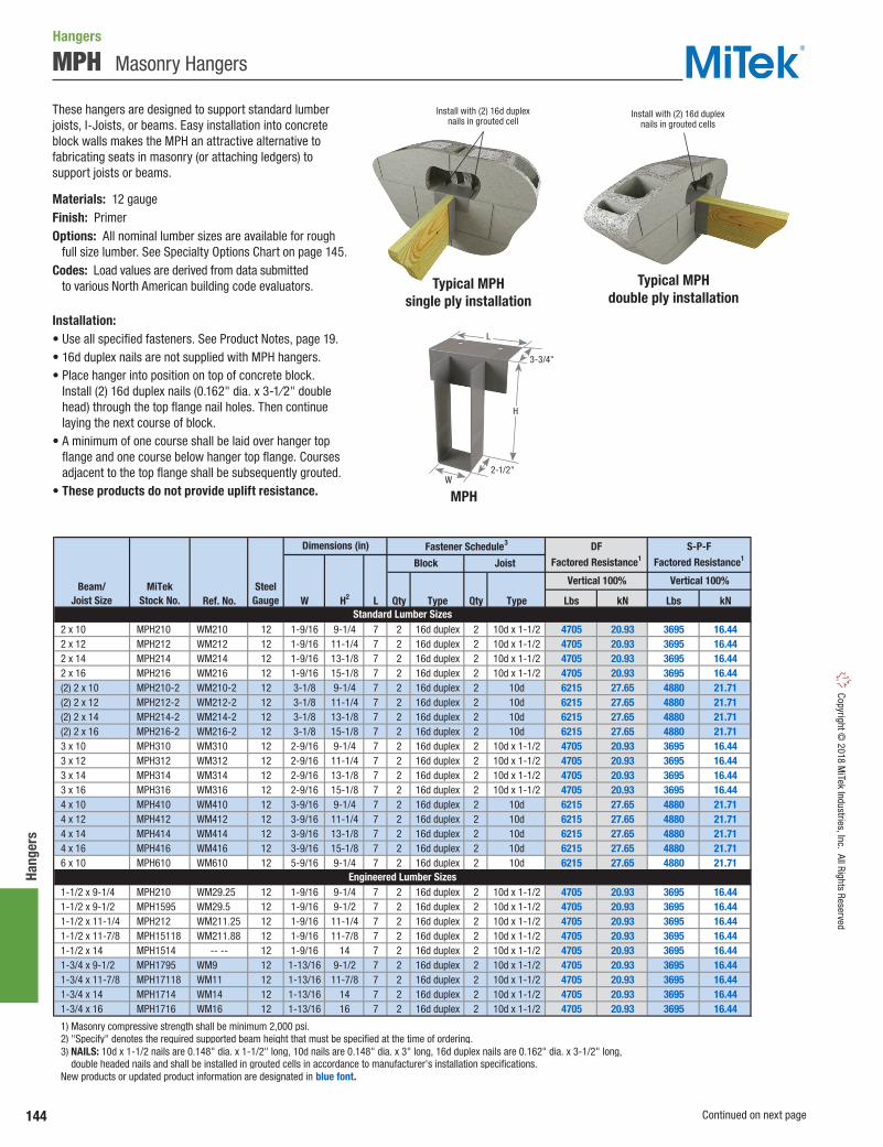
144
Hang
ers
Copyright © 2018 M
iTek Industries, Inc. All Rights Reserved
MPH Masonry Hangers
These hangers are designed to support standard lumber joists, I-Joists, or beams. Easy installation into concrete block walls makes the MPH an attractive alternative to fabricating seats in masonry (or attaching ledgers) to support joists or beams.
Materials: 12 gaugeFinish: PrimerOptions: All nominal lumber sizes are available for rough full size lumber. See Specialty Options Chart on page 145.Codes: Load values are derived from data submitted to various North American building code evaluators.
Installation:• Use all specified fasteners. See Product Notes, page 19.• 16d duplex nails are not supplied with MPH hangers.• Place hanger into position on top of concrete block.
Install (2) 16d duplex nails (0.162" dia. x 3-1⁄2" double head) through the top flange nail holes. Then continue laying the next course of block.
• A minimum of one course shall be laid over hanger top flange and one course below hanger top flange. Courses adjacent to the top flange shall be subsequently grouted.
• These products do not provide uplift resistance.
Ref. No. W H2 L Qty Type Qty Type Lbs kN Lbs kN
2 x 10 MPH210 WM210 12 1-9/16 9-1/4 7 2 16d duplex 2 10d x 1-1/2 4705 20.93 3695 16.44 2 x 12 MPH212 WM212 12 1-9/16 11-1/4 7 2 16d duplex 2 10d x 1-1/2 4705 20.93 3695 16.44 2 x 14 MPH214 WM214 12 1-9/16 13-1/8 7 2 16d duplex 2 10d x 1-1/2 4705 20.93 3695 16.44 2 x 16 MPH216 WM216 12 1-9/16 15-1/8 7 2 16d duplex 2 10d x 1-1/2 4705 20.93 3695 16.44 (2) 2 x 10 MPH210-2 WM210-2 12 3-1/8 9-1/4 7 2 16d duplex 2 10d 6215 27.65 4880 21.71 (2) 2 x 12 MPH212-2 WM212-2 12 3-1/8 11-1/4 7 2 16d duplex 2 10d 6215 27.65 4880 21.71 (2) 2 x 14 MPH214-2 WM214-2 12 3-1/8 13-1/8 7 2 16d duplex 2 10d 6215 27.65 4880 21.71 (2) 2 x 16 MPH216-2 WM216-2 12 3-1/8 15-1/8 7 2 16d duplex 2 10d 6215 27.65 4880 21.71 3 x 10 MPH310 WM310 12 2-9/16 9-1/4 7 2 16d duplex 2 10d x 1-1/2 4705 20.93 3695 16.44 3 x 12 MPH312 WM312 12 2-9/16 11-1/4 7 2 16d duplex 2 10d x 1-1/2 4705 20.93 3695 16.44 3 x 14 MPH314 WM314 12 2-9/16 13-1/8 7 2 16d duplex 2 10d x 1-1/2 4705 20.93 3695 16.44 3 x 16 MPH316 WM316 12 2-9/16 15-1/8 7 2 16d duplex 2 10d x 1-1/2 4705 20.93 3695 16.44 4 x 10 MPH410 WM410 12 3-9/16 9-1/4 7 2 16d duplex 2 10d 6215 27.65 4880 21.71 4 x 12 MPH412 WM412 12 3-9/16 11-1/4 7 2 16d duplex 2 10d 6215 27.65 4880 21.71 4 x 14 MPH414 WM414 12 3-9/16 13-1/8 7 2 16d duplex 2 10d 6215 27.65 4880 21.71 4 x 16 MPH416 WM416 12 3-9/16 15-1/8 7 2 16d duplex 2 10d 6215 27.65 4880 21.71 6 x 10 MPH610 WM610 12 5-9/16 9-1/4 7 2 16d duplex 2 10d 6215 27.65 4880 21.71
1-1/2 x 9-1/4 MPH210 WM29.25 12 1-9/16 9-1/4 7 2 16d duplex 2 10d x 1-1/2 4705 20.93 3695 16.44 1-1/2 x 9-1/2 MPH1595 WM29.5 12 1-9/16 9-1/2 7 2 16d duplex 2 10d x 1-1/2 4705 20.93 3695 16.44 1-1/2 x 11-1/4 MPH212 WM211.25 12 1-9/16 11-1/4 7 2 16d duplex 2 10d x 1-1/2 4705 20.93 3695 16.44 1-1/2 x 11-7/8 MPH15118 WM211.88 12 1-9/16 11-7/8 7 2 16d duplex 2 10d x 1-1/2 4705 20.93 3695 16.44 1-1/2 x 14 MPH1514 -- -- 12 1-9/16 14 7 2 16d duplex 2 10d x 1-1/2 4705 20.93 3695 16.44 1-3/4 x 9-1/2 MPH1795 WM9 12 1-13/16 9-1/2 7 2 16d duplex 2 10d x 1-1/2 4705 20.93 3695 16.44 1-3/4 x 11-7/8 MPH17118 WM11 12 1-13/16 11-7/8 7 2 16d duplex 2 10d x 1-1/2 4705 20.93 3695 16.44 1-3/4 x 14 MPH1714 WM14 12 1-13/16 14 7 2 16d duplex 2 10d x 1-1/2 4705 20.93 3695 16.44 1-3/4 x 16 MPH1716 WM16 12 1-13/16 16 7 2 16d duplex 2 10d x 1-1/2 4705 20.93 3695 16.44
1) Masonry compressive strength shall be minimum 2,000 psi. 2) "Specify" denotes the required supported beam height that must be specified at the time of ordering. 3) NAILS: 10d x 1-1/2 nails are 0.148" dia. x 1-1/2" long, 10d nails are 0.148" dia. x 3" long, 16d duplex nails are 0.162" dia. x 3-1/2" long, double headed nails and shall be installed in grouted cells in accordance to manufacturer's installation specifications. New products or updated product information are designated in blue font.
Engineered Lumber Sizes
DFFactored Resistance1
S-P-FFactored Resistance1
Standard Lumber Sizes
Vertical 100%
Dimensions (in)
Block Joist
Fastener Schedule3
Beam/Joist Size
MiTekStock No.
SteelGauge
Vertical 100%
Hangers
Typical MPHsingle ply installation
Typical MPHdouble ply installation
MPH
Install with (2) 16d duplex nails in grouted cells
Install with (2) 16d duplex nails in grouted cell
H
2-1/2"
3-3/4"
W
L
Continued on next page

145
Hangers Co
pyrig
ht ©
201
8 M
iTek
Indu
strie
s, In
c. A
ll Ri
ghts
Res
erve
d
MPH Masonry Hangers
Ref. No. W H2 L Qty Type Qty Type Lbs kN Lbs kN
2-5/16 x 9-1/2 MPH2395 -- 12 2-3/8 9-1/2 7 2 16d duplex 2 10d x 1-1/2 6215 27.65 4880 21.71 2-5/16 x 11-7/8 MPH23118 WM3511.88 12 2-3/8 11-7/8 7 2 16d duplex 2 10d x 1-1/2 6215 27.65 4880 21.71 2-5/16 x 14 MPH2314 WM3514 12 2-3/8 14 7 2 16d duplex 2 10d x 1-1/2 6215 27.65 4880 21.71 2-5/16 x 16 MPH2316 WM3516 12 2-3/8 16 7 2 16d duplex 2 10d x 1-1/2 6215 27.65 4880 21.71 2-5/16 x 18 MPH2318 WM3518 12 2-3/8 18 7 2 16d duplex 2 10d x 1-1/2 6215 27.65 4880 21.71 2-5/16 x 20 MPH2320 WM3520 12 2-3/8 20 7 2 16d duplex 2 10d x 1-1/2 6215 27.65 4880 21.71 2-1/2 x 9-1/4 MPH25925 -- 12 2-1/2 9-1/4 7 2 16d duplex 2 10d x 1-1/2 6215 27.65 4880 21.71 2-1/2 x 9-1/2 MPH2595 -- 12 2-1/2 9-1/2 7 2 16d duplex 2 10d x 1-1/2 6215 27.65 4880 21.71 2-1/2 x 11-1/4 MPH25112 -- 12 2-1/2 11-1/4 7 2 16d duplex 2 10d x 1-1/2 6215 27.65 4880 21.71 2-1/2 x 11-7/8 MPH25118 -- 12 2-1/2 11-7/8 7 2 16d duplex 2 10d x 1-1/2 6215 27.65 4880 21.71 2-1/2 x 14 MPH2514 WMI314 12 2-1/2 14 7 2 16d duplex 2 10d x 1-1/2 6215 27.65 4880 21.71 2-1/2 x 16 MPH2516 WMI316 12 2-1/2 16 7 2 16d duplex 2 10d x 1-1/2 6215 27.65 4880 21.71 2-1/2 x 18 MPH2518 WMI318 12 2-1/2 18 7 2 16d duplex 2 10d x 1-1/2 6215 27.65 4880 21.71 2-1/2 x 20 MPH2520 WMI320 12 2-1/2 20 7 2 16d duplex 2 10d x 1-1/2 6215 27.65 4880 21.71 2-1/2 x 22 MPH2522 -- 12 2-1/2 22 7 2 16d duplex 2 10d x 1-1/2 6215 27.65 4880 21.71 2-1/2 x 24 MPH2524 -- 12 2-1/2 24 7 2 16d duplex 2 10d x 1-1/2 6215 27.65 4880 21.71 2-1/2 x 26 MPH2526 -- 12 2-1/2 26 7 2 16d duplex 2 10d x 1-1/2 6215 27.65 4880 21.71 3 x 9-1/4 MPH210-2 WM29.25-2 12 3-1/8 9-1/4 7 2 16d duplex 2 10d 6215 27.65 4880 21.71 3 x 9-1/2 MPH1595-2 WM29.5-2 12 3-1/8 9-1/2 7 2 16d duplex 2 10d 6215 27.65 4880 21.71 3 x 11-1/4 MPH15112-2 WM211.25-2 12 3-1/8 11-1/4 7 2 16d duplex 2 10d 6215 27.65 4880 21.71 3 x 11-7/8 MPH15118-2 WM211.88-2 12 3-1/8 11-7/8 7 2 16d duplex 2 10d 6215 27.65 4880 21.71 3-1/2 x 9-1/4 MPH410 WM410 12 3-9/16 9-1/4 7 2 16d duplex 2 10d 6215 27.65 4880 21.71 3-1/2 x 9-1/2 MPH1795-2 WM3.56/9.5 12 3-5/8 9-1/2 7 2 16d duplex 2 10d 6215 27.65 4880 21.71 3-1/2 x 11-1/4 MPH412 WM412 12 3-9/16 11-1/4 7 2 16d duplex 2 10d 6215 27.65 4880 21.71 3-1/2 x 11-7/8 MPH17118-2 WM3.56/11.88 12 3-5/8 11-7/8 7 2 16d duplex 2 10d 6215 27.65 4880 21.71 3-1/2 x 12 MPH3512 WMI412 12 3-1/2 12 7 2 16d duplex 2 10d 6215 27.65 4880 21.71 3-1/2 x 14 MPH3514 WMI414 12 3-1/2 14 7 2 16d duplex 2 10d 6215 27.65 4880 21.71 3-1/2 x 16 MPH3516 WMI416 12 3-1/2 16 7 2 16d duplex 2 10d 6215 27.65 4880 21.71 3-1/2 x 18 MPH3518 WMI418 12 3-1/2 18 7 2 16d duplex 2 10d 6215 27.65 4880 21.71 3-1/2 x 20 MPH3520 WMI420 12 3-1/2 20 7 2 16d duplex 2 10d 6215 27.65 4880 21.71 4-5/8 x 11-7/8 MPH23118-2 WM3511.88-2 12 4-5/8 11-7/8 7 2 16d duplex 2 10d 6215 27.65 4880 21.71 4-5/8 x 14 MPH2314-2 WM3514-2 12 4-5/8 14 7 2 16d duplex 2 10d 6215 27.65 4880 21.71 4-5/8 x 16 MPH2316-2 WM3516-2 12 4-5/8 16 7 2 16d duplex 2 10d 6215 27.65 4880 21.71 4-5/8 x 18 MPH2318-2 WM3518-2 12 4-5/8 18 7 2 16d duplex 2 10d 6215 27.65 4880 21.71 4-5/8 x 20 MPH2320-2 WM3520-2 12 4-5/8 20 7 2 16d duplex 2 10d 6215 27.65 4880 21.71 5-1/4 x 9-1/2 MPH5595 WM5.50/9.5 12 5-5/8 9-1/2 7 2 16d duplex 2 10d 6215 27.65 4880 21.71 5-1/4 x 11-7/8 MPH55118 WM5.50/11.88 12 5-5/8 11-7/8 7 2 16d duplex 2 10d 6215 27.65 4880 21.71 7 x 9-1/2 MPH3595-2 WMI49.5-2 12 7-1/8 9-1/2 8 2 16d duplex 2 10d 6215 27.65 4880 21.71 7 x 11-1/4 MPH35112-2 WMI411.25-2 12 7-1/8 11-1/4 8 2 16d duplex 2 10d 6215 27.65 4880 21.71 7 x 11-7/8 MPH35118-2 WMI411.88-2 12 7-1/8 11-7/8 8 2 16d duplex 2 10d 6215 27.65 4880 21.71 7 x 14 MPH3514-2 WMI414-2 12 7-1/8 14 8 2 16d duplex 2 10d 6215 27.65 4880 21.71 7 x 16 MPH3516-2 WMI416-2 12 7-1/8 16 8 2 16d duplex 2 10d 6215 27.65 4880 21.71 7 x 18 MPH3518-2 WMI418-2 12 7-1/8 18 8 2 16d duplex 2 10d 6215 27.65 4880 21.71
3-1/8 x glulam MPH325 -- 12 3-1/4 specify 7 2 16d duplex 2 10d 6215 27.65 4880 21.71 5-1/8 x glulam MPH525 -- 12 5-1/4 specify 7 2 16d duplex 2 10d 6215 27.65 4880 21.71
1) Masonry compressive strength shall be minimum 2,000 psi. 2) "Specify" denotes the required supported beam height that must be specified at the time of ordering. 3) NAILS: 10d x 1-1/2 nails are 0.148" dia. x 1-1/2" long, 10d nails are 0.148" dia. x 3" long, 16d duplex nails are 0.162" dia. x 3-1/2" long, double headed nails and shall be installed in grouted cells in accordance to manufacturer's installation specifications. New products or updated product information are designated in blue font.
Glulam Sizes
Beam/Joist Size
MiTekStock No.
SteelGauge
Vertical 100% Vertical 100%
Engineered Lumber Sizes
Dimensions (in) Fastener Schedule3 DFFactored Resistance1
S-P-FFactored Resistance1Block Joist
Specialty Options Chart Refer to Specialty Options pages 246, 248-249 for additional details.
Option Skewed1,3 Sloped Seat2 Sloped / Skewed1,2,3 Top Flange Offset
Range 1˚ to 60˚ 1˚ to 45˚ See Sloped Seat and Skewed
1) Skewed hangers with skews greater than 15° may have all joist nailing on outside flange. 2) Sloped or sloped / skewed hangers with slopes greater than 15° may have additional joist nails. 3) For skewed hangers, the required cut type (square or bevel) of joist member may vary based on skew angle and width of hanger. Some square cut hangers will require custom pricing due to welded back plate.
-- --
See Sloped Seat and Skewed.Ex. MPH210_SK45R_SQ_SL30D
Add OS, andright (R) or left (L), to product number.Ex. MPH210_OSL
FactoredResistance
Ordering
100% of table load
Add SK, angle required,right (R ) or left (L ), and
square cut (SQ ) or bevel cut (BV )to product number.
Ex. MPH210_SK45R_SQ
Add SL, slope required,and up (U) or down (D),
to product number.Ex. MPH210_SL30D
100% of table load 100% of table load
Hanger Width3-1/2" or less
3-9/16" to 5-1/2"5-9/16" to 7-1/2"
% of table load:60%75%85%
1) Skewed hangers with skews greater than 15° may have all joist nailing on outside flange.
2) Sloped or sloped / skewed hangers with slopes greater than 15° may have additional joist nails.
3) For skewed hangers, the required cut type (square or bevel) of joist member may vary based on skew angle and width of hanger. Some square cut hangers will require custom pricing due to welded back plate.
Hangers

146
EWP
Hang
ers
Copyright © 2018 M
iTek Industries, Inc. All Rights Reserved
EWP Hangers
Supporting Member
HangerType
MiTekSeries
SteelGauge I-
Jois
t
I-Jo
ist
Tru
ss (2
x)
Flo
or T
russ
4x
LVL SPF DF
16 6,855 5,380 6,855
12 6,680 5,245 6,680
THFI 18 • • • • • • • 1,860 - 2,045 1,715 - 1,885 1,860 - 2,045
IHFL 18 • • • • • • 2,345 - 4,420 1,845 - 3,310 2,345 - 4,420
IHF 16 • • • • • 3,845 - 5,875 2,900 - 4,715 3,845 - 5,875
HUS 16 • • • • • • • 9,025 6,408 9,025
HD 14 • • • • • • • • • 3,010 - 7,715 2,290 - 6,965 3,010 - 7,715
HDQIF 14 • • • • • • • • • • 5,315 - 8,460 3,775 - 6,005 5,315 - 8,460
14 11,540 8,193 11,540
12 12,455 - 13,785 8,843 - 9,787 12,455 - 13,785
THDH 12 • • • • • • • • 13,050 - 16,365 9,200 - 14,020 13,050 - 16,365
TFL 18 • • • • • • • • • 2,370 1,771 2,495
18 1,935 - 3,910 1,170 - 3,160 1,645 - 4,450
16 1,485 - 3,355 1,200 - 3,425 1,690 - 4,820
12 3,355 - 5,090 4,265 - 6,745 6,005 - 9,500
TFI 16 • • • • • • • • • 3,685 - 4,675 2,975 - 3,775 4,190 - 5,315
BPH 12 • • • • • • • • • • • • 4,415 - 5,300 2,865 - 4,725 3,780 - 5,055
HBPH 12 • • • • • • • • • 9,555 7,890 9,380
PHM7 - Top Flange,
10 - Stirrup • • • • • • • • • 5,090 - 5,395 3,935 - 4,685 4,125 - 4,685
PHXU 7 • • • • • • • • • 6,370 - 9,575 4,420 - 5,170 6,370 - 7,610
HLBH 7 • • • • • • 14,725 - 15,295 12,840 13,825
HGU 7 • • • • • • • 20,240 20,240 20,240
KLEG 1 7 • • • • 15,060 12,950 15,060
KMEG 1 7 • • • • 17,555 15,095 17,555
KEG 11/4" - Top Flange,
7 - Stirrup • • • • 23,125 - 27,785 19,890 - 23,895 23,125 - 27,785
KHHB 7 • • • • 7,035 5,910 7,035
KGB 7 • • • • • 9,300 7,810 9,300
KHGB 7 • • • • • 10,845 9,110 10,845
KGLT2 3 - Top Flange,7 - Stirrup • • • • • • 10,865 9,125 10,865
KHGLT2 3 - Top Flange,7 - Stirrup • • • • 14,615 - 18,420 12,275 - 15,475 14,615 - 18,420
KGLS3 - Top Flange,
7 - Stirrup • • • • • 14,795 - 29,410 12,430 - 24,705 14,795 - 29,410
KHGLS3 - Top Flange,
7 - Stirrup • • • • 29,785 - 30,220 25,020 - 25,385 29,785 - 30,220
KGLST3 - Top Flange,
7 - Stirrup • • • • • 18,575 - 37,575 15,605 - 31,565 18,575 - 37,575
KHGLST3 - Top Flange,
7 - Stirrup • • • • 27,720 - 38,280 23,285 - 32,155 27,720 - 38,280
LGU 10 • • • • • • • 10,760 8,655 10,760
MGU 10 • • • • • 17,465 14,055 17,465
18 1,340 - 2,775 950 - 1,970 1,340 - 2,775
16 2,985 - 5,230 2,120 - 3,715 2,985 - 5,230
1) KEG, KEGQ, KLEG, KMEG hangers assume factored resistences with top flange. 2) KGLT, KHGLT hangers assume factored resistences based on 460 psi. • Represents common applications and product configurations. Consult MiTek for additional applications and/or optional product configurations. New products or updated product information are designated in blue font.
Slope/Skew
TopMount
FaceMount
Glulam
THF
THD
THO
•
•
100% Factored Resistance (Lbs.) Range
LSSH
Trus
s (2
x)
Floo
r Tru
ss 4
x
• • ••
•
Beam
/Joi
st/R
afte
r(r
ect s
hape
s)
•
Naile
r
Glul
am
Rim
Joi
st
Beam
/Joi
st/R
afte
r(r
ect s
hape
s)
Wal
l
Post
Header Material
•
• •
• •• • •
•
•
• • •
Supported Member
Glul
am
Strin
ger
•
•
•
• • •
• •• • • ••
EWP Hanger Selector Guide

147
EWP Hangers
Copy
right
© 2
018
MiT
ek In
dust
ries,
Inc.
All
Righ
ts R
eser
ved
Wood I-Joist Installation to WoodEWP Hangers
Sloped I-JoistsUse sloped seat hangers and beveled web stiffeners whenever the slope exceeds the following: 1/2:12 for seat bearing lengths of 2-1/2" or less; 3/8:12 for bearing lengths between 2-1/2" and 3-1/2"; and 1/4:12 for bearing lengths in excess of 3-1/2".
Multiple I-Joist PliesFasten together multiple plies of wood joists, in accordance with the manufacturer’s installation guidelines, such that the joists act as a single unit.
I-Joist RotationIt may be necessary to install straps, blocking, or sheathing to restrain torsional rotation of a supporting wood I-Joist when using top mount I-Joist hangers.
FastenersInstall only the specified nails. The flanges of wood I-Joists may split if larger diameter nails or longer nails are installed. Do not install nails larger than 16d common wire nails (0.162" diameter) into the web stiffeners in the wood I-Joist.
Backer BlocksPattern the nails used to install backer blocks or web stiffeners in wood I-Joists to avoid splitting the block. The nail pattern should be sufficiently spaced to avoid the same grain line, particularly with solid sawn backer blocks. Backer blocks must be installed on wood I-Joist acting as the header, or supporting member. Install in accordance with the I-Joist manufacturer’s installation guidelines. The nails used to install hangers mounted to an I-Joist header must penetrate through the web and into the backer block on the opposite side.
The thickness of the hanger metal and nail heads on top mount hangers must be evaluated for the effect on subsequent sheathing. Ensure that the top mount hanger is installed so the flanges of the hanger are not over-spread which tends to elevate the supported I-Joist causing uneven
floor surfaces and squeaking. Similarly, ensure that the hanger is installed plumb such that the face flanges of the hanger are mounted firmly against the wide-face surface of the header.
Common Nailing Errors
Wrong Angle
When a nail is driven into the bottom flange of the wood I-Joist parallel to the glue lines, separation of veneers can occur which substantially reduces the design loads of the connection.
Nail Too Long
When using nails longer than MiTek’s recommended nails, bottom flange splitting may occur. Also, this can raise the wood I-Joist off the seat, resulting in uneven surfaces and squeaky floors along with reduced factored resistance.
Always secure wood I-Joist using 10d (0.148") x 1-1⁄2" nail driven at a 30° to 45° angle and firmly seated
Top Flange Hangers
Correct Slant Nail Installation
Flush framing Hanger over-spread Hanger not plumb!!
!
!

148
EWP
Hang
ers
Copyright © 2018 M
iTek Industries, Inc. All Rights Reserved
Support Height & Lateral StabilityEWP Hangers
Hangers for joists without web stiffeners must support the I-Joist’s top flange and provide lateral resistance with no less than 1⁄8" contact.
Hangers for joists with web stiffeners must support a minimum of 60% of joist depth or potential joist rotation must be addressed.
(Top flange support requirements can be verified in this sections charts under Web Stiffener Reqd. Column.)
Wrong Nailer Size Causes Component Failure
Correct Hanger Attachment to NailerA nailer or sill plate is considered to be any wood member attached to a steel beam, concrete block wall, concrete stem wall, or other structure unsuitable for nailing, which is used as a nailing surface for top mount hangers to hold beams or joists.
Nailer Sized CorrectlyTop flange of hanger is fully supported and recommended nails have full penetration into nailer, resulting in a carried member hanging safely at the proper height.
The nailer must be sized to fit the support width as shown and be of sufficient thickness to satisfy recommended top flange nailing requirements. A design professional must specify nailer attachment to steel beams.
Top flange not fully supported can cause nail breakout. Or, by fully supporting top flange, hanger is tilted back, causing lifting of carried member which results in uneven surfaces and squeaky floors.
Loading can cause cross grain breaking of nailer. The recommended nailer overhang is 1⁄4" maximum per side.
Top flange nailing cannot fully penetrate nailer, causing reduced factored resistance. Never use hangers which require multiple face nails since the factored resistance are dependent on all nail holes being used.
Nailer Installations
Correct Attachment
Too Narrow Too Wide Too Thin!!!
1/8" (3.175mm) maximum gap Resist lateral movement Web stiffener
For hangers less than 60% joist depth, install framing angles, one on each side, for lateral stability.
Refer to pages 82, 84-85 for angle selections.
1/4"(6.35mm)
max
Avoid direct contact between hangers and
steel beams which may cause squeaks
1/4" (6.35mm)
max
60% min.
of joist depth
Joist depth

149
EWP Hangers
Copy
right
© 2
018
MiT
ek In
dust
ries,
Inc.
All
Righ
ts R
eser
ved
THFI Face Mount I-Joist Hangers
The THFI is a face mount hanger designed to attach EWP I-joist members to wood headers. The unique design of the THFI combines the installation ease of a top mount hanger with the installation flexibility of a face mount hanger. Because the side flanges extend to the top chord of the I-joist, web stiffeners are not required. The THFI hangers also feature strategically placed Seat Cleats® which lock the bottom flange of the I-joist to the hanger eliminating the need for joist nails to be installed.
The innovative top flange alignment tabs with the holding cleats assist the placing and alignment of the hanger prior to nailing by hanging onto the header with holding cleats biting into the wood. If the alignment tabs are not desired or a deeper height member is to be carried, the tabs can be easily bent out of the way. Alignment tabs do not contribute to the allowable design values of the THFI hangers.
Materials: 18 gaugeFinish: G90 galvanizingCodes: Load values are derived from data submitted to various North American building code evaluators.
Installation:• Use all specified fasteners.• Alignment tabs are not structural and can be bent back
or removed to assist hanger placement.• Web stiffeners are not required for THFI hangers unless
specified by the I-joist manufacturer. Web stiffeners are not required for lateral stability.
• For additional uplift capacity, install (2) 10d x 1-1/2" nails through diamond holes and into the joist member. (web stiffeners required)
• THFI2514 model has diamond holes in the header flange for MIN/MAX nailing option. For the MAX nailing option, install nails in both the round and diamond shaped header holes.
Typical THFIinstallation
THFI2514
D
H
W
Alignment tab
1-3/8"
Diamond holes for maximum
nailing
Round holes for minimum
nailing
Holding Cleats (patent
pending)Guide tabs
for joist placement
Alignment tab
SpeedProng
SeatCleats
Seat Cleats® lock I-joists into place for
positive seating
Stiffeningtab
EWP Hangers

150
EWP
Hang
ers
Copyright © 2018 M
iTek Industries, Inc. All Rights Reserved
IHFL / IHF Face Mount I-Joist HangersEWP Hangers
IHFL (18GA) and IHF (16GA) series face mount hangers feature speed prongs for temporary placement and seat cleats to grab the bottom flange of the supported I-joist. Diamond holes in header and joist allow for optional Max nailing for customized fastening to match factored resistance needed. Install nails in all fastener holes where the Max factored resistance is needed while lighter load capacities can be achieved with a quick installation of round holes only, saving you time and money on the jobsite.
Features:• Seat Cleats lock bottom chord of I-joist eliminating need for joist nails.• Dimples with diamond nail holes for optional joist nailing when higher
uplift resistances are needed.• Min/Max nailing provide flexible installation options.
Materials: IHFL – 18 gauge; IHF – 16 gauge Finish: G90 galvanizing Options: See Specialty Options chart.
Installation:• Use all specified fasteners.• Position I-joist into hangers and tap or push into place to fully seat
joist and engage cleats.• Web stiffeners are not required unless specified by the I-joist
manufacturer. • Min Nailing – Fill all round nail holes.• Max Nailing – Fill all round and diamond holes.
Raised Dimple nail holes allow 30°
to 45° nailing into I-Joist bottom flange.
Seat Cleat® helps lock I-Joist into place for positive seating and nailing ease.
IHFL2514Typical IHFL2514 min nailing installation
Additional diamond nail holes for max nailing
Standard round holes for
min nailing
H
2-1/2"W
Option Skewed1,3,4,5 Sloped Seat2,3,4 Sloped / Skewed1,2,3,4 Inverted Flange4
1) Skewed hangers with skews greater than 15° may have all joist nailing on outside flange. 2) Sloped or sloped / skewed hangers with slopes greater than 15° may have additional joist nails. 3) For skewed hangers, the required cut type (square or bevel) of joist member may vary based on skew angle and width of hanger. Some square cut hangers will require custom pricing due to welded back plate. 4) Modifications to IHFL or IHF hangers do not feature seat cleats or optional nailing. 5) Skewed hangers may require web stiffeners to be installed in order to facilitate joist nail installations.
Add SL, slope required, and up (U) or down (D), to product number.
Example: IHFL23925_SL30D
See Sloped Seat and SkewedExample: IHFL23925_SK45R_BV_SL30D
Add IF, to product number.Example: IHFL23925_IF
1˚ to 67-1/2˚ when width is 1-3/4" or less.1˚ to 50˚ on all others.
100% of table load
Not available inwidths less than 2-1/4"
1˚ to 45˚
100% of table load.65% of table load when nailing into the support
members end grain.
80% of table load. 75% of uplift load on
skews greater than 15˚.
See Sloped Seat and SkewedRange
FactoredResistance
OrderingAdd SK, angle required, right (R) or left (L),
and square cut (SQ) or bevel cut (BV) to product number. Example: IHFL23925_SK45R_BV
100% of table load.75% of uplift load on
skews greater than 15˚.
Specialty Options Chart – refer to Specialty Options pages 246-247 for additional details.
IHF3516Typical IHF3516 max nailing installation
H
W
Additional diamond
nail holes for max nailing
Standard round
holes for min nailing
2-1/2"

151
EWP Hangers
Copy
right
© 2
018
MiT
ek In
dust
ries,
Inc.
All
Righ
ts R
eser
ved
THF Face Mount I-Joist Hangers
EWP Hangers
Designed to provide lateral support for the top chords of I-Joists in depths up to 16".
Materials: See EWP Face Mount Hangers charts, page 156.Finish: G90 galvanizingOptions: See Specialty Options chart.Codes: Load values are derived from data submitted to various North American building code evaluators.
Installation:• Use all specified fasteners. See Product Notes, page 19.
Option Skewed1,3 Sloped Seat2 Sloped / Skewed1,2,3 Inverted Flange
1) Skewed hangers with skews greater than 15° may have all joist nailing on outside flange. 2) Sloped or sloped / skewed hangers with slopes greater than 15° may have additional joist nails. 3) For skewed hangers, the required cut type (square or bevel) of joist member may vary based on skew angle and width of hanger. Some square cut hangers will require custom pricing due to welded back plate.
Add SL, slope required,and up (U) or down (D),
to product number.Example: THF23118-2_SL30D
See Sloped Seat and SkewedExample:
THF23118-2_SK45R_BV_SL30D
Add IF,to product number.
Example: THF23118-2_IF
1˚ to 67-1/2˚when width is 1-3/4" or less.
1˚ to 50˚ on all others.
100% of table load
Not available inwidths less than 2-1/4"
1˚ to 45˚
100% of table load.65% of table load when nailing into the support
members end grain.
80% of table load. 75% of uplift load on
skews greater than 15˚.
See Sloped Seat and SkewedRange
FactoredResistance
Ordering
Add SK, angle required,right (R) or left (L), and
square cut (SQ) or bevel cut (BV)to product number.
Example: THF23118-2_SK45R_BV
100% of table load.75% of uplift load on
skews greater than 15˚.
Specialty Options Chart – refer to Specialty Options pages 246-247 for additional details.
Typical THF double I-Joist to LVL installation
THF
H
W D
Typical THF I-Joist to joist installation

152
EWP
Hang
ers
Copyright © 2018 M
iTek Industries, Inc. All Rights ReservedEWP Hangers
Designed to support LVL, LSL, and PSL beams and headers in medium load conditions.
Ma terials: See EWP Face Mount Hangers charts, pages 157-159.Finish: G90 galvanizingOptions: See Specialty Options chart.Codes: Load values are derived from data submitted to various North American building code evaluators.
Installation:• Use all specified fasteners. See Product Notes, page 19.• Min Nailing – Fill all round nail holes.• Max Nailing – Fill all round and diamond nail holes.
Option Skewed1,3 Sloped Seat2 Sloped / Skewed1,2,3 Inverted Flange
1) Skewed hangers with skews greater than 15° may have all joist nailing on outside flange. 2) Sloped or sloped / skewed hangers with slopes greater than 15° may have additional joist nails. 3) For skewed hangers, the required cut type (square or bevel) of joist member may vary based on skew angle and width of hanger. Some square cut hangers will require custom pricing due to welded back plate. 4) HD option hangers may be manufactured as welded products to achieve listed loads. Welded products have a primer finish.
OrderingAdd IF,
to product number.Example: HD410_IF
Add SK, angle required,right (R) or left (L), and
square cut (SQ) or bevel cut (BV)to product number.
Example: HD410_SK45R_SQ
Add SL, slope required,and up (U) or down (D),
to product number.Example: HD410_SL30D
See Sloped Seat and SkewedExample:
HD410_SK45R_SQ_SL30D
Range
FactoredResistance
See Sloped Seat and Skewed
100% of table load.75% of uplift load on
skews greater than 15˚.
100% of table load.65% of table load when nailing into the support
members end grain.
1˚ to 67-1/2˚when width is 1-3/4" or less.
1˚ to 50˚ on all others.
Not available inwidths less than 2-1/4"
100% of table load
1˚ to 45˚
80% of table load. 75% of uplift load on
skews greater than 15˚.
Specialty Options Chart – refer to Specialty Options pages 246-247 for additional details.
Typical HDinstallation
HDW
D
HAdditional diamond
nail holes for max nailing
Standard round nail holes for min nailing
HD Face Mount Hangers

153
EWP Hangers
Copy
right
© 2
018
MiT
ek In
dust
ries,
Inc.
All
Righ
ts R
eser
ved
HDQIF Inverted Flange Face Mount Hangers
Inverted flange face mount hangers fasten to LVL, LSL and PSL beams and headers with WS Wood Screws.
Ma terials: See EWP Face Mount Hangers charts, pages 157-159.
Finish: G90 galvanizingOptions: See Specialty Options chart.Codes: Load values are derived from data submitted to various North American building code evaluators.
Installation:• Use all specified fasteners. See Product Notes, page 19.• WS15 (1/4" dia. x 1-1/2" long) and WS3 (1/4" dia. x 3" long)
Wood Screws are supplied with HDQIF hangers.
Designed for medium load conditions. Extended 3" deep seat provides extra truss bearing.
Materials: 16 gaugeFinish: G90 galvanizingCodes: Load values are derived from data submitted to various North American building code evaluators.
Installation:• Use all specified fasteners. See Product Notes,
page 19.• Joist nails must be driven at a 30° to 45° angle
through the joist into the header to achieve listed loads. Slant / double shear nails must be used to achieve listed load values.
HUS Face Mount Hangers
EWP Hangers
HDQIFTypical HDQIFinverted flange installation
3"
H
W
Typical HUSinstallation
Typical HUS double shear installation
HUS
Drive joist nails into header at 30° to 45° to
achieve listed loads.
2"
H
W
3"
Raised dimple allows 30°
to 45° nailing

154
EWP
Hang
ers
Copyright © 2018 M
iTek Industries, Inc. All Rights Reserved
THD / THDH Face Mount Hangers
THD – Medium capacity hanger for LVL, LSL, and PSL beams.
THDH – Heavy capacity hanger for LVL, LSL, and PSL beams.
Materials: See EWP Face Mount Hangers charts, pages 157-159.Finish: G90 galvanizingOptions: Rough/ Full sizes available for THD series. See Specialty Options chart.Codes: Load values are derived from data submitted to various North American building code evaluators.
Installation:• Use all specified fasteners. See Product Notes, page 19.• THD – Drive bend line nails into header at 45° to achieve
listed loads.• THDH – Drive joist nails into header at 30° to 45° to achieve
listed loads.
Specialty Options Chart – refer to Specialty Options pages 246-247 for additional details.
Some model designs may vary from
illustration shown
Option MiTek Series Skewed1,3,4 Sloped Seat2 Sloped / Skewed1,2,3,4 Inverted Flange
THDH N/A
1) Skewed hangers with skews greater than 15° may have all joist nailing on outside flange. All skewed THDH hangers have nails on one side only. 2) Sloped or sloped / skewed hangers with slopes greater than 15° may have additional joist nails. 3) THDH models - Skewed hangers typically require a bevel cut. A square cut option may be available as a custom. 4) THD models - For skewed hangers, the required cut type (square or bevel) of joist member may vary based on skew angle and width of hanger. Some square cut hangers will require custom pricing due to welded back plate.
Add IF, one flange, right (R) and left (L),
Ex. THD410_IFR
1˚ to 45˚ 1˚ to 45˚ See Sloped Seat and Skewed
N/A
65% of table load
85% of table load.50% of table uplift load.
100% of table load.65% of table load when nailing into the support
members end grain.
85% of table load
Add SK , angle required,right (R) or left (L) , and
square cut (SQ) or bevel cut (BV)to product number.
Ex. THDH410_SK45R_BV
Add SL, slope required,and up (U) or down (D),
to product number.Ex: THDH410_SL30D
65% of table load
N/A52% of table load52% of table load.
50% of table uplift load.
Not available in widths < 3".Widths > 3" can haveone flange inverted.
See Sloped Seat and SkewedEx. THDH410_SK45R_BV_SL30D
THD
THDH
Ordering
Range
FactoredResistance
THDH
THD
THD
Typical THDHinstallation
Typical THDinstallation
Typical THDH double shear installation
Typical bend line nailing installation
THD410THDH
Drive joist nails into header at 30° to 45° to
achieve listed loads.
H
D
W
EWP Hangers
H
DW
Raised dimple allows 30° to 45° nailing
2-1/2"
Drive bend line nails into header at 45º to achieve listed loads
Bend line nailing where applicable
Obround hole nailing
where applicable
THD7210
W
2-1/2"Bend line nailing
D
H

155
EWP Hangers
Copy
right
© 2
018
MiT
ek In
dust
ries,
Inc.
All
Righ
ts R
eser
ved
I-Joist Charts Face Mount Hangers
Header
D Qty Type Qty Type
Min -- -- 90 0.40 90 0.40
Max 2 10d x 1-1/2 405 1.80 385 1.71
Min -- -- 90 0.40 90 0.40
Max 2 10d x 1-1/2 405 1.80 385 1.71
Min -- -- 90 0.40 90 0.40
Max 2 10d x 1-1/2 405 1.80 385 1.71
Min -- -- 90 0.40 90 0.40
Max 2 10d x 1-1/2 405 1.80 385 1.71
Min -- -- 90 0.40 90 0.40
Max 2 10d x 1-1/2 405 1.80 385 1.71
Min -- -- 90 0.40 90 0.40
Max 2 10d x 1-1/2 405 1.80 385 1.71
Min -- -- 90 0.40 90 0.40
Max 2 10d x 1-1/2 405 1.80 385 1.71
Min -- -- 90 0.40 90 0.40
Max 2 10d x 1-1/2 405 1.80 385 1.71
Min -- -- 90 0.40 90 0.40
Max 2 10d x 1-1/2 405 1.80 385 1.71
Min -- -- 90 0.40 90 0.40
Max 2 10d x 1-1/2 405 1.80 385 1.71
Min -- -- 90 0.40 90 0.40
Max 2 10d x 1-1/2 405 1.80 385 1.71
THFI2595 IUS2.56/9.25 18 2-5/8 9-1/2 2 -- 8 10d -- -- 2345 235 10.43 1.05 1845 185 8.21 0.82
Min -- -- 90 0.40 90 0.40
Max 2 10d x 1-1/2 405 1.80 385 1.71
THFI25118 IUS2.56/11.88 18 2-5/8 11-7/8 2 -- 10 10d -- -- 2345 235 10.43 1.05 1845 185 8.21 0.82
Min -- -- 90 0.40 90 0.40
Max 2 10d x 1-1/2 405 1.80 405 1.80
Min 12 -- --
Max 14 -- --
Min -- -- 90 0.40 90 0.40
Max 2 10d x 1-1/2 405 1.80 385 1.71
Min -- -- 90 0.40 90 0.40
Max 2 10d x 1-1/2 405 1.80 385 1.71
Min -- -- 90 0.40 90 0.40
Max 2 10d x 1-1/2 405 1.80 385 1.71
Min 10 10d -- -- 4420 90 19.66 0.40 3310 90 14.72 0.40
Max 24 16d 2 10d x 1-1/2 5655 605 25.15 2.69 4280 585 19.04 2.60
1) Factored uplift resistance has been increased 15% for short-term loads such as wind and earthquake; reduce for other load durations in accordance with the code. 2) Web stiffeners may be required by I-Joist manufacturers. 3) NAILS: 10d x 1-1/2 nails are 0.148" dia. x 1-1/2" long, 10d nails are 0.148" dia. x 3" long, 16d nails are 0.162" dia. x 3-1/2" long. Load tables address hanger/header/fastener limitations only. Joist limitations must be determined for each installation. New products or updated product information are designated in blue font.
0.8210d
14 10d 4420 19.66 3310 14.72
10 10d 4420 19.66 3310 14.72
10 10d 4420 19.66 3310 14.72
12 10d 4420 19.66 3310 14.72
4605 235 20.48 1.05 3615 185 16.08
14 10d 4420 19.66 3310 14.72
8 10d 3240 14.41 2425 10.79
10 10d 4420 19.66 3310 14.72
12 10d 4420 19.66 3310 14.72
14 10d 4420 19.66 3310 14.72
8 10d 3240 14.41 2425 10.79
10 10d 4420 19.66 3310 14.72
12 10d 4420 19.66 3310 14.72
12 10d 4420 19.66 3310 14.72
8 10d 3240 14.41 2425 10.79
8 10d 3240 14.41 2425 10.79
10 10d 4420 19.66 3310 14.72
IHFL2516
THFI2514
13-7/16
14
2-1/28-5/8
3-1/2 x 9-1/4 - 9-1/2
IHF35925 MIU3.56/9 16 3-1/2
IHFL35925 IUS3.56/9.5, LF359
18 3-1/2 8-5/8 2-1/2
Fastener Schedule3Dimensions (in)
Min/Max
Joist
2-1/2
2-1/2
2-1/2
H
2-1/2 x 16 IUS2.56/16 18 2-1/2
2-1/2
2-1/2 x 14
IHFL2514 LF2514 18 2-1/2
IUS2.56/14 18 2-5/8
2-1/2
2
15-1/2
D Fir-L Factored Resistance S-P-F Factored Resistance
Lbs kN Lbs kN
Vertical100%
Uplift1
115%Vertical100%
Uplift1
115%Vertical100%
Uplift1
115%Vertical100%
Uplift1
115%Joist
Size (in)MiTek
Stock No. Ref. No. GA W
13-3/8
2-5/16 x 14 IHFL2314 IUS2.37/14, LF2314
18 2-5/16 13-1/2
1-3/4 x 14 IHFL1714 IUS1.81/14, LF1714
18 1-3/4
15-11/16
13-3/16 2 - 2-1/8 x 14 IHFL2014 IUS2.06/14, LF2014
18 2-1/16
IHFL25112 LF2511 18 2-1/2 11-1/8 2-1/2
2-1/2 x 11-1/4 - 11-7/8
2-5/16 x 16 IHFL2316 IUS2.37/16 18 2-5/16 15-9/16 2-1/2
2-1/2 x 9-1/4 - 9-1/2 IHFL25925 LF259 18 2-1/2 9-1/8 2-1/2
2 - 2-1/8 x 16 IHFL2016 IUS2.06/16 18 2-1/16
2-1/2
8-15/16 2-1/2
IUS1.81/11.88, LF1711
18 1-3/4 10-15/16 2-1/2 1-3/4 x 11-7/8 IHFL17112
18
18
2-1/16
2-1/16
IUS1.81/9.5, LF179
IHFL17925 1-3/4 x 9-1/4 - 9-1/2
18 1-3/4
11-5/16
8-3/4 2-1/2
2-1/2
2-5/16 x 9-1/2 IHFL23925
2-5/16 x 11-7/8 IHFL23112
IUS2.37/9.5, LF239
IUS2.37/11.88, LF2311
18
18
2-5/16
2-5/16 11-3/16
9-3/16 2-1/2
2-1/2
2 - 2-1/8 x 9-1/2 IHFL20925 IUS2.06/9.5, LF209
2 - 2-1/8 x 11-7/8 IHFL20112 IUS2.06/11.88, LF2011
EWP Hangers
DW
H
Continued on next page
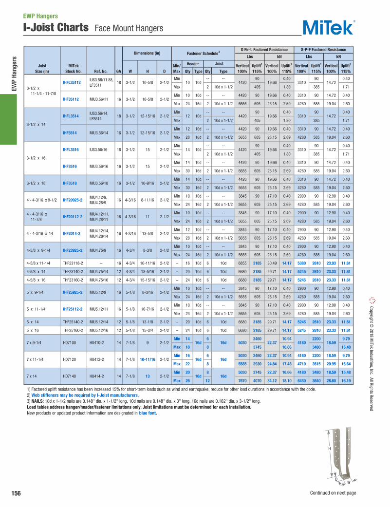
156
EWP
Hang
ers
Copyright © 2018 M
iTek Industries, Inc. All Rights Reserved
I-Joist Charts Face Mount Hangers
Header
D Qty Type Qty Type
Min -- -- 90 0.40 90 0.40
Max 2 10d x 1-1/2 405 1.80 385 1.71
Min 10 10d -- -- 4420 90 19.66 0.40 3310 90 14.72 0.40
Max 24 16d 2 10d x 1-1/2 5655 605 25.15 2.69 4280 585 19.04 2.60
Min -- -- 90 0.40 90 0.40
Max 2 10d x 1-1/2 405 1.80 385 1.71
Min 12 10d -- -- 4420 90 19.66 0.40 3310 90 14.72 0.40
Max 28 16d 2 10d x 1-1/2 5655 605 25.15 2.69 4280 585 19.04 2.60
Min -- -- 90 0.40 90 0.40
Max 2 10d x 1-1/2 405 1.80 385 1.71
Min 14 10d -- -- 4420 90 19.66 0.40 3310 90 14.72 0.40
Max 30 16d 2 10d x 1-1/2 5655 605 25.15 2.69 4280 585 19.04 2.60
Min 14 10d -- -- 4420 90 19.66 0.40 3310 90 14.72 0.40
Max 30 16d 2 10d x 1-1/2 5655 605 25.15 2.69 4280 585 19.04 2.60
Min 10 10d -- -- 3845 90 17.10 0.40 2900 90 12.90 0.40
Max 24 16d 2 10d x 1-1/2 5655 605 25.15 2.69 4280 585 19.04 2.60
Min 10 10d -- -- 3845 90 17.10 0.40 2900 90 12.90 0.40
Max 24 16d 2 10d x 1-1/2 5655 605 25.15 2.69 4280 585 19.04 2.60
Min 12 10d -- -- 3845 90 17.10 0.40 2900 90 12.90 0.40
Max 28 16d 2 10d x 1-1/2 5655 605 25.15 2.69 4280 585 19.04 2.60
Min 10 10d -- -- 3845 90 17.10 0.40 2900 90 12.90 0.40
Max 24 16d 2 10d x 1-1/2 5655 605 25.15 2.69 4280 585 19.04 2.60
4-5/8 x 11-1/4 THF23118-2 -- 16 4-3/4 10-11/16 2-1/2 -- 16 10d 6 10d 6855 3185 30.49 14.17 5380 2610 23.93 11.61
4-5/8 x 14 THF23140-2 MIU4.75/14 12 4-3/4 13-5/16 2-1/2 -- 20 10d 6 10d 6680 3185 29.71 14.17 5245 2610 23.33 11.61
4-5/8 x 16 THF23160-2 MIU4.75/16 12 4-3/4 15-15/16 2-1/2 -- 24 10d 6 10d 6680 3185 29.71 14.17 5245 2610 23.33 11.61
Min 10 10d -- -- 3845 90 17.10 0.40 2900 90 12.90 0.40
Max 24 16d 2 10d x 1-1/2 5655 605 25.15 2.69 4280 585 19.04 2.60
Min 10 10d -- -- 3845 90 17.10 0.40 2900 90 12.90 0.40
Max 24 16d 2 10d x 1-1/2 5655 605 25.15 2.69 4280 585 19.04 2.60
5 x 14 THF25140-2 MIU5.12/14 12 5-1/8 13-1/8 2-1/2 -- 20 10d 6 10d 6680 3185 29.71 14.17 5245 2610 23.33 11.61
5 x 16 THF25160-2 MIU5.12/16 12 5-1/8 15-3/4 2-1/2 -- 24 10d 6 10d 6680 3185 29.71 14.17 5245 2610 23.33 11.61
Min 14 6 2460 10.94 2200 9.79
Max 18 8 3745 16.66 3480 15.48
Min 16 6 5030 2460 22.37 10.94 4180 2200 18.59 9.79
Max 22 8 5585 3930 24.84 17.48 4710 3515 20.95 15.64
Min 20 8 5030 3745 22.37 16.66 4180 3480 18.59 15.48
Max 26 12 7670 4070 34.12 18.10 6430 3640 28.60 16.19
1) Factored uplift resistance has been increased 15% for short-term loads such as wind and earthquake; reduce for other load durations in accordance with the code. 2) Web stiffeners may be required by I-Joist manufacturers. 3) NAILS: 10d x 1-1/2 nails are 0.148" dia. x 1-1/2" long, 10d nails are 0.148" dia. x 3" long, 16d nails are 0.162" dia. x 3-1/2" long. Load tables address hanger/header/fastener limitations only. Joist limitations must be determined for each installation. New products or updated product information are designated in blue font.
16d 5030 22.37 4180 18.59
16d 16d
16d 16d
3310 14.72
12 10d 4420 19.66 3310 14.72
14 10d 4420 19.66 3310 14.72
3-1/2 x 14
IHF3514 MIU3.56/14 16 3-1/2
MIU3.56/16 16 3-1/2
IHFL3514 IUS3.56/14, LF3514
18 3-1/2
13
3-1/2 x 18
15 2-1/2
IHF3518 MIU3.56/18 16 3-1/2 16-9/16 2-1/2
3-1/2 x 16
IHFL3516 IUS3.56/16 18 3-1/2
IHF3516
2-1/2
2-1/2
2-1/2
2-1/2
2-1/2
2-1/2
2-1/2
16
Uplift1
115%Vertical100%
Uplift1
115%
Dimensions (in)
2-1/2
2-1/2
2-1/2
2-1/2
12-15/16
15
12-15/16
4-3/16
13-5/8
2-1/2
9
8-3/8
10-7/16
8-3/16
11
10 10d 4420 19.66
16d
JoistSize (in)
MiTekStock No. Ref. No. GA W
8-11/16
S-P-F Factored Resistance
Lbs kN Lbs kN
H
Fastener Schedule3D Fir-L Factored Resistance
Vertical100%
Uplift1
115%Vertical100%
Uplift1
115%Min/Max
Joist Vertical100%
4 - 4-3/16 x 9-1/2 IHF20925-2 MIU4.12/9, MIU4.28/9
4 - 4-3/16 x 11-7/8
IHF20112-2 MIU4.12/11, MIU4.28/11
16 4-3/16
4 - 4-3/16 x 14 IHF2014-2 MIU4.12/14, MIU4.28/14
16 4-3/16
7 x 9-1/4 HD7100 HU410-2 14 7-1/8
4-5/8 x 9-1/4 IHF23925-2 MIU4.75/9 16 4-3/4
5 x 9-1/4 IHF25925-2 MIU5.12/9 16 5-1/8
5 x 11-1/4 IHF25112-2 MIU5.12/11 16 5-1/8
14 7-1/8 7 x 14 HD7140 HU414-2
10-5/8
10-5/8 2-1/2
2-1/2
3-1/2 x 11-1/4 - 11-7/8
IHFL35112 IUS3.56/11.88, LF3511
18 3-1/2
IHF35112 MIU3.56/11 16 3-1/2
7 x 11-1/4 HD7120 HU412-2 14 7-1/8 10-11/16
EWP Hangers
DW
H
Continued on next page
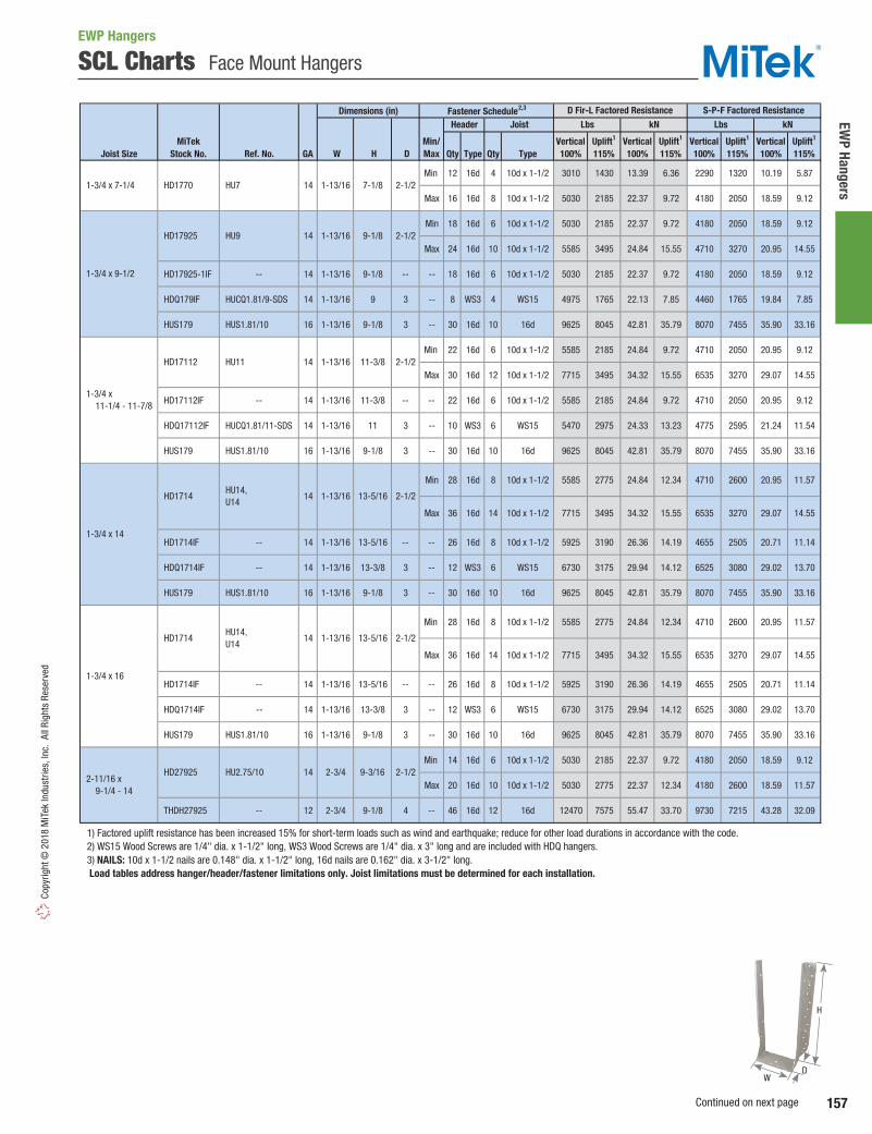
157
EWP Hangers
Copy
right
© 2
018
MiT
ek In
dust
ries,
Inc.
All
Righ
ts R
eser
ved
SCL Charts Face Mount Hangers
Dimensions (in)
Joist Size Ref. No. W H D Qty Type Qty Type
Min 12 16d 4 10d x 1-1/2 3010 1430 13.39 6.36 2290 1320 10.19 5.87
Max 16 16d 8 10d x 1-1/2 5030 2185 22.37 9.72 4180 2050 18.59 9.12
Min 18 16d 6 10d x 1-1/2 5030 2185 22.37 9.72 4180 2050 18.59 9.12
Max 24 16d 10 10d x 1-1/2 5585 3495 24.84 15.55 4710 3270 20.95 14.55
HD17925-1IF -- 14 1-13/16 9-1/8 -- -- 18 16d 6 10d x 1-1/2 5030 2185 22.37 9.72 4180 2050 18.59 9.12
HDQ179IF HUCQ1.81/9-SDS 14 1-13/16 9 3 -- 8 WS3 4 WS15 4975 1765 22.13 7.85 4460 1765 19.84 7.85
HUS179 HUS1.81/10 16 1-13/16 9-1/8 3 -- 30 16d 10 16d 9625 8045 42.81 35.79 8070 7455 35.90 33.16
Min 22 16d 6 10d x 1-1/2 5585 2185 24.84 9.72 4710 2050 20.95 9.12
Max 30 16d 12 10d x 1-1/2 7715 3495 34.32 15.55 6535 3270 29.07 14.55
HD17112IF -- 14 1-13/16 11-3/8 -- -- 22 16d 6 10d x 1-1/2 5585 2185 24.84 9.72 4710 2050 20.95 9.12
HDQ17112IF HUCQ1.81/11-SDS 14 1-13/16 11 3 -- 10 WS3 6 WS15 5470 2975 24.33 13.23 4775 2595 21.24 11.54
HUS179 HUS1.81/10 16 1-13/16 9-1/8 3 -- 30 16d 10 16d 9625 8045 42.81 35.79 8070 7455 35.90 33.16
Min 28 16d 8 10d x 1-1/2 5585 2775 24.84 12.34 4710 2600 20.95 11.57
Max 36 16d 14 10d x 1-1/2 7715 3495 34.32 15.55 6535 3270 29.07 14.55
HD1714IF -- 14 1-13/16 13-5/16 -- -- 26 16d 8 10d x 1-1/2 5925 3190 26.36 14.19 4655 2505 20.71 11.14
HDQ1714IF -- 14 1-13/16 13-3/8 3 -- 12 WS3 6 WS15 6730 3175 29.94 14.12 6525 3080 29.02 13.70
HUS179 HUS1.81/10 16 1-13/16 9-1/8 3 -- 30 16d 10 16d 9625 8045 42.81 35.79 8070 7455 35.90 33.16
Min 14 16d 6 10d x 1-1/2 5030 2185 22.37 9.72 4180 2050 18.59 9.12
Max 20 16d 10 10d x 1-1/2 5030 2775 22.37 12.34 4180 2600 18.59 11.57
THDH27925 -- 12 2-3/4 9-1/8 4 -- 46 16d 12 16d 12470 7575 55.47 33.70 9730 7215 43.28 32.09
1) Factored uplift resistance has been increased 15% for short-term loads such as wind and earthquake; reduce for other load durations in accordance with the code. 2) WS15 Wood Screws are 1/4" dia. x 1-1/2" long, WS3 Wood Screws are 1/4" dia. x 3" long and are included with HDQ hangers. 3) NAILS: 10d x 1-1/2 nails are 0.148" dia. x 1-1/2" long, 16d nails are 0.162" dia. x 3-1/2" long. Load tables address hanger/header/fastener limitations only. Joist limitations must be determined for each installation.
2-11/16 x 9-1/4 - 14
HD27925
2-1/2
HU2.75/10 14 2-3/4 9-3/16 2-1/2
14 1-13/16 13-5/16
1-3/4 x 14
1-3/4 x 16
14 HU7 HD1770 1-3/4 x 7-1/4
1-3/4 x 9-1/2
1-3/4 x 11-1/4 - 11-7/8
7-1/81-13/16 2-1/2
HD1714 HU14, U14
HD17112 HU11 14 1-13/16 11-3/8 2-1/2
HD1714 HU14, U14
14
MiTekStock No. GA
Vertical100%
Uplift1
115%
Header JoistFastener Schedule2,3
Min/Max
Vertical100%
D Fir-L Factored Resistance S-P-F Factored ResistanceLbs kN Lbs kN
Vertical100%
Uplift1
115%Uplift1
115%Uplift1
115%Vertical100%
1-13/16 13-5/16 2-1/2
HD17925 HU9 14 1-13/16 2-1/29-1/8
EWP Hangers
H
WD
Continued on next page
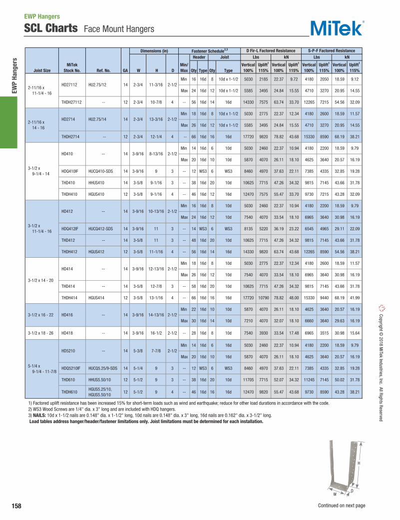
158
EWP
Hang
ers
Copyright © 2018 M
iTek Industries, Inc. All Rights Reserved
SCL Charts Face Mount Hangers
Dimensions (in)
Joist Size Ref. No. W H D Qty Type Qty Type
Min 16 16d 8 10d x 1-1/2 5030 2185 22.37 9.72 4180 2050 18.59 9.12
Max 24 16d 12 10d x 1-1/2 5585 3495 24.84 15.55 4710 3270 20.95 14.55
THDH27112 -- 12 2-3/4 10-7/8 4 -- 56 16d 14 16d 14330 7575 63.74 33.70 12265 7215 54.56 32.09
Min 18 16d 8 10d x 1-1/2 5030 2775 22.37 12.34 4180 2600 18.59 11.57
Max 26 16d 12 10d x 1-1/2 5585 3495 24.84 15.55 4710 3270 20.95 14.55
THDH2714 -- 12 2-3/4 12-1/4 4 -- 66 16d 16 16d 17720 9820 78.82 43.68 15330 8590 68.19 38.21
Min 14 16d 6 10d 5030 2460 22.37 10.94 4180 2200 18.59 9.79
Max 20 16d 10 10d 5870 4070 26.11 18.10 4625 3640 20.57 16.19
HDQ410IF HUCQ410-SDS 14 3-9/16 9 3 -- 12 WS3 6 WS3 8460 4970 37.63 22.11 7385 4335 32.85 19.28
THD410 HHUS410 14 3-5/8 9-1/16 3 -- 38 16d 20 10d 10625 7715 47.26 34.32 9815 7145 43.66 31.78
THDH410 HGUS410 12 3-5/8 9-1/16 4 -- 46 16d 12 16d 12470 7575 55.47 33.70 9730 7215 43.28 32.09
Min 16 16d 8 10d 5030 2460 22.37 10.94 4180 2200 18.59 9.79
Max 24 16d 12 10d 7540 4070 33.54 18.10 6965 3640 30.98 16.19
HDQ412IF HUCQ412-SDS 14 3-9/16 11 3 -- 14 WS3 6 WS3 8135 5220 36.19 23.22 6545 4965 29.11 22.09
THD412 -- 14 3-5/8 11 3 -- 48 16d 20 10d 10625 7715 47.26 34.32 9815 7145 43.66 31.78
THDH412 HGUS412 12 3-5/8 11-1/16 4 -- 56 16d 14 16d 14330 9820 63.74 43.68 12265 8590 54.56 38.21
Min 18 16d 8 10d 5030 2775 22.37 12.34 4180 2600 18.59 11.57
Max 26 16d 12 10d 7540 4070 33.54 18.10 6965 3640 30.98 16.19
THD414 -- 14 3-5/8 12-7/8 3 -- 58 16d 20 10d 10625 7715 47.26 34.32 9815 7145 43.66 31.78
THDH414 HGUS414 12 3-5/8 13-1/16 4 -- 66 16d 16 16d 17720 10790 78.82 48.00 15330 9440 68.19 41.99
Min 22 16d 10 10d 5870 4070 26.11 18.10 4625 3640 20.57 16.19
Max 30 16d 14 10d 7210 4070 32.07 18.10 6660 3640 29.63 16.19
3-1/2 x 18 - 26 HD418 -- 14 3-9/16 16-1/2 2-1/2 -- 28 16d 8 10d 7540 3930 33.54 17.48 6965 3515 30.98 15.64
Min 14 16d 6 16d 5030 2460 22.37 10.94 4180 2200 18.59 9.79
Max 20 16d 10 16d 5870 4070 26.11 18.10 4625 3640 20.57 16.19
HDQ5210IF HUCQ5.25/9-SDS 14 5-1/4 9 3 -- 12 WS3 6 WS3 8460 4970 37.63 22.11 7385 4335 32.85 19.28
THD610 HHUS5.50/10 12 5-1/2 9 3 -- 38 16d 20 10d 11705 7715 52.07 34.32 11245 7145 50.02 31.78
THDH610 HGUS5.25/10, HGUS5.50/10
12 5-1/2 9 4 -- 46 16d 16 16d 12470 9820 55.47 43.68 9730 8590 43.28 38.21
1) Factored uplift resistance has been increased 15% for short-term loads such as wind and earthquake; reduce for other load durations in accordance with the code. 2) WS3 Wood Screws are 1/4" dia. x 3" long and are included with HDQ hangers. 3) NAILS: 10d x 1-1/2 nails are 0.148" dia. x 1-1/2" long, 10d nails are 0.148" dia. x 3" long, 16d nails are 0.162" dia. x 3-1/2" long. Load tables address hanger/header/fastener limitations only. Joist limitations must be determined for each installation.
14-13/16 2-1/23-9/16
HD5210 -- 14 5-3/8 7-7/8 2-1/2
14
5-1/4 x 9-1/4 - 11-7/8
3-1/2 x 16 - 22 HD416 --
2-1/212-13/1614
3-1/2 x 11-1/4 - 16
10-13/16 HD412 -- 14 3-9/16
3-1/2 x 14 - 20
3-9/16-- HD414
2-1/2
8-13/16 2-1/2
3-1/2 x 9-1/4 - 14
HD410 -- 14 3-9/16
2-11/16 x 14 - 16
HD2714 HU2.75/14 14
2-11/16 x 11-1/4 - 16
HD27112 HU2.75/12 14 11-3/16 2-1/2
2-3/4 13-3/16 2-1/2
2-3/4
Vertical100%
MiTekStock No. GA
Vertical100%
Uplift1
115%Uplift1
115%Vertical100%
Uplift1
115%
Fastener Schedule2,3
Min/Max
Header JoistD Fir-L Factored Resistance S-P-F Factored Resistance
Lbs kN Lbs kN
Vertical100%
Uplift1
115%
EWP Hangers
H
WD
Continued on next page

159
EWP Hangers
Copy
right
© 2
018
MiT
ek In
dust
ries,
Inc.
All
Righ
ts R
eser
ved
SCL Charts Face Mount Hangers
Dimensions (in)
Joist Size Ref. No. W H D Qty Type Qty Type
Min 16 16d 8 16d 5030 2460 22.37 10.94 4180 2200 18.59 9.79
Max 24 16d 12 16d 5870 4070 26.11 18.10 4625 3640 20.57 16.19
HDQ5212IF HUCQ5.25/11-SDS 14 5-1/4 11 3 -- 14 WS3 6 WS3 8135 5220 36.19 23.22 6545 4965 29.11 22.09
THD612 -- 12 5-1/2 11 3 -- 48 16d 20 10d 11705 7715 52.07 34.32 11245 7145 50.02 31.78
THDH612 HGUS5.25/12, HGUS5.50/12
12 5-1/2 11 4 -- 56 16d 20 16d 14725 9820 65.50 43.68 11740 8590 52.22 38.21
Min 18 16d 8 16d 5030 3745 22.37 16.66 4180 3480 18.59 15.48
Max 26 16d 12 16d 7670 4070 34.12 18.10 6430 3640 28.60 16.19
THD614 -- 12 5-1/2 12-7/8 3 -- 58 16d 20 10d 11705 7715 52.07 34.32 11245 7145 50.02 31.78
THDH614 HGUS5.50/14 12 5-1/2 13 4 -- 66 16d 22 16d 17720 10790 78.82 48.00 15330 9440 68.19 41.99
Min 22 16d 10 16d 5870 4070 26.11 18.10 4625 3640 20.57 16.19
Max 30 16d 14 16d 7715 4070 34.32 18.10 6535 3640 29.07 16.19
6-3/4 x 9-1/4 - 14
THDH6710 HGUS210-4, HGUS6.88/10
12 6-7/8 8-13/16 4 -- 46 16d 12 16d 12470 7575 55.47 33.70 9730 7215 43.28 32.09
6-3/4 x 11-1/4 - 18
THDH6712 HGUS212-4, HGUS6.88/12
12 6-7/8 10-13/16 4 -- 56 16d 14 16d 12470 9820 55.47 43.68 9730 8590 43.28 38.21
6-3/4 x 14 - 20 THDH6714 HGUS214-4, HGUS6.88/14
12 6-7/8 12-13/16 4 -- 66 16d 16 16d 17720 10790 78.82 48.00 15330 9440 68.19 41.99
Min 14 16d 6 16d 2460 10.94 2200 9.79
Max 18 16d 8 16d 3745 16.66 3480 15.48
THD7210 HHUS7.25/10 12 7-1/4 9 3 -- 38 16d 20 10d 11705 7715 52.07 34.32 11245 7145 50.02 31.78
THDH7210 HGUS7.25/10 12 7-1/4 9 4 -- 46 16d 12 16d 12470 7575 55.47 33.70 9730 7215 43.28 32.09
Min 16 16d 6 16d 5030 2460 22.37 10.94 4180 2200 18.59 9.79
Max 22 16d 8 16d 5585 3930 24.84 17.48 4710 3515 20.95 15.64
THDH7212 HGUS7.25/12 12 7-1/4 10-1/2 4 -- 56 16d 14 16d 12470 9820 55.47 43.68 9730 8590 43.28 38.21
Min 20 16d 8 16d 5030 3745 22.37 16.66 4180 3480 18.59 15.48
Max 26 16d 12 16d 7670 4070 34.12 18.10 6430 3640 28.60 16.19
THDH7214 HGUS7.25/14 12 7-1/4 12-1/4 4 -- 66 16d 16 16d 17720 10790 78.82 48.00 15330 9440 68.19 41.99
7 x 16 - 22 HD7160 -- 14 7-1/8 15-5/8 2-1/2 -- 24 16d 8 10d 5585 3930 24.84 17.48 4710 3515 20.95 15.64
7 x 18 - 26 HD7180 -- 14 7-1/8 17-3/4 2-1/2 -- 28 16d 8 10d 7670 3930 34.12 17.48 6430 3515 28.60 15.64
1) Factored uplift resistance has been increased 15% for short-term loads such as wind and earthquake; reduce for other load durations in accordance with the code. 2) WS3 Wood Screws are 1/4" dia. x 3" long and are included with HDQ hangers. 3) NAILS: 10d nails are 0.148" dia. x 3" long, 16d nails are 0.162" dia. x 3-1/2" long. Load tables address hanger/header/fastener limitations only. Joist limitations must be determined for each installation.
7 x 14 - 20
7 x 11-1/4 - 16 HD7120 HU412-2
HU414-2 HD7140
14 7-1/8 10-11/16 2-1/2
7 x 9-1/4 - 14
2-1/2 HD7100 HU410-2 14 7-1/8
5-1/4 x 14 - 20
5-3/814-- HD5214 2-1/211-7/8
9-7/8 2-1/2-- 14 5-3/8
5-1/4 x 11-1/4 - 16
MiTekStock No. GA
Vertical100%
Uplift1
115%
HD5212
Vertical100%
Uplift1
115%
Header JoistFastener Schedule2,3
Min/Max
D Fir-L Factored Resistance S-P-F Factored ResistanceLbs kN Lbs kN
Vertical100%
Uplift1
115%Vertical100%
Uplift1
115%
2-1/2137-1/814
5-1/4 x 16 - 22 HD5216 -- 14
5030 22.37 4180 18.59
5-3/8 13-7/8 2-1/2
9
H
WD

160
EWP
Hang
ers
Copyright © 2018 M
iTek Industries, Inc. All Rights Reserved
TFI / TFL / THO Top Mount Hangers
TFI / THO – Engineered for I-Joist to header applications. Offers full lateral support of the I-Joist top chord, eliminating the need for web stiffeners in most applications. Raised dimple nailing guides help assure correct 45° nailing into the I-Joist bottom flange. The THO’s feature the Seat Cleat® that allows for quick, positive seating. The Seat Cleat® will hold the I-Joist in place, eliminating spring back during nailing in the bottom flange.
TFL – Features 1-1/2" top flange depth that accommodates all header types as well as back-to-back installations. Also features MiTek’s Seat Cleat® for quick, positive seating.
Materials: See EWP Top Mount Hangers charts, pages 164-173.Finish: G90 galvanizingCodes: Load values are derived from data submitted to various North American building code evaluators.
Installation:• Use all specified fasteners. See Product Notes, page 19.• Refer to the top mount chart for applications requiring web stiffeners.• Requirements for web stiffener from the I-Joist manufacturer should be
followed, even if web stiffeners are not required in MiTek literature.
Vertical Uplift1 Vertical Uplift1 Vertical Uplift1 Vertical Uplift1
Type Qty Type 100% 115% 100% 115% 100% 115% 100% 115%2X 4 2 10d x 1-1/2 2 10d x 1-1/2 1830 265 8.14 1.18 1575 230 7.01 1.023X 4 2 16d x 2-1/2 2 10d x 1-1/2 2305 265 10.25 1.18 1960 230 8.72 1.02
(2) 2X 4 2 10d 2 10d x 1-1/2 1845 265 8.21 1.18 1585 230 7.05 1.024X 4 2 16d 2 10d x 1-1/2 2495 265 11.10 1.18 1960 230 8.72 1.022X 4 2 10d x 1-1/2 2 10d x 1-1/2 1595 375 7.09 1.67 1250 325 5.56 1.453X 4 2 16d x 2-1/2 2 10d x 1-1/2 1595 375 7.09 1.67 1250 325 5.56 1.45
(2) 2X 4 2 16d x 2-1/2 2 10d x 1-1/2 1595 375 7.09 1.67 1250 325 5.56 1.454X 4 2 16d 2 10d x 1-1/2 1595 375 7.09 1.67 1250 325 5.56 1.452X 4 2 10d x 1-1/2 2 10d x 1-1/2 2095 375 9.32 1.67 1800 325 8.01 1.453X 4 2 16d x 2-1/2 2 10d x 1-1/2 3360 520 14.95 2.31 2890 445 12.86 1.98
(2) 2X 4 2 10d 2 10d x 1-1/2 3415 520 15.19 2.31 2935 445 13.06 1.984X 4 2 16d 2 10d x 1-1/2 3840 520 17.08 2.31 3300 445 14.68 1.982X 4 2 10d x 1-1/2 2 10d x 1-1/2 2930 -- 13.03 -- 2355 -- 10.48 --3X 4 6 16d x 2-1/2 2 10d x 1-1/2 4190 -- 18.64 -- 3290 -- 14.63 --
(2) 2X 4 6 10d 2 10d x 1-1/2 4190 -- 18.64 -- 3290 -- 14.63 --4X 4 2 16d 2 10d x 1-1/2 3685 375 16.39 1.67 3170 325 14.10 1.454X 4 6 16d 2 10d x 1-1/2 4190 375 18.64 1.67 3290 325 14.63 1.45
1) Factored resistances have been increased 15% for short-term loads such as wind and earthquake; reduce for other load durations in accordance with the code. 2) Listed loads shall not be increased. 3) The nailer must be sized to fit the supported width and be of sufficient thickness to satisfy specified top flange nailing requirements. A design professional must specify nailer attachment to steel beams. 4) NAILS: 10d x 1-1/2 nails are 0.148" dia. x 1-1/2" long, 10d nails are 0.148" dia. x 3" long, 16d nails are 0.162" dia. x 3-1/2" long, 16d x 2-1/2 nails are 0.162" dia. x 2-1/2" long.
MiTekSeries
TFL
THO (single joist)
THO (double joist)
TFI
Fastener Schedule4 D Fir-L Factored Resistance2 S-P-F Factored Resistance2
NailerSize3
Header Joist Lbs kN Lbs kN
TopQty
FaceQty
Nailer Options– chart represents maximum factored resistance for hangers used on wood nailers. Reference page 148.
Typical TFL installation
TFL
TFI
Slant Nailingvia dimplenail holes
Diamondholes
Seat Cleat® helps lock I-Joist into place for positive seating and nailing ease.
EWP Hangers
Typical THO installation
THO
TF
WD
H
H
DW
2"
1-1/2"
DW
H
TF

161
EWP Hangers
Copy
right
© 2
018
MiT
ek In
dust
ries,
Inc.
All
Righ
ts R
eser
ved
BPH / HBPH Top Mount Hangers
These hangers are used to support LVL, LSL, and PSL beams and headers in medium-to-heavy load conditions.
Materials: BPH – 12 gauge; HBPH – 10 gaugeFinish: G90 galvanizingCodes: Load values are derived from data submitted to various North American building code evaluators.
Installation:• Use all specified fasteners. See Product Notes, page 19.• Refer to the top mount chart for applications requiring web stiffeners.• Requirements for web stiffener from the I-Joist manufacturer should
be followed, even if web stiffeners are not required in MiTek literature.• For welded installations, see page 250.
Nailer Options– chart represents maximum factored resistance for hangers used on wood nailers. Reference page 148.
Specialty Options Chart – refer to Specialty Options pages 246 and 248 for additional details
Vertical Uplift1 Vertical Uplift1 Vertical Uplift1 Vertical Uplift1
Type Qty Type 100% 115% 100% 115% 100% 115% 100% 115%
2X 4 2 10d x 1-1/2 4 10d x 1-1/2 2995 240 13.32 1.07 2575 205 11.45 0.913X 4 4 16d x 2-1/2 4 10d x 1-1/2 3400 555 15.12 2.47 2925 475 13.01 2.11
(2) 2X 4 4 10d 4 10d x 1-1/2 3325 555 14.79 2.47 2860 475 12.72 2.114X 4 4 16d 4 10d x 1-1/2 3235 555 14.39 2.47 2780 475 12.37 2.112X 6 2 10d x 1-1/2 10 16d 4165 -- 18.53 -- 3490 -- 15.52 --3X 6 6 16d x 2-1/2 10 10d 7370 -- 32.78 -- 5785 -- 25.73 --
(2) 2X 6 8 10d 10 16d 6785 3035 30.18 13.50 5880 2460 26.16 10.944X 6 10 16d 10 16d 9410 3035 41.86 13.50 7630 2460 33.94 10.94
1) Factored resistances have been increased 15% for short-term loads such as wind and earthquake; reduce for other load durations in accordance with the code. 2) Listed loads shall not be increased. 3) The nailer must be sized to fit the supported width and be of sufficient thickness to satisfy specified top flange nailing requirements. A design professional must specify nailer attachment to steel beams. 4) NAILS: 10d x 1-1/2 nails are 0.148" dia. x 1-1/2" long, 10d nails are 0.148" dia. x 3" long, 16d nails are 0.162" dia. x 3-1/2" long, 16d x 2-1/2 nails are 0.162" dia. x 2-1/2" long.
kN
BPH
HBPH
Fastener Schedule4 D Fir-L Factored Resistance2 S-P-F Factored Resistance2
MiTekSeries
Nailer
Size3
Header Joist Lbs kN Lbs
TopQty
FaceQty
Option Skewed1,3 Sloped Seat2 Sloped / Skewed1,2,3 Sloped Top Flange4
Range 1˚ to 50˚ 1˚ to 45˚ See Sloped Seat and Skewed 0˚ to 45˚
1) Skewed hangers with skews greater than 15° may have all joist nailing on outside flange. 2) Sloped or sloped / skewed hangers with slopes greater than 15° may have additional joist nails. 3) For skewed hangers, the required cut type (square or bevel) of joist member may vary based on skew angle and width of hanger. Some square cut hangers will require custom pricing due to welded back plate. 4) Sloped top flanges with slopes greater than 15° may have additional header nails.
100% of table load
Add SK , angle required,right (R) or left (L) , and
square cut (SQ) or bevel cut (BV)to product number.
Example: BPH3595_SK45R_SQ
Add SL, slope required,and up (U) or down (D),
to product number.Example:
BPH3595_SL30D
See Sloped Seat and Skewed.Example:
BPH3595_SK45R_SQ_SL30D
Add SF, angle requiredand right (R) or left (L),
to product number.Example:
BPH3595_SF30L
FactoredResistance
Ordering
100% of table load 100% of table load 100% of table load
EWP Hangers
Typical BPHinstallation
Typical HBPHinstallation
HBPHW
TF
H
D
BPH
H
WD
TF

162
EWP
Hang
ers
Copyright © 2018 M
iTek Industries, Inc. All Rights Reserved
HLBH Beam Hangers
Heavy-duty hanger for LVL, LSL, and PSL beams.
Materials: 7 gaugeFinish: PrimerCodes: Load values are derived from data submitted to various North American building code evaluators.
Installation:• Use all specified fasteners. See Product Notes, page 19.• For welded installations, see page 250.• NA16D-RS ring shank nails are supplied with HLBH hangers.
Fastener Schedule4
Type Qty Type2x 3 4 10d x 1-1/2 6 10d x 1-1/2 10015 -- 44.55 -- 8120 -- 36.12 --
3x 3 6 16d x 2-1/2 6 10d 11175 -- 49.71 -- 10120 -- 45.02 --
(2) 2x 3 8 10d 6 10d x 1-1/2 6365 -- 28.31 -- 5275 -- 23.46 --
4X 3 8 NA16D-RS 6 10d x 1-1/2 13825 1430 61.50 6.36 12840 1235 57.12 5.49
4X 3 8 NA16D-RS 6 16d 13825 1770 61.50 7.87 12840 1430 57.12 6.36
1) Factored resistances have been increased 15% for short-term loads such as wind and earthquake; reduce for other load durations in accordance with the code. 2) Listed loads shall not be increased. 3) The nailer must be sized to fit the supported width and be of sufficient thickness to satisfy specified top flange nailing requirements. A design professional must specify nailer attachment to steel beams. 4) NAILS: 10d x 1-1/2 nails are 0.148" dia. x 1-1/2" long, 10d nails are 0.148" dia. x 3" long, NA16D-RS nails are 0.148" dia. x 3-1/2" long, 16d nails are 0.162" dia. x 3-1/2" long, 16d x 2-1/2 nails are 0.162" dia. x 2-1/2" long
HLBH
MiTekSeries
NailerSize3
Vertical100%
Uplift1
115%
D Fir-L Factored Resistance2
kN
Uplift1
115%Vertical100%
Uplift1
115%
S-P-F Factored Resistance2
Header Joist Lbs Lbs kN
Vertical100%
Uplift1
115%Vertical100%
TopQty
FaceQty
Option Skewed1,3 Sloped Seat2 Sloped / Skewed1,2,3 Sloped Top Flange4 Top Flange Offset Saddle5 Ridge
Range 1˚ to 50˚ 1˚ to 45˚ See Sloped Seat and Skewed 0˚ to 45˚ -- -- 0˚ to 45˚
1) Skewed hangers with skews greater than 15° may have all joist nailing on outside flange. 2) Sloped or sloped / skewed hangers with slopes greater than 15° may have additional joist nails. 3) Skewed hangers typically require a bevel cut however, a square cut option may be available as a custom when requested. 4) Sloped top flanges with slopes greater than 15° may have additional header nails. 5) Minimum header thickness shall be double the top flange (TF) dimension for 100% table load.
Add OS, and right (R) or left (L),to product number.
Ex. HLBH3595_OSL
100% of table load45% of table load
100% of table loadper side.
See footnote 5.100% of table load
Add SA,and saddlewidth required
to product number.Ex.
HLBH3595_SA=5-1/2"
Add DA, and angle required
to product number.Ex.
HLBH3595_DA30
Ordering
Add SK , angle required,right (R) or left (L) , and
square cut (SQ) or bevel cut (BV) to
product number. Ex. HLBH3595_SK45R_BV
FactoredResistance
11,620 lbs. Max.50% of uplift load on
skew greater than 15˚.
Add SF, angle required,and right (R) or left (L),
to product number.Ex.
HLBH3595_SF30L
10,080 lbs. Max.9,575 lbs. Max.
50% of uplift load onskew greater than 15˚.
Add SL, slope required,and up (U) or down (D),
to product number.Ex.
HLBH3595_SL30D
See Sloped Seat and Skewed.Ex.
HLBH3595_SK45R_BV_SL30D
Nailer Options– chart represents maximum factored resistance for hangers used on wood nailers. Reference page 148.
Specialty Options Chart– refer to Specialty Options pages 246, 248-249 for additional details
Typical HLBHinstallation
HLBH
EWP Hangers
H
L
TF4-3/8"
D
W

163
EWP Hangers
Copy
right
© 2
018
MiT
ek In
dust
ries,
Inc.
All
Righ
ts R
eser
ved
PHM / PHXU Top Flange Hangers
Nailer Options – chart represents maximum factored resistance for hangers used on wood nailers. Reference page 148.
Specialty Options Chart– refer to Specialty Options pages 246, 248-249 for additional details
Used to connect LVL, LSL, and PSL beams to headers in medium load conditions using standard nails.
Materials: See EWP Top Mount Hangers charts, pages 164-177.Finish: Primer; PHXU – G90 galvanizing.Codes: Load values are derived from data submitted to various North American building code evaluators.
Installation:• Use all specified fasteners. See Product Notes, page 19.• For welded installations, see page 250.
Type Qty Type Lbs kN Lbs kN Lbs kN Lbs kN2X 2 -- 10d x 1-1/2 2 10d x 1-1/2 4335 19.28 -- -- 3730 16.59 -- --3X 2 -- 16d x 2-1/2 2 10d x 1-1/2 5140 22.86 -- -- 4420 19.66 -- --
(2) 2X 2 -- 10d 2 10d x 1-1/2 4790 21.31 -- -- 4120 18.33 -- --4X 2 -- 16d 2 10d x 1-1/2 4685 20.84 -- -- 4030 17.93 -- --2X 4 -- 10d x 1-1/2 6 10d x 1-1/2 4240 18.86 -- -- 3550 15.79 -- --3X 4 2 16d x 2-1/2 6 10d x 1-1/2 6315 28.09 -- -- 6005 26.71 -- --
(2) 2X 4 2 10d 6 10d x 1-1/2 5880 26.16 -- -- 4930 21.93 -- --4X 4 4 16d 6 10d x 1-1/2 6370 28.34 1210 5.38 4420 19.66 920 4.092X 4 -- 10d x 1-1/2 6 10d 4525 20.13 -- -- 3590 15.97 -- --3X 4 2 16d x 2-1/2 6 10d 6380 28.38 -- -- 5170 23.00 -- --
(2) 2X 4 2 10d 6 10d 6200 27.58 -- -- 5110 22.73 -- --4X 4 4 16d 6 10d x 1-1/2 7610 33.85 1005 4.47 5170 23.00 865 3.854X 4 4 16d 6 10d 7610 33.85 1290 5.74 5170 23.00 1150 5.12
1) Factored resistances have been increased 15% for short-term loads such as wind and earthquake; reduce for other load durations in accordance with the code. 2) Listed loads shall not be increased. 3) The nailer must be sized to fit the supported width and be of sufficient thickness to satisfy specified top flange nailing requirements. A design professional must specify nailer attachment to steel beams. 4) NAILS: 10d x 1-1/2 nails are 0.148" dia. x 1-1/2" long, 10d nails are 0.148" dia. x 3" long, 16d nails are 0.162" dia. x 3-1/2" long, 16d x 2-1/2 nails are 0.162" dia. x 2-1/2" long.
PHXU widths < 3-1/2"
PHXU width > 3-1/2"
MiTekSeries
Vertical 100% Uplift 115%1 Vertical 100% Uplift 115%1
PHM
Nailer
Size3
Fastener Schedule4 D Fir-L
Factored Resistance2
S-P-F
Factored Resistance2Header Joist
TopQty
FaceQty
Option Skewed1,3,5 Sloped Seat2 Sloped / Skewed1,2,3 Sloped Top Flange4 Saddle5,6 RidgePHM 1˚ to 84˚ 0˚ to 45˚PHXU 1˚ to 60˚ N/A
1) Skewed hangers with skews greater than 15° may have all joist nailing on outside flange. 2) Sloped or sloped/skewed hangers with slopes greater than 15° may have additional joist nails. 3) For skewed hangers, the required cut type (square or bevel) of joist member may vary based on skew angle and width of hanger. Some square cut hangers will require custom pricing due to welded back plate. 4) Sloped top flanges with slopes greater than 15° may have additional header nails. 5) Skewed, top flange offset, or saddle options will have a solid, welded top flange. 6) Minimum header thickness shall be double the top flange (TF) dimension for 100% table load. 7) PHXU offset option - hanger will be welded with a closed top angle, not formed.
Range
FactoredResistance
Add SK , angle required,right (R) or left (L) , and
square cut (SQ) orbevel cut (BV) to product number.
Ex: PHXU1795_SK45R_SQ
Ordering
PHXU
PHM
100% of table load
PHM
PHXU
Add OS, andright (R) or left (L),to product number.
Ex: PHXU1795_OSL
Add SL, slope required,
and up (U) or down (D), to
product number.Ex:
PHXU1795_SL30D
See Sloped Seatand Skewed.
Ex: PHXU1795_SK45R_SQ_SL30D
Add SF, angle required,and right (R) or left (L),
to product number.Ex:
PHXU1795_SF30L
100% of table load
% oftable load
60%75%85%
MiTekSeries
Hanger Width 3-1/2" or less 3-9/16" to 5-1/2" 5-9/16" to 7-1/2"
Add DA, and angle required to product
number.Ex. PHXU1795_DA30
N/A
Top Flange Offset5,7
See Sloped Seat and Skewed
--0° to 35° --1˚ to 45˚
Add SA, and saddlewidth required
to product number.Ex:
PHXU1795_SA=5-1/2"
100% of table load100% of table load
100% of table load up toMax. load of 5615 lbs.
100% of table load up toMax. load of 3600 lbs.
100% of table load.See footnote 6.
PHM
EWP Hangers
Typical PHXUinstallation
L
DW
H
TF
PHXU
W
L
D
TF
H

164
EWP
Hang
ers
Copyright © 2018 M
iTek Industries, Inc. All Rights Reserved
Top Mount Hanger Charts
Dimensions (in) Fastener Schedule3
Uplift1
Joist Size Ref. No. Ga. W H D L TF Type2 Qty Type Unit LVL PSL LSL SPF
Lbs 1935 1860 1920 1250 1445 1595 420
kN 8.61 8.27 8.54 5.56 6.43 7.09 1.87
Lbs 4415 4415 4415 3965 -- 5050 1140
kN 19.64 19.64 19.64 17.64 -- 22.46 5.07
Lbs 1935 1860 1920 1360 1815 1730 490
kN 8.61 8.27 8.54 6.05 8.07 7.70 2.18
Lbs 4415 4415 4415 3965 -- 5050 1140
kN 19.64 19.64 19.64 17.64 -- 22.46 5.07
Lbs 4415 4415 4415 3965 -- 5050 1140
kN 19.64 19.64 19.64 17.64 -- 22.46 5.07
Lbs 1935 1860 1920 1505 1880 1915 490
kN 8.61 8.27 8.54 6.69 8.36 8.52 2.18
Lbs 4415 4415 4415 3965 -- 5050 1140
kN 19.64 19.64 19.64 17.64 -- 22.46 5.07
Lbs 1485 1485 1485 1285 1485 1635 420
kN 6.61 6.61 6.61 5.72 6.61 7.27 1.87
Lbs 4415 4415 4415 3965 -- 5050 1140
kN 19.64 19.64 19.64 17.64 -- 22.46 5.07
Lbs 1935 1860 1920 1250 1445 1595 420
kN 8.61 8.27 8.54 5.56 6.43 7.09 1.87
Lbs 2370 2305 2450 1285 1795 1635 420
kN 10.54 10.25 10.90 5.72 7.98 7.27 1.87
Lbs 2370 2305 2450 1285 1795 1635 420
kN 10.54 10.25 10.90 5.72 7.98 7.27 1.87
Lbs 1485 1485 1485 1285 1795 1635 420
kN 6.61 6.61 6.61 5.72 7.98 7.27 1.87
Lbs 6370 6370 6370 6075 -- 7740 1890
kN 28.34 28.34 28.34 27.02 -- 34.43 8.41
Lbs 4890 4890 4890 4160 -- 5300 1140
kN 21.75 21.75 21.75 18.50 -- 23.58 5.07
Lbs 5090 4795 4435 4450 -- 5670 --
kN 22.64 21.33 19.73 19.79 -- 25.22 --
Lbs 6370 6370 6370 6075 -- 7740 1890
kN 28.34 28.34 28.34 27.02 -- 34.43 8.41
Lbs 1935 1860 1920 1585 1570 2020 490
kN 8.61 8.27 8.54 7.05 6.98 8.99 2.18
Lbs 4890 4890 4890 4160 -- 5300 1140
kN 21.75 21.75 21.75 18.50 -- 23.58 5.07
Lbs 5090 4795 4435 4450 -- 5670 --
kN 22.64 21.33 19.73 19.79 -- 25.22 --
Lbs 6370 6370 6370 6075 -- 7740 1890
kN 28.34 28.34 28.34 27.02 -- 34.43 8.41
Lbs 4890 4890 4890 4160 -- 5300 1140
kN 21.75 21.75 21.75 18.50 -- 23.58 5.07
Lbs 5090 4795 4435 4450 -- 5670 --
kN 22.64 21.33 19.73 19.79 -- 25.22 --
Lbs 6370 6370 6370 6075 -- 7740 1890
kN 28.34 28.34 28.34 27.02 -- 34.43 8.41
1) Factored uplift resistance has been increased 15% for short-term loads such as wind and earthquake; reduce for other load durations in accordance with the code. 2) When I-joist is used as a header, all nails must be 10d x 1-1/2. 3) NAILS: 10d x 1-1/2 nails are 0.148" dia. x 1-1/2" long, 10d nails are 0.148" dia. x 3" long, 16d nails are 0.162" dia. x 3-1/2" long. Load tables address hanger/header/fastener limitations only. Joist limitations must be determined for each installation.
11-1/4
11-1/4
11-1/41-13/16
1-11/162-3/8
2-1/2 7
10
4 10d x 1-1/2
6 10d x 1-1/2
2 16d 2 10d x 1-1/2
4 16d
6
--
4
4 10d x 1-1/2
--
3-1/4
3
2-1/2
1-3/4 x 11-1/4
12
7/10
7
x BPH17112
PHM17112
LBV1.81/11.25
--
WPU1.81/11.25
x
x PHXU17112
1-13/16
1-13/16
-- 4 16d
1-5/8 x 14
THO15140
BPH1514
1-1/2 x 14
1-1/2 x 9-1/4
THO15925 LT15925 --
BPH15925 x
1-1/2 x 11-7/8
THO15118
BPH15118
THO16950
THO16112
THO16118 1-5/8 x 11-7/8
--
--
x LBV1.56/14
--
--
--
1-3/4 x 7-1/4
LBV1.56/9.25
THO16140
PHXU17725
--
Joist Web StiffReqd
Header
4 16d1-13/16
18
12
--
x 12
1-5/8 x 9-1/2
1-5/8 x 11-1/4
21-9/16 9-1/4
9-1/4 2-3/8 4
1-1/2 2 10d x 1-1/2
-- 1-1/2
--
--
10d x 1-1/2
16d 4 10d x 1-1/2
4
4
10d 2
16d 41-1/2 4
4 10d 2
1-9/16 16d
--
9-1/21-9/16
1-1/2 11-7/8
12
16
11-7/8
9-1/2
11-1/4
11-7/8
14
14
14
1-1/2 x 9-1/2
1-1/2 x 11-1/4
THO15950
BPH1595
BPH15112 x
LBV1.81/7.25, WP1.81/7.25
-- 1-1/2
1-1/2--
x
LT159
LBV1.56/9.5, MIT29.5
LBV1.56/11.25
LT151188, MIT211.88
LBV1.56/11.88
--
2--
x
2-3/8
2-3/8
18
18
12
1-1/2 9-1/2
10d x 1-1/22 -- 1-9/16
1-9/16 10d x 1-1/2--11-1/4
7
1-9/16
1-9/16
1-9/16
1-11/16
1-11/16
1-11/16
16
12
18
16
16
1-11/16
2
2
3
--
--
--
--
--
2-3/8
2-3/8
2-3/8
2
--
--
10d x 1-1/2
10d x 1-1/2
1-3/4
4 16d 4
4 10d 2
1-1/2
1-1/2
1-1/2
1-1/2
1-1/2
1-1/2
4 16d 4 10d x 1-1/2
4 10d 2
6 10d x 1-1/2109-1/4
1-13/16
7-1/4 3-1/4 2-1/2 6
2-1/2
2-3/8
2-1/2
3-1/4
--
7
16d 4
4
10d x 1-1/210
--
1-3/4 x 9-1/2
THO17950 LT179, ITS1.81/9.5
--
PHXU1795 -- x
1-11/16
3 1-3/4 x 9-1/4 1-13/16
1-13/16
LBV1.81/9.25
WP9.25
WPU1.81/9.25
12
7/10
7 1-13/16 9-1/2 3-1/4 10 2-1/2
PHM1795
Factored Resistance
Header Material (100%)
WP9 x 7/10 1-13/16 9-1/2 2-1/2 7 3
2-3/8 -- 1-11/16
4 10d 2 10d x 1-1/2
BA1.81/9.5, LBV1.81/9.5, MIT9.5
x 12 1-13/16 9-1/2
18 1-3/4
4 16d 6 10d x 1-1/2
BPH1795
9-1/2 2 -- 1-1/2
10d x 1-1/24 16d 46
--
4
2
MiTekStock No.
D Fir-L I-Joist2
D Fir-L115%
2 16d 2 10d x 1-1/2
10d x 1-1/2
16d 2 10d x 1-1/2
BPH17925
PHM17925
PHXU17925
4
2
x
x
9-1/4
9-1/4
7x 4 16d
2
6
2
6
6
2
6
6
6
D Fir-LTopQty
FaceQty
2
2
2
6
4
6
10d 2 10d x 1-1/2
4 10d 2 10d x 1-1/2
4 10d 2 10d x 1-1/2
10d x 1-1/2
4
4 10d
EWP Hangers
H
W
L
TF
D
Continued on next page
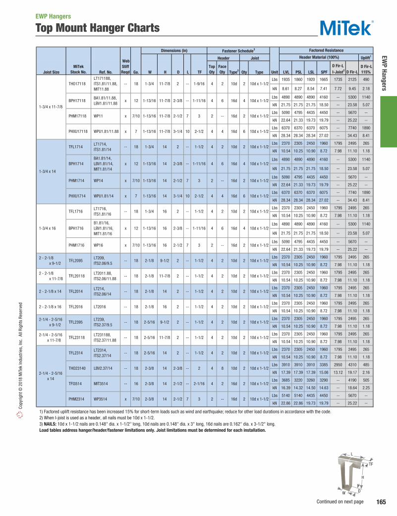
165
EWP Hangers
Copy
right
© 2
018
MiT
ek In
dust
ries,
Inc.
All
Righ
ts R
eser
ved
Top Mount Hanger Charts
Dimensions (in) Fastener Schedule3
Uplift1
Joist Size Ref. No. Ga. W H D L TF Type2 Qty Type Unit LVL PSL LSL SPF
Lbs 1935 1860 1920 1665 1735 2125 490
kN 8.61 8.27 8.54 7.41 7.72 9.45 2.18
Lbs 4890 4890 4890 4160 -- 5300 1140
kN 21.75 21.75 21.75 18.50 -- 23.58 5.07
Lbs 5090 4795 4435 4450 -- 5670 --
kN 22.64 21.33 19.73 19.79 -- 25.22 --
Lbs 6370 6370 6370 6075 -- 7740 1890
kN 28.34 28.34 28.34 27.02 -- 34.43 8.41
Lbs 2370 2305 2450 1960 1795 2495 265
kN 10.54 10.25 10.90 8.72 7.98 11.10 1.18
Lbs 4890 4890 4890 4160 -- 5300 1140
kN 21.75 21.75 21.75 18.50 -- 23.58 5.07
Lbs 5090 4795 4435 4450 -- 5670 --
kN 22.64 21.33 19.73 19.79 -- 25.22 --
Lbs 2370 2305 2450 1960 1795 2495 265
kN 10.54 10.25 10.90 8.72 7.98 11.10 1.18
Lbs 2370 2305 2450 1960 1795 2495 265
kN 10.54 10.25 10.90 8.72 7.98 11.10 1.18
Lbs 2370 2305 2450 1960 1795 2495 265
kN 10.54 10.25 10.90 8.72 7.98 11.10 1.18
Lbs 2370 2305 2450 1960 1795 2495 265
kN 10.54 10.25 10.90 8.72 7.98 11.10 1.18
Lbs 2370 2305 2450 1960 1795 2495 265
kN 10.54 10.25 10.90 8.72 7.98 11.10 1.18
Lbs 2370 2305 2450 1960 1795 2495 265
kN 10.54 10.25 10.90 8.72 7.98 11.10 1.18
Lbs 2370 2305 2450 1960 1795 2495 265
kN 10.54 10.25 10.90 8.72 7.98 11.10 1.18
Lbs 3910 3910 3910 3385 2950 4310 485
kN 17.39 17.39 17.39 15.06 13.12 19.17 2.16
Lbs 3685 3220 3260 3290 -- 4190 505
kN 16.39 14.32 14.50 14.63 -- 18.64 2.25
Lbs 5140 5140 4435 4450 -- 5670 --
kN 22.86 22.86 19.73 19.79 -- 25.22 --
1) Factored uplift resistance has been increased 15% for short-term loads such as wind and earthquake; reduce for other load durations in accordance with the code. 2) When I-joist is used as a header, all nails must be 10d x 1-1/2. 3) NAILS: 10d x 1-1/2 nails are 0.148" dia. x 1-1/2" long, 10d nails are 0.148" dia. x 3" long, 16d nails are 0.162" dia. x 3-1/2" long. Load tables address hanger/header/fastener limitations only. Joist limitations must be determined for each installation.
16d14 2-1/2 --
2-1/2
2-3/8 --
7
2
2
10d x 1-1/2
4
2-1/4 - 2-5/16 x 14
TFL2314 LT2314, ITS2.37/14
THO23140 LBV2.37/14
TFI3514 MIT3514
x
--
-- 4 10d14 22-5/16
2-3/8
2-3/8 2 10d x 1-1/2
2 10d x 1-1/2
--
1-1/2
2 --
4 10d 2
PHM2314 WP3514
18
-- 18
7/10
16
1-1/2
2
3
14
14
2-3/8 2-1/16
2
16d 2
--
18
TFL2016 LT2016
10d x 1-1/2
2-1/8
2-1/8
10d x 1-1/2
2-5/16
14
2-5/16
16
4 10d 2
2
9-1/2
11-7/8 2 --
2 --
1-1/2
1-1/2
1-1/2
2 - 2-1/8 x 14
2 - 2-1/8 x 16
2-1/4 - 2-5/16 x 9-1/2
2-1/4 - 2-5/16 x 11-7/8
TFL2014 LT214, ITS2.06/14
TFL23118 LT231188, ITS2.37/11.88
--
2 ---- 18
-- 18 TFL2395 LT239, ITS2.37/9.5
-- 18
1-3/4 x 11-7/8
1-3/4 x 14
Web StiffReqd
BPH1714
TFL1714
PHXU1714
PHM1714
LT171188, ITS1.81/11.88, MIT11.88
BA1.81/11.88, LBV1.81/11.88
WP11
WPU1.81/11.88
THO17118
BPH17118
PHM17118
PHXU17118
--
x
x
WP14
WPU1.81/14
LT1714, ITS1.81/14
BA1.81/14, LBV1.81/14, MIT1.81/14
--
x
18
x 12
x 7/10
x 7
2 --
--
7
101-13/16
1-13/16
1-13/16
1-3/4 11-7/8
11-7/8 2-3/8
11-7/8 2-1/2
11-7/8 3-1/4
3
1-9/16
1-11/16
2 16d 2 10d x 1-1/2
4 16d 6 10d x 1-1/2
4 10d 2 10d x 1-1/2
4 16d 4 10d x 1-1/2
2-1/2
18
12 14
16d1-13/16
1-13/16
2-3/8
2-1/2
3-1/4
1-3/4
1-13/16
16d
14
14
14 2
7/10
--
--
10d 2
27
10
10d
2
1-1/2
2-1/2 4
2
6
--
2
1-11/16
3
2-1/8
10d x 1-1/2
4 16d 4 10d x 1-1/2
2 16d 2 10d x 1-1/2
16
16
1-1/2
9-1/2
11-7/8 2
10d x 1-1/2
4
4
--
1-1/2
2
4 10d18
12
2 --
2-3/8
1-3/4
1-13/16 --
10d x 1-1/267 4
2 - 2-1/8 x 9-1/2
2 - 2-1/8 x 11-7/8
1-3/4 x 16
--
x
x
LT1716, ITS1.81/16
TFL20118 LT2011.88, ITS2.06/11.88
--
LT209, ITS2.06/9.5
TFL1716
BPH1716 B1.81/16, LBV1.81/16, MIT1.81/16
WP16
Factored Resistance
D Fir-L I-Joist2
D Fir-L115%
MiTekStock No.
Header Joist Header Material (100%)
18
TFL2095
PHM1716
1-11/16
-- 2 -- 1-1/218 2-1/8
2
7/10 3161-13/16 2-1/2 7
10d x 1-1/2
10d
TopQty
FaceQty
2
6
--
4
2
6
--
4
4
10d x 1-1/2
10d
4
4
4
D Fir-L
2
2
2
2
2
2
8
10d x 1-1/2
16d 4 10d x 1-1/2
10d x 1-1/2
10d 2 10d x 1-1/2
10d x 1-1/2
10d 2
EWP Hangers
H
W
L
TF
D
Continued on next page
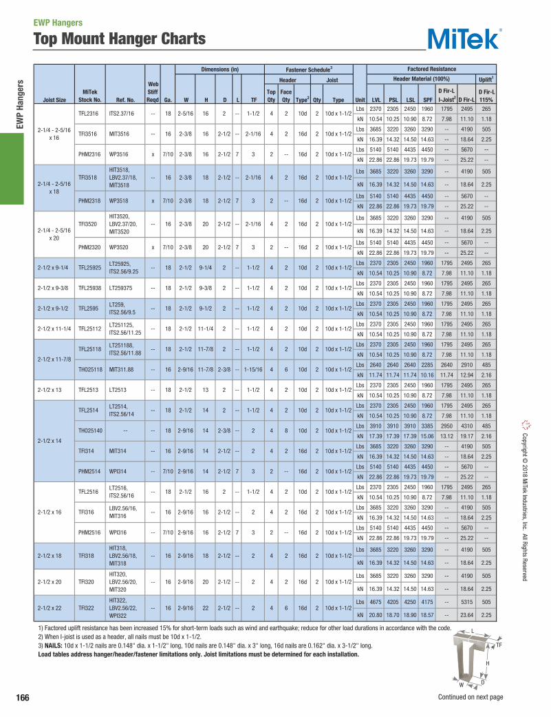
166
EWP
Hang
ers
Copyright © 2018 M
iTek Industries, Inc. All Rights Reserved
Top Mount Hanger Charts
Dimensions (in) Fastener Schedule3
Uplift1
Joist Size Ref. No. Ga. W H D L TF Type2 Qty Type Unit LVL PSL LSL SPFLbs 2370 2305 2450 1960 1795 2495 265
kN 10.54 10.25 10.90 8.72 7.98 11.10 1.18
Lbs 3685 3220 3260 3290 -- 4190 505
kN 16.39 14.32 14.50 14.63 -- 18.64 2.25
Lbs 5140 5140 4435 4450 -- 5670 --
kN 22.86 22.86 19.73 19.79 -- 25.22 --
Lbs 3685 3220 3260 3290 -- 4190 505
kN 16.39 14.32 14.50 14.63 -- 18.64 2.25
Lbs 5140 5140 4435 4450 -- 5670 --
kN 22.86 22.86 19.73 19.79 -- 25.22 --
Lbs 3685 3220 3260 3290 -- 4190 505
kN 16.39 14.32 14.50 14.63 -- 18.64 2.25
Lbs 5140 5140 4435 4450 -- 5670 --
kN 22.86 22.86 19.73 19.79 -- 25.22 --
Lbs 2370 2305 2450 1960 1795 2495 265
kN 10.54 10.25 10.90 8.72 7.98 11.10 1.18
Lbs 2370 2305 2450 1960 1795 2495 265
kN 10.54 10.25 10.90 8.72 7.98 11.10 1.18
Lbs 2370 2305 2450 1960 1795 2495 265
kN 10.54 10.25 10.90 8.72 7.98 11.10 1.18
Lbs 2370 2305 2450 1960 1795 2495 265
kN 10.54 10.25 10.90 8.72 7.98 11.10 1.18
Lbs 2370 2305 2450 1960 1795 2495 265
kN 10.54 10.25 10.90 8.72 7.98 11.10 1.18
Lbs 2640 2640 2640 2285 2640 2910 485
kN 11.74 11.74 11.74 10.16 11.74 12.94 2.16
Lbs 2370 2305 2450 1960 1795 2495 265
kN 10.54 10.25 10.90 8.72 7.98 11.10 1.18
Lbs 2370 2305 2450 1960 1795 2495 265
kN 10.54 10.25 10.90 8.72 7.98 11.10 1.18
Lbs 3910 3910 3910 3385 2950 4310 485
kN 17.39 17.39 17.39 15.06 13.12 19.17 2.16
Lbs 3685 3220 3260 3290 -- 4190 505
kN 16.39 14.32 14.50 14.63 -- 18.64 2.25
Lbs 5140 5140 4435 4450 -- 5670 --
kN 22.86 22.86 19.73 19.79 -- 25.22 --
Lbs 2370 2305 2450 1960 1795 2495 265
kN 10.54 10.25 10.90 8.72 7.98 11.10 1.18
Lbs 3685 3220 3260 3290 -- 4190 505
kN 16.39 14.32 14.50 14.63 -- 18.64 2.25
Lbs 5140 5140 4435 4450 -- 5670 --
kN 22.86 22.86 19.73 19.79 -- 25.22 --
Lbs 3685 3220 3260 3290 -- 4190 505
kN 16.39 14.32 14.50 14.63 -- 18.64 2.25
Lbs 3685 3220 3260 3290 -- 4190 505
kN 16.39 14.32 14.50 14.63 -- 18.64 2.25
Lbs 4675 4205 4250 4175 -- 5315 505
kN 20.80 18.70 18.90 18.57 -- 23.64 2.25
1) Factored uplift resistance has been increased 15% for short-term loads such as wind and earthquake; reduce for other load durations in accordance with the code. 2) When I-joist is used as a header, all nails must be 10d x 1-1/2. 3) NAILS: 10d x 1-1/2 nails are 0.148" dia. x 1-1/2" long, 10d nails are 0.148" dia. x 3" long, 16d nails are 0.162" dia. x 3-1/2" long. Load tables address hanger/header/fastener limitations only. Joist limitations must be determined for each installation.
10d x 1-1/22-1/2 41-1/2--
TFL25938 LT259375 10d x 1-1/2
2
2-1/2
--
--
9-1/4
2 10d x 1-1/2
2
10d x 1-1/24
16d 2 10d x 1-1/22
10d x 1-1/2
10d x 1-1/2
2-1/2 x 9-3/8 2
29-1/2 2-1/2 x 9-1/2 TFL2595 LT259, ITS2.56/9.5
-- 18 10d 2
2-1/2 49-3/8 1-1/22 ---- 18 10d2
2
2-1/4 - 2-5/16 x 20
PHM2318 WP3518
PHM2320 WP3520
2-1/2 x 9-1/4 TFL25925 LT25925, ITS2.56/9.25
2-1/4 - 2-5/16 x 18
TFI3518 HIT3518, LBV2.37/18, MIT3518
10d x 1-1/2
2-1/4 - 2-5/16 x 16
--
x
--
2-3/8
2-5/16
2-3/8
4 10d16
16
716
1-1/2
2-1/16
3
4
PHM2316 WP3516
TFL2316 ITS2.37/16
2-1/2 2
1-1/2
2-1/16
2-1/16
3
2-1/2
2-3/8
4 16d 2
20
2
2-1/2
2-1/2
2-1/2
2-1/2
7
--
--
--
7
16d
2
TFI3516 MIT3516
-- 18 10d
x 7/10
16
7/10
20
2-3/8
2-3/8
2-3/8
18
18 3
TFI3520 HIT3520, LBV2.37/20, MIT3520
-- 16
-- 16
x 7/10
18
4 10d x 1-1/2
10d x 1-1/2
2-9/16
16
16
2
2-3/8
7
--
--
10d x 1-1/2
10d x 1-1/2
10d x 1-1/2
10d x 1-1/2
--
2-9/16 14 2-1/2 --
7/10
2-1/2 x 16
2-1/2 x 18
2-1/2 x 20
2-1/2 x 22
16d 2
4 16d 2
4 10d 2
16d-- 16
-- 16
-- 18
-- 16
-- 7/10
22 4 16d 2 10d x 1-1/2
10d x 1-1/24 2
TFL2516
TFI316
HIT322, LBV2.56/22, WPI322
PHM2516
TFI322
LT2516, ITS2.56/16
LBV2.56/16, MIT316
WPI316
HIT318, LBV2.56/18, MIT318
HIT320, LBV2.56/20, MIT320
TFI318
TFI320
--2-9/16-- 16
10d x 1-1/2
2-1/2
2-9/16
2
16
2-1/2
2-1/2
2-1/2
2-9/16
2-9/16
18
20
2-1/2
2-1/2
2
2
2
1-1/2
2
3
--
--
2
4 10d 2
10d1-1/2
2
4 16d 2
16d 2
2 16d 2
2
7 3
LT2514, ITS2.56/14
--
WPI314 2-1/2
--
2-9/16
2-9/16
2
11-7/8 2
2 4
2-1/2 x 14
4
2
-- 18
-- 18
--
TFL2514
THO25140
PHM2514
14
14
14
2-1/2
--
TFI314 MIT314 -- 16
18
1-15/16--
-- 1-1/2
11-7/8 2-3/8
13
2-9/16
2-1/2 2-1/2 x 13
1-1/2--2-1/2
1-1/2---- 18
MIT311.88
LT2513
TFL25112
TFL25118
THO25118
TFL2513
LT251125, ITS2.56/11.25
LT251188, ITS2.56/11.88
2-1/2 11-1/4 2
-- 18
-- 16
--
Factored Resistance
MiTekStock No.
Header Joist Header Material (100%)
D Fir-L I-Joist2
D Fir-L115%
2-1/2 x 11-1/4
2-1/2 x 11-7/8
10d x 1-1/24 10d
10d x 1-1/2
4 10d 2 10d x 1-1/2
2
4 10d 2
Web StiffReqd
10d x 1-1/2
16d
TopQty
FaceQty
2
2
--
2
--
2
--
2
4
D Fir-L
2
2
6
2
2
6
2
2
8
2
--
2
10d 2 10d x 1-1/2
10d x 1-1/2
2
16d 2
16d
2
2 10d x 1-1/2
EWP Hangers
H
W
L
TF
D
Continued on next page

167
EWP Hangers
Copy
right
© 2
018
MiT
ek In
dust
ries,
Inc.
All
Righ
ts R
eser
ved
Top Mount Hanger Charts
Dimensions (in) Fastener Schedule3
Uplift1
Joist Size Ref. No. Ga. W H D L TF Type2 Qty Type Unit LVL PSL LSL SPF
Lbs 4675 4205 4250 4175 -- 5315 505
kN 20.80 18.70 18.90 18.57 -- 23.64 2.25
Lbs 4675 4205 4250 4175 -- 5315 505
kN 20.80 18.70 18.90 18.57 -- 23.64 2.25
Lbs 2340 2340 2340 2025 2950 2580 485
kN 10.41 10.41 10.41 9.01 13.12 11.48 2.16
Lbs 2535 2535 2535 2285 2640 2910 485
kN 11.28 11.28 11.28 10.16 11.74 12.94 2.16
Lbs 3910 3910 3910 3385 2950 4310 485
kN 17.39 17.39 17.39 15.06 13.12 19.17 2.16
Lbs 3910 3910 3910 3385 2950 4310 485
kN 17.39 17.39 17.39 15.06 13.12 19.17 2.16
Lbs 8670 8330 8670 7090 -- 9030 1770
kN 38.57 37.05 38.57 31.54 -- 40.17 7.87
Lbs 14725 15180 13825 12215 -- 15560 2530
kN 65.50 67.52 61.50 54.34 -- 69.21 11.25
Lbs 8670 8330 8670 7090 -- 9030 1770
kN 38.57 37.05 38.57 31.54 -- 40.17 7.87
Lbs 14725 15180 13825 12215 -- 15560 2530
kN 65.50 67.52 61.50 54.34 -- 69.21 11.25
Lbs 8670 8330 8670 7090 -- 9030 1770
kN 38.57 37.05 38.57 31.54 -- 40.17 7.87
Lbs 14725 15180 13825 12215 -- 15560 2530
kN 65.50 67.52 61.50 54.34 -- 69.21 11.25
Lbs 8670 8330 8670 7090 -- 9030 1770
kN 38.57 37.05 38.57 31.54 -- 40.17 7.87
Lbs 14725 15180 13825 12215 -- 15560 2530
kN 65.50 67.52 61.50 54.34 -- 69.21 11.25
Lbs 8670 8330 8670 7090 -- 9030 1770
kN 38.57 37.05 38.57 31.54 -- 40.17 7.87
Lbs 14725 15180 13825 12215 -- 15560 2530
kN 65.50 67.52 61.50 54.34 -- 69.21 11.25
Lbs 8670 8330 8670 7090 -- 9030 1770
kN 38.57 37.05 38.57 31.54 -- 40.17 7.87
Lbs 14725 15180 13825 12215 -- 15560 2530
kN 65.50 67.52 61.50 54.34 -- 69.21 11.25
Lbs 5265 5055 5435 4285 -- 5455 1140
kN 23.42 22.49 24.18 19.06 -- 24.27 5.07
Lbs 8670 8330 8670 7090 -- 9030 1770
kN 38.57 37.05 38.57 31.54 -- 40.17 7.87
Lbs 3355 3585 3585 3180 3790 4050 2140
kN 14.92 15.95 15.95 14.15 16.86 18.02 9.52
Lbs 5265 5055 5435 4285 -- 5455 1140
kN 23.42 22.49 24.18 19.06 -- 24.27 5.07
Lbs 8670 8330 8670 7090 -- 9030 1770
kN 38.57 37.05 38.57 31.54 -- 40.17 7.87
1) Factored uplift resistance has been increased 15% for short-term loads such as wind and earthquake; reduce for other load durations in accordance with the code. 2) When I-joist is used as a header, all nails must be 10d x 1-1/2. 3) NAILS: 10d x 1-1/2 nails are 0.148" dia. x 1-1/2" long, 10d nails are 0.148" dia. x 3" long, NA16D-RS nails are 0.148" dia. x 3-1/2" long, 16d nails are 0.162" dia. x 3-1/2" long. Load tables address hanger/header/fastener limitations only. Joist limitations must be determined for each installation.
10d
4 16d 6 10d
Web StiffReqd
7 9-1/4 2-1/2 16d
4 16d 62-1/2
1-1/2
2-7/16
10
--
-- 16d 4
3 NA16D-RS 6
2-1/2
3-1/16
3-1/8 3-1/4
410
4
PHXU3195
2-11/16 x 9-1/4
2-11/16 x 9-1/2
2-11/16 x 11-1/4
2-11/16 x 11-7/8
2-11/16 x 14
2-11/16 x 16
4
3 x 9-1/4
3 x 9-1/2 BPH3195
THO15950-2
PHXU31925
3
3-1/4
2-3/8
3-1/8
3-1/8
9-1/4
9-1/2
9-1/2
9-1/2
LBV3.12/9.5
WP29.5-2
WP29.25-2
LT2-159, MIT29.5-2
7
x 16
x
12
x 7
x
10d x 1-1/2
4 16d 6 10d x 1-1/2
10
12
4
12
--
6
3-1/4
6
12
10
12
11-7/8
9-1/4
2-3/4
2-3/4
2-3/4
2-3/4
3 NA16D-RS 6 10d x 1-1/2
4 16d 6 10d x 1-1/2
16d 6 10d x 1-1/2
3 NA16D-RS 6 10d x 1-1/2
4 16d 6 10d x 1-1/2
6
--
x 7
3 NA16D-RS 6 10d x 1-1/2
4 16d 4 10d
3 NA16D-RS 6 10d x 1-1/2
4 16d 6 10d x 1-1/2
3 NA16D-RS 6 10d x 1-1/2
4
HWU2.75/9.25
GLTV2.75/9.25
--
GLTV2.75/9.5
--
GLTV2.75/11.25
-- 7
x 7
x 7
-- 7
x 7
-- 7
x 7
-- 7
x 7
PHXU27925
HLBH27925
PHXU2795
HLBH2795
PHXU27112
HLBH27112
PHXU27118
HLBH27118
PHXU2714
HLBH2714
PHXU2716
HLBH2716
BPH31925
12
10
12
10
12
10
LBV3.12/9.25
--
GLTV2.75/11.88
--
GLTV2.75/14
--
GLTV2.75/16
x 12
-- 7
3-1/4
6
3
3-1/4
6
3-1/4
6
3-1/4
3-1/4 102-3/4
2-3/4
2-3/4
2-3/4
9-1/2
9-1/2
11-1/4
11-1/4
11-7/8
2-3/4
2-3/4
2-3/4
9-1/4
2-3/4
2-1/8
2-3/4
2-1/2
2-3/4
2-11/16
11-7/8
2
2
2
14
2-3/4
2-1/214
14
16
16
2-3/4
2-1/2
2-3/4
2-1/2
2-3/4
2-1/2
3-1/8
2-5/8 x 11-7/8
2-5/8 x 14
2-5/8 x 16 --
THO26118
THO26140
THO26160
--
--
4 10d 2 10d x 1-1/2
4 10d 2 10d x 1-1/2
-- 18
-- 18
16 2-3/8 --
2-3/8 --2-11/16 8
8
-- 16 2-3/82-11/16 --
2-9/16 2-1/2 --
22
4 10d 26
2-11/16 9-1/2 2-3/8 4 10d6
2-1/2 x 24 4 16d 216
2-1/2 x 26 -- 16 TFI326
22-9/16 TFI324 HIT324, LBV2.56/24, WPI324
-- 2-1/224
HIT326, LBV2.56/26, WPI326
6
2-5/8 x 9-1/2 THO26950
--
Factored Resistance
MiTekStock No.
Header Joist Header Material (100%)
D Fir-L I-Joist2
D Fir-L115%
--
26 4 16d 2 10d x 1-1/22
10d x 1-1/2
-- 18--
TopQty
FaceQty
6
D Fir-L
12
6
4
6
6
4
4
12
4
12
4
12
4
12
4
10d x 1-1/2
10d x 1-1/2
6 10d x 1-1/2
16d 6 10d x 1-1/2
10d x 1-1/2
EWP Hangers
H
W
L
TF
D
Continued on next page

168
EWP
Hang
ers
Copyright © 2018 M
iTek Industries, Inc. All Rights Reserved
Top Mount Hanger Charts
Dimensions (in) Fastener Schedule3
Uplift1
Joist Size Ref. No. Ga. W H D L TF Type2 Qty Type Unit LVL PSL LSL SPF
Lbs 5265 5055 5435 4285 -- 5455 1140
kN 23.42 22.49 24.18 19.06 -- 24.27 5.07
Lbs 8670 8330 8670 7090 -- 9030 1770
kN 38.57 37.05 38.57 31.54 -- 40.17 7.87
Lbs 3355 3550 3550 3155 3790 4020 2140
kN 14.92 15.79 15.79 14.03 16.86 17.88 9.52
Lbs 5265 5055 5435 4285 -- 5455 1140
kN 23.42 22.49 24.18 19.06 -- 24.27 5.07
Lbs 8670 8330 8670 7090 -- 9030 1770
kN 38.57 37.05 38.57 31.54 -- 40.17 7.87
Lbs 5265 5055 5435 4285 -- 5455 1140
kN 23.42 22.49 24.18 19.06 -- 24.27 5.07
Lbs 8670 8330 8670 7090 -- 9030 1770
kN 38.57 37.05 38.57 31.54 -- 40.17 7.87
Lbs 9575 8330 9245 8280 -- 10550 2355
kN 42.59 37.05 41.12 36.83 -- 46.93 10.48
Lbs 2950 2950 2950 2620 2950 3335 485
kN 13.12 13.12 13.12 11.65 13.12 14.83 2.16
Lbs 5300 5055 5435 4340 -- 5530 2080
kN 23.58 22.49 24.18 19.31 -- 24.60 9.25
Lbs 11005 11005 11005 8640 -- 11005 5530
kN 48.95 48.95 48.95 38.43 -- 48.95 24.60
Lbs 5395 5140 4435 4665 -- 5940 --
kN 24.00 22.86 19.73 20.75 -- 26.42 --
Lbs 9575 8330 9245 8280 -- 10550 2355
kN 42.59 37.05 41.12 36.83 -- 46.93 10.48
Lbs 15295 15215 13825 11730 -- 14940 2530
kN 68.04 67.68 61.50 52.18 -- 66.46 11.25
Lbs 2950 2950 2950 2620 2950 3335 485
kN 13.12 13.12 13.12 11.65 13.12 14.83 2.16
Lbs 2950 2950 2950 2620 2950 3335 485
kN 13.12 13.12 13.12 11.65 13.12 14.83 2.16
Lbs 3355 3585 3585 3320 3790 4230 2140
kN 14.92 15.95 15.95 14.77 16.86 18.82 9.52
Lbs 5300 5055 5435 4340 -- 5530 2080
kN 23.58 22.49 24.18 19.31 -- 24.60 9.25
Lbs 11005 11005 11005 8640 -- 11005 5530
kN 48.95 48.95 48.95 38.43 -- 48.95 24.60
Lbs 5395 5140 4435 4665 -- 5940 --
kN 24.00 22.86 19.73 20.75 -- 26.42 --
Lbs 9575 8330 9245 8280 -- 10550 2355
kN 42.59 37.05 41.12 36.83 -- 46.93 10.48
Lbs 15295 15215 13825 11730 -- 14940 2530
kN 68.04 67.68 61.50 52.18 -- 66.46 11.25
1) Factored uplift resistance has been increased 15% for short-term loads such as wind and earthquake; reduce for other load durations in accordance with the code. 2) When I-joist is used as a header, all nails must be 10d x 1-1/2. 3) NAILS: 10d x 1-1/2 nails are 0.148" dia. x 1-1/2" long, 10d nails are 0.148" dia. x 3" long, NA16D-RS nails are 0.148" dia. x 3-1/2" long, 16d nails are 0.162" dia. x 3-1/2" long. Load tables address hanger/header/fastener limitations only. Joist limitations must be determined for each installation.
-- 16
4 16d
3-1/2 x 9-1/2
GLTV3.59, HWI49.5, HWU3.56/9.5
HGLTV3.59
THO35950
HLBH3595
PHXU3595
PHM3595
THO17950-2
BPH3595
LT359
MIT49.5
LBV3.56/9.5
WPI49.5
HBPH3595 HB3.56/9.5
7/10
7
x 16
x 12
7
x
x
x
x 10
4 10d
3 NA16D-RS
2-7/162-3/89-1/2 --3-9/16
9-1/2 3-1/2 --
126
3
2-1/2
2-3/8
3-1/8
9-1/2
9-1/2
-- 1-9/16
2-3/8
3-9/16
3-9/16
3-5/8
9-1/2
9-1/2
3-9/16
2-3/8
2-1/2
3-1/4
--
7
3
4 16d 6 10d
6 10d
3-5/8
3-9/16
9-1/2
10
2 16d 2 10d
4 16d 4 10d
6 16d 10 16d
6
6
10d x 1-1/2
4 16d
6
2-1/2
3-1/8
2-9/16
2-3/8
3
--
--
7
10
12 NA16D-RS 6 16d
4
--
4
3
4 10d
16d
3-9/16
3-5/8
3-9/16
3-5/8 HLBH35925
PHXU35925
PHM35925
BPH35925
THO35938 -- 16
x 12
x 7/10
7
x 7
x
3-9/16
16
LBV3.12/11.25
WP211.25-2
x
3-1/8
2-1/2
3 2-1/8--
10
2-1/210
3-1/8
3-1/8
3-1/8 11-1/4
3-1/411-1/4
3-1/4
2-3/32
1-1/2
3 2-1/8
2-3/8
--
x 7
x 12
x
3-1/8
9-1/4
9-1/4
11-7/8
3-9/1616
7
x 7
3-9/16
14
9-3/8
9-1/4
9-1/4
9-1/4
14
2-3/8
3-1/4
2-3/8
2-3/8
2-1/2
3-1/4
7-1/4 3-1/4
4 16d 6
--
--
3
2-1/2
2-1/2
2-1/210
10d 2 10d x 1-1/2
4 16d 6 10d x 1-1/2
16d 2 10d
4 16d 4 10d
2
4
4 16d 6 10d
10d
4 16d 6 10d
4 16d 4
4 16d 6 10d x 1-1/2
4 10d
3-1/2 x 9-3/8
3 x 11-1/4
3 x 11-7/8
3 x 14
3-1/2 x 9-1/4
LBV3.12/14
--
LT2-151188, MIT211.88-2
LBV3.12/11.88
WP211.88-2
HWI49.25, HWU3.56/9.25
--
LT359375
LT35925
BA410, LBV3.56/9.25
WPI49.25
3-1/2 x 7-1/4 PHXU35725
PHXU31112
THO35925
BPH31112
PHXU31118
BPH31118
THO15118-2
PHXU3114
BPH3114
WPU3.56/7.25
Factored Resistance
MiTekStock No.
Header Joist Header Material (100%)
D Fir-L I-Joist2
D Fir-L115%
12
x 7
x
4
x 12 11-7/8
--
10
3-1/8
11-7/8
Web StiffReqd
3-1/16
6 16d 10 16d-- 3 HBPH35925 x 10 3-4/7 9-1/4 3.5 HB3.56/9.25
TopQty
FaceQty
6
4
6
6
4
6
4
D Fir-L
4
12
4
6
6
16
--
4
12
6
6
16d 6 10d
10d 2 10d x 1-1/2
6 16d
2 10d x 1-1/2
16
--
EWP Hangers
H
W
L
TF
D
Continued on next page

169
EWP Hangers
Copy
right
© 2
018
MiT
ek In
dust
ries,
Inc.
All
Righ
ts R
eser
ved
Top Mount Hanger Charts
Dimensions (in) Fastener Schedule3
Uplift1
Joist Size Ref. No. Ga. W H D L TF Type2 Qty Type Unit LVL PSL LSL SPFLbs 2950 2950 2950 2620 2950 3335 485
kN 13.12 13.12 13.12 11.65 13.12 14.83 2.16
Lbs 5300 5055 5435 4340 -- 5530 2080
kN 23.58 22.49 24.18 19.31 -- 24.60 9.25
Lbs 11005 11005 11005 8640 -- 11005 5530
kN 48.95 48.95 48.95 38.43 -- 48.95 24.60
Lbs 9575 8330 9245 8280 -- 10550 2355
kN 42.59 37.05 41.12 36.83 -- 46.93 10.48
Lbs 15295 15215 13825 11730 -- 14940 2530
kN 68.04 67.68 61.50 52.18 -- 66.46 11.25
Lbs 2950 2950 2950 2620 2950 3335 485
kN 13.12 13.12 13.12 11.65 13.12 14.83 2.16
Lbs 3355 3550 3550 3665 3790 4670 2140
kN 14.92 15.79 15.79 16.30 16.86 20.77 9.52
Lbs 5300 5055 5435 4340 -- 5530 2080
kN 23.58 22.49 24.18 19.31 -- 24.60 9.25
Lbs 11005 11005 11005 8640 -- 11005 5530
kN 48.95 48.95 48.95 38.43 -- 48.95 24.60
Lbs 5395 5140 4435 4665 -- 5940 --
kN 24.00 22.86 19.73 20.75 -- 26.42 --
Lbs 9575 8330 9245 8280 -- 10550 2355
kN 42.59 37.05 41.12 36.83 -- 46.93 10.48
Lbs 15295 15215 13825 11730 -- 14940 2530
kN 68.04 67.68 61.50 52.18 -- 66.46 11.25
Lbs 2950 2950 2950 2620 2950 3335 485
kN 13.12 13.12 13.12 11.65 13.12 14.83 2.16
Lbs 5300 5055 5435 4245 -- 5405 2080
kN 23.58 22.49 24.18 18.88 -- 24.04 9.25
Lbs 11005 11005 11005 8640 -- 11005 5530
kN 48.95 48.95 48.95 38.43 -- 48.95 24.60
Lbs 9575 8330 9245 8280 -- 10550 2355
kN 42.59 37.05 41.12 36.83 -- 46.93 10.48
Lbs 15295 15215 13825 11730 -- 14940 2530
kN 68.04 67.68 61.50 52.18 -- 66.46 11.25
Lbs 2950 2950 2950 2620 2950 3335 485
kN 13.12 13.12 13.12 11.65 13.12 14.83 2.16
Lbs 3910 3910 3910 3385 2950 4310 485
kN 17.39 17.39 17.39 15.06 13.12 19.17 2.16
Lbs 3685 3220 3260 3290 -- 4190 505
kN 16.39 14.32 14.50 14.63 -- 18.64 2.25
Lbs 5300 5055 5435 4245 -- 5405 2080
kN 23.58 22.49 24.18 18.88 -- 24.04 9.25
Lbs 11005 11005 11005 8640 -- 11005 5530
kN 48.95 48.95 48.95 38.43 -- 48.95 24.60
Lbs 5395 5140 4435 4665 -- 5940 --
kN 24.00 22.86 19.73 20.75 -- 26.42 --
Lbs 9575 8330 9245 8280 -- 10550 2355
kN 42.59 37.05 41.12 36.83 -- 46.93 10.48
Lbs 15295 15215 13825 11730 -- 14940 2530
kN 68.04 67.68 61.50 52.18 -- 66.46 11.25
1) Factored uplift resistance has been increased 15% for short-term loads such as wind and earthquake; reduce for other load durations in accordance with the code. 2) When I-joist is used as a header, all nails must be 10d x 1-1/2. 3) NAILS: 10d x 1-1/2 nails are 0.148" dia. x 1-1/2" long, 10d nails are 0.148" dia. x 3" long, NA16D-RS nails are 0.148" dia. x 3-1/2" long, 16d nails are 0.162" dia. x 3-1/2" long. Load tables address hanger/header/fastener limitations only. Joist limitations must be determined for each installation.
-- 18
x 7
BPH3514
PHM3514
PHXU3514
HLBH3514
LT3514
MIT414
x 10
-- 16
x 12
-- 18
x 7/10
x 7
3 NA16D-RS 6
--
14
3
3-1/2
13
14
14
14
14 10
--
8
2
6
16
--
4
12
3-1/2 x 13
3-1/2 x 14
THO35130
THO35140
TFI414
HBPH3514
B3.56/14, BA3.56/14, LBV3.56/14
WPI414
GLTV3.514, HWI414, HWU3.56/14, WPU3.56/14
HGLTV3.514
HB3.56/14
LT3513
16d
4
4
4 16d 2 10d x 1-1/2
4 10d 2 10d x 1-1/2
2 16d 2 10d
4 16d
10 16d
10d
16d
2 10d x 1-1/2
10d
10d
3-9/16
3-9/16
3-9/16
3-9/16
3-5/8
2-1/2
2-3/8
2-3/8
2-1/2
2-3/4
2-1/2
2-1/2
2-1/8
2-1/32
--
--
-- 3 6 16d
6
6
6
11-7/8
3-9/16
3-9/16
3-9/16
11-7/8
3-9/16
3-9/16 14
3-1/812
3-9/16 3-1/4
2-1/2
14 6
7
3-5/8
3
2-1/2
2-1/2
10
12
2-1/2
3-1/8
Web StiffReqd
3-1/8
3-1/4
11-7/8
11-7/8
2-1/2
3-5/8
3-5/8
3-9/16
3-5/8
6
2-1/2
3-1/86
2-3/8
7
10
2-3/8
12
2-1/2
2-3/811-1/4
--
--
2-3/8
2-3/8
11-7/8
11-7/8
3-1/2 -- 3
10
12
--
3-1/4
3-9/16
3-9/16
3-9/16 11-1/4
11-1/4
11-1/4
3-9/16 11-1/4
10d
16d 6 10d2-3/8
2-3/8
--
--
1-9/16
4 10d 2 10d x 1-1/2
4 16d 4
16d
3 NA16D-RS 6 16d
4 16d 6 10d
2 16d 2
x 7
x 7
x 10
16--
x
x
x 7
x 7
12
12
x 10
x 7/10
-- 18
x 16
3-1/2 x 11-7/8
3-1/2 x 12
THO35120
BPH3512
PHXU3512
HLBH3512
--
HWI412, LBV3.56/12
WPI411.88
GLTV3.511, HWI411.88, HWU3.56/11.88, WPU3.56/11.88
HGLTV3.511
LT351188
MIT411.88
B3.56/11.88, BA3.56/11.88, LBV3.56/11.88
THO35118
WPI412
GLTV3.512, HGLTV3.512
HLBH35118
THO17118-2
BPH35118
PHXU35118
PHM35118
HBPH35118 HB3.56/11.88
3-1/2 x 11-1/4
BA412, LBV3.56/11.25
GLTV3.56/11.25, HWI411.25, HWU3.56/11.25, WPI411.25
HGLTV3.56/11.25
LT351125 THO35112
BPH35112
PHXU35112
HLBH35112
HBPH3512 HB3.56/12
7
x 7 3-5/8
2-3/8
2-3/4
3-1/412
12
3-9/16
3-9/16
12
12
6
x 10 3-9/16 12 3-1/2
-- 18
x 12
x 6 10d
3 NA16D-RS 6 16d
4 16d
12
4
2-1/2
-- 3 6 16d 10 16d
-- 4 16d 62-1/32
-- 4
Factored Resistance
MiTekStock No.
Header Joist Header Material (100%)
D Fir-L I-Joist2
D Fir-L115%
3-9/16 11-7/8 3-1/2 -- 3 6 16d 10 16d
HBPH35112 HB3.56/11.25
4 10d 2 10d x 1-1/2
10d
4
TopQty
FaceQty
6
6
16
4
12
6
6
3
4
4
6
D Fir-L
6
16
--
4
12
6
6
16
2 10d x 1-1/2
10d
10d
10d
NA16D-RS 6 16d
16d 6 10d
16d 4
16d 10
Top Mount Hanger ChartsEWP Hangers
H
W
L
TF
D
Continued on next page
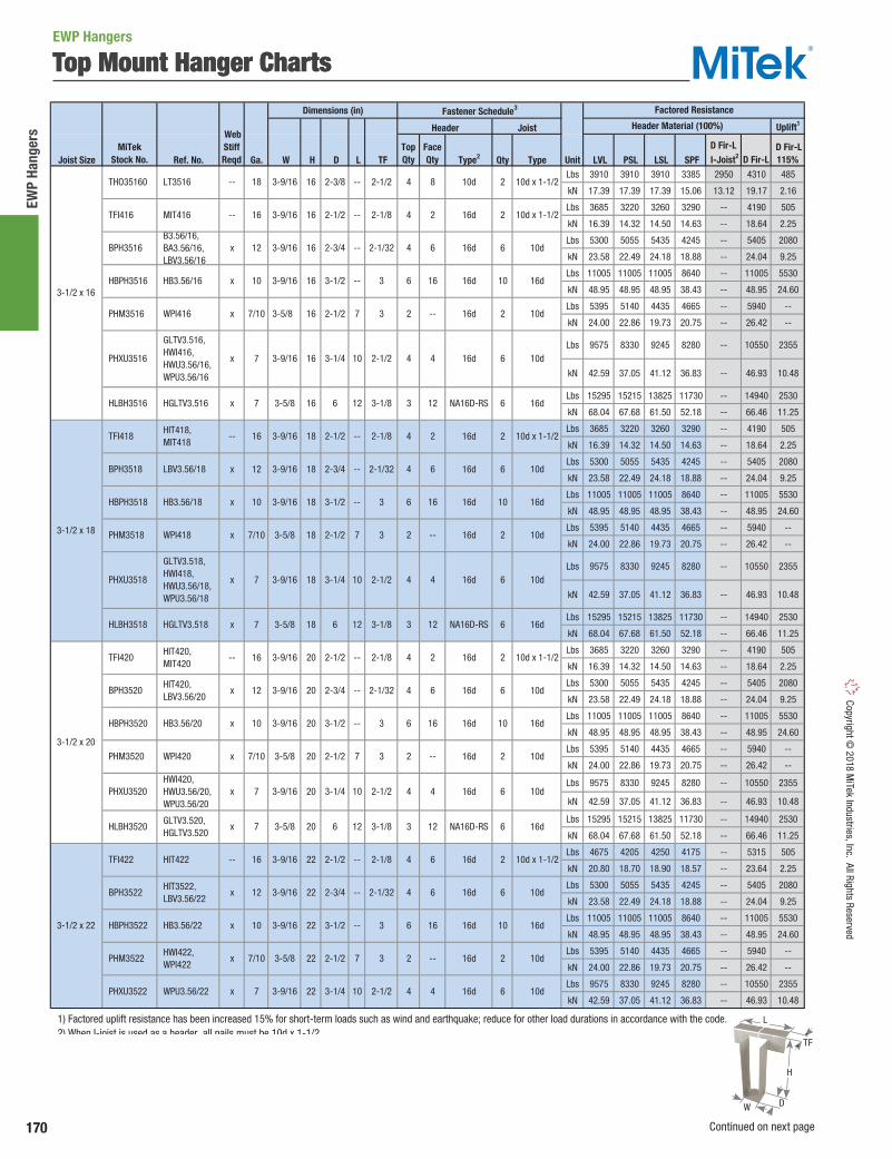
170
EWP
Hang
ers
Copyright © 2018 M
iTek Industries, Inc. All Rights Reserved
Top Mount Hanger Charts
Dimensions (in) Fastener Schedule3
Uplift1
Joist Size Ref. No. Ga. W H D L TF Type2 Qty Type Unit LVL PSL LSL SPFLbs 3910 3910 3910 3385 2950 4310 485
kN 17.39 17.39 17.39 15.06 13.12 19.17 2.16
Lbs 3685 3220 3260 3290 -- 4190 505
kN 16.39 14.32 14.50 14.63 -- 18.64 2.25
Lbs 5300 5055 5435 4245 -- 5405 2080
kN 23.58 22.49 24.18 18.88 -- 24.04 9.25
Lbs 11005 11005 11005 8640 -- 11005 5530
kN 48.95 48.95 48.95 38.43 -- 48.95 24.60
Lbs 5395 5140 4435 4665 -- 5940 --
kN 24.00 22.86 19.73 20.75 -- 26.42 --
Lbs 9575 8330 9245 8280 -- 10550 2355
kN 42.59 37.05 41.12 36.83 -- 46.93 10.48
Lbs 15295 15215 13825 11730 -- 14940 2530
kN 68.04 67.68 61.50 52.18 -- 66.46 11.25
Lbs 4675 4205 4250 4175 -- 5315 505
kN 20.80 18.70 18.90 18.57 -- 23.64 2.25
Lbs 5300 5055 5435 4245 -- 5405 2080
kN 23.58 22.49 24.18 18.88 -- 24.04 9.25
Lbs 11005 11005 11005 8640 -- 11005 5530
kN 48.95 48.95 48.95 38.43 -- 48.95 24.60
Lbs 5395 5140 4435 4665 -- 5940 --
kN 24.00 22.86 19.73 20.75 -- 26.42 --
Lbs 9575 8330 9245 8280 -- 10550 2355
kN 42.59 37.05 41.12 36.83 -- 46.93 10.48
1) Factored uplift resistance has been increased 15% for short-term loads such as wind and earthquake; reduce for other load durations in accordance with the code. 2) When I-joist is used as a header, all nails must be 10d x 1-1/2. 3) NAILS: 10d x 1-1/2 nails are 0.148" dia. x 1-1/2" long, 10d nails are 0.148" dia. x 3" long, NA16D-RS nails are 0.148" dia. x 3-1/2" long, 16d nails are 0.162" dia. x 3-1/2" long. Load tables address hanger/header/fastener limitations only. Joist limitations must be determined for each installation.
3-1/2 x 22
TFI422 HIT422
HBPH3522 HB3.56/22
BPH3522
PHM3522
HIT3522, LBV3.56/22
HWI422, WPI422
WPU3.56/22 PHXU3522
--
x
x
x 10
12
x 7/10
7
4 16d 2 10d x 1-1/2
6 16d 10 16d
16
3-9/16 22 3-1/2
2-1/83-9/16 --22
22
6
4 16d 6 10d
16d 6 10d
2 16d 2 10d
4 6
16
--
422
3-9/16
2-1/2
2-3/4
3
2-1/2
2-1/32
3-5/8 2-1/2
3-1/43-9/16
22
--
7
10
-- 3
3-1/2 x 20
PHM3520
PHXU3520
HLBH3520
HIT420, MIT420
HIT420, LBV3.56/20
WPI420
HWI420, HWU3.56/20, WPU3.56/20
BPH3520
TFI420
GLTV3.520, HGLTV3.520
HBPH3520 HB3.56/20
16
x 12
x 7/10
7
x
--
x
7
x 10
3-1/83-5/8 620 12
16d 6 10d
2 16d 2 10d
4
16d 6 10d
3-9/16 20 3-1/2 -- 3 6 16d 10
3 NA16D-RS 6 16d
4
16d
--
4
12
16
3-5/8
20
2-1/8
2-1/32
3
2-1/23-9/16
2-1/2
2-3/4
2-1/2
3-1/4
20
10
--
--
7
20
203-9/16
3-9/16
Web StiffReqd
3-9/16
3-9/16
2-1/2--
2-1/82-1/216 --
3-1/4
2-1/2 3
2-1/2x 7
3-9/16 2-3/816
2-1/32--
7
2-3/4
16
--
3-1/816
3-9/16
3-5/8
16
16
3-5/8 6 12
10
3-9/16 16 3-1/2 -- 3
GLTV3.518, HWI418, HWU3.56/18, WPU3.56/18
HGLTV3.518
HGLTV3.516 HLBH3516
3-1/2 x 18
3-1/2 x 16
THO35160
TFI418
PHXU3518
PHM3518
BPH3518
HLBH3518
HBPH3518
WPI418
HB3.56/18
LT3516
LBV3.56/18
x 10
WPI416
GLTV3.516, HWI416, HWU3.56/16, WPU3.56/16
PHXU3516
TFI416
BPH3516
PHM3516
x 7
x 12
x 7/10
-- 16
HBPH3516 HB3.56/16 x 10
MIT416
B3.56/16, BA3.56/16, LBV3.56/16
x 12
3-9/16 18 3-1/2 -- 3 6 16d 10 16d
18 16d 6
4 16d 2
--2-3/43-9/16 2-1/32
3-1/8
x 7
x 7
3-9/16
3-5/8
2-1/2
7
3-1/4
6
2-1/2
10
12
18
18
18
x 7/10 3-5/8 3
Factored Resistance
10d x 1-1/2
NA16D-RS 6 16d
2 10d x 1-1/24 10d
6 10d
4 16d 2
Header Material (100%)
D Fir-L I-Joist2
D Fir-L115%
6 16d 10 16d
TopQty
FaceQty
818
10d x 1-1/2
4 16d
MiTekStock No.
Header Joist
2-1/2 2-1/83-9/16 18 ---- 16 HIT418, MIT418
3
6 10d
2 16d 2 10d
4 16d
4
D Fir-L
2
6
16
--
4
12
2
2
6
16
--
4
12
3
4
2
4
6
10d
NA16D-RS 6 16d
16d 6
10d
16d 2 10d
16d 2 10d x 1-1/2
Top Mount Hanger ChartsEWP Hangers
H
W
L
TF
D
Continued on next page

171
EWP Hangers
Copy
right
© 2
018
MiT
ek In
dust
ries,
Inc.
All
Righ
ts R
eser
ved
Top Mount Hanger Charts
Dimensions (in) Fastener Schedule3
Uplift1
Joist Size Ref. No. Ga. W H D L TF Type2 Qty Type Unit LVL PSL LSL SPF
Lbs 4675 4205 4250 4175 -- 5315 505
kN 20.80 18.70 18.90 18.57 -- 23.64 2.25
Lbs 5300 5055 5435 4245 -- 5405 2080
kN 23.58 22.49 24.18 18.88 -- 24.04 9.25
Lbs 11005 11005 11005 8640 -- 11005 5530
kN 48.95 48.95 48.95 38.43 -- 48.95 24.60
Lbs 5395 5140 4435 4665 -- 5940 --
kN 24.00 22.86 19.73 20.75 -- 26.42 --
Lbs 9575 8330 9245 8280 -- 10550 2355
kN 42.59 37.05 41.12 36.83 -- 46.93 10.48
Lbs 5300 5055 5435 4245 -- 5405 2080
kN 23.58 22.49 24.18 18.88 -- 24.04 9.25
Lbs 5395 5140 4435 4665 -- 5940 --
kN 24.00 22.86 19.73 20.75 -- 26.42 --
Lbs 9575 8330 9245 8280 -- 10550 2355
kN 42.59 37.05 41.12 36.83 -- 46.93 10.48
Lbs 3355 3840 3840 3320 3790 4230 2140
kN 14.92 17.08 17.08 14.77 16.86 18.82 9.52
Lbs 5395 5140 4435 4665 -- 5940 --
kN 24.00 22.86 19.73 20.75 -- 26.42 --
1) Factored uplift resistance has been increased 15% for short-term loads such as wind and earthquake; reduce for other load durations in accordance with the code. 2) When I-joist is used as a header, all nails must be 10d x 1-1/2. 3) NAILS: 10d x 1-1/2 nails are 0.148" dia. x 1-1/2" long, 10d nails are 0.148" dia. x 3" long, 16d nails are 0.162" dia. x 3-1/2" long. Load tables address hanger/header/fastener limitations only. Joist limitations must be determined for each installation.
16d 2 10d
16d 6 10d THO20950-2
PHM4295
4 - 4-3/16 x 9-1/2
4-3/16
4-3/16
LBV4.12/9.5, LBV4.28/9.5, MIT4.28/9.5
--
x 16
x 7/10
42
3
3
2-1/2
9-1/2
9-1/2
--
7 2
Web StiffReqd
3-9/16 3-1/4
3
2-1/224 10
3-9/16
3-9/16 2-1/32
3-5/8 2-1/2
2-1/2
2-3/4
24
24
24
2-1/8
--
7
--
3-9/16 24 3-1/2 -- 3
4 16d 6 10d
16d 2 10d x 1-1/2
4 16d 6 10d
2 16d 2 10d
6 16d 10 16d 3-1/2 x 24
PHM3524
PHXU3524
--
HBPH3524 HB3.56/24
HIT426 16
3-1/2 x 26
x 12
x 7/10
x 7
TFI424
HWI424, WPI424
WPU3.56/24
HIT424, LBV3.56/24
BPH3524
x 7
x 12
3-1/2 x 28
LBV3.56/26
HWI426, WPI426
WPU3.56/26
LBV3.56/28
HWI428, WPI428
WPU3.56/28
TFI426
PHXU3528
BPH3528
PHM3528
HBPH3528 HB3.56/28
2 16d
10 16d
x 12
BPH3526
PHM3526
PHXU3526
2 10d
4 16d 6 10d
26 --
HBPH3526 HB3.56/26 x 10 3-9/16 26 3-1/2
3
3-9/16
--
3-5/8
-- 2-1/32
4 16d
2-1/32
2-1/2
2-3/4
2-1/826
26
26
7
2-1/210
3-9/16
-- 3 6 16d
4
7
10
6 10d
2 16d 2 10d
4 16d
3
2-1/2
x 12
x 7/10
x 7
3-5/8
2-1/2
3-1/4
2-3/428
2-1/2
3-1/4
x 7/10
x 7
3-9/16
3-5/8
3-9/16
28
28
x 10
2 16d
4 16d
4 16d30
30
10
2-1/32
3
2-1/2
2-3/4
2-1/2
3-1/4
--
7
6 16d
3-1/2 x 32
--
--
HWI432, WPI432
PHXU3532
BPH3532
PHM3532
2 10d30
3-9/16 10d
3-1/2 x 30
LBV3.56/30
HWI430, WPI430
--
BPH3530
PHM3530
PHXU3530
32 3-1/4 2-1/2
x 12
x 7/10
x 7 6 10d
7
103-9/16 4 16d
3-9/16 2-1/32
3
2-3/4
2-1/23-5/8
6 10d
2 16d 2 10d
-- 4 16d32
32
Factored Resistance
MiTekStock No.
Header Joist Header Material (100%)
D Fir-L I-Joist2
D Fir-L115%
3-9/16
3-9/16
-- 2 10d x 1-1/2
16d 6 10d
4 16d
x 7/10
x 10
-- 16 4
3-9/16 28 3-1/2 -- 3 6 16d 10 16d
HBPH3530 HB3.56/30 x 10 3-9/16 30 3-1/2 -- 3
TopQty
FaceQty
6
6
16
--
4
6
6
D Fir-L
--
4
6
--
4
6
--
16
--
4
6
16
--
4
6
16
10d
6
6
10 16d
6 10d
EWP Hangers
H
W
L
TF
D
Continued on next page

172
EWP
Hang
ers
Copyright © 2018 M
iTek Industries, Inc. All Rights Reserved
Dimensions (in) Fastener Schedule3
Uplift1
Joist Size Ref. No. Ga. W H D L TF Type2 Qty Type Unit LVL PSL LSL SPF
Lbs 3355 3890 3890 3665 3790 4670 2140
kN 14.92 17.30 17.30 16.30 16.86 20.77 9.52
Lbs 5395 5140 4435 4665 -- 5940 --
kN 24.00 22.86 19.73 20.75 -- 26.42 --
Lbs 3355 5330 5330 4610 3785 5870 2140
kN 14.92 23.71 23.71 20.51 16.84 26.11 9.52
Lbs 5395 5140 4435 4665 -- 5940 --
kN 24.00 22.86 19.73 20.75 -- 26.42 --
Lbs 3355 5330 5330 4610 3785 5870 2140
kN 14.92 23.71 23.71 20.51 16.84 26.11 9.52
Lbs 5395 5140 4435 4665 -- 5940 --
kN 24.00 22.86 19.73 20.75 -- 26.42 --
Lbs 5090 5235 5235 4570 3785 5820 2140
kN 22.64 23.29 23.29 20.33 16.84 25.89 9.52
Lbs 5395 5140 4435 4665 -- 5940 --
kN 24.00 22.86 19.73 20.75 -- 26.42 --
Lbs 5090 5280 5280 4570 3785 5820 2140
kN 22.64 23.49 23.49 20.33 16.84 25.89 9.52
Lbs 5395 5140 4435 4665 -- 5940 --
kN 24.00 22.86 19.73 20.75 -- 26.42 --
Lbs 5090 6345 6345 5545 3785 7060 2140
kN 22.64 28.22 28.22 24.67 16.84 31.40 9.52
Lbs 5090 6345 6345 5545 3785 7060 2140
kN 22.64 28.22 28.22 24.67 16.84 31.40 9.52
Lbs 5395 5140 4435 4665 -- 5940 --
kN 24.00 22.86 19.73 20.75 -- 26.42 --
Lbs 5090 6745 6745 7225 3785 9205 2140
kN 22.64 30.00 30.00 32.14 16.84 40.95 9.52
Lbs 5395 5140 4435 4665 -- 5940 --
kN 24.00 22.86 19.73 20.75 -- 26.42 --
Lbs 5090 6745 6745 7225 3785 9205 2140
kN 22.64 30.00 30.00 32.14 16.84 40.95 9.52
Lbs 5395 5140 4435 4665 -- 5940 --
kN 24.00 22.86 19.73 20.75 -- 26.42 --
Lbs 5090 5280 5280 4570 3785 5820 2140
kN 22.64 23.49 23.49 20.33 16.84 25.89 9.52
Lbs 5090 5280 5280 4570 3785 5820 2140
kN 22.64 23.49 23.49 20.33 16.84 25.89 9.52
Lbs 5395 5140 4435 4665 -- 5940 --
kN 24.00 22.86 19.73 20.75 -- 26.42 --
Lbs 5090 5280 5280 4570 3785 5820 2140
kN 22.64 23.49 23.49 20.33 16.84 25.89 9.52
Lbs 5090 5280 5280 4570 3785 5820 2140
kN 22.64 23.49 23.49 20.33 16.84 25.89 9.52
1) Factored uplift resistance has been increased 15% for short-term loads such as wind and earthquake; reduce for other load durations in accordance with the code. 2) When I-joist is used as a header, all nails must be 10d x 1-1/2. 3) NAILS: 10d nails are 0.148" dia. x 3" long, 16d nails are 0.162" dia. x 3-1/2" long. Load tables address hanger/header/fastener limitations only. Joist limitations must be determined for each installation.
5 x 11-1/4
5 x 11-7/8
16d 6 10d
16d 10d
--3
x 12
x 12 11-1/45-1/8 LBV5.12/11.25
LBV5.12/11.88, MIT311.88-2
5-1/8 11-7/8
2-1/8
2-1/8 64
4
4-3/4
5-1/8 9-1/4
9-1/25-1/8
--
--
THO25118-2
THO25112-2
3 --
20
5-1/8 2
6
--
16d 22-1/2
3
3
2-11/16
2-1/83 --
7
2-1/2
4-1/2 - 4-5/8 x 20
5 x 9-1/4
THO23200-2
PHM2320-2
THO25925-2
5 x 9-1/2
THO25950-2
PHM2595-2
12
x 12
x 7/10
x 7/10
MIT39.5-2, LBV5.12/9.5
x 12
x
WPI39.5-2
LBV5.12/9.25
LBV4.75/20
WP3520-2
2-1/83204-3/4
9-1/2
6
10d
4 16d 6 10d
4 16d 6 10d
2
2 10d16d2-1/2 7 3
4 16d
Web StiffReqd
2
3
311-7/8 --
3
2-1/2
3
2-1/2
14
14
11-7/8 7
--
7
9-1/2
7
--
7
--
7
--
1-15/16
4 - 4-3/16 x 11-7/8
4-3/4
4-3/16
4-3/16
4-3/4
4-3/4
4-3/16
4-3/16
4-3/4
x
x 7/10
x 12
x 7/10
4-3/16
4-3/16
x
x
12
x
16 LBV4.12/11.88, LBV4.28/11.88, MIT4.28/11.88
3
16d 2
2
1-15/16
3
2
9-1/2
11-7/8
16
16
3
2-1/2 3
2
3
2-1/8
--
6
x 12
14
16
10d
4 16d 6 10d
2 16d
6 10d
2 16d 2 10d
16d4 6 10d
4 16d 6
--
PHM2316-2
LBV4.12/16, LBV4.28/16
--
THO20118-2
PHM42118
THO20140-2 LBV4.12/14, LBV4.28/14, MIT4.28/14
THO23950-2
PHM2395-2
THO23118-2
PHM23118-2
PHM4216
PHM4214
LBV4.75/9.5, MIT359.5-2
WP359.5-2
LBV4.75/11.88, MIT3511.88-2
WP3511.88-2
THO20160-2
12
x 7/10
x 12
WP3516-2
11-7/8
7/10
x 7/10
7/10
4 - 4-3/16 x 14
4-1/2 - 4-5/8 x 11-7/8
4 - 4-3/16 x 16
4-1/2 - 4-5/8 x 9-1/2
--
4-1/2 - 4-5/8 x 14
4-1/2 - 4-5/8 x 16
THO23140-2
THO23160-2
2 16d 2 10d
4 16d
3
2-1/2
PHM2318-2
10d2 16d
6 10d
6 10d
2
16d
4 16d
4
16
4-3/4
4-3/4
4-1/2 - 4-5/8 x 18
2-1/8
2-1/8
3
THO23180-2 4-3/4 2-1/8
--
--
7
3
3
2-1/2
18
18
x 12
x
LBV4.75/14, MIT3514-2
LBV4.75/16, MIT4.75/16
x 12
x 4-3/4
Factored Resistance
MiTekStock No.
Header Joist Header Material (100%)
D Fir-L I-Joist2
D Fir-L115%
4
3
--
77/10
3
2-1/2
10d
2 16d 2 10d4-3/4
16d 6 LBV4.75/18
WP3518-2
TopQty
FaceQty
6
--
6
--
6
--
6
2
4
D Fir-L
6
6
--
8
8
--
10
--
10
--
6
10d
10d
16d 2
10d
16d 6 10d
10d
Top Mount Hanger ChartsEWP Hangers
H
W
L
TF
D
Continued on next page

173
EWP Hangers
Copy
right
© 2
018
MiT
ek In
dust
ries,
Inc.
All
Righ
ts R
eser
ved
Dimensions (in) Fastener Schedule3
Uplift1
Joist Size Ref. No. Ga. W H D L TF Type2 Qty Type Unit LVL PSL LSL SPF
Lbs 5090 6345 6345 5545 3785 7060 2140
kN 22.64 28.22 28.22 24.67 16.84 31.40 9.52
Lbs 5395 5140 4435 4665 -- 5940 --
kN 24.00 22.86 19.73 20.75 -- 26.42 --
Lbs 5090 6345 6345 5545 3785 7060 2140
kN 22.64 28.22 28.22 24.67 16.84 31.40 9.52
Lbs 10405 10405 10405 8635 -- 10405 5620
kN 46.28 46.28 46.28 38.41 -- 46.28 25.00
Lbs 5395 5140 4435 4665 -- 5940 --
kN 24.00 22.86 19.73 20.75 -- 26.42 --
Lbs 5090 6745 6745 7225 3785 9205 2140
kN 22.64 30.00 30.00 32.14 16.84 40.95 9.52
Lbs 10405 10405 10405 8635 -- 10405 5620
kN 46.28 46.28 46.28 38.41 -- 46.28 25.00
Lbs 5395 5140 4435 4665 -- 5940 --
kN 24.00 22.86 19.73 20.75 -- 26.42 --
Lbs 5090 6745 6745 7225 3785 9205 2140
kN 22.64 30.00 30.00 32.14 16.84 40.95 9.52
Lbs 10405 10405 10405 8635 -- 10405 5620
kN 46.28 46.28 46.28 38.41 -- 46.28 25.00
Lbs 5395 5140 4435 4665 -- 5940 --
kN 24.00 22.86 19.73 20.75 -- 26.42 --
Lbs 10405 10405 10405 8635 -- 10405 5620
kN 46.28 46.28 46.28 38.41 -- 46.28 25.00
Lbs 5395 5140 4435 4665 -- 5940 --
kN 24.00 22.86 19.73 20.75 -- 26.42 --
Lbs 10405 10405 10405 8635 -- 10405 5620
kN 46.28 46.28 46.28 38.41 -- 46.28 25.00
Lbs 5395 5140 4435 4665 -- 5940 --
kN 24.00 22.86 19.73 20.75 -- 26.42 --
Lbs 10405 10405 10405 8635 -- 10405 5620
kN 46.28 46.28 46.28 38.41 -- 46.28 25.00
Lbs 5395 5140 4435 4665 -- 5940 --
kN 24.00 22.86 19.73 20.75 -- 26.42 --
Lbs 10405 10405 10405 8635 -- 10405 5620
kN 46.28 46.28 46.28 38.41 -- 46.28 25.00
Lbs 10405 10405 10405 8635 -- 10405 5620
kN 46.28 46.28 46.28 38.41 -- 46.28 25.00
Lbs 5300 5055 5435 4295 -- 5470 2935
kN 23.58 22.49 24.18 19.11 -- 24.33 13.06
Lbs 10405 10405 10405 8635 -- 10405 5620
kN 46.28 46.28 46.28 38.41 -- 46.28 25.00
Lbs 10405 10405 10405 8635 -- 10405 5620
kN 46.28 46.28 46.28 38.41 -- 46.28 25.00
Lbs 9575 8330 9575 8280 -- 10550 2355
kN 42.59 37.05 42.59 36.83 -- 46.93 10.48
Lbs 15295 15215 13825 11730 -- 14940 2860
kN 68.04 67.68 61.50 52.18 -- 66.46 12.72
1) Factored uplift resistance has been increased 15% for short-term loads such as wind and earthquake; reduce for other load durations in accordance with the code. 2) When I-joist is used as a header, all nails must be 10d x 1-1/2. 3) NAILS: 10d nails are 0.148" dia. x 3" long, NA16D-RS nails are 0.148" dia. x 3-1/2" long, 16d nails are 0.162" dia. x 3-1/2" long. Load tables address hanger/header/fastener limitations only. Joist limitations must be determined for each installation.
4 16d
10d12x
7
Web StiffReqd
22-1/2
2-1/8
3
--
7
4 16d
2 16d
6
TopQty
FaceQty
8
--
8
16
--2 16d 2
5 x 20
PHM2518-2
PHM2520-2
THO25200-2
THO25180-2
B5.12/20
WPI320-2
3
205-1/8
2-1/2
3
2-1/2
18 4 16d 6
2 16d 2
5 x 14
5 x 16
5 x 18
PHM2516-2
THO25140-2
PHM2514-2
5-1/8
5-1/8
5-1/8
5-1/8
5-1/8
5-1/8
x
MIT5.12/16, LBV5.12/16
MIT314-2, LBV5.12/14
7/10
x 12
x 7/10 WPI316-2
WPI318-2
WPI314-2
B5.12/18
2-1/8--
10d
7
3 6
3
2-1/2
14
14
16
16
2-1/8
3 6 16d 10
10d
10d
2 16d 2 10d
3 --
18
--
7
x 7
HBPH5118 HB5.12/18 x 10 5-1/8 18 3-1/2 --
x 7/10
x 12
x 7/10
PHM2522-2
PHM2524-2
x 12
WPI324-2
--
PHM2526-2
10d
3 NA16D-RS
2 10d
2 10d
6 16d
2 16d
2 16d
2 --
6
16
16
4
12 HLBH55925
PHXU55925
WPI326-2
GLTV5.50/9.25, HWU5.50/9.25
16d
4 16d 611-1/2
4 16d 6
6 16d 10
6 16d
3-1/85-9/16 129-1/4 6
3-1/4
10 3
3
3
3
2-1/2
22
24
26
9-1/4
7
7
2-1/2
2-1/2
2-1/2
26 3-1/2 --
x 7/10
x 7/10
x 7/10
10 16d
THO25160-2
5-1/8
5-1/8
5-1/8
5-1/2
7
10d-- x 10 5-9/16 7-1/4 2-1/4 --
3-1/2 -- 3 6 16d 10 16d
HB5.12/30
10d
4 16d
3
2-1/8
3
Factored Resistance
MiTekStock No.
Header Joist Header Material (100%)
D Fir-L I-Joist2
D Fir-L115%
HBPH5116 HB5.12/16 x 10 5-1/8 16 3-1/2 -- 3 6 16d
16d
HBPH5120 HB5.12/20 x 10 5-1/8 20 3-1/2 -- 3 6 16d 10 16d
5-1/8 20
5 x 22
HBPH5122
16
HB5.12/22 x 10 5-1/8 22 3-1/2 --
WPI322-2
5-1/8 24 3-1/2 -- 3 6 16d 10 16d
16d
2 10d
16
--
16
3 6 16d 10 16d
3
16d
5-1/4 x 7-1/4
HBPH55725 -- x 10 5-1/2 7-1/4 3-1/2 -- 3 6 16d 10 16d
5 x 30 5-1/8 30 3-1/2 -- 16
BPH55725
HBPH5130 x
5-1/4 x 9-1/4
HBPH55925 HB5.50/9.25 x 10 5-1/2 9-1/4
10
5 x 28 HBPH5128 HB5.12/28 x 10 5-1/8 28 3-1/2 -- 3 6 16d 10
x 7
2-1/2
5 x 26
HBPH5126 HB5.12/26 x 10 5-1/8
D Fir-L
10
16
--
10
16
--
16
--
6 10d
10d
16d
5 x 24
HBPH5124 HB5.12/24 x 10
Top Mount Hanger ChartsEWP Hangers
H
W
L
TF
D
Continued on next page

174
EWP
Hang
ers
Copyright © 2018 M
iTek Industries, Inc. All Rights Reserved
Dimensions (in) Fastener Schedule3
Uplift1
Joist Size Ref. No. Ga. W H D L TF Type2 Qty Type Unit LVL PSL LSL SPF
Lbs 5300 5055 5435 4295 -- 5470 2935
kN 23.58 22.49 24.18 19.11 -- 24.33 13.06
Lbs 10405 10405 10405 8635 -- 10405 5620
kN 46.28 46.28 46.28 38.41 -- 46.28 25.00
Lbs 5395 5140 4435 4665 -- 5940 --
kN 24.00 22.86 19.73 20.75 -- 26.42 --
Lbs 9575 8330 9575 8280 -- 10550 2355
kN 42.59 37.05 42.59 36.83 -- 46.93 10.48
Lbs 15295 15215 13825 11730 -- 14940 2860
kN 68.04 67.68 61.50 52.18 -- 66.46 12.72
Lbs 10405 10405 10405 8635 -- 10405 5620
kN 46.28 46.28 46.28 38.41 -- 46.28 25.00
Lbs 9575 8330 9575 8280 -- 10550 2355
kN 42.59 37.05 42.59 36.83 -- 46.93 10.48
Lbs 15295 15215 13825 11730 -- 14940 2860
kN 68.04 67.68 61.50 52.18 -- 66.46 12.72
Lbs 15295 15215 13825 11730 -- 14940 2860
kN 68.04 67.68 61.50 52.18 -- 66.46 12.72
Lbs 5300 5055 5435 4245 -- 5405 2935
kN 23.58 22.49 24.18 18.88 -- 24.04 13.06
Lbs 10405 10405 10405 8635 -- 10405 5620
kN 46.28 46.28 46.28 38.41 -- 46.28 25.00
Lbs 5395 5140 4435 4665 -- 5940 --
kN 24.00 22.86 19.73 20.75 -- 26.42 --
Lbs 9575 8330 9575 8280 -- 10550 2355
kN 42.59 37.05 42.59 36.83 -- 46.93 10.48
Lbs 15295 15215 13825 11730 -- 14940 2860
kN 68.04 67.68 61.50 52.18 -- 66.46 12.72
Lbs 10405 10405 10405 8635 -- 10405 5620
kN 46.28 46.28 46.28 38.41 -- 46.28 25.00
Lbs 9575 8330 9575 8280 -- 10550 2355
kN 42.59 37.05 42.59 36.83 -- 46.93 10.48
Lbs 15295 15215 13825 11730 -- 14940 2860
kN 68.04 67.68 61.50 52.18 -- 66.46 12.72
Lbs 5300 5055 5435 4245 -- 5405 2935
kN 23.58 22.49 24.18 18.88 -- 24.04 13.06
Lbs 10405 10405 10405 8635 -- 10405 5620
kN 46.28 46.28 46.28 38.41 -- 46.28 25.00
Lbs 5395 5140 4435 4665 -- 5940 --
kN 24.00 22.86 19.73 20.75 -- 26.42 --
Lbs 9575 8330 9575 8280 -- 10550 2355
kN 42.59 37.05 42.59 36.83 -- 46.93 10.48
Lbs 15295 15215 13825 11730 -- 14940 2860
kN 68.04 67.68 61.50 52.18 -- 66.46 12.72
1) Factored uplift resistance has been increased 15% for short-term loads such as wind and earthquake; reduce for other load durations in accordance with the code. 2) When I-joist is used as a header, all nails must be 10d x 1-1/2. 3) NAILS: 10d nails are 0.148" dia. x 3" long, NA16D-RS nails are 0.148" dia. x 3-1/2" long, 16d nails are 0.162" dia. x 3-1/2" long. Load tables address hanger/header/fastener limitations only. Joist limitations must be determined for each installation.
10d6
16d
7
2-1/2
3-1/4
HB5.50/9.5
16d
10 16dx 10 5-1/2 9-1/2 3-1/2 -- 3 6 16d
12 3-1/8 69-1/25-9/16
x
x
3-1/8
11-1/2
12
5-1/2
5-1/4 x 9-1/2
4
5-5/8
312
7/10
3
6
16d
4 16d
--
WP5.50/9.5
BPH5595
PHM5595
HLBH5595
GLTV5.59, HWU5.50/9.5
HGLTV5.59
PHXU5595
3 NA16D-RS
2-1/6
5-1/2 9-1/2
HBPH5595
29-1/2 7
11.5
3
2-1/2
5-9/16
3-1/8
2-1/2
3-1/8
2-1/32
3
2-1/2
14
2-1/32
3
2-1/2
3
6
11-7/8
11-7/8
12
12
14
14
14
3-1/4
6
3-1/4
7
11-1/2
12
6
2-1/2
2-1/2
3
3-1/4
14 3-1/2
3-1/8
11-1/2
12
--
3
12
5-9/16 11-1/2 6 12
5-1/2 11-7/8 3-1/2 --
5-1/2
5-9/16
11-7/8
11-7/8
2-1/2
5-9/16
5-9/16
5-9/16
5-5/8
5-9/16
5-9/16
5-5/8
5-1/2
5-1/2
5-1/2
x 7
x 7
x 12
x 7/10
x 7
x 7
x 7
x 7/10
x 7
x 10
x 10
x 7
16d 6 10d
4 16d 6
6 16d 10 16d
12
16
4
NA16D-RS 6 16d
6 16d 10 16d
10d PHXU55118 11-1/2
12
6
16
--
4
HLBH5512
HLBH55112
BPH55118
PHM55118 5-1/4 x 11-7/8
5-1/4 x 14
5-1/4 x 11-1/2 HLBH55115
HBPH55118
HLBH55118
PHXU5512
BPH5514
PHXU5514
PHM5514
HLBH5514
HBPH5514
5-1/4 x 11-1/4
HBPH55112
5-1/4 x 12
HBPH5512
PHXU55112
GLTV5.514, HGLTV5.514
GLTV5.512, HGLTV5.512
--
--
HWU5.50/14
HWU5.50/11.88
--
HB5.50/11.88
GLTV5.511, HGLTV5.511
HWU5.50/12
HB5.50/14
HB5.50/12
6 16d
4 16d 6 10d
2 16d
3 NA16D-RS
2 10d
16d 6 10d
6 16d 10 16d
10d
2 16d 2 10d
4 16d 6
3 NA16D-RS 6 16d
3 NA16D-RS 6 16d
4
6x 7 2-1/2
3-1/8
11-1/4
11-1/4 6 12
Factored Resistance
MiTekStock No.
Header Joist Header Material (100%)
D Fir-L I-Joist2
D Fir-L115%
3 6 16d 10 16d3-1/2 --
Web StiffReqd
x 7
-- 10d
2 10d
4x 9-1/2
x 10
x 12
x 7
--
HB5.50/11.25 x 10 5-1/2 11-1/4
GLTV5.50/11.25, HWU5.50/11.25
--
--
WP5.50/11.88
5-1/2
--
2-1/2
3-1/4
12 3-1/2 --
7
D Fir-L
12
6
16
--
4
12
TopQty
FaceQty
6
16
--
4
12
16
4
4
10d
3 NA16D-RS 6 16d
4 16d
Top Mount Hanger ChartsEWP Hangers
H
W
L
TF
D
Continued on next page

175
EWP Hangers
Copy
right
© 2
018
MiT
ek In
dust
ries,
Inc.
All
Righ
ts R
eser
ved
Dimensions (in) Fastener Schedule3
Uplift1
Joist Size Ref. No. Ga. W H D L TF Type2 Qty Type Unit LVL PSL LSL SPF
Lbs 5300 5055 5435 4245 -- 5405 2935
kN 23.58 22.49 24.18 18.88 -- 24.04 13.06
Lbs 10405 10405 10405 8635 -- 10405 5620
kN 46.28 46.28 46.28 38.41 -- 46.28 25.00
Lbs 5395 5140 4435 4665 -- 5940 --
kN 24.00 22.86 19.73 20.75 -- 26.42 --
Lbs 9575 8330 9575 8280 -- 10550 2355
kN 42.59 37.06 42.59 36.83 -- 46.93 10.48
Lbs 15295 15215 13825 11730 -- 14940 2860
kN 68.04 67.68 61.50 52.18 -- 66.46 12.72
Lbs 10405 10405 10405 8635 -- 10405 5620
kN 46.28 46.28 46.28 38.41 -- 46.28 25.00
Lbs 9575 8330 9575 8280 -- 10550 2355
kN 42.59 37.06 42.59 36.83 -- 46.93 10.48
Lbs 15295 15215 13825 11730 -- 14940 2860
kN 68.04 67.68 61.50 52.18 -- 66.46 12.72
Lbs 9575 8330 9575 8280 -- 10550 2355
kN 42.59 37.06 42.59 36.83 -- 46.93 10.48
Lbs 5300 5055 5435 4340 -- 5530 2935
kN 23.58 22.49 24.18 19.31 -- 24.60 13.06
Lbs 10405 10405 10405 8635 -- 10405 5620
kN 46.28 46.28 46.28 38.41 -- 46.28 25.00
Lbs 5395 5140 4435 4665 -- 5940 --
kN 24.00 22.86 19.73 20.75 -- 26.42 --
Lbs 9575 8330 9575 8280 -- 10550 2355
kN 42.59 37.06 42.59 36.83 -- 46.93 10.48
Lbs 15295 14935 13825 11730 -- 14940 2860
kN 68.04 66.44 61.50 52.18 -- 66.46 12.72
Lbs 5300 5060 5435 4340 -- 5530 2935
kN 23.58 22.51 24.18 19.31 -- 24.60 13.06
Lbs 10405 10405 10405 8635 -- 10405 5620
kN 46.28 46.28 46.28 38.41 -- 46.28 25.00
Lbs 5395 5140 4435 4665 -- 5940 --
kN 24.00 22.86 19.73 20.75 -- 26.42 --
Lbs 9575 8330 9575 8280 -- 10550 2355
kN 42.59 37.06 42.59 36.83 -- 46.93 10.48
Lbs 15295 14935 13825 11730 -- 14940 2860
kN 68.04 66.44 61.50 52.18 -- 66.46 12.72
1) Factored uplift resistance has been increased 15% for short-term loads such as wind and earthquake; reduce for other load durations in accordance with the code. 2) When I-joist is used as a header, all nails must be 10d x 1-1/2. 3) NAILS: 10d nails are 0.148" dia. x 3" long, NA16D-RS nails are 0.148" dia. x 3-1/2" long, 16d nails are 0.162" dia. x 3-1/2" long. Load tables address hanger/header/fastener limitations only. Joist limitations must be determined for each installation.
D Fir-L
--
4
12
16
4
12
4
6
6
6
16d 6
16d
16d 6 10d
NA16D-RS
2 10d
10d
16d
6
10d
16
TopQty
FaceQty
6
16
--
4
12
6
166
4
4
3
2
9-1/2 3-1/2 -- 3 6 16d 10 16d
7-1/8 9-1/4 3-1/2 -- 3 6 16d 10 16d
10d
10d
9-1/4 2 16d 2
9-1/4
Factored Resistance
MiTekStock No.
Header Joist Header Material (100%)
D Fir-L I-Joist2
D Fir-L115%
5-1/4 x 20
HBPH5520 HB5.50/20 x 10 5-1/2 20 3-1/2 -- 3 6 16d 10 16d
x 7
x
2-1/2
3-1/4
6
4 16d 6
3 NA16D-RS 6
12
13-1/8
12 3-1/8
3-1/4 4
12
6
16
--
4
12 16d
4 16d 6 10d
3 NA16D-RS 6
616d 10d
10d
16d
4
2 16d 2
10-- 7-1/8
7-1/8
2-1/2
6
6 10d-- x 7
x 12
7-1/4
9-1/4 10d
4 16d
--
13-1/8
37-1/8
3-1/4
--
--
GLTV5.520, HGLTV5.520
7 x 7-1/4
7 x 9-1/4
7 x 9-1/2
PHM35925-2
BPH71925
PHXU71725
HLBH71925
PHXU71925 WPI49.25-2
HBPH71925 HB7.12/9.25
HBPH7195 HB7.12/9.5
HLBH5520
PHXU5520
--
HLBH7195
PHXU7195
PHM3595-2
BPH7195
--
B7.12/9.5
7
x
x 7/10
x 7
x 10
x 10
9-1/2
9-1/2
10d
5-9/16
5-1/2 20
20
3-1/4
6
2-1/2
3-1/8
11.5
12 3 NA16D-RS 16d
4 16d 6
4 16d
2-1/2
6
3
--
7-1/8
7-1/8
7-1/8
7-1/8
7-1/87
x 7
GLTV49.5-2, WPI49.5-2
7
x 12
x 7/10
x
--
7-1/8
Web StiffReqd
--
10
3-1/8
2-3/8
13-1/8 2-1/2
9-1/4
9-1/2
7-1/8
2-3/8
3
39-1/2
2-1/2
11-1/2
5-9/16
5-5/8
5-1/2
5-9/16 18
18
7
x
HGLTV5.518
5-1/4 x 18 PHM5518
PHXU5518
HLBH5518
--
--
GLTV5.518
BPH5518
HBPH5518 HB5.50/18
12
x 7
x 7/10
x
2-1/32
3
2-1/2
3-1/8
18
18
6
2-1/2
2-1/2
3-1/4
12
--
7
x 10 5-1/2 18 3-1/2 -- 3 16d 10 16d
3-1/85-9/16
2-1/32
3
2-1/2
16
16
16
16 6
2-1/2
2-1/2
3-1/4
7
11-1/2
12
--5-9/16
5-5/8
BPH5516
16d
16d
4 16d 6 10d
2 10d
3 NA16D-RS
2 16d
x 7
x 7/10
x 7 5-1/2
4
5-1/4 x 16 PHM5516
-- 3
x 12
6 16d 10 HBPH5516 HB5.50/16 x 10 5-1/2 16 3-1/2
--
--
GLTV5.516, HWU5.50/16
HGLTV5.516
616d
HLBH5516
PHXU5516
Top Mount Hanger ChartsEWP Hangers
H
W
L
TF
D
Continued on next page

176
EWP
Hang
ers
Copyright © 2018 M
iTek Industries, Inc. All Rights Reserved
Dimensions (in) Fastener Schedule3
Uplift1
Joist Size Ref. No. Ga. W H D L TF Type2 Qty Type Unit LVL PSL LSL SPF
Lbs 5300 5060 5435 4305 -- 5485 2935
kN 23.58 22.51 24.18 19.15 -- 24.40 13.06
Lbs 10405 10405 10405 8635 -- 10405 5620
kN 46.28 46.28 46.28 38.41 -- 46.28 25.00
Lbs 9575 8330 9575 8280 -- 10550 2355
kN 42.59 37.05 42.59 36.83 -- 46.93 10.48
Lbs 15295 14935 13825 11730 -- 14940 2860
kN 68.04 66.43 61.50 52.18 -- 66.46 12.72
Lbs 5300 5060 5435 4305 -- 5485 2935
kN 23.58 22.51 24.18 19.15 -- 24.40 13.06
Lbs 10405 10405 10405 8635 -- 10405 5620
kN 46.28 46.28 46.28 38.41 -- 46.28 25.00
Lbs 5395 5140 4435 4665 -- 5940 --
kN 24.00 22.86 19.73 20.75 -- 26.42 --
Lbs 9575 8330 9575 8280 -- 10550 2355
kN 42.59 37.05 42.59 36.83 -- 46.93 10.48
Lbs 15295 14935 13825 11730 -- 14940 2860
kN 68.04 66.43 61.50 52.18 -- 66.46 12.72
1) Factored uplift resistance has been increased 15% for short-term loads such as wind and earthquake; reduce for other load durations in accordance with the code. 2) When I-joist is used as a header, all nails must be 10d x 1-1/2. 3) NAILS: 10d nails are 0.148" dia. x 3" long, NA16D-RS nails are 0.148" dia. x 3-1/2" long, 16d nails are 0.162" dia. x 3-1/2" long. Load tables address hanger/header/fastener limitations only. Joist limitations must be determined for each installation.
3-1/8
13-1/8
12
2-3/16 4
3
2-1/23-1/4
6
2-1/2
3
4
14
12
-- 3 6 16d 10 16d
HBPH7114 HB7.12/14 x 10 7-1/8 14 3.5 -- 3 6 16d 10 16d
7-1/8
10d
16d
7 x 14
PHXU7114
HLBH7114
BPH7114
PHM3514-2
7
x 12
x 7/10
x 7
7-1/8
7-1/8
7-1/8
B7.12/14
--
GLTV414-2, WPI414-2
HGLTV414-2 x 6
7-1/8 14
3
3-1/8
10
13-1/8 2-1/2
14
--
3-1/4
3
2-1/2
6
2-3/1614
10d
3 NA16D-RS
4 16d 6 10d
2 16d 2 10d
-- 2-3/16
2-1/2
12
--
10
13-1/8
12
13-1/8
2-3/16
3-1/8
3
2-1/2
3-1/8
-- 3
6
11-1/4 3-1/2
11-7/8 3-1/2
11-1/4
3
3-1/4
6
11-7/8
11-7/8
11-7/8
11-7/8
x 10 7-1/8
7-1/8
7-1/8
11-1/4
11-1/4
3
2-1/2
3-1/4
7
x 7
--
--
HLBH71112
7-1/8
HLBH71118
BPH71118
7-1/8
7-1/8
7-1/8
x 7
GLTV411.25-2, WPI411.25-2
HGLTV411.25-2
B7.12/11.88
HBPH71112 HB7.12/11.25 x 10 7-1/8
HBPH71118 HB7.12/11.88
16d
4 16d
10
4 16d 6
7 x 11-1/4
7 x 11-7/8 PHM35118-2
PHXU71118
BPH71112
PHXU71112
x 12
x 7/10
x 7 GLTV411.88-2, HWU7.12/11.88, WPI411.88-2
HGLTV411.88-2
x 12
x
10d
2 16d 2 10d
4 16d 6
3 NA16D-RS 6
4 16d 6
18
18
18
18
7-1/8
7
x
16
16
16
7-1/8
7-1/8
7-1/8
7/10
x
7-1/8
7-1/8
7-1/8
--
2-1/2
3
--
10
6 12
3
102-1/2
3-1/4 13-1/8
HGLTV418-2
HB7.12/18
7/10
x 10
PHXU7116
HLBH7116 7
GLTV416-2, WPI416-2
HGLTV416-2
BPH7118
PHM3518-2
PHXU7118
HLBH7118
B7.12/18 x 12
x
7 x 16
7 x 18
BPH7116
PHM3516-2
16d
16d 6
2 16d
4 16d
3 NA16D-RS
2
NA16D-RS 6
x 12
x
x 7
HBPH7118
x 7
16d 6 10d
2 16d 10d
6 16d
MiTekStock No.
Header Joist
--
4
12
6
16
--
3
6
--
GLTV418-2, HWI418-2
3 2-3/167-1/8
Header Material (100%)
D Fir-L I-Joist2
7-1/8 18 3-1/2 -- 3 6 16d 10 16d
10d
2 10d
6 10d
6 10d
3-1/8
16
TopQty
FaceQty
6
16
D Fir-L115%
HBPH7116 HB7.12/16 x 10 7-1/8 16 3-1/2 -- 3 6 16d 10 16d
Web StiffReqd
Factored Resistance
10d
4 16d
4 B7.12/16
6
16d
10d
D Fir-L
--
4
12
6
16
--
4
12
4
12
6
16
--
4
12
6
16
16d
6
NA16D-RS 6 16d
16d
Top Mount Hanger ChartsEWP Hangers
H
W
L
TF
D
Continued on next page
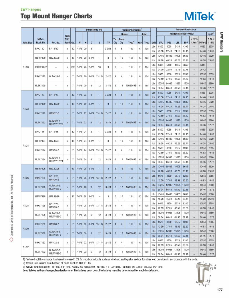
177
EWP Hangers
Copy
right
© 2
018
MiT
ek In
dust
ries,
Inc.
All
Righ
ts R
eser
ved
Dimensions (in) Fastener Schedule3
Uplift1
Joist Size Ref. No. Ga. W H D L TF Type2 Qty Type Unit LVL PSL LSL SPF
Lbs 5300 5055 5435 4305 -- 5485 2935
kN 23.58 22.49 24.18 19.15 -- 24.40 13.06
Lbs 10405 10405 10405 8635 -- 10405 5620
kN 46.28 46.28 46.28 38.41 -- 46.28 25.00
Lbs 5395 5140 4435 4665 -- 5940 --
kN 24.00 22.86 19.73 20.75 -- 26.42 --
Lbs 9575 8330 9575 8280 -- 10550 2355
kN 42.59 37.05 42.59 36.83 -- 46.93 10.48
Lbs 15295 14935 13825 11730 -- 14940 2860
kN 68.04 66.43 61.50 52.18 -- 66.46 12.72
Lbs 5300 5055 5435 4305 -- 5485 2935
kN 23.58 22.49 24.18 19.15 -- 24.40 13.06
Lbs 10405 10405 10405 8635 -- 10405 5620
kN 46.28 46.28 46.28 38.41 -- 46.28 25.00
Lbs 9575 8330 9575 8280 -- 10550 2355
kN 42.59 37.05 42.59 36.83 -- 46.93 10.48
Lbs 15295 14935 13825 11730 -- 14940 2860
kN 68.04 66.43 61.50 52.18 -- 66.46 12.72
Lbs 10405 10405 10405 8635 -- 10405 5620
kN 46.28 46.28 46.28 38.41 -- 46.28 25.00
Lbs 9575 8330 9575 8280 -- 10550 2355
kN 42.59 37.05 42.59 36.83 -- 46.93 10.48
Lbs 15295 14935 13825 11730 -- 14940 2860
kN 68.04 66.43 61.50 52.18 -- 66.46 12.72
Lbs 10405 10405 10405 8635 -- 10405 5620
kN 46.28 46.28 46.28 38.41 -- 46.28 25.00
Lbs 9575 8330 9575 8280 -- 10550 2355
kN 42.59 37.05 42.59 36.83 -- 46.93 10.48
Lbs 15295 14935 13825 11730 -- 14940 2860
kN 68.04 66.43 61.50 52.18 -- 66.46 12.72
Lbs 9575 8330 9575 8280 -- 10550 2355
kN 42.59 37.05 42.59 36.83 -- 46.93 10.48
Lbs 15295 14935 13825 11730 -- 14940 2860
kN 68.04 66.43 61.50 52.18 -- 66.46 12.72
Lbs 9575 8330 9575 8280 -- 10550 2355
kN 42.59 37.05 42.59 36.83 -- 46.93 10.48
Lbs 15295 14935 13825 11730 -- 14940 2860
kN 68.04 66.43 61.50 52.18 -- 66.46 12.72
1) Factored uplift resistance has been increased 15% for short-term loads such as wind and earthquake; reduce for other load durations in accordance with the code. 2) When I-joist is used as a header, all nails must be 10d x 1-1/2. 3) NAILS: 10d nails are 0.148" dia. x 3" long, NA16D-RS nails are 0.148" dia. x 3-1/2" long, 16d nails are 0.162" dia. x 3-1/2" long. Load tables address hanger/header/fastener limitations only. Joist limitations must be determined for each installation.
7-1/8
7-1/8
-- 3 6 16d 10 16d
-- 3 6 16d 10 16d
2-3/16
16d
6 10d13-1/8 16d
10d
3 NA16D-RS 6
7
x 7
x 12
x
HLBH7120
BPH7122
PHXU7122
HLBH7122
B7.12/22
HWI422-2
GLTV422-2, HGLTV7.12/22
-- x 7
HBPH7122 HB7.12/22 x 10
3 --
422
22
22
6
2-1/2
3-1/812
3-1/4 13-1/8
22 3-1/2
3
4
7 x 22
7-1/8
7-1/8
7-1/8
7-1/8
7 x 20
BPH7120
PHM3520-2
PHXU7120 x 7
x 12
7/10
B7.12/20
--
GLTV420-2
HBPH7120 HB7.12/20 x 10 7-1/8
7-1/8
7-1/8
Factored Resistance
3-1/86
3-1/4
12
3-1/8
2-1/2
13-1/8
3-1/4
-- 3
2-1/2
--
10
3-1/86 12
3
2-3/16
2-1/2
16d 6 10d4
Web StiffReqd
3 16d 6-- 2-3/1624 10d4
4
20 3-1/2
3-1/4
4 16d
2
6 16d
16d 6 10d
6 10d
16d
7-1/8
7
x 12
x 7
x
x
7-1/8
7-1/8
7 x 24
PHXU7124
BPH7124
B7.12/28, HWI428-2
GLTV428-2, HGLTV428-2
7 x 32
PHXU7132
HLBH7132
HLBH7128
HLBH7130
GLTV432-2, HGLTV432-2
B7.12/26, HWI426-2
GLTV426-2, HGLTV426-2
PHXU7126
PHXU7128
PHXU7130
7 x 30
32
32
26
28
28
30
30
7-1/8
HWI424-2
GLTV424-2, HGLTV7.12/24
7
HWI432-2 x 7
7
x 7
x 7
x 7
24
HWI430-2
GLTV430-2, HGLTV430-2
7-1/8
7-1/8
7-1/8
7-1/8
7-1/8
7
x 7
x
2-1/2
3-1/8
4
12
3-1/4
6
13-1/8
12
13-1/8
12
13-1/8
12
13-1/8
12
3-1/8
3-1/8
2-1/2
2-1/2
6
3-1/4
-- 3
6
3-1/4
4
12
NA16D-RS 6 16d
4 16d 6 10d
3
NA16D-RS 6 16d
4 16d 6 10d
3
Header Material (100%)
D Fir-L I-Joist2
D Fir-L115%
HBPH7124 HB7.12/24 x 10 7-1/8 24 3-1/2 -- 3 6 16d 10 16d
B7.12/24
x 2
20
20
20
20 3
4
3
4
3
6
6 16d
MiTekStock No.
Header Joist
16d 6 10d
3 12 NA16D-RS
24
26
x
7-1/8
7-1/8
HLBH7126
HLBH7124
2-1/2
7 x 26
7 x 28
HBPH7126 HB7.12/26 x 10 7-1/8 26 3-1/2
HBPH7128 HB7.12/28 x 10 7-1/8 28 3-1/2
6
16d
16d
TopQty
FaceQty
6
16
--
4
12
6
16
10d
6
4
12
16d
NA16D-RS
10 16d6
4
D Fir-L
6
16
4
12
16
4
12
16
16d
16d 6 10d
NA16D-RS 6 16d
NA16D-RS 6
16d 10
Top Mount Hanger ChartsEWP Hangers
H
W
L
TF
D

178
EWP
Hang
ers
Copyright © 2018 M
iTek Industries, Inc. All Rights Reserved
TMP / TMPH Adjustable Rafter-To-Plate Connectors
The TMP and TMPH are designed to make rafter-to-plate connections and eliminate time-consuming bird’s-mouth notching or bevel plate installation. Both series are available in I-Joists sizes, as well as standard 2x sizes.
TMP – Adjusts to pitches from 1/12 to 6/12.
TMPH – Adjusts to pitches from 6/12 to 14/12.
Ma terials: TMP – 18 gauge; TMPH – 16 gauge, Fulcrum – 12 gauge
Finish: G90 galvanizing Codes: Load values are derived from data submitted to various North American building code evaluators.
Installation:• Use all specified fasteners. See Product Notes, page 19.• Position connector on top plate. Fasten connector to
outside of top plate with specified nails. Insert rafter into rafter pocket. Adjust rafter and pocket to correct pitch. Fasten rafter to connector with specified nails. Installing the TMP requires driving specified nails through the opposing slots in the pocket. TMPH installation involves sliding the fulcrum until it supports the pocket at the desired pitch and nailing down through the fulcrum base into the top plate to lock the fulcrum into position.
Ref. No. W L Qty Type Qty Type1390 400 1090 3156.18 1.78 4.85 1.401620 400 1270 3157.20 1.78 5.65 1.401815 400 1425 3158.07 1.78 6.34 1.402770 400 2175 31512.32 1.78 9.67 1.402770 400 2175 31512.32 1.78 9.67 1.402770 400 2175 31512.32 1.78 9.67 1.402770 400 2175 31512.32 1.78 9.67 1.40
1) Factored resistances have been increased 15% for short-term loads such as wind and earthquake; no further increase is allowed. 2) NAILS: 10d x 1-1/2 nails are 0.148" dia. x 1-1/2" long, 10d nails are 0.148" dia. x 3" long.
MiTekStock No.
SteelGauge
Rafter Width(in)
10d x 1-1/2
1-9/16 5-9/16
5-9/161-13/16
2-1/8
2-3/8 6-3/8
6-3/8
2-11/16 6-3/8
7-5/16
7-5/163-9/16
3-1/8
10d x 1-1/2
10d x 1-1/2
10d x 1-1/2
6 10d 4 10d x 1-1/2
6 10d 4
6 10d 4
6
18
18
10d x 1-1/2
6 10d 4 10d x 1-1/2
6 10d 4
10d 4
6 10d 4
18
18
18
3
3-1/2
TMP23 VPA35
TMP25 VPA3
TMP31 --
TMP4 VPA4
18
18
TMP2 VPA2
TMP175 VPA25
TMP21 VPA2.06, VPA2.1
1-1/2
1-3/4
2 or 2-1/8
2-5/16
2-1/2 or 2-5/8
Dimensions (in)
Plate
D Fir-LFactored Resistance
S-P-FFactored ResistanceRafter
Fastener Schedule2
Vertical100%
Uplift1
115%Vertical100%
Uplift1
115%
Ref. No. W H L Qty Type Qty Type Unit 6/12 7/12 8/12 10/12 12/12 6/12 7/12 8/12 10/12 12/12Lbs 5220 5385 5540 4470 4120 375 4100 4225 4350 3510 3235 295kN 23.22 23.95 24.64 19.88 18.33 1.67 18.24 18.79 19.35 15.61 14.39 1.31Lbs 5220 5385 5540 4470 4120 375 4100 4225 4350 3510 3235 295kN 23.22 23.95 24.64 19.88 18.33 1.67 18.24 18.79 19.35 15.61 14.39 1.31Lbs 5220 5385 5540 4470 4120 375 4100 4225 4350 3510 3235 295kN 23.22 23.95 24.64 19.88 18.33 1.67 18.24 18.79 19.35 15.61 14.39 1.31Lbs 5220 5385 5540 4470 4120 375 4100 4225 4350 3510 3235 295kN 23.22 23.95 24.64 19.88 18.33 1.67 18.24 18.79 19.35 15.61 14.39 1.31Lbs 5220 5385 5540 4470 4120 375 4100 4225 4350 3510 3235 295kN 23.22 23.95 24.64 19.88 18.33 1.67 18.24 18.79 19.35 15.61 14.39 1.31Lbs 5220 5385 5540 4470 4120 375 4100 4225 4350 3510 3235 295kN 23.22 23.95 24.64 19.88 18.33 1.67 18.24 18.79 19.35 15.61 14.39 1.31Lbs 5220 5385 5540 4470 4120 375 4100 4225 4350 3510 3235 295kN 23.22 23.95 24.64 19.88 18.33 1.67 18.24 18.79 19.35 15.61 14.39 1.31
1) Factored resistances have been increased 15% for short-term loads such as wind and earthquake; no further increase is allowed. 2) Web stiffeners are required for all Wood I-Joist installations. 3) NAILS: 10d x 1-1/2 nails are 0.148" dia. x 1-1/2" long, 10d nails are 0.148" dia. x 3" long.
VPA4
8
83-9/16
2-1/8
10d2-1/2
2-5/16
2-11/16 10d3-1/8
2-1/2
10d x 1-1/2
10d x 1-1/2
10 10d 8 10d x 1-1/2
8
10d 810
10 10d
10d x 1-1/2
7-3/8
10d x 1-1/2
10 10d 8 10d x 1-1/2
108-9/16
8-9/16
7-3/8
10
10d x 1-1/2
810 10d
6-9/16
6-9/16
7-3/8
3-1/2
TMPH2
TMPH175
TMPH21
TMPH23
TMPH25
1-1/2
1-3/4
TMPH31
TMPH4
2 or 2-1/8
2-5/16 2-3/8
1-9/16
1-13/16
2-11/16
2-1/2
2-3/8
2-5/8
2-1/2 or 2-5/8
3
VPA2
VPA25
VPA2.06, VPA2.1
VPA35
VPA3
--
Uplift1
115%
D Fir-LFactored Resistance
S-P-FFactored Resistance
MiTekStock No.
Dimensions (in)
RafterWidth
(in)
According to Pitch
Plate Rafter2
Fastener Schedule3
According to Pitch Uplift1
115%
EWP Hangers
Typical TMPH installation
Typical TMP installation
TMPHTMP
Pitch Range: TMP - 1/12 – 6/12
TMPH - 6/12 – 14/12
3-1/2"
LW
W
L
4"
4-11/16"
Fulcrum
H
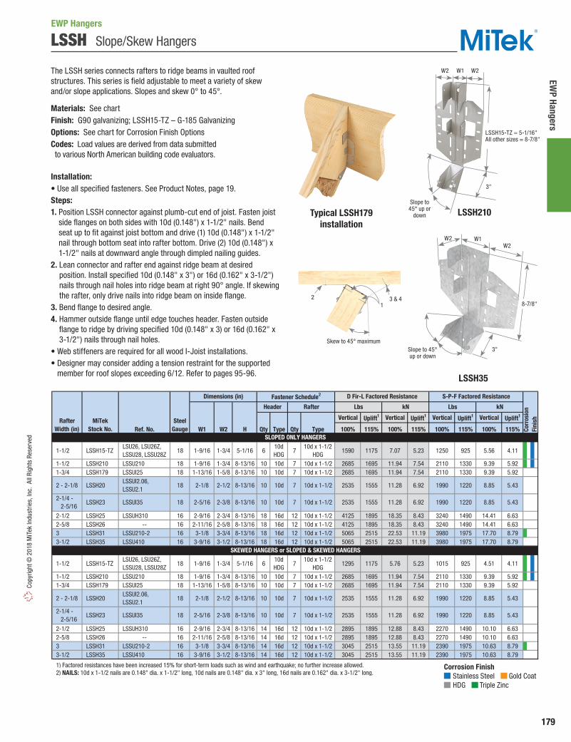
179
EWP Hangers
Copy
right
© 2
018
MiT
ek In
dust
ries,
Inc.
All
Righ
ts R
eser
ved
LSSH Slope/Skew Hangers
The LSSH series connects rafters to ridge beams in vaulted roof structures. This series is field adjustable to meet a variety of skew and/or slope applications. Slopes and skew 0° to 45°.
Materials: See chartFinish: G90 galvanizing; LSSH15-TZ – G-185 GalvanizingOptions: See chart for Corrosion Finish OptionsCodes: Load values are derived from data submitted to various North American building code evaluators.
Installation:• Use all specified fasteners. See Product Notes, page 19.Steps:1. Position LSSH connector against plumb-cut end of joist. Fasten joist
side flanges on both sides with 10d (0.148") x 1-1/2" nails. Bend seat up to fit against joist bottom and drive (1) 10d (0.148") x 1-1/2" nail through bottom seat into rafter bottom. Drive (2) 10d (0.148") x 1-1/2" nails at downward angle through dimpled nailing guides.
2. Lean connector and rafter end against ridge beam at desired position. Install specified 10d (0.148" x 3") or 16d (0.162" x 3-1/2") nails through nail holes into ridge beam at right 90° angle. If skewing the rafter, only drive nails into ridge beam on inside flange.
3. Bend flange to desired angle.4. Hammer outside flange until edge touches header. Fasten outside
flange to ridge by driving specified 10d (0.148" x 3) or 16d (0.162" x 3-1/2") nails through nail holes.
• Web stiffeners are required for all wood I-Joist installations.• Designer may consider adding a tension restraint for the supported
member for roof slopes exceeding 6/12. Refer to pages 95-96.
Vertical Uplift1 Vertical Uplift1 Vertical Uplift1 Vertical Uplift1
Ref. No. W1 W2 H Qty Type Qty Type 100% 115% 100% 115% 100% 115% 100% 115%
1-1/2 LSSH15-TZ LSU26, LSU26Z, LSSU28, LSSU28Z
18 1-9/16 1-3/4 5-1/16 610dHDG
710d x 1-1/2
HDG1590 1175 7.07 5.23 1250 925 5.56 4.11
1-1/2 LSSH210 LSSU210 18 1-9/16 1-3/4 8-13/16 10 10d 7 10d x 1-1/2 2685 1695 11.94 7.54 2110 1330 9.39 5.92 1-3/4 LSSH179 LSSUI25 18 1-13/16 1-5/8 8-13/16 10 10d 7 10d x 1-1/2 2685 1695 11.94 7.54 2110 1330 9.39 5.92
2 - 2-1/8 LSSH20 LSSUI2.06, LSSU2.1
18 2-1/8 2-1/2 8-13/16 10 10d 7 10d x 1-1/2 2535 1555 11.28 6.92 1990 1220 8.85 5.43
2-1/2 LSSH25 LSSUH310 16 2-9/16 2-3/4 8-13/16 18 16d 12 10d x 1-1/2 4125 1895 18.35 8.43 3240 1490 14.41 6.63 2-5/8 LSSH26 -- 16 2-11/16 2-5/8 8-13/16 18 16d 12 10d x 1-1/2 4125 1895 18.35 8.43 3240 1490 14.41 6.63 3 LSSH31 LSSU210-2 16 3-1/8 3-3/4 8-13/16 18 16d 12 10d x 1-1/2 5065 2515 22.53 11.19 3980 1975 17.70 8.79 3-1/2 LSSH35 LSSU410 16 3-9/16 3-1/2 8-13/16 18 16d 12 10d x 1-1/2 5065 2515 22.53 11.19 3980 1975 17.70 8.79
1-1/2 LSSH15-TZ LSU26, LSU26Z, LSSU28, LSSU28Z
18 1-9/16 1-3/4 5-1/16 610dHDG
710d x 1-1/2
HDG1295 1175 5.76 5.23 1015 925 4.51 4.11
1-1/2 LSSH210 LSSU210 18 1-9/16 1-3/4 8-13/16 10 10d 7 10d x 1-1/2 2685 1695 11.94 7.54 2110 1330 9.39 5.92 1-3/4 LSSH179 LSSUI25 18 1-13/16 1-5/8 8-13/16 10 10d 7 10d x 1-1/2 2685 1695 11.94 7.54 2110 1330 9.39 5.92
2 - 2-1/8 LSSH20 LSSUI2.06, LSSU2.1
18 2-1/8 2-1/2 8-13/16 10 10d 7 10d x 1-1/2 2535 1555 11.28 6.92 1990 1220 8.85 5.43
2-1/2 LSSH25 LSSUH310 16 2-9/16 2-3/4 8-13/16 14 16d 12 10d x 1-1/2 2895 1895 12.88 8.43 2270 1490 10.10 6.63 2-5/8 LSSH26 -- 16 2-11/16 2-5/8 8-13/16 14 16d 12 10d x 1-1/2 2895 1895 12.88 8.43 2270 1490 10.10 6.63 3 LSSH31 LSSU210-2 16 3-1/8 3-3/4 8-13/16 14 16d 12 10d x 1-1/2 3045 2515 13.55 11.19 2390 1975 10.63 8.79 3-1/2 LSSH35 LSSU410 16 3-9/16 3-1/2 8-13/16 14 16d 12 10d x 1-1/2 3045 2515 13.55 11.19 2390 1975 10.63 8.79
1) Factored resistances have been increased 15% for short-term loads such as wind and earthquake; no further increase allowed. 2) NAILS: 10d x 1-1/2 nails are 0.148" dia. x 1-1/2" long, 10d nails are 0.148" dia. x 3" long, 16d nails are 0.162" dia. x 3-1/2" long.
Corr
osio
nFi
nish
SLOPED ONLY HANGERS
SKEWED HANGERS or SLOPED & SKEWED HANGERS
MiTekStock No.
SteelGauge
Dimensions (in)
Lbs Lbs
Fastener Schedule2
Rafter Width (in)
Header Rafter kN kN
D Fir-L Factored Resistance S-P-F Factored Resistance
2-1/4 - 2-5/16
LSSH23 LSSUI35 18 2-5/16 2-3/8 8-13/16 10 10d 7 10d x 1-1/2 2535 1555 11.28 6.92 1990 1220 8.85 5.43
2-1/4 - 2-5/16
LSSH23 LSSUI35 18 2-5/16 2-3/8 8-13/16 10 10d 7 10d x 1-1/2 2535 8.85 5.431555 11.28 6.92 1990 1220
Corrosion Finish Stainless Steel Gold Coat HDG Triple Zinc
Corrosion Finish Stainless Steel Gold Coat HDG Triple Zinc
Corrosion Finish Stainless Steel Gold Coat HDG Triple Zinc
LSSH210Typical LSSH179installation
LSSH35
LSSH15-TZ = 5-1/16" All other sizes = 8-7/8"
W2
W2
W1 W2
W2
3"
3"
Slope to 45° up or
down
Slope to 45° up or down
2 3 & 41
Skew to 45° maximum
8-7/8"
EWP Hangers
W1

Glul
am B
eam
Con
nect
ors
180
Copyright © 2018 M
iTek Industries, Inc. All Rights Reserved
LGU / MGU / HGU Girder Hangers
Glulam Beam Connectors
LGU, MGU, and HGU’s are high capacity girder to girder face mount connectors. Fastening is by WS structural screws for ease of installation. Fastenings are placed high on connector to permit the connection of a deep carried member to a shallower carrying member. Very useful where tops of beams must be flush.
Materials: LGU / MGU – 10 gauge; HGU – 7 gaugeFinish: G90 galvanizing Options: See Specialty Options chart on page 181.Codes: Load values are derived from data submitted to various North American building code evaluators.
Installation:• Use all specified fasteners. See Product Notes, page 19.• WS structural screws supplied with connector. Substituting lag
screws will reduce capacity.• Beams comprised of multiple plies must be laminated to act
as a single member.• Multi-ply carrying beams may require additional connection
of laminations at connector.• Beam height dimension (H) must be specified when ordering.
Ref. No. W H1 D A Qty Type Qty Type UnitLbs 10760 6980 8655 6305kN 47.86 31.05 38.50 28.05Lbs 10760 6980 8655 6305kN 47.86 31.05 38.50 28.05Lbs 17465 8555 14055 7730kN 77.69 38.05 62.52 34.38Lbs 20240 11355 20240 11355kN 90.03 50.51 90.03 50.51Lbs 10760 6980 8655 6305kN 47.86 31.05 38.50 28.05Lbs 17465 8555 14055 7730kN 77.69 38.05 62.52 34.38Lbs 20240 11355 20240 11355kN 90.03 50.51 90.03 50.51Lbs 17465 8555 14055 7730kN 77.69 38.05 62.52 34.38Lbs 20240 11355 20240 11355kN 90.03 50.51 90.03 50.51Lbs 17465 8555 14055 7730kN 77.69 38.05 62.52 34.38Lbs 20240 11355 20240 11355kN 90.03 50.51 90.03 50.51Lbs 17465 8555 14055 7730kN 77.69 38.05 62.52 34.38Lbs 20240 11355 20240 11355kN 90.03 50.51 90.03 50.51Lbs 20240 11355 20240 11355kN 90.03 50.51 90.03 50.51Lbs 20240 11355 20240 11355kN 90.03 50.51 90.03 50.51
1) Factored resistances have been increased 15% for short-term loads such as wind and earthquake; reduce for other load durations in accordance with the code. 2) H denotes minimum hanger height. Specify height when ordering. 3) WS3 Wood Screws are 1/4" dia. x 3" long and are included in hangers.
Vertical100%
Vertical100%
Uplift1
115%Uplift1
115%
D Fir-LFactored Resistance
S-P-FFactored Resistance
3-1/2
5-1/8
MGU3.63-SDS
HGU3.63-SDS
LGU5.25-SDS
MGU5.25-SDS
HGU5.25-SDS
BeamWidth
(in)
10
10
10
7
10
SteelGauge
MiTekStock No.
Fastener Schedule3
Header Truss
Dimensions (in)
H2
(min)
LGU3.25-SDS
LGU3.63-SDS
7
8-3/4
LGU325
LGU363
MGU363
HGU363
LGU525
MGU525
HGU525
MGU550
HGU562
HGU725
3-1/8
5-1/4
5-1/2
6-3/4 MGU700 MGU7.00-SDS
HGU700 HGU7.00-SDS
MGU5.50-SDS
HGU550 HGU5.50-SDS
MGU562 MGU5.62-SDS
10
7
10
7
10
HGU7.25-SDS
HGU900 HGU9.00-SDS 38
11
11
11
11
7
7
7
7 9
7
10
7 10-3/8
10-3/8
HGU5.62-SDS
8-5/8
WS3
38 WS3 24 WS3
12 WS3
18 WS3 12 WS3
18 WS3
24 WS3
WS3
24 WS3 16 WS3
12 WS3
24 WS3 16 WS3
18 WS3
38 WS3
WS3
24 WS3
24 WS3 16 WS3
38 WS3
38 WS3
WS3
3-1/4
3-5/8
3-5/8
3-5/8
5-1/4
5-1/4
5-1/4
5-1/2
5-1/2
5-5/8
5-5/8
8
WS3 24 WS3
38 WS3 24 WS3
24
11
WS3
24
8
9-1/4
4-3/4
7-3/8 4-1/2
10-3/8 5-1/4
WS3 24
WS3 16
24
16
38
4-3/4
8-5/8
10-3/8
3-1/4
4
4
9-1/4
9-1/4
11
8
7-3/8 4-1/2 3-1/4
7-3/8 4-1/2 3-1/4
8-5/8 4-1/2
10-3/8 5-1/4
4
9-1/4 8-5/8 4-1/2 4
11
7-1/4
10-3/8
9-1/4 4-1/2 4
5-1/4 4-3/4
4-1/2
5-1/4
4-1/2
5-1/4
5-1/4
5-1/4
4-3/4
4-3/4
4-3/4
4-3/4
8-5/8
10-3/8
Continued on next page
Typical LGU, MGU, HGUinstallation
LGU, MGU, HGU
A
H
D
W
H1

Glulam Beam
Connectors
181
Copy
right
© 2
018
MiT
ek In
dust
ries,
Inc.
All
Righ
ts R
eser
ved
Floor Uplift3 Floor Uplift3 Floor Uplift3 Floor Uplift3
W H D Qty Type Qty Type 100% 115% 100% 115% 100% 115% 100% 115% 3-1/8 x 6 GHF31600 -- 12 3-3/16 5-7/8 2-3/8 10 WS25 4 WS25 3980 2340 17.70 10.41 3125 1835 13.90 8.16
3-1/8 x 7-1/2 GHF31750 -- 12 3-3/16 7-3/8 2-3/8 12 WS25 4 WS25 4770 2340 21.22 10.41 3745 1835 16.66 8.16
3-1/8 x 9 GHF31900 -- 12 3-3/16 8-7/8 2-3/8 16 WS25 5 WS25 6360 2920 28.29 12.99 4995 2295 22.22 10.21
3-1/8 x 10-1/2 GHF31105 -- 12 3-3/16 10-3/8 2-3/8 20 WS25 6 WS25 7950 3505 35.36 15.59 6240 2755 27.76 12.25
3-1/8 x 12 GHF31120 -- 12 3-3/16 11-7/8 2-3/8 22 WS25 6 WS25 8420 3505 37.45 15.59 6610 2755 29.40 12.25
3-1/8 x 13-1/2 GHF31135 -- 12 3-3/16 13-3/8 2-3/4 24 WS25 6 WS25 8420 3505 37.45 15.59 6610 2755 29.40 12.25
3-1/8 x 15 GHF31150 -- 12 3-3/16 14-7/8 2-3/4 26 WS25 7 WS25 9770 4100 43.46 18.24 7670 3220 34.12 14.32
3-1/8 x 16-1/2 GHF31165 -- 12 3-3/16 16-3/8 2-3/4 28 WS25 9 WS25 10565 5270 47.00 23.44 8295 4135 36.90 18.39
3-1/8 x 18 GHF31178 -- 12 3-3/16 17-3/4 2-3/4 30 WS25 11 WS25 11360 6435 50.53 28.62 8920 5055 39.68 22.49
3-1/4 x 9 GHF32900 -- 12 3-5/16 8-7/8 2-3/8 16 WS25 5 WS25 6360 2920 28.29 12.99 4995 2295 22.22 10.21
3-1/4 x 12 GHF32120 -- 12 3-5/16 11-7/8 2-3/8 22 WS25 6 WS25 8420 3505 37.45 15.59 6610 2755 29.40 12.25
1) Factored resistances based on seat bearing calculated at 560 psi perpendicular to grain. 2) WS25 Wood Screws are 1/4" dia. x 2-1/2" long and are included with GHF hangers. 3) Factored uplift resistances have been increased 15% for short-term loads such as wind and earthquake; reduce for other load durations in accordance with the code.
Floor Uplift3 Floor Uplift3 Floor Uplift3 Floor Uplift3
W H D Qty Type Qty Type 100% 115% 100% 115% 100% 115% 100% 115% 5-1/8 x 6 GHF51600 -- 12 5-3/16 5-7/8 2-3/8 10 WS3 4 WS3 3980 2340 17.70 10.41 3125 1835 13.90 8.16
5-1/8 x 7-1/2 GHF51750 -- 12 5-3/16 7-3/8 2-3/8 14 WS3 4 WS3 5570 2340 24.78 10.41 4370 1835 19.44 8.16
5-1/8 x 9 GHF51900 -- 12 5-3/16 8-7/8 2-3/8 18 WS3 5 WS3 7160 2920 31.85 12.99 5620 2295 25.00 10.21
5-1/8 x 10-1/2 GHF51105 -- 12 5-3/16 10-3/8 2-3/8 22 WS3 6 WS3 8750 3505 38.92 15.59 6870 2755 30.56 12.25
5-1/8 x 12 GHF51120 -- 12 5-3/16 11-7/8 2-3/8 24 WS3 6 WS3 9540 3505 42.44 15.59 7490 2755 33.32 12.25
5-1/8 x 13-1/2 GHF51135 -- 7 5-3/16 13-3/8 2-3/8 26 WS3 6 WS3 11800 4010 52.49 17.84 9260 3145 41.19 13.99
5-1/8 x 15 GHF51150 -- 7 5-3/16 14-7/8 2-3/4 28 WS3 7 WS3 12705 4675 56.51 20.80 9975 3670 44.37 16.32
5-1/8 x 16-1/2 GHF51165 -- 7 5-3/16 16-3/8 2-3/4 30 WS3 7 WS3 13615 4675 60.56 20.80 10685 3670 47.53 16.32
5-1/8 x 18 GHF51178 -- 7 5-3/16 17-3/4 2-3/4 32 WS3 8 WS3 14520 5345 64.59 23.78 11400 4195 50.71 18.66
5-1/8 x 19-1/2 GHF51192 -- 7 5-3/16 19-1/8 2-3/4 34 WS3 8 WS3 15095 5345 67.15 23.78 11850 4195 52.71 18.66
5-1/8 x 21 GHF51205 -- 7 5-3/16 20-3/8 2-3/4 36 WS3 9 WS3 15545 6010 69.15 26.73 12200 4720 54.27 21.00
5-1/8 x 24 GHF51233 -- 7 5-3/16 23-1/4 2-3/4 40 WS3 11 WS3 16450 7345 73.17 32.67 12915 5770 57.45 25.67
5-1/4 x 9 GHF52900 -- 12 5-5/16 8-7/8 2-3/8 18 WS3 5 WS3 7160 2920 31.85 12.99 5620 2295 25.00 10.21
5-1/4 x 12 GHF52120 -- 12 5-5/16 11-7/8 2-3/8 24 WS3 6 WS3 9540 3505 42.44 15.59 7490 2755 33.32 12.25
6-3/4 x 6 GHF67600 -- 12 6-7/8 5-7/8 2-3/8 12 WS3 4 WS3 4770 2340 21.22 10.41 3745 1835 16.66 8.16
6-3/4 x 7-1/2 GHF67750 -- 12 6-7/8 7-3/8 2-3/8 16 WS3 5 WS3 6360 2920 28.29 12.99 4995 2295 22.22 10.21
6-3/4 x 9 GHF67900 -- 12 6-7/8 8-7/8 2-3/8 20 WS3 6 WS3 7950 3505 35.36 15.59 6240 2755 27.76 12.25
6-3/4 x 10-1/2 GHF67105 -- 12 6-7/8 10-3/8 2-3/8 24 WS3 8 WS3 9540 4685 42.44 20.84 7490 3675 33.32 16.35
6-3/4 x 12 GHF67120 -- 7 6-7/8 11-7/8 2-3/4 28 WS3 8 WS3 12705 5345 56.51 23.78 9975 4195 44.37 18.66
6-3/4 x 13-1/2 GHF67135 -- 7 6-7/8 13-3/8 2-3/4 30 WS3 8 WS3 13615 5345 60.56 23.78 10685 4195 47.53 18.66
6-3/4 x 15 GHF67150 -- 7 6-7/8 14-7/8 2-3/4 32 WS3 10 WS3 14520 6680 64.59 29.71 11400 5245 50.71 23.33
6-3/4 x 16-1/2 GHF67165 -- 7 6-7/8 16-3/8 2-3/4 34 WS3 10 WS3 15430 6680 68.64 29.71 12110 5245 53.87 23.33
6-3/4 x 18 GHF67180 -- 7 6-7/8 17-3/4 2-3/4 36 WS3 12 WS3 16335 8015 72.66 35.65 12825 6290 57.05 27.98
6-3/4 x 19-1/2 GHF67195 -- 7 6-7/8 19-1/8 3 40 WS3 14 WS3 18150 9350 80.74 41.59 14250 7340 63.39 32.65
6-3/4 x 21 GHF67210 -- 7 6-7/8 20-3/8 3 44 WS3 18 WS3 18875 12025 83.96 53.49 14820 9440 65.92 41.99
6-3/4 x 22-1/2 GHF67225 -- 7 6-7/8 21-7/8 3 46 WS3 20 WS3 18875 13360 83.96 59.43 14820 10485 65.92 46.64
6-3/4 x 24 GHF67240 -- 7 6-7/8 23-1/4 3 48 WS3 22 WS3 18875 14695 83.96 65.37 14820 11535 65.92 51.31
1) Factored resistances based on seat bearing calculated at 560 psi perpendicular to grain. 2) WS3 Wood Screws are 1/4" dia. x 3" long and are included with GHF hangers. 3) Factored uplift resistances have been increased 15% for short-term loads such as wind and earthquake; reduce for other load durations in accordance with the code.
GlulamSize (in)
MiTekStock No.
SteelGauge
Dimensions (in) Fastener Schedule2
Ref. No.
D Fir-L Factored Resistance1 S-P-F Factored Resistance1
Header Joist Lbs kN Lbs kN
GlulamSize (in)
MiTekStock No.
SteelGauge
Dimensions (in)
Lbs
D Fir-L Factored Resistance1 S-P-F Factored Resistance1
kNJoist
Fastener Schedule2
LbsHeader kN
Ref. No.
Option MiTek Series Skewed1 Inverted Flange
1) Skewed hangers with skews greater than 15° may have all joist fasteners on outside flange. 2) One inverted-flange (IF) is available on the following sizes: LGU363, LGU525 MGU525, MGU550, MGU563, MGU700 HGU525, HGU550, HGU562, HGU700, HGU725, HGU900 3) The inverted flange option is not available on skewed LGU, MGU or HGU hangers. 4) Bevel cut rquired on skewed parts to meet table loads. 5) Skewed hangers typically require a bevel cut however, a square cut option may be available as a custom when requested.
One Inverted-Flange option available on some sizes.See footnotes 2 and 3.
100% of table value
Ordering
Add SK , angle required,right (R) or left (L) , and
square cut (SQ) or bevel cut (BV)to product number.
Ex. LGU525_H=18_SK45R_SQ
Add IF and right (R) or left (L)to product number.
Ex. LGU525_H=18_IFR
FactoredResistance
Range 1˚ to 45˚
LGUMGUHGU
LGUMGUHGU
LGU55% of table value.
30% of uplift.
MGU65% of table value.
30% of uplift.
HGU70% of table value.
30% of uplift.
Specialty Options Chart– refer to Specialty Options pages 246-247 for additional details
LGU / MGU / HGU Girder Hangers
Glulam Beam Connectors
GHF Glulam Face Mount Hangers
Materials: See chartFinish: Primer Options: See Specialty Options Chart on page 182.
Installation:• Use all specified fasteners. See Product Notes, page 19.• WS Wood Screws are supplied with GHF hangers.
Typical GHF51135installation
GHF
W D
H
2-1/8"
1) Skewed hangers with skews greater than 15° may have all joist fasteners on outside flange.
2) One inverted-flange (IF) is available on the following sizes: LGU363, LGU525 MGU525, MGU550, MGU563, MGU700 HGU525, HGU550, HGU562, HGU700, HGU725, HGU900
3) The inverted flange option is not available on skewed LGU, MGU or HGU hangers.
4) Bevel cut required on skewed parts to meet table loads.5) Skewed hangers typically require a bevel cut however, a square
cut option may be available as a custom when requested.
Continued on next page

Glul
am B
eam
Con
nect
ors
182
Copyright © 2018 M
iTek Industries, Inc. All Rights Reserved
GHF Glulam Face Mount Hangers
Glulam Beam Connectors
Floor Uplift3 Floor Uplift3 Floor Uplift3 Floor Uplift3
W H D Qty Type Qty Type 100% 115% 100% 115% 100% 115% 100% 115% 3-1/8 x 6 GHF31600 -- 12 3-3/16 5-7/8 2-3/8 10 WS25 4 WS25 3980 2340 17.70 10.41 3125 1835 13.90 8.16
3-1/8 x 7-1/2 GHF31750 -- 12 3-3/16 7-3/8 2-3/8 12 WS25 4 WS25 4770 2340 21.22 10.41 3745 1835 16.66 8.16
3-1/8 x 9 GHF31900 -- 12 3-3/16 8-7/8 2-3/8 16 WS25 5 WS25 6360 2920 28.29 12.99 4995 2295 22.22 10.21
3-1/8 x 10-1/2 GHF31105 -- 12 3-3/16 10-3/8 2-3/8 20 WS25 6 WS25 7950 3505 35.36 15.59 6240 2755 27.76 12.25
3-1/8 x 12 GHF31120 -- 12 3-3/16 11-7/8 2-3/8 22 WS25 6 WS25 8420 3505 37.45 15.59 6610 2755 29.40 12.25
3-1/8 x 13-1/2 GHF31135 -- 12 3-3/16 13-3/8 2-3/4 24 WS25 6 WS25 8420 3505 37.45 15.59 6610 2755 29.40 12.25
3-1/8 x 15 GHF31150 -- 12 3-3/16 14-7/8 2-3/4 26 WS25 7 WS25 9770 4100 43.46 18.24 7670 3220 34.12 14.32
3-1/8 x 16-1/2 GHF31165 -- 12 3-3/16 16-3/8 2-3/4 28 WS25 9 WS25 10565 5270 47.00 23.44 8295 4135 36.90 18.39
3-1/8 x 18 GHF31178 -- 12 3-3/16 17-3/4 2-3/4 30 WS25 11 WS25 11360 6435 50.53 28.62 8920 5055 39.68 22.49
3-1/4 x 9 GHF32900 -- 12 3-5/16 8-7/8 2-3/8 16 WS25 5 WS25 6360 2920 28.29 12.99 4995 2295 22.22 10.21
3-1/4 x 12 GHF32120 -- 12 3-5/16 11-7/8 2-3/8 22 WS25 6 WS25 8420 3505 37.45 15.59 6610 2755 29.40 12.25
1) Factored resistances based on seat bearing calculated at 560 psi perpendicular to grain. 2) WS25 Wood Screws are 1/4" dia. x 2-1/2" long and are included with GHF hangers. 3) Factored uplift resistances have been increased 15% for short-term loads such as wind and earthquake; reduce for other load durations in accordance with the code.
Floor Uplift3 Floor Uplift3 Floor Uplift3 Floor Uplift3
W H D Qty Type Qty Type 100% 115% 100% 115% 100% 115% 100% 115% 5-1/8 x 6 GHF51600 -- 12 5-3/16 5-7/8 2-3/8 10 WS3 4 WS3 3980 2340 17.70 10.41 3125 1835 13.90 8.16
5-1/8 x 7-1/2 GHF51750 -- 12 5-3/16 7-3/8 2-3/8 14 WS3 4 WS3 5570 2340 24.78 10.41 4370 1835 19.44 8.16
5-1/8 x 9 GHF51900 -- 12 5-3/16 8-7/8 2-3/8 18 WS3 5 WS3 7160 2920 31.85 12.99 5620 2295 25.00 10.21
5-1/8 x 10-1/2 GHF51105 -- 12 5-3/16 10-3/8 2-3/8 22 WS3 6 WS3 8750 3505 38.92 15.59 6870 2755 30.56 12.25
5-1/8 x 12 GHF51120 -- 12 5-3/16 11-7/8 2-3/8 24 WS3 6 WS3 9540 3505 42.44 15.59 7490 2755 33.32 12.25
5-1/8 x 13-1/2 GHF51135 -- 7 5-3/16 13-3/8 2-3/8 26 WS3 6 WS3 11800 4010 52.49 17.84 9260 3145 41.19 13.99
5-1/8 x 15 GHF51150 -- 7 5-3/16 14-7/8 2-3/4 28 WS3 7 WS3 12705 4675 56.51 20.80 9975 3670 44.37 16.32
5-1/8 x 16-1/2 GHF51165 -- 7 5-3/16 16-3/8 2-3/4 30 WS3 7 WS3 13615 4675 60.56 20.80 10685 3670 47.53 16.32
5-1/8 x 18 GHF51178 -- 7 5-3/16 17-3/4 2-3/4 32 WS3 8 WS3 14520 5345 64.59 23.78 11400 4195 50.71 18.66
5-1/8 x 19-1/2 GHF51192 -- 7 5-3/16 19-1/8 2-3/4 34 WS3 8 WS3 15095 5345 67.15 23.78 11850 4195 52.71 18.66
5-1/8 x 21 GHF51205 -- 7 5-3/16 20-3/8 2-3/4 36 WS3 9 WS3 15545 6010 69.15 26.73 12200 4720 54.27 21.00
5-1/8 x 24 GHF51233 -- 7 5-3/16 23-1/4 2-3/4 40 WS3 11 WS3 16450 7345 73.17 32.67 12915 5770 57.45 25.67
5-1/4 x 9 GHF52900 -- 12 5-5/16 8-7/8 2-3/8 18 WS3 5 WS3 7160 2920 31.85 12.99 5620 2295 25.00 10.21
5-1/4 x 12 GHF52120 -- 12 5-5/16 11-7/8 2-3/8 24 WS3 6 WS3 9540 3505 42.44 15.59 7490 2755 33.32 12.25
6-3/4 x 6 GHF67600 -- 12 6-7/8 5-7/8 2-3/8 12 WS3 4 WS3 4770 2340 21.22 10.41 3745 1835 16.66 8.16
6-3/4 x 7-1/2 GHF67750 -- 12 6-7/8 7-3/8 2-3/8 16 WS3 5 WS3 6360 2920 28.29 12.99 4995 2295 22.22 10.21
6-3/4 x 9 GHF67900 -- 12 6-7/8 8-7/8 2-3/8 20 WS3 6 WS3 7950 3505 35.36 15.59 6240 2755 27.76 12.25
6-3/4 x 10-1/2 GHF67105 -- 12 6-7/8 10-3/8 2-3/8 24 WS3 8 WS3 9540 4685 42.44 20.84 7490 3675 33.32 16.35
6-3/4 x 12 GHF67120 -- 7 6-7/8 11-7/8 2-3/4 28 WS3 8 WS3 12705 5345 56.51 23.78 9975 4195 44.37 18.66
6-3/4 x 13-1/2 GHF67135 -- 7 6-7/8 13-3/8 2-3/4 30 WS3 8 WS3 13615 5345 60.56 23.78 10685 4195 47.53 18.66
6-3/4 x 15 GHF67150 -- 7 6-7/8 14-7/8 2-3/4 32 WS3 10 WS3 14520 6680 64.59 29.71 11400 5245 50.71 23.33
6-3/4 x 16-1/2 GHF67165 -- 7 6-7/8 16-3/8 2-3/4 34 WS3 10 WS3 15430 6680 68.64 29.71 12110 5245 53.87 23.33
6-3/4 x 18 GHF67180 -- 7 6-7/8 17-3/4 2-3/4 36 WS3 12 WS3 16335 8015 72.66 35.65 12825 6290 57.05 27.98
6-3/4 x 19-1/2 GHF67195 -- 7 6-7/8 19-1/8 3 40 WS3 14 WS3 18150 9350 80.74 41.59 14250 7340 63.39 32.65
6-3/4 x 21 GHF67210 -- 7 6-7/8 20-3/8 3 44 WS3 18 WS3 18875 12025 83.96 53.49 14820 9440 65.92 41.99
6-3/4 x 22-1/2 GHF67225 -- 7 6-7/8 21-7/8 3 46 WS3 20 WS3 18875 13360 83.96 59.43 14820 10485 65.92 46.64
6-3/4 x 24 GHF67240 -- 7 6-7/8 23-1/4 3 48 WS3 22 WS3 18875 14695 83.96 65.37 14820 11535 65.92 51.31
1) Factored resistances based on seat bearing calculated at 560 psi perpendicular to grain. 2) WS3 Wood Screws are 1/4" dia. x 3" long and are included with GHF hangers. 3) Factored uplift resistances have been increased 15% for short-term loads such as wind and earthquake; reduce for other load durations in accordance with the code.
GlulamSize (in)
MiTekStock No.
SteelGauge
Dimensions (in) Fastener Schedule2
Ref. No.
D Fir-L Factored Resistance1 S-P-F Factored Resistance1
Header Joist Lbs kN Lbs kN
GlulamSize (in)
MiTekStock No.
SteelGauge
Dimensions (in)
Lbs
D Fir-L Factored Resistance1 S-P-F Factored Resistance1
kNJoist
Fastener Schedule2
LbsHeader kN
Ref. No.
Specialty Options Chart– refer to Specialty Options pages 246-247 for additional details
Option Skewed1,3 Sloped Seat2 Sloped / Skewed1,2 Inverted Flange
1) Skewed hangers with skews greater than 15° may have all joist nailing on outside flange. 2) Sloped or sloped / skewed hangers with slopes greater than 15° may have additional joist nails. 3) Skewed hangers typically require a bevel cut however, a square cut option may be available as a custom when requested.
Range 1˚ to 50˚ 1˚ to 45˚ See Sloped Seat and SkewedNot available in widths
less than 4-1/2"
FactoredResistance
Ordering
80% of table load75% of uplift load on skews
greater than 15˚.
100% of table load.65% of table load when
fastening into the support members end grain.
Add SK , angle required,right (R) or left (L) , and
square cut (SQ) orbevel cut (BV)
to product number.Ex. GHF31900_SK45R_BV
See Sloped Seat and Skewed.Ex.
GHF31900_SK45R_BV_SL30D
Add IF to product number.Ex. GHF51135_IF
Add SL, slope required, and up (U) or down (D),
to product number.Ex. GHF31900_SL30D
100% of table load100% of table load.
75% of uplift load on skewsgreater than 15˚.
Typical GHF51135IFinverted flange
installation

Glulam Beam
Connectors
183
Copy
right
© 2
018
MiT
ek In
dust
ries,
Inc.
All
Righ
ts R
eser
ved
Glulam Beam Connectors
KEGQ Glulam Beam Hangers
WS Wood Screw fastening, heavy steel construction, and a continuous top flange allow the KEGQ products to have high load capacities.
Materials: See chartFinish: Primer
Installation:• Use all specified fasteners.• WS3 Wood Screws, ¼" dia. x 3" long, are supplied with
KEGQ hangers.• Minimum header height (H) is 11-7/8".• Beam height dimension (H) must be specified when ordering.
Ref. No W H2 Qty Type Qty Type UnitLbs 30875 9730 24235 7640
kN 137.34 43.28 107.80 33.98
Lbs 30875 17270 24235 13555kN 137.34 76.82 107.80 60.30Lbs 30875 17270 24235 13555kN 137.34 76.82 107.80 60.30
1) Factored resistances have been increased 15% for short-term loads such as wind and earthquake; reduce for other load durations in accorandance with the code. 2) "Specify" denotes the required supported beam height that must be specified at the time of ordering, with 11" being the minimum. 3) WS3 Wood Screws are 1/4" dia. x 3" long and are included with KEGQ hangers.
28 WS3 12 WS3
28 WS3 12 WS3
5-1/2
7-1/4
specify
specify
specify
EGQ5.50-SDS3
EGQ7.25-SDS3
3
3 7
7
3 7
5-1/4
7
KEGQ362
KEGQ550
KEGQ725
12 WS33-1/2 EGQ3.62-SDS3 3-5/8 WS328
Uplift
115%1
Uplift
115%1
D Fir-LFactored Resistance
S-P-FFactored Resistance
Vertical100%
Fastener Schedule3
Header Joist
U-Strap
Vertical100%
MiTekStock No.
Joist orPurlinSize
Dimensions (in)Steel Ga.
TopFlange
Typical KEGQ550installation
KEGQ550
KEG / KLEG / KMEG Bolted Glulam Beam Hangers
Bolt-only fastening, heavy steel construction, and a continuous top flange allow the KLEG, KMEG, and KEG products to have high load capacities.
KLEG – (4) bolt light-duty hanger.
KMEG – (6) bolt medium-duty hanger.
KEG – (8) bolt heavy-duty hanger.
Materials: See chartFinish: PrimerOptions: See Specialty Options Chart.Codes: Load values are derived from data submitted to various North American building code evaluators.
Installation:• Use all specified fasteners. See Product Notes, page 19.• Bolts are not supplied unless ordered separately. Bolts
provided by other suppliers must meet or exceed ASTM A 307 Grade A, or ASME SAE Grade 2.
• Minimum header height is 10" for the KLEG; 13" for the KMEG; 20" for the KEG.
• Beam height dimension (H) must be specified when ordering.
Typical KLEG5 installation
KLEG3 KEG5 KLEG without top flange
KMEG5
H4"
4"
4"
4"
4"
4"
DW
17-1/2"
LTF
D3"
3"
TF L
H8-1/4"
4"
3"
W
H
4"
3"
3"
DW
LTF
3"
11-1/4"
3"
W
18"
11-3/4"
6"
H
Continued on next page

Glul
am B
eam
Con
nect
ors
184
Copyright © 2018 M
iTek Industries, Inc. All Rights Reserved
KEG / KLEG / KMEG Bolted Glulam Beam Hangers
Ref. No. W H3 D TF L Qty Qty UnitLbs 15060 5125 4040 12950 4410 3475kN 66.99 22.80 17.97 57.60 19.62 15.46Lbs 15060 5125 5125 12950 4410 5085kN 66.99 22.80 22.80 57.60 19.62 22.62Lbs 17555 7620 5915 15095 6555 5085kN 78.09 33.90 26.31 67.15 29.16 22.62Lbs 23125 13190 7625 19890 11345 6560kN 102.87 58.67 33.92 88.48 50.47 29.18Lbs 15060 5125 5125 12950 4410 5085kN 66.99 22.80 22.80 57.60 19.62 22.62Lbs 17555 7620 5910 15095 6555 5085kN 78.09 33.90 26.29 67.15 29.16 22.62Lbs 24410 13235 9595 20995 11380 8250kN 108.58 58.87 42.68 93.39 50.62 36.70Lbs 26100 13270 9580 22445 11410 8240kN 116.10 59.03 42.61 99.84 50.75 36.65Lbs 27785 13300 9570 23895 11440 8230kN 123.59 59.16 42.57 106.29 50.89 36.61
1) Factored resistances are for a supporting member with a width of 5-1/2", and 560 psi perpendicular to grain loading in single shear. 2) Factored uplift resistances have been increased 15% for short-term loads such as wind and earthquake; reduce for other load durations in accordance with the code. 3) "Specify" denotes the required supported beam height that must be specified at the time of ordering.
Vertical100%
Uplift
115%2Vertical100%
D Fir-L Factored Resistance1 S-P-F Factored Resistance1
Vertical100%
Vertical100%
Uplift
115%2MiTek
Stock No.Top
Flange
Dimensions (in)Steel Gauge
Joist
BoltDia.
BoltDia.
With Top Flange
Fastener Schedule
Header With Top Flange
WithoutTop Flange
WithoutTop Flange
6
specify
specify
6
6
specify
122-1/2
BeamWidth
(in)
5-1/4
6-7/8 13-1/2
15-1/2
2-1/2
2-1/2
2-1/2
6
6
6
7
specify 6 12
specify
1
1
2
2
2
8
8
8
2
8-7/8
10-7/8
1
1
2
2
2
3/4
3/4
3/4
3/4
3/4
3/4
3/4
3/4
3/4
3/4
1
1
2
2
8
1
1
1/4 7
LEG7
KEG9
KEG11
4 LEG3 7 7 2-1/23-1/4
specify
specify
specify
EG5
4
4
2-1/2
2-1/2 17-1/2
12
12
12
12
3-1/8
5-1/8
6-3/4
8-3/4
10-3/4
LEG5
7 7
7
7 7
7 7
1/4 7
1/4
EG7
EG9
--
7
MEG5
MEG7
KEG7
1/4
KLEG3
KLEG5
KMEG5
KEG5
KLEG7
KMEG7
U-Strap
2-1/2
2-1/25-1/4
6-7/8
6
6
6
6
specify7
5-1/4
6-7/8
Option Skewed3,4 Sloped Seat Top Flange Offset1,2
1) Top flange offset hangers may not be skewed. 2) Top flange offset option is not available for KEG models. 3) Carried member must have square cut end on skewed option. Refer to Typical PHXU hanger, skewed, left shown, square cut illustration on page 248.
Range --
KLEG – 14,400 lbs. Max.KMEG – 14,400 lbs. Max.KEG – 20,520 lbs. Max.
KLEG – 13,920 lbs. Max.KMEG – 13,,920 lbs. Max.KEG – 13,920 lbs. Max.
1˚ to 45˚ 1˚ to 45˚
KMEG - 8,160 lbs. Max.KMEG - 11" min. height.
KLEG - 8,160 lbs. Max.KLEG - 9" min. height.
Add SK , angle required,right (R) or left (L) , and
square cut (SQ) to product number.Ex. KLEG3_H=112_SK45R_SQ
Add SL, slope required,and up (U) or down (D),
to product number.Ex. KLEG3_H=112_SL30D
Add OS, andright (R) or left (L),to product number.
Ex. KLEG3_H=112_OSL
FactoredResistance
Ordering
Specialty Options Chart– refer to Specialty Options pages 246, 248-249 for additional details
Glulam Beam Connectors

Glulam Beam
Connectors
185
Copy
right
© 2
018
MiT
ek In
dust
ries,
Inc.
All
Righ
ts R
eser
ved
KGB / KHGB / KHHB Glulam Top Mount Hangers
These hangers cover medium-to-heavy glulam beam and purlin applications.
KHHB – Medium capacity hanger.
KGB – Medium-to-heavy capacity hanger.
KHGB – Heavy capacity hanger.
Materials: 7 gaugeFinish: PrimerCodes: Load values are derived from data submitted to various North American building code evaluators.
Installation:• Use all specified fasteners. See Product Notes, page 19.• WS3 Wood Screws are supplied with hangers.• Beam height dimension (H) must be specified when ordering.• Minimum height (H) is 7-1/2".• See Welded Installation chart on page 250.
Top Face
Ref. No. W H3 D Qty Qty Qty UnitLbs 9545 3005 7495 2360kN 42.46 13.37 33.34 10.50Lbs 10165 3005 7980 2360kN 45.22 13.37 35.50 10.50Lbs 9545 3005 7495 2360kN 42.46 13.37 33.34 10.50Lbs 10165 3005 7980 2360kN 45.22 13.37 35.50 10.50Lbs 10165 3005 7980 2360kN 45.22 13.37 35.50 10.50Lbs 9545 3005 7495 2360kN 42.46 13.37 33.34 10.50Lbs 10165 3005 7980 2360kN 45.22 13.37 35.50 10.50Lbs 10165 3005 7980 2360kN 45.22 13.37 35.50 10.50
1) Factored resistances are based on 560 psi perpendicular to grain loading. 2) Factored uplift resistances have been increased 15% for short-term loads such as wind and earthquake; reduce for other load durations in accordance with the code. 3) "Specify" denotes the required supported beam height must be specified at the time of ordering. 4) Supporting header shall be no less than 3" thick. 5) WS3 Wood Screws are 1/4" dia. x 3" long and are included with hangers.
KHGB7
Dimensions (in)3
MiTekStock No.
SteelGauge
3
3-1/2
4
specify
specify
specify
33-1/4
3-1/4
5-1/4
5-1/4
5-1/4
6-7/8
6-7/8
6-7/8
3-1/2
3
4 10 WS3 6 WS3
4 10 WS3 6 WS3
4 6 WS3 6 WS3
4 6 WS3 6 WS3
4 12 WS3 6 WS3
4 12 WS3 6 WS3
4 10 WS3 6 WS3
Vertical100%
Uplift2
115%Vertical100%
Uplift2
115%WoodScrew
WoodScrew
S-P-F
Factored Resistance1
6 WS3 6 WS3
Header4 Joist
Fastener Schedule5 D Fir-L
Factored Resistance1
4
6-3/4
HHB7
GB7
HGB7
7
7
7
7
7
7
7
7
HHB3
GB3
HHB5
GB5
HGB5
KHHB3
KGB3
KHHB5
KGB5
KHGB5
KHHB7
KGB7
3-1/2
4
specify
specify
specify
specify
specify
BeamWidth
(in)
3-1/8
5-1/8
KHGB
Glulam Beam Connectors
Typical KHHB installation
KHHB
KGB
H
D
D
D
W
W
W
2-1/2"
2-1/2"
2-1/2"
H
H

Glul
am B
eam
Con
nect
ors
186
Copyright © 2018 M
iTek Industries, Inc. All Rights Reserved
Typical KGLT5 installation
These heavy beam hangers are designed for use with glulam and timber beams. The continuous top mount flange offers high load capacity with minimal fastening.
KGLT – Medium capacity hanger.
KHGLT – Heavy capacity hanger.
Materials: Top Flange – 3 gauge; U-Strap – 7 gaugeFinish: PrimerOptions: See Specialty Options Chart on page 187.Codes: Load values are derived from data submitted to various North American building code evaluators.
Installation:• Use all specified fasteners. See Product Notes, page 19.• Beam height dimension (H) must be specified when ordering.• See Welded Installation chart on page 250.
Ref. No. W H3 L Qty Unit 100% 100%Lbs 15325 4575 12030 3590kN 68.17 20.35 53.51 15.97Lbs 19455 3875 15275 3040kN 86.54 17.24 67.95 13.52Lbs 15325 4575 12030 3590kN 68.17 20.35 53.51 15.97Lbs 19455 3875 15275 3040kN 86.54 17.24 67.95 13.52Lbs 15325 4575 12030 3590kN 68.17 20.35 53.51 15.97Lbs 19455 3875 15275 3040kN 86.54 17.24 67.95 13.52Lbs 15325 4575 12030 3590kN 68.17 20.35 53.51 15.97Lbs 19455 3875 15275 3040kN 86.54 17.24 67.95 13.52Lbs 19455 3875 15275 3040kN 86.54 17.24 67.95 13.52Lbs 15325 4575 12030 3590kN 68.17 20.35 53.51 15.97Lbs 19455 3875 15275 3040kN 86.54 17.24 67.95 13.52Lbs 15325 4575 12030 3590kN 68.17 20.35 53.51 15.97Lbs 19455 3875 15275 3040kN 86.54 17.24 67.95 13.52Lbs 19455 3875 15275 3040kN 86.54 17.24 67.95 13.52
1) Factored uplift resistances have been increased 15% for short-term loads such as wind and earthquake; reduce for other load durations in accordance with the code. 2) KGLT and KHGLT load values based on 625 psi perpendicular to grain loading. 3) "Specify" denotes the required supported beam height that must be specified at time of ordering, with 7-1/2" being the minimum. 4) WS3 Wood Screws are 1/4" dia. x 3" long and are included with the hangers. 5) No further increase for duration of load allowed.
specify
specify
specify
3-1/8
3-1/2
5-1/8
5-1/2
6-3/4
8-3/4
specify
specify
specify
specify
specify
specify
specify
specify
specify
specify
HGLTV5.37
KGLT7 GLT7, GLTV7.12
--
GLT3
12 WS3 6 WS3
14 6 12 WS3 6 WS3
16 6
WS3
14 4 6 WS3 8 WS3
12 6 12 WS3 6
WS3
12 4 6 WS3 8 WS3
12 6 12 WS3 6
WS3
12 6 12 WS3 6 WS3
12 4 6 WS3 8
6 WS3
10 4 6 WS3 8
WS3
12 6 12 WS3 6 WS3
10 4 6 WS3 8
3-5/8
5-1/4
5-1/4
5-5/8
5-5/8
5-3/8
8 WS3
12 6 12 WS3 6 WS3
specify 10 4 6 WS3
WS3
12 6 12 WS3
6-7/8
6-7/8
8-7/8
8-7/8
10-7/8
HGLT7, HGLTV7.12
GLT5, GLTV5
10-3/4
KGLT3
KHGLT3
KGLT5
KHGLT6
KHGLT7
KHGLT11
5-5/16
KGLT9 --
KHGLT9 HGLT9, HGLTV9
HGLT6, HGLTV6
KHGLT537
3-1/4
3-1/4
3-5/8
KHGLT5 HGLT5, HGLTV5
KGLT6 GLT6, GLTV6
HGLT3
KGLT4 GLT4, GLTV4
KHGLT4 HGLT4, HGLTV4
D Fir-L
Factored Resistance2,5
Uplift1
115%
S-P-F
Factored Resistance2,5
BeamWidth
MiTekStock No.
Dimensions (in)
Header Joist
Fastener Schedule4
fcp = 625 psi
fcp = 625 psi
WoodScrew
WoodScrew
Uplift1
115%TopQty
FaceQty
KGLT / KHGLT Glulam Beam Hangers
KGLT
KHGLT
L
L
H
H
5"
6"
W
W
3-1/2"
2-1/2"
2-1/2"
6-3/4"
Glulam Beam Connectors
Continued on next page
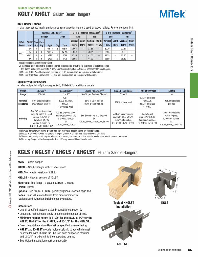
Glulam Beam
Connectors
187
Copy
right
© 2
018
MiT
ek In
dust
ries,
Inc.
All
Righ
ts R
eser
ved
KGLT / KHGLT Glulam Beam Hangers
Option Skewed1,3 Sloped Seat2,3 Sloped / Skewed1,2,3 Sloped Top Flange4 Top Flange Offset Saddle
Range 1˚ to 50˚ 1˚ to 45˚ See Sloped Seat and Skewed 0˚ to 45˚ -- --
1) Skewed hangers with skews greater than 15° may have all joist nailing on outside flange. 2) Sloped or sloped / skewed hangers with slopes greater than 15° may have additional joist nails. 3) Skewed hangers typically require a bevel cut however, a square cut option may be available as a custom when requested. 4) Sloped top flanges with slopes greater than 15° may have additional header nails.
FactoredResistance
Ordering
50% of uplift load onskew greater than 15˚
Add SK , angle required,right (R) or left (L) , and
square cut (SQ) or bevel cut (BV) to
product number. Ex. KGLT3_H=16_SK45R_BV
Add SA,and saddlewidth required
to product number.Ex.
KGLT3_H=16_SA=5-1/2"
KGLT – 5,920 lbs. Max.
KHGLT – 10,080 lbs. Max.
Add SL, slope required,and up (U) or down (D),
to product number.Ex.
KGLT3_H=16_SL30D
See Sloped Seat and Skewed.Ex.
KGLT3_H=16_SK45R_BV_SL30D
Add SF, angle requiredand right (R) or left (L),
to product number.Ex. KGLT3_H=16_SF30L
Add OS, andright (R) or left (L),to product number.
Ex. KGLT3_H=16_OSL
50% of uplift load onskew greater than 15˚
100% of table load
60% of table loadfor KGLT.
45% of table loadfor KHGLT.
100% of table loadper side
Specialty Options Chart– refer to Specialty Options pages 246, 248-249 for additional details
KGLS / KGLST / KHGLS / KHGLST Glulam Saddle Hangers
KGLS – Saddle hanger.
KGLST – Saddle hanger with seismic straps.
KHGLS – Heavier version of KGLS.
KHGLST – Heavier version of KGLST.
Materials: Top flange - 3 gauge; Stirrup - 7 gaugeFinish: PrimerOptions: See KGLS / KHGLS Specialty Options Chart on page 188.Codes: Load values are derived from data submitted to various North American building code evaluators.
Installation:• Use all specified fasteners. See Product Notes, page 19. • Loads and nail schedule apply to each saddle hanger stirrup.• Minimum header height is 8-1⁄2" for the KGLS; 8-1⁄2" for the
KGLST; 10-1⁄2" for the KHGLS, and 10-1⁄2" for the KHGLST. • Beam height dimension (H) must be specified when ordering.• KGLST and KHGLST models include seismic straps which must
be installed with (3) 3⁄4" thru-bolts in each supported member and (2) 3⁄4" thru-bolts into the supporting beams.
• See Welded Installation chart on page 250.KHGLST
KGLSTypical KHGLSTinstallation
Glulam Beam Connectors
SA L
DW
H
Vertical Uplift Vertical Uplift Vertical Uplift Vertical Uplift
Type Qty Type 100% 115% 100% 115% 100% 115% 100% 115%
2x 4 -- WS15 8 WS15 7565 -- 33.65 -- 6220 -- 27.67 --3x 4 2 WS15 8 WS15 10905 -- 48.51 -- 8595 -- 38.23 --
(2) 2x 4 4 WS3 8 WS3 9335 -- 41.52 -- 7935 -- 35.30 --4X 4 6 WS3 8 WS3 9895 -- 44.02 -- 8580 -- 38.17 --
1) Listed loads shall not be increased. 2) The nailer must be sized to fit the supported width and be of sufficient thickness to satisfy specified top flange nailing requirements. A design professional must specify nailer attachment to steel beams. 3) MiTek's WS15 Wood Screws are 1/4" dia. x 1-1/2" long and are not included with hangers. 4) MiTek's WS3 Wood Screws are 1/4" dia. x 3" long and are not included with hangers.
kN
KGLT
Fastener Schedule3,4 D Fir-L Factored Resistance1 S-P-F Factored Resistance1
MiTekSeries
Nailer
Size2
Header Joist Lbs kN Lbs
TopQty
FaceQty
KGLT Nailer Options – chart represents maximum factored resistance for hangers used on wood nailers. Reference page 148.
Continued on next page

Glul
am B
eam
Con
nect
ors
188
Copyright © 2018 M
iTek Industries, Inc. All Rights Reserved
Ref. No. W H7 D L SA Type Dia. UnitLbs 15570 3755 12225 2945kN 69.26 16.70 54.38 13.10Lbs 19265 3755 15125 2945kN 85.69 16.70 67.28 13.10Lbs 15570 3755 12225 2945kN 69.26 16.70 54.38 13.10Lbs 19265 3755 15125 2945kN 85.69 16.70 67.28 13.10Lbs 15570 3755 12225 2945kN 69.26 16.70 54.38 13.10Lbs 19265 3755 15125 2945kN 85.69 16.70 67.28 13.10Lbs 22020 3755 17290 2945kN 97.95 16.70 76.91 13.10Lbs 28075 3755 22040 2945kN 124.88 16.70 98.04 13.10Lbs 23450 3755 18410 2945kN 104.31 16.70 81.89 13.10Lbs 29505 3755 23165 2945kN 131.24 16.70 103.04 13.10Lbs 30595 5005 24020 3930kN 136.09 22.26 106.85 17.48Lbs 28575 5005 22435 3930kN 127.11 22.26 99.80 17.48Lbs 29850 3755 23435 2945kN 132.78 16.70 104.24 13.10Lbs 35755 3755 28070 2945kN 159.05 16.70 124.86 13.10Lbs 29850 3755 23435 2945kN 132.78 16.70 104.24 13.10Lbs 37825 3755 29695 2945kN 168.25 16.70 132.09 13.10Lbs 32630 5005 25615 3930kN 145.15 22.26 113.94 17.48Lbs 36565 5005 28705 3930kN 162.65 22.26 127.69 17.48Lbs 32630 5005 25615 3930kN 145.15 22.26 113.94 17.48Lbs 40505 5005 31800 3930kN 180.18 22.26 141.45 17.48
1) Factored uplift resistances have been increased 15% for short-term loads such as wind and earthquake; reduce for other load durations in accordance with the code. 2) Factored resistances and fastener schedules apply to each side of the saddled hanger. 3) Minimum header height is 8-1/2" for the KGLS and KGLST; 10-1/2" for the KHGLS and KHGLST. 4) Hangers with seismic straps may require a minimum joist depth. Consult MiTek for additional information. 5) WS3 Wood Screws are 1/4" dia. x 3" long and are included with hangers. 6) The bearing loads are based on 560 psi. 7) "Specify" denotes the required supported beam height that must be specified at time of ordering.
HeaderQty
JoistQty
HeaderQty
JoistQty
6-1/2
6-1/2
6-1/2
6
Vertical100%
16
6-1/2
5
6-1/2
5
6-1/2
5
6-1/2
5
6-1/2
6-1/2
6
5
6
5
6-1/2
12
12
12
14
12
specify
specify
specify
10
6
10
6
10
9
12
9
12
12
12
12
12
6-7/8
6-7/8
8-7/8
8-7/8
specify
8-7/8
8-7/8
5 6 5-1/4
5-1/4
6-7/8
6-7/8
8-7/8
8-7/8
5-1/4
5-1/4
6-7/8
6-7/8
specify
specify
6-7/8
6-7/8
6-7/8
6-7/8
6-7/8 specify
specify
specify
5-1/4
5-1/4
6-7/8 specify
specify
specify
specify
specify
3-1/4
3-1/4
3-1/4
3-1/4
3-1/4
3-1/4
5-1/4
5-1/4
5-1/45-1/8
6-3/4
8-3/4
specify
specify
specify
specify
specify
specify
specify
specify
specify
specify
specify
specify
--
HGLS7
--
HGLS9
--
HGLS5
--
GLS7-7
5-1/4
--
GLS7-9
--
GLS5-5
--
GLS5-7
--
GLS3-5
--
GLS3-7
--
GLS3-9
KGLST79
KHGLS7
KHGLST7
KHGLS9
KHGLST9
KHGLS5
KHGLST5
KGLS77
KGLST77
KGLS79
-- --
14 8 WS3 2 3 3/4
14 8 WS3 --
-- --
14 8 WS3 2 3 3/4
14 8 WS3 --
-- --
6 6 WS3 2 3 3/4
6 6 WS3 --
-- --
6 6 WS3 2 3 3/4
6 6 WS3 --
-- --
14 8 WS3 2 3 3/4
14 8 WS3 --
-- --
6 6 WS3 2 3 3/4
6 6 WS3 --
-- --
6 6 WS3 2 3 3/4
6 6 WS3 --
6 6 WS3 2 3 3/4
6 6 WS3 --
3-1/8
Uplift1
115%
D Fir-L
Factored Resistance2,6
S-P-F
Factored Resistance2,6
KGLS55
KGLST55
Fastener Schedule
--6 6 WS3
6 6
-- --
SupportedGlulam
Beam Size(in)
Dimensions (in)3
MiTekStock No.
KGLS35
KGLST35
KGLS37
6 6 WS3
KGLS57
KGLST57
Bolts
Uplift1
115%Vertical100%
WS3 2 3 3/4
Wood Screws2,5
-- --
KGLST37
KGLS39
KGLST39
2 3 3/4
6 6 WS3 --
-- --
KGLS / KGLST / KHGLS / KHGLST Glulam Saddle Hangers
Option Skewed1,3 Sloped Seat2 Sloped / Skewed1,2 Sloped Top Flange4 Top Flange Offset Saddle
Range 1˚ to 50˚ 1˚ to 45˚ See Sloped Seat and Skewed 0° to 30° May not be skewed 5" minimum saddle
1) Skewed hangers with skews greater than 15° may have all joist nailing on outside flange. ` 2) Sloped or sloped / skewed hangers with slopes greater than 15° may have additional joist nails. 3) Skewed hangers typically require a bevel cut however, a square cut option may be available as a custom when requested. 4) Sloped top flanges with greater than 15° may have additional header nails.
50% of table loadfor KGLS.
45% of table loadfor KHGLS.
Add SL, slope required,and up (U) or down (D),
to product number.Example:
KGLS35H115_SL30D
Add SF, angle required,and right (R) or left (L),
to product number.Example:
KGLS35H115_SF30L
See Sloped Seat and Skewed.Example:
KGLS35H115_SK45R_BV_SL30D
100% of table loadper side
Add OS, andright (R) or left (L),to product number.
Example:KGLS35H115_OSL
Add SA, andsaddle width requiredto product number.
Example:KGLS35H115_SA=5-1/2"
KGLS - 7,920 lbs. Max.KHGLS - may not
be sloped / skewed.100% of table load
FactoredResistance
Ordering
KGLS – 6,500 lbs. Max.KHGLS – 7,980 lbs. Max.
50% of uplift load on skews greater than 15°.
Add SK , angle required,right (R) or left (L) , and
square cut (SQ) or bevel cut (BV)
to product number.Ex. KGLS35H115_SK45R_BV
KGLS – 9,360 lbs. Max.
KHGLS – 13,200 lbs. Max.
KGLS / KHGLS Specialty Options Chart – refer to Specialty Options pages 246, 248-249 for additional details
Glulam Beam Connectors

189
Truss & Rafter
Copy
right
© 2
018
MiT
ek In
dust
ries,
Inc.
All
Righ
ts R
eser
ved
NOP Moisture Barrier Plates
Truss & Rafter
Moisture Barrier Plates protect the bottom chords of trusses from moisture damage caused by direct contact with concrete. These plates eliminate the need for more expensive treated wood plates.
Materials: See chartFinish: G90 galvanizing
Installation:• Use all specified fasteners. See Product Notes, page 19.• Pre-attach to truss bottom chord or rafter using pre-punched prongs
and/or 6d common nails to prevent wood-to-concrete contact.
Size Ref. No. W L Qty Type NOP2X TSS2, TBP8 26 1-7/16 8 -- -- NOP1 -- 22 1-1/2 8 2 6d
4x NOP4 TSS2-2 26 3-1/2 8 2 6d
1) NAILS: 6d nails are 0.120" dia. x 2" long.
MiTekStock No.
SteelGauge
Dimensions (in) Fastener Schedule1
2x
LPTA Embedded Truss Anchors
Low profile design attaches to 2x4 or larger bottom chords and provides uplift and lateral load resistance.
Materials: 18 gaugeFinish: G90 galvanizingCodes: Load values are derived from data submitted to various North American building code evaluators.
Installation:• Use all specified fasteners. See Product Notes, page 19.• Embed LPTA 4" into concrete tie beam or masonry bond beam.• Anchors should be spaced no closer than 8" center-to-center.• Moisture barrier may be required.
Ref. No. W H Type3 UnitLbs 1555 1005 1865 1555 1005 1865kN 6.92 4.47 8.30 6.92 4.47 8.30
1) Factored resistances have been increased 15% for short-term loads such as wind and earthquake; reduce for other load durations in accordance with the code. 2) Minimum quantity of fasteners to be installed. Product may have additional nail holes not needed to meet published factored resistance of product. 3) NAILS: 10d x 1-1/2 nails are 0.148" dia. x 1-1/2" long.
Uplift115%
F1115%
F2115%
Min
Qty2
Fastener Schedule
D Fir-L
Factored Resistance1
S-P-F
Factored Resistance1
Uplift115%
F1115%
F2115%
MiTekStock No.
10d x 1-1/21018 5 8-1/4 LTA2 LPTA
SteelGauge
Dimensions(in)
LPTATypical LPTA perpendicular
installation
Typical LPTA parallel installation
Uplift
F1
F2
NOP2X
NOP1
NOP4
Typical NOP4 installation
L
L
LW
W
W
1-7/16"1-3/4"
H
W
4"
Uplift
F1F1
F2

190
Trus
s &
Raf
ter
Copyright © 2018 M
iTek Industries, Inc. All Rights Reserved
The HLPTA75 is designed and tested to provide higher lateral capacity and net uplift. Offers greater pullout resistance and is compatible with bond beam reinforcing.
Materials: 18 gaugeFinish: G90 galvanizing
Installation:• Use all specified fasteners. See Product Notes, page 19.• Embed in concrete tie beam or masonry bond beam until
the seat is resting on the surface.• Minimum of one #7 rebar or two #5 rebars through the
theoretical shear cone is required.• Grout or concrete compressive strength shall be 2,500 psi
at 28 days.• Minimum spacing between anchors is 10" to achieve
full design load capacities on single anchors.• When used in a double rebar installation, concrete tie
beam stirrup should be sized to accommodate connector leg placement.
• Designer shall verify connector clearance when using in conjunction with stirrups and two rebar applications.
• Verify grout is not in contact with truss member. Moisture barrier may be required.
HLPTA Embedded Truss Anchor
Truss & Rafter
Qty Qty TypeSingle Anchor 2 20 10d x 1-1/2 3105 2590 2500 13.81 11.52 11.12 2660 2220 2145 11.83 9.88 9.54Double Anchor -- 40 10d x 1-1/2 5085 2995 3045 22.62 13.32 13.54 4355 2565 2610 19.37 11.41 11.61
1) Short-term load duration has been taken into consideration; no further increase is allowed. 2) NAILS: 10d x 1-1/2 nails are 0.148" dia. x 1-1/2" long.
Fastener Schedule2
Lbs kNkN LbsD Fir-L Factored Resistance1 S-P-F Factored Resistance1
SeatPlate
Truss/Rafter Uplift
115%F1
115%F2
115%Uplift115%
F1115%
F1115%
F2115%
InstallationType
HLPTA75
MiTekStock No. Ga.
-- 18
Ref. No.
F2115%
Uplift115%
F1115%
F2115%
Uplift115%
Typical HLPTA75 single rebar installation
Typical HLPTA75single anchor installation
HLPTA75
Typical HLPTA75 double rebar installation
Typical HLPTA75double anchor installation
Truss member Truss
member
Masonry wall
Tie beam reinforcing
Concrete tie wall
4-15/16"
9-9/16"
5-1/8"1-9/16"
13/16"
13/16"1-3/16"
F1
F1
F2F2
Uplift
F1
F1
F2F2
Uplift

191
Truss & Rafter
Copy
right
© 2
018
MiT
ek In
dust
ries,
Inc.
All
Righ
ts R
eser
ved
Truss & Rafter
The RFUS is a multi-purpose engineered solution for attaching trusses to concrete or masonry walls. Screw anchor fastening eliminates mislocated cast-in-place anchor bolts and allows retrofit installations.
Materials: 10 gaugeFinish: PrimerCodes: Load values are derived from data submitted to various North American building code evaluators. Installation:• Always install in pairs.• Use all specified fasteners. See Product Notes, page 19.• Designer shall be responsible for design of masonry structure,
including any required reinforcement.• For 1-ply applications, add filler block. Refer to page 221
for wood filler block installation.• Moisture barrier may be required.
Ref. No. Qty Qty Lbs kN Lbs kN
RFUS FGTR 10 > 2 Ply 12 WS3 4 3/4" x 6" 7100 31.58 5965 26.53
1) 15% increase for short-term loads has been considered for the factored uplift resistance, no further increased allowed. 2) Use DeWalt 3/4" x 6" Screw-Bolt+; or equal, installed in accordance with manufacturer's specifications. 3) DeWalt 3/4" x 6" Screw-Bolt+ are not supplied with RFUS ties. See page 31 for anchor information. 4) Fasteners shall be installed to fully grouted and reinforced concrete masonry or reinforced concrete (f'c = 2,500 psi at 28 days). 5) Fastener shedule is for two straps used together. The straps shall be installed in pairs. 6) Truss plies shall be fastened together to act as a unit. 7) WS3 Wood Screws are 1/4" dia. x 3" long and are supplied with RFUS connector.
D Fir-LFactored Resistance
S-P-FFactored Resistance
Uplift 115%1 Uplift 115%1
MiTekStock No.
No. of
Plies6Steel
Gauge
Fastener Schedule5
Rafter/Truss Concrete/Masonry4
Screw
Anchor2,3
WS
Screws7
Typical RFUS installation
RFUS
30-1/2"
4"
5-1/2"
5"
Uplift
RFUS Uplift Girder Ties
Truss & Rafter

192
Trus
s &
Raf
ter
Copyright © 2018 M
iTek Industries, Inc. All Rights Reserved
Ref. No. Qty Type5 Qty Screw Anchor3 UnitLbs 3415 1795 765 2685 1410 600kN 15.19 7.98 3.40 11.94 6.27 2.67Lbs 5260 -- -- 4220 -- --kN 23.40 -- -- 18.77 -- --Lbs 5260 -- -- 4275 -- --kN 23.40 -- -- 19.02 -- --
1) Factored resistances have been increased 15% for short-term loads such as wind and earthquake; reduce for other load durations in accordance with the code. 2) Factored resistances apply where roof pitch is between 3:12 and 8:12. 3) 1/4" x 3" or 3/8" x 5" screw anchor denotes DeWalt Screw-Bolt+; or equal, installed in accordance with manufacturer's specification. Screw Anchors must be ordered seperately. 4) Fasteners must be installed in fully grouted and reinforced concrete masonry (f'm = 1,500 psi) or reinforced concrete (f'c = 2,500 psi). 5) NAILS: 10d nails are 0.148" dia. x 3" long, WS25 Wood Screws are 1/4" dia. x 2-1/2" long (supplied with LUGT3) and WS3 Wood Screws are 1/4" dia. x 3" long (supplied with LUGT4).
3
4
4 3/8" x 5"
LUGT4 LGT4-SDS3 12 16 WS3 4 3/8" x 5"
LUGT3 LGT3-SDS2.5 12 12 WS25
5 1/4" x 3"2
Uplift115%1,2
F1115%1,2
MiTekStock No.
SteelGauge
LUGT2 LGT2 14 16 10d
CMU/ConcreteWall4
Rafter/Truss
Fastener Schedule
No.of
PliesF2
115%1,2
D Fir-LFactored Resistance
S-P-FFactored Resistance
Uplift115%1,2
F1115%1,2
F2115%1,2
LUGT Girder Tiedowns
The LUGT series is an extremely adaptable tiedown for girder trusses and offers several installation options to accommodate different framing conditions. It is an ideal retrofit solution to reinforce truss connections to transfer high wind loads to supporting walls and can be used on either, concrete or CMU block walls. Sizes available for 2-ply, 3-ply and 4-ply trusses.
Materials: See chartFinish: G90 galvanizingCodes: Factored resistances are derived from data submitted to various North American building code evaluators and are in accordance with CSA 086-14. Installation:• Use all specified fasteners. See Product Notes, page 19.• All fastener holes must be filled with specified fasteners
to achieve loads listed in the chart. Smaller fasteners holes are for girder-to-stud applications (reference page 196) and do not need to be filled when used for concrete/masonry installations.
• WS Wood Screws included with LUGT3 and LUGT4.• For concrete and masonry applications,
a moisture barrier may be required, check local building code.
LUGT2Typical LUGT2masonry installation
Typical LUGT4 masonry installation (LUGT3 similar)
12-7/8"
6-3/4"
3-1/4"
3"
LUGT3
15-15/16"
11-1/8"
5"
4-3/4"
LUGT4
16-1/8"
12-7/8"
6-9/16"
6-1/4"
Truss & Rafter
Uplift
F1
F1
F2
F2
Uplift
F1
F1
F2
F2
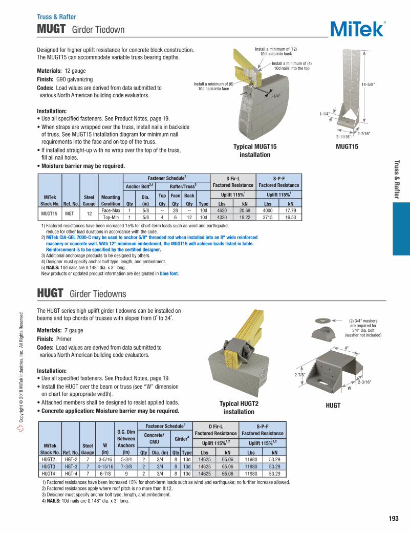
193
Truss & Rafter
Copy
right
© 2
018
MiT
ek In
dust
ries,
Inc.
All
Righ
ts R
eser
ved
MUGT Girder Tiedown
Designed for higher uplift resistance for concrete block construction. The MUGT15 can accommodate variable truss bearing depths.
Materials: 12 gaugeFinish: G90 galvanizingCodes: Load values are derived from data submitted to various North American building code evaluators.
Installation:• Use all specified fasteners. See Product Notes, page 19.• When straps are wrapped over the truss, install nails in backside
of truss. See MUGT15 installation diagram for minimum nail requirements into the face and on top of the truss.
• If installed straight-up with no wrap over the top of the truss, fill all nail holes.
• Moisture barrier may be required.
MUGT15
Top Face Back
Ref. No. Qty Qty Qty Qty Type Lbs kN Lbs kNFace-Max 1 5/8 -- 28 -- 10d 4650 20.69 4000 17.79Top-Min 1 5/8 4 6 12 10d 4320 19.22 3715 16.53
1) Factored resistances have been increased 15% for short-term loads such as wind and earthquake; reduce for other load durations in accordance with the code.
masonry or concrete wall. With 12" minimum embedment, the MUGT15 will achieve loads listed in table. Reinforcement is to be specified by the certified designer. 3) Additional anchorage products to be designed by others. 4) Designer must specify anchor bolt type, length, and embedment. 5) NAILS: 10d nails are 0.148" dia. x 3" long. New products or updated product information are designated in blue font.
2) MiTek CIA-GEL 7000-C may be used to anchor 5/8" threaded rod when installed into an 8" wide reinforced
Anchor Bolt2,4 Rafter/Truss5
Uplift 115%1 Uplift 115%1
Fastener Schedule3 D Fir-LFactored Resistance
S-P-FFactored Resistance
Dia. (in)
MUGT15 MGT 12
MountingCondition
MiTekStock No.
SteelGauge
Typical HUGT2installation
The HUGT series high uplift girder tiedowns can be installed on beams and top chords of trusses with slopes from 0˚ to 34˚.
Materials: 7 gaugeFinish: PrimerCodes: Load values are derived from data submitted to various North American building code evaluators.
Installation:• Use all specified fasteners. See Product Notes, page 19.• Install the HUGT over the beam or truss (see “W” dimension
on chart for appropriate width).• Attached members shall be designed to resist applied loads.• Concrete application: Moisture barrier may be required.
Ref. No. Qty Dia. (in) Qty Type Lbs kN Lbs kN HUGT2 HGT-2 7 3-5/16 5-3/4 2 3/4 8 10d 14625 65.06 11980 53.29 HUGT3 HGT-3 7 4-15/16 7-3/8 2 3/4 8 10d 14625 65.06 11980 53.29 HUGT4 HGT-4 7 6-7/8 9 2 3/4 8 10d 14625 65.06 11980 53.29
1) Factored resistances have been increased 15% for short-term loads such as wind and earthquake; no further increase allowed. 2) Factored resistances apply where roof pitch is no more than 8:12. 3) Designer must specify anchor bolt type, length, and embedment. 4) NAILS: 10d nails are 0.148" dia. x 3" long.
O.C. DimBetweenAnchors
(in)
Fastener Schedule3 D Fir-LFactored Resistance
MiTekStock No.
SteelGauge
W(in)
S-P-FFactored Resistance
Uplift 115%1,2 Uplift 115%1,2
Concrete/CMU Girder4
HUGT Girder Tiedowns
HUGT
(2) 3/4" washers are required for 3/4" dia. bolt
(washer not included)
4"
2-3/16"W
2-7/8"
Truss & Rafter
14-5/8"
1-1/4"
3-11/16"2-7/16"
Typical MUGT15 installation
Install a minimum of (12) 10d nails into back
Install a minimum of (4) 10d nails into the top
1-1/4"
Install a minimum of (6) 10d nails into face

194
Trus
s &
Raf
ter
Copyright © 2018 M
iTek Industries, Inc. All Rights Reserved
HGAM Hurricane Gusset Angles
SHA Masonry Uplift Connectors
Connects trusses directly to masonry or concrete and features slotted base holes to ease installation.
Materials: Angle – 3 gauge; Gussets – 10 gaugeFinish: PrimerCodes: Load values are derived from data submitted to various North American building code evaluators.
Installation:• Use all specified fasteners. See Product Notes, page 19.• Install directly flush to masonry wall.• The SHA series connectors shall be installed in pairs.• Moisture barrier may be required.
SHA6T
Qty Dia. (in) Qty Dia. (in) Unit Lbs 2500 2500 kN 11.12 11.12 Lbs 3750 3750 kN 16.68 16.68 Lbs 11180 8825 kN 49.73 39.26 Lbs 12600 8945 kN 56.05 39.79
1) Factored resistances have been increased 15% for wind or seismic loads; no further increase shall be permitted. 2) Factored resistances are for a pair of SHA devices. SHA's shall be installed in pairs. 3) Fastener schedule is for a pair of SHA devices. 4) 1/2" x 8" J-Bolts or equivalent. 5) Concrete compressive strength shall be 2500 psi or greater at 28 days. 6) Multiple ply truss shall be fastened together to act as a single unit. 7) Bolts shall conform to ASTM A 307 or better. 8) The designer must specify anchor bolt type, length, and embedment.
Fastener Schedule3
Concrete Wall Rafter/Truss7
MiTekStock No.
Anchor Bolts4,5,8Ref. No.
No.of Plies6
Uplift1,2
115%Uplift1,2
115%
D Fir-L Factored Resistance
S-P-F Factored Resistance
2 Ply
3 Ply or >
SHA6T -- 4 1/2 2 3/4 2 Ply
3 Ply or >
SHA6 -- 4 1/2 2 3/4
For installation into grouted concrete tie beam or masonry bond beam. Provides lateral and uplift resistance.
Materials: 14 gaugeFinish: G90 galvanizingCodes: Load values are derived from data submitted to various North American building code evaluators.
Installation:• Use all specified fasteners. See Product Notes, page 19.• Install WS15 Wood Screws into the truss and drill holes for
screw anchors. Install screw anchors into concrete block per manufacturer’s recommendation.
• WS Wood Screws and screw anchors are included with HGAM10 angles.
• Moisture barrier may be required.
Ref. No. Qty Qty UnitLbs 945 1115 1150 765 815 955 990 660kN 4.20 4.96 5.12 3.40 3.63 4.25 4.40 2.94
1) Factored resistances have been increased 15% for short-term loads such as wind and earthquake; no further increase is allowed. 2) WS15 Wood Screws are 1/4" dia. x 1-1/2" long. 3) Use DeWalt 1/4" dia. x 1-3/4" long Screwbolt+; or equal, installed in accordance with manufacturer's specification. 4) The HGAM10KT is a kit with (10) HGAM10 angles packaged with MiTek's WS Wood Screws and 1-3/4" screw anchors.
4 1/4" x 1-3/4"
Screw
Anchor3
WS
Screw2
HGAM10KT 4 HGAM10KTA 14 4 WS15
Fastener Schedule
Rafter/Truss
MiTekStock No.
SteelGauge
Plate
D Fir-LFactored Resistance
S-P-FFactored Resistance
Uplift
115%1
F1
115%1
F2
115%1
F3
115%1
Uplift
115%1
F1
115%1
F2
115%1
F3
115%1
Typical HGAM10 installation HGAM10
1) Factored resistances have been increased 15% for wind or seismic loads; no further increase shall be permitted.
2) Factored resistances are for a pair of SHA devices. SHA's shall be installed in pairs.3) Fastener schedule is for a pair of SHA devices.4) 1/2" x 8" J-Bolts or equivalent.
5) Concrete compressive strength shall be 2500 psi or greater at 28 days. 6) Multiple ply truss shall be fastened together to act as a single unit.7) Bolts shall conform to ASTM A 307 or better.8) The designer must specify anchor bolt type, length, and embedment.
Embossed gussets improve lateral load
resistance
Moisture barrier not shown
3-1/2"
3"
2-7/8"
SHA6
Truss & Rafter
Typical SHA6installation
Typical SHA6T installation
1-1/2"
6"
4-1/4"
3-1/4"
2-1/4"
2-1/4"
6"
13-3/4"
2-1/2"
2-1/2"
12-1/2"
1-1/2"
F1
F1
Uplift
F2
F3
Uplift

195
Truss & Rafter
Copy
right
© 2
018
MiT
ek In
dust
ries,
Inc.
All
Righ
ts R
eser
ved
RTM Hurricane Retrofit Connector
Designed as a retrofit connector for trusses installed on top plates. Can also be used as a holdown for a roof or floor system.
Materials: 18 gaugeFinish: G90 galvanizingCodes: Load values are derived from data submitted to various North American building code evaluators.
Installation:• Use all specified fasteners. See Product Notes, page 19.• Tapcon® Concrete Screws are not supplied with RT16M connector.• Install Tapcon® Concrete Screws in lower two holes for Single Top Plate
or Conventional Raised Foundation or Modular Home Installations.• Moisture barrier may be required.
Typical RT16Mtop plate installation
RT16M
Ref. No. Qty Type Qty Type Qty Type UnitLbs 1730 1045 190 795 1470 1045 190 795kN 7.70 4.65 0.85 3.54 6.54 4.65 0.85 3.54Lbs 1690 -- -- -- 1470 -- -- --kN 7.52 -- -- -- 6.54 -- -- --
1) Factored resistances have been increased 15% for short-term loads such as wind and earthquake; no further increase is allowed. 2) Install with 1/4" dia. x 1-3/4" long Tapcon® Concrete Screws in accordance to manufacturer's installation specifications. 3) Fasteners to be installed to fully grouted and reinforced concrete masonry. 4) NAILS: 10d x 1-1/2 nails are 0.148" dia. x 1-1/2" long.
16d 2 1/4" x 1-3/4" Tapcon
Uplift115%
F1115%
-- 4 1/4" x 1-3/4" Tapcon
F3115%
S-P-F Factored Resistance1D Fir-L Factored Resistance1Fastener Schedule2,3,4
Masonry BlockTruss/Rafter Top Plate F2115%
F3115%
Uplift115%
F1115%
F2115%
MiTekStock No.
SteelGauge
9 10d x 1-1/2 -- RT16M HM9KT 18
10d x 1-1/2 49
Versatile wood-to-wood connector that satisfies high wind and seismic loading requirements.
Materials: 14 gaugeFinish: G90 galvanizingCodes: Load values are derived from data submitted to various North American building code evaluators.
Installation:• Use all specified fasteners. See Product Notes, page 19.• Install with Wood Screws into top plate, and WS15 Wood
Screws into the truss.• WS Wood Screws are included with HGA10 angles.• Moisture barrier may be required.
Ref. No. Qty Qty UnitLbs 1330 1365 1620 865 1145 1175 1395 745kN 5.92 6.07 7.21 3.85 5.09 5.23 6.21 3.31
1) Factored resistances have been increased 15% for short-term loads such as wind and earthquake; no further increase is allowed. 2) WS15 Wood Screws are 1/4" dia. x 1-1/2" long and WS3 Wood Screws are 1/4" dia. x 3" long. 3) The HGA10KT is a kit with (10) HGA10 angles packaged with MiTek's WS Wood Screws.
D Fir-L
Factored Resistance1
S-P-F
Factored Resistance1
Uplift115%
F1115%
F2115%
F3115%
Uplift115%
F1115%
F2115%
F3115%
Fastener Schedule2
Rafter/Truss
MiTekStock No.
SteelGauge
Plate
WoodScrew
WoodScrew
4 WS3 HGA10KT 3 HGA10KT 14 4 WS15
HGA Hurricane Gusset Angles
5"
1-9/16"
8-15/16"
3-1/2"
Typical HGA10 installation HGA10
3-1/2"
Embossed gussets improve
lateral load resistance
3"
2"
Truss & Rafter
F1
F1
Uplift
F2
F3
F1F1
Uplift
F2
F3

196
Trus
s &
Raf
ter
Copyright © 2018 M
iTek Industries, Inc. All Rights Reserved
LUGT Girder Tiedowns
The LUGT series is an extremely adaptable tiedown for girder trusses and offers several installation options to accommodate different framing conditions. It is an ideal retrofit solution to reinforce truss connections to transfer high wind loads to supporting walls. Sizes available for 1-ply, 2-ply, 3-ply and 4-ply trusses.
Materials: See chartFinish: G90 galvanizingCodes: Factored resistances are derived from data submitted to various North American building code evaluators and are in accordance with CSA O86-14.
Installation:• Use all specified fasteners. See Product Notes, page 19.• All fastener holes must be filled with specified fasteners to achieve loads listed in
the chart. Large fastener holes are for concrete/masonry installations (reference page 192) and do not need to be filled when used for girder-to-stud applications.
• WS Wood Screws included with LUGT3 and LUGT4.
Ref. No. Qty Type Qty Type Qty Type UnitLbs 1415 1090 290 1295 895 235kN 6.29 4.85 1.29 5.76 3.98 1.05Lbs 3595 1795 805 2825 1410 630kN 15.99 7.98 3.58 12.57 6.27 2.80Lbs 3595 -- 805 2825 -- 630kN 15.99 -- 3.58 12.57 -- 2.80Lbs 5485 3075 1380 4775 2415 1085kN 24.40 13.68 6.14 21.24 10.74 4.83Lbs 7345 -- -- 5765 -- --kN 32.67 -- -- 25.64 -- --
1) Factored resistances have been increased 15% for short-term loads such as wind and earthquake; reduce for other load durations in accordance with the code. 2) For proper installation, the number of studs must be equal-to or greater-than the number of roof truss plies. 3) The LUGT1 can be installed with the stud offset from the rafter a maximum of 1" (center-to-center) with no reduction in factored resistances. 4) NAILS: 8d x 1-1/2 are 0.131" dia. x 1-1/2" long, 10d nails are 0.148" dia. x 3" long, 16d Sinkers are 0.148" dia. x 3-1/4" long, WS25 Wood Screws are 1/4" dia. x 2-1/2" long (supplied with LUGT3) and WS3 Wood Screws are 1/4" dia. x 3" long (supplied with LUGT4).
Uplift115%1
F1115%1
F2115%1
D Fir-LFactored Resistance
S-P-FFactored Resistance
32 16d Sinker
Uplift115%1
F1115%1
F2115%1
14 10d
24 16d Sinker
7 8d x 1-1/2
14 10d
4 16 WS3 5 16d Sinker12 LUGT4 LGT4-SDS3
3 12 WS25 4 16d Sinker12 LUGT3 LGT3-SDS2.5
10d
16 10d 2 10d
H10S
216 10d 2
14
14
LGT2
--
Fastener Schedule4
No.of
Plies
LUGT13
LUGT2
LUGTC2
MiTekStock No.
SteelGauge
PlateRafter/Truss Stud2
1 8 8d x 1-1/2 8 8d x 1-1/218
Truss & Rafter
Typical LUGT2 installation
Typical LUGT1installation
Typical LUGTC2corner hip installation
LUGT1LUGTC2
Typical LUGT3 installation(LUGT4 similar)
LUGT4LUGT3
LUGT2
14-13/16"
3-3/16"
11-1/2"
1-5/8"
5"
3"
4-3/4"
15-15/16"
5"11-1/8"
6-1/4"
16-1/8"
6-9/16"
12-7/8"
12-7/8"
8-7/8"
6-3/4"
3-1/4"
3"
Typical LUGT1 offset stud installation
F1F1
F2
F2
Uplift
F1F1
F2
F2
Uplift
F2
F2
Uplift
F1F1
F2
F2
Uplift
7-3/4"
10-15/16"10-15/16"
10-13/16"

197
Truss & Rafter
Copy
right
© 2
018
MiT
ek In
dust
ries,
Inc.
All
Righ
ts R
eser
ved
MUGT Girder Tiedown
Designed for higher uplift resistance for wood frame construction. The MUGT15 can accommodate variable truss bearing depths.
Materials: 12 gaugeFinish: G90 galvanizingCodes: Load values are derived from data submitted to various North American building code evaluators.
Installation:• Use all specified fasteners. See Product Notes, page 19.• When straps are wrapped over the truss, install nails in backside
of truss. See MUGT15 installation diagram for minimum nail requirements into the face and on top of the truss.
• If installed straight-up with no wrap over the top of the truss, fill all nail holes.
• Moisture barrier may be required.
Top Face Back
Ref. No. Qty Qty Qty Qty Type Lbs kN Lbs kNFace-Max 1 5/8 -- 28 -- 10d 4650 20.69 4000 17.79Top-Min 1 5/8 4 6 12 10d 4320 19.22 3715 16.53
1) Factored resistances have been increased 15% for short-term loads such as wind and earthquake; reduce for other load durations in accordance with the code. 2) Additional anchorage products to be designed by others. 3) Designer must specify anchor bolt type, length, and holdown device. 4) NAILS: 10d nails are 0.148" dia. x 3" long.
Rod/Bolt3 Rafter/Truss4
Uplift 115%1 Uplift 115%1
Fastener Schedule2 D Fir-LFactored Resistance
S-P-FFactored Resistance
Dia. (in)
MUGT15 MGT 12
MountingCondition
MiTekStock No.
SteelGauge
HUGT Girder Tiedowns
The HUGT series high uplift girder tiedowns can be installed on beams and top chords of trusses with slopes from 0˚ to 34˚.
Materials: 7 gaugeFinish: PrimerCodes: Load values are derived from data submitted to various North American building code evaluators.
Installation:• Use all specified fasteners. See Product Notes, page 19.• Install the HUGT over the beam or truss (see “W” dimension
on chart for appropriate width).• Install (4) LBP58-TZ washers for (2) 5/8" tension rod/bolts.• Attached members shall be designed to resist applied loads.
Ref. No. Qty Type Qty Dia. (in) Qty Type Lbs kN Lbs kN HUGT2 HGT-2 7 3-5/16 5-3/4 4 LBP58-TZ 2 5/8 8 10d 14625 65.06 11980 53.29 HUGT3 HGT-3 7 4-15/16 7-3/8 4 LBP58-TZ 2 5/8 8 10d 14625 65.06 11980 53.29 HUGT4 HGT-4 7 6-7/8 9 4 LBP58-TZ 2 5/8 8 10d 14625 65.06 11980 53.29
1) Factored resistances have been increased 15% for short-term loads such as wind and earthquake; no further increase allowed. 2) Factored resistances apply where roof pitch is no more than 8:12. 3) Additional anchorage products to be designed by others. 4) Designer must specify anchor bolt type, length, and holdown device. 5) NAILS: 10d nails are 0.148" dia. x 3" long.
O.C. DimBetweenAnchors
(in)
Fastener Schedule3,4 D Fir-LFactored ResistanceAnchor
WashersMiTek
Stock No.Steel
GaugeW
(in)
S-P-FFactored Resistance
Uplift1,2 Uplift1,2
ThreadedRod Girder5
Truss & Rafter
Typical MUGT15top-min installation
with PHD4A
MUGT15
PHD4A page 52
14-5/8"
1-1/4"1-1/4"
Install a minimum of (4) 10d nails
into the top
Install a minimum of (12) 10d nails into back
Install a minimum of (6) 10d nails into the face
3-11/16" 2-7/16"
Typical HUGT3installation with HTT45’s HUGT
(4) LBP58-TZ washers are required for 5/8" dia. bolt
(washers not included).
2-3/16"
W4"
2-7/8"
HTT45 (not included) see page 55
Typical MUGT15connection to support beam
Min 3" x 3" x 1/4" Bearing Plate
Support beam designed by others
1-1/4"
Install a minimum of (4) 10d nails
into the top
Install a minimum of (12) 10d nails into back
Install a minimum of (6) 10d nails into the face
MUGT15
5/8" bolt

198
Trus
s &
Raf
ter
Copyright © 2018 M
iTek Industries, Inc. All Rights Reserved
HC / HCPRS / HHCP / LFTA / RT / TSP Hurricane Ties
These anchors tie trusses and rafters to top plates and may be used to tie wood framing members to resist uplift and lateral forces.
Materials: See chartFinish: G90 galvanizing; HHCP4-TZ – G-185 galvanizing.Options: See chart for Corrosion Finish OptionsCodes: Factored resistances are derived from data submitted to various North American building code evaluators.
Truss & Rafter
HHCP4-TZ
RT6
RT4 (left version shown)
RT7A
LFTA6 (left version shown)
HHCP2
RT3A
RT7(left version shown)
RT16ART10
RT16-2
RT15 RT16AR
RT20
HC520
HCPRS
1-7/16"
RT5(left version shown)
RT8A
1-1/4"
1-1/4"
7-13/16"
4-15/16"
5-1/4"
2-5/8"
1-9/16"
5"
6-1/2"
3-1/2"
1-9/16"
19-1/8"
8-3/8"
6-1/2"
2-1/4"
1-15/16"
2-7/8"
5-1/4"
1-7/8"
1-9/16"
2-1/2"
1-3/8" 3-9/16"
1-9/16"
10-3/4"
3-1/16"
2-3/8"
6-1/2"
6-1/2"
3-1/8"
3-1/2"
3"
6-5/8"
1-5/8"
4"1-1/2"
1-5/8"
2"
4-1/4"
4-5/8"
2-1/4"
21-1/8"
6-5/8"
3"
3-9/16"
1-9/16"
5-1/4"
4-1/4"
1-7/16"
1-1/2"
1-1/2"
4-1/2"
1-9/16"
1-9/16"
1-3/8"
2-15/16"
5-1/4"
1-1/2"
1-1/2"
4"
2-7/16"
6-1/2"
5-1/2"2-1/16"
3-3/8"
6-1/2"
TSP
7-7/8"
1-5/8"
1-5/8"
additional diamond holes for maximum
nailing
standard round holes for
minimum nailing
Continued on next page
1-1/2"
2"
3-3/4"
1-7/8"

199
Truss & Rafter
Copy
right
© 2
018
MiT
ek In
dust
ries,
Inc.
All
Righ
ts R
eser
ved
HC / HCPRS / HHCP / LFTA / RT / TSP Hurricane Ties
Ref. No. Qty Type Qty Type Qty Type UnitLbs 570 305 100 520 235 90kN 2.54 1.36 0.44 2.31 1.05 0.40Lbs 465 310 205 465 310 185kN 2.07 1.38 0.91 2.07 1.38 0.82Lbs 605 245 130 555 210 120kN 2.69 1.09 0.58 2.47 0.93 0.53Lbs 1075 1430 1480 1005 1140 1190kN 4.78 6.36 6.58 4.47 5.07 5.29Lbs 775 395 180 775 340 160kN 3.45 1.76 0.80 3.45 1.51 0.71Lbs 910 450 290 845 375 265kN 4.05 2.00 1.29 3.76 1.67 1.18Lbs 1160 435 160 1110 330 150kN 5.16 1.93 0.71 4.94 1.47 0.67Lbs 775 395 180 775 340 160kN 3.45 1.76 0.80 3.45 1.51 0.71Lbs 750 715 325 725 625 300kN 3.34 3.18 1.45 3.22 2.78 1.33Lbs 1655 1280 790 1535 960 725kN 7.36 5.69 3.51 6.83 4.27 3.22Lbs 1655 1280 790 1535 960 725kN 7.36 5.69 3.51 6.83 4.27 3.22Lbs 1690 1230 640 1555 1035 590kN 7.52 5.47 2.85 6.92 4.60 2.62Lbs 1505 710 -- 1070 505 --kN 6.69 3.16 -- 4.76 2.25 --Lbs 1835 690 -- 1575 590 --kN 8.16 3.07 -- 7.01 2.62 --Lbs 640 510 560 555 440 485kN 2.85 2.27 2.49 2.47 1.96 2.16Lbs 1020 945 340 660 665 240kN 4.54 4.20 1.51 2.94 2.96 1.07Lbs 1265 870 -- 1075 775 --kN 5.63 3.87 -- 4.78 3.45 --Lbs 1695 -- -- 1650 -- --kN 7.54 -- -- 7.34 -- --Lbs 740 675kN 3.29 3.00Lbs 1300 565 295 1170 520 270kN 5.78 2.51 1.31 5.20 2.31 1.20Lbs 1345 565 295 1235 520 270kN 5.98 2.51 1.31 5.49 2.31 1.20
1) 15% increase for short-term loads such as wind and earthquake has been taken into account for factored resistances, no further increase allowed. 2) LFTA6: To achieve F1 lateral loads, three nails must be installed on each side on the strap located closest to the bend line. Lateral F1 load direction does not apply to roof truss-to-top plate installations. 3) TSP factored lateral resistance for DF: F3 = 315 lb (1.40 kN), F4 = 365 lb (1.62 kN). For SPF: F3 = 290 lb (1.29 kN), F4 = 335 lb (1.49 kN). 4) NAILS: 8d x 1-1/2 are 0.131" dia. x 1-1/2" long, 8d nails are 0.131" dia. x 2-1/2" long, 10d x 1-1/2 nails are 0.148" dia. x 1-1/2" long, 10d nails are 0.148" dia. x 3" long. New products or updated product information are designated in blue font.
10d x 1-1/2 10 10d x 1-1/2
Corr
osio
nFi
nish
HCP4Z
GBC
--
H7 10d x 1-1/2 4 10d
-- 5 8d
-- 11 8d
10d 8 10d
8d 8 8d
18
HCPRS
RT20
H3
--
--
HS24
--
H2.5A
H6
H8
H2A
H1
H10A, H14
H10AR
H10A-2
RT16A
RT16AR
RT16-2
HHCP2
HHCP4-TZ
RT7A
LFTA6 2
RT8A
HCP2
RT10
RT15
RT3A
RT4
RT5
RT6
RT7
16 9
18 --
18 --
16 8
18 10
18 8
18 5
16 8
HC520
8 8d
18 5 10d x 1-1/2 5
9 10d x 1-1/2 8 10d
18 9 10d x 1-1/2 8 10d
9 10d x 1-1/2
18 4 8d x 1-1/2 4 8d
18 4 8d x 1-1/2 4 8d
18 4 8d x 1-1/2 4
6 8d x 1-1/2
8d 8 8d
18 5 8d x 1-1/2
-- --
-- --
8d
10d x 1-1/2
18 8 8d x 1-1/2 6 8d
5 8d
18 5 8d x 1-1/2 5 8d
8d x 1-1/2 5 8d
18 6 8d x 1-1/2
--
--
--
-- --
--
--
--
-- --
-- --
-- --
--
--
--
--
6 8d
6 8d
-- --
TSP 3 TSP 16
10d x 1-1/2 -- --
F2115%1
Stud
Fastener Schedule4
MiTekStock No.
SteelGauge
Truss/Rafter Plate
F1115%1
F2115%1
F1115%1
Uplift115%1
Uplift115%1
D Fir-LFactored Resistance
S-P-FFactored Resistance
--
--
--
--
3 10d x 1-1/2
9 10d x 1-1/2
-- -- -- --
--
--
3
--
--
6 10d x 1-1/2
6 10d
Corrosion Finish Stainless Steel Gold Coat HDG Triple Zinc
Corrosion Finish Stainless Steel Gold Coat HDG Triple Zinc
Corrosion Finish Stainless Steel Gold Coat HDG Triple Zinc
Installation:• Use all specified fasteners. See Product Notes, page 19.• TSP Min Nailing – Fill all round holes.• TSP Max Nailing – Fill all round and diamond holes.• All nail holes must be filled with specified nails to achieve loads listed in the chart. For substituting
with different nail sizes, refer to “Optional Nails” on page 21 or consult a design professional.• Depending on pitch, birdsmouth notching may be required with some models to enable installers
to fill all nail holes. Consult a design professional for appropriate notching.• Designer shall determine if solid blocking is required.• LFTA6, RT4, RT5, and RT7 ship in equal quantities of left and right versions. Left version images shown.
Truss & Rafter
Continued on next page
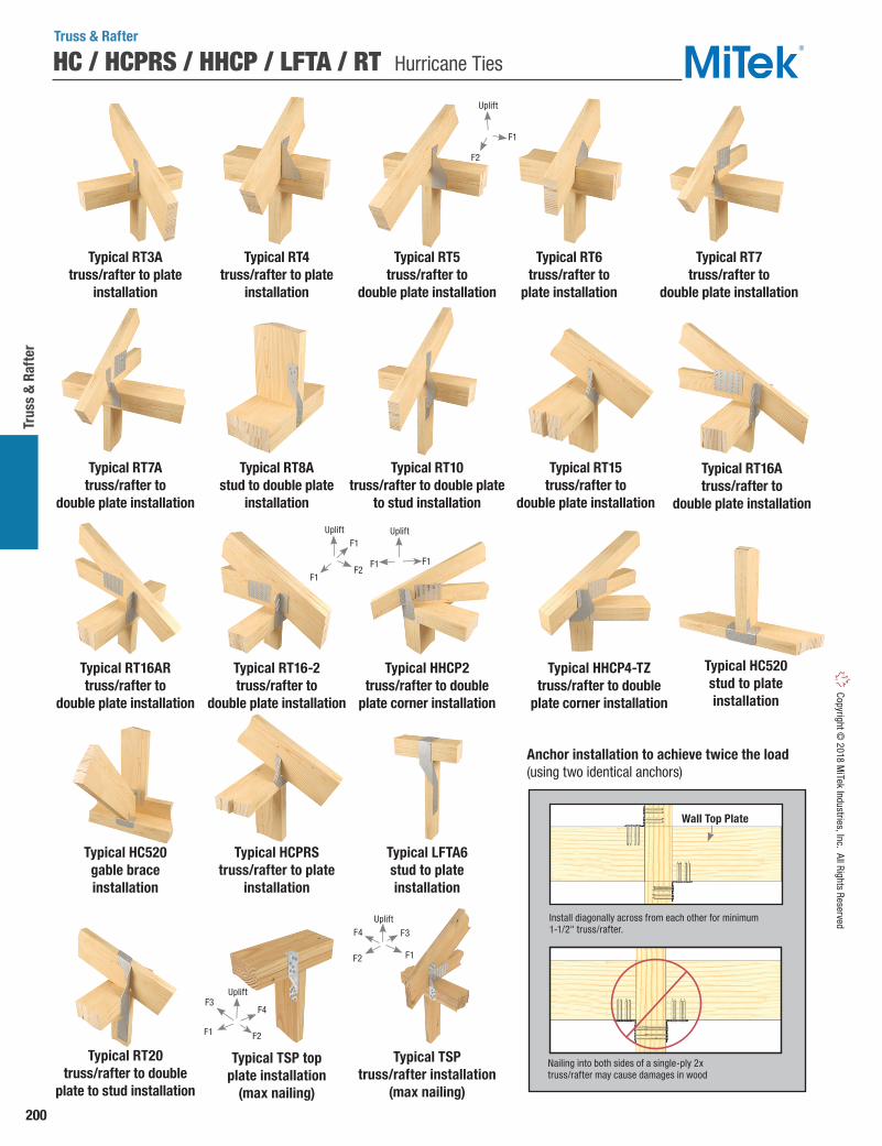
200
Trus
s &
Raf
ter
Copyright © 2018 M
iTek Industries, Inc. All Rights Reserved
HC / HCPRS / HHCP / LFTA / RT Hurricane Ties
Truss & Rafter
Typical RT6 truss/rafter to
plate installation
Typical RT4 truss/rafter to plate
installation
Typical RT3Atruss/rafter to plate
installation
Typical RT10 truss/rafter to double plate
to stud installation
Typical RT15 truss/rafter to
double plate installation
Typical RT8Astud to double plate
installation
Typical RT7A truss/rafter to
double plate installation
Typical RT5truss/rafter to
double plate installation
Typical RT7truss/rafter to
double plate installation
Typical HHCP4-TZtruss/rafter to double
plate corner installation
Typical LFTA6stud to plate installation
Typical HHCP2 truss/rafter to double
plate corner installation
Typical RT16Atruss/rafter to
double plate installation
Typical RT16ARtruss/rafter to
double plate installation
Typical RT16-2truss/rafter to
double plate installation
Typical RT20 truss/rafter to double
plate to stud installation
Typical HC520 gable brace installation
Typical HC520 stud to plate installation
Typical HCPRS truss/rafter to plate
installation
Anchor installation to achieve twice the load (using two identical anchors)
Install diagonally across from each other for minimum 1-1/2" truss/rafter.
Nailing into both sides of a single-ply 2x truss/rafter may cause damages in wood
Wall Top Plate
Typical TSP top plate installation
(max nailing)
Typical TSP truss/rafter installation
(max nailing)
Uplift
F3
F1F2
F4
F1
F2
Uplift
F1
F1
F2
Uplift
F1 F1
Uplift
F3
F2
F4
F1
Uplift

201
Truss & Rafter
Copy
right
© 2
018
MiT
ek In
dust
ries,
Inc.
All
Righ
ts R
eser
ved
RUSC Retrofit Strap Connector
Typical RUSCinstallation
RUSC
The RUSC retro uplift strap connector provides a wood-to-wood uplift connection attaching trusses with a 2x4 bottom chord to a double stud in the wall below. WS3 Wood Screws are utilized for fast installation. The connector can be installed after roof sheathing has been installed.
Materials: 10 gaugeFinish: PrimerCodes: Load values are derived from data submitted to various North American building code evaluators. Installation:• Use all specified fasteners. See Product Notes,
page 19.• The RUSC shall be installed in pairs.• Install on minimum 2 ply with equal wall studs
centered directly below.• Works with 2x4 bottom chord member and
2x4 wall studs.
Qty Type Qty Type Lbs kN Lbs kN RUSC -- 10 2 Ply or greater 16 WS3 16 WS3 6250 27.80 5410 24.07
1) Factored resistances have been increased 15% for short-term loads such as wind and earthquake; no further increase is allowed. 2) Designer must specify stud or post to resist published load values. 3) WS3 Wood Screws are 1/4" dia. x 3" long and are included with RUSC connectors. 4) Fastener schedule is for two straps used together. The RUSC shall be installed in pairs with a minimum 2-ply truss and wall stud attachment. 5) Truss plies shall be fastened together to act as a single unit.
StudRafter/Truss
Fastener Schedule3,4 D Fir-LFactored Resistance
S-P-FFactored Resistance
Uplift 115%1,2 Uplift 115%1,2MiTek
Stock No.Steel
Gauge
No, of
Plies5Ref. No.
Truss & Rafter
7"
3-1/2"
22-3/4"
3-1/8" 3-1/8"
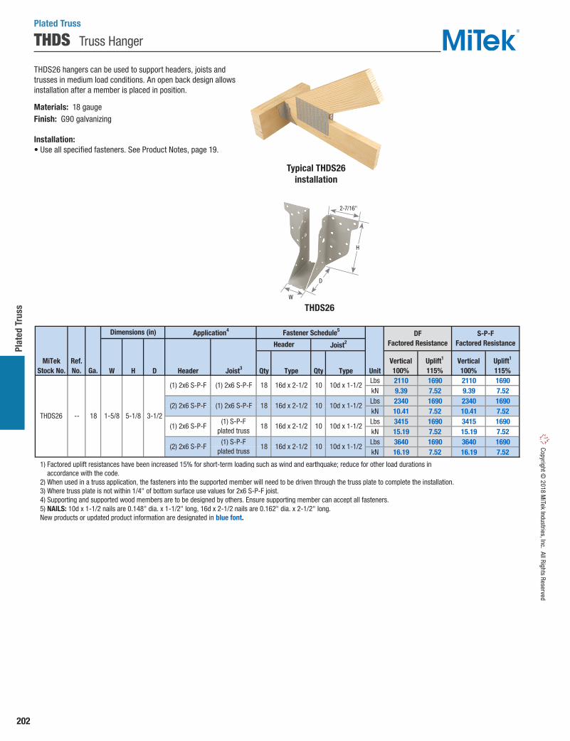
202
Plat
ed T
russ
Copyright © 2018 M
iTek Industries, Inc. All Rights Reserved
THDS Truss Hanger
Plated Truss
THDS26 hangers can be used to support headers, joists and trusses in medium load conditions. An open back design allows installation after a member is placed in position.
Materials: 18 gaugeFinish: G90 galvanizing
Installation:• Use all specified fasteners. See Product Notes, page 19.
Typical THDS26installation
W H D Header Joist3 Qty Type Qty Type UnitLbs 2110 1690 2110 1690kN 9.39 7.52 9.39 7.52Lbs 2340 1690 2340 1690kN 10.41 7.52 10.41 7.52Lbs 3415 1690 3415 1690kN 15.19 7.52 15.19 7.52Lbs 3640 1690 3640 1690kN 16.19 7.52 16.19 7.52
1) Factored uplift resistances have been increased 15% for short-term loading such as wind and earthquake; reduce for other load durations in accordance with the code. 2) When used in a truss application, the fasteners into the supported member will need to be driven through the truss plate to complete the installation. 3) Where truss plate is not within 1/4" of bottom surface use values for 2x6 S-P-F joist. 4) Supporting and supported wood members are to be designed by others. Ensure supporting member can accept all fasteners. 5) NAILS: 10d x 1-1/2 nails are 0.148" dia. x 1-1/2" long, 16d x 2-1/2 nails are 0.162" dia. x 2-1/2" long. New products or updated product information are designated in blue font.
5-1/81-5/8-- 18
(2) 2x6 S-P-F
(1) 2x6 S-P-F
18 16d x 2-1/2 10
10d x 1-1/2
3-1/2
(1) S-P-Fplated truss
18 16d x 2-1/2 10
10d x 1-1/2
(1) S-P-F plated truss
18 16d x 2-1/2
MiTekStock No. Ga.
Ref. No.
THDS26
Fastener Schedule5Dimensions (in)
(1) 2x6 S-P-F (1) 2x6 S-P-F 18 16d x 2-1/2 10 10d x 1-1/2
10 10d x 1-1/2
(2) 2x6 S-P-F (1) 2x6 S-P-F
Vertical100%
Uplift1
115%
Application4
Header Joist2
S-P-F Factored Resistance
DFFactored Resistance
Vertical100%
Uplift1
115%
THDS26
2-7/16"
H
D
W

203
Plated Truss Co
pyrig
ht ©
201
8 M
iTek
Indu
strie
s, In
c. A
ll Ri
ghts
Res
erve
d
MUS / HUS Slant Nail Truss Hangers
Plated Truss
The MUS / HUS hanger series offers double shear nailing. MiTek’s raised dimple allows for 30° to 45° nailing through the joist into header, resulting in higher loads and less nailing.
Materials: MUS – 18 gauge; HUS – 16 gauge Finish: G90 galvanizingCodes: Load values are derived from data submitted to various North American building code evaluators.
Installation:• Use all specified fasteners. See Product Notes, page 19.• Joist nails must be driven in at a 30° to 45° angle through the joist
or truss into the header to achieve listed loads. Slant / double shear nails must be used to achieve listed load values.
• HUS – See EWP applications page 157.
Ref. No. W H Qty Type Qty Type UnitLbs 2845 1425 2825 1415kN 12.66 6.34 12.57 6.29Lbs 6090 3915 5195 3625kN 27.09 17.41 23.11 16.12Lbs 3855 2030 3830 2015kN 17.15 9.03 17.04 8.96Lbs 8050 5775 6875 5345kN 35.81 25.69 30.58 23.78Lbs 9625 8045 8070 7455kN 42.81 35.79 35.90 33.16Lbs 6090 3915 5195 3625kN 27.09 17.41 23.11 16.12Lbs 8050 5775 6875 5345kN 35.81 25.69 30.58 23.78Lbs 9625 8045 8070 7455kN 42.81 35.79 35.90 33.16
1) Factored uplift resistances have been increased 15% for short-term loads such as wind and earthquake; reduce for other load durations in accordance with the code. 2) Nails must be driven at a 30˚ to 45˚ angle through the joist or truss into the header to achieve the table loads. 3) NAILS: 10d nails are 0.148" dia. x 3" long, 16d nails are 0.162" dia. x 3-1/2" long. New products or updated product information are designated in blue font.
10 16d
16d
10d
22 16d 8 16d
16d
14 16d
8 16d
16d 6
16d
1-5/8
1-9/16
1-5/8
1-5/8
1-13/16
1-13/16
6
22
301-13/16
5-3/8
7-1/8
9-1/8
7-1/16
7-3/16
9-3/16
10d 6
14 16d 6
8 10d 8
30 16d 10
SteelGauge
Joist /Truss Size
2 x 10 - 12
1-3/4 x 5-1/2 - 7-1/4
1-3/4 x 7-1/4 - 11-1/4
1-3/4 x 9-1/4 - 14
MUS26
HUS26
MUS28
HUS28
HUS210
HUS175
HUS177
HUS179
HUS210 16
HU1.81/5 16
-- 16
HUS1.81/10 16
Dimensions (in)
Header Truss2
Fastener Schedule3 DFFactored Resistance
MiTekStock No.
2 x 8 - 10 MUS28 18
HUS28 16
Vertical100%
Uplift1
115%
2 x 6 - 8 MUS26 18
HUS26, LJS26DS
16
10d
16d
1-9/16 5-1/16
5-7/16
S-P-FFactored Resistance
Corr
osio
nFi
nishVertical
100%Uplift1
115%
Corrosion Finish Stainless Steel Gold Coat HDG Triple Zinc
Corrosion Finish Stainless Steel Gold Coat HDG Triple Zinc
Corrosion Finish Stainless Steel Gold Coat HDG Triple Zinc
Typical HUS installation(MUS similar)
HUS
MUS
3"
W
W
Raised dimple allows 30° to 45° nailing
H
2"
2"
1"
H
Double shear nail designfeatures fewer nails and
faster installation
Uses standard length nails

204
Plat
ed T
russ
Copyright © 2018 M
iTek Industries, Inc. All Rights Reserved
Corrosion Finish Stainless Steel Gold Coat HDG Triple Zinc
Corrosion Finish Stainless Steel Gold Coat HDG Triple Zinc
Corrosion Finish Stainless Steel Gold Coat HDG Triple Zinc
Medium-to-heavy capacity face mount hanger. Some THD models are available with a min/max installation option.
Materials: See chartFinish: G90 galvanizingOptions: See chart for Corrosion Finish Options and Specialty Options ChartCodes: Load values are derived from data submitted to various North American building code evaluators.
Installation:• Use all specified fasteners. See Product Notes, page 19.• Drive bend line nails into header at 45° to achieve listed loads.• Min Nailing – Fill all round nail holes.• Max Nailing – Fill all round and diamond holes.
Plated Truss
Some model designs may
vary fromillustration
shown
Ref. No. W H A Qty Type Qty Type UnitLbs 5490 4020 4675 3725kN 24.42 17.88 20.80 16.57Lbs 5490 4020 4675 3725kN 24.42 17.88 20.80 16.57Lbs 6895 4020 6245 3725kN 30.67 17.88 27.78 16.57Lbs 7620 4020 7365 3725kN 33.90 17.88 32.76 16.57Lbs 9430 7715 8250 7145kN 41.95 34.32 36.70 31.78Lbs 10035 7715 8790 7145kN 44.64 34.32 39.10 31.78Lbs 6525 5270 6030 4715kN 29.02 23.44 26.82 20.97Lbs 7545 4480 6970 4005 kN 33.56 19.93 31.00 17.82Lbs 10625 7715 9815 7145kN 47.26 34.32 43.66 31.78Lbs 6525 5270 6030 4715kN 29.02 23.44 26.82 20.97Lbs 7545 4480 6970 4005kN 33.56 19.93 31.00 17.82Lbs 10625 7715 9815 7145kN 47.26 34.32 43.66 31.78Lbs 10625 7715 9815 7145kN 47.26 34.32 43.66 31.78Lbs 10625 7715 9815 7145kN 47.26 34.32 43.66 31.78Lbs 11705 7715 11245 7145kN 52.07 34.32 50.02 31.78Lbs 11705 7715 11245 7145kN 52.07 34.32 50.02 31.78Lbs 11705 7715 11245 7145kN 52.07 34.32 50.02 31.78Lbs 11705 7715 11245 7145kN 52.07 34.32 50.02 31.78Lbs 11705 7715 11245 7145kN 52.07 34.32 50.02 31.78Lbs 11705 7715 11245 7145kN 52.07 34.32 50.02 31.78
1) Factored uplift resistances have been increased 15% for short-term loads such as wind and earthquake; reduce for other load durations in accordance with the code. 2) NAILS: 10d x 1-1/2 nails are 0.148" dia. x 1-1/2" long, 10d nails are 0.148" dia. x 3" long, 16d nails are 0.162" dia. x 3-1/2" long.
12 6-3/4 9 3 -- 38 16d 20 10d
20 10d x 1-1/2
38 16d 32 10d x 1-1/2
1-7/8
1-7/8
1-7/8
Max
Max
Max
12
Min 28 16d 16
Min 18 16d
Min 38 16d
10d x 1-1/2
20 16d 20 10d x 1-1/2
10d x 1-1/2
28 16d 26 10d x 1-1/2
5-5/16
7-1/16
9-1/16
1-5/8
1-5/8
1-5/8
7
9
5-1/16
3
3-7/16
3-7/16
5-3/8
7-1/8
9-1/8
3-7/16
5-1/2
7-1/4
12-7/8
11
9
9
11
12-7/8
9
3-5/8
3-5/8
5-1/8
5-1/2
5-1/2
3-5/8
3-5/8
3-5/8
20 10d
38 16d 20 10d
48 16d 20 10d
16d 20 10d
18 16d
38 16d
38 16d
12
12
HHUS5.50/10
--12
28 16d
18 16d
38 16d
58 16d
58
38 16d
2
2
12
16
12
20
20
THD410 HHUS410
THD46 HHUS46
THD48 HHUS48
--
--
--
2
2
2
2
3
3
3
3
3
3
12
20
20
48 16d 20
28
14
14
14
14
14
12
--
--
--
--
16d 16
--
--
--
--
--
16
16
16
14
14
14
THD26
THD28
THD210
HTU26
HTU28
HTU210
THD26-2 HHUS26-2, HTU26-2
THD28-2 HHUS28-2, HTU28-2
THD210-2 HHUS210-2, HTU210-2
7 x 9-1/4 - 14
THD412 --
THD414 --
THD210-3 HHUS210-3
THD610
4 x 14 - 16
(3) 2 x 10 - 12
6 x 10 -12
6 x 12 - 14
6 x 14 - 16
THD7210 HHUS7.25/10
THD612 --
THD614 --
(4) 2 x 10 - 12 THD210-4 HHUS210-4
(2) 2 x 10 - 12
4 x 6 - 8
4 x 8 - 10
4 x 10 -12
4 x 12 - 14
(2) 2 x 6 - 8
(2) 2 x 8 - 10
2 x 6 - 8
2 x 8 - 10
2 x 10 - 12
D Fir-LFactored Resistance
S-P-FFactored Resistance
Joist /Truss Size
MiTekStock No. Ga.
Dimensions (in)
Header Joist
Vertical100%
Uplift1
115%Vertical100%
Uplift1
115%
Fastener Schedule2
Min/Max Co
rros
ion
Fini
sh10d
10d
10d
10d
10d
10d
10d
10d
10d
Option Skewed1,3 Sloped Seat2 Sloped / Skewed1,2,3 Inverted Flange
1) Skewed hangers with skews greater than 15° may have all joist nailing on outside flange. 2) Sloped or sloped / skewed hangers with slopes greater than 15° may have additional joist nails. 3) For skewed hangers, the required cut type (square or bevel) of joist member may vary based on skew angle and width of hanger. Some square cut hangers will require custom pricing due to welded back plate.
RangeNot available in widths < 3".
Widths > 3" can have one flange inverted.1˚ to 45˚ 1˚ to 45˚ See Sloped Seat and Skewed
Ordering
85% of table load 65% of table load 65% of table load100% of table load.
65% of table load when nailing intothe support members end grain.
Add SK , angle required,right (R) or left (L) , and square cut (SQ)
or bevel cut (BV) to product number.Ex. THD410_SK45R_SQ
Add SL, slope required,and up (U) or down (D),
to product number.Ex. THD410_SL30D
See Sloped Seat and Skewed.Ex. THD410_SK45R_SQ_SL30D
Add IF, one flange, right (R) and left (L), to product number.
Ex. THD410_IFR
FactoredResistance
1) Skewed hangers with skews greater than 15°may have all joist nailing on outside flange.
2) Sloped or sloped / skewed hangers with slopes greater than 15° may have additional joist nails.
3) For skewed hangers, the required cut type (square or bevel) of joist member may vary based on skew angle and width of hanger. Some square cut hangers will require custom pricing due to welded back plate.
Specialty Options Chart – refer to Specialty Options pages 246-247 for additional details.
1) Factored uplift resistances have been increased 15% for short-term loads such as wind and earthquake; reduce for other load durations in accordance with the code.
2) NAILS: 10d x 1-1/2 nails are 0.148" dia. x 1-1/2" long, 10d nails are 0.148" dia. x 3" long, 16d nails are 0.162" dia. x 3-1/2" long.
Typical THD28installation
THD28
H
A
W 3"
THD Heavy-Duty Face Mount Truss Hangers
Typical bend line nail installation
Drive bend line nails
into header at 45° to
achieve listed loads.
THD210-3
W
A
Bend line nailing
3"
HAdditional diamond nail
holes for max nailing
Standard round
nail holes for min nailing

205
Plated Truss Co
pyrig
ht ©
201
8 M
iTek
Indu
strie
s, In
c. A
ll Ri
ghts
Res
erve
d
Corrosion Finish Stainless Steel Gold Coat HDG Triple Zinc
Corrosion Finish Stainless Steel Gold Coat HDG Triple Zinc
Corrosion Finish Stainless Steel Gold Coat HDG Triple Zinc
Materials: 12 gaugeFinish: G90 galvanizingOptions: See chart below for Corrosion Finish Options and Specialty Options Chart on page 206.Codes: Load values are derived from data submitted to various North American building code evaluators.
Installation:• Use all specified fasteners. See Product Notes, page 19.• Joist nails must be driven in at a 30° to 45° angle through the joist
or truss into the header to achieve listed loads. Slant / double shear nails must be used to achieve listed load values.
THDH Heavy-Duty Truss Hangers
Typical THDH installation
Ref. No. W H D Qty Type Qty Type UnitLbs 7130 4880 5470 4740kN 31.72 21.71 24.33 21.08Lbs 12130 7575 9475 7345kN 53.96 33.70 42.15 32.67Lbs 14620 10030 11905 8775kN 65.03 44.62 52.96 39.03Lbs 12430 7575 9725 7345kN 55.29 33.70 43.26 32.67Lbs 14330 7575 12265 7345kN 63.74 33.70 54.56 32.67Lbs 17720 10030 15320 8775kN 78.82 44.62 68.15 39.03Lbs 12430 7575 9725 7345kN 55.29 33.70 43.26 32.67Lbs 14330 10030 12265 8775kN 63.74 44.62 54.56 39.03Lbs 9480 4880 7420 4740kN 42.17 21.71 33.01 21.08Lbs 12130 5110 9475 5110kN 53.96 22.73 42.15 22.73Lbs 12430 7575 9725 7345kN 55.29 33.70 43.26 32.67Lbs 7130 4880 5470 4740kN 31.72 21.71 24.33 21.08Lbs 12130 5110 9475 5110kN 53.96 22.73 42.15 22.73Lbs 12430 7575 9725 7345kN 55.29 33.70 43.26 32.67Lbs 14330 10030 12265 8775kN 63.74 44.62 54.56 39.03Lbs 17720 10185 15320 8905kN 78.82 45.31 68.15 39.61
1) Factored resistances have been increased 15% for short-term loads such as wind and earthquake; reduce for other load durations in accordance with the code. 2) Joist nails need to be toe nailed at a 30° to 45˚ angle to achieve factored resistances shown. 3) NAILS: 16d nails are 0.162" dia. x 3-1/2" long. New products or updated product information are designated in blue font.
Ref. No. W H D Qty Type Qty Type UnitLbs 7130 4880 5470 4740kN 31.72 21.71 24.33 21.08Lbs 12130 7575 9475 7345kN 53.96 33.70 42.15 32.67Lbs 12430 10030 9725 8775kN 55.29 44.62 43.26 39.03Lbs 13975 10030 11750 8775kN 62.16 44.62 52.27 39.03Lbs 17720 10185 15320 8905kN 78.82 45.31 68.15 39.61Lbs 12430 10030 9725 8775kN 55.29 44.62 43.26 39.03Lbs 13975 10030 11750 8775kN 62.16 44.62 52.27 39.03Lbs 17720 10185 15320 8905kN 78.82 45.31 68.15 39.61Lbs 7130 4880 5470 4740kN 31.72 21.71 24.33 21.08Lbs 11015 7575 8680 7345kN 49.00 33.70 38.61 32.67Lbs 12430 7575 9725 7345kN 55.29 33.70 43.26 32.67Lbs 12430 10030 9725 8775kN 55.29 44.62 43.26 39.03Lbs 17720 10185 15320 8905kN 78.82 45.31 68.15 39.61Lbs 12430 7575 9725 7345kN 55.29 33.70 43.26 32.67Lbs 12430 10030 9725 8775kN 55.29 44.62 43.26 39.03Lbs 17720 10185 15320 8905kN 78.82 45.31 68.15 39.61
1) Factored resistances have been increased 15% for short-term loads such as wind and earthquake; reduce for other load durations in accordance with the code. 2) Joist nails need to be toe nailed at a 30° to 45˚ angle to achieve factored resistances shown. 3) NAILS: 16d nails are 0.162" dia. x 3-1/2" long. New products or updated product information are designated in blue font.
D Fir-LFactored Resistance
S-P-FFactored ResistanceHeader Truss
Joist / Truss Size
MiTekStock No.
Vertical100%
Uplift1
115%Vertical100%
Uplift1
115%
--
D Fir-LFactored Resistance
S-P-FFactored Resistance
Vertical100%
Uplift1
115%Vertical100%
Uplift1
115%
7-1/4
10-1/2
12-1/4
HGUS26-4
HGUS28-4
6-9/16
6-7/16
5-7/16
6-7/8
6-7/8
6-7/8
7-1/4
7-1/4
7-9/16
8-13/16
10-13/16
12-13/16
9
5-1/2
5-1/2
5-1/2
9
11
13
5-1/8
5-1/8
5-7/16
7-3/16
9-3/16
11-3/16
13-3/16
3-5/8
3-5/8
5-1/8
5-1/8
5-1/8
Dimensions (in)
4
7-1/16
9-1/16
11-1/16
12-1/4
9-3/8
10-5/8
5-1/2
7-1/4
13-1/16
9-3/16
9-1/8
10-7/8
7 x 11-1/4 - 16
7 x 14 - 18
1-5/8
1-5/8
1-5/8
2-3/4
2-3/4
2-3/4
3-1/4
3-1/4
3-1/4
3-1/4
3-1/4
3-5/8
3-5/8
3-5/8
6 x 14 - 16
6-3/4 x 9 - 14-1/2
6-3/4 x 11 - 18
9-1/4
5-5/16
7 x 9-1/4 - 14
(3) 2 x 14 - 16
(4) 2 x 6 - 8
(4) 2 x 8 - 10
6 x 10 - 12
6 x 12 - 14
4 x 14 - 16
(3) 2 x 6 - 8
(3) 2 x 8 - 10
(3) 2 x 10 - 12
(3) 2 x 12 - 14
4 x 8 - 10
4 x 10 - 12
4 x 12 - 14
2-11/16 x 14 - 16
3-1/4 x 9-1/2
3-1/4 x 10-5/8
(2) 2 x 6 - 8
(2) 2 x 8 - 10
6-3/4 x 13 - 20-1/2
2 x 10 - 12
2-11/16 x 9-1/4 - 14
2-11/16 x 11-1/4 - 16
HGUS212-4, HGUS6.88/12
HGUS214-4, HGUS6.88/14
HGUS7.25/10
HGUS7.25/12 THDH7212
THDH612
THDH414
THDH26-3
THDH28-3
THDH210-3
THDH212-3
THDH210-2
THDH46
THDH48
THDH410
THDH412
THDH2714
THDH3210
THDH3212
(2) 2 x 10 - 12
4 x 6 - 8
HGUS7.25/14
HGUS214-3
HGUS5.25/10, HGUS5.50/10
HGUS5.25/12, HGUS5.50/12
HGUS5.50/14
HGUS210-4, HGUS6.88/10
HGUS414
HGUS26-3
HGUS28-3
HGUS210-3
HGUS212-3
THDH7214
HGUS26
HGUS28
HGUS2.75/10
HGUS2.75/12
HGUS2.75/14
HGUS3.25/10
HGUS3.25/12
HGUS26-2
HGUS28-2
HGUS210-2
HGUS46
HGUS48
HGUS410
HGUS412
THDH614
THDH6710
THDH6712
THDH6714
THDH7210
THDH214-3
THDH26-4
THDH28-4
THDH610
THDH26-2
THDH28-2
THDH26
THDH28
THDH210
THDH27925
THDH27112
4 66
4 66
4 66
4 36
4 56
4 20
4 46
4 46
4
16d 12 16d
4 20 16d 8 16d
16d 16 16d
4 56 16d 14 16d
4 46 16d 12 16d
16d 16 16d
4 56 16d 14 16d
4 46 16d 12 16d
66 16d 22 16d
16d 22 16d
4 56 16d 20 16d
4 46 16d 16 16d
16d 20 16d
4 46 16d 16 16d
4 36 16d 12 16d
16d 8 16d
4 66 16d 16 16d
4 56 16d 14 16d
Fastener Schedule2,3
16d 12 16d
4 36 16d 10 16d
4 20 16d 8 16d
16d 12 16d
4 36 16d 10 16d
4 22 16d 8 16d
56 16d 14 16d
4 46 16d 12 16d
4 66 16d 16 16d
4 56 16d 14 16d
Corr
osio
nFi
nish
5 20 16d 8 16d
4 46 16d 12 16d
5 46 16d 16 16d
Joist / Truss Size
MiTekStock No.
Dimensions (in) Fastener Schedule2,3
Header Truss
5 36 16d 12 16d
2 x 6 - 8
2 x 8 - 10
5-7/16
7-3/16
Drive joist nails into header at 30° to 45°
to achieve listed loads.
Plated Truss
Continued on next page
Typical bend line nail installation
Drive bend line nailsinto header at 45° to achieve listed loads.
THDH
H
D
W
Obround hole nailing where applicable
Bend line nailing where applicable
Typical double shear installation

206
Plat
ed T
russ
Copyright © 2018 M
iTek Industries, Inc. All Rights Reserved
Ref. No. W H D Qty Type Qty Type UnitLbs 7130 4880 5470 4740kN 31.72 21.71 24.33 21.08Lbs 12130 7575 9475 7345kN 53.96 33.70 42.15 32.67Lbs 14620 10030 11905 8775kN 65.03 44.62 52.96 39.03Lbs 12430 7575 9725 7345kN 55.29 33.70 43.26 32.67Lbs 14330 7575 12265 7345kN 63.74 33.70 54.56 32.67Lbs 17720 10030 15320 8775kN 78.82 44.62 68.15 39.03Lbs 12430 7575 9725 7345kN 55.29 33.70 43.26 32.67Lbs 14330 10030 12265 8775kN 63.74 44.62 54.56 39.03Lbs 9480 4880 7420 4740kN 42.17 21.71 33.01 21.08Lbs 12130 5110 9475 5110kN 53.96 22.73 42.15 22.73Lbs 12430 7575 9725 7345kN 55.29 33.70 43.26 32.67Lbs 7130 4880 5470 4740kN 31.72 21.71 24.33 21.08Lbs 12130 5110 9475 5110kN 53.96 22.73 42.15 22.73Lbs 12430 7575 9725 7345kN 55.29 33.70 43.26 32.67Lbs 14330 10030 12265 8775kN 63.74 44.62 54.56 39.03Lbs 17720 10185 15320 8905kN 78.82 45.31 68.15 39.61
1) Factored resistances have been increased 15% for short-term loads such as wind and earthquake; reduce for other load durations in accordance with the code. 2) Joist nails need to be toe nailed at a 30° to 45˚ angle to achieve factored resistances shown. 3) NAILS: 16d nails are 0.162" dia. x 3-1/2" long. New products or updated product information are designated in blue font.
Ref. No. W H D Qty Type Qty Type UnitLbs 7130 4880 5470 4740kN 31.72 21.71 24.33 21.08Lbs 12130 7575 9475 7345kN 53.96 33.70 42.15 32.67Lbs 12430 10030 9725 8775kN 55.29 44.62 43.26 39.03Lbs 13975 10030 11750 8775kN 62.16 44.62 52.27 39.03Lbs 17720 10185 15320 8905kN 78.82 45.31 68.15 39.61Lbs 12430 10030 9725 8775kN 55.29 44.62 43.26 39.03Lbs 13975 10030 11750 8775kN 62.16 44.62 52.27 39.03Lbs 17720 10185 15320 8905kN 78.82 45.31 68.15 39.61Lbs 7130 4880 5470 4740kN 31.72 21.71 24.33 21.08Lbs 11015 7575 8680 7345kN 49.00 33.70 38.61 32.67Lbs 12430 7575 9725 7345kN 55.29 33.70 43.26 32.67Lbs 12430 10030 9725 8775kN 55.29 44.62 43.26 39.03Lbs 17720 10185 15320 8905kN 78.82 45.31 68.15 39.61Lbs 12430 7575 9725 7345kN 55.29 33.70 43.26 32.67Lbs 12430 10030 9725 8775kN 55.29 44.62 43.26 39.03Lbs 17720 10185 15320 8905kN 78.82 45.31 68.15 39.61
1) Factored resistances have been increased 15% for short-term loads such as wind and earthquake; reduce for other load durations in accordance with the code. 2) Joist nails need to be toe nailed at a 30° to 45˚ angle to achieve factored resistances shown. 3) NAILS: 16d nails are 0.162" dia. x 3-1/2" long. New products or updated product information are designated in blue font.
D Fir-LFactored Resistance
S-P-FFactored ResistanceHeader Truss
Joist / Truss Size
MiTekStock No.
Vertical100%
Uplift1
115%Vertical100%
Uplift1
115%
--
D Fir-LFactored Resistance
S-P-FFactored Resistance
Vertical100%
Uplift1
115%Vertical100%
Uplift1
115%
7-1/4
10-1/2
12-1/4
HGUS26-4
HGUS28-4
6-9/16
6-7/16
5-7/16
6-7/8
6-7/8
6-7/8
7-1/4
7-1/4
7-9/16
8-13/16
10-13/16
12-13/16
9
5-1/2
5-1/2
5-1/2
9
11
13
5-1/8
5-1/8
5-7/16
7-3/16
9-3/16
11-3/16
13-3/16
3-5/8
3-5/8
5-1/8
5-1/8
5-1/8
Dimensions (in)
4
7-1/16
9-1/16
11-1/16
12-1/4
9-3/8
10-5/8
5-1/2
7-1/4
13-1/16
9-3/16
9-1/8
10-7/8
7 x 11-1/4 - 16
7 x 14 - 18
1-5/8
1-5/8
1-5/8
2-3/4
2-3/4
2-3/4
3-1/4
3-1/4
3-1/4
3-1/4
3-1/4
3-5/8
3-5/8
3-5/8
6 x 14 - 16
6-3/4 x 9 - 14-1/2
6-3/4 x 11 - 18
9-1/4
5-5/16
7 x 9-1/4 - 14
(3) 2 x 14 - 16
(4) 2 x 6 - 8
(4) 2 x 8 - 10
6 x 10 - 12
6 x 12 - 14
4 x 14 - 16
(3) 2 x 6 - 8
(3) 2 x 8 - 10
(3) 2 x 10 - 12
(3) 2 x 12 - 14
4 x 8 - 10
4 x 10 - 12
4 x 12 - 14
2-11/16 x 14 - 16
3-1/4 x 9-1/2
3-1/4 x 10-5/8
(2) 2 x 6 - 8
(2) 2 x 8 - 10
6-3/4 x 13 - 20-1/2
2 x 10 - 12
2-11/16 x 9-1/4 - 14
2-11/16 x 11-1/4 - 16
HGUS212-4, HGUS6.88/12
HGUS214-4, HGUS6.88/14
HGUS7.25/10
HGUS7.25/12 THDH7212
THDH612
THDH414
THDH26-3
THDH28-3
THDH210-3
THDH212-3
THDH210-2
THDH46
THDH48
THDH410
THDH412
THDH2714
THDH3210
THDH3212
(2) 2 x 10 - 12
4 x 6 - 8
HGUS7.25/14
HGUS214-3
HGUS5.25/10, HGUS5.50/10
HGUS5.25/12, HGUS5.50/12
HGUS5.50/14
HGUS210-4, HGUS6.88/10
HGUS414
HGUS26-3
HGUS28-3
HGUS210-3
HGUS212-3
THDH7214
HGUS26
HGUS28
HGUS2.75/10
HGUS2.75/12
HGUS2.75/14
HGUS3.25/10
HGUS3.25/12
HGUS26-2
HGUS28-2
HGUS210-2
HGUS46
HGUS48
HGUS410
HGUS412
THDH614
THDH6710
THDH6712
THDH6714
THDH7210
THDH214-3
THDH26-4
THDH28-4
THDH610
THDH26-2
THDH28-2
THDH26
THDH28
THDH210
THDH27925
THDH27112
4 66
4 66
4 66
4 36
4 56
4 20
4 46
4 46
4
16d 12 16d
4 20 16d 8 16d
16d 16 16d
4 56 16d 14 16d
4 46 16d 12 16d
16d 16 16d
4 56 16d 14 16d
4 46 16d 12 16d
66 16d 22 16d
16d 22 16d
4 56 16d 20 16d
4 46 16d 16 16d
16d 20 16d
4 46 16d 16 16d
4 36 16d 12 16d
16d 8 16d
4 66 16d 16 16d
4 56 16d 14 16d
Fastener Schedule2,3
16d 12 16d
4 36 16d 10 16d
4 20 16d 8 16d
16d 12 16d
4 36 16d 10 16d
4 22 16d 8 16d
56 16d 14 16d
4 46 16d 12 16d
4 66 16d 16 16d
4 56 16d 14 16d
Corr
osio
nFi
nish
5 20 16d 8 16d
4 46 16d 12 16d
5 46 16d 16 16d
Joist / Truss Size
MiTekStock No.
Dimensions (in) Fastener Schedule2,3
Header Truss
5 36 16d 12 16d
2 x 6 - 8
2 x 8 - 10
5-7/16
7-3/16
Some model designs may vary from
illustration shown
Option Skewed1,3 Sloped Seat2 Sloped / Skewed1,2,3
Range 1˚ to 45˚ 1˚ to 45˚ See Sloped Seat and Skewed
1) Skewed THDH hangers with skews greater than 15° always have all joist nailing on one side of the outside flange. 2) Sloped or sloped / skewed hangers with slopes greater than 15° may have additional joist nails. 3) Skewed hangers typically require a bevel cut. A square cut option may be available as a custom. Inverted flange option is not available for THDH models.
85% of table loadFactored
Resistance85% of table load.
50% of table uplift load.52% of table load.
50% of table uplift load.
Ordering
Add SK , angle required,right (R) or left (L) , and
square cut (SQ) or bevel cut (BV)to product number.
Ex. THDH410_SK45R_BV
Add SL, slope required,and up (U) or down (D),
to product number.Ex. THDH410_SL30D
See Sloped Seat and Skewed.Ex. THDH410_SK45R_BV_SL30D
Specialty Options Chart – refer to Specialty Options pages 246-247 for additional details.
THDH
THDH Heavy-Duty Truss Hangers
Plated Truss
H
D
W
Obround hole nailing where applicable
Bend line nailing where applicable

207
Plated Truss Co
pyrig
ht ©
201
8 M
iTek
Indu
strie
s, In
c. A
ll Ri
ghts
Res
erve
d
THDHQ Girder Truss Hangers
The THDHQ hangers are designed to attach multi-ply girder trusses together using WS Wood Screws for higher design load capacity. THDHQ hangers can also be used to attach structural composite lumber (SCL).
Materials: 12 gauge Finish: G90 galvanizingCodes: Load values are derived from data submitted to various North American building code evaluators.
Installation:• Use all specified fasteners. • WS Wood Screws are supplied with THDHQ hangers.• See table footnotes.
Ref. No. W H D A Qty Type Qty Type Unit
Lbs 8070 3430 6175 3175kN 35.90 15.26 27.47 14.12Lbs 14610 6080 11360 5970kN 64.99 27.05 50.53 26.56Lbs 16675 9700 13615 9115kN 74.17 43.15 60.56 40.55
Lbs 8070 3430 6175 3175kN 35.90 15.26 27.47 14.12Lbs 14610 6080 11360 5970kN 64.99 27.05 50.53 26.56Lbs 16675 9700 13615 9115kN 74.17 43.15 60.56 40.55
Lbs 8070 4425 6175 3875kN 35.90 19.68 27.47 17.24Lbs 14610 8205 11360 7835kN 64.99 36.50 50.53 34.85Lbs 16675 7870 13615 7235kN 74.17 35.01 60.56 32.18
Lbs 8070 3430 6175 3175kN 35.90 15.26 27.47 14.12Lbs 14610 6080 11360 5970kN 64.99 27.05 50.53 26.56Lbs 16675 9700 13615 9115kN 74.17 43.15 60.56 40.55
1) Factored uplift resistances have been increased 15% for short-term loads such as wind and earthquake; no further increase allowed. 2) WS3 is 1/4" x 3" long wood screw, WS45 is 1/4" x 4-1/2" long wood screw, WS6 is 1/4" x 6" long wood screw and are included with THDHQ hangers. 3) WS Wood Screw length into supporting member is based on supporting member width being equal to supported member width. See notes 4 and 5 for fastening information. 4) WS Wood Screws shall penetrate properly into all plies of the supporting member and as a minimum, penetration into the last ply of the supporting member shall be at least one inch. Additional WS screws (not supplied) can be installed to the back side of the outer ply, designed by others, when the aforementioned penetration requirement is not met. 5) For construction safety concern, if the supplied WS Wood Screws protrude past the last ply of the supporting member, shorter length WS screws can be used; ex. WS3 screws may be substituted for WS45 screws and WS45 screws may be substituted for WS6 screws, with no load reduction. Alternately, a backer block member may be used as determined by the designer. 6) Cross-grain tension may limit factored resistances per CSA O86-14 Section 12.2.1.4. For assistance, contact MiTek. 7) WS Wood Screws may be installed through metal truss connector plates as approved by the Truss Designer, provided the requirements of CSA O86-14 Section 5.3.8 and TPIC-2014 Section 7.5 are met. (Pre-drilling required through the plate using a maximum of 5/32" bit). 8) For hanger installations supported by LSL, of specific gravity no less than 0.50, use the DF factored resistances. New products or updated product information are designated in blue font.
Fastener Schedule2,7Dimensions (in)
WS6
(4) 2 x 10 - 12 THDHQ210-4 HGUQ210-4-SDS6 6-9/16 9-3/16 4 2-13/16 28 WS6 8 WS6
4 2-13/16 20 WS6 8 (4) 2 x 8 - 10 THDHQ28-4 HGUQ28-4-SDS6 6-9/16 7-3/16
4 WS6
4 2-13/16 28 WS45 8
4 1-15/16 12 WS6
(3) 2 x 10 - 12 THDHQ210-3 HGUQ210-3-SDS4.5 4-15/16 9-3/16
(4) 2 x 6 - 8 THDHQ26-4 HGUQ26-4-SDS6 6-9/16 5-7/16
WS3
4 x 10 - 12 THDHQ410 HGUQ410-SDS3 3-5/8 9-3/16 4 2-13/16 28 WS3 8 WS3
4 2-13/16 20 WS3 8 4 x 8 - 10 THDHQ48 HGUQ48-SDS3 3-5/8 7-3/16
8 WS3
4 2-13/16 28 WS3 8 (2) 2 x 10 - 12 THDHQ210-2 HGUQ210-2-SDS3 3-5/16 9-3/16
WS45
(3) 2 x 8 - 10 THDHQ28-3 HGUQ28-3-SDS4.5 4-15/16 7-3/16 4 2-13/16 20 WS45 8 WS45
4 x 6 - 8 THDHQ46 HGUQ46-SDS3 3-5/8 5-7/16 4 1-15/16 12 WS3
4x Sizes
Supporting Member3,4,5
Supported MemberSupported
MemberMiTek
Stock No.
5-7/16
WS3
4 1-15/16 12 WS45 4 (3) 2 x 6 - 8 THDHQ26-3 HGUQ26-3-SDS4.5 4-15/16 5-7/16
WS45
WS3
(2) 2 x 8 - 10 THDHQ28-2 HGUQ28-2-SDS3 3-5/16 7-3/16
DFFactored Resistance
S-P-FFactored Resistance
Vertical100%
Uplift1
115%Vertical100%
Uplift1
115%Double 2x Sizes
Triple 2x Sizes
Quadruple 2x Sizes
4 2-13/16 20 WS3 8 WS3
4 1-15/16 12 WS3 4 (2) 2 x 6 - 8 THDHQ26-2 HGUQ26-2-SDS3 3-5/16
Plated Truss
Typical THDHQ28-2truss installation
Typical THDHQ28-2dimension lumber
installation
H
D
W
A
THDHQ28-2
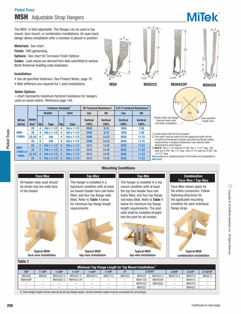
208
Plat
ed T
russ
Copyright © 2018 M
iTek Industries, Inc. All Rights Reserved
MSH Adjustable Strap Hangers
Plated Truss
Nailer Options – chart represents maximum factored resistance for hangers used on wood nailers. Reference page 148.
Lbs kN Lbs kN
Qty Type Qty Type2X 4 10d x 1-1/2 4 10d x 1-1/2 2045 9.10 1655 7.363X 4 10d x 1-1/2 4 10d x 1-1/2 2045 9.10 1655 7.36
(2) 2X 6 10d 4 10d x 1-1/2 3200 14.23 2635 11.724X 6 10d 4 10d x 1-1/2 3200 14.23 2635 11.722X 6 10d x 1-1/2 6 10d x 1-1/2 3215 14.30 2525 11.233X 6 10d x 1-1/2 6 10d x 1-1/2 3215 14.30 2525 11.23
(2) 2X 6 16d x 2-1/2 6 10d x 1-1/2 3215 14.30 2525 11.234X 6 16d x 2-1/2 6 10d x 1-1/2 3215 14.30 2525 11.23
1) Listed loads shall not be increased. 2) The nailer must be sized to fit the supported width and be of sufficient thickness to satisfy specified top flange nailing requirements. A design professional must specify nailer attachment to steel beams. 3) NAILS: 10d x 1-1/2 nails are 0.148" dia. x 1-1/2" long, 10d nails are 0.148" dia. x 3" long, 16d x 2-1/2 nails are 0.162" dia. x 2-1/2" long. New products or updated product information are designated in blue font.
MSH (18GA)
MSH (16GA or 14GA)
Fastener Schedule3 DF Factored Resistance1 S-P-F Factored Resistance1
MiTekSeries
Nailer
Size2
Header Joist
Vertical100%
Vertical100%
Vertical100%
Vertical100%
1) Listed loads shall not be increased.2) The nailer must be sized to fit the supported width and be
of sufficient thickness to satisfy specified top flange nailing requirements. A design professional must specify nailer attachment to steel beams.
3) NAILS: 10d x 1-1/2 nails are 0.148" dia. x 1-1/2" long, 10d nails are 0.148" dia. x 3" long, 16d x 2-1/2 nails are 0.162" dia. x 2-1/2" long.
New products or updated product information are designated in blue font.
Double shear nail designfeatures fewer nails
and faster installation
Uses standard length nails
The MSH is field adjustable. The flanges can be used in top mount, face mount, or combination installations. An open back design allows installation after a member is placed in position.
Materials: See chartFinish: G90 galvanizingOptions: See chart for Corrosion Finish OptionsCodes: Load values are derived from data submitted to various North American building code evaluators.
Installation:• Use all specified fasteners. See Product Notes, page 19.• Web stiffeners are required for I-Joist installations.
Face Max
All header nails used should be driven into the wide face of the header
Top-Max
The hanger is installed in a topmount condition with at least six lowest header face nail holes filled, and four top flange nails filled. Refer to Table 1 below for minimum top flange length requirements.
Top-Min
The hanger is installed in a top mount condition with at least the top two header face nail holes filled, and four top flange nail holes filled. Refer to Table 1 below for minimum top flange length requirements. The joist nails shall be installed straight into the joist for all models.
Combination Face-Max / Top-Max
Face-Max values apply for the entire connection. Follow fastening directions for the applicable mounting condition for each individual flange strap.
Typical MSH face-max installation
Typical MSH top-max installation
Typical MSH top-min installation
Typical MSH combination installation
Mounting Conditions
Table 1
Continued on next page
7/8" 1-1/8" 1-3/8" 1-1/2" 1-3/4" 1-7/8" 2" 2-5/8" 2-3/4" 2-13/16"MSH426 MSH29 MSH2322-2 MSH422-2 MSH426-2 MSH1713 MSH424 MSH222 MSH222-2 MSH218-2 MSH218 MSH213
MSH426IF -- MSH2622-2 MSH422-2IF -- -- -- MSH1722 MSH422IF -- MSH413 ---- -- -- -- -- -- -- MSH2322 MSH2022 -- MSH418 ---- -- -- -- -- -- -- MSH322 -- MSH422 --
1) Total hanger height will be reduced by the top flange length. Carried member height must be accounted for accordingly.
Minimum Top Flange Length for Top Mount Installations 1
2-3/16"
MSH MSH422IFMSH222 MSH426
H
D
B
WD
22"
3-5/8"
H
DW
BD
23"
1-5/8"
A
AA

209
Plated Truss Co
pyrig
ht ©
201
8 M
iTek
Indu
strie
s, In
c. A
ll Ri
ghts
Res
erve
d
Top Face
Ref. No. W H D A B Qty Qty Type Qty Type
face-max -- 18 10d 4 10d x 1-1/2 4625 1435 20.57 6.38 3630 1125 16.15 5.00
top-max 4 6 10d 4 10d x 1-1/2 4785 1435 21.28 6.38 3760 1125 16.73 5.00
top-min 4 2 10d 4 10d x 1-1/2 3630 -- 16.15 -- 2850 -- 12.68 --
face-max -- 20 10d 4 10d 4625 1435 20.57 6.38 3630 1125 16.15 5.00
top-max 4 6 10d 4 10d 4785 1435 21.28 6.38 3760 1125 16.73 5.00
top-min 4 2 10d 4 10d x 1-1/2 3630 -- 16.15 -- 2850 -- 12.68 --
face-max -- 26 10d 4 10d x 1-1/2 4625 1435 20.57 6.38 3630 1125 16.15 5.00
top-max 4 6 10d 4 10d x 1-1/2 4785 1435 21.28 6.38 3760 1125 16.73 5.00
top-min 4 2 10d 4 10d x 1-1/2 3630 -- 16.15 -- 2850 -- 12.68 --
face-max -- 22 10d 4 10d x 1-1/2 3640 1085 16.19 4.83 2860 850 12.72 3.78
top-max 4 6 10d 4 10d x 1-1/2 4125 1085 18.35 4.83 3235 850 14.39 3.78
top-min 4 2 10d 4 10d x 1-1/2 3440 -- 15.30 -- 2700 -- 12.01 --
face-max -- 12 10d 4 10d 3640 1085 16.19 4.83 2860 850 12.72 3.78top-max 4 6 10d 4 10d 4125 1085 18.35 4.83 3235 850 14.39 3.78top-min 4 2 10d 4 10d x 1-1/2 3440 -- 15.30 -- 2700 -- 12.01 --
face-max -- 22 10d 4 10d x 1-1/2 3410 940 15.17 4.18 2900 800 12.90 3.56top-max 4 6 10d 4 10d x 1-1/2 4495 975 19.99 4.34 3660 795 16.28 3.54top-min 4 2 10d 4 10d x 1-1/2 3370 -- 14.99 -- 2750 -- 12.23 --
face-max -- 22 10d 4 10d 3410 940 15.17 4.18 2900 800 12.90 3.56top-max 4 6 10d 4 10d 4495 975 19.99 4.34 3660 795 16.28 3.54top-min 4 2 10d 4 10d 3370 -- 14.99 -- 2750 -- 12.23 --
face-max -- 22 10d 4 10d x 1-1/2 3410 940 15.17 4.18 2900 800 12.90 3.56top-max 4 6 10d 4 10d x 1-1/2 4495 975 19.99 4.34 3660 795 16.28 3.54
top-min 4 2 10d 4 10d x 1-1/2 3370 -- 14.99 -- 2750 -- 12.23 --
face-max -- 22 10d 4 10d x 1-1/2 3410 940 15.17 4.18 2900 800 12.90 3.56top-max 4 6 10d 4 10d x 1-1/2 4495 975 19.99 4.34 3660 795 16.28 3.54
top-min 4 2 10d 4 10d x 1-1/2 3370 -- 14.99 -- 2750 -- 12.23 --
face-max -- 16 10d 4 10d 3940 1105 17.53 4.92 3090 865 13.75 3.85top-max 4 6 10d 4 10d 5530 1105 24.60 4.92 4340 865 19.31 3.85top-min 4 2 10d 4 10d 3425 -- 15.24 -- 2690 -- 11.97 --
face-max -- 22 10d 4 10d 5335 1105 23.73 4.92 4190 865 18.64 3.85top-max 4 6 10d 4 10d 5530 1105 24.60 4.92 4340 865 19.31 3.85top-min 4 2 10d 4 10d 3425 -- 15.24 -- 2690 -- 11.97 --
face-max -- 14 10d 6 10d 5505 2865 24.49 12.74 4320 2250 19.22 10.01top-max 4 6 10d 6 10d 5125 2865 22.80 12.74 4020 2250 17.88 10.01top-min 4 2 10d 6 10d 3215 -- 14.30 -- 2525 -- 11.23 --
face-max -- 18 10d 6 10d 6930 2865 30.83 12.74 5440 2250 24.20 10.01top-max 4 6 10d 6 10d 5125 2865 22.80 12.74 4020 2250 17.88 10.01top-min 4 2 10d 6 10d 3215 -- 14.30 -- 2525 -- 11.23 --
face-max -- 22 10d 6 10d 6015 2490 26.76 11.08 5115 2115 22.75 9.41top-max 4 6 10d 6 10d 5125 2865 22.80 12.74 4020 2250 17.88 10.01top-min 4 2 10d 6 10d 3215 -- 14.30 -- 2525 -- 11.23 --
face-max -- 22 10d 4 10d 5335 1105 23.73 4.92 4190 865 18.64 3.85top-max 4 6 10d 4 10d 5530 1105 24.60 4.92 4340 865 19.31 3.85top-min 4 2 10d 4 10d 3425 -- 15.24 -- 2690 -- 11.97 --
face-max -- 36 10d 6 10d 6285 2345 27.96 10.43 4935 1840 21.95 8.18top-max 4 6 10d 6 10d 4705 2345 20.93 10.43 3695 1840 16.44 8.18top-min 4 2 10d 6 10d 2455 -- 10.92 -- 1930 -- 8.59 --
1-13/16 top-max 4 8 16d 6 16d 6115 3415 27.20 15.19 4800 2685 21.35 11.94-- top-min 4 2 16d 6 16d 4340 905 19.31 4.03 3405 710 15.15 3.16
face-max -- 26 16d 6 16d 9025 1935 40.15 8.61 7355 1575 32.72 7.01top-max 4 10 16d 6 16d 7275 2145 32.36 9.54 5710 1685 25.40 7.50top-min 4 4 16d 6 16d 6665 -- 29.65 -- 5230 -- 23.26 --
face-max -- 26 16d 6 16d 9025 1935 40.15 8.61 7355 1575 32.72 7.01top-max 4 10 16d 6 16d 7275 2145 32.36 9.54 5710 1685 25.40 7.50top-min 4 4 16d 6 16d 6665 -- 29.65 -- 5230 -- 23.26 --
face-max -- 22 10d 4 10d 9025 1935 40.15 8.61 7355 1575 32.72 7.01top-max 4 6 10d 4 10d 7275 2145 32.36 9.54 5710 1685 25.40 7.50top-min 4 4 10d 4 10d 6665 -- 29.65 -- 5230 -- 23.26 --
face-max -- 46 10d 4 10d 8120 995 36.12 4.43 6375 810 28.36 3.60
top-max 4 6 10d 4 10d 5240 995 23.31 4.43 4115 810 18.30 3.60
top-min 4 2 10d 4 10d 3475 -- 15.46 -- 2830 -- 12.59 --
face-max -- 46 10d 4 10d 8120 995 36.12 4.43 6375 810 28.36 3.60
top-max 4 6 10d 4 10d 5240 995 23.31 4.43 4115 810 18.30 3.60
top-min 4 2 10d 4 10d 3475 -- 15.46 -- 2830 -- 12.59 --
1) Factored uplift resistances have been increased 15% for short-term loads such as wind and earthquake; reduce for other load durations in accordance with the code. 2) NAILS: 10d x 1-1/2 nails are 0.148" dia. x 1-1/2" long, 10d nails are 0.148" dia. x 3" long, 16d nails are 0.162" dia. x 3-1/2" long. New products or updated product information are designated in blue font.
5
4-5/8" wide
I-Joist
MSH2322-2 -- 16 4-3/4 22
1-5/8 2-1/4 516-3/4
2xLumber
orTrusses
MSH218 THA218 18
MSH222 THAI222 18 1-5/8 1-3/4 10-13/16
MSH29 THA29 18 1-5/8
(2) 3-1/2"wideFloor
Trusses
MSH422-2 THA422-2 14 7-1/4 22-1/8
1-3/4 9-1/4
5-3/16
MSH426 MSH426IF
THA426, THAC426
14 3-5/8 26 1-3/4 8
MSH424 -- 16 3-5/8 21-1/2 2
THAC418, THAC422
MSH2622-2
2 11
MSH426-2 THA426-2 14 7-1/4 26-1/16 2 11
-- 16 5-3/8 22 1-3/4 9-1/41-7/8
MSH422-2IF THAC422-2 14 7-1/4 22-1/8 2 11
16 3-5/8 22 1-3/4 9-13/16
MSH422 THA422, THAI422
16 3-9/16 21-1/2 1-3/4
THA418 16 3-9/16 17-1/2 1-3/4 7-5/8
10-1/16
3-1/2" wideFloor
Trusses
MSH413 THA413 16 3-9/16 14 1-3/4 7-5/8
MSH418
MSH222-2 THA222-2 16 3-1/8 22-1/4 1-3/4
7-5/8
MSH422IF
1-3/4 10-3/8
(2) 2xLumber
orTrusses
MSH218-2 THA218-2 16 3-1/8 17-3/4 1-3/4 10-1/16
2-1/2" wide FloorTrusses
MSH322 THAI322 18 2-9/16 22-1/2
1-13/16
1-13/16
1-3/4 10-7/16
2-5/16"wide
I-Joist MSH2322 THAI3522 18 2-3/8 22-5/8 1-3/4 10-7/16
2" wideI-Joist
MSH2022 THAI2.06/22 18 2-1/16 22-5/8
Ga.
Dimensions (in) Fastener Schedule2 DF Factored Resistance S-P-F Factored Resistance
10-3/4
MSH1722 THAI1.81/22 18 1-13/16 22-7/8 1-3/4 10-3/4
Uplift1
115%
12-3/4
2-1/4 5
MSH213 THA213 18 1-5/8 2-1/4
8-3/4
23
Corr
osio
nFi
nish
kN
Vertical100%
Uplift1
115%Vertical100%
Vertical100%
Uplift1
115%
1-3/4"LVLor
I-Joist
MSH1713 -- 18 1-13/16 14-7/16 1-3/4
JoistMaterial& Width
Header Joist Lbs kN Lbs
MiTekStock No.
MountingCondition
Vertical100%
Uplift1
115%
2-7/16
2-3/8
2-7/16
1-13/16
1-13/16
1-7/8
1-13/16
1-13/16
1-13/16
1-7/8
1-7/8
2-1/8
--
2-1/16
2-1/8
1-7/8
1-7/8
--
MSH Adjustable Strap Hangers
Plated Truss
Corrosion Finish Stainless Steel Gold Coat HDG Triple Zinc
Corrosion Finish Stainless Steel Gold Coat HDG Triple Zinc
Corrosion Finish Stainless Steel Gold Coat HDG Triple Zinc

210
Plat
ed T
russ
Copyright © 2018 M
iTek Industries, Inc. All Rights Reserved
MSHL / R Skewed Truss Hangers
Ref. No. Type Qty Type UnitLbs 2795 1155 2790 1150kN 12.43 5.14 12.41 5.12Lbs 2700 1155 2600 1150kN 12.01 5.14 11.57 5.12Lbs 1925 -- 1855 --kN 8.56 -- 8.25 --Lbs 2795 1155 2790 1150kN 12.43 5.14 12.41 5.12Lbs 2630 995 2065 780kN 11.70 4.43 9.19 3.47Lbs 2605 995 2045 780kN 11.59 4.43 9.10 3.47Lbs 2290 -- 1800 --kN 10.19 -- 8.01 --Lbs 2630 995 2065 780kN 11.70 4.43 9.19 3.47
1) Factored uplift resistances have been increased 15% for short-term loads such as wind and earthquake; reduce for other load durations in accordance with the code. 2) NAILS: 10d x 1-1/2 nails are 0.148" dia. x 1-1/2" long, 10d nails are 0.148" dia. x 3" long. New products or updated product information are designated in blue font.
TopQty
FaceQty
2 10 10d
2 14 10d
4 2 10d
6 10d
top-max
top-min
10d
4 6 10d 6 10d
10d
3-1/2" LVLor FloorTrusses
MSH422L/R THAL/R422 16
10d x 1-1/26
combination
-- 14 10d 6
4 2 10d 6
face-max
10d x 1-1/2
-- 22 10d 6
JoistMaterial& Width
MiTekStock No.
SteelGauge
MountingCondition
MSH213L/R2x Lumber
orTrusses
-- 18
face-max
top-min
top-max
combination
6 10d x 1-1/2
Vertical100%
Uplift1
115%
DFFactored Resistance
S-P-FFactored ResistanceJoist
Fastener Schedule2
Header
Vertical100%
Uplift1
115%
10d x 1-1/2
4 6 10d 6
Plated Truss
The MSHL/R is a versatile 45-degree skewed hanger with multiple installation options. It can be installed on a supporting girder truss as well as solid-sawn and structural composite lumber headers.
Materials: See chartFinish: G90 galvanizing
Installation:• Install the required number of fasteners according to the load table.• Install fasteners into the carrying members at the locations
described below based on the proper “Mounting Condition.” • Web stiffeners are required for I-Joist installations.• Hanger is factory
skewed at 45° left or right.
Typical MSH213R installationright skew
Typical MSH213L installationleft skew
MSH213L left skew
13-1/4"
5"
1-5/8"
1-3/4"
Right skew Left skew
Drive nails at angle
40° to 50°
Typical MSH422R face-max installation
Typical MSH422R top-max installation
Typical MSH422R top-min installation
Typical MSH422R combination installation
Install six (6) 10d x 1-1/2" nails into 2x carried member, or six (6) 10d nails into 3-1/2" wide carried member.
CONNECTION TO CARRYING MEMBERMounting Condition
CONNECTION TO CARRIED MEMBER - All Mounting Conditions
Top-MinThe straps must be field bent over the header a minimum of 2" to allow four (4) top flange nail holes to be filled (two in each strap). Also install the two (2) uppermost face nails (one on each strap) near the top of the header.
Top-Max The straps must be field-bent over the header a minimum of 2" to allow four (4) top flange nail holes to be filled (two in each strap). The bottom six (6) fastener holes (three on each side of the bucket) must be filled. Min. 2x6 bottom chord required.
MSH422R right skew
MSH422L left skew
22"
5-1/8"
1-3/4"
3-9/16"
9-5/16"
Combination Face-Max/Top-Max
Follow the Face-Max installation for one side of the connector and the Top-Max installation for the opposite side of the connector. The Face-Max factored resistances apply to this type of installation. Min. 2x6 bottom chord required.
Face-Max For MSH422L/R, bottom six (6) fastener holes (three on each side of bucket) must be filled. Install eight (8) additional fasteners (four (4) in each strap) where applicable. For MSH213L/R, bottom eight (8) fastener holes must be filled (four (4) in each strap). Install fourteen (14) additional fasteners, seven (7) in each strap. Min. 2x6 bottom chord required.
1) Factored uplift resistances have been increased 15% for short-term loads such as wind or earthquake; reduce for other load durations in accordance with the code.
2) NAILS: 10d x 1-1/2 nails are 0.148" dia. x 1-1/2" long, 10d nails are 0.148" dia. x 3" long
New products or updated product information are designated in blue font.
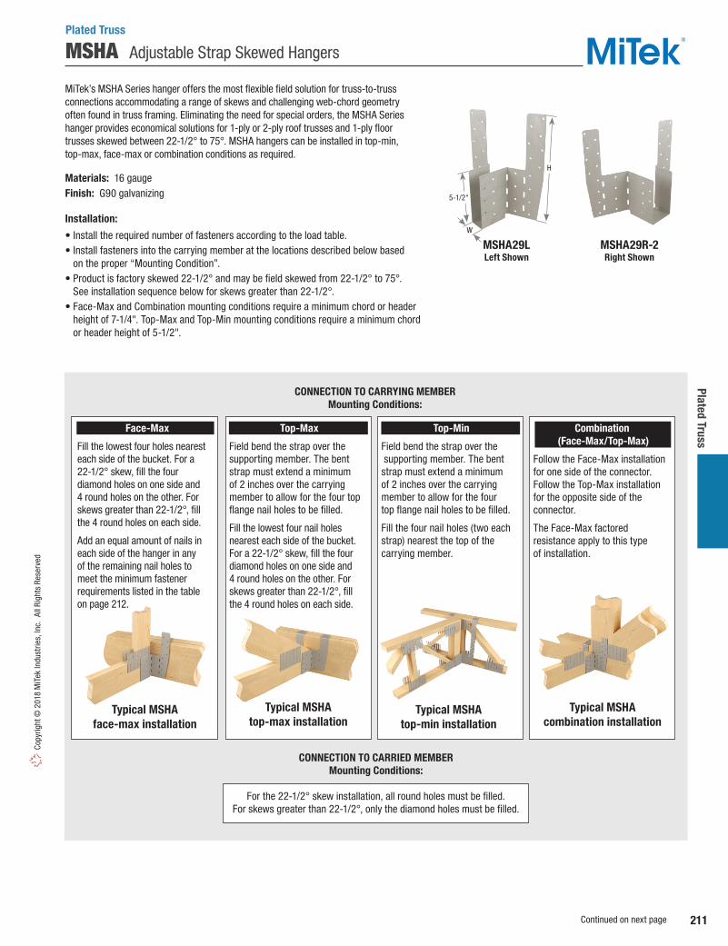
211
Plated Truss Co
pyrig
ht ©
201
8 M
iTek
Indu
strie
s, In
c. A
ll Ri
ghts
Res
erve
d
MSHA Adjustable Strap Skewed Hangers
MiTek’s MSHA Series hanger offers the most flexible field solution for truss-to-truss connections accommodating a range of skews and challenging web-chord geometry often found in truss framing. Eliminating the need for special orders, the MSHA Series hanger provides economical solutions for 1-ply or 2-ply roof trusses and 1-ply floor trusses skewed between 22-1/2° to 75°. MSHA hangers can be installed in top-min, top-max, face-max or combination conditions as required.
Materials: 16 gauge Finish: G90 galvanizing
Installation:
• Install the required number of fasteners according to the load table.• Install fasteners into the carrying member at the locations described below based
on the proper “Mounting Condition”. • Product is factory skewed 22-1/2° and may be field skewed from 22-1/2° to 75°.
See installation sequence below for skews greater than 22-1/2°.• Face-Max and Combination mounting conditions require a minimum chord or header
height of 7-1/4". Top-Max and Top-Min mounting conditions require a minimum chord or header height of 5-1/2".
MSHA29LLeft Shown
MSHA29R-2Right Shown
Plated Truss
Typical MSHA combination installation
Typical MSHA top-min installation
Typical MSHA face-max installation
Typical MSHA top-max installation
CONNECTION TO CARRYING MEMBERMounting Conditions:
CONNECTION TO CARRIED MEMBERMounting Conditions:
For the 22-1/2° skew installation, all round holes must be filled. For skews greater than 22-1/2°, only the diamond holes must be filled.
Face-Max
Fill the lowest four holes nearest each side of the bucket. For a 22-1/2° skew, fill the four diamond holes on one side and 4 round holes on the other. For skews greater than 22-1/2°, fill the 4 round holes on each side.
Add an equal amount of nails in each side of the hanger in any of the remaining nail holes to meet the minimum fastener requirements listed in the table on page 212.
Top-Max
Field bend the strap over the supporting member. The bent strap must extend a minimum of 2 inches over the carrying member to allow for the four top flange nail holes to be filled.
Fill the lowest four nail holes nearest each side of the bucket. For a 22-1/2° skew, fill the four diamond holes on one side and 4 round holes on the other. For skews greater than 22-1/2°, fill the 4 round holes on each side.
Top-Min
Field bend the strap over the supporting member. The bent strap must extend a minimum of 2 inches over the carrying member to allow for the four top flange nail holes to be filled.
Fill the four nail holes (two each strap) nearest the top of the carrying member.
Combination (Face-Max/Top-Max)
Follow the Face-Max installation for one side of the connector. Follow the Top-Max installation for the opposite side of the connector.
The Face-Max factored resistance apply to this type of installation.
H
W
5-1/2"
Continued on next page

212
Plat
ed T
russ
Copyright © 2018 M
iTek Industries, Inc. All Rights Reserved
Vertical Uplift1 Vertical Uplift1 Vertical Uplift1 Vertical Uplift1
Ref. No. W H Type Qty Type 100% 115% 100% 115% 100% 115% 100% 115%
22-1/2 -- 12 10d 7 10d x 1-1/2 2335 1625 10.39 7.23 2015 1400 8.96 6.23
23 to 45 -- 12 10d 4 10d x 1-1/2 2025 930 9.01 4.14 1590 805 7.07 3.58
46 to 75 -- 12 10d 4 10d x 1-1/2 2025 930 9.01 4.14 1590 805 7.07 3.58
22-1/2 4 8 10d 7 10d x 1-1/2 2870 1625 12.77 7.23 2260 1360 10.05 6.05
23 to 45 4 8 10d 4 10d x 1-1/2 2435 930 10.83 4.14 1915 755 8.52 3.36
46 to 75 4 8 10d 4 10d x 1-1/2 2190 930 9.74 4.14 1720 755 7.65 3.36
22-1/2 4 4 10d 7 10d x 1-1/2 1955 -- 8.70 -- 1685 -- 7.50 --
23 to 45 4 4 10d 4 10d x 1-1/2 1765 -- 7.85 -- 1385 -- 6.16 --
46 to 75 4 4 10d 4 10d x 1-1/2 950 -- 4.23 -- 745 -- 3.31 --
22-1/2 -- 12 10d 7 10d 2340 1630 10.41 7.25 1955 1360 8.70 6.05
23 to 45 -- 12 10d 4 10d 1910 935 8.50 4.16 1495 755 6.65 3.36
46 to 75 -- 12 10d 4 10d 1910 935 8.50 4.16 1495 755 7.70 3.36
22-1/2 4 8 10d 7 10d 2880 1630 12.81 7.25 2260 1360 10.05 6.05
23 to 45 4 8 10d 4 10d 2470 935 10.99 4.16 1970 780 8.76 3.47
46 to 75 4 8 10d 4 10d 2125 935 9.45 4.16 1665 780 7.41 3.47
22-1/2 4 4 10d 7 10d 1960 -- 8.72 -- 1685 -- 7.50 --
23 to 45 4 4 10d 4 10d 1765 -- 7.85 -- 1385 -- 6.16 --
46 to 75 4 4 10d 4 10d 950 -- 4.23 -- 745 -- 3.31 --
22-1/2 -- 12 10d 7 10d 2320 1615 10.32 7.18 2015 1400 8.96 6.23
23 to 45 -- 12 10d 4 10d 2025 925 9.01 4.11 1590 805 7.07 3.58
46 to 75 -- 12 10d 4 10d 2025 925 9.01 4.11 1590 805 7.07 3.58
22-1/2 4 8 10d 7 10d 2855 1615 12.70 7.18 2260 1360 10.05 6.05
23 to 45 4 8 10d 4 10d 2450 925 10.90 4.11 1970 780 8.76 3.47
46 to 75 4 8 10d 4 10d 2125 925 9.45 4.11 1665 780 7.41 3.47
22-1/2 4 4 10d 7 10d 1940 -- 8.63 -- 1685 -- 7.50 --
23 to 45 4 4 10d 4 10d 1765 -- 7.85 -- 1385 -- 6.16 --
46 to 75 4 4 10d 4 10d 950 -- 4.23 -- 745 -- 3.31 --
1) Factored uplift resistances have been increased 15% for short-term loads such as wind and earthquake; reduce for other load durations in accordance with the code. 2) Heff is the minimum distance from the top of the hanger seat to the top of the carrying member. 3) For tabulated top-mount installation loads, the straps must be wrapped over the header a minimum of 2". 4) NAILS: 10d x 1-1/2 nails are 0.148" dia. x 1-1/2" long, 10d nails are 0.148" dia. x 3" long. New products or updated product information are designated in blue font.
SkewAngle
(degrees)
MinHeff
2
(in)
Fastener Schedule4
top-min
top-max
MountingCondition3
TopQty
FaceQty
CarryingMember
Carried Member
MSHA29L/R THASR/L29 1-5/8 10-3/4
Dimensions(in)
JoistWidth
MiTekStock No.
face-max
top-min
top-max2-2x
Trusses MSHA29L/R-2 THASR/L29-2 3-1/8 10-3/4
face-max
5-1/2
7-1/4
7-1/4
5-1/2
2xTrusses
top-min
top-max4x
Trusses MSHA422L/R THASR/L422 3-5/8 22-1/8
face-max7-1/4
5-1/2
S-P-FFactored Resistance
Lbs kN
DFFactored Resistance
Lbs kN
MSHA Adjustable Strap Skewed Hangers
Step 1: Install acute side top and/or face header fasteners.
Step 2: Utilizing a piece of scrap fastened to the hanger on the obtuse side, bend the hanger to the desired angle.
Step 3: Bend the obtuse side of hanger back toward the header until the flange lies flat against the header, and install header top and/or face fasteners as noted above.
Step 4: Install carried truss and all required fasteners working from the bottom up.
Installation Sequence for Skews > 22-1/2°
Rotate acute side todesired angle
Align back edge of carried member with the slotted holes on the acute side
Plated Truss

213
Plated Truss Co
pyrig
ht ©
201
8 M
iTek
Indu
strie
s, In
c. A
ll Ri
ghts
Res
erve
d
Qty Type Qty Type Qty Type Lbs kN Lbs kNface-max -- -- 8 10d x 1-1/2 1 10d x 1-1/2 2115 9.41 1720 7.65top-min 2 10d 3 10d x 1-1/2 1 10d x 1-1/2 2115 9.41 1720 7.65
1) No uplift value with this hanger. Use other hardware higher on carried member to counteract uplift. 2) One or both straps may be bent over chord member with top and backside nailing. 3) Maintain minimum 3/4" edge distance when installing nails. 4) The supported member shall be supported by blocking or other means to prevent rotation. 5) Nails: 10d x 1-1/2 nails are 0.148" dia. x 1-1/2" long, 10d nails are 0.148" x 3" long. Note: The lower holes on each strap are for top nailing when strap is bent. These holes are not for face nailing.
1 or 2
Vertical 100%
Vertical 100%
Fastener Schedule2,3,5 DF
Factored Resistance1
S-P-F
Factored Resistance1
GirderPlies
Supporting MemberSupportedMemberTop
(per strap)Face/Backside
(per strap)MountingCondition
MSSH217L/R -- 18
MiTekStock No.
SteelGauge
Ref.No.
MSSHL/R Severely Skewed Hangers
MiTek’s MSSH217 hanger accommodates a skew range of 60° to 85° (5° minimum to 30° maximum off the girder) without the need for a more expensive custom design hanger. Face nail to webs or bend the flange strap over the chord. Available in left (L) or right (R) configurations.
Materials: 18 gaugeFinish: G90 galvanizing
Installation:• Use all specified fasteners. See Product Notes, page 19.• The 3 lower holes on each strap are for top nailing when the strap is bent
over the truss chord. These holes are not for face nailing.• One or both straps may be bent over the bottom chord of the girder with
top and backside nailing.• Note: Select the correct (right or left) hanger so that the strap on the outside
of the angle will pass the end of the truss. When facing the hanger, the strap in the rear turns in the direction of the skew. The front strap turns to pass behind the end of the carried member.
• Attach the hanger at the end of the truss with a single 10d (0.148" dia) x 1-1⁄2" nail into the side flange or bottom.
• Place the truss in position against the girder. Push the outside strap past the end of the truss to the girder web and face nail through the top 8 holes with 10d (0.148" dia) x 1-1⁄2" nails into the girder.
• The strap inside the angle can be formed over diagonal webs (if design allows) or bend over the girder chord. Use two nails into the top and fill all nail holes on the front/back side of the girder.
• If the outside strap does not contact a web, bend the strap tightly over the girder chord. Use two nails into the top and fill all nail holes on the back side of the girder.
• For uplift resistance, other means of attachment are required. If both the truss and girder have vertical webs, attach a scab to pack out the girder web nearly flush with the truss web and use a field adjustable MP framing angle across the two. A top chord connection for uplift requires a flat LSTA strap tie wrapped under the girder and over the truss chord.
Plated Truss
Back side with straps bent over
Right shownbent over bottom chord
Additional strappingfor high uplift
Additional strappingfor high uplift
Back view shown
MP Framing Angle pg. 82 Scab
LSTA StrapTie pg. 96
Bend over
MSSH217LLeft shown attached
to web and top of chord
MSSH217RRight shown
attached to webs
Top view right shown
MSSH217Rright shown
Pocket Nail
8 holes for face nailing
3 holes for top nailing 2x6 or 2x8
17-3/16"
1-5/8"1-3/4"
Bend over
Girder
Truss

214
Plat
ed T
russ
Copyright © 2018 M
iTek Industries, Inc. All Rights Reserved
SNP Skewed Nail Plate
The SNP3 Skewed Nail Plate is designed and tested for connecting square cut corner jack trusses at skews up to 45 .̊
Materials: 16 gaugeFinish: G90 galvanizingCodes: Load values are derived from data submitted to various North American building code evaluators.
Installation:• Install specified fasteners from bend line out from
each end. Not all nail holes will be filled.• Attach to the supported truss on the acute angle
side so the SNP3 runs behind the end of the jack.• Set jack truss against supporting truss and nail on
exposed flange.• Bend angle only once.• 8d common (0.131" dia. x 2-1/2" long) nails
may be substituted for 8d (0.131" dia.) x 1-1/2 nails with no reduction in load.
Ref. No. Qty Type UnitLbs 865 995 680 780kN 3.85 4.43 3.02 3.47
1) Factored resistances have been increased 15% for short-term loads such as wind and earthquake; no further increase is allowed. 2) NAILS: 8d x 1-1/2 nails are 0.131" dia. x 1-1/2" long. New products or updated product information are designated in blue font.
SNP3 TJC37 16 6 8d x 1-1/2
MiTekStock No.
SteelGauge
Each End Vertical100%
Upift1
115%Vertical100%
Upift1
115%
DFFactored Resistance
S-P-FFactored Resistance
Fastener
Schedule2
HHC – Designed to support hip/hip and jack truss/rafter. Contact MiTek when using in multi-ply applications.
HJHC – Allows for hip/hip support and hip/jack/hip installations.
HJC / HTHJ – Used to simultaneously hang a combination of hips and jacks off girder trusses. These hangers fit both left-hand and right-hand applications. An open back design allows for retrofit installations.
Materials: HHC / HJC / HJHC – 12 gauge, HTHJ –18 gauge Finish: G90 galvanizingOptions: See Specialty Options Chart on page 215.Codes: Load values are derived from data submitted to various North American building code evaluators.
Installation:• Use all specified fasteners. See Product Notes, page 19.
Typical HJC/HTHJinstallation
HHC / HJC / HJHC / HTHJ Hip / Jack Connectors
Plated Truss
Typical SNP3 installation
Supporting truss
3-1/2"
3-1/2"
Supported truss
0°to
45°
Typical HJC/HTHJ installation top view Typical HHC installation top view
Typical HJHCinstallation top view
45°45°45°
45° 45°
45°
SNP3
3-1/2"
3-1/2"
3-3/8"
Continued on next page

215
Plated Truss Co
pyrig
ht ©
201
8 M
iTek
Indu
strie
s, In
c. A
ll Ri
ghts
Res
erve
d
HHC / HJC / HJHC / HTHJ Hip/Jack Connectors
Description Ref. No. Qty Type3 Qty Type Qty Type UnitLbs 5740 4540 4505 3565kN 25.53 20.19 20.04 15.86Lbs 5740 3105 4505 2725kN 25.53 13.81 20.04 12.12Lbs 5740 2175 4505 1910kN 25.53 9.67 20.04 8.50Lbs 3695 2570 2900 2020kN 16.44 11.43 12.90 8.99Lbs 5740 4540 4505 3565kN 25.53 20.19 20.04 15.86Lbs 5740 3725 4505 3270kN 25.53 16.57 20.04 14.55Lbs 5740 2485 4505 2180kN 25.53 11.05 20.04 9.70
1) 15% increase for short-term loads such as wind and earthquake has been taken into consideration, no further increase allowed. 2) Loading published for total load of hip / jack connection. 3) For maximum factored uplift resistance for individual hip or jack member, consult MiTek design professional. 4) For single 2x carrying member (header), 10d header nails may be substituted with 10d x 1-1/2" and multiply the listed factored resistances by 0.90; 16d header nails may be substituted with 10d x 1-1/2" and multiply the listed fastored resistances by 0.78. 5) NAILS: 10d nails are 0.148" dia. x 3" long, 16d nails are 0.162" dia. x 3-1/2" long. New products or updated product information are designated in blue font.
2 x 6 terminal
2 x 8 terminal
7-1/8
5-7/16
7-3/16
5-7/16
7-3/16
--
12
--
LTHJA26, THJA26
--
--
-- HJHC28
12
10d
16 16d 7 16d 5 16d
24 16d 6 10d 2
--24 16d 6
10d 8
10d --
--
10d
10d
10d 2
10d --
20 16d 5
12
12
12 20 16d 5
5
12
18
20 16d 6
HJC26
HJC28
HHC26
HHC28
HJHC26
HTHJ26-18
2 x 8 right / left
Vertical100%
Uplift1,3
115%
DF
Factored Resistance2
S-P-F
Factored Resistance2
2 x 6 right / left LTHJA26, THJA26, THJU26
16 16d 5 10d 7 10d
CarryingMember
5-3/8
MiTekStock No.
Uplift1,3
115%
Carried Member
Fastener Schedule4,5
SteelGauge
per Hip per JackH(in)
Vertical100%
Option Hip Truss Skew
Range 30˚ to 60˚Factored
Resistance100% of table load
OrderingAdd SK, angle of hip
required, to product number.Ex. HJC26_SK55
HJC Specialty Options Chart – refer to Specialty Options pages 246-247 for additional details.
Plated Truss
Typical HJC (skewed) installationwith alternate skew angle top view
Specify angle(60° max)
10-1/2"5"6" 3-1/4" 5-7/8"
1-3/4"1-3/4"
2"
3-1/4"
HHH
9"
1-7/8"
3-1/4"
H
HJC HHCHTHJ HJHC
HJC (skewed)
Varies 8"max. width
H
3-1/4"
1-3/4"

216
Plat
ed T
russ
Copyright © 2018 M
iTek Industries, Inc. All Rights Reserved
BN Breakfast Nook Hangers
Designed to carry four mono trusses in one connector, it reduces installation time and cost. Provides a tested, load rated connection. Standard configuration spacing: 22-1/2°, 45°, 45°, 45°, 22-1/2°. The design also includes field adjustable nailing tabs.
Materials: 14 gaugeFinish: PrimerCodes: Load values are derived from data submitted to various North American building code evaluators.
Installation:• Use all specified fasteners. See Product Notes, page 19.• Allow a 2" setback for each mono truss.• For pitched ceiling, design mono trusses with
end-vertical upset. Upset equals tangent of the ceiling slope times 5.6".
• Bend tab only once.
Typical DSC4R installation
LDSC4L left shown
DSC4R right shown
BN264
Ref. No. L H B Qty Type Qty Type Lbs. kN Lbs. kN Lbs. kN Lbs. kN BN264 THJM2-4-SDS3 14 10 5-3/8 3-1/4 20 10d 2 10d x 1-1/2 4565 20.31 1060 4.72 3585 15.95 830 3.69 BN284 -- 14 10 7-1/8 3-1/4 20 10d 2 10d x 1-1/2 4565 20.31 1060 4.72 3585 15.95 830 3.69
1) Short-term load duration factor has been taken into consideration; no further increase allowed. 2) Loading published for total load of connection. Factored load on each single member shall not exceed 25% of the factored resistance listed. 3) NAILS: 10d x 1-1/2 nails are 0.148" dia. x 1-1/2" long, 10d nails are 0.148" dia. x 3" long. New products or updated product information are designated in blue font.
Dimensions (in)
MiTekStock No.
SteelGauge
Carried Member
per Mono Truss
Fastener Schedule3
Carrying Member Vertical (100%) Uplift (115%)1 Vertical (100%) Uplift (115%)1
DFFactored Resistance2
S-P-FFactored Resistance2
LDSC / DSC Drag Strut Connectors
Transfers lateral loads from girder truss into bearing walls.
Materials: See chartFinish: PrimerCodes: Load values are derived from data submitted to various North American building code evaluators.
Installation:• Use all specified fasteners. See Product Notes, page 19.• WS3 Wood Screw, 1/4" dia. x 3" long, are supplied with
DSC4 connector.
Ref. No. Qty Type Qty Type Lbs kN Lbs kN Lbs kN Lbs kN LDSC4L/R -- 14 9 10d x 1-1/2 9 10d x 1-1/2 1700 7.56 1700 7.56 1475 6.56 1475 6.56 DSC4L/R DSC5R/L-SDS3 3 16 WS3 16 WS3 6165 27.42 6140 27.31 5305 23.60 5280 23.49
1) Factored resistances have been increased 15% for short-term loads such as wind and earthquake; reduce for other load durations in accordance with the code. 2) WS3 wood screws are 1/4" x 3" and are included with DCS4 connector. 3) NAILS: 10d x 1-1/2 nails are 0.148" dia. x 1-1/2" long.
DFFactored Resistance
Compression
115%1
Tension
115%1
Compression
115%1
Tension
115%1
S-P-FFactored Resistance
MiTekStock No.
SteelGauge
Fastener Schedule2,3
Truss Top Plate
Plated Truss
Standard configuration(top view)
Typical BN264installation
22-1/2°
Nailing tabs adjust to fasten 22-1/2°
mono trusses
22-1/2°
45°
45°
45°
10-1/2"
7"2-1/8"
21"10-1/2"
3-1/4"3"
2"
Field adjustable nailing tabs with slotted fastening
holes for slant nailing
L
H
B

217
Plated Truss Co
pyrig
ht ©
201
8 M
iTek
Indu
strie
s, In
c. A
ll Ri
ghts
Res
erve
d
GTWS High Uplift Girder Truss Hangers
The GTWS series girder-to-girder hangers feature high uplift capacities along with high gravity load ratings.
Materials: 10 gaugeFinish: G90 galvanizingCodes: Load values are derived from data submitted to various North American building code evaluators.
Installation:• Use all specified fasteners. See Product Notes, page 19.
• WS Wood Screws are included with hangers where specified.
• GTWS2T shall be installed to a minimum 2x4 vertical member of a girder truss with no restriction on the size of the bottom chord.
• GTWS3T shall be installed to a minimum 2x6 vertical member of a girder truss with no restriction on the size of the bottom chord.
• GTWS4T shall be installed to a minimum 2x8 vertical member of a girder truss with no restriction on the size of the bottom chord.
Ref. No. W H D Qty Qty UnitLbs 20425 18400 16035 14445kN 90.85 81.85 71.33 64.25Lbs 20425 23530 16035 18470kN 90.85 104.67 71.33 82.16Lbs 20425 23530 16035 18470kN 90.85 104.67 71.33 82.16
1) Factored resistances have been increased 15% for short-term loads such as wind and earthquake; no further increase allowed. 2) WS3 wood screws are 1/4" x 3" long and are included with the GTWS hangers. 3) The wood screws of the GTWS hangers may be installed in both vertical and horizontal members. New products or updated product information are designated in blue font.
MiTekStock No.
SteelGauge
Fastener Schedule
Supporting Truss
Supported Truss
Dimensions (in)
Wood
Screw2,3
Wood
Screw2,3Vertical100%
Uplift1
115%Vertical100%
Uplift1
115%
S-P-FFactored Resistance
DFFactored Resistance
GTWS2T
GTWS3T
GTWS4T
--
--
-- 28 WS3 24 WS3
3-1/4
4-7/8
6-1/2
22 WS3 16 WS3
28 WS3 24 WS3
10
10
10
16 4
16 5
16 5
Plated Truss
GTWS3T GTWS2T
Typical GTWSinstallation
16" 16"
4"5"W
W
Min. 2x6 vertical (Min. 3" height truss plates,
flush with hanger seat, required on end grain verticals
to resist wood splitting)

218
Plat
ed T
russ
Copyright © 2018 M
iTek Industries, Inc. All Rights Reserved
GTQ / GTQM Girder Truss Hangers
The GTQ / GTQM hangers connect to multi-ply girder truss with WS Wood Screws offering high load capacities. Design features minimum and maximum fastening installation options to accommodate various sizes of vertical web. GTQM’s are designed for LVL sizes, for example GTQM218.
Materials: 7 gaugeFinish: G90 galvanizing
Installation:• Use all WS wood screws as specified. • Install hanger centered on vertical web.• GTQ’s are designed to be installed on various sizes of vertical web.
Maintain a minimum 5/8" fastener edge distance as per the National Design Specification where truss connector plates are not present.
• Install WS wood screws in all fastener holes including diamond holes for maximum values.
• Refer to Backer Block Installation on page 221 if the length of the screw going into the supporting truss are longer than the thickness of the plies.
Ref. No. Qty Qty UnitLbs 11760 7870 10490 7020kN 52.31 35.01 46.66 31.23Lbs 19595 7870 17190 7020kN 87.16 35.01 76.46 31.23Lbs 11760 7870 10490 7020kN 52.31 35.01 46.66 31.23Lbs 19595 7870 17190 7020kN 87.16 35.01 76.46 31.23Lbs 16665 7870 13515 7020kN 74.13 35.01 60.12 31.23Lbs 21295 8150 17265 7270kN 94.72 36.25 76.80 32.34Lbs 16665 7870 13515 7020kN 74.13 35.01 60.12 31.23Lbs 21295 8150 17265 7270kN 94.72 36.25 76.80 32.34Lbs 20960 8050 16455 6935kN 93.23 35.81 73.20 30.85Lbs 24025 8050 20440 6935kN 106.87 35.81 90.92 30.85Lbs 20960 8050 16455 6935kN 93.23 35.81 73.20 30.85Lbs 24025 8050 20440 6935kN 106.87 35.81 90.92 30.85
1) Factored resistances have been increased 15% for short-term loads such as wind and earthquake; no further increase allowed. 2) Wood Screws: WS3 is 1/4" x 3" long, WS45 is 1/4" x 4-1/2" long, WS6 is 1/4" x 6" long and are included with GTQ and GTQM hangers. 3) If the length of the screws going into the supporting truss are longer than the thickness of the plies, refer to the backer block installation on page 221. 4) WS Wood Screws may be installed through metal truss connector plates as approved by the Truss Designer, provided the requirements of CSA O86-14 Clause 5.3.8. and TPIC-2014 Clause 7.5 are met. (Pre-drilling required through the plate using a maximum 5/32" bit). 5) Truss plies of the supporting member must be fastened together to transfer the load (through all truss plies) that is not transferred by the hanger screws; fastening schedule is to be specified by the truss designer. 6) Supported members on GTQM hangers shall have Specific Gravity of not less than 0.50. 7) The span of the supported member shall be shortened by 1/2" at the hanger end to allow space for screw head and back plate (7 ga). New products or updated product information are designated in blue font.
Vertical100%
Uplift1
115%
Fastener Schedule
Min #of Plies
Supporting Truss Supported Member
# of Plies
DFFactored Resistance
S-P-FFactored Resistance
Vertical100%
Uplift1
115%Wood
Screw2,4
25
41
2x8 41
47 GTQ420
GTQM420
6-1/2
7-1/4
2x8
Max 2x10
25 THGQ3, THGQH3
--
THGQH4
-- 5-1/2
Max 2x10 47
Min
Min 2x8
33
Min
Max
33
InstallType
Min
Max
GTQM218
W(in)
MiTekStock No.
GTQ218 THGQ2, THGQH2
3-1/4
Min
GTQ318
--
GTQM318
2x8
4-7/8
3-5/8
Max 2x8
Min 2x6
Max
2x6
2x6 18
2x8 30
WS3
Min.Vert.WebSize
30
WoodScrew2,3,4
2x6 18
2
3
WS6 3 20 WS6 4
WS3
WS45 WS452 20
2 20
Plated Truss
GTQ218(GTQM218 similar)
GTQ318(GTQM318 similar)
GTQ420(GTQM420 similar)
Typical GTQ218 installation(GTQM218 similar)
Typical GTQ318 installation(GTQM318 similar)
Typical GTQ420 installation
(GTQM420 similar)
W
18"
4-1/2"
6-1/4"
W5"
18"
6-1/4"
20"
5-3/4"W
5-15/16"

219
Plated Truss Co
pyrig
ht ©
201
8 M
iTek
Indu
strie
s, In
c. A
ll Ri
ghts
Res
erve
d
GT / GTD / GTS Girder Truss Hangers
The GT primarily hangs girder trusses off other girder trusses, although a wide variety of other heavy-duty installations apply.
Materials: Back Plate – 3 gauge; Strap – 7 gaugeFinish: PrimerOptions: All models available in LVL sizes, use M in place of T, as in GT2M4B.Codes: Load values are derived from data submitted to various North American building code evaluators.
Installation:• Use all specified fasteners. See Product Notes, page 19.• Minimum heel height is 9-1/4" for GT hangers. Typical GT2T4B
installation
Ref. No. W1 L H D Qty Qty Type Unit
Lbs 2880 4230 5575 3340 2265 3320 4375 2620kN 12.81 18.82 24.80 14.86 10.08 14.77 19.46 11.65Lbs 3790 6670 9545 3340 2975 5235 7495 2620kN 16.86 29.67 42.46 14.86 13.23 23.29 33.34 11.65Lbs 4180 6250 8320 3340 3285 4910 6530 2620kN 18.59 27.80 37.01 14.86 14.61 21.84 29.05 11.65Lbs 5785 9720 13650 3340 4540 7630 10715 2620kN 25.73 43.24 60.72 14.86 20.19 33.94 47.66 11.65Lbs 8685 14855 21020 3340 6815 11660 16500 2620kN 38.63 66.08 93.50 14.86 30.31 51.87 73.40 11.65Lbs 11450 16515 21575 3340 8990 12965 16935 2620kN 50.93 73.46 95.97 14.86 39.99 57.67 75.33 11.65Lbs 11580 17530 23475 3340 9090 13760 18430 2620kN 51.51 77.98 104.42 14.86 40.43 61.21 81.98 11.65Lbs 4180 6250 8320 3340 3285 4910 6530 2620kN 18.59 27.80 37.01 14.86 14.61 21.84 29.05 11.65Lbs 5335 9760 14180 3340 4190 7660 11130 2620kN 23.73 43.41 63.08 14.86 18.64 34.07 49.51 11.65Lbs 5785 9720 13650 3340 4540 7630 10715 2620kN 25.73 43.24 60.72 14.86 20.19 33.94 47.66 11.65Lbs 7630 14750 21865 3340 5990 11580 17165 2620kN 33.94 65.61 97.26 14.86 26.64 51.51 76.35 11.65Lbs 8685 14855 21020 3340 6815 11660 16500 2620kN 38.63 66.08 93.50 14.86 30.31 51.87 73.40 11.65Lbs 11450 16515 21575 3340 8990 12965 16935 2620kN 50.93 73.46 95.97 14.86 39.99 57.67 75.33 11.65Lbs 11580 17530 23475 3340 9090 13760 18430 2620kN 51.51 77.98 104.42 14.86 40.43 61.21 81.98 11.65Lbs 15270 23485 31695 3340 11985 18435 24885 2620kN 67.92 104.47 140.99 14.86 53.31 82.00 110.69 11.65Lbs 5785 9720 13650 3340 4540 7630 10715 2620kN 25.73 43.24 60.72 14.86 20.19 33.94 47.66 11.65Lbs 7630 14750 21865 3340 5990 11580 17165 2620kN 33.94 65.61 97.26 14.86 26.64 51.51 76.35 11.65Lbs 8685 14855 21020 3340 6815 11660 16500 2620kN 38.63 66.08 93.50 14.86 30.31 51.87 73.40 11.65Lbs 11440 16510 21575 3340 8980 12960 16935 2620kN 50.89 73.44 95.97 14.86 39.95 57.65 75.33 11.65Lbs 11570 17525 23475 3340 9085 13760 18430 2620kN 51.47 77.96 104.42 14.86 40.41 61.21 81.98 11.65Lbs 15230 23465 31695 3340 11955 18420 24885 2620kN 67.75 104.38 140.99 14.86 53.18 81.94 110.69 11.65
1) Factored uplift resistance has been increased 15% for short-term loads such as wind and earthquake; no further increase allowed. 2) Bolts shall conform to ASTM A 307 Grade A or better. 3) GT series require 2 x 6 vertical member for 2, 3, and 4 bolt hangers and 2 x 8 for 6 and 8 bolt hangers. 4) NAILS: 16d nails are 0.162" dia. x 3-1/2" long. New products or updated product information are designated in blue font.
SupportedTruss
4 ply
GT3T6B
GT3T6BH
GT4T8B
THGB3
--
--
--
--
5-1/8
22
6
6
22
4-1/2
4-1/2
4-1/2
5-1/2
4-1/2
4-1/2
5-1/2
5-1/2
22
5 ply
GT2T2B
GT2T2BH
GT2T3B
GT2T4B
GT2T6B
GT2T8B
GT3T3B
GT3T3BH
GT2T6BH
GT5T8BH
GT4T4B
GT4T4BH
GT4T6B
GT4T6BH
GT3T4B
GT3T4BH3 ply
GT3T8BH
GT3T8B
--
--
--
--
-- --
--
THGBH4
THGB2
THGBH2
-- --
--
--
88-1/8
6
6
22
26-1/4
19
22-1/4
22
26-1/4
6-1/2
6-1/2
6-1/2
6-1/2
5-1/8
5-1/8
6-1/2
5-1/8
7-1/2
9-1/4
22-1/4
5-1/8
5-1/8
6
7-1/2
25
30-1/4
6
6
7-1/2
7-1/2
7
7
7-1/4
7-1/4
7-1/2
7-1/4
25
6
5-1/2
5-1/2
Supporting Truss
2
--
26-1/4
THGBH3 5-1/8 7-1/4
6
5-1/8
26-1/4
19
25
30-1/4 6
4
Bolt
Dia.2
(in)
6
6
22-1/4
8
Dimensions (in)
3-7/16
3-7/16
6
6
19--
2 ply
6
3-7/16
7
6
6
3-7/16
3-7/16
3-7/16
-- 3-7/16
19
7-1/4
7-1/4
7-1/4
SupportedMember
MiTekStock No.
12
4 12
6 12
2 12
3 12
3/4
1
3/4
3/4
3 12
3 121
3/44
1
12
6 12
8 12
8 12
6
6
6
1
1
8
3/4
1
12
12
16d
16d
16d
16d
3/4
1
3/4
1
3/4
3/4
12
12
12
12
12
12
12
12
Fastener Schedule3,4
16d
16d
16d
16d
16d
16d
16d
16d
16d
16d
16d
16d
16d
3/4
4
4
3/4
1
3/4
16d
16d
16d
16d
1 Ply 100%
2 Ply 100%
3 Ply 100%
Uplift
115%11 Ply 100%
2 Ply 100%
3 Ply 100%
Uplift
115%1
DF Factored Resistance1 S-P-F Factored Resistance1
Supporting Member
Supporting Member
GT top view
GT2T4B
Plated Truss
9-1/4"
H
D
W1W
L
GT Load Table
Continued on next page
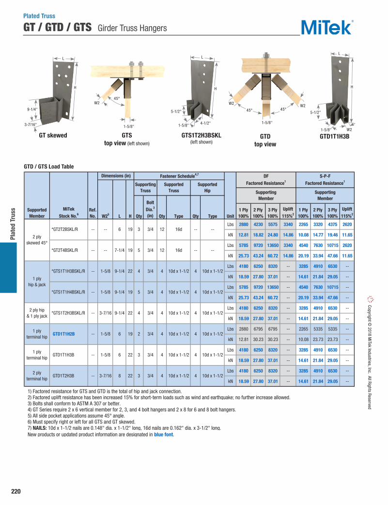
220
Plat
ed T
russ
Copyright © 2018 M
iTek Industries, Inc. All Rights Reserved
GT / GTD / GTS Girder Truss Hangers
W25 L H Qty Qty Type Qty Type Unit
Lbs 2880 4230 5575 3340 2265 3320 4375 2620
kN 12.81 18.82 24.80 14.86 10.08 14.77 19.46 11.65
Lbs 5785 9720 13650 3340 4540 7630 10715 2620
kN 25.73 43.24 60.72 14.86 20.19 33.94 47.66 11.65
Lbs 4180 6250 8320 -- 3285 4910 6530 --
kN 18.59 27.80 37.01 -- 14.61 21.84 29.05 --
Lbs 5785 9720 13650 -- 4540 7630 10715 --
kN 25.73 43.24 60.72 -- 20.19 33.94 47.66 --
Lbs 4180 6250 8320 -- 3285 4910 6530 --
kN 18.59 27.80 37.01 -- 14.61 21.84 29.05 --
Lbs 2880 6795 6795 -- 2265 5335 5335 --
kN 12.81 30.23 30.23 -- 10.08 23.73 23.73 --
Lbs 4180 6250 8320 -- 3285 4910 6530 --
kN 18.59 27.80 37.01 -- 14.61 21.84 29.05 --
Lbs 4180 6250 8320 -- 3285 4910 6530 --
kN 18.59 27.80 37.01 -- 14.61 21.84 29.05 --
1) Factored resistance for GTS and GTD is the total of hip and jack connection. 2) Factored uplift resistance has been increased 15% for short-term loads such as wind and earthquake; no further increase allowed. 3) Bolts shall conform to ASTM A 307 or better. 4) GT Series require 2 x 6 vertical member for 2, 3, and 4 bolt hangers and 2 x 8 for 6 and 8 bolt hangers. 5) All side pocket applications assume 45° angle. 6) Must specify right or left for all GTS and GT skewed. 7) NAILS: 10d x 1-1/2 nails are 0.148" dia. x 1-1/2" long, 16d nails are 0.162" dia. x 3-1/2" long. New products or updated product information are designated in blue font.
10d x 1-1/2-- 1-5/8 6 19 2 3/4 4 10d x 1-1/2 4
DF
Factored Resistance1
1 Ply 100%
2 Ply 100%
3 Ply 100%
Uplift
115%21 Ply 100%
2 Ply 100%
3 Ply 100%
Uplift
115%2
S-P-F
Factored Resistance1
Supporting Member
Supporting Member
SupportedMember
MiTek
Stock No.6
Fastener Schedule4,7
Supporting Truss
SupportedTruss
SupportedHip
Dimensions (in)
Bolt
Dia.3
(in)
3
6
7-1/4
9-1/4
19
19
22
10d x 1-1/2
10d x 1-1/2
4
3
5
4
4
3/4
5
4
3
--16d
16d
3/4 12
9-1/4
9-1/4 22
22
19
1-5/8
3-7/16
1-5/8
22
1-5/8
3-7/16 8
6
2 ply terminal hip
--
--
GTD1T1H3B
GTD1T2H3B
1 ply terminal hip
1 plyhip & jack
--
--
--
2 ply hip & 1 ply jack
*GTS1T1H3BSKL/R
*GTS1T1H4BSKL/R
*GTS1T2H3BSKL/R
1 ply terminal hip
GTD1T1H2B
2 plyskewed 45°
*GT2T2BSKL/R
*GT2T4BSKL/R
--
--
-- 12 --
--
Ref.No.
10d x 1-1/2
10d x 1-1/2
3/4
3/4 10d x 1-1/24 4
4
10d x 1-1/23/4 4 4
10d x 1-1/2
--
--
10d x 1-1/2
10d x 1-1/2
3/4
3/4
4 4
4
10d x 1-1/2
Plated Truss
GTS top view (left shown)
GTS1T2H3BSKL (left shown)
GTD top view
GTD1T1H3BGT skewed
45°W2
1-5/8"1-5/8" W2
3-7/16" 1-5/8"1-5/8"
W2 W25-1/2" 5-1/2"
4-1/2"
45°45°
L
H
L
H
L
H
9-1/4"
GTD / GTS Load Table

221
Plated Truss Co
pyrig
ht ©
201
8 M
iTek
Indu
strie
s, In
c. A
ll Ri
ghts
Res
erve
d
Filler Blocking
Alternate Installations
Backer block installation
Wood blocking used to achieve full design load value of a face mount hanger attached to a carrying member. (Blocking to be designed by truss designer or engineer of record).
• Wood blocking should be of similar size/grade as the truss member to which it is attached. The blocking should be designed to act as one unit with truss members.
• Truss designer shall approve blocking size/grade, fasteners required, and application.
• All fasteners used to attach wood blocking should be independent of the fasteners in the truss hanger.
Panel joint installation
Connection with face mount hanger attaching to a truss panel joint.
• Hanger nails that do not penetrate wood at panel joint provide no load resistance; reduce listed factored resistance accordingly.
Filler block installation
Wood filler blocking used for supported member of width less than hanger width. (Blocking and blocking fasteners/quantity to be designed by truss designer or engineer of record).
• Wood blocking should be of similar or better grade as the truss member to which it is attached. The blocking should be designed to act as one unit with truss member.
Plated Truss
JUS26 page 107
THDH28-2 page 205
THDH26-2 page 205
GT4T6BH page 219
Filler blocking
Backer block

222
Plat
ed T
russ
Copyright © 2018 M
iTek Industries, Inc. All Rights Reserved
Truss Brace & Spacer (Stabilizer™)
The Stabilizer™ Truss Brace & Spacer provides temporary construction bracing in the roof and ceiling planes, as well as permanent lateral bracing for webs as specified by your truss engineering.
The Stabilizer™ is easily installed by embedding the patented MII 20 teeth on the top flange straight into the edge of the truss member to be braced with a framing hammer. The side tabs are then secured by driving the teeth into the face of the truss member being braced.
Materials: 20 gaugeFinish: G60 galvanizingCodes: Load values are derived from data submitted to various North American building code evaluators.
Installation:• Use 31-16 for standard 16" o.c. spacing and 31-24 for
standard 24" o.c. spacing. For odd spacing, cut and insert a solid block between the trusses.
• Typically, The Stabilizer™ is installed at 6'– 8' centers along the roof plane and 10'– 15' along the ceiling plane. (Refer to engineering specifications BCSI 1-03, published by The Truss Plate Institute for specific bracing requirements.)
• The Stabilizer™ must be supplemented with diagonal bracing in the roof and ceiling planes and cross bracing in the web plane at required intervals.
• Web forces are not to exceed 8000 lbs.• The Stabilizer™ is properly installed when the top flap
and side tabs are flush with the member being braced.
Important: The erection contractor is responsible for determining and installing the temporary bracing for the structure, including the trusses. It is most important for the installer to provide adequate means for bracing the first truss installed. The performance of the entire bracing system depends on the adequacy of the ground bracing or other means of bracing the first group of trusses installed. The building designer is responsible for the permanent bracing design of the overall structure including the truss. This includes the design of required supplemental diagonal and cross bracing.
Ref. No. Tension Compression 31-16 TSBR2-16 20 16 152 222 608 31-24 TSBR2-24 20 24 152 222 608
1) 1 pound = 4.448N. 2) Fastener shall be (1) 8d or 10d common wire nail inserted through nail slot. 3) NAILS: 8d nails are 0.131" dia. x 2-1/2" long, 10d nails are 0.148" dia. x 3" long.
Factored Axial Loads (Lbs.)
Tensionwith Fastener
O.C.Spacing
(in)MiTek
Stock No.Steel
Gauge
Plated Truss
Temporary constructionbracing installation
Side view
1-3/8" Flap
Hammer here
Hammer here
1"
Chordattachment detail
Web bracinginstallation
31-24 Stabilizer™
Top view
End view
24 o.c.
Odd spacing
25-1/4"
22-1/2"
73.19°1-3/8"
1-1/2"
Tab
Standard MII 20 punch
1-3/8"
1-1/2"
1"7/8"
1/4"
1-3/8"
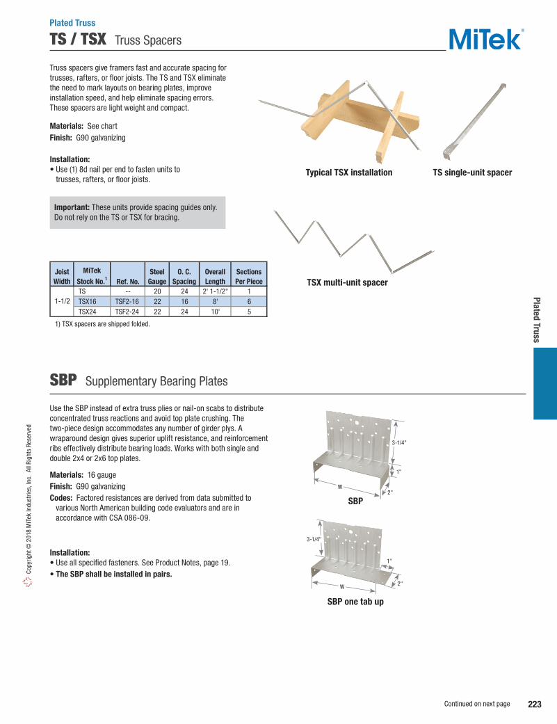
223
Plated Truss Co
pyrig
ht ©
201
8 M
iTek
Indu
strie
s, In
c. A
ll Ri
ghts
Res
erve
d
TS / TSX Truss Spacers
Truss spacers give framers fast and accurate spacing for trusses, rafters, or floor joists. The TS and TSX eliminate the need to mark layouts on bearing plates, improve installation speed, and help eliminate spacing errors. These spacers are light weight and compact.
Materials: See chartFinish: G90 galvanizing
Installation:• Use (1) 8d nail per end to fasten units to
trusses, rafters, or floor joists.
Use the SBP instead of extra truss plies or nail-on scabs to distribute concentrated truss reactions and avoid top plate crushing. The two-piece design accommodates any number of girder plys. A wraparound design gives superior uplift resistance, and reinforcement ribs effectively distribute bearing loads. Works with both single and double 2x4 or 2x6 top plates.
Materials: 16 gaugeFinish: G90 galvanizingCodes: Factored resistances are derived from data submitted to various North American building code evaluators and are in
accordance with CSA 086-09.
Installation:• Use all specified fasteners. See Product Notes, page 19.• The SBP shall be installed in pairs.
SBP one tab up
Important: These units provide spacing guides only. Do not rely on the TS or TSX for bracing.
Ref. No. TS -- 20 24 2' 1-1/2" 1 TSX16 TSF2-16 22 16 8' 6 TSX24 TSF2-24 22 24 10' 5
1) TSX spacers are shipped folded.
1-1/2
Joist Width
SectionsPer Piece
MiTek
Stock No.1Steel
GaugeO. C.
SpacingOverallLength
SBP Supplementary Bearing Plates
Plated Truss
Typical TSX installation TS single-unit spacer
TSX multi-unit spacer
SBP
3-1/4"
W2"
1"
2"
1"
3-1/4"
W
Continued on next page

224
Plat
ed T
russ
Copyright © 2018 M
iTek Industries, Inc. All Rights Reserved
SBP Supplementary Bearing Plates
SBP's Alone SBP's Alone
100% 100% EBL (in) 100% 100% EBL (mm)
1 5035 9300 7.63 22.40 41.37 193.882 5035 13565 5.57 22.40 60.33 141.393 5035 17825 4.88 22.40 79.30 123.894 5035 22090 4.53 22.40 98.27 115.141 3575 6805 7.38 15.90 30.26 187.342 3575 10030 5.44 15.90 44.63 138.123 3575 13260 4.79 15.90 58.99 121.714 3575 16490 4.47 15.90 73.35 113.511 3930 6730 8.41 17.48 29.95 213.592 3930 9535 5.95 17.48 42.41 151.243 3930 12335 5.14 17.48 54.88 130.464 3930 15140 4.73 17.48 67.34 120.07
1 7315 14015 11.50 32.54 62.35 292.212 7315 20715 8.50 32.54 92.15 215.963 7315 27415 7.50 32.54 121.96 190.544 7315 34115 7.00 32.54 151.77 177.831 5195 10270 11.13 23.11 45.68 282.752 5195 15340 8.31 23.11 68.24 211.233 5195 20415 7.38 23.11 90.81 187.384 5195 25490 6.91 23.11 113.38 175.461 5705 10110 12.63 25.38 44.97 320.702 5705 14510 9.06 25.38 64.55 230.203 5705 18915 7.88 25.38 84.14 200.034 5705 23320 7.28 25.38 103.73 184.95
1) Factored resistance is for a pair of SBP devices. 2) Multiple ply trusses shall be fastened together to act as a single unit. 3) EBL denotes effective bearing length and includes the actual bearing length plus the contribution of the SBP device. 4) Assumes full seating of truss on top plate.
SBP + Truss Bearing
SBP4 on 2x4 / 2x6 Top Plate and Alternate Installation
SBP6 on 2x6 / 2x8 Top Plate and Alternate Installation
Factored Resistance (kN)
SBP + Truss Bearing
Factored Resistance (Lbs)
WoodSpecies
No. ofTrussPlies
fcp
(psi)
DF
S-P-F
Hem Fir
1015
769
667
769
667
S-P-F
Hem Fir
DF 1015
Type Qty Type Application2-7/8 or less 10dx1-1/2
3 or more 10d2-7/8 or less 10dx1-1/2
3 or more 10d2-7/8 or less 10dx1-1/2
3 or more 10d2-7/8 or less 10dx1-1/2
3 or more 10d2-7/8 or less 10dx1-1/2
3 or more 10d2-7/8 or less 10dx1-1/2
3 or more 10d
1) Factored resistances have been increased 15% for short-term loads such as wind and earthquake; no further increase is allowed. For standard term loads divide the values by 1.15. 2) Fastener schedule is for a pair of SBP devices. 3) Factored resistances are for a pair of SBP devices, 4) Multiple ply trusses shall be fastened together to act as a single unit. 5) Where truss sits on a single top plate, 10d x 1-1/2 nails may be used on the top side of the top plate. 6) NAILS: 10d x 1-1/2 nails are 0.148" dia. x 1-1/2" long, 10d nails are 0.148" dia. x 3" long. New products or updated product information are designated in blue font.
DF (kN) S-P-F (kN)
9.68
S-P-F (Lbs)
12.8110.83 20451730
Uplift115%1
F1115%1
F2115%1
12.816.38 2045805 8.743.58
6.38
MiTekStock No.
4 8
DF (Lbs)
13.63
Truss/JoistThickness
(in)
Fastener Schedule2,6
TrussFactored Resistance3
9.10 9.687.70
Uplift115%1
F1115%1
F2115%1
20
Plate
Uplift115%1
F1115%1
F2115%1
Uplift115%1
F1115%1
F2115%1
TBE4 3-1/2 8 4
W(in)
10d
Top5
QtySidesQty
Ref. No.
SBP6 TBE6 5-1/2
4 4
StandardInstallation
StandardInstallation
30652435
10d 2880 30652435
10dOne Tab Up
(2x6 Top Plate)2880 22301435
8 4 10d
4 4
SBP4
3.58One Tab Up (Alternate)
6.38 5.00
7.7012.8110.83
3.588.36
805 4.98
8.743.58
One Tab Up (Alternate)
17302880
1880 13151435
2045
5.85
One Tab Up(2x8 Top Plate)
1120
5.00
1880 13151435 8.36
4 8 10d
2175
1965
1125
2175
1965
1125
6.38 2045805
28
112020
28
28
805
10d
20
9.102880 22301435 12.81
9.92
5.85
13.63
9.92
4.98
9.10
9.10
Typical SBP6 one tab up on a 2x8 top plate installation
(SBP4 similar)
Typical SBP one tab up alternate installation
Plated Truss
Typical SBP installation
F2
F2F1
F1

225
Plated Truss Co
pyrig
ht ©
201
8 M
iTek
Indu
strie
s, In
c. A
ll Ri
ghts
Res
erve
d
FTC / FTCF Floor Truss Clips
FTC clips slide easily onto the top or bottom chord and provides a guide to help position and support the second truss during assembly.
FTCF clips easily install after the trusses are installed.
Materials: 18 gaugeFinish: G90 galvanizingCodes: Factored resistances are derived from data submitted to various North American building code evaluators.
Installation:• Use all specified fasteners. See Product Notes, page 19.• The truss designer must determine the number of clips required
and the spacing between clips based on loading conditions.
Concentrated Load Condition: (Side-loaded onto a 2-ply truss):• The FTC clips shall be installed in pairs, or multiples of two, on
either side of, and within 12" of a concentrated load.• Divide half of the concentrated load by the clip capacity to
determine the number of clips required.
Example:Concentrated (point) load = 3000 lbs, FTC1 capacity (SPF) = 1080 lbs
= 1.4 = 2 clips Install two FTC1 clips, one on each side of, and within 12" of concentrated load.
Uniform Load condition (side-loaded onto a 2-ply truss):• To transfer uniform loads to the second ply, the FTC clips shall
be installed at a regular interval along the loaded chord. Spacing between clips is limited to 24" maximum.
• Divide the clip capacity by half the required load per lineal foot (PLF) to determine the spacing between clips.
Example:Uniform distributed load = 500 PLF. FTC1 capacity (SPF) = 1080 lbs
= 4.32' spacing
Space clips at 24" (MAX) along the loaded chord.
1⁄2 (3000 lbs)1080 lbs
1080 lbs 1⁄2 (500) PLF
FTC
Typical FTC installationTypical FTC
2-ply metal web truss installation
Typical FTC2F retrofit installation
Ref. No. W1 W2 H Qty Type Unit 100% 100%Lbs 980 850kN 4.36 3.78Lbs 1245 1080kN 5.54 4.80Lbs 1245 1080kN 5.54 4.80Lbs 1245 1080kN 5.54 4.80Lbs 1245 1080kN 5.54 4.80
1) Factored transfer resistances are for 100% floor load, and shall not be increased for short term load duration. 2) Truss designer shall determine the number of clips for concentrated loads and the spacing for uniform loads. 3) NAILS: 10d x 1-1/2 nails are 0.148" dia. x 1-1/2" long, 10d nails are 0.148" dia. x 3" long.
(2) 4 x 2
FTC32
FTC1
FTC1F
FTC2
FTC2F
MiTekStock No.
SteelGauge
Truss Size
3 x 2
4 x 2
--
--
--
--
--
18
18
18
18
18
10 10d
10 10d
DF FactoredMaximum Transfer
Resistance1,2
10 10d x 1-1/2
10 10d x 1-1/2
10 10d x 1-1/2
Fastener Schedule3S-P-F Factored
Maximum Transfer
Resistance1,2
2-1/2 1-1/2
1-1/2
2-1/16
3-1/163-1/2
Dimensions (in)
-- -- --
-- -- --
3-1/2 3-1/16 3
Step 1 Step 2
Plated Truss
4-3/8"
W2
W1
1-1/8"2"
H
FTC_F
FTC1F= 6-1/16"FTC2F=7-5/8"
4-3/8"
3-1/16"2-1/16"

226
Plat
ed T
russ
Copyright © 2018 M
iTek Industries, Inc. All Rights Reserved
VTT Valley Truss Tie
Plated Truss
W H Qty Type Qty Type Lbs kN Lbs kN Lbs kN Lbs kN< 4/12 995 4.43 235 1.05 870 3.87 180 0.80
4/12 to < 8/12 995 4.43 290 1.29 870 3.87 225 1.008/12 to 12/12 995 4.43 335 1.49 870 3.87 265 1.18
1) Factored uplift resistances have been increased 15% for short-term loads such as wind and earthquake; no further increase is allowed. 2) Factored resistances are based on installation over 7/16" or 15/32" sheathing. 3) NAILS: 10d x 1-1/2 nails are 0.148" dia. x 1-1/2" long, 10d nails are 0.148" dia. x 3" long. New products or updated product information are designated in blue font.
Fastener Schedule3
MiTekStock No. Ga.
SupportingFraming
Valley Truss
Ref. No.
Dimensions(in)
10d x 1-1/2
Uplift 115%1
VTT VTCR 18 2-3/4 3-1/4 3 10d 3
SupportingRoof Pitch
Download100%
Download100%
Uplift 115%1
DF Factored Resistance2
S-P-FFactored Resistance2
Typical VTT side view installation
Typical VTT front view installation
Valley Truss
Lower roof sheathing
Valley Truss
The VTT is a Valley Truss Tie designed to transfer loads from a valley truss into the supporting structure below. It also resists the sliding forces from downward loads when the valley truss is set upon a sloped lower roof. The ability to resist the sliding force eliminates the need for support wedges under the valley truss bottom chord or special order valley roof trusses with a bevel-cut bottom chord.
• Double-dimple nail holes assure the nails are driven in at the correct angle into the supporting member every time.
• Flat design requires no field bending to match the supporting roof pitch.• 2-Ply steel with stiffening ribs provides a high resistance to sliding forces
from downward loads.• Prong teeth help hold the VTT in place while nailing.• Accommodates supporting roof pitches from 0/12 to 12/12.• Pitch guide embossments allow attachment to valley truss on ground.
Materials: 18 gaugeFinish: G90 galvanizing
Installation:• Mark the location of the supporting truss located below the lower
roof sheathing.• Place the VTT flat against the valley truss, centered over the top chord
of the truss below. Tap the top edge down with a hammer to engage the prong teeth.
• Nail the VTT to the bottom chord of the valley truss using (3) 10d x 1-1/2" nails.
• Install (3) 10d common nails through the double-dimples and drive them through the sheathing into the top chord of the supporting truss below. One nail will be centered in the top chord below. The other two nails are driven in at preset angles guided by the dimple holes.
Alternate Installation for Ground/Pre-Placement of VTT• Mark the location of the supporting truss located below the lower
roof sheathing. Center VTT horizontally on that mark.• Use pitch guide embossments on part to locate the vertical position of
VTT. Pitch numbers on connector are the numerator in the pitch slope ratio. (i.e. “6” indicates a 6/12 pitch, “12” indicates a 12/12 pitch, etc.)
• Secure the VTT to valley truss with (3) 10d x 1-1/2" nails.• When valley truss is hoisted into proper position on roof, install
(3) 10d common nails through the double-dimples and drive them through the sheathing into the top chord of the supporting truss below. One nail will be centered in the top chord below. The other two nails are driven in at a preset angles guided by the dimple holes.
VTT Front View VTT Back ViewProng Teeth
Double-Dimple Nail Holes
(patent pending)
Pitch guide embossments3-1/4"
Typical VTT installation
VTT
Lower roof sheathing
Supporting truss
Valley Truss
VTT
Supporting Truss
VTT
Supporting truss
Alternate Installation for Ground /
Pre-Placement installation
Use pitch guide on part to locate vertical position
of VTT
Mark valley truss at supporting truss framing member location and center VTT horizontally on
that mark. Secure with (3) 10d x 1-1/2"
nails
(3) 10d nails fastened to the
supporting framing
2-3/4"

227
Plated Truss Co
pyrig
ht ©
201
8 M
iTek
Indu
strie
s, In
c. A
ll Ri
ghts
Res
erve
d
STC Truss Clips
The STC provides uplift resistance by securing trusses to top plates. Slotted nail holes allow for horizontal movement up to 1-1/4" as scissor trusses deflect.
Materials: 12 gaugeFinish: G90 galvanizingCodes: Load values are derived from data submitted to various North American building code evaluators.
Installation:• Use all specified fasteners. See Product Notes, page 19.• When installing, do not fully set nails.• Locate nails into the center of slots to allow for horizontal movement.
Ref. No. W1 W2 Type UnitLbs 725 1100 635 850kN 3.22 4.89 2.82 3.78Lbs 725 1100 635 850kN 3.22 4.89 2.82 3.78Lbs 725 1100 635 850kN 3.22 4.89 2.82 3.78
1) Factored resistances have been increased 15% for short-term loads such as wind and earthquake; reduce for other load durations in accordance with the code. 2) NAILS: 10d x 1-1/2 nails are 0.148" dia. x 1-1/2" long. New products or updated product information are designated in blue font.
D Fir-L Factored Resistance S-P-F Factored Resistance
6 10d x 1-1/2
Uplift
115%1
F1
115%1
Uplift
115%1
F1
115%1
6 10d x 1-1/22 x 4
5 6 10d x 1-1/2
2 x 6
2 x 8
12
12
5
5
3-9/16 1-5/8
5-1/2 1-5/8
7-1/4 1-5/8
12
STC26
STC28
TC24
TC26
TC28
STC24
Top PlateSize
MiTekStock No.
SteelGauge
Dimensions (in) Fastener Schedule2
TrussQty
PlateQty
Slotted design allows truss to deflect without imposing load on wall below.
Materials: See chartFinish: G90 galvanizing
Installation:• Use all specified fasteners. See Product Notes, page 19.• Do not fully set nails.• Locate nails into the center of slots.• Due to the potential for squeaks, the TR series products
are not recommended for floor applications.
TR Roof Truss Ties
Truss Plate
Description Ref. No. Qty Qty Type UnitLbs 105 60 45 45 -- -- 90 50 35 35 -- --kN 0.47 0.27 0.20 0.20 -- -- 0.40 0.22 0.16 0.16 -- --Lbs 375 -- 205 -- 125 -- 320 -- 175 -- 110 --kN 1.67 -- 0.91 -- 0.56 -- 1.42 -- 0.78 -- 0.49 --Lbs 155 260 105 170 -- -- 130 220 90 140 -- --kN 0.69 1.16 0.47 0.76 -- -- 0.58 0.98 0.40 0.62 -- --
1) Factored resistances have been increased for short-term loading; no further increase is allowed. 2) Truss must be bearing on top plate to achieve the factored resistances under "Without Gap". 3) Installed with maximum 1/4" space between rafter or truss and top plate under "With 1/4" Gap". Space is not limited to 1/4", where resistances are not required. 4) Installed with maximum 1/2" space between rafter or truss and top plate under "With 1/2" Gap". Space is not limited to 1/2", where resistances are not required. 5) To achieve F1 loads in both directions, clips must be installed on both sides of the trussand staggered to avoid nail interference. 6) NAILS: 8d nails are 0.131" dia. x 2-1/2" long.
F2115%
F2115%
D Fir-L Factored Resistance S-P-F Factored Resistance
Without Gap2 With 1/4" Gap3With 1/4" Gap3 With 1/2" Gap4 With 1/2" Gap4
F15
115%F15
115%F15
115%F15
115%F15
115%F2
115%
Without Gap2
F15
115%F2
115%
FastenerSchedule6
F2115%
F2115%
8d
TR2 DTC 18 8d
8d
MiTekStock No.
SteelGauge
Double slot 2 4
TR1 STC 18 1
2 TR1T STCT 16 1 Single slot
2
Plated Truss
STCTypical STC installation
F1
1-1/4" slots
W2
W1
TR1T
Typical TR2 installation
TR2
TR1
2-3/4"
1-1/4"
1-1/4"
2"
2-1/2"
2-11/16"
1-7/8"
4-1/4"
1-3/4
F2
F2
F1(see
footnote #5)

228
Plat
ed T
russ
Copyright © 2018 M
iTek Industries, Inc. All Rights Reserved
HTC Heavy Truss Deflection Clip
Slotted design allows truss to deflect without imposing load on wall below.
Materials: 16 gaugeFinish: G90 galvanizingCodes: Load values are derived from data submitted to various North American building code evaluators.
Installation:• Use all specified fasteners. See Product Notes, page 19.• Do not fully set nails.
Ref. No. Qty Type UnitLbs 265 545 55 305 230 470 45 260kN 1.18 2.42 0.24 1.36 1.02 2.09 0.20 1.16
1) Factored resistances have been increased 15% for short-term loads such as wind and earthquake; reduce for other load durations in accordance with the code. 2) Truss/Rafter must be bearing on top plate to achieve the allowable loads under "Without Gap". 3) When installed with maximum 1-1/4" space between truss/rafter and top plate, use loads under "With 1-1/4" Gap". 4) To achieve F1 loads in both directions, clips must be installed on both sides of the truss and staggered to avoid nail interference. 5) NAILS: 10d x 1-1/2 nails are 0.148" dia. x 1-1/2" long. New products or updated product information are designated in blue font.
3 10d x 1-1/2
F1
115%4F2
115%
HTC4 HTC4 16 2 4
MiTekStock No.
SteelGauge
Without Gap2 With 1-1/4" Gap3Without Gap2 With 1-1/4" Gap3
DF
Factored Resistance1
S-P-F
Factored Resistance1Fastener Schedule5
Truss/Rafter
Plate
TopQty
SideQty
F1
115%4F2
115%
F1
115%4F2
115%
F1
115%4F2
115%
HTC4
ZC2 ZC4
Typical HTC4 installation
Typical ZC installation
ZC clips secure blocking between joists or trusses which provides support for drywall or sheathing.
Materials: See chartFinish: G90 galvanizing
Installation:• Use all specified fasteners. See Product Notes, page 19.
ZC Blocking Supports
Ref. No. W H D Qty Type Qty Type UnitLbs 670 475
kN 2.98 2.11
Lbs 460 385
kN 2.05 1.71
Lbs
kN
Lbs
kN
1) Factored resistance shall not be increased for other load duration factors. 2) NAILS: 10d x 1-1/2 nails are 0.148" dia. x 1-1/2" long.
----
DF Factored Resistance1
S-P-FFactored Resistance1
Vertical100%
Vertical100%
-- --10d x 1-1/2 10d x 1-1/2
2 10d x 1-1/2 2 10d x 1-1/2
10d x 1-1/2 1 10d x 1-1/22
10d x 1-1/210d x 1-1/2
ZC2
ZC4
ZC24
ZC34
Z2
Z4
Z28
Z38
1-9/16
3-9/16
1-9/16
2-9/16
1-1/2
1-3/8
1-3/8
1-5/1628
2-1/4
1-1/2
2-9/32
2-9/32
20
12
28
MiTekStock No.
Dimensions (in)
Header Blocking
Fastener Schedule2
SteelGauge
Plated Truss
1-15/16"
3-1/4"
1"3-1/2"
D
W
H
(see footnote #4)
F2
F2
F1
D
W
H
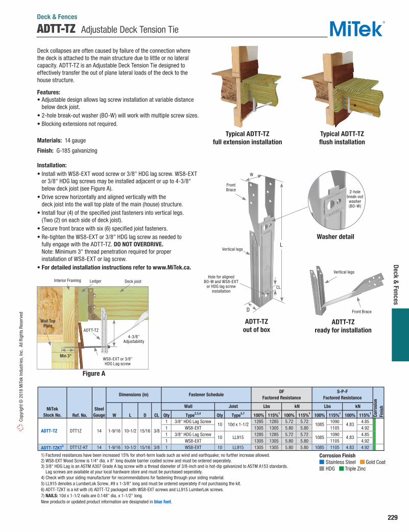
229
Deck & Fences
Copy
right
© 2
018
MiT
ek In
dust
ries,
Inc.
All
Righ
ts R
eser
ved
Deck collapses are often caused by failure of the connection where the deck is attached to the main structure due to little or no lateral capacity. ADTT-TZ is an Adjustable Deck Tension Tie designed to effectively transfer the out of plane lateral loads of the deck to the house structure.
Features: • Adjustable design allows lag screw installation at variable distance
below deck joist. • 2-hole break-out washer (BO-W) will work with multiple screw sizes.• Blocking extensions not required.
Materials: 14 gau ge
Finish: G-185 galvanizing
Installation: • Install with WS8-EXT wood screw or 3/8" HDG lag screw. WS8-EXT
or 3/8" HDG lag screws may be installed adjacent or up to 4-3/8" below deck joist (see Figure A).
• Drive screw horizontally and aligned vertically with the deck joist into the wall top plate of the main (house) structure.
• Install four (4) of the specified joist fasteners into vertical legs. (Two (2) on each side of deck joist).
• Secure front brace with six (6) specified joist fasteners.• Re-tighten the WS8-EXT or 3/8" HDG lag screw as needed to
fully engage with the ADTT-TZ. DO NOT OVERDRIVE. Note: Minimum 3" thread penetration required for proper installation of WS8-EXT or lag screw.
• For detailed installation instructions refer to www.MiTek.ca.
Ref. No. W L D CL Qty Type2,3,4 Qty Type5,7 100% 115%1 100% 115%1 100% 115%1 100% 115%1
1 3/8" HDG Lag Screw 1285 1285 5.72 5.72 1090 4.851 WS8-EXT 1305 1305 5.80 5.80 1105 4.921 3/8" HDG Lag Screw 1285 1285 5.72 5.72 1090 4.851 WS8-EXT 1305 1305 5.80 5.80 1105 4.92
ADTT-TZKT5 DTT1Z-KT 14 1-9/16 10-1/2 15/16 3/8 1 WS8-EXT 10 LL915 1305 1305 5.80 5.80 1085 1105 4.83 4.92
1) Factored resistances have been increased 15% for short-term loads such as wind and earthquake; no further increase allowed. 2) WS8-EXT Wood Screw is 1/4" dia. x 8" long double barrier coated screw and must be ordered seperately. 3) 3/8" HDG Lag is an ASTM A307 Grade A lag screw with a thread diameter of 3/8-inch and is hot-dip galvanized to ASTM A153 standards. Lag screws are available at your local hardware store and must be purchased seperately. 4) Check with your siding manufacturer for recommendations for fastening through your siding material. 5) LL915 denotes a LumberLok Screw, #9 x 1-3/8" long and must be ordered seperately if not purchasing the kit. 6) ADTT-TZKT is a kit with (4) ADTT-TZ packaged with WS8-EXT screws and LL915 LumberLok screws. 7) NAILS: 10d x 1-1/2 nails are 0.148" dia. x 1-1/2" long. New products or updated product information are designated in blue font.
Corr
osio
nFi
nish
10d x 1-1/215/16 3/8
10 LL915
kN
10 1085 4.83
1085 4.83 ADTT-TZ DTT1Z 14 1-9/16 10-1/2
MiTekStock No.
LbsLbs kNSteelGauge
Fastener Schedule
Wall Joist
Dimensions (in)DF
Factored ResistanceS-P-F
Factored Resistance
Ledger Deck joist
Figure A
ADTT-TZ
4-3/8" Adjustability
Interior Framing
WS8-EXT or 3/8" HDG Lag screw
Wall Top Plate
Min 3"
ADTT-TZ Adjustable Deck Tension Tie
Corrosion Finish Stainless Steel Gold Coat HDG Triple Zinc
Corrosion Finish Stainless Steel Gold Coat HDG Triple Zinc
Corrosion Finish Stainless Steel Gold Coat HDG Triple Zinc
Deck & Fences
Typical ADTT-TZ full extension installation
Typical ADTT-TZ flush installation
Front Brace
Vertical legs
ADTT-TZ ready for installation
ADTT-TZ out of box
L
Front Brace
Vertical legs
Hole for aligned BO-W and WS8-EXT
or HDG lag screw installation
2-hole break-out washer(BO-W)
W
D
CL
Washer detail

230
Deck
& F
ence
s Copyright ©
2018 MiTek Industries, Inc. All Rights Reserved
Deck Tie Back reinforces the connection of rail posts to a deck. Also provides lateral strength of deck-to-ledger attachment by securing deck to house framing.
Materials: 14 gau geFinish: G-185 galvanizingOptions: See chart for Corrosion Finish OptionsCodes: Load values are derived from data submitted to various North American building code evaluators.
Installation:• Use all specified fasteners. See Product Notes, page 19. • Install with MiTek’s THR 1/2" threaded rod or equivalent.• Drive WS15-EXT wood screws into joist. • Re-install threaded rod or anchor bolt. Secure with washer and nut. • Tighten anchor bolt nuts finger tight to base plus 1⁄3 to 1⁄2
additional turns with wrench.
DTB Deck Tie Back
Deck & Fences
CL
Ref. No. (in) Qty 100% 115%1 100% 115%1 100% 115%1 100% 115%1
DTB-TZ DTT2Z, FSC
14 1/2 1-1/8 8 WS15-EXT 2640 2640 11.74 11.74 2220 2220 9.88 9.88
1) Factored resistances have been increased 15% for short-term loads such as wind and earthquake; reduce for other load durations in accordance with the code. 2) WS15-EXT Wood Screws are 1/4" dia. x 1-1/2" long exterior coat screw and are included with DTB-TZ Deck Tie-Backs. New products or updated product information are designated in blue font.
Corr
osio
nFi
nishkNMiTek
Stock No.Wood
Screws
Rod / BoltAnchor Dia. (in)
LbsLbs
Fastener Schedule2
kNSteelGauge
DF Factored Resistance S-P-F Factored Resistance
Corrosion Finish Stainless Steel Gold Coat HDG Triple Zinc
Corrosion Finish Stainless Steel Gold Coat HDG Triple Zinc
Corrosion Finish Stainless Steel Gold Coat HDG Triple Zinc
Corrosion Finish Stainless Steel Gold Coat HDG Triple Zinc
Corrosion Finish Stainless Steel Gold Coat HDG Triple Zinc
Corrosion Finish Stainless Steel Gold Coat HDG Triple Zinc
DTB-TZTypical DTB-TZ Deck to ledger
installation
Typical DTB-TZrail post installation
6"
1-13/16"
CL
2-1/4"
The CSH-TZ concealed stringer hanger provides a method of connecting a stair stringer with a hidden hanger. The seat of the hanger is adjustable to match the slope of the stair stringer.
The reversible design allows the connector to be used on the left, right, or interior stringers. The CSH-TZ may be used with MiTek’s SCA Stair Angles for a complete, easy-to-use stair framing solution.
Materials: 18 gaugeFinish: G-185 galvanizingCodes: Load values are derived from data submitted to various North American building code evaluators.
Installation:• Use all specified fasteners. See Product Notes, page 19. • Bend angle only once.
Steps:1. Attach CSH-TZ to header with tabs positioned towards the inside of the stringer member. 2. Adjust the seat of the CSH-TZ to match the slope of the stringer member. Diamond shaped holes
in the connector allow temporary installation of wood screws to aid in installation of the CSH-TZ.3. Install 10d x 1-1/2" HDG nails into the stringer and rim/band joist.
CSH Concealed Stringer Hanger
Vertical Uplift1 Vertical Uplift1 Vertical Uplift1 Vertical Uplift1
Ref. No. Qty Type Type 100% 115% 100% 115% 100% 115% 100% 115% CSH-TZ LSCZ 18 8 10d x 1-1/2 HDG 4 1 10d x 1-1/2 HDG 1455 545 6.47 2.42 1030 385 4.58 1.71
1) Factored resistances have been increased 15% for short-term loads such as wind and earthquake; no further increase is allowed. 2) NAILS: 10d x 1-1/2 nails are 0.148" dia. x 1-1/2" long. New products or updated product information are designated in blue font.
Fastener Schedule2
kN
DF Factored Resistance S-P-F Factored Resistance
Corr
osio
nFi
nish
kN
WideFace Qty
NarrowFace Qty
MiTekStock No.
SteelGauge
Lbs LbsRim/Band Joist Stringer
Typical CSH-TZinstallation
CSH-TZ
Adjustable 5"
5"
1-7/16"
1-1/2"

231
Deck & Fences
Copy
right
© 2
018
MiT
ek In
dust
ries,
Inc.
All
Righ
ts R
eser
ved
Typical SCA9-TZ installation
SCA9-TZ
Typical SCA10-TZ installation
SCA Stair Angles
Deck & Fences
Stair angles simplify stair construction. There is no need to calculate and notch stair stringers. Stronger and safer than wood blocking, and the angle and fasteners are hidden from view.
Materials: 12 gaugeFinish: G-185 galvanizingCodes: Load values are derived from data submitted to various North American building code evaluators.
Installation:• Use all specified fasteners. See Product Notes, page 19.• WS15-EXT (1/4" dia x 1-1/2" long) wood screws are not
supplied with SCA angles.• Use the SCA9-TZ for single 2x10 stair treads. Use the
SCA10-TZ for double 2 x 6 stair treads. • To calculate stair construction do the following:
1. Find the number of steps needed by taking the vertical drop from the deck surface to grade. Divide by 7. Round off to the nearest whole number. (Ex: Vertical drop of 39" divided by 7 equals 5.57" rounded off is 6")
2. Find the step rise by dividing the vertical drop by the number of steps (39" divided by 6 = 6.5")
3. Find the step run by measuring the depth of your tread board (Ex: (2) 2x6s have a run of 11-1⁄4")
4. Find the stairway span by multiplying the run by the number of treads minus one (Ex: 11-1⁄4" x 5 = 56-1⁄4")
• Using the above calculations, mark stair angle locations on each stringer. Attach a stair angle to the inside of each stringer at the marked locations. Attach stringers to deck rim joist and railing posts. Position treadboards on angles and fasten from below.
Ref. No. w L Qty Type Lbs kN Lbs kN
SCA9-TZ TA9Z 12 1-3/8 9 6 WS15-EXT 1925 8.56 1365 6.07
SCA10-TZ TA10Z 12 1-3/8 10 8 WS15-EXT 1925 8.56 1365 6.07
1) Loads assume rise over run of 7/11. 2) WS15-EXT Wood Screws are 1/4" dia. x 1-1/2" long and are not included with SCA angles. 3) HDG lag screws may be substituted for specified WS15-EXT screws with no load reduction.
Corr
osio
nFi
nishMiTek
Stock No.Steel
Gauge
Down 100%1 Down 100%1
DFFactored Resistance
S-P-FFactored Resistance
Fastener
Schedule2,3Dimensions
(in)
Corrosion Finish Stainless Steel Gold Coat HDG Triple Zinc
Corrosion Finish Stainless Steel Gold Coat HDG Triple Zinc
Corrosion Finish Stainless Steel Gold Coat HDG Triple Zinc
L 1-3/8"
1-3/8"

232
Deck
& F
ence
s Copyright ©
2018 MiTek Industries, Inc. All Rights Reserved
DC Deck Clip
Deck & Fences
Connects deck boards to joists without face nails or screws. Eliminates rust stains on decks, as well as splintering or wood rot caused by screw or nail “craters”. The DC50-TZ works like tongue-in-groove flooring and is easy to install. Raised dimples on the clip provide consistent spacing between deck boards.
Materials: 20 gaugeFinish: G-185 galvanizing
Installation:• Use all specified fasteners. See Product Notes, page 19.• Fits 1-1/8" or thicker decking. • Fasten the first deck board onto the joists by toenailing up through the
joist below into the deck board. Be sure no sharp points protrude above the deck surface. For subsequent deck board rows, nail DC50-TZ's onto the deck board edge, positioned 2" from each joist. Slide the deck board along the joist until the DC50-TZ “lip” is under the previously laid deck board. Toenail the deck board’s exposed edge to the joist. Repeat until decking is completed. The last deck board will require toenailing up from below to secure the outside edge.
ML angles are multi-purpose angles that install easily with WS15 wood screws. The staggered fastener pattern allows for back-to-back installations.
Materials: 12 gau geFinish: G-185 galvanizing
Installation:• Use all specified fasteners. See Product Notes, page 19.• WS15 (1/4" dia. x 1-1/2" long) are not supplied with ML angles.
Ref. No. Qty Type DC50-TZ DBT1Z 20 1 8d x 1-1/2 HDG
1) Use with 1-1/8" or thicker wood decking. 2) NAILS: 8d x 1-1/2 nails are 0.131" dia. x 1-1/2" long.
Corr
osio
nFi
nishMiTek
Stock No.Steel
Gauge
Fastener
Schedule1,2
ML Angles
Ref. No. W H Qty Type Qty Type Unit 100% 115% 100% 115%Lbs 1100 1265 780 900kN 4.89 5.63 3.47 4.00Lbs 1890 2175 1340 1545kN 8.41 9.68 5.96 6.87
1) Factored resistances have been increased 15% for short-term, duration loading; no further increase allowed. 2) WS15 Wood Screws are 1/4" diameter x 1-1/2" long and are not included with angles. 3) For exterior applications use WS15-EXT screws with the exterior coat finish.
6
3
4
WS15
WS15 4 WS15
4 WS15 3
ML26-TZ
ML24Z
ML26Z
12 2
12 2
ML24-TZ
MiTekStock No.
SteelGauge
Header Joist
Corr
osio
nFi
nish
DFFactored Resistance1
S-P-FFactored Resistance1
Dimensions (in) Fastener Schedule2,3
Typical DC50-TZ installation
DC50-TZ
Typical ML26-TZinstallation
(ML24-TZ similar)
ML26-TZ(ML24-TZ similar)
F1
H
WW
Corrosion Finish Stainless Steel Gold Coat HDG Triple Zinc
Corrosion Finish Stainless Steel Gold Coat HDG Triple Zinc
Corrosion Finish Stainless Steel Gold Coat HDG Triple Zinc
Corrosion Finish Stainless Steel Gold Coat HDG Triple Zinc
Corrosion Finish Stainless Steel Gold Coat HDG Triple Zinc
Corrosion Finish Stainless Steel Gold Coat HDG Triple Zinc
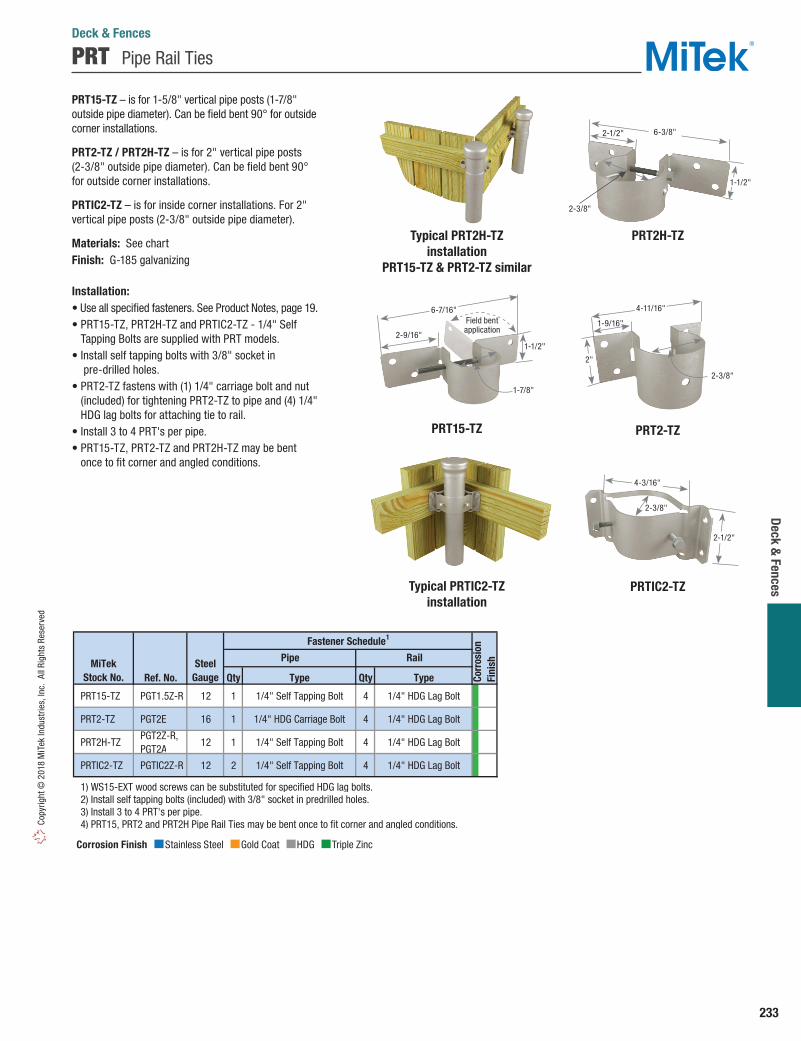
233
Deck & Fences
Copy
right
© 2
018
MiT
ek In
dust
ries,
Inc.
All
Righ
ts R
eser
ved
PRT Pipe Rail Ties
Deck & Fences
PRT15-TZ – is for 1-5/8" vertical pipe posts (1-7/8" outside pipe diameter). Can be field bent 90° for outside corner installations.
PRT2-TZ / PRT2H-TZ – is for 2" vertical pipe posts (2-3/8" outside pipe diameter). Can be field bent 90° for outside corner installations.
PRTIC2-TZ – is for inside corner installations. For 2" vertical pipe posts (2-3/8" outside pipe diameter).
Materials: See chartFinish: G-185 galvanizing
Installation:• Use all specified fasteners. See Product Notes, page 19.• PRT15-TZ, PRT2H-TZ and PRTIC2-TZ - 1/4" Self
Tapping Bolts are supplied with PRT models.• Install self tapping bolts with 3/8" socket in
pre-drilled holes.• PRT2-TZ fastens with (1) 1/4" carriage bolt and nut
(included) for tightening PRT2-TZ to pipe and (4) 1/4" HDG lag bolts for attaching tie to rail.
• Install 3 to 4 PRT's per pipe.• PRT15-TZ, PRT2-TZ and PRT2H-TZ may be bent
once to fit corner and angled conditions.
Ref. No. Qty Type Qty Type
PRT15-TZ PGT1.5Z-R 12 1 1/4" Self Tapping Bolt 4 1/4" HDG Lag Bolt
PRT2-TZ PGT2E 16 1 1/4" HDG Carriage Bolt 4 1/4" HDG Lag Bolt
PRT2H-TZ PGT2Z-R, PGT2A
12 1 1/4" Self Tapping Bolt 4 1/4" HDG Lag Bolt
PRTIC2-TZ PGTIC2Z-R 12 2 1/4" Self Tapping Bolt 4 1/4" HDG Lag Bolt
1) WS15-EXT wood screws can be substituted for specified HDG lag bolts. 2) Install self tapping bolts (included) with 3/8" socket in predrilled holes. 3) Install 3 to 4 PRT's per pipe. 4) PRT15, PRT2 and PRT2H Pipe Rail Ties may be bent once to fit corner and angled conditions.
MiTekStock No.
SteelGauge
Pipe Rail
Fastener Schedule1
Corr
osio
nFi
nish
Corrosion Finish Stainless Steel Gold Coat HDG Triple Zinc
Corrosion Finish Stainless Steel Gold Coat HDG Triple Zinc
Corrosion Finish Stainless Steel Gold Coat HDG Triple Zinc
Typical PRT2H-TZinstallation
PRT15-TZ & PRT2-TZ similar
Typical PRTIC2-TZinstallation
PRTIC2-TZ
PRT2-TZ
PRT2H-TZ
2-3/8"
4-3/16"
2-1/2"
2"
1-9/16"
2-3/8"
4-11/16"
1-1/2"
2-1/2"
2-3/8"
6-3/8"
PRT15-TZ
1-1/2"2-9/16"
1-7/8"
6-7/16"Field bentapplication

234
Deck
& F
ence
s Copyright ©
2018 MiTek Industries, Inc. All Rights Reserved
ERB / FB / FRB Fence Brackets
Deck & Fences
ERB24 – Designed to mount prefabricated fence sections and works with 2x4 horizontal section rails.
FB26 – Secures 2x6 rails to wood posts.
FRB24 – Secures continuous 2x4 rails to wood posts. Pre-punched holes allow installers to splice 2x4 rail ends within the bracket.
Materials: See chartFinish: G-185 galvanizing
Installation:• Use all specified fasteners. See Product
Notes, page 19.
Ref. No W H Qty Rail Qty Post Unit Down F1 Down F1 1 x 4 FB14-TZ -- 20 3/4 3-1/2 3 14 ga. x 3/4 HDG 2 8d x 1-1/2 HDG -- -- -- -- -- 2 x 3 FB23-TZ -- 20 1-9/16 2-3/8 3 8d x 1-1/2 HDG 4 8d x 1-1/2 HDG -- -- -- -- --
ERB24-TZ -- 18 1-1/2 3-9/16 4 8d x 1-1/2 HDG 3 8d HDG -- -- -- -- --
FRB24-TZ -- 18 1-9/16 3-9/16 2 10d x 1-1/2 HDG 4 10d HDG -- -- -- -- --Lbs 550 700 390 495kN 2.45 3.11 1.73 2.20Lbs 780 715 550 505kN 3.47 3.18 2.45 2.25
1) Factored resistances have been increased 15% for short-term loading such as wind and earthquake; no further increase is permitted. 2) NAILS: 8d x 1-1/2 nails are 0.131" dia. x 1-1/2" long, 8d nails are 0.131" dia. x 2-1/2" long, 10d x 1-1/2 nails are 0.148" dia. x 1-1/2" long, 10d nails are 0.148" dia. x 3" long, LL915 denotes a LumberLok Screw, #9 x 1-3/8" long. New products or updated product information are designated in blue font.
4 LL915
Fastener Schedule2
4 10d x 1-1/2 HDG 4 10d x 1-1/2 HDG
3 8d x 1-1/2 HDG20 1-9/16 3-3/8
4 LL915 2 x 6 FB26-TZ FB26 18 1-9/16 5
Rail Size
2 8d HDG -- --
MiTekStock No.
SteelGauge
Dimensions (in) DFFactored Resistance1
S-P-FFactored Resistance1
---- -- 2 x 4 FB24-TZ FB24Z, FBR24, FBR24Z
Corr
osio
nFi
nish
Corrosion Finish Stainless Steel Gold Coat HDG Triple Zinc
Corrosion Finish Stainless Steel Gold Coat HDG Triple Zinc
Corrosion Finish Stainless Steel Gold Coat HDG Triple Zinc
FB24-TZ
FB26-TZ
FB14-TZ
Typical FB24-TZ installation
Typical FB26-TZinstallation
FB23-TZ
ERB24-TZ
FRB24-TZ
Typical ERB24-TZinstallation
Typical FRB24-TZinstallation
W
H
W 1-3/16"
1-9/16"
H
H
W H
3/4"
W
Download
F1
F1

235
Deck & Fences
Copy
right
© 2
018
MiT
ek In
dust
ries,
Inc.
All
Righ
ts R
eser
ved
These seamless caps keep water off post tops, protecting wood from moisture damage. The PCP’s plastic construction is corrosion-proof and paintable. Not available in rough or full lumber sizes.
Materials: Hi-impact plasticFinish: Gray
Installation:• Fasten cap to post top with (1) 8d HDG or 10d HDG nail.
PCP Plastic Post Caps
FPH Fence Rail Hanger
Deck & Fences
Typical FPH24-TZ installation
FPH24-TZ
The FPH24-TZ attaches 2x4 fence rails to wood posts. The Triple Zinc (G-185) galvanized finish offers superior corrosion resistance in outdoor applications and/or with treated wood.
Materials: 18 gaugeFinish: G-185 galvanizing
Installation:• Use all specified fasteners. See Product Notes, page 19.• Fasteners need to be Hot-Dip Galvanized for outdoor applications
and for use with preservative treated wood.
Bearing Uplift1 Bearing Uplift1 Bearing Uplift1 Bearing Uplift1
Ref. No. Qty Type Qty Type 100% 115% 100% 115% 100% 115% 100% 115%3 8d x 1-1/2 HDG 3 8d x 1-1/2 HDG 410 545 1.82 2.42 350 465 1.56 2.073 10d x 1-1/2 HDG 3 10d x 1-1/2 HDG 485 560 2.16 2.49 420 485 1.87 2.16
1) Factored resistances have been increased 15% for short-term loads such as wind and earthquake; reduce for other load durations in accordance with the code. 2) NAILS: 8d x 1-1/2 nails are 0.131" dia. x 1-1/2" long, 10d x 1-1/2 nails are 0.148" dia. x 1-1/2" long.
2 x 4 FPH24-TZ -- 18
JoistSize
MiTekStock No.
SteelGauge Co
rros
ion
Fini
sh
Fastener Schedule2
kN
DF Factored Resistance S-P-F Factored Resistance
kNLbsLbsHeader Joist
Dimension (in)
Ref. No. W Color 4 x 4 PCP44 DPPC4BK 3-5/8 Gray 6 x 6 PCP66 DPPC6BK 5-5/8 Gray
1) Not available in rough or full lumber sizes.
Post/Column
Size1MiTek
Stock No.PCP66Typical PCP44
installation
W W
Corrosion Finish Stainless Steel Gold Coat HDG Triple Zinc
Corrosion Finish Stainless Steel Gold Coat HDG Triple Zinc
Corrosion Finish Stainless Steel Gold Coat HDG Triple Zinc
3"
1-15/16"
1-9/16"
Bearing
Uplift

236
Deck
& F
ence
s Copyright ©
2018 MiTek Industries, Inc. All Rights Reserved
SFP / SMP Fence Post Connectors
Deck & Fences
Typical SMPinstallation
BD Bolt Down
Take the work out of fence post installation and repair with the Speedpost, SFP30, and Speedmender, SMP. The Speedpost is used to install 4x4 fence posts without digging post holes or pouring concrete. The Speedmender plates act as reinforcement brackets for rotted or damaged 4x4 fence posts.
SFP30 – For 6' nominally-sized 4x4 fence posts.
SMP – For nominally-sized 4x4 posts.
Materials: 13 gaugeFinish: Paint
Installation:• Step-by-step installation instructions are labeled onto each product.
Anchors 4x4 post to wood or concrete surfaces.
Materials: 13 gaugeFinish: Paint
Installation:• Use all specified fasteners. See Product Notes, page 19.• Not rated for overturning resistance. Not recommended
for unrestrained posts.
Ref. No. Qty Type SFP30 FPBS44 13 3 1/4" HDG Lag Bolts SMP FPBM44 13 20 10d HDG
1) Fastener schedule is per pair of SMP's. 2) NAILS: 10d nails are 0.148" dia. x 3" long.
MiTekStock No.
SteelGauge
Fastener Schedule1,2
PostSize
4 x 4
Post Size Ref. No. Qty Lag Bolts4 x 4 BD FPBB44 13 3 1/4" x 1-1/2" HDG
MiTekStock No.
SteelGauge
Fastener Schedule
SMP
SFP30 Typical SFP30installation
30"
28-1/16"
5-5/8"
3-5/8"
BDTypical BDinstallation
5-5/8"
3-5/8"

237
General Hardware
Copy
right
© 2
018
MiT
ek In
dust
ries,
Inc.
All
Righ
ts R
eser
ved
RC Plywood Clips
General Hardware
Steel plywood clips. All models feature embossed dimples to provide 1/8" gap.
Materials: 18 gaugeFinish: G90 galvanizing
Ref. No. RC38 PSCL3/8 18 3/8
RC716 PSCL7/16, PSCA7/16
18 7/16
RC1532 PSCL15/32, PSCA15/32
18 15/32
RC12 PSCL1/2 18 1/2 RC58 PSCL5/8 18 5/8
PlywoodThickness (in)
MiTekStock No.
SteelGauge
Typical RC installation
Typical DC1 installation
Typical IS installation
RC
DC1
Drywall clips or “stops” help support drywall or wood paneling and reduce wood blocking on top plates, end walls, and corners.
Materials: 20 gaugeFinish: G90 galvanizing
Installation:• Use 8d nails to install DC1, 16" on-center or less.
Insulation supports secure batt-type insulation in place between joists. Chisel-cut ends dig into joists for permanent holding. Easy to install in hard-to-reach crawl spaces.
Materials: 13 gauge carbon steel wireFinish: None
Installation:• Use IS16 for joist spaced 16" O.C. and IS24 for 24" O.C. spacing.• Position insulation batt in place between joists. Hold IS unit at the
center and push into place.• Wear gloves and safety glasses during installation.
DC Drywall Clip
IS Insulation Supports
Ref. No. Qty Type DC1 DS 20 1 8d
1) NAILS: 8d nails are 0.131" dia. x 2-1/2" long.
MiTekStock No.
SteelGauge
Fastener Schedule1
Dimensions (in)
Ref. No. Overall Length IS16 IS16-R100 13 16" O.C. 15-1/2 IS24 IS24-R100 13 24" O.C. 23-1/2
MiTekStock No.
SteelGauge
Joist Spacing (in)
Provides 1/8" gap
3/4"
1-1/8"1-1/2"
Simply push into place

238
Gene
ral H
ardw
are
Copyright © 2018 M
iTek Industries, Inc. All Rights Reserved
TT D.I.Y. Products
General Hardware
Connectors for home owner / D.I.Y. projects.
TTA12-TZ - an angle connects two 1x wood members at 90º angles.
TTA2-TZ - an angle connects two 2x wood members at 90º angles.
TTB22-TZ - a bracket connects two intersecting 2x wood members at 90º angles.
TTC24-TZ - a corner tie connects 2x wood members at 90º to the corner of a 2x4 post. Mirror design allows for post to be oriented in either direction.
TTC42-TZ - a corner tie connects 2x wood members at 90º to the corner of a 4x4 post.
TTF22-TZ - a bracket connects 2x wood members to opposite sides of a 2x4 or 4x4 post.
TTR-TZ - a clip connects a 2x wood member to the face of another wood member.
TTU2-TZ - a U-clip connects 2x wood members crossing at 90º.
Materials: See chart
Finish: G-185 galvanizing
Installation:• Use all specified fasteners. See Product Notes, page 19.• LumberLok LL915 (#9 x 1-3/8" long) wood screws are not supplied
with connectors.
1) LL915 denotes a LumberLok Screw, #9 x 1-3/8" long.
2) Factored resistances have been increased 15% for short duration loading. No further increase is permitted.
3) TTF22-TZ: Factored resistances must be equally distributed on both joists.
4) TTC24-TZ and TTC42-TZ: Factored resistances listed in this table are for each joist being carried by the post.
Ref. No. Qty Type Qty Type Unit Download Uplift F1 F2 Download Uplift F1 F2Lbs -- 355 330 355 -- 255 235 255kN -- 1.58 1.47 1.58 -- 1.13 1.05 1.13Lbs -- 315 440 315 -- 225 315 225kN -- 1.40 1.96 1.40 -- 1.00 1.40 1.00Lbs 610 610 610 425 435 435 435 300kN 2.71 2.71 2.71 1.89 1.93 1.93 1.93 1.33Lbs 1125 715 -- -- 800 505 -- --kN 5.00 3.18 -- -- 3.56 2.25 -- --Lbs 1075 430 -- -- 765 305 -- --kN 4.78 1.91 -- -- 3.40 1.36 -- --Lbs 1400 750 -- -- 995 530 -- --kN 6.23 3.34 -- -- 4.43 2.36 -- --Lbs 545 545 490 235 390 390 350 170kN 2.42 2.42 2.18 1.05 1.73 1.73 1.56 0.76Lbs -- -- 550 565 -- -- 390 400kN -- -- 2.45 2.51 -- -- 1.73 1.78
1) LL915 denotes a MiTek LumberLok Screw, #9 x 1-3/8" long.2) Factored resistances are for a standard term load duration Kd = 1.003) TTF22-TZ: Factored resistances must be equally distributed on both joists.4) TTC24-TZ and TTC42-TZ: Factored resistances listed in this table are for each joist being carried by the post.
18
18
20
18
18
18
20
16
2x
2 LL915 4
LL915 4 LL915
2x
LL915
4 LL915 4 LL915
4
4
LL915
2x 2
JoistSize
LL915 8 LL915
RTR
9
14 LL915 8 LL915
4 LL915 8 LL915
2x
2x
1x 1x
2 x 4 2x
2x
2x
2x
2 x 4
4
TTR-TZ
TTU2-TZ
RTA12
RTA2Z
RTB22
RTC24Z
RTC42, RTC42Z
RTF2Z
TTA12-TZ
TTA2-TZ
RTU2
TTC24-TZ
TTC42-TZ
TTF22-TZ
TTB22-TZ
MiTekStock No.
SteelGauge
Post Size
2x
4 x 4
S-P-FFactored Resistance2,3,4Post
Fastener Schedule1
DFFactored Resistance2,3,4
4 LL915
Joist (Total)
LL9152x
LL915
Corr
osio
nFi
nish
Corrosion Finish Stainless Steel Gold Coat HDG Triple Zinc
Corrosion Finish Stainless Steel Gold Coat HDG Triple Zinc
Corrosion Finish Stainless Steel Gold Coat HDG Triple Zinc
TTB22-TZ
TTR-TZ
TTF22-TZ
Typical TTB22-TZinstallation
Typical TTR-TZinstallation
Typical TTF22-TZinstallation
TTA12-TZ(TTA2-TZ Similar)
TTC24-TZ(TTC42-TZ Similar)
TTU2-TZ
Typical TTA12-TZinstallation
Typical TTC24-TZinstallation
Typical TTU2-TZinstallation
Uplift
Uplift
Download
Uplift
Download
Download
F1F1
F2
F2
F2
Uplift
DownloadF2
F1
F1
F1F1
F2F1
Uplift
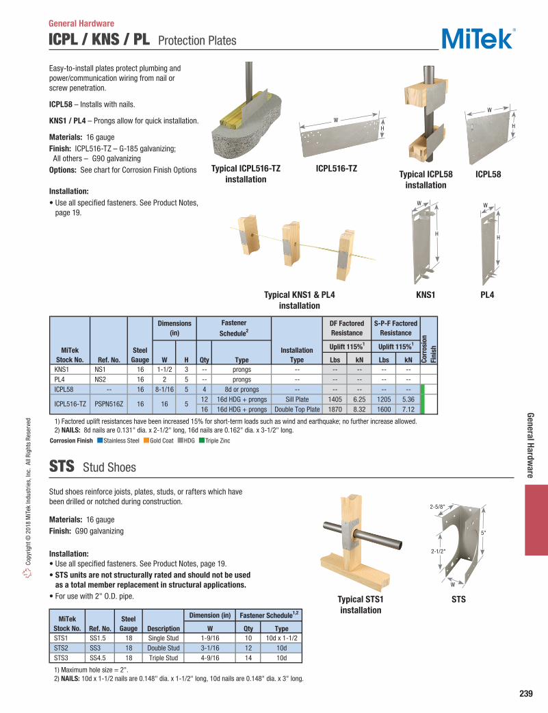
239
General Hardware
Copy
right
© 2
018
MiT
ek In
dust
ries,
Inc.
All
Righ
ts R
eser
ved
ICPL / KNS / PL Protection Plates
General Hardware
Easy-to-install plates protect plumbing and power/communication wiring from nail or screw penetration.
ICPL58 – Installs with nails.
KNS1 / PL4 – Prongs allow for quick installation.
Materials: 16 gaugeFinish: ICPL516-TZ – G-185 galvanizing; All others – G90 galvanizingOptions: See chart for Corrosion Finish Options
Installation:• Use all specified fasteners. See Product Notes,
page 19.
Ref. No. W H Qty Type Lbs kN Lbs kN KNS1 NS1 16 1-1/2 3 -- prongs -- -- -- -- -- PL4 NS2 16 2 5 -- prongs -- -- -- -- -- ICPL58 -- 16 8-1/16 5 4 8d or prongs -- -- -- -- --
12 16d HDG + prongs Sill Plate 1405 6.25 1205 5.3616 16d HDG + prongs Double Top Plate 1870 8.32 1600 7.12
1) Factored uplift resistances have been increased 15% for short-term loads such as wind and earthquake; no further increase allowed. 2) NAILS: 8d nails are 0.131" dia. x 2-1/2" long, 16d nails are 0.162" dia. x 3-1/2" long.
Corr
osio
nFi
nish
Dimensions(in)
ICPL516-TZ
Uplift 115%1 Uplift 115%1
MiTekStock No.
SteelGauge
InstallationType
PSPN516Z 16 16 5
DF Factored Resistance
S-P-F Factored Resistance
Fastener
Schedule2
Stud shoes reinforce joists, plates, studs, or rafters which have been drilled or notched during construction.
Materials: 16 gaugeFinish: G90 galvanizing
Installation:• Use all specified fasteners. See Product Notes, page 19.• STS units are not structurally rated and should not be used
as a total member replacement in structural applications.• For use with 2" O.D. pipe.
STS Stud Shoes
Dimension (in)
Ref. No. Description W Qty Type STS1 SS1.5 18 Single Stud 1-9/16 10 10d x 1-1/2 STS2 SS3 18 Double Stud 3-1/16 12 10d STS3 SS4.5 18 Triple Stud 4-9/16 14 10d
1) Maximum hole size = 2". 2) NAILS: 10d x 1-1/2 nails are 0.148" dia. x 1-1/2" long, 10d nails are 0.148" dia. x 3" long.
MiTekStock No.
SteelGauge
Fastener Schedule1,2
Corrosion Finish Stainless Steel Gold Coat HDG Triple Zinc
Corrosion Finish Stainless Steel Gold Coat HDG Triple Zinc
Corrosion Finish Stainless Steel Gold Coat HDG Triple Zinc
ICPL58
PL4
Typical ICPL58installation
KNS1
ICPL516-TZTypical ICPL516-TZinstallation
Typical KNS1 & PL4installation
W
H
W
H
WH
W
H
STSTypical STS1installation
5"
2-1/2"
2-5/8"
W

240
Gene
ral H
ardw
are
Copyright © 2018 M
iTek Industries, Inc. All Rights Reserved
O / N Bridging
General Hardware
O – The O series spans three joists in under/over installation. Prong teeth in the center help reduce nailing. For 1-1/2" wide dimensional lumber only.
N – The N series spans two joists per unit. Can be used for bridging or bracing. See chart.
Materials: See chartFinish: G90 galvanizing
Installation:• Use specified fasteners in models with fastener requirements.• Install prior to subfloor sheathing. Use (2) 8d x 1-1⁄2" nails at each end. Fully seat
nails to avoid any movement against the bridging and subsequent floor noise.• Must be installed in cross pairs. Avoid bridging overlap, it may cause squeaks
Joist Installations
Ref. No. W L Qty Type N16 LTB20, TB20 22 3/4 19-3/4 4 8d x 1-1/2 O40 LTB40 22 3/4 39-3/4 4 8d x 1-1/2 N27 TB27 20 3/4 26-13/16 4 8d x 1-1/2 N30 TB30 20 3/4 29-13/16 4 8d x 1-1/2 N36 TB36 20 3/4 35-13/16 4 8d x 1-1/2 N42 TB42 20 3/4 42 4 8d x 1-1/2 N48 TB48 20 3/4 48 4 8d x 1-1/2 N54 TB54 20 3/4 54 4 8d x 1-1/2 N56 TB56 20 1 56 4 8d x 1-1/2 N60 TB60 20 1 60 4 8d x 1-1/2 O16 -- 18 1 44 4 8d x 1-1/2
1) NAILS: 8d x 1-1/2 nails are 0.131" dia. x 1-1/2" long.
Dimensions (in)MiTekStock No.
SteelGauge
Fastener Schedule1
12" 16" 19.2" 24" 30" 32" 36" 42" 48"
7-1/4 --O40/O16
/N16N27 N27/N30 N36 N36 N42 N48 N54/N56
9-1/4 N16O40/O16
/N16N27 N30 N36 N36 N42 N48 N54/N56
11-1/4O40/O16
/N16O40 N27 N30 N36 N36 N42 N48 N54/N56
9-1/2 N16 N16 N27 N30 N36 N36 N42 N48 N54/N5611-7/8 N16 N16 N27 N30 N36 N36 N42 N48 N54/N56
14 N16 N27 N27/N30 N30 N36 N36 N42 N48 N54/N5616 N27 N27 N27/N30 N30 N36 N42 N42 N48 N54/N56
9-1/2 N16 N16 N16 N27/N30 N36 N36 N36 N42 N5611-7/8 N16 N16 N27 N30 N36 N36 N42 N48 N56
14 N16 N16 N27 N30 N36 N36 N42 N48 N54/N5616 N16 N27 N27/N30 N30 N36 N36 N42 N48 N54/N5618 N27 N27 N30 N30 N36 N36 N42 N48 N54/N5620 N27 N30 N30 N36 N36 N42 N42 N48 N54/N5622 N30 N30 N30 N36 N42 N42 N42 N48 N54/N56/N6024 N30 N30 N36 N36 N42 N42 N48 N56 N56/N60
1) Grey shaded cells represent bridging installed on the face of the joist; web stiffeners required for I-Joists. 2) All bridging products require (2) 8d x 1-1/2 nails at each end, which are 0.131" dia. x 1-1/2" long.
1-3/4" SCL
I-Joists: 2-1/2"
& 3-1/2" wide
Joist Spacing1
Joist Height
(in)JoistType
2xDimensional
Lumber
O
N
Typical O installation
Typical N installation
L
W
L
W

241
General Hardware
Copy
right
© 2
018
MiT
ek In
dust
ries,
Inc.
All
Righ
ts R
eser
ved
MB / MBG Bridging
General Hardware
MBG – Grip tooth bridging. Features special teeth which grip joists and provide easy single-nail installation. Can be installed after subfloor is in place.
MB16 – Snap-on, no-nail bridging can be placed in existing floor systems where joist movement is suspected. Two-piece construction creates a solid diagonal brace against joist movement.
Materials: See chartFinish: G90 galvanizing
Installation:• Use specified fasteners in models with fastener requirements.• MBG – May be installed before or after sheathing. Position
the unbent end of the bridging unit near the top of the joist and drive prongs into wood with a hammer blow to the heel of the bent end. Wedge bent end near the lower edge of the opposite joist, set teeth into wood with hammer blow. Nail holes are provided at the bent end if prongs are damaged during installation. Fully seat nails to avoid any movement against the bridging and subsequent floor noise.
• MB16 – Two-piece unit is shipped as one piece. Bend unit in center up and down to break into two pieces. Slide narrower piece inside wider piece, setting the end tab into slot appropriate for joist spacing. Setting one prong end near the top of one joist and the opposite prong end near the bottom of the opposite joist, pull down on the center of the bridging until the wider piece snaps into place over the narrow piece and creates a rigid, one-piece bridging unit. Wear gloves during installation.
MB16
Joist Size Ref. No. W L Qty Type 2 x 8 12 MBG812 NCA2X8-12 22 15/16 11-3/4 1 8d x 1-1/2 2 x 10 12 MBG1012 NCA2X10-12 22 15/16 12-3/4 1 8d x 1-1/2 2 x 12 12 MBG1212 NCA2X12-12 22 15/16 14 1 8d x 1-1/2 2 x 14 12 MBG1412 -- 22 15/16 16 1 8d x 1-1/2 2 x 16 12 MBG1612 -- 22 15/16 17 1 8d x 1-1/2 2 x 8-12 16 MB16 -- 22 11/16 -- -- -- 2 x 8 16 MBG816 NCA2X8-16 22 15/16 15-9/16 1 8d x 1-1/2 2 x 10 16 MBG1016 NCA2X10-16 22 15/16 16-5/16 1 8d x 1-1/2 2 x 12 16 MBG1216 NCA2X12-16 22 15/16 17-1/4 1 8d x 1-1/2 2 x 14 16 MBG1416 -- 22 15/16 18-7/16 1 8d x 1-1/2 2 x 16 16 MBG1616 -- 22 15/16 19-5/8 1 8d x 1-1/2 2 x 8 24 MBG824 -- 22 1-5/16 23-1/2 1 8d x 1-1/2 2 x 10 24 MBG1024 -- 22 1-5/16 24 1 8d x 1-1/2 2 x 12 24 MBG1224 -- 22 1-5/16 24-3/4 1 8d x 1-1/2 2 x 14 24 MBG1424 -- 22 1-5/16 25-5/8 1 8d x 1-1/2 2 x 16 24 MBG1624 -- 22 15/16 26-5/8 1 8d x 1-1/2
1) Joist spacing is based on a 1-1/2" joist, consult MiTek regarding wider joist applications. 2) NAILS: 8d x 1-1/2 nails are 0.131" dia. x 1-1/2" long.
Fastener Schedule2Joist Spacing
O.C. (in)1
Dimensions (in)MiTekStock No.
SteelGauge
Typical MB16installation
MBG
Step 1 Step 2
Typical MBG installation
W
L

242
Gene
ral H
ardw
are
Copyright © 2018 M
iTek Industries, Inc. All Rights Reserved
RWB / WB / WBC / WBT Wall Bracing
Wall bracing products are engineered to meet the prescriptive 1x4 let-in brace code requirements.
RWB – Flat bracing conveniently packaged in a handy roll out dispenser. Perfect for unexpected job site shortages. The 35-pound dispenser pack fits easily into a truck bed for transport. Pre-embossed snap-off points can be broken off by hand (wear gloves for safety).
WB – A flat style bracing engineered to easily nail to studs. No cutting or fitting needed.
WBC – L-shaped design for additional strength and rigidity.
WBT – Rolled edges and T-style design gives the WBT strength, rigidity, and eliminates sharp, sheared edges.
Materials: See chartFinish: G90 galvanizing
Installation:• Use all specified fasteners. See Product Notes, page 19.• Bracing is a framing aid, not a substitute for structural shearwall
components.• RWB / WB – Use with 16" or 24" o.c. studs. Install in pairs
forming an “X” or opposing “V” at each end of a maximum 25-foot long wall panel.
Steps: Square the panel. Straighten any kinks in bracing caused by handling. Lay bracing on the panel flush to the top of top plate and flush to the bottom of the bottom plate. Secure bracing to the top plate and bottom plate using 16d nails (WB) or 8d nails (RWB). Position second bracing at an angle opposite to the first brace to form an “X” and secure to top and bottom plate as with the first bracing. Using 8d nails, secure bracing to all intersecting studs.
• WBC / WBT – Use with 16" o.c. studs. Install one brace at each end of wall section, not exceeding 25 feet, in an opposing “V” pattern. Use the web portion of a length of bracing as a straight edge to mark studs. Cut a saw kerf 5⁄8" deep (1" deep for WBC). Insert the bracing web into the saw kerf, and drive one nail into the top plate. Raise the wall section into place and plumb. Finish fastening according to the nail schedule.
Ref. No. W Qty Type Qty Type RWB96 WB106C 16 1-1/4 9' 6" 15 8' 60° 4 8d 1 8d RWB114 WB126C 16 1-1/4 11' 4-3/8" 12 8' 45° 4 8d 1 8d RWB143 WB143C 16 1-1/4 14' 3" 10 10' 45° 4 8d 1 8d WBC10 RCWB10 18 15/16 9' 5-3/4" -- 8' 60° 2 16d 1 8d WBC12 RCWB12 18 15/16 11' 4-3/8" -- 8' 45° 2 16d 1 8d WBT10 TWB10 22 1-3/8 9' 3" -- 8' 60° 4 8d 1 8d WBT12 TWB12 22 1-3/8 11' 4" -- 8' 45° 4 8d 1 8d
WBT14 RCWB14, TWB14
22 1-3/8 14' 2" -- 10' 45° 4 8d 1 8d
WB106 WB106 16 1-1/4 9' 5-1/2" -- 8' 60° 3 16d 1 8d WB126 WB126 16 1-1/4 11' 4-1/4" -- 8' 45° 3 16d 1 8d
1) These products substitute for code prescribed 1 x 4 let-in bracing. 2) NAILS: 8d nails are 0.131" dia. x 2-1/2" long, 16d nails are 0.162" dia. x 3-1/2" long.
Dimensions (in) Fastener Schedule2,3
Each PlateSteelGauge
MiTek
Stock No.1Each StudPieces
Per RollWall
Height InstallAngle
L(ft - in)
General Hardware
RWB pre-embossedsnap-off points
Typical RWB/WBinstallation
Typical WBC/WBTinstallation
WBT
WBC
L
W
9/16"
W W
L
WB
L
W1
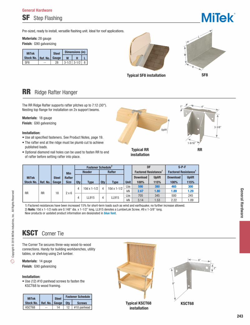
243
General Hardware
Copy
right
© 2
018
MiT
ek In
dust
ries,
Inc.
All
Righ
ts R
eser
ved
Typical SF8 installation SF8
SF Step Flashing
Pre-sized, ready to install, versatile flashing unit. Ideal for roof applications.
Materials: 28 gauge Finish: G90 galvanizing
Dimensions (in)
Ref. No. W H L SF8 -- 28 3-1/2 3-1/2 8
MiTekStock No.
SteelGauge
Typical KSCT68 installation
KSCT68
The Corner Tie secures three-way wood-to-wood connections. Handy for building workbenches, utility tables, or shelving using 2x4 lumber.
Materials: 14 gaugeFinish: G90 galvanizing
Installation:• Use (12) #10 panhead screws to fasten the
KSCT68 to wood framing.
KSCT Corner Tie
Ref. No. Qty Screws KSCT68 -- 14 12 #10 panhead
MiTekStock No.
SteelGauge
Fastener Schedule
RR Ridge Rafter Hanger
The RR Ridge Rafter supports rafter pitches up to 7:12 (30°). Nesting top flange for installation on 2x support beams.
Materials: 18 gaugeFinish: G90 galvanizing
Installation:• Use all specified fasteners. See Product Notes, page 19.• The rafter end at the ridge must be plumb cut to achieve
published loads.• Optional diamond nail holes can be used to fasten RR to end
of rafter before setting rafter into place.
Download Uplift Download UpliftRef. No. Qty Type Qty Type Unit 100% 115% 100% 115%
Lbs 590 380 465 300kN 2.67 1.80 1.89 1.29Lbs 705 345 500 245kN 3.14 1.53 2.22 1.09
1) Factored resistances have been increased 15% for short-term loads such as wind and earthquake; no further increase allowed. 2) Nails: 10d x 1-1/2 nails are 0.148" dia. x 1-1/2" long, LL915 denotes a LumberLok Screw, #9 x 1-3/8" long. New products or updated product information are designated in blue font.
Fastener Schedule2 DFFactored Resistance1
S-P-FFactored Resistance1
4 RR
4 4LL915
10d x 1-1/2 4 RR
MiTekStock No.
SteelGauge
Header Rafter
10d x 1-1/2
LL91518 2 x 6
MinRafterSize
Typical RRinstallation
RR
General Hardware
H
W
L
Uplift
1"
1-9/16"
4"
3-3/8"
8"
6"
2"

244
Gene
ral H
ardw
are
Copyright © 2018 M
iTek Industries, Inc. All Rights Reserved
SB Shelf Brackets
This shelf bracket combines shelving capabilities and closet rod support in a one-piece design.
Materials: 13 gauge cold rolled steelFinish: SBZ – Zinc plated; SBW – Electro-static powdered coat (white)
SBZ (SBW similar)
Dimensions (in)
Finish Ref. No. H L
11 11
White Powder Coat
SBW -- 13 11 11
MiTekStock No.
SteelGauge
ZincPlated
SBZ -- 13
Typical CRZP installation (CRWP similar)
CRZP (CRWP similar)
CRZFP(CRWFP similar)
These adjustable Closet Rods are available in various lengths which attach easily to wall studs or shelf support strapping (see diagram).
Materials: 20 gauge cold rolled steelFinish: CRZP – Zinc plated; CRWP – Electro-static powdered coat (white)
These adjustable Fluted Closet Rods are a two-piece design which consists of separate end brackets to be installed prior to inserting the closet rods into place.
Materials: 20 gauge cold rolled steelFinish: CRZFP – Zinc plated; CRWFP – Electro-static powdered coat (white)
CRZP / CRWP Closet Rods
CRZFP / CRWFP Fluted Closet Rods
Finish Ref. No. CRZP1830 -- 20 18 - 30 CRZP3048 -- 20 30 - 48 CRZP4872 -- 20 48 - 72 CRZP7296 -- 20 72 - 96 CRZP96120 -- 20 96 - 120 CRWP1830 -- 20 18 - 30 CRWP3048 -- 20 30 - 48 CRWP4872 -- 20 48 - 72 CRWP7296 -- 20 72 - 96 CRWP96120 -- 20 96 - 120
SteelGauge
MiTekStock No.
AdjustableSize (in)
ZincPlated
WhitePowder
Coat
Finish Ref. No. CRZFP1830 -- 20 18 - 30 CRZFP3048 -- 20 30 - 48 CRZFP4872 -- 20 48 - 72 CRZFP7296 -- 20 72 - 96 CRZFP96120 -- 20 120 - 144 CRWFP1830 -- 20 18 - 30 CRWFP3048 -- 20 30 - 48 CRWFP4872 -- 20 48 - 72 CRWFP7296 -- 20 72 - 96 CRWFP96120 -- 20 96 - 120
White Powder
Coat
ZincPlated
MiTekStock No.
SteelGauge
AdjustableSize (in)
General Hardware
L
H
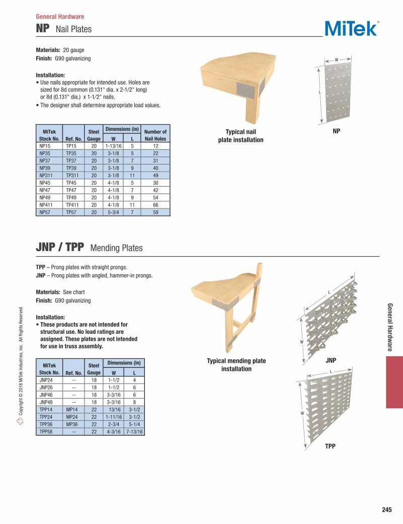
245
General Hardware
Copy
right
© 2
018
MiT
ek In
dust
ries,
Inc.
All
Righ
ts R
eser
ved
NP Nail Plates
TPP – Prong plates with straight prongs.JNP – Prong plates with angled, hammer-in prongs. Materials: See chartFinish: G90 galvanizing
Installation:• These products are not intended for
structural use. No load ratings are assigned. These plates are not intended for use in truss assembly.
Typical nail plate installation
NP
Materials: 20 gaugeFinish: G90 galvanizing
Installation:• Use nails appropriate for intended use. Holes are
sized for 8d common (0.131" dia. x 2-1/2" long) or 8d (0.131" dia.) x 1-1⁄2" nails.
• The designer shall determine appropriate load values.
JNP / TPP Mending Plates
Dimensions (in)
Ref. No. W L NP15 TP15 20 1-13/16 5 12 NP35 TP35 20 3-1/8 5 22 NP37 TP37 20 3-1/8 7 31 NP39 TP39 20 3-1/8 9 40 NP311 TP311 20 3-1/8 11 49 NP45 TP45 20 4-1/8 5 30 NP47 TP47 20 4-1/8 7 42 NP49 TP49 20 4-1/8 9 54 NP411 TP411 20 4-1/8 11 66 NP57 TP57 20 5-3/4 7 59
MiTekStock No.
SteelGauge
Number ofNail Holes
Ref. No. W L JNP24 -- 18 1-1/2 4 JNP26 -- 18 1-1/2 6 JNP46 -- 18 3-3/16 6 JNP48 -- 18 3-3/16 8 TPP14 MP14 22 13/16 3-1/2 TPP24 MP24 22 1-11/16 3-1/2 TPP36 MP36 22 2-3/4 5-1/4 TPP58 -- 22 4-3/16 7-13/16
Dimensions (in)MiTekStock No.
SteelGauge
General Hardware
Typical mending plate installation
JNP
TPP
L
W
W
L
W
L

246
Spec
ialty
Opt
ions
Copyright © 2018 M
iTek Industries, Inc. All Rights Reserved
The information listed only applies to hangers manufactured by MiTek® and installed according to the instructions listed in this catalog. Some of the options listed may not have been evaluated on a single hanger. The designer must always evaluate each connection, including the joist and header capacities, before specifying a specialty connector. MiTek sloped hangers are manufactured with the plumb cut of the joist already calculated. If a hanger with a different height is needed, it must be specified at the time of ordering.
Materials: Steel gauge may vary from that specified depending on the specialty option and manufacturing process used. Some formed hangers may be welded when modifying the hanger. Hanger configurations, fastener schedules, and height may vary from the tables depending on the joist size, skew, and slope.
Finish: See specific hanger option tables. Welded hangers are painted with gray primer. Non-catalogue hangers available in Hot-dip galvanized, use HDG after product number.
Factored Resistance: For multiple options for the same connector, use the most conservative reduction to give the lowest design load. See specific hanger option tables for applicable load reductions and maximum tolerances. Reference Specialty Options Summary Table for MiTek series catalog references.
Installation:• Fill all nail holes with fasteners specified in
the tables.• Fastener quantities may increase from the
amount listed in the tables depending on hanger option.
• NA16D-RS and NA20D nails are supplied with hangers.
• For type A skewed hangers, the end of joist must be bevel cut; for type B skewed hangers, the end of joist must be square cut.
MiTekSeries Width S
kew
ed (M
axim
um)
Slo
ped
Seat
(Max
imum
)
Slo
ped
/ Ske
wed
Slo
ped
Top
Flan
ge (M
axim
um)
Top
Fla
nge
Offs
et
Sad
dle
Hang
er
Rid
ge H
ange
r (M
axim
um)
Inve
rted
Fla
nge
Upl
ift
Wel
dabi
lity
MiT
ek S
erie
s Ca
talo
g Pa
ge R
efer
ence
BPH all 50º 45º • 45º • • 161 FWH all 70º • • 128
GHF all 50º 45º ••
width > 4-1/2"• 182
HBPH all 50º 45º • 45º • • 1611-3/4" or less 67-1/2º
> 1-3/4" 50º1-3/4" or less 67-1/2º
> 1-3/4" 50º HDQIF all • 106, 152
HGU all 45º• one flange
width > 5-1/4"• 181
HGUM all • one flange • 141 HJC all 60º • 215 HLBH all 50º 45º • 45º • • 45º • • 162
HUS all•
width > 2-1/4" • 105
HWUH all 45º 45º • • • • 1431-3/4" or less 67-1/2º
> 1-3/4" 50º KB all • • 122 KEG all 45º 45º • • 184 KGB all • • 185 KGH all 45º • 47 KGLS all 50º 45º • 30º • • • • 188 KGLST all • • • 188 KGLT all 50º 45º • 45º • • • • 187 KHGB all • • 185 KHGLS all 50º 45º 30º • • • • 188 KHGLST all • • • 188 KHGLT all 50º 45º • 45º • • • • 187 KHHB all • • 185 KHW all 84º 45º • 35º • • 45º • 123 KLB all • 122 KLEG all 45º 45º • • 184 KMEG all 45º 45º • • 184
LGU all 45º• one flange
width > 3-5/8"• 181
LSSH all 45º 45º • • 179
MGU all 45º• one flange
width > 5-1/4"• 181
MPH1 all 60º 45º • • 145 MSHA all 75° • 211 MSHL/R all 45º • 210
PHM1 all 84º 45º • 35º • • 45º • 163
PHXU1 all 60º 45º • 35º • • • • 163 SKH all 45º • 132 SKHH all 45º • 132
1-3/4" or less 67-1/2º> 1-3/4" 50º
SW1 all 84º 45º • 35º • • 45º • 123
SWH1 all 84º 45º • 35º • • 45º • 123
THDH all 45º 45º • • 153, 206
1) Skews greater than 45° will have square cut joist with back plate. Refer to Typical HLBH hanger skewed, left shown, squre cut illustration on page 248. 2) HD hanger widths less than 2-1/4" may have flanges inverted as a Custom, contact MiTek. New products or updated product information are designated in blue font.
•width > 2-1/4"
• 150•
•width > 3-1/8"
••
•width > 2-1/4"
••45º
SUH 45º
HD1
HDO 45º
IHFL/IHF 45º
• •
106, 151
104
153, 204
122
THF
45º 45º •
45º •
THD all• one flangewidth > 3"
•
•
151•
width > 2-1/4" > 1-3/4" 50º
Specialty Options & General NotesSpecialty Options

247
Specialty Options Co
pyrig
ht ©
201
8 M
iTek
Indu
strie
s, In
c. A
ll Ri
ghts
Res
erve
d
Face Mount Hanger Specialty DetailsSpecialty Options
See the Specialty Options Chart for each hanger series for load reductions and hanger maximum range of skew, slope, etc.
Skewed Hanger:• Consider SKH or SKHH hangers for 45° skews.• Joist nails on the closed side may be relocated to the
open side by MiTek designer to ensure proper nailing.• Specify skew angle, type (square cut or bevel cut),
and direction when ordering.
Sloped Seat Hanger:• Consider LSSH series for sloped applications.• Additional nail holes may be added to joist flanges.• Specify slope angle and direction when ordering.
Sloped/Skewed Hanger:• See nailing notes above for both Skewed Hanger
and Sloped Seat Hanger.• Specify skew and slope angles as well as skew/slope
directions and skew type (square cut or bevel cut) when ordering.
Inverted Flange Hanger:• When fastening into the carrying member’s end grain,
the allowable load is 0.65 of the table load.• Hangers with one flange inverted achieve 100%
of listed table load.• Specify right or left flange when inverting only
one flange.
Refer to GHF, HD, SUH, THD, THDH, THF series Special Order Worksheet for ordering instructions at MiTek.ca.
Typical SUH hanger skewed, right shown
(bevel cut)
Typical HD hanger sloped seat,down shown
Typical GHF hanger one flange inverted,
left shown
Typical SUH formed hanger skewed,
right shown(square cut)
Typical HD hanger inverted flange
90° Open side
Specify angle
Closed side
Specify angle
Specify angle
Plumb height
Joist height
2-1/8"
Typical HD hanger sloped down,
skewed left shown
Slope angle Skew
angle
90° 90°

248
Spec
ialty
Opt
ions
Copyright © 2018 M
iTek Industries, Inc. All Rights Reserved
Open Top Flange Hanger Specialty DetailsSpecialty Options
See Specialty Options Chart for each hanger series for load reductions and hanger maximum range of skew, slope, etc.
Skewed Hanger:• Joist nails may be located on obtuse angle side by MiTek
designer to ensure proper nailing.• Specify skew angle, type (square cut or bevel cut), and
direction when ordering.
Sloped Seat Hanger:• Additional nail holes may be added to joist flanges by MiTek
designer. All fastener holes must be filled.• Specify slope angle, direction, and joist height when ordering.
Sloped/Skewed Hanger:• See nailing notes above for both Skewed Hanger and Sloped
Seat Hanger.• Specify skew and slope angles as well as skew/slope
directions, and skew type (square cut or bevel cut) when ordering.
• Similar to face mount skewed/sloped hanger, refer to illustration on page 247: Typical HD hanger sloped down, skewed left shown.
• Specify if hanger is to be high side flush, low side flush, or center flush.
Sloped/Skewed/Sloped Top Flange Hanger:• See nailing notes for both skewed and sloped hangers.• Specify skew, slope, and top flange slope angles as well as
skew/slope and top flange slope directions when ordering.• Hangers may be galvanized or painted.• Hangers may be made with solid top plate.
Refer to BPH series Special Order Worksheet for ordering instructions at MiTek.ca.
Typical BPH hangerskewed, left shown
(bevel cut)
Typical BPH hangersloped seat,down shown
Typical BPH hangerskewed right,
sloped down, top flange sloped
Typical HDO hanger skewed, right shown
(square cut)
Typical BPH hangersloped down, skewed right,
low side flush shown
Typical BPH hangersloped top flange
right shown (this configuration will not
be open back)
Specify angle Specify angle
Slope angle
Skew angle
Specify angle
Joist skew right shown
Slope angle
Specify angle
Joist height
Plumb height
Specify angle High side flushCenter flush
Low side flush
90° 90°
Typical HLBH hangerskewed, left shown
(bevel cut)
Typical HLBH hangerskewed, left shown
(square cut)
See Specialty Options Chart for each hanger series for load reductions and hanger maximum range of skew, slope, etc.
Skewed Hanger:• Joist nails may be located on obtuse angle side by MiTek designer
to ensure proper nailing.• Specify skew angle, type (square cut or bevel cut), and direction
when ordering.
Sloped Seat Hanger:• Additional nail holes may be added to joist flanges by MiTek designer.• Specify slope angle, direction, and joist height when ordering.
Solid Top Flange Hanger Specialty Details
Specify angle Specify angle
Continued on next page

249
Specialty Options Co
pyrig
ht ©
201
8 M
iTek
Indu
strie
s, In
c. A
ll Ri
ghts
Res
erve
d
Solid Top Flange Hanger Specialty DetailsSpecialty Options
Typical PHXU hangersaddle option
Typical HLBH hangersloped down, skewed right,
center flush shown
Typical HLBH hangerridge, top
flange slope
Typical HLBH hanger top flange offset,
right shown
Typical HLBH hangersloped seat, down
shown
Typical HLBH hangerskewed right, sloped down
right, top flange sloped
Sloped/Skewed Hanger:• See nailing notes above for both Skewed Hanger
and Sloped Seat Hanger.• Specify skew and slope angles as well as skew/slope
directions, and skew type (square cut or bevel cut) when ordering.
• Specify if hanger is to be high side flush, low side flush, or center flush.
Sloped Top Flange Hanger:• Additional nail holes may be added to top angle
by MiTek designer.• Specify top flange slope and direction when ordering.• Specify if hanger is to be high side flush, low side flush,
or center flush.
Ridge Hanger:• Specify flush top of beam at center, right side, or left side.• Specify angle of slope when ordering.
Top Flange Offset Hanger:• Specify offset, left (L) or right (R), when ordering.
Saddle Hanger:• Specify saddle width, “SA” when ordering. Allow
clearance for saddled member.
Refer to options for HLBH, KGLS, KGLT, KHGLS, KHGLT series or HWUH, KHW, PHM, PHXU, SW, SWH series Special Order Worksheet for ordering instructions at MiTek.ca.
Typical HLBH hangersloped down top flange,
right shown
Specify angle
W1
H1
SAW2
H2
Plumb height
Specify angle
Joist height
Specify angle High side flushCenter flushLow side flush
Skew angle
Slope angle
Specify angle
Slope angle
Skew angle
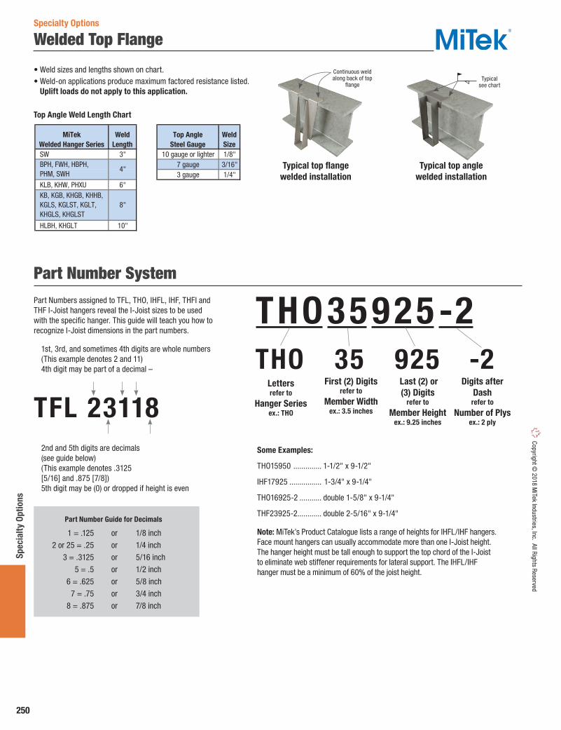
250
Spec
ialty
Opt
ions
Copyright © 2018 M
iTek Industries, Inc. All Rights Reserved
Welded Top Flange
• Weld sizes and lengths shown on chart.• Weld-on applications produce maximum factored resistance listed.
Uplift loads do not apply to this application.
SW 3" 10 gauge or lighter 1/8"7 gauge 3/16"3 gauge 1/4"
KLB, KHW, PHXU 6"
HLBH, KHGLT 10"
Weld shall be distributed evenly.
Top AngleSteel Gauge
WeldSize
KB, KGB, KHGB, KHHB, KGLS, KGLST, KGLT, KHGLS, KHGLST
8"
MiTekWelded Hanger Series
WeldLength
BPH, FWH, HBPH, PHM, SWH
4" Typical top flange welded installation
Typical top anglewelded installation
Continuous weld along back of top
flangeTypical
see chart
Part Number SystemPart Numbers assigned to TFL, THO, IHFL, IHF, THFI and THF I-Joist hangers reveal the I-Joist sizes to be used with the specific hanger. This guide will teach you how to recognize I-Joist dimensions in the part numbers.
1st, 3rd, and sometimes 4th digits are whole numbers (This example denotes 2 and 11) 4th digit may be part of a decimal –
TFL 23118 2nd and 5th digits are decimals
(see guide below) (This example denotes .3125 [5/16] and .875 [7/8]) 5th digit may be (0) or dropped if height is even
THO 35 925 -2
Part Number Guide for Decimals
1 = .125 or 1/8 inch
2 or 25 = .25 or 1/4 inch
3 = .3125 or 5/16 inch
5 = .5 or 1/2 inch
6 = .625 or 5/8 inch
7 = .75 or 3/4 inch
8 = .875 or 7/8 inch
THO 35 925 -2
Letters refer to
Hanger Seriesex.: THO
First (2) Digitsrefer to
Member Widthex.: 3.5 inches
Last (2) or (3) Digits
refer to
Member Heightex.: 9.25 inches
Digits after Dash
refer to
Number of Plysex.: 2 ply
Some Examples:
THO15950 .............. 1-1/2" x 9-1/2"
IHF17925 ................ 1-3/4" x 9-1/4"
THO16925-2 ........... double 1-5/8" x 9-1/4"
THF23925-2............ double 2-5/16" x 9-1/4"
Note: MiTek’s Product Catalogue lists a range of heights for IHFL/IHF hangers. Face mount hangers can usually accommodate more than one I-Joist height. The hanger height must be tall enough to support the top chord of the I-Joist to eliminate web stiffener requirements for lateral support. The IHFL/IHF hanger must be a minimum of 60% of the joist height.
Top Angle Weld Length Chart
Specialty Options
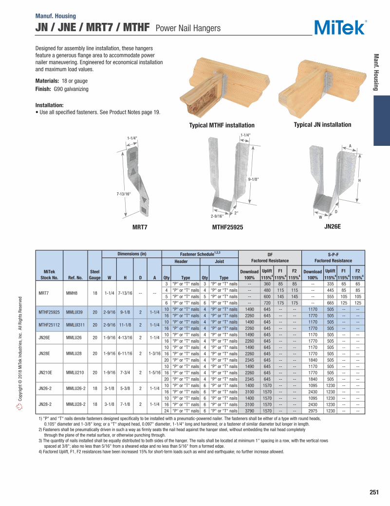
251
Manf. Housing
Copy
right
© 2
018
MiT
ek In
dust
ries,
Inc.
All
Righ
ts R
eser
ved
JN / JNE / MRT7 / MTHF Power Nail Hangers
Manuf. Housing
Designed for assembly line installation, these hangers feature a generous flange area to accommodate power nailer maneuvering. Engineered for economical installation and maximum load values.
Materials: 18 or gaugeFinish: G90 galvanizing
Installation:• Use all specified fasteners. See Product Notes page 19.
MTHF25925MRT7
Typical JN installation
JN26E
Typical MTHF installation
Ref. No. W H D A Qty Type Qty Type3 "P" or "T" nails 3 "P" or "T" nails -- 360 85 85 -- 335 65 654 "P" or "T" nails 4 "P" or "T" nails -- 480 115 115 -- 445 85 855 "P" or "T" nails 5 "P" or "T" nails -- 600 145 145 -- 555 105 1056 "P" or "T" nails 6 "P" or "T" nails -- 720 175 175 -- 665 125 12510 "P" or "T" nails 4 "P" or "T" nails 1490 645 -- -- 1170 505 -- --16 "P" or "T" nails 4 "P" or "T" nails 2260 645 -- -- 1770 505 -- --10 "P" or "T" nails 4 "P" or "T" nails 1490 645 -- -- 1170 505 -- --16 "P" or "T" nails 4 "P" or "T" nails 2260 645 -- -- 1770 505 -- --10 "P" or "T" nails 4 "P" or "T" nails 1490 645 -- -- 1170 505 -- --16 "P" or "T" nails 4 "P" or "T" nails 2260 645 -- -- 1770 505 -- --10 "P" or "T" nails 4 "P" or "T" nails 1490 645 -- -- 1170 505 -- --16 "P" or "T" nails 4 "P" or "T" nails 2260 645 -- -- 1770 505 -- --20 "P" or "T" nails 4 "P" or "T" nails 2345 645 -- -- 1840 505 -- --10 "P" or "T" nails 4 "P" or "T" nails 1490 645 -- -- 1170 505 -- --16 "P" or "T" nails 4 "P" or "T" nails 2260 645 -- -- 1770 505 -- --20 "P" or "T" nails 4 "P" or "T" nails 2345 645 -- -- 1840 505 -- --10 "P" or "T" nails 6 "P" or "T" nails 1400 1570 -- -- 1095 1230 -- --16 "P" or "T" nails 6 "P" or "T" nails 3100 1570 -- -- 2430 1230 -- --10 "P" or "T" nails 6 "P" or "T" nails 1400 1570 -- -- 1095 1230 -- --16 "P" or "T" nails 6 "P" or "T" nails 3100 1570 -- -- 2430 1230 -- --24 "P" or "T" nails 6 "P" or "T" nails 3790 1570 -- -- 2975 1230 -- --
1) "P" and "T" nails denote fasteners designed specifically to be installed with a pneumatic-powered nailer. The fasteners shall be either of a type with round heads, 0.105" diameter and 1-3/8" long; or a "T" shaped head, 0.097" diameter, 1-1/4" long and hardened; or a fastener of similar diameter but longer in length. 2) Fasteners shall be pneumatically driven in such a way as firmly seats the nail head against the hanger steel, without embedding the nail head completely through the plane of the metal surface, or otherwise punching through. 3) The quantity of nails installed shall be equally distributed to both sides of the hanger. The nails shall be located at minimum 1" spacing in a row, with the vertical rows spaced at 3/8"; also no less than 5/16" from a sheared edge and no less than 5/16" from a formed edge. 4) Factored Uplift, F1, F2 resistances have been increased 15% for short-term loads such as wind and earthquake; no further increase allowed.
Fastener Schedule1,2,3
Header JoistDF
Factored ResistanceS-P-F
Factored Resistance
MiTekStock No.
SteelGauge
MRT7 18
Dimensions (in)
7-13/16 -- --
MTHF25925 20 2-9/16 9-1/8 2 1-1/4
1-1/4
1-1/4
JN26E 20 1-9/16 4-13/16 2 1-1/4
MTHF25112 20 2-9/16 11-1/8 2
MMH8
MMLUI39
1-3/16
JN210E 20 1-9/16 7-3/4 2 1-5/16
JN28E 20 1-9/16 6-11/16 2
1-1/4
JN28-2 18 3-1/8 7-1/8 2 1-1/4
JN26-2 18 3-1/8 5-3/8 2
MMLU28-2
Uplift115%4
F1115%4
F2115%4
Download100%
Uplift115%4
F1115%4
F2115%4
Download100%
MMLUI311
MMLU26
MMLU28
MMLU210
MMLU26-2
7-13/16"
1-1/4"1-1/4"
9-1/8"
2" DW
A
H
2-9/16"

252
Late
ral S
yste
ms
Copyright © 2018 M
iTek Industries, Inc. All Rights ReservedLateral Systems
Hardy Frame® Shear Walls
Hardy Frames has been leading the pre-manufactured shear wall industry from its beginning. Hardy Frames were the first to be recognized by ICBO-ES and LA City, first to gain approval for multi-story applications, first Balloon Wall application and first to be recognized to comply with the 2003 and 2006 IBC and IRC Building Codes. Today we are the first and only to offer a 9 inch Panel width and a Balloon Wall application that is fully assembled in the manufacturing plant and ships as a one piece unit.
All Hardy Frame® Shear Walls are code listed and include installations on concrete, raised floor and upper floor systems.
Hardy Frame® Panels• Panels are available in 9, 12, 15, 18, 21 and 24" widths• Standard Heights range from 78" for portal applications to 20' for Balloon Walls• Custom heights are manufactured routinely• R factors used: Rd = 3.0, Ro = 1.7• “Back to Back” installations provide two times the allowable shear value without increasing the wall length
Hardy Frame® Code EvaluationICC-Evaluation Service ESR-2089
Hardy Frame® Brace• Available in 32 and 44" widths• Standard Heights range from nominal 8 to 13 feet• Custom heights are manufactured routinely• For a given shear load, installing a wider shear wall results in reduced overturning
Hardy Frame® Brace
Hardy Frame®
Balloon PanelHardy Frame®
Panel
“Back to Back” installations provide
two times the allowable shear value
Hardy Frame® Panel “Back to Back”
Shear Wall Systems

253
Lateral Systems
Copy
right
© 2
018
MiT
ek In
dust
ries,
Inc.
All
Righ
ts R
eser
ved
Lateral Systems
Hardy Frame® Moment FramesShear Wall Systems
The all new MiTek Hardy Frame® CFS Moment Frame and CFS Picture Frame are the industries first standardized, pre-engineered, pre-manufactured cold formed steel moment frames.
Lighter and less cost than structural steel moment frames, our CFS product line provides high capacities, ductility and cost economics that complete a spectrum of MiTek shear wall solutions.
Standard configurations are the Hardy Frame® CFS Moment Frame (portal applications) and the Hardy Frame CFS Picture Frame for stacking in multi-story applications.
MiTek Hardy Frame® Special Moment Frames are constructed of wide flange columns connected to hollow structural steel (HSS) beams with SidePlate special moment connections.
The SidePlate special moment connection is approved in the AISC 358 Prequalified Moment Connections Standard and the review included testing that confirmed lateral bracing to prevent twist and out-of-plane displacements is not required at the hollow structural section (HSS) beams. Standard configurations are the Hardy Frame® Moment Frame with a pinned base and the Hardy Frame® Picture Frame.
Hardy Frame® CFS Moment Frame• Similar materials and installation as Hardy Frame Panels the industry leader for 20 years• Available in standard designs and standard detailing• Capacities that are equal to four or five Hardy Frame Panels of same width• Can be installed “Back to Back” to double the capacity
Hardy Frame® CFS Picture Frame• Second beam that assembles at the bottom of the Frame distributes compression over wood below to significantly reduce crushing and maintain shear capacity• Incorporates the MiTek Z4 Continuous Tie-Down System to transfer overturning and uplift forces to the foundation• Narrow columns (12 through 21 inches) and shallow beam depths (12 and 15 inches) enable large openings and architectural freedom• Ships as a “knock-down” unit: easy to handle, ship and field assemble
Hardy Frame® Moment Frame• Standard designs for nominal 6 inch through 14 inch column depths with pinned base anchorage are now available• Delivery options for pre-assembled, bolted column splice or “knock-down”• All standard designs fit in typical 8 inch wall framing, 6 inch column depths fit 6 inch framing• New construction and retrofit applications• Includes wood nailers at top & bottom of HSS beam and at all column flanges
Hardy Frame® Picture Frame• Constructed with HSS beams at top and bottom of Frame, SidePlate special moment connections at all four corners• HSS beam at bottom of Frame eliminates the engineering and field construction of costly grade beams• Significant reductions in installation time result from elimination of field built grade beam• Standard designs for nominal 6 inch through 14 inch column depths that fit into typical wall framing with double the capacity of our pinned base option are now available• All the same delivery options and wood nailer inclusions as the Hardy Frame® Moment Frame with pinned base
The First and Only Cold Formed Steel (CFS) Moment Frames

254
Late
ral S
yste
ms
Copyright © 2018 M
iTek Industries, Inc. All Rights Reserved
MiTek® Z4 Tie-Down SystemsLateral Systems
MiTek® Z4 Tie-Down System for Lateral Load
To resist tension loads due to overturning moments in multi-story buildings the CNX Cinch Nut is installed over a Bearing Plate Washer at each level in a fast and easy application. At the upper-most level a Cinch Nut is installed over a Bearing Plate Washer above the top plates. At walls below that bear on wood floor systems, the Cinch Nut and Bearing Plate Washer are installed over the bottom plate. Tension loads are gathered at each level and transferred into the foundation through a continuous system of Cinch Nuts, Bearing Plate Washers, Threaded Rods and Couplers all are available lines of MiTek®, USA.
MiTek® Z4 Tie-Down System for Wind Uplift
For resisting roof uplift loads resulting from wind the Z4 Cinch Nut is installed over a Bearing Plate Washer above the top plates with roof framing above to create a tie-down system. Uplift forces are transferred into a continuous system of Threaded Rods and Couplers that form a load path to the foundation.
1
4
3
5
2Lorem ipsum
BPW5, BPW6 Installation
BPW7 and larger Installation
1. Threaded Rod2. Cinch nut3. MiTek® Pro Series Screw4. Bearing Plate Washer5. Wood Framing
For Lateral Loads
For Wind Uplift Loads
Roof Rafters
MiTek® Z4 Tie-Down Systems utilize CNX-Series Cinch Nuts to compensate for wood shrinkage and building settlement that cause connections to loosen over time. The Cinch Nut uses a self-ratcheting action that permits the cinch nut to move (the rod doesn’t move) or “travel” perpetually in one direction only down the rod. Available for installation with threaded rods that are 3/8" through 1-1/2" diameter in 1/8" increments, the CNX Cinch Nut has been code evaluated and published in ESR-2190.
• Place the specified Bearing Plate Washer onto the bottom plate of a wood framed wall.
• With the “wings” oriented downward, place Cinch Nut over the threaded rod extending from below and push down until it seats firmly on the Bearing Plate Washer.
• Install 1/4 inch diameter MiTek® Pro-Series™ Screws through the wings, penetrating 1-1/2" (minimum) into the wood bottom plate.
• Model numbers BPW5 and BPW6 fit in-between the screws fastening the wings.
• Model numbers BPW7 (3-1/4 x 4-3/8) and larger are provided with two screw holes. Align the wing and the Bearing Plate Washer screw holes to allow installation of 1/4" diameter MiTek® Pro-Series™ Screws.

MITEK® DECK DESIGNER™
Build, collaborate and share ideas easily with our free online software that will help you and your clients design the deck of their dreams. Deck Designer™ software is a simple point and click tool used by anyone from the homeowner to the pro deck builder. Free download at: MiTek.ca/software/Deck-Designer.
MITEK® SAPPHIRE™ SUPPLYEliminate the guesswork and create take-offs that everyone agrees on. For building material dealers, SAPPHIRE™ Supply is the one-stop solution for whole-house estimating, EWP and lumber design. Now your waste factor no longer has to account for the fudge factor. Learn more at: MiTek.ca/software/SAPPHIRE-Supply
MITEK® SPECIFIER™
Designed for Engineers and Estimators, Specifier™ software simplifies access to information on thousands of MiTek® Structural Connectors. Looking up connector capabilities, viewing code evaluation reports and mapping from referenced products to MiTek products is free, quick and easy to use. Specifier™ assists with the design, specification and quoting processes for steel connections in wood frame structure of all sizes. Free download: MiTek.ca/software/Specifier
MITEK® ADHESIVE ANCHOR DESIGNAdhesive Anchor Design is powerful design software that provides optimized epoxy connection solutions for threaded anchors post-installed into concrete. The software determines the required anchor rod steel grade, diameter and effective embedment depth based on applied factored tension, shear and moment loads. Free download: Mitek.ca/software/Adhesive-Anchor-Design
BETTER BUILDING BEGINS WITH MITEK SOFTWARE OUR INNOVATIVE SOFTWARE IS DESIGNED TO WORK WITH MITEK ENGINEERED STRUCTURAL HARDWARE.

MADE IN NORTH AMERICA. DESIGNED TO LAST.MiTek Structural Connectors are manufactured and distributed in strategic locations in North America. We are proud that our structural connector products are designed and made in North America.
CANADIAN MANUFACTURING & DISTRIBUTION
ONTARIO 221 Racco Parkway Thornhill, ON L4J 8X9
BRITISH COLUMBIA 2455 – 192nd Street Suite 102 Surrey, BC V3Z 3X1
ONTARIO 100 Industrial Rd. Bradford, ON L3Z 3G7
ALBERTA 21 Aero Drive NE - Unit #35 Calgary, AB T2E 8Z9
QUÉBEC 2952, Joseph-A. Bombardier Laval, QC H7P 6E3
NEW BRUNSWICK 55 Maxime Drive Dieppe, NB E1A 9B5
Phone: 1-800-268-3434Fax: 1-905-952-2903 Email: [email protected] Website: www.MiTek.ca
Better TechnologyBetter Building
INFORMATION / CUSTOMER SERVICE
© 2018 M
iTek Canada, Inc. All rights reserved 1030-SEP-18