Product manual 5437 2-wire HART 7 temperature transmitter
56
PERFORMANCE MADE SMARTER PENDING COMMUNICATION PROTOCOL Product manual 5437 2-wire HART 7 temperature transmitter TEMPERATURE | I.S. INTERFACES | COMMUNICATION INTERFACES | MULTIFUNCTIONAL | ISOLATION | DISPLAY No. 5437V101-UK Product version: 01.00.00-01.99.99
-
Upload
khangminh22 -
Category
Documents
-
view
0 -
download
0
Transcript of Product manual 5437 2-wire HART 7 temperature transmitter

PERFORMANCEMADE
SMARTER
PENDING
C O M M U N I C A T I O N P R O T O C O L
Product manual 54372-wire HART 7 temperature transmitter
TEMPER ATURE | I .S . INTERFACES | COMMUNIC ATION INTERFACES | MULTIFUNC TIONAL | ISOL ATION | D ISPL AY
No. 5437V101-UKProduct version: 01.00.00-01.99.99

6 Product Pillarsto meet your every need
With our innovative, patented technologies, we make signal conditioning smarter and simpler. Our portfolio is composed of six product areas, where we offer a wide range of analog and digital devices covering over a thousand applications in industrial and factory automation. All our products comply with or surpass the highest industry standards, ensuring reliability in even the harshest of environments and have a 5-year warranty for greater peace of mind.
Individually outstanding, unrivalled in combination
Our range of temperature transmitters and sensors provides the highest level of signal integrity from the measurement point to your control system. You can convert industrial process temperature signals to analog, bus or digital communications using a highly reliable point-to-point solution with a fast response time, automatic self-calibration, sensor error detection, low drift, and top EMC performance in any environment.
Our unique range of single devices covering multiple applications is easily deployable as your site standard. Having one variant that applies to a broad range of applications can reduce your installation time and training, and greatly simplify spare parts management at your facilities. Our devices are designed for long-term signal accuracy, low power consumption, immunity to electrical noise and simple programming.
We provide inexpensive, easy-to-use, future-ready communication interfaces that can access your PR installed base of products. The detachable 4501 Local Operator Interface (LOI) allows for local monitoring of process values, device configuration, error detection and signal simulation. The next generation, our 4511 Remote Operator Interface (ROI) does all that and more, adding remote digital communications via Modbus/RTU, while the analog output signals are still available for redundancy.With the 4511 you can further expand connectivity with a PR gateway, which connects via industrial Ethernet, wirelessly through a Wi-Fi router or directly with the devices using our Portable Plant Supervisor (PPS) application. The PPS app is available for iOS, Android and Windows.
Our display range is characterized by its flexibility and stability. The devices meet nearly every demand for display readout of process signals, and have universal input and power supply capabilities. They provide a real-time measurement of your process value no matter the industry, and are engineered to provide a user-friendly and reliable relay of information, even in demanding environments.
We deliver the safest signals by validating our products against the toughest safety standards. Through our commitment to innovation, we have made pioneering achievements in developing I.S. interfaces with SIL 2 Full Assessment that are both efficient and cost-effective. Our comprehensive range of analog and digital intrinsically safe isolation barriers offers multifunctional inputs and outputs, making PR an easy-to-implement site standard. Our backplanes further simplify large installations and provide seamless integration to standard DCS systems.
Our compact, fast, high-quality 6 mm isolators are based on microprocessor technology to provide exceptional performance and EMC-immunity for dedicated applications at a very low total cost of ownership. They can be stacked both vertically and horizontally with no air gap separation between units required.
5437V101-UK 3
2-wire HART 7 temperature transmitter
5437
Table of contentsApplication . . . . . . . . . . . . . . . . . . . . . . . . . . . . . . . . . . . . . . . . . . . . . . . . . . . . . . . . . . . . . . . . . . . . . . . . . . . . . . . . . . . . . . . . . . . . . 4Technical characteristics . . . . . . . . . . . . . . . . . . . . . . . . . . . . . . . . . . . . . . . . . . . . . . . . . . . . . . . . . . . . . . . . . . . . . . . . . . . . . . . . . 4Mounting / installation. . . . . . . . . . . . . . . . . . . . . . . . . . . . . . . . . . . . . . . . . . . . . . . . . . . . . . . . . . . . . . . . . . . . . . . . . . . . . . . . . . . 4Applications . . . . . . . . . . . . . . . . . . . . . . . . . . . . . . . . . . . . . . . . . . . . . . . . . . . . . . . . . . . . . . . . . . . . . . . . . . . . . . . . . . . . . . . . . . . . 4Order . . . . . . . . . . . . . . . . . . . . . . . . . . . . . . . . . . . . . . . . . . . . . . . . . . . . . . . . . . . . . . . . . . . . . . . . . . . . . . . . . . . . . . . . . . . . . . . . . . . 5Accessories . . . . . . . . . . . . . . . . . . . . . . . . . . . . . . . . . . . . . . . . . . . . . . . . . . . . . . . . . . . . . . . . . . . . . . . . . . . . . . . . . . . . . . . . . . . . . 5Electrical specifications . . . . . . . . . . . . . . . . . . . . . . . . . . . . . . . . . . . . . . . . . . . . . . . . . . . . . . . . . . . . . . . . . . . . . . . . . . . . . . . . . . 5Mechanical specifications . . . . . . . . . . . . . . . . . . . . . . . . . . . . . . . . . . . . . . . . . . . . . . . . . . . . . . . . . . . . . . . . . . . . . . . . . . . . . . . . 12LED function . . . . . . . . . . . . . . . . . . . . . . . . . . . . . . . . . . . . . . . . . . . . . . . . . . . . . . . . . . . . . . . . . . . . . . . . . . . . . . . . . . . . . . . . . . . . 13Jumpers . . . . . . . . . . . . . . . . . . . . . . . . . . . . . . . . . . . . . . . . . . . . . . . . . . . . . . . . . . . . . . . . . . . . . . . . . . . . . . . . . . . . . . . . . . . . . . . . 13Test pins . . . . . . . . . . . . . . . . . . . . . . . . . . . . . . . . . . . . . . . . . . . . . . . . . . . . . . . . . . . . . . . . . . . . . . . . . . . . . . . . . . . . . . . . . . . . . . . 14HART commands . . . . . . . . . . . . . . . . . . . . . . . . . . . . . . . . . . . . . . . . . . . . . . . . . . . . . . . . . . . . . . . . . . . . . . . . . . . . . . . . . . . . . . . . 14Advanced functions . . . . . . . . . . . . . . . . . . . . . . . . . . . . . . . . . . . . . . . . . . . . . . . . . . . . . . . . . . . . . . . . . . . . . . . . . . . . . . . . . . . . . 15Dynamic variable mapping . . . . . . . . . . . . . . . . . . . . . . . . . . . . . . . . . . . . . . . . . . . . . . . . . . . . . . . . . . . . . . . . . . . . . . . . . . . . . . . 16Overview of device variables . . . . . . . . . . . . . . . . . . . . . . . . . . . . . . . . . . . . . . . . . . . . . . . . . . . . . . . . . . . . . . . . . . . . . . . . . . . . . 16Write protection by software . . . . . . . . . . . . . . . . . . . . . . . . . . . . . . . . . . . . . . . . . . . . . . . . . . . . . . . . . . . . . . . . . . . . . . . . . . . . . 17Write protection by jumper. . . . . . . . . . . . . . . . . . . . . . . . . . . . . . . . . . . . . . . . . . . . . . . . . . . . . . . . . . . . . . . . . . . . . . . . . . . . . . . 17Changing the HART protocol version . . . . . . . . . . . . . . . . . . . . . . . . . . . . . . . . . . . . . . . . . . . . . . . . . . . . . . . . . . . . . . . . . . . . . . 17SIL functionality . . . . . . . . . . . . . . . . . . . . . . . . . . . . . . . . . . . . . . . . . . . . . . . . . . . . . . . . . . . . . . . . . . . . . . . . . . . . . . . . . . . . . . . . 19Connections . . . . . . . . . . . . . . . . . . . . . . . . . . . . . . . . . . . . . . . . . . . . . . . . . . . . . . . . . . . . . . . . . . . . . . . . . . . . . . . . . . . . . . . . . . . . 20Block diagram . . . . . . . . . . . . . . . . . . . . . . . . . . . . . . . . . . . . . . . . . . . . . . . . . . . . . . . . . . . . . . . . . . . . . . . . . . . . . . . . . . . . . . . . . . . 21Programming . . . . . . . . . . . . . . . . . . . . . . . . . . . . . . . . . . . . . . . . . . . . . . . . . . . . . . . . . . . . . . . . . . . . . . . . . . . . . . . . . . . . . . . . . . . 21Connection of transmitters in multidrop mode . . . . . . . . . . . . . . . . . . . . . . . . . . . . . . . . . . . . . . . . . . . . . . . . . . . . . . . . . . . . . 23EMC specifications - immunity. . . . . . . . . . . . . . . . . . . . . . . . . . . . . . . . . . . . . . . . . . . . . . . . . . . . . . . . . . . . . . . . . . . . . . . . . . . . 24EMC specifications - emmision. . . . . . . . . . . . . . . . . . . . . . . . . . . . . . . . . . . . . . . . . . . . . . . . . . . . . . . . . . . . . . . . . . . . . . . . . . . . 25ATEX Installation Drawing. . . . . . . . . . . . . . . . . . . . . . . . . . . . . . . . . . . . . . . . . . . . . . . . . . . . . . . . . . . . . . . . . . . . . . . . . . . . . . . . 26IECEx Installation Drawing . . . . . . . . . . . . . . . . . . . . . . . . . . . . . . . . . . . . . . . . . . . . . . . . . . . . . . . . . . . . . . . . . . . . . . . . . . . . . . . 31CSA Installation Drawing . . . . . . . . . . . . . . . . . . . . . . . . . . . . . . . . . . . . . . . . . . . . . . . . . . . . . . . . . . . . . . . . . . . . . . . . . . . . . . . . . 36FM Installation Drawing. . . . . . . . . . . . . . . . . . . . . . . . . . . . . . . . . . . . . . . . . . . . . . . . . . . . . . . . . . . . . . . . . . . . . . . . . . . . . . . . . . 39Instalaçao INMETRO . . . . . . . . . . . . . . . . . . . . . . . . . . . . . . . . . . . . . . . . . . . . . . . . . . . . . . . . . . . . . . . . . . . . . . . . . . . . . . . . . . . . . 44NEPSI Installation Drawing . . . . . . . . . . . . . . . . . . . . . . . . . . . . . . . . . . . . . . . . . . . . . . . . . . . . . . . . . . . . . . . . . . . . . . . . . . . . . . . 49Appendix A: Diagnostics overview . . . . . . . . . . . . . . . . . . . . . . . . . . . . . . . . . . . . . . . . . . . . . . . . . . . . . . . . . . . . . . . . . . . . . . . . 51Document history . . . . . . . . . . . . . . . . . . . . . . . . . . . . . . . . . . . . . . . . . . . . . . . . . . . . . . . . . . . . . . . . . . . . . . . . . . . . . . . . . . . . . . . 54

4 5437V101-UK
2-wire HART 7 temperature transmitter 5437
• RTD, TC, potentiometer, linear resistance and bipolar mV input
• Single or true dual inputs with sensor redundancy and drift detection
• Wide ambient operating temperature of -50 to +85°C
• Total accuracy from 0.014%
• 2.5 kVAC galvanic isolation
• Full assessment to IEC61508 : 2010 for use in SIL 2/3 applications
Application
• Temperature measurement of a wide range of TC and RTD types.
• Conversion of wide span linear resistance and potentiometer inputs to 4...20 mA.
• Conversion of bipolar mV signals to 4...20 mA.• Integration into asset management schemes.• Critical applications requiring superior accuracy and/or
sensor redundancy and drift detection.
Technical characteristics
• True dual input transmitter. High density 7-terminal design accepts the widest range of dual input combinations.
• Sensor redundancy - output automatically switches to secondary sensor in event of primary sensor failure, maintaining uptime.
• Sensor drift detection - alerts when sensor differential exceeds user-defined limits, for maintenance optimization.
• Dynamic variable mapping for process data in addition to the primary variable e.g. dual input features such as average, differential and min./max. tracking.
• Groundbreaking digital and analog signal accuracy over full input span and ambient conditions.
• Extensive sensor matching including Callendar Van Dusen and custom linearizations.
• Programmable input limits with runtime metering ensure maximum process traceability and sensor out of range protection.
• IEC 61508 : 2010 full assessment up to SIL 3 together with enhanced EMC Functional Safety testing to IEC 61236-3-1.
• Meets NAMUR NE21, NE43, NE44, NE89 and NE107 compliant diagnostics information.
Mounting / installation
• For DIN form B sensor head mounting.• Configuration via standard HART communication
interfaces or by PR 5909 Loop Link.• The 5437A can be mounted in zone 2 and zone 22 / Class I,
Division 1, Groups A, B, C, D.• The 5437D can be mounted in zone 0, 1, 2 and zone 20,
21, 22 including M1 / Class I, Division 1, Groups A, B, C, D.
EXT1
234
56
7
9
TEST -
TEST +
-3W
4W
3W
4W8
EXT1
23
45
6 TEST -
TEST +
-3W
4W
Dual input
Single input
2 x 2/3/4 w RTD2 x TC (2/3/4 w ext. CJC)
2 xTC (int. CJC)TC (int. CJC) + 2/3/4 w RTD
TC (2/3 w ext. CJC) +2/3/4 w RTD
2 x 2/3/4 w lin. R2 x 3/4 w Pot
5 w Pot + 3 w Pot 2 x mV unipolar2 x mV bipolar
4...20 mA(Advanced functions)
Input Output
2/3/4 w RTDTC (2/3 w. ext. CJC)
TC (int. CJC)2/3/4 w lin. R
3/4 w PotmV unipolarmV bipolar
4...20 mA
Applications
5437V101-UK 5
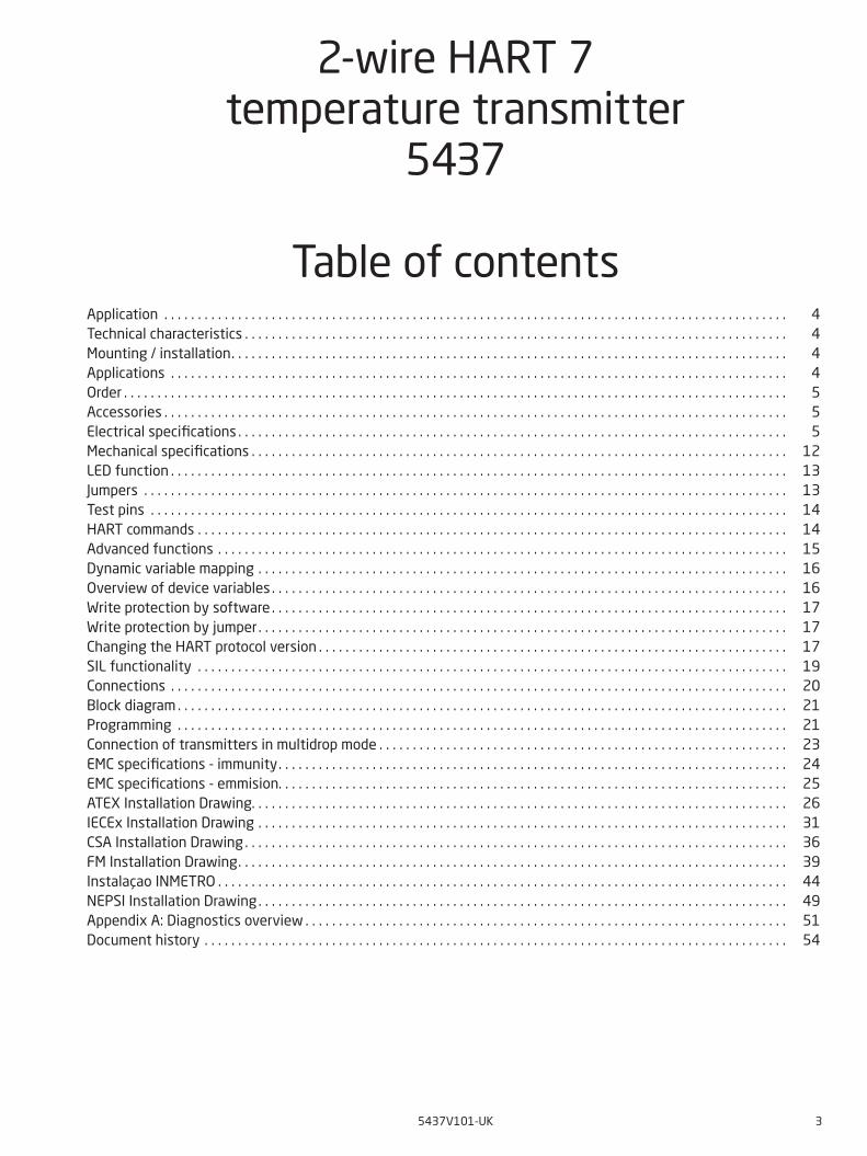
Electrical specifications
Environmental conditions:Ambient operating temperature range: Standard. . . . . . . . . . . . . . . . . . . . . . . . . . . . . . . . . . . . . . . . -50°C to +85°C SIL . . . . . . . . . . . . . . . . . . . . . . . . . . . . . . . . . . . . . . . . . . . -40°C to +80°CStorage temperature . . . . . . . . . . . . . . . . . . . . . . . . . . . . . . . . . -50°C to +85°CCalibration temperature. . . . . . . . . . . . . . . . . . . . . . . . . . . . . . . . 23...25°CHumidity. . . . . . . . . . . . . . . . . . . . . . . . . . . . . . . . . . . . . . . . . < 99% RH (non-cond.)Protection degree, enclosure / terminals. . . . . . . . . . . . . . . . . . . . . . IP68 / IP00
Mechanical specifications:Dimensions . . . . . . . . . . . . . . . . . . . . . . . . . . . . . . . . . . . . . . . Ø 44 x 20.2 mm Center hole diameter . . . . . . . . . . . . . . . . . . . . . . . . . . . . . . . . . Ø 6.35 mm / ¼ inWeight . . . . . . . . . . . . . . . . . . . . . . . . . . . . . . . . . . . . . . . . . . 50 gMax. wire size. . . . . . . . . . . . . . . . . . . . . . . . . . . . . . . . . . . . . . 1 x1.5 mm2 stranded wireScrew terminal torque. . . . . . . . . . . . . . . . . . . . . . . . . . . . . . . . . 0.4 NmVibration. . . . . . . . . . . . . . . . . . . . . . . . . . . . . . . . . . . . . . . . . IEC 60068-2-6 2...25 Hz. . . . . . . . . . . . . . . . . . . . . . . . . . . . . . . . . . . . . . . . ±1.6 mm 25...100 Hz . . . . . . . . . . . . . . . . . . . . . . . . . . . . . . . . . . . . . . ±4 g
Common specifications:Supply voltage, DC 5437A . . . . . . . . . . . . . . . . . . . . . . . . . . . . . . . . . . . . . . . . . 7.5*...48** VDC 5437D . . . . . . . . . . . . . . . . . . . . . . . . . . . . . . . . . . . . . . . . . 7.5*...30** VDC 5437, EU-RO . . . . . . . . . . . . . . . . . . . . . . . . . . . . . . . . . . . . . 8.3...33.6 VDC ±10%Additional min. supply voltage when using test terminals . . . . . . . . . . . 0.8 V Max. internal power dissipation . . . . . . . . . . . . . . . . . . . . . . . . . . . ≤ 850 mWMin. load resistance at > 37 V supply. . . . . . . . . . . . . . . . . . . . . . . . (Supply voltage – 37) / 23 mA Isolation voltage, test/operation: 5437A . . . . . . . . . . . . . . . . . . . . . . . . . . . . . . . . . . . . . . . . . 2.5 kVAC / 55 VAC 5437D . . . . . . . . . . . . . . . . . . . . . . . . . . . . . . . . . . . . . . . . . 2.5 kVAC / 42 VAC Polarity protection . . . . . . . . . . . . . . . . . . . . . . . . . . . . . . . . . . . All inputs and outputsWrite protection . . . . . . . . . . . . . . . . . . . . . . . . . . . . . . . . . . . . Jumper or softwareWarm-up time. . . . . . . . . . . . . . . . . . . . . . . . . . . . . . . . . . . . . . < 5 min.Start-up time . . . . . . . . . . . . . . . . . . . . . . . . . . . . . . . . . . . . . . < 2.75 sProgramming . . . . . . . . . . . . . . . . . . . . . . . . . . . . . . . . . . . . . . Loop Link & HARTSignal / noise ratio . . . . . . . . . . . . . . . . . . . . . . . . . . . . . . . . . . . > 60 dBLong-term stability, better than . . . . . . . . . . . . . . . . . . . . . . . . . . . ±0.05% of span / year ±0.18% of span / 5 yearsResponse time . . . . . . . . . . . . . . . . . . . . . . . . . . . . . . . . . . . . . 70 msProgrammable damping. . . . . . . . . . . . . . . . . . . . . . . . . . . . . . . . 0...60 sSignal dynamics, input . . . . . . . . . . . . . . . . . . . . . . . . . . . . . . . . 24 bitSignal dynamics, output . . . . . . . . . . . . . . . . . . . . . . . . . . . . . . . 18 bitEffect of supply voltage variation . . . . . . . . . . . . . . . . . . . . . . . . . . < 0.005% of span / VDC
* Note: Observe that the minimum Supply Voltage must be as measured at the terminals of the 5437, i.e. all external drops must be considered.
** Note: Make sure to protect the device from overvoltages by using a suitable power supply or by installing overvoltage protecting devices.
Order
Type Version Inputs SIL approval Marine approval
5437 General purpose
Hazardous area
: A
: D
Single input (4 terminals)
Dual input (7 terminals)
: 1
: 2
SIL
No SIL
: S
: -
Yes (Pending)
No
: M
: -
5909 = Loop Link USB interface and PReset Software276USB = HART modem with USB connection
Accessories
6 5437V101-UK
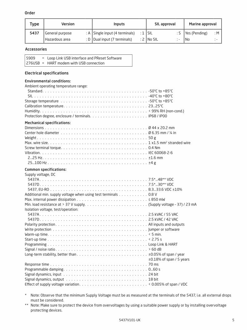
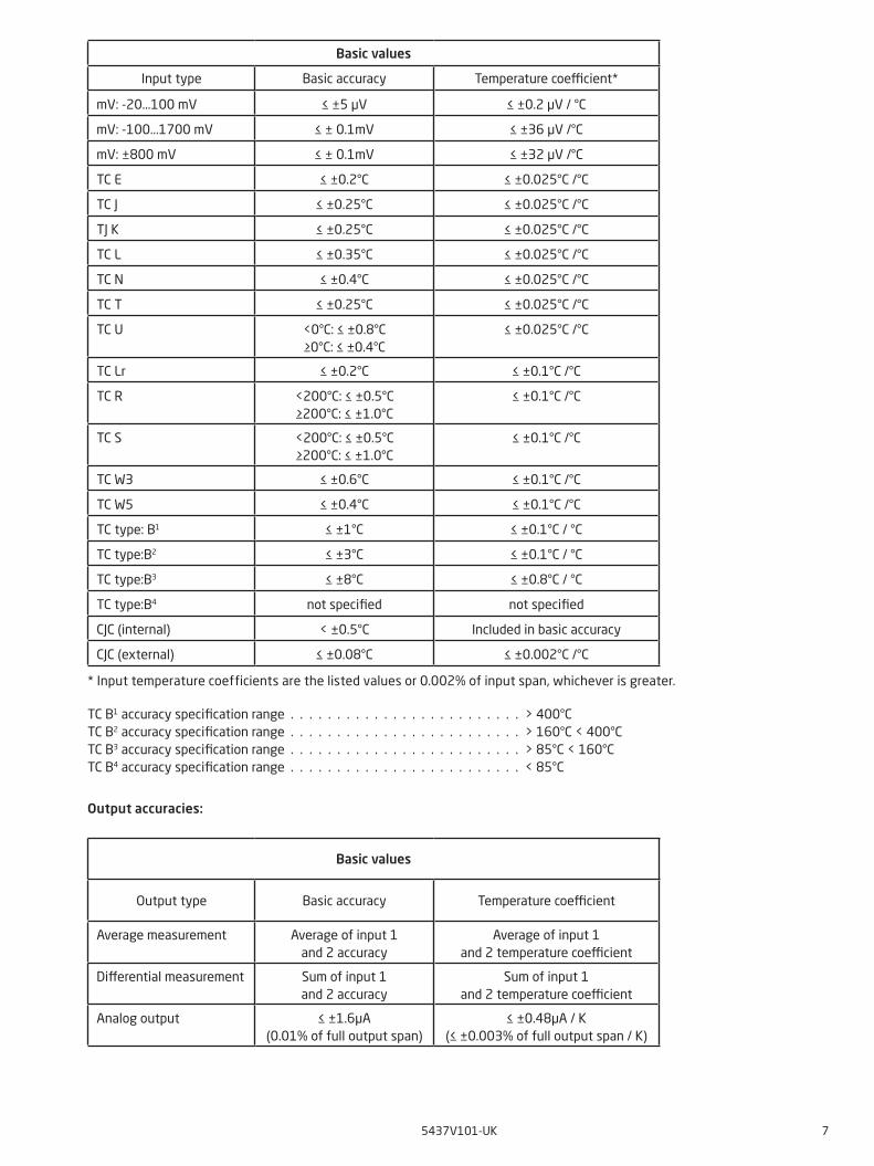
Input accuracies:
* Input temperature coefficients are the listed values or 0.002% of input span, whichever is greater.
Basic values
Input type Basic accuracy Temperature coefficient*
Pt10 ≤ ±0.8°C ≤ ±0.020°C /°C
Pt20 ≤ ±0.4°C ≤ ±0.010°C /°C
Pt50 ≤ ±0.16°C ≤ ±0.004°C /°C
Pt100 ≤ ±0.04°C ≤ ±0.002°C /°C
Pt200 ≤ ±0.08°C ≤ ±0.002°C /°C
Pt500 Tmax. ≤ 180°C: ≤ ±0.08°CTmax. > 180°C: ≤ ±0.16°C
≤ ±0.002°C /°C
Pt1000 ≤ ±0.08°C ≤ ±0.002°C /°C
Pt2000 Tmax. ≤ 300°C: ≤ ±0.08°CTmax. > 300°C: ≤ ±0.40°C
≤ ±0.002°C /°C
Pt10.000 ≤ ±0.16°C ≤ ±0.002°C /°C
Pt x The highest tolerance of the adjacent points
The highest coefficient of the adjacent points
Ni10 ≤ ±1.6°C ≤ ± 0.020°C /°C
Ni20 ≤ ±0.8°C ≤ ± 0.010°C /°C
Ni50 ≤ ± 0.32°C ≤ ± 0.004°C /°C
Ni100 ≤ ±0.16°C ≤ ± 0.002°C /°C
Ni120 ≤ ±0.16°C ≤ ± 0.002°C /°C
Ni200 ≤ ±0.16°C ≤ ± 0.002°C /°C
Ni500 ≤ ±0.16°C ≤ ± 0.002°C /°C
Ni1000 ≤ ±0.16°C ≤ ± 0.002°C /°C
Ni2000 ≤ ±0.16°C ≤ ± 0.002°C /°C
Ni10000 ≤ ±0.32°C ≤ ± 0.002°C /°C
Ni x The highest tolerance of the adjacent points
The highest coefficient of the adjacent points
Cu5 ≤ ±1.6°C ≤ ± 0.040°C /°C
Cu10 ≤ ±0.8°C ≤ ± 0.020°C /°C
Cu20 ≤ ± 0.4°C ≤ ± 0.010°C /°C
Cu50 ≤ ± 0.16°C ≤ ± 0.004°C /°C
Cu100 ≤ ±0.08°C ≤ ± 0.002°C /°C
Cu200 ≤ ±0.08°C ≤ ± 0.002°C /°C
Cu500 ≤ ±0.16°C ≤ ± 0.002°C /°C
Cu1000 ≤ ±0.08°C ≤ ± 0.002°C /°C
Cu x The highest tolerance of the adjacent points
The highest coefficient of the adjacent points
Lin. R: 0...400 Ω ≤ ±40 mΩ ≤ ±2mΩ /°C
Lin. R: 0...100 kΩ ≤ ±4 Ω ≤ ±0.2Ω /°C
Potentiometer: 0...100% <0.05% <±0.005%
5437V101-UK 7
TC B1 accuracy specification range . . . . . . . . . . . . . . . . . . . . . . . . . > 400°C TC B2 accuracy specification range . . . . . . . . . . . . . . . . . . . . . . . . . > 160°C < 400°C TC B3 accuracy specification range . . . . . . . . . . . . . . . . . . . . . . . . . > 85°C < 160°CTC B4 accuracy specification range . . . . . . . . . . . . . . . . . . . . . . . . . < 85°C
Output accuracies:
* Input temperature coefficients are the listed values or 0.002% of input span, whichever is greater.
Basic values
Input type Basic accuracy Temperature coefficient*
mV: -20...100 mV ≤ ±5 μV ≤ ±0.2 μV / °C
mV: -100...1700 mV ≤ ± 0.1mV ≤ ±36 μV /°C
mV: ±800 mV ≤ ± 0.1mV ≤ ±32 μV /°C
TC E ≤ ±0.2°C ≤ ±0.025°C /°C
TC J ≤ ±0.25°C ≤ ±0.025°C /°C
TJ K ≤ ±0.25°C ≤ ±0.025°C /°C
TC L ≤ ±0.35°C ≤ ±0.025°C /°C
TC N ≤ ±0.4°C ≤ ±0.025°C /°C
TC T ≤ ±0.25°C ≤ ±0.025°C /°C
TC U <0°C: ≤ ±0.8°C≥0°C: ≤ ±0.4°C
≤ ±0.025°C /°C
TC Lr ≤ ±0.2°C ≤ ±0.1°C /°C
TC R <200°C: ≤ ±0.5°C≥200°C: ≤ ±1.0°C
≤ ±0.1°C /°C
TC S <200°C: ≤ ±0.5°C≥200°C: ≤ ±1.0°C
≤ ±0.1°C /°C
TC W3 ≤ ±0.6°C ≤ ±0.1°C /°C
TC W5 ≤ ±0.4°C ≤ ±0.1°C /°C
TC type: B1 ≤ ±1°C ≤ ±0.1°C / °C
TC type:B2 ≤ ±3°C ≤ ±0.1°C / °C
TC type:B3 ≤ ±8°C ≤ ±0.8°C / °C
TC type:B4 not specified not specified
CJC (internal) < ±0.5°C Included in basic accuracy
CJC (external) ≤ ±0.08°C ≤ ±0.002°C /°C
Basic values
Output type Basic accuracy Temperature coefficient
Average measurement Average of input 1and 2 accuracy
Average of input 1and 2 temperature coefficient
Differential measurement Sum of input 1and 2 accuracy
Sum of input 1and 2 temperature coefficient
Analog output ≤ ±1.6μA(0.01% of full output span)
≤ ±0.48μA / K(≤ ±0.003% of full output span / K)
8 5437V101-UK
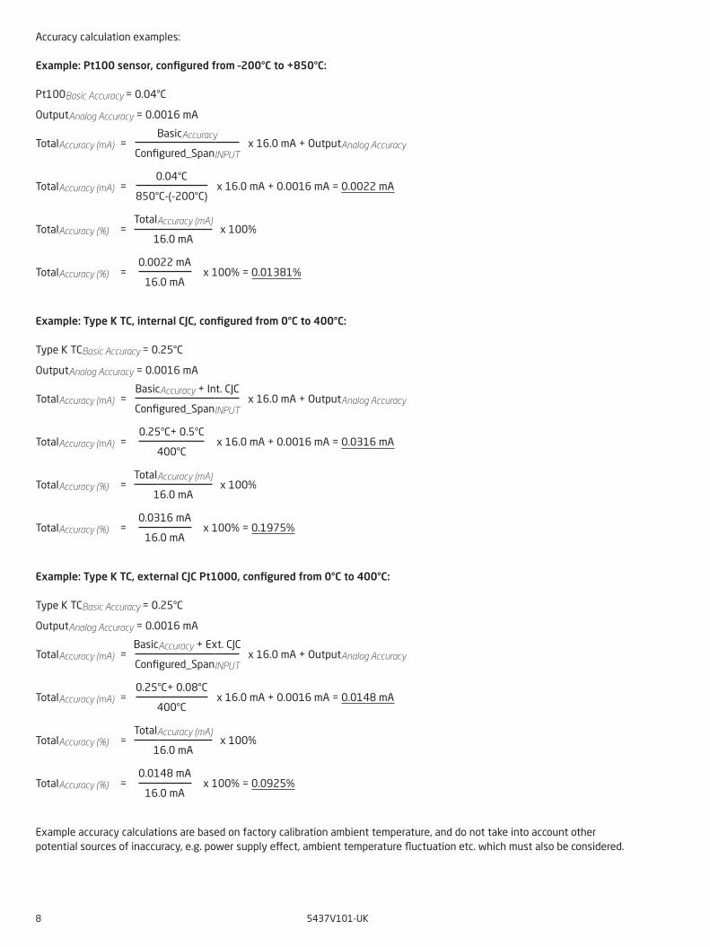
Accuracy calculation examples:
Example: Pt100 sensor, configured from –200°C to +850°C:
Pt100Basic Accuracy = 0.04°C
OutputAnalog Accuracy = 0.0016 mA
TotalAccuracy (mA) = BasicAccuracy
Configured_SpanINPUT x 16.0 mA + OutputAnalog Accuracy
TotalAccuracy (mA) = 0.04°C
850°C-(-200°C) x 16.0 mA + 0.0016 mA = 0.0022 mA
TotalAccuracy (%) = TotalAccuracy (mA)
16.0 mA x 100%
TotalAccuracy (%) = 0.0022 mA
16.0 mA x 100% = 0.01381%
Example: Type K TC, internal CJC, configured from 0°C to 400°C:
Type K TCBasic Accuracy = 0.25°C
OutputAnalog Accuracy = 0.0016 mA
TotalAccuracy (mA) = BasicAccuracy + Int. CJC
Configured_SpanINPUT x 16.0 mA + OutputAnalog Accuracy
TotalAccuracy (mA) = 0.25°C+ 0.5°C
400°C x 16.0 mA + 0.0016 mA = 0.0316 mA
TotalAccuracy (%) = TotalAccuracy (mA)
16.0 mA x 100%
TotalAccuracy (%) = 0.0316 mA
16.0 mA x 100% = 0.1975%
Example: Type K TC, external CJC Pt1000, configured from 0°C to 400°C:
Type K TCBasic Accuracy = 0.25°C
OutputAnalog Accuracy = 0.0016 mA
TotalAccuracy (mA) = BasicAccuracy + Ext. CJC
Configured_SpanINPUT x 16.0 mA + OutputAnalog Accuracy
TotalAccuracy (mA) = 0.25°C+ 0.08°C
400°C x 16.0 mA + 0.0016 mA = 0.0148 mA
TotalAccuracy (%) = TotalAccuracy (mA)
16.0 mA x 100%
TotalAccuracy (%) = 0.0148 mA
16.0 mA x 100% = 0.0925%
Example accuracy calculations are based on factory calibration ambient temperature, and do not take into account other potential sources of inaccuracy, e.g. power supply effect, ambient temperature fluctuation etc. which must also be considered.
5437V101-UK 9
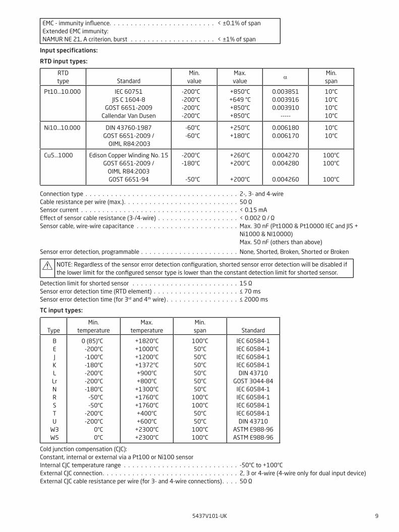
Input specifications:
RTD input types:
Connection type . . . . . . . . . . . . . . . . . . . . . . . . . . . . . . . . . . . . 2-, 3- and 4-wireCable resistance per wire (max.). . . . . . . . . . . . . . . . . . . . . . . . . . . 50 ΩSensor current . . . . . . . . . . . . . . . . . . . . . . . . . . . . . . . . . . . . . < 0.15 mA Effect of sensor cable resistance (3-/4-wire) . . . . . . . . . . . . . . . . . . . < 0.002 Ω / ΩSensor cable, wire-wire capacitance . . . . . . . . . . . . . . . . . . . . . . . . Max. 30 nF (Pt1000 & Pt10000 IEC and JIS + Ni1000 & NI10000) Max. 50 nF (others than above)
Sensor error detection, programmable . . . . . . . . . . . . . . . . . . . . . . . None, Shorted, Broken, Shorted or Broken
NOTE: Regardless of the sensor error detection configuration, shorted sensor error detection will be disabled if the lower limit for the configured sensor type is lower than the constant detection limit for shorted sensor.
Detection limit for shorted sensor . . . . . . . . . . . . . . . . . . . . . . . . . 15 ΩSensor error detection time (RTD element) . . . . . . . . . . . . . . . . . . . . ≤ 70 msSensor error detection time (for 3rd and 4th wire) . . . . . . . . . . . . . . . . . ≤ 2000 ms
TC input types:
Cold junction compensation (CJC):Constant, internal or external via a Pt100 or Ni100 sensorInternal CJC temperature range . . . . . . . . . . . . . . . . . . . . . . . . . . . -50°C to +100°CExternal CJC connection. . . . . . . . . . . . . . . . . . . . . . . . . . . . . . . . 2, 3 or 4-wire (4-wire only for dual input device)External CJC cable resistance per wire (for 3- and 4-wire connections) . . . . 50 Ω
RTD type
Standard
Min. value
Max. value
αMin. span
Pt10...10.000 IEC 60751JIS C 1604-8
GOST 6651-2009Callendar Van Dusen
-200°C-200°C-200°C-200°C
+850°C+649 °C+850°C+850°C
0.0038510.0039160.003910
-----
10°C10°C10°C10°C
Ni10...10.000 DIN 43760-1987GOST 6651-2009 /
OIML R84:2003
-60°C-60°C
+250°C+180°C
0.0061800.006170
10°C10°C
Cu5...1000 Edison Copper Winding No. 15GOST 6651-2009 /
OIML R84:2003GOST 6651-94
-200°C-180°C
-50°C
+260°C+200°C
+200°C
0.0042700.004280
0.004260
100°C100°C
100°C
Type
Min.temperature
Max.temperature
Min. span
Standard
BEJKLLrNRSTU
W3W5
0 (85)°C-200°C-100°C-180°C-200°C-200°C-180°C
-50°C-50°C
-200°C-200°C
0°C0°C
+1820°C+1000°C+1200°C+1372°C+900°C+800°C
+1300°C+1760°C+1760°C+400°C+600°C
+2300°C+2300°C
100°C50°C50°C50°C50°C50°C50°C
100°C100°C50°C50°C
100°C100°C
IEC 60584-1IEC 60584-1IEC 60584-1IEC 60584-1DIN 43710
GOST 3044-84IEC 60584-1IEC 60584-1IEC 60584-1IEC 60584-1DIN 43710
ASTM E988-96ASTM E988-96
EMC - immunity influence. . . . . . . . . . . . . . . . . . . . . . . . . < ±0.1% of spanExtended EMC immunity:NAMUR NE 21, A criterion, burst . . . . . . . . . . . . . . . . . . . . < ±1% of span
10 5437V101-UK
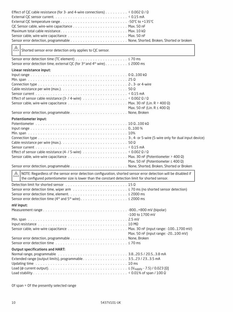
Effect of CJC cable resistance (for 3- and 4-wire connections) . . . . . . . . . < 0.002 Ω / ΩExternal CJC sensor current. . . . . . . . . . . . . . . . . . . . . . . . . . . . . . < 0.15 mAExternal CJC temperature range . . . . . . . . . . . . . . . . . . . . . . . . . . . -50°C to +135°CCJC Sensor cable, wire-wire capacitance . . . . . . . . . . . . . . . . . . . . . . Max. 50 nFMaximum total cable resistance . . . . . . . . . . . . . . . . . . . . . . . . . . . Max. 10 kΩSensor cable, wire-wire capacitance . . . . . . . . . . . . . . . . . . . . . . . . Max. 50 nFSensor error detection, programmable . . . . . . . . . . . . . . . . . . . . . . . None, Shorted, Broken, Shorted or broken
Shorted sensor error detection only applies to CJC sensor.
Sensor error detection time (TC element) . . . . . . . . . . . . . . . . . . . . . ≤ 70 msSensor error detection time, external CJC (for 3rd and 4th wire) . . . . . . . . . ≤ 2000 ms
Linear resistance input:Input range . . . . . . . . . . . . . . . . . . . . . . . . . . . . . . . . . . . . . . . 0 Ω...100 kΩMin. span . . . . . . . . . . . . . . . . . . . . . . . . . . . . . . . . . . . . . . . . 25 Ω Connection type . . . . . . . . . . . . . . . . . . . . . . . . . . . . . . . . . . . . 2-, 3- or 4-wireCable resistance per wire (max.). . . . . . . . . . . . . . . . . . . . . . . . . . . 50 ΩSensor current . . . . . . . . . . . . . . . . . . . . . . . . . . . . . . . . . . . . . < 0.15 mAEffect of sensor cable resistance (3- / 4-wire) . . . . . . . . . . . . . . . . . . < 0.002 Ω / ΩSensor cable, wire-wire capacitance . . . . . . . . . . . . . . . . . . . . . . . . Max. 30 nF (Lin. R > 400 Ω) Max. 50 nF (Lin. R ≤ 400 Ω)Sensor error detection, programmable . . . . . . . . . . . . . . . . . . . . . . . None, Broken
Potentiometer input:Potentiometer . . . . . . . . . . . . . . . . . . . . . . . . . . . . . . . . . . . . . 10 Ω...100 kΩInput range . . . . . . . . . . . . . . . . . . . . . . . . . . . . . . . . . . . . . . . 0...100 %Min. span . . . . . . . . . . . . . . . . . . . . . . . . . . . . . . . . . . . . . . . . 10%Connection type . . . . . . . . . . . . . . . . . . . . . . . . . . . . . . . . . . . . 3-, 4- or 5-wire (5-wire only for dual input device)Cable resistance per wire (max.). . . . . . . . . . . . . . . . . . . . . . . . . . . 50 ΩSensor current . . . . . . . . . . . . . . . . . . . . . . . . . . . . . . . . . . . . . < 0.15 mAEffect of sensor cable resistance (4- / 5-wire) . . . . . . . . . . . . . . . . . . < 0.002 Ω / ΩSensor cable, wire-wire capacitance . . . . . . . . . . . . . . . . . . . . . . . . Max. 30 nF (Potentiometer > 400 Ω) Max. 50 nF (Potentiometer ≤ 400 Ω)Sensor error detection, programmable . . . . . . . . . . . . . . . . . . . . . . . None, Shorted, Broken, Shorted or Broken
NOTE: Regardless of the sensor error detection configuration, shorted sensor error detection will be disabled if the configured potentiometer size is lower than the constant detection limit for shorted sensor.
Detection limit for shorted sensor . . . . . . . . . . . . . . . . . . . . . . . . . 15 ΩSensor error detection time, wiper arm . . . . . . . . . . . . . . . . . . . . . . ≤ 70 ms (no shorted sensor detection)Sensor error detection time, element. . . . . . . . . . . . . . . . . . . . . . . . ≤ 2000 msSensor error detection time (4th and 5th wire) . . . . . . . . . . . . . . . . . . . ≤ 2000 ms
mV input:Measurement range . . . . . . . . . . . . . . . . . . . . . . . . . . . . . . . . . . -800...+800 mV (bipolar) -100 to 1700 mVMin. span . . . . . . . . . . . . . . . . . . . . . . . . . . . . . . . . . . . . . . . . 2.5 mVInput resistance . . . . . . . . . . . . . . . . . . . . . . . . . . . . . . . . . . . . 10 MΩSensor cable, wire-wire capacitance . . . . . . . . . . . . . . . . . . . . . . . . Max. 30 nF (input range: -100...1700 mV) Max. 50 nF (input range: -20...100 mV)Sensor error detection, programmable . . . . . . . . . . . . . . . . . . . . . . . None, BrokenSensor error detection time . . . . . . . . . . . . . . . . . . . . . . . . . . . . . ≤ 70 ms
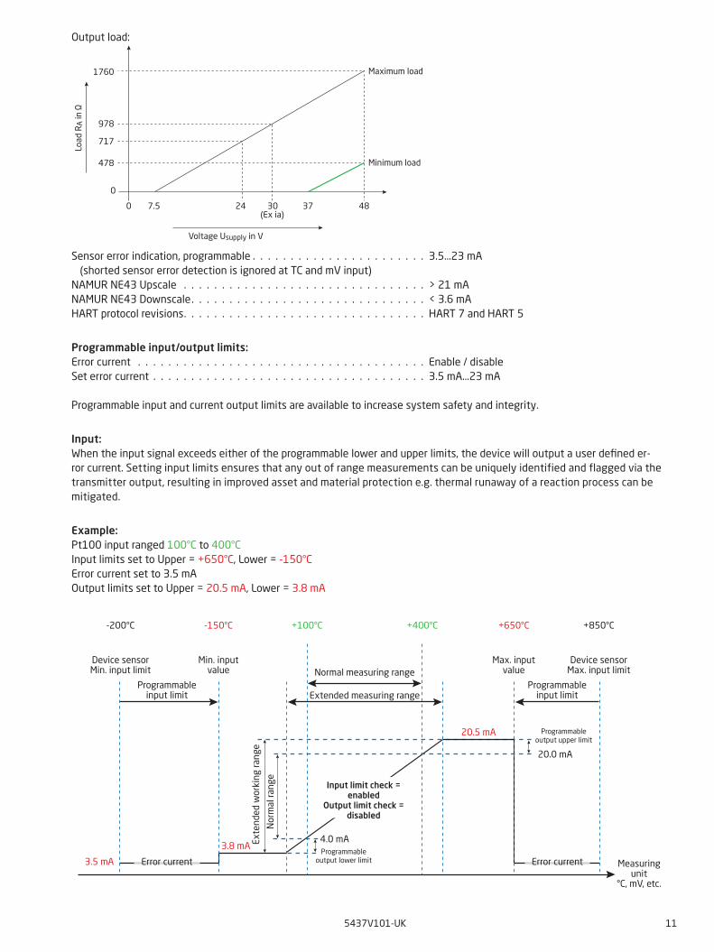
Output specifications and HART:Normal range, programmable . . . . . . . . . . . . . . . . . . . . . . . . . . . . 3.8...20.5 / 20.5...3.8 mAExtended range (output limits), programmable . . . . . . . . . . . . . . . . . . 3.5...23 / 23...3.5 mAUpdating time . . . . . . . . . . . . . . . . . . . . . . . . . . . . . . . . . . . . . 10 msLoad (@ current output) . . . . . . . . . . . . . . . . . . . . . . . . . . . . . . . . ≤ (Vsupply - 7.5) / 0.023 [Ω]Load stability . . . . . . . . . . . . . . . . . . . . . . . . . . . . . . . . . . . . . . < 0.01% of span / 100 Ω
Of span = Of the presently selected range
5437V101-UK 11
Output load:
Sensor error indication, programmable . . . . . . . . . . . . . . . . . . . . . . . 3.5...23 mA (shorted sensor error detection is ignored at TC and mV input)NAMUR NE43 Upscale . . . . . . . . . . . . . . . . . . . . . . . . . . . . . . . . > 21 mANAMUR NE43 Downscale. . . . . . . . . . . . . . . . . . . . . . . . . . . . . . . < 3.6 mAHART protocol revisions. . . . . . . . . . . . . . . . . . . . . . . . . . . . . . . . HART 7 and HART 5
Programmable input/output limits:Error current . . . . . . . . . . . . . . . . . . . . . . . . . . . . . . . . . . . . . . Enable / disableSet error current . . . . . . . . . . . . . . . . . . . . . . . . . . . . . . . . . . . . 3.5 mA...23 mA
Programmable input and current output limits are available to increase system safety and integrity.
Input:When the input signal exceeds either of the programmable lower and upper limits, the device will output a user defined er-ror current. Setting input limits ensures that any out of range measurements can be uniquely identified and flagged via the transmitter output, resulting in improved asset and material protection e.g. thermal runaway of a reaction process can be mitigated.
Example:Pt100 input ranged 100°C to 400°CInput limits set to Upper = +650°C, Lower = -150°CError current set to 3.5 mAOutput limits set to Upper = 20.5 mA, Lower = 3.8 mA
-200°C -150°C +650°C +850°C+100°C +400°C
Device sensorMin. input limit
Min. inputvalue
Max. inputvalue
Device sensorMax. input limit
Error current
Programmableinput limit
Programmableinput limit
Error current Measuringunit
°C, mV, etc.
Normal measuring range
Extended measuring range
Nor
mal
rang
e
Exte
nded
wor
king
rang
e
4.0 mAProgrammable
output lower limit
Programmableoutput upper limit
20.0 mA
Input limit check =enabled
Output limit check =disabled
3.5 mA
3.8 mA
20.5 mA
0 30(Ex ia)
3724 48
0
717
478
978
1760Lo
ad R
A in
Ω
Voltage Usupply in V
Maximum load
Minimum load
7.5

12 5437V101-UK
Output:When the current output exceeds either of the programmable upper and lower limits, the device will output a user defined error current.
Approvals:
Ex / I.S.:ATEX 2014/34/EU . . . . . . . . . . . . . . . . . . . . . . . . . . . . . . . . . . . DEKRA 16ATEX0047X IECEx . . . . . . . . . . . . . . . . . . . . . . . . . . . . . . . . . . . . . . . . . . . IECEx DEK. 16.0029X cFMus . . . . . . . . . . . . . . . . . . . . . . . . . . . . . . . . . . . . . . . . . . FM16CA0146X / FM16US0287XcCSAus . . . . . . . . . . . . . . . . . . . . . . . . . . . . . . . . . . . . . . . . . . 70066266INMETRO . . . . . . . . . . . . . . . . . . . . . . . . . . . . . . . . . . . . . . . . DEKRA 16.0008XNEPSI . . . . . . . . . . . . . . . . . . . . . . . . . . . . . . . . . . . . . . . . . . GYJ18.1054XEAC Ex TR-CU 012/2011 . . . . . . . . . . . . . . . . . . . . . . . . . . . . . . . RU C-DK.ПБ.98.В.00192
Marine approval:EU RO Mutual Recognition Type Approval . . . . . . . . . . . . . . . . . . . . . Pending
Observed authority requirements:EMC. . . . . . . . . . . . . . . . . . . . . . . . . . . . . . . . . . . . . . . . . . . . 2014/30/EURoHS . . . . . . . . . . . . . . . . . . . . . . . . . . . . . . . . . . . . . . . . . . . 2011/65/EUEAC . . . . . . . . . . . . . . . . . . . . . . . . . . . . . . . . . . . . . . . . . . . . TR-CU 020/2011
Functional safety:SIL2 Certified & Fully Assessed acc. to IEC 61508 : 2010SFF> 93% - type B componentSIL3 Applicable through redundant structure (HFT=0; 1oo2)FMEDA report - www.prelectronics.com
Mechanical specifications
44 mm 33 mm
20.2 mm
6.35 mm / ¼ in
Error current Error current Measuringunit
°C, mV, etc.
Normal measuring range
Extended measuring range
Nor
mal
rang
e
Exte
nded
wor
king
rang
e
4.0 mAProgrammable
output lower limit
Programmableoutput upper limit
20.0 mA
Output limit check = enabled
5437V101-UK 13
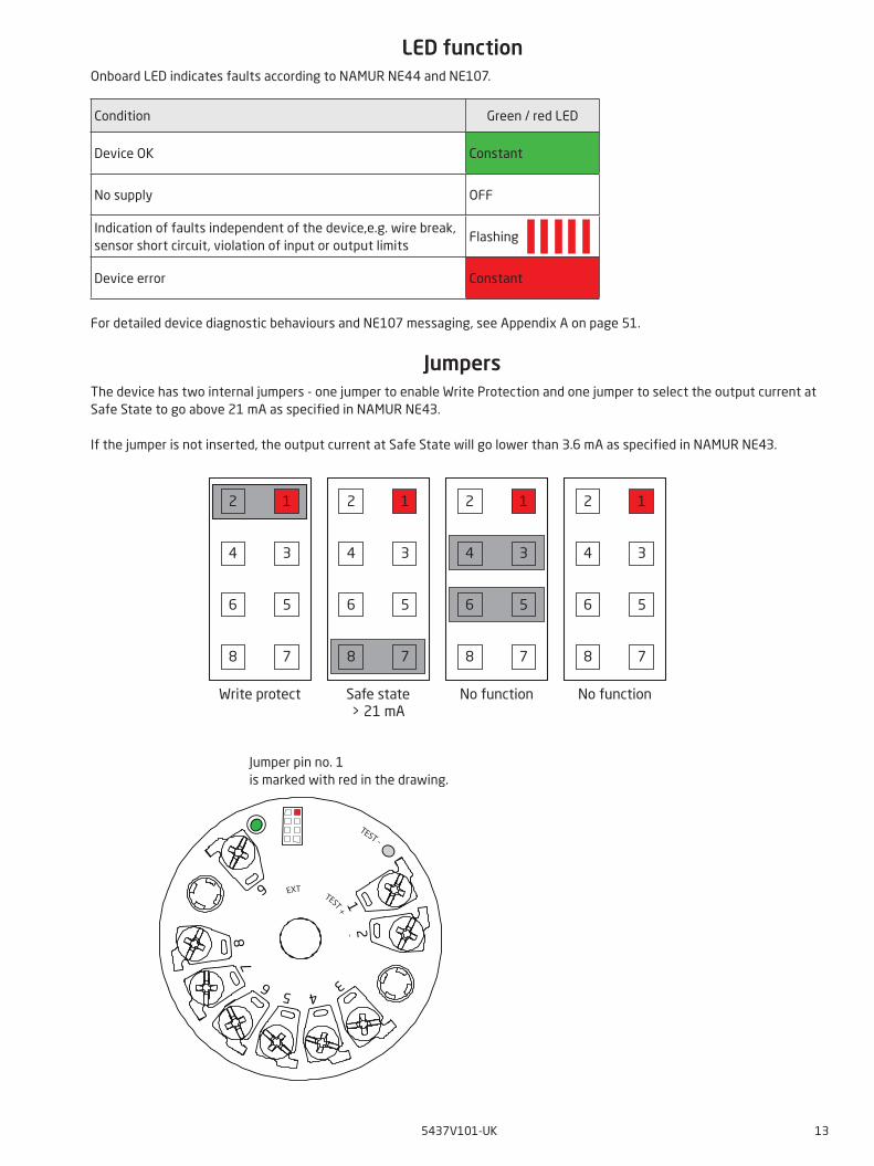
LED functionOnboard LED indicates faults according to NAMUR NE44 and NE107.
Condition Green / red LED
Device OK Constant
No supply OFF
Indication of faults independent of the device,e.g. wire break, sensor short circuit, violation of input or output limits
Flashing
Device error Constant
For detailed device diagnostic behaviours and NE107 messaging, see Appendix A on page 51.
JumpersThe device has two internal jumpers - one jumper to enable Write Protection and one jumper to select the output current at Safe State to go above 21 mA as specified in NAMUR NE43.
If the jumper is not inserted, the output current at Safe State will go lower than 3.6 mA as specified in NAMUR NE43.
Jumper pin no. 1 is marked with red in the drawing.
2
7
5
3
1
8
6
4
2
7
5
3
1
8
6
4
2
7
5
3
1
8
6
4
2
7
5
3
1
8
6
4
Write protect Safe state> 21 mA
No function No function
12
3456
78
9 EXT TEST + -
TEST -
14 5437V101-UK
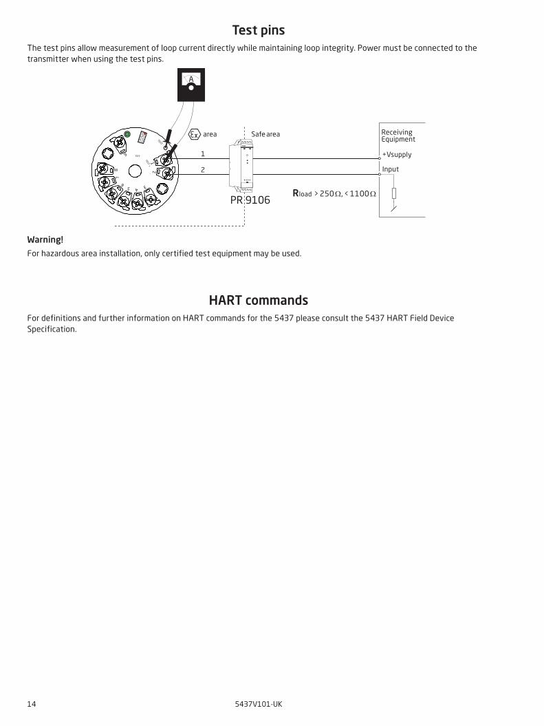
Test pinsThe test pins allow measurement of loop current directly while maintaining loop integrity. Power must be connected to the transmitter when using the test pins.
Warning!
For hazardous area installation, only certified test equipment may be used.
HART commandsFor definitions and further information on HART commands for the 5437 please consult the 5437 HART Field Device Specification.
12
345
6
78
9 EXT TEST + -
TEST -
1
2
PR 9106
A
Safe area
+Vsupply
Input
ReceivingEquipment
area
Rload > 250 Ω, < 1100 Ω
5437V101-UK 15
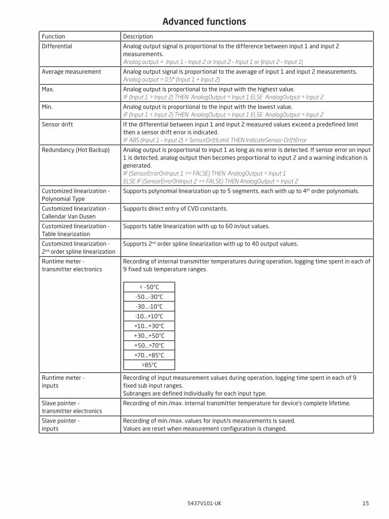
Advanced functionsFunction Description
Differential Analog output signal is proportional to the difference between input 1 and input 2 measurements.Analog output = Input 1 – Input 2 or Input 2 – Input 1 or |Input 2 – Input 1|
Average measurement Analog output signal is proportional to the average of input 1 and input 2 measurements. Analog output = 0.5* (Input 1 + Input 2)
Max. Analog output is proportional to the input with the highest value.IF (Input 1 > Input 2) THEN AnalogOutput = Input 1 ELSE AnalogOutput = Input 2
Min. Analog output is proportional to the input with the lowest value.IF (Input 1 < Input 2) THEN AnalogOutput = Input 1 ELSE AnalogOutput = Input 2
Sensor drift If the differential between input 1 and input 2 measured values exceed a predefined limit then a sensor drift error is indicated.IF ABS (Input 1 – Input 2) > SensorDriftLimit THEN IndicateSensor-DriftError
Redundancy (Hot Backup) Analog output is proportional to input 1 as long as no error is detected. If sensor error on input 1 is detected, analog output then becomes proportional to input 2 and a warning indication is generated.IF (SensorErrorOnInput 1 == FALSE) THEN AnalogOutput = Input 1ELSE IF (SensorErrorOnInput 2 == FALSE) THEN AnalogOutput = Input 2
Customized linearization - Polynomial Type
Supports polynomial linearization up to 5 segments, each with up to 4th order polynomials.
Customized linearization - Callendar Van Dusen
Supports direct entry of CVD constants.
Customized linearization - Table linearization
Supports table linearization with up to 60 in/out values.
Customized linearization - 2nd order spline linearization
Supports 2nd order spline linearization with up to 40 output values.
Runtime meter - transmitter electronics
Recording of internal transmitter temperatures during operation, logging time spent in each of 9 fixed sub temperature ranges.
< -50°C
-50...-30°C
-30...-10°C
-10...+10°C
+10...+30°C
+30...+50°C
+50...+70°C
+70...+85°C
>85°C
Runtime meter - inputs
Recording of input measurement values during operation, logging time spent in each of 9 fixed sub input ranges.Subranges are defined individually for each input type.
Slave pointer - transmitter electronics
Recording of min./max. internal transmitter temperature for device’s complete lifetime.
Slave pointer - inputs
Recording of min./max. values for input/s measurements is saved.Values are reset when measurement configuration is changed.
16 5437V101-UK
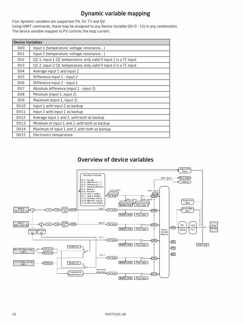
Dynamic variable mappingFour dynamic variables are supported, PV, SV, TV and QV. Using HART commands, these may be assigned to any Device Variable (DV 0 - 15) in any combination. The device variable mapped to PV controls the loop current.
Device Variables
DV0 Input 1 (temperature, voltage, resistance... )
DV1 Input 2 (temperature, voltage, resistance... )
DV2 CJC 1, input 1 CJC temperature, only valid if input 1 is a TC input
DV3 CJC 2, input 2 CJC temperature, only valid if input 2 is a TC input
DV4 Average input 1 and input 2
DV5 Difference input 1 - input 2
DV6 Difference input 2 - input 1
DV7 Absolute difference (input 1 - input 2)
DV8 Minimum (input 1, input 2)
DV9 Maximum (input 1, input 2)
DV10 Input 1 with input 2 as backup
DV11 Input 2 with input 1 as backup
DV12 Average input 1 and 2, with both as backup
DV13 Minimum of input 1 and 2, with both as backup
DV14 Maximum of input 1 and 2, with both as backup
DV15 Electronics temperature
Overview of device variables
5437V101-UK 17
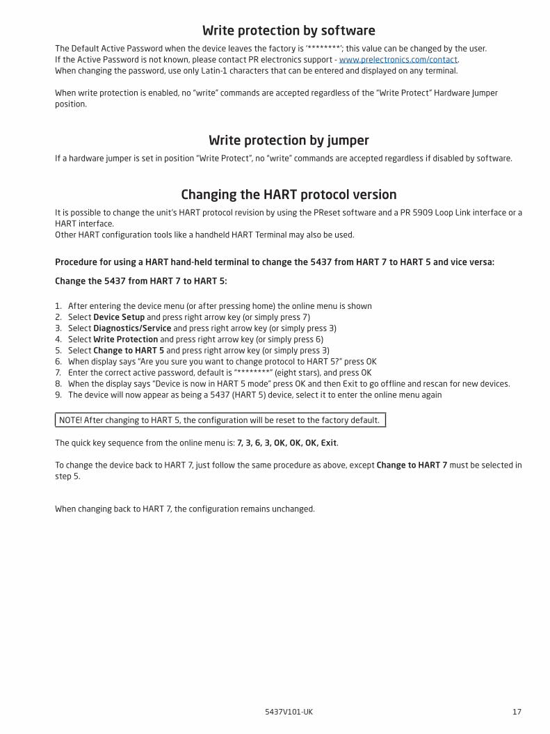
Write protection by softwareThe Default Active Password when the device leaves the factory is ‘********’; this value can be changed by the user. If the Active Password is not known, please contact PR electronics support - www.prelectronics.com/contact. When changing the password, use only Latin-1 characters that can be entered and displayed on any terminal.
When write protection is enabled, no “write” commands are accepted regardless of the “Write Protect” Hardware Jumper position.
Write protection by jumperIf a hardware jumper is set in position “Write Protect”, no “write” commands are accepted regardless if disabled by software.
Changing the HART protocol versionIt is possible to change the unit’s HART protocol revision by using the PReset software and a PR 5909 Loop Link interface or a HART interface.Other HART configuration tools like a handheld HART Terminal may also be used.
Procedure for using a HART hand-held terminal to change the 5437 from HART 7 to HART 5 and vice versa:
Change the 5437 from HART 7 to HART 5:
1. After entering the device menu (or after pressing home) the online menu is shown2. Select Device Setup and press right arrow key (or simply press 7)3. Select Diagnostics/Service and press right arrow key (or simply press 3)4. Select Write Protection and press right arrow key (or simply press 6)5. Select Change to HART 5 and press right arrow key (or simply press 3)6. When display says “Are you sure you want to change protocol to HART 5?” press OK7. Enter the correct active password, default is “********” (eight stars), and press OK8. When the display says “Device is now in HART 5 mode” press OK and then Exit to go offline and rescan for new devices.9. The device will now appear as being a 5437 (HART 5) device, select it to enter the online menu again
NOTE! After changing to HART 5, the configuration will be reset to the factory default.
The quick key sequence from the online menu is: 7, 3, 6, 3, OK, OK, OK, Exit.
To change the device back to HART 7, just follow the same procedure as above, except Change to HART 7 must be selected in step 5.
When changing back to HART 7, the configuration remains unchanged.
18 5437V101-UK
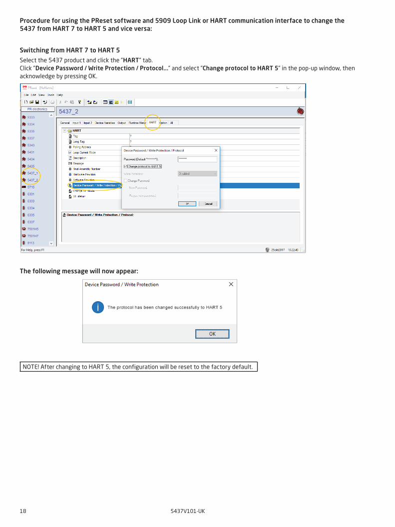
Procedure for using the PReset software and 5909 Loop Link or HART communication interface to change the 5437 from HART 7 to HART 5 and vice versa:
Switching from HART 7 to HART 5
Select the 5437 product and click the ”HART” tab.Click ”Device Password / Write Protection / Protocol...” and select ”Change protocol to HART 5” in the pop-up window, then acknowledge by pressing OK.
The following message will now appear:
NOTE! After changing to HART 5, the configuration will be reset to the factory default.

5437V101-UK 19
Switching from HART 5 to HART 7
Select the 5437 product and click the ”HART” tab.Click ”Device Password / Write Protection / Protocol...” and select ”Change protocol to HART 7” in the pop-up window, then acknowledge by pressing OK.
The following message will now appear:
SIL functionalityFor instructions and further information on how to enable SIL mode on the 5437 please consult the Safety Manual.
20 5437V101-UK
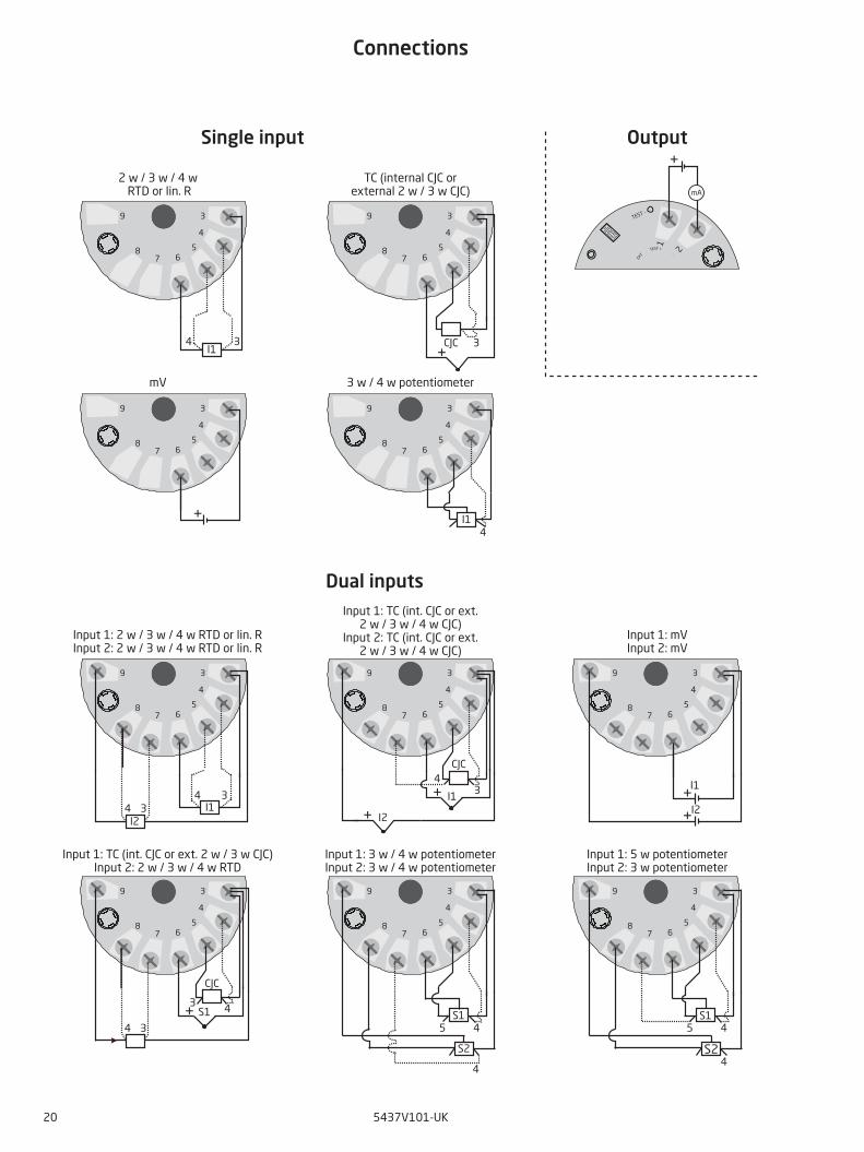
Connections
TEST -
1
2
3
78
9
65
4
3
78
9
65
4
3
78
9
65
4
3
78
9
65
4
3
78
9
65
4
3
78
9
65
4
3
78
9
65
4
3
78
9
65
4
3
78
9
65
4
3
78
9
65
4
EX
T TEST + -
I2
I14
3
I2
CJC
I14 3
I2
43
CJC
S1
4 3S1
4
45S1
4S2
+
mA
I14
4 3 3CJC
4 3I1
5
S2
4
I1
+
+
++
++
+
Input 1: TC (int. CJC or ext. 2 w / 3 w CJC)Input 2: 2 w / 3 w / 4 w RTD
Input 1: 3 w / 4 w potentiometerInput 2: 3 w / 4 w potentiometer
Input 1: 5 w potentiometerInput 2: 3 w potentiometer
Input 1: TC (int. CJC or ext.2 w / 3 w / 4 w CJC)
Input 2: TC (int. CJC or ext.2 w / 3 w / 4 w CJC)
Input 1: 2 w / 3 w / 4 w RTD or lin. RInput 2: 2 w / 3 w / 4 w RTD or lin. R
Input 1: mVInput 2: mV
2 w / 3 w / 4 w RTD or lin. R
TC (internal CJC orexternal 2 w / 3 w CJC)
mV 3 w / 4 w potentiometer
Single input
Dual inputs
Output
5437V101-UK 21
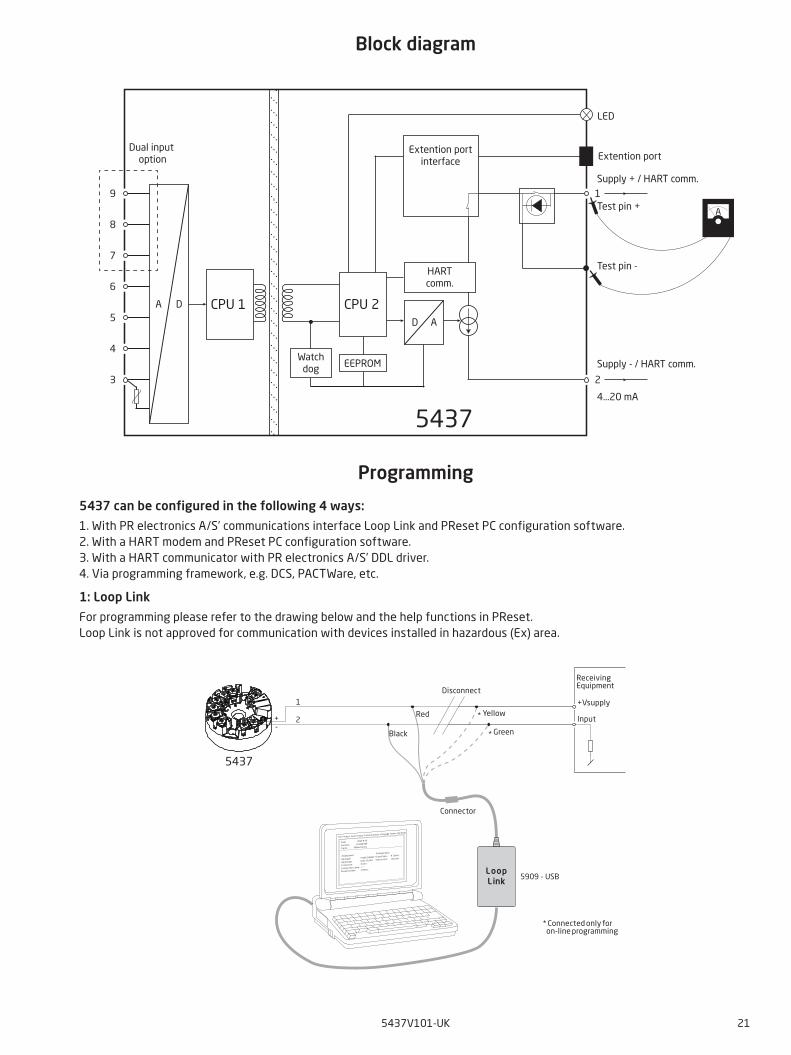
Block diagram
Programming
5437 can be configured in the following 4 ways:
1. With PR electronics A/S’ communications interface Loop Link and PReset PC configuration software.2. With a HART modem and PReset PC configuration software.3. With a HART communicator with PR electronics A/S’ DDL driver.4. Via programming framework, e.g. DCS, PACTWare, etc.
1: Loop Link
For programming please refer to the drawing below and the help functions in PReset.Loop Link is not approved for communication with devices installed in hazardous (Ex) area.
*
*
LoopLink 5909 - USB
File Product Input O utput C ommunication Language O ption 08:30:00
Date: 2015-8-10
153201594
PRelectronics
Analog inputAnalog output
Serial no:
Input type:O utput type: 4 - 20mA
UpscaleSensor error:Pt100 DIN/IEC
0.00 - 50.00 C
3-wire
1.00 sec------
Input range:
Connection:
Cold junction com p:
Response time:
Tag no:
1
2
5437
+-
Disconnect
+Vsupply
* Connected only for on-line programming
Black
Red Yellow
Green
Input
ReceivingEquipment
Connector
5437
CPU 1 CPU 2
EEPROM
A D
8
7
6
5
4
3 2
19
AD
LED
A
Dual input option
Extention portinterface Extention port
Supply - / HART comm.
Supply + / HART comm.
4...20 mA
HARTcomm.
Test pin -
Test pin +
Watchdog
22 5437V101-UK
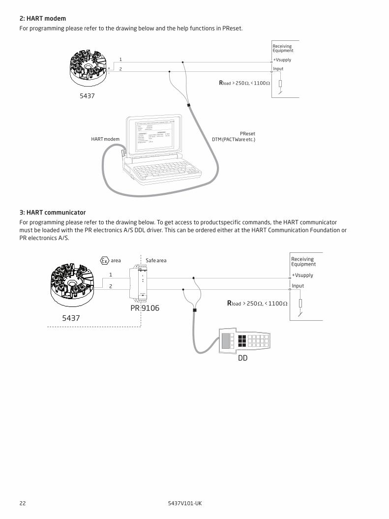
2: HART modem
For programming please refer to the drawing below and the help functions in PReset.
3: HART communicator
For programming please refer to the drawing below. To get access to productspecific commands, the HART communicator must be loaded with the PR electronics A/S DDL driver. This can be ordered either at the HART Communication Foundation or PR electronics A/S.
File Product Input O utput C ommunication Language O ption 08:30:00
Date: 2015-8-10
153201594
PRelectronics
Analog inputAnalog output
Serial no:
Input type:O utput type: 4 - 20mA
UpscaleSensor error:Pt100 D IN/IEC
0.00 - 50.00 C
3-wire
1.00 sec------
Input range:
C onnection:
C old junction comp:
Response time:
Tag no:
1
2
5437
+-
+Vsupply
Input
ReceivingEquipment
Rload > 250 Ω, < 1100 Ω
HART modemPReset
DTM (PACTWare etc.)
1
2
5437PR 9106
DD
Safe area
+Vsupply
Input
ReceivingEquipment
area
Rload > 250 Ω, < 1100 Ω
5437V101-UK 23
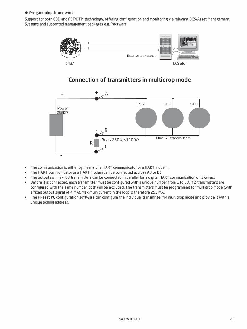
4: Progamming framework
Support for both EDD and FDT/DTM technology, offering configuration and monitoring via relevant DCS/Asset Management Systems and supported management packages e.g. Pactware.
Connection of transmitters in multidrop mode
• The communication is either by means of a HART communicator or a HART modem.• The HART communicator or a HART modem can be connected accross AB or BC.• The outputs of max. 63 transmitters can be connected in parallel for a digital HART communication on 2-wires.• Before it is connected, each transmitter must be configured with a unique number from 1 to 63. If 2 transmitters are
configured with the same number, both will be excluded. The transmitters must be programmed for multidrop mode (with a fixed output signal of 4 mA). Maximum current in the loop is therefore 252 mA.
• The PReset PC configuration software can configure the individual transmitter for multidrop mode and provide it with a unique polling address.
R
A
B
C
+
-
+
-
5437 54375437Powersupply
Max. 63 transmittersRload > 250 Ω, < 1100 Ω
1
2
5437
+-
Process Computer
Rload > 250 Ω, < 1100 Ω
DCS etc.
24 5437V101-UK
IEC
61
32
6-2
-3, E
N 6
13
26
-1
Indu
stri
al e
nvir
onm
ent
NA
MU
R N
E21
: 2
00
7IE
C 6
13
26
-3-1
E10
PR
sta
ndar
d sp
ecifi
cati
ons
Port
Phen
omen
onTe
st s
tand
ard
Test
val
ueCr
iter
ion
Test
val
ueCr
iter
ion
Test
val
ue f
or
safe
ty f
unti
ons
Crit
erio
nCr
iter
ion
Test
val
ueCr
iter
ion
Encl
osur
e
ESD
IEC
61
00
0-4
-24
kV
/ 8
kV
Con
tact
/ A
irB
6 k
V /
8 k
V C
onta
ct /
Air
A6
kV
/ 8
kV
Con
tact
/ A
irD
S6
kV
/ 8
kV
Con
tact
/ A
irB
6 k
V /
8 k
V C
onta
ct /
Air
A 1
%
HF
fiel
dIE
C 6
10
00
-4-3
10 V
/m: 8
0...1
000
MH
z3
V/m
: 1.4
...2
GH
z1
V/m
: 2...
2.7
GH
zA
10
V/m
: 80
...2
00
0 M
Hz
3 V
/m: 2
...2
.7 G
Hz
AM
: 1 k
Hz
80
%A
20
V/m
: 80
...1
00
0 M
Hz
10
V/m
: 1.4
...2
GH
z3
V/m
: 2...
6 G
Hz
AM
: 1 k
Hz
80
%
DS
10 V
/m: 8
0...2
000
MH
zA
M: 1
kH
z 8
0%
Step
1%
/ 3
sA
20
V/m
: 80
...1
00
0 M
Hz
10
V/m
: 1.4
...2
GH
z3
V/m
: 2..6
GH
zA
M: 1
kH
z 8
0%
A 0
.1%
Mag
neti
c fi
eld
IEC
61
00
0-4
-83
0 A
/mA
10
0 A
/mA
30
A/m
DS
NA
30
A/m
A 0
.1%
I/O
sig
nal
Bur
stIE
C 6
10
00
-4-4
1 k
V /
5 k
Hz
B1
kV
/ 5
kH
zA
2 k
VD
urat
ion
x 5
DS
1 k
VPe
riod
30
0 m
sD
urat
ion
15
ms
Dur
atio
n /
pola
rity
5 s
B2
kV
Dur
atio
n x
5A
1.0
%
Surg
eIE
C 6
10
00
-4-5
1 k
V -
Lin
e to
gro
und
B1
kV
- L
ine
to g
roun
dB
2 k
V -
Lin
e to
gro
und
Puls
e nu
mbe
r x
3D
S1
kV
- L
ine
to g
roun
d5
00
V -
Diff
eren
tial
B2
kV
- L
ine
to g
roun
d5
00
V -
Diff
eren
tial
Puls
e nu
mbe
r x
3B
Cond
ucte
d R
FIE
C 6
10
00
-4-6
3 V
: 15
0 k
Hz.
..80
MH
zA
M: 1
kH
z 8
0%
A1
0 V
: 10
kH
z...8
0 M
Hz
AM
: 1 k
Hz
80
%A
10
V: 1
50
kH
z...8
0 M
Hz
AM
: 1 k
Hz
80
%
DS
10
V: 1
0 k
Hz.
..80
MH
zA
M: 1
kH
z 8
0%
Step
1%
/ 3
sA
10
V: 1
0 k
Hz.
..80
MH
zA
M: 1
kH
z 8
0%
A 0
.1%
Cond
ucte
d LF
IEC
61
00
0-4
-16
Not
requ
ired
Not
requ
ired
1...
10
V: 1
.5...
15
kH
z 1
0 V
: 15
....1
50
kH
zD
SN
ot re
quire
d1
...1
0 V
: 1.5
...1
5 k
Hz
10
V: 1
5...
.15
0 k
Hz
A 0
.1%
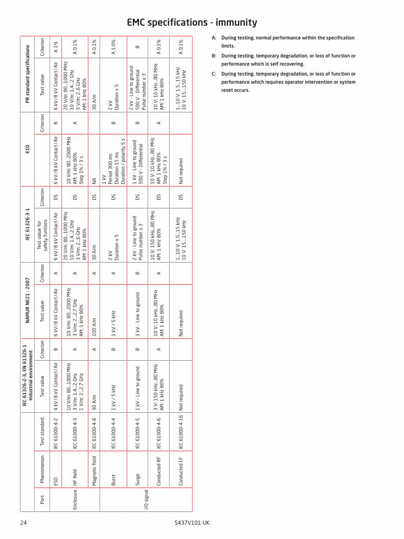
EMC specifications - immunityA: During testing, normal performance within the specification
limits.
B: During testing, temporary degradation, or loss of function or
performance which is self recovering.
C: During testing, temporary degradation, or loss of function or
performance which requires operator intervention or system
reset occurs.
5437V101-UK 25
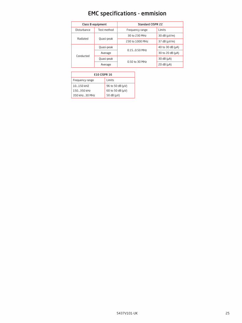
Class B equipment Standard CISPR 22
Disturbance Test method Frequency range Limits
Radiated Quasi-peak30 to 230 MHz 30 dB (µV/m)
230 to 1000 MHz 37 dB (µV/m)
Conducted
Quasi-peak0.15...0.50 MHz
40 to 30 dB (µA)
Average 30 to 20 dB (µA)
Quasi-peak0.50 to 30 MHz
30 dB (µA)
Average 20 dB (µA)
EMC specifications - emmision
E10 CISPR 16
Frequency range Limits
10...150 kHZ
150...350 kHz
350 kHz...30 MHz
96 to 50 dB (µV)
60 to 50 dB (µV)
50 dB (µV)
26 5437V101-UK
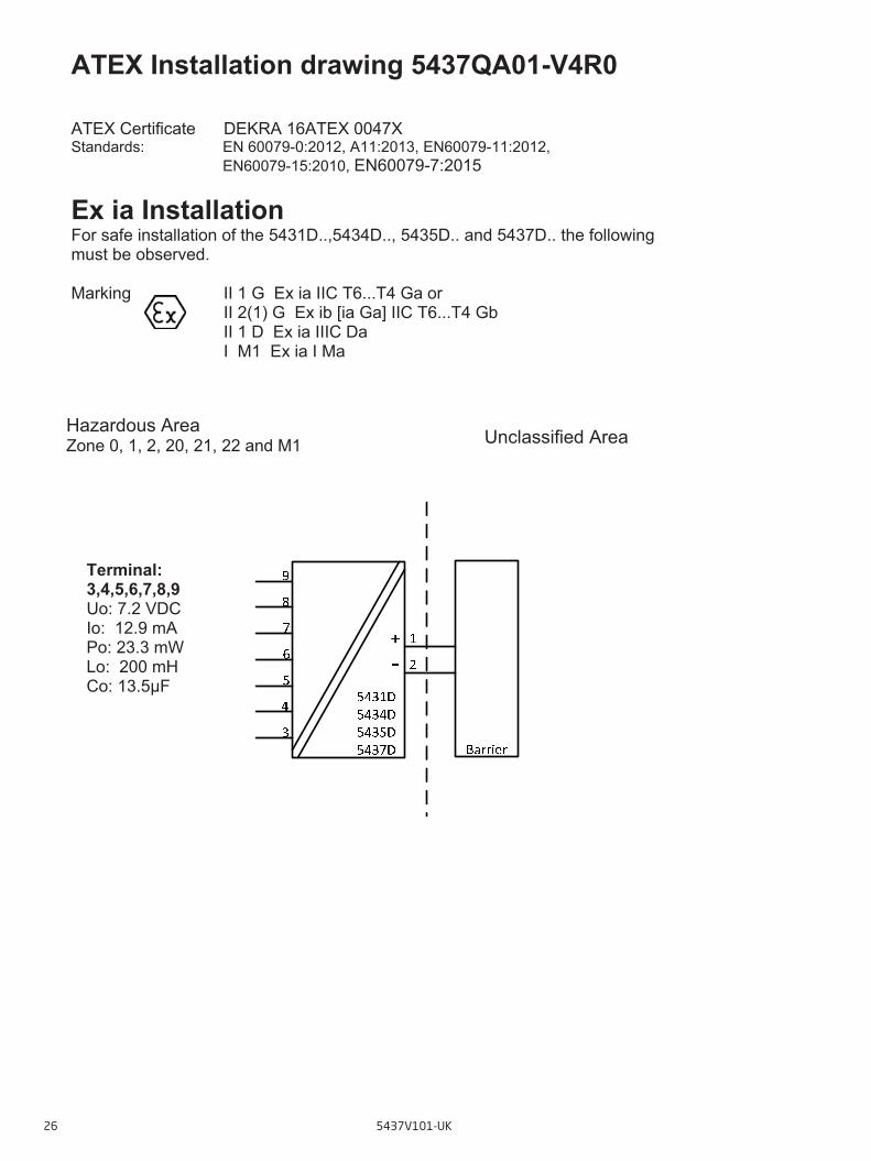
ATEX Installation drawing 5437QA01-V4R0 ATEX Certificate DEKRA 16ATEX 0047X Standards: EN 60079-0:2012, A11:2013, EN60079-11:2012,
EN60079-15:2010, EN60079-7:2015
Ex ia Installation For safe installation of the 5431D..,5434D.., 5435D.. and 5437D.. the following must be observed. Marking II 1 G Ex ia IIC T6...T4 Ga or
II 2(1) G Ex ib [ia Ga] IIC T6...T4 Gb II 1 D Ex ia IIIC Da I M1 Ex ia I Ma
Unclassified Area Hazardous Area Zone 0, 1, 2, 20, 21, 22 and M1
Terminal: 3,4,5,6,7,8,9 Uo: 7.2 VDC Io: 12.9 mA Po: 23.3 mW Lo: 200 mH Co: 13.5μF
ATEX Installation Drawing
5437V101-UK 27
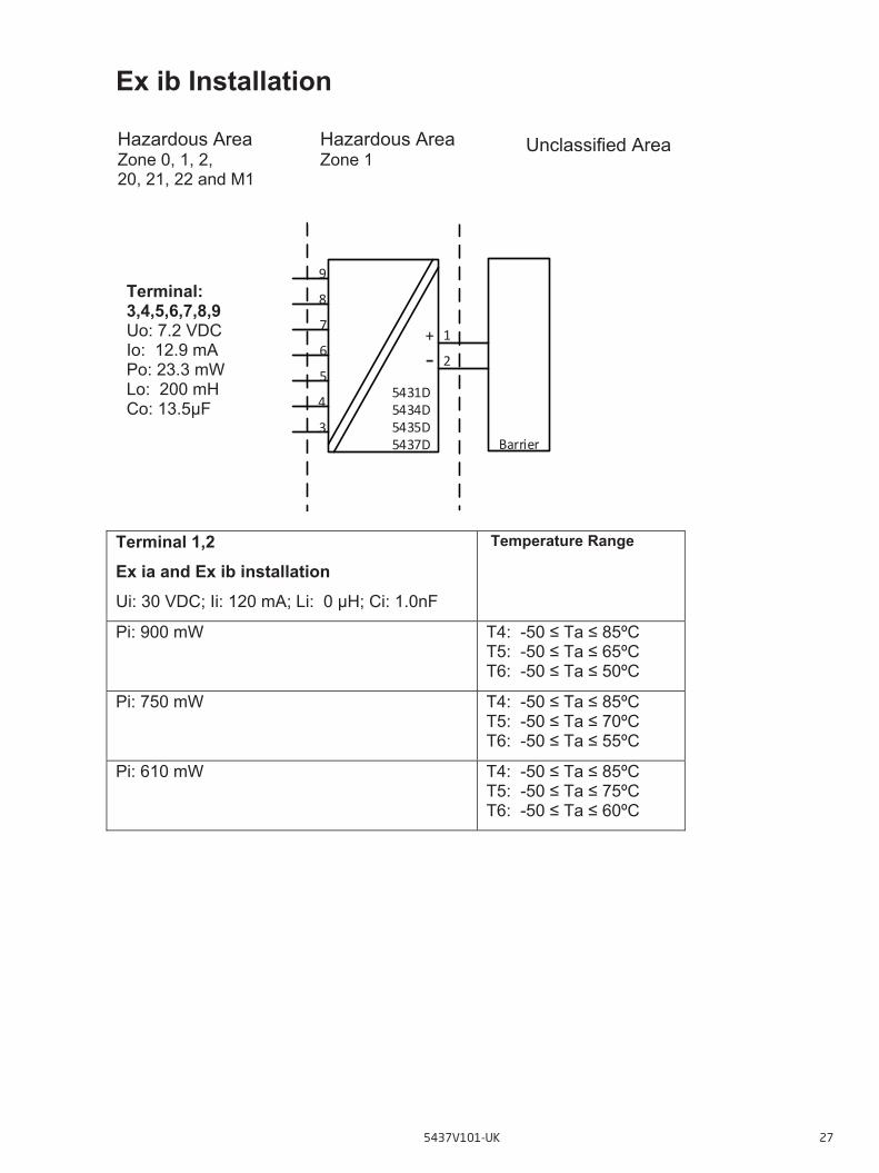
Ex ib Installation
Terminal 1,2 Ex ia and Ex ib installation Ui: 30 VDC; Ii: 120 mA; Li: 0 μH; Ci: 1.0nF
Temperature Range
Pi: 900 mW
T4: -50 ≤ Ta ≤ 85ºC T5: -50 ≤ Ta ≤ 65ºC T6: -50 ≤ Ta ≤ 50ºC
Pi: 750 mW
T4: -50 ≤ Ta ≤ 85ºC T5: -50 ≤ Ta ≤ 70ºC T6: -50 ≤ Ta ≤ 55ºC
Pi: 610 mW
T4: -50 ≤ Ta ≤ 85ºC T5: -50 ≤ Ta ≤ 75ºC T6: -50 ≤ Ta ≤ 60ºC
4
1
5
6
7
5431D5434D5435D5437D Barrier
9
8
3
2+‐
Terminal: 3,4,5,6,7,8,9 Uo: 7.2 VDC Io: 12.9 mA Po: 23.3 mW Lo: 200 mH Co: 13.5μF
Hazardous Area Zone 0, 1, 2, 20, 21, 22 and M1
Unclassified Area Hazardous Area Zone 1
28 5437V101-UK
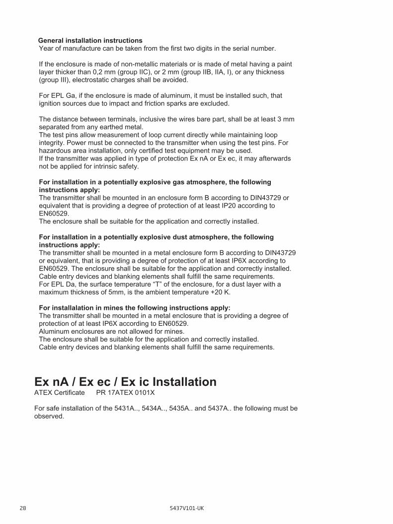
General installation instructions Year of manufacture can be taken from the first two digits in the serial number. If the enclosure is made of non-metallic materials or is made of metal having a paint layer thicker than 0,2 mm (group IIC), or 2 mm (group IIB, IIA, I), or any thickness (group III), electrostatic charges shall be avoided. For EPL Ga, if the enclosure is made of aluminum, it must be installed such, that ignition sources due to impact and friction sparks are excluded. The distance between terminals, inclusive the wires bare part, shall be at least 3 mm separated from any earthed metal. The test pins allow measurement of loop current directly while maintaining loop integrity. Power must be connected to the transmitter when using the test pins. For hazardous area installation, only certified test equipment may be used. If the transmitter was applied in type of protection Ex nA or Ex ec, it may afterwards not be applied for intrinsic safety. For installation in a potentially explosive gas atmosphere, the following instructions apply: The transmitter shall be mounted in an enclosure form B according to DIN43729 or equivalent that is providing a degree of protection of at least IP20 according to EN60529. The enclosure shall be suitable for the application and correctly installed. For installation in a potentially explosive dust atmosphere, the following instructions apply: The transmitter shall be mounted in a metal enclosure form B according to DIN43729 or equivalent, that is providing a degree of protection of at least IP6X according to EN60529. The enclosure shall be suitable for the application and correctly installed. Cable entry devices and blanking elements shall fulfill the same requirements. For EPL Da, the surface temperature “T” of the enclosure, for a dust layer with a maximum thickness of 5mm, is the ambient temperature +20 K.
For installalation in mines the following instructions apply: The transmitter shall be mounted in a metal enclosure that is providing a degree of protection of at least IP6X according to EN60529. Aluminum enclosures are not allowed for mines. The enclosure shall be suitable for the application and correctly installed. Cable entry devices and blanking elements shall fulfill the same requirements.
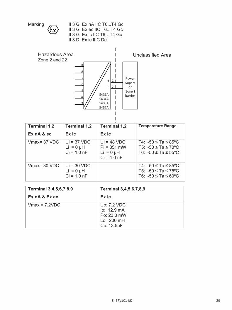
Ex nA / Ex ec / Ex ic Installation ATEX Certificate PR 17ATEX 0101X For safe installation of the 5431A.., 5434A.., 5435A.. and 5437A.. the following must be observed.
5437V101-UK 29
Marking II 3 G Ex nA IIC T6...T4 Gc II 3 G Ex ec IIC T6...T4 Gc II 3 G Ex ic IIC T6…T4 Gc II 3 D Ex ic IIIC Dc
Terminal 1,2 Ex nA & ec
Terminal 1,2 Ex ic
Terminal 1,2 Ex ic
Temperature Range
Vmax= 37 VDC Ui = 37 VDC Li = 0 μH Ci = 1.0 nF
Ui = 48 VDC Pi = 851 mW Li = 0 μH Ci = 1.0 nF
T4: -50 ≤ Ta ≤ 85ºC T5: -50 ≤ Ta ≤ 70ºC T6: -50 ≤ Ta ≤ 55ºC
Vmax= 30 VDC Ui = 30 VDC Li = 0 μH Ci = 1.0 nF
T4: -50 ≤ Ta ≤ 85ºC T5: -50 ≤ Ta ≤ 75ºC T6: -50 ≤ Ta ≤ 60ºC
Terminal 3,4,5,6,7,8,9 Ex nA & Ex ec
Terminal 3,4,5,6,7,8,9 Ex ic
Vmax = 7.2VDC Uo: 7.2 VDC Io: 12.9 mA Po: 23.3 mW Lo: 200 mH Co: 13.5μF
Hazardous Area Zone 2 and 22
4
1
5
6
7
5431A5434A5435A5437A
Power Supply or
Zone 2 barrier
9
8
3
2+‐
Unclassified Area
30 5437V101-UK
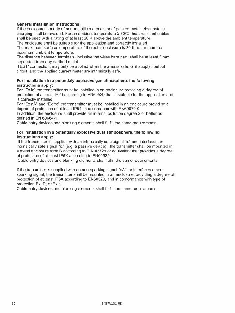
General installation instructions If the enclosure is made of non-metallic materials or of painted metal, electrostatic charging shall be avoided. For an ambient temperature ≥ 60ºC, heat resistant cables shall be used with a rating of at least 20 K above the ambient temperature. The enclosure shall be suitable for the application and correctly installed The maximum surface temperature of the outer enclosure is 20 K hotter than the maximum ambient temperature. The distance between terminals, inclusive the wires bare part, shall be at least 3 mm separated from any earthed metal. 'TEST' connection, may only be applied when the area is safe, or if supply / output circuit and the applied current meter are intrinsically safe. For installation in a potentialy explosive gas atmosphere, the following instructions apply: For “Ex ic” the transmitter must be installed in an enclosure providing a degree of protection of at least IP20 according to EN60529 that is suitable for the application and is correctly installed. For “Ex nA” and “Ex ec” the transmitter must be installed in an enclosure providing a degree of protection of at least IP54 in accordance with EN60079-0. In addition, the enclosure shall provide an internal pollution degree 2 or better as defined in EN 60664-1. Cable entry devices and blanking elements shall fulfill the same requirements. For installation in a potentially explosive dust atmposphere, the following instructions apply: If the transmitter is supplied with an intrinsically safe signal "ic" and interfaces an intrinsically safe signal "ic" (e.g. a passive device) , the transmitter shall be mounted in a metal enclosure form B according to DIN 43729 or equivalent that provides a degree of protection of at least IP6X according to EN60529. Cable entry devices and blanking elements shall fulfill the same requirements. If the transmitter is supplied with an non-sparking signal "nA", or interfaces a non sparking signal, the transmitter shall be mounted in an enclosure, providing a degree of protection of at least IP6X according to EN60529, and in conformance with type of protection Ex tD, or Ex t. Cable entry devices and blanking elements shall fulfill the same requirements.
IECEx Installation Drawing
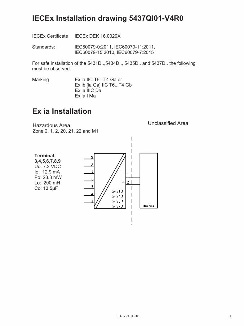
IECEx Installation drawing 5437QI01-V4R0 IECEx Certificate IECEx DEK 16.0029X Standards: IEC60079-0:2011, IEC60079-11:2011,
IEC60079-15:2010, IEC60079-7:2015 For safe installation of the 5431D..,5434D.., 5435D.. and 5437D.. the following must be observed. Marking Ex ia IIC T6...T4 Ga or
Ex ib [ia Ga] IIC T6...T4 Gb Ex ia IIIC Da Ex ia I Ma
Ex ia Installation
Unclassified Area Hazardous Area Zone 0, 1, 2, 20, 21, 22 and M1
Terminal: 3,4,5,6,7,8,9 Uo: 7.2 VDC Io: 12.9 mA Po: 23.3 mW Lo: 200 mH Co: 13.5μF
5437V101-UK 31
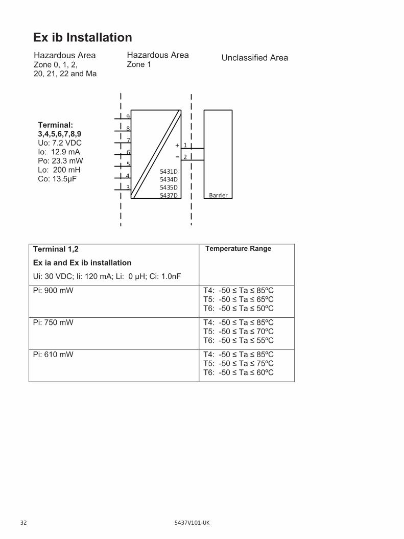
Ex ib Installation
Terminal 1,2 Ex ia and Ex ib installation Ui: 30 VDC; Ii: 120 mA; Li: 0 μH; Ci: 1.0nF
Temperature Range
Pi: 900 mW
T4: -50 ≤ Ta ≤ 85ºC T5: -50 ≤ Ta ≤ 65ºC T6: -50 ≤ Ta ≤ 50ºC
Pi: 750 mW
T4: -50 ≤ Ta ≤ 85ºC T5: -50 ≤ Ta ≤ 70ºC T6: -50 ≤ Ta ≤ 55ºC
Pi: 610 mW
T4: -50 ≤ Ta ≤ 85ºC T5: -50 ≤ Ta ≤ 75ºC T6: -50 ≤ Ta ≤ 60ºC
4
1
5
6
7
5431D5434D5435D5437D Barrier
9
8
3
2+‐
Terminal: 3,4,5,6,7,8,9 Uo: 7.2 VDC Io: 12.9 mA Po: 23.3 mW Lo: 200 mH Co: 13.5μF
Hazardous Area Zone 0, 1, 2, 20, 21, 22 and Ma
Unclassified Area Hazardous Area Zone 1
32 5437V101-UK
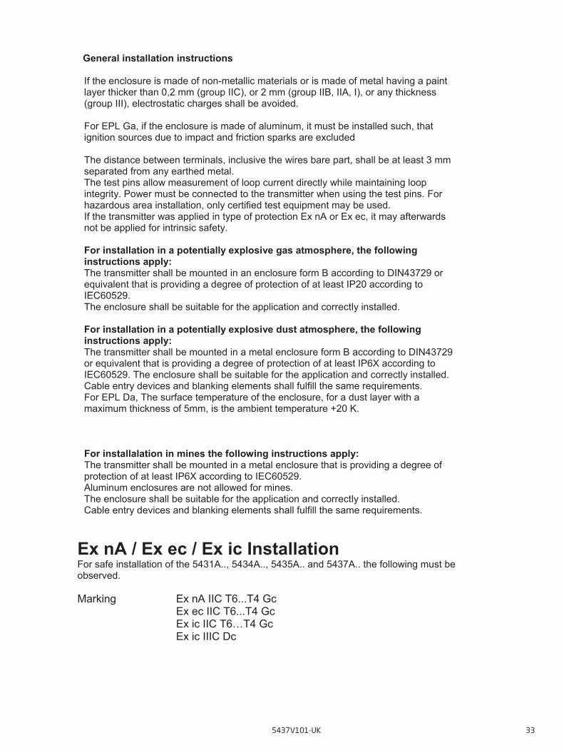
General installation instructions If the enclosure is made of non-metallic materials or is made of metal having a paint layer thicker than 0,2 mm (group IIC), or 2 mm (group IIB, IIA, I), or any thickness (group III), electrostatic charges shall be avoided. For EPL Ga, if the enclosure is made of aluminum, it must be installed such, that ignition sources due to impact and friction sparks are excluded The distance between terminals, inclusive the wires bare part, shall be at least 3 mm separated from any earthed metal. The test pins allow measurement of loop current directly while maintaining loop integrity. Power must be connected to the transmitter when using the test pins. For hazardous area installation, only certified test equipment may be used. If the transmitter was applied in type of protection Ex nA or Ex ec, it may afterwards not be applied for intrinsic safety. For installation in a potentially explosive gas atmosphere, the following instructions apply: The transmitter shall be mounted in an enclosure form B according to DIN43729 or equivalent that is providing a degree of protection of at least IP20 according to IEC60529. The enclosure shall be suitable for the application and correctly installed. For installation in a potentially explosive dust atmosphere, the following instructions apply: The transmitter shall be mounted in a metal enclosure form B according to DIN43729 or equivalent that is providing a degree of protection of at least IP6X according to IEC60529. The enclosure shall be suitable for the application and correctly installed. Cable entry devices and blanking elements shall fulfill the same requirements. For EPL Da, The surface temperature of the enclosure, for a dust layer with a maximum thickness of 5mm, is the ambient temperature +20 K.
For installalation in mines the following instructions apply: The transmitter shall be mounted in a metal enclosure that is providing a degree of protection of at least IP6X according to IEC60529. Aluminum enclosures are not allowed for mines. The enclosure shall be suitable for the application and correctly installed. Cable entry devices and blanking elements shall fulfill the same requirements.
Ex nA / Ex ec / Ex ic Installation For safe installation of the 5431A.., 5434A.., 5435A.. and 5437A.. the following must be observed. Marking Ex nA IIC T6...T4 Gc
Ex ec IIC T6...T4 Gc Ex ic IIC T6…T4 Gc Ex ic IIIC Dc
5437V101-UK 33

Terminal 1,2 Ex nA & ec
Terminal 1,2 Ex ic
Terminal 1,2 Ex ic
Temperature Range
Vmax= 37 VDC Ui = 37 VDC Li = 0 μH Ci = 1.0 nF
Ui = 48 VDC Pi = 851 mW Li = 0 μH Ci = 1.0 nF
T4: -50 ≤ Ta ≤ 85ºC T5: -50 ≤ Ta ≤ 70ºC T6: -50 ≤ Ta ≤ 55ºC
Vmax= 30 VDC Ui = 30 VDC Li = 0 μH Ci = 1.0 nF
T4: -50 ≤ Ta ≤ 85ºC T5: -50 ≤ Ta ≤ 75ºC T6: -50 ≤ Ta ≤ 60ºC
Terminal 3,4,5,6,7,8,9 Ex nA & Ex ec
Terminal 3,4,5,6,7,8,9 Ex ic
Vmax = 7.2VDC Uo: 7.2 VDC Io: 12.9 mA Po: 23.3 mW Lo: 200 mH Co: 13.5μF
General installation instructions If the enclosure is made of non-metallic materials or of painted metal, electrostatic charging shall be avoided. For an ambient temperature ≥ 60ºC, heat resistant cables shall be used with a rating of at least 20 K above the ambient temperature. The enclosure shall be suitable for the application and correctly installed. The maximum surface temperature of the outer enclosure is 20 K hotter than the maximum ambient temperature. The distance between terminals, inclusive the wires bare part, shall be at least 3 mm separated from any earthed metal. 'TEST' connection, may only be applied when the area is safe, or if supply / output circuit and the applied current meter are intrinsically safe.
Hazardous Area Zone 2 and 22
4
1
5
6
7
5431A5434A5435A5437A
Power Supply or
Zone 2 barrier
9
8
3
2+‐
Unclassified Area
34 5437V101-UK
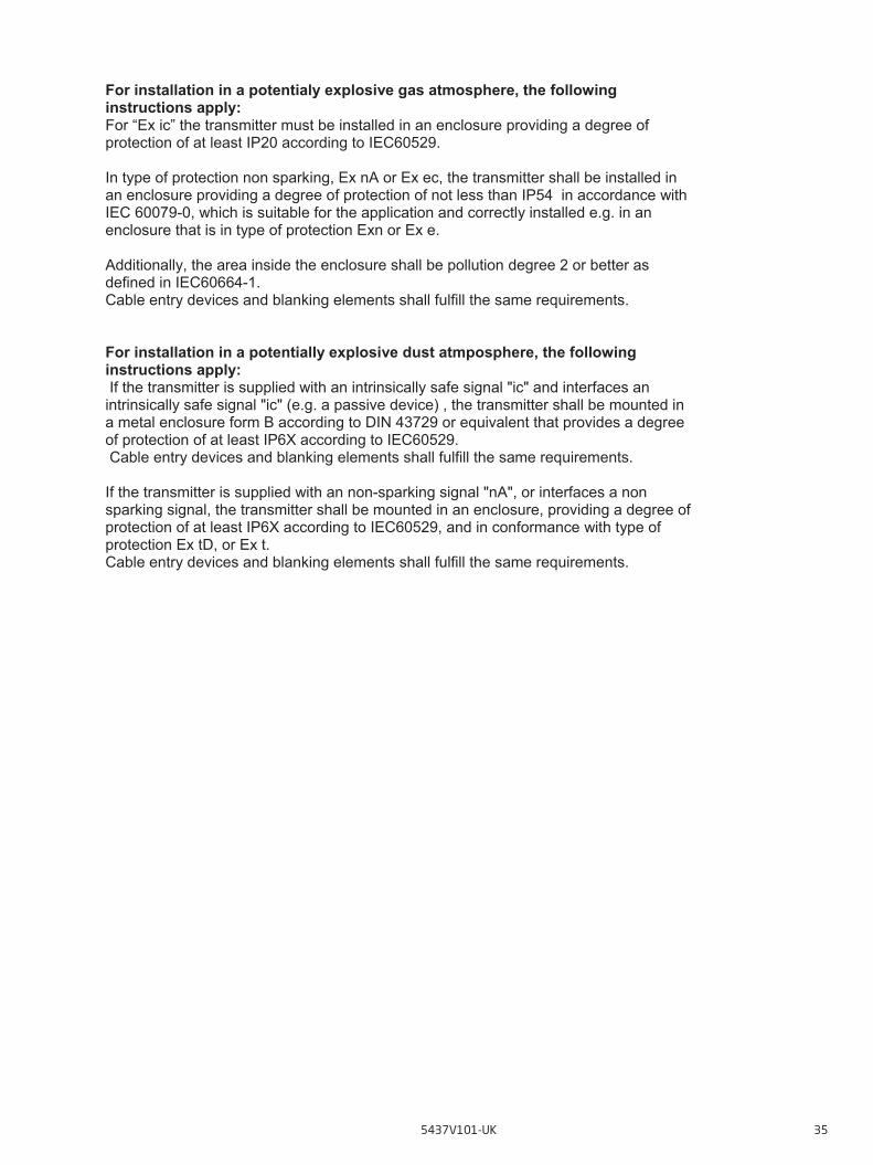
For installation in a potentialy explosive gas atmosphere, the following instructions apply: For “Ex ic” the transmitter must be installed in an enclosure providing a degree of protection of at least IP20 according to IEC60529. In type of protection non sparking, Ex nA or Ex ec, the transmitter shall be installed in an enclosure providing a degree of protection of not less than IP54 in accordance with IEC 60079-0, which is suitable for the application and correctly installed e.g. in an enclosure that is in type of protection Exn or Ex e. Additionally, the area inside the enclosure shall be pollution degree 2 or better as defined in IEC60664-1. Cable entry devices and blanking elements shall fulfill the same requirements. For installation in a potentially explosive dust atmposphere, the following instructions apply: If the transmitter is supplied with an intrinsically safe signal "ic" and interfaces an intrinsically safe signal "ic" (e.g. a passive device) , the transmitter shall be mounted in a metal enclosure form B according to DIN 43729 or equivalent that provides a degree of protection of at least IP6X according to IEC60529. Cable entry devices and blanking elements shall fulfill the same requirements. If the transmitter is supplied with an non-sparking signal "nA", or interfaces a non sparking signal, the transmitter shall be mounted in an enclosure, providing a degree of protection of at least IP6X according to IEC60529, and in conformance with type of protection Ex tD, or Ex t. Cable entry devices and blanking elements shall fulfill the same requirements.
5437V101-UK 35

CSA Installation drawing 5437QC01-V4R0 CSA Certificate 70066266 Division1 / Ex ia, Intrinsic Safe Installation For safe installation of the 5431D..,5434D.., 5435D.. and 5437D.. the following must be Observed. Marking Class I Division 1, Group A,B,C,D
Class I, Zone 0: Ex/AEx ia IIC T6…T4 Ex/AEx ia IIC T6…T4 Ex/AEx ib [ia] IIC T6…T4
Terminal 1,2 Ex ia, Div1 Ui: 30 VDC; Ii: 120 mA Li:0 μH; Ci:1.0nF
Temperature Range
Pi: 900 mW
T4: -50 ≤ Ta ≤ 85ºC T5: -50 ≤ Ta ≤ 70ºC T6: -50 ≤ Ta ≤ 55ºC
Pi: 750 mW
T4: -50 ≤ Ta ≤ 85ºC T5: -50 ≤ Ta ≤ 75ºC T6: -50 ≤ Ta ≤ 60ºC
Non Classified Area Hazardous Area CL I, Div 1 GP ABCD or CL I, Zone 0
Terminal: 3,4,5,6,7,8,9 Uo: 7.2 VDC Io: 12.9 mA Po: 23.3 mW Lo: 200 mH Co: 13.5μF
Um ≤ 250V Voc or Uo ≤ Vmax or Ui Isc or Io ≤ Imax or Ii Po ≤ Pmax or Pi Ca or Co ≥ Ci + Ccable La or Lo ≥ Li + Lcable
Associated Apparatus
or Barrier 4
1
5
6
7
5431D5434D5435D5437D
9
8
3
2+‐
CSA Installation Drawing
36 5437V101-UK
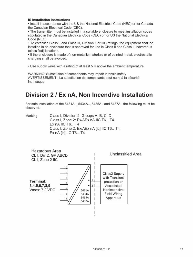
IS Installation instructions • Install in accordance with the US the National Electrical Code (NEC) or for Canada the Canadian Electrical Code (CEC). • The transmitter must be installed in a suitable enclosure to meet installation codes stipulated in the Canadian Electrical Code (CEC) or for US the National Electrical Code (NEC). • To establish Class II and Class III, Division 1 or IIIC ratings, the equipment shall be installed in an enclosure that is approved for use in Class II and Class III hazardous (classified) locations. • If the enclosure is made of non-metallic materials or of painted metal, electrostatic charging shall be avoided. • Use supply wires with a rating of at least 5 K above the ambient temperature. WARNING: Substitution of components may impair intrinsic safety AVERTISSEMENT : La substitution de composants peut nuire à la sécurité intrinsèque
Division 2 / Ex nA, Non Incendive Installation For safe installation of the 5431A.., 5434A.., 5435A.. and 5437A.. the following must be observed. Marking Class I, Division 2, Groups A, B, C, D Class I, Zone 2: Ex/AEx nA IIC T6…T4 Ex nA IIC T6…T4 Class I, Zone 2: Ex/AEx nA [ic] IIC T6…T4 Ex nA [ic] IIC T6…T4
Unclassified Area Hazardous Area CL I, Div 2, GP ABCD CL I, Zone 2 IIC
Terminal: 3,4,5,6,7,8,9 Vmax: 7.2 VDC
4
1
5
6
7
5431A5434A5435A5437A
Class2 Supply with Transient protection or Associated
Nonincendive Field Wiring Apparatus
9
8
3
2+‐
5437V101-UK 37
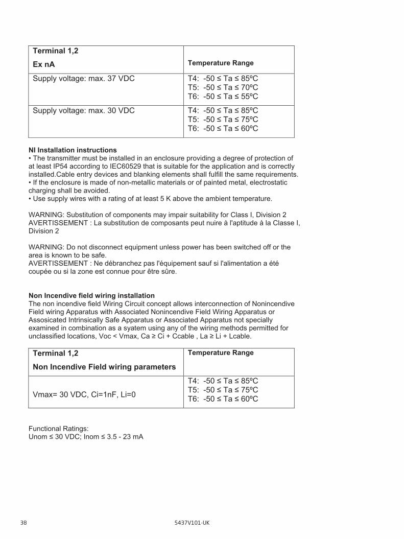
Terminal 1,2 Ex nA
Temperature Range
Supply voltage: max. 37 VDC T4: -50 ≤ Ta ≤ 85ºC T5: -50 ≤ Ta ≤ 70ºC T6: -50 ≤ Ta ≤ 55ºC
Supply voltage: max. 30 VDC T4: -50 ≤ Ta ≤ 85ºC T5: -50 ≤ Ta ≤ 75ºC T6: -50 ≤ Ta ≤ 60ºC
NI Installation instructions • The transmitter must be installed in an enclosure providing a degree of protection of at least IP54 according to IEC60529 that is suitable for the application and is correctly installed.Cable entry devices and blanking elements shall fulfill the same requirements. • If the enclosure is made of non-metallic materials or of painted metal, electrostatic charging shall be avoided. • Use supply wires with a rating of at least 5 K above the ambient temperature. WARNING: Substitution of components may impair suitability for Class I, Division 2 AVERTISSEMENT : La substitution de composants peut nuire à l'aptitude à la Classe I, Division 2 WARNING: Do not disconnect equipment unless power has been switched off or the area is known to be safe. AVERTISSEMENT : Ne débranchez pas l'équipement sauf si l'alimentation a été coupée ou si la zone est connue pour être sûre. Non Incendive field wiring installation The non incendive field Wiring Circuit concept allows interconnection of Nonincendive Field wiring Apparatus with Associated Nonincendive Field Wiring Apparatus or Assosicated Intrinsically Safe Apparatus or Associated Apparatus not specially examined in combination as a syatem using any of the wiring methods permitted for unclassified locations, Voc < Vmax, Ca ≥ Ci + Ccable , La ≥ Li + Lcable. Terminal 1,2 Non Incendive Field wiring parameters
Temperature Range
Vmax= 30 VDC, Ci=1nF, Li=0
T4: -50 ≤ Ta ≤ 85ºC T5: -50 ≤ Ta ≤ 75ºC T6: -50 ≤ Ta ≤ 60ºC
Functional Ratings: Unom ≤ 30 VDC; Inom ≤ 3.5 - 23 mA
38 5437V101-UK
FM Installation Drawing
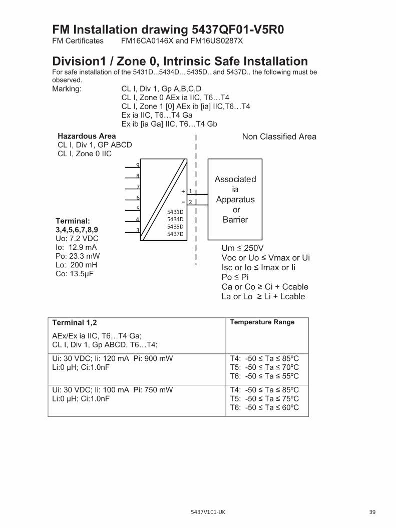
FM Installation drawing 5437QF01-V5R0 FM Certificates FM16CA0146X and FM16US0287X Division1 / Zone 0, Intrinsic Safe Installation For safe installation of the 5431D..,5434D.., 5435D.. and 5437D.. the following must be observed. Marking: CL I, Div 1, Gp A,B,C,D
CL I, Zone 0 AEx ia IIC, T6…T4 CL I, Zone 1 [0] AEx ib [ia] IIC,T6…T4 Ex ia IIC, T6…T4 Ga Ex ib [ia Ga] IIC, T6…T4 Gb
Terminal 1,2 AEx/Ex ia IIC, T6…T4 Ga; CL I, Div 1, Gp ABCD, T6…T4;
Temperature Range
Ui: 30 VDC; Ii: 120 mA Pi: 900 mW Li:0 μH; Ci:1.0nF
T4: -50 ≤ Ta ≤ 85ºC T5: -50 ≤ Ta ≤ 70ºC T6: -50 ≤ Ta ≤ 55ºC
Ui: 30 VDC; Ii: 100 mA Pi: 750 mW Li:0 μH; Ci:1.0nF
T4: -50 ≤ Ta ≤ 85ºC T5: -50 ≤ Ta ≤ 75ºC T6: -50 ≤ Ta ≤ 60ºC
Non Classified Area Hazardous Area CL I, Div 1, GP ABCD CL I, Zone 0 IIC
Terminal: 3,4,5,6,7,8,9 Uo: 7.2 VDC Io: 12.9 mA Po: 23.3 mW Lo: 200 mH Co: 13.5μF
Um ≤ 250V Voc or Uo ≤ Vmax or Ui Isc or Io ≤ Imax or Ii Po ≤ Pi Ca or Co ≥ Ci + Ccable La or Lo ≥ Li + Lcable
Associatedia
Apparatus or
Barrier 4
1
5
6
7
5431D5434D5435D5437D
9
8
3
2+‐
5437V101-UK 39
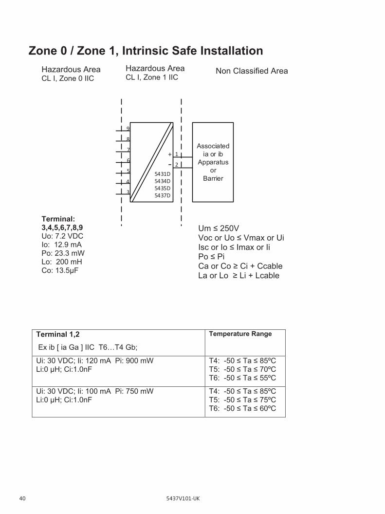
Zone 0 / Zone 1, Intrinsic Safe Installation
Terminal 1,2 Ex ib [ ia Ga ] IIC T6…T4 Gb;
Temperature Range
Ui: 30 VDC; Ii: 120 mA Pi: 900 mW Li:0 μH; Ci:1.0nF
T4: -50 ≤ Ta ≤ 85ºC T5: -50 ≤ Ta ≤ 70ºC T6: -50 ≤ Ta ≤ 55ºC
Ui: 30 VDC; Ii: 100 mA Pi: 750 mW Li:0 μH; Ci:1.0nF
T4: -50 ≤ Ta ≤ 85ºC T5: -50 ≤ Ta ≤ 75ºC T6: -50 ≤ Ta ≤ 60ºC
Non Classified Area Hazardous Area CL I, Zone 1 IIC
Hazardous Area CL I, Zone 0 IIC
Um ≤ 250V Voc or Uo ≤ Vmax or Ui Isc or Io ≤ Imax or Ii Po ≤ Pi Ca or Co ≥ Ci + Ccable La or Lo ≥ Li + Lcable
Terminal: 3,4,5,6,7,8,9 Uo: 7.2 VDC Io: 12.9 mA Po: 23.3 mW Lo: 200 mH Co: 13.5μF
Associated ia or ib
Apparatus or
Barrier 4
1
5
6
7
5431D5434D5435D5437D
9
8
3
2+‐
40 5437V101-UK

IS installation instructions • Install in accordance with the US the National Electrical Code (NEC) or for Canada the Canadian Electrical Code (CEC).
• Equipment that is FM-approved for intrinsic safety may be connected to barriers based on the ENTITY CONCEPT. This concept permits interconnection of approved transmitters, meters and other devices in combinations which have not been specifically examined by FM, provided that the agency's criteria are met. The combination is then intrinsically safe, if the entity concept is acceptable to the authority having jurisdiction over the installation. • The entity concept criteria are as follows: The intrinsically safe devices, other than barriers, must not be a source of power. The maximum voltage Ui (Vmax) and current Ii (Imax), and maximum power Pi (Pmax), which the device can receive and remain intrinsically safe, must be equal to or greater than the voltage (Uo or Voc or Vt) and current (Io or Isc or It) and the power Po which can be delivered by the barrier. • The sum of the maximum unprotected capacitance (Ci) for each intrinsically device and the interconnect-ing wiring must be less than the capacitance (Ca) which can be safely connected to the barrier. • The sum of the maximum unprotected inductance (Li) for each intrinsically device and the interconnecting wiring must be less than the inductance (La) which can be safely connected to the barrier. • The entity parameters Uo,Voc or Vt and Io,Isc or It, and Ca and La for barriers are provided by the barrier manufacturer. • The transmitter must be installed in a suitable enclosure to meet installation codes stipulated in the Canadian Electrical Code (CEC) or for US the National Electrical Code (NEC). • If the enclosure is made of non-metallic materials or of painted metal, electrostatic charging shall be avoided. • Use supply wires with a rating of at least 5 K above the ambient temperature. WARNING: Substitution of components may impair intrinsic safety AVERTISSEMENT: la substitution de composants peut nuire à la sécurité intrinsèque
Division 2 / Zone 2, Non Sparking Installation For safe installation of the 5431A.., 5434A.., 5435A.. and 5437A.. the following must be observed. Marking Class I, Division 2, GP A,B,C,D T6...T4 Class I, Zone 2 AEx nA IIC, T6...T4 Gc Class I, Zone 2 Ex nA IIC, T6...T4 Gc NIFW, CL I, Div 2, GP A,B,C,D
5437V101-UK 41
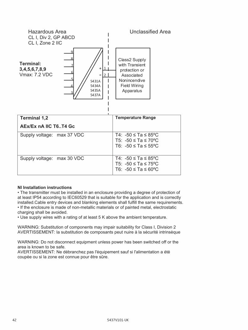
Terminal 1,2 AEx/Ex nA IIC T6..T4 Gc
Temperature Range
Supply voltage: max 37 VDC T4: -50 ≤ Ta ≤ 85ºC T5: -50 ≤ Ta ≤ 70ºC T6: -50 ≤ Ta ≤ 55ºC
Supply voltage: max 30 VDC T4: -50 ≤ Ta ≤ 85ºC T5: -50 ≤ Ta ≤ 75ºC T6: -50 ≤ Ta ≤ 60ºC
NI Installation instructions • The transmitter must be installed in an enclosure providing a degree of protection of at least IP54 according to IEC60529 that is suitable for the application and is correctly installed.Cable entry devices and blanking elements shall fulfill the same requirements. • If the enclosure is made of non-metallic materials or of painted metal, electrostatic charging shall be avoided. • Use supply wires with a rating of at least 5 K above the ambient temperature. WARNING: Substitution of components may impair suitability for Class I, Division 2 AVERTISSEMENT: la substitution de composants peut nuire à la sécurité intrinsèque WARNING: Do not disconnect equipment unless power has been switched off or the area is known to be safe. AVERTISSEMENT: Ne débranchez pas l'équipement sauf si l'alimentation a été coupée ou si la zone est connue pour être sûre.
Unclassified Area Hazardous Area CL I, Div 2, GP ABCD CL I, Zone 2 IIC
4
1
5
6
7
5431A5434A5435A5437A
Class2 Supply with Transient protection or Associated
Nonincendive Field Wiring Apparatus
9
8
3
2+‐
Terminal: 3,4,5,6,7,8,9 Vmax: 7.2 VDC
42 5437V101-UK
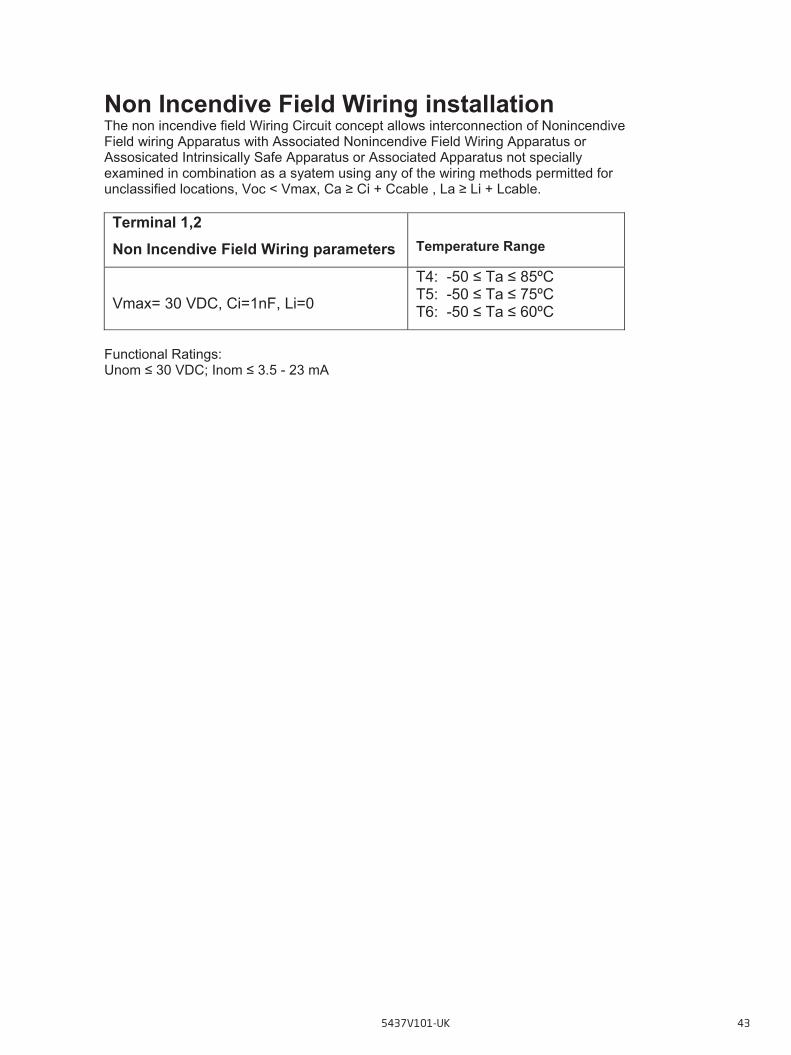
Non Incendive Field Wiring installation The non incendive field Wiring Circuit concept allows interconnection of Nonincendive Field wiring Apparatus with Associated Nonincendive Field Wiring Apparatus or Assosicated Intrinsically Safe Apparatus or Associated Apparatus not specially examined in combination as a syatem using any of the wiring methods permitted for unclassified locations, Voc < Vmax, Ca ≥ Ci + Ccable , La ≥ Li + Lcable. Terminal 1,2 Non Incendive Field Wiring parameters
Temperature Range
Vmax= 30 VDC, Ci=1nF, Li=0
T4: -50 ≤ Ta ≤ 85ºC T5: -50 ≤ Ta ≤ 75ºC T6: -50 ≤ Ta ≤ 60ºC
Functional Ratings: Unom ≤ 30 VDC; Inom ≤ 3.5 - 23 mA
5437V101-UK 43
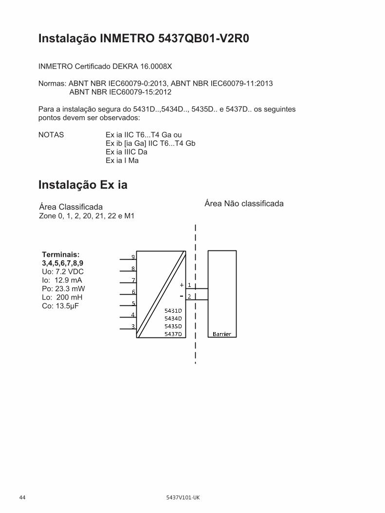
Instalaçao INMETRO
Instalação INMETRO 5437QB01-V2R0 INMETRO Certificado DEKRA 16.0008X Normas: ABNT NBR IEC60079-0:2013, ABNT NBR IEC60079-11:2013 ABNT NBR IEC60079-15:2012 Para a instalação segura do 5431D..,5434D.., 5435D.. e 5437D.. os seguintes pontos devem ser observados: NOTAS Ex ia IIC T6...T4 Ga ou
Ex ib [ia Ga] IIC T6...T4 Gb Ex ia IIIC Da Ex ia I Ma
Instalação Ex ia
Área Não classificada Área Classificada Zone 0, 1, 2, 20, 21, 22 e M1
Terminais: 3,4,5,6,7,8,9 Uo: 7.2 VDC Io: 12.9 mA Po: 23.3 mW Lo: 200 mH Co: 13.5μF
44 5437V101-UK

Instalação Ex ib
Terminais 1,2 Instalações Ex ia e Ex ib Ui: 30 VDC; Ii: 120 mA; Li: 0 μH; Ci: 1.0nF
Faixas de Temperaturas
Pi: 900 mW
T4: -50 ≤ Ta ≤ 85ºC T5: -50 ≤ Ta ≤ 65ºC T6: -50 ≤ Ta ≤ 50ºC
Pi: 750 mW
T4: -50 ≤ Ta ≤ 85ºC T5: -50 ≤ Ta ≤ 70ºC T6: -50 ≤ Ta ≤ 55ºC
Pi: 610 mW
T4: -50 ≤ Ta ≤ 85ºC T5: -50 ≤ Ta ≤ 75ºC T6: -50 ≤ Ta ≤ 60ºC
4
1
5
6
7
5431D5434D5435D5437D Barrier
9
8
3
2+‐
Terminais: 3,4,5,6,7,8,9 Uo: 7.2 VDC Io: 12.9 mA Po: 23.3 mW Lo: 200 mH Co: 13.5μF
Área Classificada Zonas 0, 1, 2, 20, 21, 22 e Ma
Área Não Classificada Área Classificada Zona 1
5437V101-UK 45

Instruções Gerais de Instalação Se o gabinete é feito de alumínio, deve ser então instalado desta forma, em eventos de raros incidentes, as fagulhas oriundas de fontes de ignições devido ao impacto e fricções, são evitados. Se o gabinete é feito de material não-metálico ou metal pintado, cargas eletrostáticas devem ser evitadas. A distância entre terminais, fios inclusivos não isolados, deve ser separada por pelo menos 3 mm de qualquer metal aterrado. Os pinos de testes para medição devem permitir os destes de loop de corrente mantendo a integridade do loop. A energia deve estará conectada ao transmissor quando for usado os pinos de teste. Para instalações em áreas classificadas deve ser utilizado somente equipamentos certificados. Se o transmissor foi aplicado no tipo de proteção Ex nA, não pode ser aplicado para segurança intrínseca. Para instalações com uma atmosfera de gás potencialmente explosiva, a seguinte instrução se aplicará: O transmissor deverá ser montado em um gabinete de formato tipo B de acordo com a norma DIN43729 ou equivalente que possibilita um grau mínimo de proteção IP20 de acordo com a ABNT NBR IEC60529. O gabinete deve ser adequado para a aplicação e instalado corretamente. Para instalação em uma atmosfera de poeira potencialmente explosiva, as seguintes instruções se aplicarão: O transmissor deverá ser montado em um gabinete de metal de formato B de acordo com a DIN43729 ou equivalente que possibilita um grau mínimo de proteção IP6X de acordo com a ABNT NBR IEC60529. O gabinete deve ser adequado para a aplicação e instalado corretamente. Os dispositivos de entrada de cabos e os elementos espaçadores devem satisfazer os mesmos requisitos. A temperatura máxima da superfície externa do gabinete é 20 K mais quente do que a máxima temperatura ambiente.
Para instalações em Minas, as instruções abaixo se aplicam: O transmissor deverá ser montado em um gabinete de metal que possibilita um grau mínimo de proteção IP6X de acordo com a ABNT NBR IEC60529 Gabinetes de Alumínio não são permitidos para instalações em Minas. O gabinete deve ser adequado para a aplicação e instalado corretamente. Os dispositivos de entrada de cabos e os elementos espaçadores devem satisfazer os mesmos requisitos
46 5437V101-UK
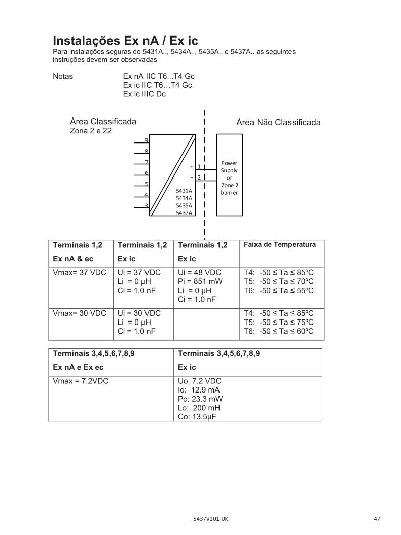
Instalações Ex nA / Ex ic Para instalações seguras do 5431A.., 5434A.., 5435A.. e 5437A.. as seguintes instruções devem ser observadas Notas Ex nA IIC T6...T4 Gc
Ex ic IIC T6…T4 Gc Ex ic IIIC Dc
Terminais 1,2 Ex nA & ec
Terminais 1,2 Ex ic
Terminais 1,2 Ex ic
Faixa de Temperatura
Vmax= 37 VDC Ui = 37 VDC Li = 0 μH Ci = 1.0 nF
Ui = 48 VDC Pi = 851 mW Li = 0 μH Ci = 1.0 nF
T4: -50 ≤ Ta ≤ 85ºC T5: -50 ≤ Ta ≤ 70ºC T6: -50 ≤ Ta ≤ 55ºC
Vmax= 30 VDC Ui = 30 VDC Li = 0 μH Ci = 1.0 nF
T4: -50 ≤ Ta ≤ 85ºC T5: -50 ≤ Ta ≤ 75ºC T6: -50 ≤ Ta ≤ 60ºC
Terminais 3,4,5,6,7,8,9 Ex nA e Ex ec
Terminais 3,4,5,6,7,8,9 Ex ic
Vmax = 7.2VDC Uo: 7.2 VDC Io: 12.9 mA Po: 23.3 mW Lo: 200 mH Co: 13.5μF
Área Classificada Zona 2 e 22
4
1
5
6
7
5431A5434A5435A5437A
Power Supply or
Zone 2 barrier
9
8
3
2+‐
Área Não Classificada
5437V101-UK 47
Instruções gerais de instalação: Se o gabinete é feito de material não-metálico ou metal pintado, carga eletrostática deverá ser evitada. Para uma temperatura ambiente ≥ 60ºC, cabos resistentes a aquecimento deverão ser usados com classificação de no mínimo 20 K acima da temperatura ambiente. O gabinete deve ser adequado para a aplicação e instalado corretamente. A temperatura máxima da superfície externa do gabinete é 20 K mais quente do que a máxima temperatura ambiente. A distância entre terminais, fios inclusivos não isolados, deve ser separada por pelo menos 3 mm de qualquer metal aterrado. A conexão TESTE, deve ser utilizado somente quando a área é segura, ou quando a fonte / circuito de saída e o medidor de corrente aplicado seja do tipo intrinsicamente seguro. Para instalações em uma atmosfera de gás potencialmente explosiva, as instruções abaixo e aplicarão: Para “Ex ic” o transmissor deverá ser instalado em um gabinete que possibilita um grau de proteção de no mínimo IP20 de acordo com a ABNT NBR IEC60529. Para “Ex nA” o transmissor deverá ser instalado em um gabinete que possibilita um grau de proteção de no mínimo IP54 de acordo com a ABNT NBR IEC 60079-0. Em adição, o gabinete deverá possibilitar um grau de poluição interna de 2 ou melhor, como definido na ABNT NBR IEC60664-1. Os dispositivos de entrada de cabos e os elementos espaçadores devem satisfazer os mesmos requisitos Para a instalação em uma atmosfera de poeira potencialmente explosiva, as seguintes instruções se aplicarão: A temperatura da superfície do invólucro é igual à temperatura ambiente mais 20 K, para uma camada de pó, com uma espessura de até 5 mm. Se o transmissor de temperatura é alimentado com o sinal de segurança intrínseca “ic” e faz com um sinal de segurança intrínseco “ic” (exemplo de um dispositivo passivo), o transmissor deverá ser montado em um gabinete de metal de forma B de acordo com a DIN 43729 ou equivalente que possibilite um grau de proteção de no mínimo IP6X de acordo com a ABNT NBR IEC60529. Se o transmissor é alimentado com um sinal anti-faísca “nA”, ou faz interface com um sinal anti-faísca, o transmissor deverá ser montado em um gabinete que, possibilite uma proteção mínima do tipo IP6X de acordo com a ABNT NBR IEC60529, e em conformidade com o tipo de proteção Ex tD, ou Ex t. Os dispositivos de entrada de cabos e os elementos espaçadores devem satisfazer os mesmos requisitos
48 5437V101-UK
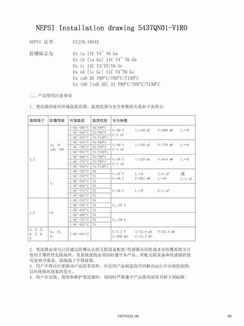
NEPSI Installation drawing 5437QN01-V1R0
NEPSI 证书 GYJ18.1054X
防爆标志为 Ex ia IIC T4~ T6 Ga
Ex ib [ia Ga] IIC T4~ T6 Gb
Ex ic IIC T4/T5/T6 Gc
Ex nA [ic Gc] IIC T4~T6 Gc
Ex iaD 20 T80ºC/T95ºC/T130ºC
Ex ibD [iaD 20] 21 T80ºC/T95ºC/T130ºC
二、产品使用注意事项
1. 变送器的使用环境温度范围、温度组别与安全参数的关系如下表所示:
接线端子 防爆等级 环境温度 温度组别 安全参数
1,2
ia, ib
iaD, ibD
(-50~+50)ºC T6/T80ºC Ui=30 V
Ci=1 nF
Ii=120 mV
Pi=900 mW
Li≈0
(-50~+65)ºC T5/T95ºC
(-50~+85)ºC T4/T130ºC
(-50~+55)ºC T6/T80ºC Ui=30 V
Ci=1 nF
Ii=120 mV
Pi=750 mW
Li≈0
(-50~+70)ºC T5/T95ºC
(-50~+85)ºC T4/T130ºC
(-50~+60)ºC T6/T80ºC Ui=30 V
Ci=1 nF
Ii=120 mV
Pi=610 mW
Li≈0
(-50~+75)ºC T5/T95ºC
(-50~+85)ºC T4/T130ºC
ic
(-50~+55)ºC T6 Ui=37 V
Ui=48 V
Li≈0
Pi=851 mW
Ci=1 nF
Li≈0 或
Ci=1 nF (-50~+70)ºC T5
(-50~+85)ºC T4
(-50~+60)ºC T6
Ui=30 V Li≈0 Ci=1 nF (-50~+75)ºC T5
(-50~+85)ºC T4
1,2 nA
(-50~+55)ºC T6
Umax=37 V (-50~+70)ºC T5
(-50~+85)ºC T4
(-50~+60)ºC T6
Umax=30 V (-50~+75)ºC T5
(-50~+85)ºC T4
3, 4, 5,
6, 7, 8,
9
ia, ib,
ic (-50~+85)ºC
Uo=7.2 V
Lo=200 mH
Io=12.9 mA
Co=13.5 µF
Po=23.3 mW
2. 变送器必须与已经通过防爆认证的关联设备配套/传感器共同组成本安防爆系统方可
使用于爆炸性危险场所。其系统接线必须同时遵守本产品、所配关联设备和传感器的使
用说明书要求,接线端子不得接错。
3. 用户不得自行更换该产品的零部件,应会同产品制造商共同解决运行中出现的故障,
以杜绝损坏现象的发生。
4. 用户在安装、使用和维护变送器时,须同时严格遵守产品使用说明书和下列标准:
NEPSI Installation Drawing
5437V101-UK 49

GB 3836.13-2013 爆炸性环境 第 13 部分: 设备的修理、检修、修复和改造
GB 3836.15-2000 爆炸性气体环境用电气设备 第 15 部分: 危险场所电气安装 (煤矿除
外)
GB 3836.16-2006 爆炸性气体环境用电气设备 第 16 部分: 电气装置的检查和维护 (煤
矿除外)
GB 3836.18-2010 爆炸性环境第 18 部分: 本质安全系统
GB 3836.20-2010 爆炸性环境第 20 部分: 设备保护级别 (EPL) 为 Ga 级的设备
GB 50257-2014 电气装置安装工程爆炸和火灾危险环境电气装置施工及验收规范
GB 12476.2-2010 可燃性粉尘环境用电气设备 第 2部分: 选型和安装
GB 15577-2007 粉尘防爆安全规程
50 5437V101-UK
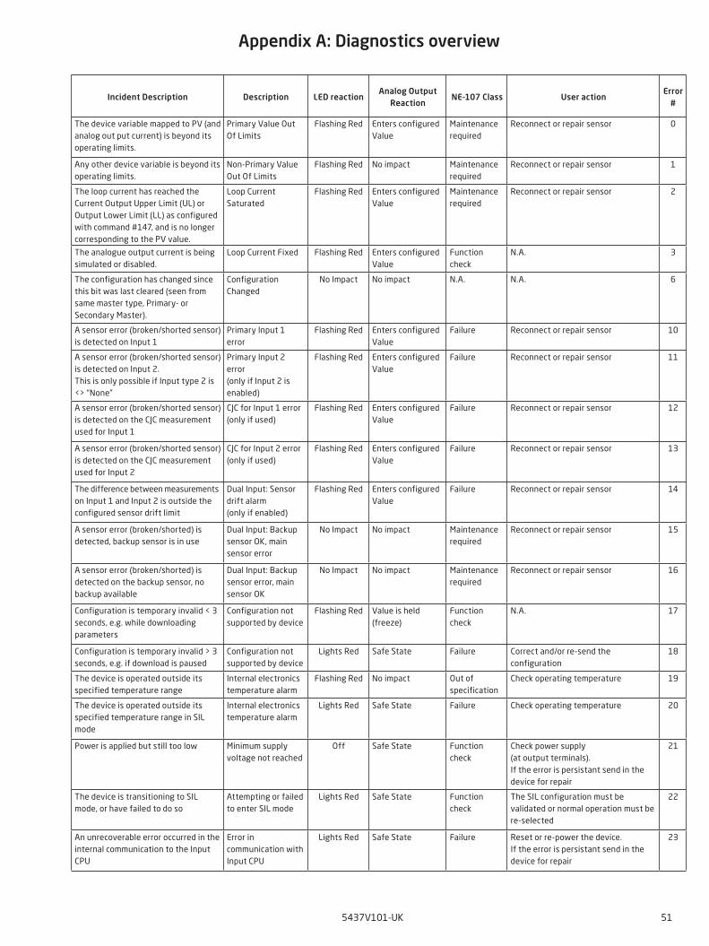
Incident Description Description LED reactionAnalog Output
ReactionNE-107 Class User action
Error #
The device variable mapped to PV (and analog out put current) is beyond its operating limits.
Primary Value Out Of Limits
Flashing Red Enters configured Value
Maintenance required
Reconnect or repair sensor 0
Any other device variable is beyond its operating limits.
Non-Primary Value Out Of Limits
Flashing Red No impact Maintenance required
Reconnect or repair sensor 1
The loop current has reached the Current Output Upper Limit (UL) or Output Lower Limit (LL) as configured with command #147, and is no longer corresponding to the PV value.
Loop Current Saturated
Flashing Red Enters configured Value
Maintenance required
Reconnect or repair sensor 2
The analogue output current is being simulated or disabled.
Loop Current Fixed Flashing Red Enters configured Value
Function check
N.A. 3
The configuration has changed since this bit was last cleared (seen from same master type, Primary- or Secondary Master).
Configuration Changed
No Impact No impact N.A. N.A. 6
A sensor error (broken/shorted sensor) is detected on Input 1
Primary Input 1 error
Flashing Red Enters configured Value
Failure Reconnect or repair sensor 10
A sensor error (broken/shorted sensor) is detected on Input 2. This is only possible if Input type 2 is <> “None”
Primary Input 2 error (only if Input 2 is enabled)
Flashing Red Enters configured Value
Failure Reconnect or repair sensor 11
A sensor error (broken/shorted sensor) is detected on the CJC measurement used for Input 1
CJC for Input 1 error (only if used)
Flashing Red Enters configured Value
Failure Reconnect or repair sensor 12
A sensor error (broken/shorted sensor) is detected on the CJC measurement used for Input 2
CJC for Input 2 error (only if used)
Flashing Red Enters configured Value
Failure Reconnect or repair sensor 13
The difference between measurements on Input 1 and Input 2 is outside the configured sensor drift limit
Dual Input: Sensor drift alarm (only if enabled)
Flashing Red Enters configured Value
Failure Reconnect or repair sensor 14
A sensor error (broken/shorted) is detected, backup sensor is in use
Dual Input: Backup sensor OK, main sensor error
No Impact No impact Maintenance required
Reconnect or repair sensor 15
A sensor error (broken/shorted) is detected on the backup sensor, no backup available
Dual Input: Backup sensor error, main sensor OK
No Impact No impact Maintenance required
Reconnect or repair sensor 16
Configuration is temporary invalid < 3 seconds, e.g. while downloading parameters
Configuration not supported by device
Flashing Red Value is held (freeze)
Function check
N.A. 17
Configuration is temporary invalid > 3 seconds, e.g. if download is paused
Configuration not supported by device
Lights Red Safe State Failure Correct and/or re-send the configuration
18
The device is operated outside its specified temperature range
Internal electronics temperature alarm
Flashing Red No impact Out of specification
Check operating temperature 19
The device is operated outside its specified temperature range in SIL mode
Internal electronics temperature alarm
Lights Red Safe State Failure Check operating temperature 20
Power is applied but still too low Minimum supply voltage not reached
Off Safe State Function check
Check power supply (at output terminals). If the error is persistant send in the device for repair
21
The device is transitioning to SIL mode, or have failed to do so
Attempting or failed to enter SIL mode
Lights Red Safe State Function check
The SIL configuration must be validated or normal operation must be re-selected
22
An unrecoverable error occurred in the internal communication to the Input CPU
Error in communication with Input CPU
Lights Red Safe State Failure Reset or re-power the device. If the error is persistant send in the device for repair
23
Appendix A: Diagnostics overview
Appendix A: Diagnostics overview
5437V101-UK 51
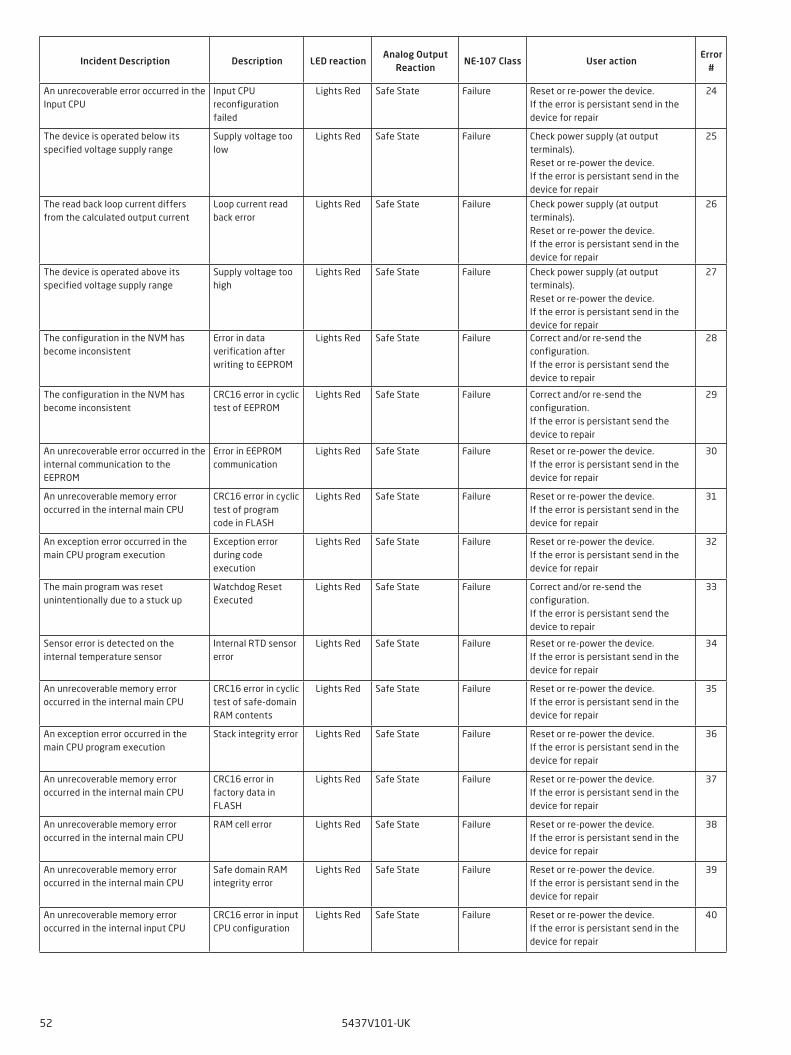
Incident Description Description LED reactionAnalog Output
ReactionNE-107 Class User action
Error #
An unrecoverable error occurred in the Input CPU
Input CPU reconfiguration failed
Lights Red Safe State Failure Reset or re-power the device. If the error is persistant send in the device for repair
24
The device is operated below its specified voltage supply range
Supply voltage too low
Lights Red Safe State Failure Check power supply (at output terminals). Reset or re-power the device. If the error is persistant send in the device for repair
25
The read back loop current differs from the calculated output current
Loop current read back error
Lights Red Safe State Failure Check power supply (at output terminals). Reset or re-power the device. If the error is persistant send in the device for repair
26
The device is operated above its specified voltage supply range
Supply voltage too high
Lights Red Safe State Failure Check power supply (at output terminals). Reset or re-power the device. If the error is persistant send in the device for repair
27
The configuration in the NVM has become inconsistent
Error in data verification after writing to EEPROM
Lights Red Safe State Failure Correct and/or re-send the configuration. If the error is persistant send the device to repair
28
The configuration in the NVM has become inconsistent
CRC16 error in cyclic test of EEPROM
Lights Red Safe State Failure Correct and/or re-send the configuration. If the error is persistant send the device to repair
29
An unrecoverable error occurred in the internal communication to the EEPROM
Error in EEPROM communication
Lights Red Safe State Failure Reset or re-power the device. If the error is persistant send in the device for repair
30
An unrecoverable memory error occurred in the internal main CPU
CRC16 error in cyclic test of program code in FLASH
Lights Red Safe State Failure Reset or re-power the device. If the error is persistant send in the device for repair
31
An exception error occurred in the main CPU program execution
Exception error during code execution
Lights Red Safe State Failure Reset or re-power the device. If the error is persistant send in the device for repair
32
The main program was reset unintentionally due to a stuck up
Watchdog Reset Executed
Lights Red Safe State Failure Correct and/or re-send the configuration. If the error is persistant send the device to repair
33
Sensor error is detected on the internal temperature sensor
Internal RTD sensor error
Lights Red Safe State Failure Reset or re-power the device. If the error is persistant send in the device for repair
34
An unrecoverable memory error occurred in the internal main CPU
CRC16 error in cyclic test of safe-domain RAM contents
Lights Red Safe State Failure Reset or re-power the device. If the error is persistant send in the device for repair
35
An exception error occurred in the main CPU program execution
Stack integrity error Lights Red Safe State Failure Reset or re-power the device. If the error is persistant send in the device for repair
36
An unrecoverable memory error occurred in the internal main CPU
CRC16 error in factory data in FLASH
Lights Red Safe State Failure Reset or re-power the device. If the error is persistant send in the device for repair
37
An unrecoverable memory error occurred in the internal main CPU
RAM cell error Lights Red Safe State Failure Reset or re-power the device. If the error is persistant send in the device for repair
38
An unrecoverable memory error occurred in the internal main CPU
Safe domain RAM integrity error
Lights Red Safe State Failure Reset or re-power the device. If the error is persistant send in the device for repair
39
An unrecoverable memory error occurred in the internal input CPU
CRC16 error in input CPU configuration
Lights Red Safe State Failure Reset or re-power the device. If the error is persistant send in the device for repair
40
52 5437V101-UK
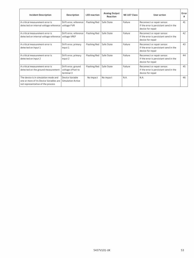
Incident Description Description LED reactionAnalog Output
ReactionNE-107 Class User action
Error #
A critical measurement error is detected on internal voltage reference
Drift error, reference voltage FVR
Flashing Red Safe State Failure Reconnect or repair sensor. If the error is persistant send in the device for repair
41
A critical measurement error is detected on internal voltage reference
Drift error, reference voltage VREF
Flashing Red Safe State Failure Reconnect or repair sensor. If the error is persistant send in the device for repair
42
A critical measurement error is detected on Input 1
Drift error, primary Input 1
Flashing Red Safe State Failure Reconnect or repair sensor. If the error is persistant send in the device for repair
43
A critical measurement error is detected on Input 2
Drift error, primary Input 2
Flashing Red Safe State Failure Reconnect or repair sensor. If the error is persistant send in the device for repair
44
A critical measurement error is detected on the ground measurement
Drift error, ground voltage offset to terminal 3
Flashing Red Safe State Failure Reconnect or repair sensor. If the error is persistant send in the device for repair
45
The device is in simulation mode and one or more of its Device Variables are not representative of the process
Device Variable Simulation Active
No Impact No impact N.A. N.A. 46
5437V101-UK 53

54 5437V101-UK
Document historyThe following list provides notes concerning revisions of this document.
Rev. ID Date Notes101 1817 Initial release of the product

We are near you,all over the world
All our devices are backed by expert service and a 5-year warranty. With each product you purchase, you receive personal technical support and guidance, day-to-day delivery, repair without charge within the warranty period and easily accessible documentation.
We are headquartered in Denmark, and have offices and authorized partners the world over. We are a local
business with a global reach. This means that we are always nearby and know your local markets well. We are committed to your satisfaction and provide PERFORMANCE MADE SMARTER all around the world.
For more information on our warranty program, or to meet with a sales representative in your region, visit prelectronics.com.
Our trusted red boxes are supported wherever you are

PR electronics is the leading technology company specialized in making industrial process control safer, more reliable and more efficient. Since 1974, we have been dedicated to perfecting our core competence of innovating high precision technology with low power consumption. This dedication continues to set new standards for products communicating, monitoring and connecting our customers’ process measurement points to their process control systems.
Our innovative, patented technologies are derived from our extensive R&D facilities and from having a great understanding of our customers’ needs and processes. We are guided by principles of simplicity, focus, courage and excellence, enabling some of the world’s greatest companies to achieve PERFORMANCE MADE SMARTER.
Benefit today from PERFORMANCE MADE SMARTER
www.prelectronics.com