HART - STB Multiplexer - Applications Guide - Cloudinary
204
S1B40735.01 www.schneider-electric.com HART S1B40735 4/2013 HART STB Multiplexer Applications Guide 4/2013
-
Upload
khangminh22 -
Category
Documents
-
view
0 -
download
0
Transcript of HART - STB Multiplexer - Applications Guide - Cloudinary

HART
S1B40735 4/2013
S1B
4073
5.01
www.schneider-electric.com
HARTSTB MultiplexerApplications Guide
4/2013

The information provided in this documentation contains general descriptions and/or technical characteristics of the performance of the products contained herein. This documentation is not intended as a substitute for and is not to be used for determining suitability or reliability of these products for specific user applications. It is the duty of any such user or integrator to perform the appropriate and complete risk analysis, evaluation and testing of the products with respect to the relevant specific application or use thereof. Neither Schneider Electric nor any of its affiliates or subsidiaries shall be responsible or liable for misuse of the information contained herein. If you have any suggestions for improvements or amendments or have found errors in this publication, please notify us.
No part of this document may be reproduced in any form or by any means, electronic or mechanical, including photocopying, without express written permission of Schneider Electric.
All pertinent state, regional, and local safety regulations must be observed when installing and using this product. For reasons of safety and to help ensure compliance with documented system data, only the manufacturer should perform repairs to components.
When devices are used for applications with technical safety requirements, the relevant instructions must be followed.
Failure to use Schneider Electric software or approved software with our hardware products may result in injury, harm, or improper operating results.
Failure to observe this information can result in injury or equipment damage.
© 2013 Schneider Electric. All rights reserved.
2 S1B40735 4/2013

Table of Contents
Safety Information . . . . . . . . . . . . . . . . . . . . . . . . . . . . . . 5About the Book . . . . . . . . . . . . . . . . . . . . . . . . . . . . . . . . . 7
Chapter 1 Getting Started . . . . . . . . . . . . . . . . . . . . . . . . . . . . . . . . . 9Creating Your First Multiplexer . . . . . . . . . . . . . . . . . . . . . . . . . . . . . . . . . 9
Chapter 2 Introducing HART . . . . . . . . . . . . . . . . . . . . . . . . . . . . . . . 23Introducing HART . . . . . . . . . . . . . . . . . . . . . . . . . . . . . . . . . . . . . . . . . . . 24Introducing the STB HART Multiplexer . . . . . . . . . . . . . . . . . . . . . . . . . . . 26HART Multiplexer Features . . . . . . . . . . . . . . . . . . . . . . . . . . . . . . . . . . . . 28HART Multiplexer Functions . . . . . . . . . . . . . . . . . . . . . . . . . . . . . . . . . . . 29Multiplexer Data Flow . . . . . . . . . . . . . . . . . . . . . . . . . . . . . . . . . . . . . . . . 31
Chapter 3 Planning the HART Multiplexer . . . . . . . . . . . . . . . . . . . . 33Island Segments . . . . . . . . . . . . . . . . . . . . . . . . . . . . . . . . . . . . . . . . . . . . 34Extending the Island Bus. . . . . . . . . . . . . . . . . . . . . . . . . . . . . . . . . . . . . . 40Enclosing the HART Multiplexer . . . . . . . . . . . . . . . . . . . . . . . . . . . . . . . . 42The Power Distribution Modules . . . . . . . . . . . . . . . . . . . . . . . . . . . . . . . . 47Logic, Sensor, and Actuator Power Distribution on the Island Bus . . . . . . 52Understanding Multiplexer Island Power Supply and Consumption . . . . . 56Selecting Power Supplies . . . . . . . . . . . . . . . . . . . . . . . . . . . . . . . . . . . . . 60
Chapter 4 Building the Multiplexer . . . . . . . . . . . . . . . . . . . . . . . . . . 63Installing the DIN Rail . . . . . . . . . . . . . . . . . . . . . . . . . . . . . . . . . . . . . . . . 64Installing the HART Enabled Ethernet NIM. . . . . . . . . . . . . . . . . . . . . . . . 65Creating the Backplane of the Island Bus . . . . . . . . . . . . . . . . . . . . . . . . . 68Terminating the Island Bus . . . . . . . . . . . . . . . . . . . . . . . . . . . . . . . . . . . . 71Inserting STB Modules into their Bases . . . . . . . . . . . . . . . . . . . . . . . . . . 73Installing Extension Segments to the Island Bus . . . . . . . . . . . . . . . . . . . 76
Chapter 5 Grounding the HART Multiplexer . . . . . . . . . . . . . . . . . . 79Galvanic Isolation Requirements for Power Supplies on the Island Bus. . 80Voltage Cut-out Switching. . . . . . . . . . . . . . . . . . . . . . . . . . . . . . . . . . . . . 81Creating a Protective Ground Connection. . . . . . . . . . . . . . . . . . . . . . . . . 82Creating a Functional Ground Connection . . . . . . . . . . . . . . . . . . . . . . . . 84Using EMC Kits . . . . . . . . . . . . . . . . . . . . . . . . . . . . . . . . . . . . . . . . . . . . . 85
S1B40735 4/2013 3

Chapter 6 Assigning an IP Address to the HART Multiplexer. . . . . 93Assigning an IP Address to the HART Multiplexer. . . . . . . . . . . . . . . . . . 94Determining the HART Multiplexer Default IP Address . . . . . . . . . . . . . . 98
Chapter 7 Configuring the HART Multiplexer . . . . . . . . . . . . . . . . . . 99Auto-Configuring the HART Multiplexer. . . . . . . . . . . . . . . . . . . . . . . . . . 100Customizing the HART Multiplexer Configuration . . . . . . . . . . . . . . . . . . 103Configuring STB AHI 8321 Channel Settings . . . . . . . . . . . . . . . . . . . . . 105Mapping Data items to the HART Multiplexer Island Data Process Image 108Viewing the IO Image for the STB AHI 8321 HART Interface Module. . . 110Configuring the STB AHI 8321 Module as Mandatory or Not Present. . . 112Data Process Image Items for the STB AHI 8321 HART Interface Module 114Using the STB XMP 4440 Optional Removable Memory Card to Configure the Island. . . . . . . . . . . . . . . . . . . . . . . . . . . . . . . . . . . . . . . . . 121Applying a Stored Configuration to the HART Multiplexer . . . . . . . . . . . . 123
Chapter 8 Wiring the Multiplexer . . . . . . . . . . . . . . . . . . . . . . . . . . . . 1278.1 Providing Power to the HART Multiplexer . . . . . . . . . . . . . . . . . . . . . . . . 128
Wiring External Power Supplies to the HART Multiplexer Island. . . . . . . 1288.2 Wiring the HART Multiplexer to I/O Modules . . . . . . . . . . . . . . . . . . . . . . 132
Resistance Calculation for Current Loop Wiring . . . . . . . . . . . . . . . . . . . 133Setting Analog Output Rise and Fall Times for the STB AHI 8321 Module 134STB I/O Wiring Example . . . . . . . . . . . . . . . . . . . . . . . . . . . . . . . . . . . . . 136Quantum I/O Wiring Example . . . . . . . . . . . . . . . . . . . . . . . . . . . . . . . . . 141Premium I/O Wiring Example. . . . . . . . . . . . . . . . . . . . . . . . . . . . . . . . . . 146M340 I/O Wiring Example . . . . . . . . . . . . . . . . . . . . . . . . . . . . . . . . . . . . 151
Chapter 9 HART Device Management Software . . . . . . . . . . . . . . . . 1559.1 Configuring HART Devices . . . . . . . . . . . . . . . . . . . . . . . . . . . . . . . . . . . 156
Using the DTM. . . . . . . . . . . . . . . . . . . . . . . . . . . . . . . . . . . . . . . . . . . . . 157User Interface Configuration for the HART STB Multiplexer DTM. . . . . . 161
9.2 AMS Device Management Software Example . . . . . . . . . . . . . . . . . . . . . 171Eltima Software Serial to Ethernet Connector Setup. . . . . . . . . . . . . . . . 172Add the Schneider Electric Multiplexer to the AMS Device List. . . . . . . . 176Creating a HART Multiplexer Network . . . . . . . . . . . . . . . . . . . . . . . . . . . 180Managing HART Network Devices . . . . . . . . . . . . . . . . . . . . . . . . . . . . . 185
Glossary . . . . . . . . . . . . . . . . . . . . . . . . . . . . . . . . . . . . . . . . . . . 189Index . . . . . . . . . . . . . . . . . . . . . . . . . . . . . . . . . . . . . . . . . . . 201
4 S1B40735 4/2013

§
Safety InformationImportant Information
NOTICERead these instructions carefully, and look at the equipment to become familiar with the device before trying to install, operate, or maintain it. The following special messages may appear throughout this documentation or on the equipment to warn of potential hazards or to call attention to information that clarifies or simplifies a procedure.
S1B40735 4/2013 5

PLEASE NOTEElectrical equipment should be installed, operated, serviced, and maintained only by qualified personnel. No responsibility is assumed by Schneider Electric for any consequences arising out of the use of this material.
A qualified person is one who has skills and knowledge related to the construction and operation of electrical equipment and its installation, and has received safety training to recognize and avoid the hazards involved.
6 S1B40735 4/2013

About the Book
At a Glance
Document ScopeThis manual describes specific application solutions employing the Highway Addressable Remote Transducer (HART) multiplexer.
The specific configuration settings contained in this manual are intended to be used for instructional purposes only. The settings required for your specific configuration may differ from the examples presented in this manual.
Validity NoteThe solutions described in the manual require the use of the following versions of hardware and software:
Advantys configuration software version 5.5 with patch 4 build 6, or Advantys Configuration software version 7.0 or higherSTB AHI 8321 HART interface module, version 1.00 or higherSTB NIP 2311 network interface module, version 4.00 or higher
S1B40735 4/2013 7

Related DocumentsFor additional information about the STB AHI 8321 HART interface module, refer to the online help files for the Advantys configuration software, and to the following technical publication:
You can download these technical publications and other technical information from our website at www.schneider-electric.com.
User CommentsWe welcome your comments about this document. You can reach us by e-mail at [email protected].
Title of Documentation Reference Number
Advantys STB Special Modules Reference Guide 31007730 (English), 31007731 (French), 31007732 (German), 31007733 (Spanish), 31007734 (Italian)
Advantys STB Standard Dual Port Ethernet Modbus TCP/IP Network Interface Module
EIO0000000051 (English), EIO0000000052 (French), EIO0000000053 (German), EIO0000000054 (Spanish), EIO0000000055 (Italian)
8 S1B40735 4/2013

S1B40735 4/2013
1
HARTGetting StartedS1B40735 4/2013
Getting Started
Creating Your First Multiplexer
OverviewThe Schneider Electric HART multiplexer acts as a gateway to HART-enabled intelligent field instruments. This example shows you how to get started and build your first Schneider Electric HART multiplexer.
After you complete this chapter, you will be able to see the status and data from HART field instruments on the multiplexer web pages.
This example is intended for use on your test bench. For permanent installation, consult the later chapters of this guide.
The HART MultiplexerThe Schneider Electric HART multiplexer solution is modular and expandable solution. A single Schneider Electric HART multiplexer can support up to 32 HART channels. The HART protocol communicates at the rate of 1200 baud.
9

Getting Started
This example shows you how to build the following Schneider Electric HART multiplexer. This example presents the minimum configuration.
1 STB NIP 2311 Ethernet network interface module version 4.0 or higher2 STB PDT 3100 power distribution module3 STB AHI 8321 4-channel HART interface module4 STB XMP 1100 terminator plate
Explosive EnvironmentsThe STB AHI 8321 multiplexer is ATEX and FM certified for use in hazardous locations where potentially explosive atmospheres may exist. For details see Explosive Environments in the Advantys STB System Planning and Installation Guide (890 USE 171).
DANGEREXPLOSIVE ENVIRONMENT HAZARDDo not substitute components which may impair suitability for ATEX Ex or FM Class 1 Division 2 certifications.
Failure to follow these instructions will result in death or serious injury.
10 S1B40735 4/2013

Getting Started
Task 1: Selecting a DIN RailThe STB modules in your HART multiplexer are designed to be mounted on a standard high-profile din rail. A standard DIN rail is 35 mm (1.38 in) wide.
The standard DIN rail is 15 mm (0.59 in) deep:
Select a DIN rail that is wider than the cumulative widths of modules you will install on it. In this example, select a DIN rail that is at least 152 mm (6 in) long.
NOTE: The HART multiplexer requires 24 Vdc power. If you plan to mount your power supply on the DIN rail, select a DIN rail long enough for both the HART multiplexer modules and the power supply.
Task 2: Installing the HART-Enabled Ethernet Network Interface ModuleEvery HART multiplexer includes a single HART-enabled Ethernet network interface module (NIM). The NIM is the first (leftmost) module on the DIN rail.
S1B40735 4/2013 11

Getting Started
In this example, use an STB NIP 2311 NIM, product version 4.0 or higher. You can locate the NIM product version (PV), plus the original module firmware version and certification markings, on the face of the NIM as indicated below:
Install the STB NIP 2311NIM directly on the DIN rail in one piece, as follows:
Step Action
1 Determine the exact location on the DIN rail where you want to position the NIM before you place it on the rail.NOTE: Reserve sufficient space to the right of the NIM for the other island modules you want to mount on the DIN rail.
2 Turn the release screw (2) on the NIM so that the mounting clips on the back are in their relaxed state.
12 S1B40735 4/2013

Getting Started
CAUTIONUNINTENDED EQUIPMENT OPERATIONDo not slide the NIM along the DIN rail. Sliding the NIM can crush the functional ground (FE) contacts on the back of the NIM. Crushed FE contacts can prevent the creation of the FE connection.
Failure to follow these instructions can result in injury or equipment damage.
Step Action
3 Align the mounting clips with the DIN rail and push the NIM straight onto the rail. The slope of the mounting clips causes the rail to open the clips when you apply light pressure.
4 Push the module pushed on to the rail until the clips snap closed.
S1B40735 4/2013 13

Getting Started
Task 3: Assembling the HART Multiplexer BackplaneUnlike the NIM, the remaining island modules are not attached directly to the DIN rail. Instead, each module resides in a base unit that comes with the module. In this example, you will create the HART multiplexer backplane by interconnecting the following sequence of base units:1. add one STB XBA 2200 base unit (for the STB PDT 3100 power distribution
module) to the right of the NIM2. add one STB XBA 3000 base unit (for the STB AHI 8321 HART interface
module) to the right of the PDT base3. add an STB SMP 1100 termination plate to the right of the PDT base, to
terminate the HART multiplexer backplane
Proceeding in a left to right direction from the NIM, follow these steps to create your HART multiplexer backplane:
Step Action
1 Select the STB XBA 2200 base unit that came with your PDM to place directly to the right of the NIM.
2 Using a small screwdriver with a flat blade no wider than 2.5 mm (0.99 in), move the DIN rail latch on the base unit to its full open position.
14 S1B40735 4/2013

Getting Started
3 Align the contacts on the base with the contact channels on the NIM and push the base toward the DIN rail until the interlocking channels meet. Using the interlocking channels as guides, slide the base toward the DIN rail (push from the center of the base). When the base meets the DIN rail, hold the base unit firmly against the DIN rail and push the DIN rail latch into the locked position.
4 Select the STB XBA 3000 base unit for the STB AHI 8321 HART interface module. Insert this unit directly to the right of the previous base unit; then repeat steps 2 and 3.
5 Select the STB XBE 1100 termination plate
6 Align the interlocking channels at the top and bottom left of the termination plate with the channels on the right side of the last module base.
7 Using the interlocking channels as guides, slide the plate toward the DIN rail until it snaps onto the rail.
NOTE: The illustration, above, displays several base units. The backplane you will construct in this example includes only 2 base units.
Step Action
S1B40735 4/2013 15

Getting Started
Task 4: Providing Power to the HART MultiplexerThe next task is to bring 24 Vdc power to the HART multiplexer. You need to supply power to both:
STB NIP 2311 NIM, which provides logic power to the HART multiplexer modulesSTB PDT 3100 power distribution module, which provides both sensor and actuator power to the island
The following graphic shows you how to provide power supply wiring to the STB NIP 2311 NIM and an STB PDT 3100 standard PDM:
1 +24 Vdc sensor bus power2 sensor bus return3 +24 Vdc actuator bus power4 actuator bus return5 +24 Vdc island logic power supply6 island logic power return7 External 24 Vdc power supply8 Wurth 74271633 ferrite bead
NOTE: To maintain CE compliance, use a Wurth 74271633 ferrite bead with NIM, PDM, BOS, and CPS power supplies. Pass the twisted pair wiring through the ferrite bead twice.
Schneider Electric recommends the Phaseo ABL8 RP 24100 power supply (see page 61) for supplying logic, actuator and sensor power.
16 S1B40735 4/2013

Getting Started
Task 5: Wiring the Current LoopsEach STB AHI 8321 HART interface module provides 4 HART channels. Each channel can connect to a single 4-20 mA current loop and communicate with a single HART field instrument. In this example, the HART multiplexer is connected to a single HART field instrument on channel 1.
The following graphic shows you how to connect 4-20 mA current loop wiring channel 1 of the STB AHI 8321 HART interface module:
1 220 Ω resistor 2 Channel 1 current loop (+) wiring to HART field instrument3 Channel 1 current loop (-) return from HART field instrument 4 Functional ground (FE) 5 HART field instrument 6 24 Vdc current loop power supply
As the preceding graphic indicates, use pins 2 and 4 to connect channel 1 of the STB AHI 8321 HART interface module to a HART field instrument.
When connecting the island modules to current loop wiring:use wire sizes in the range 0.20...0.82 mm2 (24...18 AWG)strip at least 9 mm from the wire’s jacket for the connection to STB AHI 8321 moduleuse shielded twisted-pair cabletie the twisted-pair cable shield to an external clamp that is tied to ground
NOTE: Refer to the topic Wiring the HART Multiplexer to I/O Modules (see page 132) for examples of wiring the HART multiplexer to I/O on STB, Quantum, Premium, and M340 platforms.
S1B40735 4/2013 17

Getting Started
Task 6: Assigning an IP AddressIn this example, you will set the IP address of the HART multiplexer to its default IP address. To do this, use the bottom rotary switch (the ONES switch) on the front of the STB NIP 2311 NIM.
Follow these steps to assign your HART multiplexer island its default IP address:
The default IP address is derived from the last 2 pair of two-digit numbers in the MAC ID of your STB NIP 2311 NIM. The MAC ID of your STB NIP 2311 NIM is printed on the front of the NIM above the two Ethernet connector ports.
The default IP address observes the format 10.10.x.y, where:10.10. are constantsx.y. are the decimal values of the last 2 pair of two-digit numbers in the MAC ID.
Step Action
1 Apply power to the HART multiplexer.
2 Turn the bottom (ONES) switch on the STB NIP 2311 NIM so that it points to one of the CLEAR IP positions. This clears any previously assigned IP address.NOTE: The position of the top (TENS) switch does not matter.
3 Turn the bottom (ONES) switch on the STB NIP 2311 NIM so that it points to one of the STORED positions. This NIM applies its default IP address.NOTE: The position of the top (TENS) switch does not matter.
18 S1B40735 4/2013

Getting Started
The following example shows you how to convert the two x.y. pair of two-digit numbers from hexadecimal to decimal format and identify the HART multiplexer’s default IP address:
Task 7: Auto-Configuring the HART MultiplexerThe auto-configuration process assigns default settings to the modules that comprise your HART multiplexer island—except IP address, which was assigned in the previous task. Using auto-configuration, no manual configuration of island modules needs to be performed. To perform auto-configuration, press the RST button on the STB NIP 2311 NIM.
The RST button is located immediately above the CFG port on the NIM, behind the NIM hinged cover:
Step Action
1 Using a sample MAC ID of 00-00-54-10-25-16, ignore the first four pair (00-00-54-10).NOTE: You need to use the MAC ID that appears on your STB NIP 2311 NIM.
2 Convert the last two pair (25 and 16) from hexadecimal to decimal format.
25: (2 x 16) + 5 = 37
16: (1 x 16) + 6 = 22
3 Observe the specified format (10.10.x.y.) to assemble the derived default IP address.
The default IP address is: 10.10.37.22
CAUTIONUNINTENDED EQUIPMENT OPERATIONDo not press the RST button–or force auto-configuration–for a HART multiplexer island that is operating using an application that was custom configured with Advantys configuration software.
Failure to follow these instructions can result in injury or equipment damage.
S1B40735 4/2013 19

Getting Started
To perform auto-configuration, follow these steps:
Task 8: Confirming the HART Multiplexer is Operating NormallyTo confirm that your multiplexer is operating properly, check the RDY and ERR LEDs on the front of the STB AHI 8321 HART interface module:
When your HART multiplexer is operating normally:the RDY LED is solid greenthe ERR LED is off
Task 9: Monitoring HART Multiplexer OperationsAfter confirming that the HART multiplexer is operating normally, you can open the web pages for the STB NIP 2311 NIM where you can:
monitor operationsdiagnose the HART multiplexeredit the HART multiplexer configuration—for example, you can assign the multiplexer a different IP address
NOTE: When commissioning a HART multiplexer for operation in a network, Schneider Electric recommends that you not use the default IP address. Instead, give each HART multiplexer its own unique IP address, as assigned by your network administrator.
Step Action
1 Confirm that power is applied to the HART multiplexer.
2 Using a small screwdriver with a flat blade no wider than 2.5 mm (0.99 in), press the RST button and hold it down for at least 2 seconds. Do not use:
a sharp object that can damage the RST button, ora soft item like a pencil that can break off and jam the RST button
20 S1B40735 4/2013

Getting Started
To access the web pages, follow these steps:
The Home page of the STB NIP 2311 NIM:
You can access HART-specific web information by clicking on the Diagnostics menu item (above), then under HART selecting the following page:
Instrument Overview: to monitor data relating to selected HART field instruments
Step Action
1 Connect your PC via Ethernet cable to one of the Ethernet ports of the STB NIP 2311 NIM.
2 Confirm that your PC has an alternate IP address on the same network as the HART multiplexer. Recall that the default IP address of the multiplexer is in the format 10.10.x.y. You will probably need to add an alternate network IP address to your PC using the same format. Verify that the IP address you add is not the same as the default IP address for the HART multiplexer.
3 Open an internet browser on your PC and type in the default IP address of the HART multiplexer, then press Enter.
4 In the Security dialog, enter the appropriate username and password.NOTE:
the User name is the constant value USERthe default Password is also USER, but can be changed
The Password page opens.
S1B40735 4/2013 21

Getting Started
The following is an example of the HART Instrument Overview web page:
For details of the contents of this page, refer to the Embedded Web Pages section of the Advantys STB Standard Dual Port Ethernet Modbus TCP/IP Network Interface Module Applications Guide.
22 S1B40735 4/2013

S1B40735 4/2013
2
HARTIntroducing HARTS1B40735 4/2013
Introducing HART
OverviewThis chapter introduces the Highway Addressable Remote Transducer (HART) protocol, and describes the Schneider Electric HART multiplexer.
What Is in This Chapter?This chapter contains the following topics:
Topic Page
Introducing HART 24
Introducing the STB HART Multiplexer 26
HART Multiplexer Features 28
HART Multiplexer Functions 29
Multiplexer Data Flow 31
23

Introducing HART
Introducing HART
The HART ProtocolThe Highway Addressable Remote Transducer (HART) protocol provides digital communication to microprocessor-based analog process control instruments.
HART uses the Bell 202 frequency-shift-keying (FSK) standard to superimpose a digital signal on top of the 4-20 mA current loop analog signal:
the analog signal communicates the primary measured process variable valuethe digital signal communicates additional instrument information including instrument status, additional process variables, configuration data, and diagnostics
The digital signal shifts between a frequency of 1200 Hz (representing a binary 1) and a frequency of 2200 Hz (representing a binary 0):
These digital signal frequencies are higher than the analog signaling frequency range of 0...10 Hz. The digital signal is typically isolated using a passive high-pass filter with a cut-off frequency in the range of 400 Hz to 800 Hz. The analog signal is likewise isolated using a passive low-pass filter.
The separation in frequency between HART and analog signaling allows both signals to coexist on the same current loop. Because the HART digital signal is phase continuous:
it does not interfere with the 4-20 mA signal, andallows the analog process to continue operating during HART digital communication
24 S1B40735 4/2013

Introducing HART
Half-duplex Communication ProtocolHART communication is half-duplex in design, which means that a HART-compliant instrument does not simultaneously transmit and receive.
Master - Slave ProtocolHART is a master-slave protocol. A HART-slave responds only when commanded by a HART master. Examples of HART-compliant instruments include:
HART masters:asset management software (AMS) running on a PCa HART interface module—for example, the STB AHI 8321 module—when it is communicating with a HART process control instrumenta hand-held device temporarily attached to the network
HART slaves:a HART process control instrument
Defining HART InstrumentsA Device Description Language (DDL) file—provided by the device manufacturer—can define a HART instrument. The DDL serves as a universal software interface for new and existing network instruments.
S1B40735 4/2013 25

Introducing HART
Introducing the STB HART Multiplexer
Multiplexer ComponentsThe Schneider Electric STB HART multiplexer is a special-purpose STB island that includes some combination of the following modules:
Required modules:1 HART-enabled STB Ethernet network interface module, for example the STB NIP 2311 version 4.0 or higher1 STB PDT 310x power distribution modulea minimum of 1, up to a maximum of 8, STB AHI 8321 HART interface modules
Optional modules:Analog input modulesAnalog output modulesSTB CPS 2111 auxiliary power supply modules, as neededSTB XBE 1300 beginning of segment (BOS) modules STB XBE 1100 end of segment (EOS) modules
NOTE: The HART multiplexer is a special kind of STB island. Only the modules described above relate to the use of the STB island as a HART multiplexer. Although you can add other types of modules to a HART multiplexer, STB island designs that include other modules are beyond the scope of this document.The HART multiplexer operates at the default backplane speed of 800 kbaud. However, if you add an STB XBE 2100 CANopen extension module to the island, you need to re-configure the backplane speed to 500 kbaud, thereby slowing the performance of the HART multiplexer. Refer to the help topics for the STB XBE 2100 CANopen extension module for additional information.
26 S1B40735 4/2013

Introducing HART
The following is an example of an HART multiplexer island.
1 STB NIP 2311 Ethernet network interface module, version 4.0 or higher2 STB PDT 3100 power distribution module3 2 STB ACO 0220 analog output module (optional)4 STB AHI 8321 HART interface module 5 STB CPS 2111 auxiliary power supply6 STB ACI 8320 analog input module (optional) 7 STB XMP 1100 terminator plate
Maximum Multiplexer SizeA single Schneider Electric HART multiplexer can support a maximum of 32 HART instruments—one instrument per channel—when you use:
the maximum of eight (8) STB AHI 8321 HART interface modules per islandthe maximum of four (4) channels for each HART interface module
S1B40735 4/2013 27

Introducing HART
HART Multiplexer Features
Multiplexer FeaturesThe STB HART multiplexer presents the following features:
Auto-configurable default operating parameter settings, which enable the commissioning of the multiplexer without custom configurationA minimum of 4 (up to a maximum of 32) 4-20 mA current loop connections, each connection linking a channel on an input or output module to an analog HART instrumentPassive filters on each channel that attenuate HART communication signals, permitting pass-through of the analog signal to analog I/OTwo Ethernet ports (on the NIM) that let you place the multiplexer into service in a daisy chain topology, or in a daisy chain loop with RSTP enabledCapacity to receive IP address settings from a DHCP or BootP serverEmbedded web page diagnosticsCustom configurable operating parameter settings—via Advantys configuration softwareAn Ethernet interface to a HART master, for example, asset management software resident on a PC A fieldbus interface over Ethernet, such as Modbus TCP, which lets a PLC connect to a HART instrument and access instrument process variables and status
28 S1B40735 4/2013

Introducing HART
HART Multiplexer Functions
The Role of a MultiplexerThe STB HART multiplexer facilitates the transmission of HART field instrument data as follows:
the multiplexer provides one-to-many communications between:a HART master device, for example, asset management software resident on a PC, andmultiple HART slave devices (for example, HART field instruments)
the multiplexer provides HART instrument data to a secondary fieldbus—such as Modbus TCP—where it is made available to the fieldbus master, for example a PLC.
Multiplexer Component FunctionsThe HART multiplexer component modules perform the following functions:
The STB AHI 8321 HART interface module is a passive device that can pass through the analog transmission between an analog field instrument and an analog I/O module. A single HART interface module can be placed into up to four 4-20 mA current loops (or channels)—one instrument per channelThe STB AHI 8321 HART interface module receives a combined analog and digital signal from each connected HART instrument. The STB AHI 8321 HART interface module filters out the digital HART signal and, if connected to an analog I/O module, passes the analog portion of the signal to the I/O module.The STB AHI 8321 HART interface module uses the digital signal to cyclically poll the HART instrument for HART data. The HART data describes the status of each channel and the connected HART instrument.Each STB AHI 8321 HART interface module forwards HART data—contained in digital signals received from a HART instrument—to a HART enabled Ethernet network interface module, for example, the STB NIP 2311.The HART enabled Ethernet NIM stores the HART data received from each HART interface module located in the multiplexer island. The network interface module makes this data available as follows:
HART data is available to asset management software (AMS) running on a PC connected to the NIM via Ethernet. Some of the HART data is stored in registers and becomes part of the island data process image. You can access this data via the PLC, and in the network interface module web pages.
S1B40735 4/2013 29
Introducing HART
The HART enabled Ethernet NIM also processes asynchronous commands it receives from HART master devices. These commands instruct the HART instrument to read, write, or reset data values, including instrument configuration and diagnostic data. The network interface module forwards the command to the target HART instrument and returns the response to the master.
NOTE: HART master devices include:
Asset management software (AMS) running on a connected PC. AMS is referred to as a primary HART master, that can send both read and write commands.Hand-held devices that are temporarily attached to the control loop on the instrument side of the HART multiplexer. Referred to as a secondary HART master, a hand-held device can also send both read and write commands.
30 S1B40735 4/2013

Introducing HART
Multiplexer Data Flow
The Path from HART Field Instrument to Analog I/OThe HART multiplexer is a passive, pass-through device placed between analog HART field instruments and analog I/O modules.
The physical location of the I/O does not matter. The I/O can be an STB I/O module that resides in the STB HART multiplexer island. Or it can be a module that resides in a Quantum, Premium, M340, or third-party platform rack.
NOTE: In the following data flow diagram, the Ethernet transmission is performed via Modbus TCP. The PC with asset management software is equipped with serial-to-Ethernet connector software.
The following figure outlines the flow of data for non-HART tolerant I/O:
S1B40735 4/2013 31

Introducing HART
I/O PlacementFor both HART tolerant I/O and non-HART tolerant I/O, the physical location of the I/O can vary. The I/O can be an STB analog I/O module that resides in the STB HART multiplexer island. Or it can be an analog I/O module that resides in a separate rack. Typical I/O placement locations include the following:
You can create a topology that combines both designs and places analog I/O modules both in the multiplexer island and in a separate I/O drop.
Placement of I/O modules Platforms Use this design for...
The STB HART multiplexer island STB New STB networks
A separate I/O drop STBM340PremiumQuantumThird party platforms
Existing networks
32 S1B40735 4/2013

S1B40735 4/2013
3
HARTPlanning the HART MultiplexerS1B40735 4/2013
Planning the HART Multiplexer
Introducing the STB HART MultiplexerThe HART multiplexer is a specific-purpose STB island. An STB HART multiplexer island is a modular distributed I/O system. This chapter describes how to plan the installation of an STB HART multiplexer island.
What Is in This Chapter?This chapter contains the following topics:
Topic Page
Island Segments 34
Extending the Island Bus 40
Enclosing the HART Multiplexer 42
The Power Distribution Modules 47
Logic, Sensor, and Actuator Power Distribution on the Island Bus 52
Understanding Multiplexer Island Power Supply and Consumption 56
Selecting Power Supplies 60
33

Planning the HART Multiplexer
Island Segments
The Primary SegmentEvery HART multiplexer island begins with a group of interconnected devices called the primary segment. The primary segment consists of the island NIM and a set of interconnected module bases attached to a DIN rail. The PDMs, auxiliary power supplies, I/O, and HART interface modules reside in these bases on the DIN rail. The NIM is the first (leftmost) module in the primary segment.
Depending on your needs, you can expand the island to include additional segments of STB modules, called extension segments.
The DIN RailThe NIM and the module bases snap onto a 35 mm (1.38 in) wide, conductive metal, DIN rail:
The BasesThe bases provide the physical connections between modules on the island bus. These connections enable communication between the NIM and other island modules. A set of contacts on the side of each base transmit:
logic power from the NIM, from a beginning of segment BOS module, or from an auxiliary power supply sensor power (for inputs) from the PDMactuator power (for outputs) from the PDM]the auto-addressing signalisland bus communications between the NIM and other island modules, including I/O and HART interface modules
There are seven types of bases that can be used in a segment. For a specific module, use only the base required by that module.
NOTE: When you buy a module, it is packaged as a part of a kit that includes the base for that module.
When constructing the island bus, install the bases in the same left-to-right sequence as the modules they will support.
34 S1B40735 4/2013

Planning the HART Multiplexer
Bases come in several sizes (see page 69). For example, the STB AHI 8321 HART interface module uses a size 3 base. The following graphic depicts typical base components, in this case an STB XBA 1000 size 1 base:
1 user-customizable label tab2 six island bus contacts3 DIN rail lock/release latch4 DIN rail contact5 five field power distribution contacts
As you assemble the island bus, insert the correct base in each specific island location.
The Island BusThe module bases that you interconnect on the DIN rail form an island bus structure. The island bus houses the modules and supports the communications buses across the island.
The NIM, unlike the PDMs and I/O modules, attaches directly to the DIN rail.
When an STB system consists of a single primary segment, terminate the island by placing an STB XMP 1100 terminator plate (which is included in the NIM packaging) in the right-most island position. If a second segment is added, replace the terminator plate with an STB XBE 1100 end of segment (EOS) extension module.
S1B40735 4/2013 35

Planning the HART Multiplexer
The structure of a single-segment island bus:
1 NIM2 module bases3 termination plate4 DIN rail
36 S1B40735 4/2013

Planning the HART Multiplexer
An Example of an STB IslandThe following illustration presents a multiplexer island bus with standard STB modules.
1 The NIM in the first location of the segment. The NIM provides 5 Vdc logic power to the I/O and HART interface modules located between the NIM and the STB CPS 2111 auxiliary power supply.
2 Two 24 Vdc STB PDT 3100 power distribution modules. One is installed directly to the right of the NIM; the other is installed to the right of an STB CPS 2111 auxiliary power supply. The NIM distributes DC power over the sensor and actuator buses to the I/O directly to its right. The auxiliary power supply supplies DC power to the single input module to its right.
3 Two STB ACO 0220 2-channel output modules, which receive DC field power from the island actuator bus. The 4-20 mA current loops from these modules pass through the adjacent STB AHI 8321 HART interface module. Each current loop is connected to a HART field instrument.
4 Two 4-channel STB AHI 8321 HART interface modules. The first (leftmost) HART interface module is connected via pass-through wiring to current loops (or channels) on the two 2-channel output modules. The second (rightmost) HART interface module is connected to current loops (or channels) on the single 4-channel input module.
5 An STB CPS 2111 auxiliary power module, which provides 5 Vdc logic power to the I/O and HART interface modules located to its right.
6 An STB ACI 8320 4-channel input module, which receives DC field power from an external 24 Vdc power supply. Each current loop is connected to a single HART field instrument. The four 4-20 mA current loop signals from this module connect to the STB AHI 8321 HART interface module on the same even numbered pins used by the HART field instrument(s).
7 An STB XMP 1100 terminator plate
S1B40735 4/2013 37
Planning the HART Multiplexer
Network Interface Module FunctionsThe first module on the HART multiplexer primary segment is a HART-enabled Ethernet NIM, for example the STB NIP 2311. The NIM performs several key functions:
It is the master of the island bus, supporting the I/O and HART interface modules by acting as their communications interface across the bus.It is the gateway between the island and the fieldbus on which the island operates. It manages the data exchange between the island modules (including both I/O and HART interface modules) and the fieldbus master.It is the gateway between HART asset management software (resident on a dedicated PC connected via Ethernet) and both the island HART interface modules and the HART field devices.It provides an interface to the Advantys configuration software, which you can use to customize the island configuration.It is the primary power source for logic power on the island bus, delivering 5-Vdc logic power to modules in the primary segment.
Power Distribution ModulesThe second module on the primary segment is a PDM (see page 47). If the STB island is intended to perform only as a HART multiplexer, it requires only 24 Vdc field power for the modules in a segment.
NOTE: If digital I/O is required for the island, refer to the Advantys STB System Planning and Installation Guide for information on how to supply 24-Vdc power to digital I/O.
I/O ModulesAn STB HART multiplexer island can include resident analog 24 Vdc input modules and output modules.
I/O Module Logic PowerLogic power is the power that the STB I/O modules require to run their internal processing and light their LEDs.
The NIM converts the incoming 24 Vdc to 5 Vdc. The NIM then distributes the 5 Vdc as logic power for the primary segment (see page 52). A similar power supply built into the beginning of segment (BOS) modules provides 5 Vdc for the I/O modules in any extension segments.
Each power supply produces 1.2 A. If the sum of the logic power current consumed by the I/O modules in a segment exceeds that value, you can insert an auxiliary power supply (for example, the STB CPS 2111) to provide an additional 1.2A of power to the modules located to its right. Therefore, the total current draw (see page 56) determines the number of power supplies required by a segment.
38 S1B40735 4/2013

Planning the HART Multiplexer
The Last Device on the Primary SegmentIf the STB island consists of only a single (primary) segment, terminate the island bus by placing an STB XMP 1100 terminator plate at the end of the segment.
Extending the Island BusIf you elect to extend the island bus (see page 40) to another segment, terminate the primary segment with an STB XBE 1100 EOS bus extension module.
The EOS module has an IEEE 1394-style output connector for a bus extension cable. The extension cable carries the island communications bus and auto-addressing line to the extension segment or to the preferred module.
S1B40735 4/2013 39

Planning the HART Multiplexer
Extending the Island Bus
Why Extend the Island Bus?There are two reasons for adding extension segments to the island bus:
to place island modules near to the actuators, sensors, and other end devices with which the island modules communicatethe physical length of the island exceeds the size of the cabinet
An example of a primary island segment with an extension segment:
1 Primary island segment2 Extension segment3 Network interface module (NIM)4 Power distribution module (PDM)5 STB XBE 1100 EOS module6 STB XBE 1300 BOS module7 STB XCA 100x extension cable8 Island bus termination plate
Maximum Length ConsiderationsThe maximum electrical length of an island bus is 15 m (49.2 ft) end-to-end. The maximum length computation includes:
The width of every STB module in every segmentEvery extension cable connecting island segments to:
other island segmentspreferred modules
The maximum island bus length does not include the space required for supporting devices, such as external 24-Vdc power supplies. Also, maximum bus length does not include space required for the wiring between these devices and the island.
40 S1B40735 4/2013

Planning the HART Multiplexer
Maximum Number of Extension SegmentsAn island bus can support up to six extension segments of STB modules in addition to the primary segment. Extension segments can be installed on the same, or on separate DIN rails.
S1B40735 4/2013 41

Planning the HART Multiplexer
Enclosing the HART Multiplexer
Open System RequirementSTB modules meet CE mark requirements for open equipment. Schneider Electric recommends that you install the multiplexer in an enclosure that meets NEMA 250 type 1 requirements and IP 20 requirements conforming to IEC 529. Use of an enclosure is recommended to help reduce the likelihood of:
unauthorized accesspersonal injury resulting from access to live parts
Consider the specific environmental conditions under which the modules operate when planning the enclosure.
Size of the EnclosureVerify that the size of the enclosure is large enough to house the modules included in the island. To fit more easily into the enclosure, you may want to divide the HART multiplexer island into multiple island segments, then arrange the segments horizontally.
A single HART multiplexer island supports up to 32 analog I/O channels, and includes:
one NIMup to 32 analog modules, including analog I/O and HART interface modulesPDMs, auxiliary power supplies, and EOS/BOS modules as needed
Module DimensionsSTB modules come in three widths, and present the following dimensions:
In addition to the module depth and height dimensions, above, consider the dimensions of external power supplies or other equipment—not described above—that you may attach to your island.
Module type
Width of module Height of module in base
Depth of module in base with field connectors
1 13.9 mm (.55 in.) 128.25 mm (5.05 in.) 75.5 mm (2.97 in.)
2 18.4 mm (.73 in.) 128.25 mm (5.05 in.) 75.5 mm (2.97 in.)
2-PDM 18.4 mm (.73 in.) 137.90 mm (5.45 in) 79.5 mm (3.13 in.)
3 28.1 mm (1.11 in.) 128.25 mm (5.05 in.) 70.1 mm (2.76 in)
42 S1B40735 4/2013

Planning the HART Multiplexer
STB Modules Size & Base TypeEach STB module comes packaged with the base that is appropriate for that module. Use the base unit that comes with your module. If you need to replace a base unit for any reason, refer to the following table:
Spacing RequirementsMaintain adequate clearance between the modules installed in the enclosure and surrounding fixed objects such as wire ducts and inside surfaces. The following two illustrations depict the spacing requirements within an enclosure
Model Type Base Model Type Base
Analog Input Modules Analog Output Modules
STB ACI 0320 2 STB XBA 2000 STB ACO 0120 2 STB XBA 2000
STB ACI 8320 2 STB XBA 2000 STB ACO 0220 2 STB XBA 2000
Power Distribution Modules Special Purpose Modules
STB PDT 3100 2 STB XBA 2200 STB AHI 8321 3 STB XBA 3000
STB PDT 3105 2 STB XBA 2200 STB XBE 1100 2 STB XBA 2400
STB CPS 2111 2 STB XBA 2200 STB XBE 1300 2 STB XBA 2300
S1B40735 4/2013 43

Planning the HART Multiplexer
NOTE: The preceding graphic is not drawn to scale.
MountingMount the island on one or more 35 mm (1.38 in) wide DIN carrier rails.
Install the metal DIN rail by:attaching it to a flat metal mounting surfacemounting it on an EIA rackmounting it in a NEMA cabinet enclosure
44 S1B40735 4/2013

Planning the HART Multiplexer
The standard DIN rail is 35 mm x 15 mm (1.38 in x 0.59 in) deep.
Use M5 threaded mounting hardware to affix the DIN rail to the mounting surface. Allow a maximum spacing of 150 mm (5.91 in) between each mounting hardware.
WiringInstall wiring so that it does not obstruct the 100 mm (3.94 in) of free air space above and below the island segment. Tie down the wiring to help guard against undue load or strain on the STB modules. Use a service loop to dress the leads from a harness or cable channel. This practice helps reduce strain on the module.
Thermal ConsiderationsFor proper heat dissipation, allow a minimum clearance of 100 mm (3.94 in) above and below each island segment. Allow the unobstructed flow of air to the vent openings on the top and bottom of the modules.
S1B40735 4/2013 45

Planning the HART Multiplexer
The following list presents some worst-case values for estimating the wattage dissipation when you plan the cooling for your system and cabinet enclosure:
These values assume elevated bus voltage, elevated field-side voltage and maximum load currents. Typical wattage values are often lower.
Module Type Base Type Worst-case Wattage Value
inputs type 1 1.5 W
type 2 2.75 W
type 3 3.5 W
outputs type 1 1.0 W
type 2 2.25 W
type 3 3.5 W
HART interface module type 3 3.5 W
EOS type 2 1.0 W
BOS type 2 2.5 W
auxiliary power supply type 2 2.5 W
DC PDM type 2 - PDM 1.5 W
NIM 3.5 W
46 S1B40735 4/2013

Planning the HART Multiplexer
The Power Distribution Modules
FunctionsThe power distribution module (PDM) supplies field power to the input and output modules resident on the island. Standard PDM modules can distribute sensor power and actuator power via the same or separate power lines across the island bus.
The PDM includes a user-replaceable fuse that helps protect both the island input and output modules, and the wiring. It also provides a protective ground (PE) connection for the island.
PositioningThe HART multiplexer, like other STB islands, requires the placement of a PDM immediately to the right of the NIM, BOS or auxiliary power supply. Depending on the number of input and output modules resident on the segment, additional PDMs can be required. The placement of a PDM to the right of a module group terminates the sensor and actuator buses for the preceding (leftward) module group.
Selecting a PDMIf you are building an STB island to serve exclusively as a HART multiplexer, you will need to include only 24 Vdc analog I/O modules. There are two PDMs that can supply 24 Vdc power:
the STB PDT 3100 standard modulethe STB PDT 3105 basic module
Standard versus Basic PDMsWhen you use a standard PDM, the PDM separately provides power to:
the island sensor bus, for the input modules in its groupthe actuator bus, for the output modules in its group
When you use a basic PDM, the PDM simultaneously provides power to both the sensor bus and the actuator bus.
The standard PDM can also handle more current than a basic PDM.
Standard PDM Power DistributionPlace a PDM immediately to the right of the NIM (or BOS or auxiliary power supply) on the island. The modules in the group follow in series to the right of the PDM.
NOTE: The illustrations presented below are simplified drawings that focus on a single island feature. They may not display every necessary component.
S1B40735 4/2013 47

Planning the HART Multiplexer
The following simplified illustration shows a STB PDT 3100 PDM supporting a cluster of analog 24 Vdc I/O modules:
1 24 Vdc sensor power signal to the PDM2 24 Vdc actuator power signal to the PDM
Sensor power (to the input modules) and actuator power (to the output modules) are brought to the island (from an external 24 Vdc power supply) via separate two-pin connectors on the PDM.
48 S1B40735 4/2013

Planning the HART Multiplexer
In the following simplified illustration, an STB CPS 2111 auxiliary power supply is placed directly to the right of the last I/O module in the first module group, to provide additional logic power (see page 52) to the island. A second PDM is then required to provide power for new sensor and actuator buses for the 24 Vdc modules to the right of the second PDM:
1 24 Vdc sensor power signal to the PDM (first module group)2 24 Vdc actuator power signal to the PDM (first module group)3 24 Vdc sensor power signal to the PDM (second module group)4 24 Vdc actuator power signal to the PDM (second module group)
Each standard PDM contains a pair of time-lag fuses:a 10 A fuse for the actuator busa 5 A fuse for the sensor bus
These fuses are user-replaceable.
S1B40735 4/2013 49

Planning the HART Multiplexer
Basic PDM Power DistributionIf your island uses an STB PDT 3105 basic PDM, power is sent from a single power source (in the PDM) to the sensor bus and the actuator bus. The sensor and actuator busses join together in the PDM. In the following illustration, two basic STB PDT 3105 PDMs are used to provide actuator power and sensor power to two separate groups of I/O:
1 24 Vdc actuator and sensor power to the first (leftmost) module group2 24 Vdc actuator and sensor power to the second (rightmost) module group
Each basic PDM contains one 5 A time-lag fuse that is user-replaceable.
50 S1B40735 4/2013

Planning the HART Multiplexer
PE GroundingA captive screw terminal on the bottom of the PDM base connects to each I/O base, establishing an island PE bus. The screw terminal on the PDM base meets IEC-1131 requirements for field power grounding. Wire the screw terminal to the PE point on your system.
S1B40735 4/2013 51

Planning the HART Multiplexer
Logic, Sensor, and Actuator Power Distribution on the Island Bus
Logic PowerThe NIM requires an external supply of 24 Vdc power. The NIM converts the supplied 24 Vdc, then provides 5 Vdc logic power to the I/O and HART interface modules in the primary island bus segment.
NOTE: The illustrations presented below are simplified drawings that focus on a single island feature. The illustrations may not display every necessary component.
The NIM can supply maximum current of 1.2 A to the island segment modules. If your island design requires more power than the NIM can provide, you can:
install an STB CPS 2111 auxiliary power supply to provide additional logic power to the remaining (rightward) modules.segment the island: Remove some modules from the primary segment to reduce the current draw on that segment to less than 1.2 A. Place these modules into an island extension segment with a BOS.
BOS and auxiliary power supply modules on STB island extension segments require their own 24 Vdc logic power source. This source can come either from the same power supply used by the primary island segment, or from an additional one. The same 1.2 A current limit applies to each extension segment. If a segment exceeds the 1.2 A current draw limit, auxiliary power supplies can also be added to the extension segment.
52 S1B40735 4/2013

Planning the HART Multiplexer
Here is an illustration of the extension segment scenario:
Operating voltages for the island range from 19.2 Vdc to 30 Vdc.
The power components are not galvanically isolated. Use them only in systems designed to provide SELV isolation between:
the supply inputs or outputs, andthe load devices or system power buses
CAUTIONIMPROPER GALVANIC ISOLATIONUse SELV-rated supplies to provide 24 Vdc source power to the NIM.
Failure to follow these instructions can result in injury or equipment damage.
S1B40735 4/2013 53

Planning the HART Multiplexer
Sensor and Actuator Power For standard PDMs, provide power to the island sensor and actuator buses separately from external sources. The source power is fed to separate two-pin power connectors on the PDM.
The top connector is for the sensor (input) power bus.The bottom two-pin connector is for the actuator (output) power bus
Depending on your application, you can use the same or different external power supplies (see page 60) to feed the 24 Vdc sensor and the actuator busses.
For basic PDMs, provide power to both the sensor and actuator buses via a single two-pin power connector on the PDM.
24 Vdc Field Power DistributionIn the following illustration, an external power supply delivers 24 Vdc power to an STB PDT 3100 PDM. The PDM, in turn, distributes field power to the island sensor and actuator busses:
1 24 Vdc signal to the NIM logic power supply2 24 Vdc signal to the segment sensor bus3 24 Vdc signal to the segment actuator bus4 optional relay on the actuator bus
Above 130 Vac, the relay module may compromise the double insulation provided by a SELV-rated power supply.
54 S1B40735 4/2013

Planning the HART Multiplexer
You can use the same power supply for both logic power and field power when:the I/O load on the island bus is low, andthe system is operating in a low electromagnetic noise environment
CAUTIONCOMPROMISED DOUBLE INSULATIONWhen you use a relay module, use separate external 24 Vdc power supplies for the PDM supporting that module and the logic power to the NIM or BOS module when the contact voltage is above 130 Vac.
Failure to follow these instructions can result in injury or equipment damage.
S1B40735 4/2013 55

Planning the HART Multiplexer
Understanding Multiplexer Island Power Supply and Consumption
OverviewWhen you design your HART multiplexer, consider:
the combined capacity of modules that supply logic, sensor and actuator power to the island, andthe load requirements of each module—including I/O modules and HART interface modules—that consume the supplied power
The operating temperature ranges for the STB HART multiplexer modules are listed in the following tables. The listed modules are designed to operate in an environment where the ambient temperature is in the range 0...60° C (32...140° F).
Input Voltage Power Supply Temperature Range VariationsInput voltage for NIMs, STB XBE 1300, STB XBE 1100, STB CPS 2111, STB PDT 3100 modules, and external power supplies can vary with temperature. For the normal operating temperature range of 0...60°C, the supply voltage range is 19.2...30 Vdc
NIM, BOS & Auxiliary Power Supply ModulesThe operating temperature ranges for the STB NIM, BOS, and Auxiliary Power Supply modules are as follows:
Check the front of the NIM (see page 11) to confirm that it is product version 4.0 or higher.
NIM, BOS, and Auxiliary Power Supply Modules
Model Product Version
Type Logic Bus Current Supply at 0...60°C
STB NIP 2311 4.0 Dual Port Ethernet MB TCP/IP NIM standard
1.2 A
STB CPS 2111 N/A Auxiliary Power Supply 1.2 A
STB XBE 1300 N/A BOS Extension Module 1.2 A
56 S1B40735 4/2013

Planning the HART Multiplexer
Analog I/O ModulesThe heat generated by the following STB analog I/O modules is, under normal operating conditions, noticeably greater than the other STB I/O modules. The microprocessor and digital signal processor, required for these types of modules, primarily generate the heat in these modules. These components operate correctly at higher temperatures as noted by their respective manufacturers. The modules are:
STB ACI 0320 (4 channel analog, current input)STB ACI 8320 (4 channel analog, current input)STB ACO 0120 (1 channel analog, current output)STB ACO 0220 (2 channel analog, current output)STB AHI 8321 (4 channel HART interface module)
The HART multiplexer operates in the range 0...60° C. When installing an STB island, mount the product vertically so that natural convection cooling is not impeded.
Logic bus current consumption amounts for analog modules operating in the normal operating temperature range are as follows:
Special Purpose ModulesLogic bus current consumption amounts for special purpose modules operating in the normal operating temperature range are as follows:
Analog Input Model
Type Logic Bus Current Consumption @ 0...60°C
STB ACI 0320 Cur, 4 ch, 4-20 mA, 16-bit standard 95 mA
STB ACI 8320 Cur, 4 ch, 4-20 mA, 16-bit standard 95 mA
Analog Output Model
Type Logic Bus Current Consumption @ 0...60°C
STB ACO 0120 Cur, 1 ch, 4-20 mA, 16-bit standard 155 mA
STB ACO 0220 Cur, 2 ch, 4-20 mA, 16-bit standard 210 mA
Special Purpose Model
Type Logic Bus Current Consumption @ 0...60°C
STB AHI 8321 HART Interface Module 400 mA
STB XBE 1100 EOS Extension Module 25 mA
S1B40735 4/2013 57

Planning the HART Multiplexer
Power Distribution ModulesField power supplied to I/O modules by the PDM operating in the normal operating temperature range are as follows.
STB PDT 3100 Performance ConsiderationsFor the STB PDT 3100 PDM, the maximum combined module current-the sum of the actuator and sensor currents-depends upon the island ambient temperature. The following diagram presents a curve that plots the module’s maximum combined current against its operating temperature range.
This example shows:At 60 °C the total maximum combined current is 8 AAt 45 °C the total maximum combined current is 10 AAt 30 °C the total maximum combined current is 12 A
NOTE: At any temperature, the maximum actuator current is 8 A and the maximum sensor current is 4 A.
PDM Model Type Field Power Supplied to I/O Modules @ 0...60°C
STB PDT 3100 24 Vdc Power Distr. standard 8.0 A
STB PDT 3105 24 Vdc Power Distr. basic 4 A
58 S1B40735 4/2013

Planning the HART Multiplexer
Logic Bus Current Draw VariationsThe total number of modules in a logic power supply group determines the total bus current drawn from the NIM, BOS, or auxiliary power supply. The more modules, the greater the amount of current required to support them. You can determine the total bus current required from the NIM by totaling the individual current requirements for the I/O modules residing on the island.
Verify that the total bus current value is within the allowable current draw range listed for the particular type of NIM module installed on the island. If the logic bus current draw exceeds the capacity of the NIM, either:
divide the island segment into smaller segments, oradd an auxiliary power supply to the segment
S1B40735 4/2013 59

Planning the HART Multiplexer
Selecting Power Supplies
OverviewThe power components are not galvanically isolated. They are for use only in systems designed to provide SELV isolation between the supply inputs or outputs and the load devices or system power bus.
In an STB island, there can be three different connections that need 24 Vdc power from an external source:
logic power connection (to the NIM, to any auxiliary power supplies, and to any BOS extension modules in the island)actuator power connection (to a PDM)sensor power connection (to a PDM)
Source power for these power connections can come from one or more supplies. The following considerations should be considered when selecting your power options:
field devicesvoltage and current needsisolation requirementsEMI/RFI suppression needsCE requirementscost limitations
CAUTIONIMPROPER GALVANIC ISOLATION
Use SELV-rated supplies to provide 24 Vdc source power to the NIM and any BOS or auxiliary power supply modules in your systemIf you are using a relay module with a contact voltage above 130 Vac, do not use a common external 24 Vdc power supply for the PDM supporting that module and the logic power in the NIM, auxiliary power supplies, or BOS modulesAbove 130 Vac, the relay module defeats the double insulation provided by a SELV-rated power supply
Failure to follow these instructions can result in injury or equipment damage.
60 S1B40735 4/2013

Planning the HART Multiplexer
Logic, Sensor, and Actuator PowerUse external 24 Vdc power to support the logic, sensor, and actuator requirements of each segment in your STB island.
For a standard STB PDT 3100 or a basic STB PDT 3105 PDM, verify that the power supplies you choose operate within a voltage range bounded by:
a lower voltage limit of 19.2 Vdcan upper voltage limit of 30 Vdc
Wattage RequirementsSupply the NIM with at least 13 W of power. If your island uses a BOS or an auxiliary power supply, supply each such module on your island with at least 7 W of power.
NOTE: If the 24 Vdc source power supply also supplies field voltage to a PDM, add the field load to your wattage calculation. For 24 Vdc loads, the calculation is: amps x volts = watts.
Recommended SuppliesWe recommend the Phaseo ABL8 family of 24 Vdc power supplies. Here are several possible power supply solutions to consider:
one supply for 4-20 mA current loop power: ABL8 MEM 24003one supply for three connections (logic power, actuator power, and sensor power): ABL8 RPS 24100 two supplies for three connections (one for logic power, one for actuator and sensor powerFor logic power: ABL8 RPS 24030 For the 24 Vdc PDM: ABL8 RPS 24100 three supplies for three connections (one for logic power, one for actuator power and one for sensor power)For logic power: ABL8 RPS 24030 For the 24 Vdc PDM sensor: ABL8 RPS 24050For the 24 Vdc PDM actuator: ABL8 RPS 24100
For more information on recommended 24 Vdc Phaseo power supplies, contact your Schneider Electric representative and ask for brochure 8440BR1001.
S1B40735 4/2013 61

Planning the HART Multiplexer
62 S1B40735 4/2013

S1B40735 4/2013
4
HARTBuilding the MultiplexerS1B40735 4/2013
Building the Multiplexer
OverviewThis chapter describes how to assemble the physical components comprising an STB HART multiplexer.
What Is in This Chapter?This chapter contains the following topics:
Topic Page
Installing the DIN Rail 64
Installing the HART Enabled Ethernet NIM 65
Creating the Backplane of the Island Bus 68
Terminating the Island Bus 71
Inserting STB Modules into their Bases 73
Installing Extension Segments to the Island Bus 76
63

Building the Multiplexer
Installing the DIN Rail
Carrier Rails for the Island BusThe STB modules are designed for mounting on 35 mm x 15 mm (1.38 in x 0.59 in) deep DIN rail conforming to IEC 60715. The use of 15 mm deep DIN rail is required to achieve the stated system performance specifications. As shown on the following illustration, install M5 threaded mounting hardware at the end positions and at 150 mm (5.91 in) maximum increments along the length of the rail.
Low profile 7.5 mm (0.30 in) deep DIN mounting rail can be used with low profile mounting hardware such as flat head screws, with countersunk mounting holes.
NOTE: Mount the DIN rail on a grounded metal plate.If you use low profile 7.5 mm deep DIN rail, the fastener screw head cannot protrude more than 1.0 mm (0.04 in) above the DIN rail.
Grounding FunctionThe DIN rail provides the functional ground (see page 84) across the island.
64 S1B40735 4/2013

Building the Multiplexer
Installing the HART Enabled Ethernet NIM
The First Module on the Island BusEvery STB island includes a single NIM. It is the first (leftmost) module on the DIN rail in the primary island segment. For the HART multiplexer island, use only a HART enabled Ethernet NIM, such as the STB NIP 2311 version 4.0 and higher.
How to Install the NIMUnlike other STB modules, the mounting base of the NIM is permanently attached to the module. Install the NIM on the DIN rail in one piece, as follows:
Step Action
1 Determine the exact location on the DIN rail where you want to position the NIM before you place it on the rail.NOTE: Reserve sufficient space to the right of the NIM for the other island modules you want to mount on the DIN rail. In addition, reserve space for any DIN-mounted external devices you plan to use, for example, power supplies.
2 Turn the release screw (2) on the NIM so that the mounting clips on the back are in their relaxed state.
CAUTIONUNINTENDED EQUIPMENT OPERATIONDo not slide the NIM along the DIN rail. Sliding the NIM can crush the functional ground (FE) contacts on the back of the NIM. Crushed FE contacts can prevent the creation of the FE connection
Failure to follow these instructions can result in injury or equipment damage.
S1B40735 4/2013 65

Building the Multiplexer
For instructions on how to remove the NIM, refer to the Advantys STB System Planning and Installation Guide.
Step Action
3 Align the mounting clips with the DIN rail and push the NIM onto the rail. The slope of the mounting clips causes the rail to open the clips when you apply light pressure.
4 When the module is pushed completely on to the rail, the clips snap closed.
66 S1B40735 4/2013

Building the Multiplexer
FE ContactsOne of the roles of the DIN rail is to provide a FE for the modules on the island. FE helps protect the island from radio frequency interference (RFI) and electromagnetic interference (EMI). The contacts on the back of the NIM, (3), make the functional ground connection between the rail and the NIM.
S1B40735 4/2013 67

Building the Multiplexer
Creating the Backplane of the Island Bus
Installation PlanTo help you install island modules in the correct sequence, create an installation plan before you begin the actual installation process. A useful installation plan describes:
the sequence of modulesthe base required for each module
It is also helpful to use the STB XMP 6700 marking label kit to identify the module you plan to add to each base
Interlocking Base Units on the DIN RailAfter you attach the NIM to the DIN rail, create the island back plane by intercon-necting the proper sequence of base units.
Start directly to the right of the NIM with a PDM base unit. Then add a series of base units for the modules you plan to add to the island. Base units are installed from left to right along the rail. These base units together with the NIM form the backplane for the primary segment of the island.
The following illustration depicts features that relate to connecting base units to the DIN rail.
1 Interlocking channels2 Contacts3 Contact channels4 DIN rail latch
68 S1B40735 4/2013

Building the Multiplexer
The Base UnitsThe following table lists the base types.
How To Attach Base units to the DIN RailThe following steps describe how to attach base units to the DIN rail. When attaching base units, proceed in a left to right direction.
Base Model Base Width STB Modules It Supports
STB XBA 1000 13.9 mm (0.53 in) size 1 I/O modules
STB XBA 2000 18.4 mm (0.71 in) size 2 I/O modules
STB XBA 2100 18.4 mm (0.71 in) the STB CPS2111 auxiliary power supply
STB XBA 2200 18.4 mm (0.71 in) PDMs
STB XBA 2300 18.4 mm (0.71 in) the BOS module
STB XBA 2400 18.4 mm (0.71 in) the EOS module
STB XBA 3000 28.1 mm (1.06 in) the STB AHI 8321 HART interface module and other size 3 modules
Step Action
1 Working from your installation plan, select an STB XBA 2200 base unit for the PDM to place directly to the right of the NIM.
2 Using a screwdriver, move the DIN rail latch on the base unit to its full open position.
S1B40735 4/2013 69

Building the Multiplexer
3 Align the contacts on the base with the contact channels on the NIM and push the base toward the DIN rail until the interlocking channels meet. Using the interlocking channels as guides, slide the base toward the DIN rail (push from the center of the base). When the base meets the DIN rail, hold the base unit firmly against the DIN rail and push the DIN rail latch into the locked position.
4 Working from your installation plan, select the correct base unit for the module. Insert this unit directly to the right of the previous base unit; then repeat steps 2 and 3.
5 Repeat steps 2 ... 4 until base units for all the modules in the primary segment are installed.
6 Refer to the procedures in the next topic (see page 71) for information on installing the last device in the segment.
Step Action
70 S1B40735 4/2013

Building the Multiplexer
Terminating the Island Bus
One or More Segments?Terminate the last device on the HART multiplexer island bus with an STB XMP 1100 termination plate, which is included in your NIM packaging.
If the island bus is a single segment (without extension segments), terminate the island at the right end of the segment.If the island is extended (see page 40), terminate only the last segment of the island bus.
Termination OptionsThe following table describes the different ways to terminate the island bus, depending on the type of installation.
If the island bus includes... then...
A primary segment with no extension segments
Terminate the segment with an STB XMP 1100 termination plate.
A primary segment plus one or more extension segments
Install an STB XBA 2400 base at the end of the segment. This base holds an STB XBE 1100 end of segment EOS module. Terminate at the end of the last segment with an SCB XMP 1100 termination plate.The EOS module provides a connector for a bus extension cable. This cable runs to the STB XBE 1300 (BOS) module placed in the first position in the extension segment.
S1B40735 4/2013 71

Building the Multiplexer
How to Terminate the Last SegmentTo terminate the last segment on the island bus:
For instructions on how to remove the termination plate, refer to the Advantys STB System Planning and Installation Guide.
Step Action
1 Align the interlocking channels at the top and bottom left of the termination plate with the channels on the right side of the last module base.
2 Using the interlocking channels as guides, slide the plate toward the DIN rail until it snaps onto the rail.
72 S1B40735 4/2013

Building the Multiplexer
Inserting STB Modules into their Bases
Preliminary ConsiderationsEach STB module slides into its base and locks with snap latches. Match each module with the base designed for use with that module. Before you install the modules in their bases, we recommend that you consult your installation plan (see page 68) and confirm that you have the correct base in each position on the island backplane.
If you have not already done so, use the STB XMP 6700 marking label kit to identify the module you plan to add to each base.
How to Insert a Module in a BaseTo install a module into its base:
Step Action
1 Guide the bottom of the module into the tray at the bottom of the base.
1 Module to base latch (bottom)2 Module base latch receptor (bottom)3 Module latch (top)4 Module to base latch receptor (top)
S1B40735 4/2013 73

Building the Multiplexer
2 Push the bottom of the module toward the back of the base until the latch (1) fully engages the bottom of the base (2). A snapping sound is audible when the bottom of the module is engaged.
3 Push the top of the module inward until the latch (3) fully engages the top of the base (4). A snapping sound is audible when the top of the module is engaged.
4 Pull outward on the module to confirm that the module is affixed to its base.
Step Action
74 S1B40735 4/2013

Building the Multiplexer
How to Remove a Module from its BaseOnly remove a module from its base when power to the island is disconnected.
NOTE: If you remove an I/O module from the island, any connected sensor or actuator field instruments will no longer work.If you remove a module configured as a mandatory module, island operations stop.
To remove a module from its base:
Step Action
1 Remove any wiring connectors from the module.
2 Using both hands, release the module from the base by depressing the two module to base latches. Latches are located on both the top and on the bottom of the module.
1 Module to base latch (top)2 Module to base latch (bottom)
3 With a rocking motion, slowly pull the module evenly out of the base.
S1B40735 4/2013 75

Building the Multiplexer
Installing Extension Segments to the Island Bus
How to Build an Extension SegmentBuild a HART multiplexer extension segment the same way you would build the primary segment, with one exception. Place a beginning of segment (BOS) module in the first position, instead of a NIM.
The BOS module mounts in a special size 2 base, the STB XBA 2300. A BOS delivers logic power across the extension island backplane. Like the NIM, connect a BOS module to an external 24 Vdc power supply.
The rest of the modules are assembled the same as in a primary segment. The second module is a PDM followed by other STB modules.
The last device in the segment can be:
an STB XMP 1100 termination plate, if placed at the end of the island busan STB XBE 1100 EOS module, if the island bus includes one or more additional segments
An example of a primary segment with extension segment:
1 Primary island segment2 Extension segment3 Network interface module (NIM)4 Power distribution module (PDM)5 STB XBE 1100 EOS module6 STB XBE 1300 BOS module7 STB XCA 100x extension cable8 Island bus termination plate
Length of the Island BusThe maximum length of an island bus (the maximum distance between the NIM and the last device on the island) is 15 m (49.2 ft). This length includes the extension cables between segments, extension cables between preferred modules, and the space consumed by the devices themselves.
76 S1B40735 4/2013

Building the Multiplexer
EOS/BOS Paired ModulesYou can use an EOS module to connect to either:
a BOS module in the first position of an extension segmenta preferred module
Refer to the Advantys STB System Planning and Installation Guide for instructions on how to connect a primary segment to a preferred module.
When joining island bus segments together, only paired EOS/BOS modules work with one another. Use the STB XBE 1100 EOS module and the STB XBE 1300 BOS module when extending HART multiplexer island segments
ConnectorsThe STB XBE 1300 BOS module can accept 24V-DC voltage from a 24V-DC power supply connected to its 2-pin power connector. This module can then pass power to the modules on its segment.
Both of the following connectors, which are included with the EOS and BOS modules as part of the kit, can connect to the modules 2-pin connector:
a screw type power connector, available in a kit of 10 (model STB XTS 1120)a spring clamp power connector, available in a kit of 10 (model STB XTS 2120)
Island Bus Extension CablesThe STB XCA 100x island bus extension cable connects two STB island segments:
One cable end plugs into the island bus communications output port on the front panel of the EOS module (at the end of a segment)The other end plugs into the island bus communications input port on the front panel of the BOS (at the beginning of the next segment).
Bus extension cables are available in five lengths:
Each cable has IEEE 1394-style connectors on each end. The cable does not transmit the 5-Vdc logic signal to the next segment.
Model Cable Length
STB XCA 1001 0.3 m (1 ft)
STB XCA 1002 1.0 m (3.3 ft)
STB XCA 1003 4.5 m (14.8 ft)
STB XCA 1004 10.0 m (32.8 ft)
STB XCA 1006 14.0 m (45.9 ft)
S1B40735 4/2013 77
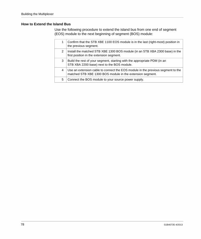
Building the Multiplexer
How to Extend the Island BusUse the following procedure to extend the island bus from one end of segment (EOS) module to the next beginning of segment (BOS) module:
1 Confirm that the STB XBE 1100 EOS module is in the last (right-most) position in the previous segment.
2 Install the matched STB XBE 1300 BOS module (in an STB XBA 2300 base) in the first position in the extension segment.
3 Build the rest of your segment, starting with the appropriate PDM (in an STB XBA 2200 base) next to the BOS module.
4 Use an extension cable to connect the EOS module in the previous segment to the matched STB XBE 1300 BOS module in the extension segment.
5 Connect the BOS module to your source power supply.
78 S1B40735 4/2013

S1B40735 4/2013
5
HARTGrounding the HART MultiplexerS1B40735 4/2013
Grounding the HART Multiplexer
OverviewThis chapter presents techniques for grounding the HART multiplexer.
What Is in This Chapter?This chapter contains the following topics:
Topic Page
Galvanic Isolation Requirements for Power Supplies on the Island Bus 80
Voltage Cut-out Switching 81
Creating a Protective Ground Connection 82
Creating a Functional Ground Connection 84
Using EMC Kits 85
79

Grounding the HART Multiplexer
Galvanic Isolation Requirements for Power Supplies on the Island Bus
Isolation RequirementsVerify that the power sources for the NIM and any other auxiliary power supply or BOS modules are galvanically isolated. Galvanic isolation is not provided by the NIM, BOS or auxiliary power supply modules.
External Power Supply RequirementUse only SELV-rated external 24 Vdc power supplies to provide power to the island bus. Verify that the input side is galvanically isolated from the output side.
This SELV requirement applies to 24 Vdc power supplies supporting both logic power and field power.
The power components are not galvanically isolated. They are for use only in systems designed to provide SELV isolation between the supply inputs or outputs and the load devices or system power bus. Above 130 Vac, the relay module defeats the double insulation provided by a SELV-rated power supply.
CAUTIONIMPROPER GALVANIC ISOLATION
Use SELV-rated supplies to provide 24 Vdc source power to the NIM and any BOS or auxiliary power supply modules in your system.If you are using a relay module with a contact voltage above 130 Vac, do not use a common external 24 Vdc power supply for the PDM supporting that module and the logic power in the NIM, auxiliary power supplies, or BOS modules.
Failure to follow these instructions can result in injury or equipment damage.
80 S1B40735 4/2013

Grounding the HART Multiplexer
Voltage Cut-out Switching
Advantage of the Power Distribution MethodOne of the key features of an STB island featuring a standard NIM is the separate distribution of field power to input and output modules. The STB PDT 3100 standard PDM distributes field power to island modules via a sensor bus. It independently distributes field power to the output modules over an actuator bus.
You can test your application program with live inputs while the outputs are disabled. To do this place a relay or switch installed between the source power supply and the actuator bus connection on the standard PDM,
Here is an example of this relay or switch setup:
Recommended RelaysSchneider Electric recommends its Preventa line of relays. For a complete selection, contact your Schneider representative and ask for catalog MKTED208051EN-US-2011-SU.
S1B40735 4/2013 81

Grounding the HART Multiplexer
Creating a Protective Ground Connection
PE Contact for the IslandIn addition to distributing sensor and actuator power to the I/O modules, the PDM can provide protective ground (PE) to the multiplexer. On the bottom of each STB XBA 2200 PDM base is a captive screw in a plastic block. Use the captive screw, on every PDM base in the multiplexer, to make a PE contact with the island bus.
How to Make a PE ContactTo create a PE contact:
NOTE: Local electrical codes take precedence over our PE wiring recommendations.
Making Multiple PE ConnectionsIf the multiplexer island includes more than one PDM, distribute PE by connecting a protective ground conductor to each PDM base (see page 85).
Step Action
1 Bring a PE connection to the HART multiplexer island using a heavy-duty cross-sectional wire, usually a copper braided cable that is 6 mm2 or larger.
2 Connect the protective ground conductor to the bottom of the PDM base, using the PE captive screw.
3 Tie the wire to a single grounding point.
82 S1B40735 4/2013

Grounding the HART Multiplexer
This illustration shows separate PE connections tied to PE protective ground points:
1 the NIM2 a PDM3 another PDM4 captive screws for the PE connections5 FE connection on the DIN rail6 Protective ground points
S1B40735 4/2013 83

Grounding the HART Multiplexer
Creating a Functional Ground Connection
Functional Ground (FE) on the DIN RailThe DIN rail for your STB island is the functional ground (FE) plane for your system. EMI and RFI are suppressed at the DIN rail. The contacts—on the back of both the NIM and the module bases—establish the connection between the functional ground and your island.
Rail Mounting TipsCreate the FE connection by mounting the NIM and the module bases on the DIN rail.
When performing this task, consider the following tips:Do not slide the NIM and the module bases along the DIN rail when installing them. Sliding them along the DIN rail can crush the FE contacts on the back of the NIM and bases. Crushed FE contacts can prevent the creation of the FE connection.If you are using 7.5 mm (0.30 in) DIN rail, use flat-head threaded mounting hardware. Countersink the mounting hardware so that the head does not protrude more than 1 mm (0.04 in) above the DIN rail.
NOTE: If the top of the mounting hardware protrudes 1 mm or more above the DIN rail, the base units may not be able to make proper contact with the DIN rail and create an FE connection.
A 7.5 mm DIN rail can support vibration conditions up to 3 g. For high vibration environments (up to 5 g), use 15 mm (0.59 in) DIN rail and fasten the rail to the mounting surface along areas where the island modules are mounted. Confirm that the screw heads on 15 mm rail are sufficiently recessed so that they do not interfere with the base-to-rail FE contacts.
CAUTIONUNINTENDED EQUIPMENT OPERATIONDo not slide the NIM along the DIN rail. Sliding the NIM can crush the functional ground (FE) contacts on the back of the NIM. Crushed FE contacts can prevent the creation of the FE connection.
Failure to follow these instructions can result in injury or equipment damage.
84 S1B40735 4/2013

Grounding the HART Multiplexer
Using EMC Kits
OverviewEMC kits reduce electromagnetic and radio interference by grounding the shielded cables entering your island modules at close proximity.
The STB XSP 3000 kit comes with a 1 m (39.37 in) grounding bar that can be cut to needed lengths.
Reasons to use the EMC kits on the HART multiplexer island include:to make STB analog I/O modules CE compliantto enable the use of shielded cables that help protect analog signals from interference from RFI/EMI
S1B40735 4/2013 85

Grounding the HART Multiplexer
The following illustration depicts an STB island segment with an EMC kit making the analog I/O modules CE compliant.
1 metal mounting, grounded surface2 the DIN rail attached to metal mounting surface3 Functional ground (FE) grounding point4 EMC side brackets5 PDM PE screw6 EMC FE clamp7 FE grounding bar from an STB XSP 3000 EMC kit, used as a FE point for shielded cables
and as a cable stabilizer8 EMC cable clamp9 cable channel10 6 mm2 braided cable to plant protective ground11 Protective ground (PE) grounding point (made as close as possible to the I/O)
86 S1B40735 4/2013

Grounding the HART Multiplexer
The KitsSchneider Electric offers 3 kits you can use to provide functional ground to your shielded cable. An initial setup consists of an STB XSP 3000 kit and at least one of the cable clamp kits (STB XSP 3010 or STB XSP 3020). STB XSP 3010 kit comes with ten cable clamps for 1.5 mm to 6.5 mm (0.059 to 0.256 in) size cable. STB XSP 3020 kit comes with ten cable clamps for 5 mm to 11 m (0.19 in to 36.09 ft) size cables.
Kit Comes with...
STB XSP 3000 two side brackets, one 1 m grounding bar and one FE grounding clamp
STB XSP 3010 10 small cable clamps for 1.5mm to 6.5mm (0.059 to 0.256 in) cable
S1B40735 4/2013 87

Grounding the HART Multiplexer
STB XSP 3000 AssemblyUse the following procedure to assemble an STB XSP 3000 kit.
STB XSP 3020 10 medium cable clamps for 5mm to 11mm (0.19 in to 36.09 ft) cable
Kit Comes with...
Step Action
1 Open kit STB XSP 3000 and confirm you have the two side brackets, one grounding bar and one FE grounding clamp.
2 Assemble an STB island segment.
88 S1B40735 4/2013

Grounding the HART Multiplexer
3 Loosen the bracket lockdown screws on each side bracket. Attach the side brackets to the DIN rail on both ends of your assembled STB island segment. They gently snap into place.
4 Push the side brackets toward both ends of your segment so that they are snug against its walls, and tighten the lockdown screws.
Step Action
S1B40735 4/2013 89

Grounding the HART Multiplexer
5 Determine the grounding bar length by measuring the distance between the outsides of the side bracket/segment assembly and add 1 cm (0.39 in). You can estimate a different bar length to meet your particular needs. Cut the bar to length.
The grounding bar is originally 1 M (9.37 in) long x 18 mm (0.71 in) wide x 3 mm (0.12 in) thick. It is made of tinned copper. Contact a supplier to order extra grounding bars.
6 With the bar cut to length, slide the FE grounding clamp onto the grounding bar. Tighten the lockdown screw on top of the clamp.
7 Attach the grounding bar to the side brackets and tighten the lockdown screws on the side brackets.
Step Action
90 S1B40735 4/2013

Grounding the HART Multiplexer
Clamp and Cable AssemblyUse the grounding clamps to attach the shielding of the stripped cable to the FE grounding bar.
8 Attach the clamp to your supplied functional ground using flat braided grounding cable.
Step Action
Step Action
1 Position the grounding clamp in front of the module to which you intend to fasten the wiring. Pull back the spring loaded lock down bolt on the clamp. Slip the clamp onto the grounding bar, then release the lockdown bolt.
S1B40735 4/2013 91

Grounding the HART Multiplexer
2 Strip 2.5 cm (0.98 in) of insulation off your cable to expose the braided shield. (Confirm the cable on either side of the stripped area is long enough to reach the I/O and field instruments). Pull back on the spring loaded lockdown bolt and slip the cable into the clamp. Release the lockdown bolt.
Alternatively, you can clamp your cable to the grounding bar while you attach the cable clamp to the bar.
3 Connect your cable to its I/O and devices.
Step Action
92 S1B40735 4/2013

S1B40735 4/2013
6
HARTAssigning an IP Address to the HART MultiplexerS1B40735 4/2013
Assigning an IP Address to the HART Multiplexer
OverviewNow that you have built the multiplexer, you need to give it an IP address to be able to communicate with it. This chapter describes several different ways to do this.
What Is in This Chapter?This chapter contains the following topics:
Topic Page
Assigning an IP Address to the HART Multiplexer 94
Determining the HART Multiplexer Default IP Address 98
93

Assigning an IP Address to the HART Multiplexer
Assigning an IP Address to the HART Multiplexer
Planning your Ethernet NetworkBefore you assign an IP address to your multiplexer, it is helpful to first develop a plan for how you will assign an IP address to each device. Such a plan should identify:
the network prefix of the IP addressthe (optional) use of subnet masks to organize your network into logically distinct subdivisions the unique IP address to be assigned to each addressable device
Assignment MethodsThe HART multiplexer island communicates to a PLC and to asset management software (resident on a connected PC) over Ethernet. To prepare the multiplexer for Ethernet communications, assign IP parameter settings to the HART enabled Ethernet NIM.
You can set the IP address of the multiplexer island’s NIM in several different ways, including the use of:
the rotary switches on the front of the NIM the NIM embedded web pagesAdvantys configuration software connected to the NIM via Ethernet or a serial cable
For information on using the NIM embedded web pages, refer to the documentation that comes with your HART enabled Ethernet NIM, for example the STB NIP 2311.
94 S1B40735 4/2013

Assigning an IP Address to the HART Multiplexer
Rotary SwitchesUse the rotary switches on the front of the HART enabled Ethernet NIM to specify how the NIM obtains its IP address settings:
IP Parameter Assignment SourcesBefore assigning an IP address, use the rotary switches to clear the NIM stored IP parameters. After setting the lower switch to either CLEAR IP setting, cycle power to the NIM to clear the previous IP address.
You can assign a new IP address using the following rotary switch settings:DHCP server: Set the upper and lower switches to numeric values—from 00 to 159—to create a device name. Do this by using both switches, as follows:
On the upper switch (tens digit), the available settings are 0...15.On the lower switch (ones digit), the available settings are 0...9.
The device name is the three-digit concatenation of the module name, the upper switch value, and the lower switch value. For example, for an STB NIP 2311 NIM:
an upper switch setting of 12 and a lower switch setting of 3 creates a device name of STBNIP2311_123, oran upper switch setting of 1 and a lower switch setting of 3 creates a device name of STBNIP2311_013
S1B40735 4/2013 95

Assigning an IP Address to the HART Multiplexer
NOTE: You also need to separately configure a DHCP server to assign the desired IP address to the NIM based on this device name. For example, you can use the DHCP server that is included in your Schneider Electric PLC Ethernet communication module.
BootP server:For a BootP-served IP address, select either of the two BOOTP positions on the bottom switch. (The setting of the top switch is ignored.)
NOTE: Separately configure a BootP server to assign the desired IP address to the NIM based on the NIM MAC ID. For example, you can use the BootP server that is included in your Schneider Electric PLC Ethernet communication module.
Static IP address settings: Set the lower switch to one of its two STORED positions. (The setting of the upper switch is ignored.) Then, use either the Advantys configuration software or the HART enabled Ethernet NIM embedded web pages to input IP address settings. Any assignment takes place on next power cycle. The two CLEAR IP settings clear the NIM stored IP parameters, leaving the island without an IP address.
NOTE: After you use the rotary switches to specify the IP addressing source, cycle power to the NIM to configure the IP address.
If the NIM does not receive its IP address setting via the selected method, it assigns a default IP address based on its MAC address (see page 98). The MAC address for a NIM is displayed above the Ethernet ports on the front of the module.
IP Address Assignment FlowchartThe NIM performs the following checks to determine the IP address:
96 S1B40735 4/2013

Assigning an IP Address to the HART Multiplexer
S1B40735 4/2013 97

Assigning an IP Address to the HART Multiplexer
Determining the HART Multiplexer Default IP Address
Deriving an IP Address from a MAC AddressThe STB NIP 2311 NIM assigns itself a default IP address—derived from its MAC address—when it does not receive an IP address by the method specified by the rotary switches. For example, a default IP address is assigned if:
the bottom (ONES) switch is set to CLEAR IPthe top (TENS) and bottom (ONES) switches are set to numerical values, but no DHCP server assigns an IP address to the NIMthe bottom (ONES) switch is set to BootP, but no BootP server assigns an IP address to the NIMthe bottom (ONES) switch is set to STORED, but no user-defined IP address has been input using either the Advantys configuration software or the web pages. This situation occurs, for example, when a new NIM is being used for the first time
The 32-bit default IP address of the NIM is derived from the last 2 octets of its 48-bit MAC address. The default IP address observes the format 10.10.x.y, where:
10.10. are constantsx.y. are the decimal values of the last 2 hexadecimal octets of the MAC address.
The following example shows you how to convert the two x.y. octets from hexadecimal to decimal format and identify the default IP address:
Step Action
1 Using a sample MAC address of 00-00-54-10-25-16, ignore the first four pairs (00-00-54-10).
2 Convert the last two pairs (25 and 16) from hexadecimal to decimal format.
25: (2 x 16) + 5 = 37
16: (1 x 16) + 6 = 22
3 Observe the specified format (10.10.x.y.) to assemble the derived default IP address.
The default IP address is: 10.10.37.22
98 S1B40735 4/2013

S1B40735 4/2013
7
HARTConfiguring the HART MultiplexerS1B40735 4/2013
Configuring the HART Multiplexer
OverviewBefore placing the STB AHI 8321 HART interface module into operation, configure its operating parameters. There are several ways to configure the STB AHI 8321, including:
Use the HART enabled Ethernet NIM auto-configuration function to apply default parameter settings to all configurable island modules, including the STB AHI 8321 HART interface module.Use the Advantys configuration software to customize the default configuration of the STB AHI 8321 HART interface module, and any other island module with configurable settings.If you previously saved the STB island configuration settings to a SIM card, you can also apply those saved settings to the island.
What Is in This Chapter?This chapter contains the following topics:
Topic Page
Auto-Configuring the HART Multiplexer 100
Customizing the HART Multiplexer Configuration 103
Configuring STB AHI 8321 Channel Settings 105
Mapping Data items to the HART Multiplexer Island Data Process Image 108
Viewing the IO Image for the STB AHI 8321 HART Interface Module 110
Configuring the STB AHI 8321 Module as Mandatory or Not Present 112
Data Process Image Items for the STB AHI 8321 HART Interface Module 114
Using the STB XMP 4440 Optional Removable Memory Card to Configure the Island
121
Applying a Stored Configuration to the HART Multiplexer 123
99

Configuring the HART Multiplexer
Auto-Configuring the HART Multiplexer
Factory Default SettingsEvery configurable STB module is shipped with a set of predefined parameter settings. When you apply these predefined parameter settings, the HART multiplexer island becomes operational. You can apply the default settings via auto-configuration.
When you auto-configure the HART multiplexer island, the following default parameter settings are applied to each STB AHI 8321 HART interface module in the multiplexer island:
NOTE: Your HART multiplexer island can also include the following analog I/O modules:
STB ACI 0320STB ACI 8320STB ACO 0120STB ACO 0220
Refer to the Advantys STB Analog I/O Modules Reference Guide for a description of analog I/O default parameter settings.
Parameter Description Default Setting
CH-Enable The states—enabled or disabled—of the four channels of the HART interface module.
15 (all channels are enabled)
Channel 1...4 Settings
Lower Scan Address The first address, of a range of addresses, scanned by the HART interface module when looking for a HART instrument on the channel.
0
Upper Scan Address The last address, of a range of addresses, scanned by the HART interface module when looking for a HART instrument on the channel.
15
Number of Preambles The minimum number or preambles the HART interface module uses to communicate with a HART instrument.
5
Number of Communication Retries
The number of times the HART interface module will re-send a command after failing to communicate with a HART instrument.
5
Number of Busy Retries The number of times the HART interface module will re-send a command after receiving a busy reply from a HART instrument.
2
Fallback Mode Setting If the HART instrument on this channel is disconnected, or if there is no HART instrument, this value is assigned to the field instrument variables until a connection to a HART instrument is made.
NaN
100 S1B40735 4/2013

Configuring the HART Multiplexer
To perform auto-configuration, you can use either:the RST button on the front face of the NIMthe Online → Force Auto-configuration command in the Advantys configuration software
The simplest way to auto-configure the HART multiplexer is to use the RST button.
NOTE: Auto-configuration overwrites any pre-existing custom configuration with default settings for island modules. If you have previously used Advantys configuration software to apply a custom configuration (see page 103) to your HART multiplexer island, do not press the RST button or force auto-configuration.
The RST ButtonThe RST button performs a Flash memory overwrite operation. The RST button is located immediately above the CFG port on the NIM, behind the NIM hinged cover:
CAUTIONUNINTENDED EQUIPMENT OPERATIONDo not press the RST button—or force auto-configuration—for a HART multiplexer island that is operating using an application that was custom configured with Advantys configuration software.
Failure to follow these instructions can result in injury or equipment damage.
S1B40735 4/2013 101

Configuring the HART Multiplexer
How to Perform Auto-ConfigurationTo perform auto-configuration, follow these steps:
If the HART multiplexer island was previously auto-configured, auto-configuration changes no parameter settings. However, the HART multiplexer island stops updating I/O during the auto-configuration process.
If you previously used Advantys configuration software to edit the island parameters, auto-configuration overwrites your customized settings with the factory default parameters.
Step Action
1 Remove any SIM card (see page 125) from the NIM.
2 Using a small screwdriver with a flat blade no wider than 2.5 mm (0.99 in), press the RST button and hold it down for at least 2 seconds. Do not use:
a sharp object that can damage the RST button, ora soft item like a pencil that can break off and jam the RST button
102 S1B40735 4/2013

Configuring the HART Multiplexer
Customizing the HART Multiplexer Configuration
Using Advantys Configuration SoftwareAfter the HART multiplexer island is powered up and auto-configured, you can use the Advantys configuration software to upload the default island configuration, where you can customize the configuration.
NOTE: You do not need to use the Advantys configuration software to operate your HART multiplexer. Using the RST button, you can apply default settings (see page 100) to each module in your island, and continue to operate the multiplexer in its default configuration. However, Schneider Electric recommends that you use Advantys configuration software to configure and monitor your HART multiplexer.
You can use the Advantys configuration software to:create, modify, and save the logical description of the physical devices used in a projectmonitor, adjust data values, and debug the project in online modeview a graphical display of the selected equipment and a hierarchical display of the island (the Workspace Browser)enhance performance of specific modules
For information on how to use the Advantys configuration software to configure the configurable modules in your HART multiplexer island, refer to the Advantys configuration software online help. Detailed instruction on how to use Advantys configuration software is beyond the scope of this document.
Customizing the STB AHI 8321 HART Interface ModuleTo customize the configuration of the HART multiplexer island, including the STB AHI 8321 HART interface module, you need to use the Advantys configuration software. In the Advantys configuration software, with the island unlocked, select a HART interface module in the island and open the Module Editor, which presents the following tabs:
Use the Parameters tab to access and edit configurable parameters for the STB AHI 8321 module.Use the I/O Mapping tab to edit the multiplexer island data process image, by adding and removing STB AHI 8321 module data items.Use the IO Image tab to view a list of STB AHI 8321 module data process image items for the selected HART interface module.Use the Options tab to specify that the STB AHI 8321 module is:
a mandatory island modulenot present, but its place preserved in the island process image
S1B40735 4/2013 103

Configuring the HART Multiplexer
Schneider Electric Technical SupportSchneider Electric provides technical support for its products, including the Advantys configuration software. To reach Schneider Electric tech support, visit www.Schneider-Electric.com and click on the image for the Schneider Electric
Customer Care Center .
104 S1B40735 4/2013

Configuring the HART Multiplexer
Configuring STB AHI 8321 Channel Settings
Configuring HART Interface Module Channel PropertiesUse the Parameters tab of the Module Editor for the STB AHI 8321 module to configure the HART channels. In this tab, you can:
enable or disable each of the module’s four HART channelsdefine the range of address the STB AHI 8321 module scans when searching for a HART instrument on each HART channelspecify the minimum number of preambles the STB AHI 8321 module uses to communicate with a HART instrument
Create the STB AHI 8321 module configuration settings offline, then download them—along with the rest of the multiplexer island settings—to the NIM. The NIM uses these settings to configure the STB AHI 8321 module before placing the island into the run state.
NOTE: You cannot configure values or labels when the island is locked or online. For editable parameters, the valid value range is displayed in the status bar of the Module Editor.The Parameters tab:
S1B40735 4/2013 105

Configuring the HART Multiplexer
NOTE: Configuration changes entered in this tab take effect only after you use the Advantys Configuration Software to:
1. save your edits by clicking either the OK or Apply button2. download the island configuration by using:
a. the Online → Connect command to connect to the islandb. the Online → Download into the Island command to send the configuration
to the island
Configurable ParametersYou can configure the following parameters for the STB AHI 8321 HART interface module:
Parameter Name Description
CH-Enable The state of all four of the HART channels. The CH-Enable value equals the sum of the bit value for each channel that is enabled:
bit 0 (channel 1) has a value of 1, when enabledbit 1 (channel 2) has a value of 2, when enabledbit 2 (channel 3) has a value of 4, when enabledbit 3 (channel 4) has a value of 8, when enabled
The default value is 15, indicating all 4 HART channels are enabled.NOTE: When CH-Enable appears as a parameter in this tab, it is not mapped to the process image and cannot be controlled by program logic. You can map the CH-Enable parameter to the process image by selecting it in the I/O Mapping tab.
Channel 1...4 Bit 0 (channel 1), bit 1 (channel 2), bit 2 (channel 3), bit 3 (channel 4) of CH-Enable. Sets the status of the selected channel to one of the following settings:
0 = disabled1 = enabled (default)
Channel 1...4 Settings
Lower Scan Address
Use these two settings to establish the address range the HART interface module searches when looking for a HART instrument on the specified channel.
minimum value = 0maximum value = 63
Lower Scan Address Default = 0; Upper Scan Address Default = 15.NOTE: The value of the Upper Scan Address must be equal to or greater than the value of the Lower Scan Address.
Upper Scan Address
106 S1B40735 4/2013

Configuring the HART Multiplexer
Restore Default ValuesYou can click the Restore Default Value button to reset the modified values on this tab to their default values.
Number of Preambles
The minimum number of preambles the HART interface module uses to communicate with a HART instrument. If the HART instrument requires:
more preambles, the HART interface module sends more preamblesfewer preambles, the HART interface module sends the minimum number configured by this setting
Default = 5.
Number of Communication Retries
The number of times the HART interface module re-sends a command to a non-responsive HART instrument. Valid values = 0, 1, and 2. Default = 5.
Number of Busy Retries
The number of times the HART interface module re-sends a command after receiving a busy reply from a HART instrument. Valid values = 0, 1, and 2. Default = 2.
Fallback Mode Setting
If the HART instrument on this channel is disconnected, or if there is no HART instrument, this setting determines the value that is assigned to the primary variable (PV) until a connection to a HART instrument is made:
0 - Set to 01 - Hold Last Value2 - Not a Number (NaN)
Default = NaN
Parameter Name Description
S1B40735 4/2013 107

Configuring the HART Multiplexer
Mapping Data items to the HART Multiplexer Island Data Process Image
Editing the HART Multiplexer Data Process ImageYou can modify the HART multiplexer island data process image only by using the Advantys configuration software. You can use the I/O Mapping tab of the Module Editor to perform the following tasks for a selected STB AHI 8321 module:
Add data items to, or remove data items from, the multiplexer island data process image relating to the selected STB AHI 8321 moduleConfigure the CH-Enable parameter for the selected STB AHI 8321 module as either:
a static property manually set in the Parameters tab of the Module Editor, ora dynamic property controlled by program logic
Restore the default list of input and output data items included in the island data process image by clicking the Restore Default Values buttonDisplay the data type and object ID for each input and output data item
I/O mapping lets you optimize the HART multiplexer island process image on a module-by-module basis. The title bar at the top of the Module Editor displays the name of the HART interface module and its exact location on the island bus.
The I/O Mapping tab:
108 S1B40735 4/2013

Configuring the HART Multiplexer
NOTE: Configuration changes entered in this tab take effect only after you use the Advantys configuration software to:
1. save your edits by clicking either the OK or Apply button2. download the island configuration by using:
a. the Online → Connect command to connect to the islandb. the Online → Download into the Island command to send the configuration
to the island
Both the Input Data and the Output Data areas present the following columns:
NOTE: Saving an added or deleted data item in this tab simultaneously adds or deletes it in the IO Image tab.
If the current setting of any data item is different from its default setting, the icon is displayed to the left of the Hexadecimal check box.
To restore input and output data items to their default mappings, click Restore Default Values in offline mode.
Mapping Input Data ItemsFor information describing individual input data items, refer to the topic STB AHI 8321 Input Items (see page 114).
Mapping Output Data ItemsFor information describing individual output data items, refer to the topic STB AHI 8321 Output Items (see page 118).
Column Name Description
Data Item Name Displays both mapped and unmapped data items.
I/O A check mark indicates the data item is mapped to the island data process image. You can manage the quantity of data included in the HART multiplexer data process image by selecting or de-selecting data items in this column.NOTE: A gray background in this column indicates the data item is part of the data process image and cannot be deleted.
User Defined Label
Displays the labels associated with each data item. You can edit labels for a single HART interface module in the I/O Image tab and the Parameters tab of the Module Editor.NOTE: You can also use the Island → Label Editor... command to open a Label Editor and edit labels for the entire island.
S1B40735 4/2013 109

Configuring the HART Multiplexer
Viewing the IO Image for the STB AHI 8321 HART Interface Module
Viewing Mapped Data ItemsUse the IO Image tab of the Module Editor for the STB AHI 8321 module to:
view the STB AHI 8321 module data items that are part of the multiplexer island data process imageadd user-defined labels to items in the list
The title bar of the Module Editor displays the name of the module and its exact location on the island bus.
The IO Image tab:
110 S1B40735 4/2013

Configuring the HART Multiplexer
The IO Image tab presents the following columns:
Column Name Description
Data Item Name Displays data items, for the selected STB AHI 8321 module, that have been mapped to the HART multiplexer island data process image. Items that appear in this column are selected in the I/O Mapping tab
Current Value Current Value: Displays the current value for each mapped data item. You can toggle the format of the displayed values between decimal (the default) and hexadecimal by selecting or clearing the Hexadecimal check box.NOTE: The actual values are displayed only when the island is online and in either the operational state or the non-mandatory module mismatch state. For other states, the symbol --- is displayed.
User Defined Label
Displays the labels associated with each data item. Double-click in the appropriate cell to enter label text. Each label can be up to 24 characters long.
Memory Address Displays the Modbus register address for parent data items. Values in this column are read-only
S1B40735 4/2013 111

Configuring the HART Multiplexer
Configuring the STB AHI 8321 Module as Mandatory or Not Present
IntroductionUse the Options tab of the Module Editor to indicate if the STB AHI 8321 HART interface module is:
a mandatory island module (see page 113)a module that is not present (see page 113) in the island
The Options tab of the STB AHI 8321 HART interface module:
The Prioritize parameter is disabled and does not apply to the STB AHI 8321HART interface module.
112 S1B40735 4/2013

Configuring the HART Multiplexer
Mandatory ModuleSelect the Mandatory Module setting to designate the module as mandatory. If a mandatory module stops operating or is removed from the island, the island stops writing to outputs, and island modules go to their fallback states.
The island returns to its operational state after you install at this exact location on the bus:
the same functional modulea new module of the same type and major version number
By default, the Mandatory Module setting is de-selected.
NOTE: The Mandatory check box can be selected or de-selected only when the island is in offline mode.
Not PresentCheck this box to mark the module as virtual placeholder.
The virtual placeholder designation lets you physically remove both a module and its base from the island without changing the island process image. In this way, you can physically remove one or more modules without having to edit the PLC program that controls the island.
In the Module Editor, modules configured as Not Present are marked with crossed red lines.
S1B40735 4/2013 113

Configuring the HART Multiplexer
Data Process Image Items for the STB AHI 8321 HART Interface Module
Input and Output Data Process Image ItemsThe STB AHI 8321 HART interface module supports the mapping of HART instrument input and output data items to the HART multiplexer island process image.
Input Data ItemsThe Input Data area of the I/O Mapping tab of the Module Editor lists read-only input items for the STB AHI 8321 HART interface module. These items can be added to the HART multiplexer island data process image, and include:
NOTE: You can monitor the status of the mapped input data items, listed above, as follows:
you can view all of the mapped input data items in the Advantys configuration software Module Editor for the selected STB AHI 8321 HART interface module, oryou can view many of the mapped input data items in the diagnostic web pages for the HART enabled Ethernet NIM
Data Item Data Type
Mapped by Default?
Is Default Mapping Editable?
Bytes
Module Status Word Yes No 2
Channel 1...4 Status Word Yes No 2
Alignment Word No Yes 2
Channel 1...4 Hart Instrument Specific Variables:
Primary Variable (Channel 1...4 Input Data)
Float Yes Yes 4
Instrument Status 32 bit unsigned
No Yes 4
Secondary Variable Float No Yes 4
Current Value Float No Yes 4
Percent Value Float No Yes 4
Update Counter 32 bit unsigned
No Yes 4
114 S1B40735 4/2013

Configuring the HART Multiplexer
Module StatusThe Module Status word presents a snapshot of the overall health of the HART interface module and its 4 channels.
Bit Number Name Description
0 Global Status = 1 if the HART interface module has detected one or more of the following conditions:
one or more HART channels are disconnected (Bit 1 (Disconnected) = 1)a HART channel is connected to a field device that is materially different from the device configured for that channel; e.g., a device of different device type or made by a different manufacturer. (Bit 3 (Instrument Changed, Major) = 1) an internal communication event—ICE—has occurred (Bit 4 (ICE) = 1)
1 Disconnected = 1 if any channel is in the disconnected (CH-Disconnected) state
2 Instrument Changed, Minor
=1 if any channel is in the instrument changed, minor (see page 120) state
3 Instrument Changed, Major
=1 if any channel is in the instrument changed, major (see page 120) state
4...6 — = 0 (not used)
7 ICE = 1 on the occurrence of an internal communication event
8...15 — = 0 (not used)
S1B40735 4/2013 115

Configuring the HART Multiplexer
Channel StatusThe Channel Status words report the status of each of the STB AHI 8321 HART interface module’s four channels. Channel Status values are as follows:
AlignmentUse this parameter to place data objects on a 32-bit boundary, for architectures—such as the Schneider Electric M340 platform—that require input data to be read or written in 32-bit (2 register) increments. Mapping this parameter to the input data process image adds a 2 byte (1 register) buffer to the I/O image immediately in front of the input data.
Value Name Description
0 CH-Disabled The channel is disabled.
1 CH-Connecting The STB AHI 8321 is searching for, and attempting to connect with, a HART instrument on the channel.
2 CH-Connected The channel is connected to a HART instrument.
3 CH-MinorDiff One or more minor differences (see page 120) exist between the connected HART instrument and the instrument description in the multiplexer island configuration.
4 CH-MajorDiff One or more major differences (see page 120) exist between the connected HART instrument and the instrument description in the multiplexer island configuration.
5 CH-Disconnected This state indicates either:The STB AHI 8321 discovered no HART instrument on the channel, after performing two scans of the specified address range.The STB AHI 8321 discovered a HART instrument on the channel, but the connection was lost.
The STB AHI 8321 continues to search for a HART instrument on this channel.
6...255 — (not used)
116 S1B40735 4/2013

Configuring the HART Multiplexer
You can use the I/O Image tab of the Module Editor in the Advantys configuration software to determine whether input data for an STB AHI 8321 HART interface module resides on a 32-bit boundary.
In the above example, the Alignment parameter is not enabled. Input data begins at memory address 45426. Because 45426 is an even number, input data begins at a 32-bit boundary. In this case, it is not necessary to enable the Alignment parameter.
Alternatively, if input data instead began at an odd number memory address—for example, 42425—input data would not begin at a 32-bit boundary. In this case, enabling the Alignment parameter adds a 2 byte buffer to the I/O image, and places the input data object on a 32-bit boundary.
S1B40735 4/2013 117

Configuring the HART Multiplexer
Channel 1...4 HART Instrument Specific Data ItemsThe STB AHI 8321 can also add to the multiplexer island process image the following data items for each HART channel:
Primary Variable (PV): manufacturer definedInstrument Status: reports one of the following conditions:
Non-operational Instrument: a detected error rendered the instrument non-operationalConfiguration Changed: an operation occurred that changed the instrument configurationCold Start: the instrument was reset, or power was cycled off then onMore Status Available: additional instrument information is available via HART command 48 (Read Additional Status Information)Loop Current Fixed: current on the HART channel is being held at a fixed value, and is not responding to process variationsLoop Current Saturated: current on the HART channel has reached its upper or lower limit, and cannot increase or decrease furtherNon-primary Variable Out of Limits: the value of an instrument variable, other than the Primary Variable (PV), has travelled beyond its operating limitsPrimary Variable Out of Limits: the value of the instrument Primary Variable (PV) has travelled beyond its operating limits
Secondary Variable (SV): manufacturer definedCurrent Value: the actual reading of loop current, from 4...20 mAPercent Value: the actual reading of loop current, expressed as a percent of the 16 mA range Update Counter: a counter that is incremented each time the data process image is updated
Check the documentation for your specific HART instrument to determine if it offers the above data items.
Output Data ItemsThe Output Data area of the I/O Mapping tab of the Module Editor lists output items for the STB AHI 8321 HART interface module. These items can be added to the HART multiplexer island data process image. These items include:
NOTE: When an output data item in the I/O Mapping tab is:
Selected: program logic dynamically controls the item during run-time.De-selected: the data item is added to the list of configurable data items in the Properties tab, where you can set a static value to be assigned to the item at start-up.
Data Item Data Type Mapped by Default? Is Default Mapping Editable?
CH-ResetChanged Byte Yes No
CH-Enable Byte No Yes
118 S1B40735 4/2013

Configuring the HART Multiplexer
CH-ResetChangedLogic in the PLC application uses the CH-ResetChanged data item to accept a HART instrument that has been detected to have a Module Status identity of either Instrument Changed, Minor or Instrument Changed, Major. When PLC logic causes a bit in this register to transition from 0 to 1, the HART instrument detected on that channel is accepted as the current instrument.
The CH-ResetChanged word includes the following bits:
CH-EnableThe CH-Enable output item reports and controls the state—enabled or disabled—of each of the four channels of the HART interface module. Default value = 15 (dec), indicating the 4 HART channels are enabled
The bits in the CH-Enable word:
Bit Number Name Description
0 CH-1 Reset 0 to 1 transition clears changed instrument indicators, and accepts the detected HART instrument on the channel.1 CH-2 Reset
2 CH-3 Reset
3 CH-4 Reset
4...15 — (not used)
Bit Number Name Description
0 CH-1 Enable 0 = disabled1 = enabled (default)1 CH-2 Enable
2 CH-3 Enable
3 CH-4 Enable
4...15 — = 0
S1B40735 4/2013 119

Configuring the HART Multiplexer
Major and Minor DifferencesWhen the STB AHI 8321 module establishes connection with a HART instrument, it checks whether the present connection is the first connection made on the channel.
If there was a previous connection, the module checks whether the connected instrument matches the previously connected instrument. It does this by comparing the instrument-defining elements in the presently connected instrument with those recorded for the previously connected instrument.
The module gathers data from the HART instrument in the same manner whether the instrument is connected, connected with major differences, or connected with minor differences.
NOTE: To see which instrument-defining element has changed, you can use HART command 0 (Read Unique Identifier) to examine the definition of the presently connected HART field device.To accept a connected HART field instrument that has either major differences or minor differences, set the value of the CH-ResetChanged parameter to 1 for the appropriate channel.
Major Differences:The following differences in the definition of a HART field instrument are described as major:
instrument type: e.g., a NIM (protocol gateway) instead of a sensorinstrument manufacturermanufacturer-specific instrument model numberinstrument firmware revision numberthe collection of instrument supported Universal and Common Practice HART commands
Minor Differences:The following differences in the definition of a HART field instrument are described as minor:
instrument serial numberinstrument supported HART protocol version: e.g., V. 7 instead of V.5 instrument electronics components
120 S1B40735 4/2013
Configuring the HART Multiplexer
Using the STB XMP 4440 Optional Removable Memory Card to Configure the Island
When to Use a SIM CardYou can use a removable memory card in the following scenarios. Each scenario assumes that a removable memory card—with a valid island configuration—is already installed in the NIM.
Initial island bus configurationReplacement of the current configuration data in Flash memory to:
apply custom configuration data to your islandtemporarily implement an alternative configuration; for example, to replace an island configuration used daily with one used to fulfill a special order
Copying configuration data from one NIM to another NIM with the same part number. For example, copying the configuration form a non-operational NIM to its replacement.Configuring multiple islands with the same configuration data
NOTE: The use of the Advantys configuration software is required when writing configuration data to the removable memory card in the first instance.
Applying Ethernet Address Settings Using a SIM CardThe removable memory card option in the STB NIP 2311 has an additional feature that allows you to store Ethernet network configuration parameters. When properly configured, these parameters are written to flash along with the island parameters on power up. To apply Ethernet addressing parameters:1. Use the Advantys configuration software to configure the network communication
parameters.2. Configure the communication parameters only while the island is offline. The
configured settings take effect after a power cycle of the STB NIP 2311.3. Select the Enable Editing check box in the Ethernet Parameters tab to enable
parameter entries. Verify that this check box remains selected when the configuration is downloaded to the island. If it is de-selected before configuration download to the island, these parameters are not used upon power up.
4. Set the ONES rotary switch position to STORED to use the configured communication parameters.
NOTE: Using the same memory card to replicate multiple islands with the same stored IP configuration can lead to duplicate IP addresses. In this case, obtain a unique IP address for each island NIM and separately configure the IP address (see page 94) for each island.
S1B40735 4/2013 121

Configuring the HART Multiplexer
Initial Configuration and Reconfiguration ScenariosUse the following procedure to set up an island bus with configuration data that was previously saved to a removable memory card. You can use this procedure to configure a new island or to overwrite an existing configuration.
NOTE: The use of this procedure overwrites your existing configuration data.
Configuring Multiple Islands with the Same DataYou can use a removable memory card to make a copy of your configuration data; then use the card to configure multiple island buses. This capability is advantageous in a distributed manufacturing environment or for an OEM (original equipment manufacturer).
NOTE: The islands can be either new or previously configured, provided that:
the island NIMs are the same type, with the same part number, andthe physical island configurations (i.e., the sequence and identity of island modules) are the same
Step Action Result
1 Install the removable memory card in its drawer in the NIM (see page 123).
2 Power up the new island bus. The configuration data on the card is checked. If the data is valid, it is written to the NIM and overwrites the existing configuration. The system restarts automatically, and the island is configured with this data. If the configuration data is invalid, it is not used and the island bus stops.
122 S1B40735 4/2013

Configuring the HART Multiplexer
Applying a Stored Configuration to the HART Multiplexer
Using a Removable Memory CardThe STB XMP 4440 removable memory card (SIM card) lets you store, distribute, and reuse custom island bus configurations. If a memory card with a valid configuration is in the NIM on start-up, the configuration on the card overwrites the configuration in Flash memory. In this way, you can use a SIM card to replace the existing configuration in the NIM with the configuration that is stored on the SIM card. This process can be very useful if you need to replace your NIM or you want to quickly replicate island configurations.
The removable memory card is an optional STB feature.
Caring for a SIM CardSIM card performance can be degraded by dirt or grease on its circuitry. Contamination of, or damage to, the SIM card can create an invalid configuration.
CAUTIONLOSS OF CONFIGURATION: MEMORY CARD DAMAGE OR CONTAMINATION
Use care when handling the card.Inspect for contamination, physical damage, and scratches before installing the card in the NIM drawer.If the card does get dirty, clean it with a soft dry cloth.
Failure to follow these instructions can result in injury or equipment damage.
S1B40735 4/2013 123

Configuring the HART Multiplexer
Installing the SIM CardUse the following procedure to install the memory card:
Step Action
1 Punch out the removable memory card from the plastic card on which it is shipped.
Confirm that the edges of the card are smooth after you punch it out.
2 Open the card drawer on the front of the NIM. To more easily work with the SIM card, you can pull the drawer out from the NIM housing.
3 Align the chamfered edge (the 45° corner) of the removable memory card with the one in the mounting slot in the card drawer. Hold the card so that the chamfer is in the upper left corner.
4 Seat the card in the mounting slot, applying slight pressure to the card until it snaps into place. Verify that the back edge of the card is flush with the back of the drawer.
5 Close the drawer.
124 S1B40735 4/2013

Configuring the HART Multiplexer
Removing the CardUse the following procedure to remove the memory card from the NIM. Avoid touching the circuitry on the card.
Step Action
1 Open the card drawer.
2 Push the removable memory card out of the drawer through the round opening at the back. Use a soft but firm object like a pencil eraser.
S1B40735 4/2013 125

Configuring the HART Multiplexer
126 S1B40735 4/2013

S1B40735 4/2013
8
HARTWiring the MultiplexerS1B40735 4/2013
Wiring the Multiplexer
OverviewThis chapter presents sample wiring diagrams for the HART multiplexer island, including:
providing logic power to the NIMproviding sensor and actuator power to:
power distribution modulesauxiliary power supply modules
wiring the STB AHI 8321 HART interface module to I/O, which can be:located in remote I/O dropsresident in the HART multiplexer island
What Is in This Chapter?This chapter contains the following sections:
Section Topic Page
8.1 Providing Power to the HART Multiplexer 128
8.2 Wiring the HART Multiplexer to I/O Modules 132
127

Wiring the Multiplexer
8.1 Providing Power to the HART Multiplexer
Wiring External Power Supplies to the HART Multiplexer Island
Logic PowerThe STB NIP 2311 NIM provides 5 Vdc logic power to the HART multiplexer island backplane, and can provide 1.2 A of maximum current to island modules. If you place more modules in the primary island segment than the NIM can support, you can add an STB CPS 2111 auxiliary power supply to the island segment.
NOTE: Refer to the list of NIM, BOS and Auxiliary Power Supply Modules (see page 56) for information describing the logic power capacity of the STB NIP 2311 NIM. Refer to the list of Analog I/O modules (see page 57) for the power consumption requirements of island modules.
Input and Output PowerThe STB PDT 3100 standard power distribution module (PDM) distributes power separately across the island’s sensor bus to the input modules in its group and along the island’s actuator bus to the output modules in its group. By contrast, the STB PDT 3105 basic power distribution module distributes a single supply of sensor and actuator power along a single bus.
If you place more modules in the primary island segment than either PDM can supply, you can add additional PDMs to the island. Placing a PDM to the right of a module group terminates the sensor and actuator bus for the preceding (leftward) group and begins a new (rightward) module group.
NOTE: Refer to the list of power distribution modules (see page 58) for information describing the logic power capacity of the STB PDT 3100 and STB PDT 3105 PDMs.
Providing Logic, Input and Output Power to the First Module GroupThe first module in each HART multiplexer island is an STB NIP 2311 NIM, which provides logic power to the following modules. A PDM module is placed in the second position in the HART multiplexer island, and provides input (actuator) and output (sensor) power to the first module group.
128 S1B40735 4/2013

Wiring the Multiplexer
The following graphic shows you how to provide power supply wiring to the STB NIP 2311 NIM and an STB PDT 3100 standard PDM:
1 +24 Vdc sensor bus power2 sensor bus return3 +24 Vdc actuator bus power4 actuator bus return5 +24 Vdc island logic power supply6 island logic power return7 External 24 Vdc power supply8 Wurth 74271633 ferrite bead
NOTE: To maintain CE compliance, use a Wurth 74271633 ferrite bead with NIM, PDM, BOS, and CPS power supplies. Pass the twisted pair wiring through the ferrite bead twice.
NOTE: This example presumes a single external power supply is adequate to meet the logic, actuator and sensor power requirements of the first module group. If this is not true, you can use separate external power supplies to provide each type of power.
S1B40735 4/2013 129

Wiring the Multiplexer
Providing Logic, Input and Output Power to the Subsequent Module GroupsYou begin a new (rightward) module group by inserting an additional PDM module into the island segment. The additional PDM provides input (actuator) and output (sensor) power to the new module group. You may also need to provide additional logic power to the new module group. In this case, you will add an auxiliary power supply.
The following graphic shows you how to provide power supply wiring to the STB CPS 2111 auxiliary power supply and an STB PDT 3100 standard PDM:
1 +24 Vdc sensor bus power2 sensor bus return3 +24 Vdc actuator bus power4 actuator bus return5 +24 Vdc island logic power supply6 island logic power return7 External 24 Vdc power supply8 Wurth 74271633 ferrite bead
130 S1B40735 4/2013

Wiring the Multiplexer
NOTE: To maintain CE compliance, use a Wurth 74271633 ferrite bead with NIM, PDM, BOS, and CPS power supplies. Pass the twisted pair wiring through the ferrite bead twice.
NOTE: This example presumes a single external power supply is adequate to meet the logic, actuator and sensor power requirements of the first module group. If this is not true, you can used separate external power supplies to provide each type of power.
S1B40735 4/2013 131

Wiring the Multiplexer
8.2 Wiring the HART Multiplexer to I/O Modules
OverviewA single Schneider Electric HART multiplexer can support up to 32 current loop channels. The STB AHI 8321 HART interface module is a passive device. If the HART interface module loses its power, the operations of connected analog I/O and HART field devices continue without interruption.
The following topics depict HART multiplexers that support the maximum number of channels for I/O modules that are:
resident in the HART multiplexer STB islandlocated in a remote M340, Premium, or Quantum drop
NOTE: Current loop wiring to the STB AHI 8321 HART interface module are made using the STB XTS 2150 18-terminal clamp style connector that ships with the module.
Unplugging the I/O wiring connector on the STB AHI 8321 HART interface module breaks the 4-20 mA current loop connecting the analog I/O card to the field devices. Digital and analog communication on the loop will be lost.
What Is in This Section?This section contains the following topics:
WARNINGLOSS OF COMMUNICATIONDo not remove the I/O wiring connector on the STB AHI 8321 HART interface module while the system is operating under power.
Failure to follow these instructions can result in death, serious injury, or equipment damage.
Topic Page
Resistance Calculation for Current Loop Wiring 133
Setting Analog Output Rise and Fall Times for the STB AHI 8321 Module 134
STB I/O Wiring Example 136
Quantum I/O Wiring Example 141
Premium I/O Wiring Example 146
M340 I/O Wiring Example 151
132 S1B40735 4/2013

Wiring the Multiplexer
Resistance Calculation for Current Loop Wiring
Calculating Resistance RequirementsA load resistor may need to be connected in series with either terminal of a HART field instrument. The maximum series resistance in the circuit—including wiring lead resistance—is a function of the voltage supply, and can be calculated using the formula:
RL Load resistance expressed in ohmsVs Voltage supply expressed in VoltsRS Total loop resistance in ohms, including resistances of analog cards to which the HART
instrument is to be serially connected
The following table displays examples of maximum series resistance at supply voltages, assuming RS = 0:
NOTE: The wiring diagrams depicted in this chapter include the necessary load resistors for those specific wiring designs. Use the preceding formula when calculating load resistance for wiring designs that differ from the wiring diagrams depicted in this chapter.
Maximum Series Resistance (RL) Supply Voltage
1300 ohms 42.0 Volts
520 ohms 24.0 Volts
417 ohms 21.6 Volts
250 ohms 18.0 Volts
0 ohms 12.0 Volts
S1B40735 4/2013 133

Wiring the Multiplexer
Setting Analog Output Rise and Fall Times for the STB AHI 8321 Module
Adjusting Output Module Rise and Fall TimesMany analog output modules can exceed the maximum rise and fall time—known as “slope”—that is recommended by the HART Foundation for current signals. A faster than recommended slope can cause variations in the HART signal. To help avoid this occurrence, configure the application that drives analog current outputs so that maximum output rise and fall time does not exceed:
0.8ma/msec
or
(0.04 * Full Scale Value)/msec
However, because the PLC, network interface module and analog I/O modules are updated only once every scan period, Schneider Electric recommends that analog current outputs be incremented or decremented 4% of full scale value every scan period until the desired current value is attained.
For example, in the case of an STB island with a scan period is 40 msec: for an output module (for example, the STB ACO 0220), the rise or fall slope should equal 4% of full scale value every 40 msec.
134 S1B40735 4/2013

Wiring the Multiplexer
The following chart describes the relation between current and slope times for 4-20 mA current output modules:
S1B40735 4/2013 135

Wiring the Multiplexer
STB I/O Wiring Example
HART Multiplexer with Resident I/OThe STB input and output modules that you connect to the HART multiplexer can be located in:
the HART multiplexer islandan STB island that is separate from the HART multiplexer island
The specific placement of your input and output modules is determined by your specific application.
The following diagram provides an example of a HART multiplexer island that supports the maximum number of 32 analog channels—in this example, 28 input channels and 4 output channels. The input and output modules are resident in the HART multiplexer island. This HART multiplexer is assembled using the following STB equipment:
Modules:STB NIP 2311 network interface module (1)STB PDT 3100 power distribution modules (5) STB ACI 8220 4-channel analog input modules (7)STB ACO 0220 2-channel analog output modules (2)STB AHI 8321 HART interface modules (8)STB CPS 2111 Auxiliary Power Supplies (4)
Bases:STB XBA 2200 base (5)—for power distribution modulesSTB XBA 2100 bases (4)—for auxiliary power suppliesSTB XBA 2000 Type 2 bases (9)—for analog I/O modulesSTB XBA 3000 Type 3 bases (8)—for HART interface modules
136 S1B40735 4/2013

Wiring the Multiplexer
A HART multiplexer with STB I/O:
1 PC running asset management software2 Ethernet switch3 Fieldbus master (PLC)4 HART multiplexer with resident I/O and HART interface modules5 4-20 mA current loop wiring from I/O to HART instruments
When connecting the island modules to current loop wiring:use wire sizes in the range 0.20...0.82 mm2 (24...18 AWG)strip at least 9 mm (0.35 in) from the wire’s jacket for the module connectionuse shielded twisted-pair cabletie the twisted-pair cable shield to an external clamp that is tied to functional ground (FE)
NOTE: Refer to the following examples, for detailed wiring diagrams of inputs and outputs.
Wiring the STB ACI 8320 Input Module to the HART Interface ModuleIn this specific example:
Current loop wiring connections are made directly from the HART compliant instruments to pins on the input module.Parallel wiring connections are made from the input module to the STB AHI 8321 for each HART channel.Each input module provides an internal 250 Ω resistor to the current loop.Each HART interface module provides an internal 260 Ω resistor to the current loop.
S1B40735 4/2013 137

Wiring the Multiplexer
Schneider Electric recommends that each current loop utilize a loop power supply (see page 61).
NOTE: For other I/O modules and configurations, you need to calculate your specific resistance requirements (see page 133).
1 HART instrument2 External 24 Vdc power supply
The STB ACI 8320 input module uses two six-terminal field wiring connectors. You can use either:
two STB XTS 1100 screw type field wiring connectorstwo STB XTS 2100 spring clamp field wiring connectors
Each field wiring connector has six connection terminals, with a 3.8 mm (0.15 in) pitch between each pin.Individual connector terminals accept one field wire. Use shielded twisted pair wire sizes in the range 0.20...0.82 mm2 (24...18 AWG).
138 S1B40735 4/2013

Wiring the Multiplexer
Wiring the STB ACO 0220 Output Module to the HART Interface Module, Using Internal PowerThe following diagram shows you how to wire the STB ACO 0220 output module to the STB AHI 8321 HART interface module for use as either a current source or a current sink.
Current loop wiring connections are made from the HART compliant instruments, through the HART interface module, to pins on the output module. This design employs the 260 Ω HART filter in the STB AHI 8321HART interface module.Jumper connections are made on the STB ACO 0220 output module to apply 24 Vdc internal power to the current loop.An external 220 Ω resistor is applied to each current loop.
NOTE: It may be necessary to adjust the rise and fall times (see page 134) of analog output modules to facilitate HART communication.
NOTE: For other I/O modules and configurations, you need to calculate your specific resistance requirements (see page 133).
1 HART instrument
S1B40735 4/2013 139

Wiring the Multiplexer
The STB ACO 0220 output module uses two six-terminal field wiring connectors. You can use either:
two STB XTS 1100 screw type field wiring connectorstwo STB XTS 2100 spring clamp field wiring connectors
Each field wiring connector has six connection terminals, with a 3.8 mm (0.15 in) pitch between each pin.Individual connector terminals accept one field wire. Use shielded twisted pair wire sizes in the range 0.20...0.82 mm2 (24...18 AWG).
140 S1B40735 4/2013

Wiring the Multiplexer
Quantum I/O Wiring Example
HART Multiplexer and Remote Quantum I/O DropThe following graphic depicts an overview of a HART multiplexer that supports the maximum number of 32 analog channels—28 input channels and 4 output channels. The input and output modules are located in a Quantum PLC drop.
This HART multiplexer is assembled using the following STB equipment:Modules:
STB NIP 2311 network interface module (1)STB AHI 8321 HART interface modules (8)STB PDT 3100 power distribution modules (3)STB CPS 2111 auxiliary power supplies (2)
Bases:STB XBA 2100 bases (2)—for auxiliary power suppliesSTB XBA 2200 bases (3)—for power distribution modulesSTB XBA 3000 type 3 bases (8)—for HART interface modules
The Quantum PLC includes the following modules:140 CPS 124 20 power supply (1)140 CPU 651 50 central processing unit (1)140 ACI 030 00 8-channel input modules (4)140 ACO 020 00 4-channel output module (1)
S1B40735 4/2013 141

Wiring the Multiplexer
A HART multiplexer with Quantum I/O:
1 PC running asset management software2 Ethernet switch3 Quantum PLC with analog I/O4 4-20 mA current loop wiring, connecting analog I/O and HART multiplexer5 HART multiplexer 6 4-20 mA current loop wiring, connecting HART multiplexer to HART instruments
142 S1B40735 4/2013

Wiring the Multiplexer
When connecting the island modules to current loop wiring:use wire sizes in the range 0.20...0.82 mm2 (24...18 AWG)strip at least 9 mm (0.35 in) from the wire’s jacket for the module connectionuse shielded twisted-pair cabletie the twisted-pair cable shield to an external clamp that is tied to functional ground (FE)
NOTE: Refer to the following examples, for detailed wiring diagrams of inputs and outputs.
Wiring the 140 ACI 030 00 Quantum Input Module to the HART Interface ModuleIn the following diagram:
Current loop wiring is made through the STB AHI 8321 HART interface module thereby employing its 260 Ω internal HART filter.Schneider Electric recommends that each current loop utilize a loop power supply (see page 61).Each input module provides an internal 250 Ω resistor to the current loop.
NOTE: For other I/O modules and configurations, you need to calculate your specific resistance requirements (see page 133).
S1B40735 4/2013 143

Wiring the Multiplexer
1 HART instrument2 External 24 Vdc power supply
Wiring the 140 ACO 020 00 Quantum Output Module to the HART Interface ModuleThe following diagram shows you how to wire the 140 ACO 020 00 output module to the STB AHI 8321 HART interface module for use as either a current source or a current sink.
Current loop wiring is made through the STB AHI 8321 HART interface module thereby employing its 260 Ω internal HART filter.Schneider Electric recommends that each current loop utilize a loop power supply (see page 61).
144 S1B40735 4/2013

Wiring the Multiplexer
NOTE: For other I/O modules and configurations, you need to calculate your specific resistance requirements (see page 133).
NOTE: It may be necessary to adjust the rise and fall times (see page 134) of analog output modules to facilitate HART communication.
1 HART instrument2 External 24 Vdc power supply
S1B40735 4/2013 145

Wiring the Multiplexer
Premium I/O Wiring Example
HART Multiplexer and Remote Premium I/O DropThe following graphic depicts an overview of a HART multiplexer that supports the maximum number of 32 analog channels—28 input channels and 4 output channels. The input and output modules are located in a Premium PLC drop.
This HART multiplexer is assembled using the following STB equipment:Modules:
STB NIP 2311 network interface module (1)STB AHI 8321 HART interface modules (8)STB PDT 3100 power distribution modules (3)STB CPS 2111 auxiliary power supplies (2)
Bases:STB XBA 2100 bases (2)—for auxiliary power suppliesSTB XBB 2200 bases (3)—for power distribution modulesSTB XBA 3000 type 3 bases (8)—for HART interface modules
The Premium PLC includes the following modules:TSX PSY 2600M power supply (1)TSX P57 5634M central processing unit (1)TSX AEY 810 8-channel input modules (4)TSX ASY 410 ASY 4-channel output module (1)
146 S1B40735 4/2013

Wiring the Multiplexer
A HART multiplexer with Premium I/O:
1 PC running asset management software2 Ethernet switch3 Premium PLC with analog I/O4 4-20 mA current loop wiring, connecting analog I/O and HART multiplexer5 HART multiplexer 6 4-20 mA current loop wiring, connecting HART multiplexer to HART instruments
S1B40735 4/2013 147

Wiring the Multiplexer
When connecting the island modules to current loop wiring:use wire sizes in the range 0.20...0.82 mm2 (24...18 AWG)strip at least 9 mm (0.35 in) from the wire’s jacket for the module connectionuse shielded twisted-pair cabletie the cable shield to an external clamp tied to functional ground (FE)
NOTE: Refer to the following examples, for detailed wiring diagrams of inputs and outputs.
Wiring the TSX AEY 810 Premium Input Module to the HART Interface ModuleIn the following example:
Because the TSX AEY 810 output module has no pin connectors, this example employs the ABE7CPA31E Telefast connector module.This design uses the 260 Ω internal HART filter of the STB AHI 8321 HART interface module. Wiring connections are made from the HART compliant instruments, through the STB AHI 8321 HART interface module, to pins on the ABE7CPA31E Telefast connector module.24V power is supplied through to each channel through the ABE7CPA31E Telefast connector module.The TSX AEY 810 input module provides a 250 Ω resister to the current loop.
NOTE: For other I/O modules and configurations, you need to calculate your specific resistance requirements (see page 133).
148 S1B40735 4/2013

Wiring the Multiplexer
1 HART instrument2 External 24 Vdc power supply
Wiring the TSX ASY 410 Premium Output Module to the HART Interface ModuleThe following diagram shows you how to wire the TSX ASY 410 output module to the STB AHI 8321 HART interface module.
Current loop wiring is made through the 260 Ω internal HART filter of the STB AHI 8321 HART interface module.Wiring connections are made from the HART compliant instruments, through the STB AHI 8321 HART interface module, to pins on the TSX ASY 410 output module.Schneider Electric recommends that each current loop utilize a loop power supply.Each current loop employs a 220 Ω resistor placed between the output module and HART interface module.
S1B40735 4/2013 149

Wiring the Multiplexer
NOTE: It may be necessary to adjust the rise and fall times (see page 134) of analog output modules to facilitate HART communication.
NOTE: For other I/O modules and configurations, you need to calculate your specific resistance requirements (see page 133).
1 HART instrument2 External 24 Vdc power supply
150 S1B40735 4/2013

Wiring the Multiplexer
M340 I/O Wiring Example
HART Multiplexer and Remote M340 I/O DropThe following graphic depicts an overview of a HART multiplexer that supports the maximum number of 32 analog channels—28 input channels and 4 output channels. The input and output modules are located in an M340 PLC drop.
This HART multiplexer is assembled using the following STB equipment:Modules:
STB NIP 2311 network interface module (1)STB AHI 8321 HART interface modules (8)STB PDT 3100 power distribution modules (3)STB CPS 2111 auxiliary power supplies (2)
Bases:STB XBA 2100 bases (2)—for auxiliary power suppliesSTB XBA 2200 bases (3)—for power distribution modulesSTB XBA 3000 type 3 bases (8)—for HART interface modules
The M340 PLC includes the following modules:BMX CPS 3500 power supply (1)BMX P34 20302 central processing unit (1)BMX AMI 0310 4-channel input modules (7)BMX AMO 0210 ASY 4-channel output module (2)
S1B40735 4/2013 151

Wiring the Multiplexer
A HART multiplexer with M340 I/O:
1 PC running asset management software2 Ethernet switch3 M340 PLC with analog I/O4 4-20 mA current loop wiring, connecting analog I/O and HART multiplexer5 HART multiplexer 6 4-20 mA current loop wiring, connecting HART multiplexer to HART instruments
152 S1B40735 4/2013

Wiring the Multiplexer
When connecting the island modules to current loop wiring:use wire sizes in the range 0.20...0.82 mm2 (24...18 AWG)strip at least 9 mm (0.35 in) from the wire’s jacket for the module connectionuse shielded twisted-pair cabletie the twisted-pair cable shield to an external clamp that is tied to functional ground (FE)
NOTE: Refer to the following examples, for detailed wiring diagrams of inputs and outputs.
Wiring the BMX AMI 0410 M340 Input Module to the HART Interface ModuleIn the following diagram:
Current loop wiring is made through the internal 260 Ω HART filter of the STB AHI 8321 HART interface module.Schneider Electric recommends that each current loop utilize a loop power supply (see page 61).
NOTE: For other I/O modules and configurations, you need to calculate your specific resistance requirements (see page 133).
1 HART instrument2 External 24 Vdc power supply
S1B40735 4/2013 153

Wiring the Multiplexer
Wiring the BMX AMO 0210 M340 Output Module to the HART Interface ModuleThe following diagram shows you how to wire the BMX AMO 0210 output module to the STB AHI 8321 HART interface module.
Current loop wiring is made through the internal 260 Ω HART filter of the STB AHI 8321 HART interface module.The BMX AMO 0210 output module supplies 24 Vdc internal power to each current loop, so an external power supply is not required.Each output module provides an internal 250 Ω resistor to the current loop.
NOTE: It may be necessary to adjust the rise and fall times (see page 134) of analog output modules to facilitate HART communication.
NOTE: For other I/O modules and configurations, you need to calculate your specific resistance requirements (see page 133).
1 HART instrument
154 S1B40735 4/2013

S1B40735 4/2013
9
HARTHART Device Management SoftwareS1B40735 4/2013
HART Device Management Software
Introduction to HARTA HART multiplexer can centralize the management of HART field instruments. From a PC with device management software, you can manage HART instruments that are connected to the multiplexer:
Configure field instruments.Diagnose field instruments.Save field instrument configurations on your PC. (You can later download a configuration to a replacement field instrument.)Track changes made to field instruments.
What Is in This Chapter?This chapter contains the following sections:
Section Topic Page
9.1 Configuring HART Devices 156
9.2 AMS Device Management Software Example 171
155

HART Device Management Software
9.1 Configuring HART Devices
What Is in This Section?This section contains the following topics:
Topic Page
Using the DTM 157
User Interface Configuration for the HART STB Multiplexer DTM 161
156 S1B40735 4/2013

HART Device Management Software
Using the DTM
IntroductionFollow these instructions to add the DTM for the HART STB Multiplexer to your application. The instructions apply to these software platforms:
Unity Pro: Unity Pro is high-performance PC-based multitask software for Modicon M340, Premium, and Quantum platforms from Schneider Electric.Endress+Hauser FieldCare: FieldCare is PC-based Asset Management Software.PACTware: PACTware (Process Automation Configuration Tool software) runs on a PC and communicates with field instruments through DTMs. PACTware is a free download that is device- and fieldbus-independent.
NOTE: The Schneider Electric HART DTMs are supported by STB NIP 2311 firmware version 4.01 or greater.
Download the DTMsDownload the Schneider Electric HART DTMs:
NOTE: A single installation file contains both the STB HART Multiplexer DTM and the Schneider Electric Generic HART Device DTM.
Initial Installation of DTMs and Device Catalog UpdateIf your software platform (Unity Pro, Endress+Hauser FieldCare, or PACTware) automatically detects the new DTM, follow the on-screen instructions to install the DTM and update your device catalog. Otherwise, use these steps the first time you install and update the DTMs:
Step Action
1 Go to the global Schneider Electric web site (www.schneider-electric.com).
2 Locate the DTM files (Support → Documents & Downloads → Software/Firmware → DTM files).
3 Download the Schneider Electric HART DTMs to your PC.
4 Unzip the downloaded files.
5 Double-click the executable file (.exe).
6 Follow the on-screen instructions to download the DTMs.
Unity Pro:
1 Open Unity Pro.
2 In the DTM Browser, right-click Host PC → DTM Hardware Catalog.
3 In the Hardware Catalog, press Update. (Unity Pro scans your PC and automatically imports all newly installed DTMs.)
S1B40735 4/2013 157

HART Device Management Software
Add the DTM to Your ProgramFollow these steps to add the DTM (with your preferred software platform):
Endress+Hauser FieldCare:
1 Open Endress+Hauser FieldCare.
2 From the menu, select DTM Catalog → Update.
3 Press the Update button. (NOTE: Wait for the Update progress window to run. The new DTMs appear under Device Types not part of DTM Catalog.)
4 Select (left-click) the DTMs in Device Types not part of DTM Catalog.
5 Press the Move >> button to move the selected DTMs into Device Types in DTM Catalog.
6 Press OK to close and update the DTM Catalog window.
PACTware:
1 Open PACTware (or open an existing PACTware project).
2 From the menu, select View → Device Catalog.
3 Press Update device catalog.
4 When the prompt for a new PACTware device catalog appears, say Yes. (PACTware scans and automatically imports all newly installed DTMs.)
Unity Pro:
1 Open Unity Pro.
2 In the DTM Browser, right-click Host PC → Add.
3 Select (left-click) HART STB Multiplexer in the Devices column.
4 Click Add DTM.
5 In the Properties of Devices dialog, press OK.
Endress+Hauser FieldCare:
1 Open Endress+Hauser FieldCare.
2 Double-click Create Project (or open an existing project).
3 Right-click Host PC → Add Device.
4 Select (left-click) HART STB Multiplexer in the Devices column.
5 Press OK.
PACTware:
1 Open PACTware (or open an existing PACTware project).
2 Right-click Host PC → Add Device.
3 Select (left-click) HART STB Multiplexer in the Devices column.
4 Press OK.
158 S1B40735 4/2013

HART Device Management Software
Access DTM ParametersUse these commands to access the DTM parameters (with your preferred software platform):
For each software platform, the same DTM configuration parameters screen appears:
Software Right-Click ...
Unity Pro HART_STB_Multiplexer → Device → Configuration
Endress+Hauser FieldCare HART_STB_Multiplexer → Configuration
PACTware HART_STB_Multiplexer → Parameter → Configuration
S1B40735 4/2013 159

HART Device Management Software
Configure DTM Parameters and ConnectFollow these steps to configure the parameters and connect the DTM:
Find All HART DevicesUse your software to find HART field devices:
NOTE: To search for HART field devices to add to your project, refer to the Unity Pro, Endress+Hauser FieldCare, and PACTware software documentation.Schneider Electric provides a generic DTM for HART field devices. Use the generic DTM when a HART field device does not have a device-specific DTM from the manufacturer. (The generic DTM contains online help.)Initially, the Schneider Electric generic HART DTM is “Unregistered Trial (0) day” (with limited functionality). A few moments after being instantiated, it changes to “Registered Professional.” The DTM is then fully functional and ready to use.Schneider Electric recommends that only 4 device DTM windows are active at any given time.Refer to www.schneider-electric.com for known resolutions concerning device-specific DTMs.
Step Action
1 Configure these parameters:IP Address: Enter the IP address of the STB NIP 2311 NIM on the STB island.Node Id: The Node Id (0...31) corresponds to the HART multiplexer.Comm retry count: This value represents the number of times that the HART interface module resends a command after it does not communicate with a HART instrument.Busy retry count: This value represents the number of times that the HART interface module resends a command after receiving a busy reply from a HART instrument.
2 Press Apply to apply all changes.
3 Right-click HART_STB_Multiplexer → Connect to connect the software platform to the DTM.
Software Right-Click ...
Unity Pro HART_STB_Multiplexer → Fieldbus Discovery
Endress+Hauser FieldCare HART_STB_Multiplexer → Create Network
PACTware HART_STB_Multiplexer → Topology Scan
160 S1B40735 4/2013

HART Device Management Software
User Interface Configuration for the HART STB Multiplexer DTM
IntroductionTo access the communication parameters for the user interface (UI) of the HART STB Multiplexer, right-click the DTM icon in the network view of your FDT (Field Device Tool) frame application and click Configuration:
This table describes the components of the window:
Parameter IP Address Enter the IP address of the STB NIP 2311 NIM on the STB island.
Node Id Enter the node ID (0 ... 31) that corresponds to the HART multiplexer. (The default value is 0.)
Comm retry count Enter a value that represents the number of times that the HART interface module resends a command after it does not communicate with a HART instrument. (The default value is 2.)
Busy retry count Enter a value that represents the number of times that the HART interface module resends a command after receiving a busy reply from a HART instrument. (The default value is 2.)
Button OK Save all parameters and close the Configuration window.
Cancel Cancel the modification of all parameters and close the configuration window. (The original values are applied at the next connection.)
Apply Save the parameters. (The configuration window remains open. New parameter values are applied at the next connection.)
S1B40735 4/2013 161

HART Device Management Software
Offline (DTM) ParametersThe offline parameter UI of the HART STB Multiplexer DTM contains the parameters that are used in the DTM dataset. To view the offline parameters, right-click the DTM icon in the network view of your FDT frame application and click Offline Parameter:
162 S1B40735 4/2013
HART Device Management Software
This table describes the read/write parameters for the Offline Parameter window:
Online (Device) ParametersThe online parameter UI of the HART STB Multiplexer DTM contains the parameters that are set in the online dataset. To view the device parameters, right-click the DTM icon in the network view of your FDT frame application and click Online Parameter:
Parameter Tag This field contains the HART tag name for the HART STB Multiplexer. It is used as the FDT tag name in the DTM.NOTE: The HART tag has an 8-character limit. However, some FDT frames allow tag names that exceed 8 characters. If there are more than 8 characters in the FDT frame, the HART STB Multiplexer DTM truncates all characters after the eighth character.
Descriptor This field contains the HART Descriptor (16-character maximum) for the HART STB Multiplexer.
Date This field contains the HART date field for the HART STB Multiplexer.
Long Tag This field contains the Long Tag name (16-character maximum) for the HART STB Multiplexer.
Message This field contains the HART message (32-character maximum) for the HART STB Multiplexer.
Gender The HART protocol provides for up to 2 masters (primary and secondary). This allows secondary masters such as handheld communicators to be used without interfering with communications to or from the primary master.
Button OK Save all parameters and close the configuration window.
Cancel Cancel the modification of all parameters and close the configuration window. (The original values are applied at the next connection.)
Apply Save the parameters. (The configuration window remains open. New parameter values are applied at the next connection.)
S1B40735 4/2013 163

HART Device Management Software
164 S1B40735 4/2013

HART Device Management Software
This table describes the parameters on the Online Parameter window:
Diagnostics ConfigurationThe diagnostics UI of the HART STB Multiplexer DTM contains status information about the HART STB Multiplexer device. The diagnostics configuration screen contains these tabs:
Multiplexer StatusInstrument StatusHART Communication Status
To access the diagnosis UI, right-click the DTM icon in the network view of your FDT frame application and click Diagnosis.
Parameter Tag This field contains the HART tag name for the HART STB Multiplexer. It is used as the FDT tag name in the DTM.NOTE: The HART tag has an 8-character limit. However, some FDT frames allow tag names that exceed 8 characters. If there are more than 8 characters in the FDT frame, the HART STB Multiplexer DTM truncates all characters after the eighth character.
Descriptor This field contains the HART Descriptor (16-character maximum) for the HART STB Multiplexer.
Date This field contains the HART date field for the HART STB Multiplexer.
Long Tag This field contains the Long Tag name (16-character maximum) for the HART STB Multiplexer.
Message This field contains the HART message (32-character maximum) for the HART STB Multiplexer.
Gender The HART protocol provides for up to 2 masters (primary and secondary). This allows secondary masters such as handheld communicators to be used without interfering with communications to or from the primary master.
Button OK Save all parameters and close the configuration window.
Cancel Cancel the modification of all parameters and close the configuration window. (The original values are applied at the next connection.)
Apply Save the parameters. (The configuration window remains open. New parameter values are applied at the next connection.)
Refresh Upload all parameters from the device and display them in the window.
Equality Indication
These symbols apply to values in the window:
green equal: The online (device) value is equal to the offline (DTM) value.
yellow not equal: The online (device) value is not equal to the offline (DTM) value.
S1B40735 4/2013 165

HART Device Management Software
The Multiplexer Status shows the status of the HART STB Multiplexer:
166 S1B40735 4/2013

HART Device Management Software
This table describes the read-only parameters on the Multiplexer Status tab:
HARTPORT Parameters
Max Delayed Responses/Primary
These fields display the number of supported messages that can simultaneously wait for data from HART instruments.
Max Delayed Responses/Secondary
Number Delayed Responses/Primary
These fields display the number of messages that are waiting data from the HART instruments.
Number Delayed Responses/Secondary
Signaling This field displays the algorithm that is used for sending signals between a master and a device.
Max Instruments Connected This field displays the maximum number of instruments that can be connected to the HART STB Multiplexer.
Max Instruments Stored This field displays the maximum number of instruments that can be stored in the HART STB Multiplexer.
Instruments on Instrument List
This field displays the number of stored instruments in the instrument list.
Instruments on Scan List This field displays the number of stored instruments in the scan list.
Gender The HART protocol provides for up to 2 masters (Primary or Secondary). This allows secondary masters such as handheld communicators to be used without interfering with communications to or from the primary master.
Search Algorithm This field displays the algorithm that the HART STB Multiplexer uses to search for an instrument in the loop.
Scan Command This field displays the command the HART STB Multiplexer uses to cache data from instruments on the scan list.
Scan Mode This field displays the scanner status (Enable or Disable).
Busy retry count This is the number of busy retries.
Comm retry count This is the number of communication retries.
S1B40735 4/2013 167

HART Device Management Software
The Instrument Status tab displays the HART instruments that are connected to the HART STB Multiplexer:
Status Device Malfunction This indicator is not used by the HART STB Multiplexer.
Configuration Changed ON: The configuration of the HART STB Multiplexer has been changed.
Cold Start ON: The HART STB Multiplexer has been reset.NOTE: It is only set for the first command after the reset.
More Status Available ON: You can get additional status information through command 49.NOTE: The bit is cleared when command 48 is read.
Loop Current Fixed This indicator is not used by the HART STB Multiplexer.
Loop Current Saturated This indicator is not used by the HART STB Multiplexer.
Non-Primary Variable Out of Limits
This indicator is not used by the HART STB Multiplexer.
Primary Variable Out of Limits
This indicator is not used by the HART STB Multiplexer.
Button Close Close the window.
168 S1B40735 4/2013

HART Device Management Software
This table describes the read-only parameters on the Instrument Status tab:
The Host Communication Status tab displays the status of the host:
Parameter Channel This field contains the number of instruments stored in the instrument list.NOTE: This number may not match the actual channel that an instrument is connected to if the instrument was move from one channel to another.
Manufacturer This field contains the name of the instrument manufacturer.
Device Type Id This field contains the unique device type that is defined by the manufacturer.
Communication Status
This field contains the number of communication errors that were detected since the last reset.
Device Status This field displays the set device status information that is stored in the HART STB Multiplexer.
Tries This field contains the total number of messages sent by the HART STB Multiplexer to the instruments.
Fails This field contains the total number of messages that included detected communication errors.
Button Reset Set all values in the Tries and Fails columns to 0.
Close Close the window.
S1B40735 4/2013 169

HART Device Management Software
This table describes the read only parameters on the Host Communication Status window:
Parameter Description
Number of commands This field contains the total number of messages received by the multiplexer from a client.
Number of replies This field contains the total number of replies sent by the multiplexer back to the client.
Number of burst replies
This value is always 0. (The HART STB Multiplexer does not support burst replies.)
170 S1B40735 4/2013

HART Device Management Software
9.2 AMS Device Management Software Example
OverviewThis section explains the use of Emerson Process Management’s AMS Device Manager, Version 10.5 software (including its Network Configuration tool).
It also includes an introduction to Eltima Software’s Serial to Ethernet Connector, Version 5.0, which allows device management software programs (Unity Pro, FieldCare, PACTware) to communicate over Ethernet.
NOTE: The following example describes third-party software. Refer to the manufacturer’s product documentation for detailed operating instructions.
What Is in This Section?This section contains the following topics:
Topic Page
Eltima Software Serial to Ethernet Connector Setup 172
Add the Schneider Electric Multiplexer to the AMS Device List 176
Creating a HART Multiplexer Network 180
Managing HART Network Devices 185
S1B40735 4/2013 171

HART Device Management Software
Eltima Software Serial to Ethernet Connector Setup
Converting an Ethernet Port to a Virtual Serial PortThe Schneider Electric HART multiplexer communicates via Ethernet connections. Device management software typically communicates via serial connections. This topic introduces the Serial to Ethernet Connector software application from Eltima Software. You can use this software to enable communication between device management software and the Schneider Electric HART multiplexer.
NOTE: The following example describes third-party software. Refer to the manufacturer’s product documentation for detailed operating instructions.
172 S1B40735 4/2013

HART Device Management Software
Eltima Software SetupTo configure the Eltima Software Serial to Ethernet Connector program, follow these steps:
Step Action
1 Install the Eltima Software Serial to Ethernet Connector program on your PC by following the manufacturer’s installation instructions.
2 Start up the Serial to Ethernet Connector program.
3 Click on the Create connection tab to display the following page:
4 In the Create connection page (above), enter the following connection settings:
Setting Description
Connection type Select Connect serial port to remote host (Client).
Port type Select an unused serial port—in this case, COM6.
Virtual serial port Select Create as virtual serial port.NOTE: This setting may be pre-selected and read-only.
Remote IP/ Host name Type in the IP address of the HART multiplexer network interface module—in this case, 192.168.1.6.
Socket number Type in the socket number, 5001.NOTE: The HART server uses socket number 5001.
S1B40735 4/2013 173

HART Device Management Software
5 Click Add to add the new connection to the connection list.
6 Repeat steps 4 and 5 for each additional connection you wish to add to the list. NOTE: Each HART multiplexer on your network requires a separate COM port. In this example, with only one multiplexer, no additional connections are required.
7 When all connections have been added, click Create connection.The new connections are created, and the page looks like this:
Step Action
174 S1B40735 4/2013

HART Device Management Software
8 After the serial port is also configured in the HART OPC server, you can use this screen to observe the communication between the PC and the multiplexer. This screen will display the connected state, and the number of bytes sent and received over the connection:
Step Action
S1B40735 4/2013 175
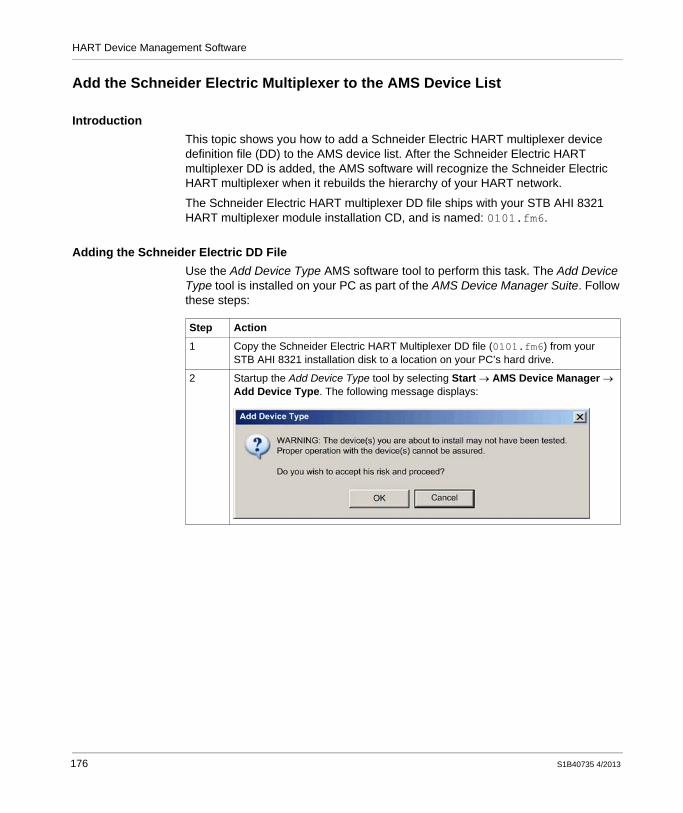
HART Device Management Software
Add the Schneider Electric Multiplexer to the AMS Device List
IntroductionThis topic shows you how to add a Schneider Electric HART multiplexer device definition file (DD) to the AMS device list. After the Schneider Electric HART multiplexer DD is added, the AMS software will recognize the Schneider Electric HART multiplexer when it rebuilds the hierarchy of your HART network.
The Schneider Electric HART multiplexer DD file ships with your STB AHI 8321 HART multiplexer module installation CD, and is named: 0101.fm6.
Adding the Schneider Electric DD FileUse the Add Device Type AMS software tool to perform this task. The Add Device Type tool is installed on your PC as part of the AMS Device Manager Suite. Follow these steps:
Step Action
1 Copy the Schneider Electric HART Multiplexer DD file (0101.fm6) from your STB AHI 8321 installation disk to a location on your PC’s hard drive.
2 Startup the Add Device Type tool by selecting Start → AMS Device Manager → Add Device Type. The following message displays:
176 S1B40735 4/2013

HART Device Management Software
3 Click OK. The following navigation dialog opens:
4 Click Browse... to open the following navigation dialog:
5 Click in the Directories area of this dialog to navigate to and select the folder that contains the Schneider Electric HART multiplexer DD file. In this case, that path is C:\AMS\006058\e1b1.
Step Action
S1B40735 4/2013 177

HART Device Management Software
6 Click OK to close the Select Source Directory dialog. The selected directory appears as the Source Directory:
7 Click OK to close the Add Device Type dialog.
8 The following dialog may open:
If this dialog opens, enter the following information:: Schneider ElectricDevice’s name: HRM V1.0
Click OK to close the dialog.
Step Action
178 S1B40735 4/2013

HART Device Management Software
9 The following message appears, indicating the Schneider Electric HART multiplexer DD file is saved to the AMS device list:
Click OK to close the message.
Step Action
S1B40735 4/2013 179

HART Device Management Software
Creating a HART Multiplexer Network
IntroductionThe first task to perform when working with Emerson Process Management’s AMS Device Manager, Version 10.5 software is to create a new HART multiplexer network. To do this, use the Network Configuration tool that installs on your PC as part of the AMS Device Manager Suite.
Creating a New HART NetworkFollow these steps to create a new HART multiplexer network:
Step Action
1 Install the AMS Device Manager, Version 10.5 software, following the manufacturer’s installation instructions.
2 Startup the Network Configuration tool, by selecting Start → AMS Device Manager → Network Configuration. The Network Configuration dialog opens:
180 S1B40735 4/2013

HART Device Management Software
3 Click Add. The Select Network Component Type dialog opens:
4 Select Multiplexer Network, then click Install.... The following dialog opens for starting the new network wizard:
Step Action
S1B40735 4/2013 181

HART Device Management Software
5 Click Next. The following dialog opens for naming the new network:
Step Action
182 S1B40735 4/2013

HART Device Management Software
6 For the purpose of this example, accept the default network name Multiplexer Network 1, then click Next>. The following dialog opens:
Step Action
S1B40735 4/2013 183

HART Device Management Software
7 In the Connection dialog, define the COM port connection the new multiplexer network will use. Enter the following settings:
COM Port: Select COM 6. This is the same COM port that was previously configured using the Eltima software (see page 173). Baud Rate: Select 9600. Network Timeout: Accept the default value of 1000. Communication Retries: Select 2. HART Busy retries: Select 5. RS485 addresses: Select from 0 to 1. Multiplexer HART Master Mode: Select Primary master.
Click Next>. The Connection dialog closes, and the Network Configuration dialog displays the new network:
8 Click Close to close the Network Configuration tool.
Step Action
184 S1B40735 4/2013

HART Device Management Software
Managing HART Network Devices
IntroductionThe next task is to open the AMS Device Manager tool, confirm that it includes the Schneider Electric HART multiplexer in its device list, then automatically discover the HART instruments connected to the Schneider Electric HART multiplexer. The AMS Device Manager tool installed on your PC when as part of the AMS Device Manager Suite.
S1B40735 4/2013 185

HART Device Management Software
Discovering the New NetworkTo view the HART instruments connected to the new network, follow these steps:
Step Action
1 Startup the AMS Device Manager by selecting Start → AMS Device Manager → AMS Device Manager. The following Login dialog opens:
2 Type in your Username/Password combination.NOTE: You created the Username/Password combination when you installed the AMS Device Manager on your PC.
3 Click OK. The AMS Device Manager opens:
4 Click on the Device List node (above) to confirm there is a folder for Schneider Electric. This confirms the Schneider Electric HART multiplexer DD has been added to the AMS device list.
186 S1B40735 4/2013

HART Device Management Software
5 Open the Physical Networks node to display the new network Multiplexer Network 1, then click the right mouse button to display the following menu:
6 Select Rebuild Hierarchy (above). The AMS Device Manager software searches for HART devices connected to the network. The software adds a new node to the physical network tree when it discovers the Schneider Electric HART multiplexer:
Step Action
S1B40735 4/2013 187

HART Device Management Software
7 Select the new HART multiplexer node in the left pane to display a list of connected HART field instrument in the right pane.
8 You can right click on an item listed in the right pane to display a menu, which you can use to open monitoring, configuration, and diagnostic windows relating to that device.NOTE: Consult the documentation provided by the vendor of the device management software and the HART field instruments for instructions on how to work use the software in conjunction with the HART instruments.
Step Action
188 S1B40735 4/2013

HARTGlossaryS1B40735 4/2013
Glossary
A
analog inputA module that contains circuits that convert analog input signals to digital values that can be manipulated by the processor. By implication, these analog inputs are usually direct. That means a data table value directly reflects the analog signal value.
analog outputA module that contains circuits that transmit an analog signal proportional to a digital value input to the module from the processor. By implication, these analog outputs are usually direct. That means a data table value directly controls the analog signal value.
asset management softwareA software application that can configure, monitor, and manage devices employed as part of an industrial automation system.
asynchronousCommunication mode typified by the absence of a global, fixed-rate clock signal. Instead, asynchronous communication control is spread among multiple devices, that communicate and synchronize over shared channels.
auto addressingThe automatic assignment of an address to each island bus I/O module.
S1B40735 4/2013 189

Glossary
auto configurationThe ability of island modules to operate with predefined default parameters. A configuration of the island bus based completely on the actual assembly of I/O modules.
B
basic I/OLow-cost STB input/output modules that use a fixed set of operating parameters. A basic I/O module cannot be re-configured with the Advantys configuration software, and cannot be used in reflex actions.
basic NIMA low-cost STB network interface module that supports up to 12 STB I/O modules. A basic NIM does not support the Advantys configuration software, reflex actions, nor the use of an HMI panel.
basic PDMA low-cost STB PDM that distributes sensor power and actuator power over a single field power bus on the island. The bus provides a maximum of 4 A total power. A basic PDM requires a 5 A fuse to help protect the I/O.
Bell 202 FSK standardA standard defining the operation of frequency shift keying: a frequency modulation scheme that transmits digital information by means of discrete frequency changes in a carrier wave.
BootPBootstrap Protocol: A UDP/IP protocol that allows an internet node to obtain its IP parameters based on its MAC address.
BOSBeginning of Segment: An STB XBE 1300 BOS module is installed in the first position in an extension segment, when the STB island consists of more than one segment. Its job is to carry island bus communications to—and provide logic power for—the modules in the extension segment.
190 S1B40735 4/2013

Glossary
C
configurationThe arrangement and interconnection of hardware components within a system, and the hardware and software settings that determine the operating characteristics of the system.
current loopAn analog electrical signaling scheme, that allows a device to be monitored or controlled over a pair of conductors. Only one current level can exist in a current loop at any point in time. A digital signal can be added to the analog current loop using the HART protocol, enabling additional communication with the analog device.
D
DDLDevice Description Language file: A definitional template for a HART field instrument, that describes its configurable parameters, the data that it can produce, and its operating procedures, including menus, commands and display formats.
device nameA user-defined, unique identifier for an Ethernet NIM. A device name (or role name) is created when you combine the upper and lower numeric rotary switch values with the NIM (for example, STBNIP2212_123). After the NIM is configured with a valid device name, a DHCP server can use it to identify the island and provide an IP address to the NIM at power up.
DHCPDynamic Host Configuration Protocol. A TCP/IP protocol that allows a server to assign an IP address based on a device name (host name) to a network node.
DINDeutsche Industrial Norms. A German agency that sets engineering and dimensional standards and now has worldwide recognition.
S1B40735 4/2013 191

Glossary
DTMDevice Type Manager. A DTM is a software component that acts as a device driver. It contains information for configuring, diagnosing, and maintaining particular field devices. Many manufacturers provide device-specific DTMs, but a generic DTM can be used to drive a wide variety of devices.
E
EIAElectronic Industries Association: An organization that establishes electrical/electronic and data communication standards.
EMCelectromagnetic compatibility: Devices that meet EMC requirements can operate within a system’s expected electromagnetic limits without interruption.
EMIelectromagnetic interference: EMI can cause an interruption or disturbance in the performance of electronic equipment. It occurs when a source electronically transmits a signal that interferes with other equipment. Also known as radio frequency interference (RFI).
EOSEnd of Segment: An STB XBE 1100 EOS module is installed in the last position in every segment that has an extension following it, when an island consists of more than 1 segment. The EOS module extends island bus communications to the next segment.
EthernetA 10 or 100 Mb/s, CSMA/CD, frame-based LAN that can run over twisted pair or fiber optic cable, or wireless. The IEEE standard 802.3 defines the rules for configuring a wired Ethernet network; the IEEE standard 802.11 defines the rules for configuring a wireless Ethernet network.
192 S1B40735 4/2013

Glossary
F
fallback stateA known state to which an STB I/O module can return in the event that it loses communication with the PLC.
FEfunctional ground: A grounded supply conductor, often carrying current, that is used to enhance the operation of equipment. Contrast: protective ground (PE).
Flash memoryNonvolatile memory that can be overwritten. It is stored on an EEPROM that can be erased and reprogrammed.
H
half duplexA system of communication that provides for transmissions in both directions, but in only one direction at a time.
HARTHighway Addressable Remote Transducer protocol: A bi-directional communication protocol for transmitting—across analog wires—digital information between intelligent field devices and a host control/monitoring system. For more information, refer to the HART Communication Foundation web site: www.hartcomm.org.
HART interface moduleA modem that serves as the pass through device between one or more HART master devices, and multiple HART slave devices. In STB the STB AHI 8321 module.
HART masterA HART host application, typically resident in a PC. For example, asset management software.
S1B40735 4/2013 193
Glossary
HART slaveA HART compliant smart field device, which responds via the HART protocol only when commanded to do so by a HART master.
high pass filterA frequency-based filter that permits transmissions only above a pre-set frequency threshold to pass. In HART, the frequency threshold is typically set in range of 400...800 Hz: transmissions above this threshold—HART digital signals—are allowed to pass through; transmissions beneath this threshold are filtered.
HMIhuman-machine interface: An operator interface, usually graphical, used by operators of industrial equipment.
hot swappingReplacing a component with a like component while the system remains operational. When the replacement component is installed, it begins to function automatically.
I
I/O baseA mounting device, designed to seat an STB I/O module, connect the module to a DIN rail, and connect the module to the island bus. The I/O base provides the connection point where the I/O module can receive power from the input or output power bus distributed by a PDM.
I/O moduleIn a programmable controller system, an I/O module interfaces directly to the sensors and actuators of the machine/process. This module is the component that mounts in an I/O base and provides electrical connections between the controller and the field devices.
IECInternational Electrotechnical Commission Carrier: Founded in 1884 to focus on advancing the theory and practice of electrical, electronics and computer engineering, and computer science. EN 61131-2 is the specification that deals with industrial automation equipment.
194 S1B40735 4/2013

Glossary
IEEEInstitute of Electrical and Electronics Engineers, Inc.: The international standards and conformity assessment body for all fields of electrotechnology, including electricity and electronics.
IPInternet Protocol: That part of the TCP/IP protocol family that tracks the internet addresses of nodes, routes outgoing messages, and recognizes incoming messages.
IP ratingingress protection rating: A standardized approach to establishing the degree to which a device resists the ingress of particles and water, as defined by IEC 60529. For example:
IP20 requires that a device not permit the ingress and contact of objects larger than 12.5 mm (0.49 in). The standard does not require resistance to ingress by water.IP67 requires that a device completely resist the ingress of dust and contact by objects. The standard requires that no Ingress of water in harmful quantity be permitted when the enclosure is immersed in water up to 1 m (39.37 in).
L
low pass filterA frequency-based filter that permits transmissions only below a pre-set frequency threshold to pass. In HART, the frequency threshold is typically set in range of 25 Hz: transmissions below this threshold—analog signals—are allowed to pass through; transmissions above this threshold—HART digital signals—are filtered.
M
MAC addressMedia Access Control address: A 48-bit number, unique on a network, that is programmed into each network card or device when it is manufactured.
S1B40735 4/2013 195
Glossary
mandatory moduleAn STB I/O module configuration setting that requires the module to be present and healthy in the island configuration, if the island is to remain operational. If a mandatory module is inoperable or is removed from its location on the island bus, the island goes to a pre-operational state. By default, all I/O modules are not mandatory. Use the Advantys configuration software to set this parameter.
ModbusAn application layer messaging protocol. Modbus provides serial communications between master and slave devices connected on different types of buses or networks.
multiplexerA multiplexer (MUX) is a device that selects one of several input signals and forwards the selected input into a single line. In STB, an island consisting of a HART enabled Ethernet network interface module and from 1 to 8 HART interface modules perform the task of multiplexer.
N
NaNNot a number: A numeric data type value representing an undefined or unrepresentable value.
NEMANational Electrical Manufacturers Association
NIMnetwork interface module: The interface between an island bus and the fieldbus network of which the island is a part. A NIM enables all the I/O on the island to be treated as a single node on the fieldbus. The NIM also provides 5 V of logic power to the STB I/O modules in the same segment as the NIM. The HART multiplexer uses the STB NIP 2311 Ethernet NIM.
196 S1B40735 4/2013

Glossary
P
PDMpower distribution module: A module that distributes either field power to a cluster of input and output modules, located directly to its right, on the island bus. For the HART multiplexer, you can use either the STB PDT 3100 standard NIM, or the STB PDT 3105 basic NIM.
PEprotective ground: An equipment grounding conductor that keeps the exposed conductive surfaces of equipment at earth potential. A PE conductor does not enhance or facilitate the operation of the equipment. Its purpose is to guard the operator against potential electric shock. Contrast: functional ground (FE).
PLCprogrammable logic controller: The PLC is a digital computer used for automation of electromechanical processes, such as control of machinery. PLCs are used in many industries and machines. The PLC is designed to:
communicate via multiple inputs and outputsoperate in an extended range of temperaturesperform under conditions that may include dust, water, electrical noise, vibration and impact
Programs to control machine operation are typically stored in non-volatile memory. A PLC is designed to provide highly deterministic performance, within predictable time boundaries.
primary masterIn HART, when two master devices are connected to the HART communication network, the HART controller. The HART primary master is typically asset management software resident on a PC.
process imageA part of the NIM firmware that serves as a real-time data area for the data exchange process. The process image includes an input buffer that contains current data and status information from the island bus and an output buffer that contains the current outputs for the island bus, from the fieldbus master.
S1B40735 4/2013 197

Glossary
R
reflex actionA simple, logical command function configured locally on an island bus I/O module. Reflex actions are executed by island bus modules on data from various island locations, like input and output modules or the NIM. Examples of reflex actions include compare and copy operations.
RFIradio frequency interference: See EMI.
S
secondary masterIn HART, when two master devices are connected to the HART communication network, a hand-held master device temporarily connected to the network.
segmentA group of interconnected I/O and power modules on an island bus. An island consists of at least 1 segment and, depending on the type of NIM used, may have as many as 7 segments. The first (leftmost) module in a segment needs to provide logic power and island bus communications to the I/O modules on its right. In the primary segment, that function is filled by a NIM. In an extension segment, that function is filled by a BOS module.
SELVsafety extra low voltage: A secondary circuit designed so that the voltage between any 2 accessible parts (or between 1 accessible part and the PE terminal for Class 1 equipment) does not exceed a specified value under normal conditions or under single point of failure conditions. Schneider Electric’s Phaseo ABL8 range of power supplies has products that comply with the SELV standard in IEC/EN 60364-4-41.
SIMsubscriber identification module. In STB, configuration data created or modified with the Advantys configuration software can be stored on a SIM (referred to as the “removable memory card”) and then written to the NIM’s Flash memory.
198 S1B40735 4/2013

Glossary
sink loadAn output that, when turned on, receives DC current from its load.
size 1 baseA mounting device, designed to seat an STB module, connect it to a DIN rail, and connect it to the island bus. It is 13.9 mm (0.55 in.) wide and 128.25 mm (5.05 in.) high.
size 2 baseA mounting device, designed to seat an STB module, connect it to a DIN rail, and connect it to the island bus. It is 18.4 mm (0.73 in.) wide and 128.25 mm (5.05 in.) high.
size 3 baseA mounting device, designed to seat an STB module, connect it to a DIN rail, and connect it to the island bus. It is 28.1 mm (1.11 in.) wide and 128.25 mm (5.05 in.) high.
source loadA load with a current directed into its input; it is driven by a current source.
standard I/OAny of a subset of STB input/output modules designed at a moderate cost to operate with user-configurable parameters. A standard I/O module may be reconfigured with the Advantys configuration software, and may be used in reflex actions.
standard NIMAn STB network interface module designed at moderate cost to support the configuration capabilities, multi-segment design and throughput capacity suitable for many standard applications on the island bus. An island run by a standard NIM can support up to 32 addressable I/O modules. The HART multiplexer uses the STB NIP 2311 standard NIM.
standard PDMA standard PDM (power distribution module) is an STB module that distributes sensor power to the input modules and actuator power to the output modules over two separate power buses on the island. The bus provides a maximum of 4 A to the input modules and 8 A to the output modules. A standard PDM requires a 5 A fuse to help protect the input modules and an 8 A fuse to help protect the outputs. The HART multiplexer supports the use of the STB PDT 3100 standard PDM.
S1B40735 4/2013 199

Glossary
T
TCPtransmission control protocol:. A connection-oriented transport layer protocol that provides full-duplex data transmission. TCP is part of the TCP/IP suite of protocols.
200 S1B40735 4/2013

HARTIndexS1B40735 4/2013
CBA
Index0-9140 ACI 030 00
wiring, 143140 ACO 020 00
wiring, 144
AAMS software
add Schneider Electric DD file, 176create network, 180discover network, 185
analog I/Ocurrent consumption, 57
analog I/O modulesCE compliance for, 85
auto-configure, 100
BBMX AMI 0410
wiring, 153BMX AMO 0210
wiring, 154BootP server, 95
Cconfiguration
custom, 103default, 100
cooling the cabinet, 46
S1B40735 4/2013
current consumptionanalog I/O, 57EOS, 57HART interface module, 57
current loop resistancecalculating, 133
custom configuration, 121, 123
Ddefault IP address, 98device description language file, 25DHCP server, 95DIN rail
installing, 64
EEltima software, 172enclosing the multiplexer, 42EOS module
current consumption, 57EOS/BOS modules compatibility
installing extension segments, 77extending the island bus, 40extension segments
installing, 76external power supplies
recommended, 61selecting, 60
201

Index
FFE, 84Flash memory, 101
overwriting, 121functional ground, 84
Ggetting started, 9
Hhalf-duplex, 25HART protocol, 24
Iinitial configuration, 122input power, 54installation plan, 68installing extension segments
EOS/BOS modules compatibility , 77IP address
default, 98MAC address, 98setting, 95
IP addresssetting, 95
island buscreating, 68extending, 40terminating, 71
island bus node address, 95Isolation requirements, 80
Llogic power, 52
MM340 I/O wiring, 151MAC address, 98mandatory module, 113
202
multiplexercomponents, 26enclosing, 42features, 28functions, 29HART data flows, 31I/O placement, 32island components, 34maximum size, 27
Nnetwork considerations, 122NIM
installing, 65not present, 113
Ooutput power, 54
PPE, 82power distribution modules, 47power supplies
logic bus current capacity, 56Premium I/O wiring, 146protective ground, 82
QQuantum I/O wiring, 141
Rreflex actions, 113removable memory card, 123, 125resistance
current loop, 133RFI/EMI
suppressing with EMC kit, 85rise and fall times
analog outputs, 134rotary switches, 95
S1B40735 4/2013

Index
RST button, 101
SSELV-rated isolation
in the 24 Vdc power source, 80Serial to Ethernet Connector, 172STB ACI 8320
wiring, 137STB ACO 0220
wiring, 139STB AHI 8321 module
adding data items, 114channel settings, 105configuring, 103current consumption, 57IO image, 110mandatory, 112mapping data items, 108
STB I/O wiring, 136STB modules
installing, 73STB PDT 310x
power supply capacity, 58STB XMP 4440 removable memory card
installing, 124removing, 125
STB XTS 1120 screw type power connector, 77STB XTS 2120 spring clamp field wiring con-nector, 77storing configuration data
to a removable memory card, 123
TTSX AEY 810
wiring, 148TSX ASY 420
wiring, 149
VVirtual Placeholders, 113
S1B40735 4/2013
voltage cut-out switchingadvantages, 81relays for, 81
Wwattage dissipation
in a system cabinet, 46wiring
140 ACI 030 00, 143140 ACO 020 00, 144BMX AMI 0410, 153BMX AMO 0210, 154M340 I/O, 151Premium I/O, 146Quantum I/O, 141STB ACI 8320, 137STB ACO 0220, 139STB I/O, 136TSX AEY 810, 148TSX ASY 420, 149
wiring diagramactuator power, 128logic power, 128sensor power, 128
203

Index
204 S1B40735 4/2013