vertamill 220 hs/5 - Cloudinary
161
-
Upload
khangminh22 -
Category
Documents
-
view
0 -
download
0
Transcript of vertamill 220 hs/5 - Cloudinary

GRETONE LtdTEMPLE ROAD
LEICESTER. LE5 4JGENGLAND
VERTAMILL 220 HS/5
Machine number : 8264Year : 1999
Your order : C0N0000639, 29th October 1999
MAINTENANCE MANUAL

GRETONE VERTAMILL 220 HS/5 Maintenance Manual
26/01/2001
N/ref: 8264 Y/ref: C0N0000639
P.I Table of contents.
INTRODUCTION Our Machines and Milling Heads, which are tested, before shipment, including geometry positioning and repeatability as well as a verification of all machine functions, have been designed and built by experienced designer and assembler with the latest practical features and with the relevant factory safety regulations. However, hazards still exists. Therefore safety measures must be strictly observed, that is to say: - not to use this machine or these components in applications not allowed; - to provide a right maintenance which will ensure the safety conditions to the machine service and its permanency; - before to use the machine, the involved staff (operators, maintenance dept.) must have studied and understood the manual, in particular safety and hazards warnings; - to avoid the machine service in duty atmosphere (wood, ceramic, graphite, ... duty) and important temperature fluctuation. We deny all responsibility for material damage and accidents to everyone in the machine area when the safety instructions of Maintenance and Operator Manual are not strictly observed. Although the machine is equipped to a numeric control system, it can not be considered as able to perform automatically. The quality of pieces will depend on the operator’s abilities who, despite an automatic cycle used by the numeric control of the machine, has to control the machining and his parameters. So the operator of this machine would have to be qualified, to know the machining, to follow a training and to be aware of the inevitable risk due to the rotation of the cutting tool.
GRETONE VERTAMILL 220 HS/5 Maintenance Manual
26/01/2001
N/ref: 8264 Y/ref: C0N0000639
P.II Table of contents.
How to use this manual This maintenance manual is designed to help you quickly find the information you need on your machine. It describes the machine mechanical and electrical features, the required maintenance and the suggested spare parts. The manual is divided in 6 parts, related to six different aspects of your milling machine. The first part, Basics, gives a general description of the machine and its components. It contains reference drawings, to help you quickly find where the components are located on the machine. This parts includes section 1 (General description) only. The second part, Safety, gives a description of the machine and operator safety devices. This parts includes section 2 (Safety) only. The third part, Mechanical description, gives detailed information on the axes (section 3), the milling head (section 4), the hydraulic and pneumatic system (section 5) as well as the machine accessories (section 6). Major technical specifications for the mechanical components can be found in this part. The fourth part, Electrical description, provides all the information on the electrical layout of the machine, plus the configuration of its CNC. If you need information on the layout of any electrical components or cables, you can identify them on the diagrams (section 7 and appendices), and then find the parts name and features in the parts and cables lists or if you need to replace an electrical part, you will find the part number. The fifth part of this manual, Maintenance and repairs, provides the needed information to keep the machine in good working order. If you need information on the machine maintenance, you will find a description of the maintenance tasks in section 8. If you need to order a replacement part, you will find the spare parts list in section 9, which also gives you the information needed to establish a replacement parts stock, with the recommended quantities, shipment delays, priorities, etc. Finally, the sixtieth part of this manual, References, gives additional information on the machine and its components. If you need to check a specific drawing, you can consult the list of drawings provided with this manual (section 10). If you want technical specifications for a spare part, you should refer to section 11 (Documentation) or to the manufacturer’s manuals accompanying this machine.
GRETONE VERTAMILL 220 HS/5 Maintenance Manual
26/01/2001
N/ref: 8264 Y/ref: C0N0000639
P.III Table of contents.
TABLE OF CONTENTS Introduction...............................................................................................................................I How to use this manual............................................................................................................ II
PART 1 - BASICS SECTION 1. GENERAL DESCRIPTION......................................................................1-1
1.1. MACHINE DESCRIPTION.................................................................................... 1-1 1.2. MACHINE STRUCTURE....................................................................................... 1-5
1.2.1. Worktable (bed + table).................................................................................... 1-5 1.2.2. Gantry............................................................................................................... 1-5 1.2.3. Columns and crossrail........................................................................................ 1-5 1.2.4. Saddle .............................................................................................................. 1-6 1.2.5. Ram.................................................................................................................. 1-6 1.2.6. Milling head....................................................................................................... 1-6
1.3. MACHINE AXES ................................................................................................... 1-7 1.4. MECHANICAL SPECIFICATIONS...................................................................... 1-9 1.5. OPERATING CONDITIONS............................................................................... 1-13
1.5.1. Electrical requirements..................................................................................... 1-13 1.5.2. Environmental requirements ............................................................................. 1-13
PART 2 - SAFETY
SECTION 2. SAFETY......................................................................................................2-1
2.1. APPROVED APPLICATIONS............................................................................... 2-1 2.2 ORGANIZATIONAL MEASURES ........................................................................ 2-2 2.3. SAFETY MEASURES (AND SLINGING) ............................................................. 2-3 2.4. HAZARDS............................................................................................................... 2-9
2.4.1. Inherent Spindle hazards.................................................................................. 2-10 2.4.2. Other hazards.................................................................................................. 2-10
2.4.2.1. Electrical hazards...................................................................................... 2-10 2.4.2.2. Hydraulic hazards ..................................................................................... 2-10 2.4.2.3. Pneumatic hazards .................................................................................... 2-10 2.4.2.4. Coolant unit hazards.................................................................................. 2-10 2.4.2.5. Oil and cooling fluid .................................................................................. 2-11 2.4.2.6. Environmental protection........................................................................... 2-11
2.5. OPERATOR & MACHINE SAFETY SYSTEM ................................................... 2-12 2.5.1. MACHINE SAFETY SYSTEM..................................................................... 2-12 2.5.2. OPERATOR SAFETY SYSTEM................................................................... 2-12

GRETONE VERTAMILL 220 HS/5 Maintenance Manual
26/01/2001
N/ref: 8264 Y/ref: C0N0000639
P.IV Table of contents.
PART 3 - MECHANICAL DESCRIPTION SECTION 3. AXES...........................................................................................................3-1
3.1 X-AXIS ................................................................................................................... 3-1 3.1.1 Drive................................................................................................................ 3-1 3.1.2 Guiding ............................................................................................................. 3-4
3.2 Y AXIS.................................................................................................................... 3-6 3.2.1 Drive................................................................................................................. 3-6 3.2.2 Guiding ............................................................................................................. 3-8
3.3 Z AXIS .................................................................................................................. 3-10 3.3.1 Drive............................................................................................................... 3-10 3.3.3 Guiding ........................................................................................................... 3-13
SECTION 4. MILLING HEAD.......................................................................................4-1
4.1. SPINDLE................................................................................................................. 4-2 4.2. C-AXIS ................................................................................................................... 4-6 4.4. A/B AXIS ................................................................................................................ 4-8
SECTION 5. HYDRAULIC ET PNEUMATIC SYSTEMS...........................................5-1
5.1. HYDRAULIC SYSTEM.......................................................................................... 5-1 Hydraulic diagramm........................................................................................ 5-2
5.2. PNEUMATIC SYSTEM........................................................................................ 5-10 Pneumatic diagramm .................................................................................... 5-11 SECTION 6. PERIPHERAL SYSTEMS.........................................................................6-1
6.1. AUTOMATIC TOOL CHANGER.......................................................................... 6-1 6.2. PROBE ............................................................................................................ 6-4 6.3. LASER MEASURING SYSTEM ............................................................................ 6-5 6.4 CENTRALIZED LUBRICATION ........................................................................... 6-6 6.5 FLOOD COOLANT UNIT..................................................................................... 6-9 6.6 COOLANT UNIT ................................................................................................. 6-11 6.7 CHIP CONVEYORS ............................................................................................ 6-15 6.8 CONTROL SYSTEM............................................................................................ 6-16
6.8.1 Position control system.................................................................................... 6-16 6.8.2 Limitation control system................................................................................. 6-16

GRETONE VERTAMILL 220 HS/5 Maintenance Manual
26/01/2001
N/ref: 8264 Y/ref: C0N0000639
P.V Table of contents.
PART 4 - ELECTRICAL DESCRIPTION SECTION 7. ELECTRICAL MAINTENANCE.............................................................7-1
7.1. INHERENT PRODUCT HAZARDS ....................................................................... 7-1 7.2. ELECTRICAL INSPECTIONS............................................................................... 7-2
7.2.1. Periodic inspection............................................................................................ 7-2 7.2.1.1 Pneumatic unit .............................................................................................. 7-2 7.2.1.2 Hydraulic system.......................................................................................... 7-3 7.2.1.3 Work lights (Wahlman)................................................................................. 7-3
7.2.2. Electrical cabinets inspection.............................................................................. 7-3 7.2.3. Recommended electrical maintenance chart........................................................ 7-3
7.3. CNC MAIN CONSOLES....................................................................................... 7-4 ELECTRICAL DIAGRAMM AND PART LIST............................................................... 7-5
Dominique DELAIRE
HLMO
Only on paper
GRETONE VERTAMILL 220 HS/5 Maintenance Manual
26/01/2001
N/ref: 8264 Y/ref: C0N0000639
P.VI Table of contents.
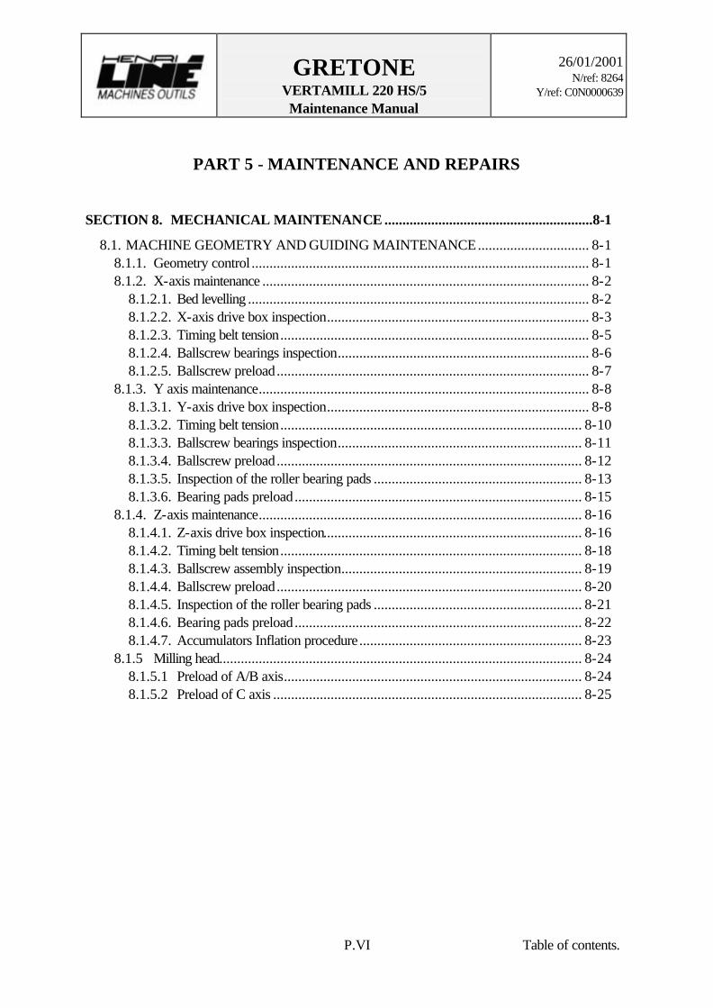
PART 5 - MAINTENANCE AND REPAIRS
SECTION 8. MECHANICAL MAINTENANCE ..........................................................8-1
8.1. MACHINE GEOMETRY AND GUIDING MAINTENANCE............................... 8-1 8.1.1. Geometry control .............................................................................................. 8-1 8.1.2. X-axis maintenance ........................................................................................... 8-2
8.1.2.1. Bed levelling ............................................................................................... 8-2 8.1.2.2. X-axis drive box inspection......................................................................... 8-3 8.1.2.3. Timing belt tension...................................................................................... 8-5 8.1.2.4. Ballscrew bearings inspection...................................................................... 8-6 8.1.2.5. Ballscrew preload....................................................................................... 8-7
8.1.3. Y axis maintenance............................................................................................ 8-8 8.1.3.1. Y-axis drive box inspection......................................................................... 8-8 8.1.3.2. Timing belt tension.................................................................................... 8-10 8.1.3.3. Ballscrew bearings inspection.................................................................... 8-11 8.1.3.4. Ballscrew preload..................................................................................... 8-12 8.1.3.5. Inspection of the roller bearing pads .......................................................... 8-13 8.1.3.6. Bearing pads preload................................................................................ 8-15
8.1.4. Z-axis maintenance.......................................................................................... 8-16 8.1.4.1. Z-axis drive box inspection........................................................................ 8-16 8.1.4.2. Timing belt tension.................................................................................... 8-18 8.1.4.3. Ballscrew assembly inspection................................................................... 8-19 8.1.4.4. Ballscrew preload..................................................................................... 8-20 8.1.4.5. Inspection of the roller bearing pads .......................................................... 8-21 8.1.4.6. Bearing pads preload................................................................................ 8-22 8.1.4.7. Accumulators Inflation procedure.............................................................. 8-23
8.1.5 Milling head..................................................................................................... 8-24 8.1.5.1 Preload of A/B axis................................................................................... 8-24 8.1.5.2 Preload of C axis ...................................................................................... 8-25

GRETONE VERTAMILL 220 HS/5 Maintenance Manual
26/01/2001
N/ref: 8264 Y/ref: C0N0000639
P.VII Table of contents.
8.2. LUBRICATION AND FLUIDS MAINTENANCE............................................... 8-27
8.2.1. Centralized lubrication (point N° 1 & 2)........................................................... 8-28 8.2.2. Flood coolant (point N° 3, 4, 5 & 6) ............................................................... 8-29 8.2.3. Hydraulic unit (point N° 7, 8 & 9).................................................................... 8-30 8.2.4. Coolant unit (point N° 10 & 11) ...................................................................... 8-31 8.2.5. Pneumatic unit – Lubrication (point N° 12 to 21).............................................. 8-32
8.2.5.1 Conditioning (n° 12 & 13)......................................................................... 8-32 8.2.5.2 Scales – DA200 (n° 14 & 15) .................................................................. 8-33 8.2.5.3 Electrospindle (n° 16 to 20) ...................................................................... 8-34 8.2.5.4. Laser control system BLUM (n° 19) ......................................................... 8-35
8.2.6. Lubrication procedure of the A/B and C axes bearings (n° 22) ......................... 8-36 8.2.7. Bearings of Ballscrew (n° 23) .......................................................................... 8-39 8.2.8. Automatic Tools Changer (point N° 24, 25 & 26)............................................. 8-39
CONVERSION TABLE OF OIL AND GREASE............................................ 8-40 LUBRICATION AND MAINTENANCE INSTRUCTIONS CHART .............. 8-41 SECTION 9. SPARE PARTS...........................................................................................9-1
9.1. X-AXIS (DRIVE AND GUIDING) ......................................................................... 9-2 9.2. Y-AXIS (DRIVE AND GUIDING) ......................................................................... 9-3 9.3. Z-AXIS (DRIVE AND GUIDING).......................................................................... 9-4 9.4. MILLING HEADS................................................................................................... 9-6
9.4.1. Bottom of Head ................................................................................................ 9-6 9.4.2. C axis ............................................................................................................... 9-8 9.4.3. Attachment........................................................................................................ 9-9 9.4.4. B-axis and Electrospindle ................................................................................ 9-10
9.5. PNEUMATIC, HYDRAULIC & LUBRICATION UNIT...................................... 9-11
PART 6 - REFERENCES SECTION 10 - DRAWINGS LIST.................................................................................10-1 SECTION 11 - DOCUMENTATION.............................................................................11-1
HLMO
Only on paper
HLMO
Only on paper

BASICS

GRETONE VERTAMILL 220 HS/5 Maintenance Manual
26/01/2001
N/ref: 8264 Y/ref: C0N0000639
P. 1-1 Section 1 : General description
1. GENERAL DESCRIPTION
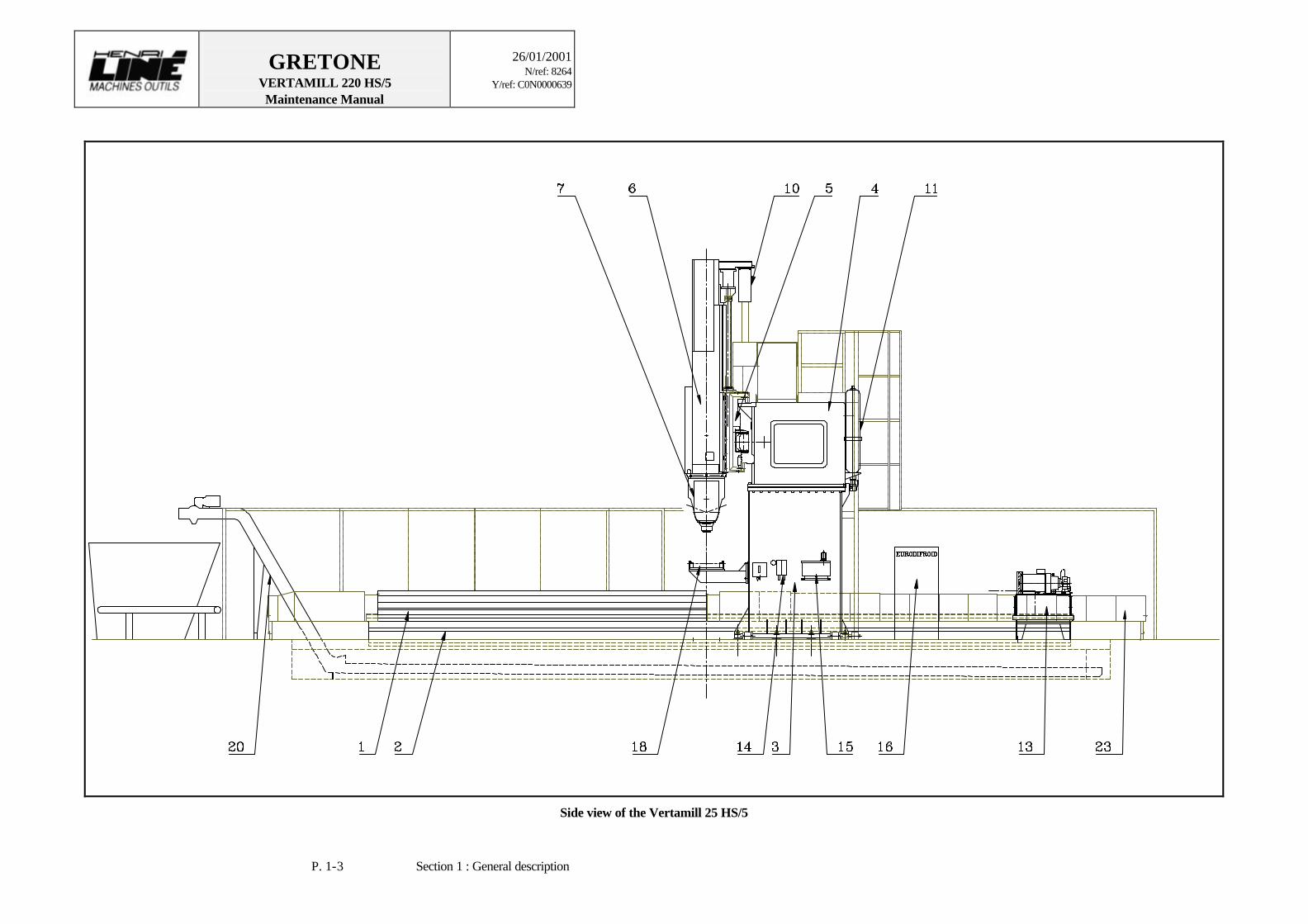
1.1. MACHINE DESCRIPTION The Vertamill 220 HS/5 is a vertical gantry type milling machine with 5 axes which has been built to deliver maximum performance for heavy duty machining of a large range of materials. The machine incorporates the latest practical features of numerically controlled milling machines including anti-friction way bearings for all power operated slide movements. Particular attention has been given to the reduction of the number of parts required. All components of the machine are carefully designed in order to provide and maintain the performances and accuracy stated in the technical specifications. Every component is made of high strength fabricated steel weldments or castings. They are heavily ribbed and stress relieved to ensure sufficient strength and rigidity needed to properly withstand allowable loads with a minimum wear and the least possible deflection. The machine is schematized on pages 1-2, 1-3 and 1-4. The following elements refer to this drawing.
1. Bed 14. Pneumatic filters 2. Worktable 15 (Centralised or Spindle) Lubrication 3. Columns 16 Coolant unit 4. Crossrail 17 Flood coolant unit 5. Saddle 18. Tool control 6. Ram 19. Automatic Tool Changer 7. Milling Head 20. Chip conveyor 8. X-axis drive unit 21. Electrical cabinet 9. Y-axis drive unit 22. NC (+ auxilliary) 10. Z-axis drive unit 23. Protection by bellows or telescopic plate 11. Accumulator 24. Attachment changer 12. Counterbalance hyd. cylinder 25. Electrical line in 13. Hydraulic unit 26. Compressed air in

GRETONE VERTAMILL 220 HS/5 Maintenance Manual
26/01/2001
N/ref: 8264 Y/ref: C0N0000639
P. 1-2 Section 1 : General description
Front view of the Vertamill 25 HS/5
GRETONE VERTAMILL 220 HS/5 Maintenance Manual
26/01/2001
N/ref: 8264 Y/ref: C0N0000639
P. 1-3 Section 1 : General description
Side view of the Vertamill 25 HS/5

GRETONE VERTAMILL 220 HS/5 Maintenance Manual
26/01/2001
N/ref: 8264 Y/ref: C0N0000639
P. 1-4 Section 1 : General description
Plan view of the Vertamill 25 HS/5

GRETONE VERTAMILL 220 HS/5 Maintenance Manual
26/01/2001
N/ref: 8264 Y/ref: C0N0000639
P. 1-5 Section 1 : General description
1.2. MACHINE STRUCTURE
The main structural elements are described below. The basic machine configuration is made of three linear axes and one rotary axis movements which can be manually and automatically controlled with a CNC console and mobile pendants. All the major structural elements are heavily ribbed for maximal rigidity and they are stress relieved.
1.2.1. Bed and Worktable
The bed section can be defined as the structural element which support the moving worktable. It is made of welded and stress relieved steel, and it is constituted by two parallel rail guides. The worktable is made of welded and stress relieved steel too and rides the bed.
1.2.2. Gantry
The gantry is the static and the main part of the machine. It is made of the following structural elements: the two columns, the crossrail, the saddle, the ram and the milling head.
1.2.3. Columns and crossrail This assembly rides the bed and the worktable. The crossrail is bolted to the columns and the assembly provides maximum rigidity with minimal vibration. Two guiding ways, for the saddle motion are bolted on the crossrail. These guiding ways have been hardened to 60 HRC and ground and they are protected by bellows installed on each side of the saddle. A “large diameter \ high precision” preloaded ballscrew mounted on that crossrail provides the horizontal thrust transmission to the saddle.

GRETONE VERTAMILL 220 HS/5 Maintenance Manual
26/01/2001
N/ref: 8264 Y/ref: C0N0000639
P. 1-6 Section 1 : General description
1.2.4. Saddle
The saddle is equipped with double sets of preloaded roller bearing pads for the Y-axis & Z-axis movements and providing low friction and high rigidity under all machining conditions.. It rides on the guiding ways(slide ways) of the crossrail, creating the Y-axis movement. It is driven by an AC servo-motor and a "large diameter/high precision" preloaded ball screw. The saddle is designed to receive the ram slide ways creating the Z-axis movement.
1.2.5. Ram
The ram carries its own guiding ways, which ride through the saddle roller bearing pads. The ram is driven by an AC servo-motor and a "large diameter/ high precision" preloaded ball screw. To provide maximum precision, its weight is counterbalanced with hydraulic cylinders fixed to the saddle.
1.2.6. Milling head The 2 rotary axes milling head is permanently mounted to the bottom of square section weldments or rams. It is built in two parts : a U-shaped main casting which includes the gears and bearings for the head rotation (A/B-axis). The spindle housing mounted in the U-shaped casting provides the spindle tilt for the B-axis rotation movement.

GRETONE VERTAMILL 220 HS/5 Maintenance Manual
26/01/2001
N/ref: 8264 Y/ref: C0N0000639
P. 1-7 Section 1 : General description
1.3. MACHINE AXES
The Vertamill 220 - HS/5 has 3 linear axes and 2 rotary axes, which are represented on the photos below. The first linear axis, X, is created by the motion of the gantry on the bed. The second linear axis, Y, is created by the motion of the saddle on the crossrail. The third linear axis, Z, is created by the motion of the ram on the saddle.
Machine axes
X
Y
Z

GRETONE VERTAMILL 220 HS/5 Maintenance Manual
26/01/2001
N/ref: 8264 Y/ref: C0N0000639
P. 1-8 Section 1 : General description
One rotary axis, C, is created by the rotation of the milling head perpendicularly to the
Z-axis. The other rotary axis, A/B, may be explained as follows: when C angle = 0°, the B-axis rotates perpendicularly to Z-axis.
Milling head axes
B
C

GRETONE VERTAMILL 220 HS/5 Maintenance Manual
26/01/2001
N/ref: 8264 Y/ref: C0N0000639
P. 1-9 Section 1 : General description
1.4. MECHANICAL SPECIFICATIONS The following drawings show the machine with the main Machine- and Head-Specifications (Dimensions, travel, feed and Power diagramm).
Dimensions, travel and feed – 1/3

GRETONE VERTAMILL 220 HS/5 Maintenance Manual
26/01/2001
N/ref: 8264 Y/ref: C0N0000639
P. 1-10 Section 1 : General description
Dimensions, travel and feed – 2/3
AXES Feed rates (m/mn) X 0 to 20 m/mn Y 0 to 20 m/mn Z 0 to 15 m/mn

GRETONE VERTAMILL 220 HS/5 Maintenance Manual
26/01/2001
N/ref: 8264 Y/ref: C0N0000639
P. 1-11 Section 1 : General description
Dimensions, travel and feed – 3/3
AXES SPEED C 4 RPM A/B 5 RPM

GRETONE VERTAMILL 220 HS/5 Maintenance Manual
26/01/2001
N/ref: 8264 Y/ref: C0N0000639
P. 1-12 Section 1 : General description
Power diagramm of Spindle
Your Vertamill 220 - HS/5 is equipped with a FANUC 15MB Computer Numerical
Control. The CNC controls the 5 programmable axes, the peripherical units... For a description of the CNC systems please refer to the specifical manuals.

GRETONE VERTAMILL 220 HS/5 Maintenance Manual
26/01/2001
N/ref: 8264 Y/ref: C0N0000639
P. 1-13 Section 1 : General description
1.5. OPERATING CONDITIONS
1.5.1. Electrical requirements To operate, the machine needs the following supply : Tension : 380V Phases : 3 Frequency : 50 Hz Power : 120 KVA Max. Current 175 A Minimal section : 70 mm² x 3 Conducting protection : 35 mm² Power dip : < 20 ms Ground : < 3 OHM Compressed air : pressure 6 b (stop valve) Flow 100m3/h
1.5.2. Environmental requirements
The machine was manufactured and assembled at a constant temperature of 20º C. Major temperature fluctuations can have a bad effect on the geometry of the machine, the lubrication system, the hydraulic system and the electrical components.
To prevent any troubles caused by temperature fluctuations, make sure that the following conditions are met: Humidity: 25 to 80% Temperature: 12 to 35 °C

SAFETY
GRETONE VERTAMILL 220 HS/5 Maintenance Manual
26/01/2001
N/ref: 8264 Y/ref: C0N0000639
P. 2-1 Section 2 : Safety
2. SAFETY
2.1. APPROVED APPLICATIONS The machines HLMO and their components are designed and built for safe operation. However, if not used according to instructions the spindles can cause hazards. The Machine is to be used exclusively for the specifications, which are be constituteds between You and HLMO. Other applications are not approved. HLMO accepts no responsibility for damage caused by non-approved usage. The user carries the full responsibility for any risks. The following points also have to be observed : 1. The full observation and implementation of the procedures, guidelines and information contained in this manual. 2. The prescribed inspection and maintenance intervals. 3. Suitable maintenance of the machine. 4. Operation within the specified environmental and operating conditions.
ø Warning ! In particular, the spindles are not permitted to be used : - as centrifuges of for ventilator operation - in general as a drive - under water If used in the above-mentioned applications, you must expect the spindle to be damaged or, due to the centrifugal force caused by the high rotation speed, parts of the object being driven could fly out.
GRETONE VERTAMILL 220 HS/5 Maintenance Manual
26/01/2001
N/ref: 8264 Y/ref: C0N0000639
P. 2-2 Section 2 : Safety
2.2 ORGANIZATIONAL MEASURES Only persons sufficiently qualified for the work involved and who have the necessary knowledge of the product are permitted to install, operate, service and if necessary repair the machine and his components. It is the responsibility of the customer to ensure that the manual is supplemented by company-internal instructions with respect to supervision, work organization, staff qualification and training, etc. The responsibility for the various tasks involved in the maintenance and the operation of the machine must be clearly determined and followed in order to prevent any doubt on accountability. This applies in particular to work carried out on electrical, pneumatic and hydraulic equipment which demands specially trained personnel. All personnel involved (operator, maintenance staff) must have read and understood these manual. Please observe the additions to the operating instructions : - all warnings for safety and hazards contained in the documents for periphery devices; - all local and general instructions and regulations regarding work safety, prevention of accidents and protection of the environment. Without written permission obtained from HLMO, it is not permitted to carry out modifications or extension to the machine and his components. For replacements to the machine parts use exclusively original accessories (admises by HLMO) and spare parts provided by the company HLMO.

GRETONE VERTAMILL 220 HS/5 Maintenance Manual
26/01/2001
N/ref: 8264 Y/ref: C0N0000639
P. 2-3 Section 2 : Safety
2.3. SAFETY MEASURES (and Slinging) - To limit the access to the machine area from non authorized people, we recommend the installation of a one-meter-fence around the machine. Only the machine’s operator can go in the protected area while the machine service. - The user must supply the installation of a protection system avoiding any projection of chips and coolant cutting fluid. - Lubrication and check must be carried out by a qualified staff of the maintenance dept. - On the Milling Head, maintenance operations (lubrication of spindle motor, gearbox or vertical axis control of motor electrical parts) oblige the operator to stand on the machine table and for some points to use a stool. He will make it with all precautions required. - The access on the table, which will have to be cleaned, will have to be easy and particularly the operator must access to the table only after having stopped every motion.
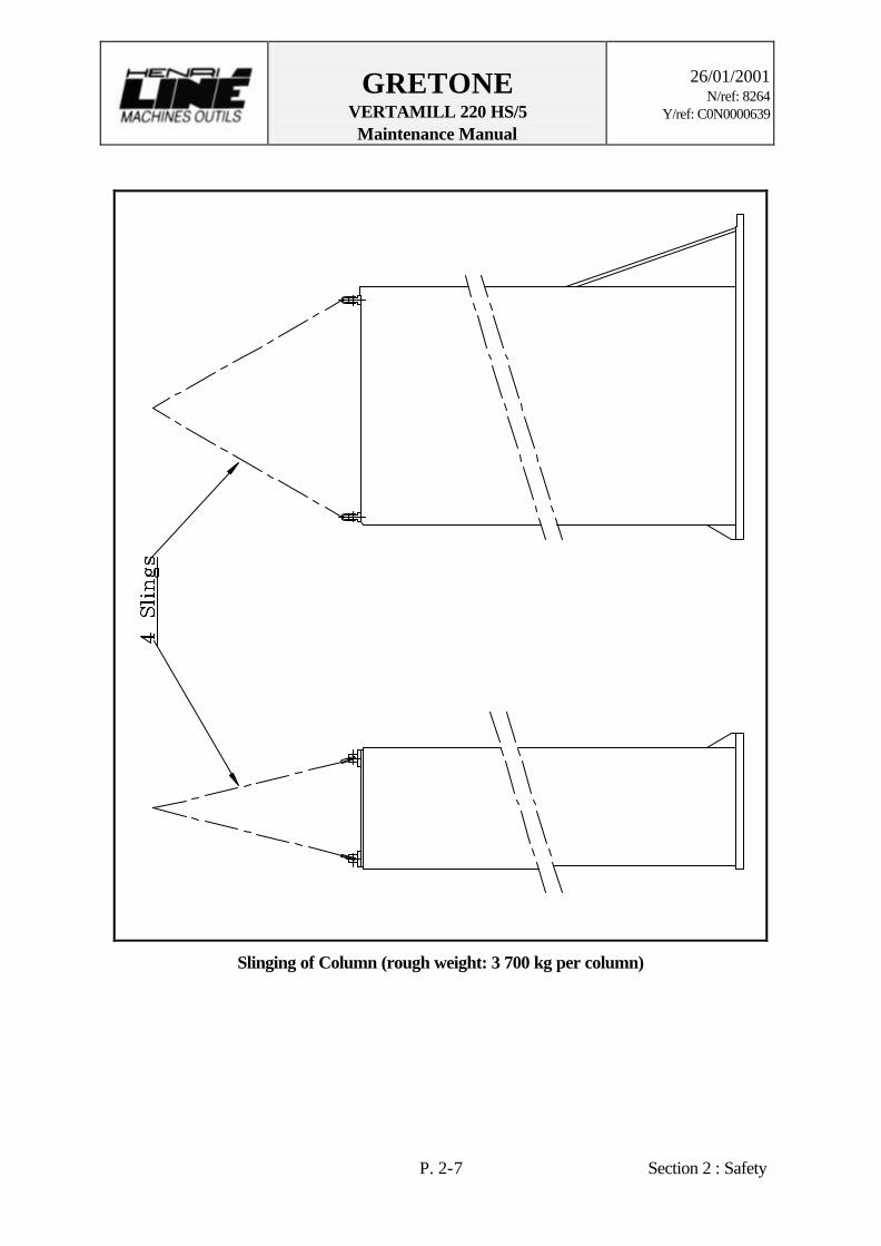
ø Warning ! Unexpected movements - We supply the first mounting. If the machine place should be modified, the handling must be done by our staff or specialized company. Refer to below drawings for sling system of different parts.

GRETONE VERTAMILL 220 HS/5 Maintenance Manual
26/01/2001
N/ref: 8264 Y/ref: C0N0000639
P. 2-4 Section 2 : Safety
Slinging of Crossrail and Saddle (rough weight: 12 600 kg)

GRETONE VERTAMILL 220 HS/5 Maintenance Manual
26/01/2001
N/ref: 8264 Y/ref: C0N0000639
P. 2-5 Section 2 : Safety
Slinging of Bed (rough weight: 13 500 kg)

GRETONE VERTAMILL 220 HS/5 Maintenance Manual
26/01/2001
N/ref: 8264 Y/ref: C0N0000639
P. 2-6 Section 2 : Safety
Slinging of Table (rough weight: 8 000 kg)
GRETONE VERTAMILL 220 HS/5 Maintenance Manual
26/01/2001
N/ref: 8264 Y/ref: C0N0000639
P. 2-7 Section 2 : Safety
Slinging of Column (rough weight: 3 700 kg per column)

GRETONE VERTAMILL 220 HS/5 Maintenance Manual
26/01/2001
N/ref: 8264 Y/ref: C0N0000639
P. 2-8 Section 2 : Safety
Slinging of Milling Head (rough weight: 3 300 kg)
GRETONE VERTAMILL 220 HS/5 Maintenance Manual
26/01/2001
N/ref: 8264 Y/ref: C0N0000639
P. 2-9 Section 2 : Safety
2.4. HAZARDS
2.4.1. Inherent Spindle hazards Even when used strictly according to instructions, when working on or with the spindle an inherent danger to life and limb of the user or third persons still exists and damage can be caused to the spindle or other property. Therefore the following safety and hazard warnings must be strictly observed : 1. The spindles have a very high rotational speed therefore in operation, splinters or, should a tool break, pieces of tool can fly out at very high speed. Transparent shields have been installed for the operator protection to avoid injuries with chips and particles coming from the cutter.
ø Warning ! If this protection is removed for any reasons, persons could bed injured or killed by flying splinters or pieces of tool. 2. Under no circumstances are the fingers to be placed inside the taper mount. If this warning is ignored, the fingers could be crushed.
ø Warning ! If this is ignored, persons can be injured or killed by flying parts of the spindle. 3. All tools must be dynamically balanced. The maximum permitted rotation speed of the tool/tool holder and the spindle is not to be exceeded under any circumstances.
ø Warning ! If this warning is ignored, persons can be injured or killed by flying parts of the tool or tool holder. 4. Some parts of the spindle subject to large forces through the spring ring of the tool clamping system. The wrong removing of the spindle, this parts can fly out at high speed. Therefore only properly trained personnel are permitted to open the spindles.
ø Warning ! If this is ignored, persons can be injured or killed by flying parts of the spindle.

GRETONE VERTAMILL 220 HS/5 Maintenance Manual
26/01/2001
N/ref: 8264 Y/ref: C0N0000639
P. 2-10 Section 2 : Safety
2.4.2. Other hazards
2.4.2.1. Electrical hazards Only skilled and fully trained personnel who are familiar with the inherent dangers are permitted to work on the electrical system. In cases where the machine has to be worked on under power, an additional skilled person should be called in who can take the necessary steps in emergency situations. Before carrying out any work on the electrical system disconnect the machine and periphery devices from the mains and ensure that the power cannot be reconnected.
ø Warning ! Disconnect control equipment from all power sources and lock it before maintenance or repairs in order to avoid hazard or electrical shocks or unintended action of control equipment.
2.4.2.2. Hydraulic hazards Only skilled and fully trained personnel who are familiar with the inherent dangers are permitted to work on the hydraulic system. Before carrying out any work on the hydraulic system disconnect the machine and periphery devices from the mains and ensure that the power cannot be reconnected.
2.4.2.3. Pneumatic hazards Only skilled and fully trained personnel who are familiar with the inherent dangers are permitted to work on the pneumatic system. Before carrying out any work on the hydraulic system disconnect the machine and periphery devices from the mains and ensure that the power cannot be reconnected.
2.4.2.4. Coolant unit hazards Only skilled and fully trained personnel who are familiar with the inherent dangers are permitted to work on the coolant system. Before carrying out any work on the hydraulic system disconnect the machine and periphery devices from the mains and ensure that the power cannot be reconnected.

GRETONE VERTAMILL 220 HS/5 Maintenance Manual
26/01/2001
N/ref: 8264 Y/ref: C0N0000639
P. 2-11 Section 2 : Safety
2.4.2.5. Oil and cooling fluid Oil and cooling fluid can be hazardous to persons in several ways (allergic reaction, danger of slipping if the material leaks on the floor, etc.). Therefore take great care when handling such materials and always observe the relevant factory safety regulations.
2.4.2.6. Environmental protection When not correctly used, oil and cooling agent additives can pollute the environment. Therefore handle such materials with care and strictly observe local regulations and laws. Collect the used materials in suitable containers (e.g. original canisters) and ensure that the correct disposal procedures are carried out.

GRETONE VERTAMILL 220 HS/5 Maintenance Manual
26/01/2001
N/ref: 8264 Y/ref: C0N0000639
P. 2-12 Section 2 : Safety
2.5. OPERATOR & MACHINE SAFETY SYSTEM
2.5.1. MACHINE SAFETY SYSTEM Some parts of machine is protected either by case or by bellows or telescopic covers protection in order to avoid exposing these parts lubricated or guiding to the dust or other particles. In addition , each system (e.g. Hydraulic unit or axes) has level or safety switches. Position/limitation control system (see Mechanical description) is part of safety system too.
2.5.2. OPERATOR SAFETY SYSTEM During the machining, the operator is protected by Shatterproof glass windows on the platform. In case of problem, the machine, the conveyor, the electrical system, etc. have emergency stop switches. Detection contours prevent the machine movement when a person is in front of the ATC and the platform, or behind the gantry.

MECHANICALDESCRIPTION
GRETONE VERTAMILL 220 HS/5 Maintenance Manual
26/01/2001
N/ref: 8264 Y/ref: C0N0000639
P. 3-1 Section 3 : Axes
3. AXES
3.1 X-AXIS
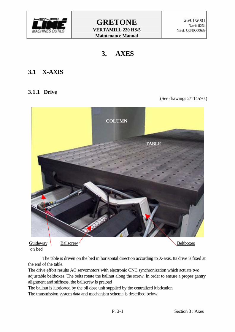
3.1.1 Drive (See drawings 2/114570.)
The table is driven on the bed in horizontal direction according to X-axis. Its drive is fixed at the end of the table. The drive effort results AC servomotors with electronic CNC synchronization which actuate two adjustable beltboxes. The belts rotate the ballnut along the screw. In order to ensure a proper gantry alignment and stiffness, the ballscrew is preload The ballnut is lubricated by the oil dose unit supplied by the centralized lubrication. The transmission system data and mechanism schema is described below.
TABLE
COLUMN
Guideway on bed
Ballscrew Beltboxes

GRETONE VERTAMILL 220 HS/5 Maintenance Manual
26/01/2001
N/ref: 8264 Y/ref: C0N0000639
P. 3-2 Section 3 : Axes
Servomotors model: Fanuc (ALPHA 40 A06b-01-57-B0)
Rated output (power) : 5.9 kW
Rated torque : 38 N•m
Rotational speed (Maxi) 2000 RPM
Position indicator model: HEIDENHAIN LB382C encoder
Reduction and preload system: Henri-Liné feedbox
Lubricant used by HLMO: Macurat D 68 (BP)
Lubricant (ISO): G68
Belt reduction factor : 1/3
Ballscrew : ∅100 x 30
Rapid travel speed: 20 m/min
X-axis transmission system mechanism

GRETONE VERTAMILL 220 HS/5 Maintenance Manual
26/01/2001
N/ref: 8264 Y/ref: C0N0000639
P. 3-3 Section 3 : Axes
X-axis measure schema
The speed feedback is ensured by rotary encoder integrated in the AC servomotors while the position feedback of the table is provided by a linear encoder HEIDENHAIN, fixed at the inside of bed,with measure readers fixed to table. To prevent the inngress of contamination, the measure units are protected and sealed with compressed air. Cams fixed at each end of bed associated with multiple limit switches EUCHNER fixed to columns near the gearboxes locate the ends of travel and the origine. Mecanical thrusts prevent the over-dimension movement.
GRETONE VERTAMILL 220 HS/5 Maintenance Manual
26/01/2001
N/ref: 8264 Y/ref: C0N0000639
P. 3-4 Section 3 : Axes
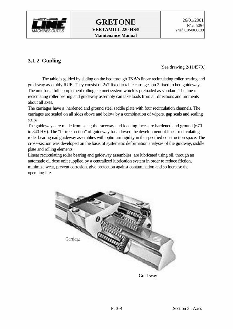
3.1.2 Guiding (See drawing 2/114579.)
The table is guided by sliding on the bed through INA’s linear recirculating roller bearing and guideway assembly RUE. They consist of 2x7 fixed to table carriages on 2 fixed to bed guideways. The unit has a full complement rolling elemnet system which is preloaded as standard. The linear reciculating roller bearing and guideway assembly can take loads from all directions and moments about all axes. The carriages have a hardened and ground steel saddle plate with four recirculation channels. The carriages are sealed on all sides above and below by a combination of wipers, gap seals and sealing strips. The guideways are made from steel; the raceway and locating faces are hardened and ground (670 to 840 HV). The “fir tree section” of guideway has allowed the development of linear recirculating roller bearing nad guideway assemblies with optimum rigidity in the specified construction space. The cross-section was developed on the basis of systematic deformation analyses of the guidway, saddle plate and rolling elements. Linear recirculating roller bearing and guideway assemblies are lubricated using oil, through an automatic oil dose unit supplied by a centralized lubrication system in order to reduce friction, minimize wear, prevent corrosion, give protection against contamination and so increase the operating life.
Carriage
Guideway

GRETONE VERTAMILL 220 HS/5 Maintenance Manual
26/01/2001
N/ref: 8264 Y/ref: C0N0000639
P. 3-5 Section 3 : Axes
X guiding schema
GRETONE VERTAMILL 220 HS/5 Maintenance Manual
26/01/2001
N/ref: 8264 Y/ref: C0N0000639
P. 3-6 Section 3 : Axes
3.2 Y AXIS
3.2.1 Drive (See drawings 2/114574.)
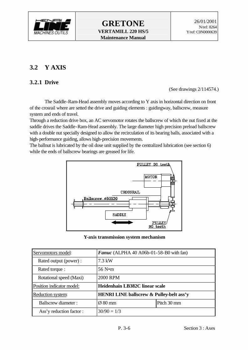
The Saddle-Ram-Head assembly moves according to Y axis in horizontal direction on front of the crosrail where are setted the drive and guiding elements : guidingway, ballscrew, measure system and ends of travel. Through a reduction drive box, an AC servomotor rotates the ballscrew of which the nut fixed at the saddle drives the Saddle-Ram-Head assembly. The large diameter high precision preload ballscrew with a double nut specially designed to allow the recirculation of its bearing balls, associated with a high-performance guiding, allows high-precision movements. The ballnut is lubricated by the oil dose unit supplied by the centralized lubrication (see section 6) while the ends of ballscrew bearings are greased for life.
Y-axis transmission system mechanism
Servomotors model: Fanuc (ALPHA 40 A06b-01-58-B0 with fan)
Rated output (power) : 7.3 kW
Rated torque : 56 N•m
Rotational speed (Maxi) 2000 RPM
Position indicator model: Heidenhain LB382C linear scale
Reduction system: HENRI LINE ballscrew & Pulley-belt ass’y
Ballscrew diameter : Ø 80 mm Pitch 30 mm
Ass’y reduction factor : 30/90 = 1/3
GRETONE VERTAMILL 220 HS/5 Maintenance Manual
26/01/2001
N/ref: 8264 Y/ref: C0N0000639
P. 3-7 Section 3 : Axes
Rapid travel speed : 20 m/mn

GRETONE VERTAMILL 220 HS/5 Maintenance Manual
26/01/2001
N/ref: 8264 Y/ref: C0N0000639
P. 3-8 Section 3 : Axes
The speed feedback is ensured by rotary encoder integrated in the AC servomotors while the position feedback of the Saddle is provided by a linear encoder HEIDENHAIN, fixed at the each crossrail side,with measure readers fixed to bottom of saddle. To prevent the inngress of contamination, the measure units are protected and sealed with compressed air. Cams fixed at each end of crossrail associated with multiple limit switches EUCHNER fixed to saddle on the top of the ballscrew nut locate the ends of travel and the origine
Y-axis measure schema
GRETONE VERTAMILL 220 HS/5 Maintenance Manual
26/01/2001
N/ref: 8264 Y/ref: C0N0000639
P. 3-9 Section 3 : Axes
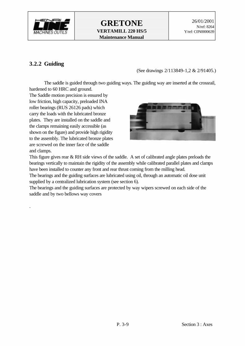
3.2.2 Guiding (See drawings 2/113849-1,2 & 2/91405.)
The saddle is guided through two guiding ways. The guiding way are inserted at the crossrail, hardened to 60 HRC and ground. The Saddle motion precision is ensured by low friction, high capacity, preloaded INA roller bearings (RUS 26126 pads) which carry the loads with the lubricated bronze plates. They are installed on the saddle and the clamps remaining easily accessible (as shown on the figure) and provide high rigidity to the assembly. The lubricated bronze plates are screwed on the inner face of the saddle and clamps.
This figure gives rear & RH side views of the saddle. A set of calibrated angle plates preloads the bearings vertically to maintain the rigidity of the assembly while calibrated parallel plates and clamps have been installed to counter any front and rear thrust coming from the milling head. The bearings and the guiding surfaces are lubricated using oil, through an automatic oil dose unit supplied by a centralized lubrication system (see section 6). The bearings and the guiding surfaces are protected by way wipers screwed on each side of the saddle and by two bellows way covers .

GRETONE VERTAMILL 220 HS/5 Maintenance Manual
26/01/2001
N/ref: 8264 Y/ref: C0N0000639
P. 3-10 Section 3 : Axes
Y guiding schema

GRETONE VERTAMILL 220 HS/5 Maintenance Manual
26/01/2001
N/ref: 8264 Y/ref: C0N0000639
P. 3-11 Section 3 : Axes
3.3 Z AXIS
3.3.1 Drive (See drawings 2/114655 and 2/107101.)
The Ram-Head assembly moves according to Y axis in horizontal direction on front of the Saddle. The drive and guiding elements of the Ram : guidingway, ballscrew are setted on its own structure. The ballscrew which is rotated by an AC servomotor and a reduction drive box drives the Ram-Head ass’y through its nut fixed at the saddle. The large diameter high precision preload ballscrew with a double nut specially designed to allow the recirculation of its bearing balls allows, associated with a high-performance guiding, high-precision movements. In the event of a power failure or a machine stop, an brake prevents further movement. A system of cylinders counterbalance the Z-assembly.The ballnut is lubricated by the oil dose unit supplied by the centralized lubrication (see section 6) while the ends of ballscrew bearings are greased for life.
Z-axis transmission system mechanism
Servomotors model: Fanuc (ALPHA 40 A06b-01-58-B1 with fan and brake)
Rated output (power) : 7.3 kW
Rated torque : 56 N•m
Rotational speed (Maxi) 2000 RPM
Position indicator model: Heidenhain LB382C linear scale
Reduction system: HENRI LINE ballscrew & Pulley-belt ass’y
Ballscrew diameter : Ø 80 mm Pitch 20 mm
Ass’y reduction factor : 1/ 2.66
Rapid travel speed : 10 m/mn

GRETONE VERTAMILL 220 HS/5 Maintenance Manual
26/01/2001
N/ref: 8264 Y/ref: C0N0000639
P. 3-12 Section 3 : Axes
Z-axis transmission and counterbalancing system mechanism
Counterbalancing jacks
Scale
Z drivebox

GRETONE VERTAMILL 220 HS/5 Maintenance Manual
26/01/2001
N/ref: 8264 Y/ref: C0N0000639
P. 3-13 Section 3 : Axes
The speed feedback is ensured by rotary encoder integrated in the AC servomotors while the position feedback of the Ram is provided by a linear encoder HEIDENHAIN, fixed at the saddle,with measure readers fixed to Ram. To prevent the inngress of contamination, the measure units are protected and sealed with compressed air. Cams fixed at each end of saddle associated with multiple limit switches EUCHNER fixed to Ram locate the ends of travel and the origine
Z-axis measure schema

GRETONE VERTAMILL 220 HS/5 Maintenance Manual
26/01/2001
N/ref: 8264 Y/ref: C0N0000639
P. 3-14 Section 3 : Axes
3.3.3 Guiding (See drawings 2/113849-1,2 & 2/91405.)
The Ram is guided through its own two guiding ways which are inserted type, hardened to 60 HRC and ground. The Ram motion precision is ensured by low friction, high capacity, preloaded INA roller bearings (RUS 26126 pads) which carry the loads with the lubricated bronze plates. They are installed on the saddle and the clamps remaining easily accessible (as shown on the figure) and provide high rigidity to the assembly. The lubricated bronze plates are screwed on the inner face of the saddle and clamps.
Z guiding schema
A set of calibrated angle plates preloads the bearings laterally (Y-axis) to maintain the rigidity of the assembly while calibrated parallel plates and clamps have been installed to counter any front and rear thrust coming from the milling head (X-axis). The bearings and the guiding surfaces are lubricated using oil, through an automatic oil dose unit supplied by a centralized lubrication system (see section 6). The bearings and the guiding surfaces are protected by way wipers screwed on each side of the saddle.
GRETONE VERTAMILL 220 HS/5 Maintenance Manual
26/01/2001
N/ref: 8264 Y/ref: C0N0000639
P. 4-1 Section 4: Head
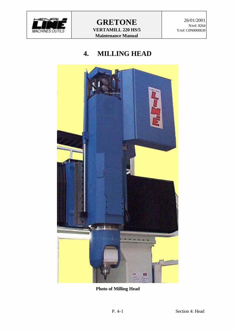
4. MILLING HEAD
Photo of Milling Head

GRETONE VERTAMILL 220 HS/5 Maintenance Manual
26/01/2001
N/ref: 8264 Y/ref: C0N0000639
P. 4-2 Section 4: Head
4.1. SPINDLE (See drawings 2/111531, 2/114680 & 2/114020.)
The milling unit of FAP55 MB PLUS type slides along the saddle according to Z-axis on a 800mm-stroke. It is built to allow continuous 5 axis machining. It is composed mainly a ram and an angle head, which is composed an U-shaped part and an electrospindle FISCHER, which has an integrated tool clamping system and motor (see section 11: documentation), with 2 tilting axes (B and C). The C-drive of Angle Head is located in bottom of Ram while the A/B-drive of the spindle is located inside of U-shaped sides of Angle Head. The coupling system between the ram and the Angle Head transmit liquid and energy to electrospindle for the tool locking, flood coolant, cooling and airtightness. The connectors transmit electrical signal for the tool locking and the movement of the electrospindle and the A/B-drive. An integrated to electrospindle switch transmit the position and the rotation speed of electro-spindle. The spindle is protected by a SCHENK’s unit VIBROCONTROL 920 (see section 11: documentation), which is an instrument for measurement monitoring and display of bearing vibrations.
E-SPINDLE SPECIFICATIONS Type: MFWS-2307/24/18 VCS HSK-A/E63 Lubrication Oil-Air Motor cooling system Liquid cooled (water) Tool Clamping system Hydraulically operated Manufacturer Ott-Jakob Type HSK-A63 Min. clamping force 14 400 N Hydraulic pressure for unclamping Min 90 b, max 150 b Hydraulic pressure for clamping Min 5 b, max 150 b Dimensions Sleeve diameter 230 mm Weight Ca. 135 kg Motor specifications Number of poles 4 Rotation speed 6 670 RPM 12 000 RPM 24 000 RPM Frequency 222 Hz 400 Hz 800 Hz Torque S1 100% 57 Nm 31.8 Nm 15.9 Nm Power S1 100% 40 kW 40 kW 40 kW Voltage 205 V 350 V 350 V

GRETONE VERTAMILL 220 HS/5 Maintenance Manual
26/01/2001
N/ref: 8264 Y/ref: C0N0000639
P. 4-3 Section 4: Head
Power and Torque diagram

GRETONE VERTAMILL 220 HS/5 Maintenance Manual
26/01/2001
N/ref: 8264 Y/ref: C0N0000639
P. 4-4 Section 4: Head
Accessory clamping and coupling system diagram
As well as the coupling system the bottom of head consist of an accessory or angle head clamping system, composed 4 single acting jacks with clamping units Berg. The set of unused spring washer keep up the closed unit, so locked on the pull stud of accessory. At the time of unclamping, the pressure pushes on piston and washers so open the clamping units.
GRETONE VERTAMILL 220 HS/5 Maintenance Manual
26/01/2001
N/ref: 8264 Y/ref: C0N0000639
P. 4-5 Section 4: Head
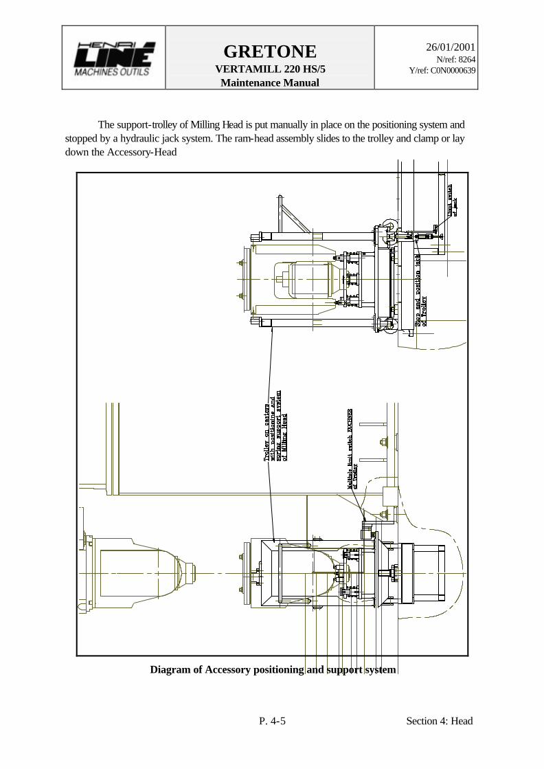
The support-trolley of Milling Head is put manually in place on the positioning system and stopped by a hydraulic jack system. The ram-head assembly slides to the trolley and clamp or lay down the Accessory-Head
Diagram of Accessory positioning and support system

GRETONE VERTAMILL 220 HS/5 Maintenance Manual
26/01/2001
N/ref: 8264 Y/ref: C0N0000639
P. 4-6 Section 4: Head
4.2. C-AXIS (See drawings2/111532 & 2/111533.)
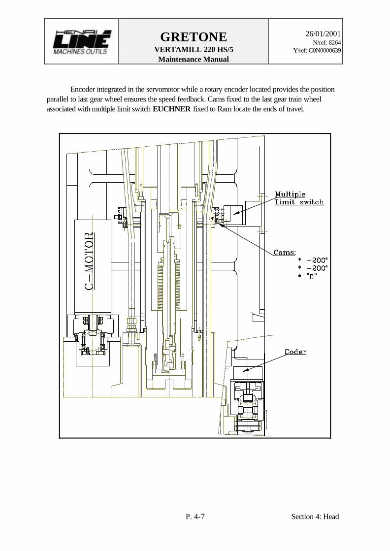
A CNC actuated servomotor rotates the milling head around of the C-axis on Nx360° by means of 2 reducers and 2 gear trains. The ball and roller bearing, which ensures the C-axis guiding, is preloaded by a lot of «no stroke» hydraulic cylinders placed on the sides of its. This preload counterbalances the forces and so increases the rigidity.
C-axis diagram
Servomotors model: Fanuc (ALPHA M9/3000 A06b-01-63-B5)
Rated torque: 9 N.m
Maxi. speed 3000 RPM
Reducer HDUR IH size 40, HARMONIC DRIVE, R= 1/160
Position switch: Rotary encoder ROD270 18000 lines HEIDENHAIN
Drive system Reduction ratio: (29/29) x (18/108) x (1/160) = 1/960
Rotation speed 4 RPM
Rotation +/- 200°
GRETONE VERTAMILL 220 HS/5 Maintenance Manual
26/01/2001
N/ref: 8264 Y/ref: C0N0000639
P. 4-7 Section 4: Head
Encoder integrated in the servomotor while a rotary encoder located provides the position parallel to last gear wheel ensures the speed feedback. Cams fixed to the last gear train wheel associated with multiple limit switch EUCHNER fixed to Ram locate the ends of travel.

GRETONE VERTAMILL 220 HS/5 Maintenance Manual
26/01/2001
N/ref: 8264 Y/ref: C0N0000639
P. 4-8 Section 4: Head
4.3. A/B AXIS (See drawings2/114020.)
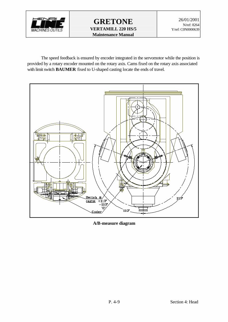
A servomotor tilts the spindle around of the A/B-axis on -/+110° between the 2 parts of U-shaped main casting by means of a reduction preloaded gear train.
A/B-axis diagram
Servomotors model: Fanuc (ALPHA M9/3000 A06b-01-28-B5)
Rated torque: 9 N.m
Maxi. speed 3000 RPM
Position switch: Rotary encoder ROD282 18000 lines HEIDENHAIN
Drive system Reduction ratio: (19/109) x (21x95) x (19/108) = 1/147.5
Rotation speed 5 RPM
Rotation +/- 110°
GRETONE VERTAMILL 220 HS/5 Maintenance Manual
26/01/2001
N/ref: 8264 Y/ref: C0N0000639
P. 4-9 Section 4: Head
The speed feedback is ensured by encoder integrated in the servomotor while the position is provided by a rotary encoder mounted on the rotary axis. Cams fixed on the rotary axis associated with limit switch BAUMER fixed to U-shaped casting locate the ends of travel.
A/B-measure diagram

GRETONE VERTAMILL 220 HS/5 Maintenance Manual
26/01/2001
N/ref: 8264 Y/ref: C0N0000639
P. 5-1 Section 5: Hyd. & Pneu. Syst.
5. HYDRAULIC & PNEUMATIC SYSTEMS
5.1. HYDRAULIC SYSTEM (See following pages the diagrams H/114673a 8pl.)
The hydraulic system, controlled by CNC, is equipped by a hydraulic unit, which provides the Counterbalancing System and the Actuation of the Milling Head. The hydraulic counterbalancing of the Head, through Accumulators, makes it possible to release the pressure on the Ballscrews (Z-axis) and the power supply for the drive unit. The hydraulic actuation of the Head controls:
- Automatic tool changer, - Tool unlocking, - Accessory unlocking, - C axis preload, - Accessory positioning system
The hydraulic unit, schematized on next pages, is briefly described below: - Hydraulic unit Bosch - Accumulator with safety system Olaer - Actuation Hawe ø Note : - For the recommended oil, please refer to section 8 (Maintenance) of this
manual. - For the spare parts list of the hydraulic unit, please refer to section 9 (Spare
parts) - For a detailed description of the hydraulic components refer to section 11
(Documentation).

GRETONE VERTAMILL 220 HS/5 Maintenance Manual
26/01/2001
N/ref: 8264 Y/ref: C0N0000639
P. 5-2 Section 5: Hyd. & Pneu. Syst.

GRETONE VERTAMILL 220 HS/5 Maintenance Manual
26/01/2001
N/ref: 8264 Y/ref: C0N0000639
P. 5-3 Section 5: Hyd. & Pneu. Syst.

GRETONE VERTAMILL 220 HS/5 Maintenance Manual
26/01/2001
N/ref: 8264 Y/ref: C0N0000639
P. 5-4 Section 5: Hyd. & Pneu. Syst.

GRETONE VERTAMILL 220 HS/5 Maintenance Manual
26/01/2001
N/ref: 8264 Y/ref: C0N0000639
P. 5-5 Section 5: Hyd. & Pneu. Syst.

GRETONE VERTAMILL 220 HS/5 Maintenance Manual
26/01/2001
N/ref: 8264 Y/ref: C0N0000639
P. 5-6 Section 5: Hyd. & Pneu. Syst.
GRETONE VERTAMILL 220 HS/5 Maintenance Manual
26/01/2001
N/ref: 8264 Y/ref: C0N0000639
P. 5-7 Section 5: Hyd. & Pneu. Syst.

GRETONE VERTAMILL 220 HS/5 Maintenance Manual
26/01/2001
N/ref: 8264 Y/ref: C0N0000639
P. 5-8 Section 5: Hyd. & Pneu. Syst.

GRETONE VERTAMILL 220 HS/5 Maintenance Manual
26/01/2001
N/ref: 8264 Y/ref: C0N0000639
P. 5-9 Section 5: Hyd. & Pneu. Syst.
GRETONE VERTAMILL 220 HS/5 Maintenance Manual
26/01/2001
N/ref: 8264 Y/ref: C0N0000639
P. 5-10 Section 5: Hyd. & Pneu. Syst.
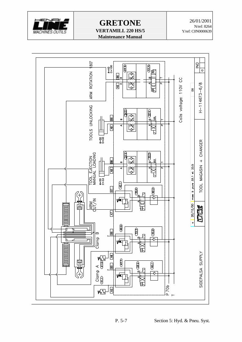
5.2. PNEUMATIC SYSTEM (See following pages the diagrams P/114676-3pl, P/114691-2pl & P/114677-2pl.)
The pneumatic system is controlled through the CNC and uses Plant air supply. First the Plant air passes through a conditioning unit FESTO. The filter removes humidity with water separator from the system as well as possible to avoid oxidation of the metal components. The drain of this filter is semi-automatic. The pressure reduction valve ensures a constant working pressure. Then the Air is conditioned by pressurizing system DA200 Heidenhain or lubricated by an oil spray lubricator. Air of Pneumatic system has for main uses: - Tightness of Heidenhain linear encoders, Blum system, spindles… - Blowing of spindle taper and tools; - Electrospindle lubrication with an air/oil mixture, which is supplied by VOGEL system of which oil is recuperated by vacuum pump PIAB.
- Cylinder actuation of the ATC.
ø Note : - For the recommended oil, please refer to section 8 (Maintenance) of this
manual. - For the spare parts list of the pneumatic unit, please refer to section 9 (Spare
parts) - For a detailed description of the pneumatic components refer to section 11
(Documentation).

GRETONE VERTAMILL 220 HS/5 Maintenance Manual
26/01/2001
N/ref: 8264 Y/ref: C0N0000639
P. 5-11 Section 5: Hyd. & Pneu. Syst.

GRETONE VERTAMILL 220 HS/5 Maintenance Manual
26/01/2001
N/ref: 8264 Y/ref: C0N0000639
P. 5-12 Section 5: Hyd. & Pneu. Syst.

GRETONE VERTAMILL 220 HS/5 Maintenance Manual
26/01/2001
N/ref: 8264 Y/ref: C0N0000639
P. 5-13 Section 5: Hyd. & Pneu. Syst.

GRETONE VERTAMILL 220 HS/5 Maintenance Manual
26/01/2001
N/ref: 8264 Y/ref: C0N0000639
P. 5-14 Section 5: Hyd. & Pneu. Syst.

GRETONE VERTAMILL 220 HS/5 Maintenance Manual
26/01/2001
N/ref: 8264 Y/ref: C0N0000639
P. 5-15 Section 5: Hyd. & Pneu. Syst.

GRETONE VERTAMILL 220 HS/5 Maintenance Manual
26/01/2001
N/ref: 8264 Y/ref: C0N0000639
P. 5-16 Section 5: Hyd. & Pneu. Syst.

GRETONE VERTAMILL 220 HS/5 Maintenance Manual
26/01/2001
N/ref: 8264 Y/ref: C0N0000639
P. 5-17 Section 5: Hyd. & Pneu. Syst.

GRETONE VERTAMILL 220 HS/5
Operator Manual
26/01/2001
N/ref: 8264 Y/ref: C0N0000639
P. 6-1 Section 6 : Accessoires
6. PERIPHERAL SYSTEMS
6.1. Automatic tool changer (See following pages the diagrams L/114668-2pl and documentation SIDEPALSA.)
The machine is equipped a tool magazine with changer arm SIDEPALSA fixed to the
ground. The magazine allows to store the tools in their supports and to position the tool at the time of the interchange. The changer allows the tools grasp and interchange between magazine and the milling head. The changer is a “double-arm” system which slides upon a guide-support between magazine and the head. This system is driven by a servomotor and actuated by the hydraulic system.

GRETONE VERTAMILL 220 HS/5
Operator Manual
26/01/2001
N/ref: 8264 Y/ref: C0N0000639
P. 6-2 Section 6 : Accessoires
TOOLS MAGAZINE SPECIFICATIONS :
Type : AH60 SIDEPALSA Quantity : 60 Werkzeugkegel : HSK A 63 BT50 Maxi tool diameter 150 mm Maxi Diameter of consetive tools 125 mm Maxi Tool length 400 mm Maxi tool weight 25 kg

GRETONE VERTAMILL 220 HS/5
Operator Manual
26/01/2001
N/ref: 8264 Y/ref: C0N0000639
P. 6-3 Section 6 : Accessoires

GRETONE VERTAMILL 220 HS/5
Operator Manual
26/01/2001
N/ref: 8264 Y/ref: C0N0000639
P. 6-4 Section 6 : Accessoires
6.2. Probe (see documentation Renishaw)
The Renishaw MP16 Touch-Trigger Probe System (MP3 Probe with Selectable Channel Radio Transmission) provides a means of workpiece measurement with transmission of the trigger signal over large distances, with non line of sight operation. This probe is fitted to a tool taper.

GRETONE VERTAMILL 220 HS/5
Operator Manual
26/01/2001
N/ref: 8264 Y/ref: C0N0000639
P. 6-5 Section 6 : Accessoires
6.3. Laser measuring system (see documentation Blum)
The Blum Laser measuring system is an optical measuring device for automated tool measuring inside the working area of a machining center under operating conditions. The measuring results are the basis for tool wear correction and a criterion for the tool change in due time. The complete laser measuring system consists of a transmitter, a receiver, electronic ad extra components. The lens is protected against dirt and coolant by a tube with an air seal.
GRETONE VERTAMILL 220 HS/5
Operator Manual
26/01/2001
N/ref: 8264 Y/ref: C0N0000639
P. 6-6 Section 6 : Accessoires
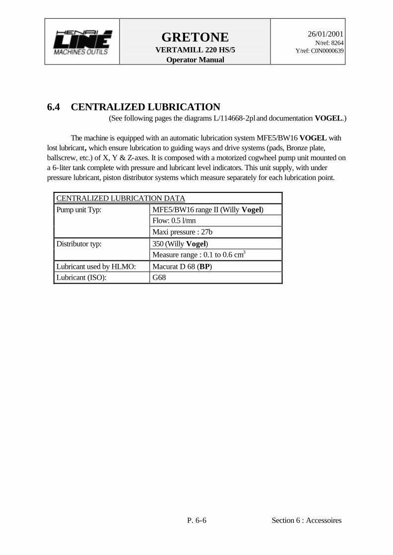
6.4 CENTRALIZED LUBRICATION (See following pages the diagrams L/114668-2pl and documentation VOGEL.)
The machine is equipped with an automatic lubrication system MFE5/BW16 VOGEL with lost lubricant, which ensure lubrication to guiding ways and drive systems (pads, Bronze plate, ballscrew, etc.) of X, Y & Z-axes. It is composed with a motorized cogwheel pump unit mounted on a 6-liter tank complete with pressure and lubricant level indicators. This unit supply, with under pressure lubricant, piston distributor systems which measure separately for each lubrication point.
CENTRALIZED LUBRICATION DATA Pump unit Typ: MFE5/BW16 range II (Willy Vogel) Flow: 0.5 l/mn Maxi pressure : 27b Distributor typ: 350 (Willy Vogel) Measure range : 0.1 to 0.6 cm3 Lubricant used by HLMO: Macurat D 68 (BP) Lubricant (ISO): G68

GRETONE VERTAMILL 220 HS/5
Operator Manual
26/01/2001
N/ref: 8264 Y/ref: C0N0000639
P. 6-7 Section 6 : Accessoires

GRETONE VERTAMILL 220 HS/5
Operator Manual
26/01/2001
N/ref: 8264 Y/ref: C0N0000639
P. 6-8 Section 6 : Accessoires

GRETONE VERTAMILL 220 HS/5
Operator Manual
26/01/2001
N/ref: 8264 Y/ref: C0N0000639
P. 6-9 Section 6 : Accessoires
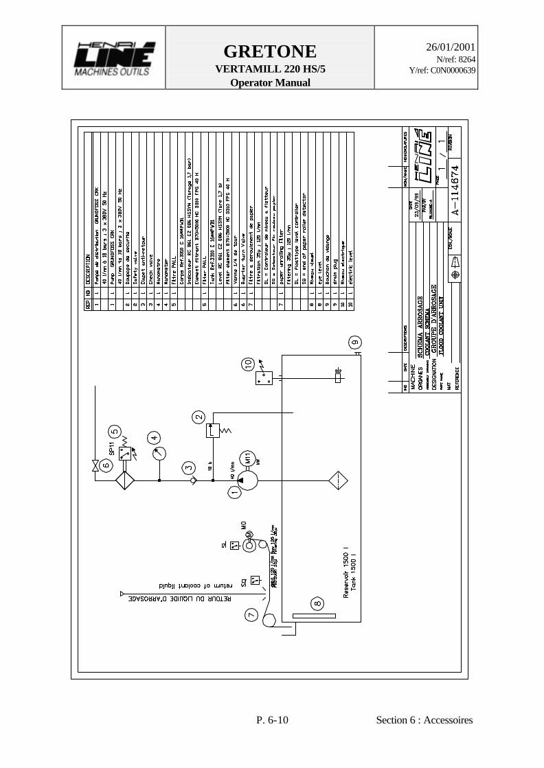
6.5 FLOOD COOLANT UNIT (See following page the diagram A/114674.)
The machine is equipped with a flood coolant unit FM located in a hole in the behind of the machine and used during machining in order to clear the machine part of chips. The unit, controlled by NC, is composed a 1500 l tank and a cleaning system. Clean coolant fluid is pumped from tank through the filter combination PALL and fittings to the Milling Head and is delivered to the machining part by nozzles or by Spindle center. The used coolant fluid flow off the table , baffle plates to conveyors. The metallic cloth filter basically the liquid which flow through a paper rolling filter during its return to tank. A floattype level indicator controls the tank and prevents a pump idling. Please refer to the FM manual instruction for the different parts of this unit.
FLOOD COOLANT DATA Typ: BETA 2 (FM) Tank: 1500l Flow: 40 l/mn pressure: 1b
GRETONE VERTAMILL 220 HS/5
Operator Manual
26/01/2001
N/ref: 8264 Y/ref: C0N0000639
P. 6-10 Section 6 : Accessoires

GRETONE VERTAMILL 220 HS/5
Operator Manual
26/01/2001
N/ref: 8264 Y/ref: C0N0000639
P. 6-11 Section 6 : Accessoires
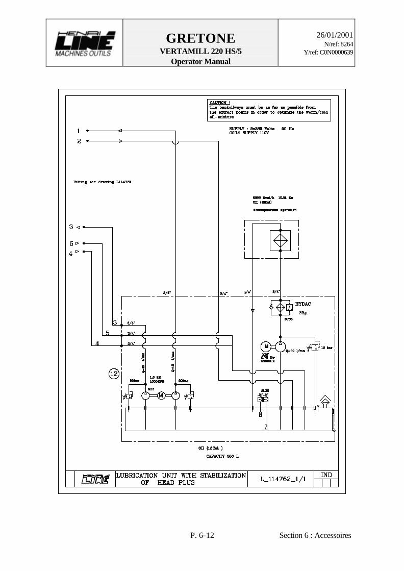
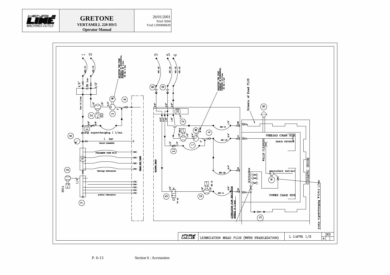
6.6 COOLANT UNIT The milling head is cooled with water through a peripheral system : a coolant unit EURODIFROID. The coolant unit, controlled by NC, is composed mainly of a condenser with fan, a compressor and regulation system which controls automatically the temperatur according to specifications
COOLANT DATA Coolant unit Type: KAW 310 HP Hart RD CD Sp2 (EURODIFROID)
Refrigerating power: 11.5 kW to 20°C Refrigerating fluid R22 Three-phase supply 415V – 50Hz Pump flow: 10 to 15 l/mn Volume 100 l
Cooling agent additive used by FISCHER:
MOTOREX Frigosol
Cooling agent concentrator used by FISCHER:
MOTOREX Swisscare Antisept
GRETONE VERTAMILL 220 HS/5
Operator Manual
26/01/2001
N/ref: 8264 Y/ref: C0N0000639
P. 6-12 Section 6 : Accessoires
GRETONE VERTAMILL 220 HS/5
Operator Manual
26/01/2001
N/ref: 8264 Y/ref: C0N0000639
P. 6-13 Section 6 : Accessoires
GRETONE VERTAMILL 220 HS/5
Operator Manual
26/01/2001
N/ref: 8264 Y/ref: C0N0000639
P. 6-14 Section 6 : Accessoires
GRETONE VERTAMILL 220 HS/5
Operator Manual
26/01/2001
N/ref: 8264 Y/ref: C0N0000639
P. 6-15 Section 6 : Accessoires
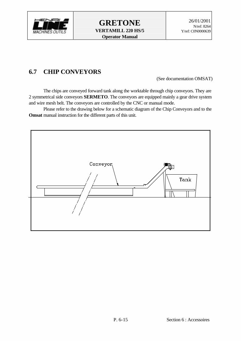
6.7 CHIP CONVEYORS (See documentation OMSAT)
The chips are conveyed forward tank along the worktable through chip conveyors. They are 2 symmetrical side conveyors SERMETO. The conveyors are equipped mainly a gear drive system and wire mesh belt. The conveyors are controlled by the CNC or manual mode. Please refer to the drawing below for a schematic diagram of the Chip Conveyors and to the Omsat manual instruction for the different parts of this unit.
GRETONE VERTAMILL 220 HS/5
Operator Manual
26/01/2001
N/ref: 8264 Y/ref: C0N0000639
P. 6-16 Section 6 : Accessoires
6.8 CONTROL SYSTEM
6.8.1 Position control system The position feed back of the machine is controlled by CNC through incremental linear (X, Y, Z) or rotary (A/B, C) encoders. These system uses a Photoelectric scanning of a periodic graduation track which results in an incremental, i.e. counted, measurement. Incremental encoders provide sinusoidal measuring signals, which are then interpolate by an interpolation unit. Features: X, Y & Z-axis: Heidenhain LB382C linear encoder A/B & C-axis: Heidenhain ROD 282 or 270 rotary encoder ATC: Heidenhain ROD 486 rotary encoder
6.8.2 Limitation control system For travels limitation which are also safety limits, the machine uses 3 safety levels: 1. Software limits (programming). 2. Electrical limits (switches). 3. Mechanical limits (bumper). For every axis, the CNC programming sets the software limits. During program execution, any prescribed move out of these limits is immediately countered and the machine is put “E-stop” condition while the CNC waits for new instructions. The + and - over travel limits are defined according to specifications. The electrical limits are made of multiple Euchner or Telemecanique limit switches installed on the mobile component and cams which are fixed to the static part at the required locations. The + and - over travel limit switches are located as per design/maintenance purposes and adjusted during the final set up of the machine prior to machine operations. The mechanical limits (+ and -) are made of bumpers located at the ends of every axis travels to prevent further moves of the machine out of its software/electrical limits.

ELECTRICAL DESCRIPTION

GRETONE VERTAMILL 220 HS/5 Maintenance Manual
26/01/2001
N/ref: 8264 Y/ref: C0N0000639
P. 7-1 Section 7: Electrical Description
7. ELECTRICAL MAINTENANCE
7.1. INHERENT PRODUCT HAZARDS 1. Only skilled and fully trained personnel who are familiar with the inherent dangers are permitted to work on the electrical system. In cases where the machine has to be worked on under power, an additional skilled person should be called in who can take the necessary steps in emergency situations. 2. Before carrying out any work on the electrical system disconnect the machine and periphery devices from the mains and ensure that the power cannot be reconnected.
ø Warning! Disconnect control equipment from all power sources and lock it before maintenance or repairs in order to avoid hazard or electrical shocks or unintended action of control equipment.

GRETONE VERTAMILL 220 HS/5 Maintenance Manual
26/01/2001
N/ref: 8264 Y/ref: C0N0000639
P. 7-2 Section 7: Electrical Description
7.2. ELECTRICAL INSPECTIONS The following section details the electrical maintenance needs of your VERTAMILL 220 HS/5. The maintenance description is followed by an electrical maintenance chart, which should be used for preventive maintenance scheduling.
7.2.1. Periodic inspection A first inspection within 3 or 4 months of installation is suggested. Intervals between inspections should be based on environmental and operating conditions, and adjusted when necessary according to past experience. The following is a list of the required tasks for the electrical preventive maintenance of the machine. 1. Make sure the interior of the cabinet is clean, free of dust and humidity. Otherwise check the filtering components. 2. Check condition of relays and contactors. 3. Verify the proper function of the mechanism. 4. Verify the wear and cleanliness of the contacts. They may be in good condition even when discolored. 5. Verify the terminal blocks. Loose connections can cause overheating, which can lead to equipment malfunction or failure. Replace any parts or wiring damaged by overheating. 6. Visually inspect the connectors located on the cabinets. 7. Check for coil overheating indicated by cracks, burns or traces of melting insulation. 8. Check pressure switches. 9. Make a visual inspection to ensure that all components are normal (no thermal deterioration). 10. Verify the good insertion of the cards (electrical cabinets). 11. Check the position of the board locking tabs. 12. Clean or replace the air filters as recommended by the manufacturer. Every 6 months, the thermostat should be inspected. It is visible only when the filter is removed. The maintenance personnel should also make sure that there is a positive air pressure inside the cabinets.
7.2.1.1 Pneumatic unit Visually inspect solenoid valves and pressure switches every 6 months. These components are located on the left column.

GRETONE VERTAMILL 220 HS/5 Maintenance Manual
26/01/2001
N/ref: 8264 Y/ref: C0N0000639
P. 7-3 Section 7: Electrical Description
7.2.1.2 Hydraulic system Visually inspect solenoid valves and pressure switches every 6 months. These components are located on top of the machine crossrail.
7.2.1.3 Work lights (Wahlman) Remove the covers and clean inside and outside every year. Replace lights only when needed.
7.2.2. Electrical cabinets inspection
Once a year, visually inspect the electrical components to make sure they are well installed on the fixations inside the cabinets. Make sure the wires are all connected, that they are not cracked, and that their insulation is still in proper condition. Visually inspect the electrical connectors, located on top of the cabinets. Special care must be provided to all cabinet fasteners, which will have to be checked and tightened (every 2 years) in the eventual case of loosening parts due to vibrations.
7.2.3. Recommended electrical maintenance chart
Components Every 6 months Every year Electrical cabinets -Clean the air conditioning
-Check the thermostat -Check positive air pressure
-Check the components -Check the wires -Check connectors
Pneumatic unit -Check solenoid valves -Check pressure switches
Hydraulic unit -Check solenoid valves -Check pressure switches
GRETONE VERTAMILL 220 HS/5 Maintenance Manual
26/01/2001
N/ref: 8264 Y/ref: C0N0000639
P. 7-4 Section 7: Electrical Description
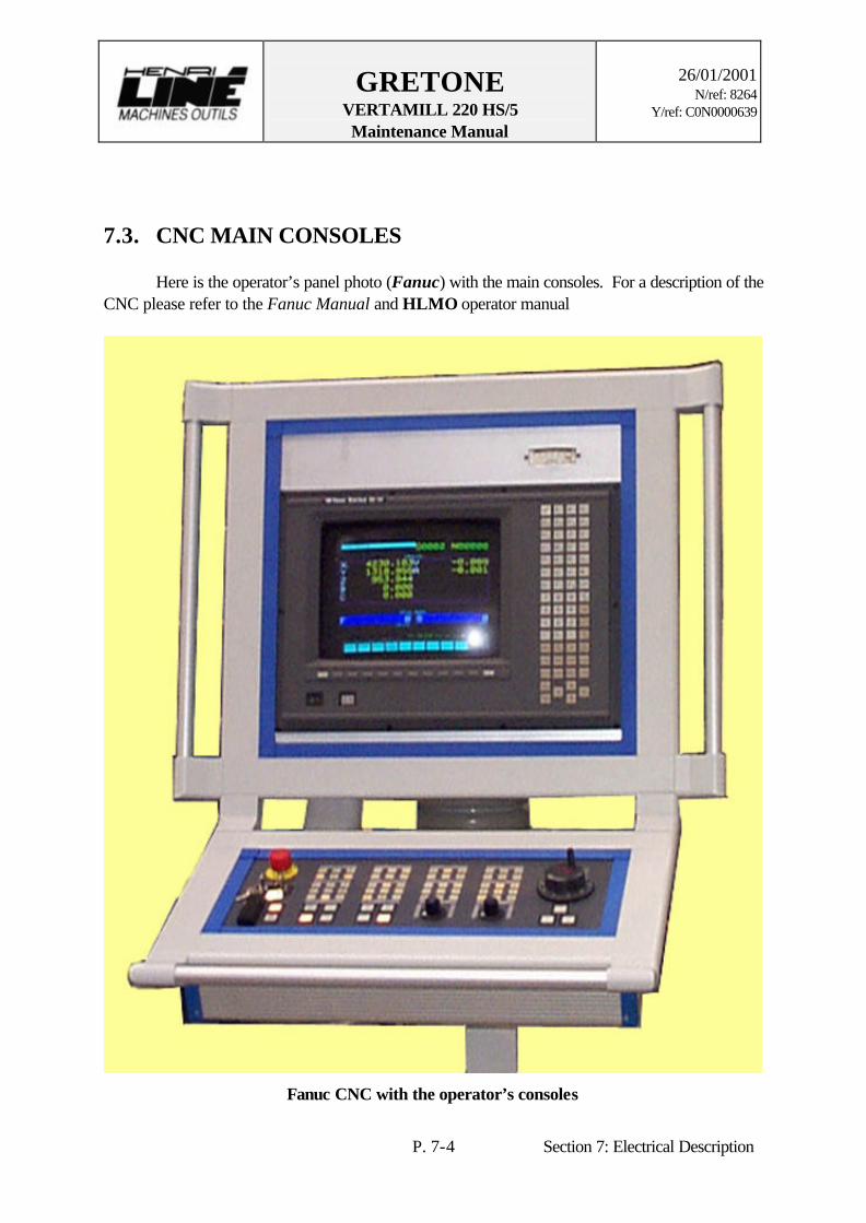
7.3. CNC MAIN CONSOLES Here is the operator’s panel photo (Fanuc) with the main consoles. For a description of the CNC please refer to the Fanuc Manual and HLMO operator manual
Fanuc CNC with the operator’s consoles
GRETONE VERTAMILL 220 HS/5 Maintenance Manual
26/01/2001
N/ref: 8264 Y/ref: C0N0000639
P. 7-5 Section 7: Electrical Description
Electrical diagrams
- Electrical diagrams - Part list
HLMO
Only on paper
MAINTENANCEAND
REPAIRS

GRETONE VERTAMILL 220 HS/5 Maintenance Manual
26/01/2001
N/ref: 8264 Y/ref: C0N0000639
P. 8-1 Section 8 : .Maintenance & repair
8. MECHANICAL MAINTENANCE
8.1. MACHINE GEOMETRY AND GUIDING MAINTENANCE The following section describes the mechanical maintenance and the periodic adjustments for your VERTAMILL 220 HS/5. To insure the reliability of the major components and the entire machine tool, we suggest that you use this information as a main part of a preventive maintenance plan (=> scheduled maintenance and inspection).
8.1.1. Geometry control Because the guiding parts are mounted on calibrated parallel and angle plates, the machine geometry does not require to be adjusted. It will not be affected when rollers are changed as long as the prescribed precautions were taken. The machine could be misalign due to: a) A defective roller/ball bearing. b) An external shock on the machine, c) A bump on the mechanical end of travel. d) A collision with the part. e) Poor foundation stability. f) A defective slide way, g) A misalign and/or misplaced bed/worktable.
ø Caution ! Previously to work on the drive and bearing systems of the machine please use (“PUSH”) the E-Stop button on the operator console to shut the machine down. Because there’re some automatic systems on the machine, unattended moves of the components may occur anytime.

GRETONE VERTAMILL 220 HS/5 Maintenance Manual
26/01/2001
N/ref: 8264 Y/ref: C0N0000639
P. 8-2 Section 8 : .Maintenance & repair
8.1.2. X-axis maintenance For the X-axis, a good maintenance has to be achieved to prevent rigidity problem. The sources of that problem can be not enough preload on the driving pinions of the gearbox or some damaged bearing assemblies. The following procedures indicate the way to inspect and correct these problems.
ø Note : After you have finished the adjustments, always make sure that the screws and
nuts are really tight.
8.1.2.1. Bed levelling 1. Move the table to motorside. 2. Use an electronic level (verify its measure repeatability). 3. Longitudinal and Transversal level: Put a 1-meter ruler on 2 shims with suited width (5/9 rules) that are put on guiding ways of bed . 4. Put the level on the ruler. 5. Verify the Bed by one-meter section. 6. Make the necessary adjustments through the A-type push and pull screws. 7. Screw the B-type pull screw with 11.7 m.kg-torque. 8. Verify the nivel preserving torque ≥ 11.7m.kg. 9. Draw a diagram of results.
Bed levelling (1/3)

GRETONE VERTAMILL 220 HS/5 Maintenance Manual
26/01/2001
N/ref: 8264 Y/ref: C0N0000639
P. 8-3 Section 8 : .Maintenance & repair
8.1.2.2. X-axis drive box inspection (See drawing 2/114570.)
1. Stop the machine and turn the breaker “OFF” and attach a lockout device, lock and tag. 2. Remove covers, which could hamper the inspection of pulleys. 3. Inspect the timing belt for any visual defect, replace if necessary. 4. Check the screws torque for the locking elements. 5. Set the tension on the timing belt (see Timing belt tension procedure). 6. Reassemble the cover.
ø Caution ! Never force a belt (for example with a lever). Check noise or vibration (sign of excessive or insufficient belt tension)
TABLE
COLUMN
Guideway on bed
Ballscrew Beltboxes

GRETONE VERTAMILL 220 HS/5 Maintenance Manual
26/01/2001
N/ref: 8264 Y/ref: C0N0000639
P. 8-4 Section 8 : .Maintenance & repair
X-axis drive

GRETONE VERTAMILL 220 HS/5 Maintenance Manual
26/01/2001
N/ref: 8264 Y/ref: C0N0000639
P. 8-5 Section 8 : .Maintenance & repair
8.1.2.3. Timing belt tension (See drawing 2/114570.)
To ensure an appropriate belt tension, follow the described procedure below. 1. Loosen fixing screws of motor plate 2/114571. 2. Adjust centre distance (= 248.2 mm) between motor axis and ballscrew axis with adjusting screws, checking the belt tension.
To check tension, put a ruler on the pulley and a ø5 mm-cylinder between the ruler and the belt without force
or use a tensiometer. 3. Tighten all other screws. 4. Reassemble cover.
ø Caution ! The timing belt requires not a high tension. An excessive or insufficient tension can cause an early wear.

GRETONE VERTAMILL 220 HS/5 Maintenance Manual
26/01/2001
N/ref: 8264 Y/ref: C0N0000639
P. 8-6 Section 8 : .Maintenance & repair
8.1.2.4. Ballscrew bearings inspection (See drawing 2/114570.)
To inspect and replace the ballscrew timing belt or bearings, disassemble the unit following the procedures. 1. Bring the table but letting easy access. Stop the machine and turn the breaker “OFF”. Attach a lockout device, lock and tag. 2. Remove the covers. 3. Check the ballscrew for any visual defect (pitting, chipping, grooving, etc). ø Note : Because the ballscrew has been carefully tempered and polished take good
care not to damage its components during the maintenance operations. 4. Loosen the fixing screws of motor and the adjusting screws of belt tension. 5. Unscrew the double nut 3/101188 + 3/101189 after unlocking any screws. 6. Remove the bearing 2/101168. 7. Remove the belts to the moved pulley then the pulley. 8. Disconnect the lubrication fitting of the ballscrew nut. 9. Disengage the ballscrew nut to the table and check its function (noise, backlash, etc.) 10. Remove and inspect the bearings for any visual defect (pitting, chipping, grooving, etc) and replace non-conforming parts. 11. At the time of removing, fill up the bearings with grease. It is a life lubrication, 20000h. 12 Set the preload (see Ballscrew preload).

GRETONE VERTAMILL 220 HS/5 Maintenance Manual
26/01/2001
N/ref: 8264 Y/ref: C0N0000639
P. 8-7 Section 8 : .Maintenance & repair
8.1.2.5. Ballscrew preload (See drawing 2/114570.)
To the rear of the Table 1. Install a dial indicator at a ballscrew end to the rear of the table; 2. Tighten the nut 4/101188 to obtain an elastic displacement of 0.15 mm at the indicator; 3. Measure the dimension T with gauge blocks and adjust the shim 3/101193 to the dimension T. ø Note : Because the ballscrew has been carefully tempered and polished take good
care not to damage its components during the maintenance operations.
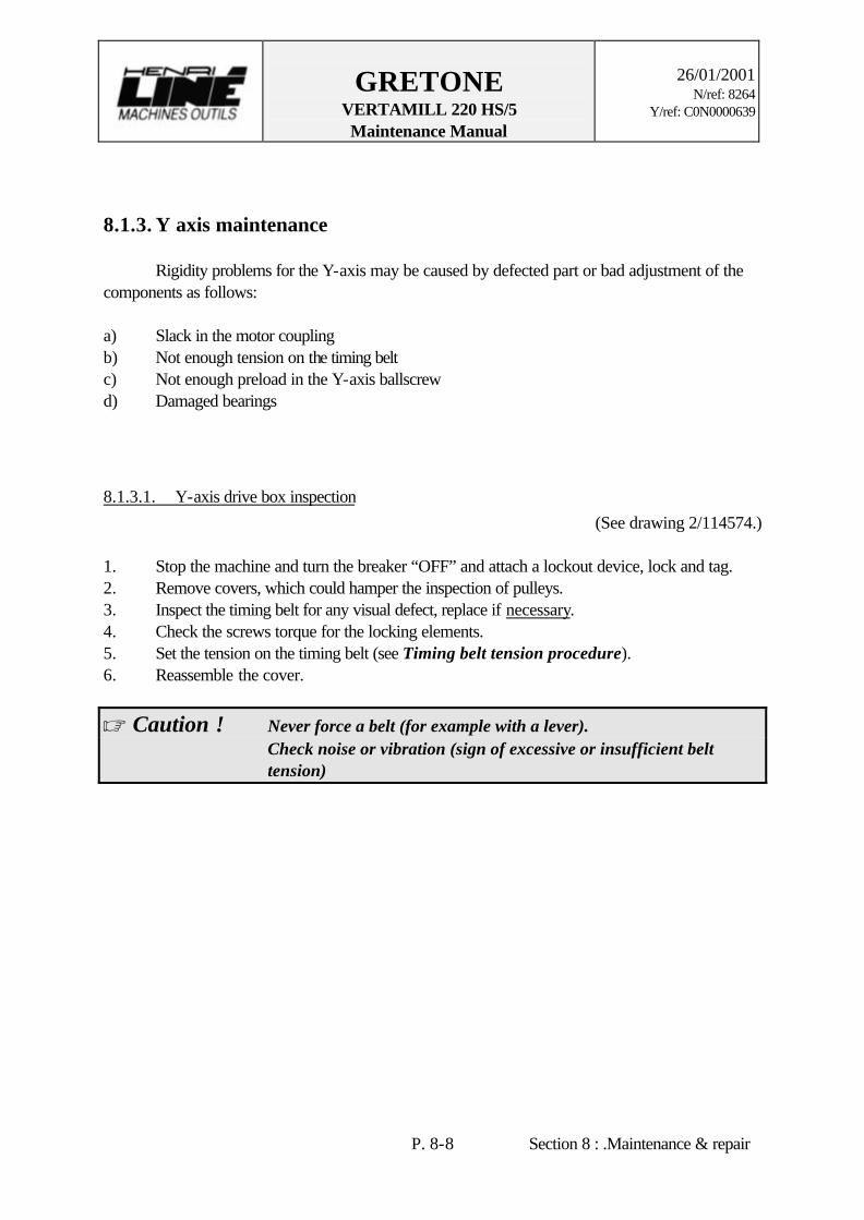
GRETONE VERTAMILL 220 HS/5 Maintenance Manual
26/01/2001
N/ref: 8264 Y/ref: C0N0000639
P. 8-8 Section 8 : .Maintenance & repair
8.1.3. Y axis maintenance Rigidity problems for the Y-axis may be caused by defected part or bad adjustment of the components as follows: a) Slack in the motor coupling b) Not enough tension on the timing belt c) Not enough preload in the Y-axis ballscrew d) Damaged bearings
8.1.3.1. Y-axis drive box inspection (See drawing 2/114574.)
1. Stop the machine and turn the breaker “OFF” and attach a lockout device, lock and tag. 2. Remove covers, which could hamper the inspection of pulleys. 3. Inspect the timing belt for any visual defect, replace if necessary. 4. Check the screws torque for the locking elements. 5. Set the tension on the timing belt (see Timing belt tension procedure). 6. Reassemble the cover.
ø Caution ! Never force a belt (for example with a lever). Check noise or vibration (sign of excessive or insufficient belt tension)

GRETONE VERTAMILL 220 HS/5 Maintenance Manual
26/01/2001
N/ref: 8264 Y/ref: C0N0000639
P. 8-9 Section 8 : .Maintenance & repair
Y-axis drive

GRETONE VERTAMILL 220 HS/5 Maintenance Manual
26/01/2001
N/ref: 8264 Y/ref: C0N0000639
P. 8-10 Section 8 : .Maintenance & repair
8.1.3.2. Timing belt tension (See drawing 2/114574.)
To ensure an appropriate belt tension, follow the described procedure below. 1. Loosen fixing screws of motor plate 2/114575. 2. Adjust centre distance (= 310.56 mm) between motor axis and ballscrew axis with adjusting screws, checking the belt tension.
To check tension, put a ruler on the pulley and a ø6 mm-cylinder between the ruler and the belt without force
or use a tensiometer. 3. Tighten all other screws. 4. Reassemble cover.
ø Caution ! The timing belt requires not a high tension. An excessive or insufficient tension can cause an early wear.

GRETONE VERTAMILL 220 HS/5 Maintenance Manual
26/01/2001
N/ref: 8264 Y/ref: C0N0000639
P. 8-11 Section 8 : .Maintenance & repair
8.1.3.3. Ballscrew bearings inspection (See drawing 2/114574.)
To inspect and replace the ballscrew timing belt or bearings, disassemble the unit following the procedures. 1. Bring the saddle but letting easy access. Stop the machine and turn the breaker “OFF”. Attach a lockout device, lock and tag. 2. Remove the covers. 3. Check the ballscrew for any visual defect (pitting, chipping, grooving, etc). ø Note : Because the ballscrew has been carefully tempered and polished take good
care not to damage its components during the maintenance operations. 4. Loosen the fixing screws of motor and the adjusting screws of belt tension. 5. Remove the belt to the moved pulley then the pulley and the locking washer. 6. Unscrew the nut KMT10 after unlocking any setscrews. 7. Remove the bearing 2/91583. 8. LH side: Remove the nut KMT10 after unlocking setscrews and the bearing 2/104048. 9. Disconnect the lubrication fitting of the ballscrew nut. 10. Disengage the ballscrew nut to the saddle and check its function (noise, backlash, etc.) 11. Remove and inspect the bearings for any visual defect (pitting, chipping, grooving, etc) and replace non-conforming parts. 12 At the time of removing, fill up the bearings with grease. It is a life lubrication, 20000h. 13. Set the preload (see Ballscrew preload).
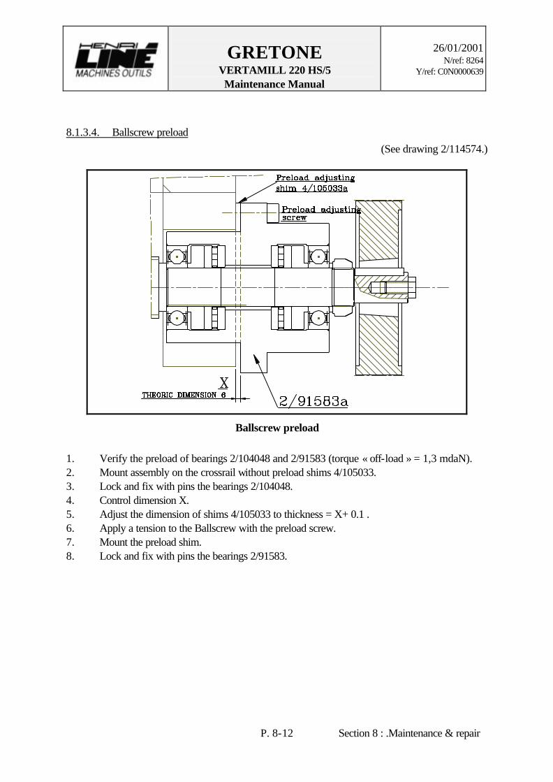
GRETONE VERTAMILL 220 HS/5 Maintenance Manual
26/01/2001
N/ref: 8264 Y/ref: C0N0000639
P. 8-12 Section 8 : .Maintenance & repair
8.1.3.4. Ballscrew preload (See drawing 2/114574.)
Ballscrew preload
1. Verify the preload of bearings 2/104048 and 2/91583 (torque « off-load » = 1,3 mdaN). 2. Mount assembly on the crossrail without preload shims 4/105033. 3. Lock and fix with pins the bearings 2/104048. 4. Control dimension X. 5. Adjust the dimension of shims 4/105033 to thickness = X+ 0.1 . 6. Apply a tension to the Ballscrew with the preload screw. 7. Mount the preload shim. 8. Lock and fix with pins the bearings 2/91583.

GRETONE VERTAMILL 220 HS/5 Maintenance Manual
26/01/2001
N/ref: 8264 Y/ref: C0N0000639
P. 8-13 Section 8 : .Maintenance & repair
8.1.3.5. Inspection of the roller bearing pads (See drawing 2/113849 & 2/91405.)
The 12 INA roller bearing pads (RUS 26126KS) and bronze plates provide the guiding of the saddle. These pads are fixed onto plates and to the top and bottom behind of the saddle to be distributed along the guiding way. They support the vertical loads and the front/rear thrusts. Any angle plate sets, located under the bottom guiding way, preload the bearing pads. Any parallel plates are located over the way.
Saddle guiding according to Y-axis

GRETONE VERTAMILL 220 HS/5 Maintenance Manual
26/01/2001
N/ref: 8264 Y/ref: C0N0000639
P. 8-14 Section 8 : .Maintenance & repair
Because of the high precision of the slide ways and the bearing ass’y parts, these components must be carefully inspected. Here is the procedure to inspect these units. Disassembling: 1. Disassemble the covers, the wiper plates and any other components before the roller bearings. 2. Lay the saddle on two jacks resting on the table, making sure it will not lower when the upper external roller support will be loosened. 3. Loosen the roller pad supports the top saddle along. 4. Remove the two screws that retain the angle plates to each side of the saddle. 5. Using a puller, remove the angle and parallel plates from their location. 6. Remove all the rollers and replace them if necessary. ø Note : When reassembling, make sure that : a) the rollers used are such as specified . b) the plate casings are clean . c) plates is put back in the same location they were before removing . d) the saddle has not been moved. Reassembling: 7. Reassemble the rollers with the parallel and angle plates. 8. Reassemble the roller units in their proper locations. Reinstall last the rollers with angle plates. 9. Set the preload with the angle plates (see Bearing pads preload). 10. Reinstall the components that were on the saddle.
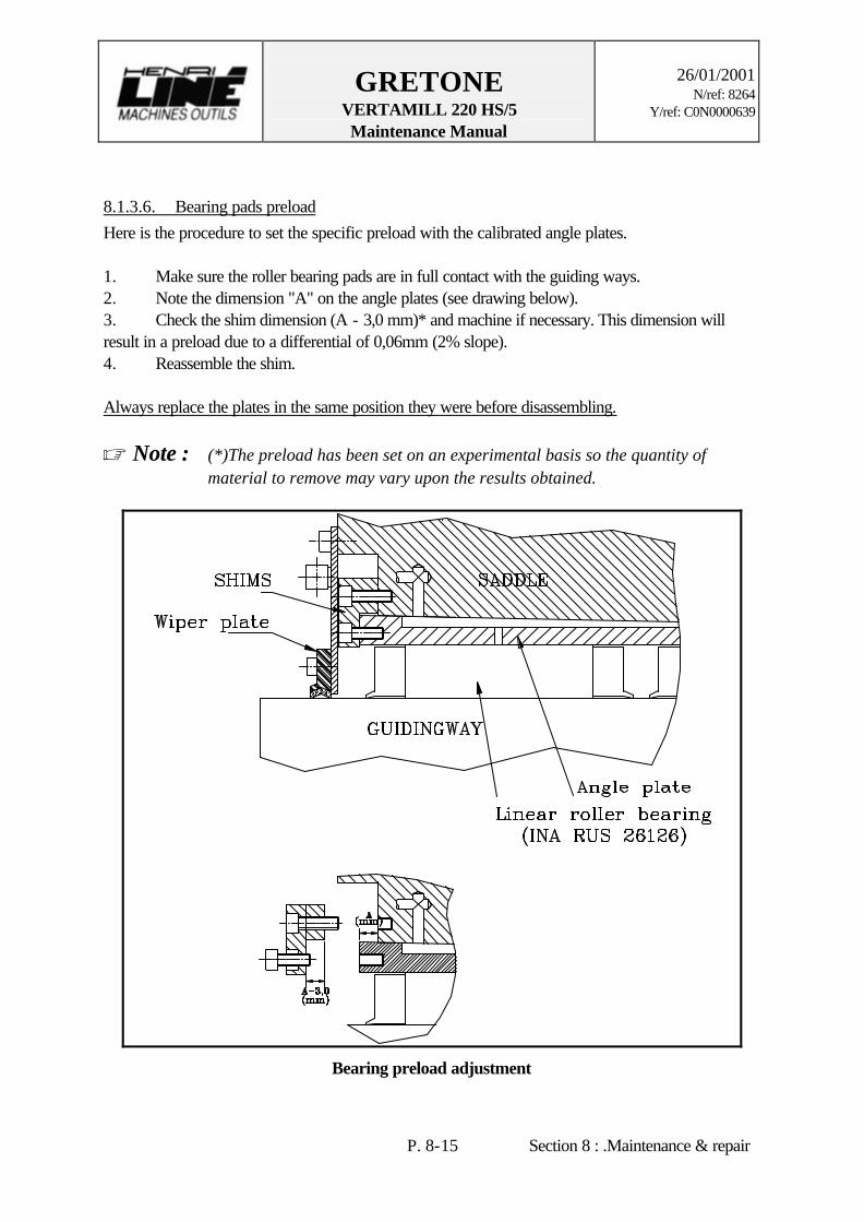
GRETONE VERTAMILL 220 HS/5 Maintenance Manual
26/01/2001
N/ref: 8264 Y/ref: C0N0000639
P. 8-15 Section 8 : .Maintenance & repair
8.1.3.6. Bearing pads preload Here is the procedure to set the specific preload with the calibrated angle plates. 1. Make sure the roller bearing pads are in full contact with the guiding ways. 2. Note the dimension "A" on the angle plates (see drawing below). 3. Check the shim dimension (A - 3,0 mm)* and machine if necessary. This dimension will result in a preload due to a differential of 0,06mm (2% slope). 4. Reassemble the shim. Always replace the plates in the same position they were before disassembling. ø Note : (*)The preload has been set on an experimental basis so the quantity of
material to remove may vary upon the results obtained.
Bearing preload adjustment
GRETONE VERTAMILL 220 HS/5 Maintenance Manual
26/01/2001
N/ref: 8264 Y/ref: C0N0000639
P. 8-16 Section 8 : .Maintenance & repair
8.1.4. Z-axis maintenance For the Z-axis, a good maintenance has to be achieved to prevent rigidity problem. The sources of that problem can be a slack in the motor pulley, in the timing belt or some damaged bearing assemblies. The following procedure indicates an inspection/adjustment method to correct these problems.
8.1.4.1. Z-axis drive box inspection (See drawings 2/114655 and 2/107101.)
1. Move the crossrail to access the top easily. 2. Depose the head of the machine on jacks. 3. Stop the machine and turn the breaker “OFF”. Attach a lockout device, lock and tag. 4. Remove the Z-axis drive box cover. 3. Inspect the timing belt for any visual defect, replace if necessary. 4. Check the screw torque for the locking elements. 5. Check the ballscrew pulley screws torque. 6. Set the tension on the timing belt (see Timing belt tension procedure). 7. Reassemble the cover.

GRETONE VERTAMILL 220 HS/5 Maintenance Manual
26/01/2001
N/ref: 8264 Y/ref: C0N0000639
P. 8-17 Section 8 : .Maintenance & repair
Z-axis drive

GRETONE VERTAMILL 220 HS/5 Maintenance Manual
26/01/2001
N/ref: 8264 Y/ref: C0N0000639
P. 8-18 Section 8 : .Maintenance & repair
8.1.4.2. Timing belt tension (See drawings 2/114655 and 2/107101.)
To ensure an appropriate belt tension, follow the described procedure below. 1. Loosen fixing screws of motor plate. 2. Adjust centre distance between motor axis and ballscrew axis with adjusting screw, checking the belt tension. To check tension, put a ruler on the pulley and a ø5 mm-cylinder between the ruler and the belt without force
Timing belt tension
or use a tensiometer 3. Tighten all other screws. 4. Reassemble cover.
ø Caution ! The timing belt requires not a high tension. An excessive or insufficient tension can cause an early wear.

GRETONE VERTAMILL 220 HS/5 Maintenance Manual
26/01/2001
N/ref: 8264 Y/ref: C0N0000639
P. 8-19 Section 8 : .Maintenance & repair
8.1.4.3. Ballscrew assembly inspection (See drawings 2/114655 and 2/107101.)
To inspect the ball screw assemblies, please follow the procedure detailed below. 1. Move the crossrail to access the ball screw lower ends easily. 2. Depose the heads of the machine on jacks. 3. Stop the machine and turn the breaker “OFF”. Attach a lockout device, lock and tag. 4. Depressurise the counterbalance system. 5. Disconnect the lubrication fitting of the ballscrew nuts. 6. Disassemble the ballscrew nut from the crossrail. 7. Move the nuts to clear it. 8. Check the ballscrew nuts. Removing the lower bearing ass’y: 9. Disassemble the lower bearing assemblies by first removing covers; next remove lock nuts KMT10, which preload the ballscrews (rigidity device). 10. Unscrew and extract the pillow blocks from the ram with the spacers, the thrust bearing and the two needle bearings 11. Disassemble the bearings from the pillow blocks. 12. Inspect parts for any visual defect and replace if necessary. Removing the upper bearing ass’y: 13. Loosen the head cap screws of motor plate. 14. Unscrew the full threaded head cap screw to slack the timing belt. 15. Remove the ballscrew sprocket (driven pulley). 16. Remove the plate with the motor. 17. Unplug the ballscrew nut lubrication conduit. 18. Remove the ball screw nut from the saddle. 19. Unscrew and remove the pillow block from the ram. 20. Remove the ball screw ass'y by pulling it, its nut and its upper bearing subassembly upwards over the saddle and put it on a work bench. 21. Disassemble the lock nut SKF KMT 10 from the upper bearing assembly. 22. Extract the pillow block from the ballscrew. 23. Remove the ball bearings and the thrust bearings from the pillow block for inspection. 24. Inspect the bearings and the other ass’y components for any visual defect (check for marks of indentations, scoring, pitting and also deformations). 25. At the time of removing, fill up the bearing with grease. It is a life lubrication, 20000h. ø Note : “BIKON 1006” assembly: Insert the BIKON after lubricating it. Do not use
Molybdenum Disulphide. After inserting the BIKON in the pulley’s boring, take back the screw from the
threading of part 1, and pass them through the smooth holes in the threads of part 2.

GRETONE VERTAMILL 220 HS/5 Maintenance Manual
26/01/2001
N/ref: 8264 Y/ref: C0N0000639
P. 8-20 Section 8 : .Maintenance & repair
Tighten uniformly the screw with torque wrench in crossed way and several times; begin with the 2 screw on both slotsides.

GRETONE VERTAMILL 220 HS/5 Maintenance Manual
26/01/2001
N/ref: 8264 Y/ref: C0N0000639
P. 8-21 Section 8 : .Maintenance & repair
8.1.4.4. Ballscrew preload (See drawings 2/114655 and 2/107101.)
1. Install a dial indicator at the ballscrew lower end. 2. Tighten the nut to obtain an elastic displacement of 0.05 mm at the indicator. 3. Block the lock nut with the set screws. ø Note : Because the ballscrew has been carefully tempered and polished take good
care not to damage its components during the maintenance operations.
Z-Ballscrew preload adjustment

GRETONE VERTAMILL 220 HS/5 Maintenance Manual
26/01/2001
N/ref: 8264 Y/ref: C0N0000639
P. 8-22 Section 8 : .Maintenance & repair
8.1.4.5. Inspection of the roller bearing pads (See drawing 2/113849 & 2/91405.)
The guiding of the ram is provided by the 8 INA roller bearing pads (RUS 26126 KS) which support the side loads and bronze plates for the front/rear loads. The bearing pads have angle plate sets located for their lateral preload adjustment. They have also parallel plates and clamps provided for the front/rear preload. Because of the high precision of the slide ways and the bearing ass’y parts, these components must be carefully inspected. Here is the procedure to inspect these units.
Disassembling: 1. Position the head on two jacks resting on the table, making sure it will not lower when the upper external roller support will be loosened. 2. Remove all components in the way of the disassembling of the angle plates (covers, wipers, limit switches, hydraulic jacks fastening system, all obstructing or attached connections, etc.) 3. Loosen the two clamps. 4. Loosen the two upper screws (M6 x 35) of the block 3/89612 which preloads the bearing pads. 5. Remove the two short screws (M6 x 16), the block 3/89612 and the spacer 4/89613. 6. Using a puller, remove the angle plates (3/89609 and 3/89630) from their location. 7. Remove all the rollers. 8. Inspect the pads for any visual defect (the pads from the plates on which they are fixed). øNote: When the preload is released, you can remove the parallel plates (3/89444)
and the bearing pads.

GRETONE VERTAMILL 220 HS/5 Maintenance Manual
26/01/2001
N/ref: 8264 Y/ref: C0N0000639
P. 8-23 Section 8 : .Maintenance & repair
Reassembling: 9. Reassemble the rollers with the parallel plates. 10. Reassemble the roller units in their proper locations. Reinstall last the rollers with angle plates. 11. Set the preload with the angle plates (see Bearing pads preload procedure). 12. Tighten the anti-thrust clamps screws. 13. Reinstall the components which were on the ram.
ø Caution ! When reassembling, make sure that: a) The angle plate casings are clean . b)every angle plate is put back in the same casing it was before the disassembling . c)the crossrail has not been moved.
8.1.4.6. Bearing pads preload (See drawings 2/108345 & 2/91405.)
Here is the procedure to set the specific preload with the calibrated angle plates. 1. Make sure that the roller bearing pads are in full contact with the guiding ways. 2. Note the dimension "A" on the angle plates (as shown on the drawing below). 3. Machine part 4/89613 to the dimension (A – 2 mm) which will result in a preload due to a differential of 0,04 mm. 4. Reassemble parts 4/89612, 4/89613 and angle plates (3/89609 and 89630). Always replace the plates in the same position they were before disassembling.
Bearing preload adjustment

GRETONE VERTAMILL 220 HS/5 Maintenance Manual
26/01/2001
N/ref: 8264 Y/ref: C0N0000639
P. 8-24 Section 8 : .Maintenance & repair
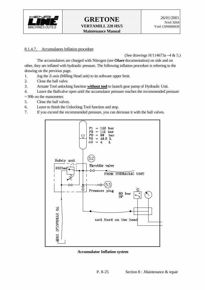
GRETONE VERTAMILL 220 HS/5 Maintenance Manual
26/01/2001
N/ref: 8264 Y/ref: C0N0000639
P. 8-25 Section 8 : .Maintenance & repair
8.1.4.7. Accumulators Inflation procedure (See drawings H/114673a –4 & 5.)
The accumulators are charged with Nitrogen (see Olaer documentation) on side and on other, they are inflated with hydraulic pressure. The following inflation procedure is referring to the drawing on the previous page. 1. Jog the Z-axis (Milling Head unit) to its software upper limit. 2. Close the ball valve. 3. Actuate Tool unlocking function without tool to launch gear pump of Hydraulic Unit. 4. Leave the Ballvalve open until the accumulator pressure reaches the recommended pressure = 99b on the manometer. 5. Close the ball valves. 6. Leave to finish the Unlocking Tool function and stop. 7. If you exceed the recommended pressure, you can decrease it with the ball valves.
Accumulator Inflation system
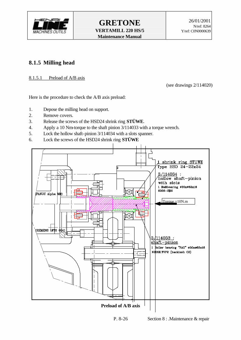
GRETONE VERTAMILL 220 HS/5 Maintenance Manual
26/01/2001
N/ref: 8264 Y/ref: C0N0000639
P. 8-26 Section 8 : .Maintenance & repair
8.1.5 Milling head
8.1.5.1 Preload of A/B axis (see drawings 2/114020)
Here is the procedure to check the A/B axis preload: 1. Depose the milling head on support. 2. Remove covers. 3. Release the screws of the HSD24 shrink ring STÜWE. 4. Apply a 10 Nm-torque to the shaft pinion 3/114033 with a torque wrench. 5. Lock the hollow shaft-pinion 3/114034 with a slots spanner. 6. Lock the screws of the HSD24 shrink ring STÜWE
Preload of A/B axis
Torque =10N.m

GRETONE VERTAMILL 220 HS/5 Maintenance Manual
26/01/2001
N/ref: 8264 Y/ref: C0N0000639
P. 8-27 Section 8 : .Maintenance & repair
8.1.5.2 Preload of C axis (See drawings 2/111532)
Here is the procedure to check the C axis preload: 1. Depose the milling head on supports. 2. Remove covers. 3. Remove the motor assembly with the first pinion assembly. 4. Apply a 5 Nm-torque to the C axis with the part 4/111563 on the line 1 or 2. 5. Lock the part 4/111563 with the screw. 6. Try to position the first pinion assembly. If the teeth don’t mesh, NO FORCE ! Release a little preload on the part 4/111563 until a proper gearing. 7. Remove the part 4/111563. 8. Assemble the motor assembly again.
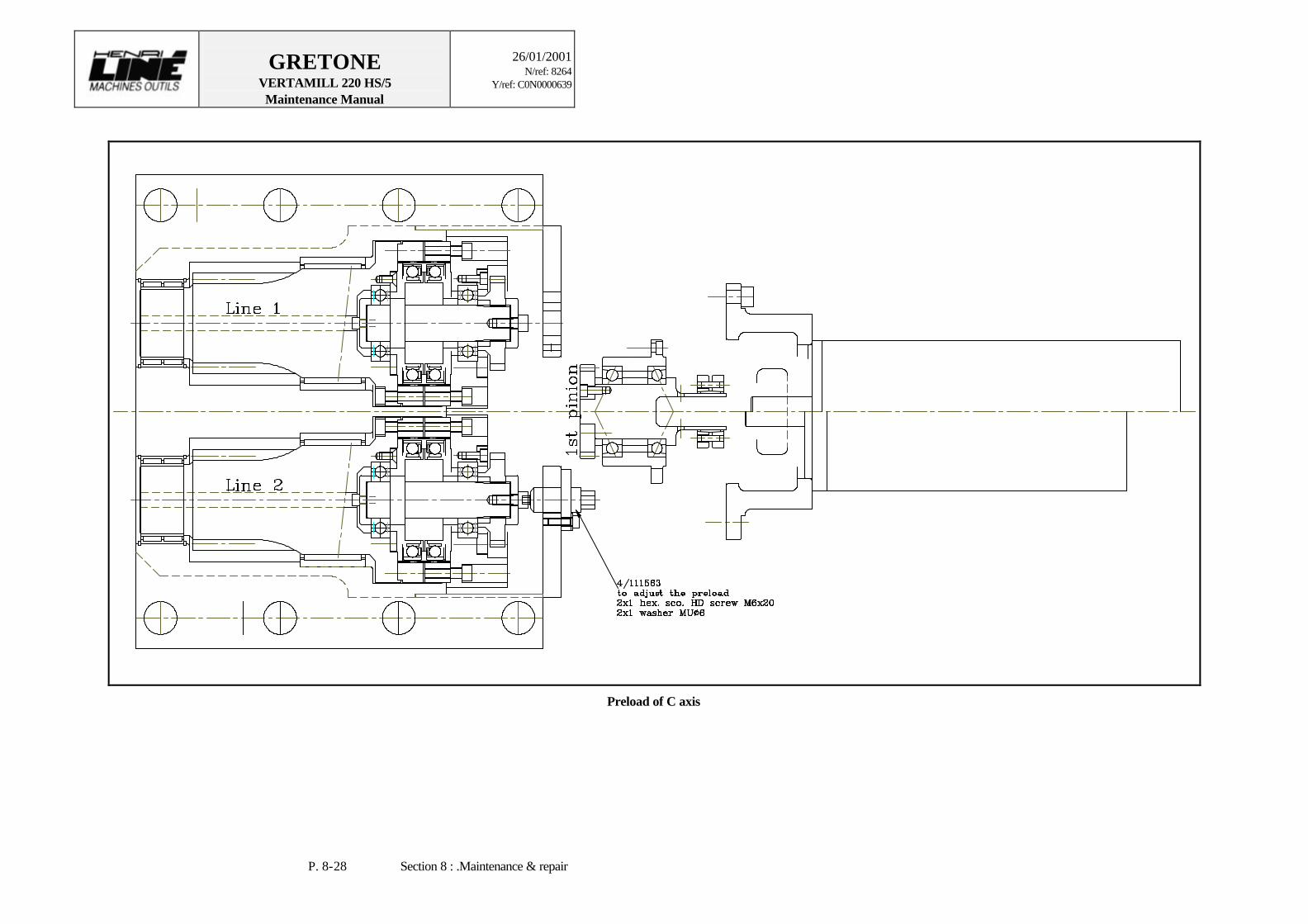
GRETONE VERTAMILL 220 HS/5 Maintenance Manual
26/01/2001
N/ref: 8264 Y/ref: C0N0000639
P. 8-28 Section 8 : .Maintenance & repair
Preload of C axis

GRETONE VERTAMILL 220 HS/5 Maintenance Manual
26/01/2001
N/ref: 8264 Y/ref: C0N0000639
P. 8-29 Section 8 : .Maintenance & repair
8.2. LUBRICATION AND FLUIDS MAINTENANCE A (yellow and black) chart « Lubrication and maintenance instructions » is fixed on the machine, which resume the main lubrication and maintenance operation. The copy of this chart and a conversion table of oil and grease follow the maintenance description. The arrows show the rough lubrication locations. The indicated times in the chart depend on such factors as the ambient conditions, the use of the machine, etc. and it is a machine time. The chart indicate the lubricant types and the filter references too. This chart should be used preventive maintenance scheduling. For safe operation and prolonged parts life, maintenance should be performed as we recommend. Even though the critical systems have switches that will indicate extremely low levels, you should NEVER wait for a “low level” warning message to fill a reservoir.
ø Caution ! Fuels (oil and cooling fluid) can be hazardous to persons in several ways (allergic reaction, danger of slipping if the material leaks on the floor, etc.) Therefore, take great care when handling such materials and always observe the relevant factory safety regulations. When not correctly used, oil and cooling agent additives can pollute the environment. Therefore handle such materials with care and strictly observe local regulations and laws. Collect the used materials in suitable containers (e.g. original canisters) and ensure that the correct disposal procedures are carried out.
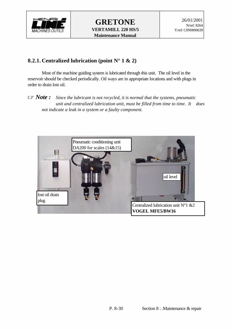
GRETONE VERTAMILL 220 HS/5 Maintenance Manual
26/01/2001
N/ref: 8264 Y/ref: C0N0000639
P. 8-30 Section 8 : .Maintenance & repair
8.2.1. Centralized lubrication (point N° 1 & 2) Most of the machine guiding system is lubricated through this unit. The oil level in the reservoir should be checked periodically. Oil ways are in appropriate locations and with plugs in order to drain lost oil. ø Note : Since the lubricant is not recycled, it is normal that the systems, pneumatic
unit and centralized lubrication unit, must be filled from time to time. It does not indicate a leak in a system or a faulty component.
Pneumatic conditioning unit DA200 for scales (14&15)
Centralized lubrication unit N°1 &2 VOGEL MFE5/BW16
lost oil drain plug
oil level

GRETONE VERTAMILL 220 HS/5 Maintenance Manual
26/01/2001
N/ref: 8264 Y/ref: C0N0000639
P. 8-31 Section 8 : .Maintenance & repair
8.2.2. Flood coolant (point N° 3, 4, 5 & 6) The machine is equipped with an FM external flood coolant system used during machining. Clean coolant fluid is pumped from a tank which should be checked and refilled if necessary (N°3) every day (8 h) and drain (N°6) once a year (2000 h) and is delivered to the machining part after flowing through filters (N°4) with clogging indicator which will be replaced after a detection or at least once a year (2000 h). The used fluid is recuperate to be filtered by paper (N°5) which should be checked every day (8 h) and replace once a year (2000 h).
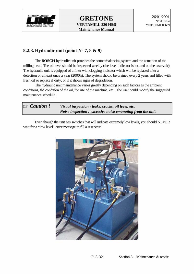
GRETONE VERTAMILL 220 HS/5 Maintenance Manual
26/01/2001
N/ref: 8264 Y/ref: C0N0000639
P. 8-32 Section 8 : .Maintenance & repair
8.2.3. Hydraulic unit (point N° 7, 8 & 9) The BOSCH hydraulic unit provides the counterbalancing system and the actuation of the milling head. The oil level should be inspected weekly (the level indicator is located on the reservoir). The hydraulic unit is equipped of a filter with clogging indicator which will be replaced after a detection or at least once a year (2000h). The system should be drained every 2 years and filled with fresh oil or replace if dirty, or if it shows signs of degradation. The hydraulic unit maintenance varies greatly depending on such factors as the ambient conditions, the condition of the oil, the use of the machine, etc. The user could modify the suggested maintenance schedule.
ø Caution ! Visual inspection : leaks, cracks, oil level, etc. Noise inspection : excessive noise emanating from the unit. Even though the unit has switches that will indicate extremely low levels, you should NEVER wait for a “low level” error message to fill a reservoir
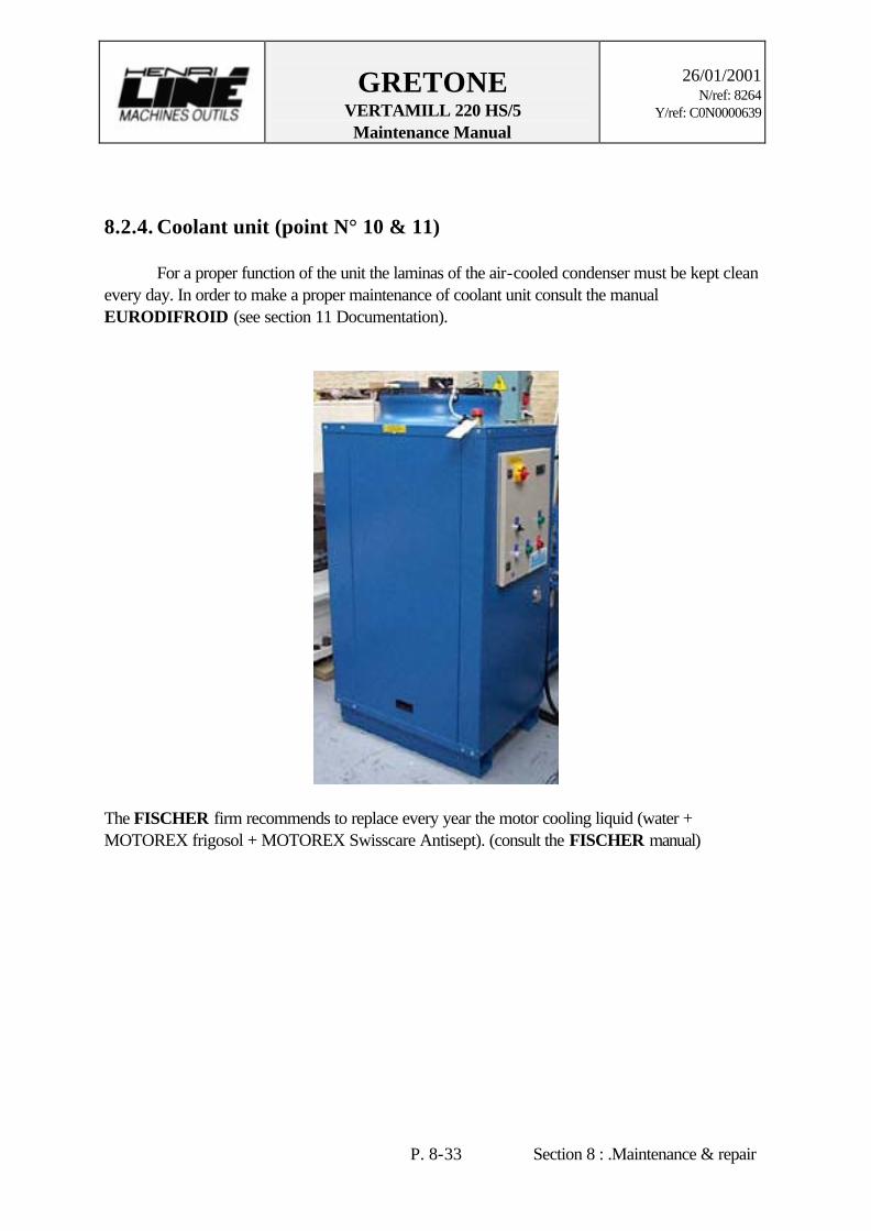
GRETONE VERTAMILL 220 HS/5 Maintenance Manual
26/01/2001
N/ref: 8264 Y/ref: C0N0000639
P. 8-33 Section 8 : .Maintenance & repair
8.2.4. Coolant unit (point N° 10 & 11) For a proper function of the unit the laminas of the air-cooled condenser must be kept clean every day. In order to make a proper maintenance of coolant unit consult the manual EURODIFROID (see section 11 Documentation).
The FISCHER firm recommends to replace every year the motor cooling liquid (water + MOTOREX frigosol + MOTOREX Swisscare Antisept). (consult the FISCHER manual)

GRETONE VERTAMILL 220 HS/5 Maintenance Manual
26/01/2001
N/ref: 8264 Y/ref: C0N0000639
P. 8-34 Section 8 : .Maintenance & repair
8.2.5. Pneumatic unit – Lubrication (point N° 12 to 21)
8.2.5.1 Conditioning (n° 12 & 13) Before it is used, the plant compressed air is conditioned by a LFR-3/4-D FESTO filter with pressure reducing valve which frees the air of dirt particles and condensed water then the compressed air is lubricated.. This system prevents the most possible the oxidizing and the damage of parts. The filter has a cartridge and a water separator with manual drain, also must be checked. The LOE-3/4-D FESTO lubricator mixes an oil dose to the compressed air, also this unit should be controlled periodically (40h, 12) and refilled if necessary . The cartridge of LFR-3/4-D FESTO filter must be exchanged once a year (2000h, 13) and its feed trough must be drained according to the level of condensate.
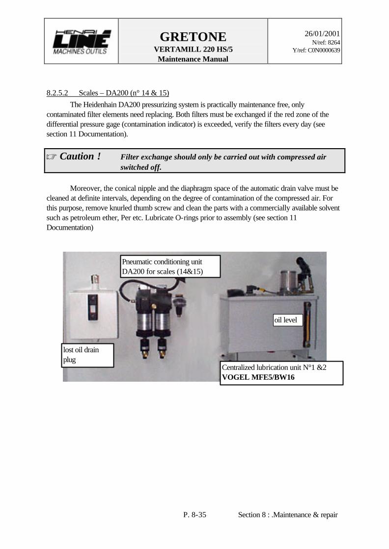
GRETONE VERTAMILL 220 HS/5 Maintenance Manual
26/01/2001
N/ref: 8264 Y/ref: C0N0000639
P. 8-35 Section 8 : .Maintenance & repair
8.2.5.2 Scales – DA200 (n° 14 & 15) The Heidenhain DA200 pressurizing system is practically maintenance free, only contaminated filter elements need replacing. Both filters must be exchanged if the red zone of the differential pressure gage (contamination indicator) is exceeded, verify the filters every day (see section 11 Documentation).
ø Caution ! Filter exchange should only be carried out with compressed air switched off. Moreover, the conical nipple and the diaphragm space of the automatic drain valve must be cleaned at definite intervals, depending on the degree of contamination of the compressed air. For this purpose, remove knurled thumb screw and clean the parts with a commercially available solvent such as petroleum ether, Per etc. Lubricate O-rings prior to assembly (see section 11 Documentation)
Pneumatic conditioning unit DA200 for scales (14&15)
Centralized lubrication unit N°1 &2 VOGEL MFE5/BW16
lost oil drain plug
oil level
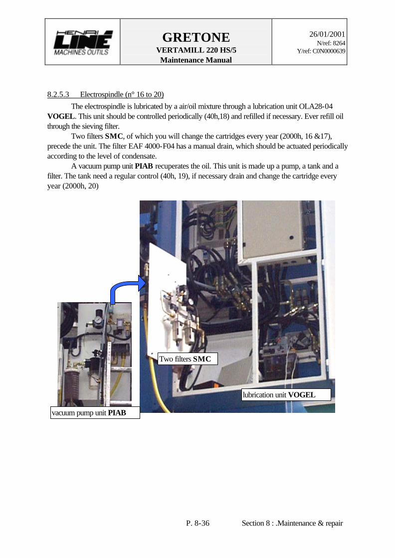
GRETONE VERTAMILL 220 HS/5 Maintenance Manual
26/01/2001
N/ref: 8264 Y/ref: C0N0000639
P. 8-36 Section 8 : .Maintenance & repair
8.2.5.3 Electrospindle (n° 16 to 20) The electrospindle is lubricated by a air/oil mixture through a lubrication unit OLA28-04 VOGEL. This unit should be controlled periodically (40h,18) and refilled if necessary. Ever refill oil through the sieving filter. Two filters SMC, of which you will change the cartridges every year (2000h, 16 &17), precede the unit. The filter EAF 4000-F04 has a manual drain, which should be actuated periodically according to the level of condensate. A vacuum pump unit PIAB recuperates the oil. This unit is made up a pump, a tank and a filter. The tank need a regular control (40h, 19), if necessary drain and change the cartridge every year (2000h, 20)
vacuum pump unit PIAB
Two filters SMC
lubrication unit VOGEL
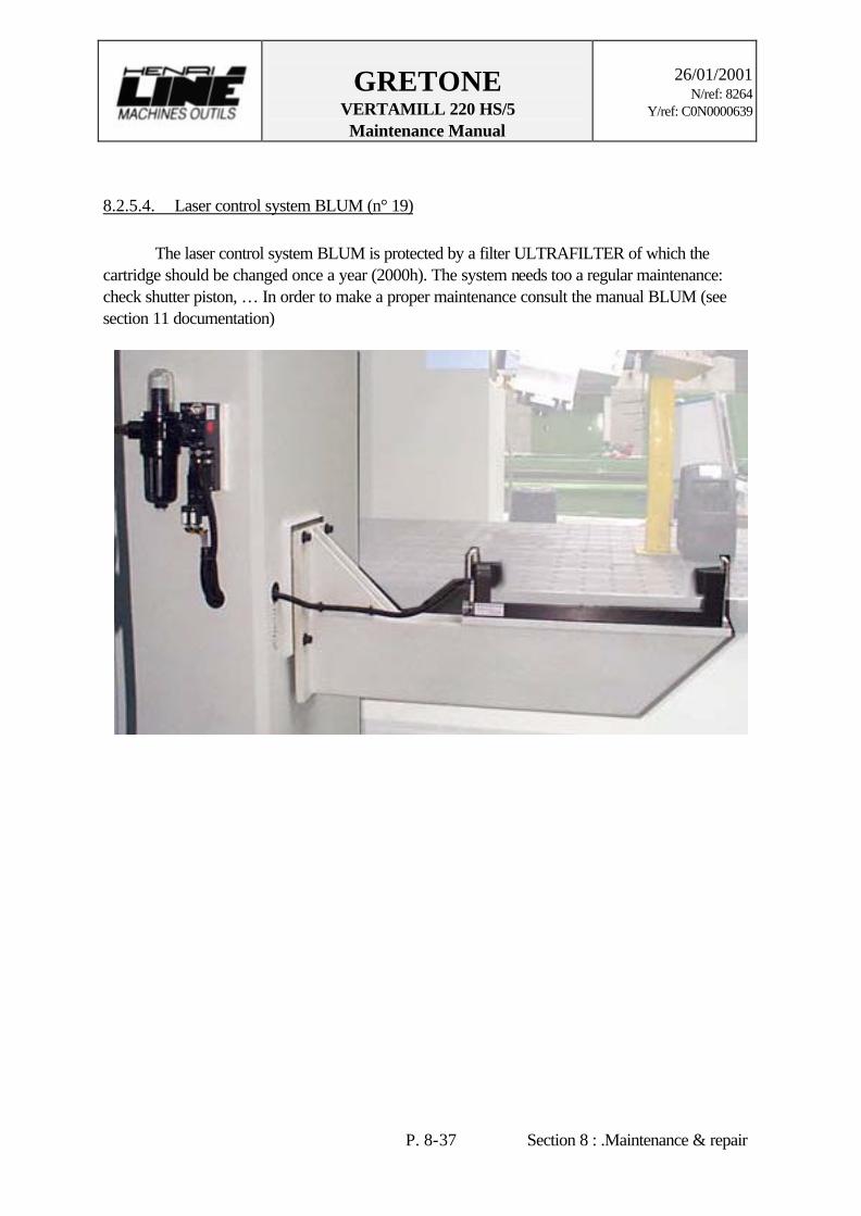
GRETONE VERTAMILL 220 HS/5 Maintenance Manual
26/01/2001
N/ref: 8264 Y/ref: C0N0000639
P. 8-37 Section 8 : .Maintenance & repair
8.2.5.4. Laser control system BLUM (n° 19) The laser control system BLUM is protected by a filter ULTRAFILTER of which the cartridge should be changed once a year (2000h). The system needs too a regular maintenance: check shutter piston, … In order to make a proper maintenance consult the manual BLUM (see section 11 documentation)

GRETONE VERTAMILL 220 HS/5 Maintenance Manual
26/01/2001
N/ref: 8264 Y/ref: C0N0000639
P. 8-38 Section 8 : .Maintenance & repair
8.2.6. Lubrication procedure of the A/B and C axes bearings (n° 22) See drawings 2/114020 and 2/111532.
The assemblies C and A/B axes are lubricated with grease without lubrication unit so they should be totally and regularly renew after removing of the milling head. We advise you at the time of removing: - To confide the maintenance work to any qualified persons. - To study carefully the advises below and drawings. - To work in a room and on a surface clean. - To have proper bearings removing tools. The greasing time is evaluated at 10 000 h (machine time) for normal working conditions without the effect uncontrolled parameters. The quantities of grease are evaluated for the same parameters. The A/B and C axes bearings are precision bearings that must not get a make-up grease and so the used grease should be completely cleaned and replaced.
ø Caution ! Before you remove C or A/B assembly, you must release their preload (see § 8.1.5.1 & 8.1.5.2) and at the time of mounting, DO NOT FORGET THE PRELOAD !
The A/B and C axes bearings ass’y is completely removed to grease and to verify the bearings. The grease is cleaned imperatively by a chlorinated hydrocarbon or light solvents as the special essences, the trichloroethane.
ø Caution ! Do not use gasoline, petrol or gas oil. The new recommended grease should be type FAG LV135. Clean carefully bearings with a proper fluid and the other parts too and dry them carefully. Inspect the bearings for any visual defect (check for marks of indentations, scoring, pitting and also deformations) and replace them if necessary. Fill up grease the free spaces of bearings. Share out uniformly. Make a manual rotation to bearings to place properly the Grease We advise you to use a graduated grease gun, which is more precise and handier. ø Note : It is possible - To strike the bearings or their axes with a puller and a plastic hammer in
order to unlock the bearings. - To warm lightly the bearings at a 20° to 30°C temperature higher than
ambient temperature on a heated plate in order to make easier the reassembling.

GRETONE VERTAMILL 220 HS/5 Maintenance Manual
26/01/2001
N/ref: 8264 Y/ref: C0N0000639
P. 8-39 Section 8 : .Maintenance & repair
- To brush the bearing surface with the oil film.
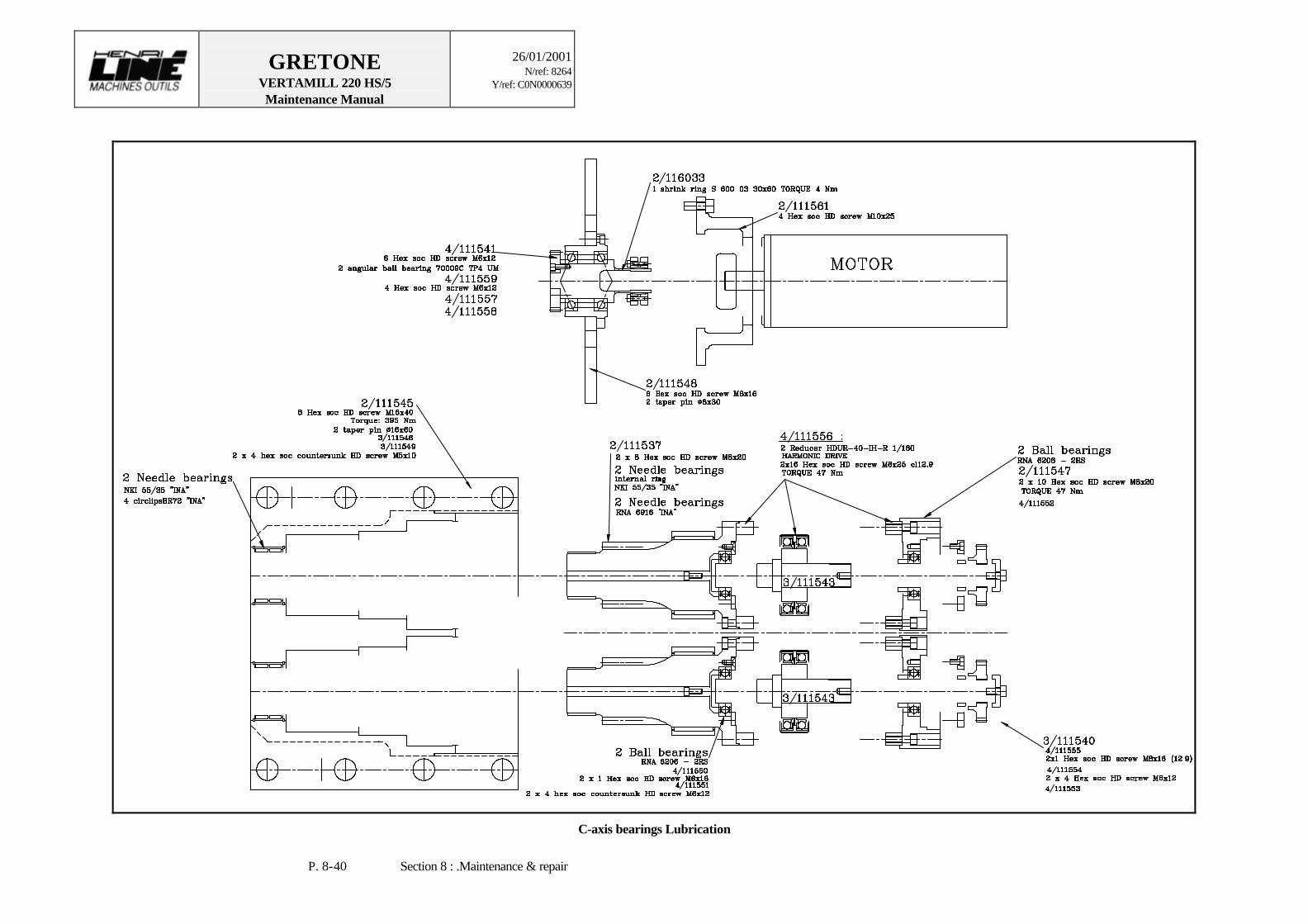
GRETONE VERTAMILL 220 HS/5 Maintenance Manual
26/01/2001
N/ref: 8264 Y/ref: C0N0000639
P. 8-40 Section 8 : .Maintenance & repair
C-axis bearings Lubrication

GRETONE VERTAMILL 220 HS/5 Maintenance Manual
26/01/2001
N/ref: 8264 Y/ref: C0N0000639
P. 8-41 Section 8 : .Maintenance & repair
A/B-axis bearings Lubrication
Needle cages
GRETONE VERTAMILL 220 HS/5 Maintenance Manual
26/01/2001
N/ref: 8264 Y/ref: C0N0000639
P. 8-42 Section 8 : .Maintenance & repair
8.2.7. Bearings of Ballscrew (n° 23) The bearings of Z and Y Ballscrew are not lubricating with oil of a centralized unit. They need that you renew regular the grease. Although it is a life lubrication (20000h) See paragraphs 8.1.3.3. and 8.1.4.3.
8.2.8. Automatic Tools Changer (point N° 24, 25 & 26) The interior of the Automatic Tools Changer should be cleaned up thoroughly weekly as the taper tools locations which should be cleaned once year (2000 h), to keep it in good working condition. The drive needs a regular lubrication (20 000 h). In order to know more information, consult specific documentation.

GRETONE VERTAMILL 220 HS/5 Maintenance Manual
26/01/2001
N/ref: 8264 Y/ref: C0N0000639
P. 8-43 Section 8 : .Maintenance & repair
CONVERSION TABLE OF OIL AND GREASE LUBRICATION OF OUR MACHINE
* We advise BP lubricant using. This document provides for information only an equivalent oil or grease which advised by HLMO. PRODUCT BRAND ISO DIN Remark Rough equivalence EXAMPLES MACCURAT D68 or 32 BP G68 or G32 CGLP68 Gearbox Moglia 68 or Hygliss 82 ELF-ANTAR Centralized lubricat ion
FEBIS K 68 or 32. ESSO Hydrostatic set
VACTRA 2 or 1. MOBIL TONNA 68 or 32. SHELL DROSERA MS 68 or 32. TOTAL ENERGOL HLP-HM 32- BP HM 32 HLP 32 Hydraulic set POLYTELLIS 32 ELF-ANTAR NUTO H 32 ESSO DTE LIGHT MOBIL TELLUS 32 SHELL AZOLLA 32 TOTAL ENERGOL GRXP 220 or 460 BP CKC 220 or 460 CLP 220 or 460 Worm drive REDUCTELF SP 220 or 460. ELF-ANTAR Planetary reducer SPARTAN EP 220 or 460. ESSO MOBILGEAR 630 or 634. MOBIL OMALA 220 or 460. SHELL CARTER EP 220 or 460. TOTAL ENERGOL HP5 BP FD5 RU+ SPINELF 32 ELF-ANTAR NUTO PH32 ESSO DTE OIL LIGHT MOBIL TELLUS C5 SHELL DROSERA MS5 TOTAL BARTRAN HV15 BP HV15 air lubricator HYDRELF DS22. ELF-ANTAR Accessory lubricate UNUVIS HP22 ESSO recuperation unit DTE 10 M MOBIL TELLUS SX32 SHELL DROSERA MS15 or EQUIVIS15 TOTAL ENERGREASE LS EP 2- BP XM2 KP2K Bearing EXPEXA 2. ELF-ANTAR BEACON EP 2. ESSO MOBILUX EP 2. MOBIL ALVANTA EP 2. SHELL MULTIS EP 2. TOTAL KLUBER ISOFLEX LDS18 SPECIAL A.
KLUBER Spindle bearing
Energrease LT2 BP AVIATION GREASE 10 ELF-ANTAR MOBILGREASE 22 MOBIL AEROGREASE 22 TOTAL
changed 01 July 1999
GRETONE VERTAMILL 220 HS/5 Maintenance Manual
26/01/2001
N/ref: 8264 Y/ref: C0N0000639
P. 8-44 Section 8 : .Maintenance & repair
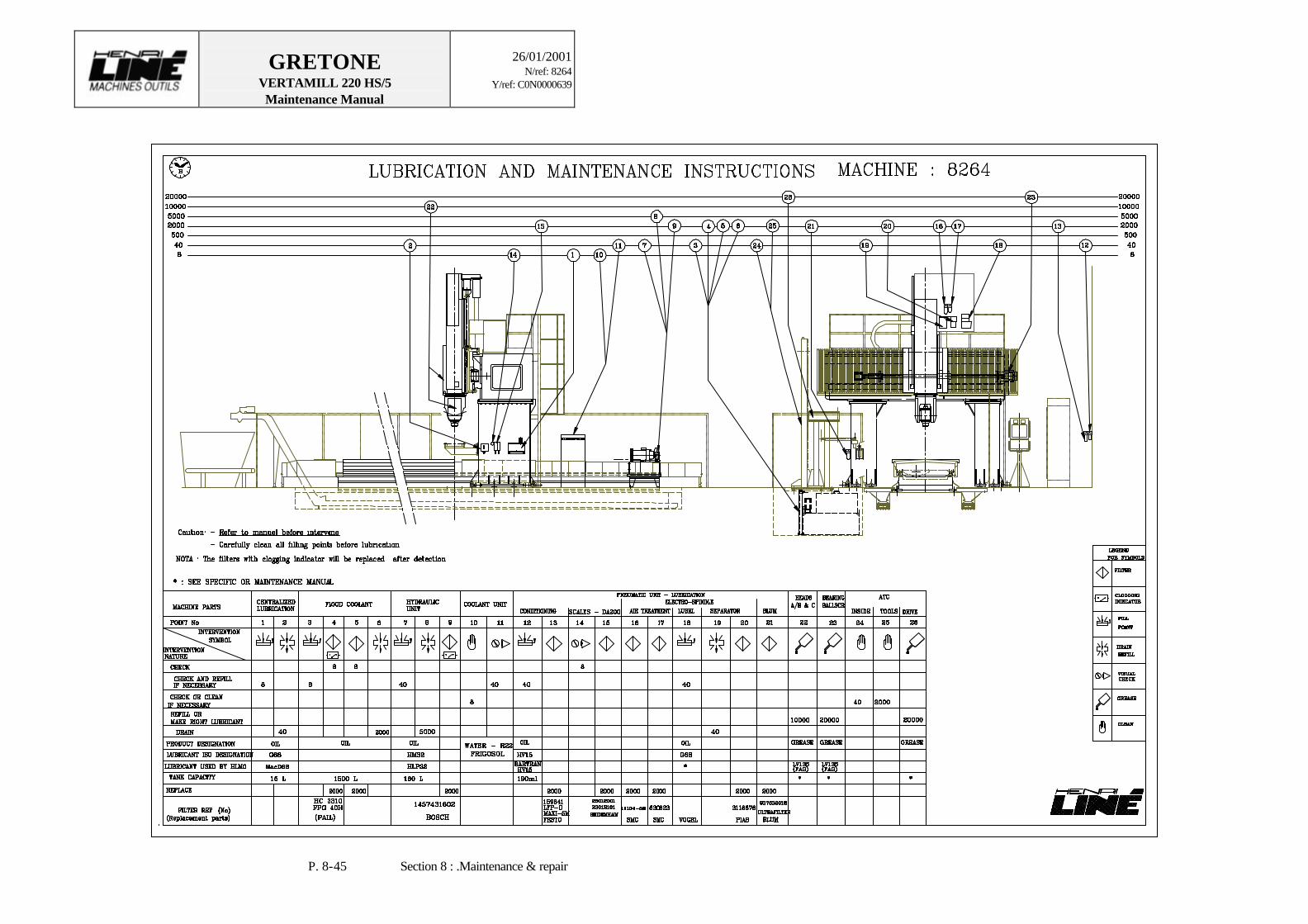
GRETONE VERTAMILL 220 HS/5 Maintenance Manual
26/01/2001
N/ref: 8264 Y/ref: C0N0000639
P. 8-45 Section 8 : .Maintenance & repair
GRETONE VERTAMILL 220 HS/5 Maintenance Manual
26/01/2001
N/ref: 8264 Y/ref: C0N0000639
P. 9-1 Section 9 : Spare parts.
9. SPARE PARTS To keep machine down time to its minimum, we recommend a list of spare parts that you should keep in stock. The list is organized as below :
PART DESCRIPTION MANUFACTURER PART NUMBER MQ RQ LEVEL (1/2/3)
DELIV. (S/M/L)
MQ: Machine Quantity (quantity of this piece used on the machine) RQ: Recommended Quantity (quantity you should keep in stock) We have included some parts in the list for your information only. These parts have a RQ of 0. Level - Level of recommendation for having this part in stock: 1: STRONGLY recommended 2: Recommended 3: Optional Deliv. - Estimated delivery time for the part: S: short time (less than a week) M: medium time (between 1 and 3 weeks) L: long time (4 weeks or more) Although we indicate specific models and manufacturers, equivalents can be used for some of the parts. Before using a different part, though, always check with us first.
ø Caution ! Never use a part substitute before checking with Henri Liné Machine-Tools first!
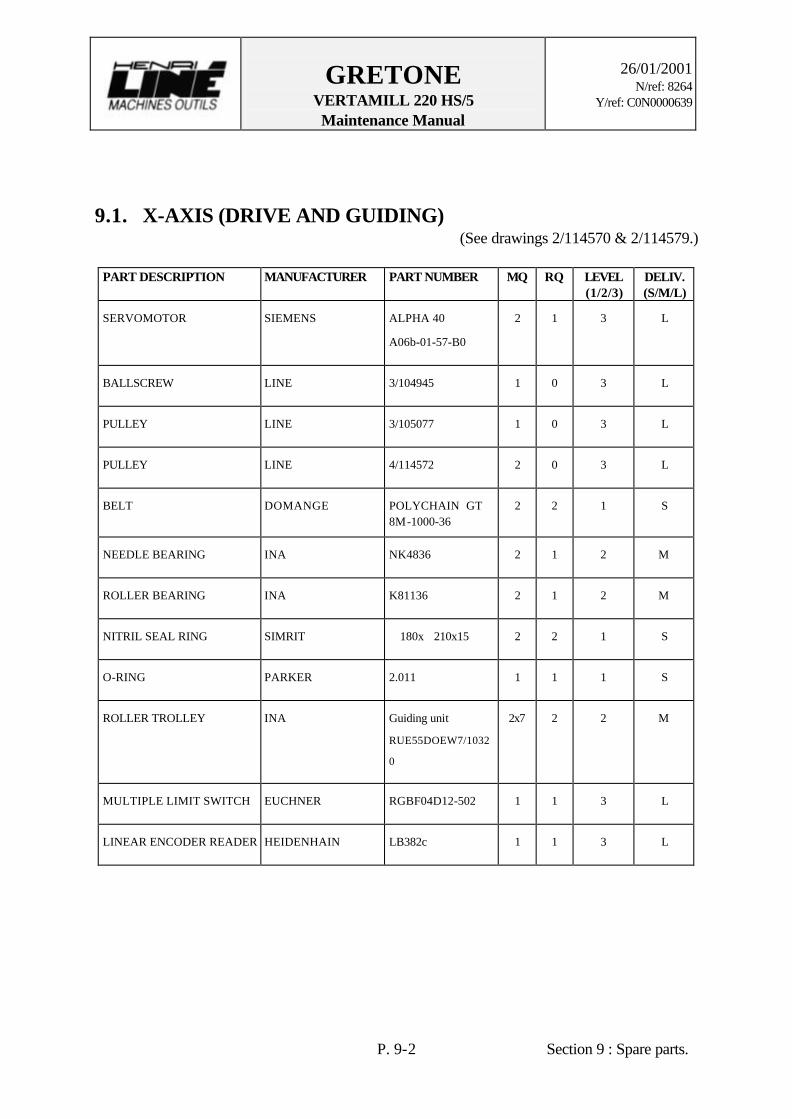
GRETONE VERTAMILL 220 HS/5 Maintenance Manual
26/01/2001
N/ref: 8264 Y/ref: C0N0000639
P. 9-2 Section 9 : Spare parts.
9.1. X-AXIS (DRIVE AND GUIDING) (See drawings 2/114570 & 2/114579.)
PART DESCRIPTION MANUFACTURER PART NUMBER MQ RQ LEVEL
(1/2/3) DELIV. (S/M/L)
SERVOMOTOR SIEMENS ALPHA 40
A06b-01-57-B0
2 1 3 L
BALLSCREW LINE 3/104945 1 0 3 L
PULLEY LINE 3/105077 1 0 3 L
PULLEY LINE 4/114572 2 0 3 L
BELT DOMANGE POLYCHAIN GT 8M-1000-36
2 2 1 S
NEEDLE BEARING INA NK4836 2 1 2 M
ROLLER BEARING INA K81136 2 1 2 M
NITRIL SEAL RING SIMRIT ∅180x∅210x15 2 2 1 S
O-RING PARKER 2.011 1 1 1 S
ROLLER TROLLEY INA Guiding unit
RUE55DOEW7/1032
0
2x7 2 2 M
MULTIPLE LIMIT SWITCH EUCHNER RGBF04D12-502 1 1 3 L
LINEAR ENCODER READER HEIDENHAIN LB382c 1 1 3 L
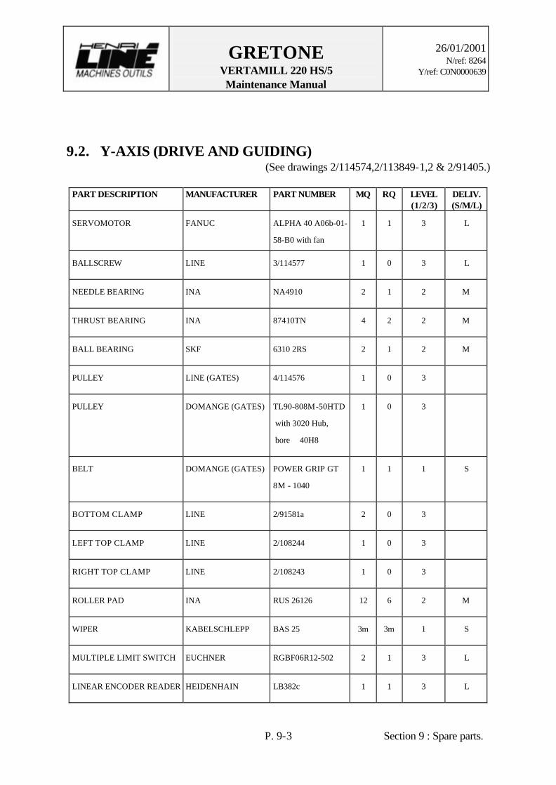
GRETONE VERTAMILL 220 HS/5 Maintenance Manual
26/01/2001
N/ref: 8264 Y/ref: C0N0000639
P. 9-3 Section 9 : Spare parts.
9.2. Y-AXIS (DRIVE AND GUIDING) (See drawings 2/114574,2/113849-1,2 & 2/91405.)
PART DESCRIPTION MANUFACTURER PART NUMBER MQ RQ LEVEL
(1/2/3) DELIV. (S/M/L)
SERVOMOTOR FANUC ALPHA 40 A06b-01-
58-B0 with fan
1 1 3 L
BALLSCREW LINE 3/114577 1 0 3 L
NEEDLE BEARING INA NA4910 2 1 2 M
THRUST BEARING INA 87410TN 4 2 2 M
BALL BEARING SKF 6310 2RS 2 1 2 M
PULLEY LINE (GATES) 4/114576 1 0 3
PULLEY DOMANGE (GATES) TL90-808M-50HTD
with 3020 Hub,
bore ∅40H8
1 0 3
BELT DOMANGE (GATES) POWER GRIP GT
8M - 1040
1 1 1 S
BOTTOM CLAMP LINE 2/91581a 2 0 3
LEFT TOP CLAMP LINE 2/108244 1 0 3
RIGHT TOP CLAMP LINE 2/108243 1 0 3
ROLLER PAD INA RUS 26126 12 6 2 M
WIPER KABELSCHLEPP BAS 25 3m 3m 1 S
MULTIPLE LIMIT SWITCH EUCHNER RGBF06R12-502 2 1 3 L
LINEAR ENCODER READER HEIDENHAIN LB382c 1 1 3 L
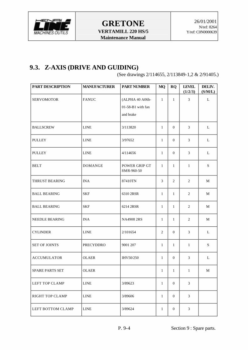
GRETONE VERTAMILL 220 HS/5 Maintenance Manual
26/01/2001
N/ref: 8264 Y/ref: C0N0000639
P. 9-4 Section 9 : Spare parts.
9.3. Z-AXIS (DRIVE AND GUIDING) (See drawings 2/114655, 2/113849-1,2 & 2/91405.)
PART DESCRIPTION MANUFACTURER PART NUMBER MQ RQ LEVEL
(1/2/3) DELIV. (S/M/L)
SERVOMOTOR FANUC (ALPHA 40 A06b-
01-58-B1 with fan
and brake
1 1 3 L
BALLSCREW LINE 3/113820 1 0 3 L
PULLEY LINE 3/97652 1 0 3 L
PULLEY LINE 4/114656 1 0 3 L
BELT DOMANGE POWER GRIP GT 8MR-960-50
1 1 1 S
THRUST BEARING INA 87410TN 3 2 2 M
BALL BEARING SKF 6310 2RSR 1 1 2 M
BALL BEARING SKF 6214 2RSR 1 1 2 M
NEEDLE BEARING INA NA4908 2RS 1 1 2 M
CYLINDER LINE 2/101654 2 0 3 L
SET OF JOINTS PRECYDDRO 9001 207 1 1 1 S
ACCUMULATOR OLAER IHV50/250 1 0 3 L
SPARE PARTS SET OLAER 1 1 1 M
LEFT TOP CLAMP LINE 3/89623 1 0 3
RIGHT TOP CLAMP LINE 3/89606 1 0 3
LEFT BOTTOM CLAMP LINE 3/89624 1 0 3

GRETONE VERTAMILL 220 HS/5 Maintenance Manual
26/01/2001
N/ref: 8264 Y/ref: C0N0000639
P. 9-5 Section 9 : Spare parts.
PART DESCRIPTION MANUFACTURER PART NUMBER MQ RQ LEVEL (1/2/3)
DELIV. (S/M/L)
RIGHT BOTTOM CLAMP LINE 3/89607 1 0 3
ROLLER PAD INA RUS 26126-2S 8 4 2
WIPER KABELSCHLEPP BAS 25 5 m 5 m 1 S
MULTIPLE LIMIT SWITCH EUCHNER RGBF04D12-502 1 1 3 L
LINEAR ENCODER READER HEIDENHAIN LB382c 1 1 3 L

GRETONE VERTAMILL 220 HS/5 Maintenance Manual
26/01/2001
N/ref: 8264 Y/ref: C0N0000639
P. 9-6 Section 9 : Spare parts.
9.4. MILLING HEADS
9.4.1. Bottom of Head 2/111531
PART DESCRIPTION MANUFACTURER PART NUMBER MQ RQ LEVEL
(1/2/3) DELIV. (S/M/L)
FITTING LINE (STAUBLI) 3/91605 (SPH06-2102MA/IA/JV)
8 2 1 M
FITTING STAUBLI SPH12-
2104MA/IA/JV)
3 1 1 M
FITTING LINE (STAUBLI) 3/113180 (SPH06-2102MA/IB/JV)
1 1 1 M
O-RING PARKER 2-211 4 4 1 S
O-RING PARKER 2-113 8 8 1 S
O-RING PARKER 2-224 4 4 1 S
O-RING PARKER 2-122 9 9 1 S
O-RING PARKER 2-111 9 9 1 S
PARBAK PARKER 8-111 9 9 1 S
BALL & ROLLER BEARING IAN YRT460BGKSL977 1 0 3 L
CLAMP WASHER LINE 4/87589 22 0 3 L
O-RING PARKER 2-211 22 22 1 S
CLAMPING GRIPPER BERG SSK50ANSI 4 1 2 S
SPRING WASHER SCHNORR 80x41x5 144 144 1 S

GRETONE VERTAMILL 220 HS/5 Maintenance Manual
26/01/2001
N/ref: 8264 Y/ref: C0N0000639
P. 9-7 Section 9 : Spare parts.
PART DESCRIPTION MANUFACTURER PART NUMBER MQ RQ LEVEL (1/2/3)
DELIV. (S/M/L)
GUIDING SEGMENT BUSAK &
SHAMBON
ORKOT
BB50704.0820.A.TL
G
4 4 1 S
O-RING PARKER 2-335 4 4 1 S
PARBAK PARKER 8-235 4 4 1 S
POSITION SWITCH EUCHNER EGT1-5000 3 1 1 S

GRETONE VERTAMILL 220 HS/5 Maintenance Manual
26/01/2001
N/ref: 8264 Y/ref: C0N0000639
P. 9-8 Section 9 : Spare parts.
9.4.2. C axis 2/111532 & 2/111533
PART DESCRIPTION MANUFACTURER PART NUMBER MQ RQ LEVEL
(1/2/3) DELIV. (S/M/L)
C-AXIS SERVOMOTOR FANUC ALPHA M9/3000
A06b-01-63-B5
1 1 3 L
REDUCER LINE (HARMONIC) 3/111556A (HDUR40-IH)
2 1 2 M
PINION LINE 2/111537 2 0 3 L
PINION LINE 3/111540 2 0 3 L
PINION LINE 3/111541 1 0 3 L
SHAFT LINE 3/111543 2 0 3 L
BALL BEARING, ANGULARCONTACT
FAG 7009C.T.P4.UM 2 1 2 M
NEEDLE BEARING INA NKI 55/35 2 1 2 S
NEEDLE BEARING INA RNA 6916 2 1 2 S
BALL BEARING 6206 2RS1 4 1 2 S
ENCODER HEIDENHAIN ROD 270 18000
(FANUC)
1 1 2 M
COUPLING HEIDENHAIN K18 1 1 2 S
PINION LINE 3/111538 1 0 3 L
PINION LINE 3/111539 1 0 3 L
SPRING OLMA T0 5.6x2.8x50 2 2 1 S
BALL BEARING, ANGULARCONTACT
FAG 7206C.T.P4.UM 2 1 2 M

GRETONE VERTAMILL 220 HS/5 Maintenance Manual
26/01/2001
N/ref: 8264 Y/ref: C0N0000639
P. 9-9 Section 9 : Spare parts.
PART DESCRIPTION MANUFACTURER PART NUMBER MQ RQ LEVEL (1/2/3)
DELIV. (S/M/L)
MULTIPLE LIMIT SWITCH EUCHNER SN04D12 1 1 3 L

GRETONE VERTAMILL 220 HS/5 Maintenance Manual
26/01/2001
N/ref: 8264 Y/ref: C0N0000639
P. 9-10 Section 9 : Spare parts.
9.4.3. Attachment 2/114680
PART DESCRIPTION MANUFACTURER PART NUMBER MQ RQ LEVEL
(1/2/3) DELIV. (S/M/L)
FITTING LINE (STAUBLI) 4/113179 (SPH06-5102IB/MA/JV)
1 1 1 M
FITTING LINE (STAUBLI) 4/80945 (SPH06-5102MA/IA/JV)
1 1 1 M
FITTING STAUBLI SPH12-
5104MA/IA/JV)
3 1 1 M
O-RING PARKER 2-130 3 3 1 S
O-RING PARKER 2-117 9 9 1 S
O-RING PARKER 2-112 9 9 1 S

GRETONE VERTAMILL 220 HS/5 Maintenance Manual
26/01/2001
N/ref: 8264 Y/ref: C0N0000639
P. 9-11 Section 9 : Spare parts.
9.4.4. B-axis and Electrospindle 2/114020
PART DESCRIPTION MANUFACTURER PART NUMBER MQ RQ LEVEL
(1/2/3) DELIV. (S/M/L)
U-SHAPED PART LINE 2/114021b 1 0 3 L
COVER LINE 2/114023 1 0 3 L
SEAL CORD PARKER ∅2.62x4m 1 1 1 S
SEAL RING INA A/R1126 2m 1 1 1 S
CROSS ROLLER BEARING INA SX011840VSPGKSL
107
1 1 2 M
CROSS ROLLER BEARING INA SX011840VSPGKSL
107
1 1 2 M
O-RING PARKER 2-275 1 1 1 S
O-RING PARKER 2-265 1 1 1 S
SEAL RING INA A/R1025 2m 1 1 1 S
ELECTROSPINDLE FISHER MFWS2307/24/16
VCS HSK A63
B-AXIS SERVOMOTOR FANUC ALPHA M9/3000
A06b-01-28-B5
1 1 3 L
BALL BEARING 6206-2RS1 2 2 2 M
SHAFT LINE 3/114035 1 0 3 L
SET OF 3 NEEDLE CAGES INA K30x35x13 SORT 0-2 2 2 2 M
SHAFT LINE 3/114036 1 0 3 L
SET OF 3 NEEDLE CAGES INA K20x26x13 SORT 0-2 2 2 2 M

GRETONE VERTAMILL 220 HS/5 Maintenance Manual
26/01/2001
N/ref: 8264 Y/ref: C0N0000639
P. 9-12 Section 9 : Spare parts.
PART DESCRIPTION MANUFACTURER PART NUMBER MQ RQ LEVEL (1/2/3)
DELIV. (S/M/L)
ENCODER HEIDENHAIN ROD 282 18000
(FANUC)
1 1 2 M
COUPLING HEIDENHAIN K15 1 1 2 S
LIMIT SWITCH BAUMER IRFM 06P3701/L 1 1 3 L
9.5. PNEUMATIC, HYDRAULIC & LUBRICATION UNIT
PART DESCRIPTION MANUFACTURER PART NUMBER MQ RQ LEVEL (1/2/3)
DELIV. (S/M/L)
FILTER FESTO LFR-3/4D 1 0 3 M
FILTER ELEMENT FESTO 159641 LFP-D
MAXI 5M (12980)
1 1 1 C
FILTER SMC EAF 4000-FO4 3 0 3 M
FILTER ELEMENT SMC 11 104 –5 B 3 3 1 C
FILTER SMC EAFM 000-FO4 3 0 3 M
FILTER ELEMENT SMC 630623 3 3 1 C
FILTER PIAB 31 16 653 3 0 3 M
FILTER ELEMENT PIAB 31 16 676 3 3 1 C
FILTER ELEMENT ULTRAFILTER
(BLUM)
937532018 1 1 1 C
FILTER UNIT HEIDENHAIN DA200 2 0 3 M
FILTER ELEMENT HEIDENHAIN 23012001 2 2 1 C
FILTER ELEMENT HEIDENHAIN 23012101 2 2 1 C
SOLENOID VALVE TH FRANCE 321-910 1 1 1 S

GRETONE VERTAMILL 220 HS/5 Maintenance Manual
26/01/2001
N/ref: 8264 Y/ref: C0N0000639
P. 9-13 Section 9 : Spare parts.
HYDRAULIC FILTER BOSCH 0455900058 1 0 3 M
FILTER ELEMENT BOSCH 1457435602 1 1 1 S
PRESSURE LIMITOR TELEMECANIQUE XMLA300D2S11 1 1 1 S
FLOOD COOLANT UNIT FM BETA 2 1 0 3 L
PAPER ROLLER FM 35µ 1 1 1 S
FILTER PALL HC3310 FPG40H 1 1 1 S

REFERENCES

GRETONE VERTAMILL 220 HS/5 Maintenance Manual
26/01/2001
N/ref: 8264 Y/ref: C0N0000639
P. 10-1 Section 10 : Drawings list
10. DRAWINGS LIST The list below describes the most useful drawings used for the design and the maintenance of the milling machine. These drawings should be utilized with the manuals for the good comprehension of the milling machine principles. X-axis description : - Drive : 2/114570 - Gantry guiding 2/114579 Y-axis description (Saddle) : - Drive box and Ball screw ass’y 2/114574 - Saddle/Crossrail guiding ways ass'y 2/113849 - pl. 1,2 & 2/91405 Z-axis description (Ram) : - Drive 2/114655 & 2/107101 - Ram/Saddle guiding ways ass'y 2/113849 - pl. 1,2 & 2/91405 Milling head : - Bottom of milling head 2/111531 pl. 2 to 5 - C Axis 2/111532 - C Axis encoder 2/111533 - Attachment 2/114680 – 2pl - B Axis 2/114020 – 4pl
HLMO
Only on paper
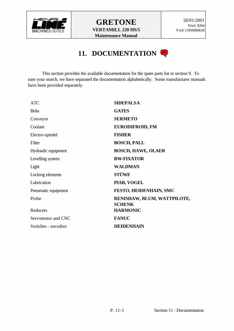
GRETONE VERTAMILL 220 HS/5 Maintenance Manual
26/01/2001
N/ref: 8264 Y/ref: C0N0000639
P. 11-1 Section 11 : Documentation
11. DOCUMENTATION This section provides the available documentation for the spare parts list in section 9. To ease your search, we have separated the documentation alphabetically. Some manufacturer manuals have been provided separately. ATC SIDEPALSA
Belts GATES
Conveyor SERMETO
Coolant EURODIFROID, FM
Electro-spindel FISHER
Filter BOSCH, PALL
Hydraulic equipment BOSCH, HAWE, OLAER
Levelling system BW-FIXATOR
Light WALDMAN
Locking elements STÜWE
Lubrication PIAB, VOGEL
Pneumatic equipment FESTO, HEIDENHAIN, SMC
Probe RENISHAW, BLUM, WATTPILOTE, SCHENK
Reducers HARMONIC
Servomotor and CNC FANUC
Switches - encoders HEIDENHAIN
HLMO
Only on paper