Swov - SWO/STB-06/104 - Puc overheid
26
Pl:: 12119& TEST REPORT STEP - BARÏtIER IN STEEL Swov SWO/STB-06/104 . t.I.E.R Laboratoire d'essais Inrets Equipements de la Route Rijkswaterstaat Adviesdienst Verkeer en Vervoer Bureau Dokumentatie Postbus 1031 3000 BA Rotterdam C 8466 -2
-
Upload
khangminh22 -
Category
Documents
-
view
0 -
download
0
Transcript of Swov - SWO/STB-06/104 - Puc overheid
Pl:: 12119&
TEST REPORT
STEP - BARÏtIER IN STEEL
Swov SWO/STB-06/104
.
t.I.E.R
Laboratoire d'essais Inrets Equipements de la Route
Rijkswaterstaat
Adviesdienst Verkeer en Vervoer
Bureau Dokumentatie
Postbus 1031
3000 BA Rotterdam
C 8466 -2
TEST REPORT
STEP - BARRIER IN STEEL
SWOV
SWO/STB-06/104
1.1.111 Laboratoire d'essais Inrets Equipements de la Route
SWO/STB-06/1 04 22nd of JuIv 1996
22 pages
CLIENT: SWOV
TEST REPORT
STEP - BARRIER IN STEEL
swov SWO/STB-06/1 04
55.201
-
Technical Director Report Preparation Instrumentation Director
WMouni uincy r This documeiit may not be reprdticed in whole or in part without the authorizatioii ofJe1.C.R.
LIE.R SA - D 29 - route de Crémieu BP 352 -69125 Lyon Satolas Aéroport Tél. 72 48 37 30- Fax 72 48 37 37 No Soel 393 068 796 000 19 Code APE 743
STEP-BARRIER IN STEEL n° ref: SWO/STB-06/104
SWOV page :2/22
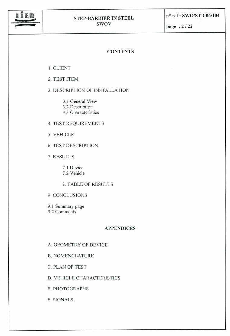
CONTENTS
CLIENT
TEST ITEM
DESCRIPTION OF INSTALLATION
3.1 General View 3.2 Description 3.3 Characteristics
TEST REQUIREMENTS
VEHICLE
TEST DESCRIPTION
RESULTS
7.1 Device 7.2 Vehicle
TABLE OF RESULTS
CONCLUSIONS
9.1 Summary page 9.2 Comments
APPENDICES
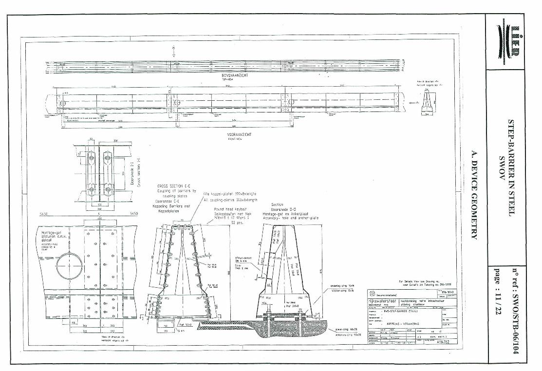
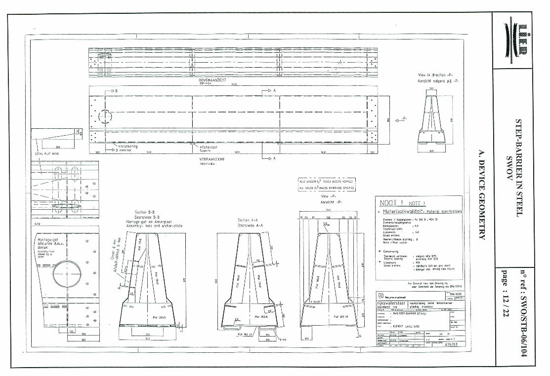
GEOMETRY OF DE VICE
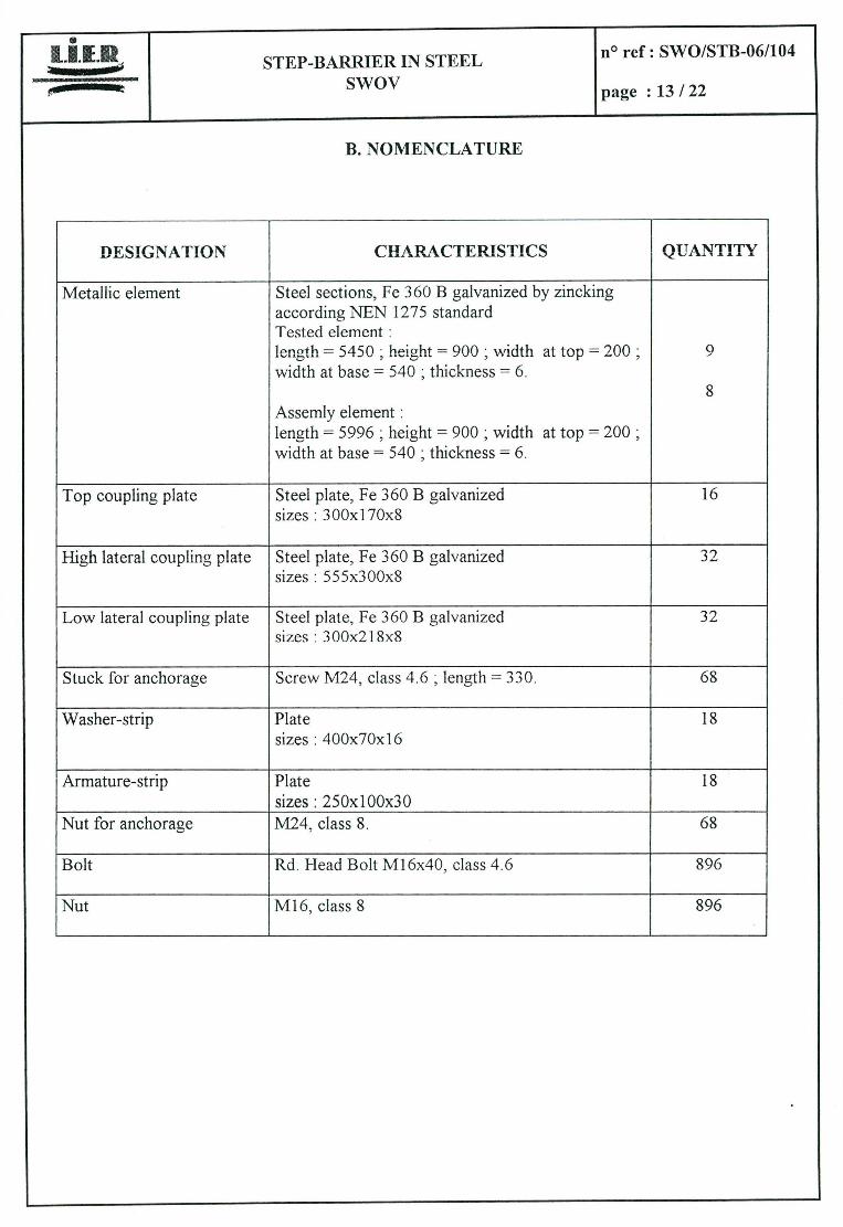
NOMENCLATURE
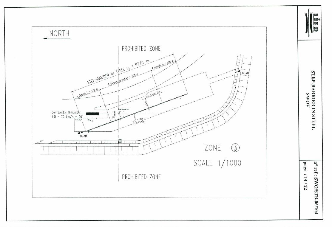
PLAN OF TEST
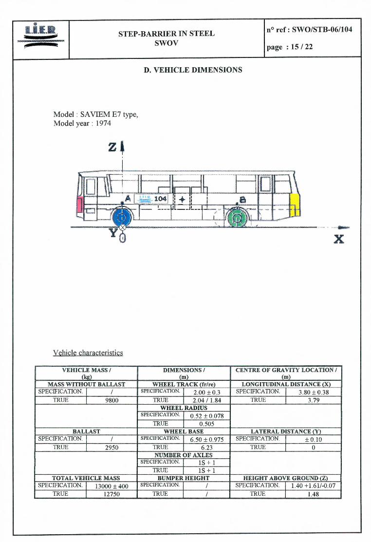
VEHICLE CHARACTERISTICS
PHOTOGRAPHS
SIGNALS
STEP-BARRIER IN STEEL O ref: SWO/STB-06/104
Swov page :3/22
CLIENT
swOv P.O. box 170 2260 AD LEJDSCHENDAM DUINDOORN 32 The NETHERLANDS Tél :31703209323 Fax : 31703201261
Contact: Mr VAN DE POL
TEST ITEM
Step-barrier in steel (see plans in appendix A and nomenciature in B).
The equipment was delivered on the 3rd of June 1996 and the test took place on the 6th of June.
STEP-BARRIER IN STEEL no ref: SWO/STB-06/104
Swov page :4/22
3. DESCRIPTION OF IISTALLATION
Step-barrier in steel
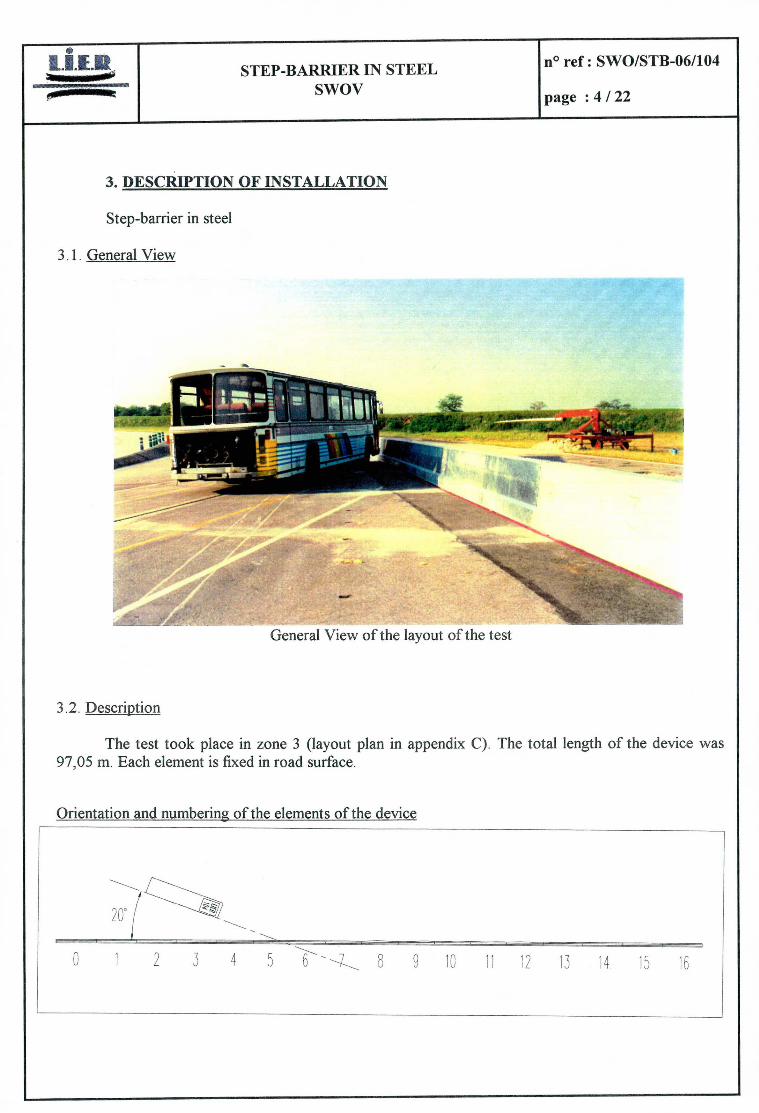
3. 1. General View
- General View of the layout of the test
3.2. Description
The test took place in zone 3 (layout plan in appendix C). The total length of the device was 97,05 m. Each element is fixed in road surface.
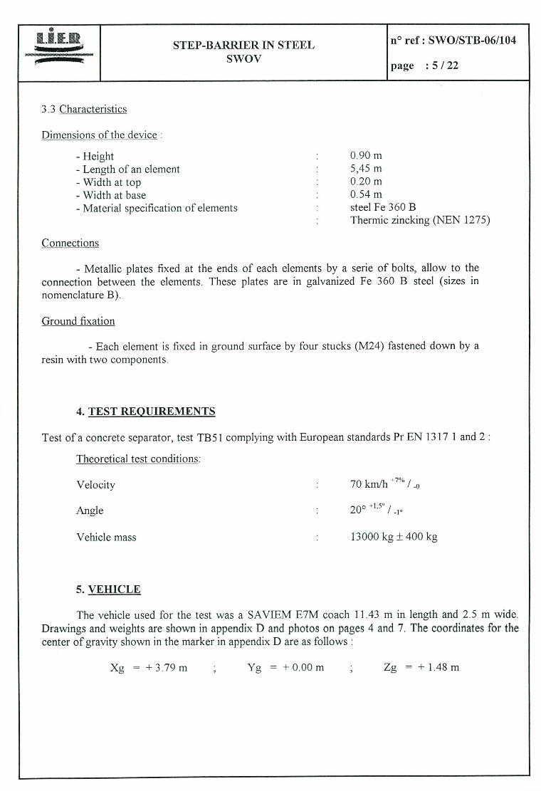
Orientation and numbering of the elements of the device
200 /
0 1 2 3 4 5 6 8 9 10 11 12 1S 14 15 16
STEP-BARRIER IN STEEL n° ref: SWO/STB-06/104
SWOV page :5/22
3.3 Characteristics
Dimensions of the device:
- Height - Length of an element - Width at top - Width at base - Material specification of elements
Connections
0.90 m 5,45 m 0.20 m 0.54 m steel Fe 360 B Thermic zincking (NEN 1275)
- Metallic plates fixed at the ends of each elements by a serie of boits, allow to the connection between the elements. These plates are in galvanized Fe 360 B steel (sizes in nomenciature B).
Ground fixation
- Each element is fixed in ground surface by four stucks (M24) fastened down by a resin with two components.
TEST REOIJIREMENTS
Test of a concrete separator, test TB5I complying with European standards Pr EN 1317 1 and 2
Theoretical test conditions:
Velocity : 70 kmlh / -o
Angle : 200 +1,5° /
Vehicle mass : 13000 kg ± 400 kg
VEHICLE
The vehicle used for the test was a SAVIEM E7M coach 11.43 m in length and 2.5 m wide. Drawings and weights are shown in appendix 0 and photos on pages 4 and 7. The coordinates for the center of gravity shown in the marker in appendix D are as foliows:
Xg = +3.79m Yg = +0.00m ; Zg = +1.48m
STEP-BARRIER IN STEEL no ref: SWO/STB-06/104
SWOV page :6/22
6. TEST DESCRIPT1ON
The test took place on the 06th of June, 1996 at 12h40 on the [NRETS test track at SATOLAS on shock zone number 3 (test layout in appendix C).
Sunny weather, dry ground.
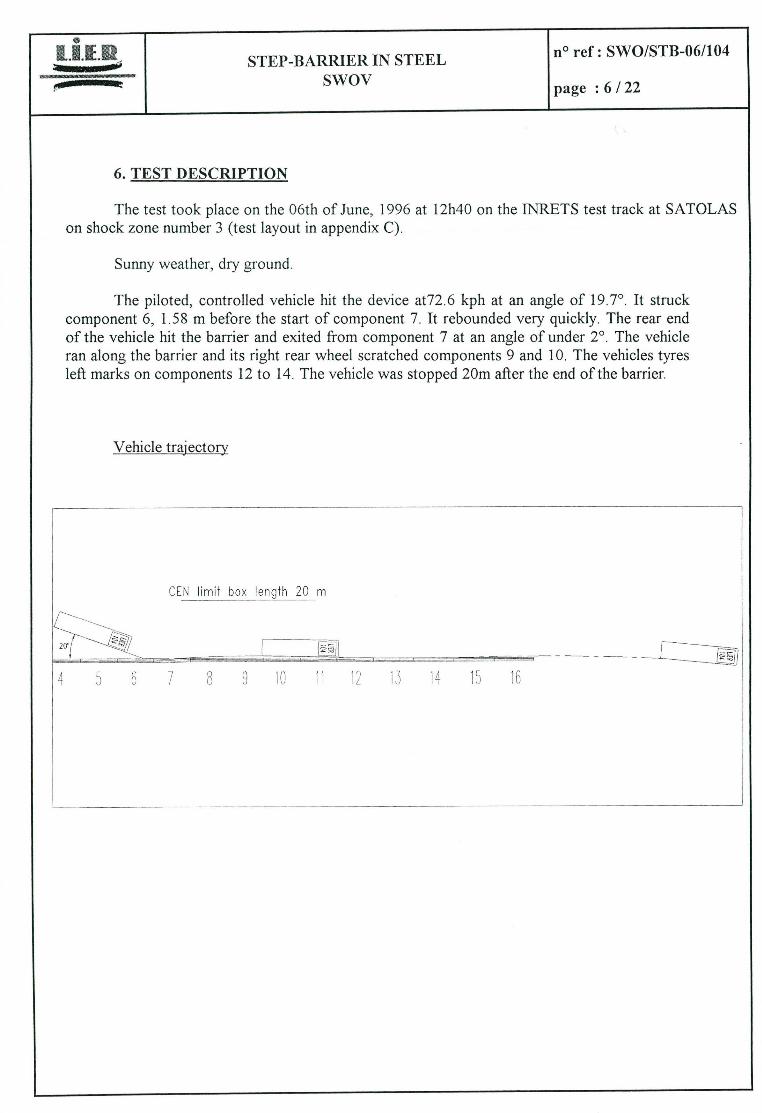
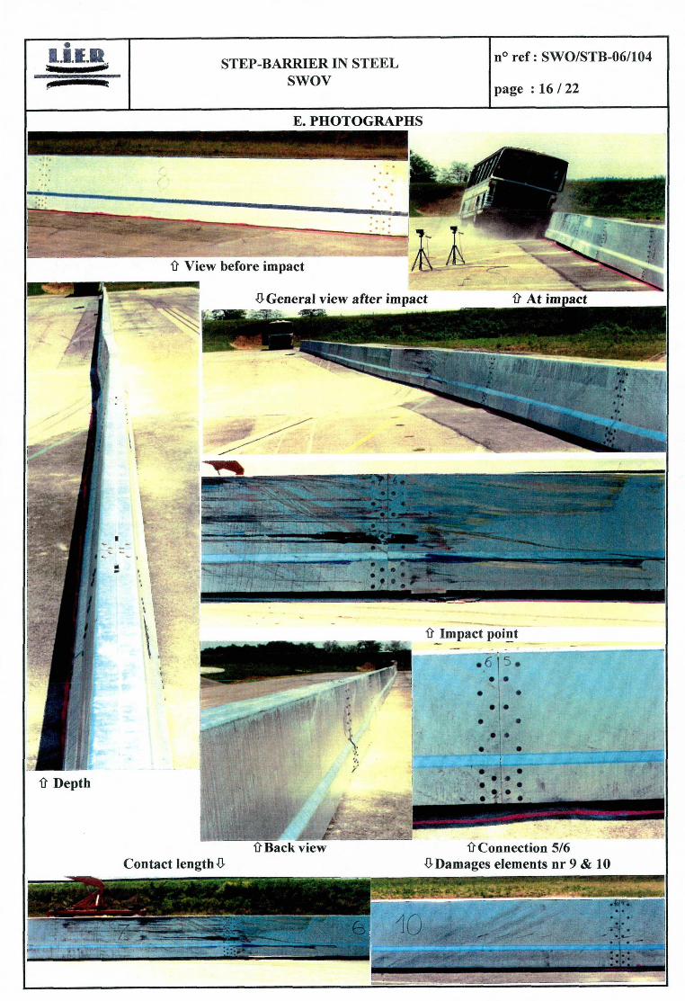
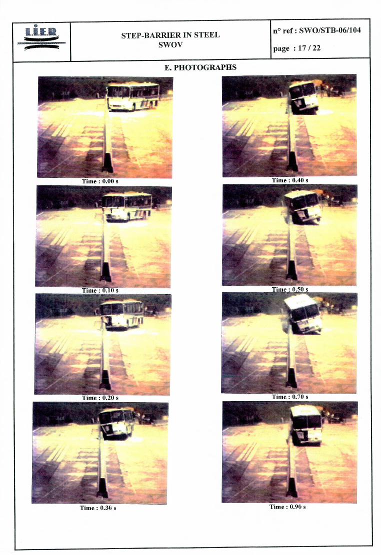
The piloted, controlled vehicle hit the device at72.6 kph at an angle of 19.7°. It struck component 6, 1.58 m before the start of component 7. It rebounded very quickly. The rear end of the vehicle hit the barrier and exited from component 7 at an angle of under 2°. The vehicle ran along the barrier and its right rear wheel scratched components 9 and 10. The vehicles tyres left marks on components 12 to 14. The vehicle was stopped 20m after the end of the barrier.
Vehicle trajectory
20'
il
CON limit box letiqlh 20 m
- .--
-- w- -
STEP-BARRIER IN STEEL no ref: SWO/STB-06/104 Swov page :7/22
7. RESULT
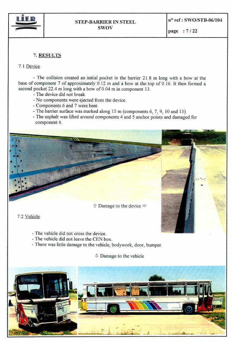
7.1 Device
- The collision created an initial pocket in the barrier 21.8 m long with a bow at the base of component 7 of approximately 0.12 in and a bow at the top of 0.16. It then formed a second pocket 22.4 m long with a bow of 0.04 m in component 13.
- The device did not break. - No components were ejected from the device. - Components 6 and 7 were bent. - The barrier surface was marked along 15 m (components 6, 7, 9, 10 and 13). - The asphalt was lifted around components 4 and 5 anchor points and damaged for
component 6.
- rT -.--••---.__
7.2 Vehicle
Damage to the device ft:
- The vehicle did not cross the device. - The vehicle did not leave the CEN box. - There was littie damage to the vehicle, bodywork, door, bumper.
Damage to the vehicle
40
STEP-BARRIER IN STEEL n° ref: SWO/STB-06/104 HJI SWOV page :8/22
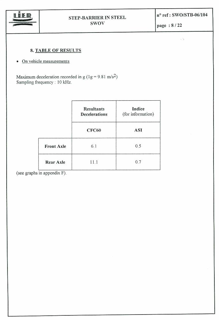
8. TABLE OF RESULTS
On vehicle measurements
Maximum deceleration recorded in g (ig = 9.81 mis 2) Sm'1 friincy: 10 kHiz.
Resu!tant co Indice Decelerations (for information)
CFC6O AS!
FrontAxle 6.1 0.5
RearAxie 11.1 0.7
(see graphs in appendix F).
STEP-BARRIER IN STEEL n° ref: SWO/STB-06/104
Swov page :9/22
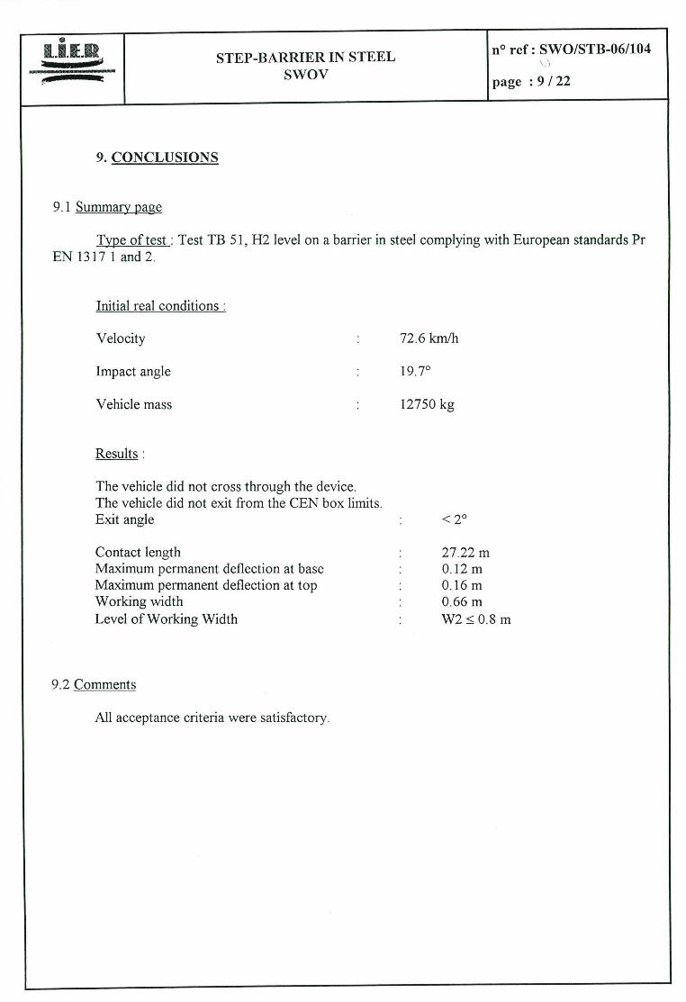
9. CONCLUSIONS
9.1 Summary page
Type of test Test TB 51, H2 level on a barrier in steel complying with European standards Pr EN 1317 1 and 2.
Initial real conditions
Velocity
Impact angle
Vehicle mass
Results
The vehicle did not cross through the device. The vehicle did not exit from the CEN box limits. Exit angle
Contact length Maximum permanent deflection at base Maximum permanent deflection at top Working width Level of Working Width
9.2 Comments
All acceptance criteria were satisfactory.
72.6 kmlh
19.7°
12750 kg
<2°
27.22 m 0.12 m 0.16 m 0.66 m W2 ~ 0.8 m
* tIER STEP-BARRIER IN STEEL
no ref: SWO/STB-061104
Swov page :10/22
APPENDICE S
- -
SOVENAANZICH
L
VODRAANZICHT
H L r CDS NC
:° pg
r s
y 1 / 1
Seci o
-.
Doorsnede D-D KoppeingBa
Koppelptaten / k 2 n t e r erp t
_________ -
) C
22 , J 7 • " -: __________
• C/D
—
c
0 -
S-
Cl)
S--
•
NOOT _roj - Matori911kwaheif _Mafectalsoecif,cai , ons'
E,p,,,e,1 / KDpp.Ip9aTe , 9. 350 & CEl ES ELeVeIE/C9,pIElQOatt0 Bo1VOpEDW.n 4.9
1.6
* taEHr.erirq
109r*s(h,eDprèEn ElHQeflS HEN DES EVVo oV*ç no9 - HEN 1215
* MEI GrIep an000re • IipElepe 260 9119 0eot9
bQErÇOI 934 a 4 len
904P OVIE1VIE 01. l*N.reI, '0 DGE-0E51O
'" 095-16539
rijkssaferstaat 1 500l60l5051n9 .919* 4EErl1V0t19 bc.r.'d.e:l r*t •f0*ig *93*90:.
RVIS.SIEP_SOEVIER 519.111
• ,3.EVEMIEIS LVIIO. 5650
L9051 lW 11901E 6110105
[oVDs V9.1SS CIVIOW'SE
VieW -P-Aanzicht -P-
Sclion Â-A
Doorsnede A-A
Vie., in dtrection -P-Aanzicht vatpens pijl -P-
EsV0
5-00
Manthoe-apt e Of St ViSME
deksel
BOVENAÂNZICHT lap-VIEW 5190 -
-
1IT ïTITTITJTTTII Tj:
Veankeng ÂfsEetaet
9950
- VEE
VOORAANZICHT L__ A
Seçtiao 91-5 Doorsnede S-S
MorrtaOe-gat en AnVerplOat AssInDty- hate and anahor-plate
pVr NVCVS
tR i ( 1,9
0
11111, STEP-BARRIER IN STEEL no ref: SWO/STB-061104
SWOV page :13/22
B. NOMENCLATURE
DESIGNATION CHARACTERISTICS QUANTITY
Metallic element Steel sections, Fe 360 B galvanized by zincking according NEN 1275 standard Tested element: !ength = 5450 ; height = 900 ; width at top = 200; 9 width at base 540 ; thickness = 6.
8 Assemly element length = 5996 ; height = 900 ; width at top = 200; width at base = 540 ; thickness = 6.
Top coupling plate Steel plate, Fe 360 B galvanized 16 sizes: 300x170x8
High lateral coupling plate Steel plate, Fe 360 B galvanized 32 sizes : 555x300x8
Low lateral coupling plate Steel plate, Fe 360 B galvanized 32 sizes: 300x218x8
Stuck for anchorage Screw M24, class 4.6 ; lenglh = 330. 68
Washer- strip Plate 18 sizes: 400x70x16
Armature-strip Plate 18 sizes: 250x100x30
Nut for anchorage M24, c!ass 8. 68
Bolt Rd. Head Bolt M16x40, class 4.6 896
Nut M16, class 8 896
_ NORTH
PROHBITED ZONE
til
til
LOCAM
ZONE©
SCALE i/000 cm
PROHIBrED ZONE
.L 1 STEP-BARRIER IN STEEL ° f . SWO/STB-06/104
SWOV page : 15 /22
D. VEHICLE DIMENSIONS
Model: SAVIEM E7 type, Model year: 1974
[J-
Vehicie characteristics
VEHICLE MASS / DIMENSIONS / CENTRE OF GRAVITY LOCATION / (kg) (m) (m)
MASS WITHOUT BALLAST WHEEL TRACK (frire) LONGITUDLNAL DISTANCE (X) SPECIFICATION. 1 / SPECIFICATION. 2.00± 0.3 SPECIFICATION. 3.80± 0.38
TRIJE f_9800 TRUE 2.04/1.84 TRUE 3.79 WHEEL RADIUS
SPECIFICATION. 0_52±0_078 TRUE 0.505
BALLAST WHEEL BASE LATERAL DISTANCE (Y) SPECWICATION. / SPECIFICATJON. 6.50 ± 0.975 SPECIFICATJON ± 0.10
TRUE 2950 TRUE 6.23 TRUE 0 NIJMBER OF AXLES
SPECIFICATION. is_+1 TRUE 1S+1
TOTAL VEffiCLE MASS BUMPER HEIGHT HIEIGHT ABOVE GROUND (Z) SPECIFICATION. 13000± 400 SPECIFICATION. / SPECIFICATION. _1.40± 1.611 -0.07
TRIJE 12750 TRUE / TRUE _1.48
STEP-BARRIER IN STEEL O ref: SWO/STB-061104
SWOV page :16/22
E. PHOTOGRAPHS
- - r View before impact
t!' General view after impact
f At imnact
1
/ 1
i Impact point
kjlk
/ • fDepth _______ •: :•
-:
û Back view fI'Connection 5/6 Contact lengthG ODamages elements nr 9 & 10
-
Ii
STEP-BARRIER IN STEEL no ref: SWO/STB-06/104
Swov page :17/22
E. PHOTOGRAPHS
?
1 ime : 0.00 s linie : 0.40 S
-
Ïie0I0s____
ii - Fime 0.20 s - -
-
1 ilne 0.30 s - -
Time 0.70 s -
",li
wuséw 79
Time : 0.90 s
STEP-BARRIER IN STEEL n° ref: SWO/STB-06/104
Swov page : 18 /22
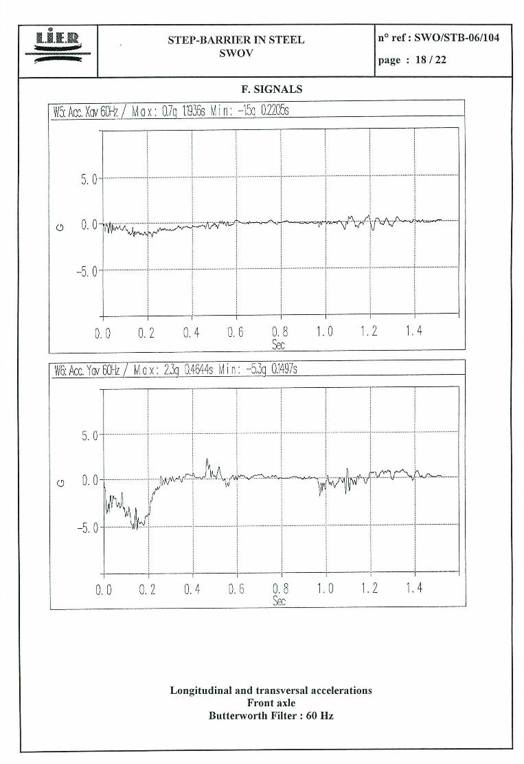
F. SIGNALS
i5: Acc. Xcv 6Ü -
Oul
0.0
—5. 0
0,0 0.2 0.4 0.6 0.8 1.0 1.2 1.4 Sec
Longitudinal and transversal accelerations Front axie
Butterworth Filter: 60 Hz
STEP-BARRIER IN STEEL n° ref: SWO/STB-061104
Swov page : 19/22
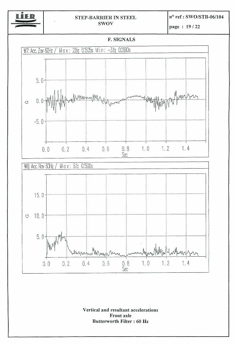
F. SIGNALS
0.0 0.2 0.4 0.6 0.8 1.0 1.2 1.4 Sec
V8: Acc. Rav 6']-z
15.0
o 10.0
5. 0
0.0 0.2 0.4 0.6 0.8 1.0 1.2 1.4 Sec
Vertical and resultant accelerations Front axie
Butterworth Filter: 60 Hz
STEP-BARRIER IN STEEL no ref: SWO/STB-061104
Swov page : 20/22
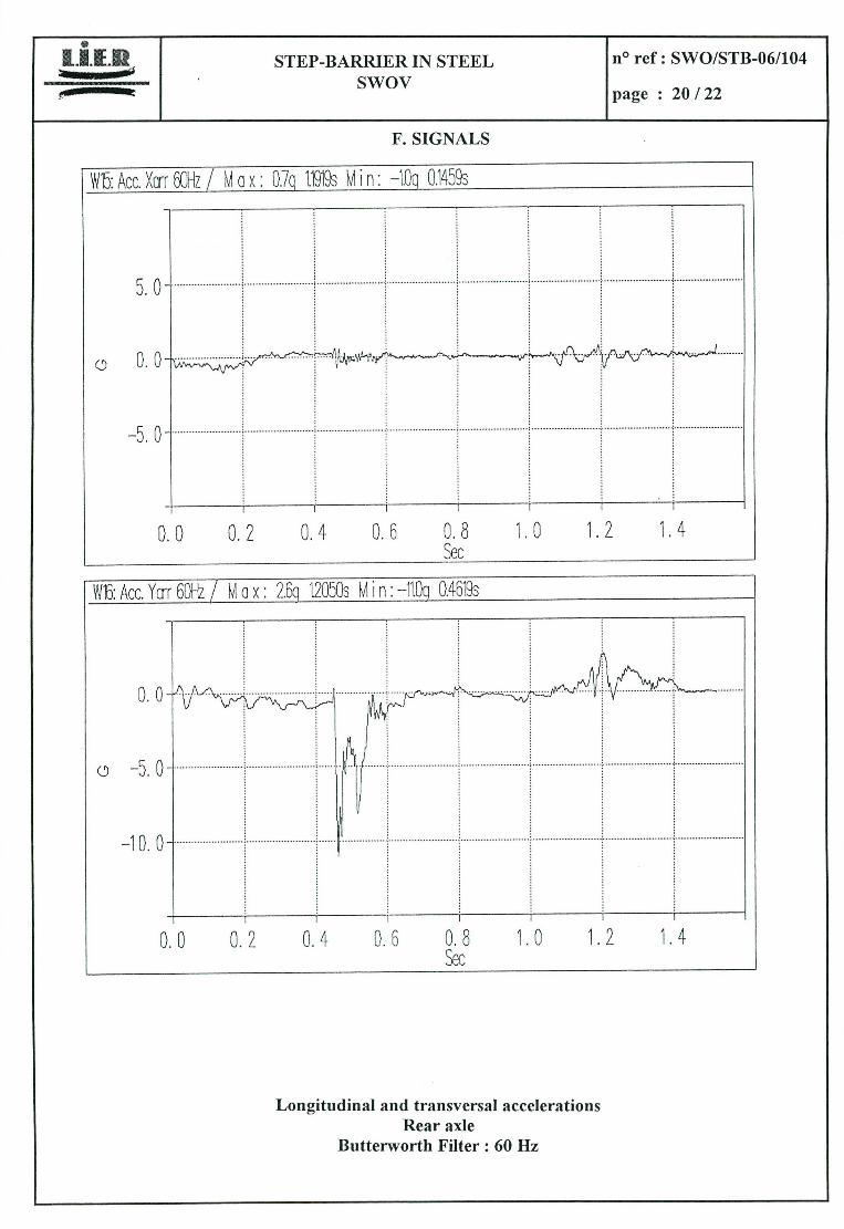
F. SIGNALS
0.0 0.2 0.4 0.6 0.8 1.0 1.2 1,4 Sec
0.0 0.2 0.4 0.6 0.8 1.0 1.2 1.4 Sec
Longitudinal and transversal accelerations Rear axie
Butterworth Filter: 60 Hz
0 1 1 LU 1 STEP-BARRIER IN STEEL 1 no ref: SWO/STB-06/104 - 1 Swov
1 page : 21122
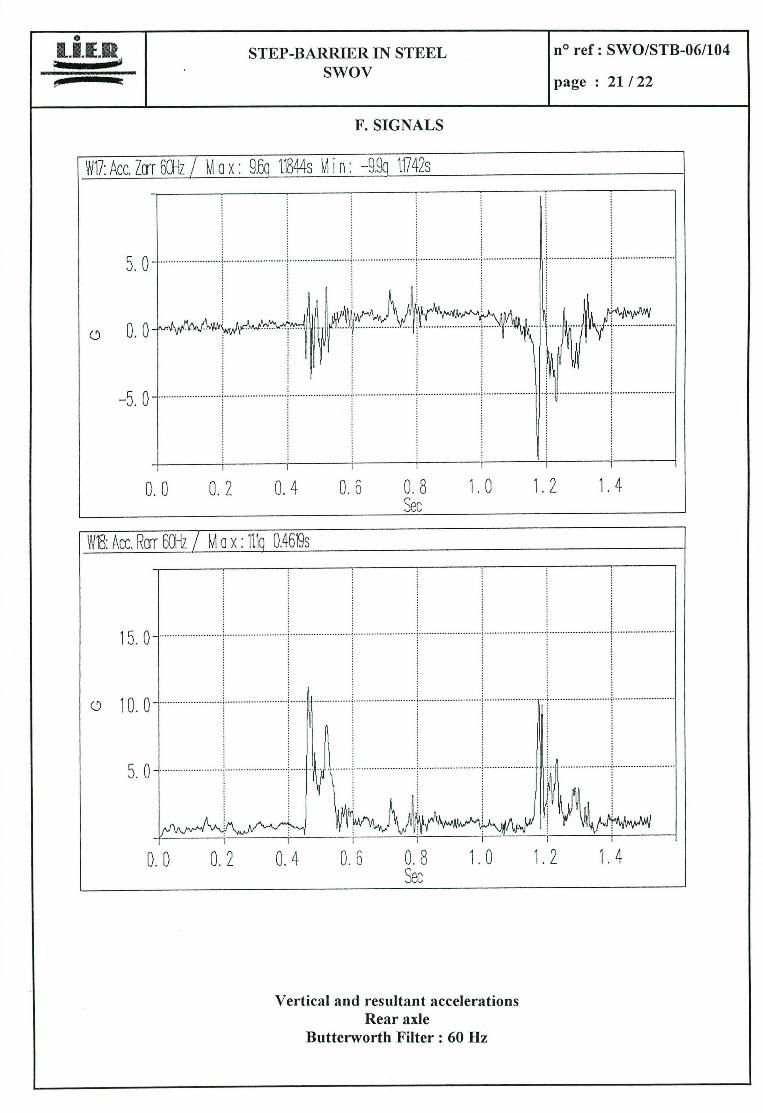
F. SIGNALS
0.0 0.2 0.4 0.6 0.8 1.0 1.2 1.4 Sec
V18: Acc. Rarr 6011z
15.0
0 10.0
5. 0
0.0 0.2 0.4 0.6 0.8 1,0 1.2 1.4 Sec
Vertical and resultant accelerations Rear axie
Butterworth Filter: 60 Hz
E9 STEP-BARRIER IN STEEL Swov
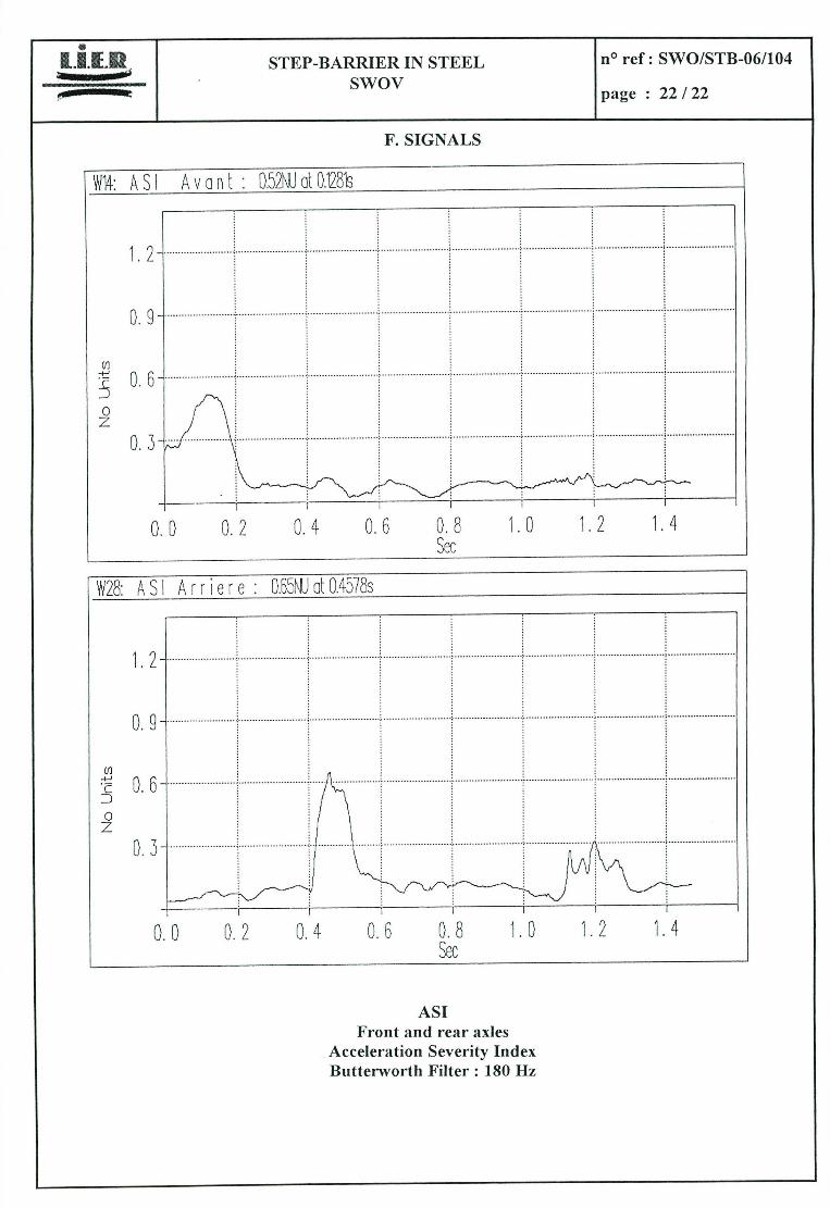
F. SIGNALS
no ref: SWO/STB-061104
page : 22/22
S 1 A v 0 fl t : 0.52WU al 021s ____________________________
1,2
0. 9
(/1
c
0 z 0. 3
0.0 0.2 0.4 0.6 0.8 1.0 1.2 1.4 Sec
8: A S 1 A r r e r e: D.65NU aL 0.4578e
1.2
D. 9
(t] 4-1
c D 0 z
0. 3
0.0 0.2 0.4 0.6 0.8 1.0 1.2 1.4 çec
ASI Front and rear axles
Acceleration Severity Index Butterworth Filter: 180 Hz

L.IE.R SA - D 29 - route de Crémeu BP 352 - 691 25 Lyon Satolas Aéroport TéJ. 72 48 37 30 - Fax 72 48 37 37 N Siret 393 068 796 000 19 - Code APE 743 B