PROCESSING MANUAL BINDERHOLZ CLT BBS
120
PROCESSING MANUAL BINDERHOLZ CLT BBS
-
Upload
khangminh22 -
Category
Documents
-
view
1 -
download
0
Transcript of PROCESSING MANUAL BINDERHOLZ CLT BBS

1Binderholz Bausysteme GmbHPROCESS ING MANUALB INDERHOLZ CLT BBS

3Binderholz Bausysteme GmbH
Purpose 4
Target group 4
Work preparation project planning 5
Process of AV project planning 6
Presentation of plan 7
Plan issuance 8
Template planning record 9
Edge processing BBS 10
Drillholes 10
Cutouts 11
Break-throughs 12
Pocket milling 13
Presentation of cutout angle < 90° 13
Machining tolerances 14
Presentation Ausschnittvarianten 15
Offset of cutouts 16
Example | checklist for BBS deliveries 17
Loading plans 18
Loading types | truck 19
Loading types | rail 21
Loading types | containers 22
Manipulation | loading 23
Loading guidelines 23
Consignment note - CMR 24
Example of delivery note 25
Manipulation | unloading 26
Unloading 26
Lifting anchor 26
Lifting loop 27
Lifting loops + bolt/thorn 27
Lifting loops for non-visible quality 28
Lifting loops with a thorn 28
Lifting loops double hole 29
Assy/T-lift screws 29
Packages with premounted lifting loops 29
Other lifting options 30
Consequences of usage of wrong lifting systems by the customer 30
Manipulation | storage 31
Intermediate storage at the construction site 31
Assembly | walls on ground floor 32
Checking of the floor plate 32
Bituminous sealing against humidity 32
Setting up the walls 33
Setting of angles 33
Compensation plates for levelling 34
Foot threshold 34
Erection of first wall 35
Erection of second wall 36
Outer wall - inner wall 37
Erection of remaining walls 37
Assembly | ceilings 38
Application of sealing membrane 38
Mounting of the ceiling 38
Second ceiling element 39
Remaining ceiling elements 39
Execution detail: Longitudinal joint of element 40
Execution detail: Longitudinal joint of element in the wall axes I jetty (e.g. balkony) 40
Assembly | walls upper floor 41
Setting up the walls in the first upper floor 41
Setting of angles 41
Assembly | protection 42
Weather protection 42
Temporary construction time sealing 42
Shell construction details 43 - 117
Safety at the construction site 118
Personal protection equipment 118
Fall protection 118
TABLE OF CONTENTS
4 Binderholz Bausysteme GmbH
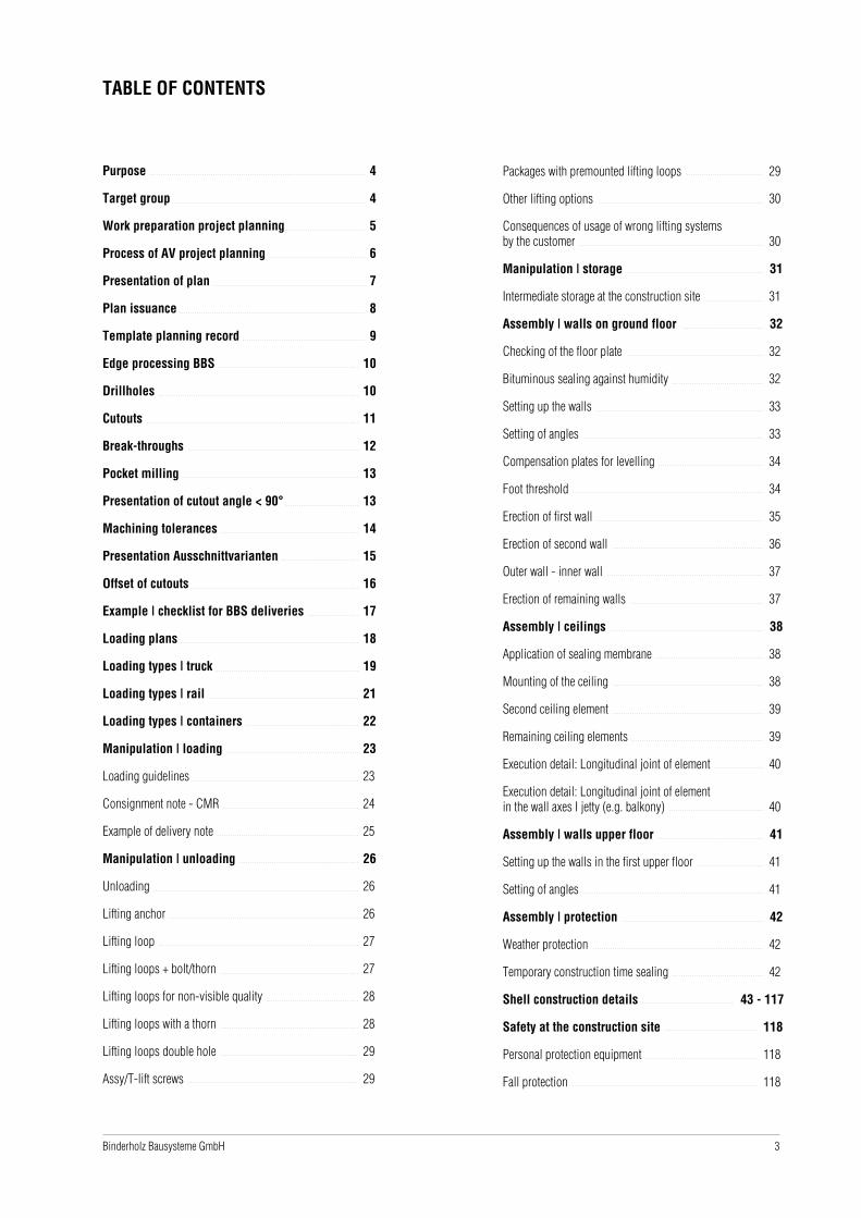
Processing Manualbinderholz CLT BBS
PURPOSE
In this Processing Manual you will find everything you need to know about the further processing of binderholz
CLT BBS. The information ensures that skilled personnel can professinally and pproperly erect solid wood struc-
tures even without BBS experience.
This Processing Manual and all the details and hints presented in it have been kept as simple as possible.
TARGET GROUP
The target grpup of this Processing Manual are all direct processors
of binderholz CLT BBS.
5Binderholz Bausysteme GmbH
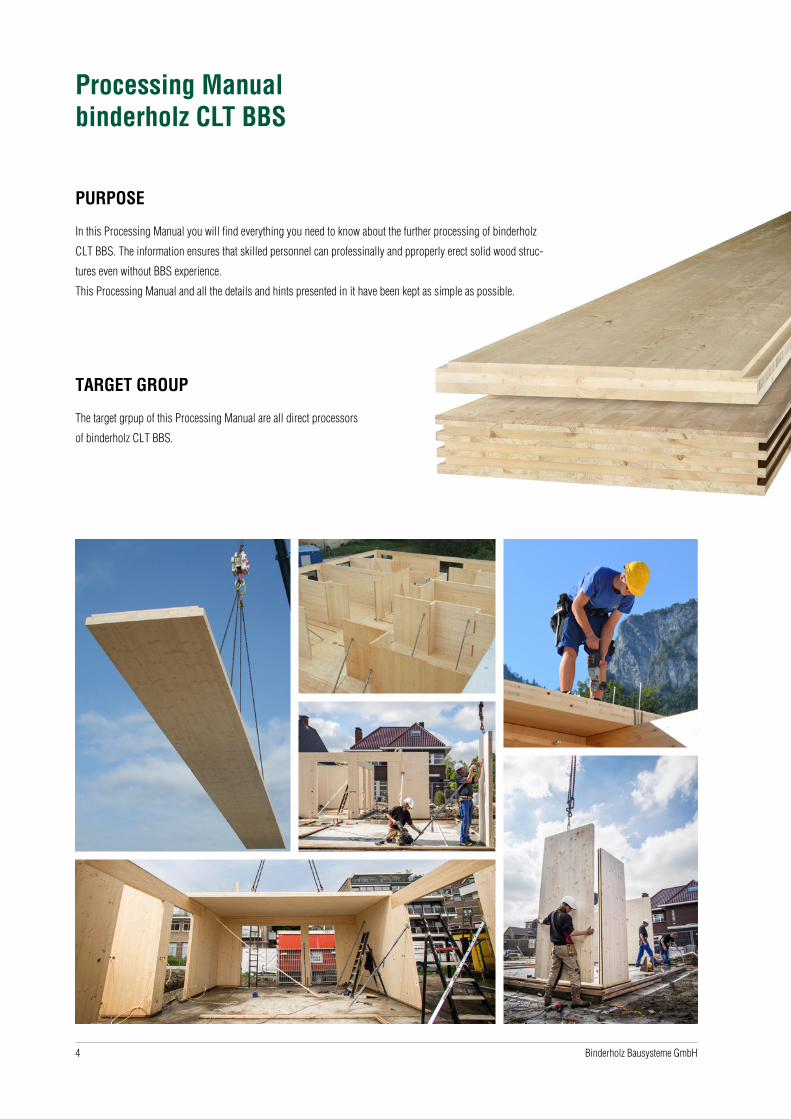
WORK PREPARATION - PROJECT PLANNING
Interfaces from the drawing program Cadwork - Import | Export
Processable file formats
Import Export
Cadwork 3D IFC
SAT DXF
IFC ACIS
BTL RHINO
STEP STEP
RVT IGES
SEMA Viewer
Dietrichs
HSB
DXF
DWG
The Work Preparation department (AV_Projektierung) prepares the plans for production.
All plans that are processed by us are created with the program Cadwork. Cadwork is a 3D CAD/CAM software for the timber construction industry. The
following interfaces enable import of data. Depending on the imported file format and the quality of the plans, it calculates the in-house effort and thus
the time needed for processing.
6 Binderholz Bausysteme GmbH
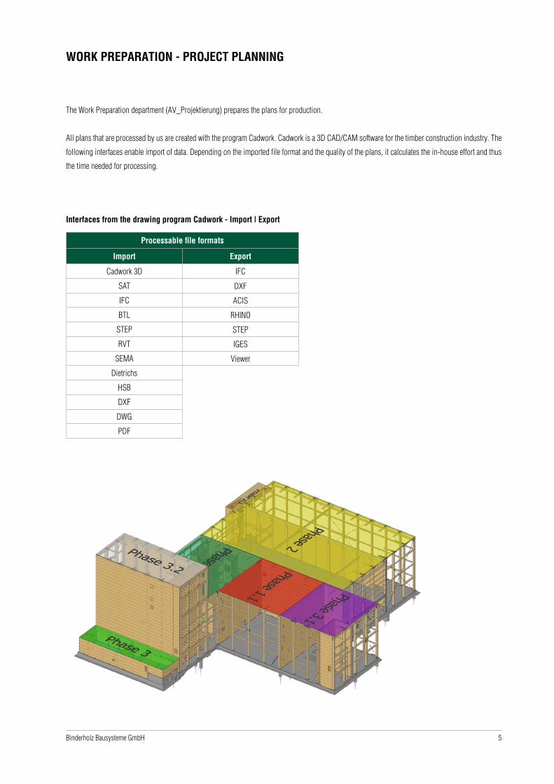
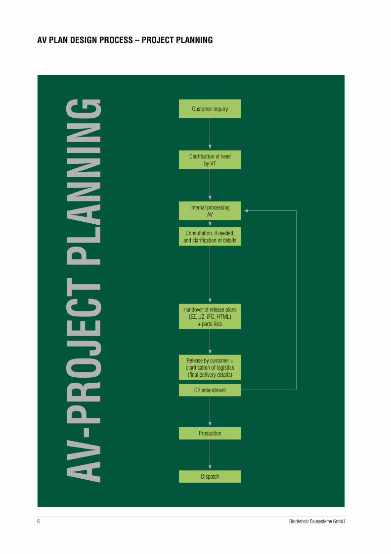
AV PLAN DESIGN PROCESS – PROJECT PLANNING
Customer inquiry
Clarification of need by VT
Internal processing AV
Consultation, if needed, and clarification of details
Handover of release plans (EZ, UZ, IFC, HTML)
+ parts lists
Release by customer + clarification of logistics (final delivery details)
OR amendment
Production
Dispatch
7Binderholz Bausysteme GmbH
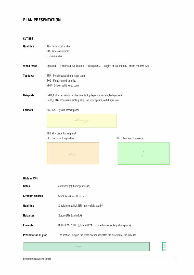
PLAN PRESENTATION
CLT BBS
Qualities AB - Residential visible
BC - Industrial visible
C - Non-visible
Wood types Spruce (F), Fir antique (TG), Larch (L), Swiss pine (Z), Douglas fir (D), Pine (K), Mixed conifers (NH)
Top layer ESP - Prefabricated single-layer panel
EKG - Fingerjointed lamellas
MHP - 3-layer solid wood panel
Beispiele F-AB_ESP - Residential visible quality, top layer spruce, single-layer panel
F-BC_EKG - Industrial visible quality, top layer spruce, with finger joint
Formats BBS 125 - System format panel
BBS XL - Large format panel
DL = Top layer longitudinal DQ = Top layer transverse
Glulam BSH
Setup combined (c), homogenous (h)
Strength classes GL24, GL28, GL30, GL32
Qualities SI (visible quality), NSI (non-visible quality)
Holzarten Spruce (FI), Larch (LA)
Example BSH GL24c NSI FI (glulam GL24 combined non-visible quality spruce)
Presentation of plan The section lining in the cross-section indicates the direction of the lamellas.

8 Binderholz Bausysteme GmbH
PLAN ISSUANCE
Single-part drawing (EZ)
The EZ always shows a single component. Two cross-sections are issued per part, whose position is indicated by the section lines. The viewed side
is always the visible side. The single-part drawing is a detailed drawing for production and is primarily not used for customer review or plan release.
Overview drawing (UZ)
Representation of several components of an entire wall or ceiling or a wall or ceiling section. It serves for plan review and plan release by the customer.
Axonometry (AXO) + floor plan
The axonometry shows a three-dimensional representation of a floor or a ceiling or roof section incl. component numbers. For each axonometry, the
corresponding floor plan is created.
Viewed side = Visible side Viewed side = Visible side
Overcut rafter sections
Axonometry Floor plan
Scale 1:65 Scale 1:65

9Binderholz Bausysteme GmbH
TEMPLATE PLANNING RECORD
Lege
nde
ELE
KTRO
PLAN
UN
G -
Frö
sunge
n in
Farb
e und
Posi
tion
in d
enW
anda
nsi
chte
n d
arst
elle
n (
sieh
e Le
gende
)
EG AW 01
EG
AW
08
EG AW 07
EG
AW
06
EG AW 05
EG
AW
04
EG AW 03
EG
AW
02
Wan
dansi
cht
BSH 120 x 600 GL 24c Si/NSi
BSH 120 x 600 GL 28h Si/NSi
BBS XL | 120 | 5s
F-AB | NH-C
BBS XL | 120 | 5s
F-AB | NH-C
BBS XL | 120 | 5s
F-AB | NH-C
BBS X
L | 120 | 5s
F-AB | N
H-C
BBS XL | 120 | 5s
F-AB | NH-C
BBS
XL
| 12
0 |
5s
F-AB |
NH
-C
BBS X
L | 120 | 5s
F-AB | N
H-C
F-AB |
NH
-C
BBS
XL
| 12
0 |
5s
EG
IW 02
BBS XL | 120 | 5s
F-AB | NH-C
BBS XL | 120 | 5s
F-AB | NH-C
EG IW 01
BBS
XL
| 12
0 |
5s
F-AB |
NH
-C
EG
AW
02
EG
AW
06
EG
AW
04
EG
AW
08
EG AW 01
EG AW 03
EG AW 07
EG AW 05
BB
AA
Schn
itt
B-B
Schn
itt
A-A
BB
A
A
Schnitt B-B
Schnitt A-A
BB
A A
Schnitt B
-B
Schnitt A
-A
BB
A
A
Schnitt B-B
Schnitt A-A
BB
A A
Schnitt B
-B
Schnitt A
-A
BB
A
A
Schnitt B-B
Schnitt A-A
BB
A A
Schnitt B
-B
Schnitt A
-A
B B
A
A
Schnitt B-B
Schnitt A-A
EG AW 01
EG IW 01
EG
IW
02
Schnitt B
-B
Schnitt A
-A
A A
BB
Schnitt A-A
BB
A
A
Schnitt B-BStartpunkt Montage
EG AW 07
EG AW 03
Wan
dansi
cht
BSH 120 x 600 GL 24
BBS XL | 120 | 5s
F-AB | NH-C
BBS XL | 120 | 5s
F-AB | NH-C
BBS XL | 120 | 5s
F-AB | NH-C
BBS X
L | 120 | 5s
F-AB | N
H-C
BBS XL | 120 | 5s
F-AB | NH-C
BBS
XL
| 12
0 |
5s
F-AB |
NH
-C
BBS X
L | 120 | 5s
F-AB | N
H-C
F-AB |
NH
-C
BBS
XL
| 12
0 |
5s
BBS XL | 120 | 5s
F-AB | NH-C
BBS XL | 120 | 5s
F-AB | NH-C
EG IW 01
EG
AW
02
EG
AW
06
EG
AW
04
EG
AW
08
EG AW 01
EG AW 03
EG AW 07
EG AW 05
BB
AA
Schn
itt
B-B
Schn
itt
A-A
BB
A
A
Schnitt B-B
Schnitt A-A
BB
A A
Schnitt B
-B
Schnitt A
-A
BB
A
A
Schnitt B-B
Schnitt A-A
BB
A A
Schnitt B
-B
Schnitt A
-A
BB
A
A
Schnitt B-B
Schnitt A-A
BB
A A
Schnitt B
-B
Schnitt A
-A
B B
A
A
Schnitt B-B
Schnitt A-A
EG AW 01
EG IW 01
EG
IW
02
Schnitt B
-B
Schnitt A
-A
A A
BB
BB
A
A
Schnitt B-BStartpunkt Montage
EG
Dec
ke 0
1 -
Ansi
cht
von o
ben
Span
nrich
tung
BBS
125
| 14
0 |
5s
F-AB |
NH
-CB
B
AA
Span
nrich
tung
BBS
125
| 14
0 |
5s
F-AB |
NH
-CB
B
AA
Span
nrich
tung
BBS
125
| 14
0 |
5s
F-AB |
NH
-CB
B
AA
Bau
unte
rgru
ppe:
AW
ode
r IW
(=
Wan
dsch
eibe
n)
Bau
grupp
e:EG
(=
Ges
chos
s)
alle
Bem
aäunge
n in
mm
Üff
nunge
n:
blau
BSH
: gr
�n
BBS:
bra
un
Bau
grupp
e:EG
(=
Ges
chos
s)
AW
ode
r IW
(=
Wan
dsch
eibe
n)
Bau
unte
rgru
ppe:
Frös
ung
auf de
r Ansi
chts
seite:
hel
lgr�
nFr
ösung
auf de
r R�ck
seite:
gra
uBoh
rung:
rot
1:1
00 @
A2
Must
erpl
ansa
tzPR
OJE
KT
ZEIC
HN
UN
GSN
AM
E
Erd
gesc
hoss
KU
ND
E
PLAN
VER
FASS
ERER
STEL
LT A
M
MAäS
TAB
PLAN
NU
MM
ER
1/ 5
18.0
2.20
21
fon +
43.6
245.
7050
0fa
x +
43.6
245.
7050
0-70
01w
ww
.bin
derh
olz.
com
Bin
derh
olz-
Bau
syst
eme
Gm
bHSo
lvay
-Hal
vic-
Stra
äe 4
6A
-540
0 H
alle
inbb
s@bi
nde
rhol
z.co
m
All information on the individual BBS components in a 2D plan file is required for the targeted processing of the BBS components and the creation of
production drawings.
In the 2D view drawings of the BBS elements, important additional information such as, e.g., component thickness and BBS structure must be entered in
text form.
Wal
l vie
w
EG c
eilin
g 01
- vi
ew fr
om a
bove
grou
nd fl
oor
10 Binderholz Bausysteme GmbH
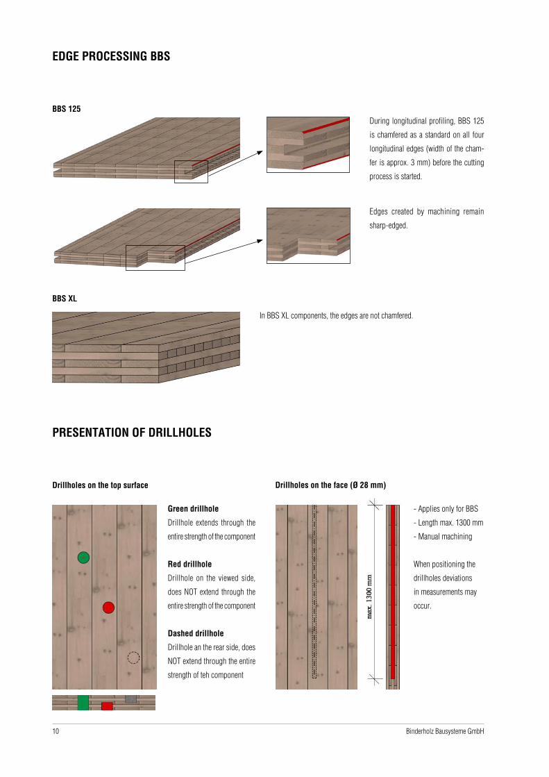
EDGE PROCESSING BBS
BBS 125During longitudinal profiling, BBS 125
is chamfered as a standard on all four
longitudinal edges (width of the cham-
fer is approx. 3 mm) before the cutting
process is started.
Edges created by machining remain
sharp-edged.
BBS XL
In BBS XL components, the edges are not chamfered.
PRESENTATION OF DRILLHOLES
Drillholes on the top surface
Green drillhole
Drillhole extends through the
entire strength of the component
Red drillhole
Drillhole on the viewed side,
does NOT extend through the
entire strength of the component
Dashed drillhole
Drillhole an the rear side, does
NOT extend through the entire
strength of teh component
Drillholes on the face (Ø 28 mm)
- Applies only for BBS
- Length max. 1300 mm
- Manual machining
When positioning the
drillholes deviations
in measurements may
occur.

11Binderholz Bausysteme GmbH
PRESENTATION OF CUTOUTS
Cutout at 90° to the board surface
Non-visible area
Ausschnitte ≥ 100 mm: Corners are overcut
Ausschnitte < 100 mm: Corners are executed with sharp edges
(Executionas in visible area)
Visible area
Cutout bevel to the board surface
Non-visible area Visible area
Corners are executed with sharp edges
Ausschnitte ≥ 100 mm: Corners are overcut
Ausschnitte < 100 mm: Corners are executed with sharp edges
Corners are executed with sharp edges
The red line shows the section as it is drawn up in the plans. The images show the actual machining.

12 Binderholz Bausysteme GmbH
PRESENTATION OF BREAK-THROUGHS
Non-visible area
Execution 1 Execution 2
Corners are overcut
Cutout is smaller than 200 x 200 mm,
but larger than 100 x 100 mm
The remaining radius depends on the diameter of the
milling cutter which in turn depends on the depth the
of processing. Rremaining radius of 20 - 40 mm
Visible area
The red line shows the section as it is drawn up in the plans. The images show the actual machining.

13Binderholz Bausysteme GmbH
PRESENTATION OF POCKET MILLING
Non-visible area Visible area
Remaining radius stays the same
The remaining radius depends on diameter of the milling cutter
which in turn depends on the depth of processing.
Remaining radius of 20 - 40 mm.
Subject to a surcharge, the corners can be reworked with sharp
edges or, upon consultation, milled over.
Remaining radius stays the same.
The remaining radius depends on diameter of the milling cutter
which in turn depends on the depth of processing.
Remaining radius of 20 - 40 mm.
PRESENTATION OF A CUTOUT WITH AN ANGLE OF < 90°
Non-visible area Visible area
The red line shows the section as it is drawn up in the plans. The images show the actual machining.
14 Binderholz Bausysteme GmbH
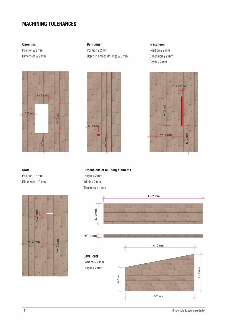
MACHINING TOLERANCES
Openings
Position ± 2 mm
Dimension ± 2 mm
Bohrungen
Position ± 2 mm
Depth in limited drillings ± 2 mm
Fräsungen
Position ± 2 mm
Dimension ± 2 mm
Depth ± 2 mm
Slots
Position ± 2 mm
Dimension ± 2 mm
Dimensions of building elements
Length ± 2 mm
Width ± 2 mm
Thickness ± 1 mm
Bevel cuts
Position ± 2 mm
Length ± 2 mm

15Binderholz Bausysteme GmbH
V1
Cutout section remains in the building element and is held merely by the circular saw run-ups (green).
PRESENTATION OF CUTOUT VARIANTS
Board thickness
Minimum cutout dimensions
60 mm 480 x 480 mm
80 mm 550 x 550 mm
100 mm 610 x 610 mm
120 mm 660 x 660 mm
140 mm 700 x 700 mm
160 mm 740 x 740 mm
180 mm 770 x 770 mm
200 mm 800 x 800 mm
220 mm 830 x 830 mm
240 mm 860 x 860 mm
260 mm 880 x 880 mm
280 mm 900 x 900 mm
300 mm 920 x 920 mm
320 mm 940 x 940 mm
340 mm 950 x 950 mm
Circular saw run-up remains Cut through (crcular saw /chainsaw)
V2
Cutout section does NOT remain in the building element.
A transport crosspiece reinforces the weakened cross-section of
the building element.
V3
Cutout section remains in the building element and is held by multiple
crosspieces.
Board thick-ness
Cutout dimensions
60 - 340 mm min. 200 x 200 mm
Board thick-ness
Cutout dimensions
60 - 340 mm min. 550 x 550 mm
Crosspiece

16 Binderholz Bausysteme GmbH
Cutouts larger than 800 x 800 mm are cut with the circular saw and the chainsaw.
This can result in an offset between circular saw and chainsaw of up to 3 mm.
OFFSET IN CUTOUTS
17Binderholz Bausysteme GmbH
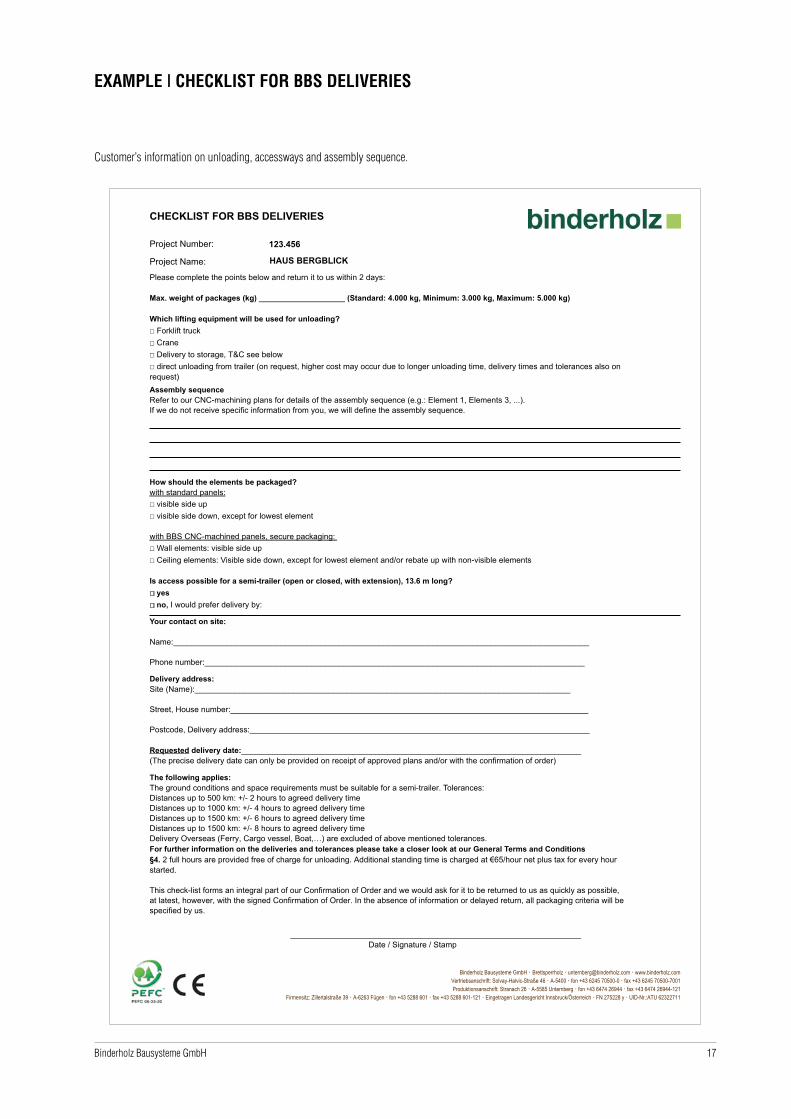
Customer’s information on unloading, accessways and assembly sequence.
EXAMPLE | CHECKLIST FOR BBS DELIVERIES

18 Binderholz Bausysteme GmbH
• Loading plans ae drafted specifically for the project and the type of loading, separately for container, rail or loading under tarps
• The loading plan shows the exact location of the individual packages to the customer
• Space optimisation allows for freight reductions
• Optimal loading safety can be exactly defined
Example for loading in containers
LOADING PLANS
- schematical portrayal of the loading!- schematische Darstellung der Beladung!
- wooden slats below the packages were assumed to be 8 cm high, also the distance between the packages and the opening gate.- Unterleger zwischen jedem Paket wurden 8 cm hoch angenommen, ebenso der Abstand zwischen den Paketen und dem ÖffnungstorP 07P 06
P 03
P 10
P 01 P 02
P 04
P 08
P 05
P 09
P 07 P 06
P 03
P 10
P 01P 02
P 04
P 08
P 05
P 09
26
0 c
m
front side / Vorderseite - Fahrtrichtung / driving direction
front side / Vorderseite - Fahrtrichtung / driving direction
LKW Plane - Truck closed
Project / Projekt:
254265 Veidekke Voldslokka_school_H_Bygget
drawn by / Bearbeiter:
thofordate / Datum
DIN A4
Formatsheet no. / Seite
LT-01Lorry no. / Transport Nr.
left hand side / linke Seite
right hand side / rechte Seite
AXO left hand front side / AXO linke vordere Seite AXO right hand rear side / AXO rechte hintere Seite
front view / Frontansicht
add. information / zus. Informationen
1m 1m50cm50cm 50cm 50cm
scale:
15.01.2021 1 / 1typ of transport / Transportart
Maöstab:
List of packages
Liste der Pakete
package length width heightPaket L�nge Breite H�he
(cm) (cm) (cm)
245 cm
fon +43.6245.70500fax +43.6245.70500-7001www.binderholz.com
Binderholz-Bausysteme GmbHSolvay-Halvic-Straöe 46A-5400 Hallein
P 01 480 240 40P 02 480 240 40P 03 260 240 40P 04 980 240 40P 05 300 240 60P 06 300 240 48P 07 300 240 48P 08 300 240 42P 09 300 240 54P 10 360 240 30

19Binderholz Bausysteme GmbH
Standard open semitrailer
• Fast loading and unloading
• More loading volume possible
TYPES OF LOADING | TRUCK
Enclosed truck
• If the dimensions of the BBS elements permit it, delivery can be provided in enclosed trucks
• Weather protection

20 Binderholz Bausysteme GmbH
Packages
• Various format sizes such as BBS 125 & BBS XL elements are wrapped separately in foil
• Boards of similar dimenions are wrapped in foil to form packages
• Intermediate storage of these packages at the construction site is possible
• The foil acts as UV and weather protection
• Unloading is possible by forklift or crane
• Transported in a lying position (exception: loading in containers)
Tight up = the boards are stapled on top of each other without intermediate layers
• Loading CLT BBS elements directly on top of each other is possible only with the BBS XL format
• The wbole truck load is wrapped in foil once
• Observe weather conditions during unloading
• Unloading by means of a crane
The final sequence of loading the packages is subject to loading safety rules according to the general road traffic regulations (StVO).
21Binderholz Bausysteme GmbH
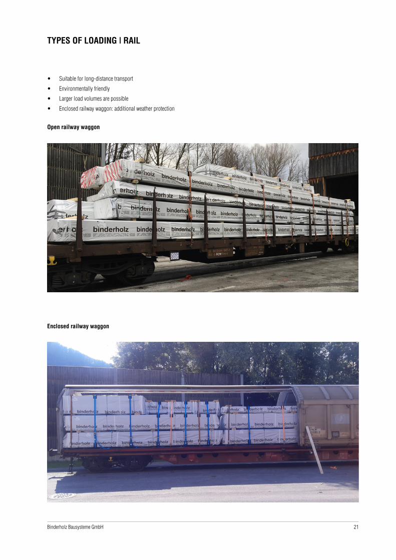
• Suitable for long-distance transport
• Environmentally friendly
• Larger load volumes are possible
• Enclosed railway waggon: additional weather protection
TYPES OF LOADING | RAIL
Open railway waggon
Enclosed railway waggon

22 Binderholz Bausysteme GmbH
• Overseas
• Possible with BBS XL and BBS 125
• Small load volumes are possible
• The load is protected from the weather
TYPES OF LOADING | CONTAINERS
Interior dimensions depend on loading method
Truck
Type of transport Max. width Max. length
Standard transport < 2,55 m< 13,60 m (with overhang in AT. DE: 15.10 m – precondition: not dividable goods)
Special transport without escort 2,55 m - 3,00 m 13,60 m - 18,80 m
Special transport with escort 3,01 m - 3,50 m 18,80 m - 21,00 m
Standard semitrailer open 2,49 m - 2,55 m 13,40 m - 13, 60 m
Mega trailer open 2,49 m - 2,55 m 13,30 m - 13,60 m
Rigid truck with trailer 2,49 m - 2,55 m 6,00 m + 7,00 m
Steered semitrailer 2,49 m - 2,55 m 12,00 m - 13,60 m
Low-loader 2,49 m - 2,55 m 12,00 m - 13,60 m (7,00 m - 9,00 m load area lowered throughout)
Inloader < 1,50 m 9,00 m - 9,50 m
Tarp < 2,45 m < 13,60 m
Container
Type of transport max. width max. length
Container 40 feet high cube < 2,33 m < 11,90 m
Container 40 feet open top - in/out of gauge
< 2,34 m < 11,90 m
Rail
Type of transport max. width max. length
Railway wwaggon open < 2,64 m < 21 m
Railway waggon closed < 2,84 m < 22 m

23Binderholz Bausysteme GmbH
MANIPULATION | LOADING
Execution
Transport always in a lying position. Exception: loading in containers
Packages wrapped in foil
Underlays with anti-slip mats are used between the layers
BBS 125
Execution
The whole shipment is or the individual packages are wrapped in foil
Observe weather conditions when unloading
Underlays with anti-slip mats are used between the layers
BBS XL
The final sequence of loading the packages is subject to loading safety rules according to the general road traffic regulations (StVO).
CAUTION!
- The access road to the contruction ite mut be approved for a 40t truck
- Check whether the truck can make the trip to the construction site (manoeuvrability and curve radius)
Loading guideline
24 Binderholz Bausysteme GmbH
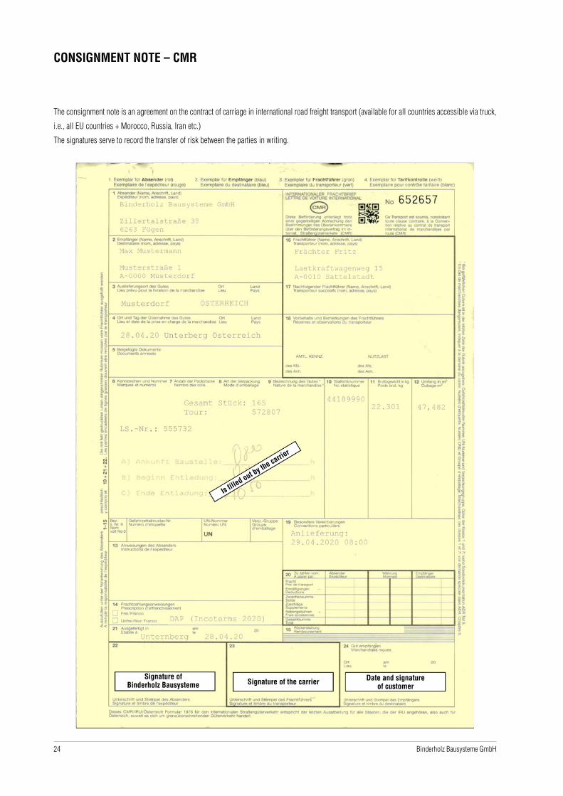
CONSIGNMENT NOTE – CMR
The consignment note is an agreement on the contract of carriage in international road freight transport (available for all countries accessible via truck,
i.e., all EU countries + Morocco, Russia, Iran etc.)
The signatures serve to record the transfer of risk between the parties in writing.
Is filled out by the carrie
r
Signature ofBinderholz Bausysteme Signature of the carrier Date and signature
of customer

25Binderholz Bausysteme GmbH
EXAMPLE OF DELIVERY NOTE
Zimmerei GmbHMusterstraße 7
Max MustermannMusterstraße 1
A-1234 Musterdorf A-1234 Musterdorf
Rechnungsempfänger
KundeVertreterIhre USt-ID-Nr.Unsere USt-ID-Nr. ATU62322711
ATU65952524
115595162
LIEFERSCHEINvom
56160714.01.21
Nr.rhs
zu Auftrag Nr. 254747
254747 LT 01 Spedition Frächtername
Lieferung: DAP (Incoterms 2020) A-1234 Musterdorf
Bezeichnung Holz Qualität Länge Breite Stärke Stück Menge in
BBS 1.250 100 1 10 m²8.000Profil ohne Profilierung10000100% PEFC ZERTIFIZIERT Cert.Nr. HFA-COC-0211Frachtkosten* 1 1Kombinationslieferung BBS max. 2,50 m x 13,50 m (BxL), max. 10m³/Auftrag, Zeitfenster für die Anlieferung ca. 3 Tage
Zwischensumme
Gewicht in kg: 480 Gesamt m³: 1,000 Menge m²: 10
Gelieferte Waren bleiben bis zur Bezahlung unser Eigentum!Holz stammt aus Nutzungen, die den jeweiligen gesetzlichen Vorgaben entsprechen.Wenn nicht anders ausgewiesen, stammen alle Waren aus PEFC kontrollierten Quellen -- HFA–CoC–0211 --. Ausgenommen mit (*)markierte Positionen.Verkauf in Übereinstimmung mit den Anforderungen der europäischen Holzhandelsrichtlinie (EUTR) 995/2010.
Ware übernommen
Seite 1 / 1 Binderholz Bausysteme GmbH · Brettsperrholz · [email protected] · www.binderholz.comNiederlassung Hallein: Solvay-Halvic-Straße 46 · A-5400 Hallein · fon +43 6245 70500-0 · fax +43 6245 70500-7001
Firmensitz: Zillertalstraße 39 · A-6263 Fügen · fon +43 5288 601 · fax +43 5288 601-121 · Eingetragen Landesgericht Innsbruck · FN 275228 y · UID-Nr.: ATU62322711
Muster

26 Binderholz Bausysteme GmbH
MANIPULATION | UNLOADING
Execution
Short-term interim storage of wrapped packages is possible
Unloading by crane or forklift
Underlays with anti-slip mats are used between the layers
Unloading
NOTE
- Apply according to manufacturer’s instructions and approval of the lifting anchor
Lifting anchor
Lifting anchor
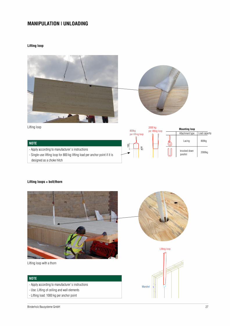
27Binderholz Bausysteme GmbH
MANIPULATION | UNLOADING
Lifting loop
Lifting loop
NOTE
- Apply according to manufacturer`s instructions
- Single-use lifting loop for 800 kg lifting load per anchor point if it is
designed as a choke hitch
Lifting loops + bolt/thorn
Lifting loop with a thorn
NOTE
- Apply according to manufacturer`s instructions
- Use: Lifting of ceiling and wall elements
- Lifting load: 1000 kg per anchor point
800kg per lifting loop
2000 kg per lifting loop
Mounting loop
Attachment type Load capacity
Lacing
knocked down parallel
800kg
2000kg
Lifting loop
Mandrel

28 Binderholz Bausysteme GmbH
MANIPULATION | UNLOADING
Lifting loops for non-visible quality
Choke hitch per lifting loop 800 kg Folded over / parallel per lifting loop 2000 kg
Lifting loops with a thorn
Applicable from a thickness of 80 mm:
Top layer lengthwise from a 3-layer setup
Top layer traverse from 5-layer setup
Non-visible sideVisible side
Per lifting loop:1000 kg

29Binderholz Bausysteme GmbH
MANIPULATION | UNLOADING
Lifting loops double hole Assy/T-lift screws
Packages with premounted lifting loops
- Facilitates faster unloading and immediate lifting of packages at the construction site

30 Binderholz Bausysteme GmbH
MANIPULATION | UNLOADING
Other lifting options (to be provided by the customer)
e.g. Sigha Pick, Pitzl PowerClamp
NOTE
- Not included in the delivery scope of Binderholz Bausysteme GmbH
Consequences of usage of wrong lifting systems by the customer
CAUTION!
- Grouting due to missing edge protector
- Grouting g due to too narrow hoisting slings
GROUTING
© S
igha
Pic
k
© P
itzl
31Binderholz Bausysteme GmbH
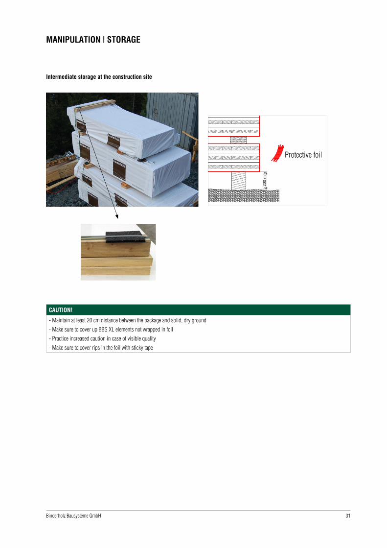
MANIPULATION | STORAGE
Intermediate storage at the construction site
≥ 20
0 m
m
Schutzfolie
CAUTION!
- Maintain at least 20 cm distance between the package and solid, dry ground
- Make sure to cover up BBS XL elements not wrapped in foil
- Practice increased caution in case of visible quality
- Make sure to cover rips in the foil with sticky tape
Protective foil

32 Binderholz Bausysteme GmbH
ASSEMBLY | WALLS
Checking of the floor plate
Execution
Check floor plate together with the master builder (re-measure on site and check the height)
Bituminous sealing against humidity
Execution
Bituminous sealing (scorching) on the finished floor plate (after the drying time)
Lay bituminous sealing against humidity according to the manufacturer’s instructions - if appropriate, lay two layers (observe structural physics)
LEGAL NOTE
All presentations, explanations, dimensions and selected materials are only recommendations and examples provided by binderholz.
33Binderholz Bausysteme GmbH
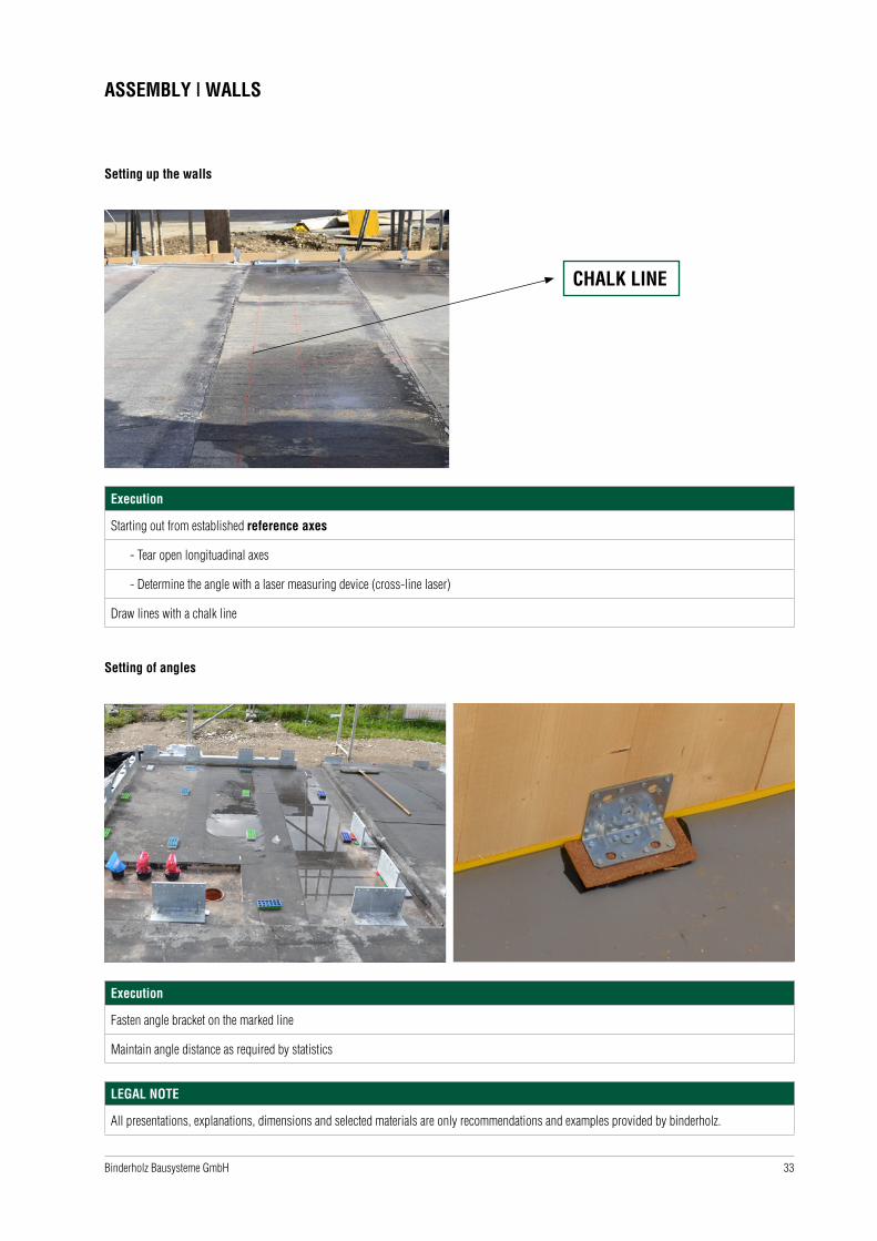
ASSEMBLY | WALLS
Setting up the walls
Execution
Starting out from established reference axes
- Tear open longituadinal axes
- Determine the angle with a laser measuring device (cross-line laser)
Draw lines with a chalk line
CHALK LINE
Setting of angles
Execution
Fasten angle bracket on the marked line
Maintain angle distance as required by statistics
LEGAL NOTE
All presentations, explanations, dimensions and selected materials are only recommendations and examples provided by binderholz.
34 Binderholz Bausysteme GmbH
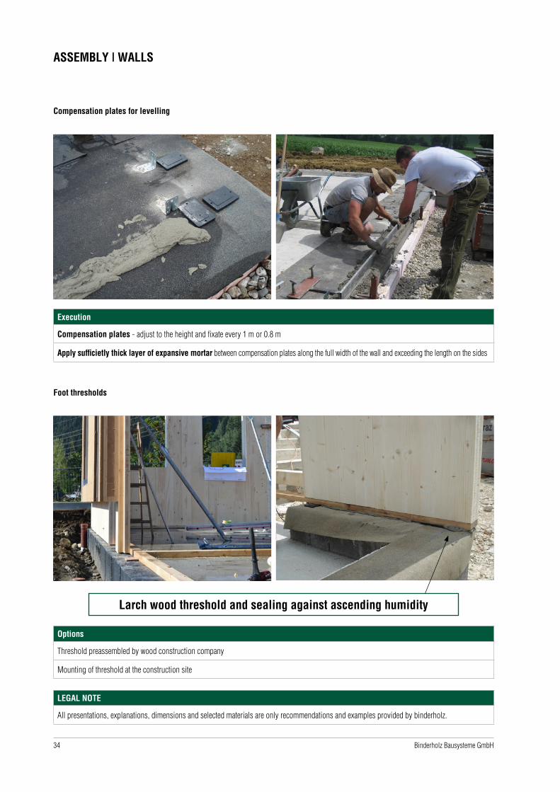
ASSEMBLY | WALLS
Compensation plates for levelling
Execution
Compensation plates - adjust to the height and fixate every 1 m or 0.8 m
Apply sufficietly thick layer of expansive mortar between compensation plates along the full width of the wall and exceeding the length on the sides
Foot thresholds
Options
Threshold preassembled by wood construction company
Mounting of threshold at the construction site
Larch wood threshold and sealing against ascending humidity
LEGAL NOTE
All presentations, explanations, dimensions and selected materials are only recommendations and examples provided by binderholz.
35Binderholz Bausysteme GmbH
ASSEMBLY | WALLS
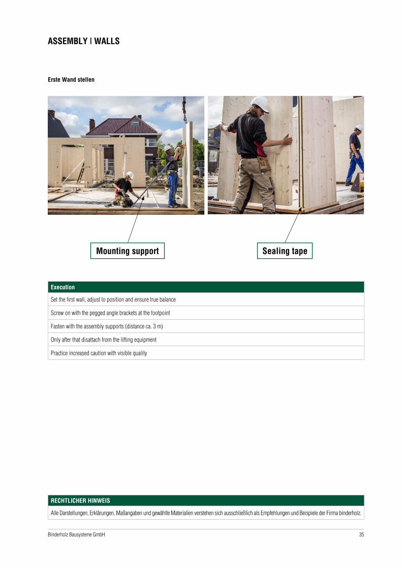
Erste Wand stellen
Execution
Set the first wall, adjust to position and ensure true balance
Screw on with the pegged angle brackets at the footpoint
Fasten with the assembly supports (distance ca. 3 m)
Only after that disattach from the lifting equipment
Practice increased caution with visible quality
Mounting support Sealing tape
RECHTLICHER HINWEIS
Alle Darstellungen, Erklärungen, Maßangaben und gewählte Materialien verstehen sich ausschließlich als Empfehlungen und Beispiele der Firma binderholz.
36 Binderholz Bausysteme GmbH
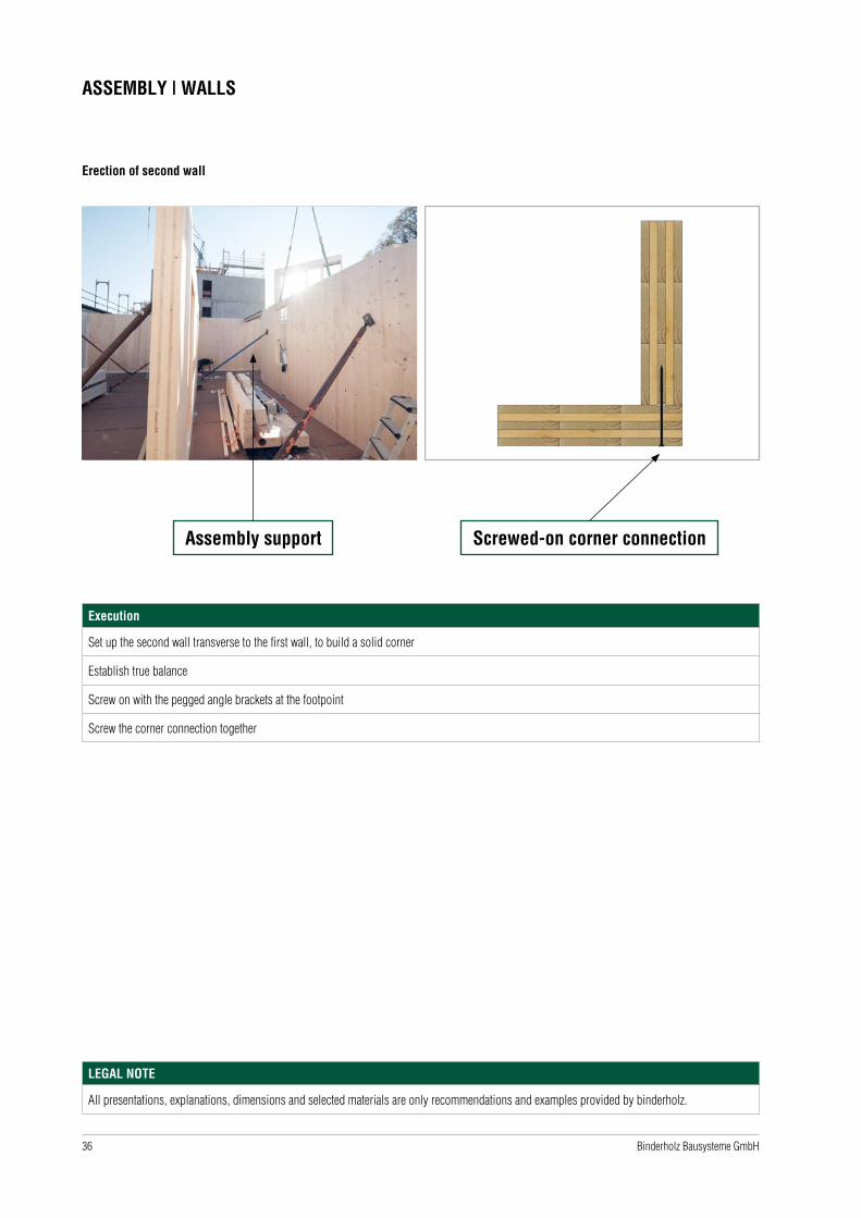
ASSEMBLY | WALLS
Erection of second wall
Execution
Set up the second wall transverse to the first wall, to build a solid corner
Establish true balance
Screw on with the pegged angle brackets at the footpoint
Screw the corner connection together
Assembly support Screwed-on corner connection
LEGAL NOTE
All presentations, explanations, dimensions and selected materials are only recommendations and examples provided by binderholz.
37Binderholz Bausysteme GmbH
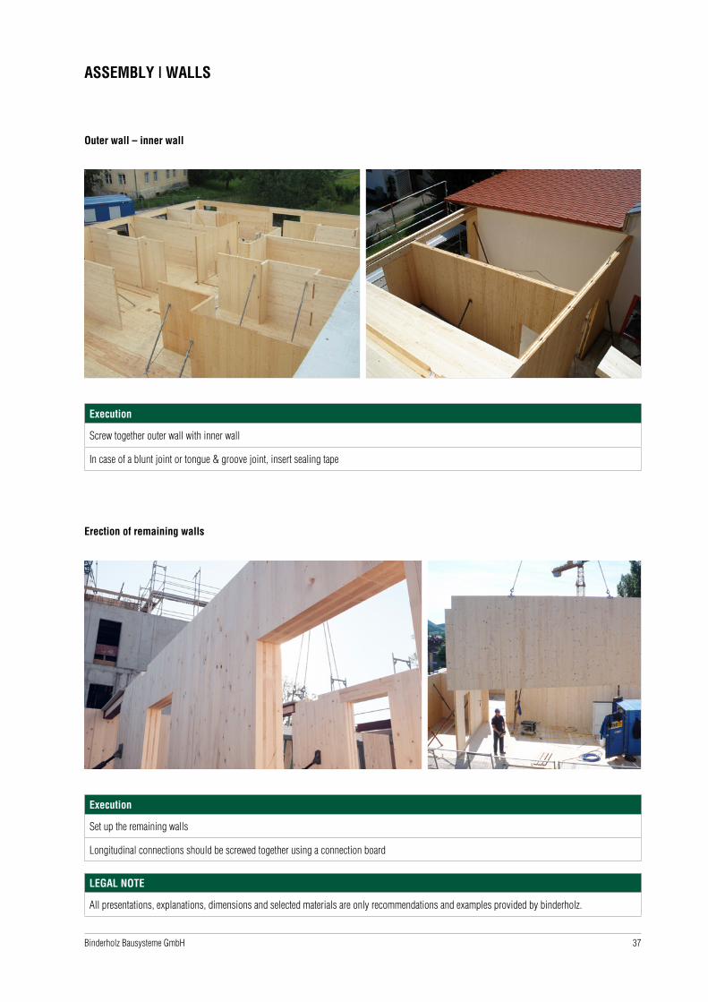
ASSEMBLY | WALLS
Outer wall – inner wall
Execution
Screw together outer wall with inner wall
In case of a blunt joint or tongue & groove joint, insert sealing tape
Erection of remaining walls
Execution
Set up the remaining walls
Longitudinal connections should be screwed together using a connection board
LEGAL NOTE
All presentations, explanations, dimensions and selected materials are only recommendations and examples provided by binderholz.
38 Binderholz Bausysteme GmbH
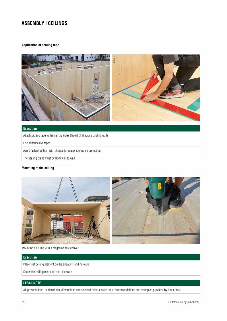
ASSEMBLY | CEILINGS
Application of sealing tape
Execution
Attach sealing tape to the narrow sides (faces) of already standing walls
Use selfadhesive tapes
Avoid fastening them with clamps for reasons of noise protection
The sealing plane must be from wall to wall
Mounting of the ceiling
Execution
Place first ceiling element on the already standing walls
Screw the ceiling elements onto the walls
Mounting a ceiling with a magazine screwdriver
LEGAL NOTE
All presentations, explanations, dimensions and selected materials are only recommendations and examples provided by binderholz.
© G
etzn
er
39Binderholz Bausysteme GmbH
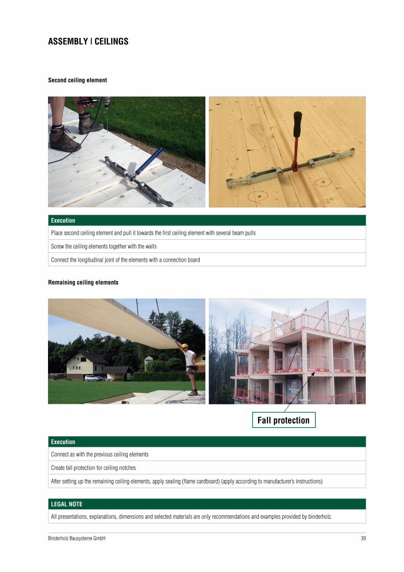
ASSEMBLY | CEILINGS
Second ceiling element
Execution
Place second ceiling element and pull it towards the first ceiling element with several beam pulls
Screw the ceiling elements together with the walls
Connect the longitudinal joint of the elements with a connection board
Remaining ceiling elements
Execution
Connect as with the previous ceiling elements
Create fall protection for ceiling notches
After setting up the remaining ceiling elements, apply sealing (flame cardboard) (apply according to manufacturer’s instructions)
Fall protection
LEGAL NOTE
All presentations, explanations, dimensions and selected materials are only recommendations and examples provided by binderholz.

40 Binderholz Bausysteme GmbH
ASSEMBLY | CEILINGS
Execution detail Longitudinal joint of elements
Execution
If necessary, balance out the ceiling element from underneath
Below, raise/lower with assembly support, before screwing on the cover plate
Execution detail: Longitudinal joint of elements in the wall axes I jetty (e.g. balkony)
Execution
Sealing of the longitudinal element connections
Noise protection in the interior area
Creation of the airtight plane for the outside area

41Binderholz Bausysteme GmbH
ASSEMBLY | WALLS UPPER FLOOR
Setting up the walls on the first upper floor
Execution
Starting out from the established reference axes
- Tear up the longitudinal axes
- Place angles to measure using a laser measuring device (cross-line laser)
Add chalk lines
CHALK LINE
Setting of angles
Execution
Attach angle pieces on the predrawn line
Maintain angle distance as requitred by statistics
These are binderholz suggestions, hints, examples

42 Binderholz Bausysteme GmbH
ASSEMBLY | PROTECTION
Weather protection
Execution
BBS may get wet during the construction phase, but avoid waterlogging
Before mounting further layers (e.g. ceiling extension, roof structures), make sure wood moisture is reduced to a maximum of 18%
(check with a wood moisture measuring device)
Permanently cover narrow areas (end grain) (use binderholz foil from the packages), install windows as fast as possible
Caution with surfaces in visible quality: avoid optical defects caused by water stains and dirt pollution
Temporary construction time sealing
On request, a full-surface temporary construction time sealing can be applied on our BBS elements at the factory. This can be temporarily used during
the construction time for up to 4 weeks on ceilings and roofs and can be exposed to the weather (including driving rain and UV light). The processing
instructions of the manufacturer of the sealing membrane as well as the binderholz instructions on the temporary construction time sealing must be
observed at any time. For further details, please ask our sales representatives.
These are binderholz suggestions, hints, examples
© S
IGA
© S
IGA

43Binderholz Bausysteme GmbH
INDEX OF SHELL CONSTRUCTION DETAILS
Shell construction details | symbols 44
Foundation - BBS outer wall 46
Foundation - BBS inner wall 50
BBS outer wall - BBS outer wall 52
BBS wall - BBS wall 54
BBS outer wall - BBS ceiling 61
BBS inner wall - BBS ceiling 66
BBS ceiling/roof - BBS ceiling/roof 67
BBS outer wall - BBS roof 71
Rafter solid wood - BBS outer wall 73
Ridge 77
Attika as coating - BBS flat roof 81
BSH girder - BBS outer wall 82
BSH ceiling-level girder - BBS ceiling 86
Steel girder - BBS outer wall 87
Ceiling-level steel girder - BBS ceiling 89
Steel support as suspender beam - BBS ceiling 91
BBS ceiling with a butt joint - BBS inner wall 92
BBS ceiling - wooden frame wall (outer wall) 93
BBS ceiling - wooden frame wall (inner wall) 95
BBS wall - wooden frame wall (outer wall) 96
BBS wall - inserted BBS ledgez 98
Stairwell 102
BBS ceiling - brickwall 105
BBBS ceiling - concrete wall 108
BBS staircase 115

44 Binderholz Bausysteme GmbH
SHELL CONSTRUCTION DETAILS | SYMBOLS
Symbol Denomination Function Dimension (Examples)
Concrete anchororscrew anchor
For fastening on mineral substrate (concrete, stone)
Ø 12 x 178 mm
Ø 16 x 220 mm
Fully threaded screw
Selfdrilling screw for wood
For the transmission of high tensile forces,e.g. in suspender beams
Ø 8 x 140 mm
Comb nailFor fastening angle connectors, joist hangers, metal plates and for the execution of cross-type screw fittings
Ø 4 x 60 mm
Wood screw
Selfdrilling partially threaded screw for wood
Increase of the head pull-through value by means of using washers
Ø 6 x 80 mm
Ø 8 x 100 mm
Ø 8 x 160 mm
Washer head screwSelfdrilling partially threaded screw for wood
Large screw head for high head pull-through values
Ø 8 x 200 mm
Ø 10 x 240 mm
Ø 10 x 360 mm
LEGAL NOTE
The presented dimensions (especially connecting means) and symbol images are to be understood as examples and do not replace subject specific
or project-specific static and physical calculation.

45Binderholz Bausysteme GmbH
SHELL CONSTRUCTION DETAILS | SYMBOLS
Symbol Denomination Function Dimension (Examples)
Angle connector For fastening of wooden walls on substrate (wood, reinforced concrete)
100 x 100 mm
Perforated metal plate For transmission of tensile forces 80 x 600 mm
3-layer panel For transmission of tensile forces Thickness 19 mm or 27 mm
Tie rod Rod for tension connection between a wooden wall and substrate from reinforced concrete
Height 540 mm
Glue tapeTo create an airtight plane
Recommended for wood-wood connectionsWidth 60 mm
Wall barrier from butylProtection of the wood against ascending moisture
Variable widthWidth 500 mm
EPDM sealing tapeSealing to create an airtight plane
Fasten with clamps
Noise protection bearing
Sealing to create an airtight plane
Decouples in case of increased requirements for noise protection
Colour division in different pres-sure strengths
Application of different bearings depending on actual line load
EPDM zigzag band
Sealing to create an airtight plane
Decouples in case of normal requirements for noise protection
Depending on the construction object, specific calculation is recommended
Glue Sealing to create an airtight plane PU glues, mounting glue
Insulation Mineral wool, cellulose, EPS/XPS
LEGAL NOTE
The presented dimensions (especially connecting means) and symbol images are to be understood as examples and do not replace subject specific
or project-specific static and physical calculation.
46 Binderholz Bausysteme GmbH
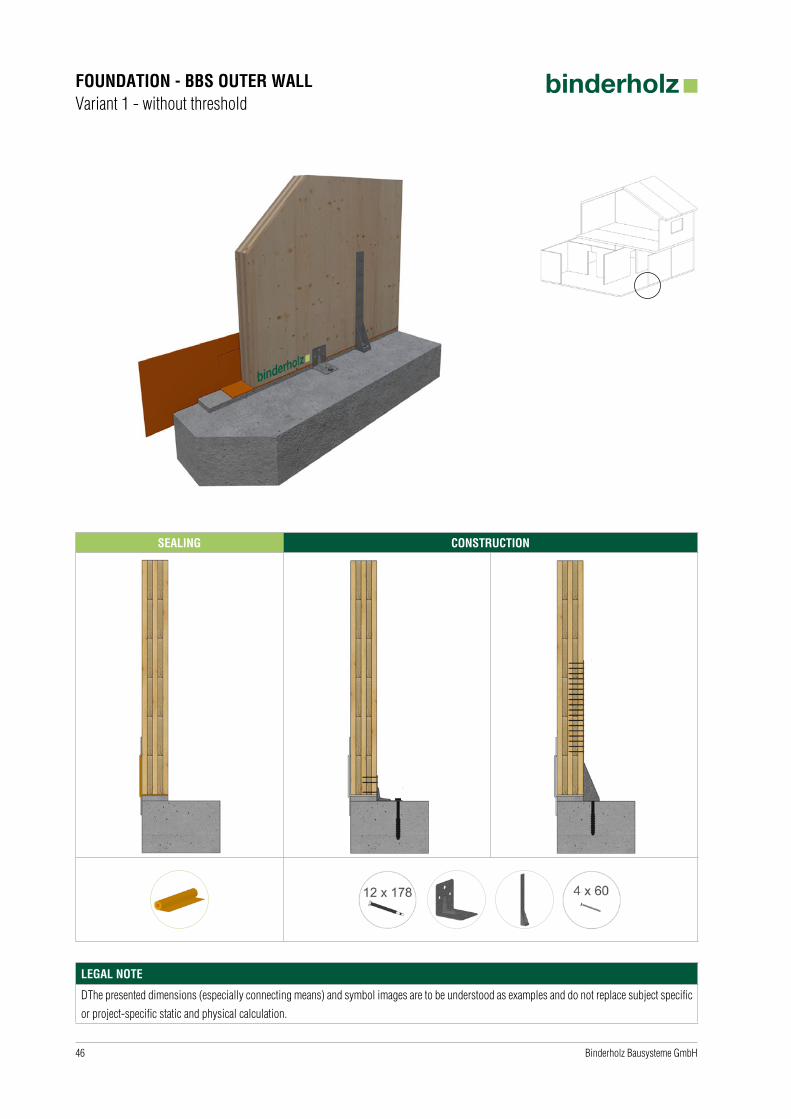
FOUNDATION - BBS OUTER WALLVariant 1 - without threshold
SEALING CONSTRUCTION
LEGAL NOTE
DThe presented dimensions (especially connecting means) and symbol images are to be understood as examples and do not replace subject specific
or project-specific static and physical calculation.

47Binderholz Bausysteme GmbH
FOUNDATION - BBS OUTER WALLVariant 2 - with threshold
SEALING CONSTRUCTION
LEGAL NOTE
The presented dimensions (especially connecting means) and symbol images are to be understood as examples and do not replace subject specific
or project-specific static and physical calculation.
48 Binderholz Bausysteme GmbH
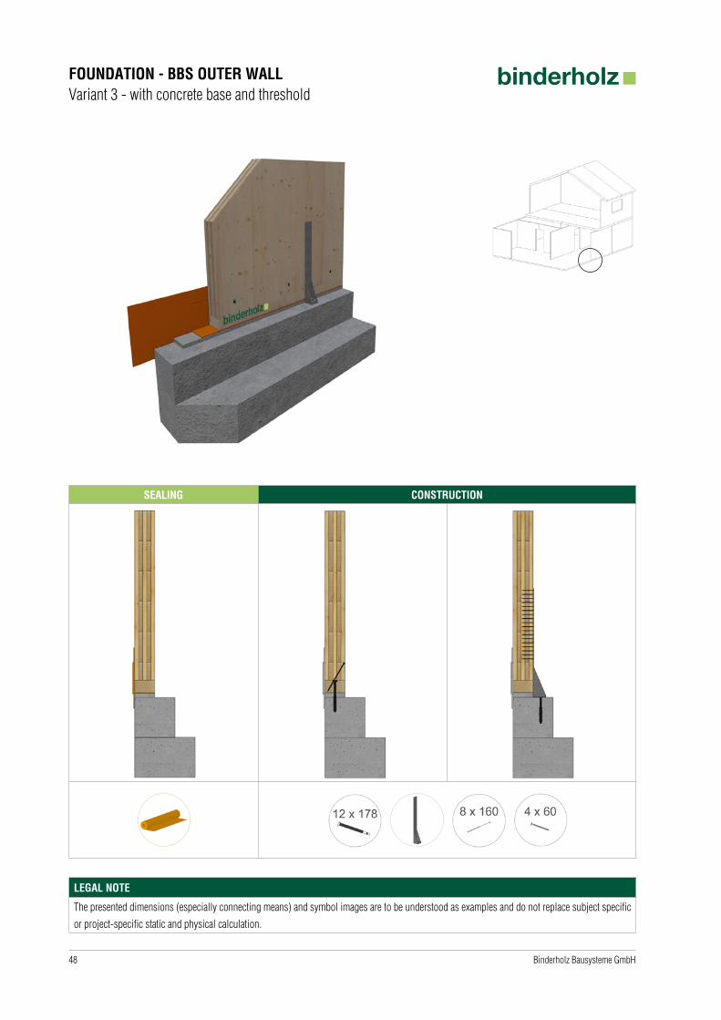
FOUNDATION - BBS OUTER WALLVariant 3 - with concrete base and threshold
SEALING CONSTRUCTION
LEGAL NOTE
The presented dimensions (especially connecting means) and symbol images are to be understood as examples and do not replace subject specific
or project-specific static and physical calculation.
49Binderholz Bausysteme GmbH
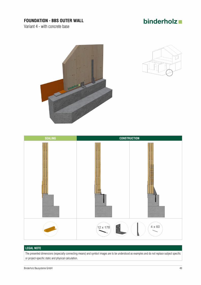
FOUNDATION - BBS OUTER WALLVariant 4 - with concrete base
SEALING CONSTRUCTION
LEGAL NOTE
The presented dimensions (especially connecting means) and symbol images are to be understood as examples and do not replace subject specific
or project-specific static and physical calculation.
50 Binderholz Bausysteme GmbH
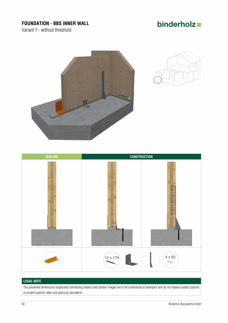
FOUNDATION - BBS INNER WALLVariant 1 - without threshold
SEALING CONSTRUCTION
LEGAL NOTE
The presented dimensions (especially connecting means) and symbol images are to be understood as examples and do not replace subject specific
or project-specific static and physical calculation.

51Binderholz Bausysteme GmbH
FOUNDATION - BBS INNER WALLVariant 2 - with threshold
SEALING CONSTRUCTION
LEGAL NOTE
The presented dimensions (especially connecting means) and symbol images are to be understood as examples and do not replace subject specific
or project-specific static and physical calculation.

52 Binderholz Bausysteme GmbH
BBS OUTER WALL - BBS OUTER WALLVariant 1 - with sealing tape
SEALING CONSTRUCTION
LEGAL NOTE
The presented dimensions (especially connecting means) and symbol images are to be understood as examples and do not replace subject specific
or project-specific static and physical calculation.

53Binderholz Bausysteme GmbH
BBS OUTER WALL - BBS OUTER WALLVariant 2 - with glue tape
SEALING CONSTRUCTION
LEGAL NOTE
The presented dimensions (especially connecting means) and symbol images are to be understood as examples and do not replace subject specific
or project-specific static and physical calculation.
54 Binderholz Bausysteme GmbH
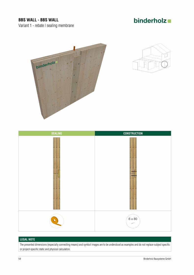
BBS WALL - BBS WALLVariant 1 - rebate | sealing membrane
SEALING CONSTRUCTION
LEGAL NOTE
The presented dimensions (especially connecting means) and symbol images are to be understood as examples and do not replace subject specific
or project-specific static and physical calculation.
55Binderholz Bausysteme GmbH
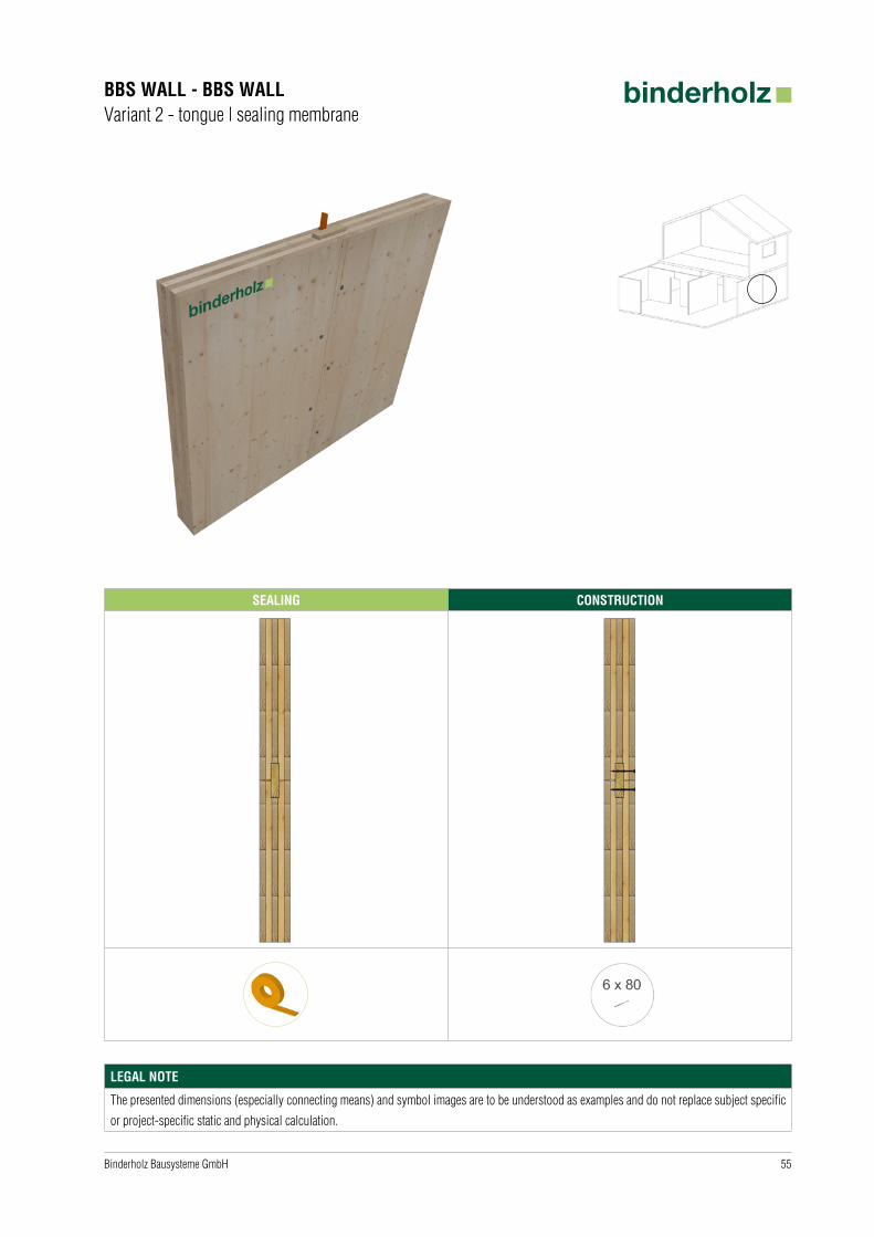
BBS WALL - BBS WALLVariant 2 - tongue | sealing membrane
SEALING CONSTRUCTION
LEGAL NOTE
The presented dimensions (especially connecting means) and symbol images are to be understood as examples and do not replace subject specific
or project-specific static and physical calculation.

56 Binderholz Bausysteme GmbH
BBS WALL - BBS WALLVariant 3 - rebate | glue tape
SEALING CONSTRUCTION
LEGAL NOTE
The presented dimensions (especially connecting means) and symbol images are to be understood as examples and do not replace subject specific
or project-specific static and physical calculation.
57Binderholz Bausysteme GmbH
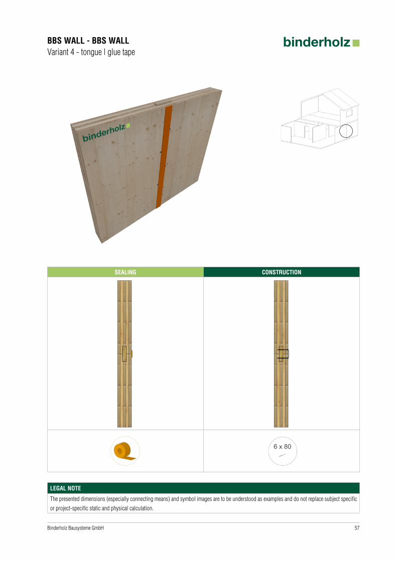
BBS WALL - BBS WALLVariant 4 - tongue | glue tape
SEALING CONSTRUCTION
LEGAL NOTE
The presented dimensions (especially connecting means) and symbol images are to be understood as examples and do not replace subject specific
or project-specific static and physical calculation.

58 Binderholz Bausysteme GmbH
BBS WALL - BBS WALLVariant 5 - stepped rebate | glue tape
SEALING CONSTRUCTION
LEGAL NOTE
The presented dimensions (especially connecting means) and symbol images are to be understood as examples and do not replace subject specific
or project-specific static and physical calculation.
59Binderholz Bausysteme GmbH
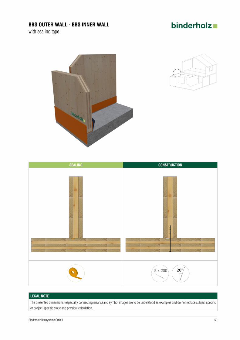
BBS OUTER WALL - BBS INNER WALLwith sealing tape
SEALING CONSTRUCTION
LEGAL NOTE
The presented dimensions (especially connecting means) and symbol images are to be understood as examples and do not replace subject specific
or project-specific static and physical calculation.
60 Binderholz Bausysteme GmbH
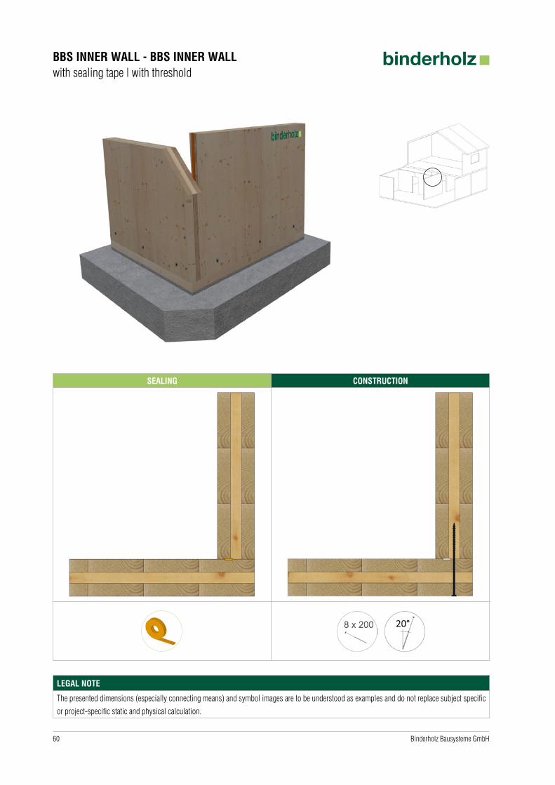
BBS INNER WALL - BBS INNER WALLwith sealing tape | with threshold
SEALING CONSTRUCTION
LEGAL NOTE
The presented dimensions (especially connecting means) and symbol images are to be understood as examples and do not replace subject specific
or project-specific static and physical calculation.

61Binderholz Bausysteme GmbH
BBS OUTER WALL - BBS CEILINGVariant 1 - angle connection
SEALING CONSTRUCTION
erhöhteSchallschutzanforderungen
normaleSchallschutzanforderungen
increased noise protection requirements
lower noise protection requirements
LEGAL NOTE
The presented dimensions (especially connecting means) and symbol images are to be understood as examples and do not replace subject specific
or project-specific static and physical calculation.
62 Binderholz Bausysteme GmbH
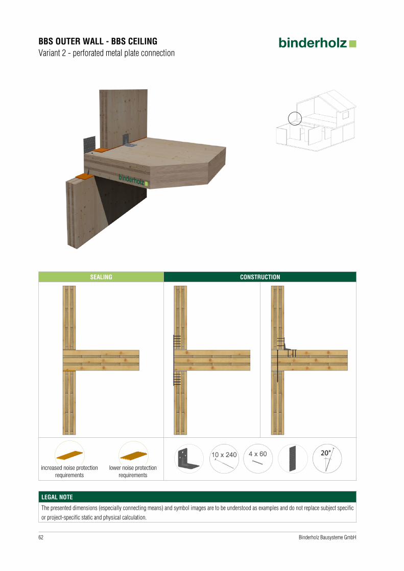
BBS OUTER WALL - BBS CEILINGVariant 2 - perforated metal plate connection
SEALING CONSTRUCTION
increased noise protection requirements
lower noise protection requirements
LEGAL NOTE
The presented dimensions (especially connecting means) and symbol images are to be understood as examples and do not replace subject specific
or project-specific static and physical calculation.
63Binderholz Bausysteme GmbH
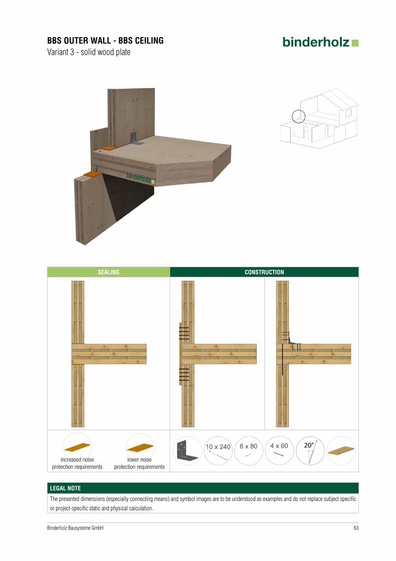
BBS OUTER WALL - BBS CEILINGVariant 3 - solid wood plate
SEALING CONSTRUCTION
increased noise protection requirements
lower noise protection requirements
LEGAL NOTE
The presented dimensions (especially connecting means) and symbol images are to be understood as examples and do not replace subject specific
or project-specific static and physical calculation.

64 Binderholz Bausysteme GmbH
BBS OUTER WALL - BBS CEILINGVariant 4 - continuous outer wall | bearing trimmer beam
SEALING CONSTRUCTION
increased noise protection requirements
lower noise protection requirements
LEGAL NOTE
The presented dimensions (especially connecting means) and symbol images are to be understood as examples and do not replace subject specific
or project-specific static and physical calculation.

65Binderholz Bausysteme GmbH
BBS OUTER WALL - BBS CEILINGVariant 5 - continuous outer wall | bearing T-square
SEALING CONSTRUCTION
increased noise protection requirements
lower noise protection requirements
LEGAL NOTE
The presented dimensions (especially connecting means) and symbol images are to be understood as examples and do not replace subject specific
or project-specific static and physical calculation.
66 Binderholz Bausysteme GmbH
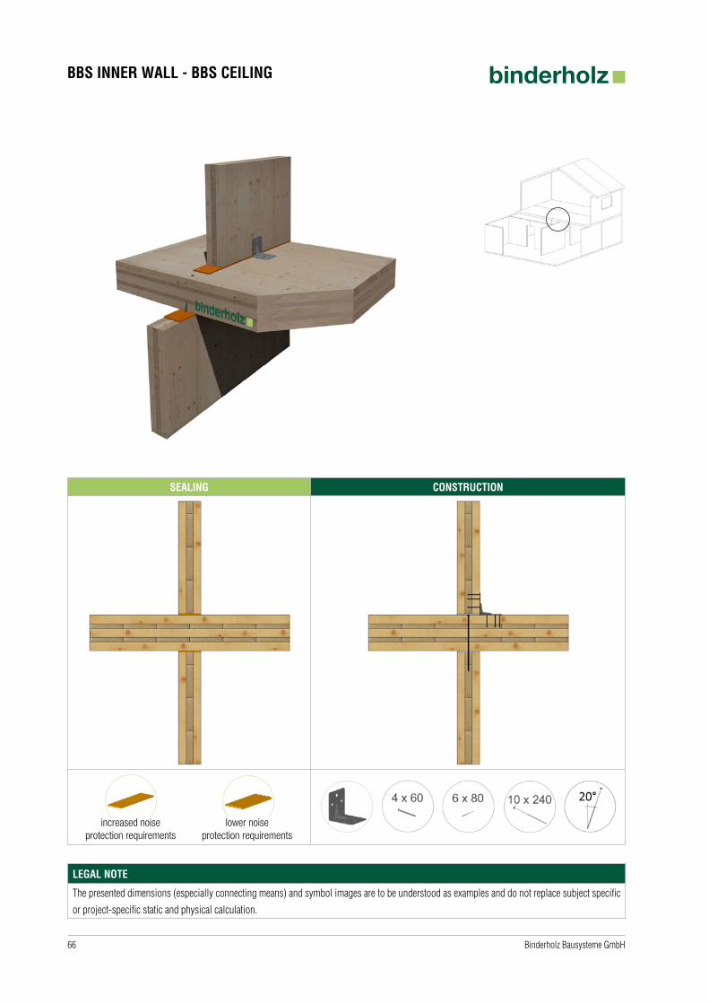
BBS INNER WALL - BBS CEILING
SEALING CONSTRUCTION
increased noise protection requirements
lower noise protection requirements
LEGAL NOTE
The presented dimensions (especially connecting means) and symbol images are to be understood as examples and do not replace subject specific
or project-specific static and physical calculation.

67Binderholz Bausysteme GmbH
BBS CEILING/ROOF - BBS CEILING/ROOFVariant 1 - rebate | glue tape
SEALING CONSTRUCTION
LEGAL NOTE
The presented dimensions (especially connecting means) and symbol images are to be understood as examples and do not replace subject specific
or project-specific static and physical calculation.

68 Binderholz Bausysteme GmbH
BBS CEILING/ROOF - BBS CEILING/ROOFVariant 2 - rebate | glue
SEALING CONSTRUCTION
LEGAL NOTE
The presented dimensions (especially connecting means) and symbol images are to be understood as examples and do not replace subject specific
or project-specific static and physical calculation.
69Binderholz Bausysteme GmbH
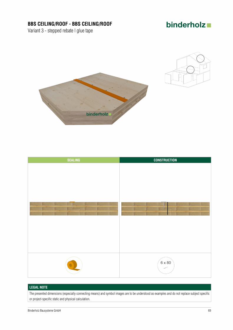
BBS CEILING/ROOF - BBS CEILING/ROOFVariant 3 - stepped rebate | glue tape
SEALING CONSTRUCTION
LEGAL NOTE
The presented dimensions (especially connecting means) and symbol images are to be understood as examples and do not replace subject specific
or project-specific static and physical calculation.

70 Binderholz Bausysteme GmbH
BBS CEILING/ROOF - CEILING/ROOFVariant 4 - screwed crosswise | glue tape
SEALING CONSTRUCTION
LEGAL NOTE
The presented dimensions (especially connecting means) and symbol images are to be understood as examples and do not replace subject specific
or project-specific static and physical calculation.

71Binderholz Bausysteme GmbH
BBS OUTER WALL - BBS ROOFVariant 1 - sealing tape
SEALING CONSTRUCTION
LEGAL NOTE
The presented dimensions (especially connecting means) and symbol images are to be understood as examples and do not replace subject specific
or project-specific static and physical calculation.
72 Binderholz Bausysteme GmbH
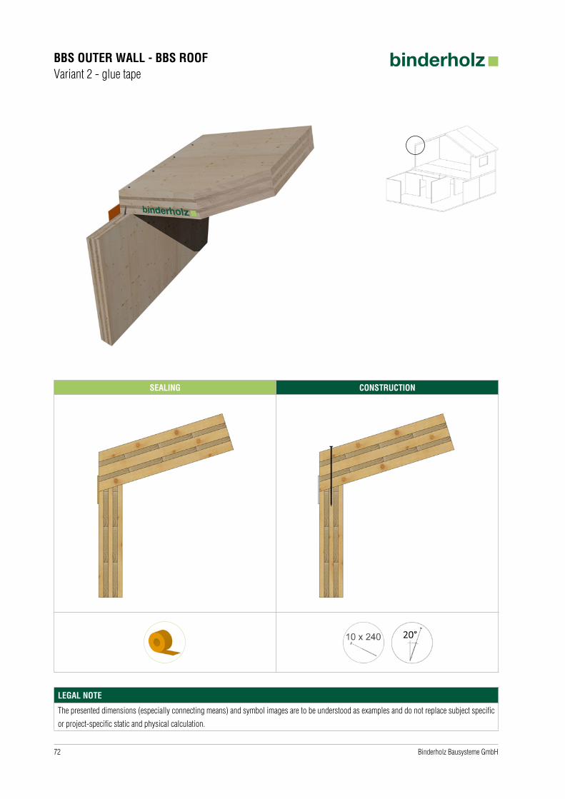
BBS OUTER WALL - BBS ROOFVariant 2 - glue tape
SEALING CONSTRUCTION
LEGAL NOTE
The presented dimensions (especially connecting means) and symbol images are to be understood as examples and do not replace subject specific
or project-specific static and physical calculation.

73Binderholz Bausysteme GmbH
SOLID WOOD RAFTER - BBS OUTER WALLVariant 1 - without glue tape
CONSTRUCTION
LEGAL NOTE
The presented dimensions (especially connecting means) and symbol images are to be understood as examples and do not replace subject specific
or project-specific static and physical calculation.

74 Binderholz Bausysteme GmbH
SOLID WOOD RAFTER - BBS OUTER WALLVariant 2 - with glue tape
SEALING CONSTRUCTION
LEGAL NOTE
The presented dimensions (especially connecting means) and symbol images are to be understood as examples and do not replace subject specific
or project-specific static and physical calculation.

75Binderholz Bausysteme GmbH
SOLID WOOD RAFTER - BBS OUTER WALLVariant 3 - rafter inserted | glue tape
SEALING CONSTRUCTION
LEGAL NOTE
The presented dimensions (especially connecting means) and symbol images are to be understood as examples and do not replace subject specific
or project-specific static and physical calculation.
76 Binderholz Bausysteme GmbH
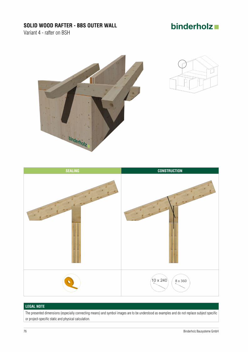
SOLID WOOD RAFTER - BBS OUTER WALLVariant 4 - rafter on BSH
SEALING CONSTRUCTION
LEGAL NOTE
The presented dimensions (especially connecting means) and symbol images are to be understood as examples and do not replace subject specific
or project-specific static and physical calculation.

77Binderholz Bausysteme GmbH
RIDGEVariant 1 - with stringer | sealing tape
SEALING CONSTRUCTION
LEGAL NOTE
The presented dimensions (especially connecting means) and symbol images are to be understood as examples and do not replace subject specific
or project-specific static and physical calculation.

78 Binderholz Bausysteme GmbH
RIDGEVariant 2 - with stringer | glue tape
SEALING CONSTRUCTION
LEGAL NOTE
The presented dimensions (especially connecting means) and symbol images are to be understood as examples and do not replace subject specific
or project-specific static and physical calculation.
79Binderholz Bausysteme GmbH
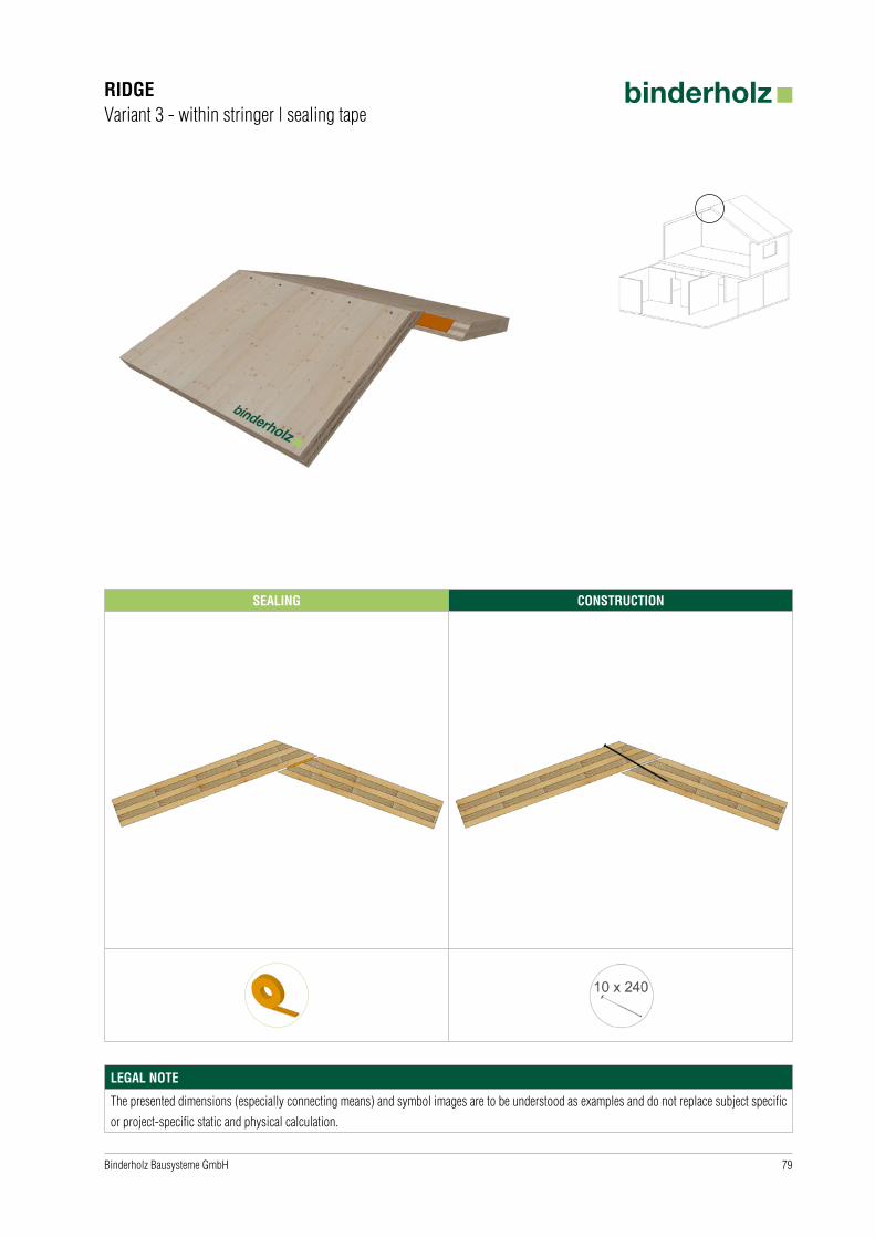
RIDGEVariant 3 - within stringer | sealing tape
SEALING CONSTRUCTION
LEGAL NOTE
The presented dimensions (especially connecting means) and symbol images are to be understood as examples and do not replace subject specific
or project-specific static and physical calculation.
80 Binderholz Bausysteme GmbH
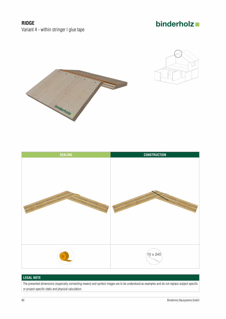
RIDGEVariant 4 - within stringer | glue tape
SEALING CONSTRUCTION
LEGAL NOTE
The presented dimensions (especially connecting means) and symbol images are to be understood as examples and do not replace subject specific
or project-specific static and physical calculation.

81Binderholz Bausysteme GmbH
ATTIKA AS SUSPENDER BEAM - BBS FLAT ROOF
SEALING CONSTRUCTION
LEGAL NOTE
The presented dimensions (especially connecting means) and symbol images are to be understood as examples and do not replace subject specific
or project-specific static and physical calculation.

82 Binderholz Bausysteme GmbH
GIRDER BSH - BBS OUTER WALLVariant 1 - joist hanger
CONSTRUCTION
LEGAL NOTE
The presented dimensions (especially connecting means) and symbol images are to be understood as examples and do not replace subject specific
or project-specific static and physical calculation.

83Binderholz Bausysteme GmbH
GIRDER BSH - BBS OUTER WALLVariant 2 - summer
CONSTRUCTION
LEGAL NOTE
The presented dimensions (especially connecting means) and symbol images are to be understood as examples and do not replace subject specific
or project-specific static and physical calculation.

84 Binderholz Bausysteme GmbH
GIRDER BSH - BBS OUTER WALLVariant 3 - push-in connection
CONSTRUCTION
LEGAL NOTE
The presented dimensions (especially connecting means) and symbol images are to be understood as examples and do not replace subject specific
or project-specific static and physical calculation.
85Binderholz Bausysteme GmbH
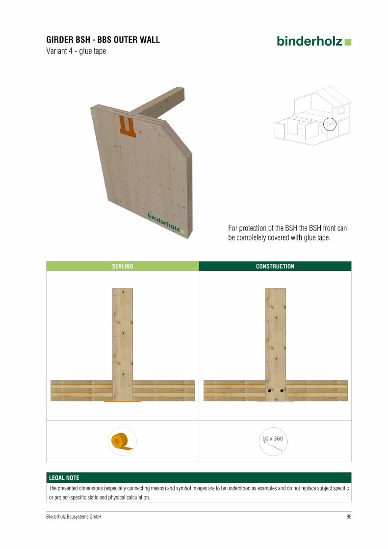
GIRDER BSH - BBS OUTER WALLVariant 4 - glue tape
SEALING CONSTRUCTION
For protection of the BSH the BSH front can be completely covered with glue tape.
LEGAL NOTE
The presented dimensions (especially connecting means) and symbol images are to be understood as examples and do not replace subject specific
or project-specific static and physical calculation.
86 Binderholz Bausysteme GmbH
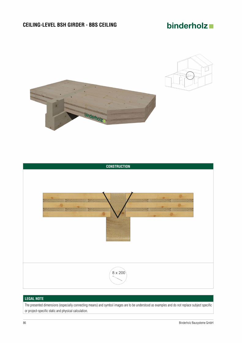
CEILING-LEVEL BSH GIRDER - BBS CEILING
CONSTRUCTION
LEGAL NOTE
The presented dimensions (especially connecting means) and symbol images are to be understood as examples and do not replace subject specific
or project-specific static and physical calculation.
87Binderholz Bausysteme GmbH
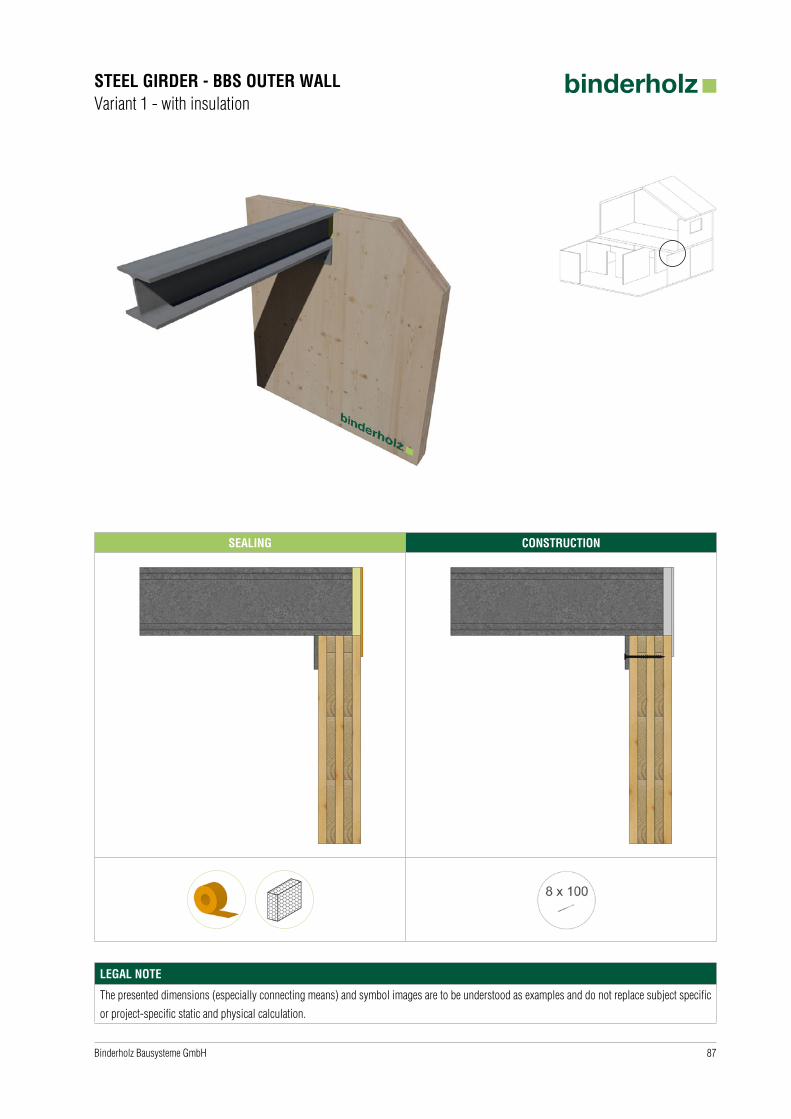
STEEL GIRDER - BBS OUTER WALLVariant 1 - with insulation
SEALING CONSTRUCTION
LEGAL NOTE
The presented dimensions (especially connecting means) and symbol images are to be understood as examples and do not replace subject specific
or project-specific static and physical calculation.
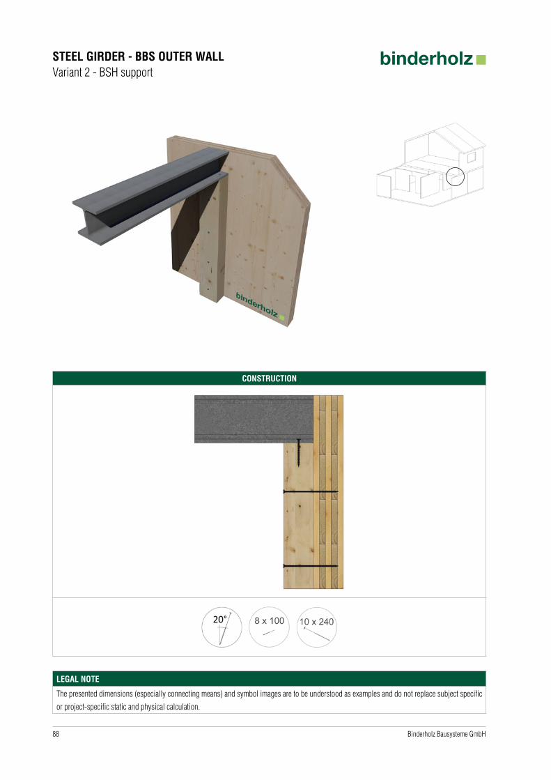
88 Binderholz Bausysteme GmbH
STEEL GIRDER - BBS OUTER WALLVariant 2 - BSH support
CONSTRUCTION
LEGAL NOTE
The presented dimensions (especially connecting means) and symbol images are to be understood as examples and do not replace subject specific
or project-specific static and physical calculation.

89Binderholz Bausysteme GmbH
CEILING-LEVEL STEEL GIRDER - BBS CEILINGVariant 1 - with noise protection
SEALING CONSTRUCTION
increased noise protection requirements
lower noise protection requirements
LEGAL NOTE
The presented dimensions (especially connecting means) and symbol images are to be understood as examples and do not replace subject specific
or project-specific static and physical calculation.
90 Binderholz Bausysteme GmbH
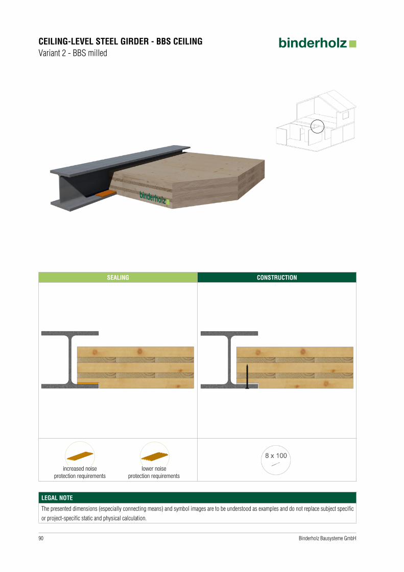
CEILING-LEVEL STEEL GIRDER - BBS CEILINGVariant 2 - BBS milled
SEALING CONSTRUCTION
increased noise protection requirements
lower noise protection requirements
LEGAL NOTE
The presented dimensions (especially connecting means) and symbol images are to be understood as examples and do not replace subject specific
or project-specific static and physical calculation.

91Binderholz Bausysteme GmbH
STEEL SUPPORT AS SUSPENDER BEAM - BBS CEILING
CONSTRUCTION
LEGAL NOTE
The presented dimensions (especially connecting means) and symbol images are to be understood as examples and do not replace subject specific
or project-specific static and physical calculation.
92 Binderholz Bausysteme GmbH
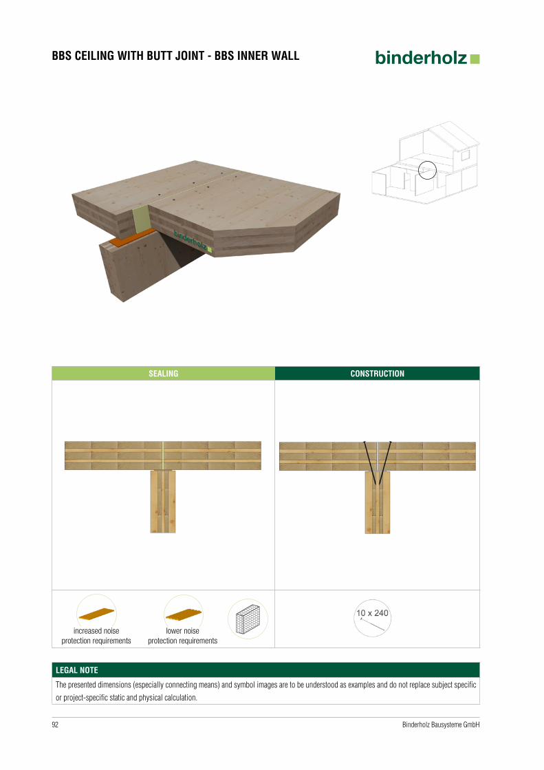
BBS CEILING WITH BUTT JOINT - BBS INNER WALL
SEALING CONSTRUCTION
increased noise protection requirements
lower noise protection requirements
LEGAL NOTE
The presented dimensions (especially connecting means) and symbol images are to be understood as examples and do not replace subject specific
or project-specific static and physical calculation.
93Binderholz Bausysteme GmbH
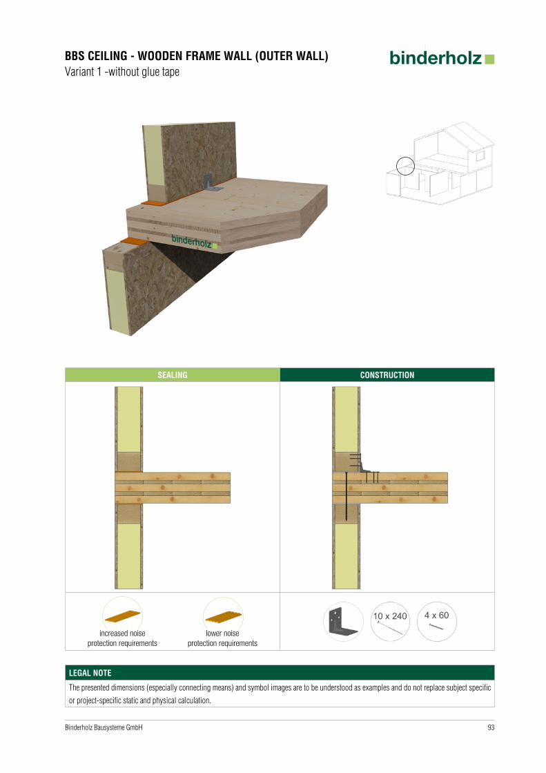
SEALING CONSTRUCTION
BBS CEILING - WOODEN FRAME WALL (OUTER WALL)Variant 1 -without glue tape
increased noise protection requirements
lower noise protection requirements
LEGAL NOTE
The presented dimensions (especially connecting means) and symbol images are to be understood as examples and do not replace subject specific
or project-specific static and physical calculation.
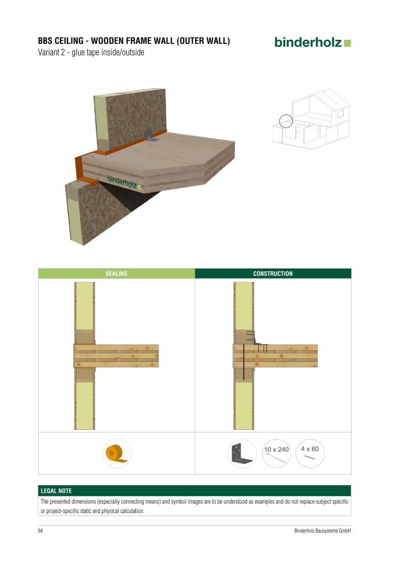
94 Binderholz Bausysteme GmbH
SEALING CONSTRUCTION
BBS CEILING - WOODEN FRAME WALL (OUTER WALL)Variant 2 - glue tape inside/outside
LEGAL NOTE
The presented dimensions (especially connecting means) and symbol images are to be understood as examples and do not replace subject specific
or project-specific static and physical calculation.

95Binderholz Bausysteme GmbH
SEALING CONSTRUCTION
BBS CEILING - WOODEN FRAME WALL (INNER WALL)
increased noise protection requirements
lower noise protection requirements
LEGAL NOTE
The presented dimensions (especially connecting means) and symbol images are to be understood as examples and do not replace subject specific
or project-specific static and physical calculation.

96 Binderholz Bausysteme GmbH
SEALING CONSTRUCTION
BBS WALL - WOODEN FRAME WALL (OUTER WALL)Variant 1 - sealing tape
LEGAL NOTE
The presented dimensions (especially connecting means) and symbol images are to be understood as examples and do not replace subject specific
or project-specific static and physical calculation.

97Binderholz Bausysteme GmbH
SEALING CONSTRUCTION
BBS WALL - WOODEN FRAME WALL (OUTER WALL)Variant 2 - glue tape inside (in BBS NH-C)
LEGAL NOTE
The presented dimensions (especially connecting means) and symbol images are to be understood as examples and do not replace subject specific
or project-specific static and physical calculation.

98 Binderholz Bausysteme GmbH
SEALING CONSTRUCTION
BBS WALL - INSERTED BBS LEDGEVariant 1 - fitted end-to-end
LEGAL NOTE
The presented dimensions (especially connecting means) and symbol images are to be understood as examples and do not replace subject specific
or project-specific static and physical calculation.
99Binderholz Bausysteme GmbH
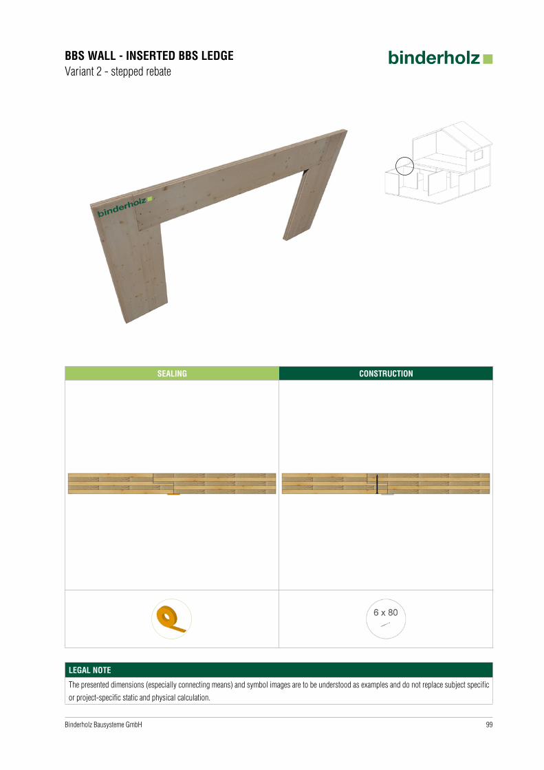
SEALING CONSTRUCTION
BBS WALL - INSERTED BBS LEDGEVariant 2 - stepped rebate
LEGAL NOTE
The presented dimensions (especially connecting means) and symbol images are to be understood as examples and do not replace subject specific
or project-specific static and physical calculation.
100 Binderholz Bausysteme GmbH
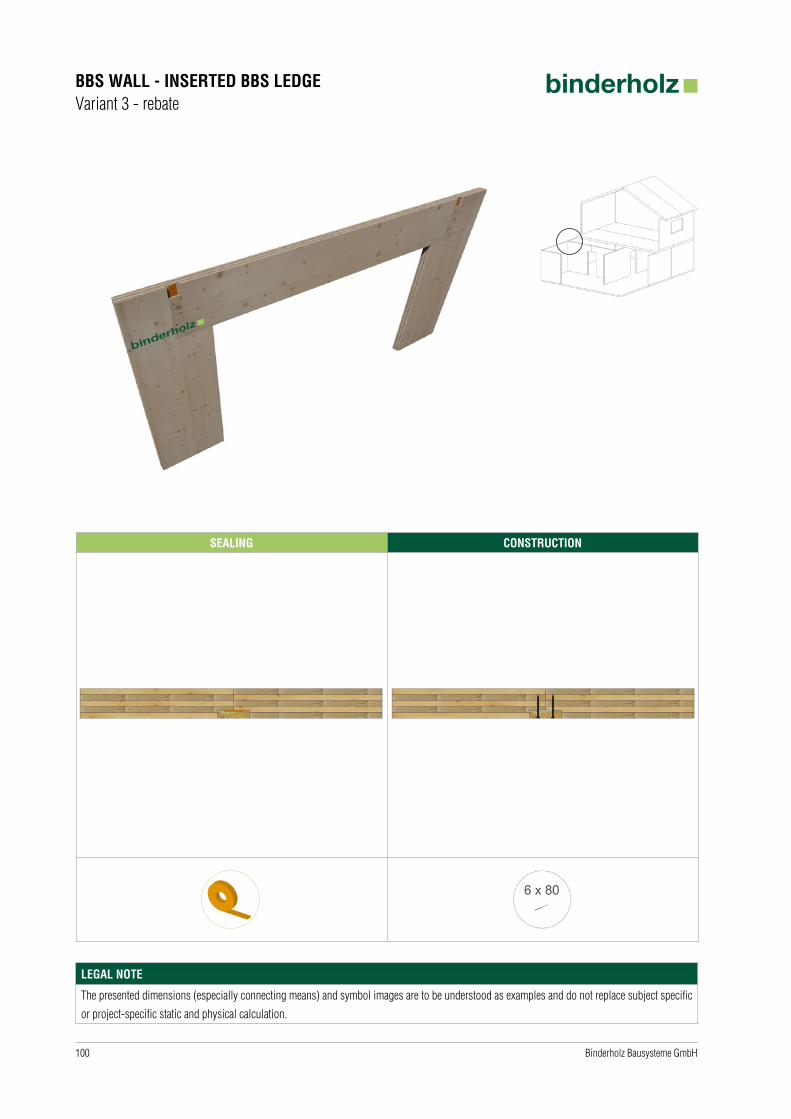
SEALING CONSTRUCTION
BBS WALL - INSERTED BBS LEDGEVariant 3 - rebate
LEGAL NOTE
The presented dimensions (especially connecting means) and symbol images are to be understood as examples and do not replace subject specific
or project-specific static and physical calculation.

101Binderholz Bausysteme GmbH
SEALING CONSTRUCTION
BBS WALL - INSERTED BBS LEDGEVariant 4 - BSH support
LEGAL NOTE
The presented dimensions (especially connecting means) and symbol images are to be understood as examples and do not replace subject specific
or project-specific static and physical calculation.

102 Binderholz Bausysteme GmbH
CONSTRUCTION
STAIRWELLVariant 1 - BSH screwed
LEGAL NOTE
The presented dimensions (especially connecting means) and symbol images are to be understood as examples and do not replace subject specific
or project-specific static and physical calculation.

103Binderholz Bausysteme GmbH
CONSTRUCTION
STAIRWELLVariant 2 - steel support
LEGAL NOTE
The presented dimensions (especially connecting means) and symbol images are to be understood as examples and do not replace subject specific
or project-specific static and physical calculation.
104 Binderholz Bausysteme GmbH
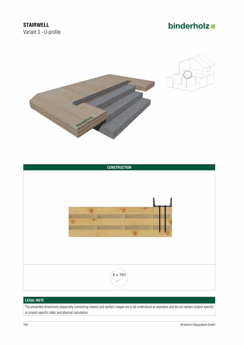
CONSTRUCTION
STAIRWELLVariant 3 - U-profile
LEGAL NOTE
The presented dimensions (especially connecting means) and symbol images are to be understood as examples and do not replace subject specific
or project-specific static and physical calculation.

105Binderholz Bausysteme GmbH
SEALING CONSTRUCTION
BBS CEILING - BRICKWALLVariant 1 - inner wall | continuous ceiling
LEGAL NOTE
The presented dimensions (especially connecting means) and symbol images are to be understood as examples and do not replace subject specific
or project-specific static and physical calculation.

106 Binderholz Bausysteme GmbH
SEALING CONSTRUCTION
BBS CEILING - BRICKWALLVariant 2 - with insulation
LEGAL NOTE
The presented dimensions (especially connecting means) and symbol images are to be understood as examples and do not replace subject specific
or project-specific static and physical calculation.

107Binderholz Bausysteme GmbH
SEALING CONSTRUCTION
BBS CEILING - BRICKWALLVariant 3 - with expansive mortar
LEGAL NOTE
The presented dimensions (especially connecting means) and symbol images are to be understood as examples and do not replace subject specific
or project-specific static and physical calculation.
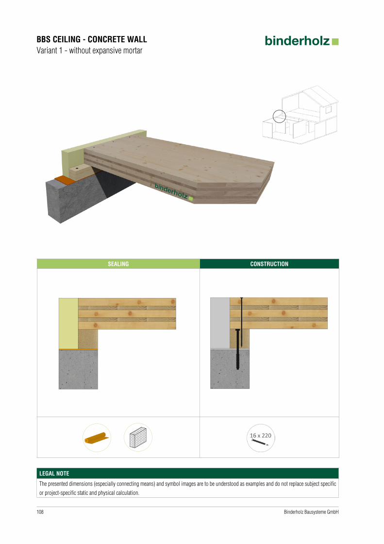
108 Binderholz Bausysteme GmbH
SEALING CONSTRUCTION
BBS CEILING - CONCRETE WALLVariant 1 - without expansive mortar
LEGAL NOTE
The presented dimensions (especially connecting means) and symbol images are to be understood as examples and do not replace subject specific
or project-specific static and physical calculation.

109Binderholz Bausysteme GmbH
SEALING CONSTRUCTION
BBS CEILING - CONCRETE WALLVariant 2 - with expansive mortar
LEGAL NOTE
The presented dimensions (especially connecting means) and symbol images are to be understood as examples and do not replace subject specific
or project-specific static and physical calculation.

110 Binderholz Bausysteme GmbH
SEALING CONSTRUCTION
BBS CEILING - CONCRETE WALLVariant 3 - concrete rear wall | without expansive mortar
LEGAL NOTE
The presented dimensions (especially connecting means) and symbol images are to be understood as examples and do not replace subject specific
or project-specific static and physical calculation.

111Binderholz Bausysteme GmbH
SEALING CONSTRUCTION
BBS CEILING - CONCRETE WALLVariant 4 - concrete rear wall | with expansive mortar
LEGAL NOTE
The presented dimensions (especially connecting means) and symbol images are to be understood as examples and do not replace subject specific
or project-specific static and physical calculation.
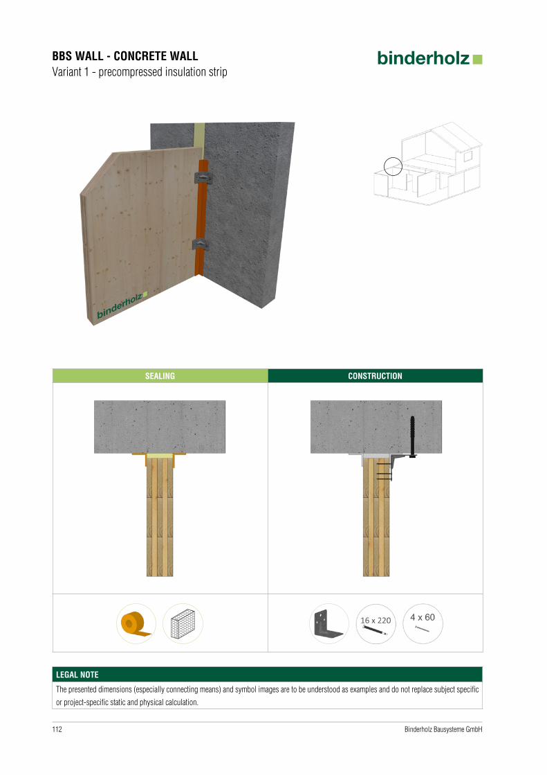
112 Binderholz Bausysteme GmbH
SEALING CONSTRUCTION
BBS WALL - CONCRETE WALLVariant 1 - precompressed insulation strip
LEGAL NOTE
The presented dimensions (especially connecting means) and symbol images are to be understood as examples and do not replace subject specific
or project-specific static and physical calculation.
113Binderholz Bausysteme GmbH
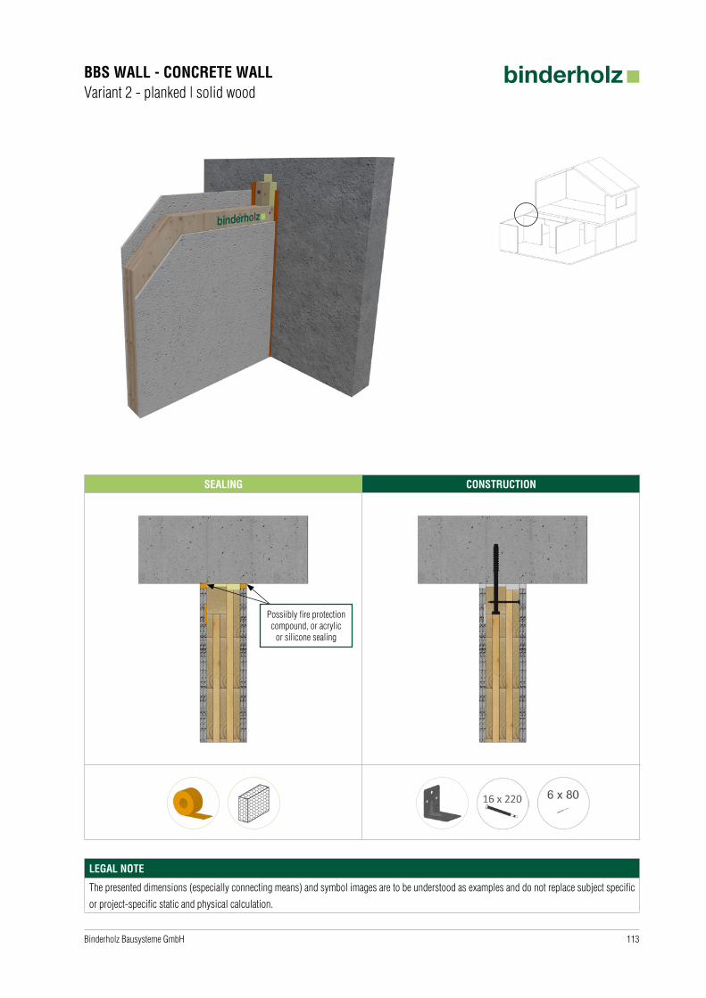
SEALING CONSTRUCTION
BBS WALL - CONCRETE WALLVariant 2 - planked | solid wood
Possiibly fire protectioncompound, or acrylic
or silicone sealing
LEGAL NOTE
The presented dimensions (especially connecting means) and symbol images are to be understood as examples and do not replace subject specific
or project-specific static and physical calculation.
114 Binderholz Bausysteme GmbH
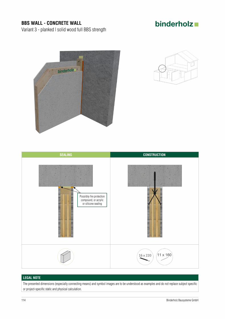
SEALING CONSTRUCTION
BBS WALL - CONCRETE WALLVariant 3 - planked | solid wood full BBS strength
Possiibly fire protectioncompound, or acrylic
or silicone sealing
LEGAL NOTE
The presented dimensions (especially connecting means) and symbol images are to be understood as examples and do not replace subject specific
or project-specific static and physical calculation.
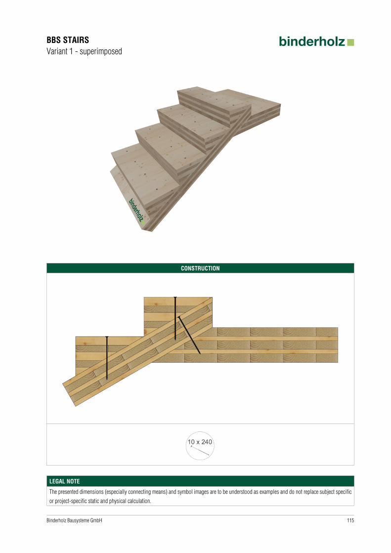
115Binderholz Bausysteme GmbH
CONSTRUCTION
BBS STAIRSVariant 1 - superimposed
LEGAL NOTE
The presented dimensions (especially connecting means) and symbol images are to be understood as examples and do not replace subject specific
or project-specific static and physical calculation.
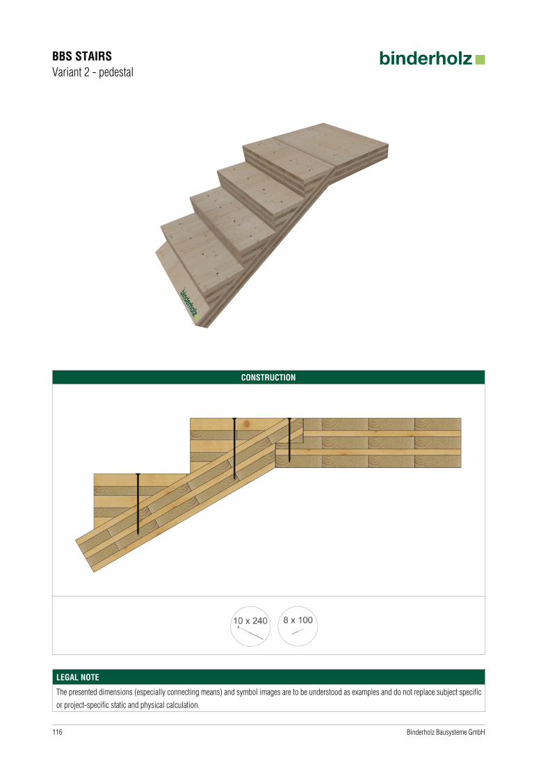
116 Binderholz Bausysteme GmbH
CONSTRUCTION
BBS STAIRSVariant 2 - pedestal
LEGAL NOTE
The presented dimensions (especially connecting means) and symbol images are to be understood as examples and do not replace subject specific
or project-specific static and physical calculation.
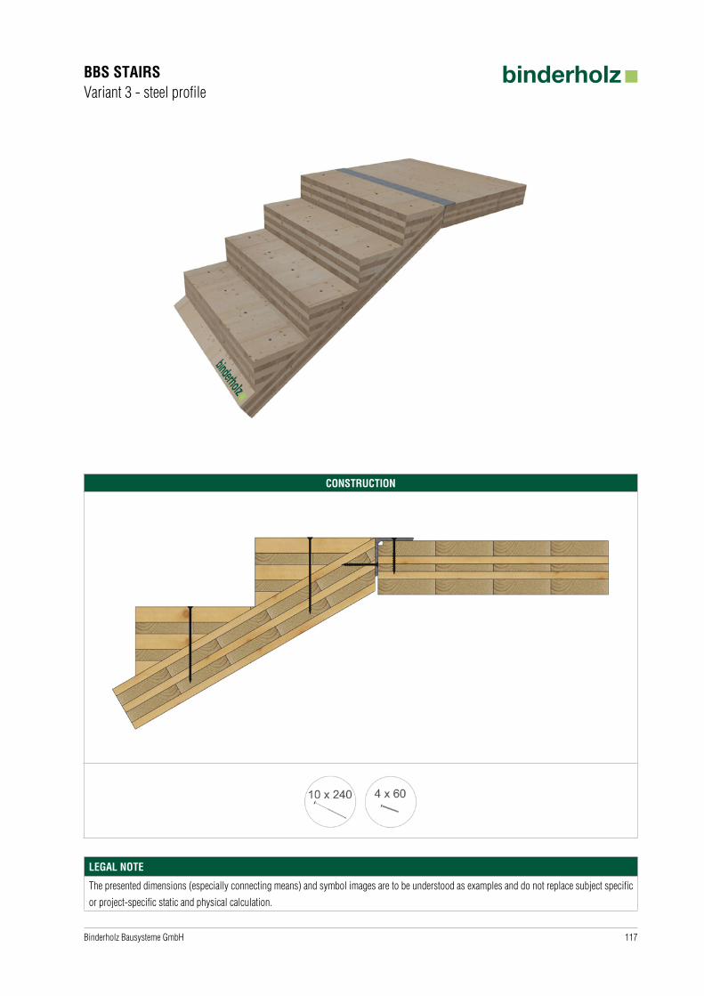
117Binderholz Bausysteme GmbH
CONSTRUCTION
BBS STAIRSVariant 3 - steel profile
LEGAL NOTE
The presented dimensions (especially connecting means) and symbol images are to be understood as examples and do not replace subject specific
or project-specific static and physical calculation.

118 Binderholz Bausysteme GmbH
SAFETY ON THE CONSTRUCTION SITE
Personal protection equipment
Fall protection
Combisafe
Scaffolding Rope protection
LEGAL NOTE
All presentations, explanations, dimensions and selected materials are only recommendations and examples provided by binderholz.


NOTE | CONTACT
Important note
The information is intended exclusively for professionals who have the appropriate skill and expertise (in wood construction, building industry) and are
capable, qualified and authorised for the appropriate handling and processing and/or planning.
The information in this brochure is intended to help them to understand the proper handling of binderholz CLT BBS which is always subject to the
applicable legal regulations, standards as well as state-of-the-art. The dimensions and symbol images provided are examples only and serve as
technical and/or optical references for obtaining materials. The actual dimensions of fastening materials as well as sealing and protection materials
(screws, angles, sealing tapes, etc.) are specific to each project and to be agreed individually with the customer and, if necessary, with the assistance of
professional counsel. It is expressly pointed out that each construction project must be subjected to a static, physical and fire-technical assessment and
corresponding calculations executed by experts in those fields. Any liability or warranty of Binderholz Bausysteme GmbH on the basis of this brochure
or Information is hereby excluded.
Eager to find out more?
You can contact us in person by calling +43 6245 70500 or by email to [email protected].
We will be happy to send you detailed information material on request.
Download
Binderholz Bausysteme GmbH · Brettsperrholz BBS Solvay-Halvic-Strasse 46 · A-5400 Hallein fon +43 6245 70500 · fax +43 6245 [email protected] · www.binderholz.com