monthly report on indigenous crude oil - production, import ...
Upload
khangminh22Category
view
0download
0
Bratakh M., Toporov V., Varavina O.
CRUDE OIL PROCESSING

УДК 662.276.5(072)
ББК 3303Я7
Т 38
Рекомендация к изданию ученым советом факультета
«Технологии органических веществ» НТУ «ХПИ» (протокол № от .)
Fyk Illya Mykhailovych
Doctor of Technical Sciences, head of oil, gas and condesate production department in
National Technical University "Kharkivs`kyi Politekhnichnyi Instytut"
Doroshenko Yaroslav Vasylyovych
PhD, associate professor of the pipeline and underground gas storage building and
repairing department in Ivano-Frankivs`k National Technical University of Oil and Gas
Т 38 Bratakh M. Crude oil processing/ M. Bratakh, V. Toporov, O. Varavina – K. :
НТУ «ХПИ», 2013. – 125 p.
The main purpose of the training manual is to teach the students the basic methods
of Crude Oil Processing.
Training manual provides well-organized theoretical and technical background
knowledge on oil and gas field operations. Emphasis is given to the separation of the
produced reservoir fluids, oil, gas, and water, as well as their subsequent treatments at
various facilities at the oil field in order to produce marketable quantities of the
products.
The manual is intended for the students trained on a specialty 6.050304 "Oil and
gas extraction" in English
УДК 662.276.5(072)
ББК 33003Я7
M. Bratakh, V. Toporov, O. Varavina 2015

THE LIST OF ABBREVIATIONS
GOSP – gas–oil separation plant;
BS&W – basic sediments and water;
PTB – pounds of salt per thousand barrels of oil;
API – American Petroleum Institute;
CCR – Conradson carbon residue;
RVP – Reid Vapor Pressure;
ppm – parts per million;
PTB – per 1000 barrels of oil;
ASTM – American Society for Testing and Materials
TBP – true boiling point;
EFV – equilibrium flash vaporization;
RR – reflux ratio; GOR – gas–oil ratio;
VRU – vapor recovery unit;
LTS – Low-temperature separator;
PTB – pounds per thousand barrels (of oil);
MOM – multiple-orifice plate mixers;
PPI – parallel plate interceptors;
CPI – corrugated plate interceptors;
PFD – process flow diagram.
LECTURE 1
CRUDE OIL COMPOSITION
Crude oil processing
Crude oil–gas–water mixtures produced from wells are generally directed through
flowlines and manifold system to a central processing and treatment facility normally
called the gas–oil separation plant (GOSP). The first step in processing of the produced
stream is the separation of the phases (oil, gas, and water) into separate streams. This
takes place in mechanical devices known as two-phase gas–oil separators when the
produced stream contains no water or three-phase separators when the produced stream
contains water. Gas–oil separation carried out in these separators is recognized as the
backbone process in a train of field processing units of oil and gas operations. The
separators are used to relieve the excess pressure due to the gas associated with the
produced crude and, consequently, separating it from the oil. When water exists in the
produced stream, separators are also used to separate the free water from the oil. Once
separation is done, each stream undergoes the proper processing for further field
treatment, as shown in Fig. 1.1.
Figure 1.1 – An outline of the processing surface field operations

Oil leaving the separator does not generally meet the purchaser’s specifications.
Oil may still contain between 10% and 15% water that exists mostly as emulsified
water. The presence of this salt water presents serious corrosion and scaling problems in
transportation and refinery operations. Water remaining in the oil is known as the basic
sediments and water (BS&W). A maximum of 1% BS&W and in some cases less than
0.5% BS&W is acceptable. The limit on the salt content of the remnant water in oils is
usually in the range of 10 to 15 PTB (pounds of salt per thousand barrels of oil) [of 3.7
to 5.6 kg]. If these specifications are not met, then further treatment of the oil leaving the
separator will be needed. Such treatment involves emulsion treatment/dehydration and
desalting processes.
After oil treating, there may be a need to stabilize the crude oil to optimize the oil
recovery and reduce its volatility. Some produced crude oils contain hydrogen sulfide
and other sulfur products. When it contains more than 400 ppm of H2S gas, the oil is
classified as sour crude. Sour crude oils present serious safety and corrosion problems.
In such cases, another treatment known as the sweetening process is needed to remove
hydrogen sulfide or reduce its content to acceptable limits (Table 1.1).
Table 1.1 – Comparison of crude and treated crude oil
Crude oil Characteristics: Treated crude
oil
Characteristics:
Water in 2 forms: Water content 0.3 % maximum
emulsion 10%
free water 30%
Salt 50,000 – 250,000 mg/L
formation water
Salt content 10 lbs (such as NaCl)
per 1000 barrels of oil
3.73 kg of salt per
159,000 liters of oil
Gas: Gas (only H2S) 70 ppm
dissolved 600 scf/bbl crude oil
17 scm/bbl crude oil
Vapor pressure 10 psig (4-5 psi RVP)
0.7 bar (0.28-0.35 bar
RVP)
H2S 1000 ppm
Crude oil composition
Crude oils are complex mixtures of a vast number of hydrocarbon compounds.
Properties of crude petroleum vary appreciably and depend mainly on the origin. In this
chapter, the chemical composition of the crude oils is viewed, including the hydrocarbon
series as well as the nonhydrocarbon compounds. Physical methods generally used for
identifying types of crude oils are described next.
Identification of the hydrocarbon constituents of crude oils and associated natural
gas along with their corresponding commercial products are summarized in Table 1.2 [1].

Table 1.2 – Constituents of Crude Oil and Associated Gases*)
Hydrocarbons
Identification of constituents In the field streams
As commercial product Liquid phase (at normal conditions) Two phases
Gaseous phases (and liquefied gases) Name Formula Normal B, P (
oC)
Methane CH4 -161,7
Field separator
gas Gas condensate
well effluent
Crude oil well effluent
LNG Dry gas
Natural gas
Ethane C2H6 -88,9
NGL
Natural gas
Propane C3H8 -42,2
LPG
Natural gas, propane
Isobutane i-C4H10 -11,7
Stock tank
crude oil
Stock tank condensate
Natural gasoline
Natural
gasoline, butane
n-butane n-C4H10 -0,6
Natural gasoline,
motor fuel, butane
Pentanes C5H12 32,2
Debutanized condensate
Natural
gasoline, motor fuel
Hexane C6H14 62,8 Natural
gasoline, motor fuel
Heptane C7H16 90,6 Natural
gasoline, motor fuel
Octane C8H18 118,3 Natural
gasoline, motor fuel
Decanes C10H22 173,9 Motor fuel
Tetradocane C14H30 254,4 Kerosene, light
furnace oil
Hexadecane C16H34 287,2 Mineral seal
oil, furnace oil
Triacontane C30H62 457,2 Light
lubricating oil, heavy fuel oil
Tetracontane C40H62 544,4 Lubricating
oil, heavy fuel oil
Asphalthene C80H162 648,9 Asphalt, road
oil, bunker fuel oil
LPG – liquefied petroleum gases, NGL – natural gas liquid (normally C3+)
, LNG – Liquefied natural gas

In general, composition of crude oil may be studied by two methods:
- Chemical approach;
- Physical methods.
Chemical composition describes and identifies the individual chemical
compounds isolated from crude oils over the years. Physical representation, on the
other hand, involves considering the crude oil and its products as mixtures of
hydrocarbons and describing physical laboratory tests or methods for
characterizing their quality.
Chemical Approach
Nearly all petroleum deposits are made up of a mixture of chemical
compounds that consist of hydrogen and carbon, known as hydrocarbons, with
varying amounts of nonhydrocarbons containing S, N2, O2, and other some metals.
The composition of crude oil by elements is approximated as shown in Table 1.3 [1].
Table 1.3 – Composition of Petroleum Crude
Element Percent by Weight
Carbon 83 - 87
Hydrogen 11 - 14
Sulfur 0.05 – 2.5
Nitrogen 0.1 - 2
Oxygen 0 - 2 Note: sulfur, nitrogen and oxygen are regarded as impurities
It could be further stated that these hydrocarbon compounds making up oils
are grouped chemically into different series of compounds described by the
following characteristics:
- each series consists of compounds similar in their molecular structure and
properties (e.g., the alkanes or paraffin series);
- within a given series, there exists a wide spectrum of compounds that range
from extremely light or simple hydrocarbon to a heavy or complex one. For
example: CH4 for the former and C40H82 for the latter in the paraffinic series.
Hydrocarbon Series
The major constituents of most crude oils and its products are hydrocarbon
compounds, which are made up of hydrogen and carbon only. These compounds
belong to one of the following subclasses:
1. Alkanes or Paraffins: Alkanes are saturated compounds having the general
formula CnH2n+2. Alkanes are relatively nonreactive compounds in comparison to
other series. They may either be straight-chain or branched, the latter are more
valuable than the former, because they are useful for the production of high-octane
gasoline.
2. Cycloalkanes or Cycloparaffins (Naphtenes): Cycloalkanes and
bicycloalkanes are normally present in crude oils and its fractions in variable

proportions. The presence of large amounts of these cyclic compounds in the
naphtha range has its significance in the production of aromatic compounds.
Naphtha cuts with a high percentage of naphthenes would make an excellent
feedstock for aromatization.
3. Alkenes or Olefins: Alkenes are unsaturated hydrocarbon compounds
having the general formula CnHn. They are practically not present in crude oils, but
they are produced during processing of crude oils at high temperatures. Alkenes
are very reactive compounds. Light olefinic hydrocarbons are considered the base
stock for many petrochemicals. Ethylene, the simplest alkene, is an important
monomer in this regard. For example, polyethylene is a well known thermoplastic
polymer and polybutadiene is the most widely used synthetic rubber.
4. Aromatics: Aromatic compounds are normally present in crude oils. Only
monomolecular compounds in the range of C6–C8 (known as B-T-X) have gained
commercial importance. Aromatics in this range are not only important
petrochemical feedstocks but are also valuable for motor fuels. Dinuclear and
polynuclear aromatic compounds are present in heavier petroleum fractions and
residues. Asphaltenes, which are concentrated in heavy residues and in some
asphaltic crude oils, are, in fact, polynuclear aromatics of complex structures. It
has been confirmed by mass spectroscopic techniques that condensed-ring
aromatic hydrocarbons and heterocyclic compounds are the major compounds of
asphaltenes.
Nonhydrocarbon Compounds So far, a brief review of the major classes of the hydrocarbon compounds
that exist in crude oils and their products was presented. For completeness, we
should mention that other types of nonhydrocarbon compound occur in crude oils
and refinery streams. Most important are the following:
- sulfur compounds;
- nitrogen compounds;
- oxygen compounds;
- metallic compounds.
Sulfur Compounds. In addition to the gaseous sulfur compounds in crude oil,
many sulfur compounds have been found in the liquid phase in the form of
organosulfur. These compounds are generally not acidic.
Sour crude oils are those containing a high percentage of hydrogen sulfide.
However, many of the organic sulfur compounds are not thermally stable, thus
producing hydrogen sulfide during crude processing. High-sulfur crude oils are in
less demand by refineries because of the extra cost incurred for treating refinery
products. Naphtha feed to catalytic reformers is hydrotreated to reduce sulfur
compounds to very low levels (1 ppm) to avoid catalyst poisoning.
The following sulfur compounds are typical:
1. Mercaptans (H–S–R): Hydrogen sulfide, H–S–H, may be considered as
the simple form of mercaptan; however, the higher forms of the series are even
more objectionable in smell. For example, butyl mercaptan (H–S–C4H9) is
responsible for the unusual odor of the shank.

2. Sulfides (R–S–R): When an alkyl group replaces the hydrogen in the
sulfur-containing molecule, the odor is generally less obnoxious. Sulfides could be
removed by the hydrotreating technique, which involves the hydrogenation of the
petroleum streams as follows:
- R-S-R + 2H-H → 2R-H + H-S-H;
- R-S-R + H+H → R-R + H-S-H.
The hydrogen sulfide may be removed by heating and may be separated by
using amine solutions.
3. Polysulfides (R–S–S–R): These are more complicated sulfur compounds
and they may decompose, in some cases depositing elemental sulfur. They may be
removed from petroleum fractions, similar to the sulfides, by hydrotreating.
Nitrogen Compounds
Nitrogen compounds in crude oils are usually low in content (about 0.1–
0.9%) and are usually more stable than sulfur compounds. Nitrogen in petroleum is
in the form of heterocyclic compounds and may be classified as basic and
nonbasic.
Basic nitrogen compounds are mainly composed of pyridine homologs and
have the tendency to exist in the high-boiling fractions and residues.
The nonbasic nitrogen compounds, which are usually of the pyrrole and
indole, also occur in high-boiling fractions and residues. Only a trace amount of
nitrogen is found in light streams.
During hydrotreatment (hydrodesulfurization) of petroleum streams,
hydrodenitrogeneation takes place as well, removing nitrogen as ammonia gas,
thus reducing the nitrogen content to the acceptable limits for feedstocks to
catalytic processes. It has to be stated that the presence of nitrogen in petroleum is
of much greater significance in refinery operations than might be expected from
the very small amounts present. It is established that nitrogen compounds are
responsible for the following:
- catalyst poisoning in catalytic processes;
- gum formation in some products such as domestic fuel oils.
Oxygen Compounds
Oxygen compounds in crude oils are more complex than sulfur compounds.
However, oxygen compounds are not poisonous to processing catalysts. Most
oxygen compounds are weakly acidic, such as phenol, cresylic acid and naphthenic
acids. The oxygen content of petroleum is usually less than 2%, although larger
amounts have been reported.
Metallic Compounds
Many metals are found in crude oils; some of the more abundant are sodium,
calcium, magnesium, iron, copper, vanadium, and nickel. These normally occur in
the form of inorganic salts soluble in water—as in the case of sodium chloride—or
in the form of organometallic compounds—as in the case of iron, vanadium, and
nickel.

The occurrence of metallic constituents in crude oils is of considerably
greater interest to the petroleum industry than might be expected from the very
small amounts present. The organometallic compounds are usually concentrated in
the heavier fractions and in crude oil residues. The presence of high concentration
of vanadium compounds in naphtha streams for catalytic reforming feeds will
cause permanent poisons. These feeds should be hydrotreated not only to reduce
the metallic poisons but also to desulfurize and denitrogenate the sulfur and
nitrogen compounds.
Hydrotreatment may also be used to reduce the metal content in heavy feeds
to catalytic cracking.
REFERENCE
1. Abdel-Aal, H.K. Surface Petroleum Operations, Saudi Publishing &
Distributing House, Jeddah, 1998.

LECTURE 2
PHYSICAL PROPERTIES OF CRUDE OIL
Crude oils from different locations may vary in appearance and viscosity and
also vary in their usefulness as producers for final products. It is possible by the
use of certain basic tests to identify the quality of crude oil stocks. The tests
included in the following list are primarily physical (except sulfur determination):
1) distillation;
2) density, specific gravity, and API (American Petroleum Institute) gravity;
3) viscosity;
4) vapor pressure;
5) flash and fire points;
6) cloud and pour points;
7) color;
8) sulfur content;
9) basic sediments and water (B.S.&W.);
10) aniline point;
11) carbon residue.
The details of some of these tests are described next.
API Gravity
Earlier, density was the principal specification for petroleum products.
However, the derived relationships between the density and its fractional
composition were only valid if they were applied to a certain type of petroleum.
Density is defined as the mass of a unit volume of material at a specified
temperature. It has the dimensions of grams per cubic centimeter.
Another general property, which is more widely, is the specific gravity. It is
the ratio of the density of oil to the density of water and is dependent on two
temperatures, those at which the densities of the oil sample and the water are
measured. When the water temperature is 4oC (39
oF), the specific gravity is equal
to the density in the CGS system (centimeters-gram-second system), because the
volume of 1 g of water at that temperature is, by definition, 1 mL. Thus, the
density of water, for example, varies with temperature, whereas its specific gravity
is always unity at equal temperatures. The standard temperatures for specific
gravity in the petroleum industry in North America are 60/60°F and 15.6/15.6
°C all
over the world.
Although density and specific gravity are used extensively in the oil
industry, the API gravity is considered the preferred property. It is expressed by the
following relationship:
where γ - is the oil specific gravity at 60
oF (15.6
°C). Thus, in this system, a liquid
with a specific gravity of 1.00 will have an API of 10 deg. A higher API gravity
indicates a lighter crude or oil product, whereas a low API gravity implies a heavy
crude or product.

Carbon Residue
Carbon residue is the percentage of carbon by weight for coke, asphalt, and
heavy fuels found by evaporating oil to dryness under standard laboratory
conditions. Carbon residue is generally referred to as CCR (Conradson carbon
residue). It is a rough indication of the asphaltic compounds and the materials that
do not evaporate under conditions of the test, such as metals and silicon oxides.
Viscosity
The viscosity is the measure of the resistance of a liquid to flow, hence
indicating the «pumpability» of oil.
Pour Point
This is defined as the lowest temperature (5oF/-15
oC) at which the oil will
flow. The lower the pour point, the lower the paraffin content of the oil.
Ash Content
This is an indication of the contents of metal and salts present in a sample.
The ash is usually in the form of metal oxides, stable salts, and silicon oxides. The
crude sample is usually burned in an atmosphere of air and the ash is the material
left unburned.
Reid Vapor Pressure
The Reid Vapor Pressure (RVP) is a measure of the vapor pressure exerted
by oil or by light products at 100oF/37,8
oC.
Metals
In particular, arsenic, nickel, lead, and vanadium are potential poisons for
process catalysts. Metal contents are reported in parts per million (ppm).
Nitrogen
It is the weight of total nitrogen determined in a liquid hydrocarbon sample
(in ppm). Nitrogen compounds contribute negatively to process catalysts.
Salt Content
Salt content is typically expressed as pounds of salt (sodium chloride, NaCl)
per 1000 barrels of oil (PTB). Salts in crude oil and in heavier products may create
serious corrosion problems, especially in the toptower zone and the overhead
condensers in distillation columns.
Sulfur
This is the percentage by weight (or ppm) of total sulfur content determined
experimentally in a sample of oil or its product. The sulfur content of crude oils is
taken into consideration in addition to the API gravity in determining their
commercial values. It has been reported that heavier crude oils may have high
sulfur content [2].

Hydrogen Sulfide
Hydrogen sulfide dissolved in a crude oil or its products is determined and
measured in parts per million. It is a toxic gas that can evolve during storage or in
the processing of hydrocarbons.
The above tests represent many properties for the crude oils that are
routinely measured because they affect the transportation and storage facilities. In
addition, these properties define what products can be obtained from a crude oil
and contribute effectively to safety and environmental aspects. The price of a crude
oil is influenced by most of these properties.
To conclude, it can be stated that light and low-sulfur crude oils are worth
more than heavy and high-sulfur ones. One can summarize the two approaches of
examining crude oils as follows:
1. Chemical composition
2. Physical properties:
(a) API, S, salt, metals, nitrogen and so forth;
(b) Distillation: ASTM, TBP, EFV;
(c) Correlations: Kw, Ind,
where ASTM is Americal Society for Testing and Materials distilation TBP is true
boiling point, EFV is equilibrium flash vaporization, Kw is Watson
characterization factor, Ind is U.S. Bureau of Mines correlation index.
Сrude oil comparisons and crude oil assay
In order to establish a basis for the comparison between different types
of crude oil, it is necessary to produce experimental data in the form of what is
known as an “assay”. Crude assays are the systematic compilation of data for
the physical properties of the crude and its fractions, as well as the yield. In
other words, a crude assay involves the determination of the following:
- the properties of crude oil;
- the fractions obtained: (a) their percentage yield and (b) properties.
Analytical testing only without carrying out distillation may be
considered an assay. However, the most common assay is a comprehensive
one that involves all of the above-stated parameters.
The basis of the assay is the distillation of a crude oil under specified
conditions in a batch laboratory distillation column, operated at high
efficiency [column with 14 plates and reflux ratio (RR)]. Pressure in column
is reduced in stages to avoid thermal degradation of high boiling
components.
A comparison of the characteristics of different types of crude oil
over the distillation range could be made via a graph that relates the
following:
- the density of distillate fractions;
- their mid-boiling points.
Such a comparison is illustrated in Figure 2 . 1 [3]. The density level
of a crude at given boiling point on the curve is a function of the relative

proportions of the main three hydrocarbon series: aromatics, cycloparaffins,
paraffins; their densities decrease in that order.
Figure 2.1 – Comparison of crude oils density/mid-boiling point basis [4]
In order to show how the properties of crude oils affect strongly
processing requirements, product expectations, storage and transportation, and
others, a comparison is presented as given in Table 2.1.
Table 2.1 – Properties of Some Reference Crude Oils
Property Arabian
light
Arun
Indonesia
Beryl N.S
Canada
Nigerian
light
SJV
Calif.
API (gravity) 33.9 54.1 36.5 37.6 15.2
Pour Point (оF/
oC) — 45/-42.8 — 55/-48.3 20/-6.7 5/-15 — 5/-20.6
CCR (wt%) 3.6 0.01 1.3 1.1 7.0
Sulfur (wt%) 1.8 > 0.1 0.42 0.13 1.05
Nitrogen (ppm) 60 50 880 0.06 6200
Nickel (ppm) 3 0.65 0.8 3.6 63
Vanadium (ppm) 19 0.15 3.7 0.3 60
Salt Content (PTB)/
kg
10/3.73 3/1.1 7.4/2.8 5/1.9 14/5.2

Table 2 .2, on the other hand, gives the percent yield and other
characteristics of the fractions obtained by the distillation of a typical Arabian
crude oil having an API gravity of about 34–37.
Table 2.2 – Fractions Obtained from Arabian Crude
Fractions Percent
yield
No. of carbon atoms
in molecule Boiling range (
оC)
Gases
(dry/wet)
2 1–2 - 162 to - 90 dry
3–4 - 48 to -1 wet
Naphtha 20–26 5–12 32–182
Kerosene 7–12 10–15 160–238
Diesel oil 10–14 12–20 204–316
Wax distillate 15–20 17–22 260–371
Residuum 35–40 20–90 316 and above
Сrude oil classifications and characterization and classifications
Although there is no specific method for classifying crude oils, it would be
useful to establish simple criteria to quantify the crude quality. Numerous
attempts have been made to devise a system to classify crude oils into types
based on the predominant hydrocarbon series present in the crude. Such attempts
have only partially succeeded. In the OPEC, crude oils are classified into three
types:
- paraffinic: paraffinic hydrocarbons with a relatively lower percentage
of aromatics and naphthenes;
- naphthenic: cycloparaffins in a higher ratio and a higher amount of
asphalt than in paraffinic crudes;
- asphaltic: fused aromatic compounds and asphalt in higher amounts.
Another method of classification is the following:
1) paraffinic base;
2) mixed base;
3) naphthenic base.
Based on this classification, a rating for the processing of crude oils
is envisaged as follows for the production of certain products and their
treatment (Table 2.3).
Table 2.3 - Rating for the processing of crude
Products Lub. oil Asphalt Gasoline
Treatment of
products Type of oil:
Paraffinic 1 3 3 1
Mixed 2 2 2 2
Naphthenic 3 1 1 3
Rating: 1 - excellent; 2 - good; 3 – poor.

Characterization Factors
Correlation indexes or characterization factors are used in the
petroleum industry to indicate the crude type or class. There are several
correlations between yield and type of crude in terms of aromaticity and
paraffinicity. The two most widely accepted relationships are the following:
- Watson characterization factor:
o
b
W
TK
31
- U.S. Bureau of Mines Correlation Index:
8.4567.473552.87 ob
TInd
where o
- is the specific gravity at 60 oF (15.6
oC) and Tb is the mean average
boiling point (oR).
The Watson factor ranges from 10.5, for highly naphthenic crude oils,
to 12.9, for the paraffinic type [4].
REFERENCES
1. Abdel-Aal, H. K., Bakr, A., and Al-Sahlawi, M. A., Petroleum Economics
and Engineering, 2nd ed., Marcel Dekker, New York, 1992.
2. Gary, J. H. and Handwerk, G. E., Petroleum Refining—Technology and
Economics, 3rd ed., Marcel Dekker, New York, 1994.
3. Hatch, L. F. and Matar, S., From Hydrocarbons to Petrochemicals, Gulf
Publishing Co., Houston, TX, 1981.
4. British Petroleum Handbook, BP Company Ltd, London, 1977.

LECTURE 3
TWO-PHASE GAS–OIL SEPARATION
At the high pressure existing at the bottom of the producing well, crude oil
contains great quantities of dissolved gases. When crude oil is brought to the
surface, it is at a much lower pressure. Consequently, the gases that were dissolved
in it at the higher pressure tend to come out from the liquid. Some means must be
provided to separate the gas from oil without losing too much oil.
In general, well effluents flowing from producing wells come out in two
phases: vapor and liquid under a relatively high pressure. The fluid emerges as a
mixture of crude oil and gas that is partly free and partly in solution. Fluid pressure
should be lowered and its velocity should be reduced in order to separate the oil
and obtain it in a stable form. This is usually done by admitting the well fluid into
a gas–oil separator plant (GOSP) through which the pressure of the gas–oil mixture
is successively reduced to atmospheric pressure in a few stages.
Upon decreasing the pressure in the GOSP, some of the lighter and more
valuable hydrocarbon components that belong to oil will be unavoidably lost along
with the gas into the vapor phase. This puts the gas–oil separation step as the initial
one in the series of field treatment operations of crude oil. Here, the primary
objective is to allow most of the gas to free itself from these valuable
hydrocarbons, hence increasing the recovery of crude oil.
In some fields, no salt water will flow into the well from the reservoir along
with the produced oil. This is the case we are considering in this lecture, where it is
only necessary to separate the gas from the oil; (i.e., two-phase separation).
High-pressure crude oils containing large amount of free and dissolved gas
flow from the wellhead into the flowline, which routes the mixture to the GOSP. In
the separator, crude oil separates out, settles, and collects in the lower part of the
vessel. The gas, lighter than oil, fills the upper part of the vessel. Crude oils with a
high gas–oil ratio (GOR) must go through two or more stages of separation. Gas
goes out the top of the separators to a gas collection system, a vapor recovery unit
(VRU), or a gas flowline. Crude oil, on the other hand, goes out the bottom and is
routed to other stages of separation, if necessary, and then to the stock tank
(Fig. 3.1).

Figure 3.1 – Flow of crude oil from oil well through GOSP [3]
Movement of the crude oil within the GOSP takes place under the influence
of its own pressure. Pumps, however, are used to transfer the oil in its final trip to
the tank farm, or pipeline (Fig. 3.2).
Figure 3.2 – Separation of gas from oil
Pressure reduction in moving the oil from stage to stage is illustrated in
Fig. 3.3.

Figure 3.3 – Pressure-drop profile for a typical GOSP in the Middle East
Gas–Oil Separation Equipment
The conventional separator is the very first vessel through which the well
effluent mixture flows. In some special cases, other equipment (heaters, water
knockout drums) may be installed upstream of the separator. The essential
characteristics of the conventional separator are the following:
1. It causes a decrease in the flow velocity, permitting separation of gas and
liquid by gravity.
2. It always operates at a temperature above the hydrate point of the flowing
gas.
The choice of a separator for the processing of gas–oil mixtures containing
water or without water under a given operating conditions and for a specific
application normally takes place guided by the general classification illustrated in
Figure 3.4.

Figure 3.4 – Classification of separators
Functional Components of a Gas–Oil Separator
Regardless of their configuration, gas–oil separators usually consist of four
functional sections, as shown in Figure 3.5:
Figure 3.5 – Schematic outline of the main components in a gas–oil
separator
1. Section A: Initial bulk separation of oil and gas takes place in this section.
The entering fluid mixture hits the inlet diverter. This causes a sudden change in
momentum and, due to the gravity difference, results in bulk separation of the gas
from the oil. The gas then flows through the top part of the separator and the oil
through the lower part.

2. Section B: Gravity settling and separation is accomplished in this section
of the separator. Because of the substantial reduction in gas velocity and the
density difference, oil droplets settle and separate from the gas.
3. Section C: Known as the mist extraction section, it is capable of removing
the very fine oil droplets which did not settle in the gravity settling section from
the gas stream.
4. Section D: This is known as the liquid sump or liquid collection section.
Its main function is collecting the oil and retaining it for a sufficient time to reach
equilibrium with the gas before it is discharged from the separator.
The separation process at all of listed above section is shown at figure 3.6.
Figure 3.6 – Separation process
In separating the gas from oil, a mechanical mechanism could be suggested
[3], as shown in Figure 3.7, which implies the following two steps:
(step 1) To separate oil from gas: Here, we are concerned primarily with
recovering as much oil as we can from the gas stream. Density difference or
gravity differential is responsible for this separation. At the separator’s operating
condition of high pressure, this difference in density between oil and gas becomes
small (gas law). Oil is about eight times as dense as the gas. This could be a
sufficient driving force for the liquid particles to separate and settle down. This is
especially true for large-sized particles, having diameter of 100 mm or more. For
smaller ones, mist extractors are needed.

(step 2) To remove gas from oil: The objective here is to recover and collect
any nonsoluted gas that may be entrained or ‘‘locked’’ in the oil. Recommended
methods to achieve this are settling, agitation, and applying heat and chemicals.
Figure 3.7 – Two-step mechanism of separating gas from oil [2]
REFERENCES
1. Bradley, H. B., Petroleum Engineering Handbook, Society of Petroleum
Engineers, Richardson, TX, 1987.
2. Maddox, R. N., Erbar, J. H., and A. Shariat, PDS Ducumentation, CPC,
Inc., Stillwater, OK, 1976.
3. Abdel-Aal, H. K., Surface Petroleum Operations, Saudi Publishing &
Distributing House, Jeddah, 1998.
4. Arnold, K. and Stewart, M., Design of Oil Handling Systems and
Facilities, Gulf Publishing Company, Houston, TX, Vol. I, 1989.
5. Vonday, D., Spherical process vessels, Oil Gas J., 121–122, April 8, 1957.
6. Chilingarian, G. V., Robertson, J. O. Jr., and Kumar, S., Surface
Operations in Petroleum Production, I, Elsevier Science, Amsterdam, 1987.
7. Whinery, K. F. and Campbell, J. M. A method for determining optimum
second stage pressure in 3-stage separation, J. of Petrol. Technol. 4, 53–54, 1958.
8. Szilas, A. P., Production and Transportation of Oil and Gas, Elsevier
Science, Amsterdam, 1975.
9. Holland, C. D., Fundamentals of Multi component Distillation, McGraw–
Hill, New York, 1981.

LECTURE 4
UPSTREAM PROCESS: COMMERCIAL TYPES OF GAS–OIL
SEPARATOR
Based on the configuration, the most common types of separator are
horizontal, vertical, and spherical, as illustrated in Figures 4.1, 4.2, and 4.3,
respectively. A concise comparison among these three types is presented in Table
4.1. Large horizontal gas–oil separators are used almost exclusively in processing
well fluids in the Middle East, where the gas–oil ratio of the producing fields is
high. Multistage GOSPs normally consists of three or more separators.
Figure 4.1 – (a) Single-barrel horizontal separator; (b) horizontal separator
schematic [1]
Figure 4.2 – (a) Vertical separator, three-phase operation; (b) vertical
separator schematic [2]

Figure 4.3 – Spherical separator [3]
Table 4.1 – Comparison among different configurations of gas–oil
separators
Function Vertical Horizontal Spherical
Usage For low gas-oil
ratio
For high gas-oil
ratio
For small leases
operating at
moderate
pressure
Location of inlet
and outlet streams
Capacity or
efficiency
Large fluid
capacity
Large gas capacity
(handles high GOR)
Capacity rated
less (low
efficiency)
Handing foreign
material Rated No. 1 Rated No. 3 Rated No. 2
Separation
efficiency Rated No. 2 Rated No. 1 Rated No. 3
Rating in use in
Middle East Rated No. 2 Rated No. 1 Rated No. 3
Handing foaming oil Rated No. 2 Rated No. 1 Rated No. 3
Maintenance and
inspection Very difficult Accessible Average
Cost per unit
capacity Average Least expensive Most expensive
Installation Most difficult Average Easy

Controllers and Internal Components of Gas–Oil Separators
Gas–oil separators are generally equipped with the following control devices
and internal components (figure 4.4) [4].
Figure 4.4 – Separator components (3-D and 2-D diagrams)
Liquid Level Controller
The liquid level controller (LLC) is used to maintain the liquid level inside
the separator at a fixed height. In simple terms, it consists of a float that exists at
the liquid–gas interface and sends a signal to an automatic diaphragm motor valve
on the oil outlet. The signal causes the valve to open or close, thus allowing more
or less liquid out of the separator to maintain its level inside the separator.
Pressure Control Valve

The pressure control valve (PCV) is an automatic backpressure valve that
exists on the gas stream outlet. The valve is set at a prescribed pressure.
It will automatically open or close, allowing more or less gas to flow out of
the separator to maintain a fixed pressure inside the separator.
Pressure Relief Valve
The pressure relief valve (PRV) is a safety device that will automatically
open to vent the separator if the pressure inside the separator exceeded the design
safe limit.
Mist Extractor
The function of the mist extractor is to remove the very fine liquid droplets
from the gas before it exits the separator. Several types of mist extractors are
available:
1. Wire-Mesh Mist Extractor: These are made of finely woven stainless-steel
wire wrapped into a tightly packed cylinder of about 15 mm thickness. The liquid
droplets that did not separate in the gravity settling section of the separator
coalesce on the surface of the matted wire, allowing liquid-free gas to exit the
separator. As the droplets size grows, they fall down into the liquid phase.
Provided that the gas velocity is reasonably low, wire-mesh extractors are capable
of removing about 99% of the 10-μm and larger liquid droplets. It should be noted
that this type of mist extractor is prone to plugging. Plugging could be due to the
deposition of paraffin or the entrainment of large liquid droplets in the gas passing
through the mist extractor (this will occur if the separator was not properly
designed). In such cases, the vane-type mist extractor, described next, should be
used.
2. Vane Mist Extractor: This type of extractor consists of a series of closely
spaced parallel, corrugated plates. As the gas and entrained liquid droplets flowing
between the plates change flow direction, due to corrugations, the liquid droplets
impinge on the surface of the plates, where they coalesce and fall down into the
liquid collection section.
3. Centrifugal Mist Extractor: This type of extractor uses centrifugal force to
separate the liquid droplets from the gas. Although it is more efficient and less
susceptible to plugging than other extractors, it is not commonly used because of
its performance sensitivity to small changes in flow rate.
Inlet Diverters
Inlet diverters are used to cause the initial bulk separation of liquid and gas.
The most common type is the baffle plate diverter, which could be in the shape of a
flat plate, a spherical dish, or a cone. Another type, is the centrifugal diverter; it is
more efficient but more expensive. The diverter provides a means to cause a
sudden and rapid change of momentum (velocity and direction) of the entering
fluid stream. This, along with the difference in densities of the liquid and gas,
causes fluids separation.
Wave Breakers
In long horizontal separators, waves may develop at the gas–liquid interface.
This creates unsteady fluctuations in the liquid level and would negatively affect

the performance of the liquid level controller. To avoid this, wave breakers, which
consist of vertical baffles installed perpendicular to the flow direction, are used.
Defoaming Plates
Depending on the type of oil and presence of impurities, foam may form at
the gas–liquid interface. This results in the following serious operational problems:
1. Foam will occupy a large space in the separator that otherwise would be
available for the separation process; therefore, the separator efficiency will be
reduced unless the separator is oversized to allow for the presence of foam.
2. The foam, having a density between that of the liquid and gas, will disrupt
the operation of the level controller.
3. If the volume of the foam grows, it will be entrained in the gas and liquid
streams exiting the separator; thus, the separation process will be ineffective. The
entrainment of liquid with the exiting gas is known as liquid carryover. Liquid
carryover could also occur as a result of a normally high liquid level, a plugged liquid
outlet, or an undersized separator with regard to liquid capacity. The entrainment of gas
in the exiting liquid is known as gas blowby. This could also occur as a result of a
normally low liquid level, an undersized separator with regard to gas capacity, or
formation of a vortex at the liquid outlet.
Foaming problems may be effectively alleviated by the installation of
defoaming plates within the separator. Defoaming plates are basically a series of
inclined closely spaced parallel plates. The flow of the foam through such plates
results in the coalescence of bubbles and separation of the liquid from the gas.
In some situations, special chemicals known as foam depressants may be
added to the fluid mixture to solve foaming problems. The cost of such chemicals
could, however, become prohibitive when handling high production rates.
Vortex Breaker
A vortex breaker, similar in shape to those used in bathroom sink drains, is
normally installed on the liquid outlet to prevent formation of a vortex when the
liquid outlet valve is open. The formation of a vortex at the liquid outlet may result
in withdrawal and entrainment of gas with the exiting liquid (gas blowby).
Sand Jets and Drains
Formation sand may be produced with the fluids. Some of this sand will
settle and accumulate at the bottom of the separator. This takes up separator
volume and disrupts the efficiency of separation. In such cases, vertical separators
will be preferred over horizontal separators. However, when horizontal separators
are needed, the separator should be equipped with sand jets and drains along the
bottom of the separator. Normally, produced water is injected though the jets to
fluidize the accumulated sand, which is then removed through the drains.
The following is a brief description of some separators for some specific
applications. In addition, the features of what is known as ‘‘modern’’ GOSP are
highlighted.
Test Separators
These units are used to separate and measure at the same time the well
fluids. Potential test is one of the recognized tests for measuring the quantity of

both oil and gas produced by the well in 24 hours period under steady state of
operating conditions. The oil produced is measured by a flow meter (normally a
turbine meter) at the separator’s liquid outlet and the cumulative oil production is
measured in the receiving tanks.
An orifice meter at the separator’s gas outlet measures the produced gas.
Physical properties of the oil and GOR are also determined. Equipment for test
units is shown in Figure 4.5.
Figure 4.5 – Main equipment for test separator
Low-Temperature Separators
Low-temperature separators (LTSs) are used to effectively remove light
condensable hydrocarbons from a high-pressure gas stream (gas condensate feed).
Liquid (condensate) separation is made possible by cooling the gas stream before
separation. Temperature reduction is obtained by what is known as the Joule–
Thomson effect of expanding the well fluid as it flows through the pressure-
reducing choke or valve into the separator. Condensation of the vapors takes place
accordingly, where the temperature is in the range 0–10 °F (-12-18 oC). The
process is shown at the figure 4.6.

Figure 4.6 – Low temperature separation diagram
Modern GOSPs
Safe and environmentally acceptable handling of crude oils is assured by
treating the produced crude in the GOSP and related crude-processing facilities.
The number one function of the GOSP is to separate the associated gas from oil.
As the water content of the produced crude increases, field facilities for control or
elimination of water are to be added. This identifies the second function of a
GOSP. If the effect of corrosion due to high salt content in the crude is recognized,
then modern desalting equipment could be included as a third function in the
GOSP design.
One has to differentiate between ‘‘dry’’ crude and ‘‘wet’’ crude. The former is
produced with no water, whereas the latter comes along with water. The water
produced with the crude is a brine solution containing salts (mainly sodium chloride) in
varying concentrations.
The input of wet crude oil into a modern GOSP consists of the following:
1) crude oil;
2) hydrocarbon gases;
3) free water dispersed in oil as relatively large droplets, which will separate
and settle out rapidly when wet crude is retained in the vessel;
4) emulsified water, dispersed in oil as very small droplets that do not settle
out with time. Each of these droplets is surrounded by a thin film and held in
suspension;
5) salts dissolved in both free water and in emulsified water.
The functions of a modern GOSP could be summarized as follows:
1) separate the hydrocarbon gases from crude oil;
2) remove water from crude oil;
3) reduce the salt content to the acceptable level [basic sediments and water].
It should be pointed out that some GOSPs do have gas compression and low-
temperature or refrigeration facilities to treat the gas before sending it to gas
processing plants. In general, a GOSP can function according to one of the
following process operation:
1) three-phase, gas–oil–water separation;

2) two-phase, gas–oil separation;
3) two-phase, oil–water separation;
4) deemulsification;
5) washing;
6) electrostatic coalescence.
To conclude, the ultimate result in operating a modern three-phase separation
plant is to change ‘‘wet’’ crude input into the desired outputs, as given in Figure 4.7.
Outputs from a three-phase regular separation plant, on the other hand, are as shown in
Figure 4.8.
Figure 4.7 – Functions of modern GOSPs [2]
Figure 4.8 – Products obtained from a three-phase GOSP
REFERENCES:
1. Abdel-Aal, H. K., Surface Petroleum Operations, Saudi Publishing &
Distributing House, Jeddah, 1998.
2. Arnold, K. and Stewart, M., Design of Oil Handling Systems and
Facilities, Gulf Publishing Company, Houston, TX, Vol. I, 1989.
3. Vonday, D., Spherical process vessels, Oil Gas J., 121–122, April 8, 1957.
4. Chilingarian, G. V., Robertson, J. O. Jr., and Kumar, S., Surface
Operations in Petroleum Production, I, Elsevier Science, Amsterdam, 1987.

LECTURE 5
THREE-PHASE SEPARATION
In almost all production operations the produced fluid stream consists of
three phases: oil, water, and gas.
Generally, water produced with the oil exists partly as free water and partly
as water-in-oil emulsion. In some cases, however, when the water–oil ratio is very
high, oil-in-water rather than water-in-oil emulsion will form. Free water produced
with the oil is defined as the water that will settle and separate from the oil by
gravity. To separate the emulsified water, however, heat treatment, chemical
treatment, electrostatic treatment, or a combination of these treatments would be
necessary in addition to gravity settling. This will be discussed later. Therefore, it
is advantageous to first separate the free water from the oil to minimize the
treatment costs of the emulsion.
Along with the water and oil, gas will always be present and, therefore, must
be separated from the liquid. The volume of gas depends largely on the producing
and separation conditions. When the volume of gas is relatively small compared to
the volume of liquid, the method used to separate free water, oil and gas is called a
free-water knockout. In such a case, the separation of the water from oil will
govern the design of the vessel. When there is a large volume of gas to be
separated from the liquid (oil and water), the vessel is called a three-phase
separator and either the gas capacity requirements or the water–oil separation
constraints may govern the vessel design. Free-water knockout and three-phase
separators are basically similar in shape and components. Further, the same design
concepts and procedures are used for both types of vessel. Therefore, the term
three-phase separator will be used for both types of vessel throughout the lecture.
Three-phase separators may be either horizontal or vertical pressure vessels
similar to the two-phase separators. However, three-phase separators will have
additional control devices and may have additional internal components. In the
following sections, the two types of separator (horizontal and vertical) are
described and the basic design aspects are developed.
Horizontal three-phase separators
Three-phase separators differ from two-phase separators in that the liquid
collection section of the three-phase separator handles two immiscible liquids (oil
and water) rather than one. This section should, therefore, be designed to separate
the two liquids, provide means for controlling the level of each liquid, and provide
separate outlets for each liquid. Figures 5.1 and 5.2 show schematics two common
types of horizontal three-phase separators. The difference between the two types is
mainly in the method of controlling the levels of the oil and water phases. In the
first type (Fig. 5.1), an interface controller and a weir provide the control. The
design of the second type (Fig. 5.2), normally known as the bucket and weir
design, eliminates the need for an interface controller.

Figure 5.1 – Horizontal three-phase separator schematic of one type
Figure 5.2 – Horizontal three-phase separator; bucket and weir design
The operation of the separator is, in general, similar to that of the two-phase
separator. The produced fluid stream, coming either directly from the producing
wells or from a free-water knockout vessel, enters the separator and hits the inlet
diverter, where the initial bulk separation of the gas and liquid takes place due to
the change in momentum and difference in fluid densities. The gas flows
horizontally through the gravity settling section (the top part of the separator)
where the entrained liquid droplets, down to a certain minimum size (normally 100
μm), are separated by gravity. The gas then flows through the mist extractor, where
smaller entrained liquid droplets are separated, and out of the separator through the

pressure control valve, which controls the operating pressure of the separator and
maintains it at a constant value. The bulk of liquid, separated at the inlet diverter,
flows downward, normally through a downcomer that directs the flow below the
oil–water interface. The flow of the liquid through the water layer, called water
washing, helps in the coalescence and separation of the water droplets suspended
in the continuous oil phase. The liquid collection section should have sufficient
volume to allow enough time for the separation of the oil and emulsion from the
water. The oil and emulsion layer forming on top of the water is called the oil pad.
The weir controls the level of the oil pad and an interface controller controls the
level of the water and operates the water outlet valve. The oil and emulsion flow
over the weir and collect in a separate compartment, where its level is controlled
by a level controller that operates the oil outlet valve.
The relative volumes occupied by the gas and liquid within the separator
depend on the relative volumes of gas and liquid produced. It is a common
practice, however, to assume that each of the two phases occupies 50% of the
separator volume. In such cases, however, where the produced volume of one
phase is much smaller or much larger than the other phase, the volume of the
separator should be split accordingly between the phases. For example, if the gas–
liquid ratio is relatively low, we may design the separator such that the liquid
occupies 75% of the separator volume and the gas occupies the remaining 25% of
the volume.
The operation of the other type of horizontal separator (Fig. 5.2) differs only
in the method of controlling the levels of the fluids. The oil and emulsion flow
over the oil weir into the oil bucket, where its level is controlled by a simple level
controller that operates the oil outlet valve. The water flows through the space
below the oil bucket, then over the water weir into the water collection section,
where its level is controlled by a level controller that operates the water outlet
valve. The level of the liquid in the separator, normally at the center, is controlled
by the height of the oil weir. The thickness of the oil pad must be sufficient to
provide adequate oil retention time. This is controlled by the height of the water
weir relative to that of the oil weir. A simple pressure balance at the bottom of the
separator between the water side and the water and oil side can be used to
approximately determine the thickness of the oil pad as follows:
W
O
WWOW
O
HHH
1
(5.1)
where Ho is the thickness of the oil pad, How is the height of the oil weir, Hww is the
height of the water weir, and ρo and ρw are the oil and water densities, respectively.
Equation (5.1) gives only an approximate value for the thickness of the oil
pad. A more accurate value could be obtained if the density of the oil in Eq. (5.1) is
replaced by the average value of the density of oil and density of emulsion, which
depends on the thickness of the oil and emulsion layers within the oil pad. The
height of the water weir should not be so small as to avoid the downward growth of

the oil pad and the possibility of the oil flowing below the oil bucket, over the water
weir, and out with the water.
It is advisable to have the oil bucket as deep as possible and to have either
the oil weir, or the water weir, or both to be adjustable to accommodate any
unexpected changes in flow rates and/or liquids properties. Such problems are
easily accommodated in the interface controller and weir design of Fig. 5.1, as the
interface controller could be easily adjusted. In some cases, however, when the
difference in density between the water and oil, or the water and emulsion are
small (e.g., in heavy oil operations), the operation of the interface controller
becomes unreliable and the bucket design (Fig. 5.2) will be preferred.
Vertical three-phase separators
The horizontal separators are normally preferred over vertical separators due
to the flow geometry that promotes phase separation. However, in certain
applications, the engineer may be forced to select a vertical separator instead of a
horizontal separator despite the process-related advantages of the later. An
example of such applications is found in offshore operations, where the space
limitations on the production platform may necessitate the use of a vertical
separator.
Figure 5.3 shows a schematic of a typical three-phase vertical separator.
Figure 5.3 – Schematic of a three-phase vertical separator
The produced fluid stream enters the separator from the side and hits the
inlet diverter, where the bulk separation of the gas from the liquid takes place. The
gas flows upward through the gravity settling sections which are designed to allow
separation of liquid droplets down to a certain minimum size (normally 100 μm)
from the gas. The gas then flows through the mist extractor, where the smaller
liquid droplets are removed. The gas leaves the separator at the top through a

pressure control valve that controls the separator pressure and maintains it at a
constant value.
The liquid flows downward through a downcomer and a flow spreader that
is located at the oil–water interface. As the liquid comes out of the spreader, the oil
rises to the oil pad and the water droplets entrapped in the oil settle down and flow,
countercurrent to the rising oil phase, to collect in the water collection section at
the bottom of the separator. The oil flows over a weir into an oil chamber and out
of the separator through the oil outlet valve. A level controller controls the oil level
in the chamber and operates the oil outlet valve. Similarly, the water out of the
spreader flows downward into the water collection section, whereas the oil droplets
entrapped in the water rise, countercurrent to the water flow, into the oil pad. An
interface controller that operates the water outlet valve controls the water level. In
the design shown in Figure 5.3, a chimney must be provided, as shown in the
figure, to allow the gas liberated from the oil to rise and join the rest of the
separated gas and, thus, avoid overpressurizing the liquid section of the separator.
The use of the oil weir and chamber in this design provides good separation
of water from oil, as the oil has to rise to the full height of the weir before leaving
the separator. The oil chamber, however, presents some problems. First, it takes up
space and reduces the separator volume needed for the retention times of oil and
water. It also provides a place for sediments and solids to collect, which creates
cleaning problems and may hinder the flow of oil out of the vessel. In addition, it
adds to the cost of the separator.
Other methods of level control are also available. Figure 5.4 shows a
schematic of a separator where an oil–water-interface controller and a gas–oil-
interface controller control the water and oil levels, respectively.
Figure 5.4 – Interface level control
Figure 5.5 shows yet another method of level control. In this design, an
external water column equipped with adjustable weir is connected to the water
section of the separator. The column is also piped to the gas section of the
separator to establish pressure equilibrium between the water column and
separator. A simple level controller controls the height of the water in the column,

which, in turn, controls the height of water in the separator. This eliminates the
need for an oil–water interface controller and avoids the potential problems
associated with such controllers. This design, however, takes additional space and
adds additional significant cost.
Figure 5.5 – Water leg with or without oil chamber
Liquid–liquid interface controllers will function effectively as long as there
is an appreciable difference between the densities of the two liquids.
In most three-phase separator applications, water–oil emulsion forms and a
water–emulsion interface will be present in the separator instead of a water–oil
interface. The density of the emulsion is higher than that of the oil and may be too
close to that of the water. Therefore, the smaller density difference at the water–
emulsion interface will adversely affect the operation of the interface controller.
The presence of emulsion in the separator takes up space that otherwise would be
available for the oil and/or the water. This reduces the retention time of the oil
and/or water and, thus results in a less efficient oil–water separation. In most
operations where the presence of emulsion is problematic, chemicals known as
deemulsifying agents are injected into the fluid stream to mix with the liquid
phase. These chemicals help in breaking the emulsion. Another method that is also
used for the same purpose is the addition of heat to the liquid within the separator.
In both cases, however, the economics of the operations have to be weighed
against the technical constraints.
REFERENCES
1 Ken Arnold, Maurice Steward Surface production operations. Design of
oil handling system and facilities. Volume I. Third editions. Copyright © 2008,
Elsevier Inc. All rights reserved., 747 pages.
2 Abdel-Aal, H. K., Surface Petroleum Operations, Saudi Publishing &
Distributing House, Jeddah, 1998.

LECTURE 6
OIL EMULSION
The fluid produced at the wellhead consists usually of gas, oil, free water,
and emulsified water (water–oil emulsion). Before oil treatment begins, we must
first remove the gas and free water from the well stream. This is essential in order
to reduce the size of the oil–treating equipment.
As presented in previous lectures, the gas and most of the free water in the
well stream are removed using separators. Gas, which leaves the separator, is
known as ‘‘primary gas.’’ Additional gas will be liberated during the oil treatment
processes because of the reduction in pressure and the application of heat. Again,
this gas, which is known as ‘‘secondary gas,’’ has to be removed. The free water
removed in separators is limited normally to water droplets of 500 μm and larger.
Therefore, the oil stream leaving the separator would normally contain free water
droplets that are 500 μm and smaller in addition to water emulsified in the oil. This
oil has yet to go through various treatment processes (dehydration, desalting, and
stabilization) before it can be sent to refineries or shipping facilities.
First specialist has deals with the dehydration stage of treatment. The
objective of this treatment is first to remove free water and then break the oil
emulsions to reduce the remaining emulsified water in the oil. Depending on the
original water content of the oil as well as its salinity and the process of
dehydration used, oil-field treatment can produce oil with a remnant water content
of between 0.2 and 0.5 or 1%. The remnant water is normally called the basic
sediments and water (B.S. &W.). The treatment process and facilities should be
carefully selected and designed to meet the contract requirement for B.S.&W. Care
should be taken not to exceed the target oil dryness. Removal of more remnant
water than allowed by contract costs more money while generating less income
because the volume of oil sold will be based on the contract value of the B.S.&W.
The basic principles for the treating process are as follows:
1) breaking the emulsion, which could be achieved by either any, or a
combination of the addition of heat, the addition of chemicals, and the application
of electrostatic field;
2) coalescence of smaller water droplets into larger droplets;
3) settling, by gravity, and removal of free water.
The economic impact of these treating processes is emphasized by Abdel-
Aal et al. [8].
Rarely does oil production takes place without water accompanying the oil.
Salt water is thus produced with oil in different forms as illustrated in Figure 6.1.

Figure 6.1 – Forms of saline water produced with crude oil
Apart from free water, emulsified water (water-in-oil emulsion) is the one
form that poses all of the concerns in the dehydration of crude oil. Oil emulsions
are mixtures of oil and water. In general, an emulsion can be defined as a mixture
of two immiscible liquids, one of which is dispersed as droplets in the other (the
continuous phase), and is stabilized by an emulsifying agent. In the oil field, crude
oil and water are encountered as the two immiscible phases together. They
normally form water-in-oil emulsion (W/O emulsion), in which water is dispersed
as fine droplets in the bulk of oil. This is identified as type C in Figure 6.2.
Figure 6.2 – Schematic representation of (A) a non-dispersed system, (B) an
O/W emulsion, and (C) a W/O emulsion
However, as the water cut increases, the possibility of forming reverse
emulsions (oil-in-water, or O/W emulsion) increases. This is type B in Figure 6.2.
For two liquids to form a stable emulsion, three conditions must exist:
1) the two liquids must be immiscible;
2) there must be sufficient energy of agitation to disperse one phase into the
other;
3) there must be the presence of an emulsifying agent.
Conditions 2 and 3 are discussed in the following subsections.

Energy of Agitation
Emulsions normally do not exist in the producing formation, but are formed
because of the agitation that occurs throughout the oil production system. Starting
within the producing formation, the oil and water migrate through the porous rock
formation, making their way into the wellbore, up the well tubing, through the
wellhead choke, and through the manifold into the surface separators. Throughout
this journey, the fluids are subjected to agitation due to the turbulent flow. This
energy of agitation, which forces the water drops in the bulk of oil, functions in the
following pattern:
- first, energy is spent to overcome the viscous force between the liquid
layers, leading to their separation into thin sheets or parts. This is what we call
‘‘shearing energy’’ and is mathematically approximated by the formula
0DASE (6.1)
where SE is the shearing energy, A is the shear surface area, Do is the characteristic
length, and τ is the shearing force per unit area, which is defined by Eq. (6.2) as
follows:
C
d
g
vC
2
2
(6.2)
where Cd is the drag coefficient, ρ is the density of the fluid, v is the velocity of
flow, and gc is a conversion factor.
- second, energy is used in the formation of “surface energy”, which
occurs as a result of the separation of the molecules at the plane of cleavage. This
surface energy is related to the surface tension, which involves the creation of an
enormous area of interface with attendant free surface energy. Energy contained
per unit area is referred to as “surface tension”, having the units of dynes/cm (N/m
in SI).
The drops attain the spherical shape, which involves the least energy
contained for a given volume. This is in accordance with the fact that all energetic
systems tend to seek the lowest level of free energy [4]. Because the surface
tension is defined as “the physical property due to molecular forces existing in the
surface film of the liquid”, this will cause the volume of a liquid to be contracted or
reduced to a shape or a form with the least surface area.
This is the same force that causes raindrops to assume a spherical shape. A
schematic presentation of energy utilization in emulsion formation is given in
Figure 6.3. A crucial question that can be asked now is the following:
Can the plant designer prevent emulsion formation?
Well, the best he can do is to reduce its extent of formation based on the fact
that the liquids initially are not emulsified. From the design point of view,
primarily reducing the flowing velocity of the fluid and minimizing the restrictions
and sudden changes in flow direction could minimize formation of emulsion.

Figure 6.3 – Forms of energy participating in emulsification
Emulsifying Agents
If an oil emulsion is viewed through a microscope, many tiny spheres or
droplets of water will be seen dispersed through the bulk of oil, as depicted in
Figure 6.4. A tough film surrounds these droplets; this is called a stabilizing film.
Emulsifying agents, which are commonly found in crude oil or water in the natural
state or introduced in the system as contaminants during drilling and/or
maintenance operations, create this film. Some of the common emulsifiers are as
follows:
1) asphaltic materials;
2) resinous substances;
3) oil-soluble organic acids;
4) finely dispersed solid materials such as sand, carbon, calcium, silica, iron,
zinc, aluminum sulfate, iron sulfide, and so on.
These emulsifying agents support the film formation encasing the water
droplets, hence the stability of an emulsion.
Figure 6.4 – Photomicrograph of loose emulsion containing about 30%
emulsified water in the form of droplets ranging in diameter
from about 60 μm downward
The stability of oil–water emulsions could be viewed through the following
analysis. The relative difficulty of separating an emulsion into two phases is a

measure of its stability. A very stable emulsion is known as a ‘‘tight’’ emulsion
and its degree of stability is influenced by many factors.
Accordingly, we can best understand the resolution problem and, hence, the
treatment procedure if we consider the following factors:
1. Viscosity of oil: Separation is easier for a less viscous oil phase.
2. Density or gravity difference between oil and water phases: Better
separation is obtained for a larger difference.
3. Interfacial tension between the two phases (which is related to the type of
emulsifying agent): Separation is promoted if this force is lowered (i.e., decreasing
the interfacial tension).
4. Size of dispersed water droplets: The larger the size of water drops, the
faster is the separation. This could be readily concluded from Figure 6.5, which
relates the velocity of settling of emulsified water drops to the diameter for
different temperatures.
Figure 6.5 – The change of settling velocity with water drop size for
different operating temperatures (40oAPI oil)
The size of dispersed water droplets is an important factor in emulsion
stability. A typical droplet size distribution for emulsion samples was determined
by using a special computer scanning program. Results reported in Figure 6.6 [2]
indicate that most of the droplets found in oil emulsions are below 50 μm.
5. Percentage of dispersed water: The presence of a small percentage of water
in oil under turbulence conditions could lead to highly emulsified mixture. Water
droplets are finely divided and scattered with very little chance of agglomerating to
larger particles.

Figure 6.6 – Droplet size distribution for an emulsion sample
6. Salinity of emulsified water: Highly saline water will lead to a faster
separation because of a higher density difference between the oil and the water
phases.
REFERENCES
1. Arnold, K. and Stewart, M., Surface Production Operations: Design of Oil-
Handling Systems and Facilities, 2nd ed., Gulf Publishing Co., Richardson, TX, 1998,
Vol. I.
2. Al-Tahini, A., Crude oil Emulsions, Co-op Report, Department of
Chemical Engineering, KFUPM, Dhahran, Saudi Arabia, 1996.
3. Thro, M. E. and Arnold, K. E., Water droplet size determination for
improved oil treater sizing, SPE 69th Annual Technical Conference and
Exhibition, 1994.
4. Basseler, O. U., De-emulsification of Enhanced Oil Recovery Produced
Fluids, Tretolite Div., Petrolite Corp., St. Louis, MO, 1983.
5. Manning, F. S. and Thomson, R., Oil-Field Processing of Petroleum,
Penn-well Publishing, Tulsa, OK, 1991.
6. Mennon, V. B. and Wassam, D. T., De-emulsification, in Encyclopedia of
Emulsion Technology, P. Becher (ed.), Marcel Dekker, New York, 1984.
7. Nalco Chemical Co., Theories of Emulsion Breaking, Technology Series
CTS, Sugarland, TX, 1983, Vol. 3. 8. Abdel-Aal, H. K., Bakr, A., and Al-Sahlawi, M. A., Petroleum Economics
and Engineering, 2nd ed. Marcel Dekker, New York, 1992. 9. www. exploenergy.com

LECTURE 7
DEHYDRATION/TREATING PROCESSES
The method of treating ‘‘wet’’ crude oil for the separation of water
associated with it varies according to the form(s) in which water is found with the
crude. Free-water removal comes first in the treating process, followed by the
separation of ‘‘combined’’ or emulsified water along with any foreign matter such
as sand and other sediments [1]. The basic approaches of handling ‘‘wet’’ crude
oils are illustrated in Figure 7.1.
Figure – 7.1 - Basic approach of handling wet crude oil (F.W. = free water,
SS.W. =suspended water, E.W. = emulsified water)
Again, from an economic point of view, removal of free water at the
beginning will reduce the size of the treating system, hence its cost. The same
applies for the separation of associated natural gas from oil in the gas–oil separator
plant (GOSP).
A dehydration system in general comprises various types of equipment.
Most common are the following [1]:
- free-water knockout vessel;
- wash tank;
- gun barrel;
- flow treater (heater/treater);
- chemical/Injector;
- electrostatic dehydrator.
Removal of Free Water
Free water is simply defined as that water produced with crude oil and will
settle out of the oil phase if given little time. There are several good reasons for
separating the free water first:
1. Reduction of the size of flow pipes and treating equipment

2. Reduction of heat input when heating the emulsion (water takes about
twice as much heat as oil)
3. Minimization of corrosion because free water comes into direct contact
with the metal surface, whereas emulsified water does not.
Free water, on the other hand, has its distinctive benefits. Free water found
in the reservoir fluid will carry twice as much heat as oil and take it up the tubing
to the surface. Eventually, it will help in breaking oil emulsions. It is to be
observed that:
- a well producing salt water (free water) will be much warmer than a well
producing oil only.
Further, free water contributes to what is called “water wash”, which is the
action of the salt water to break the oil emulsions.
Free water removal takes place using a knockout vessel, which could be an
individual piece of equipment or incorporated in a flow treater.
Figures 7.2 and 7.3 show some of the common types of two-phase and three-
phase free-water knockout drums, respectively.
Figure 7.2 – Two-phase free-water knockouts

Figure 7.3 – Three-phase free-water knockouts
Resolution of Emulsified Oil
This is the heart of the dehydration process, which consists of three consecutive
steps:
1. Breaking the emulsion: This requires weakening and rupturing the
stabilizing film surrounding the dispersed water droplets. This is a destabilization
process and is affected by using what is called an “aid”, such chemicals and heat.
2. Coalescence: This involves the combination of water particles that
became free after breaking the emulsion, forming larger drops. Coalescence is a
strong function of time and is enhanced by applying an electrostatic field,
impingement on a solid surface area, and water washing.
3. Gravitational settling and separation of water drops: The larger water
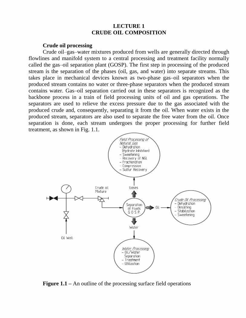
droplets resulting from the coalescence step will settle out of the oil by gravity and
be collected and removed.
Because these steps are in series, the slowest one is the most controlling. Out
of these, coalescence is the slowest step. In other words, using either heat or
chemicals followed by gravitational settling can break some emulsions, but the
process is dependent on the time spent in coalescence. This time is the element that
determines the equipment size, hence its capital cost.
Treating the Emulsion
As explained earlier, using chemicals followed by settling can break some
emulsions. Other emulsions require heating and allowing the water to settle out of
the bulk of oil. More difficult (tight) emulsions require, however, both chemicals
and heat, followed by coalescence and gravitational settling.
Basically, a dehydration process that utilizes any or a combination of two or
more of the treatment aids mentioned earlier (heating, adding chemicals, and an

applying electrical field) is used to resolve water–oil emulsions [6, 7]. The role of
each of these aids is discussed next in detail.
REFERENCES
1. McKetta, John J. (editor), Petroleum Processing Handbook, Marcel
Dekker, Inc., New York, 1992.
2. Mennon, V. B. and Wassam, D. T., De-emulsification, in Encyclopedia of
Emulsion Technology, P. Becher (ed.), Marcel Dekker, New York, 1984.
3. Nalco Chemical Co., Theories of Emulsion Breaking, Technology Series
CTS, Sugarland, TX, 1983, Vol. 3.

LECTURE 8
HEATING
Heating is the most common way of treating water–oil emulsions. To
understand how heating aids in the resolution of water–oil emulsions and
separation of the water droplets from the bulk of oil, reference is made to the
droplet settling velocity equation
sec/)(
10787.1
0
6ft
du
m
(8.1)
where u is the water droplet settling velocity, Δγ is the difference between water
and oil specific gravities, dm is the diameter of the water droplet (in μm) and μo is
the oil viscosity.
Benefits and Drawbacks of Heating
Heating of water–oil emulsions aids in the resolution of the emulsion and the
separation of the emulsified water in several ways. The most significant effect is
the reduction of oil viscosity with temperature. The viscosity of all types of crude
oil drops rapidly with increasing their temperature. From Eq. (8.1), such reduction
in viscosity results in increasing the water droplet settling velocity and, thus,
speeds and promotes the separation of water from the oil.
As the water and oil mixture is heated, the density (specific gravity) of both
water and oil is reduced. However, the effect of temperature on oil density is more
pronounced than on water density. The result is that the difference in density (or
specific gravity) increases as the emulsion is heated. For example, if oil and water
are heated from 15°C to 65°C, the following change in their specific gravity takes
place.
Table 8.1 - Difference in specific gravity of oil and water at the different
temperature
at 15°F at 65°F
Oil specific gravity 0.83 0.79
Water specific gravity 1.05 1.03
Difference in specific gravity 0.22 0.24
With reference to Eq. (8.1) an increase in Δγ increases the settling velocity
and, therefore, promotes the separation of water droplets from the bulk of oil. The
change in the specific gravity difference is, however, small.
Therefore, this effect is not as significant as the effect of viscosity. In fact,
we may completely ignore the effect of specific gravity on the process up to a
temperature of 93°C. For some specific crude oils, increased temperature may
cause a reverse effect on the difference in specific gravity. For some heavy oils, the
specific gravity of the oil and water will be equal at certain temperature. This
situation must be avoided, as it will stop the separation process completely.

Therefore, care should be exercised when determining the treating temperature for
a specific crude oil.
Another beneficial effect of heating is that the increased temperature
promotes movements of the small water droplets, which upon collision with one
and the other, may form larger size droplets. The increased droplet size
significantly speeds the settling process, as indicated by Eq. (8.1). Heat will also
help to destabilize (weakening) the emulsifying film, hence breaking the emulsion.
Further, heating will dissolve the small paraffin and asphaltenes crystals and, thus,
neutralize their potential effect as emulsifiers.
Despite of all of the above-discussed benefits of heating, there are some
drawbacks associated with this method of treatment. Heating of the oil can result in
significant loss of the lighter hydrocarbon ends and thus results in loss of the oil
volume. For example: heating 35oAPI oil from 38°C to 65°C results in losing more
than 1% of the oil volume. Of course, the evaporates (light ends) could be
collected and sold with the gas. This, however, will not make up for the loss of
revenue resulting from oil losses. In addition to oil losses, evaporation of the light
ends leaves the treated oil with lower API gravity (i.e., lower quality), which will
be sold at a lower price. Finally, heating requires additional investment for heating
equipment and additional operating cost for the fuel gas and maintenance.
Because of the above drawbacks, it is generally recommended to avoid using
heating as a treatment process if it is possible. Otherwise, some of the benefits of
heating may be realized with the minimum amount of heating.
Methods of Heating Oil Emulsions
The fuel used to supply heat in oil-treating operations is practically natural
gas. Under some special conditions, crude oil may be used.
Heaters are generally of two basic types:
1. Direct heaters, in which oil is passed through a coil exposed to the hot flue
gases of the burned fuel (or to introduce the emulsion into a vessel heated using a
fire tube heater).
2. Indirect heaters, in which heat is transferred from the hot flue gases to the
emulsion via water as a transfer medium. The emulsion passes through tubes
immersed in a hot water bath.
In general, the amount of free water in the oil emulsion will be a factor in
determining which method is to be used. If free water is found to be 1–2%, then
use an indirect heater. If the free-water content is more enough to hold a level
around the fire tube, then use a direct heater. Both types are shown in Figure 8.1.

Figure 8.1 – Methods of heating the emulsion
Types of Heater Treater
The various types of field heater and heater treater and gunbarrel treaters are
presented in Figures 8.2 and 8.3, respectively [1].
Figure 8.2 – Type of field heater

Figure 8.3 – Details of heater treater [2]
Vertical Treaters
Vertical treaters are commonly used as single-well treaters. The oil +
emulsion stream enters the treater from the side at the top section of the vessel
where gas, if any, separates and leaves the vessel at the top through a mist
extractor. The liquid flows downward through a pipe called the downcomer and
exits through a flow spreader located slightly below the water–oil interface to
water wash the oil–emulsion stream. Water washing helps in coalescing the small
water droplets suspended in the oil. The oil and emulsion flow upward, exchanging
heat with the heater fire tubes, then through the coalescing section. The coalescing
section, normally packed with porous material such as hay, is sized to provide
sufficient time for the coalescence of the water droplets and their settling out of the
oil. The treated oil is then collected from the treater.

Horizontal Treaters
This type of treater is normally used in centralized multiwell-treating
facilities (GOSP). The oil and emulsion stream is introduced to heating section of
the treater near the top where gas is flashed, separated, and exits the vessel at the
top through a mist extractor. The liquid is made to flow tangent to the inside
surface of the vessel and falls below the water–oil interface, where it is water
washed. Water washing causes coalescence and separation of free water. The oil +
emulsion rises up, exchanging heat with the fire tubes, and flows over a weir into
an oil surge chamber. The hot oil + emulsion leaves the oil surge chamber near the
bottom of the vessel and enters the coalescing section of the treater through a flow
spreader, which ensures that the oil flows evenly throughout the length of the
coalescing section. The oil flows upward, where it is withdrawn from the vessel
through a collector. The spreader–collector system allows the oil flow to be
vertical. This section of the treater is sized to allow sufficient retention time for the
coalescence and settling of the water out of the oil. The separated water is removed
from the treater at two locations:
- one at the bottom of the heating section;
- the other at the bottom of the coalescing section.
Interface level controllers control both outlet valves.
Gunbarrel Settling Tanks
Gunbarrel tanks are large-diameter vertical tanks operating mostly at
atmospheric pressure. They are generally used for small fields where no or
minimum heating is required for separation of the emulsion. When heating is
needed, the most common way is to preheat the oil and emulsion stream before it
enters the tank.
The oil + emulsion stream enters the tank at the top (where gas is flashed
and separated) into a downcomer. It leaves the downcomer through a spreader
located below the water–oil interface and rises vertically upward, flowing through
the large cross-sectional area of the tank. As the oil + emulsion rises, it is first
water washed to coalesce the water droplets. Then, it is retained for a sufficient
time in the settling section to allow for the separation of the water droplets, which
flow countercurrent to the oil flow and collects at the bottom section of the tank.

Figure 8.4 – Gunbarrel settling tanks [3]
REFERENCES:
1. Arnold, K. and Stewart, M., Surface Production Operations: Design of Oil-
Handling Systems and Facilities, 2nd ed., Gulf Publishing Co., Richardson, TX, 1998,
Vol. I.
2 Abdel-Aal, H. K., Surface Petroleum Operations, Saudi Publishing &
Distributing House, Jeddah, 1998.
3 tycoonequipment.com

LECTURE 9
CHEMICAL TREATMENT
As mentioned earlier, some oil emulsions will readily break upon heating
with no chemicals added; others will respond to chemical treatment without heat.
A combination of both «aids» will certainly expedite the emulsion-breaking
process [1]. Chemical additives, recognized as the second ‘‘aid,’’ are special
surface-active agents comprising relatively highmolecular-weight polymers. These
chemicals (deemulsifiers), once adsorbed to the water–oil interface, can rupture the
stabilizing film and/or displace the stabilizing agent due to the reduction in surface
tension on the inside of the film (i.e., on the water side of the droplet). In other
words, when the deemulsifiers are added to the oil, they tend to migrate to the oil–
water interface and rupture the stabilizing film, as depicted in Figure 9.1. A
deemulsifier, as it reaches to oil–water interface, functions in the following pattern:
flocculation, then film rupture, followed by coalescence. The faster the
deemulsifier reaches the oil–water interface, the better job it achieves.
Figure 9.2 illustrates these steps.
Figure 9.1 – Action of chemicals in deemulsification of water drops [2]

Figure 9.2 – Steps leading to large drop formation
Selection and Injection of Chemicals (Deemulsifiers)
The very first step for selecting the proper chemical for oil treating is testing
an oil sample. The representative sample is measured into a number of bottles (12
or more). To each bottle, a few drops of different chemicals are added, followed by
shaking to ensure good mixing between the emulsion and the chemical. Heat could
be applied if needed. Final selection of the right chemical will be based on testing a
sample of the oil to find out how complete the water removal was.
From the practical point of view, most oil deemulsifiers are oil soluble rather
than water soluble. Because such small amounts are used in treating and to ensure
thorough mixing, it is recommended to dilute the chemical with a solvent to have a
larger volume of the solution to inject.
The point of deemulsifiers injection will depend largely on the type used.
For the case of water-soluble deemulsifiers, injection is carried out after free water
has been removed; otherwise, most of the chemical is lost down the drain. Three
points of injection are recommended:
1. Upstream of the choke, where violent agitation takes place in the choke as
the pressure is lowered from wellhead to that corresponding to the gas/oil
separator. It is considered the ideal injection point. This is illustrated in Figure 9.3.
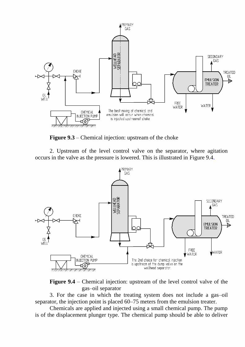
Figure 9.3 – Chemical injection: upstream of the choke
2. Upstream of the level control valve on the separator, where agitation
occurs in the valve as the pressure is lowered. This is illustrated in Figure 9.4.
Figure 9.4 – Chemical injection: upstream of the level control valve of the
gas–oil separator
3. For the case in which the treating system does not include a gas–oil
separator, the injection point is placed 60–75 meters from the emulsion treater.
Chemicals are applied and injected using a small chemical pump. The pump
is of the displacement plunger type. The chemical pump should be able to deliver

small quantities of the deemulsifier into the oil line. At normal treating conditions,
1 L of chemical is used for each 15–20 m3 of oil (or about 1 qt per 100 bbl of oil).
As was stated earlier, dilution of the chemical with proper solvents is necessary.
Based on the type of oil, the required concentration of the chemical ranges between
10 and 60 ppm (parts per million) [3].
Chemical deemulsifiers (emulsion breakers) are complex organic
compounds with surface-active characteristics. A combination of nonionic,
cationic and anionic materials contributes the surface-active properties. Some of
the deemulsifiers are sulfonates, polyglycol esters, polyamine compounds, and
many others.
A final and important word is that excessive amounts of chemicals can do
harm. Too much chemicals is usually called overtreating. In addition to the
unnecessary additional operating cost, excessive treatment would lead to what is
known as “burning of the emulsion” (i.e., unbreakable or tight emulsion).
REFERENCES
1. Manning, F. S. and Thomson, R., Oil-Field Processing of Petroleum,
Penn-well Publishing, Tulsa, OK, 1991.
2 Abdel-Aal, H. K., Surface Petroleum Operations, Saudi Publishing &
Distributing House, Jeddah, 1998.
3. Nalco Chemical Co., Theories of Emulsion Breaking, Technology Series
CTS, Sugarland, TX, 1983, Vol. 3.

LECTURE 10
ELECTRICAL AID
This is the third aid of emulsion treating in crude oil dehydration. However,
it should be realized that both heating and chemical treating work in order to
“break the emulsion”, whereas electrical emulsion treating is aimed at speeding up
“coalescence”, hence settling. In other words, electric dehydration does not break
the emulsion electrically.
Looking at the three consecutive steps involved in the dehydration of
emulsified crude oils (breaking the emulsion, coalescence of water droplets, and
settling and separation) and assuming that the first and third steps are fast
compared to the second step, it can be concluded that coalescence is the controlling
step. In other words, coalescence, which is a function of time, influences settling.
Consequently, in the design of dehydrators, some means should be implemented to
reduce the coalescence time, hence the settling time. Some of these means are (1)
installing a coalescing medium in the settling section to speed up the buildup and
the formation of water drops, (2) applying centrifugal force to the emulsion that
can promote separation, and (3) applying an electrical field in the settling section
of the treater.
The principle of breaking oil–water emulsions using electrical current is
known as electrostatic separation. Ionization of these emulsions with the aid of
electric field was introduced in 1930 for crude oil desalting in oil refineries. High-
voltage field (10,000 to 15,000 v) is used to help dehydration according to the
following steps:
1. The water droplet is made up of polar molecules, because the oxygen
atom has a negative end, and the hydrogen atoms have positive charges. These
polar forces are magnetized and respond to an external electrical force field.
Therefore, a dipole attraction between the water droplets in the emulsion is
established, leading to coalescence, hence settling and separation (see Figure 10.1).
2. As a result of the high-voltage field, the water droplets vibrate
rapidly, causing the stabilizing film to weaken and break.
3. The surface of the water droplets expands (droplets` shapes change
into ellipsoids); thus attracted to each other, they collide and then coalesce, as
depicted in Figure 10.2.
4. As the water droplets combine, they grow in size until they become
heavy enough to separate by settling to the bottom of the treater.

Figure 10.1 – Coalescence of water droplets in W/O emulsion [1]

Figure 10.2 – Emulsion breaking with the aid of an electric current [2]
Chemielectric Dehydratros (Emulsion Treaters) It is normal practice to call emulsion treaters ‘‘heater treaters.’’ However,
when other or additional treating aids are used, the name of the treater would be
made to reflect such aids of treatment. Consequently, a name such as chemielectric
dehydrator is used to indicate that both chemical and electrical aids are used (in
addition to heating) in the treatment.
Figure 10.3 is a sketch illustrating a typical chemielectrical treater.
Figure 10.3 – Chemelectric dehydrator
The vessel is basically the same as the horizontal heater treater described
earlier. Once the oil is heated, it flows to the settling section. Free water separated

from the emulsion (under the effect of both heat and chemicals) settles to the
bottom. The oil on the other hand moves slowly upward, passing across the electric
grid in the settling section, where remnant emulsified water is separated as
explained earlier. Finally, clean oil flows to the top of the treater.
It should be made clear that most of the emulsified water is removed by the
dual action of both heat and chemicals before the oil passes to the electric grid. The
water content in the oil could be reduced to 1–0.5% before it gets to the grid.
The application of the electrical field has a significant impact on the treater’s
performance. This is exemplified by Figure 10.4, which clearly illustrates the
improvement of a treater when an electric field is applied.
Figure 10.4 – Effect of an electrical field on coalescence
REFFERENCES:
1 Abdel-Aal, H. K., Surface Petroleum Operations, Saudi Publishing &
Distributing House, Jeddah, 1998.
2 Arnold, K. and Stewart, M., Surface Production Operations: Design of Oil-
Handling Systems and Facilities, 2nd ed., Gulf Publishing Co., Richardson, TX, 1998,
Vol. I.
°

LECTURE 11
DESALTING OF CRUDE OIL
The removal of salt from crude oil for refinery feed stocks has been and still is
a mandatory step. This is particularly true if the salt content exceeds 20 PTB (pounds
of salt, expressed as equivalent sodium chloride, per thousand barrels of oil).
The most economical place for the desalting process is usually in the refinery.
However, when marketing or pipeline requirements are imposed, field plants are
needed for processing the salty oil prior to shipping. The principals involved are the
same whether desalting takes place at the refinery or in the field. Salt in crude oil is, in
most cases, found dissolved in the remnant brine within the oil.
The remnant brine is that part of the salty water that cannot be further reduced by
any of the dehydration methods described in the previous lectures. It is commonly
reported as basic sediments and water (B.S.&W.). It is understood that this remnant
water exists in the crude oil as a dispersion of very tiny droplets highly emulsified in the
bulk of oil.
The mineral salts of this brine consist mainly of chlorides of sodium,
calcium and magnesium. A summary of the properties of crude oil as received at
the refinery is given in Table 11.1.
Table 11.1 – Properties of Crude Oils Shipped to Refineries
Range Average Water in crude, % by volume of crude 0.1–2.0 0.3–0.5 Salt content in crude, PTB 10–250 60-130 Salt concentration in brine, wt% 0.4–25 — Salt concentration in brine, ppm 4,000–250,000 —
Source: Ref. 1.
Nelson [1] compiled the data given in Table 11.2 on the amount of salts
found in oils for various regions in the world.
Table 11.2 – Average Values for the PTB for Some Typical Crude Oils
Source of oil Avg. salt content (PTB) Middle East 8 Venezuela 11 United States
Pennsylvania 1 Wyoming 5 East Texas 28 Gulf Coast 35 Oklahoma and Kansas 78 West Texas 261
Canada 200

The amount of salt in the crude oil is a function of the amount of the brine
that remains in the oil WR (% B.S.&W.) and of its salinity SR in parts per million
(ppm). In other words, this relationship could be written in the following functional
form (after Manning and Thompson [2]):
610100
1000350
R
R
R
Brine
S
W
WPTB (11.1)
The method of reducing the PTB by lowering the quantity of remnant water
WR is usually referred to as the treating process of oil dehydration. The other
alternative of reducing the PTB is to substantially decrease the dissolved salt
content of the remnant water (i.e., its concentration, SR). This practice is the one
we are dealing with in this lecture and is known as desalting. Desalting of crude oil
will eliminate or minimize problems resulting from the presence of mineral salts in
crude oil. These salts often deposit chlorides on the heat transfer equipment of the
distillation units and cause fouling effects. In addition, some chlorides will
decompose under high temperature, forming corrosive hydrochloric acid [3]:
(11.2)
The removal of these salts is aimed at providing an economical operating
cycle in the refining process of crude oil. The reduction of salt content down to 5
PTB is feasible. Even with this low salt content, it has been reported that the
processing of 25,000 bb1/day of crude oil could result in an amount of HCl equal
to 65 lb/day (29.5 kg per day) [4].
Description of the desalting process
We cannot economically achieve a satisfactory salt content in oil by using
dehydration only (single stage). This is particularly true if the salinity of the water
produced with oil is much greater than 20,000 ppm (formation water has a
concentration of 50,000–250,000 mg/L). Accordingly, a two-stage system (a
dehydration stage and a desalting stage) is shown in Figure 11.1 (a). Under certain
conditions, however, a three-stage system may be used which consists of a
dehydration stage and two consecutive desalting units as shown in Figure 11.1(b).

Figure 11.1 – (a) Single-stage desalting system (from Ref. 5). (b) A two-
stage desalting system
As shown in Figure 11.1, wash water, also called dilution water, is mixed
with the crude oil coming from the dehydration stage. The wash water, which
could be either fresh water, or water with lower salinity than the remnant water,
mixes with the remnant water, thus diluting its salt concentration. The mixing
results in the formation of water–oil emulsion.
The oil (and emulsion) is then dehydrated. The separated water is disposed
of through the field-produced water treatment and disposal system. In the two-
stage desalting system, dilution water is added in the second stage and all, or part,
of the disposed water in the second stage is recycled and used as the dilution water
for the first desalting stage. Two-stage desalting systems are normally used to
minimize the wash water requirements.
The mixing step in the desalting of crude oil is normally accomplished by
pumping the crude oil (which is the continuous phase) and wash water (which is
the dispersed phase) separately through a mixing device. The usual mixing device
is simply a throttling valve. The degree of mixing can be enhanced if the interfacial
area generated upon mixing is increased. A useful device for such a purpose is the
application of multiple-orifice-plate mixers (MOMs) shown in Figure 11.2.

Figure 11.2 – Details of multiple-orifice plate mixers (MOM)
It is of importance to point out that although the theory of dilution of
remnant water with fresh water is sound in principle, it can become impossible to
implement in actual application. It all depends on the intimate mixing of remnant
water with dilution water.
In the emulsion-treating step, a heating, chemical, or electrical demulsifying
aid (or a combination of them) is commonly used. The chemical desalting process
involves adding chemical agents and wash water to the preheated oil, followed by
settling, is shown in Figure 11.3. The settling time varies from a few minutes to 2
h. Some of the commonly used chemical agents are sulfonates, long-chain
alcohols, and fatty acids.
Figure 11.3 – Chemical desalting

REFERENCES
1. Nelson, W. L. Petroleum Refinery Engineering, 4th ed., McGraw-Hill,
New York, 1958.
2. Manning, F. S. and Thompson, R. E., Oil Field Processing, Penn Well
Books, Tulsa, OK, 1995, Vol. 2.
3. Abdel-Aal, H. K. and Shaikh, A. A., Desalting of oil using multiple
orifice mixers: An empirical correlation for the water of dilution, presented at the
Third Iranian Congress of Chemical Engineering, 1977.
4. Beychok, M. R., Aqueous Wastes from Petroleum & Petrochemical
Plants, John Wiley & Sons, New York, 1967.
5. McKetta, John J. (editor), Petroleum Processing Handbook, Marcel
Dekker, Inc., New York, 1992.
6. Bradley, H. B., Petroleum Engineering Handbook, Society of Petroleum
Engineers, Richardson, TX, 1987.
7. Merchant, P. and Lacy, S. M., Water-based demulsifier formulation and
its use in dewatering and desalting crude hydrocarbon oils, US Patent 455123 gA,
1985.

LECTURE 12
ELECTROSTATIC DESALTING
In this case, an external electric field is applied to coalesce the small water
droplets and thus promote settling of the water droplets out of the oil. The electric
field may be applied in any of the following manners [1]:
1. ac field devices for water-rich emulsions. Alternating current (ac) is
applied, which alternates the polar water molecule arrangements leading to better
coalescence. A schematic diagram of ac electrostatic coalescence is shown in
Figure 12.1.
Figure 12.1 – ac electrostatic coalescer
2. ac/dc field for maximum dehydration. A combination of ac and dc
(direct current) is used in this case. The basic configuration of this process is
shown in Figure 12.2. The ac is produced in the zone beneath the electrodes,
whereas the dc field is produced between adjacent electrodes. This arrangement
achieves maximum water removal.
Figure 12.2 – Dual polarity ac/dc field
3. Variable gradient field for maximum salt reduction. If the field gradient is
increased beyond a certain limit (Ec), this will shatter the drops; it is expressed as

21
dkE
c
(12.1)
where k is the dielectric constant, γ is the interfacial tension, and d is the drop
diameter. Thus, the drop size can be controlled by the field gradient. The electric
field can be used both to mix and separate the drops.
By cycling the field strength, the process can be repeated many times during
the retention time of the drops within the electric field. Voltage modulation will
create mixing, coalescence, and settling, as shown in Figure 12.3. The electrostatic
field causes the dipolar water molecules to align with the field.
Figure 12.3 – Voltage modulation for electrostatic mixing coalescing
In the electrical desalting process, a high potential field (16,500–33,000 V)
is applied across the settling vessels to help coalescence, as shown in Figure 12.4.
Figure 12.4 – Electrical desalting
The chemielectric concept utilizing both chemical agents and electrical field
is schematically illustrated in Figure 12.5. In the desalting process, it is a common
practice to apply enough pressure to suppress any loss of hydrocarbon due to
vaporization of the oil. The pressure normally used in a desalting process is in the
range 50–250 psi.

Figure 12.5 – A typical desalting system utilizing chemelectric approach
Determining Dilution Water Requirement
From the operational point of view, it has been reported that the amount of
water of dilution WD added in the desalting of crude oils is in the range 5–10% by
volume, based on the amount of remnant water and its salinity.
Effect of operating parameters
The efficiency of desalting is dependent on the following parameters [2,3]:
1. Water–crude interface level. This level should be kept constant; any
changes will change electrical field and perturbs electrical coalescence.
2. Desalting temperature. Temperature affects water droplet settling through
its effect on oil viscosity; therefore, heavier crude oils require higher desalting
temperatures.
3. Wash water ratio. Heavy crudes require a high wash water ratio to
increase electrical coalescence. A high wash ratio acts similarly to raise
temperatures, as illustrated in Table 12.1.
4. Pressure drop in the mixing valve. A high-pressure-drop operation results
in the formation of a fine stable emulsion and better washing. However, if the
pressure drop is excessive, the emulsion might be difficult to break. The optimum
pressure drop is 1.5 bar for light crudes and 0.5 bar for heavy crudes.
5. Type of demulsifiers. Demulsifiers are added to aid in complete
electrostatic coalescence and desalting. They are quite important when heavy
crudes are handled. Levels ranging between 3 and 10 ppm of the crude are used.
Table 12.1 – Average Desalting Conditions
Crude gravity
(°API)
Desalting temperature
(°C)
Minimum water
ratio (vol%)
>40 110 2–4
30–40 110 4–8
120 4–7
<30 130 8–10
140 >10

Design consideration
The following major parameters are considered when designing the desalting
system:
1) flow scheme arrangements (conventional one-stage or countercurrent
contact desalters);
2) number of desalting stages;
3) dehydration levels achieved;
4) salinity of the brine in the crude;
5) efficiency of valve mixing;
6) salinity of dilution water;
7) target PTB specification.
Trouble shooting
Table 12.2 lists some “tips” that are helpful in solving some of the operating
problems or troubles that are of significance to the desalting process.
Table 12.2 – Problems, causes and solutions
Problems Causes Solutions
1 2 3
1. A high salt
content in the
desalted crude
oil
(a)Feed salt content high
(b)Wash water injection low
(c)Crude oil flow rate
exceeds the design flow
rate
(d)Insufficient mixing of the
crude oil and wash water
(a)Increase the wash
water rate
(b)Reduce the crude oil
flow rate
(c)Increase the mix value
pressure drop
2. Oil in the
desalter effluent
water
(a)"Interface" level too low
(b)Wide emulsion band at the
"interface"
(c)Excessive crude oil wash
water mixing
(d)Poor wash water quality
(e)Crude temperature too
low
(a)Increase the interface
level
(b)Inject a chemical or
dump the emulsion
(c)Reduce the mix valve
pressure drop
(d)Check for any waste in
the wash water source
3. High water
carry over in
desalted crude
oil
(a)Wash water flow rate too
high
(b)Excessive formation water
in the crude oil
(c)Interface level too high
(d)Disturbance in the
desalter vessel
(a)Reduce the wash water
flow rate and
commence or increase
chemical injection
(b)Reduce the interface
level and check the
effluent water valve
(c)Check for an excessive
cause and allow the
unit to settle down

REFERENCES
1 Abdel-Aal, H. K. and Shaikh, A. A., Desalting of oil using multiple orifice
mixers: An empirical correlation for the water of dilution, presented at the Third
Iranian Congress of Chemical Engineering, 1977.
2 Bradley, H. B., Petroleum Engineering Handbook, Society of Petroleum
Engineers, Richardson, TX, 1987.
3 Merchant, P. and Lacy, S. M., Water-based demulsifier formulation and its
use in dewatering and desalting crude hydrocarbon oils, US Patent 455123 gA,
1985.

LECTURE 13
CRUDE OIL STABILIZATION AND SWEETENING
Once degassed and dehydrated–desalted, crude oil is pumped to gathering
facilities to be stored in storage tanks. However, if there are any dissolved gases
that belong to the light or the intermediate hydrocarbon groups, it will be necessary
to remove these gases along with hydrogen sulfide (if present in the crude) before
oil can be stored. This process is described as a “dual process” of both stabilizing
and sweetening a crude oil.
In stabilization, adjusting the pentanes and lighter fractions retained in the
stock tank liquid can change the crude oil gravity. The economic value of the crude
oil is accordingly influenced by stabilization. First, liquids can be stored and
transported to the market more profitably than gas. Second, it is advantageous to
minimize gas losses from light crude oil when stored.
This lecture deals with methods for stabilizing the crude oil to maximize the
volume of production as well as its API gravity, against two important constraints
imposed by its vapor pressure and the allowable hydrogen sulfide content.
To illustrate the impact of stabilization and sweetening on the quality of
crude oil, the properties of oil before and after treatment are compared as follows
(Table 13.1).
Table 13.1 – Compare of properties of oil before and after treatment
Before treatment After treatment
Water
content:
up to 3% of crude in
the form of emulsions
and
from 3% to 30% of
crude as free water
Water content
(B.S.&W.)
0.3% by volume,
maximum
Salt content 50,000–250,000 mg/L
formation water
Salt content:
10–20 lbs salt (NaCl)
per 1000 barrels oil
(PTB)
Gas dissolved gases in
varying amounts
depending on the gas–
oil ratio (GOR)
Vapor pressure
5–20 psia RVP (Reid
vapor pressure)
Hydrogen
Sulfide
up to 1000 ppm by
weight
H2S
10–100 ppmw
After treatment (dual-purpose operation) sour wet crude must be treated to
make it safe and environmentally acceptable for storage, processing, and export.
Therefore, removing water and salt, is mandatory to avoid corrosion; separation of
gases and H2S will make crude oil safe and environmentally acceptable to handle.
Crude oil is considered “sweet” if the dangerous acidic gases are removed
from it. On the other hand, it is classified as “sour” if it contains as much as 0.05

ft3 of dissolved H2S in 100 gal of oil (3,54x10
-6 m
3 of H2S in 2,77 barrels (440
liters). Hydrogen sulfide gas is a poison hazard because 0.1% in air is toxically
fatal in 30 min. Additional processing is mandatory—via this dual operation—in
order to release any residual associated gases along with H2S present in the crude.
Prior to stabilization, crude oil is usually directed to a spheroid for storage in
order to reduce its pressure to very near atmospheric, as shown in Figure 13.1.
Figure 13.1 – Typical spheroid for oil storage prior to stabilization
Stabilization Operations
The traditional process for separating the crude oil–gas mixture to recover
oil consists of a series of flash vessels [gas–oil separation plant (GOSP)] operating
over a pressure range from roughly wellhead pressure to nearly atmospheric
pressure. The crude oil discharged from the last stage in a GOSP or the desalter has
a vapor pressure equal to the total pressure in the last stage. Usually, operation of
this system could lead to a crude product with a RVP in the range of 4 to 12 psia
(0.27-0.81 bar). Most of the partial pressure of a crude oil comes from the low-
boiling compounds, which might be present only in small quantities—in particular
hydrogen sulfide and low-molecular-weight hydrocarbons such as methane and
ethane.
Now, stabilization is directed to remove these low-boiling compounds
without losing the more valuable components. This is particularly true for
hydrocarbons lost due to vent losses during storage. In addition, high vapor
pressure exerted by low-boiling-point hydrocarbons imposes a safety hazard.
Gases evolved from an unstable crude oil are heavier than air and difficult to
disperse with a greater risk of explosion.
The stabilization mechanism is based on removing the more volatile
components by (a) flashing using stage separation and (b) stripping operations.
As stated earlier, the two major specifications set for stabilized oil are as
follows:
- the Reid vapor pressure (RVP)

- hydrogen sulfide content
Based on these specifications, different cases are encountered:
Case 1: Sweet oil (no hydrogen sulfide); no stabilization is needed. For this
case and assuming that there is a gasoline plant existing in the facilities (i.e., a
plant designed to recover pentane plus), stabilization could be eliminated, allowing
the stock tank vapors to be collected [via the vapor recovery unit (VRU)] and sent
directly to the gasoline plant, as shown in Figure 13.2.
Case 2: Sour crude; stabilization is a must. For this case, it is assumed that
the field facilities do not include a gasoline plant. Stabilization of the crude oil
could be carried out using one of the approaches outlined in Figure 13.3. Basically,
either flashing or stripping stabilization is used.
Figure 13.2 – Field operation with no stabilization
Figure 13.3 – Alternatives for stabilizing crude oil
It can be concluded from the above that the hydrogen sulfide content in the
well stream can have a bearing effect on the method of stabilization. Therefore, the
recovery of liquid hydrocarbon can be reduced when the stripping requirement to

meet the H2S specifications is more stringent than that to meet the RVP specified.
Accordingly, for a given production facility, product specifications must be
individually determined for maximum economic return on any investment.
Stabilization by Flashing (Additional Gas–Oil Separator)
The method utilizes an inexpensive small vessel to be located above the
storage tank. The vessel is operated at atmospheric pressure. Vapors separated
from the separator are collected using a VRU. This approach is recommended for
small-size oil leases handling small volume of fluids to be processed. The
principles underlying the stabilization process are the same as for gas–oil
separation.
Stabilization by Stripping
The stripping operation employs a stripping agent, which could be either
energy or mass, to drive the undesirable components (low-boiling-point
hydrocarbons and hydrogen sulfide gas) out of the bulk of crude oil. This approach
is economically justified when handling large quantities of fluid and in the absence
of a VRU. It is also recommended for dual-purpose operations for stabilizing sour
crude oil, where stripping gas is used for stabilization. Stabilizer-column
installations are used for the stripping operations.
Types of Stabilizer Employing Energy as a Stripping Agent
Two basic types of trayed stabilizer are commonly used:
- Conventional reflux types normally operate from 150 to 300 psia (10 – 20
bar).
This type of stabilizer is not common in field installations. It is more suitable
for large central field processing plants.
- Non-refluxed stabilizers generally operate between 55 and 85 psia (3.7 –
5,7 bar).
These are known as “cold feed” stabilizers. They have some limitations, but
they are commonly used in field installations because of their simplicity in design
and operation.
Non-refluxed Stabilizers
When hydrocarbon liquids are removed from the separators, the liquid is at
its vapor pressure or bubble point. With each subsequent pressure reduction,
additional vapors are liberated. Therefore, if the liquids were removed directly
from a high-pressure separator into a storage tank, vapors generated would cause
loss of lighter as well as heavier ones. This explains the need for many stages in a
GOSP. Nevertheless, regardless of the number of stages used, some valuable
hydrocarbons are lost with the overhead vapor leaving the last stage of separation
or the stock tank.
A maximum volume of hydrocarbon liquid could be obtained under stock
tank conditions with a minimum loss of solution vapors by fractionating the last-
stage separator liquid. This implies using a simple fractionating column, where the

vapors liberated by increasing the bottom temperature are counter flowed with the
cool feed introduced from the top. Interaction takes place on each tray in the
column. The vapors act as a stripping agent and the process is described as
stabilization.
Equipment and Operation
In general, a conventional fractionating column would require main
auxiliaries such as reflux, pumps, condensers, cooling water, and utilities
frequently not available on site in oil fields. Stabilizers or stripping columns, on the
other hand, can be operated with a minimum of these auxiliaries.
Figure 13.4 depicts a stabilizer in its simplest form.
Figure 13.4 – Typical trayed stabilizer
A cold feed stabilizer normally operates with a fixed top and bottom
temperatures. The former is kept as low as possible to maximize recovery, whereas
the latter is controlled to maintain the product bottom pressure. It is of interest to
mention that the overhead gas temperature is identical to the liquid feed

temperature because the ratio of masses of vapor leaving the column to liquid feed
entering is rather small.
Most stabilizers operate above 200 psia (13.5 bar) and consist of 20 bubble
trays. High-pressure stabilizers have more trays because of the higher temperature
gradient between the top and the bottom trays. More trays allow the column to
operate closer to equilibrium. Columns less than 20 inches in (50.4 mm) diameter
generally use packing rather than trays. A useful rule of thumb is that 1 ft2 (0.93
m2) of tower area could handle about 100 bbl/day of stock tank liquid. In some
designs, the cold feed is introduced several trays below the top tray, using the
upper trays as a scrubber in order to prevent liquid carry over during burping.
Field operation of a stabilizer is described as follows. Relatively cool liquid
(oil) exiting the GOSP is fed to the top plate of the column where it contacts the
vapor rising from below. The rising vapors strip the lighter ends from the liquid
(i.e., acting as a stripping agent). At the same time, the cold liquid—acting as an
internal reflux – will condense and dissolve heavier ends from the rising vapor,
similar to a rectification process. The net separation is very efficient as compared
to stage separation (3–7% more).
To have a stabilized product of certain specifications, in theory a stabilizer
can be operated at multiple combinations of tower pressure and bottom
temperature. In general, as the tower pressure is increased, more light ends will
condense in the bottom. In normal operation, it is best to operate the tower at the
lowest possible pressure without losing too much of the light ends at the initial
feed flash. This will minimize ‘‘burping’’ and cause the column to operate near
equilibrium. In addition, lower operating pressures require less reboiler duty with
less fuel consumption. Operating data for a 40,000-bbl/day non-refluxed stabilizer
are given in Figure 13.5.
Main Features and Applications of Stabilizers
Stabilizers used for oil production field operations should have the following
features:
– They must be self-contained and require minimum utilities that are
available in the field, such as natural gas for fuel.
– Stabilizers must be capable of unattended operation and to stand fail-safe
operation.
– Stabilizers must be equipped with simple but reliable control system.
– They should be designed in a way to make them accessible for easy
dismantling and reassembly in the field.
– Maintenance of stabilizers should be made simple and straight forward.
Stabilizer’s applications, on the other hand, are justified over simple stage
separation under the following operating conditions:
– The first-stage separation temperature is between 0 °C and 40 °C.
– The first-stage separation pressure is greater than 1200 psig (81.3 barg).
– The liquid gravity of the stock tank oil is greater than 45 °API.
– Oil to be stabilized contains significant quantities of pentanes plus, even
though the oil gravity is less than 45 °API.

– Specifications are set by the market for product compositions—obtained
from crude oil—that require minimum light ends.
Figure 13.5 – Typical trayed stabilizer with operating data for 40 MB/D of
oil
REFERENCES:
1 Abdel-Aal, H. K., Surface Petroleum Operations, Saudi Publishing &
Distributing House, Jeddah, 1998.
2 Kister, H. Z., Distillation Operations, McGraw-Hill, New York, 1988.
3 Meyers, R. A. (ed.), Handbook of Petroleum Refining Processes,
McGraw-Hill Book Company, New York, 1996.
4 Moins, Georges, ‘‘Stabilization Process Comparison Helps Selection’’, Oil
and Gas Journal, January 28, 1980:163–173.

LECTURE 14
CRUDE OIL SWEETENING
Apart from stabilization problems of “sweet” crude oil, “sour” crude oils
containing hydrogen sulfide, mercaptans, and other sulfur compounds present
unusual processing problems in oil field production facilities. The presence of
hydrogen sulfide and other sulfur compounds in the well stream impose many
constraints. Most important are the following:
– Personnel safety and corrosion considerations require that H2S
concentration be lowered to a safe level.
– Brass and copper materials are particularly reactive with sulfur
compounds; their use should be prohibited.
– Sulfide stress cracking problems occur in steel structures.
– Mercaptans compounds have an objectionable odor.
Along with stabilization, crude oil sweetening brings in what is called a
‘‘dual operation,’’ which permits easier and safe downstream handling and
improves and upgrades the crude marketability. Three general schemes are used to
sweeten crude oil at the production facilities:
Process Stripping agent
1 Stage vaporization with stripping gas Mass (gas)
2 Trayed stabilization with stripping gas Mass (gas)
3 Reboiled tray stabilization Energy (heat)
1. Stage vaporization with stripping gas. This process—as its name
implies—utilizes stage separation along with a stripping agent.
Hydrogen sulfide is normally the major sour component having a vapor
pressure greater than propane but less than ethane. Normal stage separation will,
therefore, liberate ethane and propane from the stock tank liquid along with
hydrogen sulfide. Stripping efficiency of the system can be improved by mixing a
lean (sweet) stripping gas along with the separator liquid between each separation
stage.
Figure 14.1 represents typical stage vaporization with stripping gas for crude
oil sweetening/stabilization. The effectiveness of this process depends on the
pressure available at the first-stage separator (as a driving force), well stream
composition, and the final specifications set for the sweet oil.
2. Trayed stabilization with stripping gas. In this process, a tray stabilizer
(non-reflux) with sweet gas as a stripping agent is used as shown in Figure 14.2.
Oil leaving a primary separator is fed to the top tray of the column countercurrent
to the stripping sweet gas. The tower bottom is flashed in a low-pressure stripper.
Sweetened crude is sent to stock tanks, whereas vapors collected from the top of
the gas separator and the tank are normally incinerated. These vapors cannot be
vented to the atmosphere because of safety considerations. Hydrogen sulfide is
hazardous and slightly heavier than air; it can collect in sumps or terrain
depressions.

Figure 14.1 – Crude sweetening by stage vaporization with stripping gas
Figure 14.2 – Crude sweetening by trayed stabilization with stripping gas
This process is more efficient than the previous one. However, tray
efficiencies cause a serious limitation on the column height. For an efficiency of
only 8%, 1 theoretical plate would require 12 actual trays. Because trays are spaced
about 2 ft (0.61 m) apart, columns are limited to 24–28 ft (7.3-8.5 m) high, or a
maximum of two theoretical trays.
3. Reboiled trayed stabilization. The reboiled trayed stabilizer is the most
effective means to sweeten sour crude oils. A typical reboiled trayed stabilizer is
shown in Figure 14.3. Its operation is similar to a stabilizer with stripping gas,

except that a reboiler generates the stripping vapors flowing up the column rather
than using a stripping gas. These vapors are more effective because they possess
energy momentum due to elevated temperature.
Figure 14.3 – Crude sweetening by reboiled trayed stabilization
Because hydrogen sulfide has a vapor pressure higher than propane, it is
relatively easy to drive hydrogen sulfide from the oil. Conversely, the trayed
stabilizer provides enough vapor/liquid contact that little pentanes plus are lost to
the overhead.
BIBLIOGRAPHY
Abdel-Aal, H. K., Surface Petroleum Operations, Saudi Publishing &
Distributing House, Jeddah, 1998.
Kister, H. Z., Distillation Operations, McGraw-Hill, New York, 1988.
Meyers, R. A. (ed.), Handbook of Petroleum Refining Processes, McGraw-
Hill Book Company, New York, 1996.
Moins, Georges, ‘‘Stabilization Process Comparison Helps Selection’’, Oil
and Gas Journal, January 28, 1980:163–173.

LECTURE 15
STORAGE TANKS
Storage tanks for crude oil are needed in order to receive and collect oil
produced by wells, before pumping to the pipelines as well as to allow for
measuring oil properties, sampling, and gauging (figure 15.1).
Figure 15.1 – Storage tanks
The design of storage tanks for crude oil and petroleum products requires, in
general, careful consideration of the following important factors:
- the vapor pressure of the materials to be stored;
- the storage temperature and pressure;
- toxicity of the petroleum material.
In order to meet the environmental constraints on air pollution, to prevent
fire hazards, and to avoid losses of valuable petroleum products at the same time, it
is recommended to adopt the following:
- the use of floating-roof tanks for petroleum materials with a vapor
pressure of 1.12–11.5 psia (0.08 – 0.78 bar) at the storage temperature$
- using fixed-roof tanks along with the VRU system (to be described
later).
These alternatives are schematically illustrated in Figure 15.2.

Figure 15.2 – Vapor recovery units are used to minimize the loss of
hydrocarbon vapor formed during storage
Types of Storage Tank
The main features of some of the common types of storage tank used by the
petroleum industry in general are presented in Table 15.1.
The atmospheric tank, or standard storage tank, is one that is designed to be
used within plus or minus a few pounds per square inch of atmospheric pressure. It
may be open to the atmosphere (vented) or enclosed.
As will be explained next, an effective method of preventing vent loss in a
storage tank is to use one of the many types of variable-volume tank (type II in
Table 15.1). These are built under API Standard 650. They may have floating roofs
of the double-deck or single-deck type. These are lifter-roof types in which the
roof either has a skirt moving up and down in an annular seal or is connected to the
tank shell by a flexible membrane.

Table 15.1 – Summary of Refinery Storage Tanks
Characte-
ristics Standard
Storage Tanks
Conservation-Type Storage Tanks I (Floating
Roofs)
II (Variable-
Vapor-Space) III (Pressure Storage)
Evaporation
losses High
Significantly
reduced Significantly
reduced Prevented or eliminated
Operating
conditions
Recommended
for liquids
whose vapor
pressure is
atmospheric or
below at storage
conditions
(vented).
Allow no vapor
space above the
liquid: level (no
venting)
Allow the air-
vapor mixture to
change volume at
constant or
variable pressure
(no venting)
Allow the pressure in the
vapor space to build up.
Tanks are capable of
withstanding the
maximum pressure
without venting.
Sub-
сlassification
1.Rectangular
2.Cylinderical:
a) Horizontal
b) Vertical
-
1. Lifter roof,
which is a gas
holder mounted
on a standard
storage tank.
2. Vapor-dome
1. Low-pressure storage
normally designed for
2.5-5 psig and up to 15
psig (0.14 – 0.34 bar and
up to 1.02 bar)
2.High pressure storage:
30-200 psig (2 – 13.5 bar)
Typical types
Cone-roof-
vertical
(cylinderical
tanks)
Floating-roof.
wiggins-Hidek
type
Lifter roof tanks.
wiggins dry seal
type
Spheroids and
hemispheroids for low
pressure storage, spheres
for high pressure storage
Applications Heavy refinery-
products
Sour crude oils,
light crude oils,
light products.
Light refinery
product and
distillates
Spheroids are used to
store aviation, motor, jet
fuels. Spheres are used to
store natural gasoline and
LPG.
Vapor recovery Units
The loss of hydrocarbon vapors formed above crude oil or its products—
when stored—could be minimized using what is called vapor recovery units
(VRUs). If allowed to escape to the atmosphere, these vapors will not only cause a
loss of income due to loss of hydrocarbon volume and change in the API of the oil
but will also lead to pollution and fire hazards.
The three main functions for the vapor recovery system are (as illustrated in
Fig. 15.3) as follows:
1) to collect vapor from storage/loading facilities;
2) to reliquefy vapors;
3) to return liquid hydrocarbons to storage.
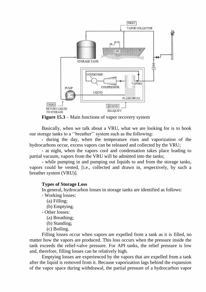
Figure 15.3 – Main functions of vapor recovery system
Basically, when we talk about a VRU, what we are looking for is to hook
our storage tanks to a ‘‘breather’’ system such as the following:
- during the day, when the temperature rises and vaporization of the
hydrocarbons occur, excess vapors can be released and collected by the VRU;
- at night, when the vapors cool and condensation takes place leading to
partial vacuum, vapors from the VRU will be admitted into the tanks;
- while pumping in and pumping out liquids to and from the storage tanks,
vapors could be vented, [i.e., collected and drawn in, respectively, by such a
breather system (VRU)].
Types of Storage Loss
In general, hydrocarbon losses in storage tanks are identified as follows:
- Working losses:
(a) Filling;
(b) Emptying.
- Other losses:
(a) Breathing;
(b) Standing;
(c) Boiling.
Filling losses occur when vapors are expelled from a tank as it is filled, no
matter how the vapors are produced. This loss occurs when the pressure inside the
tank exceeds the relief-valve pressure. For API tanks, the relief pressure is low
and, therefore, filling losses can be relatively high.
Emptying losses are experienced by the vapors that are expelled from a tank
after the liquid is removed from it. Because vaporization lags behind the expansion
of the vapor space during withdrawal, the partial pressure of a hydrocarbon vapor

drops. Enough air enters during the withdrawal to maintain the total pressure at the
barometric value.
However, when vaporization into the new air reaches equilibrium, the
increase in the vapor volume will cause some vapor expansion.
Breathing losses occur when vapors are expelled from a tank under one of
the following conditions:
1. The thermal expansion of the existing vapors
2. An expansion caused by barometric pressure changes
3. An increase in the amount of vapors from added vaporization in the
absence of a liquid level change
Breathing losses take place in most types of tanks and occurs when the
tank’s limits of pressure or volume changes are exceeded.
The fixed-roof API type tanks used to store stock tank oil are designed for
only for a few inches of water pressure or vacuum and suffer relatively large
breathing losses.
Standing losses are losses of vapor which result from causes other than
breathing or a change in liquid level in tanks. Sources of standing losses are vapor
escape from hatches or other openings and from glands, valves, and fittings.
Boiling losses occur when liquid boils in a tank and vapors are expelled. In
other words, the vapor pressure of the liquid exceeds the surrounding pressure.
Vapor Recovery Methods
Ideally, it would be best to design a tank or a storage system to operate at
pressures high enough to suppress evaporation; hence minimizing evaporation
losses. However, this is not generally economical; also, refiners require crude oil to
meet maximum vapor pressure specifications.
Various methods can be recommended to recover vapors generated in
storage tanks and from other sources such as liquefied petroleum gas (LPG)
tankers. These usually involve one or a combination of the following schemes
implemented through what is referred to as the VRU:
a) Absorption: Usually carried out under pressure using a liquid solvent of
higher molecular weight than that of the vapors being recovered. Vapors are then
separated from the rich solvent, which is recycled in the process as ‘‘lean solvent.’’
b) Condensation: Vapors can be totally or partially condensed by
compression and cooling, as shown in Figure 15.3.
c) Simple cooling: Cooling the vapors without compression may condense
the vapors, but it is not normally economical unless refrigeration is applied.
d) Adsorption: Hydrocarbon vapors mixed with non-condensable gases, such
as air, can be adsorbed by molecular sieves, activated charcoal, or silica gel. Heat
or depressurization will remove the adsorbed vapors from the solid bed. The
vapors could then be condensed for recovery.
The basic part of equipment operating the VRU is the vapor regulator setup
(see Figure 15.4).

Figure 15.4 – Vapor regulator system connected to storage tanks
The basic functions of the regulator are the following:
1. Release vapor from the storage tank battery when the normal operating
pressure within the system increases beyond a preset value
2. Add vapor to the battery system if the normal operating pressure
decreases and reaches a preset value
One should mention that, in addition to this vapor regulator, other automatic
relief valves are found in the VRU. The system works automatically and in
harmony. The breather valve operates if excessive pressure or vacuum exists,
whereas the manhole relief functions if abnormal pressure or vacuum is
experienced in the system.
Finally, it should be pointed out that the loss of vapors from oil during
storage results in the following:
- a decrease in the API gravity of the oil, which degrades its quality;
- a reduction in the volume of oil to be sold.
The loss in volume of oil per degree of API gravity reduction varies
depending on the original gravity of the oil. On average, a 2% volume loss is
experienced per one degree reduction in the API gravity of the oil, as exemplified
in Figure 15.5.
Figure 15.5 – Change of volume with gravity decrease

BIBLIOGRAPHY
Abdel-Aal, H. K., Surface Petroleum Operations, Saudi Publishing &
Distributing House, Jeddah, 1998.
Abdel-Aal, H. K., Bakr, A., and Al-Sahlawi, M. A. (eds.), Petroleum
Economics &Engineering, 2nd ed., Marcel Dekker, New York, 1992.
Abdel-Aal, H. K. and R. Schmelzlee, Petroleum Economics and
Engineering, An Introduction, Marcel Dekker, Inc, NY, 1976.
Chilingar, G. V., and Carrol M. Beeson, ‘‘Surface Operations in Petroleum
Production,’’ Elsevier Publishing Inc., 1969.
Perry, R. H. and Green, D., Perry’s Chemical Engineer’s Handbook, 50th
ed., McGraw-Hill, New York, 1984.
Yocum, B. T., Proceedings of the Second AIME Regional Technical
Symposium, Dhahran, Saudi Arabia, March 1968.

LECTURE 16
PRODUCED WATER TREATMENT
Production of crude oil and natural gas is usually associated with the
production of water. During the early life of the petroleum fields, water-free
production of oil and gas is normally experienced. However, water will eventually
be produced later. The produced water may be water that exists within the
petroleum reservoir as connate water or bottom water. Alternatively, water may be
produced as a result of water-flooding operations, where water is injected into the
reservoir to enhance the recovery.
Water production presents serious operating, economic, and environmental
problems. Production of water with the crude oil or natural gas reduces the
productivity of the well due to the increased pressure losses throughout the
production system. This may either result in reduced production or necessitate the
installation of costly artificial lifting systems to maintain the desired production
levels. Production of water also results in serious corrosion problems, which add to
the cost of the operation. Production of water with the crude oil or natural gas
requires the use of three-phase separators, emulsion treatment, and desalting
systems, which further add to the cost of the operation.
In most situations, the produced water has no value and should be disposed
of. In other situations, the produced water may be used for water flooding or
reservoir pressure maintenance. The produced water, collected from the separation,
emulsion treatment, and desalting systems, contains hydrocarbon concentrations
that are too high for environmentally safe disposal. The presence of the
hydrocarbon droplets in the water makes it difficult to inject the water into disposal
wells or into water-injection-wells for enhanced recovery operations. This is
because the hydrocarbon droplets cause severs plugging of the formation. In all
cases, the produced water must be treated to lower its hydrocarbon content to
acceptable limits. For the heavy oil field, produced water may be used to generate
the steam needed for oil recovery. In this case, additional chemical treatment will
be needed to reduce the concentration of the salt and other minerals to make the
water quality adequate for steam generation.
The purpose of this lecture is to present the concepts and procedures used for
selecting and sizing the equipment used for removal of oil from the produced
water.
Produced and Treated Water Quality
The quality of treated water (i.e., the maximum allowable oil concentration
and maximum allowable oil droplet size) is determined to meet water-injection or
disposal requirements. From an environmental point of view, it should be desirable
to remove all of the oil from the produced water or at least allow the technically
minimum possible. This, however, can impose substantial additional operating
costs. Therefore, operators would usually provide the necessary water treatment to
achieve the maximum allowable oil content. To properly design an efficient and
economical treatment system that achieves this objective, knowledge of the

produced water quality (oil concentration and droplet size distribution) is
necessary. This is best determined from laboratory analysis of actual field samples.
Such samples, however, are not normally available, especially when designing a
treatment system for new field development.
Theoretically speaking, it is possible to determine the droplet size distribution
throughout the various components of the production system and the separation and
oil treatment equipment. However, most of the parameters needed to solve the
governing equations, especially those involving dispersion and coalescence, are
normally unknown. The design of separation and oil treatment equipment determines
the maximum oil droplet size remaining in the water. Several attempts have been
made to determine the oil concentration in water for properly designed separation and
treatment equipment. The results showed that the dispersed oil content ranges from
1000 to 2000 μg oil per liter of water. Unfortunately, as the water leaves the
separation and treatment equipment, it flows through various restrictions (such as
valves and bends) in the piping system before it reaches the water treatment facility.
In its journey, the oil droplets are subjected to a series of dispersion and coalescence
that makes it difficult to exactly determine the oil droplet size distribution in the water
to be treated. Experience showed that a conservative assumption for design purposes
would be to represent the droplet size distribution by a straight-line relationship
between the droplet size and cumulative oil concentration, with the maximum oil
droplet diameter being between 250 and 500 μm.
Produced Water Treatment System
In general, produced water always has to be treated before it is disposed of
or injected into the reservoir. The purpose of the treatment is to remove enough oil
from the water such that the remaining amount of oil in the water and the oil
droplet size are appropriate for the disposal or injection of the water. For example,
for water disposal into underground formations and water injection into the
producing reservoir, the pore size of the formation determines the allowable oil
droplet size in the treated water.
The maximum droplet size of the remaining oil in the water should be less
than the minimum pore size of the formation to avoid plugging of the formation by
the oil droplets. For water disposal into the sea, as is normally practiced in offshore
operations, the amount and droplet size of the oil in the water is governed by
environmental constraints.
Depending on the amount and droplet size of the oil in the produced water,
the required quality of the treated water, and the operating conditions, water
treatment may be achieved through a single or two stages of treatment. The single,
or first, stage of treatment is normally known as the primary treatment stage; the
second stage of treatment is known as the secondary treatment stage.
The equipment used for water treatment serves the function of allowing the
oil droplets to float to the surface of the water, where they are skimmed and
removed. For primary treatment, this may be achieved by using skim tanks for
atmospheric treatment or skim vessels for treatment under pressure. Plate
coalescers such as the parallel plate interceptor and corrugated plate interceptor are

used to promote coalescence of the oil droplets to increase their size and thus
speeds their floatation to the surface. Another device, known as the SP pack, is also
used to promote coalescence of the oil droplets. For secondary treatment, plate
interceptors, SP packs, and flotation units are normally used.
For offshore operations, water disposal must be through a disposal pile, skim
pile, or SP pile. The deck drains normally contains free oil and must be treated
before disposal. This can be done either in similar primary treatment equipment or
directly through the various disposal piles.
Water Treatment Equipment
The various produced water treatment equipment mentioned are described in
this section. The main function of the treating equipment is to separate the free oil
droplets from the water. The fluid may contain some dissolved gas, which will be
liberated in the treating equipment and must be removed. Therefore, the produced
water treatment equipment are, in essence, similar to the three-phase oil–water–gas
separators. The main difference is that for water treatment equipment, water is the
main and continuous phase and oil represents a small volume of the fluid mixture.
1 Skim Tanks and Vessels
The skim tanks and vessels are the simplest equipment used for primary
treatment of produced water. Skim tanks and skim vessels are generally similar in
shape, components, and function. However, the designation of skim tanks is
associated with atmospheric treatment, whereas skim vessels are used when water
treatment is performed under pressures above the atmospheric pressure. These
equipment are normally large in volume to provide residence time that is
sufficiently long (10–30 min) for the coalescence and gravity separation of the oil
droplets.
Pressure vessels are more expensive than atmospheric tanks. However, the
choice is controlled by the overall requirements of the water treatment system.
Pressure vessels are normally preferred over atmospheric tanks for the following
reasons:
1. To avoid the potential gas venting problems associated with atmospheric
tanks
2. To eliminate the potential danger of overpressure that may occur in an
atmospheric tank
3. To eliminate the need for pumps that may be required to deliver the
treated water to other secondary treating equipment or to other locations for
disposal
The technical aspects, benefits, and cost should all be considered in deciding
on the pressure rating of the skimmers.
Skimmers can be either horizontal or vertical in configuration. The shape
and internal components of the skimmers are generally similar to those of the
three-phase separators. Figure 1 shows a schematic of a horizontal skimmer. As
shown in the figure, the produced water enters the skimmer below the water–oil
interface and flows horizontally along the length of the vessel. The oil droplets

coalesce and rise to the oil pad perpendicular to the direction of the water flow.
The oil flows over the weir into the oil collection section and out of the skimmer.
The height of the oil pad is controlled by the weir as shown in Figure 16.1.
Figure 16.1 – Schematic of a horizontal skimmer [1]
Alternatively, the height of the oil pad may be controlled by an interface
level controller or by an external water leg. The treated water is withdrawn from
the skimmer at the bottom of the vessel. The liberated gas leaves the vessel at the
top through a mist extractor.
Figure 16.2 shows a schematic of a vertical skimmer that is equipped with
an inlet spreader and a water outlet collector, which work to even the distribution
of the incoming and outgoing flow, respectively. As with the horizontal skimmers,
the produced water enters the vessel below the oil–water interface. Water flows
downward while the oil droplets rise upward to the oil pad. Because of this
countercurrent flow of the water and oil, vertical vessels are generally less efficient
than horizontal vessels. The oil is skimmed over the weir into the oil collection
section, where it is withdrawn from the vessel. The water outlet is at the bottom of
the vessel through the water collector. The liberated gas leaves at the top of the
vessel through a mist extractor.

Figure 16.2 – Vertical skimmer schematic
Vertical vessels are preferred over horizontal vessels when treating water
containing sand or other solids. A sand drain at the bottom of the vertical vessel
always provide a simpler and more effective means for cleaning the vessels as
compared to the sand drains in horizontal vessels.
Further, vertical vessels are better than horizontal vessels with regard to
handling liquid surges. Surging in horizontal vessels tends to create internal waves,
which results in a false indication of a high liquid level within the vessel and leads
to false high-level shutdown.
Another type of skimmer is the API separator, which is basically a
horizontal, rectangular cross-section tank. This type of skimmer is mostly used for
treatment under atmospheric conditions.
2 Plate Coalescers
There are mainly two types of plate coalescer: the parallel plate interceptors
(PPI) and the corrugated plate interceptors (CPI). Both types consist of a set of
parallel plates that are spaced a short distance apart and are inclined by an angle of
45o.
The PPI was the first form of plate coalescers where a series of inclined
parallel plates is installed inside an API separator, as shown in Figure 16.3.

Figure 16.3 – The parallel plate interceptor
The water flow is split between the plates; therefore, the oil droplets need
first to rise along the short distance between two consecutive plates where
coalescence occurs (Figure 16.4). Due to gravity, the large oil droplets move
upward along the bottom surface of the inclined plate and then vertically upward to
the oil collection section, where oil is skimmed out of the tank. Sediments in the
water move downward to the bottom of the tank, where they can be removed.
Figure 16.4 – Oil droplets rise between two consecutive plates in the PPI
The CPI is the most commonly used plate interceptor in the industry. The
CPI was an improvement over the PPI, where the surface of the parallel plates was
made corrugated with the axis of the corrugations being parallel to the direction of
water flow. As shown in Figure 16.5, the water to be treated flows downward
through the CPI pack. The oil raises upward, counter to the water flow and
accumulates at the corrugations. The accumulated oil flows along the axis of
corrugations and upward to the oil–water interface.

Figure 16.5 – The corrugated plate interceptor
Both PPI and CPI are normally used for water treatment under atmospheric
conditions. The 45o inclination of the plates may present a problem when produced
water contains appreciable amounts of sediments or sand, particularly oil-wet sand.
The solids have the tendency to adhere to the surface of the plates at such an angle
of inclination, which may cause clogging of the plates. To avoid such a problem
and to enable treatment at pressures higher than atmospheric, modified CPI
equipment known as cross-flow devices have been developed. In such equipment,
the angle of inclination of the plates is made steeper than 45o (normally 60
oto the
horizontal) and the plate pack is placed inside a pressure vessel (vertical or
horizontal) such that the water flow is perpendicular to the axis of corrugations in
the plates.
Vertical vessels are generally preferred for handling sediments and sand
problems. Regular CPI units are less expensive and more efficient than cross-flow
devices, but the later should be used for treatment under pressure and for water
containing large amounts of sand or sediments.
3 Flotation Units
Flotation units utilize a completely different concept is removing oil droplets
from water. In this type of treatment equipment, a large number of small gas
bubbles are produced within the water. As the gas bubbles rise upward, they carry
the oil droplet to the surface, where they accumulate and are then skimmed out of
the unit. Flotation units are classified into two types based on the method by which
the gas bubbles are produced. These are the dissolved gas units and the dispersed
gas units.
3.1 Dissolved Gas Flotation Units
As shown in Figure 16.6, a portion of the treated water (between 20% and
50% of the effluent) is taken and saturated with natural gas in a contactor at a

pressure between 20 and 40 psi (1.35 – 2.7 bar). The amount of gas used in
standard cubic feet (SCF) ranges from 0.2 to 0.5 SCF/bbl of water to be treated
(0.23 – 0.36 liters per 1 bbl).
The gas-saturated water is recycled back into the unit, which operates at a
pressure lower than that of the gas–water contactor. Due to the reduction in
pressure, the dissolved gas breaks out of solution as small bubbles. The gas
bubbles carry the oil droplets with them as they move to the surface.
The size and depth of the unit are determined to provide retention times
between 10 and 40 min. The equipment manufacturer normally determines the
detailed design parameters of the unit based on the specific operating conditions.
Figure 16.6 – Dispersed gas flotation unit with reduction
3.2 Dispersed Gas Flotation Units
In this type of flotation unit, the gas bubbles are created, introduced, and
dispersed into the bulk of the water to be treated. This is basically done by two
methods. In one method, the gas bubbles are created and dispersed in the water by
inducing a vortex using a mechanical rotor driven by an electric motor. Figure 16.7
shows a schematic cross section of a unit utilizing this method and manufactured
by Petrolite Corporation.

Figure 16.7 – Unit utilizing the method of creating gas bubbles and
dispersing them in the water by inducing a vortex [2]
The vortex induced by the rotor creates vacuum within the vortex tube. Due
to this vacuum, gas is withdrawn into the vortex and is dispersed in the water. The
gas bubbles carry the oil droplets as froth to the surface, where the oil is skimmed
and collected in the recovery channel for removal out of the unit.
The other method of creating and dispersing the gas bubbles utilizes an
inductor device as shown in Figure 16.8.
As shown in the figure, a portion of the treated water is recycled back to the
unit using a pump. The recycled water flows through a Venturi and, due to the
reduction in pressure, sucks gas from the vapor space at the top of the unit. The gas
is released through a nozzle near the bottom in the form of small bubbles that carry
the oil droplets to the surface as they rise. Finally, the oil is skimmed and collected
in a chamber for removal out of the unit.
Normally, a dispersed gas flotation unit consists of three or four of the cells
described. The water to be treated moves from one cell to the next for further
removal of oil. Typically, the oil removal efficiency of one cell is about 50%.
Therefore, a three-cell unit will have an overall efficiency of 87%, whereas a four-
cell unit will have an overall efficiency of 94%.

Figure 16.8 – Unit utilizing the method of creating and dispersing gas
bubbles using an inductor device
Flotation unit manufacturers have patented design and produce standard
units that are typically designed to handle produced water flow rate of about 5000
BPD. For higher flow rates, additional units are added in parallel. Flotation units
are capable of removing oil droplets smaller than 30 μm.
REFERENCES
1 Arnold, K. and Stewart, M., Surface Production Operations, Gulf
Publishing, Houston, TX, 1998, Vol. 1.
2 Production Facilities, SPE Reprint Series No. 25, SPE, Richardison, TX,
1989.

LECTURE 17
OFFSHORE WATER DISPOSAL EQUIPMENT
Produced water in offshore operations should not be dumped directly into
the sea after treatment. In addition to the treated produced water, rainwater, and
equipment-washdown water represent another source of oil-contaminated water
that needs to be disposed of properly. For this purpose, offshore production
platforms should be equipped with some form of a disposal device that disposes of
the water deep enough below the surface of the sea and away from the wave action
to prevent sheens from occurring. The most common of these disposal devices are
the disposal piles, skim piles, and SP piles; these are described in the following
subsections.
1 Filters
One of the very efficient ways of removing oil droplets from water is the use
of filters. In this method of water treatment, produced water is made to flow
through a bed of porous medium, normally sand, where the oil droplets are trapped
in the filtering medium. At least two filters arranged in parallel are used. As the
filter in use gets clogged, the flow is directed to the other filter and the clogged
filter is backwashed using water or solvent.
The backwash fluid must be treated or disposed of properly, which adds
more complications and cost to the water treatment process. Several onshore
successful operations have been reported in which sand filters were used to yield
treated produced water with oil content as little as 25 mg/L of water.
Figure 17.1 shows the porous medium for oil-water filters.
Figure 17.1 – Porous medium for oil-water filters

2 Precipitators
In this method of treatment, the produced water is directed through a bed of
porous material, such as excelsior, placed inside a horizontal vessel that is similar
in design to the three-phase separator to promote the coalescence of oil droplets.
The coalesced large oil droplets flow upward, countercurrent to the downward
flow of the water where it can be skimmed out of the vessel. Although this method
has been effective in treating produced water to desired quality, clogging of the
coalescing medium represented a serious problem, which limited the use of such
precipitators. Figure 17.2 represents the process of oil-water separation inside the
precipitator.
Figure 17.2 – Precipitator schematic
3 Disposal Piles
Disposal piles are the simplest form of offshore water disposal devices. The
disposal pile is simply a large diameter open-ended pipe that is attached to the
platform and extends to a specific minimum depth below the surface of the sea.
The diameter of the pile is determined based on the total flow of water to be
disposed of and the water and oil gravities. In shallow water, the disposal pile
should extend down to near the seafloor. In deep water, however, the depth of the
pile below the normal water level is determined such that a high level in the pile
will be sensed and the shutdown signal measured before the oil in the pile comes
within 10 ft (3.05 m) of the bottom.
Disposal piles are used to collect treated produced water, deck drains, treated
sand, and liquids from drip pans and dispose of them deep below the surface.
Disposal piles are also useful as traps for oil in the event of equipment failure or
upset operating conditions. The deck drainage, normally rainwater and washdown
water, is saturated with oxygen and may contain sand and other solids. Therefore,
it should not be treated in the same equipment as produced water to avoid
corrosion and plugging problems. Disposal piles are particularly useful for disposal
of the platform drainage.
Disposal diagram is represented by figure 17.3.

Figure 17.3 – Disposal diagram
4 Skim Piles
The skim pile is basically a disposal pile equipped with a series of inclined
baffle plates and oil collection risers, as shown in Figure 17.4.
The presence of these baffles plates serves two functions. It reduces the
distance a given oil droplet has to rise to be separated from the water and creates
zones of no flow below each plate. The oil droplets rise to the zone of no flow
between two successive plates, where coalescence and gravity separation occurs.
The coalesced large oil droplets travel up the bottom side of the plate and into the
oil collection riser to the surface of the pile where oil could be skimmed out.

Skim piles have two specific advantages over standard disposal piles. Skim
piles are more efficient in separating oil from water. Skim piles also provide for
some degree of cleaning sand that may be present in the water from oil.
Figure 17.4 – Schematic of a skin pile
5 SP Piles
The serpentine-pipe pack (SP pack) is another device that is used to promote
coalescence of the oil droplets and thus facilitates their separation by gravity. The
coalescence concept for the SP pack is, however, different from that of the
previously described equipment. Water is forced to flow through a serpentine path
that is properly sized to create turbulence that is sufficient to cause coalescence
without causing shearing of oil droplets below a specified size. The SP packs are
available in standard dimensions ranging from 2 to 8 in. (5.1 to 20.3 mm) in
diameter for handling water flow ranging from 900 to 73,000 bbl/day (BPD). Such
packs are designed to develop a drop size distribution curve with a maximum drop
size of 1000 μm. By producing such a drop size distribution, gravity settling
becomes very efficient. In fact, SP packs can result in about 50% additional oil
removal as compared to gravity settling alone. The SP pack is normally placed
inside any gravity settling vessel with the water inlet diameter being the same as
the SP diameter. SP packs can be staged in series to allow successive coalescence
and removal of oil as the water flows from one stage to the next.
In this type of device, the disposal pile is equipped with a number of equally
separated SP packs and oil risers. As water flows through a SP pack, coalescence
of oil droplets occurs due to the induced turbulence. As the water travels out of the
SP pack to the next SP pack, the larger oil droplets rise to form an oil pad below

the upper SP pack. This continues as the water goes from one SP pack to the next.
The oil accumulated below the bottom SP pack rises to the oil pad above through
the risers until it reaches the surface to be pumped out.
The SP packs are normally designed to develop oil droplets to a maximum
size of 750 μm. The number of SP packs needed is determined from the desired
overall efficiency of oil removal.
Skim tank with SP Packs installed is shown at figure 17.5.
Figure 17.5 - Skim tank with SP Packs installed
The process of water disposal into the sea is the same as for disposal pipe
(figure 17.6).
Figure 17.6 – Clean water outlet
REFERENCES:
1. Abdel-Aal, H.K. Surface Petroleum Operations, Saudi Publishing &
Distributing House, Jeddah, 1998.
2 oilngasseparator.info
3 energyspecialities.com

LECTURE 18
SURFACE GATHERING SYSTEMS
Hydrocarbons must be separated from each other and from water before they
may be processed into usable petroleum produces. The equipment used for field
processing is expensive and is often installed so that several wells are served by a
single process facility. The fluids produced from one or more wells are collected in
a gathering system and transported to the separation facilities. The gathering
system may consist of a single flow-line from a well to its separation equipment or
many flow-lines, headers, and process facilities.
Usually the wells are drilled according to specific geographical spacing.
Depending on ownership of mineral rights and regulations, wells are drilled within
areas called leases. The petroleum produced from different leases must be kept
separate. Lease restrictions and economics determine the arrangement of gathering
systems and the equipment used.
Types of Gathering Systems One type of gathering system is a radial gathering system (individual
flowlines system – figure 18.1). The flow-lines in this system converge at a central
point where facilities are located. Flow-lines are usually terminated at a header, a
pipe large enough to handle the flow of all flow-lines.
Figure 18.1 – Radial gathering system: all flow-lines brings fluids to a
central header
Another gathering system is an axial or trunk-line gathering system
(wellhead separation system – figure 18.2). This gathering system is usually used
on larger leases, or where it is not practical to build the process facilities at a
central point. The remote headers are simply smaller versions of those used in
radial systems.

Figure 18.2 – An axial gathering system (trunk-line)
Leases are equipped to process fluids through equipment large enough to
handle all wells simultaneously. To measure the production of individual wells
simultaneously, a very complex process and metering facility is required. However,
unless some method is provided, all fluid is measured at once; no information on
individual wells can be gained.
Regulations and good operating practices require that oil, gas, and water
production rates be measured for individual wells. Most leases are equipped so that
all but one well on a lease are routed through the large process equipment, and the
production from this equipment represents the entire lease.
The fluids from one well are routed through other equipment so that the flow
rates for that well may be measured singly.
To measure the fluid from a well separately, a method must be provided for
routing fluids to the production facility (the equipment used for all wells at once)
or the test facility (the system for a single well). This selection is made in a well
test header (figure 18.3). To test a single well, the test valve is opened and the
production valve closed (figure 18.4). All other well's production valves are open
and test valves closed.
Figure 18.3 – Test and production equipment: by opening and closing
selected header valves, an individual well`s fluid flow can be
measured in a vessel equipped with metering equipment

Figure 18.4 – Valves at well test header: for each well to provide routing
produced fluids to production or test vessels
When test and production facilities are used with a trunk-line gathering
system, both test and production trunk lines are required. The type of gathering
system used on an individual lease is determined on the basis of economics. A
radial system requires many meters of comparatively small pipe for flowlines. The
cost of this pipe may be small in comparison to the cost of the larger pipe required
for trunk lines, and the total cost of many long flowlines may be less than that of
the same number of short flowlines and one or two long, large trunk lines. The
latter is particularly true of the thick pipe used for high-pressure gas production
leases.
Another consideration in determining the type of gathering system is the use
to which the surface land is put. If the land is rugged pasture land, the flowlines
may be laid on the surface and left there permanently. If the land is under
cultivation or a populated area, the pipe must be buried 3-5 feet (0.915 – 1.525 m)
deep to assure it is below the maximum operating depth of earth-working
equipment (like farm machinery). In these areas the flowlines may be required to
be buried beneath or adjacent to roads or streets. The length, installation cost, and
maintenance costs of the gathering system are influenced by land use, and these
factors determine the gathering system type.
REFERENCES:
1 Arnold, K. and Stewart, M., Design of Oil Handling Systems and
Facilities, Gulf Publishing Company, Houston, TX, Vol. I, 1989.
2 Abdel-Aal, H.K. Surface Petroleum Operations, Saudi Publishing &
Distributing House, Jeddah, 1998.

LECTURE 19
CRUDE OIL AND NATURAL GAS METERING
The final stage before the oil and gas leaves the platform or onshore
processing facilities consists of storage, pumps and pipeline terminal equipment.
But first just after the treatment the volume of produced oil must be metered.
Fiscal metering
Partners, authorities and customers all calculate invoices, taxes and
payments based on the actual product pumped or shipped out. Often, custody
transfer also takes place at this point, which means transfer of responsibility or title
from the producer to a customer, shuttle tanker operator or pipeline operator.
Although some small installations are still operated with a dipstick and manual
records, larger installations have analysis and metering equipment.
To make sure readings are accurate, a fixed or movable prover loop for
calibration is also installed. The illustration at Figure 19.1 shows a full liquid
hydrocarbon (oil and condensate) metering system. The analyzer instruments on
the left provide product data such as density, viscosity and water content. Pressure
and temperature compensation is also included.
Figure 19.1 – Metering system

For liquids, turbine meters with dual pulse outputs are most common.
Alternatives are positive displacement meters (pass a fixed volume per rotation or
stroke) and Coriolis mass flow meters. These instruments cannot cover the full
range with sufficient accuracy. Therefore, the metering is split into several runs,
and the number of runs depends on the flow. Each run employs one meter and
several instruments to provide temperature and pressure correction. Open/close
valves allow runs to be selected and control valves can balance the flow between
runs. The instruments and actuators are monitored and controlled by a flow
computer. If the interface is not digital, dual pulse trains are used to allow direction
sensing and fault finding.
To obtain the required accuracy, the meters are calibrated. The most
common method is a prover loop. A prover ball moves though the loop, and a
calibrated volume is provided between the two detectors (Z). When a meter is to be
calibrated, the four-way valve opens to allow oil to flow behind the ball. The
number of pulses from it passes one detector Z to the other and is counted. After
one loop, the four-way valve turns to reverse flow direction and the ball moves
back, providing the same volume in reverse, again counting the pulses. From the
known reference volume, number of pulses, pressure and temperature the flow
computer can calculate the meter factor and provide accurate flow measurements
using formulas from industry standard organizations such as API MPMS and ISO
5024. The accuracy is typically ± 0.3% of standard volume.
Gas metering is similar, but instead, analyzers will measure hydrocarbon
content and energy value (MJ/scm or BTU, Kcal/scf) as well as pressure and
temperature. The meters are normally orifice meters or ultrasonic meters. Orifice
plates with a diameter less than the pipe are mounted in cassettes. The pressure
differential over the orifice plate as well as pressure and temperature, is used in
standard formulas (such as AGA 3 and ISO 5024/5167) to calculate normalized
flow. Different ranges are accommodated with different size restrictions.
Orifice plates are sensitive to a buildup of residue and affect the edges of the
hole (figure 19.2). Larger new installations therefore prefer ultrasonic gas meters
that work by sending multiple ultrasonic beams across the path and measure the
Doppler effect.
Figure 19.2 – Gas metering

Gas metering is less accurate than liquid, typically ±1.0% of mass. There is
usually no prover loop, the instruments and orifice plates are calibrated in separate
equipment instead.
LNG is often metered with mass flow meters that can operate at the required
low temperature. A three run LNG metering skid is shown below (figure 19.3).
At various points in the movement of oil and gas, similar measurements are
taken, usually in a more simplified way. Examples of different gas types are flare
gas, fuel gas and injected gas, where required accuracy is 2-5% percent.
Figure 19.3 – LNG metering center
REFERENCES:
1 ISO 5024 Petroleum liquids and liquefied petroleum gases – Measurement
– Standard reference conditions.
2 ISO 5167 Sizing and flow calculation of differential pressure devices.

LECTURE 20
POTENTIAL OPERATING PROBLEMS
Foamy Crude
The major cause of foam in crude oil is the presence of impurities, other than
water, which are impractical to remove before the stream reaches the separator.
One impurity that almost always causes foam is CO2.
Sometimes completion and workover fluids, that are incompatible with the
wellbore fluids, may also cause foam. Foam presents no problem within a
separator if the internal design assures adequate time or sufficient coalescing
surface for the foam to “break.”
Foaming in a separating vessel is a threefold problem (figure 20.1):
1. Mechanical control of liquid level is aggravated because any control
device must deal with essentially three liquid phases instead of two.
2. Foam has a large volume-to-weight ratio. Therefore, it can occupy much
of the vessel space that would otherwise be available in the liquid collecting or
gravity settling sections.
3. In an uncontrolled foam bank, it becomes impossible to remove separated
gas or degassed oil from the vessel without entraining some of the foamy material
in either the liquid or gas outlets.
Figure 20.1 – Foam formation
The foaming tendencies of any oil can be determined with laboratory tests.
Only laboratory tests, run by qualified service companies, can qualitatively
determine oil’s foaming tendency. One such test is ASTM D 892, which involves
bubbling air through the oil. Alternatively, the oil may be saturated with its
associated gas and then expanded in a gas container.

This alternative test more closely models the actual separation process.
Both of these tests are qualitative. There is no standard method of measuring
the amount of foam produced or the difficulty in breaking the foam. Foaming is not
possible to predict ahead of time without laboratory tests. However, foaming can
be expected where CO2 is present in small quantities (1–2%). It should be noted
that the amount of foam is dependent on the pressure drop to which the inlet liquid
is subjected, as well as the characteristics of the liquid at separator conditions.
Comparison of foaming tendencies of known oil to a new one, about which
no operational information is known, provides an understanding of the relative
foam problem that may be expected with the new oil as weighed against the known
oil. A related amount of adjustment can then be made in the design parameters, as
compared to those found satisfactory for the known case.
The effects of temperature on foamy oil are interesting. Changing the
temperature at which foamy oil is separated has two effects on the foam. The first
effect is to change the oil viscosity. That is, an increase in temperature will
decrease the oil viscosity, making it easier for the gas to escape from the oil. The
second effect is to change the gas-oil equilibrium. A temperature increase will
increase the amount of gas, which evolves from the oil.
It’s very difficult to predict the effects of temperature on the foaming
tendencies of oil. However, some general observations have been made. For low
API gravity crude (heavy oils) with low GORs, increasing the operating
temperature decreases the oils’ foaming tendencies. Similarly, for high API crude
(light oils) with high GORs, increasing the operating temperature decreases the
oils’ foaming tendencies. However, increasing the operating temperature for high
API gravity crude (light oil) with low GORs may increase the foaming tendencies.
Oils in the last category are typically rich in intermediates, which have a tendency
to evolve to the gas phase as the temperature increases. Accordingly, increasing the
operating temperature significantly increases gas evolution, which in turn increases
the foaming tendencies.
Foam depressant chemicals often will do a good job in increasing the
capacity of a given separator. However, in sizing a separator to handle specific
crude, the use of an effective depressant should not be assumed because
characteristics of the crude and of the foam may change during the life of the field.
Also, the cost of foam depressants for high-rate production may be prohibitive.
Sufficient capacity should be provided in the separator to handle the anticipated
production without use of a foam depressant or inhibitor. Once placed in operation,
a foam depressant may allow more throughput than the design capacity.
Paraffin
Separator operation can be adversely affected by an accumulation of
paraffin. Coalescing plates in the liquid section and mesh pad mist extractors in the
gas section are particularly prone to plugging by accumulations of paraffin. Where
it is determined that paraffin is an actual or potential problem, the use of plate-type
or centrifugal mist extractors should be considered. Manways, handholes, and
nozzles should be provided to allow steam, solvent, or other types of cleaning of

the separator internals. The bulk temperature of the liquid should always be kept
above the cloud point of the crude oil. Otherwise paraffin creates solid deposits
inside the pipeline during the transportation (figure 20.2).
Figure 20.2 – Paraffin plugins in the oil pipeline
Sand
Sand can be very troublesome in separators by causing cutout of valve trim,
plugging of separator internals, and accumulation in the bottom of the separator.
Special hard trim can minimize the effects of sand on the valves. Accumulations of
sand can be removed by periodically injecting water or steam in the bottom of the
vessel so as to suspend the sand during draining. Figure 20.3 is a cutaway of a sand
wash and drain system fitted into a horizontal separator fitted with sand jets and an
inverted trough.
Figure 20.3 – Schematic of a horizontal separator fitted with sand jets and
inverted trough
Sometimes a vertical separator is fitted with a cone bottom. This design
would be used if sand production was anticipated to be a major problem. The cone
is normally at an angle of between 450 and 60
0 to the horizontal.
Produced sand may have a tendency to stick to steel at 45o. If a cone is
installed, it could be part of the pressure-containing walls of the vessel (refer to
Figure 20.4), or for structural reasons, it could be installed internal to the vessel

cylinder (refer to Figure 20.5). In such a case, a gas equalizing line must be
installed to assure that the vapor behind the cone is always in pressure equilibrium
with the vapor space.
Figure 20.4 – Vertical separator with a pressure containing cone bottom
used to collect solids
Figure 20.5 – Vertical separator fitted with an internal cone bottom and an
equalizing line

Plugging of the separator internals is a problem that must be considered in
the design of the separator. A design that will promote good separation and have a
minimum of traps for sand accumulation may be difficult to attain, since the design
that provides the best mechanism for separating the gas, oil, and water phases
probably will also provide areas for sand accumulation. A practical balance for
these factors is the best solution.
Liquid Carryover
Usually phases occupy some level inside 3-phase separator respectively to
their density (figure 20.6).
Liquid carryover occurs when free liquid escapes with the gas phase and can
indicate high liquid level, damage to vessel internals, foam, improper design,
plugged liquid outlets, or a flow rate that exceeds the vessel’s design rate. Liquid
carryover can usually be prevented by installing a level safety high (LSH) sensor
that shuts in the inlet flow to the separator when the liquid level exceeds the
normal maximum liquid level by some percentage, usually 10–15%.
Figure 20.6 – Phase height information
Gas Blowby
Gas blowby occurs when free gas escapes with the liquid phase and can be
an indication of low liquid level, vortexing, or level control failure. This could lead
to a very dangerous situation. If there is a level control failure and the liquid dump
valve is open, the gas entering the vessel will exit the liquid outlet line and would
have to be handled by the next downstream vessel in the process. Unless the
downstream vessel is designed for the gas blowby condition, it can be over-
pressured. Gas blowby can usually be prevented by installing a level safety low
sensor (LSL) that shuts in the inflow and/or outflow to the vessel when the liquid
level drops to 10–15% below the lowest operating level. In addition, downstream
process components should be equipped with a pressure safety high (PSH) sensor
and a pressure safety valve (PSV) sized for gas blowby.

During gathering or transportation associated gases can leave crude oil due
to the decreasing the operating pressure. Is such gases, gas occupies the upper part
of relief large diameter pipeline (picture 20.7).
Figure 20.7 – The gas formation in relief pipeline:
a) in large diameter pipeline, b) in small diameter pipeline.
The volume of these gas formations inside the pipeline decreases or
increases respectively to the pressure changes (the equation of the state for natural
gas). The cycle of the change in gas formation volume leads to the uncontrolled
pulsation of inlet pressure and flow rate at the CPF or GOSP. To prevent these
uncontrolled pulsation facilities is usually equipped with inlet pressure stabilizers
(depulsators – figure 20.8).
1 – inlet pipeline, 2 – outlet tubes, 3 – technological line before inlet separator,
4 – movable safety low sensors, 5 – water drainage system,
7 – the end point of the inlet pipeline, 8 – VRU line, 9 – liquid drainage line.
Figure 20.8 - Inlet pressure stabilizers
Liquid Slugs
Two-phase flow lines and pipelines tend to accumulate liquids in low spots
in the lines. When the level of liquid in these low spots raises high enough to block

the gas flow, then the gas will push the liquid along the line as a slug. Depending
on the flow rates, flow properties, length and diameter of the flow line, and the
elevation change involved, these liquid slugs may contain large liquid volumes.
Situations in which liquid slugs may occur should be identified prior to the
design of a separator. The normal operating level and the high-level shutdown on
the vessel must be spaced far enough apart to accommodate the anticipated slug
volume. If sufficient vessel volume is not provided, then the liquid slugs will trip
the high-level shutdown.
When liquid slugs are anticipated, slug volume for design purposes must be
established. Then the separator may be sized for liquid flow-rate capacity using the
normal operating level. The location of the high-level set point may be established
to provide the slug volume between the normal level and the high level. The
separator size must then be checked to ensure that sufficient gas capacity is
provided even when the liquid is at the high-level set point. This check of gas
capacity is particularly important for horizontal separators because, as the liquid
level rises, the gas capacity is decreased. For vertical separators, sizing is easier as
sufficient height for the slug volume may be added to the vessel’s seam-to-seam
length.
Often the potential size of the slug is so great that it is beneficial to install a
large pipe volume upstream of the separator. The geometry of these pipes is such
that they operate normally empty of liquid, but fill with liquid when the slug enters
the system. This is the most common type of “slug catcher” used when two-phase
pipelines are routinely pigged.
Figure 20.9 is a schematic of a liquid finger slug catcher.
Figure 20.9 – Schematic of a two-phase horizontal slug catcher with liquid
“fingers”

Slugging is the main problem in pipeline. Slugging is also called deposits.
They reduce oil or gas flow. Sometimes they block the pipeline completely. This
slows production. Both gas and oil pipeline must be cleaned by the PIG (figure
20.10). Cleaning means the removing of the all type of deposits inside the pipeline.
The process of removing the deposits requires next steps:
- inspection of pipes and plan pipeline cleaning;
- installation of a launcher and receiver in the pipeline system;
- putting a pipeline inspection gauge (sometimes called – PIG)
into the pipeline.
Then the oil or gas pressure in pipeline pushes the pig, the disk and brushes
clean the pipe, the pig pushes the deposits out of the pipes. Device is took out from
the receiver.
Figure 20.10 – Pigging
REFERENCES
1. Fabian, P., Cusack, R., Hennessey, P., Neuman, M., and van Dessel, P.,
“Demystifying the Selection of Mist Eliminators,” Chemical Engineering, Nov.
1993.
2. Viles, J. C. “Predicting Liquid Re-entrainment in Horizontal Separators”
(SPE 25474). Paper presented at the Production Operations Symposium in
Oklahoma City, OK, USA, in March 1993.
3 ASTM D 892 – 03 Standard test method for foaming characteristics of
lubricating oil.

LECTURE 21
CONTROLLING THE PROCESS
A process flowsheet is used to describe the system. Figure 21.1 is a typical
flowsheet that will be used as an example for discussion purposes. Another name
for a process flowsheet is a process flow diagram (PFD). Regardless what it is
called, either a flowsheet or a diagram, the information contained on both is the
same. Figure 21.2 defines many of the commonly used symbols in process
flowsheets.
Operation of a Control Valve
Control valves are used throughout the process to control pressure, level,
temperature, or flow. It is beyond the scope of this lecture to discuss the
differences between the various types of control valves and the procedures for their
sizing.
This section focuses primarily on the functions of this equipment.
Figure 21.3 shows the major components of a typical sliding-stem control
valve. All control valves have a variable opening or orifice. For a given pressure
drop across the valve, the larger the orifice is, the greater the flow through the
valve will be.
Chokes and other flow control devices have either a fixed or a variable
orifice. With a fixed pressure drop across the device (i.e., with both the upstream
and downstream pressures fixed by the process system), the larger the orifice is,
the greater the flow will be. Chokes are used to regulate the flow rate.
In Figure 21.3 the orifice is made larger by moving the valve stem upward.
This moves the plug off the seat, creating a larger annulus for flow between the
seat and the plug. Similarly, the orifice is made smaller by moving the valve stem
downward. The most common way to effect this motion is with a pneumatic
actuator, such as that shown in Figure 21.4.
Instrument air or gas applied to the actuator diaphragm overcomes a spring
resistance and moves the stem either upward or downward. The action of the
actuator must be matched with the construction of the valve body to assure that the
required failure mode is met. That is, if it is desirable for the valve to fail to close,
then the actuator and body must be matched so that on failure of the instrument air
or gas, the spring causes the stem to move in the direction that blocks flow (i.e.,
fully shut). This would normally be the case for most liquid control valves. If it is
desirable for the valve to fail to open, as in many pressure control situations, then
the spring must cause the stem to move in the fully open direction.

Figure 21.1 – Typical flowsheet

Figure 21.2– Common flowsheet symbols
Figure 21.3 – Major components of a typical sliding stem control valve. (courtesy
of Fisher Controls International, Inc.)
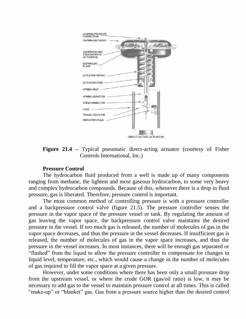
Figure 21.4 – Typical pneumatic direct-acting actuator (courtesy of Fisher
Controls International, Inc.)
Pressure Control
The hydrocarbon fluid produced from a well is made up of many components
ranging from methane, the lightest and most gaseous hydrocarbon, to some very heavy
and complex hydrocarbon compounds. Because of this, whenever there is a drop in fluid
pressure, gas is liberated. Therefore, pressure control is important.
The most common method of controlling pressure is with a pressure controller
and a backpressure control valve (figure 21.5). The pressure controller senses the
pressure in the vapor space of the pressure vessel or tank. By regulating the amount of
gas leaving the vapor space, the backpressure control valve maintains the desired
pressure in the vessel. If too much gas is released, the number of molecules of gas in the
vapor space decreases, and thus the pressure in the vessel decreases. If insufficient gas is
released, the number of molecules of gas in the vapor space increases, and thus the
pressure in the vessel increases. In most instances, there will be enough gas separated or
“flashed” from the liquid to allow the pressure controller to compensate for changes in
liquid level, temperature, etc., which would cause a change in the number of molecules
of gas required to fill the vapor space at a given pressure.
However, under some conditions where there has been only a small pressure drop
from the upstream vessel, or where the crude GOR (gas/oil ratio) is low, it may be
necessary to add gas to the vessel to maintain pressure control at all times. This is called
“make-up” or “blanket” gas. Gas from a pressure source higher than the desired control

pressure is routed to the vessel by a pressure controller that senses the vessel pressure
automatically, allowing either more or less gas to enter the vessel as required.
Figure 21.5 – Back pressure valve
Level Control
It is also necessary to control the gas/liquid interface or the oil/water interface in
process equipment. This is done with a level controller and liquid dump valve (figure 21.6).
The most common forms of level controllers are floats and displacers, although electronic
sensing devices can also be used. If the level begins to rise, the controller signals the liquid
dump valve to open and allow liquid to leave the vessel. If the level in the vessel begins to
fall, the controller signals the liquid dump valve to close and decrease the flow of liquid
from the vessel. In this manner the liquid dump valve is constantly adjusting its opening to
assure that the rate of liquid flowing into the vessel is matched by the rate out of the vessel.

Figure 21.6 – Level contoller
Temperature Control
The way in which the process temperature is controlled varies. In a heater a
temperature controller measures the process temperature and signals a fuel valve to let either
more or less fuel to the burner. In a heat exchanger the temperature controller could signal a
valve to allow more or less of the heating or cooling media to bypass the exchanger. Figure
21.7 shows the controlling the temperature inside storage tanks.
Figure 21.7 – Process oil flow diagram in SCADA

Flow Control
It is very rare that flow must be controlled in an oil field process. Normally, the
control of pressure, level, and temperature is sufficient. Occasionally, it is necessary to
assure that flow is split in some controlled manner between two process components in
parallel, or perhaps to maintain a certain critical flow through a component. This can
become a complicated control problem and must be handled on an individual basis.
REFERENCES:
1 Havard Devold Oil and gas production handbook. An Introduction to oil and gas
production. – 116 pages. ISBN 978-82-997886-1-8
2 oilandgasprocessing.blogpost.com
3 tuddp.utulsa.edu
4 gen-c.co.uk
5 marshbellofram. com
6 marshalcitra.worldpress.com

CONTENTS
THE LIST OF ABBREVIATIONS 3
LECTURE 1 CRUDE OIL COMPOSITION 4
LECTURE 2 PHYSICAL PROPERTIES OF CRUDE OIL 11
LECTURE 3 TWO-PHASE GAS–OIL SEPARATION 17
LECTURE 4 UPSTREAM PROCESS: COMMERCIAL TYPES OF
GAS–OIL SEPARATOR
23
LECTURE 5 THREE-PHASE SEPARATION 31
LECTURE 6 OIL EMULSION 37
LECTURE 7DEHYDRATION/TREATING PROCESSES 43
LECTURE 8 HEATING 47
LECTURE 9 CHEMICAL TREATMENT 53
LECTURE 10 ELECTRICAL AID 57
LECTURE 11 DESALTING OF CRUDE OIL 61
LECTURE 12 ELECTROSTATIC DESALTING 66
LECTURE 13 CRUDE OIL STABILIZATION AND SWEETENING 71
LECTURE 14 CRUDE OIL SWEETENING 78
LECTURE 15 STORAGE TANKS 81
LECTURE 16 PRODUCED WATER TREATMENT 88
LECTURE 17 OFFSHORE WATER DISPOSAL EQUIPMENT 98
LECTURE 18 SURFACE GATHERING SYSTEMS 103
LECTURE 19 CRUDE OIL AND NATURAL GAS METERING 106
LECTURE 20 POTENTIAL OPERATING PROBLEMS 109
LECTURE 21 CONTROLLING THE PROCESS 118
Copyright © 2022 FDOKUMEN