Image Processing
72
PROJECT DETAILS Project Name: Computer Vision and Image Processing Project Type: Microsoft Visual C++ Programming Project Performed At: Video-Data Analysis Systems Lab, Electro- Optical Tracking Division, Integrated Test Range, Chandipur, Defense Research and Development Organisation Project Performed By: Adarsh Ranjan, UG Student (B- Tech), Roll Number: 65907, VII Semester, Computer Science Engineering, National Institute Of Technology, Patna Project Supervised By: Dr. B.K. Das, Scientist ‘G’ Project Performed Under: Sri. S.K. Sahani, Scientist ‘E’ Project Guided By: Sri. Deepak Kumar Das, Scientist ‘D’ Sri. G. Adhikari, Scientist ‘D’ Sri. Darla Ranjeet, Scientist ‘C’
-
Upload
sorbonne-universites -
Category
Documents
-
view
0 -
download
0
Transcript of Image Processing
PROJECT DETAILS
Project Name: Computer Vision and Image Processing
Project Type: Microsoft Visual C++ Programming
Project Performed At: Video-Data Analysis Systems Lab, Electro-Optical Tracking Division,
Integrated Test Range, Chandipur, Defense Research and Development
Organisation
Project Performed By: Adarsh Ranjan, UG Student (B-Tech),
Roll Number: 65907, VII Semester, Computer Science Engineering, National Institute Of Technology,
Patna
Project Supervised By: Dr. B.K. Das, Scientist ‘G’
Project Performed Under: Sri. S.K. Sahani, Scientist ‘E’
Project Guided By: Sri. Deepak Kumar Das, Scientist‘D’
Sri. G. Adhikari, Scientist ‘D’ Sri. Darla Ranjeet, Scientist ‘C’
IMPORTANCE OF TRAINING
Undergoing a vocational training is an important aspectof education for any undergraduate student. The traininghelps us identify many things including the level ofknowledge that we have, or the importance of different partsof an organization or industry. The various aspects andbenefits of industrial training are described below: -
The first and foremost importance of training is togain knowledge about professional work that isundergone in an organization. It helps us gain a lotof information about how things are carried out insystem and in groups or teams. This is a majoraspect of knowing how to deal with any job in anyorganization. Most of the students now-a-days go forplacement and jobs immediately after theirgraduation is complete, basically because of theglobal demand for software engineers, but a lot ofus even face many difficulties in our jobs as wedon’t have much idea on working in a corporation.Thus, the industrial training gives an overall ideaon the job management part.
The second greatest benefit is the experience andscientific knowledge that we gain working with theprofessional engineers and scientists. No matter howgood grades we have in college, the education insidea classroom, lecture hall or a college laboratory isnot good enough to make us highly efficient in ourprofessional career or jobs. This efficiency canonly be increased by working with the scientists,watching their method of working and analyzing thereal time applications of different subjects andtopics.
Industrial Training also provides us an opportunityto observe and work with various sophisticatedsystems and complex machines that we do not have inour college laboratories. In this lab of Video DataAnalysis Systems (VDAS) itself, there are systemsand software that are meant for specified defenseresearch work only, and thus their use cannot be
2

discussed here. These are worth millions and evennot quite available for general purpose sale in themarket. These products are imported from variouscountries around the world.
Various other factors like aim for completion ofcertain tasks in given time, completing taskswithout much assistance, and getting to know aboutspecified researches that are so current and on-going that there isn’t even a single book that hasbeen written about it; all these sorts ofexperiences are a vital part and industrial trainingthat prepare us for our professional life afterstudies.
3
Defense Research and DevelopmentOrganisation
Introduction:
The Defence Research and DevelopmentOrganisation (DRDO) is one of Asia's largest defencecontractors and a leading aerospace manufacturer,headquartered in New Delhi, India. It was formed in 1958 bythe merger of Technical Development Establishment and theDirectorate of Technical Development and Production with theDefence Science Organisation.
DRDO was formed in 1958 from the amalgamation of thethen already functioning Technical Development Establishment(TDEs) of the Indian Army and the Directorate of TechnicalDevelopment & Production (DTDP) with the Defence ScienceOrganisation (DSO). DRDO was then a small organisation with10 establishments or laboratories. Over the years, it hasgrown multi-directionally in terms of the variety of subjectdisciplines, number of laboratories, achievements andstature.
Today, DRDO is a network of more than 50 laboratorieswhich are deeply engaged in developing defence technologiescovering various disciplines, like aeronautics, armaments,electronics, combat vehicles, engineering systems,instrumentation, missiles, advanced computing andsimulation, special materials, naval systems, life sciences,training, information systems and agriculture. Presently,the Organisation is backed by over 5000 scientists and about25,000 other scientific, technical and supporting personnel.Several major projects for the development of missiles,armaments, light combat aircrafts, radars, electronicwarfare systems etc are on hand and significant achievementshave already been made in several such technologies.
Project and Researches in the field of Computer Science:
DRDO has worked extensively high speed computing givenits ramifications for most of its defence projects. Theseinclude supercomputers for computational flow dynamics, todedicated microprocessor designs manufactured in India forflight controllers and the like, to high speed computing
4

boards built around Commercial Off The Shelf (COTS)components, similar to the latest trends in the defenceindustry.
Supercomputing: DRDO's ANURAG developed the PACE+Supercomputer for strategic purposes for supporting itsvarious programs. The initial version, as detailed in 1995,had the following specifications: The system delivered asustained performance of more than 960 Mflops (millionfloating operations per second) for computational fluiddynamics programs. Pace-Plus included 32 advanced computingnodes, each with 64 megabytes(MB) of memory that can beexpanded up to 256MB and a powerful front-end processorwhich is a hyperSPARC with a speed of 66/90/100 megahertz(MHz). Besides fluid dynamics, these high-speed computersystems were used in areas such as vision, medical imaging,signal processing, molecular modeling, neural networks andfinite element analysis. The latest variant of the PACEseries is the PACE ++, a 128 node parallel processingsystem. With a front-end processor, it has a distributedmemory and message passing system. Under Project Chitra, theDRDO is implementing a system with a computational speed of2-3 Teraflops utilizing commercial off the shelf componentsand the Open Source Linux Operating System.
Processors and other critical items: DRDO has developed arange of processors and application specific integratedcircuits for its critical projects. Many of these systemsare modular, in the sense that they can be reused acrossdifferent projects. These include "Pythagoras processor" toconvert Cartesian to polar coordinates, ANUCO, a floatingpoint coprocessor and several others, including the ANUPAMA32-bit processor, which is being used in several DRDOprojects.
Electronic components: One of the endeavours undertakenby the DRDO has been to create a substantial local designand development capability within India, both in the privateand public sectors. This policy has led to several hard toobtain or otherwise denied items, being designed andmanufactured in India. These include components such asradar subsystems (product specific travelling wave tubes) tocomponents necessary for electronic warfare and other
5

cutting edge projects. Today, there are a range of firmsacross India, which design and manufacture key componentsfor DRDO, allowing it to source locally for quite asubstantial chunk of its procurement. The DRDO has alsoendeavoured to use COTS (Commercial off the shelf)processors and technology, and follow Open Architecturestandards, wherever possible, in order to pre-emptobsolescence issues and follow industry practice. Onesignificant example is the development of an OpenArchitecture computer for the Light Combat Aircraft, basedon the PowerPC architecture and VME64 standard. The earlierMission computer utilizing Intel 486 DX chips has alreadyseen success, with variants being present on the Su-30 MKI,Jaguar and MiG-27 Upgrades for the Indian Air Force.
6

Integrated Test Range, ChandipurIntroduction:
The Integrated Test Range (ITR) is a research and experimental facility, which aims at providing user/project specified data for performance evaluation of different sortsof air-borne weapon systems and their corresponding vehicles.
Historical Background:
Integrated Test Range started as a project underIntegrated Guided Missile Development Programme (IGMDP) in1982, for setting up Range facilities for evaluating theperformance of rockets, missiles and other flight testvehicles. Starting out with the launch of the Trishul classof missiles, we went on to launch the historic AE-01 testvehicle, an achievement that put ITR on the World Map. Sincethen, we have taken up a number of challenges including theperformance evaluation of the multi-role, multi-capabilitymissile Akash, the Nag - anti tank missile, Prithvi - themost precise surface to surface missile with multiplewarhead capabilities and the large scale technologydemonstrator Agni. With our versatile technicalcapabilities, we even supported missions the ITR wasn'tdesigned for. For instance, the evaluation of Pilot-lessTarget Aircraft, the Pinaka Rocket and Drop Tests ofaltitude sensing warhead.
Electro-Optical Tracking DivisionIntroduction:
The Electro-Optical Tracking Division is a facilityunder ITR, which aims in using the Electro-Optical TrackingSystems (EOTS), to help in automatic target detection andtracking using the concept of image processing in the domainof Electro-Optics. The EOTD has been a part of ITR since thebeginning phases. EOTS provides user specified Trajectory
7
data in real time as well as off line for Weapon SystemTesting and Evaluation.
Labs under EOTD:
VDAS (Video Data Analysis Systems):- Performs the task of Trajectory Extraction From Video Data. My training was undertaken in this lab.
VLSI (Very Large Scale Integration): -Aims at developing embedded systems.
MSL (Multi-Media System Lab): - Aims at developing the multimedia products for specific use in tracking operations.
8

IMAGE 1.0 Introduction on Image:
An image (derived from Latin imago) is a two (or three)dimensional representation of a real world entity. Theentity may be an object, a person, or any other formperceivable by the human eye. The most common example ofimage can basically be seen as a two dimensional picturethat has similar appearance to some object (entity).
1.1 Characteristics of Image:
An image is mostly a two dimensional representation,but can also be found in three dimensional form such as astatue. They can be captured by artificial objects such ascameras, mirrors, lenses, telescopes, microscopes etc. andalso by natural objects such as an eye of an organism, orthe reflection in water.
The classification of image at an initial level can bedone according to their stability and lifetime. According tothis classification there are basically three types ofimage:1. Volatile Image : - A volatile image is one which does come
into existence in the real world, or which can beexperimentally observed, but exists only for a shortperiod of time. For Example: reflection of an object by amirror, a projection of a camera obscura, or a scenedisplayed by a cathode ray tube.
2. Fixed Image : - A fixed image is one which has existencein the real world and it stays for a considerably longamount of time in real world. A fixed image can also beknown as a hard-copy. It stays recorded on a fixedobject. Example: photograph, statue, painting, etc.
3. Virtual Image : - A Virtual Image is one that stays insideone’s mind, or something that a person remembers orimagines. The virtual images can become fixed, when theperson tries to analyze and jot it down, in forms ofgraph, painting, software data, etc.
Images can sequentially be shown with a high speed tothe human eye. If the speed is more than a certain limit,then the human brain cannot distinguish it as distinct
9
images. In this case the mind merges one image to anotherthus viewing it as a moving image or a movie. The concept ofmoving images have been successful in thoroughly capturingreal life or worldly phenomenon and thus are usedeverywhere.
Images have changed the very way of life. As human eyeis the most powerful and fastest way of communicating, thusimages have influenced every part of the human society,being it graphs and diagrams in the scientific community, orpaintings, photographs and sculptures in the art community,or various fields of electronics and information technology.
2.0 Digitization
Digitizing or digitization is the representation of anobject, image, sound, document or a signal (usually ananalog signal) by a discrete set of its points or samples.The result is called digital representation or, more specifically,a digital image, for the object, and digital form, for the signal.Strictly speaking, digitizing means simply capturing ananalog signal in digital form. For a document the term meansto trace the document image or capture the "corners" wherethe lines end or change direction.
McQuail identifies the process of digitization havingimmense significance to the computing ideals as it "allowsinformation of all kinds in all formats to be carried withthe same efficiency and also intermingled".
2.1 Process of Digitization
The term digitization is often used when diverse forms ofinformation, such as text, sound, image or voice, areconverted into a single binary code. Digital informationexists as one of two digits, either 0 or 1. These are knownas bits (a contraction of binary digits) and the sequences of0s and 1s that constitute information are called bytes.
Analog signals are continuously variable, both in the numberof possible values of the signal at a given time, as well asin the number of points in the signal in a given period oftime. However, digital signals are discrete in both of those
10

respects – generally a finite sequence of integers –therefore a digitization can only ever be an approximationof the signal it represents.
2.2 Digitization occurs in two parts:
Discretization: The reading of an analog signal A, and, atregular time intervals (frequency), sampling the value ofthe signal at the point. Each such reading is called asample and may be considered to have infinite precision atthis stage. Quantization: Samples are rounded to a fixed set of numbers(such as integers), a process known as quantization.
In general, these can occur at the same time, thoughthey are conceptually distinct.A series of digital integerscan be transformed into an analog output that approximatesthe original analog signal. Such a transformation is calleda DA conversion. The sampling rate and the number of bitsused to represent the integers combine to determine howclose such an approximation to the analog signal adigitization will be.
a = b + c
2.3 Examples Of Digitization
The term is often used to describe the scanning ofanalog sources (such as printed photos or taped videos) intocomputers for editing, but it also can refer to audio (wheresampling rate is often measured in kilohertz) and texturemap transformations. In this last case, as in normal photos,sampling rate refers to the resolution of the image, oftenmeasured in pixels per inch.
Digitizing is the primary way of storing images in aform suitable for transmission and computer processing,whether scanned from two-dimensional analog originals orcaptured using an image sensor-equipped device such as adigital camera, tomographical instrument such as a CATscanner, or acquiring precise dimensions from a real-worldobject, such as a car, using a 3D scanning device.
11
Digitizing is central to making a digitalrepresentations of geographical features, using raster orvector images, in a geographic information system, i.e., thecreation of electronic maps, either from variousgeographical and satellite imaging (raster) or by digitizingtraditional paper maps (vector).
"Digitization" is also used to describe the process ofpopulating databases with files or data. While this usage istechnically inaccurate, it originates with the previously-proper use of the term to describe that part of the processinvolving digitization of analog sources such as printedpictures and brochures before uploading to target databases.
Digitizing may also used in the field of apparel, wherean image may be recreated with the help of embroiderydigitizing software tools and saved as embroidery machinecode. This machine code is fed into an embroidery machineand applied to the fabric. The most supported format is DSTfile.
12

DIGITAL IMAGE
3.0 Introduction:
A digital image is a representation of a two-dimensional image in any electronic system (embedded or not)using ones and zeros (binary). If the image resolution isfixed it is called a vector type image, if is not fixed,then the image is termed as a raster type image (also calledbitmap images).
Digital Images have been an important part of computerdevelopment. As history tells us the earliest computermodels were operated by complex program codes andalgorithms. Thus its use was limited to a handful ofmathematicians and scientists. But after the advent ofdigital image handling, the programs were sent back to coremachines and the program codes were connected to the uservia a set of symbols and simple command sets. This furtherled to development of command buttons, switches andpictorial representations. And now every software in moderndays is built keeping in mind the simplest interaction withthe user. Because of these advantages, even the common manstarted using computers and thus leading to development ofthe entire human civilization.
13
3.1 History of Digital Image:
The first computer-generated digital images wereproduced in the early 1960’s, alongside development of thespace program and in medical research. Projects at the JetPropulsion Laboratory, MIT, Bell Laboratories and theUniversity Of Maryland, among others, used digital images toadvance satellite imagery, wire-photo standards conversion,medical imaging, videophone technology, characterrecognition, and photo enhancement.
Rapid advances in digital imaging began with theintroduction of microprocessors in the early 1970s,alongside progress in related storage and displaytechnologies. The invention of computerised axial tomography(CAT scanning), using x-rays to produce a digital image of a"slice" through a three-dimensional object, was of greatimportance to medical diagnostics. As well as origination ofdigital images, digitization of analog images allowed theenhancement and restoration of archaeolgical artifacts andbegan to be used in fields as diverse as nuclear medicine,astronomy, law enforcement, defence and industry.
Advances in microprocessor technology paved the way forthe development and marketing of charge-coupled devices(CCDs) for use in a wide range of image capture devices andgradually displaced the use of analog film and tape inphotography and videography towards the end of the 20thcentury. The computing power necessary to process digitalimage capture also allowed computer-generated digital imagesto achieve a level of refinement close to photorealism.
3.2 Types of Digital Images:
The digital images can basically be divided into twoparts:
1) Vector Images: These are images that have a fixed imageresolution, ie-their resolution is fixed and cannot bedynamically allocated.Vector Images can be created fromscratch with illustration software, or by converting araster image to vector form.
14
Often both raster and vector elements will be combinedin one image, for example in the case of billboard withtext (which is in vector form) and photographs (which isin raster form).
2) Raster Images: -These images have a finite set ofdigital values, called picture elements or pixels. Pixelsare the smallest invidual elements of an image, holdingleast possible values(quantized) that represent variousinformation about the different colours and theirbrightness at the specific point.
3.3 Desciption of Rastor Image Type:
The pixels of an image are stored in computer meory asa raster image or raster map, a two dimensional array ofsmall integers.These values are stored in the imagefiles(compressed or normally) according to theirspecification and nature of the particular file format orextension.
Raster images can be created by a variety of inputdevices and techniques, such as digital cameras, scanners,coordinate-measuring machines, seismographic profiling,airborne radar, and more.They all save the image as adigital signature or data according to their theirrespective format descriptions. They can also be synthesizedfrom arbitrary non-image data, such as mathematicalfunctions or three-dimensional geometric models. Thealgorithms and complex mathematical functions are a basisfor the various manipulations done in the existing image oreven used for creating an entirely different graphs andimages. The three dimesional geometric model covers a majorarea of computer graphics designing. Both af these are abasis for the field of digital image processing.
3.3.1 Rastor Image Types:
The rastor image type as discussed earlir is made up ofpixels. A pixel represents one single(smallest) part of theimage and the entire image can only be seen when all pixelsare placed in their correct position. A pixel of a specificposition gives information on the colours representing
15
that position in the image and the magnitude in which thecolours are present. It may have a single value or a numberof values according to the image type.
Digital Images can be clssified according to theirpixel values in the following types:
Binary GrayScale
Color
False-Color
Multi-Spectral
Thematic
Picture Function
The Binary Image Format is the simplest and smallest ofall digital images. It consists of only two pixel values(eg:1 and 0), that is in the binary image format the values ofeach position of the image can have only two values for itscolour desciption, like 1 and 0. The pixel cannot containany other number or symbol.Thus it is named ‘Binary’(meaningtwo).
In the GrayScale the pixel may contain two or morevalues but these values can only be for one colour(mostcommonly grey), that is the pixel may have values rangingfrom 0 to 255, but it will only give the density in whichthe grey colour in present in that pixel(for example 0-white, 255-black). No other colour is present.The grayscaleis a little more bigger in size than a binary image.
The Color Image Format consists of pixel values formore than one color. The basic example is that its pixelwill contain three values representing three colors, Red,Green and Blue. These three colours are basic and can buildany other colours by their combination, thus they are mostlyused.These images have relatively much higher file size thangrayscale images.
16
All Other formats are mostly similar to Color ImageFormats, but have various other features like extra colourvalues, compression algorithms, representation techniques,etc. The term digital image is also applied to dataassociated to points scattered over a three dimensionalregion, such as produced by tomographic equipment. In thatcase, each datum is called a voxel.
4.0 General Image Description
A typical image file consists of a Header and a Datapart. The Header part contains information about the imageat various points(offsets). The header information also actsas a signature of the image and can be used further foradvanced image manipulation and processing.
The Data part consists of the series of array stored inthe registers defining different values of colour at diffentpoints of the image. For our ease we divide the image intopixels which is like the quantum part of an image. The pixelvalue for each point for an image is defined.
A typical pixel value can be defined accordingly forgrayscale and colour image. The grayscale value basicallyhas only 8bits, which gives us 2^8 different values of apixel, which most commonly is 0-255, in which 0 representsblack and 255 represents white, whereas the rest othervalues are intermediate from black to white.
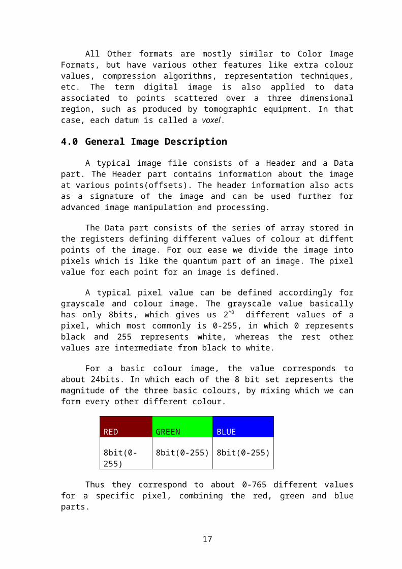
For a basic colour image, the value corresponds toabout 24bits. In which each of the 8 bit set represents themagnitude of the three basic colours, by mixing which we canform every other different colour.
RED GREEN BLUE
8bit(0-255)
8bit(0-255) 8bit(0-255)
Thus they correspond to about 0-765 different valuesfor a specific pixel, combining the red, green and blueparts.
17

This is the basic colour combination technique used.Besides this there are various other factors to be takeninto account which has been developed, like false colouring,applying various algorithms for image handling andprocessing, etc.
The Image File Formats (Extensions)
5.0 Introduction:
The digital images have a long history of theirdifferent types of existence. As discussed before the imageswere first taken from a real source(like an analogphotograph), and then digitized by converting them to adigital data which could be further processed to form anoutput signal which can then be displayed in a device likemonitor. The aim was to produce an output in the monitorthat must be similar to that of the original image from thereal source. This whole process is called the digitizationof an image. It basically involves in taking any image andconverting it into pixels or parts which have values indigital form.
The digital images were very frequently used soonafter their development. The use grew on a large extent. Asthe digital images had the advantage of their storage, i.e.-now people could keep images in a hard-drive instead of thenegatives which were very hard to be safely kept and evensomewhat hazardous or photos which had to be kept in glassframes or albums to protect from getting damaged. Thusbecause of its security, compact size, method of storage andalmost no risk of tampering, the digital images became themost efficient way of storing images in the modern days.
But as the demand grew, so did the flaws. The digitalimages were further questioned for their good quality andvarious other safety measures. Thus the engineers designedvarious formats of images. Taking into account that thequality was not to be compromised the scientists devisedsome image formats which would take up a lot of data for onepixel. This was beneficial for the quality, but
18
consequtively the quantity was compromised. As the pixelinformation grew, the size of a single image became verylarge. Thus the problem of storage came into being.
When the problem of storage space grew, two majordevelopments took place. The first was the development oflarger storage devices, with almost same physical volume.This was quite helpful, but did not solve the problemtotally. Thus the other method was undertaken. Thescientists worked on developing efficient file formats.Using complex mathematical functions and thus developingvarious algorithms, various types of compression techniquescame into being. Using these techniques and otherinformations on digitization, the scientists from all overthe world developed various digital image file formats.These formats had their own specifications, qualities anddrawbacks, according to which they were accepted andrejected, in various field and areas of image handling.
5.1 Types of Digital Image File Formats(RASTER TYPE):
The various types of file formats(Raster Type) aregiven below: -
1) Bitmap Images (*.bmp): - These formats store images asbitmaps(also known as pixmaps). They map up the entire imageusing data bits from pixel values.These are of basicallyfour types:-
a) Monochrome Bitmap(*.bmp, *.dib)b) 16 Color Bitmap(*.bmp, *.dib)
c) 256 Color Bitmap(*.bmp, *.dib)
d) 24-bit Bitmap(*.bmp, *.dib)
*Bitmap images have two classes- Device Independent Bitmaps(DIB) andDevice Dependent Bitmap(DDB). We will discuss them later.
2) JPEG/JFIF format(*.jpg, *.jpeg, *.jpe, *.jfif):JPEG(Joint Photographic Experts Group) is a compressionmethod, JPEG compressed images are usually stored in the
19

JFIF(JPEG File Interchange Format) file format. JPEGcompression is (in most cases) lossy compression. TheJPEG/JFIF filename extension in DOS(Disk Operating System)is JPG(other operating systems may use JPEG). Nearly everydigital camera can save images in the JPEG/JFIF format,which supports 8 bits per color(red, green, blue) for atotal 24 bit total, producing relatiely small files. Whennot too great, the compression does not noticeably detractfrom image’s quality, but JPEG files suffer generationaldegradation when repeatedly edited and saved. The JPEG/JFIFformat also is used as image compression algorithm in manyAdobe PDF Files.
3) Exif format(*.Exif): The Exif(Exchangeable image fileformat) format is a file standard similar to the JFIF formatwith TIFF extension. It is incorporated in the JPEG writingsoftware used in most cameras. Its purpose is to record andto standardize the exchange of images with image-metadatabetween cameras and editing and viewing software. Themetadata are recorded for individual images and include suchthings as camera settings, time and date, shutter speed,exposure, image size, compression, name of camera, colorinformation, etc. When images are viewed or edited by imageediting software, all of this image information can bedisplayed.
4) TIFF(*.TIF): The TIFF(Tagged Image File Format) formatis a flexible format that normally saves 8 bits or 16 bitsper color(red, green and blue) for 24-bit and 48-bit totals,respectively, usually using either the TIFF or TIF filenameextension. TIFF's flexibility can be both an advantage anddisadvantage, since readers that read every type of TIFFfile does not exist. TIFFs can be lossy and lossless; someoffer relatively good lossless compression for bi-level(black&white) images. Some digital cameras can save in TIFFformat, using the LZW compression algorithm for losslessstorage. TIFF image format is not widely supported by webbrowsers. TIFF remains widely accepted as a photograph filestandard in the printing business. TIFF can handle device-specific color spaces, such as the CMYK defined by aparticular set of printing press inks. OCR (OpticalCharacter Recognition) software packages commonly generate
20
some (often monochromatic) form of TIFF image for scannedtext pages.
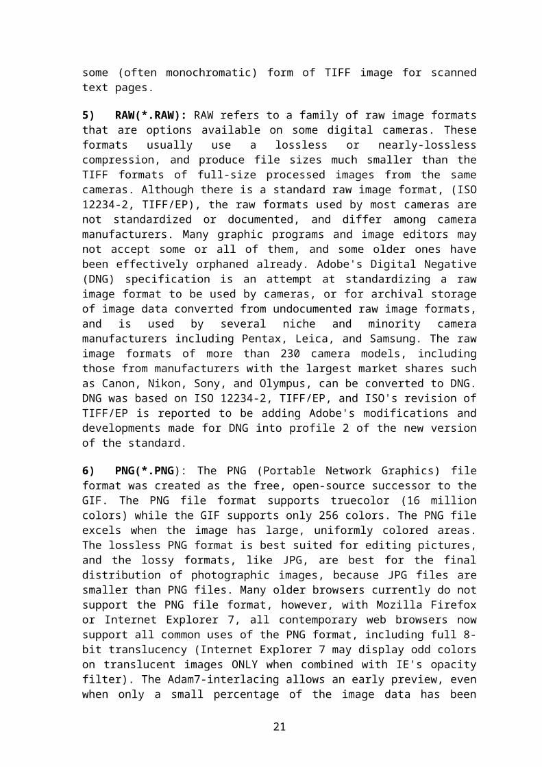
5) RAW(*.RAW): RAW refers to a family of raw image formatsthat are options available on some digital cameras. Theseformats usually use a lossless or nearly-losslesscompression, and produce file sizes much smaller than theTIFF formats of full-size processed images from the samecameras. Although there is a standard raw image format, (ISO12234-2, TIFF/EP), the raw formats used by most cameras arenot standardized or documented, and differ among cameramanufacturers. Many graphic programs and image editors maynot accept some or all of them, and some older ones havebeen effectively orphaned already. Adobe's Digital Negative(DNG) specification is an attempt at standardizing a rawimage format to be used by cameras, or for archival storageof image data converted from undocumented raw image formats,and is used by several niche and minority cameramanufacturers including Pentax, Leica, and Samsung. The rawimage formats of more than 230 camera models, includingthose from manufacturers with the largest market shares suchas Canon, Nikon, Sony, and Olympus, can be converted to DNG.DNG was based on ISO 12234-2, TIFF/EP, and ISO's revision ofTIFF/EP is reported to be adding Adobe's modifications anddevelopments made for DNG into profile 2 of the new versionof the standard.
6) PNG(*.PNG): The PNG (Portable Network Graphics) fileformat was created as the free, open-source successor to theGIF. The PNG file format supports truecolor (16 millioncolors) while the GIF supports only 256 colors. The PNG fileexcels when the image has large, uniformly colored areas.The lossless PNG format is best suited for editing pictures,and the lossy formats, like JPG, are best for the finaldistribution of photographic images, because JPG files aresmaller than PNG files. Many older browsers currently do notsupport the PNG file format, however, with Mozilla Firefoxor Internet Explorer 7, all contemporary web browsers nowsupport all common uses of the PNG format, including full 8-bit translucency (Internet Explorer 7 may display odd colorson translucent images ONLY when combined with IE's opacityfilter). The Adam7-interlacing allows an early preview, evenwhen only a small percentage of the image data has been
21

transmitted. PNG, an extensible file format for thelossless, portable, well-compressed storage of rasterimages. PNG provides a patent-free replacement for GIF andcan also replace many common uses of TIFF. Indexed-color,grayscale, and truecolor images are supported, plus anoptional alpha channel. PNG is designed to work well inonline viewing applications, such as the World Wide Web, soit is fully streamable with a progressive display option.PNG is robust, providing both full file integrity checkingand simple detection of common transmission errors. Also,PNG can store gamma and chromaticity data for improved colormatching on heterogeneous platforms. Some programs do nothandle PNG gamma correctly, which can cause the images to besaved or displayed darker than they should be. Animatedformats derived from PNG are MNG and APNG. The latter issupported by FireFox and Mozilla and is backwards compatiblewith PNG.
7) GIF(*.GIF): GIF (Graphics Interchange Format) islimited to an 8-bit palette, or 256 colors. This makes theGIF format suitable for storing graphics with relatively fewcolors such as simple diagrams, shapes, logos and cartoonstyle images. The GIF format supports animation and is stillwidely used to provide image animation effects. It also usesa lossless compression that is more effective when largeareas have a single color, and ineffective for detailedimages or dithered images.
8) BMP(*.BMP): The BMP file format (Windows bitmap)handles graphics files within the Microsoft Windows OS.Typically, BMP files are uncompressed, hence they are large;the advantage is their simplicity and wide acceptance inwindows programs.
9) PPM, PGM, PBM, PNM: Netpbm format is a family includingthe portable pixmap file format (PPM), the portable graymapfile format (PGM) and the portable bitmap file format (PBM).These are either pure ASCII files or raw binary files withan ASCII header that provide very basic functionality andserve as a lowest-common-denominator for converting pixmap,graymap, or bitmap files between different platforms.Several applications refer to them collectively as the PNMformat(Portable Any Map).
22

Other image file formats of raster type include:
TGA (TARGA) ILBM (InterLeaved BitMap) PCX (Personal Computer eXchange) ECW (Enhanced Compression Wavelet) IMG (ERDAS IMAGINE Image) SID (multiresolution seamless image database, MrSID) CD5 (Chasys Draw Image) FITS (Flexible Image Transport System) PGF (Progressive Graphics File)
5.2 Types of Digital Image File Formats(VECTOR TYPE):
As opposed to the raster image formats above (where thedata describes the characteristics of each individualpixel), vector image formats contain a geometric descriptionwhich can be rendered smoothly at any desired display size.
Vector file formats can contain bitmap data as well. 3Dgraphic file formats are technically vector formats withpixel data texture mapping on the surface of a vectorvirtual object, warped to match the angle of the viewingperspective.
At some point, all vector graphics must be rasterized inorder to be displayed on digital monitors. However, vectorimages can be displayed with analog CRT technology such asthat used in some electronic test equipment, medicalmonitors, radar displays, laser shows and early video games.Plotters are printers that use vector data rather than pixeldata to draw graphics.
The various types of Image file formats(Vector Type) aregiven below: -
1) CGM (Computer Graphics Metafile) is a file formatfor 2D vector graphics, raster graphics, and text, and isdefined by ISO/IEC 8632. All graphical elements can bespecified in a textual source file that can be compiled intoa binary file or one of two text representations. CGMprovides a means of graphics data interchange for computerrepresentation of 2D graphical information independent from
23
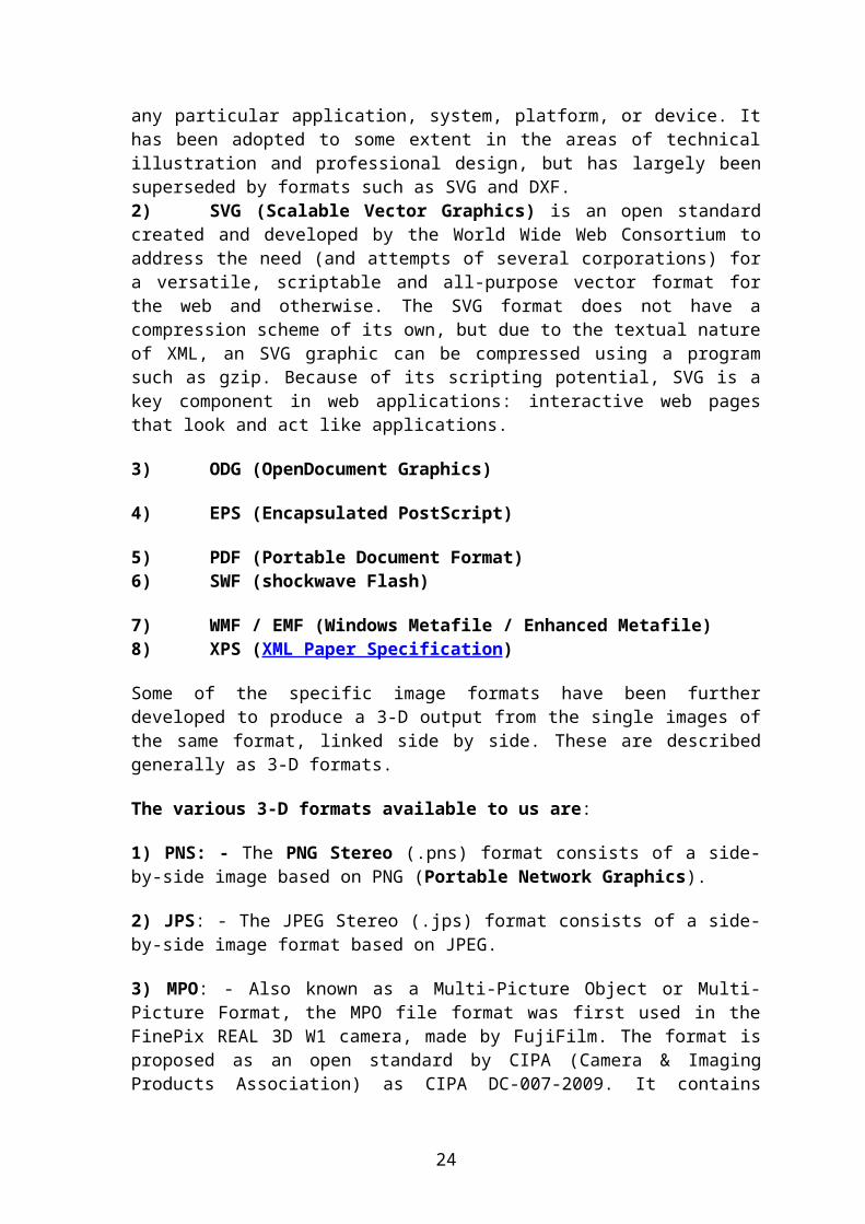
any particular application, system, platform, or device. Ithas been adopted to some extent in the areas of technicalillustration and professional design, but has largely beensuperseded by formats such as SVG and DXF.2) SVG (Scalable Vector Graphics) is an open standardcreated and developed by the World Wide Web Consortium toaddress the need (and attempts of several corporations) fora versatile, scriptable and all-purpose vector format forthe web and otherwise. The SVG format does not have acompression scheme of its own, but due to the textual natureof XML, an SVG graphic can be compressed using a programsuch as gzip. Because of its scripting potential, SVG is akey component in web applications: interactive web pagesthat look and act like applications.
3) ODG (OpenDocument Graphics)
4) EPS (Encapsulated PostScript)
5) PDF (Portable Document Format) 6) SWF (shockwave Flash)
7) WMF / EMF (Windows Metafile / Enhanced Metafile) 8) XPS (XML Paper Specification)
Some of the specific image formats have been furtherdeveloped to produce a 3-D output from the single images ofthe same format, linked side by side. These are describedgenerally as 3-D formats.
The various 3-D formats available to us are:
1) PNS: - The PNG Stereo (.pns) format consists of a side-by-side image based on PNG (Portable Network Graphics).
2) JPS: - The JPEG Stereo (.jps) format consists of a side-by-side image format based on JPEG.
3) MPO: - Also known as a Multi-Picture Object or Multi-Picture Format, the MPO file format was first used in theFinePix REAL 3D W1 camera, made by FujiFilm. The format isproposed as an open standard by CIPA (Camera & ImagingProducts Association) as CIPA DC-007-2009. It contains
24

multiple JPEG images with respective thumbnails andmetadata.
25
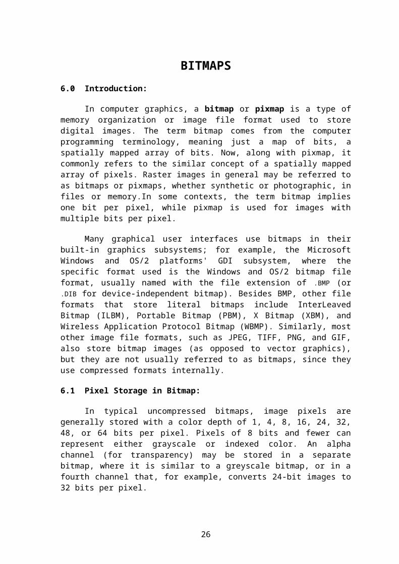
BITMAPS6.0 Introduction:
In computer graphics, a bitmap or pixmap is a type ofmemory organization or image file format used to storedigital images. The term bitmap comes from the computerprogramming terminology, meaning just a map of bits, aspatially mapped array of bits. Now, along with pixmap, itcommonly refers to the similar concept of a spatially mappedarray of pixels. Raster images in general may be referred toas bitmaps or pixmaps, whether synthetic or photographic, infiles or memory.In some contexts, the term bitmap impliesone bit per pixel, while pixmap is used for images withmultiple bits per pixel.
Many graphical user interfaces use bitmaps in theirbuilt-in graphics subsystems; for example, the MicrosoftWindows and OS/2 platforms' GDI subsystem, where thespecific format used is the Windows and OS/2 bitmap fileformat, usually named with the file extension of .BMP (or.DIB for device-independent bitmap). Besides BMP, other fileformats that store literal bitmaps include InterLeavedBitmap (ILBM), Portable Bitmap (PBM), X Bitmap (XBM), andWireless Application Protocol Bitmap (WBMP). Similarly, mostother image file formats, such as JPEG, TIFF, PNG, and GIF,also store bitmap images (as opposed to vector graphics),but they are not usually referred to as bitmaps, since theyuse compressed formats internally.
6.1 Pixel Storage in Bitmap:
In typical uncompressed bitmaps, image pixels aregenerally stored with a color depth of 1, 4, 8, 16, 24, 32,48, or 64 bits per pixel. Pixels of 8 bits and fewer canrepresent either grayscale or indexed color. An alphachannel (for transparency) may be stored in a separatebitmap, where it is similar to a greyscale bitmap, or in afourth channel that, for example, converts 24-bit images to32 bits per pixel.
26

The bits representing the bitmap pixels may be packedor unpacked (spaced out to byte or word boundaries),depending on the format or device requirements. Depending onthe color depth, a pixel in the picture will occupy at leastn/8 bytes, where n is the bit depth.
For an uncompressed, packed within rows, bitmap, suchas is stored in Microsoft DIB or BMP file format, or inuncompressed TIFF format, a lower bound on storage size fora n-bit-per-pixel (2n colors) bitmap, in bytes, can becalculated as:
size = width • height • n/8, where height and width aregiven in pixels.
In the formula above, header size and color palettesize, if any, are not included. Due to effects of rowpadding to align each row start to a storage unit boundarysuch as a word, additional bytes may be needed.
THE WINDOWS BITMAP IMAGE7.0 Introduction:
Microsoft has defined a particular representation ofcolor bitmaps of different color depths, as an aid toexchanging bitmaps between devices and applications with avariety of internal representations. They called thesedevice-independent bitmaps or DIBs, and the file format forthem is called DIB file format or BMP file format. Accordingto Microsoft support:
A device-independent bitmap (DIB) is a format used todefine device-independent bitmaps in various colorresolutions. The main purpose of DIBs is to allow bitmapsto be moved from one device to another (hence, the device-independent part of the name). A DIB is an external format,in contrast to a device-dependent bitmap, which appears in
27
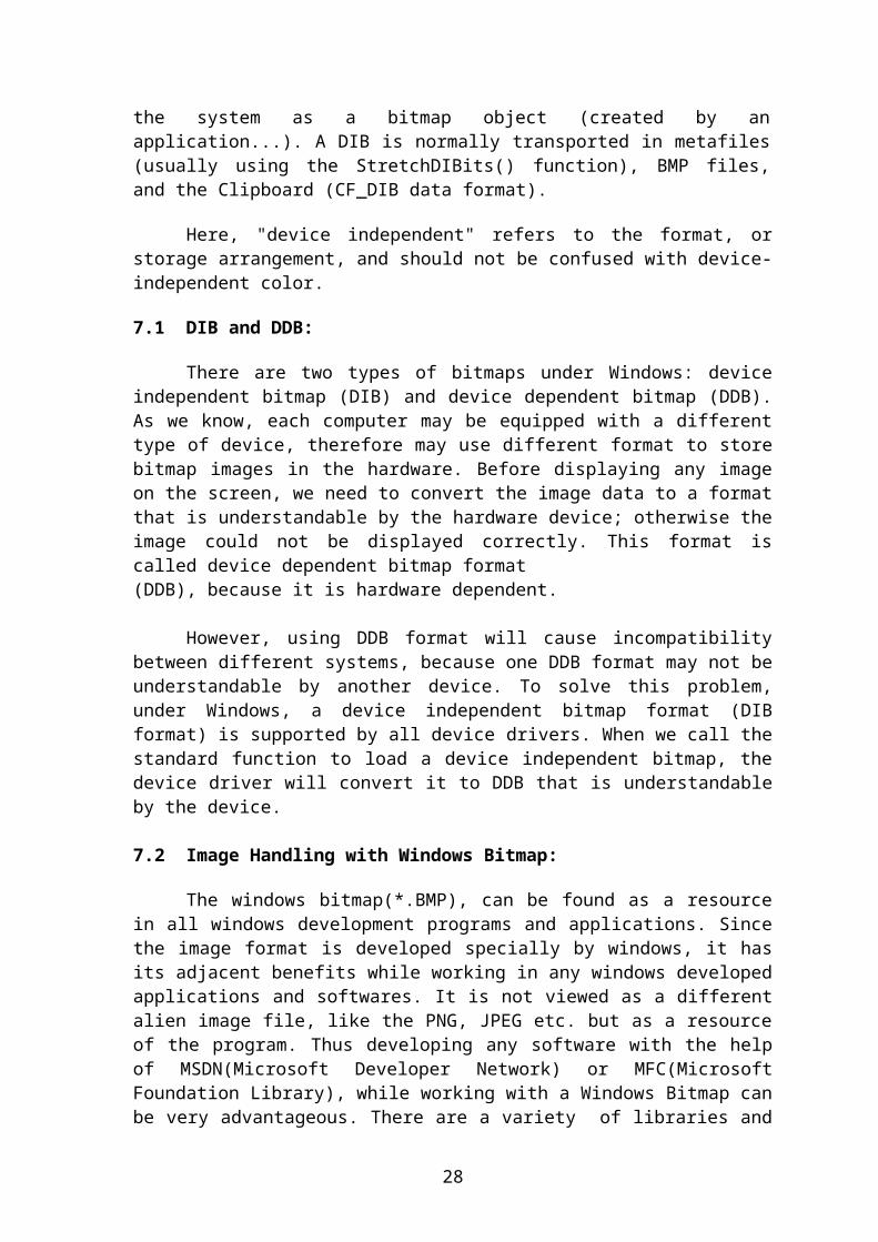
the system as a bitmap object (created by anapplication...). A DIB is normally transported in metafiles(usually using the StretchDIBits() function), BMP files,and the Clipboard (CF_DIB data format).
Here, "device independent" refers to the format, orstorage arrangement, and should not be confused with device-independent color.
7.1 DIB and DDB:
There are two types of bitmaps under Windows: deviceindependent bitmap (DIB) and device dependent bitmap (DDB).As we know, each computer may be equipped with a differenttype of device, therefore may use different format to storebitmap images in the hardware. Before displaying any imageon the screen, we need to convert the image data to a formatthat is understandable by the hardware device; otherwise theimage could not be displayed correctly. This format iscalled device dependent bitmap format(DDB), because it is hardware dependent.
However, using DDB format will cause incompatibilitybetween different systems, because one DDB format may not beunderstandable by another device. To solve this problem,under Windows, a device independent bitmap format (DIBformat) is supported by all device drivers. When we call thestandard function to load a device independent bitmap, thedevice driver will convert it to DDB that is understandableby the device.
7.2 Image Handling with Windows Bitmap:
The windows bitmap(*.BMP), can be found as a resourcein all windows development programs and applications. Sincethe image format is developed specially by windows, it hasits adjacent benefits while working in any windows developedapplications and softwares. It is not viewed as a differentalien image file, like the PNG, JPEG etc. but as a resourceof the program. Thus developing any software with the helpof MSDN(Microsoft Developer Network) or MFC(MicrosoftFoundation Library), while working with a Windows Bitmap canbe very advantageous. There are a variety of libraries and
28

classes built especially to help the user in working with awindows bitmap image.
But as we use a specific extension type we start facingthe disadvantages to it simultaneously. There are severaldisadvantages of windows bitmap, and the most prominent ofit is the file size. The windows bitmap is a non-compressedimage format, thus taking a huge amount of space. It doesnot contain any mechanism to process a compression algorithmif necessary(as available in JPEG). Even its formatproperties change when we use it in different OperatingSystems. Thus it may not appear to be a problem for commonuse but it creates large problems while its use in advancedsoftware developments. Even while creating a web-based pageor program we cannot include windows bitmap format becauseit allocates large space, which will create problem foruploading and downloading pages.
7.3 Pixel Storage in Windows Bitmap:
In uncompressed BMP files, and many other bitmap fileformats, image pixels are stored with a color depth of 1, 4,8, 16, 24, or 32 bits per pixel (BPP). Images of 8 bits andfewer can be either grayscale or indexed color. An alphachannel (for transparency) may be stored in a separate file,where it is similar to a grayscale image, or in a fourthchannel that converts 24-bit images to 32 bits per pixel.
Uncompressed bitmap files (such as BMP) are typically muchlarger than compressed (with any of various methods) imagefile formats for the same image. For example, the 1058×1058Wikipedia logo, which occupies about 271 KB in the losslessPNG format, takes about 3358 KB as a 24-bit BMP file.Uncompressed formats are generally unsuitable fortransferring images on the Internet or other slow orcapacity-limited media.
The bits representing the bitmap pixels are packed withinrows. Depending on the color depth, a pixel in the picturewill occupy at least n/8 bytes (n is the bit depth, since 1byte equals 8 bits). The approximate size for a n-bit (2n
colors) BMP file in bytes can be calculated, including theeffect of starting each word on a 32-bit dword boundary, as:
29

, for BPP ≤ 8
Height and Width are given in pixels.
In the formula above, 54 is the size of the headers in thepopular Windows V3 BMP version (14-byte BMP file header plus40-byte DIB V3 header); some other header versions will belarger or smaller than that, as described in tables below.And is the size of the color palette; this size is anapproximation, as the color palette size will be bytesin the OS/2 V1 version, and some other versions mayoptionally define only the number of colors needed by theimage, potentially fewer than 2n . Only files with 8 orfewer bits per pixel use a palette; for 16-bit (or higher)bitmaps, omit the palette part from the size calculation:
, for BPP > 8.
7.4 Description of the Windows Bitmap Image:
The Windows Bitmap Image file can usually contains fourblocks of data: -
1) BMP File Header: Stores general information about the BMPfile.
2) Bitmap Information (DIB header): Stores detailedinformation about the bitmap image.
3) Color Palette: Stores the definition of the colors beingused for indexed color bitmaps.
4) Bitmap Data: Stores the actual image, pixel by pixel.
A BMP File Headers are a part of an image structurewhich displays a variety of information about the file, likethe size of an image, its color type, its width, height etc.These all informations are stored at certainpoints(offsets), in the file structures and can be further
30
used to access and control image properties and modify itaccording to will.
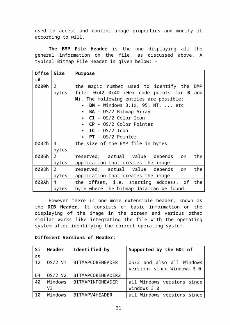
The BMP File Header is the one displaying all thegeneral information on the file, as discussed above. Atypical Bitmap File Header is given below: -
Offset#
Size Purpose
0000h 2bytes
the magic number used to identify the BMPfile: 0x42 0x4D (Hex code points for B andM). The following entries are possible:
BM - Windows 3.1x, 95, NT, ... etc BA - OS/2 Bitmap Array CI - OS/2 Color Icon CP - OS/2 Color Pointer IC - OS/2 Icon PT - OS/2 Pointer
0002h 4bytes
the size of the BMP file in bytes
0006h 2bytes
reserved; actual value depends on theapplication that creates the image
0008h 2bytes
reserved; actual value depends on theapplication that creates the image
000Ah 4bytes
the offset, i.e. starting address, of thebyte where the bitmap data can be found.
However there is one more extensible header, known asthe DIB Header. It consists of basic information on thedisplaying of the image in the screen and various othersimilar works like integrating the file with the operatingsystem after identifying the correct operating system.
Different Versions of Header:
Size
Header Identified by Supported by the GDI of
12 OS/2 V1 BITMAPCOREHEADER OS/2 and also all Windowsversions since Windows 3.0
64 OS/2 V2 BITMAPCOREHEADER240 Windows
V3BITMAPINFOHEADER all Windows versions since
Windows 3.010 Windows BITMAPV4HEADER all Windows versions since
31
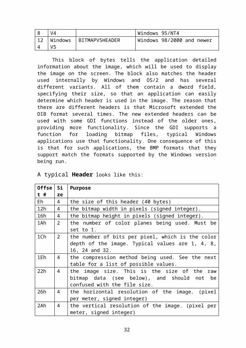
8 V4 Windows 95/NT4124
WindowsV5
BITMAPV5HEADER Windows 98/2000 and newer
This block of bytes tells the application detailedinformation about the image, which will be used to displaythe image on the screen. The block also matches the headerused internally by Windows and OS/2 and has severaldifferent variants. All of them contain a dword field,specifying their size, so that an application can easilydetermine which header is used in the image. The reason thatthere are different headers is that Microsoft extended theDIB format several times. The new extended headers can beused with some GDI functions instead of the older ones,providing more functionality. Since the GDI supports afunction for loading bitmap files, typical Windowsapplications use that functionality. One consequence of thisis that for such applications, the BMP formats that theysupport match the formats supported by the Windows versionbeing run.
A typical Header looks like this:
Offset #
Size
Purpose
Eh 4 the size of this header (40 bytes)12h 4 the bitmap width in pixels (signed integer).16h 4 the bitmap height in pixels (signed integer).1Ah 2 the number of color planes being used. Must be
set to 1.1Ch 2 the number of bits per pixel, which is the color
depth of the image. Typical values are 1, 4, 8,16, 24 and 32.
1Eh 4 the compression method being used. See the nexttable for a list of possible values.
22h 4 the image size. This is the size of the rawbitmap data (see below), and should not beconfused with the file size.
26h 4 the horizontal resolution of the image. (pixelper meter, signed integer)
2Ah 4 the vertical resolution of the image. (pixel permeter, signed integer)
32

2Eh 4 the number of colors in the color palette, or 0to default to 2n.
32h 4 the number of important colors used, or 0 whenevery color is important; generally ignored.
Note: The image size field can be 0 for BI_RGB bitmaps.
THE PNG IMAGE8.0 Introduction:
Portable Network Graphics (PNG) is a bitmapped imageformat that employs lossless data compression. PNG wascreated to improve upon and replace GIF (GraphicsInterchange Format) as an image-file format not requiring apatent license. It is pronounced /ˈpɪŋ/ ping, or pee-en-gee.The PNG acronym is optionally recursive, unofficiallystanding for PNG's Not GIF.
PNG supports palette-based (palettes of 24-bit RGB or32-bit RGBA colors), greyscale, RGB, or RGBA images. PNG wasdesigned for transferring images on the Internet, not forprint graphics, and so does not support color spaces (suchas CMYK).
PNG files nearly always use file extension "PNG" or"png" and are assigned MIME media type "image/png"; it wasapproved for this use by the Internet Engineering SteeringGroup on October 14, 1996.
33
8.1 History and development:
The motivation for creating the PNG format was in early1995, after it had come to light that the Lempel-Ziv-Welch(LZW) data compression algorithm used in the GIF format hadbeen patented by Unisys. For more on this controversy, see:GIF (Unisys and LZW patent enforcement). There were alsoother problems with the GIF format which made a replacementdesirable, notably its limitation to 256 colors at a timewhen computers capable of displaying far more than 256colors were becoming common. Although GIF allows foranimation, it was decided that PNG should be a single-imageformat. A companion format called MNG (Multi-image NetworkGraphics) has been defined for animation.
A January 1995 precursory discussion thread, on the usenetnewsgroup "comp.graphics" with the subject Thoughts on a GIF-replacement file format, had many propositions, which would laterbe part of the PNG file format. In this thread OliverFromme, author of the popular MS-DOS JPEG viewer QPEG,proposed the PING name, meaning PING is not GIF, and also thePNG extension for the first time.
October 1, 1996: Version 1.0 of the PNG specificationwas released, and later appeared as RFC 2083. It becamea W3C Recommendation on October 1, 1996.
December 31, 1998: Version 1.1, with some small changesand the addition of three new chunks, was released.
August 11, 1999: Version 1.2, adding one extra chunk,was released.
November 10, 2003: PNG is now an International Standard(ISO/IEC 15948:2003). This version of PNG differs onlyslightly from version 1.2 and adds no new chunks.
March 3, 2004: ISO/IEC 15948:2004.
8.2 PNG FILE SPECIFICATION:
File header
A PNG file starts with an 8-byte signature. The hexadecimalbyte values are 89 50 4E 47 0D 0A 1A 0A; the decimal values are137 80 78 71 13 10 26 10. Each of the header bytes is there fora specific reason:
34

Bytes Purpose89 Has the high bit set to detect transmission systems
that do not support 8 bit data and to reduce thechance that a text file is mistakenly interpretedas a PNG, or vice versa.
50 4E 47 In ASCII, the letters PNG, allowing a person toidentify the format easily if it is viewed in atext editor.
0D 0A A DOS style line ending (CRLF) to detect DOS-UNIXline ending conversion of the data.
1A A byte that stops display of the file under DOSwhen the command type has been used—the end-of-filecharacter
0A A UNIX style line ending (LF) to detect UNIX-DOSline ending conversion.
"Chunks" within the file
After the header comes a series of chunks, each of whichconveys certain information about the image. Chunks declarethemselves as critical or ancillary, and a program encounteringan ancillary chunk that it does not understand can safelyignore it. This chunk-based storage layer structure, similarin concept to a container format, is designed to allow thePNG format to be extended while maintaining compatibilitywith older versions—it provides forward compatibility, andthis same file structure (with different signature andchunks) is used in the associated MNG, JNG, and APNGformats.
A chunk consists of four parts: Length (4 bytes), Chunktype/name (4 bytes), Chunk data (length bytes) and CRC(Cyclic Redundancy Code / Checksum, 4 bytes).
Length(4 bytes)
Chunk type(4 bytes)
Chunk data(length bytes)
CRC(4 bytes)
Chunks are given a four letter case sensitive ASCIItype/name; compare FourCC. The case of the different lettersin the name (bit 5 of the numeric value of the character) isa bit field that provides the decoder with some informationon the nature of chunks it does not recognize.
35

The case of the first letter indicates if the chunk iscritical or not. If the first letter is uppercase, the chunkis critical; if not, the chunk is ancillary. Critical chunkscontain information that is necessary to read the file. If adecoder encounters a critical chunk it does not recognize,it must abort reading the file or supply the user with anappropriate warning.
The case of the second letter indicates if the chunk is"public" (either in the specification or the registry ofspecial purpose public chunks) or "private" (notstandardised). Uppercase is public and lowercase is private.This ensures that public and private chunk names can neverconflict with each other (although two private chunk namescould conflict).
The third letter must be uppercase to conform to the PNGspecification. It is reserved for future expansion. Decodersshould treat a chunk with a lower case third letter the sameas any other unrecognised chunk.
The case of the fourth letter indicates if a chunk is safeto copy by editors that do not recognize it. If lowercase,the chunk may be safely copied regardless of the extent ofmodifications to the file. If uppercase, it may only becopied if the modifications have not touched any criticalchunks.
Critical chunks
A decoder must be able to interpret these to read and rendera PNG file.
IHDR must be the first chunk; it contains the header. PLTE contains the palette; list of colors. IDAT contains the image, which may be split among
multiple IDAT chunks. Doing so increases filesizeslightly, but makes it possible to generate a PNG in astreaming manner.
IEND marks the image end.
The PLTE chunk is essential for color type 3 (indexedcolor). It is optional for color types 2 and 6 (truecolor
36
and truecolor with alpha) and it must not appear for colortypes 0 and 4 (greyscale and greyscale with alpha).
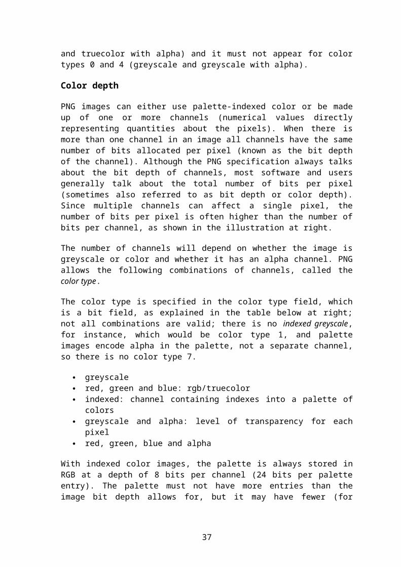
Color depth
PNG images can either use palette-indexed color or be madeup of one or more channels (numerical values directlyrepresenting quantities about the pixels). When there ismore than one channel in an image all channels have the samenumber of bits allocated per pixel (known as the bit depthof the channel). Although the PNG specification always talksabout the bit depth of channels, most software and usersgenerally talk about the total number of bits per pixel(sometimes also referred to as bit depth or color depth).Since multiple channels can affect a single pixel, thenumber of bits per pixel is often higher than the number ofbits per channel, as shown in the illustration at right.
The number of channels will depend on whether the image isgreyscale or color and whether it has an alpha channel. PNGallows the following combinations of channels, called thecolor type.
The color type is specified in the color type field, whichis a bit field, as explained in the table below at right;not all combinations are valid; there is no indexed greyscale,for instance, which would be color type 1, and paletteimages encode alpha in the palette, not a separate channel,so there is no color type 7.
greyscale red, green and blue: rgb/truecolor indexed: channel containing indexes into a palette of
colors greyscale and alpha: level of transparency for each
pixel red, green, blue and alpha
With indexed color images, the palette is always stored inRGB at a depth of 8 bits per channel (24 bits per paletteentry). The palette must not have more entries than theimage bit depth allows for, but it may have fewer (for
37
example, if an image only uses 90 colors then it does notneed palette entries for all 256 colors).
Indexed color PNGs are allowed to have 1, 2, 4 or 8 bits perpixel by the standard; greyscale images with no alphachannel allow for 1, 2, 4, 8 or 16 bits per pixel.Everything else uses a bit depth per channel of either 8 or16. The combinations this allows are given in the tableabove. The standard requires that decoders can read allsupported color formats, but many image editors can onlyproduce a small subset of them.
Transparency of image
PNG offers a variety of transparency options. With truecolorand greyscale images either a single pixel value can bedeclared as transparent or an alpha channel can be added(enabling any percentage of partial transparency to beused). For paletted images, alpha values can be added topalette entries. The number of such values stored may beless than the total number of palette entries, in which casethe remaining entries are considered fully opaque.
The scanning of pixel values for binary transparency issupposed to be performed before any color reduction to avoidpixels becoming unintentionally transparent. This is mostlikely to pose an issue for systems that can decode 16 bitsper channel images (as they must be compliant with thespecification) but only output at 8 bits per channel (thenorm for all but the highest end systems).
8.3 Compression
PNG uses a 2-stage compression process:
pre-compression: filtering (prediction) compression: DEFLATE
PNG uses a non-patented lossless data compression methodknown as DEFLATE, which is the same algorithm used in thezlib compression library.
38
8.4 Comparison with Graphics Interchange Format (GIF) On most images, PNG can achieve greater compression
than GIF (see the section on filesize, below). PNG gives a much wider range of transparency options
than GIF, including alpha channel transparency. Whereas GIF is limited to 8-bit indexed color, PNG
gives a much wider range of color depths, including 24-bit (8 bits per channel) and 48-bit (16 bits perchannel) truecolor, allowing for greater colorprecision, smoother fades, etc. When an alpha channelis added, up to 64 bits per pixel (before compression)are possible.
GIF intrinsically supports animated images. PNGsupports animation only via unofficial extensions (seethe section on animation, above).
PNG images are widely supported (for instance, withmodern web browsers and office software), but not aswidely supported as GIF images.
Silverlight supports PNG but has opted to not supportGIF.
Optimizing tools
Various tools are available for optimizing PNG files; theydo this by:
(optionally) removing ancillary chunks, reducing color depth, either:
o use a palette (instead of RGB) if the image has256 or fewer colors,
o use a smaller palette, if image has 2, 4, or 16colors, or
o (optionally) lossy discard some of the data in theoriginal image,
optimizing line-by-line filter choice, and optimizing DEFLATE compression.
As some tools are PNG-specific, while others onlyoptimize DEFLATE, in general one must use a combination of 2tools in sequence for optimal compression: one whichoptimizes filters (and removes ancillary chunks), and onewhich optimizes DEFLATE. Most commonly, OptiPNG is used for
39
the first (non-DEFLATE) step, and either of AdvanceCOMP orPNGOUT is used for the DEFLATE step.
THE JPEG IMAGE9.0 Introduction:
The term "JPEG" is an acronym for the JointPhotographic Experts Group which created the standard. Itbasically refers to a compression algorithm.
In computing, JPEG (pronounced /ˈdʒeɪpɛɡ/, JAY-peg) isa commonly used method of lossy compression for photographicimages. The degree of compression can be adjusted, allowinga selectable tradeoff between storage size and imagequality. JPEG typically achieves 10:1 compression withlittle perceptible loss in image quality.
40
JPEG compression is used in a number of image fileformats. JPEG/Exif is the most common image format used bydigital cameras and other photographic image capturedevices; along with JPEG/JFIF, it is the most common formatfor storing and transmitting photographic images on theWorld Wide Web.These format variations are often notdistinguished, and are simply called JPEG.
9.1 Use of the compression technique:
The JPEG compression algorithm is at its best onphotographs and paintings of realistic scenes with smoothvariations of tone and color. For web usage, where thebandwidth used by an image is important, JPEG is verypopular. JPEG/Exif is also the most common format saved bydigital cameras.
On the other hand, JPEG is not as well suited for linedrawings and other textual or iconic graphics, where thesharp contrasts between adjacent pixels cause noticeableartifacts. Such images are better saved in a losslessgraphics format such as TIFF, GIF, PNG, or a raw imageformat.
JPEG is also not well suited to files that will undergomultiple edits, as some image quality will usually be losteach time the image is decompressed and recompressed,particularly if the image is cropped or shifted, or ifencoding parameters are changed – see digital generationloss for details. To avoid this, an image that is beingmodified or may be modified in the future can be saved in alossless format such as PNG, and a copy exported as JPEG fordistribution.
As JPEG is a lossy compression method, which removesinformation from the image, it must not be used inastronomical or medical imaging or other purposes where theexact reproduction of the data is required. Lossless formatssuch as PNG must be used instead.
9.2 JPEG files:
The file format known as 'JPEG Interchange Format'(JIF) is specified in Annex B of the standard. However, this
41
"pure" file format is rarely used, primarily because of thedifficulty of programming encoders and decoders that fullyimplement all aspects of the standard and because of certainshortcomings of the standard:
Color space definition Component sub-sampling registration Pixel aspect ratio definition
Several additional standards have evolved to addressthese issues. The first of these, released in 1992, was JPEGFile Interchange Format (or JFIF), followed in recent yearsby Exchangeable image file format (Exif) and ICC colorprofiles. Both of these formats use the actual JIF bytelayout, consisting of different markers, but in additionemploy one of the JIF standard's extension points, namelythe application markers: JFIF use APP0, while Exif use APP1.Within these segments of the file, which for the JIFstandard's part is simply a "byte blob" that aren't read,these standards add specific metadata.
Thus, in some ways JFIF is a cutdown version of the JIFstandard in that it specifies certain constraints (such asnot allowing all the different encoding modes), while inother ways it is an extension of JIF due to the addedmetadata. The documentation for the original JFIF standardstates:
JPEG File Interchange Format is a minimal file format which enables JPEGbitstreams to be exchanged between a wide variety of platforms andapplications. This minimal format does not include any of the advancedfeatures found in the TIFF JPEG specification or any application specific fileformat. Nor should it, for the only purpose of this simplified format is toallow the exchange of JPEG compressed images.
Image files that employ JPEG compression are commonlycalled "JPEG files". Most image capture devices (such asdigital cameras) and most image editing software programsthat output "JPEG files" are actually creating a file in theJFIF and/or Exif format.
Strictly speaking, the JFIF and Exif standards areincompatible because they each specify that their header
42

appears first. In practice, most JPEG files in Exif formatcontain a small JFIF header that precedes the Exif header.This allows older readers to correctly handle the olderformat JFIF header, while newer readers also decode thefollowing Exif header.
Syntax and structure:
A JPEG image consists of a sequence of segments, eachbeginning with a marker, each of which begins with a 0xFFbyte followed by a byte indicating what kind of marker itis. Some markers consist of just those two bytes; others arefollowed by two bytes indicating the length of marker-specific payload data that follows. (The length includes thetwo bytes for the length, but not the two bytes for themarker.) Some markers are followed by entropy-coded data;the length of such a marker does not include the entropy-coded data. Note that consecutive 0xFF bytes are used asfill bytes for padding purposes (see JPEG specificationsection F.1.2.3 for details).
Within the entropy-coded data, after any 0xFF byte, a0x00 byte is inserted by the encoder before the next byte,so that there does not appear to be a marker where none isintended, preventing framing errors. Decoders must skip this0x00 byte. This technique, called byte stuffing, is onlyapplied to the entropy-coded data, not to marker payloaddata.
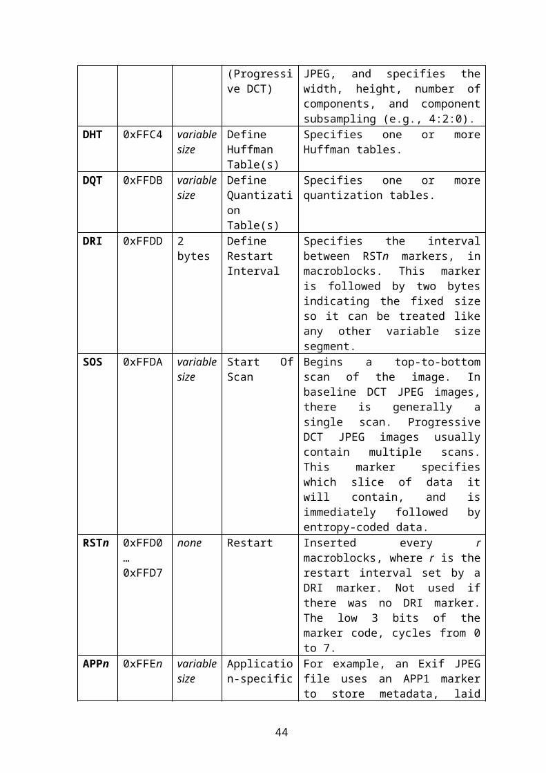
Common JPEG markersShortname
Bytes Payload
Name Comments
SOI 0xFFD8 none Start OfImage
SOF0 0xFFC0 variablesize
Start OfFrame(BaselineDCT)
Indicates that this is abaseline DCT-based JPEG,and specifies the width,height, number ofcomponents, and componentsubsampling (e.g., 4:2:0).
SOF2 0xFFC2 variablesize
Start OfFrame
Indicates that this is aprogressive DCT-based
43
(Progressive DCT)
JPEG, and specifies thewidth, height, number ofcomponents, and componentsubsampling (e.g., 4:2:0).
DHT 0xFFC4 variablesize
DefineHuffmanTable(s)
Specifies one or moreHuffman tables.
DQT 0xFFDB variablesize
DefineQuantizationTable(s)
Specifies one or morequantization tables.
DRI 0xFFDD 2bytes
DefineRestartInterval
Specifies the intervalbetween RSTn markers, inmacroblocks. This markeris followed by two bytesindicating the fixed sizeso it can be treated likeany other variable sizesegment.
SOS 0xFFDA variablesize
Start OfScan
Begins a top-to-bottomscan of the image. Inbaseline DCT JPEG images,there is generally asingle scan. ProgressiveDCT JPEG images usuallycontain multiple scans.This marker specifieswhich slice of data itwill contain, and isimmediately followed byentropy-coded data.
RSTn 0xFFD0…0xFFD7
none Restart Inserted every rmacroblocks, where r is therestart interval set by aDRI marker. Not used ifthere was no DRI marker.The low 3 bits of themarker code, cycles from 0to 7.
APPn 0xFFEn variablesize
Application-specific
For example, an Exif JPEGfile uses an APP1 markerto store metadata, laid
44
out in a structure basedclosely on TIFF.
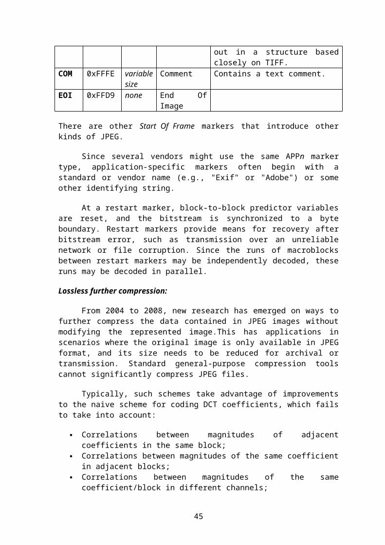
COM 0xFFFE variablesize
Comment Contains a text comment.
EOI 0xFFD9 none End OfImage
There are other Start Of Frame markers that introduce otherkinds of JPEG.
Since several vendors might use the same APPn markertype, application-specific markers often begin with astandard or vendor name (e.g., "Exif" or "Adobe") or someother identifying string.
At a restart marker, block-to-block predictor variablesare reset, and the bitstream is synchronized to a byteboundary. Restart markers provide means for recovery afterbitstream error, such as transmission over an unreliablenetwork or file corruption. Since the runs of macroblocksbetween restart markers may be independently decoded, theseruns may be decoded in parallel.
Lossless further compression:
From 2004 to 2008, new research has emerged on ways tofurther compress the data contained in JPEG images withoutmodifying the represented image.This has applications inscenarios where the original image is only available in JPEGformat, and its size needs to be reduced for archival ortransmission. Standard general-purpose compression toolscannot significantly compress JPEG files.
Typically, such schemes take advantage of improvementsto the naive scheme for coding DCT coefficients, which failsto take into account:
Correlations between magnitudes of adjacentcoefficients in the same block;
Correlations between magnitudes of the same coefficientin adjacent blocks;
Correlations between magnitudes of the samecoefficient/block in different channels;
45
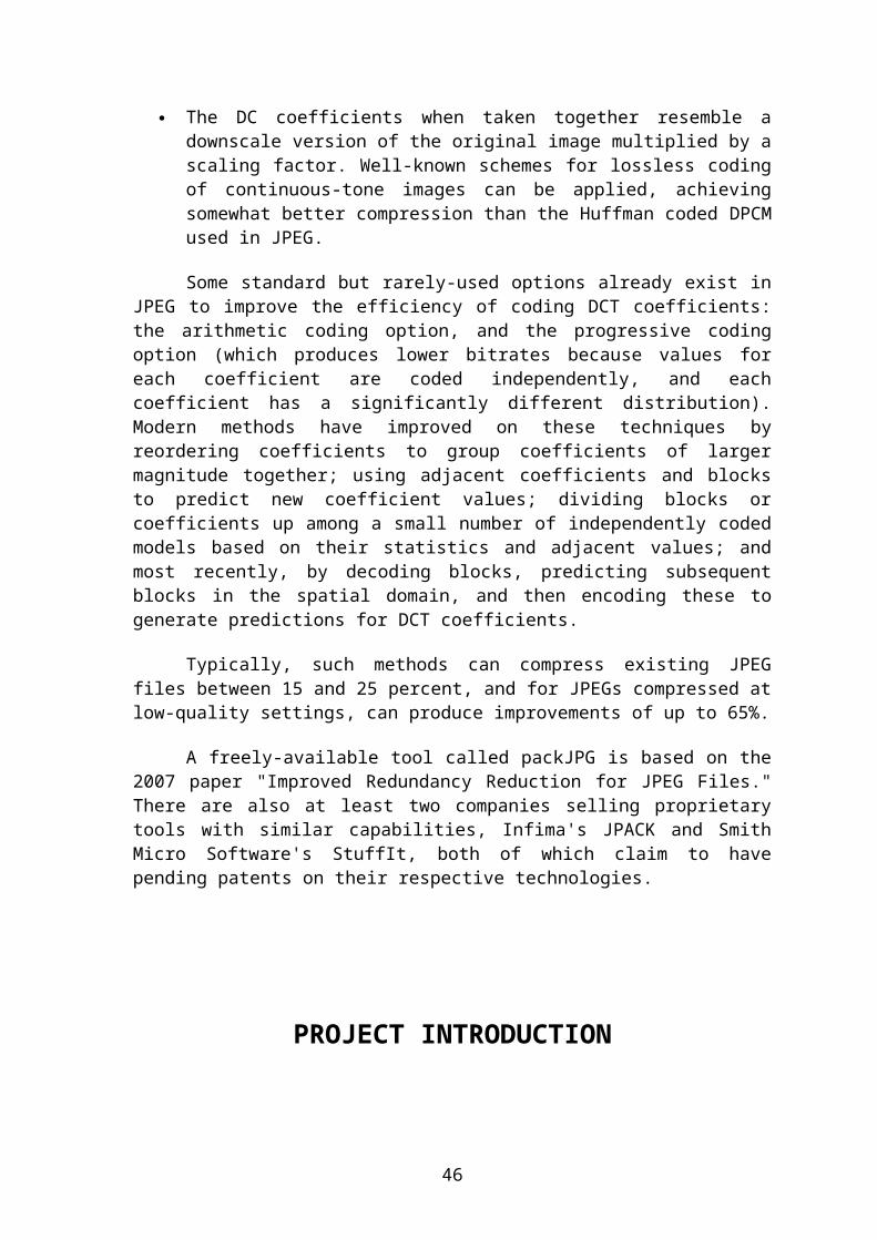
The DC coefficients when taken together resemble adownscale version of the original image multiplied by ascaling factor. Well-known schemes for lossless codingof continuous-tone images can be applied, achievingsomewhat better compression than the Huffman coded DPCMused in JPEG.
Some standard but rarely-used options already exist inJPEG to improve the efficiency of coding DCT coefficients:the arithmetic coding option, and the progressive codingoption (which produces lower bitrates because values foreach coefficient are coded independently, and eachcoefficient has a significantly different distribution).Modern methods have improved on these techniques byreordering coefficients to group coefficients of largermagnitude together; using adjacent coefficients and blocksto predict new coefficient values; dividing blocks orcoefficients up among a small number of independently codedmodels based on their statistics and adjacent values; andmost recently, by decoding blocks, predicting subsequentblocks in the spatial domain, and then encoding these togenerate predictions for DCT coefficients.
Typically, such methods can compress existing JPEGfiles between 15 and 25 percent, and for JPEGs compressed atlow-quality settings, can produce improvements of up to 65%.
A freely-available tool called packJPG is based on the2007 paper "Improved Redundancy Reduction for JPEG Files."There are also at least two companies selling proprietarytools with similar capabilities, Infima's JPACK and SmithMicro Software's StuffIt, both of which claim to havepending patents on their respective technologies.
PROJECT INTRODUCTION
46

The project parts that I have been working on are allperformed in the field of image processing and handling inMicrosoft Visual C++ (2006) only.
The project which I have been working on can bedistinguished in three parts: -
Image Handling
Image Understanding
Simple Image Processing
The Image Handling Part Include three main topics:
Handling the Windows Bitmap Image(*.BMP)
Handling the Portable Network Graphics Format(*.PNG)
Handling the JPEG Compressed Format(*.jpg, *.jfif)
The Image Understanding Part includes my work on:
Image Header
Image Data
The Image Processing Operations Include:
Simple Image Inversion(Negative Operation)
Averaging And Smoothing
Threshold/ Segmentation
Median Filtering
Prewitt operator for edge detection
Sobel operator for edge detection
High Pass Filter
High Boost Filter
The parts on Image Processing are based on the windowsbitmap format and they are especially performed on GrayscaleImages, as it becomes a little bit complex to access andwork on colors. However all the works on image processingeven in real-time are also based on grayscale images only.
47

The respective field of work and classification will befurther described in the project itself.
AIM OF THE PROJECTThe basic aim of my project was to implement image
processing techniques in Microsoft Visual C++ and study itsimplementation and use it real-time systems and embeddedtechnologies.
The aim of my project can be described as:
Studying how to create an Application using MicrosoftFoundation Classes and various libraries in VC++. I hadto create applications using dialog based windows inearly phase and further learn to create application usingthe Single Document Interface.
Studying to create Buttons, Menus, Lists, etc. which arebasically used in a standard application, earlier bydirect input with the help of Options in a Dialog BasedApplication and then manually with the help of MSDN inSingle Document Interface.
Opening an image file, that is not available in theresource using various functions and displaying it in theApplication Window.
Creating a link between two consecutive image files usingstring operations thus creating the next and previousfunctions to view image serially.
Manually creating a view to display image using variousinternal functions of MFC in VC++.
48
Extracting the pixel information of an image file usingtwo ways- Using MFC to extract information using specificfunction, and using basic C++ structures and functions.
Working on the pixel information- displaying the pixelvalues in a text file, extracting header information andcreating a whole output image using pixel informationfrom the input image.
Advanced operations on image using pixel information.Implementation of basic image processing techniques asdescribed in the introduction.
EXPERIMENTS CONDUCTEDWhile studying the various aspects of the project, I made upnumber of smaller sub-projects. These subprojects were madeduring the training period by me.
The various sub-projects are described below:
1) Creating a Dialog Based Application for openingand displaying a bitmap image.
This was my first task and I was able to successfullycreate a two dialog based application, in which one dialogbox had a button which opened the image and I used specificfunctions to link the main class to the other class
49

representing the window in which image had to be shown. Thenin the displaying dialog, i wrote the commands to displaythe image properly.
The main dialog is provided from the start, and we cancreate a new dialog window by using create function asdescribed in my program(PHOTO-EXTENSION).
The image is then loaded to the application using abutton, thus we create a function inside the button as:
/////////////////---------------------------------------------------------------------------///////////////////static char BASED_CODE sz_Filter[] = "Bitmap FIles (*.bmp)|*.bmp||";//Creating an FilterCFileDialog m_ldFile(TRUE, ".bmp", m_sBitmap,OFN_HIDEREADONLY | OFN_OVERWRITEPROMPT, sz_Filter);//Passing the Filter to FileDialog which is used to open filesCString m_sBitmap = m_ldFile.GetPathName();//Get path name to a stringHBITMAP hBitmap = (HBITMAP) ::LoadImage(AfxGetInstanceHandle(),m_sBitmap, IMAGE_BITMAP, 0, 0,LR_LOADFROMFILE | LR_CREATEDIBSECTION);//Create a handle and pass it
if (hBitmap){
if (m_bmpBitmap.DeleteObject())m_bmpBitmap.Detach();//If there is an image delete itm_bmpBitmap.Attach(hBitmap);//Attach current image
}
/////////////////---------------------------------------------------------------------------///////////////////
The last major part of the job is to create a device-context, which can be used to actually display the image onthe screen:
50

/////////////////---------------------------------------------------------------------------///////////////////
//Convert the pointer to a pointer to the main dialog class
CGraphicsDlg *lpWnd = (CGraphicsDlg*)pWnd;
BITMAP bm;
// Get the loaded bitmap
lpWnd->m_bmpBitmap.GetBitmap(&bm);
CDC dcMem;
//Create a device context to load the bitmap into
dcMem.CreateCompatibleDC(pdc);
// Select the bitmap into the compatible device context
CBitmap* pOldBitmap = (CBitmap*)dcMem.SelectObject(lpWnd->m_bmpBitmap);
CRect lRect;
// Get the display area available
GetClientRect(lRect);
lRect.NormalizeRect();
// Copy and resize the bitmap to the dialog window
pdc->StretchBlt(10, 10, (lRect.Width() - 20),
(lRect.Height() - 20), &dcMem, 0, 0,bm.bmWidth, bm.bmHeight,SRCCOPY);
/////////////////---------------------------------------------------------------------------///////////////////
The project was relatively easier because we have functionsand operation that can make us deal with the bitmap easily.
2) Creating an SDI Application for opening anddisplaying a bitmap image.
Most of the part of this project resembles the abovementioned one except some important changes, which have tobe done precisely. In a single document interface, we don’tget to have everything in the dialog window. We have toimplement codes for many of the above said functions. But it
51

is relatively quite efficient if we know the codes properly.We first create a toolbar button and connect the imageopening functionality with it. Then we declare the loadingand displaying part of the image in a in-built main classfunction-OnDraw(). Thus we do the FileDialog and LoadImagefunctionalities in the Toolbar Button Click Functiondeclared in main class and then load the device-context andfurther image in the OnDraw() function.
3) Creating an SDI Application for opening generalfile formats and connecting serially numbered fileswith links.
The above both applications can be used top open justBitmap files only. But if we need one program to open anygeneral file format we need to use general functions,instead of bitmap oriented functions.
For opening any image, first we need to understand howthe whole thing works. The File Dialog takes a file andbrings it to the program. The getpathname() returns path ofthe file as string. Now first of all we need to create aview. This job was done earlier by the Device Context, thusreducing our problem. But now we have to create our ownview, in which we can further display the image by using afunction called Set Background Image.
/////////////////---------------------------------------------------------------------------///////////////////
//Create object of a list view
LVBKIMAGE IBBkImg;
//In OnInitialUpdate() function create a rectangle and pass itthrough list-control
//define an object of rectangle class and give its body from
RECT rect;//start point(top,left)
52
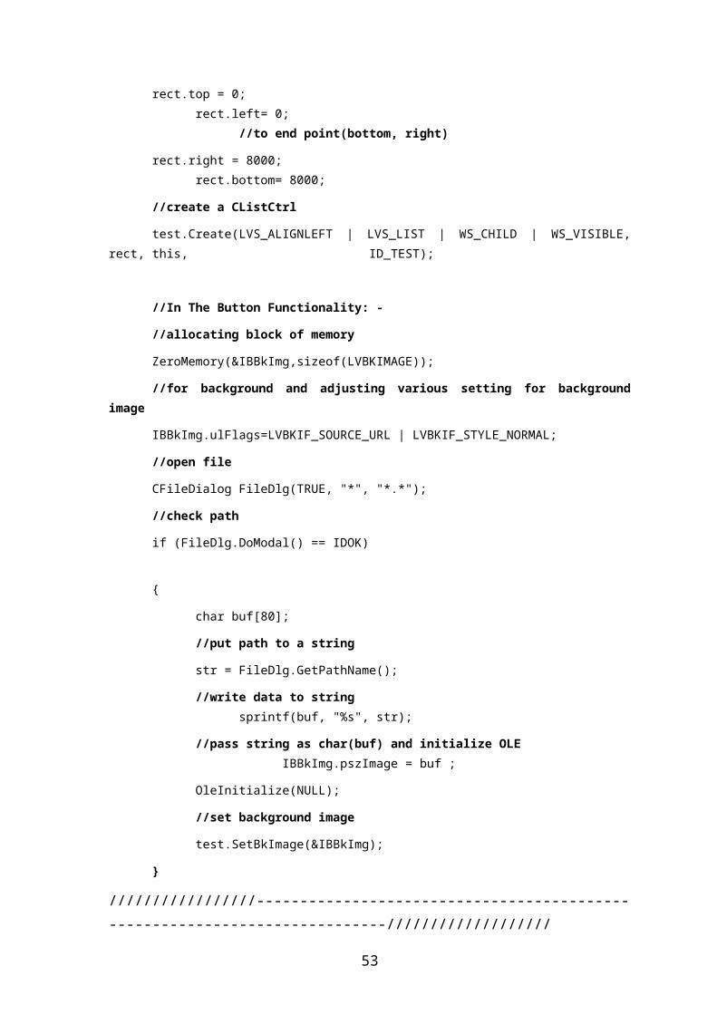
rect.top = 0;rect.left= 0;
//to end point(bottom, right)
rect.right = 8000;rect.bottom= 8000;
//create a CListCtrl
test.Create(LVS_ALIGNLEFT | LVS_LIST | WS_CHILD | WS_VISIBLE,rect, this, ID_TEST);
//In The Button Functionality: -
//allocating block of memory
ZeroMemory(&IBBkImg,sizeof(LVBKIMAGE));
//for background and adjusting various setting for backgroundimage
IBBkImg.ulFlags=LVBKIF_SOURCE_URL | LVBKIF_STYLE_NORMAL;
//open file
CFileDialog FileDlg(TRUE, "*", "*.*");
//check path
if (FileDlg.DoModal() == IDOK)
{
char buf[80];
//put path to a string
str = FileDlg.GetPathName();
//write data to stringsprintf(buf, "%s", str);
//pass string as char(buf) and initialize OLEIBBkImg.pszImage = buf ;
OleInitialize(NULL);
//set background image
test.SetBkImage(&IBBkImg);
}
/////////////////---------------------------------------------------------------------------///////////////////
53
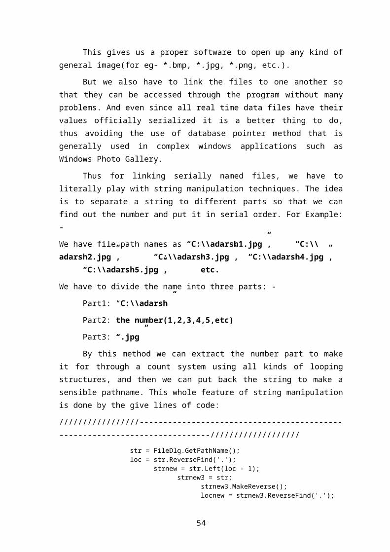
This gives us a proper software to open up any kind ofgeneral image(for eg- *.bmp, *.jpg, *.png, etc.).
But we also have to link the files to one another sothat they can be accessed through the program without manyproblems. And even since all real time data files have theirvalues officially serialized it is a better thing to do,thus avoiding the use of database pointer method that isgenerally used in complex windows applications such asWindows Photo Gallery.
Thus for linking serially named files, we have toliterally play with string manipulation techniques. The ideais to separate a string to different parts so that we canfind out the number and put it in serial order. For Example:-
We have file path names as “C:\\adarsh1.jpg”, “C:\\adarsh2.jpg”, “C:\\adarsh3.jpg”, “C:\\adarsh4.jpg”,
“C:\\adarsh5.jpg”, etc.
We have to divide the name into three parts: -
Part1: “C:\\adarsh”
Part2: the number(1,2,3,4,5,etc)
Part3: “.jpg”
By this method we can extract the number part to makeit for through a count system using all kinds of loopingstructures, and then we can put back the string to make asensible pathname. This whole feature of string manipulationis done by the give lines of code:
/////////////////---------------------------------------------------------------------------///////////////////
str = FileDlg.GetPathName();loc = str.ReverseFind('.');
strnew = str.Left(loc - 1);strnew3 = str;
strnew3.MakeReverse();locnew = strnew3.ReverseFind('.');
54
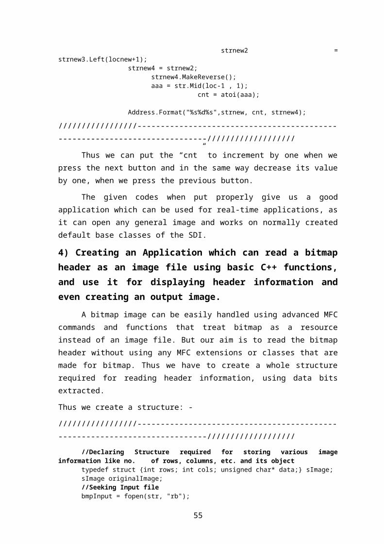
strnew2 =strnew3.Left(locnew+1);
strnew4 = strnew2; strnew4.MakeReverse();
aaa = str.Mid(loc-1 , 1);cnt = atoi(aaa);
Address.Format("%s%d%s",strnew, cnt, strnew4);
/////////////////---------------------------------------------------------------------------///////////////////
Thus we can put the “cnt” to increment by one when wepress the next button and in the same way decrease its valueby one, when we press the previous button.
The given codes when put properly give us a goodapplication which can be used for real-time applications, asit can open any general image and works on normally createddefault base classes of the SDI.
4) Creating an Application which can read a bitmapheader as an image file using basic C++ functions,and use it for displaying header information andeven creating an output image.
A bitmap image can be easily handled using advanced MFCcommands and functions that treat bitmap as a resourceinstead of an image file. But our aim is to read the bitmapheader without using any MFC extensions or classes that aremade for bitmap. Thus we have to create a whole structurerequired for reading header information, using data bitsextracted.
Thus we create a structure: -
/////////////////---------------------------------------------------------------------------///////////////////
//Declaring Structure required for storing various imageinformation like no. of rows, columns, etc. and its object
typedef struct {int rows; int cols; unsigned char* data;} sImage;sImage originalImage;//Seeking Input filebmpInput = fopen(str, "rb");
55

fseek(bmpInput, 0, 0);
//Defining and declaring Functions used for extracting variousinformation from input file and copying them to output file.
long getImageInfo(FILE*, long, int);{ unsigned char *ptrC;
long value = 0L; unsigned char dummy; int i;
dummy = '0'; ptrC = &dummy;
fseek(inputFile, offset, SEEK_SET);for(i=1; i<=numberOfChars; i++)
{ fread(ptrC, 1, 1, inputFile);
//Reading the input filevalue = (long)(value + (*ptrC)*(pow(256, (i-1))));//Expression for evaluating the information stored in
bitmap file}
return(value);//Returning Information for use
}
void copyImageInfo(FILE* inputFile, FILE* outputFile);//Function used for copying image information from input to output{
unsigned char *ptrC; unsigned char dummy; int i;
dummy = '0'; ptrC = &dummy;
fseek(inputFile, 0L, SEEK_SET); fseek(outputFile, 0L, SEEK_SET);
for(i=0; i<=53; i++)//From 0 to 53 offset, i.e.-image header
{ fread(ptrC, sizeof(char), 1, inputFile); fwrite(ptrC, sizeof(char), 1, outputFile); }
}
void copyColorTable(FILE* inputFile, FILE* outputFile, intnColors);
//Function used for copying image data from input to output{
unsigned char *ptrC; unsigned char dummy; int i;
dummy = '0'; ptrC = &dummy;
56

fseek(inputFile, 54L, SEEK_SET); fseek(outputFile, 54L, SEEK_SET);
for(i=0; i<=(4*nColors); i++) { fread(ptrC, sizeof(char), 1, inputFile); fwrite(ptrC, sizeof(char), 1, outputFile); }
}
//Defining output files(image, data and header)bmpOutput = fopen(“address of output image”, “w”)datafile= fopen(“address of data writing file”, “w”);header = fopen(“address of header information file”, “w”);
/////////////////---------------------------------------------------------------------------///////////////////
The header information for windows OS is providedbelow for bitmaps:-
offset
size
description
0 2 signature, must be 4D42 hex 2 4 size of BMP file in bytes
(unreliable) 6 2 reserved, must be zero 8 2 reserved, must be zero 10 4 offset to start of image data in
bytes 14 4 size of BITMAPINFOHEADER structure,
must be 40 18 4 image width in pixels 22 4 image height in pixels 26 2 number of planes in the image, must
be 1 28 2 number of bits per pixel (1, 4, 8,
or 24) 30 4 compression type (0=none, 1=RLE-8,
2=RLE-4) 34 4 size of image data in bytes
(including padding) 38 4 horizontal resolution in pixels per
57
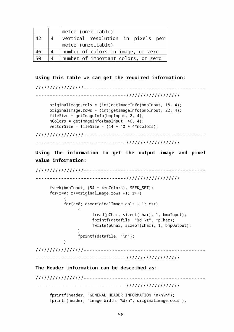
meter (unreliable) 42 4 vertical resolution in pixels per
meter (unreliable) 46 4 number of colors in image, or zero 50 4 number of important colors, or zero
Using this table we can get the required information:
/////////////////---------------------------------------------------------------------------///////////////////
originalImage.cols = (int)getImageInfo(bmpInput, 18, 4);originalImage.rows = (int)getImageInfo(bmpInput, 22, 4);fileSize = getImageInfo(bmpInput, 2, 4);nColors = getImageInfo(bmpInput, 46, 4);vectorSize = fileSize - (14 + 40 + 4*nColors);
/////////////////---------------------------------------------------------------------------///////////////////
Using the information to get the output image and pixelvalue information:
/////////////////---------------------------------------------------------------------------///////////////////
fseek(bmpInput, (54 + 4*nColors), SEEK_SET);for(r=0; r<=originalImage.rows -1; r++)
{for(c=0; c<=originalImage.cols - 1; c++)
{fread(pChar, sizeof(char), 1, bmpInput); fprintf(datafile, "%d \t", *pChar);fwrite(pChar, sizeof(char), 1, bmpOutput);
}fprintf(datafile, "\n");
}
/////////////////---------------------------------------------------------------------------///////////////////
The Header information can be described as:
/////////////////---------------------------------------------------------------------------///////////////////
fprintf(header, "GENERAL HEADER INFORMATION \n\n\n");fprintf(header, "Image Width: %d\n", originalImage.cols );
58
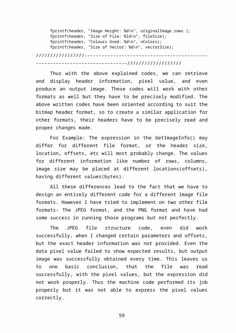
fprintf(header, "Image Height: %d\n", originalImage.rows );fprintf(header, "Size of File: %ld\n", fileSize);fprintf(header, "Colours Used: %d\n", nColors);fprintf(header, "Size of Vector: %d\n", vectorSize);
/////////////////---------------------------------------------------------------------------///////////////////
Thus with the above explained codes, we can retrieveand display header information, pixel value, and evenproduce an output image. These codes will work with otherformats as well but they have to be precisely modified. Theabove written codes have been oriented according to suit thebitmap header format, so to create a similar application forother formats, their headers have to be precisely read andproper changes made.
For Example: The expression in the GetImageInfo() maydiffer for different file format, or the header size,location, offsets, etc will most probably change. The valuesfor different information like number of rows, columns,image size may be placed at different locations(offsets),having different values(bytes).
All these differences lead to the fact that we have todesign an entirely different code for a different image fileformats. However I have tried to implement on two other fileformats- The JPEG format, and the PNG format and have hadsome success in running those programs but not perfectly.
The JPEG file structure code, even did worksuccessfully, when I changed certain parameters and offsets,but the exact header information was not provided. Even thedata pixel value failed to show expected results, but outputimage was successfully obtained every time. This leaves usto one basic conclusion, that the file was readsuccessfully, with the pixel values, but the expression didnot work properly. Thus the machine code performed its jobproperly but it was not able to express the pixel valuescorrectly.
59
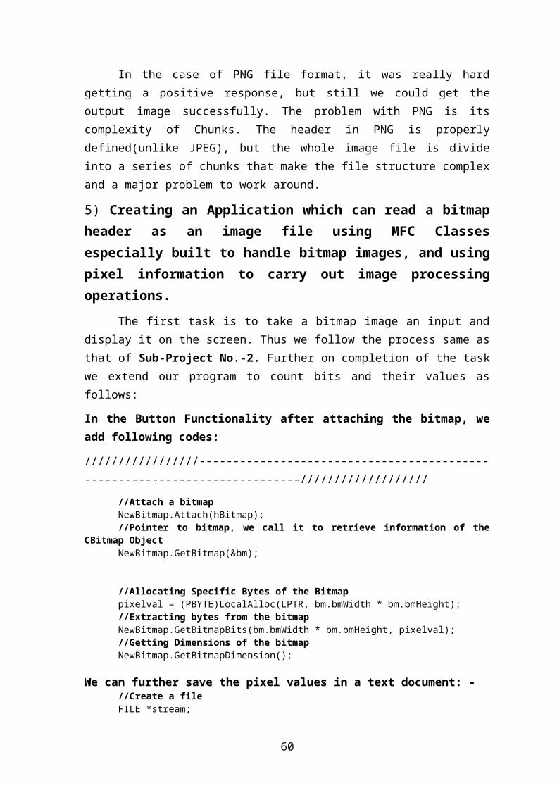
In the case of PNG file format, it was really hardgetting a positive response, but still we could get theoutput image successfully. The problem with PNG is itscomplexity of Chunks. The header in PNG is properlydefined(unlike JPEG), but the whole image file is divideinto a series of chunks that make the file structure complexand a major problem to work around.
5) Creating an Application which can read a bitmapheader as an image file using MFC Classesespecially built to handle bitmap images, and usingpixel information to carry out image processingoperations.
The first task is to take a bitmap image an input anddisplay it on the screen. Thus we follow the process same asthat of Sub-Project No.-2. Further on completion of the taskwe extend our program to count bits and their values asfollows:
In the Button Functionality after attaching the bitmap, weadd following codes:
/////////////////---------------------------------------------------------------------------///////////////////
//Attach a bitmapNewBitmap.Attach(hBitmap);//Pointer to bitmap, we call it to retrieve information of the
CBitmap ObjectNewBitmap.GetBitmap(&bm);
//Allocating Specific Bytes of the Bitmappixelval = (PBYTE)LocalAlloc(LPTR, bm.bmWidth * bm.bmHeight);//Extracting bytes from the bitmapNewBitmap.GetBitmapBits(bm.bmWidth * bm.bmHeight, pixelval);//Getting Dimensions of the bitmapNewBitmap.GetBitmapDimension();
We can further save the pixel values in a text document: -//Create a fileFILE *stream;
60
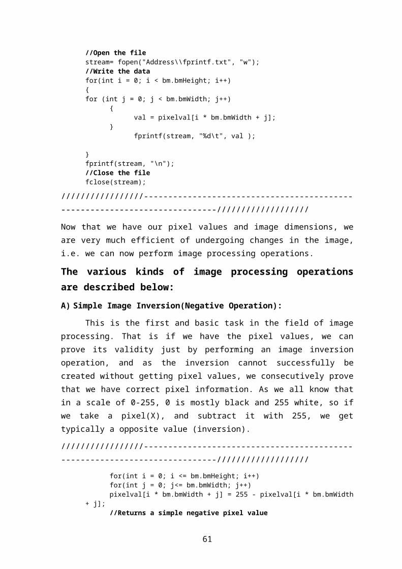
//Open the file stream= fopen("Address\\fprintf.txt", "w");//Write the datafor(int i = 0; i < bm.bmHeight; i++){for (int j = 0; j < bm.bmWidth; j++)
{val = pixelval[i * bm.bmWidth + j];
}fprintf(stream, "%d\t", val );
}fprintf(stream, "\n");//Close the filefclose(stream);
/////////////////---------------------------------------------------------------------------///////////////////
Now that we have our pixel values and image dimensions, weare very much efficient of undergoing changes in the image,i.e. we can now perform image processing operations.
The various kinds of image processing operationsare described below: A) Simple Image Inversion(Negative Operation):
This is the first and basic task in the field of imageprocessing. That is if we have the pixel values, we canprove its validity just by performing an image inversionoperation, and as the inversion cannot successfully becreated without getting pixel values, we consecutively provethat we have correct pixel information. As we all know thatin a scale of 0-255, 0 is mostly black and 255 white, so ifwe take a pixel(X), and subtract it with 255, we gettypically a opposite value (inversion).
/////////////////---------------------------------------------------------------------------///////////////////
for(int i = 0; i <= bm.bmHeight; i++)for(int j = 0; j<= bm.bmWidth; j++)pixelval[i * bm.bmWidth + j] = 255 - pixelval[i * bm.bmWidth
+ j];//Returns a simple negative pixel value
61

NewBitmap.SetBitmapBits(bm.bmHeight * bm.bmWidth, pixelval);//Scales the bitmap using pixel value
/////////////////---------------------------------------------------------------------------///////////////////
B) Averaging/Mean Filter:
Averaging is a very simple image processing techniqueby which we can remove noise from an image by blurring.
Averaging can be carried out in a NxN matrix(N=3,5,9etc). depending upon the intensity in which it hasto be carried out. The basic idea is to add all the valuesis an grid(say 3x3), and divide it by the total number ofcells(9). Thus we get an average value which is furtherdistributed throughout the grid.
FOR 3x3 MATRIX:
AVERAGE VALUE(A)=
X1+X2+X3+X4+X5+X6+X7+X8+X9
9
NEW MATRIX :
The required loop is given below:
/////////////////---------------------------------------------------------------------------///////////////////
for(int i = 1; i <= bm.bmHeight - 1 ; i++)for(int j = 1; j<= bm.bmWidth - 1 ; j++){
X1 X2 X3
X4 X5 X6
X7 X8 X9
A A A
A A A
A A A
62

S = 0;for(int m = -1; m <= 1; m++)for(int n = -1; n <= 1; n++)
S = S + pixelval[(i + m) * w + (j + n)];val = S / 9;pixelval[i * w + j] = val;
}
NewBitmap.SetBitmapBits(bm.bmHeight * bm.bmWidth, pixelval);//Scales the bitmap using pixel value
/////////////////---------------------------------------------------------------------------///////////////////
C) Smoothing/ Median Filter:
Smoothing is a simple image processing technique bywhich we can smooth out or blur out a sharp image, reducingthe noise parts inside it.
Smoothing can also be carried out in a NxNmatrix (N=3,5,9etc) just as averaging depending upon theintensity of noise removal required. In smoothing we don’taverage out the values as in mean filter, instead we checkall the values in a grid, and then pick up the median valuefrom them, and further replace the whole grid cells with themedian value. It helps in removing sharp points and extremevalues in an image.
FOR 3x3 MATRIX:
MEDIAN VALUE(M) =11
NEW MATRIX :
5 7 2
15 11 43
14 23 32 3 5 7 11 14 15 23 43
11 11 11
11 11 11
11 11 1163

The required loop is given below:
/////////////////---------------------------------------------------------------------------///////////////////
w= bm.bmWidth; for( i = 1; i <= bm.bmHeight - 1 ; i++)for( j = 1; j<= bm.bmWidth - 1 ; j++){
a[0] = pixelval[(i - 1) * w + (j - 1)];a[1] = pixelval[(i - 1) * w + (j)];a[2] = pixelval[(i - 1) * w + (j + 1)];a[3] = pixelval[(i) * w + (j - 1)];a[4] = pixelval[(i) * w + (j)];a[5] = pixelval[(i) * w + (j + 1)];a[6] = pixelval[(i + 1) * w + (j - 1)];a[7] = pixelval[(i + 1) * w + (j)];a[8] = pixelval[(i + 1) * w + (j + 1)];
for(k=0;k<=8;k++){for(l=0;l<8;l++){
if(a[l]>a[l+1]){temp=a[l];a[l]=a[l+1];a[l+1]=temp;}
}val = a[4];pixelval[i*w+j] = val;
}}
NewBitmap.SetBitmapBits(bm.bmHeight * bm.bmWidth, pixelval);//Scales the bitmap using pixel value
/////////////////---------------------------------------------------------------------------///////////////////
D) Histogram of an image:
The histogram of an image is a graphical representation ofthe tonal distribution in a digital image. The histogramplots the number of pixels in the image (vertical axis) with
64

a particular brightness value (horizontal axis). Histogramsare basically used in the field of computer vision forthresholding.
Due to lack of time and complete negligence in my partI could not produce a VC++ code for creation of a histogram,but given below is a code for Histogram creation in C++:
/////////////////---------------------------------------------------------------------------///////////////////
for(i=0;i<image_colours;i++)count=0;for(i=0;i<image_height;i++){
for(j=0;j<image_width;j++)count+=*(optdata+i*128+j);
}detectgraph(&graphdriver, &graphmode);initgraph(&graphdriver,&graphmode,"c:\\tc\\bgi\\");cleardevice();setcolor(RED);line(10,10,10,450);line(10,450,630,450);setcolor(BROWN);settextstyle(1,0,3);outtextxy(300,30,"HISTOGRAM OF IMAGE");setcolor(YELLOW);for(i=0;i<256;i++)bar(0, 12+i*25, 450, (1+i)*25);free(inpdata);getch();closegraph();exit(0);
/////////////////---------------------------------------------------------------------------///////////////////
E) Prewiit edge detection operators:
Prewitt is a method of edge detection in image processingwhich calculates the maximum response of a set ofconvolution kernels to find the local edge orientation foreach pixel. Mathematically, the operator uses two 3×3kernels which are convolved with the original image tocalculate approximations of the derivatives - one forhorizontal changes, and one for vertical. If we define A
65
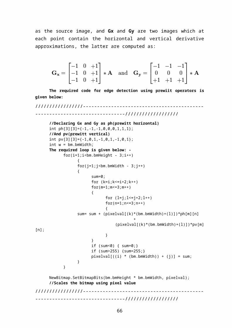
as the source image, and Gx and Gy are two images which ateach point contain the horizontal and vertical derivativeapproximations, the latter are computed as:
The required code for edge detection using prewiit operators is
given below:
/////////////////---------------------------------------------------------------------------///////////////////
//Declaring Gx and Gy as ph(prewitt horizontal) int ph[3][3]={-1,-1,-1,0,0,0,1,1,1};//And pv(prewitt vertical)int pv[3][3]={-1,0,1,-1,0,1,-1,0,1};int w = bm.bmWidth;The required loop is given below: -
for(i=1;i<bm.bmHeight - 3;i++){for(j=1;j<bm.bmWidth - 3;j++){
sum=0;for (k=i;k<=i+2;k++)for(m=1;m<=3;m++){
for (l=j;l<=j+2;l++)for(n=1;n<=3;n++){
sum= sum + (pixelval[(k)*(bm.bmWidth)+(l)])*ph[m][n]+
(pixelval[(k)*(bm.bmWidth)+(l)])*pv[m][n];
}}if (sum<0) { sum=0;}if (sum>255) {sum=255;}pixelval[((i) * (bm.bmWidth)) + (j)] = sum;
}}
NewBitmap.SetBitmapBits(bm.bmHeight * bm.bmWidth, pixelval);//Scales the bitmap using pixel value
/////////////////---------------------------------------------------------------------------///////////////////
66
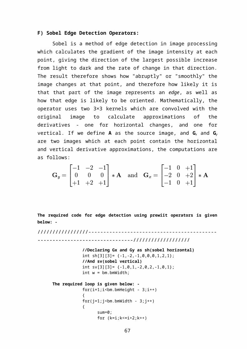
F) Sobel Edge Detection Operators:
Sobel is a method of edge detection in image processingwhich calculates the gradient of the image intensity at eachpoint, giving the direction of the largest possible increasefrom light to dark and the rate of change in that direction.The result therefore shows how "abruptly" or "smoothly" theimage changes at that point, and therefore how likely it isthat that part of the image represents an edge, as well ashow that edge is likely to be oriented. Mathematically, theoperator uses two 3×3 kernels which are convolved with theoriginal image to calculate approximations of thederivatives - one for horizontal changes, and one forvertical. If we define A as the source image, and Gx and Gy
are two images which at each point contain the horizontaland vertical derivative approximations, the computations areas follows:
The required code for edge detection using prewiit operators is givenbelow: -
/////////////////---------------------------------------------------------------------------///////////////////
//Declaring Gx and Gy as sh(sobel horizontal) int sh[3][3]= {-1,-2,-1,0,0,0,1,2,1};//And sv(sobel vertical)int sv[3][3]= {-1,0,1,-2,0,2,-1,0,1};int w = bm.bmWidth;
The required loop is given below: -for(i=1;i<bm.bmHeight - 3;i++){for(j=1;j<bm.bmWidth - 3;j++){
sum=0;for (k=i;k<=i+2;k++)
67
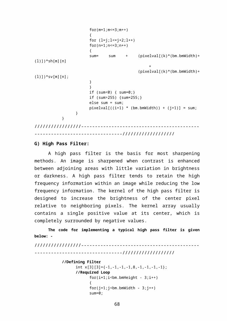
for(m=1;m<=3;m++){for (l=j;l<=j+2;l++)for(n=1;n<=3;n++){sum= sum + (pixelval[(k)*(bm.bmWidth)+
(l)])*sh[m][n] +
(pixelval[(k)*(bm.bmWidth)+(l)])*sv[m][n];
}}if (sum<0) { sum=0;}if (sum>255) {sum=255;}else sum = sum;pixelval[((i+1) * (bm.bmWidth)) + (j+1)] = sum;
}}
/////////////////---------------------------------------------------------------------------///////////////////
G) High Pass Filter:
A high pass filter is the basis for most sharpeningmethods. An image is sharpened when contrast is enhancedbetween adjoining areas with little variation in brightnessor darkness. A high pass filter tends to retain the highfrequency information within an image while reducing the lowfrequency information. The kernel of the high pass filter isdesigned to increase the brightness of the center pixelrelative to neighboring pixels. The kernel array usuallycontains a single positive value at its center, which iscompletely surrounded by negative values.
The code for implementing a typical high pass filter is givenbelow: -
/////////////////---------------------------------------------------------------------------///////////////////
//Defining Filterint x[3][3]={-1,-1,-1,-1,8,-1,-1,-1,-1};//Required Loop
for(i=1;i<bm.bmHeight - 3;i++) {
for(j=1;j<bm.bmWidth - 3;j++)sum=0;
68
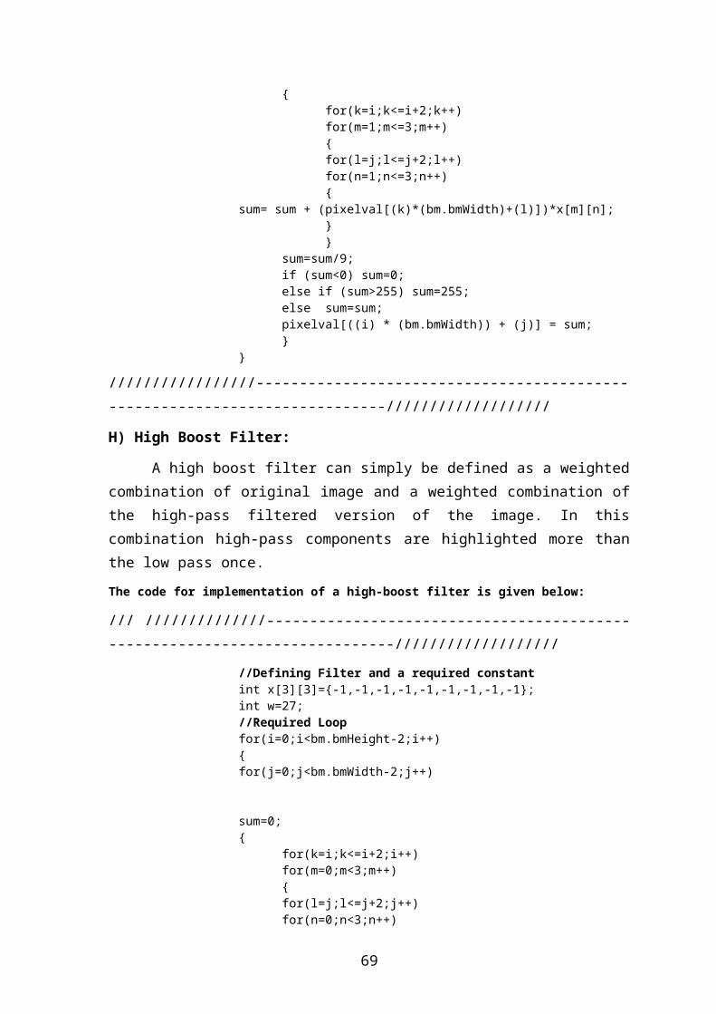
{for(k=i;k<=i+2;k++)for(m=1;m<=3;m++){for(l=j;l<=j+2;l++)for(n=1;n<=3;n++){
sum= sum + (pixelval[(k)*(bm.bmWidth)+(l)])*x[m][n];}}
sum=sum/9;if (sum<0) sum=0;else if (sum>255) sum=255;else sum=sum;pixelval[((i) * (bm.bmWidth)) + (j)] = sum;}
}
/////////////////---------------------------------------------------------------------------///////////////////
H) High Boost Filter:
A high boost filter can simply be defined as a weightedcombination of original image and a weighted combination ofthe high-pass filtered version of the image. In thiscombination high-pass components are highlighted more thanthe low pass once.The code for implementation of a high-boost filter is given below:
/// //////////////---------------------------------------------------------------------------///////////////////
//Defining Filter and a required constantint x[3][3]={-1,-1,-1,-1,-1,-1,-1,-1,-1};int w=27;//Required Loopfor(i=0;i<bm.bmHeight-2;i++){
for(j=0;j<bm.bmWidth-2;j++)
sum=0;{
for(k=i;k<=i+2;i++)for(m=0;m<3;m++){for(l=j;l<=j+2;j++)for(n=0;n<3;n++)
69
{if((k==i+1) && (l==j+1))
sum = sum + (((int)(pixelval[(i)*(bm.bmWidth)+(j)])*x[m][n])*w);
else sum = sum + ((int)(pixelval[(i)*(bm.bmWidth)+(j)])*x[m][n]);
sum=sum/9;if (sum<0) sum=0;else if (sum>255) sum=255;else sum=sum;pixelval[((i) * (bm.bmWidth)) + (j)]=sum;}}
}}
/////////////////---------------------------------------------------------------------------///////////////////
70

FINAL RESULTThe final result is that all the above given programs
were successfully created in the systems and saved asdifferent programs submitted as the practical work. Thedetails of the various applications created are given below:-
PHOTO-EXTENSION: This is a preliminary program usedfor testing the image handling task. It is a dialog-based application which opens a bitmap from thegiven bitmap button in the main dialog box anddisplays the image in the secondary window.
Image-Viewer: A simple single-document interface(SDI) based application, that opens a general imageand links it with other images with similar names,so that they can be viewed serially. If the imagehas anonymous names, they can be opened by a simpleopen command.
BMP Viewer: The image viewer program, shortened foruse in opening bitmap files only.
PNG Viewer: The image viewer program, shortened foruse in opening PNG files only.
JPEG Viewer: The image viewer program, shortened foruse in opening JPEG files only.
BMP2: This is a Single Document Interface (SDI)based application, which opens a bitmap file, readsthe information of the file byte by byte, andprocesses this information for further creatingheader information, output image and pixel-values.These values are further stored in a file inside theBMP2 application, named-“Image”. Similar programs asabove were also created with partial success, forJPEG named ‘JPG Header’ and for PNG name ‘PNGHeader’.
71
BMP-INVERSION: BMP2 application was used to create aprogram that took header information for an imageand then produced an inverted image. Thisapplication is named as BMP-INVERSION.
Pixel: The works of image processing as described inthe last experiment (experiment no.-5) are allcompiled in the applications Pixel and Pixel2respectively. All the image processing works aredeclared as specific buttons in the applicationinterface.
REFERENCE
1. Sams Teach Yourself Visual C++ in 21 days, Sams Publication, Macmillan Computer Publication, 1998.
2. Herbert schildt’s, C++ complete reference, Mc-Graw Hill Publication, 3rd Edition, 1998.
3. Beginning Visual C++ Programming 2005, Ivor Horton, Wrox Publication, Wiley Publishing Inc., 2005
4. R C Gonzalez and R E Woods. “Digital Image Processing,” 2nd Edition, 3rd Impression, 2007, Pearson Prentice Hall.
5. Wikipedia, the online dictionary.6. www.codeguru.com
72