Avantgarde CV / CS / CLT - Professionals Ottobock AU
64
Service manual Avantgarde CV / CS / CLT
-
Upload
khangminh22 -
Category
Documents
-
view
2 -
download
0
Transcript of Avantgarde CV / CS / CLT - Professionals Ottobock AU
Service manual
Avantgarde CV / CS / CLT

Introduction1 5.........................................................................................................................................................Foreword1.1 5.............................................................................................................................................Support1.2 5...............................................................................................................................................Product overview1.3 5..................................................................................................................................
Safety2 8....................................................................................................................................................................Explanation of warning symbols2.1 8..............................................................................................................General safety instructions2.2 8.....................................................................................................................
Service Work3 8.......................................................................................................................................................General Information3.1 8..............................................................................................................................Instructions for adjustment3.2 9.....................................................................................................................Maintenance Schedule3.3 9..........................................................................................................................Required Tools3.4 9.....................................................................................................................................Special features of the Avantgarde CLT3.5 9...................................................................................................Assembly A: Frame3.6 9...............................................................................................................................Replacement Work on the Frame3.6.1 9............................................................................................................Replacing the Front Frame Part3.6.1.1 9..............................................................................................................Replacing the Rear Frame Part3.6.1.2 10.............................................................................................................Replacing the Cross-Brace/Cross-Brace Bracket3.6.1.3 11...................................................................................Replacing the Joint Tubes3.6.1.4 11....................................................................................................................Replacing the Seat Tube Supports3.6.1.5 12........................................................................................................Retrofitting the Vertical Accessory Mount3.6.2 12...............................................................................................Installing and adjusting the anti-tipper3.6.3 13....................................................................................................Installing the anti-tipper3.6.3.1 13........................................................................................................................Replacing the Pivot Arm3.6.3.2 14.......................................................................................................................Replacing Anti-Tipper Rollers3.6.3.3 14...............................................................................................................Adjusting the Anti-Tipper3.6.3.4 14......................................................................................................................Retrofitting the transport wheels3.6.4 15............................................................................................................Retrofitting the Horizontal Accessory Mount3.6.5 16...........................................................................................Retrofitting the Tip-Assist3.6.6 16.....................................................................................................................Retrofitting the Crutch Holder3.6.7 16...............................................................................................................Retrofitting the Frame Pads (CS/CLT only)3.6.8 17............................................................................................Assembly B: Footrest3.7 17..........................................................................................................................Adjusting the Foot Rests/Tube Foot Rest/Foot Plates3.7.1 17..............................................................................Replacement Work on the CV Model3.7.2 17.....................................................................................................Replacing the Foot Rest3.7.2.1 17.......................................................................................................................Replacing the Foot Rest Bar/Swivel Segment3.7.2.2 18.........................................................................................Replacing the Foot Plate3.7.2.3 18......................................................................................................................Replacing the Pivot Bearing3.7.2.4 19.................................................................................................................Replacing the Locking Device3.7.2.5 19..............................................................................................................Retrofitting the Heel Strap3.7.2.6 19....................................................................................................................Elevating Foot Rest with Automatic Length Adjustment3.7.2.7 20............................................................................Retrofitting the Elevating Foot Rest3.7.2.7.1 20........................................................................................................Replacing the Foot Rest Bar3.7.2.7.2 20.................................................................................................................Replacing the Calf Pads3.7.2.7.3 21......................................................................................................................Replacing the Retaining Plate3.7.2.7.4 21...............................................................................................................Replacement work on the CS and CLT model3.7.3 21........................................................................................Replacing the Foot Rest Bar3.7.3.1 21.................................................................................................................Replacing the Foot Plate3.7.3.2 22......................................................................................................................Replacing the Foot Plate3.7.3.3 22......................................................................................................................Replacing the Tube Foot Rest3.7.3.4 22...............................................................................................................Replacing the Tube Foot Rest Mounting3.7.3.5 23................................................................................................Assembly C: seat, seating system3.8 23.........................................................................................................Replacing the Standard/Business Seat Upholstery3.8.1 23..................................................................................Replacing the Seat Upholstery, Adaptable3.8.2 23.............................................................................................
Table of contents
2
Table of contents
Avantgarde CV / CS / CLT

Cleaning the Seat Upholstery3.8.3 24...............................................................................................................Cleaning Seat Cushions3.8.4 24......................................................................................................................Assembly D: back/push handle3.9 25.............................................................................................................Replacement Work on the Push Handles3.9.1 25...............................................................................................Replacing the "standard" push handles3.9.1.1 25.................................................................................................Retrofitting the "height-adjustable" push handles3.9.1.2 25....................................................................................Retrofitting the "height-adjustable/removable" push handles3.9.1.3 25....................................................................Retrofitting the "folding" push handles3.9.1.4 26...................................................................................................Replacing the hand grips3.9.1.5 26.....................................................................................................................Replacing the Back Upholstery3.9.2 28.............................................................................................................Replacing the Back Upholstery, Standard3.9.2.1 28..............................................................................................Replacing the Back Upholstery, Adaptable3.9.2.2 28.............................................................................................Replacing the Back Tubes3.9.3 29...................................................................................................................Replacing the Angle-Adjustable Back Tubes3.9.4 29...........................................................................................Assembly E: Side Panels3.10 30.....................................................................................................................Replacement work on "standard" and "clothing protector" side panel3.10.1 30.......................................................Replacing the side panel3.10.1.1 30......................................................................................................................Replacing the Side Panel Mounting3.10.1.2 31.......................................................................................................Replacement Work on the Desk Side Panel3.10.2 31............................................................................................Replacing the Desk Side Panels3.10.2.1 31...........................................................................................................Replacing the Side Panel Mounting3.10.2.2 32.......................................................................................................Replacing the Seat Tube Support3.10.2.3 32.........................................................................................................Replacing the Retaining Clip3.10.2.4 32................................................................................................................Replacing the Pivot Pin3.10.2.5 32........................................................................................................................Replacing the Strut3.10.2.6 33.............................................................................................................................Replacing the Arm Rest Pad3.10.2.7 33.................................................................................................................Assembly F: Caster Wheels3.11 33.................................................................................................................Changing the installation position of the caster head3.11.1 33...............................................................................Replacing the caster head3.11.2 34....................................................................................................................Adjusting the Caster Wheel Journal Angle3.11.3 34..............................................................................................Replacing/Changing the Installation Position of the Caster Wheels3.11.4 35...........................................................Replacing the Caster Fork3.11.5 36...................................................................................................................Replacing the Eccentric Disc3.11.6 36................................................................................................................Retrofitting the Caster Fork System Frog Legs (spring-mounted)3.11.7 36..............................................................Retrofitting the seat height adapter3.11.8 37........................................................................................................Assembly G: Rear Wheels3.12 38...................................................................................................................Adjusting the Rear Wheels/Rear Wheel Adapters3.12.1 38....................................................................................Rear Wheel Adapter, Standard3.12.2 38.............................................................................................................Replacing the Rear Wheel Adapter, Standard3.12.2.1 38.........................................................................................Installing the Fitting3.12.2.2 39.............................................................................................................................Shock Absorber System3.12.3 40......................................................................................................................Retrofitting the Shock Absorber3.12.3.1 40............................................................................................................Installing the Fitting3.12.3.2 41.............................................................................................................................Wheelbase extension3.12.4 41...........................................................................................................................Retrofitting the Wheelbase Extension3.12.4.1 41.....................................................................................................Installing the Fitting3.12.4.2 42.............................................................................................................................Changing the Rear Wheel Camber3.12.5 42.......................................................................................................Changing the rear wheel camber with a rear wheel adapter3.12.5.1 43......................................................................Changing the rear wheel camber with a shock absorber3.12.5.2 43..........................................................................Maintenance Work on the Rear Wheel3.12.6 44...................................................................................................Replacing the push rings / adjusting the "narrow/wide" mounting position3.12.6.1 44.................................................Replacing/Retrofitting a Spoke Protector3.12.6.2 44...............................................................................................Tensioning the spokes; adjusting the out-of-round3.12.6.3 45...................................................................................Adjusting the Quick-Release Axle3.12.6.4 45..........................................................................................................Retrofitting the Tetra Axle3.12.6.5 45.....................................................................................................................Inner tube, rim tape and tyre replacement3.12.6.6 46..............................................................................................
3Avantgarde CV / CS / CLT
Table of contents

Assembly H: Wheel Lock/Brake3.13 47............................................................................................................Replacing the knee lever wheel lock3.13.1 47......................................................................................................Replacing the Brake Block3.13.2 48...................................................................................................................Retrofitting the Wheel Lock Lever Extension3.13.3 48...........................................................................................Attaching the knee-lever wheel lock for one-handed operation3.13.4 48..................................................................Retrofitting the Drum Brake3.13.5 49..................................................................................................................Adjusting the Braking Force of the Drum Brake3.13.6 50......................................................................................Retrofitting the Scissor Wheel Lock3.13.7 51.......................................................................................................Adjusting the wheel locks3.13.8 52.....................................................................................................................Additional options3.14 54...............................................................................................................................Retrofitting a Lap Belt3.14.1 54..........................................................................................................................Retrofitting a Tray3.14.2 54................................................................................................................................Retrofitting a fixation kit3.14.3 54........................................................................................................................Installing the 481S64=SK010 fixation kit (Avantgarde CS)3.14.3.1 54........................................................................Installing the 481S64=SK015 fixation kit (Avantgarde CV)3.14.3.2 55........................................................................
Technical data4 56...................................................................................................................................................Appendices5 59........................................................................................................................................................Torque values of the screw connections5.1 59.................................................................................................Maintenance Schedule5.2 60........................................................................................................................
4 Avantgarde CV / CS / CLT
Table of contents

1 Introduction1.1 Foreword• Regular maintenance is important – it improves safety and increases the lifespan of the product.• All Mobility products should be inspected and serviced once a year. • However, we recommend inspecting, readjusting, and if necessary servicing the product every 6 months if the
product is used frequently, by growing children or by users with changing clinical conditions.• Only use original spare parts for all service and maintenance work. The service and maintenance tasks
described here should only be completed by trained, qualified personnel and not by the user of the device.• This service and maintenance manual refers to the respective spare parts catalogues and the instructions for
use of the described products. Please use these documents together.• Use the maintenance schedule (checklist) as a template for making copies. Retain completed maintenance
schedules and provide the customer with a copy.
Instructions for Use (qualified personnel)
Instructions for Use (user)
Avantgarde CV, CS, CLT 647G585=* 647G689=*
1.2 SupportYour national Ottobock team will be happy to answer any technical questions. The contact addresses and telephone numbers can be found on the back inside cover of the service manual.
1.3 Product overview1
Avantgarde CS
5Avantgarde CV / CS / CLT
Introduction

Maximum load (in combination with double cross-brace): 140 kgThanks to its closed frame geometry, the Avantgarde CS allows very rigid and sporting use.
1 Seat/seat pad 9 Rear wheel with push ring2 Side panel 10 Quick-release axle release button3 Back/back upholstery 11 Double cross-brace4 Push handle 12 Caster wheel5 Back tube 13 Caster fork6 Rear frame 14 Foot plate7 Front frame 15 Knee lever wheel lock8 Rear wheel adapter
2
Avantgarde CV
Maximum load (in combination with double cross-brace): 140 kgThanks to its frame geometry, the Avantgarde CV offers precise leg guidance with the possibility of swinging awayand removing the foot rests. When the foot rests are removed, the upright frame front section allows the wheelchairto be manoeuvred close to objects.
1 Seat/seat pad 9 Rear wheel with push ring2 Side panel 10 Quick-release axle release button3 Back/back upholstery 11 Double cross-brace4 Push handle 12 Caster wheel5 Back tube 13 Caster fork6 Rear frame 14 Foot plate (foot rest removable)
6
Introduction
Avantgarde CV / CS / CLT

7 Front frame 15 Knee lever wheel lock8 Rear wheel adapter
3
Avantgarde CLT
Maximum load (in combination with double cross-brace): 100 kgThe Avantgarde CLT is the weight-optimised sports version for particularly active users. In the version CLT "welded", subsequent modification of the wheel position and back height was sacrificed in favour of saving additionalweight.
1 Seat/seat pad 9 Rear wheel with push ring2 Side panel 10 Quick-release axle release button3 Back/back upholstery 11 Double cross-brace4 Back tube 12 Caster wheel5 Push handle 13 Caster fork6 Rear frame 14 Foot rest7 Front frame 15 Knee lever wheel lock8 Rear wheel attachment device (here welded)
7Avantgarde CV / CS / CLT
Introduction

2 Safety2.1 Explanation of warning symbols
WARNING Warning regarding possible serious risks of accident or injury.CAUTION Warning regarding possible risks of accident or injury.
NOTICE Warning regarding possible technical damage.
2.2 General safety instructions
CAUTIONFailure to observe installation instructionsPinching, crushing due to installation errors► Do not reach between force-actuated surfaces during installation work (e.g. when tightening screw connec
tions).
CAUTIONUse of unsuitable toolsPinching, crushing or damaging the product due to use of unsuitable tools ► When completing the tasks, only use tools that are suitable for the conditions at the place of work and for
which safety and the protection of health are assured with proper use.► Observe the specifications in the section "Required Tools".
CAUTIONRe-use of self-locking nutsTipping over, falling of the user due to unintended loosening of the screw connections► Always replace self-locking nuts with new self-locking nuts after disassembly.
NOTICETipping or falling of the productDamage to product due to lack of attachment► When you work on the product, secure it so that it cannot tip over or fall over.► Use a clamping fixture to secure the product whenever you work on it at a workbench.
3 Service Work3.1 General Information
INFORMATIONRead the service manual before starting work. Familiarise yourself with the functions of the product prior toinspection and use. In order to do so, you can request this service manual and other documentation from themanufacturer (see the overview of national Ottobock branches on the inside of the back cover).
INFORMATIONClean and disinfect the product before commencing service work. Observe all product care and product-specific inspection instructions in the instructions for use.
INFORMATIONMany screw connections utilise screws and nuts equipped with a thread lock. If you loosen screw connections,be sure to replace the respective nut or screw with one equipped with a new thread lock. If new screws or nutswith thread lock are not available, use a medium strength liquid thread locking compound (e.g. Loctite® 241 orEuro Lock A24.20).
8
Safety
Avantgarde CV / CS / CLT

3.2 Instructions for adjustment
WARNINGLack of stability against tippingUser may fall or tip over due to lack of inspection► Changing the settings can lead to instability of the system as a whole. Verify tipping resistance after any
changes to the settings.
The sections that follow describe the replacement and retrofitting of standard and option parts on the productshown on the cover. All instructions concerning the adjustment of the installed parts are included in the instructions for use (qualifiedpersonnel) – see the section "Foreword" for the order number.
3.3 Maintenance ScheduleMaintenance schedule as a template for copying: see Page 60.
3.4 Required ToolsThe following tools are required in order to perform the service work:• Reversible ratchet handle wrench and sockets (size: 8 – 24)• Torque wrench (measurement range 5 - 50 Nm)• Wrench (size: 8 – 24), contained in the 481C08=ST010 Tool Set• Allen wrench (size: 2.5 – 6), size 3 – 6 contained in the 481C08=ST010 Tool Set• Screwdriver (blade width: 2.5 mm, 3.5 mm, 5 mm)• Phillips head screwdriver (size: 2)• Hammer (approx. 300 g); soft-faced hammer• Pliers: cutting pliers, combination pliers, snap ring pliers• Pin punches ø 3 mm, 4 mm, 5 mm, 6 mm• Drill/twist drill ø 2.5 mm, 3.2 mm, 5 mm, 5.2 mm, 6 mm• Stanley knife with sickle hooked blade and standard blade• Tyre mounting levers and inner tube repair kit• Workbench and vice with plastic jaws and rubber insert• Measurement equipment: yardstick, spirit level, back square• Liquid thread lock, "medium" and "strong"
3.5 Special features of the Avantgarde CLTLightweight construction was strictly applied in the design of the Avantgarde CLT ultra-light active wheelchair. Thisnecessitates the greatest possible care during adjustment. In particular the tightening torques for the bolts of high-strength aluminium alloy must be strictly observed (seetable).
Bolt diameter (mm) Maximum torque for aluminium bolts (Nm)6 5.58 13
Before the first assembly or re-use of the aluminium bolts, inspect the threads for damage. We recommend thatnew aluminium bolts are used at each (re-)assembly. Use a liquid bolt locking compound on the aluminium bolts (e.g., Loctite 241®).
3.6 Assembly A: Frame3.6.1 Replacement Work on the Frame3.6.1.1 Replacing the Front Frame Part1) Remove the rear wheels and flip up the footplates.2) Remove the side panels (see Page 30). 3) Slightly fold the wheelchair.4) Unscrew and remove the caster wheel assembly from the lower frame tube (see fig. 4).
→ The lower frame tube is detached from the rear part of the frame.5) Lay the wheelchair on its back and unscrew the upper frame tube (see fig. 5).
9Avantgarde CV / CS / CLT
Service Work

6) Remove the front part of the frame upward (see fig. 6). 7) Remove all parts (knee lever brake, supports) installed on the frame.8) To reassemble, perform these steps in reverse order. Tighten the frame tubes with 23 Nm.
4 5
6
3.6.1.2 Replacing the Rear Frame Part1) Remove the rear wheels and flip up the footplates.2) Remove the side panels (see Page 30). 3) Unscrew the rear wheel adapter and remove (see Page 38).4) Slightly fold the wheelchair.5) Remove the seat pad (see fig. 8)6) Open the back upholstery hook-and-loop fasteners and remove the back upholstery (see fig. 9).7) Remove the rear part of the frame rearward (see fig. 10). 8) Remove all parts (back tubes, supports) installed on the frame.9) To reassemble, perform these steps in reverse order. Tighten the frame tubes with 23 Nm.
7 8
10
Service Work
Avantgarde CV / CS / CLT

9 10
3.6.1.3 Replacing the Cross-Brace/Cross-Brace Bracket
INFORMATION► The frame components are no longer properly connected when the crossbrace is removed. Carefully lay the
frame components on the work surface after removing the crossbrace.
1) Remove both front parts of the frame (see Page 9).2) Unscrew the crossbrace centre screw and remove (see fig. 11).3) Remove the crossbrace bracket retaining clip (see fig. 12).4) Remove the end caps (see fig. 13).5) Remove the crossbrace upward (see fig. 14) and replace.6) To reassemble, perform these steps in reverse order. Tighten the centre screw to the point that folding without
jamming is possible.
11 12
13 14
3.6.1.4 Replacing the Joint Tubes1) Remove the front part of the frame (see Page 9).2) Unscrew the rear wheel adapter and remove (see Page 9).
11Avantgarde CV / CS / CLT
Service Work

3) Remove the crossbrace (see Page 11).4) Remove/replace the joint tubes (see fig. 15).5) To reassemble, perform these steps in reverse order. Tighten the frame tubes with 23 Nm.
15
3.6.1.5 Replacing the Seat Tube Supports1) Slightly fold the wheelchair (see fig. 16).2) Unscrew the seat tube supports Allen head screws, wrench size 3 (the support with side panel attachment
device as well if necessary) (see fig. 17).3) Remove/replace the supports.4) To reassemble, perform these steps in reverse order. Tighten the Allen head screws to 4 Nm.
16 17
3.6.2 Retrofitting the Vertical Accessory Mount
INFORMATIONThe vertical accessory mount and the frame accessories cannot be installed on the welded Avantgarde CLT.
The vertical accessory mount is required for the installation of the anti-tipper and the transport wheels (see fig. 18,item 1). The vertical accessory mount can be installed in two positions.1) Remove the rear reflector from the rear frame (see fig. 19).2) Hold the vertical accessory mount against the inside of the frame tube with the rounded side towards the frame
tube (see fig. 20).3) Bolt on the accessory mount:
→ Insert a screw with washer from the outside through the frame tube (see fig. 21, item 1).→ Thread a nut from above into the profile of the vertical accessory mount (see fig. 21, item 2).→ Hold the nut (see fig. 21, item 3) and tighten the screw from the outside to 7 Nm.
12
Service Work
Avantgarde CV / CS / CLT

18 19
20 21
3.6.3 Installing and adjusting the anti-tipper
WARNINGIncorrect installation of the anti-tipper/missing anti-tipperTipping over, falling of the user due to failure to observe the installation instructions and because of incorrectadjustment► Depending upon the settings of the chassis, the centre of gravity, the back angle and the experience of the
user, the use of an anti-tipper may be necessary.► For a small wheelbase and a backrest that is tilted far back, an anti-tipper may need to be installed on both
sides, depending upon the user's experience. ► Verify that the anti-tipper has been installed and adjusted properly. Find the appropriate position with the
assistance of a helper.
CAUTIONAnti-tipper not intended Tipping over of the user due to missing safety devices► On the Avantgarde CLT with fixed welded fitting, installation of an anti-tipper is not intended. ► Therefore examine the user intensively for suitability (adequate physiological capabilities) before supplying the
user with this version. This wheelchair version is intended only for experienced users with sporting ambitionswho, thanks to their physiological capabilities, are able to handle the wheelchair proficiently.
3.6.3.1 Installing the anti-tipper
INFORMATIONNote that, for a seat inclination ≥ 3 cm, the 481A64=SV172 conversion set must also be installed with the combination of the anti-tipper, right, and the crutch holder, right. This conversion is necessary to stop the anti-tipper fromstriking against the frame when deactivated.
The anti-tipper can be installed at 5 positions on the vertical accessory mount (see fig. 22, item 1).1) Push the anti-tipper tube from below into the vertical accessory mount.
13Avantgarde CV / CS / CLT
Service Work

2) Tighten the anti-tipper tube in the vertical accessory mount with the Allen head screw to 7 Nm (see fig. 22,item 2).
3) Adjusting the anti-tipper (see Page 14).
22
3.6.3.2 Replacing the Pivot Arm1) Loosen and remove the Allen head screw below the pivot arm through the maintenance opening (see fig. 23).2) Take hold of the clamping piece inside the tube and remove it (not illustrated).3) Remove the pivot arm mounting screw from the anti-tipper tube (see fig. 24).4) Remove and replace the pivot arm.5) Adjust the angle of the pivot arm if needed (see Page 14). 6) Tighten the pivot arm screw connections (see fig. 24).7) Hold the clamping piece in the tube (not illustrated). Insert the Allen head screw below the pivot arm and screw
on the clamping piece. (see fig. 23).
23 24
3.6.3.3 Replacing Anti-Tipper RollersThe replacement is made without tools by pulling out the plug-in tube.
3.6.3.4 Adjusting the Anti-Tipper
INFORMATIONIn order to adjust the anti-tipper correctly, it may be necessary to combine the steps to adjust the height andlength.
Adjusting the height of the pivot arm1) Unscrew the Allen head screw on the accessory mount (see fig. 22, item 1).2) Adjust the height of the pivot arm (see fig. 22, item 2).
→ The distance between the anti-tipper rollers and the ground must be max. 50 mm (2 inch) (see fig. 25).3) Tighten the Allen head screw to 7 Nm.
14
Service Work
Avantgarde CV / CS / CLT

Adjusting the angle of the pivot arm1) Loosen and remove the Allen head screw below the pivot arm (see fig. 26, item 1). Take hold of the clamping
piece inside the tube and remove it (see fig. 26, item 2).2) Remove the pivot arm mounting screw from the anti-tipper tube (see fig. 26, item 3).3) Move the pivot arm to a new position (3 setting possibilities: see fig. 26, item 4).
→ The distance between the anti-tipper rollers and the ground must be max. 50 mm (2 inch) (see fig. 25).4) Bolt down the pivot arm.5) Hold the clamping piece in the tube (see fig. 26, item 2). Insert the Allen head screw below the pivot arm and
screw on the clamping piece (see fig. 26, item 1).
Adjusting the length of the pivot arm1) Press in the pushbutton on the pivot arm (see fig. 27).2) Adjust the length of the pivot arm.
→ As a minimum, the anti-tipper rollers must project fully beyond the largest diameter of the rear wheel (seefig. 28).
3) Allow the pushbutton on the pivot arm to engage.
max. 5 cm
25 26
27 28
3.6.4 Retrofitting the transport wheels
CAUTIONIncorrect adjustment of the transport wheelsUser tipping over or falling due to installation errors► Align the transport wheels to the rear while installing.► Verify that the transport wheels have been set to the same height before using them.
1) Press the transport wheel locking pin in (see fig. 29).2) Insert the transport wheel true to side into the vertical accessory mount.3) Adjust the height of the transport wheels (see fig. 30). Adjust the height so that the transport wheels are
approx. 20 mm above the ground when the rear wheel is installed.
15Avantgarde CV / CS / CLT
Service Work

29
2 cm
30
3.6.5 Retrofitting the Horizontal Accessory MountThe horizontal accessory mount is required for the installation of the tip-assist and the crutch holder (see fig. 31).► Screw the mounting screws (above/inside) into the holes on the frame to 8 Nm (see fig. 32).
31 32
3.6.6 Retrofitting the Tip-Assist1) Unscrew the mounting screw on the accessory mount clamp (see fig. 33).2) Insert the tip-assist true to side (see fig. 34).3) Tighten the clamp's mounting screw to 8 Nm.
33 34
3.6.7 Retrofitting the Crutch Holder► Set the crutch holder onto the tip-assist and screw it in place.
16
Service Work
Avantgarde CV / CS / CLT

35 36
3.6.8 Retrofitting the Frame Pads (CS/CLT only)1) Position the frame pad on the front frame (see fig. 37).2) Close the frame pad hook-and-loop fastener (see fig. 38).
37 38
3.7 Assembly B: Footrest3.7.1 Adjusting the Foot Rests/Tube Foot Rest/Foot PlatesAll instructions concerning the adjustment of the foot rests are included in the Instructions for Use (qualified personnel) – order number 647G585.
3.7.2 Replacement Work on the CV Model3.7.2.1 Replacing the Foot Rest1) Open the calf strap or pull it off the retaining lug on the swivel segment.2) Push the swivel handle of the foot rest to the rear.3) Swing the foot rest outwards and to the side by 90° (see fig. 39). 4) Remove the foot rest upward and replace (see fig. 40).5) To reassemble, perform these steps in reverse order.
17Avantgarde CV / CS / CLT
Service Work

39 40
3.7.2.2 Replacing the Foot Rest Bar/Swivel Segment1) Remove the footrest.2) Unscrew/remove the set screws on the swivel segment (see fig. 41, see fig. 42).3) Remove the foot rest bar from the swivel segment (see fig. 43). Replace the foot rest bar/swivel segment if
necessary.4) Slide the foot rest bar at least 40 mm into the swivel segment.
INFORMATION: A mark on the foot rest bar indicates the minimum distance the foot rest bar must beinserted during installation..
5) Tighten the set screws to 8 Nm.
41 42
43
3.7.2.3 Replacing the Foot Plate1) Remove the foot rest.2) Unscrew the size 4 Allen head screws on the angle adjustment (see fig. 44).3) Replace the foot plate.4) To reassemble, perform these steps in reverse order. Tighten the Allen head screw to 10 Nm.
18
Service Work
Avantgarde CV / CS / CLT
44
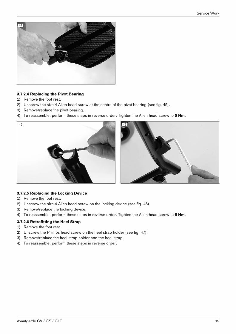
3.7.2.4 Replacing the Pivot Bearing1) Remove the foot rest.2) Unscrew the size 4 Allen head screw at the centre of the pivot bearing (see fig. 45).3) Remove/replace the pivot bearing.4) To reassemble, perform these steps in reverse order. Tighten the Allen head screw to 5 Nm.
45 46
3.7.2.5 Replacing the Locking Device1) Remove the foot rest.2) Unscrew the size 4 Allen head screw on the locking device (see fig. 46).3) Remove/replace the locking device.4) To reassemble, perform these steps in reverse order. Tighten the Allen head screw to 5 Nm.
3.7.2.6 Retrofitting the Heel Strap1) Remove the foot rest.2) Unscrew the Phillips head screw on the heel strap holder (see fig. 47).3) Remove/replace the heel strap holder and the heel strap.4) To reassemble, perform these steps in reverse order.
19Avantgarde CV / CS / CLT
Service Work

47
3.7.2.7 Elevating Foot Rest with Automatic Length Adjustment3.7.2.7.1 Retrofitting the Elevating Foot Rest1) Remove the foot rest.2) Tighten the retaining bolt with shell and size 4 Allen head screw on the frame (see fig. 48).3) Insert the elevating foot rest with automatic length adjustment into the frame. In doing so, keep the foot rest
swung outward by 90° (see fig. 49).4) Swing the elevating foot rest inward and press down.
48 49
3.7.2.7.2 Replacing the Foot Rest Bar1) Remove the Allen head screw from the foot rest bar (see fig. 50).2) Select one of the 3 threaded bores.
INFORMATION Depending on the setting it may be necessary to add or remove one or more spacer sleeves.3) Insert the Allen head screw. 4) Tighten the Allen head screw to 8 Nm.
50
20
Service Work
Avantgarde CV / CS / CLT

3.7.2.7.3 Replacing the Calf Pads1) Unscrew the calf pad with retaining plate from the foot rest (see fig. 51).2) Unscrew the calf pad from the retaining plate (see fig. 52).3) Install the new calf pad with retaining plate on the foot rest. The slots and the alternative holes can be used to
adjust the position and angle.
51 52
3.7.2.7.4 Replacing the Retaining Plate1) Unscrew the size 10 Allen head screw.2) Replace and install the retaining plate.
53
3.7.3 Replacement work on the CS and CLT model3.7.3.1 Replacing the Foot Rest Bar1) Unscrew/remove the size 5 Allen head screw on the inside of the front frame (see fig. 54).2) Remove and replace the foot rest bar (see fig. 55).3) The foot rest bar must be pushed at least 40 mm into the swivel segment.4) Tighten the Allen head screw to a torque of 10 Nm.
54 55
21Avantgarde CV / CS / CLT
Service Work

3.7.3.2 Replacing the Foot Plate1) Unscrew the size 5 Allen head screw at the under foot rest bar (see fig. 56).2) Remove the foot plate (see fig. 57).3) To reassemble, perform these steps in reverse order. Tighten the Allen head screw to 10 Nm.
56 57
3.7.3.3 Replacing the Foot PlateThe instructions for the CV model apply (see Page 18).
3.7.3.4 Replacing the Tube Foot Rest1) Flip up the tube foot rest.2) Release and flip up the lateral cover for the angle adjustment (see fig. 58, item 1).3) Unscrew the size 5 Allen head screw (see fig. 58, item 2).4) Remove/replace the tube foot rest from the lateral mounting (see fig. 59).5) Position the tube foot rest in place and tighten the Allen head screw to 10 Nm.6) Set the width of the tube foot rest by adjusting the screw (see fig. 60). 7) Flip down the tube foot rest and close the lateral cover for the angle adjustment.
58 59
60 61
22
Service Work
Avantgarde CV / CS / CLT

3.7.3.5 Replacing the Tube Foot Rest Mounting1) Unscrew the size 3 Allen head screw on the tube foot rest mounting (see fig. 61).2) Remove/replace the tube foot rest mounting.3) Tighten the Allen head screw on the tube foot rest mounting to the point that flipping up and down without
clearance is possible.
3.8 Assembly C: seat, seating system3.8.1 Replacing the Standard/Business Seat Upholstery1) Slightly fold the wheelchair and remove the seat cushion.2) Remove the protective cap (see fig. 62).3) Remove/replace the seat upholstery from the cross-brace (see fig. 63).4) If necessary, tighten the seat upholstery with the aid of the hook-and-loop connector on the bottom of the seat
upholstery (see fig. 64).5) Push the new seat upholstery onto the cross-brace.6) Push on the protective cap.7) Unfold the wheelchair. In doing so, the cross-brace must seat fully in the support guides.
62 63
64
3.8.2 Replacing the Seat Upholstery, Adaptable1) Slightly fold the wheelchair and remove the seat cushion.2) Remove the seat pad.3) Remove the protective cap (see fig. 65).4) Remove the seat upholstery from the cross-brace (see fig. 66).5) Remove/replace the upholstery bar (see fig. 67).6) Replace the seat upholstery.7) To reassemble, perform these steps in reverse order.8) If necessary, adjust the seat upholstery with the aid of the upholstery strap hook-and-loop connector (see
fig. 68).
23Avantgarde CV / CS / CLT
Service Work
65 66
67 68
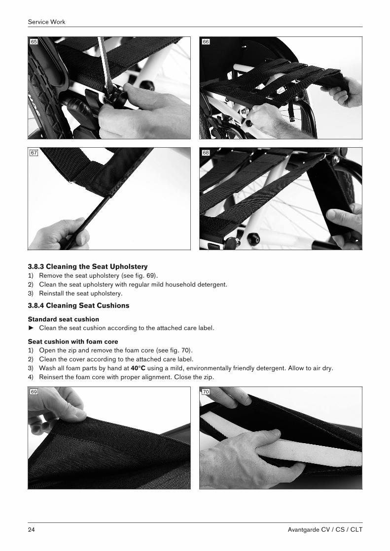
3.8.3 Cleaning the Seat Upholstery1) Remove the seat upholstery (see fig. 69).2) Clean the seat upholstery with regular mild household detergent.3) Reinstall the seat upholstery.
3.8.4 Cleaning Seat Cushions
Standard seat cushion► Clean the seat cushion according to the attached care label.
Seat cushion with foam core1) Open the zip and remove the foam core (see fig. 70).2) Clean the cover according to the attached care label.3) Wash all foam parts by hand at 40°C using a mild, environmentally friendly detergent. Allow to air dry.4) Reinsert the foam core with proper alignment. Close the zip.
69 70
24
Service Work
Avantgarde CV / CS / CLT

3.9 Assembly D: back/push handle3.9.1 Replacement Work on the Push HandlesAll push handles are installed on the upper end of the back tubes.
3.9.1.1 Replacing the "standard" push handles1) Unscrew/remove both size 5 Allen head screws on the back tube (see fig. 71).2) Remove/replace the push handle off the back tube (see fig. 72).3) To reassemble, perform these steps in reverse order.
71 72
3.9.1.2 Retrofitting the "height-adjustable" push handles1) Remove the old push handle.2) Push the height-adjustable push handle into the back tube (see fig. 73).3) In the upper hole screw the clamping lever onto the clamping lever slide block (see fig. 74).
73 74
3.9.1.3 Retrofitting the "height-adjustable/removable" push handles1) Remove the old push handle.2) Slide the "height-adjustable/removable" push handle onto the back tube.3) Insert the installation adapter into the back tube (see fig. 75).4) Bolt the installation adapter together with the push handle (see fig. 76).
25Avantgarde CV / CS / CLT
Service Work

75 76
3.9.1.4 Retrofitting the "folding" push handles1) Remove the old push handle.2) Remove the back pad.3) For adaptable back upholstery: Open/remove the uppermost strap.4) Insert the folding push handle into the back tube and tighten the 2 size 5 Allen head screws (see fig. 77).5) For adaptable back upholstery: Mount the uppermost strap on the push handle and secure with hook-and-loop
fastener (see fig. 78).6) Put the back pad back on.
77 78
3.9.1.5 Replacing the hand grips
a) "Standard" push handle, "height-adjustable/removable" push handle1) Carefully cut open the old hand grip (see fig. 79) and remove material residue from the back tube.2) Clean the tube end with solvent.3) Open the adhesive packaging and follow the instructions provided by the manufacturer of the adhesive. The
manufacturer recommends using a 2-component epoxy resin adhesive or cyanoacrylate adhesive.4) Apply the adhesive to the grip opening of each hand grip. Apply the adhesive evenly around the grip opening,
or let it spread by evenly turning the grip, up to a depth of approx. 40 to 50 mm.5) Turn the hand grip slightly to slide it onto the tube up to the end of the handle and position it vertically on the
wheelchair. Observe the processing time.NOTICE! Once the processing time (pot life) has expired, the adhesive is hardened and the pushhandle can no longer be moved or adjusted.
6) Allow the adhesive to harden for approx. 24 h before handing the wheelchair over to the user.
26
Service Work
Avantgarde CV / CS / CLT

79
b) "Height-adjustable" push handle
INFORMATIONWhen installing hand grips on the 481D64=SK040, 481D64=SK045, 481D64=SK050 and 481D64=SK055 pushhandles, the adhesive may become displaced when sliding on the grip handle, resulting in the clamping bolt forthe height adjustment being glued in place. A hole must therefore be drilled in the back side of the hand grip priorto installation.
1) Carefully cut open the old hand grip and remove material residue from the back tube.2) Clean the tube end with solvent.3) Drill a hole in the back side of the hand grip (481D64=ST021; 481D64=ST022) with a Ø 2.5 mm drill (see
fig. 80).4) Open the adhesive packaging and follow the instructions provided by the manufacturer of the adhesive. The
manufacturer recommends using a 2-component epoxy resin adhesive or cyanoacrylate adhesive.5) Apply the adhesive to the grip opening of each hand grip. Apply the adhesive evenly around the grip opening,
or let it spread by evenly turning the grip, up to a depth of approx. 40 to 50 mm.6) Turn the hand grip slightly to slide it onto the tube up to the end of the handle and position it vertically on the
wheelchair (see fig. 82). Observe the processing time.NOTICE! Once the processing time (pot life) has expired, the adhesive is hardened and the hand gripcan no longer be moved or adjusted.
7) Allow the adhesive to harden for approx. 24 h before handing the wheelchair over to the user.
80 81
27Avantgarde CV / CS / CLT
Service Work

82
3.9.2 Replacing the Back Upholstery3.9.2.1 Replacing the Back Upholstery, Standard1) Remove the push handles.2) Remove the side panels (see Page 30 ff; desk side panel example: see fig. 83).3) Remove/replace the back upholstery (see fig. 84). 4) To reassemble, perform these steps in reverse order.
83 84
3.9.2.2 Replacing the Back Upholstery, Adaptable1) Remove the push handles.2) Remove the side panels.3) Remove the back pad.4) Open the uppermost strap and remove/replace (see fig. 85). 5) Remove/replace other straps (see fig. 86).6) To reassemble, perform these steps in reverse order.
85 86
28
Service Work
Avantgarde CV / CS / CLT

3.9.3 Replacing the Back Tubes1) Remove the push handles.2) Remove the side panels.3) Remove the back upholstery.4) Remove the lower mounting screw(s) (depending on the version) from the rear frame (see fig. 87).5) Remove the mounting screw for the side panel mounting (see fig. 88).6) Remove the rear reflector and frame accessories from the rear frame (see fig. 89).7) Remove/replace the back tube (see fig. 90).8) To reassemble, perform these steps in reverse order. Tighten the screw connection evenly with 7 Nm.
87 88
89 90
3.9.4 Replacing the Angle-Adjustable Back Tubes
CAUTIONMissing anti-tipperTipping over of the user due to missing safety devices► If the back is tilted far to the rear and in the case of a short wheelbase, 2 anti-tippers (one on each side) must
be mounted and in a functional position; in the case of a long wheelbase, at least one anti-tipper must bemounted and in a functional position.
► Check that the anti-tipper is securely attached.
1) Remove the old back tube (see previous section).2) Insert the angle-adjustable back tube into the rear part of the frame (see fig. 91).3) Install the mounting for the side panel.4) Tighten all mounting screws on the rear frame to 7 Nm.5) Finally, adjust the angle on both back tubes in the same way (see fig. 92).
CAUTION! Ensure that the mounting screw is loosened enough to avoid damage to the ratchet mechanism.
29Avantgarde CV / CS / CLT
Service Work

91 92
3.10 Assembly E: Side Panels3.10.1 Replacement work on "standard" and "clothing protector" side panel3.10.1.1 Replacing the side panel1) Remove the rear wheel.2) At the back tube unscrew the size 5 Allen head screw from the side panel (see fig. 93).3) Unscrew the mounting screw on the adjustment disc and remove the cover of the adjustment disc (see fig. 94).4) Remove/replace the side panel.
93 94
Installing/adjusting the side panelsFine adjustment of the side panels to the rear wheel position is required during installation:1) If necessary, slightly loosen the slide block on the bottom of the frame (see fig. 95).2) Connect the side panel mounting on the back tube to the side panel – do not tighten (see fig. 93).3) Push on the rear wheel to determine the position.4) Adjust the position:
→ Front: Find the position of the adjustment disc relative to the mounting point (see fig. 96).→ Rear: Adjust the angle (see fig. 97).→ Slide block: If necessary, adjust the depth position (see fig. 98, item 2).
5) Push the cover onto the adjustment disc (see fig. 98, item 1). The marks on the disc help to find the position.6) Securely retighten all the screws.7) Push on the rear wheel and ensure that it can rotate freely.→ After adjustment of both side panels, both rear wheels must rotate freely without scraping noises.
30
Service Work
Avantgarde CV / CS / CLT

95 96
97 98
3.10.1.2 Replacing the Side Panel Mounting1) Remove the size 5 Allen head screw on the adjustment disc (see fig. 98, item 1).2) Unscrew the size 4 Allen head screw on the slide block (see fig. 95).3) Remove/replace the side panel mounting (see fig. 100).4) To reassemble, perform these steps in reverse order. Tighten the Allen head screws.
99 100
3.10.2 Replacement Work on the Desk Side Panel3.10.2.1 Replacing the Desk Side Panels1) Remove/replace the desk side panel.2) Insert the desk side panel in the side panel mounting and fold downward.
31Avantgarde CV / CS / CLT
Service Work

101 102
3.10.2.2 Replacing the Side Panel Mounting1) Remove the desk side panel (see fig. 103).2) Unscrew the size 3 Allen head screw (see fig. 104).3) Remove/replace the side panel mounting.4) To reassemble, perform these steps in reverse order. Tighten the Allen head screw to 5 Nm.
103 104
3.10.2.3 Replacing the Seat Tube SupportFor the replacement Replacing the Seat Tube Supports.
3.10.2.4 Replacing the Retaining Clip1) Remove the desk side panel.2) Unscrew the size 5 Allen head screw on the retaining clip (see fig. 105).3) Replace/position/bolt down the retaining clip.
105 106
3.10.2.5 Replacing the Pivot Pin1) Remove the side panel.2) Unscrew the 2 Phillips head screws on the pivot pin (see fig. 106).
32
Service Work
Avantgarde CV / CS / CLT
3) Remove/replace/bolt down the pivot pin.
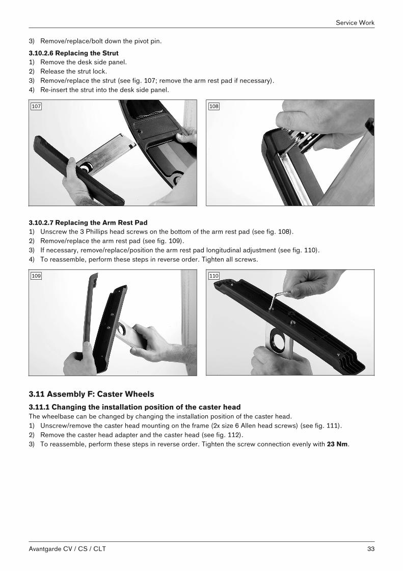
3.10.2.6 Replacing the Strut1) Remove the desk side panel.2) Release the strut lock.3) Remove/replace the strut (see fig. 107; remove the arm rest pad if necessary).4) Re-insert the strut into the desk side panel.
107 108
3.10.2.7 Replacing the Arm Rest Pad1) Unscrew the 3 Phillips head screws on the bottom of the arm rest pad (see fig. 108).2) Remove/replace the arm rest pad (see fig. 109).3) If necessary, remove/replace/position the arm rest pad longitudinal adjustment (see fig. 110).4) To reassemble, perform these steps in reverse order. Tighten all screws.
109 110
3.11 Assembly F: Caster Wheels3.11.1 Changing the installation position of the caster headThe wheelbase can be changed by changing the installation position of the caster head.1) Unscrew/remove the caster head mounting on the frame (2x size 6 Allen head screws) (see fig. 111).2) Remove the caster head adapter and the caster head (see fig. 112).3) To reassemble, perform these steps in reverse order. Tighten the screw connection evenly with 23 Nm.
33Avantgarde CV / CS / CLT
Service Work

111 112
3.11.2 Replacing the caster head1) Loosen/remove the caster head from the frame (2x Allen head screws size 6) (see fig. 111; see fig. 112).2) Remove the cover cap and loosen/pull the caster head off the threaded axle (not illustrated: 1x Allen head
screw size 5 + 1x washer)3) To reassemble, perform these steps in reverse order. When screwing the caster head to the threaded axle,
secure the Allen head screw size 5 with Loctite® 241. 4) Tighten the Allen head screws on the inside of the frame to 23 Nm (see fig. 111; see fig. 112).
3.11.3 Adjusting the Caster Wheel Journal Angle
WARNINGDamage to the eccentric during adjustment workLoss of the caster fork► When changing the position of the caster head on the frame, check the M8 interior thread on the eccentric for
damage and replace the eccentric if necessary.
The threaded axle in the caster wheel adapter should be perpendicular to the ground to ensure optimum rollingbehaviour of the wheelchair. The caster wheel adapter permits a continuous adjustment of this angle. 1) Remove the protective cap.2) Slightly loosen the Allen head screw on the eccentric (see fig. 113).3) Slightly loosen the Allen head screws on the inside of the frame (see fig. 114).4) Position the spirit level (see fig. 115, item 1).5) Adjust the caster angle to 90° with a wide flat screwdriver. The spirit level must be in the centre position to do
so (see fig. 115, item 2).6) Tighten the Allen head screw on the eccentric to 8 Nm (CLT: 5.5 Nm) (see fig. 116).7) Tighten the Allen head screws on the inside of the frame to 23 Nm.→ The threaded axle on both caster wheel adapters must be positioned vertically.
113 114
34
Service Work
Avantgarde CV / CS / CLT

115 116
3.11.4 Replacing/Changing the Installation Position of the Caster Wheels
INFORMATIONObserve the seat height table in the "Technical Data".
INFORMATIONReplace the caster wheels if cracks are visible in the material or if the material is damaged.
1) Unscrew the screw connection of the threaded axle (see fig. 117). 2) Remove the threaded axle/spacers (see fig. 118).3) Remove/replace the caster wheel.4) Insert the threaded axle with the 1st spacer bush (see fig. 119, item 1).5) Install the caster wheel.6) Push on the 2nd spacer bush (see fig. 120, item 1).7) Tighten the threaded axle to 8 Nm.→ Once changed, the left and right caster wheel must have the same vertical position in the caster wheel fork.
117 118
119 120
35Avantgarde CV / CS / CLT
Service Work

3.11.5 Replacing the Caster Fork1) Loosen/remove the size 19 hexagon nut inside the caster fork (see fig. 121).2) Remove the caster fork from the threaded stud (caster axle) and replace it. 3) Set the caster fork onto the threaded stud.4) Retighten the hexagon nut to 25 Nm.5) Make sure that the threaded axle (see fig. 122, item 1) is firmly connected to the caster attachment device (see
fig. 122, item 2). The mounting screw (see fig. 122, item 3) must be secured with Loctite® 241 (mediumstrength) and tightened to 8 Nm.
121 122
3.11.6 Replacing the Eccentric Disc1) Unscrew/remove the Allen head screw on the eccentric (see fig. 123).2) Remove/replace the eccentric disc.3) To reassemble, perform these steps in reverse order. Tighten the screw connections to 6 Nm.
123
3.11.7 Retrofitting the Caster Fork System Frog Legs (spring-mounted)1) Unscrew/remove the caster head mounting on the frame (2x size 6 Allen head screws) (--- FEHLENDER LINK -
--).2) Remove the caster head adapter and the caster head.3) Install the frog legs installation unit (caster head, frog legs caster fork: see fig. 124) on the frame using 2 size 6
Allen head screws. In doing so, install the longer screw in the rear in travel direction. 4) Tighten the Allen head screws to 6 Nm.5) Finally, adjust the caster wheel journal angle (see fig. 125; see Page 33).
36
Service Work
Avantgarde CV / CS / CLT

124 125
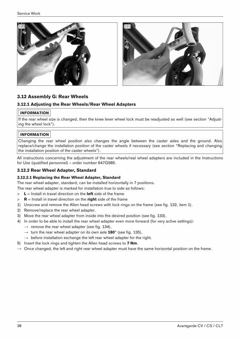
3.11.8 Retrofitting the seat height adapter1) Unscrew/remove the caster head mounting on the frame (2x size 6 Allen head screws) (see fig. 111).2) Remove the caster head adapter and the caster head (see fig. 112).3) Position the new seat height adapters on the frame:
→ Position A: for high front seat heights (see fig. 126).→ Position B: for low front seat heights (see fig. 127). With this alignment, a spacer also has to be attached to
the seat height adapter (see fig. 128)4) Tighten the seat height adapter/spacer screw connections to 23 Nm (example: see fig. 129). 5) Install the caster head with 23 Nm:
→ Position A: for high front seat heights (see fig. 130).→ Position B: for low front seat heights (see fig. 131).
6) Adjust the caster wheel journal angle (see Page 34).
126 127
128 129
37Avantgarde CV / CS / CLT
Service Work
130 131
3.12 Assembly G: Rear Wheels3.12.1 Adjusting the Rear Wheels/Rear Wheel Adapters
INFORMATIONIf the rear wheel size is changed, then the knee lever wheel lock must be readjusted as well (see section "Adjusting the wheel lock").
INFORMATIONChanging the rear wheel position also changes the angle between the caster axles and the ground. Alsoreplace/change the installation position of the caster wheels if necessary (see section "Replacing and changingthe installation position of the caster wheels").
All instructions concerning the adjustment of the rear wheels/real wheel adapters are included in the Instructionsfor Use (qualified personnel) – order number 647G585.
3.12.2 Rear Wheel Adapter, Standard3.12.2.1 Replacing the Rear Wheel Adapter, StandardThe rear wheel adapter, standard, can be installed horizontally in 7 positions.The rear wheel adapter is marked for installation true to side as follows:> L = Install in travel direction on the left side of the frame> R = Install in travel direction on the right side of the frame1) Unscrew and remove the Allen head screws with lock rings on the frame (see fig. 132, item 1). 2) Remove/replace the rear wheel adapter.3) Move the rear wheel adapter from inside into the desired position (see fig. 133). 4) In order to be able to install the rear wheel adapter even more forward (for very active settings):
→ remove the rear wheel adapter (see fig. 134),→ turn the rear wheel adapter on its own axle 180° (see fig. 135),→ before installation exchange the left rear wheel adapter for the right.
5) Insert the lock rings and tighten the Allen head screws to 7 Nm.→ Once changed, the left and right rear wheel adapter must have the same horizontal position on the frame.
38
Service Work
Avantgarde CV / CS / CLT

132 133
134 135
3.12.2.2 Installing the Fitting
INFORMATIONTo set a rear wheel camber on the fitting: see Page 43.
The rear wheel can be installed at 12 height positions in the rear wheel adapter.1) Slightly loosen the nuts on both sides of the fitting (see fig. 136, see fig. 137).2) Pull the camber washers (selection disc for track adjustment: see fig. 138, item 1) from the interior sleeve (see
fig. 138, item 2) until the fitting can be moved.3) Move the fitting together with the nuts, camber washers and the sleeve into the desired position.4) Pay attention to the following when installing the fitting:
→ Slide the inner opening of each camber washer on to the teeth of the sleeve on the correct side (seefig. 151).
→ Position the camber washer groove as parallel and upright as possible (see fig. 138, item 3).5) Insert the spirit level holder into the groove. Insert the spirit level and align the camber washers upright (see
fig. 139).6) Tighten the nuts on both sides of the fitting to 50 Nm.→ Once changed, the left and right fittings must both have the same vertical position in the rear wheel adapter.
39Avantgarde CV / CS / CLT
Service Work

136 137
138 139
3.12.3 Shock Absorber System3.12.3.1 Retrofitting the Shock AbsorberThe shock absorber system is clamped to the frame and is continuously adjustable as a result. 1) Remove the rear wheel adapter, standard (see Page 38).2) Pre-install the upper shell on the shock absorber (see fig. 140):
→ To do so, insert the 2 size 10 hex nuts into the shell's profile.→ Bolt on the size 5 Allen head screws – do not tighten.
3) Guide the shock absorber true to side at the proper clearance onto the frame from outside (see fig. 141):→ The elastomer is situated above.→ The fitting position is – as required – toward the front or rear.
4) Pre-install the lower shell (see fig. 142).5) Adjust the shock absorber depth. Use the bores in the frame for orientation (see fig. 143, item 1).6) Tighten the clamping screws to 8 Nm (see fig. 143, item 2).→ Once changed, the left and right shock absorber must have the same horizontal position on the frame.
140 141
40
Service Work
Avantgarde CV / CS / CLT

142 143
3.12.3.2 Installing the Fitting
INFORMATIONTo set a rear wheel camber on the fitting of the shock absorber: see Page 43.
The rear wheel can be installed at 3 height positions on the shock absorber.1) Loosen the nuts on both sides of the fitting (see fig. 144, item 1).2) Remove and change the installation position of the fitting.3) Before tightening the fitting, position the camber washers offset from one another (for 0° wheel camber; see
fig. 144, item 2).4) Tighten the nuts to 50 Nm.→ Once changed, the left and right fitting must have the same vertical position on the shock absorber.
144
3.12.4 Wheelbase extension3.12.4.1 Retrofitting the Wheelbase Extension1) Remove the rear wheel adapter, standard (see Page 38).2) Move the wheelbase extension from below via the frame into position (see fig. 145).3) Tighten the upper Allen head screw on the wheelbase extension arm from inside to 6 Nm (see fig. 146).4) Install the centre screw (see fig. 147):
→ Guide the Allen head screw through the centre bore on the wheelbase extension arm.→ Insert the spacer to prevent incisions.→ Tighten the centre screw with the aid of the hex nut to 23 Nm.
5) Bolt down the wheelbase extension on the top rear part of the frame with size 4 Allen head screw, washer andsize 10 hex nut (see fig. 148). Torque = 23 Nm.
6) Bolt down the wheelbase extension on the bottom rear part of the frame with size 4 Allen head screw, washerand size 10 cap nut (see fig. 149). Torque = 23 Nm.
7) Finally, push the protective caps onto the hex nuts (see fig. 150).
41Avantgarde CV / CS / CLT
Service Work

145 146
147 148
149 150
3.12.4.2 Installing the FittingFor the installation of the fitting see the section entitled "Shock Absorber System > Installing the Fitting".
3.12.5 Changing the Rear Wheel CamberThe modular system of the product offers camber washers for different sloped settings of the rear wheels. The rear wheel camber is adjusted by exchanging the camber washers in the fitting (quick-release axle mounting).This has the following effects:
Position of rear wheel Effects0° position • Narrow track, excellent straight-line stability
• Low rolling resistanceWheel camber • Wheelchair becomes more manoeuvrable, turns faster and tips less easily
to the side • The wheel position protects the hands when turning the push ring• Overall width increases• Increased rolling resistance
42
Service Work
Avantgarde CV / CS / CLT

3.12.5.1 Changing the rear wheel camber with a rear wheel adapterThe rear wheel camber can be set to 2°, 3° and 4° (for CLT fixed welded: 2.5°).1) Remove the outer mounting nut of the fitting (see fig. 136).2) Remove the front camber washer (selection disc for track adjustment) (see fig. 151, item 1).3) Remove the sleeve (see fig. 152, item 2) and the rear camber washer (see fig. 152, item 1).4) Replace the camber washers (selection discs for track adjustments). The respective wheel camber angle is
engraved in the camber washer.5) Pay attention to the following when installing the fitting:
→ Slide the inner opening of each camber washer on to the teeth of the sleeve on the correct side (seefig. 151, item 2).
→ Position the camber washer groove as parallel and upright as possible (see fig. 138, item 3).6) To correct the toe-in, insert the spirit level holder into the groove. Insert the spirit level and align the camber
washers upright (see fig. 139).7) Tighten the nuts on both sides of the fitting to 50 Nm.→ After adjustment, the camber of the left and right rear wheels must have the same angle.
151 152
3.12.5.2 Changing the rear wheel camber with a shock absorber
INFORMATION► Ottobock provides a camber adjustment set for shock absorbers as an aid for the following work. Article num
ber: 481G64=SV039 (see fig. 153). The spirit level is not part of the set.► The camber setting is only possible when the shock absorber is in the far front position on the frame.
The rear wheel camber can be set to 2.5°.1) Loosen the hexagon nuts on both sides of the fitting (see fig. 144, item 1).2) Remove the fitting.3) Prepare the adjustment plate for track correction (see fig. 153, item 1). Slide on the spirit level holder and the
spirit level (see fig. 153, item 2/3).4) Hold the adjustment plate onto the perforated plate and slide the fitting through.5) Position the camber washers on both sides of the adjustment plate, offset from one another (see fig. 153,
item 4). Note the following:→ Position the locking points of the camber washers respectively in the recesses in the plate (see fig. 154,
item 1).→ Inner camber washer alignment: The thicker/heavier side of the camber washer is on top (see fig. 155,
item 1). → Outer camber washer alignment: The thinner side of the camber washer is on top (see fig. 155, item 2).
6) Slide on the Nord-Lock® washers according to the illustration (see fig. 155, item 3).7) Install and slightly tighten the hexagon nuts.8) With the help of the spirit level, align the camber washers vertically (see fig. 156, arrows).9) Tighten the hexagon nuts to 50 Nm.→ After adjustment, the camber of the left and right rear wheels must have the same angle.
43Avantgarde CV / CS / CLT
Service Work

153 154
155 156
3.12.6 Maintenance Work on the Rear Wheel3.12.6.1 Replacing the push rings / adjusting the "narrow/wide" mounting position1) Completely remove the tyre (see fig. 157).2) Unscrew/remove the push ring screws from the rim (see fig. 158).3) Tightly bolt the push rings onto the rim in narrow or wide installation position.4) Completely reinstall the tyre.
157 158
3.12.6.2 Replacing/Retrofitting a Spoke ProtectorThe spoke protector serves to protect the spokes and prevents reaching into the rotating rear wheels.Snap fasteners (attachment nipples) are used for installation.1) Remove the rear wheels.2) Position the spoke protector on the rim so that it is centred and you can see a spoke beneath each of the six
bore holes. 3) From the outside, press in the attachment nipples e.g. with a hammer handle until you hear them lock in place
on the spokes (see fig. 159).INFORMATION: Screw connections are required for installation in some versions (see fig. 160).
44
Service Work
Avantgarde CV / CS / CLT

159 160
3.12.6.3 Tensioning the spokes; adjusting the out-of-round
Tensioning the Spokes1) Completely remove the tyre (see fig. 157).2) Check the spoke tension by shaking/moving the spokes.3) If necessary, carefully adjust the tension of the spokes with spoke tensioner.4) Completely reinstall the tyre.
Adjusting the Out-of-RoundAdjusting the out-of-round by a maximum of 1 mm requires special instruments and technical knowledge. Theadjustment should be performed in a bicycle specialist workshop.
3.12.6.4 Adjusting the Quick-Release AxleThe quick-release axle (see fig. 161) should be adjusted so that it engages properly and so that the wheel has noplay on the axle. 1) Hold the tip of the quick-release axle with a wrench (size 11).2) Adjust the play by turning the nut on the end of the quick-release axle (size 19; see fig. 161, item 1) in or out.
161 162
3.12.6.5 Retrofitting the Tetra Axle1) Remove the quick-release axle with rear wheel.2) Exchange quick-release axle for tetra axle.3) Insert rear wheel with tetra axle into the fitting.
45Avantgarde CV / CS / CLT
Service Work

163
3.12.6.6 Inner tube, rim tape and tyre replacement
INFORMATIONWhen driving outdoors, always carry a repair kit and tyre pump (when using pneumatic tyres) in case of emergency. Suitable tyre pumps are listed on the order form and are supplied with the product. An alternative is tyre foam,which fills your tyre and then hardens (available from bicycle shops etc.).
Removal and Preparing for Installation1) Carefully remove the tyre from the rim using appropriate tools.
INFORMATION: Take care not to damage the rim or the inner tube.2) Unscrew the valve nut from the valve and remove the tube.3) Repair the tube according to the directions in the repair kit or replace it with a new tube.4) Before fitting the tyre again, inspect the rim bed and tyre inner wall for foreign objects. This could have caused
the puncture. 5) Before installing the tube, check that the rim band is in proper condition. The rim band protects the tube from
being damaged by the ends of the spokes.
164 165
Replacing the Rim Band (only when necessary)1) If the rim band needs to be replaced, remove it from the rim.2) Install the new rim band on the inside of the rim, making sure the valve opening is in the right position. 3) Glue the rim band in place if this is intended. Ensure that all spoke ends are covered.
Installing the Tube and Tyre1) Behind the valve, push one side of the tyre over the edge of the rim. 2) Slightly inflate the tube until it starts to assume its round shape. 3) Unscrew the valve nut from the tube and push the valve through the valve opening in the rim.4) Insert the tube into the tyre. 5) Mount the other side of the tyre on the rim, starting from the position across the valve. Ensure that the tube is
not pinched between the tyre and rim during this process.
46
Service Work
Avantgarde CV / CS / CLT
166 167
Inflating the Tube1) Ensure that the valve is positioned perpendicularly for proper positioning of the tube and tyre in the region of
the valve. 2) Firmly screw on the valve nut.3) Inflate the tube so that the tyre can still be pressed in easily with your thumb.
INFORMATION: If the circumferential lines on the two sides of the tyre are both at an even distancefrom the rim, the tyre is centred. If not, let some air out and realign the tyre.
4) Inflate the tube to the maximum pressure specified by the tyre manufacturer (see information printed on thecasing).
5) Firmly screw the valve cap onto the valve.
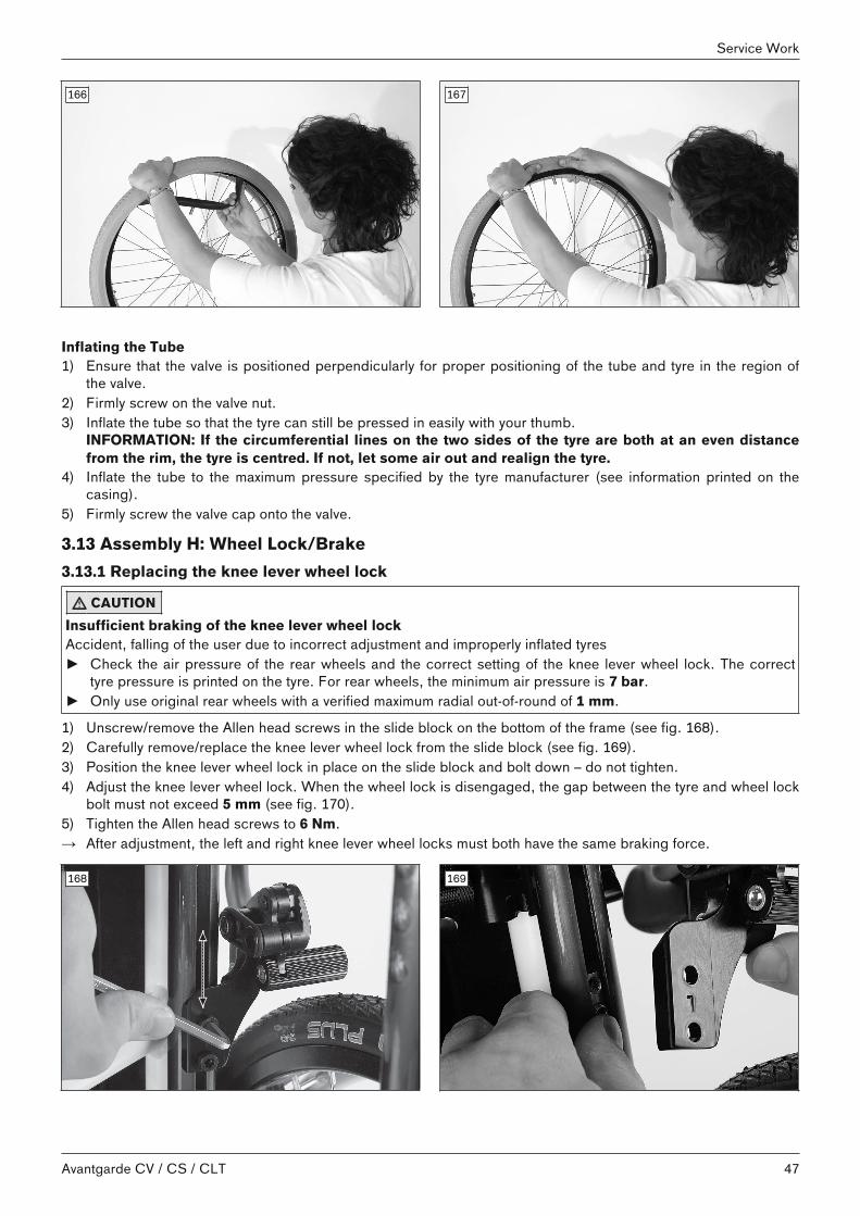
3.13 Assembly H: Wheel Lock/Brake3.13.1 Replacing the knee lever wheel lock
CAUTIONInsufficient braking of the knee lever wheel lockAccident, falling of the user due to incorrect adjustment and improperly inflated tyres► Check the air pressure of the rear wheels and the correct setting of the knee lever wheel lock. The correct
tyre pressure is printed on the tyre. For rear wheels, the minimum air pressure is 7 bar.► Only use original rear wheels with a verified maximum radial out-of-round of 1 mm.
1) Unscrew/remove the Allen head screws in the slide block on the bottom of the frame (see fig. 168).2) Carefully remove/replace the knee lever wheel lock from the slide block (see fig. 169).3) Position the knee lever wheel lock in place on the slide block and bolt down – do not tighten.4) Adjust the knee lever wheel lock. When the wheel lock is disengaged, the gap between the tyre and wheel lock
bolt must not exceed 5 mm (see fig. 170).5) Tighten the Allen head screws to 6 Nm.→ After adjustment, the left and right knee lever wheel locks must both have the same braking force.
168 169
47Avantgarde CV / CS / CLT
Service Work

5 mm
170 171
3.13.2 Replacing the Brake Block1) Unscrew the Allen head screw on the brake block (see fig. 171).2) Remove/replace the brake block.3) Tighten the screw connection with 6 Nm.
3.13.3 Retrofitting the Wheel Lock Lever Extension1) Remove the wheel lock handle from the knee lever wheel lock (see fig. 172). Cut open if necessary.2) Slip the wheel lock lever extension on true to side (see fig. 173).
172 173
3.13.4 Attaching the knee-lever wheel lock for one-handed operation1) Unfold the frame.2) Remove the installed knee lever wheel locks on the left/right and replace with the supplied assembly (see
Page 47).3) Engage the end of the Bowden cable in the knee lever wheel lock (see fig. 174).4) Insert the Bowden cable through the hole in the cable attachment pin (see fig. 175).5) Feed the Bowden cable underneath the frame to the other side (see fig. 176).6) Slide the protective cover over the Bowden cable (see fig. 177).7) Insert the Bowden cable through the hole in the cable attachment pin on the other side (see fig. 178).8) Slide the spring and sleeve over the Bowden cable (see fig. 178 and see fig. 179).9) Clamp the Bowden cable by tightening the nut (see fig. 180). Optional: Pull the Bowden cable further out so
that the braking effect is the same on both sides.10) Shorten the Bowden cable to 1 cm after making the adjustments (see fig. 181).11) Attach the cable end sleeve to the end of the Bowden cable.
48
Service Work
Avantgarde CV / CS / CLT

174 175
176 177
178 179
180 181
3.13.5 Retrofitting the Drum BrakeIn order to use rear wheels equipped with a drum brake, the standard fitting must be replaced with a mountingplate with fitting, and brake handles and Bowden cables must be installed on the wheelchair.
49Avantgarde CV / CS / CLT
Service Work

Installing the anchor plate with fitting1) Remove the standard fitting (quick-release axle housing) from the rear wheel adapter (see Page 44).2) Install the rotation prevention.3) Pre-install the mounting plate with fitting on the rear wheel adapter – do not tighten. 4) Insert the supplied spacer bushing between the anchor plate and the locking device.5) Connect the mounting plate and rotation prevention.6) Install the mounting plate tightly on the fitting. Secure the hex nuts (size 24) with high-strength thread locker
(Loctite® 601). The proper tightening torque of the screw connection on the fitting is 50 Nm on each side.
Installing the brake handles / Bowden cables1) Install the brake handles on the back tubes (Phillips head screws; see fig. 183, similar to figure).2) Route the Bowden cables from the brake handles to the brake drums. Make sure to prevent that scraping
noises can develop.3) Connect the Bowden cables to the brake drums.4) Install the rear wheels and readjust the Bowden cables if necessary. 5) The maximum braking force should be attained within the first third of the brake lever travel.
182 183
3.13.6 Adjusting the Braking Force of the Drum Brake
INFORMATIONAfter making adjustments, check that activating the manual brake lever creates a sufficient braking effect.Note that the drum brake must still be able to produce sufficient braking force even when the manual brake leveris locked into a ratchet position.
To achieve an optimum braking effect, the braking force is adjusted at the adjustment screw (see fig. 184, item 2). • Increase the braking force: Back off the adjusting screw.• Reduce the braking force: Screw in the adjustment screw.1) Loosen the counter nut (see fig. 184, item 1) and back off the adjustment screw until a scraping noise can be
heard when the rear wheel is rotated.2) Screw in the adjustment screw (see fig. 184, item 2) until the scraping noise at the rear wheel disappears and
the wheel runs freely.3) Tighten the counter nut (see fig. 184, item 1) until the adjustment screw is fixed.→ The braking force of both rear wheels must be adjusted equally.
50
Service Work
Avantgarde CV / CS / CLT

184
3.13.7 Retrofitting the Scissor Wheel Lock
Out front scissor wheel lock1) Unscrew/remove the Allen head screws in the slide block on the bottom of the frame (see fig. 168).2) Take off the knee lever wheel lock (see fig. 169).3) Reposition the slide block in the area of the clamp fitting installation position. The existing set screw remains in
the slide block for guiding in the groove (see fig. 185, item 1). Secure the slide block with an additional, longerset screw to keep it from shifting (see fig. 185, item 2).INFORMATION: The slide block prevents crushing of the frame tube when tightening the Allen headscrews on the clamp fitting.
4) Install the clamp fitting on the frame tube using the mounting materials (see fig. 185).5) Slide the scissor wheel lock into the wheel lock clamp and mount it (see fig. 186; see fig. 187). 6) Adjust the wheel lock (see Page 52).
Depending on the adjustment, it may be necessary to dismantle the support for the wheel lock and mount it in arotated position (see fig. 185, item 3).INFORMATION: Use new Allen head screws or secure the existing Allen head screws with liquidthread locking compound.
7) Tighten the Allen head screws on the clamp fitting to 15 Nm.
185 186
51Avantgarde CV / CS / CLT
Service Work

187
S-type wheel lockThe S-type wheel lock (see fig. 188) is installed in the same way as the out front scissor wheel lock.
188
3.13.8 Adjusting the wheel locks
WARNINGFailure to verify brake functionalityAccident, falling of the user due to incorrect adjustment and improperly inflated tyres► Verify the correct setting of the wheel lock (especially the distance between the wheel lock bolt and tyre). ► Ensure that the user can operate the wheel lock without great effort. The force required to do so must not
exceed 60 N (~ 6 kg).► Check the tyre pressure of the rear wheels. Note the information in the section “Technical data” or on the tyre
sidewall.► Only use original rear wheels with a verified maximum radial out-of-round of 1 mm.
This adjustment must be made after the rear wheel has been repositioned or during fine adjustment.
Adjusting the knee lever wheel locks1) Loosen the Allen head screws in the slide block on the underside of the frame (see fig. 168).2) The knee lever wheel lock is continuously adjustable in the slotted hole. When the wheel lock is disengaged,
the gap between the tyre and wheel lock bolt must not exceed 5 mm (see fig. 170).3) Tighten the Allen head screws.→ After adjustment, the left and right knee lever wheel locks must both have the same braking force.
Adjusting the scissor wheel lock: S-type wheel lock version1) Loosen the Allen head screws in the slide block (see the section "Adjusting the knee lever wheel lock").2) Adjust the wheel lock by shifting the slide block.3) Install the scissor wheel lock so that the full braking force is reached and the swivelling parts can also move
freely without colliding.→ The scissor wheel lock must not hit the frame when it is open.
52
Service Work
Avantgarde CV / CS / CLT

→ It must be impossible to push the wheelchair with the wheel locks engaged.4) Tighten the Allen head screws in the slide block to 6 Nm.→ After adjustment, the left and right scissor wheel locks must both have the same braking force.
Adjusting the scissor wheel lock: Outfront scissor wheel lock version
INFORMATION► Note that there is a slide block in the area of the clamp fitting with this wheel lock type. The slide block pre
vents crushing of the frame tube when tightening the Allen head screws on the clamp fitting.► If you have to move the clamp fitting to make major changes to the wheel lock settings, the slide block must
be moved as well.► In order to do so, loosen the longer setscrew in the slide block (see fig. 185, item 2), reposition the slide
block and firmly tighten the setscrew again. The small setscrew in the middle merely serves as a guide in thegroove (see fig. 185, item 1).
1) Loosen the Allen head screws in the clamp brackets (see fig. 190, item 1).2) Adjust/move the support for the scissor wheel lock to any position in the clamp bracket (see fig. 190, item 2).
Depending on the adjustment, it may be necessary to dismantle the support for the wheel lock and mount it in arotated position (see fig. 185, item 3).INFORMATION: Use new Allen head screws or secure the existing Allen head screws with liquidthread locking compound.
3) Install the scissor wheel lock so that the full braking force is reached and the swivelling parts can also movefreely without colliding.→ The scissor wheel lock must not hit the frame when it is open (see fig. 190).→ It must be impossible to push the wheelchair with the wheel locks engaged (see fig. 191).
4) Tighten the Allen head screws to 15 Nm (see fig. 190, item 1).→ After adjustment, the left and right scissor wheel locks must both have the same braking force.
189 190
191
Special Requirements for Adjustments (All Types of Wheel Locks)Depending on the adjustment, it may be necessary to rotate or replace the support for the wheel lock. This makesfurther wheel lock adjustments possible.
53Avantgarde CV / CS / CLT
Service Work

3.14 Additional options3.14.1 Retrofitting a Lap Belt► Tighten the lap belt screws on the back rest tube to 7 Nm. The lap belt mounting point is the upper free hole at
the rear part of the frame.
192
3.14.2 Retrofitting a TrayThe tray can be attached to the standard/height-adjustable desk side panel:1) Remove the protective foil from the tray.2) Slide the tray corresponding to the seat width onto the arm rests evenly.
3.14.3 Retrofitting a fixation kitFor using the product in vehicles for transporting persons with reduced mobility, Ottobock - in compliance withnational and international standards - has developed safety elements that improve the safety of the passengers during transport.The installation of the fixation kit offered for the product is briefly described in the following.
3.14.3.1 Installing the 481S64=SK010 fixation kit (Avantgarde CS)The 481S64=SK010 fixation kit is intended for installation on the Avantgarde CS.
Required tools• Ring spanners, sizes 10 and 13• Allen keys, sizes 4 and 5
Assembly1) Attach the pipe clamps to the frame at the positions indicated (see fig. 193).2) Screw 1 anchor plate to each of the D24 pipe clamps on the left and right of the front frame. The securement
brackets and hook symbols face outwards (see fig. 193).3) Screw 1 anchor plate to each side of the rear frame (see fig. 194). Do not fully tighten the screws until you have
installed all pipe clamps and anchor plates and have turned them to the proper angles.4) Screw the included pins onto the retaining plates on the left and right sides (see fig. 195, item 1).
→ The fixation kit is installed.
193 194
54
Service Work
Avantgarde CV / CS / CLT

195
3.14.3.2 Installing the 481S64=SK015 fixation kit (Avantgarde CV)The 481S64=SK015 fixation kit is intended for installation on the Avantgarde CV.
Required tools• Ring spanners, sizes 10 and 13• Allen keys, sizes 4 and 5
Assembly1) Screw 1 anchor plate to each side of the front frame. The securement brackets and hook symbols face out
wards (see fig. 196).2) Screw 1 anchor plate to each side of the rear frame (see fig. 197). The securement brackets and hook symbols
face outwards. 3) Screw the included pins onto the retaining plates on the left and right sides (see fig. 198, item 1).
→ The fixation kit is installed.
196 197
198
55Avantgarde CV / CS / CLT
Service Work

4 Technical dataINFORMATION
► Much of the technical data below is given in mm. Please note that product settings – unless otherwise specified – cannot be adjusted in the mm range but only in increments of approx. 0.5 cm or 1 cm.
► Note that the values achieved during adjustment may deviate from the values specified below. The deviationcan be ±10 mm and ±2°.
Avantgarde CS/CV/CLT – General data
CV CS CLTMaximum load capacity[kg]
140 140 100
Weight [kg](for seat width of 440 mm)
approx. 14.2 1) approx. 131) approx. 12 (adjustablevariant)1)
approx. 11 (welded variant)1)
Transport weights [kg](for seat width of 440 mm)
Frame: 9.51)
Footrest: 0.91)
Rear wheel 24": 1.251)
Frame: 10.51)
Rear wheel 24": 1.251)
Adjustable frame: 91)
Welded frame: 81)
Rear wheel 24": 1.251)
Seat width [mm] 320 – 500 320 – 500 320 – 500Seat depth [mm] 360 – 520 360 – 520 360 – 520Min. tyre pressure [bar] 72)
1) The specified weights vary according to the selected options and model.2) Varies according to tyre option; see the print on the tyre wall
Avantgarde CV – overall length 1) [mm]
Seat depth Lower leglengthmin./max.
22" rear wheel 24" rear wheel 25" rear wheel
Front axleposition
Rear axleposition
Front axleposition
Rear axleposition
Front axleposition
Rear axleposition
300 785 820 845 845 855 855360510 850 885 910 910 920 920300 785 840 845 865 855 875380510 850 905 910 930 920 940300 785 860 845 885 855 895400510 850 925 910 950 920 960300 785 880 845 905 845 915420510 850 945 910 970 920 980300 785 900 845 925 855 935440510 850 965 910 990 920 1000300 805 920 845 945 855 955460510 870 985 910 1010 920 1020300 820 940 845 965 855 975480510 885 1005 910 1030 920 1040300 840 960 865 985 875 995500510 905 1025 930 1050 940 1060300 860 980 885 1005 895 1015520510 925 1045 950 1070 960 1080
1) With wheelbase extension: rear axle position + 95 mm.
56
Technical data
Avantgarde CV / CS / CLT

Avantgarde CS/CLT – overall length1), 2) [mm]
Seat depth 22" rear wheel 24" rear wheel 25" rear wheelFront axleposition
Rear axleposition
Front axleposition
Rear axleposition
Front axleposition
Rear axleposition
360 – 420 720 925 775 950 785 960440 – 480 760 965 775 990 785 1000500 – 520 800 1005 825 1030 835 1040
1) With wheelbase extension: rear axle position +95 mm.2) On Avantgarde CLT, fixed welded variant: rear axle position -20 mm.
Avantgarde CV/CS/CLT – overall width with rear wheel with hollow rim1), 2), 3) [mm]
Seat width Side panels, standard and clothing protector Desk side panel with armrest, height-adjustable
320 490 505340 510 525360 530 545380 550 565400 570 585420 590 605440 610 625460 630 645480 650 665500 670 685
1) Applicable to push rim attachment, narrow and a 0° camber of the rear wheels (push rim attachment, wide:+20 mm).2) For installation of rear wheel with Infinity Ultralight rim: overall width -10 mm.3) For installation of rear wheel with Spinergy SPOX rim and rear wheel with attendant wheel lock: overall width+10 mm.
Increase of the overall width because of the wheel camber setting of the rear wheels (all models) [mm]
Wheel camber 22" rear wheel 24" rear wheel 25" rear wheel0° 0 0 02° < 40 40 > 403° < 60 60 > 604° < 80 80 > 80
Folded dimensions, including rear wheelsfrom 260 mm
Avantgarde CS/CV/CLT – lower leg length1), 2) [mm]
Short lower leg length 160 – 310Lower leg length 300 – 510
1) Measured from top of seat cover to top of footplate2) Lower leg length minus thickness of seat cushion used
Avantgarde CV/CS/CLT – front seat height1), 2), 3) [mm]Caster fork, threaded axle/quick-release axle
Caster wheel size Setting range – caster fork, short
57Avantgarde CV / CS / CLT
Technical data

Caster wheel size Setting range – caster fork, shortWith adapter for smallfront seat heights
Without seat heightadapter
With adapter for largefront seat heights
3" 390; 400 420; 430 4504" 390 – 410 420 – 440 4505" 400 – 420 430 – 460 ---5.5" --- 440 – 460 ---6" --- 460; 470 ---7" --- 480 ---
Caster wheel size Setting range – caster fork, long (see fig. 199)With adapter for smallfront seat heights
Without seat heightadapter
With adapter for largefront seat heights
3" 450 460; 470 490; 5004" 450 460 – 480 500 – 5205" --- 460 – 490 500 – 5305.5" 430 470 – 500 510 – 5406" 440; 450 470 – 500 510 – 5407" 450 – 470 490 – 520 530 – 550
Frogleg caster fork
Caster wheel size Setting range – caster fork, shortWith adapter for smallfront seat heights
Without seat heightadapter
With adapter for largefront seat heights
3" 410; 420 440; 450 480; 4904" 410 – 430 440 – 460 480 – 5005" 430; 440 470; 480 5106" --- 490 530
Caster wheel size Setting range – frogleg caster fork, longWith adapter for smallfront seat heights
Without seat heightadapter
With adapter for largefront seat heights
3" 430 460; 470 480; 5104" 430 470 – 490 500 – 5205" 450; 460 490; 500 520; 5306" 480 510 550
1) The front seat height depends on the selected wheel size, caster fork and mounting position.2) Specified at 0° seat angle, without seat cushion.3) The values indicated are rounded values which have been theoretically determined. Max. deviation 10 mm.
Avantgarde CS/CV/CLT – rear seat height1), 2), 3) [mm])
Rear wheel size Adjustment range22" 360 – 47024" 380 – 49525" 400 – 510
1) The rear seat height depends on the selected wheel size and mounting position in the rear wheel attachmentdevice.2) From position E, the rear wheel adapter must be turned around (see fig. 200): right side to the left side and leftside to the right side.3) Avantgarde CLT, fixed welded variant: for the exact values for "rear seat height", see 647F105* order form.
58
Technical data
Avantgarde CV / CS / CLT

199 200
5 Appendices5.1 Torque values of the screw connectionsUnless otherwise specified, screw connections are tightened with the following torque values:• Thread diameter M4: 3 Nm• Thread diameter M5: 5 Nm• Thread diameter M6: 10 Nm• Thread diameter M8: 25 Nm
59Avantgarde CV / CS / CLT
Appendices

5.2 Maintenance ScheduleMaintenance Schedule Type of wheelchair: Customer:Item Area Inspection (checklist)
SN: 1. Function/setting(depending on equipment)
2. Inspected for damage/deformation
3. Screw connectionsinspected
Frame Frame x xAnti-tipper x xCrutch holder x xTip-assist x x
AFrame accessories
Frame pad xFolding mechanism x xLower leg length setting x x
Foot rests
Angle adjustment x xPlastic plate x xLateral heel blocks x x
B
Foot rest accessories
Heel strap x xCross-brace x xSeat upholstery x x
C Seat
Seat cushion xBack upholstery xBack tubes x xAngle adjustment x x
D Back / push handles
Push handles x xHeight setting x xSwivel mechanism x x
Side panels
Removability xArm rest padded, swing-away x x
E
Side panel accessoriesTray x xTyres (wear) x xAir pressure x xCaster wheel journal angle x xScrew connections on the frame x xSwivelling of the caster forks x x
F Caster wheel
Running behaviour of the wheels x xTyres (wear) x xRunning behaviour of the wheels x xSpokes / push rings x xQuick-release axles x xWheel camber x x
Rear wheel
Rear wheel attachment device x xDrum brake x xHub brake x xOne-arm drive x xWheelbase extension x xSpoke protectors x x
G
Rear wheel accessories
Shock absorber x xBraking function x xWheel locks / brakesSwing-away mechanism x x
H
Wheel lock accessories Wheel lock lever extension x xTray x xAccessoriesLap belt x x
Do the wheelchair settings match the user's requirements?The maintenance service was performed by: on:
60
Appendices
Avantgarde CV / CS / CLT

61Avantgarde CV / CS / CLT

Avantgarde CV / CS / CLT62

Kundenservice/Customer Service
EuropeOtto Bock HealthCare Deutschland GmbHMax-Näder-Str. 15 · 37115 Duderstadt · GermanyT +49 5527 848-3433 · F +49 5527 [email protected] · www.ottobock.de
Otto Bock Healthcare Products GmbHBrehmstraße 16 · 1110 Wien · AustriaF +43 1 [email protected] · www.ottobock.at
Otto Bock Adria d.o.o. SarajevoRamiza Salčina 8571000 Sarajevo · Bosnia-HerzegovinaT +387 33 255-405 · F +387 33 [email protected] · www.ottobockadria.com.ba
Otto Bock Bulgaria Ltd.41 Tzar Boris III‘ Blvd. · 1612 Sofia · BulgariaT +359 2 80 57 980 · F +359 2 80 57 [email protected] · www.ottobock.bg
Otto Bock Suisse AGLuzerner Kantonsspital 10 · 6000 Luzern 16 · SuisseT +41 41 455 61 71 · F +41 41 455 61 [email protected] · www.ottobock.ch
Otto Bock ČR s.r.o.Protetická 460 · 33008 Zruč-Senec · Czech RepublicT +420 377825044 · F +420 [email protected] · www.ottobock.cz
Otto Bock Iberica S.A.C/Majada, 1 · 28760 Tres Cantos (Madrid) · SpainT +34 91 8063000 · F +34 91 [email protected] · www.ottobock.es
Otto Bock France SNC4 rue de la Réunion - CS 9001191978 Courtaboeuf Cedex · FranceT +33 1 69188830 · F +33 1 [email protected] · www.ottobock.fr
Otto Bock Healthcare plc32, Parsonage Road · Englefield GreenEgham, Surrey TW20 0LD · United KingdomT +44 1784 744900 · F +44 1784 [email protected] · www.ottobock.co.uk
Otto Bock Hungária Kft.Tatai út 74. · 1135 Budapest · HungaryT +36 1 4511020 · F +36 1 [email protected] · www.ottobock.hu
Otto Bock Adria d.o.o.Dr. Franje Tuđmana 14 ·10431 Sveta Nedelja · CroatiaT +385 1 3361 544 · F +385 1 3365 [email protected] · www.ottobock.hr
Otto Bock Italia Srl UsVia Filippo Turati 5/7 · 40054 Budrio (BO) · ItalyT +39 051 692-4711 · F +39 051 [email protected] · www.ottobock.it
Otto Bock Benelux B.V.Mandenmaker 14 · 5253 RCNieuwkuijk · The NetherlandsT +31 73 5186488 · F +31 73 [email protected] · www.ottobock.nl
Industria Ortopédica Otto Bock Unip. Lda.Av. Miguel Bombarda, 21 - 2º Esq.1050-161 Lisboa · PortugalT +351 21 3535587 · F +351 21 [email protected]
Otto Bock Polska Sp. z o. o.Ulica Koralowa 3 · 61-029 Poznań · PolandT +48 61 6538250 · F +48 61 [email protected] · www.ottobock.pl
Otto Bock Romania srlŞos de Centura Chitila - Mogoşoaia Nr. 3077405 Chitila, Jud. Ilfov · RomaniaT +40 21 4363110 · F +40 21 [email protected] · www.ottobock.ro
OOO Otto Bock Servicep/o Pultikovo, Business Park „Greenwood“,Building 7, 69 km MKAD143441 Moscow Region/Krasnogorskiy RayonRussian FederationT +7 495 564 8360 · F +7 495 564 [email protected] · www.ottobock.ru
Otto Bock Scandinavia ABKoppargatan 3 · Box 623 · 60114 Norrköping · SwedenT +46 11 280600 · F +46 11 [email protected] · www.ottobock.se
Otto Bock Slovakia s.r.o.Röntgenova 26 · 851 01 Bratislava 5 · Slovak RepublicT +421 2 32 78 20 70 · F +421 2 32 78 20 [email protected] · www.ottobock.sk
Otto Bock Sava d.o.o.Industrijska bb · 34000 Kragujevac · Republika SrbijaT +381 34 351 671 · F +381 34 351 [email protected] · www.ottobock.rs
Otto Bock Ortopedi ve Rehabilitasyon Tekniği Ltd. Şti.Mecidiyeköy Mah. Lati Lokum Sok.Meriç Sitesi B Blok No: 30/B34387 Mecidiyeköy-İstanbul · TurkeyT +90 212 3565040 · F +90 212 [email protected] · www.ottobock.com.tr
AfricaOtto Bock Algérie E.U.R.L.32, rue Ahcène Outaleb - Coopérative les MimosasMackle-Ben Aknoun · Alger · DZ AlgérieT +213 21 913863 · F +213 21 [email protected] · www.ottobock.fr
Otto Bock Egypt S.A.E.28 Soliman Abaza St. Mohandessein - Giza · EgyptT +20 2 37606818 · F +20 2 [email protected] · www.ottobock.com.eg
Otto Bock South Africa (Pty) LtdBuilding 3 Thornhill Office Park · 94 Bekker RoadMidrand · Johannesburg · South AfricaT +27 11 564 [email protected]
AmericasOtto Bock Argentina S.A.Av. Belgrano 1477 · CP 1093Ciudad Autônoma de Buenos Aires · ArgentinaT +54 11 5032-8201 / [email protected]
Otto Bock do Brasil Tecnica Ortopédica Ltda.Alameda Maria Tereza, 4036, Bairro Dois CórregosCEP: 13.278-181, Valinhos-São Paulo · Brasil T +55 19 3729 3500 · F +55 19 3269 6061 [email protected] · www.ottobock.com.br
Otto Bock HealthCare Canada5470 Harvester Road Burlington, Ontario, L7L 5N5, CanadaT +1 800 665 3327 · F +1 800 463 [email protected] ·www.ottobock.ca
Oficina Ottobock HabanaCalle 3ra entre 78 y 80.Edificio Jerusalen · Oficina 112 · Calle 3ra.Playa, La Habana. CubaT +53 720 430 69 · +53 720 430 [email protected]
Otto Bock HealthCare Andina Ltda.Calle 138 No 53-38 · Bogotá · ColombiaT +57 1 8619988 · F +57 1 [email protected] · www.ottobock.com.co
Otto Bock de Mexico S.A. de C.V.Prolongación Calle 18 No. 178-ACol. San Pedro de los PinosC.P. 01180 México, D.F. · MexicoT +52 55 5575 0290 · F +52 55 5575 [email protected] · www.ottobock.com.mx
Otto Bock HealthCare LP11501 Alterra Parkway Suite 600Austin, TX 78758 · USAT +1 800 328 4058 · F +1 800 962 [email protected]
Asia/PacificOtto Bock Australia Pty. Ltd.Suite 1.01, Century Corporate Centre62 Norwest BoulevardeBaulkham Hills NSW 2153 · AustraliaT +61 2 8818 2800 · F +61 2 8814 [email protected] · www.ottobock.com.au
Beijing Otto Bock Orthopaedic Industries Co., Ltd.B12E, Universal Business Park10 Jiuxianqiao Road, Chao Yang DistrictBeijing, 100015, P.R. ChinaT +8610 8598 6880 · F +8610 8598 [email protected]
Otto Bock Asia Pacific Ltd.Unit 1004, 10/F, Greenfield Tower, Concordia Plaza 1 Science Museum Road, Tsim Sha TsuiKowloon, Hong Kong · China T +852 2598 9772 · F +852 2598 7886 [email protected] · www.ottobock.com
Otto Bock HealthCare India Pvt. Ltd.20th Floor, Express TowersNariman Point, Mumbai 400 021 · IndiaT +91 22 2274 5500 / 5501 / [email protected] · www.ottobock.in
Otto Bock Japan K. K.Yokogawa Building 8F, 4-4-44 ShibauraMinato-ku, Tokyo, 108-0023 · JapanT +81 3 3798-2111 · F +81 3 [email protected] · www.ottobock.co.jp
Otto Bock Korea HealthCare Inc.4F Agaworld Building · 1357-74, Seocho-dongSeocho-ku, 137-070 Seoul · KoreaT +82 2 577-3831 · F +82 2 [email protected] · www.ottobockkorea.com
Otto Bock South East Asia Co., Ltd.1741 Phaholyothin RoadKwaeng Chatuchark · Khet ChatucharkBangkok 10900 · ThailandT +66 2 930 3030 · F +66 2 930 [email protected] · www.ottobock.co.th
Other countriesOtto Bock HealthCare GmbHMax-Näder-Straße 15 · 37115 Duderstadt · GermanyT +49 5527 848-1590 · F +49 5527 [email protected] · www.ottobock.com

Template-Version: SB_2016-10-21 · FM483 · SB_210x297
Ihr Fachhändler | Your specialist dealer
Otto Bock Mobility Solutions GmbHLindenstraße 13 · 07426 Königsee-Rottenbach/Germanywww.ottobock.com
© O
ttobo
ck ·
647G
690=
en-0
3-17
04
Printed by: