PROCEEDINGS OF SPIE - Caltech Authors
13
PROCEEDINGS OF SPIE SPIEDigitalLibrary.org/conference-proceedings-of-spie TMT telescope structure system: design and development progress report Kei Szeto, Scott Roberts, Mike Gedig, Glenn Austin, Christie Lagally, et al. Kei Szeto, Scott Roberts, Mike Gedig, Glenn Austin, Christie Lagally, Steven Patrick, Dominic Tsang, Doug MacMynowski, Mark Sirota, Larry Stepp, Peter M. Thompson, "TMT telescope structure system: design and development progress report," Proc. SPIE 7012, Ground-based and Airborne Telescopes II, 70122G (10 July 2008); doi: 10.1117/12.787002 Event: SPIE Astronomical Telescopes + Instrumentation, 2008, Marseille, France Downloaded From: https://www.spiedigitallibrary.org/conference-proceedings-of-spie on 7/9/2018 Terms of Use: https://www.spiedigitallibrary.org/terms-of-use
-
Upload
khangminh22 -
Category
Documents
-
view
1 -
download
0
Transcript of PROCEEDINGS OF SPIE - Caltech Authors
PROCEEDINGS OF SPIE
SPIEDigitalLibrary.org/conference-proceedings-of-spie
TMT telescope structure system:design and development progressreport
Kei Szeto, Scott Roberts, Mike Gedig, Glenn Austin,Christie Lagally, et al.
Kei Szeto, Scott Roberts, Mike Gedig, Glenn Austin, Christie Lagally,Steven Patrick, Dominic Tsang, Doug MacMynowski, Mark Sirota, LarryStepp, Peter M. Thompson, "TMT telescope structure system: design anddevelopment progress report," Proc. SPIE 7012, Ground-based and AirborneTelescopes II, 70122G (10 July 2008); doi: 10.1117/12.787002
Event: SPIE Astronomical Telescopes + Instrumentation, 2008, Marseille,France
Downloaded From: https://www.spiedigitallibrary.org/conference-proceedings-of-spie on 7/9/2018 Terms of Use: https://www.spiedigitallibrary.org/terms-of-use
TMT Telescope Structure System – Design and Development Progress Report
Kei Szeto*†a, Scott Robertsa, Mike Gedigb, Glenn Austinb, Christie Lagallyb, Steven Patrickb,
Dominic Tsangb, Doug MacMynowskic, Mark Sirotac, Larry Steppc, Peter M. Thompsond aNational Research Council Canada, Herzberg Institute of Astrophysics, 5071 West Saanich Road,
Victoria, B.C., Canada, V9E 2E7 bEmpire Dynamic Structures, 1515 Kingsway Avenue, Port Coquitlam , B.C., Canada V3C 1S2
cThirty Meter Telescope Project, 2632 E. Washington Blvd., Pasadena, CA 91107 dSystems Technology, Inc., 13766 S. Hawthorne Blvd., Hawthorne, CA 90250-7083 USA
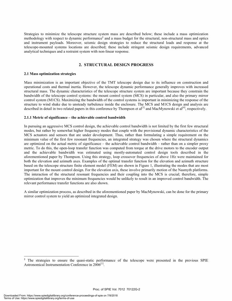
The Thirty Meter Telescope (TMT) project‡ has revised the reference optical configuration from an Aplanatic Gregorian to a Ritchey-Chrétien design. This paper describes the revised telescope structural design and outlines the design methodology for achieving the dynamic performance requirements derived from the image jitter error budget. The usage of transfer function tools which incorporate the telescope structure system dynamic characteristics and the control system properties is described along with the optimization process for the integrated system. Progress on the structural design for seismic considerations is presented. Moreover, mechanical design progress on the mount control system hardware such as the hydrostatic bearings and drive motors, cable wraps and safety system hardware such as brakes and absorbers are also presented. Keywords: telescope structure, seismic restraint, mount control, transfer function, linear motor, wind
1. INTRODUCTION 1.1 Revised TMT telescope configuration The TMT telescope structure design based on the original Aplanatic Gregorian optical design was presented in the last SPIE Astronomical Instrumentation Conference in 2006[1]. Since then, the TMT project has adopted a Ritchey-Chrétien optical design resulting in an overall height reduction of the telescope structure by 6.2 m. Other noteworthy changes to the telescope structure configuration are:
• The size of the hexagonal primary mirror segments was increased from 1.2 m to 1.4 m from vertex to vertex, and the number of segments was reduced from 738 to 492;
• No part of the telescope, including telescope mounted systems, is allowed to extend more than 28.5 m from the intersection of the azimuth axis and elevation axis; this was reduced from instead of 34 m;
• The Nasmyth platform horizontal deck level, which serves as the default TMT instrument support location, was lowered by 5 m to 7 m below the elevation axis and the outer edge radius was reduced to 27.6 m from 32 m originally;
• A central pintle bearing has been incorporated to provide lateral restraint during operation and earthquake conditions;
• The unvignetted telescope field of view has been reduced to 15 arcminutes; however, the telescope structure is required to maintain the original structural clearance of 20 arcminutes along the elevation axis.
The aforementioned changes are the results of engineering development and programmatic changes of the TMT project. For example, the Ritchey-Chrétien optical configuration was adopted to shorten the telescope structure and reduce the enclosure size thus realizing lower costs on site excavation, foundation work, enclosure fabrication and erection. The TMT enclosure design is presented in a related paper in this conference by Loewen et al[2].
* Email: [email protected]; Telephone: 250-363-0059; Fax 250-363-0045 † The TMT project is a partnership between ACURA (Association of Canadian Universities for Research in Astronomy) in Canada, the University of California and Caltech.
Ground-based and Airborne Telescopes II, edited by Larry M. Stepp, Roberto Gilmozzi,Proc. of SPIE Vol. 7012, 70122G, (2008) · 0277-786X/08/$18 · doi: 10.1117/12.787002
Proc. of SPIE Vol. 7012 70122G-1
Downloaded From: https://www.spiedigitallibrary.org/conference-proceedings-of-spie on 7/9/2018Terms of Use: https://www.spiedigitallibrary.org/terms-of-use
Strategies to minimize the telescope structure system mass are described below; these include a mass optimization methodology with respect to dynamic performance§ and a mass budget for the structural, non-structural mass and optics and instrument payloads. Moreover, seismic design strategies to reduce the structural loads and response at the telescope-mounted systems locations are described; these include stringent seismic design requirements, advanced analytical techniques and a restraint system with non-linear response.
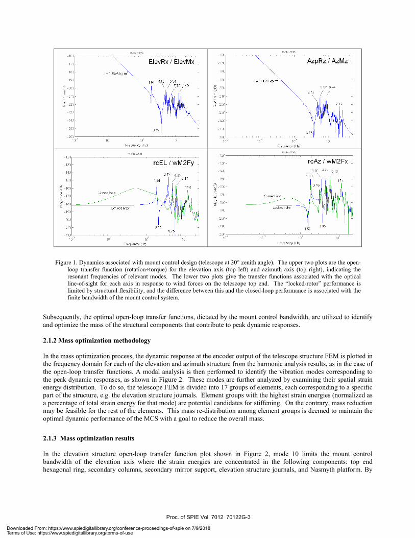
2. STRUCTURAL DESIGN PROGRESS 2.1 Mass optimization strategies Mass minimization is an important objective of the TMT telescope design due to its influence on construction and operational costs and thermal inertia. However, the telescope dynamic performance generally improves with increased structural mass. The dynamic characteristics of the telescope structure system are important because they constrain the bandwidth of the telescope control systems: the mount control system (MCS) in particular, and also the primary mirror control system (M1CS). Maximizing the bandwidth of the control systems is important in minimizing the response of the structure to wind shake due to unsteady turbulence inside the enclosure. The MCS and M1CS design and analysis are described in detail in two related papers in this conference by Thompson et al[3] and MacMynowski et al[4], respectively. 2.1.1 Metric of significance – the achievable control bandwidth In pursuing an aggressive MCS control design, the achievable control bandwidth is not limited by the first few structural modes, but rather by somewhat higher frequency modes that couple with the provisional dynamic characteristics of the MCS actuators and sensors that are under development. Thus, rather than formulating a simple requirement on the minimum value of the first few resonant frequencies, an integrated strategy was chosen where the structural dynamics are optimized on the actual metric of significance – the achievable control bandwidth – rather than on a simpler proxy metric. To do this, the open-loop transfer function was computed from torque at the drive motors to the encoder output and the achievable bandwidth was estimated using mostly-automated control design tools described in the aforementioned paper by Thompson. Using this strategy, loop crossover frequencies of above 1Hz were maintained for both the elevation and azimuth axes. Examples of the optimal transfer function for the elevation and azimuth structure based on the telescope structure finite element model (FEM) are shown in Figure 1, illustrating the modes that are most important for the mount control design. For the elevation axis, these involve primarily motion of the Nasmyth platforms. The interaction of the structural resonant frequencies and their coupling into the MCS is crucial; therefore, simple optimization that improves the minimum frequencies would be unlikely to result in an improved control bandwidth. The relevant performance transfer functions are also shown. A similar optimization process, as described in the aforementioned paper by MacMynowski, can be done for the primary mirror control system to yield an optimized integrated design.
§ The strategies to ensure the quasi-static performance of the telescope were presented in the previous SPIE Astronomical Instrumentation Conference in 2006[1].
Proc. of SPIE Vol. 7012 70122G-2
Downloaded From: https://www.spiedigitallibrary.org/conference-proceedings-of-spie on 7/9/2018Terms of Use: https://www.spiedigitallibrary.org/terms-of-use
10-n 100
Frequency (Hz)
-240
100
Frequency (Hz)
AzpRz/AzMz
-120
Frequency (Hz)
rcEL/wM2Fy
10-n 100
Frequency (Hz)
rcAz I wM2Fx
Figure 1. Dynamics associated with mount control design (telescope at 30° zenith angle). The upper two plots are the open-loop transfer function (rotation÷torque) for the elevation axis (top left) and azimuth axis (top right), indicating the resonant frequencies of relevant modes. The lower two plots give the transfer functions associated with the optical line-of-sight for each axis in response to wind forces on the telescope top end. The “locked-rotor” performance is limited by structural flexibility, and the difference between this and the closed-loop performance is associated with the finite bandwidth of the mount control system.
Subsequently, the optimal open-loop transfer functions, dictated by the mount control bandwidth, are utilized to identify and optimize the mass of the structural components that contribute to peak dynamic responses. 2.1.2 Mass optimization methodology In the mass optimization process, the dynamic response at the encoder output of the telescope structure FEM is plotted in the frequency domain for each of the elevation and azimuth structure from the harmonic analysis results, as in the case of the open-loop transfer functions. A modal analysis is then performed to identify the vibration modes corresponding to the peak dynamic responses, as shown in Figure 2. These modes are further analyzed by examining their spatial strain energy distribution. To do so, the telescope FEM is divided into 17 groups of elements, each corresponding to a specific part of the structure, e.g. the elevation structure journals. Element groups with the highest strain energies (normalized as a percentage of total strain energy for that mode) are potential candidates for stiffening. On the contrary, mass reduction may be feasible for the rest of the elements. This mass re-distribution among element groups is deemed to maintain the optimal dynamic performance of the MCS with a goal to reduce the overall mass.
2.1.3 Mass optimization results In the elevation structure open-loop transfer function plot shown in Figure 2, mode 10 limits the mount control bandwidth of the elevation axis where the strain energies are concentrated in the following components: top end hexagonal ring, secondary columns, secondary mirror support, elevation structure journals, and Nasmyth platform. By
Proc. of SPIE Vol. 7012 70122G-3
Downloaded From: https://www.spiedigitallibrary.org/conference-proceedings-of-spie on 7/9/2018Terms of Use: https://www.spiedigitallibrary.org/terms-of-use
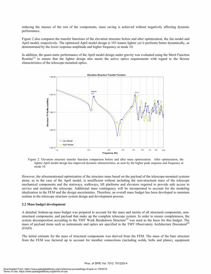
reducing the masses of the rest of the components, mass saving is achieved without negatively affecting dynamic performance. Figure 2 also compares the transfer functions of the elevation structure before and after optimization, the Jan model and April model, respectively. The optimized April model design is 183 tonnes lighter yet it performs better dynamically, as demonstrated by the lower response amplitude and higher frequency at mode 10. In addition, the quasi-static performance of the April model design under gravity was evaluated using the Merit Function Routine[1] to ensure that the lighter design also meets the active optics requirements with regard to the flexure characteristics of the telescope-mounted optics.
Figure 2. Elevation structure transfer function comparison before and after mass optimization. After optimization, the
lighter April model design has improved dynamic characteristics, as seen by the higher peak response and frequency at mode 10.
However, the aforementioned optimization of the structure mass based on the payload of the telescope-mounted systems alone, as in the case of the April model, is insufficient without including the non-structural mass of the telescope mechanical components and the stairways, walkways, lift platforms and elevators required to provide safe access to service and maintain the telescope. Additional mass contingency will be incorporated to account for the modeling idealization in the FEM and the design uncertainties. Therefore, an overall mass budget has been developed to maintain realism in the telescope structure system design and development process. 2.2 Mass budget development A detailed, bottom-up mass budget was prepared to account for the mass and inertia of all structural components, non-structural components, and payload that make up the complete telescope system. In order to ensure completeness, the system decomposition according to the TMT Work Breakdown Structure[5] was used as the basis for this budget. The mass of payload items such as instruments and optics are specified in the TMT Observatory Architecture Document[6] (OAD). The initial estimate for the mass of structural components was derived from the FEM. The mass of the bare structure from the FEM was factored up to account for member connections (including welds, bolts and plates), equipment
Elevation Structure Transfer Function
1.0E-13
1.0E-12
1.0E-11
1.0E-10
1.0E-09
1.0 10.0Frequency (Hz)
Elev
atio
n TF
Rx/
Mx
(rad
/Nm
)
Jan Model
April Model
2.0 3.0 4.0 5.0 6.0 7.0 8.0 9 0
10,11Modes3,4
10
Proc. of SPIE Vol. 7012 70122G-4
Downloaded From: https://www.spiedigitallibrary.org/conference-proceedings-of-spie on 7/9/2018Terms of Use: https://www.spiedigitallibrary.org/terms-of-use
mounts, non-structural attachments, and protective coatings. The mass of all mount control and safety systems’ mechanical components, including hydrostatic bearings, bearing track covers, drives, brakes, cable wraps, counterweights, locks, earthquake restraints and encoders was included. Preliminary hose and cable schematics were used to estimate the mass of the utility distribution system (UDS) including hydrostatic bearing oil supply, coolant, cryogens, compressed air, power, communication (monitoring and control) and data. The UDS mass was distributed appropriately over the telescope structure. Contingency factors were included for all non-payload items to reflect the maturity of the design and the risk of significant changes in existing designs and their associated mass. A plan for accessing telescope components for service and maintenance was developed, and includes layouts for walkways, platforms, stairways, elevators and lifts. These components were incorporated in the telescope 3D solid model and used as the basis for mass and inertia estimates in the budget. The mass budget was incorporated into the FEM using a number of different methods. Larger masses were represented as point mass elements in the model. Smaller or distributed masses were included by increasing the density of certain components. The inclusion of non-structural mass caused performance decreases in some areas, as expected; however, the current finite element model provides a realistic representation of the as-built telescope structure. 2.3 Seismic design strategies The potential observatory sites are located in high seismicity area[7]. It is paramount that no damage to the telescope structure system and the telescope mounted systems such as optics and science instruments occurs during an earthquake. Two seismic performance criteria based on the severity of the earthquake are specified in the TMT Observatory Requirements Document[8] (ORD) and Telescope Structure Design Requirements Document (DRD). For an Operational Basis Survival Condition (OBSC) earthquake, which is defined as a seismic event with an average return period of 200 years, the telescope system should suffer no damage, and astronomical observations and regular maintenance operations shall be able to resume after inspections lasting no longer than 6 hours for the entire telescope system and 4 hours for the telescope structure system. For a Maximum Likely Earthquake Condition (MLEC) event, with an average return period of 500 years, damage must be limited such that resumption of operations can occur within 7 days for the entire telescope system and 5 days for the telescope structure system. To mitigate the impact of earthquakes on the telescope structure, a seismic restraint is to be incorporated into the central base of the structure and a pintle bearing assembly is being evaluated. At the current conceptual design stage for the seismic restraint, several top-level design choices need to be made, namely whether the restraints will behave linearly or in a nonlinear fashion, and whether the restraints will be loaded serially or in parallel with the hydrostatic bearing which primarily resists operational lateral loads. These decisions will depend on the results of the seismic analysis. A comprehensive seismic analysis work is underway to support the seismic restraint design. The detailed description of the seismic analysis and design can be found in a related paper in this conference by Tsang et al[9]. 2.4 Pintle bearing assembly The telescope needs an azimuth lateral guide and restraint system to hold the telescope on the azimuth track while providing enough stiffness to ensure acceptable dynamic performance during normal operation and protecting the telescope during seismic events. This requires a balance of strength, stiffness, stability and predictability. Two classes of design concepts have been studied. The first involves lateral guides and restraints on the azimuth track, at a diameter of approximately 34 meters. The second puts the lateral guiding and restraint at a pintle bearing near the centre of the telescope. The key advantage of the pintle bearing concept is that it allows for a much more compact guide and restraint system compared to the azimuth track concept. The guiding function is supplied by a radial bearing of 3 meters diameter, which can be more economical, stiffer, and held to higher tolerances than a bearing ten times the diameter. Installation and alignment of the pintle bearing is less complicated, since the pintle bearing can be shipped as a single assembly, as opposed to a larger number of separate components, which would be required for azimuth track restraints.
Proc. of SPIE Vol. 7012 70122G-5
Downloaded From: https://www.spiedigitallibrary.org/conference-proceedings-of-spie on 7/9/2018Terms of Use: https://www.spiedigitallibrary.org/terms-of-use
The pintle bearing concept supports a seismic restraint system with a compact, dedicated load path. For the azimuth track solution, additional reinforcement would be required around the telescope pier to account for the possibility of an earthquake occurring with the telescope in any azimuth position. For the pintle concept, the load path is independent of telescope position, and all seismic reinforcement is utilized in a major seismic event. The seismic restraint design may need to incorporate energy dissipation components such as friction interfaces or dampers. The pintle bearing concept allows the behaviour of these devices to be more accurately modeled and analyzed than components distributed around the perimeter of the azimuth structure, thus ensuring greater reliability in the protection of the telescope during earthquakes. Potential disadvantages of the pintle bearing concept are that additional structure is required on the azimuth structure to carry loads to the center. Also, additional foundations are required to carry the reactions from the pintle bearing to the pier. During optimization of the telescope it was found that only a minimal amount of additional structural weight was required to support the pintle bearing concept. The additional cost of pintle bearing foundations was found to be less than the cost of manufacturing and installing a large diameter radial bearing. Therefore, the pintle bearing has been incorporated into the TMT structural design.
3. MECHANICAL DESIGN PROGRESS
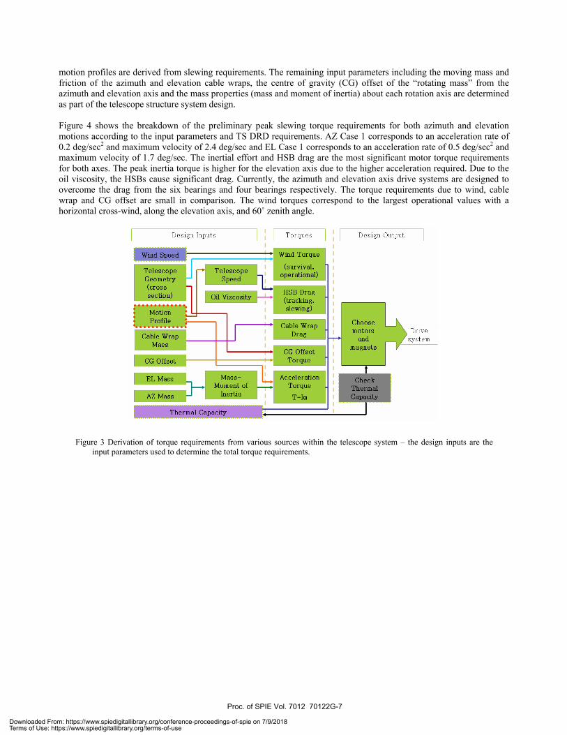
The TMT telescope structure system has two major mechanical systems: the mount control system and the safety system. The baseline mount control hardware includes hydrostatic bearings, direct drive linear (DDL) motors and optical tape encoders for both azimuth and elevation motions. This hardware combination will be configured to provide the requisite accuracy and resolution to meet the mount control motion requirements. The azimuth axis uses six HSBs, three under each azimuth cradle with two master bearings at the corners and a slave bearing in the centre; the DDL system** is a ring of 582 magnet segments mounted around the azimuth track with two groups of 21 forcers attached on the azimuth structure; a 3 m diameter central hydrostatic pintle bearing provides lateral restraint; the size of the azimuth encoder ring is similar in diameter to the pintle bearing support with a minimum of four equally spaced read heads. The elevation axis uses four HSBs, two on each elevation journal positioned at 25° symmetrically about the centerline. Lateral restraint bearings are incorporated on each elevation journal. The DDL system†† is a 104° sector of 100 magnet segments mounted circumferentially on each elevation journal, and 54 forcers attached symmetrically about the centerline atop each azimuth cradle. The elevation encoder system is approximately a 10 m encoder tape covering a sector of 150° with three equally spaced read heads on each journal. Although not under direct control by the mount control system, the cable wraps could impede the azimuth and elevation motions. In order to minimize this effect, the azimuth cable wrap is motor driven, synchronized to the azimuth rotation. In addition, all bend-radii are kept to be as large as practical and the major lines such as hydraulic hoses, power cables, coolant lines and cryogenic hoses are stacked vertically and compartmentalized in order to minimize friction due to rubbing. The elevation cable wrap is a cable carrier supported by a fixed cable tray. The cable tray is located along the centerline of the azimuth structure below the elevation structure. The elevation cable wrap is given the same design considerations to minimize friction. The factors influencing the DDL motor selection are described in the next section, following by the design considerations for the hydrostatic bearings, cable wraps and safety system. 3.1 DDL motor design considerations 3.1.1 Motor torque requirements Figure 3 shows schematically the derivation of torque requirements from different sources within the telescope system. The input parameters of wind speed are derived from the external wind speeds for operational and survival conditions found in the TMT ORD and site testing data, respectively, using reduction factors derived from computational fluid dynamics (CFD). The top end cross-section area is a flow-down from the TMT OAD. The acceleration and velocity
** Including a 50% torque margin †† Including a 50% torque margin
Proc. of SPIE Vol. 7012 70122G-6
Downloaded From: https://www.spiedigitallibrary.org/conference-proceedings-of-spie on 7/9/2018Terms of Use: https://www.spiedigitallibrary.org/terms-of-use
Desi Inputs Torques Desi Output
TelescopeGeometry(cross —
L section)
MotionProfile
Cable WrapMass
CG Offset
EL Mass
AZ Mass
Thermal Capacity
Wind Torque
Oil Viscosity
(survival.Telescope operational)Speed
HSB Drag(tracking,slewing)
Cable WrapDrag
Drivesystem
Inertia
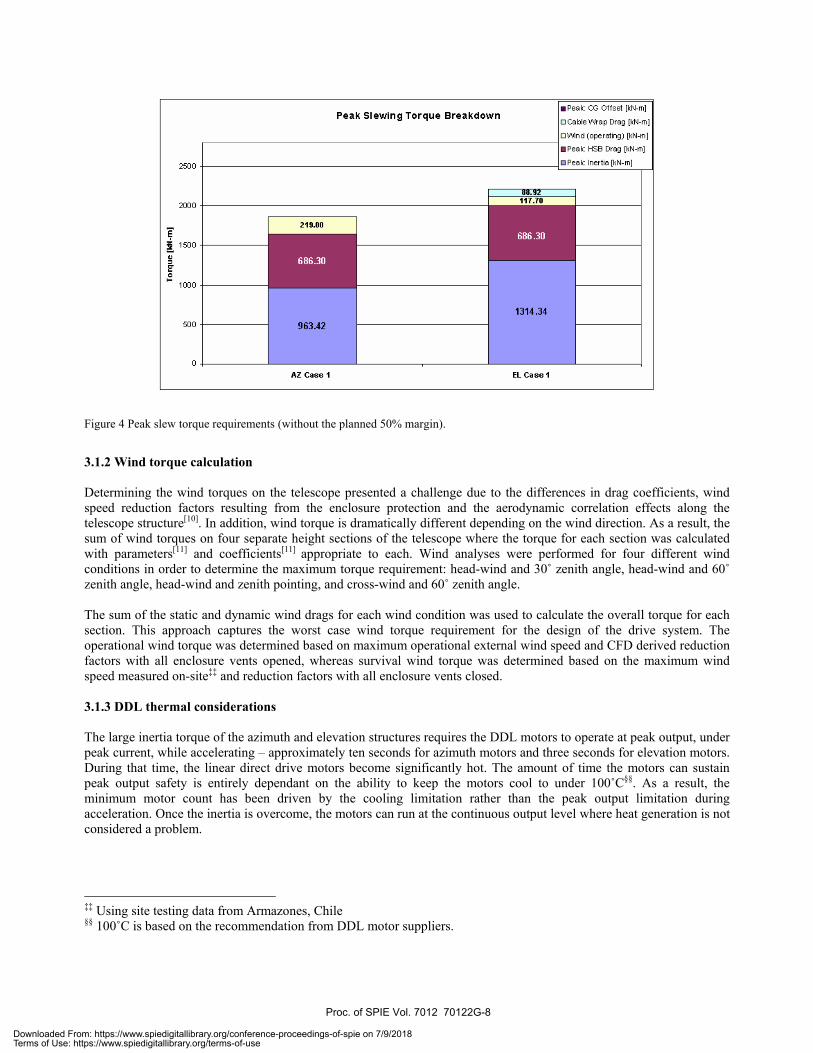
motion profiles are derived from slewing requirements. The remaining input parameters including the moving mass and friction of the azimuth and elevation cable wraps, the centre of gravity (CG) offset of the “rotating mass” from the azimuth and elevation axis and the mass properties (mass and moment of inertia) about each rotation axis are determined as part of the telescope structure system design. Figure 4 shows the breakdown of the preliminary peak slewing torque requirements for both azimuth and elevation motions according to the input parameters and TS DRD requirements. AZ Case 1 corresponds to an acceleration rate of 0.2 deg/sec2 and maximum velocity of 2.4 deg/sec and EL Case 1 corresponds to an acceleration rate of 0.5 deg/sec2 and maximum velocity of 1.7 deg/sec. The inertial effort and HSB drag are the most significant motor torque requirements for both axes. The peak inertia torque is higher for the elevation axis due to the higher acceleration required. Due to the oil viscosity, the HSBs cause significant drag. Currently, the azimuth and elevation axis drive systems are designed to overcome the drag from the six bearings and four bearings respectively. The torque requirements due to wind, cable wrap and CG offset are small in comparison. The wind torques correspond to the largest operational values with a horizontal cross-wind, along the elevation axis, and 60˚ zenith angle.
Figure 3 Derivation of torque requirements from various sources within the telescope system – the design inputs are the input parameters used to determine the total torque requirements.
Proc. of SPIE Vol. 7012 70122G-7
Downloaded From: https://www.spiedigitallibrary.org/conference-proceedings-of-spie on 7/9/2018Terms of Use: https://www.spiedigitallibrary.org/terms-of-use
606.30
606.30
Figure 4 Peak slew torque requirements (without the planned 50% margin).
3.1.2 Wind torque calculation Determining the wind torques on the telescope presented a challenge due to the differences in drag coefficients, wind speed reduction factors resulting from the enclosure protection and the aerodynamic correlation effects along the telescope structure[10]. In addition, wind torque is dramatically different depending on the wind direction. As a result, the sum of wind torques on four separate height sections of the telescope where the torque for each section was calculated with parameters[11] and coefficients[11] appropriate to each. Wind analyses were performed for four different wind conditions in order to determine the maximum torque requirement: head-wind and 30˚ zenith angle, head-wind and 60˚ zenith angle, head-wind and zenith pointing, and cross-wind and 60˚ zenith angle. The sum of the static and dynamic wind drags for each wind condition was used to calculate the overall torque for each section. This approach captures the worst case wind torque requirement for the design of the drive system. The operational wind torque was determined based on maximum operational external wind speed and CFD derived reduction factors with all enclosure vents opened, whereas survival wind torque was determined based on the maximum wind speed measured on-site‡‡ and reduction factors with all enclosure vents closed. 3.1.3 DDL thermal considerations The large inertia torque of the azimuth and elevation structures requires the DDL motors to operate at peak output, under peak current, while accelerating – approximately ten seconds for azimuth motors and three seconds for elevation motors. During that time, the linear direct drive motors become significantly hot. The amount of time the motors can sustain peak output safety is entirely dependant on the ability to keep the motors cool to under 100˚C§§. As a result, the minimum motor count has been driven by the cooling limitation rather than the peak output limitation during acceleration. Once the inertia is overcome, the motors can run at the continuous output level where heat generation is not considered a problem.
‡‡ Using site testing data from Armazones, Chile §§ 100˚C is based on the recommendation from DDL motor suppliers.
Proc. of SPIE Vol. 7012 70122G-8
Downloaded From: https://www.spiedigitallibrary.org/conference-proceedings-of-spie on 7/9/2018Terms of Use: https://www.spiedigitallibrary.org/terms-of-use
3.1.4 Torque ripple and pointing errors For TMT, torque ripple is seen as a speed variation of the telescope resulting from discrete DDL motors working in unison to move the telescope structure. Excessive variations in torque output would limit the overall resolution and accuracy of telescope pointing and tracking. In addition, motor force variations can induce vibration in the structure. Force ripple frequencies near the fundamental modes should be avoided to prevent resonance in the structure. Torque ripple can come from several sources[12],[13]. The following sources are being considered in the design of the TMT drive system: • Slot Cogging: variation in force due to misalignment of the tangential magnetic forces; caused by the air-gap
between magnet segments and the straight forcer segment; for curved direct drive applications, slot cogging varies with radius and magnet width;
• Segment Cogging: variation in force resulting from space between forcer segments; • Back EMF: force affecting the motor due to magnetic field induced current which counters the propelling force and
changes with the variation in the strength of the magnetic field; • Reluctance: variation of force output due to the difference in magnetic permeability of free space of other magnetic
materials inside the windings. Optimal forcer and magnet spacing and shaping will minimize the torque ripple, and additional mount control system tuning will remove much of the torque ripple. However, at the frequency of around 1 Hz, the mount control system is less effective at minimizing ripple. Currently, work is in progress to determine the mechanical and control systems interaction over the motion speed range, the overall magnitude of the torque ripple and the pointing error that may result. 3.2 Hydrostatic bearing design considerations A conceptual design study has been conducted for TMT by SKF and their recommendations are presented in this section along with additional design considerations. 3.2.1 Azimuth bearings The arrangement of six bearings on the azimuth track must support the 18,000kN weight of the entire telescope with additional capacity to handle seismic events. The largest bearing in the SKF standard line of hydrostatic bearings, the HSB 600, has been recommended as the baseline configuration along with a high oil supply pressure of 10 Mpa (1450psi). An alternate design being considered is a symmetric arrangement of 12 of these bearings arranged as 6x2 (six trucks of 2 bearings each) can then run at 79% of rated 2000kN*** capacity during normal operating conditions. The hydrostatic oil system will supply pressurized oil through a flow divider such that every bearing receives exactly the same flow rate, which is the standard method of ensuring load sharing. 3.2.2 Pintle bearings The azimuth axis of rotation is defined by a set of five HSBG 120 bearings equally spaced around a cylindrical steel journal at the top of the pintle structural column. 3.2.3 Elevation bearings The elevation structure is supported on two 10.75m radius cylindrical journals. Each journal rests upon a pair of HSB 500 bearings 50° apart and equally disposed about the vertical centerline. An additional pair of bearings restrains each journal axially (along the telescope elevation axis). 3.2.4 Thermal requirements To avoid causing local seeing problems, the structural surfaces below the light path must be maintained within +1˚ C to -2˚ C relative to ambient. This requirement and viscosity considerations require tight temperature control of the hydrostatic oil. Because of the need for cable wraps to accommodate the ±270° of azimuth motion, the length of hydraulic supply hose exposed in the cable wrap will be more than 75m.
*** This is a standard industrial load rating at an oil supply pressure of 5.5Mpa (798psi).
Proc. of SPIE Vol. 7012 70122G-9
Downloaded From: https://www.spiedigitallibrary.org/conference-proceedings-of-spie on 7/9/2018Terms of Use: https://www.spiedigitallibrary.org/terms-of-use
7
I
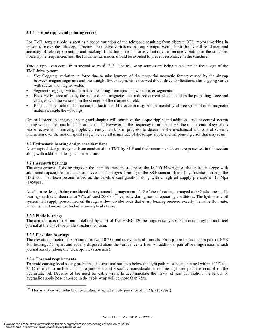
3.2.5 Seismic considerations The HSB 600 bearing has been shown by finite element analysis to be safe from damage by axial loading up to 6,400kN. Various concepts for seismic restraints are being evaluated for the protection of the telescope and to prevent the bearings from lifting up or sliding off the azimuth track and azimuth cradles. The number, location and master/slave control configurations of the bearings are important factors in determining the seismic response of the telescope. 3.3 Cable wrap design considerations 3.3.1 Azimuth cable wrap A total of 94 cables and 69 hoses, with a design margin of 50% for utility lines (hydraulic oil, coolant, cryogen, compressed air, power), and 100% for data and communication (monitoring and control) lines, travel through the azimuth cable wrap. To avoid excessive wear on the lines, vertically mounted cable chains are used to support the cables and hoses, as described previously. The cable chains are set into two traveling loop assemblies with mandrels (see Figure 5). The cable chains are wrapped in two directions and allow for ±270° of rotation. The traveling loop assemblies are self-driven to avoid imparting any perturbation to the telescope azimuth motions. Bar code ribbon tape sensors, that sense absolute position, control the position of the drive system. Along with the feedback from the relative azimuth position sensors, the traveling loop sensor system will keep pace with the telescope with an accuracy of ±3mm linear travel.
Figure 5 Azimuth cable wrap concept as installed inside the telescope pier – the inner wrap supports the data and communication lines and the outer wrap supports the utility lines, and the right figure shows the moving points (telescope attachment) and fixed points (base attachment) of both wraps.
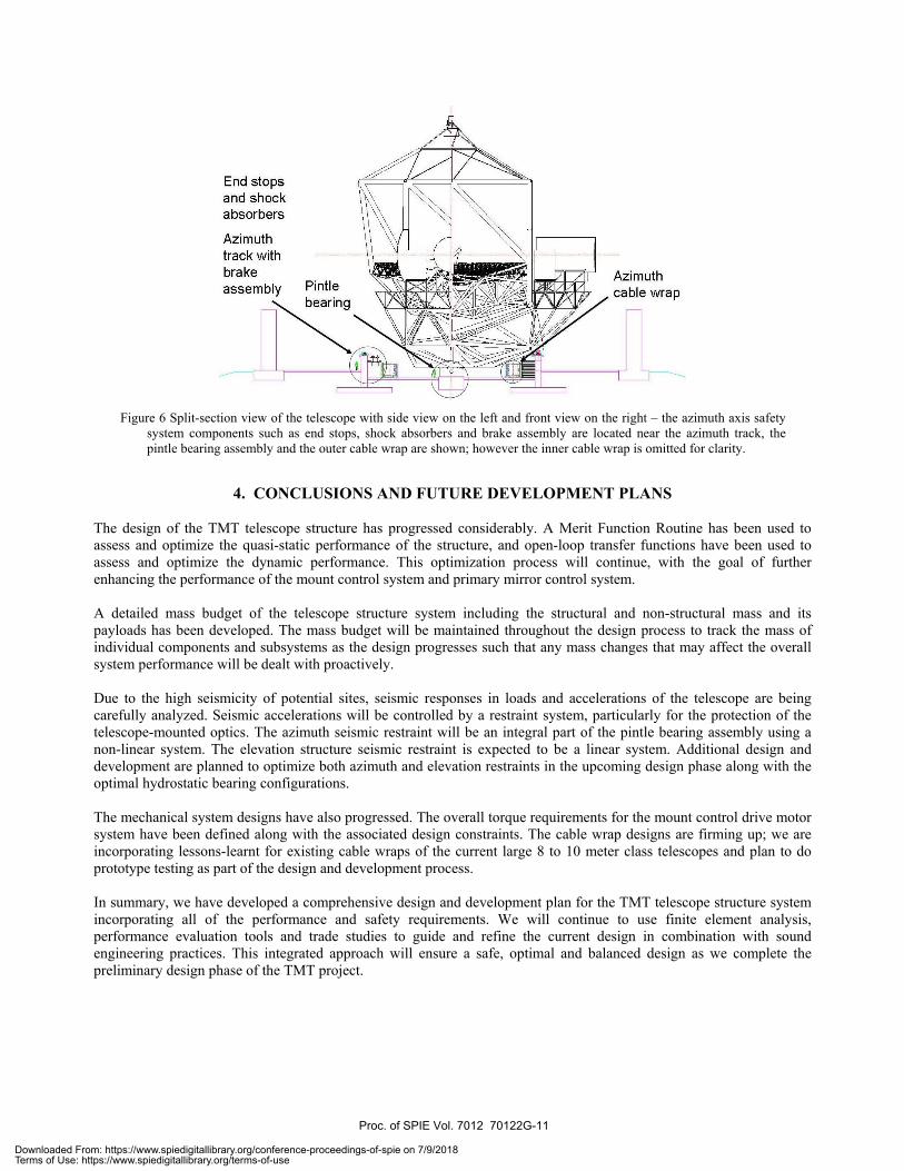
3.3.2 Elevation cable wrap A total of 44 cables and 11 hoses, with the same design margin, travel through the elevation cable wrap. Two parallel cable chains are required to support these lines. To minimize perturbation to the telescope elevation motions these chains need to be placed as close to the axis of rotation as possible. The design of these cable chains is ongoing. 3.4 Safety systems A safety system of sensors, limit switches, brakes, absorbers and end stops provides over-speed and over-travel protection at each motion axis. The safety system is interfaced with the MCS and Telescope Safety System (TSS). The system is currently designed with four shock absorbers and six caliper type brakes for the azimuth axis, and eight and four for the elevation axis, respectively. Figure 6 shows the implementation of the safety hardware for the azimuth axis inside the telescope pier. In addition, an elevation axis counterbalance system composed of coarse static ballasts and fine active control is implemented along with a locking pin system that holds the elevation structure for servicing under unbalanced conditions.
Attachment to telescope
Attachment to Base
Proc. of SPIE Vol. 7012 70122G-10
Downloaded From: https://www.spiedigitallibrary.org/conference-proceedings-of-spie on 7/9/2018Terms of Use: https://www.spiedigitallibrary.org/terms-of-use
End stopsand shockabsorbers
Azimuthtrack withbrake
assembly PintleAzimuthcable wrap
Figure 6 Split-section view of the telescope with side view on the left and front view on the right – the azimuth axis safety
system components such as end stops, shock absorbers and brake assembly are located near the azimuth track, the pintle bearing assembly and the outer cable wrap are shown; however the inner cable wrap is omitted for clarity.
4. CONCLUSIONS AND FUTURE DEVELOPMENT PLANS
The design of the TMT telescope structure has progressed considerably. A Merit Function Routine has been used to assess and optimize the quasi-static performance of the structure, and open-loop transfer functions have been used to assess and optimize the dynamic performance. This optimization process will continue, with the goal of further enhancing the performance of the mount control system and primary mirror control system. A detailed mass budget of the telescope structure system including the structural and non-structural mass and its payloads has been developed. The mass budget will be maintained throughout the design process to track the mass of individual components and subsystems as the design progresses such that any mass changes that may affect the overall system performance will be dealt with proactively. Due to the high seismicity of potential sites, seismic responses in loads and accelerations of the telescope are being carefully analyzed. Seismic accelerations will be controlled by a restraint system, particularly for the protection of the telescope-mounted optics. The azimuth seismic restraint will be an integral part of the pintle bearing assembly using a non-linear system. The elevation structure seismic restraint is expected to be a linear system. Additional design and development are planned to optimize both azimuth and elevation restraints in the upcoming design phase along with the optimal hydrostatic bearing configurations. The mechanical system designs have also progressed. The overall torque requirements for the mount control drive motor system have been defined along with the associated design constraints. The cable wrap designs are firming up; we are incorporating lessons-learnt for existing cable wraps of the current large 8 to 10 meter class telescopes and plan to do prototype testing as part of the design and development process. In summary, we have developed a comprehensive design and development plan for the TMT telescope structure system incorporating all of the performance and safety requirements. We will continue to use finite element analysis, performance evaluation tools and trade studies to guide and refine the current design in combination with sound engineering practices. This integrated approach will ensure a safe, optimal and balanced design as we complete the preliminary design phase of the TMT project.
Proc. of SPIE Vol. 7012 70122G-11
Downloaded From: https://www.spiedigitallibrary.org/conference-proceedings-of-spie on 7/9/2018Terms of Use: https://www.spiedigitallibrary.org/terms-of-use
ACKNOWLEDGMENTS
The authors gratefully acknowledge the support of the TMT partner institutions. They are the Association of Canadian Universities for Research in Astronomy (ACURA), the California Institute of Technology and the University of California. This work was supported as well by the Gordon and Betty Moore Foundation, the Canada Foundation for Innovation, the Ontario Ministry of Research and Innovation, the National Research Council of Canada, the Natural Sciences and Engineering Research Council of Canada, the British Columbia Knowledge Development Fund, the Association of Universities for Research in Astronomy (AURA) and the U.S. National Science Foundation.
REFERENCES
[1] K. Szeto et al, “TMT telescope structure system: design and development”, Proc. SPIE 6267, 62672Q (2006) [2] N. Loewen et al, “Progress on Enclosure Design for Thirty Meter Telescope”, Ground-based and Airborne
Telescopes, ed. L. Stepp and R. Gilmozzi, SPIE 7012, Marseille, France (2008) (this conference). [3] P. M. Thompson et al, “Analysis of the TMT Mount Control System”, Ground-based and Airborne Telescopes, ed.
L. Stepp and R. Gilmozzi, SPIE 7012, Marseille, France (2008) (this conference). [4] D. G. MacMynowski et al, “Analysis of TMT Primary Mirror Control-Structure Interaction”, Modeling, Systems
Engineering, and Project Management for Astronomy, ed. G. Angeli and M. Cullum, SPIE 7017, Marseille, France (2008) (this conference).
[5] Jeff Oram, “TMT Work Breakdown Structure”, Thirty Meter Telescope Project document TMT.BUS.SPE.05.003.REL06.
[6] G. Angeli, “TMT Observatory Architecture Document”, Thirty Meter Telescope Project document TMT.SEN.DRD.05.002.CCR17.
[7] Thirty Meter Telescope Construction Proposal, September 2007, http://www.tmt.org/news/TMT-Construction%20Proposal-Public.pdf
[8] G. Angeli, “Observatory Requirements Document”, Thirty Meter Telescope Project document TMT.SEN.DRD.05.001.CCR18.
[9] D. Tsang et al, “TMT Telescope Structure System Seismic Analysis and Design”, Ground-based and Airborne Telescopes, ed. L. Stepp and R. Gilmozzi, SPIE 7012, Marseille, France (2008) (this conference).
[10] D. G. MacMynowski et al, “Wind loads on ground-based telescopes”, TMT.SEN.JOU.011.REL01, Applied Optics, Vol. 45, No.30, P.7913 (2006).
[11] D. G. MacMynowski, “Simply estimates of wind forces TMT”, Thirty Meter Telescope Project TMT.SEN.TEC.05.013.REL01.
[12] F. Leonardi, M. Venturini, and A. Vismara, “Design and Optimization of Very High Torque, Low Ripple, Low Cogging PM Motors for Direct Driving Optical Telescope”, Industry Applications Society Annual Meeting, conference record of the 1994 IEEE, Vol.1, p. 272-278 (1994).
[13] T.M. Erm, and A. Seppey, “A cost effective direct drive option for the Thirty Meter Telescope”, Proc. SPIE 6273, 627335 (2006).
Proc. of SPIE Vol. 7012 70122G-12
Downloaded From: https://www.spiedigitallibrary.org/conference-proceedings-of-spie on 7/9/2018Terms of Use: https://www.spiedigitallibrary.org/terms-of-use