Optical instruments - SPIE Digital Library
44
61 I n this chapter, we will find out how rays of light behave when they pass through the different elements that make up an optical system: lenses, mirrors and prisms. In other words, we will look at the deviation of the rays of light as they pass through different items. This examination helps us to predict the characteristics of an image formed by the combination of certain optical elements, e.g., in the case of a microscope, where the image is inverted and larger than the real size object we are looking at. This means that we will not be looking at phenomena related to the behavior of light as a wave, although they may actually be present (interference, diffraction, etc.). Nor are we going to take into consideration the intensity of light; we will concentrate on describ- ing these properties based solely on the path followed by the rays of light. We will do this using what is known as geometrical optics, with calculations, or graphs, to work out the path of light through certain optical elements or a combination of these (optical systems). Using geometrical optics, we will discover the key characteristics of basic optical ele- ments and systems, as well as more complex systems made from a combination of differ- ent simple ones, such as cameras, telescopes and microscopes. Basic concepts It is very important to know what type of image an optical element will form of an object, as it helps us understand how the world will look through that instrument. An object either emits light (light source) or reflects light from a separate light source in the form of rays. These rays travel in a straight line through a homogeneous and isotro- pic medium, which is most common, until they reach a medium with a different index of refraction. As we saw in Chapter 1, the surface between the two media with differing indi- ces of refraction will refract or reflect the rays of light that have not been absorbed; they will change direction according to the law of refraction (Snell’s law) or the law of reflec- tion (angle of reflection = angle of incidence), respectively. When we study the image formed of an object by an optical element, it is not enough to examine a single ray of light. We need to study at least two rays as the image will form at the point where two rays leaving the same point on the original object cross over, having passed through all the elements making up the optical system in question. In reality, not only two rays leave each point on the object but also what is known as a stroke of light, i.e., many rays of light from the same point on the object that fill up the optical element as they pass through it and then reflect or refract to form the corresponding image. Studying the propagation of these strokes of light, made up of rays, allows us to predict that the Optical instruments Chapter 3 Downloaded From: https://www.spiedigitallibrary.org/ebooks/ on 07 Feb 2022 Terms of Use: https://www.spiedigitallibrary.org/terms-of-use
-
Upload
khangminh22 -
Category
Documents
-
view
0 -
download
0
Transcript of Optical instruments - SPIE Digital Library

61
In this chapter, we will find out how rays of light behave when they pass through the different elements that make up an optical system: lenses, mirrors and prisms. In other words, we will look at the deviation of the rays of light as they pass through different
items. This examination helps us to predict the characteristics of an image formed by the combination of certain optical elements, e.g., in the case of a microscope, where the image is inverted and larger than the real size object we are looking at.
This means that we will not be looking at phenomena related to the behavior of light as a wave, although they may actually be present (interference, diffraction, etc.). Nor are we going to take into consideration the intensity of light; we will concentrate on describ-ing these properties based solely on the path followed by the rays of light. We will do this using what is known as geometrical optics, with calculations, or graphs, to work out the path of light through certain optical elements or a combination of these (optical systems).
Using geometrical optics, we will discover the key characteristics of basic optical ele-ments and systems, as well as more complex systems made from a combination of differ-ent simple ones, such as cameras, telescopes and microscopes.
Basic conceptsIt is very important to know what type of image an optical element will form of an object, as it helps us understand how the world will look through that instrument.
An object either emits light (light source) or reflects light from a separate light source in the form of rays. These rays travel in a straight line through a homogeneous and isotro-pic medium, which is most common, until they reach a medium with a different index of refraction. As we saw in Chapter 1, the surface between the two media with differing indi-ces of refraction will refract or reflect the rays of light that have not been absorbed; they will change direction according to the law of refraction (Snell’s law) or the law of reflec-tion (angle of reflection = angle of incidence), respectively.
When we study the image formed of an object by an optical element, it is not enough to examine a single ray of light. We need to study at least two rays as the image will form at the point where two rays leaving the same point on the original object cross over, having passed through all the elements making up the optical system in question. In reality, not only two rays leave each point on the object but also what is known as a stroke of light, i.e., many rays of light from the same point on the object that fill up the optical element as they pass through it and then reflect or refract to form the corresponding image. Studying the propagation of these strokes of light, made up of rays, allows us to predict that the
Optical instrumentsChapter 3
Chapter 3.indd 61 4/23/2021 1:29:07 PM
Downloaded From: https://www.spiedigitallibrary.org/ebooks/ on 07 Feb 2022Terms of Use: https://www.spiedigitallibrary.org/terms-of-use

62 Discovering Light: Fun Experiments with Optics
image of an object created by an optical system or element will be like: position, nature (real or virtual), relative size (magnified or reduced) and orientation (real or inverted).
The characteristic of light rays that provides us with information about the position of the object they have come from or the image they are forming is the vergence. If the rays spread out or separate as they travel, we say that they diverge (like the rays leaving the points of the object in Figure 3.1, left), coming from a common starting point and with a negative vergence. If, however, the rays in a single stroke of light draw closer to each other as they travel, angled towards a single point, we say they converge, and the vergence is said to be positive. In principle, only optical elements with a curved dioptric can change the vergence of the light passing through it or reflected off it. Vergence is measured in diopters, which is the inverse of the unit for distance, the meter (D = 1/m). So, if we know the vergence of light as it enters or leaves an optical element or system, it is easy to determine the position of the object from which the light comes or the image that the light is creating. If the rays of light remain parallel to each other as they travel, i.e., they do not get closer or farther apart, we say that they are collimated, and they come from (or are travelling to) an infinitely distant point.
The easiest way to understand how images are formed is to work with a very familiar element, such as a convergent lens like the one in Figure 3.1, where we see a cross-section of this kind of lens. If we place an object such as a pencil in front of the lens at the right distance, the strokes of light leaving the points on the object refract as they pass through the lens, converging as they leave it, and form an image at the point where rays from the same stroke of light meet (or converge). We can find this position by moving a screen (or sheet of paper) away from the lens until the image comes into view.
In most cases, the object is real: it is placed in front of the lens (on the left if we are looking at the cross-section), and it emits divergent rays of light towards the optical ele-ment. However, an optical element or system does not need to have a “physical” object in front of it to form an image. All it needs is to receive divergent rays of light that appear to come from an object to form an image of that “real” object. An example of a real object for the optical system we use to see—our eyes—that is not physically present, is a holo-gram. A hologram is a photographic image that, when lit up properly, reflects or emits light that looks like it comes from a three-dimensional object, which is not actually there. In Experiment 3.1, we explain how to build a reflective hologram.
We say the image is real when we can observe it formed on a screen. In these cases, the image is always on the other side of the lens in question (on the right when looking at the cross-section), at the point where the strokes of light from the object converge after passing through the lens. However, this is not always the case. If we have a divergent system, or the object is too close to a converging lens, then the rays diverge as they leave the lens. If we extend the light backwards, we can find a point where they cross (Figure 3.1, right), but
Figure 3.1 Path of light through a convergent optical element that forms the image of an object. The image and object planes are perpendicular to the optical axis and parallel to the surface of the lens (left). Magnified virtual image of an object using a convergent lens. In this case, the observer is on the left of the image (right).
Source: Camilo Florian Baron.
Chapter 3.indd 62 4/23/2021 1:29:09 PM
Downloaded From: https://www.spiedigitallibrary.org/ebooks/ on 07 Feb 2022Terms of Use: https://www.spiedigitallibrary.org/terms-of-use

Chapter 3 Optical instruments 63
this point, where the light appears to be coming from, is in front of the lens. It is impos-sible to use a screen to see this image as it is in front of the lens and therefore would block out the light coming from the original object. In this case, we say that the image is virtual.
An example of a virtual image is the augmented image we see through a magnifying glass; although the image is virtual, our eyes (an optical system) can make the divergent light exiting the magnifying glass converge on our retina, forming a real image, which is the one we can see (see Chapter 4).
The space in front of the relevant optical element, where the real object is positioned, is called the object space, while the space behind the lens, where the real images are located, is call the image space.
What elements reflect light? MirrorsAs we have seen, when light meets a medium with a different index of refraction, part of that light is reflected, part is refracted, and part is absorbed. Mirrors are just optical ele-ments that reflect a high proportion of the light they receive. In general, the mirrors we use every day are made using a highly reflective metallic surface behind a protective glass sheet.
All mirrors work using the law of reflection that we have already seen: when a ray of light meets the surface of the mirror, it is reflected in the opposite direction at the same angle to the norm (perpendicular) as the one where it met the surface. Depending on the shape of the mirror’s surface (flat, curved, etc.), the norm will be different for each of the points of impact, and therefore the effect of the mirror on the rays of light, particularly its vergence, will also be different (Figure 3.2).
The left figure shows the path of the light as it meets a flat mirror from different points on the object. To establish the direction of the reflected light, just trace the normal at each point of incidence, then trace the light reflected at the same angle as it hits the surface. As we have already mentioned, to find the image we need to see the point where the reflected rays of the light converge.
A flat mirror does not change the vergence of the light, and as the rays from a real object placed in front of the mirror are divergent as they meet the surface, they also diverge when reflected. This means that the image we see is virtual, and in order to see where the reflected light seems to be coming from we have to extend them backwards. For this reason, when we look into a flat mirror it looks like the image is “behind” or “inside” the glass.
Figure 3.2 When we look into a mirror, what we see is always a virtual image. In the picture on the left, with a flat mirror, it looks like the pencil is on the other side of the mirror at the same distance. In the middle and on the right, we can see how the image of the same object is formed using a concave and convex mirror, respectively.
Source: Camilo Florian Baron.
Chapter 3.indd 63 4/23/2021 1:29:10 PM
Downloaded From: https://www.spiedigitallibrary.org/ebooks/ on 07 Feb 2022Terms of Use: https://www.spiedigitallibrary.org/terms-of-use

64 Discovering Light: Fun Experiments with Optics
Also, the image created by a flat mirror has the same size and orientation as the object, and it is located at the same dis-tance from the mirror as the virtual image reflected by the mirror. The image is par-tially inverted: left becomes right, but there is no vertical inversion. In Experiment 3.2, we will build our own periscope, an opti-cal instrument that makes is possible to see things when there is something in the way of our line of vision, using two flat mirrors.
Curved or spherical mirrors also obey the law of reflection, but unlike flat mirrors, the normals at each point of their surface are not parallel to each other. In the case of spheri-cal curved surfaces, the normals perpendic-ular to the surface pass through the center of curvature. This is why spherical mirrors change the vergence of light and as a result the reflected image is not the same size as the object but larger or smaller, depending on the type of curve, concave or convex, and the position of the object (Figure 3.2).
Before describing the effect of these kinds of mirrors on light, we need to define some of the elements involved.
As with any sphere, the center of cur-vature (C) of a spherical mirror is the equi-distant point of all spherical surface points. Any line running from a point on the surface to the center of curvature is called the radius
of curvature (R) and is perpendicular to the surface at that point.The optical axis of a mirror (or any optical element) is the horizontal line passing
through its center of curvature. The point where the optical axis crosses the surface of the mirror is the apex.
In concave mirrors, the inner area of the sphere forming the surface is the reflective part, and its center of curvature is therefore in front of the mirror (on the left of the sec-tion as shown in Figure 3.2, center). Concave mirrors are convergent, i.e., the incident light on the mirror will converge more after reflection on its surface. In the case of inci-dent rays parallel to its optical axis (zero vergence), the reflected light converges on a point on the optical axis in front of the mirror, halfway between the mirror surface and its center of curvature. This is the focal point or mirror focus, represented on our dia-grams by the letter F. Applying the principle of reversibility of light, all incident rays on the surface coming from the focal point will be reflected parallel to the optical axis. The distance from the apex of the mirror to the focal point is called focal length, represented by the letter f.
The focal length of a mirror is half the length of its radius of curvature (f = R/2).The capacity of a mirror to change the vergence of incident light after it is reflected
is what we call its power, denoted by the letter F. Like vergence, it is measured in diopters, and it is calculated as the inverse of the focal length of the mirror, in meters (F = 1/f). The shorter this focal length (and therefore the radius of the mirror), the greater its power, i.e., a convergent mirror (positive power) will converge light more, whereas
Figure 3.3 Patent for a submarine periscope submitted by Sarah Mather in 1845.
Source: MujeresConCiencia, https://mujeresconciencia.com/.
Did you know...?
Sarah Mather was the inventor of the underwater periscope, which she patented in 1845. The periscope was a key part of the history of underwater navigation, as it coulfd be used to observe the surface of the water from a submarine.
The first record of a periscope in use dates back to 1864, when the Chief US Army Engineer Thomas Doughty used an iron pipe and some mirrors on board an expedition to the Red River.
Chapter 3.indd 64 4/23/2021 1:29:10 PM
Downloaded From: https://www.spiedigitallibrary.org/ebooks/ on 07 Feb 2022Terms of Use: https://www.spiedigitallibrary.org/terms-of-use

Chapter 3 Optical instruments 65
a divergent mirror (negative power) will diverge them more. Concave mirrors are con-vergent mirrors. When the object is farther away than its focal point, they form a real, inverted image that may be larger, smaller or the same size as the object, depending on its position. When the object is closer to the mirror than its focal point, the resulting image is virtual, non- inverted and augmented. The magnifying mirrors we often find in bathrooms for shaving or make-up are concave mirrors. Concave mirrors are also used to project light, such as in car headlights.
Convex mirrors, where the reflective surface is on the outer side of the sphere making up the surface, are divergent mirrors. In other words, they change the vergence of incident rays, making them diverge more as they are reflected (Figure 3.2, right). In this case, the center of curvature of the mirror is behind the reflective surface, like its focal point, half-way between the apex of the mirror and its center of curvature (f = R/2). When rays paral-lel to the optical axis meet a concave mirror, they are reflected as divergent. If we were to extend the rays beyond the surface of the mirror, they appear to come from the focal point, which in this case is virtual, as it is “behind” the mirror. Due to the principle of revers-ibility of light, and just as we saw in the case of concave mirrors, incident rays meeting the mirror in the direction of the focal point will be reflected parallel to the optical axis. The power of a divergent mirror is considered negative, and the higher the absolute value is, the shorter its focal length (F = 1/f). Convex mirrors form a virtual image that is smaller than the real object reflected.
Elements that refract light: flat optics, prisms and lensesAs we saw in Chapter 1, when light travels towards a medium with a different refractive index, it changes direction. This phenomenon is known as refraction, and it is described mathematically under Snell’s law that, if we know the angle of incidence and the refractive indices of both media, we can determine the direction of the refracted rays.
The interface between two materials of a different reflective index is called a dioptric interface. Depending on whether the interface is flat or curved, they are called plane or curved interfaces, respectively. Just as we saw with flat mirrors, a flat interface does not change the vergence of light rays. This means that the divergent rays meeting a flat inter-face from a real object in its object space will also be divergent, and they will form a vir-tual image. If we extend the rays backwards to find the point where the image appears to form, it is on the same side of the interface as the object. A simple, common example of this is a window. The light passing through it practically doesn’t divert from its course, but if we look through it at a flat angle, the real object and the image we see are in dif-ferent positions. This effect can be understood as the refraction in a plane-parallel sheet (Figure 3.4, left).
The effect of a flat interface on rays of light from an object is to change direction towards the normal if the object is surrounded by the lower refraction medium, or away from the normal if it is the other way around. If the object is surrounded by a medium with a greater refractive index, the virtual image formed by the interface will be closer than the object itself. This can be seen by tracing the rays from the object to the surface; as they refract towards the medium with the lower index—where we are looking—they will move away from the normal. If we extend these rays backwards, they will cross over between the sur-face and the object. This is why swimming pools look shallower than they really are: the bottom of the pool is under water (n = 1.33), which has a greater refraction index than air (n = 1), from where we are observing the refracted light. The truth is we are not looking at the bottom of the pool but a virtual image of it created by the flat interface (water–air), which is closer to the surface of the water than the bottom of the pool.
Chapter 3.indd 65 4/23/2021 1:29:10 PM
Downloaded From: https://www.spiedigitallibrary.org/ebooks/ on 07 Feb 2022Terms of Use: https://www.spiedigitallibrary.org/terms-of-use

66 Discovering Light: Fun Experiments with Optics
However, in cases where the object is surrounded by the medium with the lower refraction index and we are looking at it from the medium of greater refraction, the vir-tual image will form behind the object. The rays, which in this case refract towards the medium of higher refraction index that we are observing from, bend towards the nor-mal, and by extending them backwards they cross at a point behind the object. The position of the virtual image depends on the proportion
between the refraction indices of the two media and the distance from the object.If we combine two flat interfaces to form an angle, separating the medium (e.g., glass)
between the surfaces from another (generally air), we have an optical prism. The effect of a prism on the light passing through it is lateral displacement, and a change in direc-tion. This is proportional to the angle between the interfaces (apical angle) and the ratio between the refraction index of the prism and the medium surrounding it. Assuming that the medium is air and the refractive index of the prism is greater than 1, the rays will be diverted in the opposite direction to the apical angle, where the base of the prism is located. If we observe the path of two rays of light from the same object passing through the prism, we can find the position of the resulting image, which is virtual, located in the object space and displaced laterally towards the apex of the prism (joint between the two flat interfaces). If when observing an object we place a prism in front of our eye, it looks like the object jumps towards the apex of the prism, as what we are then seeing is the image formed by the prism.
Prisms (Figure 3.4, right) can also be used for their reflective properties, when total internal reflection takes place on one or more of its surfaces. This is the case of the prisms used in Kepler-type telescopes to keep the final image upright.
Just as there are curved mirrors, there are curved interfaces made up of a curved separa-tion between two media of different refraction indices.
In the case of spherical interfaces, the curved surface forms a sphere. As we saw in the case of mirrors, this curvature allows optical elements to change the vergence of incident rays, in this case via refraction. This property is what we call refractive power (F), and it depends on the difference between the refraction indices separating the surface and its radius of curvature:
F = (n'− n)/R
The greater the difference between the refraction indices, or the smaller the radius of curvature of the surface, the greater the refractive power, i.e., a convergent interface (posi-tive power) will converge rays more strongly, while a divergent one (negative power) will diverge them more.
A spherical interface is convergent (positive power) if the convex side of the sphere is in contact with the lower refraction index and divergent (negative power) if it is the con-cave side of the sphere.
Figure 3.4 Refraction of a ray of light in a flat lens (flat-parallel trans-parent sheet) (left) and refraction of a ray of white light through a combination of different flat dioptrics positioned at angles to each other—a prism (right).
Source: Camilo Florian Baron.
Chapter 3.indd 66 4/23/2021 1:29:10 PM
Downloaded From: https://www.spiedigitallibrary.org/ebooks/ on 07 Feb 2022Terms of Use: https://www.spiedigitallibrary.org/terms-of-use

Chapter 3 Optical instruments 67
Spherical interfaces have two focal points:
• The focal point (or focus) of an image is the point on the optical axis where the rays meeting the interface parallel to its optical axis converge (or appear to come from) after refraction
• The focal point (or focus) of an object is the point on the axis where the rays that pass (or point in that direction) as they meet the lens will emerge in parallel, after refraction.
In the case of a convergent lens, the focal points are real (Figure 3.5, left). This means that the object focal point is in the object space and the image focal point is in the image space. However, in the case of a divergent lens, the focal points are virtual: parallel incident rays diverge after refraction, and to find a focal point we need to extend them backwards into the image space (Figure 3.5, right). In the case of the object focal point, in order to obtain paral-lel refracted rays we need them to be convergent as they meet the lens, and when we extend them beyond the surface of the lens they must converge in the image space.
The distances from the apex of the interface (intersection with its optical axis) to the object focal point and the image focal point are the object focal length (f) and the image focal length (f'), respectively. These distances can be calculated using the refractive power of the interface (F) and the refractive indices for the object space, in front of the interface (n) and the image space, situated behind the interface (n') thus:
f = −n/F and f ' = n'/F
respectively. The object and image focal distances are therefore not the same, as the refrac-tive indices are different: F = −n/f = n'/f' . The shorter the focal length is, the greater the power of the lens.
As for the image formed by a convergent interface, when the object is placed farther away from the interface than the object focus, the image formed is real, inverted and larger, the same or smaller than the object, depending on its position. If the object is closer to the mirror than its focal point, the resulting image is virtual, non-inverted and augmented. Convex mirrors form a virtual image that is smaller than the real object the reflect.
A lens is an optical element formed by two interfaces, generally curved, which separate the material from which the lens is made from the exterior. The effect of a lens on the ver-gence of light, i.e., its refractive power depends on the refractive index of its two interfaces,
Figure 3.5 Refraction of a beam of light through a converging spherical lens (left) and a diverging spherical lens (right).
Source: Camilo Florian Baron.
Chapter 3.indd 67 4/23/2021 1:29:11 PM
Downloaded From: https://www.spiedigitallibrary.org/ebooks/ on 07 Feb 2022Terms of Use: https://www.spiedigitallibrary.org/terms-of-use

68 Discovering Light: Fun Experiments with Optics
and in the case of thick lenses, their depth. Depending on the sum of the refractive powers of the interfaces making up the lens, we have convergent lenses (positive refractive power) or divergent lenses (negative refractive power).
Convergent lenses (Figure 3.6, left) are thicker in the middle than at the edges; they can form real images that can be seen on a screen, and when looking through them, objects look bigger. Divergent lenses (Figure 3.6, right), however, are thicker at the edge than in the middle; they generally form virtual images, and things look smaller when looking through them.
There are also different combinations of concave and convex dioptric interfaces that result in convergent or divergent lenses. This is what is known as the “shape” of the lens, and each one has a different name. As we saw with curved dioptric interfaces, a conver-gent lens will converge rays of light parallel to the optical axis inciding on the surface in the direction of the image focus, located behind the lens. In the case of divergent lenses, inciding rays parallel to the axis are refracted as divergent, and they seem to come from the image focus, located in front of the lens in this object space, as it is virtual.
When working with lenses, we usually forget about the focal points of each of the inter-faces, and define an object focus and an image focus for the lens, which covers the effect of both surfaces. These focal points are both located outside the lens, meaning that if the lens is in air, we can calculate its power using the position of the image focal point, i.e., the image focal length, F = 1/f '.
In most cases, for simplicity, we can assume that the thickness of the lenses is so small that the front and back surfaces are practically alongside each other. In this case, we say that they are thin lenses and both surfaces are drawn as a single line where light refracts.
In Experiment 3.3, we will build several optical elements, and we will see how they affect light. In Experiment 3.4, we will use small spherical lenses to look at tiny objects.
What is ray tracing?Ray tracing is a graphic technique that allows us to work out the characteristics of the image of an object by tracing the path of the rays as they pass through or are reflected off the elements they encounter until the final image is formed (Figure 3.8). Ray tracing
Figure 3.6 Rays of light passing through a converging lens (left) and a diverging lens (right).
Source: Camilo Florian Baron.
Chapter 3.indd 68 4/23/2021 1:29:11 PM
Downloaded From: https://www.spiedigitallibrary.org/ebooks/ on 07 Feb 2022Terms of Use: https://www.spiedigitallibrary.org/terms-of-use

Chapter 3 Optical instruments 69
requires a scale drawing, although the vertical and horizontal scales do not need to be the same. A ray tracing needs to include:
• The optical axis, which is a straight horizontal line that matches the sym-metrical axis of the optical system and passes through the centers of curva-ture of the elements making up that system. The optical axis is perpen-dicular to all surfaces, and the light inciding in the direction of the optical axis does not change course.
• The object is normally represented by a vertical line perpendicular to the optical axis, with an arrowhead to show whether the image is inverted or not in comparison with the object. The size of the object is generally mea-sured from the optical axis to the point furthest from the axis and is denoted using the letter y.
• The optical element(s) is represented with a vertical line perpendicular to the optical axis. The point where the line crosses the optical axis is the apex of the surface/lens. We also need to include the focal points of the optical element and its center of curvature.
Each of these elements must be positioned at the appropriate distance as per the rel-evant scale (vertical or horizontal, if they are not the same). Once we have our scale drawing with the necessary elements, we move on to the ray tracing itself.
The idea is to trace certain rays of light, called principal rays. These princi-pal rays form part of the same stroke of light, which departs the point on the object that is furthest from the optical axis, and although there are three principal rays, it is only necessary to trace two to find, at the point where they cross over after passing through the optical system, the corresponding point on the image, which is furthest from the optical axis. The principal rays are:
• A ray inciding on the optical surface parallel to the optical axis, which travels towards (divergent) or through (convergent) the image focal point.
• A ray that, when it meets an optical element, crosses (convergent) or travels towards (divergent) the object focal point, parallel to the optical axis.
• The nodal ray is one that passes through the system without changing course. In the case of a curved mirror or lens, this is the ray that travels towards or crosses the center of curvature (normal ray). In the case of a lens, this is the ray that travels towards the
Did you know...?
Converging lenses are used to correct hypermetropia, and divergent lenses for myopia. If when we look at someone’s eyes through their glasses and they seem bigger, the lenses are convergent and so we know that person is long-sighted. If their eyes look smaller, the lenses are divergent, and they are short-sighted.
Instead of having a single lens in their eyes, like humans, many insects have a system of micro-lenses. This gives them a larger field of vision. Humans have managed to reproduce this system and apply it in compound cameras as we will see in Chapter 4.
Figure 3.7 Arthropods like this fly Calliphora vomitoria have compound eyes, i.e., their visual system is made up of many micro-lenses.
Photograph: J. J. Harrison. Wikimedia Commons.
Chapter 3.indd 69 4/23/2021 1:29:11 PM
Downloaded From: https://www.spiedigitallibrary.org/ebooks/ on 07 Feb 2022Terms of Use: https://www.spiedigitallibrary.org/terms-of-use

70 Discovering Light: Fun Experiments with Optics
so-called optical center of the lens, which in a thin lens is the intersection of its surface with the optical axis.
Characteristics and types of optical systemsIt is sometimes difficult to obtain the desired type of image, in high quality and under certain conditions, using a single optical element. In these cases, it is pos-sible to use a combination of optical ele-ments; this is known as an optical system. An optical system can consist of any set of reflective surfaces (mirrors) or refractive surfaces (e.g., lenses) in any order and if it has both types it is called a catadioptric system. In Experiment 3.5, we will build catoptric and dioptric optical systems,
which we can use to make things “disappear”. The ray tracing method we saw earlier also applies to optical systems. All we have to do is remember that rays do not stop trav-elling when the first image is formed; they continue in a straight line until they meet the next optical element. This means that the image formed by an element in the system is, in turn, the object for the next element to receive the rays.
Sometimes the convergent rays from an optical element meet the next one before they form a real image. As a result, the rays inciding on the second optical element, instead of divergent—as we saw for a real object—will be convergent. If we extend these rays beyond the surface of the optical element, we can see how they cross in the image space to form a virtual object.
When working with an optical system, we talk about power, lengths and focal points for the whole system. We only consider these characteristics for each individual element in specific applications, such as an item to item ray tracing. There are other characteristics that define an optical element and its application, some of which we have already seen in reference to optical elements.
One example is lateral magnification, which is the quotient between the size of the image produced by an optical system (yi) and that of the corresponding object (y):
m = yi
y
i.e., indicating if the image is larger (m > 1), the same size (m = 1) or smaller than the corresponding object (m < 1 in absolute figures). The magnification sign also indicates the orientation of the image in comparison to the object: m > 0 if they are the same, and m < 0, i.e., if it is inverted (m < 0) or straight (m > 1).
The field of view of an optical system is the extension of the object that appears in the image produced by the system. The optical system acts as a window through which we see the object, and depending on the characteristics of that window (size, distance, position), we will see more or less of the object. In general, the more magni-fication an optical system has, the smaller its visual field. It can be measured in mm on the object or in degrees (the subtended angle of the object and the optical system) (Figure 3.9).
Figure 3.8 Tracing of three rays as they pass through a converging lens forming the image of an object positioned at a distance d
0 and a distance d
1 after the lens.
Source: Camilo Florian Baron.
Chapter 3.indd 70 4/23/2021 1:29:12 PM
Downloaded From: https://www.spiedigitallibrary.org/ebooks/ on 07 Feb 2022Terms of Use: https://www.spiedigitallibrary.org/terms-of-use
Chapter 3 Optical instruments 71
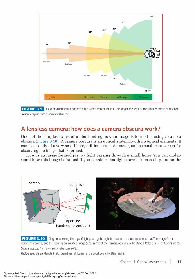
A lensless camera: how does a camera obscura work?Once of the simplest ways of understanding how an image is formed is using a camera obscura (Figure 3.10). A camera obscura is an optical system...with no optical elements! It consists solely of a very small hole, millimeters in diameter, and a translucent screen for observing the image that is formed.
How is an image formed just by light passing through a small hole? You can under-stand how this image is formed if you consider that light travels from each point on the
Figure 3.9 Field of vision with a camera fitted with different lenses. The longer the lens is, the smaller the field of vision.
Source: Adapted from quecamarareflex.com
Figure 3.10 Diagram showing the rays of light passing through the aperture of the camera obscura. The image forms inside the camera, and the result is an inverted image (left). Image of the camera obscura in the Duke’s Palace in Béjar (Spain) (right).
Source: Adapted from www.scratchpixel.com (left).
Photograph: Manuel Garrote Prieto, department of Tourism at the Local Council of Béjar (right).
Chapter 3.indd 71 4/23/2021 1:29:14 PM
Downloaded From: https://www.spiedigitallibrary.org/ebooks/ on 07 Feb 2022Terms of Use: https://www.spiedigitallibrary.org/terms-of-use

72 Discovering Light: Fun Experiments with Optics
object in all directions. Only one stroke of light from each point on the object passes through the hole and continues travelling in a straight line towards the screen, where it forms a “patch” of light representing the image “point” corresponding to the point on the image where the rays originated. The smaller the hole is, the smaller the patch of light. (in reality, there is a limit to the size of the orifice, beyond which the image “point” starts to increase in size again due to diffraction, as we saw in Chapter 1), which limits the size of the stroke of light passing through it. The narrower the beam of light is, the finer the “points” formed on the screen, and therefore the easier it will be to see the details of the image, which will be sharper. As the light crosses the optical axis on its path from the object to the screen, we obtain an inverted image.
From small transparent object to full-screen image: projection systemsAn optical projection system is generally a convergent optical system, whose function is to form the image of an object on a plane acting as a screen, meaning that the image must be real. This requires the object to be farther away from the object focal point. Depending on this distance, the projected image will be larger, smaller or the same size as the object (lateral magnification), and it will be inverted.
An example of a projection system is a film or slide projector, where the image pro-jected is larger than the object. In this type of system, it is important that the transparent object (slide) is sufficiently and consistently lit for the image to be of high quality. The main optical element of an illumination system is the condensing lens, which concen-trates the light emitted by the source into a certain position, depending on the system in question. There are two different types of illumination system: critical illumination and Kohler illumination, shown in Figure 3.11.
A picture of the outside world: how does a photographic camera work?Once of the best-known optical systems is the photographic cam-era (Figure 3.12). The purpose of cameras is to form an image of an object over a light sensor through an optical system. This optical system is made up of a set of con-vergent lenses, known collectively as the objective, and a diaphragm located either in the lens or the body of the camera.
Until a few years ago, the “sen-sor” used was photographic film (35 mm), made from a photosensi-tive material on which the image was recorded when it came into contact with light. This process required subsequent chemical
Figure 3.11 Diagram of different types of illumination. Köhler illumination uses two different kinds of diaphragms: one field diaphragm and one aperture diaphragm, positioned in different places along the path of the light from light source to object. Critical illumination also uses two apertures but fewer optical elements.
Source: Camilo Florian Baron.
Chapter 3.indd 72 4/23/2021 1:29:14 PM
Downloaded From: https://www.spiedigitallibrary.org/ebooks/ on 07 Feb 2022Terms of Use: https://www.spiedigitallibrary.org/terms-of-use

Chapter 3 Optical instruments 73
“developing” in order to see the final pho-tograph. Nowadays, however, cameras have swapped film for an electronic sensor (gen-erally a CCD, see Chapter 2).
The element that controls when and how much light reaches the sensor or the film is the shutter, which remains closed until the shot is taken. The longer the shutter is open (technically called expo-sure time), the more light is registered by the sensor. There are two type of shutter: (1) central, located between the different lenses, made from small plates that open and close, and (2) focal plane, so-called as they are located very close to the pho-tographic sensor. The diaphragm is the part of the camera that controls how much light enters through a variable diameter (Figure 3.13).
A key feature of cameras is their abil-ity to focus on objects at different dis-tances. This is possible thanks to the internal mechanism of the camera, which adjusts the relative distances between the lenses. We can assume that each lens is convergent with a specific aperture and focal length. The f number denotes the ratio between the lens focal point (f) and the aperture of the diaphragm (D), and it is gen-erally indicated using f/4 (or 1:4), or in some cases F4, where 4 represents the f number. The smaller the f number is, the greater the amount of light passing through the lens. Furthermore, two lenses with different focal points but the same number f will allow the same amount of light through. Objective specifications indicate a minimum f num-ber, which corresponds to the maximum aperture possible for that lens. If the number is very close to 1, the lens is considered to be highly luminous. The standard objective
Figure 3.12 Cross-section (cut) of a reflex camera (SLR).
Source: Libreshot.
Did you know...?
Reflex cameras got their name from the archaic word reflexion. This is because a mirror is used so that you can see the exact image that will be recorded on the film through the viewfinder.
Figure 3.13 Inside of a photographic camera, showing the path of light. The sensor that receives the light from the object of interest is marked with a red box.
Source: Camilo Florian Baron.
Chapter 3.indd 73 4/23/2021 1:29:15 PM
Downloaded From: https://www.spiedigitallibrary.org/ebooks/ on 07 Feb 2022Terms of Use: https://www.spiedigitallibrary.org/terms-of-use

74 Discovering Light: Fun Experiments with Optics
is one with focal points between 45 and 60 mm, as this approximately covers the central angle of vision of the human eye, which is between 40° and 65°. It is normally known for hav-ing large aperture (typically f/1.4 or f/1.8). These are very bright lenses, and they can therefore also be used under poorly lit and indoor conditions. In Experiment 3.6, we will build our own photographic camera using a shoebox)
Let’s look at the stars: Observing distant objects using a telescopeThe telescope is an opti-cal instrument used to make distant objects look larger than with the naked eye and therefore in more
detail. All telescopes consist of at least two lenses: an objective and an eyepiece. The objective is the optical element of the telescope that directly receives the rays of light from the object we are observing; its purpose is to form a real image of the object, called the intermediate image, in front of the eyepiece. The objective is therefore a mirror or conver-gent lens, depending on whether the telescope is a reflector or a refractor, respectively. It is very important that the objective can capture a large amount of light from the object so that, when magnified, the image is bright enough for the small details to be seen. For this reason, objectives are the largest optical elements in the telescope. The function of the eyepiece, the lens closest to the user’s eye, is to form a highly magnified image from the intermediate one created by the objective. The image formed by the eyepiece is the final one we see.
The rays of light entering a telescope, as they come from so far away that it can be con-sidered an infinite distance, are parallel to each other. In order to see the image formed by a telescope without having to make the effort to focus, as happens with close-up objects, we need the rays to reach the eye parallel. When parallel rays are inciding on an optical system and coming out the other side in parallel, we say that it is an afocal system, i.e., it has no focal points, and does not either converge or diverge light (it has no power). In the case of a telescope, the distance between the objective and the eyepiece (length of the tele-scope) is equal to the sum of the focus of both lenses, so that the image focus of the objec-tive matches that of the eyepiece. In this way, the objective makes the rays from the object at the image focal point, where the intermediate image is formed. This image then becomes the object for the eyepiece, located in its object focal point, meaning that the rays travel in parallel, forming an image at an infinite distance.
Figure 3.14 Drawing of the field of vision of a fish. It clearly shows that there are several areas where there is binocular vision.
Source: Camilo Florian Baron.
Did you know...?
Fish have a large field of vision in each eye (around 180º). Their eyes are positioned on either side of their heads, and although they don’t see very well in each individual eye, the combination forms a single image at the front of the head (around 30º). This means they can see more details than simple movements, distinguishing shapes and identifying their prey. The fish-eye lens in photography matches only the vision in one eye, i.e., with a wide field of vision.
Chapter 3.indd 74 4/23/2021 1:29:16 PM
Downloaded From: https://www.spiedigitallibrary.org/ebooks/ on 07 Feb 2022Terms of Use: https://www.spiedigitallibrary.org/terms-of-use

Chapter 3 Optical instruments 75
The visual or angular magnification (M) (the magnification that a telescope produces compared to direct observation or, for example, the moon) is the quotient of the focus of the objective and the eyepiece as a negative value:
M = f1ob
f1oc
So, in order to obtain high magni-fication, the focus of the objective needs to be much larger than that of the eyepiece (and therefore its power must be much smaller).
There are two main types of tele-scopes: refractors and reflectors. In refractor telescopes, there are just two kinds, depending on whether the eyepiece is a convergent or a divergent lens. Both kinds of refrac-tive telescopes have similar objec-tive lenses.
In the 17th century, Galileo invented the telescope named after him. In the Galileo telescope, the objective is a convergent lens or system of lenses, like in the Kepler-like telescope, but the eyepiece is divergent (Figure 3.15, top). As the object focus of a divergent lens is located behind the lens, Galileo-type telescopes are shorter than Kepler ones. Also, the final image formed by the divergent eyepiece in this kind of telescope is turned in the same direction as the object, and therefore they do not need an inversion system like in Kepler telescopes. A disadvantage of this type of telescope is that its field of vision is narrower than that of a Kepler telescope with similar power.
The Kepler telescope, invented by Johannes Kepler in the 17th century, is formed by two converg-ing lenses, i.e., the eyepiece is converging in a refractive tele-scope (Figure 3.15, middle). The final image formed by this kind of telescope is inverted, which is not too important for astronomy purposes. When this kind of tele-scope is used for other purposes,
Figure 3.15 Diagram of a Galileo telescope (top) using one convergent lens and another divergent one; a Kepler (center) using two converging lenses. The separation between the lens is equal to the sum of their focal lengths; a Newton (bottom), where the light from a distant object are reflected in a spherical mirror and then travel towards the objective (converging lens or mirror) via a flat mirror.
Source: Camilo Florian Baron.
Did you know...?
The largest telescope on Earth will have a 40-meter curved mirror (larger than a basketball court). Work on this telescope, called the ELT (Extremely Large Telescope), started in Chile in 2017.
Chapter 3.indd 75 4/23/2021 1:29:18 PM
Downloaded From: https://www.spiedigitallibrary.org/ebooks/ on 07 Feb 2022Terms of Use: https://www.spiedigitallibrary.org/terms-of-use

76 Discovering Light: Fun Experiments with Optics
an inversion system is fitted between the objective and the eyepiece so that the final image is oriented in the same way as the object. The inversion system may be made up of lenses, as in the case of a land telescope, or reflective prisms, as in the case of binoculars - these are two identical telescopes placed par-allel to each other, each with a pair of inverting prisms at the thicker end, where we hold them.
There are different types of reflector telescopes, depending on the shape of the mirror or combination of curved mirrors that make up the telescope objec-tive. In 1668, Newton was the first person to design a reflective telescope, and a kind of reflec-tive mirror was named after him. The use of the mirror as the objective for the telescope meant improved quality in the image,
as mirrors, unlike lenses, do not cause chromatic dispersion (Figure 3.15, below). This is one of the reasons why reflective mirrors are the most commonly used nowadays.
In Experiment 3.7, we will build these three types of telescopes: Galileo, Kepler and Newton.
How can we see the tiniest things? Looking very close up with a microscopeUnlike the telescope, a microscope allows us to look at tiny details up closely. The micro-scope simply consists of a single converging lens with a high refractive power: the magnify-ing glass. For a converging lens to act as a magnifying glass, i.e., producing an augmented, non-inverted image of an object, the object must be placed between the lens and its focal point F. In these conditions, the image is virtual, and the light leaving the lens are parallel or divergent. The greater the refractive power of the lens is, the greater is magnification. As we have seen, the greater the refractive power is, the shorter the focal length of the lens and the smaller the radius of curvature of its surfaces. As the radius of curvature reduces, the diameter of the lens is also smaller, and its optical quality worsens.
For this reason, for applications requiring considerable magnification, such as for observing microscopic organisms (1 μm is 1000 times smaller than 1 mm), a combination of lenses allow large magnification and control of the optical quality of the whole system without affecting the diameter of the lenses used. That is why we need an optical system including at least two lenses (Figure 3.17), each one partly contributing to the final mag-nification achieved. This is known as a microscope or compound microscope. Compound microscopes consist of two optical systems: the viewing system and the lighting system.
Figure 3.16 Drawing of a microscope belonging to Van Leeuwenhoek (1756).
Photograph: Henry Baker, Wikimedia Commons.
Did you know...?
Back in 1660, Antoni van Leeuwenhoek (1632−1723) made significant contributions to microbiology using a simple microscope that he designed and built himself, capable of up to 200× magnification. By using a single lens to achieve such magnification, it needed such a small radius of curvature that its diameter was just 1 to 2 mm.
Chapter 3.indd 76 4/23/2021 1:29:18 PM
Downloaded From: https://www.spiedigitallibrary.org/ebooks/ on 07 Feb 2022Terms of Use: https://www.spiedigitallibrary.org/terms-of-use

Chapter 3 Optical instruments 77
The viewing system consists of a diaphragm, the objective and the eyepiece. Both lenses are converging, and, as in the case of the telescope, the objec-tive is closest to the object and the eyepiece closer to the eye. However, the set-up of a micro-scope is different than that of a telescope. In a microscope, the object is very close to the objec-tive lens, the strokes of light are therefore highly divergent, and they converge behind the objec-tive image focus. This interme-diate image is real, augmented and inverted, formed by the microscope objective, and acts as the object for the eyepiece, which acts as a magnifying glass. The intermediate image is closer to the eyepiece than its image focal point, so the image generated by this lens is virtual, augmented and oriented in the same direction as the intermediate image. In other words, the final image generated by the microscope is inverted.
The objective and the eyepiece are, in general, two convergent lenses (or combinations of lenses) separated so that their total focal power is very small. In Experiment 3.8, we will build a classic microscope, and in Experiment 3.9, we will build a more special micro-scope: a laser microscope.
BibliographyCasas, J. (1985): Óptica, Zaragoza, J. Casas, Librería Pons.Donnelly, J. anD Massa, N. (2007): Light: Introduction to Optics and Photonics. Boston, New England
Board of Higher Education.HeCHt, e. (2019): Optics, Pearson; 5th edition. tippler, p. a. anD MosCa, G. (2007): Physics for Scientists and Engineers, WH Freeman; 6th edition.
Figure 3.17 Diagram of a basic microscope, formed by two lenses, for viewing an object (top). Image of a modern conventional microscope (bottom left). Images of a bee’s eye under an optical microscope (right).
Sources: Camilo Florian Baron (top); Tomia, Wikimedia Commons (left); Woodturner, Wikimedia Commons (right).
Chapter 3.indd 77 4/23/2021 1:29:18 PM
Downloaded From: https://www.spiedigitallibrary.org/ebooks/ on 07 Feb 2022Terms of Use: https://www.spiedigitallibrary.org/terms-of-use

78 Discovering Light: Fun Experiments with Optics
Experiment
Virtual image. Reflection20 min (+)
Catch Me if You Can!
3.1
A 1948 science-fiction work, where a magnified face appeared in a scene in front of a transparent plate pre-
senting great realism and three dimen-sions, inspired physicist Yuri Denisyuk to research deeper into the optical procedure that caused this phenomenon. In this way, what we know today as reflection holo-grams, widely used in photography and with major variations in technique, were perfected. The pseudo-holographic pyra-mid is an innovative system used by com-panies to display products, logos, objects or 3D animations, amongst other things.
Procedure 1. Take the pen, ruler and graph paper.
Start by making the template of one of the faces of the pyramid as indicated in Figure 3.1.2.
2. Place the template on the overhead projector sheet. Draw it four times, and cut out all four sides.
3. Paste the sides with sticky tape or transparent glue forming a pyramid.
4. Search YouTube for “videos to project holograms.”
5. Place the pyramid in the center of the mobile phone screen and play the video. You have created a virtual image. Try to catch it!
ExplanationWhat takes place in this experiment is that an image is reflected on a reflective surface with an angle equal to that of incidence. As the reflective surface is in turn translucent, it causes the sensation that the image comes from the other side of the surface, that is, from
Figure 3.1.1 Materials.
Source: in house.
Figure 3.1.2 Diagram for creating the pyramids.
Source: In-house.
OBJECTIVES:Objective 1: Create a pseudo-holographic pyramid.
MATERIALS• Mobile or tablet• Graph paper • Scissors • Felt-tipped pens • Overhead projector sheet• Sticky tape or clear glue
Chapter 3.indd 78 4/23/2021 1:29:21 PM
Downloaded From: https://www.spiedigitallibrary.org/ebooks/ on 07 Feb 2022Terms of Use: https://www.spiedigitallibrary.org/terms-of-use

Experiment: Catch Me if You Can!
Chapter 3 Optical instruments 79
3.1
the center of the pyramid. By having four images, it is possible to rotate the system, or go around it, and continue seeing the image as if it were in three dimensions floating in the center of the pyramid.
In order to see a complete three- dimensional image, it is necessary that the four images (Figure 3.1.4) that are projected are symmetrical with respect to the center, exactly where the tip of the pyramid should be. If not, it would not give us the feeling of always seeing the same image, and there would be small shifts from one image with respect to another.
TricksYou can create your own videos to cre-ate the images you want. You can use a PowerPoint and add the GIF you like the most four times. Think about which direc-tion each one has to go. Save it as a video, and there you have it!
Let’s see what you have learned• How do you think the image must
appear on the tablet or mobile phone for you to see it properly?
• What would happen if there was only one image on the tablet or mobile phone?
Related experimentsExperiment 3.2 There is nothing beyond my reach!Experiment 3.5 Nothing here, nothing there: invisibility with mirrors and lenses
Figure 3.1.3 Photo of the pseudo-holographic pyramid.
Photography: Juan Aballe / Scientific Culture (CSIC) / IOSA.
Figure 3.1.4 Photo of the pseudo-holographic pyramid.
Photography: Juan Aballe / Scientific Culture (CSIC) / IOSA.
Chapter 3.indd 79 4/23/2021 1:29:22 PM
Downloaded From: https://www.spiedigitallibrary.org/ebooks/ on 07 Feb 2022Terms of Use: https://www.spiedigitallibrary.org/terms-of-use

80 Discovering Light: Fun Experiments with Optics
Experiment
45 min (+) Mirrors, reflection
There is Nothing Beyond My Reach!
The periscope is an optical instrument that is used to observe the outside world from areas inaccessible to our
vision in a direct way, extending the field of vision. This is the case of the first peri-scopes in submarines or in World War I, with military purposes on the ground to monitor the enemy from the trenches. Also, it is the basis of certain medical instru-ments that serve to observe internal organs.
The one you build may be used to get closer to the edge of a wall and look at the other side of it, where you cannot reach because of your height and without stretching.
Procedure 1. Take the empty milk carton (or any of
the alternatives) and cut a rectangle near one end, as wide as the width of the cardboard allows. This will be one of the viewers through which you can look.
2. On the opposite side, make a similar hole so that if one is at the front and top, the other is at the back and bot-tom, as in Figure 3.2.2.
3. With a few pieces of adhesive tape, glue one of the mirrors inside the box in front of one of the openings, but place it at a 45° inclination. Similarly, place the other mirror in the other opening, also at 45°. For this step, you can cut a piece of cardboard on which to support the mirror, this will have as a section an angle of 90° and two of 45°. One of the sides will have the sizing of the mirror, and the other two a somewhat smaller
3.2
Figure 3.2.1 A periscope inside an American navy submarine.
Photography: US Navy, Wikimedia Commons.
Figure 3.2.2 Mirror placement diagram (left). Diagram of how the periscope should look (right).
Source: Camilo Florian Baron.
OBJECTIVES:Objective 1: Mount a simple periscope.Objective 2: Understand its principle of operation, based on the
reflection of two mirrors arranged at an angle of 45º.
MATERIALS• A large, empty rectangular
container (e.g., milk or juice)• A box of cookies (alternative)• Corrugated cardboard
(alternative)• Kitchen paper cardboard tubes
(alternative)
• Two flat mirrors of similar size (preferably rectangular)
• Frame and conveyor belt• Adhesive tape and glue• Aluminum foil (optional)
Chapter 3.indd 80 4/23/2021 1:29:23 PM
Downloaded From: https://www.spiedigitallibrary.org/ebooks/ on 07 Feb 2022Terms of Use: https://www.spiedigitallibrary.org/terms-of-use

Experiment: There is Nothing Beyond My Reach!
Chapter 3 Optical instruments 81
3.2
height. This way you can make sure the angles are correct and the mirror is well aligned (Figure 3.2.2).
4. You already have your periscope. Now all you have to do is try it. Hold the periscope with the upper opening just above the edge of a wall or wall and look through the lower opening.
You can see over the edge! If you want it to resemble a professional periscope, wrap it with aluminum foil (Figure 3.2.3).
ExplanationThe operation of mirrors can be explained by following the law of light reflection. In a common flat mirror, a beam of parallel rays of light that strikes the surface is reflected in such a way that each reflected beam remains in the same plane as its corresponding incident beam, so the beam of reflected rays continues to be of parallel rays, even if they change direction.
The second law of reflection indicates that the reflected ray will have the same angle as the incident ray. This phenomenon is observed when we look in front of the mirror, in which case the incident rays project our image on it. The reflected rays return this same image but inverted (the image is right, symmetric and virtual).
In the mirror of the upper end of the periscope that we have built, the rays coming from objects located outside our area of vision will be reflected. When this is affected at 45º and, following the second law of reflection of light, the objects will be reflected at 45º as well, so that the incident rays and the reflected rays will form a right angle to each other. This is what allows the rays reflected in the upper mirror to accompany the path of the tube and be directed vertically downwards, although projecting the inverted image. These reflected rays, in turn, will affect the mirror located at the lower end, repeating this phenomenon that will reverse the image, so the final rays perceived by the eye of the observer will cor-respond exactly to the original image.
Tricks• You can build the periscope in two halves that fit inside one another, so you can
“extend” or “shrink” it according to your needs. In this case, you should use two sepa-rate boxes in its construction.
Figure 3.2.3 Periscope operation.
Photography: Eliezer Sánchez González / Scientific Culture (CSIC) / IOSA.
Chapter 3.indd 81 4/23/2021 1:29:23 PM
Downloaded From: https://www.spiedigitallibrary.org/ebooks/ on 07 Feb 2022Terms of Use: https://www.spiedigitallibrary.org/terms-of-use

82 Discovering Light: Fun Experiments with Optics
Experiment: There is Nothing Beyond My Reach! 3.2
• Choose mirrors of appropriate dimensions to the box or tube you are going to use so that you can face them at 45° more easily. Before inserting the mirrors in the tube you have chosen, help yourself by making a sketch on the tube, marking the place where they will be located.
Let’s see what you have learned• Why is it important for mirrors to internally form a 45º angle with the sides of the box?• Why is the use of lenses not essential in this experiment? Are you able to relate it in
some way with your daily life?• Is there an image formation in this experiment? Yes? No? Where?• The reflection of light in a mirror is possible thanks to a property of light that we have
already learned about. This is also the one that allows imaging in a dark chamber (through a hole). Do you know the one we are talking about?
Related experimentsExperiment 3.1 Catch me if you can!Experiment 3.7 Become a top-notch astronomer at home!
Chapter 3.indd 82 4/23/2021 1:29:23 PM
Downloaded From: https://www.spiedigitallibrary.org/ebooks/ on 07 Feb 2022Terms of Use: https://www.spiedigitallibrary.org/terms-of-use

Chapter 3 Optical instruments 83
Experiment
Building a homemade lens is not a simple task. Pay attention to the size of the lens, its angles and the shape
of its sides. To make our lenses and prisms we will use jelly and silicone. The jelly is transparent and solidifies at room tempera-ture, it is also easy to cut. Silicone is also transparent and easy to handle.
In this experiment we will learn the dif-ference between convergent and divergent lenses. To do this we will use lasers, whose beam will be deflected and refracted, depending on the type of lens it passes through. After seeing how the beams are refracted with each lens, we will apply this knowledge to the formation of the image, putting it behind the convergent and divergent lens. We will also calculate the focal length in order to see the image clearly.
ProcedureManufacture of lenses and jelly prisms 1. The first step is the construction of the lenses. You have to prepare the jelly as
instructed by the manufacturer, put it inside the tray and make sure it covers at least 1 cm of the tray.
2. Once the jelly is solid, use a glass or cup to cut the silicone on curved surfaces and a knife to create the straight surfaces (Figure 3.3.2). See the shapes in Figure 3.3.3.
3. Remove the lenses from the tray, being careful not to break them, and leave the rest of the jelly on the tray.
4. In order to see if the lenses you have made deflect light, the light must pass from the laser pointers. You must join the three pointers with adhesive tape so that the rays are parallel and then pass them through the jelly lenses to see how they deviate.
3 h (+)Lenses, prisms, micro-lenses, imaging, focal length
Make Your Own Lenses and See What Happens
3.3
Figure 3.3.1 View through a thick convergent lens.
Photography: in house.
• 3 laser pointers• MeterFor silicone micro-lenses• Hot melt silicone bar• Tweezers• Craft knife• Heat source (candle or lighter)
OBJECTIVES:Objective 1: Build optical lenses with jelly and silicone.Objective 2: Understand image formation and measure the focal
length of our lenses.
MATERIALSFor lenses and jelly prisms• Transparent jelly (flavorless)• Flat tray with walls at least
2 cm high• Glass or cup• Craft knife• Pot• Kitchen
Chapter 3.indd 83 4/23/2021 1:29:24 PM
Downloaded From: https://www.spiedigitallibrary.org/ebooks/ on 07 Feb 2022Terms of Use: https://www.spiedigitallibrary.org/terms-of-use

84 Discovering Light: Fun Experiments with Optics
Experiment: Make Your Own Lenses and See What Happens 3.3
5. Use the convergent jelly lens and pass the rays of the pointers through it. Write down the distance between the lens and the point at which the three beams pass through. Can the same be done with the divergent lens (Figure 3.3.4)?
Making of a silicone micro-lens 1. Use the silicone bar and a craft knife.
The idea is to have a thread of the sili-cone bar as thin as possible. The thin-ner and shorter it is, the smaller the final micro-lens will be.
2. Once you have prepared the silicone thread, with the help of the tweezers, you should slowly bring it closer to the heat source you have used (for example, the candle).
3. As you get closer, the silicone will melt. Be careful not to go too fast, as the silicone may be consumed by the flame.
4. As soon as you detect that the silicone wire contracts and forms a small spherical drop, you must move it away so that it solidifies while retaining this shape.
5. You have built small lenses that allow you to observe things that your eyes alone cannot.
ExplanationWhen light passes through any transparent medium, depending on its index of refraction and the level of polishing of its surface, the light will be diverted to a greater or lesser extent. In the specific case of lenses, the convergent ones will divert the light to a specific point known as the focal length, measured from the side of the lens where the light comes out. A very simple way to measure the focal length of a lens is to pass parallel rays through it that strike the lens at different points. Once these pass through the lens, they will con-verge at a point that can be measured with a tape measure. You can do the same with the other types of convergent lenses.
Figure 3.3.2 Trimming and separation of solid jelly according to the lens molds: convergent lens (left), divergent lens (center) and flat convex lens (right).
Photography: Eliezer Sánchez González / Scientific Culture (CSIC) / IOSA.
Figure 3.3.3 Desired shape of the different types of lenses and prisms.
Source: In-house.
Chapter 3.indd 84 4/23/2021 1:29:24 PM
Downloaded From: https://www.spiedigitallibrary.org/ebooks/ on 07 Feb 2022Terms of Use: https://www.spiedigitallibrary.org/terms-of-use
Experiment: Make Your Own Lenses and See What Happens
Chapter 3 Optical instruments 85
3.3
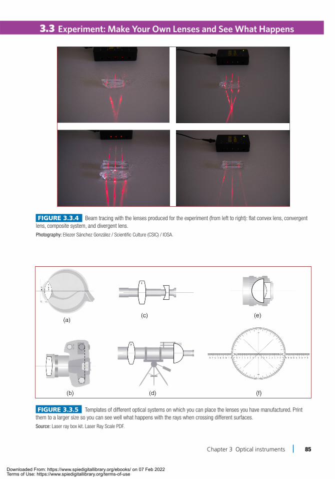
Figure 3.3.4 Beam tracing with the lenses produced for the experiment (from left to right): flat convex lens, convergent lens, composite system, and divergent lens.
Photography: Eliezer Sánchez González / Scientific Culture (CSIC) / IOSA.
Figure 3.3.5 Templates of different optical systems on which you can place the lenses you have manufactured. Print them to a larger size so you can see well what happens with the rays when crossing different surfaces.
Source: Laser ray box kit. Laser Ray Scale PDF.
Chapter 3.indd 85 4/23/2021 1:29:25 PM
Downloaded From: https://www.spiedigitallibrary.org/ebooks/ on 07 Feb 2022Terms of Use: https://www.spiedigitallibrary.org/terms-of-use

86 Discovering Light: Fun Experiments with Optics
Experiment: Make Your Own Lenses and See What Happens 3.3
In the case of divergent lenses, the effect is the opposite. Instead of diverting the rays to a specific point, these lenses separate them. To be able to measure the focal length of this type of lens, the sur-face where the light strikes must be well polished in order to view the low light that is reflected. If you succeed, you can see that the reflected rays behave as if they had passed through a convergent lens, all joining at a point that corresponds to the focal length of the lens. If the surface of your lens is smooth enough, you can also measure the focus of your divergent lens. If you put the silicone micro-lenses or the convergent jelly lens on the screen of a mobile phone, you will see that the image looks magnified, although to form a clear image there must be bubbles inside and a very smooth surface.
Tricks• Until now, the jelly lenses you have made are transparent. You can try using different
colored jelly and see what happens when it has the same color as the light of the laser pointers.
• You can place the silicone lenses on the templates (A - F figures) to see how different optical instruments work.
• You can play with the size of the silicone micro-lenses you have made and check if the size of the object you are viewing alters. Since these lenses are very small, you can use your mobile phone screen to magnify the light-emitting pixels.
Let’s see what you have learned• What would happen if the lens surface were not completely smooth?• What happens to the focal length if you squeeze the lens and increase its curvature?• What would happen if we used sparkling water to make the ice magnifier? Do you
think it would improve?• Why do you think we need a small lens to see the light emitting pixels of our mobile
phone screen?
Related experiments:Experiment 3.4 Micro-lenses: beyond a magnifying glass
Figure 3.3.6 Laser light through a combination of con-vergent and divergent lens.
Photography: Sara el Aissati.
Chapter 3.indd 86 4/23/2021 1:29:25 PM
Downloaded From: https://www.spiedigitallibrary.org/ebooks/ on 07 Feb 2022Terms of Use: https://www.spiedigitallibrary.org/terms-of-use

Chapter 3 Optical instruments 87
30 min (+)
Experiment
Refraction, convergent lenses, thick lenses, magnification
Micro-Lenses: Beyond a Magnifying Glass
Have you ever seen the screen of your computer or mobile phone with water droplets on its surface? If so and you
have looked carefully, you will surely have seen blue, red and green dots. In reality, the small drops of water are acting as a lens that allows us to solve/view the light emitting pixels of our screens. To give you an idea, a high-resolution mobile screen is made up of 1,920 pixels high and 1,800 wide. That makes, if the screen is 5.5 inches (diagonal), the pixel size is less than 10 microns on the side (a hair is 100 microns).
In this experiment, you will manufac-ture liquid water lenses to view the pixels of your mobile phone screen. Furthermore, we will also use dried hydrogel beads and see how their optical behavior is affected by hydrating them. Finally, we will show how hydrated hydrogel balls can be used as convergent lenses.
ProcedureWater droplet experimentBefore you start, bear in mind that water can damage the electronic device you are going to use. Therefore, you must use small amounts of water; you can use a sprayer, for example, and try to avoid wetting the head-set. If the drops are too large, quickly move the mobile phone horizontally while blowing on the screen.
Spray a little water on the unlocked screen and with luminous wallpaper. Notice that in the places where the small droplets are, the colors green, blue and red appear. If the drop-let is small enough, you will distinguish that these colors are grouped into small squares, each occupying a third part with a rectangular shape.
3.4
Figure 3.4.1 Hydrogel pearl without hydration.
Photography: in house.
Figure 3.4.2 Hydrogel beads without hydration on a screen.
Photography: in house.
OBJECTIVES:Objective 1: View and draw the pixel distribution of your mobile
phone screen.Objective 2: Use dried and hydrated hydrogel beads to produce a
higher resolution than with liquid drops.
MATERIALS• Water• Water sprayer• Mobile phone or tablet• Hydrogel beads• Micro-lenses manufactured in Experiment 3.3 (optional)
Chapter 3.indd 87 4/23/2021 1:29:26 PM
Downloaded From: https://www.spiedigitallibrary.org/ebooks/ on 07 Feb 2022Terms of Use: https://www.spiedigitallibrary.org/terms-of-use
88 Discovering Light: Fun Experiments with Optics
Experiment: Micro-Lenses: Beyond a Magnifying Glass3.4
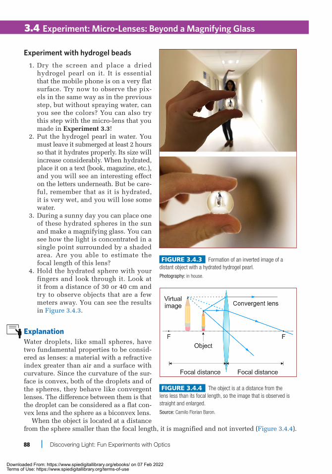
Experiment with hydrogel beads 1. Dry the screen and place a dried
hydrogel pearl on it. It is essential that the mobile phone is on a very flat surface. Try now to observe the pix-els in the same way as in the previous step, but without spraying water, can you see the colors? You can also try this step with the micro-lens that you made in Experiment 3.3!
2. Put the hydrogel pearl in water. You must leave it submerged at least 2 hours so that it hydrates properly. Its size will increase considerably. When hydrated, place it on a text (book, magazine, etc.), and you will see an interesting effect on the letters underneath. But be care-ful, remember that as it is hydrated, it is very wet, and you will lose some water.
3. During a sunny day you can place one of these hydrated spheres in the sun and make a magnifying glass. You can see how the light is concentrated in a single point surrounded by a shaded area. Are you able to estimate the focal length of this lens?
4. Hold the hydrated sphere with your fingers and look through it. Look at it from a distance of 30 or 40 cm and try to observe objects that are a few meters away. You can see the results in Figure 3.4.3.
ExplanationWater droplets, like small spheres, have two fundamental properties to be consid-ered as lenses: a material with a refractive index greater than air and a surface with curvature. Since the curvature of the sur-face is convex, both of the droplets and of the spheres, they behave like convergent lenses. The difference between them is that the droplet can be considered as a flat con-vex lens and the sphere as a biconvex lens.
When the object is located at a distance from the sphere smaller than the focal length, it is magnified and not inverted (Figure 3.4.4).
Figure 3.4.3 Formation of an inverted image of a distant object with a hydrated hydrogel pearl.
Photography: in house.
Figure 3.4.4 The object is at a distance from the lens less than its focal length, so the image that is observed is straight and enlarged.
Source: Camilo Florian Baron.
Chapter 3.indd 88 4/23/2021 1:29:26 PM
Downloaded From: https://www.spiedigitallibrary.org/ebooks/ on 07 Feb 2022Terms of Use: https://www.spiedigitallibrary.org/terms-of-use

Experiment: Micro-Lenses: Beyond a Magnifying Glass
Chapter 3 Optical instruments 89
3.4
On the other hand, when a distant object is observed (at a greater distance than the focal length), it will be observed as inverted (Figure 3.4.5). As the curvature of the micro-lenses is quite large, its focal length is rather short. That is why we see a con-siderable expansion of the object studied, which makes them very efficient when it is necessary to view small objects.
As we saw in the theoretical part, the focal length of a thick lens depends on the radius of curvature of its sides. This relationship indicates that the smaller the radius of curvature is, the smaller its focal length. When using spheres where there are two curved surfaces with the same radius of curvature, the focal length is smaller still, producing a much greater magnification, as demonstrated by being able to observe the pixels of the screen when placing a small spher-ical lens.
In both cases, when the curvature is very large and the parallel rays that come from afar affect different points of the surface, it is observed that not all rays are focused on the same point. This effect is known as spherical aberration. Spherical aberration is responsible for seeing the deformed objects. For example, the image of pixels, whose shape is rectangular, is rather a trapezoidal image.
Tricks• You can use a spray bottle to spray the drops of water on the mobile phone screen,
such as those used for perfumes. In this way, the water droplets will be more even and much smaller than if you do it with your hand.
• You can look for other spherical objects that can help you magnify objects. For exam-ple, you can use a crystal marble.
Let’s see what you have learned• Why does a spherical or hemispherical lens behave like a convergent lens?• Why are objects magnified that are very close to the micro-lens support point?• Why does such a large magnification occur when the spheres (or hemispheres) become
smaller and smaller?• Why with the hydrated hydrogel ball do we see the image without inverting when the
object is near and inverted when the object is far away?
Related experimentsExperiment 3.3 Make your own lenses and see what happens
Figure 3.4.5 The object is at a distance from the lens greater than its focal length, so the image that is observed is inverted and smaller.
Source: Camilo Florian Baron.
Chapter 3.indd 89 4/23/2021 1:29:27 PM
Downloaded From: https://www.spiedigitallibrary.org/ebooks/ on 07 Feb 2022Terms of Use: https://www.spiedigitallibrary.org/terms-of-use

90 Discovering Light: Fun Experiments with Optics
Experiment
30 min (+)
Nothing Here, Nothing There: Invisibility with Mirrors and Lenses
Mirrors, reflection, lenses, divergence, convergence
Invisibility is one of the most recurring fantasies in science fiction works. Having a cape that allows you to go unnoticed
to the rest of the world is a dream that has appealed to not only writers and film direc-tors but also many renowned scientists. At present, a certain type of invisibility is pos-sible, although it is limited to objects on a very small scale made of a new class of materials that are not found in nature and that present unusual electromagnetic prop-erties. These are known as meta-materials, which allow deflecting or attenuating the incident light rays on an object, making them imperceptible. Despite this, on a larger scale, it is possible to achieve an invisibility effect used by illusionists and prestidigi-tators by way of mirrors or lenses. In this experiment, we will show you their tricks.
ProcedureInvisibility with mirrors 1. Place the four mirrors as indicated in
Figure 3.5.2. Reflective sides should be on the inside, facing each other.
2. Make sure they form a 90º angle. To do this, you can use a conveyor or a square.
3. Position an object of appropriate size in the invisibility area indicated in the figure. To prove that it works, scroll it up and down, and enjoy the effect of appearance and disappearance.
3.5
Figure 3.5.1 Materials.
Photography: in house.
Figure 3.5.2 Assembly diagram of invisibility with mirrors.
Source: Camilo Florian Baron.
OBJECTIVES:Objective 1: Create a camouflage device with mirrors or lenses.Objective 2: Understand how light propagates in this system and
how imaging occurs.Objective 3: Understand how prestidigitators play with these
concepts to create optical illusions.
MATERIALSSetup I: mirrors• 4 flat mirrors• Mounts• Conveyor
Setup II: lenses• 4 convergent lenses (200-mm focal)• 4 divergent lenses (focal 75−100 mm)• Mounts• Ruler
Chapter 3.indd 90 4/23/2021 1:29:28 PM
Downloaded From: https://www.spiedigitallibrary.org/ebooks/ on 07 Feb 2022Terms of Use: https://www.spiedigitallibrary.org/terms-of-use

Chapter 3 Optical instruments 91
3.5
4. To see if the trick works, first place yourself in front of mirror 1. Then try to change position and see what hap-pens (Figure 3.5.4).
Invisibility with lenses 1. In this case, your ability will be tested
as the alignment of the lenses is criti-cal. Take two convergent lenses and two divergent lenses and place them in line following the order of Figure 3.5.3: first a convergent, then two divergent, to end with a convergent.
2. Remember that divergent lenses are those that are positioned in the central part of the device.
3. Make sure with a ruler that the dis-tance between convergent and diver-gent lenses is identical both at the beginning and at the end.
4. Replicate the previous side assem-bly, taking into account that you must keep the lenses with the same dis-tances as indicated in the figure.
5. Place the object you want to make disappear in the invisibility area (Figure 3.5.3).
6. To increase or decrease the invisibility zone, you will have to zoom in or out of the divergent lenses without losing symmetry.
Now you have it—enjoy your invisibility device!
Figure 3.5.3 Assembly diagram with invisibility with lenses.
Source: Camilo Florian Baron.
Figure 3.5.4 Assembly and proof of invisibility with mirrors.
Photography: Eliezer Sánchez González / Scientific Culture (CSIC) / IOSA.
Figure 3.5.5 Assembly and proof of invisibility with lenses.
Photography: in house.
Experiment: Nothing Here, Nothing There: Invisibility with Mirrors and Lenses
Chapter 3.indd 91 4/23/2021 1:29:29 PM
Downloaded From: https://www.spiedigitallibrary.org/ebooks/ on 07 Feb 2022Terms of Use: https://www.spiedigitallibrary.org/terms-of-use

92 Discovering Light: Fun Experiments with Optics
ExplanationThe secret of this experiment is to deflect the light around the object that we want to dis-appear. In the first case, the first mirror (mirror 1 in the figure) reflects the light away from the invisible area towards the second pair of mirrors (mirrors 2 and 3) to return it at the end to the mirror behind the hidden area (mirror 4). In the second case, the convergent lenses concentrate the light on the divergent lenses, avoiding the hidden object. Divergent lenses are important in the proposed design because they prevent the background of the image from being inverted.
Tricks• The larger the mirrors or lenses are, the larger the objects you can hide.• Perpendicular mirrors can be separated (so long as you keep the angle 90º) to cover
elongated objects.• If you don’t want them to discover your secret, hide the second pair of mirrors (2 and 3)
behind a wall (for example, at the end of a corridor) or place the mirrors in a box, leav-ing the observer a single point from which to observe the phenomenon.
Let’s see what you have learned• Are hidden objects invisible to an observer from any point?• How would we see an object located in the area marked out between the mirrors?
Related experimentsExperiment 3.1 Catch me if you can!Experiment 3.3 Make your own lenses and see what happens
3.5 Experiment: Nothing Here, Nothing There: Invisibility with Mirrors and Lenses
Chapter 3.indd 92 4/23/2021 1:29:29 PM
Downloaded From: https://www.spiedigitallibrary.org/ebooks/ on 07 Feb 2022Terms of Use: https://www.spiedigitallibrary.org/terms-of-use
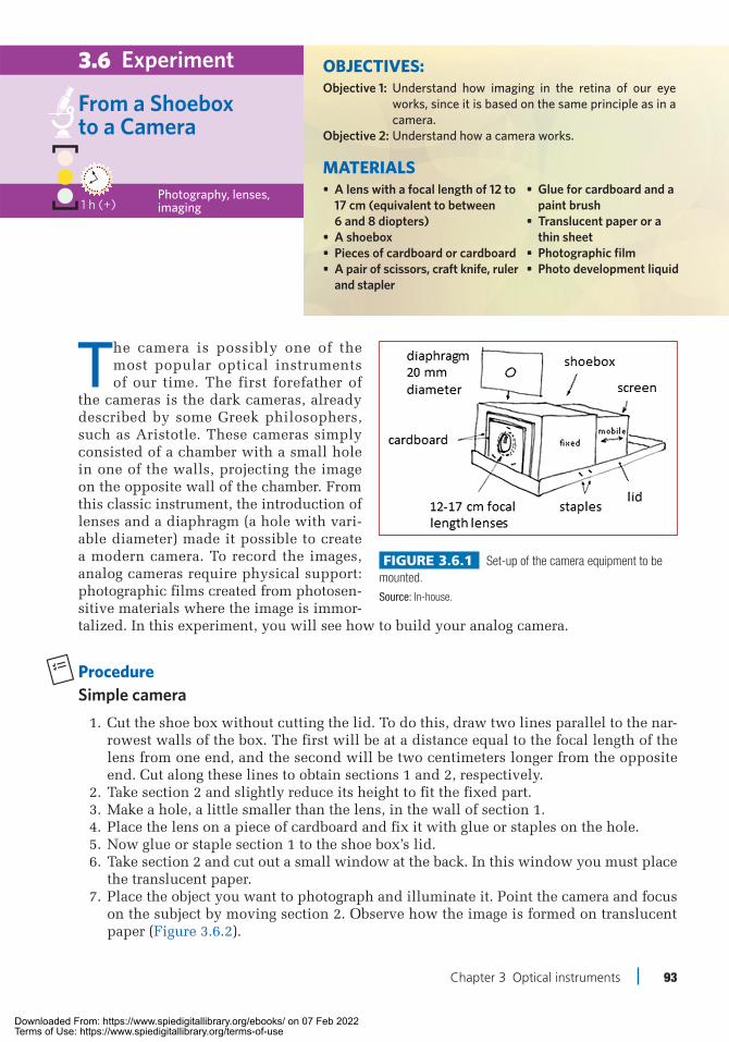
Chapter 3 Optical instruments 93
1 h (+)
Experiment
Photography, lenses, imaging
From a Shoebox to a Camera
3.6
The camera is possibly one of the most popular optical instruments of our time. The first forefather of
the cameras is the dark cameras, already described by some Greek philosophers, such as Aristotle. These cameras simply consisted of a chamber with a small hole in one of the walls, projecting the image on the opposite wall of the chamber. From this classic instrument, the introduction of lenses and a diaphragm (a hole with vari-able diameter) made it possible to create a modern camera. To record the images, analog cameras require physical support: photographic films created from photosen-sitive materials where the image is immor-talized. In this experiment, you will see how to build your analog camera.
ProcedureSimple camera 1. Cut the shoe box without cutting the lid. To do this, draw two lines parallel to the nar-
rowest walls of the box. The first will be at a distance equal to the focal length of the lens from one end, and the second will be two centimeters longer from the opposite end. Cut along these lines to obtain sections 1 and 2, respectively.
2. Take section 2 and slightly reduce its height to fit the fixed part. 3. Make a hole, a little smaller than the lens, in the wall of section 1. 4. Place the lens on a piece of cardboard and fix it with glue or staples on the hole. 5. Now glue or staple section 1 to the shoe box’s lid. 6. Take section 2 and cut out a small window at the back. In this window you must place
the translucent paper. 7. Place the object you want to photograph and illuminate it. Point the camera and focus
on the subject by moving section 2. Observe how the image is formed on translucent paper (Figure 3.6.2).
Figure 3.6.1 Set-up of the camera equipment to be mounted.
Source: In-house.
• Glue for cardboard and a paint brush
• Translucent paper or a thin sheet
• Photographic film• Photo development liquid
OBJECTIVES:Objective 1: Understand how imaging in the retina of our eye
works, since it is based on the same principle as in a camera.
Objective 2: Understand how a camera works.
MATERIALS• A lens with a focal length of 12 to
17 cm (equivalent to between 6 and 8 diopters)
• A shoebox• Pieces of cardboard or cardboard• A pair of scissors, craft knife, ruler
and stapler
Chapter 3.indd 93 4/23/2021 1:29:30 PM
Downloaded From: https://www.spiedigitallibrary.org/ebooks/ on 07 Feb 2022Terms of Use: https://www.spiedigitallibrary.org/terms-of-use

94 Discovering Light: Fun Experiments with Optics
Experiment: From a Shoebox to a Camera
Adding new items to your camera 1. Make a small hole of about 2 cm in a cardboard to create a diaphragm. Place it in front
of the objective lens. 2. Use an additional lens to create a macro lens or a fish-eye. 3. To build a fish-eye, take another lens and place it on the end of a tube 4. Use felt and insulating tape to give it greater consistency. Finally, paste it or hold it on
the lens of your camera.
Immortalizing the image in a photograph 1. Once the images taken are clear, try to take a homemade photo. Cover the lens of your
camera and work with the maximum possible darkness. Place the photo paper on the transparent plastic and close the camera.
2. Turn on the light and then, with the lens covered, point and focus the object to be photographed.
3. Uncover the camera and let the light penetrate the camera for 20 seconds. 4. Cover the camera again and, again in the dark, remove the photo paper and apply the
developer liquids to produce the image on the paper.
ExplanationIn the camera we have built, we can identify the basic parts of an analog camera. Basically, a traditional camera consists of at least a first objective lens; then a diaphragm, which is responsible for regulating the amount of light that will reach the film; a shutter, which will define the moment in which we want to capture and, finally (depending on our objective lens), a second lens that will send the image to the film at a suitable size.
The shutter speed is what defines the exposure time of the film to the incoming light. The diaphragm is fixed, or we can build it additionally, as we have previously suggested. The cover that we put on the lens acts as a shutter, regulating the exposure time by the camera’s aperture time.
If we want to take pictures in low-light conditions (where we need an open diaphragm and more exposure time), the simplest solution is to use a roll of film that is more sensitive to light.
TricksAn alternative to build a diaphragm is to use your hand or a bottle cap to increase or reduce the amount of light that reaches our camera.
3.6
Figure 3.6.2 Backlit object and camera taken image. Photo camera operation.
Photography: Eliezer Sánchez González / Scientific Culture (CSIC) / IOSA.
Chapter 3.indd 94 4/23/2021 1:29:30 PM
Downloaded From: https://www.spiedigitallibrary.org/ebooks/ on 07 Feb 2022Terms of Use: https://www.spiedigitallibrary.org/terms-of-use

Experiment: From a Shoebox to a Camera
Chapter 3 Optical instruments 95
Let’s see what you have learned• Why is the image projected on the transparent screen upside down?• If we remove the lens from the system, will the image of the object be shown on the
screen? Why?
Related experimentsExperiment 3.2 There is nothing beyond my reach!Experiment 3.7 Become a top-notch astronomer at home!
3.6
Chapter 3.indd 95 4/23/2021 1:29:30 PM
Downloaded From: https://www.spiedigitallibrary.org/ebooks/ on 07 Feb 2022Terms of Use: https://www.spiedigitallibrary.org/terms-of-use

96 Discovering Light: Fun Experiments with Optics
Experiment
Lenses, mirrors, refraction, reflection2 h (+)
Become a Top-Notch Astronomer at Home!
The telescope is an optical instru-ment that allows distant objects to be observed in much more detail than
the naked eye. It is a fundamental tool in astronomy: each development or improve-ment of this instrument has allowed for advances in our understanding of the uni-verse. There are two types of telescopes, refractors and reflectors, depending on whether they are constituted only by lenses, which refract light, or also incor-porate mirrors, which reflect it. Within the refracting mirrors, we can find those of Galileo and those of Kepler, with different characteristics due to their different lens combinations.
In this experiment, a telescope of each type will be built. In this way we will better understand the differences between the two, and we can begin to observe the beauty that a starry sky hides.
3.7
Figure 3.7.1 Materials.
Photography: Eliezer Sánchez González / Scientific Culture (CSIC) / IOSA.
Figure 3.7.2 Galileo telescope (left), and Kepler telescope (right).
Source: In-house.
OBJECTIVES:Objective 1: Build a Galileo- and Kepler-type refracting telescope. Identify their main differences.Objective 2: Know the advantages and disadvantages of each tele-
scope according to its characteristics (type of lens, aperture, focal length, focal ratio, magnification, etc.).
Objective 3: Characterize the telescope that has been built from the concepts that have been learned in the previous objectives.
MATERIALSFor the Galileo telescope• A small concave lens• A large convex lens• Recycling cardboard tubes• Glue• Filter strips• Ruler• Scissors and craft knife
For the Kepler telescope (in addition to the above):• Two convex lenses: one
small for the eyepiece and one larger for the lens
Chapter 3.indd 96 4/23/2021 1:29:31 PM
Downloaded From: https://www.spiedigitallibrary.org/ebooks/ on 07 Feb 2022Terms of Use: https://www.spiedigitallibrary.org/terms-of-use

Experiment: Become a Top-Notch Astronomer at Home!
Chapter 3 Optical instruments 97
Procedure 1. The first thing you need to know is the
diameter and focal length of your lenses. If you cannot remember how to measure the focal length of a lens, don’t worry! Go back to Experiment 3.3 to look it up.
2. Paste both lenses on each end of a tube. Remember that the diameter of the tubes must be similar to that of the lenses. If the lens is larger, you can glue it carefully as not to dirty it, and if it is small, you can fill the hole with felt, for example.
3. Place one tube inside the other, so that the lenses are at opposite ends of the two tubes. It is necessary that the smaller tube can slide smoothly in and out of the larger tube.
4. Glue the felt strips around the out-side of the smaller tube to fill the gap between the tubes. Put enough layers so that it is more or less tight but can slide to carry out the approach.
5. To calculate the length of your telescope, remember: the sum of the focal points of both lenses is equal to the distance between them, this being so when the telescope is focused infinitely, theo-retically. The tube of greater diameter, for aesthetics, is longer than the one of smaller diameter. The tube of smaller diameter must be in the middle position according to the total length. Thus, we will have enough travel to increase or reduce the distance when focusing (Figures 3.7.4 and 3.7.5).
3.7
Figure 3.7.4 Right image produced by the Galileo telescope.
Photography: Eliezer Sánchez González / Scientific Culture (CSIC) / IOSA.
Figure 3.7.3 Final result when assembling the components.
Photography: in house.
Figure 3.7.5 Inverted image produced by the Kepler telescope.
Photography: Eliezer Sánchez González / Scientific Culture (CSIC) / IOSA.
Chapter 3.indd 97 4/23/2021 1:29:32 PM
Downloaded From: https://www.spiedigitallibrary.org/ebooks/ on 07 Feb 2022Terms of Use: https://www.spiedigitallibrary.org/terms-of-use

98 Discovering Light: Fun Experiments with Optics
Experiment: Become a Top-Notch Astronomer at Home!
Even harder: Newton’s telescope 1. A refracting telescope does not have
many parts, and you can build it if you follow the diagram outlined in Figure 3.7.6.
2. As a primary mirror, you will need a concave one. For example, a make-up mirror could have the right diameter and focal length. The larger the diam-eter is, the more light you will get.
3. For the secondary mirror, you will need a flat mirror with dimensions smaller than the primary one. Ideally, the reflective surface should be the first, not the second, as in normal mirrors, since loss of light is avoided.
4. Cut two cardboard circles with the dimensions of the primary mirror. These two cir-cles will be separated by screws and nuts that will create a stop. This will allow us to move the mirror forward or backward to focus the telescope.
5. Paste the primary mirror onto this system. 6. You need to place the secondary mirror (the flat one) at an angle of 45º with respect
to the primary one, as it appears in the diagram. The centers of both mirrors must be at the same height. Keep in mind that you are magnifying: a small mistake will be noticed much more! Fix the optical elements as well as possible to avoid vibrations.
7. With a convergent lens, form an eyepiece to look through. Adjust the distance as you see in the diagram so that the light comes out collimated from the telescope.
8. And then it is ready. You can also use a PVC tube to avoid external light and have more protected telescope optics.
ExplanationIn the Galileo telescope, parallel rays of light from a distant object are brought to a point in the focal plane of the objective lens using a convergent lens. The eyepiece is a divergent lens that intercepts these rays and makes them parallel once again.
The final image is a virtual image, right, located in the infinite and with the same shape as the object. In contrast, both the eyepiece and the objective lens are convergent lenses in the Kepler telescope. The objective lens provides a real and inverted image and, through the eyepiece, the observer sees a virtual image of the same meaning, that is, inverted with respect to the object. The Newtonian telescope uses mirrors instead of lenses. Light from the observed object propagates along the tube until it reaches the primary mirror, located at the rear. The mirror reflects the rays forward and, thanks to its concave shape, concentrates them in a very small space. Next, a flat mirror directs the light towards a hole in the side of the tube, and with the help of an eyepiece that is nothing more than a lens, the desired star can be observed.
The Galileo telescope is a very bright telescope, and the final image is right without the need for an inverter system. However, it has a very small field of vision. The Kepler telescope, when using a convex lens in the eyepiece instead of the concave of the Galileo model, has the advantage of allowing a much wider field of vision and in greater detail, but the image for the viewer is reversed. The Newtonian telescope, when using mirrors, avoids the chromatic aberration of the lenses; however, the disadvantage of Newtonians
3.7
Figure 3.7.6 Newton’s telescope.
Source: Camilo Florian Baron.
Chapter 3.indd 98 4/23/2021 1:29:32 PM
Downloaded From: https://www.spiedigitallibrary.org/ebooks/ on 07 Feb 2022Terms of Use: https://www.spiedigitallibrary.org/terms-of-use

Experiment: Become a Top-Notch Astronomer at Home!
Chapter 3 Optical instruments 99
versus refractors is the shading of incoming light. Since refractors have no element in the optical path that causes obstruction in the optical path, they are able to provide more light and contrast to images with the same aperture as the reflectors.
By knowing the focal points of the lenses that have been used in the lens and eyepiece and their diameters, you can calculate their aperture, their focal ratio, their magnifications and classify the telescope. Identify all the characteristics you have learned in the previous aims:
The aperture is the effective diameter of the telescope’s main lens or mirror. The opening will be who defines the collection capacity of our telescope. The greater the aperture, the more capacity to capture light and, to a greater amount of light, we can see more dim objects.
Focal length is the point where the light concentrates, that is, the main lens or mirror of the telescope.
When we mathematically relate aperture and focal length, it gives us a very useful value: the focal relationship, which is defined as follows:
Focal Ratio = Focal Length
Diameter
The focal relationship is also known as number f. The lower the focal ratio is, the brighter the telescope. That is, less time would be needed to photograph weak objects.
The magnification of a telescope is defined by the following expression:
Magnification = Telescope Focal LengthEyepiece Focal Length
In order for our telescope to have good optical quality, it is advisable not to exceed twice the magnification of our aperture. In other words, if our telescope is 50 mm in diameter, we should not use more than 100 magnifications. If we add more, we will see the image as highly distorted and blurred.
Tricks• Try different combinations of lenses and tube materials. You can use the lenses of old
cameras, magnifiers or other optical items.• Paint the inside of your telescopes slate black to avoid reflections of parasitic light.
Outside, you can be as creative as you want.• Try not to touch the front of your lenses and optical mirrors with your hands (wear latex
gloves), and before incorporating them into your telescope, clean them with a cloth.• When you go to make the observation, choose a day of clear sky and an area with little
artificial light pollution.
Let’s see what you have learned• What is the difference between a refracting telescope and a reflector?• What is the main difference between the Galileo and Kepler telescopes?• What are the benefits and drawbacks of each?
Related experimentsExperiment 3.2 There is nothing beyond my reach! Experiment 3.3 Make your own lenses and see what happensExperiment 3.6 From a shoebox to a camera
3.7
Chapter 3.indd 99 4/23/2021 1:29:32 PM
Downloaded From: https://www.spiedigitallibrary.org/ebooks/ on 07 Feb 2022Terms of Use: https://www.spiedigitallibrary.org/terms-of-use

100 Discovering Light: Fun Experiments with Optics
Experiment
Lenses, imaging, focal length, lens combination60 min (+)
Microscope: How to See the Tiniest Things
Amicroscope is an optical instrument that produces a magnified image of small objects (or microscopic, that
is, of the size of microns) thanks to the help of convex lenses. A magnifying glass would be a simple microscope composed of a single lens, but if we wish to view tiny details, we need to combine different optical elements.
Mainly, a basic microscope consists of (1) a plate, or transparent sheet where we place the sample we want to observe; (2) a lighting and diaphragm system, which illuminates the sample (lights below); (3) an objective lens, which is the lens closest to the sample (usually with great power) and (4) an eyepiece, which is the lens located near our eye. The combination of the power of the objective and ocular lenses determines the magnification of our microscope (for example, the 40× nota-tion indicates that we see the object a ver-sion scaled 40 times larger). The observed image is created in our retina, if we are the ones who observe, or in the camera sensor, in case we want to register that image.
Today, we can build a microscope and take the images with the help of our smartphone.Would you like one?
ProcedureMicroscope construction 1. Identify the two lenses to construct the microscope: one with a short focal length (used as
lens 1, objective), and one with a longer lens (which we will use as an eyepiece, lens 2).
3.8
Figure 3.8.1 Magnifying glass and simple microscope (two lenses, two diaphragms and one lighting source).
Source: Camilo Florian Baron.
OBJECTIVES:Objective 1: Build a microscope following the proposed instruc-
tions. Objective 2: Optimize the system to obtain measurements with
real scale, align the optical elements (smartphone, lens, sample and lighting) and calculate the magnifi-cation of the system.
MATERIALS• Two convergent lenses of a
disposable camera (usually with 25-mm and 45-mm focal lengths)
• PVC tube ~ 3 cm in diameter or cardboard (to form a tube)
• 2 wooden or plastic bases• 4 LEGO pieces• Lighting source (or
continuous flash of another mobile phone)
• Adhesive tape
Chapter 3.indd 100 4/23/2021 1:29:32 PM
Downloaded From: https://www.spiedigitallibrary.org/ebooks/ on 07 Feb 2022Terms of Use: https://www.spiedigitallibrary.org/terms-of-use

Experiment: Microscope: How to See the Tiniest Things
Chapter 3 Optical instruments 101
2. We will mount one of the lenses at one end of the tube and, at the other end, the other. The length of the tube will depend on the focal length of the lenses. We suggest using a length of 16 cm.
3. To create the platform to hold the lens tube, you can use an additional piece of tube (part 1). It is important that the pieces can be moved in height to be able to modify the distances between lenses and, for this, use the LEGO pieces as indicated in the figure.
4. You must also make a first platform that has a hole for the light to pass to your object (part 2).
5. Finally, the lighting system, which can be an LED or the flash in continuous mode (flashlight) of a mobile phone (part 3).
6. Once you have it assembled, it is time to adjust the system. The first thing is to place the object on the transparent plate and turn on the lighting.
7. Try looking through lens 2 and adjust the distance between the lens tube and your object. The theoretical distance is 21.6 mm using a 25-mm focal lens as lens 1.
8. And voilà! You already have it… now you can use your mobile phone camera to take pictures of your magnified object (Figure 3.8.2).
Quantification of the magnification capacity of our system: direct measurement 1. In this case, to facilitate the measurements, we are going to use as a sample the lead of
a propelling pencil, for example, 0.5. This means that it will be approximately 0.5 mm thick (500 µm).
2. To know what the magnification level we have is, we simply have to make a quotient between the real measure of the object and the measure of the object in a photo taken with the mobile phone.
3. If you want to make a theoretical estimate based on the actual values of your system, you will have to know what the length of the tube is and the focal lengths of the lenses you are using. To do this, follow the procedure indicated in the explanation.
ExplanationCuriosity regarding small things has allowed us to develop and implement many improve-ments to the different optical instruments that are within our reach today. In the specific case of the microscope, its origins go back to the use of a simple magnifying glass that allows us to magnify objects in the simplest possible way, even the most modern high-resolution optical microscopes with which research is currently being performed.
The microscope you just built is the result of combining two convergent lenses to view the world of small things without having to use a single, giant convergent lens. Basically, it incorporates an objective lens (which is the one that is closest to the object to be studied) and an ocular lens (which allows us to form the enlarged image).
Over the years, different elements have been incorporated to obtain sharper images, with more magnifications and exceptional spatial resolutions. Two basic elements are the
Figure 3.8.2 Final view of the built microscope, which shows how the object is illuminated with the flashlight of a mobile phone and imaged through the system.
Photography: Eliezer Sánchez González / Scientific Culture (CSIC) / IOSA.
3.8
Chapter 3.indd 101 4/23/2021 1:29:33 PM
Downloaded From: https://www.spiedigitallibrary.org/ebooks/ on 07 Feb 2022Terms of Use: https://www.spiedigitallibrary.org/terms-of-use

102 Discovering Light: Fun Experiments with Optics
Experiment: Microscope: How to See the Tiniest Things3.8
incorporation of different diaphragms that allow controlling, for example, the amount of light that will reach the sample and the visual field. With the development of complex lenses that contain multiple lenses, it has been possible to use various filters that allow us to obtain even more information about the object under analysis. Such are the efforts geared towards these improvements that, in 2014, Eric Betzig, Stefan W. Hell and William E. Moerner were awarded the Nobel Prize in Chemistry for their developments in high-resolution fluorescence microscopy techniques.
Tricks• To optimize your system, you can also play with the distances between the light
source and the sample, in order to obtain a more even lighting system. In the case of samples that are not translucent, you can illuminate the sample from the top, so that it reflects on its surface and goes to the lens.
• If you want to further increase the resolution of your system, use a micro-lens. Experiment 3.4 Micro-lenses: beyond a magnifying glass is suitable for this case.
Let’s see what you have learned• What is the importance of lighting in the image quality that we can obtain?• Could we use a telescope as if it were a microscope?• What size is a virus? With our microscope, can we view one?• What do you think is the smallest object we could observe with a light-based
microscope?• What do you think it would take to view an atom? Would it be possible with a similar
system?
Related experimentsExperiment 3.3 Make your own lenses and see what happensExperiment 3.4 Micro-lenses: beyond a magnifying glassExperiment 3.9 A micro-world in a droplet
Chapter 3.indd 102 4/23/2021 1:29:33 PM
Downloaded From: https://www.spiedigitallibrary.org/ebooks/ on 07 Feb 2022Terms of Use: https://www.spiedigitallibrary.org/terms-of-use
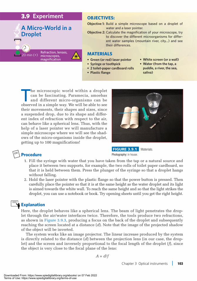
Chapter 3 Optical instruments 103
20 min (+)
Experiment
Refraction, lenses, microscopes, magnification
A Micro-World in a Droplet
The microscopic world within a droplet can be fascinating. Paramecia, amoebas and different micro-organisms can be
observed in a simple way. We will be able to see their movements, their shapes and sizes, since a suspended drop, due to its shape and differ-ent index of refraction with respect to the air, can behave like a spherical lens. Thus, with the help of a laser pointer we will manufacture a simple microscope where we will see the shad-ows of the micro-organisms inside the droplet, getting up to 100 magnifications!
Procedure 1. Fill the syringe with water that you have taken from the tap or a natural source and
place it between two supports, for example, the two rolls of toilet paper cardboard, so that it is held between them. Press the plunger of the syringe so that a droplet hangs without falling.
2. Hold the laser pointer with the plastic flange so that the power button is pressed. Then carefully place the pointer so that it is at the same height as the water droplet and its light is aimed towards the white wall. To reach the same height and so that the light strikes the droplet, you can use a notebook or book. Try opening sheets until you get the right height.
ExplanationHere, the droplet behaves like a spherical lens. The beam of light penetrates the drop-let through the air/water interfaces twice. Therefore, the tools produce two refractions, as shown in Figure 3.9.3, producing a focus on the back of the droplet and subsequently reaching the screen located at a distance (d). Note that the image of the projected shadow of the object will be inverted.
The system works like an image projector. The linear increase produced by the system is directly related to the distance (d) between the projection lens (in our case, the drop-let) and the screen and inversely proportional to the focal length of the droplet (f), since the object is very close to the focal plane of the lens:
A = d/f
3.9
Figure 3.9.1 Materials.
Photography: in house.
• White screen (or a wall)• Water (from the tap, a
puddle, a river, the sea, saliva)
OBJECTIVES:Objective 1: Build a simple microscope based on a droplet of
water and a laser pointer.Objective 2: Calculate the magnification of your microscope, try
to discover the different microorganisms for differ-ent water samples (mountain river, city...) and see their differences.
MATERIALS• Green (or red) laser pointer• Syringe or toothpick• 2 toilet-paper cardboard rolls• Plastic flange
Chapter 3.indd 103 4/23/2021 1:29:34 PM
Downloaded From: https://www.spiedigitallibrary.org/ebooks/ on 07 Feb 2022Terms of Use: https://www.spiedigitallibrary.org/terms-of-use

104 Discovering Light: Fun Experiments with Optics
Experiment: A Micro-World in a Droplet
For a spherical droplet, the focal length (f) can be approximated to f = R / 2 · [n / (n − 1)], where R is the radius of the droplet (which you can approximate to the radius of your syringe hole), and n is the refractive index of water (n = 1.33).
Tricks• If you do not have a syringe, you can
use a stick by wetting it and allowing the droplet to hang without falling; finally, place the toothpick carefully on a support with adhesive tape so that it is suspended. The smaller the droplet is, the more magnification you will have in your microscope.
• Add water from the sea, river or pud-dles to see the micro-organisms move, although this water must not be too cloudy.
• You can put a transparent sheet, such as an insect wing or onion skin, between the laser and the droplet, and you will also see it enlarged, as if it were a projector.
Let’s see what you have learnedGiven that the refractive index of water is n = 1.33, and knowing the distance (d) of the droplet to your screen, can you calculate the magnification of your microscope?
Related experimentsExperiment 3.3 Make your own lenses and see what happensExperiment 3.4 Micro-lenses: beyond a magnifying glassExperiment 3.8 Microscope: how to see the tiniest things
Figure 3.9.2 Assembly of the complete experiment (left) and detail of the assembly in which the suspended droplet (right) is observed.
Photography: in house.
Figure 3.9.3 Projection onto a white surface of a back-lit droplet using a green laser (you can see the wing of a wasp located between the laser and droplet.
3.9
Chapter 3.indd 104 4/23/2021 1:29:34 PM
Downloaded From: https://www.spiedigitallibrary.org/ebooks/ on 07 Feb 2022Terms of Use: https://www.spiedigitallibrary.org/terms-of-use