Instructions for Authors - CiteSeerX
11
Displacement- and Performance-Based Seismic Design for Sustainable Earthquake Resistant Concrete Construction Michael N. Fardis University of Patras, PO BOX 1424, 26504, Patras, Greece. E-mail: <[email protected]>. ABSTRACT A seismic design procedure is proposed for specific and measurable performance of concrete structures for at least two seismic hazard levels. It tailors capacities to seismic demands over the structure, allowing significant savings in materials compared to conventional opaque design codes with prescriptive and wasteful detailing. The procedure is described in detail as a sequence of steps. Design expressions are given for carrying out these steps in bridges with integral deck and piers or buildings. Detailing of members for ductility is based on a transparent explicit verification of inelastic deformation demands against capacity limits. An application to eight bridges shows major savings in steel without loss in seismic performance. INTRODUCTION Design of structures for sustainability should entail, among other, concerted efforts to use as little material as absolutely necessary for the target performance of the structure. Such efforts should be undertaken, of course, by the individual designer of each structure. Besides, codes and standards should promote design for minimum material quantities and explicitly include a requirement to estimate and reduce the structure’s carbon footprint. Unfortunately current design codes are far from there. This is the case in particular with seismic design according to current codes, which is still force-based, with reduction of the lateral forces derived from the elastic spectrum by the behavior (or force reduction) factor. Prescriptive member detailing rules are employed, to provide the ductility associated with the value of the behavior factor used in the design. This approach is opaque as far as seismic performance is concerned, but also very wasteful, because the prescriptive detailing rules result in an excess of material for the achieved performance. Performance-based seismic design allows targeting specific and measurable performance under - normally more than one – seismic hazard levels. Moreover, if based on displacements and their derivatives, i.e., deformations, it allows tailoring the capacities to the seismic demands throughout the structure and savings in materials. In this paper a practical procedure is proposed for displacement- and performance-based seismic design of concrete structures (buildings or bridges with integral deck and piers). The concept has evolved from the work of Panagiotakos and Fardis [1999, 2001] for buildings and Bardakis and Fardis [2008] for bridges and draws its tools from [Biskinis and Fardis, 2008]. PROPOSED SEISMIC DESIGN PROCEDURE Performance levels, requirements and criteria Structures are designed here to meet the Immediate Use Serviceability Limit State and at
-
Upload
khangminh22 -
Category
Documents
-
view
6 -
download
0
Transcript of Instructions for Authors - CiteSeerX

Displacement- and Performance-Based Seismic Design for
Sustainable Earthquake Resistant Concrete Construction
Michael N. Fardis
University of Patras, PO BOX 1424, 26504, Patras, Greece. E-mail: <[email protected]>.
ABSTRACT
A seismic design procedure is proposed for specific and measurable performance of concrete
structures for at least two seismic hazard levels. It tailors capacities to seismic demands over
the structure, allowing significant savings in materials compared to conventional opaque
design codes with prescriptive and wasteful detailing. The procedure is described in detail as
a sequence of steps. Design expressions are given for carrying out these steps in bridges with
integral deck and piers or buildings. Detailing of members for ductility is based on a
transparent explicit verification of inelastic deformation demands against capacity limits. An
application to eight bridges shows major savings in steel without loss in seismic performance.
INTRODUCTION
Design of structures for sustainability should entail, among other, concerted efforts to use as
little material as absolutely necessary for the target performance of the structure. Such efforts
should be undertaken, of course, by the individual designer of each structure. Besides, codes
and standards should promote design for minimum material quantities and explicitly include
a requirement to estimate and reduce the structure’s carbon footprint. Unfortunately current
design codes are far from there. This is the case in particular with seismic design according to
current codes, which is still force-based, with reduction of the lateral forces derived from the
elastic spectrum by the behavior (or force reduction) factor. Prescriptive member detailing
rules are employed, to provide the ductility associated with the value of the behavior factor
used in the design. This approach is opaque as far as seismic performance is concerned, but
also very wasteful, because the prescriptive detailing rules result in an excess of material for
the achieved performance. Performance-based seismic design allows targeting specific and
measurable performance under - normally more than one – seismic hazard levels. Moreover,
if based on displacements and their derivatives, i.e., deformations, it allows tailoring the
capacities to the seismic demands throughout the structure and savings in materials. In this
paper a practical procedure is proposed for displacement- and performance-based seismic
design of concrete structures (buildings or bridges with integral deck and piers). The concept
has evolved from the work of Panagiotakos and Fardis [1999, 2001] for buildings and
Bardakis and Fardis [2008] for bridges and draws its tools from [Biskinis and Fardis, 2008].
PROPOSED SEISMIC DESIGN PROCEDURE
Performance levels, requirements and criteria
Structures are designed here to meet the Immediate Use Serviceability Limit State and at
cbx054
Text Box
Coventry University and The University of Wisconsin Milwaukee Centre for By-products Utilization Second International Conference on Sustainable Construction Materials and Technologies June 28 - June 30, 2010, Università Politecnica delle Marche, Ancona, Italy. Proceedings of Honouree sessions ed. T Naik, F Canpolat, P Claisse, E Ganjian, ISBN 978-1-4507-1487-7 http://www.claisse.info/Proceedings.htm

least one of two Ultimate Limit States (ULS): (a) Life Safety and (b) Near Collapse. Each
Limit State (performance level) is met at its own seismic hazard level, with the seismic action
defined for each level via its own 5%-damped elastic spectrum.
The proposed compliance criteria for the three Limit States (performance levels) are:
a) For Immediate Use, nominal yielding at potential plastic hinges may be exceeded by a
factor with a value of about 2.0, reflecting a presumed overstrength factor of at least 1.5
in materials and members and certain tolerance of flexural yielding at some sections.
b) At the Near Collapse Limit State, members should stay below an upper-fractile (e.g., a
95%-fractile) of their ultimate flexural deformation, to account for model uncertainty.
c) At the Life Safety Limit States, a safety margin against the above upper-fractile ultimate
flexural deformation at member ends should be provided. A safety factor of 1.5 seems
appropriate for ordinary buildings, or of 2.0 for bridges.
d) Brittle (i.e., shear) failures of members and their connections should be prevented at both
ULSs. A safety factor of 1.25 on shear resistances based on design values of material
strengths (nominal strengths divided by the material partial factor) seems appropriate.
A constant safety factor between the limits for Life Safety and Near Collapse in (b) and (c)
means that it is normally redundant to check flexural deformations at both ULSs. The Near
Collapse ULS governs if the spectral values of its own seismic action at the elastic structure’s
important natural periods (from Step 5 below for the final effective stiffness) clearly exceed
those of the Life Safety action by more than the inverse of the safety factor. Conversely, if
they are clearly less. Besides, the shear verifications are carried out only once. In the end the
three-tier design may reduce to single tier design in shear and a two-tier one in flexure.
Steps of the proposed design procedure:
Step 1 - Conceptual design and sizing of members: Select a clear and simple structural
system, with the maximum feasible regularity of geometry and mass in plan and in elevation.
Provide sufficient lateral stiffness near the perimeter in plan to ensure that the period of the
lowest primarily transnational mode in two orthogonal horizontal directions is longer than
that of a torsional mode. Size the members as follows, for fruition of Step 7 below:
In buildings, vertical members of the same family (i.e., walls or columns) should have as
uniform a cross-sectional depth as possible in each one of the two horizontal directions.
If the rotational restraint of members by others in the considered horizontal direction
varies among members of the same family, those restrained more by others may be
chosen with smaller depth than the rest.
In buildings, the beam depth should be uniform all-along any plane frame, but may be
smaller in frames with shorter spans than in others with longer ones. It should gradually
decrease from the base to the roof.
In bridges, the section and free length of piers integral with the deck should be chosen so
that they all present about the same lateral stiffness in each one of the two orthogonal
horizontal directions of the seismic action (longitudinal and transverse).
Member cross-sections should be large enough for their connections to accommodate
bond requirements for the intended sizes of bars passing through them or anchored there.
Step 2 - Design for non-seismic actions: Dimension the reinforcement of all members on
the basis of the Ultimate and the Serviceability Limit States for all pertinent non-seismic
actions, taking into account minimum reinforcement requirements for structures without
earthquake resistance. Redistribute ULS moments in horizontal members from supports to
mid-spans or vice-versa, as optimal in design for non-seismic actions. In bridges, design also
for the ULS at all relevant intermediate stages of construction, taking into account the
redistribution of action effects due to creep and losses of prestress, etc., as appropriate.
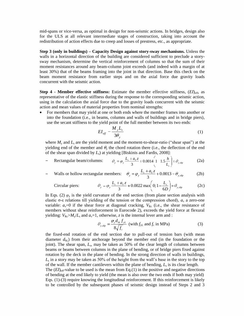
Step 3 (only in buildings) – Capacity Design against story-sway mechanisms. Unless the
walls in a horizontal direction of the building are considered sufficient to preclude a story-
sway mechanism, determine the vertical reinforcement of columns so that the sum of their
moment resistances around any beam-column joint exceeds (and indeed with a margin of at
least 30%) that of the beams framing into the joint in that direction. Base this check on the
beam moment resistance from earlier steps and on the axial force due gravity loads
concurrent with the seismic action.
Step 4 - Member effective stiffness: Estimate the member effective stiffness, (EI)eff, as
representative of the elastic stiffness during the response to the corresponding seismic action,
using in the calculation the axial force due to the gravity loads concurrent with the seismic
action and mean values of material properties from nominal strengths:
For members that may yield at one or both ends where the member frames into another or
into the foundation (i.e., in beams, columns and walls of buildings and in bridge piers),
use the secant stiffness to the yield point of the full member between its two ends:
y
sy
eff
LMEI
3 (1)
where My and Ls are the yield moment and the moment-to-shear-ratio (“shear span”) at the
yielding end of the member and y the chord rotation there (i.e., the deflection of the end
of the shear span divided by Ls) at yielding [Biskinis and Fardis, 2008]:
Rectangular beam/columns: slipy
s
Vs
yyL
hzaL,
5.110014.03
(2a)
Walls or hollow rectangular members: slipy
Vs
yy
zaL,
0013.03
(2b)
Circular piers: slipy
sVs
yyD
LzaL,
61;0max0022.0
3 (2c)
In Eqs. (2) φy is the yield curvature of the end section (from plane section analysis with
elastic σ-ε relations till yielding of the tension or the compression chord), av a zero-one
variable: av=0 if the shear force at diagonal cracking, VRc (i.e., the shear resistance of
members without shear reinforcement in Eurocode 2), exceeds the yield force at flexural
yielding: VRc>My/Ls and av=1, otherwise, z is the internal lever arm and :
c
yLbLy
slipy
f
fd
8,
(with fyL and fc in MPa) (3)
the fixed-end rotation of the end section due to pull-out of tension bars (with mean
diameter dbL) from their anchorage beyond the member end (in the foundation or the
joint). The shear span, Ls, may be taken as 50% of the clear length of columns between
beams or beams between columns in the plane of bending, or of bridge piers fixed against
rotation by the deck in the plane of bending. In the strong direction of walls in buildings,
Ls in a story may be taken as 50% of the height from the wall’s base in the story to the top
of the wall. If the member cantilevers within the plane of bending, Ls is its clear length.
The (EI)eff-value to be used is the mean from Eq.(1) in the positive and negative directions
of bending at the end likely to yield (the mean is also over the two ends if both may yield)
Eqs. (1)-(3) require knowing the longitudinal reinforcement. If this reinforcement is likely
to be controlled by the subsequent phases of seismic design instead of Steps 2 and 3

above, and if it is the first time Step 4 is carried out (cf. Step 8 for the iterations), the
outcome of Eqs. (1)-(3) should be checked against that of empirical expressions
independent of the reinforcement, e.g. [Biskinis and Fardis, 2008]:
c
s
A
NMPa
h
La
IE
EI;50min048.016.0;maxln8.0
)(
cc
eff (4)
where Ic, Ac and h are the moment of inertia, the area and the depth of the section, Ec the
Elastic Modulus of concrete, the axial load N is positive for compression, N/Ac is in MPa,
and a=0.081 for rectangular columns or circular piers, a=0.1 for beams, a=0.112 for
rectangular walls and a=0.09 for members with T-, H-, U- or hollow rectangular section.
The larger of the two (EI)eff-values from Eqs. (4) or (1)-(3) should be used. If Step 4 is
carried out after Step 7 within iterations towards convergence of the stiffness values,
(EI)eff is calculated only from Eqs. (1)-(3), using as Ls the moment-to-shear ratio from the
seismic analysis in Step 5 at the end of the member where the moment is largest.
For bending of bridge decks about the horizontal axis (about which the section and
prestressing are asymmetric), (EI)eff is taken from a moment-curvature diagram as the
secant stiffness between: (a) the point of cracking in bending that puts the mean tendon in
tension, and (b) the point of first yielding of the non-prestressed reinforcement in the
opposite direction of bending (average of secant value at the two nodes of a deck
element). For bending of the deck about the vertical axis, (EI)eff may be taken as 85% of
the elastic stiffness of the uncracked gross concrete section.
Step 5 - Linear analysis for the Immediate Use seismic action: Carry out a modal response
spectrum analysis for the seismic action after which Immediate Use is desired, using its 5%-
damped elastic spectrum and the estimates of effective stiffness from Step 4. The expected
maximum value of each seismic action effect is obtained by combining modal contributions
via the complete quadratic combination rule and by taking the square-root-of-sum-of-squares
of the seismic action effects for the (two or three) individual seismic action components.
Step 6 - Demand-capacity ratios at the Immediate Use seismic action: Compute the ratio:
of the elastic moment demand, D, taken equal to the seismic moment from Step 5 plus
the one due to the concurrent gravity loads, to
the corresponding design resistance, C, (i.e., with design values of material strengths).
at any section where a member is connected to another having stiffness in a plane of bending
normal to the vector of the moment in question.
Step 7 - Tailoring of flexural capacities to demands for uniformly distributed
inelasticity: Increase the longitudinal reinforcement at all locations where plastic hinges are
intended to develop, so that their D/C ratios are as uniform as possible:
within the following families of such locations:
the wall base sections in buildings with a wall or dual (frame-wall) structural systems,
the base sections of bridge piers or columns in buildings with a frame or dual system,
the end sections of building beams connected to stronger columns (i.e., whose sum of
moment resistances above and below a joint exceeds the corresponding sum in the
beams framing into the joint),
the ends of building columns connected to stronger beams (whose sum of moment
resistances across a joint exceeds that of the columns above and below the joint),
the end sections of bridge piers which are fixed against rotation by the deck in the
plane of bending, as well as
between different ones among the above families, as relevant.

The apparent aim of this step is to promote simultaneous yielding under the Immediate Use
seismic action at as many locations as possible, but its deeper motivation is to reduce
overstrengths and uniformize the distribution of inelasticity among members of the same
family or among different families in stronger earthquakes. Compliance criterion no (a)
above for the Immediate Use Limit State suggests a target D/C-value in each family around
2. However, important plastic hinge locations may come out of Step 6 with D/C values well
below this target. If the C-value at such a location is governed by Step 2, it cannot be reduced
for increasing D/C towards the target value of 2.0. Unless such low D/C values are sporadic
and do not cast doubt about the prevailing plastic mechanism, we may achieve the target
D/C-value at these locations by raising the seismic action for Immediate Use (as well as the
capacities at all other locations, so that D/C≈2 there under the increased seismic action level).
Step 8 - Iterations with updated stiffness values. Repeat Steps 3-7, using everywhere the
longitudinal reinforcement from Step 7. The change in stiffness may affect the demands and
partly undo the harmonization achieved in Step 7. So iterations may be needed through Steps
3-8 until satisfactory convergence. Depending on the progress towards convergence, we may
have to overshoot in Step 7 (i.e., increase the low C-values more than required for the target
D/C-value), in order to harmonize in the end the D/C values over all potential plastic hinges.
Step 9 - Analysis for the Life Safety or/and the Near Collapse seismic actions. Determine
the chord rotations at the ends of all members due to all relevant simultaneous components of
the Life Safety or the Near Collapse seismic action, whichever seems most critical according
to the reasoning in the last paragraph before Step 1 above. Thanks to the uniform distribution
of inelasticity promoted through Step 7, modal response spectrum analysis may well be used,
with the 5%-damped elastic spectrum of the seismic action in question. If this spectrum is
proportional to that of the Immediate Use seismic action over the range of natural periods
considered, seismic action effects from Step 5 are scaled-up by that proportionality constant
and added to those due to the concurrent gravity loads. Alternatively, nonlinear dynamic
analysis may be carried out both for the Life Safety and the Near Collapse seismic actions.
Step 10 - Member detailing for the chord rotation demands: Check the chord rotation
demands, θEd, from Step 9 against the chord rotation capacities at member ends where plastic
hinges are intended or likely to form:
θEd ≤ θRd = uk,0.05/γR (5)
where θRd is the design value of the member chord rotation capacity, γR a safety factor against
exceedance of the ultimate chord rotation with values γR.= 1.0 if θEd comes from the Near
Collapse seismic action and γR.= 1.5 or γR.= 2.0 for ordinary buildings or bridges,
respectively, if it refers to the Life Safety level; uk,0.05 is the 5%-fractile value of the ultimate
chord rotation, obtained by dividing its mean (expected) value by a model uncertainty factor,
γRd:
uk,0.05= um/γRd. (6)
The expected (mean) value of the ultimate chord rotation at a member end may be found as:
yuslip
s
pl
plyuymuL
LL
,,2
1)( (7)
with θy from Eqs.(2), Lpl the plastic hinge length, Δθslip,u-y the post-yield part of the fixed-end-
rotation due to slip of longitudinal bars from their anchorage zone past the member end and
φu, φy the ultimate and yield curvature, respectively, of the end section from plane section
analysis. For φu the simplified parabola-rectangle σ-ε diagram may be used for concrete in

compression and a bilinear one with linear strain-hardening for the reinforcing bars.
Calculation of φu should take into account all possible failure modes (with mode (b)
governing over (c) or (d) if the moment resistance of the confined core is more than 80% of
that of the full unspalled, unconfined section) [Biskinis and Fardis, 2008]:
(a) rupture of tension bars the full, unspalled section, taken to take place under cyclic loading
at strain:
εsu,cyc = (3/8)εu,k (8)
(b) exceedance of the ultimate concrete strain εcu2=0.0035 at the extreme compression fibers
of the unspalled section;
(c) rupture of tension bars according to Eq.(8) in the confined core after spalling of the cover;
(d) exceedance of the ultimate strain εcu2,c of the confined core after spalling, where .
cc
yww
ccuf
f4.00035.0,2 (9)
with w: ratio of transverse reinforcement in the direction of bending (or the minimum in the
two transverse directions for biaxial bending), fyw: its yield stress and : the confinement
effectiveness factor:
for rectangular sections: oo
i
o
h
o
h
hb
b
h
s
b
s 6/1
21
21
2
(10a)
for circular sections with circular hoops:
2
21
o
h
D
s (10b)
for circular sections with spiral reinforcement: o
h
D
s
21 (10c)
with sh denoting the centerline spacing of stirrups, Do, bo and ho the confined core dimensions
to the centerline of the hoop and bi the centerline spacing along the section perimeter of
longitudinal bars (indexed by i) engaged by a stirrup corner or a cross-tie.
The fixed-end-rotation of the end section due to slip of longitudinal bars from their anchorage
increases between yielding of the end section and ultimate cyclic curvature there as:
ubLyuslipd5.5
, (11)
For φu, φy and Δθslip,u-y as above, the plastic hinge length Lpl is [Biskinis and Fardis, 2008]:
in beams, rectangular columns or walls, members of T-, H-, U- or hollow rectangular
section in cyclic loading: 15/2.0 spl LhL (12a)
for circular columns or piers with diameter D: spl LDL 09.06.0 (12b)
If θu,m is calculated as above with the help of Eqs. (7)-(12), the safety factor for its conversion
to a characteristic value via Eq. (6) is γRd =2.
In beams, rectangular columns or walls and members of T-, H-, U- or hollow rectangular
section θu,m (in rads) may also be estimated by a purely empirical expression, with potentially
wider scope and smaller model uncertainty, giving a lower safety factor for Eq. (6), γRd=1.75:
dc
yww
f
f
c
s
w
y
pl
muf
h
L
b
h 1002.03
1
1
2
,225.125
);01.0max(
);01.0max(2.0;10min;5.1max05.01017.0 (13)
where [Biskinis and Fardis, 2008]:

θy is given from Eqs. (2a), (2b);
=N/bhfc, with b = width of compression zone, N = axial force (positive for compression);
1=( 1fy1+ vfyv)/fc: mechanical reinforcement ratio for the entire tension zone, including
the tension chord (index 1) and the web longitudinal bars (index v);
2= 2fy2/fc: mechanical reinforcement ratio for the compression zone;
Ls/h=M/Vh: shear-span-to-depth ratio at the section of maximum moment;
: confinement effectiveness factor from Eq. (10a);
w=Ash/bwsh: ratio of transverse steel parallel to the plane of bending;
d: steel ratio of diagonal bars (if any) in each diagonal direction of the member;
bw: width of one web, even in cross-sections with two or more parallel webs.
If Eq.(5) is violated at a member end, means to meet it are:
1. to increase the confining reinforcement ratio (i.e., ρsx at the exponent of the 2nd
term
before the last one in Eq. (13)) over an appropriate length near the end in question; this
may be the only practical means to increase the chord rotation capacity of circular piers;
all other measures below are limited to sections with one or more rectangular parts;
2. in a beam, to increase its bottom reinforcement (see term 2 in Eq. (13)); and/or
3. to replace part of any “web” reinforcement distributed between the tension and the
compression one with a smaller total amount of tension plus compression reinforcement,
to increase 2 in Eq. (13) and reduce 1 (which is the sum of the tension and “web”
reinforcement) while keeping My and (EI)eff, unchanged; and/or
4. in a column which is squat in a single plane of bending or in a short beam, to add diagonal
bars (preferably replacing longitudinal ones, to avoid increasing My and (EI)eff); and/or
5. in members where Eq. (13) applies, to increase the width of narrow webs, bw (cf. term
involving h/bw); in a rectangular section this will also increase the width of the
compression zone, b, and reduce the axial load ratio, ν, which is normalized by bh.
Measures 2 and 5 increase My and (EI)eff. If the increase is small and limited to few members,
it may not be worth revisiting any previous steps. The same applies for any measure where
involving the longitudinal reinforcement, if care is taken not to increase My or (EI)eff. Such
increases are anyway safe-sided, as they reduce the seismic chord rotation demands in Step 9.
Step 11 – Capacity Design of force-controlled mechanisms and of sensitive components:
The shear force demands, VCD, in all members and joints,
the seismic internal forces and deformations in components of multi-pier bridges which
are to remain elastic (i.e., in the deck, fixed bearings, shock transmission units, seismic
links consisting of shear keys, buffers and/or linkage bolts or cables, etc.),
the seismic internal forces in the foundation system, and
the forces transferred to the ground,
are estimated assuming that the intended or likely plastic hinges develop the design value of
their moment resistance times an overstrength factor, γo, greater than 1.0 and as high as 1.35
for strain-hardening, and using the final longitudinal reinforcement in all relevant members
(“Capacity Design”). In frame beams or columns, in bridge piers and in joints between a
horizontal member (a beam – including foundation ones – a bridge deck, etc.) and a vertical
one (frame column, wall, bridge pier, etc), this calculation may be based on equilibrium
alone. Equilibrium is not sufficient for the calculation of capacity design forces in walls of
buildings, at the interface between foundation elements and the ground, or in the deck and
those components of multi-pier bridges which are designed to remain elastic after plastic
hinging in the piers. In such cases capacity-design forces may be found assuming that the
seismic action effects at the instant the moment capacities at plastic hinge are reached are
proportional to the corresponding outcomes of the elastic analysis from Step 9.

Members or joints are dimensioned so that the design value of their shear resistance exceeds
their capacity-design shear force. For members, critical is the check of shear resistance in the
plastic hinge, VRd,cyc(μθ), which degrades with increasing chord rotation ductility factor at the
corresponding end, μθ:
VG+ψQ+P + VCD ≤ VRd,cyc(μθ)/γRd (14)
VG+ψQ+P in Eq. (14) is the shear force in the member due to the concurrent quasi-permanent
loads G+ψQ+P and μθ is the value of θEd at the member end from Step 9 divided by the chord
rotation at yielding there θy, as this comes out of Eqs. (2) for the member final longitudinal
reinforcement and the shear span Ls (moment-to-shear ratio) from the analysis in Step 9.
Fig. 1: Type-C3 bridges: (a) C3; (b) C3a;(c) C3b; (d) deck sections near supports
to piers (left) or at midspan (right); (e) pier section of bridges C3 and C3a; (f)
pier section of bridge C3b: lower hollow part (left) upper twin-blade part (right)

Fig. 2: Type-T6 bridges: (a) T6; (b) T6a;(c) T6b; (d) T6c; (e) T6d; (f) deck
sections near supports to piers (left) or at midspan (right); (g) pier section in
bridges T6 and T6b (left) or T6a (right); (h) pier section of bridge T6c; (i) pier
section of bridge T6d: lower hollow part (left) upper twin-blade part (right)

The entire foundation system and the ground, as well as the deck and other components of
multi-pier bridges meant to remain elastic, are also verified at the ULS for their force
demands from capacity design. Eq. (14) is also symbolic of the force-based verification of all
these elements, with the 1st term standing for internal forces due to the concurrent quasi-
permanent loads and the 2nd
one for the seismic action effects from capacity design. At the
right-hand-side of the generalized verification is the design value of the corresponding force
resistance (with design values of material properties), further divided by a model uncertainty
factor. If any dimensions turn out to be insufficient, Steps 2 to 10 are repeated as necessary.
Step 12 - Evaluation of the design via nonlinear dynamic analysis: For regular structures
(including bridges with piers of similar height) this step is optional. It is essential for irregular
ones, as 5%-damped elastic response spectrum analysis may underestimate in Step 9 the
inelastic deformation demands.
EXAMPLE APPLICATION TO EIGHT BRIDGES AND CONCLUSIONS
The outcome of the application of the procedure is demonstrated here for 8 bridges. They
have prestressed box-girder deck, free longitudinally but fully restrained transversely at the
abutments, integral with piers of similar or different heights and circular, annular, hollow
rectangular or twin-blade section. They are variants of two real bridges, C3 and T6 (Figures 1
and 2), giving a set of 8 different bridges with 3 or 5 spans. To harmonize the longitudinal
stiffness of the piers in bridges C3b and T6d, the top 30m of their piers consist of “twin
blades” with the long dimension in the transverse direction of the bridge; the lower part of the
pier has a stiff box section (Figures 1(c), (f), 2(e), (i)). The Life Safety earthquake has peak
ground acceleration (PGA) of 0.21g for the type-C3 bridges or 0.16g for the type-T6 ones.
Each bridge has been designed either with: (a) the conventional, force-based seismic design
of Eurocode 8, or (b) the proposed seismic design procedure and just the prescriptive
detailing rules for non-earthquake resistant bridges [Bardakis and Fardis, 2008]. To facilitate
the comparison, the two versions of each bridge have exactly the same deck and the same
pier section. Only the pier reinforcement changes between the two designs and indeed comes
out of the proposed procedure much lighter (see Tables 1 and 2). However, this is not at the
expense of the seismic performance, as exemplified in Table 1. Detailed results [Bardakis and
Fardis, 2008] show that the proposed procedure gives a more balanced design, with less
inelasticity in the deck, more uniform deformation demands among the piers and damage in
shear or flexure which is not more severe than in the Eurocode 8 designs.
Table 1. Peak Ground Acceleration (PGA) at which safety margin of 2.0 on
flexural capacity or of 1.25 on shear resistance is exhausted anywhere in the
bridge and total amount of steel in the piers
Bridge Eurocode 8 Proposed design
PGA steel in piers (t) PGA steel in piers (t)
C3 0.45g 219 0.57g 153
C3a 0.81g 437 0.80g 306
C3b 0.73g 1014 0.73g 897
T6 0.49g 15 0.45g 5
T6a 0.49g 48 0.45g 25
T6b 0.63g 36 0.60g 13
T6c 0.64g 158 0.63g 84
T6d 0.55g 512 0.56g 343

Table 2. Pier reinforcement ratios (%): vertical ρL, horizontal/confining: ρw,L in
bridge’s longitudinal direction, ρw,T in transverse (denoted by ρw if ρw,L=ρw,T)
bridge location in pier and
type of reinforcement
Eurocode 8 Present design
solid
or
box
piers
30m-
tall
twin
blades
solid or
box piers
30m-tall twin blades in:
outer long pier central long pier short piers
long short top half bottom
half
Top
half
bottom
half
top
half
bottom
half
C3
and
C3a
full height ρL 1.05 - 0.76 0.48 - - - - - -
in plastic hinges ρw,L 0.67 - 0.41 0.36 - - - - - -
ρw,T 0.88 - 0.51 0.44 - - - - - -
outside plastic
hinges
ρw,L 0.34 - 0.37 0.29 - - - - - -
ρw,T 0.44 - 0.46 0.36 - - - - - -
C3b full height ρL 1.61 1.00 1.61 0.68 0.39 0.68 0.39 0.68 0.39
in plastic hinges ρw,L 1.57 0.48 1.57 0.48 0.42 0.48 0.42 0.48 0.42
ρw,T 1.58 0.46 1.58 0.46 0.40 0.46 0.40 0.46 0.40
outside plastic
hinges
ρw,L 0.88 0.24 0.88 0.24 0.21 0.24 0.21 0.24 0.21
ρw,T 0.89 0.23 0.89 0.23 0.20 0.23 0.20 0.23 0.20
T6 full height ρL 1.56 - 0.24 0.21 - - - - -
top half ρw 0.55 - 0.29 0.32 - - - - -
bottom half ρw 0.55 - 0.37 0.43 - - - - -
T6a full height ρL 1.00 - 0.51 - - - - - -
in plastic hinges ρw 1.57 - 0.81 - - - - - -
outside pl. hinge ρw 0.79 - 0.41 - - - - - -
T6b full height ρL 1.00 - 0.21 - - - - - -
in plastic hinges ρw 0.40 - 0.27 - - - - - -
outside pl. hinge ρw 0.20 - 0.14 - - - - - -
T6c full height ρL 1.00 - 0.51 - - - - - -
in plastic hinges ρw,L 0.57 - 0.29 - - - - - -
ρw,T 0.57 - 0.36 - - - - - -
outside plastic
hinges
ρw,L 0.51 - 0.26 - - - - - -
ρw,T 0.51 - 0.32 - - - - - -
T6d full height ρL 1.00 1.05 1.00 0.88 0.26 0.54 0.21 0.41 0.26
in plastic hinges ρw,L 0.37 0.70 0.37 0.50 0.27 0.35 0.30 0.35 0.27
ρw,T 0.35 0.68 0.35 0.48 0.26 0.33 0.28 0.33 0.28
outside plastic
hinges
ρw,L 0.19 0.34 0.19 0.25 0.14 0.18 0.15 0.18 0.13
ρw,T 0.18 0.33 0.18 0.24 0.13 0.17 0.14 0.17 0.14
REFERENCES
Bardakis, V. and Fardis, M.N. (2008) “Displacement-based seismic design of concrete
bridges.” 14th World Conference on Earthquake Engineering, Beijing.
Biskinis, D. and Fardis M.N. (2008) “Cyclic Deformation Capacity, Resistance and Effective
Stiffness of RC Members.” 14th World Conference on Earthquake Engineering, Beijing.
Panagiotakos, T.B. and Fardis M.N. (1999) “Deformation-controlled earthquake resistant
design of RC buildings.” Journal of Earthquake Engineering, 3(4), 495-518.
Panagiotakos, T.B. and Fardis M.N. (2001) “A displacement-based seismic design procedure
of RC buildings and comparison with EC8.” Earthquake Engineering and Structural
Dynamics, 30, 1439-1462.