
1.1722117.pdf - Caltech Authors
16
Submicroscopic Structure Determination by Long Wavelength XRay Diffraction Burton L. Henke and Jesse W. M. DuMond Citation: Journal of Applied Physics 26, 903 (1955); doi: 10.1063/1.1722117 View online: http://dx.doi.org/10.1063/1.1722117 View Table of Contents: http://scitation.aip.org/content/aip/journal/jap/26/7?ver=pdfcov Published by the AIP Publishing Articles you may be interested in Structure determination of liquid argon by xray diffraction J. Chem. Phys. 66, 5730 (1977); 10.1063/1.433847 Structure of thin lead oxide layers as determined by xray diffraction J. Appl. Phys. 46, 1489 (1975); 10.1063/1.321799 Determination of the Structure of Liquid Ammonia by XRay Diffraction J. Chem. Phys. 41, 890 (1964); 10.1063/1.1725978 Nomographs for the Determination of Wavelength for Highest Angle XRay Diffraction Rev. Sci. Instrum. 26, 827 (1955); 10.1063/1.1715321 The XRay Method of Determining the Sizes of SubMicroscopic Crystals J. Appl. Phys. 3, 57 (1932); 10.1063/1.1745084 [This article is copyrighted as indicated in the article. Reuse of AIP content is subject to the terms at: http://scitation.aip.org/termsconditions. Downloaded to ] IP: 131.215.225.9 On: Fri, 20 Jun 2014 02:44:06
-
Upload
khangminh22 -
Category
Documents
-
view
6 -
download
0
Transcript of 1.1722117.pdf - Caltech Authors

Submicroscopic Structure Determination by Long Wavelength XRayDiffractionBurton L. Henke and Jesse W. M. DuMond
Citation: Journal of Applied Physics 26, 903 (1955); doi: 10.1063/1.1722117 View online: http://dx.doi.org/10.1063/1.1722117 View Table of Contents: http://scitation.aip.org/content/aip/journal/jap/26/7?ver=pdfcov Published by the AIP Publishing Articles you may be interested in Structure determination of liquid argon by xray diffraction J. Chem. Phys. 66, 5730 (1977); 10.1063/1.433847 Structure of thin lead oxide layers as determined by xray diffraction J. Appl. Phys. 46, 1489 (1975); 10.1063/1.321799 Determination of the Structure of Liquid Ammonia by XRay Diffraction J. Chem. Phys. 41, 890 (1964); 10.1063/1.1725978 Nomographs for the Determination of Wavelength for Highest Angle XRay Diffraction Rev. Sci. Instrum. 26, 827 (1955); 10.1063/1.1715321 The XRay Method of Determining the Sizes of SubMicroscopic Crystals J. Appl. Phys. 3, 57 (1932); 10.1063/1.1745084
[This article is copyrighted as indicated in the article. Reuse of AIP content is subject to the terms at: http://scitation.aip.org/termsconditions. Downloaded
to ] IP: 131.215.225.9 On: Fri, 20 Jun 2014 02:44:06

JOURNAL OF APPLIED PHYSICS VOLUME 26, NUMBER 7 JULV, 1955
Submicroscopic Structure Determination by Long Wavelength X-Ray Diffraction*
BURTON L. HENKEt AND JESSE W. M. DuMOND California Institute of Technology, Pasadena, California
(Received May 3, 1954; revised version received February 14, 1955)
This pa~er r~views the.theo~y of low angle x-ray diffraction as applied in the long wavelength region for the determu:atlOn of partIcle SIzes and s~apes and other structural features in the submicroscopic size range and emphaslzes the advantages to be gamed by employing the longer x-ray wavelengths (8 to 25 A). It also is intended to serve as an introduction to a description of an entirely new instrumental technique developed for this long wavelength range utilizing a diffraction apparatus consisting of a special gas-filled x-ray tube and a total reflection camera in which the primary radiation is simultaneously monochromatized and made to c?nver~e to a point focus. The sample for stu~y is placed in the converging part of the primary beam and the dIffraction patterns are formed around the pomt focus on a photographic film.
I INTRODUCTION
T HE problem of determining the sizes and shapes of structures which lie beyond the range of the
light microscope is usually a very difficult one. The most direct approach, of course, is to use the electron microscope. But the scope of this instrument is limited, (1) by the necessity of working in vacuum, (2) by the change in the specimen due to the relatively intense bombardment of the electron beam, (3) by the lack of contrast due to insufficient scattering power, particularly for organic specimens, (4) by the difficulty with which a calibration of the true magnification of the electron microscope is obtained, and ultimately (5) by its resolution limit of approximately 20 A. Nevertheless, just beyond these limits lie some of the most important and challenging problems of the medical and biological fields. Such structures include, for example, the smaller virus, the large organic molecules, as many protein molecules, the long-spaced protein crystals, as the collagens, and many important colloidal systems.
The conventional methods for studying such systems are based upon measurements of light scattering, ultracentrifuge sedimentation-diffusion, and viscosity. These methods are characteristically indirect and tedious and are often inconclusive.!
In a light scattering measurement, a calculation of a size of a particle must be based upon a knowledge of its refractive index and absorption coefficient. Light scattering can give no information as to shape except for very large particles, larger than O.l.u. Measurements of sedimentation velocity or of sedimentation equilibrium often take as long as a week of ultracentrifuge operation. And, before any information as to the shape of the particle can be gained, other experiments on the diffusion of the particles must be made.
The method of low angle x-ray diffraction is a rela-
* This research was supported by funds from the Office of Naval Research and the U. S. Atomic Energy Commission.
t Now at Pomona College, Claremont, California. This work was the subject of the thesis of Burton L. Henke for his doctorate and is being extended as part of a soft x-ray research program at Pomona College under contract with the Office of Scientific Research (U. S. Air Force).
1 A. E. Alexander and P. Johnson, Colloid Science (Oxford University Press, New York, 1947), Vol. 1.
tiveIy new approach2 to the problem of determining the size and shape of submicroscopic structures but has already shown good promise of being more direct,· of simpler interpretation, and of higher precision than any of the other existing methods. Unlike light scattering, the low angle x-ray diffraction by a small particle yields a pattern which is independent of the absorption coefficient and of the refractive index and is characteristic of only the size, the shape, and the spacing of the units of structure. A calibration of the diffraction camera is based upon a knowledge of the wavelength of the radiation and of the geometry of the camera both of which can be obtained accurately. Thus the method permits high precision. For a homogeneous randomly dispersed sample, both the size and the shape of the particles are uniquely determined by the diffraction pattern. If the shape is known for the particles in a nonhomogeneous sample, the size distribution may be determined. The sample need not be subjected to a high vacuum as must obtain for the electron microscope.
Already a considerable amount of important work has been accomplished with this method of low-angle x-ray diffraction with conventional wavelengths such as CuKal(1.54 A).3 There are several serious disadvantages in using these conventional wavelengths. (1) Because scattering is relatively weak for these wavelengths, the ratio of diffracted intensity to background is often too low for precise measurements. (2) In order to obtain sufficient scattered intensity, it is often necessary to use thick samples with a consequent alteration of the intensity distribution due to interparticle interference and to multiple scattering. (3) The usual very small angles of scattering for the conventional wavelengths impose difficult measurement problems. The very important central portion of the diffraction pattern is often so close to the direct beam as to be made inaccessible to measurement.
It is proposed here that for many of the important problems in the size and shape determination of submicroscopic structure by low-angle diffraction, the
2 A. Guinier, Ann. phys. 12, 161 (1939). a K. L. Yudowitch, Bibliography of Small Angle
(The American Crystallographic Association, 1952), Scattering
903 [This article is copyrighted as indicated in the article. Reuse of AIP content is subject to the terms at: http://scitation.aip.org/termsconditions. Downloaded
to ] IP: 131.215.225.9 On: Fri, 20 Jun 2014 02:44:06

904 B. L. HENKE AND J. W. M. DuMOND
wavelengths in the 8 to 25 A range are much more appropriate than are the conventional x-ray wavelengths. There are several reasons for this. (1) Since the cross section for low angle diffraction increases with )..2, the intensity of scattering is relatively high for these wavelengths so that very thin samples may be used. This permits the use of a more simply ordered, more easily controlled diffraction system. Since the sample mounting becomes much the same as for the electron microscope, the dispersing techniques which have been highly developed in electron microscopy may be applied, thus permitting the needed control over interparticle interference and multiple scattering. Methods of obtaining preferred orientation of nonspherical particles in monolayers may be applied so that more distinctive and precise diffraction patterns can be obtained. (2) The diffraction sample may be studied with the electron microscope as to the nature of packing and other gross features of the material which would be of very great value in the interpretation of the x-ray data. The same sample mounting could be used for microscopy as had been used in single or multiple layers in the diffraction sample mounting. (3) The minute amounts of sample material required for these mountings permit the investigation of material of which only such minute amounts are available, e.g., certain virus studies. (4) The larger angles of scattering, which are proportional to the wavelength, permit a much easier high resolution measurement of the intensity distribution. The important central features of the diffraction pattern are brought out of the vicinity of the direct beam. (5) The larger scattering angles permit a more effective use of stops to limit parasitic background scattering thus allowing the measurement of relatively weak diffraction patterns.
Except for the extremely soft wavelengths, it is feasible to obtain long wavelength diffraction studies without subjecting the sample material to high vacuum. This may be accomplished by filling the specimen-film portion of the diffraction camera with saturated water
FIG. 1. The constant phase geometry for the diffraction of a plane wave at an angle of diffraction E from a nonabsorbing sphere of radius R.
vapor only, for radiations of less than 10 A wavelength. For softer radiations, thin-walled cells may be used to separate the wet sample material from the remaining space in the camera, which is filled with hydrogen at atmospheric pressure. Another factor of importance in the study of biological materials is that since the low angle diffraction pattern is due to the addition of the effects of many units of the structure, the intense irradiation per unit, with accompanying changes of structure, is not necessary as it is in the use of the electron microscope. These factors open the way to measurements of dynamic changes in certain structures through repeated diffraction studies of the same sample.
In the sections that follow, some of the theory that is pertinent to long wavelength x-ray diffraction is summarized and a new type of instrumentation is described which has been specially designed for the 8 to 25 A region.
II. LOW-ANGLE DIFFRACTION THEORY SUMMARIZED
(a) Diffraction by a Sphere, Neglecting Absorption and Refraction
The theoretical problem of the diffraction of a plane electromagnetic wave by a homogeneous sphere is greatly simplified by assuming the sphere to consist of a uniform distribution of dipole scatterers which are very small compared to the radiation wavelength and by assuming that absorption and refraction within the sample may be neglected. This was done by Rayleigh4
and by Gans· in terms of the plarizability of the material and by Guinier2 for the x-ray region, in terms of Thomsonian electron scatterers. By rewriting the RayleighGans result in terms of the refractive index of the material and substituting therein the classical expression for the refractive index for the x-ray region one obtains the Guinier expression.
This Guinier expression is obtained directly by integrating over the limits of the sphere the differential amplitudes scattered by circular sections contributing scattered amplitudes of constant phase throughout each section. Thus from Fig. 1, we may write
R
A = f A.mr(R2-z2)coskzdz, -R
in which n is the number of electrons per unit volume and k is given by the relation k= (411/X)sin(E/2). A.= amplitude for Thomson scattering per electron. This may be readily integratedA= (211")!nA.,R3Jj(u)/u! in which u=kR, and JI(u) is the Bessel function of order!. By squaring the amplitude in order to obtain the intensity of scattering, and recalling the Thomson
• Lord Rayleigh, Proc. Roy. Soc. (London) 84, 25 (1911) j ibid. 90, 219 (1914).
Ii R. Gans, Ann. Physik 76, 29 (1925).
[This article is copyrighted as indicated in the article. Reuse of AIP content is subject to the terms at: http://scitation.aip.org/termsconditions. Downloaded
to ] IP: 131.215.225.9 On: Fri, 20 Jun 2014 02:44:06
LONG WAVELENGTH X-RAY DIFFRACTION 905
expression for the intensity scattered per electron,
I e= / A e /2= Io[e4/ (2r2m2c4) J(1 + COS2t) ,
we obtain, finally the Guinier expression for the diffraction by a sphere:
I = 10 (91T'/2)N2[e4/ (2r2m2c4)J X (1 + COS2t)ft2 (u)/u3
, (1)
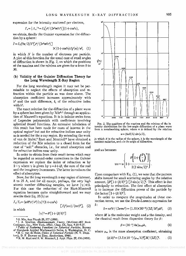
in which N is the number of electrons per particle. A plot of this function for the usual case of small angles of diffraction is shown in Fig. 2, on which the positions of the maxima and the minima are given for u from 0 to 30.
(b) Validity of the Guinier Diffraction Theory for the Long Wavelength X-Ray Region
For the long wavelength region it may not be permissible to neglect the effects of absorption and refraction within the particle as was done above. The absorption coefficient increases approximately with X3 and the unit difference, 0, of the refractive index withX2.
The exact solution for the diffraction of a plane wave by a sphere has been given by Mie6•7 through an application of Maxwell's equations. It is in infinite series form of Legendre polynomials with coefficients involving spherical Bessel functions. An extensive tabulation of this result has been made for cases of interest in the optical regionS but not for refractive indices near unity as is needed for the x-ray region. By extending the work of van de Hulst,9 Hart and Montroll10 have obtained a reduction of the Mie solution to a closed form for the case of "soft" obstacles, i.e., for small absorption and for refractive indices near unity.
In order to obtain from their result terms which may be regarded as second-order corrections to the Guinier expression we replace the index of refraction m by 1-'1' where 'I' is given by 'Y=o+i,B, the sum of the real and the imaginary increments. The latter introduces the effect of absorption.
Now, for the long wavelength x-ray region of interest, 8 to 2S A, and for all except, perhaps, the very high atomic number diffracting samples, we have / 'I' / «1. For this case the reduction- of the Hart-Montroll equation becomes quite straightforward and we may rewrite their Eq. 3S(b) as
18/10= (1T'R2x4/r2) / 'I' /2(1 +COS2t)
in which [ft2(WX)/(WX)3J, (2)
/ 'I' /2 = 02[1 + (,8/0)2J
6 G. Mie, Ann Physik 25, 377 (1908). 7 J. A. Stratton, Electromagnetic Theory (McGraw-Hili Book
Company, Inc., New York, 1941), Chap. IX, Sees. 9.25-9.27. 8 Tables oj Scattering Functions jor Spherical Particles, Bureau
of Standards Applied Mathematics Series, 4, Washington, D. C. 9 H. C. van de Hulst, Optics oj Spherical Partids (N. V. Druk
kerij, D. F. Duwaer en Zone, Amsterdam, 1946). 10 R. W. Hart and E. W. Montroll, J. App!. Phys. 22, 376 (1951).
lOT
10 .~ \
10 . !\
10 . 9.09
(\
n 10'
15.52
n n (~ 28.17
10'
let o 449~ 7.725 IO.~ 14.07 17.23 2037 23 52 26.67 U
FIG. 2. The positions of the maxima and the minima of the in tensity distribution for the low-angle diffraction of a plane wave from a nonabsorbing sphere, where u is defined by the relation
u= (47rR/>..) sin(E/2),
in which R is the radius of the sphere, >.. is the wavelength of the incident radiation, and E is the angle of diffraction.
and wx becomes
{ 0{1+(~r]} wx=u 1+ .
2 (2 sint/2)2
Upon comparison with Eq. (1), we note that the pattern shifts inward for small scattering angles by the relative amount, !02[1+(,8/0)2J/[2 sin(t/2)J2. This effect is due principally to refraction. The first effect of absorption is to increase the diffraction power of the particle by the factor [1 + (,B/O)2]'
In order to compute the magnitudes of these correction terms, we use the Drude-Lorentz expression for 0:
0= neW/(21T'mc2) = (1.35 X 10--6) (2Z/M)pX2, (3)
where M is the molecular weight and p the density, and the classical result from dispersion theory for {3 :
(4)
where J.l.m is the mass absorption coefficient, obtaining
[This article is copyrighted as indicated in the article. Reuse of AIP content is subject to the terms at: http://scitation.aip.org/termsconditions. Downloaded
to ] IP: 131.215.225.9 On: Fri, 20 Jun 2014 02:44:06

906 B. L. HENKE AND J. W. M. DuMOND
At the inflection point of the central maximum we have in which
2 sin(Ej2)=X/(4R) C= (2 411'5R6/r2) (0/X2)2[1+ GB/o) 2] (1 + COS2€) ,
and we obtain for this position in the pattern
(02/2)/2[sin( €/2) J2 = (1.45 X 10⁻¹¹) (2Z/ M)2(pRX)2. (6)
In these equations X is to be expressed in angstrom units. These correction terms become significant for the
long wavelength region providing the particles are very large and/or very dense. We have calculated the magnitudes of the correction terms for CuKal (1.54 A) and NKa (31.6 A) for diffraction samples of very large polystyrene spheres, R= 1400 A, and for very dense spheres of gold, R= 100 A. For ultra-long wavelength diffraction (31.6 A) from these "extreme" samples we find a significant absorption and refraction effect. The diffraction power is increased by factors 1.2 and 2.5 and the inflection point of the central maximum of the pattern is shifted by refraction by 3 percent and 5 percent for the polystyrene and gold spheres, respectively. These calculated effects at 1.54 A were found to be entirely neglible.
The following conclusions may be drawn concerning the absorption and refraction effects. (1) If the criterion oR«X does not obtain, the corrected Eq. (2) must be used. (2) For the usual problems of interest in low-angle diffraction work, i.e., for very small and/or low atomic number particles, the simpler Guinier expression (Eq. 1) is valid for the long wavelength region as it is for the conventional wavelength region. Thus a knowledge of the refractive index and of the absorption coefficient is not necessary in the interpretation of the long wavelength x-ray diffraction data in the size determination of the usual samples. (3) Since the Drude-Lorentz expression for 0 is valid only for wavelengths sufficiently remote from an absorption edge of the scattering material [Eq. (2)J, rather than the Guinier expression [Eq. (l)J, must be used in the calculation of intensities when the radiation wavelength is near an absorption edge.
Consequently, for the long wavelength region we may use for the angular distribution of diffracted energy
and for the usual sample of low atomic number elements consisting of particles of such size as to diffract only in the small angles and for wavelengths not very close to a critical absorption edge,
C"" (1.78Xl0-24)p2R6/r2=Kp2R6/r2. (8)
We note that the diffracted energy per unit area is thus independent of wavelength, and, since the angle of scattering is proportional to the wavelength, the total energy scattered per particle is proportional to X2.
By comparing the series expansion for Eq. (7) with that for e-x2 we obtain the Guinier approximation to Eq. (7) for the central region of the diffraction pattern
(9)
which is accurate to within 5 percent for values of u less than 2.
(c) Cross Section for Low-Angle Diffraction
An exact expression for the particle cross section for the scattering of plane electromagnetic waves by spheres for which the index of refraction m approaches unity has been derived by Hart and Montrollio and by van de Hulst.9
Sp=1I'R2[2- (4/ PI) sinpl+ (4/ Pl2) (l-cosPl)J,
in whichpl= (47rR/X)(m-l). For the x-ray investigation of submicron structure,
we have Pl«l, and the above expression reduces to
Sp= (1I'R2/2) Pl2= (811'3R4/X2) (02+.82). (10)
This result may also be obtained directly by integrating Eq. (7) over a spherical surface for the total power scattered. The cross section per gram becomes
Sm= sp/[ (4/3)1I'pR3J= [(611'2R)/ (pX2) J(02+.82). (11)
For low atomic number material for which we have .8«0, we obtain, using Eq. (3), the cross section per gram for low angle diffraction:
(12)
(7) in which R and X are to be expressed in angstrom units.
~.'~' (d) - ---- 4>-- E--FIRST SCATTERED
(b) -a=rl--Li~ SECOND SCATTERED
" "
I-x...J dx
FIG. 3. Multiple scattering geometry for thick samples.
(d) Effect of Multiple Scattering
We shall calculate first the shape of the secondscattered intensity distribution. This component would, of course, be the strongest contribution to the low-order multiple scattered energy. It will be necessary to compute the distribution of the scattered intensity from a spherical particle which receives an incident intensity that is made up of components from first scatterers which are behind this particle. These components are proportional to the value of the first-scattered intensity
[This article is copyrighted as indicated in the article. Reuse of AIP content is subject to the terms at: http://scitation.aip.org/termsconditions. Downloaded
to ] IP: 131.215.225.9 On: Fri, 20 Jun 2014 02:44:06

LONG WAVELENGTH X-RAY DIFFRACTION 907
distribution function for the angle cp, which is the angle between the incident beam direction and this firstscattered component at the second scatterer [see Fig. 3 (a)]. The first-scattered component also depends upon the distance of the first scatterer to the second scatterer, but for a uniform sample this dependence will not involve cp. It will be assumed that these particles are far enough away that the first-scattered waves are plane. Then the second-scattered intensity will be proportional to the integral
12 cc f"'I(E-CP)I(CP)dc/J, o
in which I is the first-scattered intensity distribution derived above. Since only the strong central portion of the scattering will be important in second scattering, it would be sufficient here to use the exponential approximation to the exact distribution, Eq. (9). The upper limit of integration 00 is permitted because the integrand approaches zero rapidly with increasing angle cp. The desired integral becomes
12 a; fu"'exp ( -x2cfN5)exp[ -x2 (E-cp)2j5]dcp,
in which x= 27rR/A.
Integrating, we obtain
12 cc exp(-x2E2/1O) f"'exp[ -2x2(cp-E/2)2j5Jdc/J. o
12 a; exp( -x2e2/10)
Then the second-scattered intensity distribution may be written as
1z=C exp( -x2e2/1O),
in which C does not depend upon e and may be determined in terms of the scattering coefficient as will be shown below. We note that the second-scattering produces another Gaussian distribution which is broader than that of first scattering by a v2 factor.
Let us now consider the effect of a thick sample with respect to both the first- and second-scattered components. The total mass absorption coefficient will be JLtm=JLm+Sm, and we shall let JLt=JL+s denote the corresponding linear absorption coefficient for the sample material. We consider first the amount of firstscattered intensity that leaves an element of unit area and thickness dx within the sample and reaches the region outside the sample [see Fig. 3(b)]. This is
d1lt=lo exp( -JLtx)sdx exp[ -JLt(L-x)].
Integrating, we obtain the total intensity of the "pure" first-scattered component
Ilt= (sL) [exp( -JLtL)J1o = (Smm) [exp( -JLtmm)]10, (13)
in which m is the mass per unit area of sample.
Similarly, the total intensity of second-scattered radiation that emerges from the sample is derived from
dlu= (sx) [exp( -/.Ltx)] (sdx) exp[ -/.Lt(L-x)]Io,
and
12t= [(sL)2/2J[exp( -JLtL)]Io = [(smm)2/2][exp( -JLtmm)]Io. (14)
From Eq. (13) and Eq. (14) we may obtain the ratio of the total power that is second scattered to that which is first scattered:
(15)
Integrating the first-scattered intensity distribution function over the spherical area included in the pattern and equating this to the total power that is first scattered from Eq. (13), we obtain
II = [x2/(57rr2)](smm)[exp( -JLtmm)] Po exp( -X2€2/5, (16)
in which Po is the power in the primary beam. The scattering coefficient Sm is given from Eq. (12).
In a similar way we may obtain the second-scattered intensity distribution for a thick sample,
12= [x2/ (57r1'2)J[ (smm)2j4J X [exp( -P,tmm)]Po exp(-x2e2/1O). (17)
And the ratio of the intensity that is second scattered to that which is first scattered at a particular angle becomes
(18)
Setting dl1/dm=0 in Eq. (13) we obtain the value for the mass per unit area of sample that will yield maximum first-scattered intensity. This is
m= l//.Ltm= l/(JLm+Sm). (19)
Doing the same for 12 in Eq. (14) we note that the value of m that results in maximum second-scattered intensity is only twice this thickness.
The nature of multiple scattering is such as to "smear" out the first-scattered distribution, thus obliterating the secondary maxima in the secondscattered distribution. Often the secondary maxima from first scattering can be detected above a relatively large amount of more or less continuous secondscattered background. A correction for the shift in the positions of the peaks due to the presence of the background can be made. Therefore it is conceivable that if one is concerned only with the position of secondary maxima the amount of second scattering that is associated with 1/JLtm mass thickness, as indicated above, could be tolerated.
Usually, however, one does not have the uniformity of particle size that is necessary to obtain these secondary maxima even in first scattering. The problem then is to determine the size distribution as well as the size from information that is obtained from the scattered
[This article is copyrighted as indicated in the article. Reuse of AIP content is subject to the terms at: http://scitation.aip.org/termsconditions. Downloaded
to ] IP: 131.215.225.9 On: Fri, 20 Jun 2014 02:44:06

908 B. L. HENKE AND J. W. M. DuMOND
(a)
(b)
FIG. 4. Electron micrographs taken of two different diffraction sample mountings of the Dow polystyrene latex (580 G). The regular packing of the particles in sample (a) causes detrimental interparticle interference effects whereas the random dispersion obtained in (b) does not. (Micrographs were taken by E. Henderson, California Institute of Technology.)
intensity distribution in the central region only. In this case, 1/ fLtm mass thickness would yield a very erroneous intensity distribution if interpreted as resulting from single scattering alone. In fact, the sample thickness should be determined by the criterion that
(20)
which usually gives a value of m considerably less than 1/ fLtm·
For the "extreme" particles, i.e., for very large and/or very dense particles, refraction and hence multiple refraction may become noticeable. This effect would be accounted for by using an analysis similar to that outlined above but with the exact scattering function [Eq. (2) ] rather than with the Guinier function. In this case multiple refraction can seriously distort the pattern if the sample thickness provides many superposed layers of the particles or structures studied.
It is therefore of importance to note that by virtue of the relatively large cross section for scattering for the ultra-long x-ray wavelengths, sufficient diffraction intensities can be obtained for monolayers of many
of the samples of interest. For these mountings, the effects of multiple scattering are eliminated entirely.
(e) Effect of Interparticle Interference
The effect of interparticle interference becomes appreciable whenever there exists a regularity of the spacing of the particles within the sample. If the spacing is highly ordered, for example, as in a protein crystal, the dominating interparticle interference pattern consists of very sharp maxima which are "modulated" by the single particle diffraction pattern. Such maxima yield precise and valuable information as regards the long spacings of such crystals when analyzed by long wavelength x-ray diffraction.
However, when one must measure the size and shape of individual units of the structure, such interparticle interference may offer a serious obstacle. In poorly dispersed diffraction samples, it: is very probable thlt clumping will occur so as to form a random collection of crystallites; for example, hexagonally close-packed groups of spherical particles. Since relatively few particle planes can thus contribute to the interparticle interference pattern, the resulting maxima are not sharp and usually tend simply to distort the dominant single particle diffraction pattern. Since the distances characteristic of regular spacings cannot be smaller than particle diameters, the first interparticle interference maxima occur within the central "peak" of the single particle pattern. This region, unfortunately, is usually the most important for single-particle size and shape analysis.
It is generally impossible to correct for such interparticle interference with any precision because of our ignorance of the nature and the extent of the packing. Such information is virtually impossible to obtain with the relatively thick samples needed for low-angle diffraction at conventional wavelengths (such as CuKa). If the size and shape of the individual particle is to be deduced from the shape and extent of the central region of the diffraction pattern, not only must the sample be randomly dispersed and be thin enough to eliminate multiple scattering, but also a secondary test must be provided to assure that these conditions do sufficiently obtain.
With the very thin samples which are permissible in ultra-long wavelength diffraction, highly random dispersions are possible. And for such samples, it is possible to check for clumping and regular packing by viewing these samples directly in the electron microscope.
In Fig. 4 are shown electron micrographs of diffraction sample mountings of the Dow polystyrene latex spheres for ultra-long x-radiation. A droplet of the latex suspended in water solution was spread on a protein monolayer on top of a collodion substrate. Regular packing shown in (a) resulted from slow drying in air at 20°C. The dispersed sample in (b) was obtained by freeze-drying under vacuum.
[This article is copyrighted as indicated in the article. Reuse of AIP content is subject to the terms at: http://scitation.aip.org/termsconditions. Downloaded
to ] IP: 131.215.225.9 On: Fri, 20 Jun 2014 02:44:06

LONG WAVELENGTH X-RAY DIFFRACTION 909
(f) Analysis for Nonspherical and for N onuniformly Sized Particles
If the particles to be measured are uniform in size but of a fixed shape which is different from that of the sphere, and of random orientation, Guinier2 has shown that the central maximum of the diffracted intensity distribution may be approximated by the expression
1= (2/91r)C[exp( -u2/3)], (21)
in which u is given by U= 21rRE/A where R is the "radius of gyration" of the particle, i.e., the root-meansquare distance of all of the electrons from the particle's center of gravity. When the radius of gyration of the sphere (R.= (3/S)!R) is substituted into Eq. (21) we obtain the expression (9).
A large number of the nonspherical particles that might be studied by low angle diffraction may be accurately approximated as spheroids, including the extreme shapes of rods and plates. Guinier2 has calculated the distribution of diffracted energy for spheroids which have two equal (and one different) principal axes, R, R, and v.R along x, y, and z coordinate axes, respectively, which may readily be shown to coincide with the distribution function for the sphere Eq. (7) if the argument U therein is replaced by v, given by the reduction,
v= u(sin28+v.2 cos28)l,
where 8 is the angle between the z-axis and the vector difference (8- 80), between the unit vectors 80 and 8 which specify the directions of the incident and diffracted beams, respectively.
Therefore a collection of randomly spaced spheroidal particles all of which have a fixed common orientation produces a pattern with maxima and minima positions which are characteristic of both the size and the shape of the particle.
If, however, the spheroids are of random orientation, the distribution function must be obtained by integrating the intensity given by the single spheroid function over all directions of the vector (8 - 80). This has been done in series form by Roess and Shull.ll
The result of random orientation is the smoothing out of the single particle pattern and the obliteration of the secondary maxima. The pattern is then much less distinctive as to size and shape.
Another possible advantage of diffraction studies with ultra-long wavelengths, then, is that, with the thin samples permitted, it may often be possible to lay the spheroidal particles onto a substrate in a high degree of preferred orientation. The deduction of the size and shape of the spheroidal particle from the resulting diffraction pattern would then be practically as straightforward as that for the size of a spherical particle.
Obviously the effect of nonuniformity of size of the
11 L. C. Roess and C. C. Shull, J. App!. Phys. 18, 308-313 (1947).
diffracting particles will also smooth out the diffraction pattern. A method for deducing from the diffraction pattern the parameters for a postulated Maxwellian or rectangular size distribution has also been given by Roess and Shull.I1 They have pointed out, however, that it is possible to obtain identical diffraction patterns for different combinations of the particle shape and of the size distribution.
(g) Prediction of the Time Required for the Measurement of the Diffraction Pattern
It is pertinent to conclude this summary of low angle diffraction theory with an estimation of the problem of measurement. Let us assume that the cross section of the primary beam at the photographic film which is used for recording the pattern has a small radius, t, and has an average power per unit area 10. We may then replace Po in Eq. (16) by 10(1r(2). Also let the distance from the sample to the film, r, be replaced by alE, where a is the radial position of a particular point in the diffraction pattern corresponding to angle E. Equation (16) then becomes
11= (liS) (Smm) [exp ( -Utmm)] X[u2 exp( -u2/S)](tla)210. (22)
The quantity (tl a) is equal to the angular resolution, (fJ,.Ej E), of the diffraction pattern at the position corresponding to the parameter u. The quantity (Smm) is fixed by the amount of second scattering that can be tolerated according to Eq. (18).
By setting (Smm) equal to 0.1 (thus allowing 3 percent second scattering at the inflection point) the firstscattered intensity becomes at the inflection point of the central maximum (for which u2= S/2)
II =0.027 exp( -10KA/ pR) (AEI E)210,
in which K is defined by the approximate relation Um=KA3, and Utm was equated to um+Sm. For many samples of interest the argument of the exponential term is small compared with unity so that this factor has only a small effect on the intensity function. For organic materials for which we might consider absorption by essentially carbon, K"", 1.2 (for A expressed in angstroms) and p is approximately unity. If we should fix the camera geometry so that (AEj E) is 3 percent at the inflection point, and A is chosen so that R/A""'SO, we obtain, finally, the scattered intensity
/ 1= (2XIo-6)Io.
Thus if the equivalent of the film blackening which is desired at the inflection point of the central maximum can be obtained from the unobstructed primary beam in one second, the required exposure time would be approximately 14 hours.
It is important to note that essentially the only factor which determines the useful intensity of the diffraction
[This article is copyrighted as indicated in the article. Reuse of AIP content is subject to the terms at: http://scitation.aip.org/termsconditions. Downloaded
to ] IP: 131.215.225.9 On: Fri, 20 Jun 2014 02:44:06

910 B. L. HEN K E:," AND J. W. M. DuM 0 N D
(bl
\cl
COUNTER
DOUBLE-CRYSTAL SPECTROMETER
A B
t40N :::~:::TE 1-\
SITUATED AT SECOND SLIT
• COPPER-FOil + _~" TARGET SITUATED~_
AT FIRST SLIT CATHODE
ANNULAR·SUT DIFFRACTION CAMERA
POINT-FOCUSING CONCAVE MICA MONOCHROMATOR
FIG. 5. Three basic types of x-ray beam geometries used for the measurement of the diffraction intensity distritions: (a) "effectively" straight slit, (b) annular slit, and (c) point focusing,
pattern for a given precision of measurement is the intensity of the primary monochromatic beam, and that the wavelength of the radiation enters into this result only through its effect upon the efficiency with which lois obtained.
III. INSTRUMENTATION-GENERAL
(a) Design Requirements for the Long-Wavelength Diffraction Instrument
The theoretical considerations outlined above make evident certain requirements which must be met in the design of a successful diffraction instrument. These are as follows:
(1) The source and camera must result in a very high intensity and signal-to-background ratio in the diffraction pattern. The energy diffracted in the low angle patterns is characteristically very weak, first because of the small cross section for low angle diffraction, and second because thin samples must be used in order to eliminate multiple scattering and provide the necessary control over interparticle interference.
(2) A very high over-all resolution is required of the diffraction method. This is demanded by the fact that the measured diffraction pattern must be very precise in order to allow subsequent and necessary "unfolding" of integrated effects such as arise from size distributions of particles, from nonspherical shapes, and from the natural width of the "monochromatic" radiation employed. In order to optimize intensity the system should be designed so as to balance the resolution uncertainty t:.t/ € with the wavelength uncertainty, t:.X/X.
(b) Total Reflection, Point-Focusing Camera, Its Basic Principles of Operation
Four methods for obtaining the low-angle diffraction pattern were investigated. These involved the use of (1) effectively straight slit geometry in the doublecrystal spectrometer arrangement as shown in Fig. S(a); (2) annular slit geometry [which required no slit cort:ection as is required in (l)J shown in Fig. S(b); (3) point-focused radiation from a very thin mica sheet which was cemented to a concave metal block with two different principal radii of curvature Rl and R2 as shown in Fig. S(c), the sample being placed in the converging beam; and finally, (4) total-reflection from a nearly cylindrical mirror to form a converging beam in which the diffraction sample is placed as shown in Fig. 6.
Of these four methods of obtaining the diffraction pattern the total-reflection camera seemed to be the most attractive for the long-wavelength region. This camera satisfies the aforementioned requirements in the following ways:
(1) By using a section of an ellipsoidal mirror to form a point image of a point source of x-radiation, a focused beam of high intensity is obtained. This is because a large solid angle of radiation is utilized compared with that of usual slit geometries, and because the reflection efficiencies for "total-reflection" mirrors are considerably higher than those encountered with crystal monochromators at long wavelengths. Also, since the resulting focused diffraction pattern is usually radially symmetric, an effectively circular slit microphotometer may be employed; thereby all of the effect of the diffracted energy in the measurement are used.
(2) Since the direct beam is focused, long camera geometry may be used with no sacrifice of intensity.
~n'l ~'AA:"" -----r::.r 20C"'PH;aro. COOLED PIN HOLE 1 ~ FILM
TARGEr I "
- --~-~-~~ +
GAS f"ILLED WATER x-RAY TUSE COOLED
CATHODE
ELLIPSOIDAL ANNULAR. COUNTER MIRROR STOP MONITOR
(3.8CM OIAM)
(a)
(bl
FIG. 6. A total reflection diffraction camera with a gas type x-ray tube, A large solid angle of radiation is point focused by an ellipsoidal mirror which is of such diameter as to present angles of reflection only slightly smaller than the critical angle for the desired line radiation. In this way, the harder general radiation is effectively "cutoff" and a high intensity, monochromatized beam is obtained.
[This article is copyrighted as indicated in the article. Reuse of AIP content is subject to the terms at: http://scitation.aip.org/termsconditions. Downloaded to
] IP: 131.215.225.9 On: Fri, 20 Jun 2014 02:44:06

LONG WAVELENGTH X-RAY DIFFRACTION 911
Therefore, because of the thin annular cross section of the beam, a narrow circular slit mav he used at the sample and far enough from the mi~or to provide a very effective cutoff of parasitic (i.e., unfocused) radiation. In this way, a high ratio of diffracted intensity to background may be obtained.
(3) Since a point-focused beam results in a focused diffraction pattern which is radially symmetric and therefore permits circular-slit microphotometry, no straight-slit correction is necessary and a high angular resolution results. It can be shown that with this geometry, the error due to finite sample size is negligible.
(4) Effective monochromatization is obtained (a) by the general suppression of the continuous radiation background by using only the characteristic radiation emitted from the target in the direction 1800 from that of the electron beam, the direction in which the continuous radiation is a minimum (b) by eliminating any remaining hard continuous radiation by virtue of the total reflection cutoff of a mirror of such size as to present angles for reflection only slightly smaller than the critical angle for the desired line radiation, and finally (c) by the elimination of any remaining soft component of background radiation by the filter action of an appropriately chosen substrate for the diffraction sample [e.g., copper foil substrate for CuL radiation (see Fig. 7) J.
IV. DESIGN AND CONSTRUCTION OF TOTAL~REFLECTION DIFFRACTION
CAMERA
(a) Monochromatic Long-Wavelength Sources
A survey of the long-wavelength characteristic x-ray lines will show that there are several which are sharp and are dominant over the other lines in their series, and over their satellite structure. Gwinner12 has made a detailed study of the L-series lines from Ge-L (10.42 A) to Fe-L (11.57 A). Of these, the Ni-La1,2 line is outstandingly sharp and free of satellite structure. It is very strong compared with the fh line, which is only 2 percent harder. (Ni-Lal, 2= 14.53 A and Ni-L/31 = 14.25 A.) The full line width at the half-maximum point is 2.2 10-4 A or 1.5 10-3 percent of the wavelength.
Of the long wavelength K-series lines, oxygen K (23.6 A) is very strong compared with any associated background.ls Its line breadth is somewhat less than 1 A, or about 4 percent of the wavelength. The K-series lines are considerably stronger than comparable wavelengths in the L-series but are characteristicallv broader.
The CU-L/31 is of appreciable intensity compared with the Cu-LaI , z. However, the combination Cu-La,/3 is a very strong and easy radiation to produce, and has been very convenient to use for preliminary work. The effective width of the combination Cu-La,/3 radiation is still less than 3 percent of the wavelength.
12 E. Gwinner, Z. Physik 108, 523 (1938). 13 Lawrence Y. Faust, Phys. Rev. 36, 161 (1930).
tOO
I.!) MICRON
coPPER f'OIL 50
FILTER
o 100
.029 RADIAN
RULECTION 50
Of'r GLASS
fiLTER
o 100
PLUS 50
TOTAL REF'LECTlON
o
\1 \ \ \ '--
(
j
\
" 0 CU !3.3
TRANSMISSION VS WAVELENGTH
2
FIG. 1. Monochromatization of the Cu-L (13.3 A) radiation in the total reflection camera. The soft component of the radiation is rapidly absorbed by the copper foil substrate of the diffraction sample. Since the angles for reflection are not favorable for the total reflection of the hard component of the general radiation this is absorbed in the mirror. '
Another favorable aspect of long·wavelength monochromatization, beside that of the simplicity of the characteristic line structure, is that the ratio of the intensity of the characteristic radiation to that of the assodiated continuous background radiation increases very rapidly with wavelength.14 Also, it has been observed14 that this ratio increases with the voltage. Consequently, since no crystal monochromator is used in the total reflection method and since there is therefore no danger of passing second-order radiation it is possible further to emphasize the characteristi~ radiation over the c~ntinuous background by running the x-ray tube at hIgher-than-usual voltages utilizing the cutoff of the mirror to eliminate the resulting hard ?omponent of. the continuous radiation. In this way, ~ncrea~~d effiClency of x-ray production, hence higher mtensltles, may also be obtained by virtue of the higher tube voltage.
For the oxygen K (23.6 A) line, SiOz, Alz0 3, and BeO targe.st were. used. The~e were obtained (1) by imbeddmg a thm quartz dISk into a water-cooled anode of copper, (2) by "anodizing" the tip of an aluminum anode, and (3) by painting an acidulated solution of BeO onto the tip of an anode, respectively. Oxygen targets made by the first two methods were of relat~vely high e~ciency because of the effect of secondary lme productIOn by fluorescent absorption of the K
14 Emory Carl Unnewehr, Phys. Rev. 22, 529 (1923).
[This article is copyrighted as indicated in the article. Reuse of AIP content is subject to the terms at: http://scitation.aip.org/termsconditions. Downloaded to
] IP: 131.215.225.9 On: Fri, 20 Jun 2014 02:44:06

912 B. L. HENKE AND ]. W. M. DuMOND
Ie)
006 FILM MOUNTING llIIF~
fJLM.MQ\lliI At!I2 MQt!lIQB.
FIG. 8. Cross-sectional drawings indicating the construction of a vacuum, total-reflection diffraction camera.
radiation emitted by the Si and Al atoms. With these targets, the usual levelling-off of the intensity versus voltage was not reached for the same reason. The anodized surface was the easiest to cool and to maintain.
In spite of the fact that the oxides used for target material were refractory, they would decompose under a high-intensity bombardment of the electron beam in a matter of a few hours. Because of the rather effective water cooling of the anodes, very little deterioration of the Ni and eu metal targets occurs even after hundreds of hours of use.
(b) Gas-Type Tube
There were several reasons for choosing a gas-filled tube for long-wavelength diffraction work. (1) Its simplicity and complete demountability make it ideal for research purposes. (2) For these wavelengths, it has been found to be very stable, and it permits the focusing of a very intense electron beam onto the anode. (3)
This tube does not require a high vacuum as does the filament type tube and therefore it is possible to use it "open" to the evacuated camera so as to avoid the use of extra windows.
A cross-sectional drawing of the tube is shown in Fig. 8(a). It will be noticed that the exit opening of the x-ray tube and entrance pinhole of the camera is located in the cathode focusing cup. Thus only the radiation 1800 from the electron beam direction is used. It is in this direction that the continuous radiation will be a minimum.
The target has a cone-shaped hole at the electron beam focus. In this way, the atoms which can be "seen" by the mirror through the pinhole give off radiation not only because of direct bombardment under the electron beam, but also because of the fluorescent absorption of harder components of the general radiation in the neighboring region of the hole.
Because of its very low sputtering rate, pure aluminum is used for the focusing cathode cup. This screws into place, and holds in contact with the water-cooled cathode support, a thin i-in. diameter aluminum disk in which is drilled an 0.OO8-in. pinhole.
It was found that by enclosing the exposed cathodesupporting structure with a Pyrex jacket, the tube operated more "quietly," and very little sputtered material reached the outer glass walls.
The operating limit of power for the tube has not been determined. A typical operating condition is 40 to 50 rna at 5000 volts. The stability is such that after about a two-hour period for stabilization, the tube may be left running for days without attention.
(c) Total Reflection of X-Rays-General
Some of the results of the work which has been done on the total reflection of x-rays have been described16- 38
with respect to the reflection of long wavelengths. 16 A. H. Compton, Phys. Rev. 20, 84 (1922). 16 F. Holweck, Compt. rend. 176, 570 (1923). 17 Laby, Bingham, and Shearer, Nature 122, 96 (1928). 18 H. E. Stauss, Phys. Rev. 31, 491 (1928). 19 Hiram W. Edwards, Phys. Rev. 32, 712 (1928). 20 Thomas H. Osgood, Revs. Modern Phys. 1,228 (1929). 21 M. Schon, Z. Physik 58, 165 (1929). 22 H. E. Stauss, ]. Opt. Soc. Am. 20, 616 (1930). 23 J. E. Henderson and E. B. Jordan, Phys. Rev. 36, 785 (1930). 24 H. W. Edwards, Phys. Rev. 37, 1246 (1931). 26 Elmer Dershem and Marcel Schein, Phys. Rev. 37, 1246
(1931). 26 C. B. O. Mohr, Proc. Roy. Soc. (London) AI33, 292 (1931). 27 T. H. Laby and R. T. W. Bingham, Proc. Roy. Soc.
(London) AI33, 274 (1931). 28 J. M. Cork and J. A. Bearden, Phys. Rev. 39, 1 (1932). 29 ]. M. Cork, Phys. Rev. 39, 193 (1932). 30 H. Honl, Ann. Physik 18, 42, 625 (1933). ~' E. Dershem and M. Schein, Z. Physik 75, 395 (1932). ~2 P. Ewald and E. Schmid, Z. Krist. 94, 150 (1936). 33 W. Ehrenberg, Nature 160, 330 (1947) ~ W. Ehrenberg, ]. Opt. Soc. Am. 39, 741, 746 (1949). '36 Edward Prince, J. App!. Phys. 21, 698 (1950). '36 J. L. Farrant, ]. App!. Phys. 21, 63 (1950). 37 H. Eisenlohr and G. L. J. Muller, Z. Physik, 136, 491, 511
(1954). 38 L. G. Parratt and C. F. Hempstead, Phys. Rev. 94, 1593
(1954).
[This article is copyrighted as indicated in the article. Reuse of AIP content is subject to the terms at: http://scitation.aip.org/termsconditions. Downloaded to
] IP: 131.215.225.9 On: Fri, 20 Jun 2014 02:44:06

LONG WAVELENGTH X-RAY DIFFRACTION 913
(1) AI-K (8.32 A), Cu-L (13.3 A), and C-K (44.5 A) have been studied for total reflection from glass, quartz, steel, silver, and gold. The reflected intensity versus angle of reflection is given for the region of angles near the critical angle. . .
(2) The experimental values measured for the cntIcal angles agree only roughly with the current theories of total reflection. For wavelengths which are not close to an absorption edge of the reflector, the simple DrudeLorentz expression for the critical angle is in as good an agreement as any with present experimental data. Thus
8e= (20)1= (m?/zrmc2)tA = 2.32X 10⁻³ (pZjM) $11., (23)
in which A is to be expressed in Angstrom units. (3) The shape of the "cutoff" in the curve of re
flected intensity vs angle of reflection is only roughly predicted by the Fresnel theory.39
(4) Mohr26 has given some approximate values for the reflection efficiencies for various surfaces for 8.3 A and 13.3 A radiations. He found 25-30 percent reflection for glass, 15 percent for steel, and 5 percent for gold reflectors. Recalling the densities of these reflectors, 2.7,7.7, and 18.9 g cm-3, respectivley, we note that the efficiency of reflection would seem to be approxima~ely proportional to the reciprocal of the reflector denSIty.
(5) EhrenbergM has measured the broadening of a line image by total reflection from a curved mirror. He attributes the effect to diffraction from Fourier components of an inherent structure of the reflecting surface.
(d) Method for the Measurement of the Critical Angle of Total Reflection
Because of the need for more information on critical angles of total reflection than is available, it was felt that it would be advisable to devise some method for their measurement. A very simple apparatus was developed which permits a precise measurement of 8e
and which fits easily into the diffraction camera so that no elaborate arrangement was necessary. A sketch of the geometry for this measurement is shown in Fig. 9. Filtered radiation from the pinhole in the cathode of the x-ray tube finds a uniform distribution of planes at various angles to the incident beam on the external surface of a cylindrical reflector from which it is "totally reflected," in accord with the specular law over the permissible range of grazing angles up to the critical limiting angle, and passes thence onto a photographic film.
It can readily be shown that the ratio of the reflected intensity to the incident intensity for the grazing angle
3D A. H. Compton and S. K. Allison, X-Rays in Theory and Experiment (D. Van Nostrand Company, Inc., New York, 1935), p.305.
FIG. 9. A sketch illustrating a method for measuring the critical angle for the total reflection of x-radiation. Filtered radiation from a pinhole is totally reflected through all permissible angles up to the critical angle from a cylindrical mirror and thence to a photo- £
STOP
CYLlNOI'UCAI. REFLECTOR
graphic film. Reflection effi- ""'F=2~z>..~~'£:::fciencies for angles in the region 4> ~/ of "cutoff" can be deduced -from a microphotometer measurement of the photographic film.
cp is given by the expression
R(cp) = [mn(m+n)/(rIo)J[E(cp)/cpJ, (24)
in which 10 is the flux per unit solid angle emanating from the pinhole source of radiation and E(cp) is the flux per unit area measured by the film; m and n are distances from the pinhole source to the mirror and from the mirror to the film, respectively; r is the radius of the mirror and cp is the grazing angle of total reflection from the mirror. .
In practice, it may not be possible to measure pre" cisely the distance n. For this reason a second film may be exposed simultaneously to one-half of the reflected beam at position B. Since the distance between films may be measured very accurately, the critical angle may be obtained from the relation
Bc= (a-b)/c.
The usual method for measuring (Je is to intercept a slit-collimated beam of x-rays by a plane mirror which is rotated through a series of angles. At each of these an exposure of constant time duration is made on a film. There are several significant advantages of the method used here. (1) A simultaneous curve of reflected intensity is obtained for all angles, with a high resolution, and there is no dependence upon possible fluctuations of the x-ray source during an exposure. (2) The geometrical effect of obtaining an experimentally measured distribution given by the reflection efficiency function multiplied by the angle of reflection is favorable because it yields an intensity versus angle of reflection curve for an inside cylindrical mirror of constant length as used for point focusing. The optimum angular aperture for the cylindrical mirror corresponds to the angle for maximum density as measured directly by this method. (3) Using two film positions, A and B, not only permits a more accurate measurement of Be but yields two complete photographic density scales with corresponding points at a known ratio of intensities [n/(n-c)J2. This permits an "internal" calibration of the film with each measurement. In fact, this same artifice has proven very useful for the calibration of the film used for the low-angle diffraction work.
[This article is copyrighted as indicated in the article. Reuse of AIP content is subject to the terms at: http://scitation.aip.org/termsconditions. Downloaded
to ] IP: 131.215.225.9 On: Fri, 20 Jun 2014 02:44:06

914 B. L. HENKE AND ]. W. M. DuMOND
(e) Mirror Geometry
Ideally, the barrel shaped mirror which forms the point focused converging beam, should be a section of a very elongated ellipsoid of revolution with the point source of x-radiation and the point image at the respective foci. Let a be the major and b the minor principal axes of this ellipsoid. Certain geometrical properties, which will be useful and which are very easily derived, are listed here (using the notation of Fig. 10 and the fact that b«a). The radius of the circular arc that best approximates the ellipse at the center (the part to which the inner surface of the mirror conforms) is given by
(25)
The solid angle presented to the source by the mirror is given by
.1Q= 47r(b/ C)2(X/ c), (26)
where x is the half-length of the mirror measured axially. In order to learn how good the circular arc approxi
mation is, and to determine the effect of a deviation from the calculated radius of curvature R upon the image radius of confusion, p, the following aberration equation is derived.
p= 2 (b/c)x.1R/R-b[ (x/c)3+2b2xjc3] (27)
in which the first term arises from not having the proper radius for the mirror (R+.1R instead of R) and the second is that caused by the use of a circular in place of an elliptical profile.
(f) Error Resulting from the Finite Size of the Sample
The sample is mounted upon a thin film of metal foil or of plastic which is stretched across an annular slit through which the beam passes. It may be readily shown that for the usual "small" angle scattering there is negligible error introduced by the fact that the sample is spread in this way over an extended area. This is the case even though the photographic film is flat. However, particularly for the long wavelengths, "medium" angle scattering might often be of interest, and the foregoing summarized theory may be applied to this region as well.
FIG. 10. Ellipsoidal mirror geometry.
FIG. 11. Finite sample geometry. The error associated with relatively large diffraction angels due to the effect of a sample distributed over an area of finite extent can be made negligibly small by mounting the film with a cylindrical (or spherical) curvature of a radius equal to one-half the distance d from the sample to the center of the focused diffraction pattern. The sample circle and film circle in this perspective view lie in mutually perpendicular planes.
For large angles of diffraction, it can be shown that the diffraction pattern will focus with minimum error on a circle (or a sphere) which passes through the sample and through the focal point of the beam, and has its center situated on the principal axis. See the perspective view of Fig. 11. Therefore, for large diffraction angles, the film must be pressed onto a cylindrical (or spherical) form of radius equal to one-half the axial sample-tofocal point distance-since the sample size is small compared with this distance. It can also be shown that the variation .1E in the angle of scattering E to a particular point of the film (due to the finite extension of the sample) becomes .1E= (tan E) X (qN2). Since the angle cp is the total reflection angle from the mirror and is very small, .1E becomes negligible. The angle E is measured from the arc distance s along the film by the relation E= (s/ d).
(g) Choice of Mirror Material
There are two reasons why glass seems to be the most appropriate material with which to construct these total-reflection mirrors. First, the relatively short x-ray wavelengths compared with the wavelengths of light place an even higher requirement on the smoothness of the mirror surface. And second, the need for a very precise circular arc in the mirror cross section suggests the desirability of using the proven accurate methods of random optical lapping techniques which are most highly developed for glass.
An apparent objection to using glass is that a choice of stainless steel, for example, because of its higher density, would allow a larger diameter mirror for a given wavelength, and therefore present a considerably larger solid angle than that obtained from the corresponding glass mirror. A glass mirror, in fact, could be given an evaporated or sputtered film of some dense metal such as gold, thus permitting larger mirrors. It was found, incidentally, that gold evaporated films age badly so that after a few weeks the film deteriorates into a grainy surface which gives a large background diffraction pattern of its own.
[This article is copyrighted as indicated in the article. Reuse of AIP content is subject to the terms at: http://scitation.aip.org/termsconditions. Downloaded
to ] IP: 131.215.225.9 On: Fri, 20 Jun 2014 02:44:06
LONG WAVELENGTH X-RAY DIFFRACTION 915
However, as was deduced above from Mohr's26 work, the reflection efficiency for total reflection varies approximately inversely with the density of the reflector. From Eq. (26) we note that the solid angle presented by the mirror is proportional to (b / C)2 which is equal to 60
2. Since the critical angle squared is proportional to the unit decrement of the index of refraction, 0, and thus is proportional to the density, we conclud: that there is no gain of intensity by using more dense mIrrors. For mirrors cut at the critical diameters for total reflection, the total resultant intensity is approximately independent of the material of the mirror. In fact, by using the smaller mirror, say of glass, the sample size is reduced, and also we note from Eq. (27) that the aberration problem is reduced.
(h) Optimum Mirror and Camera Dimensions
By combining the aberration equation [Eq. (27)J with that for the solid angle included by the mirror [Eq. (26)J we obtain the relation for the angular width of the circle of confusion
.:le= p/ c= (1/211') (.:lQ/6c).1R/ R.
Now since 60 is proportional to the wavelength, and since the angle of scattering is also proportional to the wavelength, the angular resolution may be written as
(.:lei E) ex: AQ(AR/ R) (1/;\.2).
This approximate expression indicates that for a given precision of mirror construction, and for a given solid angle presented to the source by the mirror, the angular resolution improves with the square of the wavelength, and is independent of the size of the camera. The method is thus most suitable for long wavelengths.
Besides the requirement for a large solid angle and for a high angular resolution, there remains the equally important requirement for a high intensity-to-background ratio. All diffraction methods have a background of stray radiation either due to diffraction or scattering from slits, from general radiation scattered from crystals, from the radiation in the "wings" of a crystal rocking-curve, or, in this instance of totalreflection focusing, from diffraction from edges of the mirror and from irregularities of the mirror surface. In order to reduce such effects, it is necessary to intoduce a stop between the mirror and the sample which does not touch the main beam, but which cuts off a large component of the stray radiation. The effectiveness of such a stop is increased by having a large distance between the mirror and the stop position. For this reason, therefore, it was felt advisable to use a relatively long geometry, with at least 50 cm between the mirror and the film.
(i) Construction of the Cylindrical Mirror
The mirror was made from a 4.5-in. length of a straight Pyrex cylinder, 1.5 in. in diameter. It was
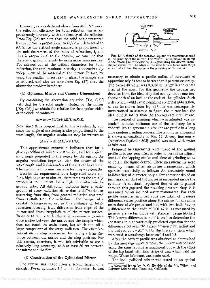
FIG. 12. A sketch of the cast-iron lap and its mountin~ as used in the grinding of the mirror. This "short" l~p is move? m an out of the rotating mirror cylinder, thus generatmg the desIred barrelshaped curvature. The edges .of the s~e !ap are face~ with strips of wax which hold the rouge m the pohshmg of the mirror.
necessary to obtain a profile radius of curvature of approximately 54 feet to better than 2 percent accuracy. The barrel diameter was 0.0038 in. larger in the center than at the ends. For this geometry the circular arc deviates from the ideal elliptical arc by about one tenthousandth of an inch at the ends of the cylinder. Such a deviation would cause negligible spherical abberation, as can be shown from Eq. (27). It was consequently unwarranted to attempt to figure the mirror into the ideal elliptic rather than the approximate circular arc.
The method of grinding which was adopted was intended to make optimum use of the tendency for a "short" lap to generate a circular arc profile in a long time random grinding process. The lapping arrangement is shown schematically in Fig. 12. A very fine emery (American Optical's 303t grade) was used with water as lubricant.
Frequent measurements were made of the ground profile as it was generated in order to permit an adjustment of the lapping stroke and time of grinding so as to obtain the figure desired. These measurements were made by means of an air-gauge arrangement which operated essentially as follows: An accurately round ball-bearing of diameter only a few thousandths of an inch less than that of the mirror is suspended inside the cylinder. A constant, regulated flow of air is passed through this gap and the resulting pressure drop P is measured by an inclined water manometer. For each profile measurement, two runs are taken of pressure difference versus position along the mirror for the same mass flow of air per second but with two balls having a difference in their radii of 0.00147 in. as measured by an interference technique with standard gauge blocks.t This known difference in radii is used to determine the constants in a theoretically predicted equation for the difference t between the mirror cross-section radius and the ball radius: t=Kp-n. For the flow conditions which were used n was always between 0.4 and 0.5.
After the correct profile was obtained as determined by this air-gauge measurement, the mirror was polished using the same lapping arrangement but with the edges of the lap faced with thin strips of wax which held the rouge. Water lubricant was again used. .
The final, polished mirror was tested on an optIcal
t Measured for us by D. O. Hendrix of the Mt. Wilson and Palomar Laboratories, Pasadena, California.
[This article is copyrighted as indicated in the article. Reuse of AIP content is subject to the terms at: http://scitation.aip.org/termsconditions. Downloaded to
] IP: 131.215.225.9 On: Fri, 20 Jun 2014 02:44:06

916 B. L. HENKE AND ]. W. M. DuMOND
. (] •..• FIG. 13. Focal spot broadening under prolonged exposures. The
centrally punched hole used to prevent halation in the very long exposures is 0.040 inch in diameter. The transverse scattering characteristics of the unfocused radiation is indicated by the "shadow" of the sector-stop used on the mirror (in addition to the central stop) for these photographs.
bench with a point source of light. The geometry for the optimum point focus thus determined corresponded to that predicted by air-gauge measurements to within the experimental error of the optical measurement. The mirror was mounted into the instrument as shown in Fig.8(b).
V. TESTING THE TOTAL-REFLECTION CAMERA
(a) Focal Properties of the Converging Primary Beam
A series of photographic exposures were taken at the focal point of the primary beam using Cu-L radiation; prints of these photographs are shown in Fig. 13. Short exposures of the order of one second yielded a well-exposed spot of very nearly the same size as the x-ray source pinhole. There was no strong evidence of geometrical aberrations. However, prolonged exposures to the beam, without any stops except for the central stop at the mirror indicated the presence of a transverse type of scattered, nonfocused radiation. The fact that this scattered radiation does remain in the plane of incidence is evidenced by the sharp shadows of the spiders in the central stop which are always seen in such long exposure photographs. The same effect is seen in Fig. 13 in the shadow pattern cast by the 60° sector stop. This effect is probably due in part to surface irregularities of the mirror and has been studied by Ehrenberg.34
An annular aperture, just wide enough to permit the passage of the converging beam and which is placed at the sample approximately midway between the mirror and the focal point does effectively eliminate
this stray scattering for most practical diffraction measurements. This is because it is usually possible to keep the portion of the pattern to be measured far outside the region of the direct beam focal point when using long x-ray wavelengths.
(b) Monochromaticity and the Intensity of the Primary Beam
In order to measure the monochromaticity of the focused radiation, a small spectrograph was designed to fit into the film holder position. With this instrument a focused spectrogram is produced, measuring wavelengths up to about 20 A.
A sketch of the spectrograph is shown in Fig. 14 . The converging x-ray beam from the mirror strikes a small cylinder of mica crystal so that all angles from 0° to 90° incidence are presented. Since the spacing of the cleavage planes of mica is 9.9 A, this permits Bragg reflections up to 19.8 A. Nearly all such reflections are focused onto a circular arc which passes through the image point and along which a film is placed. The resulting positions of a few of the wavelengths of interest are indicated.
A spectrogram was taken with unfiltered Cu-L (13.3 A) radiation with the x-ray tube at 4000 volts. A well-focused spot image was formed at the expected position on the film for the 13.3 A radiation and with no effective background radiation at any other position along the film.
The primary beam passes through a central hole which is punched into the photographic film and then into an x-ray detector. [See Fig. 8(c).] Such a measurement of the primary beam intensity permits (1) the adjustment of the x-ray tube for optimum intensity, (2) the determination of the proper mass thickness for the sample, and (3) the prediction of exposure times. For most of the work which has been accomplished to date, GM counters have been used for this purpose. The primary beam intensity Io can be estimated for 4000 volt Cu-L radiation at SO ma to be about 109 quanta per cm2 per minu teo
(c) Diffraction Pattern of the 580-G Polystyrene Latex Partic1es§
A diffraction photograph is shown in Fig. 15 of the 580-G polystyrene latex which has been often used by
FlG.14. A small spectrograph which slips into the film mount of the diffraction camera and
MICA CYLINDER
which is used for checking the =====~~ monochromaticity of the point-focused radiation. Radiation of a given wavelength finds an appropriate angle for Bragg reflection from the small mica crystal cylinder and is focused to a corresponding point on 13.3A.U FILM
a film circle. '-------------'
§ This sample was kindly given to us by Dr. R. C. Williams of the University of California at Berkeley.
[This article is copyrighted as indicated in the article. Reuse of AIP content is subject to the terms at: http://scitation.aip.org/termsconditions. Downloaded
to ] IP: 131.215.225.9 On: Fri, 20 Jun 2014 02:44:06

LONG WAVELENGTH X-RAY DIFFRACTION 917
electron microscopists as a standard because of its uniformity of size. This pattern was taken with the total reflection camera in a ten-hour exposure using Cu-L radiation and Ilford Industrial Type G x-ray film. The tenth secondary maximum of the pattern was just readable in this exposure.
A pattern of approximately the same resolution, blackening and size as measured on the film which was used to obtain Fig. 15, but taken of the region in the vicinity of the inflection point in the central maximum, would require about two hours of exposure for an organic sample of density near 1 g cm-3•
(d) "Circular Slit" Microphotometry
The conventional method for the microphotometry of the diffraction pattern is to scan, with a narrow and short slit window in front of the photocell, a section across a diameter of the image of the photographic pattern. Such a measurement "wastes" all of the information represented in the vast, un scanned part of the photographic pattern.
By virtue of using the point focused primary beam geometry, patterns of spherical or randomly oriented particle systems will be radially symmetric. Because of this symmetry, circular slit microphotometry might be employed in order to use the entire pattern in the measurement.
One method for obtaining effectively circular slit microphotometry with the conventional microphotometer is to rotate the photographic pattern about its axis as a very short and narrow slit window of the microphotometer is scanned across a diameter of the pattern. By making the period of rotation small compared with the time constant of the photocell and recording system, the information in the total pattern may be effectively integrated. This permits very high
f----l eM
FIG. 15. Diffraction pattern of the Dow (580 G) polystyrene latex obtained with Cu-L (13.3 A) radiation in a ten-hour exposure with the total reflection camera. (This photographic enlargement was "dodged" in order to show as many of the rings as possible in the one reproduction). Measurements from patterns such as this one yielded a particle diameter of 2830±20 A.
resolution measurements of the diffraction patterns with none of the effects of film granularity as is typically met in conventional microphotometry. Also, coarsegrained but higher speed photographic film may be used with an appreciable reduction of necessary exposure times.
ACKNOWLEDGMENTS
We would like to acknowledge the invaluable assistance of Mr. Herbert Henrikson and Mr. Raymond Burt in the design and construction of the total reflection camera, and that of Mr. Theodore Garner in the later modification of this instrument.
[This article is copyrighted as indicated in the article. Reuse of AIP content is subject to the terms at: http://scitation.aip.org/termsconditions. Downloaded to
] IP: 131.215.225.9 On: Fri, 20 Jun 2014 02:44:06


