Print 15chap13.tif (15 pages) - NATO STO
15
PERFOWANCE J.P.K. Vleghert Parkietstraat 36 1171 HV Badhoevedorp The Netherlands 13.0 I~RODUCTION This Section Will set forth the types of tests, procedures, instrumentation requirements, data analysis and presentation, and the purposes for conducting performance tests. In general, performance tests are conducted to: . Determine those elements of the aircraft's performance which are critical from flight safety considerations, i.e., the weight/altitude/temperature limits at which the applicable performance requirements with respect to the take-off and landing distance* and climb gradients are met a Acquire data to quantify the capabilities of an aircraft, to verify and/or establish the aircraft's performance model, and to provide information for the Aircraft Operation Manual (AOM) - Determine if an aircraft meets specifications/guarantees. There are a number of *ourc** of detailed information on conducting performance tests, and analyzing and presenting data. A few of these *ourc*s are listed as references and a selected few are contained as bibliographie entries. [13-l, 13-z. 13-31 This Section offers a broad introduction to the topic: although based principally on typical civil practice, a similar approach is applied to military aircraft, and aspects specific to military aircraft, such as combat, are covered. 13.1 QENNNAL CONSIDERATIONS Test planning depends on the type of aircraft and the purpose of the tests. Traditionally, clin& performance and cruise performance for "low"-performance aircraft and for civil aircraft that require a lot of One-Engine-Inoperative (OEI) performance to be established, bave been determined in steady-state tests. In steady-state tests it is possible to faithfully reproduce the conditions that ultimately bave to be met. However, for high-performance aircraft which generally bave shorter endurance, steady-state tests require too much flying time. Therefore, performance is usually determined over a range of conditions in non-steady maneuvers. This type of testing requires more sophisticated instrumentation and processing, which take more time and money to prepare. For purposes of this discussion, high-performance aircraft are typified by military fighters and/or fighter-bomber*. (It is worthy of note that high performance aircraft become low-performance aircraft after the failure of an engine.) 13.1.1 Te& Objective8 The scope of the flight testing is dependent on the stage of development of the aircraft under consideration. On a prototype aircraft initial testing Will be exploratory, with limited performance evaluation, directed to find possible critical items for later detailed testing. Depending on the extent of performance information required and whether models are available for aircraft lift and drag and engine performance, tests may be directed to determining the required range and verify, establish, or update the model. This mode1 cari then be used to calculate performance under any desired conditions. An alternative is to test just the points necessary to show compliance with contract (or other) specifications. In that case, performance Will only be reduced to standard conditions of temperature, pressure, and weight. As the number of test points increases it becomes more Pape published by AGARD as part of AGARDograph 300 Flight Tut Techniques Suies - Volume 14, Sepkvnber 1995. entitled “ lnlroducrion m Flighr Test Engineering” .
-
Upload
khangminh22 -
Category
Documents
-
view
0 -
download
0
Transcript of Print 15chap13.tif (15 pages) - NATO STO

PERFOWANCE
J.P.K. Vleghert Parkietstraat 36
1171 HV Badhoevedorp The Netherlands
13.0 I~RODUCTION
This Section Will set forth the types of tests, procedures, instrumentation requirements, data analysis and presentation, and the purposes for conducting performance tests. In general, performance tests are conducted to: . Determine those elements of the aircraft's performance which are critical from flight safety considerations, i.e., the weight/altitude/temperature limits at which the applicable performance requirements with respect to the take-off and landing distance* and climb gradients are met a Acquire data to quantify the capabilities of an aircraft, to verify and/or establish the aircraft's performance model, and to provide information for the Aircraft Operation Manual (AOM) - Determine if an aircraft meets specifications/guarantees.
There are a number of *ourc** of detailed information on conducting performance tests, and analyzing and presenting data. A few of these *ourc*s are listed as references and a selected few are contained as bibliographie entries. [13-l, 13-z. 13-31 This Section offers a broad introduction to the topic: although based principally on typical civil practice, a similar approach is applied to military aircraft, and aspects specific to military aircraft, such as combat, are covered.
13.1 QENNNAL CONSIDERATIONS
Test planning depends on the type of aircraft and the purpose of the tests. Traditionally, clin& performance and cruise performance for "low"-performance aircraft and for civil aircraft that require a lot of One-Engine-Inoperative (OEI) performance to be established, bave been determined in steady-state tests. In steady-state tests it is possible to faithfully reproduce the conditions that ultimately bave to be met. However, for high-performance aircraft which generally bave shorter endurance, steady-state tests require too much flying time. Therefore, performance is usually determined over a range of conditions in non-steady maneuvers. This type of testing requires more sophisticated instrumentation and processing, which take more time and money to prepare. For purposes of this discussion, high-performance aircraft are typified by military fighters and/or fighter-bomber*. (It is worthy of note that high performance aircraft become low-performance aircraft after the failure of an engine.)
13.1.1 Te& Objective8
The scope of the flight testing is dependent on the stage of development of the aircraft under consideration. On a prototype aircraft initial testing Will be exploratory, with limited performance evaluation, directed to find possible critical items for later detailed testing.
Depending on the extent of performance information required and whether models are available for aircraft lift and drag and engine performance, tests may be directed to determining the required range and verify, establish, or update the model. This mode1 cari then be used to calculate performance under any desired conditions. An alternative is to test just the points necessary to show compliance with contract (or other) specifications. In that case, performance Will only be reduced to standard conditions of temperature, pressure, and weight. As the number of test points increases it becomes more
Pape published by AGARD as part of AGARDograph 300 Flight Tut Techniques Suies - Volume 14, Sepkvnber 1995. entitled “lnlroducrion m Flighr Test Engineering”.
13-2
advantageous to "se the mode1 approach because this is the only wsy to find out if the results are mutually consistent.
A third test objective would be analysis of discrepancies which are found. Tbis may lead to more, and dedicated, testing.
13.1.2 Test Aircraft
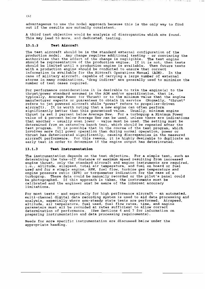
The test aircraft should be in the standard external configuration of the production model. Any change requires additional testing - or convincing the authorities that the effect of the change is negligible. The test engine should be representative of the production engine. If it is not, then tests should be limited until a production engine is available. Then future tests with a production engine should be conducted to ensure that correct information is available for the Aircraft Operations Manual (AOM). In the case of military aircraft, capable of carrying a large number of externe.1 stores in many combinations, "drag indices" are generally used to minimize the number of test cases required.
For performance considerations it is desirable to trim the engine(s) to the thrust/power standard assumed in the AOM and/or specification, that is, typically, Average Paver (or Thrust) or to the minimum value that the engine manufacturer expects or guarantees to obtain in service INormally, "thrust" refers to jet powered aircraft while "power" refers to propeller-driven aircraft). It is worth noting that a new engine cari often perform significantly better than this guaranteed value. Usually, minimum engine thrust is set 2 percent below Average New. For a turboprop a Minimum Power value of 4 percent below Average New cari be used, unless there are indications that another - usually even lower - value must be used. The setting must be determined from an extensive bench test, which should be repeated after the test program. It is possible that in the course of the test program, which involves more full power operation than during normal operation, power or thrust has deteriorated significantly, causing discrepancies in the measured aircraft performance. For this reason, it is highly desirable to duplicate an early test in order to determine if the engine output has deteriorated.
13.1.3 Test Instrumentation
Tbe instrumentation depends on the test objective. For a simple test, such as determining the take-off distance or maximum speed resulting from increased engine thrust, only the standard aircraft and engine instruments are required, i.e., altitude, airspeed, total air temperature, and fuel on board or fuel used and for a simple engine, RPM, fuel flow, turbine gas temperature and engine pressure ratio (EPR) or torquemeter indication for the case of a turboprop. These data cauld be manually recorded or the pilot's pane1 could be photographed. If this approach is taken, the instruments must be calibrated and the engineer must be aware of the inherent accuracy limitations.
For most tests - and especially for high performance aircraft - an automated, multi-channel digital data recording system is used to aid data processing and analysis, especially where non-steady state tests are performed. Airspeed, altitude, air temperature, fuel used, fuel flow rates, time, and engine parameters must a11 be recorded at rates sufficient to allow correct determination of performance. (Sec Sections 6 and 1 for information on preparing instrumentation and data processing requirements).
Needs for more specific instrumentation are discussed below under the appropriate heading.

13-3
Both airspeed and altitude measurements may be affected by pneumatic lag and attenuation. This is especially true of aircraft operating at rapid rates of change of altitude or speed and at very high altitudes. It may be necessary to conduct ground and flight tests to determine calibration factors that cari be used during data correction. (Sec reference 13-4 and paragraph 11.5.4.)
13.1.4 Nature and Scopa of Testa
In general, each test Will reproduce the condition for which performance information is desired, but in some cases the parameter of interest Will be determined by indirect means. For example, climb performance (rate of climb) cari be measured over a speed range by flying a level acceleration at a constant engine power setting. The climb performance cari be readily calculated from the excess thrust obtained from the measured flight path acceleration or equivalent level acceleration. This takes less flying time than a series of steady climbs at constant values of the airspeed over the range required to define peak rate of climb, but requires more effort in instrumentation and data analysis (sec 13.3.4 for more details).
If point performance, such as a guarantee on maximum speed, is to be determined, the aircraft weight, center of gravity position, engine power or thrust, and atmospheric temperature mut usually be within certain tolerances. For verifying the performance model, tests are conducted over a range of
conditions, usually at high and low weights for a ntier of altitudes. Performance tests such as take-off and landing tests, are sometimes conducted at the extremes of ambient temperatures associated with desert environments. Performance tests under arctic conditions are not required if the engine maximum power is reached under near-ISA conditions and does not increase as temperature is further reduced. These conditions usually require off-base expeditions which are very expensive but, apart from performance mode1 verification, serve to bring out possible handling or hardware difficulties or to prove that there are none. (Sec Section 18). Not a11 combinations of the above conditions need to be covered but there usually are requirements that must be satisfied. Typically, a sample of about six runs is made at each condition to establish a reasonable estimate of the mean value, but fewer tests at each condition may be acceptable where the test results are "mutually supportive", i.e., where there is sufficient coverage of the independent variable(s) to allo" the mean trend to be established with a reasonable confidence. It must be borne in mind that even if more than one airplane is tested, it requires "engineering judgement" to arrive at an estimate of Fleet Average Performance.
13.1.5 An.¶lY~i~ alld Prs~sntation of Rsmulta
Data reduction covers the calculation of standard day values, and/or the calculation of performance mode1 data such as lift and drag coefficients, from the recordings. However, before calculations begin the recorded values bave to be corrected for instrument errors and then the position errer correction of the pitot-static system. <The position errer must be established separately as discussed in Section 11). From the corrected values, pressure altitude, true airspeed, Mach number and static air temperature are calculated. (The computational procedure is the same as that used in the aircraft's Air Data Computer). [13-l, 13-21
Excess thrust and aircraft weight are calculated and used with the previous data to determine the lift and drag characteristics of the aircraft.
Further analysis covers comparison of similar measurements to check repeatability, e.g., determination of rate of climb as a function of airspeed. Possible outliers ("wild points") must be analyzed. They should be discarded

._
only if a good technical reason cari be found: they may otherwise indicate errors in the set-up or the execution of the test.
The reduced data are then presented in a form suitable for analysis for a particular test *et, i.e., take-off roll versus weight for various lift-off speeds and/or flap settings for a series of weights, lift coefficient V*~*U* drag coefficient, etc.
Point performance cari be deduced better from a number of measurements over a range of airspeeds than from attempting to repeat the same condition. It is usually not possible to repeat measurements at exactly the same conditions of airspeed, altitude, weight, engine performance, etc. Therefore, in order to establish a mean value with confidence a "reasonable' *ample size is required. The range enables corrections to be made for discrepancies and optimum climb
speed, for example, to be determined. The value of rate of climb cari be deduced at any speed from a curve fit. The engine instruments serve to check whether the engine is indeed flown at the desired thrust level. The observed aircraft performance must be corrected for any discrepancies in thrust level. The absolute value of engine thrust need not be known.
From the above procedure it is only a small step to the performance model, which enables a large number of measurements to be coordinated. In that case the absolute level of engine thrust must be known and it is no small task to establish the validity of the measured/calculated engine thrust. Once the mode1 is validated by measurements taken over as wide a range of conditions as feasible, performance cari be calculated for any set of conditions within this range. Limited extrapolation is allowed. The results may then be given or presented in tabular or graphie form for incorporation in the AOM.
13.2 TAKE-OFF N.ID LANDIN TESTS
13.2.1 Deacxlption of the Ta*ta
Take-off tests are conducted to define the time, distance, and airspeed to rotation, lift-off, and minimum barrier or screen height for a range of weights and flap settings. The important take-off speeds, such as Vl (decision speed), VR (rotation speed), and V2 ('cake-off safety speed or initial climb speed) are chose" to give specified margins over VS (stalling speed) and VMCG/VMCA (minimum control speed on the ground/in the air) as defined in the appropriate requirements documents. Landing tests are maneuvers conducted to determine the distance from a barrier/screen height to touchdown and then to a full stop. Rejected take-off tests define the distance to accelerate to a refusa1 speed and to corne to a standstill from there. [13-5, 13-6, 13-71
Each take-off test should be considered complete when the aircraft is out of ground effect, approximately one wingspan above the ground, but for certification purposes specific values are often chose", e.g., 50 or 35 feet for military and civil aircraft, respectively. For both military and civilian aircraft, failure of one engine is assumed during acceleration. If not enough runway is available to stop, the aircraft continues until rotation speed is attained. The aircraft then climbs out at V2 which is chose" to provide the specified speed margins over the stall speed VS and the minimum control speeds VMCG and VMCA (Sec paragraph 12.2.3). Below that speed take-off must be rejected if an engine fails. Aircraft weight, and therefore payload, must be chose" such that the required runway length cari be satisfied within the available distance.
It is important to establish that enough elevator/stabilizer authority is available to permit the aircraft to rotate at the desired speeds. If elevator/stabilator authority is very strong, it is also important not to

13-5
rotate at too low a speed and get into a situation where the aircraft may not bave enough thrust to continue the take-off. (Also, see paragraph 9.9).
13.2.2 Test In=trumentation P.¶ramaterS
There are no special airborne instrumentation requirements other than the need to correlate time between airborne and ground-based instrumentation. There are many different methods to measure distance along the runway, speed attained, lift-off point, and height above the ground such as kinetheodolite tracking, laser tracking, airborne camera, and inertial systems. These methods a11 differ in case of operation, data reduction difficulty, and the ability to synchronize ground and on-board equipment. The ground instrumentation must also measure the atmospheric conditions such as temperature and pressure plus wind velocity and direction. In the interest of brevity, none of this ground based instrumentation is discussed here. For a complete review the reader is directed to AG-160-Vo1.16. [13-81
13.2.3 Ta& Yansuvar~
The typical maneuver for a take-off is to set the desired power with the brakes locked, release the brakes, and start rolling. For a continuous take- off the aircraft is rotated at VR, which is chosen such that climb-out occurs at take-off safety speed W2) which is defined as 1.2 times the stalling speed (VS) for jets and twin turboprops. For short take-off and landing (STOL) propeller aircraft, rotation for the shortest ground roll cari be at VS (determined with engines idling) if pitch control power allows, because the propeller slipstream provides the necessary stall margin. Usually a minimum VR is also determined.
In a rejected take-off test, the pilot/co-pilot simulates engine failure by retarding the critical engine's throttle/power lever (sec 12.2.3) to the idle position at a pre-determined airspeed. After power reduction, the pilot is required to "ait three seconds before taking any corrective action, such as utilizing nose wheel steering, reducing power to any additional operating engines, applying brakes, and activating lift dumpers/"spoilers", if available, to provide maximum aircraft weight on the wheels for maximum braking power. Especially at heavy weight the brakes should be released just before standstill to keep rolling, otherwise the brakes may lock, with considerable damage resulting. If the take-off is continued the speed must be above VMCG. VMCG is determined with the elevator positioned for full aircraft nose-down to provide maximum weight on the nose wheel for best control. Sometimes speeds are tenter-of-gravity dependent because of limited pitch control. In those cases where engine failure is simulated, realistic pilot delay times must be allowed between the simulated failure and any pilot corrective activities.
For some military aircraft, tests must be conducted to determine the "ferry" take-off capability with one engine totally inoperative and with and without the 'failure" of a second engine. Also military requirements may dispense with safety regulations essential for civil aircraft, e.g., discount the failure of an engine and/or accept lower reference speeds to reduce the required take-off distances "hile accepting the handling control implications. Needless to say, these tests have to be carefully planned and executed using
a very conservative approach "hile ensuring that realistic response times are allowed between successive piloting actions.
Engine brochure power is determined on the test bench with a stabilization period of about four minutes to "set" tip and seal clearances. This means that in the first minute after setting Power Lever Angle (PLA) both the indications and the engine output change appreciably; in practice the whole take-off run is executed with the engine not stabilized. Also, in a rejected

. -_..___
take-off, it is not reasonable to eut engine power by shutting off its fuel SUPPlY. The sudden decrease of interna1 temperatures could cause turbine seizure and consequent damage. Also, by only cutting the engine to idle, power may be brought back up to help control the aircraft in the event of unexpected control problems. When PLA is closed to idle, the maximum speed in the rejected take-off ru11 Will be substantially above the value which would result from a true engine failure.
Landings are performed from stabilized conditions in the final approach configuration, utilizing power as required to attain the desired approach speed and angle. Power-off normally tends to result in a high vertical velocity which makes the flare maneuver critical. Usually the approach speed is 1.3 VS, unless additional requirements are imposed due to the phenomenon of speed instability, which is characteristic of "flight at the back side of the power Cur"e". This means that additional thrust/power is required to maintain the flight path at decreasing speed. Lower speeds may be utilized after analyzing data and detailed discussions with the pilot regarding the feasibility and desirability of operating at lower speeds. High performance aircraft often enter the final approach with excess speed, which is bled off before touch-down. This tends to give a rather large variation of performance because this maneuver is difficult to reproduce. Civil aircraft are required to perform five landings consecutively with the same tires and brakes to provide an average value and to prove that tires and brakes are not overstressed. Only in the "maximum kinetic energy accelerate-stop" tests may the brakes be expended in one test run.
13.2.4 Data Analyais and Presentation
Take-off and landing data are reduced to standard weights and atmospheric conditions using the techniques set forth, for example in references 13-l and 13-z. and are presented as plots of velocity or total energy versus distance. For take-offs, the distance is shown to lift-off and to a height of 50 feet
for various weights and, if appropriate, flap positions with indicated airspeeds noted on the plots. Landing data are presented as distance from 50 feet to a complete stop versus velocity or total energy. It is also possible to mode1 acceleration and deceleration as a function of atmospheric conditions, aircraft configuration, speed, and engine power and derive distances from that. [13-81
13.3 CLIMB TESTS
13.3.1 DaacriDtion of ths Teat8
Knowledge of climb performance is required to determine climb speeds, time to climb to a given height, fuel used, and distance covered for flight planning. In addition, there is the safety aspect; after failure of one engine, the
remaining aircraft performance must be sufficient to continue safely. This means that the aircraft must be able to clear obstacles with a certain margin and reach a height from which a landing pattern cari be initiated if an engine failure occurs during take-off. Or the aircraft must be able to continue to climb to a cruise altitude that Will permit completion of a mission. Of course, this does not hold for single-engine aircraft, which are generally military or light. In the latter case a. forced landing straight ahead is feasible or the pilot must eject from the aircraft. For aircraft with three or more engines, the possibility of a second failure later in the flight must be considered. [13-5, 13-6, 13-71
13.3.1 Test Instrumentation Paramstars
'j%e instrumentation noted in paragraph 13.1.3, above, is often supplemented with a flight path accelerometer (FPA) and/or an inertial navigation system in

13-7
order to measure acceleration along a flight path or acceleration components along a11 three axes. Angles of attack and sideslip, and roll should also be recorded. The use of the accelerometers is noted in paragraph 13.3.4, below.
13.3.3 Te& Maneuver#
The test maneuvers to acquire climb data must be tailored to the end use of the data. Different tests are utilized for determining the speed for best rate of climb as opposed to determining time to climb through an altitude increment.
The simplest case of measuring climb performance is that of determining rate of climb (ROC) through an altitude increment at a constant indicated airspeed. (These climbs are often referred to as "saw-tooth" climbs because that is the
shape of a plot of altitude versus tirne). The climbs are conducted over a range of speeds to determine the speed for best climb angle for obstacle clearance and a higher speed for best ROC. Engine power should be stabilized before entering the timed altitude increment. Duration of a single sawtooth climb test is usually less than five minutes.
These classical climb tests consist of a stabilization period for engine and aircraft of at least one minute, followed by three minutes of recording at a sampling rate of one sample per five seconds. With One-Engine-Inoperative (OEI) there are several different techniques to fly the tests which influence the end result. Optimum performance usually results from holding the "live"/operative engine 10" (approximately 5 degrees of bank) and flying with little side-slip. The possibilities range from maximum sideslip into the "live" engine and minimum rudder force to maximum rudder deflection (casier to hold against the stop), generally with the "live" engine high. Propeller- driven aircraft may require considerable aileron angle in OEI-flight to counteract asynunetric lift generated by the propeller slipstream. At higher airspeed, much smaller control deflections are required for equilibrium. The asynunetry of the slipstream in a propeller aircraft gives rise to the concept of "critical engine". Usually both propellers turn in the same direction. If this is clockwise, viewed in the direction of flight, the vertical fin experiences a force to the right, requiring more rudder deflection if the left (critical) engine is made inoperative than the other way round. The concept of a "critical" engine also holds truc for turbo-jet/fan engines.
At this point, it is appropriate to introduce the concept of Specific Excess Power (SEP) as a means of defining and determining the performance of high performance aircraft. Simply stated, SEP represents the difference between power available and that required for steady straight and level flight at the same speed and altitude, and is a masure of the aircraft's ability tcz accelerate, climb, or maneuver (i.e., overcome the increased induced drag in a turn). turn, is
It is defined as the rate of change of energy height (hS) which, in the sum of the specific potential and kinetic energy (1.e.. the total
energy of the aircraft per unit mass). Thus it cari be written: SEP = dh,/dt = d/dt(h + ti/Zg) = dh/dt + V/g x dV/dt where the last two terms represent the "tape measure" rate of climb and the longitudinal acceleration, respectively, and g is the normal acceleration.
SEP is usually determined from non-steady flight maneuvers, such as performing a level acceleration at constant PLA and measuring the acceleration along the flight path. As cari be seen from the above equation, the measured accelerations in level flight, i.e., with dh/dt = 0, is a direct measure of SEP, which may be converted into rate of climb at constant speed, i.e., with dV/dt = 0. This concept is developed in Ryland's method in which, with PLA fixed, a straight and level acceleration over a chosen Mach range, followed by a smooth increase in normal acceleration to decelerate the aircraft back to the initial speed is used to provide data from which the variation of SEP with

,3-x
Mach number at the test altitude and aircraft mass ca" be derived. 113-91 1t should be noted that while the concept of SEP is simple, its determination calls for very accurate flying and considerable data reductio" effort in allowing for the changes in Position Errer Correction (PEC) with speed and inadvertent variations in the salient variables.
For high performance aircraft, level accelerations at constant PLA, and minimum sideslip, are used to determine climb performance for a range of airspeeds. Level acceleration tests are often performed by accelerating and/or decelerating parallel to a condensation or smoke trail laid down by a calibrated aircraft. This trail provides a constant altitude so that the test pilot does not have to try to judge a constant altitude from his altimeter readings. This procedure Will help minimize corrections to test data. (This same data Will provide airspeed system calibration information when the pressure altitudr of the trail is defined by using a pater aircraft or by tracking the contrail-creating aircraft by radar). When initiating horizontal accelerated flight it is desirable to start off with a" engine stabilization period in steady climb of at least one minute. The changing altitude makes no difference in the engine stabilization, it is the interna1 temperatures that must be stabilized to obtain reliable power indications. It is commo" practice to utilize the speed brake, if available, to slow climb/acceleration while the engine is stabilizing. Eve" SO, the step from stable climb at minimum airspeed to horizontal acceleration may be excessive, upsetting the first few seconds of recording so pilot technique becomes critical. HOWeVer, the test data of real interest is usually in the mid-range of the speed envelope SO the loss of data at low and very high speeds is usually not critical. These tests are usually repeated at a series of altitudes, e.g., every 5,000 or 10,000 ft. The airspeed/Mach number at maximum SEP which is calculated from each level acceleration is the airspeed for maximum rate of climb at that altitude. The line through the peaks of the SEP curves at different altitudes denotes the optimum climb schedule. Normal acceleration should be kept to approximately one g, however, corrections ca" be applied in the data analysis for small discrepancies. Sampling rate is 5 to 10 samples per second (sps).
One or more continuous climbs are then executed, sometimes with different airspeed schedules, to check the results, especially time, distance, and fuel required to reach a given altitude. If there is more than one external configuration, such as external tanks or stores, then climbs should be flown at each configuration.
13.3.4 Data A"alyais and Presantation
Data analysis is different whether the result wanted is a number of point performances, e.g., for contract purposes, or preparation/verification of a performance mode1 for subsequent calculation of a" AOM.
Climb performance over a range of airspeeds ca" be determined in a single maneuver, such as a level acceleration or deceleration. In this case, however, the demand for instrument accuracy is much more stringent, as the differentiatio" process has to be executed over a much shorter time interval. The sampling rate should be at least five sps. The static pressure and
Position Errer Correction (PEC) have to be known exactly as a discrepancy bas a cumulative effect on the rate of climb, e.g., a single errer, ca" result in bath pressure altitude and airspeed deviating in the same direction.
performance ca" be measured without differentiating if accelerations along the aircraft axes are measured and transformed to flight path axes utilizing angle of attack, the so-called Flight Path Acceleration technique. A recording rate of 5-10 sps should be used, with adequate filtering of the accelerometer output, say a one Hz low pass filter.

13-9
Especially for 10" performance aircraft the angle of attack has to be calibrated accurately in-flight. Vane angle may be influenced by upflow ahead of the wing or by inflow to an engine or by control deflection. It is also influenced by aircraft rotation in pitch. An error of one milliradian, or about 0.05 degree, cari give an error of 0.1 percent in climb gradient, whlch cannot be neglected. This angle-of-attack calibration has to be repeated for each flap angle, as the fuselage attitude for constant lift coefficient varies with flap angle.
Performance cari also be measured by earth-bound accelerometers, i.e., an Inertial Navigation System (INS) without the necessity of an angle-of-attack calibration. In this case, however, the accuracy of the vertical acceleration is critical as a discrepancy which through integration would result in a vertical speed which implies performance that does net exist. computer programs exist which reconstruct the flight path accurately from the combination of accelerometers and altitude/airspeed measurement; subsequently, this flight path-time history cari be used to determine performance. [13-101 Small errors in vertical accelerometers accumulate through integration in an INS. This leads to significant errors in altitude and altitude rate over a period of time. These errors are primarily due to changes in acceleration of gravity as a function of latitude, accelerometer bias, changes in the atmosphere such as wind gradients or up/downdrafts. Using an external altitude reference (air data computer's altitude output), these errors cari be corrected. This is a so-called baro-damped loop. This loop is closed for most maneuvers: however, it is "open" for maneuvers such as climlx and descents).
13.3.4.1 Point Partormanc~. In the simple Rate of Climb (ROC) test, the measured ROC is corrected for variations from standard day and standard weight and presented as plots of ROC versus airspeed. Comparison of this ROC to that ubtained during level acceleration must include corrections for the changing absolute speed, experienced during a steady climb at either constant indicated airspeed or constant Mach number.
The thrust and drag corrections required for the correction of the point performance cari be derived from generalized data for aircraft and engine. As long as the correction is less than, say, 10 percent, a correction accuracy of 10 percent is sufficient to get a final accuracy within 1 percent; the absolute values of thrust and drag are net required. Corrections cari be made in a linearized differential form. For contract purposes it is recommended not to rely on a single test, but on the average of, say, five tests at the same airspeed or over a range of airspeeds or engine settings. In the latter case a computer curve fit cari be calculated, which is then read at the desired value: the accuracy cari be evaluated from the Random Errer Limit of Cur~e Fit.
The above quoted accuracy does not include bias errons, which cari occur in climb tests because of atmospheric phenomena like vertical speed or horizontal wind speed or pressure gradients. These may occur over a surprisingly wide area, and cari cause errors in RoC of 100 feet per minute or more, which cannot be neglected in a low-performance aircraft. usua11y only one or two tests out of a series are affected, they cari be found by vetting (i.e., eliminating outliers or bogus data by using expert knowledge of the shape or charactesistic of the data) the results for outliers. Do not execute a11 tests in the same area and "se reciprocal headings to show "p differences, if any.
Stable air for conducting performance tests is best found over water early in the morning before significant convection from the surface develops. Tests performed near mountains cari have substantial atmospheric disturbances, i.e., "pdrafts and downdrafts, which should be avoided.

._
13.3.4.1 PerFom,anco Mo&l. If a performance mode1 is to be verified, thrust and drag must be separated and known in absolute value. For the larger engines, thrust is determined by the engine manufacturer and given as a computer file, which cari be adapted by the aircraft manufacturer to include installation effects. (However, the Flight Test Engineer should be aware that there is a great deal of effort to determine the installation effects such as ground calibration of engines fitted with flight tail pipes.) For the simpler cases thrust and specific fuel consumption cari be given in non-dimensional or quasi-non-dimensiona for-m as a function of Engine Pressure Ratio or fan RPM for different flight Mach numbers. Corrections for Reynold's Number effects must be considered but they are beyond the scope of this volume.
Aircraft drag is usually computed as drag coefficient versus lift coefficient for different Mach Numbers.
For one-engine-inoperative flight an asymmetric drag coefficient must be included! which cari usually be expressed as a quadratic function of the asymmetrlc thrust coefficient. It is conunonly established empirically. Also pitch trim drag cari be evaluated separately: it is a function of center of gravity position.
13.4 CRUISE TESTS
13.4.1 Deucription of tha Ta#ta
Cruise tests are used to obtain data from which best cruise conditions cari be determined. For 10" performance aircraft, tests are often conducted using quasi-stabilized conditions, allowing very small variations in speed or altitude, at various combinations of weight and external configuration. For high performance aircraft, data is obtained from non-steady maneuvers.
13.4.2 Test In&zrumantation Parsaetrrs
The instrumentation required is the same as that required for climb performance determination.
13.4.3 Ta#t Maneuver~
For developing AOM and/or mode1 data, more detailed information must be obtained through quasi-stable tests or non-steady tests, or from both sources. Quasi-steady tests require considerable time to establish the necessary test conditions at various combinations of velocity, altitude, weight, and external configuration. The pilot establishes a throttle setting at a given altitude- weight-configuration and then holds a constant altitude "hile waiting for speed to stabilize. This technique is repeated at airspeed intervals until adequate data has been obtained to define a power required-velocity curve at that altitude. It is highly desirable for low performance aircraft to obtain a range of speeds from the "back side of the power curve. to near maximum speed for normal rated power to ensure that the lift-drag relationships are defined and that the best cruise speed cari be defined. An alternate method of obtaining cruise data for turbo-jet/fan engines is to establish engine setting required versus Mach Number at several constant values of "Weight-over-delta", where delta is the static pressure at altitude divided by the standard sea level pressure. At constant throttle setting, the pilot attempts to hold constant Mach, i.e., a change in airspeed less than one knot in two minutes, as the aircraft settles into a "cruise climb" which is held steady for five minutes while records are taken. (Sec also paragraph 13.4.4).
For the high performance aircraft, data cari be obtained during non-steady maneuvers such as level accelerations/decelerations at a near constant

altitude and turns where the normal acceleration is gradually increased (a "wind-up" turn) at various altitudes and weights. The PLA should be fixed (auto-throttle off) for each run. Runs should be accomplished at different fixed PLA settings to obtain engine mapping data as well as the effects of power on the lift-drag relationships (Note that data from the non-steady climb and sustained turn tests cm be used in defining cruise performance).
13.4.4 Data Analy#i# and Prementation
Cruise performance determined by quasi-steady state tests could be recorded by hand if it was not for the problem of evaluating stability, i.e., residual acceleration. For this reason the last minute of a cruise test should be recorded and the increment of drag resulting from the derived acceleration should be calculated.
Cr"ise drag is primarily a function of lift coefficient and Mach Number and should be evaluated as such. (The influence of Reynold's number effects on both drag and the engine must be considered but are beyond the scope of this volume.) In the AOM, cruise performance is usually given as engine setting and fuel flow versus aircraft weight for a limited number of cruise schedules and diverse heights, including Reynold's number effects. For reference, other engine parameters cm also be included.
Another way of presenting cruise performance is to evaluate the range factor as a function of Mach Number and aircraft weight divided by atmospheric pressure ("Weight-over-delta"). These values determine the lift coefficient for optimum cruise. The engine setting required is also a function of Mach Number and "Weight-over-delta". This presentation allows the finding of optimum cruise height as a function of aircraft weight and desired Mach nimber. This is defined by the value of "Weight-mer-delta" for maximum Range Factor (best nautical air miles traveled per pond of fuel consumed at the weight and altitude). 'Weight-over-delta",
Range factor versus Mach number is constant for a given except for the Reynold's number (skin friction drag
effect) mentioned above.
The data from the non-steady maneuvers is reduced to lift and drag coefficients and presented as plots of lift coefficient versus drag coefficient, fuel flow over pressure ratio versus Mach number for various power conditions (i.e., EPR, RPM, etc.). These plots are then the basis for forming or evaluating the aircraft and engine models.
13.5 COMBAT PERFORmNCE
13.5.1 Demription of the To&n
For military aircraft, combat performance cm be defined as maximum speed, turn rate (bath instantaneous and sustained), excess thrust (which gives accelerating performance and/or rate of climb), and minimum "sable speeds. (Handling qualities also involve combat performance and are discussed in Section 15).
13.5.2 Ta& Inntrumentation Parmaters
In principle, the determination of Combat Performance demnds the same instrumentation and data analysis as climb performance, but the maneuvering requirement goes up to 9 g and the very high thrust-to-weight ratio aircraft usually demands high data sample rates. On the other hand, the absolute data accuracy cari be less and still give a good relative accuracy.

_
The excess thrust of the vehicle is measured in high-g maneuvers, performed to the normal positive and negative acceleration limits of the aircraft, stability considerations permitting. Apart from acceleration performance, deceleration tan alsa be evaluated along with the effect of deceleration devices like speed brakes.
Even though high performance aircraft usually bave a low aspect ratio, and therefore, high drag at low speed, the initial acceleration for aircraft with a thrust to weight ratio of one or greater is still high enough to make the maneuver difficult to perform.
On the other hand, the Maximum Sustained Turn Rate demands the utmost from pilot, airframe, and instrumentation. The test is usually started from high speed in a horizontal wind-up turn, in which speed decreases at high g. Tests are flown at maximum power (full afterburning) and at different g levels. Sustained turn rate is found by interpolation. Besides performance, important aspects are controllability, buffet boundary, post-stall behavior and engine tolerance to high angle-of-attack and sideslip.
In modem engines the control system is often adaptive and cari include parameters like Mach Number, angle of attack, and sideslip angle. It is possible to run the afterburner in closed loop control ("buzz riding"). With a full authority Digital Electronic Engine Control, surge margins cari be varied with Mach number, angle of attack, and angle of sideslip. This allows better performance in low angle of attack flight and the best possible performance during turning maneuvers.
13.5.4 Data Analysis and Prerentation
Determination of excess power/thrust demands the evaluation of changes in speed and altitude with either pressure instruments or with the Flight Path Acceleration technique. It should be recognized that SEP cari be either a positive or a negative value.
Combat Performance is difficult to establish accurately. When employing the Flight Path Acceleration technique at high g, fuselage bending - and that of the boom carrying the angle-of-attack sensor - cari have a large influence on the measurement results. Also air loads on the boom cari be significant.
The variation of Energy Height (the imaginary height at which the potential energy is equivalent to the total energy of the aircraft, i.e., the sum of its potential (height) and kinetic (speed) energy) gives only the effective acceleration in flight path direction. Aircraft axis-orientated accelerometers transformed to the flight path axes using the angle of attack give the acceleration in the direction of the flight path and normal to the flight path, due to the resultant thrust, lift and drag. The determination is irrespective of aircraft attitude, and therefore independent of the test RBIleLlver.
The flight path acceleration is given by coordinate transformation from the body axes to the earth axes. The normal component of the flight path acceleration determines pitch rate. The maneuver performed cari bave a different pitch rate from the desired case, which may be a pull-up in the vertical plane or turning in the horizontal plane, or anything else. Therefore a correction to the measured flight path acceleration may be necessary. For that it is desirable to add pitch rate to the measurands.
13.6 DESCENT TESTS
13.6.1 h‘EriDtiOn of ths Temtn
‘NO?Xl.Sl” descent tests are accomplished to determine time, distance, and fuel used to descend from one altitude to another, and determine fuel used and distance covered while emergency descents (utilizing speed brakes, steep nose down attitude, and, if possible, gear and flaps extended), are conducted to determine the maximum possible rate of descent fallowing emergency conditions such as loss of cabin pressure.
Rate of Descent at constant airspeed is a function of engine setting and external configuration (which could include extension of flaps and gear). Engine setting has to satisfy requirements for accessory drive, possible flame-out or die-out and acceleration time to high power in case of a go- around. Unless idle RPM is closed-loop controlled it varies with airspeed. Sometimes separate values exist for ground and flight idle. It may be possible to utilize the lower ground idle value in descent to increase rate of descent. The flight idle condition must then be restored in the approach for better
acceleration.
13.6.2 Te& Instrumentation Parametara
The instrumentation defined for climb and cruise performance determination Will satisfy requirements for determination of descent performance.
13.6.3 Tent Manauverm
In a previous paragraph deceleration performance has been mentioned as a logical by-product of measuring excess power/thrust. This measurement cari be performed in nominally horizontal flight and then corrected to steady descent or. more directly, descents cari be accomplished at various combinations of speed and configuration.
13.6.4 Data Analyaim an.5 Pre~entation
Test data must be corrected to standard day conditions and standard weight for presentation of distance covered, elapsed time, and fuel used. Additional plots should be prepared showing altitude required to recover from descents/dives of varying dive angle and speed to allow for the case of dive bombing or an escape maneuver.
Descent performance cari be calculated from a performance model, which has been verified for conditions as close as practical to the actual maneuver.
13.7 CONCLUDING REHARXS
This section has presented procedures to determine aircraft performance, both for isolated tests and for verification of a performance model. Calculations are not worked out in detail: this has to be obtained from the indicated references, but most aspects bave been discussed.
REFERENCES
13-1. US Air Force Test Pilot School, Volume 1, "Performance Manual".
13-2. US Naval Test Pilot School (USNTPS) FTM-104, "Fixed Wing Performance Test Manual", July 1977.
13-3. USNTPS FTM-106, "Rotary Wing Performance", December 1987.
13-4. Lawford, J.A. and Nipress, K.R., 'Calibration of Air-Data Systems and Flow Direction Sensors", AGARDograph 300 "AGARD Flight Test Techniques Series", Volume 1, 1983.

13-5. UK Ministry of Defense, Defense Standard 00-970, "Design and Airworthiness Requirements for Service Aircraft . Volume 1 Aeroplanes: Issue 1 dated 12 December 1993, to amendment 12 dated October 1992 . Volume 2 Rotorcraft: Issue 1 dated 31 July 1984, to amendment 8 dated 8 December 1990."
13-6. Federal Aviation Regulations Part 25 - "Airworthiness Standards: Transport Category Airplanes", U.S. Department of Transportation, Federal Aviation Administration (FAA).
13-7. Joint Aviation Requirements (JAR)-25 - "Large Aeroplanes", (European) Joint Aviation Authorities.
13-8. de Benque d'Agut, P., Riebeek, H., and Pool, A., 'Trajectory Measurements for Take-off and Landing and Other Short-Range Applications", AGARDograph 160 "AGARD Flight Test Instrumentation Series", Volume 16, 1985.
13-9. Norris (Ed.), E.J., "Handbook of Test Methods for Assessing the Flying Qualities and Performance of Military Aircraft, Vol 1 Aeroplanes", A&AEE, Boscombe DOW~, UK.
13-10. Gerlach, O.H., "The Determination of Stability Derivatives and Performance Characteristics from Dynamic Maneouvers", AGARD FMP Symposium, May 1971.
BIBLIWRAPHY
USNTPS FTM-106, "Rotary Wing Performance", USNTPS Flight Test Manual, Patuxent River, MD, US, 31 Dec 1987.
Cohen, Ii., Rogers, G.F.C., and Saravanamuttoo, H.I.H., "Gas Turbine Theory", Longman, 1987.
Perkins, C.D. and Hage, R.E., "Airplane Performance, Stability and Control", Wiley, 1950.
Herrington, R.M., and Shoemacher, P.E., "Flight Test Engineering Manual", USAF Technical Report No. 6273, Air Research and Development Command, W-PAFB, Ohio, 1951.
Various Volumes in AGARDograph 160, "Flight Test Instrumentation Series".
Various Volumes in AGARDograph 300, "Flight Test Techniques Series".
Kohlman, D.L. and Schweikhard, W.G., "Flight Test Principles and Practices", The University of Kansas, USA, 26 April 1991.
LXl, C.E. and Roskam, J., "Airplane Aerodynamics and Performance", The University of Kansas, USA, first printing 1981.
Roskam, J., "Airplane Flight Dynamics and Automatic Flight Controls", Part 1 and Part II, The University of Kansas, USA, second printing 1982.
Ruygrok, J., "Elements of Airplane Performance", Technical University Delft, the Netherlands, Delft University Press, 1990.
Austyn Mair, W. and Birdsall, D.L., "Aircraft Performance", Cambridge Aerospace Series 5, Cambridge University Press, UK, Cambridge, New York, 1992. Ecole du Personnel Navigant D'Essais et de Reception

- Pratique des Essais en Vol Helicopteres (2 Vol), ref EPNER 25. - Pratique des Essais en Vol Avions (3 Vol), ref EPNER 24. - Pratique de la Reception (1 Vol), ref EPNER 27.