
Flying Qualities - NATO STO
396
AGARD-C AGARD CONFERENCE PROCEEDINGS No.508 Flying Qualities (QualitQ de Vol) DlSTRlBUTlO N AND AVAlLABl LlTY ON BACK COVER
-
Upload
khangminh22 -
Category
Documents
-
view
23 -
download
0
Transcript of Flying Qualities - NATO STO

AGARD-C
AGARD CONFERENCE PROCEEDINGS No.508
Flying Qualities (QualitQ de Vol)
DlSTRlBUTlO N A N D AVAlLABl LlTY ON BACK COVER


AGARDCP-508 , , ~ x,~.:: "' I , .
' . r .__ ,,,. I
i /
NORTH ATLANTIC TREA'N ORGANIZATION
ADVISORY GROUP FOR AEROSPACE RESEARCH AND DEVELOPMENT
(ORGANISATION DU TKAITE DE UATLANTIQUE NORD)
AGARD Conference Proceedings No.508
Flying Qualities
(Qualitks de Vol)
Copies of papers presented at the Flight Mechanics Panel Symposium, held in Quebec City, Quebec, Canada from 15th to 18th October 1990.

The Mission of AGARD
According to its Charter, the mission of AGARD is to bring together the leading persondlilics of the NATO nations in the fields of science and technology relating to aerospace for the following purposes:
Recommending effective ways for the member nations to use their research and development capabilities for the common benefit of the NATO community;
- Providing scientific and technical advice and assistance to the Military Committee in the field of aerospace research and development (with particular regard to its military application);
- Continuously stimulating advances i n the aerospace scieiices relevant to strengthening the common defence posture;
-Improving the co-operation among member nations in aerospace research and development;
Exchange of scientific and technical information;
-Providing assistance to member nations for the purpose of increasing their scientific and technical potential;
- Rendering scientific and technical assistance, as requested, to other NATO bodies and to member nations in connection with research and development problems in the aerospace field.
The highest authority within AGARD is the National Delegates Board consistingof officially appointed senior representatives from each member nation. The mission of AG4RD is carried out through the Panels which are composed of experts appointed by the National Delegates, the Consultant and Exchange Programme and the Aerospace Applications Studies Programme. The results of AGARD work are reported to the member nations and the NATO Authorities through the AGARD serics of publications of which this is one.
Participation in AGARD activities is by invitation only and is normally limited to citizens of the NATO nations.
The content of this publication has bcen reproduced directly from material supplied by AGARD or the authors.
Published February 1991
Copyright 0 AGARD 199 1 All Rights Reserved
ISBN 92-835-0602-2
Printed by Speciulised Printing Services Limited 40 Chigwell Lune, Loughlon, Essex IG10 3TZ

Preface
The validity of constraining thc responses of today’s control dominant aircraft to conform to the classic flying qualities criteria derived From stability dominant aircraft experience has been an issue for many years. The introduction of full time visual scene enhancement with scnsor Fusion, and computer generatedhterpreted night scenes, also escalates display dynamics into the arena of flying qualities concern.
Integrated flight and propulsion control schemes and direct force controllers have the potential for completely coupling all the sensors with all the controllers to provide any combination of controlled motion From six independently controlled single- degree of freedom systems to a single completely coupled six-degrees-OF-freedom system.
These new technologies have expanded flight envelopes, reduced drag, increased manusuvrability, provided the Framework For practical gust alleviation and active flutter suppression, and provided flexibility For Fault-tolerant, damage-adaptive flight controls.
However, the updating of flying qualities criteria has in general not kept pace with these technological changes. The purpose of this Symposium was to review flying qualities issues today, and to report progress towards their resolution. The Following topic areas were covered:
- - ~ Flying Qualities Research -
The concluding “Round Table Discussion” provided the Session Chairmen with an opportunity to share with the Symposium attendees their view of the major issues relevant to their session topic which need to he addressed in the future.
Flying Qualities Experiences on Contemporary Aircraft Application of Flying Qualities Specifications
Flying Qualities at High Incidence.

Prkface
Depuis de nombreuses annees, la communaute de la mecanique du vol s'interroge sur la validit6 de la mithode qui consiste a moduler les reponses des aeronefs d'aujourd'hui, qui sont caractirisis par la commande, pour qu'elles se conforment aux criteres des qualitb de vol classiques qui decoulent des aeronefs caractirises par la stabilite.
L'arrivee des systimes d'enrichissement permanent de I'image combines avec I'interconnexion des capteurs, ainsi que I'imagerie nocturne crWanalysee par ordinateur, fait passer la dynamique de la visualisation dans le domaine des qualites de VOI
Les systemes integres de commande de vol et de commande de la propulsion et les systemes de contr6le direct des forces permettent d'envisager le couplage direct de taus les capteurs avec toutes les commandes pour rialiser toute combinaison de mouvement commande, allant de six systemes a un seul degre de liberte et a commande individuelle, a un seul systeme i six degres de liberte et a couplage integral.
Ces nouvelles technologies ont eu pour effet d'elargir le domaine de vol, de reduire la trainee, d'accroitre la maniabilite, de fournir I'environnement technologique favorable a I'attinuation des rafales et a la suppression du flottement et d'amener la flexibilid demandee pour la realisation de commandes de vol insensihles aux defaillances et adaptatives a I'endommagement de I'aeronef.
Cependant, les criteres applicables aux qualites de voI n'ont pas suivi ces evolutions technologiques. L'objet de ce symposium a & t i d'examiner les questions qui se posent dans le domaine des qualitis de vol aujourd'hui, et de rendre compte des progres realisis en vue de leur resolution. Le symposium a traite des sujets suivants:
- - - -
Le debat "table ronde" qui a cl6turC la seance a fourni aux presidents de seance I'occasion d'avoir un echange de vues avec les participants sur les principales questions qui se posent dans ce domaine et qui sont a resoudre a I'avenir.
L'experience acquise dans le domaine des qualitis de vol sur les avions modernes. La mise en application des specifications des qualites de vol. La recherche en qualitis de vol. Les qualitis de vol a forte incidence.
iv

Flight Mechanics Panel
Chairman: Mr R.C.A'Harrah Deputy Chairman: ICA J.-M.Duc Charge Affaires Internationales
29, Avenue de la Division Leclerc
O.C.N.R. Code OOJDL ONERA 800 N Quincy Street BCT-1 Arlington 92322 Chatillon-sous-Bagneux Virginia 22217-5000 France United States
TECHNICAL PROGRAMME COMMITTEE
MI D.L.Key Mr H.Wuennenberg Chief, Flight Control Branch Department of the Army
Ames Research Center 7990 Friedrichshafen M/S 210-7 Germany Moffett Field California 94035 United States
Head of Flight Mechanics Dornier GmbH
Aeroflightdynamics Directorate PostFach 1303
HOST NATION COORDINATOR
Mr S.W.Baillie Flight Research Laboratory National Aeronautical Establishment National Research Council Montreal Road Ottawa, Ontario KIA OR6 Canada
PANEL EXECUTIVE
Mr M.K.Foster
Mail from Europe: AGARDOTAN AGARD-NATO Attn: FMP Executive 7, rue Ancelle 92200 Neuilly SUI Seine France
Mail from USA and Canada:
Attn: FMP Executive APO New York 09777
Telephone: 33 (1) 47 38 57 70 Telex: 610176 (France)
Telefax: 33 (1)47 38 57 99
ACKNOWLEDGEMENT
The Flight Mechanics Panel wishes to express its thanks to the National Authorities of Canada for the invitation to hold this meeting in Quebec, and for the facilities and personnel which made the meeting possible.
Le Panel du Mecanique du Vol tient a remercier 1es Autorites Nationales du Canada pour leur invitation a tenir cette riunion a Quebec ainsi que des installations et du personnel mis a sa disposition.
V

Preface
Preface
I Flight Mechanics Panel
L’Adaptation des Qualitks de Vol au Pilote et a la Mission par J.Coureau
The Art of Flying Qualities Testing by D.Thomas
ADFCS and NOTARTM: Two Ways to Fix Flying Qualities by C.S.Morse
Paper 5 withdrawn
Qualites de Vol Lateral d’un Avion de Transport Civil Equipe de Commandes de Vol Electriques. Experience de I’Airbus A320
par J.Farineau et X.Le tron
MIL-STD-1797 is Not a Cookbook by D.B.Leggett and G.T.Black
Flying Qualities Experience on the AMX Aircraft by R.Bava
~ The Development of Alternate Criteria for FBW Handling Qualities by J.C.Gibson
Development of MIL-8785C into a Handling Qualities Specification for a New European Fighter Aircraft
by E.Buchacker, H.Galleithner, R.Kohler and M.Marchand
Do Civil Flying Qualities Requirements Address Military Missions for “ON-the-Shelf” Procurement?
by G.T.Black, W.A.Grady and D.C.McDonald
Handling Qualities of Highly Augmented Unstable Aircraft. Summary of an AGARD-FMP Working Group Effort
by H.Wuennenberg
The Handling Qualities of the STOL and Maneuver Technology Demonstrator fr0.m Specification to Flight Test
by D.J.Moorhouse, K.D.Citurs, R.W.Thomas and M.R.Crawford
Metrics for Roll Response Flying Qualities by MJnnocenti
Handling Qualities Guidelines for the Design of Fly-by-Wire Flight Control Systems for Transport Aircraft
by O.P.Nicholas, WPde Boer, J.A.J.van Engelen, H.T.Huynh and DShafranek
Flying Qualities Research - Quo Vadis by R.ESiewert
Contents
Page
iii
iv
V
Reference
1
vi
2
3
4
6
7
8
9
10
11
12
13
14
15
The Flying Qualities Influence of Delay in the Fighter Pilot's Cuing Environment by R.E.Bailey
Estimation of Pilot Ratings via Pilot Modeling by D.McRuer
An Initial Study into the Influence of Control Stick Characteristics on the Handling Qualities of a Fly-by-Wire Helicopter
by J.M.Morgan
An Investigation into the Use of Side-Arm Control for Civil Rotorcraft Applications by S.W.Baillie and S.Kereliuk
Determination of Decision-Height Windows for Decelerating IMC Approaches in Helicopters
by R.H.Hoh, S.W.Baillie, S.Kereliuk and J.J.Traybar
Evaluation des Lois de Pilotage Evolukes sur Dauphin N par F'Delestrade et D.Papillier
Integration of Handling Quality Aspects into the Aerodynamic Design of Modern Unstable Fighters
by P.Mangold
Paper 2 3 withdrawn
B-1B High AOA Testing in the Evaluation of a Stall Inhibitor System by MSSobota
Flying Qualities of the X-29 Forward Swept Wing Aircraft by L.A.Walchli and R.E.Smith
Handling Qualities Evaluation for Highly Augmented Helicopters by H:J.Pausder and W.von Griinhagen
Agility: A Rational Development of Fundamental Metrics and their Relationship to Flying Qualities
by C.J.Mazza
A Review of High Angle of Attack Requirements for Combat Aircraft by K.McKay and M.J.Walker
X-31A at First Flight by W.B.Herbst
Round Table Discussion by H.Wuennenberg
Reference
16
17
18
19
20
21
22
24
25
26
27
28
29
RTD
vii


FLYING QUALITlES RESEARCH - QUO VADIS
by
Ravmond FSiewerI Deputy Di;ector, Defense R. & Eng.
ODDRElR & AT Room 3D1089 The Pentagon
Washington DC 20301-3080 United States
Thank YOU Dave for that very kind introduction.
Good morning ladies and gentlemen. It is indeed an honor to present one of the keynote addresses at this symposium. However, I do have a some concern that members of the AGARD flying qualities community now look upon me as a senior citizen for it seems one has to achieve that status in order to give a proper keynote. In retrospect that may be closer to the truth than I care to admit, as my first AGARD presentation was twenty four years ago to the flying qualities symposium in Cambridge England. At that symposium I delivered a paper that Dresented a controversial criterion on the susceptibility to longitudinal pilot induced oscillation (PIO) which was developed jointly with Mr. A'harrah, current chairman of the flight mechanics panel. MY comments today may be equally controversial, but in a broader context,
My remarks this morning are directed toward fixed wing aircraft, principally high performance tactical aircraft. However, as evidenced by the title of several papers on the agenda at this symposium, they will soon be applicable to helicopters as well.
I ask the students of Latin to excuse my very liberal translation of that beautiful language in the title of this talk. However, I believe flying qualities research is at a cross roads and that the community should address the question "What are the future directions in this discipline?"
To place this thesis in proper perspective, I will briefly trace the history of flying qualities, to explore the more noteworthy highlights of the past as a back drop to explore where flying qualities research might be going in the future.
Before embarking on our historical journey, I believe we should take a moment to consider this technical area and those characteristics which make it unique and fascinating area of research. It is one of the few disciplines which ties together highly complex dynamics analyses with the performance and likes and dislikes of the human operator. practitioners of the art must:
o Be thoroughly schooled in aircraft dynamics and aerodynamics
o Be familiar with the limitations of the human operator
0 Understand the attributes of mission effectiveness
In essence flying qualities research presents the classic interface problem among the disciplines of aerodynamics/ dynamics, electronics/controls, and human factors. Increased integration of these disciplines and a blurring of the distinction between them characterizes recent trends. There is no reason to believe this will change in the foreseeable future.
Thus far I have referred to "Flying Qualities" as the topic of my presentation, and indeed that is the title of this symposium, However when examining the agenda for this meeting, I note the intermixine of the term - "handling qualities" with that of "Flying Qualities". I would not have thought much of this difference in terminology, had not our session chairman, Mr. Key recently brought it to my attention that he believes there is a distinct difference in the application of these terms. It seems that "Handling Qualities" is concerned with flight control (note-not controls) and produces design criteria, assessment techniques, and design tools. Whereas, "Flying Qualities" is concerned with the interface with the pilot primarily to reduce workload and improve task performance. If one accepts these distinctions, I believe history shows us that early experimenters were concerned primarily with "Handling Qualities". However, modern practitioners of the art must concern themselves with both aspects of the discipline.
The importance of handling qualities was certainly recognized by the Wright Brothers, as seen in this excerpt from a speech Wilbur made in 1901:
"The difficulties which obstruct the pathway to sucoess in flying machine construction are of three general classes: 1) those which relate to the construction of the sustaining wings, 2 ) those which relate to the generation and application of power required to drive the machine through the air, 3 ) those relating to the balancing and steering of the machine after it is actually in flight. Of these difficulties the first two are already to a certain extent solved; but the third, the inability to balance and steer still confronts students of the flying problem. When this one feature has been worked out the age of flying machines will have arrived, for all other difficulties are of minor importance."
We all know that during the next two years, the Wright Brothers succeeded in

1-2
solving that difficulty, at least to the point that their flying machine had sufficient control to successfully accomplish relatively safe flight. However, we would all question the adequacy of the flying qualities.
Some eight years after the first flight of the Wright Brothers, the next major component of today's flying qualities was developed by contemporary mathematicians. It was the British applied mathematician, G. H. Bryan who placed the hole problem of airplane dynamics on a more rigorous mathematical basis in 1911. Bryan introduced the concept of "stability derivates, " broke the total airplane motion down into symmetrical and rotative components and uncovered the nature of the airplanes natural frequencies. Thus the foundations of aircraft dynamic analysis were established.
It was not until almost forty years after the Wright Brothers first flight that the final element of modern flying qualities was established. The work at the,national advisory committee for aeronautics or NACA at Langley Field in the U.S. which began in the 1930's, was coming together in 1940, just prior to World War 11, in a group of sophisticated prpgrams to correlate airplane stability and control characteristics with pilot's opinions on the airplane's "flying qualities." This work focused on those factors that could be measured in flight and could be used to define quantitatively the flying qualities of airplanes. The fundamental nature of that body of technology that we call flying qualities has not changed in almost fifty years.
Almost simultaneous with the establishment of flying qualities as a technical discipline, was the development of the first flying qualities specification. This work was performed by E. Warner of NACA the when he was asked to prepare the specifications for the Douglas DC-4 airplane. Warner discussed the problem with airline pilots, industrial development engineers, and the NACA staff, and his specification was the result of these studies. While Warner is credited with the development of the first flying qualities specification, the U.S. Army Signal Corps had some thoughts on this matter in 1907 when they drafted the specification for the first military airplane to be procured from the Wright Brothers. Flying qualities were not even given a stand alone paragraph in that one page specification, but merely a sentence which is as follows:
"During this trial flight of one hour, it [the airplanel must be steered in all directions without difficulty and at all times under perfect control and equilibrium."
Those requirements are almost elegant in their simplicity.
We like to believe that we have come a long way from those simplistic times.
the flight regime of early manned aircraft was so rudimentary that control power was the key to success, and the aerodynamic instabilities could be stabilized by the pilot after a little practice, As airplanes flew faster and became more heavily loaded, the divergences of the unstable airplane became too rapid for the human pilot to cope with and design for inherent aerodynamic stability became mandatory. As the airplane moved into more and more complex flight regimes, the capability of designing for complete aerodynamic stability throughout the flight envelope became nearly impossible. Due to the great nonlinearities arising from power effects, compressibility and aeroelasticity we have had to introduce stabilization elements through the control system to aid the pilot in controlling the airplane to perform the mission. Indeed, modern control technology has progressed to the point where we now intentionally design airplanes to be unstable over a large portion of their flight envelope to enhance performance and mission effectiveness.
These advances while contributing to overall mission effectiveness have caused their share of problems for the flying qualities engineer. As designers rely more and more on the flight control system to compensate for poor dynamics and aerodynamics of the airplane, the flight control engineers have been forced to ever higher levels of complexity, resulting in total system dynamic characteristics several orders greater that those first identified by Bryan. The result is that we are no longer able to identify the characteristic modes, not only mathematically, but also in the airplane response characteristics.
As this situation evolved over the past fifty years, we have attempted to define and redefine criteria to insure "good flying qualities'' with the result that today's specification is an extremely complex document which has to be supported by a back up manual over eight hundred pages in length. Still we have problems defining flying qualities criteria. This has resulted in efforts such as the notion of equivalent systems. In this concept an equivalent set of second order response characteristics are derived from the modal characteristics of the complete higher order airframe. The criteria for acceptability are now defined in terms of these equivalent characteristics. In my view we are attempting to "force'' airplanes which exhibit new and unique dynamics into our traditional mode of thinking about flying qualities criteria. To what extremes can we continue this practice?
Coupled with the increase in control complexity is the increasing trend toward cockpit automation. We have such programs as integrated fire and flight control, wherein we demonstrated the ability to shoot down a drone under flight conditions where such a feat was

1-3
disturbing, I find this very disturbing because it ignores the foundations of Bryan, Gilruth and others who pioneered the concept of relating the flight mechanics parameters to pilot preference and performance.
Finally, we all recognize the importance of simulation, both ground based and in flight, to flying qualities research. However, from my observations of some recent simulations, we are no longer building systematic data bases upon which to base new or revised criteria. Rather, the researcher has a concept for a new mode of integration, writes an algorithm to implement it, and conducts simulation to prove it works. The result is that if the airplane designer does not wish to utilize that particular mechanization, he has no data base upon which to base alternate designs. It appears that the days of systematically varying parameters and studying their overall effect on pilot opinion and performance is becoming a lost art. I can only reflect that future designs will suffer.
By now you have heard some of my concerns and recognize why at the start of this talk, I suggested that it might be controversial. I would like to conclude by posing some challenges to the community here today. I ask you to consider the following questions as YOU go through your program this week, as well as in your future work:
considered impossible in the past. The pilot remarked, " I don't know if he [the automatic system] got it or I got it, but we got it!" Considering that much of our flying qualities research for military aircraft is devoted to defining the characteristics of a stable and precisely controllable weapon delivery platform, what then should be the nature of this research in the above example?
"The drone demonstration" was accomplished almost ten years ago, and we have been pursuing technology development for automated ground attack, automated target hand off, automatic terrain following/terrain avoidance, automated systems monitoring and flight management and much more. This leads me to the question, "What is the role of man in cockpit?" The traditional response has been that he will become a manager of the battle. I have not discussed this with very many pilots, but I do know from long experience that pilots like to fly airplanes, and all of our governments spend a considerable sum to insure that they can do it very well. Management training is significantly less expensive.
A survey conduct by the Naval Weapons Center in China Lake, California a few years back of Marine attack pilots indicted that while control of the aircraft trajectory was considered critical to the success of the mission, it was not consider a difficult or high workload task. What was surprising was that they rated weapon interface critical to the mission as well, but as a high workload task. The weapons were iron bombs! These admittedly sparse data raise the following question in my mind:
"In our eagerness to automate cockpit functions, have we overlooked the preferences of the pilots and automated those things which we think will be beneficial?"
Advances in technology are also bringing in new modes of control. The U.S. Air Force is currently flying a modified F-15 airplane which integrates the flight control with the propulsion system which includes in flight thrust vectoring and reversing. A paper describing this program will be presented later ,in the symposium. The point I would make here is that this integrated control concept may result in response characteristics which are not generally recognized in the classical flying qualities sense, but which may be very acceptable to the pilot.
Closely related to the above is the topic of high angle of attack post stall flight, which is the subject of the final session of this symposium. Airplane response characteristics in this regime are far from classical. Accordingly, we have taken to developing a new term -- aircraft agility. There is currently great debate in the united states on identification of these agility parameters and the range of acceptable values. There is a tendency to agree these by consensus which I find very
0 Why should we continue to try to define the characteristics of advanced airplane configurations which no longer exhibit classical response characteristics, such as the short period or dutch roll modes, in those terms?
0 What is the role of man in the cockpit, and how should this role be addressed in future flying qualities research?
o Are flying qualities criteria and the resulting specifications becoming too complex? If so, what are some alternate approaches?
In closing, I ask YOU to again consider my original thesis, that flying qualities research is assuming new directions. Further, those here today must determine what those directions are and develop the research agenda to pursue them.
Thank you for your kind attention and I wish you success in your symposium.


L'ADAPTATION DES QUALITES DE VOL AU PILOTE ET A LA MISSION
par J. Coureau, Directeur de la Skcuritk des Vols DASSAULT AVIATION - 13800 - Istres - France
L'aviation a debut6 comme uu grand jeu sportif auquel se sont livrb des fanatiques assez fortunb pour fabriquer la machine, assez ing6nieux pour qu'elle puisse voler, et assez tkmkraires pour la faire voler.
Ceux qui ont rtussi avaient par dessus tout
Ces constructeurs-pilotes ont dii obtenir
du g6nie !
assez rapidement une stabilit6 suffisante pour permettre des vols de plusieurs minutes sans fatigue excessive, une bonne prkcision de pilotage pour r6aliser de faqon r6p6titive et sans trop de c a s e les manoeuvres de dkcollage et d'atterrissage, puis la tenue de palier, puis le virage. Les premihes courses "au pylBne" imposaient dkji une certaine mattrise dans ces domaines.
Les rkgles en usage pour dmensionner les gouvernes, caler les surfaces portantes, tenir compte des couples d'hklice, etc ... devaient se communiquer oralement. Bien peu d'kcrits de l'6poque font &tat de ces problkmes. 11s furent pourtant rbolus et la premihe guerre mondiale voit relativement tBt apparaitre une aviation militaire utilisable.
Les aviateurs sont d'abord charges de r6gler les tirs d'artillerie. Mais pour dtloger ceux d'en face, on crke I'aviation de chasse vers 1916. La qualit6 de la plate-forme devait i tre excellente car le pilote devait manoeuvrer pour se placer i "port6e de fusil" et Ikher les commandes pour tirer sur un adversaire qui manoeuvrait pour kviter. Tr& vite Parmement de bord a kvoluk vers des mitrailleuses puis des canons fixes dans l'axe avion, preuve kvidente que la maniabilit6 des avions en permettait un usage performant. L'abandon de cet armement est souvent 6voqu6, mais sou usage est encore rkpandu de nos jours.
En France, un organisme d'Etat, cr66 en 1920, d6bute l'ktude rkellement scientifique des qualitks de vol des avions; ses pilotes et ing6nieurs trouvent les bonnes rkgles, les communiquent aux constructeurs puis tentent de les faire respecter.
statique, la stabitit6 de route, le mouvement sp iral... et aussi le flottement.
11s dicouvrent la stabilitk longitudinale
Un des coustructeurs porte un grand intkret aux qualitks de vol de ses avions, il incite ses ing6nieurs & participer aux vols de d6veloppemenf et i tenir compte de I'avis du pilote ; il conseme ces principes tout au long de sa brillante carrikre. J'ai eu le plaisir de travailler sous ses ordres pendant 30 ans : vous avez reconnu Monsieur Marcel DASSAULT.
LES AVIONS CLASSIOUES :
La deuxikme guerre mondiale rkalise une grande confrontation des matkriels.
De belles machines deviennent dlkbres pour leurs qualitks de vol. On demande aux bombardiers une bonne stabilitk longitudinale et transversale car les moyens de vide et les calculateurs associb rkclament pendant le "bomb run" des corrections prkcises et bien amorties.
Les chasseurs par contre ont besoin de manoeuvrabilit6 et de maniabilitk pour conduire les combats basks SUI l'utilisation des armes dans l'axe de l'avion. C'est la course i la puissance pour les moteurs; les gouvernes doivent kquilibrer des couples d'h6lice t r b importants.
A I'apparition du rkacteur, l'accroissement de vitesse qu'il permet rkvkle un nouvel accident de comportement : la compressibilitk. Les phknomknes les plus courants sont des vibrations (buffet), des oscillations peu contrBlables (purpoising), de l'auto- cabrage (pitch-up), des dkfauts de compensation des gouvernes. Cela cr66 de nouveaux soucis pour le pilote de combat.
L'emploi des profils minces gukrit ces inconvknients mais en a m h e d'autres. L'aQodistorsion revient en force pour rkduire les vitesses de roulis. On rencontre des dkcrochages dynamiques plus violents. Rendues plus plates par I'inertie accrue du fuselage, les vrilles sont rkputkes difficiles i contrBler.
Les aualitks de vol reauises :
1 - La s6curit6 d'emdoi : l'avion doit pouvoir i tre employ6 sans danger jusqu'aux limites de son domaine de vol, tant i grande vitesse ou grand Mach qu'i basse vitesse, comme prks du sol. Ceci suppose que soient maitrises les comportements en subsonique, transsonique et 6ventuellement supersonique aussi bien qu'au cows de d6crochages statiques et dynamiques.
Dans diff6rents pays, des normes strictes
haute altitude
sont 6tablies qui ont pour but d'kviter le renouvellement de d6fauts ayant amen6 des accidents. S'appuyant sur des cas particuliers, elles manquent parfois d'universalit6. Le fait de les respecter ne garantit pas vraiment la qualit6 de Pavion.

2-2
Le transsonique provoque sur les gouvernes et les timoneries associkes des moments h la dynamique et aux variations si rapides qu'il n'est pas pensable de les compenser efficacement. On a recours aux servo-commandes irrtversibles gtnkralement hydrauliques : la stcuritt repose sur deux circuits indtpendants alimentant des servo- commandes double-corps. Le pilote ne ressent plus qu'un effort proportionnel aux dkplacements de la commande (boite h ressorts) et aucune reaction de gouverne ne "remonte au manche".
L'efficacitk des gouvernes varie tellement, dans un domaine de vol trks tlargi, qu'il faut adapter la commande aux conditions de vol. Ceci est surtout nkcessaire en profondeur : un delta peut prksenter une efficacitk de profondeur de 0,3 degrk par "9" h basse altitude et grande vitesse, lorsqu'il est centrk arrikre ! Le contr6le en devient alors trks dtlicat : il y a risque de "pompage pilot&". On recherche donc des centrages trks avant, avion lisse, pour accepter les pertes de stabilit6 dues aux emports sous voilures.
sont install&, des lois de dkplacement non lin6aires, des lois d'effort h plusieurs pentes, variables en fonction de la vitesse et m&me du facteur de charge, des amortissements visqueux (dash pot) ...
Des amortisseurs h commande klectronique
BientBt une chaine klectronique fournit la commande normale, la commande m6canique servant de secours. On est cependant en simple chaine, le "secours" doit &tre d'excellente qualit6 et conserve donc tous les dispsitifs ci-dessus.
On r6alise ainsi des avions polyvalents sur lesquels le pilote peut passer des faibles vitesses aux grands mach, de l'avion Esse h "l'6tagkre B bombes" sans devoir porter au pilotage une attention trop soutenue : la perte d'aides au pilotage n'est pas trop gBnante et permet dans la majorit6 des cas la poursuite de la mission.
prkfkrable de disposer d'une stabilisation 101s de l'observation attentive de l'kcran puis de retrouver, si possible, I'entiPre maniabilit6 du chasseur ; divers dispositifs ont tent6 de rkpondre h ces besoins contradictoires : auto-commande et stabilisateurs de roulis, pilote automatique embrayable et d6brayable instantanbment, pilote automatique transparent. Accessoirement ils r6alisent tous un auto-trim bien agr6able.
2 - L'Efficacitk
Sur les avions munis de radar, il est
Le combat classique impose toujours une maniabilitk excellente mais dont la recherche va h I'encontre des qualit6s de vol classiques comme la stabilite. Sur les avions conGus pour le temps de paix on opkre donc un compromis qui est plut6t du c6tk de la skcuritk : efforts par g klevks, stabilit6 statique forte en volant centrk avant.
LES COMMANDES DE VOL ELECTRIOUES :
L'idtal, connu depuis longtemps, est de faire piloter l'avion i% travers un calculateur klectronique qui assure les amortissements et les protections, et qui permet, gr2ce h ses r6actions t r P s rapides, d'accepter les accidents akrodynamiques, de reculer le centrage jusqu'au vol en instabilitk statique, procurant ainsi un gain important en performance. Ceci a rkhabilitk la formule Delta.
La commande mkcanique traditionnelle n'est plus utilisable dans ces conditions de vol car les kcarts augmentent beaucoup trop vite pour &e correctement contr6lks par un pilote. I1 faut donc un autre calculateur en secours, puis comparer les deux En cas de panne, lequel a tort ? On voit bien que c'est I'escalade vers trois et m&me quatre chaines.
C'est l'arrivke sur le march6 de calculateurs Clectroniques compacts qui a rendu possible la rkalisation de ces commandes de vol 6lectriques sans secours mkcanique.
La suppression de la transmission mkcanique a post quelques problkmes psychologiques, bien vite oublib devant la somme des avantages obtenus.
sont pas encore tous oubliks !
klectriques ?
-
Dans l'aviation civile, ces problh" ne
Que permettent les commandes de vol
une tr&s bonne stabilisation de plate-forme en conditions de vol instable, donc la possibilit6 d'une t r b grande maniabilit6. Ceci r&soud le probleme des chasseurs prkddents : un avion stable comme le roc et trks ardent ! Que1 avantage en combat !
la manoeuvrabilitk maximale grice a w limitations automatiques en facteur de charge et en incidence, dans toutes les configurations. C'est I'avion que l'on manoeuvre tr&s vite, B fond, sans souci de la perte de contr6le ou de la casse. Bien sik les couplages roulis-lacet rendent le dosage du pied inutile. Autres knormes avantages en combat !
la facilit6 de pilotage : l'avion h mettre entre toutes les mains, qui p o m e vers le haut les performances individuelles, efface les dBrences de pilotage, accroissant ainsi I'effcacit6 d'nne force aerienne avec le minimum de temps d'entrainement.
les nombreuses fonctions nouvelles :
-
-
-
le pilote automatique de base peut Btre inclus dans les calculateurs, donc multi-chaines, ce qui accroit la skcurit6 d'emploi h tr&s b a s e altitude et la disponibilit6,

2-3
. l'kvitement de sol automatique devient possible, m&me en manoeuvre, grace au relief nnmkrisk en mbmoire,
la rkcupkration de l'avion, en cas de perte de conscience du pilote, est rkalisable, par analyse de ses rtactions au moyen de dktecteurs pen contraignant : mouvements de la t&te, efforts aux commandes,
le contrale a i d de l'energie en combat, sans consulter d'iistrument, par limitation prbklectke des kvolutions ou par signaux tactiles au pilote,
la gestion optimale de la trainke on de la portance par utilisation de toutes les surfaces mobiles,
l'utilisation possible des six degrks de libertk pour dkcoupler les translations des rotations autour du centre de gravitk, bien que la complication des commandes et des stratkgies de pilotage n'ait pas encore permis d'application opkrationnelle en combat,
l'allkgement de certains efforts structuraux,
.
.
.
.
.
. l'auti-turbulence,
. I'approche dynamique on m&me le maintien des grandes incidences (post dicrochage ou post-stall), etc ... encore que l ' iith&t opkrationnel en soit largement discutk. Ceci peut changer trks vite en fonction de l'kvolution des moyens de dksignation de cible et des domaines de t u des missiles.
Les limites de cette liste sont celles de l'imagination !
N'v a-t-il Das de revers B ces mkdailles ?
Si, bien sOr.
l'instabilitk, point trop d e n faut : elle rkdame de grands braquages de gouvernes ou des surfaces excessives ou m&me une pousde orientable pour le contrale dynamique p r b des limites ; la performance s'en resent, le poids et le prix grimpent.
les manoeuvres faciles B facteur de charge klevk (9 g t ) deviennent physiquement kprouvantes, accroissent fortement les risques de perte de conscience ("9" LOC) si l'on ne preud pas de prkcautions pour limiter les cadences et anticiper les prises de "g". Les avions "agressifs" le sont anssi pour leur propres pilotes ! Les risques de perte d'orientation spatiale sont accrus.
la limite B la charge sOre est trop basse en cas de resource tardive ou de manoeuvre d'kvitement. La butke surpassable du MIRAGE 2ooo rksoud partiellement cet inconvenient.
- les innovations cofitent cher ! dkvelopper un logiciel et le qualifier exige des annkes de travail de nombreux spkcialistes et l'emploi intensif de moyens de simulation.
- la complication des modes rend incertain le diagnostic du pilote en cas de panne, d'anomalie ou simplement de non prise en compte.
les modes de pilotage dkcouplks ne sont pas faciles d'emploi ou demandent un entrainement spkcitique entretenu, donc cher.
Eniin, on peut se poser des questions sur l'iit&r&t de l'adaptation au combat tournoyant B l'heure oh l'armement principal est constituk d'engins 2. grande portke ou de missiles de combat rapprochk, beaucoup plus manoeuvrants que ne sera jamais l'avion pilot6 !
Pour la courte portke, la dksignation par viseur de casque et le tir d'un missile agile non accrochk peuvent remplacer des manoeuvres kprouvantes. Si la faisabilitk de ces tirs est kvidente, leur mise au point n'est pas terminke ... On est par coutre beancoup moins optimiste au sujet du comportement d'un missile tu6 pendant nne manoeuvre style "cobra" ?
bien se placer, t r h tat, et donc manoeuvrer vite. I1 reste cependant que l'avion tireur doit
Ouelanes auestions se Dosent :
- Jusqn'oh doit-on pousser la sophistication et son prix ?
Avec quelle prkcision doit-on approcher les b i t e s de la structure ou celles du contr8le de l'avion ? Faut-il couvrir toutes les manoeuvres imaginables pour kviter quelques consignes restrictives ?
Est-on parfaitement s b de la protection contre la perte de contr8le ? Faut-il concevou une dktection de vrille et un mode de rkcupkration, automatique ou non, qui traite le problkme sans risque de l'aggraver ?
Les pilotes accepteront-ils les modes de pilotage oh un dispositif aura autoritk sur leurs propres ordres (kvitement de sol par exemple) ? Les cas de dkdenchement intempestifs sont-ils exclus, vue la faible prkcision des capteurs ?
-
-
-
Au milieu de cet imbroglio, l'ktablissement des normes et de rkgles d'application posera problkme ! La mise au point puis la qualification des logiciels est un travail ardu, dficile B contr8ler par un service officiel. Quels principes devront &tre krigks en rkglement ? Une boune partie de ces techniques n'ont pas encore subi l'kpreuve du feu.

2-4
LES MOYENS D Y PARVENIR :
COMMENT EVOLUE LE PILOTE ? I
On constate que, comme par le passt, c’est I’expkrience et la qualitt des personnes impliqukes, leur esprit d’tquipe et la collaboration 6troite des diverses parties prenantes, ingtnieurs de conception, ingbnieurs d’essais spkcialists, pilotes d‘essais, et surtout utilisateurs, pour d’abord dtfinir le besoin puis corriger les erreurs prtctdentes et assurer la qualitt du produit : avant hier on maniait des dispositifs mtcaniques, hier de l’hydraulique et de I’tlectronique, aujourd’hui surtout du logiciel.
Les pr6dictiom les plus pessimistes portaient sur sa rhistance physique aux forts facteurs de charge. Musculation et entrainement intensif etaient fortement conseillts. I1 se trouve que la musculation ne porte pas les fruits escomptts et que le probBme principal n’est peut-&re pas l i !
machines modernes est paradoxalement la perte de vigilance, le manque d’attention. La facilitt de pilotage prksente un revers inattendu ou du moins dipassant largement les prtvisions.
confiance, amplifite par la grande facilitk d‘extcution des manoeuvres. Les militaires ne sont pas les seuls touch& par ce mal ! Les commandes de vol ne peuvent rien contre le danger des bases vitesses i trop basse altitude, ni contre le risque d‘un retournement engage trop bas.
les programmes d’entrainement des pilotes d’aviom i commandes de vol tlectroniques a h qu’ils s’adaptent mieux B ces nouvelles machines tr&s sophitiqukes, en attendant que nous sachions amtliorer ces machines pour qu’elles tiennent compte des faiblesses humaines.
La cause principale d’accidents sur les
La cause qui vient ensuite est l’exds de
I1 parait important de revoir les moyens et

THE ART OF FLYING QUALITIES TESTING
Dieter Thomas Hauptstrape 17
D - 8080 Furstenfeldbruck FEDERAL REPUBLIC OF GERMANY
by
Basicly, there are two ways of testing the qualities of a piloted aeroplane: Either you do it "by the book" or you do it by experience and intuition. When I decided to be a test pilot - 25 years ago - I started to learn all the necessary details by means of the available books. Thereby I got a thorough knowledge of most of the related paragraphs. Then I went to the test pilot school and learned to evaluate the flying machines and the practical methods to demonstrate compliance with all the related requirements. The first shock I got was during the final flight examination by Monsieur Plessier, the famous Le Bourget "Jupiter" when I showed him in the air and explained during the debriefing how I confirm lateral stability: As teached, I lowered one of the wings while maintaining a constant heading with rudder and then giving free the ailerons for self-recovering. He asked me:"Do you think this is really a good method to simulate the recovery after an atmospheric gust?" "But Sir, this is the way I was taught to do it at your test pilot school." "Do you believe everything a teacher tells you?" "But Sir, what shall I believe in?" "If you want to be accepted as a test pilot and if you want to survive during your career, you must learn to question everything you are told. From now on, your main job will be to discuss and even fight for optimum solutions, this for the sake of flying safety and in the interest of your company to produce good aircraft." And he was right. - The fights for the best solutions became daily routine, and by the way: steady sideslip is really not a good initial condition to prove lateral stability, it is only an established and accepted method to show compliance with a FAR paragraph. If you really want to evaluate the roll stability, you need to fly the airplane normally in turbulence or in bad weather and then you know whether it is stable or not and this without questioning maneuvrability. You must be ready to evaluate between these contradictionary qualities of stability and maueuvrability keeping always in mind, the main task the airplane was designed for.
After the test pilot school, I was lucky enough to work for seven years in the Franco-German Alpha-Jet programme at the Dassault flight test center in Istres. My French partner test pilots did not carry the MIL Spec. unter their arms all day long, they preferred to create flying qualities by experience. They had enough experience by flying a new prototype practically every year - from the Alpha-Jet or the Etandard subsonic fighter bombers and the Mercure transport plane, to the different supersonic Mirages fighters and to the various Falcon business jet family members. There, I learned and after return to Germany I practised this at the Dornier company - not to test aircraft against requirements only, but to:
+ fly + evaluate +judge + discuss + change and + fly again
in order to create an aircraft which
+ fulfils the operational requirements it was intended for + has qualities that please the customers and their pilots + assures a maximum of safety when operated in the normal envelope + shows ample and clear warnings, should unusual situations appear and + remains flyable even in emergency situations (e.g. heavy icing conditions, system failures, etc.).
Fortunately I was able to reduce active development testing when the electronic industry started to take control of cockpit design and flight control systems. When they convinced the design engineers that the human pilot is

3-2
overstressed and needs the help of computers in the linking between cockpit handles and the flight controls surfaces. Links which were more and more of the electric wire or the fibre optic type only. They also spread the news that sophisticated software only could solve the future airtasks as the limited human intelligence infringes the possibilitics to further optimise flight operations to increase profit or deterrence. Initially, I had problems to understand my hesitation to follow this develoment trend. Today I know that this personal feeling comes from the fact that - at least for civil air transport systems - the industry is taking too fast an unnecessary risk in changing from quasi solid molecular flight control and display systems to soft and fragile electromagnetic or electrooptical variants. Saying molecular, I mean systems where the interaction between crew and aircraft is either: + solid (metal or plastic) + liquid (hydraulic) or + gaseous (pneumatic)
It is clear to everybody that these molecular systems can fail, as well as electromagnetic systems, but their failures and the subsequent system reaction is predictable. In the case of electromagnetic systems, their types of failures and system reaction are very hard to predict. In addition, they can easily be disturbed in our world of increasing electromagnetic pollution. This pollution and the disturbances are hard to test in every aspect before a new machine is released for public air transport. This should be of great concern to all of us. Another point of concern is that today many aircraft companies unfortunately have completely separate military and civil aircraft divisions. Due to this fact, the civil products do not benefit enough from the normally more advanced military systems as it was the case in former times. The military experience - including the knowledge of this AGARD group - is not penetrating any more deep enough into civil design works, and here I see an unnecessary flying safety risk, simply due to a tack of communication.
Coming back to my reluctance against soft display and flight controls. When we started the initial definition on the Do 328 cockpit, I was the test pilot in charge. I was very embarrassed how reluctant the civil electronic industry behaved when I addressed vital flying safety considerations concerning the CRT-display presentation, the switchology and the failure modes. - A n area of responsibility I really had, when working on military aircraft in close cooperation with the scrvices. Most arguments were countered by the remark "we have discussed all this with x- and y-company, you take this system as it is or you leave it". I found myself in a situation where I had to fear loosing control over the design of g cockpit and I had to give away vital areas of classic test pilot responsibilities. Parallel to this situation I learned about problems encountered with civil fly-by-wire aircraft by own experience and by aviation magazines. Here some examples:
I flew a big transport aircrart where:
- a pilot can give inputs to the control stick and the computer refuses to follow because a limit is reached - this without advising the pilot clearly of thc software decision or the throttles do not move in the cockpit when engine power is changed by the computer and time constants, necessary for turbulent weather operations for autopilot operation, are not removed when flying manually. This results during turbulent weather approaches often in situations where the fast pilot's reaction is blocked by a heavily damped computer action: leading to a severe loss of pilot confidence in the aircraft.
- -
Recently, I read that on another big transport plane, power of all engines was reduced on several occasions to idle after takeoff or in climb due to a falsc gear down signal. This list could be continued with at least 10 examples more. I see here a dramatic gap in aircraft definition which can only be solved by sticking to reliable systems as long as possible and leaving the molecular way only where necessary for safety and for a real reduction in pilot's workload. Electronic flight control and display system as they are designed today do not always fulfil this requirement. To prove this, I quote the German Airline Pilots Organisation "Vereinigung Cockpit" from their September meeting: "The Airbus A 320 is not yet fully developed. The computer systems are helping the pilot only if they are fully operational. In case of failures the crcw workload will go well abovc the one in conventional aircraft." In my opinion time has come to regain old fashioned team work between test pilots, aircraft design und test engineers - not to forget aircraft mechanics - and the legislative, placing the electronic industry back to its position of real subcontractor. Every system should be designed only according to aircraft type and flying safety orientated specifications written by the aircraft designer. If electronic systems are unavoidable, it would be of great help to the civil side, if the military experience would enter rapidly the brains of civil aircraft designers.

3-3
MIL 8785 Revision D is here an excellent example for the future. It should be taken as a basis also for future revisions of civil aircraft certification regulations.
Let me return to conventional flight testing as more than 95 % of all new aircraft types are still treated this way. When I get a new aircraft in my hands - prototype or already certified - I first fly it from takeoff to landing through its normal flight envelope (fast, slow, high and low, straight and crazy); ground handling is included in such a flight. The first flight is the most important one for the overall test pilots evaluation and to determine the area to concentrate on during the following mission. For sales flights, by the way, there is normally only one such flight possible - if too many excuses are needed during this flight the plane will not find its customer. Already during the second flight the pilot starts to adapt even to the worst qualities because he has the natural tendency to master also the worst machine. This natural tendency to perform must be supressed for a while by a good test pilot keeping in mind the "normal pilot skill". A normal pilot, by the way, is normally not familiar with the details of the topic "flying qualities". For him, a good aircraft is one which flies like the one he has flown for the last ten years. If he can fly it without thinking too much, then it is a good one - nothing else counts. It remains with the test pilot to discover and describe all the problem areas during initial evaluation. The detail work of "fine tuning" the behaviour of a machine is not very popular within the companies as the results are not clearly visible in dollars and cents because they touch the border of personal feelings and even philosophy. If the certification competition continues as it is practised today, that means every company outdoing all others in shortening more and more the flight test phases, flying qualities optimisations will be very soon a banned topic in aircraft development. The flight test period is also the time when the conflict with existing airworthiness requirements takes place. Here some examples:
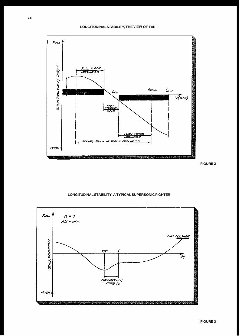
Example no. 1 Civil airworthiness regulations still require the old fashioned speed stability (figure l), that means that during an increase or decrease of the speed outside the 10 % friction band a positive push or pull action is required by the pilot (figure 2). But looking at supersonic aircraft, this required steady positive stick force is reversed above Mach = 1 but the aircraft still remains perfectly flyable even with an apparent instability according to the books (figure 3). At M > 1 the actual stability has even increased due to the backtravel of the center of pressure on the Cl@-curve as can be seen on figure 4.
The Alpha-Jet fighterhrainer is accepted as one of the nicest flying machines that exist. One of the most praised qualities is the autotrim function of the flight control system when flying between 150 and 450 HAS. The pilot does not need to touch the trim button because the control surface moves all by itself giving perfect stability but not by the civil books (figures 5 and 6) . MIL Spec. is here more advanced than FAR'S. Apparently there was a constant dialog between pilots and well experienced scientists who understood the problem and translated it to useful criteria, not calling them "certification requirements" but "decision guidelines" (figure 7 and figure 8). The term "neutral apparent speed stability" which is used recently could solve a lot of certification problems if adopted to civil regulations and would even help to make better aircraft to fly by the pilots.
Example no. 2 Quite often I have seen aircraft which were perfectly stable according to FAR when stabilized long enough at certain speed intervals, hut when accelerating towards higher speeds they were unstable with a definite pull force required to stop them even at VD. This is often due to free masses within the control linkage forcing the stick forward on acceleration or in a descent and backwards when decelerating or when climbing. I have seen aircraft which were driven progressively into a stall without any selfrecovery tendency. Nobody can stop today a manufacturer delivering such critical airplane to new customers. A rather funny experience was the reverse free mass action on the Do-24 ATT amphibian which I tested in 1983. The Do-24 flying boat was heavily stable when tested at well stabilized speed intervals (figure 9). But it was famous of being relatively free of the dangerous porpoise tendencies when aerodynamics fight hydrodynamics during speed excursions on the water (figure 10). Porpoise is normally triggered by out-of-phase pilot inputs. Not so on the Do-24. As you touched the water, the control column was driven forward by the sudden decelleration when water drag started. When waves caught and left the hull changing periodically the water drag, the column was also pumping in the proper manner calming down not only the aircraft but also the skipper. We never found out if this funny detail was one of the secrets of Professor Dornier or whether it was just an inherent quality installed by chance.

3-4
Example no. 3 As already mentioned, the Alpha-Jet is one of the finest aircraft I have ever flown, also due to the nearly perfect harmony between aileron and elevator stick forces. These forces are considered light but well adapted, not only for the trainer but also for the low altitude attack mission. It was therefore clear that Dornier when starting the development of the Argentine IA 63 trainer several years ago, saw no need of changing these characteristics. We even bought the hardware, the ARTHUR variable stick force bellcrank, which was explained on figure 5, from Dassault. But already in the development phase a discussion started with Argentine specialists about MIL Spec. level 1 performance. They insisted that the proposed IA 63 stick forces per g did not meet the level 1 as contracted. They had plotted the required stick force gradients as seen on figure 11 creating a form of g-envelope. It was only at that time that we looked at the Alpha-Jet in respect to the MIL Spec levels and we found out that also this pilot-loved machine did not meet this presentation. The discussions were endless and are still going on. We optimized in the meanwhile the IA 63 giving it control forces that suit the envelope, by that giving np the elegance of operations. I am sure that the founder of this MIL section did not want to create an envelope. But I must say, with all my experience it took me half a day to understand table V (figure 12) together with MIL spec figure 16 (figure 13). Only after plotting stick forces per g over airspeed I had something also normal trained test pilots could understand (figure 14). Therefore, I urge this group to look for a simpler way of treating this subject in MIL spec and to leave the area below 2 g free for definition by aircraft designers and test personnel.
Example no. 4 Small aeroplanes are certified according to FAR 23 and airworthiness requirement related to aircraft with a takeoff mass equal or below 5700 kg. The Dornier 228 ist one of the airplanes in this category. The initial certification was at the specification limit that means 5700 kg. All documents including the POH were printed and delivered with this limit, until we found a customer in Japan. At that time, a young engineer of the Japanese certification agency refused to certify our aircraft because it did not meet the personal licencing reqnirments as this operational regulation applies only to aircraft &w 5700 kg. We were forced to change all documentation by replacing the number 5700 kg by 5699 kg (figure 15).
From the last two examples we can learn a lot. If a group of specialists gives leading numbers for future regulations it has a big responsibility because once a number is published it will be used often by persons who do not see the difference between an apple and a pear. It may take years and years to change it if experience and progress finds it inadequate. This opinion was confirmed to me at the last SETP meeting in Arles when I had the honour to talk to Mr. Georges Cooper who invented together with Mr. Harper the famous flying quality scale. He explained to us that he never intended, when he first presented his paper to this AGARD panel, to fx his numbers for ever. He only intended to present a basis of discussion, But everybody grabbed the numbers and called them practically "the law for evaluation". And when it was found that in parts the explanations were inadequat nobody was able to change them in the whole western world. So Mr. Cooper himself was addressed again several years later and was asked to revise it.
CONCLUSION
To conclude this paper, I urge you, the scientists, for the sake of progress in aviation, not to give too many numbers and not to lay down regulation if they are not absolutely necessary for the safety of flying. Proposals, recommendations, however, and printed discussions are always welcome and highly desirable. In doing so, you give us, the test pilots and flight test engineers, the possibility to create good flying machines for the specified tasks, flying machines created by experience, thorough knowledge and intuition. For a test pilot the ultimate goal must always be to "promote air safety by expressing pilot's opinion" - the leading objective of our society (SETP). In the cockpit we do not need doctors in science, analysing prototypes in flight -what we need are technically orientated pilots creating good airplanes as part of an integrated team of aircraft designers, aircraft mechanics, development and test engineers. The team must be a mixture of elder, experienced, hesitating people and young, progressive and aggressive persons. This mixture gives maximum assurance that the resulting flying machines will be classified as: '"Safe, economic, mission orientated and beautiful to fly". "Beautiful to fly" is the pilots' way of saying: good flying qualities.
3-5
REFERENCES
1.
2.
3.
4.
5.
6.
Military Specification, Flying Qualities of Piloted Airplanes MIL-F-8785C
Federal Aviation Regulations - Part 34
Federal Aviation Regulations - Part 25
BCAR Section K Light Aeroplanes
A.G. Barnes: Handling Qualities Specification Deficiencies, AGARD Advisory Report NO. 89
G.K.L. Kriechbaum and J. Spiritzyk, Dornier GmbH: Development and Flight Testing of a New Amphibian Technology Demonstrator
George E. Cooper and Robert P. Harper jr.: The use of pilot rating in the evaluation of aircraft handling qualities
7 .
FIGURES
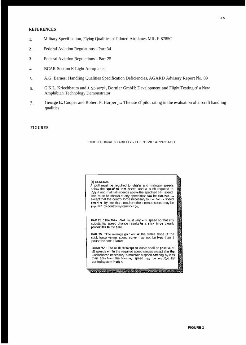
LONGITUDINAL STABILITY - THE "CIVIL" APPROACH
(a) GENERAL A pull must be requlred to obtain and malntaln speeds below the speclned trlm speed and a push requlred to obtafn and malntaln speeds above the speclned trim speed. This must be shown at any speed that a n be obtained ... except that the control lorce necessary to malntaln a speed dlnerlng by less than 10% lrom the trlmmed speed may be supplled by control system irlctlon.
FAR 23 : The stfck IOrCe must vary WRh speed so that any substantial speed change results In a nlck lorce clearly parceptlble to the pllol
FAR 25 : The average gradlem of the stable slope of the stick lorce versus speed CYNB may not be less than 1 pound lor each E knots
BCAR "K" : The stlck forcelspeed curve shall be posltlve at a11 speeds wlthln the requlred speed ranges except that the Control lorce necessary lo malntaln a speed dinering by less than 10% hom the trlmmed speed may be supplfed by control system frlctlon.
FIGURE 1
3-6
LONGITUDINAL STABILITY, THE VIEW OF FAR
I
~
FIGURE 2
LONGITUDINAL STABILITY, A TYPICAL SUPERSONIC FIGHTER
FIGURE 3

3-1
FIGURE 4
ALPHA-JET ELEVATOR CONTROL CINEMATIC
FLAPS . HORIZONTAL STABILIZER
"HE I N I '' KIN EMATIC 4 1 1 OPERATING MECHANISM
SERVO ACTUATOR 2 -L AUTO.TRIM MOVEMENT
"ARTHUR" VARIABLE SPRING BOX GEARING BELLCRANK
(q-controlled. hydraulically operatedl H - q ~ Position LOW AIRSPEED
Position HIGH AIRSPEED
"ARTHUR" ADJUSTMENT RANGE 150 kl < V; <440 kl TRIM ACTUATOR
FIGURE 5

3-8
ALPHA-JET ELEVATOR CONTROL CHARACTERISTICS INCLUDING AUTOTRIM FUNCTION
FIGURE 6
LONGITUDINAL STABILITY - THE MIL APPROACH
3.2.1.1 Longaudlnal static stability For levels 1 and 2 there shall DB no tendency for airspeed to diverge aperlodlcally when the airplane 1st disturbed from trim wilh the cockpit controls fixed and wilh them lree. This requirement will be considered satislied It the ~ar ls t lon~ 01 pitch control force and p3eh control position with airspeed are smooth and local gradients stable, with : a) Trimmer and thronle controlo not moved from the trim senlngs by the crew and b) Ig ecceieration normal l o the liight path, and c) Constant altitude over a range about the trim speed of f 15% or i 50 knots equivalent airspeed, whichever is less ._. 3.2.1.1.1 Relaxation in transsonic flight a) Levels 1 and 2 . For center stick controilers, no local force gradient shall be more Unstable than 3 pounds per 0.01 M nor shall the force change exceed 10 pounds in the unstable direction. The corresponding limits lor wheel COntrOiierS are 5 pounds per 0.01 M and 15 pounds, respectively. b) Level 3 - For center-stick controllere, no local force gradient shall be more unstable than 8 pounds per 0.01 M nor shell the farce ever exceed 20 pounds In the unstable direction. The corresponding limits for wheel controllers are 10 pounds per 0.01 M and 30 pounds respectively.
3.2.1.1.2 Pitch control force variations during rapid speed changes.
3.2.1.3 Flight path stability
FIGURE 7

3-9
FLIGHT PATH STABILITY ACCORDING TO MIL SPEC
3.2.1.3 Flight path stabilny Flight path stabilay is defined in terms of flight-path-angle change where the airspeed is changed by the use of pnch conlroi only (thronle setting not changed by the crew). For the landing approach Flight Phase, the curve of flight-path angle versus (rue airspeed shall have a local slope at Vo ,,,in which is negative or less posnive than:
a) Level 1 - 0.06 degreeohnot b) Level 2- 0.15 degreeohnot c) Level 3 - 0.24 degreeslknot
LONGITUDINAL STABILITY OF DO 24 A l T AMPHIBIAN
FIGURE 8
FIGURE 9

3-10
DO 24 ATT TRIM ANGLE AND PORPOISE LIMITS
20
5
STICK FORCE PER g ACCORDING TO MIL SPEC
FIGURE 10
FIGURE 11

3-11
TABLE V. Pitch manueverinq force qradient limits.
Center Stick Controllers
Level
1
- 2
3
but nor
240/(n/ ) not more than 28 .0 less than 56/n~-1
360/(n/ ) but not more than 42.5 nor less than 85/n~-1
5 6 . 0
Minimum gradient (Fs/n),in. pounds Per g
the higher of 2l/n~-l
STICKFORCE PER g FROM MIL SPEC 8785 C
FIGURE 12
the higher of 18/N~-1 and 3.0 I the higher of 12/n~-l ,,-,1 I
For nL < 3 , (Fs/n)max is 28.0 f o r Level 1, 42.5 for Level 2.
EXAMPLE OF PITCH MANEUVERING FORCE GRADIENTS LIMITS : CENTER-STICK CONTROLLERS, nL = 7.0
" I
li a
FIGURE 13

3-12
EXAMPLE OF STICKFORCE PER g OVER AIRSPEED : CENTER-STICK CONTROLLER, nL = 6.0
FIGURE 14
DORNIER DO 228 - 200 SECTION 2 - LIMITATIONS OPERATING LIMITATIONS
MAXIMUM CERTIFICATED WEIGHTS
Whenever the Pilots Operating Handbook refen to a maximum takeoff and landing weight of 5700 kg (12.556 ibs). ii should be read as 5699 kg
FIGURE 15

ADFCSAND NOTAR": TWO WAYSTO FIX FLYING QUALITIES
CHANNING S . MORSE Senior Experimental Test Pilot
Research and Engineering Specialist McDonnell Douglas Helicopter Company
5000 E. McDOwell Road/560/G23 Mesa, AZ 8 2 5 0 5
INTRODUCTION
Since the first helicopter flight, "Desir- able helicopter flying qualities" has appeared under Webster's definition of the term oxymoron. That is THE paradoxical phrase. Early helicopter designers were limited in their capability to affect fly- ing qualities. There seemed to be little the designer could do to improve the pilot's task until the development of flight control augmentation devices.
These augmentation devices took two forms: Mechanical and Electronic. Of late, elec- tronic has been the preferred method of tailoring helicopter flying qualities due to its inherent flexibility and to the rapid advances in computational power. These advances have recently taken the form of artificial flying qualities generated entirely by digital computers. While this tends to work very well in theory, the basic helicopter has some non- linear aerodynamic characteristics which even the digital computers of today have trouble dealing with in real time.
As the Project Test Pilot for the McDonnell Douglas Helicopter Company (MDHC) Advanced Digital Flight Control System (ADFCS) and NOTAR", I have had the pleasure of participating in the design and flight test of two systems which significantly reduce the workload of the helicopter pilot by improving the heli- copter's flying qualities. This paper reviews the development, flight test and flying qualities improvements of these two systems. Emphasis is placed on some of the directional control problems faced on the ADFCS program in left sideward flight and the potential for the NOTAR= system to improve the flying qualities of an advanced, highly augmented rotorcraft.
ADVANCED DIGITAL FLIGHT CONTROL SYSTEM
In 1983, a general question was presented to the then Hughes Helicopters Experimen- tal Test Pilots: "What is required to make a mission effective, single seat scout/attack helicopter." The assumption was made that the primary pilot task was to respond to the volatile battlefield situation and to make complex logical/tac- tical decisions. On this assumption, any task which diverts the pilot's attention from the primary task decreases his capa- bility to survive. Extending this logic to the flight control system, aircraft control had to become a secondary task, including night and poor usable visual cue conditions. Another assumption was that the level of sensor data available would
preclude a sensor coupled flight control system, analogous to an automatic terrain following radar system, for helicopter combat operations. This meant the pilot would still be responsible for the direct control of the aircraft flight path and provide the input to the flight control system. Expanding on these two assumptions it became apparent that the flight control design should minimize the pilot cognitive and physical interaction required to manage control of the aircraft flight path.
McDonnell Douglas Helicopter Company undertook a flight control development program to evolve a system which would make flight control a secondary task for the combat helicopter pilot. The ADFCS control logic would be developed through an iterative process of concept, simula- tion, and flight test to evolve toward the goal of making flight control a secondary task. MDHC configured a prototype Apache, YAH-64 AV-05 (77-23258), with an experi- mental flight control system for develop- ment. Since that beginning in 1983, 6 years of design and development, 1800 hours of real time piloted simula- tion, and 2 7 0 hours of flight test have gone into the development of the ADFCS. Reference 1 contains a description of the program, the aircraft and the testing. The flight test aircraft is shown in figure 1 and a schematic of the ADFCS installation are shown in figures 2 , 3 and 4 .
The cockpit controls incluae the capa- bility to fly the ADFCS With 4+0 sidestick controllers left or right, 3+1 collective, 3t1 pedals or 2+1+1. Controller config- uration is a subject unto itself and will not be reviewed as part of this paper. Advanced flight controls are often con- fused with the flight controller config- uration and the two are interrelated but not dependent on one another. The evolu- tion of the flight control logic is deu- cribed in reference 2 . The flight control system logic and flight testing as evolved up to October 1989 will be reviewed here.
FLIGHT CONTROL LOGIC
Distillation of the flight experiences of the experimental test pilot staff resulted in some basic rules for development of the flight control system:
Flight control workload should not be traded for button workload. Auto- matic moding would be required because there is no workload advant- age if the pilot has to manually
4-2
select the flight control mode required. This automatic moding includes flight control logic, gain shaping, and control stick charac- teristic shaping.
Envelope limiting was required to free the pilot from monitoring aircraft maneuver margins and enhance his ability to use the entire flight envelope.
Some basic automated emergency con- dition handling was required if the flight control task was to become secondary.
A hierarchy of performance trade-offs was required to allow for an orderly prioritization of aircraft capability and pilot commanded performance.
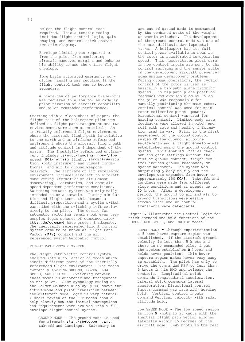
Starting with a clean sheet of paper, the flight task of the helicopter pilot was defined as flight path management and two environments were seen as critical: An inertially referenced flight environment where the aircraft flight path is relative to the earth and an airframe referenced environment where the aircraft flight path and attitude control is independent of the earth. The inertially referenced environ- ment includes takeoff/landing, hover/low speed, NOE/terrain flight, enroute/naviga- tion (both instrument and visual condi- tions), and air to ground weapons delivery. The airframe or air referenced environment includes aircraft to aircraft maneuvering (formation or Air Combat Maneuvering), aerobatics, and some air- speed dependent performance conditions. Switching between systems was originally intended to be automatic. During simula- tion and flight test, this became a difficult proposition and a cyclic switch was added with the switching left exclu- sively to the pilot. The desire for automatic switching remains but even very complex logic schemes of combined rate/ attitude/command have proven inadequate. The inertially referenced flight control system came to be known as Flight Path Vector (FPV) control and the air referenced system Aerobatic control.
FLIGHT PATH VECTOR SYSTEM
The Flight Path Vector control system evolved into a collection of modes which handle different parts of the inertially referenced flight environment. The modes currently include GROUND, HOVER, LOW SPEED, and CRUISE. Switching between these modes is automatic and transparent to the pilot. the Helmet Mounted Display (HMD) shows the active mode and pilot transition between the different mode logic is very natural. A short review of the FPV modes should help clarify how the initial assumptions and requirements were evolved into a full envelope flight control system.
Some symbology cueing on
GROUND MODE - The ground mode is used for aircraft start/shutdown, taxi, takeoff and landings. Switching in
and out of ground mode is commanded by the combined state of the weight on wheels switches. The development of the ground control mode was one of the more difficult developmental tasks. A helicopter has its full control power available as soon as the rotor is accelerated to operating speed. This necessitates great care in how control inputs are sent to the control surfaces and the sensor suite on the development aircraft presented some unique development problems. During ground operations, the cyclic control of the rotor is used as basically a tip path plane trimming system. No tip path plane position feedback was available on AV-05 so the pilot was responsible for manually positioning the main rotor. vertical control was used for main rotor collective pitch (power). Directional control was used for heading control. Limited body rate feedbacks were allowed in pitch and roll with rate and heading informa- tion used in yaw. Prior to the first engagement of the ground control system on the ground, airborne engagements and a flight envelope was established using the ground control system. This enabled initial check- out and gain settings without the risk of ground contact, flight con- trol induced ground resonance, or system hardover. The system was surprisingly easy to fly and the envelope was expanded from hover to approximately 150 KCAS. Takeoffs and landings were made from different slope conditions and at speeds up to 50 knots. After a development period, the ground to air and air to ground transitions were easily accomplished and no control transients were detectable.
Figure 5 illustrates the Control logic for stick command and hold functions of the HOVER, LOW SPEED, and CRUISE modes.
HOVER MODE - Through experimentation a 5 knot hover capture region was established. If the aircraft ground velocity is less than 5 knots and there is no commanded pilot input, the system establishes a hover and holds hover position. This hover capture region makes hover very easy to establish. The pilot has only to drive the commanded FPV to less than 5 knots in his HMD and release the controls. Longitudinal stick commands longitudinal acceleration. Lateral stick commands lateral acceleration. Directional control inputs command yaw rate with heading hold. Vertical control inputs command Vertical velocity with radar altitude hold.
Low SPEED MODE - The low speed region is from 5 knots to 20 knots with the inertial flight path vector aligned laterally within 15 degrees of the aircraft nose: 5-45 knots in the rest
4-3
of the circle. In this region, longitudinal stick commands longitu- dinal acceleration and the longitu- dinal inertial velocity is held in the absence of a command. Lateral stick commands lateral acceleration with inertial velocity hold. Above 2 0 knots with the nose aligned with the flight path vector and above 4 5 knots, lateral stick commands roll rate with turn rate hold. Early work was done with a more conventional bank angle hold. This was refined to the current turn rate hold to make the commanded ground track in the turn independent of speed changes. With the turn rate hold, bank angle is varied with speed changes and the ground track is held relatively constant. This reduced the multiple control inputs required for a turning acceleration or deceleration close to ground obstacles. Directional con- trol commands yaw rate with heading hold and the established flight path is held constant. Directional trim- med flight is defined as zero iner- tial beta up to KO knots. If the directional command displaces the nose less than 15 degrees from the flight path vector the aircraft returns to trim when the control is released. If the directional command displaces the nose more than 15 deg- rees from the flight path vector, the new heading is held. The vertical command becomes vertical acceleration with gamma hold. Level flight is a subset with gamma equal to zero and a capture band around gamma = 0 degrees allows easy capture of level flight. This allows descending/decelerating approaches with only a deceleration command once the descent angle is set. In the terrain flight environ- ment, the frequency of vertical com- mands were reduced because the air- craft can be easily trimmed to follow the general slope of the terrain by placing the flight path vector symbol in the display over the desired point on the terrain. This flight path vector is displayed as a virtual symbol in the helmet mounted display. A recent addition to the level flight hold mechanism has added a radar altitude reference with a relatively long time constant up to 4 5 knots, which was not intended as a terrain following mode, but does reduce the workload in the NOE environment.
CRUISE MODE - Cruise mode is defined as inertial speed above 20 knots if the nose is within 15 degrees of the flight path vector, 4 5 knots in any case. Longitudinal stick command remains longitudinal acceleration, inertial speed hold. Lateral stick command remains roll rate with turn rate hold. Directional commands heading to the sideslip limit of the airframe and returns to trim when the command is released. Lateral trim is defined as wings level, inertial ground track hold. Vertical command
is vertical acceleration with gamma hold. The level flight subset has a small capture window near gamma = 0 with barometric altitude hold.
The Flight Path Vector system includes the full envelope of the Apache test vehicle. The flight test and demonstration of the system has shown a dramatic workload reduction in the inertially referenced environment. The best indication of the low workload during the demonstration program was the performance of people without any flying experience. With a preflight briefing on the system and some in cockpit coaching, non-pilots could command near envelope limit performance from the aircraft in the course of a one hour demonstration flight. Experienced pilots found that in the normally intense low altitude terraid flight environment relatively few flight control inputs were required and far more time was available for other tasks - the flight control task was secondary and the fewer flight control inputs the better the performance of the aircraft.
AEROBATIC SYSTEM
The Aerobatic system has a much lower level of flight control automation. It is essentially a rate command/attitude hold system. The envelope limiting features of FPV are retained. Classically good con- ventional flying qualities were built into this rate command/attitude hold system. Additional coordination includes the addi- tion of pitch coordination with bank angle to maintain 1 g flight at all attitudes with the pilot able to modulate g level above or below that reference. A high level of decoupling was retained to allow single axis inputs with single axis res- ponse. Heave damping was added to the vertical axis for reduced workload in collective control. Future additions to the aerobatic mode could easily include automation as a function of weapon and sensor status to include features of integrated flight and fire control (IFFC). 'Phis system was also designed for full Apache envelope operation and switching between the two modes is smooth. No rate or attitude lipits are imposed for switch- ing and the pilots have adapted well to the inflight change in reference systems.
While the original intent of the concept was that these two systems would be com- pletely mission dependent, it has turned out that they can be used in concert to achieve the characteristics desired by the pilot at the moment. That is, as experi- ence with the total system increased, the pilot was more likely to switch between the systems dependent on workload and used the FPV system to unload the flight can- trol task and apply himself to other tasks. It was particularly interesting during the development process that con- trol difficulties in the aerobatic system were usually resolved by switching to the FPV system. For example, flight test of the aerobatic/rate command-attitude hold system sometimes revealed regions of pilot

4-4
induced oscillation (PIO) or flight con- trol system instabilities and the FPV system was a quick transition to controlled flight.
In my experience, the ADFCS is the most advanced and sophisticated augmentation system implemented on a helicopter. At the opposite extreme of flight control augmentation is the NOTAR" system applied to an MD500 series helicopter - no elec- tronics, no hydraulics and no mechanical stabilization - yet very desirable flying qualities.
NOTAR" SYSTEM
NOTAR" is the McDonnell Douglas Helicopter Company (MDHC) trademark for a system which replaces a conventional helicopter's tail rotor. "Conventional" meaning a single main rotor helicopter with a tail rotor or fenestron.
NOTAR" DESCRIPTION
The NOTAR" system design philosophy was to replace the tail rotor with something "as good" and eliminate the exposed auxiliary rotor for safety considerations. A con- ventional helicopter tail rotor or fenes- tron system provides directional control for the pilot or flight control system and antitorque to counter the fuselage moment generated by the main rotor torque. Two concepts were postulated as a means to this end:
1. That directional control could be satisfactorily accomplished by an air thruster directed by the pilot.
2 . That a significant percentage of the required anti-torque in the low speed regime could be accomplished by producing lift on the tailboom. Lift produced using a low pressure circu- lation control tailboom as the wing and the main rotor downwash as the free stream.
The research program was structured to validate these concepts and then to inte- grate them onto a helicopter for evalua- tion. The flight test vehicle was origi- nally an OH-6A and it has been used throughout the NOTAR" development process. The system development process is outlined in table 1.
Some of the significant events in the NOTAR" development program were: valida- tion of the concept that circulation con- trol lift could be produced under the rotor of a hovering helicopter using a low pressure slot system; addition of the second slot; demonstration of an efficient €an design; qualitative flight evaluation; empennage flight test and measurement of the flow field at the rear of the aircraft.
The 13 year research and development program resulted in the configuration shown in figure 6 .
The NOTAR" system has now been integrated into the MW500 series and the MD530N and MD520N are in FAA certification testing. Figure 7 shows the configuration of those aircraft.
NOTAR- IN PRACTICE
A discussion of the flying qualities and operational impact of a NOTAR" equipped helicopter must be preceded by a discus- sion of tail rotor characteristics, parti- cularly thrust required and thrust produced.
The tail rotor operates in the environment at the rear of the helicopter. This exposes it to trees, bushes, fences, wires, people, rocks, ground, and the air. The exposure to the first seven usually result in some change in thrust output and structural damage. The exposure to air can be described as the aerodynamic environment and leads to the following generalized equations.
TAIL ROTOR THRUST REQUIRED = f(MA1N ROTOR TORQUE + DIRECTIONAL CONTROL INPUT)
TAIL ROTOR THRUST PRODUCED = f(DIRECTI0NAL CONTROL INPUT + RELATIVE WIND AZIMUTH AND VELOCITY + YAW RATE + YAW ACCELERATION + AIR QUALITY + WIND AND MAIN ROTOR RELATIVE POSITION)
A comparison to the same equations for NOTAR" provides some insight into the relative flying qualities.
NOTAR" THRUST REQUIRED = f(MA1N ROTOR TORQUE * DIRECTIONAL CONTROL INPUT)
NOTAR" THRUST PRODUCED = f(MAIN ROTOR TORQUE + DIRECTIONAL CONTROL INPUT)
Figure 8 shows some of the influences on tail rotor thrust.
The directional control task in trimmed flight is to make thrust produced equal thrust required. For NOTAR" the thrust required and the thrust produced are functions of the same parameters, main rotor torque and directional control input. There are two equations in two variables and the solution for the pilot is very simple. The tail rotor problem is far more complex, two equations in eight variables, and it's surprising the pilot can solve it at all. The impact of these simple generalizations on pilot workload is significant. The developmental and certification flight testing of the MDSOON series has demonstrated the following characteristics with a mechanical control system and no hydraulic boost or artificial stability augmentation.
Power changes in low speed flight do not require pedal inputs to compen- sate for increased or decreased main rotor torque as in a conventional helicopter. This reduces pilot

4-5
workload and leads to a reduced total power required for maneuvering flight. This can be easily seen using a helicopter quick stop maneu- ver as an illustration. With a con- ventional anti-torque system, the large power increase required at the end of a quick stop must be accompan- ied by a large increase in tail rotor thrust which reduces the power avail- able to the main rotor to control sink rate and establish a hover. Contrast this to the situation with NOTAR". The large power increase to complete the quick stop does not require a corresponding directional control input and the horsepower required for anti-torque is the same as required for a stable hover. This provides an increase in power avail- able to the main rotor to arrest a sink rate or to maneuver.
The pilot directional control work- load to hover and control yaw rate is not impacted by relative wind velo- city, direction or gust spread. The force from the tail rotor is a func- tion of these external factors while the force from the NOTAR" thruster is not affected by them. Any change in the thrust bf the anti-torque system must be compensated for by the pilot to balance the moment equation. This is particularly significant when con- sidering relative wind/motion which induces vortex ring state at the tail rotor or loss of tail rotor effec- tiveness/stall. We have been unable to induce any similar effect with the NOTAR" system.
Yaw rate and acceleration do not impact the NOTAR" thruster force. Conventional anti-torque systems be- come very difficult to control at yaw rates above 60 degrees per second and large control inputs at these rates can produce loss of directional con- trol and large torque fluctuations. NOTAR" has demonstrated useful yaw rates in excess of 120 degrees per second with full throw pedal rever- sals and very linear control res- ponse. This useful yaw rate was achieved with 100 degree per second per second yaw acceleration and 40 percent per second control inputs. This control capability has also been demonstrated in 30- 40 knot winds.
Current generation military helicop- ters are specified to be capable of 45 knots crosswind and downwind hover. To meet this specification, the designer must include a large, powerful tail rotor. For clearance, the large tail rotor must be mounted in a high position above the tailboom on a pylon. This combination of powerful tail rotor and mounting above the centerline of the boom introduces structural problems which are common to most modern helicop- ters. The structural problems can be identified as tailboom torsion, tail-
boom bending, and tail rotor hub strain due to precession flapping. These problems are aggravated with high roll rates or large, rapid pedal inputs. Typically, the pilot must be prevented from making large, rapid pedal inputs by flight manual res- triction or tail rotor control rate damping. The incidence of structural damage is increased during aerobatic maneuvering. During structural test- ing with NOTAR-, we have not encoun- tered any structural limitations associated with the size or rate of pedal input. This includes full pedal reversals in less than . 3 sec- onds at 120 degrees per second yaw rate. The implication for the heli- copter pilot is significant when combined with the linear control response in these conditions. The NOTAR" pilot can make large, high frequency directional control inputs and maintain precise aircraft control enabling him to safely perform maneu- vers well outside the safe envelope for a tail rotor. The operational impact is significant. The structur- al flight test for the MD-SOON in- cluded full aerobatic maneuvers to qualify the aircraft for aerobatic flight. This testing was very suc- cessful and the third production prototype demonstrated its aerobatic prowess at the Farnborough Air Show.
Downwind hover in conventional helicopters has been accompanied by increases in torque, vibration level and workload. This has forced the helicopter pilot to be very aware of the wind direction in all his low altitude/low speed tasks. In most situations, the penalty for inatten- tion was degraded flight control at best, loss of aircraft control or inadequate power available at worst. Good pilot technique to overcome these problems has been to find targets and landing zones into the relative wind - not always practical or possible. NOTAR- has freed the helicopter pilot from this slavery to the wind direction in the same manner that tandem, coaxial, and syncopters have in the past. The improvement over those configurations is the retention of excellent yaw maneuver- ability/agility.
The helicopter is aerodynamically and dynamically coupled in all axes. This has the effect of requiring secondary control inputs in three axes for every primary control input. All the experienced helicopter pilots who have flown NOTAR" have commented that the workload reduction extends to all control axes. This synergism of reduced workload is a result of reducing the pedal workload and thereby eliminating the corresponding inputs in pitch, roll, and yaw, in addition to reducing the required

4-6
pedal input to compensate for inputs in the other axes.
Implied in the above workload discus- sion is the elimination of interfer- ence effects between main and tail rotors. The downwind hover effect of tail rotor vortices impinging on the main rotor is one area of impact. Main rotOK vortices effect on tail rotor performance must also be considered.
All these workload effects are significant to the operation of the helicopter. Digi- tal flight control could enhance the NOTAR" system by optimizing the configura- tion for the flight regime. The current system configuration is fixed throughdut the flight envelope but only has a signif- icant impact on the flying qualities of the helicopter in the low speed environ- ment. A digital control system and flexi- ble configuration could easily optimize the system configuration for the each part of the flight envelope. Conversely, the NOTAR- system characteristics in the low speed environment can greatly ease the job of the helicopter digital flight control designer.
Conventional helicopters have a very nonlinear response region in crosswind conditions; sideward flight to the left for counter clockwise main rotor rotation (U.S., British, German, Italian) and to the right for clockwise main rotOK rota- tion (French, Russian). Tail rotor thrust can change dramatically and be very non- linear in these wind conditions. The vor- tices from the tail rotor can also aggravate main rotor response by interfer- ence effects in these same conditions. This condition is usually self correcting in that; if nothing is done, the helicop- ter will yaw to a new relative wind azi- muth and take the tail rotor out of this difficulty. When the pilot, ground obstacles, or a flight control system interfere with this natural response, the problem is magnified and sometimes cata- strophic. In the case of a digital flight control system, any flight regime in which the aircraft response becomes nonlinear or the sign of the response changes for a given control input special design con- siderations are required. The development of the ADFCS on AV-05 exposed Some of these problems. In left sideward flight at approximately 4 0 knots, the AH-64 enters a region of nonlinear control res- ponse marked by a tail rotor control sense reversal. Pilots can easily adapt to this effect and the aircraft is easily control- led by the pilot in 40 knot crosswinds. The digital flight control system had more difficulty. Even after gain and system tuning a pitch, roll, and yaw oscillation remains divergent in this flight region. Figure 9 shows this aircraft response in the form of attitude-time history traces.
Figure 10 is a comparable time history of the basic aircraft with pilot control.
The NOTAR" system has the potential to eliminate this problem for the flight control designer. Development of the flight control system in the right side- ward flight regime remains incomplete. With design and flight test effort, the digital flight control system has the potential to eliminate the instability shown here; however, a software fix for this anomaly in the helicopter's flight envelope may not be as good a solution as an aerodynamic/configuration change. This is intended as one illustration of a flight condition which does not respond easily to digital flight control augmenta- tion. There are many others, in both helicopter and fixed wing aircraft, which involve regions of the flight envelope that cannot be modeled accurately with a second order differential equation. In spite of the power of the digital compu- ter, the project/program manager must continue to view the development of new aircraft as a big picture and pursue the entire range of design solutions for the best combination to fulfill the aircraft's mission objectives.
CONCLUSION
By combining the capabilities of all the design tools, aircraft potential is en- hanced. An excellent example in the fixed wing community is the trend to reducing the static stability of modern aircraft to enhance maneuver capability and/or perfor- mance. It has been used as a design tech- nique in the fighter mission to increase agility and in the transport mission to increase cruise performance. These designs depend on electronic augmentation for acceptable handling qualities. StKUC- tural design of large wings has been modi- fied to reduce weight by using flight control to reduce g and gust loading on the outboard wing sections.
This synergism of design is only possible through open minded pursuit of good total design solutions. The helicopter commun- ity can certainly benefit from this approach. Advancement of aircraft design can be easily stagnated by imposing requirements/restrictions on the designers through over-specification. Specifica- tions tend to lag design innovation because they must be based on existing knowledge and technology. The specifica- tions should ease the way of design inno- vation and not restrict it. Design innovation can be restricted directly by over-specification and indirectly by program management perception of penalties for not meeting the letter of a specifi- cation. This is particularly true in competitively bid programs.
In these instances, the entire aircraft design team must be open to solutions outside their areas of expertise. Good solutions, like medical cures, must treat the cause of the symptoms not just the Symptoms.

4-7
REFERENCES
Gupta, B. P., Barnes, B. B., Docktor, G., Hodge, R., Morse, C. S., "Design, Development and Flight Evaluation of an Advanced Digital Flight Control System," presented at 43rd American Helicopter Society Forum, St Louis, Missouri, May 1987.
Parlier, C. A., "An Advanced Digital Flight Control Concept for Single Pilot, Attack Helicopter Operations," presented at 43rd American Helicopter Society Forum, St Louis, Missouri, May 1987.
Morse, C. S . , "NOTAR": From the Pilot's Perspective," presented at Canadian Aeronautics and Space Institute Flight Test Symposium, March 1989.
1.
2 .
3.
I I

4-8
AV-05 FLIGHT TEST AIRCRAFT FIGURE 1
SCHEMATIC OF ADFCS INSTALLATION FIGURE 2
r 7 7

4-10
29020274-13
POLAR PLOT OF SPEED/AZIMUTH CONTROL LOGIC FIGURE 5
TABLE 1 NOTARm TEST/ANALYSES HISTORY
AUG 1976 - BASIC DATA GENERATION - MDHC WHIRL TOWER DEC 1977 - FIRST CONCEPTUAL FLIGHT APR 1980 - NOTAR PATENT ISSUED SEP 1981 -GROUND TESTS - FANTTHRUSTERTTHRUSTER TRANSIENT RESPONSE
DEC 1981 - FIRST TOTAL SYSTEM FLIGHT, OH-6A SEP 1982 - SIMULATION - FLIGHT SIMULATION ON FLIGHT SIMULATOR FOR ADVANCED
AIRCRAFT AT AMES
MAY 1983 - GOVERNMENT PILOT EVALUATION MAY 1983 - USAAVRADCOM TECHNICAL REPORT DEC 1983 -AERODYNAMIC PANEL MODELS FEE 1984 - TIEDOWN TESTS - AIRCRAFT ON TOWER TO SIMULATE OUT OF GROUND
EFFECT HOVER AUG 1984 - NEW FAN DESIGNED, INLET MODS SEP 1985 - FANlSTATOR GROUND TESTS
OCT 1985 - WATER TANK TESTING OCT 1985 - WIND TUNNEL TESTS DEC 1985 - GROUND TEST WITH NEW FANANLET AND MORE POWERFUL ENGINE
MAR 1986 -SECOND SLOT FLIGHT TEST
MAR 1987 - GOVERNMENT PILOT EVALUATION
87101767A

4-11
Control Boom
_----- Direct Jet Thruster
CUTAWAY VIEW OF NOTAR" DEMONSTRATOR FIGURE 6
MDSOON FIGURE 7

4-12
I.
$ :,o.ooooQ- s = *
Y “*o,ooooD-.
89118904
. . . . . . . . .
. . . . . . . . .
INFLUENCES ON TAIL ROTOR THRUST FIGURE 8
09077
OQOZl 0 2s so 75 80 1s:49:30.000 TIYE - SEC 15:50:50.000
29020274-14
TIME HISTORY OF AV-05 IN LEFT SIDEWARD FLIGHT FIGURE 9

TIME HISTORY OF AH-64 WITH PILOT CONTROL FIGURE 10


QUALITES DE VOL LATERAL D'UN AVION DE TRANSPORT CIVIL EQUIPE DE COMMANDES DE VOL ELECTRIQUES. EXPERIENCE DE L'AIRBUS A320.
3. Farineau, X. Le tron, Aerospatiale Division Avions, 316 Rte de Bayonne
31060 TOULOUSE Cedex. (FRANCE).
Res I".
Les commandes de vol electriques, dans un environnement de calculateurs numeriques, permettent d'elaborer des lois de pilotage manuel sophistiquees dont le but principal est d'ambliorer les qualites de v o l d'un avion, en particulier au niveau stabilite, pilotage, et protections du damaine de vol. Cependant, les degrbs de liberte effectifs dans la conception de ces lois SOnt limites par des contraintes physiques aussi bien que humaines, puisqu'il s'agit de pilotage manuel. Sur 1'Airbus A320, les calculateurs de
commandes de vol ont acces aux informations anemometriques et inertielles ainsi qu'd d'autres donnees caracteristiques de 1'8tat de l'avion, et peuvent asservir toUtes les qouvernes. Ceci a permis de real iser des loir de pilotage rbpandant A des objectifs de pilotage simples et adaptes aux contraintes rencontrees. Des rbsultats d'essais en vol seront present& pour mettre en evidence les points caracteristiques des qualites de vol lateral ainsi obtenues.
possibilites d'amblioration de la disponibilite de ces lois evoluees par "ne meilleure tolerance aux pannes des systemes embarques, et en consequence le rdle potentiel qu'elles peuvent jouer dans l'optimisation du dimensionnement des avions futurs
NOUS evoquerons pour conclure les
0. Notations
6, angle de derapaqe, ('?; ny, facteur de charge lateral, (g) ; p1, vitesse de roulis, I o / s ) ; rl, vitesse de lacet, ( ' /s) ; , angle d'assiette laterale, ('1 ; commande des gouvernes alaires, ailerons
et spoilers, ('1; 6r, commande de gouverne de direction, (') ; (dx/dt), derivee de x par rapport au temps; 5, facteur d'amortissement d'un mode; w. pulsation d'un mode, en rd/s; E , symbole mathematique d'appartenance; CDVE, Commandes De Vol Electriques; vc. Vitesse air conventionnelle; canf, configuration des becs/volets; PIO, pompaqe pilot6 (Pilot Induced Oscillations) ; ADC, centrale anemombtrique (Air Data ComDuter) : . . IRS, centrale inertielle (Inertial Reference System) ;
I. Generalit& sur la conception de lois de pilotage.
a) Contexte.
Le contexte necessaire B des lois de pilotage evalu6es. et donc a des qualites de vol ameliorees (par rapport B l'avion "naturel"), est schematise fig. 0: des capteurs Blectriques s u r les organes de pilotage (manche et palonnier pour le pilotage lateral) permettent de transformer ces braquages en objectifs de pilotage; ceux- ci sont ensuite compares A I'Btat reel de l'avion, mesure par des capteurs anemometriques, inertiels, etc... De Cette comparaison, on deduit l'ordre a envoyer aux asservissements des qouvernes de roulis (ailerons & spoilers) et de lacet (direction).
- lois de Dllotacei servos
U numeriques flg. 0
b) possibilitks.
Cette StructuIe permet d'utiliser les principes de contrdle actif generalise (CAG), autrement dit les techniques d'automatique, dont la caracteristique de commander des braquages de gouvernes fonctions de l'ordre pilote, bien sur, mais aussi de 1'Qtat de l'avion (ce point est important, car il peut Gtre necessaire de fournir au pilote des informations sur la position des gouvernes l .
I1 existe, sur la plupart des avions actuels, des dispositifs permettant d'en augmenter la stabilite en pilotage manuel, en particulier des stabilisateurs de lacet pour le mode de roulis hollandais. On peut aller plus loin: s u r un avion de transport civil, on dispose maintenant d'informations completes sur les 4 variables representatives de l'etat de l'avion (le derapaqe, b, ou le facteur de charge lateral, ny, la vitesse de roulis, pi, la vitesse de lacet, r l , et l'assiette laterale, $I), et de plus les modeles fournis soit par les calculs ou essais en soufflerie, soit par l'identifica- tian, sont suffisamment representatifs du mouvement de l'avion. Comme 1'0" dispose de deux commandes independantes, en roulis, tip, et en lacet, 6r. l'application des principes de l'automatique nous assure que 1'0" peut

6-2
contrdler les quatre modes lateraux de l'avion (le roulis hollandais, compose de deux modes complexes conjugues, en general relativement m a l amorti, le mode de roulis pur, mode reel assez rapide, et le mode spiral, mode reel proche de 0, et donc tres lentement convergent ou divergentl; de plus il reste certains degres de liberte pour gerer d'autres objectifs concernant le comportement de l'avion ou l'activitb des gouvernes: en effet, "ne gouveine est en theorie suffisante pour contrdler autant de modes que 1'0" a de mesures independantes. Diffbrentes methodes de l'automatique lineaire permettent de gerer c e s degres de libertb suivant les objectifs choisis:
un critere, generalement representatif d'un compromis performance/coW,
- placement de structure propre (modes et vecteurs propres) pour moduler l'impact de certains modes sur certaines variables d'etat ou sur les gouvernes, etc...
- contrdle optimal, si 1'0" veut minimiser
L'augmentation de stabilite ainsi obtenue ameliore donc ies qualites de vol, et contribue aussi d la SeCUritC de l'avion: sur "ne perturbation telle que rafale ou panne moteur, une stabilite spirale importante permettra d'assurer (dans les limites des gouvernes disponibles Cvidemment) que l'avion restera stable, m6me sans reaction du pilote. ce qui n'est pas le cas sur les avions conventionnels.
Bien SUI, le pilote reste rarement inactif en commandes de vol manueiles, et le pilotage constitue un autre aspect des qualites de vol, relie toutefois au precedent par le fait qu'un avion stable est plus facile a piloter. Les commandes de vol electriques dans leur contexte de calculateurs lappelees CDVE en abrege) permettent de reduire notablement la charge de travail de pilotage, en adoptant un pilotage par objectifs, rejoignant les concepts de pilotage autoniatique ou le pilote reprbsenterait la "grande boucle", qui gere ies objectifs, et les CDVE la "petite boucle'' qui realise ces objectifs, avec "ne reponse adaptbe B la grande boucle.
Pour augmenter la securite et le confort de pilotage, il est interessant d'introduire des protections contre les sorties potentielle- ment dangereuses du domaine de vol normal. Le principal avantaqe de tels dispositifs est de permettre au pilote d'agir tres rapidement et franchement, puisqu'il sait que son action ne risque pas de mettre son avion dam une situation critique.
S'il est possible de modifier ainsi de facon importante les qualit69 de vol d'un avion, on se heurte vite d diffbrent types de contraintes limitant les degres de liberte effectifs dans la conception des lois de pilotage.
La premiere contrainte concerne les entrbes des iois de pilotage, c'est-=-dire les capteurs. En effet, supposons le mouvement de l'avion bien identifie, et modelis6 par exemple par une equation differentielle du type :
ldx/dtl = A l x ) + BIUI
o~
et
Dam ce modele, la matrice A represente la
x=[P,pl,rl,$llt est le vecteur d'etat u= [6p, 6rl t. le vecteur des commandes.
dynamique de l'avion, et la matrice B la contribution des gouvernes. Elles SOnt toUtes deux fonctions de 1'Btat complet de l'avion (vitesse, configuration des becs et volets, altitude, masse, inerties, souplesse, etc...). Si 1'0" en connait (par des capteurs, calculateurs, ... ) les parametres principaux, on peut realiser une loi evoluee u=f(x*,A*.B*I, oh x* represente les mesures ou estimations de l'etat x , A' et B* les estimations de A et B en fonction des parametres disponibles et de la puissance de caicul utilisable dans les CDVE.
Mais ii faut toujours considerer les pannes de capteurs, et assurer la skurite et la pilatabilite de l'avion dans ces cas, en fonction de la probabilite d'occurrence. toute panne nan extremement improbable ne devant pas avoir de consequence catastrophi- que. Cela limite donc la difference entre l'avion muni de CDVE en fonctionnement normal , et l'avion dans sa configuration la plus degradee, plus proche de l'avion "naturel": il faut en particulier que le pilote puisse s'adapter, c'est-8-dire que les qualites de vol ne soient pas trop mauvaises. C'est dire qu'il y a une correlation imunrtante entre l'architecture des svstemes
possibilite d
Le mOme type de contrainte tient aux possibilites physiques des gouvernes. I1 est en effet intuitif que plus on s'bloigne des caracteristiques de l'avion naturel, en particulier dans le sen% d'ambliorer les amortissements et temps de reponse, plus les gouvernes sont sollicitees. Par exemple , si 1'0" veut accelerer le mode de roulis pur, il faudra un debattement et une vitesse de debattement plus importants, et l'on amplifiera les haute* frequences. Fig 1 et 2 montrent l'effet d'un mode de roulis pur accelere de 50% I les autres modes restant inchanges1 sur un avion de type A320: l'entree est un crdneau de manche de 5"/s de vitesse de roulis commandbe. On voit sur la figure 1 un depassement d'environ 30% de la commande en roulis f'acc616ree'a par rapport d la "nominaie", tandis que la figure 2 montre l'effet sur la vitesse de roulis lpl, le derapage restant nul dans les deux cas.

6-3
-3 0 2 4 ( 8 )
On est donc limit6 dans les modifications des qualites de vol par rapport B l'avion naturel par les caracteristiques des gouvernes et servocommandes (braquages maximaux, vitesses maximales de braquages, fatigue, etc.. .) .
En plus des limites dDes aux gouvernes proprement dites, il existe des contraintes resultant de leur interaction avec la cellule de l'avion, c'est-$-dire le confort des passagers, le flottement, ou les charges: contrairement d un avion conventionnel, les lois de pilotage d'un avion muni de CDVE peuvent modifier ces caracteristiques.
Par exemple, "ne pulsation du roulis hollandais trop augmentee par rapport a l'avion naturel peut avoir tendance B augmenter l'effet en lacet d'une rafale de vent lateral, donc nuire au confort (ou l'ameliorer), en particulier au niveau des passagers situ& 8 l'arriere de l'appareil. Cette modification risque aussi de modifier les calculs de charge sur la derive. Les figures 3 et 4 montrent l'effet d'une telle modification du roulis hollandais sur la reponse B une condition initiale en derapage ( 5 ' ) . representant un creneau de vent lateral. On voit sur la figure 3 que l a commande "acceleree" de la gouverne de direction part dans le $ens oppose B l a commande nominale, c'est-8-dire qu'elle a tendance d amplifier le mouvement de lacet en mettant de la gouverne vers la droite pour un derapage q u i vient de la droite; par contre le derapage (figure 4 ) revient alors plus vite d 0.
nominal 1 acce1ere --------- * fig. 4 p asselere
NOUS mons aussi mentionne des contraintes humaines dans la conception des lois de pilotage: il s'agit essentiellement des besoins des utilisateurs, c'est-a-dire des pilotes, qui ont certaines habitudes de pilotages bien ancrees, et adaptees au pilotage de la plupart des avions, car fondees sur des sensations ou des visualisa- tions. I1 faut d'autre part que les qualites de vol (temps de reponse, ... 1 soient compatibles avec le comportement qu'attend le pilote, afin d'eviter des phenomdnes de pompage pilot6 (PIO) qui peuvent &re dangereux a l'approche du sol; enfin, il faut donner au pilote la possibilite de maltriser les pannes de systemes amenant une degradation des qualites de vol.
Si de nombreuses etudes theoriques ont et4 menees sur les critdres de qualites de vol, et sur la sensibilite d'un avion au PI@, il convient de mentionner ici le rdle essentiel joue par les essais au simulateur, puis en V o l , et la necessite de disposer de moyens pour adapter les lois de pilotage en fonction des appreciations des pilotes.
Enfin, les autorites de certification imposent certaines contraintes: leur exigences vont en general dans le sens de la skurite et d'une bonne maneuvrabilitb; ainsi en lateral, il faut essentiellement demontrer des taux de roulis minimaux, et une bonne resistance aux pannes moteur(s1.
II. Experience de 1 'A320.
a) Architecture
L'architecture des commandes de vol electriques de 1'11320. schematisee figure 5, est la suivante: sur l'axe de roulis, les ELAC (ELevators and Ailerons Computer) recoivent les informations anbmometriques, inertielles, etc, necessaires d l'blaboration des lois de pilotage, qui Sont donc calculees dans les ELAC Len fonctionnement normal). Ceux-ci elaborent ainsi les ordres pour toUtes les gouvernes, et asservissent les gouvernes d'ailerons. Les SEC (Spoilers and Elevators Computer) realisent l'asservissement des spoilers aux ordres issus des ELAC. Sur l'axe de lacet, les PAC (Flight
Augmentation Computer), repivent aussi I'ordre des ELAC pour commander la servocommande de "Yaw Damper Actuator", qui

6-4
vient s'ajouter au braquage commande mecaniquement par le palonnier, et electri- quement par le trim. (L'ordre total est ensuite limit6 par une butbe mecanique fonction de la vitesse de l'avion, afin de limiter les charges sur la derive). Ainsi toutes les gouvernes sont activables Olectriquement par des calculateurs numeriques (dont le rdle "'est pas limite aux fonctions presentees ici) .
A I SPOILERS (servos)
AILERONS (servos) EIAC 1
L
J I trim& I, 1' , , ,gLle - f-! laison mecani
fig. 5: schema simplifie des CDVE laterales de l ' A 3 2 0 .
Les organes de pilotage sont donc le mini- m c h e et le palonnier, mnis de capteurs Clectriques de position. Le mini-"he n'a aucune liaison nkcanique avec les gouvernes, contrairement a la gouverne de direction qui reste disponible en dernier secours (perte totale de la generation electrique) .
fig. 6: schema simplifie du PFD de l'A320.
La visualisation associee au pilotage est essentiellement constituee du PFD (Primary Flight Display), qui rassemble les parametres primaires du vol, dont ceux qui nous interessent pour le pilotage lateral de l'A320: l'assiette laterale, le derapage, et aussi le cap: fig. 6.
L'architecture des CDVE des l'A320 est donc prevue pour rBaliser des lois de pilotage lateral (et longitudinal) "Cvoluees", dont nous allons detailler les objectifs, et la maniere dont ont et6 traitees certaines contraintes.
b) Objectifs et contraintes.
AU niveau stabilite, il s'agissait d'amortir le roulis hollandais (avec un facteur d'amortissement 5>0.6 alors que celui de l'avion naturel est en general E,<o.z) en conservant sensiblement la m6me pulsation, de garder le mode de roulis pur proche de celui de i'avion naturel, et d'augmenter nettement la stabilitb spirale. On reste ainsi relativement proche des modes de l'avion naturel lorsqu'ils sont compatibles avec nos objectifs, afin d'eviter "ne activite des gouvernes trop importante, ou un changement de pilotage trop radical en cas de panne.Ce placement des modes de l'avion avec CDVE en assure la StabilitC sur panne moteur ou autre dissymetrie raisonnable.
Les degres de liberte restant ont Bte utilises pour decoupler l'assiette laterale 0 et le derapage p, c'est-h-dire faire en some en particulier qu'un &rapage soudain, dD h une rafale par exemple, cree peu de roulis induit (pour ameliorer le confort), et que le roulis hollandais ne soit pas perceptible sur l'assiette laterale ( pour Bviter depassement et flottement dans La prise d'assiette).
Une fois La stabilite spBcifiBe, il Teste d fixer les objectifs de pilotage: sur un avion conventionnel (a "cables"), ie manche commande "ne mise en virage, dont la coordination est assuree par le pied. Pour que l'A320 reste coherent avec ce comportement, tout en reduisant la charge de travail du pilote, le braquage du manche est transfarme en "ne commande de vitesse de roulis, mais h derapage nul, c'est-h-dire u n e mise en virage coordonne. Quantitativement, la reponse (en p1) de l'avion doit Btre semblable a un ler ordre, de canstante de temps correspondant au mode de raulia pur, pour un pilotage precis et disposant d'une bonne marge vis-a-vis du PIO. Ainsi on obtient en fait "ne stabilite spirale importante s u r perturbation, et parfaitement nulle au regard du pilotage (assiette constante manche au neutre).
Quant au palonnier, il commande du derapage, plus une legere assiette de roulis induit, qui a et& demandee par les pilotes pour retrouver un comportement plus conventionnel qu'un dBrapage obtenu l es ailes parfaitement B plat. La principale contrainte dans la commande en lacet etait de permettre le contre de la panne moteur, en particulier a basse vitesse, et le decrabe par fort vent de travers.

6-5
stabilise et hors perturbations, p=pc et @=@c.
H o r ~ protection, il n'y a pas d'integrateur de precision, puisque les variables pc et oc ne sont pas accessible au pilote. Par contre. en mode de protection, c'est-a-dire pour 1$1 I € 133'. 66'1, l'intbgrateur se transforme en integrateur de precision pour assurer @1=33" manche neutre et @1=66O plein manche, le terme de protection &ant fonction du @1 mesure.
Ainsi en fonctionnement normal, le pilotage est effectue au manche seul, et par impulsions puisque l'avion reste equilibre manche au neutre.
Les protections du domaine de vol lateral sur l'A320 se limitent en fait a une protection en assiette laterale, qui est introduite de la maniere suivante: pour 141 I € [ 3 3 * , 66O1, "ne stabilite spirale est retablie de maniare d ce que l'avion revienne a 33' d'assiette manche au neutre, et que plein manche il atteiyne la limite fixee a 66'; ceci correspond, en virage stabilise, a un facteur de charge de 2.5 g coherent avec les protections du domaine de vol longitudi- nal en facteur de charge, et permet de proteger l'avion contre la vrille.
Cependant, du fait que la position des gouvernes de r o u l i s n'est pas proportionnelle a la position du manche, il a et& necessaire d'aider le pilote en cas de panne moteur au decollage, 00 l'objectif de performance se traduit par des gouvernes alaires non braquees (Surtout les spoilers). Un disposi- tif automatique de remise h zero de ces surfaces par le trim de direction a cap constant a et6 teste, mais peu apprecie des pilotes, car il interferait trop avec leur propre reaction. Un objectif de derapage a donc 6th visualis6 sur le PFD, qui permet au pilote de rejoindre ces performances optimales, par w e action au pied instinctive (le pied chasse la bilk) annulant le derapage visualis6 sur le PFD Iderapage decal6 du p taxget).
le "p target",
c) Realisation.
La realisation de ces objectifs , en utilisant les techniques maintenant classiques de l'automatique multivariable (techniques de placement des modes pour le contrdle de la stabilite, et des vecteurs propres pour le d6couplage @ / p ) , ~ O U S donne une lai avec un interaction complete entre les deux axes de roulis et de lacet (fig. 7 ) .
Les objectifs de stabilite sont realises par les qains de retour Kret en p*, p, I, et @, 00 p est une estimation du derapage fondee sur la mesure de l'accel6ration laterale ny, et la connaissance a priori de l'kquation des farces laterales. La matrice Kret est de dimension 2x4 et se deduit entierement et de maniere unique des objectifs de placement des pales et de decouplage $/p, ce qui a facilite les ajuste-ments rendus necessaires apres essais pilotes au simulateur, ou identification apres essais en vol. Cette matrice depend du cas de vol, estime par la vitesse conventionnelle (Vc) et la configuration des becs et volets (conf).
Quant aux objectifs de pilotage, la vitesse de roulis commandee par le manche est transformee en consigne d'assiette apres integration dl et un gain direct d'avance de phase IK), dont le rdle est d'accelerer la reponse de l'avion sur un ordre pilote, en particulier en compensant le mode spiral. Le palonnier commande du derapage et une assiette laterale C$c--pc). La matrice de precommande Kp permet de relier ces consignes d l'avion stabilis6 par les gains de retour: elle est calculee pour obtenir, en regime
protection
L....
fig. 7: structure de la loi laterale
cette Structure a permis de realiser les objectifs fixes, comme le montrent les resultat$ d'essais en vol retranscris sur les planches 1 a 4.
~a premiere planche montre la reponse de l'avion d des creneaux de manche lateral. L e 6p represente l'ordre global de roulis (avant distribution aux gouvernes alaires), qui suit d peu prDs l'ordre manche sans trop de depassement. La direction assure autamatiquement la coordination de viraye et l'amortissement du roulis hollandais, alors que le palonnier n'est pas sollicite. La vitesse de roulis rbagit bien comme un ler ordre, ce qui se traduit par une assiette rejoignant l a c o n s i g n e sans depassement (on remarque l'avance de phase presente sur la consigne $c, assurant un bon temps de reponse en r o u l i s ) , tandis que le derapage reste tres faible.
La deuxieme planche montre la reponse de l'avion d une sollicitation au palonnier: la gouverne de direction suit la commande avec toutefois un ordre de stabilisation superpos&, tandis que la commande en roulis agit immediatement pour contrer la majeure partie du roulis induit par la direction; l'avion se stabilise alors d un derapage d'environ 6' avec une assiette laterale d'environ -3'. Sur un avion conventionnel, cette manceuvre amenerait vite l'assiette a diverger . La troisieme planche montre la limitation en
roulis, active B partir de 33O: le manche est continGment braque B droite (d'environ 12O) et l'assiette se stabilise d SO', 6 derapage toujours nul.

6-6
L a derniere planche montre l'effet d'une panne moteur: les vitesses de lacet et de roulis commencent A deriver mais sont contrees par les braquages automatiques de la direction et des surfaces de roulis, qui aboutirait d un &tat stable si le pilote ne reagissait pas au manche pour replacer l'avion dans "ne trajectoire 6 cap Constant, toujours sans toucher au palonnier. L e dispositif automatique Iabandonnb par l a suite), ramene ensuite l'ordre de roulis B zero en braquant progressivement la direction par le trim, tout en restant a cap constant.
Finalement, les objectifs fixes et leur realisation ont et6 valid&* apres de nombreux essais au simulateur et en vol, et seront reconduits SUI les prochains Airbus (A330 et A3401. En effet, la stabilite ainsi obtenue est bonne, le pilotage simple lpilotage principalement au manche par impulsions), et la protection en assiette laterale efficace.
III. Perspectives.
Sur l'A320, les lois de pilotage implantees dans les calculateurs de CUVE ont pleine autorite sur les gouvernes, et peuvent donc contrer, par leurs protections en particulier, un ordre du pilote qui amenerait l'avion dans "ne situation potentiellement dangereuse. Ceci implique donc, en particulier, d'elaborer ces lois a partir d'informations sures, c'est-=-dire provenant d'au moins deux sources concordantes. Avec une redondance suffiSante des calculateurs de CDVE, la disponibilite des lois evoluees repose donc surtout sur celle des capteurs: les A320 disposent de trois centrales AUC/IRS, mais si Une AUC tombe en panne. ou etait en panne en cas de depart sous MMEL (Master Minimum Equipment List), ces lois sont d la merci d'un desaccord entre les deux ADC restantes, auquel cas les lois dites "normales" sont reconfigurees en lois simplifiees, crest-a-dire loi directe en roulis (braquages des gouvernes alaires proportionnels au manchel et comande mecanique de la direction, avec toutefois un stabilisateur de lacet d autorite limitee si une IRS est disponible.
Une meilleure disponibilite des lois BvoluBes, necessaire si l a o n veut e l a r g i r leur possibilites d'action, suppose donc "ne meilleure disponibilite des systkmes embarques et surtout sur une redondance &levee sur les mesures, redondance soit materielle (et onereuses, surtout proportion- nellement sur les petits avions), soit analytique. Par redondance analytique, on entend en general reconstitution d'une variable par un estimateur, fond6 sur des capteurs ne mesurant pas directement la variable, et sur la prediction du comportement de l'avion. Ainsi un mSme capteur peuc &re artificiellement demultiplie pour fournir plusieurs informations, et, a nombre de capteurs equivalent, ameliorer la disponibilite de lois evoluees.
Ceci est deja utilise sur l'A320 sur l'axe longitudinal: lorsqu'il ne reste plus qu'une IRS, la vitesse de tangage qui en est issue est utilisee pour estimer le facteur de
charge noimal i la trajectoire, estimation comparee aux mesures acc6lCrometriques disponibles (capteurs sp6cifiques peu onereux) afin de validec cette I R S .
De maniere generale, on tend B rendre les lois de pilotage tolerantes aux pannes (voir les nombreux articles sur re sujet dans les publications), "ne methode etant de rendre les surveillances des capteurs plus intelligentes en tenant compte de la connaissance de la dynamique de l'avion, pour Bliminer les sources incoherentes.
Ceci conduit donc B considerer les lois de pilotage des CDVE de plus en plus tbt dans le dimensionnement d'un avion. I1 "'est qu'd prendre l'exemple des avions militaires qui sont naturellement instables (ce qui n'est pas le cas des avions de transport civil actuels!], et qui comptent sur les CDVE pour &re pilotables. Plus raisonnablement, sur les avions de transport civil, il est possible de relacher, par exemple, les exigences d'amortissement du roulis hollandais naturel, pour beneficier de gains de masse sur la derive au prix de quelquels) gyrometre 1s) de lacet supplementaires pour assurer la fonction de stabilisation de ce mode.
De meme, les charges induites sur la structure par les gouvernes sont dependantes des lois de pilotage, qui peuvent les augmenter, mais aussi les diminuer: il existe sur A320 une fonction LAF (Load Alleviation Function) pour reduire les charges sur l a voilure en rafale verticale par braquage automatique des spoilers; sur A340, un dispositif MLA (Maneeuvre Load Alleviation) permettra de reduire le moment de flexion d lLemp'lanture des ailes par braquage des ailerons et spoilers externes lorsque le facteur de charge mesure depasse 2 q.
Des etudes Sont aussi en cours (sur Les A340/A330) pour evaluer un amortissement de certains modes structuraux basse frequence en utilisant la gouverne de direction par l'intermediaire des CDVE, couplees d un capteur accelerometrique situ6 d l'arriere de l'appareil.
En Outre. les orotections dU domaine de vol
structure, ce qui equivaut qeneralement a un gain de masse... Pour le mouvement lateral par exemple, on peut imaginer u n e protection en derapage afin de reduire les charges maximales sur la derive.
Inversement, si les objectifs de qualites de vol ameliorees sont prioritaires, le dimensionnement de la cellule, des servocommandes, etc ... devra tenir compte des lois de pilotage.
La difficult6 essentielle devient donc la coordination, c'est-d-dire la determination de priorites entre tous les objectifs et contraintes de domaines traditionnellement relativement independants, au mains au stade de la conception: les qualites de vol, les performances, 1es systemes, et 1es StrUctUreS (sans oublier les contraintes de Coot et de maintenance),

6-7
r IO
',I
P f-- ,J
8
. . . . , . I , . b 4 6 12 16 20 21 25 32 36 40
101
. . . . . . . . . b 4 8 12 16 20 28 32 36 40
REPONSEADESCRENEAUXDEMA?JCHE REPONSE A UN CRENEATJ DE PALONNXER
PLANCHE 2 ?LANCHE 1
PLANCHE 3
r lo
PLANCHE 4
r 4


MIL-STD-1797 IS NOT A COOKBOOK
by
David B. Leggett USAF Flight Dynamics Laboratory (WRDC)
Wright-Patterson AFB, Ohio 45433-6553 (USA)
and
G. Thomas Black USAF Aeronautical Systems Division (AFSC)
Wright-Patterson AFB, Ohio 45433-6503 (USA)
ABSTRACT
At the 1989 A I M Atmospheric Flight Mechanics Conference, participants in the Flying Qualities Workshop engaged in a lively discussion regarding the content and application of the military flying qualities specification. As a result of this and other discussions it has become apparent that, despite many years of experience, some confusion still exists concerning the nature, purpose, and application of the flying qualities Specification.
Much of this confusion stems from the form of the requirements themselves. A question frequently raised is whether flying qualities are pilot-oriented properties or whether they are the parameters defined in the requirements of the flying qualities specification. This question arises from the fact that most of the objective criteria in the specification are not closed-loop (pilot-in-the-loop) performance criteria or pilot acceptance criteria, but rather are criteria on open-loop (pilot-out-of-the-loop) characteristics o f the augmented aircraft. Another Saurce of confusion concerns the role of the specification itself: is it only a contractual document, or is it also a design guide? If the latter, is it equally effective in both roles? Consideration of the above questions leads to yet another. If the specification is intended as a design guide and the criteria are open-loop properties instead of closed-loop
properties, which is more important: pilot satisfaction with closed-loop performance or compliance with the open-loop requirements?
In this paper the authors will address these questions by reviewing the background of the United States military flying qualities specifications. They will discuss the advantages and disadvantages of different types of requirements. Finally they will describe the way the specification is used by the USAF Aeronautical Systems Division program offices, for whom, among others, the flying qualities specification is intended.
BACKGROUND
The current version of the flying qualities specification is MIL-STD-l797A, "Flying Qualities of Piloted Aircraft", published in January 1990 (Reference 1). This is the tri-service version of MIL-STD-1797, which was first published in March 1987 as an Air Force specification (Reference 2). The MIL-STD-1797 series is the successor to the MIL-F-8785 series, the last revision of which was MIL-F-8785C (Reference 3). Though there are a few new requirements and some modifications to old ones, MIL-STD-1797A is primarily a remodelling of MIL-F-8785C into a Mil-Prime standard and handbook format. The standard is meant to be a framework for a specification that a procuring agency can tailor to each individual procurement. The quantitative and
7-2
qua l i t a t ive values of most of t h e requirements contained i n the standard have been l e f t blank. These blanks are t o be f i l l e d i n by the procuring agency when wri t ing a spec i f ica t ion fo r a pa r t i cu la r program. The handbook i s Appendix A of MIL-STD-1797 and ac tua l ly comprises t h e grea ter pa r t of the document. The handbook provides the procuring agency with guidance t o f i l l i n t h e blanks i n t h e standard w i t h appropriate c r i t e r i a , and lessons learned from previous experience.
TYPES OF REQUIREMENTS
A survey of t h e system requirements of MIL-STD-1797 suggests t h a t they may be divided i n t o four d i f fe rent types. The first type i s a Descriptive requirement. T h i s type does not place any requirements on t h e a i r c r a f t . I t requires t h e contractor (or sometimes t h e procurement agency) t o define or describe ce r t a in aspects of the a i r c r a f t . Examples of t h i s type of requirement a re 4 . 1 . 1 Loadinqs, which requires the contractor t o define the c .9 . envelopes and corresponding weights, and 4 . 1 . 4 . 2 Service F l i q h t Envelopes, which requires the contractor t o define t h e Service Fl ight Envelopes fo r each Aircraf t Normal S t a t e . Table I shows those paragraphs of MIL-STD-1797 which consis t predominately of Descriptive requirements.
The second type of requirement a re upper-level requirements. We w i l l c a l l these Primary requirements. This type places requirements on the a i r c r a f t but only through lower-level requirements. For example, 4 . 1 . 6 . 1 Allowable Levels f o r Aircraf t Normal S ta t e s requires t h a t f ly ing q u a l i t i e s fo r Aircraf t Normal S t a t e s within the Operational Fl ight Envelope be Level 1. Obviously t h i s i s a requirement on the a i r c r a f t , but it does not define the cons t ra in ts of Level 1. That i s l e f t t o lower-level requirements. Table I1 lists those paragraphs of MIL-STD-1797 which consis t predominately of Primary requirements.
The lower-level requirements can
be divided i n t o two more types. The first type is a Subjective requirement. This type of requirement i s qua l i t a t ive i n nature and thus open t o d i f f e ren t semantic in t e rp re t a t ions . A good example of t h i s i s 4 . 1 . 1 1 . 2 Release of StoreS which requires t h a t the " in tent ional re lease or e jec t ion of any s to res shal.1 not r e s u l t i n objectionable f l i g h t cha rac te r i s t i c s or impair t a c t i c a l effect iveness of Levels 1 and 2 " . Obviously the question of whether a pa r t i cu la r cha rac te r i s t i c i s "objectionable" or not would be open t o in t e rp re t a t ion .
The other type of lower-level requirement i s an Objective requirement. T h i s i s a quant i ta t ive requirement and t h u s l e s s subject t o d i f f e ren t i n t e rp re t a t ions . One example of t h i s i s t h e f i rs t p a r t of 4 . 2 . 1 . 1 Lonq-term p i t ch resuonse which requires t h a t any osc i l l a t ion ( i n t h e p i t ch response t o a s t ep input) with a period of 15 seconds or longer s h a l l have an equivalent damping r a t i o grea ter than 0 . 0 4 fo r Level 1, a damping r a t i o grea ter than 0 . 0 f o r Level 2, and a t i m e t o double amplitude grea ter than or equal t o 55 seconds fo r Level 3 .
Figure 1 shows t h e proportion of each of these types of requirements i n MIL-STD-1797. The Objective requirements cons t i t u t e about 85% of t h e requirements i n t h e standard. The Subjective requirements cons t i t u t e l e s s than 1 0 % of t h e to ta l number of requirements. The Descriptive and Primary requirements cons t i t u t e somewhere between 3% and 4 % each.
Examination of t h e lower leve l requirements reveals t h a t they may be divided i n another way. T h i s second approach depends on whether the requirement appl ies with t h e p i l o t i n or out of t h e control loop. The first type places requirements on the cha rac te r i s t i c s of t h e a i r c r a f t without the p i l o t . W e w i l l c a l l these Open-Loop requirements because t h e outer control loop, t h e one with t h e p i l o t ac t ing t o control the a i r c r a f t , i s open. An

7-3
example of this is 4.2.1.1 cited above.
Another type of requirement under this approach is one that applies to the behavior Of the pilot-aircraft combination. We will call this a Closed-Loop requirement. This type requires the pilot to perform some task or maneuver in order to determine compliance. However, for some requirements, 4.1.8 Dangerous flisht conditions, for example, the pilot does not necessarily have to evaluate the actual aircraft'. Sometimes a piloted evaluation of an accurate simulation is sufficient to show compliance.
A third type of requirement under this system of classification is one that applies to the closed-loop response with a pilot model closing the loop. This type places requirements on either the performance of the closed-loop system with a given pilot model, or on the characteristics of the pilot model in order for the closed-loop system to achieve a given level of performance. Only one paragraph in MIL-STD-1797 contains requirements of this type: Alternative E. of 4.2.1.2 Short-term pitch response. This is a modified Neal-Smith criteria which places requirements on the pitch tracking performance of the closed-loop system with a given form of pilot model.
Figure 2 shows the proportion of lower level requirements that fall into each category of requirement type. Almost 79% of the lower-level requirements are of the Objective, Open-Loop type. About 12% are the Objective, Closed-Loop type. The Subjective, Closed-Loop and Subjective, Open-Loop types constitute about 8% and 1%, respectively, of the lower-level requirements. Less than half a percent are of the Objective, Pilot Model type. Since a Primary requirement will apply to several lower-level requirements, a
simultaneously be Open-Loop, Closed-Loop, and a Pilot Model type. The Descriptive requirements are not requirements on the aircraft, so the
given Primary requirement may
control loop approach to grouping these requirements does not apply.
SUBJECTIVE REQUIREMENTS
The Subjective Closed-Loop requirements are the oldest form of flying qualities requirements. The very first flying qualities specification in the US was of this form. The specification for the US Army's first heavier-than-air aircraft called for it to "be steered in all directions without difficulty and at all times under perfect control and equilibrium" during the course of a one hour trial flight (Reference 4). This requirement serves as an excellent example of the general advantages and disadvantages of this form of requirement. Table I11 lists those paragraphs of MIL-STD-1797 which are predominately Subjective, Closed-Loop requirements. There are no paragraphs in which Subjective, Open-Loop requirements predominate.
The most significant advantage of subjective requirements is that they tend to describe the behavior we want (or do not want) from the aircraft in the terms the pilots would describe it. These requirements tend to be very pilot-oriented. Usually the purpose and value of these requirements are self-evident by reading them. They do not require a complex analytical derivation to understand.
The Subjective requirements also tend to be very general. Unlike Objective criteria, they do not need to be conditioned by Aircraft Class, or speed, or other flight parameters. AS an example consider 4.1.12.1 Control centerins and breakout forces, part of which requires that "the combined effects of centering, breakout force, stability and force gradient" of cockpit controls "shall not produce objectionable flight characteristics". This one statement suffices for all classes of aircraft, all Aircraft States, and all Flight Envelopes. The reason this type of requirement is so general is that the meaninq of the

7-3
qualitative terms is interpreted by the pilot in light of these other factors. What a pilot would call "objectionable" under one set of circumstances would change when given another set. But the qualitative term "objectionable" is a valid descriptor in both sets of circumstances.
The real attraction of this type of requirement for the people who write the flying qualities standard is that it can be used in situations where we do not know how to quantify what we want or perhaps even what we want to quantify. But we can usually describe what we want in qualitative terms. The best example of this is that first US Signal Corps specification cited above. If there was ever a time when we did not know how to quantify what we wanted in aircraft characteristics that was it. But it was possible to describe what was desired qualitatively. It is still a valid qualitative description of what we want in an aircraft today.
Despite the advantages we have listed for this type of requirement, the authors of this paper subscribe to the guidance given in MIL-STD-1797A under 4.1.9 Interpretation of subiective requirements. In general, "the focus in the flying qualities specifications has been, and will continue to be, on quantifying all requirements for which sufficient data exists. " The desire for Objective specifications stems from the inherent disadvantages of Subjective requirements.
From a legal or contractual standpoint, the biggest problem with Subjective specifications is disparate interpretation of the qualitative terms. Obviously the test of compliance with this type of specification is a piloted evaluation of the aircraft or of a simulation of the aircraft. Different pilots will have different interpretations of the meaning of the qualitative terms, and if the differences between two pilots is big enough, the two pilots will come to different conclusions about compliance
with a given requirement. In that case, whose judgement do you use? The contractor and the procuring agency will probably disagree. The first recourse is to get some more pilots. Hopefully enough of them will agree that a consensus can be reached one way or the other - but what if opinion remains evenly divided? This is not an ideal way to run a specification.
There are a couple of other problems from the design engineer's standpoint. First of all, Subjective requirements give the designer absolutely no guidance on how to design an aircraft to comply. (This is called "design freedom',). The designer must rely on his experience, knowledge, and judgement to determine what design parameters to play with to achieve compliance. Even after he decides what parameters will affect the behavior of interest, such quantities as "not objectionable", "realistic", "normal", or "not excessive" are extremely nebulous objectives to try to achieve.
The second problem for the design engineer is that he does not really know if his design has complied with a Subjective requirement until the development has reached a stage where a pilot can fly a simulation of it. At this point in the development it may be too late to make changes to key aspects of the design which affect the behavior in question.
An analogy to Subjective requirements in a cookbook (an idea suggested by the title of this paper) would be an instruction in a soup recipe to "make the soup taste good". The requirement is obviously desireable and easily stated on paper. But there is no guidance on what to do or how much of what to add in order to comply. Compliance can only be tested by tasting and then is Subject to the whims of personal preference. Such a statement in a recipe serves no purpose. However, an airplane is not a soup, and a flying qualities requirement is not a recipe. The purpose of Subjective requirements
in the flying qualities standard is to force the contractor to at least satisfy the pilots for those aspects of aircraft behavior that the engineers do not know how to quantify.
OBJECTIVE OPEN-LWP REQUIREMENTS
The Objective Open-Loop requirements are the ones we most often think of when we talk about flying qualities specifications. These are the requirements on the open-loop transfer function parameters or on the characteristics of the time response to a step input. The theory behind these requirements is that some of these open-loop parameters or characteristics correlate with pilot opinion of aircraft behavior during closed-loop tasks, a theory which has been confirmed by experience and research. These open-loop parameters or characteristics can then be used to quantify aircraft flying qualities. Table IV shows those paragraphs of MIL-STD-1797 in which Objective, Open-Loop requirements predominate.
The primary advantage of the Objective Open-Loop requirements is that determination of compliance is not subject to interpretation or pilot variability. Compliance is not subject to interpretation because the criteria have quantitative values: you either meet those values or you don't. Compliance is not subject to pilot variability because the criteria are open-loop characteristics: no pilot is required in order to evaluate them. The requirements apply solely to the aircraft. Engineers like these qualities in a specification, as do contracting and legal departments.
Another big advantage of this type of requirement is that these parameters or characteristics can usually be related to aircraft design parameters. Thus the design engineer gets some guidance on what needs to be done to achieve compliance. Furthermore, in theory, he does not have to wait until the design is developed enough for
piloted evaluation to decide whether he is on the right track or not. The engineer can evaluate his design analytically.
The big disadvantage of this type of requirement lies in the inconstant success of open-loop characteristics as measures of flying qualities. Though this approach has worked fairly well, history is replete with examples of aircraft which did not meet particular open-loop requirements, but still had satisfactory flying qualities in the behavior those requirements were supposed to address. There are also cases where aircraft met existing open-loop requirements but still had handling problems that those requirements were supposed to preclude. References 1, 2, 'and 5 through 14 all recount examples of both cases.
The reasons that Objective Open-Loop requirements have been only partially successful are numerous. The heart of the problem lies in the way the open-loop requirements are derived. The typical approach is to first define a closed-loop task to investigate some aspect of flying qualities. Pilots fly the closed-loop task in in-flight or ground-based simulators in which the open-loop dynamics can be varied. The pilots evaluate the flying qualities of various combinations of open-loop dynamics in the performance of the closed-loop task. Typically, one or more parameters are varied over a range of values while other parameters are set at values known to correlate with good flying qualities. The pilots evaluate the open-loop combinations qualitatively by their comments and quantitatively through use of a pilot rating scale. The most common scale in use today is, of course, the Cooper-Harper scale, which uses task performance, pilot workload, and controllability as the bases for the ratings. The engineers analyze the pilots' evaluations and try to determine which open-loop parameters correlate with the pilots' opinions and over what range of values the pilots found these parameters satisfactory,

accept able, controllable, OK uncontrollable. The results form the ranges or boundaries of the Objective Open-Loop requirements.
The first problem with this approach is that of pilot variability. As we mentioned in the section on Subjective requirements, the meaning of qualitative comments will vary from pilot to pilot or, for that matter, from pilot to engineer. For Objective Open-Loop requirements this variability affects, not the issue of compliance with the requirement, but, rather, the issue of the validity of the requirement in the first place. Pilot rating scales do not completely avoid this variability because the decision process used to arrive at the ratings depends on how the pilot interprets the qualitative terms in the "decision tree". To minimize this, at least one basis of the Cooper-Harper rating scale, the task performance, is usually discussed in advance, with the pilots and engineers agreeing to use specific values for desired and adequate performance. This still leaves the pilot workload and the degree of controllability as Subjective evaluations by the pilots. The problems of piloted evaluation and Cooper-Harper rating variability have received considerable attention recently (References 15 through 18).
Explicitly defining the task performance actually aggravates another problem however. Flying qualities are known to be task dependent. Pilot ratings and comments for a particular set of open-loop dynamics could be changed simply by changing the definitions of desired and adequate performance for a given evaluation task. MIL-STD-1797 recognizes this task dependence by dividing flight tasks into Flight Phase Categories. Several Objective Open-Loop requirements in MIL-STD-1797 have different Level ranges for each Flight Phase Category. But the Flight Phase Categories in MIL-STD-1797 are very broad and nonspecific. Users of MIL-STD-1797 should bear in mind that the tasks or the level of task
performance desired in a new aircraft may not correlate exactly with the tasks or level of performance used to derive the criteria for a given requirement.
Another problem with the usual approach to flying qualities research is the practice of varying one parameter and setting all of the others to values known to correspond to satisfactory flying qualities. The obvious weakness of this approach is that the resulting criteria will not account for the interaction of various parameters when they are less than optimum. This interaction can seriously degrade the overall :flying qualities. Even combinations of parameters which individually would be considered borderline Level 1 can degrade overall flying qualities to Level 2 . This interaction is demonstrated in Figure 3, taken from Reference 19. This shows the Cooper-Harper ratings for various configurations in a combined pitch and roll tracking task, plotted against ratings for the same configurations in separate pitch and roll tracking tasks. Note that, as a general rule, the ratings for the combined pitch and r o l l tracking tasks are always worse than the worst rating for either of the separate single-axis tasks. This factor is not accounted for in the requirements of MIL-STD-1797.
The bottom line of all of this is that the ranges and boundaries of the Objective Open-Loop requirements of MIL-STD-1797 should not be treated as precise boundaries, but as broad "gray areas"; regions of transition from one Level to the next. Figure 4, taken from Reference 1, is a typical illustration of this. Figure 4 shows the Level 1 and Level 2 boundaries for Category A Flight Phases on a plot of Cooper-Harper ratings from several flight investigations of short-period pitch response dynamics. Note that along the Level 1 boundary line there are several instances of Level 2 pilot ratings inside the Level 1 boundaries. There are also instances of Level 1 pilot ratings outside the Level 1 boundaries.

TO again make a comparison with a cookbook: the Objective, Open-Loop requirements would, at a casual glance, seem to have the closest resemblance to cookbook instructions, and this is the way engineers would like to treat them. But cookbooks usually give their instructions in specific quantities: a specific temperature to cook at, a specific length of time to cook, a specific quantity of an ingredient to add, etc. In the flying qualities standard the Objective requirements usually specify rancres of values or. limits. These ranges or limits often depend on the values of other parameters. Furthermore, these ranges or limits are not absolute.
OBJECTIVE CLOSED-LOOP REQUIREMENTS
The Objective, Closed-Loop requirements are the requirements on aircraft characteristics or performance of the pilot-vehicle system in some task. Since MIL-STD-1797 is meant to be a general standard the type of tasks associated with these requirements are those common to all manned aircraft: takeoffs, landings, crosswind takeoffs and landings, control of failure transients, etc. Frequently, specifications for individual programs have also added other Objective, Closed-Loop requirements associated with the specific tasks expected for their aircraft. For example, the STOL and Maneuver Technology Demonstrator was required to make a precision landing with very demanding performance criteria. Table V illustrates those requirements of MIL-STD-1797 which are predominately Objective, Closed-Loop.
There are several advantages of this type of requirement. First, if you know what kind of performance you want for the pilot-vehicle system, this is the direct way to require it. Because the requirements are closed-loop they are very pilot-oriented; like the Subjective requirements. Unlike the Subjective requirements, however, the quantitative nature of this type of
requirement is not subject to questions of interpretation. Furthermore, since the quantitative criteria of this kind of requirement are task performance parameters, they are mutually understandable for both the pilots and engineers.
The big question in this type of requirement is what level of performance to require in a task. This is an extremely tricky problem because this type of requirement can easily overdrive a design in one direction. In order to achieve the required level of performance for this kind of requirement a designer may make compromises in other aspects of flying qualites covered by subjective or open-loop requirements. For example, the stick sensitivity needed to achieve an extremely tight tolerance in fine tracking performance might cause a designer to sacrifice some control authority for gross maneuvering. If the pilot never really needs this level of precision in operational use, the designer may have sacrificed some maneuverability that the pilot could have used. The specific criteria to be used in these kinds of requirements must be carefully tailored to the actual needs of the operational user and must be balanced with other requirements to insure that the design is not needlessly driven to do one task well at the expense of handling in other tasks.
Another problem with this type of requirement is pilot variability. Pilots differ in their levels of training, experience, and techniques. Since this type of requirement is on the pilot-vehicle combination, differences in pilots will result in differences in pilot-vehicle performance. If the pilot-vehicle combination fails to meet the performance requirement, is the failure the fault of the pilot or the aircraft? If no pilots can make the aircraft meet the requirement, then the aircraft is obviously at fault (provided the requirement is not outrageous). But what happens when some pilots can meet the requirement and some cannot. This is the same sort of situation we faced

with interpretation of subjective requirements. In this case, because the criteria are quantitative, we can use statistical analyses of multiple evaluations to determine if the probability of achieving the desired level of performance is acceptable. Even so, determination of compliance is still not as straight forward as with the Objective, Open-Loop requirements.
Another problem that the Objective, Closed-Loop requirements share with the Subjective requirements is that they must be evaluated with the pilot in the loop to determine compliance. In performing a closed-loop task a pilot introduces additional dynamics to those of the vehicle. What the pilot introduces is not always well-described for the designer, particularly for complex tasks. Thus, this type of requirement frequently does not offer the designer much guidance on how to achieve compliance.
Because this type of requirement applies to the pilot-vehicle combination, not just the vehicle, and because the performance criteria tend to be so specific for each procurement, there have never been very many requirements of this type in the general flying qualities specifications. However, in the past, individual programs have added requirements of this type to their particular flying qualities specifications and this trend will undoubtedly continue in the future. The Army's new Aeronautical Design Standard for rotorcraft flying qualities, ADS-33C, has an entire section consisting of this type of requirement. This section, called Flight Test Maneuvers, explicitly describes several demonst rat ion maneuvers that must be performed by the vehicle and defines the level of performance that must be achieved and still get Level 1 pilot ratings. Most, if not all, of the requirements of ADS-33C will probably be incorporated in the next revision of the military rotorcraft flying qualities specification, MIL-H-8501 (Reference
21). The Flight DynamiCS Laboratory has begun to look at similar ideas for fixed-wing aircraft to be incorporated in MIL-STD-1797 sometime in the future.
USE OF MIL-STD-1797A
We will now consider how the flying qualities specification is used by the USAF's Aeronautical Systems Division (ASD) . The System Program Offices (SPOs) of ASD are representative users of the document in the procurement of aircraft for the Air Force's using commands.
To a SPO, MIL-STD-1797A represents a contractual document. It is not, however, a stand-alone specification, but is rather part of a heirarchy +of specifications which are levied against a weapons system being procured by the U. S . Air Force. This heirarchy, along with pertinent specifications is illustrated in part in Figure 5 . Of note is that each level in the hierarchy takes precedence over lower levels.
The contract is the legal document which states exactly what the contractor is going to supply to the government, under what conditions, and for what price. The Statement of Work (SOW) indicates the tasks to be performed, while the Contract Data Requirements List (CDRL) defines what data will be supplied to the government to show compliance with the contract. Data Item Descriptions (DIDs) define exactly what form and format these data are to be in.
For an aircraft procurement, the System Specification (SS) defines exactly what the complete weapon system, including avionics, weapons, etc., must be able to do. Performance requirements are usually specified at this level, and are in the form of a tailored MIL-STD-1793 performance specification (Reference 2 2 ) . Requirements unique to the air vehicle itself appear at the next level in the form of an Air Vehicle Specification (AVS) ; flight control system and flying qualities requirements are levied at this level.
When a contractor responds to a Request for Proposals (RFP) issued by the government, he will offer a proposed contract with supporting hierarchy. This will include a tailored flying qualities specification. This proposed tailored specification may be further negotiated during the source selection process. Upon the signing of the contract between the selected contractor and the government, the tailored flying qualities specification becomes a contractual document at the appropriate level in the hierarchy Of specifications. (Of course, methods do exist to amend the specification later if necessary.)
The purpose of the above discussion is not to detail the legal processes or documents of any specific program, but rather to make the point that, as used in the procurement of weapons systems, MIL-STD-1797A is a contractual document and is part of a hierarchy of specifications. As such, it levies requirements on the design which are binding. In order to show compliance with these requirements, the design is evaluated via analyses, simulations (both piloted and non-piloted), and, ultimately, flight test. Some of the flight tests may be oriented toward identification of the closed-loop characteristics of the vehicle or toward specific flying qualities requirements. However, in recent years, there has been a trend toward "operational" testing, in which flying qualities characteristics may be evaluated as part of a larger scenerio. In some cases, this operational testing is a carefully-controlled approximation to service use, such as Handling Qualities During Tracking (HQDT) testing (Reference 23). In other cases it may actually be a true operational task. Brandeau (Reference 24) provides an example of the latter in his discussion of the development of the directional Stability Augmentation System (SAS) for the A-10. With the advent of the Air Force Operational Test and Evaluation Center (AFOTEC) and the requirement for
Operational Testing and Evaluation (OT&E) in the 198Os, it is expected that the evaluation of flying qualities via operational or operational-type testing will become even more the rule.
A significant portion of the flying qualities testing examines various failure cases or degraded modes. This is to insure that catastrophic degradations in flying qualities following component or subsystem failures or damage are minimized, allowing the pilot to discontinue combat operations and return to base when necessary. While objective requirements may be levied against degraded-mode flying qualities, often such requirements are subjective.
In evaluating these and other subjective requirements, as well as evaluating the suitability of the aircraft for the operational tasks, heavy dependence is made on pilot opinion. This opinion is in the form of pilot comments and, in some cases, pilot ratings (usually Cooper-Harper ratings, Reference 25). In determining compliance with the subjective requirements, several representative pilots should be used, and each should have adequate time to fully evaluate the characteristic (s) in question. Pilot ratings should be individually considered rather than averaged, as one pilot may through his technique find a questionable or objectionable characteristic not noted by the other evaluating pilots. (For a more detailed discussion of inter- and intra-pilot variability and its implications, the reader is referred to Riley, References 15 and 16).
This of course raises the issue of specification noncompliance. In the case of the performance specification, compliance or noncompliance is (usually) obvious, while with flying qualities the issue is not so clear cut. This is because a performance specification is an obiective specification, while flying qualities are by nature subiective. Thus the flying qualities specification

7-10
is an attempt to reach a subiective goal, i. e., pilot acceptance, by means of a specification mixing objective and subjective criteria. Even the specification itself recognizes this dichotomy, and allows for demonstration via compliance with subjective as well as objective requirements (Paragraph 4.1.9). Thus there are not two but four possible results when evaluating flying qualities, as illustrated by Figure 6.
We would argue that in the end the pilots must find the flying qualities of the aircraft acceptable. This raises the possibility of the "off-diagonal" cases illustrated in Figure 6. In the first case (shown in the upper right of the figure), the aircraft does not meet some of the objective requirements of the specification, yet the flying qualities are judged as acceptable by the evaluating pilots. At this point, we would ask the contractor to "prove it" to the satisfaction of the SPO. If a sufficient number of pilots of the same class of aircraft, who collectively encompass the range of experience and background of future operators of the aircraft rate the characteristic(s) in question as acceptable for operational use, we would advocate accepting the characteristic as is. If, on the other hand, the aircraft meets the objective requirements of the tailored specification yet is rated as unacceptable by evaluating pilots (the lower left case of Figure 6 ) . the characteristic ( s ) in question must be corrected. These two cases together proba3ly account for less than 10% of the results of flying qualities testing yet occupy over 90% of the time and effort of the flying qualities engineers involved in any program. These cases require the most judgement, experience, and commitment by all parties and organizations involved to find and fix the problem(s) and make the customer - tne operational user - happy with the flying qualities of the final product. This requires a dedication to doing what is right, not what is expedient.
CONCLUSIONS
To conclude this paper we would like to revisit some of the questions we mentioned in the introduction. To begin with we contend that flying qualities are actually subjective and closed-loop in nature. Thus the Subjective, Closed-Loop requirements come closer to specifying flying qualities than do the Objective, Open-Loop requirements. However, as we have already discussed, the Subjective requirements are not very satisfactory as specification criteria because their qualitative nature leaves the question of compliance open to different interpretation of the qualitative terms. Also they do not provide any design guidance.
This brings us to the second quest ion : Is MIL-STD-1797 intended solely as a specification, or is it also intended to provide design guidance? Though the first priority of MIL-STD-1797 is as a specification, it has always been the intent of the Flight Dynamics Laboratory and ASD that it alSO provide design guidance. This is the reason for the great predominance of Objective, Open-Loop requirements in MIL-STD-1797.
The answer to the last question is the most important point in this paper. Pilot satisfaction with the flying qualities of the actual aircraft is more important than compliance with the Objective, Open-Loop requirements. Users of MIL-STD-1797, both contractors and procurement agencies, should always bear in mind that compliance with the Objective, Open-Loop criteria (which constitute the majority of the requirements in MIL-STD-1797) does not necessarily guarantee good flying qualities. The ultimate objective is not to meet the Objective, Open-Loop requirements but to get flying qualities with which the pilot can satisfactorily accomplish the required missions. In other words, it is more important to meet the intent of the specification than to meet the specification criteria. However, that statement should not be interpreted as a recommendation to

7-11
ualities of ignore the criteria in the Specification - Flvinq Q specification, of the criteria in Piloted Airplanes, AFWAL-TR-81-3109, the specification are backed up by extensive flight testing and experience 11, HOh, R, H,, et al, proposed MIL with past aircraft. TO ignore this standard and Handbook - Flvinq Oualities experience is a considerable risk. Our of Air Vehicles, AFWAL-TR-82-3081, recommendation to the designer is to use
Meyer, R. T., et al, Su ested the criteria, but bear in mind their 12. limitations and do not try to use the Revisions to MIL-F-8785C forqqLarue specification as a cookbook. (Class 111) Aircraft, AFWAL-TR-83-3015.
July 1982.
volume 11, November 1982.
REFERENCES
1. Militarv Standard - Flvinu Qualities of Piloted Aircraft, MIL-STD-l797A, 30 January 1990.
2. Militarv Standard - Flvinq Qualities of Piloted Vehicles, MIL-STD-1797, 31 3. Military Specification - Flvinq pualities of Piloted Airplanes, MIL-F-8785C, 5 November 1980.
13. Bailey, R. E., Experimental Investigation of the Short-Period Requirements Of MIL-F-8785C, AFWAL-TR-86-3109, November 1986.
14. BOOZ, 3. E., Relative Evaluation of Candid+-taongitudXal Flvinu Oualitl.C.9 Criteria Applica.ble LO .Flared Landinq and Approach, NADC-87157-60, August 1987.
15. Wilson, D. J. and Riley, D. R., "Cooper-Harper Pilot Rating Variability", AIAA-89-3358, August 1989.
4. Advertisement and Specification for 16. ~ i l ~ ~ , D. R. and wilson, D. J., - . ~~
a Heavier-than-air Flvinu Machine, "More on Cooper-Harper Rating Signal Corps Specification No. 486, 23 Variability", AIAA-90-2822, August 1990. December 1907.
5. Chalk, C. R., et al, Backsround Information and User Guide for MIL-F-8785B (ASG) , "Militarv Specification - Flvinu 0 ualities of Piloted Airplanes", AFFDL-TR-69-72, August 1969.
17. ApOnSO, B. and Mitchell, D., "Reassessment and Extensions of Pilot Ratings with New Data", AIAA-90-2823, August 1990.
18. Hoh, R., "Lessons Learned in Interpreting Pilot Rating Data", AIAA-90-2824, August 1990.
6 . Brady, C. C. and Hodgkinson, J., 19, Mitchell, D, G,, et al, mnimum Validation of the Flvinu 0 ualities F1 in uali ies, WRDC-TR-89-3125, Requirements of MIL-F-O08785A(USAF), -ggo, AFFDL-TR-70-155, January 1971.
20. Aeronautical Desisn Standard -
MIL-F-8785B (ASG), 198g. AFFDL-TR-71-134, September 1971.
8. Silvers, C. L. and Withers, C. C., Evaluation of the Flvinq 0 ualities Requirements of MIL-F-8785B (ASG) Using the C-5A Airplane, AFFDL-TR-75-3, 20 March 1975.
9. Weingarten, N. C. and Chalk, C. R., In-Flight Investiqation of Larue Airplane Flvinq Qualities for Approach and Landinq, AFWAL-TR-81-3118, September 1981.
10. Moorhouse, D. J. and Woodcock, R. J., Backsround Information and User Guide for MIL-F-8785'2, Military
21. Militarv Specification - Helicopter Flvinu and Ground Handling Oualities: General Requirements for, MIL-H-8501A, 7 September 1961.
22. Militarv Standard - Fliuht Performance, Air Vehicle, MIL-STD-1793, 13 Dec 1985.
23. Twisdale, T. R. and Franklin, D. L., Trackinu Test Techniques for Handlins Oualities Evaluation,
24. Brandeau, G., "Task-Oriented Flying Qualities for Air-to-Ground Gun Attack",
AFFTC-TD-75-1, May 1975.

7-12
AFFDL-TR-78-171, December 1978.
25. Cooper, G. E. and Harper, R. P., Jr. , The Use of Pilot Rating in the Evaluation of Aircraft Handlinq Qualities, NASA TN D-5153, April 1969.
TABLE I
PARAGRAPHS WITH PREDOMINATELY DESCRIPTIVE REQUIREMENTS
4.1.1 Loadings 4.1.2 Moments and Droducts of inertia ~~ ~ ~ ~~ ~~
Internal and- external stores I i: : i. 1 Operational Flight Envelopes 4.1.4.2 Service Flight Envelopes I 4.1.4.3 Permissible Fliaht EnveloDes 4.1.5 Configurations and States- of the aircraft I 4.1.6 Aircraft Normal States 4.1.7 Aircraft Failure States I 4.1.7.1 Aircraft Special Failure States
TABLE I1
PARAGRAPHS WITH PREDOMINATELY PRIMARY REQUIREMENTS
4.1.6.1 Allowable Levels for Aircraft Normal States 4.1.6.3 Ground operation 4.1.7.4 Generic failure analysis 4.1.7.5 When Levels are not specified 4.1.9 Interpretation of subjective requirements 4 . 8 . 4 Flight at high angle of attack 4.8.4.2 Stalls 4.8.4.3 Post-stall gyrations and spins

sject i L
Object i L
'rimar
Descr Y
ipt ive
Figure 1. Proportion of each type of requirement in MIL-STD-1797
OBJECTIVE.
OB OP
SUBJECTIVE CLOSED-LOOP
SUBJECT I V E, OPEN-LOOP
PILOT MODEL
Figure 2. Proportion of each type of lower-level requirement in MIL-STD-1797
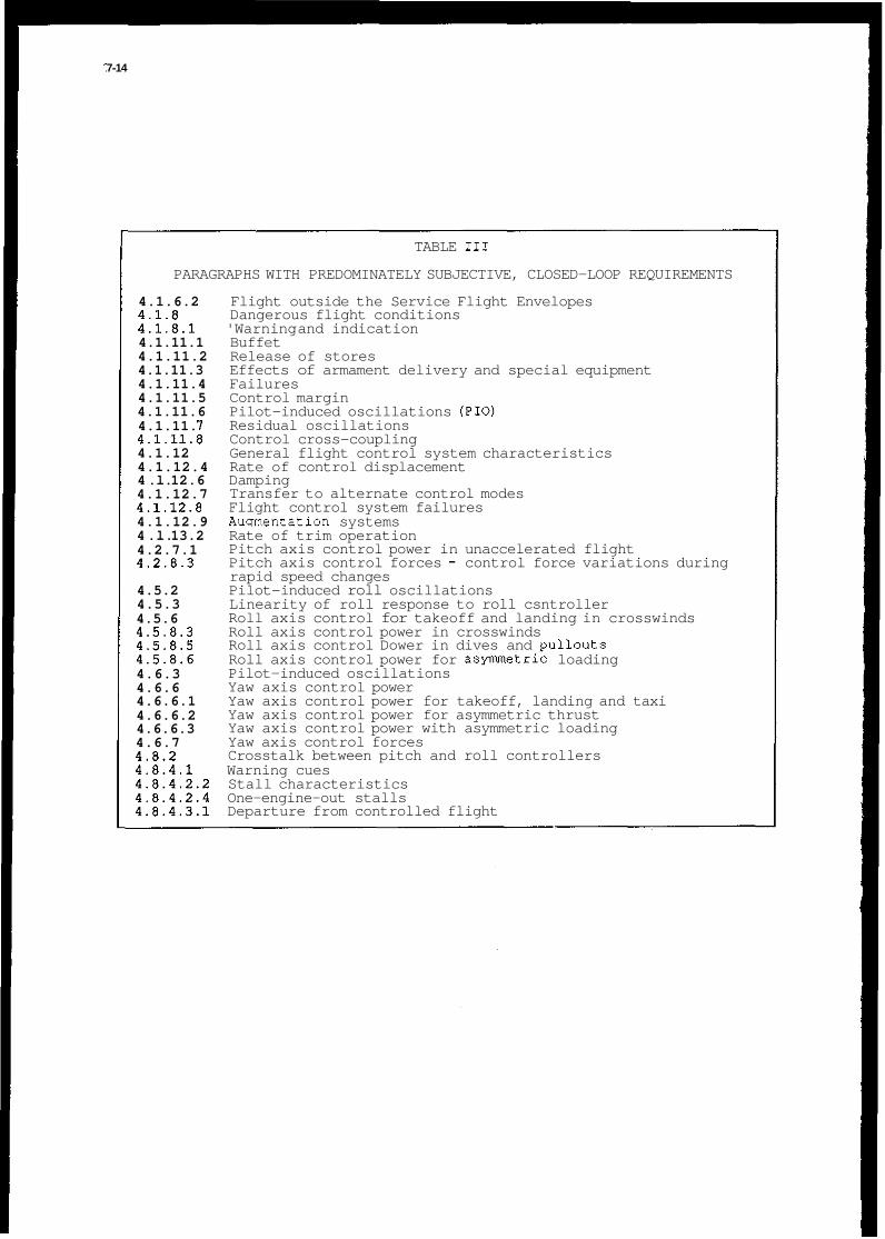
7-14
TABLE 111
PARAGRAPHS WITH PREDOMINATELY SUBJECTIVE, CLOSED-LOOP REQUIREMENTS
4.1.6.2 4.1.8 4.1.8.1 4.1.11.1 4.1.11.2 4.1.11.3 4.1.11.4 4.1.11.5 4.1.11.6 4.1.11. I 4.1.11.8 4.1.12 4.1.12.4 4 .l. 12.6 4.1.12.7 4.1.12.8 4.1.12.9 4 .l. 13.2 4.2.7.1 4.2.8.3
4.5.2 4.5.3 4.5.6 4.5.8.3 4.5.8.5 4.5.8.6 4.6.3 4.6.6 4.6.6.1 4.6.6.2 4.6.6.3 4.6.7 4.8.2 4.8.4.1 4.8.4.2.2 4.8.4.2.4 4.8.4.3.1
Flight outside the Service Flight Envelopes Dangerous flight conditions 'Warning and indication Buffet Release of stores Effects of armament delivery and special equipment Failures Control margin Pilot-induced oscillations (PIO) Residual oscillations Control cross-coupling General flight control system characteristics Rate of control displacement Damping Transfer to alternate control modes Flight control system failures Aumentation systems Rate of trim operation Pitch axis control power in unaccelerated flight Pitch axis control forces - control force variations during rapid speed changes Pilot-induced roll oscillations Linearity of roll response to roll csntroller Roll axis control for takeoff and landing in crosswinds Roll axis control power in crosswinds Roll axis control Dower in dives and Dullouts Roll axis control power for asymmetric loading Pilot-induced oscillations Yaw axis control power Yaw axis control power for takeoff, landing and taxi Yaw axis control power for asymmetric thrust Yaw axis control power with asymmetric loading Yaw axis control forces Crosstalk between pitch and roll controllers Warning cues Stall characteristics One-engine-out stalls Departure from controlled flight

TABLE IV
PARAGRAPHS WITH PREDOMINATELY OBJECTIVE, OPEN-LOOP REQUIREMENTS
4.1.12.10 4.1.13.1 4.1.13.5 4.1.13.6 4.2.1.1 4.2.1.2
4.2.6.1 4.2.7.2 4.2.8.1 4.2.8.2 4.2.8.4 4.2.8.5 4.2.8.6.3 4.2.8.6.4 4.2.8.7 4.3.1.2 4.4.1 4.4.1.1
4.5.1.1 4.5.1.2 4.5.1.3 4.5.1.4 4.5.1.5 4.5.4 4.5.7.1 4.5.8.1 4.5.8.2 4.5.9.1 4.5.9.2 4.5.9.3 4.5.9.4 4.5.9.5.1 4.5.9.5.4 ~~~~
4.5.9.5.5 4.6.1.1 4.6.1.3 4.6.2 4.6.4 4.6.5.2 4.6.5.3 4.6.7.2 4.6.7.3 4.6.7.5 4.6.7.7 4.6.7.11 4.7.1
Auxiliary dive recovery devices Trim system irreversibility Trim for asymmetric thrust Automatic trim system Long-term pitch response Short-term pitch responsez Alternative A - CAP or 0 p/ (n/a), csp. ‘ e Alternative B - ws g TO f r L g . ‘ e Alternative C - Tr ns ent eak ratio, rise time, effective time
delay Alternative D - Bandwidth, time delay Alternative F - Time- and frequency-response criteria by Gibson Pitch axis response to failures, controls-free Pitch axis control power in maneuvering flight Pitch axis control forces - steady-state control force per 9 Pitch axis control forces - transient control force per g Pitch axis control forces - control force vs. control deflection Pitch axis control breakout forces Pitch axis control force limits - dives Pitch axis control force limits - sideslips Pitch axis trim systems Steady-state flight path response to attitude change Speed-response to attitude changes Speed response to attitude changes - relaxation in transonic flight Roll mode Spiral stability Coupled roll-spiral oscillation Roll oscillations Roll time delay Lateral acceleration at pilot station Roll axis response to augmentation fai ires Roll axis resoonse to roll control inputs Roll axis control power in steady sideslips Roll control displacements R o l l axis control forces to achieve required roll performance Roll axis control sensitivity Rol l axis control centering and breakout forces Roll axis control force limits in steady turns Roll axis control force limits in steady sideslips Roll axis control force limits for asymmetric thrust Dynamic lateral-directional response Wings-level turn Yaw axis response to roll controller Yaw axis control for takeoff and landinq in crosswinds ~- ~ ~~
Yaw axis response to failures Yaw axis response to configuration or control mode change Yaw axis control force limits in steady turns Yaw axis control force limits during speed changes Yaw axis control force limits with asymmetric loading Yaw axis control force limits for waveoff (go-around) Yaw axis breakout forces Dynamic response for lateral translation
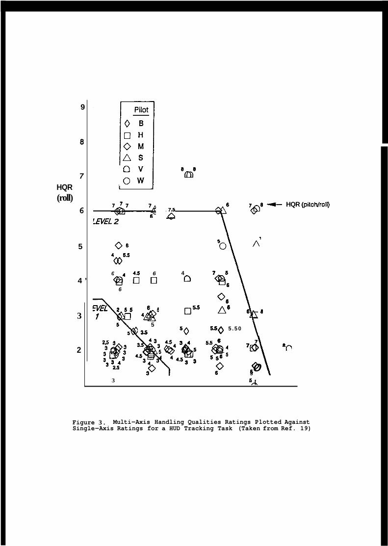
9
8
7 HQR (roll)
6
5
4 ’
3
2
o v o w
W E L 2
0 6
4#55
3 5A
$ 16 7&8 -f HQR (pitcNrol1)
”\ 4
0” A6 8
5 5 0 5 . 5 0
n 6 4 5 6 e4 0 0 6
5 35
0 ’”\ 5
Figure Single
3 . Multi-Axis Handling Qualities Ratings Plotted Against -Axis Ratings for a HUD Tracking Task (Taken from Ref. 19)

* * -Unrugmented mnfiountiom
Figure 4. Comparison of pilot ratings with Category A short-period frequency requirements (Taken from Ref 1)

7 - IX
TABLE V
PARAGRAPHS WITH PRE30MINATELY OBJECTIVE, CLOSED-LOOP REQUIREMENTS
4.2.5 Pitch trim changes 4.2.8.6.1 Pitch axis control force limits - takeoff 4.2.8.6.2 Pitch axjs control force limits - landing 4.2.8.6.5 Pitch axis control force limits - failures 4.2.8.6.6 Pitch axis control force limits - control mode change 4.5.8.4 Roll axis control power for asymmetric thrust 4.5.9.5.2 Roll axis control force limits in dives and pullouts 4.5.9.5.3 Roll axis control force limits in crosswinds 4.5.9.5.6 Roll axis control force limits for failures 4.5.9.5.7 Roll axis control force limits for configuration or control mode
4. 4. 4. 4.
change 6.7.1 Yaw axis control force limits in rolling maneuvers 6.7.4 Yaw axis control force limits in crosswinds 6.7.6 Yaw axis control force limits in dives and pullouts 6.7.8 Yaw axis control force limits for asymmetric thrust. during
takeoff 4.6.7.9 Yaw axis control force limits with flight control failures 4.6.7.10 Yaw axis control force limits - control mode change 4.8.3 Control harmony 4.8.4.2.1 Stall approach 4.8.4.2.3 Stall prevention and recovery 4.8.4.3.2 Recovery from post-stall gyrations and Spins
CDRL CONTRACT sow E DOD- STD- 963
DIDs
CDRL CONTRACT sow E DOD- STD- 963
DIDs
Performance
AFGS- 87253 MIL-C-SOll/MIL-STD-1793 MIL-STD-210 MIL-STD-490 MIL-STD-810 MIL-STD-1521
FC FQ
I MI L-A-87211 MIL-F-87851
MIL-STD-1797 M I L - F - 9 4 9 0 1 MIL/F-87242
Figure 5. Sample Specification Tree

7-19
Fix I t
Pilots Like
I t Pilot
Opinion
Pilots Don't Like
I t
Fix I t
Specification Compliance
Doesn't Meet Meets Specification Specification
Figure 6. Possible Outcomes of Flying Qualities Evaluations


LITIES EXPERIENCE ON THE
Bava Renzo AERITALIA Flight Mechanics Group
Corso Marche 41 TURIN ITALY
ABSTRACT
AMX is a subsonic ground attack aircraft with a fly-by-wire “Flight Control System“ (F.C.S.) built into a digital flight control computer. From the Flight Mechanics stand-point it has been designed against the MIL-F8785-C requirement. For some specific flight tasks the need of more demanding requirements has been envisaged. Modern handling qualities criteria have been applied in the area of longitudinal and lateral-directional precision tracking task and P.I.O. tendencies to cope with operational problems. High incidence criteria have been used in the design and evaluation of control modifications which improve the flying qualities in the stall and post stall regions. Comparisons between analytical predictions, manned simulation and in-flight results have beenmade. Indications of agreement or disagreement with data and new criteria are presented.
Longitudinal stick deflection Lateral stick deflection Pedal deflection Elevator deflection Stabilizer deflection Aileron deflection Spoiler deflection Rudder deflection Angle of attack Flight path angle Pitch attitude Pitch rate Normal load factor A1 t itude Downrange distance
Roll attitude Roll rate Yaw rate Dutch roll frequency Dutch roll damping Zero roll frequency Zero roll damping Sideslip angle Nose heading angle Azimuth CCIP Spiral time constant Roll time constant Roll time delay
zKm”a Brief History
AMX aircraft (figure 1) is a subsonic, single seat, single engine, dedicated attack aircraft developed within a framework of a joint Italian and Brazilian programme. Both Air-Forces had requirements for an aircraft whose primary mission would be “ground support just bevond the forward edae of battle“ suuuortina the lancl and naval forces and
at and having _ _
capability to provide: - close interdiction - close air support - reconnaissance and possibility of: - air defense and offense
Therefore the main design aims were about an aircraft capability to operate at low altitude subsonic speed with the following characteristics: - large external store capability for ground attack - air to air missile and gun for the air defense - low sweep, medium thick wing to adopt a sophisticated “High Lift System“ for adequate - single seat, high visibility cockpit - advanced avionic systems for navigation and weapon aiming with head-up - high survivability to continue the mission despite considerable battle damage. - safe return-home capability following total electrical and hydraulic failure.
take-off and landing performances.

Flight control system description
The AMX flight control system, therefore, has been designed as a "fail operative" system with a mechanical "back-up". A fly-by-wire F.C.S. provides three axes control, trim and compensation employing a dual-dual digital computer, in addition to analog motion dampers for all three axes. The hydraulic system is a dual-source, dual-redundant throughout. Normal functioning is still ensured after the first electrical and/or hydraulic failure whereas after the second electrical failure the controls are provided by hydraulically assisted back-up linkage on ailerons and elevator. These revert to manual following the second hydraulic failure, degrading the flying qualities to level 3 for the longitudinal and lateral stick forces in cruise as well as in landing flight phases. Figure 2 shows the layout of the aerodynamic control surfaces assisted by mechanical (hydraulic or manual) and electrical control lines, while figure 3 shows a schematic of these connections.
Flight simulator
The AIT Flight simulator has played a very important role since the very beginning in the development of AMX aircraft. It continues to support flight testing on the instrumented prototypes relevant to handling and manoeuvrability of aircraft modifications. At the moment an activity is in progress to investigate on the twin-seat aircraft behaviour at high incidence angle, in the post-stall region.
Part of an expanding simulation complex (figure 4 ) , the AMX simulator is a fixed base, fully instrumented cockpit with a real "head up display", in an inflatable dome with 10m diameter. A "control loading system" is available for a quick change of stickcharacteristics and a "G-suit, G-seat" system is available to improve the usable cue environments.
Handling Qualities Requirements
The aircraft is basically stable and not completely "fly-by-wire" dependant. From the flight-mechanics standpoints it has therefore been designed using fundamentally MIL-F8785-C requirement as a design criteria and generally good results have been achieved. For some specific tasks the MIL Spec. turned out to be insufficient to fit the flying characteristics, so the need for more demanding requirements arose. New criteria, in time and frequency domain, developed for highly unstable aircraft have been a good aid to evaluate the handling qualities in critical flight phases with the pilot in the loop. In particular they have been used, both for longitudinal and lateral control, for the landing task and to predict behaviour during precise tracking in weapon aiming or in flight formation. A good help has been found also with some new criteria developed for high angle of attack and used to predict and to improve the aircraft manoeuvrability near the stall incidence angle and the aircraft departure and spin susceptibility in the post-stall area.
m"
One of the most difficult tasks, which often involves serious safety problems, certainly is the landing task. In particular the performance landing on a short runway with a precision touchdown point tends to drive up pilot workload with a very tight loop closure. For this reason, AMX has been evaluated against some of the more recent landing criteria developed for '8fly-by-wire" aircraft.
Longituuinal control in landing
The longitudinal control in landing is a very complex multitask that involves pitch control using the stick, and speed control using thrust and aerodynamic drag. The criteria for this ta-k (Ref.1) usually consider only the short period step response at constant speed with flight path control as a primary task. For a conventional aircraft without a "lift control'- it is achieved by the pitch control which cannot be decoupled from the flight path. In such a context, the time delay 1 , between the step control input and the flight path angle response, could be equally or more valuable as a metric than the short period criteria, to which it is directly related. Further parameters (defined in ref.1 ) affecting the pilot rating duringthe flare manoeuvre depend on the pitch acceleration and pitch rate response. suggested landing optimum level 1 values for these parameters are:
flight path angle delay time at pitch rate peak time at pitch accel. peak f q < 0 . 2 5 s e c
pitch attitude dropback D B / q < 1.25sec
All these figures have generally been considered as guide-ljnes but the transient step response alone does not completely address themore complex landlngproblems like overcontrol or PI0 conditions approaching the touch-down point. In Ref.1 the time response criterion is integrated with a frequency response criterion,
L,< 1.5sec O.S<t,< I . l s e c
pitch rate ratio '?,,,/Y < 3
8-3
reflecting the past experiences of its author. It's based on the assumption that, in the frequency range used by the pilot for the pitch aircraft control (up to 0.25-0.5 Hz) the phase lag shall be less than 120 deg. Furthermore in this range the response must be neither too sluggish nor too abrupt. At higher frequency instead, the pitch control does not particularly influenced the aircraft response, nevertheless limits on the amplitude attenuation and on phase rate level are to be applied in order to avoid PI0 conditions. The fundamental behaviour observed in landing PI0 is the unconscious stick activity called "stick pumping" that the pilot exerts during the runway approach a few second before the touch-down. This activity occurs at a frequency where the pitch acceleration is nearly in phase with the stick deflection input and at an amplitude of about 6.5deg/sec2
These time and frequency criteria have been proven a good guide-line to evaluate the landing controllability in the frequency range of aircraft control. Figure 5 shows a classical time and frequency response against the above-mentioned criteria, for a typical landing condition in "High-Lift" configuration, low speed, gear down. The time response parameters reflect the optimum range values and they are not particularly affected by the landing conditions. The frequency response fulfils the expected limits with a pilot gain 0.9 and a cross-over frequency at 120 deg phase lag of about 0.3 Hz. The pumping frequency is about 1.1 HZ with a corresponding amplitude of:
( A ( :)) = 3.6sec.' "3.I.I"Z
The stick deflection to reach the threshold pilot sensibility to the pitch acceleration of 6 d e g / s e c 2 is:
g,,, 6 degsec-% A 3.6 ~ e - ~
5,,, = _ =- = 1.7deg
Flight test data, shown in figure 6 , confirm this figures. The pumping activity just a few seconds before the touch-down is performed by the pilot with a frequency and stick amplitude according to prediction and no tendency to overcontrol or divergent oscillation are noticeable.
Lateral control in landing
For the lateral control in landing flight phase, shortage of available data have not yet allowed to draw a specific criterion even if the basic rules of a quite large attenuation at 180 deg phase lag ( 15-20 db) and a crossover frequency higher than 1.0 HZ are to be considered useful to Drevent PI0 conditions. For lateral control no unconscious Dilot
~ ~ . ~~
activity, like the longitudinal stick pumping, is performed as a PI0 catalyst during the landing approach.
The AMX lateral control is considered by the pilots satisfactory too, and adequate to allow a performance landing with a precise contact point.
During the flight testing different F.C.S. standards with various level of roll control sensitivity have been tested. Some occasional tendency to lateral divergent oscillation approaching the runway has been experienced particularly for short field landings where the pilot workload is somewhat increased.
Figure 7 refers to an AMX landing in the above-mentioned condition. The initial large lateral stick deflection, used to counteract an unexpected lateral atmosphericdisturbances, demands large surface deflection reaching the actuator rate limit. The rate limit decreases considerably the stability margin of the open loop pilot-aircraft bank attitude control.
Figure 8 presents the lateral time and frequency response of a typical landing condition in "High lift" configuration, low speed, gear down. No criticalities come up from the linear analysis, but a different situation is highlighted if the control system non-linearities are considered.
Figure 9 shows a frequency response comparison between linear, non-linear small oscillation and non-linear large oscillation systems. The non-linear small oscillation is very similar to the linear response up to the higher frequencies where, due to a small dead-zone on spoilers deflection, a small loss of gain margin and phase rate is evident. For large stick inputs, instead, a large non-linearity due to the actuator rate saturation, considerably reduces the phase and gain margin ,thereby entering a PI0 condition.
From the latter case emerges that: the pilot, using a "high gain" for different emergency situation, low visibility or unfavourable atmospheric condition, can reach a PI0 condition due to large amplitude lateral stick motion. This could be promptly recoverable within few cycles if the stick deflection is kept to a minimum, thereby reducing the spoiler demand and avoiding the actuator rate limiting.
Generally, lateral stick activities similar to longitudinal stick pumping is not often seen in the landing phase. However, the flight test time-histories of figure 10 show a rare example of small lateral excitation corresponding to cross-over frequency of 1.1 Hz at 180 deg of phase lag (figure 9) without any tendencies toward divergent oscillations.

8-4 I
z"!a-
Both longitudinal and lateral-directional flying qualities of a combat aircraft are very important for a successful mission. The tracking characteristics, infact, are highlighted in the most critical phases of an operative mission such as ground attack with either gun or weapon aiming mode, or during in-flight refuelling or close flight formation. However, it is during these phases when continuous small control inputs are necessary to reach the final or a constant line-up.
For a such important tasks, as a result of a specific investigation, some time and frequency criteria have been considered to evaluate the AMX "fine tracking characteristics.
Lateral-directional trackins requirement
The primary lateral-directional control task is the control of the bank angle by use of lateral stick. The equivalent transfer function relating the dynamics of this task can be obtained by reducing the high order system over the frequency range from 0.1 rad/sec to 10 rad/sec based on the principle of matching the bank angle to lateral control and the dutch roll to directional control (Ref.2):
P - Li-,,s(s'+ 2<,w,s+ w:)e-"."* _ _ Fa, ( s i l / r 3 ) ( s + l / z , ) ( s z + c 2 < , w u , s + w ~ )
It is evident that, when the complex dipole cancels out (w,=wd;<,=<J the roll rate response is not contaminated by sideslip excursion in the dutch-roll mode and the major consequence is its non-oscillatory behaviour.
When dipole cancellation does not occur lateral-directional precision tasks both in the open and closed loop control are severely affected. A potential methodology that can be applied in this case is the Northrop criterion (Ref.3). To cancel the complex roots the criterion uses the magnitude ratio w,/w, and the real axis location of the zero with respect to the dutch-roll pole < , W ~ / < ~ W ~ . The cancellation depends mainly on the values of w e and w d and to a lesser extent on C b and t d . Hence the importance of w b / w , as a parameter which determines proverse ( w b / w u , > 1.) or adverse (w,/w, < 1.) yaw tendency during the roll control.
All the interactions caused by this quadratic pair are lumped under the general heading of w,/w, and <,w,/<,w, effects, however several others parameters play an important role in the totality of effects, such as l/'C,, l/Ts , T a p , lO/Pld .
For this reason the application of the requirement implies quite a number of guidelines which must be considered. The rol1,spiral and dutch roll mode MIL requirements should first be met as well roll time delay: moreover, small to medium values of l m / @ l d are preferred.
In Ref.4 correlation of pilot rating with the parameter w, /wu , exhibits different trends as a function of 10/@ld, especially with low <, and t d leading to:
for I+/ /3Jd small w , / w d = 1.0 0.75 < w,/wu, < 1.0 for l+/pldmedium to large
Forlarge<,and<,assuchas fo rh igh lyaugmenteda i rc ra f tmee t ing leve l l r equ i rement s , w, = w6 is generally preferred.
A limited, fixed base, simulation of the lateral directional tracking criterion has been carried out using an AMX aircraft. Several F.C.S. configurations have been considered, the nominal along with the degraded states. These configurations, all for the same flight condition (one of the most critical) have been reported in figure 11.
The simulation activity has been performed using Aeritalia's fixed base simulator. Formation flight has been simulated using a computer generated image of the lead aircraft flying in the same direction. The pilot was asked to maintain the fixed vector displayed on the H.U.D. exactly on the nozzle of the model in level flight or in a 4 5 deg bank turn manoeuvre. Of course during the whole manoeuvre (30 sec) the yaw control was free and minimum use of longitudinal control was recommended.
The average and integral errors on lateral and longitudinal motions were monitored to indicate the quality of the tracking task and the stick activity provided a measure of the pilot workload. Both these parameters were used as a comparison term among the various cases to establish a correlation with the analytical prediction (lateral directional tracking criterion).
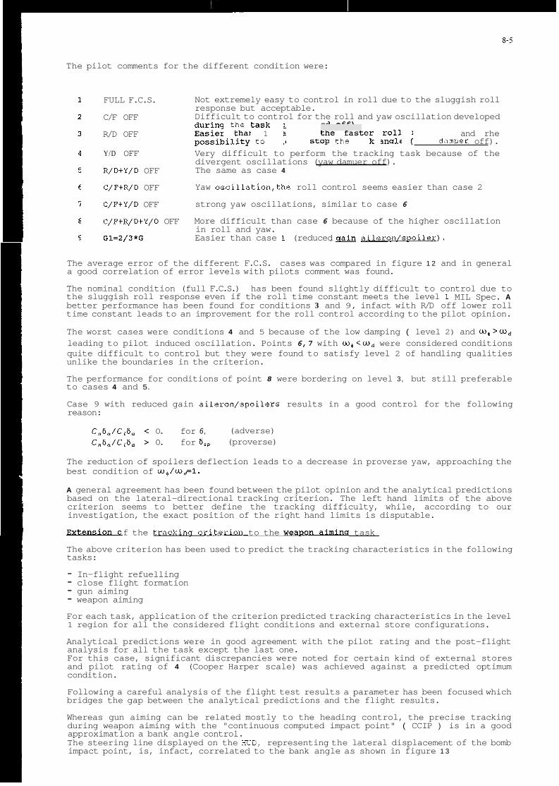
The pilot comments for the different condition were:
FULL F.C.S.
C/F OFF
R/D OFF
Y/D OFF
R/D+Y/D OFF
C/F+R/D OFF
C/F+Y/D OFF
C/F+R/D+Y/D OFF
G1=2/3*G
Not extremely easy to control in roll due to the sluggish roll response but acceptable. Difficult to control for the roll and yaw oscillation developed during thc task (cross-feed off). Easier rhan 1 because the faster roll response and rhe possibiliry ro quicker SLOP che bank angle (roll damDer off). Very difficult to perform the tracking task because of the divergent oscillations (yaw damuer off). The same as case 4
Yaw oscillation,the roll control seems easier than case 2
strong yaw oscillations, similar to case 6
More difficult than case 6 because of the higher oscillation in roll and yaw. Easier than case 1 (reduced & aileron/sDoiler).
The average error of the different F.C.S. cases was compared in figure 1 2 and in general a good correlation of error levels with pilots comment was found.
The nominal condition (full F.C.S.) has been found slightly difficult to control due to the sluggish roll response even if the roll time constant meets the level 1 MIL Spec. A better performance has been found for conditions 3 and 9, infact with R/D off lower roll time constant leads to an improvement for the roll control according to the pilot opinion.
The worst cases were conditions 4 and 5 because of the low damping ( level 2) and w p > w d leading to pilot induced oscillation. Points 6,7 with w + < w d were considered conditions quite difficult to control but they were found to satisfy level 2 of handling qualities unlike the boundaries in the criterion.
The performance for conditions of point 8 were bordering on level 3, but still preferable to cases 4 and 5.
Case 9 with reduced gain aileron/spoilers results in a good control for the following reason:
Cn6, /C ,6 , < 0. for 6, (adverse) C,6,/C,6, > 0. for E , , (proverse)
The reduction of spoilers deflection leads to a decrease in proverse yaw, approaching the best condition of w + / w ~ l .
A general agreement has been found between the pilot opinion and the analytical predictions based on the lateral-directional tracking criterion. The left hand limits of the above criterion seems to better define the tracking difficulty, while, according to our investigation, the exact position of the right hand limits is disputable.
f the t- to the weaI"1na task . .
The above criterion has been used to predict the tracking characteristics in the following tasks:
- In-flight refuelling - close flight formation - gun aiming - weapon aiming For each task, application of the criterion predicted tracking characteristics in the level 1 region for all the considered flight conditions and external store configurations.
Analytical predictions were in good agreement with the pilot rating and the post-flight analysis for all the task except the last one. For this case, significant discrepancies were noted for certain kind of external stores and pilot rating of 4 (Cooper Harper scale) was achieved against a predicted optimum condition.
Following a careful analysis of the flight test results a parameter has been focused which bridges the gap between the analytical predictions and the flight results.
Whereas gun aiming can be related mostly to the heading control, the precise tracking during weapon aiming with the "continuous computed impact point" ( CCIP ) is in a good approximation a bank angle control. The steering line displayed on the HUD, representing the lateral displacement of the bomb impact point, is, infact, correlated to the bank angle as shown in figure 1 3

8-6
The ratio of altitude release to the downrange distance of the bomb, ( H / X ) , is a key factor in establishing the relationship between the r$/@, and Azcc ip / A z c c i p c transfer functions (figure 14).
Figure 14 shows the frequency response for the above tranfer function for two different kind of bombs. H / X ratio depends on the balistic characteristics of the bombs and the flight conditions of the release. As the ratio approaches to 1.0 the aiming task appears to the pilot as difficult as the lateral control task. In case of low speed, high dive angle or for delayed bombs, ( i.e. H / X > I ) , the frequency response curve moves toward the closed loop resonance area and lateral PI0 conditions are achieved.
Figure 15 illustrates this concept in the time-domain through a 6 d.0.f. non-linear simulation in which the weapon aiming algorithm is accounted for. An ideal pilot (a pure unity gain) acts on the lateral control in the attempt to minimize the error between the reference value for the azimuth (1.0 degree) and the actual one, settled initially to 0.0.
With H / X = 1 . 0 a good acquire is reached without overshoot or oscillations. Reducing the downrange distance of the bomb, X, with exaggerated bomb drag to have H / X = 5 . 6 (degradation of open loop gain of approximately 15 db) the steering line control becomes extremely difficult and, due tothe increase ofthe systemgain, continuous lateral control oscillation with low damping is induced by the pilot.
on the basis of the above consideration on the diagram of figure 16 the line H / X = I . O reflects the conditions for which the weapon aiming task is very similar to the aircraft lateral controllability. The area standing on the right sj.de of the line H / X ~ 1 .O indicates conditions of an easy task, whereas proceeding on the left side a more and more difficult task and even PI0 occurrence are to be expected.
Flight tests confirm these tendencies, figure 17 shows a different target tracking behaviour for two different flight conditions corresponding to the points A and B on figure 16. The point A represents a normal ground attack condition and a good tracking is achieved with a small pilot workload. The point B, instead, in the area of reduced controllability, refers to a test outside the bomb delivery envelope with the pipper elevation out of the HUD displayed field. In the latter case the pilot is able to stabilise the steering line on the target with enormous workload.
Once the relationship has been established between the A/C lateral controllability and the quality of the weapon aiming task, it is legimate to extend the tracking criterion to those weapon aiming conditions for which the spurious effects related to the bomb characteristics ( H / X ) are minimized (i.e. the conditions related to the H / X = 1.0 line).
The validity of such an assumption has been verified through the analysis of the flight records, the still-photos of the HUD videorecorder and the pilot ratings.
The relative error between the target and the CCIP steering line during precise tracking has been evaluated against the level 1 or 2 "Median Lateral Error" criterion as well as the "Lateral Error Cumulative Distribution Function" requirement, according to which the level 1 or level 2 median error shall be 50% or greater.
It has been found that, at different flight conditions and with different kinds of bombs, all spreaded around the H / X - 1 . 0 line, were appreciated by the pilots and resulted in agreement with the "median lateral error" (figure 18).
In this way, from all the conditions which fulfilled the "fine lateral tracking criterion" it is possible to pick-up those which are expected to be satisfactory also for the weapon aiming, ( H / X = 1.0). On the other hand the unsatisfactory aiming situation can be improved by acting on the release conditions in such a way that H / X < 1 .

8-5
NCE BEHAVIOVB
The Northrop and Weissman departure criteria have been applied to predict the departure conditions and to estimate the effectiveness of the corrective actions undertaken both via aerodynamic changes and via FCS modifications.
The considered parameters are:
lZ I X
C n P d y n = C n B * c o s a - - * C l p * s i n a
which measures the yaw departure susceptibility when the incidence angle is increased as result of the longitudinal control application.
cna0 +x, K . n * Cn,,, + ? * c n a ,
C l o a + $=clasp+ < * c 1 8 p
K O LCDP = Cn, - CIP* K
The lateral control departure parameter predicts the roll reversal when the rolling moment due to the adverse yaw overcomes the lateral control power.
nce at hiah anale of attack
The roll control of the AMX has been designed to meet the requirement of the MIL-F-8785C expressed in terms of time-to-bank defined for 1 "G" flight condition and for 80% of the minimum and maximum operational load factor.
Beyond the above normal load factor limits, no specification is given for the roll performances, while from an operational standpoint it is desirable to maintain a suitable lateral manoeuvrability.
In the a range approaching the stall, AMX exhibited unsatisfactory roll performances due to a rapid change of lateral and directional stability, along with the loss of lateral control effectiveness. Albeit the MIL requirement was fully satisfied the roll capability resulted as being a limiting factor for the maximum angle of attack allowed.
The phenomena, increasing the incidence angle, were at first evident as a roll hesitation and then as a roll reversal.
Figure 19 shows the in-flight results relevant to an objectionable situation. With a sustained full lateral stick, at an angle of attack near to the stall a large sideslip build-up generates a roll acceleration inversion with a consequent roll-reversal.
Predictions with the above mentioned departure criteria, reported in figure 20, show that the aircraft without crossfeed exhibit a rapid loss of LCDP which becomes negative at a-values lower than the a-stall by some degrees. The point I, in figure 20, is the corresponding point for the in-flight manoeuvre of figure 19.
To improve the roll performances within this area, up to the stall, a roll-to-yaw crossfeed has been designed which cause the rudder to be deflected as a function of the lateral and longitudinal stick displacement. The advantages associated with this solution are shown in figure 20: the L C D P - u s - C n P d y n curve, in the a range up to the stall moves toward the positive value of LCDP.
Flight tests confirmed the predicted improvement for the roll characteristics up to the Stall angle as can be seen in the 'etime-histories't presented in figure 21 related to the points I1 and 111 on the previous analytical criteria. The roll manoeuvre performed at the a-stall (point 111) is still acceptable, even if the low LCDP contributes to generate continuous roll oscillation.
Improvements in terms of roll rate versus angle of attack are shown in figure 2 2 .
Stall behavbw
The approach to the stall and post-stall flight trials has been carried out through a gradual work-up according to the following steps: -increasing the nose-up trim setting up to its full authority -moving the CG rearward -increasing the en@rgy entry -sustaining the stall up to 15 sec
The aircraft motion beyond stall is characterized by a bounded wing rock which develops into a slow nose sLice (yaw rate 2-3 deg/sec) when the stick is held hard back.
The wing rock is a classical and regular roll oscillation developed as a divergent dutch-roll with frequency proportional to the square root of L, and amplitude limited by the non-linear roll damping characteristics. Time-histories of figure 23 refer to a flight test record reflecting the conditions of the point IV in the afore-mentioned criteria.

8-8
Stalls aggravated with clinical manoeuvres, such as full back stick-full lateral stick, showed, for the clean configuration, a moderate rolling departure. Figure 24 shows the flight recorded time-histories of such a behaviour matched with a 6 d.0.f. simulation program. Moderate angular rates are reached after departure and due to good longitudinal control effectiveness a very fast recovery is possible after controls release. This is in a good agreement with the departure criteria that for the point V predicts acceptable stall with mild rolling departure and low spin susceptibility.
Other conditions, like flap setting or store configuration have been evaluated against the deoarture criteria and a aood aareement with the orediction has alwavs been found. For . - ~
example an additional increase in departures resistance is predictable and was experienced with manoeuvre flap setting.
Forthis reason, to improve the combat capability while reducingthe probability of departure and the pilot workload, especially with underfuselage load or asymmetric store, an automatic deployment of manocuvrc dcvices will be shortly introduced.
REFERENCE
Ref. 1 J.C.Gibson "Piloted Handling Qualities Design Criteria for High Order Flight Control System" AGARD-CP-333 April 1982
Ref.2 J.Hodgkinson, W.J.LaManna "Equivalent System Approaches to Handling Qualities Analysis and Design Problems of Augmented Aircraft" A I M Atmospheric Flight Conference, Hollywood, FL, August 1977
Ref.3 J.T.Gallagher, W.E.Nelson Jr. "Flying Qualities of the Northrop YF-17 Fighter Prototypes" Business Aircraft Meeting, Wichita March 1977
Anon., "Flying Qualities Requirement for United States Navy and Air Force Aircraft", AGARD-CP, October 1961
Ref. 5 ~.~.skow, A.Titiriga Jr. "A survey of Analytical and Experimental Techniques to Predict Aircraft Dynamic Characteristics At High Angle of Attack" AGARD-CP-235, Athene, May 1978
Ref.4

8-9
m it) $& t -. I
- Figure 1 AMX THREE VIEW
Figure 2 AMX-FLIGHT CONTROL SYSTEM LAYOUT

8-10
LAT.STIU( __-_ E? PEDAL ----
51,:c.n C r a l l i l i s
Figure 4 AIT-FLIGHT SIMULATION FACILITIES

8-11
t. Sst i...... ..... .................... .......................
- 1 ~: . . . . . ....... ..... I
! . .
1 2 3 ‘ 5 6 e.8
T6-2 = A, 6% ................... .._.... . .....
.....
......
...
Figure 5 AMX-LANDING APPROACH PITCH HANDLING QUALITIES
..................
..............
/CASE 2
Figure 6 AMX-LANDING APPROACH FLIGHT TEST TIME-HISTORIES

8-12
Figure 7 AMX-LANDING APPROACH LATERAL PI0 WITH A NON-STANDARD FCS
R E R I T A L I O La1ERI)L STEP
FL IWT HECHIIHICS IIESPCUSE
Figure 8 AMX-LANDING APPROACH LATERAL HANDLING QUALITIES

8-13
I
Figure 9 AMX-LANDING APPROACH LATERAL FREQUENCY RESPONSE
Figure 10 AMX-LANDING APPROACH SMALL LATERAL EXCITATION

8-14
- 1 FULL FCS - 2 A C/F OFF - 3 6 R/D OFF - 4 i Y/D OFF - 5 + R/D + Y/D OFF - 6 C/F + R/D OFF - 7 C/F + Y/D OFF - 8 + c/F + R/O + Y/D OFF
Figure 11 AMX - LATERAL DIRECTIONAL TRACKING PARAMETER
h 1 ERROR
LIST OF SIMBOLS
F.C.S. : flight control system C/F : cross-feed
Y/D : yaw-damper G=2/3*G: reduced gain aileron/spoiler
R/D : roll-damper
Figure 12 AMX - CLOSE FLIGHT FORMATION TRACKING ERROR

8-15
H.U.D. steering
4 / / ‘9\
I , , , , , , , , , , , , ,
H s i n $ Az,,,,= alan- X
H small oscillation P A z m , p = j i @
Figure 13 RELATIONSHIP BETWEEN CCIP AZIMUTH AND BANK ANGLE
Figure 14 AMX - CCIP STEERING LINE CONTROLLABILITY
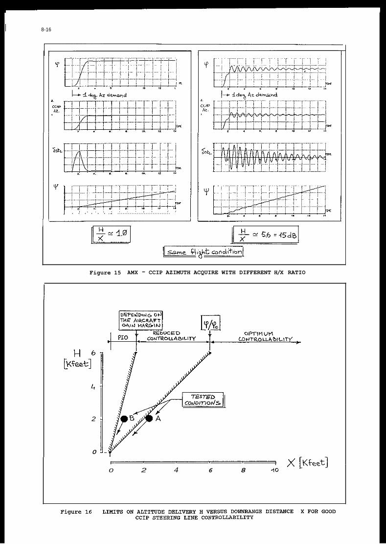
I 8-16
8 Y
: : . . . : : : . . . . . . . . . .
I .. 0 IO I* I..
. . : . . . . . . . : : . . . . . . . . ..............................
I '
Figure 15 AMX - CCIP AZIMUTH ACQUIRE WITH DIFFERENT H/X RATIO
2
0
I
0 2 4 6 8 10

8-17
-.. i ............. i i ............. i - .......... i L...L L
........ 20 i ....... .....; .............. 1 ............................................ -- !.,.,,,A
I .... ..... ....... < i i
~~
Figure 17 AMX - IN-FLIGHT TEST OF DIFFERENT TARGET TRACKING CONDITIONS
Median lateral error
BOHB' RELEASE
Figure 18 FLIGHT TEST PRECISE TARGET TRACKING RESULTS
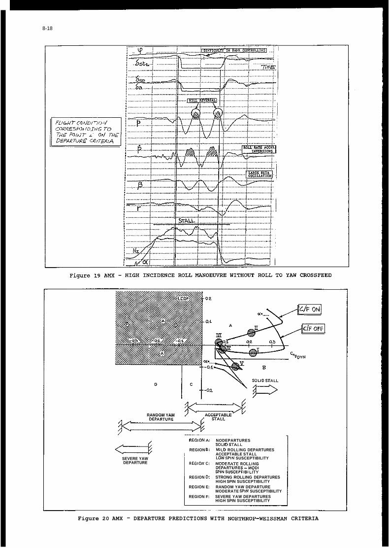
8-18
RANDOM YAW ACCEPTABLE
SEVERE YAW DEPARTURE
~~ ~~
R E G I D N A NODEPARTURES
REGION 8: MILD ROLLING DEPARTURES SOLIDSTALL
ACCEPTABLE STALL LDWSPIN SUSCEPTIBILITY
REG.OS C MODERATC ROLLIYG DEPARTURES -MODERATE SPIk SVSCEPTiB T Y
REGION D: STRONG ROLLING DEPARTURES HIGH SPIN SUSCEPTIBILITY
REGION E: RANDOM YAW DEPARTURE MODERATE SPIN SUSCEPTIBILITY
REGION F: SEVERE YAW DEPARTURES HIGH SPIN SUSCEPTIBILITY
Figure 20 AMX - DEPARTURE PREDICTIONS WITH NORTHROP-WEISSMAN CRITERIA

8-19
.............. .............. .............. .............. ............ -4 j l .!
!i .............. .............. ..............
CORRESpD*/D?4G TO ............... ..............
:I .... !.p ........ i . ........... ~. .......... ; ............................. : I :w ............... 6 ..............
! .............. +. ............................. +
.... p y- ... -
j i : I
i ...... ........................ ........- 9 1 I- (............... j .............. j .............. j .............. .$ .............. d
! I ...... ; .............. 4 ............. ; ................. ........... I r !2, i -1 _.
. ............................ ~ .............. ...........................
.............. i.. .......... > .............. > ............... > ............... : j -;
............. .. .............. .. .............. .. .............. .. .............., v
, , . . P A , r - - - -q j ......
F i g u r e 21 AMX - ROLL MANOEUVRES CLOSE TO THE STALL ANGLE WITH A ROLL-TO-YAW CROSSFEED
Figure 22 AMX - ROLL RATE IMPROVEMENTS AT HIGH INCIDENCE

8-20
COURESPOhID i d G TO T H ~ Poidr iv Od THE
03oreoLS RELE4SE
............. : .....
Figure 23 AMX - CLASSICAL STALL WITH A BOUNDED WING ROCK
.................. ........
13
..... ... ~ ....... ~ . . ~ .......... T--.--. : I / ! ) . : ; , . !
0- P
I.,.,; ...... ~ .... i .... i ...... ; ...... ~ ..... ~
1 J .- ! .! I : .! -..!. y / j ! i - ) ! i j
...... ....... . . . . . . . . . . I ............ I ........ POLLNG DEPARTURE
+ FLIGHT T - + SlnULAT,W
Figure 24 AMX - CLASSICAL ROLLING DEPARTURE AFTER A STALL AGGRAVATED BY LATERAL CONTROL

THE DEVELOPMENT OF ALTERNATE CRITERIA FOR FBW HANDLING QUALITIES
J.C.Gibson B r i t i s h Aerospace ( M i l i t a r y A i r c r a f t ) L t d
Warton Aerodrome Preston PR4 1AX
UK
SUMMARY
Prov is ion of robust FCS and s t r u c t u r a l mode s t a b i l i t y margins and carefree handling i n h igh ly unstable combat a i r c r a f t w i t h a wide range of s to re loading requires new methods f o r handling q u a l i t i e s opt imisat ion. The p o s s i b i l i t i e s f o r new cont ro l modes and task- ta i l o red handling have been g rea t l y enhanced by modern cont ro ls . This has led t o development of many a l te rna te c r i t e r i a which were t r i e d and tes ted i n two d i g i t a l FBW research a i r c r a f t , the EAP and Jaguar FBW, and have been f u r t h e r developed f o r use i n EFA. They cover the f i e l d o f f l i g h t path and a t t i t u d e bandwidth, t rack ing precis ion, p i t c h and r o l l acce lera t ion dynamics and s e n s i t i v i t y , P I 0 prevention, and enhanced la te ra l- d i rec t iona l damping. Derived as design guidel ines, w i t h the f a c i l i t y t o design fo r optimum ra ther than merely acceptable handling, more research i s needed i n t o formal boundaries fo r Levels 1, 2 and 3 spec i f ica t ions. This paper reviews the c r i t e r i a and i l l u s t r a t e s some of them by example.
1. INTRODUCTION
It i s widely acknowledged t h a t formal handling q u a l i t i e s c r i t e r i a , developed d i r e c t l y from the f l i g h t experience o f the e a r l y decades and formalised i n i t i a l l y i n the 1940's. are inadequate f o r the needs of modern con t ro l systems. While t h i s was evident i n the many handling problems o f recent years, ranging from a nuisance t o ser ious d i f f i c u l t i e s , i t i s a l so the r e s u l t o f the g rea t l y increased p o s s i b i l i t i e s fo r new cont ro l modes, and f o r optimised task t a i l o r e d handling. The c lass i ca l a i r c r a f t handling o f the past was determined by the basic aerodynamics. Later the s k i l l s o f the cont ro l designer were added t o r e p l i c a t e the natural-seeming q u a l i t i e s o f s t i c k f e e l and t o augment the damping t o a l i m i t e d extent. Simple modal parameters such as frequency and damping, although descr ib ing on ly the f l i g h t path behaviour, s u f f i c e d t o quant i fy i n general terms the response charac te r i s t i cs both t o p i l o t inputs and t o external disturbances. The handling o f the suberaugmented unstable combat a i r c r a f t o f today, and increasingly a l so w i t h fu ture a i r l i n e r s , i s determined almost completely by the f l i g h t cont ro l system. The r e s u l t i n g behavioural dif ferences can be profound.
This has begun t o be addressed i n Ref.1 i n .the form of a l tg rna te c r i t e r i a offered fo r considerat ion i n the design process. Some of these and others are discussed i n Refs.2 t o 4, which describe how handling q u a l i t i e s can be i d e n t i f i e d from elements o f t rans ien t and frequency responses independently of the FCS complexity. They can there fore be der ived from the 8785 database o r other sources o f experimental data, requ i r i ng no t ransformat ion i n t o s i m p l i f i e d forms. The approach fol lowed a t
Warton i n t h e i r development has always been t o es tab l i sh what response charac te r i s t i cs were favoured by p i l o t s and t o evolve methods of desc r ip t i on and measurement which can be d i r e c t l y associated w i th p i l o t s ' comments and t h e i r perception o f task performance. This work has been g rea t l y assisted by f l i g h t experience o f two h igh ly unstable research a i r c r a f t w i t h advanced d i g i t a l FEW, the FBW Jaguar ( 5 ) and the EAP ( 6 ) . While the c r i t e r i a used fo r design and f l i g h t clearance of the FEW Jaguar were informal, those f o r the EAP were comprehensive and completely replaced sources such as Ref.7 i n formal clearance processes. Both demonstrated exce l lent handling and complete absence of PIO, and the c r i t e r i a methodology has become the standard fo r the EFA a i r c r a f t when formal requirements seem less appropriate.
has o f ten been blamed f o r poor handling. However, i t i s convenient t o consider the "orderedness" of handling q u a l i t i e s t o be re la ted t o the phase ranges i n which they are p r i m a r i l y generated, ra ther than t o the order of the FCS. The design problem then reduces t o the e l im ina t ion o f excessive and PIO-prone h igh order e f f e c t s a r i s i n g from phase lags greater than the c lass i ca l norm, and secondly t o the prov is ion w i t h i n the c lass i ca l response phase l a g range of low order q u a l i t i e s optimum f o r given tasks. These may d i f f e r s i g n i f i c a n t l y from the c lass i ca l forms.
The high order of some con t ro l systems
2. HIGH ORDER PILOT INDUCED OSCILLATIONS
"Low order P I O" associated w i t h p i t c h bobble, overcontrol due t o i n s u f f i c i e n t p i l o t gain adaptation, improper p i l o t c losure o f a l t i t u d e loops, e tc . i s found i n c lass i ca l responses and i s not s p e c i f i c a l l y a FEW problem. Bobweight P I O , although no t low order, i s a lso not re levant here. This discussion r e f e r s only t o P I 0 caused by gain/phase def ic ienc ies i n FEW cont ro l law design, which can be considered t o be the p r i n c i p a l h igh order problem area.
High order p i t c h and r o l l P I 0 i s q u i t e c l e a r l y an unstable a t t i t u d e loop closure, w i th a "synchronous" p i l o t ac t i ng as a simple gain on a t t i t u d e e r ro r . This model s i m p l i f i e s the task o f i d e n t i f y i n g and e l im ina t ing the a t t i t u d e dynamics which provoke a P I O . While a somewhat non- linear behaviour i s o f ten seen i n f l i g h t records, w i t h the s t i c k being switched when the a t t i t u d e r a t e changes sign, sometimes w i th a s t i c k d i t h e r wh i le the p i l o t wa i ts fo r the next swi tching Doint, i t i s unnecessary t o model t h i s . These records a lso suggest t h a t s t i c k p o s i t i o n cont ro l i s dominant and the f e e l dynamics should not be included i n the analysis. I n t h i s loop c losure model, i n s t a b i l i t y occurs a t the frequency where the a t t i t u d e phase l a g i s 180 degrees o r

9-2
s l i g h t l y more. Factors which have been emp i r i ca l l y found t o be associated w i t h PI0 tendencies are the gain, the frequency and the r a t e o f increase o f l ag w i t h frequency a t t h i s po in t . The l a t t e r , more simply known as the phase ra te , i s found t o co r re la te s t rong l y w i t h P I O , as discussed i n Refs.3 and 4 .
A h i g h l y e f fec t i ve P I 0 metr ic , phase r a t e i s read i l y p l o t t e d i n design work and i s e a s i l y found g raph ica l l y from o lder 'data. Phase slope i s a s i m i l a r met r ic , given i n Ref.1, which has been developed fu r the r i n Ref.8 t o account f o r the e f fec ts of response bandwidth. The t y p i c a l P I 0 combination o f low frequency and high a t t i t u d e gain, marked by a h igh phase ra te , permi ts la rge amplitude o s c i l l a t i o n s i n a t t i t u d e t o be generated w i t h i n t he con t ro l Power p i t c h acce lera t ion l i m i t s . The frequency tends t o be h igh when the gain and phase r a t e are low and therefore not P I 0 prone, bu t can a l so be h igh w i t h poor dynamics. This may reduce the poss ib le p i t c h amplitude, bu t i t i s no p ro tec t i on a t h igh airspeed, where h igh loads are e a s i l y generated. The des t ruc t i on of an F .4 a t 800 knots on the t h i r d cyc le o f a PI0 i n under three seconds i s witness t o t h i s .
The frequency p lays a s i g n i f i c a n t p a r t i n landing P I O , which i s thought t o grow ou t of the s t i c k pumping usua l ly exercised by p i l o t s i n the few seconds before touchdown. The B i h r l e theory i s t h a t p i l o t s e x c i t e a p i t c h acce lera t ion o f about +6 deg/sec2 t o t e s t the response. This i s done subconsciously and a t the frequency where i t i s c lose l y i n phase w i t h the s t i c k i npu t , convent ional ly we l l above the sho r t per iod. The a t t i t u d e lags by 180 degrees and so resembles a P I O , bu t t h i s i s no t observed by the p i l o t normally because a t t y p i c a l frequencies fo r low order a i r c r a f t the a t t i t u d e response i s small . With increasing h igh order lags t h i s frequency reduces u n t i l the a t t i t u d e f o r the nominal acce lera t ion i s la rge enough t o become obvious t o the p i l o t . A ready-made P I 0 may then occur because the p re- ex i s t i ng con t ro l o s c i l l a t i o n , harmless as a subconscious i npu t t o the a i r c r a f t p i t c h acce lera t ion , e s s e n t i a l l y an open loop, becomes unstable as a p i l o t gain of lbs/degree i n the closed a t t i t u d e loop.
A PI0 frequency gain o f less than 0.1 degrees/lb seems t o be associated w i t h the absence of P I O , bu t a h igher gain may be very s a t i s f a c t o r y given good dynamics. With a low gain the ampli tude l i m i t imposed by the maximum possib le s t i c k inputs does no t permi t a la rge P I 0 o s c i l l a t i o n t o develop whatever the dynamics. With poor dynamics, the higher the P I 0 gain the more e a s i l y a P I 0 w i l l be t r iggered. P i l o t s may use the f u l l s t i c k t r a v e l when t r y i n g t o regain cont ro l regardless o f the forces involved. It i s espec ia l l y important t o assess the consequences of such inputs by c a l c u l a t i o n and i n s imulat ion, and i t must no t be assumed t h a t p i l o t s would never f l y l i k e t h a t " .
The Calspan NT.33 has provided most of the data used t o develop an understanding of the problem. Two examples from Refs.9 and 10 i n Figs.1 and 2 i l l u s t r a t e some task re la ted d i f ferences and the s i m p l i c i t y of analys is . Both have except iona l ly poor a t t i t u d e frequency response shapes, w i t h a
rap id increase of phase l ag and r e l a t i v e l y h igh gain towards and a t the 180 degree lag region. The h igh phase ra tes are associated w i t h severe P I O . P i t c h acce lera t ion i s a l so shown, s h i f t e d by 180 degrees phase angle so as to p o s i t i o n i t s frequency p o i n t s d i r e c t l y above those of a t t i t u d e . The p i t c h acce lera t ion i s exac t ly i n phase w i t h t he s t i c k when a t t i t u d e lags i t by 180 degrees, and i t s gain a t t h i s PI0 frequency i s o f great importance i n determining the nature o f the P I O .
I n the Fig.1 example, the p i l o t could no t t r ack because t h i s always resu l ted i n a P I O , which diverged when he t ightened h i s gain, earning r a t i n g s o f 8 and 9 . The response shape invokes both c losed loop droop and resonance, and despi te the heavy s t i c k f o rce per g the uncompensated p i l o t a t t i t u d e gain f o r i n s t a b i l i t y i s on l y 3 l b per degree. Because of the l a rge l ag b u i l t i n t o the con t ro l law, p i l o t compensation i s very d i f f i c u l t t o achieve. With a h igh fee l s t i f f n e s s and an a t t i t u d e gain of 7 degrees per inch o f s t i c k a t t he P I 0 frequency, i t i s no t s u r p r i s i n g t h a t an o s c i l l a t i o n of about +35 m i l s i s the best the p i l o t could achieve instead o f a s a t i s f a c t o r y 2 m i l s median t rack ing e r r o r . The PI0 t r i g g e r i s the a c t of t r ack ing i n i t i a t e d by the p i l o t , a conscious dec is ion which can equa l l y be reversed. The th resho ld p i t c h acce lera t ion o f about 6 deg/secz i s exc i t ed by i npu ts o f on ly 1 l b o r 0.05 inch, and as the P I 0 i ncur red inputs some s i x t imes l a rge r the o s c i l l a t i o n could be t i e d p o s i t i v e l y t o t he s t i c k . The p i l o t was ab le t o stop the PI0 simply by abandoning the task .
I n the example o f Fig.2, the p i l o t could complete the c i r c u i t bu t was unable t o land because of unstoppable P I 0 i n t he f l a r e , earning a r a t i n g o f 10. The record shows s t i c k pumping as predicted, al though the p i t c h acce lera t ion ampli tude i s l ess than the nominal. This may be due t o t he combined low frequency and response gain r e q u i r i n g a s t i c k f o rce o f +6 l b s f o r t he threshold acce lera t ion , ra the r h igh f o r a subconscious a c t i v i t y . P i l o t s do e x h i b i t considerable v a r i a b i l i t y , however, from s l i g h t t o h i g h l y a c t i v e pumping. A t 10 t o 15 seconds the P I 0 i s t r i gge red , poss ib ly a f t e r increasing the pumping t o generate a more p o s i t i v e " f e e l " f o r t he response. The sudden reduct ion i n ampli tude i nd i ca tes the s t a r t of the unsuccessful attempt t o ge t i t under c o n t r o l . The increased frequency when swi tching from pumping t o PI0 seems t o be t y p i c a l .
The landing PI0 has a n e g l i g i b l e d i r e c t e f f e c t on the f l i g h t path task i n hand, and the pumping which may be the t r i g g e r i s no t p a r t o f the task . Large s t i c k forces and displacements have t o be app l ied before there i s much sense of a d i r e c t l y commanded response because the p i t c h acce lera t ion gain i s so low. I n one such case a p i l o t bel ieved t h a t the motion consisted of Some i n i t i a l turbulence response fo l lowed by a p i t c h up which d i d no t immediately respond t o h i s app l i ca t i on o f f u l l forward s t i c k , completely unaware t h a t he was i n a c l a s s i c PI0 d r i ven e n t i r e l y by h i s con t ro l inputs . Given t h a t the a i r c r a f t i s about t o contac t the ground i n a very unsafe a t t i t u d e and t h a t i t has apparently gone out o f c o n t r o l , f r eez ing the s t i c k and overshooting i s no t usua l l y seen as an op t i on .

9-3
As discussed i n Ref.4, such a i r c r a f t , genera l ly w i t h modest wing loadings and h igh l i f t slopes, d i d no t requ i re la rge changes i n angle o f a t tack fo r manoeuvre. The corresponding a t t i t u d e t rans ien ts were moderate and good t rack ing performance was o f t e n achieved, as seen i n many WW2 gun camera f i lms . Later types were fas ter , heavier , eventua l ly supersonic, f l e w t o much greater a l t i t u d e s , and lacked na tu ra l f ee l . Because of t he degraded handl ing they requ i red s t a b i l i t y augmentation. Research t o de f i ne s a t i s f a c t o r y q u a l i t i e s l ed t o t he s t i l l cu r ren t s p e c i f i c a t i o n of s h o r t per iod frequency l i m i t s r e l a t e d t o t he r a t i o o f g t o angle of a t t ack . This r e f l e c t s t he na tu ra l behaviour o f a i r c r a f t w i t h constant manoeuvre margin. The frequency i s r e l a t e d t o equ iva len t airspeed and the p i t c h i n g moment t o t r i m a given g increment i s constant . This r e s u l t s i n the f i x e d upper and lower CAP l i m i t s o f i n i t i a l p i t c h i n g acce lera t ion per g.
The s p e c i f i c a t i o n therefore inc ludes a p a r t i a l element o f a t t i t u d e sluggishness o r o v e r s e n s i t i v i t y , bu t on ly i n t he f i r s t i n s t a n t of t he angle o f a t tack response. The subsequent a t t i t u d e t ime h i s t o r y i s undefined. Refs.2 and 3 show how t h i s can be p rec i se l y de f ined by the parameters of a t t i t u d e dropback o r overshoot and the p i t c h r a t e overshpot cha rac te r i s t i cs . These can vary widely f o r f i x e d p o i n t s w i t h i n t he standard s p e c i f i c a t i o n , which g ives no design guidance f o r p rec i s ion a t t i t u d e con t ro l tasks. The p i l o t r a t i n g s i n pas t research, o f ten incons is ten t when r e l a t e d t o sho r t per iod met r ics alone, f requen t l y become we l l co r re la ted when a t t i t u d e parameters are accounted f o r . Any one o f t he many formats i n which handl ing data have been presented i n pas t l i t e r a t u r e can be augmented t o inc lude such e f f e c t s , which usua l l y i l l u m i n a t e the reasons f o r t he choice of handl ing boundaries i n terms which i d e n t i f y the phys ica l response seen o r f e l t by the p i l o t .
q u a l i t i e s by feedback adjustments may be severely constra ined i n a h i g h l y unstable and f l e x i b l e a i r c r a f t by the d i f f i c u l t y i n p rov id ing adequate s t a b i l i t y margins i n both f l i g h t response and s t r u c t u r a l modes. For any l e v e l o f s t a b i l i t y , a powerful and f l e x i b l e technique i s command f i l t e r i n g . By t h i s means it i s poss ib le t o perform a l l o r most of t he compensation otherwise l e f t t o t he p i l o t , who i s then ab le t o a c t as a simple ga in c o n t r o l l e r and t o devote f u l l a t t e n t i o n t o developing a small t ime delay f o r compensatory t rack ing . The compensated a i r c r a f t response q u a l i t i e s can be r e l a t e d t o standard low order c h a r a c t e r i s t i c s a f t e r t he adverse h igh order e f f e c t s discussed above are e l im inated separately.
The freedom t o ob ta in des i red handl ing
3.1 A t t i t u d e Tracking
For pure compensatory t a r g e t t r ack ing , i n which on ly the e r r o r i s displayed, t he optimum a t t i t u d e model K/S i s we l l known. I n r e a l t r ack ing a mix ture o f p u r s u i t and compensatory t r a c k i n g w i l l be employed, bu t even so t he bes t r e s u l t s w i l l be obtained w i t h a response c l o s e l y resembling K / S . This i s o f ten described ve rba l l y as "The nose f o l l o w s the s t i c k " , associated w i t h nominal ly zero a t t i t u d e dropback, though small values of dropback o r overshoot can be acceptable. The p i t c h r a t e overshoot
Although the p i t c h acce lera t ion i s i n phase w i t h t he s t i c k dur ing the example PIO's, a ser ious de f i c i ency i s ev ident i n the r a p i d increase o f phase l ag a t h igher frequencies. I n t h e c l a s s i c response, acce lera t ion phase angles decrease from a lead a t low frequencies t o zero a t h igh frequencies. This r e s u l t s i n an immediacy o f response t o s t i c k inputs , e f fec ted p h y s i c a l l y by the d i r e c t equivalence o f the con t ro l sur face and s t i c k motions. This i s no t a f f ec ted s i g n i f i c a n t l y by the a d d i t i o n of ac tua t ion lags o f any reasonable q u a l i t y o r by the presence o f feedback paths. With increas ing l a g i n t h i s forward path, h igh order handl ing problems may be expected as the immediacy o f response t o t he s t i c k i s l o s t . The LAHOS r e s u l t s showed t h a t a s i n g l e 0 . 2 5 second l a g s t i c k f i l t e r added t o a low order FCS could be ca tas t roph ic although i n another conf igura t ion a 0.5 second lag a l t e r e d the p i l o t comments bu t no t the ra t i ng . With the proper a t t e n t i o n g iven t o the forward path design, both the FEW Jaguar and the EAP w i t h t y p i c a l l y 36th order p i t c h FCS have demonstrated exce l l en t handl ing f r e e o f any P I 0 tendencies.
Hence the common a t t r i b u t i o n o f h igh order problems t o the complexity o f t he FCS design i s misplaced. I n simple terms, t he absence o r otherwise o f such problems can be q u a l i t a t i v e l y i d e n t i f i e d by the ex ten t t o which a s t i c k s igna l i s adu l te ra ted by lags i n t he forward path t o t he con t ro l surface. It i s never necessary t o accept t h e i r presence as a consequence o f feedback design as they can always be circumvented. A q u a n t i t a t i v e measure of a c c e p t a b i l i t y i s the p i t c h acce lera t ion peak r i s e t ime, which should never exceed about 0.25 seconds o r i d e a l l y much less . Because o f t h e i r nature, handl ing d i f f i c u l t i e s from t h i s source r a p i d l y t u r n i n t o c losed loop problems which should be analysed i n t he frequency plane as discussed above.
3. TASK RELATED HANDLING QUALITIES
The tasks performed by an a i r c r a f t r equ i re i t e i t h e r t o be d i rec ted along a given f l i g h t pa th o r t o be po in ted i n a given d i r e c t i o n , usua l l y a t d i f f e r e n t t imes but sometimes both together. For most o f t he f l i g h t t ime the primary task i s con t ro l of t he f l i g h t path, bu t i n a general sense the p i l o t e f f e c t s manoeuvres by c o n t r o l of a t t i t u d e . This may dominate the percept ion of t he general handl ing as Well as being crucial f o r p r e c i s i o n po in t i ng . The measure o f t he sho r t term p i t c h response i s usua l l y t he manoeuvre margin, w i t h t h e r e l a t e d sho r t per iod frequency and damping which e s s e n t i a l l y quan t i f y t he dynamics of t he angle o f a t t ack mode. Th is determines on ly how r a p i d l y the f l i g h t path angle r a t e commences, w i t h a magnitude propor t iona l t o t he g and the inverse of t r u e speed. The p i t c h r a t e i s equal f i r s t t o t he t r a n s i e n t angle o f a t t ack r a t e and then t o t he steady f l i g h t path angle ra te , i n Proport ions f i x e d by frequency, damping, wing loading, l i f t s lope and t r u e speed. No formal s p e c i f i c a t i o n e x i s t s t o def ine t h i s complex a t t i t u d e response.
A t the end o f the 1940's. the handl ing o f some 60 types had been analysed by NACA and the data formed the bas is f o r new m i l i t a r y handl ing q u a l i t y spec i f i ca t i ons , which inc luded the sho r t per iod response among many o ther equa l ly important metr ics.

9-4
needed i n the i n i t i a l t r ans ien t t o achieve the nominal K/S response i s no t t o be confused w i t h low damping. However, too much w i l l produce excessive a t t i t u d e dropback, which w i l l a l so be s tep- l i ke if the t rans ien t i s very rap id . There w i l l be a confusing mixture o f apparent a t t i t u d e overshoot fo l lowed by dropback if i t i s slow t o s e t t l e . With a f a s t response, zero p i t c h r a t e overshoot w i t h a corresponding a t t i t u d e overshoot can g ive Sat is fac tory t rack ing .
Typical problems are i l l u s t r a t e d i n Fig.3 by examples from Refs.11. I t had been intended t o f i n d out i f s t i c k f e e l changes could degrade the handl ing of a case on the Level 1 upper frequency l i m i t t o Level 2 i n p rec i s ion t rack ing tasks. However, Level 1 ra t i ngs could no t be achieved a t a l l , even a f t e r frequency reduct ion. The t r a n s i e n t a t t i t u d e response can be der ived from the basic modal parameters given i n such repor ts . A s tep con t ro l i npu t i s assumed which i s removed a t t he i n s t a n t when a t a r g e t a t t i t u d e i s reached. This shows t h a t t he la rge a t t i t u d e dropback and p i t c h r a t e overshoot fo r both frequencies ensured t h a t the exerc ise could no t succeed.
I n Ref.12 the superaugmented FCS was configured t o produce a c lose low order match of a selected moderate frequency and CAP. General f l i g h t tasks received Level 1 ra t i ngs , bu t f i n e t rack ing was ra ted Level 2 because of excessive p i t c h bobble. This was shown i n the a t t i t u d e response f o r the nominal 20,000 ft/0.7M case by the l a rge 0.4 second dropback and s i g n i f i c a n t p i t c h r a t e overshoot. The r a t i n g could no t be improved by any acceptable v a r i a t i o n i n frequency o r damping. Level 1 r a t i n g s were achieved by adding a lag- lead s t i c k path f i l t e r t o replace the numerator zero by an e f fec t i ve 1/T& value which reduced the dropback t o 0.17 seconds. This leaves the a t t i t u d e response i n the conventional low order form but the f l i g h t path response contains the add i t i ona l lag- lead. For o ther designs a non-classical form i s i s equa l ly possib le i n the a t t i t u d e response.
The ef fects of a t t i t u d e bandwidth can be observed i n t he step response i n i t i a l t r ans ien t , eg the t ime a t the peak p i t c h r a t e and the t ime t o s e t t l e t o steady ra te . I t i s b e t t e r t o measure t h i s closed loop parameter i n the frequency response. The d e f i n i t i o n here i s t h a t of t he Bandwidth C r i t e r i o n i n Ref.1, the frequency where the a t t i t u d e lag i s 135 degrees. This loose ly resembling the 45 degree phase margin po in t , and it can be considered as the e f fec t i ve boundary between the low frequency dynamics used by the p i l o t f o r task performance and the h igher frequency region whose e f f e c t s are an i n t r u s i v e nuisance i f no t adequately suppressed. Refs 2 and 3 used the 120 degree l ag frequency f o r t h i s .
F ig.4 shows th ree t y p i c a l response shapes f o r a hypothet ica l con f i gu ra t i on used i n a t rack ing s imula t ion . Shape A has a rap id shor t per iod f l i g h t path response g i v i n g good a t t i t u d e bandwidth, bu t it has a la rge dropback o f 0 . 6 seconds. Shape E achieves zero dropback by reduced frequency and a s t i c k f i l t e r t o modify the apparent 1/TO2, w i th a g rea t l y reduced bandwidth. Shape C r e t a i n s the o r i g i n a l frequency and achieves zero dropback e n t i r e l y by a s t i c k
lag- lead f i l t e r , w i t h on ly s l i g h t bandwidth reduct ion. I n t he task of repeated t a r g e t re- acqu is i t i on and f i n e t rack ing , t he r e l a t i v e t rack ing e f f i c i e n c i e s o f A, E and C were 1.0, 1.035 and 1.3 respec t i ve l y . A r e l a t i v e value o f 1 . 7 was achieved by a d i f f e r e n t conf igura t ion w i t h smal ler TO2 and even higher bandwidth, w i t h near zero dropback.
Such r e s u l t s show t h a t f o r e x c e l l e n t f i n e t rack ing performance, h igh bandwidth i s no t s u f f i c i e n t and near zero dropback i s necessary bu t no t s u f f i c i e n t . The best r e s u l t s are obtained w i t h h igh bandwidth and near zero dropback combined, which W i l l general ly requ i re a non- classical response. Spec i f i ca t i on o f a maximum bandwidth seems unnecessary. The maxima i n t he Bandwidth C r i t e r i o n and the Northrop C r i t e r i o n are due t o the c l a s s i c a l response which r e s u l t s i n excessive a t t i t u d e dropback. The i dea l bu t unrea l isab le K/S has i n f i n i t e bandwidth w i t h zero dropback. As shown i n Ref.4, t he na tu ra l bandwidth v a r i a t i o n i s p ropo r t i ona l t o airspeed, and t h i s should be r e f l e c t e d i n s p e c i f i c a t i o n of a minimum i n the same way as the sho r t per iod frequency.
3.2 F l i q h t Path Tasks
Te2 i s o f t e n r e f e r r e d t o as the f l i g h t path lag, a r i s i n g from the path t o a t t i t u d e re la t i onsh ip . I t does no t appear i n t he path t o con t ro l i npu t t r a n s f e r f u n c t i o n and i s more proper ly known as a t t i t u d e lead. Quickened v e l o c i t y vector and c l imb- dive HUD informat ion a l l ow the p i l o t t o c o n t r o l f l i g h t path d i r e c t l y . While t he a t t i t u d e c h a r a c t e r i s t i c s have an important p a r t t o p lay i n the p r e d i c t a b i l i t y o f t he response by g i v i n g the p i l o t phase advanced cues t o the fu ture f l i g h t path, con t ro l o f t he path as the primary task i s e f fec ted through the f l i g h t path angle t ime delay determined by the sho r t per iod frequency and damping (Ref.2). It increases i nve rse l y w i t h speed and represents a constant d is tance a t a given a l t i t u d e . I n c losed loop f l i g h t pa th c o n t r o l , the path angle bandwidth, def ined as the 135 degree phase l ag frequency, i s o f s i gn i f i cance .
A i r - t o- a i r combat requ i res an a g i l e path response bu t does no t depend on fo l lowing a uniquely prescr ibed path. The path delay d is tance can be as l i t t l e as 50 metres o r less f o r t he h ighest poss ib le a g i l i t y , where on ly t he problem of p i l o t incapac i ty through r a t e of g onset might s e t a minimum l i m i t . A c u r i o s i t y of t he non- classical response f i l t e r e d t o zero dropback f o r optimum p i t c h t r a c k i n g i s t h a t , regardless o f how h igh the a t t i t u d e bandwidth i s made, the path t ime delay i s a constant Te2 seconds and the path bandwidth approaches but can never exceed 1/TO2 rad/sec. The e f f e c t i s always a slower g response, termed "g creep" i n Ref.12, bu t which can s t i l l g i ve s a t i s f a c t o r y t a r g e t a c q u i s i t i o n espec ia l l y a t low a l t i t u d e s . This may not be so a t h igh wing loadings o r a t h igher a l t i t u d e s because o f increased Te2. The use o f d i r e c t l i f t can enhance the path response but few con f i gu ra t i ons can generate enough t o match more than a small p ropor t ion o f the l i f t due t o p i t c h r o t a t i o n . The design f l e x i b i l i t y inherent i n s t i c k command shaping techniques permi ts op t imisa t ion o f e i t h e r t he f l i g h t path o r a t t i t u d e response, o r o f a f i x e d compromise between them, o r o f an ampli tude dependent

9-5
most of which r e l a t e s t o t h i s task, i s discussed below.
4.0 FURTHER ASPECTS OF BANDWIDTH
Height e r r o r t r ack ing invo lves the double i n t e g r a t i o n K/S2 p lus the sho r t per iod lag. Improperly used i n s i n g l e loop c o n t r o l , i t can lead t o severe P I 0 i n f l i g h t r e f u e l l i n g , i n format ion o r i n f l i g h t very c lose t o the ground. The path angle invo lves a K/S- l ike i n t e g r a t i o n p l u s the sho r t pe r i od lag. This produces the c h a r a c t e r i s t i c s tep t ime response o f a ramping path angle fo l l ow ing an apparent t ime delay i nve rse l y p ropo r t i ona l t o speed. The constant d is tance t h i s approximates could be considered as a constant bandwidth i n t he f l i g h t path p r o f i l e , as noted i n Ref.3, bu t as speed decreases the path delay t ime increases excessively. This becomes a major f a c t o r i n p r e d i c t a b i l i t y which se ts a l i m i t on the response time.
The landing f l a r e i s a task where open loop con t ro l i s t y p i c a l l y employed, f o r which t ime domain c r i t e r i a are appropr iate. A prec i s ion o r instrument approach requ i res c losed loop path con t ro l , i n which the frequency bandwidth i s s i g n i f i c a n t . The r e l a t i o n s h i p between t h i s and path delay i s shown i n Fig.5, though t h i s i s v a l i d on ly f o r the c l a s s i c a l second order sho r t per iod. With increas ing natura l frequency, t he bandwidth tends towards the inverse of t he path t ime delay. I n a we l l damped response, t y p i c a l o f h i g h l y auymented systems, a path t ime delay l i m i t o f 1.0 second f o r p r e c i s i o n approaches i s c l o s e l y equ iva len t t o t he minimum bandwidth of 0.8 rad/sec given i n Ref.14. S i m i l a r l y f o r more r o u t i n e approach tasks a path delay l i m i t o f 1 .5 seconds i s near ly equ iva len t t o t h e minimum bandwidth o f 0.6 rad/sec g iven i n Ref.16. A 0.7 second path delay l i m i t f o r f l i g h t r e f u e l l i n g i s equ iva len t t o a minimum bandwidth o f 1.15 rad/sec.
These l i m i t s exclude a substant ia l p o r t i o n of t he Cat.C Level 1 envelope. The need f o r a wider exc lus ion i s h igh l i gh ted by many examples from the low frequency/low damping area. One i s t he c a r r i e r approach Case K w i t h 1 rad/sec and 0.39 damping r a t i o shown i n Fig.9 o f Ref.3 (from Eney, Navy NF-ED), where the r a t i n g was an average 7.3 and was 8 f o r t he GCA task. This case comfortably meets the usual Cat.C c r i t e r i a , though the f l i g h t path bandwidth i s s l i g h t l y l ess than the suggested optimum a t 0.7 rad/sec. However, t he a t t i t u d e t ime response i s very s lugg ish w i t h t he p i t c h r a t e peak occur r ing a f t e r 2 seconds and reaching steady cond i t ions on ly a f t e r 8 seconds. The a t t i t u d e response does no t a f f e c t t he func t i ona l performance o f a f l i g h t path c o n t r o l task d i r e c t l y , bu t i t can in f luence the p i l o t ’ s percept ion of i t t o modify t he achieved performance.
f l i g h t pa th from the i n i t i a l a t t i t u d e t r a n s i e n t , which i s mostly t he angle of a t t ack increment. The measure o f t h i s increment i s TBz, t he angle o f a t t ack per u n i t steady p i t c h ra te . It provides the a t t i t u d e phase lead r e l a t i v e t o f l i g h t pa th angle, and determines the a t t i t u d e dropback o r overshoot, t he p i t c h r a t e overshoot r a t i o , and the t ime t o the f i r s t p i t c h r a t e peak f o r a g iven frequency and damping. The cue w i l l be unsa t i s fac to ry if i t i s t oo
The p i l o t der ives a cue t o t he f u t u r e
response graduated from p rec i s ion a t t i t u d e t o r a p i d f l i g h t path.
i s computed but i t does no t requ i re great a g i l i t y . P u l l i n g up we l l i n advance of an obstacle f o r minimum clearance i n l e v e l f l i g h t i s no t much a f fec ted by f l i g h t pa th delay. P i l o t confidence i s enhanced by smooth, p rec ise a t t i t u d e handl ing when f l y i n g a t extremely low a l t i t u d e s , even f o r heav i l y loaded types where t h i s could g ive a one second o r 300 metre pa th delay. I n t he experiment o f Ref.13 the t e r r a i n f o l l ow ing d isp lay was q u i t e i n s e n s i t i v e t o sho r t per iod dynamics. The s a t i s f a c t o r y boundary, which could be i n t e r p r e t e d as a 0.6 second o r 200 metre path delay l i m i t , seems t o have been se lec ted by r o u t i n e manoeuvres and was probably in f luenced by the s lugg ish a t t i t u d e overshoot, Ref.3.
r e q u i r i n g exact al ignment o f t he f l i g h t pa th w i t h the mean path o f the drogue o r flying-boom tanker. However, t he t e s t s i n Ref.9 showed very c l e a r l y t h a t al though the absence o f h igh order a t t i t u d e con t ro l problems i s essen t i a l , e x c e l l e n t a t t i t u d e t rack ing c h a r a c t e r i s t i c s are no t required. The best con f i gu ra t i ons had small path delays o f about 0.3 seconds (equ iva len t t o 50 metres d is tance) o r less, w i t h a la rge a t t i t u d e bobble which was not t o o i n t r u s i v e because of t he very small con t ro l inputs used. Cases 1E and 20 achieved a p i l o t r a t i n g o f 1 w i t h dropback and p i t c h r a t e overshoot values o f about 0.5/2.0. Case 2A was ra ted 2.5 bu t tended t o unpleasant o v e r s e n s i t i v i t y w i t h values o f 0.73/3.4. The a t t i t u d e t rack ing r a t i n g s were 4/5/6/7 ( l e ) , 2/2.5/3 ( 2 D ) , and 3/4 (2A). The NT.33 w i t h i t s q u i t e small 0 . 8 second value of TB2 was no t f u l l y representa t ive of modern h igher wing loading con f i gu ra t i ons a t r e f u e l l i n g a l t i t u d e s , where f o r s i m i l a r path delays the a t t i t u d e t r a n s i e n t s are l a rge r . The data from Ref.14 i n d i c a t e t h a t t he path delay should no t exceed about 0.7 seconds. If a f l i g h t r e f u e l FCS mode i s required, i t should probably respect such values f o r bo th path and a t t i t u d e , as f a r as i s poss ib le . The data a v a i l a b l e from more recent types are i n s u f f i c i e n t t o generate a formal c r i t e r i o n .
Performance o f t he approach and landing task depends on c o n t r o l of t he f l i g h t path, bu t t h i s i s a f u n c t i o n o f many Parameters such as f r o n t - o r back-side drag, t h r u s t response, phugoid and speed s t a b i l i t y , t ime and distance ava i l ab le , ground e f f e c t , e t c , as we l l as t h e basic sho r t term response which underpins a l l t he others. The most s i g n i f i c a n t open loop parameter i s the f l i g h t path delay, which should no t exceed about 1.5 seconds genera l ly o r 1.0 second f o r p rec i s ion path con t ro l . A t t i t u d e t rack ing performance i s no t such a s t rong f a c t o r , al though as i n f l i g h t r e f u e l l i n g the re are l i m i t s t o t he a t t i t u d e parameters f o r s a t i s f a c t o r y p r e d i c t a b i l i t y . Dropback and p i t c h r a t e overshoot r a t i o greater than about 1.0 second and 2.5 respec t i ve l y are l i k e l y t o appear t o o aggressive. Although zero o r p o s i t i v e dropback w i l l be usual when the path delay i s sho r t , Level 1 has been obtained w i t h a t t i t u d e overshoot up t o about 0.3 seconds, i n one example w i t h p i l o t r a t i n g s o f 1 o r 2 w i t h e x c e l l e n t con t ro l o f t he nose i n t he f l a r e . Some of t h e f l i g h t path bandwidth research data,
I n t e r r a i n f o l l o w i n g a prescr ibed path
F l i g h t r e f u e l l i n g i s a demanding task ,

9-6
small, sluggish, large or rapid. Time response and frequency bandwidth criteria which reflect this are discussed in Refs.2 and 3.
Attitude lead is not always necessary, and there are many examples which show that flight path can be directly controlled. Given a high enough natural frequency, a pure direct lift mode would provide a very satisfactory attitude response even at constant angle of attack. For example, at 8 rad/sec and a damping ratio of 1.0, both bandwidths would be 3.3 rad/sec, and the flight path time delay and the attitude overshoot would be 0.25 seconds, settling to steady rates in less than a second. Many powered aircraft from Cessnas to jets can use thrust for short term control o f flight path, as well as in the long term which all aircraft must do. V/STOL aircraft such as the Harrier can only use direct lift for powered approaches, usually at constant attitude. Even in the simple sailplane, pilots use the airbrakes for accurate high bandwidth control of flight path directly through drag modulation, at constant speed and without explicit pitch control except for the flare, estimating the path angle deviations from relative movements of the aiming point.
Many HUDS show velocity vector or climb-dive angle quickened to eliminate the usual lag, effectively giving a bandwidth similar to attitude and enabling the pilot to control the path with great ease and accuracy by simply flying the symbol onto the desired aiming point. This is not always available, of course, and there are many situations where the pilot does not have specific flight path guidance. For good handling in the general case, it IS recommended that the bandwidth guidelines should always be followed for aerodynamic lift configurations. An upper limit on bandwidth, or lower limit on path delay, will result from excessively abrupt and large attitude time response dropback, as noted in 3.2, but it is not possible to define unique limits. However, attitude time responses can be adjusted by stick filtering to maintain constant values of path delay and dropback while increasing the path and attitude frequency bandwidths substantially, impossible with classical response relationships. Unlike optimisation for pitch tracking, the optimum path time delay is usually much less than TO2 and the path bandwidth is not constrained to l/TOz rad/sec.
can lead to a K/Sz-like path response with poor control qualities (Ref.l4), a similar effect is achieved by low bandwidth in a classical response (Ref.4). Path bandwidth is determined by the combined effect of the short period frequency and damping. These are specified separately in Ref.1 and can be transformed into path delay boundaries as shown in Fig.6. The limits suggested above are superimposed and show the large areas of permitted but inadequate response in the Ref.1 requirements. For the reasons found in Ref.11, the lower boundary is unlikely to give good handling due to severe attitude bobble at all speeds. The upper boundary may not be satisfactory at higher speeds for some task requirements. Additional "best response" boundaries can be inserted as required. Used with other
While improper superaugmentation design
criteria discussed above, this format enables highly augmented systems to be assessed against the Ref.1 requirements without potentially invalid identification of frequency and damping,
function of the g response, for the landing approach the optimum control sensitivity is not closely related to stick force per g. Refs.2 and 13 indicate a correlation with attitude gain at the bandwidth frequency. Pilots were found to select a high attitude gain for a low bandwidth decreasing to a low gain as bandwidth increased. This seems to relate to their desire to overdrive a sluggish response and to constrain an abrupt one. However, pitch acceleration gain sensitivity has long been known to be significant though no criterion has become widely used. The influence of this gain on the nature and violence of PI0 has been considered above. Ref.4 notes the fact that the LAHOS results indicate a correlation of high frequency acceleration gain with the attitude bandwidth as good as that of the attitude gain. These results fair smoothly in to the lower bandwidth end of a similar correlation from Ref.9 data. It can be observed that stick force per g should be proportional to CAP in order to maintain satisfactory pitch acceleration sensitivity in up-and-away flight.
Although flight path control is a
5 . 0 MANOEUVRE DEMAND EFFECTS
Ways in which the manoeuvre demand structure affects handling and therefore task performance are discussed in Ref.3. Pitch instability can be corrected by angle of attack, g or attitude feedback, the latter being implemented by integral pitch rate in practice. The dynamic response to control input and the steady manoeuvre of these systems can be made identical by command filtering and scheduling. The superior attitude disturbance rejection of integral pitch rate systems in turbulence is greatly favoured by pilots. If the heave response must be reduced for pilot comfort or weapon delivery accuracy, direct lift gust alleviation added to a pitch rate demand system is optimum. For accurate control of manoeuvre limits, integral angle of attack or g demand is most suitable, and the attitude stability and self trimming of integral pitch rate demand is ideal in level, climbing or diving flight. The best attributes of all three can be blended into an optimum system.
While the performance of most tasks is predominantly influenced by short period fixed speed handling, the three manoeuvre demand concepts differ in their long term responses. This is most significant in low speed flight where the speed, flight path and static stabilities have important effects. Many criteria have been proposed for the landing flare, though there is no final consensus so far. The take off and landing rotation, inhibition of integrators on the ground, ratio of static to manouevre stability, phugoid effects, etc., must be carefully managed to avoid unexpected handling problems, The integral pitch rate system has proved to be highly compatible with Cat. C task elements, with excellent pilot ratings when enhhnced by short period path response shaping and speed feedback for static stability.
9-7
the full stick input giving a roll rate of 1 5 degrees per second, representing a landing approach case or the initial slope of a non-linear command in a high speed case. Linear equations normally used only for small amplitude can be used here, even though inaccurate for actual full stick inputs, because such plots are an ex’cellent guide to the relative sensitivity at small inputs where closed loop control problems are usually initiated.
Response A has a relatively short augmented roll mode of 0.25 seconds. Even after some typical actuator lag is added the frequency at 180 degree lag is high with low gain, ensuring freedom from closed loop problems. Smaller values than this can easily be achieved by augmentation. A stick lag filter has been used in some command augmentation systems for response attenuation. Response B represents this by adding a 0.3 second stick lag to A. The response at given frequencies is clearly attenuated, but at the critical case for closed loop stability the gain is several times greater and the frequency is reduced, well into the range of potential piloting problems. The alternative solution is a lag-lead filter to increase the apparent piloted roll mode constant. Response C represents this by a 0.55 second roll mode, achieving similar attenuation with much less lag penalty, and maintaining a low order response free from PIO.
A comprehensive database of roll PI0 examples does not exist, but the metrics which indicate PI0 sensitivity are the Same as in the pitch axis. Excessive attitude gain, low frequency and high phase rate at the 180 degree lag point all indicate a problem. A response amplitude of more than + I O degrees and lag crossover frequency less than 1 HZ should be cause for concern. Less than +5 degrees at well over 1 Hz should be very satisfactory and it is not difficult to do much better than this. The pitch phase rate criterion seems to apply equally to the roll axis, although the order of magnitude greater accelerations and pilots’ readiness to use large inputs in roll suggest that a more stringent application is sensible. Pilots do not tolerate significant roll attitude errors in the landing flare and are likely to exercise tight closed loop control in the presence of turbulence. This can act as the PI0 trigger in a similar way to stick pumping in pitch, and probably most roll PI0 occurs in this flight phase.
Roll ratcheting is another form of closed loop oscillation found with some augmented controls, but whether the pilot i s active or passive seems to be disputed. It can occur in level flight or while rolling, and it seems generally to occur at a frequency of about 2 to 3 Hz. For aircraft with significant lateral stick displacement, it is sufficient to treat the problem as a bobweight loop. The pilot’s contribution is confined to the passive effects of arm and hand on the reflected mass, stiffness and damping o f the stick and connected control circuit. This can vary widely according to pilot technique. In one example pilots found they could control the presence or absence of mild ratchet by the way the stick was held, but it was readily eliminated by a software change following a bobweight analysis. In
6 . LATERAL-DIRECTIONAL HANDLING
Highly augmented aircraft with manoeuvre limiting or carefree handling facilities will usually have full authority augmentation in the lateral-directional axes also. It is less common for advanced augmentation to be employed in these axes, as instability is unusual except for limiting conditions. These include roll damping reversal beyond the stall, or directional instability beyond or near the stall or at very high Mach number.
The directional axis augmentation will usually take a traditional form. In the lateral axis conventional roll rate damping is coupled with enhanced command authority augmentation. An integral loop is seldom used as completely adequate control of the roll performance is obtainable without it for most configurations. There has been little fundamental need for high order handling metrics, reflected in the relative scarcity of research data. However, the lateral handling qualities of some modern aircraft have given rise to difficulties ranging from slight to serious. The causes and solutions are similar to those of the pitch axis, and metrics to describe the handling by similar methods can be derived by considering how the pilot perceives the handling responses.
6 . i . Roll Attitude PI0
The standard low order PI0 hypothesis is that of closed loop attitude instability due to the roll numerator and the dutch roll mode when the latter is poorly damped. It is not certain how much support is available in flight records for this hypothesis. Many have shown the lateral control loop to be closed around the heading angle. This is consistent with pilots’ greater aversion to disturbances in yaw than in roll, and a preference for correcting heading errors by lateral rather than by directional control. In either case the same mechanism is involved and the same solution is needed to match the numerator and dutch roll frequency and damping. It is not a problem for highly augmented aircraft except for remote failure states.
occurred in some modern types is identical in principle to the high order pitch attitude P I 0 discussed above. The Pilot can immediately synchronise with the oscillation, fixing it at the frequency where the attitude and lateral Control input are 180 degrees out of phase. This is possible because of additional lag and increased gain at this crossover frequency introduced into the response by the control laws, Such PI0 was not experienced in past aircraft because the attitude lag did not exceed 180 degrees, the direct path to the control surfaces giving unlagged roll acceleration at high frequencies. Routinely achievable actuator lags are not normally sufficient to cause closed loop handling problems, especially when coupled with non-linear command to alleviate overcontrol tendencies at low or zero roll rate in high roll performance aircraft.
plots of pure or modified roll mode time responses. The nominal input amplitude is
The pure roll attitude PI0 which has
Fig.7 shows some typical basic Nichol’s

9-8
the l a t e r EAP, the bobweight loop gain margins are 30 o r more and the s t i c k i s t o t a l l v i n e r t deSDite r o l l acce lera t ion described by one p i l o t as "spectacular ' . Ratchet d i d no t occur i n e a r l i e r a i r c r a f t because o f the n e g l i g i b l e acce lera t ion l ag and the h igh s t i c k f ree frequency and damping o f the unpowered con t ro l c i r c u i t s . These margins have deter io ra ted i n more recent designs.
6.2. R o l l Time Response M e t e c s
The con t ro l of r o l l a t t i t u d e i s mainly open loop. Except as discussed above, precise t rack ing of a t a r g e t bank angle i s usua l ly a low bandwidth task, eg trimming t o l eve l f l i g h t f o r the c ru ise . As an inner loop i n con t ro l o f heading or o f v e r t i c a l v e l o c i t y i n steep tu rns , inputs t y p i c a l l y take the form of pre-programmed d i sc re te adjustments. Because there i s no frequency response lead term corresponding t o Te2 i n the p i t c h ax i s t o compensate f o r the r o l l mode lag, a K/S- l ike response i s no t possib le and can only be approached by reducing the lag. This i s l i m i t e d i n p rac t i ce by p i l o t s ' in to le rance o f the r e s u l t i n g h igh r o l l acce lera t ion , both physical i n a rea l a i r c r a f t and t o a lesser ex ten t v isua l i n a f i xed base s imula tor .
The standard met r ics o f r o l l handl ing q u a l i t i e s have long been the r o l l mode damping t ime constant TR, and the t ime t o bank. Usual ly the r o l l mode has been measured as the t ime t o reach 63% o f t he steady r o l l r a t e i n a step response. This has been a convenient l abe l , bu t i t does not i d e n t i f y the way i n which r o l l damping i s perceived. The most meaningful v i sua l measure o f damping i s the bank a t t i t u d e overshoot, the ex tent t o which the r o l l continues before stopping a f t e r con t ro l removal. A l l response c h a r a c t e r i s t i c s o f a pure r o l l mode are completely defined by the time constant. I t i s equal t o the r a t i o of the steady r o l l r a t e t o the i n i t i a l r o l l accelerat ion, the r a t i o o f r o l l a t t i t u d e overshoot t o steady r o l l r a te , and the i n te rcep t on the t ime ax i s o f the a t t i t u d e . The time taken t o reach a steady r o l l r a t e i s e f f e c t i v e l y about 5 % . I n these ways the e f fec t i ve r o l l mode constant of a h i g h l y augmented response can be i d e n t i f i e d .
When FCS lags and delays are added, d i s t o r t i o n s occur i n the acce lera t ion and r a t e t ime h i s t o r i e s . The a t t i t u d e overshoot and time ax i s i n t e r c e p t are good measures of e f f e c t i v e r o l l damping f o r any order o f system if a reasonably steady r o l l r a t e can be measured. F i g . 8 shows the t ime responses of the basic cases A, B and C from Fig.7. Although B and C are no t i d e n t i c a l , they have the same a t t i t u d e overshoot and t ime ax is i n te rcep t , and there fore the Same e f f e c t i v e ro l l damping of 0 . 5 5 seconds. An e f f e c t i v e time delay of 0.07 seconds and equivalent r o l l mode o f about 0.52 seconds could be derived i n the r a t e response o f case B . This does no t exac t ly produce the co r rec t a t t i t u d e response overshoot bu t i t i s very c lose. This i s an unsat is fac tory method because the small t i m e delay f a i l s t o i nd i ca te the border l ine closed loop behaviour shown very obviously i n Fig.7. The acce lera t ion t ime response shows a substant ia l l ag which i s c l e a r l y much more i n d i c a t i v e o f a h igh order problem than the e f f e c t i v e time delay i n the r a t e reseonse.
6 . 3 . Ro l l Bandwidth
The s i n g l e degree o f freedom r o l l response i s o f such a form t h a t the bandwidth, def ined as the frequency where the a t t i t u d e response l ag i s 135 degrees, i s always 1/%. Requirements expressed i n terms of the t ime response mode t R de f i ne the r o l l bandwidth. When higher order e f f e c t s are introduced, t h i s i s no longer automatic. F ig.7 shows t h a t al though cases 8 and C have the same e f f e c t i v e r o l l mode i n terms o f the bank angle damping, B has a lower bandwidth than C. The d i f f e rence i s v i s i b l e i n Fig.8 as a slower i n i t i a l growth o f r o l l r a te , bu t ne i t he r t h i s nor the bandwidth i s s u f f i c i e n t t o i n d i c a t e the closed loop con t ro l problems of case E. I t s bandwidth i s s t i l l h igher than t h a t of a 1 second low order r o l l mode s a t i s f y i n g Cat.A Level 1 . No research has been c a r r i e d Out i n t o bandwidth e f f e c t s as such, so f a r as i s known.
6 . 4 Dutch R o l l
The Cat.A Combat requirement f o r a minimum frequency o f 1 rad/sec and damping o f 0.4 i s very e a s i l y met. High r e l a t i v e damping of 0.7 t o 0.9 i s often obta inable, which provides exce l l en t behaviour i n turbulence but may s t i l l be unsa t i s fac to ry . Ref.17 describe6 how gun aiming o f t he F-20 was degraded by a small nose s l i c e o r d r i f t a f t e r t a r g e t acqu is i t i on , a t t r i b u t e d t o the e f f e c t s o f the washout f i l t e r producing a res idua l d r i f t i n rudder command. The minimum dutch r o l l frequency was 2 rad/sec w i th r e l a t i v e damping o f 0 . 5 t o 0 . 8 . A f t e r e x c i t a t i o n o f the dutch r o l l by l a t e r a l c o n t r o l , some seconds then elapsed before the s i d e s l i p se t t l ed . This was cured by adjustment o f t he f i l t e r and dutch r o l l frequency.
Even wi thout consider ing the washout f i l t e r e f f e c t , the combination o f low frequency and high damping g ives long s e t t l i n g t imes. The common use o f rudder pedals t o p o i n t the nose i n gun aiming i s s i m i l a r t o t rack ing w i t h a d i r e c t s i de force yaw p o i n t i n g mode, f o r which the Bandwidth C r i t e r i o n i n Ref . l was o r i g ina ted . The Level 1 minimum bandwidth o f 1.25 radians per second could we l l be used t o f i x t he minimum values o f dutch r o l l frequency a t h igher damping leve ls . Both considerat ions requ i re the frequency t o be increased w i t h h igher damping t o compensate f o r t he increased sluggishness, and show t h a t the standard Cat.A l i m i t s are inadequate.
7.0 FUTURE RESEARCH NEEDS
A comprehensive range o f FCS design c r i t e r i a f o r enhanced handl ing q u a l i t i e s o f FBW a i r c r a f t has evolved a t Warton using the p r i n c i p l e s discussed above and i n t he references. Their aim has been t o provide the best achievable q u a l i t i e s ra the r than j u s t acceptable- sat is factory, and by 1986 were already developed s u f f i c i e n t l y t o achieve p i l o t r a t i n g s i n t he EAP t y p i c a l l y o f 1 and 2. Work has continued subsequently t o r e f i n e the c r i t e r i a and t o f u r t h e r t he understanding o f t he r e l a t i o n s h i p w i t h task performance. Other recent FEW a i r c r a f t are showing good q u a l i t i e s a lso , and i t should be expected t h a t the d i f f i c u l t i e s o f t he past are l a rge l y overcome.

9-9
The increasingly high standards now available inevitably lead to changing pilot perceptions of desired handling limits. It is also the case that there may be no counterpart in conventional handling of the past to some of the characteristics widely found on FEW aircraft. An example of this is the combination of extreme attitude stability coupled with responsive control now feasible, and another is the potential to combine high bandwidth, smooth precision attitude tracking and sharp manoeuvres in a single mode. Criteria for optimum handling are not acceptable as specifications, both because it is unnecessarily restrictive and because it may be impossible to achieve under all operational conditions of flight envelope, store carriage, etc. Consequently the boundaries of Level 1 handling are in need of updating and indeed reformulation to account for the alternate criteria methodology which must surely supplant the current formal requirements.
There is a strong need to conduct new simulation in an operationally realistic environment to determine Level boundaries appropriate to FEW aircraft. With the increasingly potent CGI systems now available, this process can be initiated and developed in ground based simulators, but the final validation requires the use of a modern variable stability aircraft. It is to be hoped that such a programme will be undertaken with sufficient funding to provide an in-depth database of new handling information.
References
1. Military Standard "Flying Qualities of Piloted Vehicles", MIL-STD-1797
2. Gibson, John C . , "Piloted Handling Qualities Design Criteria for High.Order Flight Control Systems", AGARD CP-333, 1982
3. Gibson, John C., "Handling Qualities for Unstable Combat Aircraft'', ICAS-86-5.3.4, September 1986
4 . Gibson, John C., ''Evaluation of Alternate Handling Qualities Criteria for Highly Augmented Unstable Aircraft", AIAA Paper 90-2844
5 . Daley, E . , "An Update on Experience on the Fly-by-Wire Jaguar Equipped with a Full Time Digital Flight Control System", AGARD-CP-384, 1984
6 . Hartlev. R.A.. "The ExDerimental ~ircraft-Fl;ght Test Programme', AGARO-CP-452, 1988
7. Military Specification, Flying Qualities of Piloted Airplanes, MIL-F-8785C, 1980
8 . Anon, "Handling Qualities Requirements for Military Rotorcraft", US Army ADS-33C. Aug. 1969
9. Boothe, E.M. et al, "A Two-Phase Investigation of Longitudinal Flying Qualities for Fighters", AFFDL-TR-74-9, April 1974
10. Bjorkman, Eileen A,, "Flight Test Evaluation of Techniques to Predict Longitudinal Pilot Induced Oscillations", AFIT-GAE-86J-1, December 1986
1 1 . Quinn. William M. et al, "Limited Evaluation of the Longitudinal Flying Qualities of a Centrestick Controlled NT-33A Aircraft with Variations in Stick Force per G and Stick Force per Inch", AIAA 84-2094, August 1984
12. Bland, Michael P. et al, "Alternative Design Guidelines for Pitch Tracking", AIAA 87-2289, August 1987
13. A'Harrah, Ralph C., "Low Altitude, High Speed Handling and Riding Qualities", J.Aircraft Vol.1 No.1, Jan/Feb 1964
14. Hoh. Roger H., "Concepts and Criteria for a Mission Oriented Flying Qualities Specification", AGARD LS-157, May 1988
15. Sarrafian, S.K. and Powers, B.G., "Application of Frequency - Domain Handling Qualities Criteria to the Longitudinal Landing Task", J.Guidance & Control, July-August 1988
16. Hoh, Roger H., "Recommendations for Approach and Landing Flying Qualities", STI Working Paper 2361-1, Dec. 1988
17. Iloputaife, 0. and Ma, L., "Handling Qualities Design of a Northrop High Performance Fighter", AIAA Paper 87-2450, 1 987

9-10
3 2 .
1 .
0 ' Deg .
- 1
- 2
IN/ 20 '.
''
''
0 , - 220 -180 -140
Phase
1 .o - 2 0 t
1 7 - 1
I . . . . . . . .
1
0 5 10 1 5 2 0 Time secs.
F i g . 1 EXAMPLE OF TRACKING P I 0
R e f . 9 Case 4D PR = 8 , 9
S t i c k t -2
I n p u t
P i t c h
des. ' I 1 s t i c k Pumping POSt-PIO
-'* 5 2 . 2 5 r a d / s e c + 2 P i t c h Ra te 0 .J-v--- ",
deg/sec. - 5 t
-0.51 I I --t
5 10 15 2 0 25 30 t 0
Time secs.
Ref.10 Case 5-10 PR = 10
dE '
F i g . 2 EXAMPLE OF LANDING P I 0

al U 3 4J
e, e, 4
.r
T a r g e t A t t i t u d e
T ime
0.13
n/oc
F i g . 3 TRACKING PROBLEMS WITHIN LEVEL 1 L I M I T S
9-11
-30 4
F i g . 4 EFFECTS OF BANDWIDTH AN0 OROPBACK ON TRACKING

9-12
3.0
2 . 5
,“: 2 . 0 m m cu) < I 0 % m m 1 . 5
.o
. 5
0
0
C a t . C L e v e l 1 ~ ~. ....
1 2 3 4 5 N a t u r a l F r e q u e n c y r a d / s e c .
F i g . 5 FLIGHT PATH ANGLE BANDWIDTH
1 (
6.1
3.0f 2 . f
0
0)
x
; 1 . c
m m ?.
Q
0 E
c L
.-
D.1 a * I m .- - LL
0 . 0 1
Bandwidth
F i g . 6 TRANSFORMED FREQUENCY/DAMPING BOUNDARIES
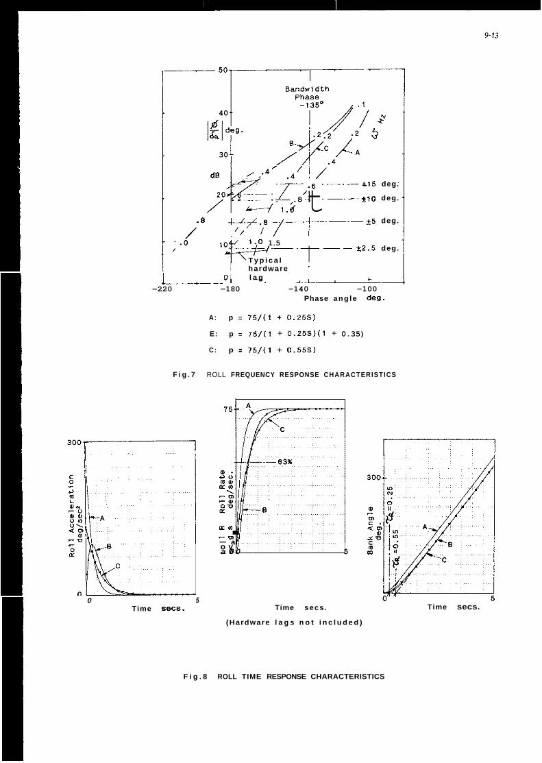
40
A 30 .-
6 .----+15 deg.
7 ’ . 6 ~ i _ j 6 1 , 0 fl E! , .---:IO deg.
. 8 .-L.L.~ -/-1-----+5 deg.
t2.5 deg.
. -. dB
/’
/ t /,’ /
.o lo<:/ 1.0 1.5 /
T y p i c a l hardware ’
0 l a g c
-220 -180 -140 -100 Phase ang le deg.
A: p = 75/(1 + 0.25s)
E: p I 75/(1 + 0.25S)(1 + 0.35)
C: p = 75/(1 + 0.55s)
F i g . 7 ROLL FREQUENCY RESPONSE CHARACTERISTICS
0 5 Time SeCs.
75 A
a a
~~ a 0 0 5
a m . -In - a o v
Time secs.
(Hardware l a g s n o t i n c l u d e d )
Time secs.
F i g . 8 ROLL TIME RESPONSE CHARACTERISTICS


DEVELOPMENT OF MIL-8785C INTO A HANDLING QUALITIES SPECIFICATTON FOR A NEW EUROPEAN FIGHTER AIRCRAFT
bY
E.Buchacker. WTD 61. GE H.Galleithner, DLK, 6t.
R.Koehler, ID1 R, GI: M.Marchand, DLR, GE
Institut fiir Flugmechanik (DLR) Postfach 3267
D-3300 Braunschweig Germany
1. Introduction
For the development of the Tornado, which started in the sixties, a dra f t version of MIL 87858 [11 was used as a guideline and specification for the f ly ing quaiities the airplane should have. No consideration was given at that time to the fact that requirements in Ill, which were based on mathematical models of the airplane, only considered the f l igh t mechanics of the bare airframe. An example of th is is shown in f igure 1, where a f l ight test measured transfer function "pitch rate due to elevator" is depicted which has the shape one would expect for a f i r s t over second order transfer function with a total phase change of 90 degrees. No hint was given on the method of approach to f l y by wire airplanes with a fu i i time fu l l authority f l ight control system, which after all does change the transfer function of the airplane the pilot has to work with considerably. I n f igure 2 the transfer function pitch rate due to stick force for the same airplane and f l igh t condition as in f igure 1 clearly shows the effect. The total phase change in the frequency range shown is at least 180 degree with no apparent limit value.
I n most cases a new airplane is sold on performance promises. The fact that a pilot has to be able to f l y an airplane safely and efficiently in order to achieve fu l l performance, especially in a combat airplane, is often forgotten. The Services are not seldom quite disappointed when it becomes clear that it is impossible to achieve the promised performance for reasons of conflicting f ly ing qualities issues which demand e.g. other than performance optimal t r im schedules.
This, coupled with the fact that there was not a lot of f lying quaiities research within the nations participating in the Tornado program, led to the situation that i t was more o r less only dur ing f l ight test that we on the user side realized the problems involved with full authority fu l l time f l ight control systems.
I n the meantime, however, some research efforts have been initiated by government as well as industry (mostly government funded), which have provided us with some second thoughts on f ly ing qualities requirements for highly augmented airplanes with a basically unstable pitch axis.
Together with industry, the four nations involved in the European Fighter Aircraft ( E i A ) Program decided to initiate an effort t o generate a f lying qualities specification for EFA based on the MIL-F-8785C [Z]. Germany undertook the task of Providing a dra f t of what is now the Handling Qualities Definition Document for EFA [31 (HQDD). I n subsequent discussions and negotiations chaired by the NATO E A Hanagement Agency (NEFMA) the draf t was turned into the final document which is now part of the EFA development contract.
Some of the issues we discussed and which might be of more general interest will be presented below. Our presentation wiii contain remarks on
- the equivalent system approach
-
- the carefree handling issue
- roll performance
- small lateral directional inputs
- air combat
- stall and spin
high order requirements for the pi tch axis
2. Lonaltudinal Axis
2.1 Equivalent System Appmch
Lower order equivalent systems were developed as a methodology in the early seventies as part of a f ly ing qualities assurance program in suppart of the F-14, pr ior to i ts f i r s t f l ight. This methodology was refined to the point where i t could be utilized as a f lying qualities criterion in Ref. [Z].
Guidelines on the use of the equivalent system methodology are to be found in the background information to MIL-F-8785'2 [41 and i n the draft of the MIL-Prime Standard and Handbook [SI, where a mismatch

10-2
envelope f o r the simultaneous match o f p i tch at t i tude and normal acceleration transfer functions (shor t period approximation), f igure 3, i s given. The following example indicated t o us that we should use those mismatch envelopes with caution. A second order system with a frequency o f 3 rad/sec a damping of 0,7 and an assumed n/alpha = 10 was corrupted with a pref i l ter having two poles and two zeros. The original system was chosen t o have levei I f l y ing qualities.
I n f igure 4 the p i tch acceleration response and the normal acceleration response of the resul t ing t rans fe r functions are shown. Figure 5 depicts a comparison of the result ing mismatch with the mismatch envelopes, tak ing the uncorrumed system as the equivalent system. The result ing mismatch is clearly inside the recommended envelope.
With the Control Anticipation Parameter (CAP) computed according t o i t s original definition,
the evaluation o f the systems led t o the results given i n f igure 6, .placing the systems with the added dynamics i n levei 2 and level 3 respectively.
However, since the original system without the added dynamics qualifies as an equivalent system, i t can be conciuded that the mismatch envelopes as given i n El allow too great variabi l i ty in the equivalent systems.
The equivalent normal acceleration transfer function as given i n f igure 3 refers t o the instantaneous center o f rotation, a point which i s not normally readily known, e.g. i n f l ight test.
Figure 7 shows normal acceleration due to st ick force transfer functions as deduced from f l ight tests fo r the f ron t seat and the back seat respectively o f the Tornado airplane under the same f l igh t conditions. The t ransfer functions were derived af ter estimating equivalent derivat ives with a MMLE t ype program and then computing the t ransfer functions. For the f r on t seat t h i s resulted in a numerator with a complex conjugate pai r o f zeros i n the left half plane whereas f o r the back seat, a non minimum phase system was the answer.
I f e.g. f l i gh t test measured t ransfer functions are used f o r the equivalent system matching process those differences have t o be accounted for.
Therefore we recommend the use o f equivalent model s t ructures as given i n Annex A, Table 1, which include second and four th order numerators f o r the short period and phugoid modes o f the acceleration t ransfer functions, If the t ransfer function referenced t o the instantaneous center o f rotation (COR) i s s t i l i required, it could be computed with the heip of the p i tch acceleration due t o st ick force transfer function according to the following reiationship:
n Z m nz q . . + k -- FS FS FS __--. _.
The arb i t ra ry constant k has t o be selected i n such a manner tha t the numerator of n d F S reduces t o zero order.
Given a higher order aircraft, f i ve parameters are available t o accomplish the match: M~s , I,,, WW, I/Tnz and r ( f igure 3) the new one being r, the delay time. The delay time basically enables us t o account f o r the additional phase sh i f t o f higher o rder systems as i s shown in f igure 8 where a time delay of .05 sec has been added t o the t ransfer functions of f igure 7. For the evaluation of stabi l i ty the shape o f the phase curve down to - 180 degrees is o f paramount concern. The frequency range f o r approximation of the higher o rder system by the equivalent system should therefore be selected i n such a manner as t o provide sufficient data points t o lead t o a good approximation o f the phase curve down to - 180 degrees and thus t o a g m d and meaningful representation of the phase b y the resul t ing delay time. Therefore we recommend the following procedure f o r definition of the frequency range of approximation.
The selected frequency range should contain the characterist ic frequencies of ail modes o f interest. Additionally, an upward and downward margin of one octave should be provided.
Ini t ial ly, a range from 0.1 t o 10 rad/sec is defined, which may be modified according to the following ru les if required:
For fu l l longitudinal model with phugoid: Lower limit < 0.5 wnp.
For Short-Period model, with the phugoid st i l l showing strong influence at 0.1 rad/sec: The lower limit i s the frequency between the peaks of resonance o f the phugoid mode and the short-period mode, a t which the minimum o f the p i tch rate amplitude appears.
The upper limit should be > 2 W ~ S P o r > 2 wm (ww = frequency a t which the phase angle of the p i tch rate response is - 90 degrees), whichever i s greater.
It must be noted that the deiay time computed with the above approach has t o be used f o r comparison with the equivalent system requirements and not delay times defined by other means as f igure 9 indicates. In f igure 9 four d i f ferent rules f o r computing delay times are compared. Here i t i s clearly shown tha t t he delay time computed according t o the bandwidth cr i ter ion st i l l indicates level 1 when the equivalent deiay time indicates levei 2 and the other two c r i te r ia never indicate ievel 1 at all when compared t o the set of l imits for time delay as given in [ Z ] .
A fu r ther variable which influences the qual i ty o f the equivalent system obtained is the number and

10-3
distr ibut ion of values used i n the approximation Process.
It appears reasonable to select values WR as logarithmic equidistant in order to provide for a uniform distr ibution of the points of support in the Bode plot. This poses no problem when frequency responses o f a mathematical model are to be computed.
I n contrast to the above frequencies are iinear equidistant when evaluating f l i gh t test data by FFT directly. This fact introduces the foiiowing disadvantages for an approximation:
( i )
( i i ) most of the values are situated i n the upper frequency range so that th is par t is weighted more
Therefore, conversion of a data set with a iinear distr ibution to a data set with an approximated logarithmic distr ibution is recommended. I n order to accomplish this, the frequency band is subdivided into intervals of equal size in the logarithmic scale. Should more than one point l ie inside such intervals, the original data are replaced by one averaged data point. In t h i s way, a shorter data set is obtained.
The influence o f the distr ibut ion of frequency Points used can be identif ied in f igure 10. A 4th-order system was used to generate three data sets with different d istr ibut ions of frequencies. From these data sets, second order models (wi th time delay) have been approximated.
Using 1,000 l inearly d istr ibuted values, a poor fit was achieved (Run A). The same data set was then converted to obtain a nearly logarithmic distr ibut ion at high frequencies. Using th i s wnver ted data set, better curve f i ts and results were achieved (Run E). Finally, a logarithmically equaiiy spaced data set was generated, From th is set, a good curve fit was obtained (Run C) (except at very high frequencies) and the eigenvalues of the LOES are very close to those of the dominant HOS-mode.
With a logarithmic-equidistant distr ibution, the number of values may be kept relatively low without degrading the quality of the approximation. When all poles and zeros of the system are sufficiently damped, a density of 20 points per decade may be recommended. Systems with weaker damping, however, w i l l require a substantially higher number of points, i n order t o provide coverage of ail the resonance peaks and the steeper phase drop, and exact determination of the damping ratio.
The above experiences and lessons learned were drafted into a recommendation of how t o apply the equivalent systems approach which then became par t of the HQDD for EFA 131 and is attached t o th is paper at Annex A. It also contains guideiines for the use of equivalent models in the iaterai directional axes.
the number of frequencies is very high and thus computation time i s very extensive,
intensively.
2.2 High order requirements
Besides a detailed look at the application of the equivalent systems approach we ais0 screened some of the higher order cr i ter ia and eventually developed one for EFA.
The cr i te r ia we started with were
- The Neal-Smith cr i ter ion in i t s original form 1121 - the Neal-Smith cr i ter ion as proposed in [51 - the Neal-Smith cr i ter ion with some changes in i t s boundaries proposed by one of us (Mr. Marchand),
- the Bandwidth cr i ter ion developed by Mr. Roeger from MBB [61 -
and a reduced bandwidth for level 2 (2.5 rad/sec) and level 3 (1.5 rad/sec) f igure 11
the Nichols-plot cr i ter ion developed by Mr. Oiederich from MBB [61
The two last named cr i ter ia were among others checked against pi lot ratings i n a simulation study which Oornier undertook under government contract in 1985 and 1986. The most promising cr i ter ion turned out to be the Diederich criterion. The application of the Roeger cr i ter ion Posed some diff icult ies in principle because of the way st ick force gradients had t o be considered fo r i t s use.
However, some modifications to the boundaries of the Diederich cr i ter ion proved t o be necessary and were proposed by Dornier and DLR. Dornier combined the Diederich Criterion with a cr i ter ion proposed by Gibson [131 which was a i m formulated in the frequency domain and presented i H a Nichols plot. DLR proposed some modifications to the boundaries on the r i gh t hand side.
The result ing Nichols plot criterion, f igure 12, defines limits for the normalized open loop t ransfer function pi tch attitude, e, due to st ick deflection, 6=, o r due to stick force in a Nichols diagram. Normalizing means in th i s cmtex t that the transfer function under test has t o be shifted up or down by vary ing the gain unt i l it runs through 0 db at -110 deg phase lag.
Because the Nichols diagram contains no constraints for the frequency range allowed, f igure 13 gives the required bandwidth fo r the f ly ing qualities levels L1, L2, L3 for f l igh t Phases A, B and C.
The cr i ter ion was designed for the evaluation of closed loop f ly ing qualities involving Smaii st ick inputs, i. e. it i s applicable to essentially linear conditions only. Regions of h igh angle of attack may have to be excluded.
The boundaries identif ied by asterisks (*) in f igure 12 are applicable only where provision is made for precision att i tude control fo r fine t racking at small st ick inputs. I n th i s case the boundaries identified by the asterisk in f igure 13 need not be observed for stick inputs of less than 10 mm fo r center st ick controllers.
10-4
For the boundaries identified by a double asterisk (**I, additional cr i ter ia apply to the not normalized transfer functions pitch attitude due to stick deflection (or due to stick force). A t the frequency where phase lag of pitch attitude to cockpit control displacement (or force) i s 180 deg, the following applies to levels 1, 2 and 3:
The rate of change of phase lag shall be less than 16 deg/rad/sec (100 deg/Hz) o r i f greater, then the phase rate at 190 and 200 degrees phase lag shall be significantly less than 16 deg/rad/sec (100 deg/Hz).
The amplitude shall be less than a maximum of 0.03 deg/mm o r 0.022 deg/N (0.1 deg/lb) for a phase rate of 16 deg/rad/sec (100 deg/Hz), increasing to 0.05 deg/mm o r 0.036 deg/N (0.16 deg/ib) for a phase rate of 11 deg/rad/sec (70 deg/Hz) o r less i f omega 180 > = 1.0 Hz.
The absolute limits stated above regarding stick displacement o r force gradients are mainly based on experience with EAP and f ly by wire Jaguar. They should really be rechecked for control stick designs vastly different from those used in the two airplanes mentioned.
DLR compared three versions ofthe Neal Smith criteria as given in f igure 11, the equivalent systems approach and the above described Nichols plot criterion with the Neal Smith database 1121 finding good correlation for the Nichols plot criterion jus t described (f igure 14). I n addition the combined criterion was checked by Gibson (British Aerospace) against his f lying qualities database collected mainly from the f l y by wire Jaguar and the experimental aircraft programmes (EAP). I n the course of joint discussions Dornier, DLR and Brit ish Aerospace developed the final version of the criterion, described above, which now serves as one of the design guidelines for the development of the longitudinal f ly ing qualities of the European Fighter Aircraft (EFA) 131.
The following limited guidance is offered for application of the criterion:
During the design phase of an aircraft project, the transfer function pitch attitude due to stick deflection i s readily available as an equation and can therefore easily be compared to the criterion and the additional features, e. g. phase rate between -150 deg and -200 deg phase can be computed as local gradients. For f l ight test derived transfer functions more care is needed in the region of the -180 deg phase and suitable mean values of the phase rate have to be derived because of the occasional poor quality of f l ight test data especially near and beyond the -180 deg phase.
I f the r i gh t hand side level 1 limit above 0 db is violated excessive droop back leading to pitch bubble i s indicated whereas violation of the left hand limits points to sluggish aircraft behavior resulting i n overshoots. Infringement of the left hand limits of Level 1 below 0 db hints at the fact that the design may be pilot induced oscillation prone. The criterion should at present be limited i n i ts application to judging the precision tracking behavior of combat aircraft in f l ight conditions where essentially linear behavior can be assumed. Feasibility in the high angle of attack region will be demonstrated by the X-31A program. The original Diederich criterion was used in the design of th is experimental aircraft up to high angles of attack.
3. Lateral directional axes
3.1 Roll performance
Figure 15, which is essentially taken from [ 7 ] , depicts the problem. With the wn t ro l power available .by aerodynamic means, roll performance will deteriorate at the high angles of attack readily attainable by modern fighter airplane designs. Here, the deteriorating yawing power is the key contributing factor when considering rolls around the velocity vector. A survey of the l i terature and rol l performance data available to us led to the wnclusion that combat roli performance requirements as stated in [21 have to be waived above a certain angie of attack. For the reduction of the requirements for the time to bank through 30 deg, 50 deg and 90 deg, we adopted the following equation:
t m k = tm.m + K(n - amif)
where t m k i s the resulting t ime to bank allowed tmmm is the time to bank as given in 121 for the combat f l ight phase k is a suitably selected constant n is the angie of attack attained axm* is the angle of attack above which the relationships may be applied.
However, it would be preferred not to need such a relaxation. But th is may have to wait unti l th rus t vectoring has become a standard design feature for f ighter airplanes.
3.2 Additional roll rate requirements for small inputs
Modification of the requirement "additional roll rate requirement for smaii inputs" (see 121) was a consequence of the experience gained from the Tornado Trials Program.
The MIL Specification of th is paragraph read:
"The value of the parameter p-/paV following a yaw-control-free step roll-controi command shall be within the limits as shown in f igure 16 for Levels 1 and 2. This requirement applies for step roll-control commands up to the magnitude which causes a 60-degree bank angle change i n 1.7 Td seconds".

10-5
Dutch Roll Motion provides the phase angle between the rate of roll and the angle of sideslip, which in t u r n i s a crucial factor in deciding which x-axis i s to be used. I n the Background Information to MIL-F-87856 [ l l ] an explanation is provided that th is angle for the linearised system of equations o f motion for the lateral directional axis with coefficients of conventional aircraft is to be found in one of the following areas:
90' < Phase (p/fl) < 180' 270' < Phase ( P A ) < 360'.
ot
When deviations from these values occur they are so minimal that configurations can sti l l be clearly allocated to the one o r the other axis.
I n the case o f modern f ighter aircraft w i t h complicated control systems values ly ing outside the normal areas can, however, be registered. I n the course of the official t r ia ls of the Tornado, mathematical models were established from f l igh t t r ia l data by means of System identification. The phase angle pattern p to fl as ascertained i n one particular test series is shown at f igure 17. The values iay in the region of 180' and thus bordered on the area i n which the phase angles were expected. 7 % of the evaluation values w e r e even found close to 225', with the result that smali changes in the parameters allowed the phase t o wander under o r over th is limit.
Now, exceeding a limit i n such a fashion after small changes have been made means that each time a change is made the second x-axis must be used. An evaluation which had init ial ly provided a value in the area for Level 1, subsequently intimated after an abrupt transition that the characteristics wouid not even be sufficient for Level 2 (see f igure 18).
I n order to obviate such discrepancies, the hypotheses for the derivation of the criterion were ascertained and included in the f l ight characteristic specifications for EFA. The requirements are as follows:
abs (L'r * YO) < < abs (L'P) abs (L'r * Ys) < < abs (L's) abs (4 * g * L'r) < < abs (V * L'%) abs (L'r) << abs (L'd.
If any one of these conditions is not fulfilled, then the requirement discussed here for the underlying parametric representation i s no longer applicable.
This limitation of the scope of application will obviate application of the criterion based on false premises. I n addition there will be no absurd abrupt transitions in the evaluation due to small changes i n parameter.
4. Miscellaneous
4.1 Carefree Handling
When industry tr ies to sell you a new fighter design, "Carefree Handling" is one of the colorful terms thrown at you to make you feel good about the product You are going to order.
Therefore the questions which arise are: what could th is term mean, what would be technically feasibie, how would i t support a pilot i n accomplishing his task.
As simulations have shown, a feature which protects the pilot from exceeding vital airplane limits frees his mind from the task of watching e.g. angle of attack, normal acceleration etc.. He would then be i n a position to direct more of his attention to the combat task at hand and would be less concerned with f ly ing the airplane. This i n t u r n would make him more successful against an otherwise equal opponent. Therefore limit setting systems make sense, especially if the airplane cannot be designed inherently carefree from i ts aerodynamic design point of view. It is exactly this, however, which would solve the problem of the angle of attack, but not of normal acceleration i.e. structural limits.
The minimum components a "Carefree Feature" should be able to offer should be, in our opinion:
Automatic prevention of stall departure, autorotation and spin. This would have to include incidence and sideslip control and limiting for both positive and negative values.
- Normal acceleration control and limiting for positive and negative values.
- The capability for safe but aggressive lateral/directional maneuvering inside the fu l l angle of attackhormal acceleration envelope.
Unrestricted use of the throt t le and of other means which decelerate or accelerate the airplane.
- Automatic scheduling of limits according to configuration and loading conditions.
Together with the desire to exploit the aerodynamic/flight mechanic possibilities of the basic airframe design to its fu l l extent, Le. to provide the pilot with an envelope which gives him superior combat capabilities, the above w i l l prove to be quite a design challenge.

10-6
4.2 Stall and Spin
As a "Carefree Handling" feature should inciude angle of attack limiting functions, then definition of stail angle of attack as a basis for defining important airplane speeds and speed limitations would have to be reconsidered. Stall angle of attack may not be determined by an air flow related phenomenon such as a normal acceleration break but simpiy by some suitable limit set by some iimiting function inside the f l ight control system.
This, in turn, would change emphasis of f l ight test of stall and spin. The characteristics of staii departure and post stall gyrations are not of prime concern anymore. O f prime concern, however, are the following questions:
How suitable are the f l ight control system limiting functions set and implemented, given the task of the airplane.
Can they easily be defeated by any pilot action?
A thorough f l ight test of departure and post stall gyrations would become necessary in order to define the changes, including changes to airplane configuration, which would make i t safe to f l y only i f a limiting feature proved to be incapable of doing i ts job of protecting pilot and airplane and at the same time providing a sufficient envelope for the task.
Therefore requirements for stall and spin were formulated for EFA to allow for a stepwise approach. Further testing depending on results of steps compieted. I t may well be that the airplane will never be spun i f the only way of achieving th is is to switch o f f the f i ight control system completely. However, th is approach places a heavy burden on wind tunnel testing and simulation.
4.3 The Air-to-Air Combat Fliqht Phase
Any requirement drawn up is in effect the application of past experience in an attempt to forecast the future. However, there is a way out for handling qualities requirements for piloted airplanes. All requirements defined in terms of envelopes for open o r closed loop system parameters have been developed by matching pilot opinion to those system parameters. Where no numeral can 'be defined, pilot opinion itself may be used and th is i s done frequently. Based on experience gained at the Air Force Flight Test Center with the handling qualities during tracking (HQDT) approaches [81 and our own experience using th is technique 191, 1101, we introduced the following as a requirement.
During air-to-air combat, the pilot will perform a series of gross turning, rol l ing and puil-up maneuvers, target acquisition maneuvers, and precise target tracking. To help ensure that the EFA has satisfactory Handling Qualities during the acquisition and precise tracking segments of the air-to-air combat engagement, pilot opinion ratings must clearly indicate Level 1 Handling Qualities. Such ratings shall be achieved within the primary air combat f l ight envelope.
We are now preparing a simulation at IABG in their dual dome combat simulator where we will more closely define and match to the European Fighter Aircraft the methods (pilot brief ing papers, combat maneuvers, pitot questionnaires and debriefing procedures) to be used dur ing simulation and f i ight test to prove compliance with the above requirement.
5. Summary
MIL-F-8785C 121 was used in a sense which in the US was introduced with the deveiopment of the MIL- standard and handbook concept, namely, to provide a framework for the development of f lying qualities for airplanes. I n our case 121 was stripped of everything not related to a f ighter type airplane and amended where we believed it was necessary. From the many details which had to be considered, our paper concentrated on areas of the HQDD 131 where we fe l t it necessary to give better guidance for the application of the criteria (equivalent system approach, small roll step inputs), where new criteria had to be introduced (high order system criterion, carefree handling, pilot evaiuation in simulated air-to-air combat) and where the emphasis of existing ones had to be changed o r amended (stall and spin, roll performance).
We feel that the concentrated efforts of industry and government have produced a set of f lying qualities criteria which will pave the way to excellent f iy ing qualities of the European Fighter Aircraft.
6. References
111 Military Specification, Flying Qualities of Piloted Airplanes, MIL-F-8785B(ASG), August 1969
[21 Military Specification, Flying Qualities o f Piloted Airplanes, MIL-F-8785C, November 1980
Dl Handling Qualities Definition Document fo r EFA, Issue D, January 1990
141 0. J. Mwrhouse, R. J. Woodcock, Background Information and User Guide for MIL-F-8785C, Military Specification, Flying Qualities of Piloted Airplanes, AFWAL-TR-81-3109, July 1982
151 Flying Qualities of Piloted Airplanes, MIL-Prime Standard and Handbwk (Draft), Wright Patterson

10-7
AFB, February 1386
K. Brauser, L. Diederich, W. Roger, Steuerbarkeitskri ter ien zur Bewertung der Manovriereigenschaften moderner Hochieistungsflugzeuge MBE/FE 301/S/R/1505, Dezember 1380
J. R. Cody, J. Hodgkinson, A. M. Skow, Combat Aircraft Control Requirements for Agility, AGARD Fluid Dynamics Panel Symposium, Madrid, October 1989
8. L. Schofield, T. R. Twisdale, W. G. Kitto, T. A. Ashurst, Development o f Handling Qualities Testing in the 70's a New Direction, AGARD CP 333
H. Galleithner, Operationelle Flugeigenschaften von .Kampffiugzeugen im Luftkampf und im Tieffiug, DFVLR, I B 563-81/1, Oberpfaffenhofen, 1983
R. Koehler, E. Buchacker, D. J. Biezad, GRATE - A New Fl ight Test Tool f o r F ly ing Quaiitles Evaiuations, AGARD CP 452
R. J. Woodcock, C. R. Chik, T. P. Neal, T. M. Harris, F. E. Pri tchard, Background Information and User Guide for MIL-F-8785B(ASG), Mil i tary Specification - Fly ing Qualities of Piloted Airpianes, AFFDL-TR-69-72
T. P. Neal, R. E. Smith, An In f l i gh t Investigation t o Develop Control System Design Cr i ter ia fo r F ighter Airpianes (Vol I and 11), AFFDL-TR-70-74, 12/1370
J. C. Gibson,Piloted Handling Qualities Design Cr i ter ia f o - High Order F l ight Control Systems, AGARD CP 333
ANNEX A
GUIDELINES FOR THE DETERMINATION OF EQUIVALENT MODELS
A. 1 General Procedure
A. I . I Gensral Approach
Fo- the determination o f equivalent modeis, one o r simultaneously two frequency responses of the h igh o rder system are approximated by complex functions of the formula
where 2, and N are polynomials o f the formula
m:
(wi th i = 1, 2). The coefficients av of the denominator polynomial, together with coefficients bvi ( i = 1, 2) o f the numerator poiynomiais and the dead times 7% ( i = 1, 2) are determined i n such a way tha t a cost function i s minimized with given numerator degrees mi ( i = 1, 2) and a given denominator degree n. To obtain unambiguous solutions, one o f the coefficients for each frequency response must be given beforehand, which i s most easily done by specifying
a , - 1
A. l .2 Definition of the Cost Function for One Frequency Response
The defini t ion must ensure tha t the resul t of the aooroximation is indeDendent o f the standardization o f the frequency iisponses. I n the foliowing, two types o f 'the cost function are stated which fu l f i l l th is defini t ion ( for the approximation o f one frequency response t o begin with).
a) Gain Phase Er ror Function
N I C = 5$ 1 [ A G f + ( A P f ]
x= i

10-8
where
C = Cost of function o r mismatch N = Number of discrete frequencies wk
Gk = Deviation of the amplitude at W k ( in dB) APk = Deviation of the phase at wk ( in degrees) f r Weighting factor between amplitude and phase
The factor f is generaily stated with 0.017 or 0.020, but can be varied if required.
b ) Maximum Likelihood Error Function
Based on the assumption that the real and imaginary parts of the approximation error are statistically independent Gaussian random variables with constant relative standard deviation, the M L er ror function reads as follows:
where
N r Fk = Value of frequency response at WL
= Complex value of deviation at w k
The ML error function can be transformed by approximation into an ampiitude-phase er ror function for Small errors with a resultant factor f = 0.023 between phase and amplitude terms.
A. 1.3 Cost Function for Two Frequency Responses
On simultaneous approximation of two frequency responses, the deviations (errors) along the two frequency responses are accumulated:
c = c, t gc2
where
c, , c2
9
The weighting factor g may be used to consider differing error levels of the two frequency responses.
= Cost functions for the 1st and 2nd frequency responses as stated above
= Weighting factor between the two frequency responses generally g = 1
A. 1.4 Selection of the Approximation Method
A specific method will not be suggested, as any minimum finding method may be applied. When Selecting such method, however, the following items should be given due consideration:
'
.
. possibility of individual weighting (e.g. along the frequency o r by means of amplitude and phase
structure of cost function (e.g. whether o r not the gradients may be analytically expressed)
possibility of f ixing or varying specific parameters within given limits
errors).
A. 1.5 Selection of Frequencies
When selecting frequencies, the following items should be considered:
' low-frequency cutoff ' high-frequency cutoff '
' number of frequencies
a) Frequency Cutoffs
Cutoff frequencies are generally dependent on the examined system. The eigenvalues, the influence of which is to be evaluated, must be inside th is frequency range of approximation. Standard default values are given in paragraph A.2.3.
distribution of values, e.g. linear o r logarithmic equidistant along frequency
10-9
b) Distribution of Values
It appears reasonable to select values wk as logarithmic equidistant i n order to provide for a uniform distr ibution of the points of support i n the Bode plot. This poses no problem when frequency responses of a mathematical model are to be wmputed.
I n contrast to the above, frequencies are linear equidistant when evaluating f l ight test data by FFT directly. This fact introduces the following disadvantages for an approximation:
*
' most of the values (as seen in Bode plot) are situated i n the upper frequency range so that th is par t
the number of frequencies i s very high and thus computation time i s very extensive
i s weighted more intensely.
Therefore, conversion of these values with a linear distr ibution to values with an approximated logarithmic distr ibution is recommended. I n order to accomplish this, the frequency band i s subdivided into intervals of equal size in the logarithmic scale. Should more than one point lie inside such intervals, both frequency and frequency response values are averaged. I n th is way the original points are replaced by average values and a shorter data set i s obtained.
c) Number of Frequencies
With a logarithmic-equidistant distribution, the number of values may be kept relatively low without degrading the quality of the approximation. When all poles and zeros of the system are sufficiently damped, a density of 20 points per decade may be recommended. Systems with weaker damping, however, will require a substantially higher number of points i n order to provide coverage of ail the resonance peaks and the steeper phase drop, and exact determination of the damping ratio.
A.1.6 Assessment of Curve Fits
No binding statement can be made as to when an approximation will be useful or not. Therefore, the use of er ror tolerance limits - as stated in US l i terature - i s not t o be recommended. The safest method is t o make use of the experience of, and lessons learnt by, the person performing the assessment. In order to accomplish this, i t is recommended that the assessment be carried out by interactive computer programs providing an immediate graphical display of the frequency response curves of both the higher-order system and the low-order model. I t w i l l be necessary to determine which parameters of the equivalent model are of special importance and i n which frequency ranges these Darameters will be of particular influence. Thus i t i s quite possible that one or several parameters of the equivalent model may not be usable because the curve fit i n the respective frequency range is inadequate.
A. 1.7 Assessment of Parameters
Even with perfect curve fit i t cannot always be ensured that the approximation will produce meaningful and unambiguous values for the parameters of the equivalent model. Probiems should be expected when output data (e.g. for frequency outputs obtained on f l igh t test) are of poor quality or when modei structure is inadequate for the problem. The following paragraphs are intended to provide some assistance to th is end.
a) Frequency Response Values
When analyzing f l igh t test data by FFT, the confidence limits and/or the coherence fubction should also be considered. For example, the frequency ranges for which the value of the coherence function is distinctly ( 0.7 (maximum possible and most favorable value i s 1.0) should be excluded from fur ther computation.
b) Correlation of Parameters of Highly Damped Systems
With systems displaying a damping ratio of about 1.0 or with 2 adjacent real eigenvalues, the frequency response does not show distinct peaks. I n such cases the natural frequency and the damping ratio may be increased o r decreased simultaneously without achieving any substantial change in the frequency response curve.
This results in a margin of uncertainty which can become as high as i 30 % and mUSt be also considered when applying these parameters to Handling Quaiities cr i ter ia of aircraft.
c) correlation of Time Delays and Time Constants
When several time constants of the numerator poiynomial and the denominator poiynomiai and an equivalent time delay are to be determined for a frequency response, the results may prove to be strongly correlated, so that several sets of values of the parameters may belong to very similar frequency responses. Because e-Ts 2 1/(1 t To), such influences of time delays and lag time constants cannot be discriminated at low frequencies. If problems are encountered they might be solved by applying one of the following measures:
Reduction of the order of numerator and/or denominator. Fixing o f individual parameters. Change of frequency range, e.g. extension to higher frequencies. Selection of other o r addition of fur ther frequency responses which can contribute to obtaining better

10-IU
information on specific parameters.
d) Correlation Between Poles and Zeroes
When poles and zeroes are close together, their location in the s-plane has scarcely any influence on the frequency response, and the associated natural frequencies cannot be determined unambiguously. I f problems are encountered they may be solved by applying one of the following measures:
Reduction of the order of numerator and denominator, when a single frequency response is to be assessed only. Fixing of individual parameters, e.g. the eigenvalues of the denominator. Addition of a fur ther frequency response, i n which poles and zeroes are more distinctly separated.
A.2 Determination of Equivalent Models
The general structure of equivalent models has been outlined in Section A. l . l above. Special information for the individual models has been compiled in Table A . l . I n doing so, potentially known elements of the model, e.g. factors l/s or 1 + TBZS at a fixed Ter, were included in the transfer functions to be adjusted. This measure decreases the order of the models and thus computation ef for t without invalidating the cost functions (cf. Sect. A 1 ) and thus the results.
A.2.1 Structure o f the Models for Longitudinal Motion
The Full Longitudinal Model includes both, the phugoid mode and the short-period mode, and will be employed in cases where both modes are not distinctly separated. The Short Period Model may always be employed in those cases where the modes are distinctly separated from each other i n their frequency responses.
The "Phugoid Model" is listed for the sake of completeness, although it need not necessarily be employed, as stability may easily be verified without using an equivalent model.
The numerator time constant T a of the pitch frequency response determines one zero digit of the transfer functions (1) and (5). I t may either be computed from the aircraft data and preassigned as a fixed value, o r it may be determined in the course of the approximation. When fixed, a linear factor.may be extracted from the model and correspondingly included in the values of the transfer function. To accomplish this, the values available are divided by (1 + Tms), and the degree of the numerator of the equivalent model reduced by 1. I n th is way we obtain the transfer functions (2) and ( 6 ) instead of (1) and (5).
To improve the validity of the equivalent model, approximation of a transfer function of normal acceleration (3, 4, 7 or 8) in conjunction with a transfer function of the pitch motion (1, 2, 5 o r 6 ) is recommended. I n doing so, we must differentiate whether the values available are for the so-called "center of rotation" (= COR) or for another point, e.g. the c.g. o r pilot station, When the reference point coincides with the COR, the numerator degree of the Short-Period Model = 0 (or = 2 with the phugoid mode model). For other points of reference, vertical acceleration wntains a component of q-dot and thus an additional quadratic component i n the numerator (transfer functions (4) and (8)). This generally i s the case dur ing the assessment of test data, inasmuch as a computation of vertical acceleration for the COR is not possible without exact knowledge of the derivatives.
A.2.2 Structure of the Models for Lateral Motion
The object of approximation of equivalent models for lateral motion is to determine both the parameters of the dutch roll and the roll time constant. Therefore, t w o different transfer functions are to be approximated simultaneously, one for each dominating mode. Best suited for th is purpose are R/Fv and @/Fa (transfer functions (10) and (11) or (13) and (14) from Table A.1). A th i rd transfer function, R/F. (12) has also been given. This function is only required, however, when the cr i ter ia 3.3.2.2.1, 3.3.2.3, 3.3.2.4 or 3.3.2.4.1, 121, which wnta in A D or B on the basis of roll control inputs, are to be applied.
Apart from the dutch rol l mode and the roil mode, the "Full Lateral Model" also includes the spiral mode. For the purpose of assessments conducted outside the frequency range o f the spiral mode, the model may be reduced by one pole by multiplying the transfer function to be assessed by s. This results in the model with transfer functions (13) through (15).
I n cases where application of the above-mentioned models does not render useful results, we can attempt to determine the parameters step by step, using the reduced model ((16) and (17)). To accomplish th is we star t with transfer function (16) above and only determine Cd , wnd and re initially. Values of C# and Wnd then remain fixed during the second step, where TR and re are determined by approximation of (17).
A.2.3 Frequency Ranges for the Approximation
The selected frequency range should contain the characteristic frequencies of all modes of interest. Additionally, an upward and downward margin of one Octave should be provided. To determine the frequency range, the following procedure may be used:
Initially, a range from 0.1 t o 10 rad/sec is defined, which may be modified on the basis of the following
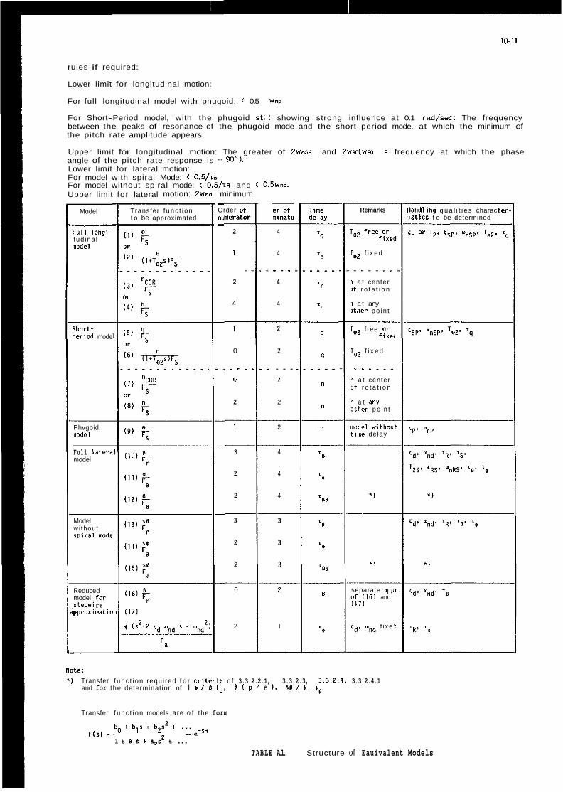
10-11
rules if required:
Lower limit for longitudinal motion:
For full longitudinal model with phugoid: < 0.5 Wnp
For Short-Period model, with the phugoid st i l i showing strong influence at 0.1 rad/sec: The frequency between the peaks of resonance of the phugoid mode and the short-period mode, at which the minimum of the pitch rate amplitude appears.
Upper limit for longitudinal motion: The greater of 2wmp and 2wsdw.a = frequency at which the phase angle of the pitch rate response is - go*). Lower limit for lateral motion: For model with spiral Mode: < 0.5/rs For model without spiral mode: < 0.5/rR and < 0.5Wn.i Upper limit for lateral motion: 2wnd minimum. -
Order o i ""merat< -
2
1
2
4
- er o f minata
Remarks i and l i ng q u a l i t i e s charac i s t i c s t o be determined
cp or T2' csp+ Y ~ ~ ~ , Te2.
Transfer f u n c t i o n t o be approximated
Model
4
4
- . -
4
4
'"I1 l ong i - t ud ina l nodel
f i x e d
1 a t center If r o t a t i o n
1 a t any i t h e r p o i n t
j h o r t - ,eriad mode
1
0
. - - 11
2
2
2
...
2
2
9
q ..
n
n
f ree or f i x e <
Ig2 f i x e d
- . - . . . 1 a t center If r o t a t i o n
1 a t any i t h e r p o i n t
I 9 1 FS
I
__ 3
2
2
__ 3
2
2
2 iiotlel wit l iou tiine de lay rip c p . Y Phvgoid
nodel
Full later? model
4
4
4
~
3
3
3
*I
Model wi thout s p i r a l mode
* \ * )
Reduced model for I tepwi re pproximnatii
0
2
-
B separate app o f ( 1 6 1 and ( 1 7 1
cd, wnd f i xe '
Note: *I Transfer f u n c t i o n requ i red f o r C r i t e v i a o f 3.3.2.2.1, 3.3.2.3, 3 . 3 . 2 . 4 , 3.3.2.4.1
and for t he determinat ion of I + I s Id, X I p / e I , be / k ,
Transfer f u n c t i o n models a re o f t he form 2
e-s. b o t b ls t b2s + ... Flsl =
1 t 8,s + a,$ t ... TABLE A.1. Structure of Eauivalent Models

L i l
', F Y
.,: a . * z <
I
c- < L L
2 , ~ PITCH RATE / ELEVATOR
Fig. 1 Flight Test Derived Transfer Function Pitch Rate / Elevator
. 2 , 3 , ] PITCH RATE / STICK FORCE
Fig. 2 Flight Test Derived Transfer Function Pitch Rate / Stick Force
Fig. 3 LOES Short Period Approximation

EXAMPLES OF ADDED DYNAMICS
10-13
COMPARISON OF ADDED DYNAMICS AND MISMATCH ENVELOPES
CAP Requirements (Cat. A) Influence of Added Dynamics
omega nsp CAP. 100
n 3
i t
d
a
n
" c
d B
188
h
18
8
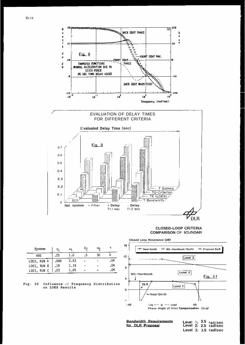
10-14
System
I80
a h
i 20 98 =
ti 30
9 n s
t
d
a
e 10 0
d 8
0 -98
-180 10-2 101 102
kquencr ( r a d k d
/ EVALUATION OF DELAY TIMES FOR DIFFERENT CRITERIA
_.__ valuated Delay Time (sec)
-.-
0.7
0.6
0.5
0.4
0.3
0.2
0.1
/' ,/
/
0 Ref. system + Filter * Delay + Delay
T-.I sec T*.2 sec
CLOSED-LOOP CRITERIA COMPARISON OF BOUNDARIES
Closed L o w Resonance (dB)
c2 Y .I * Neal-Smith MIL-Handbook (Draft) +Proposal DLR
Fig. 10 Influence of Frequency Distribution on LOES Results
-45 Lag '--- 0 ---, Lead 45 Phase Angle 01 Pilot Compen~atlon ldegl
Bandwidth Reauirements ~~~~l 1: 3.5 rad/sec for DLR ProDosal Level 2: 2.5 radlsec
Level 3: 1.5 radlsec

10-15
OPEN LOOP PHASE (DEG)
- m 2o s!. ul ,” 16 . 0
0 12 3
J
w
k n I 8 U n 0
z W
4 2
g o 2 + -4. 5 a
W
W
- 8
-12
Fig. 12 High Order System Criterion Pitch Attitude Frequency Response Limits
ww ~
(n /a )D ’
ATTITUDE RESPONSE O . l O 7
0.067 * F,, HZ
0.5
0.2
5 10 0.1
1 2 “la giraa
CORRELATION OF H.O. CRITERIA Fig. 13 Bandwidth Requirement for the WITH COOPER-HARPER RATINGS
Data 8ase: T-33 Tests, 57 Configurations High Order System Criterion of Fig. 12
Handling Qualities Criteria

591 OS1 SCI 0
0 1
D Z
I3 S818-+lIwl LN3W3tlln03tl NOiiVlli3SO 31Vtl 110H
D C
3P ( 061/L) SON033S/l-Alll10V lVt131Vl
(SNOIlVflWA3 is31 1HE)ll-I OLlVNt(O1) U/d 313NV 3SVHd 3 0 NOllnFJtllSIa
91-01

DO Civil Flying Qualities Requirements Address Militaly Missions for "off-the-shelf" Procurement?
by
0. Thomas Black USAF Aeronautical Systems Division (AFSC)/YFEF
Wright-Patterson AFB, Ohio 45433-6503 (USA)
and
Walter A. Grady, Major, USAF USAF 4950th Teat Wing (AFSC)/DOF
Wright-Patterson AFB, Ohio 45433-6503 (USA)
and
Dan" C. McDonald, Major, USAF USAF Aeronautical Systems Division (AFSCl/VXEF
Wright-Patterson AFB, Ohio 45433-6503 (USA)
Abstract:
"Off-the-shelf" procurement of oivil aircraft for use by the military services is a tradition dating back t o the earliest days o f aviation. This relieves the military of t h e responsibility for development Costs, takes advantage o f civil designs already i n existence, and has resulted i n many capable - even famous - aircraft being added t o t h e military inventory. However, while civil aircraft missions have remained relatively unchanged for over half a century, new militaey missions have continued t o evolve: radar surveillance, battlefield management, aerial refueling, and routine low-level high-speed operations being examples. Yet, t h e military services still procure civil-certificated aircraft t o aocomplish these demanding new missions.
Aviation Regulations (FARs) 23 and 25 and their predecessors (e. g. CAR 4b) are the certification standards for civil aircraft. The primary objective of these regulations is t o insure a minimum standard of airworthiness. Flying qualities requirements make up only a small portion o f these regulations, and address primarily static Stability characteristics. This has Sometimes led t o undesirable flying qualities when attempting t o perform demanding military missions with civil-certificated aircraft.
The unique military missions are addressed in the u . S. military flying qualities specification, M I L - s T D - ~ ~ ~ ~ A , and its predecessors (MIL-F-8785 series). These military specification requirements are compared t o the civil (primarily FAR 2 5 ) requirements t o substantiate their applicability t o off-the-shelf procurement. Specifically, where military and civil missions differ, military flying qualities requirements should be invoked. TO illustrate this, several examples will be examined. Finally, the future of off-the-shelf procurement will be contemplated, some implications discussed, and recommendations made.
In the United States, Federal
Introduction:
From the earliest days of military aviation i n the United States, many aircraft have been procured "off-the-shelf" by the armed forces. The first military aircraft - the Wright Flyer o f 1909 - was an off-the-shelf purchase, albeit with a simple (by today's standards) military specification oreated t o cover t h e aircraft. Other famous off-the-shelf aircraft include the DC-3, 4, 6, 9, and 10, Boeing 707, 727, 737, and 741 vaxiants, and various Small transports and trainers. In aome cases, these aircraft were procured "as is", while in other cases military-requested modifications were made t o the aircraft due t o unique missions. In many of these procucements, civil certification ~ 8 8
accepted rather than requiring compliance with military specifications.
aviation operations, there are many applications which are militaxy specific. Some o f these, such as aerial oombat, battlefield area interdiction, and close air support are obvious. These missions require aircraft produced exclusively for their accomplishment, and which are purchased e x ~ l u ~ i v e l y by military services. Such aircraft are required t o comply with military specifications as a matter o f C O Y T S ~ . Other missions, such as basic training and air transport, are common t o civil and military operations, and contain Common elements: takeoff, climb, cruise, descent, and landing. Civil and militaxy flying qvalitiea specifications both address these basic missions and tasks. Seeing this, one would conclude that it may not be necessary t o have different specifications, and One set should be able t o adequately address aircraft performing these missions. More specifically, civil certification should be adequate t o cover Sueh aircxaft.
The United State3 Air Force, recognizing certain advantages in procuring existing designs when possible, has provided guidanoe and direction in Air Force Regulation (AFR) 80-36 (Reference
When considering military and civil

11-2
1). This regulation addresses procurement of commercial off-the-shelf aircraft fox Air Force "*e, and provides guidance concerning circumstances under which certification t o civil standards is acceptable. According t o AFR 80-36. "Trangport aircraft must be designed t o comply with civil airworthiness standards when their use is generally consistent with civil operations." (Emphasi5 added). This policy allows the USAF t o lower development costs by taking advantage of existing civil certification testing, and lower production and operating costs by taking advantage o f existing civil production and logisties programs and facilities. This policy also facilitates greater interchangeability of USAF and civil tranSport aiecraft t o gain maximum airlift and flexibility in emergencies, and improves the ability t o dispose of s"rp1"s aircraft.
Because civil and military standards and practices differ - in 8ome cases, significantly - the Air Force has experienced mixed results in operating commercial off-the-shelf aircraft. While generally S U C C ~ S S ~ Y ~ , the experiences have not been painless, and many lessons have been learned concerning how "generally consistent" civil and military operations should be before allowing the use of commercial standards. This paper does not presume t o State Air Force policy, except where noted, but instead will simply discuss civil and military flying qualities requirements, their applicability t o military missions, and will relate the authors' experience in dealing with the various requirements on Several recent Air Force programs. From this, the authors will try t o derive lessons applicable t o flying qualities specifications for future off-the-shelf procurements.
Flying Qualities Specifications:
civil aizccaft certificated by the United States' Federal Aviation Administration (FAA) a x e done so t o the Standards Of Federal Aviation Regulations, generally part 23 (FAR 23) or 25 (FAR 25, Refezence 2); for the purposes of this discussion the two documents are similar. The foemer addresses primarily light aircraft (up t o 5,682 kg) while the latter is directed toward larger, transport-type aircraft. These regulations cover the entire range of topics associated with aircraft airworthiness, including Structures and strength, flight envelope, performance, and Stability and control. The ~ u r r e n t United States military flying qualities specification is Military Standard 1797A (MIL-STD-17971, Reference 3). Unlike FAR 25, MIL-STD-1797A OOnfineS itself exclusively t o flying qualities.
The stability and control/flying qualities portion of FAR 25 is contained in some 21 paragraphs. These paragraphs address:
- Controllability and Maneuverability - Longitudinal Control - Directional and Lateral Control - Minimum Control Speed - Trim . ~ ~~~~
- Stability - Static Longitudinal Stability - Demonstration of Static
Longitvdinal Stability
- Static Directional and Lateral Stability
- Dynamic Stability - Stall Demonstration - Stall Characteristics - Stalls: Critical Engine Inoperative - Longitudinal Stability and Control - Directional Stability and Control - Wind Velocities (fox Taxiing) - Spray Characteristios, Control, and
- vibration and Buffeting - High-speed Characteristics - Out-of-Trim Characteristics The user Of the Federal Aviation
- Stall warning (Ground Handling)
(Ground Handling)
Stability On Water
Regulations muSt understand from the outset that the GARS primarily address flight safety. They are intended to insure only that the aircraft is safe to put on the market. The suitability of the design fox its intended mission(s) i s not assured; rather, it is assumed the S U C C ~ S S
or failure of the design will be detecmined by marketplace forces. That is, if the users (pilots, passengers, and operators) find seriou9 operational fault(s) with the design, it will through lack of $ales be a failure.
specifically address takeoff, climb, level flight (cruise), descent, and landing, including turns required in performing those items. EaOh of the items listed is considered by MIL-STD-1797A t o be a non-precision (Flight Phase Category 8 ) or terminal (Flight Phase Category C) task. There are no requirements which address high-precision tasks (MIL-STD-1797A Flight Phase Category A), as it is not contemplated by FAR 25 that FAA-certificated aircraft will be required t o perform SuOh tasks.
The vast majority of the requirements of FAR 25 are subjective in nature. At flight Condition3 specified In the regulation, the characteristics of the airplane must be acceptable to the pilot. In practice, guidance is usually provided by FAA regional Offices concerning the definition of "acceptable", and the final judgment o € any characteristic is by experienoed company and FAA test pilots. This judgment is binary - the characterietic i s either acceptable or it is not - and levels of acceptability are not addressed. AS noted by generations Of flying qualities engineers, exactly what is "acceptable" is open for interpretation by engineers and pilots; FAA regulatory processes add variations in interpretation between regional Offices t o further confuse the issue.
Where objeotive requirements are given, they are usually in aceas critical t o flight safety. Specifioally, Control force limits, longitudinal Static (speed) stability, minimum control speed characteristics, stall warning, crosswind taxi, takeoff, and landing wind velocities, and characteristics following a trim system runaway or failure are specified.
attitude or flight path (alluded t o above) generally lead t o requirements on the dynamic Characteristics of an aircraft and its Stick feel and dynamics. Again, as civil air transport operations rarely
The requirements o f FAR 25
Tasks requiring precise control of
11-3
definitions section includes all of the pertinent aeronautical terms. Consequently, it is not neoessary t o cros9 reference terms with other publications for clarity.
possible t o review all the areas addressed by MIL-STD-1797Ai the reader is referred to Leggett (5) and Woodcock(6) for more details. However, in general terms, the document addresses:
In the interest of brevity it is not
- Loadings and Inertias - Flight Envelopes - Flight Phase Categories - Aircraft Configuration and States - Failure Modes and Effects on Flying - Interpretation Of Requirements - Static and Dynamic Stability
3ua1ities
Requirements fox - Pitch Axis - Flight Path (Normal) Axis - Speed (Longitudinal) Axis - Roll Axis - Yaw Axis - Side (Lateral) Axis - Combined Axes
- Flight at High Angle of Attack - Atmospheric Disturbances - Stick FOrCe-Feel-Deflection - pilot Induced Oscillations - Trim Systems
Characteristics
The above list is not meant t o be exhaustive, but is rather meant to illustrate the breadth and scope of the subjects addressed by the dooument. AS mentioned earlier, the various tasks t o be performed by the aircraft are addressed by the Flight Phase Categories. Another important distinction is that M I L - s T D - I ~ ~ ~ A contains many objective requirements, and allows for levels of flying qualities in demonstrating compliance with these objective requirements (for a disoussion of
Leggett and Black (7)). The intent Of this is to allow graceful degradation o f the flying qualities as the edges of the envelope are approached, but Still require the best flying qualities in the portion9 o f the envelope where the aizcraft accomplishes its primary tasks.
by MIL-STD-1797A are geared directly t o the flying qualities of airoraft performing specific military missions; the requirements themaelves reflect lesson5 learned in the flying qualities found necessary for the performance of those missions. In contrast, Federal Air Regulations apply more generally t o the airworthiness of aieceaft transiting from point A t o point B. AS noted earlier, AFR 80-36 States "Transport aircraft must be designed t o Comply with civil airworthiness standards when their use is generally consistent with civil operations." Obviously, missions Such as low-level operations, formation flying, and aerial refueling do not conform with "...generally consistent with civil operations." However, AFR 80-36 i-ecogn,izes this by continuing, "This does not preclude using military specifications and Standards in designing an aircraft when necessary t o make sure that the aircraft performs its military role properly under the intended operating
objective and subjective requirements, See
The framework and guidance provided
require such Control precision, no quantitative requirements are levied against these characteristics by FAR 25.
It is also implicit in the requirements Of FAR 25 that the flying qualities of the aircraft are those of the unaugmented airframe. If Stability augmentation is used, it is assumed that the "bare airframe" dynamics are not unsafe; they must be demonstrated in flight test. Degraded-mode operation is not explicitly addressed except for failure o f stability augmentation and/or trim Systems (and engine failures). TO date, except for the Airbus Industrie A320 (Reference 4). the FAA has not had to address aircraft whose flying qualities are highly augmented or which are open-loop unstable, nor have they had t o addre*$ flying qualities degradations following system 01- subsystem failures, or failures of integrated control or guidance modes.
complement of regulations exercises a "cradle-to-grave" philosophy. A certificated aircraft is manufactured in accordanoe with approved drawings and pcocedures using approved materials, parts, and processes, and is maintained in aocordance with regulations by FAA-approved repair stations. Any change in any of those requires a new oe amended certification to be granted for the aircraft t o remain certificated.
qualities specifications have been levied against aircraft being procured by the United States Armed Forces. These requirements have evolved through the MIL-F-8785 series t o the Military Standard 1797 (MIL-STD-1797) series. MIL-STD-1797A is presently the Standard and handbook for flying qualities requirements of US
the document is presented by Leggett in Reference 5. It is approved for use by all department9 and agencies of the US Department of Defense (DOD). AS a joint service document, it can easily be applied by any US service branch t o the procurement of "off-the-shelf" as well as new military aizcraft designs. The standard is suitable for specifying flying qualities of fixed wing aircraft on the ground and in the air as well as piloted transatmospheric flight when flight depends on aerodynamic lift and/or air breathing propulsion systems.
to provide a framework and guidance for specifying the flying qualities of military aircraft. The logical sequencing and ordering of the document allows for ease Of application. MIL-STD-1797A is in a format referred t o as "MIL-PRIME" by the USAF. In this format, the document consists of a 50-page (approximately) speoification framework, referred to as the "standard", followed by three appendices. The most important (and by far the largest) appendix is Appendix A, an approximately 630-page document called the "handbook". This handbook repeats each requirement from the standard, and gives guidance and lessons learned for adding actual numerical requirements to the standard to form a specification unique t o the subject procurement. This process is called "tailoring", and is explicitly allowed for - even required - by the MIL-PRIME format. Also, a
Finally, the FAA through its full
Since 1942, dedicated military flying
military aircraft; a capsule summary Of
MIL-STD-1797A w a s especially set up

11-4
conditions." MIL-STD-1797A does apply t o the unique military missions mentioned as well as the less demanding air transportation mission. The same Cannot be said for civil airworthiness standards.
A Comparison of Select MIL-STD-1797A and FAR 25 Requirements:
It is useful at this point t o contrast several requirements between MIL-STD-1797A and FAR 25. This COmpariSon is not meant t o be exhaustive; rather, it is meant t o give the reader a taSte of the type of requirements contained in the two documents. We have chosen t o examine the requirements on Longitudinal Static Stability, Flight Path Stability, P h ~ g o i d , Short-Period Mode, Dutch Roll Mode, Roll Performance, and Control Forces.
in the tendency for an aircraft t o return t o a trim airspeed if disturbed, and can further be interpreted as a relationship between stick force and airspeed when the pilot intentionally untrims the aircraft for whatever reason. It is particularly important in terminal operations such as takeoff, climbout, and approach and landing, or in operations at oz near stall speed. FAR 25 paragraph 173 (FAR 25.173) places objective requirements on the free-return characteristios of the aircraft when intentionally accelerated or decelerated via the pilot's control Stick, and places requirements on the slope of the control force t o speed variation ratio. his is quite appropriate foz aircraft which spend the majozity of theiz flying hours in steady State (or nearly 3 0 ) conditions. However, a large Stick force variation with airspeed can be tiring during maneuvering; pilots generally prefer light Control force - airspeed gradients for aircraft which are required t o maneuver even moderately as part of their missions. MIL-STD-1797A reflects this preference when it simply requixes a Stable response foz Levels 1 and 2 in Paragraph 4.4.1. In practice, it is not uncommon for designers o f fly-by-wire aizcraft t o provide neutral speed stability at moderate t o high speeds for maneuvering, and high speed stability in low-speed flight for good "feel". Paragraph 4.4.1 can be tailored t o reflect this as desired.
places requirement. on the flight path stability Of the aircraft. This is in e ~ s e n c e a requirement on the degree of "back-sidedness" which is allowable in approach and landing. For Conventional field operations, an approach speed may usually be found which is a good compromise of flying qualities and performance considerations; long runway length does not require low approach speeds or steep approach angles, thus the charactexistic addressed in this paragraph is usually not a consideration under those circumstanoes. This is reflected in the absence of a corresponding FAR 25 requirement. T h i ~ characteristic is critical, however, for STOL, assault. or naval shipboard operation^, thus the requirement is present in MIL-STD-1797A.
FAR 25 also places no explicit requirement on the characteristics of the
longitudinal Static Stability is seen
MIL-STD-1797A Paragraph 4.3.1.2
Phvgoid mode other than requiring general dynamic stability. MIL-STD-1797A Paragraph 4.2.1.1 places objective
requirement3 on damping or time-to-double amplitude for any longitudinal oscillatian having a period of longer than 15 seconds.
been found t o exert a major influence on pilot opinion for precision control tasks. FAR 25.1811a) requires that any Shoet period oscillation =imply be "heavily damped", and places no requirements on frequency. By contrast, MIL-STD-1797A has extensive objective frequency, damping, and time delay requirements i n section 4.2.1.2 which apply t o this mode; they are t o o extensive t o consider here.
The requirements Of FAR 25.18l(b) specify that the Dutch roll mode be "positively damped with Controls fzee" and that the mode be "controllable". MIL-STD-1797A Paragraphs 4.1.11.7 and 4.6.1.1 levy objective frequency and damping requirements On this mode.
found in FAR 25.147(c) - ( e ) , and are meant t o insure the aixccaft's ability t o make 20 degree banked turns with one or more engines out, and that the "roll response must allow normal maneuvers with all engines operating." MIL-STD-1797A has at least seven sections which address roll performance requirements (see Bise and Black, Refezence 8) for various maneuverS, portions of the envelope, etc, the majority of whioh are objective requirements.
Likewise. control forces are objectively addressed only by FAR 25.143(c), but values are speoified for both temporary and prolonged foeoe application. MIL-STD-1797A has multiple objective zequirements addressing control friction, breakout, and maximum forces, maneuvering force gradients, and simultaneovs application of forces i n multiple a x e s . Again brevity prevents our citing the actual requirements heee.
The seven sets of requirements w e have just examined are contrasted in Table 1. Examined as a whole, a consistent trend emerges.
First, most (but not all) of the objective and subjective requirements levied by FAR 25 fall in the Level 2 region Of the MIL-STD-179lA tequirements. This is Consistent with the guidanoe of MIL-STD-1797A indioating Level 2 is "acoeptable", albeit with increased workload or degraded mission effectiveness. However, the workload increase or mission degradation is probably minimal for non precision control task-, which is again consistent with the intent of FAR 25. Further, Level 2 is also the lowest level at whioh safety is guaranteed, which is the entire intent of the FARs! Hoh (Reference 9) elaborates 9n this further. ne shows that "a cough equivalence between Cooper-Harper (ratings) and the decision t o certify hag been shown t o exist at the 5 t o 6 level", with many FAA pilots plaoing t h e break point at about a 5. This is t h e center to lowee portion of t h e Level 2 region, again consistent with our observation.
~y contrast, t h e requirements of MIL-STD-1797A are most explicit for flight phases where precise control during maneuvering is required. Most o f these flight phase3 are the domain o f the military, and are required in t h e accomplishment of various military missions. This raises the question of t h e adequacy of civil (flying qualities)
Short-Period CharaCteriSticS have
~ 0 1 1 pexformance cequirements are

Topic
Longitudinal Static Stability
Flight Path Stability
Phugoid
Short Period
Dutch Roll
Roll Performance
Control Forces
11-5
FAR 25 Requirement MIL-STD-1797A Requirement
Objective, on Free Return and Slope
None
None
"Heavily Damped"
"Positively Damped", "Controllable"
Subjective
Objective, on Temporary and Prolonged Application
"Stable" f o r Level 1, 2
Objective, on Slope
Objective, on Damping o r Time to Double Amplitude
Objective, on Frequency, Damping, and Time Delay
Objective, on Frequency and Damping
Objective, on Time Delay, Time Constant, Time to a Bank Angle, Cross Coupling; Subjective, on Departure Resistance
Objective, on Friction, Breakout, Maximum Forces, Force Gradients, and Simultaneous Application of Forces in Multiple Axes
TABLE 1
COMPARISON OF SELECTED REQUIREMENTS, FAR 25 VS MIL-STD-1797A
certification for aircraft performing these type missions. In the procurement of off-the-shelf aircraft for military missions, this question usually lands squarely in the laps Of the flying qualities engineer and test pilot.
The decision of whether to levy FAR 25 or MIL-STD-1797A flying qualities requirements (or some combination of the two) is not clearly prescribed by AFR 80-36. Therefore, the procuring agency's flying qualities engineer must examine the intended use of the aircraft and exercise professional judgment. This judgment shovld be based on an understanding Of civil and military flying qualities specifications (already discussed) and previous military experience with civil-certificated airoraft. The most logical approach for the latter is to look at previous airexaft procured "off-the-shelf" and base one's conclusions on their degree of success in accomplishing military mission(s). W e shall now do this by considering several examples.
Examples of Militaey Use of Civil-Certificated Aircraft:
W e will consider the Beech King Air 200 (military C-lZ), Boeing 707 (military C-18) and derivatives (military E-6, E-E), McDonnell-Douglas DC-10 (military KC-lo), Learjet 35/36 (military c-Zl), and Beechjet 400 (military T-1A) in this section. The authors have collectively flown several of these aircraft, and have performed flying qualities analyses and specification compliance comparisons on most. AS Such, some of the observations following are based on personal exPe=ie"Ce.
The first example is the Beech C-12
series. This Sturdy, twin turbo-prop i9 used exteneively by the United States armed forces for a myriad Of missions. A derivative of the Beech King Air model ZOOT, it has been an overwhelming S U C C ~ S S . Most of the modifications made to the aircraft have been to extend its range or loiter time, and make it more able to operate out of austere locations. nowever, it still basically travels from point to point. The flying qualities are basioally "honest" and generally Level 1, albeit with slightly heavy Stick forces for precision tasks. However, it was originally built as a civil executive transport and observation/utility aircraft and that is how it is used by the military. Thus, in this case the civil and military mission and usage generally coincide. From a flying qualities perspective, the c-12 represents a suc~e55ful Off-the-shelf acquisition.
The next aircraft w e will consider is the Boeing 707 series. This aircraft definitely has longevity and has fulfilled various military missions worldwide zanging from air transport to air refueling (tanker and receiver) to eleCtrOniC warfare. Though this aircraft has been a workhorse for the U. S. Armed Forces, it .is not without problems. These problem9 arise from the aircraft being originally designed as a point to point passenger and cargo transport, as well as being a pioneer jetliner. Like its near twin the KC-135, it can be a handful during heavy gross weight takeoffs. Also, flying qualities in high crosswind eituations on very slick runway surfaces are very tenuous, yet it must operate in this environment also.
The U. S. ~ a v y operates the E-6A. a CFM56-powered derivative Of the Boeing 707. This aircraft provides a Continuous survivable communications link between the
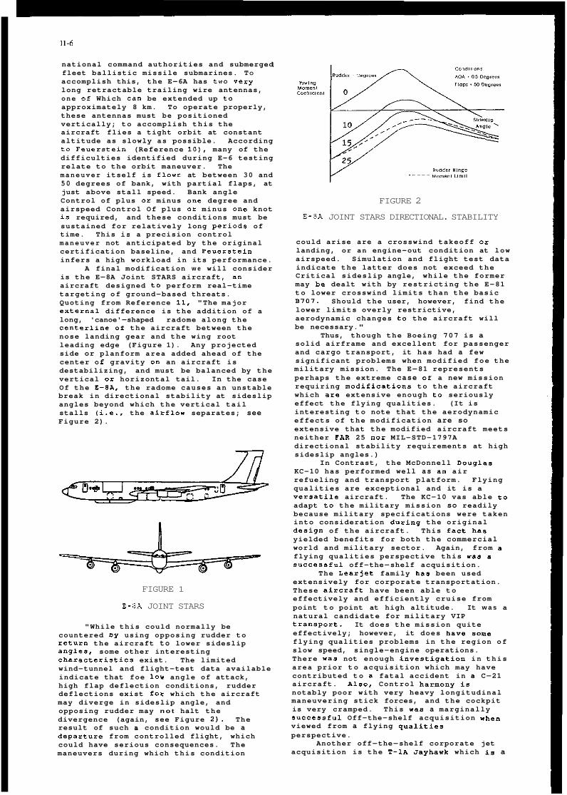
11-6
national command authorities and submerged fleet ballistic missile submarines. TO accomplish this, the E-6A has two vexy long retractable trailing wire antennas, one of Which can be extended up to approximately 8 km. To operate properly, these antennas must be positioned vertically; to accomplish this the aircraft flies a tight orbit at constant altitude as slowly as possible. According to Feuerstein (Reference lo), many of the difficulties identified during E-6 testing relate to the orbit maneuver. The maneuver itself is flovr at between 30 and 50 degrees of bank, with partial flaps, at just above stall speed. Bank angle Control of plus or minus one degree and airspeed Control Of plus or minus one knot i5 required, and these conditions must be sustained for relatively long period3 of time. This is a precision control maneuver not anticipated by the original certification baseline, and Feuerstein infers a high workload in its performance.
A final modification w e will consider is the E-8A Joint STARS aircraft, an aircraft designed t o perform real-time targeting of ground-based threats. Quoting from Reference 11, "The major exteznal difference is the addition of a long, 'canoe'-shaped radome along the Centerline of the aircraft between the nose landing gear and the wing root leading edge (Figure 1). Any projected side or planform area added ahead of the center of gravity on an aircraft is destabilizing, and must be balanced by the vertical 01- horizontal tail. In the case Of the E-8A. the radome causes an unstable break in directional stability at sideslip angles beyond which the vertical tail stalls 1i.e.. the airflow separates; see Figure 2).
FIGURE 1
E-8A JOINT STARS
"While this could normally be countered Dy using opposing rudder to retuxn the aircraft to lower sideslip angle*, some other interesting charactezistics exist. The limited wind-tunnel and flight-test data available indicate that foe low angle of attack, high flap deflection conditions, rudder deflections exist fot which the aircraft may diverge in sideslip angle, and opposing rudder may n o t halt the divergence (again, see Figure 2 ) . The result of such a condition would be a depazture from controlled flight, which could have serious consequences. The maneuvers during which this condition
FIGURE 2
E-8A JOINT STARS DIRECTIONAL. STABILITY
could arise are a crosswind takeoff or landing, or an engine-out condition at low airspeed. Simulation and flight test data indicate the latter does not exceed the Critical sideslip angle, while the former may be dealt with by restricting the E-81 t o lower crosswind limits than the basic 8707. Should the user, however, find the lower limits overly restrictive, aerodynamic changes to the aircraft will be necessary."
Thus, though the Boeing 707 is a solid airframe and excellent for passenger and cargo transport, it has had a few significant problems when modified foe the military mission. The E-81 represents perhaps the extreme case of a new mission requiring modifioations to the aircraft which are extensive enough to seriously effect the flying qualities. (It is interesting t o note that the aerodynamic effects of the modification are so extensive that the modified aircraft meets neither FAR 25 nor MIL-STD-1797A directional stability requirements at high sideslip angles.)
KC-10 has performed well as an air refueling and transport platform. Flying qualities are exceptional and it is a versatile aircraft. The KC-10 vas able t o adapt t o the military mission so readily because military specifications were taken into consideration dulcing the original deSign of the aircraft. This fact has yielded benefits for both the commercial world and military sector. Again, from a flying qualities perspective this w a s a s u ~ c e ~ s f u l off-the-shelf acquisition.
The Learjet family has been used extensively for corporate transportation. These airczaft have been able t o effectively and efficiently cruise from point t o point at high altitude. It w a s a natural candidate for military VIP transpozt. It does the mission quite effectively; however, it does have some flying qualities problems in the region of slow speed, single-engine operations. There w a 9 not enough investigation in this area prior t o acquisition which may have contributed t o a fatal accident in a C-21 aircraft. Also, Control harmony is notably poor with very heavy longitudinal maneuvering stick forces, and the cockpit is very cramped. This w a s a marginally SvCCeSsful Off-the-shelf acquisition when viewed from a flying qualitiea perspective.
acquisition is the T-lA Jayhawk which is a
In Contrast, the McDonnell DOUglaa
Another off-the-shelf corporate jet

11-7
derivative of the Beechjet 400A. This robust little aircraft is an excellent point to point transport and has good, predominately ~ e v e l 1 flying qualities. It is a very stable platform with good control harmony but slightly heavy roll axie forces. modifications are being made to the cockpit to adapt the aircraft to the training role. AS a trainer, the aircraft will be required to perform numerous tovch and go landings as well a s opezate routinely in the high-speed, low- l e v ~ l environment. Even though the ~eezhjet was not explicitly designed for thi5, its inherently good flying qualities make it adaptable to theSe missions.
ConCluSionS and Recommendations:
In summary, it is evident that in off-the-shelf acquisitions the military has had varying levels of flying qualities success. In those instances where there was s u c c e s . ~ , the aircraft designers used the military flying qualities specifications as a guide, or the aircraft generally complies with those specifications. Alternately, civil flying qualities apecifications have been adequate where the civil and military missions and the conduet of those missions have been nearly identical. In the not-so-successful c a s e a , the military mis9ion and the civilian usage were simply too diverse.
emphasized phrase above. In the authors' opinion, it is not enough that the civil and military missions coincide: the way the missions are flown must also coincide. For example, tactical airlift could be argued to parallel freight operations, yet civil freight operators are not required to operate in low-level terrain following or perform STOL operations from austere locations as a matter of C O U T S ~ . This is almost exclusively a military-unique type of air transport, and must be treated as such by the invoking of military flying qualities specifications.
of an aircraft's mission are military-unique, or require precision control, it is possible to use a blend of civil and military Llying qualities requirements. The MIL-PRIME format Of MIL-STD-1797A allows the document to be tailored to ~eflect this blending. This may be done, for example, by substituting civil requirements in appropriate paragraphs of a tailored MIL-STD-1797A where more demanding military requirements are not warranted. The resulting document then becomes a military specification unique to the svbjeot application. The authors advocate this approach for off-the-shelf acquisition of aircraft where the military mission or mission conduct does not differ extensively from the civil, and the aircraft is not being greatly modified. Tn the case of substantial modifications and/or a uniquely different military mission, the authors suggest using the handbook-recommended values from MIL- S~u-1797A. invoking full military flying
It is important to note the
In cases where only certain elements
qualities requirements.
Postscript:
Finally, though not Centeal to the topio of this paper, an observation must
be made regarding civil flying qualities requirements and the FAA certification process. As noted earlier, the Airbus Industrie A320 reptesents.the first fly-by-wire civil air transport with highly integrated guidance and control modes. MCElroy (4) described this
technology on much of the U. S. regulatory flight criteria." (Reference 4). The authors agree that the criteria of FAR 25 do not envision such technology and are ill-prepared to address it, yet we have no doubt that the A320 represents only the beginning. The FAA must reassess its own criteria, regulatory, and certification processes to meet future fly-by-wire transports. The experience basis to do this is alive and well in the military services, and is preserved in the criteria, guidance, and lessons learned of the military specification system. This does not mean that the FAA shovld abandon its own criteria in favor of military specifications; rather, the FAA must be familiar with military specifications, and adopt their criteria or methods where necessary or advantageouq. In like manner, the military 5ervices should be prepared to extend their knowledge and experience to the FAA when aaked.
References:
1. Anon: Air Force Regulation 80-36: Civil Airworthiness Standards for US Air Force Transport Aircraft. Department Of the Air Fozoe, 16 September, 1983.
2 . Anon: Federal Air Regulation Part 25: airworthiness Standards: Transport Category Airplanes.
3. Anon: MIL-STD-17978: Flying Qualities of Piloted Aircraft. 30 January, 1990.
4. M~Elroy, Collett E.: FAA Handling Qualities Assessment - Methodology in rans sit ion. The Society of Expezimental Test Pilots 1988 Report to the Aerospace Profession, pp. 149 - 166. 5 . Leggett, David B.: An Overview of MIL-STD-1797, The New Flying Qualities standard and Handbook. Presented at the 1988 IEEE National Aerospace Electronics Conference (NAECON), 23 - 27 May, 1988: available from the author.
6. Woodcock, R. J.: A Second Look.at MIL-PRIME Flying Qualities Requirements. AGARD-LS-157, Advances in Flying Qualities, 1988.
7. Leggett, David B., and Black, G. Thomas: MIL-STD-1797 Is Not a Cookbook. AGARD FMP Conference on Flying Qualities, Quebec City, Canada. 15 - 18 October, 1990.
8 . Bise, Michael E., and Black, G . Thomas: 1s Agility Implicit in =lying Qualities? 1990 IEEE National Aerospace Electronics Conference 90CHZ881-1 pp. 484 - 489, May, 1990.
aircraft as "a complete assault Of
9. Hob, Rogee H.: LeSSOnS Learned Concerning the Interpretation of Subjective Handling Qualities Pilot Rating Data. aIaA-90-2824, August, 1990.
10. Feuerstein, Mark G., Lt., USN: Beware

11-8
"Off-the-shelf". 1989 Society of Experimental Test Pilot's Mini-Symposium, San Diego, California, 7 April, 1989.
11. Black, G. Thomas, and Thomas, William T.: Flying Qualities Lessons Leaxned - 1988. 1 9 8 9 IEEE National Aerospaoe Electronics Conference 88c82759-9, pp. 299 - 306, M a y , 1989.

Handling Qualities of Highly Aqented Unstable Aircraft
Surrmary of an AGARD-FMP Working Group Effort
Horst Wiinnenberg DOmier Luftfahrt MlbH
P.0.m~ 13 03 0-7990 Friedrichshafen 1
Germany
1. Preface
The flying characteristics and handling qualities of all types of aircraft are major items of interest in the activities of the AGRRD Flight Mechanics Panel. A subcommittee of the Panel has specifically addressed this subject over a
long period and initiated a questionnaire several years ago to determine the ongoing research, future plans and the need for additional activities in the area of aircraft handling qualities. Responses from interested organizations and institutions in the AGRRD community indicated that the item "Handling
Qualities of Unstable Highly Augmented Aircraft" showed the first priority. In
response to this interest, the Panel formed a Working Group, We-17, in 1987,
consisting of Specialists from all interested AGARD countries, to study this
specific handling qualities subject. Six working sessions were held within the years of 1987 - 1990 the outcome of which is an AGRRD-Advisory Report Nr.
?A-279 which is to be published early 91. This report was a team effort and Consists of contributions from all of the members of the working group. AGRRD has been most fortunate in finding these competent pwple willing to contri-
bute their knowledge and time in the preparation of this document. This paper
only gives a short overview of the contents and tries to highlight the Mst important aspects and results.
2. Scecial Features of HiqhlV Augmented Unstable Aircraft
Statically unstable aitcraft are not new; for example the Wright Flyer was
statically unstable and the pilot provided the control "augmentation". AS knowledge of the balance between stability and control improved. aircraft were balanced stable to allow safe piloted control for demanding or protracted tasks. Today we again relax stability to produce configurations with SUb- stantially increased performance. With today's technology we now have the advantage of actuation, sensor and computing devices to augment, with full authority, the pilot's effort. Benefits of task-tailored handling, Carefree handling and automatic functions and Control modes outweigh penalties like larger actuators with high power consumption, high sensor performance, redundant controls and demanding computer speed and capacity requirements.
Handling Qualities of these highly augmented vehicles are largely the designer's choice; however, the effects of any increased flight control System complexity on handling qualities should be transparent to be pilot. It should not be necessary to distinguish between stable and unstable aircraft or even whether the aircraft i s highly augmented, when specifying flying qualities. The stability of the basic design is immaterial to the pilot, who rightly expects low workload in an aircraft with full authority hardware and software.

12-2
Unlike the Classic highly augmented aircraft, the handling qualities of the
unstable highly augmented aircraft cannot degrade after failures to those of the basic aircraft. Instead, when failures occur the handling qualities do not
change appreciably but the level of "protection" i.n the form of failure tolerance is reduced. For example, the X-29 technology demonstrator is highly unstable. with times to double amplitude in pitch of almut 0.15 sec., it can-
not be controlled by a pilot Without augmentation. Following failures in its
digital system, either the system logic or the pilot Can Select alternate redundant sensors or the analog reversion system, with virtually no flying qualities degradation.
3. Outline Of the Workinq GrOUpS AGAKJ-Report AR-279
The purpose of the report is to present methods and criteria which have been found to be Useful by members of the Working group as design guides and for the evaluation Of handling qualities of highly augmented aircraft. It is the unanimous opinion of the members that no one method or criterion is adequate by itself, and that several, or even a l l of the rec-ended criteria should be
checked. orperience has shown that one metric may not show a deficiency that will be exposed by Other criteria. Alternatively, a configuration that passes
several of the proposed criteria has a high probability of being accepted as
desirable by most pilots.
The report is organized in a series of major sections in which the major
themes of this working group are presented followed by appendices in which
important supporting infomtion and other areas of interest to this working group are presented.
0 A review of existing highly augmented aircraft (stable and unstable is given in Section 2.
0 R unified method to match the shape of the response properly (i.e. type of augmentation) with the required mission tasks is presented in section 3 . This section also contains some guidance on the proper choice of criteria for different Response Types, discusses the in- fluence of divided attention and presents a methodology for the
minimum required stabilization according to visual environemental condition (outside world plus cockpit displays).
D Handling qualities criteria recomended by the working group members
are contained in Sections 4 (longitudinal small amplitude1 and 5 (longitudinal large amplitude).
0 Considerations for the basic design of highly unstable airframes are presented in section 6 .
o There is growing evidence that feel systems must be treated as a
separate entity, i.e., not as an integral part of the augmented air- plane. This is covered in section 7 along with the important issue Of control sensitivity. It is important to note that none of the criteria
in this report include the effect of control sensitivity, and that it must be Separately optimized.
0 Evaluation techniques utilized in simulation, lmth ground-based and in-flight, and flight test are discussed in Section 8. Guidance for
the conduct of handling qualities evaluations, based on the collective experience of the working group, is presented in this section.

12-3
0 Important lessons learned from this handling qualities review and general guidelines for the conduct of handling qualities evaluations are presented in Section 9. In addition, a series of recommendations which represent the collective advice from this working group are presented to assist in the proper design and evaluation of future advanced highly augmented aircraft.
0 The conclusions and recommendation of the working group members are presented in Section 10. This summary includes reconmendations On areas which are in need of additional research and testing.
0 An overview of the important subject of envelope limiting and carefree handling is presented in Appendix A.
o Although the instabilities of interest are generally in the pitch axis, for completeness lateral-directional handling qualities are reviewed in Appendix B.
0 Since agility and handling qualities are closely related subjects with considerable overlap, this subject was of particular interest within the working group. In fact, it may be argued that the non-performance
related aspects of agility are essentially handling qualities. This interesting subject is riefly discussed in Appendix C.
One of outcaw of this Working Group is the installation of a follow-on
Working Group, dealing with this special subject.
The Report gets its final review during this symposium and will1 be published in the early 1991.
A few examples of the presented results:
Effect of Optimum Unstable Design on Aircraft -+- aG- Performance and Size </
Aspects of full-authority electronic flight -+- AG- control systems for unstable aircraft \/


12-5
Based anOpen Lmp Boxcar lnpvsal Varying Duration and Amplitude.
Is Analogous 10 Bandwidth, Except it applies 10 iamerAmplifvde Maneuvers.
Oel8nition 01 Cltferion Paramelars. and expected Shape 0, Bavndarler is shown Oelav
Attitude Quickness Criterion as a -&- a G m Moderate Amplitude Requirement Limits on Pitch and Roll Oscillations as a Funktian of Required Pilot Division of Attention
Aspects of LaterallOirectional characteristics -+- A G m of highly augmented aircraft
--I-
-4- Envelope limiting and carefree handling </

12-6
-4. & ~ m Schematic Outline of the SHIFT Pilot-in-the-Loop Handling Oualities Test Techniques
-4- &G- Proposed Metric for Torsional Agility
Terms of Reference for WG '19 on -@- & G m "Functional Agility"
-+- &%- Conclusion and Recommendations

13-1
THE HANDLING QUALITIES OF THE STOL &MANEWER TECHNOLOGY DEMONSTRATOR FROM SPECIFICATION TO FLIGHT TEST
by
David J.Moorhouse S XITD ('hief t ngincc'r
\VRDC I I M X Department of the Air Force
Wright-Patterson AFB Ohio 45433-6523
United States
Kevin D.Citurs and Richard W.Thomas McDonnell Aircraft Co
Mark R.Crawford AF Flight Test Center
INTRODUCTION
The WAF contracted with McDonnell Aircraft Company in 1984 for the development of the STOL and Maneuver Technology Demonstrator (SIMTD). The SlMTD program was structured to investigate, develop and validate through analysis, experiment and flight test, four specific technologies:
o Two-dimensional thrust vectoring and reversing exhaust nozzles
o Integrated FlighrlPropulsian Control (IFPC) System
o Advanced PilotIVehicle Interface
o Roughlsoft field landing gear.
These technologies, together with all-moving canard surfaces, have been incorporated into an F-15B (see Figure 1) with the overall objective of providing current and future high performance fighters both STOL capability and enhanced combat mission performance. Level 1 handling qualities were required across the full envelope from subsonic and supersonic maneuvering through precision approach and touchdown to ground handling on a wet runway with crosswind. control modes were also required in order to demonstrate and evaluate the technologies. hours of piloted simulation were performed to verify the analytical control laws. has been flying a phased test program since September 1988, with handling qualities results that agree very well with the piloted simulations. The general development of the control system configuration is presented in some detail in Reference 1. The present paper documents the development of the handling qualities of the S/Mn, aircraft from the original specification through the analytical development and simulator verification to the flight test results.
HANDLING QUALITIES SPECIFICATION
Various
Many
The aircraft
A new version of the Military Flying Qualities Specification, MIL-F-8785C, had been published in 1980. Major revisions incorporated in this version were expected to be applicable to the SIMTD development, e.g. equivalent system representation of highly-augmented System dynamics, low altitude disturbance, etc. At the stme time, however, the contract was written to allow for deviations from individual requirements if an' improvement could be substantiated. As far as possible for the overall design, required performance was specified rather than design approaches or solutions. Some performance requirements also translate into implicit handling qualities requirements. landing distance implies a requirement to minimize touchdown dispersion. i.e., "very good" handling qualities are needed to control the flight path and sink rate through the approach to touch down.
The required 1500 ft
Similarly, the 50 ft width of the landing strip plus a 30 kt crosewind formed the flaps down lateral/directional handling qualities requirements. The handling qualities task developed from these requirements was to touch down in a box 60 ft long by 20 ft wide at the threshold of the operating strip. A stringent ground handling task was produced by specifying a runway surface friction coefficient corresponding to wet bordering an icy conditions, while using reverse thrust to stop with crosswinds.
The preceding discussion reflects implied handling qualities requirements, whereas more direct ones were as follows. requirement of the IFPC system was stated to be "capable of functionally integrating all aspects of flight, engine, nozzle control iricluding aerodynamic control surfaces, engine thrust, thrust vectoring. thrust reversing and differential efflux modulation, control and stability augmentation. high lift system, steering and braking". The intent was to convey the understanding that integration was an objective of the demonstration program, not just a means to achieve mission requirements. The IFPC system was required to provide "good inner-loop stability and positive manual control in all axes of the air vehicle throughout its intended operating envelope both in flight and on the ground (satisfying the intent of MIL-F-87850". This subjective requirement was intended to convey that we were seeking good flying qualities over the whole envelope guided more by the intent than the letter of the specification. This recognizes that, while the intent is to provide flying qualities clearly adequate for the mission, the letter of the specification is no guarantee. Sn addition, the requirement for 'positive manual control' was intended to preclude consideration of automatic landing systems, for instance. One flying qualities requirement that was explicitly called out in the Statement of Work was to minimize time delay, i.e., lag in aircraft response to pilot control input. Although the importance of time delay is more widely accepted now, it still should be an explicit, hard requirement in any control system to be designed for any precise task.
The overriding
Specific flight control modes were required with the rationale: ',In order to provide the ability to assess task performance and minimize pilot workload in the flight vehicle, the integrated system shall also provide the flexibility to permit inflight selection of mission task oriented control modes as determined by analysis and simulation. Mode switching transients shall not produce unsafe aircraft responses. As a minimum, the following modes are required :
A CONVENTIONAL mode shell be designed for satisfactory performance over the flight test envelope, including conventional landing, without

13-2
the use of the added technologies. This mode will selye as a baseline for performance evaluation and as a backup in the event of multiple failure of the new technology components.
A STOL mode shall be designed to provide precise manual control of flight path trajectory, airspeed and aircraft attitudes. system and other technologies shall be combined to provide short field performance in weather and poor visibility. minimize pilot workload during precise manual landings, high reveme thrust ground operations and maximum performance takeoffs.
A CRUISE mode shall be designed to enhance normal up-and-away and cruise task performance, with and without external stores. 5s to use the integrated control system and other technologies to optimize appropriate measures of merit representing an improvement over the cruise .capability of the baseline aircraft.
A COMBAT mode shall be designed to enhance up-and-away maneuverability, with and without external stores. The purpose of this mode ie to use the integrated control system and other technologies to optimize appropriate measures of merit representing an improvement over the combat maneuvering or weapon delivery performance of the baeelioe aircraft”.
During the development process, these required modes evolved into the list shown in Figure 2 and described further throughout the paper. The S / m control law development was done analytically but, a= with any other, was supported by exteneive piloted simulation. A fixed-base facility at McDonnell Aircraft and a motion-base one at Wright Research 6 Development Center were both used - with identical modelling. have proven to agree with flight test results to be discussed.
The integrated control
The purpose of this mode is to
The purpose of this mode
The simulation results
AANDLING QUALITIES DEVELOPMMT
All the bidders on the Sll4TD contract were strongly encouraged to use multivariable control theory, although it was not expressed as an absolute requirement. program objective, there was some uncertainty that a classical approach would optimize uee of all the available effectors. At the same time, there was no desire to commit to a totally multivariable design approach. designed using a combination of classical techniques by McAir and multivariable theory by Honeywell (see e.g. Reference 2) . One of the results of this development is that problems with the flying qualities specification are independent of the design methodology. multivariable approaches first require the definition of the optimum transfer function to use a8 the design requirement. Figure 3 shows the final implementations that are being flow in the aircraft.
With integration as a
The SlMTO control laws vere
Both classical and
Longitudinal Axes
The obvious emphasis in developing the up-and-away modes was for pitch tracking. initial design represented a Level 1 configuration by MIL-F-8785C requirements, but received Level 2 cments and pilot ratinge for a tracking task in piloted simulation. The development to the final Level 1 configuration (References 3 and 4 ) also led to a natural separation of requirements between the CONVENTIONAL/COMBAT mode tracking characteristics and the CRUISE mode flight path control.
The
The method chosen to improve the
original design (1.e. increase the pitch attitude bandwidth) was to increase the effective numerator time constant to a higher frequency, end augment short period frequency to maintain the chosen value of Uk /n, (Figure 48). results were favorable pilot comments and ratings for the tracking task. At the game time. the short term response of normal acceleration to pitch rate differed from the classical long term response. Figure 4b. improved tracking characteristics in the CONVENTIONAL and COMBAT modes, but to leave the CRUISE mode with Level 2 tracking characteristics and a precise load factor (flight path) response. This yielded the opportunity of flying the different characteristics in back-to-back tests.
The simulation
This gives the characteristics shown in The decision was made to implement the
A significant development effort went inta achieving precision flaps-down flying qualities to support the landing distance requirement. Statement of Work. landing was defined as a Category A tracking task in the notation of MIL-F-8785C. increaeing the minimum allowable short period frequency, ie.. increasing minimum pitch attitude bandvidth. less stringent than bandwidth requirements proposed as alternate criteria and now included in MIL-STD-1797. It did establish that the intent was to develop a maneuverable and controllable configuration, including the effects of crosswinds, gusts, turbulence etc. This applied to the CONYENTIONAL and STOLTOA modes, but mom emphasis was placed on the SLAM) mode.
In the
This had the practical effect of
Even this increased requirement was
The short landing distances are facilitated by providing maximum reverse thrust immediately after touching down. To achieve this. the final approach is made with the engine spooled up to 100% RPM and the exhaust passing through vanes which are controllable from 45 degrees aft to 45 degrees forward of normal. vanes also provide for high-bandwidth control of airspeed because there is no influence of engine spool-up time. Design of the SJAND longitudinal control laws (pitch end thrust axes) was accomplished using multivariable control techniques. The complete design requirements included a specified form of the pitch and airspeed responses. to decouple the two axes, 80 that there is neither airspeed response to a stick input nor pitch rate response to throttle input. In the final form of the control laws, two features are to be noted - decoupling is achieved by sending both pitch and thrust commends to the upper and lower reverser vanes, and the form of the response in each axis is defined by a command prefilter. Now, in terms of pilot action, the feedback of airspeed to vane angle holds airspeed constant until the throttle is moved. throttle movement commands a new airspeed and consistent flightpath change. pitch rate directly but. with speed held constant. it is effectively a flightpath rete command. On approach, the pilot sets airspeed with throttle and, once the correct airspeed is acquired, flightpath is controlled solely with stick input.
This development highlighted the lack of criteria for a precision touchdown (see also References 4 - 6 ) . Figure 5 (and References 4 6 5) presents results from a moving-base simulation which show that the alternate bandwidth required is too stringent with speed hold and not stringent enough without it, using the S/MTD touchdown dispersion goal. Reference 6 presents resuIts from a fixed-base simulation in which generally lower values of bandwidth vere satisfactory.
These fast-acting
There are also requirements
The pilot retains control because
The stick commands

13-3
control laws are compared in Figure 6. sideslip is very small in either case, the pipper excursions during tracking far exceeded those caused by the sideslip. was essentially identical in each case. The biggest difference was in yaw rate. While the magnitude was the Same in each case, the lag between the yaw rate and the roll rate was noticeably smaller with the revised system.
The
The roll rate response
The next step taken was to obtain a better indication of the dynamic characteristics of the pipper aim point on the target aircraft. target was assumed to hold the initial load factor throughout the run. used. Time histories of the lateral variation of the aim point on the target aircraft as a result of lateral control inputs were obtained. results using the original control laws confirmed the pilot observations. little motion in the target aim point is evident for at least a half a second following a lateral stick input. move very rapidly. The control law revision was effective in both decreasing the initial time delay observed in the aim point response. and in moderating the rate at which it traversed the target aircraft.
The
A range of 1,500 feet was
The
As shown in Figure 7,
Then the lateral aim point begins to
It was further observed that the difference in the dynamics of the target aim point is related to the lag in the yaw rate described earlier. Because the relative phasing of the roll and yaw rates appeared to be important, a frequency response of the yaw rateiroll rate phase angle was generated. The results presented in Figure 8 indicate large differences in the frequency responses of the original and revised control laws. the phase lag with the original control laws begins to increase. while the revised control law phase lag actually decreases somewhat. Above 10 radianslseeonds the differences in the phase lag become even more pronounced. differences in dynamic characteristics of the two systems exist even though the conventional flying qualities parameters are similar.
Above a frequency of about 2 radianelsecond
Hence significant
Flight test results have confirmed the simulator findings. to air tracking taeke were in the Level 1 category, with the exception of one point which received a rating of 4 . offset in the corrected AoA used by the flight controller resulted in a larger phase angle between yaw rate and roll rate at this condition than was predicted. A software change corrected the AoA offset and improved the phase angle. repeat of this test point received a pilot rating of 2. This data provided a variation of pilot rating with phase angle that is presented in Figure 9 . since it was found to be typical of pilot inputs during the tracking task. Simulator results for the CO"TI0NAI mode are also shown. The data available are inadequate to establish a firm specification but do indicate that this phase angle is a candidate for a second-tier criterion to provide guidance in designing the lateral/directional axes to have Level 1 tracking characteristics.
Pilot ratings obtained in air
It was found that an
A
A frequency of 6.0 rad/sec was used,
The development of the flaps-down lateral and directional axes would have been conventional except for the heavy emphasis on crosswind landing and also on an unconventional control capability of the configuration. Differential canard deflection can be combined with rudder deflection to yield direct sideforce control. approach. the direct sideforce is commanded by the
During the
Motion cues may explain some or all of the differences. We conclude, however, that more research is needed to define landing requirements for pitch as B function of both the speed stability and the required touchdown dispersion.
Lateral 6 Directional Axes
Initially, the lateral directional requirements were believed to be a conventional application of MIL-P-8785C. No multivariable design or analysis was attempted for these axes. the lateral-directional control laws were developed using classical design methods. lateral control laws utilize a conventional roll rete feedback path, in addition to a limited roll rate feedback for gust rejection. control laws incorporate N and estimated feedback paths. In addition. interconnects from the lateral control surface co-nds to the directional controls are used for roll coordination. guidelines established early in the development phase. The goal for the Dutch roll damping was 0.7, the Dutch roll frequency was designed to emulate the F-15. and the roll mode time constant was 0.3 seconds above 180 knots.
The
The directional
Y
The gains were defined using design
Equivalent system analyses indicated that the Dutch roll and roll mode characteristics were close to those desired. In addition, the equivalent time delays in the lateral axis were between 0.055 and 0.060 seconds. excursions to lateral stick commands were very small, and the roll rate oscillations (P IP ) were zero. parameters were within the MIL-F-8785C Level 1 requirements.
Sideslip
OSC AV All of the handling qualities
Results from the McAir manned flight simulator indicated that the large amplitude, open loop response was Level 1. The pilots considered the roll responee crisp, with excellent roll capture characteristics. However, tracking a 36 or 56 reversing target was Level 2. When moving the pipper from one wing tip to another, it vas noted that there was no initial response to a lateral stick input. Then. about the time the pilot would typically begin to add more stick, the pipper would rapidly move across the target, resulting in an overshoot. The difficulty this caused resulted in Cooper Harper ratings consistently between four and six. The tracking appeared to degrade with increasing airspeed, with the worst flight condition evaluated being at Mach 0 . 9 , 10,000 feet. Load factor had little effect on the tracking.
The tracking evaluation was repeated on the LAMARS facility at WAFB with the same results. The presence or absence of motion was not a factor. then tested et selected flight conditions. Based on the results, a shaping prefilter was added to the crossfeed path of differential stabilator to rudder and implemented in subsequent simulation testing. The result was Level 1 flying qualities in tracking. a8 well as open loop response, at all flight conditions evaluated.
A matrix of control law point designs was
The control law change had minor effects on the MIL-Spec flying qualities parameters. Since there was no obvious reason for the improvement in tracking, further analyses were undertaken in an attempt to identify the parameters important in this task and to understand the dynamics involved. To accomplish this, t i m e historie8 of the lateral control response were generated in a 3g banked turn. The roll rate, yaw rate end sideslip angle responses with the original and the revised
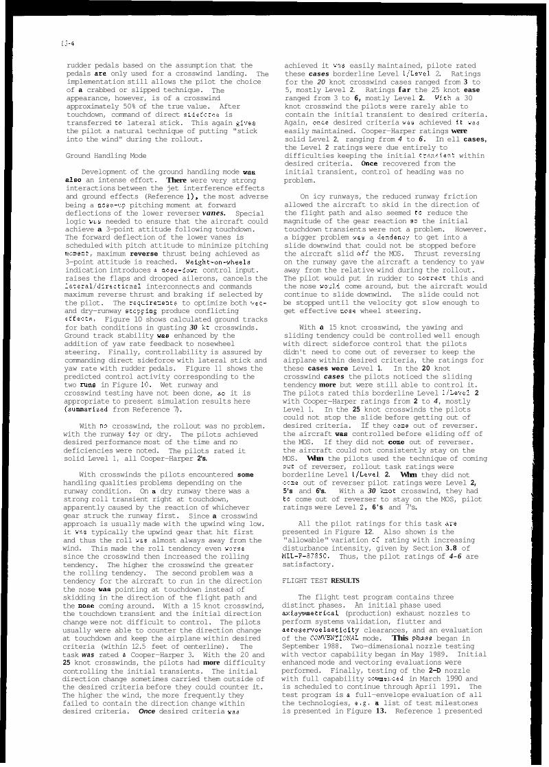
13-4
rudder pedals based on the assumption that the pedals are only used for a crosswind landing. implementation still allows the pilot the choice of a crabbed or slipped technique. appearance, however, is of a crosswind approximately 50% of the true value. After touchdown, command of direct sidefarce is transferred to lateral stick. This again give8 the pilot a natural technique of putting "stick into the wind" during the rollout.
Ground Handling Mode
The
The
Development of the ground handling mode wan There were very strong also an intense effort.
interactions between the jet interference effects and ground effects (Reference I), the most adverse being a nose-up pitching moment at forward deflections of the lower reverser vanes. logic was needed to ensure that the aircraft could achieve a 3-point attitude following touchdown. The forward deflection of the lower vanes is scheduled with pitch attitude to minimize pitching mwent, maximum reverse thrust being achieved as 3-point attitude is reached. Weight-on-wheels indication introduces B nose-down control input. raises the flaps and drooped ailerons, cancels the lateral/directional interconnects and commands maximum reverse thrust and braking if selected by the pilot. and dry-runway stopping produce conflicting effecta. for bath conditions in gusting 30 kt crosswinds. Ground track stability was enhanced by the addition of yaw rate feedback to nosewheel steering. Finally, controllability is assured by commanding direct sideforce with lateral stick and yaw rate with rudder pedals. Figure 11 shows the predicted control activity corresponding to the two rune in Figure 10. Wet runway and crosswind testing have not been done, so it is appropriate to present simulation results here (sunrmarized from Reference 7).
Special
The requiremeote to optimize both wet-
Figure 10 shows calculated ground tracks
With no crosswind, the rollout was no problem. with the runway icy or dry. desired performance most of the time and no deficiencies were noted. solid Level 1, all Cooper-Harper 2's.
The pilots achieved
The pilots rated it
With crosswinds the pilots encountered some handling qualities problems depending on the runway condition. On a dry runway there was a strong roll transient right at touchdown, apparently caused by the reaction of whichever gear struck the runway first. approach is usually made with the upwind wing low. it was typically the upwind gear that hit first and thus the roll was almost always away from the wind. since the crosswind then increased the rolling tendency. The higher the crosswind the greater the rolling tendency. The second problem was a tendency for the aircraft to run in the direction the nose was pointing at touchdown instead of skidding in the direction of the flight path and the n o m coming around. With a 15 knot crosswind, the touchdown transient and the initial direction change were not difficult to control. The pilots usually were able to counter the direction change at touchdown and keep the airplane within desired criteria (within 12.5 feet of centerline). The task was rated a Cooper-Harper 3. With the 20 and 25 knot crosswinds, the pilots had more difficulty controlling the initial transients. The initial direction change sometimes carried them outside of the desired criteria before they could counter it. The higher the wind, the more frequently they failed to contain the direction change within desired criteria. Once desired criteria wae
Since a crosswind
This made the roll tendency even worse
achieved it was easily maintained, pilote rated these cases borderline Level l/Level 2. Ratings for the 20 knot crosswind cases ranged from 3 to 5, mostly Level 2. Ratings far the 25 knot ease ranged from 3 to 6, mostly Level 2. knot crosswind the pilots were rarely able to contain the initial transient to desired criteria. Again, once desired criteria was achieved iC wa8 easily maintained. Cooper-Harper ratings were solid Level 2, ranging from 4 to 6 . the Level 2 ratings were due entirely to difficulties keeping the initial transient within desired criteria. once recovered from the initial transient, control of heading was no problem.
Wjth a 30
In ell cases,
On icy runways, the reduced runway friction allowed the aircraft to skid in the direction of the flight path and also seemed to reduce the magnitude of the gear reaction 80 the initial touchdown transients were not a problem. a bigger problem wae a dendency to get into a slide downwind that could not be stopped before the aircraft slid off the MOS. Thrust reversing on the runway gave the aircraft a tendency to yaw away from the relative wind during the rollout. The pilot would put in rudder to correct this and the nose wou1.d come around, but the aircraft would continue to slide downwind. The slide could not be stopped until the velocity got slow enough to get effective nose wheel steering.
However.
With a 15 knot crosswind, the yawing and sliding tendency could be controlled well enough with direct sideforce control that the pilots didn't need to come out of reverser to keep the airplane within desired criteria, the ratings for these cases were Level 1. In the 20 knot crosswind cases the pilots noticed the sliding tendency more but were still able to control it. The pilots rated this borderline Level 1ILevel 2 with Cooper-Harper ratings from 2 to 4 , mostly Level 1. In the 25 knot crosswinds the pilots could not stop the slide before getting out of desired criteria. the aircraft was controlled before eliding off of the MOS. If they did not come out of reverser. the aircraft could not consistently stay on the MOS. When the pilots used the technique of coming out of reverser, rollout task ratings were borderline Level 11Level 2. c m e out of reverser pilot ratings were Level 2, 5's and 6's. With a 30 knot crosswind, they had to come out of reverser to stay on the MOS, pilot ratings were Level 2. 6 ' s and 7's.
If they came out of reverser.
When they did not
All the pilot ratings for this task are presented in Figure 12. Also shown is the "allowable" variation of rating with increasing disturbance intensity, given by Section 3.8 of MIL-F-8785C. Thus, the pilot ratings of 4-6 are satisfactory.
FLIGHT TEST RESULTS
The flight test program contains three distinct phases. An initial phase used axisymmetrical (production) exhaust nozzles to perform systems validation, flutter and aeroservoelasticity clearances, and an evaluation of the COA'VENTIONAL mode. September 1988. Two-dimensional nozzle testing with vector capability began in May 1989. enhanced mode and vectoring evaluations were performed. Finally, testing of the 2-D nozzle with full capability commenced in March 1990 and is scheduled to continue through April 1991. The test program is B full-envelope evaluation of all the technologies, e.g. a list of test milestones is presented in Figure 13. Reference 1 presented
This phase began in
Initial

13-5
o "Fine tracking was really nice in all three modes. In CRUISE I did have more directional errors than in the other two modes." (Pilot E )
"COMBAT gross aequiaitian is better than COW. A little more wandering in the fine tracking though.'' (Pilot B)
o
o "Big overshoot in CRUISE mode." (Pilot B)
Gross Mach 0.9/30K: - C O W HOR 3 2
some early results of the axisymmetric configuration including the minor software fixes that were required. References 6-10 present the pilots' opinions of the aircraft. The simplest and most direct form of presentation of handling qualities flight-test results would be tables or graphs of Cooper-Harper ratings. In fact, the table of ratings shom in Figure 14 has been published. There is a lot more information behind the simple numbers. qualities results mostly in the form of pilot comments. These eonrments (with ratingo) show excellent agreement with the analytical and simulation development results. an interesting diversion in comparing different likes of the different pilots. which would he masked by a simple presentation of Cooper-Harper ratings.
Handling Qualities During Tracking
Mach 0.6/10K:
Here, we present the flying
They also provide
Gross Fine _ .-
C O W HQR 2 2 COMBAT HQR 3 3
0 "Combat received HQR 3 or 3.5 because of increased pitch bobble." (Pilot A)
"Lateral accelerations at the cockpit in COMBAT mode are much higher. (Pilot B)
o
0 "COW stopped when put it there." (Pilot A)
0 "COMBAT not as predictable, tracks better COW." (Pilot A)
0 "COMBAT HQDT Improves with G increases." (Pilot A)
Gross Fine _ .-
Mach 0.7/20K:
CONV HQR 3 3 CRUISE AQR 4 4 COMBAT HQR 3 3
o "Slight pitch sensitivity in CONV." (Pilot C)
0 "Tendency toward small directional overshoots in CRUISE with pitch sensitivity equivalent to COW." (Pilot C)
0 "Very nice pitch control in COMBAT: less pitch sensitive than COW. This was the best mode of all for tracking.'' (Pilot C)
0 "COtBAT was much less PI0 prone." (Pilot C)
Mach 0.9/20K Gross Fine _ _ - CONV HQR 3 2 CRUISE HQR 4 3 COMBAT HQR 3 3
0 "HQDT in all three modes was very nice. (Pilot B)
0 "The biggest delineator for all tasks in the three modes was the relatively poor gross acquisition in CRUISE. The initial overshoot was large, 25+ mil, but I usually only had one overshoot in CRUISE. In COMBAT and CONV I generally had a much smaller overshoot, better predictability, hut often more than one overshoot. One small difference wa8 noted in that the COMBAT mode seemed to have less pitch acceleration in the gross acquisition task than C O W mode - to get the same performance I had to pull harder and this was evident as apparent higher stick forces." (Pilot B)
-..-~ ~
CRUISE HQR 4 3 COMBAT HQR 3 2
o "COW-solid. easy, well damped, delightful." (Pilot A)
o "CRUISE - ~oorlv damoed. difficult . . acquisition, fair tracking but bobble prone." (Pilot A)
o "COMBAT - bobble prone, not as predictable as C O W but better than CRUISE.'' (Pilot A)
Note that all of the ratings are Level 1 for the COWENTIONAI and COMBAT modes, and Level l/borderline Level 2 for the CRUISE mode. little discrimination would be implied by the ratings alone. The comments reflect perceived differences and preferences even when the ratings are identical. Thus Pilot B says that COMBAT gross acquisition is better than COW, but assigns a rating of 3 to both. Pilot C says that COMBAT was the best mode of all for tracking, but assigns the same rating as the COW. Also, it can be seen that Pilot A consistently prefers the CONV made while Pilot C chooses the COMBAT mode. No explanation will be attempted to explain them? results. different pilots is that both pilots A and B are high gain relative to pilot C. We can certainly rationalize their preferences on this basis, and it supports the technique of requiring multiple pilot opinions. In a development program, however, do we have to satisfy all pilots? If not, whose opinion is given precedence? In the S/MTE program we are lucky - the differences are within the Level 1 range and the distinction is academic. This aircraft is unique in having the capability to switch modes at will, and fly the modes back-to-back. Fine distinction within Level 1 characteristice is not normally a problem in B development program. What is important is that these comments do indeed repeat the comments that were noted during the piloted simulation program.
Landing Configuration
Very
The "engineering evaluation" of the
10K/10.5' AOA:
o Pitch Captures - "Nice and stable" (Pilot B) o Flight Path Captures - "Sluggish just like
normal" (Pilot B) o "Everything was fine. I didn't see anything
I didn't like." (Pilot B)
10K/12' AOA:
o Pitch Captures - "Slight hobble, not bad." (pilot cj
o o
Flight Path Captures - "Not bad" (Pilot C) Heading Captures - "Slight under shoot." (Pilot C)
o
o
Bank Angle Captures - "Slight over shoot, not bad" (Pilot C) "I think it flies pretty nicely, wallowing on heading capture a little." (Pilot C)

13-6
o "Pitch axis is fine, harmony between axes is
o "Easy to control flight path" (Pilot C) o
good" (Pilot C)
"45" bank to bank rolls using full lateral stick produce B sloppy feel, comparable to other aircraft at this condition and not unique to the S/MTD. Overall SLAND felt good in all axes. (Pilot C) Formation Uaodling Qualities in SLAM) made showed no PI0 tendencies. somewhat sluggish but was satisfactory for this flight condition." (Pilot A) "Pitch capture in SLANX mode had some bobble" (Pilot A) "Velocity vector capture was easy and felt good far a landing made"
o Response was
o
o (Pilot A)
The above mments can be augmented with the following quotes taken from Reference 10: "The initial SLAND test was at 10,000 ft at 165 kt. Engine operation was flawlese and the pitching moment transient was negligible. Flight path angle had to be placed into a mild descent to avoid limiting the vanes at their maximum push position of 45 deg, but once stabilized. the speed hold feature worked well. Pitch control power was fine with good controllability. hteral- directional feel was slightly heavier, but bank angle capture remained good as did directional control power. damped.
The Dutch roll was also well No PI0 tendencies were apparent.
After an early morning takeoff, the first SLANDing was planned for idle power at touchdown to assess ground effects, pitchdown discrete, and lift dumping. Results showed that ground effects caused a very slight no88 rise prior to touchdown, but nothing which would change pilot technique.
The second SLAM) approach, planned for a slow pull to full reverse, was flown slightly slower. on-speed, with a 3 deg glideslope. Autobrake was armed to provide full wheel braking. touchdown. the pilot pulled to full reverse. The SMTD derotated, dumped lift, reversed. and braked. 'It was almost like catching an arresting cable.' Handling qualities were good - no lateral directional inputs were needed. nor pitch inputs. Deceleration was quite good. Actual landing distance W ~ G 1.707 ft, in spite of the heavier weight and Edwards' altitude and temperature. If corrected to sea level standard day and demonstration gross weight, the distance would have been in the fifteen hundreds".
o "Spot landings in bath CONVENTIONAL and STOL mode were difficult. I could not see any difference in precision between the two modes". These comments are consistent with the piloted simulation reeults, i.e. with no speed hold in either mode and "normal" flaps dawn flying qualities. The results will form a reference for touchdown dispersion evaluation of the SLAND mode still to be done.
CONCLUSIONS
The STOL and Maneuver Technology Demonstrator
At
has integrated thrust vectoring and reversing into an Integrated FlightiPropulsion Control system. Level 1 handling qualities have been developed acro~s the full envelope from supersonic and subsonic maneuvering to precision landing. The design was done to the "intent" of MIL-F-8785C. which had to be supplemented in some areas with second-tier criteria that are now included in MIL-STD-1797. This paper ha8 reviewed the SlMTD development from the initial specification through t o current flight test results. Lessons learned have been presented with respect to both
individual specification criteria and design methodology. Two areas are identified in which it is considered that the current criteria are inadequate: 1 ) pitch axis requirements as a function of touchdown dispersion, and 2 ) directional a x i s requirement for target tracking.
REFERENCES
1. Moorhouse, D.J.. J.A. Laughrey aod R.W. Thomas. "Aerodynamic and Propulsive Control Development of the STOL and Maneuver Technology Demonstrator", AGARD Conference Proceedings CP 465, October 1989.
2. Moorhouse, D.J. and R.L. Kisslinger, "Lessons Learned in the Development of a Multivariable Control System", Proceedings of NAECON'89, May 1989.
3. Bland, M.P., K.D. Citurs, F. Shirk and D.J. Moorhouse, "Alternative Design Guidelines for Pitch Tracking", AIM Paper 87-2289. Proceedings of the Atmospheric Flight Mechanics Conference, August 1987.
4. Moorhouse, D.J., "Lessons Learned from the S/MTD Program far the Flying Qualities Specification", AIM Paper 90-2849, Proceedings of the Atmospheric Flight Mechanics Conference. August 1990.
5. Moorhause, D.J., D.B. Leggett and K.A. Feeser, "Flying Qualities Criteria for Precision Landing of a STOL Fighter", AIAA Paper 89-3390, Proceedings of the Atmospheric Flight Mechanics Conference, August 1989.
6. Citurs, K.D., and J.H. Caton, "An Investigation of Flying Qualities Requirements for a STOL Fighter in Approach and Landing", AIAA Paper 85-1807, Atmospheric Flight Mechanics Conference, August 1985.
7. Feeser, K.A., J.M. Zeh and D.B. Leggett, "The STOL h Maneuver Technology Demonstrator Manned Simulation Test Program". Proceedings of NAECON'89, May 1989.
8. Walker, L.A., and W.R. Neely, "F-15 STOLiManeuver Technology Demonstrator PIight Test Status". Society of Experimental Test Pilots, 32nd Annual Symposium, Sept 1988.
9. Walker. L.A.. and E.B. Jenschke, "F-15 STOLlManauvering Technology Demonstrator Phase Two: 2-D Nozzle Vectoring", SETP, 33rd Annual Symposium, Sept 1989.
10. Walker, L.A., and E.B. Jenschke, "F-15 STOLiManeuvering Technology Demonstrator Phase 111: Thrust Vectoring. Reversing and STOL Operations", SETP, 34th Annual Symposium, Sept 1990.

Integrated Flight/ Propulsion Contro l7
13-7
2D CD T V r R 4 [ " d e
Canards7 \ R\
Modified Landing Gear
ORIGINAL
3.31
0.7
1.2
CRUISE
3.31
0.8
1.2
CONVICOMBAT
4.68
0.8
1.2
1/T o2 ( 4 s e c ) 1.2 1.2 2.0 Figure 1. SIMTD Configuration
ta (msec) < 70 65 65
a. Pitch Transfer Function Characteristics
CONVENTIONAL
CRUISE
COMBAT
STOL-TOA
STOL-LAND
STOL-GH
SPIN RECOVERY
- All effectors except vectoring/reversing
- Optimum flight path control
- Optimum pitch tracking
- Max performance takeoff/normal approach
- Max performance approach/touchdown
- Rollout handling qualities
-Full control authority/no feedbacks
Longitudinal CONV
Figure 2. Modes of Control
b. Load Factor Responses
Figure 4. Comparison of CRUISE h CONVICOMBAT Modes
. . CRUISE/COMBAT STOL-LAND STOL-TOA STOL-GH
CONV CRUISE/COMBAT
I.atcral/Directional
STOL-LAND STOL-TOA STOL-GH
Thrust CONV CRUISE/COMBAT STOL-LAND STOL-TOA STOL-GH
Honeywell MCAIR LQG/LTR Analysis Classical Analysis
X .. X X X u
,-. m m Y
X
2 3 m .o
x X X X X m
.c a
x X
X X X
'7 JS Lfl Level 1 u
... Level 2
bandwidth (rad/sec)
Figure 3. Implementation of Modes Figure 5. Required Bandwidth for Landing

13-8
RI 3%
U,...L -.7 ,. Figure 8. YawIRoll Phase Angle ..A OYI -*,
I..
4,. ................................................ ...... 1 1 1
Figure 7. Pipper Aim Point Response
I I I I t
Jo 4 0 -30 a -ID
Phase Angle between Yaw Rate and Roll Rate at 6 deglsec -- deg
~igare 9. Potential Tracking Criterion

13-9
Pilot Ratings vs Crosswind l o
Dry runway .... " Wet runway - 5 8
Z I
I-
Y - 8 E
1 5
Y . & 0
~
8 ' Crosswind Gusting 10 30 X I
0 0 I 5 2* *I 30
CROSSWIND IKTSI
Figure 12. Effect of Crosswind on P i l o t Rating
k r o u c h d o w n I -or* runway
Slippery ruoway
I I I I I I I I I -200 0 200 400 600 800 1.000 1,200 1,400 1,600
Length 07 DEC 89 - AUTONOMOUS LANDING GUIDANCE
Figure 10. Ground Handling ~ i m e His tor ie s 22 FEB 90 REVERSING DURING TAXI
23 MAR 90 - FIRST IN-FLIGHT REVERSING
29 MAR 90 - TAKEOFF WITH VECTORING
22 MAY 90 - FIRST SHORT LANDING
01 JUN 90 - SUPERSONIC REVERSING
Crosswind Gusllng ID 30 kl [Canl) 40
I20
Rudder 11 JUL 90 - VECTORING EFFECTIVENESS 30 deg 0
Angle - deg
- 20 Figure 13. Fl ight Test Milestones
-40 40 I -Dry runway 20
0
- 20 -40
Dill. Canard Angle - deg
Time - O ~ E Touchdown 2.8
Figure 11 . Direct Sideforce and Yaw Control
14
FLIGHT
0.6/10K CONDlTlONS
0.7/20K
0.9/20K
0.9/30K
GROSS bKmE A!2"i CONV 2 COMBAT 3
CONV 3 CRUISE 4 COMBAT 3
CONV 3 CRUISE 4 COMBAT 3
CONV 3 CRUISE 4 COMBAT 3
FINE TRACKlNG
2 3
3 4 3
2 3 3
2 3 3
Figure 14. HQDT P i l o t Ratings


METRICS FOR ROLL RESPONSE FLYING QUALITIES
Mario Innoccnti' Dipmimento di lngcgneria Aerorpaziale, Univcnita'di Pisa
Via Diotisalvi 2.56100 Pisa. Italis
Summary
Roll characreristics of highly augmented aircrq? &ring compensatory tasks such as Racking and landing have shown fo presenr degraded flying qualities and unstable oscillarions similar to those observed in the pitch axis, The presenr work extendr the ideas behind Gibson's method to develop handling qualities criteria for the roll aris control sysrem. The amlysis is pe$ormed using an exisring data-base for highly augmented class N aircrafr and paramerers such as roll rime constant. system's delay and loop sensirivig are considered for designing for good handling quaiiries and to evaluate control system pe$ormance. Levels of flying qualitires are determined in the time domain as well as in the frequency domain for borh tracking and landing tasks. Furthermore, the presence of pilot induced oscillations and roll rarcheting is identified.
roll angle at t = 5 sec. normalized bank angle overshoot frequency at phase lag = 180 deg. frequency at phase lag = 200 deg. pure time delay roll time constant effective h e delay Lateral High Order Systems roll control effectiveness phase rate steady state roll rate maximum pitch rate steady state pitch rate acceleration ratio
1. Introduction
Modern high performance aircraft rely heavily on stability augmentation for increased performance. Current experience with aircraft having high order dynamics due to arfificial stabilization controllers, digital implementation, etc. has shown a dramatic improvement in system response, controllability and maneouverability. Handling qualities deficiencies, however, have surfaced due to generic problems such as over sensitivity to small control inputs and sluggish response to large inputs. Improper control gains and time delays coupled with higher order effects have resulted in low frequency PI0 and high frequency ratcheting interaction [l].
As reflected in the latest milimy specifications [Z], [3], the majoriry of the work in handling qualities research has been limited to longitudinal motion. Among the reasons were the recognition of the longitudinal plane as the primary plane in closed loop control tasks, the availability of a large experimental data-base and the introduction of aircraft with high level of longitudinal augmentation to compensate for relaxed static stability.
' Prosenlly with he Aerospace Engineering DEparlrnent Auburn University, AL 36849-5338. U.S.A.
Traditionally, lateral dynamic characteristics have not been considered critical in the assessment of the overall handling qualities. Specifications for the roll response, for example, are based essentiallv on omn IOOD tvDe Dammeters such as roll time . ,. . constant, muimum roil raw and lune to go through a bank angle for roll control cffrctiveness 121, [3]
Lateral handling qualities, however, an becoming more important in relation to increased control system augmentation level at high angle of attack, to pitch-roll coupling during loaded maneuvers and to agility requirements. Recent experimental results [4] have shown the presence of low frequency pilot induced oscillations in roll (due to mismatch between roll zms and poorly damped dutch-roll) and high frequency ratcheting [51. Highly augmented aircraft have also shown poor handling qualities in the roll axis due to the compensation of roll time constant lag to yield an integral-type response, resulting in large lateral acceleration at the pilot's station. The attenuation of such acceleration and consequent lagging has shown [41 to introduce pilot induced oscillations similar to those experienced in the pitch axis.
A comprehensive technique for longitudinal handling qualities analysis and assessment has been developed over the years by Gibson at British Aerospace [61, [7], [8] using experience acquired in the EAP (experimental aircraft programme) and in the development of a h a f t like the Jaguar FBW and the Tornado. The main objectives of Gibson's derivations (also referred as the dropback method) are the explanation and prediction of PI0 experienced during critical flight phases of highly augmented aircraft Good correlation has been obtained with the dropback method in matching pilot opinions to aircraft characteristics in tracking and landing for military [8], [9] as well as transpo~ aircraft [IO]. Agreement with the new longitudinal handling qualities specifications has alsobeenreported[ll], [12].
The basic idea behind Gibson's method is that of achieving "good classical airplane characteristics" in the presence of high order effects due to augmentation. Ihe flight control system should be designed to have not only classical responSe but also to satisfy the specific task requirements. It is clear that easily and directly identifiable meuics are required instead of specifications given in terms of modes. These would then encompass both classical and modern airplanes in a more straightforward manner.
Gibson's method combines time response and frequency response techniques in the pitch axis to cover the frequency specr" of interest to the pilot. Ihe time domain analysis looks at attitude, pitch rate and acceleration responses to a block type stick input, as shown in Fig. 1 [71. The behavior of the initial response at the time of stick release is related to pilot comments. The frequency domain analysis, based on Nichols charts of the open loop response with pure gain manual compensation, highlights PI0 tendencies by relating such instability to the phase rate at -180 degrees and its corresponding phase lag crossover frequency. Parameters such as dropback, overshoot and phase rate can be easily obtained. These are related to typical short period dynamics comments like bobbling, sluggishness and induced instability. The Gibson's criterion is not reviewed here and the interested reader can refer to 161, [7], [8], 191, [13] for more details.

14-2
The proposed work extends Gibson's technique to the roll axis using the LATHOS experiment as data-base [5]. Memcs for handling qualities evaluation are defined and level boundaries as well as dynamic instabilities are identified for the tracking and landing tasks.
2. Roll Response Requirements and Data Base
The limitations of lateral handling qualities with respect to high performance aircraft have been acutely felt since the MU-SPEC-8785C, which, while being used for both design and testing of developing aircraft, failed to provide the desired handling qualities. These limitations could be atuibuted to a limited data base which mainly represented aircraft of the World War Il era, having little or no lateral augmentation. The need for identifying problems related to a lateral highly augmented fighter aircraft led to a series of in-flight simulations to generate experimental data and to investigate the effects of lateral high order systems (LATHOS) [5]. The additional insight gained through the LATHOS experiment provided a large enough data- base for the revision of MU-SPEC-8785'2. Currently, MIL- STD-1797 [31 presents the requirements in a format similar to the older specification and, at the same time, provides some guidance for highly augmented systems.
The present paper suggests new roll response mehics based on the application of Gibson's method to the LATHOS data base and presents qualitative as well as quantitative relationships between pilot ratings and typical parameters such as roll time consmt, time delay and control system gain, which constitute the scope of the present analysis. Fig. 2 shows the modified block diagram of the lateral-directional flight control system for the stick-roll loop in the LATHOS flight tests. The three primary variables are shown by their corresponding symbols, linear command gain Spa, roll time constant 5 and
pure time delay z, The time delay zd is the pure time delay generated by the NT-33As time delay circuit which merely holds the signal by ' T ~ seconds. This could be thought of as representing delays due to various possible sources like suuctural lag, transport lag and digital delays present in actual system. The filters surrounding the time delay circuiuy are third order Buttenvonh low pass filters which help in smoothing the signal. The dutch roll characteristics and the lead-lag time constants were held to their nominal value in this work.
The typical first order response for the aircraft is assumed to be given by the transfer function
in which the dutch-roll mode is absent due to dipole effect and the spiral mode is absent due to a large time constant.
The roll requirements and justifications for choosing the a b v e parameters are as follows :
(a) The roll damping requirement given by MU-STD-1797 limits the lower damping to 0.3 sec. (0.3 5 T, 2 1 seconds for level 1). These results are supported by the fact that some modem aircraft equipped with high gain augmentation have time constants that a ~ e too small and experience an excessive lateral sensitivity described as roll ratcheting.
(b) The time delay in a control system can drastically degrade lateral flying qualities. The MILSTD-1797 retains the pure time delay limits given in the 878% mainly because of a lack in supporting data to revise them, which limits maximum delay to 0.1 seconds for level 1 and no more than 0.2 seconds for level 2.
(c) A very important parameter that has not been dealt with in sufficient depth is the effect of command gain 6$F,,. Earlier meuics normally excluded the effect of this open loop gain variation, as it was considered as an independent variable to be optimized. Usually the gain is very critical to the pilot in that it changes hidher equalization and it is known to conuibute greatly to the pilot opinion and ratings. Hence the roll metrics developed in this paper include the effect of command gain
variation along with other roll parameters. Roll control sensitivity and roll control effectiveness are directly related 10
command gain, Spa, , We defme roll control sensitivity as the gain required by the steady state roll rate, prr to a unit step input. Roll control effectiveness, CFu is defined as roll control sensitivity per unit roll time constant, or
L'Fas Pss 1 %r (2)
Tasks performed during the LATHOS experiment were representative of flight phases category A and C and consisted of actual target tracking, air-refuelling, precision approach and landing as well as special head up display uacking tasks.
The complete set of configurations, including all the cases with linear gain only, for the tracldng task are analyzed (29 cases in all). The analysis of the landing is similar to the tracking (although fewer data points are available) and involves U S (Insmment Landing System) and visual landing tasks. The analysis makes no distinction between these tasks. In all, 16 configurations were considered with only linear gain variations. Throughout the analysis the pilot behavior is represented by a pure gain and time delay, with transfer function
where 'T is the pilot's time delay constant, usually of the order of 0.2 seconds (these are typical experimental values for the pilot in compensatory tracking tasks). The gain K for the tracking cask is adjusted so as to obtain a gain crossover frequency of 0.3 Hz. In the case of the approach and landing task, the gain K is adjusted so as to have a phase lag of 120 degrees at the gain crossover point. Table 1 and 2 list the tracking and landing configurations respectively alongwith the values for the variables, pilot comments and the pilot ratings based on the Cooper-Harper scale.
3. Time Response Analysis
Several new mehics are needed to characterize the roll handling qualities. Gibson's metrics like dropback edb. the
effective time delay Odds, and qmax/qss [61, [71, [81 are no longer directly applicable due to the basic difference between pitch and roll responses and the inclusion of control s y m m command gain.
The basic roll response to step input is of a first order type and hence consists of overshoot only (in the context of Fig. 1). The traditional definition of dropback coulds now be replaced by 'normalized bank angle overshoot' @",,,, and is given by
@"OS = ( @= - $5 )i@s, 'T, (4)
where qSs is the seeady state bank angle, and $5 is the bank angle at time t = 5 sec (time of block input release). However it is seen that direct use of Eq. (4) for the normalized overshwt, though similar in nature to dropback, is not helpful since ennos is independent of roll control sensitivity and by irs direct relation to pilot comments no correlation is observed.
The metrics that are introduced in this work are the effective time delay zeE. the roll control effectiveness pS&, and the acceleration ratio R, Ihe maximum bank angle acceleration is also used in the analysis since it is known that the pilots respond to acceleration cues sensed by their vestibular sensory system

14-3
while when zr > 0.3 sec. ratcheting may or may not occur depending on roll control sensitivity. The frequency analysis also corroborates the statement. From Fig. 3, for zero time delay, we obtain boundary level limits on Lks as
Level 1 15 < L'Fs < 60 z& 0.07 sec (6)
Level 2 7.5<L'Fas<110 Z & < O . l S e C
The effective time delay zeff, affects roll handling
qualities in a fashion similar to e,&* for the pitch axis. Large
The pure time delay Z& does not account for the effect of higher order dynamics. To overcome this difficulty, an effective time delay, za is defined as the time taken by the system to respond to a change in forcing function and it is the sum of pure time delay zd and delays due to presence of other higher order terms. This parameter represents the actual response delay as seen by a pilot and it is similar to zeff defined in [31, the difference being only in the way it is measured.
Roll control effectiveness p,,/zr, also represented by UFs in Eq. (l), is used to compute initial roll acceleration. This could be derived by applying inidal value theorem to the roll acceleration transfer function, hence the terms roll control effectiveness and initial acceleration are used interchangeably depending on the context.
As it will be shown, a good correlation exists between zeR, pS$, and pilot ratings, which is similar to the longitudinal case (edqsS, qmax/4ss) as pointed ont in previous work by Rynaski 1151. Some anomalies exist, but these were found to be related to the acceleration ratio, Ra, defined as the ratio of maximum acceleration, (measured from the block step response simulation of the entire system) to initial acceleration pS& , (computed from the roll acceleration transfer function), and given by
Trackine Task
The configurations listed in Table 1 were simulated in terms of bank angle, roll rate and roll acceleration time responses. Based on the mehics discussed above, the results of the analysis are shown in Fig. 3.
Fig. 3 relates effective time delay reff to initial
acceleration ps& Clearly initial acceleration is a function of steady state roll rate pss and roll time constant 2, On the other
hand,zeff is mainly a function of pure time delay z& Qualitative boundaries are drawn in Fig. 3 showing lower and upper hounds on pss/zr From a physical standpoint, a sufficient threshold value is required for the initial acceleration in order for the response to be sensed by the pilot. However, too large a value is not acceptable. Comments like quick and jerky responses are typified. For any given level of flying qualities, the threshold value for the initial acceleration remains constant (for level 1 L'Fas is > 15 sec-2ilb), though the upper limit is seen to decrease with increase in effective time delay zep
Let us consider a few typical cases and analyze the initial acceleration parameter p& from a different viewpoint. Configurations A, E, N, R all have constant roll control sensitivity but decreasing roll time constant 5 Thus the roll
control sensitivity pss/% increases as zr decreases. The new
MIL-STD 1797 conditions specify a lower limit for z,. For z, < 0.3 sec., ratcheting is predicted. Thus cases A, E do not have ratcheting as zr > 0.3 sec., whereas cases N, and R do (z, < 0.3 sec.).
Now consider cases F, J, A2 which have T, = 0.45 sec.
(zr > 0.3 sec.), but different roll control sensitivities. In this case A2 exhibits ratcheting deficiency due to high roll control sensitivity. Frome the previous discussion we can conclude that configurations with zr < 0.3 sec. are likely to show ratcheting
time delays slow down the response forcing an induced oscillation by the pilot as in configurations C and M. Both are commented as slow responding airn;rft and exhibit definite PI0 in precision manoeuvers. For level 1 criteria the effective time delay zeff is limited to less than 0.07 sec. In the case of configurations with higher roll control sensitivity (coupled by large time delays), pilot comments about oscillatory motion border between the PI0 and ratcheting regions.
Some anomalies do exist and, as mentioned earlier, can be evaluated using the accelerstion ratio parameter R,. Agreement with the boundaries is observed if a given configuration satisfies the inequality
0.91 > R, z 0.71 (7)
Failure to satisfy Eq. (7) yields relatively poor pilot ratings compared to neighboring points.
Configurations B and U are typical in this respect. l k y both have level 3 handling qualities but lie very close to configurations N and L which are levcl2. B and U, however, do not satisfy the specified bo unds on R,, whereas, configurations N and Ldo. The acceleration ratii thus can be used as a test for normaVabnotmal response as described by pilot comments.
LandineTask
The landing task usually deserves particular attention because it can never be avoided and may present pilot induced oscillations non detectable by non terminal flight tests and ground simulations. The results of the analysis are summarized in Fig. 4 and should be compared to Fig. 3. Again large time delays are associated with sluggish response and, possibly, PI0 as shown by configurations M and E.
Too high values of initial acceleration are unacceptable and the results in Fig. 4 are consistent with the limits given in the present military specification [31. On the other hand lower values of roll acceleration are acceptable unless the time delay is too large. For the landing task, the following boundaries can be identified:
Level 1 10 < Upas <42 ~ e c - ~ f i b zeff< 0.11 sec
Level 2 L'Fs < 10, 42 < L'Fa sec"Atxeff < 0.15 sec (8)
The presence of ratcheting appears to be function of roll control effectiveness. Unlike the hacking analysis, however, not enough data was available to fully support the conclusion.
Separate comments must be made for configuration G. There seems to be a discrepancy between its location well within level 1 boundaries and the pilot comments indicating the presence of ratcheting and a level 2 rating. IR this case, the acceleration ratio R, can be used effectively to identify the anomaly. It can be computed that normal response (absence of oscillations and instahilities) requires the acceleration ratio to be 0.76 < R, < 0.94. Lower values are indicative of ratcheting, while values of Ra near unity imply the presence of PIO. Since configuration G has

14-4
R, = 0.75, the ratcheting instability can be accounted for in Fig. 4. In conclusion, level 1 and 2 boundaries can again be identified, keeping in mind the constraints on R,
In summary, the metrics used in the context of roll performance using Gibson's method are given in Table 3.
4. Frequency Response Analysis
The frequency analysis does not deviate much from that of the pitch axis, except that it includes the roll acceleration frequency response to identify ratcheting phenomena which are unique to the roll axis. Compensatory tasks, like precision tracking and approach and landing tasks, consist of an open loop closure via the pilot in the feedback loop. During the task execution it is essential that the aircraft have good predictability and a smooth response. Such good behavior is observed to be related to an open loop frequency response around the crossover region. The crossover point, defined as the point where the frequency ratio has unit gain (0 db), plays an important role in the analysis of such tasks. Gibson's frequency domain analysis is applied to the open loop frequency response of roll attitude around the crossover region and relates it to the pilot comments. Deviation from good behavior leads to additional closed loop control activity and possibly to dynamic instabilities.
The two types of dynamic instabilities exhibited by the roll axis are PI0 and ratcheting. PI0 is a low frequency instability and is related to pilot's control activity around the phase crossover region, where the deficiency is caused by the pilot's stick input being out of phase with the aircraft response. The attitude frequency response shows that this is possible with a rapid increase in phase lag accompanied by a very little gain attenuation amund the phase crossover point Quantitatively, the phase rate parameter P, [SI, [91 gives excellent correlation with PI0 in the pitch ax is^ as well as in roll. The phase rate is evaluated using Eq. (9).
P, = 20/(yoo - w I 8 d d e f l z (9)
The other instability, unique to the roll axis, IS ratcheting. Historically, roll ratcheting was identified by pllots as a high frequency PIO. Recent findings indicate that roll ratcheting is excited by the pilot's neuromuscular activity 141. It has been shown [41 that the natural frequency of the neuromuscular system lies in the frequency band from 12 to 18 rad/sec. Ratcheting affects the ride qualities but does not usually endanger the pilot I aircraft system and it can be improved by altering the aircraft stick feel system I81
mckineTask
Frequency response for roll attitude and roll acceleration are analyzed for all the tracking configurations. Deficiencies like PIO, quick and jerky responses are identified by using Nichols cham of roll attitude. The roll attitude frequency responses are compared for all the configurations, with gain equalization so as to have a gain crossover frequency of 0.3 Hz (0.3 Hz is identified with the pilot's control activity). The same gain adjusunent is also used to obtain the roll acceleration frequency responses, necessary to identify ratcheting. From the analysis of roll acceleration frequency response and stability margins, it is found that the presence of ratcheting occurs if the roll acceleration crossover frequency lies within the limits
1 2 r d s e c < w180 < 18 radJsec. (10)
corresponding to typical pilot's neuromuscular bandwidth. These boundaries can extend to 10 rad/sec on the lower side and to 20 radlsec on higher side if other deficiencies like PIO. ierky, oscillatory response are present.
The present roll criteria 131 associate ratcheting to a low roll time constant (z, < 0.3 sec.), however they fail to single out configurations such as Q and A5. Ratcheting is not limited to low 'c, values, for example configuration A3 (o180 = 20 d s e c ) has ratcheting although it has 'c, = 0.45 sec. Use of Eq. (10)
appears therefore more accurate in describing Occurrence of ratcheting.
Fig. 5 shows the roll attitude frequency response boundaries. The various regions are labeled showing the nature of the aircraft reswnse. There are three ~ r i t n a ~ reeions : (1) ~~~~~ ~ ~ ~~~~ ~ ~
sluggish, PlO~p& region; (2) o p t i d &king &gi& and (3j quick, oscill3tory ratcheting prone region. The central band, which marks a region of good and optimal response, shows a good phase-gain relationship
If the attitude plot is to the left or right of the cenual band the response of the aircraft becomes less or more sensitive, respectively. To the left of the good response band lies the sluggish, PI0 prone zone. Time delay and higher order terms cause the frequency lines to shift to the left of the cenual band. Time delay causes a quicker phase lag increase, with smaller gain attenuation causing sluggish response. The PIO, sluggish response boundary shows g w d correlation with most of the PI0 cases, provided the attitude response be greater than -10 dB. Frequency response less than -10 dB does not effect the pilot comments.
In Fig. 6 , three cases are selected as an example. Configuration J shows a well-behaved response. Configuration M clearly indicates the presence of PI0 and configuration A5 is consistent with pilot comments reporting a quick, jerky response and ratcheting.
The above examples are typical of what can be expected in general, with frequency response boundaries showing the general trends in phase lag and magnitude attenuation. Frequency boundaries plots, however, do not include the effects of conuol sensitivity nor z, and zd directly. The effects of variation in roll time constant and time delay on dynamic instabilities is shown in Fig. 7 by plotting phase rate versus phase lag crossover frequency. The phase rate plot shows 5 and zd isoclines, constant zr are represented by vertical curves moving to the left as %, increases, whereas zd are the horizontal
curves which shift upwards as zdincreases. From the Figure it can be seen how 'c, &ects ratcheung
(note the MILSTD level 1 boundary at 0.3 seconds). The time delay z , on the other hand, affects phase rate which in turn is indicative of PIO. Since phase rate increases with T,+ large delays cause PI0 and the horizontal boundary drawn for Pr = 75 def lz separates PI0 from non-PI0 regions.
In the above discussion roll control sensitivity was not considered because pilot-in-the-loop equalization acts as a normalizing variable gain. To account for sensitivity effects, a thumbprint plot is drawn in Fig. 8. The ordinate of the thumbprint is the gain equalization required to attain a 0.3 Hz crossover, while the abscissa represents the corresponding phase lag value for the adjusted attitude gain crossover point. The figure shows configurations to be separated in three bands. These bands are the gain sensitivities of the configurations used in the analysis. Thecenwl zone identifies thelevel 1.
LandineTask
The landing frequency analysis IS clnied out in 3 fashion similar to the Gibson's frequency analysis done for the longitudinal landing w e [6], 171. The frequency response for the longitudinal landing task Looks at the open loop response of the pitch attitude and the attitude gain is adjusted so as to have a unity gain with a phase lag value of 120 degree. Similarly, the bank angle frequency response with the l w p gain adjusted so as to have a unity gain at a 120 degree phase lag value is considered in the present analysis. Using pilot comments in [51 we obtain the frequency response bou'ndaries for the task as shown in Fig. 9.
The various regions labeled on Fig. 9 correspond to different aircraft responses. Four main zones are identified : (I) optimal approach and landing region, (2) conditionally good region (3) sluggish, P I 0 prone region and (4) quick, oscillatory andratchetingproneregion.
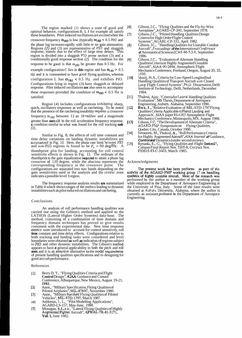
14-5
Gibson, J.C., "Flying Qualities and the Fly-by-Wire Aeroplane", AGARD-CP-260, September 1978. Gibson, J.C., "Piloted Handling Qualities Design Criteria for High Order Flight Control Systems", AGARL-CP-333, April 1982. Gibson, J.C., "Handling Qualities for Unstable Combat Aircraft", Proccedings of the International Corference of Aeronautical Sciences ICAS-86-5.3.4, September 1986. Gibson, J.C., "Evaluation of Altemate Handling Qualities Criteria in Highly Augmented Unstable Aircraft", AM-90-2844, Atmospheric Flight Mechanics Conference, Portland, Oregon, August 20,22, 1990. Mooij, H.A., Criteria for Low-Speed Longitudinal Handling Qualities of TranspoR Aircraft with Closed Loop Flight Control Systems", Ph.D. Dissertation, Delft Institute of Technology, Delft, Netherlands, December 1984. Thukral, Ajay, "Criteria for Lateral Handling Qualities Evaluation", MS Thesis, Depanment of Aerospace Engineering, Aubum, Alabama, September 1990. Bwz, I., "Relative Evaluation of MIL-STD- 1797 Flying Qualities Criteria Applicable toFlaredLanding and Approach', AIAA paper 88-4363 Atmospheric Flight Mechanics Conference, Minneapolis, MN, August 1988 Gibson, J.C, "The Development of Altemate Criteria", AGARD-FMP Symposium on Flying Qualities, Quebec City, Canada, October 1990. Innocenti, M., Thukral, A,, "Roll Performance Criteria for Highly Augmented Aircraft"AIAA Journal of Guidance, Control and Dynamics (under second review). Rynaski, E., G., "Flying Qualities and Flight Control", Calspan Final Report Nos. 7205-8, Conuact Nos. F33615-83-C-3603, March 1985.
The region marked (1) shows a zone of good and optimal behavior, configurations B, I, J for example all satisfy these boundaries. Pilot induced oscillations are excited when the crossover frequency w180 is low (typically wlm < 0.5 Hz) and the phase lag increases rapidly with little or no gain attenuation. Regions ( 2 ) and (3) are representative of PI0 and sluggish response, mainly due to the effect of large time delays. This region is divided into a sluggish PI0 prone section (3) and a conditionally good response section (2). The condition for the response to be gocd is that wlB0 be greater than 0.5 Hz. For example configuration C lies in this region and has wlso > 0.5 Hz and it is commented to have gocd flying qualities, whereas configuration L has wigo < 0.5 Hz. and exhibits PIO. Configurations lying in region (3) have sluggish or delayed response. Pilot induced oscillations are also seen to accompany these responses provided the condition of w180 < 0.5 Hz is satisfied.
Region (4) includes configurations exhibiting sharp, quick, oscillatory responses as well as ratcheting. To be noted that the presence of the ratcheting instability requires a crossover frequency wlB0 between 12 an 18 rad/sec and a magnitude greater than zero dB in the roll acceleration frequency response, a condition similar to what was found for the roll tracking task PI.
Similar to Fig. 8, the effects of roll time constant and time delay variations on landing dynamic instabilities are summarid in Fig. IO. Here, the phase rate limit between PI0 and non-PI0 regions is found to be P, = 90 deg/Hz. A thumbprint plot for landing, accounting for roll control sensitivity effects is shown in Fig. 11. The ordinate of the thumbprint is the gain equalization required to attain a phase lag crossover of 120 degree, while the abscissa represents the corresponding frequency at the crossover point. The configurations are separated into two bands depending on the gain sensitivities used in the analysis and the central zone indicates a possible level 1 region.
The frequency response analysis results are summarized in Table 4 which shows ranges of the mehics leading to dynamic instabilities such as pilot induced oscillations and ratcheting.
Conclusions
An analysis of roll performance handling qualities was carried out using the Gibson's method and applied to tbe LATHOS (Lateral Higher Order Systems) data-base. The method, consisting of a combination of time domain and frequency domain techniques has proved to give results consistent with the experimental data. New time response merrics were introduced to account for control sensitivity, roll time constant and time delay effects. Configurations relative to both tracking and landing tasks were considered and level boundaries were obtained as well as indication of regions subject to PI0 and other dynamic instabilities. The Gibson's metbod appears to have a general applicability in both the pitch and roll axes and it is an amactive alternative to the modal requiremens of present handling qualities specifications and to designing for good aircraft performance.
References
[l] Berry D. T., "Flying Qualities Criteria and Flight Control Design", A M Guidance and Conuol Conference, Albuquerque, New Mexico, August 19-21, 1981.
P I [31
r41
151
.. .~ . Anon., "Military Specification, Flying Qualities of Piloted Airplanes", MIL-8785C. November 1980. Anon., "Military Standard Flying Qualities of Piloted Vehicles", MIL-STD-1797, March 1987. Ashkenas, I., L., "Pilot Modelling Applications", AGARD-LS-157, May-June, 1988. Monagan, S.J., e.a., "Lateral Flying Qualities of Highly AugmentedFighter Aircraft", AFWALTR-81-3171, Vol. I, June 1982.
Acknowledgments
The present work has k e n performed a) psri of inc activity of the AGARD-FMP working group 17 on handling qualities of highly unstable aircrsft. Most of rhr research was performed by the author as a member of the working group while employed in the Depamnent of Aerospace Engineering at the University of Pisa, Italy. Some of the later results were obtained at Aubum Universitv. Alabama. where the author is currently an assistant professo; k the Depamnent of Aerospace Engineering.

14-6
(TR)lJTl 7R3 B 0.8 0.03 18 ~,NR4SIR,G%.BP,BFl,LS~L
(TR)13T2 BIW C 0.8 0.06 18 Pi~,NR~SlR.GFR.BAg.Sp,BFl,LSen
m ) l - 2 W D 0.8 0.00 10 NPio.NRa.SlR.BFR.G*a.BPL,GFl,~en
(rR)23 a1 E 0.45 0.00 18 Ntio.NRa.GlR.GFR.GAg.GP.GnG~,HS%~S
(TR)nJTl 4.542 F 0.45 0.03 18 or.NPb.NRa.QlR.OFR.BAg.OP.GFl,HS%~
(rRI23T2 5.542 G 0.45 0.08 18 Ox,NPb.NRaPIR.BAg,BP,BFl,HS%"
(TR)23T3 8.m H 0.45 0.08 18 O x . Plo.DIR.oFR.BAg.BP.BU,LlSen,HFSen
m12.2 a 1 I 0.45 0.00 10 NU~.NRa.SIR.OFR.OA,GP.GFl,OSen
(TR)2.2Tl a 1 J 0.45 0.03 10 Ntio.NRa,GlR.GFR.GA(I.GP.GF(GSen
(rRp-ZT2 5 . W K 0.45 0.06 10 NPlo.NRa.SIROFR,BAg.sP.Bn.LSen
(rR)2-2T3 7R3 L 0.45 0.08 10 Plo,NRa.NIRS.OIRL.GFRLBAg,BPS,GPLOSen
(TR)2-2T4 &U M 0.45 0.18 10 Oso.Pb.NRa.BIR.BFR.BAg.BP.BFfLSen
ml33 SI2 N 0.25 0.00 18 Or.Pb.R~QlR.OFR.B.OP,BFl,HSsnS
(rRp3T2 7R3 0 0.25 0.06 18 Ra,OlR.BFR.EW.BP.HS%n
(TR133T3 7R3 P 0.25 0.08 18 R4Q1R.BFR.~.OP.GR.HSen
(TR)3.2 3 . a 1 0 0.25 0.W 10 N~,NRa.GlR.GFR.GA(I.GPpFt.NSsn(abou( newdl
(TR)53 7R3 R 0.15 0.W 18 or.Ra,olR,GFR.BAg.BP,BF~LlS~,HF~n
(TRI53T1 7R3 S 0.15 0.03 18 Osc.Ra,QIR.OFR.BAg.BP,BF~HSen
(TR)5dT2 &U T 0.15 0.06 18 Oso.Plo.QlR.BFR.BAg.8P.HSen
(TR)5.2 7/w U 0.15 0 . 0 10 Osc.Ra.OIR.BFR.~g,BP,BF~OSen
mI5.2T1 7R3 V 0.15 0.03 10 OX.RB.B,HSenS
(TR)5.2T3 Bh3 W 0.15 0.08 10 0x.Ra.QlR.OFR.BAg.BPP.HSsn
(TRIM 3 . a l A1 0.45 0.W 25 NPio.NR4GIR.GFR.GAg.GP,GF1,LlSen,~~n
(TR)24T1 W 1\2 0.45 0.03 25 Oso.Rs.QIR.OFR.BAg.B,BF~HSenS
(rR)24TZ 6N A3 0.45 0.08 25 Pb.Ra.QlR.WR.BAg.BP.HSen
mI2473 OIL3 A4 0.45 0.08 25 Plo.BIR,BFR,B,BP,HSen
(rR)34 5112 A5 0.25 0.00 25 Osc.NPb.NR4Q1RIOFR,~,BP,BF1,H~
(rR)34T2 7 N A8 0.25 0.06 25 oac.NPb.R~QlR,BAg,BP,HSen
Table 2 Pilot Commnts. Landing Task
n
( U ) l - l 4 . W A 0.8 0.00 5 NPio.NRa,SIR,BFR,BAg,GP,G~n
(LA)2-1 ZAI E 0.45 o.m 5 NF'w,NRa.GIR,GFR,GP,CSm
(IA)2-111 4 U C 0.45 0.m 5 NPa.NmGIR.GR.GAg.OP,mn
(LA)PlT2 5rl2 D 0.45 0.06 5 Os.NPa.NR4SlR.BFR,BAg.BP.LSen
(U)2-114 9A.3 E 0.45 0.18 5 Os.P~o.NRa.SIR.OFR.E~,~,LSen
( U p 1 3Shl F 0.25 0.00 5 NPw.NmGIR,GFR,GAg,GP,L~n
(LA)dl 50-2 G 02 0.00 5 NPio.Ra01R.OFR.BAg.EP.OSen
(LAp112 3111 H 0.2 0.06 5 Osc.NPio.NRa,EFR.BAg,EP,LSen
(LA)1-2 3111 I 0.8 0.00 10 NP~.NR40lR.OFR.O~.oP.OSen
(U)l-ZTl 3111 J 0.8 0.W 10 Osc.NPio,NRa,GIR,OFR.BAg.GP,G~n
(LA)1-212 6W.2 K 0.8 0.06 10 Pio.NR4SIR.EFR.BAg.EP.O~n
(U)1-213 8 t U L 0.8 0.08 10 Orc.Pio.NRa.SIR.8Ag.EP,LSen
(U)1-214 EA3 M 0.8 0.18 10 Pio,NR46IR.BFR,BAg,EP.BSen
(LA)2-2 ZAl N 0.45 0.00 10 NPm,NRa.GIR.GFR.DAg.GP.GSen
(Up2 2111 0 0.25 0.w 10 Osc.NPio.N~GIR.GFR.GAg,GP,OSen
( I A ~ Z T Z SAZ P 025 0.06 io 6IR.W (Patiialevaluation)
PREFIX B = Bad G = Good H = High L = Lob a = obq N = No
Q = &it&erky S = Sluggish
SUFFIX L = Largeinput R = Response s = Smallinput
ROOT Ag = Aggressiveness F = F d Ft = FmeTracking I = Initial Os0 oscillation P = hdictabZN Pio= Pilot Induo& Oscillation Ra = Ratcheting Sen= Sensitivity

14-7
Table 3 Time Response Metrics
Metric DeSniption Tracking Landing
Teff Effective time delay Figure 3 Figure 4
L'paS In idal r~l laccelera t ionp~~~ Figure 3 Figure 4 Ra Roll acceleration ratio 0.91 > Ra > 0.7 1 0.94 > Ra > 0.76
Table 4 Values of Metrics for Dynamic Instabilities
Deficiency Tracking Landing
PI0 ~ 1 ~ ~ ~ < 0 . 7 5 H z a n d P , 2 6 O d e g / H z ~1~~~<0.75HzandP,26OdegRIz
or%<0.3sec
Ratchedng o18,, 2 (10-20) r d s e c ~~,~=(12-18)rad/sec roll accel. > -10 dB roll accel. > 0 dB
e DIP
Figure 1. Longitudinal Dropback Time Responses (taken from [7])
I I _. I
P
Figure 2. Latera-Directional Block Diagram (taken from [3])

m 0 0 125.0 , - R S T
OSCILLATION
75.0 : L .
-1
50.0
25.0
. 0 0
LEVEL 1 0
C
LEVEL 3
SLUGGISH PI0
50.0
40.0
30.0 L. . P
cn ,A a
20.0
10.0
Figure 3. Time Response Analysis. Tracking Task
0 OM E
0.0 1 0.00 0.10 0.20 0 .
reli W C )
Figure 4. Time Response Analysis, Landing Task
C

Nichols Chart
a I M 25 I k 1 I
I
1 SLUGGISH. PI0 PRONE
3 QUlCK. RAXHETING / A I I
-25 I / I / I -360 -180
Phase (deg:
Figure 5. Frequency Response Boundaries, Tracking Task
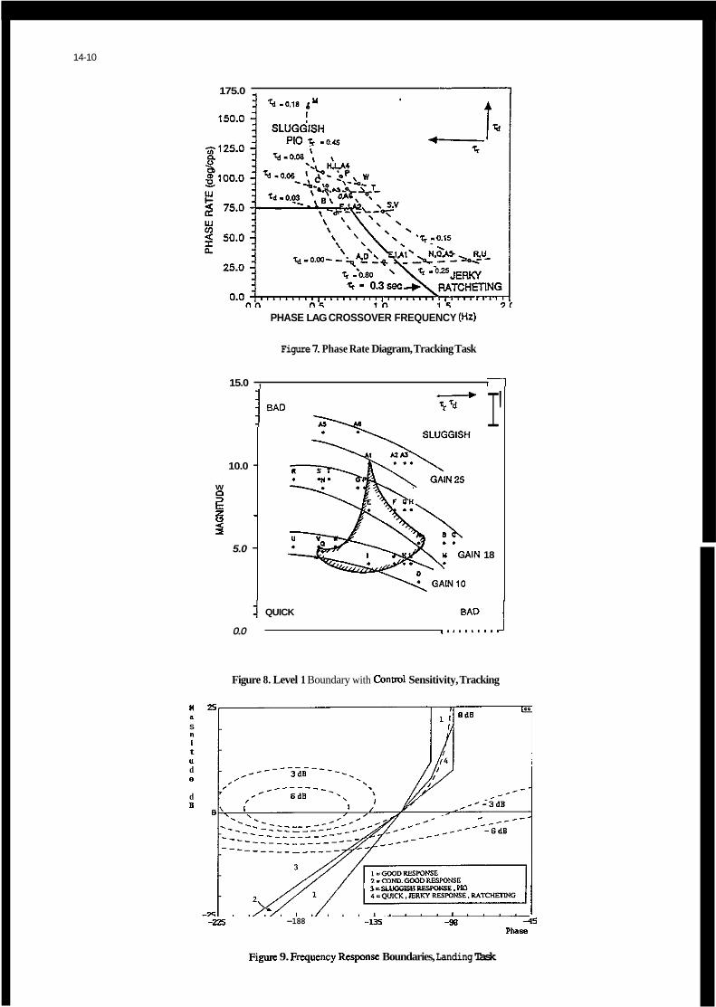
175.0 I
10.0 - W
2 3 z -
5.0 -
PHASE LAG CROSSOVER FREQUENCY !Hd
0.0 , . ~ . ~ ~ - * ~ .
Figure 7. Phase Rate Diagram, Tracking Task
15.0 , I 1 1 BAD
14-10
I'
18
QUICK BAD I
Figure 8. Level 1 Boundary with Conool Sensitivity, Tracking
" S
1 t
d " e
d B
3 i SLUGGISHRESPONSE. PI0
-188 4 5 P h S E
Figurc 9. Fnquency Rcsponsc Boundaries, Landing Task

175.0
150.0
'2 125.0 Q < 0
U
W
E
W
I
a, 100.0 v
75.0
50.0 a
25.0
0 . O ~ ~ ~ ~ ~ ~ ~ ~ ~ ~ I ~ ~ ~ ~ ~ ~ ~ ~ ~ l ~ " " " " ~ 0.0 0.5 1 .o 1.5
PHASE LAG CROSSOVER FREQUENCY (Hz)
Figure 10. Phase Rate Diag", Landing Task
30.0 I
LEVEL I N s m E DASHED AREA
GAIN ~ 10
G 0
GAIN = S
0.0 tT"n, I 8 I I I I I I I , a I 0 8 4 4 I I I , ( I I I I m - 0.00 0.10 0.20 0.30 0.40 C
FREQUENCY (Hz) AT PHASE LAG 120 deg. IO
Figure 11. Level 1 Boundary with Control Sensitivity, Tracking


HANDLING QUALITIES GUIDELINES FOR THE DESIGN OF FLY-BY-WIRE FLIGHT CONTROL SYSTEMS FOR TRANSPORT AIRCRAFT
0 P Nicholas Royal Aerospace Establishment
Bedford
W P de Boer & J A J van Engelen Nationaal Lucht-en Ruimtevaartlaboratorium
PO Box 90502 MK41 6AE England
1006 BM Amsterdam The Netherlands
H T Huynh Office National d'Etudes e t de Recherches
D r D Shafranek Deutsche Forschungsanstalt f u r Luft-und
Aerospatial es Raumfahrt e.V. RD 79 Postfach 32 67 I. .-
92322 C h a t i l l o n Cedex France
3300 Braunshweig Germany
SUMMARY
This paper describes the work o f GARTEUR F l i h t
reports. t r a t e d on long i tud ina l con t ro l ) are out l ined. Secondly, the f l i g h t cont ro l systems designed and used, and the simulator t r i a l , a re described. Th i rd ly , t he resu l t s are reviewed. Fourthly, e x i s t i n g handling q u a l i t i e s c r i t e r i a , and the Act ion Group's t e n t a t i v e proposals f o r handling q u a l i t i e s measures which can be appl ied t o f l i g h t p a t h cont ro l and system changeover, are assessed. F ina l l y , the Group's guide1 ines and recommendations fo r f u r t h e r work are reviewed.
Mechanics Act ion Group 01 on Havdlin Qua l i t 9 es and summarises the contents o f I t s f 9 nal
F i r s t , t he ob jec t ives (which concen-
1 INTRODUCTION
The Group f o r Aeronautical Researth and Technology i n EURope (GARTEUR) was set up i n 1981 by France, the Federal Republic of Germany, the Netherlands and the United Kingdom. It aims a t s t imula t ing and coordi- nat ing cooperation between research i n s t i t u t e s and indust ry i n the areas o f aerodynamics, f l i g h t mechanics, hel icopters, structures and mater ia ls and propuls ion technology. The GARTEUR management has approved the pub1 i c a t i o n of t h i s paper which describes the work o f GARTEUR F l i g h t Mechanics Act ion Group 01 on Handling Qua l i t i es , (which was se t up i n 1982 and has recent ly completed i t s work), and sum- marises the Act ion Group's f i n a l reports. This work involved co l l abo ra t io? between the ONERA, DLR, NLR and RAE research i n s t i t u t e s of the four GARTEUR member countr ies, w i t h advice from i ndustry . 2 OBJECTIVES
The Act ion Group f i r s t investigated, through a quest ionnaire t o the aerospace indust ry o f t he four European countr ies involved, the a n t i c i - pated manual cont ro l tasks and cont ro l concepts fo r fu ture t ranspor t a i r c r a f t w i t h advanced f l i g h t cont ro l and d isp lay systems. i ndus t ry ' s response and a review o f ex i s t i ng long i tud ina l handling q u a l i t i e s c r i t e r i a , a comprehensive study on the NLR moving-base p i l o t e d f l i g h t s imulator was approved, w l t h the a i m of es tab l ish ing long i tud ina l handling qual- i t i e s guidel ines fo r f u t u r e t ranspor t a i r c r a f t w i t h advanced systems.
Following
Some concern had been expressed by Indust ry t h a t the resu l t s aimed a t by the Act ion Group could poss ib ly develop i n t o add i t iona l requirements t o be app l ied by the c e r t i f y i n g au tho r i t i es . However, t he Act ion Group was convinced t h a t the app l i ca t i on o f ACT br ings w i t h i t such wide p o s s i b i l i t i e s t h a t useful ! genera l ly applicable, handling q u a l i t i e s guide- l i n e s w i l l be necessary f o r the design o f ACT t ranspor t a i r c r a f t , and could be generated as a r e s u l t o f t he proposed f l i g h t s imulator experiment.
Three d i s t i n c t aspects were invest igated, i n the terminal f l i g h t phases:
a. The v a l i d i t y of various e x i s t i n g and pro- posed handling q u a l i t y c r i t e r i a , based on p i t c h r a t e control , f o r the design of a sophist icated ( l ong i tud ina l ) cont ro l sys- tem which instead appl ies f l i g h t p a t h as the primary con t ro l l ed parameter.
C.
primary system, eg due t o the occurrence of a massive sensor fa i l u re .
I n p a r t i c u l a r the impl ica t ions o f the change i n handling qualities when rever t - i n from a sophist icated primary manual F lgght Control System (FCS) t o a simpler backu long i tud ina l system having d i f f e r - ent, !ut s t i l l good, cha rac te r i s t i cs . ( Indust ry had commented t h a t the hand!ing q u a l i t i e s o f a f u t u r e backup Fly-By-Wire (FBW) system would be as good as those o f cur rent a i r c r a f t ) .
3 FLIGHT CONTROL SYSTEMS AND ASSOCIATED
Preparatory invest igat ions were f i r s t performed i n the simple fixed-base simulat ion setup of the ONERA F1 i g h t Mechanics Laboratory. purpose of these invest igat ions was t o design and va l i da te a harmonized primary f l i g h t con- t r o l and d isp lay system f o r the l a t e r compre- hensive inves t iga t ion a t NLR, by undertaking a l i m i t e d p i l o t assessment. A t t he end of t h i s preparatory work two primary and one backup long i tud ina l f l i g h t cont ro l systems were flown by evaluat ion p i l o t s a t ONERA i n ea r l y 1987. Apart from p i l o t comments on the obvious l i m i - t a t i o n s of the ONERA experiment, i t was con- cluded t h a t the ob jec t ives had been met, and
DISPLAYS
The

15-2
t h a t a sound basis had been establ ished fo r the study a t NLR. dations from t h i s study formed the background fo r the comprehensive s imulator experiment a t NLR.
Following the preparatory invest igat ions a t ONERA, a Typical Heavy E l e c t r i c a l Transport A i r c r a f t (THETA-4) based on an ex i s t i ng NLR a i r c r a f t model was represented on the NLR simu- la to r . This model was derived from a Boeing 747 model w i t h some modif icat ions so tha t the a i r c r a f t behaved almost l i k e the a i r c r a f t model (THETA-3) used i n the i n v e s t i - gat ion a t ONERA. t h a t means having the same approach speed and a s l i g h t l y unstable natural long i tud ina l behaviour. It was a lso equipped w i t h an a l l f l y i n g t a i l and a f ly- by-wire FCS.
Four long i tud ina l f l i g h t control systems were designed f o r t h i s study.
The conclusions and recommen-
Two were sophist icated primary systems w i t h f l i g h t p a t h r a t e command, and two were sat isfac- t o r y backup systems.
f l l g h t p a t h angle feehack loop. A gamma-trim switch was therefore included t o permit the p i l o t t o produce s m a l l f l i g h t p a t h angle changes without discontinuous e f fec ts .
The second primary system, B, had the same f l i a h t o a t h anale term as svstem A. b u t i t held the-angle b e i i s t i c k release.' I n t h l s system, s t i c k inputs went through a forward f l i g h t p a t h i n teg ra to r i n combination w i t h a continuous gamma-feedback loop. layout than system A, but it d i d not produce d i scon t inu i t i es so d i d not requ i re a gamma-trim f a c i l i t y .
commanded i t the ins tan t of
The system had a somewhat more complex
F i g 1 shows t yp i ca l responses o f commanded and actual f l i g h t p a t h angle f o r systems A and 8. F i g 2 i l l u s t r a t e s step redatuming of system A.
As noted, the two a l t e r n a t i v e primary long i- tud ina l f l i g h t control systems provlded f l i g h t - path ra te command w i t h f l i g h t p a t h angle hold. Both smoothly changed t o a p i t c h r a t e mode f o r f l a r e and landing. A l l these primary systems provided bank compensation and an au to th ro t t l e . On f a i l u r e a step change t o one o f two possible p i t c h r a t e backup systems (C o r 0) occurred. The backup systems had no bank compensation o r au to th ro t t l e . A s ing le l a t e r a l system, provid- ing r o l l r a t e command w i t h bank angle hold, was used throughout and d i d not change on fa i l u re .
The fundamental differences between the ' dponse o f the f l i g h t a t h mode o f primary sys- .ems A and B, and the Lackup systems C and D
and the f l a r e mode of A and B, t o a block p i l o t input are shown i n F igs 3 and 4.
b. This i s achieved by using subs tan t ia l l y more p i t c h r a t e overshoot f o r the f l i g h t - path mode of A and 8, than f o r C, D and the f l a r e mode o f A and B.
path ho ld tl f l a r e mode o f A and B are symmetrical because a l l t h e i r terms are continuous.
Head-down instrumentat ion consisted of an experimental E lec t ron ic F l i g h t Instrument System (EFIS) which included two d isp lay u n i t s pos i t ioned i n a v e r t i c a l ar ray i n f r o n t of t he p i l o t . The top, Primary F l i g h t Display, pro- vided primary f l i g h t informat ion inc lud ing f l i gh tpa th vector. The bottom, Navigation Display, provided what was b a s i c a l l y an elec- t r o n i c equivalent o f a Hor izontal S i t u a t i o n Ind icator .
No attempt was made t o design a f u l l head-up d i sp la (HUD). The r e s t r i c t e d HUD format (Fig 5: used i n the NLR simulator included com- manded and actual f l i gh tpa th , -3 deg f l i g h t p a t h ta rge t and synthet ic runway, b u t d i d not pro- vide airspeed o r a l t i t u d e .
Changes t o the HUD format (accompanied by an audio s igna l ) provided a f l a r e warning as the a i r c r a f t descended through 30.5 m (100 f t).
It was assumed t h a t the massive sensor f a i l u r e which caused reversion t o the backup cont ro l system would also a f f e c t the displays, so the HUD and head-down f l i g h t p a t h symbols were removed when a cont ro l system f a i l u r e occurred.
4 SIMULATOR TRIAL
The NLR moving-base f l i g h t s imulator was f i t t e d w i t h a t ranspor t a i r c r a f t cockp i t f lown using a s idest ick con t ro l l e r .
approach, f l a r e and landing.
Fa i l u re of the primary FCS might occur some- where i n the c i r c u i t . an audio s i nal which the p i l o t had t o cancel. He was requfred t o continue and land w i t h the backup system.
Dayl ight v isual condi t ions were provided, w i t h a c loud base a t 152.4 m (500 ft).
Disturbances included both wind p r o f i l e and
F a i l u r e was announced by
a l t i t ude , and the turbu ler dev ia t ion around the mean values.
Wind p r o f i l e could be d i f f e r e n t f o r each c i r c u i t .
I n the experiments, two leve ls o f environmental disturbance were used:
1 ' low ' l eve l o f disturbance.
2 'h igh ' l eve l of disturbance.
Some f a m i l i a r i z a t i o n runs were made w i t h no disturbance.
Four d i f f e ren t wind p r o f i l e s were used f o r each leve l of disturbance.

15-3
The turbulence was s t ruc tured according t o a model described i n Ref 1 which i s able t o gen- erate t ime h i s fo r ies having the proper ty of ' in termi t tency representat ive o f a non- aussian d i s t r i b u t i o n o f v e l o c i t y differences
gn rea l atmospheric turbulence.
Each of the f o u r p a r t i c i a t i n g t e s t p i l o t s
changeovers and the corresponding fa i l u re - induced change i n character is t ics , based on f l y i n g about 50 ( p a r t i a l ) c i r c u i t s i n the simu- l a t o r . The r e s u l t s obtained consisted of:
evaluated the four possi 1 l e cont ro l system
a. Cooper-Harper r a t i n s given by the p i l o t s fo r the behaviour of t he primary and backup f l i g h t cont ro l systems separately.
Extensive commentary given by the p i l o t s dur ing the execution of the runs, and durina the debr ie f ina i n resDonSe t o a
b.
questionnaire. -
c. Recorded performance measures, cons is t ing of values o f selected parameters a t t he moment of fa i lu re , threshold and touchdown and of mean values, standard deviat ions and leve l crossings o f selected parameters fo r c e r t a i n segments o f the c i r c u i t .
5 SIMULATOR RESULTS
Prel iminary r e s u l t s were presented a t the AIAA Atmospheric F l i g h t Mechanics Conference a t Minneapolis, USA, I n August 1988 (Ref 2). The f u l l r e s u l t s have been published i n the Act ion Group's f i n a l report, GARTEURITP-055 (Ref 3).
Primary systems:
System A f l i g h t p a t h mode received an equal number of Level 1 and Level 2 handling q u a l i t i e s ra t ings, whereas system B was sa id by a l l p i l o t s t o provide Level 1 handling q u a l i t i e s and t o be a near- optimal FCS f o r the a i r c r a f t under con- s iderat ion. S stem'A f l i g h t p a t h mode was ra ted less sa t f s fac to ry than system B mainly because of the d i s l i k e d jum i n g o f
the HUD.
Performance leve l crossings ind ica te t h a t e i t h e r the automatic airspeed cont ro l was n o t t i g h t enough o r the performance l i m i t s (on the approach f2 kn desired, f5 kn adequate) were too s t r ingent .
the f l i g h t p a t h command and i t s sym E 01 on
The p i t c h r a t e command mode o f A and B used below 100 f t wheel he ight permit ted the p i l o t s t o make landings which were good fo r a simulator.
Changeover i n handling qua l i t i es :
The loss o f system sophis t ica t ion a t FCS f a i l u r e sometimes made it necessary f o r the p i l o t t o react immediately t o sustain the f l i g h t cond i t i on a t which the f a i l u r e occurred, t h i s was considered objectionable.
Backup systems:
Althou h the performance measures some- times Qndicate s l i g h t d i f fe rences between the two backup systems, the p i l o t s most ly could not d i s t i ngu ish between them.
I n cont ras t t o the primary systems, the p i l o t ra t i ngs f o r the backup systems were dependent on the leve l of atmospheric d i s- turbances; most o f t he ra t i ngs ind lcated Level 1 handling q u a l i t i e s i n ' low , and Level 2 handling q u a l i t i e s i n 'h igh ' l eve l disturbances, i e t h e i r ove ra l l r a t i n g was Level 2.
The reason f o r the Level 2 handling qual- i t i e s r a t i n g was not the dynamics o f the backup systems themselves, b u t merely the change i n augmentation features a t FCS fa i l u re .
the primary systems.
Displays :
The way o f d isp lay ing the necessary i n f o r - mation t o the p i l o t s c e r t a i n l y inf luenced t h e i r ra t i ngs f o r the handling q u a l i t i e s o f the a i r c r a f t .
Although no attempt was made t o design a complete HUD, the value o f a HUD i n a t ranspor t a i r c r a f t was confirmed by a l l p i l o t s .
S idest ick :
When the FCS provided ho ld terms, p i l o t s tended t o s teer i n separate axes i n a pu lse- l i ke manner, which provoked the p o s s i b i l i t y of accidental cross-coupling and making unintended inputs.
Cross-coupling, due t o a poor harmoniz- a t i o n between the p i t c h and the r o l l channels, a l so inf luenced the handling q u a l i t i e s ra t i ngs i n the present study.
6 ASSESSMENT OF EXISTING CRITERIA
General The f l i g h t cont ro l systems were assessed against the pred ic t ions of selected e x i s t i n g handl in q u a l i t i e s c r i t e r i a (Table l), although the avaglable c r i t e r i a do not g i v e consider- a t i o n t o the f l i g h t p a t h r a t e command laws used i n t h i s invest igat ion, o r t o the changeover effects. The c r i t e r i a a lso do not consider auto thro t t les , o r terms such as bank compen- sation. It has t o be remembered a lso t h a t the cont ro l s t ra tegy of in t roduc ing pu lse type s t i c k inputs, app l ied most1 by the p i l o t s w i t h
d i f f e ren t from the continuous t i g h t cont ro l behaviour under ly ing most o f t he c r i t e r i a .
t he primary FCS because o f r t s ' ho ld ' terms, i s

15-4
As noted, the p i l o t s ' ra t ings o f the handling q u a l i t i e s o f the control systems were i n f l u - enced by the HUO format. Up t o now the k ind o f d isp lay has not been taken i n t o account by any c r i t e r i o n . lead in t o some uncer ta in t ies when comparing the ratgngs obtained w i t h the predic- t i ons provided by applying these c r i t e r i a .
Primary f l i g h t control systems:
System A f l i g h t p a t h mode
The p i l o t s ra ted system A i n the Level 1 t o 2 handling q u a l i t i e s region. However, when the p i l o t ra t ings ind icated Level 2, t he reason given f o r the degredation was the redatuming o f the f l i g h t p a t h command and I t s symbol on the HUD, a f a c t o r which i s not considered by any c r i t e r i o n . This impl ies t h a t those handling q u a l i t i e s c r i t e r i a , based on p i t c h a t t i t u d e and p i t c h r a t e responses, which pred ic ted Level 2 are c l e a r l y not appl icable t o a i r c r a f t w i th f l i g h t p a t h r a t e commandlflightpath angle hold control laws. While most c r i t e r i a under con- s iderat ion p r e d i c t Level 1, the Bandwidth C r i t e r i o n and the Equivalent Time Delay requirement o f the Transfer Function C r i t e r i o n both p red ic t Level 2. The p i l o t rat ings, which ind ica te t h a t the Equivalent Time Delay o f t h i s control system i s i n f a c t acceptable f o r a t ransport a i r c r a f t , are consistent w i t h resu l t s from other invest igat ions i n the US and Europe tha t f o r t ranspor t a i r c r a f t t h i s boundary should be moved (see the fo l lowing section).
System B f l i g h t p a t h mode
However, these Level 2 pred ic t ions were based on three p a r t i c u l a r parameters: e f fec t ive t ime delay obtained from open loop responses: equiv- a len t t ime delay determined through e u i va len t system t rans fe r functions; and bandwiith. The present boundaries f o r these three parameters are mainly based on resu l t s o f f i g h t e r f l i g h t tes ts i n category A f l i g h t phases ( l e rap id manoeuvring, prec is ion tracking, etc). A re laxat ion o f these requirements fo r t h e i r app l ica t ion t o la rge t ranspor t a i r c ra f t , i s therefore already under discussion. Even though the p a r t i c u l a r c r i t e r i a may not be f u l l y v a l i d f o r a i r c r a f t w i t h f l i g h t p a t h control laws, the resu l t s from the present experiment may cont r ibute t o the establishment of new boundaries appropriate for la rge t ranspor t a i r c r a f t i n terminal f l i g h t phases.
Control system changeover
The case o f a f a i l u r e i n the FCS and the changeover t o a backup system which has d i f f e r- ent handling q u a l i t i e s i s not covered by any ex i s t i ng handling q u a l i t i e s c r i t e r i o n .
Backup f l i g h t cont ro l systems
The handling u a l i t i e s c r i t e r i a considered sometimes r e i i c t s i g n i f i c a n t di f ferences be- tween the gackup systems C and 0. This does not correspond t o the p i l o t ra t ings obtained, which indicated t h a t the p i l o t s mostly could not d i s t i ngu ish between the two d i f fe rent backup systems.
Most of the c r i t e r i a p r e d i c t Level 1 f o r these systems, whi le the ove ra l l p i l o t r a t i n g was Level 2. Since the p i t c h r a t e command laws of the backup cont ro l systems are su i ted f o r an assessment against e x i s t i n g handling q u a l i t i e s c r i t e r i a , the resu l t s of the assessments per- formed do not g i ve any consistent explanat ion fo r t h e i r Level 2 handling qua l i t i es .
However, t he loss o f cont ro l augmentation fea- tures was mentioned as the main reason f o r handling q u a l i t i e s degradation r e l a t i v e t o the primary systems, a f a c t which i s not covered by any c r i t e r i o n . Apart from these def ic iencies, the handling q u a l i t i e s of the backup cont ro l systems were ra ted Level 1. This can almost be taken as conf i rmat ion o f the pred ic t ions from the app l i ca t i on o f handling q u a l i t i e s c r i t e r i a , tak ing account o f t he f a c t t h a t f o r t ranspor t a i r c r a f t the lowering o f the boundaries of those c r i t e r i a p red ic t i ng Level 2 handling q u a l i t i e s i s under discussion.
7 PROPOSALS FOR NEW HANDLING QUALITIES MEASURES
F l ightpath cont ro l
Most ex i s t i ng c r i t e r i a assume t h a t the s stem
permit the i l o t t o achieve good f l i g h t p a t h control . R h s t u d i e s the basis o f each o f the c r i t e r i a o f Table 1, t o consider whether as it stands it i s appropriate f o r systems which a ive d i r e c t control o f f l igh tpath , and i f not,
must provide good p i t c h cont ro l i n order -yt o
i h e r e possible proposes a i o i c a l adaptation
System changeover
P i l o t comments on t he cont ro l system changeover a t fa i lu re , and the associated transients, were h igh ly dependent on the actual f l i g h t cond i t ion a t the i n s t a n t o f t he f a i l u r e . Consequently i t w i l l be extremely d i f f i c u l t t o def ine a s ing le parameter o r a combination o f parameters on which a measure of handling q u a l i t i e s du r in changeover t rans ients can be based, b u d a y be possible t o measure the change i n handling q u a l i t i e s once the t rans ients are over.
If the ex is t i ng c r i t e r i a are app l ied t o the f l i gh tpa th control primary systems considered here then, although many of the c r i t e r i a are l o g i c a l l y inappropr iate f o r such systems, most of them g ive resu l t s which are consistent w i t h the p i l o t s ' rat ings. This suggests a poss ib le technique f o r quant i fy ing the change i n hand- l i n g q u a l i t i e s when an FCS changeover from f l i gh tpa th t o p i t c h r a t e cont ro l (as wel l as from p i t c h r a t e t o p i t c h ra te) occurs. The change could be measured by assessing the mag- n i tude o f the changes w i t h i n i nd i v idua l e x i s t - ing c r i t e r i a . t o quant i fy such measures of handling q u a l i t i e s change, i n order t o es tab l i sh sound changeover measures.
As noted e a r l i e r , t he changeover o f e i t h e r p r i - mary system t o i t s f l a r e and landing mode was f u l l y acceptable. This was e f f e c t i v e l y a smooth change from system A t o 0 o r B t o ?, b u t w i t h no change o f o ther features, a t 'low speed.
which should make it appropr 9 ate.
Further work w i l l be necessary
Thus a chan e of t h i s magnitude w i t h i n any relevant c r i t e r 4 on i s acceptable.

8 CONCLUSIONS
15-5
A technique i s proposed f o r using ex is t ing c r i t e r i a t o measure the change i n handling qua l i t i e s when an FCS mode change o r reversion t o a backup control system nrriirc. Althouoh ex is t ing c r i t e r i a are i n
e t o f l i a h t n a t h con-
A prime object ive o f the invest igat ion was t o assess the value of longi tud ina l handling qual- i t i e s c r i t e r i a when appl ied t o a relaxed longi- tudinal s t a b i l i t y t ransport a i r c r a f t cont ro l led through an ACT system. . The aim was t o estab- l i s h guidel ines which could be appl ied to: sophist icated primary systems having f l i gh tpa th as the primary cont ro l parameter: associated modes o r simpler backup systems with p i t c h r a t e control : and the changeover between them.
It must be recognised t ha t ex is t ing longi tud i- nal c r i t e r i a have been developed from systems which i n general provide on ly p i t c h r a t e con- t r o l . Also, most ex is t ing c r i t e r i a have not been developed f o r a control strategy w i t h pu lse- l ike inputs such as are used when the FCS incorporates ho ld terms. Furthermore, they do not g ive consideration t o changeover effects, augmentation features 11 ke au to th ro t t l e and bank compensation, o r advanced displays l i k e the HUD used here.
In order t o assess the value o f ex is t ing c r l - t e r i a and proposed measures it has been necess- ary t o estimate what the r a t i n s i n the resent
able t o disregard the augmentation features and advanced displays. c r i t e r i a and measures should ind icate the fo l lowing handling qua l i t i es .
Level 1-2 for primary system A.
Level 1 f o r primary system B.
Level 1 fo r the f l a r e and landing modes o f A
Level 1 for the changeover from A o r B t o
Level 1-2 f o r backup systems C and D.
Level 2 f o r the changeover from primary sys- tems A o r B t o backup systems C o r 0.
study would have been if the p 9 l o t s had E een
It i s considered t ha t the
and B.
t h e i r f l a r e modes.
Based on these ra t ings the fol lowing con- clusions can be drawn:
Fourteen of the sixteen ex is t ing c r i t e r i a assessed i n t h i s invest igat ion are con- s is ten t w i t h the p i l o t s ' ra t ings of the backup systems, and the primary f l a r e and landing systems, provided t ha t the t ime delay requirements are relaxed. which seem less appropriate are the Bandwidth C r i t e r i on w i t h i t s current fi hter-based boundaries and the Dropback crs ter ion.
The two
t e r i a are based-is. inappropriate for assessing f l i g h ath control systems, so
However, f o r appl icat ion spec i f ica l l y t o fli htpath control systems, log ica l adap- tatgons are t en ta t i ve l y proposed i n Ref 3 f o r ten of the remaining t h i r t een ex is t ing c r i t e r i a which are not appropriate as they stand. Further work w i l l be necessary t o estab l ish boundaries between levels.
they should not 'g e used for t h i s purpose.
DropOSed change
necessary. However, even w i t h the same handling qua l i t i e s f o r primary and backup systems according t o ex is t ing c r i t e r i a , handling qua l i t i e s may be ra ted qu i t e di f- ferent by the p i l o t because of changes i n augmentation and displays which the c r i - t e r i a do not recognise.
C r i t e r i a are required f o r au to th ro t t l e systems.
9 GUIDELINES
9.1 General A summary o f the main resu l t s deduced from the reported experiment follows. extracted from Ref 4 and i s sub-divided i n t o some general experimental resu l t s i n Section 9.2. and the handling qua l i t i e s design guidel ines i n Section 9.3. o r gu ide l ine i s introduced by a short descrip- t i o n o f the background t ha t l e d t o it.
9.2 Generic experimental resu l t s
With respect t o the setup o f the experiment, i t was concluded from the expressed p i l o t opinions t h a t i t i s a v iab le concept f o r future FBW transport a i r c r a f t t o be equipped w i t h a HUD and cont ro l led by means o f a sidest ick. Also the philosophy of a primary longi tud ina l FCS as mechanized i n the reported experiment was well accepted by the p i l o t s . Therefore:
It has been
Each generic r e s u l t
I A f1ztm-a flv-by-wire FCS for t ransport ta t . i s fac to r i l v be mechanized
htnath
- . . . . - - . . , a i r c r a f t can _... as f l i gh tpa th r a t e command7flig angle ho ld w i t h associated au to th i o t t l e and bank compensation features, he con- t r o l l e d by means of a s idest ick
_ _ , and be
equipped w i t h a HUD.
P i l o t s read i l y accepted the changeover charac- t e r i s t i c s from the primary system t o the f l a r e system below 100 ft and, apart from the loss of sophistication, the changeover t o the backup system a t FCS f a i l u re .
b. The dynamic changeover from an FCS based on f l i gh tpa th control t o a p i t c h control mode a t f lare, o r t o a backup p i t c h con- t r o l system a t FCS fa i lure, can sat isfac- t o r i l v be mechanized as i n the reported experjment: fading from f l i gh tpa th t o p i t c h control mode a t f l a re , and i ns tan t l y freezing parameter values and switching t o the backup mode a t FCS fa i lu re , fol lowed by fading from primary t o backup signals.
A i thnimh fnrca varsiic displacement character- :oll control w i t h the
hamnni7ad~ the o i l o t s Com-
iystem sophist icat ion.

15-6
c. Harmonization between p i t c h and r o l l should include a l l aspects: sidestick, response and display character ist ics. and system sophist icat ion.
9.3 Guidelines
Future transport a i r c r a f t are l i k e l y t o be equipped w i th FEW f l i g h t control systems w i th which p i l o t s can d i r e c t l y control f l i g h t var i- ables tha t are only cont ro l lab le i nd i r ec t l y i n most current a i r c ra f t . This means tha t the function of the controls i s changed, and t ha t the cont ro l led parameter must be d isp la ed t o
assessment of handling qua l i t i e s o f an a i r c r a f t l f l i g h t control system combination becomes inseparable from control and display character ist ics. This leads t o the fol lowing guide1 ine:
the p i l o t . Therefore, i n such a s i t ua t .r on the
Guideline 1: When assessing handlina aual- X c o m l e t e svstem must
The ex is t ing handlin qua l i t i e s c r i t e r i a , which have been used here 4n the assessment o f the various f l i g h t control systems, only consider the a i r c r a f t and cont ro l~ laws, without the character ist ics o f cockpit controls and d is- plays. Hence the fo l lowing guideline:
Guideline 2: When applying ex is t ing hand- ling qual iRes c r i t e r i a , be careful because they do not include the character- i s t l c s o f cockpit controls and displays.
The ex is t ing longitudinal handling qua l i t i es c r i t e r i a have been established f o r a i r c ra f t where the stick controls elevator o r p i t c h rate, and i n most cases are based on the p i l o t exercising inner-loop p i t c h control i n order t o obtain outer- loop f l i gh tpa th control . Although p i t c h a t t i t ude (or ra te) remains a ver impor- tan t parameter f o r p i l o t s judging the {andling qua l i t i es of t ransport a i r c r a f t (eg passenger^ comfort considerations), such c r i t e r i a are not d i r ec t l y applicable t o f l i gh tpa th control sys- tems, even though they may appear t o g ive va l i d measures of handling qua l i t i e s levels.
Guideline 3: When applying any handling qua l i t i es c r i te r ion , care must be taken t o ensure tha t i t s basis i s compatible w i th the control system being studied. Specif ic c r i t e r i a f o r f l i gh tpa th control systems must be developed.
One o f the inves t i ated primary f l i g h t control systems featured dqscontinuit ies i n the com- manded f l i gh tpa th angle when t ha t was d i f f e ren t from the actual f l i gh tpa th angle a t i n i t i a t i o n o f a longitudinal s t i c k input. This was h i h l i gh ted by the HUD and was disturbing w i t h fn - tent ional inputs, bu t even more so when accidental cross-coup1 ing from r o l l inputs occurred. especial ly i n high turbulence.
control systems, However, boundaries between handling qua l i t i e s leve ls are on ly presented f o r one o f these proposals.
Gufdeline 5: The adapted c r i t e r i a pre-
ms. To ensure T7lTRef 3 should be appl ied t o
not d i f f e r too much from the data po in ts for these c r i t e r i a i n Ref 3 .
Although the handling qua l i t i e s o f the backup systems were j u ed good by the p i l o t s , the
backup system was the main reason f o r the degraded handling qua l i t i e s ra t ings for the backup systems. The p i l o t s argued t h a t the change i n system sophis t icat ion was too b i g i n the current experiment (especial ly mentioned were the loss o f turn coordination and auto- t h r o t t l e functions, and the loss o f the f l i g h t - path vector information i n the HUO).
changeover a t f a 9 l u r e from the primary t o the
Guideline 6: I f a primary FCS f a i l u re resu l ts I n a changeover t o a less sophis- t i ca ted backup system, then the change i n sophist icat ion must be l imited, as must changes i n f l i g h t information displayed, t o be acceptable t o the p i l o t s .
The study also addressed the simpler question of p i l o t s ' react ion t o the change i n basic hand1 ing character is t ics on changeover t o a d i f ferent control mode, o r backup system. Ref 3 proposes t ha t ex is t ing longi tud ina l c r i - t e r i a can provide the basis f o r measuring such changes i n handling qua l i t i es . of acceptabi l i ty have ye t t o be established.
Guideline 7: The measurement technique proposed i n Ref 3 should be appl ied t o any sudden change i n longi tud ina l FCS charac- t e r i s t i c s . TO ensure good handling qual- I t f e s . care should be taken t ha t the
However. l i m i t s
-- - - - - - magnitude o f such a change i s not substan- t i a l l y larger than ind icated by the data po in ts i n Ref 3.
Durin the experiment, the p i l o t s were f r e - quentgy confronted w i t h FCS fa i lu res , and hence were wel l t ra ined t o cope w i t h the change i n system so h is t i ca t ion . . They were however worried agout future day-to-day operation, when fa i lu res only occur very rare1
t o the fo l lowing guideline:
and the p i l o t s are l i k e l y t o be less well t r a .r ned. This leads
For the primary f l i g h t control systems under consideration, which were based on f l i gh tpa th rate, an au to th ro t t l e was imperative. p i l o t comments ind lcated t h a t the au to th ro t t l e s stem used during the experiment was too slow. T x ere are, however, no ex is t ing c r i t e r i a f o r the design o f autothrot t les . Therefore:
The
Ref 3 proposes adaptations t o the basis of ten ex is t ing longitudinal c r i t e r i a , t o make them applicable spec i f i ca l l y to f l i gh tpa th

10 RECWENDATIONS FOR FURTHER WORK
The recommendations f o r f u r t h e r work evolved from the less than sat is fac tory charac te r i s t i cs o f t he l a t e r a l l d i r e c t i o n a l FCS, and the loss of augmentation features and some HUD informat ion a t the moment of f a i l u re , which may have i n f l u - enced the r e s u l t s o f t he long i tud ina l study. It was proposed tha t :
a. The present study should be extended, so as t o es tab l i sh a bas is f o r low-speed l a t e r a l l d i r e c t i o n a l hand1 i n g q u a l i t i e s gu ide l ines f o r t ranspor t a i r c r a f t . This study should inc lude the ef fects of rever- s ion t o a backup system on f a i l u r e .
b. A f u l l HUD format and associated head-down displays should be developed as an i n t e- grated p a r t o f t he FCS fo r use w i t h (a) above.
C. Fol lowing the above, a re tu rn should be made t o a fu r the r l ong i tud ina l handling q u a l i t i e s study inc lud ing an improved a u t o t h r o t t l e. -Th is work-would resolve some of the questions l e f t unanswered by the present study. broader v a r i a t i o n o f system parameters would prov ide the bas is f o r more wel l defined design guidel ines.
The GARTEUR organisat ion has recent ly approved a new l a t e r a l l d i r e c t i o n a l handl in q u a l i t i e s
whether there are c l e a r grounds fo r a fur ther study t o cover some o f these items.
I n p a r t i c u l a r a
Exploratory Group t o establ ish, w 9 t h Industry,
I n conclusion, a t t he end of the old Act ion Group's work, the members considered t h a t t h e i r conclusions and gu ide l ines represented a f r u i t - f u l cooperation between research i n s t i t u t e s of the four European countr ies involved.
REFERENCES
ACKNOWLEDGEMENT
The authors wish t o acknowledge the valuable cont r ibut ions t o t h l i work from other members of the research i n s t i t u t e s and a l so from the t e s t p i l o t s involved.
TABLE 1
EXISTING LONGITUDINAL HANDLING QUALITIES CRITERIA
C r i t e r i a using frequency-domain charac te r i s t i cs
A i r c r a f t t rans fe r funct ion
Neal-Smith
In fe r red cl osed-l oop
Bandwidth
NLR p rec is ion f l i g h t p a t h cont ro l
A t t i t u d e l f l i g h t p a t h consonance
C r i t e r i a using time-domain charac te r i s t i cs
A i r c r a f t open-loop t ime response
C*time-history envelope
Large supersonic a i r c r a f t
Shu t t l e p i t c h r a t e t ime-history envelope
Dropback
NLR r ise- t ime and s e t t l ing- time
Miscellaneous c r i t e r i a
Longitudinal (speed) s t a t i c s t a b i l i t y
Steady manipulator forces
C J JANSEN Dynamic manipulator forces
Steady manipulator forces vs p i t c h acce lera t ion
Copyright 0 Controller HMSO London 1990
A d i g i t a l turbulence model f o r the NLR moving-base f l i g h t simulator. P a r t 1, NLR Memorandum VS-77-024U 1977 Par t 2, NLR Memorandum VS-77-025U 1977 ] J A J VAN ENGELEN
Results of a f l i g h t s imulator experiment t o es tab l i sh handling q u a l i t y guidel ines f o r the design o f f u t u r e t ranspor t a i r c r a f t . AIM 88-4365 CP (1988) Also publ ished as GARTEURITP-051 and NLR MP 8804411
W P DE BOER. e t a1
F ina l repor t on a simulator s tud i n t o low
ACT t ranspor t a i r c r a f t . GARTEURITP-055 (1990).
speed long i tud ina l handling qual r t i e s of
W P DE BOER. e t a1
Some long i tud ina l handl in q u a l i t i e s
nology t ranspor t a i r c r a f t . GARTEURITP-056 (1990).
design gu ide l ines fo r ac t 9 ve cont ro l tech-

SYSTEfl A
..................... PILOT INPUT ,/
\ \
COflmAND
..........................................................................................
ACTUAL
SYSTEM B
0
0
..................... PILOT INPUT '/
TImE ( a ) 28
FIGURE 1 FLIGHTPATH RESPONSE OF SYSTEflS A AND B

15-9
FIGURE 2 FLIGHTPATH RESPONSE OF SYSTER A

15-10
0
LlJ P 0 E I + a + I W
2 LL
I
U
a
r( ‘I
W
0 E LI II:
el LL I
n
a
a m
= a
c O d
W
0 E I + Q I- I W
2 LI
I
n
a
c(
m
+ 3 Q z
Y 0 0 a
0 I-
w cn z 0 Q cn W PI
w c- PI I 0 t
Q
+I
m
a
I+
(r,
w a: 1 W
L L Y
-1 W

W
0 E I I-
a I- I c3
2 LL
I
a
n
a
H
w 0 E w p:
d LL
I
n
a
a m
cIa
C do6
W
0 E I + a. f- I W
d LL
I
n
a
u
m
15-11
f- 3 a z
Y 0 0 a m 0 I-
w in I 0
in w PI
z 0
c- p: u .J w 0 0
a E p: 0 2
c-(
n
c-(
a
a
a
4- w a: 3 u L +-4

/ \O /
pitch ladder
aircraft symbol
I LS
-
- 1
localizer
synthetic runway
flight path
FIGURE 5 HEAD-UP DISPLAY
commanded -flight
path angle
-3 deg t.arg et
- iLS glide slope
heading reference
-
-
actual heading

16-1
THE FLYING QUALITIES INFLUENCE OF DELAY IN THE FIGHTER PILOT'S CUING ENVIRONMENT
by Randall E. Bailey
Principal Aeronautical Engineer Flight Research Department Arvin/Calspan Corporation
P.O. Box 400 Buffalo, NY 14225
USA
SUMMARY
Flight testing has amply demonstrated the serious flying qualities deficiencies that can occur from excessive control system delay. Delay outside of the control system, yet within the pilot's cuing environment, can be potentially as deleterious as control system delay effects. This paper summarizes the results of flight tests to evaluate the effect on flying qualities of time delay in the pilot's cuing environment introduced outside the flight control system. These delays were introduced in the tactile cuing, head-up display visual cuing, and the motion and visual cuing during simulation of fighter aircraft.
NOMENCLATURE
ALT
Fas Fes FS HUD KIAS km
KPF KFS
Li
mils msec
"2
P
PF
q
P
Altitude Roll stick force Pitch stick force Feel system Head-up display Knots, indicated air speed Kilometer Prefilter static gain value Feel system static gain value Primed roll control effectiveness stability derivative Milliradian Millisecond Aircraft normal acceleration
Aircraft roll rate Aircraft roll angular acceleration
Prefilter Aircraft pitch rate
Root-mean squared Short period Aircraft pitch attitude Pitch attitude command
Pitch attitude error
Aircraft roll attitude Roll attitude command
Roll attitude error
Equivalent time delay Effective time delay
Damping ratio Natural frequency, rad/sec
INTRODUCTION
The influence of time delay on fighter flying qualities has been a subject of considerable concern because the effects are so deleterious. Flight test results of the YF-16, F-18, and Tornado aircraft (Reference 1) have shown that delay in the path between pilot control input and aircraft response creates imprecision and unpredictability in the pilot's ability to control the vehicle. The outcome is increased pilot workload for control and, if severe enough, pilot-induced oscillations with their concomitant potential for disaster.
Research has been undertaken to understand the effects of control system time delay and higher order control system effects, in general (Reference 2 and 3). Flight control system design criteria, goveming allowable control system delay levels, have evolved (Reference 1, 4, and 5). These criteria, however, are by no means complete or comprehensive. For instance, considerable disagreement exists as to whether time delay criteria such as those of MIL-F-8785C or MIL- STD-1797 are applicable to all classes of aircraft

16-2
(ix., both fighter-type and transport-type aircraft) since data substantiating the time delay requirements were primarily developed from fighter-class aircraft. The MIL-F-8785C (and MIL-STD-1797) requirements for time delay are:
LEVEL 1: LEVEL 2: LEVEL 3:
z = 100 msec z = 200 msec z = 250 msec
Despite the understanding of control system time delay effects that has been evolving, available design criteria and research are inadequate or inappropriate when the delay is not resident in the control system. These other sources of time delay can occur in the motion, visual, or tactile cue feedbacks to the pilot. This can be illustrated using the pilot-vehicle dynamic system diagram of Figure 1 (Reference 10). The pilot is the controller of the augmented aircraft in this closed-loop system. Control system delay equally affects both the motion and visual cues feedback to the pilot. Delays outside of the control system but within the pilot's cuing environment may affect only one feedback element, yet its influence can be as deleterious as control system delay effects. For instance, delay is introduced by the display processing requirements for head-up displays, helmet- mounted displays, and others. The capabilities and sophistication of these devices increase their importance in mission success and thus, enhance their predominance in the pilot cuing environment. Therefore, the delay in the visual cuing response introduced by these devices can significantly impact flying qualities as it affects the pilot-vehicle dynamic system. However, design criteria, governing control system delay requirements, are not appropriate for the delay requirements for visual-only, motion-only, and tactile cuing feedbacks. Application of control system delay criteria in these instances can severely and incorrectly impact a vehicle design.
In this paper, the results of several research programs are presented where the influences of delay or high order dynamics in the pilot cuing environment were evaluated. These data and analyses provide guidance into the effect that delays introduced by elements other than the control system have on fighter aircraft flying qualities.
The definitions of time delay in this paper are "equivalent" delay measures; that is, the delay components include both pure digital delay @e., from digital computing elements) and "high order" phase delay (i.e., the delay is caused by phase lag added to the "nominal" response). This concept follows the basis provided in Reference 1. The term "equivalent" time delay (ze) refers to the sum of the digital and high order delays measured in the frequency domain using a technique such as that proposed in Reference 4. "Effective" time delay (Teff) refers to the sum of the digital and high order delays measured in the time domain by the maximum slope intercept method (Reference 1). These two metrics should yield similar delay quantities for the same system although important differences arise that demand attention. In either case, these measures attempt to quantify the delay between pilot control input and the response perceived by the pilot.
FEEL SYSTEM INFLUENCE ON FIGHTER AIRCRAFT FLYING QUALITIES
In the F/A-18 and X-29A aircraft develop- ments, important design questions were raised as to the role that the pilot's tactile cuing played in the aircraft flying qualities. In particular, the questions concerned the significance that the delay introduced by the primary cockpit controller feel system (a centerstick in both cases) had on the aircraft handling qualities. Data generated previous to these aircraft developments by such research aircraft as the USAF variable stability NT-33 employed feel system designs that were of sufficiently high frequency and damping that the position response of the controller to a pilot- applied force input was essentially instantaneous. Consequently, the displacement of the controller was dynamically "transparent" to the pilot and unobtrusive to this control actions. Control system time delay criteria developed from data produced by the vehicles, indicated that the delay should be measured from control force input to aircraft angular rate response. Thus, the delay introduced by the feel system dynamics should be included in the overall time delay "account." This procedure was adopted in MIL-F-8785C (Reference 8) with a maximum of 100 msec allowable for Level 1 flying qualities.
The early design of the F/A-18 aircraft utilized a force command control system architec-ture. The primary advantage of this command type is

16-3
its immiinity to loss of aircraft control due to damage or immobilization of the cockpit controller. In addition, this architecture theoret- ically reduces the overall delay between control force input and aircraft response since the feel system dynamic elements are placed in a parallel instead of serial path between pilot control input and the aircraft control command. This difference in architecture is illustrated using the simplified schematic diagram for a roll flight control system in Figure 2. A pilot-applied step force command is input to both the force and position command control system architectures. For these same step inputs, 90 msec more effective time delay results from a position command system compared to a force command system.
This simple example does not, however, consider the practical implementation of a force command system and, as demonstrated in the F/A- 18 development, contradicts this hypothetical time delay reduction. The force signal sensed at the controller is inherently more noisy than the position signal due to transducer differences and the mechanical smoothing that occurs from the feel system spring, mass, damper mechanics. The F/A-l8 force signal, therefore, required significant filtering to attenuate noise and, combined with forward path structural notches filters on the stick input, the "equivalent delay" due to these "high order" filters, more than offset the delay produced by the feel system dynamics. The F/A-18 actually changed from a force command to a position command control system architecture (Reference 11) in an effort to reduce the overall response lag between pilot control input and aircraft response.
The X-29A control law mechanization utilizes a stick position command architecture. In the X- 29A design, the question of whether the feel system should be included in the time delay account for MIL-F-8785C requirements took special significance because the feel system natural frequency was only 13 rad/sec. With a 0.7 damping ratio, over 100 msec of equivalent time delay is contributed by the feel system alone in an equivalent system analysis between aircraft response and pilot-applied force input. Consequently, Level 1 delay requirements could not possibly be met with the X-29 feel system design. During the design stage, this situation created considerable turmoil. In the end, X-29A flight test results did not reveal any flying qualities deficiencies that were related to
excessive delay between pilot control input and aircraft response (Reference 13).
These two designs highlight the powerful and unique role that the tactile cuing provided by the feel system response feedback to the pilot plays in aircraft flying qualities. The feel system provides vital information feedback to the pilot regarding his control actions, yet it also acts as the interface between the pilot and vehicle control system. This interface is unique, however, as both the input (force) and output (position) of this element are directly sensed by the pilot. To further investigate the effect of the feel system on flying qualities, the USAF variable stability NT-33 was used as the testbed for an in-flight flying qualities research program evaluating the influence of the feel system on lateral fighter flying qualities.
The NT-33A aircraft was modified by Calspan and is now operated by Calspan under USAF contract as an in-flight simulator. The vehicle is an extensively modified Lockheed T-33 jet trainer. The evaluation pilot, who sits in the front cockpit, controls the aircraft through a standard centerstick or sidestick and rudder pedal arrangement. The front seat control system of the NT-33A has been replaced by a full authority fly- by-wire flight control system and a variable response artificial feel system. A fully programm- able head-up display (HUD) is installed in the front cockpit. The system operator in the rear cockpit, who also acts as safety pilot, controls the simulated HUD and aircraft configuration characteristics.
To meet the test objectives, variations were made to the generic roll flight control system architectures shown in Figure 2. Evaluations of fighter-type (Class IV) roll flying qualities were made with variations primarily in:
Augmented Aircraft Configuration (combinations of TR. L'8)
Control System Command Architecture (position or force command)
Feel System Dynamics (CI$S = 26, 13, or 8 rad/sec)
Control System Prefilter ( w p ~ = 26, 13, or 8 rad/sec)

16-4
Evaluations primarily utilized a centerstick controller although some evaluations with a side- stick controller were conducted. The augmented aircraft roll mode time constant variations spanned the lower Level 1 range of fighter aircraft values (ZR = .45 to .15 sec). The effective command gain (L'g) was adjusted to maintain a steady-state roll rate-per-unit roll stick force for each ZR variation. A linear command gradient was used exclusively with essentially no breakout or hysteresis force in the feel system. Nominally, a 4 lbs/inch roll force-deflection gradient was simulated.
Evaluations were conducted in power approach (Flight Phase Category C) and up-and- away (Flight Phase Category A) tasks. Up-and- away evaluations included formation flying, gun tracking, and computer-generated HUD-displayed roll attitude compensatory tracking tasks. The nominal flight condition was 280 KIAS (518 kmhr indicated) at 7500 ft (2290m) altitude. The power approach task was a visual approach with a 300 ft (91m) lateral offset and the lateral line-up correction initiated at 200 ft (61m) AGL (above ground level) concluding with a flared landing to touchdown. Stringent desired and adequate performance standards were established for each task. Details of the experiment and its results are contained in Reference 12.
Three engineering test pilot's served as evaluators. Based on their pilot rating and comment data, the feel system characteristics and the tactile cuing were evaluated as being somewhat, but not completely, independent of the configuration response characteristics. This could occur because both the input and output of this "system element" were sensed directly by the pilot and these characteristics potentially dominated the aircraft flying qualities irrespective of the aircraft roll response due to these control inputs. The influence that these characteristics had on flying qualities was often "separated" from the augmented aircraft roll response flying qualities. (The evaluation pilots had no knowledge of the configurations they were evaluating nor of whether a force or position command control system was being employed.)
With this result, the feel system influence could be described almost independently of the augmented aircraft configuration or control law
architecture. For instance, pilot rating data for three configurations are shown in Figure 3. The 26 rad/sec feel system was essentially "transparent" to the pilots; that is, the dynamic response of the stick position due to a force input was not consciously noticeable nor obtrusive to his control actions. With a 0.7 damping ratio maintained, a centerstick feel system frequency change from 26 rad/sec to 13 rad/sec was occasionally, but not often, noticeable by the pilots and/or influencial of the aircraft flying qualities. The 13 rad/sec frequency was apparently just at the threshold above which the stick dynamics are transparent and below which the dynamic stick response became noticeable. Whether the 13 rad/sec feel system was noticeable and influenced flying qualities depended upon the required control actions for the task, the aircraft configuration, and to a certain degree, on the individual piloting control technique. If large amplitude or rapid inputs were employed, the feel system dynamics were noticed, and degraded flying qualities could occur due to the poor controller feedback cues. For feel system frequencies below 13 rad/sec, (i.e. 8 rad/sec), the feel system was almost always noticed by the pilots and the feel system characteristics significantly influenced the closed-loop pilot- vehicle dynamic system. The pilots could often tell that the stick dynamics were slow or sluggish, although sometimes the pilots just noted a peculiar aircraft response to control inputs. The 8 rad/sec stick feel system effect was sometimes described as a "bobweight effect" in the stick itself. This characteristic was typically rated as Level 3 (deficiency that requires improvement) although it was rated as a Level 2 characteristic by some pilots. Significant scatter in pilot ratings occurred for these slower feel system configurations since there was an apparent dependency on whether the feel system dynamics were more noticeable for individual piloting technique.
One pre-experiment hypothesis was that a slower, more sluggish feel system could physically filter the pilot's control inputs and hence, ameliorate the poor up-and-away flying qualities characteristics of a high roll damping (short roll mode time constant), high roll command authority configuration. As shown in Figure 3 in a force command architecture, the 13 rad/sec feel system produced little change in roll flying qualities from the 26 rad/sec feel system configuration. With an 8 rad/sec feel system, a

significant degradation in flying qualities was produced and "roll ratchet" tendencies were exacerbated rather than ameliorated. In Figure 4, tracking task time histones for the same aircraft configuration with different feel system natural frequencies are compared. The tracking task was compensatory roll attitude tracking displayed on the HUD. The PI0 or roll ratchet tendencies with the slow feel systems are clearly more pronounced. This example illustrates the importance of tactile cuing. A decrease in feel system frequency, introduced in a dynamic element outside of (parallel to) the direct command path from pilot input into the control system, degraded handling in the pilot's ability to control roll.
Using these data and others, the influence of delay or high order dynamics in the pilot's tactile cuing was examined with respect to the flying qualities design and flying qualities specification problems. Specifically, the flying qualities effects of higher order dynamics or "equivalent delay" in the tactile cuing to the pilot were evaluated using several position command control system configurations which exhibited identical transfer function characteristics between aircraft roll rate response and pilot stick force input. However, these configurations were very different in where the dynamic elements or equivalent delays were located throughout the control system. The flying qualities results, summarized in Figure 5 , highlight important design considerations that are mt always reflected properly by their equivalent systems representations. These results also highlight the uniqueness of the feel system element in this control system. For instance:
The "baseline" configuration exhibited Level 2 flying qualities. Adequate or even desired task performance could be attained but the roll response was overly abrupt and objectionable. Moderate pilot compensation was required for desired or adequate performance so Cooper-Harper pilot ratings of 5 or 4 were given. When measured for a stick force input, this configuration exhibits 100 msec of equivalent time delay (equal to the MIL-F- 8785C Level 1 upper limit for allowable delay).
When an 8 rad/sec feel system was used, Level 2 and Level 3 pilot ratings were
given to reflect the general degradation in handling qualities. Objectionable stick characteristics predominated the ratings by one pilot whereas another pilot did not object to the feel system change. The equivalent time delay for this configuration is 220 msec when measured from a stick force input. This configuration, just as the baseline configuration, exhibits only 40 msec of equivalent delay if the transfer function model uses the position signal as the input instead of the stick force signal.
The addition of 110 msec digital delay to the baseline configuration created PIO- prone flying qualities characteristics. The abrupt initial response of the baseline configuration was compounded by initial delay. Level 3 flying qualities ratings were given accordingly. This configuration has nearly the same equivalent delay from stick force inputs as the previous configuration but much more delay when measured from the stick position input. Hence, this delay is downstream of the pilot's direct perception.
A fast feel system combined with a moderate prefilter lag ( o p ~ = 13 rad/sec) provided some smoothing of the abrupt initial response of the "baseline" configuration. However, the delay that this filter introduces negates its benefits and Level 2/Level 3 ratings were given. This configuration exhibits the same equivalent delay measured from either the force or position signal input as the previous configuration but the flying qualities are very different.
The interchange of the feel system and flight control system dynamics from the previous situation created PI0 tendencies similar to the addition of 110 msec of pure digital delay. The 26 rad/sec prefilter frequency does not attenuate any of the configuration roll abruptness yet it introduces detrimental phase lag or "equivalent" delay between the control position input and aircraft response. The 13 rad/sec feel system is on the edge of being "transparent" or unobtrusive to the
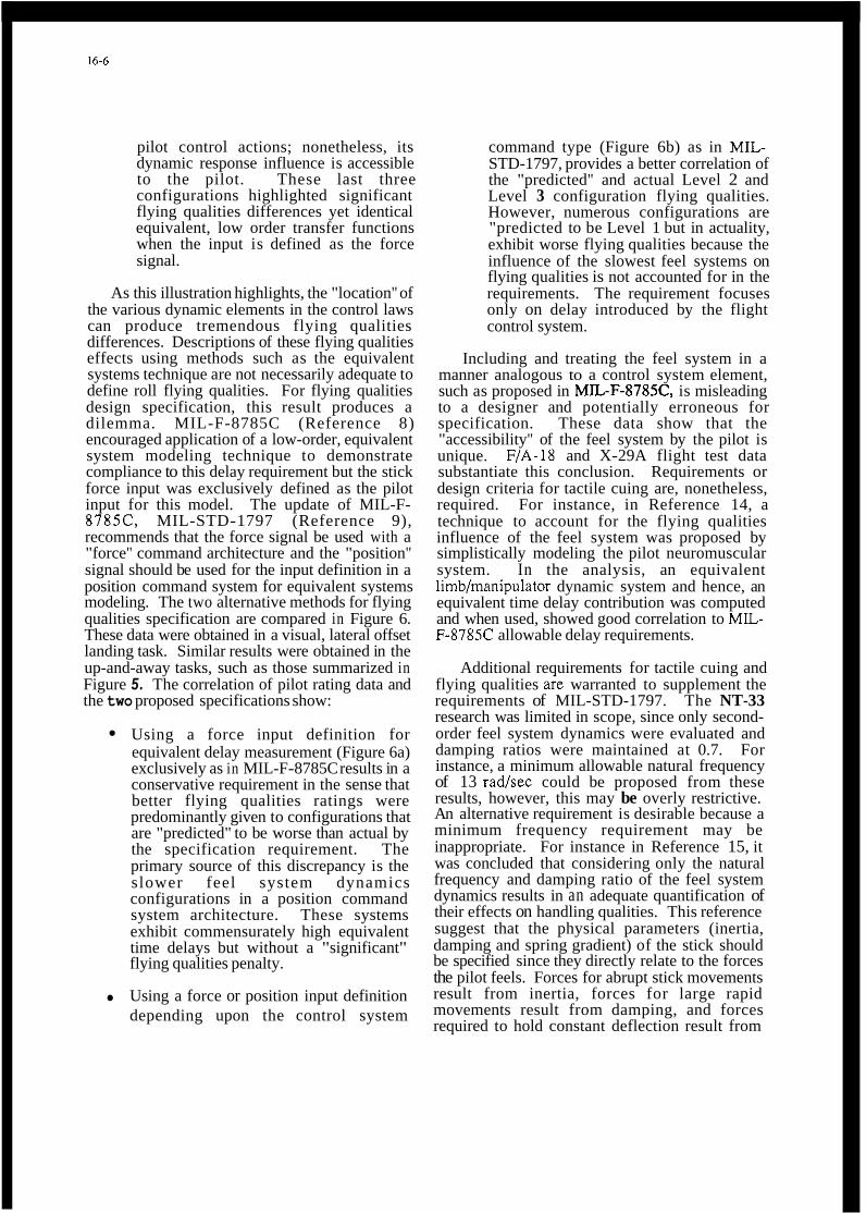
16-6
pilot control actions; nonetheless, its dynamic response influence is accessible to the pilot. These last three configurations highlighted significant flying qualities differences yet identical equivalent, low order transfer functions when the input is defined as the force signal.
As this illustration highlights, the "location" of the various dynamic elements in the control laws can produce tremendous flying qualities differences. Descriptions of these flying qualities effects using methods such as the equivalent systems technique are not necessarily adequate to define roll flying qualities. For flying qualities design specification, this result produces a dilemma. MIL-F-8785C (Reference 8) encouraged application of a low-order, equivalent system modeling technique to demonstrate compliance to this delay requirement but the stick force input was exclusively defined as the pilot input for this model. The update of MIL-F- 8785C, MIL-STD-1797 (Reference 9), recommends that the force signal be used with a "force" command architecture and the "position" signal should be used for the input definition in a position command system for equivalent systems modeling. The two alternative methods for flying qualities specification are compared in Figure 6. These data were obtained in a visual, lateral offset landing task. Similar results were obtained in the up-and-away tasks, such as those summarized in Figure 5. The correlation of pilot rating data and the two proposed specifications show:
Using a force input definition for equivalent delay measurement (Figure 6a) exclusively as in MIL-F-8785C results in a conservative requirement in the sense that better flying qualities ratings were predominantly given to configurations that are "predicted" to be worse than actual by the specification requirement. The primary source of this discrepancy is the slower feel system dynamics configurations in a position command system architecture. These systems exhibit commensurately high equivalent time delays but without a "significant" flying qualities penalty.
Using a force or position input definition depending upon the control system
command type (Figure 6b) as in MIL- STD-1797, provides a better correlation of the "predicted" and actual Level 2 and Level 3 configuration flying qualities. However, numerous configurations are "predicted to be Level 1 but in actuality, exhibit worse flying qualities because the influence of the slowest feel systems on flying qualities is not accounted for in the requirements. The requirement focuses only on delay introduced by the flight control system.
Including and treating the feel system in a manner analogous to a control system element, such as proposed in MIL-F-8785C, is misleading to a designer and potentially erroneous for specification. These data show that the "accessibility" of the feel system by the pilot is unique. F/A-18 and X-29A flight test data substantiate this conclusion. Requirements or design criteria for tactile cuing are, nonetheless, required. For instance, in Reference 14, a technique to account for the flying qualities influence of the feel system was proposed by simplistically modeling the pilot neuromuscular system. In the analysis, an equivalent limb/manipulator dynamic system and hence, an equivalent time delay contribution was computed and when used, showed good correlation to MlL- F-8785C allowable delay requirements.
Additional requirements for tactile cuing and flying qualities are warranted to supplement the requirements of MIL-STD-1797. The NT-33 research was limited in scope, since only second- order feel system dynamics were evaluated and damping ratios were maintained at 0.7. For instance, a minimum allowable natural frequency of 13 radhec could be proposed from these results, however, this may be overly restrictive. An alternative requirement is desirable because a minimum frequency requirement may be inappropriate. For instance in Reference 15, it was concluded that considering only the natural frequency and damping ratio of the feel system dynamics results in an adequate quantification of their effects on handling qualities. This reference suggest that the physical parameters (inertia, damping and spring gradient) of the stick should be specified since they directly relate to the forces the pilot feels. Forces for abrupt stick movements result from inertia, forces for large rapid movements result from damping, and forces required to hold constant deflection result from

the spring gradient. Thus, the pilot can perceive the independent effects of inertia, damping and spring gradient.
Finally, portions of the NT-33 in-flight research program were repeated in a fixed-based ground simulation (Reference 16). The comparison of these results to the in-flight experiment vividly highlight the problems with ground-based simulation "answers" for fighter aircraft flying qualities. From the ground-based simulation experiment, the following conclusions were drawn:
"Sensitivity (of flying qualities degrada- tion) to ze (equivalent time delay) de- creased as (roll) command gain increased."
- During the in-flight experiment, the sensitivity of flying qualities degrad- ation to ze decreased as roll com- mand gain decreased.
"The dismbution of principal lag between feel and command prefilter has essentially no influence on flying quality rating."
- In-flight, the lag location signi- ficantly changed the configuration handling qualities.
Finally, this in-flight/ground simulation com- parison is further highlighted by considering that the "baseline" roll configuration was evaluated as Level 1 in the ground simulation but was evaluated in-flight to be Level 3 with excessive roll acceleration to pilot control inputs with high frequency PI0 (roll "ratcheting") tendencies.
EFFECT OF DELAY DURING SIMULATION
The vivid differences between ground-based simulation and in-flight evaluation of fighter flying qualities have been leamed through aircraft developments and loose replications of in-flight experiments in ground-based simulation facilities, such as the one discussed above (e.g., see References 16-18). These experiences and experiments highlight ground simulation deficiencies but, because of the many differences between the ground and in-flight studies, these works do not sufficiently pinpoint the pilot- vehicle dynamic system differences. To help
focus this understanding, an extensive in-flight and ground simulation study was performed using the NT-33 as a flight vehicle and also as a ground simulator cab. In this way, the cockpit environment, feel system, and field-of-view were duplicated for both a fixed-based, no-motion ground simulation and in a full-motion, in-flight simulation. Also, by simulating instrument meteorological conditions and using the head-up display for evaluation task generation, the visual cues were replicated between ground simulation and flight. Consequently, the vast majority of the pilot-vehicle dynamic system elements were duplicated. Time delay was introduced into the two simulation conditions to investigate its influence on flying qualities and simulation fidelity with and without motion cues.
For this program, a broad-based experimental approach was used. The NT-33 simulated four generic aircraft "types" ranging from a highly responsive, fighter configuration to a less responsive, transport aircraft configuration. Evaluation tasks were fashioned in concert with the aircraft type and hypothetical missions. The results of the fighter aircraft evaluations are presented here, while details of the experiment and the results for the other aircraft evaluations are contained in Reference 19.
The fighter aircraft characteristics were designed to be highly agile yet, to produce Level 1 flying qualities in the in--flight environment with no control system delay added experimentally. The lateral-directional characteristics of the configuration were tailored to be good and unobtrusive; thus, "feet-on-the-floor'' roll maneuvers could be performed. This allowed the pilot to concentrate on pitch and roll control without objectionable yaw or sideslip. The centerstick feel system dynamic characteristics were of high frequency with a force command control system architecture in both pitch and roll.
The experimental set-up is sketched in the schematic diagram of Figure 7. The simulated control system was identical for both the in-flight and ground-based simulations. Pure digital delay was added experimentally. The "baseline" condition included no added delay (z = 0 msec). Delay effects were evaluated in both pitch and roll flying qualities with equal amounts of delay added in both control axes simultaneously.

16-8
The fixed-based ground simulation capability was provided by appropriate interfaces to the NT- 33A aircraft. The ground simulation utilizes the actual aircraft hardware and cockpit with the exception that the NT-33A motion responses are computed 'by a real-time computer simulation and are interfaced into the fly-by-wire flight control system through the NT-33A sensor system. Thus, the ground-based NT-33A simulation system is operated the same as it is in flight, with the exception of aircraft motion. The real-time computer simulation operated at an 80 hz update rate. In Table I, the pitch (8) and roll attitude (I$) transfer functions are shown for both the "HUD- displayed" (Le., visual states) and the "motion" states. Naturally, the motion response states were only available as a piloting cue in the in-flight simulation. The other motion state transfer functions are not shown in Table I as they follow naturally from the tabulated transfer functions. Equivalent systems transfer functions are used to simply represent the configuration response. Nonetheless, the models are good approximations. The 55 msec equivalent delay from pilot stick input to the motion state response occurs from the phase lags produced by necessary high order control system filters and control surface actuators. The attitude response displayed on the HUD lags the motion response by 45 msec due to the sensor, signal conditioning, and digital display processing components. Hence, a total of 100 msec equivalent delay exists between pilot stick force input and HUD-displayed attitude response. In the ground simulation, the same equivalent delay of 100 msec occurs between pilot stick input force and HUD attitude response.
The head-up display was programmed to generate the piloting evaluation tasks. Insmment meteorological conditions (IMC) were simulated using a blue/amber vision restriction system to limit the visual cues available to the pilot. The evaluation tasks were thus repeatable, known quantities that could easily be replicated in ground simulation. The instantaneous field-of-view (FOV) of the HUD and hence, the total visual FOV available to the pilot for task cuing was approximately 20 degrees. Airspeed control was maintained by the rear seat safety pilot so that the evaluation pilot could concentrate on pitch and roll control.
In this set-up, the visual evaluation task in- flight and i n ground simulation is identical.
Consequently, the primary difference between the in-flight and ground simulation is the absence of motion cuing although, to the evaluation pilots, other differences also exist, such as the absence of aural cues and flight stresses. The in-flight and ground-based simulations were mechanized such that the equivalent time delay between the cockpit control input and the HUD (visual) attitude response was identical during in-flight or ground- based simulation. Without any experimentally added delay, this was a constant 100 msec. During in-flight simulation, the visual (HUD) response lagged the motion response by 45 msec equivalent delay.
Three types of HUD-displayed evaluation tasks were used for this experiment. The format of the HUD and the computer-generated tracking task are presented in Figure 8. The primary evaluation task was step-and-ramp compensatory tracking of pitch and roll attitude display on the HUD. This "discrete" tracking task is shown in Figure 9 where the command bar moved in a series of attitude commands in both pitch and roll to lead the pilot through a coordinated maneuvering flight profile. In addition, com- pensatory attitude tracking tasks were also performed using a psuedo-random sum-of-sines generated command. Three engineering test pilots served as the initial evaluation subjects although their results were substantiated by data from eight additional engineering test pilots.
The influence of delay on simulator ef- fectiveness and flying qualities can be "measured" by pilot ratings. Using the Cooper-Harper pilot rating (PR) scale (Reference lo), Level 1 flying qualities are defined as being satisfactory without improvement with pilot compensation not a factor (PR < 3.5); conversely, Level 2 flying qualities exhibit deficiencies which warrant improvement. pilot compensation is, at least, moderate and pilot- vehicle performance is adequate or desired at best (3.5 < PR < 6.5). The maximum tolerable delay introduced in a simulation can be defined as the maximum deIay before which flying qualities degrade to Level 2 (given that Level 1 flying qualities existed without added delay). Implicit in this rating difference is a change in pilot control strategy, behavior, and/or workload. The other specific simulation effectiveness measure, transfer-of-training, was not addressed in this experiment.

16-9
In Figure 10, the effects of time delay on fighter aircraft flying qualities are shown during full-motion, in-flight simulation and during no- motion, ground-based simulation. Flying qualities are shown using averaged Cooper-Harper pilot ratings, and the extreme ratings that were given for each configuration. The in-flight data are plotted in two ways. In one case, the equivalent time delay was measured from the pilot stick force input to the HUD display response (is., the "visual delay"). In the other case, the delay was measured from the same stick input but only to the aircraft motion response (is., the "motion delay"). The motion response lead the visual response by 45 msec. Of course, no motion cues were available to the pilot in the ground simulation.
The data of Figure 10 indicates the following:
As control system time delay was intro- duced, the flying qualities of the in-flight simulated aircraft degraded at a rate of approximately 1 PR unit for each 30 msec of delay added above a 130 msec thres- hold. This trend is based on close com- parison to the data of Reference 1 using the "motion delay" values. Pilot com- ments support the pilot rating trends, that is, as the delay was increased beyond 130 msec, PI0 tendencies became more prevalent and overshoots in target tracking were more pronounced. Good correlation of the in-flight pilot rating data using the "motion" delay substantiates the impor- tance of the motion cuing influence and the effects of time delay.
During no-motion, ground-based simula- tion, the lowest simulated delay config- uration was judged as being Level 2. Only adequate tracking performance could be attained although sometimes desired per- formance was obtained but with moderate or considerable pilot compensation. As delay was added experimentally, flying qualities degraded but at less severity than that demonstrated in-flight. The in-flight'- ground simulation differences were pri- marily attributed to the different cuing
Tracking performance and hence, flying quali- ties in the no-motion ground simulation were poor in comparison to the identical configuration simulated in-flight. The lack of motion cues changed the pilot-vehicle dynamic system to such a degree that bobbling tendencies and an inability to steadily track the target occurred even with the lowest values of time delay. Tracking problems were most evident during gross acquisition maneuvers. For large amplitude maneuvers, the lack of "g-cuing" was felt by the pilots to deteriorate their ability to judge target closure rates. In Figure 11, two time histories of step- and-ramp HUD tracking task are overlaid for the identical configuration and evaluation pilot. This configuration only exhibited 100 msec delay between stick input and HUD, "visual" response. The different motion cues, however, are clearly affecting tracking performance. In the fixed- based simulation, significant pitch bobble is evident and tremendous "over-g" is being commanded by the pilot. In-flight, this configuration was rated as a 3 whereas, in the ground-simulation, a pilot rating of 5 was given.
In this program, very good consistency in pilot rating data were achieved both within-subjects and across-subjects. Pilot ratings, of course, reflect pilot-vehicle performance and the attendant pilot compensation or workload to achieve that performance The consistency in pilot rating data is remarkable particularly when considering the fairly significant differences in pilot control techniques and tracking performance. For example, tracking statistics from the step-and- ramp HUD tracking task are shown in Figure 12 for three values of control system time delay during in-flight simulation. The statistics are the "time-on-target" (the cumulative time that the pitch aacking error was less than 5 mils) and the normalized root-mean-squared (rms) pitch tracking error.
Pilot A demonstrated the best performance (Le., highest time-on-target and lowest normalized error) with the lowest delay configuration. As delay was added, his tracking performance degraded. The closed-loop tracking performance by Pilot B exhibited a similar degradation but overall his performance was not as good as Pilot A. On the other hand, Pilot C with the lowest delay configuration,was not as precise as Pilot A, but Pilot C was extraordinarily adaptative, in that, as delay was increased his pilot-vehicle performance remained essentially constant. The

16-10
pilot rating data, despite these tracking performance differences, were very consistent between each subject.
Without motion cuing, degradation in tracking performance occurred and consistency in tracking performance and flying qualities (i.e., pilot ratings) could not be maintained. For instance, the HUD tracking task statistics for the same configuration as previously shown are presented in the ground simulation environment in Figure 13. The normalized rms error, which could be related to pitch bobbling or PI0 tendencies, was consistently higher in all cases of ground simulation than for in-flight simulation. Inconsistencies in performance as control system delay was added occurred frequently. For example, Pilot B achieved an increase in time-on- target and a reduction in normalized tracking error in one case with 280 msec of control system delay compared to just 190 msec of delay.
Measurement of the tracking performance degradation with increased control system delay was also made during the sum-of-sines command tracking tasks. The normalize pitch and roll rms tracking errors are presented in Figure 14. The sum-of-sines tasks were not demanding flying qualities evaluation "tasks" but they provided good data from which to analyze pilot control action during random, small amplitude tracking. The data in Figure 14 shows fairly consistent degradation in tracking performance as delay is increased. Motion cuing effects (i.e., the difference between the in-flight and ground simulation environments) produced an almost constant, mcking error performance difference at each value of control system delay. Unlike the pilot rating data for increasing control system delay, the rate of change of the sum-of-sines tracking error with respect to the delay did not change when the motion cues were deleted. The standard deviation measures, particularly for the roll tracking task, are fairly large and reflect the aforementioned differences in individual piloting performance.
EFFECT OF DISPLAY SYSTEM DELAY ON FIGHTER FLYING QUALITIES
The role of the head-up display in fighter aircraft has increased tremendously in recent years. Night and adverse weather mission rely significantly on information provided to the pilot for navigation and situational awareness. This
reliance is certainly not going to subside but will undoubtedly increase. Since flight in this scenario is conducted primarily with visual reference to the HUD, the display system dynamic response may be critical to flying qualities. The current U.S. Military standards do not address temporal response requirements (Reference 20) and applicable research has been primarily limited to V/STOL aircraft and their intended missions (Reference 21). Consequently, a research program was conducted using the USAF NT-33 variable stability aircraft and its programmable head-up display.
The HUD was used as the primary flight instrument reference in both visual (VMC) and instrument meteorological conditions (IMC) tasks. Instrument meteorological conditions were simulated using a "blue/amber" system. A display format similar to that of the FIA-18 aircraft was used exclusively. The format, symbology, and content of the HUD are important factors that affect the pilot's ability (speed and accuracy) to process displayed information; however, these were not evaluated because the intent of the program was to determine what influence the temporal distortion of the display information had on pilot-vehicle performance and pilot workload (ix., flying qualities). Both up-and-away and power approach tasks were investigated. In the power approach task, a conformal runway display symbology was drawn for landing guidance, analogous to the display system developed by Gilbert Klopfstein (Reference 22). Details of the program are contained in Reference 23.
The schematic diagram of Figure 15 outlines the experimental variation. The aircraft flight control was designed for good flying qualities characteristics. The equivalent delay between stick force input and aircraft motion response was 80 msec. (In the position command control system architecture, 50 msec of that delay was due to the centerstick feel system dynamics.) The aircraft "motion" response from stick input commands remained unchanged in this evaluation of display system delay effects.
An irreducible delay of 65 msec was contained in the display system response characteristics. This delay is an equivalent delay composed of analog dynamic elements (such as sensors, signal conditioning filters) and digital processing elements (analog anti-aliasing filters, sampling delays, computational time delay). Pure

16-11
digital delay was added on top of the 65 msec irreducible delay, rather than sampling effects, under the assumption that multiple processors in a "pipeline" architecture would more likely be used than one processor running at a reduced sample rate. The delay was introduced into the HUD input signals uniformly.
A variety of up-and-away evaluation tasks were flown including simulated gun tracking using a HUD-programmed pitch-and-roll tracking (identical task to that shown in Figure 9) simulated air-to-ground weapons delivery, and acrobatic maneuvers. The power approach task was an Ih4C approach starting on downwind and concluding with a 50 to 200 ft (15 to 60 m) breakout for a visual landing.
Pilot rating data are shown as a function of the display time delay in Figure 16 for the up-and- away tasks. Averaged pilot ratings and standard deviations were calculated and are used to illustrate flying qualities. A trend line is drawn showing an estimate of the flying qualities degradation with display time delay based on a least-squares fit to the raw rating data.
For the up-and-away configurations, the pilot rating and comment data indicated the following:
1) As the computational delay for head-up display processing increased, flying qualities reflected by the Cooper-Harper pilot ratings (PR) were essentially unaffected until after 250 msec of equivalent "display system" delay. Some degradation occurred below 250 msec of delay but the degradation was not dramatic. Flying qualities degraded markedly beyond the 250 msec display delay value. Level 3 ratings (PR > 6.5) were given for 385 msec of display delay.
2) The overall task ratings were primarily based on the pilot compensatiodworkload and task performance in the simulated air- to-air gun tracking. To a lesser degre, the ratings were also based on the subjective opinion as to the degree by which the display characteristics were deficient. As display time delay increased, "bounce" in the pitch ladder and lag in the flight-path marker became more noticeable. These deficiencies were noticed primarily during precise control maneuvers or those
maneuvers that had clearly defmed attitude or flight path performance "end points."
3) The added pure delay in the head-up display did not significantly affect performance or flying qualities for the large-amplitude maneuvering tasks (modified cloverleaf and pop-up weapons delivery). Because precise and aggressive pilot control was not required in these tasks, the effect of display time delay was relatively transparent to the pilot, except for pitch ladder bobbling and flight-path marker lag at the "end points" of these maneuvers.
4) Control was not in question for any of the configurations. Thus, the pilot rating range was essentially limited to a maximum of 7. Added display time delay, unlike added control system time delay, did not evoke pilot-vehicle dynamic system instabilities.
These results suggest that flying qualities are not significantly affected until 250 ms delay exists in the display system. This delay is in addition to the 80 msec of delay between the cockpit control input and aircraft motion response. The 80 msec "motion" delay was held constant and is below the Level 1 MIL-F-8785C or MIL-STD-1797 allowable control system delay requirements.
The pilot rating data for the power approach task are shown in Figure 17 as a function of display time delay. Averaged pilot ratings are plotted with standard deviations about the mean illustrating the rating trends. A trend line is drawn based on these data. These data indicate the following:
1) As display system delay was added, flying qualities degraded after 300 msec of display time delay, as indicated by the rating data. The averaged pilot rating below 300 msec of display time delay was essentially Level 1 (PR < 3.5).
2) The degradation of flying qualities with display time delay was less severe in power approach than up-and-away flight. The pilot comments indicate that the pilot ratings were primarily determined by the pilot workload demands as display time delay increased. Added display delay
16-12
amplified the "bouncing" and "wobbling" of the contact analog runway projection, thus, increasing the pilot workload to keep the display centered and to maintain the approach course.
The influence of the evaluation task is evident in both the power approach and up-and-away task data. The power approach evaluation task was the instrument approach with a visual landing made after instrument breakout. The visual delay experiment was, in actuality, only evaluated in the IMC approach phase. After IMC breakout, a visual landing was made without significant reference to the HUD. In Reference 3, it was noted that the effects of added (motion) delay were most dramatic in the final 50 ft (Ism) to landing when the pilot's control task becomes critical (high stress). In this power approach task, the effects of delay added to the display were evaluated only on the relatively benign approach course flight task to breakout. Consequently, the flying qualities degradation with display delay would not be expected to be as severe as a more demanding task. Similar conclusions could be drawn from the up-and-away task.
Turbulence was another factor that was significant but it could not be experimentally controlled. In up-and-away flight tasks, tur- bulence was not typically encountered. In power approach tasks, turbulence was sometimes en- countered and turbulence produced a significant degradation in flying qualities when the display delay was greater than 100 msec. The pilot ratings that were influenced by turbulence are not shown in Figure 17. In turbulence, the tem- porally-delayed display characteristics created sig- nificant pilot workload for compensation and ob- jections by the pilot regarding the continual bobbling of the display. Turbulence affects will likely reduce the amount of display delay that is acceptable based on flying qualities. Unfor- tunately, sufficient data were not gathered to demonstrate this result conclusively,.
The apparent 250 msec threshold in allowable display system time delay for the up-and-away evaluations and 300 msec in power approach tasks seemingly contrasts with the previous works from which the 100 msec MIL-F-8785C and MIL-STD- 1797 time delay requirements evolved. Control system time delay has been shown to significantly impact the pilot-vehicle dynamic system. Flying qualities have been demonsbated to degrade from
Level 1 to Level 2 by 100-150 msec of control system time delay with pilot-vehicle instabilities occurring from 250 msec delay. Much larger delays were tolerated in this program when delay was added to the display system. The significant difference between control system and display system time delay effects can be demonstrated by examining the pilot-vehicle dynamic system.
The results of this experiment indicate that with constant Level 1 motion flying qualities, a substantial threshold exists where added visual delay does not affect flying qualities. It could be deduced because of the different flying qualities effects between control system delay and display system delay that the pilot, as the closed-loop controller in the pilot-vehicle dynamic system, was either unaffected by the visual delay, or he could easily compensate (without workload or performance penalty) for its influences. From a physiological viewpoint (Reference 24), it could be logically defended that the visual cue feedback to the pilot was not a critical cue in task performance in the presence of a visual delay. Since time delay adds deleterious phase lag proportionally to frequency, the high-frequency spectrum of the cue feedback to pilot would be most influenced by delay. However, the visual senses are primarily used during piloting tasks for low-frequency cuing or steady-state reference. Conversely, the motion response primarily provides the high frequency response cue such as onset or acceleration cuing. The pilot blends the motion and visual senses, in a complementary fashion, to provide a full-fidelity, broad-banded frequency response estimate of the aircraft states. Hence, significantly greater time delays in the visual feedback would be required to affect the low frequency visual cue feedback than the delay permitted in the high frequency motion feedback due to the physiological nature of the human pilot. This was shown experimentally. Motion cue effects must, therefore, always be referenced in assessing the influence of display system dynamics.
CONCLUDING REMARKS
The influence of delay outside of the control system but within the perceptual cuing environment of the fighter pilot can significantly affect flying qualities. The influence is, however, different than the effects due to control system delay. The pilot-vehicle dynamic system provides
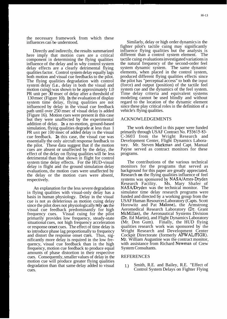
the necessary framework from which these influences can be understood.
Directly and indirectly, the results summarized here imply that motion cues are a critical component in determining the flying qualities influence of the delay and in why control system delay effects are a clearly detrimental flying qualities factor. Control system delay equally lags both motion and visual cue feedbacks to the pilot. The flying qualities degradation with control system delay (ix., delay in both the visual and motion cuing) was shown to be approximately 1.0 PR unit per 30 msec of delay after a threshold of 130 msec (Figure 10). In the evaluation of display system time delay, flying qualities are not influenced by delay in the visual cue feedback path until over 250 msec of visual delay is added (Figure 16). Motion cues were present in this case but they were unaffected by the experimental addition of delay. In a no-motion, ground-based simulation, flying qualities degrade at less than 1 PR unit per 100 msec of added delay in the visual cue feedback. In this case, the visual cue was essentially the only aircraft response feedback to the pilot. These data suggest that if the motion cues are absent or unaffected by the delay, the effect of the delay on flying qualities will be less detrimental than that shown in flight for control system time delay effects. For the HUD-visual delay in flight and the ground simulation delay evaluations, the motion cues were unaffected by the delay or the motion cues were absent, respectively.
An explanation for the less severe degradation in flying qualities with visual-only delay has a basis in human physiology. Delay in the visual cue is not as deleterious as motion cuing delay since the pilot does not physiologically rely on the visual cue feedback predominantly for high frequency cues. Visual cuing for the pilot primarily provides low frequency, steady-state situational cues, not high frequency acceleration or response onset cues. The effect of time delay is to introduce phase lag proportionally to frequency and distort the response onset cues. Thus, sig- nificantly more delay is required in the low fre- quency, visual cue feedback than in the high frequency, motion cue feedback to produce equal amounts of phase distortion in their respective cues. Consequently, smaller values of delay in the motion cue will produce greater flying qualities degradation than that same delay added to visual cues.
Similarly, delay or high order dynamics in the fighter pilot's tactile cuing may significantly influence flying qualities but the analysis is different than a control system element. The tactile cuing evaluations investigated variations in the natural frequency of the second-order feel system dynamic system. The same dynamic elements, when placed in the control system, produced different flying qualities effects since the pilot has "perceptual access" to both the input (force) and output (position) of the tactile feel system cue and the dynamics of the feel system. Time delay criteria and equivalent systems modeling cannot be used blindly and without regard to the location of the dynamic element since these play critical roles in the definition of a vehicle's flying qualities.
ACKNOWLEDGEMENTS
The work described in this paper were funded primarily through USAF Contract No. F33615-83- C-3603 from the Wright Research and Development Center, Flight Dynamics Labora- tory. Mr. Steven Markman and Capt. Manual Payne served as contract monitors for these programs.
The contributions of the various technical monitors for the programs that served as background for this paper are greatly appreciated. Research on the flying qualities influence of feel systems was sponsored by NASAfAmes-Dryden Research Facility. Ms. Mary Shafer of NASA/Dryden was the technical monitor. The simulator time delay research programs were funded and directed by a working group from the USAF Human Resources Laboratory (Capts. Scott Horowitz and Pat Malone), the Armstrong Aeromedical Research Laboratory (Dr. Grant McMillan), the Aeronautical Systems Division @r. Ed Martin), and Flight Dynamics Laboratory (Mr. Don Gum). Finally, the HUD flying qualities research work was sponsored by the Wright Research and Development Center Cockpit Directorate (formerly AFWALFIGR). Mr. William Augustine was the contract monitor, with assistance from Richard Newman of Crew System Consultants.
REFERENCES
1.) Smith, R.E. and Bailey, R.E. "Effect of Control System Delays on Fighter Flying
16-14
Qualities," AGARD Flight Mechanics Panel Symposium on Criteria for Handling Qualities of Military Aircraft, Ft. Worth, TX, Apr 1982.
Berry, D.T., et al., "A Summary of an In- flight Evaluation of Control System Pure Time Delays During Landing using the F- 8 DFBW Airplane," Paper presented a1 AIAA Flight Mechanics Conference, AIAA Paper No. 80-1626CP, Danvers, MA, 11-3, Aug 1980.
Smith, R.E., "Effects of Control System Dynamics on Fighter Approach and Landing Longitudinal Flying Qualities,"
A'Harrah, R.C., Hodgkinson, J., and LaManna, W.J., "Are Today's Specifications Appropriate for Tomorrow's Airplanes?," AGARD Flight Mechanics Panel Symposium on Stability and Control, Ottawa, Canada, Sept. 1978.
Hoh, R.H., Mitchell, D.G., and Hodgkinson, J., "Bandwidth - A Criterion for Highly Augmented Airplanes," AGARD Flight Mechanics Panel Symposium on Criteria for Handling Qualities of Military Aircraft, Ft. Worth, TX, Apr 1982.
Meyer, R.T., Knox, J.R., and Turgas, S.A., "Suggested Revisions to MIL-F-878SC for Large (Class 111) Aircraft," AFWAL-TR- 83-3015, Feb 1983.
Weingarten, N.C. and Chalk, C.R., "In- flight Inspection of Large Airplane Flying Qualities for Approach and Landing," AFWAL-TR-8 1-3 1 18, Sept 198 1.
Moorhouse, D.J. and Woodcock, R.J., "Background Information and User Guide for ML-F-8785C, Military Specification -
AFFDLTR-78-122, Mar 1978
Flying Qualities of Piloted Airplanes'' AFWAL-TR-81-3109, July 1982.
Anon, "Military Standard - Flying Qualities of Piloted Vehicles," MIL-STD- 1797,31 Mar 1987.
10.) Harper, R.P., Jr. and Cooper, G.C., "Handling Qualities and Pilot Evaluation,"
Journal of Guidance, Control, and Dynamics, Vol. 9, No. 5, Sept-Oct 1986.
11.) Walker, L.A. and LaManna, W.J., "Development of the F/A-18 Handling Qualities Using Digital Flight Control Technology," paper presented at 26th Society of Experimental Test Pilot Symposium, Beverly Hills, CA Sept 1982.
12.) Bailey, R.E. and Knotts, L.H., "Interaction of Feel System and Flight Control System Dynamics on Lateral Flying Qualities," NASA-CR-179445, Jun 1990.
13.) Smith, R.E. and Sarrafian, S.K., "Effects of Time Delay on Flying Qualities: An Update," paper presented at AIAA Guidance, Navigation, and Control Conference, Paper No. 86-2202-CP, Williamsburg, VA, 18-20 Aug 1986.
14.) Potsdam, E. and Hodgkinson, J., "An Analysis of Feel System Effects on Lateral Flying Qualities," paper presented at AIAA International Aerospace Engi- neering Conference and Show, paper No. 90-1824, Jan 1990.
15.) Watson, D.C. and Schroeder, J.A., "Effects of Stick Dynamics on Helicopter Flying Qualities," Paper presented AIAA Atmos- pheric Flight Mechanics Conference, Portland, OR, August 1990.
16.) Johnson, D.E. and Aponso, B.L., "Design Considerations of Manipulator and Feel System Characteristics in Roll Tracking," NASA-CR-4111, Feb 1988.
17 Wood, J.R., "Comparison of Fixed-Base and In-Flight Simulation Results for Lateral High Order Systems," paper presented at AIAA Atmospheric Flight Mechanics Conference, Paper No. 83- 2105, Gatlinburg, TN, Aug 1983.
18.) Woods, J.R., "A Comparison of Fixed- base and In-Flight Longitudinal Handling Qualities Simulations," Paper presented at AIAA Atmospheric Flight Mechanics Conference, Paper No. 84-2104, Seattle, WA, Aug 1984.

16-15
19.) Bailey, R.E., Knotts, L.H., and Levison, W.H., "An Investigation of Time Delay During In-Flight and Ground-Based Simulation," Calspan Corporation, Buffalo, N Y , Calspan Report TR-7205-16, Aug 1987.
20.) "Military Specification: General Specification for Head-Up Displays," MIL-D-8164 (AS), June 1972.
21.) Lebacqz, J.V. and Aiken, E.W., "A Flight Investigation of Control Display, and Guidance Requirements for Decelerating Descending VTOL Instrument Transitions Using the X-22A Variable Stability Aircraft," Calspan Corporation, Buffalo, NY, Calspan Report AK-5336-F-1, Vols. I and II, Sept 1977.
22.) Monagan, S.J. and Smith, R.E., "Display Evaluation Flight Test," Calspan Corporation, Buffalo, NY, Calspan Report 6645-F-2, May 1980.
23.) Bailey, R.E., "Investigation of Head-Up Display Dynamic Response and Symbol Accuracy Requirements," Calspan Corpor- ation, Buffalo, NY, Calspan Report 7205-14, Aug. 1986.
24.) Meiry, J.L., "The Vestibular System and Human Dynamic Space Orientation" Massachusetts Institute of Technology, Man-Vehicle Control Laboratory Report T-65-1, June 1965.
Table I Fighter Aircraft Configuration Characteristics
I 'MOTION' I STATES 'HUD-DISPLAYED' STATES
t t NRCRAFT TASK
ULOT
4
RESXUSE -
Figure 1 Pilot-Vehicle Dynamic System

16-16
POSITION COMMAND CONTROL SYSTEM ARCHITECTURE FORCE COMMAND CONTROL SYSTEM ARCHITECTURE
0 s I 1 t i c , 1
0 0 ' O F 0.0 1.0 TIME ,-I 2.0 3.0
-- I FEELSYSTEM
I -1 <
Figure 2 Position and Force Command Conaol System Comparison
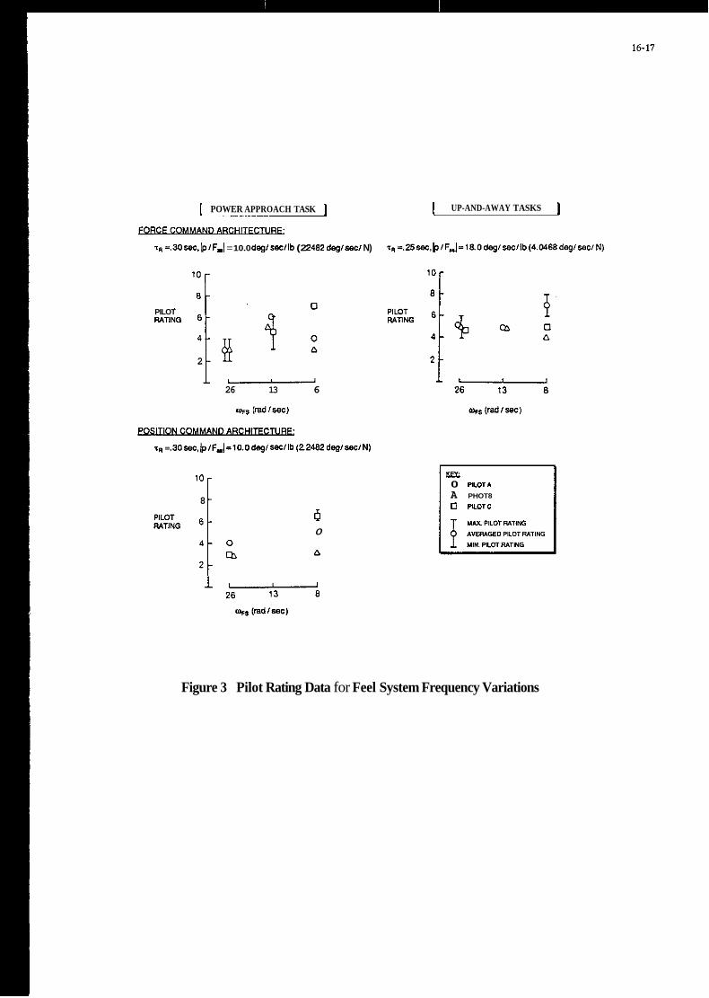
I POWER APPROACH TASK I
1. =.30 w. b /F,I = 10.0 degl secllb (2 2482 dag/ w/ N)
l o r n C
0 PILOT WING 6
2
I UP-AND-AWAY TASKS I
26 13 6
mrs (radlsec)
zR =.SOw.(p/F,I =10.0 deg/ m l l b (22482 dag/ sec/N)
l o 8 [: 6 0
Km 0 PILOT*
A PHOT8
0 PLOTC
Figure 3 Pilot Rating Data for Feel System Frequency Variations

1-1 P "'0P-47-vT .IW.O L -75.0L
-75.0
r5'0+75'0:k
I/ " +- la01
-75.0
1-1
-73.0 -75.0
I . . . . . . . . . , . . I , . . . I ~ I I . . > 10 0 IO 20 0 ' ' 'Ib' ' * ' ' ' ' " ' ' I
TIUE.sSs TIME.-
Figure 4 Time History of HUD-displayed Roll Tracking Task
Figure 5 Experimental Results of Feel System and Flight Conuol System Dynamics Variation
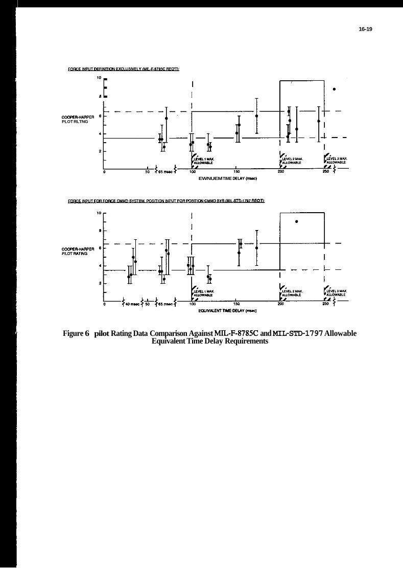
16-19
I lo 8 E I
WOPER.H*RPER PLOT RLTNG
EWNUEM TIME DELAY 1-1
Figure 6 pilot Rating Data Comparison Against MIL-F-8785C and MIL-STD-1797 Allowable Equivalent Time Delay Requirements

16-20
,YO" RESPONSE
COCKPIT VISUAL CONTROL RESPONSE FORCE
Figure 7 Simulation Time Delay Experimental Set-Up
5 'EXTENDEBWINGS WATERLINE
4 \N 5MlLS (FIXED PIPPER TRACKING REFERENCE) . TASK MMMAND M R
HORIZON LINE 7-
Figure 8 HUD-based Tracking Display Format

I II U
.75.0 " ' " " ' ' I " ' " " '
TIME. rec TIME. sec 0.0 50.0 100.0 150.0 0.0 50.0
Figure 9 Step-and-Ramp HUD Tracking Task
10
a
6 PILOT RATING
d
IkELLW !%WR.SM PILOT RATING DATA
- 'MOTIMI VISUAL VISUAL I DELAY OEUY DELAY ---
MAXIMUM RATING AVERAGED PILOT RATING - f * MINIMUMRATING
-
- \-
REFERENCE 1 2l J I I I I I I 0 50 100 150 200 250 300
EQUIVALENT TIME DELAY (msec)
'.O 150.0
Figure 10 Comparison of Time Delay Effects on Flying Qualities During In-Flight and No-Motion Ground-Based Simulation

16-22
LO
0. 0.0 lbo)
I -I
4 3 I I
a n I I
TWE 1-1
Figure 11 Effect of Motion Cuing on Fighter Aircraft, HUD Tracking Task
1.0 2
0.8 PILOTS A PILOTC: 0
- -
A
0.0 4 0.0 10 20 30 40 50 60 70 80
TIME-ON-TARGET (sec) (c 5 mils)
Figure 12 Pitch Time-on-Target and Normalized rms Error During In-Flight Simulation

16-23
1.0 1 i
0.8
NORMALIZED RMS 0.6 ERROR,
0.2
0.0
+
PILOTA: 0
~m 0
0 At3
M 4
O A
m
0.0 10 20 30 40 50 60 70 80
TIME-ON-TARGET (sec) (< 5 mils)
Figure 13 Pitch Time-on-Target and Normalized rms Error During Ground-Based Simulation
$ 0.5
2 0.25
z 8 2 I l++!?!l E o 0 50 EOUIVALENT 100 YlSUACTlME 150 200 DELAY (mseC) 250 300
- 0 . 7 5 a . . I . . . . : . . . . : t i w
Y) z
O w Y
z 4 A
0 50 100 150 200 250 300 MUIVALENT'VISUAC TIME DELAY (msec)
Figure 14 Sum-of-Sines Task Tracking Performance

16-24
- PITCH
* AIRCRIFTPKCHAmNDE(0)
VARUBLEADDED DISFUY TIME DEUY
* E W I V A L W SYSTEM TIME D U V REPRESWATION OF HK3H FREOUWCV ANALOG DYNAMIC ELEMENTSAND DKiKALCOMPLITING ELEMENTS
t SHORWANDNOTATYXI USED: POWER APPBQdEt!
1 v-zso~ms~163*nv)u. wiuied) v - im~w12~l*nv)u,i,~1aim~ea)
ALT.-ZKnl6lomI
l / Z B * -o.m€nc Ssp -0.7
Figure 15 Schematic Diagram for Experimental Evaluation of Display System Delay Effects
10
8
6 PILOT WTING
4
2
AVERAGED PILOT RATING
T 4 1 1
50 100 150 200 250 300 350 400
EOUIVALENT*DISPLAV-TIME DELAY. e+*' (-1
Figure 16 Effect of Display System Time Delay on Fighter Aircraft Flying Qualities During Up-and- Away Tasks

16-25
' O l 8 AVERAGED PILOT RATING
6 - PILOT RATING
4 -
2 -
0 50 100 150 200 250 300 350 400
EOUIVALENTQISPLAYTIME DELAY. enHMs (msec)
Figure 17 Effect of Display System Time Delay on Fighter Aircraft Flying Qualities During Power Approach Task

ESTIMATION OF PILOT RATINGS VIA PIMT MODELING
Duane McRuer President and Technical Director
Systems Technology, Inc. 13766 S . Hawthorne Blvd.
Hawthorne, CA 90250
SUMMARY
The dynamic behavior of pilots engaged in closed-loop, full-attention piloting can be estimated with some confidence using either the well-known "Crossover Model, " a structural-iso- morphic model, or an algorithmic (optimal control) model. Data and interpretations of the analyses made with these models can also be factors in the estimation of pilot ratings. In one technique a pseudo-pilot com- mentary in technical terms is devel- oped employing results obtained from analysis with the classical models which is then converted to a pilot rating estimate for each axis of con- trol. Ratings for multi-axis control are then determined with a special multiplicative rule, which has recently been validated with compre- hensive multi-axis pilot dynamic meas- urements. While the algorithmic model results can be used in a similar way, it can also sometimes deliver pilot rating estimates directly. When suit- able pilot-rating calibration data are available, the performance index which the OCM minimizes can be used to accomplish these estimates. Both the classical and algorithmic models are now suitable for application to deli- ver multiaxis rating pilot rating estimates.
INTRODUCTION
Flying qualities and piloting considerations have always been cent- ral issues in manned aircraft. The development of understanding and appreciation of flying qualities has relied on combinations of experiment and analysis in which the most impor- tant "metrics" have been subjective assessments and commentary. For undemanding task combinations these
measures can be almost delphically obscure and poor descriminators. For- tunately, many piloting tasks crit- ical to flying qualities are closed- loop in that the pilot's behavior is both constrained by the vehicle and task-centered dynamics, and condi- tioned on the aircraft's state rela- tive to a desired condition. For these tasks closer connections between dynamic behavior and subjective asses- sments are possible.
A major part of the analysis activities in the flying qualities art has been focused on control theory applications of pilot models which intrinsically summarize and charac- terize vast amounts of experimental data. These models serve as the math- ematical attornies in what are, in many ways, typical applications of controls analyses akin to those con- ducted for automatic systems. But there are uniquely human attributes that must be embodied in the models. The most important by far is the enor- mously adaptive character of the human as a controller. Many modes of adap- tive and plastic behavior are pos- sible; most are well-recognized and understood, and can be represented with appropriate models (see e.g., Ref. 1). Another unique attribute is the self-assessment capability inher- ent in the overall system - the pilot's role as a vocal as well as an adaptive controller. In well-designed flying qualities experiments pilot ratings and commentaries become fundamental indicators of pilot and system dynamic behavior, system performance, and pilot workload. Accordingly, they are intrinsically associated with pilot models. The primary purpose of this paper is to summarize and indicate some of these connections.

17-2
Detailed descriptions of models for pilot dynamics, as such, are not the theme here. Current and compre- hensive summaries of such models suit- able for flying qualities applications appear in a recent AGARD Lecture Ser- ies (Item 14 on the "Surveys" list) and elsewhere (e.g., Refs. 2, 8 ) . But models for dynamic analysis are neces- sary as the first step in an analysis procedure intended to provide ratings /comments estimates. Accordingly, the first section of the paper pro- vides a brief review of appropriate pilot dynamic models.
The second section introduces pilot ratings in general and notes that there are basically two approaches which have been used to connect the pilot's assessments to pilot and pilot-vehicle system dynam- ics. The first is to associate pilot and system dynamic and performance characteristics with ratings using functional relationships. Represen- tative forms of pilot rating function- als are given in the next sections, illustrated by an extensive cross- section of examples. The second approach is "clinical," and its treat- ment is deferred to the last section.
One means of combining single axis ratings into a multi-axis esti- mate is developed in the next section. The development relies on workload and attentional demand concepts, although the ultimate combination rules have a validity based on experiment which transcends any such basis.
The final section covers a clini- cal approach to rating estimates which is more general and does not rely directly on empirical correlations. Instead, it takes into account the pilot and pilot-vehicle system charac- teristics as revealed by analysis, and considers their implications for con- trol.
PILOT DYNAMIC MODELS
The human pilot is the archetype hierarchical, adaptive, optimalizing, decision-making controller. In accom- plishing these functions the pilot exhibits a bewildering variety of
behavior which defies quantitative description when considered in the large. Nonetheless, since World War I1 scientists and engineers have attempted to describe specific ele- ments within this functional list in terms of quantitative models. The major source of paradigms for quan- titative descriptions derive from control theory. Control theories can also be classified using similar adjectives, so it is not surprising that almost every new advance in con- trol theory has led to attempts to better understand aspects of human behavior in the perspective of this advance. When these attempts have been fruitful, a control theory par- adigm has emerged which is useful in quantifying the human's operations. In the process theory has been used to "explain" experiment, and unexplained experimental results have motivated new theory. The results of this wide- spread synergistic activity have been documented in hundreds of research papers and in a series of summary surveys which have appeared periodi- cally. (A chronological listing of surveys is given at the end of this paper, following the reference list). As a consequence, much of the success- ful art is now mature. Furthermore, it has become a fundamental mode of thinking on the part of technical practitioners in the fields of pilot- vehicle systems, flying qualities, operator/vehicle control system inte- gration and many aspects of inter- active man-machine systems. From this rich variety of man-machine control models that have been addressed, the emphasis here will be confined to models particularly pertinent to fly- ing qualities situations. The models of interest are quite comprehensive (as encapsulations of experimental data) as well as broadly represen- tative of useful theory (in that both classical and modern control view- points are presented).
Flying qualities in general can be divided into "unattended" (and trim), large amplitude maneuvering, and "closed-loop" operations. A l l three categories have some degree of pilot interaction, and pertinent mod- els exist for all types (Ref. 1). The

17-3
model - the algorithmic or optimal control model (Ref. 2-8) - stems from a quite different control theory per- spective (Fig. IC). The primary pur- pose of this model is to mimic the human operator's total response by appropriate specialization of modern control computational procedures. Because the "Crossover Model" is the most broadly applicable and best understood of human dynamic descriptions, the behavior predicted by either the structural-isomorphic or the algorithmic models must "reduce" to this form in the crossover frequen- cy region. Thus the more elaborate models must inevitably return to the crossover model as a necessary limit- ing case "consequence".
In order to exercise the algo- rithmic model, a new formulation of the computational steps involved in the optimal control model has been developed in the context of a commer- cially available control system analy- sis program (Program CC). Besides the PC compatible format, this new formu- lation includes additional sequences which allow the analyst to determine the actual estimated pilot charac- teristics from the optimal controller solution. These steps should improve the understanding and interpretation of algorithmic model-based estimates, and should broaden the use of the OCM by making it available as a PC com- patible routine. The new formulation is documented in Reference 8.
In modern high performance air- craft the pilot is no longer primarily a controller. Instead communications, monitoring and management of automated equipment, planning, re-adjusting to adapt to changing circumstances, etc., place increasingly arduous demands on the pilot. Thus, flying stressful, high workload mission phases may require the pilot to divide his atten- tion between control and managerial tasks. The dynamic models for the pilot must take these divided atten- tion operations into account. This is done for both classical and algo- rithmic models in Ref. 2.
The pilot models briefly reviewed focus on the dynamics of pilots above
pilot-vehicle systems most relevant for the exposure of critical flying qualities involve operations in which the pilot controls the effective air- craft dynamics in a closed-loop fashion. "Closed-loop'' in this sense means operations wherein at least part of the pilot's control actions are conditioned by the differences between the aircraft's desired and actual out- puts. The kinds of piloting covered include precision control, regulation, and stabilization tasks; the types of flying qualities tests represented include "flying qualities while track- ing". For these cases the core pilot- vehicle system, and the associated human pilot behavior, are referred to as "compensatory". Fortunately, com- pensatory operations are the most definitive in disclosing critical flying qualities deficiencies, and the associated pilot models are the most extensive and advanced.
There are currently three predom- inant types of human operator models used to describe compensatory behav- ior. Reference 2 is an up-to-date summary which includes both full-and divided-attention operations. By far the simplest model describes the human pilot-vehicle system dynamics in the crossover frequency region (Fig. la). (The crossover frequency occurs where the open-loop amplitude ratio of the pilot-vehicle system is unity.) It is often sufficient for flying qualities analyses intended to elicit the gov- erning vehicle parameters, key varia- tions, and basic relationships. Because of its overall importance and simplicity, the implications of the Crossover Model and some simple rubrics for pilot-vehicle analysis using the model are summarized in the Appendix.
The most elaborate description of human dynamic properties as a control- ler is the structural-isomorphic model, This is an expansion of the crossover model which attempts to account for many of the subsystem aspects of the human controller as well as the total input-output behavior. A somewhat simplified version of the pilot's transfer characteristic is shown in Fig. lb. The third type of pilot

17-4
a) CROSSOVER MODEL
b) STRUCTUFLAL-ISOMORPHIC MODEL
c) ALGORITHMIC (LINEAR OPTIMAL CONTROL) MODEL
Sytlam Oulpul
"tt l y l t l . CI 'D"
Displayed Votioblei oprr01or 0"lp"l i l t l . i l t l = A x + B u r Ew Diipioy
H U M A N O P E R A T O R
r - - l ~ E ~ ~ MO~ZOF- I MANIMACHINE SYSTEM I
Molor I Eslimalrd
slole Delayed Slole
Figure 1. Pilot Models

17-5
Pilot.. ." column that pilot compensa- tion (equalization) and effort (workload) and task performance are major constituents of the rating scheme. When the task variables (effective vehicle dynamics, forcing functions and disturbances, etc. ) are well-defined, the pilot-vehicle system dynamic models described in Refs. 2 and 8 can be used to make quantitative estimates of pilot compensation and task performance. Workload, on the other hand, is much more difficult to quantify. Still, the subjective pilot ratings and comments, which are subjective workload indices, should have some connections with the pilot and pilot-vehicle system dynamics and performance. These connections are intrinsically empirical. They are also awkward theoretically because the rating scale is ordinal. Consequently, averages, standard deviations, etc., are not legitimate statistics, although this has never stopped flying qualities engineers from using them! (Fortunately, the scales seem to be close to interval in some ranges or, for the purist, data can be converted to an underlying interval scale where- in all the parametric statistics can be applied and then converted back - see Ref. 10.)
The goal of this paper is to sum- marize the available connections between pilot and pilot-vehicle system dynamics and pilot ratings. There are fundamentally two approaches which have been used with some success. The first directly associates pilot and system dynamic and performance charac- teristics with the pilot rating via a functional relationship. Such func- tionals have been developed for use with both the classical and OCM ver- sions of pilot models. The actual connections which have been estab- lished are based on specific tasks and circumstances.
The second approach is more clinical in style. It takes into account the pilot and pilot-vehicle system characteristics in terms of their implications for control. A list of assessment features is con- sidered in order to reveal symptoms of flying qualities problems. Some
in flying qualities tasks for both full and divided attention conditions. This paper concentrates on the work- load associated with generating these dynamics and accomplishing the control task as measured by subjective impres- sions delivered as pilot ratings. Ideally we would like to predict the workload (pilot commentaries and ratings) along with the prediction of the underlying pilot dynamics. This paper summarizes the extent to which this can be done.
PILOT RATINGS
The previous section briefly listed techniques for the estimation of pilot dynamics in closed-loop tasks. Because aggressively performed closed-loop tasks are ordinarily crit- ical from the standpoint of pilot compensation or skill required and are usually high workload flight phases, they tend to be dominant discrim- inators in flying qualities assess- ments. The assessments themselves are provided by pilot comments and associated ratings, such as the Cooper-Harper scale (Ref. 9 ) , part of which is shown in Fig. 2. It is apparent from the "Demands on the
Figure 2. Cooper-Harper Handling Qualities Rating Scale

17-6
quantitative aspects can be set forth, but others are only qualita- tive. Consequently, this approach is more the basis for a pseudo-pilot commentary rather than a means to make numerical rating esti-mates directly. Of course, if the "Commentary" is sufficiently complete it can be con- verted to a rating by working through Fig. 2. The clinical technique is especially useful to define possible flying qualities prob-lems and key effective airplane dynamic para- meters, or as a means of interpreting experimental data.
The two approaches described are currently most highly developed for single axis situations. Multi-axis rating estimates can be developed from single axis results using a "product rule," and OCM-based multi-axis results can be the basis for direct estimates of multi-axis ratings. Both approaches are described below.
PIMT RATING FUNCTIONALS
A direct approach is to formulate a functional which incorporates the pilot and system dynamic and perfor- mance quantities which are presumed to underlie the pilot rating. A general form which explicitly contains some and implicitly contains all of the desired features is given by,
PILOT WORKLOAD YISSlON/rASK PERMRLlP.NCE
(1)
the subscript notation used is intended to imply that ieI motion and task measures are controlled by keK pilot loops actuating j 6 . l control points. This functional form is gen- eral enough to include the existing (e.g., Refs. 1, 2, 10-23) approaches to quantitative flying qualities rating functions. The key closed-loop system quantities in the rating func- tional are measures of mission/task
performance. These are conveniently described by a set of dominant weighted aircraft motion deviations and total task accuracy or error indi- cations (represented by the 91).
The pilot activity component of pilot effort, 6 f (either force or displacement, as pertinent to the manipulator involved) and ;: are par- ticularly dependent on the level of pilot gain. For a given gain, these will increase directly with gust dis- turbance spectrum amplitude and pilot- induced noise (remnant) amplitude. Accordingly, both the mission/task and pilot activity quantities will reflect turbulence and remnant levels.
The pilot equalization component of pilot workload is generally represented in Eq. 1 by the slope (in dB per octave or decade) of the pilot's amplitude ratio evaluated at a particular frequency (generally near crossover). This is by no means the only measure available to describe the dynamic quality of the pilot's effort: others (e.g., Refs. 12-16) use pilot lead time constants (the TL shown in Eq. 1) which are a desirable alterna- tive for particular situations with a sufficient data base. Then the rating functional takes the very useful form illustrated in Fig. 3 . At present, adequate functions of this form exist for precision hover tasks (Refs. 12 13). pitch attitude control (Ref. 1 4 ) , and roll attitude control (based on Refs. 17 and 18). In addition, the Ref. 19 data provide a base for a multiloop functional.
k
The technique pioneered in Ref. 12 actually used the pilot rating functional as a performance index, as well as a rating estimator. That is, the pilot model parameters (Fig. 3a) were adjusted to minimize R, the pilot rating functional.
The follow-on work of Ref. 16, which was dedicated to experimentally verifying the Ref. 12 result, produced a "modified" pilot rating functional for the R2 + R3 component, as shown in Fig. 4 . The correlation between predicted and actual ratings, shown in Fig. 5 are reasonably good.

While Noise
a ) Pilot/ Vehicle Model
R Z 3.25
P E R F ' 1 . 2 5 v . +.218vq -1.0 (111 (deg/sec)
b/ Pi101 f?oling Funcliunol
J = I +PERF + R z + R 3
PERF, R t , R3 - as defined in b)
I) Kp, .TL, , KPg , TLe found to minimize J
2) Kp, , KPg simultaneously increased by 20%. I f system asymptotically stable. performance and ra volues found in I). If system not stable, ga to 3).
3 computed based an
3) TLs.TLI held fixed at values found in I ) . K p , , Kpg simultaneously decreased
until values found for which o 20.3 % increase would result in an unstable
system while a 20% increase would result in a stable system. These values
are used to campule performance and rating.
c/ Minimum Piloi Rafing Concept For Piloi Model Poramefer Adjusimeni
Figure 3. The Elements of the "Paper Pilot" for the Hover (Ref. 12)

17-8
and
R 5 10 , 0 5 R2 5 3.25 , 0 5 R1
(If a value of a < .974 cannot be obtained, R - 10)
Yet another way to estimate pilot ratings is to use correlations developed for the algorithmic pilot model (Refs. 20-22, 24, 25). This pilot rating estimation procedure is based on the hypothesis that the pilot rating for a particular task and set of vehicle dynamics can be correlated with the numerical value of the index of performance (minimum values of the OCM Cost Function) resulting from the optimal pilot modeling procedure. As indicated in Fig. 6, this has worked fairly well for some single-axis cases (e.g., helicopter hover and longitudinal approach).
The extension of the OCM perfor- mance-index-based pilot rating esti- mating procedure to the multi-axis case has recently been addressed. The basic developments are given in Refs. 8 and 22. Reference 26 is the pri- mary source for these studies of con- nected single- and multi-axis rating data, although no associated pilot dynamic information is available. Consequently, the OCM was used to establish pilot and system dynamics estimates. For the rating estimates only the performance index is needed. The appropriate performance index for each single axis was chosen to be,
1.8
(TLs T<-I (secl
Modificotion for Hover Paper Pilot Rating Funcfionals (Ref I61
Figure 4. "Paper Pilot" Rating Functionals
8-
7 -
- D
Flagged symbols ore for Pilot S,a l l others for Pilot E
1 2 3 4 5 6 7 8 9 Pilot Rating Computed Using Meosured System Properties
ond the Modified Paper Pilot Roting Funclionol Wilh.Egulualen?T~,
Figure 5. Comparison of Actual Ratings with Ratings Computed Using Modified Hover Paper Pilot Rating Functional (Ref. 16)
In Ref. 14 the task was changed to pitch attitude control and the result-ing pilot rating functional evolved to:
R1 R2
0.1 .974 - a
R - + 2.5T~ + 1.0
where
a = ae/q - ratio of rms error to rms input
TL - pilot lead, seconds
Jaxisi -
And for a multi-axis task, the objec- tive function used was
Naxes
Jtask = 1 Jaxis i (3)
i

17-9
0 (ARNOLD. 1973) IO - A (MILLER AND VINJE, 1968) 15 ,/
' 0' ' 9 -
- 8 - z F 7 - 4 a 6 -
E 4 -
3 - / o /
I I I I 1 I I I .I .2 .4 .6 .E LO 2 4 6
VALUE OF INDEX OF PERFORMANCE
Model Panmeters for Hover Task of Miller and Vinjc (1968)
Parameter Val"*
Time delay 7 02 5 Neuromuscular time constant T,, 0.2 s Visual thresholds None "Full-attention'' noisesignal ratio for observation noise 0.0025 Fraction of attention on control task 1. Noisesignal ratio for motor noise 0.m
0.25- 1.0 (configuration dependent)
Figure 6. Pilot Rating vs. Value of Model Index of Performance (Ref. 20)
The justification of this selection involves three considerations. The first relates to the selection of equal (unity) weighting on each Jaxisi in the definition of Jtask in multi-axis tasks. This decision was based on the instructions given to the subjects in the Ref. 26 experiment. They were to attempt to minimize the errors in all controlled axes. That is, they were instructed that no axis was to be given preference, which would then define primary and second- ary sub-tasks.
Secondly, the normalization of the mean-square error with the mean-
square command deals nicely with the fact that different units and dif- ferent command-signal strengths were used in several axes.
Finally, the interpretation of gi requires some discussion. In the OCM, the selection of gi defines the fre- quency range over which the open-loop system amplitude ratio approximates a K/s-like form. In connection with the OCM it is often cited that gi is selected to yield a desired neuromotor time constant, Tn, in the pilot's describing function obtained from the model. But, as indicated in Refs. 2 and 8 , when the total pilot describing

17-10
function, Yp, is actually constructed from its various elements in the OCM, the Tn established in this fashion is canceled by a directly compensating lead, leaving the actual estimated Yp with no (Tn s + 1)-l lag. Still, it has been convenient to adjust gi in this fashion even though the lag will later disappear. In this vein, the value of the desired neuromotor time constant used is either 0.1 sec, the Tn that yields the lowest error (e.g., best performance), whichever is greater. Notice that after Tn is determined in the above fashion, this "operating point" is associated with some weight gi in .Taxis i. This value may also infer the subject's subjec- tive trade between performance ( u c ) and workload cub). And since pilot lead and ub are correlated, this pro- cedure maximizes the possibility of relating the resulting value of Jtask to the subjective rating of the task.
Shown in Fig. 7 is the corre- lation between Jtask, as modeled, and the subjective ratings of the task. The correlation between Jtask and POR from the single-axis results appears to hold for the multi-axis results as well. This result seems to indi- cate that the ratings reflect the
Dander
Single-Axis
Data
Single-Axis Trend Line Slope 3 3.7 PORl log J task /
I I I -2.0 -1.0 0.0
LO9 Jtask
Figure 7. Pilot Rating vs. Perfor- mance Index for Dander Single- and Multi-Axis Tasks (see Ref. 22)
actual performance and workload (stick) rate) in the overall task. The results also tend to support the hypothesis that determining the weightings gi in the manner discussed leads to approximately "correct" rela- tive weightings on control rate in the axis, and the relative weight between control rate and normalized error. Because the multi-axis correlations follow the same trend as the single- axis data, this study indicates that the objective function for multi-axis situations can be extrapolated (or calibrated) from single axis correla- tions.
WORKMAD, ATTENTIONAL DEMANDS, AND THE PRODUCT RULE FOR MULTI-AXIS RATINGS
There is a strong connotation of increasing pilot effort and workload in the phrases of the Cooper-Harper Scale (Ref. 9) which invoke levels of "pilot compensation," but workload is difficult to define and, consequently, to quantify. A general definition that can be measured and predicted is workload margin, defined as the abil- ity (or capacity) to accomplish addi- tional (expected or unexpected) tasks. The pilot opinion rating scale satis- fies this definition up to its "uncon- trollable" limit point. It is, there- fore, a key workload measure, easy to obtain in some experimental circum- stances.
Auxiliary tasks have been devel- oped that satisfy the workload margin definition given above and that permit more objective measurements. One such task provides a complementary pair of measures suitable for integrating many workload concepts and factors into one basic context. These are the "atten- tional demand" and the "excess control capacity. I'
The attentional demand and excess control capacity measures have been connected with pilot rating in a multi-multi-axis experiment using the so-called cross-coupled subcritical task (see, for example, Refs. 10 and 27). A block diagram of the general experimental setup is shown in Fig. 8 . The pilot first performs the primary task alone, attempts to achieve
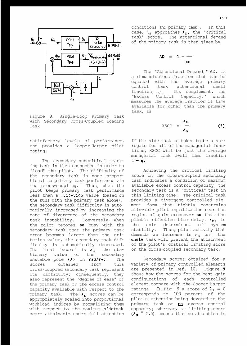
17-11
conditions (no primary task). In this case, Xs approaches A,, the "critical task" score. The attentional demand of the primary task is then given by
I ' I 1
Figure 8 . Single-Loop Primary Task with Secondary Cross-Coupled Loading Task
satisfactory levels of performance, and provides a Cooper-Harper pilot rating.
The secondary subcritical track- ing task is then connected in order to "load" the pilot. The difficulty of the secondary task is made propor- tional to primary task performance via the cross-coupling. Thus, when the pilot keeps primary task performance less than a criterfon value (based on the runs with the primary task alone), the secondary task difficulty is auto- matically increased by increasing the rate of divergence of the secondary task instability. Conversely, when the pilot becomes so busy with the secondary task that the primary task error becomes larger than the cri- terion value, the secondary task dif- ficulty is automatically decreased. The final "score" is A,, the sta- tionary value of the secondary unstable pole ( A ) in rad/sec. The scores obtained from this cross-coupled secondary task represent its difficulty: consequently, they also represent the "degree of ease" of the primary task or the excess control capacity available with respect to the primary task. The As scores can be appropriately scaled into proportional workload indices by normalizing them with respect to the maximum sidetask score attainable under full attention
XC
The "Attentional Demand," AD, is a dimensionless fraction that can be equated with the average primary control task attentional dwell fraction, q . Its complement, the "Excess Control Capacity," which measures the average fraction of time available for other than the primary task, is
AS xscc - - If the side task is taken to be a sur- rogate for all of the managerial func- tions, XSCC will be just the average managerial task dwell time fraction 1 - q .
Achieving the critical limiting score in the cross-coupled secondary task indicates a condition of maximum available excess control capacity; the secondary task is a "critical" task in this limiting case. The critical task provides a divergent controlled ele- ment form that tightly constrains allowable pilot equalization near the region of gain crossover so that the pilot's effective time delay, T ~ , is the sole determinant of system stability. Thus, pilot activity that demands an increase in re on the whole task will prevent the attainment of the pilot's critical limiting score on the cross-coupled secondary task.
Secondary scores obtained for a variety of primary controlled elements are presented in Ref. 10. Figure 9 shows how the scores for the best gain configurations of each controlled element compare with the Cooper-Harper ratings. In Fig. 9 a score of As = 0 corresponds to 100 percent of the pilot's attention being devoted to the primary task or no excess control capacity; whereas, a limiting score (A, - 5.5) means that no attention is

17-12
cooper Rating
ange of A,. imiling. Score
Slde Task Scores Flying A, (radfrec) Quaiilles
1.0 A,lA,. EXCBSS
0 l-[A,lA,) Allenlional Workload Control Task Oweil Fraction 0.7 0.33
YC - 0 Kls A K1slst4l Lt K l S l s t Z l
?fro1 Capacity
Figure 9 . Calibration of: Pilot Rating with Attentional Workload and Excess Control Capacity (adapted from Ref. 10)
required to maintain primary task performance, or that 100 percent of excess control capacity is available.
These relationships suggest that subjective pilot ratings can be associated closely with the objective measures of workload provided by the attentional demand and the excess control capacity. The lower (better) values of pilot rating correspond to low attentional demands and large excess capacity to perform other functions. More difficult effective vehicle dynamics that receive poorer pilot ratings of their flying qualities require much more of the pilot's attention and hence leave less capacity for other tasks.
The excess control capacity con- cept also provides a potential basis for estimating ratings for multiloop situations (Ref. 28). First, assume that the relationship between pilot rating and excess control capacity, Xn - Xs/Xc given by Fig. 9 , is applicable to each axis in a multiaxis situation. Then, single-axis capacity or attention, values can be combined to yield the combined axis value by a multiplication process, i.e., the multiaxis excess capacity, ,Inm, is
given by the product of the excess capacities for the individual axes:
m = nxni 'nm
For R = A + BX as a linear fit of the Fig. 9 data, the multiaxis rating R, will be given by,
n
m - Rm - A + BXnm = A + BIIXni
Ri - A
B - A + B i [ ]
Combined ratings are always greater than (or equal to) individual rat- ings, since combined An's are always less than any individual An. Also, the maximum value of Rm never exceeds A , i.e., for large Ri 4 A, m n (Ri -A) -+ 0.
The logical value for A is 10.0, and B was determined, using the emp- irical data, to be equal to - 8 .3 . As depicted in Fig. 10, this results in a good, overall fit to the multi-axis

17-13
Ref. 31; 3-Axis Dota,Series UHH Q M H D L H Q H M V M M C ILM
OHL OML O L L Ref.30; 2-Axis Doto X Ref.32; 3- AXIS Dora 0
Ref.33 ; 2-Axis Doto +
Line of Perfect Correlation
Line of Perfect Correlotionf112 v 4 -
// 3-// / / / Y)(
I I I I I 1 I 3 4 5 6 7 8 9 10
Observed Multi-Axis Rating 22
Figure 10. Correlations Obtained with Product Method (Ref. 28)
rating data of Ref. 28. Notice that in its final form the multi-axis rat- ing, R,, can be computed directly from the single-axis ratings, Ri. Measures or computation of excess control capa- city or attentional demand are not required.
For far too many years (1962- 1990) the Ref. 26 ("Dander") data were unique as the only generally available experiments in which single and mul- tiple axis ratings were systematically taken and compared. They are the basis of the developments leading to Figs. 7 and 10. A brand new data set (Ref. 29) are now available which enormously extends the data base on which to build and assess new correla- tion and rating-model building possi- bilities. The data are unique in including both fixed and moving base multi-axis conditions with comprehen- sive measures of pilot dynamics (e.g., describing functions) as well as pilot ratings. Reference 29 provides a good start on the development of more elab- orate functional relationships between
single and multiple axes, but we fully expect many more to follow in the course of time. For the present, the fixed-base data shown in Figs. 11 and 12 serve to further refine and vali- date the product rule for combining single axis data into multi-axis esti- mates. Figure 11 illustrates that the product rule continues to work well with these data. Figure 1 2 provides a useful diagram with boundaries suit- able for combinations of ratings in flying qualities "Levels" terms. Among other things, the Level bound- aries pertinent to conditions wherein one of the axes is highly rated (the horizontal and vertical boundary lines) implicitly recognize that the combined axis ratings can never be superior to single axis ratings. This is a possibility if the basic formula is used for these cases, e.g., a rat- ing of 1 in one axis combined with a rating of 4 in the other yields a combined rating of 3.5. Reference 29 provides alternative product rules based on various regressions with several parameters, including in some

17-14
10
9
2
I I 2 3 4 5 6 7 8 9 10
V Y ' " / I I I I I I I I
I 2 3 4 5 6 7 8 9 10 Actual Multi-Axis Rating
Figure 11. Comparison of Product Rule with Single- and Multi-Axis Pilot Ratings from STI Simulation (Ref. 29)
I3 Subject J
7
3
2
- 1 1 2 3 4 5 6 7 8 9
Longitudinal HQR
Figure 12. Comparison of Single-Axis (Pitch and Roll) HQRs with Multi-Axis HQRs from STI Simulation (Ref. 29)
cases such quantities as aircraft bandwidth measures. These more exten- sive and refined formulas can be par- ticularly useful for specific roll pitch control situations.
THE CLINICAL APPROACH TO RATING ESTIMATION
The treatment above has the great merit that, when appropriate measures and experimental correlates are avail- able, a set of pilot rating estimates can be made using relatively simple formulas. The detailed reasons for the rating estimates are inherently buried in the empirical data which serve as bases for the correlations. In other words, the pilot commentary and reasons behind whatever the rating estimate comes out may be quite obscure. To alleviate this diffi- culty, and to provide an alternative for situations where the data base is insufficient or non-existent, a clin- ical approach is indicated. Here the characteristics exhibited by the pilot and pilot-vehicle system dynamics are examined for "symptoms" of potential problems. These are then reflected into a summary of properties which amount to a pilot commentary expressed in technical terms.
Consider, for the most elementary situation, that the crossover model is used to accomplish a pilot-vehicle analysis for a given set of effective aircraft dynamics. The data directly available from the analysis includes an estimate of:
e the stability-limited (zero phase margin) maximum crossover frequency, %;
pilot lead equalization required in the region of crossover to make good the crossover law (measured in terms of pilot amplitude ratio slope, [dIYpIdB/d log wIwc);
the nominal full-attention cross- over frequency, wc.
A s developed in Ref. 2 , the two cross- over frequencies are closely related, i.e.,
wc/wu
No pilot lead 0.78
Low-frequency pilot lead 0.66

17-15
system data point shows a pilot rat- ing, PR - 2-1/2 with an attentional demand of 0.2 while the acceleration command system data point has PR - 6 and a control task dwell fraction of about 0.65. The primary reasons for rating shifts for these data are the amount of lead required and the reduc- tion in system performance (the attainable crossover frequency for the acceleration case is less than that for the rate command situation because of the increased re due to the need for lead generation). In any event, even a best gain acceleration command system will be Level 2 (3-1/2 < PR < 6-1/2) from a flying qualities stand- point. From the descriptive adjec- tival phrases of Fig. 2 this level of low-frequency lead generation would therefore be interpreted as "consider- able pilot compensation' required to achieve adequate performance.
The effects of pilot low-frequen- cy lag equalization have been more difficult to quantify. When the con- trolled element is a pure gain, the pilot will introduce a very-low-fre- quency lag to create crossover model properties in the region of pilot- vehicle crossover (Ref. 1). In this case there appears to be no particular rating penalty associated with the lag or trim-like control features. Simi- lar consequences have been seen with high-bandwidth attitude command /attitude hold systems. On the other hand, pitch attitude dynamics in which a conspicuous shelf is present between the 1/T02 lead and a lightly damped effective short-period undamped natural frequency, require the pilot to generate a lag or lag-lead feature. This is needed to cope with the lightly damped short-period mode as well as to make the open-loop pilot- vehicle system approach the crossover model. The pilot response data of Ref. 29 demonstrate that the crossover model applies to these situations, and that the pilot does indeed generate a lag or lag-lead. Consideration of the rating data associated with the Ref. 29 experiments, reported in Ref. 23, indicate that, in this case, there is a distinct rating penalty associated with the pilot-generated lag. Also, when the "shelf" length is
If, in addition, equivalent forcing function information is available the system steady-state performance can be determined easily (see e.g., Ref. 2, Figs. 9 or 13a).
As might be expected, the most important pilot dynamics correlates with pilot rating are pilot gain and pilot lead. Empirical connections between these are given in Fig. 13. For a particular controlled element there is an optimum controlled element gain which depends on the manipulator dynamics, controller sensitivity, control harmony among axes, etc. No theory yet exists to establish this optimum gain, so it must be determined empirically. Then, curves such as those shown in Fig. 13 can be used to assess any rating decrements from the optimum. By virtue of the wc-Kc independence property (Refs. 1, 2) any change in the effective aircraft gain, Kc, will be countered by a change in pilot gain, Kp, to keep the pilot- vehicle system crossover frequency approximately constant. However, either too-sluggish (Kc too small, Kp too large) or too-sensitive conditions can give rise to major decrements. This can be greater than 6 rating points even for the Yc - Kc/s controlled element dynamics. As can be appreciated from Fig. 13 the optimum is quite broad (changes of plus or minus 50% in either direction are less than 1 rating point for even the narrowest U-shaped curve), so once the controlled element sensitivity is properly adjusted minor controlled element gain changes are not major factors in pilot rating.
The pilot lead equalization required to make good the crossover model has a major effect on the pilot rating. For example, Fig. 13 indicates that the difference between a Yc - Kc/s controlled element, which requires no pilot lead, and Yc - Kc/s2, which demands +1 lead units, is a pilot rating decrement of about 3 Cooper-Harper rating points. Considered as idealized systems these correspond, respectively, to "rate command" and "acceleration command" effective vehicle characteristics. Re-examining Fig. 9, the rate command

17-16
I I I I I I 1
0.1 - 0.1 t - I 0 + I +2 Lead Units I
0 1 2 3 4 5 6 7 8 Rating Increment, AR
Figure 1 3 . Pilot Rating Decrements as Functions of Lead Equalization and Gain Tracking with Full Attention, Single Axis (Ref. 1)
extreme and/or the effective short period damping ratio too small, the pitch attitude control transfer func- tion becomes a "PI0 Syndrome" situa- tion, which can be very poorly rated indeed.
There are, of course, factors other than pilot lead and gain adjustment that affect the pilot rat- ing. In general, flying qualities ratings tend to be given on a global basis which may include several maneuvers in a task complex. Both open-loop (unattended) and closed-loop (attended) piloting operations will be considered in the rating. Concern here is, of course, primarily with the closed-loop piloting aspects. In fact, for stability and control flight testing the important connection is with "flying qualities while tracking" aspects and other precision and/or aggressive tasks which involve tight closed-loop pilot-vehicle control.
The unattended category can be the major factor in determining the acceptable values of very low fre- quency divergences such as the spiral
or a divergent phugoid. It can also be decisive in setting the nature of the "hold" characteristic built into the stability augmentation system. For example, for most flying tasks the attended longitudinal pitch attitude system should, ideally, require no pilot lead equalization. For this to be true the ideal effective airplane dynamics would approximate Yc = Kc/s in the region of crossover. But for unattended operations a rate command system is not ideal in that an atti- tude-stable platform is desired. Thus a rate-command/attitude-hold system has superiorr pilot ratings to rate- command/rate-hold.
Another major facet in some nearly unattended or divided-attention operations is "commandability" , the ability of the airplane to respond in a precise, orderly, and predictable manner to highly skilled, precognitive pilot command inputs. These inputs are pure commands, functions of time alone, and, as such, are basically open-loop in character. Typical examples are turn entries, step-like (for attitude command systems) or

17-17
structural-isomorphic pilot model in some form or other.
The "Urgency Adjustment Gain Tolerance" factor can best be under- stood by considering two limiting cases of controlled element. For the first, consider a Kc/s controlled element form. From the crossover model the pilot dynamic characteristic for this system will be a pure gain plus effective time delay. The closed-loop system for this case can support a range of pilot gains which correspond to crossover frequencies from zero to an octave or so below wu with only minor changes in the basic dynamic form of the closed-loop sys- tem. In terms of pilot-vehicle system input/output characteristics this will be approximately,
M(s) 1 - =
ICs) (s/wc + 1)
As the pilot attention level, urgency, or aggressiveness modifies his gain, oc will increase or decrease, with the dominant closed-loop system time con- stant constant, l/wc, waxing and wan- ing in corresponding fashion. Thus, there is a very wide range of excel- lent closed-loop dynamic response properties available to the pilot which is easily adjusted in direct proportion to his effort. In the words of Fig. 1, "pilot compensation is not a factor for desired perfor- mance", and the configuration will be highly rated. For the other extreme imagine a set of effective airplane characteristics which has dynamics in the region of crossover which require precise adjustment of the pilot's lead-lag equalization and gain to make good the crossover model and to close the loop in a stable manner. The pilot can exert closed-loop control, but the dynamic quality and even closed-loop system stability require that his describing function be precisely tuned to offset the controlled element deficiencies. The pilot's compensation in this case will
"intense", and the configuration configuration will be rated very poorly.
range from "considerable" to
pulse-like (for rate command systems) inputs to adjust attitude, precogni- tive landing flares, etc. These maneuvers may have to be fine-tuned at the end via closed-loop control, but for an ideal vehicle and a skilled pilot this will not ordinarily be necessary. Again, to the extent that this feature of the airplane's charac- teristics enter into the rating game, closed-loop dynamics considerations are not explicitly involved.
An important distinction about the unattended factors in the current context is that they may set a base for the pilot rating which does not depend on closed-loop factors. This base can itself shift as the divided attention requirements shift. For example, if managerial tasks take up almost all the available time the effective vehicle dynamics in the unattended state may have to be highly automated, even including path, alti- tude, or position control. In any event, the closed-loop effects should be thought of as increments from the base level determined from the unattended operation requirements.
Table 1 presents a list of pri- mary factors to which the pilot is sensitive and which, accordingly, underlie pilot rating. Except for pilot lead and gain variation from optimum these factors are not yet individually quantifiable in ratings terms. On the other hand, with modern flight control system technology most of them can be modified by design. Consequently, these system aspects can be profitably compared in competing system studies, and also serve as a useful checklist for interpreting manned simulation or flight test results. As remarked earlier, a pseudo pilot commentary can be con- structed by considering them.
In Table 1 both items under "Unattended Operations" and the "Pilot Lead" and "Pilot Gain/Optimum" parts of the "Attended Operations" list have been covered above. The remaining items will be discussed below. Some of the considerations can be developed from the crossover model, while others will require application of the

17-18
TABLE 1, PLOTYDIICLE SYSTEM FACTORS IN PLOT RATING
ATTENDED omnow - pilot Lead/Lag
- Urgencyfiwmwt Gain Toleraw Whuf Umging
- stability Margin Gain Tolerams lnduding Total
- PI0 Syndrome
- Neuromusarlar *em Coupling
- AnentjoMl DerrandslEuza Control capacihl - ClmedloOp system Performance
- Pilot GaidOptimum
Cbed4oop DyMmi Form
A v a i W Gain Ranse
* UNATTENDED OPERATIONS
- ~llowable Fluauatbns in PilotConUoCPrWn Demands
- Equiliiunffdm RopertRs (Efkctive 'How Characteristics)
The "Stability Margin Gain Toler- ances" factor is most easily described when the pilot-vehicle system is con- ditionally stable. In this situation the system becomes unstable if the gain is either too low o r too high. When the pilot lead-lag equalization is adjusted to maximize this range (which will ordinarily provide cross- over model-like features in the nomi- nal crossover region), there is a "total available gain range" (TAGR) through which the pilot can maintain some semblance of closed-loop control. Clearly, the more narrow this range becomes the more difficult the pilot's adjustment and the worse his rating will become.
The "PI0 Syndrome" has been introduced in connection with pilot lag equalization. When the pitch attitude transfer function exhibits a shelf and a lightly damped short per- iod the pilot has to introduce a pre- cisely located and tuned lag or lag- lead characteristic to accomplish tight closed-loop control. If he inadvertently drops the precision adjustment of his equalization and switches to a proportional control characteristic, as can happen when triggered by an unexpected major upset or need for divided attention, the pilot-vehicle system may then become unstable. This is a relatively common condition for a PIO, thus the appel- lation.
The "Neuromuscular System Coupling" factor can become important when the low-frequency effective air- plane dynamics are excellent but the closed-loop system gain margin in the region of the neuromuscular actuation mode ( w in Fig. 1) is reduced. This is covered in Refs. 30 and 31 . The resulting closed-loop system insta- bility is high frequency, 2 - 3 hz. It is one explanation for "roll ratchet".
The "Attentional Demands/Excess Control Capacity" factor is primarily related to divided attention opera- tions. When the control task itself is responsible for using most of the pilot's excess control capacity the reasons for this are invariably due to factors already covered. When the managerial, communication, planning, and other non-control tasks consume too much of the pilot's available attention, pilot ratings will suffer. The obverse of this is that the effec- tive vehicle dynamics must be very good in order to require a minimum of attention. The ratings for control alone should, in general, be superior, and the unattended operations factors would be good as well.
NM
The last Table 1 factor to be discussed is "Closed-Loop Perfor- mance". Many facets of task perfor- mance stem directly from mission requirements and are hence mission- specific. Using the complete Cooper- Harper rating sequence (Ref. 9) the status of the pilot-vehicle system relative to mission requirements is the very first thing the pilot assesses before more detailed ratings are established. Average error per- formance in command and regulation tasks can be calculated with all the pilot models once these inputs are defined. 'These estimates can serve as one basis for ',Closed-Loop Perfor- mance" in flying qualities assess- ments.
There are other, more general, closed-loop dynamic performance aspects which should also be consid- ered in flying qualities assessments. These are listed in Table 2 . The first two are simple statements of closed-loop dynamic response quality.

17-19
of an inner loop system which serves both independently and as a means to equalize the outer loop. Thus the pilot closure of a pitch attitude loop satisfies an attitude control function and gives rise to an effective outer, altitude control, loop which needs very little if any further pilot equalization. This is supported in a more quantitative sense by the sugges- tion for the separation of crossover frequencies for multiloop systems with series pilot elements.
Interaxis considerations apply to the last three items listed in Table 2 . Ideally the control effec- tors, as seen by the pilot, should be cooperative or actually decoupled. Potentially cooperative cases lead to the desirable crossfeed feature listed. This accounts for the pos- sibility possibility of pilot-induced crossfeeds to reduce or eliminate subsidiary modes or response quantities. A common example is an aileron to rudder crossfeed for turn coordination. The last feature on the list of desires is control harmony, which relates primarily to multi-axis control conditions with a common mani- pulator . Force and position gradients, pre-loads and centering springs and other manipulator features between elevator and aileron need to be in proper balance so that the effective controlled element gains in each axis are near optima, interaxis crosstalk is minimized, etc. Just as with the setting of controlled element optimum gain, control harmony is a subject of experimental determination.
As a consequence of flying qual- ities analyses using pilot-vehicle analysis to examine the factors of Tables 1 and 2 , the analyst can deve- lop a set of conclusions and arrive at a wide variety of issues and possible problems. Table 3 illustrates the type of problems that might be uncovered by such examinations for the case of either lateral-directional or longitudinal attitude and path control.
TABLE2 DESIRABLE CLOSED LOOP DYNAMIC FEATURES
* ADEQUATE CLOSED-LOOP DAMPING, 5 c ~ t 0.354.50
* AVOIDANCE OF CLOSEDLOOP MIDFREQUENCY DROOP, NUISANCE OR SUBSIDIARY MODES
MULTlLOOP CONTROL VIA SERIES SIRUCTURE FOR SINGLE CONTROL
FREQUENCY SEPAMllON OF INNER, OUTER LOOPS
* COOPERATIVEIDECOUPED CONTROL EFFECTORS
SIMPLE CROSSFEEDSTO DIRECTLY NEGATE SUBSIDIARY RESPONSES
- CONTROL HARMONY
They, in essence, suggest that any second-order dominant closed-loop pilot-vehicle system mode have a damp- ing ratio greater than 0 . 3 5 to 0.5. The requirement to avoid a closed-loop mid-frequency droop is tantamount to a prescription of one dominant mode per axis, for the droop will show up as an additional minor mode with a longer time constant. The Neal-Smith cri- teria (Ref. 3 2 ) , for example, call specific attention to the mid-fre- quency droop and require that it be less than 3 dB to achieve Level 1 ratings. By way of example, a 3 dB mid-frequency droop can be associated with the presence of a minor mode comprising a single dipole pair in the closed-loop pilot-vehicle system (with the [zero/polel < 1.41) supplementing the major dominant mode.
The remaining two desirable closed-loop dynamic features are asso- ciated with multi-loop, single control axis situations. Common examples of this include: 1) the control of alti- tude wherein altitude error is the outer loop feedback and pitch angle is an inner loop; and 2 ) however con- trol, as shown in Fig. 3 . "Desirable" aspects of such systems include the qualitative feature that a "series" (rather than parallel) closure of the outer loop is possible in the presence
17-20
TABLE 3. TYPICAL PILOT CENTERED REGULATION PROBLEMS
* CLOSED-LOOP DOMINANTMODE INADEQUACIES
- Too Slow
- WWDmped - Low/Mid Frequency Droop
- Too Many Modes DomiMnt
* A m D E COMROL
- InadequateBandWidm
- Inwr43vter Loop EqdiMwn CoMilnt~acfion
- LowSmicGain
- Over- to GainfEqualin - PATH CONlFlOL
- Perbrmance Rewr&
- InadequateBandWidm
- Inadequate separation of Path and Attitude Responses
- D i n or CoMcting CrossfeedslCoupling Interaction
- Excessive Depktiun of Sakty Margins - Low (High) Efiective Path Gains
REFERENCES
1. McRuer, D.T., and E.S. Krendel, Mathematical Models of Human Pilot Behavior, AGARDograph No. 188, Jan. 1974.
2. McRuer, Duane, Warren Clement, Peter Thompson, and Raymond Magdaleno, Pilot Modeling for Flying Oualities ADPli- cations cations, WRDC-TR-89- 3125, Vol. 11, Jan 1990.
3 . Baron, S . , and D.L. Kleinman, The Human As An Optimal Con- troller and Information Pro-
- 9 cessor NASA CR-1151. (Also IEEE Trans. Man-Machine Sys- tem, Vol. 10, No. 1, Mar. 1969, pp. 9-17.)
4. Kleinman, D.L., S.Baron, and W.H. Levison, "An Optimal Control Model of Human Response," Parts 1 and 2, Automatica, Vol. 6, May 1970, pp. 357-383.
5. Kleinman, D.L., S . Baron, and W. H. Levison, "A Control Theo- retic Approach to Manned- Vehicle Systems Analysis," IEEE Trans., Vol. AC-16,
6.
7.
8.
9.
10.
11.
12.
13.
14.
15.
No. 6, Dec. 1971, pp. 824-832.
Curry, R.E., W.C. Hoffman, and L. R. Young, Pilot Modeline for Manned Simulation,AFFDL- TR-76-124, Vol. 1, Dec. 1976.
Doyle, K.M., and W.C. Hoffman, Pilot Modeline for Manned Simulation. Volume 11: Pro- gram User's Manual (PIREP), AFFDL-TR-76-124, Dec. 1976.
Thompson, Peter M., Propram CC's ImDlementation of the Human Optimal Control Model, WRDC- TR-3125, Vol. 111, Jan 1990.
Cooper, G. E., and R. P. Harper Jr., The Use of Pilot Ratings in the Evaluation of Aircraft Handline Oualities, NASA TN D-5153, Apr. 1969.
McDonnell, J.D., Pilot Rating Techniques for the Estima- tion and Evaluation of Hand- linv 0 ualities, AFFDL-TR- 68-76, Dec. 1968.
Ashkenas, I.L., and D.T. McRuer, "A Theory of Handling Qual- ities Derived from Pilot- Vehicle System Considera- tions," Aerosuace Ene., Vol. 21, No. 2, Feb. 1962, pp. 60, 61, 83-102.
Anderson, R.O., A New Amroach to the SDecification and Eval- uation of FlvinP Oualities, AFFDL-TR-69-120, June 1970.
Dillow, J.D., The "Paper Pilot" - A Dieital Comuuter Pro- gram to Predict Pilot Rating for the Hover Task, AFFDL- TR-70-40, Mar. 1971.
Anderson, R.O., A.J. Connors, and J . D. Dillow, PaDer Pilot Ponders Pitch, AFFDL/FGC-TM- 70-1, Nov. 1970.
Anderson, R. O . , "Theoretical Pilot Rating Predictions, I' Handline Oualities Criteria, AGARD Conf. Proceedings.

17-21
Schmidt, D.K., "Time Domain Iden- tification of Pilot Dynamics and Control Strategy," Pro- ceedings of the 18th Annual Conference on Manual Con- - trol, AFWAL TR-83-3021, June 1982.
Anderson, M.R., and D.K. Schmidt, "Closed-Loop Pilot Vehicle Analysis of the Approach and Landing Task," J. of Guid- ance. Control. and Dynamics, Vol. 10, No. 2, 1987, pp. 187-194.
Dander, V., An Evaluation of Four Methods for Convertine Sin- gle Axis Pilot Ratines to Multi-Axis Pilot Ratines
16.
17.
18.
19.
20.
21.
22.
23.
No. 106, June 1972, pp. 19-1 to 19-14.
Teper, G.L., An Assessment of the "Pauer Pilot" - - An Analvti- cal Auuroach to the Suec- ification and Evaluation of Flying Qualities, AFFDL-TR- 71-174, June 1972.
Onstott, E.D., and E.P. Salmon, Airulane Flying Character- istics in Turbulence, AFFDL- TR-70-143, Feb. 1971.
Onstott, E.D., E.P. Salmon, and R. L. McCormick, Prediction and Evaluation of Flving
~
Qualities in Turbulence, AFFDL-TR-71-162, Feb. 1972.
Clement, W.F., R. Wade Allen, and D. Graham, Pilot Exueriments for a Theory of Integrated Disulay Format, Systems Technology, Inc., Technical Report 183-1, Oct. 1971 (Also JANAIR Report 711107).
Hess, Ronald A., "Prediction of Pilot Opinion Ratings Using an Optimal Pilot Model," Human Factors, Vol. 19, NOV. 5, 1977, pp. 459-475.
Schmidt, D. K., "On the Use of the OCM's Quadratic Objec- tive Function as a Pilot Rating Metric," Proceedinns of the 17th Annual Confer- ence on Manual Control, JPL Publication 81-95, Oct. 1981.
McRuer, Duane and David K. Schmidt, "Pilot-Vehicle Ana- lysis of Multi-Axis Task," J. Guidance, Control. and Dynamics, Vol. 13, No.2 Mar.-Apr. 1990, pp. 348-355.
Mitchell, David G., and Bimal L. Aponso , "Reassessment and Extensions of Pilot Ratings with New Data," AIAA Paper 90-2823, AIAA Atmospheric Flight Mechanics Conference, Portland, OR, 20-22 Aug. 1990.
24.
25.
26.
27.
28.
29.
30.
31.
Usine Fixed Base Simulation Data, M.S. Thesis, AFIT, GE/FE/62-4, Dec. 1962.
Allen, R. W., W. F. Clement, and H. R. Jex, Research on Disulav Scanning. Samuling, and Reconstruction Using Seuarate Main and Secondary Tracking Tasks, NASA CR-1559 July 1970.
Ashkenas, I. L., R. H. Hoh, and S . J. Craig, Section I11 Requirements for Airulane Normal and Failure States-- in Recommended Revisions to Selected Portions of MIL-F- 8785B (ASG) and Background Data, AFFDL-TR-73-76, Aug. 1973.
Mitchell, David G., Bimal L. Aponso, and Roger H. Hoh, Piloted Simulation Evalua- tion of Multiule Axis Flving Qualities, WRDC-TR-89-3125, Vol. I, Jan. 1990.
Johnston, D.E., and D.T. McRuer, Investigation of Interac- tions Between Limb-Maniou- lator Dvnamics and Effective Vehicle Roll Control Charac- teristics, NASA CR-3983, May 1986.
Johnston, D.E., and B. L. Aponso, Design Considerations of

17-22
Maniuulator and Feel System Characteristics in Roll Tracking, NASA CR 4111, Feb. 1988.
32. Neal, T.P., and R.E. Smith, &I In-Flight Investieation to Develou System Desim Crit- eria for Fighter AGulanes Vol. I, AFFDL-TR-7074, Dec. 1970.
SURVEYS
1. Tustin, A,, "The Nature of the Operator's Response in Man- ual Control, and Its Impli- cations for Controller Des- ign," J. IEE, Vol. 94, Part IIA, No. 2, 1947, pp. 190- 207.
2. McRuer, D.T., and E.S. Krendel, Dynamic Resuonse of Human Ouerators, WADC-TR-56-524, Oct. 1957. (Also, "The Human Operator as a Servo System Element, " -. , Vol. 267, No. 5, May 1959, pp. 381-403 and No. 6 , June 1959, pp. 511-536.
3. Licklider, J. C. R., "Quasi-lin- ear Operator Models in the Study of Manual Tracking, " 1st Edition, R. D. Luce (Ed.), m n Mathematical Psvchology, Free Press of Glencoe, Il., 1960, pp. 169-279.
4. Sheridan, T. B., "The Human Operator in Control Instru- mentation," R. H. MacMillan, T. 3. Higgins, and P . Naslin (Eds.), Progress in Control Engineerinp, Vol. I, Aca- demic Press, New York, 1962, pp. 141-187.
5. Elkind, J . I., "A Survey of the Development of Models for the Human Controller, R. C. Langford and C. J. Mundo (Eds.), trol-11, Vol. 13 of Propress
6
7,
8 .
9.
10.
11.
12.
13.
in Astronautics and Aero- nautics, Academic Press, New York, 1964, pp. 623-643.
Summers, L. G., and K. Ziedman, Study of Manual Control Methodoloev with Annotated Bibliograuhv, NASA CR-125, Nov. 1964.
Young, L. R., and L. Stark, & loeical Control Systems - A Critical Review and Evalua- - tion, NASA CR-190, 1965.
Costello, R. G., and T. J . Hig- gins, "An Inclusive Class- ified Bibliography Per- taining to Modeling the Human Operator as an Ele- mentin an Automatic Control System, " IEEE Trans. Human Factors in Elect., Vol. 7, No. 4, Dec. 1966, pp. 174-181.
McRuer, D. T., and H. R. Jex, "A Review of Quasi-Linear Pilot Models," IEEE Trans. Human Factors in Elect., Vol. HFE- 8 , No. 3, Sept. 1967, pp. 231-249.
Young, L. R., "Human Control Capabilities," J . F. Parker, Jr., and V. R. West (Eds.) 2nd Edition, Bioastronautics Data Book, Chap. 16, NASA SP-3006, 1973, pp. 751-806.
Sheridan, T. B., and W. R. Fer- rell, "Man-Machine System: Information, Control, and Deci-sion Models of Human Performance, " MIT Press, Cambridge, 1974.
McRuer, D.T., and E.S. Krendel, Mathematical Models of Human Pilot Behavior, AGARDograph 188, Jan. 1974.
McRuer , D. T. , "Human Dynamics in Man-Machine Systems. Auto- mation, Vol. 16, No. 3 , May 1980, pp. 237-253.

17-23
14. McRuer, Duane T., "Pilot Model- 15. McRuer, Duane, Warren Clement ing," in Advances in Flying Peter Thompson, and Raymond Oualities, AGARD Lecture Magdaleno, "Pilot Modeling Series No. 157, AGARD-LS- for Flying Qualities Appli- 157, May 1988. cations," Vol.11 of Minimum
Flvine Oualities, WRDC-TR- 89-3125, Vol.11, Jan. 1990.
APPENDIX
SIMPLE RUBRICS FOR PIMT-VEHICLE ANALYSIS
0 CROSSOVER LAW
. MAXIMUM FULL-ATTENTION wo (0, i 0)
0 DIVIDED ATTENTION CONTROL DWELL FRACTIONS, q
LEVEL rl EFFECTIVE Y, MUST SUPPORT ~ - & (DEGREES)
1 < 1/3 > 60
2 1/3 < q < 0.7 25 < & < 60
0 PURE GAIN (Yp - %e-'+) CLOSURES
If Closed-Loop Dynamics are Good over Wide $ Range
Effective Aircraft Dynamics OK if K, OK -
If Closed-Loop Dynamics Exhibit Difficulties
- Aircraft Dynamics which inhibit good closures are revealed as potential flying qualities problems and parameters

17-24
IMPLICATIONS OF THE CROSSOVER MODEL
. DUALITY OF Y, AND Y, FOR CLOSED-LOOP CONTROL
.. Can specify open-loop effective aircraft dynamics needed for "Good" pilot dynamics
. FULL-ATTENTION wc > DIVIDED ATTENTION wc
:. Single Loop wc 2 Multi-Loop ut's . DIVIDED ATTENTION -> FULL ATTENTION OPERATIONS IMPLY
1T - Wide Range of w C e From 0 -> wu = -
- Effective aircraft dynamics which support large phase margins
eff
. GOOD PILOT RATINGS REQUIRE MINIMUM PILOT ANTICIPATION
:. Desired Y, - Kpe-'""
:. Desired Crossover Region Y, - K,/s ;
For Divided Attention K,/s Region should extend from wc -> wc
Divided Full
METRICS FOR w PURE GAIN (Y, - CLOSURES A R E
"AIRPLANE BANDWIDTH" PARAMETERS %Ax
*

18-1
AN INITIAL STUDY INTO THE INFLUENCE OF CONTROL STICK CHARACTERISTICS ON THE HANDLING QUALITIES OF A FLY-BY-WIRE HELICOPTER
J. Murray Morgan Manager, In-Flight Simulation Systems
Flight Research Laboratory Institute for Aerospace Research
Ottawa, Ontario, K1A OR6 Canada
SUMMARY
A pilotedexperiment was flownusingthehtitute for Aerospace Research Bell 205A variable stability helicop- ter. The experimental variables were the static and dy- namic characteristics of a conventional centre-mounted cyclic controller. The cyclic controller characteristics were changed by varying the mass and spring gradient to provide five basic cases, while for each case the dynamics of the stick were varied to provide critically damped, underdamped and overdamped models. Two pilots were asked to fly a variety of tasks designed to exercise three fundamental modes of helicopter fight, high frequency stabisation, gross single axis tasks with off axis stabisa- tion and simultaneous multi axis control. The stick sensi- tivity was adjusted in proportion to the spring gradient to give constant static sensitivity with respect to applied force. A fust order filter was incorporated on an optional basis to reduce the command response bandwidth of the roll channel to the Level D v e l 2 boundary of the ADS- 33C criterion for divided attention operation. The results achieved indicate that cyclic stick characteristics are of considerably less importance than had been previously thought, that large values of overdamping can be toler- ated even in low frequency sticks, but that underdamped sticks should be avoided especially if the resonant fre- quency of the stick is close to an undesirable and easily excited aircraft mode. There was a suggestion that a boundary based on undamped natural frequency also existed. The results did not support the contention that inertia alone is enough to specify an acceptable/unaccept- able boundary for stick design.
6 Generic control displacement 7, Equivalent time delay P Roll attitude 'pc Commanded roll attitude p d Attitude disturbmg function 9 Pitch attitude 5 Damping coefficient w,, Undamped natural frequency
INTRODUCTION
A physical manipulator, operating a conventional control run to move a control or signal an actuator, may be characterised by a wide variety of parameters associ- ated with, and to a large extent determined by, the me- chanical design of the system. In the early days of the helicopter the physical control runs acted directly on the rotor blades and the forces reflected back to the pilot depended on such things as the inertia in the system, the friction characteristics it displayed, the aerodynamic forces generated by the rotor blades and the relative positions of the feathering, flapping and drag hinges. Even in small machines, these forces could become very large under some fight conditions and moreover, unlike the situation found in fured wing aircraft, they had no fundamental relationship to the stability of the machine or its departure from trim. This situation required the designer to give the pilot some form of assistance in changing the main rotor blade incidence. Initially, a vari- ety of aerodynamic devices were to be seen and very early
a Fa GP Gs Gff GP I Ks K" Id P Pc PC S
t X
- - Pilot's applied force Gain on roll rate error Sensitivity gain Forward feed function Gain on roll attitude error Inertia Spring gradient Damping coefficient Roll control power derivative Body axis roll rate Commanded roll rate Commanded rolling acceleration The Laplace operator Time Generic linear displacement
- in.the life of the helicopter, powered or power assisted controls became almost universal.
Lacking a basic aerodynamic relationship between force and stability early designers tended to leave the
LIST OF SYMBOLS
Disturbance function weighting coefficient lhf ---
cyclic controller &th noforce feel whatsoever (the classic
slugs lbf/ft lbf/ft/se; radlsec radlsec radlsec rad/sec2
sec ft
limp noodle). However, as helicopter design matured and particularly with the advent of Stability Augmentation Systems and Automatic Flight Control Systems, a need arose to have a controller which had reasonably well defined self-centring and which could be abandoned for short periods without its falling away from its trimmed position. Various force feel systems were introduced, yet it is still possible to fmd pilots who will immediately disable such systems and continue to fly the limp noodle until such time as they wish the release the stick.
Progressing to the future, and anticipating the pro- duction of a full fly-by-wire helicopter, it is an appropriate time to address the characteristics of the cyclic controller for such applications. This activity is particularly needed

18-2
since the guidance concerning static characteristics given in therecentlypublishedADS-33C[l] appearstobebased on very old data, and while it may be appropriate for simple unaugmented helicopters, there is no evidence that it is applicable for the coming generations of ma- chines. Moreover, this document gives no guidance what- soever as to the acceptable or unacceptable dynamic behaviour for such controllers. Dynamics are mentioned not at all in the section on Controller Characteristics (3.6.1) and one finds only a passing mention of them in the discussion of the small amplitude response bandwidth criteria thus:
'Tt is desirable to meet this criterion for both controllerforce andposition inputs. Ifthe bandwidth for farce inputs falls outside the specified limits, flight testing should be conducted to determine thal the force feel system is not excessively sluggish"
Recent experimental evidence(2],[3], obtained at the Institute for Aerospace Research (IAR) as secondary observations in other bandwidth related studies, indicates that the force to attitude bandwidth has less significance than was previously thought. This evidence was suffi- ciently powerful to suggest that a formal study of centre mounted cyclic controller characteristics should be un- dertaken. This paper will describe the initial exploratory investigation in this study. While a complete analysis of the experimental results has not yet been completed, the initial findings are presented together with the body of in-flight data.
GENERAL DISCUSSION
If one considers Figure 1 to be a generic representa- tion of the full closed loop task facing a helicopter pilot, the stick appears to be a discrete dynamic element in the system. However, little is known in general terms about theexact function ofthis element, or howthe human pilot interactswith it. It is not even clear whether the pilot and stick should be considered separate elements or whether they behave as a single entity.
Figure 1: Generic Helicopter Piloting Task
There exists a considerable body of work relating to manipulators for fixed wing applications. This ranges from the early work of McRuer and Magdelano[4], and McRuer and Krendelp] on human pilot dynamics,
through the experimental work performed by a variety of investigators on the Calspan NT-33A to the comprehen- sive analysis of Johnston and Aponso[6]. The majority of thiswork concentrates on roll trackingperformance,gen- erally as a single axis task and while it provides excellent insight into the behaviour of the human neuromuscular sub-system in a task of great importance in fxed wing flying, it does not address those open loop or pre-cogni- tive inputs used by pilots to perform, or at least initiate gross manoeuvring tasks.
The practice in the fvred wing world of considering the roll and pitch axes separately is quite understandable and well established as a valid procedure. In fixed wing aircraft the two axes are almost completely de-coupled, have quite different natural response types and control responses that can vary one from the other by over an order of magnitude. The helicopter, using the same force or moment generators in both pitch and roll has the same response type in each axis and response magnitudes that vary only by the ratio of the moments of inertia about the X and Y axes, t y p i d y 1:3 in a single rotor helicopter.
The piloting task in the helicopter is quite different from that in a fvred wing aircraft; it is frequently required to control pitch and roll simultaneously in similar and coordinated ways. Moreover, the helicopter pilot at and around the hover is rarely faced either with a single axis task, or with the need for sustained tracking (excepting that precision hover has many of the attributes of the high frequency portions of a tracking task). These considera- tions may explain why there is a relative paucity of previ- ous work on manipulator characteristics relating to helicopters. However, during the course of this experi- ment a new work, Reference [q, was published, which contained fight and ground based simulation data relat- ing to roll axis stick characteristics in a classic single axis experiment. Since the data acquired at the IAR to that point did not seem to correlate with those published in that paper, it was decided to add a roll regulation task to thisstudy.Thepurposeinsodoingwastotrytodetermine if the tasks used were responsible for any divergence in observations or whether other factors were involved.
THE AIRBORNE SIMULATOR The Flight Research Laboratory (FRL) of the IAR
operates a variable stability Bell u)5A, known as the Airborne Simulator. The aircraft has been extensively modified for this role in such a way that in its fly-by-wire mode the right seat pilot creates inputs to a high speed computing system which in turn drives full authority high bandwidth dual-mode actuators. A comprehensive set of state sensors is used to derive feed-back signals to create the desired aircraft responses in all axes. A safety pilot in the left seat has conventional controls mechanically linked to thesame actuators. The flight control computers operate at 64 Hz (a 15.625 ms cycle).
Evaluation Pilot's Controllers
The cyclic stick and rudder pedals at the evaluation pilot's station are themselves simulations, based on the well known force feed-back principle. The forces applied bythepilotarefedtoadedicated,purposebuiltanalogue

18-3
As will be seen in later figures, this had the required effect and since only the command path was modified while the disturbancerejectioncharacteristicsofthe plant remained unchanged, any changes in pilot opinion be- tween the fdtered and un-fdtered cases canbe attributed entirely to the change in the quality of the command control system and not to any change in the task content due to a dif€erence in the aircraft's gust response.
Lateral Model Following Control System
To replicate the experiment described in Reference [7] as closelyas possible, a model following control system was built in the lateral channel only, this was a relatively crude design based on the scheme shown in Figure (2).
computer which computes stick acceleration, velocity and position and uses these signals to position hydraulic actu- ators attached to the controllers. Both the main control lidage and a backlash element can be modelled on thk system. The following parameters are variables in the analogue computation:
a. Backlash b. Main Linkage
Extent Inertia Inertia Viscous damping Spring gradient Spring gradient Coulomb friction Coulomb/static ratio
Static Friction Break-out force Hard-stop limits SYmmetrY
For this study a simple second order stick was approxi- mated within the capabilities of the analogue computa- tion by setting the Extent of the Backlash model to zero and setting all the main linkage variables to zero with the exception of Inertia, Viscous damping, Spring gradi- ent and Hard-stop limits. For cases requiring an isomet- ric stick the Hard-stop limits were also set to zero
Aircraft Control Systems
Yaw and Colleetive. Yaw control was rate command, heading hold at the hover, blending into turn coordination as the IAS passed through 40 kt accelerating and return- ing to rate command heading hold at 35 kt decelerating. Collective control was direct drive, scaled one for one with the standard Bell 205 control.
Pitch and Roll. Both pitch and roll were rate com- mand systems, identified by frequency sweep analysis as being:
and
-0.110s : = [.(. + 3.J e
This resulted in values of bandwidth and Tau-p well within the ADS-33C Level 1 specification in both chan- nels. To avoid excessive length, only the roll channel will be discussed in detail, it being understood that the pitch channel remains in the same relative relationship to the roll channel at all times. The HQR assignments refer to the entire aircraft, however, not simply to the roll axis.
As an addition to the basic inner loop, a fust order fdter was designed to bring the command response of the roll channel onto the LevelLevel2 boundary, giving a transfer function :
( P - ( 8.66 ) [ 53.7 ] e - ~ . ~ 1 3 ) 5 - s + 8.66 s (s + 4.5)
+ 90 9
I
Fignre 2: Model Following System
Assuming a very simple first order model of the Bell m 5 A t o k
(P- Ld a - s ( s + L,)
then Gn is constructed by saying
E=,=,[ (PC s 2 L d + L e ]
(4)
from which
The gains Gp and Gp were set empirically (based on existingknowledgeoftheAirborneSiulator) to 1.25and 2.0 respectively. This system proved to have fairly good model following properties, identified by the Bode plot at Figure (3)
Driving this system with a command model (Eqn (1) without the delay element) raised no problems, the model rolling acceleration and roll rate were passed directly to the forwardfeed functionbut applyingasumofsinewaves disturbing function proved difhult. The second deriva- tive, ( - wz Sin (wt) ) of the function reaches excessively high values for direct drive of the aircraft's actuators even

18-4
A._d,."d. "-*OD Id m -. . . . . . . . . . . . . . . . . . . . . . .. -1%. .... "01. ,d.'.>
0.1 10 P.rq"."ov ,R.d,..cr,
Figure 3: Model Following Performance PhiiCommand
when scaled by the weighting array shown later. It was therefore necessary to scale this component by 0.25.
METHODOLOGY Stick Design
While a conventional physical control system consists of a variety of both linear and non linear elements, there is no a priori reason why a controller for a modern heli- copter should have similar characteristics or that they should share the same relative magnitudes. Since this frst experiment was exploratory, it was decided to use a very simple second order model, the only non linear element in the controller being hard stops at full travel and these are reached only during slope landings. Stick models were built based on the classic mass, spring damper system, the variables being inertia, spring gradient and damping co- efficient. The mass, spring, damper system may be characterised br.
This is usually easier to use in transfer function form when it becomes:
111 (8)
& = Fa(s) s2 + (K" /QS + 14 / I
Which may be written in the standard form:
by writing wn = and 5' = Kv/2
When considering the relationship between the human operator and the controller he has to manipulate, it becomes clear that he has to adapt to both the static and the dynamic characteristics of that controller. In this sense, the static characteristics can be described simply by the force gradient and the displacement to controlled element relationship embodied in the system. However,
to make all the possible elements variables would have made the experimental matrix too large and unwieldy for a single experiment. It was therefore decided to use a variety of controllers having different spring gradients, but a constant appliedforce to swashplate anglegain under static condifions. This was achieved by applying a gain to the stick position signal consisting of the product of a constant sensitivity gain Gs and the spring gradient value k, making the transfer function of Eqn (9) become:
which has constant zero frequency gain for all wn and 5. While this has the effect of not requiring additional
sustained applied force on the part of the pilot as spring gradient was increased, it nevertheless reduced the mag nitude of the biokinaesthetic feedback cues available to him. (Note that when using a Rate Command control system it is necessary to ensure that the pilot has full control over the swashplate angle at steady state to permit normal off-level operations). The limiting case here is the isometric stick, and an isometric model was used in the experiment.
Three spring gradients were used for the displace- ment controllers, 1.5, 3 and 9 l b h respectively. These were chosen on the basis of experiences at the IAR during previous experiments using high gain feed-back control systems in the Airborne Simulator. It has been observed that the very light (0.5 to 1.0 lb/ii) spring gradients typi- cally used with unaugmented or lightly rate damped con- figurations were too prone to bio-inertial pick-up to be suitable for use with high gain feed-back systems. These gradients, read in conjunction with equation (10) above led to a selection of Gs to make the stick deflections for fullswashplatedeflection: f 7.5,23.75 and 5 1.25inre- spectively, which may be compared to the h 6.5 in found in the standard Bell 205A.
Three inertia settings were used in combination with these spring gradients to provide five basic cases (La- belled 0 to 4) of different undamped natural frequencies. For each Case the magnitude of the viscous damping coefficient was varied to alter the damping ratio of the stick. Three damping levels were used at each Case, underdamped (U), critically damped (C) and overdam- ped (S). Note that limitations in the stick computer pre- vented the realisation of an overdamped model in Case 3.
The immense complexity of the Airborne Simulator's stick model made the use of nominal values of the poten- tiometers inaccurate in setting model parameters, how- ever, the settings used were repeatable to very close tolerances and the fmal stick models were documentedby the frequency analysis of undamped free oscillation and hand excited frequency sweeps. The results of this docu- mentation are shown in Table 1, while Figure (4) shows the results of the free oscillation tests and Figure (5) gives an example of m e documentation frequency sweep anal- ysis.
Isometric Cases. Output from the isometric stick was passed through a second order digital fdter to provide a

18-5
Amnrplilude (dbl
1 m Frequency (Radlsec)
Figure 4: Free Oscillation Analysis, Lateral
Fl.qw"oY lR.d,.ro>
Figure 5 Sample Stick Documentation, Case 1
similar range of dynamic lags as were available from the displacement models. Four cases were used, labelled SO,Sl,S2 and S4, having fdter break-points set at 16,l2,8 and 4 rad/sec respectively. These cases are also h ted in the Table.
Total Aircraft Responses
Figures (6) and (7) show the experimental array of force response contigurations on the map of bandwidth and Tau-p, the position of the displacement bandwidth is also shown for both the filtered and unfiltered cases. AU cases were documented by the analysis of hand flown frequency sweeps and all were phase margin limited.
1- (8.01 0.4 I
0 ' I I 0 1 2 3 4
Bandwldth (Radlsecl Figure 6 Case Positioning Map, Unfiltered
0 I 2 3 4 6 Bandwldth (Radlsec)
Figure 7: Case Positioning Map, With Filter
Tasking
General Hover Manoeuvring. Particularly at low speed or at the hover, helicopter piloting tasks can be considered to be of one of three types, high frequency stabilisation, gross single axis control with off axis stabilisation and simultaneous multi axis control and stabilisation. A set of tasks was used for this experiment to exercise these modes of operation, they comprised
Precision Hover Precision Landing Accelerate/Stop Pirouette Lateral Sidestep Hesitation Turn Off Level Landinflake Off

18-6
The details of how the pilots were asked to perform these tasks and the "Desired Performance" limits are shown in detail at Appendix A. Adequate performance wasacceptedasbeimgthat thetaskcouldbeaccomplished in a safe manner. The tasks were flown as a continuous exercise, taking between 350 and 700 seconds to a m m - plish and the pilots were asked to perform the sequence a minimum of two times before applying Cooper Harper[8] ratings (CHR) to the individual tasks. Repeats, of the entire sequence or of specific tasks, were at the evaluation pilot's discretion. The various stick models were presented in a pseudo random sequence and the pilots were unaware of the stick characteristics until shortlybefore the fly-by-wire system was engaged. Before commencing each set of evaluations the pilots were per- mitted a period of free manoeuvring to adjust to the new stick.
Lateral Tracking Task. A lateral regulation task, driven by the same attitude disturbing function as defmed in Reference (71, was installed in the Airborne Simulator. The disturbing signal used the weighted sum of 9 discrete sine wave frequencies (Reproduced for completeness in Table 2).
Sice the control system for this experiment was of the rate command type it was not possible to drive the aircraft with the attitude signal itself, the derivative being used in its place. The task was flown at the hover and the pilots were required to maintain wings level during the disturbances. Following Reference [I, a pilot warm-up period was followed by several 27 second recorder runs.
Since this task was not particularly close in form to that described in Reference (7l, a second version was implemented using the model following control system described earlier. In this case, the task was flown under simulated IMC and provision was made to permit the evaluation pilot to see either the true aircraft attitude or
the model attitude. Since it is not possible to operate in a split axis system in the Airborne Simulator the evaluation pilot was obliged to fly the entire aircraft. However, his off axis tasks were made easier by making the pitch re- sponse attitude command and flying the exercise at 60 kt IAS well clear of the ground so that a fvred collective setting could be used.
Evaluation Pilots
The evaluation pilots in this study were two IAR staff pilots, both of whom are experienced, militarytrained test pilots. Pilot A has a total flight time of9800 hours of which 1400 were in helicopters while Pilot B (total flight time 4450 hours) has recently been cross-trained to rotary winged aircraft and had only 12.5 hours in helicopters at the end of the experiment.
RESULTS
Piloting Techniques
The two pilots displayed quite different techniques in flying the Airborne Simulator in this exercise. Pilot A always took a full handed grip on the cyclic controller, with the rear of the hand-grip in contact with the thumb/iidex fmger cusp, while Pilot B held the stick almost at the bottom of the grip using only the forward portionofhisfmgers.PilotAmadehiscontro1inputswith forearm and wrist, while Pilot B appeared to make small amplitude inputs with his fmgers, reserving the larger muscle groups for large inputs. Pilot B frequently com- mented that he preferred the high gradient sticks (Cases 3 and 4) to the others because he preferred not to make large displacement inputs.
Handling Qualities Evaluations
General Hover Manoeuvring. The complete set of Cooper Harper ratings obtained during this experiment are given at Appendix B while figures (8) and (9) give an overall appreciation of the results as an average of CHR for all tasks for both the unfiltered displacement stick and the isometric controller. To avoid clutter, the results ob- tained from the two pilots are plotted separately.
o,3 .............. m.0 .................. *:* ............................................ i / / 0 19 IlOm.f.lO m o l
o,z ............ .,,a .... a0 ...............................................................
o,( 1 ................................. (*.;a:f .P:. 0 ?Y*:.?&&. o a Y.., ROO*l" l Mod.
....................................... * a
0 0 I 2 3 I 6
Bandwidth (Radlsac) Figure 8: Average CHR, All Tasks, Pilot A, No Filter
Significant points of interest are the Level 2 ratings assigned well within the Level 1 boundary by both pilots.

18-7
both for the very low frequency stick. His comments indicate that the 4.4 average was due to a sensation of the stick"fightingback"while the3,6(threeCHR3,fourCHR 4) was because he disliked having to make physically large inputs to achieve the desired response. His evaluation of the third version of Case 0 was very similar to that of the other two, and equally marginal (four CHR 3, three CHR 4).
In-Line Filter. Placing a fnst order filter between the stick displacement signal and the input to the inner loop, which brought the command response characteristics of the plant onto the Level l/Level 2 boundary of the Bandwidtmau-p criterion had the effect of degrading the handling qualities to a borderline Level 1/2 (as shown in Figure (11)). Since this is what would be predicted by the positioning of the plant it would appear that the quality of the command responses dominated the stick characteristics. Even when the forcdattitude characteris- tics place the model well into the Level 3 area, one pilot still considers it to be Level 1, while the other places it just over the Level 1 boundary.
Tau-p (Sed 0.4
Pllot A . 1111.1 euMLLwm
o., . ......... ............................... *.
0 0 1 2 3 4 6
Bandwidth (Radlsec) Figure 11: Average CHR, All Tasks, With Filter
0 I I 0 1 2 3 4 5
Bandwidth (Radlsec) Figure 9 Average CHR, All Tasks, Pilot B, No Filter
CUR 10
e - 0 Sllllt B 3u
+ PllOt B I U 0 0
* * + * * PllOl A su 0 Ptb l A 1u
- 8 - * 6 - + * 4 - * * 0 0 L1 0
3 - 0 0 + 2 - + m e 0 + 0
0
0 I - o ,,;., "e,;,ca, *ld:.lep~ss.;.r.tsPl,o:.lh"..l;.li.n 8 1 k
L."di"Ll 8 t O D T"." L."diW
Task Name Figure 1 0 Cases 3U and 4U by Task
These occurred in the cases of the high frequency, un- derdamped sticks (Cases 3U and 4U) and were caused by the pilot/stick coupling with the Bell 205 mast rocking mode of oscillation. This type of coupling is not uncom- mon in this aircraft and results in a disturbing, occasion- ally divergent oscillation at about 15 raasecwith the pilot sometimes having to abandon the controller to permit it to damp out. It is interestingto note, though, that ifthese average ratings are examined by their components (Fig- ure 10) it can be seen that the sticks were well liked except in those tasks which induced the coupling. Generally the Level 3 ratings were assigned when the coupling was so severe that the pilot felt obliged to relinquish the cyclic controller for a short period to allow it to damp out before resuming the task. Pilot comments concerning the Level 2 assignments indicated that the CHR 4's were because the coupling was "nibbling at me" or "I feel that it is just about to bite", Level 2 ratings numerically higher than this were caused by the coupling taking place but damping out without the pilot having to abandon control, yet causing him to reduce his desired level of aggression.
Apart from the cases discussed above, the CHR as- signed to the displacement sticks are dominantly Level 1, even when the fordattitude bandwidth and Tau-p are almost on the Level -vel 3 boundary. Note that in Figure 6 Pilot A assigns NO Level 2 ratings to any but the Cases mentioned above, Pilot B, however, produces two average CHRs at Level 2 (One 4.4, one a marginal 3.6),
Isometric Stick. As can be seen clearly in Figures (8) and (9) the Cooper Harper ratings for the isometric cases follow closely the anticipated values predicted by the bandwidth criterion. This confnms previous studies which have shown that delays downstream of the stick and for which the pilot can not compensate sub-consciously will affect the handling qualities of the vehicle.
Lateral Regulation TaskFigures (12) and (U) show the CHR and tracking performance results from the ver- sion of this task in which the aircraft was driven by the derivative of the attitude disturbance function, while Fig- ures (14) and (15) refer to the version in which a model following control system was used and the pilot was under simulated IMC. For ease of comparison with other stud- ies, these plots have Equivalent Time Delay (ETD), de- fmed as (re = %/con ) on the horizontal axis. It should be noted that this is specifically the Equivalent Time Delay of the stick, not the entire aircraft.

18-8
o,6 ...................................................................................... * . *a ,,,I., 0 . mt" x A *o rllUr 0 A ,111..
OI 0 *
I li .I
a o m * * * 0 ~ ~ 0 0 0 0 0 0
2 0 * * o 0 K cc 'I 1" 4 C X .. 0 (00 200 3W 400
Equivalent Time Delay (ma) Figure 12: CHR Roll Regulation, Hover
BO Bank Ermr (Des1
..... .................... x . ................................
.... ..... ............... ..* .......... x... ... ......................... * o * * ( c 0.3
... .............................................................
3 ox Y X O Y O x zc Y Y
0 - 2 4u " 0
x 01
Mi .. 80 Bank Error (deal
3.5 I Y U
x x m o IS 1J ............ .sc.L1 ....... IS ............................................................. !! ...
2c 0 x x IC *o .c
2 ....," ........................ 1 a ............................................................... 1 '.-I I
01 I 0 100 2W 300 400
Equivalent Time Delay (ma) Figure 13: SD Bank Angle Error, Hover
DISCUSSION OF RESULTS
Introduction
Oneofthediffcultiesin trying todeterminetheeffect of stick characteristics on the handling qualities of an aircraft is that one can not be certain as to which domi- nates, the stick or the quality or type of the vehicle's responses. It has been clearly shown (References [9],[2]) that changing the bandwidth or phase delay of the com- mand response or changing the response type can have a dramatic effect on the handling qualities evaluations of the vehicle. Were this not so, the ADS-33C bandwidth criteria would not exist. Accepting this, the results of this study can only be taken to apply to an aircraft with a high quality RATE COMMAND control system. Not oulyis it uncertain, but from empirical knowledge unlikely, that the same results would obtain for, say, an A'lTITUDE COMMAND system. The general evidence from this experiment is that the aircraft's characteristics dominate those of the stick, the lesson here is that research of this nature should only be undertaken if a plant of adequate quality is available.
General Hover Manoeuvring
Displacement Sticks. The CHR assigned for these tasks reveals two possible boundary conditions for centre mounted cyclic configurations. Both at high and low fre- quencies there is an indication that underdamped sticks should be avoided, albeit for different reasons. One of the
0 YXI 200 '00 400 Equivalent Time Delay (me)
Figure 14: CHR, Roll Regulation, IMC
........................................ 0 Alror.,, x Y0d.l
- 0 HI0 200 300 400
Equivalent Time Delay (ms) Figure 15: SD Bank Angle Error, IMC
evaluators appeared to find a boundary based on low undamped natural frequency.
Thehighfrequencystickswithlowdampingratiosare susceptible to excessive bio-inertial feedback and possibly neuro-muscular resonance as described in Reference 161, while at low frequency (from pilot comment rather than CHR) thesensation ofahob-weighted stickis present and should be avoided. AU underdamped second order sys- tems will, of conrse, 'ring' after an abrupt input but at frequencies of 9 rad/sec or higher this ringing appears to be undetected by the pilots, while they were definitely aware of it with the 5.4 rad/sec stick. Although the cou- pling with the Bell 205 "Mast Rocking" oscillation noted during this experiment is aircraft type specific, it is likely that all helicopters will have excitable oscillatory modes at frequencies low enough to he triggered by pilot activity, voluntary or otherwise.
Pilot B, the naive subject also considered the lowest frequency stick to be, at best, marginally Level 1 and his opinion should probably dominate. One of the difficulties associated with handling qualities research using very experienced pilots as subjects is that they have probably already adapted, as a matter of past necessity, to quite unsatisfactory systems. That Pilot A in this study was not aware of any problem in having to move the cyclic stick through large deflections in routine tasks, while his less experienced colleague found this requirement quite irk- some and commented frequently on it, is undoubtedly a manifestation of such adaptation.

18-9
from about 1.6 deg to 2.4 deg for the unfidtered sticks and from about 2.0 deg to 3.1 with the in-line. filter. It is possibly significant that in all cases for which data were taken, the roll errors are less with the critically damped sticks than with the underdamped versions, another argu- ment against using underdamped controllers.
Roll Regulation Under Simulated IMC. The HQR assigned in this task are remarkably similar to those achieved during the same task at the hover, despite a different task implementation and although the pilot was now limited to an instrument display for aircraft control. The majority of cases are still considered to be Level 1 but there are insufficient data to determine whether present- ing the pilot with the actual aircraft state or the model state is of importance or not. Pilot performance in the IMC task is slightly poorer at the low ETD than when at the. hover, but is much the same at high ETD. This is probably a function of the poorer cues available to him under IMC and that disturbance recognition was more significant when the stick lags were low.
General Comparison. A general comparison be- tween both the CHR and pilot performance data ac- quired in this study and those published in Reference [I indicates that more benign handling qualities and slightly better performances were achieved in the Airborne Sm- ulator than in the CH-47. Taking the internal evidence of this study and the results of previous research from Ref- erences [9] and [2] the reason for this is probably associ- ated with the positioning of the basic plant on the bandwidth criterion map, as shown in Figure (16), rather than for any other reason. This being accepted, the results of the two studies are not altogether different, the trends being in much the same direction but somewhat displaced from one another in the expected direction.
Isometric Sticks. Comparing data from the displace- ment and isometric sticks, it becomes clear that the pilots were using the motion cues in the displacement control- lers to very good, indeed dramatic, effect. One of the reasons for selecting such a high stick gradient as 9 l b h was in an attempt to determine at what point the motion cues failed to provide the pilot with useful feed-back. In this the experiment failed, since the two Cases with high spring gradient, Cases 3 and 4 remained solidly Level 1, unless underdamped, even in the presence of a stick filter. Itwillbenecessarytoextend therangeof springgradients in future. experiments to defme such a limit.
Roll Regulation Task. While reading the literature of roll tracking or roll regulation experiments under simu- lated IMC, onc fmds two main techniques used in tasking the pilot. Either a displayof'attitude'k disturbed andthe pilot is required to restore it to trim, or a symbol of some kind is perturbed and the pilot has to control attitude to restore it to a null. These can both be compensatory tracking tasks (depending on symbol drive) and in a fued base simulator are probably identical as far as pilot behaviour is concerned. In the air, however, they are far from identical. If the aircraft is disturbed, the pilot re- ceives vestibular and inertial cues two integrations in advance of the attitude disturbance, while if a display symbol is driven he has only his visual cues on which to rely. In compensating for aircraft external disturbances pilots typically react to the inertial cues with open loop pulse inputs, proportional in magnitude to the severity of the accelerations detected. Thus a corrective input is made before the aircraft has moved suffkiently to pro- duce a significant attitude change. In the helicopter pilot in particular this is a highly trained reaction for without it maintaining a precise hover in turbulent conditions would be impossible. The implication of this is that great caution should be exercised in comparing data taken from fued base simulation or 'null the symbol' flight experiments, with data from experiments of the type conducted here.
Roll Regulation at the Hover. The HQR data achieved in this task indicate no significant change from those assigned in the general hover manoeuvring phase for tasks with the same general frequency content. They are, however, somewhat at variance with the data from those tasks containing large discrete manoeuvres and did not discover those shortcomings in the stick models re- vealed by such tasks. In this task, the majority of cases of the unfidtered sticks are considered to be Level 1 by both evaluators, while again Pilot B shows his dislike for the very low frequency stick. That the fdtered cases fall just over the Level 1 HQR boundary is again considered to be due to the command response having repositioned to the Level 1 boundary on the bandwidth criterion. This is strongly supported by the fact that the fdtered cases drop quite early to Level 2 but arc then assessed as an almost constant CHR4despite the equivalent t i e delay increas- ing from about 130 ms to 377 ms. This must suggest that the pilot is not aware of the increasing time delay in the stick and is not consciously compensating for it. Pdot performance, as measured by the standard deviation of bank angle error, degrades with increasing stick ETD
o.4T[-~
0.3 ...................................................................................................
0 2 ..................................................................................................
&,,bW". .I."l.lo,. FIIU, o,, .o.. .............................................................
~ A l l b o l n Blrml.to.. " B Pll,..
0 0 i 2 3 4
Bandwidth (Radlsec) Figure 16: Basic Position Loops, 205 and CH-47
CONCLUSIONS
Although this was only an exploratory study, and although there is considerable in-depth analysis still to be done(inparticularit isintendedtosubject allpilot control inputs to frequency analysis in an attempt to determine how the pilot compensates for differing stick dynamics),

18-10
there is sufficient evidence to draw several major conclu- sions:
a. Under damped sticks (damping ratio of the order of 0.3) should be avoided, as should sticks with an un- damped natural frequency less than about 9 rad/sec. A tentative boundary based on these premises is shown in Figure (17).
.........
............................. ..,D PllDtA
... .................... p .t:! ..................... - .................. I
2 . 6 4 .............. 1. 1 .... u I 1 - ACCEPTABLE ! .................................................... ~ ; ~ . ......... 2.3 ". 2.0
~
0 6 W l4 ?a 26 30 Natural Frequency
Figure 17:Suggested Boundary for Stick Dynamics
b. Spring gradients of at least 9.0 lb/i are thoroughly acceptable provided the maximum displacement does not required an unreasonable force.
c. The quality of the plant has a profound effect on the handling qualities of the vehicle and the variance in HQR assigned to an aircraft with responses close to the Level 1 boundary may be sufficient to mask changes due to the characteristics of the stick itself. The inner loop responses of the aircraft should be solidly Level 1 to permit meaningful research in this area.
FUTURE STUDIES
Future studies in this area are required to determine if the suggested low frequency boundary really exists, if there is an absolute limit on acceptable spring gradient andpreciselywhere thelowdampingboundaryshouldbe drawn. As a further extension, the effect of changing the aircraft's response type should be investigated. It is the intentionoftheFRLtocontinue thislineofresearchafter fust converting part of the stick simulation to digital computation to permit simpler and more accurate model realisation.
REFERENCES
1. Anon.,"Handling Qualities Requirements for Military Rotorcraft",Aeronautical Design Standard, ADS-33C, US Army AAVSCOM, August 1989
2. Baillie S.W. and Morgan J.M., "Control Sensitivity, Bandwidth and Disturbance Rejection Concerns for Advanced Rotorcraft", Proceedings of the 45th Annual Forum of the American Helicopter Society, May, 1989
3. Baillie S.W. and Morgan J.M., "An In-Flight Investiga tion into the Relationships Among Control Sensitivity, Control Bandwidth and Disturbance Rejection Bandwidth Using a Variable Stability Helicopter", Fif- teenth European Rotorcraft Fonun, Amsterdam, S e p tember 1989
4. Magdelano R.E. and McRuer D.T., "Experimental Validation and Analytical Evaluation for Models of the Pilot's Neuromuscular Subsystem in Tracking Tasks", NASA CR-1157, April 1971
5. McRuer D.T.and Krendel E.S., "Mathematical Mod- els of Human Pilot Behaviour", AGARD-AG-188, Jan 1974
6. Johnston D.E. and Aponso B.L., "Design Considera- tions of Manipulator and Feel System Characteristics in Roll Tracking", NASA CR-4111, Feb 1988
7. Watson, D.C. and Schroeder LA.," Effects of Stick Dynamics on Helicopter Flying Qualities", Paper pre- sented at the AIAA Guidance Navigation and Control Conference, Portland, Oregon, Aug 1990
8. Cooper, G.E. and Harper, R.P. Jr.,"The Use of Pilot Rating in the Evaluation of Aircraft Handling Quali- ties", NASA TN-5153,1%9
9. Mitchell, D.G., Hoh, R.H. and Morgan J.M., "A Flight Investigation of Helicopter Low Speed Response Requirements", AIAA Atmospheric Flight Mechanics Conference, Monterey, CA, Aug 1981
ACKNOWLEDGEMENTS
The author wished to recognise the contributions to thisworkofMessrsS.KereliukandJ.Croll,theFRLpilots who participated in this study, and the stoic forbearance of Mr. G.Burton, who modified and maintained the in- fight and ground analysis computing systems under con- siderable time constraints. The work reported here was partially funded by the Canadian Department of National Defence.

APPENDIX A
GENERAL HOVER TASK DETAIS
THE TASK DESCRIPTIONS GNEN HERE ARE REPRINTED FROM
THE EVALUATION PILOT BRIEF USED IN THIS STUDY
PRECISION HOVER
Pick a traffic cone for reference and come to a five foot hover with it in view. Hover for 45 seconds attempting to maintain:
Height +I- 1 foot Position +/- 1 foot X and Y
PRECISION LANDING
Using the same cone for reference, make a pre- cision vertical landing adjacent to it. Aim for the same X/Y limits as for the hover and attempt to make a smooth, continuous descent to touch- down.
LATERAL UNMASWMASK (SIDESTEP)
Using the markers as demonstrated
Establish 10 foot hover and hold for 10 seconds. Perform rapid lateral translation to second marker, establish hover and maintain for 5 sec- onds, rapid lateral translation back to start point and re-establish hover. Aim to achieve:
Height +/- 3 feet Accelerate and decelerate without bank angle oscillation Headhg +/- 5 degrees Forelaft motion +/- half fuselage
ACCELERAWSTOP
Establish a 10 foot hover, accelerate to reach 35 kt groundspeed at the gate (45 kt if alternate course in use), and decelerate to end at a hover inside the Pirouette circle. Aim to achieve:
Height +/- 4 feet
No undesirable or uncommanded motions during recovery to hover.
PIROUETTE
At the marked circle, establish a 10 foot into wind hover. Commence yawing lateral transla- tion to maintain fuselage over markers and nose pointing at centre marker. Re-establish hover at start point. Aim to maintain:
Height +/- 4 feet Constant lateral velocity/ yaw rate
Re-establish hover without bank angle oscillations Complete circle in 60 seconds
PDEAL TURN WTH HESITATIONS
From a 10 foot hover, perform a brisk 360 degree pedal turn, pausing every 909 degrees for 3 sec- onds. Aim for:
Height +/- 2.5 feet Heading pauses +I- 5 degrees
OFF LEVEL LANDING
Inside the marked box, make normal approach to slope landing, when the nphiU skid is in con- tact with the ground, maintain the constrained hover for 20 seconds before lowering the down- hill skid. Aim for a steady and smooth lowering of the downhill skid with no yawing excursions once in contact.
During take-off, again maintain a constrained hover for 20 seconds before breaking clear of the ground.

18-12
APPENDIX B
DETAILED COOPER-HARPER RATINGS
CHR Pilot A - GENERAL HOVER MANOEUVRING -
Case Hover Ldg Side Accel step stop
plrou- Hes ette Turn
oc ou os os* 1c 1u 1s 1s' 2C 2u 2s 3 c 3 u 3c* 4c 4u 4s 4s' OSF 2CF 3CF SO2 s12 s22 S42
2 2 3 2 2.5 3 3 4 3 2.5 2 2 4 3 2 1.5 2 3 3 2.5 3 3 2 4 6
3 2.5 3 3 3.0 2.5 3 4 2.5 3 2 2 4 3 2 2 2 2.5 3 2.5 4 3 2 4.5 7
2 2.5 2.5 2.5 2 3 2 4 3 3 2 2 7 2.5 3 3 2.5 2.5 4 4 4 2 2 4 6 -
2.5 2 3 3 2 3 2 4 3 3 2 2 7 2.5 2 4 2.5 1.5 4 4 3 2 2 2.5 2 5
3 2.5 3 2.5 2 3 2 3 2 2 2 2 6 3 3 4 2.5 3 2.5 2.5 4 2.5 2 4 6
3 2.5 4 2 2 2.5 2.5 2 2.5 2 2 2 7 2.5 3 4 2 2.5 2.5 2.5 3 2.5 2 5 6
Slope Ldg
2.5 2 3 2.5 2.5 2.5 3 3 2.5
2 2 5 3 3 2 3 2.5 3 3 4 2.5 2 4.5 7
~
Mean
~
2.57 2.29 3.07 2.50 2.29 2.79 2.50 3.43 2.64 2.21 2.00 2.00 5.71 2.79 2.57 2.93 2.36 2.50 3.14 3.00 3.57 2.50 2.00 4.07 5.79
CHR ROLL REGATION TASK
Case CHR Case CHR Case CHR
oc 2.5 ou os 1c 2.5 1u 1s 3 2 c 2u 2 2s 3 c 3 3 u 4c 2.5 4u 4s 2
OCF 4 OUF OSF 1CF 4 1UF 1SF 4.5 2CF 2.5 2UF 2SF 3CF 2.5 3UF 3 4CF 4UF 4SF 2.5
so 5 s1 s4 5
S2 3

APPENDIX B
DETAILED COOPER-HARPER RATINGS
CHR Pilot B - GENERAL HOVER MANOEUVRING
Case Hover Ldg Side Accel Pirou- Hes Slope Mean step stop ette Turn Ldg
oc ou os 1c 1u 1s 2c 2u 2s x 3u 4c 4u 4s OSF 2CF 3CF SO2 s12 s22 S42
3 3 4 5 4 4.5 4 4 5 3 2.5 4 3 2.5 4.5 3 3 3 2.5 2 3 3 3 4 2 2 3 2.5 2 2 3 2.5 2 2.5 2.5 2 2 2 2 2 2 2.5 4 4 4 4 3 4 4 4 5 3 3 4 3 3 4 4 4 4 4.5 4 5
4 4 4 3 3 3 2.5 4 2.5 2.5 2 3 5 2.5 4 3 4 45 3 4 4
4 4 4 3 3 2.5 2 4 2.5 3 8 2.5 7 2.5 4.5 4 4 3 3 4 4
3 4 4 3 2.5 2.5 2 3 2.5 2 8 2 2 2 3 3 4 2.5 2.5 3 4
4 3.51 5 4.36 4.5 4.21 2.5 3.00 4 3.21 3 2.86 2 2.29 4 3.57 2 2.36 2 2.29 4 4.21 4 2.64 3 3.29 3 2.36 4.5 4.00 4 351 5 4.29 4 3.43 4 3.21 4 3.86 6 4.50
CHR ROLL REGATION TASK
Case CHR Case CHR Case CHR
oc 4 ou os 4 1c 3 1u 4 1s 4.5 2 c 3 2 u 4 2s 3 3 c 2 3u 4c 2 4 u 3 4s 3
OCF 4.5 OUF OSF 4.5 1CF 4 1UF 3 1SF 4 2CF 2 2UF 4.0 2SF 4 3CF 3 3uF 6 4CF 3 4UF 4SF 3
so 7 s1 4 s2 3 s4 5

AN INVESTIGATION INTO THE USE OF SLOE-ARM CONTROL FOR CIVIL ROTORCRAFT A O N S
BY S.W. Baillie & S. Kereliuk National Resesarch Council
Institute for Aerospace Research Flight Research Lahoratory
Building U - 61 Montreal Road
Ottawa, Ontario KlA OR6
ABSTRACT
An evaluation of the handling qualities of civil rotorcraft incorporating force or displacement sensing side-arm controllers with varying levels of control integration was carried out on the NAE Bell 205 Airborne Simulator. Evaluators were Certification pilots from the FAA and Transport Canada. The results indicate that integrated 4-axis sidearm control is a viable option for civil rotorcraft operations, even when used in conjunction with very low levels of stability and control augmentation.
hliXVdUdiOU
The advent of fly-by-wire technology and its adaptability to integrated multi-axis side-arm control will have far-reaching effects on the design and operational utility of rotorcraft. Some of these effects are highly visible such as on physical constraints in cockpit design, pilot view and comfort and crashworthiness. Other effects, such as those on the handling qualities, in terms of pilot workload and performance, can only be defined by acquiring in-flight data.
Backsromd The application of multi-axis side-am control for rotorcraft operations h a s heen investigated by the Flight Research
Laboratory (FRL) of the National Aeronautical Establishment (NAE) since 1979 (Ref. 1 to 5). These past activities have heen aimed primarily at military rotorcraft operations addressing, in large part, military rotorcraft handling qualities specifications. Although certain phases of military operations resemble civil use of rotorcraft, requirement specifications and certification procedures differ.
The Flight Research Laboratory has heen performing research on civil helicopter handling qualities in cooperation with the This report deals with one of the latest experiments US. Federal Aviation Administration (FAA) under MOA MA-CA-31.
performed under this agreement.
soopedthePlosram
This experiment was designed to address the following issues: a)
b)
c )
Is multi-axis integrated side-arm control a viable option for civil rotorcraft operations?
How is pilot workload and performance affected by the use of this made of control versus the use of conventional controls while performing tasks representative of civil operations.
Are there any special civil certification issues which must be addressed for deflection-sensing and force-sensing integrated side-arm controls?
TIIEAIRBORNESLWIJLATOR
Experiments were carried out using the NAE Airborne Simulator, an extensively modified Bell 205A-1 with special fly-hy- wire capabilities that have evolved over the last seventeen years (Figure 1). The standard hydraulically boosted mechanical control actuators incorporate servo-valves that can be positioned either mechanically from the left (safety pilot) seat or electrically from the right (evaluation pilot) seat full authority fly-by-wire station. Fly-by-wire inputs are generated by a set of motion sensors and a computing system consisting of two LSI 11/73 and one Falcon microprocessor and D/A and A/D converters. Inputs to this system come from electrical controllers which may he either a conventional stick, pedals and collective combination with a programmable force-feel system or, alternatively, a 4-axis isometric force or deflection side-arm controllers or any viable combination of these systems.
Other modifications to the NAE Airborne Simulator have heen made to increase the simulation envelope of the facility. To quicken the control response of the teetering rotor system, the standard Bell 205 stabilizer bar was removed; and to provide a n additional pitch axis control, the longitudinal cyclic-to-elevator link was replaced with an electra-hydraulic actuator, although, for this program, the elevator remained fixed in the neutral position. Reference 6 provides a full description of the NAE Airborne Simulator.
Ai"% configuration
The use of a side-arm controller in a rotorcraft implies that some level affly-by-wire technology is present in the aircraft, if only to allow the electrical signals of the controller to be passed to the control system. On the other hand, any rotorcraft with B
sidearm controller could also be highly advanced to the point of almost totally automated flight. While both extremes raise interesting research and certification issues, i t was decided early in the experiment development process that the rotorcraft dynamics to be used in the evaluation should he representative of the most probable configuration which would first appear an the civil market.
Although it is not the only successful civil rotorcraft on the market, the Sikorsky S-76 is representative of mast rotorcraft currently in production and clearly is a standard in terms of stability augmentation and IFR capability. With this in mind, the decision was made to configure the NAE Bell 205 Airborne Simulator to possess dynamic characteristics which were similar to the S- 76 with stability augmentation system (SAS) engaged. Unlike the standard S-76 SAS, which decreases with speed and reverts to a

19-2
constant level of damping at speeds below 40 knots, the airborne simulator rate damping matched the S-76 levels at high speeds but continued in a linear reduction all the way to the hover. lnteraxis control coupling between all axes were reduced to a very low level by the use of simple control cross feeds to the respective control axes. This characteristic is also similar to a fully augmented S-76. The haver rate damping derivatives of the Airborne Simulator, as used in this experiment, were 3.0 and 4.2 see-1 for roll and pitch axes respectively. Bode plots of the aircraft control response in terms of attitude per unit of control input are included as Figures 2 and 3. These mils of control input are directly related to the controller sensitivity values given in Table 1. The implementation of control filtering and integral trim on each of the controllers i s documented in Figure 4 while Figure 5 shows the pitch and roll control system architecture.
The yaw axis of the Bell 205 was configured as a rate command / heading hold system which blended to a sideslip command / turn coordination system a t 35 knots (Figure 6). The vertical axis was a standard collective system with the sensitivity and heave damping of a standard Bell 205.
Controllers
For this experiment, two side-arm control configurations were flown and compared with conventional controls comprising a eyelie stick, tail rotor pedals and collective lever.
The side-arm control configurations were:
a) b)
Table 1 summarizes the characteristics of the three control configurations. It must be noted that the4-axis displacement controller evaluated in this experiment possessed physical breakoutlgradient characteristics which were not optbnhd The Same controller was evaluated in a prior experiment (Ref. 3) with nearly optimum Characteristics which are also described in Table 1. In addition t o the three major systems, various integration leuels of side-arm control were also examined for each side-ann controller. These integration levels, as shown in Figure 9, were 4 + 0 (fully integrated), 3 + IC (collective separate), 3 + l p (pedals separate) and 2 + 1 + 1 (fully distributed).
EXPERIMENTAL PROCEDURE
a 4-axis force controller with compliance in pitch and roll axes (Figure 7) a 4-axis deflection controller (Figure 8).
Evaluation pilots typically assessed either one or two controller configurations on a given flight. To ensure t ha t each evaluator was consistent in his performanee of the evaluation tasks, the safety pilot demonstrated all tasks using the conventional controls at his station on the first flight, From that paint on, evaluators assigned handling qualities ratings (HQRs) using the Cooper-Harper handling qualities rating scale (Ref, 7), and filled aut a questionnaire (Figure 10) for each control configuration as i t was encountered. Post flight debriefings gave the project engineers the opportunity t o clarify the written comments of the pilot and to discuss, in more depth, the pilot's reasoning behind his assessments. Table 2 gives the sequence of evaluations for each evaluator. This order was designed to determine whether the sequence of evaluations (force or displacement first) would alter pilot assessments.
A total of 47.1 flight hours were flown by four evaluators (12 hours each). On completion of all evaluations, each evaluator filled out a general questionnaire (Figure 11).
Tasks
The evaluators were required to perform the tasks shown pictorially in Figure 12 two or three times for each configuration and to provide evaluations for the following tasks:
0 Precision Hover
The evaluator was asked to maintain a precision hover with respect to a traffic cone viewed through side window markings (longitudinal and lateral position approximately t 3 feet). Height was to be maintained at 5 f 2 feet and heading to i 5 degrees of nominal .
0 Precision Landing
A landing was performed with the view of the traffic cone maintained in the side window markings (position accuracy approximately i 1.5 feet). Vertical descent rate was required to be continuous to touchdown with no perceptible longitudinal o r lateral drift.
0 Sidestep
A sideward hover-taxi manoeuvre was required across a circle of 200 feet in diameter. Height was to be maintained at 10 f 3 feet, heading a t f 10 degrees from nominal, and the manoenwe was to be completed in 15 seconds or less.
0 Houer uith Divided Attention
The evaluator was required to change radio frequency while maintaining a hover position of i 10 feet horizontally and a height between 2 feet and 15 feet above ground.
0 Pirouette
The aircraft was manoeuvred around a marked circle of 200 feet in diameter with the nose pointed towards the centre of the circle a t all times. Tracking toleraneies were i- 10 feet from the circle circumference with height maintained a t 10 feet i 5 feet and heading was to be controlled within i 10 degrees of the circle center-point. Lateral velocity was to be controlled smoothly, allowing completion of one circuit in a maximum of 45 seconds.
0 Figure Eight
The evaluator was asked to track, in forward flight, a marked figure eight pattern composed of two, 200 foot diameter circles. Height was to be maintained at 10 i 5 feet, allowable lateral tracking tolerances were + 10 feet from the marked track and the manoeuvre was to be completed in less than 50 seconds.

19-3
0 QuickStop
From a hover position, the aircraft was accelerated to 35 knots groundspeed and then rapidly decelerated to a stop in B total distance of approximately 600 feet as referenced by ground markers. Heading was to be maintained at + 10 degrees and the maximum allowable height was 25 feet.
0 Slope Landing
A landing on a four-degree slope was performed with aircraft heading perpendicular to the slope. The manoeuvre was to be performed with precise control of the downslope skid and with no perceptible drift on touchdown.
0
From a hover, with maximum engine power, an obstacle clearance takeoff was performed into a tight circuit with a steep
0 Entry into Autorotation
While in cruise, with the evaluator pilot in control, the safety pilot reduced the throttle to idle to simulate a rapid engine failure. The evaluator then selected a suitable field for landing and performed left and right 90 degree turns while controlling airspeed and rotor speed to within the Bell 205 specified limits. Because throttle control was not available to the evaluator, the safety pilot took control for the recovery. Laboratory policy does not allow practice in full-on autorotation landings in the airborne simulator.
Obstacle Clearance Takeoff and Steep Apprwek
approach to a hover.
0 Instrument Approach
The evaluators were provided with a precision tracking task in the form of azimuth, elevation and airspeed information representing an MLS approach a t a 6 degree elevation angle. A flight director display was used to track the localizer and the glideslope at 60 knots, and then decelerate on a profile based an distance from a simulated touchdown point (approximately 1.3 Nsecz) to 20 knots. (See Reference 8 for a more complete description of the basic approach and flight director system).
EvalVatoR
Four experienced helicopter certification test pilots performed the evaluations, three from the FAA and one from Transport Canada. A summary of their relevant experience is tabulated in Table 3.
ENVIRONMENTAL CONDITIONS
Relevant atmospheric conditions during the program varied from calm winds in smooth conditions to winds gusting from 15 to 20 knots with moderate turbulence. The last fly off sequence of three configurations - conventional, force (4 + 0) and deflection (4 + 0). were flown in rapid succession to ensure common wind conditions for each pilot's evaluation.
PILOT RATINGS
The results of the pilot ratings for each manoeuvre m e plotted in Figures 13 to 23
How
Pilots were able to perform this task to acceptable accuracy with all controller configurations. Figure 13 indicates that pilots preferred all of the force sensing controller configurations, except the (3 + 1)p configuration, even over the conventional configuration.
Reducing the level of integration of the force controller offered no apparent advantages. The deflection controller configurations were the least acceptable ones for this task, with some improvement in handling qualities available by reducing the integration level to the fully distributed case (2 + 1 + 1).
Landing
Figure 14 indicates that three configurations of the force controller were preferred in this manoeuvre with the deflection controller configurations least preferred. With all configurations, this task was performed to satisfactory performance levels. Reducing the integration level of either of the hand controllers did not provide significant workload relief.
Sidestep
In this manmuwe (Figure 15), conventional controls and the force controller configurations were preferred, with very slight preference given to the reduced integration level configurations of the force controller.
Divided Attention H o w
Figure 16 indicates a marked preference for the force controller configurations. The deflection controller configurations were rated at least as goad as the conventional controls.
pzrouette
The fully integrated force controller was preferred for this task (Figure l l ) , even over configurations where the integration level was reduced with this controller, On the other hand, with the deflection controller, although rated poorest, some benefit is apparent in reducing the integration level.
FigvreEight
Figure 18 indicates that conventional controls and the fully integrated force controller were rated best for this manoeuvre. Reducing the level of integration on the force controller appeared to degrade the handling qualities slightly, Again, the deflection controller was rated the poorest with some benefit provided when integration level was reduced.

19-4
-stop
This manoeuvre was the only one in which the conventional controls were preferred over all other configurations (Figure 19). However, the force controller was rated only slightly poorer with no apparent benefits provided by reducing integration level. The deflection controller was rated much poorer (bordering on unacceptable) but significant improvements were apparent when the integration level was reduced.
slope Landing
In this task (Figure 20), the force controller configurations were preferred again with no benefit provided by reduced integration level. The handling qualities with the deflection controller were significantly degraded with obvious improvements when the integration level was reduced. The 2 + 1 + 1 configuration with this controller was rated the same as with conventional controls.
Obstacle ClearanceTekeofFandSteepAppmch
The force controller with the lowest level of integration was rated best for this task (Figure 21). However, conventional controls and the force controller with higher levels of integration were rated only slightly poorer. With the deflection controller, marked improvements were apparent a t reduced integration levels , to the point that the 2 + 1 + 1 configuration was almost as good as with the force controller.
I F R ~ e m t i n g ~ I U a c h
Results of pilot ratings for the IFR tracking task are shown in Figure 22. Two evaluators judged the force controller to be better than conventional controls - one rated bath the same and one rated the force controller one rating poorer, but felt that the force controller reduced pilot workload and was optimized with the flight director control laws. The deflection controller was rated poorest by all evaluators, primarily due to poor breakoutlgradient force characteristics.
AutorotationEnhy
Fully integrated side-arm controllers were rated poorest for autorotation (Figure 23). The dominant complaint was a lack of collective position feedback cue on initial collective application. Thereafter, the force controller characteristics were adequate in providing reasonable control of rotor rpm, a factor lacking in the deflection controller because of poor breakouwgradient force characteristics,
Learning Trends
In order to highlight learning trends, pilot ratings of the first and last exposure to a particular configuration are shown in Figure 24 far the conventional controls, fully integrated force control and fully integrated displacement control configurations. The reader is reminded (Table 2) that two pilots experienced all integration levels of the force-sensing controller before being introduced to the deflection-sensing controller, The reverse is true for the other two pilots. No noticeable differences in final assessments could be attributed to these different evaluation sequences. Also, these investigations were not necessarily performed in the Same atmospheric Conditions for each evaluator. The data in Figure 24 shows that the displacement controller configurations displayed the largest learning enwe effect with a typical 1 HQR improvement for most tasks over the training length of the experiment. The ratings for the quickstop, however, show no improvement for this controller, suggesting either tha t much more training was necessary or that the characteristics of the controller combined with that task were especially unsuitable. (The latter was confirmed by pilot comments).
The 4 + 0 force controller leaming C U N ~ S are in general shallow and similar to the conventional controller trends. This similarity, and pilot comments regarding learning curve effects, suggests that pilots adapted to the 4 + 0 force controller was easily adapted to for most tasks.
The data in Figure 24 far pirouette and figure 8 tasks should be highlighted. These two tasks involve considerahle multi-axis control which has been cited as a possible limitation for sidearm controllers. The fact that both controllers demonstrated steep learning curves for exposures on the order of a few hours and that the force controller final ratings were as good as conventional controls, dispells this reservation regarding side-arm controllers. I t also points aut that adquate training is necessary for proper evaluation of these devices.
PILOT COMMENTS
In general, all evaluators felt that the basic aircraft characteristics represented typical helicopter handling qualities. However, most evaluators suggested the fixed horizontal stabilizer resulted in extreme pitch attitudes when the aircraft tail was turned into wind.
Conventional Conhh
Pilots cited some deficiencies in the conventional control configuration, Two of the evaluators had difficulty in yaw axis control and stabilization. I t is felt that this difficulty stemmed from two factors, non-optimum pedal force characteristics coupled with a yaw axis system which had dynamics significantly different from a conventional unaugmented helicopter yaw axis. This interaction caused the two evaluators to have problems obtaining smooth and consistent control of the yaw axis. A typical comment was '?jerky'' or "steppy" in yaw. While the other two evaluators did not highlight this deficiency, possibly because they adapted to the system more quickly, these pilots did miss the lack of a force trim release system on the conventional cyclic and disliked the higher than "normal" cyclic stick forces that they experienced. Despite these deficiencies, all four evaluators rated the configuration as certifiable and, as indicated above, fypical.
Force Sensing Side-Arm Conholler
Evaluators were impressed, even on first exposure to this control system, with the ease a t which they could perform stabilization tasks with this controller. The integral trim system allowed precise modulation of the aircraft controls and alleviated the requirement for the pilot to continually coneem himself with aircraft trim, even in rapidly changing windheading conditions. The learning curve was assessed as Steep for all configurations using this controller and, with the exception of three evaluations of

19-5
marginal eertifiability due to yaw axidwind difficulties in the pirouette manoeuvre, all configurations incorporating the force sensing controller were assessed as certifiable. Deficieneies cited for the force sensing side-am controller were as follows:
1) In some manoeuvring tasks, the quickstop, the obstacle clearance takeoff and steep approach and the autorotation - evaluators would appreciate better control position feedback cues, especially in the collective axis.
Some evaluators initially complained of inter-axis control coupling an early exposures to the controller; however, these complaints were not received during later evaluations,\suggesting that this could be B learning curve related effect.
For all levels of controller integration, comments regarding the slope landing task, which was rated as a marginal Level 1 handling qualities manoeuvre, highlighted the need for better indications of the rotor tip-path-plane. Improved control position indicators could possihly meet this need.
2)
3)
Dendon-Sensing side-& Contmller
This control configuration was rated the poorest of all configurations for all the tasks. No significant benefits were perceived from the small controller deflections that provided a level of control position feedback to the evaluator, or perhaps any such benefits were masked by other deficiencies. The dominant deficiency appeared to be poor breakouffgradient force characteristics of the controller. I t is worthy of note that this same controller was rated much better in previous work at the NAE (Ref. 3) where cyclic pitch breakout fmce was 26% less and pitch gradient 77% greater, and where lateral cyclic breakout force was 24% less and lateral gradient was 126% greater. With the poor breakouffgradient characteristics, reducing the level of controller integration (number of axes) an the controller resulted in significant benefits in improved workload. This effect was not as noticeable, however, on the force sensing controller which had nearly optimum force characteristics.
In addition to the poor physical characteristics of the displacement controller, which were cited by all four evaluators, any deficiencies described for the force sensing controller were usually repeated for this controller as well.
I t e d w d I n ~ t i o n L e v e l s
Pilot comments directly related to the integration level of the s i d e - a n controller displayed a number of tendencies:
1) As described above, for a controller with poor physical characteristics, any reduction in integration level improved the vehicle handling qualities.
The (3 + 1)c configuration provided only a slight improvement in vehicle handling qualities, even at the earliest stages of the pilot learning curve on side-arm controllers.
At least two of the evaluators consistently preferred yaw axis control an the sidearm controller rather than the (3 + l)p configuration. Generally, if a single axis split is required, the consensus was that collective should be the separated control.
2)
3)
CONCLUSION
The following conclusions can be drawn from this experiment:
a) The use of integrated 4-axis side-am control is a viable option for civil rotorcraft operations, even when used with very low levels of stability and control augmentation such as represented in this experiment.
Pilot workload level and performance for Configurations with the farce sensing 4 + 0 controller wa8 as good or better than with conventional controls for most tasks and, with the provision of improved control position information to the pilot, this type of control has the potential for further improvement in handling qualities.
The breakouffgradient force characteristics and sensitivities of side-arm controllers may dominate aircraft handling qualities. A systematic evaluation of a range of these characteristics for all representative tasks is required to establish satisfactory boundaries for both force-sensing and deflection-sensing controllers. This would provide much needed guidance to manufacturers of such systems.
d) A number of certification issues were suggested by the evaluators. Most of these would be addressed in the incorporation of fly-by-wire technology such as:
- faulfffailure analysis to ensure redundancy - provision for monitoring coupled systems - testing for electro-magnetic interference
b)
e)
Some issues directly relevant to integrated side-arm control are:
- definition of acceptable characteristics as in c) above - definition of acceptable aircraft dynamic stability in relation to integrated s i d e - a n control - establishing pilaffco-pilot control priority in dual pilot operations - the enhancement of control position or tip path plane CUBS to the pilot
Overall, the force sensing 4 + 0 controller was preferred for most manoeuvres over the conventional control eonfiguratisn.
REFERENCES
1. Sinelair, S.R.M. An Investigation of Multi-Axis Isometric Side-Arm Controllers in a Variable Stability Helicopter. National Research Council Canada, NAE LR-606, August 1981.
A Piloted Experiment in the Use of Multi-Function Side-Arm Controllers in a Variable Stability Helicopter. Ninth European Rotorcraft Forum, Stresa, Italy, September 13-15, 1983.
Morgan, J.M.
2. Morgan, J.M.
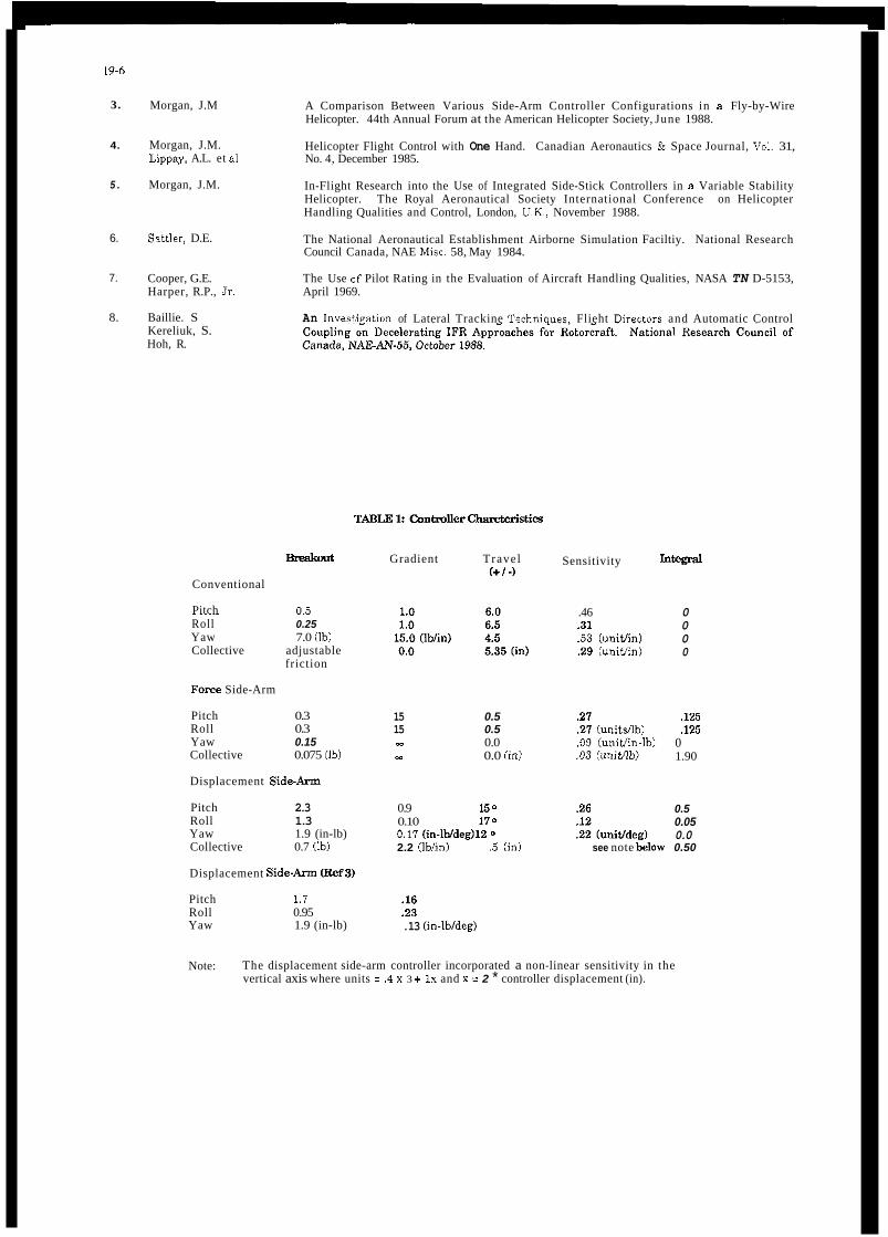
19-6
3.
4.
5 .
6.
7.
8.
Morgan, J.M
Morgan, J.M. Lippay, A.L. et al
Morgan, J.M.
Sattler, D.E.
Cooper, G.E. Harper, R.P., Jr.
Baillie. S Kereliuk, S. Hoh, R.
A Comparison Between Various Side-Arm Controller Configurations in a Fly-by-Wire Helicopter. 44th Annual Forum at the American Helicopter Society, June 1988.
Helicopter Flight Control with One Hand. Canadian Aeronautics & Space Journal, Vol. 31, No. 4, December 1985.
In-Flight Research into the Use of Integrated Side-Stick Controllers in a Variable Stability Helicopter. The Royal Aeronautical Society International Conference on Helicopter Handling Qualities and Control, London, U.K., November 1988.
The National Aeronautical Establishment Airborne Simulation Faciltiy. National Research Council Canada, NAE Mise. 58, May 1984.
The Use of Pilot Rating in the Evaluation of Aircraft Handling Qualities, NASA TN D-5153, April 1969.
An lnvastiration of Lateral Trackine Technioues. Flieht Directors and Automatic Control
B " t
Conventional
Pitch 0.5 .~~ ~ ~~.~~ Roll 0.25 Yaw 7.0 (Ib) Collective adjustable
friction
F o m Side-Arm
Pitch 0.3 Roll 0.3 Yaw 0.15 Collective 0.075 (Ib)
Displacement Side-Atm
Pitch 2.3 Roll 1.3 Yaw 1.9 (in-lb) Collective 0.7 (Ib)
Displacement SideAnn E M S )
Pitch 1.7 Roll 0.95 Yaw 1.9 (in-lb)
Gradient Travel (+ / 4
15 0.5 15 0.5 s.2 0.0 m 0.0 (in)
0.9 150 0.10 170 0.11 (in-lWdeg)lZ 0
2.2 (Ib/in) .5 (in)
.16 2 3 .13 (in-lb/deg)
Sensitivity htwd
see note i h w 0.50
.46
.3 1
.53 (unitJin) 2 9 (uniffin)
21 21 (un i tdb ) .09 (unitJin-lb) .03 (unifflb)
.26
0 0 0 0
,125 ,125
0 1.90
0.5 0.05 0.0
Note: The displacement side-arm controller incorporated a non-linear sensitivity in the vertical axis where units = .4 x 3 + Ix and x = 2 * controller displacement (in).

TABLE 2: Conholler Configuration Sequences
0
0
0 0
4 + 0 = 4-axis side-arm (3 + 1)e = 3-axis side-ann, conventional collective
(3 + 1)p = 3-axis side-arm conventional pedals
(2 + 1 + 1) = pitch roll side-arm, conventional pedals & collective
A
Conventional
Force (4+0)
(3 + 1)c
(3 + lb (2 + 1+ 1)
Deflection (4 + 0 )
(4 + 0)
( 2 + l + l )
(3+ lb (3 + 1 ) C
(4 + 0)
Force (4+0)
Conventional
EVALUATOR B C
Conventional
Deflection (4 + 0)
" (4+0)
" (3 + 1)c
" (3+ l)p
(2 + 1 + 1)
Force (4+0)
" (3+ lb " (3 + l)e
'' (2+ It 1)
" (4+ 0)
Deflection (4 + 0)
Conventional
Deflection (4+0)
" (4CO)
" (3+ 1)C
" (3+ 1)p
" ( 2 + l + 1)
Force (4 + 0)
" (3+ 1)C
" (3+ lb " (2+1+ 1)
" (410)
Conventional
Conventional Deflection (4 + 0)
D
Conventional
Force (4e0 )
(4 + 0)
(3 + 1)c
(3 + 1b (2 +1+ 1)
(3 + 1 ) C
(3 + lb (2 + 1 + 1)
(4 + 0)
(4 + 0)
Force (4+0)
Conventional
Deflection (4 + 0)
TABLE 5: Evaluator Relevant nying Experience
Pilot Total Time Total Helimpter Total Side-Ann (hours) (hours) (hours)
5800 3000 20 Research
4 1W
3x0
92w
2400 400 Cobra
3000 5 Cobra
5 7w 5 Cobra

FIG. 1: THE NAE BELL 205 AIRBORNE SIMULATOR
msE€,ABLE, SOR*PPROPRUTE"IL"ES
FIG. I: COKTROL INPUT CONDmONlNG
FIG. 3: ROLL AX15 BODE PLOT, 6. TO W A D ) (HOVER FLIGHT CONDITION)
n
FIG. 2: PITCH AXIS BODE PLOT, S. TO B(RAD1 (HOVER FLIGHT CONDITION)

19-9
FIG. 7: FORCE SENSING SIDEARM CONTROLLER FIG. 8: DISPLACEMENT SENSING SIDEARM CONTROLLER
HEAVE \ t ,ROLL - -ROLL .-
4 + 0 - FULLY INTEGRATED
HEAVE (COLLECTIVE)
W
(3 + 1)c - SEPARATE COLLECTIVE
HEAVE (COLLECTIVE)
(3 + 1)p - SEPARATE PEDALS (2 + 1 + 1) - FULLY DISTRIBUTED
FIG. 9: CONTROLLER INTEGRATION LEVELS
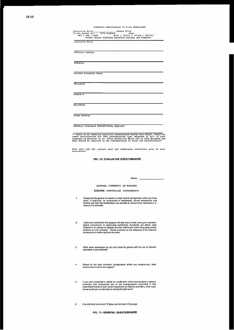
19-10
Name: -
OEWERAL COMMENTS ON FAIVNAE
SIDEARM CONTROLLER EXPERIMENTS

FIG. 13: HOVER RATINGS

19-12
j l ; : : ; , m ; ; ; 3 0 v I 0 0
* A A A
0 C F F F F D D D D c
N N 1 3 3 2 4 3 3 2 " . . . . . . . . 0 1 . 1 1 0 1 1 1
S P - T P .
Y !
FIG. 22: IFR DECELERATING APPROACH RATINGS FIG. 19: QUICKSTOP RATINGS
FIG. 20: SLOPE LANDING RATINGS
FIG. 21: OBSTACLE CLEARANCE TAKEOFF AND STEEP APPROACH RATINGS
c 0 N
FIG. 23: AUTOROTATION RATINGS
Hover Landing S/S D.A. Pir. Fig. 8 O/S Slope Circuit H0"M Landing
/IConvenfional Force 4.0 0 Displ. 4.0 I FIG. 24: LEARNING TRENDS ON INTEGRATED
SIDEARM CONTROLLERS
D-ATION OF DECISION-HE?IGHT WINDOWS FOR DECELERATING
IMC APPROACHES IN HEL,ICO€'TEXS
Roger H. Hoh Hoh Aeronautics Inc.
Lomita, CA USA
S.W. Baillie S. Kereliuk
National Research Council Ottawa, Canada
Joseph J. Traybar FAA Technical Center
Atlantic City, New Jersey USA
I SUMMARY
This program was conducted to define the basic limitations of the pilot plus rotorcraft in making the transition from a very low decision height (DH) to a steady hover over the helipad. The term "decision-height window" is defined herein as the limits of glideslope/localizer tracking errors, and groundspeed variations, that can exist at breakout to allow a safe visual transition to hover. The dimensions of the decision-height window can have a significant impact on the required rotorcraft handling qualities, and for setting autopilot coupler and flight director performance standards for decelerating instrument approaches in rotorcraft.
There have been several FAA and NASA experiments conducted to investigate tracking accuracy for helicopter instrument, and visual approaches, e.g., see Refs. 1 and 2. However, this work is the first to consider the required tracking and speed tolerances (Le. "window") for decelerating instrument approaches to a very low decision height (50 ft above ground level (AGL)).
There are a wide variety of factors that must be considered in the determination of the dimensions of a decision-height window, e.g.,
0
0
0 Rotorcraft field-of-view
0 Availability of airspace.
0
0
Rotorcraft flight dynamics and handling qualities limits.
Limitations associated with the human pilot.
Available real estate for the helipad, and approach lighting.
Rotorcraft performance for a missed-approach
This paper is concerned with the first two factors noted above. It is intended that the results of this study will be superimposed on the other considerations for the determination of a decision-height window for a given set of conditions consisting of rotorcraft performance limits, MLS configuration, and helipad geometry.

20-2
This work was done in the context of an exploratory study to determine what factors are important, and to obtain a general idea of the order of magnitude of the dimensions of the decision-height window. Further testing should be conducted to determine the effects of different rotor configurations (the test aircraft was a Bell 205 with a teetering rotor), helipad geometry and lighting, rotorcraft field-of-view, glideslope angle, and a more detailed look at the effects of winds. The testing focused primarily on the longitudinal axis, and further work to determine the maximum allowable lateral offsets should be accomplished.
The program was conducted jointly by the Federal Aviation Administration (FAA) and the Canadian National Research Council (NRC) under a memorandum of agreement between those two agencies. The test aircraft was the NRC variable stability Bell 2054 and all testing was conducted at the NRC facility in Ottawa Canada. Hoh Aeronautics Inc. (HAI) provided technical assistance in this program under an FAA subcontract. A more detailed description of the program may be found in technical reports published by the FAA and the NRC (Refs 3 and 4 respectively).
I I
All of the glideslope angles in this study are negative. The sign of these angles has been dropped in the text and figures as a matter of convenience. Also, reference to greater or steeper values of glideslope angle are intended to refer to more negative values.

20-3
These are illustrated in Figure 2, on a generic decision-height window. The shape of the upper boundary of this window indicates a tradeoff between groundspeed and glideslope error. This is a result of the first of the above factors, which infers a limit on the ability of the rotorcraft to dissipate energy. The total energy is the sum of potential energy (Ah), and kinetic energy (V2), so that a tradeoff exists between groundspeed, and glideslope error at breakout?
Height-velocity problems could occur for a breakout at low airspeed and a high-on-glideslope condition (i.e. large value of yf). This condition would be most likely if there were a tailwind at breakout. Even if the rotorcraft is not in the height-velocity envelope, a close proximity to this condition may be limiting from a piloting standpoint.
The potential for steep approach angles dictates that the vortex-ring state issue be addressed, as illustrated in Figure 2. The sketch in Figure 2 is taken from the full-scale rotor data in Ref. 5, which indicates that ring-vortex encounters require a flight path angle of 30° or greater.) Actually, it is the angle-of-attack of the rotor that is fundamentally limiting, and the interpretation in terms of flight path angle assumes a nearly level pitch attitude, and that the Right path angle is with respect to the airmass (Le. the "aerodynamic" flight path angle). It follows that the most critical condition would be a breakout high on the glideslope, and in a tailwind. The relationship between the aerodynamic and inertial flight path angles is:
+
where yInertia! would be equal to yf to make the pad from the decision point, and a positive wind is a tailwind. Practically speaking, it is unlikely that an approach would be conducted in tailwinds strong enough to increase the aerodynamic flight path angle to values large enough to enter the vortex ring state for glideslopes of 12O or less. However, for steeper glideslopes, it may become a limiting factor.
The maximum pitch attitude illustrated in Figure 2 is related to performance, in that the only way to convert low power to deceleration along the flight path is through pitch attitude. Hence, the peak pitch attitude is a measure of the power, or energy deficiency, that can be converted into deceleration without changing flight path. Because of the steepness of the constant power curves at very low airspeeds (backside of the power-required curve), simply holding collective constant while decelerating results in a rapid need for increasing pitch attitude as speed approaches zero, to hold flight path angle constant (e.& like in a quickstop maneuver). A fast condition at breakout can result in a need for significant deceleration all the way to hover. In such cases, the pilots in the present experiment were observed to delay adding collective until the very end,
' Groundspeed is used because it is, by definition, zero at hover. Therefore, any groundspeed that exists at breakout must be dissipated at the hover point or an overshoot will occur.
The edge of the vortex ring region involves some recirculation of air through the rotor plane. This shows up as increased vibration, but with little accompanying loss of performance. Proceeding deeper into the vortex-ring region involves recirculation of air over a significant portion of the rotor (black region of Figure 2), and settling with power.

20-4
and as a result, large peak pitch attitudes occurred just prior to hover. The magnitude of the peak pitch attitude is directly related to the minimum power that the pilot is willing to use in the final deceleration to hover.
The left side of the decision-height window is defined by the minimum airspeed that can be comfortably flown during the transition from IMC to VMC. Many helicopters do not posses good flying qualities in the transition region between forward flight and hover (region of effective translational lift). For example the test aircraft (a Bell 205A) tended to "buck and gallop" when operating in this region, which was considered as unacceptable by the pilots (HQR = 7). The low airspeed limit may also be set by the minimum airspeed for which IFR flight is approved. Once a minimum acceptable airspeed is established, the left boundary becomes a function of the tailwind (groundspeed = airspeed + wind) between the decision point and hover.
The lower (bottom) boundary of the DH window does not depend on the rotorcraft flight dynamics, since in the limit, the rotorcraft can fly level or even climb slightly to reach the hover point. Therefore, as noted in Figure 2, the lower limit is set by obstruction clearance and visibility constraints.
Returning to the upper boundary, it would be useful to characterize the total energy dissipation required to transition from the decision point to hover in terms of rotorcraft performance data. In that context, it is convenient to borrow a concept developed to define the vulnerability of powered lift STOL aircraft to wind shear, called the effective flight path angle, or yeff (e&, see Ref . 6). The effective flight path angle, as it is applied to the present problem, is defined as follows.
a, - V, + g siny4
gsiny, - a,
R - Range to Hover at DH V,, - Groundspeed at DH Where:
Note that the Vz term is indicative of the kinetic energy required to decelerate from the decision point to hover, and that ya is the angle between the horizon and the airspeed vector required to reach the pad from the decision point. The complete expression for the effective flight path angle, including the effect of winds, is derived in Refs 3 and 4, and is given as follows.
%H + 'VDH sin^, siny, - 2g /Rz + (hDH - hHJ /?
WhereVu is the wind velocity; positive as a tailwind.

20-5
From the geometry in Figure 1, the range from the decision point to hover over the pad is a function of the nominal glideslope angle, yo. and the glideslope error, d, as follows:
Finally, for glideslope angles less than about 200, the slant range is approximately equal to the horizontal distance (& - R, cosyf - 1, and sinyf - y v For zero wind, this yields the following approximation.
For DH - 50 ft. and a 10 ft hover:
This approximation was found to be accurate within a few percent for all of the cases tested in this flight experiment. The extrapolations to larger flight path angles discussed later in the paper utilized the more exact expression for effective flight path angle. As noted above, the V2ng term may be thought of as proportional to the kinetic energy, (hDH - hHov) as proportional to the potential energy, and as a measure of the total energy that must be dissipated. This concept allows one to lump the deceleration requirement and geometric flight path angle into a single "effective" flight path angle. The advantage of this is that ye^ can be plotted directly on the rotorcraft y vs. V performance curves as shown in Figure 3. These example y vs. V curves are for the XV-15 tilt rotor aircraft in the helicopter mode. In the example shown in Figure 3, the nominal glideslope angle is 12O, the groundspeed at the 50 ft decision height is 20 kts, and the rotorcrafI is assumed to reach the decision height with a 25 ft glideslope error. The component of y due to the
nominal glideslope, and 7.2O due to being 25 ft high. The component of the effective flight path angle due to the need to decelerate from 20 kts to zero groundspeed is 8.5O (the Vz term in the definition of yeff). This results in a total effective flight path angle of 27.7O.
geometric flight path angle from the decision point to a 10 ft hover (yf in Figure 1) is 19.2'; e% 12 due to the
The effective flight path angle will be the basis for mapping the rotorcraft performance capability on to the "decision height coordinates", defined here as glideslope error vs. groundspeed at DH (de vs. VDH), and for extrapolating the results of this program to other rotorcraft and glideslope angles.
EXPERMENTAL. SCENARIO AND RESULTS OF I" EXPLORATORY RUNS
The NRC variable stability Bell 205A was configured to have handling qualities similar to a current rotorcraft with a limited authority stability augmentation system (e& the Sikorsky S-76). A conventional cyclic stick and collective were provided as cockpit controllers. The initial phase of the testing was to determine the y-V characteristics of the Bell 205A to allow estimates of the decision height window based on the effective flight path angle. The resulting y - V curves are shown later in Figures 9 and 10. It should be noted that the horizontal component of the airspeed vector is plotted as the x coordinate in these figures to allow a direct comparison with groundspeed at DH (Le. so airspeed = groundspeed in zero wind).

20-6
The nominal glideslope angle in the experiment was 9, and some runs were made with a 6 O glideslope. Initial testing indicated that glideslope angles of over 9 resulted in excessive down collective requirements for glideslope corrections in the Bell 205.
Each run was initiated in level flight on the localizer, or just prior to turn-on to the final approach course. The evaluation pilot flew the precision approach to a 50 ft decision height in simulated instrument meteorological conditions (IMC), and completed the approach to a hover over the helipad visually (below 50 ft AGL). IMC was simulated by means of electronically fogged goggles, which were wired to the radar altimeter, and which automatically cleared at 50 ft thereby simulating breakout. The goggles were cleared on every approach so that the evaluation pilot did not have to make the missed-approach decision at DH.
The deceleration profile was taken from the Ref. 7 and 8 work, and consisted of a constant attitude deceleration of about . a 5 g. from 60 kts groundspeed to a nominal 20 kts groundspeed at DH. The radar altitude box on the EADI, and the digits within the box flashed at 10 ft above decision height, and remained flashing while below this height.
Nearly all of the runs were made using the manual flight director for the IMC portion of the approach. A few coupled runs were made, and these indicated that the transition was slightly more difficult because of the additional workload of disengaging the coupler, and transitioning into the control loop. There was some concern that the details of the mechanization of the autopilot cutoff could have a significant impact on the results, so it was decided to proceed with manual approaches for this initial exploratory program.
It was determined that the pad markings investigated in this program did not have a significant effect on the transition from DH to hover. The baseline pad consisted of eight orange traffic cones outlining a square which measured 100 feet on each side. A second pad was tested which consisted of the same basic markings plus lead-in cones which depicted two large arrowheads along the final 350 feet of the final approach course. These lead-in cones were of little or no value because they were under the nose almost immediately after breakout. essentially all of the runs were made to the pad without lead-in cones. In actual practice, such lead-in guidance would be useful to maximize the lower boundary of the DH window by extending the range of the "helipad environment". It was hypothesized by one pilot that lead-in strobes surrounding the pad, and pointing the way to the center of the pad, would be useful to assist in finding it immediately upon breakout, especially with a lateral offset.
The majority of the runs were made to obtain estimates of the size and shape of the critical upper boundary of the decision-height window using a 9' glideslope angle. The conditions at DH were systematically varied by injecting errors into the flight director control laws. The raw data displayed to the pilot was not affected so the pilot was aware of the errors at DH, as he or she would be in actual operations. This provides a valuable cue since the pilot "knows where to look" for the pad during the first few critical seconds after breakout
Systematic variations of localizer errors were beyond the scope of the program. However, the lateral flight director was degraded from the Ref. 7/8 study, and this resulted in random localizer errors at breakout which ranged from zero to about 60 ft. These lateral errors were not deemed to be a significant problem by any of the pilots.
Data was collected for four pilots. ' b o pilots were test pilots from the NRC, one is an FAA certification pilot from the Southwest region, and the other is the author of this paper. All are commercially rated helicopter pilots with significant experience in handling qualities flight testing, and the use of the Cooper Harper handling qualities rating (HQR) scale.

ANALYSIS OF RESULTS
Correlation of Pilot Rating Data and Commentary
The detailed pilot rating results are presented in a spreadsheet in Ref. 3 along with a summary of the pilot commentary for each run. The data for the 90 glideslope on the DH window coordinates (de vs VDH) in Figure 4.
The data fairings in Figure 4 (which define the upper boundaries of several example DH windows to be discussed below) resulted from the following interpretations of the pilot rating results.
All regions of the DH window coordinates containing points with HQR = 7 have been defined as "unacceptable", even if other data points in that region have been rated HQR = 4, and 5. The rationale is that these 7 rating(s) resulted from a slight delay or initial misuse of the controls in initiating the proper action from a very marginal initial condition (see pilot commentary in Reference 3 or 4). If the region is so critical that an overshoot can result from a slight delay or mistake, it should be disallowed for normal commercial operations. This interpretation of the data causes the curves to drop off steeply at speeds above 25 knots due to two points with HQR = 7 at 32 and 36 kts groundspeed. These two data-points cause a number of cases with HQR = 4 to fall in the unacceptable region. This is discussed in more detail below.
Regions with a large number of 6s, some 5s and an occasional 4 have been defined as unacceptable. This is based on the rationale that HQR = 6 is indicative of a requirement for extensive Dilot comaensation just to make the pad without an overshoot (Le. "adequate performance"), and/or very obiectionable but tolerable deficiencies. A region where such ratings are abundant seems excessively risky for commercial operations to very low instrument minimums. This interpretation causes the left side of the upper boundary to be flatter than it would be if only HQRs of 7 were considered as unacceptable (see Figure 4).
The "marginal region" contains mostly points which were assigned HQRs between 4 and 5. That is, "deficiencies warrant improvement" and adequate performance requires "moderate" to "considerable" pilot compensation on the Ref. 9 HQR scale.
The "desirable region" consists of mostly ratings of 3 or better, i.e., "satisfactory without improvement" on the HQR scale. A few points with HQR = 4 in this region all contain pilot comments related to vibration; a problem unique to the Bell 205A and not related to the DH window.
The desirable region in Figure 4 is proposed as a design goal for approach couplers and flight directors intended to achieve a decision-height of 50 ft following a decelerating approach in IMC conditions. The suggested demonstration would be similar to that used for fied wing approach couplers for Category IIIa autoland systems.'
The outer limit of the marginal region is proposed as the missed approach boundary, and would be full scale deflection on the raw data for the final segment of the approach.
' Current fied-wing category IIIa couplers are usually designed and certified within the guidelines of Advisory Circular 20-S7A which specifies touchdown performance limits which must be achieved.

20-8
The above rationale is based, in part, on the pilot commentary for ratings which fall along and outside the faired boundaries. These are summarized on Figure 5. This figure includes the faired lines from Figure 4, and several shaded ellipses to indicate general regions of pilot commentary. The right-most ellipse indicates that the upper limit on groundspeed at DH is defined by excessive pitch attitudes and high collective activity (essentially a quickstop maneuver). Moving up and to the left, the commentary still indicates that the pitch attitude is marginally high, collective activity is excessive, and that pad visibility is becoming a problem. The left-most ellipse indicates a region where the pilots were concerned with rotorcraft performance limits associated with steep approaches, and that pad visibility has become a significant problem. It should be noted that the glare-shield on the Bell 205 is reasonably low, and that the visibility over the nose of some more modern helicopters is somewhat worse. The urgency along the upper boundary is generally classified as moderate; not a good situation for a transition from IMC to a VMC hover, at altitudes below 50 ft AGL.
The faired boundaries from Figure 4 are presented without pilot ratings or commentary in Figure 6. The shaded region on the right side of Figure 6 contains primarily HQRs of 4 to 4.5 with two notable exceptions - a pair of 7s. The upper limit of this region is defined by a line of constant yefe In fact, if it were not for the two pilot ratings of 7, the line of yeff = 20° would nicely separate the HQR 6 and 7 ratings from the HQR 4 and 5 ratings. Hence, it can be argued that an effective flight path angle of 20' represents the limit of the energy dissipation capability of the Bell 205, as long as the pilot responds immediatelv, and with the correct control inputs at DH. However, if the pilot encountered some delay (such as in making a transition from fully coupled to manual flight, or lacking good speed and sink-rate cues at DH), an overshoot of the pad, and/or excessive pitch attitudes tended to result. A margin or pad is required from the yeff = 20' line for groundspeeds above about 25 kts to eliminate the shaded region in Figure 6. A review of the time histories of runs along this more restricted boundary indicate that it results in a maximum pitch attitude of about 14O. For the two runs in the shaded region where the pilots started late and assigned ratings of 7, a maximum pitch attitude of 21' was observed. In fact, this is approximately the maximum pitch attitude observed for all runs in the unacceptable region for all of the pilots.
The peak pitch attitude used during the final portion of the derxleration to hover is closely correlated to the minimum power (collective position) used by the pilot. It is therefore not surprising that the steep upper boundaries which correlate the pilot rating data in Figure 4 are well fitted by lines of constant torque (power). This is illustrated in Figure 7 where it can he seen that the data fairings (thick lines) follow lines of constant torque after departing lines of constant yeff The usefulness of this observation will be discussed in more detail in the following section.
DEVELOPMENT OF EXAMPLE DECISION-HEIGHT WINDOWS
The physical significance of yeff is that it represents an equivalent task that is more easily understood and interpreted than the complex deceleration to hover from breakout. The "equivalent task" is to fly at a constant flight path angle (y = yef and at the speed at DH. For example, if the helicopter arrives at the decision-height 35 ft above a nomin2 9' glideslope, and at a groundspeed of 25 kts, yefdyo is calculated to he 3. Therefore, yeff = 27O (3 x 9'), and the task of decelerating to hover is equivalent to flying at a constant speed of 25 kts and a flight path angle of 27O. Plotting this on the y - V curves for the Bell 205, (e.g. see Figure 8 ) indicates that it would require a very low amount of torque (approximately 7 psi), and hence is near a basic rotorcraft deceleration limit.
While the y - V curves represent the theoretical performance capability of the rotorcraft, it is well known that there are other restrictions which must he superimposed on these curves. Some restrictions are performance related (e& vortex-ring state, height-velocity curve, and vibration), and other restrictions tend to be centered about degraded handling qualities. The results discussed above indicate that below about 25 kts groundspeed, the limit consists of a line of constant effective flight path angle, y e p Above 25 kts, the boundaries departed from a constant yeff by bending down sharply and thereby limiting the maximum groundspeed (e.& see Figures 4 or 6). Interestingly these departures from constant y,ffare well approximated

20-9
by lines of constant torque or power. This is illustrated in Figure 7, where lines of constant torque, and lines of constant aerodynamic flight path angle have been mapped from the y - V coordinates onto the DH window grid of glideslope error vs. groundspeed. Here, it can be seen that the data fairings in Figures 4 and 6 can be well approximated by lines of constant effective flight path angle and lines of constant torque as follows.
Nominal missed auproach boundary Extended Missed Approach Boundary
V < 25 kts -- yeff 5 20" V < 35 kts _- yeff 5 20"
V 2 25 kts -- Torque 2 10 psi
The above missed approach boundary definitions are superimposed on the Bell 205A y - V curves in Figure 8a. Any point in the noted "nominal safe region" of this plot represents a flight path angle-airspeed combination that is flyable with good handling qualities. Once a safe y - V region is defined, its boundaries can be mapped onto coordinates of d, vs. VDH (via the yeff/vo equation by solving for d,) to obtain a decision-height window. An example of such mapping is illustrated in Figure 8b for the Bell 205, and a 9" glideslope angle.
V 2 35 kts -- Torque 2 5 psi
A less conservative "extended boundary" for the missed approach window is defined if the shaded region on the right side of Figure 6 is ignored. This extended boundary is defined by yeff = ZOO, and by a line of constant torque of 5 psi above 35 kts in Figure 8a. These limits are mapped onto the d, vs. VDH coordinates in Figure 8b. A comparison of the extended missed-approach window with the "nominal" window in Figure 8b indicates that the primary difference is that significantly higher airspeeds are allowed. The rationale for the less conservative extended window would he based on significantly improved cues due to helipad markings and lighting, and possibly a larger landing area or overrun. The helipad in this experiment was 100 ft on a side as compared to the pad used in the FAA tests at Atlantic City (Ref. 1) which was 150 ft on a side
As noted above, the extended DH window results from inclusion of most of the shaded region in Figure 6, and hence the two HQR = 7 ratings at VDH = 32 and 36 kts. As discussed earlier, these ratings both represent cases where the pilots noted some confusion between breakout and initiating action to decelerate to hover (see pilot comments in Refs. 3 or 4 for cases 5 and 78). All other ratings in this region are HQR = 4 to 4.5. It could be argued that with better cuing or a larger landing area, any delays or initial misapplication of controls would be eliminated. The physical significance of eliminating the margin afforded by the "extended region" in Figure 6 can be illustrated on the y - V curves in Figure 8a. The upper torque limit (10 psi) represents the nominal missed-approach window, and the lower torque limit (5 psi) represents the extended missed-approach window. Consider now the following example. If the pilot arrives at DH at point A (Figure Sa), and experiences some delay in initiating the proper action at breakout (due to poor cues, etc.), it will be necessary to operate in the "extended" region (e.g., point B) to stop at the pad. That is, since the deceleration was started late, a lower torque is required to make it. The pilot rating data indicate that this is not a problem since most HQRs in the "extended region" (i.e., the shaded region of Figure 6) are 4. If, on the other hand, the extended missed approach window is used, and the pilot arrives at DH at point B and encounters the same delay (like the two 7s at 32 and 36 kts), the possibility of "making it" is very poor since he will he operating in a region of solid 7s, i.e., point C? This is potentially hazardous since reaching the decision-height point with the landing area in sight, by definition, means that an abort is no longer part of the pilots mental scenario. The overshoot would result in an accident unless there is some "overrun area"
Point C cannot he mapped on to the DH window coordinates because the effective decision height is actually lower than SO ft as a result of the pilot delay. However, operating at point C requires the deceleration characteristics that were found to he unacceptable in the experiments (i.e. torque < 5 psi and yeff > ZOO).

i.e., the larger helipad discussed above as rationale for using the extended missed approach DH window.
The point of considering the nominal vs. extended decision height window is not very interesting for the Bell 205, since it is unlikely that anyone would consider using such an old machine for IMC decelerations to a 50 ft DH. However, it does illustrate that, in general, the missed approach DH window should be based on a margin from the y -V limits where the helicopter is not comfortable to fly. A more quantitative and generalized definition of such limits will require additional study. Such work is best accomplished in ground- based simulation where the generic characteristics of the rotorcraft can be systematically varied, and operation in marginal regions of the y - V curves can be safely tested. The DH window for approach coupler and/or flight director requirements should obviously be based on regions of the y ~ V curves where the performance and flying qualities are in the desirable range.
Effect of Configuration and Glideslope Angle
The ratio yefdyo has been shown to be a function of the glideslope error, decision height, hover height, and groundspeed at DH. This relationship is plotted in Figure 9 which gives an indication of the variations in window size as a function of yefdyo These generic cuives indicate that the DH window for missed approach reduces to dimensions which may be unachievable (e.&, glideslope errors of less than 20 ft at 20 kts) when the ratio of the limiting ya (and hence yeff) of the helicopter, to the glideslope angle is equal to or less than 2 (ie., yefdyo I 2). For the Bell 205 this rule of thumb would limit the glideslope angle to 20°/2 = loo which is consistent with the experimental results. That is, initial testing indicated that glideslope angles much greater than a were not practical in the Bell 205. Conversely, increasing yefdyo increases the size of the window. A direct comparison of the Bell 205 missed-approach window dimensions for glideslope angles of 6 O , 90, and 12O is shown in Figure 10. Here it can be seen that the window for a 12 degree glideslope would require very stringent, but not unreasonable approach coupler performance. It is doubtful that such performance is obtainable with a flight director. Reducing the glideslope angle to 6O increases the missed-approach DH window dimensions to the point where the flight director of Refs 7 and 8 would be adequate.
In summary, to obtain DH window with dimensions that are consistent with approach coupler and flight director performance capability:
The aerodynamic flight path angle that can be flown without degradations in handling or excessive vibrations at low speeds, should be at least twice the glideslope angle.
The minimum power that is practically usable must not result in an overly restrictive right boundary.
The approach coupler or flight director laws must provide very tight tracking in the presence of all expected winds, wind-shears, and gusts.
0
Work needs to he done to determine the flight path angle capability of modern rotor systems. The results of the Ref. 7/8 program would indicate that fully coupled approaches will be necessary for steep flight path angles unless the flight director deficiencies noted therein can be resolved. A renew of 3-cue flight director control laws and tracking performance is given in Ref. 10.
Eff& of Helipad Dimensions
The down-range dimension of the helipad will clearly have a significant impact on the size of the longitudinal decision-height window. This effect may be estimated by assuming that the target hover point is 50 feet from the far end of the pad (Le., superimpose the pad used in the present experiment on the far end of the pad with increased dimensions). This will result in a decreased value of yo, and hence increased

20-11
yefdy.o The increased dimensions of the decision-height window can then be estimated from the yeff/yo equation as plotted in Figure 10.
SUMMARY OF RESULTS AND CONCLUSIONS
A methodology has been developed to determine certain critical decision-height window dimensions based on pilot/rotorcraft factors and limitations. Specifically, the method consists of determining the regions of the y - V performance curves where the rotorcraft flying characteristics are acceptable, and mapping these regions onto coordinates that define the DH window (i.e., d, vs VDH). This mapping is accomplished via the "effective flight path angle" parameter or yefp
Insights and initial estimates of the DH window dimensions have been obtained from an exploratory flight test program with the Canadian NRC variable stability Bell 205. These results are summarized below.
0
0
0
The upper and right boundaries of the DH window are based on helicopter performance limits.
The left boundary of the DH window is based on rotorcraft handling at very low airspeeds.
The bottom boundary of the DH window is based on obstruction avoidance, and pad visibility. This boundary is not affected by rotorcraft performance or handling qualities.
The right boundary of the DH window is based on the minimum usable torque (power), and related maximum acceptable pitch attitude during deceleration. Some margin is required to account for pilot delay in initiating the deceleration after breakout.
The upper boundary of the DH window is based on the maximum aerodynamic flight path angle that can be flown at low airspeeds. It requires some margin for pilot delay or control misapplication in conditions of poor visual cuing, but is less critical in this regard than the right boundary.
The dimensions of the DH window are directly proportional to the ratio of the maximum usable aerodynamic flight path angle (i.e., yeff) to the glideslope angle (yo). Values of yefp'yo < 2 result in DH window dimensions that would be difficult to achieve consistently with existing flight hardware in a variety of wind and windshear conditions.
The DH window dimensions obtained from considerations of pilot/rotorcraft factors and limitations should be superimposed on other operational considerations such as field-of-view, airspace availability, available real estate for helipad and approach lighting, obstructions, noise, etc. The ultimate decision on setting the window dimensions should be based on flight testing on a case-by-case basis. The results of this study, and any future studies, should provide a basis for estimating reasonable window dimensions prior to such testing.
VIII REFERENCES
1.
0
Enias, James H., Course Width Determination for Collocated MLS at Heliports, DOT/FAA/ff- TN85/15, December 1985.
Weiss, Rosanne M., Christopher J. Wolf, et. al., Heliport Visual Approach and Departure Airspace Tests, Vol 1 Summary, DOT/FAA/CT-TN87/40, I, August 1988.
Hoh, Roger H., Stewart W. Baillie, Stan Kereluik, and Joseph Traybar, Decision-Height Windows for Decelerating Approaches in Helicopters - PilotNehicle Factors and Limitations, DOT/FAA/CT-90/14, June 1990.
2.
3.

20-12
4.
5.
6.
7.
8.
9.
10.
Baillie, Stewart W., Stan Kereliuk, and Roger Hoh, Trackine Performance Requirements for Rotorcraft Instrument Approaches to Reduced Minima: Phase 1 - Preliminaw Study, IAR/NRC Aeronautical Note TBD, June 1990.
Washizu, Kyuichiro, Akira Azuma, Exueriments on a Model Helicopter Rotor Operating in the Vortex Rins State, AIAA Journal of Aircraft, Vol. 3, No. 3, June 1966.
Hoh, Roger H., Investieation of the Vulnerabiliw of Powered Lift STOL’s to Wind Shear, AIAA Paper 11-1120, August 1977.
Hoh, Roger H., Stewart Baillie, and Stan Kereliuk, Flieht Test Investigation of Flieht Director and Autooilot Functions for Helicopter Deceleratine Instrument Approaches, DOT/FAA/ff-TN89/54, January 1989.
Baillie, S., S. Kereliuk, and R. Hoh, An Investigation of Lateral Trackine Techniaues, Flight Directors and Automatic Control Coupling on Deceleratine IFR Approaches for Rotorcraft, Aeronautical Note NAE AM-55, NRC No. 29604, National Aeronautical Establishment, Ottawa Canada, October 1988.
Cooper, George E., and Robert P. Harper Jr., The Use of Pilot Rating in the Evaluation of Aircraf! Handling Qualities, NASA TN D-5153, April 1969.
Hoh, Roger H., A Review of Certain Generic Characteristics of the 3-Cue Flieht Director for Decelerating Instrument Approaches in Helicopters, DOT/FAA/ff-TBD, or STI TR 1264-1, December 1989.

\ RANGE I [ GLIDESLOPE
TRANSMITTER
Figure 1 . Approach Geometry Between Decision-Height and Hover
Figure 2. Basic Rotorcraft Limitations That May Affect Decision-Height Boundaries

20-14
60 ' 40 @ w 1
Q p 20
de at 50 ft = 25 ft.
-60 0 al 40 60 80 1W 120
TRUE AIRSPEED - V,, KTS
Figure 3. Y - V Curva for XV-15 Tilt Rotor Aircrafi With Example Showing Components of Yeff
DESIRA8LE REGION r (SATISFACTORY WlMOUT IMPROVEMENT) ~ ! k ~ ~ G % A N T IMPROVEMENn
50 t 7 40 x 2 30
I*
2 Ii 20 51 z IL 10
K O 3
LT w
w Y 2 -10
-20
-30 0 10 20 30 40 50 60
GROUNDSPEED AT 50 FT ALTITUDE - Vow P S
Figure 4. Pilot Ratings as a Function of Glideslope Error and Groundspeed at Decision Height (yo = 99

40
30
20
10
0
-10
-20
1 wwer amlication intolerable at bottom -30 0 10 20 30 annude i& high I tm late
50
40
30
20
10
0
-10
-20
-30
I ~.
GROUNDSPEED AT 50 F l ALTINOE - VDH, KTS
Figure 5. Summary of Pilot Commentary
0 10 20 30 40 50 60
GROUNDSPEED AT 50 FT ALTiTUDE - VDH, KTS
Figure 6. Extended Region for Decision Height Window

20-16
Figure 8.
GROUNDSPEED AT 50 FT ALTITUDE- V m KTS
Figure 7. Lines of Constant y and Constant Torque Plotted, on Decision Height a n d o w Coordinates ('yo = 9 )
Bell 2005 y vs. V curves a)
10 20 30 40 50 Ea HORIZONTAL COMPONENT OF TRUE AIRSPEED, KTS
.Y
b) Extended DH Window for Missed Approach 50
40
30
20
10
0
-10
-20
-30 ' 0
I
20 30 40 50 10
GROUNDSPEED AT 50 FI KTITUDE- VDH, KTS
Helicoter Performance Limits Mapped onto de VS. VDH to Obtain Nominal and Extended DH Windows for Missed Approach (Yo = 9')

-.nJ ~~
0 10 20 30 40 50 60
GROUNDSPEED AT 50 FT ALTITUDE - VDH, KTS
Figure 9 Effect of Systematic Variation of yeftJro on the Decision-Height Window
t 5
-0
w n 2 2 t 8 G g
9 3 6
a:
a: W
W a
0
0 10 20 30 40 50 GROUNDSPEED AT 50 FT ALTITUDE - VDH, KTS
Figure 10. Effect of Glideslope Angle on Bell 205A Missed-Approach Decision-Height Windows


21-1
EVALUATION DES LOIS DE PILOTAGE EVOLUEES SUR DAUPHIN N
P" MM
RDelestrade Airospatiale
Marignane, France et
D.Papillier Centre d'Essais en Vol,
B.P. 19, 13800 Istres, France
1 - INTRODUCTION Le concept de commandes de vo1
Blectriques s'insere dans le cadre du contr8le actif generalis6 sur h&licopt&re dont le p8le d'interet principal se situe dans l'amelioration des qualites de vo1 des machines actuelles et la diminution de la charge de pilotage en mission. Ces deux themes constituent les axes principaux de recherche du developpement exploratoire des commandes de vol Blectriques du DAUPHIN 6001, developpement mettant en oeuvre sur helicoptere des technologies eprouvees 8 ce jour sur avion.
La philosophie de developpement des C.D.V.E. sur helicoptere s'eloigne quelque peu de cella poursuivie pour les avions dont le but principal Btait d'augmenter les performances de leurs machines en terme de maniabilite et de manoeuvrabilite. L'augmentation de ces performances se traduisait generalement par une degradation de la stabilite dynamique de l'avion qui se trouvait alors compensee artificiellement par les C.D.V.E. ~'h6licoptdre Btant naturellement instable et fortement couple en axes, la demarche poursuivie est 8 fortiori differente et consiste dans un premier temps 8 rBtablir des qualites de vol acceptables pour 1'helicoptSre et 8 reduire dans un deuxieme temps la charge de travail du pilote en proposant la fois un pilotage plus simple de l'hBlicopt8re (par objectifs) et uce aide dans la surveillance des limitations du domaine de vol, notamment dans des manoeuvres agressives. Les systemes aotuels (pilotes
automatiques) dedi& B ce jour 8 1'amBlioration du pilotage n'avaient pour vocation que de se substituer au pilote pour maintenir l'helicoptere sur des trajectoires pr6-dbterminees. Leur architecture n'etait pas prevue initialement pour inclure le pilote dans la boucle d'asservissement si ce n'est au travers d'une fonction S.A.S. permettant de garantir une stabilite apparente minimale sur action pilotee. NBanmoins, les performances de ces systemes sont limitees 8 ce jour par des contraintes de securite. imposant des autorites de fonctionnement trop insuffisantes pour garantir un pilotage performant en manoeuvres rapides.
Disposant d'un meilleur niveau de securite, les commandes de vol electriques autorisent des autorites de commande plus importantes et permettent ainsi d'atteindre des niveaux de qualitBe de vol largement supbrieurs, se concretisant par exemple par un decouplage complet des axes de commande en manoeuvre. Par ailleurs, ce type d'architecture de commandes de vol
facilite l'introduction de commandes miniaturisees ideales pour l'optimisation ergonomique des cockpits futurs et bien adaptees 8 la surveillance passive des limitations du domaine de vol (surveillance exigeant de preference une action sensitive au niveau des manches pilote plutBt qu'une alarme visuelle ou sonore 8 l'intbrieur du cockpit).
Ces considerations justifient en grande partie l'int6rBt que l'on doit porter B ce type de commandes de vol notamment pour les h6licopteres de combat futurs.
2 - OBJECTIFS DE L'EXPERIMENTATION DES COMMANDES DE VOL ELECTRIQUES SUR DAUPHIN 6001
Les deux objectifs principaux des commandes de vol electriques se rapportent essentiellement 8 l'allegement de la charge de travail du pilote en mission et a l'am6lioration des qualites de vo1 de l'helicoptere.
Elles se proposent :
1 De transformer l'h6licoptere en un appareil stable sur l'ensemble du domaine de v01, y compris sur manoeuvre agressive.
2 De garantir 8 tout moment un decouplage des axes de commande de l'h6licoptdre afin de simplifier le pilotage de l'appareil dans son enveloppe operationnelle.
l'helicoptere si necessaire, afin de diminuer les actions de commande exigees aujourd'hui sur les machines B rotor souple .
I De simplifier l'apprentissage du pilotage de l'hi?licopt&re en realisant une adaptation parfaite des objectifs de pilotage aux contraintes operationnelles de chaque mission (pilotage par objectif).
3 D'augmenter la maniabilite de
5 De gerer automatiquement les limitations du domaine de vol que le pilote est tenu de surveiller aujourd'hui en mission au travers des indications visuelles et sonores fournies et des consignes stipulees dans son manuel de vol . L'ensemble de ces considerations
constituent les axes de recherche du developpement exploratoire des commandes de vo1 Blectriques du DAUPHIN 6001. Ces etudes ont donne lieu 8 ce jour 8 des essais en simulation pour definir les lois de pilotage idbales permettant d'atteindre les niveaux de qualites de vol exiges et B la realisation du demonstrateur volant (DAUPHIN 6001) pour &valuer en vo1 les performances d'un tel systeme.

21-2
Ce document esposera la methodologie suivie dans la realisation des lois de pilotage et detaillera l'architecture du systeme C.D.V.E. retenue pour ce demonstrateur. Les resultats des premieres evaluations seront present& A la fin de ce document mettant en evidence les performances des lois de pilotage etudikes dans le cadre de cette experimentation.
3 - PRESENTATION DE L'ARCHITECTURE DU SYSTEME
L'architecture du systeme retenue pour le DAUPHIN 6001 est une architecture duplex electrique avec secours mecanique afin de respecter le niveau de &curite exigk sur ce type de demonstrateur volant. Cette architecture est presentee ci apres 06 sont representes tous les composants intervenants dans le systeme C.D.V.E..
,,*,* I"."%"M*.OU
Le secours mecanique est realis6 en place gauche par la timonerie classique de l'h6licoptAre que l'on a conservee sur ce poste de commande. Cette contrainte de realisation a donc necessite de promouvoir des servocommandes A deux entrees electriques et A une entree mecanique en lieu et place des servocommandes classiques utilisees B ce jour sur un DAUPHIN serie. Pour des problemes d'encombrement la servocomande arriAre a et6 conservee, la servocommande C.D.V.E. commandant le rotor arriere se trouvant en serie avec cette derniere. Le passage en mode secours est assure A tout instant par une recopie des positions mecaniques equivalentes sur les manches co-pilote, garanti par le lien mecanique entre la timonerie de secours et les tiroirs de commande des servocommandes C.D.V.E. Le retour en mode mecanique peut s'effectuer manuellement soit par une action volontaire du co-pilote au travers de ses boutons de debrayage pr6ws B cet effet (situ& sur ses manches cyclique et collectif), soit par surpassement d'effort du co-pilote exerce sur ces commandes, soit par la manette de deconnexion du systeme C.D.V.E. situee A portee des deux pilotes sur la console centrale. Ce retour en mode mecanique peut egalement s'effectuer automatiquement sur detection de panne du systeme C.D.V.E. A partir de la surveillance des paramPtres de fonctionnement du systeme complet introduite tant au niveau des calculateurs embarques qu'au niveau des servocommandes C.D.V.E.
realises par deux calculateurs embarques se surveillant mutuellement. Cette surveillance est realisbe par des Bchanges
Les ordres de commandes electriques sont
d'informations entre ces deux calculateurs pour v6rif.Ler la coherence des donnees qu'ils repoivent et des donnees qu'ils transmettent aux organes de commande. Ces donnees sont relatives aux informations captees emanant des divers senseurs du systeme C.D.V.E. (positions de manche, capteurs d'6tat du mouvement de l'h&licoptere, recopies des positions des servocommandes) digerees en interne par les lois de pilotage des calculateurs. Ces lois elaborent les ordres de pilotage A transmettre aux etages d'entrbe des servocommandes en vue de realiser des deplacements servocommandes compatibles des objectifs de pilotage desires. Ces ordres sont consolides en sortie des calculateurs avant transmission aux organes de commande de chaque servocommande.
ROTO"
ELECTRICAL LINK HYDRAIULIC A
SYSTSM COMPUTER 1
HYDRfiULIC ELECTRICSTICK WSSESSINO PlLOTl COMPUTER2 SYSTEM
2 ELECTRICbL INPVTS * I MECHANICAL ,NP"T
SERYoCONTROLS
MECHANICALSr'CX ,STANDBY PlLOTl MECHANICAL LINKAGE
Les ordres transmis par les calculateurs sont duplex et attaquent les deux Btages d'entree de chaque servocommande. Ces ordres sont surveill6s en entree de chaque servocommande pour verifier la coherence des informations emanant de ohaque calculateur. Cette surveillance est realisee par un systeme electronique dispose en interne de chaque servocommande. Les Atages d'entrbe sont chargBs de realiser l'asservissement des commandes des deux distributeurs venant deplacer les deux corps de la servocommande. Les capteurs utilisBs dans le systeme C.D.V.E. sont donc dupliques, chaque bloc de capteurs venant informer son calculateur associb. Les performances des capteurs utilises dans cette experimentation sont tout A fait conventionnelles et font appel A des donnees de type gyrometriques, gyroscopiques, accBlerom6triques et barometriques. L'engagement du mode Blectrique
s'effectue B partir d'un Boitier de commande (B.D.C.) sur lequel sont disposes les boutons de selection des divers modes de fonctionnement du systhe C.D.V.E. Notamment les fonctions "test prevol" permettant de verifier au sol le bon fonctionnement du systeme et le "mode synchronisation" sont engages directement A partir de ce Boitier de comande. Ce dernier mode est un point de passage obligatoire avant tout engagement du mode Blectrique de maniere B ne pas generer des A-coups sur les servocommandes. I1 consiste B synchroniser toute la chaine de commande de vo1 electrique (manches Blectriques, calculateurs) B partir des positions mecaniques imposees avant la phase d'engagement par le pilote de securite au travers de la timonerie mecanique de secours. La verification de la synchronisation des commandes de vol

21-3
electriques s'effectue a partir d'un voyant dispose directement sur le Boitier de commande autorisant ainsi le passage au mode Blectrique. Le levier d'engagement du mode Blectrique est auto-maintenu, une fois l'engagement effectue : l'auto- maintien Atant degage apres toute detection de panne du systPme ou toute action volontaire des navigants , degagement se traduisant par un retour obligatoire en mode mecanique. Pour faciliter l'experimentation, ce Boitier de commande est dote d'un selecteur de lois de pilotage permettant de tester au cours du m&me vo1 plusieurs type de lois sur les memes manoeuvres et dans les memes conditions de vol.
-1 """4'"'""'' 1"""') ")-I 1-
4 - ARCHITECTURE DES LOIS DE PILOTAGE L'architecture des lois-de pilotage
evaluees A ce jour dans le cadre de ce dhveloppement exploratoire est basee sur une technique de suivi de modele de reference de type implicite. Cette architecture bien adaptee la realisation d'un pilotage par objectif permet en outre de garantir une bonne robustesse aux lois de commande ainsi genbrees. Le principe consiste a asservir
dynamiquement l'helicopt&re a un modPle de reference representant la dynamique ideale desiree sur action de manche. Ce principe d'asservissement offre une certaine soupleese dans la selection des objectifs de pilotage desires, variables selon la mission demandbe, sans remettre en cause l'architecture globale des lois de commande. La precision entre le comportement de l'h8licoptPre et celui du modele de reference est garanti par des retours integraux disposes en interne des lois de oilotaoe. oermettant oar ailleurs
L'ingenieur navigant dispose d'un poste de designation de donnees (P.D.D.) lui permettant d'une part d'injecter dans le systPme des stimuli calibres pr6- program6s. d'autre part de modifier des gains de lois de pilotage si necessaire, et de contr6ler 1'Btat du systPme Blectrique chaque instant. Ce Boitier permet donc en cas de panne de connaitre l'origine de la panne et d'y remedier si possible.
Les performances des servocommandes ont et6 augmentees vis A vis de celles montees a ce jour sur les DAUPHIN de serie. Leur bande passante se Situe a 12 Hz et leur vitesse maximale de deplacement s'eleve a 12Omm/s permettant un plein debattement en 0,5 s .
Le$ calculateurs embarques sont programmes dans des langages differents (PASCAL et LTR) diminuant ainsi les sources d'erreur dans la programmation des logiciels embarqubs. Une trame ARINC permet l'echange des informations necessaires entre les deux calculateurs.
L'ensemble de ces equipements constitue l'architecture du systPme C.D.V.E. retenu dans le cadre du developpement exploratoire du DAUPHIN 6001. Les intervenants dans ce programme ont bte SFENA pour les calculateurs embarques, Boitier de commande et poste de designation de donnees, SAMM pour les servocommandes et les verins de sensation artificielle permettant de gerer les effo+ts au niveau des manches pilote, et le C.E.V. pour participer .S l'evaluation en v01.
terme de-decouplage d'axes, de stabilite et de maniabilite. Celle-ci peut Se representer sous la forme :
.MODELS DE P € _ P z N n
On retrouve sur cette architecture deux blocs de retours d'etats (directs et integres) dont le rble est de garantir une bonne stabilite dynamique a 1'helicoptPre sur l'ensemble du domaine de vol et de promouvoir des decouplages entre axes satisfaisants. Les retours integres permettent par ailleurs d'asservir B moyen/long terme l'h6licoptPre au modele de reference en vue de realiser les objectifs de pilotage exiges par le pilote au travers de ses deplacements de manche. Le bloc "decouplage de commande" n'est 18 que pour faciliter la tache des lois de pilotage dans le decouplage des axes de l'h6licoptare sur actions pilotees.
Le bloc "augmentation de maniabilite" permet de modifier temporairement la consigne instantanee de pilotage en vue d'accroitre si necessaire la maniabilite apparente de l'h6licoptPre.

21-4
Le bloc "melangeur et filtrage" represente le mixage des commandes en sorties des calculateurs en vue de commander les &ages d'entree des quatre servocommandes du DAUPHIN 6001. Le filtrage figurant dans cette architecture correspond B la suppression des frequences propres de vibration de l'helicoptere que l'on retrouve directement sur les informations captdes necessaires B l'elaboration des lois de commande. La reinjection de ces frequences de vibration sur les servocommandes est tout B fait inutile voire meme dangereuse en cas de resonance. Le dephasage equivalent induit par l'introduction de ce filtrage peut se ramener B un retard pur equivalent de 50 ms B 2 Hz. c'est B dire dans les frequences de pilotage traitees par les lois de commande.
5 . RESULTATS DES ESSAIS EN SIMULATION
L'objectif de ces essais Btait de valider le plus en amont possible les concepts et la definition precise des lois de pilotage des commandes de vo1 Blectriques proposees pour l'experimentation sur le DAUPHIN 6001. Ainsi, apres l'integration des logiciels
'"temps reel" des CDVE sur le Simulateur du Centre d'Essai en Vol B Istres SDVEH (Simulateur de vol d'etudes pour helicopteres), une phase d'essai de simulation pilotbe a permis de tester dans le plus large spectre de tache possible (IMC, NOE, transitions) la validit6 des concepts proposes.
5.1. Presentation des moyens d'essais
L'etude a et6 menee sur une cabine fixe de simulation. Les commandes collectif et palonnier Qtaient reliees 5 des dispositifs electro-hydrauliques programmables permettant de faire varier les parametres tels que seuil, raideur, frottements sec, visqueux. La cabine, equipbe d'une instrumentation classique Btaient installee A l'int6rieur d'une sphere oti Btait projete sur un champ de 60" de diagonal, un paysage g6nbr6 a partir d'une maquette de terrain. Le pilote avait egalement B sa disposition un viseur tete haute et un kcran tete basse sur lesquels etaient projetes une symbologie de pilotage (voir planche suivante).
PROJECTORS a
I I
Le modhle de base de l'helicoptere etait le modsle S80 developpe par le CEV avec une base de donnees du type helicoptere DAUPHIN.
Dans cette etude, il est apparu interessant de retenir des scenarios de vo1 precis qui etaient repetes par le 'pilote pour chaque configuration. Une configuration de vol &ant caracterisee par differents types: de loi de pilotage, de minimanche, de visualisation (Viseur tete haute, &ran tete basse, instrument de bord), de stabilisation machine. Des lors, le pilote pronongait, par
configurati-on, un jugement sur les qualites de vol de 1'hAlicoptPre. Les elements de cette evaluation &ant les commentaires du pilote ainsi que l'attribution d'une note (type echelle de Cooper-Harper). De plus, les essais etaient enregistres
sur une bande magnetique pour etre rejoues par la suite en temps differe B 1'Mrospatiale afin de mettre en evidence tous les problemes rencontres pendant la simulation "temps reel". Plusieurs lois de pilotage ont et6
proposees en evaluation. La planche suivante montre les principes ou plutdt les objectifs de pilotage proposes par axe de pilotage.
TOUS les objectifs pouvaient Btre "mix6.s" entre eux et fournir ainsi de imbreuses configurations de loi de .lotage. - eONGIDUDINAL CONTROL STICK)
velocity, pitch attitude. pitch rate
CATERAL CONTROL STICB bank attitude, roll rate
(COLLECTIVE CONTROL STICO vertical speed, load factor. power
(FOOT PEDAL$ yaw r a t e i n low s p e e d , side-slip in cruise speed
5.2. Presentation des resultats d'essa.
Les objectifs de pilotage retenus dans un premier temps pour notre evaluation en vol sont restes classiques et se rapprochent du comportementnaturel instantan6 d'un helicoptere. Ce choix semble se justifier par le besoin de pouvoir passer d'une machine conventionnelle B ce nouveau type de machine sans trop de discontinuite dans la philosophie de pilotage. Cette approche industrielle justifie ce choix initial des objectifs de pilotage en debut d'experimentation, pilotage qui englobe l'ensemble des missions que remplit aujourd'hui un helicoptere, sans pretendre afficher des qualites de vol optimales sur chacune d'elle.
Le pilotage propose et realis6 par le modele de reference consiste donc A :
- piloter la vitesse angulaire de tangage sur la commande cyclique longitudinal.,
sur la commande cyclique laterale en garantissant le virage coordonne en croisiere,
- piloter directement le pas general sur le manche collectif,
- piloter la vitesse angulaire de lacet en basses vitesses et le facteur de charge lateral en croisiere sur le palonnier.
- piloter la vitesse angulaire de roulis

21-5
Ce pilotage se rapproche effectivement du comportement nature1 d'un helicoptgre B court terme, tout en offrant en plus une stabilite et un decouplage des axes bien plus performants.
I1 faut cependant noter que la loi de pilotage retenue ne permet pas d'effectuer des manoeuvres telles que le poser et le decollage sur pente ou le roulage. D'une maniere generale il manquait au
pilote dans ces configurations le retour d'information des positions de gouvernes.
6. RESULTATS DES ESSAIS EN VOL
D'une facon trgs generale, ces essais en vol ont consist6 B etudier la faisabilite et l'interet des CDVE sur hblicoptere. DanS oe contexte, les essais en vol comportaient trois phases d'essais correspondant aux principaux objectifs recherchbs pour cette evaluation: 1. la mise au point d'une loi directe,
representant un transfert unite entre les manches de pilotage et les gouvernes. Cette loi a permis de valider le systeme complet des commandes de vol electriques au niveau fonctionnel avant toute experimentation de lois 6volu8s. 2. l'evaluation de la loi de pilotage
evoluee, determinee durant la phase d'essais sur simulateur. Les performances de cette loi de pilotage pouvant etre comparees vis B vis d'un pilotage conventionnel avec la loi directe, 3. l'bvaluation du pilotage de
l'h6licoptere par l'intermediaire d'un minimanche dans la configuration de pilotage testbe sur simulateur, c'est 5 dire 2+1+1.
interesse principalement 5 relever l'apport des commandes de vol electriques sur helicopteres en terme:
- d'amelioration des qualites de v01, - de diminution de la charge de travail
Durant les phases 2 et 3, on s'est
du pilote.
6.1. Presentation des moyens d'essais
Ces essais ont BtB l'occasion pour les essais en vo1 de se familiariser avec les techniques modernes dans le domaine du contrdle automatique generalis6 du vol. Ceoi concernait bien siir l'installation de mesure embarquee mais Bgalement les methodes d'analyse des qualites de vol. Ces dernieres ont permis d'exphrimenter les moyens d'essais, le vocabulaire et les concepts nouveaux qui ont et6 developpes par les Bvaluateurs americains et qui sont en train de devenir le moyen universellement reconnu pour tenter de quantifier les qualites de vol. Dans ce contexte, ont et6 pratiques,
entre autres, l'usage de 1'Bchelle de COOPER HARPER pour noter la possibilite d'accomplir une tBche qui peut se resumer B un element de mission ainsi que des essais specifiques permettant au Bureau d'Etudes de positionner le DAUPHIN vis B vis des propositions de nouvelles normes QDV .
6 . 2 . Presentation des resultats d'essais
L'avancement actuel du programme permet de fournir les resultats relatifs aux phases d'essai en vo1 n" 1 et 2.
Sept pilotes ont B ce jour effectue environ 30 heures de vo1 qui ont permis d'bvaluer la loi de pilotage proposee pour l'expbrimentation.
6.2.1. Analyse des qualites de vol
L'avis general des pilotes se resume par un comportement de la loi en termes de dBcouplages d'axes et de niveau de stabilite atteint, visibles notamment en zone de turbulences. La mise au point de la loi de pilotage n'a suscite que tres peu d'heures de v01, mettant ainsi en evidence le niveau de robustesse d'une telle architeoture de loi. L'apprentissage de cette loi s'est
av6rBe etre instantanee, ne necessitant que tres peu d'heures de vo1 d'accoutumance, justifiant ainsi le choix des objectifs de pilotage retenus pour cette premiere experimentation. Les qualites de vo1 apportes par la loi
sont conformes aux resultats de simulation et correspondent au cahier des charges fixes initialement dans notre experimentation sur les niveaux de stabilite et de decouplages a atteindre.
La maniabilite en roulis a semble B priori trop importante B grandes vitesses. Cette sur-maniabilite se traduisant par un pompage pilot6 rencontre dans la tenue d'une inclinaison donnee en turbulences, est due en realit6 au seuil trop important existant sur la commande de manche de l'axe oonsidere. Ceseuil est relatif 5 une mauvaise connaissance de la position neutre du manche roulis due aux bruits de mesure sur cet axe et au jeu mecanique du manche . commande cyclique sera resolu par l'introduction d'une commande de type minimanche sur cet axe, commande attendue B ce jour par les pilotes qui ont participe B cette evaluation car bien adaptbe B ce type de loi de pilotage expbrimente.
Cet inconvenient de la chaine de
Dans l'ensemble, la qualit6 des dBcouplageS d'axe et le niveau de stabilite de la machine notamment dans les fortes turbulences ont semble tout B fait satisfaisants. Les transitions entre la croisihre et les basses vitesses n'ont pas souleve de problemes specifiques dans les deux sens de traversee.
Les resultats de l'analyse quantitative des qualites de vol sont fournis en annexe.
Compte tenu de ces resultats et en se referant aux criteres QDV proposes par la proposition de nouvelles normes ADS.33.C, nous constatons que le DAUPHIN muni de cette loi de pilotage evoluee se place B la frontiere du niveau 1 sur les trois axes. L'objectif initial n'ayant pas et6 d'optimiser cette maniabilite, ces resultats sont satisfaisants dans l'ensemble. I1 restera B ameliorer ulterieurement la bande passante sur les trois axes afin de disposer de plus de degres de liberte dans le reglage de cette maniabilite.

21-6
6 . 2 . 2 . Le traitement des limitations
La necessite d'une gestion appropriee des limitations du domaine de vol, deja apparue en simulation, s'est clairement imposee lors de l'evaluation en vol de la loi de pilotage evoluee. Leurs implications sur la securitb du vol, la charge de travail du pilote et l'aspect conformite aux reglements en vigueur ont conduit A considerer le traitement des limitations, plus generalement, comme un point crucial et incontournable pour le developpement futur des CDVE sur hblicopthres. En effet, il faut Souligner l'aspect
insidieux que peut revetir la perte de contr8le A bord d'un aeronef equip6 d'un systdme CDVE performant et possedant une pleine autorite sur toutes les commandes. Le pilote qui sera habitue en vo1 "normal" B un certain confort de pilotage (absence de couplage, maniabilite optimale, ... ) ne saura pas forcement quelle attitude adoptee (sur quelles commandes'agir ? ) B l'approche d'une situation qui pourrait devenir catastrophique et vers laquelle il est entrain6 irremediablement par l'objectif de pilotage qu'il a assign6 au systeme.
Le traitement des limitations associBes aux CDVE doit conduire certes B l'etude d'une solution technique mais egalement B une reflexion des services certificateurs sur un cadre reglementaire nouveau. Certaines recommandations des services
officiels franpais telles que les deux principes de base suivants:
- le pilote doit avoir B sa disposition une "restitution" de la marge de commande de ses gouvernes B l'approche de leurs butees,
- cette marge doit &re suffisamment dimensionnee pour que le pilote soit en mesure de contrer une pertubation qui interviendrait en limite de marge, ont conduit B des etudes specifiques
menees par 1'Aerospatiale dans le cadre des essais en "01 sur le DAUPHIN CDVE.
Les essais a venir sur le DAUPHIN permettront l'application d'autres principes concernant entre autres les limitations du domaine de vol (vitesse air, facteur de charge) et les limitations moteurs (PMC, PMD, PMV, PIU).
r . CONCLUSION Les commandes de vo1 electriques,
prometteuses par les degres de libertB qu'elles offrent, ouvrent une voie interessante dans la realisation de qualites de vo1 optimales pour nos helicoptdres futurs. Le developpement exploratoire men4 dans le cadre du DAUPHIN 6001 a 4te dedi6 B la recherche de nouveaux concepts de pilotage en vue de faciliter la tache du pilote dans la maitrise de son appareil. Cette approche, pour laquelle le caractere industriel a prbvalu dans un premier temps, s'est concrbtisee par des resultats assez satisfaisants sur le plan de la robustesse des lois de commande ainsi generees (mise au point rapide). L'harchitecture duplex du systBme CDVE retenue pour cette experimentation est loin d'etre representative de celle d'un appareil de type NH 90. NBanmoins cette experimentation est riche d'enseignement
sur les difficult& que l'on peut rencontrer dans la realisation de ce nouveau type de commandes de v01.
Cette premiBre experimentation assez prometteuse permet 1'Bvaluation d'un nouveau type de commande plus ergonomique et mieux adapt6 aux contraintes de place des cockpits d'h6licoptBre. Ce nouveau type de manche sera experiment6 dans les tous prochains jours sur le DAUPHIN 6001 afin de juger les performances de pilotage obtenues B partir de ces commandes toutes integrees.
11 reste A approfondir certains concepts come la gestion des limitations du domaine de vol qui representent aujourd'hui une charge de travail relativement importante pour le pilote et qui peuvent limiter parfois l'agressivite de ses manoeuvres. L'Bvaluation de concepts de pilotage plus traditionnels sera bgalement realisee dans le cadre de ce developpement exploratoire afin de respecter la logique de developpement des lois du NH 90: celle-ci consistant ne considerer dans un premier temps que des concepts de pilotage classiques et familiers pour les pilotes avant de franchir le pas dans un deuxiAme temps vers des concepts plus futuristes comme ceux evalues B ce jour dans le cadre de ce developpement exploratoire.

21-7
I -
I- ANNEXE ~
I ANALYSE OUANTl TATIVE DES OUALIT~S DE VOL
Analvse f r a n t i e l l e des 0. D.V.
Cobjet de cette Ctude est de determiner les fonctions de transfert Cquivalentes entre manche pilote et vitesses angulaires gtntrtes sur action de manche. Canalyse de ces dernieres permet de connaitre les performances des lois de pilotage en terme de temps de retard et bandes passantes iquivalentes, afin de se positionner vis B vis des propositions de nouvelles normes Q.D.V. proposkes B ce jour dans l'ADS.33.C.
Pour cette dttermination, des sollicitations de type sinusoydal B frequences variables rCalisCes manuellement par le pilote permettent d'effectuer une analyse frtquentielle cohtrente des reponses temporelles de I'belicoptkre ainsi gtntrtes, et d'en deduire condcutivement l'allure des fonctions de transfert dtsiries. Ces fonctions de transfert sont pr6sentCes en annexe (figures n'l B 5 ) et permettent d'en dtduire les performances de la loi de pilotage en terme de bande passante tquivalente et de temps de retard &injection de la commande sur les trois axes (roulis, tangage, lacet). Eanalyse de l'axe collectif n'a pas Ctt faite dans la mesure OG cet axe reste conventionnel par rapport B une commande micanique.
Eanalyse spectrale des signaux enregistrCs sur les trois axes permet de determiner les coefficients des diverses fonctions de transfert recherchCes mises sous la forme canonique suivante:
exp(-r.s).ui, 2
s.( %2+ 2p .w .s + s2 )
Assiette
manche - -
A partir de ces fonctions de transfert et de leur reprdsentation sous forme de Bode, il est possible de connaitre le retard pur Cquivalent r ainsi que la bande passante Cquivalente Wbw de I'htlicopt6re sur chaque axe.
formule : Le retard r est obtenu directement par la
L a pulsation Wiso correspond B la pulsation de coupure relative B un dCphasage de 180'sur le diagramme de Bode et AGzw18o correspond B I'ecart de dCphasage entre celui obtenu B la pulsation double de Wiso et 180'.
Amplitude P b P . 1
gain I
-2 I , I Freouence Irdls)
Phase P e g )
. . I I
FrCquence (rdls)
Dans notre cas de pilotage par objectifs (vitesses angulaires), la bande passante de chaque axe Wbw est donnee par le minimum de Wbw phase et de Wbw gain obtenu pour chaque fonction de transfert.
axes sur la loi par objectif sont prCsentCs en annexe (figures no 1 B 5) . Ceux-ci correspondent aux fonctions de transfert des differents axes identifiees pour deux points de vol relatifs B Vi < 40.kts et Vi = 80.kts. Sont prCsentCs ci-dessous les valeurs numtriques obtenues pour le retard pur Cquivalent de chaque axe ainsi que la bande passante associee.
Fonction de transfert Dour Vi < 40. Kts
Les risultats obtenus pour les diffirents
Axe de roulis Le retard Cquivalent de cet axe est egal B
La bande passante Wbw de cet axe est tgale B
L=dcsmw Le retard Cquivalent de cet axe est &gal B
La bande passante Wbw de cet axe est &ale B
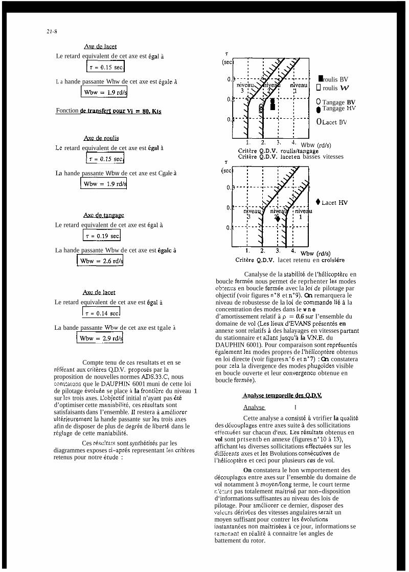
21-5
i%sxi&w Le retard equivalent de cet axe est &gal i
L a hande passante Whw de cet axe est Bgale B
Fonction d&al&rt Dour Vi = 80. Kts
Le retard equivalent de cet axe est &gal B WJ
La hande passante Wbw de cet axe est Cgale B
‘kdesuw Le retard equivalent de cet axe est tgal i
La hande passante Wbw de cet axe est &ale i
A&xkhEi Le retard equivalent de cet axe est &gal B
LzzJ La bande passante Wbw de cet axe est tgale i -4
Compte tenu de ces resultats et en se referant aux crithes Q.D.V. propods par la proposition de nouvelles normes ADS.33.C, nous constatons que le DAUPHlN 6001 muni de cette loi de pilotage evolute se place B la frontike du niveau 1 sur les trois axes. Cobjectif initial n’ayant pas i t6 d’optimiser cette maniabiliti, ces rCsultats sont satisfaisants dans I’ensemble. I1 restera i ameliorer ulterieurement la hande passante sur les trois axes afin de disposer de plus de degrks de IibertC dans le rkglage de cette maniabilitk.
diagrammes exposes ci-aprCs representant les critkres retenus pour notre etude :
Ces rksoltats sont synthktids par les
I roulis BV 0 roulis w 0 Tangage BV 0 Tangage HV
0 h c e t BV
1. 2. 3. 4. Wbw (rd/s) Critere Q.D.V. roulisltangage Critire Q.D.V. laceten basses vitesses
c
+ Lacet nv
Critire Q.D.V. lacet retenu en croisibre
Canalyse de la stabilite de I’bCliwpttke en boucle fermie nous permet de reprhenter les modes ohtenus en boucle fermte avec la loi de pilotage par ohjectif (voir figures n’8 et n-9). On remarquera le niveau de robustesse de la loi de wmmande l i t B la concentration des modes dans le w n e d’amortissement relatif B p = 0.6 sur I’ensemble du domaine de vol (Les l i e u d‘EVANS prksentts en annexe sont relatifs i des halayages en vitesses partant du stationnaire et allant jusqu’B la VN.E. du DAUPHIN 6001). Pour comparaison sont reprtsentb Cgalement les modes propres de I’h6licoptAre obtenus en loi directe (voir figures n”6 et n’7) : On constatera pour cela la divergence des modes phugoi’des visible en boucle ouverte et leur convergence obtenue en boucle fermbe).
Analvse I
Cette analyse a consist6 B vtrifier la qualit6 des dicouplages entre axes suite B des sollicitations effectuees sur chacun d‘eux. Les risultats obtenus en vol sont prtsentb en annexe (figures n’10 B 13), affichant les diverses sollicitations effectuies sur les diffkrents axes et les Bvolutions wnskutives de I’hClicopt&re et ceci pour plusieurs cas de vol.
On constatera le hon wmportement des dCcouplages entre axes sur I’ensemble du domaine de vol notamment B moyen/long terme, le court terme n’Btant pas totalement maitrise par non-disposition d‘informations suffisantes au niveau des lois de pilotage. Pour ameliorer ce dernier, disposer des valeurs dCrivtes des vitesses angulaires serait un moyen suffisant pour contrer les Cvolutions instantankes non maitrisdes i ce jour, informations se ramenant en rCalitC B connaitre les angles de battement du rotor.

21-9
Etude de la m"bht6 . . . Le deuxibme aspect de l'analyse temporelle
a consist6 B regarder les p i a en vitesses angulaires obtenus surprise d'assiette. Cette analyse a Btd faite sur les trois axes roulis/tangage/lacet. Les risultats obtenus sur ces trois axes sont presentis sur les schimas ci-dessous conformes B la proposition de norme kD.S.33.C. Les stimuli inject& sur chacun des axes ant Btd raisonnables dans cette premibe expdrimentation sans vouloir tenter d'atteindre des variations d'assiette trap rapides vues du pilote. Ces premiers rBsultats montrent que le niveau 2 de la norme ADS.33C est atteint. II restera B approfondir cette maniabilit6 par des actions de manche plus rapides en temps et plus importantes en amplitude (Les risultats visualisis dans les diagrammes de maniabilitd exposes ci-aprBs correspondent B des actions de manche de 10% B 30% sur 1 sec.)
En prenant pour definition A$k, A+pk, A$pk et qpk, ppk, Tpk :
40.1 I
I I 0. 1. 2. 3. 4.
temps (sec.)
Les risultats obtenus sur les diffdrents axes ont &t i les suivants :
Critere
ou
Pk
0 Roulis HV
h c e t BV
A+mh (ded ou A$mi,, (deg)
Critere de maniabilit6 en lacet (b.v.) et roulis (h.v.)

21-10
I FIGURES I
..................... ..................
. . . . . . . . . . . . . . . . . . . . . . . . . . . . . . . . .
I
...............................
...................... ....................... ........................ ...............................
.........................
............................
...............................
............................ ..............................
.......................
.......................
....................
. . . . . . . . . . . . . . . . . . . . . . . . . . . . . . . . . . . . . . . . . . . . . . . . . . . .
..................................
F@,. 2 : tie6 n a d m ezSh In-1
......................
.....................
........................
........................
: i ~ , / i , l l . , . i I / i l , , : , . , 6 , # :
r-,e 1 : Ro" nm.S,'7 mi", (in ~ 80 *, ................. ................
...............
. . . . . . . . . . . . . . . . . . . . . . . . . . . . . . .
...........................
. . . . . . . . . . . . . . . . . . . . . . . m " i r 6 : Yew T,m4,* w,," in-)
. . . . . . . . . . . . . . . . . . . . . . . . . . . . . .
. . . . . . . . . . . . . . . . . . . . . . . . .
. . . . . . . . . . . . . . . . . . . . . . . . . . . . . .

21-11
.-<.'E ...............
~ [j/ ...................
1: j... ......., ' I I> 88
..os ~~
m ...................
., /y, ..........
.............
4 . I ,2 ,e n n c
............ I ...... : ...... i i...
,~~ I J ................... j .s .~ .; ., /
5 s . 8 ,* , I
a,i,;,. .............. ..............
ii"C
, * / ,:,, ~ ................ .......... .t-. 1; . . .~ ....,
. s / z I' .,o
I . n n " / . Tl!L ................. ..................... I * ' , J?.s
. . . ................. i.
. . , , /I
I.,IYL
.......... ........
.E.----- :.,.: .. ;
. 12 8s . , I
I*,*"/ ,I "~ ..
..................... :
....................... .. .................... ."&ww7 I I ,I /.
I.IIIYL
i" ..............
. I 12 8.
... '"i'!". ... : ~ : ...... .................... Bl?#
..................
, a ,I I S .,o
7,"s
:-
I , ln"* .l"l . 8 19 I ( ,/ IO 2 ,
m,f . : .................. . ~ , , ~ , ~ . . . .I?*
i .... : .......... ........... . . . . . . . E : . : ",; ....... I . <.. ....... ........... . . . . .
1 . ; ,I 2 .1 ,* /. .a I '
l.IIIYL il/l
~. '"..&.*? ............ .............. ...................... ...................... . ~ . ................ . . 1.. . . . . . . . . . . . :
. * S I - . ( ' ' . 8 I 2 1' 1111
,.E. ............... .......................
.......... ,.. ............,...... : . . . . . . .
, . , , /mr
. e , I Y
.,o -I.&. ..... ~ .....
~~~~
....................... ~~~ ............ , $ ...................... t ' .
,,I ............ [ : : ; ; ....................
.,* L. < I ,I ~,f;;.:.I /I"r
n L:: ..... ~
................. t . ~
1 . : .... ; ........... .'' *& i l"C
c * c LO" i" "5 ............... .................. g ' c . , . . . . . . :*;.4L. I ..... : .... ~ y '..'
,.p ............... " E ; ,'J" l i *> :;"e $6 I # 2.
lmr ,.p ............ ......... , .................... .......
........
I. 20 11 illl
,' 2s 1. T 1 1 1
....................... ~ , , " , ............... ~. ......................... ....................
jo I , . ! ; ! .: ................. alri " . . . ....... .......... .......... .... . . . . . . . . "
/I 20 1. .s I
i:.r /,"/ /r 10
.[k: :-
t ' ' ' """ ' '
f 'i . . . . . ~ . .
,, p?'.......... . . .
. ~ , , & >o 9.
""i
L . . . . . . . . . .
1 .; . . j .. .,..
/I * m x / .Y
i,,.:


22-1
Integration of Handling Quality Aspects into the Aerodynamic Design of Modern Unstable Fighters
Peter Mansold Dornier Luftfihrt GmbH
Federal Republic of Germany P.O. Box. 13 03
7990 Friedrichshafen 1
1. Summary
The principal flightmechanical duties during the several development phases of any air- craft have always been concerned with the vital aspects of "Flying Qualities' i n a general sense. .The provision of Stability and Control, Maneuverability. sufficient trim capabilities and acceptable control forces throughout the usable flight envelope has been forming the solid bases for the design and sizing of horizontal and vertical tails, ailerons, rudder and elevator power. For stable unaugmented fighter aircraft, where pilot inputs are almost directly linked with the movement of a (single) control surface, the criteria. which lead to a proper sizing of the stabilizers and controllers. can be calculated from dynamic and static Handling Quality requirements of MIL-Spec without detour. - The flightmechanical design of highly augmented aircraft with unstable basic characteristics however is no longer straight forward. The realization of superior Hand- ling Qualities, Maneuverability and Agility up to h i g h angles of attack is mixed with other design goals like optimum performance and/or the observance of structural limita- tions. The task to integrate the requirements from different disciplines is focused on a single "Black Box". that is to say on the llight Control Lystem. The various subtasks which have to be managed by the FCS may roughly be split into two parts: One is related to the "Control of Steady-State and Instantaneous Maneuvers". which were formerly managed by the pilot himself with his direct links to the control surfaces of the air- craft. The other part covers the vital aspects of "Stabilization of the Aircraft" which for conventional unaugmented configurations used to be guaranteed by the stabilizing surfaces without artificial help. Now both tasks have to be settled via the Flight Con- trol Computers within the narrow frame of realistic hardware and the necessary scheduling of aerodynamic controls required for increased performance and load allevia- tion. In order to maintain the chance to fulfil the challenging requirements for optimum per- formance a superior Handling Qualities it is necessary to define a set of flight- mechanical criteria which translate the most important aspects derived from Handling, Agility and Safety points of view into aerodynamic requirements. These criteria have to generate the necessary l i n k between the disciplines Control Law Design, Flightmechancis and Aerodynamcis within the Pre-Development phases of modern fighter aircraft. The paper in hand illustrates that the "Time to Double Amplitude T," of the basic air- craft may act as key characteristic which describes the problems associated with stabi- lization in Pitch. If related to the available Pitch Control Power and Control Power Buildup Rate limits for "Minimum permissible T," may be established. These limits are easily convertible into aerodynamic requirements and therefore applicable within the early design phases of modern fighter design. - At high angles of attack additional pitch down control power is needed to cancel the effects of inertial coupling due to roll maneuvers. The acceleration to be provided is dependent on angle of attack and attainable rollrate around the velocitv vector. As far as the lateralldirectional axes"are concerned the FCS is mainly used for stabil- ity augmentation and for optimum coordination of the control surfaces. Therefore the flightmechanical design still aims at stable basic characteristics. To achieve this de- sign goal C d is very often the only parameter which is used for optimization during windtunnel ~ k s ~ ? n g . The discussion at the end of section 4 shows that especially at hig h angles of attack stable static derivatives are not sufficient to maintain dynamic sta- bility. The dynamic derivatives "roll and yaw damping" have to be considered as well and at least negative C characteristics. - Agility around the velocity vector at higher angles of attack is mainly a matter of roll and yaw control power. As angle of attack increases the rudder effectiveness gets more and more important: if bank angle requirements deducted from MIL-Spec shall be performed i n a well coordinated manner at high angles of attack. the body fixed yaw potential has to exceed the roll control power according to the inertia ratio (i /i ) z multiplied by tga. Section o f this paper presents some pecularities of configurations and configuration details if the criteria discussed before are considered. Among other aspects it is shown that the (in-) stability characteristics of a Canard confiquration are more comolex com-
'8 and Cnr's are necessary to complete the listing of desired
pared to those of an Aft-tail concept. This will require considerably more effort with respect to the optimization work in windtunnel and may lead to more problems during Con- trol Law design.

22-2
2. F l i g h t m e c h a n c i a l D e s i g n o f Unaugmented S t a b l e C o n f i g u r a t i o n s
Ever s i n c e a i r c r a f t have been d e s i g n e d and b u i l t t h e o r i g i n a l f l i g h t m e c h a n i c a l t a s k w i t h i n t h e s e v e r a l d e v e l o p m e n t phases has been t o p r o v i d e good and s a f e F l y i n g Q u a l - i t i e s . N e c e s s a r y m a r g i n s f o r s t a t i c and dynamic s t a b i l i t y , r e q u i r e d c o n t r o l power i n c o n n e c t i o n w i t h a c c e p t a b l e f o r c e s and s u f f i c i e n t t r i m c a p a b i l i t i e s i n a l l axes have a l - ways been r e g a r d e d as key c h a r a c t e r i s t i c s f r o m w h i c h c r i t e r i a f o r a p r o p e r s i z i n g o f s t a b i l i z e r s and c o n t r o l s u r f a c e s c o u l d be d e r i v e d . - F o r s t a b l e unaugmented f i g h t e r s o f t h e p a s t a i l e r o n s , r u d d e r and e l e v a t o r were a l m o s t d i r e c t l y l i n k e d t o t h e p i l o t b y c a b l e s , r o d s and l e v e r s v i a s t i c k and p e d a l s i n t h e c a c k p i t . So r i g h t f r o m t h e s t a r t o f t h e d e s i g n t h e t r a n s f e r f u n c t i o n s " A i r c r a f t B e h a v i o u r due t o P i l o t or G u s t I n p u t " and t h e c h a r a c t e r i s t i c e q u a t i o n s o f t h e t o t a l s y s t e m w e r e a n a l y t i c a l l y d e f i n e d . The d e s i r e d s t a t i c and dynamic f e a t u r e s o f t h e a i r c r a f t c o u l d d i r e c t l y be r e l a t e d t o t h e s i z e and p o s i t i o n i n g o f h o r i z o n t a l and v e r t i c a l s t a b i l i z e r s and t h e s e v e r a l c o n t r o l s u r - f a c e s . W i t h r e s p e c t t o p i t c h a x i s m o s t o f t h e a p p l i c a b l e c r i t e r i a w h i c h c a n b e d e d u c t e d f r o m t h e H a n d l i n g Q u a l i t i e s document M I L - F- 8 7 8 5 w i t h o u t d e t o u r , t u r n o u t t o f o r m c o r n e r s t o n e s f o r t h e d e s i g n f o r t h e h o r i z o n t a l t a i l ( s t a b i l i z e r a n d e l e v a t o r ) . f o r example summar izes dynamic r e q u i r e m e n t s f o r t h e s h o r t p e r i o d and p h u g o i d c h a r a c t e r i s t i c s and D r e s e n t s t h e r e l e v a n t e q u a t i o n s w h i c h d e f i n e t h e r e l a t i o n s t o t h e a e r o d y n a m i c d e r i - v a t i v e s . P a r a m e t r i c v a r i a t i o n s i n s i z e and p o s i t i o n o f t h e h o r i z o n t a l t a i l l e a d t o c o n- t i n u o u s p a r a m e t e r changes and i f t h e min imum and maximum l i m i t s f r o m MIL- Spec a r e c o n- s i d e r e d , p e r m i s s i b l e f o r w a r d and a f t c e n t r e - o f - g r a v i t y p o s i t i o n s due t o c r i t e r i a f o r dynamic s t a b i l i t y c a n be e v a l u a t e d as a f u n c t i o n o f t a i l a r e a o r v o l u m e . T o g e t h e r w i t h b o u n d a r i e s d e r i v e d f r o m o t h e r r e q u i r y e n t s l i k e "Nose Wheel L i f t - o f f a t a g i v e n a i r s p e e d ( 1 . 0 V,)". "Min imum S t a t i c S t a b i l i t y , " T r i m i n s e v e r a l f l i g h t c o n d i t i o n s " , e t c . D e s i g n d iag rams l i k e t h e example g i v e n i n can b e p l o t t e d and so t h e m a i n g o a l o f H o r i - z o n t a l - T a i l - D e s i g n . t o d e f i n e and open a p e r m i s s i b l e f l i g h t m e c h a n i c a l c .g . r a n g e . may b e a c h i e v e d s t r a i g h t away. The same p r i n c i p l e p r o c e d u r e i s a p p l i c a b l e i n l a t e r a l l d i r e c t i o n a l a x e s a s shown i n & 3 and 4 . The c o r r e l a t i o n s b e t w e e n t h e H a n d l i n g Q u a l i t y R e q u i r e m e n t s f o r D u t c h R o l l , S p i r a l - , R o l l mode, e t c . and t h e a e r o d y n a m i c d e r i v a t i v e s a r e a g a i n a n a l y t i c a l l y l i n k e d b y t h e c h a r a c t e r i s t i c e q u a t i o n s and b y r e l a t i v e l y s i m p l e t r a n s f e r f u n c t i o n s . So p a r t i - c u l a r v a r i a t i o n s , o f c o n f i g u r a t i o n d e t a i l s , as f o r examp le v e r t i c a l t a i l s i z e a n d l o r p o s i t i o n . w i l l d i r e c t l y l e a d t o changes i n t h e d y n a m i c b e h a v i o u r o f t h e a i r c r a f t and w i t h t h e H a n d l i n g Q u a l i t y R e q u i r e m e n t s u n d e r c o n s i d e r a t i o n s t a b i l i z e r . r u d d e r and a i l e r - ons c a n b e d e f i n e d .
3 . D e s i g n C r i t e r i a f o r modern C o n f i g u r a t i o n s w i t h U n s t a b l e C h a r a c t e r i s t i c s i n P i t c h
The f l i g h t m e c h a n i c a l d e s i g n o f h i g h l y augmented a i r c r a f t w i t h u n s t a b l e b a s i c c h a r a c t e - r i s t i c s i s n o t l o n g e r s t r a i g h t f o r w a r d . In a d d i t i o n t o h a n d l i n g q u a l i t y a s p e c t s , m a n e u v e r a b i l i t y and a g i l i t y w h i c h have t o b e p r o v i d e d up t o h i g h a n g l e s o f a t t a c k , f u r t h e r d e s i g n g o a l s l i k e o p t i m u m p o i n t p e r f o r m a n c e . o b s e r v a n c e o f s t r u c t u r a l l i m i t s and c a r e f r e e h a n d l i n g has t o b e i n t e g r a t e d i n t o t h e f l i g h t m e c h a n i c a l c o n s i d e r a t i o n s . The t a s k t o i n t e g r a t e t h e r e q u i r e m e n t s f rom d i f f e r e n t d i s c i p l i n e s i s t r a n s f e r r e d t o a s i n g l e n B l a c k Box" . t h a t i s t o say on t h e l l i g h t C o n t r o l L y s t e m . The v a r i o u s s u b t a s k s , w h i c h have t o b e managed b y t h e F C S may r o u g h l y b e s p l i t i n t o t w o p a r t s : One i s r e l a t e d t o t h e c o n t r o l o f s t e a d y - s t a t e and i n s t a n t a n e o u s maneuvers w h i c h i n c l u d e s s u r f a c e s c h e d u l i n g f o r d i f f e r e n t modes, op t imum c o o r d i n a t i o n o f t h e a v a i l a b l e c o n t r o l l e r s and t h e s u r v e i l - l a n c e o f s t r u c t u r a l and p h y s i o l o g i c a l l i m i t a t i o n s . The o t h e r p a r t c o v e r s t h e v i t a l a s p e c t s o f s t a b i l i z a t i o n t h r o u g h o u t t h e p e r m i s s i b l e f l i g h t e n v e l o p e . - So t h e g r o w i n g u s e o f t h e p o s s i b i l i t i e s o f modern f l i g h t c o n t r o l sys tems h a s p a r t l y r e l i e v e d b o t h . t h e f i x e d s t a b i l i z e r s o f t h e a i r c r a f t f rom t h e i r t a s k t o p r o v i d e s t a b i l i t y and t h e p i l o t f r o m h i s r e s p o n s i b i l i t y t o o p t i m i z e t h e manoeuvres o f t h e a i r c r a f t . O n t h e o t h e r hand t h e r e q u i r e m e n t s f o r c o n t r o l p o t e n t i a l i n a l l a x e s have t o b e i n c r e a s e d and i t i s n e c e s- s a r y t o r e l a t e t h e a v a i l a b l e c o n t r o l power t o t h e t o l e r a b l e b a s i c ( i n - ) s t a b i l i t y c h a r a c - t e r i s t i c s o f t h e a i r c r a f t . - The summary i n shows i n w h i c h d i r e c t i o n t h e f l i g h t - m e c h a n i c a l d e s i g n a s p e c t s have t o b e changed if s t a b i l i t y a u g m e n t a t i o n or a r t i f i c i a l s t a b i l i z a t i o n i s i n t r o d u c e d : S u f f i c i e n t s t a t i c and dynamic s t a b i l i t y and, a t h i g h a n g l e s o f a t t a c k . a c c e p t a b l e d e p a r t u r e c h a r a c t e r i s t i c s have t o b e r e p l a c e d b y t h e l i m i t a t i o n o f b a s i c dynamic i n s t a b i l i t i e s . The p r o v i s i o n o f c o n t r o l p o t e n t i a l f o r maneuvers and t r i m has t o be supp lemented b y a d d i t i o n a l power f o r s t a b i l i z a t i o n p u r p o s e s and if r e q u i r e d f o r e x o t i c modes. A c c e p t a b l e s t i c k and p e d a l f o r c e s need no l o n g e r b e t a k e n i n t o a c c o u n t w i t h i n e a r l y d e s i g n p h a s e s . They c a n b e t r e a t e d s e p a r a t e l y and o p t i m i z e d a r t i f i c i a l l y i n c o m b i n a t i o n w i t h t h e c o c k p i t d e s i g n . - So. i n c o n t r a r y t o unaugmented a i r c r a f t f o r w h i c h s i z i n g o f t h e a e r o d y n a m i c s u r f a c e s c o u l d d i r e c t l y b e done b y c o n s i d e r a t i o n o f L e v e l - 1 H a n d l i n g Q u a l i t y r e q u i r e m e n t s , i t i s now n e c e s s a r y t o d e s i g n f o r t h e c a p a b i l i t i e s o f t h e F C S w h i c h w i l l be d e v e l o p e d i n a l a t e r phase t o p r o v i d e t h e d e s i r e d h a n d l i n g . H o r i z o n - t a l - / v e r t i c a l t a i l s . a i l e r o n s and r u d d e r c a n no l o n g e r b e t r e a t e d as c o m p l e t l y s e p e r a t e segments. They have t o be c o n s i d e r e d as m u l t i - f u n c t i o n a l , i n t e g r a l e s t a b i l i t y and c o n- t r o l u n i t s w h i c h a r e l i n k e d v i a F C S f o r o p t i m i z e d management o f t r i m , maneuver and l i m i t a t i o n t a s k s . A s t h e c a p a b i l i t i e s o f any e x i s t i n g and f u t u r e F l i g h t C o n t r o l S y s t e m w i l l b e r e s t r i c t e d b y u n a v o i d a b l e t e c h n i c a l i n a d e q u a c i e s o f r e a l i s t i c h a r d - and s o f t w a r e , i t i s n e c e s s a r y t o d e s i g n f o r b a s i c unaugmented c h a r a c t e r i s t i c s w h i c h c a n b e h a n d l e d b y t h e FCS e v e n u n d e r a d v e r s e c o n d i t i o n s . T h e r e f o r e r e q u i r e m e n t s w h i c h i n c l u d e t h e a s p e c t s o f c o n t r o l l a w d e s i g n have t o b e d e v e l o p p e d and p r e p a r e d f o r u s e i n t h e a e r o d y n a m i c o p t i m i z a t i o n P r o c e s s i n o r d e r t o r e s t o r e t h e e a r l y l i n k b e t w e e n H a n d l i n g and A e r o d y n a m i c s w h i c h h a s been b r o k e n b y t h e F C S .

22-3
As complete design loops are always assigned by the four parameters "Mass", "Perform- ance", "Cost" and "Risk", the idea of "Performance" has to be revised by including re- quirements from agility, handling and ride quality and by introducing essential aspects from safety point of view. - As demonstrated in section 4.1 and 4.2. where the develop- ment of possible criteria for maximum instability i n pitch axis are desribed, simplified assumptions are necessary to fix the corner stones. It has to be kept i n mind that any criterion must be convertible into aerodynamic characteristics to enable the design team
... to define feasible aerodynamic instability levels,
... to fix trim scheduies which leave sufficient control power in pitch, roll and yaw, ... to optimize the basic aerodynamic characteristics i n windtunnel ... to size and position the control surfaces and stabilizers. 4. Development of Specific Criteria for Modern Fighter Configurations
. . . .
The road which has to be taken i n order to develop a suitable set of criteria for maximum instability and necessary control power in pitch will start with the definition Of aerodynamic and flightmechanical key characteristics, which can be analysed and systematically varied within early design phases. Via the introduction of realistic. principles of control law design and under the consideration of handling quality and safety aspects limits for maximum dynamic instability levels, which are easily transfer- able into aerodynamic characteristics, will be evaluated.
4.1 Key Characteristics for Unstable Design in Pitch
From the very beginning all the design phases of "New Generation" fighter aircraft are dominated by the attempt to find an optimum balanced concept within the frame of maximum performance, defined mass figures and limited costs. Especially the field o f performance encompasses aspects on at least three planes, which are defined by the headlines "Mis- sion-, Point- and Manoeuvre Performancell. Requirements derived from these different items are often rather contradlcting. A suitable tool to overcome some of the contradicting requirements is the introduction of Unstable Design i n pitch which has remarkable effects on performance as demonstrated in Fig. 6: The trim characteriqtics of the sample aircraft (i.e. a tailless configura- tion; the principles apply for any tailed configuration as well) show that the stable version will have negative slopes in the pitching moment-lift diagram for controls fixed. Therefore it is necessary to trim the configuration with negative (i.e. upwards) flap deflections. An unstable design with the centre of gravity aft of the aerodynamic centre, has a positive aC lacL- (and CmR) slope and therefore requires positive (i.e. downwards) flap settings 'Prom trim. The sketch of the polars on the righthand side of
Typical supersonic fighter winus are characterized by a relatively small aspect ratio and high leading-edge sweep. Especially for those the induced drag for a given lift coefficient is much smaller with positive than negative flap deflections. This leads on one hand to a remarkable reduction in overall drag at a desired turn rate and on the other to much larger trimmed maximum lift coefficient. If the full technically feasible potential of unstable design is used, then relative to a conventionally stable aircraft maximum lift can be increased by roughly 25 % and induced drag at a typical lift coef- ficient for manoeuvre (say C 0 .7 ) can be reduced by about 20 %. This means that unstable con\igurations when designed for the same performance require- ments and under the same flight mechanical constraints, will be remarkably smaller than the i r s tab 1 e But it has to be kept in mind that, a pure optimization for maximum point performance (i.e. sustained and instantaneous turn rates) which requires maximum lift or minimum drag respectively may not be advantageous for a desired superior agil,ity, because the preloaded aerodynamic controls do not leave enough power to initiate and stop manoeuvres in a way which lead to sufficient handling qualities. A qualified parameter which indicates the potential for drag reduction and higher maximum lift is the static instability level (Static Margin).
shows the resulting beneficial effect on trimmed performance data:
broth e r s 'I .
ac C xac - xc4 S M = - f l = - P = ~- t L R C
If only aerodynamic aspects had to be taken into account, it would make sense to in- crease the negative static margin to a point where the resulting trimmed flap schedule leads to optimum drag polars. From the flight mechanical point of view a reasonable interpretation of SM is only pos- sible in linear areas at smailer angles of attack. It defines nothing else than the lever arm of aerodynamic forces and is only useful for the flight mechanical design o f unaugmented aircraft, which have to be equipped with a certain margin of static stabil- ity. AS maximum lift is approached ( C - 0) the physical evidence of SM (SM + m ) is lost. - More definite parameters which'can be interpreted at high an;les o f attack as well, are summarized i n Fig. 7. The "Aerodynamic Key Characteristics typical C, versus R plots (CoePficients and derivatives) with curves for "zero" and "full nose down" controls point out that one limiting factor for unstable design will be given by the definition of a necessary pitch recovery moment which above all has to guarantee a safe return from high angle- of-attack manoeuvres. The basic design in- stabilit covering only performance aspects, wili usually be chosen at low and medium angles-07-attack. This instability has to be checked against the capabilities of the flight control system. The same applies to the allowable pitch-up at higher angles-of- attack i n trimmed conditions.
in terms of

22-4
U n f o r t u n a t e l y n e i t h e r t h e s t a t i c i n s t a b i l i t y SM n o r t h e p i t c h i n g moment d e r i v a t i v a Cma a r e s u f f i c i e n t t o d e s c r i b e t h e dynamic p r o b l e m s a s s o c i a t e d w i t h t h e s t a b i l i z a t i o n o f u n s t a b l e c o n f i g u r a t i o n s . A c c o r d i n g t o t h e e q u a t i o n s o f f i g . 1 and 15 t h e h i g h l y d y n a m i c s h o r t p e r i o d m o t i o n O f any a i r c r a f t i s d e p e n d e n t o n much more f a c t o r s as f o r e x a m p l e moment o f i n e r t i a , damping d e r i v a t i v e s , w i n g a r e a , mean a e r o d y n a m i c c h o r d a n d d y n a m i c p r e s s u r e . A l l t h e s e p a r a m e t e r s c o n t r i b u t e ' t o a " T i m e t o D o u b l e A m p l i t u d e " T, , d u r i n g w h i c h . w i t h c o n t r o l s f i x e d t h e a i r c r a f t w i l l d o u b l e a d i s t o r t i o n i n a n g l e o f a t t a c k . A S t h e s i m p l i f i e d s c h e m a t i c g r a p h s o f F i g . 8 ( p i t c h i n g moment v e r s u s t i m e ) show, i t i s now e s s e n t i a l t o c o u n t e r a c t t h i s a p e r i o d i c movement b y an a p p r o p r i a t e c o n t r o l i n p u t . Build- up r a t e M and m a g n i t u d e M o f t h e s t a b i l i z i n g moment m u s t be l a r g e enough t o s t o p and r e v e r s e t h e s i g n o f p i t c h a c c e l e r a t i o n s o t h a t t h e a i r c r a f t r e t u r n s t o i t s O r i g i n a l , t r i m m e d c o n d i t i o n . The T i m e O e l a y T b e t w e e n d i s t u r b a n c e i n p u t a n d s t a b i l i z i n g c o n t r o l r e a c t i o n can b e i d e n t i f i e d as a f u r t h e r i m p o r t a n t p a r a m e t e r w h i c h w i l l i n c r e a s e t h e p r o b l e m s o f c o n t r o l l a w d e s i g n i f i t e x c e e d s a c e r t a i n p e r c e n t a g e o f T,. So t h e k e y c h a r a c t e r i s t i c s f o r u n s t a b l e d e s i g n i n p i t c h may b e summar i zed . as done i n F i g . 9 :
- S t a t i c M a r g i n S M o r C, f o r t h e a e r o d y n a m i c i s t s - T ime t o D o u b l e A m p l i t u l e T,, Maximum P i t c h C o n t r o l Moment M and B u i l d - u p R a t e 6l,
T i m e O e l a y T t f o r t h e c o n t r o l l a w d e s i g n e r s and f l i g h t m e c h a n i c s p e o p l e
I n p r a c t i c e i t i s n e c e s s a r y t h a t c o n t r o l l a w p e o p l e and a e r o d y n a m i c i s t s c a n c o m m u n i c a t e and u n d e r s t a n d each o t h e r i n o r d e r t o end up w i t h a w e l l b a l a n c e d d e s i g n . So o n c e dynamic l i m i t s f o r T, h a v e been i d e n t i f i e d t h e y h a v e t o b e t r a n s l a t e d i n t o a e r o d y n a m i c c h a r a c t e r i s t i c s C,,, C,, o r SM. A good a p p r o x i m a t i o n f o r t h e t r a n s c e n d e n t a l r e l a t i o n b e t w e e n T, and t h e " a e r 6 h n a m i c d e r i v a t i v e s i s p r e s e n t e d i n F i g . 15 . - F o r t h e c o n t r o l moments t h e s i m p l e a l g e b r a i c e q u a t i o n s
"ax Mmax = k h C . + v z . s . c
- Mmax = i cmq . imax . 4 V ' . s . c
may b e u s e d . The amount o f p i t c h c o n t r o l a u t h o r i t y M c a n b e r e g a r d e d as t h e sum o f moments w h i c h i s a v a i l a b l e f r o m a l l r e l i a b l e . p r i m a r y c o n t r o l l e r s . F o r b o t h . b u i l d - u p r a t e s ri and a u t h o r i t y M, l i m i t a t i o n s due t o h i n g e moments and l o a d r e s t r i c t i o n s have t o b e c o n s i d e r e d .
4.2 Deve lopment o f a C r i t e r i o n f o r Maximum Dynamic I n s t a b i l i t y i n P i t c h
The s u m m a r i z i n g d i s c u s s i o n a b o u t t h e k e y c h a r a c t e r i s t i c s o f u n s t a b l e d e s i g n i n p i t c h f r o m s e c t i o n 4 . 1 has c o n f i r m e d t h a t i t m i g h t b e p o s s i b l e a n d h e l p f u l t o d e v e l o p r e l a - t i o n s h i p s b e t w e e n maximum p e r m i s s i b l e d y n a m i c i n s t a b i l i t y T, and r e q u i r e d c o n t r o l a u t h o r i t y M and b u i l d - u p r a t e FI. I n o r d e r t o t a k e c o n c r e t e s t e p s t o w a r d s s u c h a c r i t e r - i o n i t i s now n e c e s s a r y t o b o t h e r h i s h e a d w i t h p a r a m e t r i c a t t e m p t s t o o p t i m i z e c o n t r o l l a w p a r a m e t e r s f o r d i f f e r e n t dynamic i n s t a b i l i t y l e v e l s o f modern f i g h t e r c o n f i g u r a - t i o n s . The p r o c e d u r e has t o be done u n d e r r e a l i s t i c ( b u t s i m p l i f i e d ) a s s u m p t i o n s i n c l u d i n g e s s e n t i a l r e q u i r e m e n t s and methods w h i c h a r e n o r m a l l y u s e d w i t h i n a t h o r o u g h d e s i g n o f a F l i g h t C o n t r o l System:
- r e a l i 5 t i c c o n t r o l l a w s t r u c t u r e ~. .~~~~ - r e a l i s t i c h a r d w a r e a s s u m p t i o n s - o p t i m i z a t i o n o f C o n t r o l Law p a r a m e t e r s w i t h r e s p e c t t o h a n d l i n g a n d r i d e q u a l i t i e s - C o n s i d e r a t i o n o f s a f e t y m a r g i n s i n c o n t r o l l a w . d e s i g n - V a r i a t i o n o f " T i m e t o D o u b l e " and C o n t r o l Moment c h a r a c t e r i s t i c s b y r e a l i s t i c ,
r e l e v a n t a e r o d y n a m i c d a t a
C o n t r o l taw S t r u c t u r e and A i r c r a f t Model
To c o r r e c t t h e s h o r t p e r i o d d i v e r g e n c e o f an a i r c r a f t w i t h b a s i c a l l y u n s t a b l e c h a r a c - t e r i s t i c s i n p i t c h and a t t h e same t i m e , s i g n i f i c a n t l y i m p r o v e t h e a i r c r a f t f l y i n g q u a l - i t i e s a v a r i e t y o f F l i g h t C o n t r o l Sys tems c a n be c o n s t r u c t e d . The s y s t e m f i n a l l y s e l e c t - e d w i l l depend o n many c o n s i d e r a t i o n s as f o r e x a m p l e p r o b l e m s o f i n s t r u m e n t a t i o n a n d s e n s i n g i n c l u d i n g b i a s e s and s e n s o r e x c i t a t i o n , c o n t r o l Sys tem c o m p e n s a t i o n n e e d e d f o r f l i g h t c o n d i t i o n changes , n o n l i n e a r i t i e s , s c h e d u l i n g , b o u n d a r y c o n t r o l e t c . To p e r m i t t h e d e v e l o p m e n t o f a c r i t e r i o n f o r maximum d y n a m i c i n s t a b i l i t y , a t y p i c a l e x a m p l e o f a P i t c h r a t e Command System. w h i c h c o u l d b e r e g a r d e d as t h e e s s e n c e o f an F C S f o r modern f i g h t e r a i r c r a f t , has been c h o s e n [ L i t . 11. The f l l g h t c o n t r o l S y s t e m s e l e c t e d i s shown i n F i g . 1 0 . T h i s s y s t e m p e r f o r m s s i x m a i n f u n c t i o n s as f o l l o w s :
- C r e a t e s a h i g h d e g r e e o f e f f e c t i v e s t a t i c s t a b i l i t y - - G i v e s s u f f i c i e n t damp ing o f t h e p h u g o i d by I n t e g r a l q - f e e d b a c k (RQI) - P r n v i d ~ c n i t r h r a t e / a t t i t u d P h o l d o l a t f o r m
P o s i t i o n s t h e s h o r t p e r i o d r o o t s v i a t h e f e f . d b a c k s RA and R Q
~ ~~~~ ~ - -
Shapes T e 2 a c c o r d i n g t o t h e p i t c h ;ate f i l t e r R e g u l a t e s a g a i n s t e x t e r n a l d i s t u r b a n c e s w i t h emphas is o n P i t c h a t t i t u d e m a i n t a n c e

22-5
To account for the time delay due to sensors, computers, filters etc. a representative equivalent value of 0.02 s has been added to the system by Pad6 approximation. The overall model of the "Augmented Aircraft" which was finally used to develop the criterion is shown on the righthand diagram of Fig. 10. Together with the basic aircraft ( 4 . order), the control system incl. Pade approximation (4. Order) and the actuator dynamics for canard, flaps and aft tail (1. Order, TM = 0.05 s ) the overall model added up to a system of 9. Order.
Handling Qualities Requirements
The discussions within AGARD Working Group 17 have lead to the conclusion that many existing criteria in the frequency and time domain are qualified to optimize and assess the handling qualities of augmented aircraft. It has been made clear that a single criterion will in anv case not be sufficient. Therefore it is necessary to establish a set of criteria which is individually tuned for the aircraft under coniideration. For our purposes the criteria of the Low Order Equivalent system (MIL-F-8785) have been applied as design goal for the optimization of the Control Law parameters discussed above. The requirements for the short period motion are summarized in three subcriteria, as there are:
- Minimum and maximum damping - Short period frequency characterized by the CAP-parameter - Time constant Te2 according to wasp
Roughly Spoken the CAP parameter describes the aircraft behaviour after a step input in pitch stick in terms of required 'g'-onset A R e q and steady state load factor (Fig. 11). Good handling qualities are characterized by a reasonable time after which the steady state load factor has to be achieved. Furthermore no excessive overshoots or oscilla- tions are allowed which leads to the design goals selected for the (CAT.A) flight phases of our study:
- - -
CAP = 1 . 0 4 w O s ,
Short period damling ?. = 0.75 T82 according to wasp (wasp . Te2 = 3 . 6 )
To limit the actuator activity it was necessary to add the requirement that the damping of all complex roots should be greater than 0.75. - In addition it was required to take care of the gust responses during the optimization of control parameters in a way that the gust response should not be significantly worse than that of a conventional air- craft.
Safety Aspects, Robustness of the FCS
Experience in practical engineering has always proven that differences between the best models and reality (i.e. the aircraft in operation) cannot be avoided. Uncertainties with respect to data and model accuracy have to be taken into account and a certain robustness of the FCS is required to maintain stability and control even if the aero- dynamic efficiencies for example, deviate considerably from the values predicted i n w i n d t i i n n e l . . . . . - - - . . . . - . . A qualified method to assess the robustness and safety of the augmented aircraft system is based on the Nyquist criterion (see Fig. 12) which predicts the stability of the closed loop by analysis of the frequency response of the open control loop. According to this criterion the closed control loop is stable, if for a gain of 0 dB of the open loop the phase shift is less than -180". The distance from this stability limit may be regarded as a measure for the quality of stabilization. So the distance of the phase from -180" at a gain of 0 dB is called "Phase margin" whereas the "Gain Margin" is defined as difference in gain to 0 dB at -180". - A gain margin of - 6 dB and a phase margin of 45" is usually considered to be adequate. For a basically unstable system two stability limits have to be taken into account as pointed out in Fig. 12. If the overall gain is too high the control system is suspicious to turn unstable again while for too low gains the task of stabilization may fail at all. Therefore in addition to the required gain margin of -6 d B a further margin of t6 d B has to be introduced. - Practical application has shown that for modern fighters a phase a -145" at t3 dB (35" margin) is more appropriate which finally leads to the trapezoidal area o f "Insufficient Stability Margins" shown i n Fig. 12. - The considera- tion of this requirement therefore forms an essential assessment tool within the control law design for modern fighters.
Analysis of typical Aerodynamic Data for modern Fighters
o f the design teams has been that an unstable design together with a horizontal tail (aft-tail. vector nozzle, canard) is needed to achieve a high performance standard and agi 1 i ty.

22-6
The t a b l e o f F i g . 1 4 summar i zes t y p i c a l d a t a f o r t h e s e c o n f i g u r a t i o n s i n c l u d i n g geome- t r i c a l , a e r o d y n a m i c a l and m a s s l i n e r t i a c h a r a c t e r i s t i c s , w h i c h s h o u l d be v a l i d f o r a p r e - l i m i n a r y dynamic a n a l y s i s i n t h e s u b s o n i c r e g i o n up t o maximum l i f t . - The f i r s t l i n e o f t h e t a b l e shows t h a t t h e d e s i g n i n s t a b i l i t i e s ( s t a t i c m a r g i n S M ) o f t h e t a i l e d a i r c r a f t a r e c o n s i d e r a b l y l a r g e r t h a n t h a t o f t h e t a i l l e s s c o n f i g u r a t i o n . T h i s i s due t o r e q u i r e - m e n t s c o n c e r n i n g t h e p i t c h r e c o v e r y m a r g i n ( s e c t i o n 4 . 3 ) w h i c h f o r t a i l l e s s c o n c e p t i s h a r d t o a c h i e v e t o g e t h e r w i t h an u n s t a b l e d e s i g n . I n o r d e r t o g e t some d e e p e r i n s i g h t i n t o t h e dynamic e f f e c t s o f t h e d a t a p r e s e n t e d , i t i s n e c e s s a r y t o have a l o o k a t t h e e q u a t i o n s w h i c h d e t e r m i n e t h e l o c a t i o n o f t h e s h o r t p e r i o d r o o t s i n t h e c o m p l e x p l a n e and t h e k e y p a r a m e t e r T,. F i g . 1 5 i l l u s t r a t e s t h a t t h e p o s i t i o n s o f t h e t w o u n s t a b l e r o o t s a r e d e f i n e d b y t w o m a j o r p a r t s : ( L . w , ) s e t t l e s t h e l i n e o f symmetry f r o m w h i c h t h e t w o a p e r i o d i c r o o t s 8, and 8, w i l l s e p e r a t e o n c e s t a t i c s t a b i l i t y i s l o s t . T h i s f i r s t p a r t i s i n f l u e n c e d by t h e l i f t c u r v e s l o p e C L a a n d b y t h e d y n a m i c d e r i v a t i v e s b u t i t i s JOJ d e p e n d e n t o n t h e d e s i g n i n s t a b i l i t y . The s h i f t o f t h e r o o t s on t h e Real A x i s i s d o m i n a t e d b y t h e t e r m w n 2 and t h e r e f o r e d i - r e c t l y r e l a t e d t o Cma. If t h e d a t a f rom F i g . 1 4 a r e a n a l y s e d b y t h e dynamic e q u a t i o n s o f F i g . 15 i t g e t s e v i d e n t t h a t t h e r e l a t i v e l y h i q h mass d e n s i t v o f t h e c o n f i o u r a t i o n s u , > 70 (50 f o r t a i l l e s s a i r c r a f t ) d e m i n i s h e s i h e i n f l u e n c e i f t h p d v n a m i c - a e r o d v n a m i k d e r i v a t i v p s and .. ~~ .. ~ ~
~ ~" t h e l i f t c u r v e s l o p e ~ c o n s i d e r a b l y . The l i n e o f symmet ry (L.w,) i; t h e r e i o r e s i t u a t e d b e t w e e n - 0 .2 f o r s m a l l s u b s o n i c Machnumbers n e a r maximum l i f t a n d - 2.8 f o r h i g h s u b s o n i c speeds a t l o w a n g l e s o f a t t a c k . These v a l u e s a r e v a l i d f o r t h e w h o l e d a t a b a n d w i d t h ; t h e d i f f e r e n c e s be tween t h e t h r e e t a i l c o n c e p t s a r e n e g l i g i b l e . The t e r m w a 2 i s c l e a r l y d o m i n a t e d b y C c(; as a b o v e t h e o t h e r d e r i v a t i v e s a r e o f m i n o r i m p o r t a n c e because t h e y a r e a l l dev ide! b y t h e h i g h mass d e n s i t y . So w i t h r e s p e c t t o t h e a e r o d y n a m i c d e r i v a t i v e s t h e k e y p a r a m e t e r T, w i l l m a i n l y b e a l t e r e d by C!":,CLe. i s o f m i n o r i m p o r t a n c e b u t s h o u l d b e c o n s i d e r e d : t h e b a n d w i d t h o f t h e dvnamic e r i v a i v e s mav i n a n v c a s e b e n e g l e c t e d . R e v i e w i n g t h e p i t c h c o n t r o i d a t a b f F i g . 1 4 m a j o r d i f f e r e n c e s b e t w e e n t h e c o n f i g u r a t i o n s c a n b e i d e n t i f i e d for t h e e f f e c t i v e n e s s o f t h e c o n t r o l l e r s . F o r a f t t a i l and f l a p s a n e g a t i v e r a t i o C, I C L has t o be t a k e n i n t o a c c o u n t whereas f o r t h e c o n t r o l s u r f a c e Canard p o s i t i v e va lue ! c a n b e e x p e c t e d .
E v a l u a t i o n P r o c e d u r e f o r t h e T , - C r i t e r i o n
The d e f i n i t i o n o f c o n t r o l l a w s t r u c t u r e , a i r c r a f t m o d e l , h a n d l i n g q u a l i t y a n d s a f e t y r e q u i r e m e n t s f o r t h e o p t i m i z a t i o n o f c o n t r o l l a w p a r a m e t e r s and t h e i d e n t i f i c a t i o n o f t h e r e l e v a n t a e r o d y n a m i c d a t a h a v e s e t t h e n e c e s s a r y c o n d i t i o n s t o r u n t h e e v a l u a t i o n p r o c e d u r e f o r t h e T , c r i t e r i o n ( F i g . 1 6 ) : S t a r t i n g f r o m g e n e r a l d a t a o f modern f i g h t e r s r e p r e s e n t e d by t h r e e d i f f e r e n t t a i l c o n c e p t s , t h e r e l e v a n t a e r o d y n a m i c p a r a m e t e r s (C,,, C d\?:ere!t 9 i u e s i n T i m e- t o - D o u b l e A m p l i t u d e T,. ~n a s e c o n d s t e p t h e c o n t r o l l a w p a r a - m e t e r s have been d e f i n e d b y o p t i m i z e r s t r a t e g y i n a c c o r d a n c e w i t h t h e h a n d l i n g q u a l i t y and s a f e t y r e q u i r e m e n t s d e f i n e d above : s i m u l a t e d f l i g h t s w i t h t e s t i n p u t s h a v e been p e r - f o r m e d i n o r d e r t o e v a l u a t e t h e r e q u i r e d c o n t r o l p o w e r and c o n t r o l moment b u i l d - u p r a t e . A v e r t i c a l g u s t ramp o f 66 f t l s w i t h 50 m ramp l e n g t h h a s been s e l e c t e d f o r " T e s t I n - p u t " . as shown i n F i g . 1 7 . As t h e p r o b a b i l i t y o f s u c h a g u s t i s r e m o t e , n o f u r t h e r c o n- t r o l power f o r a d d i t i o n a l p i l o t commands has been r e q u i r e d . (Some s i m u l t a n e o u s C o n t r o l i n p u t s , s m a l l e r g u s t p l u s p i l o t command, have been t e s t e d as w e l l . B u t a f t e r some d i s - c u s s i o n s a b o u t r e a s o n a b l e maximum l o a d f a c l o r - o r a n g l e - o f - a t t a c k - o n s e t i n c o n n e c t i o n w i t h Command S h a p i n g , a f t e r a s t i c k i n p u t , i t was d e c i d e d t o s t a y w i t h t h e g u s t ramp as w e l l d e f i n e d r e q u i r e m e n t f r o m M I L- S p e c . ) .
T , - C r i t e r i o n and D i s c u s s i o n o f R e s u l t s
The r e s u l t s , p r e s e n t e d i n F i g . 1 8 c o n f i r m t h a t i t i s p o s s i b l e t o g e n e r a t e l i m i t i n g f u n c - t i o n s " R e q u i r e d P i t c h C o n t r o l Power M " and " R e q u i r e d P i t c h C o n t r o l Power B u i l d - u p R a t e A " v e r s u s " T i m e- t o - D o u b l e A m p l i t u d e T , " . As T, d e c r e a s e s t h e r e q u i r e d c o n t r o l a u t h o r i t y a n d r a t e i n c r e a s e s r a p i d l y . E s p e c i a l l y f o r s m a l l e r Mach-numbers t h e c o n t i n u o u s l i n e s a r e l i m i t e d by s h a r p edges w h i c h m a r k t h e p o i n t where t h e s a f e phase- and g a i n m a r g i n s , de- f i n e d above , c o u l d no l o n g e r b e a c h i e v e d . - D i f f e r e n c e s f o u n d f o r t h e d i f f e r e n t t a i l c o n c e p t s can be n e g l e c t e d . S o t h e l i m i t s shown i n t h e t w o d i a g r a m s s h o u l d b e v a l i d f o r a l l modern f i g h t e r c o n f i g u r a t i o n s w i t h a mass d e n s i t y u L > 5 0 and a c o n t r o l s y s t e m w i t h a n e q u i v a l e n t o v e r a l l t i m e d e l a y o f T t * 0 . 0 2 8. I n g e n e r a l a l a r g e r t i m e d e l a y w i l l n o t r e q u i r e i n c r e a s e d c o n t r o l a u t h o r i t y o r r a t e , as p o i n t e d o u t b y t h e t i m e h i s t o r i e s i n F i g . 19. I t c o u l d b e shown t h a t t h e o p t i m u m g a i n s w i t h i n t h e c o n t r o l l a w p a r a m e t e r s w i l l d e c r e a s e as t i m e d e l a y g r o w s w h i c h l e a d s t o a more s l u g g i s h b e h a v i o u r o f t h e a i r c r a f t and t o a d e l a y e d r e d u c t i o n o f e x t e r n a l d i s t u r b - ances . O f g r e a t e r i m p o r t a n c e however i s t h e l o s s i n Phase- on G a i n m a r g i n as shwon i n F i g . 20 . E s p e c i a l l y h i g h g a i n s . w h i c h w i l l h u r t t h e l o w e r b o u n d a r y , become c r i t i c a l w h i c h s u b s t a n t i a t e s t h e s t a t e m e n t t h a t t h e o p t i m u m g a i n s w i l l be l o w e r w i t h i n c r e a s i n g
C, / C ) , Machnumber and d y n a m i c p r e s s u r e h a v e been v a r i e d i n o r d e r t o a c h i e v e
T t . As f a r t h e l i m i t s o f t h e T , - C r i t e r i o n (Fig.) a r e c o n c e r n e d n o i n c r e a s e i n t h e r e q u i r - ed c o n t r o l power w o u l d b e n e c e s s a r y i f t h e o v e r a l l t i m e d e l a y e x c e e d s 0 . 0 2 8. The s h a r p edges f o r i n s u f f i c i e n t Phase and g a i n m a r g i n s , however have t h e n t o b e s h i f t e d t o w a r d s h i g h e r T, v a l u e s .

22-7
A f u r t h e r a n a l y s i s o f F i g . 1 8 shows t h a t c o n f i g u r a t i o n s w i t h t i m e - t o - d o u b l e T, < 0 . 2 s may n o t b e f e a s i b l e f o r a p r o d u c t i o n a i r c r a f t . Even a s m a l l u n f a v o u r a b l e e r r o r c o n c e r n - i n g T, ( c a u s e d b y a e r o d y n a m i c u n c e r t a i n t i e s f o r e x a m p l e ) w o u l d r e q u i r e e x c e s s i v e a d d i - t i o n a l c o n t r o l power a n d l o r w o u l d h u r t t h e a c h i e v a b l e p h a s e a n d . g a i n m a r g l n s . T h i s does n o t mean t h a t s u c h an a i r c r a f t c a n n o t b e r e a l i z e d o r e q u i p p e d w i t h r e a s o n a b l e h a n d l i n g q u a l i t i e s ( s e e f o r e x a m p l e X - 2 9 ) . B u t t h e s t a t e m e n t does p o i n t o u t t h a t s u c h a h i g h d y n a m i c d e s i g n i n s t a b i l i t y i n t r o d u c e s a l o t o f r i s k w h i c h does n o t p a y - o f f and t h a t d u r i n g d e v e l o p m e n t and o p e r a t i o n m a j o r d i f f i c u l t i e s w i t h r e s p e c t t o s a f e t y and h a n d l i n g may b e e n c o u n t e r e d .
4.3 M a r g i n s f o r P i t c h R e c o v e r y f r o m H i g h A n g l e s o f A t t a c k
The m in imum p i t c h r e c o v e r y c o n t r o l power w h i c h h a s t o be i n s t a l l e d a t h i g h a n g l e s - o f - a t t a c k n e a r C L m t o p r o v i d e a sa?e r e t u r n f r o m maneuvers n e a r s t a l l . A more d e t a i l e d a n a l y s i s o f t h e p r o b l e m l e a d s t o t h e c o n c l u s i o n t h a t t h e r e q u i r e d n o s e down c o n t r o l p o w e r c a n r o u g h l y b e s p l i t i n t o t w o p a r t s ( F i g . 2 1 ) :
1) b a s i c demand f o r s t a b i l i z a t i o n , f o r c o u n t e r a c t i n g g u s t s a n d f o r s u f f i c i e n t p i t c h
2 ) a d d i t i o n a l c o n t r o l power f o r i n c r e a s e d a g i l i t y a t h i g h a n g l e s - o f - a t t a c k
The b a s i c demand, w h i c h has t o be p r o v i d e d i n t h e n o s e- u p as w e l l as i n t h e nose- down d i r e c t i o n , c o u l d p r o b a b l y b e d e f i n e d by d e s i g n c h a r t s l i k e t h o s e d e v e l o p p e d i n s e c t i o n 4 . 2 . The c r i t e r i o n p r e s e n t e d i n F i g . 1 8 , h o w e v e r i s b a s e d on h a n d l i n g q u a l i t y r e q u i r e - ments o f C A T . A f l i g h t p h a s e s a n d a h e a v y g u s t ramp. B o t h a r e n o t a p p l i c a b l e f o r h i g h a n g l e o f a t t a c k m a n e u v e r s . S o t h e w h o l e c r i t e r i o n has t o b e r e c a l c u l a t e d o n a m o d i f i e d b a s i s w h i c h has n o t be done u p t o now. - As a r u l e o f thumb t h e r e q u i r e d p i t c h a c c e l e r a -
c a n n o t o n l y b e d e f i n e d b y s u f f i c i e n t nose down a c c e l e r a t i o n w h i c h has
h a n d l i n g q u a l i t i e s d u r i n g h i g h a n g l e - o f - a t t a c k manoeuvres
t i o n c o u l d b e f i x e d a t a b o u t B = f 0 . 3 r a d l s ' . T h i s m a r g i n w h i c h s h o u l d b e d e s i g n e d f o r i n a n v c a s e . i s s u p b o r t e d b y s e v e r a l s i m u l a t i o n s t u d i e s and r e c e n t w o r k w i t h i n s e v e r a l f i g h t i r p r o j e c t s . A d d i t i o n a l p i t c h c o n t r o l p o w e r f o r i n c r e a s e d a g i l i t y a t h i g h a n g l e s - o f - a t t a c k i s d i r e c t - l y c o m b i n e d w i t h t h e r e q u i r e m e n t s f o r maximum r o l l r a t e i n t h i s r e g i o n . The s k e t c h o n t h e l e f t h a n d s i d e o f F i g . 2 1 shows t h a t any r o l l r a t e a r o u n d t h e v e l o c i t y v e c t o r i s com- b i n e d w i t h a p i t c h - u p moment. The a i r c r a f t a c t s l i k e a d u m b- b e l l a n d t h e r e s u l t i n g i n e r t i a l c o u p l i n g p r o d u c e s a nose- up a c c e l e r a t i o n w h i c h i s g i v e n by:
Eic = 1 p; . s i n 2 a
So b e n e a t h t h e b a s i c r e c o v e r y m a r g i n a d d i t i o n a l p i t c h down c o n t r o l power i s n e e d e d t o c o u n t e r a c t t h e i n e r t i a l c o u p l i n g d u r i n g r o l l m a n o e u v r e s . As s o o n as t h e a n g l e - o f - a t t a c k f o r maximum l i f t ( i . e . r o u g h l y t h e l o c a t i o n o f min imum n o s e down c o n t r o l p o w e r ) i s known i t i s p o s s i b l e t o d raw a d e s i g n c h a r t o f r e q u i r e d p i t c h down a c c e l e r a t i o n v e r s u s r o l l r a t e , as shown on t h e r i g h t h a n d s i d e o f F i g . 2 1 . The f i x o f a r o l l r a t e r e q u i r e m e n t a t a c e r t a i n c a l i b r a t e d a i r s p e e d l e a d s us s t r a i g h t f o r w a r d t o w a r d s t h e nose down r e c o v e r y m a r g i n i n t e r m s o f 0 o r p i t c h . i n g moment c o e f f i c i e n t A C m R e c w h i c h has t o be i n s t a l l e d . I t i s i m p o r t a n t t o p o i n t o u t t h a t a c e r t a i n l o s s i n p i t c h i n g moment due t o d i f f e r e n t i a l f l a p s h a s t o be t a k e n i n t o a c c o u n t : t h i s l e a d s t o t h e s l i g h t l y t r a n s v e r s e l i n e i n t h e d e s i g n c h a r t i f t h e r e c o v e r y moment i s d e f i n e d t o be d e r i v e d f r o m t h e c o n f i g u r a t i o n w i t h a l l p i t c h c o n t r o l s d e f l e c t e d f u l l y down.
4 .4 D e s i g n C r i t e r i a f o r L a t e r a l l D i r e c t i o n a l S t a b i l i t y
C o n s i d e r a t i o n s a b o u t r e q u i r e m e n t s f o r t h e l a t e r a l l d i r e c t i o n a l b a s i c c h a r a c t e r i s t i c s o f a modern f i g h t e r d e s i g n h a v e t o s t a r t w i t h t h e e v i d e n c e t h a t an u n s t a b l e d e s i g n i n r o l l / yaw w i l l n o t l e a d t o s u c h r e m a r k a b l e g a i n s i n p e r f o r m a n c e as d e s t a b i l i z a t i o n i n p i t c h . F u r t h e r m o r e a d y n a m i c a l l y u n s t a b l e a i r c r a f t i n p i t c h & y a w may m u l t i p l y t h e C o m p l e x i t y o f t h e f l i g h t c o n t r o l s y s t e m and h e n c e i s n o t v e r y l i k e l y t o p a y o f f . The consequence i s t h a t a t l o w as w e l l as a t h i g h a n g l e s - o f - a t t a c k t h e d e s i g n s h o u l d a i m t o w a r d s c o e f f i c i e n t s and d e r i v a t i v e s w h i c h p r o d u c e a t l e a s t i n d i f f e r e n t r o o t s i n t h e d y n a m i c a n a l y s i s ( s l i g h t l y u n s t a b l e s p i . r a 1 mode e x c l u d e d ) . The c r i t i c a l a r e a f o r l o w a n g l e - o f - a t t a c k c h a r a c t e r i s t i c s , c o n t r o l f i x e d , may b e f o u n d a t h i g h s u p e r s o n i c Mach numbers . I n t h e r e g i o n o f maximum d y n a m i c p r e s s u r e t h e e l a s t i c f a c t o r s u s u a l l y d i m i n i s h t h e s t a b i l i z i n g c o n t r i b u t i o n o f t h e v e r t i c a l t a i l . F o r t h e l o w s p e e d l h i g h a n g l e - o f - a t t a c k r e g i o n s t a b l e d i r e c t i o n a l l l a t e r a l d e r i v a t i v e s
t!:k:Encies, s u f f i c i e n t m a r g i n f o r s p i n r e s i s t a n c e and e f f e c t i v e r u d d e r l r o l l c o n t r o l power h i g h l i g h t t h e o p t i m i z a t i o n g o a l s . To a s s e s s d e p a r t u r e and s p i n r e s i s t a n c e , t h e " Dynamic D i r e c t i o n a l S t a b i l i t y P a r a m e t e r " C and t h e " L a t e r a l C o n t r o l D e p a r t u r e P a r a m e t e r " LCPD h a v e been d e v e l o p e d a n d p r o -
'pd i jn n o s e as a o r e d i c t i o n m e t h o d b y Weisman [ s e e R e f . 2. 3, 41. The r e s u l t i n g Weisman C r i t e r i o n ( t a k e n f r o m [Re f . 3 1 ) i n F i g . 2 2 s p e c i f i e s r e g i o n s o f s t a b l e and u n s t a b l e b e - h a v i o u r i n t h e C e q u a t i o n as i t i s s8mmar i zed i n F i g . $3; u s i n g t h e e x p e r i e n c e t h a t d i v e r g e n c e u s u a l l y o c c u r s i f t h e C - c o e f f i c i e n t becomes n e g a t i v e . As shown i n [ R e f . 7 1 many o f t h e t e r m s , c o n t a i n e d i n C a r e u s u a l l y s m a l l enough t o b e n e g l e c t e d . The r e s u l t o f t h e e v a l u a t i o n l e a d s t o t h e c o n c l u s i o n t h a t d i r e c t i o n a l d i v e r g e n c e i s l i k e l y t o o c c u r , i f
-CIp) w i t h smoo th b e h a v i o u r v e r s u s s i d e s l i p , a v o i d a n c e o f yaw and r o l l d e p a r t u r e
-LCDP p l a n e . C n p i t s e l f h a s been d e r i v e d f r o m t h e c h a r a c t e r i s t i c n b d n
i cnpdyn = crib . c o s a - ( + ) z . C a p ' s i n a X

22-8
approaches zero or gets negative. This tendency was checked against the behaviour Of several high performance aircraft and the correlation turned out to be fairly good. So it has become common use for preliminary design to set a certain minimum Positive margin for Cn to make sure that spin tendency a t high angles-of-attack is excluded. Meanwhile man8 6apers have been published (see for example [Ref. 4 and 61) where the clear evidence was pronounced that some key phenomena may not be covered by the criter- ion. Especially the regions. marked with "affected by secondary factors'' i n Fig. 22. and the many examples of current modern fighters, whose behaviour at high angles of attack were found t o be different from the C this criterion. In examining the data used by Weisman it was found in [Ref. 41 that some important features of fighter aircraft have changed since the criterion was developed. Especially maximum lift and usable angle o f attack have shifted to considerably higher values ( a r l : 20" - 3 0 " ) which implies that the static and dynamic lateralldirectional deri-
-prediction, shows the need for revision of "dyn
- 'max vatives are now dominated by forebody vortices from nose. strakes or canard. For the older aircraft the dynamic data were of minor influence and the departure characte- ristics in Weisman's correlation were dominated by the static derivatives. - High angle of attack characteristics of modern aircraft are more dependent on the dynamic deriva- tives which are heavily influenced by forebody geometry. In spite of the fact that fighter configurations and usable flight envelopes have chang- ed the characteristic equation of Fi . 23 is still valid: Stable behaviour may be expec- ted if all the coefficients B , C. 0 znd E are positive and i f the Routh di!criminent (C.B-D).O-EB* keeps larger than zero. - So with typical data from modern flghter con- figurations under consideration some design rules for the aerodynamic optimization i n windtunnel may be derived, as done in Fig. 24: A rough estimation shows that according to the geometric. mass and i'nertia figures o f typical modern fighters (Fig. 13 with radius o f inertia i x = 1.5. iz = 3.4; span = 10 m) the following characteristic values may be assumed:
- mass density: Ps 2 80
- inertia ratios: Kx = 0.1 < Kz = 0.5
- flightmechanical time: t F c 0.1 p s
Furthermore the results of various windtunnel tests show that ... ... Cyg will always stay negative
... C p r will always stay positive (Cpr - CL, C p r > 1.0 at C L ~ ~ ~ )
Keeping these assumptions in mind the design rules for the aerodynamicists are straight forward:
- The B-coefficient stays positive if autorotation is avoided (Cpp < 0) and yaw damping is maintained (Cnr < 0).
The C-coefficient is dominated by Cngdyn: this parameter must be kept larger than zero.
- To keep D - and E-coefficient and the discriminant positive it is essential to main- tain C
-
> 0 with negative Cng and only slightly positive CnB = to). "dyn In any case it is necessary to emphasize that the dynamic aerodynamic data has to be included into the design process as early as possible and that stable and linear charac- teristics for the essential derivatives, as listed above, have to form a fundamental design goal within the optimization of modern fighters.
4 . 5 Design Rules for LaterallOirectional Controllers
The essential factors which influence the control power requirements in roll and y a w directly may be deducted from MIL-Spec., as for example from requirements for "Time to Bank". "Engine failure during Take-off" and "Take-off/Landing in Crosswind". Control power for stabilization or stability augmentation of the lateralldirectional axis is dependent on the chosen basic stability characteristics. as discussed above. But as long as no excessive instability in roll or y a w has to be covered the control power deducted from the other criteria should be sufficient. The capability to initiate and maintain coordinated rolls especially a t high angles-of- attack represents a major point of interest especially for future fighter aircraft with high agility in this part of the flight envelope. Already during preliminary design phases these aspects may be covered. Fig. 2 5 illustrates within three sketches in the time domain the essential parameters which afterwards will lead to roll and yaw power, required from aerodynamic or thrust vector devices.
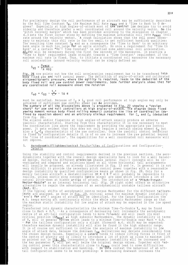
22-9
For preliminary design the roll performance of an aircraft may be sufficiently described by the Roll Time Constant TR, the Maximum Roll Rate p and a "Time to Bank to 0 de- grees" Especially at high angles-of-attack most of ti!$xcontrol law designs try to avoid sideslip and therefore prefer a well coordinated roll around the velocity vector. So the "pitch recovery margin" which has been provided according to the discussion in chapter 4.3 sets the first corner stone by defining the maximum achievable roll rate pVMAX (roll rate around the velocity vector). A rough calculation shows that the roll power neces- sary to maintain this roll rate is far too small. to get sufficient handling qualities: The resulting time constant T and as a consequence the "Time to Bank" to an arbitrary bank angle is much too large !or an agile aircraft. So once a requirement for "Time to Bank" or a certain "011 Time Constant" is settled some additional roll acceleration. AbV(t) will be necessary during the first few seconds of the manoeuvre. In practice a "Time to Bank" requirement leads straight towards a "Time Constant" requirement if the maximum roll rate is fixed. Thus. to initiate a coordinated roll manoeuvre the necessary roll acceleration (around velocity vector) can be simply defined as:
"" ' R R E Q .
F i n . 26 now points out how the roll acceleration requirement has to be transfered into f i x e d v i i w a n d roll control nnwpr. The definition o f anole-of-attack and calibrated
must be satisfied. Because of i, > i x good roll performance at high angles may only be achieved if sufficient vaw control Dower can b e nrovided.
from Fig. 26). The aileron andlor flaperons at high angles-of-attack usually produce an adverse yawlroll characteristic. Starting from this characteristic it is now necessary to meet the coordination line above the requirement by providing the appropriate yaw control power. It gets evident that this does not only require a certain yawing moment Cn but also a Cn-Cp characteristic of the yaw controller. Once the yawlroll control behaviour is fixed by configuration details it is of no use to increase the y a w potential beyond the "line of coordination". The capabilities for a well coordinated roll manoeuvre will not improve.
5. A e r o d y n a m i c l F l i g h t m e c h a n i c a l Pecularities o f Configurations and Configuration- Details
Using the stability and control requirements derived in the previous sections, the aero- dynamicists together with the overall design specialists have to look for a well balanc- ed design. During the different predesign phases several (tail-) concepts will be in- vestigated and compared and solutions based on all three horizontal tail arrangements will usually be proposed, as already illustrated in Fig. 13 and 1 4 . In general it is not very difficult to provide the necessary pitch control power together with a reasonable design instability by qualified configurative means as shown in Fig. 28. Only for a merely tailless aircraft a destabilization SM h 0 % C will probably be impossible to realize, unless exotic wing concepts (gotic wings) are used which introduce a lot of natural Ditch-down at hiaher anales of attack. The introduction nf a "Pitch-Thru<t-
~~~~~~
Vector-NozzleAA as an internal horizontal tail (Fig. 28 right side) offers an attractive alternative to regain the advantages o f an aerodynamically unstable tailless aircraft r R P f ~ X 1 ~ - . . . . . - - . If the typical shifts of aerodynamic centre versus Machnumber for the different tailcon- cepts are analysed. as done in Fig. 29, critical areas for maximum dynamic instability levels for Small angles of attack may be identified. For the Canard Configuration the a.c. keeps moving aft continuously within the whole subsonic Machnumber range so that the maximum static instability for low angles of attack may be expected in the low speed region. Transferred into dynamic characteristics the minimum Time-To-Double T, may be found close to Mach = 0.7. - As a consequence of decreasing tail increments the aerodynamic centre o f an aft-tail configuration tends to move foreward and will reach its most critical position (SM, x) at high subsonic Machnumbers. The dynamic instability in terms of T, will in general ?allow which leads to a minimum Time-to-Double near Mach = 0.9. - For the tailless configuration only a slight (forward) a.c. shift may be expected; therefore maximum dynamic instability will also be found in the high subsonic range. It is of course not sufficient to confine the analysis of maximum instability to low angle of attack data, because the dominant C cI derivatives may deviate considerably from the chosen design values. Especially a canar! tends to induce lifting forces i n front of the centre of gravity and is likely to introduce a lot o f pitch up close to maximum lift as pointed out in Fig..30. Consequently the dynamic instability will be increased and the key parameter T, will get well below the original design values. Together with fad- ing control power this characteristic close to C could lead to some difficulties with respect to stabilization and handling. - InLTt:s context the behaviour of an aft- tail Configuration seems to be more promising: A decreasing downwash increases the

22-10
s t a b i l i z i n g c o n t r i b u t i o n o f t h e t a i l v e r s u s a n g l e o f a t t a c k w h i c h l e a d s t o a c o n t i n u o u s p i t c h - d o w n e f f e c t . The maximum d y n a m i c i n s t a b i l i t y may t h e r e f o r e b e e x p e c t e d a t l o w a n g l e s o f a t t a c k where t h e l a r g e s t c o n t r o l p o t e n t i a l w i l l b e a v a i l a b l e . T h i s f a v o u r a b l e c h a r a c t e r i s t i c w i l l meet t h e g e n e r a l w i s h e s , t o i n t r o d u c e i n s t a b i l i t y i n o r d e r t o m i n i - m i z e d r a g up t o medium a n g l e s o f a t t a c k . As maximum l i f t i s a p p r o a c h e d t h e i n s t a b i l i t y i s r e d u c e d c o n s i d e r a b l y w h i c h h e l p s t o o p t i m i z e h a n d l i n g and t o a v o i d c o m p l e x i t y o f t h e c o n t r o l l a w s . - The C, - c h a r a c t e r i s t i c s o f a t a i l l e s s c o n f i g u r a t i o n a r e d o m i n a t e d b y t h e g e o m e t r y o f w i n g and s f r a k e w h i c h s h o u l d be o p t i m i z e d i n a way t h a t o n l y m i n o r p i t c h - u p t e n d e n c i e s up t o medium a n g l e s o f a t t a c k a r e t o b e e x p e c t e d . The e f f e c t s o f a w i n g s t r a k e o n t h e b a s i c p i t c h b e h a v i o u r a r e shown i n F i g . 3 1 . As s t r a k e s i z e i n c r e a s e s t h e a e r o d y n a m i c c e n t r e i s s h i f t e d f o r w a r d w h i c h i m p l i e s t h a t f o r a g i v e n d e s i g n i n s t a b i l i t y t h e maximum Cma w i l l g e t l a r g e r and t h e p i t c h r e c o v e r y m a r g i n w i l l be r e d u c e d . I n a d d i t i o n some i n c r e a s e i n maximum l i f t ( p r o b a b l y n o t u s a b l e ) a n d a s h i f t t o w a r d s h i g h e r acc i - - , , may be e x p e c t e d .
~ -1iidi A n o t v e r y o b v i o u s b u t n e v e r t h e l e s s b i g e f f e c t o n maximum i n s t a b i l i t y and r e c o v e r y m a r - g i n may come f r o m t h e c h o i c e o f t h e p r o p e r v e r t i c a l t a i l c o n f i g u r a t i o n . F i g . 32 i l l u - s t r a t e s t h e l o s s i n p i t c h down c a p a b i l i t y and t h e i n c r e a s e i n C,, when r e p l a c i n g t h e
"'-max s i n g l e v e r t i c a l b y a t w i n t a i l . The f l o w b r e a k d o w n a t h i g h e r a n g l e s o f a t r a c k p r o d u c e s a down load b e t w e e n t h e t w o v e r t i c a l f i n s and t h e r e f o r e a p o s i t i v e c o n t r i b u t l o n t o t h e n i t c h i n a moment c o e f f i c i e n t . W i n d t u n n e l t e s t s h a v e shown t h a t t h i s e f f e c t i s a l m o s t i n - 2ep inde i ; t o n t h e c a n t a n g l e o f t h e v e r t i c a l s . I n a d d i t i o n t o t a i l c o n c e p t s , s t r a k e s e t c . . t h e c h o i c e o f t h e w i n g p l a n f o r m i t s e l f may b e c r u c i a l f o r t h e d a n g e r o f t o o l a r g e p i t c h - u p . As shown i n t h e C,-a d i a g r a m s o n t h e l e f t s i d e o f F i g . 33 a " n o r m a l " t r a p e z o i d a l w i n g w i l l o b t a i n i t s m o s t c r i t i c a l SM a n d Cma a t l o w Machnumbers. I n t r a n s o n i c and s u p e r s o n i c r e g i o n s t h o s e p l a n f o r m s t e n d t o r e s t a b i l i z e and p i t c h down: t h e a e r o d y n a m i c c e n t r e moves c o n t i n u o u s l y a f t and i n s t a b i l - i t y d i s a p p e a r s . - O t h e r w i n g p l a n f o r m s l i k e c r a n k e d w i n g s may e x h i b i t a d i f f e r e n t u n- f a v o u r a b l e b e h a v i o u r ( s e e r i g h t h a n d g r a p h o f F i g . 3 3 ) : A t l o w a n g l e s o f a t t a c k t h e u s u a l a f t movement o f a.c. i s f o u n d w h e r e a s a t medium a a c o n s i d e r a b l e p i t c h - u p t e n d e n c y i s e x t e n d e d t o t r a n s - or even s u p e r s o n i c Machnumbers b e c a u s e o f a v o r t e x b u r s t a t t h e K i n k - s t a t i o n . Once a f i r s t w i n g - b o d y - t a i l c o n c e p t w i t h i t s g e o m e t r i c a l w i n g d a t a " a s p e c t r a t i o " and "s w e e p" has been s e l e c t e d . i t may be p o s s i b l e t h a t t h e r e s u l t i n g p i t c h - u p t e n d e n c i e s t u r n o u t t o b e u n s a t i s f a c t o r y . A p r o p e r p o s s i b i l i t y t o i m p r o v e t h e s i t u a t i o n may b e f o u n d b y l o o k i n g f o r a l t e r n a t i v e s i n t h e w i n g p l a n f o r m i t s e l f . - S i m i l a r t o t h e s o c a l l e d "NACA-P i t ch -up L i n e " i t i s p o s s i b l e t o d r a w d i a g r a m s o f " s i m i l a r p i t c h - b e h a v i o u r a t h i g h a n g l e s o f a t t a c k " f o r t r a p e z o i d a l w i n g s d e p e n d i n g o n t h e g e o m e t r i c a l p a r a m e t e r s " a s p e c t r a t i o A" and " l e a d i n g edge sweep $ " (- F i g . 3 4 ) . I f . s t a r t i n g f r o m a b a s e l i n e c o n f i g u r a t i o n , more ' P i t c h - d o w n " i s r e q u i r e d a t h i g h a n g l e s o f a t t a c k , i t d o e s n ' t make much s e n s e t o change t h e w i n g g e o m e t r y p a r a l l e l t o t h e s e l i n e s . I t i s m o r e p r o m i s i n g t o i n t r o d u c e changes p e r p e n d i c u l a r t o t h e c u r v e s o f " S i m i l a r P i t c h - u p " w h i c h means t o d e - c r e a s e t h e p r o d u c t A.m. The same p r i n c i p a l r e l a t i o n s h i p s may b e f o u n d f o r w i n g - s t r a k e - c o m b i n a t i o n s : t h e l i n e s a r e t h e n s h i f t e d p a r a l l e l t o w a r d s s m a l l e r A - $ - v a l u e s . A s a l r e a d y d i s c u s s e d i n s e c t i o n 4.4. t h e o r i g i n a l d e s i g n p h i l o s o p h y for t h e l a t e r a l l d i - r e c t i o n a l unaugmented b e h a v i o u r has n o t changed . The g e n e r a l d e s i g n g o a l i s s t i l l t o m a i n t a i n n a t u r a l s t a b i l i t y w h i c h j u s t has become m o r e d i f f i c u l t t o a c h i e v e b e c a u s e o f t h e n e e d t o go t o h i g h e r a n g l e s o f a t t a c k . H e r e i n d u c e d f o r c e s a n d moments f r o m t h e f o r e b o d y ( n o s e l s t r a k e l c a n a r d ) t e n d t o d o m i n a t e t h e s t a t i c and d y n a m i c a e r o d y n a m i c d a t a and t h e a f t - b o d y s u r f a c e s ( v e r t i c a l t a i l s ) w i l l g e n e r a l l y l o o s e t h e i r i m p o r t a n c e . The d i a g r a m s i n F i g . 35 ( t a k e n f r o m [Ref . 41) and F i g . 36 show t h a t t h e r e a r e f u n d a m e n t a l i n t e r c h a n g e s b e t w e e n s t a t i c a n d dynamic d e r i v a t i v e s i f t h e shape a n d l o r l e n g t h o f t h e f o r e b o d y i s a l t e r e d : I t i s t r u e t h a t v a r i a t i o n s t o w a r d s e l l i p t i c a l cross s e c t i o n s f o r examp le w i l l i m p r o v e t h e s t a t i c d i r e c t i o n a l d a t a C B . On t h e o t h e r h a n d t h e yaw d a m p i n g Cnr and t h e l a t e r a l s t a b i l i t y C p t e n d e n c i e s ( s e e a n a l y s i s o f c h a r i c t e r i s t i c e q u a t i o n F i g . 2 3 1 2 4 ) . - A d v i c e s f o r o p t i m u m f o r e b o d y- g e o m e t r y a r e d i f f i c u l t t o be d e f i n e d b e c a u s e t h e i n t e r a c t i o n s o f t h e d i f f e r e n t e m e r g i n g v o r t i c e s and t h e r e s u l t i n g f o r c e s and moments c a n h a r d l y b e p r e d i c t e d . The a n a l y s e s o f numerous w i n d t u n n e l t e s t s however h a v e shown t h a t i t may b e m o s t p r o m i s i n g t o d e s i g n f o r a r o u n d n o s e cross s e c t i o n w i t h a f o r e b o d y l e n g t h o f B N l d = 5.5 ( d = f u s e - l a g e d i a m e t e r a t w i n g a p e x ) . As t h e l a t e r a l l d i r e c t i o n a l d a t a a t h i g h a n g l e s o f a t t a c k i s h e a v i l y d e p e n d e n t o n t h e f o r e b o d y g e o m e t r y t h e s c h e d u l i n g and c o n t r o l d e f l e c t i o n s o f a c a n a r d may h u r t t h e i m p o r t a n t a e r o d y n a m i c d e r i v a t i v e s as w e l l ( s e e F i g . 3 7 ) . E s p e c i a l l y c l o s e t o maximum l i f t C i s s t r o n g l y i n f l u e n c e d by and o f t e n h i g h l y n o n l i n e a r v e r s u s c a n a r d s e t t i n g w h i c h !kposes a l o t o f s e v e r e p r o b l e m s b o t h o n t h e a e r o d y n a m i s i s t s and t h e f l i g h t c o n- t r o l l f l i g h t m e c h a n i c s p e o p l e . - F o r an a f t - t a i l c o n c e p t t h e d a t a i s g e n e r a l l y much s m o o t h e r as shown o n t h e r i g h t hand s i d e o f F i g . 37 : Once t h e f o r e b o d y shape has been o p t i m i z e d f o r s u f f i c i e n t l a t e r a l l d i r e c t i o n a l s t a b i l i t y , t h e d e f l e c t i o n s o f t h e h o r i - z o n t a l a f t - t a i l w i l l n o t d e t e r i o r a t e t h e r e l e v a n t d a t a .
6 . C o n c l u s i o n s
The d i s c u s s i o n s a b o u t r e c o m m e n d a t i o n s . r e q u i r e m e n t s and l i m i t s w h i c h have t o b e t a k e n i n t o a c c o u n t i n o r d e r t o c o v e r " F l i g h t m e c h a n i c a l " and " F l i g h t C o n t r o l Sys tem" p o i n t 8 o f v i e w , h a v e shown t h a t i t i s m a n d a t o r y t o i n v o l v e t h e s e a s p e c t s a l r e a d y i n t o a P r e l i m - i n a r y d e s i g n p r o c e s s o f a modern f i g h t e r a i r c r a f t . The c r i t e r i a w h i c h have been d e r l v e d a r e o f m a j o r i n f l u e n c e f o r t h e o v e r a l l c o n f i s u r a t i o n .
may b e d e t o r i a t e a w h l c h can l e a d t o d e p a r t u r e a n d S p i n

22-11
Maximum a l l o w a b l e i n s t a b i l i t i e s a n d c o n t r o l p o w e r r e q u i r e m e n t s , w i l l s e t r e m a r k a b l e c o n- s t r a i n t s t o t h e f r e e d o m o f a e r o d y n a m i c d e s i g n a n d i n f l u e n c e e s s e n t i a l componen ts o f t h e a i r c r a f t . Because o f t h e c o m p l e x a e r o d y n a m i c e f f e c t s a t h i g h a n g l e s - o f - a t t a c k i t w i l l b e n e c e s s a r y t o a p p r o a c h t h e " b a s i c c o n f i g u r a t i o n ' b y some o p t i m i z a t i o n l o o p s e s p e c i a l l y i n l o w speed w i n d t u n n e l t e s t s . D u r i n g t h e w h o l e p r o c e s s s p e c i a l i s t s f r o m f l i g h t m e c h a n i c s . a e r o d y n a m i c s and o v e r a l l d e s i g n d e p a r t m e n t s h a v e t o f o r m a c l o s e team i n o r d e r t o end UP w i t h an e x c e l l e n t w e l l - b a l a n c e d d e s i g n . F u r t h e r m o r e t h e d i s c u s s i o n a b o u t f l i g h t m e c h a n i c a l c r i t e r i a w h i c h can and h a v e t o b e u s e d w i t h i n t h e p r e - d e s i g n p h a s e s o f modern f i g h t e r s . has shown t h a t n o homogen ious s e t o f r e q u i r e m e n t s i s a v a i l a b l e u p t o now. E s p e c i a l l y t h e i m p a c t o f u n s t a b l e d e s i g n t o g e t h e r w i t h h i g h a n g l e s o f a t t a c k m a n e u v e r i n g i s n o t c o v e r e d s u f f i c i e n t l y . T h e r e f o r e f u r t h e r r e s e a r c h i s u r g e n t l y needed t o d e v e l o p c r i t e r i a w h i c h show t h e i n t e r - r e l a t i o n s h i p b e t w e e n a t t a i n a b l e F l y i n g Q u a l i t i e s , D e s i g n I n s t a b i l i t y a n d r e q u i r e d C o n t r o l Power w i t h i n t h e s e v e r a l f l i g h t p h a s e c a t e g o r i e s or a n g l e s o f a t t a c k r e g i o n s
7. N o m e n c l a t u r e
8. C. 0. E C o e f f i c i e n t s o f c h a r a c t e r i s t i c e q u a t i o n . s e e F i g . 23 b Wing s p a n C A P [ s - ' I C o n t r o l A n t i c i p a t i o n P a r a m e t e r C" 1-1 D r a g C o e f f i c i e n t " S Iml
C L q [ r a d - ' ] C L a [ r a d - ' ] CL, i [ r a d - ' ]
[ r a d - ' ] [ r a d - ' ]
CL 1-1
[ r a d - ' ]
C:! [ r a d - ' ]
Cy [ r a d - ' ] Cy' [ r a d - ' ] Cy' [ r a d - ' ] dyr Cml H [ m l - - -
C [ r a d - ' ] [q
[ m l LCDP M [ m l A CNmlsl Ma [-I m Ckgl n. n L Cgl p C d e g / s l q I d e g / s l r C d e g / s l RA [-I R A C [SI
R Q C s - ' l
S Cm'l
SM C% Cl
R Q I [-I
S I , 5 , c s - ' l
[SI
T , [ S I 4 F [ S I
[ S I
V Cmls l
Mean A e r o d y n a m i c C h o r d L i f t C o e f f i c i e n t L i f t due t o D e f l e c t i o n o f P i t c h C o n t r o l l e r L i f t C u r v e S l o p e L i f t due t o A n g l e o f A t t a c k R a t e L i f t due t o P i t c h R a t e R o l l i n g Moment C o e f f i c i e n t ( B o d y F i x e d ) R o l l i n g Moment due t o S i d e s l i p R o l l i n g Moment due t o R o l l R a t e R o l l i n g Moment due t o Yaw R a t e P i t c h i n g Moment C o e f f i c i e n t E f f i c i e n c y o f P i t c h C o n t r o l l e r P i t c h i n g Moment d e r i v a t i v e P i t c h i n g Moment d u e t o A n g l e o f A t t a c k R a t e P i t c h i n g Moment due t o P i t c h R a t e Yaw ina Moment C o e f f i c i e n t (Body F i x e d ) D i r e c t i o n a l S t a b i l i t y S p i n R e s i s t a n c e P a r a m e t e r ( D e f . see F i g . 2 2 ) Yaw ing Moment due t o R o l l R a t e Yaw ing Moment due t o Yaw R a t e Rudder e f f i c i e n c y S i d e f o r c e c o e f f i c i e n t (Body F i x e d ) S i d e f o r c e d u e t o S i d e s l i p S i d e f o r c e due t o R o l l R a t e S i d e f o r c e due t o Yaw R a t e D i a m e t e r o f F u s e l a g e a t Wing Apex A l t i t u d e
R a d i i o f I n e r t i a (Body F i x e d )
R a t i o s o f I n e r t i a ( s e e F i g . 1 5 / 2 3 )
L e n g t h o f V e r t i c a l G u s t Ramp L a t e r a l C o n t r o l D e p a r t u r e P a r a m e t e r ( s e e F i g . P i t c h i n g Moment P i t c h i n g Moment B u i l d - u p R a t e Mach Number Mass t o a d F a c t o r ~ 0 1 1 R a t e P i t c h ' R a t e 1 Body F i x e d Yaw R a t e J C o n t r o l taw P a r a m e t e r s see F i g . 10
R e f e r e n c e A r e a S h o r t P e r i o d R o o t s S t a t i c M a r g i n ( n e g a t i v e = u n s t a b l e ) F l i g h t m e c h a n i c a l T ime ( s e e F i g . 2 3 ) T ime C o n s t a n t T i m e- t o - D o u b l e A m p l i t u d e T ime C o n s t a n t o f L e a d- t a g F i l t e r R o l l T ime C o n s t a n t T ime C o n s t a n t o f Lead- Lag F i l t e r T ime D e l a y T ime A i r s p e e d
2 2 )

22-12
WWQ xc.4 Xa.c
B L L n 9 e m B !JL V S P W W P
a
Cmlsl Vertical Gust Component [ % Cl Centre of gravity e % 7 1 Aerodynamic centre [de91 Angle of Attack Cdegl Angle of Sideslip e-I Damping Ratio [degl Rudder Deflection [de91 Deflection of Pitch Controller Fjpfi Atti ude . E%js*1 Acceferatlon Cdegl 8ank Angle ldegl Leading Edge Sweep of Wing e-I Mass Density (see Fig. 15) [-I Mass Density (see Fig. 23) Ckglm'l Density Cradlsl Frequency Cradlsl Undamped Frequency
8. References
[Ref. 11
[Ref. 21
[Ref. 31
[Ref. 41
[Ref. 51
[Ref. 61
[Ref. 71
[Ref. 81
D. M C Ruer Progress and Pitfalls i n Advanced Flight Control SyStE" AGARD-CP-321 Advances in Guidance and Control SyStemS
Weisman Robert Criteria for Predicting Spin Susceptibility of Fighter Type Aircraft ASD-TR-72-48, June 1972
Beaufrere. H . Flight Plan Development for a Joint NASAINaVV High Angle of Attack Flight Test Program- Grumman Contract No. NASA 2965 March 1983
J.R. Chody. J. Hodgkinson, A. Skow Combat Aircraft Control Requirements for Agility AGARO Symposium "Aerodynamics of Combat Aircraft.. . " Madrid, 2-5.10.1989, CP 465
Military Specifications Flying Qualities of Piloted Air Vehicles MIL-F-8785C
P. Mangold, G. Wedekind Integration of Aerodynamic, Performance, Stability and Control Requirements into the Design PPOCeSS of Modern Fighter Aircraft Configurations AGARO, LS 153 H.D. Greer Summary of Directional Divergence Characteristics o f Several High Performance Aircraft Configurations NASA-TN 0-6993. N O V . 1972
P. MangoldlG. Wedekind "Inflight Thrust Vectoring" a Further 'Degree of Freedom in the A e r o d y n a m i c I F l i g h t m e c h a n i c a l Design of Modern Fighter Aircraft AGARD CP 465. Madrid 1989

22-13
Fig. 1 Correlations between Handling Quality Requirements and Aerodynamic Parameters for an Unaugmented Aircraft (Pitch Axis)
Complex Plane
C,, - k, C, + C,, ssp = - 2[k,( - C, C,, - p,C,,)]"'
2 2m p . S . E k, = (iJE) ; pL =
Requirements from MIL-F-8785 C (Level 1 CAT. A):
0.35 S csp 5 1.3
3.6 2- t 0.28 n/a 5, 50.04
Fig. 2 Integration of Handling Quality Requirements into the Sizing of a Horizontal Tail (Unaugmented Aircraft)
c 0 L
c a, c a, 0
Relative Tail Area

22-14
Fig. 3 Correlation between Handling Quality Requirements and Aerodynamic Parameters for Unaugmented Aircraft (Lat./Dir. Axes)
Complex Plane A
.___.. Roll Roots
&-A
\ 0
h =-<.a I Roll Mode 1
Requirements from MIL-F-8785 C (Level 1 CAT. A):
T, s 1.0s T 2 1 2 s
2SP
Fig. 4 Integration of Handling Quality Requirements into the Sizing of the Vertical Tail (Unaugmented Aircraft)
Im =
oDR [+I CDR = 0.19
Vertical Tail Size x 100% L @ 150%
-4 -3 -2 -1 -
-4 -3
Vertical Tail Size x 100% L @ 150%
-2 -1
I Spiral Mode I
i-
Level 1, CAT. A, 12 sec
Mach
Re =-cDR mODR [rad/sl
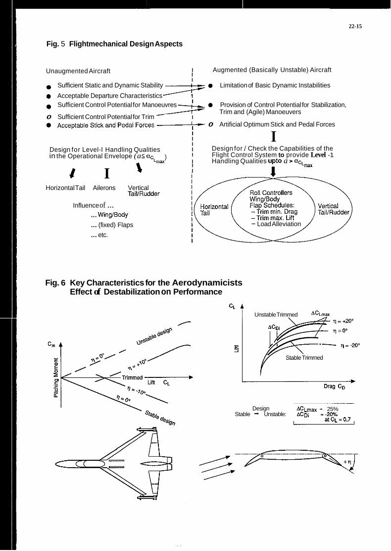
22-15
Fig. 5 Flightmechanical Design Aspects
I Augmented (Basically Unstable) Aircraft I I
Unaugmented Aircraft
0 Sufficient Static and Dynamic Stability I_ 0 Limitation of Basic Dynamic Instabilities
0 Sufficient Control Potential for Manoeuvres -- 0 Provision of Control Potential for Stabilization, Trim and (Agile) Manoeuvers
Acceptable Stick and Pedal Forces I_ 0 Artificial Optimum Stick and Pedal Forces
0 Acceptable Departure Characteristics A I I
0 Sufficient Control Potential for Trim I
I I I I I I
I
I Design for Level-I Handling Qualities in the Operational Envelope (a 5 ac
Design for I Check the Capabilities of the Flight Control System to provide Level -1 )
Lmax I Handling Qualities upto a > aCLmax 1 I J I
Horizontal Tail Ailerons Vertical TaillRudder
Influence of ... .. . Wing/Body ... (fixed) Flaps ... etc.
- Load Alleviation
Fig. 6 Key Characteristics for the Aerodynamicists Effect of Destabilization on Performance
CL A
E 2
Unstable Trimmed ACLmax q = +209
q = 0'
-- q=-200
Stable Trimmed
A C L ~ ~ - 25% Stable + Unstable: ACD~ --2o%
Design
a t C ~ =0.7

22-16
Fig. 7 Key Characteristics for the Aerodynamicists Pitching Moment versus Angle of Attack
1 Cm
I c al 0
al
._ E
I-\, i \ ' 0" I \ I
I ?\. A -
Takeoff Instantaneous aTRlM 0
Substained manoeuvres landing manoeuvres
Fig. 8 Principle Problems of (. .tch) Stabilization for an Unstable Designed Aircraft
I / 2Aa ,/ c
a,
T, = Time Delay T, = Time to Double Amplitude M = Pitching Moment lh = Build-Up of Control Moment
I a, 0 / Build-Up of Control Moment J

22-17
Fig. 9 Key Characteristics of Unstable Design in Pitch
Parameter
Static Margin
Time to Double Amplitude ... ' 2
Maximum Pitch Control Power f Mm_ Rate of Control Power Build-up * Mmax
Remarks
0 Aerodynamic Characteristic of Instability 0 Lever Arm of Aerodynamic Forces 0 Indicates Potential for Drag Reduction 0 Indicates Potential for Higher Max. Lift 0 Flightmechanical Design Criterion for stable
0 No Indication for Higher Agility Unaugmented Aircraft
0 Quantification of Dynamic Problems -t Stabilization --t Optimization of Flying Qualities
0 Defines Potential to Solve Problems
Fig. 10 Control Law Structure and Aircraft Model
Control Law Structure
0 Positioning of Short Period Roots (RA, RQ)
0 Integral q-Feedback for Suflicient Damping of Phugoid (RQI)
0 Transfer of Pitch Rate into Angle of Attack Signal (RAC)
0 Pitch Rate Filter for T,, Shaping
1 +T;s Filter = ~
1 +T;s
Model of the "Augmented Aircraft"
0 Basic Aircratl Model
0 Control System incl. Pads
4. Order
4. Order Approximation for Time Delay
0 Actuator Dynamics 1. Order (Canard, Flaps, Aft-Tail)
Overall System 9. Order
0 Representative Time Delay (Sensors. Computers, Filters, etc.) = 0.02 sec. i.e. State of the Ari

22-18
Fig. 11 Handling Quality Requirements Used for Optimization o f Control Laws
0 Low Order Equivalent System Requirements from MIL-F-8785 C lor Level-? Handling Qualities
.CAP = 1.0- mosp
-Short Period Damping 5 = 0.75
- T, acmrding to 6& (wmp 'T, = 3.6) I
t
I
t Additional Requirements c - Damping of All Complex Roots > 0.75 Requirement: nST to be reached after t sec. (limited actuator activity)
2 2 e % = O - p
9 T, Ans, ..1 nla /L CAP= =
-Gust Response not worse than wnventional aircraft
Fig. 12 Safety Aspects covered by Sufficient Robustness of Control System
Nyquist Criterion:
If at 0 dB gain of the open imp the phase is smaller than -180 deg., the closed loop is ....
...." Unstable"
0 Margins to Stability Limits cover variations of parameters:
- Phase Margin: 35 deg. at k 3 dB - Gain Margins: i 6 dB at -1 80 deg.
Fig. 13 Typical Modern Fighter Configurations (Designed for European Mission and Manoeuvre Requirements)
Aft-Tail a Canard Tail Tailles
Configuration
t / __--- \ 0 Unstable Basic Characteristics in Pitch - smaller induced drag - higher maximum lift
a Horizontal Tail 0 Instability and Agility Requires

22-19
Fig. 14 Typical Data of Modern Fighter Aircraft in the Subsonic Region (Longitudinal Motion);
Parameter
Static lnstabilitv Marain - (small a) Medium Combat Mass m Reference Wing Aerea S Mean Aerodynamic Chordc
Tail EfficiencyCLJC,, Flap Efficiency CLnK/CmqK Mass Density pL Radius of Inertia iy
* incl. Wing Interference .' incl. Tail Interference
Aft-Tail
SM = -10 % ca. 12500 kg 45 m2 5.4 m
+0.4 W 0.0 +4.0 W 0.0 -1.5 W-2.5 +1.6 D+2.0 -1.0 D- 1.0 +0.8 W+2.5 1.50130"
+0.45/-0.5 +0.63/-0.13""
84 3.4 m
Horizontal Tail Arrangement Vector Nozzle
SM=-8% ca. 12500 kg 45 mz 5.4 m
0.28D 0.35 D 0.0 +3.5 w 0.0 -0.5 D- 1.0 +1.0 D + 1 . 5 +0.1 w +0.2 +0.6 c) + 1.5 1.50130'
. . 0,=f2.0 rad/s2
84 3.3 m
+1.0/-0.30
Canard
SM - -8 % ca. 12500 kg 50 m2 5.7 m
0.26W 0.5 W 0.0 +3.3 W 0.0 -0.5 W-1.0
1 9 w+1.9 -0.1 a 0.0 +0.7 D + 1 . 5 1.35130"
+0.03/0.12" +1.15/-0.35
72 3.0 m
Fig. 15 Correlations between Aerodynamic Derivatives and Dynamic Instability (Time to Double Amplitude T2)
Tailless
SM=O% ca. 12500 kg 60 m2 6.7 m
0.0 D 0.2D 0.0 2.8W 0.0
-0.4D-0.8 + 1.2D + 1.9 -0.1 a 0.0 +0.7D + 1.5 + 1.15k30"
-/- +1.15/-0,35
3.2 m 50
2 . m
k, = (iy/C )
PL = p . s . 2
Parameter
cm, 1. Order CL, 2. Order + Cm6,C,, 3. Order CLi ,C, 4. Order

22-20
Fig. 16 Evaluation Procedure for the T,-Criterion (Required Control Power versus Time-to-Double)
0 0 Rouah but Reasonable Hardware AssumDtions
General Data of Modern Fighters (3Tail
Variation of Relevant (Aerodynamic) Characteristics (Cma,CLa, CmqICLq, Mach Number, . . .) 1 c
Varation of Time to Double I c
Optimization of Control Law Parameters 0 HQ-Requirements 0 Phase- and Gain Margins 0 Limited Actuator Activity
I
Simulated Flig; with Test lmputs -1
Required Pitch Control Moment M Required Pitch Control Moment BJi.0-up i!
Design Diagrams versus Time-to-Double T2
Fig. 17 "Test Inputs" for the Evaluation of the Necessary Control Power
0 Gross Pitch-Stick Command 0 HeavyGusts
- Maximum Angle of Attack Rate & ? - Maximum Load Factor Onset iL ? - "Command Shaping" according to Basic Aircraft Characteristics Possible
- Defined in MIL-F- 8785 -To be Demonstrated for Certification - Cannot be "Shaped"
Vel Gu Ra
Test Input
L = 50 m W,,, = 66fVs 1 -cos Form } ?;= - -
36 deg/s 23 deg/s
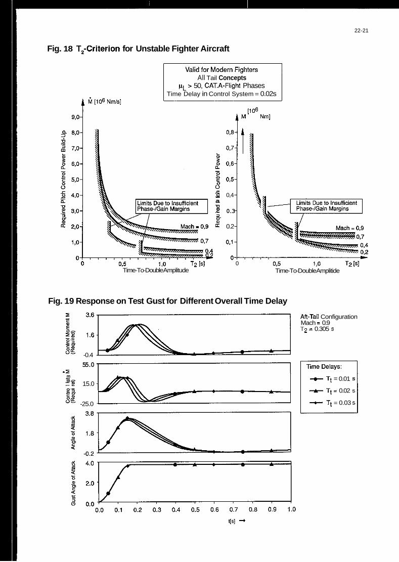
22-21
Fig. 18 T,-Criterion for Unstable Fighter Aircraft
ti [ lo6 Nmk]
9,o
All Tail Concepts pL > 50, CAT.A-Flight Phases
Time Delay in Control System = 0.02s
03 1 ,o T2 [SI Time-To-Double Amplitude
t [Io6
0
5 ._ 0,4 a .- e! 0.3 0
L? 0.2
0.1
0 m
0,5 I .o T2 [SI Time-To-Double Amplitide
Fig. 19 Response on Test Gust for Different Overall Time Delay
An-Tail Configuration Mach = 0.9 T2 = 0.305 S
I - c E sg
5g -- P 'i
VI
- -0.4
55.0 .I
t Tt = 0.01 S
+ Tt = 0.02 s
t Tt = 0.03 S
m .+ zmg -P 15.0 P '5
V E g g
-25.0

22-22
Fig. 20 Effect of Overall Time Delay on Phase and Gain Margins
Open Loop Phase (deg.)
m 3
n 0. 0 5 -1. & -2. 0" -3.
-4.
-8. -9.
-10.
Fig. 21 Definition of Pitch Recovery Margin at High Angles of Attack by Roll Rate - Requirement
.
Nose up ameleration
q C = - p .' 1 2 .sin2a #F down +
-1 .o
All controls 2 v
-2.0
$21
4 Max. roll rate ps ]
50 100
a = 25"
1

22-23
Fig. 22 Weissmann Criterion for LateraVDirectional Stability
LCDP'
..............
El H
............ ............
. . . . ............ ............ ............
High Departure and Spin Resistant
Spin Resistant. Objectional Roll Reversals can Induce Departure and Post Stall Gyrations
Weak Spin Tendency, Strong Roll Reversal Results in Control Induced Departures
Strong Departure, Roll Reversals, and Spin Tendencies
Weak Spin Tendency, Moderate De arture and Roll Revenak, ~fiected by Secondary Factors
Weak Depanure and Spit Resistance, no Roil Reversals, Heavily Influenced by Secondary Factors
L -0.012 Ref: Beaulrere 'Scales per Degree Oerivatibs US Standard
Fig. 23 Characteristic Equation of LaterallDirectional Motion (Derivatives in Body Axes)
z > 9
iz z- 0
h4 + Bha+ Ch2+ Dh + E = 0 Stable if: B,C,D,E > 0 And (C . B - D) D - EB2 > 0
B = - (K, . C,, + K,. C,, + K,K;C,,) t, K, . K,
c = ' (ps. k,. C,, . cosa - ps. K, . C,, . sina + C,, . C,, - C,, . C,, t, . k,. k,
+ k, , Cy,. C,, - K, . Cy,. C,, + K, . Cy, C,, - K, . Cy, CJ
D = ' .[p.. (C, . c,, . cosa - cn,. c,, . cosa + C, . C,,sina - C,, . C,,sina) t, . k, . k, + t:. f . ( - k, . C,cosa - K,. C,, . sina)
+ cy, ' c, . c,, + c, ' cy, . c,, + c,, ' c,, ' cy, - cy, ' c,, ' c,, - c,, : c,, ' cy, - cn, ' cy, . c,,]
(c,, . c,, . cosa - C, . c,, . sina +"con. cIpsina - c",. c,, cosa) E = t, . s . K, . K,
4m & = pSb

22-24
Fig. 24 Design Criteria for LateraVDirectional Characteristics (at High Angles of Attack)
Assumptions: p, >> 0 (typical values 2 80)
K, > K, (K, = 0.1 , K, = 0.5 i 0.8)
2 v ps "t, (p. = ' t, ; p. > lot,)
Cy, always negative C,, always positive (GI, -. C, , C, 2 1.0 at C, )
m u
Coefficients of Characteristic Equatior
B
C
D, E
( C , B - D) D - EB2
Design Rules for Dominating Parameters
Avoid Autorotation I) Clp<O Maintain Yaw Damping I) Cnr<O Dominated by ps . K x . CnOdyn Cn8dyn>o Avoid Large Positive Directional Stability I) Cnfi = + 0.
Maintain C
Keep C Larger Than D
> 0 by Lateral Stability I) C I ~ c 0
* Cn8dyn
'klyn > 0.1 with slightly
positive CnB
Fig. 25 Definition of Roll Control Power by Roll Performance Requirements
1 .o 2.0 Time[s]
0 I"]
pVl Required for pv,,,
1 .o 2.0 Time[s]

22-25
Fig. 26 Definition of Body Fixed Roll and Yaw Control Power (Coordinated Rolls at High Angles of Attack)
Transformation of Angular Accelerations: Deduction of Aerodynamic Control Potential
Velocity Vector --f Body Fixed . 2 . Z . 2
P . o = P o + I,
P o =p";cOs a
i =i "0 . s i n a 0
p , = K P . p v m w . COS a/T,
io = K, . p " mw
Kp,K, > 1. = f (Actuators, Time Delay, etc.)
.sin a / T R
1. Shot: K p , K , = 1.25
C ,=C, . 7 . t g a I Aerodynamic Coeffients AC,.AC,
Fig. 27 Design Diagram for Yaw and Roll Control Power at High Angles of Attack
Characteristics 0 Re uirementfor
Ru%der Efficiency I 2.
0 Requirement for Yaw- Roll Charakteristic of Rudder
\I i:
iz tga
. ._ Body Fixed Yaw Control Power

22-26
Fig. 28 Typical Pitching Moment Characteristics of Modern Fighters in the Subsonic Region (Mach = 0.3)
Canard Configuration
CD c .c 0 ._ E
Aft Tail Configuration
"m
4
0 c .c 0 ._ E
Pitch Thrust Vector Configuration
Cm 4
* Margin: &5 - 0.80 rad@ (200 KEAS: Pitch Recovery + MAX.. Rollrate = 65degIs)
Fig. 29 Shift of Aerodynamic Centre and Time to Double T, (Small Angles of Attack)
Canard Configuration Aft Tail Configuration
m iw .-
5 -------- c
$ 2f
t 0.5 1 .o
m
.- F I Mach
0.5 1 .o
Pitch ThNst Vector Configuration
m I "i Centre of G r a v i T K c ---------- ). -D
a/ $ , .
0:5 1 .o
9
I Mach
0.5 1 .o

22-21
Fig. 30 Static Instability and Time to Double T,versus Angle of Attack
Canard Configuration An Tail Configuration Pitch Thrust Vector Configuration
0 2t 2 4
I ' I
I
T2 min m 3 0
a a i 0 a I F Design n --- ,- - Design
a _ _ _ _ _ _ _ _ _ _ n 9 I
.
m
Fig. 31 Influence of Wing Apex Strakes on the Pitching Moment Characteristics

22-28
Fig. 32 Influence of Vertical Tail Arrangement on the Pitching Characteristics
A
-* Twin Vertical v = 25"
tical Tails. . . . . Single Vertical
. . . increase Cma -Trim , , , decrease the Pitch Down Potential . . .
from Medium Angles of Attack Upwards.
Fig. 33 Influence of Wing Planform on Pitch Behaviour (Zero Controls)
Trapezoidal-Wings: Cranked Wings:
Cmamax in Low Speed Region Danger of Transonic Pitch-up1
c C a,
5 2 m C .c 0
._ + ._ a
a,
m C ._
ITransonic Ma (-0.9) I 5 +
a a
I Supersonic Ma (> I ) ]
._
Cranked Wings Cm A

22-29
Fig. 34 Pitch-up Behaviour at Higher Angles of Attack as a Function of Wing Planform
L. E. Sweep
Fig. 35 Influence of Forebody Shape on Directional Stability and Yaw Damping (Ref.: J. Hodgkinson)
nr
t I
I L Extended Basic I
G3 Duckbill
0- Basic

22-30
Fig. 36 Influence of Forebody Shape on Static LateraVDirectional Deriatives (p = 10')
Configuration:
2.7%LEX
45 ALE -55"
AR =2.0 AFT TAIL 2 VERTICALS
v =25'
0 t C,
0" 20" 40" 60" Anale of Attack +
Fig. 37 Influence of Horizontal Tail Deflections on Lateral Stability
Canard configuration Aft Tail Configuration
+
Canard Deflections Aft Tail Deflections
- eH = 0" = CL,,~ - trim
-*- €~=+30' -+- EH=+200

24-1
B-1B HIGH AOA TESTING IN THE EVALUATION OF A STALL INHIBITOR SYSTEM
Mark S . Sobota Captain, United States Air Force
65lOthTest Squadron Air Force Flight Test Center
Edwards AFB, CA. 93523, USA
SUMMARY
High angle-of-attack (AOA) B-IB flight tests were conducted from September 1987 to June 1989 at Edwards AFB, Califomia for the purpose of evaluating a flight control Stall Inhibitor System/Stability Enhance- ment Function (SIS/SEF). The SIS/SEF system was in- tegrated into the basic B-IB flight control system (FCS) because of an inherent stability problem in the B-1 aircraft design. The problem lies in the fact that aerodynamically the B-1 was stability limited and not lift limited. This resulted in a lack of longitudinal stability while operating at high AOA conditions with no waming or natural cues to the pilot that the aircraft was approaching an lrnstable region. The B-1’s stability limitations were made even more pronounced when B-1B mission requirements called for an an 82,000- pound increase in maximum gross weight over the basic B-IA configuration. To safely utilize all the available AOA at the higher gross weights demanded, some means of providing “apparent” stability was essential to provide cues to the pilot of these stability limitations. Also essential was a means of providing departure resis- tance to protect pilots from inadvertently entering a haz- ardous poststall sitnation. This capability was provided by the SIS/SEF system which produced a marked im- provement in flying qualities and a significant increase in operational capabilities over the original B-IA FCS. This paper presents significant test results of the SIS/SEP fligl1t test program.
BACKGROUND
Initial B-1A flying qualities tests (Reference 1) completed in May 1979, identified high AOA flight con- ditions where tlie B-1 had an inherent stability problem causing uncommanded aircraft pitchup with inadequate natural stall waming to the pilot. A follow-on B-IA flying qualities evaluation (Reference 2) completed in August 1984, provided flying qualities test results of a B-1A modified with a B-1B prototype FCS when the strategic bomber program was revived in January 1982. The B-1B mission requirements called for an 82,000- pound gross weight increase to be incorporated to increase payload and range without changing the original B-IA wing and tail design. Test results indi- cated that the B-1’s stability problem was compounded because of the higher AOAs demanded by the heavier weight requirements with diminishing longitudinal flying qualities occurring within a significant portion of the B-IB flight envelope. Uncommanded pitchup ten- dencies were even more in evidence as well as unaccep-
table pitch stick control reversals (dFsuJdNz e 0) during maneuvering flight. The B-1 bomber’s inhered stability problem lies in the fact that aerodynamically the B-1 was stability limited and not lift limited. That is, the maximum achievable AOA was defied by the aircraft’s longitndinal stablity limitation and not by typical maxi- mum lift stall characteristics. This was clearly made evi- dent in B-l wind tunnel predictions (see Figure l) where there was ample lift available at AOAs well beyond the point at which the aircraft became loogitndinally unstable.
The B-1’s stability limitation was directly linked to the basic airframe aerodynaniics characteristics. By electing a variable sweep wing design, the B-1 required large wing pivot joints which were blended into the wiughselage body interface (see Figure 2). At (his point, the outer fuselage skin, commonly called the “wing glove,” served not only as a good aerodynamic fairing but an excellent lifting surface in front of the main wing as well. During high AOA flight the wing tips stall first, thereby decreasing the lift component from the wings. As higher AOAs were achieved the lift component from the “wing glove” area acted as a lifting body causing the center of lift to move forward until neutral stability occurred. Also, tfie basic aircraft flying qualities were such that there were virtually no natural cues to the pilot that the aircraft was approaching the stability limit which made it very easy to inadvertently exceed the limit.
This lack of natural cues and possible aircraft depmres ultimately constrained the B-I to a very con- servative stall waming margin to protect pilots from in- advertently entering a hazardous poststall situation. Stall waming was set at an AOA value of 80 percent of the way from zero lift AOA to neutral stability AOA, thus making the stall wanling margin 20 percent below the neutral stability AOA. As a result, this reduced opera- tional AOA envelope (stall warning envelope) was deemed unsatisfactory and modifications to the ba$ic B-IB FCS were recommended (Reference 2) to improve flying qualities and to utilize the bomber’s intended full design perfonnance capability. An interim stall inhibitor system, SIS (phase 1) or SIS-I, was developed and flight tested (Reference 3) and subsequently was installed in the first 18 production B-IBs. The SIS-I system demon- strated the ability to provide apparent stability through- out an interim B-1B flight envelope while at the same tinie providing more AOA capability by reducing the
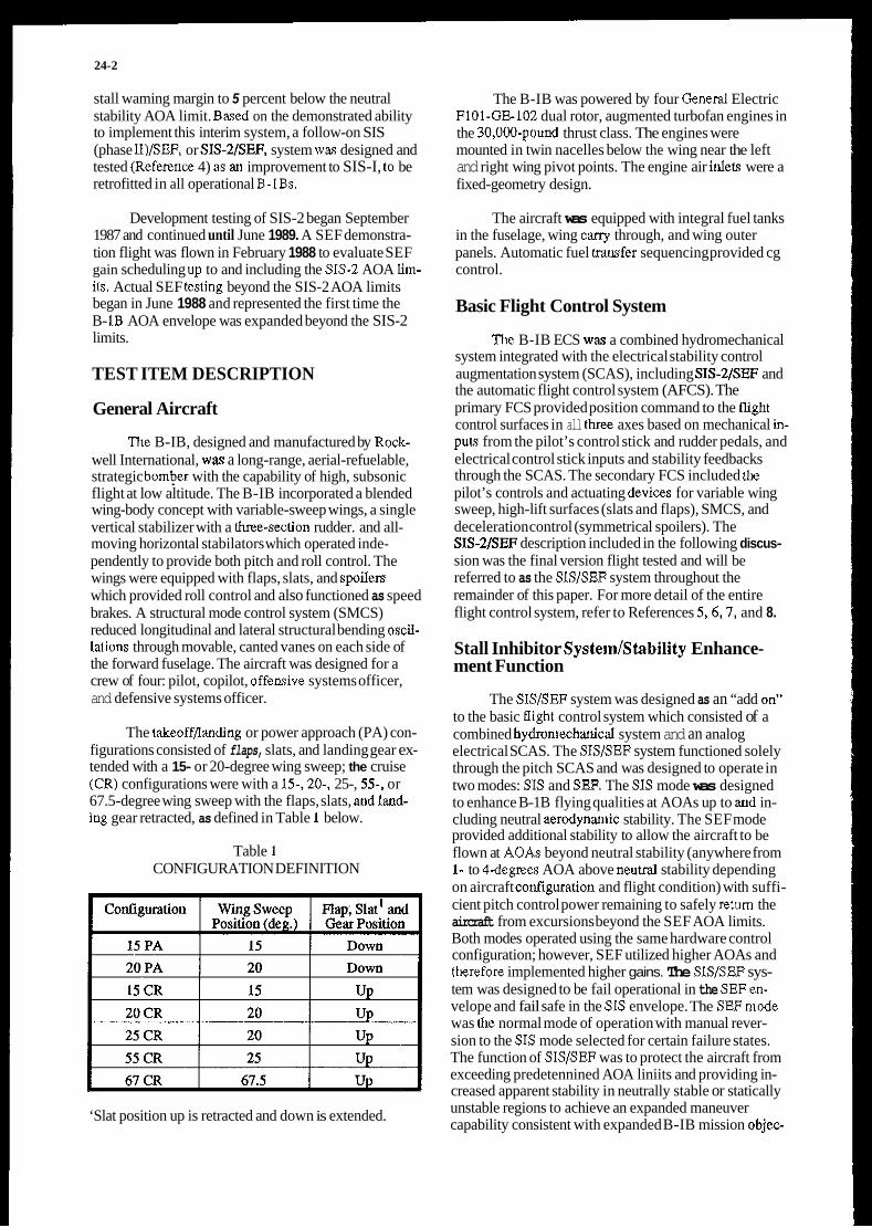
24-2
stall waming margin to 5 percent below the neutral stability AOA limit. Baved on the demonstrated ability to implement this interim system, a follow-on SIS (phase II)/SEF, or SIS-2/SEF, system way designed and tested (Referenw 4) as ai improvement to SIS-I, to be retrofitted in all operational B-1Bs.
Development testing of SIS-2 began September 1987 and continued until June 1989. A SEF demonstra- tion flight was flown in February 1988 to evaluate SEF gain scheduling up to and including the SIS-2 AOA lim- ifs. Actual SEF tcsting beyond the SIS-2 AOA limits began in June 1988 and represented the first time the B- IB AOA envelope was expanded beyond the SIS-2 limits.
TEST ITEM DESCRIPTION
General Aircraft
The B-IB, designed and manufactured by Rock- well International, way a long-range, aerial-refuelable, strategic bomber with the capability of high, subsonic flight at low altitude. The B-IB incorporated a blended wing-body concept with variable-sweep wings, a single vertical stabilizer with a he-section rudder. and all- moving horizontal stabilators which operated inde- pendently to provide both pitch and roll control. The wings were equipped with flaps, slats, and spoilers which provided roll control and also functioned as speed brakes. A structural mode control system (SMCS) reduced longitudinal and lateral structural bending oscil- lalions through movable, canted vanes on each side of the forward fuselage. The aircraft was designed for a crew of four: pilot, copilot, offemive systems officer, and defensive systems officer.
The takeoff/landing or power approach (PA) con- figurations consisted of flaps, slats, and landing gear ex- tended with a 15- or 20-degree wing sweep; the cruise (CR) configurations were with a 15-,20-, 25-, 5 5 , or 67.5-degree wing sweep with the flaps, slats, andland- ing gear retracted, as defined in Table 1 below.
Table 1 CONFIGURATION DEFINITION
‘Slat position up is retracted and down is extended.
The B-IB was powered by four General Electric Fl01-GE102 dual rotor, augmented turbofan engines in the 30,UUO-pound thrust class. The engines were mounted in twin nacelles below the wing near the left and right wing pivot points. The engine air inleu were a fixed-geometry design.
The aircraft was equipped with integral fuel tanks in the fuselage, wing cany through, and wing outer panels. Automatic fuel trarlsfer sequencing provided cg control.
Basic Flight Control System
The B-IB ECS way a combined hydromechanical system integrated with the electrical stability control augmentation system (SCAS), including SIS-2/SEF and the automatic flight control system (AFCS). The primary FCS provided position command to the tligbt control surfaces in all t h axes based on mechanical in- puL9 from the pilot’s control stick and rudder pedals, and electrical control stick inputs and stability feedbacks through the SCAS. The secondary FCS included h e pilot’s controls and actuating devicas for variable wing sweep, high-lift surfaces (slats and flaps), SMCS, and deceleration control (symmetrical spoilers). The SIS-2/SEF description included in the following discus- sion was the final version flight tested and will be referred to as the SIS/SEF system throughout the remainder of this paper. For more detail of the entire flight control system, refer to References 5,6,7, and 8.
Stall Inhibitor System/Stability Enhance- ment Function
The SlS/SEF system was designed as an “add on’’ to the basic tlight control system which consisted of a combined hydroniechilical system and an analog electrical SCAS. The SIS/SEF system functioned solely through the pitch SCAS and was designed to operate in two modes: SIS and SEF. The SIS mode was designed to enhance B-1B flying qualities at AOAs up to and in- cluding neutral aerodynaniic stability. The SEF mode provided additional stability to allow the aircraft to be flown at AOAS beyond neutral stability (anywhere from 1- to 4 d e p e s AOA above neuval stability depending on aircraft coilfiguration and flight condition) with suffi- cient pitch control power remaining to safely retum the aircraft from excursions beyond the SEF AOA limits. Both modes operated using the same hardware control configuration; however, SEF utilized higher AOAs and tkrefore implemented higher gains. The SIS/SEF sys- tem was designed to be fail operational in the SEFen- velope and fail safe in the SIS envelope. The SEFmode was tlie normal mode of operation with manual rever- sion to the SIS mode selected for certain failure states. The function of SIS/SEF was to protect the aircraft from exceeding predetennined AOA liniits and providing in- creased apparent stability in neutrally stable or statically unstable regions to achieve an expanded maneuver capability consistent with expanded B-IB mission objeo

24-3
tives. Apparent stability was achieved by utilizing an AOA feedback signal to reduce trailing edge up (TEU) horizontal stabitator commands as a function of AOA and AOA rate. Pilot stick force cues were increased by yaking slick inputs less effective at commanding TEU stabilator deflection as the aircraft approached the AOA limit, thus increasing the aircraft‘s apparent stability. In order to improve aircraft flying qualities while limiting AOA, SIS/SEF attempted to linearize stick force gradients below stall warning and considerably increase stick force gradients above stall warning. An example of this desired system response is shown in Figure 3 which depicts a I-g level deceleration maneuver performed at 20 CR, aH cg to the SEF limit (9.5 dewes AOA). Also, note the unstable characteristics of the aircraft as shown by the horizontal stabilator moving in the trailing edge dowu (TED) direction as the AOA increases from 7.5 degrees to the SEF limit.
Angle-of-attack way determined f” pressure dif- ferentials on the pitot-static probes. Three sets of side- mounted Pitot-static probes accompanied by three sets of digital pressure transducers provided air data informa- tion to two Central Air Data Computers (CADCs) for redutidancy. From the air data and aircraft configuration information provided, the CADCs independently com- puted a “standardized AOA” (Q).
The term “standardized AOA” was a signal processed by the SIS/SEF control laws to provide a means to standardize the AOA of the AOA feedback sig- nal to account for the changing stability limitations with varying wing sweep configuration and flight condition. Thus, regardless of aircraft configuration, the Q signd had a value of 1.0 at the correspomiing SIS or SEF AOA luiiit and a value of 0.0 at zero lift. This is il- lustrated in Figure 4 for SIS Q. Stall warning SIS-OFF was 0.8 as and for SIS- or SEF-ON it was 0.95 as.
In order to compute Q, the CADCs each stored AOA lkiiits for both the SIS and SEF envelopes and used the values corresponding to the position of the three-position SIS/SEFselect switch located in the cock- pit. With the switch in the SIS-OFF or SIS-ON position, SIS AOA liniits were used in the computations. With the switch in the SEF-ON position, the SEF limit was used in the computations. The CADCs also calculated the omet of proportional feedback in the SIS/SEF by use of the WSE parameter. The onset for proportional feedback was designed to occur at the same true AOA independent of the SIS/SEFmode selected. This AOA was approxiniately equal to 60 percent of the SIS AOA envelope. Proportional feedback gain (KSEF) was also computed by both CADCS and was a function of wing sweep, cg, and dynamic pressure, and is presented in Figure 5.
The SIS/SEF system functioned chrough three primary control paths:
1. Proportional stability path,
2. Mechanical pitch stick cancellation, and
3. Electrical pitch stick cancellation.
Figure 6 shows the SIS/SEF control paths and the interfaces with the CADC and SCAS. The mechanical cancellation path was from the pitch stick position (xe) to ~~€IsIs(M). The electrical cancellation path was from xe to “SIS/SEF,” and the proportional stability path was from Q (f” the CADC) to “SIS/SEF.”
The proportional stability path utilized the Q sig- nal calculated by the C A D 0 to provide increased apparent stability and AOA limiting by feeding back pitch down commands to the SCAS servo in response to increaqed changes in AOA; independent of pitch stick position. Initially, the a. signal from the CADC was enhanced by a tenn that was proportional to the rate of change of Q and was refemd to as d. Then, the bias WISE (computed from the CADC) was summed with d to provide the onset for SIS/SEF proportional feed- back to become active. The biased Q‘ was then multi- plied by the stability enhancement nonlinear gain (see Figure 7) that was proportional to the & magnitude. This gain was a four slope function that provided higher gain as d increased. Thus, as the AOA increased above the omel, additional gain compensated for the inherent decrease in stability as the aircraft approached and ex- ceeded neutral stability. Pitch rate damping was provided for wing sweeps between 22 and 63 degrees (see Figure 8) via the pitch rate feedback path. Fmally, the proponional stability path was gain-conditioned or tailored to the particular aircraft confguration with the KSEF value to produce the net proportional feedback gain for “artificial” or “apparent” stability, Le.,
(where KG represents the net propoaional feedback gain). Thus, the proportional control path provided the aircraft with apparent stability when flying in a neulral or unstable region.
CMUSIS = CMa + Kd$&
Providing additioual safety from departure were two more control patb which could potentially add to the overall “SIS/SEF‘ pitch down command signal of the proportional stability path. These control paths were the integrator and the savior paths. They were designed to prevent excessive AOA excursions above the SIS/SEF limits if abrupt pilot inputs or atmospheric tur- bulence cause the AOA to increase. The integratorpath (labeled “SIS INTEG” in Figure 6) provided TED stabilator command whenever 1.05 d was exceeded. This loop could provide TED command with a rate of up to 4 degrees per second (see Figure 9) with a maxi- mum command of 10 degrees. Once & was decreased below 0.95, the inlegrator synchronizer would fade the integration signal as a IO-second time constant. The savior path (labeled “SAV” in Figure 6) served as the final TED command path whenever ob‘ exceeded 1.3.

24-4
This path provided a direct feedback of up to a maxi- mum of 4 degrees TED stabilator command (see Figure 10).
The mechanical stick cancellation path was designed to restrict TEU stabilator command authority by aft pitch stick inputs. Cancellation was provided for aA stick positions greater than 1.25 inches by means of a four slope function (see Figure 11). This cancellation function attempted to model the slopes of the nonlinear gearing curve with an offset provided to allow for a reduced mechanical command signal to pass to the pitch SCAS servos. Similarly, the electrical stick cancellation path provided a TED stabilator command which was equal to 25 percent of the electrical SCAS pitchup com- mand (see Figure 12) for all AOAs below 0.95 oh‘.
Working in concen with the two stick cancella- tion paths was the AOA comniand limiter (see Figure 13). The function of the command limiter coupling with the stick cancellation patbs was to provide 100 percent electrical aft stick cancellation and approximately 90 percent mechanical aft stick cancellation when the AOA exceeded 0.95 oh‘ (in olher words, above staU warning). The remaining 10 percent mechanical command authority was provided so that the AOA limit could be achieved under a limited maneuvering margin, although an pitch stick force gradienls would be increased beyond stall wamiug. This increase in pitch stick caocel- lation was accomplished by means of an integrator (A131 in Figure 13) that followed the pitch stickdis- placement. Pitch stick command signals from the SCAS were sent to this integrator via an integration loop where stick error signals (the difference between XeLulrr and A13I) were driven to zero below 0.95 oh‘, resulting in no cancellation cmtribution (MEAHL and ELAHL = 0) from the AOA command limiter going lo the SCAS servo with switch A13 (SWA13) in the closed position (state 1.0). However, when d was greater than or equal to 0.95, SWA13 would move to the open position (state 0.0) at which moment the integrator value freezes. This frozen state of the integrator value when SWA13 changed to the open position was referred to as the point at which the command limiter became “latched” In this state, apitch stick error signal was calculated based upon the difference between the current stick position ad the stick position required to achieve 0.95 d. Any additional aft stick commands then resulted in the error signal being sent to two control paths the mechanical stick cancellation path (MEAHL) and the electrical stick cancellation path (ELAHL). In the ELAHL path, the stick error signal was conditioned with a stick-to-tail cancellation gain of 0.75, with a net result of 100 per- cent electrical stick cancellation when combined with the initial 0.25 cancellation gain of the electrical stick cancellation path. In the MEAHL path, the stick error signal was conditioned with a gain of 0.7 degree stabilator/inch of aft stick, resulting in an additional 70 percent mechanical stick caocellation above 0.95 oh‘. To “unlatch” the AOA command limiter or to return
SWA13 to the closed position, two conditions must be satisfied
1. AOA must be decreased such that the $is below 0.95.
2. Pitch stick command must be returned within 0.75 inch of the position where the system originally became “latched.”
The 0.75 inch stick position bias wav an outcome of a simulator evaluation to provide acceptable SIS/SEF system performance during inflight encountem with tur- bulence.
The sum of all SIS/SEF control paths, excluding the mechanical cancellation command, were gain scheduled with Mach number and altitude in the pitch SCAS exactly as the original pitch SCAS feedback sig- nals (see Figure 6). This command was then summed with the mechanical cancellation command. The total signal was vausmitted to the pitch SCAS servos and sub- sequently to the horizontal stabilator actuators. The pitch SCAS servos were limited in command authority to & 29.6 degrees.
FLIGHT TEST AND EVALUATION
Test Plan Approach
The complexity of SIS/SEF, coupled with the number of aircraft configuration combinations (Le., wing sweeps from 15 to 67 degrees and a cg range from 10 to 48 percent MAC), made the flight test program a difficult and lengthy one. Aircraft configurations were limited to previously determined optimized wing sweeps of 15,20,25,55, and 67 CR with takeoff, approach and landing done only at 15 and 20 PA for a total of seven different configurations. For each wing sweep, cgs were tested at the nominal or “target” cg, and the forward and aft cg Limits. No spin recovery device was practical on an aircraft the size of the B-I, therefore flight testing was performed in a very conser- vative build-up manner.
Since the test aircraft was used for radar avionics and terrain-following testing as well as for SIS/SEF flying qualities evaluation, a noseboom for measure- ment of AOA could not be installed, although desirable for high AOA testing. So, the production pitot-static sys- tem, which determined AOA from pressure differentials on the Pitot-static probes, was employed.
Prior to 6rst tlight, the SIS/SEF system was evaluated on a pilot-in-the-loop siniulator by a panel of five test pilots to determine its readiness for flight. Also, the simulator evaluation was invaluable for failure-state analysis, and prediction of system performance and l i t - ing characteristics. Flirthermore, the SIS/SEF system’s success in markedly improving flying qualities ad aircraft capabilities over the original SCAS-only (Le.,
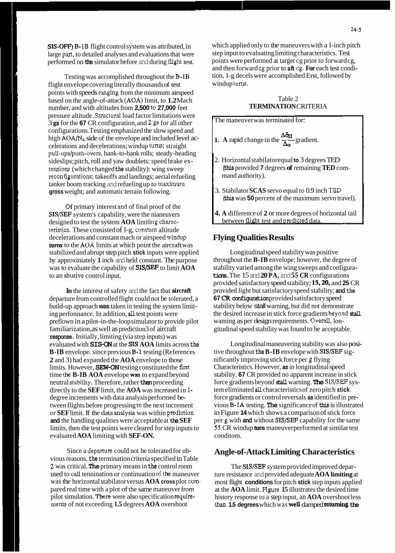
24-5
which applied only to the maneuvers with a I-inch pitch step input to evaluating limiting characteristics. Test points were performed at target cg prior to forward cg, and then forward cg prior to aft cg. For each test condi- tion, I-g decels were accomplished Erst, followed by windup tum.
SIS-OIT) B-1B flight control system was attributed, in large pm, to detailed analyses and evaluations that were performed on the simulator before and during tlight test.
Testing was accomplished throughout the B-1B flight envelope covering literally thousands of test points with speeds ranging from the minimum airspeed based on the angle-of-attack (AOA) limit, to 1.2 Mach number, and with altitudes from 2,500 to 27,000 feet pressure altitude. Sttuctural load factor limitations were 3 gs for the 67 CR configuration, and 2 gs for all other configurations. Testing emphasized the slow speed and high AOA/N, side of the envelope and included level ac- celerations and decelerations; windup turns; straight pull-ups/pusb-overs, bank-to-bank rolls; steady-heading sideslips; pitch, roll and yaw doublets: speed brake ex- tensiom (which changed the stability): wing sweep reconfigurations: takeoffs and landings; aerial refueling tanker boom tracking and refueling up to m a x i " gross weight; and automatic terrain following.
OC primary interest and of final proof of the SIS/SEF system's capability, were the nianeuvers designed to test the system AOA luniting c h m o teristics. These consisted of I-g, constaut altitude decelerations and constant mach or airspeed windup toms to the AOA limits at which point the aircraft was stabilized and abrupt step pitch stick inputs were applied by approxiniately 1 inch and held constant. The purpose was to evaluate the capability of SIS/SEF to limit AOA to an abusive control input.
In the interest of safety and the fact tbat &c& departure from controlled flight could not be tolerated, a build-up approach was taken in testing the system limit- ing perfonnance. In addition, all test points were preflown in a pilot-in-the-loop simulator to provide pilot familiarization, as well as prediction3 of aircraft response. Initially, limiting (via step inputs) was evaluated with SIS-ON at the SIS AOA limits across the B-IB envelope. since previous B-1 testing (References 2 and 3) had expanded the AOA envelope to those limits. However, SEW-ON testing constituted the first time tbe B-IB AOA envelope way to expand beyond neutral st&bility. Therefore, rather then proceeding directly to the SEF limit, the AOA was increased in 1- degree increments with data analysis performed be- tween flights before progressing to the next increment or SEF limit. If the data aoalysis was within prediaion and the handling qualities were acceptable at the SEF limits, then the test points were cleared for step inputs to evaluated AOA limiting with SEF-ON.
Since a depmure could not he tolerated for ob- vious reasons, the termination criteria specified in Table 2 was critical. The primary means in the control room used to call tennination or continuation ol-the maneuver was the horizontal stabilator versus AOA cross plot conk pared real time with a plot of the same maneuver from pilot simulation. There were also specification require ments of not exceeding 1.5 degrees AOA overshoot
Table 2 TERMINATION CRITERIA
The maneuver was terminated for:
A& Aa
1. A rapid change in the --gradient.
2. Horizontal stabilatorequal to 3 degrees TED (this provided 7 degrees of remaining TED com- mand authority).
3. Stabilator SCAS servo equal to 0.9 inch TED (this was 50 percent of the maximum servo travel).
4. A difference of 2 or more degrees of horizontal tail between flight test and oredicted data.
Flying Qualities Results
Longitudinal speed stability was positive throughout the B-IB envelope; however, the degree of stability varied among the wing sweeps and configura- tions. The 15 and 20 PA, and 55 CR configurations provided satisfactory speed stability; 15.20, and 25 CR provided light but satisfactory speed stability; and the 67 CR configuration provided satisfactory speed stability below stall warning, but did not demonstrate the desired increase in stick force gradients beyond stall waming as per design requirements. O v e d , lon- gitudinal speed stability was found to he acceptable.
Longitudinal maneuvering stability was also posi- tive throughout the B-IB envelope with SIS/SEF sig- nificantly improving stick force per g flying Characteristics. However, as in longitudinal speed stability. 67 CR provided no apparent increase in stick force gradients beyond stall warning. The SIS/SEW sys- tem eliminated all characteristics of zero pitch stick force gradients or control reversals as identified in pre- vious B-1A testing. The significance of this is illustrated in Figure 14 which shows a comparison of stick force per g with and without SIS/SEF capability for the same 55 CR windup turn maneuver performed at similar test conditom.
Angle-of-Attack Limiting Characteristics
The SIS/SEF system provided improved depar- ture resistance and provided adequate AOA limiting at most flight conditions for pitch stick step inputs applied at the AOA limit. Rgure 15 illustrates the desired time history response to a step input, an AOA overshoot less thao 1.5 degrees which was well damped reluming the
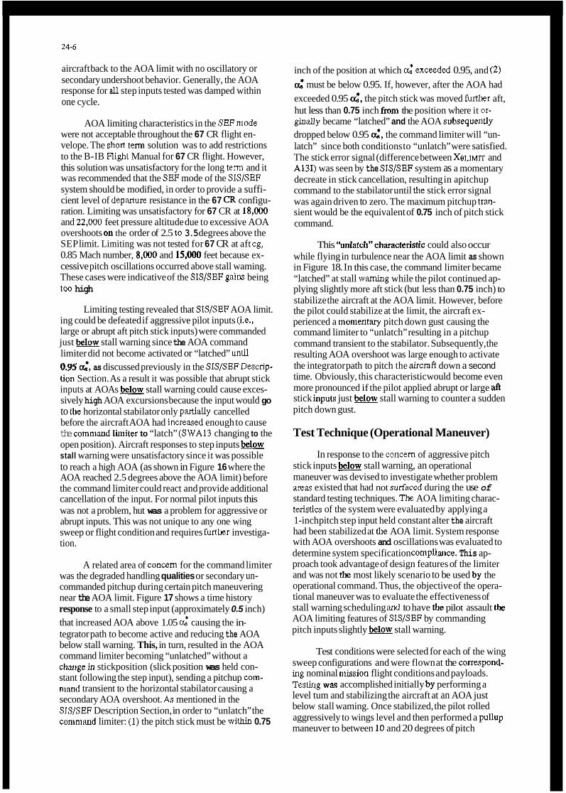
24-6
aircraft back to the AOA limit with no oscillatory or secondary undershoot behavior. Generally, the AOA response for all step inputs tested was damped within one cycle.
AOA limiting characteristics in the SEFmode were not acceptable throughout the 67 CR flight en- velope. The short tem solution was to add restrictions to the B-IB High1 Manual for 67 CR flight. However, this solution was unsatisfactory for the long term and it was recommended that the SEF mode of the SlS/SEF system should be modified, in order to provide a suffi- cient level of deparmre resistance in the 67 CR configu- ration. Limiting was unsatisfactory for 67 CR at 18,ooO and 22,000 feet pressure altitude due to excessive AOA overshoots on the order of 2.5 to 3.5 degrees above the SEP limit. Limiting was not tested for 67 CR at aft cg, 0.85 Mach number, 8,ooO and 15,000 feet because ex- cessive pitch oscillations occurred above stall waming. These cases were indicative of the SISISEF gaim being too high
Limiting testing revealed that SIS/SEF AOA limit. ing could be defeated if aggressive pilot inputs (i.e., large or abrupt aft pitch stick inputs) were commanded just below stall warning since the AOA command limiter did not become activated or “latched” uncil 0.Y5 d, as discussed previously in the SIS/SEFDescrip- lion Section. As a result it was possible that abrupt stick inputs at AOAs below stall warning could cause exces- sively high AOA excursions because the input would go to IIK horizontal stabilator only panially cancelled before the aircraft AOA had increaxd enough to cause the comniand Limiter to “latch” (SWA13 changing to the open position). Aircraft responses to step inputs below stall warning were unsatisfactory since it was possible to reach a high AOA (as shown in Figure 16 where the AOA reached 2.5 degrees above the AOA limit) before the command limiter could react and provide additional cancellation of the input. For normal pilot inputs this was not a problem, hut was a problem for aggressive or abrupt inputs. This was not unique to any one wing sweep or flight condition and requires furtkr investiga- tion.
A related area of concem for the command limiter was the degraded handling qualities or secondary un- commanded pitchup during certain pitch maneuvering near the AOA limit. Figure 17 shows a time history response to a small step input (approximately 0.5 inch) that increased AOA above 1.05 d causing the in- tegrator path to become active and reducing the AOA below stall warning. This, in turn, resulted in the AOA command limiter becoming “unlatched” without a changein stickposition (slick position was held con- stant following the step input), sending a pitchup com- ninnd transient to the horizontal stabilator causing a secondary AOA overshoot. A.7 mentioned in the SIS/SEF Description Section, in order to “unlatch” the commaud limiter: (1) the pitch stick must be within 0.75
inch of the position at which $exceeded 0.95, and (2) d must be below 0.95. If, however, after the AOA had exceeded 0.95 4, the pitch stick was moved furtller aft, hut less than 0.75 inch f” the position where it or- ginally became “latched” and the AOA subsequedy dropped below 0.95 6, the command limiter will “un- latch” since both conditions to “unlatch” were satisfied. The stick error signal (difference between XeLiMrr and A13I) was seen by the SIS/SEF system as a momentary decreate in stick cancellation, resulting in apitchup command to the stabilator until the stick error signal was again driven to zero. The maximum pitchup tran- sient would be the equivalent of 0.75 inch of pitch stick command.
This ‘~n1atcli”characteristic could also occur while flying in turbulence near the AOA limit as shown in Figure 18. In this case, the command limiter became “latched” at stall waming while the pilot continued ap- plying slightly more aft stick (but less than 0.75 inch) to stabilize the aircraft at the AOA limit. However, before the pilot could stabilize at the limit, the aircraft ex- perienced a momentary pitch down gust causing the command limiter to “unlatch” resulting in a pitchup command transient to the stabilator. Subsequently, the resulting AOA overshoot was large enough to activate the integrator path to pitch the aircdt down a second time. Obviously, this characteristic would become even more pronounced if the pilot applied abrupt or large aft stick inpuLr just below stall warning to counter a sudden pitch down gust.
Test Technique (Operational Maneuver)
In response to the concem of aggressive pitch stick inputs below stall warning, an operational maneuver was devised to investigate whether problem mas existed that had not s u r f a d during the use of standard testing techniques. Tk AOA limiting charac- teiistics of the system were evaluated by applying a 1-inch pitch step input held constant alter the aircraft had been stabilized at lhe AOA limit. System response with AOA overshoots and oscillations was evaluated to determine system specification comphnce. This ap- proach took advantage of design features of the limiter and was not the most likely scenario to be used by the operational command. Thus, the objective of the opera- tional maneuver was to evaluate the effectiveness of stall warning scheduling aml to have &e pilot assault the AOA limiting features of SIS/SEF by commanding pitch inputs slightly below stall warning.
Test conditions were selected for each of the wing sweep configurations and were flown at the correspou4- ing nominal niission flight conditions and payloads. TesCiag way accomplished initially by performing a level tum and stabilizing the aircraft at an AOA just below stall waming. Once stabilized, the pilot rolled aggressively to wings level and then performed a pullup maneuver to between 10 and 20 degrees of pitch

24-1
AOA with apossible departure from controlled flight if stall waming was not observed. This was not unique lo any one wing sweep or flight condition and will require crew training to ensure B-1B pilots are aware of these characteristics.
Longitudinal stability limitation is a potential problem that exists with highly mission specialized aircraft such as the US. F-Ill fighter and B-1B bomber because of basic aerodynamic design. Futhermore, it can be coinpounded or made even more pronounced by new mission or growh requirements as evident in this paper. SIS/SEF systems will always be needed, but should be incorporatedinto the initial flight control system design.
attitude. During the pullup maneuver, the pilot was to be aggressive with the system but to always adhere to stall wanung.
Pilot comments indicated that for both SIS and SEF, and the fonvard wing sweeps (15 CR, 15 PA, 20 CR, 20 PA and 25 CR), only small maneuver margins existed below stall wamiug. However, uo large over- sliools occurred as long as stall waming was observed and the aircraft was controllable. For the aft wing sweeps (55 and 67 CR) at the nominal flight conditions flown, stall wanung could not be achieved without ex- ceeding the s t ~ c t ~ r a l liniits of the aircraft and no prob- lem areas were noted.
CONCLUSIONS
Overall, the B-IB flight control system modified with the Stall Inhibitor System/Stability Enhancement Function system provided acceptable flying qualities throughout most of the B-IB operatiorial envelope. The SIS/SEF system produced a marked improvement in flying qualities and aircraft capabilities over the oriyinal SCAS-OIIIY (Le., SlS-OFF) B-IB FCS. The SlS/SEF sys- tem provided a significant increase in operational capabilities, which have been constrained by stability limitations rather than lift limitations. ‘Iliis improved system provided sufficient apparent stability and depar- ture resistance to fly safely near maximum lift. The addi- tion of SIS/SEF also provided an increaye in the use of the operational AOA envelope (stall waming envelope) from 0.80 Q willi SIS-OFF, to 0.95 Q with SIS- or SEF-ON. With the increased AOA envelope provided by SIS/SEF, two ‘areas of improved aircraft capability were the B-IB’s abilities to aerial refuel and to terrain follow at gross weights up to 100,000 pounds heavier over the original SCAS-only (Le., SIS-OFF) B-IB FCS (see Figures 19 and 20).
The modified B-1B FCS, with SIS engaged, provided acceptable flying qualities including adequate stick force cues for positive speed stability, positive maneuvering stahility, and departure resistance throughout most of the B-IB stable AOA envelope. The SEF mode also provided the same acceptable speed stability, nianeuveriiig stability, and departure resistance throughout the expanded AOA envelope (full operation- al envelope) for all wing sweeps and configurations tested, except 67 CR. Testing at 67 CR revealed unsatis- factory AOA liniiting at the SEF AOA h i t at altitudes greater than 15,000 feet due to excessive AOA over- shoots (greater than 2 degrees for aft stick step inputs). In addition, AOA limiting was untested at 67 CR at al- titudes less than 15,000 feet at aft cg due to oscillatory behavior above stall wandng. Testing bad revealed that SIS/SEF was not a foolproof syteni and that its ability to limit AOA could be defeated if aggressive pilot inputs @e., large or abmpt aft pitch stick inputs) were com- manded just &stall warning. The response to these ii~purs as a result of the “latcl/unlatch” characteristics of the AOA conimand limiter was a large overshoot in
REFERENCES
1. Ross, Captain Jerry L., et al., Flying Qualities and Flight Control System Evaluation of the B-1 Strategic Bomber, AFFTC-TR-79-2, AFFTC, Ed- wards AFB, California, May 1979.
2. Tiemey, Paul K., et al., B-1 Flying Qualities Evalua- tion (B-1B Prototype Flight Controls), AFmC-TR- 84-6, AFFTC, Edwards AFB, California, December 1984.
3. Regis, Theresa M., et al., B-IB Flying Qualities Evaluation (Stall Inhibitor System-1 ), AFFTGTR-88- 11, AFFTC, Edwards AFB, Califonlia, December 1984.
4. Sohota, Captain Mark S., et al., 8-1B Flying Qualities Evaluation (Stall Inhibitor System3 and Stability Enhancement Function), AFFTC-TR-89-30. AFFTC, Edwards AFB, California, December 1984.
5 . LRCA B-1B Flight Control System Description, TFD- 82-67, Rockwell International, Los Angeles, Califor- nia, 12 January 1988.
6. B-IB Stability Enhancement Function Design Requirements, TFD-84-2233, Rockwell Intemational, Los Angeles, California, 24 September 1986.
7. B-1B Automatic Flight Control Subsystem (AFCS) Description, NA-82-216, Rockwell Intemational, Los Angeles, California, 4 January 1983.
8. Standardized Angle of Attack Computation and Design Data Requirements for SIS3ISEF, TFD-86- 1470, Rockwell International, Los Angeles, Califor- nia, 24 April 1989.

WING SWEEP: 67 DEG, CRUISE C.G.: 25% MAC
M C
-10 A -20
L C
Figure 1 B-1 Lift and Moment Characteristics

P
Figwe 2 B-1B 'Ihree View

WING SWEEP: 20 DEG, CRUISE SlSlSEF Mode: SEF-ON
Pressure Altitude: 15,000 ft Mach Number: 0.51
C.G.: 36% MAC (Aft Limit) 15
10
5
0 2 4 6 8 1 0 1 2
-1
0 8 p g )
1
(TED) 2 0 2 4 6 0 1 0 1 2
CL
2-
, - .............................. ........................

c. STANDARDIZED AOA DEFINITION c.
...
0.0 l .0SlS STALL WARNING: SIS-OFF = O.SOa, SIS
SIS-ON = 0.95a,Ss SEF-ON = 0.95aSSEF
Figure 4 SIS Standardized AOADefinition
Figure 5 CADC Stability Enhancement Gain

24-12
I I r - c .- I I 3

Prop. Gain
1.0 - Pitch Rate Gain
0.0 - A
0 22
WINGSWEEP (DEGREES)
Figure 8 Pitch Rate Damping Offset

24-14
1
l 3
. --
.&we. output
/-
AQSA1O
Figure 9 a. Limit Integration Offset
4
Savior Gain
0
Ao(sF11o
Figure. 10 SIS-2/SEp Savior Patb Function

24-15
Figure 11 SIS-USEP Nonlinear Mechanical Cancellation
I 4
Xg CANCEL (INCHES)
2-. 1.75 -
0 0 1 3 4 7
X g (INCHES)
Figure 12 Blectrical Cancellation

0.75
1 xhl 0 . 7 S + l
FiQM mai %As I
SWA-13 LCGffi
SWA-13 - 0.0 FOR ai 2 0.95 (“-7 SWA-13 - 1.0 FOR m6 < 0.95 C U M 7
AM (a) - (A13 + 0.75) s 0
A131
- I
Figure 13 AOA Comaad Limiter
WING SWEEP: 55 DEG, CRUISE
Pressure Altitude: 5000 ft Mach Number: 0.55
C.G.: 43% MAC (Aft)
2
Figure 14 Windup Tum Maneuvering Performance With and Without SIS/SEF - 55CR

24-17

24-18

N P L 10
+ o i o i0 i o $0 i o 1bo ELAPSED T I M E [SEC)
Note: Repmen& secondary overshoot due to unlatching and large undershoo*; due to high-integrator output
Figure 17 Step Input - 20 CR

24-20
2’

B-1B TERRAIN FOLLOWING ENVELOPE
WING SWEEP : 25 DEG CRUISE MACH NUMBER : 0.70
” 240 280 320 360 400 440
Gross Weight (X 1000 lbs)
Figure 19 Aerial Refueling Benefit With and Without SIS/SEF
B-1B AENAL REFUELING ENVELOPE
WING SWEEP : 67 DEG CRUISE MACH NJMBER : 0.85
C.G. : 30% MAC 15
10
Altitude (X 1 OOOft )
5
n 240 280 320 360 400 440
Gross Weight (X 1000 lbs)
Figure 20 Terrain Following Benefit With and Without SIS/SEF


25-1
FLYlNG QUALITIES OF THE X-29 FORWARD SWEPT WING AIRCRAFT
Dr Lawrence A.Walchli Wright Research and Development Center Wright Patterson AFB OH 45433-6523
United States
ABSTRACT
An overview of the X-29 Foward Swept Wing Technology Demonstrator traces its development and test path during the past 6 years. Brief descriptions of the aircraft and its flight control system provide insight for evaluating this unique vehicle. system provided a starting point for safe concept evaluation and envelope expansion for the aircraft. Subsequent up-dates resulted in performance levels favorably comparable to current fighter aircraft. Efforts are described for the Current expansion of the X-29's capabilities,into the high angle-of-attack (AOA) regime of flight. Control law changes have permitted all axis maneuvering to 40 degrees AOA with pitch excursions to 66 degrees, thereby exploiting the full potential of the X-29 foward swept wing configuration.
The baseline flight control
INTRODUCTION
Agility, maneuverability, integration: key words used to describe the successful development of the X-29 Foward Swept Wing Technology Demonstrator.
The X-29 integrates several different technologies into one airframe as depicted in Figure 1 . The aeroelastically tailored composite wing covers cause the forward swept wing to twist as it deflects, successfully delaying wing divergence. The thin supercritical airfoil, coupled with the discrete variable camber produced by the double-hinged full span flaperons, provide optimum wing performance at all flight conditions. The aircraft inherits its 35 percent Static instability (time to double amplitude of about 0.15 seconds) from the close-coupled. variable incidence canard. Without it the wing-body combination is near-neutrally stable. which has an area about 20 percent of the wing area, produces lift and its downwash delays flow separation at the wing mot. The threc-surface pitch control-the canard. flaperon, and strake flap -- is used by the digital fly-by-wire flight control system to control an otherwise unflyable unstable vehicle. The success of the X-29 really rests with the integration of these technologies into a single synergistic configuration built for drag reduction in turning flight.
The canard,
Two X-29 aircraft were designed and built. The first entered flight testing in December 1984 and concluded in December 1988. completing 242 flights and over 200 flight hours. The primary objective of Ship #l testing was to validate, evaluate and quantify the benefits of the technologies on board, both individually and collectively.
The first 2 years of Ship #I testing were primarily dedicated to altitude and Mach Number lg envelope expansion. Performance testing fallowed the envelope expansion and was completed in December 1987. Drag reduction during maneuvering exceeded design goals by about 15 percent subsonically. Finally, Ship #l testing provided evaluations of handling qualities, military utility and agility metrics below 20 degrees angle-of-attack.
by Rogers ESmith
NASA Ames Dryden Research Facility Edwards CA United States
Ship (12. which was modified to allow high AOA testing, began flying in May 1969. Its spin chute was designed to assist the pilot in regaining control in the event of a departure from controlled flight. Control surface tutorial lights mounted in the cockpit assist in this task. The flight control system software was significantly modified in order to best utilize the various surfaces in controlling the aircraft in a post-stall environment. expansion is complete to 66 degrees AOA and 10 degrees sideslip. Accelerated entry high AOA expansion is well under way. Once the aircraft is cleared for full envelope maneuvering it will be used to demonstrate the military utility and agility of a forward swept wing vehicle operating in a high AOA regime.
One g envelope
AIRCRAFT AND FLIGHT CONTROL SYSTEM DESCRIPTION
Two essentially identical X-29s were designed and built by Gruman Aerospace Corporation, Bethpage, New York (Reference 1) . To reduce overall program costs, the Air Force supplied several major components of the aircraft to Gruwnan. These included the F-5A forebody and nosegear; F-16 main gear, actuators, airframe-mounted accessory drive and emergency power unit; F-18 F404 engine; SR-71 HDP5301 flight control computers; and F-14 accelerometers and rate gyros. Use of these time-proven components also increased the reliability of the flight vehicle.
The X-29 flight control system (FCS) is a triplex digital fly-by-wire system with triplex analog back-up (as shown in Figure 2). The fail-oplfail-safe system used MIL-F-R785C and MIL-F-9490D specifications as design guides. Flying quality design goals were Level I for the primary digital mode and Level I1 for the analog back-up mode.
Normal aircraft operation is accomplished through the normal digital (ND) mode with its associated functional options such as automatic camber control (ACC), manual camber control (MCC). speed stability, precision approach control (PAC) and direct electrical link (DEL). ND also contains options in its gain tables for power approach (PA), up-and-away (UA), and degraded operation.
The X-29 longitudinal control law is shown in Figure 3 , while the lateralldirectional schematic is shown in Figure 4 (See Reference 2 for a detailed description. A more general review of the X-29 technologies and the special X-29 flight test issues are presented in Reference 3 . ) The normal digital mode has a pitch rate control law with gravity vector compensation, driving a discrete ACC system. of Mach Number and altitude and incorporates a sophisticated redundancy management system allowing fail-oplfail-safe flight. MCC is a pilot-selected, fixed flaperon sub-mode of ND used for landing. The PAC function is a pilot-selected auto throttle system. control law set which is active when any landing gear weight-on-wheel relay is open. This function fades out the longitudinal foward loop integrator, allowing direct pilot control of the canards during taxi, take-off, or landing roll-out.
This mode is gain-scheduled as a function
The DEL function is a ground contact

25-2
Cain tables for degraded operation are activated by a failure of the Attitude Heading Reference System or any 2 of the 3 angle-of-attack sensors. This function Cannot be pilot-selected. nor can it be exited in flight. Degraded n o m 1 digital operation is the last option available during sensor failures prior to automatic down-moding to analog reversion.
The analog reversion (AR) mode is the back-up flight control system. designed to bring the aircraft safely back to base. The AR mode provides a highly reliable, dissimilar control mode to protect against generic digital control failures. It incorporates UA and PA functions similar to those of the ND mode. AR contains no longitudinal trim capability or pitch loop gain compensation with dynamic pressure while the aircraft is on the ground. it performs like the ND control system.
In all other aspects,
The initial X-29 Ship 01 flying was limited to 0.60 Mach Number and 30,000 feet pressure altitude. As the flight envelope was expanded. the FCS evolved. management modifications were made as a result of flight test data. added to enhance the research capability of the aircraft. Addition of the Remote Augmented Vehicle (RAV) system, developed by NASA, provided the capability to pulse individual control surfaces so as to extract their effectiveness. As Ship #l entered the military utility and agility phase of its flight test program additional changes were made. and improve handling qualities, control stick harmony was improved by reducing the longitudinal throw by about 50 percent. to the gains for both longitudinal and lateral axes was made to remove the earlier sluggishness in both pitch and roll response of the aircraft.
Several gain and redundancy
The PAC and MCC modes were
In order to enhance agility
A further modification
Late in 1987. Ship 62 was removed from storage and rcodifications were begun for a high AOA program. A spin chute system wa8 added to the aircraft to assist in recovery of the aircraft from an inadvertent departure. The system was designed for pyrotechnic chute deployment and mechanical jettison. A pyrotechnic emergency jettison is also available. Cockpit instrumentation was changed to accentuate the importance of the angle-of-attack and yaw indicators by using large 6 inch meters centered on the console. Spin chute system statu8 lights and test switches were added as well a8 instructional lights to assist the pilot in applying spin-recovery control inputs.
The Ship #2 flight control laws were modified to permit all-axis maneuvering to 40 degrees AOA, and pitch-only maneuvering to as high a8 70 degrees AOA. Below 10 degrees, the control laws are identical to those last flown on Ship 81. Between 10 and 20 degrees, the high AOA modifications are faded in until above 20 degrees they are fully functional. law modifications are included in Figures 3 and 4.
The high AOA control
The high AOA changes are fairly simple. A spin prevention logic is active above 40 degrees or below minue 25 degrees AOA with increasing yaw rate. The logic increases the authority of both the rudder peddles and lateral stick and disconnects all other lateral/directional feedbacks. Besides the Spin prevention logic, an aileron-to-rudder interconnect provides for better roll coordination at high AOA. Also assisting in roll coordination is a rate-of-sideslip feedback to the rudder. predicted for the X-29 above 30 degrees angle-of-attack. a high gain roll rate-to-aileron
Since substantial wing rock was
feedback loop has been added to compensate for the unstable rolling moment coefficient due to roll rate.
X-29 LOW AOA TEST RESULTS
Background
The ultimate goal of the X-29 Technology DemonGtrator Program was to transition new technologies to future fighter-class aircraft. The flight test program was structured to ascertain whether the suite of X-79 technologies can in fact produce performance gains through drag reduction over existing systems without sacrificing the pilot's ability to comfortably control his aircraft. control law was to have this 35 percent statically unstable aircraft exhibit Level I handling qualities. For about the first 3% years of flying (186 flights), the X-29 Ship b l exhibited Level I1 handling qualities. These less-than-desirable
decisions to trade design iterations and system performance for safety margin and cost/sehedule savings. On early flights the control stick harmony was judged poor for a fighter aircraft, but adequate for a technology demonstrator. The flight control system gains in pitch and roll were purposely reduced to achieve added margin of safety while validating the wing structure. Again. the resulting performance was acceptable for a demonstrator but did not represent current fighter capabilities.
Flight Control System Modifications
The original design goal for the X-29
ratings were a result of several programlatic
The original control stick had B 10 inch travel in pitch and a 3.2 inch travel laterally. unharmonious situation made lateral tracking difficult during high g maneuvers and created slow pitch response. made after flight 186 which cut the pitch throw on the stick in half while maintaining the same stick farce per g. moved forward one inch.
This
A hardware and software change was
The pitch neutral point was also
Following flight 213, another flight control system change was made (Reference 4 and 5). Pitch and roll gains were increased to permit better dynamic performance from the aircraft. the flight g limit of 6.4 was not changed since no structural proof test has ever been conducted (thereby limiting flight to 80 percent design limit load). The results of these gain changes were a 41 per cent improvement in available maximum pitch acceleration and a 40 per cent increase in the maximum rol l rate to 220 degrees per second. The results are shown in Figures 5 and 6 over the 0.4 to 0.9 Mach Number range. gain changes were made.
Flying Qualities Evaluation
However.
Note that no supersonic
The matrix of low AOA handling quality pilot evaluation tasks is depicted in Figure 7. These tasks were performed only in the normal digital, ACC flight control system mode with the up-and-away gain set. They were flown within a flight envelope of 10,000 to 25,000 (10 and 25K) feet pressure altitude and 200 to 450 Knots indicated air speed (KIAS). to a maximum 0.9 Mach Number. In all cases, the chase aircraft began either specified or random maneuvers and the X-29 pilot reacted to them.
The Cooper-Harper ratings for these tasks are presented in Figures 8a to 8d. The height of the bars indicates the range of ratings received for each task prior to flight 187. The elipses show

25-3
The final task for Ship # 1 handling qualities is the air-to-air tracking task (Figure 8d) . A s with the finger tip formation task, all of the early pilots flew the air-to-air tracking. Three different set-ups were used: in-trail. 3g target: 90 degree heading crossing angle. 4g target; and 180 degree heading crossing angle, 4 g target. . Pilot ratings appeared to be independent of target set-up. although with 80 many variables it was somewhat difficult to interpret the results. The average ecores ranked as Level I1 handling qualities. The lack of control stick harmony did not seem to strongly influence the pilot comments. Once the stick harmony was improved. 3 X-29 veterans and 2 new pilots f l e w the task. A l l 3 veterans found gross acquisition acceptable and fine tracking excellent. The 2 guest pilots rated the task as Level 11. roll response improvements to the flight control system. the same 3 veteran X-29 pilots reflew the task and found more improvement. "Good control harmony." "Nice roll response." "Pitch fine tracking was excellent." any aircraft I have flown!" And finally, from a guest pilot, "Fine tracks as good as our current fighters. "
Summary of X-29 Low AOA Tests
Fallowing the pitch and
"Fine tracks as well a8
The flying qualities Of X-29 Ship 111 evolved during the low AOA flight tests from Level I1 aircraft to a solid Level I aircraft with excellent flying qualities in a variety of realistic tests. This improvement in the flying qualities was accompliPhed with relatively simple modifications to the FCS. The end result was an aircraft which is representative of current fighters.
the average for data from flights 187 through 213, and the stam show the results for the final software flown in the military utility and agility flights after 213. improvement in handling qualities from Level 11 to Level I.
The data shows an overall
The finger tip formation task (Figure 8a) was flown by virtually all of the pilots who flew the X-29 prior to flight 187, a total of 13. A l l pilots felt that the stick harmony between the longitudinal and lateral axes was poor. This resulted in an apparent sluggishness in pitch and an overcontrol tendency in the lateral direction. In general. they rated the task a s medium-to-high workload. Following the control stick modification, 4 pilots repeated the task and 3 new pilots flew it for the first time. Comments referred now to good stick harmony, but perhaps too much sensitivity (gain) in roll. Pilot ratings far this task improved from Level I1 to Level I. The final 29 flights of Ship #l had the increased pitch and roll response gains in the flight control system. Cooper-Harper ratings and pilot comments remained about the same. R o l l response was better, although still too Sensitive at elevated load factor.
The close trail formation task (Figure 8b) was performed by 11 pilots using the original control stick configuration. Again, the stick harmony was found to be a little annoying. During elevated g maneuvering, one pilot commented that he would not fly the slot position with the X-29. Several of the pilots found a small overcontrol tendency in pitch. Level I handling qualities. The control stick modification was made and 2 pilots repeated the task. Another pilot flew it far the first time. A l l agreed no overcontrol tendency existed and aggressive pitch inputs could now be made. Good solid Level I ratings were given. Following the pitchlroll response flight control modification. 4 pilots reflew the task. appreciably change. Several comments indicated that roll sensitivity at elevated g could be decreased.
The pilot ratings reflect borderline
Ratings didn't
The results for the simulated terrain fallowing task are shown in Figure 8c. In this task the lead aircraft pilot made small (+$, -k g) unannounced step inputs and held his input for 5-8 seconds. The job of the X-29 evaluation pilot was not to follow the lead aircraft, but to recapture the new wing reference position as quickly and accurately as possible. these evaluations, some pilots misinterpreted the original instructions and attempted to follow the lead aircraft accurately throughout the transient maneuver - an impossible task. participated and all had problems with the task. Many suffered small pilot-induced oscillations In pitch. "Two to 3 high frequency overshoots in pitch" was the most-used expression. generally a high workload task because the aircraft response lagged the longitudinal stick inputs. A solid Level I1 rating was assigned to this task. pilots (and 2 new ones) following the stick modification. The overshoots still occurred but the pilots were now able to anticipate and recover more quickly. Ratings improved, but were Still Level 11. The biggest improvement occurred a8 a result of the pitch and roll gain changes. same time, the correct task interpretation was reinforced. Indeed, the task interpretation change was significant, for Some pilots. A l l pilots rated the simulated terrain following task Level I with the final FCS modifications.
During the course of
Ten pilots
It was
The same task was repeated by 3 of the
At the
X-29 HIGH AOA TEST RESULTS
Background
The X-29 configuration is novel in that it was designed from inception by Grumman to fly to high angles-of-attack. This design requirement, in concert with high levels of longitudinal instability at low AOA and subsonic speeds, defined the need for horizontal fuselage strakes at the rear of the aircraft. These strakes move the center of pressure of the aircraft behind the center of gravity at very large AOA, thereby ensuring a nose-down pitching moment to eliminate the possibility of a hung stall condition. Wind tunnel tests of the X-29 have demonstrated Its ability to trim at AOA through 70 degrees. In addition, lateral control is predicted to be available to 90 degrees AOA. With this combination of low AOA instability and longitudinal and lateral control power to very high AOA, the X-29 represents a unique vehicle for investigating the application of high AOA maneuverability in future tactical aircraft.
The X-29 Ship 1/2 high AOA flight test program has progressed through its 5 functional test flights (June 89) and into the envelope expansion phase. To date, 50 flights have been flown with Ship 82 on the high AOA program. Once the performance envelope is fully cleared. the military utility and agility capabilities of the X-29 will be evaluated at high AOA.
Program Objectives
The objectives or goals of the high AOA flight tests are summarized in Figure 9 which also shows the X-29 stabilized at approximately 30 degrees AOA. These objectives were:

25-4
1 . Define the limits of aircraft controllability. the aircraft will respond satisfactorily to pilot inputs, both in Ig stabilized flight and during higher speed (up to 200 K I M ) maneuvering flight must be determined. Maneuver in the 35-40 degrees AOA range. Can the aircraft be effectively maneuvered, particularly i n the lateral-directional axes, at these angles-of-attack?
3 . Pitch point up to 70 degrees AOA. Can the impressive pitch power of the X-29 be utilized to achieve these angles-of-attack without dramatic handling qualities degradations?
capability of the X-29 in the context of air-to-air maneuvers consistent with military fighter utility.
5 . Finally, since this aircraft is a technology demonstrator and not a prototype for a new fighter production run, it is important to understand the flow effects within this unique configuration which produce the high AOA capabilities. In other words, it is not sufficient to just achieve good high AOA capability; it is essential that the flow mechanism which creates this capability be understood i n order that the benefits can be transferred into future designs.
The maximum AOA at which
2.
4 . Evaluate the high angle-of-attack
High AOA Test Aircraft
The high AOA test aircraft, Ship 112, is essentially the same as Ship #I except for the following key features:
1. Modified triplex digital flight control system with special control laws for flight above 20 degrees AOA (the limit for Ship i l l ) .
2. Modified flight test noseboom to include 3 AOA vanes to provide the necessary redundancy for the high AOA control system.
3 . Spin chute for recovery from inadvertent out-of-control flight. To date, this event has been avoided by prudent test planning.
The important X-29 high AOA design features are summarized in Figure 10.
High AOA Flight Control System
Specific control law modifications for high AOA flight are given in Figures 3 and 4 while the complete details of the X-29 high AOA flight control system are summarized in Reference 2. Major features of the design are shown in Figure 11. command system in pitch with a weak AOA feedback and allowed velocity vector rolls using only lateral stick inputs. Spin prevention logic was incorporated beginning at 40 degrees AOA. Variable gain features were included i n the design which allowed f20 percent variation of selected flight control system gains i n flight.
This relatively simple design provided a rate
Flight Test Expectations
Extensive background studies and evaluations were made i n support of the development of this unique, highly unstable aircraft. Over a period of 10 years. studies were made using a rotary balance, wind and water tunnels, special drop model tests, and free flight wind tunnels. These
studies were largely done at the NASA Langley facilities and the facilities at Gruman Aircraft Corporation. who designed and built both aircraft.
From these studies, the major trends and problem arean were identified. of the X-29 (above 30 degrees) was expected to be influenced by, if not limited by:
High AOA utility
I . 2. Nose slice potential of the F-5 forebody. 3. Wing rock. 4. Engine inlets which were not specifically
Lack of directional control power.
designed for high AOA flight.
Results from these extensive studies were also used to create the aerodynamic models required to produce the necessary ground simulations. ground simulator was used in support of the high AOA control law development and the actual flight tests. essential part of the test program. particularly during the hi.gh AOA control law development phase. Once the tests began, the simulator remained an important element in the program despite the need for constant revision to incorporate the differences between predictions and the actual flight test measurements. The evolution of the X-29 flight test process, including the role of the ground simulator, is discussed in the Lessons Learned subsection which follows.
The
The X-29 simulation facility was an
High AOA Flying Qualities
The X-29 performance at high AOA was excellent and generally better than expected; the flight tests were certainly not just validation of the predictions. This phase of the X-29 program was exciting, technically stimulating. and rewarding from both the engineering and test pilot viewpoint.
The results for Ig stabilized flight can best be summarized using Figure 12. The major highlights from these X-29 high AOA tests which were conducted between 40000 and 25000 ( 4 0 and 25K) feet were:
1. Good pitch control at all AOAs. 2. Controllability degraded above 43 degrees
AOA, but always in a graceful manner (no departures).
- roll rates of approximately 35 degrees 3 . Good lateral control up to 40 degrees AOA.
per second about the velocity vector.
behaved and precise. - full lateral Stick rolls were well
4 . Wing rock didn't start until about 4 0 degrees AOA and then was mild ( f 4 degrees bank angle).
4 3 degrees AOA: 4 3 and 50 degrees AOA. left yaw above 50 degrees AOA.
5 . Directional aspmetries were evident above right yaw evident between
6. Maximum stable AOA was 50 degrees. 7. Pitch excursions were performed from a
stabilized 40 degrees AOA up to as high as 66 degrees AOA without departures (left yaw was not controllable, but graceful at forward c . g . ' s ) .
the high AOA test program. 8. Engine response was excellent throughout
The pitch transient from a stabilized point at 40 degrees AOA to 66 degrees AOA is shown in Figure 13. The impressive pitch power and linearity of the response are evident in the figure which represents the response at the most forward c.g. About 113 of the available forward stick was used to initiate recovery. It is noteworthy that the canard momentarily Saturated

25-5
testing did, however, continue with a revised. more pragmatic test approach. in an attempt to understand the differences, which represented a difficult problem since no new prediction data were available. test approach began by admitting that the flight tests were not just validation and that the aircraft was itself one of the available research tools. Surmounting that obstacle, the next step was to proceed with a series of tests to increase AOA prudently. A6 part of this process. baseline observations were solicited from the pilots: does the aircraft roll in the direction commanded? by the stick? by the rudder? is the dihedral effect positive? is the aircraft directionally stable?, ete. In this way, important fundamental stability questions were directly addressed.
Efforts continued
The new flight
As the flight test results were obtained, every effort was made to update the simulator using a variety of parameter identification data. The simulator, in addition to its usefulness for test preparation, was also used to evaluate worst-case scenarios. However, the results at the next higher increment in AOA always produced new discoveries. This less than elegant flight test process was. in fact, both effective and educational and allowed a safe expansion of the high AOA envelope.
on its 60 degree nose down stop during recovery with no ill effects. Subsequent tests to 55 degrees AOA at a more aft c.g. were not as linear and well behaved, but still there were no controllability problems.
Tests were also completed at 160 and 200 KIAS up to 35 degrees AOA which resulted in a maximum load factor of about 3.5g's. Full lateral stick 360 degree rolls were flown with good response and control. near-perfect velocity vector rolls at these AOAS.
Lessons Learned
The flight control design produced
In the case of the X-29, the differences between predictions and the flight test results were gratifyingly generally in the positive direction. The aircraft flew better than expected at high AOAs. As previously noted, the major trends in the X-29 characteristics at high AOA and the potential problem areas were properly identified by the extensive background studies. The details of the X-29 characteristics were brought out during the flight tests. caees the differences were significant; for example, the wing rock of the real aircraft was less severe and its onset delayed compared with the predictions.
In some
Out of this X-29 high AOA program experience, which can best be described as a discovery process, several lessons can be drawn. There are many potential reasons for the differences between the actual and predicted aircraft characteristics. The complete story will not be available until the flow effects on this unique configuration are better understood, hopefully through flow visualization and pressure studies. list of the reasons for the differences would include:
A partial
1. Flow effects of the forward swept wing and canard interaction are not fully understood.
2 . Important effects of the unsteady forebody vortex flow are not fully understood.
3. Rudder control power was higher at high AOA than predicted.
4. Dihedral effect was lower than predicted. 5 . Lateral control power was higher than
predicted. 6. Roll damping was more stable than
predicted. 7, The effects of the high gain FCS are not
fully understood.
In conventional flight regimes (lower AOA) with a low-gain flight control system, the observed differences in control derivatives would not be significant. However, in the sensitive hlgh AOA arena with a high-gain flight control system operating, differences between predictions and actual aircraft characteristics which are wlthin previously accepted data tolerances can now be significant. For example, the X-29 lateral control derivative was higher than predicted by about 20 percent and the roll damping was more stable than predicted. These differences. in combination with the very high lateral control system feedback gains, produced a significant delay in wing rock onset and reduction in magnitude.
From the first tests above 20 degrees AOA which showed. at the time. apparently alarming differences from the ground simulator, the test process and role of the simulator in the test program changed. The initial concerns with these differences produced B desire to stop flying long enough to understand "the problem". Flight
Summary of X-29 High Angle-of-Attack Tests
The x-29 high AOA research program was clearly a discovery process which included many important elements. Analysis, wind tunnels, rotary balances, and the final step, flight test, were all essential to this exciting learning process. Simply stated, the X-29 flies very well at high AOA.
Future Plans
The X-29 high AOA program le not yet complete.
1. Flight control system improvements. These efforts are centered on increasing the velocity vector roll rates and reducing the high frequency lateral actuator noise during higher speed, high AOA maneuvers. These high frequency inputs caused several actuator miscompares during the tests. Complete the military utility and agility evaluations to understand the potential of applying the X-29's high AOA maneuvering capabilities during air-to-air engagements.
3. If possible, inclusion of flow visualization capability and pressure measurement instrumentation on the aircraft. These additions are required to understand fully the complex flow interactions on the aircraft.
4. Finally, the control of the important forebody vortices would significantly increase the X-29 capability at high AOA. Various studies are underway to determine the best method of achieving the necessary forebody vortex control.
Future plans include:
2.
CONCLUDING REMARKS
Flight tests of the unique X-29 design have been performed at high and low angles-of-attack using both test aircraft. The drag reduction design goals of the X-29 were demonstrated at law angles-of-attack (less than 20 degrees) using Ship # I . while the high angle-of-attack capability of the forward swept wing design was explored using Ship #2. The important observations about

25-6
the X-29 flying qualities in both angle-of-attack regimes are as follows:
1. The X-29 Ship d l tests clearly demonstrated the viability of flying a highly unstable forward swept wing aircraft using a 3-surface digital flight control system.
2. Excellent flying qualities (Level I) were achieved for operations-oriented tasks during the Ship 01 testing up to 20 degrees AOA through a series of relatively simple control system modificatione.
3. Excellent high AOA capability and flying qualities were demonstrated during the recent flight tests using Ship #2.
REFERENCES
1. Whitaker, A , . and Chin, J.. "X-29 Digital Flight Control System," AGARD-CP-384, Active Control Systems Review, Evaluation and Projections. October 1984.
2. Pellicano, et al, "X-29 High Angle-of-Attack Flight Test Procedures, Results. and Lessons Learned," Society of Flight Test Engineers 21st Symposium. August 1990.
3. Smith, R. E., and Schroedee, K. C.. "Flight Testing the X-29," 30th SETP Symposium Proceedings, September 1986.
4. Hoover.. Al, Major, WAF, "Agility Flight Testing, A Progress Report.'' 32nd Annual Symposium of the Soeie'ty of Engineering Test Pilots, September 1988.
5. Bosworth, J. T., and Cox, H. C., "A Design Procedure f o r the Handling Qualities Optimization of the X-29.4 Aircraft," AIAA 89-3428, Boston, Mass.. August 1989.
FIGURE 1. X-29 ADVANCED TECHNOLOGIES

H001. FlEO F5 SILO1 CON. i n o u
FIGURE 2. X-29 FLIGHT CONTROL SYSTEM SCHEMATIC
:
. ......................... 0.0 t l w c a o , c m e GA" I ......................... :
- original (low angie of oitack)
...... *\\. I.......... . , madmoilonrand oddilioni l i fa high ongieof mock : .......... ..
FIGURE 3. X-29 LONGITUDINAL CONTROL LAW DIAGRAM

25-8
~ . . ~ " . . R . ~ ~ . ~ ~
:.....Eo ..... i ....... i
R d Canr"
....__________....
YWCOmmnd
Rwde C"
I
jsph-rryi ; .... N"'.... .I
DcBE,bm,,rm ..................
FIGURE 4. X- 29 LATEP.AL/DIRECTIDNAL CONTROL LAW DIAGRAM
FIGURE 6. X- 2 9 LATERAL PERFORMANCE F IGURE 5. X- 29 LONGITUDINAL PERFORMANCE

FINGER TIP CLOSE TRAIL FORMATION FORMATION
h SIMULATED TERRAIN AIR-TO-AIR TRACKING -=+
FIGURE 7. X-29-1 PILOT EVALUATION TASKS
COOPER-HARPER RATINGS LEVEL
10 9
8
7
6
5
4
3
2
1
L:
111
II
I
FINGER TIP FORM, TASK
- ORIGINAL STICK * MODIFIED GAINS
0 MODIFIED STICK ( ) SAMPLE NUMBER
FIGURE 8a. X-29-1 HANDLING QUALITIES

COOPER-HARPER RATINGS LEVEL
10
9
8
7
6
5
4
3
2
1
I I
I
CLOSE TRAIL FORM. TASK
Ill
II
I
- ORIGINAL STICK * MODIFIED GAINS
- MODIFIED STICK ( ) SAMPLE NUMBER
FIGURE 8b. X-29-1 HANDLING QUALITIES
COOPER-HARPER RATINGS LEVEL
10
9
8
7
6
5
4
3
2
1
_ ( j J I
I I
SIM TERRAIN FOLLOWING TASK
- ORIGINAL STICK * MODIFIED GAINS - MODIFIED STICK ( ) SAMPLE NUMBER
FIGURE 8 ~ . X-29-1 HANDLING QUALITIES

COOPER-HARPER RATINGS LEVEL
10
9
8
7
6
5
4
3
2
1
AIR TO AIR TRACKING TASK
- ORIGINAL STICK * MODIFIED GAINS
- MODIFIED STICK ( ) SAMPLE NUMBER
FIGURE 8d. X-29-1 HANDLING QUALITIES
FIGURE 9. HIGH AOA PROGRAM OBJECTIVES

FIGURE 10. HIGH AOA DESIGN FEATURES
FIGURE 11. HIGH AOA FLIGHT CONTROL SYSTEM

25-13
FIGURE 12. HIGH AOA FLYING QUAL IT IES (1G)
, I
I 1
FIGURE 13. HIGH AOA PITCH TRANSIENl


26-1
Handling Qualities Evaluation for Highly Augmented Helicopters
Heinz-Jurgen Pausder Wolfgang von Grunhagen
Deutsche Forschungsanstalt fur Luff- und Raumfahrt e.V. (DLR)
lnstitut fur Flugmechanik D-3300 Braunschweig. FRG
SUMMARY
High standards of mission performance are required for the next generation helicopters. For military and civil use. this aspect will pervade the design of helicopters and will direct the efforts to integrate control systems and cockpit technologies. The challenging question for flight control research is to specify a guideline for the development answering what is required. A facility for pilot-in-the-loop studies is needed with the capability to implement sophisticated control systems and to vary the control system parameters. This paper discusses essential aspects to evaluate in flight the performance of helicopters with high authority control systems
Starting with describing new operational demands like high agility and precise tracking ability, the derivation of flight test tasks being well suited for the use in handling qualities investigations, is con- sidered. In particular, the relevant DLR activities are addressed. To contribute to the establishment of a generic and credible data base for handling qualities, DLR is concentrating on the realization and utilization of the helicopter airborne simulator ATTHeS (Advanced Technology Testing Helicopter System). The explicit model following control system which is designed for ATTHeS is briefly presented. This paper reviews the potential of the simulation system which is illustrated by the overall system performance identified from flight test data. Due to the implemented explicit model following systems, the in-flight simulation facility is provided with the capability of a flexible and broad variation of stability and control characteristics. Finally, results of a bandwidth phase delay study are presented and the influence of coupling on handling qualities evaluation is discussed.
1. INTRODUCTION
High standards of mission performance are required for the next generation helicopters. For military and civil use this aspect will pervade the design of helicopter systems, and will direct the efforts to integrate control systems and cockpit technologies. The overall objective is to improve the potential of helicopter utilization. For example, the military operational demands include flying with high aggression close to the ground in bad weather conditions with low visibility or at night. A civil EMS (emergency medical service) mission of the future will require to land with high precision in a confined and uncon- strained area in bad weather conditions, when a high probability of accidents exists, especially. The realization of all these operational demands will lead to a continuously increasing of the pilot workload. With the ultimate objective to operate helicopters under such operational conditions and with such high gain piloting tasks, there is the need to develop and to integrate technologies which reduce drastically the pilot's workload and tailor the flying characteristics to enable a satisfactory task performance with an acceptable level of pilot's workload.
The application of active control technology (ACT) inheres the potential to change necessarily the way of developing and flying a helicopter system. The implementation of high authority control system has emerged as an important tool to tailor the flying qualities of a flight vehicle to specific demands of a mission. Only the application of sophisticated digital flight control systems can yield the level of aug- mentation and flexibility for mission oriented flying qualities. The lessons learned from fixed wing application, especially, show that such capable high authority and high bandwidth control systems can only satisfactorily be designed when all integrated elements are considered. As the helicopter is a fun- damentally different air vehicle, many of the justifications for the fixed wing application cannot be easily read across. The helicopter has its own set of problems in its design and operation for which ACT can offer attractive aspects of solution.
The challenge for flight control research is twofolded: (1) to define what is required and then (2) to design what is required. The first topic deals with the definition of guide lines for the design of high authority control systems. The control system performance evaluation is the evaluation of the integrated system and al l elements, which interfere with the piloting task, will influence the pilot's evaluation of the control system acceptance. While sensors, actuators, pilot's controllers, and information system will feature in the overall system performance, it is the control law that determines primarily the flying qualities. l h e control law aims to assist the pilot and to achieve level 1 flying qualities throughout the operational envelope. The second topic deals with the necessary level of sophistication for the design of the control system. An individual balance has to be found between the technological possibility, the operational necessity and the originated costs for the realization.
26-2
The military handling qualities specification has been currently revised considering more advanced rotorcrafts with advanced control systems integrated [I]. Data of many studies have been included to define the updated criteria. Nevertheless, data gaps have been identified which have to be filled to verify proposed criteria or to define alternate criteria. Test programs have been conducted and will be con- ducted at DLR to contribute to credible handling qualities data. Two flight test vehicle serve for flying quality investigations at DLR: (1) an operational BO 105 helicopter with a standard measurement equipment and (2) the in-flight simulator ATTHeS (Advanced Technology Testing Helicopter System) based on a BO 105. Figure 1 summarizes the areas of use for the both testbeds. The operational heli- copter is mainly used to develop flight test techniques and to define the flight test tasks which represent the mission demands. The in-flight simulator ATTHeS is endowed with the capability of variable con- trollability and stability. ATTHeS is used as the main DLR testbed to establish data bases for definition of handling qualities requirements for advanced rotorcraft systems. In addition, the simulation system is used as a testbed for technology demonstration and control law development and evaluation.
This paper highlights the activities at DLR in the field of handling qualities investigations for future helicopter systems, with particular reference to
2. OPERATIONAL DEMANDS
The user of a helicopter seems to be not so much interested in a technical solution which can meet his operational demands. He primarily asks for the demonstration of the mission performance with an acceptable workload for the pilot. The designer of a helicopter and of the subsystems needs the sub- stantial and complete requirements which can be used as a design guide in the phases of development. In addition, the established requirements are necessary for certifying a helicopter system. It is the task of the handling qualities engineer to transfer the operational demands in a technical terminology which can be understood by the designer and can be the basis for the communication between the customer, the certification administration, and the manufacturer.
The approach to define flying qualities criteria consists of three main steps: (1) the derivation of the flight test tasks which are representing the operational demands, (2) the establishment of a data base which can be used for the definition of the handling qualities criteria, and (3) the verification of the implemented handling quality characteristics. This paper concentrates on the first two topics. The third topic is reflecting the techniques of system identification which are covered in more detail in [2]. Nev- ertheless, the importance to verify the overall system characteristics shall be emphasized because the pilots are relating their evaluations to the real and not to the commanded vehicle characteristics.
A classical transport mission of a helicopter under visual meteorological conditions can be charac- terized in adequate acceptance with the parameters speed, altitude, and load factor. The mission can be described in a flight envelope and the requirement is to operate the helicopter safely within the envelope boundaries without reaching helicopter limitations. This classical approach to characterize a mission cannot indicate the demands of some special military and civil missions of today. Flying close to the ground and near the obstacles, tracking a target in a maneuvering flight, and landing within an EMS mission in an unconstrained and confined area in an adverse weather situation result in the need to describe the extremely high demands with some more sophisticated parameters.
I
i the operational demands and the derivation of flight test tasks and procedures, the in-flight simulator ATTHeS developed for sophisticated handling qualities testing, and some results of DLR studies contributing to a handling qualities data base.
in any discussion about the nature of today's and future helicopter operation the terms
high maneuverability, precise tracking ability, and high agility
are used to illustrate the demands. Reviewing the literature, some definitions for these terms are given but an accepted standard definition cannot be found. A summary of the different measures for agility of fixed wings is given in [3]. The purpose of this paper is not to offer some new individual definitions. Referring to the topics of this paper, a clarification of these attributes shall be attempted to allow a meaningful and systematic shaping of related handling qualities requirements. These definitions are close to those given by Lappos in [4]. Also in previous papers, definitions of maneuverability and agility were discussed [5, 61. A good description of the relations is given in [7] which points out two general properties of an aircraft which support its ability to maneuver. " One is related to the degree to which the aircraft can be maneuvered, and the other is related to the rapidity and precision with which the aircraft can be maneuvered."
Maneuverability is a function of the first characteristic. It describes the ability and limitation of the helicopter to change the flight path vector. With this understanding, maneuverability is an open loop parameter which quantifies the ability only of the helicopter. Quantities of maneuverability can be the maximum rate of climb, turn rate, and load factor.
In contrast to maneuverability, tracking preciseness is a parameter describing the performance of the closed loop pilot-helicopter system. Typical design areas to influence the preciseness include the feed-

26-3
back control system and the display technology. An example for a maneuver including both demands maneuverability and tracking preciseness is shown in Figure 2. The bank to target maneuver includes the two phases: (1) the turn to target phase with a performance that is determinated by the maneuver- ability and (2) the target tracking phase.
Agility is the ability to change rapidly and precisely the maneuver state. A definition of agility can be put forward: Agility is proportional to the inverse of time for the transition from one maneuver to another. Agility is mainly a function of the helicopter control response and, consequently, a pilot in the loop capability. To investigate agility aspects is therefore a typical domain of handling qualities engineers. Referring to the bank to target maneuver, the time between the turn to target phase and the tracking phase describes the agility of the tested system. Figure 3 illustrates the tracking error measured in flight. Although the testbed features good maneuverability the agility is in need of improvement. The reason for the low agility is not the on-axis response characteristics which have been evaluated as satisfactory, but the highly coupled response of the testbed which reduces the preciseness to change the maneuver state. The implementation of an adequate control system which reduces the level of coupling will facilitate the piloting task and, consequently, increase the agility.
3. FLIGHT TEST PROCEDURE ASPECTS
As previously mentioned, the approach to define handling qualities criteria includes in a first step the establishment of the test procedure which is most suited for collecting the experimental handling qual- ities data. The flight test task has to be defined in strong correlation with the mission or with a specific mission phase, and the piloting task has to represent the demands of the mission phase. The definition of the flying qualities levels is dependent on the various levels of piloting tasks which can be described as required levels of precision or of aggression. With this understanding of the brief framework of flight test tasks for handling qualities investigations this attribute to be representative for the mission demands must be underlined. Figure 4 illustrates, for example, the derivation of slalom tasks from NOE (nap of the earth) mission phases. The slalom task addresses the demands on the roll axis primarily. The power spectra of the roll rate are used to correlate the demands of the operational maneuvers and the piloting task for the handling qualities investigation. Figure 5 reviews the roll axis flight test tasks which have been used at DLR. These tasks cover the flight maneuvers of precision hover, nap of the earth, and air tracking.
In contest to the request to define representative tasks, any flight test task should fulfill the require- ment to be reproducible. This means, the task should be flown by different test pilots with the same understanding of the desired task Performance. A handling qualities experiment is usually conducted by systematically changing specific vehicle characteristic parameters and determining the respective pilot evaluations for those vehicle parameters. One problem, which should be eliminated or at least should be considered, is any unintentional variation in the task performance following a change in the vehicle characteristics. An approach to ensure the reproducibility is to simplify the task to a reduced number of axis. This allows the test pilot to concentrate his evaluation on the changed vehicle charac- teristics. An on-line quicklook to examine the achieved task performance in the test is a helpful tool for the engineer. For the slalom task a score factor was computed which indicates the averaged deviation of the flown ground track from a idealized ground track ( see Figure 6). In addition to the examination of the achieved task performance, the score factor gives an indication of the pilot’s learning curve. If parameters of the vehicle response characteristics are changed, the pilot needs some time to become familiarized with the new vehicle configuration and to adapt his control strategy to the configuration and the task. The pilot ratings and comments should be related to the test runs when the pilot has achieved a well adapted control strategy. This avoids a possible misinterpretation of the pilot evaluations in cor- relation to the implemented vehicle characteristics.
A third aspect which has to be concerned is primarily related to the investigation of level 2 or 3 han- dling qualities. To conduct handling qualities tests in a realistic operational environment with a vehicle having a reduced level of handling qualities incorporates the aspect of safety. The objectives of the definition of handling qualities levels have to include the examination of degraded handling qualities. To avoid any risk, these test can be performed in a ground simulator, but any ground simulation experiment should be verified in flight. In order to fulfill these needs, in-flight simulation is the ultimate assessment technique providing high realism, flexibility, and credibility. The utilization of an in-flight simulator ensures flight safety also when simulating a helicopter with degraded handling qualities.
The discussed attributes can be summarized as the R3 requirements on a test procedure for handling qualities investigations:
Definition of piloting tasks which are representative for the corresponding operational mission phases. Definition of piloting tasks which are reproducible in tests related to the incorporated pilots and the varied system configurations. Application of a low risk test procedure concerning the flight safety.

26-4
4. IN-FLIGHT SIMULATOR AlTHeS
The DLR has developed the helicopter in-flight simulator ATTHeS( Advanced Technology Testing Helicopter System). The ATTHeS simulator is based on the helicopter BO 105-53 (Figure 7) which pro- vides a nonredundant fly-by-wire for the main rotor and fly-by-light control system for the tail rotor. The basic research helicopter corresponds in all essential components to the serial BO 105 helicopter. Only the control system for the evaluation pilot has been modified. The modified system requires a two man crew (evaluation and safety pilot) when the system is flown from the evaluation pilot in the simulation mode. The safety pilot is provided with the standard mechanical link to the rotor controls. The evaluation pilot's control are electricalloptical linked to the helicopter control actuators. A simulation computer is integrated in the evaluation pilot's control link which offers to implement high authority control systems. The helicopter can be flown in the fly-by-wire disengaged basic helicopter mode, where the safety pilot has exclusively the control, and in the fly-by-wire simulator mode, where the evaluation pilot has full authority to control the testbed. The fly-by-wire mode can be switched off by both pilots and can be disengaged by the safety pilot by overriding the actuator inputs with specified control forces. In addition, an automatic disengagement system is installed using defined limitations of the hub and lag-bending moments. When the testbed is flown from the evaluation pilot's seat, the safety pilot has to monitor the piloting task with his hands on the controllers. This assignment of the safety pilot is significantly facili- tated by a mechanical feedback of the actuator inputs to the safety pilot's controllers. A schematic dia- gram of the control system is shown in Figure 8.
Up to now the testbed was used at the Institute for Flight Mechanics of DLR covering the objectives
The inherent high maneuverability and response bandwidth of the basic helicopter is an excellent precondition for realizing a high bandwidth in-flight simulator and for a high potential tool which can be used in the design process of future helicopter control system technology and in the establishment of credible rotorcrafl flying qualities data, covering the agility and preciseness demands of future missions. Since 1982 the testbed is operated by the DLR. The realization of an in-flight simulator was started 1985 by designing a model following control system which specifically meets the objectives of in-flight simu- lation purposes [8,9]:
The most promising and challenging method of control system design is to force the basic helicopter to respond on the pilot's inputs as a commanded model. In principle, two concepts for model following control system (MFCS) can be distinguished as skeletonized in Figure 9. In an implicit MFCS, the control inputs to the host vehicle are formed from the vehicle response (x), the pilot input (up) and the controller. The controller can be composed of a feedback and a feedforward. The commanded model states (xm) appear only in the performance criterion for the design of the overall system. The command model is implied in the controller which is designed to force the host vehicle to behave like the commanded model (x = x,,,). Any variation in the commanded model needs a modified design of the control system which opposes to the required flexibility of the simulation system. An implicit model following system is well suited for the application in operational helicopters where only a small number of commanded model configurations is required.
The commanded model response (x,,,) is calculated explicitly from the pilot inputs (u,) and is fed into the controller. The controller is not depending on the state and control matrix of the commanded model. To achieve a fast model following a explicit MFCS is most composed of a feedforward and a feedback network. The feedforward works as a compensator of the host helicopter dynamics and, ideally, the feedforward is the inversion of the host dynamics. The feedforward controller is calculated from a model of the host helicopter (state matrix A and control matrix 8). A flight vehicle state feedback is implied to minimize the influences of noise and of feedforward inaccuracies and to reduce the tendency of long term drii? in the model fol- lowing. Consequently, an explicit model following control system is being developed for the ATTHeS in-flight simulator [ l O , l l ] . Greater details will be required, however, to reflect the depth needed to describe the integrated design of the ATTHeS MFCS. Besides the control laws, the elements of com- puting, actuating and sensoring influence essentially the overall performance.
The quality ofthe long term model following of ATTHeS is demonstrated in Figure 10. The commanded model for this example has been a decoupled rate response system. No tendency of drifls in the attitude signals, especially, can be recognized. The off-axis response in the roll attitude show an satisfactory level of decoupling. Compared to the remaining coupling in the ATTHeS, the basic BO 105 helicopter has a coupling ratio of nearly one in roll due to pitch.
In designing the ATTHeS MFCS, the feedforward system was emphasized to achieve an only slightly reduced quality of the initial response characteristics compared with the basic BO 105 helicopter. The
to develop and examine high authority control systems, to realize an explicit model following control system for in-flight simulation application, and to utilize the in-flight simulation system for handling qualities studies.
high flexibility for variation of a broad spectrum of stability and control characteristics, good initial response Characteristics for application in agile and precise maneuvering, and acceptable mid and long term response.
In-flight simulation requests the use of explicit model following design.

26-5
calculation of the feedforward is based on an extended 8 DOF model of the BO 105 which has been identified from flight test data [12]. The extended model describes more accurately the short term response of the BO 105 in the roll and pitch axis which is characterized by a coupling of the main rotor tip path plane and the fuselage dynamics. The dynamic feedforward control is an exact inversion of the state space formulation of the basic helicopter model. The implementation of a well defined feedforward controller reduces the efforts necessary to design the feedback loops. In the ATTHeS approach, a clas- sical network of proportional and integral controller loops are applied.
Figure 7 7 illustrates the effective time delays for the overall simulation system in the pitch and roll axis. The time delays of ATTHeS are assessed in comparison to first order rate command models. in both axis, In addition, the effective time delays of other helicopter technology demonstrators or simulators, equipped with a high authority digital control systems, are compared in the diagram [13,14]. The main elements contributing to the overall time delays are specified. The effective time delays for the ATTHeS are about I lOms for the roll axis and about 150 ms for the pitch axis. The higher value in the pitch axis results from the slower response of the basic helicopter in this axis due to a higher moment of inertia. The computational time for the frame rate and refreshing rate contributes about 40ms. The pilot input shaping needs about 10 ms. This small value is only valid for a center stick as integrated in the ATTHeS. A more sophisticated ministick needs a more sophisticated data conditioning technique which yields higher values for the effective time delays as it is illustrated in the ADOCS result.
For an evaluation of the simulator bandwidth capability, the phase delay and bandwidth criteria, defined in the updated military handling qualities specification, can be quoted. Figure 72 shows the roll axis bandwidth and phase delay-of ATTHeS and illustrates the potential of the simulation system. Com- paring the overall simulation system with the basic BO 105, a small reduction of about 1 radlsec in the bandwidth and a small increase in the phase delay have been accepted. Nevertheless, the obtained short term response characteristics meet satisfactorily the military requirements and guarantee a broad capability to cover the expected spectrum of flight dynamics for future rotorcraft systems. Corresponding to the bandwidth assessments, the Figure 73 and 74 show the frequency response characteristics of the basic BO 105 and the in- flight simulator ATTHeS. Eigenvalues characterizing the roll response of the BO 105 are:’)
dutch roll dynamics [0.32,2.86]
coupled roll I rotor tip path plane dynamics [0.45,13.14]
[0.045.14.94] lead lag I air resonance
ro.ozi . i4.~f i i . L - . . . ~ The frequency response ofthe simulation system shows a good matching of the commanded response
up to the bandwidth frequency. The mismatch in the higher frequencies is resulting from the additional time delays and the lower relative stability of the closed loop roll response. Increasing gains in the integral controller especially reduce severely the relative stability of the closed loop system [15]. This underlines the demand to design a satisfactory feedforward which allows a low gain feedback system. For ATTHeS, the roll response eigenvalue is changed by the feedback gains to [0.23,12.90].
5.
The updated military handling qualities specification for military rotorcraft has been published in 1987 after five years of preparation. The specification is based on data and experiences from previous development programs and from recent theoretical and experimental studies [16]. The structure of the specification and the defined criteria have taken into account the new mission demands and the inte- gration of modern cockpit and control system technologies. It is not surprising that the data available from previous programs and from recently performed studies cannot be adequate to verify all the cri- teria. Many topics have not been addressed up to now, data gaps are identified, other data are not credible or the spectrum of the variation for some parameters is not sufficient. A ContinUOUS activity is required to increase the data base, in general, and to actualize the requirements by considerlng new missions and advanced technology integration. In complement, data for the establishment of criteria regarding the specific civil operational aspects have to be generated.
As mentioned before, the generation of generic and credible handling qualities data insists on sys- tematic pilot-in-the-loop studies using general purpose test facilities with adequate characteristics. DLR operates the ATTHeS to cover these objectives. A test program, specifically planned to contribute to the data for the updated specification, was a study of the roll response behaviour required in the NOE slalom flight [17]. In these tests the roll control sensitivity and the roll damping had been varied. These test were recently conducted again with a slightly modified slalom task. Tracking phases have been inte- grated into the slalom task to address more the short term response characteristic in the piloting task and, consequently, in the pilot ratings and comments. With a first order rate response commanded in the pitch and roll axis, the parameters time delay, damping coefficient, and control sensitivity have been varied harmoniously in both axis. The damping coefficient is nearly equivalent with the bandwidth of the
AlTHES UTILIZATION FOR HANDLING QUALITY STUDIES
1 ) Notation: [c,wo ] implies s + 2 (w$ t.
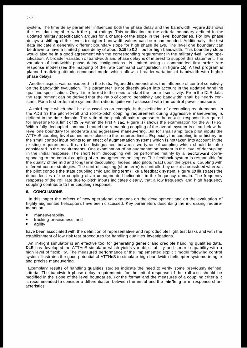
26-6
system. The time delay parameter influences both the phase delay and the bandwidth. Figure 15 shows the test data together with the pilot ratings. This verification of the criteria boundary defined in the updated military specification argues for a change of the slope in the level boundaries. For low phase delays a shiRing of the levels to higher bandwidth values can be recommended. Additionally, the test data indicate a generally different boundary slope for high phase delays. The level one boundary can be drawn to have a limited phase delay of about 0.15 to 0.2 sec for high bandwidth. This boundary slope would also be in a good agreement with the corresponding requirement in the military fixed wing spe- cification. A broader variation of bandwidth and phase delay is of interest to support this statement. The variation of bandwidth phase delay configurations is limited using a commanded first order rate response model (see the mapping of the rate command configuration in figure 15). A test program is planned realizing attitude command model which allow a .broader variation of bandwidth with higher phase delays.
Another aspect was considered in the tests. Figure 16 demonstrates the influence of control sensitivity on the bandwidth evaluation. This parameter is not directly taken into account in the updated handling qualities specification. Only it is referred to the need to adapt the control sensitivity. From the DLR data, the requirement can be derived that the ratio of control sensitivity and bandwidth shall be nearly con- stant. For a first order rate system this ratio is quite well assessed with the control power measure.
A third topic which shall be discussed as an example is the definition of decoupling requirements. In the ADS 33 the pitch-to-roll and roll-to-pitch coupling requirement during aggressive maneuvering is defined in the time domain. The ratio of the peak off-axis response to the on-axis response is required for level one to a limit of 25 % within the first 4 sec. Figure 17 shows the examination for the ATTHeS. With a fully decoupled command model the remaining coupling of the overall system is clear below the level one boundary for moderate and aggressive maneuvering. But for small amplitude pilot inputs the ATTHeS coupling level comes more closer to the required limits. Especially the coupling time history for the small control input points to an effect of augmentation systems which is not taken into account in the existing requirements. It can be distinguished between two types of coupling which should be also considered in the requirements. One examination of an augmentation system is the level of decoupling in the initial response. The short term decoupling will be performed mainly by a feedfotward corre- sponding to the control coupling of an unaugmented helicopter. The feedback system is responsible for the quality of the mid and long term decoupling. Indeed, also pilots react upon the types of coupling with different control strategies. The control coupling (short term) is controlled by use of a crossfeed whereas the pilot controls the state coupling (mid and long term) like a feedback system. Figure 18 illustrates the dependencies of the coupling of an unaugmented helicopter in the frequency domain. The frequency response of the roll rate due to pitch inputs indicates clearly, that a low frequency and high frequency coupling contribute to the coupling response.
6. CONCLUSIONS
In this paper the effects of new operational demands on the development and on the evaluation of highly augmented helicopters have been discussed. Key parameters describing the increasing require- ments on
maneuverability, tracking preciseness, and agility
have been associated with the definition of representative and reproducible flight test tasks and with the establishment of low risk test procedures for handling qualities investigations.
An in-flight simulator is an effective tool for generating generic and credible handling qualities data. DLR has developed the ATTHeS simulator which yields variable stability and control capability with a high level of flexibility. The measured performance of the implemented explicit model following control system illustrates the good potential of ATTHeS to simulate high bandwidth helicopter systems in agile and precise maneuvering.
Exemplary results of handling qualities studies indicate the need to verify some previously defined criteria. The bandwidth phase delay requirements for the initial response of the roll axis should be modified in the slope of the level boundaries. For the format and the measures of a coupling criteria it is recommended to consider a differentiation between the initial and the midllong term response char- acteristics.
26-7
REFERENCES
[I1 PI
c31
c41
151
PI
c71
PI
~ 9 1
N.N. "Handling Qualities Requirements for Military Rotorcraft", ADS-33C, Aug. 1989
Kaletka, J., Tischler. M. E., von Grunhagen, W., and Fletcher, J. W. "Time and Frequency-Domain ldentification and Verification of BO 105 Dynamic Models", 15th European Rotorcrafl Forum, Sept. 1989, Amsterdam, Netherland
Skow, A. M. "Agility as a Contribution to Design Balance", AlAA 90-1305, I990
Lappos. N. D. "Insights info Helicopter A i r Combat Maneuverability", 4Mh AHS Annual Forum, May 1984, Crystal City, Virginia
Pausder, H. J., Meyer, H., Sanders, K., and Wulff, G. "Flight Test Techniques for the Assesment of Helicopter Mission Demands", AlAA 83-2735, 1983
Gmelin, E. L. and Pausder H.-J. "Mission Requirements and Handling Qualities", AGARD-LS-139, Paper No. 5, 1985
Lappos, N. "Designing for Helicopter A i r Combat", Royal Aeronautical Society international Con- ference on Handling Qualities and Control, London, 1988
Gmelin, E., Pausder, H.-J., and Hamel, P. "Mission-Orientated Flying Qualities Criteria for Heli- copter Design via In-Flight Simulation", AGARD-CP-423, Paper No. 4, 1986
Pausder, H.-J., Bouwer, G., and von Grunhagen, W. "A Highly Maneuverable Helicopter In-flight Simulator - Aspects of Realization -", 14th European Rotorcrafl Forum, Sept. 1988, Milano, Italy
[lo] Pausder, H.-J., von Grunhagen. W., Henschel, F., and Zoilner, M. "Realization Aspects of Digital Control Systems for Helicopters", Royal Aeronautical Society International Conference on Hand- ling Qualities and Control, London, 1988
[Ill Pausder, H.-J. and Bouwer, G. "Recent Results of In-flight Simulation for Helicopter ACT Research, 15th European Rotorcrafl Forum, Sept. 1989, Amsterdam, Netherland
[12] Kaletka, J. and von GrUnhagen, W. "ldentification of Mathematical Derivative Models for the Design of a Model Following Control System", 45th AHS Annual Forum, May 1989, Boston, MA, USA
[13] Tischier, M., Fletcher, J., Morris, J., and Tucker, G. "Application of Flight Control System Methods to an Advanced Combat Rotorcraft", Royal Aeronautical Society International Conference on Handling Qualities and Control, London, 1988
[14] Watson, D. and Hindson, W. "In-Flight Simulation lnvestigation of Rotorcraft Pitch-Roll Cross Cou- pling", Royal Aeronautical Society International Conference on Handling Qualities and Control, London, 1988
[ I51 Bouwer, G., Pausder, H.-J., and von Grunhagen, W. "Experiences with High Authority Helicopter Flight Control", 16th European Rotorcrafl Forum, Sept. 1990, Glasgow, UK
[I61 Key, D. L. and Hoh. R. H. "New Handling-Qualities Requirements and How They Can Be Met", 43th AHS Annual Forum, May 1987, St. Louis, Missouri, USA
[I71 Pausder, H:J. "A Study of Roll Response Required in a Low Altitude Slalom Task", 11th European Rotorcrafl Forum, Sept. 1985, London, UK

26-8
OPERATIONAL HELICOPTER ( HIGH REALISM )
IN - FLIGHT SIMULATOR ( HIGH FLEXIBILITY )
- Flight test technique
- Flight test task definition
- Analysis method for verification
- Anchorpoint data
- Technology implementation
- Handling qualities data base
- Verification technique
Figure 1. Use of testbeds
TargelTracking Hovering Target
$ 0 -30
-5
Y -4
ground track x time 0 m 500 0 5 1Osec 15
3
deg
track y
0
- 4
Figure 2. Bank to target maneuver
0 deg track x
Figure 3. Tracking error crossplot

26-9
i 0.01 0.1 Hz 1 0.01 0.1 Hz I
0.01-
frequency frequency
~~~ slum T*sx A :Im w w 1m B
0 . - 50
, 4 0 0 m 500 0 1000 m
Figure 4. Slalom task representing NO€
I 1 I I I 1 I I I 1 I I
I I
I 1 I I I 1 I I 1 1 I I I 1 I I I 1 I I I 1 1 ,
isod ioon.!, zoon I I,.
I !
Track
60ki SLALOM
(m 60 l90ki FIGURE EIGHT SIDESTEP AND SLOPE LANDING
Target 60ki Target 8Okt - f--13
Target In Hover I AIR TRACKING 1 0
Y 3 Tracker 8Oki Tracker 1OOki
I 7 Tracker 80ki
Figure 5. Roll axis flight tasks

SCORE FACTOR
e Course Deviation (Error)
c Reference Course
8 BO 105 with reduced 1 controllability I
50 m
Y
0
-50
Figure 6. Slalom task quicklook
u Evaluation Pi lot ’ / ‘
/ - \
‘Data Recording
Gyros and Accelerometers
Data Aquisit ion
-/ L- FEW - Actuators Safety Pi lot
Figure 7. AlTHeS airborne simulator

26-11
Figure 8. BO 103 53 control system modification
IMPLICIT MODEL FOLLOWING CONTROL
nost q CDnflOllel AIC
t
EXPLICIT MODEL FOLLOWING CONTROL
Figure 9. Concepts of model following
Control System I on
Control System otf I
". I
~ commanded model - - - - helicopter response
Figure 10. AlTHeS long term model following

26-12
EOUIVALENT TIME DELAY
200
msec
100
a
B a * h Hell- Copt.
Actual .
1 I t 1
Actual .
cantr01 comput.
ADOCS NASA ATTHeS ATTHeS PITCH CH-47 ROLL PITCH AXIS ROLL AXIS AXIS
AXIS
Figure 11. Effective time delays
0.4
sec
@ 0.2
0
0 0 2 radlsec 4 ,..
0.4
0.2
0 0 2 rad/sec 4 ,,~
LL
wBW '$' BW '$'
All Other MTEs. VMC and Fully Attended Operations Air Combat
Figure 12. ATTHeS compared with bandwidth requirement
Figure 13. Frequency response (F) of basic BO 105
Air Combat
LL
wBW '$' BW '$'
All Other MTEs. VMC and Fully Attended Operations
Figure 12. ATTHeS compared with bandwidth requirement
. ~
- 1 A Q
i r a
-2Uil
-3r30 I EO 3 ' € 1 radlsec 3
frequency
Figure 13. Frequency response (F) of basic BO 105

26-13
Figure 14. Frequency response of the overall system compared with the command model
K . e - I s 0 Mapping lor RC - Response =
0 Realized RC - Respanse (open loop )
0.41
Figure 15. Verification data for roll bandwidth requirements

26-14
Figure 16. Influence of control sensitivity
A
rad sec
4
- ..
-- 5 $ '0 C m . n
2 --
PREVIOUS
SATISFACTORY (LEVEL 1 )
ACCEPTABLE CONFIGURATION (LEVEL 2 ) 'WITH VARIED
TIME DELAY
OPEN LOOP CONFIGUF WlTH 60mr TIME DELP
0
Moderate AmDlltude InDUt
.4 I I
, - rad 0
e
0 5 sec tlme
rad set' inch
1 2 roll control sensitivity
Small Amplitude Input
5 5 I/ % i?
40
Level 1
0 5 10 15sec tlme
~ commanded model - _ _ helicopter response
Figure 17. ATTHeS compared with coupling Requirement
Figure 18. BO 105 frequency response of roll rate due to pitch inputs
(+) of basic BO 105 8.

Agility: A Rational Development of Fundamental Metrics and their Relationship to Flying Qualities
C. J. Mazza Head, Flight Dynamics Branch Naval Air Development Center
Warminster, PA 18974
SUMMARY
The results of the first phase of a three year agility program are presented. In large measure, the work accomplished to date and reported in this paper has produced a highly viable approach for developing a rational concept of agility and, more importantly, for relating agility to the flight dynamics, maneuvering performance and to the design of aircraft. The flight mechanics of a rigid aircraft in three-space maneuvering flight are examined with respect to total velocity, acceleration and the time-rate-of-change of acceleration: the latter being assumed to correspond most directly with agility. In particular, the terms of the expanded "agility vector" are interpreted with regard to their potential for providing a rational basis for the evaluation of any given set of agility metrics and for suggesting, directly, a new set of metrics. A potential form of agility is offered for which a readily accceptable relationship is traced to both flying qualities and maneuvering performance. Finally, the remainder of the program is outlined to carrv the work toward the develoament of
~~
a practical set of design guidelines for agility . SYMBOLS
L
Y hY.. R"
Axial Agility ft/sec3 Curvature Agility ft/sec3 Torsional Agility ft/sec3 XB Agility Component ft/sec3 YB Agility Component ft/sec3 ZB Agility Component ft/sec3 Unit Bi-Normal Vector - Drag Rate Components lb/sec Force Rate Functions lbs/sec Curvature l/ft Lift/Rolling Moment lbs or
ft-lbs Turn Rate rad/sec Lift Rate Components lb/sec Unit Normal Vector - Position Vector ft Radius of Curvature ft Flight Path Arc Length ft Radius of Torsion ft Unit Tangent Vector - Torsion l/ft Thrust Rate Components lb/sec Side Force Rate Comps. lb/sec
paradox of "The Fighter Airplane That Could" is well known in the combat COnSCious community, i.e., the situation in which an aircraft of 'medium performance' frequently gains an advantage over its superior opponent (such observations having accounted for the differences in tactics and pilot skill levels). In many of these cases a strict comparison of the respective maneuvering performance charts of the two aircraft yield no surprising discoveries of EM areas where the medium Performance aircraft might have a distinct advantage and so, the Speculation of superior "agility" has often been suggested as a possible explanation for the apparent (?) anomaly. Another motivation for understanding and applying the concepts of agility stems from the trends in fighter aircraft designs. Today we are faced with the real possibility of designs which incorporate thrust vectoring as a means of providing useful control power well beyond normal aerodynamic limits, i.e., the X - 3 1 ~ . Such aircraft offer maneuvering capabilities which are unique and largely unmeasureable by ordinary maneuvering performance methods. Thus, once again, the speculation of agility arises as a potential means of providing us with the engineering design control required to predictably realize given levels of this "new" maneuvering capability. All of the above plus the awareness of the potential for direct force control and our growing understanding of high angle-of-attack aerodynamics, leads us quite naturally to, among other places, aaility as a means of rationally comprehending and measuring both the new and unique as well as the normal maneuvering characteristics of the next generation of fighter aircraft which may emerge from today's developing technology base. It will be useful to establish a 'reference agility concept' early in this paper in order to provide a reasonably clear and receptive communicative environment for the reader. For this we will have to, at the very least, address the issues of definition.
There are almost as many definitions of agility as there are investigators in the field. This, of course, has made it difficult to compare the results of one investicrator with those of another. The
INTRODUCTION .~~~ ~~~~ ~~ ~~~~~~ ~~ ~~~~
problem is more than just lack of standardization: it is worse...it is one
It is difficult to point precisely to of disagreement on the most fundamental the origins of the recent wave of level. There simply is very little interest in agility but they are agreement on what agility is! Despite important to consider if we are to the general acceptance of the broad understand the reasons for seeking definition that propounds that agility
is the rate of change of maneuver state, aircraft design metrics beyond those currently available to us. The combat specific interpretations depart widely
27-2
from this straight forward concept. Proposed agility metrics vary considerably from Ka stirs Point-and-
dPs/dt, tde, T.R./tde=goo Herbst,ts agility vector c_omponents, i.e., v (VU + Gv), ( E - Xsin.r - +kos.r) ( 3 ) . We find that contemporary metrics tend to fall into one of three categories: 1.those which closely resemble flying qualities design criteria, 2.those which are derivative forms of energy-maneuverability performance parameters and 3 . those which are based on the differential geometry properties of the flight path. An important fourth category, a combination of the first two, is very prevelant. The work described in this paper summarily dismisses the first two categories on the basis that, although agility may be related to flying qualities and/or maneuvering performance, it is believed to be a uniqely independant flight dynamics characteristic and that is what is sought in this work. Figure 1 provides a perspective which one can use to differentiate between flying qualities, maneuvering performance and agility. It Will be noted that, in addition to segregating flying qualities, maneuvering perfomance and agility, aircraft 'pointing' has been unambiguously assumed to be a flying qualities characteristic ... and nothing more: although its relationship to agility is recognized along with other, equally important, flying qualities characteristics.
presesented is that agility is:
transformation of long existing engineering concepts,
2 . &, in that it is impossible to completely define and apply it through our present state of knowledge of either flying qualities and/or maneuvering Performance, and
3 . can be exDlicitlv developed iqto manageable engineering tems which are relatable to 'proximity dynamic characteristics', such as flying qualities, etc. and eventually, to aircraft design.
AGILITY: A
P f j , to Shoot (DT) parameter tYj t ough Skow's
The point of view which will be
1. real, and not just another
Having indicated the wide disparity exsistins with reqard to the definitions and conceptualizafion of agility, it becomes obligatory to offer yet another definition:
Agility Is A Property Which Characterizes The Time-Rate-Of-Change Of Maneuver state (Acceleration state) And Addresses, Exclusively, The Translation Of A Moving Body In 3-Space.
In this paper, the above definition is regarded literally, with all equations
and their development being consistent with the definition. A set of corollary statements (assumptions) accompanies the definition:
* Agility Is A Characteristic Exhibited By All Bodies In Motion
* llFundamentalll Metrics ADD~Y - _ - Equally TO All Bodies (Controlled Or Uncontrolled) * Agility sensibly Exists In Any And All spatial Dimensions (1, 2 , 3 , ... n)
* Agility Is A Long-Term Property (Non-Steady-States And Multiple Maneuvers)
One further qualification is required. Although the above definition and "groundrules" refer to a generalized rigid body, in this paper agility will be developed specifically for an aircraft. The basic equations and the operations performed on them are, of course, universal and can be applied to any rigid body in motion.
- THE AGILITY VECTOR
The rate of change of maneuver state logically translates into the rate of change of aircraft acceleration and, in turn, to a possible rational development of agility. This approach reduces to the derivation, expansipn, interpretation and application of a, i.e., the agility vector: its components, terms, etc. The agility vector will be developed in two different axis systems. One will be, strictly speaking, a differential geometry approach and will be derived in the Frenet, or flight path system while the other will be derived from the ~ ~
Newtonian system, i.e., frpm ghe consideration of F=ma and F=ma. With the Frenet approach, it must be emphasized that only the flight path geometry of a point-mass aircraft is considered. Although some few investigators have confined their studies to the Frenet system exclusively, the Newtonian development is very revealing and offers considerable insight into the aircraft design characteristics which may affect agility directly (through the development of F). Both forms collapse into the same total agility vector (with proper coordinate transformations). The Frenet vector is the simpler of the two and allows us to see relationships to maneuvering performance more readily. he Newtonian vector and its associated 8 , permits us to more readily associate flying qualities characteristics and aircraft design implications with its components and terms.
The Frenet Development
Figure 2 presents a small segment of a general maneuvering flight path wherein no assumption of steady state is implied, i.e., the entire maneuvering state is assumed to be continuallv varying with time. The position-z the rigid body along the flight path-is defined by the position vector, R(t).

27-3
The familiar equations for total velocity and acceleration follow:
?=$=;: (1) - .. - (2) a = a = 'St + &2&R
Figure 2 shows that T i s coincident with the plane defined by the t and ii unit vectors. The agility vector is obtained by differentiating equation (2) with respect to time,
unit vector and-that = lies in a
Substituting for dz/dt = i/rS and dS/dt = -&t + Srb, we get
Equation ( 4 ) is the flight path axes or Frenet version of the agility vector and can be seen to consist now of three - components directed along the t, ii and b unit vectors, respectively. Figure 2 shows this clearly. If we use curvature ( 8 ) and torsion ( 7 ) instead of their reciprocal equivalents we what may be a more familiar versionqgf of equation ( 4 ) , i.e.,
= (Y-&32)t + (3is- + &zi)ii + 53x7b.
Referring to either equation ( 4 ) or ( 5 ) . the 3, fi and E components are interpreted as the axial, curvature and torsional agility components, respectively. Each of the three components can be thought of as representing three distinctly different translation path types along the differential arc segment "AB" in Figure 3 . Figure 3 provides a vizualization of the Frenet components. The illustration is interpretively useful in that one can begin to get a "feel" for the make-up of an elemental translation in three-space, for the roles of each of the terms within the components and lastly, for the types of control inputs/responses the aircraft would have to experience in order to effect a given translation or portion thereof.
The Newtonian Development
If we look at agility, i.e., the time rate of change of the translational acceleration of the aircraft, in a Newtonian or body-axis system of equations, we can begin to see not only an expanded new form of the agility vector but also the forces (aerodynamic, thrust, etc.) upon which agility depends. This, in turn, may provide us with a means through which we can ultimately derive tangible aircraft design control over agility. The development is interesting and revealinq.
Beginning with F = ma'
and taking the time derivative of both sides,
- F = mii, (7)
we immediately get the fundamental relationship that agility depends primarily on the transient behavior of all of the forces acting upon the aircraft. Agility does not necessarily, if at all, depend on the quasi-steady state of the forces as we normally treat them in solving equation (6) as we typically do to obtain response solutions to given control inputs. Futhermore, the relationship explicitly stated by equation (7) is valid whether the forces are linearly or non-linearly represented. It can be seen from the outset that the above concept can be very effective in unraveling the "puzzle" of agility. The elusiveness of the understanding of agility lies in the realization that the phenomenon is generated through what is probably the short-lived but highly influential transient behavior of the forces. Dwelling on this for a moment, we can well understand how difficult it is for a pilot to be expected to evaluate a dynamic characteristic which he cannot possibly be able to directly detect. All we can expect is that the pilot will be able to comment on the longer term effectiveness of this seemingly intangible characteristic and not so much on agility per se. That one observation tells us that the problem is not simple and also that the implications on past and future flight simulation or flight test experiments is vast. Let us take a closer look at equation (7) and develop it to a reasonably interpretable form.
derivation on equation (7) we obtain If we perform the implied time
where the components of the rates of change of forces and the components of the new form of the agility vector are:
gy = ;y + 4. + ky + +y + ... + mg[ (cosecosd)p - (sindsin0)ql (9b)
ix = [l; + zq+ - zr+.- u(92 + r2) -
iy = [ i i + z r b - 2p; - v(p2 + r2) - P(W - 4v) + wq - vrl (loa)
q(pu - W ) + ui- - $1 (lob)
r(4v - PU) + VP - u41. (10C) iz = [i; + zpt - 2qli.- w(q2 + p2) -
Equations (9) explicitly provide us with the time rate functions of lift, drag, sideforce, thrust, etc. as well as the effective time rate of change of the

27-4
weight vector direction. Equations (10) present the body axis components Of the aqility vector and can be seen to contain the axial, curvature and torsional components of the Frenet system in a much more distributed and less comprehensible form. The single axial Frenet component term, 's". for instance, is seen to be contained &n the x, y and z components of u, v and w, respectively. Equations (9) and (10) are offered principally for the benefit of the left side, i.e., the force rate terms. Closer examination of all components and terms of the left side could eventually provide a usefully different interpretation of the agility vector. Certainly this is the case when attempting to interpret the rot's of.the familiar aircraft states of 6,q and r and p, q and r throughout aircraft responses to controls applied during a set of maneuvers being examined for agility. So, both equations (10) and (9) can be of value in agility investigations.
equations given above, are the moment equations, L, M and N. Adhering to the definition already given which associates agility exclusively with translational dynamics, how an aircraft rotates, or even if the aircraft has sufficient control power to rotate is of no direct relevance in describing "agility". How the lift, drag, etc. vary throughout aircraft rotations is, of course, considerably relevant because these forces directly influence agility; but we do not have to know L(t), M(t) and N(t) per se. It is not necessary to compound the confusion which agility normally presents by introducing the moment equations. The flying qualities of the aircraft can well handle the moment generation aspects related to agility or to any other specific dynamic characteristic of the aircraft. That is why, although contrary to popular notions, an aircraft with a thrust vectoring system capable of providing impressive contol power especially in the absense of aerodynamic control...is not more agile because it can rotate (yaw/roll) faster, or at all, but because the main thrust direction can be altered much more rapidly and therefore the three-space translation characteristics of the aircraft are enhanced. This is hardly a semantic arguement. It is a logical conseqence of the ordering of the "agility" and "flying qualities" of the aircraft in such a way as to provide us with unambiguous design control, free of the conflicts inherent in most contemporary concepts of agility.
Conspicuous in their absense from the
EXPLORATION PE ix,y,z
A further look at the force rate coefficients in equations ( 9 ) is in order. We rill be-looking mainly at the effect of Lz and in the simplified , form of L and Lsi3. 'In order to do this let us examine the manner in which an aircraft qets from point A to point B
(say in the same plane) through a curved flight path achieved by first rolling in at A and subsequently rolling out again so that the aircraft is once again in a wings-level state at B. The transient character of the lateral force build-uv ($sin+), first to accelerate the aircraft toward B and then the lateral force attenuation to decelerate the aircraft in order avoid overshooting B, is of paramount importance in determining the agility inherent in this maneuver. Obviously, throughout the maneuver, the flying qualities are of equal importance in providing the control power, damping, etc. for acceptable response and precise control. For the moment, however, let us just concentrate on what happens to the tilted lift vector in order to obtain the required lateral translations.
Figure 4 presents the constructed time history of this particular maneuver in terms of Sa, A a , AL, e, Lsinm and Lsine. The traces are "broken" at each of the two relatively long duration, steady-state (constant e) turns. Also shown in the figure is a top-down view of the 'planar' maneuver, with a number key which corresponds to significant events on the time traces. A small amount of back-stick has been assumed in order to increase angle-of-attack and thereby attempt to compensate for inherent altitude losses. Although the :races are not absolutely faithful to an actual maneuver they will serve adequately, in this synthetic case, to demonstrate the nature of 'lateral agility'.
A close look at Lsinm and isinm reveals the manner in which the lateral side force and force rate due to m(t) are developing throughout the maneuver. The force rate term, in particular, can be thouggt of as being the dominant term driving ay (from equation (lob)). Readily apparant is the fact that the idne trace achieves a maximum value at the point of inflection of the turn maneuver. One can justifiably say that lateral agility is maximum at this point, which intuitively feels very comfortable; although the equations suggest it as well. The traces also show us haw we may effeat design control over agility. If, all the state parameters were computed from an actual set of aero data and examined, along with the agility terms from either equations (5) or equations (10) a far more complete analysis of this maneuver would be possible and would certainly yield effective correlations between L, D, T, a, Q , ....( t) and the agility components and terms. A complete dynamical analysis, including a 6 D.O.F.set of equations with fully coupled terms and non-linear aero is planned to begin soon in this study for the above maneuver and several other families of selected maneuvers. The relative ease of examining the relationship of flying qualities to agility is apparant from both the equations and figure 4.

21-5
RELATIONSHIP TO FLYING OUALITIES
Although the sensitivity of specific flying qualities criteria/parameters has not yet been performed, figure 4 graphically suggests that all time- domain-based criteria can be readily and directly correlated with agility. In the case cited above, for instance, if we were to look at a complete set of roll performance traces (p, e, etc.) we could draw direct relationships between the parameters of roll dynamics and agility. Further, we could re-shape roll responses in order to optimize agility, whether through aerodynamic design or through control law tailoring. Thus, we have the beginning of practical design control for agility. It was evident even durina the construction of fiqure 4 that ------~.. ~~~
changes in a(t) and ;(t) couli dramatically affect Lsins, i.e., agility. In a similar manner and to a far better degree of effectiveness, one could begin with a full set of dynamic equations, generate families of maneuvers and, using this data base, compute the agility terms, the flying qualities and the maneuvering performance and be able to relate any one part of the analysis to any other part and to the whole as well. This is a degree of design and analysis freedom that the "agility community" has not had to date.
RELATIONSHIP MANEWERING PERFORMANCE The agility vector, Equation (5a),
can be manipulated and rearranged in several revealing ways. If, for instance, we = w and divide equation ( 5 ) by g, we obtain the following:
recognize that &/r = V/r
The first term of the normal component, ii, i.e.,3wnx, can alternatively be expressed as
3Psk/r or 3xPsk, (12)
where Ps$ = "kinetic specific excess power", i.e.,P,. Muliplying through again by g to eliminate the awkward *g, we obtain ..
2 2 fi = (V - m,g) T +
(3wnxg - w r L) 2 + (UV 7 ) 5. (13)
Now we nave an expression for the total agility vector which is directly related to all of the terms commonly used in describing maneuvering performance, i.e., V (airspeed or MacH no.), (D (turn rate), nz (normal load factor) and, for all intents and purposes, Ps (specific excess power). In addition, the axial load factor, n,, appears in the curvature component and even the torsional component begins to look a little friendlier. In fact, the entire agility vector is friendlier and more easily interpretable.
CONCLUSIONS
This work, to date, has produced a rational and well structured model for agility. It has been consistent throughout and has neither supplemented existing ambiguities in contemporary agility concepts or introduced any new ambiguities. Futhermore, this agility model has been shown to be easily and directly related to both flying qualities and maneuvering performance and, quite naturally, to aircraft design. As such, the model is expected to serve well in continuing on with the investigation of aircraft agility and, further, offers the promise of doing so in an engineeringly practical manner.
Subsequent phases of this study will include the examination of a wide variety of existing and newly generated off-line, manned simulation and flight test data bases for an equally wide range of fighter aircraft types. In add- ition, existing, contemporary "agility metrics" will be re-examined in terms of this aailitv model. Those relationshios ~. with b&h fiying qualities and maneuvering performance, incompletely developed in this paper, will be expanded considerably and, in turn, a more unified set of "flight dynamics design criteria" will be sought to replace the fractured and minimally adequate flying qualities design criteria currently in use for high angle-of-attack flight conditions, i.e., for up-and-away combat environments.
REFERENCES
1. Xalviste, J. "Measures of Merit For Aircraft Dynamic Maneuvering", SAE Technical Paper 901005, April, 1990
2 . Skow, A.M., Foltyn, R.W., et. al., "Development of Innovative Air Combat Measures of Merit for Supermaneuverable Fighters", AFWAL-TR-87-3073, October, 1987
3. Herbst, W., Eberle, D., et. al., "Evaluation of Agility for Future Aircraft", Report NO. MBB/X-31A/R/29, November, 1987
4 . Brand, L., "Vector Analysis", John Wiley & Sons, 1957
Figure 1. Time/Spatial Relationship Between Flying Qualities, Maneuvering Performance and Agilit
Ze i
Figure 2 . I and in the Frenet Axis System, Showine
1 -
the Movina Trihedron, ?, E. %
* S t ra igh t Line Trans la t i on 4; * 2 n d T e r m Reduces Ability A To Reach "E" If Body $:
- - r4XI.4fl .-
S
- - s ~ ~ / r z % p . I ' "-4" Contains S o m e Cumature
lcuREEiTEZ /\ec ' -4 Planar, Curved P a t h
-4s increases Y i t h Time, P o s i t i m Error A t "E" I s
3 iyr =3(T.R.);
2 - Y ; / r z = - ( ~ . ~ . ~ F' .4
increased au 2nd T e n n
* i .Ye!icd Path .+om ".A" To "B".
</r (T.R.) X (Velocity) * Agil i ty Reduced .As d 3 r P Get Large7
Figure 3. Vizualizing The Frenet Components

Top-Down View O f Flight Path
Figure 4. Constructed Time Traces O f A Turn Reversal Maneuver, Showing Irateral lorce And Force-Rate 1)evelopmerit


28-1
Design of an aircraft for use a t him angles of attack can have major implications on the amfiguration which is &@sen. lbe c h j d v e of this paw is to review the implications of designirq for him angle of attack on configuration. Tnis MbJrally leads onto "sideration of agility ard the criteria which could be used in the early design &qes to ensu?z an aircraft is ad-tdy aqile. A nmkex of questions are raised which Cannot, as yet, be annverrd on a general basis. SCUE questions w i l l not be answered until further research is put in hard an3 the results of exist- expriments are made available.
The objective of this paper is to review the implications of designirq for him angle of attack w i t h particular emphasis that this has on the basic choice of a h f t configuration.
~ m d hardlhq qualities are the result of
chamcteristics with a "st, tolerant fligbt mntrol system. Wwn an aircraft is 'agile' an3 req6z-d to use him angle of attack i n
acivantaqe over an oppsnent, these intexl@emies become particularly evident.
me overall choice of amfiguration is achieved by a b l d of a nmnter of often conflicting -ts. lhis paper w i l l ewmine amfiguration aspects which relate specifically to hardling qualities an3 him angle of attack manoeWring. However, the paper p v that in relation to 'agility' the exarmMtion nust go further then jus t a- 'ffi an3 hardling qualities.
ccrbininq qcai basic aemiynmu 'C
combat ll"ing i n order to gain tactical
It is suggested that a better urderstandlng ' Of what is meant by 'agility' can be gained f m consideration of the total weapn system capability, i n w h i c h the aircraft nwceuvre capability is j u s t one factor. 'Ficpltins qualities1 mimt he a tetter t e n n to use.
A nmke of questions are raised, w h i c h cannot be pmperly answered on a geneml basis. AEW- nust be decided on an individual project basis. not be answered unti l further research is pt in hard ard the results of existins research are made available.
Meed, some questions w i l l

28-2
i n high angle of attack (Ad.) has always been misted w i t h defining the l i m i t s on aircraft IMnoewrability. Historically, this was typically associated w i t h investigating the w i q stall and asscciated phenmena and any higher -le of attack work related to the spin and -cry behaviau.
However, over the last twenty five years, a- 'c and craltrol systws t€d!xolcqy have pi-sp-ssd & that, for l ~ n y aircraft, wing stall is not a limit wder l ~ n y conditions and r"nn lift 03curj a t significantly higher AOA.
A l l aircraft are rzquim3 to fly a t maxinarm usable lift, or w i t h i n a m q i n th-f, a t saw point during their operation. high a, w i l l iwan different on the desiqn role of the aircraft, but it w i l l gen?cally be associated w i t h the AOA regime a"3 r"nn lift and -e.
crarht airaaft, and conbat trainers, are frequently called w n to operate a t maxinaw. lift, or clme to it. typical conbat scenario, starting a t a mzderate speed and altitude. If the initial en3agenwt dces mt result i n a k i l l and the apFowrts do decide to mix it, the fight w i l l inevitably dqzade to low speed, maxinaw. lift corditiom as the -cats seek for the fir- qp3rtunities.
mis plot was g-ted mvry years ago, but it captures the gsential f&mlres which m i n true for this type of one-on-0~ engagenwt.
me term, de-
Figure 1 illustrates a
3
Wviously the better an aircraft's control amunl maxinarm lift, then the less likely a mistake i n M i n g the aircraft is to lead to the opp3wrt winning by default. such losses were all to3 cz" i n the years betwm 1940 and 1970, w i t h advantage c h a q i q fm one side to the other as technolw developed.
Fi- 2 and 3 illustrate the typical fea- which limit the comentiolnl lmnoewrability of an aircraft. constraints are pmvided by design stwgth l i m i t s and r"nn usable lift. in3icates hcw this relates to turn rate, or the ability to turn the aircraft's velmity vector, w i t h a r t rolling the aircraft. lift +liy maxi" lift pmvides the other
rat& to sustain the turn, due to the increasing
Figure 3 1- a t the type of phenaneM which aNld l i m i t usable lift. Sane configumtions may bgxme Unmrrtmlled or exhibit m?acsptable hardling qualities M o r e r"nn lift is a+eved. Cscd a- 'c and flight ccprtrol syaepo design &xld enmre that this is mt the case, M it may cause moprcorise of ether aspects of the allcraft amfiguxation &si? AS ewnples, a large fin which
m i - hi@ k14 d i r e c t i d stability may
whia also inflllenzs stability a n d y a w w i n g (d-1). canbe influsraxd by radar kstallation and monrarce -.
?he overall
Figure 2
Usable
and use Of higher AOA may E E a Z 3 f O r c e , but reduce the turn
liuust pmvides a l i m i t on the ability
irdlx& a.
aFrcraft signature, or ~llse shape,
As mted earlier, high AnA w i l l mean different t h i r ~ ~ s deperding on the role the aircraft is being desiq-d for. Figure 4 catqorkes the w i m types, Mcatirq what would be mnsidered as high AOA for each. On a transprt design, high AnA would be likely to "$race the w i n g spll i.e. anmere m e e n 15 anl pezhaps 30 , depending ' onthe sophistication of the wing high lift devices. Equally, a ombat aircraft designer would mw define it as the region beyord mixi" lift, Le. f m 25' uplards, and this would &race p"t stall "cawre, loss of control or spming as appmpriate.
'%&mlcgy develcpmts i n aexdymnu 'c design and i n desiqn of flight control systems have mabled substantial increases in the "I AOA that can be contemplated withmt loss of control, as shewn i n figure 5, and described in refer- 2. only a few years ago, the hiqh AOA -qe that could te given to any pilot was 'the aircraft spins, so don't!', as even i f it r e c w e r e d quickly, the altitude loss and spatial disorientation could still mt in an accident. spinning ceased to be a viable conbat m 3 ~ e u v ~ e very rmny years ago, i f it ever was!)
Now, a totally different soene is emerrjing. nircraft can be designed w h i c h are protect& fmn loss of control; scut? may not lme a lot of altitude i n high AOA, but it really de- on the duration of the manowvre as to how much fnergy is lost, either kinetic or potential.
(And delitexate
A"Fra3GTGurfATImD"
It is self evident that the major inflwxe on an aircraft 's confiquation is the role for whi& it is designed.
let us briefly lmk a t hay the configuration is affected by the choice of role and related
Firstly, the role w i l l dictate payload, range, performance and " a b i l i t y rqubmmts. It w i l l mw almzst c"l . yinclude rq&wE&S relating to aircraft detectability, i.e. si--, cwerinq radar, infra-&, qkical and possibly acoustic signa-.
Reslltin3 from these rq&wE&S , the en+eezs w i l l decide on w i n q planform, wing area and w i n g sweep. They w i l l also decide on &&her the aircraft should have a tailplane, cananl e a - , ?mth or be tailless. w i l l also relate to the stability levels which c a n b e ~ , a s u e s e a r e d i c t a t e d b y consideratian of trim, peaonrarce and craltrol system capability. Tne level of acanplexlty nquir€d in the Fcs and associated electrid a M hydraulic q2plies is detenained by whether the basic aircraft is stable or - % l e , the need for carefree -ins and the AOA range to be covered. sicplatllre w i l l play a part in dictatiq omtrol pmitioning and gemral 'shape'. A &ice w i l l be made regardrng ' =m Payload, whet he^ it shculd be interral or external, which again affects size, performance ard si". Ln turn, these a f f e d the choice of engine arrl engine cycle. as far as we are collcerned w i t h i n this paper,
It w i l l also dictate any supersonic-.
zhis
Finally, a t least

28-3
Once the basic Wing is set out, it is essential that the large perbxtation or gross --are- . The nm-linear effects of aerodyMrm 'cs, wntml systan and actuation system nust be investigabd, particularly i f the aircraft is to be agile and '-free', o r ' care- less ' i n its handling. tenm is iu$wrtant. pilot can do anything, the lat ter anything -&le. of a mnplete meeting on its own!
In addition it is necessary to ensure that satisfactory safety levels are achieved under all " r ing conditions. ~n siqle tenm, this means that potential loss of the a i rc rae nust be avoided in all reaso&ly probable system failure states.
A distinction of the la t ter two Ihe fontex implies the
Ihe distinction could be worthy
the rranoewability nquirawits, in d i m t i o n with sizing and planform, dictates the high AcA use of the aircraft.
In decidiq the ACA the aircraft must fly to, this again is a parameter which, because of the need to retain good control charactesistics, w i l l inpact on wing planform, aircraft shape and layout, wntml sizing and chasen stability levels.
As can be 5 8 ~ . there are a large nunker of aspeds that the design engineers nust mnsider in the formative stage, and a significant rnrmber of the considerations w i l l inpact M y on the tehaviour of the aircraft a t high anqle of attack. nmrmarises the varicus aspects that have to be mnsidered.
Figure 6
4 omFI"AM)-oNm3m Q"AM)xxmFi
If we lcok mre clcsely a t b basic configuration design relates to harriling qualities, then the ACA the a-ft is rquired to achieve to fulfil its objectives has a significant infl-.
In setthq about desicplins an 'agile' a i r a a f t , which is what the user says he wants, and in this ccoltext one might d&=nq&htheuserfraothecugtaw, itis i n p r t m t to reaocplise the relation of handlw qualities, a- 'cs and the flight control system (=).
For -le as sham in f igye 7. the configuration laycut determugs the -cs, in terms of stability, control p3werandtheaerodyMrm 'caamping. Thedegree of con-linearity in al l of t h e can also be
by the omfiguration, but the major term a t a given Mach n m h x is AOA.
It is then the tasks of the Fcs designers, flight mechatu 'cists and aem&" 'cists to ensure that the handling qualities and safety -ts are achieved. lhis my d t in saw degree of remnfiguration.
S i q l e criteria (references 3-6) can assist w i t h critical omfiguration evaluation, based qwn the basic aerodyMrm 'cs. whilstbeing useful as guides, they fa l l short of acuxacy too often, as noted in reference 7 , and progressively nure c a ~ l e x criteria have been develqxl to try and account for the additional tenrs, see ref- 8 and 7 for -le.
Ewt h t handling qualities should we desiqn to? V a r i c u s sets of criteria exist which one might start w i t h , for ewmple reFerences 9 to 11, see figure 8. ~n addition, other criteria can be used. such as thcse relating to respree shaping and f l ight path contml, see references 12-16. relevant when hi@ levels of ampentation are rqukd. ~ t h e t r i & i s t o p r c w i d e c r i s p y w i t h high levels of c 7 a p j . q . Ulrler1yu-q it all, Uloucpl, is a very basic message; them is only as galas the
'c5 and can cnly,mke to a limited extent for poor design, ather m the
or i n the m i tself . me procequreS followed a t Bpe are illustrate3 in figure 9.
. .
meSe are probably more
omfiguration and its associated a- .cs
Alnmt inevitably, dkuss iom relating to carefree Wing and high AoAteJKl tcumrds the subject of ambat aircraft agility. A d i c t i q defines agility as 'quickn=ss of motion, nimbleness and readhss I . obvicusly, the essential el& is tim, in particular the time to achieve a given chanqe of state of the aircraft.
A definition of what we iwan by agility, as applied to a amkat aircraft, is qiven in figure 10. qualities and conventional " b i l i t y are fairly clear. They relate to changing of the aircraft 's velwity vector and the ability to mntml the chanqes. Most of the basic current handling qualities -ts identifv the sort of tehaviour to a m for. but
Ihe part played by hadling
only fo; canparatively low incidence ~ ' curxiitions.
In recent years, a rnrmber of criteria have ken put foma?xIwhich are htexled to aid the configuration desiqn asse551wt. see ref- 2-8 and 20. uses and may be a -&le guide for mnfiguration design work, furthur work remains to pmvide a set of universally aooepted criteria. A clear ' Of the limitations of any methcd w i l l be essential for suocessful application of the criteria.
"e major difficulty lies i n deciding h t level of performnze is requud ' ate levabd &A, away f m the oolxlitions close to level flight, particularly about the roll axis. Ihe prim objective, certainly within the united
motions are cuo&bd, i.e. that sideslip isminimised , over the ACA "nge for which rolling is to be performea. m i s means that the aircraft is constrained t o roll ahout the velccity vector, the win3 axis, by appmpriate design of the F(s.
However, it is essential to recognise the 7 of doing this, particularly on e l y sl- amfiwtims mica of high perfomawe amkat aircraft which exawerate the inertial ooupling effects. Figure 11 shows the sort of roll prfomawe that might be saqht i f the " ~ A O A is liinibd. leaves a roll capability a t either maxinerm wnrd acceleration and a t "n lift. A constant roll prfornxce KUld be specified, but would have significant
Wlst all have their
Kirqdm, has been to ensure that m11ing

28-4
iwliations on bch aircraft SM- an3 the size of the pit& contml. Figure 12 illustrates the latter aspect.
when rolling at high AOA. a ncse up pitching mrwlt is generated via inertial ooupling and the pit& control has to be able to overcome this term in order to allow control of AOA in the mll. Failure to achieve this. bv imd&te pitch contr.ul power or kuc;ssive roll rate will lead to a pitch up and departure. m e conoept of pitch -e.ry mugin is well hum an3 bearsw pyticvlarly significant on aircraft configurations that are longib3imlly unstable. A simple *-ion can be used to evaluate the pitch aaderation term for a 0wrdiMted wind axis roll, viz
7 q = 1/2 p2 sin 2 d
where p is the aircraft h . 3 ~ axis roll rate and d is aircraft angle of attack.
Along with these criteria for roll rate as functions of AoA and mml acceleration, roll acceleration needs to be addressed. It is hpxtant that this be adequately high: gccd acceleration should inply good control effect rather than low damping in order to ensure the roll can decelerate as well. Naturally, this axld size the roll control m o r actuation system. H w e v e r , tm high a value is also to be avoided. ?he pilot's head is usually situated abnre the roll axis and high roll acceleration can cause extreme disamfort. For any configuration, fhe maxinnrm amqtable level of roll aaderation can be set by consideration of tke georetry rela- the pilot's head position to the roll axis.
All of the foregoing a"k on agility relate to the more conventional flight m c s a.spxAs. clearly imporbnt, but what other aspects of a -t aircraft should be considered?
A "bx of systems in aation to the FCS, play a part in pmvidiw the pilot with an agile, capable aircraft. Saw have major influenoe on the choice of configuration. Figure 13 sumarises the essential elements.
mere is the wine to consider, in tezn~ of respnse charaderistics to throttle mnrenwt and a i r f m cmqxtibility and close intqmtion with the Fcs is likely to he ".plired to achieve opti" performance. m e lntake must pmvide adequate w l y and quality of air and "ise stall or surge likelihood, even whilst the aircraft engages in extreme n m n x w r % . ?his could lead to choice of inlet pmition and define any variable g m t q requimwnts. Similarly, the mzzle has to be integrated with the a m , and this m y feature thrust vetoring or reversing contmlled by the FCS. Along with all of this, both have mjor inpact cn siwture.
"e avionic system plays a mjor role. ?his needs -rs a n d . p ~ i n g to identify w e t s , de- priorities and p-t infomticm simply and clearly to the pilot such that he can ooncentrate on tactics in the battle. zqub-63 to achieve this, after all, does the
Rapid change of state is
A high level of intqration is
pilot ?xally care which sensor told him of the threat to him? Ferhap he would prefer a system to say 'that is the threat you had not SBM, and that was me launching a weapon at it'.
Firally there is weapon release. It is of little use to be able to pint at the target, or close e x q h to come within the seekers field of view, if you C"t mintain the view long emucpl to aapire the target an3 l a m a missile. how do ycu launch a missile at very high AOA?
If a.1 the systws an3 capabilities mat&, you have a formidable weapn systw.
With a gun it m y be Fible, tut
LESIW FOR W RIm AOA =LIt?3
several very basic design criteria can be us& to ch- an aircraft configuration such that it has g d high angle of attack characteristics. After all, the FCS can only
a pint, and if the des% reaches or exceeds that point, the results can be disastmus.
For most &t aircraft, the wing is designad with sustained t u n l rates, gust response and mulllhlsed sqxsonic drag (where applicable). In addition, stealth is IMW a mjor amsideration. sweep, a333 ard span. But there are limits to he observed which relate to pitch-q, as shm in f i m 14 (referenae 17). Strictly, the criteria applies to the w w and boay only, but it is irdicative of possible pmblens even for tailed aircraft. tailless configurations it is significant. It is also clear that camker an3 twist can modify the situation.
make g d deficiencies in the a e m 3 y " 'cs to
. . .
m i s leads to omprcdse of
obvicusly for canard or
in sizing, and Meed fin pmitionicg, are cmcial for gccd high AoA hardling. Supsnnic designs usually have adequate fin aGa and yaw control v e r at high AOA and the sizing criteria night be associated with mlling the aircraft at sUpers0"ic speed. For subsonic aizuaft, the kgh AOA regm is likely'to be the sizing criteria, which can make the design task more ccinplex.
control surface sizing is crucial to high AOA handling. speed flight "FS adequate actuation payer and mysical size may be dictated, for example by pmvidirq adequate roll control for crosswird landing. use Of all miq controls, partidarly tails is very beneficial. necessary to otserve "rm angles an3 chord sizes, as effectiveness r3iuce.s with increaSirq either to0 mch. Figure 15 shms the Sort of trailing -e deflection that might result if you wish to trim and control using a trailing edge flap which also stabilises the aircraft in pitch. angle is dictated aFproximately by the pint at which control payer is halved.
Forebody &ping has been the subject of l~umerous studies in recent years, particvlarly in relation to high AOA (see referenoes 1.18, and 19 for -le). It is p i b l e to qenerate shapes which give stabilising direztional effects, tut at the risk of prcducing pmpelling m c ~ w t s in the event of 1- Of ,wntJ.ul and SubSequMt spin. chined forebodies give benefits by corrtrolling vortex separation points. mey offer the possibility
win, sizing for supersonic high
For trailing edge controls, it is
28-5
of additi0m.l control i n yaw a t high AoA, by varying the separation p i n t in a mntmlled manner geanetrically, or by blowing or sucking to alter vortex strengths. Tnis lat ter effect can be applied to any nase shaping. chines are also extremely effedive for r6iucing the nose corrtribution to sicpatwe.
It is clear that an overall p r spc t ive of the total weapn system capability is essential when dfxidinq the configuration ani, i n mrticular. the need to merate the a&ft a t or significmtlfbeyord the "mu lift p i n t .
If the Feroeption is that use of the aircraft a t AoA significantly above n w x h lift is E&?.-& then it is essential that the aspects set out i n figure 16 are addressed. optimisation of the configuration my be made mre difficult as an additional rqkz"t has been ackled. Studies w i l l be E&?.-& to determine whetha this would lead to penalties in a i r f m or engine m, omplexity of a e r d y " 'cs or FCS design, reiu& prfomxc=z o v a the rest of the flight envelape or inrreaSe the overall design cycle thes2.l e and cost.
By ccsrpariscn, i f a configuration is c h m which u t i l i ses maxi" lift, &it with 'carefree' handling, then the qi"eer iy ccPnprcwise my be sinpler, as indicated m figure 17. COmrentioMl perfo?.nmEe my result, ani this could certainly benefit such aspects as weapon release. be less, due to constraining the vehicle to a f l i c jh t -ins w h i c h is ~I~P .FS nnre readily predictable.
lllgoLlEsm "BE-
A configuration mre cpti" for
design cycle tins ani cost my
me frndamental question tobe anwered is sham i n figure 18 and relates to whether or notAoA-dbelimited. Intheend, the question w i l l m c e to, 'what is it that mtters?' Is it turn rate? Is it turn radius? Is it the ability to control the aircraft such that the weapon system can lock on to a target and f i re a weapn?
me annver -d be the last of these, M that then leads to hcnr do we ensuE2 that capability in the design stage w i t h mi" develqxmt? me answer is not mdi1y available as yet. It my de& on particular project x q d m m t s or upon how the desi- choose to interpret slch tqubmzn-.
It could be considered that i f rapid weapn pointing is really what we are seeking, then should we adopt 'alternative technolqy' and return to aircraft conoepts featuring turrets.
me peMnal view of the authors is that the usefulnev Of PST remains to be d e " t e d , particularly i f it forces a cmprcmise on d i g u r a t i c n which affects other prfonwnze or aqility pramstem or d t s in unjustifable inaease in omplexity or cmt. It is likely to rquire significant develq"t of weapn system avionics, weapon release a m 'cs and weapn launcher systens in order to a- the full advantaqe.
NO dmbt the X-31 w i l l address scwe of - questions. interest.
Ihe anwars are awaited w i t h
10 ~ I c w s
whilst a definitive set of conclusions cannot be provided, indeed it would be prenrmptuous to do so given the state of the art, a smn?w Of where we StKd can be n&e.
1 o~rrentdesigntechniquescanresultin h i m y m " b l e aircraft which are l imi ted only by the structural constraints on the a i r f m and the bcpvdaries beyord which the Fcs wald no l q e r control the aircraft.
m pxdw=e an aqile aircraft w i t h excepticolal fighting qualities, then it isessmtl 'al not only to consider the
wine, avionics sy&ms, -it displays and weapn release system.
me usefulness and cost effediv- of extreme poststall - renain to be pmved and the exPri"t=. -Y in han5 w i l l prove useful in helping desi- chcssz the way ahead. Hopentlly, they.wil1 tell us ather or not we need to mider develcping the
full advantage of the capability.
4 until the d t s of such are oaopleted, then effort on praiuction aircraft -d not be a- a t PST capability, al- that could be aooeptable fall-cut fran the basic design.
2
handling, M also the p r f 0 ~ Of the arerallweapnsystem. Tnislncl*the
3
weapn release aspects in order to take

1
2
3
4
5
6
7
a
9
10
11
12
13
14
15
16
- J M & N g u y e n L T Fxperhmtal SbAy Of Effects Of F O W ~gmetly on High Angle of A t t a c k static ard DyMmic stability. AIAA 86-0331
R c s s A J e a n High kidence - ?he Umllenge to control systers. RAE lk& l4nn 2175
Cbukers J R & Anglh E L lrnalysis of xateral - oireztioml Stability ummcteristics of a 'Itrin Jewighter nirplane a t High Arqles of A t t a c k . NPSA lt-E-5361
maul M T & PdUlSan J W ?manic xateral Eehaviwr of High Ferfo- Alrcraft. NPSA RML68E16
P h s k e r W J G D i r e c t i d stability in Flight w i t h Bnk ?+e m i n t as a oordition =fining a
RAE W p r t 1R 67127
WeiSSQ3llR Qiteria for preaicting spin susoeptibility of Fighter Typ Aircraft. A%! 1R 72-48
control -ts for mJR, Cmht A1Tcl;lft pqility. XARD CP 465 Paper 4
Acoeptable Value for 'I.
' J & S k m I A M
Kalviste J Aircraft stability olaracteristics a t High AKgle of Atta&. AULRD CP 235 Paper 29
Flying mities of Piloted vehicles. EITIrF-8785C
Flying Qualities of Piloted vehicles MIb+U-1797
Design & Aimurthi~~~ Flqlimwb for mice Aircraft. Defence StandKd 00-970.
Gibson J C Flying Wities ard the Fly-Eyiiire Rirplane. XARD CP 260
G i b s o n J C piloted Hanllirg Qualities Design Criteria for High order Flight ccgltrol Systers. XARD CP 333
G i k e m J C Harruirg Qualities for Vrrstable cmbt Aircraft. ICAS 86 5-3-4
G i b s c n J C Evalution of Altermte M i n g Qualities Qiteria In Highly Unstable aimzaft. AIAA 90-2844
F a Rep3rt Of XARD hb?AiIq Grmp 17 on Ha"dl9 Qualities of H i m y wkd Vrrstable Alrcsa ft.
17
i a
19
20
Furlong C G & WKxql~ J G A SrnnOKy ard AnalysiS Of the low speed mrqituiinal characterist ics of swept wings a t High Reymlds "br. NACA lt-1339
Carr P C & G i l b e r t W P Effects of Fusehqe Foi&dy Ggmetly on the Iar speea Iateral D i r e c t i o n a l OlKacteristiCs of Twin- Fighter M at High Angles of A t t a c k . NRSA Tp1592
S W A M Forebody V o r t e x Blm$ - A N o v e l conttul ooncept t"bnce w=+=w sp"==?=Y Qlaracteristics of Fighter & T r a m Alrcra ft. AGARD CP 262 Paper 24
" r a t B F F i g h b r Aircraft pq i l i ty Asssnmt Conoepts ard their mlication on Fum AqUe FiqlIter

28-7
DOG- FIGHT S P E E D / H E l G H T PLOT
FIGmE 1
AIRCRAFT TURN RATES
30-
28-
26-
w 24- c 2"- CVI L\ 0 20-
18-
16-
.10 M .30 .u) 50 .W .70 I 14!
Mach Number
MANOEUVRE LIW
PIGORB 3
FIGURE 2
i PHENOMENA

28-8
WHAT DO WE MEAN BY 'HIGH ANGLE of ATTACK' 7
FIGURB 4
AIRCRAFT TYPE CATEGORY
TRANSPORT/ BOMBER
TRAINER
MULTI-ROLE COMBAT
MULTI-ROLE COMBAT (PST)
MAXIMUM AoA L I M I T
WING STALL
> W I N G STALL
DEPARTURE AoA, C L MAX
UNLIMITED
COMBAT AIRCRAFT TECHNOLOGY V TIME --
X-31
F-1.3 Jopw FBW F-16
TDmodD CF-105 F-(4
F-15
EUJ Rdols X-29
. . 194a 1950 1960 1970 19b 199c
FACTORS AFFECTING AlF EM
F I G W 6
I D E F I N I T I O N OF H I G H AoA
AoA > W I N G STALL
< = SPINNING AoA > = W I N G STALL
Aof? > ) WING STALL
AoA > > C L MAX
T a l R E 5
IAFT CONRGURATlOW
1 ----&OR=) ENGINE CYCLE ( W O E U V R R B I L I T Y
WING PLfflFORn I ,qc+g MISSION -SIGMTURE -FLIGHT REQUIREfiENTS ENVELOPE
L
CONTROL SIZE
C W R B I L I T Y
-_

FIGURE 7
CONFIGURATION LAYOUT
S T A B I L I T Y CHARACTERISTICS L
CONTROL SURFACE
P O S I T I O N
t
i ICOMPLEXITY OF FCS DESIGN]
TO COMPLY WITH Hff lDLING Q U A L I T I E S b
STABILITY & CONTROL & HANDLING OUAUTIES FOR HIGH AoA DESlGN - .&. BRITISU AEROSPACX - (MILITARY U R C W T ) LIMITED
i T A B l L l T Y 6 CONTROL C R I T E R I A
' I T C H RECOVERY MARGIN - POSITIVE RECOVERY MARGIN REQUIRED CN ALL MANOEUVRES
:I$ DYNAMIC - POSITIVE VALUES INDICATE DUTCH ROLL lODE REMAINS OSCILLATORY
ATERAL CONTROL DEPARTURE PARAMETER - POSITIVE VALUES INDICATE NO ADVERSE fAW DUE TO ROLL CONTROL
FIGllRE 9
FIGURE 8
HANDLING Q U A L I T I E S METHODS CHARACTERISTIC EQUATION ROOT ANALYIS -EXAMINE MIGRATION OF AIRCRAFT b FCS ROOTS WITH INCREASING AoA b ENSURE MODES ARE STABLE /DAMPED OR NOT DIVERGENT
SYSTEMS ROBUSTNESS -EXAMINE STABILITY MARGINS b SENSITIVITY TO TOLERANCES, ENSURE ADEQUATE GAIN / PHASE MARGINS ARE MAINTAINED
L i R T o $ E %!!8g !!iN 76 N%~$$&l HANDLING PRECISION b FREEDOM FROM SATURATION
FAILURE ASSESSMENT -ENSURE LOSS OF CONTROL I S AVOIDED AND THE AIRCRAFT IS RECOVERABLE IN ALL REASONABLY PROBABLE FAILURE STATES

28-10
PIGURR 10
DEFINITION OF AGILITY
-A. BRITISE IBROSPACE h (UILiTARYAIRCRAF'C)L.IMIT#D
THE A B I L I T Y TO CHANGE AND CONTROL AN A I RCRAFl'S V E L O C I T Y VECTOR, I N MAGNITUDE AND D I R E C T I O N , SUCH THAT A WEAPON F I R I N G S O L U T I O N I S ACHIEVED I N M I N I M U M T I M E
A G I L I T Y C R I T E R I A
: TURN RATE : TIME TO PITCH & STOP . TIME TO BANK & STOP I TORSIONAL AGILITY : SPECIFIC EXCESS POWER : POWER RATE
: WHCI'T ELSE 7
ROLL PERFORMANCE ~QILE AIRCRAFT NORMAL ACCELERATION
I .a. BRITISE AEROSPACE Ip1 (XILRARY U R C W ) LIUITED
AoA /a normal acceleration
PITCH RECOVERY INERTIALLY COUP1
PIGURB 12
T y p i c a l L i m i t o f A)srodynamio i Pitching Momsnt
IGIIRE 11
UARGIN FOR 1 MANOEUVRES
AOA

28-11
AGILITY - OTHER FACTORS INVOLVED
FIGORB 13
ENGINE RESPONSE CHARACTERISTICS -INLET DESIGN -NOZZLE/AFTERBODY INTEGRATION -FCS/ ENGINE INTEGRATION
A V I O N I C SYSTEM -SENSOR PERFORMANCE -TARGET DISCRIMINATION -TARGET AQUISITION -INTEGRATED SYSTEM
WEAPON RELEASE -LAUNCH AT ANY FLIGHT CONDITION, A S DEMANDED
I COCKPIT DISPLAYS
I -INFORMATION T O ENABLE PILOT T O APPRECIATE a EVALUATE HIS TACTICAL SCENARIO
I
PITCH - UP BOUNDARIES
.a. BRITISE AEROSPACE - ("U U R C M ) LTMlTED Furlong b McHvgh 10- Shortal and / (N. A. S. A REP 13391
- Boundary W i t h 8- - - L.E Devises
- 6- a o U H
L K 4 k!-I
2-
FIGllIlg 14
o ! . 0 10 20 Jo 40 50 €4
1/4 CHORD SWEEP
MAXIMUM ALLOWABLE FLAP ANGLE ALLOWING FOR FCS CONTROL AND STABILITY REQUIREMENTS 7- .a. BRiTISE AEROSPACE AL (MILITARY M R C R I R ) LIUiTED
Maximum Allowable
Ang 1 e ( 6 n d
F lap
FIGURE 15
0 1 .OO .10 20 .Jo .40 .50 .60 .70 .EO .90 1.W 1.10
Mach Number

28-12
USE OF AoA CLOSE TO CI.
FIGURE 16
- &. RRITISE AKROSPACK h (KILiTARY MRCRAFT) LIMmKD
: FREEDOM TO CHOSE CONFIGURATION FOR OTHER AREAS OF FLIGHT ENVELOPE
: WEAPONS RELEASE LESS PROBLEMATIC : SIMPLIFIED CONTROL REQUIREMENTS COMBINED WITH CAREFREE HANDLING
: BETTER ENERGY MANAGEMENT FOR COMBAT ; POTENTIAL FOR REDUCED DESIGN CYCLE : AVOIDS PENALTIES OF MASS & COST ASSOCIATED
WITH THRUST VECTORING
: CAN WEAPON SYSTEM PERFORM 7 : CAN A WEAPON BE RELEASED AT HIGH AoA
: IMPLICATIONS ON AIRCRAFT CONTROL b RECOVERY 7 : IMPLICATIONS FOR INTAKE DESIGN 7 : REQUIREMENT FOR THRUST VECTOR r’ REACTION CONTROL 7
: EFFECT ON AIRCRAFT ENERGY STATE IN COMBAT 7 : SAFETY IMPLICATIONS7
OR IS IT A GUN ATTACK ONLY 7
I . ARE THERE PENALTIES ON MASS, COMPLEXITY. AERODYNAMICS WHICH COMPROMISE THE PERFORMANCE OVER THE REST O F THE FLIGHT ENVELOPE 7 I I. WHAT IS THE COST EFFECTIVENESS 1
I QuEsnMls TO BE AI
BIGDRB 18
FIG= 17
IERED - .&. BRITISE AKROSPACZ - (KIkiTAFY MRCRAPI’) UKiTBD
. TO LIMIT OR NOT TO LIMIT 7
. WHAT PARAMETERS MATTER FOR AGILITY 7 - TURiV RATE 1 - TURN RADIUS 7 - ROLL RATE AND / OR ACCELERATION 7 - ENGINE RESPONSE 7
. IS IT CONTROL OF THE VELOCITY VECTOR SUCH THAT THE WEAPON SYSTEM CAN AQUIRE AND LAUNCH WEAPONS 7
. HOW DOES AVIONIC SYSTEM PERFORMANCE INFLUENCE AGILITY 7
. WHQT ABOUT WEAPON RELEASE ASPECTS 7
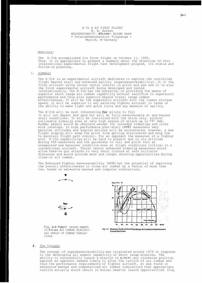
X-31 A AT FIRST FLIGHT W. B. Herbst
MESSERSCHMITT- B6LKOW- BLOHM GmbH - Unternehmensbereich Flugzeuge -
Munich, W-Germany
Abstract:
The X-31A accomplished its first flight on October 11, 1990. Thus, it is appropriate to present a summary about the objecties of this international experimental flight test development program, its status and follow-on planning.
1. summary
The X-31A is an experimental aircraft dedicated to explore the controlled flight beyond stall and enhanced agility (supermaneuverability). It it the first aircraft using thrust vector control in pitch and yaw and it is also the first experimental aircraft being developed and tested internationally. The X-31A has the potential of providing the means of superior short range air combat capability without sacrifice to supersonic performance and thus also superior beyond visual range combat effectiveness. It will be the supersonic aircraft with the lowest minimum speed, it will be superior to any existing fighter aircraft in terms of the ability to make tight and quick turns and any measure of agility.
The X-31A will be most interesting for pilots to fly: It will not depart and spin but will be fully maneuverable at and beyond stall conditions. It will be controlled with the stick only, without noticeable sideslip even at very high angles of attack up to 70° AOA. Rudder pedals would be obsolete except for intended sideslips and cross wind landings. In high performance post-stall (PST) maneuvers very peculiar attitudes and angular motions will be encountered, however, a new flight display will keep the pilot from getting disoriented and help him to maintain flight path control. For an opponent the maneuver of a fighter with X-31A capabilities will be hard to predict due to its attitude during PST-maneuvers and the quickness to roll and pitch into an unexpected new maneuver condition even at flight conditions critical to a conventional aircraft. Thrust vector enhanced sideslip maneuvers would allow head-on gun attacks to very short closure at safe collision distances and would provide more and longer shooting opportunities during close-in air combat.
The Enhanced Fighter maneuverability (EFM) hat the potential of improving the overall effectiveness in close air combat by a factor of more than two, based on extensive manned and computer simulations.
Reu
k-p. 4
Fig. 1-1 Weawn launch aspect in Future Air Combat Statisti- cal result of Combat Simula- tions
2 . The Concept
Flg.l-P
The concept of supermaneuverability was originated around 1978 in response to the developing all aspect capability of short range missiles. The ability to successfully launch a missile in almost any clockwise position against an opponent seemed likely to alter the tactics of air combat and thus the performance requirements of fighter aircraft. 1t was found in extensive manned and computerized air combat simulations that appropriate tactics actually would result in mutual head-on launch opportunities (fig.

29-2
1-11 and thus in the dilemma of potential mutual kills amongst equal high performance aircraft. The analysis of such engagements revealed a new maneuver cycle (fig. 1-2) characterized by dominance of instanteneous maneuvers and a tendency to slow speed (ref.(l)). At slower speed an aircraft would achieve a smaller radius of turn at a given rate of turn and, obviously, a tighter turn in a developing mutual head-on situation would allow for an earlier weapon launch at any given off-boresight angle (fig.1-3).
Conventional aircraft, however, are limited in controllability at slow speed and may even get uncontrolled at stall speed just as they are achieving the smallest radius-of-turn. Any significant reduction of radius-of-turn could only be achieved by deeply penetrating the post-stall regime. With thrust vector control and a proper aerodynamic design it was anticipated that an aircraft could be maneuvered safely at and beyond stall limits. very soon it was found that the biggest design challenge was to roll the aircraft at high angles of attack around its velocity vector quickly enough to achieve the desired tight turn performance (ref.(2))
Generic fighter aircraft with post-stall capability were evaluated first in manned combat simulations at the German IABG in 1977 (ref.(3)) and at Mc Donnell's facilities in St. Louis in 1978 (ref. ( 4 ) ) . By that time about 15 operational pilots of USAF and GAF have had the opportunity of familiarizing themselves with this new capability and to generate statistical data about its effectiveness. Many technical features now being installed in the X-31A have been empirically developed during those simulations, for example - mechanization of lateral stick input to roll the aircraft around the
flight path at zero sideslip angle rather than around the familiar aircraft body axis
- angle of attack and nz demand with proper blend-over - PST entry mechanization of the flight control system - gravity and gyroscopic moment compensation - consideration of inertia coupling - scheduling of control surfaces and thrust vectoring blend-in - response characteristics and maximum deflection of the thrust
vectoring system in pitch and yaw and the criteria for body axis roll
All pilots had to go through a learning process of how to use the new capability in order to achieve a tactical advantage and many of the maneuver characteristics now being defined as "PST-performance" in X-31A have been developed during manned simulation. This includes the effect of weapons and fire control. As an overall result, it was found - that combat effectiveness in one vs. one engagements can be expected
- that supermaneuverability would provide a fair chance to survive
- that the benefit of supermaneuverability tends to get bigger in multi
to be improved by a factor of at least two
against two opponents of similar conventional performance
boogies in outnumbered situations
Results of all operations analysis work performed prior to the X-31A program are summarized in the first A-31A report (ref.(5)). It was the basis of the acceptance of the program.
The X-31A Configuration
It was requested that results of X-31A flight testing should be directly transferable t o a potential aircraft. Therefore several existing US-fighter aircraft were investigated during phase I of the program

29-3
(ref.(6)) as potential candidates for modifications and implementation of supermaneuverability. Unfortunately, none of those candidates appeared to be sufficiently suitable or advisable in view of anticipated cost of modification and/or penalty f o r conventional performance. Supermaneuverability needs: - a thrust-to-weight ratio of at least 1.0 - an electronic flight control system - an intake configuration to allow full power engine operation at up to
- a low wing loading and high leading edge sweep - certain aerodynamic characteristics to allow smooth transition into
the post-stall regime - a horizontal control surface that moves into the wind at increasing
angle of attack - a configuration layout which is preferably unstable in pitch at
subsonic speeds for better supersonic performance - resistance to enter a spin and an easy recovery from a spin once
entered, needed to avoid the thrust vectoring system to become a safety critical item.
70° angle of attack
Eventually it was decided to build a dedicated new aircraft. lfig.1-4). A derivation of the German "TKF", a predecessor of the European Fighter Aircraft (EFA), was selected because it was designed to meet the above requirements and much of the existing engineering data and experience could be utilized.
The X-31A is a delta-wing configuration with a '"long coupled" canard. It distinguishes itself from all other currently existing "short coupled" delta-canard fighter aircraft - except for the British/Italian EAP which, historically, is also a derivation of the original German TKF - by the position of the canard relative to the wing. On the X-31A the canard is to be used for pitch control and trim rather than as a high lift device. In order to reduce trim drag in supersonic flight the X-31A is designed with the center of gravity aft of the subsonic center of lift which makes it aerodynamically unstable. AS a result, however, the canard moves downward into the wind at increasing angle of attack and thus always maintains its control effectiveness.
. . Fig. 3-1 X-31A lift in the conventional and FST
regime Fig. 3-2 Split of normal force on wing
and fuselage
The delta wing with its high leading edge sweep and large area in combination with the unstable layout lends itself particularly well for superior supersonic and subsonic performance. It comprises,, however, a fairly complex design because it also has to satisfy the requirements for transonic flight and for the new post-stall regime and to minimize the penalties of the canard interference.
The belly position of the intake in combination with the movable lower lip allows the air to enter the intake at post-stall conditions with minimum disturbance, a prerequisite for the GE-F-404 engine to operate with full power even at extreme angle of attack. In supersonic flight the lip will be moved into an upward position in order toreduce spill drag.
The most unusual device and a necessity for PST-maneuverings is the thrust vectoring device at the aft fuselage of the X-31A. The three devices of the X-31A allow to deflect the engine exhaust at full power condition conically up to about loo, which produces about 17 9, of engine thrust in any lateral direction. Thrust vectoring is used for control only, the "paddles" will be immersed into the hot exhaust for the very short time periods. In the conventional flight regime they can be used as speed brakes in addition to the conventional devices.

29-4
On an operational aircraft the "paddles" would be replaced by an engine integrated thrust vectoring system resulting in a cleaner rear fuselage. Unfortunately, such vectoring nozzle was not yet available for the X-31A and could not be developed within the time and funding limitations of this program.
Much of the external appearance of the X-31A was dictated by the use of existing components (such as the F-16 landing gear and the F-18 canopy) and the aim for low cost (such as carrying all fuel in the fuselage and keeping the wing dry).
Fig. 3-3 ET performance in level flight Fig. 3-4 Sumnary of PST maneuver performance
3 . X-31A Performance
The X-31A is designed to maneuver beyond maximum lift angle-of-attack up to about 80° AOA. Maximum lift is achieved at about 30° AOA, beyond that point lift is decreasing with increasing AOA (fig. 3-1). Aerodynamic load on the aircraft in terms of normal force is carried by wing and fuselage. In the PST-regime a major portion of total load is acting on the fuselage (fig. 3 - 2 ) . Total normal force is increasing steadily up to 90° AOA. comparable with the drag of a flat plate.
A simple mass point analysis leads to fig. 3- 3 . It shows aircraft rate-of-turn for a level maneuver for various AOA as function of M-number. There is a less of turn-rate and only little improvement of turn-radius as AOA is increased only marginally above maximum lift AOA. It needs a deep penetration into the PST regime until substantial benefits can be realized. Also, there seem to be little overall advantage of PST maneuvering in level flight. Fig. 3-4 shows a similar analysis covering a varity of maneuver states. Maximum performance is achieved with maximum help of earth gravity. The shaded areas indicate maneuver states with optimum angle-of-attack usage. Also indicated are best radius-of-turn performance for inverted vertical maneuvers.
Optimum PST-maneuvers have been analyzed in Ref.7 , although, disregarding control power limitations and actual 6 DOF aircraft dynamics. Fig. 3-5 is showing a 180° heading reversal as performed in manned simulation using realistic X-31A aero data and flight control characteristics. Circles indicate the entry into and recovery from the PST flight regime. In this case a very tight and quick turn was achieved with maximum instantaneous performance of 31° rate-of-turn and about 7 0 m radius of turn. The same maneuver typ with maximum lift AOA limitation is shown in fig. 3- 6 . Best rate-of-turn and radius of turn now is limited to 25O and about 400 m respectively.
Key for maximum instantaneous maneuver performance is velocity vector roll rate/acceleration to initiate a turn and stop the turn maneuver. As a rule of thumb velocity vector roll rate needs to match the desired turn rate. This is why none of the existing aircraft could perform high performance turn maneuvers at high AO.4 even though they might be able to pitch up to very high AOA. There is no PST-maneuvering capability in any tactical sense without sufficient body axis yaw power at high AOA and automatic avoidance of excessive side-slipping. Such capability can only be provided by multi axis thrust vectoring in combination with an appropriately designed flight control system. Fig. 3-7 is showing demonstrated X-31A velocity vector roll performance at 60° AOA.
Fig. 3-7 is showing a typical tactical PST maneuver as seen in many manned air combat simulations. In this particular case the aircraft is

29-5
outmaneuvering a first opponent by menas of a very quick and tight PST maneuver and subsequently chasing a second opponent. Conventional X-31A performance (fig. 3-9) is not significantly different from contemporary fighter aircraft. X-31A flight envelope is depicted in fig. 330 up to M=0.9 and 40.000 ft. The PST envelope is largely overlapping with the conventional subsonic flight regime.
............. L% I . ~. . 140
120
100
80
60
40
20
0 Fig.3-6 Maneuvering for test- t w n prformance w i t h maximum 0 0.2 0.4 0.0 0.8 1 1.:
M Fig.3-5 Maneuveriw for best ET-performance lift limitation
Fig. 3-7 X-31A Velccity vector roll performance
Multi axis thrust vectoring - as being a necessity for PST maneuvering - can also be used to enhance agility in the conventional flight regime. Fig. 3-11 shows a maneuver by which agility will be measured in the X-31A program. It consists of a high performance level wind-up followed by a maximum performance heading reversal.
Flight path decoupling (RCFAN) is a special mode of the flight control system by which the pilot could point the aircraft nose (or gun) independently from its trajectory. upon a stick input by the pilot the aircraft in RCFAM mode would react adversely in pitch and yaw. Of course, the angular range of such decoupling is aerodynamically and structurally limited, however, these limits could be enlarged by thrust vectoring and thus would be expected to be larger in comparison to conventional aircraft.
Longitudinal deceleration is important for any aircraft to quickly reduce speed for best turn performance and to effectively enter the post-stall regime. For this purpose the thrust deflection devices can be deployed outwards to act as drag devices in addition to the conventional speed brakes.
4 . Building the plane
After MBB's withdrawal from the Agile Combat Aircraft (ACA) program (which later on became the Experimental Aircraft Program-EAP and Rockwell's disappointment of not being selected to build the X-29A both companies met in October 1982 to jointly pursue the concept of supermaneuverability.
Rockwell together with MBB eventually convinced DARPA in 1984 of the potential of the supermaneuverability concept and its peculiar compatibility with DARPA's "high risk - high pay off" policy, MBB jointly with Rockwell managed to get support from the GMOD for a coordinated joint study which was named Phase I of the X-31A program.

29-6
As a happy coincidence the Nunn-Quayle initiative supporting cooperative international armament programs was promoted at that time and helped the program to materialize. Eventually a government Contract was signed in May 1986. The program was called "EFM", Enhanced Fighter Maneuverability. A "phase 11" contract was awarded to NBB by GMOD and to Rockwell by DARPA/Navy in September 1986. The objective of phase I1 effort was to perform the preliminary design of a research aircraft and the necessary wind tunnel testing to allow detailed design and fabrication in the subsequent phase. Also, a formalized mode of Rockwell-MBB cooperation had to be found and a share of work respectively. Basically, there was
- a split into Rockwell workpackages to be performed at Rockwell with MBB local participation and MBB workpackages to be performed at MBB with Rockwell local participation (fig. 4-2)
should report to MBB management and vice versa
subcontracts
- a rule that Rockwell engineers working in Munich on MBB workpackages
- no duplication of effort - no transfer of money between RI and MBB except for special
X ~ I I \ F , l ~ h l E " Y O I D ~ Fig. 3-70
It was decided in phase I1 that MBB would design and manufacture the two sets of wings and the thrust deflectors and would develop the control laws for the flight control system. Also, X-31A performance would be defined and analysed at MBB. Later on, it was suggested to develop a special display to avoid pilot disorientation in PST maneuvers. The development of this display was also charged to NBB (fig. 4-3)
Maximum use of existing equipment was part of the approach selected very early in the program. This was in particular true in the areas of landing gear (F-16), propulsion system (GEF-404 engine), canopy and windshield (F-18) and a multitude of subsystem components pulled together from fighter aircraft such as the F-16,F-18 and F-20.
A special challenge for Rockwell was the acquition of the extensive list of GFE and CFE equipment. Special help, dedication and persistance was required on all sides to get the parts in time to SUppOKt the KOllOUt and the first flight of the X-31A. Installation of system components, hydraulic tubing and electrical wiring harnesses were as usual affected by late deliveries of components in manv areas and required special attention and treatment.
The fuselage with the canards and the vertical tail was built by Rockwell, while the wings and the thrust vectoring vanes were developed and manufactured by MBB. A number of trade studies were performed to select the optimum design and manufacturing concepts with consideration given to weight impact, material aspects and manufactoring cost. The fuselage toolirqwas simplified by using the major NC bulkheads as templates/tools for the installation of longerons, fittings and finally fuselage skins.

29-7
Aluminium, aluminium/lithium, steel and titanium were used in appropriate areas utilizing the available NC capabilities existing at Rockwell's facilities. The carbon fibre system used extensively on the B-1 was utilized for honeycomb skin pannels on the fuselage, the rudder surfaces as well as on the skins for the vertical tail. Rockwell Tulsa was responsible for the manufacturing of these carbon fibre parts.
MBB selected the carbon fibre material, also used in EFA, for the manufacturing of the wing box skins as well as the leading and trailing edge flaps. The wing box has a metal substructure with NC milled and metal sheets spars and ribs. The design and manufacturing were simplified by the fact that the wing does not carry any international fuel.
2D and 3D design tools such as CADAM and CATIA were extensively used during the development phase. Exchange of technical data (e.g. loft line definitions for structural parts) between Rockwell and MBB were performed via a commercial communications network which allowed data exchange overnight.
While wing and fuselage were relative conventional in terms of the structural concept, the development of the thrust vectoring vanes required additional considerations, since these parts would be immersed into the hot jetstream of the GEF-404 engine at all power settings, including afterburner. To determine and verify design loads a full scale test was performed behind a Navy F-18 aircraft, utilizing metal structure for the thrust vectoring vanes. However, metallic vanes would result in a relatively heavy weight structure at the very end of the aircraft, thereby moving the C.G. aft, which was not desirable. Therefore, the German Company SIGRI was given the subcontract to manufacture the thrust vectoring vanes from carbon/carbon material. This material is extensively used in space vehicles for thermal insulation and for hot structures.
1 .Q C-klWill
To avoid building a third airframe for structural test to destruction the proof load concept was agreed to by the Navy, DARPA and the German Certification Agency ML. All major components were tested to at least 110% of design limit load. The German ML is responsible for the certification of the wing and thrust vectoring vane structure, whilst the US Navy has the authority to provide the flight clearance for the overall aircraft structure, including all systems.
Another challenge was and still is the development, integration and testing of the Flight Control System (FCS). Initially the FCS was planned to be a sole MBB package, however, in the concept definition phase it became apparent, that manpower and equipment resources available at Rockwell and at MBB as well as requirements for simulation and test made it strongly advisable to change this initial plan. Rockwell took over responsibility for the definition and design of the overall system architecture including redundancy management. The control law development, handling qualities and stability analysis and initial simulation were conducted at MBB's Ottobrunn facility.
Honeywell is the SubCOntraCtor of Rockwell providing the computer soft- and hardware including the control law and redundancy management coding and verification.

29-8
5. Flight testinq
At this time (Dec. 1990) aircraft I has made 9 flights by 3 pilots and a substantial part of the conventional envelope has been covered. All pilots are very satisfied with handling and response characteristics. Very soon aircraft 2 will follow and it is anticipated that the PST envelope will be opened subsequent to about 40 hours of initial flight time.
Tactical flight evaluation, at this time, is still in a stage of definition. The aircraft is not equipped with any tactical sensors, fire control system, weapon representation and suitable cockpit facilities. However, once all the effort and money is spent on developing/building two aircraft, clearing them for the new envelope, developing all the maneuver schemes for its various caoabilities and measurino its flioht oerformance. there is a strong desire tb substantiate the expected tactical-utility by' actual flight experience. The expected tactical benefit is shown in fig. 5-1 as result of many computer and manned air combat simulations.
Ref. 1 W. B. Herbst: Dynamics of Air combat Journal of Aircraft, Vol. 2 0 , No. 7, International issue 1983
Ref. 2 Phase I conf. dev. report X-31A Performance Data MBB X-31A-M-I and vol. 12 SDM Performance
Ref. 3 H. Ross: Taktische Auswirkungen Yon PST-Manovern im Luftkampf MBB Report UF 1498. 1977 und R . Haiplik: TKF/STY/0071 und R . Polis, W. Frenzl: untersuchung des Einflusses VOn Supermanovrierbarkeit im I vs. I Luftkampf TN BT 13-88-22/79, 1979
Ref. 4 AFTI, Techn. Report AFFDL-TR-75-86, 1975
Ref. 5 R . Haiplik: SNAKE OR Analysis MBB/LKE 152/STY 001, 1985
Ref. 6 SNAKE phase I report
Ref. 7 K. Wel1:Optimale dreidimensionale Steuerungen von Hochleistungsfluyzeugen nit PST-Eigenschaften DFVLR Report A 552-78/2, 1978

RTD-I
ROUND TABLE DISCUSSION
chaired by
MI H.Wuennenberg
Mr Wuennenberg
Ladies and Gentlemen, we come now to the last session of our Symposium which is entitled “Round Table”. You will miss a round table here; there isn’t one, but hopefully you have sufficient imagination to think there is somewhere a round table within the audience. The procedure which we discussed to operate our round table is the following:
From the individual sessions of our Symposium we asked the Session Chairman and the authors, and also some specialists, to come up with a general view of the session -not only of the session but on the session subject - so this group formed or should have formed, a general opinion on the subject. The intention was to discuss whether we have covered within the conference the main aspects, only a few aspects, or what is the situation, the technical situation; what is left open for further activities. We will now ask the spokesman of the individual groups who have prepared these comments to give their presentations and then leave the floor open for discussion on these opinions. You are all invited to give your own comments on what these gentlemen will present to you.
Our first session of papers was the Pilot’s View, and Professor Mulder will give the opinion of this group.
Prof. Mulder, The Netherlands
Thank you MI Chairman. We, Bob Russell and I, were Chairmen of Session 2, the Pilot’s View and as you recall we had three papers. They were presented by MrThomas,Mr Morseand Mr LeTron. After our session, wecame together, with theseauthors and some members of the audience, and we had a discussion and finally came up with several different issues together with equivalent recommendations.
The first issue is on the communication aspect of designing a new aircraft. The communication between engineers, pilots, and designers is something that needs to be thought about. They should form small groups, not more than 4 to 5, from aircraft concept, through design, development, test, etc. to insure a successful civil or military platform in regards to flying and handling qualities.
The recommendations are, first of all, that engineers and designers need a reasonable tl ight experience, to allow communication obviously, and pilots need reasonable engineering skills.
The next part of the recommendation is to involve designers in flight testing, and the last part of the recommendation is to train engineers and pilots as a test team, not as individuals. This is done, for instance, during education for test pilots at Istres. There this approach is really explicitly followed, team experience rather than individual test pilot. This will provide better communication between specialists within the team. The second issue addresses the topic of civil vs military handling qualities criteria. Civil aircraft designers are in our view not exploiting advances in military handling qualities criteria and some civil aircraft manufacturers are not addressing deeply enough the aspect or subject of flying qualities. And next, civil aircraft are built and tested more and more against product liability or legal public liability, and flying qualities requirements are becoming more or less secondary.
Our recommendation is to invite the civil aircraft community to participate in flying qualities working groups, for instance, in the context of the joint airworthiness agency’s work.
The next issue is slightly different in scope and it relates to the control of highly automated transport aircraft. In response to a question after Mr LeTronS paper on the Airbus 320 fly-by-wire lateral control system, the moregeneral problem was raised of keeping the pilot in the loop of highly automated civil and military transport aircraft. Pilots’ control inputs no longer have a direct relation to control surface deflections and control input may he made without corresponding movement from the main manipulator; for instance the thrust levers would remain stationary while thrust variations are being applied. In slightly broader context, the pilot of such a highly automated aircraft must use controls which are less natural when compared to classical controls such as control column and thrust lever. There have been complaints that mental workload may, in some instances, be higher, than in conventional aircraft and the recommendation would he that flying qualities criteria should be made to reflect operation of these highly automated aircraft. Basic research might still be necessary which would critically review present cockpit layout; rhar means controls and displays, control laws and procedures.
And our last issue, is rather controversial I think. It relates again to handling qualities criteria, and it says that handling qualities requirements should state fixed numbers only when vital for the safe conduct of flight. The recommendation would be: leave as much freedom as possible for creative aircraft design; and then, the blank part of MIL 1797A might be a good approach.
Mr Wuennenberg
There are some very stimulating recommendations which your group has made, and the question is whether the floor agrees with these, or wants to make any additional comments, or questions, or contradictions.

RTD-2
Mr Smith, United States
One of the things Ralph A’Harrah always told me to do was try to say something provocative and clearly Number 4 is provocative. One thing I was struck by early on was the statement that specifications are rules for fools and guides for wise men. Literally, I don’t agrce with that, but I do think that in my exposure to the handling qualities world we spend far too much time being technical lawyers and not enough time being technical explorers and guides. So I would go along with Number 4 in that sense and would like to say that I think we should spend more time sharing lessons so that we can guide people as much as is feasible in the context of national interests and secrecy. So I agree with Number 4.
Mr Wuennenberg
Now we come to the next group of papers entitled “Experience with Specifications”, and the statement of this group is given by MI Sella.
MI Sella, Italy
Session number three was dealing with experience with specifications and the discussion between the session chairman and the authors following the session has identified three major items which need to be recorded again here. The first one really comes from the conclusions and recommendations from the work that Working Group 17 has done, particularly realizing this very important statement, the third one, which says that sufficient knowledge is available for the design of a longitudinal FCS and the use of adequate design criteria. Now this is a very important result: the demonstration of success of 10 years of research work. We have seen that coming from the aircraft of the 70s, which had a number of handling problems like YF-16, Tornado, Shuttle, just to note a few, the aircraft of the SOs, at least most of them like Rafale, X-29, and/or EFP, and recently also the F-22/23 and X-31 have been generally flaw free in terms of flying qualities. I think it is very good news for the next generation - ATF and EFA-like aircraft. This achievement shows that indeed we have sufficient design guidelines and techniques for flying qualities and control law design. Gibson’s criteria have been particularly successful in this field.
However, these techniques may address areas for design optimization rather than provide level boundaries. Now this is perfectly reasonable taking into account the fact that most of the designs which were mentioned before are prototypes or demonstrators rather than production aircraft. But the complete specifications, including level boundaries for degraded modes or failure states and also for the definition of service and permissible flight envelopes, are required for the next generation production fly-by-wire aircraft. Now these requirements are to a large extent still missing; the group feels they could be derived from the existing data base, but the necessary effort has not yet been available.
Another important point which has been identified is the fact that flying qualities are inherently subjective while specifications tend to be quantitive. The purpose of showing this viewgraph, figure 1 (from Leggett and Black‘s paper Number 7), is to say essentially that whatcver the specifications say, the flying qualities of the aircraft must satisfy the mission needs. Now this might seem obvious to a flying qualities specialist, but in accepting this figure, there are problems because accepting this requires that someone will have to admit that they got it wrong and will require additional expenditure from a government agency or from a contractor
So the group feels that flying qualities specialists should really try to educate their managers to accept this as a fact of life and to accept the risk involved; in other words not feel that the flying qualities specification is a performance specification. Now the third point is very, very much related and was also identified in the previous session, and this point to be emphasized once again is the fact that flying qualities specialists and pilots have to work together as a team. It’s very, very important that in establishing this dialogue, engineers must not hide themselves behind the book, taking the specification as a Bible, but must understand the relation of the flying qualities to the aircraft task and mission. On the other hand, pilots must help engineers to understand their environment by talking the same language. This concludes my summary.
Mr Wuennenberg
Are there any comments?
Dr Buchacker, Germany
With respect to the last, to communicate with other people you have to learn the language of the other people - if it’s German or if it’s an engineering language. I would like to make another comment. We talked about numbers and handling qualities specifications etc. I think what we have to bear in mind, especially as we‘re talking about handling qualities, what is molded down in these specifications is always a mirror image of the abilities of the pilot, the abilities of the human being. If we apply these specifications we have always to bear in mind that more-or-less mirror image of the human being, and so ifwe deviate from those numbers we have to reconsider the prerequisites and to reconsider whether the deviation will not require other ab the human being; then we have to check that the human being will be able to do that.
Mr Wuennenberg
Now we comc to Session Number 4. We have separated Session Number 4 on “Ongoing Research and Application” into two groups and we are wondering what the two groups indcpcndently have found out on the same subject. Mr Woodfield will give the first view of this subject.
Mr Woodfield, United Kingdom
What we thought, as we looked at the somewhat mixed batch of topics which have been covered, all of great interest but sonicwhat different, was that there were one or two fcaturcs which perhaps needed to be highlighted.
RTD-3
One feature we did feel was worth highlighting is that although we are concentrating, quite rightly, on the importance of the pilot, and his aircraft and flight control system; the pilot actually interfaces into that system via two other environments: his cueing environment, and in particular, displays and the information those provide; and, of course, his control or tactile environment, the way in which he actually makes demands upon that aircraft. Although it’s vital that we do get that relationship between the pilot and his aircraft right, we musn’t ignore that, from time to time, the way in which we provide his cue environment and his tactile environment can strongly influence the overall handling qualities.
Thinking particularly about the cue environment, three aspects of that were brought to mind. First is display of flight information itself, its content, and its dynamics, and I think there are many occasions when one has to only think of the failure of head up displays in some fighter aircraft to provide a safe flight information source. And although we believe that can be overcome, nevertheless it can also produce a major degradation of the flying of that particular aircraft.
Next, the time sharing of tasks. The proportion of your flight time that is available the concentrate on the flying task, in many cases is decreasing, This has been brought out several times. We have to make sure that our requirements for handling qualities take into account the varying load or varying time share available for that. And as I” now concerned with simulation as well as with flying tasks,Icouldn’t resist puttingin the thirdone.But I thinkit isveryrelevant.Ifwe’relookingat activities,as wemust,in the simulator and in flight, the relevance of the changes of the cueing environment between the two has to be understood and recognized and taken into nccount in the translation of results from one environment to the other.
We have much less to say on the tactile environment. The impression I was left with, and I” not an expert on the various implications in this area, the impression I was left with is that we still have some way to go in understanding the way in which the pilot compensates and relates to his environment and the relationship between the force and position dynamics of those control systems. And the way in which we deal with, perhaps, effective time delays and things of this nature needs to be very carefully thought out in relation to the source of those time delays, I believe, as was emphasized by some of our authors, and cannot be left as a global parameter which explains everything, wherever it comes from.
The third point which was made by our authors, which I felt was an interesting one, didn’t come out of the talks. It has, I think, come out of many of the papers in the overall concept and the overall coverage of the Symposium. But my view so far is that we’ve heard an awful lot of very good work during the last week. People in their research environments are doing a great job.
At the end of the day we have a lot of flight test data obtained by test pilots in research aircraft and research simulation. We‘re getting very little feedback still, and I think we deserve more feedback from the behaviour of operational aircraft and how the pilots areseeing their ownvehicles. At the least, that means that we’renot actually establishingquiteasfirmly as I think wemight wish to, the areas where there is a really firm need for doing the work that we’re doing and I just leave that thought with you as a concluding thought.
Mr Wuennenberg
Is there any comment to these statements, especially the last one which I think is very provocative, but it hits the point exactly.
Mr Morgan, Canada
I’d just like to comment on the last suggestion there and it’s a lovely idea, but I think there’s an intense difficulty in taking a body of pilots at large in their day-to-day machines and trying to get any feedback at all that would be meaningful in the handling qualities research field. In the general tenor, or environment in which the line pilot works, be he civil or military, it is such that he is, he gains stature in his job amongst his peers by adapting to and coping with machine difficulties. If you ask the average line pilot about his aircraft, “It’s the best thing that ever flew”.
Mr Wuennenberg
I would now like to ask the second group on the same subject for their views, which are presented by Mr Baillie.
Mr Baillie, Canada
Clearly,as wegot togetherinourgroups youllseesomecommon themesemerging,someofthestuff that wedecided tolookon is common with what people have already talked about. We’re using a term that was around for awhile, I haven’t seen it lately, “control configured vehicles”; clearly we’re accelerating the trend to do that. Some of the papers that we’ve seen, especially in that last session, talked about that and we’ve got to optimize our applications of that type of technology for the new tasks and missions that we’re foreseeing. The question that we raised a number of times is: in what main areas of research should we be focusing our limited abilities? How should we address the possibilities of configuring the aircraft for a specific mission in a specific time? We’ve got to look at the interface between these specific roles and we’re possibly not doing that at the moment.
This second one was a common theme. A lot of our research results which, of course, we present in fine form up here and we get great charts, but the design community gets them only through the specifications. So, as we’re learning to design new vehicles we’re going to have to continually reassess our specifications. Rather than updating every 10 years, we should almost be doing updates every couple of years or have ongoing updates.
Part and parcel with that, and the fact that we’re dealing with these vehicles configured for a given task, is the fact that we’ve got to use this mission task oriented principle as is happening in the rotorcraft world and the fixed wing world. We’ve got to continue to use that. But we’ve also got to make sure that the specifications reflect the intent rather than the absolutes that we seem to be able to find all the time. And clearly the reason for doing that is avoiding the use of a spec as a cookbook. We’ve got to make our specifications reflect a lot more the intent OF what the possible problems can be if you don’t meet the criteria rather than saying, “You must meet this criteria”. And to do that thehelicopter spec has some nice things which I think should be followed including sets of maneuvers that may expose the problems that are otherwise inherent if you don’t meet the spec and also descriptions of the criteria to allow a reasonable engineering interpretation by other parts of the community.

I RTD-4
The third point we made: as our vehicles become more integrated we’ve got to get more and more cooperation between the various people putting hardware and software into the vehicle. We’re the flying qualities community, but the flight control guys are sometimes down at the other end of the hall or in another building. The aerodynamics guys, some are represented here, some are not. Avionics clearly is becoming more and more of an important part of the vehicle ability to do the flying qualities and to do the task and somewhere in all of that are our human factors colleagues - pretty much we’re all human factors colleagues when we start to think about it. The important thing that I put forward to this group is: how do we improve our cooperation between those groups and how can we educate our counterparts so that they understand what our criteria are trying to get at?
The final point was touched on a little by Mr Woodfield, simulation is becoming a design tool that’s used universally throughout the field these days and we are getting better and better at it all the time. It’s a subject for different conferences. But we must continually ask ourselves where is it appropriate and where is it inappropriate and try to make the absolute best use of this scarce commodity of time on different simulators. I ask you people, what improvements should be pursued in our simulation areas? What sort of things can we do to improve the data that’s coming out of simulation in the flying qualities world? And finally we have a number of full scale in-flight facilities, but the majority of them are getting old and we should be starting to continue to develop new facilities EO that we can use these as tools to validate our other work on the ground. I hope that stimulates a little discussion.
MI Wuennenberg
I think there was some overlap to the foregoing statements, but nevertheless I think also some new aspects that have not yet been covered, so we have been glad to come up with these two groups on the same subject. Is there any comment on the statements presented?
Prof. Campos, Portugal
I would comment on one. This was the cooperation between different subjects and I would mention in particular aerodynamics and control. Sometimes I wonder whether the complexity of the control systems is not partly due to inadequate aerodynamics, I mean, if the vehicle is designed and these qualities turn out to be less than desirable, then the tendency is to say, “We will make a control system which will fix the problem”. And I wonder whether sometimes it might not be simpler to fix the aerodynamics and have a simpler control system. In a sense, the question I’m putting is whether we don’t fall into a situation where we have people who know a lot about aerodynamics and less about control and those who know a lot about control and less about aerodynamics. Of course, one has always the argument, “Well if we’re to fix the aerodynamics we have to change the configuration and that’s very costly”. But then a complicated control system may also be costly to validatein thenumber offlight hours that you have, so I’m not sure whether we always arrive at the best compromise. I mean, some people argue we can make almost anything fly, but is that the best solution or should it not in some situations be better to try to improve the aerodynamics and perhaps have simpler control?
Mr Wuennenberg
Well it’s challenging; we should give this question to the Fluid Dynamics Panel to clarify whether they could improve the aerodynamics. I don’t know if any one of you want to comment on that?
MI Elbel, Germany
In fact, there was a meeting in Lisbon about this some years ago and I attended that and the message which came out of that meeting essentially was “fix the aerodynamics first”. I think that should be taken to mean not going to a degree of instability which you fix with a flight control system or fancy computers; fix the aerodynamics first as far as you can do that.
MI Wuennenberg
Yes, but we have seen this morning in the nice video from Rogers Smith how complicated this could be at high angle of attack - this elimination of the vortices coming from every edge and from the fuselage nose and so on. They are very dynamic so it may be very difficult. I know that the aerodynamists are using tremendous amounts of supercomputing to get it clear, but this technology seems not to be solved at the moment.
Prof. Schaenzer, Germany
It is my present feeling that one ofthe real problem areas is education of the students and you will really find only a few students who are able to be good in aerodynamics and good in flight control at the same time. You have a real separation in these two areas and I think we have to try to educate them in a better way so that they can understand both areas.
Prof. Ward, United States
I’d like to second that thought and particularly in the United States as I think Prof. Schaenzer bas a much better opportunity to do that than we do in this country. Having come from the military after 20-odd years and watching specialists work and then trying to Train young peoplc to be specialists, I’ve come to the conclusion that we’ve just about cut our feet off by not being able to have people who can integrate and design. The Germans, to a very great extent with your emphasis in university on the integrator and his importance are doing well, Try to find a US university that has emphasis on design, and they are very few and far between.

RTD-5
Prof. Innocenti, United States
I agree with what you said. On the other hand, the cooperation - the integration of such different activities towards a better flying qualities design - it appears to me more nowadays a management choice. That could be either corporate management or could be government; there’s a lot of complexity involved in putting together people from aerodynamics. I agree on the lack of integrated design capabilities in our universities. As a matter of fact, I happen to be very lucky to have a dual education and experience both, with Old World and New World education. In this country, unfortunately, the level of technology and the ease in generating numbers through computers has phased out most of the old engineering and manufacturing capabilities that we used to teach or - they used to teach me, let’s put it this way. And it seems to be a one-way street in that we have just this year completely eliminated any CAD/CAM course in our curriculum; and not to tell you about materials and manufacturing and drawing and all that stuff - it’s very difficult. I think it’s a very general national problem that clearly cannot be solved by a single place and, if it is a problem, has to be addressed in a larger context.
Mr Cooper, United States
I work for the Navy, Point Mugu and philosophically, certainly, getting back to the original question of not using controls as a fix for inadequate aerodynamics, I agree with that. Operationally, certainly in the military, we’re doomed to always have less than the best aerodynamics. For instance when you’re carrying significant external stores and you drop them, you change the aerodynamics and the mass properties of your vehicle. Another operational activity would be mid-air refuelling and yet another, which I wanted to touch on later, was battle damage. You’rejust going to have to have something to fix situations that- degrade your aerodynamics, hence control systems.
MI Wuennenberg
We now turn to the final session which was entitled “High Angle of Attack and Large Attitude Maneuvering”. I have to say this group has a disadvantage: since they couldn’t meet after the session, they had to meet prior to the session; but hopefully they have an opinion on their subject. This statement will be presented by Mr Robinson.
MI Robinson, United States
One advantage of being the last one is that you can have a very messy viewgraph and use that, the excuse that you’re the last one and didn’t have time to do it; thereby my excuse. Before I show it, I do believe that we concluded that in the conventional flight regimes that we see handling qualities in terms of criteria and, I think, specifications - the two kind of go together because, as we pointed out, specifications really are becoming the guides, the rational guides, which you design to, and then these become the criteria, especially with tailoring.
I think the biggest problem we identified is the one ironically which was just discussed. That’s the one that the advent of electronic flight controls, in particular, digital flight controls has created a schism, where what I, in our parochial language say, the “electron pushers’’ -in other words, the electronics people - do not relate to the aerodynamics people; and bridging that gap is a place where there’s tremendous progress yet to be made. However, in the other area, and I think Rogers Smith said it beautifully this morning, “discovery is in progress”; I coined that slightly differently. In the area of high angle maneuvering and agility at all angles of attack there is progress being made in the areas of theory as Carmen Maza pointed out. We didn’t talk a lot about the computational capab es, but certainly for high angle of attack, highly agile vehicles, be they helicopters or fixed wing vehicles, to be practical we’re going to have to have computational design capabilities. With the advent of supercomputers, use of Navier-Stokes through computational fluid dynamics is coming along. And, as a matter of fact, we are going to use the X-31 and the F-18 HARV as points of correlation to show that those computational tools in fact, work. I mentioned specifications; the specifications also include the design tools. The thinking of the designer is going to have to be different; particularly the thought of an airplane performance man, the sizer, the guy who puts the configuration down, establishes the basis of whether the aerodynamics of that airplane will be any good or not, who thinks of the airplane as a point mass. That’s no longer germane in the regime we’re talking about; it’s a six degree of freedom point. Therefore the bridge has to be between those aerodynamicists and the flight controls people again. And certainly, nobody has any faith in any of that until you can fly it.
Agility; the current status is we’re groping for a common definition. I’ll have to say that I personally was very heartened here to seethedefinitionhominginontherateofchangeofthestateofmaneuver,orthesecondderivativeoftheflightvectorso thatitis coming along, but what specifically that means is yet to be defined. You hear words like functional agility that pilots tend to use. What they’re really talking about, perhaps, is the time to a proper firing solution. That has embodied much more than agility in my personal opinion, but I have my definition of agility and there’s probably 30 other ones, at least, out here in the audience. That’s the point. But we have to have a common one that the pilots can understand, designers can understand; and,from that, we can understand the increment of combat utility that we get out of it.
High angle of attack, we have defined the pay-offs, I think quite rigorously. Both MBB and Rockwell have tools to do this and those tools are based on our own national government tools that we’ve adapted to be six degree of freedom models. It’s a matter of validating those. However, we clearly - after we fly these airplanes -will have to develop the requirements and criteria and be able to compare those to the other configuration drivers you have, such as observables, such as conventional performance and cost.
So what are the challenges? The clear challenge I think is to develop the path from flight test back to the criteria so now the designers know how much agility, how much maneuverability, how much handling qualities do I have to put into an airplane and what are the trades between these? Thcrcforc, we can design for high alpha and agilityand we can understand those trades. That concludes what our recommendations would be, and ends my comments.

RTD-6
Mr Wuennenberg
I think, you have exactly covered everything that the audience has in mind, so there are no questions left.
I would like to thank all the Session Chairmen, authors and those who contributed from the floor, for making this an interesting and challenging discussion period, and an excellent ending to this Symposium.

REPORT DOCUMENTATION PAGE 1. Recipient’s Reference 2. Originator’s Reference 3. Further Reference 4. Security Classificatioi
of Document ISBN 92-835-0602-2 UNCLASSIFIED
ItIk AGARD-CP-508
I I 2 1% I 5. Originator Advisory Group for Aerospace Research and Development
North Atlantic Treatv Organization I I I !i. .~ 7 rue Ancelle, 92200 Neiilly sur Seine, France
FLYING QUALITIES \ i ir , 6. Title
SQQ < i ~ ~ ~ , ~ . ~ ’ 1 .~ 7. Presented at the Flight Mechanics Panel Symposium held in Quebec City, Quebec, Canada
from 15th to 18thOctober 1990.
8. Author(s)/Editor(s) 9. Date
Various February 1991
0. AuthorWEditor’s Address 11. Pages
Various 390
1 2. Distribution Statement This document is distributed in accordance with AGARD
policies and regulations, which are outlined on the Outside Back Covers of all AGARD publications.
3. Keywords/Descriptors
Flight control Flight Active control Aircraft Flight control laws Quality Aerodynamic characteristics
14. Abstract
,(The , , validity of constraining the responses of today’s control dominant aircraft to conform to the ’. &.classic flying qualities criteria derived from stability dominant aircraft experience has been an
issue for many years.’The introduction of full time visual scene enhancement with sensor fusion, and computer generatedhterpreted night scenes, also escalates display dynamics into the arena of flying qualities concern. Integrated flight and propulsion control schemes and direct force controllers have the potential for completely coupling all the sensors with all the controllers to provide any combination of controlled motion from six independently controlled single-degree of freedom systems to a single completely coupled six-degrees-of-freedom system. These,’new technologies have expanded flight envelopes, reduced drag, increased m.anceuvrability, provided the framework for practical gust alleviation and active flutter suppressionjand provided flexibility for fault-tolerant, damage-adaptive flight controls.
, However, the updating of flying qualities criteria has in general not kept pace with these i technological changes. The purpose of this Symposium was to review flying qualities issues today, and to report progress towards their resolution. The following topic areas were covered: - Flying Qualities Experiences on Contemporary Aircraft - Flying Qualities Research - Application of Flying Qualities Specifications - Flying Qualities at High Incidence The concluding “Round Table Discussion” provided the Session Chairmen with an opportunity to share with the Symposium attendees their view of the major issues relevant to their session topic which need to be addressed in the future.
r-.-
J
i


AGARD Conference Proceedings No.508 Advisory Group for Aerospace Research and Development, NATO FLYING QUALITIES Published February 1991 390 pages
The validity of constraining the responses of today’s control dominant aircraft to conform to the classic flying qualities criteria derived from stability dominant aircraft experience has been an issue for many years. The introduction of full time visual scene enhancement with
~ sensor fusion, and computer generatedhterpreted night scenes, also escalates display dynamics into the arena of flying qualities concern. Integrated flight and propulsion control schemes and direct force controllers have the potential for completely
P.T.O.
AGARD Conference Proceedings No.508 Advisory Group for Aerospace Research and Development, NATO FLYING QUALITIES Published February 1991 390 pages
The validity of constraining the responses of today’s control dominant aircraft to conform to the classic flying qualities criteria derived from stability dominant aircraft experience has been an issue for many years. The introduction of full time visual scene enhancement with sensor fusion, and computer generatedhterpreted night scenes, also escalates display dynamics into the arena of flying qualities concern. Integrated flight and propulsion control schemes and direct force controllers have the potential for completely
P.T.O.
AGARD-CP-SOX
Flight control Active control Flight control laws Aerodynamic
characteristics Flight Aircraft Quality
AGARD-CP-508
Flight control Active control Flight control laws Aerodynamic
characteristics Flight Aircraft Quality
AGARD Conference Proceedings No.508 Advisory Group for Aerospace Research and Development, NATO FLYING QUALITIES Published February 1991 390 pages
The validity of constraining the responses of today’s control dominant aircraft to conform to the classic flying qualities criteria derived from stability dominant aircraft experience has been an issue for many years. The introduction of full time visual scene enhancement with sensor fusion, and computer generatedhterpreted night scenes, also escalates display dynamics into the arena of flying qualities concern. Integrated flight and propulsion control schemes and direct force controllers have the potential for completely
P.T.O.
AGARD Conference Proceedings No.508 Advisory Group for Aerospace Research and Development, NATO FLYING QUALITIES Published February 199 1 390 pages
The validity of constraining the responses of today’s control dominant aircraft to conform to the classic flying qualities criteria derived from stability dominant aircraft experience has been an issue for many years. The introduction of full time visual scene enhancement with sensor fusion, and computer generatedhterpreted night scenes, also escalates display dynamics into the arena of flying qualities concern. Integrated flight and propulsion control schemes and direct force controllers have the potential for completely
P.T.O.
AGARD-CP-SO8
>light control 4ctive control :light control laws 4erodynamic
characteristics :light 4ircraft 2uality
AGARD-CP-508
Flight control 4ctive control ‘light control laws 4erodynamic
characteristics Flight 4ircraft ha l i ty

coupling all the sensors with all the controllers to provide any combination of controlled motion from six independently controlled single-degree of freedom systems to a single completely coupled six-degrees-of-freedom system. These new technologies have expanded flight envelopes, reduced diag, increased maneuvrability, provided the framework for practical gust alleviation and active flutter suppression, and provided flexibility for fault-tolerant, damage-adaptive flight controls. However, the updating of flying qualities criteria has in general not kept pace with these technological changes. The purpose of this Symposium was to review flying qualities issues today, and to report progress towards their resolution. The following topic areas were covered: - - - Flying Qualities Research -
The concluding “Round Table Discussion” provided the Session Chairmen with an opportunity to share with the Symposium attendees their view of the major issues relevant to their session topic which need to be addressed in the future. ISBN 92-835-0602-2
Flying Qualities Experiences on Contemporary Aircraft Application of Flying Qualities Specifications
Flying Qualities at High Incidence.
coupling all the sensors with all the controllers to provide any combination of controlled motion from six independently controlled single-degree of freedom systems ,to a single completely coupled six-degrees-of-freedom system. These new technologies have expanded flight envelopes, reduced drag, increased manceuvrability, provided the framework for practical gust alleviation and active flutter suppression, and provided flexibility for fault-tolerant, damage-adaptive flight controls. However, the updating of flying qualities criteria has in general not kept pace with these technological changes. The purpose of this Symposium was to review flying qualities issues today, and to report progress towards their resolution. The following topic areas were covered: - - - Flying Qualities Research -
The concluding “Round Table Discussion” provided the Session Chairmen with an opportunity to share with the Symposium attendees their view of the major issues relevant to their session topic which need to be addressed in the future. ISBN’92-835-0602-2
Flying Qualities Experiences on Contemporary Aircraft Application of Flying Qualities Specifications
Flying Qualities at High Incidence.
:oupling all the sensors with all the controllers to provide any combination of controlled notion froh six independently controlled single-degree of freedom systems to a single :ompletely coupled six-degrees-of-freedom system. I’hese new technologies have expanded flight envelopes, reduced drag, increased nanceuvrability, provided the framework for practical gust alleviation and active flutter ;uppression, and provided flexibility for fault-tolerant, damage-adaptive flight controls. dowever, the updating of flying qualities criteria has in general not kept pace with these :ethnological changes. The purpose of this Symposium was to review flying qualities issues :oday, and to report progress towards their resolution. The following topic areas were :overed - - - Flying Qualities Research -
The concluding “Round Table Discussion” provided the Session Chairmen with an 3pponunity to share with the Symposium attendees their view of the major issues relevant to their session topic which need to be addressed in the future. ISBN 92-835-0602-2
Flying Qualities Experiences on Contemporary Aircraft Application of Flying Qualities Specifications
Flying Qualities at High Incidence.
coupling all the sensors with all the controllers to provide any combination of controlled motion from six independently controlled single-degree of freedom systems to a single completely coupled six-degrees-of-freedom system. These new technologies have expanded flight envelopes, reduced drag, increased manceuvrability, provided the framework for practical gust alleviation and active flutter suppression, and provided flexibility for fault-tolerant, damage-adaptive flight controls. However, the updating of flying qualities criteria has in general not kept pace with these technological changes. The purpose of this Symposium was to review flying qualities issues today, and to report progress towards their resolution. The following topic areas were covered - - - Flying Qualities Research -
The concluding “Round Table Discussion’’ provided the Session Chairmen with ar opportunity to share with the Symposium attendees their view of the major issues relevani to their session topic which need to be addressed in the future. ISBN 92-835-0602-2
Flying Qualities Experiences on Contemporary Aircraft Application of Flying Qualities Specifications
Flying Qualities at High Incidence.

WG+ED NATO -@- OTAN
7 RUE ANCELLE. 92200 NEUILLY-SUR-SEINE DIFFUSION DES PUBLICATIONS FRANCE AGARD NON CLASSIFIEES
Telephone (1)47.38.57.00 Telex 610 176 TelCcopie (1)47.38.57.99
L'AGARD ne ditient pas de stocks de ses publications, dam un but de distribution generale H I'adresse ci-dessus. La diffusion initiale des publications de I'AGARD est effectuie auprks des pays membres de cette organisation par I'intermediaire des Centres Nationaux de Distribution suivants. A I'enception des Etats-Unis, ces centres disposent parfois dexemplaires additionnels; dans les cas contraire,on peut se procurer ces exemplaires sous forme de microfiches vu de microcopies aupres des Agences de Vente dont la liste suite.
CENTRES DE DIFFUSION NATIONAUX ALLEMAGNE ISLANDE
Fachinformationszentrum, Director of Aviation Karlsruhe c/o Flugrad D-7514 Eggenstein-Leopoldshafen 2 Reykjavik
BELGIQUE Coordonnateur ACARI-VSL Etat-Major de la Force Aericnne Quartier Reine Elisabeth Rue d'Evere, 1140 Bruxelles
Directeur du Service des Renseignements Scientifiques Ministkre de la Defense Nationale
CANADA
Ottawa, Ontario KIA OK2
DANEMARK Danish Defence Research Board Ved ldraetsparken 4 2100 Copenhagen 0
ESPAGNE INTA AGARD Publications)
28008 Madrid Pintor a osales 34
ETATS-UNIS National Aeronautics and Space Administration Langley Research Center
Hampton, Virginia 23665 MIS 180
FRANCE O.N.E.R.A. (Direction) 29, Avenue de la Division Leclerc 92320, Ch2tillon sous Bagneux
GRECE Hellenic Air Force Air War College Scientific and Technical Library Dekelia Air Force Base Dekelia, Athens TGA 1010
ITALIE Aeronautica Militaire Ufficio del Delegato Nazionale alI'AGARD 3 Piazzale Adenauer 00144 Roma EUR
LUXEMBOURG Voir Belgique
NORVEGE Norwegian Defence Research Establishment Attn: Bibliateket P.O. Box 25 N-2007 Kjeller
Netherlands Delegation to AGARD National Aerospace Laboratory NLR Kluyverweg I 2629 HS Delft
PAYS-BAS
PORT1 IGAl
-. .. . . Base de Alfragide Alfragide 2700 Amadora
ROYAUME UNI Defence Research Information Centre Kentigern House 65 Brown Street Glasgow G2 8EX
Milli Sawnma BaSkanligi (MSB) ARGE Daire Bagkanhgi (ARGE) Ankara
TURQUIE
National Technical Information Service (NTIS) 5285 Port Royal Road Springfield, Virginia 2216 I Etats-Unis
AGENCES DE VENTE ESA/Information Retrieval Service European Space Agency 10,rueMarioNikis 75015 Paris France
The British Library Document Supply Division Boston Spa, Wetherby West Yorkshire LS23 7BQ Royaume Uni
Lesdemandes demicrofiches ou dephotocopiesdedocuments AGARD (y compris lesdemandesfaitesauprksdu NTIS)doiventcomporter la dinomination AGARD, ainsi que le numero de serie de I'AGARD (par exemple AGARD-AG-315 Des informations analogues, telles quele titreetladatedepublicationsontsouhaitables.Veuillernoterqu'ilyalieudespecifierAGARD-~-nnnetAGARD-AR-nnnlorsdela commandede rapports AGARD et des rapports consultatifs AGARDrespectivement. Des referencesbibliographiquescomplktesainsi que des rbumes des publications AGARD figurent dans les journaux suivants:
Scientifique and Technical Aerospace Reports (STAR) Government Repons Announcements and Index (GRA&I) publii par la NASA Scientific and Technical publii par le National Technical Information Service Information Division Springfield NASA Headquarters NTI') Virginia 22161
Etats-Unis (acce?siblp: igalement en mode interactif dans la base de Etats-Unis donnees bibliographiques en ligne du NTIS, et sur CD-ROM)
Washington D.C. 205 i 6
ImprimP pur Specialised Printing Services Limited 40 Chigwell Lane, Loughron, Essex IG10 3TZ

AG" NATO 6 OTAN
7 RUE ANCELLE ,92200 NEUILLY-SUR-SEINE
FRANCE
Telephone (1)47.38.57.00 . Telex 610 176 Telefax (1)47.38.57.99
DISTRIBUTION OF UNCLASSIFIED AGARD PUBLICATIONS
AGARD does NOT hold stocks of AGARD publications at the above address for general distribution. Initial distribution of AGARD publications is made to AGARD Member Nations through thc fallowing National Distribution Centres.Further copies are sometimes available from these Ccntres (except in the United States), hut if not may he purchased in Microfiche or Photocopy form from the Sales Agencies listed below.
NATIONAL DISTRIBUTION CENTRES BELGIUM LUXEMBOURG
Srr Belgium
Netherlands Delegation to AGARD National Aerospace Laboratory, NLR
2629 HS Delft
Norwegian Defence Research Establishment Attn: Bihlioteket P.O. Box 25
Coordonnateur AGARD - VSL Etat-Major de la Force Akricnne Quartier Reine Elisabeth NETHERLANDS Rue dEvere, I I40 Bruxelles
CANADA Kluyvenveg I Director Scientific Information Services Dept of National Defence Ottawa.OntarioKIAOK2
Danish Defence Rcscarch Board Ved Idraetsparken 4 N-2007 Kjeller 2 1110 Copcnhagen 0
O.N.E.R.A. (Direction) 29 Avenue de la Division Leclerc 92320 ChGtillan
NORWAY
DENMARK
PORTUGAL Portuguese National Coordinator to AGARD Gabinetc dc Estudos e Programas CLAFA Base de Alfragide Alfragidc
FRANCE
GERMANY 2700 Aniadora
SPAIN Fachinformationszrntrum Karlsruhc INTA (AGARD Publications) D-75 14 EggPnstein-Leopoldshafcn 2
Hellenic Air Force TURKEY Air War College Scientific and Technical Library Dekelia Air Force Base Ankara Dekelia,AthensTGA 1010
UNITED KINGDOM
Director of Aviation Kentigern House c/o Flugrad 65 Brown Street Reykjavik Glasgow G2 8EX
Pintor Rosales 34 28008 Madrid
Milli Savunma BaSkanligi MSB ARGE Daire BaSkanligi (IRGf!)
GREECE
ICELAND Defence Research Information Centre
ITALY Aeronautica Militare Ufficio del Delcgato Nazionale all'AGARD 3 Piazzalc Adenauer 00144 Roma/EUR
UNITED STATES National Aeronautics and Space Administration (NASA) Langley Research Center M/S I 8 0 Hampton, Virginia 23665
THE UNITED STATES NATIONAL DISTRIBUTION CENTRE (NASA) DOES NOT HOLD STOCKS O F AGARD PUBLICATIONS, AND APPLICATIONS FOR COPIES SHOULD BE MADE
DIRECTTO THE NATIONAL TECHNICAL INFORMATION SERVICE (NTIS) AT THE ADDRESS BELOW.
National Technical Information Service (NTIS) 5285 Port Royal Road Springfield, Virginia 22 I6 I United States
SALES AGENCIES
ESA/Infarmatian Retrieval Service European Space Agency 10, rue Mario Nikis 75015 Paris France United Kingdom
The British Library Document Supply Centre Boston Spa, Wetherby West Yorkshire LS23 7BQ
Requests for microfiches or photocopies of AGARD documents (including requests to NTIS) should include the word'AGARDand the AGARD serial number(forexamp1e AGARD-AG-315 Collateral information such as title and publication dateisdesirable. Note that AGARD Reports and Advisory Reportsshould bespeciked as AGARD-R-nnn and AGARD-AR-nnn, respectively. Full hihliograohical
references and abstracts of AGARD publications are given in the following journals: Scientific and Technical Aerospace Reports (STAR) published by NASA Scientific and Technical Informatin. m.,:":-- NASA C
Government Reports Announcements and Index GRA&I published by the National Techniril lnfnrmitinn k--&-
~ ~~
. . : i l . . . . . . . . . . . . . . , . . . . . . . . .A
. . . . . . . /I
' . ,) . . I
\ V t > h q I n ~ c J 5 ........... .; . . . i . . . . . . . . . .
, ' I I I; 1'
' 1 . . . . : 4
r : ' ' .; .,I:.
; i i{ , )., , ; a i ' .:. ..
. . . . . . . . . . . . .. , ( ., , I
:.., > . , . . .I 1. I . . . . . . . i . . . . . , . , . , , . - , . - . p 7 L , , . 3 . .. - . .