Validation of Flight Critical Control Systems - NATO STO
140
AGARD i2 9 9 9 K 2 s ADVISORY GROUP FOR AEROSPACE RESEARCH & DEVELOPMENT 7 RUE ANCELLE 92200 NEUILLY SUR SEINE FRANCE AGARD ADVISORY REPORT 274 i. i .%_ ... Validation of Flight Critical Control Systems ~ (Validation des Fonctions Critiques pour le Pilotage) This report has been prepared as a summary of the deliberations of Working Group 09 of the Guidance and Control Panel ofAGARD. I NORTH ATLANTIC TREATY ORGANIZATION - @ - Published December 1991 Distribution and Availability on Back Cover
-
Upload
khangminh22 -
Category
Documents
-
view
4 -
download
0
Transcript of Validation of Flight Critical Control Systems - NATO STO

AGARD i2 9 9 9
K
2 s ADVISORY GROUP FOR AEROSPACE RESEARCH & DEVELOPMENT 7 RUE ANCELLE 92200 NEUILLY SUR SEINE FRANCE
AGARD ADVISORY REPORT 274
i. i .%_ ...
Validation of Flight Critical Control Systems
~
(Validation des Fonctions Critiques pour le Pilotage)
This report has been prepared as a summary of the deliberations of Working Group 09 of the Guidance and Control Panel ofAGARD.
I
NORTH ATLANTIC TREATY ORGANIZATION -@- Published December 1991
Distribution and Availability on Back Cover


AGARD-AR-274
ADVISORY GROUP FOR AEROSPACE RESEARCH & DEVELOPMENT 7 RUE ANCELLE 92200 NEUILLY SUR SEINE FRANCE
AGARD ADVISORY REPORT 274
Validation of Flight Critical Control Systems (Validation des Fonctions Critiques pour le Pilotage)
Edited by Mr Gordon Belcher, Mr Duncan E. McIver and Mr Kenneth J. Szalai
This report has been prepared as a summary of the deliberations of Working Group 09 of the Guidance and Control Panel of AGARD
North Atlantic Treaty Organization Organisation du Traite de I’AtIantique Nord
I

The Mission of AGARD
According to its Charter, the mission of AGARD is to bring togethcr the leading personalities of the NATO nations in thc fields of science and technology relating to aerospace for the following purposes:
-Recommending effective ways for the member na'tions to use their research and development capabilities for The common benefit of the NATO community;
Providing scientific and technical advice and assistance to thc Military Committee in the field of aerospace research and development (with particular regard to its military application);
Continuously stimulating advances in the aerospace sciences rclevant to strengthening the common defencc posture;
-Improving the co-operation among member nations in aerospace research and development;
-Exchange of scientific and technical information;
-Providing assistancc to member nations for the purpose of increasing their scientific and technical potential;
Rendering scientific and technical assistance, as requested, to other NATO bodies and to member nations in connection with research and development problems in the aerospace field.
Thc highest authority within AGAKU is the National Delegates Board consisting of officially appointed senior representatives from each member nation. The mission of AGARD is carried out through the Panels which are composed of experts appointed by the National Delegates, the Consultant and Exchange Programme and the Aerospace Applications Studies Programme. The results of AGARD work are reported to the member nations and the NATO Authorities through the AGAKD series of publications of which this is one.
Participation in AGARD activities i s by invitation only and i s normally limii:ed to citizens of the NATO nations.
The content of this publication has been reproduced directly from material supplied by AGARD or the authors.
Published December 1991
Copyright 0 AGARD 199 1 All Rights Reserved
ISBN 92-835-0650-2
Printed by Specialised Printing Services Limited 40 Chigwell Lune, Loughton, Essex IGIO 3TZ

Preface
This report has been prepared as a summary of the deliberations of Working Group 09 of the Guidance and Control Panel of AGARD. The terms of refercnce were approved by the National Delegates Board of AGARD and the objectives of the Working Group were:
(1) To provide guidance to those concerned in the Flight Critical Control System (FCCS) validation, namely system designers and certification authorities.
(2) To identify the areas of research which need to be explored to enable validation of the next generation of FCCS
The Working Group tried to review all flight critical control system validation activities which had been completed or were under active consideration, in Europe and the United States. Detailed technical presentations of these relevant examples were made to the Working Group for their deliberation. In addition, emerging technologies which could have a significant impact on validation of future FCCS, were discussed at length by the members of the Working Group.
The Working Group started work in the fall of 1986 and met at six month intervals up to October 1989. The Group was composed of members from France, Germany, Italy, the United Kingdom, and the United States, all of whom were expert in guidance and control, and the validation of FCCS. This report represents the consensus view of the Group, hut it should not be construed as representing the views or policies of any of the nations, organizations, or individuals represented on the Working Group.
Final editing of the report took place during the last half of 1989 and during 1990 and 1991. The final report was prepared with the support of the NASA Langley Research Center in the United States, with essential help from Mrs Carolyn Wilt, of the Langlcy Office of Director for Flight Systems.
Pritface
Cc rapport est un resume dcs deliberations du groupc de travail No. 09 du Panel AGARD du guidage et du pilotagc. Le mandat de ce groupe a ete approuvi par le Conseil des deligues nationaux de I'AGARD (NDB) et ses objectifs ant et& les suivants:
(1) De fournir des conseils a la cummumute de la validation des systimes de commandes de voI critiques (FCCS), c'est a dire, aux ingenieurs systimes et aux autoritis de certification.
(2) D'identifier les voies de recherche a suivre pour permettre la validation de la prochaine gineration de FCCS.
Le groupe de travail s'est donn6 comme ohjectif de passer en revue toutes les activith connues dans le domaine des systkmes de commandes de vu1 critiques, qu'il s'agisse de travaux deji accomplis ou de projets Etude, et ceci en Europe et aux Etats-Unis. Des presentations techniques detaillees de ces cxemples pertinent! ont Cte donnees au groupe pour leur consideration. En outre, des technologies naissantes, susceptihles d'avoir un impact sensible sur la validation de futurs FCCS ont &e discutees dans le detail par les memhrcs du groupe de travail.
Le groupe s'est rCuni pour la premikre fois a llautomne de I'annee 1986 et ensuite B des intervalles de six mois jusqu'en octobre 1989. II a et& compose de membres de la France, de I'Allemagne, de I'Italie, du Royaume-Uni et des Etats-Unis; tous cxperts dans le domaine du guidage et du pilotage et de la validation des FCCS.
Ce rapport, s'il reprhente le consensus d'opinion du groupe, ne doit en aucnn cas ttre interprite comme la representation des opinions ou des politiques d'un quelconque pays, organisme ou individu, membre du groupe.
Les travaux de mise en forme dXinilivc du rapport se sontd6roulis pendant la deuxikme semestre de 1989 et courant 1990- 1991. Lc rapport definitif a ete ilabori avec le soutien du NASA Langley Research Center aux Etats-Unis, avec notamment la cooperation de Mme Carolyn Wilt, du bureau du Directeur systkmes de vol de Langley.

Working Group 09 Membbership
FKANCE
M i Luc Baron Sextant Avionique Centre Avionique de Toulousc 15 Avenue Didier Daurat BP 43 F-31708 Blagnac Cedcx France
Mr Alain Coupier Labo Gcnic Logiciel Ccat 23 Avcnuc Gailiaumct F-31056 Toulousc Ccdcx France
GERMANY
Mr H.Jucrgen Kaul Flugzcugc und Hubschraubcr MBB GmbH - Abt. FE 34 P.O. Box 80 I 1 6 0 D-8000 Munchen 80 Germany
Mr Guntcr Mansfeld DLK EV - Dcpt I1 2- 14 Institut f u r Flugfuhrung Postfach 32 6 7 D-3300 Braunschweig Germany
ITALY
Dr Luciano Kovcre Aeritalia Saipa Gruppo Vclccli Combattimento Direzone Technica Commandi di Volo Corso Marchc 41 Italy
UNITED KINGDOM
Mr Gordon Belcher Group Technical Manager GEC Avionics Limited Airport Works Rochester, Kent ME1 2XX United Kingdom
Mr David J . Walker Research Manager British Aerospace PIC Military Aircraft Division Brough North Humbcrside HU15 IEQ United Kingdom
UNITED STATES
Dr Jeremiah F.Creedon NASA Langley Research Ccntcr Mail Stop 113 Hampton, Virginia 23665-5225 Unitcd States
Mr Robert D.Evans Dircctor, Research Projects Division 6510th Test WindDOR Edwards AFB, California United States
Mr Pi0 de Fio Director, Softwarc Kr Systems Tech. Sparta, Incorporated 23041 De La Carlota, Suite 400 Laguna Hills, California 92653-1507 United States
Mr Duncan E.Mclver 104 Monraguc Circle Williamsburg, Virginia 23185 United States
Mr Ray Hood NASA Headquarters 600 Independence Avenue, SW Washington, DC 20546 United States
Mr James K.Ramagc Chief, Advanced Development
Wright Research Kr Development
WRDC/FIGX Wright-Patterson AFB Ohio 45433-6553 United States
Mr Kenneth J.Szalai Chief, Research Engineering Division NASA Ames-Dryden/OF EO. Box 273 Edwards AFB California 93523-5000 Unitcd States
Mr John Watson General Dynamics PO. Box 748 Mail Zone9310 Fort Worth, Tcxas 76101 United States
Branch
Center

Contents
Preface/Preface
Working Group 09 Membership
List of Acronyms
Chapter 1 - Introduction 1.1 Background 1.2 Scope 1.3 Working Group Objectives
1.3.1 Guidance on the Validation Process 1.3.2 Future Validation Processes and Needs
1.4 Organization of the Report References
Chapter 2 - State of the Art in Flight Critical Flight Control Systems 2.1 Functional Requirements 2.2 State of the Art Digital Flight Control System Configurations
2.2.1 Representative Digital Flight Control Systems 2.2.1.1 F-16 C/D Digital flight control system 2.2.1.2 F-18 Digital flight control system 2.2.1.3 X-29 flight control system 2.2.1.4 Jaguar FCS 2.2.1.5 A320 Digital flight control system
2.3 Implication of Design Choices on the Validation Process 2.3.1 Architectural Issues
2.3.1.1 Synchronization Techniques 2.3.1.2 Availability of Dissimilar Back-up Systems and Reversion Configurations 2.3.1.3 Partitioning of Functions with Different Criticality
2.3.2.1 HOL vs Assembly 2.3.2 Software Issues
Page
iii
iv
viii
1-1 1-1 1-2 1-3 1-3 1-3 1-3 1-3
2-1 2-1 2-2 2-2 2-2 2-3 2-3 2-4 2-5 2-6 2-6 2-7 2-8 2-8 2-9 2-10 2-11 2-11 2-1 1 2-12
3-1 3-1 3-1 3-1 3-2 3-2 3-2 3-3 3-3 3-4 3-4 3-6
4-1 4-1
4-2 4-2 4-3
4-1
2.3.2.2 Dissimilar Software 2.3.2.3 The Early Phases of the Development Process
2.3.3 Sensor/Actuator Issues References
Chapter 3 - SOA Generic Development and Validation Process 3.0 Introduction 3.1 Relationship of FCCS Development to the Military Aircraft Life Cycle 3.2 The Life Cycle of a FCCS 3.3 Goals and Requirements 3.4 System Specification 3.5 Development Specification 3.6 Implementation and Prototype 3.7 Prototype Aircraft 3.8 Production System Appendix 3-1 - A Life Cycle Model of a Military Aircraft References
Chapter 4 -Current Methodologies and Techniques 4.1 Introduction 4.2 Development of the Customer Requirement Specification 4.3 Development of the Weapon System Specification 4.4 Development of the FCS Requirements Specification 4.5 Development of the FCS System Specification, Control Law Design Specification and
the System Quality Plan

4.6 Development of the Requirements Specifications for Processing, Sensors and Actuation 4.7 Development of the Processing Sub-Systems
4.7.1 Development of the Hardware 4.7.2 Development of the Operational Flight Program 4.7.3 Development of the LRI Test Facility
4.8 Integrating the Hardware and Software 4.9 Integrating the LRl's to form a Sub-System 4.10 On Aircraft System Integration 4.1 1 Clearance of the FCS for First Flight 4.12 Flight Test 4.13 Production System Validation 4.14 Validation of the Fielded System 4.1 5 Special Topics
4.1 5.1 Traceability 4.15.2 Use of Formal/Semi Formal Languages 4.1 5.3 Project/National Specifications 4.15.4 Varying Criticality 4.1 5.5 Assessment of the Use of Test as the Principal Hardware Validatioin Method 4.15.6 Allowable Constructs in Software 4.15.7 Program Design Languages 4-15.8 Assessment of Software Validation Method 4.15.9 EM1 Tests
References
Chapter 5 - Assessment of the State of the Art Validation Process 5.1 Introduction 5.2 Assessment Criteria 5.3 System Development Plan 5.4 Management of Validation Activities 5.5 Validation Elements 5.6
Chapter 6 -Trends in Flight Control System Design and Impact on Validation 6.1 Aircraft Projections
6.1.1 Introduction 6.1.2 Maneuverability 6.1.3 Survivability 6.1.4 All WeathedNight Operational Capability 6.1.5 6.1.6 Unmanned Vehicles 6.1.7 Hypersonic Vehicles
6.2 Systems Integration Trends and Validation Impacts 6.2.1 Introduction 6.2.2 Fire/Flight Control System Integration 6.2.3
6.3 Emerging New Functional Capability 6.3.1 Introduction 6.3.2 Decision-Aiding Systems 6.3.3 Self Repairing, or Reconfigurable Flight Controls 6.3.4 Total Vehicle Energy/Thermal Management 6.3.5 High Bandwidth Flight Control System Function 6.3.6 Active Local Aerodynamic Control
6.4.1 Introduction 6.4.2 Hardware-Implemented Fault-Tolerance 6.4.3 Dynamic Resource Allocation 6.4.4 Embedded Replicated Subchannels 6.4.5 Dissimilar Embedded Subchannels 6.4.6 High Availability Architectures 6.4.7 High Throughput Architectures 6.4.8 Back-up Systems
Validation of Piloted Simulation Systems for FCCS Validation
Short Take-off and Landing Capability
Highly Integrated Flight/Propulsion Control Systems
6.4 Architecture
Page
4-4 4-4 4-4 4-6 4-9 4-10 4-11 4-12 4-13 4-13 4-15 4-18 4-19 4-19 4-19 4-19 4-19 4-20 4-20 4-21 4-21
4-22
5-1 5-1 5-1 5-3 5-4 5-5 5-1
6-1 6-1 6-1 6-1 6-2 6-2 6-2 6-2 6-2 6-3 6-3 6-3 6-4 6-4 6-4 6-4 6-5 6-5 6-5 6-6 6-6 6-6 6-6 6-1 6-1 6-1 6-8 6-9 6-9
4-22

6.5 Flight Control System Component Trends 6.5.1 Introduction 6.5.2 Sensors 6.5.3 Common-Modules 6.5.4 Optical Systems
6.6 Concluding Remarks References
Chapter 7 - Emerging Test and Validation Technology 7.1 Introduction 7.2 Emerging Technologies for Specification and Design
7.2.1 Formal Proof Technology
7.2.2 Semi Formal Methods 7.2.3 Reliability Assessment
7.2.1.1 Applications of Formal Proofs to Hardware
7.2.3.1 Reliability Assessment Tools 7.2.3.2 Reliability and Performance Analysis
7.3 Emerging Technologies for Implementation 7.3.1 Integrated Software Environments 7.3.2 Software Fault Tolerance 7.3.3 Automatic Code Validation
7.4.1 Automated Testing 7.4.2 Integrated Test Environments 7.4.3 Flight Testing
7.5 General Research in Validation Methods 7.5.1 Understanding the Validation Process 7.5.2 Specification and Design 7.5.3 Validation of Knowledge-Based Systems 7.5.4 Design and Evaluation
7.4 Test and Evaluation
7.5.5 DatcBase 7.5.5.1 Fault Experience 7.5.5.2 Validation Experience
References
Chapter 8 - Conclusions and Recommendations
Chapter 9 -Executive Summary Introduction State-of-the-Art in Flight Critical Control Systems SOA Generic Development and Validation Process A Life Cycle Model of a Military Aircraft Current Methodologies and Techniques Assessment of the SOA Validation Process Trends in Flight Critical Control System Design and Emerging Test and Validation Technology Conclusions and Recommendations
Impact . on Validation
Page
6-10 6-10 6-10 6-10 6-11
6-13 6-11
7-1
7-1 7-1
7-1 7-2 7-2 7-2 7-3 7-4 7-4 7-4 7-6 7-7 7-7 7-7 7-8 7-8 7-8 7-8 7-9 7-9 7-9 7-9 7-9 7-10 7-10
8-1
9-1 9-1 9-1 9-2 9-3 9-3 9-4 9-6 9-7 9-8

List of Acronyms
ACT ADOCS ADIRS AFB AFT1 AGARD ATP BIT CAD CAS CDR CI CR CPU CSAS DDP DFBW DOD ELAC EM1 FAC FCA FBW FCC FCD-FBW FCCS FCF FCS FDL F/H FMEA FRR FTA FSD FrP HOL HQDT HZ
Active Control Technology Army Defense Operations and Control :System Air Data & Incrtial Rcfercnce Systems Air Force Base Advanced Fighter Technology Integration Advisory Group for Aerospace REscarch and Development Automatic Test Proccdure Built In Test Computer Aided Design Control Augmentation System Critical Design Review Configuration Item Change Requests Central Processing Unit Command Stability Augmentation System Declaration of Design and Perfomiance Digital Fly-by-Wire Department of Defense Elevator & Aileron Computers Electromagnetic Interference Flight Augmcntation Computers Functional Configuration Audit Fly-by-Wire Flight Control Computer Flight Critical Digital Fly-bywire Flight Cntical Control System Functional Check Flight Flight Control System Functional Descriptive Language Failures per Hour Failure Modes and Effects Analysis Flight Readiness Review Fault Tree Analysis Full Scale Development Flight Test Program Higher Order Language Handling Qualities During Tracking Hertz

IBU ICD VO ISE JAR LVDT MIL-STD NASA NATO NOE PCA PDL PDR PRR PTL RFP SAS SB S&C sacs SCP SDR SEC SIL SIT SOA sow SRR SSA TEm VSLI VTOL WG
Independent Back-up Interface Control Documnent InpuVOutput Integrated Software Environment Joint Airworthiness Environment Linear Variable Differential Transformer Military Standard National Aeronautics and Space Administration North Atlantic Treaty Organization Nap-of-the-Earth Physical Configuration Audit Programming Design Language Preliminary Design Review Production Readiness Rcview Program Target Language Request for Proposal Stability Augmentation System Service Bulletin Stability and Control Safety Critical Flight Control System System Concept Paper System Design Review Spoiler and Elevator Computer Service Information Letter System Integration Test State -of-the-Art Statement of Work System Requirements Review System Safety Analysis Test and Evaluation Master Plan Very Large Scale Integration Vertical Take-Off and Landing Working Group


CHAPTER 1
INTRODUCTION
1.1 Background Automation and digital electronic control systems are being used in ever increasing levels in aircraft flight control systems. The benefits of these advanced control systems have been dramatic, contributing to major improvements in aircraft performance and mission effectiveness. Full time digital fly-by-wire control systems with active controls of unstable aircraft modes have reached the point of being essential to the aircraft’s safe operation. The safety-critical nature of these modem flight control systems requires an extremely high level of reliability and integrity, equivalent to that of the basic aircraft structure itself.
Although the first manned s acecraft arid earliest experimental aircraft digital fly-by-wire control systems used single thread elements8], today’s flight control systems employ extensive redundancy for any element whose failure could jeopardize vehicle safety. Triplex or quadruplex redundancy is often used for sensors, computers, actuators, and data communication links bctween them to provide continued operation in the event of failures.
Control algorithms have grown in complexity as well, often involving several modes of control, with complex gain scheduling and interfaces with various other aircraft systems and subsystems. Control laws are used to provide artificial longitudinal stability where the aircraft’s stability margins have been relaxed or designed to be negative to gain maneuvering or cruise performance advantages. In some aircraft, the unaugmented divergence rate is so high, that total loss of the electronic flight controls would result in vehicle dynamics which could compromise the crew’s ability to egress.
The multiple redundant systems and the sophisticated control laws have resulted in a complex and time- consuming design, developmcnt and qualification process. Entire AGARD symposia and leclure series’ have been devoted to the design and development aspects of advanced flight control system^[^-^]. The qualification process, however, has also grown to be a major critical activity in thc overall process of achieving a safe and effective production flight control system, and has a technology aspect of its own. This has bcen recognizcd in a recent AGARD Working Group effort addressing the verification and validation of real time software for flight control systems16].
The qualification of the entire flight-critical flight control system, including both hardware and software, presents some difficult challenges. Hardware components can usually be tested quite readily for functionality and performance in a variety of environmental conditions, and in many cases, sufficient supplier test data exists to provide credible failure rate data. However, it is not sufficient to combine all of these data in any credible manner to establish the reliability or failure tolerance of the overall flight convol system, given the usually complex interaction of all of the components and subsystems, and the action of the software in managing aLl of the elements in the system.
It is rurthermore impractical, or impossible to test directly, the entire flight control system reliability or failure tolerance, which is often expresscd in terms of the “probability of loss of control per hour”. The design targets arc often so small for this probability per hour), that direct testing cannot be accomplishcd in any crcdible manner, due to the lcngth of time it would take to acquire statistical evidence of the system’s charactcristics.
Although analyses do play a very imporrant part in the design, development, qualification, and certification proccss, analytical techniques alone are not sufficicnt to IO assure that the extremely small control loss probabilities have actually bcen achieved in a real design.
The practical qualification process must, then, be some combination of analysis, component testing,
to

subsystem testing, and integrated system testing, involving both the hardware and software in some logical process, all designed to assure the company, the customer, and the independent certifying authoeties, that the flight control system is both effective and safe. At the present time, there is no universally accepted procedure for qualifying and certifying a flight critical flight control system. Test processes, procedures, and philosophics differ among airframe manufacturers, suppliers, and customers. There is little conformity in the ccrtification requirements, except at a high lcvcl, and the companies and certifying authorities are both on a learning curve in this area.
The cost and impact of the qualification process is of such significance, that ad,vances in the technology of system qualification are expected to have a strong positive influence on vehicle safety, life cycle cost, and program schedules. Yet these processes have developcd in more or less an ad hoc manner. It was these facts that led AGARD to establish a Working Group to closely examine ihe qualification process for flight critical flight control systems with the objective of improving the process and providing some guidance for the future.
1.2 Scope The scope of this report, as it reflects the scope of Working Group 09 itself, is the assessment and projection of the state of the art of the qualification process for flight critical flight control systems, with regard to flight safety. The establishment of aircraft pcrformance or mission suitability is not included, except as it directly has a bearing on flight safety.
The focus of this report is on the validation process. Recognizing that verification can be considered to be a sub-process to validation, this report uses the term “validation” in its broadest sense, which includes the necessary verification steps that take place within it.
Validation criteria for flight equipment and systems are based on the impact that the loss, or malfunction, of such equipment and systems have on flight safety. The determination of level of criticality is achieved by means such as design description, analyses, simulations, similarity and other appropriate methods. The criticality levels are most effectively negotiated between manufacturers and relevant regulatory agencies at the earliest possible time, because they strongly affect the entire development process including development and test methods; tools, techniques, and environments; documentation requirements; and user operation and maintenance requircments.
The subject of this report is the validation process of flight systems which are critical to the control of the aircraft. Critical systems can include, for example, engine controls, large authority autopilots and weapon systems, and full authority active flight control systems. This document, however, concentrates on the latter and although addressing integration with other critical systems it assumes that there is a direct application of the the principles involved.
1.3 Working Group Objectives The objectives of the Working Group were establishcd as follows:
1.3.1 Guidance on the Validation Process
system designers, aircraft designers and certification authorities. To provide guidance to those concerned in the validation of flight crilical control systems, namely
To achieve this objective, the following aspects are addressed and reported:
(a) The phasing of the validation process and its relationship to systems development.
(b) The structure for accomplishing the dcfinition of the requirements, the testing for compliance and the formal acceptance that the requircmcnts have been met.

(c) The techniques/methods appropriate for each phase of the validation process. This aspect will include guidance on the coverage and depth of the techniques/methods.
(d) Systems design features which facilitate validation within practical constraints.
1.3.2 Future Validation Processes and Needs
To identify the ares of research which need to be explored to enable validation of the next generation of flight critical control systems.
To achieve this objective, the following aspects are addressed and
(0 The range aircraft systems and the technologies to be employed in the next fifteen years which are likely to have a major impact on validation methods.
(g) The new validation techniques which will have to be developed to allow these systems/technologies to be used safely.
reported:
1.4 Organization of the Report This report is partitioned to highlight the validation process, but it is not possible to separate validation from the design and development process itself. Therefore, the report first describes the state of the art in flight critical flight control systems in Chapter 2 to ~rovide a common hasis for understanding the validation requirements. This is done by way of four examples which illustrate the range of design variables in modem flight control systems. It is these types of systems which provide the structure for the assessment of the state of the art in validation.
In Chapter 3, a top level generic development and validation sequence is described, as well as a description of the interrelationship of the vehicle development, systems development, and validation process. This serves as both a summary of the process and also as a guide to the detailed description of the processes contained in Chapter4. In Chapter 5, a critical assessment is provided of the principal elements of the validation process. Chapter 6 contains the projection of trends in flight control design over the next 15 years, along with the expected impact on the validation process. Chapter 7 contains the emerging tools and techniques that will be needed to improve the validation process for the current generation of flight control systems as well as for those projected in Chapter 6. Chapter 8 contains conclusions and recommendations which are intended to provide guidance for future flight control design, development and validation technology developments.
REFERENCES
[ 1 ] Description and Flight Test Results of the NASA F-8 Digital Fly-by-Wire Control System, NASA T N D-7843, February, 1975
[2] Advances in Guidance and Control Systems Technology AGARD-CP-411,
[3] Fault Tolerant Design Considerations and Methods for Guidance and
October, 1986.
Control Systems, AGARD-AG-289, July, 1987.
[ 41 Computing Systems Configurations for Highly Integrated Guidance and Control Systems, AGARD-LS-158, 1988.

1-4
[ 51 Fault-Tolerant Hardware/Software Architecture for Flight Critical :Functions, AGARD-LS-
[6] The Implications of Using Integrated Software Support Environment for Design of Guidance 143, 1985
and Control Systems Software. AGARD Advisory Support N. 229 February 1990.

2- 1
CHAPTER 2
STATE OF THE ART IN FLIGHT CRITICAL FLIGHT CONTROL SYSTEMS
2.1 Functional Requirements Functional requirements and the continuous evolution of FCCS automatic control system architectures is shown in Figure 2.11'1 . Limited authority, analog, stability augmentation systems were developed during the 1950s; an example is the F-104. These were followed by the development of flight critical, analog Fly-By-Wire (FBW) systems, which began during the early 1970s; examples are the F-16 and Mirage 2000. The development of digital FBW (DFBW) systems started in the early '70s, and is still evolving. Examples are: NASA F-8 DFBW, the Jaguar DFBW and the F-16CD. The trend is clearly established towards systems which are increasingly complex and which include more flight critical functions.
Architectural complexity is increasing due to the increased functional criticality and the resulting need for satisfying stringent reliability, availability and fault tolerance requirements. Moreover, the flight critical control functions which DFBW systems are asked to provide, typically require frequent inputs to the control effecters, which cannot be effectively and consistently provided by the pilot, during some, or all flight regimes and conditions. Examples of this type of flight critical function include the integrated engine and nozzle control of Vertical Take Off and Landing (VTOL) aircraft, and the func- tions commonly referred to as active controls tcchnology (ACT) functions, which an: discusscd in the next paragraph. Additional increased complexity results from the requirement of integrating many ex- isting and new functions for improving performance, for extending the flight envelope, and for decreasing pilot workload. Examples of functions which are being considered for integration include flight control, propulsion control, weapons control, guidance, navigation, flight management. thermal management, etc.
The design of many high performance aircraft rely on augmentation systems for providing some of the safety margins traditionally provided by inhercnt aerodynamic stability and the structural strength and stiffness of the basic airframe. During the design cycle of the aircraft, the availability of ACT is taken into account to relax the constraints in the aerodynamics, structures and propulsion systems, while achieving the same effective margins with the active system. Typical applications of ACT include: load alleviation and structural mode control, relaxed stability margins, aerodynamic configuration management, maneuver enhancing or limiting and other complex functions. Examples of aircraft which use ACT systems are: a) the Boeing B-52 (G and H) gust loads alleviation for increasing the wing structural fatigue life; b) the F-16, and the X-29 stability augmentation systems for providing stability and enhancing maneuvering and cruise performance; c) the Lockheed L-1011-500 maneuver load control to extend wing span without structural changes of the wing; and d) the AIRBUS A-320 enve- lope limiting system providing protection from intrusions into unsafe regions of the flight envclope. Clearly the stability augmcntation system of an aircraft which is as inherently unstable as the X-29 is a critical function. In some cases, other ACT functions may also be flight critical.
The boundaries of flight critical control functions have also grown beyond classical control systems, especially in the case of military applications. Flight control functions and avionics sensory functions are integrated in common architectures to satisfy the mission requirements of advanced military aircraft. Examples are heliccster nap-of-the-eanh (NOE) and high speed terrain-followingherrain avoidance missions. These missions require that sensory functions such as obstacle detection, terrain data, radar altitude, target acquisition and tracking, and inertial reference system data, be carefully integrated with flight path control functions. These types of systems are evolving tu flight critical as a result of increasingly stringent mission requirements.

2.2 State of the Art Digital Flight Control System Configurations
Critical components of DFBW flight control systems include the primary sensors, the digital processors, the data distribution system, and the actuation systems of the primary control surfaces. The safety and fault tolcrance requirements of a Flight Control System (FCS) configuration can he met by using several levels of redundancy more efficiently than by applying the same level of redundancy throughout the configuration. Several examples of FCS configurations which use different levels of redundancy are discussed later in this chapter.
A large number of architectural options, which have been designed to :satisfy the same or similar safety and fault tolerance rcquirements, are available for use by system designers. Examples of redundant flight control computer configurations which have bcen designed, validated, and flight demonstrated in recent years are shown in Table 2.1. ['I
Aircraft Primary Back-Uu Maturitv Contig mConfip. XEE
Function
Digital Simplex Mech. CAS,Pitch Production N/A NIA FB W FCS
F-18 Quad ADOCS Dual-tmlx
Tech. Demo Experimental
I' Triplex Analog " Triplex Analog
Experimental AFTIF-16 Triplcx X-29 Triplex A310 Dual Sipoilers Production NIA NIA
" FCS Prototype Prototype Experimental
Simplex Analog N/A
JAS-39 Triplex LAVI Triplex Jaguar Quad DC9-80 Simplex L l 0 l l Dual-dual
NIA Autolarid Production
'1 Autopilot Production "
Production Digital FCS/Fire Con. Production Quad
Triplex Analog FCS Experimental
B161 Triplex E 1 6 C P Quad F-8 DFBW Triplex
Table 2.1. Redundant flight control system Configurations The variety of computer system configurations which have been implemented reflects the different re- quirements of each application and also the dcsigncr's choice from the many available design options. In general the level of hardware redundancy incrcases as a function of the fault tolcrance requirements. Quad configurations are often used in the cnse of applications which are flight critical during the entire duration of flight. Lower levels of redundancy have bcen used in the case of applications which: a) are critical only in a limited portion of the mission, like automatic landing; or h) have a lesser degree of criticality. The sclcction between two different configurations which provide the same level of fault tolcrance, like dual-dual and triplex configurations, is made based on considerations such as commonal- ity with existing equipment, past experience, production and maintenance issues, and economic factors. The process of selecting from compcting architectures results in difficult compromises among numer- ous and sometimes conflicting requirements. Among the requirements which must be considered are: safety and reliability; weight, volume and power; life cycle cost; maintainability; and survivability.
2.2.1
In this section, five advanced digital flight control system configurations, which are representative of the state of the art, arc dcscribcd in some detail. These examples are: 'The F-16 C P , F-18, the X-29, thc FBW Jaguar, and the Airbus A-320.
2.2.1.1
The F-16 C/D flight control system is a digital mcchanization of the existing F-16A-D analog implcmcntation. This system has fail-opcrational/fail-operational capabilities allowing it to sustain two
Representative Digital Flight Control Systems
F-16 CID Digital flight control system

2-3
similar failures and still provide full performance. This is achieved by a quad architecture of critical sensors and digital processors, and a redundant actuation system.
The flight control system includes four Mil Std 1750A processors and an Independent Back-up (IBU) system, also quad, which uses the primary system processors and independently developed software. The IBU provides protection against possible generic software errors. Reversion to the IBU is made as a result of either automatically detected failures or pilot selection.
The configuration is asynchronous. Each primary channel uses 24K words (16 bitdword). The software is coded in Jovial 573, using floating point arithmetic. Each back-up channel uses 4K words and is coded in Assembly language. Reversion to the back-up software is made by switching the Computer Processing Unit (CPU) to the memory banks of the back-up system. The primary flight software has a multi-rate execution structure. The basic rate is 64 Hz, which corresponds to a frame time of 15.6 msec. Comparison monitors among the four primary channels are the primary failure detection mechanisms. The thresholds for the trip levels are set as a function of the rate of change of the variable. A schematic of the digital flight control system is shown in Figures 2.2 and 2.3.
The flight critical sensors (rate gyros and normal acceleration), and the pilot stick sensors are also quad redundant. The sensor inputs are voted in software. Output commands to the servo-actuators are voted. Fail-operationalEai1-operational capabilities are also provided for the servo actuators. The proven electro-hydraulic servo-actuators of the analog F-16 have been retained in the F-16 C D .
2.2.1.2
The F-18 FCS is a digitally mechanized quadruplex fly-by-wire system providing stability, control and autopilot functions, and interfaces with many of the highly integrated avionic systems throu h a Mil Std
The primary control law computations are performed by four digital computers operating in parallel. Redundancy provides fail-op/fail-op capabilities. A mechanical back-up system is provided to the stabilator surfaces for pitch and roll control. An unaugmented, analog back-up system is provided for roll and yaw control, through aileron and rudder surfaces. The flight control system used four General Electric 701 microprogrammed, general purpose, 16 bit processors. The operational programs were writtcn in Jovial 73 using fixed point arithmetic. The Vax hosted software development environment which was used is the same as that used for the F-16CD. The design was documented using a pro- gramming design language (PDL). The software is highly modular and static module testing was performed prior to integration and real time testing. The operational programs were identical in all four channels, which were frame synchronized by an executive, which also scheduled alI tasks at computation iteration rates of 80,40,20, and 10 per second.
It is interesting to note that: a) the control laws require about 22% of the memory; b) preflight and in- flight Built-In-Test (BIT), the largest function, rcquires 42% of the memory; and c) InpuUOutput (I/O) processing and redundancy management rcquires 18% of the memory. This data distribution is rather typical and will be discussed further in following paragraphs.
The scnsors have a level of rcdundancy proportional to the criticality. Rate gyros and accelerometers are dual. The electrical redundancy is quad. Control stick and rudder pedal displacement sensors are simplcx, but they too hzve quad electrical rcdundancy. Other non critical sensors have a lower level of rcdundancy.
The rcdundancy of the actuation systems set by the criticality of each control function [41(Ref. 3). The most critical controls, for which aerodynamic redundancy is not available, are the stabilators and the trailing edge flaps. The redundancy OF the stabilator actuator is quad electrical and dual hydraulic. A simplex mechanical back-up control system is also provided, in the case of multiple electrical failures. The hardware redundancy requirements dccreasc in the case of control functions which have inherent aerodynamic redundancy, like the ailerons.
F-18 Digital flight control system
multiplex data bus. A functional diagram of the flight control system is shown in Fig. 2.4 I38 .
2.2.1.3 X-29 flight control system
The Grumman Aerospace X-29 advanced technology demonstrator aircraft has an inherent 35% negative static stability margin. As a result, the flight conlrol system which is required to produce

acceptable handling qualities, is flight critical throughout the flight envelope. The flight control system was developed and built by a GrummadHoneywell team and implemented with H:DP-5301 processors. The research objectives of the X-29 program are focused on basic aerodynamic and control technology, rather than fault tolerant flight control system architectures. As a result the X-29 FCS configuration includcs some ad-hoc solutions which are not well suited for a produc1.ion system. The X-29 FCS does, however, provide the very high level of reliability and fault tolerance that such a Bight critical system requires. It includes a primary triple redundant digital flight control system that used a majority vote technique to detect and isolate a faulty channel. Each flight control system channel has two digital processors; one control law processor, which uses floating point arithmetic; and one I/O processor which uses integer arithmetic. This configuration was selected to satisfy the tight execution time constraints, which could not be met by a single processor configuration. Both processors are coded in assembly language for optimizing execution speed. If an entire sensor set fails, a reversion mode can be selected which only uses a minimum number of sensors. If two or more of the digital channels should fail, the pilot can select a triple redundant analog system. In summary, the primary flight control sys- tem has two triplex reversion systems. One of these is digital, which i:r selectable in the case of some sensor set failures, and the other is analog. A schematic of the flight control system configuration is shown in Fig. 2.5.
The basic triplex configuration of the flight processors was also adopted for the critical sensors and actuators. Critical sensors include rate gyros and accelerometers (threi: axes), and the pilot control stick displacements.
Software specifications were first developed by G m m a n and by Honeywell. Honeywell spccifications included the redundancy management and mode selection, in addition to the control laws specified by Grumman. Honeywell specifications were written first in Engli.sh and then in structured PDL. Software is highly modular. Module testing was performed prior to module integration and softwarchardware integration.
2.2.1.4 Jaguar FCS
The Jaguar Integrated Flight Control System is a full authority, quadruplex DFBW system. The overall system architecture is shown in Fig. 2.6 ['I.
The critical sensors are the pilot control stick displacements, rate gyros, and pitch and yaw trim. These are all quad. Other non-critical sensors are either triplex, duplex or simplex.
The primary control surfaces are: left and right tail plane, rudder, and left and right spoilers. The configuration of the actuation system of the primary control surfaces is: dual-.triplex. For each control surface, six independent electrical drive signals are used to drive six control valves which, in groups of three, drive a dual tandem power stage. The hydraulic supply is dual.
The surface position commands and sensor inputs are processed in the four identical digital flight con- trol computers. The flight control computer was designcd around a bit slice processor developed by GEC Avionics, to ease the integrity assessment task. The basic processor configuration is quadruplex to satisfy the rcquirements of a systcm probability of loss less than 10- and to survive any two electrical failures. Triplex configurations were not used because of their reliance on self monitoring techniques. The four processors are loosely synchronized so that the major computational frames are initiated at the same time, and the signal values used by the signal selectors and therefore by the control law algorithms, are taken from the same time samples of the input signals. Sensor data is cross fed to all processors and then voted so that intcrlane tolerances arc reduced tci improve failure monitoring.
Two additional identical analog processors have been added to match the dual triplex configuration of the actuation systcm. Each analog processor receives position commands from the four digital processors, consolidates those inputs and generates the position commands for two of the six first stage control valves of the actuation system. A major objective of the program was to establish whether such architectures could be proven. The softwarc is common to aU four processors, which presents the problcm of a generic error leading to a safety critical situation. Very ti,ght control measures were then exerciscd to guard against that possibility.
The sortware design was based on functional specifications developed by the airframer (BAe). The next stage of functional decomposition was the dcvelopmcnt of a Software Requirements Document, which detailed how the software would provide the required functions, the structure of the software, the
'7
2-5
interfaces, the major algorithms, etc. The major functions provided by the software are: Executive; Data Handling; Signal Selection and Monitoring; Control Laws; Failure Identification and Monitoring; Built-In-Test.
The software is coded in Assembly language. An enhanced version of an existing instruction set (BOEING YC-14) was used. The enhancements improved the throughput of the flight control algorithms. The software support tools were derivatives of tools of proven maturity. The software development process was very structured. The Software Requirement Document was the key document which controlled the design implementation. Strict standards were imposed throughout to emphasize simplicity and clarity.
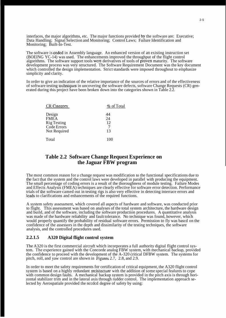
In order to give an indication of the relative importance of the sources of errors and of the effectiveness of software testing tcchniques in uncovering the software defects, software Change Requests (CR) gen- erated during this project have been broken down into the categories shown in Table 2.2.
CR Cateeorv 9% of Total
Design 44 FMEA 24 Rig Testing 12 Code Errors 7 Not Required 13
Total 100
Table 2.2 Software Change Request Experience on the Jaguar FBW program
The most common reason for a change request was modification to the functional specifications due to the fact that the system and the control laws were developed in parallel with producing the equipment. The small percentage of coding errors is a result of the thoroughness of module testing. Failure Modes and Effects Analysis (FMEA) techniques are clearly effective for software error detection. Performance trials of thc software camed out in testing rigs is also very effective in detecting interrace errors and leads to clarifications and enhancements of the required functions.
A system safety assessment, which covered all aspects of hardware and software, was conducted prior to flight. This assessment was based on analyses of the total system architecture, the hardware design and build, and of the software, including the software production procedures. A quantitative analysis was made of the hardware reliability and fault tolerance. No technique was found, however, which would properly quantify the probability of residual software errors. Permission to fly was bascd on the confidence of the assessors in the depth and dissimilarity of the testing techniques, the software analysis, and the controlled procedures used.
2.2.1.5
The A320 is the first commercial aircraft which incorporates a full authority digital flight control sys- tem. The experience gained with the Concorde analog FBW system, with mechanical backup, provided the confidence to proceed with the development of the A-320 critical DFBW system. The systems for pitch, roll, and yaw control are shown in Figures 2.7, 2.8, and 2.9.
In order to meet the safety requirements for certification of critical equipment, the A320 flight control system is based on a highly redundant architermre with the addition of some special fealures to cope with common design faults. A mechanical backup system is provided in the pitch axis is through hori- zontal stabilizer trim and in the lateral axis through rudder control. The implementation approach se- lected by Aerospatiale provided the nccdcd degree of safety by using:
A320 Digital flight control system

-3 identical Spoiler & Elevator Computers (SEC) made by Aerospatiale -2 identical Elcvator & Aileron Computers (ELAC) made by Thomson-CSF -3 identical Air Data & Inertial Rcfcrenccs Systems (ADIF!S) with separate
-2 identical Flight Augmentation Computers (FAC) made by SFENA -3 separate hydraulic channcls (1 common + 1 for each sidc of airframe) -2 scparate main electrical powcr supplies plus 3 backups (Auxiliary Powcr Unit,
scnsors made by Honeywcll
Ram Air Turbine, batteries)
The loss of control of the aircraft is highly improbable, either in the pitch axis (in that both SECs and ELACs control the elcvator) or in thc latcral axis (in that SECs can control the spoilers and ELACs the ailerons) due to the following:
components up to processors (80186 for SECs, 68000 for ELACs), differeni: suppliers
gies, tools, and languagcs.
Furthermore, each FCC (SEC or ELAC) consists of two scparate chanricls that communicate by an ARINC 429 bus (asynchronous point-to-point scrial data link, mainly used in commercial transport air- craft). The control channcl computes the control laws and actuates the surfaces (ailerons, spoilcrs and clcvators) whereas the monitor channel computes control laws and che,cks the correct actuators, and monitors the control channel. Although they arc installed in thc same box, the control and monitor channels use fully indepcndcnt hardware (cvcn for power supply modules) and dissimilar software (e.g: for SEC, the control channcl is written in asscmbly language by one engineering team; the monitor channel is written in Pascal by another tcam; fixed point arithmetic is used; thorough testing to the DO 178A lcvcl 1 softwarc rcquiremcnts). The channcls are loosely synchronized.
Output data from the ADIRS are voted by SECs or ELACs before being used. Each ADIRS includes built-in-test (BIT) which provides additional robustness to the voting scheme of the Flight Control Computers with rcspcct to self dctcctcd faults (the self dctected faulty ,4DIRS is excluded from the voting process). Threshold values are a function of scveral factorsp of computational algorithms.
Side stick controllcrs arc used which arc not mcchanically coupled. Each FCC includes a priority logic based on both sidcs stick signals. Normally onc of the FCC's is the master, while Ihc others are either in standby or in a slave modc. Thc mastcrs choice varies depending on the surface. In case of failure, rcversion inside cach computcr (altematc control laws) or to an altcma1:e computer is fully automatic.
-The hardware of SECs and ELACs arc dissimilar: i. e. dissimilar spccs, dissimilar
-The software is dissimilar: i. e. dissimilar spccs, diffcrcnt suppliers, dissimilar methodolo-
2.3 Implication of Design Choices on the Validation Process
In this section, the implications of various architectural characteristics on the verification and validation process arc discussed.
2.3.1 Architectural Issues
Thc basic configuration of thrce of the fivc flight control systems which havc bccn described is aqua- druplcx configuration. Thc X-29 flight control system has a triplex primary confi&uration which can rcvcrt to a triplcx analog back-up systcm.
Considcring typical reliability assumptions for single channcl failurcs, 'quad redundant configurations -7 . can be shown to mcct thc flight failurc ratc of 10
and isolate faults, in rcal timc, bascd on majority voting algorithms. If a failure occurs when only two channcls arc opcrational, thcn rcvcrsion to a dcgradcd control modc, or to a fail safe configuration does occur.
Flight critical systcm fault lolcrancc and reliability rcquiremcnts can alijo be ;met by triplex configura-
Failurcs/Hour(F/H). These configurations dctect

2-7
tions, if self test techniques with an appropriate failure coverage are utilized. If the assumption is made that the failure rate of a simplex flight control system channel is of the order of F/H, then a triplex system can satisfy the 10-7 F/H requirement only if an overall failure coverage equal to , or greater than, 96.7% can be achieved with a combination of self test techniques. That coverage, however, is difficult and costly to accomplish, demonstrate and validate. As a result, even if self test techiliques can reduce the required hardware redundancy, they are seldom used for that purpose in flight critical applications. Self test techniques, however, are oftcn implemented for the following purposes: a) detecting failures in flight control system components which are only active in limited regions of the flight regimes, like autoland, and b) supporting the off line maintenance process.
Other major configuration issues which effect the validation process of flight critical systems are: a) synchronous vs. asynchronous; b) use of back-up systems; and c) separation of critical and non critical functions. They are bricfly discussed in the following paragraphs.
2.3.1.1 Synchronization Techniques
There are three broad categories of synchronization techniques. The boundaries between them are not sharp, and a variety of perturbations of these basic techniques have becn used in operational and cxperimental DFB W systems. All thrce synchronization schemes have been developed to flightworthy maturity.
Tight Synchronization
The tightest form of synchronization is instruction-level synchronization, where a common clock is used to drive each of thc CPU’s in step, thus causing all of the CPU’s to execute exactly the same instruction at the same time. A voting plane at the sensor input is provided to ensure that each channel secures an identical set of input data. This results in an automatic bit-identical output from each of the computers. This permits straightforward cross-channel checking at the output, at the least significant bit level. The validation of the failure detection and isolation system is simplified because bit-by-bit checking is a relatively simple process and because of the knowledge that all computers are precisely synchronizcd in time.
Tight synchronization does require a common, fault-tolerant clock to provide timing signals to all computers. This mechanism becomes a source of potcntial common-mode faults or errors. Such a system was used to synchronize the triplex digital flight control system in an experimental U S . Army helicopter program, called TAGS (Total Automatic Guidance System).
Frame Synchronization
A looser form of synchronization is “frame” synchronization, the frame being the shortest computational segment in the application program. This is also often termed the “major cycle”. In this approach, all processors rendezvous at the end of a computational frame and resume processing after an exchange of information. Typical synchronization skew vanes from 20-50 microseconds, depending on the approach uscd. In this approach, hardware synchronization of the clocks is not required, and the computers are not executing the same instructions at the same time. Voting planes at the sensor input can produce bit-identical outputs, although skewed by the synchronization variation. Because synchronization skew is small, analog voting, and cross-channel comparison at the analog level can be used for fault detection and isolation. The design of output failure detection and isolation requires the small synchronization skew to be accommodated in threshold selection. Validation of this approach is more complex than for tight synchronization. The synchronization algorithm is a source of common-mode faults or errors, and resynchronization following an “upset” is often a challenge.
This form of synchronization is common in contemporary DFBW systems, and is characterized by a moderate amount of design and validation effort required for effective implementation. The F-18 production DFBW system and the experimental F-8 DFBW, Jaguar DFBW system, and X-29 DFBW systems used this form of synchronization.

Asynchronous Systems
In this approach, each channel executes its program independently of the other channels. The computers still exchange information, but all exchanges arc designed to be possitile for any synchronization skew. One motivation for this approach is to minimize the potential for common-mode faults or errors, using the fact of intcrchannel skew as a means of avoiding correlated faults in the channels. Input data skew can be reduced by operating the input process at a rate higher than the computational cycle.
The design of the output voting scheme must include considerations oImaximum time skew and varying time skcw, bccause output command variations among channels vary with synchronization skew. The validation process must account for the fact that the channels can be in an infinite number of relative states. The asynchronous approach is used in the F-16 C D production DFBW system.
2.3.1.2
Altcmate control methods have generally been provided to "back up" ]~imairy digital fly-by-wire sys- tems, in the event of loss of the entire primary system. These systems provide control over a subset of the aircraft's flight envelope, and usually offer degraded aircraft operational capability. Both hardware and software dissimilarity is often used in flight critical applications. The major reason for using dis- similarity is prcvcnting catastrophic consequences in the case of a) common errors in all channels, including design errors; orb) exhaustion of sparcs in the primary control channels. As the level of confidence increascs relative to the opcrational rcliability of digital channels, the primary conccm is undctcctcd common errors in all channels.
All proccssor channcls of the Jaguar Fly-by-Wirc flight control systcm, as an example, use idcntical hardware and software, and reversion is not provided to a degraded control mode, in the case of design errors or exhaustion of sparcs. The advantage of using identical software and hardware is that only one set of hardware componcnts, one sct of software programs, and a single software dcvclopment environmcnt arc nccdcd. The disadvantages, relative to the validation process, is that it requires ex- haustive and labor intcnsivc effort for achicving the confidence that the systrm is absolutely free of any design error. The approach was clearly successful in the case of the Jaguar DFBW flight control sys- tem, a tcchnology demonstrator program. Clearly there is a "trade off' to be made between the in- creased resource rcquircd to validate a systcm with a similar architccture and the lowcr recurring cost of the implcmcntation.
The prevalcnt approach is to use some form of dissimilarity in flight critical applications. In fact, the other four cxamplc systcms previously discusscd all use some form of dissimilarity in the processing elements of the flight control systcm. The F-16 has a primary flight control system and a back-up system which uses the same hardware as the primary system, and dissimilar software. Certain pilot aids are deleted, but full cnvclopc pcrformancc is maintaincd. The F-18 ha!; a mcchanical back-up system for pitch and roll control, and an analog back-up systcm for all control axes. FinaUy, the A-320 exten- sively utilizes dissimilarity in both hardware and software to achieve the high degree of reliability re- quired for certification. The disadvantages of dissimilarity, in the primary or back.up systems, is that it requires additional hardware and software. The advantages are that it diminishes the concems that residual, undctected design errors could have catastrophic consequences.
In all cases with an altcmate control capability, that system must undergo a validation process similar to that for the primary systcm. In addition, thc interfaces between the systems must be shown not to in- troduce catastrophic failure mechanisms.
Availability of Dissimilar Back-up Systems and Reversion Configurations
2.3.1.3
The dcvclopmcnt and verification costs of flight control system escalatt? very rapidly as a function of the criticality level. Therefore it is important to partition functions which have different levels of criticality. Function "A" is partitioned from function "B" if no action kom function "B" can cause a failure in function "A," If partitioning can not be demonstrated and, fuinction "B" is less critical than "A," thcn "B" automatically assume the same high level of criticality a!; funcl.ion "A," because a failure of "B" can cause a failure in "A," Partitioning can be achieved with a combination of software and/or hardware techniqucs.
Partitioning of Functions with Different Criticality

2.3.2 Software Issues
The stmcture of the embedded flight software reflects the critical and complex nature of the application. The structure, by design, is very simple. It involves the repetitive execution of sequences of
application tasks, at fixed execution rates which are multiple of a basic frequency. Common values of the basic frequency are 200, 100, 80, and 60 Hz. The application tasks are not interruptible. Once initiated they must execute to completion, within the allocated time. The main advantage of this structure is that it significantly reduces the number of system states which must be verified, by eliminating the uncertainties related to random intemptions of the execution of critical tasks.
If additional processing time is available, low priority, interruptible tasks are executed. This commonly used foregroundbackground structure makes optimum use of the available resources and, at the same time, it minimizes the complexity of flight crilical software.
The software needed to perform the most critical control functions is typically replicated in all channels. Less critical functions might be performed within some of the channels only. To gain a better understanding of the computational requirements of such systems, the software is partitioned according to the major functions which must be performed. They are:
a) Application. The algorithms included in this function are those required for sensor processing and filtering, control and navigation algorithms, computation of control command, etc.
b) Logic. Modules in this category perform the computation required for switching control and flight mode, and engaginudisengaging logic. They use almost exclusively Boolean statements.
c) Testing and Voting. These modules perform real time tests on processors, memory, sensors and actuators. They manage and control the overall system configuration, as a function of detected failures. BIT is included in this category.
Peripherals drivers and included in this category.
synchronization, scheduling and timing.
d) I/O. The modules perform data handling and formatting, data transmission and display.
e) Executives. The modules perform the task of initializing power-up procedures,
, The typical memory requirements of each software functions, as a percentage of the total, are shown in Table 2.3.
Software Functions Memorv ReauirementsPercent
Application Logic Testing I/O & Executives Miscellaneous
20 25 20 20 15
TOTAL 100
Table 2.3 Memory Requirements for flight control system Software
The data shown in the table represents typical results from the combined experience of the AGARD Working Group members. Clearly differences exist from case to case. As an example, in the case of a system which relies significantly on self test for the purpose of failure detection and isolation, testing would take a larger percentage of the total memory than that shown in the table. Highly redundant, dis- tributed FCCS configurations, have a high proportion of software related to self test, failure manage- ment, communication, and system management. The software of simplex configurations, with limited integration of functions, has a high proportion of a application code.
Equally important for understanding the software of critical, redundant flight control system is an analy

sis of the nature of the software errors which arc detected during software and system development. A common conclusion for all programs is that the majority of software errors are generated during the early phases of the development process. Five general error cate ones have been identified. A typical frequency of occurrence of each category is shown in Table 2.4 [ 6 .
Software Error Cateeory FrequencyfPercent
Computational 10 Logic 25 Data Handling 35 Interfaces 10 Miscellaneous 20
TOTAL 100
Table 2.4. flight control system Software Error Distributfon It is important to notice that the table does not include the occurrence of trivial coding errors, which are easily detected during the software coding and debugging and even during modulo testing. The table includes only those errors which were detected while the software was. in configuration control, and therefore had already been extensively tested at the module level and at the ]!eve1 of software integration. Those errors werc dctected during the softwarehardware integration Rest, iron bird test, and flight test. The table shows that errors associatcd with logic, interface.s and data handling, including testing and voting arc the biggest contributors. There are some reasons why this occurs. These func- tions arc in fact rather new, relative to the application functions. The necessary tools are not well dcvclopcd and the understanding of complex architectures (and therefore complex interfaces), logic and failure detection and reconfiguration algorithms is not as mature and established as that of the application algorithms.
Relative to the validation process, the major software issues are: a) the use of High Order Languages (HOL) vs. assembly language; b) the use of dissimilar software; and c) the methods for supporting the early phases of the design process. They are discussed further in the following paragraphs.
2.3.2.1 HOL vs Assembly
The use of HOL is increasingly accepted in flight applications. HOL is used’ in two of the previously described systems (F-16 CD, and F-18). Two others (X-29 and Jaguar) use. assembly languages. The A-320 uses both HOL and assembly languages. There are many reasons for the increasing use of HOL:
creasing the commonality among the aircraft’s systems and traccability between design documents and corresponding code source.
b) Compilers are getting more efficient. The memory and time penalties associated with the use of HOL instead of assembly are becoming smaller ( 4 0 % and <20% res~xctively), and are becoming less significant due to increasing computational speeds and decreasing cost of memory.
c) There is a strong indication that HOL programs are more reliable than assembly programs. This is due to the greater level of abstraction HOL provides.
a) HOLs such as ADA can be used as a PDL and therefore provide a great benefit by in-
d) HOL programs are easier to develop, test, understand, m’adify and maintain than assembly programs for FCS, because they usually use only very simple and straightfonvard software due to criticality.
e) Significant experience is now available relative to the peirformance and the code generated by mature software tools, like compilers, assemblers and linkers while at the same time, great advances in memory and computing power have been achieved, reducing the overhead of HOL.
and readable. Checkers for verifying the compliance to the subset can be easily built. f ) HOL easily allow the use of “safe subsets” that have been proven to be reliable, testable,

2-11
It is anticipated that the trend towards increasing use of HOL will continue. The main problem with this approach will certainly be the validation of the compilers (with respect to the safety) and that of the real-time kernel. However, specific parts of the software (I/O, intermpts, handlers) could still be written in assembly for some years and be integrated with other parts written in HOL.
2.3.2.2 Dissimilar Software
The effects of using dissimilar components and functions was discussed in previous paragraphs of this paper. In this paragraph the effects of dissimilar software, in particular, are analyzed. Dissimilar software can be used in three ways:
a) as a failure detection mechanism. In this case results from both versions of software are compared periodically and, in the case that the results differ by more than certain values, a fault condition is detected. In that case, reversion to a back-up control mode must be made, which does not utilize either of the two software versions:
software. reversion is made to the alternate version. Altemate software versions typically provide limit- ed capabilities only. The F-16 C/D flight control system is an example of this application.
c) as a way to achieve software fault tolerance. In this case redundant, but not identical, versions of the software are implemented for detection of software failures and for providing alternate, usually degraded, computational paths. Recovery blocks and N-version programming are two tech- niques used for these purposes.
For the A320, points a) and c) described above are addressed by control/monitor channel implementa- tion, as well as ELAC/SEC architecture.
2.3.2.3
Clear evidence exists that the software errors which are most difficult and costly to detect are often introduced early in the development process. This points to the need of tools, techniques and methodologies capable of effectively supporting the specification and design phases. The entire design and validation process must be supported by integrated development environments, which include specification and design languages with powerful diagnostic capability, and which are easy to use.
It is extremely important to define, as early in the development cycle as possible, design disciplines which make the software traceable, testable, maintainable and easy to understand. Design and coding standards must also be established, like:
capabilities; complexity depends mainly on the number of embedded constructs (if-then-else, loops, gotos ....) and also on the number of lines;
b) avoiding design features or coding constructs whose dynamic behavior is untractable or which may result in memoiy overflows (either in the stacks or data allocated areas) or timing overrun; complex event-driven schedulers, dynamic memory allocation, recursive/unlimited embedded calls should therefore as much as possible be banned for FCS applications;
within the operational software or exceptions handling.
b) as a back-up control mode. In this case, if a common failure is detected in the primary
The Early Phases of the Development Process
a) limiting the complexity of the smallest software blocks within the human analysis
c) enforcing the use of “robust” programming; this may include reasonableness testing
2.3.3 SensodActuator Issues
The fault tolerance and reliability requirements of advanced flight control systems often require redun- dant configurations of critical sensors and actuators for supporting functions required for continuous safe flight and landing.[71 Not all sensors and actuators have the same level of criticality, so it is rather common that different levels of redundancy are used within the same flight control system. The required level of hardware redundancy is also affected by system level considerations, like the function of analytical redundancy which might exist among different groups of sensors or actuators, and the availability of back-up systems.

Analytical redundancy has been employed at the sensor plane. The objective is to provide a synthesized feedback signal, in the case of failure of the primary sensor suite, by analytically combining (or fusing) information from other sensors. Functional redundancy is employed at the aircraft effector plane. The objective is to generate forces and moments about some control axis, in the case of failure of the primary effector, by appropriately modulating a combination of other operational effectors. The functional redundancy among many effectors existing in advanced vehicles makes this approach feasible. Another good example of functional redundancy is provided: in ro’U control of the A320 roll control may be achieved via ELAC (ailerons) and SEC (spoilers), wilh reduced efficiency, if ELAC’s or SEC’s are lost.
The availability of analytical and functional redundancies has pr0foun.d effects in the validation of fight control systems. They might reduce the criticality of some sensors and effectors ‘and correspondingly decrease the validation effort of the equipment involved. They might also reduce the hardware redundancy needed for satisfying specific fault tolerance requirements. In this case additional validation effort will be required to demonstrate the availability and the effectiveness of those redundancies.
It is important to note that, although a sensor or an actuator is often referred to as :having a certain level of redundancy, that level of redundancy often applies only to some, not all, of the elements (and/or functions) that the equipment comprises (and/or performs).
As an example, the sensing component of an Linear Variable Differential Transformer (LVDT) sensor, could be single or dual. The electrical paths to the Flight Control proc:essoa, however, could be quad, in the case that the LVDT interfaces with a quad flight control system configuration. The redundancy of the first control stage of an hydraulic system might also be quad, to reflect the flight control system architecture, but the main ram and the hydraulic supply might be only dual. In most flight critical sys- tems it is imperative to eliminate all features where a single point failure can cause a loss of control. In extreme cases where such a point cannot be eliminated the regulatory ,authorities will insist on a rigor- ous analysis and demonstration that no realistic failures can occur at that point.
Many considerations determine the final configuration of the control systems of an advanced aircraft. The objective is often to find an acceptable design among many different, and some time conflicting requirements.
REFERENCES
[ 1 ] Redias, H.A., and Buckley, E., “Technology Review of Flight Crucial Flight Control Systems”,
[2] a Harschburger, H.E., Glaser, B, and Hammel, J.R., “Backup h4odes for the F/A-18 Digital
2 b “Landis, K.H., and Glusman, S.I.; “Development of ADOCS Controllers and Control Laws.”,
2 cRamage, J.K., “AFTIF- 16 Automated Maneuvering Attack System Configuration and Integration,
NASA CR 172332, April, 1984.
Flight Control System”, AIAA 84-2622, 1984
NASA CR 177339, July, 1984.
Proceedings of the IEEE 1986 National Aerospace and Electronics ‘Conference, Dayton, Ohio, May, 1986
2 c Whitaker, A, and Chin, J . , “X-29 Digital Flight Control System”, AGARD-CP-384. October, 1984
2 d Hillis, A,, ‘‘A310 Slat and Flap Control System Management and Experience”, 5th Digital Avionics
2 eMarshall, R.E.W., Snelling, K.S., and Comey, J.M., ‘The Jaguar Fly-by-Wire Demonstrator
Conference, Seattle, WA, November, 1983
Integrated Flight Control System”, Proceedings of the Unitcd States Air F:orce Academy Advanced Flight Controls Symposium, 1981.

2-13
2 mapper, J.A., and Throndsen, E.E., “L1011 Flight Control Systems”, Integrity in Electronic Flight
2 g F-16A Andcrson, C., “F-16 Multinational Fighter”, AGARD-AG-234, November,
2 h Comey, J.M., “The Evolution of the E M Flight Control System. Presented to the Intemational
2 iA-320. Aviation Week, May 18, 1987, p. 41-45
2 jKubbat, W., “A Quadredundant Digital Flight Controls System for CCV Application.” Impact of
2 k Szalai, K.J., Felleman, P.G., Gera, J, and Glover, R.D., ‘‘Design and Test Experience with a Triply
Control Systems, AGARDograph No. 244, 1977.
1978
Symposium on Aeronautical Science and Technology of Indonesia, 24-26 June 1986.
Active Conlrol teciuiology on Airplane Design, AGARD-CP-157, June 1975.
Redundant Digital Fly-by- Wire Control System, AIAA 76-191 1, August, 1976.
[3] F/A-18 Digital Flight Control System”, AIAA 84-2622, 1984
Harschburger, H.E., Glaser, B, and Hammel, J.R., “Backup Modes for the
[4] Burton, R., Kneeland, Rabin, and Hansen “Flight Testing and Development of the F/A-18 Digital Flight Control System”, AGARD-CP-384, Toronto, Canada, October, 1984.
[5] Smith, R, “Flight Clearance of the Jaguar Fly-by-Wire Aircraft”, Royal Aeronautical Society Symposium, April, 1982.
[6] Hecht, H.M., “Trends in Software Reliability for Digital Flight Control”, NASA CR 166456, April, 1983.
[ 71 Fault-Tolerance Design and Redundancy Management Techniques, AGARD-LS-109, September, 1980.

DICITI\L
FLT. CRITIC,\L FRW
NON-FLT CRITICAL AFCSIFBW
2-14
ANALOG
FLT. CRITICAL FBW
NON-FLT CRITICAL FBW
HIGH AUTHORITY SASIC*\S
MITED AUTHORITY SAS
I950
0 RANDDSYSTEM OPERATIONAL
L
~
l
a 1:.
I I
I960 1970 1980
Figure 2.1 Trends in Flight Control Systems
I C O C K P l T W l T C H - l CONSENSUS OF
I I A i l 1
~
'OR POKER
T
C O N T R O L S U R F A C E S
D I G I T A L C O M P U T E R 3 I A I R C R A F T
MOTION- R
O l C l T A L C O M P U T E R 4 -+ I I
C O N T R O L S U R F A C E S
'OACK UP MEMORY
Figure 2.2 F-16 CID Production Quadruple Digital with Back..Up Memor!,

2-15
I -
SOFTWARE
CoNTRoL OUTPUT I
INPUT INTERf ACE ).
COMPUTATION SELECTION OUTPUT I A a a COND I C
INPUT SELECTION CONO 1 a
INPUT 1-4 OEOICATEO BRANCH B CONO
INPUTS
I 1 I I
CONTROL INPUT COMPUTATION OUTPUT ouTpuT
s~L~C-l~~ S
MONITOR
CONO a SELECTION b
MONITOR MCMT
SOFTWARE
MONITOR MONITOR MCMT
SOFTWARE
INPUT COMPUTATIOW
F A ' L U R E MCMT
MONITOR MONITOR
L_------------------- + - --t SEnlnL OIGITAL INTERFACE t3 DEOICATEJ INTERFACE
Figure 2.3 F-16 Flight Control System

ConW Sllck
Trlm SWltCh
L
Fllght Control Computers (OUJdWplel
Attack Proba
rue Alrspeed. Arnblent Temperatun, mdlng, S.lm:ted Headlng, ltude Rata, Vertlul
____
LVDT I Linear Varlable Dlffemnthl Tnnsformer HDU = Hydnullc Drive Unll s m.0 A =ACtuaf0( P, I S t 1 t I C pnsrun Oc I Dynamic prossun @ -Trim motor
-c..c, I Indicates bml of O I o c t r l u I redundancy
I'igurc 2.4 FIA-I8 Fliglit Control System Functional Diagram

2-17
AHRS (LR 801 (Linon) n l
I
ISA Integrated servo act. (F-16, dual tandem) Air data system I Sensor System
(Rosemount) ! (Honeywell)
-;-
Vanes
Camber
ns with fixed
Rudder
Figure 2.5 X-19 Flight Control System Schematic
I

2 - I H
unl

HydrauliC actuators
THS Trimmable horizontal
€LAC Elevator and aileron
SEC Spoiler and elevator
stabilizer
computer
computer
2-19
Hydraulic
6 Blue System G Green system y Yellow system
, * - t Mechanical trim RIGHT ~
LEFT Trim
< I - J -
Autopilot _ _ _ _ _ _ _ _ _
Autotrim 1 commands ,
NORM
Sidestick commands
RIGHT
Ailerons
I I I I ! LAF
Figure 2.7 A320 Pitch Control
LAF Load alleviation function ELAC Elevator and aileron
SEC Spoiler and elevator computer
computer
Hydraulic B Bluesystem G Green system Y Yellow system
Sidestick commands

c 5:
I I Hydraulic I M Motoractuator -- I 1 B Blue system I FAC Flight augmentation G Green system
I computer I Y Yellow system I ~
Figure 2.9 A320 Yaw Control

3- 1
CHAPTER 3
SOA GENERIC DEVELOPMENT AND VALIDATION PROCESS
3.0 Introduction The validation process is embedded in a complex scrics of events making up the development of the flight critical control system (FCCS), which is only part of the flight system and total airplane development process. A well organized and systcmatic airplane and flight system development process is a necessary foundation for a successful and efficient validation program.
The purpose of this chapter is to provide a top level dcscription of the FCCS validation process and its relationship to the overall airplane and flight systems dcvclopment cycle. It serves as a guide and background to chapter 4, which contains a very dctailcd description of the state-of-the-art tools, techniques, methods, and approaches used in the validation of the FCCS.
There are many ways in which systems can be developed and validated and these ways change with time. The method dcscribed in this chapter is a generic process, based on the experience of the members of the working group who have been associated with the development and validation of most of the flight critical control systems produced in Europe and USA during the past two decades.
It should be noted that in addition to the application which is the focus of this report, the methods used to validate FCCS's are sufficiently general and rigorous that they can be used to validate other flight critical systems such as those given in Table 3.1.
3.1 Relationship of FCCS Development to the Military Aircraft Life Cycle The top level rcquirements for the flight control system of a military aircraft are derived from the system requirements associated with the aircraft/wcapn systcm mission and operating requirements. The relationship between the developmcnt of the airplane and the flight control system is shown in Table 3.2, as characterized in the U.S. A more detailed description of this military aircraft life cycle model, and how the flight control system development is cmbcdded in it, is contained in Appendix 3.1.
3.2 The Life Cycle of a FCCS Figure 3.1 shows the phases in thc life cycle of a typical FCCS[*I. The process is sequential and the top level requirements are systematically converted into dctailcd designs with validation providing the fcedback to check against errors and omissions.
The system is validated by showing that the production system meets the Goals and Requirements de- fined at the start of the process. This can be done by checking that the results of each phase meets the requirements placed on it by a prior phase, e.g., the Development Specifications may be validated by checking that they meet the Systems Specifications. Altcmativcly they may be validated in part by checking that the design meets the top lcvcl Goals and Requirements.
Various methods are uscd to validate thc system in a particular phase. In the earlier phases validation may be based on abstract models, but as the project maturcs, the models become more concrete and the results of tests on prototype and production cquipment are uscd for validation. Figure 3.2 lists the gcncral categories of the methods used in cach of the phases (also from Ref 1). Figure 3.3 shows how the validation process can be considered as a feedback path checking the operation of the forward path['].
A clear hierarchy in thc development and documentation process is essential for a successful validation

program. The documentation must be structured so that all the requircnients are explicitly stated. Furthermore, the documentation should avoid confusion by being so organized that requirements are rcfcrcnced only once. One method of providing this hicrarchy is shown in Figure 3.4, based on DOD- Std 2167A. The following definitions are appropriate:
a. System Succi lication - A documcnt which slates the technical and mission requirements for a system as an entity, allocates requirements to functional areas (or confi,guration items), and defines the interface between or among the functional areas.
which states perfonnance, interface and other technical requiremcnts in sufficient detail to permit de- sign, engineering for service use, and evaluation
The key point here is that there should exist a clear and unambiguous relationship between the various specifications, development steps, and documentation itcms to provide a traceable and continuous flowpath of activities. This top-level view will provide a structure for the entire development and validation program which can be used by all pails of the organization.
b. Develoument Suecification - A document applicable to an it,em below the system level
3.3 Goals and Requirements The Goals and Rcquircments arc the overall attributes of the system; they incl.ude the mission-related requirements as defined in highest level staff targets, or statements of need. They also include the requirement to meet the appropriate national spccifications (e&, Mil Std 8785). Overall safety requirements arc included, based on national specifications (e&, Mil Std 882) or on historical data with appropriate extrapolation. The Goals and Requirements reflect the improvements in system performance which arc possiblc due to advances in technology.
A scmi formal statement of the Goals and Rcquircments is a valuable aid in the initial phases of a project; it promotes discussion, reduces ambiguitics and highlights omissions. It acts as a focus for the initial discussions and as a criteria against which Lo validate subsequent phases. The validation of the Goals and Requircments can be accomplishcd in part by carefully comparing them against the mission scenarios, against historical data and against similar systems.
3.4 System Specification The System Specification is a key document in the design of a FCCS. It is a Statement of the functions which the system must provide and forms the basis for the subsequent detailed design and becomes the model against which the system is validatcd. The system specification iusually follows a standard format and includcs a definition of the context in which Ihc system is to operate, a statemcnt of the integrity objectives. Figure 3.5 is a typical format. The validation of the Functio:nal Specification is accomplished by mapping it out against the Goals and Rcquircments by analysis.
It is possible to introduce scmi formal methods to improve the coverage and consistency of the system spccification. Software tools are now available to help in the generation and maintenance of specifications using semi formal methods.
3.5 Development Specification Once the Functional Spccikation is established, a sct of Devclopment Specilications are produced. There will be many such specifications to cover various areas. A list of typical Development Spccifications is givcn in Figure 3.6.
Development Specifications can be validatcd by checking that each of the functional requirements is covered by the specifications and that cach of the requircments in the development specifications is consistent with the functional requircmcnt. Again, this proccss can be facilitated by software tools using scmi formal methods based on a mixture of text, graphics and computer language syntax.
In a broader interpretation development spccifications include all the design definitions and as such they arc models of the system which can be validated by analyses such as a failure modes and effects

3-3
analysis, to check that the dcsign does meet the System S ecification. Some excellent approaches have
3.6 Implementation and Prototype Figure 3.7 shows the activities which lead to the prototype implementation. The control laws determine the handling qualities of the aircraft, and the structurc of the control laws determines the levels of hardware and softwarc redundancy necessary to meet the integrity and availability criteria. Thus, the design of the control function becomes the central activity which defines the complexity of the systems and the reliability lcvel required for each of the facilities within the system. The hardware designer, the software designer and the redundancy management designer cooperate to implement the specified control function.
The control law validation process uses a variety of modcling/analysis techniques (see Figure 3.8) all of which are based on aerodynamic data which must be comprehensive and accurate. Rigorous testing of models and prototypes is necessary to derive this data. The validation of these aircraft models is critical to the ultimate safety and performance of the flight control system.
Control laws in modem flight control systcms are implcmented in digital computers using software algorithms. The task of designing hardware with the capacity to meet all the requirements consists of a whole series of activities ranging from architectural studies, through stress and tolerance analyses, to FMEA's. Dcsigns arc checked by analysis and prototype testing.
The production of software is equally complex and stringent; measures have to be taken throughout the life cycle to ensure that the integrity of the software meets the requirements. Figure 3.9 illustrates a typical set of activities associated with the software developmcnt process.
It is necessary to check the integration of the hardware and soitware to ensure that the development specifications are met. Various methods of testing arc used as the test phase moves from simulation to laboratory models, to benches, to rigshron birds, and finally to prototypes. The match with the real world improves with cach step.
Test benches which allow the system elements to be interconnected, powered and stimulated with simulated inputs and outputs are used to check the detailed operations of the system. Although at each successive stage the testing becomes more realistic, the granularity of the testing becomes coarser. Thus the later phases of validation rely on the earlier phases for fine grained validation.
Rigs/iron birds are the next stage in the progression to complete systems integration and validation. In many FCCS development programs, the rigs/iron birds have k e n the key validation tools. They have combined representative hardware including cockpits, actuators using hydraulic systems with representative geometry and loads, flight control computers and sensors. They have the capability to check out thc interfaces between units and ensure compatibility. They also have capability to trigger the system to rcconfigure and hence test the redundancy management.
On many rigs it has been possible to perform pilot-in-the-loop simulation and thus validate many of the aspects of the handling qualilics and pilot interactions resulting from system rcconfguration.
bccn suggested and devclopcd for project documentation 8 I.
3.7 Prototype Aircraft Thcre is a clear trcnd toward conducting a largcr amount of work on hot benches and rigs, but there remains a significant amount of testing that must be carried out on the prototype aircraft to ensure truly rcprcsentativc conditions. This includes check of intcraction between systems, effect of aircraft structure on control system resonances, electromagnetic shielding/interference effects, power transients, cooling systcm performance, and other elements which are sensitive to the actual hardware installation.
The production of the evidence to support the requcst €or first flight clearance is a key stage in the validation. This is a large and complcx process and inevitably deals with a vast ran e of predictions and
Once the first flight is completed a whole new set of data becomes available which can be used to check
judgments. Figure 3.10 shows thc process used to validate the Jaguar FBW system fi I.

out thcse prcdictions and judgments. Flight testing ofprotorypcs is structuied to Zradually expand the information available and to check that the rcqirements dcfincd in exlier ?tages have bccn mct.
3.8 Production System The final stage is to ensure that the production system has and retains the same performance as the prototype(s). The major considerations are configuration control to ensure repeatability, routine checks to ensure that latent faults do not invalidate system integrity during the long periods of risk experienced on production systems, and maintenance to ensure that the system is a s designedhilt.
To validate the fielded system it is necessary to maintain records of failures, maintenance actions, performance, and usage, to show that the productions system is perfoiming in the way that the developer predicted.
APPEND I X 3.1 : A LIFE CYCLE AIRCRAFT
MODEL OF A MILJTARY
The following is a description of a generic life cycle model of a typical major military system, like a new aircraft. The model is consistent with the guidelines included in the System Engineering Management Guide which was published for the U.S. Defense Systems Management College. The guide describes an integrated system engineering and management approach, including methodology and tools, for dcfining the requirements, configuring and sizing the system, managing its development and verifying the capabilities of the design. It covers the acquisition Gmd development process of any major military system from inception to operational deployment and use. For the purpose of this document, the system is intended to be the entire aircraft. The FCS is a prime or critical item.
The life cycle of major DOD systems includes five phases: Mission Need Determination, Concept Exploration Phase, Demonstration and Validation Phase, Full Scale Develoiment Phase, Production and Dcploymcnt Phase.
The first Phase, Mission Need Determination. is carried out by the government. I f successful, approval to proceed with the next phases is granted.
The Concent Exnloration (CE) Dhase defines and selects promising system concepts for further analysis. Outputs include: dcfinition of performance envelopes, preliminary alternate designs, feasibility studies, preliminary life cycle cost estimates, and a functional baseline. The major documents issued at the end of this phase are: a) a System Concept Paper (SCP) which contains a statement ofneeds, alternate designs with corresponding performance estimatcs, and a risk assessment analysis; b) a Systems Requirements Review (SRR); c) a functional baseline which states the technical and mission requirements for the entire system as a single cntity (such as the aircraft); d) a Request For Proposal (RFP) for the next phase, which contains thc functional baseline (Type A specifications), management approach, and the Statement of Work (SOW) which describes the scope of the contractor effort. DuMg this phase, major subsystems are identified, and preliminary performance requirements are developed. For example, several concepts of the FCS, engine, avionics, etc., may be developed and the performance defined. A SRR may be conducted at the end of this phase or soon after initiation of the next phase. A preliminary version of the Test and Evaluation Master Plan (TEMP) document is developed in this phase.
The Dcmonstration & Validation (D&V) phase main objective is to determine whether to proceed with the Full Scalc Dcvelopment (FSD). Several trade studics are conducted for evaluating the relative merits of compcting concepts which were defined in the previous phase. The most promising concept is selccted and the prime and critical Configuration Itcms (CI) are defined. A .major output of this phase is the definition of the "allocated baseline" which satisfies the mission rcquirerncnts established by the functional baseline by allocating specific rcquiremcnts to the identified CI':;. As an example, the FCS may be partitioned in the FCC, software and hardware, actualion systcm, sensor suite, pilot interfaces,

3-5
etc. Some of them may also be defined as a CI, based on their complexity and criticality. The functional baseline is finally allocated to each CI. Assessment of achievable performance, life cycle cost and technical risks are performed. High risk items and all items for which a proof of principle and component demonstration test is beneficial, may be prototyped. A System Design Review is conducted at the end of this phase which validates the allocation of requirements to the CI's. The activities performed in this phase are supported by analysis, simulations, emulations, and prototypes. The TEMP document is updated to include the requircmenls for all major testing equipment and facility. TEMP, however, still primarily addrcsses system test requirements, rather than the testing requirements of individual CI's. A detailed test plan is also developed which includes methods for validating flight critical functions and CI's.
The Full Scale DeveloDment (FSD) Dhase primary objective is to develop and to demonstrate the design of the system concept selected in the previous phase. During this phase a small number of prototype aircraft (usually not more than three) are built. The development process of the test facilities for the individual CI's and for the entire system is conducted concurrently with the development of the CI's consistent with the test requirements established in the previous phases. They may include the development of dedicated laboratory systems, real time simulation environments, and even an iron bird. The iron bird is a most realistic duplication of the actual aircraft environment including, but not limited to: a) physical dimensions; b) aerodynamic, mechanical, electrical and thermal loads; c) hydraulic, pneumatic and electric power; d) electrical, hydraulic and pneumatic connections.
The first step of the process of building the CI's is the development of the preliminary system design which ends with the successful completion of the Preliminary Design Review (PDR). The preliminary design defines the development specifications (Type B specifications) of the CI's so that detail design process can initiate. At the end of that process a Critical Design Review (CDR) is then conducted. The CDR encompasses all CI's, and most importantly the inlerfaces among CI's, and produces development type specifications. Up to, and and including, CDR the vchicle is a paper airplane only, although laboratory prototypes of many subsystems and components may have been built for supporting the evaluation process and providing proof of principle. After successful completion of CDR the Interface Control Documents (ICD) are finalized, the system design is frozen, and the development process of prototype CI's, like the FCS, start. Once developed, the CI's are tested in dedicated laboratory environments which simulate the entire range of operational conditions. The CI development process ends with successful completion of two audits: the Functional Configuration Audit (FCA) and the Physical Configuration Audit (PCA). FCA is performed to validate that the CI has achieved the required performance and functional characteristics. PCA is performed to validate that the CI "as built" conforms to the technical documentation, and it establishes the CI baseline.
As thc CI's are baselined, they are integrated within the system test facilities. At the completion of System Integration Test, all CI's are successfully integrated and demonstrated, and a Flight Readiness Review is conducted which, if successful, clears the way to the Flight Test Program. The Flight Test Program is performed by flying the protolype aircraft, which have been assembled during the last phases of the FSD. After successful completion ofthc Flight Test Program the aircraft is qualified for operational service.
After the FSD, a Production Readiness Review (PRR) is hcld 10 verify that the system is ready to go into the next phase. A design data package is then developed which includes production drawings. An RFP is then issued which includes detail product specifications (Type C specifications), which reference or include the entire design data package.
The Production and DeDlovment (P&D) phase primary objective is to produce systems according to cost and schedule requirements. The CI's are "build-to-print." Typically the first production CI from mature tooling is subject to a PCA and a produclion bascline is established. Once a PCA has been successfully completed for all CI's, a product baseline for the syslem is established.

[ 1 ] “Validation Methods for Fault-Tolerant Avionics and Contr’ol Systems”, Working Group II,
[ 21 “Validation Methods for Fault-Tolerant Avionics and Contr,ol Systems”, Working Group I,
[3] The Implications of Using Integrated Software Support Environment for Design of Guid-
[ 41 Daley, E., and Smith, R.B., “Flight Clearance of the Jaguar Fly-by-Wire Aircraft”,
NASA Conference Publication 2130, Oct. 3-4, 1979.
NASA Conference Publication 2114, March 12-14, 1979.
ance and Control Systems Software. AGARD Advisory Report No. 229 February 1990
Proceedings of the Royal Aeronautical Society Working Group Symposium on Certification of Avionic Systems, 1982.
Fly-by-Wire Flight Control Systems
Large Authority CSAS
Large Authority Autopilots
Power Plant Control Systems
Sccondary Flight Control Systems
Stores Mariagenietit. Systems
Tcrrnin Following Systems ‘I‘a1,le 3.1 Systems Which Can be Validated ny t h e ‘kcliniqiie!~
1)escrilicd in ‘Iliis Report

3-7
FULL SCALE DEVELOPMENT
AIRPLANE LIFE CYCLE
+
I CONCEPT DEVELOPMENT 1 +
Define and select promising vehicle and systems concepts
DEVELOPMENT AND VALIDATION
Determine whether to proceed to full scale develpment
~
Develop and demonstrate vehicle design
FCS DEVELOPMENT
*Study several configurations .Conduct trade studies
. Select most promising FCS configurations . Allocate functional requirements to FCS and major FCS Configuration Items (Cl's)
. Develop, test, evaluate, validate individual Cl's
. Integration of FCS with other aircraft systems Incremental laboratory integration of Cl's
on rigliron bird, and on aircraft
PRODUCTION AND DEPLOYMENT
Produce vehicle to cosffschedule
* Develop and qualify production versions of FCS hardware and software
Table 3.2 Relationship of Flight Control System Development to Airplane Life Cycle
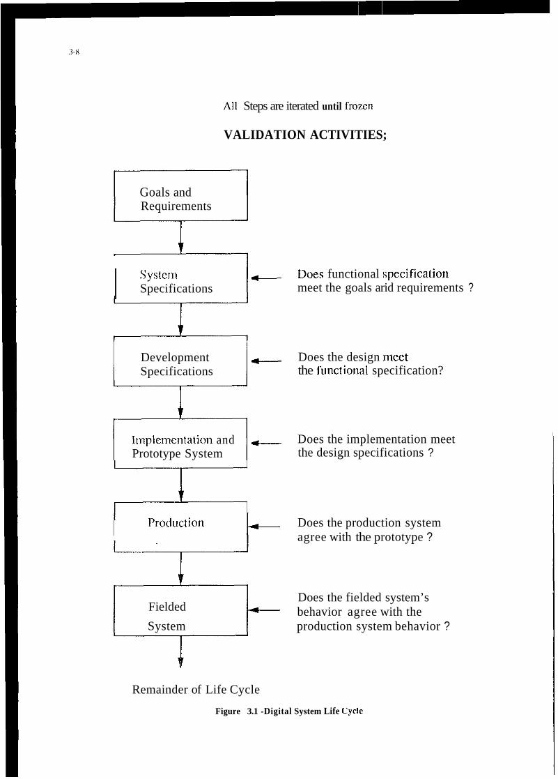
All Steps are iterated until frozen
VALIDATION ACTIVITIES;
Goals and Requirements
I SySfClKI Specifications
Development Specifications
- Does functional :specification meet the goals arid requirements ?
4-- Does the design meet the functiond specification?
- Does the implementation meet the design specifications ?
Iinplementation and Prototype System
I’roduction Does the production system agree with the prototype ?
Does the fielded system’s behavior agree with the Fielded
System production system behavior ?
Remainder of Life Cycle
Figure 3.1 -Digital System Life Cycle

Goals and Kequirements
Itnplementation and Prototype System
Goals and Kequirements
-
System Specifications
Production System
I- Development Specifications
f-
Fielded System
t-
3-9
Bench Test, Simulation, Engineering Model Analysis
”Hot-Bench” Tests, Ground Tests in the Aircraft, Experimental Flight Tests
Certification Procedures
Well-Defined Maintenance, Trouble Reporting, and Logging Procedures
Figure 3.2 - Digital System Life Cycle Applied to Aircraft Systems

Cumulative petiormance
r+ Goals I
acceptance. assurance
- 03 simulators
03 experiments +
02 softwarelfmware verification
a3 hardwarelfirmwarelsoftware verification
c Independent requirements
1 In-context requirements
I
1 Approach
Design specification
Implementation simulations FIW
Breadboards, FiW
Hybrid simulations HIW SIW
c c c i.
04 system verificationivalidation c
"05 change management c
-- Biassboards
-- Production
-- Design maintenance
0 5 system V and Vlcertificationiasswance c
Figure 3.3 Sequential Content of Validation Process
PDR CDR
Baseline Functional Baseline
I SRR SC
1 ;;;;;tdpSnal 1 I System I concepts Requirements System
Analysis
I I
Equipment I Test ing I
I I
Equipment Development
Functional I Areas I Requirements
Requirements Analysis Fac i l i t i es
Development -~ SRR - system Requirements Review
PDR - Prel iminary Design Review SDR - System Design Review
CDR - c r i t i c a l Design Review
- Development S p t ! c i f i c i ~ > ----
System Speci f icat ion
F i g u r e 3.4 a D e v e l o p m e n t and D o c u m e n t a t i o n P r o c e s s f o r a V a l i d t i o n P r o g r a m

I I I I
FRR - Fl ight Readiness Review FOR - Fl ight Operational Review
F i g u r e 3.4 b D e v e l o p m e n t and D o c u m e n t a t i o n P r o c e s s f o r a V a l i d a t i o n P r o g r a m , (cont inued)
Technical Requircnicnts
1 . Applicable Docutneilts
2. I:unctional Characteristics
2.1 Control Law Requirements 2.2 Integrity/l;light Safety Requirements 2.3 Architecture 2.4 Reliabilitv 2.5 Maintainability 2.6 Built in Test
1. lrilcrface Ilerinition
3.1 Electrical Signal Interface 1.2 I:,lectrical Power Interrace 3.3 IIydraulic Inlerface
4. Ilesign and Construction
5. Software
5.1 C;eneral 5.2 Software Development Process 5.3 Docuineiitatiori 5.4 Development Facilities 5.5 Q.A.
6. Test
6.1 Development Tests 6.2 Environmental Tests 6.3 Qualification Tests 6.4 Functional Tests 6.5 Acceptance Tests
I . Environment
Iiigurc 3.5 Functional Specification for Safely Critical Issues
3-11
I I I
I
I I
Baseline Baseline I
Equipment Test ing
FRR FC

I . Suftware Specification
2. Rcduiidaiicy Maiiagciiieiit Specificatioii
3. Integrity Requirements
4. llardware Design
5. Reliability Reqiiiremciits
6. Maintenance
7. Opcrational
8 . I Iuinaii Factors
9. 13iivironmental Test Kcquirements
Figitre 3.6 List of lypical Design Hequirennents
System requirements
Control law System design design Simulation - -
Software Hardware - design design -~
Equipment -- manufacture
Build Build test bench rig
Integration of hardware and software
&g test
J. To aircraft
Figure 3.7 Activities Leading to Prototype Implementation

3-13
Wind tunnel m Flight test
data set
Piloted simulation (standard
control aims)
I
-I- ll
transient response against 9
Yes
control .Mod r t simulation
non-linear FBW controls
Figure 3.8 Control Law Preparation and Validation
DEVELOPMEXT
I ACTIVITIES
~ - D4 CODE INTEGRATE INTEGRATE
1 1 SOFTWARE SOFnVARE SOFPNARE - MODULES 4. HWiSW
DOCUMENTS PRODUCED 1 1
/ A
REVIEW REVIEW
t
t REVIEW MODULE
MODULE HWISW SYSTEM INTEGRATION INTEGRATION VALWATION I TEST 1 ~ TEST ~ I TEST 1
I I , Figure 3.9 Software Development and Verification Activities

Quantitative risk Qualitative risk
System integity I
Software Appraisal 100% coverage single integrity + of specific c- and specific function appraisal
t .Microprogram
integrity appraisal
functions multiple fault appraisal
\ Voter, \ v r
monitor appraisal
System / \ Mollule,
appraisal andLRUFMEA f architecture connector chassis
Bite coverage Tolerance \ analysis analysis
\ r Reliability analysis
Figure 3.10 Ensuring System Integrity
Configuration inspection
I Qualification testing and inspection
r- Bum-in

4- 1
CHAPTER 4
CURRENT METHODOLOGIES AND TECHNIQUES
4.1 Introduction The purpose of this chapter is to present current methodologies and techniques used to validate a flight critical system. Assessments of individual validation methodologies are also included. In Chapter 5, an assessment is made of the overall state of the art of validation of flight critical flight control systems.
Validation begins in the system requirements analysis phase and continues through the development phase and culminates in the demonstration that the final system complies with the system-level requirements defined prior to start of development. Figures 4.1 to 4.5 show a flight control system development cycle based on European and U.S. practice
There are four basic types of validation activities:
software/hardware) as built, conforms to the applicable documentation, such as engineering drawings, flow diagrams, computer listings, user requirements, system specifications, etc. Inspection typically involves visual/physical examination or simple measurements.
Test - used to establish that the product functional characteristics conform to operational and technical requirements. The process has a high technical content, and usually requires specialized test equipment and formalized procedures. The product under test is stimulated with inputs to generate controlled responses which can be comparcd with predictions. Data generated by test is further analyzed to determine conformance with the criteria. Test passage can either be go-no-go, or be a result which falls within criteria boundaries.
Inspection - used for determining if the product (software, hardware, or integratcd
Demonstration - used to show the customer and/or legal authority that the product functions as required within the operational envelope. Test passage is usually based on go-no-go criteria established by the reviewing authority.
Analysis - used to show compliance with requirements, either to complement test, or to replace test when test is not possible or practical. Data output is from simulation and analytic models. An important, but often difficult task is the validation of the models used in the analysis.
4.2 Development of the Customer Requirements Specification The initial step in the development of an aircraft is the formulation of the customer's requirements which define what is required of the aircraft. (The terms operational baseline, functional baseline, allocated baseline and product baseline are taken from Mil Std 2167). The user will usually have conducted a series of studies which will have estahlishcd the major characteristics of the aircraft and its systems to enable the aircraft to meet its operational goals. Normally these characteristics will be contained within the statements of needhtaff targets, and later in the Program Management Directives/staff requirements which are the formal statements of the Operational Baseline. They are top-level requirements and do not prejudge how the system will be configured to achieve the requirement.
The Operational Baseline for the aircraft is usually written in plain language and often is based on previously defined operational requirements of the user. An assessment is made of the reasonableness of

4-2
the Operational Baseline, based on previous systems and experience, as well as on knowledge of the state of the art of the various technologies to be incorporated in the new vehicle and its systems.
The operational baseline for the aircraft will include the following aspects which are directly relevant to the flight control system.
a. the requirements for the handling qualities, ride qualities, and control characteristics
b. the definition of the flight envelope
c. the modes of the FCS required
d. the reliability, safety, and availability requirements
e. the maintainability and testability rcquirements
f. the growth potential required
g. the methods and standards which must be applied.
Since the Operational Baseline is a list of the customer's requirements it is 'necessary to ensure that all thcse requirements are captured and combined with requirements from other viewpoints (e.g. design, manufacture, and ccrtification), and then checked for completeness, consistency and traceability. Methods and computer-based tools are emerging to carry out these tasks in a systematic way. They model the requirements, the interactions between them, and maintain traceability with subsequent design stages.
4.3 Development of the Weapon System Specificatilon The next stage in the process is the development of the Weapons System Specification. The customer's requirements are studied and combined with candidate solutions in a series of concept development studies, analyses and rcviews.
While the emphasis in this phase is on the requirements, in some area:s the requirements will be matched with a candidate design, and it is inevitable and desirable that the requirements and design be iterated to produce a system design that is feasible and meets customer requirements.
The designers will study various configurations of aircraft and systems to di:termine how best to meet the requirements. Extensive studies involving all aspects of the system will be made and may require dcvelopment programs and prototyping.
These studies will include a preliminary assessment of the FCS functions and the major characteristics of the FCS, e.g. FBW or mechanical controls, authority levels, safety, reliab'ility, availability, interface with other sub-systems.
The result of this phase is the material for the Systems Requirement Review which will validate that the requirements in the Operational Baseline have been transformed and elaborated correctly in the System Requirements documents. It is crucial that 100% traceability is maintained during this process, because of the significant impact that errors at this point can have on the subsequent system design process.
Studies will include an assessment of the technical risk of the configui:ation and the technology required for implementation. The studies will determine what futlher development ilj required.
4.4 Development of the FCS Requirements Specification The FCS Requiremcnts Specification (FCS RS) is the entry to the FCS life cycle. It is formed by an analysis (e.g. functional decomposition) of the weapon system specification (WSS); it defines the functions performance needed from the FCS to meet the WSS.
The FCS Requirements Specification is one of the series of sub-systems requirements specifications,

4-3
each derived from the WSS; others include the Hydraulics Supply System Requirements, the Electrical System Requirements, etc.
During the development of the FCS RS studies will be made of the interaction between the airframe and the FCS to establish the levels of performance required, e.g. the level of instability that the FCS can compensate (see Figure 4.6)
The FCS RS is validated by checking the functions specified in the FCS RS against requirements in the WSS and in the customer requirements.
Another form of validation is made by comparing the functions specified against those used on previous projects and those developed in previous research and development programs. This limits the technical risk by reducing the technology increment. The validation activities will include a series of review meetings between system design specialists to ensure that the various subsystem requirements specifications are compatible.
4.5 Development of the FCS System Specification, the Control Law Design Specification and the System Quality Plan One method of proceeding with the development of a system to meet the FCS requirements is to split the process into 3 major activities: Control Law Development, FCS Development and System Qualification (see Figure 4.2). Each of these activities is controlled by a document derived from the FCS Requirement Specification.
The control law development is specified in the Control Law Design Specification which groups together and amplifies what is required from the control laws and outlines the form of the design. This document is the basis for the control law development as dctailed in the control law development plan.
The FCS System Specification outlines the total FCS. It defines the functions produced by the system and the units which comprise the system.
The specification is the result of past experience, research, development and studies and analyses to find architectures, technologies and equipments which will meet the multiple requirements placed on the FCS. It will be influenced by the requirements of other systems, by the performance required, by resources, time scales and perceived technical risk.
Techniques used in this phase include:
Hazard Analysis to determine the integrity needed in the various elements.
- Reliability Analysis to determine the reliability levels needed from the individual elements to meet overall targets.
Preliminary FMEA to determine the effect of failures of individual components.
Validation activities in this phase check that the FCS System Specification does "flow down" the requirements from the FCS RS and that the resulting design is capable of meeting the customer requirements. Independent assessment of the performance, integrity and reliability may be applied to validate the FCS System Specification.
The System Qualification Plan defines haw the system will be qualified and includes the requirements that have to be satisfied, the methods used to satisfy them, and the support facilities required. This Plan will lead to the development of all the rigs, test benches, test equipment, and support environments which will be required to accept, test and integrate the equipments which comprise the FCS.

4-4
4.6 Development of the Requirements Specifications for Processing, Sensors and Actuation Once the flight control system specification has been produced and verified, the next phase is to refine the requirements and the design.
One method of organizing this phase which has proved to be successful is to convert the FCS System Specification into the three major areas of Processing, Sensing and Actuation. This is shown in Figure 4.1.
A preliminary design is developed which has an initial hardware layout together with an allocation of functions to the three sub-systems. The characteristics of the resulting integrated system is determined, including the safety and reliability. The design is then checked to determine compliance against the FCS System Specification and the procedure is iterated until a satisfactory desigrUaLlocation is found.
As systems become more integrated there is a major risk when moving from these functional specifications to equipment specifications since the functionality is determined by several different pieces of equipment, and the effect of the combined tolerances in all the equipmerits has to be determined.
Reviews
It is important to note that the reviews at this stage are at a systems level and at a degree of abstraction which prevents detailed assessments or analysis. This tends to obscure some requirements and make it difficult to effectively review and critique those aspects of the system. It is important to include systems engineering staff with broad experience in these reviews, in addition tmo design specialists, because the system must be assessed at a level of abstraction which makes experie:nce comparisons a key technique in validating requirements. The baseline configuration validated at these reviews will become the formal requirement for the system. It will cover all aspects including integrity, functionality, environment, performance, modes of operation, reversion capabilities, and methods of val.idation.
4.7 Development of the Processing Sub-systems One approach which has proved successful, and has become standard practice is to split the processing subsystem into the three principal activities, namely hardware, software and. test equipment (see Figure 4.3). The development of the specifications for these three subsystems is based on an iterative process of design and analysis in which draft specifications are produced, outline designs are develope$, and analyses/tests are made to validate the subsystems specifications and the design against the system specification.
4.7.1 Development of the Hardware
The development of hardware for flight critical systems follows normal flight system hardware design practice with extra attention being paid to the rigor and detail of the design and to the validation of performance and operation.
Hardware Specification
The major items in the hardware specifications are shown in Table 4.1. The validation of this specification will be routine in most areas; the detailed requirements will be checked for compatibility with the overall requirements as defined in the FCS system specification. However, in two areas of validation, redundancy management and functional performance, special care is needed. In these areas the functional capability required from the system depends on interlinlted capability of the hardware and the software. Thus it is necessary to validate a matched set of subsystim requirements. This requirement for interlinking can be formulated in a separate specification of the overall capability at a more detailed level than the flight control system specification and thcn the subsystem can. be validated against it.

4-5
Reducing Abstraction
While even at this stage, it is possible to leave the requirements general, and delay design until the next stage, it is often better to base the subsystem specification on a specific implementation. This improves clarity by removing abstraction and makes it easier to detect conflicts between requirements.
Validation Analyses
Validation techniques used at this stage to check the integrity of the system include FMEA, simulation, reviews, and Fault Tree Analyses (FTA). To quantify this analysis, these calculations are based on component failure data such as Mil Hdbk 217.
Test Equipment Requirement
The hardware subsystem specification should define the test injection and monitoring equipment which will he required to verify that the system is performing correctly in normal and under fault conditions.
Purpose of Hardware Validation
The validation tests and analyses check the the following items against the subsystem specification:
Performance
-correct execution of the instruction set by the processor
- correct input-output data handling
- correct operation of the RAM and ROM functions
Integritv
- functionality of the redundancy management logic features implemented in hardware
- ability of the system to contain failures as predicted in the FMEA to meet the safety, availability and maintenance requirements
-operation of the unit under normal and extreme conditions
- BITE coverage as required for integrity, as per the FMEA
- BITE coverage required for maintainability
Description of Hardware Validation
Representative hardware is tested in a controlled environment. A wide variety of tests are conducted using special test software to check the operation of the hardware in nominal and extreme environments with inputs at nominal values and at extremes of the opcrating range. Sensitivities are measured and tolerances checked against the subsystem specification or against a new set of tolerance criteria resulting from analyses of the integrated system components. Operating characteristics especially checked include:
- Correctness of operation
- Speed of operation
- Sensitivity to power supply variations

-Thermal profile of the design
-Mechanical integrity of the design
- Range of signal inputs
- Range of signal outputs
- Interface compatibility
Support Facilities
In order to support the development of the subsystems, specialized test and support facilities and equipment are required. Specifically, the support facilities must include:
- Hardware representative of the flight system (breadboard or
- Software to exercise the computers with the facilities to change the software to
-Test equipment capable of simulating the external environment and capable of
- General test equipment (logic analyzers, emulators, lbus analyzers, scopes)
- Environmental test facilities for altitude, thermal, vibration, and Electromagnetic
brassboard)
aid diagnosis
generating simulated failures in the computer. (A hot bench)
Interference @MI)
4.7.2 Development of the Operational Flight Program
Software Specification
The major items in a software specification are shown in Table 4.2. S:oftwa.re specifications may be pro- duced using a program design language or a high order language to facilitiate the communication of dc- sign intent, and to provide a systematic set of specifications.
Procedureshlethods
Since techniques have not yct bcen devc1op.d to quantify the probabi:ily of occurrcncc of softwarc error in a particular set of codcs. it is ncccssxy to control software reliability by defining thc mcthods which must bc used to produce it., hcncc the emphais in the spccitic3tions #in standards, procedurcs and structures. Figux 4.8 shows the mcthod uscd for civil aircraft as spccilied in DO 178A. Therc is now a uide rmgc of design mcthods availablc to support softwarc dcvulopmcnt arid thc subsystcm spcciliccltion can bc chcckcd for compliance u id] thc rcquircments of m appropriw mctnod.
Software Testing
Tcsring plays a ctntral role in Lhc validxion of software and the subs)sttm spccil:cation should bc sufficicntly detailed to cnsurc that the appropriate lcvul of tcsling hJs bccn :;pccificd. \Vhcre thc vdidxion of the subsystem softwarc has bccn wcll tliougl~t out in advaiicc. cntry .and monitor points can bc built into the softwarc with little ovcrhcad to support subsequcnt tcsting.
Development of Software
7bc dcvclopmcnt of software involves thc gradual rcfinemenl of the rcquircments within thc spccificd snructure until code is produccd. Thsl code is produccd as modules which arc then thoroughly tcsted and integrated into subprograms and finally into thc total program.

4-7
Description of Software Validation Process
The two basic techniques used to validate software are extensive testing, and rigorous construction. Since 100% testing is impractical, the rigorous construction methods are a vital part of the process of developing software for safety critical systems. Most of the safety critical systems developed in the past have used a combination of rigorous construction and extensive testing. The current trends in software validation are automated testing and the application of more formal methods.
Validation by Testing
Testing is done at various stages;
- Module level (on the order of 100 lines of code)
- Subprogram level (on the order of 40 modules)
-Program level (using a simulator on a host computer)
- Hardware/Software integration (using representative hardware)
- Rig, or iron bird (Representative hardware with representative interfaces )
- Aircraft on ground
- Flight test
Module Level Test
Code reviews and module tests are used to check that the modules operate according to the module specifications. Static analysis tools can check
- control flow
- data flow
-information flow
The verification of the modules will include:
-tests to ensure correct operation with a limited data set andanalyses to show that the set
- analyses to detect banned consuuctionlinstruction.
- analyses to ensure correct use of memory.
- analysis/testing to ensure operation within time budget.
- analysis of correct entry/exit procedures
- tests of robustness for out-of-limits data
is representative.
In addition, some subsets of the software can be validated using formal proof methods.
ProgradSubprogram level test
Software integration tests are used to check that the modules, when integrated into programs or subprograms, operate according to the subsystem software specification.Validation at subprogram level will check the compatibility of the modules and in particular will check the flow of data between modules

4-8
and the overall control of the modules.
The other levels of testing involve hardware. The tests are structuredl to ensure that the software is checked in all its modes, with a large set of representative data, as detailed in the following sections.
Program Validation
Once the whole program has bccn asscmblcd it will be validatcd by tcsting and by analysis against the functional requirements as given in the subsystem specifications. These tests will include checks to ensure that the software detects faults, isolates them and reconfigures, the system as required by the redundancy management.
Automatic Testing of Software
The large number of data sets which have to be produced to check out a system can be generated automatically using special test software which usually resides in the test suppoll system. The automatic test software may also contain a model of the functional requirements and use that model to generate answers and tolerances. Automated testing facilities are used which icalculate the inputs to be injected, calculate the required results and tolerances and produce test reports which highlight failures. This technique is important to reduce schedule delays and costs particularly after modification.
Testing on the Host
Initially the software will be tested remote from the flight hardware using a host facility Typically a minicomputcr is used with a specially developed test hamess which allows the program to check out the software modules with a thorough set of test cases, then to integrate the modules into subprograms and test them at that level. The final stage on the host is to assemble the complete program and test it.
The level at which the testing can be done depends on the size of the software. Simulators which check operation at register level are inevitably slow (typically 100 times real time) and the test data produced is immense.The combination of text values required to check a system forces the engineer to split the task into parts which have a much smaller number of inputs and outputs. He then tests those parts invidually and then tests thelinks between the parts. Thus the fine grain operations of the system can be tested. Clearly this form of testing does not replace the need to test the total system which gives an overall but coarser grained text. Hence the emphasis on testing to provide proven modules and then tests to check correct interaction.
Validation by Rigorous Construction
Many of the aids to validation are based on the premise that it is better to show correctness by ensuring that rigorous methods are used in the construction of the software.
The techniques used in this type of validation include:
- Formal specification (Defining the requirements and the sytem in annotation based on mathematical methods, and then proving the system meets the requirements )
- Structured Analysis (Breaking down the requirements using a structured method)
- Static Analysis (Examination of the code to ensure sound programming rules are followed)
- Program Description Language (Using a "formal" language to define requirements)
- Dynamic Analysis Configuration Control (testing by exercising the code)

4-9
Support Facilities
The principal support facilities in this stage of development are principally those related to the software support environment:
- editor - linker - loader - assembler - compiler - debugger - simulator - test hamess - test case generators - static test tools - semantic checkers - proof checkers - test coverage analyzers
4.7.3 Development of the LRI Test Facility
The development and validation of test equipment follows closely the process for the development of flight hardware with the appropriate modification for the different environmental, cost, and integrity requirements. The validation of the test equipment consists of tests and analyses to establish that performance is correct and is representative of the real world it simulates.
Test Facility Specification
The principal items in a test equipment specification are very similar to those of the hardware specification given in Table 4.1; in addition, the test equipment may have its own software which will require specification as contained in Table 4.2
The subsystem specification will define the test injection and monitoring equipment which is rcquircd to validate system performance in normal and under fault conditions.
The validation of these specifications will be by comparison with the FCS specification and with the specifications of those units which it is simulating. The latter will require comparison of pcrformance figures or analyses to demonstrate equivalence.
Software for the Test Equipment
The development of the software for the test equipment is validated as described in Par. 4.7.2 where appropriate. Where the test equipment software does not impact the integrity of the system, then the test analyses are restricted to those necessary to ensure test equipment performance. An emerging practice is to maintain configuration control of the test equipment and software to the same level as that done for flight systems, often using the same configuration control boards and documentation. This is done in recognition of the criticality of maintaining the integrity of the systems used to validate flight critical systems.
Simulating the Interfaces
The test equipment required for flight critical systems consists of interfaces, processing sections, monitoring facilities and test injection facilities. It has to simulate the interfaces in a sufficiently representative way to make rigorous testing possible.
One important area is the fidelity of simulation of the test rigs. Test rigs must simulate aircraft systems extemal to the flight control system. The accuracy of this simulation will influence the accuracy of the results of the tests. Special tests and test rigs to check the simulation may be needed, e.g., loads simulation for actuators, motion simulation for sensors, pneumatic simulation and bus traffic simulation.

4.8 Integrating the Hardware and Software Once the hardware, software and test equipment have been proved as s'tparate systems they are integrated to check compatibility. A series of tests are undertaken to check the characteristics listed in Table 4.3 against the system and subsystem specification.
Representative software is fitted into representative hardware. The computers are then connected to a test bench which supplies power, simulates the extemal environment and prosvides monitoring and recording equipment. A typical hot bench configuration is shown in Figure 4.9.
The operation of the LRI is then validated by tests based on the structure of the computer and by tests based on the functions required of the system.
Support Facilities Required
- Hardware representative of the flight system (breadboards, brassboards)
- Software representative of the flight system to operate the computers but with extra capability to aid diagnosis.
-Test equipment capable of simulating the extemal environment and capable of generating simulated failures in the computer.
- General. test equipment (logic analyzers, emulators, bus analyzers, scopes)
- Software development environment
- Editor, linker, loader, assembler, compiler, debugger,
- Host computer with facilities to interact with the
- Software analysis tools
- Facilities to change thc target computer memory
simulator, test hamess, etc
target computer
Assessment
As is the case for the hardware-alone validation, the integrated hardware/software lests are a powerful method of checking that computers operate as per the design specification. The integrated hardware/software tests involve a lot of equipment, some of which may be still undergoing change. Hence it is often difficult to separate problems and double faults are much more difficult to resolve than single faults. These integrated tests may be used to provide the evidence to support some of the more difficult analyses, particularly the FhfEA and FTA.
The effectiveness of the BITE may be checked by a series of representative tests, which provides support for the predicted coverage values, and also demonstrates the annunciation of detected faults.
Emulation
During the integration of the hardware and software it is often necessary to check the operation of the processor at a detailed level (e.g., intemal register transfers). In many processors, access is not available to that information without adding special software. However, hardware emulators are available which simulate the operation of the processor and give the engineer visibility into the intemal functioning of the processor. This is a valuable aid to testing system operation and may be used to validate hardware architecture as well as detailed software operation.

4-1 1
Power Transients
One of the major difficulties in fly-by-wire systems has been the problem of handling power interrupts. The basic problem is that the duration of the power interrupts which was acceptable for older generation systems is larger than the duration of the “hold up” c:?acity that can be built into the units. Thus special power supply systems with shorter power interrupts have been developed. However, there are situations in which power may be lost for sufficiently long periods that computer operation stops or becomes unreliable. To cope with such situations special circuits and software are designed into the systems. These mechanisms must be specifically validated during the hardware/software integration tests .
4.9 Integrating the LRI’s to Form a System The process of integrating the LRI’s of the FCS is a gradual one which can be split into phases of increasing system coverage. Figure 4.10 illustrates one method and shows how LRI’s are accepted, integrated with other LRI’s and then tested on an iron bird. It also shows the specifications against which validation is performed and the phasing of open loop and closed loop testing.
Configuration Control
Strict configuration control must be established and maintained for the flight-qualified articles, including all software, as well as test stations and the aircraft system configuration. Identification of all components not qualified for flight but needed for testing must be traceable so that they can be tracked and replaced with safety of flight (SOF) rated components before first flight. For flight critical elements, 100% traceability of all actions taken regarding these systems is required. Discrepancy reports, test reports, change requests, change documentation, qualification test results, and clearance for flight must all be tracked precisely so that equipment or software not cleared for flight use is not able to creep into the flight system.
Integration of Subsystem Interfaces
Each individual interface within the overall flight-critical system must be validated in the proper environment prior to testing the entire system. Examples of the significant interfaces that must be exercised include the computedactuator interfaces and the interfaces between sensors, controllers, and computers.
Computer/Actuator Interface Testing
Actuator Integration Test Stations which are powered by appropriate hydraulic pressure and capacity and an electrical signal which is conditioned by and compatible with the computer is essential in risk reduction. This is to insure that the actuators and control surfaces perform as required and in conjunction with the computer, electrical, and hydraulic power prior to the actual integration of these components on the aircraft. The actuator control logic must be used in conjunction with the built-in-test development to assure that it is working before the integration begins. Figure 4.1 1 illustrates the actuation subsystem validation interfaces. The essential actuation system validation task is the definition of actual loads on the control surface which affect surface deflection and rates. The solid arrow lines indicate the validation boundaries which can be accomplished on the ground. The dashed arrow lines indicates the validation task that must be accomplished in flight.
Sensor/Controller/Computer Interfaces
The physical design and mounting of the sensors and controllers must assure that each of these units is rigidly supported by aircraft structure and are serviced by appropriate electrical control signals. Provisions to check the built-in-test must be worked in conjunction with the computer hardware and software logic. Developing this capability early is essential so that it can be used to diagnose problems that will be encountered during the integration process on the aircraft. Fig ure 4.12 shows the validation structure for an air data probe, and Fig 4.13 shows the structure for a rate gyro/accelerometer assembly.
In the case of a sensor subsystem, such as an air data probe, the challenge in the validation process is to

4-12
Iron Bird development I
provide a reprcsentative stimulus to the system on the ground. Ground modds cannot adequately represent the flow field actually encountered in flight, with current technology. The solid arrows show validation stcps that can be accomplished on the ground: the dashed arrows show the validation that must be accomplished in flight.
The extent and actual design philosophy of the "iron bird" is very much system design configuration dependent. The iron bird is an integration tool that permits early resolution of certain types of problems related to hardware mechanical and structural arrangements. The iron bird typically includes dynamical- ly faithful such control surfaces and actuation connected with control dements and hydraulic and electrical power supplies. Figure 4.14 shows a typical iron bird arrangement and its interfaces. An iron bird laboratory usually has the following features:
- interface to an avionics laboratory via a data bus - 3-axis rate table for gyro stimulation - aircraft or ground hydraulic pumps -landing gear rig area - flight control computers with test sets - actuator test bench area - aircraft -level electrical power supplies - control room for iron bird set-up - stimulation, monitoring, and recording equipment - software support environment
Pilot-in-the-Loop Hot Bench System Simulation
This is an important simulation tool to check-out and test interactive elements that can affect parameters, such as time delays, which in turn can affect thc pilot's ability to adequately control the aircraft. The term hot bench usually refers to the use of actual flight computers with emb8:dded flight software. Modem simulation and iron bird systems usually provide for the capability to use the iron bird cockpit with flight computers and a simulated actuation system. Separate cockpits may be used with flight computer hot bench configurations as well.
4.10 On-Aircraft System Integration One of the most time critical test phases is the on-aircraft systems integration. It is important to have already identified and resolved each problem that is likely to occur during these tests because of the time criticality and cost of fixing problems so close to first flight. Conducting tests on the aircraft is also diffi- cult bccause of the limited access to internal information. Examples of important tasks during this time period include:
a.
b.
C.
d. EMIEMC validation,
e. ground/aircraft power compatibility
f. control surface rigging
g.
Aircraft Equipment Installation check-out of all components,
bore sighting and/or alignment of all sensors,
structural coupling testing and validation,
validation of compatibility with the environmental control system

4-13
One facility, the NASA Dryden Integrated Test Facility, is under development which will allow a relatively high degree of integration of the actual aircraft and a ground test facility. Figure 4.15 shows the aircraft-facility interface in this facility.
4.11 Clearance of the FCS for the First Flight Prior to flight, one must assure that the aircraft is safe to fly, that the instrumentation system, data transmission and processing systems, and ground monitoring equipment is ready to support the flight, and that all the flight plans have been simulated on the ground, and have been formulated to deal with any contingencies.
Special instrumentation is often designed specifically to support flight testing. It may be required to get more visibility into internal operation of various subsystems during flight test, such as near-failure decla- rations by the failure handling systems, so that margins on failure thresholds may be determined under actual flight conditions.
Functional Configuration Audit
It is prudent that an independent audit be made of the adequacy of the design to safely accomplish the intended mission. The audit team must be knowledgeable of the technical details of the design and must specify well in advance the tasks for the design/development team to demonstrate prior to the completion of the audit. The functional configuration audit reviews the production system baseline design by comparing performance validation test results with system requirements, and the results are documented through a validation cross-reference index.
Physical Configuration Audit
It is equally important that an independent audit be conducted to demonstrate that the specified design is implemented properly on the flight article. Each system component on the aircraft must be certified as flight worthy. The physical configuration audit reviews the production system baseline and confirms the design through traceability of documentation from the drawing to the hardware part number.
First Flight Readiness Review
The aircraft is determined to be safe to fly based on analysis of the ground test data and system analyses, the findings of a flight readiness review (FRR). The project team analyzes the technical data, the various hazards analyses, and independent analyses to establish that the aircraft is technically ready to fly. The flight readiness review is conducted by a group of independent experts and those with broader experience. This group is unassociated with the project, and takes one last look at all of the technical and management processes that have been used to amve at the flight-ready aircraft. Their declaration of flight worthiness is required prior to release of the aircraft for first flight. Flight readiness certification documents are usualIy completed after this review.
The initial premise that each subsystem be already matured will most probably not be realized, and the subsystems will, in fact, continue to be refined during the entire course of this phase of the integration and development effort of the flight critical system. Changes produced by each of these overlapping tasks will require consideration by the other.
4.12 Flight Test
Background
Flight test is the culmination of all previous verification and validation testing conducted up to that point in the system's development.

4-14
Development flight testing should test to the limits of expected operational capability and should perform all tasks expected of the system operationally in a controlled test environment prior to releasing the system to the operational community. In the test environment tasks and maneuvers can be conducted in a build-up fashion under controlled conditions and monitored to optimize safety of the aircraft.
Any system is finally evaluated in the field doing the job it was designed to do. This is approximated in flight test during operational testing when operational crews conduct simulaled operational missions using the test system. The tasks performed during this phase have beein already accomplished in the development flight test phase. Accomplishing the operational tests integrates many tasks for the first time and enables identification of human factor and interaction problems that make operation of the system by non-test personnel difficult.
The ultimate objective of the flight test program is to determine that the integrated system will perform the mission for which it was designed and developed. It is pertinent to note ha t developmental flight tests usually have to be conducted prior to being able to fully validate the aircraft as a weapon system. Since safety of flight during the validation stage is insured by the testing conducted during verification, a short paragraph on verification testing is included below.
An FCF, or short series of flights, is flown with any new or modified aircrafi. to verify proper operation of the basic aircraft systems and assure the test community that the aircraft is safe prior to proceeding with the test flights. Preparing for the FCF is similar to preparing for the rest of the flight test program. The FCF is one flight or set of flights with emphasis on safety, and on exercising the various airframe, pro- pulsion, and cockpit systems. Prior to flight, a test plan or profile is defined and critical data are identified for monitoring during flight.
The requirements for measurements, instrumentation, and data processing are described in detail in the flight test plan. The test plan is usually a dynamic document subject to frequent updating during testing. It describes, in detail, the objectives of the tests, the tests that are to be perfoinned, how they are to be performed, the instrumentation parameters needed to analyze each maneuver, the analyses and displays required, and the parameters that need to be monitored in real-time to insure safe test conduct.
Initial Flight Tests
Initial flight tests are conducted to assure compliance with specificatioix andl validation flight tests are conducted to demonstrate that the requirements for which the system was built are satisfied. A list of test objectives for critical system tests should include the following:
a.
b.
Determine that all modes operate as designed.
Evaluate control systedstructural interaction, i t . , the aeroservoelasticity characteristics.
Evaluate the engage and disengage transients and mode change characteristics.
Evaluate flying quaIities with the system engaged. Include all modes of the control system including back-up and reversionary modes.
Monitor preliminary system reliability, availability, and maintainability.
C.
d.
e.
Detailed Flight Test Program
The dctailed flight tcst program of a new aircraft usually involves several vehicles, with dedicated test objectives. An example of such a vehicle set is shown below:
Aircraft #1 Basic aircraft systems

4-15
Flutter clearance Fligfht Controls/Handling qualities Initial aircraft performance
Aircraft #2 Loads
Aircraft #3 Avionics Integrated systems tests Weapons tests
Envelope expansion, stability and control (S&C), handling qualities, aircraft performance, system tests, integration, loads, flutter, high angle of attack, weapon separation, and weapons accuracy tests determine compliance with specifications. They are generally tests of the integrated aircraft and subsystems and are determining indicators of how the aircraft will perform its design mission.
attack, altitude, and load factor to the design limits or until a performance limiting condition is reached.
moments. In modem aircraft this involves both the active controls and the basic aerodynamics of the airframe and control surfaces. Stability and control derivatives are obtained using parameter identification techniques. ('1
c. Handling qualities are the subjective manifestation of stability and control as evaluated by the subjective evaluations of pilots. Quasi-quantification of the subjective ratings are obtained using the Cooper-Harper rating scale. Effective use of the Cooper-Harper scale[*] depends on a careful definition of the task, the method of accomplishing the task, and the criteria for judging the ability of the pilot to fly the task successfully. Handling qualities during tracking (HQDT) is another quantification of a special case of handling qualities. The pilot tightly closes the loop while tracking an a i h m e target, and data are obtained to show how closely he is able to accomplish the tracking task. A plot of deviation in pitch and yaw angles referenced to the target, graphically display the ability of the pilot to track the target.
environment both statically and dynamically. Emphasis is on the structural response to the environment.
In other integrated validation testing, the aircraft must perform to the extremes of its design envelope. High angle of attack, departure boundaries, post-depalture handling qualities, and basic aircraft agility all relate to the ability of the aircraft to get the job done in the operational scenario. High duty cycle system performance, robustness, and emergency system operation must be evaluated and found to be adequate to the task of accomplishing the design mission. Mission accomplishment remains the ultimate validation.
a. Envelope expansion testing extends the flight envelope in Mach number, angle of
b. Stability and control testing is the quantification of the aerodynamic forces and
d. Loads and flutter testing investigate the airframe's ability to withstand the flight
4.13 PRODUCTION SYSTEM VALIDATION
Introduction
In this section productionisation is defined to be the transition from prototype to production aircraft and includes the completion of the qualification test process. During the development phase there will be modifications due to specification evolution or changes to correct initial design errors. When modifications have been made then, prior to production, the system will have to be revalidated by revised analysis and revised testing.
For the production phase it is also necessary to have definitive acceptance test procedures which have to be camed out on each item of equipment, each system and each aircraft.
Quality Plan for Production

4-16
This plan defines the process to be followed in productionisation, in particular:
-The configuration management
- The modification management
It also defines the documents to be updated following modification.
Configuration Management
During productionisation the configuration of the production standard is frozen. :For each item a defmitive list of components is necessary which defines totally the final product. The rules and procedures define how a configuration may change, who is allowed to initiate modifications, who is allowed to accept modification requests, which forms must be used, and other protocols. Both suppliers and customers are involved in this activity with the final approval being given by the regulatory authorities.
Modification Management
The modification plan describes all the documents/tests/analyses which must be updated to demonstrate that the rcquirements are still fulfilled.
The most significant items are:
a. Qualification Test ProgranVReport
Every modification must be analyzed to determine its effect on the validity of the qualification tests. From a safety point of view it must be understood that a series of small modifications may lead to a product which is si,gnificantly different from the original; in such cases requalification will be required.
b.
For any modification to a flight critical system a systmatic review of the FMEA or SSA is necessary to identify the repercussions of this modification on the safety criteria. Any impact on the FMEA or SSA has to be addmsed in the change notice to demonstrate clearly that safety aspects are not degraded.
C. Acceptance Test Procedure (ATP)
As with the FMEA, the impact on the ATP must be considered when any modification is proposed.
d.
For European civil aircraft, the DDP is the document presented to the regulators which declares all the relevant evidence submitted to support certification of an item or system (e.g., specifications, configuration index, accomplikhment summary, qualification test report, acceptance test procedure.) It also lists the restrictions on usage. The DDP has to be reissued for any modification.
e. Accomplishment Summary
For software in civil aircraft, the current practice is to produce an "accomplishment summary." (See DO 178A) This document describes,, briefly, the major milestones of the project, the development environment and the development process. When modifications have been made, the Accomplishment Summary summarizes the modification and the problem reports resolved by the new release. It describes any remaining problems and the major features of the new release.
FMEA or System Safety Analysis (SSA )
Declaration of Design and Performance (DDP)

4-17
f. Change Notice
To be approved, any modification must be identified by a change notice. This notice will define when the modification will be introduced into production andwhether it is mandatory or can be introduced on repair or at retrofit. To provide the information to enable the modification to be assessed, documents are included to show that tests have been performed which demonstrate that the modified system is fully acceptable. This demonstration may be made by the evidence in a test report which gives the procedures used and the test results. Most of the time, the test procedures to be applied are a subset of the qualification program. For some special aspects such as electromagnetic compatibility or lightning, specific agreements may be necessary to define the rules to be followed to validate correct operation of the system after any modification, even a minor one.
g.
These documents are used in civil aviation to inform the operators of the modifications. Retrospective actions are described. When a major change is involved, in which several types of equipment have to be modified at the same time, the system authority will issue an SB to introduce the individual SB's and to describe the allowable configurations.
Service Bulletins (SB) or Service Information Letter (SIL)
Advisory Circular/Equivalent Documents
The U S . civil aviation regulations define Federal Aviation Regulations (FAR) to control the approval of aircraft and their systems. European regulations have similar rules called Joint Airworthiness Requircmcnts (JARS). Table 4.4 lists some examples of these regulations which are applicable to FCS's.
In addition, the civil aviation industry has produced documents to define various development processes. Examplcs of these documents are given in Table 4.5 The manufacturcrs must demonstrate compliance with these standards.
Acceptance Test Procedures
These procedures define how an equipment or subsystem shall be finally checked prior to acceptance. They must be approved by the customer and by the regulators (e.g., LBA in West Gcrmany, VERITAS in France for civil aviation, SIAR in France for military equipment).
Some customers require that the procedures are in "clear language" while others require the procedures to be in ATLAS (ATLAS is a test language generally requested in civil aviation). The tests for the acceptance of the hardware and the software and all the data needed for adjustments must be provided.
Environmental Testing
Environmental testing is an essential part of the validation and reliability testing of flight critical systems (see Table 4.6).
All-weather testing continues the validation and reliability testing of flight critical systems. Such systems have already bcen tested in the laboratory to extrcmcs of heat, cold, humidity, vibration, and in extensive ground and flight test by the time climatic testing is performed. The nature of flight critical systems is such that any impact on them by any source, including climate and weathcr, is a safety issue as well as an operational issue. The system must operate over the entire operational envelope of the air vehicle, and it

The major objective of all-weather testing is to determine to what extent a weapon system, including its essential support equipment and attendant crews, can accomplish the design mission in the required climatic extremes. Historically, all-weather testing has revealed design deficiencies that impact the operational capability of the air vehicle and require system modification to meet operational needs.
Four extreme environments provide the boundaries of air vehicle opera,tion--arctic, desert, tropic, and adverse. The arctic environment represents cold (-29 degrees C/-20 degrees F and below) and wind. In the desert environment, heat and sunlight (43 degrees C/110 degrees F and above) are the primary factors along with blowing sand, dust, and dryness. The tropic environment is dominated by humidity as well as precipitation and fungus (27 degrees C/86 degrees F with relative humidity of 75 percent and above). Adversc environments include weather (snow, rain, sleet, hail, slush, icing, turbulence, and IFR conditions) and corrosion (salt spray and pollutants).
Three stages of testing are involved in all-weather qualification
facility. Here conditions can he controlled individually and can he taken to e:xtremes for failure and rcliability studies. Much of this testing is at the component and subsystem level, but at facilities like the McKinley Climatic Laboratory at Eglin AFB, Florida, USA, entire aircraft can be tested.
support equipment, and test teams to locations that have the desired climatic condirions. This kind of test is usually part of the certification process for civil aircraft (e.g., certifying a head-up display in Europe rcquircs 30 landings with blind cockpit among which a defined number have to be performed in rain conditions, or with severe lateral wind in order to demonstrate that the trajectory deviations when touching down are within +/- six meters). The useful season may be limited and weather pattems may alter schedules, but when the prescribed weather is available, ground and flight operations are unrestricted beyond the rcquirements for safety, data processing, and limitations found in the system hcing tested.
malfunctions are more probable during extreme conditions when systems are being operated closer to their environmental design limits, redundancy management and backup systems are more likely to be called into use. Therefore, reversion modes and backup systems must ]perform to the limits of normal opcration and must be tested as thoroughIy as primary systems at extreme conditions.
Thc present trend is necessarily toward more reliable and more self-contained aircraft to reduce the support equipment and personncl required. For flight critical systems, this means more electronics, more rcdundancy, more backup systems, more interfacing to mechanical, hydraulic, electrical, and pneumatic subsystcms, as well as more communication with other systems.
All-weathcr testing is an important part of ensuring that the resulting air vehicle can perform its intended mission-anywhere, anytime.
I
I
a. The first stage is in a controlled environment such as a laboratory or manufacturing test
b. The second phase of testing environmental extremes involves deploying test aircraft,
c. The third stage of all-weather testinginvolves actual operational use. Since
4.14 Validation of the Fielded System
Even when a system has entered operational service there is a nccd to validate that the system is meeting the customers requirements and where nccessary to make modification.
Figure 4.16 shows one way in which the validation of the fielded system can be organized. Information from operational use may take the form of dcfect reports, flight incident reports and reports on the suitability of the system for its operational role. Where these repats, {after analysis, indicate shortcomings against the specification of a revised operational requircrnent then modification will he rcquestcd and developed.
To retain the integrity of the system it is necessary to ensure that the modifications do not invalidate the testing or analyses on which the system is certified. Thus it will be necessary to consider the impact of

4-19
all phases of development and validation and to repeat where necessary.
Rigorous configuration control will be needed when introducing the modification into service, particularly where the interfaces between functions and/or equipments are changed.
4.15 Special Topics 4.15.1 Traceability
As the subsystem specifications are developed from the system specification it is important to maintain traceability. Software tools are available to help this process. They use databases to store the multiple levels of specification and keywords to relate the lower level requirements or design statements back to the higher level requirements. One such tool is EPOS (12), developed by GPP in Germany. This form of traceability is most useful for software. It becomes the basis of a top down hierarchical structure for the software development process. In the development of hardware, the implementation is less directly linked to functional requirements because equipment is shared between functions. Hence traceability is ensured by compliance matrixes rather than hierarchical decomposition techniques.
4.15.2
There are many areas where precise design and development languages can improve the clarity of specifications, e.g. the use of Fortran to define control laws, the use of Ada to describe procedures, the use of Boolean equations to define mode switching logic, the use of structural analysis methods such as Yourdon and Hood to defme system data flows, the definition of a particularly critical piece of hardware in ELLA(5) or VHDL(6) or the definition of software in Z(7) or VDM(8) or the definition of the whole system in structured English. The use of these formal language techniques is increasing, and computer aids are available in increasing numbers with increasing capability. They aid the designer to maintain traceability, classify system models, and define system interfaces by handling large quantities of data efficiently. They ease the task of validation by producing a rigorous definition of requirements against which to compare implementation.
Use of Formal/Semi Formal Languages
4.15.3 Project/National Specifications
On a project there will be many requirements which are common and can be defined by referencing a project or national specification. Clearly the use of such specifications plays an important role in improving the quality of systems, but it is important to check that they are appropriate to safety critical systems. Many specifications were formulated prior to the development of fly-by-wire systems while others were developed for less critical applications. Where common specifications affect system integrity they should be analyzed against system requirements to validate that they are appropriate .
4.15.4 Varying Criticality
In a typical safety critical system there will be signals which have a criticality level lower than others. If such signals fail they can be removed from the control system and operation continues at a less optimum level. It is often possible to reduce the level of complexity by separating out the functions which are non- essential from those which are essential. The level of redundancy of the signal conditioning and processing for the total system may be reduced, with an attendant reduction in the degree of systems analysis and testing. However, since less critical parts ofthe system can take over the most critical ones and corrupt the whole system, some design precautions (mix of hardware and software protections) are needed for ensuring the integrity of the partition. As for synchronization, the choice of partitioning the system into varying criticalities is really an engineering trade-off and should be carefully examined.

4-20
4.15.5 Assessment of the Use of Test as the Principal Hhrdvvare Validation Method
Testing remains the principal mode of validation for flight critical flighl control system hardware. There are some notable exceptions, eg, automated sneak circuit analysis methods which analyze hardware drawings and wiring lists. It is important to understand the nature of hardware testing in the overall validation process.
Overall Assessment
Hardware tests are a powerful method of checking that the flight computers operate according to the design specification. The digital nature of the hardware permits millions of tests to be performed quickly in a representative environment. It is relatively straightforward to check the electrical signal interfaces between various parts of the system through test. In addition, it is extremely effective to let the flight computer hardware check itself through test. On the other hand, design assurance tests are normally carried out on only a sample basis. They have to be. supplemented by tolerance analyses. It is also difficult or impossible to simulate some of the internal failures of the compul.er.
Performance Validation
The exact design specification performance of the subsystem clcmcnts is often critical to safe operation of the overall flight control system, and must be. guaranteed. Hence the equipment must be carefully and thoroughly checked for performance throughout the operating environment, and this test series becomes part of the ultimate flight clearance. Similarly, precise performance must be guaranteed over the range of component tolerances and analyses/tests must be of high integrity and precision.
Bite Coverage
Where system design relies on the detection of failures by BITE, that system must be checked for correct operation and for coverage. Special analyses and tests must be done to check that the BIIE will detect, isolate and reconfigure the system as specified.
Component Validation
Many of the components used in flight control systems are complex and system operation may be dependent on their precisely correct operation. One approach to this problem has been to declare that if a system depends on the design of a component being error free for its safety, then that component must be 100% analyzed or tested. Alternatively, dissimilar components should be used to prevent system failure due to a common design error. This latter approach has also been followed for flight critical software in very high integrity systems such as civil aircraft fly-by-wire systems. 'Where: system safety depends on component designs k i n g e m r free, a formal verification of the design may be necessary. This may consist of comprehensive testing, or of specifications (formal or semi formal) of component performance and comparison of implementation against that specification or a combination of the two approaches.
Test Software
It is usual to develop and test the hardware using special software. This is done because it allows the engineers to probe the hardware more deeply, to check out critical timings, 1.0 test tolerances and to test the BITE coverage comprehensively and at a detailed level. All these aspects are difficult, if not impossible to test with operational programs. It is also useful to separa.te hardware and software development to reduce schedule constraints. The development of the hiardware may precede the development of the software, particularly if existing hardware is being used and it is very beneficial to separate the critical paths. The test software will enable the engineer to validate the hardware performance, speed, thermal characteristics, environment, accuracy and reso'lution, etc .
I
4.15.6 Allowable Constructs in Software
Experience has shown that some instructions/constructs are error prone: and should be banned; the software specification should define the software instructions/constructs which will be allowed. The

4-21
software support facilities should then contain the capability to detect violations of construct rules automatically.
4.15.7 Program Design Languages
Major sections of the software subsystem specification may be in a language format to improve rigor and facilitate traceability. This may be accomplished by using programming languages or specialized program design languages (PDL).
4.15.8
The volume of flight critical software is increasing, and it is important to assess the status of the state of the art methods of validation, because of the the significant cost, calendar time, and criticality of the software validation process.
Validation by Test
The positive aspects of validation by test are:
Assessment of Software Validation Methods
- A wide range of conditions can be checked
-The structure of the modules/programs and operation with critical data can be checked
-The task can be split between software engineers and modules/subprograms can be checked in parallel by independent testers
- Confidence can be gained by demonstrating long periods of fault free operation
The negative aspects of validation by test are
- A large number of test cases have to be generated
-Testing is very manpower intensive
- It is virtually impossible to prove that "sufficient" checks have been made.
-The testing is only as thorough as the engineers who devise the testing rules and the tests
Validation by Construction
The positive aspects of validation by construction are:
-Formal methods have the potential to prove that software is correct against a formal specification
- The structure used for construction can also be used as a framework for validation
- Software tools are available to support many of the techniques, thus reducing theconsiderable potential of human error and the drudgery involved in other methods.
The negative aspects of validation by construction are:
- Formal proof approaches are generally quite abstract and difficult to apply, even to moderately sized real time programs

- The melhods are not related to the normal skills of practicing flight control system
- Proving the integrity of the proving algorithms is diflicult
designers
4.15.9 EM1 Tests
EM1 tests one of the major concerns for flight critical systems, their irn his class of threat. One important problem is linked to the way these tests are defined in applicable documents. Most of the time, these documents comply with DO 160-B (dash-C is to be. issued soon) or ML-STD 461C. These standards are generally concerned with individual equipments, not with systems or even subsystems. The test dcscriptions provided in these standards are idealized conditions, especially for all grounding specifications. Specific tests have to be conducted on real aircraft to demonstrate compliance of the systems with the requirements.
REFERENCES
[ 1 ] “Methods for Aircraft State and Parameter Identification”, AGARD-CP.172, May, 1975
[ 21 Cooper, G.E., and Harper, Robert P., Jr., ‘The Use of Pilot Rating in the Evaluation of Aircraft Handling Qualities”, NASA TN-D-5153, 1969

4-23
ANALYSIS OF SYSTEM
( CL - DEVELOP- SPECIFICATION
ANALYSIS OF CUSTOMER REQUIREMENTS
(TEST FACILITY DEVELOPMENT PLAN )
WEAPON SYSTEM SPEC.
I ANALYSIS OF WEAPON
SYSTEM SPEC. I
SUBSYSTEM - STUDY AND
CONCEPT PHASE
~~
HYDRAULIC - ALL SUBSYSTEM ['""I REQUIREMENT [e) 0 0 REQUIREMENTS SPECIFICATION SYSTEM SPECIFICATION
Figure 4.1 State-of-Ihe-Art Validation Methods
(-1 REQUIREMENT SPECIFICATION
ANALYSIS OF REQUIREMENTS SPECIFICATION
4 [-I (-) ("'"""1 QUALIFICATION
SPECIFICATION SPECIFICATION PROGRAM PLAN
(PROCESSING) (SENSOR) REQUIREMENTS (IICTUATON) REQUIREMENTS REQUIREMENTS
Figure 4.2 State-of-the-Art Validation Methods (continued)

REQUIREMENT SPECIFICATION
I L R I - S W
REQUIREMENTS SPECIFICATION
H W-SPECIFICATION
DEVELOPMENT BUILT
DEVELOPMENT BUILT
TEST / QUALI.
O F P
I --
Figure 4.3
ACCEPTED GROUND TEST FACILITIES
L R I H W i S W
ACCEPTED [-) State-of-the-Art Validation Methods (continued)
ACCEPTED
I I- F C S - SUBSYSTEM INTEGRATION . TEST .~ . 1st FLIGHT
CLEARENCE 1 WORK
F C S - SUBSYSTEM A / C SUBSYSTEM
r
A / C -SUBSYSTEM INTEGRATION . E S T
1st FLIGHT CLEARENCE WORK
1 F C S CLEARED FOR 1st FLIGHT
Figure 4.4 State-of-the-.&? Validation .Method:; (continued)

4-25
( F C S CLEARED FOR 1st FLIGHT
PROTOWPE A / C FLIGHT
I I
WEAPON SYSTEM CERTIFICATION
PRODUCTION
AIRCRAFT
f FIEWED SYSTEM 1 Figure 4.5 State-of-the-Art Validation Methods (completed)
AIRFRAME DEV.
0 AERODYNAMICS 0 MASS/INERTIAS 0 CONTROL SURF.
CONCEPTS 0 HINGE MOMENTS
---l---
I 1 FLIGHT CONTROL SYSTEM DEVELOPMENT
0 CONTROLLER 0 SENSOR SUBSYSTEM 0 ACTUATION
-
-
I - SIMULATION
0 DEFLECTION/RATE 0 HYDRAULIC FLOW
DISTRIBUTION 0 FLOW TIME
HISTORIES
0 6 DOF 0 REAL TIME 0 DESIGN FLIGHT PHASES 0 MANOEUVERING
I HYDRAULIC SYSTEM
DEVELOPMENT 0 PUMP SIZE 0 POWER DEMAND i 0 PERFORMANCE
I
I I
SECONDARY POWER
Figure 4.6 Flight Control System Development

4-26
.................... ..... i FCS SYSTEM SPECIFICATION .......................................................................... I
.~ 3- ~ PRELIMINARY SYSTEM DESIGN 1 ............................ ...........
I SYSTEM F A l L k E DESCRIPTION]
SYSTEM UNRELlABlLlTY 1
1 :E 6 FEASIBILITY .............................................................................................................
ANALYSlS ...............................................................................................................
..... .- ______L--- PROCESSING SENSOR ACTUATION
REOUIREMENTS REQUIREMENTS SPECIFICATION SPEClFlCAnON SPECIFICATION
-. __ ........ ..
Figure 4.7 Derclopmenr ~ r l ' ILquirements Specificxiiin\ fur I'rucessinn, Senwrs, :ind A c t ~ n t o r s

I. Introduction
2. Applicable Specifications
Control -Moni tor ing - TestlBIlE
4.2 Reliability and Snrety
4.3 Maintainability
6. Weight
8. Validation
'Table 4.1 - Typical Sul)systeiii Ilardware Specification Docuaient
I, Introduction
2. App1ic;ihle Documents
3. System Dcscriplion
5 . Software Enginecring Mctliods ~ Design Methods
Stand;,nls - Langonge - Documentntion ~ Configuration Control
6. System Functional Reqiiimnents
- stanup -BITE
6.2 Failore Mode 0per;nion - redundancy tn:lti;lgemcnt
- perfom,:,nce -failure rcpoiting
9. KI 1'11
Table 4.2 - Typical Software Subsystciii Specification Docoment
4-27

4-28
DEVELOPMENT ACTlVllES
VE Rl FI CAT1 0
SYSTEM INTEGRATION VALIDATION
SYSTEM
SERVICE
+ FEEDBACK PATHS
Figure 4.8 Software Development

4-29
Simulation Computer
. VISUBI system drive
* Sim. Control
.Aerodynamic model
. Engine model
.Environment model
.Threat madel
.Avionics models .Radai .Inertial system .Air data computer
. contra1 sensors
All-digital model . Control laws
. Avionics subset
*I visual I Actuator Interface U",t
Hardware Model of 4Ct"Bt"l tet .
I , Ii
Flight Computer
Interface
Redundant bus 17
Projectors
SMuLhnoN
Instruments
Sensor- Control Tracker
Hardware
Figure 4.9 Typical Hot Bench Configuration
F C S SPECIFICATION
F C S SUBSYSTEM SPEC /
L R I SPEC - ACCEPTANCE
I
single L R
+ S T T E
CLOSED LOOP TESTING
PERFORMANCE INTEGRATION SYSTEM
BENCH ~ INTERCONN. BENCHES 11 , I !
I IRON BIRD
OPEN LOOP TESTING
Figure 4.10 Integration Phases

Hydraulic Supply
Control - control sunace 4 Surlace Deflection Surtace
~ l m , ~ . Main Actuator ACtUatOCtD hydra"liC Control Power Actuator
ElenrOnlCS - Control - Interlace valve Stage Gearing
t
Actuator Subsystem Specification b
Figure 4.11 Actuation Subsystem Validation Ooundaries
Forces, Moments -
:: c . Flow Fieid
Error Correction Algorithm lor Probe and .Parameter
Airtrame Rigid Body Motion Relative to Ambient Atmosphere Flowfield
~ Computation at Probe - Probe Location ::.
'i Ambient Atmosphere
Airlrame Disturbances m Structural Vibiational Modes Noise Aircran Skin
Parameters from Other sensor Subsystems
Flow Field Dlstumances
Engine Aerodynamic Inlet lnterlerence
;> :j :> :;. 5 :> 'j :>
Probe Specification
Sensor Specification
Sensor Subsystem Specification

4-31
I I I I
I parameters
, 4 HEP 1
Airframe Disturbances
Structural Vibrational Modes Noise
I
Ainrame l - i Rigid Body Motion h
from Other
Sub-systems sensor t c
Angular
vectorat Gyro Location - Calibration Aircran
Algorithm Body Axis
Accelerometer
- Vector at Measurement Calibration Aircran
Probe Specification H Sensor Specification +
+ Sensor Subsystem Specification
Strap-Down Algorithm
Figure 4.13 Inertial Sensor Subsystem Validation Boundaries
--b Avionic
hydr. electr.
hydr. electr.
I I T^^. "-", Test area FCC bencl
C1. loop
Act.
I G > i UGa
~ + actuator b?
Cockp.
I
Landing gear
RIG control and test area
Hydr. + electr.
I - -1 FCC
Hydraulic
4 Closedloop
Hydr. store
-! AIDASSI 1
I I r i
store FCC - S'ITE - testroom
landing gear + service area
Figure 4.14 Typical Iron Bird Configuration

Shakers
vibration Electric
equipment
T I I I Figure 4.1 5 Integrated Test Facility
a) FAR 25.303
b) FAR 25.561
c) FAR 25.1322
(I) FAR 25.1355
c) I:AR 135.335
e ) FAR 135.351
Advisory Circulars. e.&
a) AC 20-1 15A
b) AC 20. I 3 1
Tcchnical St;iiidiiig Ortlet-s. e.gL
a) '1" CI I!,
Factors of Safety
Emergency Landing Cotiditions - General
Warning, Caution arid Advisory Lights
Flight Director Systems
Approval of Aircraft Siinulators and Other Devices
Recurrent Trainiiig
RTCAIDO-17RA
Approval of Traffic Alcrt and Collision Avoidance Systcnis
I'I df ic Alcrt and Collision Avoidance System Airbome Equipment 'I'CAS TI
'lnl)le 4.4 '- Exainples of Ilegulatory Rules Applicable to Flight Control Systems

a) Radio ’f‘cchnical Conitnission for Aeronautics Ihcument DO-1 60B - Environ iiieiitiil Conditions and ’l‘est Procedures for Airborne Equipment (R’l‘CA docu tiieiits can be obtained fromR’l’CA, Washington D.C., U.S.A.)
h) Aerospace Recommentled Practice (AIII’) Y62A, - Faiilt/Failure Analysis 1”xdures
c) ARP I834 - Fault/FaiIurc Aiialysis Gnidclines fot- Digitnl Equipment. ARP tlocuincnts ciin be obtaiticd from SAE (Society of Automotive Engineers, Inc., Warrcntlale, PA., U.S.A.
Table 4.5 - Examples of Aviation Industry Standards Applicable to Flight Control Systems
‘l‘eniperature Cycling
Vibration
Acoustic Noise I luriiitlity
Low Pressure I ligh ‘l‘eniperature Imw Tenipcraturc
l’emperature Sliock
Solar 1I:tdiation Rain Funglts S:llt Fog Sand and Dust Icing/Freezing Rain Vibro-Acoustic/reniper;iture Electro Magnetic Capability
- Electro Magnetic Interference - Lightning Protection
- Electrical Grounds
- Electrical Bonding
<:tieiiiical - I?.iologic;il
Nuclear Environmental Cotitr-ol System Inputs
Internal Etivirontrieiit Elcctt-icnl Power Logistics Environment
4-33

~
IN - SERVICE
OPERATION ! I
DEVELOPMENT
PROCESS
I INNER
DEFECTS INCIDENCE REPORTS
SYSTEM SPECIFICATION
MODIFICATION REQUIREMENT SPECIFICATION
OUTER LOOP VALIDATION
Figure 4.16 Fielded Service Validation

5-1
CHAPTER 5
ASSESSMENT OF THE STATE OF THE ART VALIDATION PROCESS
5.1 Introduction This chapter contains an assessment of the validation issues associated with FCCS development, and follows the organization of Chapter 4, which described the state of the art of validation activities, methods and tools.
5.2 Assessment Criteria Validation is regarded by the Working Group as an integral part of the system development process. Since the principal focus of the WG was the safety aspect of validation, this assessment having the most direct impact on two major aircraft development milestones-first flight clearance, and demonstration of safe operation throughout the full design envelope of the aircraft.
First flight clearance must be considered as the most critical point in the development process of any new flight control system. The majority of methods and tools needed for validation, with the exception of flight test instrumentation, are driven by first flight clearance requirements. Therefore, any critical assessment of the validation process must focus on this phase.
The assessment made in this chapter is limited to the case of a completely new system, where an aircraft, has to be cleared for first flight. The majority of activities needed to clear a flight critical system after a redesign or after a major modification can be regarded as a subset of first flight clearance work.
The assessments made in this chapter on made on the basis of three criteria,
- Technical - Economics - Schedule
These three criteria are obviously important for any system development. For FCCS, the safety-criticality feature imposes constraints on the ability to trade off easily between these three criteria. More freedom exists in non-flight-critical system development
5.2.1 Technical Criteria
The dictum and policy of any flight program, “safety first”, inherently limits the flexibility to freely trade off defined steps of the validation process in order to solve resource or schedule problems elsewhere in the program. For every function which has been declared essential (MIL-Spec 9490), the safe in-flight performance must be demonstrated. The steps to doing this are usually established years before the actual ground and flight test program. This planning process also defines the amount and kind of test equipment and tools purchased and developed for the validation program.
If during the validation process leading to first flight clearance activities, a safety-of-flight problem occurs in the area of essential functions, the problem has to be cured. Concessions (waivers) are only possible in the area of non-essential functions.
During the development of new flight systems, it is common practice to carry out the first flight with a reduced functional subset of the full system (restricted envelope). This approach minimizes first flight clearance work but also eliminates most of the flexibility in the validation process because the remaining system functions are critical to safe flight.

Funding is allocated to the planned validation activities at an early state of a project. As a consequence, test facilities are constructed, engineers are assigned and trained, and specialized tools are developed during the time when the flight systems are being developed.
Quite often, a gap develops between the original validation plan on which the funding was based and the validation activities actually required for the FCCS. If that gap is not recognized until late in the program, it is difficult to close by an increase in funding, because of tlhe long lead time required to provide the tools, facilities, and people needed to accomplish the task The resources required for the validation of safety critical systems are often underestimated, hence problems frequently develop late in the program, during the peak of validation activities, when there are limited options available to correct them.
Mature methods and tools, together with experienced engineers are the major components of a successful validation program. The achievement of this state of readiiness n:quires an early technical definition of the tools, ground test hardware, interfaces, and software support environment. Ironically, this results in a lack of flexibility to respond to unforeseen events during the critical phase prior to first flight, if different or expanded validation steps must be used.
There are indirect costs related to providing a staff of experienced engineers to carry out the validation of safety critical systems in addition to the direct labor cost. This comes about because it is costly to maintain a pool of such engineers in between programs. The experience level required by such engineers usually precludes merely hiring them just prior to the final validation phase.
~
5.2.3 Schedule Criteria
First flight clearance. activities culminate during the period of time approximately 18 months before first flight. This is the phase of maximum technical uncertainty and numerous dependencies between equipment, deliveries, and integration activities. The overall top levell project planning is usually carried out years before this phase. Historically, there is always significant pressure to minimize the duration of the final validation period because of funding and milestone cornmitments. Although the first-flight system is usually a subset of the final configuration, the remaining elements and fimctions have a high criticality level, and there are usually few areas where concessions or waivers are possible.
Meeting the major program milestones of such system development plans is a challenge common to all development work. Not meeting a major milestone where validation (of a flight critical system is involved usually has major consequences:
- It may force a reevaluation and rescoping of validation activities during the peak period of validation, when it is not easy to determine all the potential impacts on total validation coverage
- It may create an imbalance between the demands for quality and thoroughness, and completion date.
5.2.4 Importance of these Criteria for the Future
In the past, there has always been much attention on the design and development of FBW flight control systems. Safe operation of such systems was generally achieved and Idemonstrated through the the expertise, experience, and ingenuity of small groups of flight control engine:ers. These same technical, economic, and schedule problems existed in the early days of FBW, but they were outweighed by the benefits provided by this emerging new technology.
It is for the current and future generations of FBW systems, that these problems are becoming dominant. FBW technology has become the standard approach for flight control systems for every new military aircraft, thus these factors and criteria are becoming discriminators between successful programs that meet cost and schedule targets, and those that do not.

5-3
‘l’hcrcfore, a principal faclorin the succcss of thc validation process is how it is accomplished within the normal progrm constraints of funding and schcdule. The tcchnical obicctives of the validation process must, of course, also be of thc highest quality for FCCS.
5.3 System Development Plan The members of WG 09 concluded that there is no general or “generic” validation plan which can be directly applied to any system containing mechanical components such as sensors and actuators, computing elements with specialized software such as sensor preprocessing, and application software such as control laws. WG 09 initially attempted to directly adapt the development process for software systems as outlined in MIL-STD 2167 as a means to develop a structure for the discussion of methods and tools.
However, due to the interdisciplinary nature of a modem flight control system, this approach failed to address the complex interrelationship between four interdependent development processes involved in the development of a FCCS:
- airframe development (aerodynamic data set, mass distribution, aeroelastic behavior, structural modes, etc.)
- control law development (providing positive stability and acceptable handling qualities)
- system development (providing the functional elements for control law implementation and failure tolerancecapability including software development)
- test facility development
These processes are carried out in parallel, and rely on a very early definition of design requirements and/or parameters crossfed from each of the other processes. This burdens the validation activities in each process with important dependencies. For example, validation tests of the overall flight control system can be achieved only within the validity of the control laws, which are only valid within the confidence level of the aerodynamic data set. All these dependencies have to be covered before first flight, which represents a threat to accomplishment within planned resources and schedule.
This challenge is amplified by the fact that airframe development and control law development traditionally follow a different plan than that for flight system hardware and software and test facility development. Nevertheless, it must be recognized that the important topic of validating a safety critical system cannot be separated from discussing the means of developing a safety critical system.
Since testing is the dominant element in the validation process, the peak of activities occurs between start of equipment manufacturing and first flight. The test activities build up in a sequence which is driven by the availability of the flight system hardware and software. This sequence is usually : Module Test, Equipment Test, Subsystem Integration Test, and System Integration Test. This sequence highlights some inherent problems in a practical validation process:
- Timing Problem: System designhpecification activities and the associated validatiodtest activities are separated in a typical development plan by a minimum of 12 months (equipment specification to equipment qualification test) and up to three years (system specification to system integration test). The most critical system integration tests begin about 12 months before first flight. There is a high schedule risk because of the dependence of the somewhat independent
- Density Problem: Normally, the planning for the last 18 months before first flight contains a high density of test activities. Based on the uncertain nature of this phase, these plans have a high degree of uncertainty. The potential for unforeseen events occurring during this phase is also high, and therefore this time period is vulnerable to being used to absorb delays in systems development.
developments.
The System Development Program Plan should be constructed with this probable schedule outcome in

5-4
well as for conventional designs. For unconventional or new designs approaches, a sensitivity analysis should be conducted during the early concept phase. This analysis should identify the areas requiring special 'emphasis in the validation process particularly with respect to specifications where experience is lacking. In most such cases, early prototyping has to be camed out. This can be done in the laboratory environment, or it may even require investigation in a flight research program, where the laboratory environment cannot faithfully reproduce the flight conditions.
Moving validation activities from the critical phase before first flight to the specification and design phases of the development cycle can only be accomplished by a redistribution of the funding. It is an accepted engineering concept to carry out early prototyping for hardware and soflware. It is equally important to use the early phases of the program for validation activitiies which can reduce the costs and schedule conflicts later in the program.
5.4 Management of Validation Activities The safety critical factor for FCCS's, although of paramount importance, should not unduly overshadow olher issues. Validation is an activity which has to be performed for any system development, and the common objective is to create evidence that a fi1nctio.n performs as it should. A significant amount of money has been invested in methods and tools for the development of mission avionics for military aircraft, especially for software development. The reason for this is that the vast majority of flight software is for aircraft avionics systems. FCCS software is usually a small fraction of the total amount of software written for a modem military aircraft.
Modem flight control systems also exhibit a high level of functional integration with other aircraft systems. As a consequence, an increasing amount of safety risk is associated with the interface between the FCCS and other aircraft systems. The use of standardized methods and tools across all aircraft systems would improve the capability of controlling these increasingly critical interfaces.
The development of safety critical systems should make use of general methods and tools for the development of complex systems to the greatest degree possible. It is a worthwhile activity to search for such general tools as a first step in the development of the validation process, before investing in the production of unique tools. Only when the need has been proven by a thoro'ugh analysis should these general tools be modified, or replaced by specialized tools/methods for safely critical system development and validation. The benefits of this approach are obvious:
I
I
i i
- Shared development costs for the tools
- Tool validation through a wide application
This approach does not ignore the specific differences in system developments associated with the level of safety criticality. This difference must be addressed by the management of the validation activities. The application of general tools and methods must be govemed by a detailed knowledge of their capabilities and limitations, and by enforcing rules and constraints necessaq for their proper application and use..
First generation FBW flight control systems were designed to perform the basic flight control task of improving stability and handling characteristics and in of providing basic autopilot modes. This basic

task required an interdisciplinary approach (aerodynamics control laws, system design software). The software problem was contained in a well defined system (functional boundaries were identical with equipment boundaries) with "simple" and tightly controllable interfaces. The development work was carried out by a small, expert, and experienced flight control team. Each responsible engineer within such a team was able to fully understand and monitor the interdisciplinary development activities, even though being directly responsible only for one m a , personally.
For example, the engineer who performed the software design could understand the mechanisms of control laws, having an engineering background in control system engineering. Design and validation was carried out by one small group. In the early developments of FBW technology, creating this small group was the most critical task of management in ensuring that a safe system would result.
For modem systems, however, the situation is considerably different.
- Increased levels of integration of modem systems has increased the complexity of the interfaces. Not only m the functional interfaces between equipments and subsystems affected, but so are the interfaces between different engineering groups.
- The function of the system data processing has increased far beyond the basic task of improving stability and handling characteristics. In the same way, the amount of software contained in the system has increased enormously.
- System boundaries are no longer unique. Equipment assigned to the flight control system is no longer identical with the functions assigned to the flight control system.
Strong management is required to handle the validation activities for this increased interface complexity within budgetary (resources) and time (planning) limits, without major technical concessions. This management process must address:
- Carefully thought-out organizational structures, including well defined responsibilities for design, program control, configuration management, documentation, technical reporting, scheduling, and decision-making.
- The rigorous use of tools and methods (common for the whole project as outlined above) to control the interfaces between the various activities
-The assignment of experienced engineers to critical tasks
The development of such complex systems as described previously requires an increasing amount of engineering labor. If this had to be provided solely by flight control specialists, it would be difficult to maintain such a large team between programs. One solution is to minimize the number of flight control specialists for design and validation, and to rely on general development teams.
As a consequence, the flight control team as described for the early days of FEiW development will cease to exist in that form. The engineer who fully understands the interdisciplinary design approach still plays the important role, but now will have a supervisory and controlliing function. Interdisciplinary experience and understanding of safety requirements and resultant implications for system development and validation must be used to control and monitor the detailed activities performed. The groups performing these activities will not necessarily be dedicated to safety critical tasks. This is required for the design activities as well as for the validation activities.
For example, execution of test activities for a flight control computer does not require a team of flight control engineers. It can be carried out by a team which has the capability and knowledge to test any other flight computer. The ground test plan for the flight control computer and the definition of the test requirements should be done by flight control specialists, however.
5.5 Validation Elements Chapter 4 contained a description of a wide range of validation elements used in actual development

I 5-6
processes. For each system, it was proved through a safe first flight (and prototype flying) that the validation process had been performed successfully. As a consequence, it can be assumed that there are a variety of validation elements/techniques and methods available. These can be used to establish a validation process for any new system which would be close to state of the art.
It must be noted that any specific process or technique may not be valid for a specific project. An example is the need for an iron-bird. There have been projects and siltuatioms where an iron bird was not required. To come to a valid conclusion about the need for an iron bird on any specific project, one has to consider a range of specific program characteristics, such as:
- The extent to which systems used in the vehicle depart from past eqwience.
- Interactions between components which must be validated we'll before the airplane is developed.
-The validation requirements of the FCS, hydraulic system, landing gear, control surfaces, and system interconnections
- Availability of aircraft (prototypes) before first flight for system integration (as an alternative)
Decisions on specific facility requirements should be made on the basis of specific validation needs and costbenefit analyses rather than on a purely historical basis. In the case of the iron-bird, the requirement for accurate performance evaluation during integration testing with flight qualified equipment in a realistic installation environment would most likely require the development of an iron bird.
The second general problem in discussing the validation elements in the abstract stems from the lack of a commonly accepted system development plan. The value and the importance of each validation element is dependent on its position in the development plan.
The system safety analysis is an example of this point. This analysis :is a compulsory bottom up activity carried out shortly before first flight. The contribution of this kind of analysis to the safe conduct of the first flight is minimal because it usually relies on second source data, and does not approach the system from an independent point of view. To be more effective, the safety analysis should formally begin in the early design phase and should gradually build up a data base of system safety characteristics as the development of the flight system progresses.
Despite the problems of assessing validation elements in isolation, there was one approach which was judged to be universally important by the WG, and that was automated testing. This approach to validation testing carries with it technical, economic, and schedule advantages.
Many validation tests could be automated except for piloted confidence tests; piloted/manned stress tests; tests where mechanical manipulation is not practical without human or complex robotic mechanisms; or tests where a high degree of human interaction is required in analyzing intermediate outcomes. Automated test can either mean automated test execution (of a test procedure which could also be executed manually) or it could mean a test procedure utilizing the full potential of a computer driven test facility. The important difference between the two approaches is that Ihe first one optimizes economic parameters and the second one primarily aims at a new quallity of test coverage. It was felt that this second form is an area for Suture developments.
A cautionary note is offered-- one must ensure that unexpected outcomes in other systems or mas are visible. This requirs the recording of many unassociated parameters for a given test, and also requires human monitoring and data review. Automated testing is emerging as a principal tool because of cost, the large and increasing validation matrix size, test time availability, ithe desire for a high degree of- repeatability, and the minimization of the impact of human error. It is the only practical way to build a 1 0 % revalidation test capability for changes.
5.6 Validation of Piloted Simulation Systems for FCCS 'Validation Piloted flight simulators are a powerful tool for designers studying the: dynamic responses of pilots,

5 - i
aircraft, systems and operating enviroments. Simulation has also proved extremely valuable for training pilots to manage their complex cockpit environment and to deal with a wide range of potential emergency conditions arising from failures and adverse operational conditions. For many years such simulations have been used successfully to predict and assess solutions to problems arising during the development of new aircraft and systems.
However, with very few exceptions, all aircraft acceptance and certification has required flight test demonstration. This situation is changing as the complexity of safety critical systems increases, presenting acceptance authorities with a very large set of potential failure modes. Also, improvements in the quality of flight simulation are increasing confidence in their ability to represent many flight situations well enough to reduce the range of conditions that require flight testing. By holding flight clearacc tcsting within rcasonahlc bunds, significant savings in cost and time can be realized, which is beneficial to both manufacturer and customer.
There already have been examples where piloted simulation has been used to demonstrate to acceptance authorities, a range of failure modes of a muti-channel fly-by-wire flight control system. From these simulation demonstrations, the authorities selected for flight demonstration, those situations that appeared to be most demanding and most probable. Economic and practical time limitations are going to increase the range of situations where piloted simulation will be used as a direct part of the acceptance (certification) process for both military and civil aircrflsystems.
This increasing use of piloted simulation for acceptance testing of aircraft is a natural consequence of the increasing physical understanding of aircraft and their operational environment, and confidence in the ability to extrapolate results from piloted simulation.
The confidence in the validity of modem simulators was achieved primarily from the subjective comments of experienced pilots involved in development flight testing of the aircraft. This is an important and necessary element of validation. The question is whether or not this approach is sufficient for the future. The members of the Working Group agreed that subjective comments are not sufficient to establish confidence in the validity of simulation for use in validating all aspects of flight critical control systems.
For example, it is not unusual in developing training simulators to try to compensate for motion and visual cue limitations, or computing delays, by altering the aircraft model to make it match actual closed-loop flight characteristics, based on pilot opinion. Pilots will then declare that the simulation is more 'like the aircraft than the earlierversion with the mathematically accurate aircraft model. This method of compensation for cueing deficiencies can often be acceptable for a training simulator, where the responses can be tuned to be a satisfactory representation of specific training tasks that are demonstrated on the aircraft. Although, even with training simulation there are frequently problems when users modify the training syllabus.
For validation or certification purposes, it is not acceptable to alter aircraft or system models to compensate for cueing deficiencies. Although this approach can improve the apparent validity of the simulation to the pilot in those areas experienced in flight, there can be little confidence that the simulator is presenting adequately those vital situations which are not going to be demonstrated in flight, or which dramatically affect system operation. The following issues should be addressed by the combined FCS/simulation/pilot team:
- For what sets of conditions had validity been confirmed from flight test?
- What confidence can be placed in simulation of conditions outside the validated range?
The art of simulation compensation is dependent on a wide range of factors, including physical characteristics of available cueing systems (visuals, motion, sound, control loading, g-seats, and other simulation features), computing systems (architecture, speed, capacity, etc), aircraft category, specific operational task, and many other factors. Thus acceptance authorities and manufacturers have to establish confidence in simulation results through either relevant flight test validation, or from an identification and acceptance of the validity of compensation techniques. Pilot acceptance alone is not sufficient.
Government publications seek to inform manufacturers and acceptance authorities of recent experience

5-8
with the use of simulation in both development and acceptance/cenification testing. They addresse a wide range of practical issues arising in modeling, provision of cues, and in integrating the aircraft and simulation systems. They also provides guidance on validation methods and outlines issues which may need to be considered by acceptance authorities. These reports finally consider areas where simulation is likely to be a major element in acceptance testing and the impact of and need for development io simulation technology to meet a wider range of these icrucial amx.

6-1
CHAPTER 6
TRENDS IN FLIGHT CONTROL SYSTEM DESIGN AND IMPACT ON VALIDATION
6.0 Introduction Flight control system design concepts and validation test technology have advanced significantly over the past 20 years since the advent of digital systems. Validation techniques and test methodology have been influenced by experiences in the qualification of systems, and system developers have convcrgcd on scvcral acccptcd mcthods for both test and analyses. For the most part, however, validation technology lags the advances in flight control system design. This has led to problems in the past with flight system validation. For example, multi-channel fault tolerant flight control systems were developed before suitable real-time multi-channel diagnostic/test equipment was developed to support the diagnosis and validation of sophisticated fault-tolerant architectures. In other cases, systems were developed with no convenient way of conducting multi-channel validation tests. Considerable time elapsed before software and hardware methods were developed to both stimulate the systems and instrument them to capture the system response for subsequent analysis.
Where ground support equipment and test methods were developed concurrently with the advanced systems they were to support, validation has proven to be less costly and more time efficient. Much has been leamed about how to validate systems to a high degree of confidence, but advancements in flight critical control systems require a complementary and continuous updating of validation tools and techniques.
This chapter forecasts trends in flight control system design based on expected aircraft trends, and identifies the potential impact on the validation process. This should provide a basis for developing research and development programs in the area of validation techniques, and for anticipating validation requirements. Although considered mature by some standards, flight control system technology is expected to advance considerably by the year 2000[’]. The forecast in this chapter is purposely far reaching, extending into the first decade of the 21st century. It is intended that this forecast be a catalyst for developing improved validation techniques simultaneously with new flight system concepts, and for influencing flight system design decisions. It is expected that many of the potentially adverse impacts on validation of these advanced flight critical control system designs can be avoided by anticipating the validation requirements early in the design process, and by using many of the emerging structured validation tools and techniques described in the next chapter.
6.1 Aircraft Projections
6.1.1 Introduction
Aircraft configurations and specific mission capabilities are derived from statements of need from the using military organizations, and are subsequently adopted and approved by govemments themselves. These needs are based on a complex and lengthy set of factors including threat assessments, obsolescence of current vehicles, budgets, timing, and national policy issues. Although it is difficult to forecast the exact path of new aircraft developmcnts, it is possible to project trends in vehicle capability. These broad trends then provide a basis for projecting trends in flight control systems and the impact on validation.
6.1.2Maneuverability
Aircraft maneuverability requirements are projected to continue to increase, especially in the the regime beyond maximum lift, often termed, “post-stall”. Experimental aircraft are probing the utility of maneuvering at very high angles of attack, and the potential benefits of such capability have been

examined on high fidelity simulators. Thrust vectoring technology is expected to provide the control augmentation required to operate safely and effectively in this regime. Control requirements are likelv to include simificant orooulsion/flizht controls integration. as well as a high degree of . - integration with theV fire conirorol'system.
Advances in rotorcraft maneuverability have been significant in the late lOSO's, and the trend toward larger maneuvering envelopes is expected to continue. The impacts on control systems are projected to be in the areas of rotor dynamics, control integration, and man-machine integration. Expansion of the maneuvering capability will also require controls and displays integration for safe operation in nap-of-the-earth operations.
6.1.3 Survivability
The trend toward reducing the signatures or observability of aircraft is expected to continue indefinitely. Large deviations from past design outcomes are likely, due to new emphasis on signature reduction. The design approaches used to achieve lower levels of observability will produce radically new configurations affecting aerodynamics, materials and structures, controls, propulsion systems, and avionics. High levels of integration between subsystems are expected, with earlier incorporation of control system capability in the design process.
6.1.4 AI1 WeathedNight Operational Capability
The mission benefits of all weather/night operations are so significant that this capability is expected to be introduced in much of the fixed wing and rotary wing aircraft fleets of the .Future. This capability implies a high degree of sensor fusion and advanced pilot-.vehicle-system integration techniques. For single pilot operations, decision aiding is expected to achieve a higher level of importance. A larger set of the aircraft's systems will achieve flight-critical stahis, and be integrated with the flight control system.
6.1.5
Technology advances in propulsion thrust-to-weight, and advanced aero-propulsion concepts are expected to make short take-off and landing, or short take-off and vertical landing capability more attractive as a design option in the next decade. Integrated thrust vectoring and reversing capability suitable for take-off and landing performance enhancement as well as in-flight maneuvering could spawn a new class of aircraft. This vehicle class is known to require extraordinary levels of intcgration of the aerodynamic and propulsion controls, avionics, and cockpit systems.
6.1.6 Unmanned Vehicles
It is expected that there will be an increase in the use of unmanned aircraft for reconnaissance and combat applications. These unmanned vehicles are also projected to liave increasing levels of autonomous operational capability, and may work in an internelted arrangement with manned aircraft, as a "team." Ensuring safety in the overflight area as well as airborne safety will pose especially difficult challenges as the performance and autonomy of these vehicles increases.
Development of the unmanned flight crucial systems may involve the use of manned testbeds in which the unmanned vehicle systems are installed, in order to provide an adequate level of safety for initial flight tests. It is also expected that there will be strong requirements to reduce the cost of the flight control systems to enable low cost vehicles. This will have the effect of reducing flight control system redundancy, and will pose an additional challenge to the systems design to ensure ground safety and vehicle integrity.
Short Take-off and Landing Capability
6.1.7 Hypersonic Vehicles
Significant international research and development efforts are underway in lightweight structures, advanced heat shield concepts, and scramjets. These enabling technologies, if sufficiently advanced in the 1990's, could lead to airbreathing vchicles with hypersonic capabilitry in the early part of the

6-3
21st century. The addition of rocket propulsion could provide access to space with such vehicle concepts. The necessary design-level integration of propulsion systems, aerodynamics, flight controls, thermal management, and cockpit systems would be unprecedented. The interactions of the various elements of the vehicle in the design, and in flight, will demand an extension of the flight control state-of-the-art to achieve hypersonic flight. The control systems will play an ever more prominent role in these vehicles for the realization of a flight vehicle, because of these strong interactions.
6.2 Systems Integration Trends and Validation Impacts
6.2.1 Introduction
Based on the vehicle projections and trends, it is clear that an ever increasing amount of integration will be required of the various subsystems of the aircraft. There is also a strong trend to integrate many of the subsystems on a vehicle through the flight control system. It is expected that this trend will continue because of mission and performance benefits. Research and development into advanced pilot-vehicle interfaces such as helmet-mounted sights/displays, virtual displays, voice command, and tactile/aural feedback suggests more highly integrated pilot-vehicle-system configurations in future aircraft. The impact on validation of these highly integrated systems of the future will be:
a) more testing required at the integrated system level, including the pilot, because of the need to include more of the system to be able to evaluate the operation of any one of the systems;
b) more difficulty in the hand-off from the vendors' and suppliers' validation programs to the integrated systems validation process usually conducted by the prime contractor,
c) a high demand for interdisciplinary expertise to design and understand the validation test requirements for such integrated systems;
d) the requirement for a larger fraction of the testing to take place with the pilot or a sophisticated pilot model in a high fidelity simulation:
e) the requirement to deal with the embedded software in these various subsystems as flight critical;
f ) the requirement for more complex and complete real time environment models, such as models of the thermal conditions over the entire vehicle to be able to evaluate integrated trajectory and cooling management systems for high speed aircraft.
6.2.2 Fire/Flight Control System Integration
There has already been si nificant integration of the fire control and flight control systems on
integration of terrain following, terrain avoidance, digital terrain map, threat waming systems, automated trajectory guidance and automated maneuvering and attack systems are likely to be common features of future aircraft. The avionics and flight control systems on most vehicles of the future will be integrated with redundant data buses for information transfer for cooperative functions. One impact of this integration will be the inclusion of more traditionally non-critical elements into the flight critical domain. This can compromise the desire to partition critical and noncritical functions.
In rotorcraft, semi-automated nap-of-the-earth flight is expected to be a major feature of the flight control system. The system will integrate trajectory control with terrain following, terrain avoidance, obstacle sensing, and obstacle avoidhce. In both fixed and rotary wing aircraft, there will be a continuous attempt to provide sufficient intelligence and integrity in the flight control and avionics systems to allow single pilot operations in complex missions.
advanced fighter aircraft rB . One such system configuration is shown in Figure 6.1. The further

6.2.3 Highly Integrated FlightPropulsion Control Systems
Major advances are being made in the integration of flight and propulsion control systems for high performance aircraft. Active engine stall margin control (Figure 6.2) has Imn achieved in flight with major performance gains[31. Future high performance aircraft will e:itend these techniques to complete inlet/engine/nozzle/flight control. Thrust vectoring capability will provide another major effector, for use in maneuvering as well as for improved take-off and landing performance under short or rough field conditions. Performance optimizing control algixithms will optimize total aircraft performance through control of vehicle trajectory while optimizin;g propulsion system and vehicle aerodynamic performance. It is expected that such systems will also account for installed engine differences and aging. Multi-mode control of the airframe and propulsion system will provide the ability to maximize thrust-minus-drag, thrust specific fuel consu:mptio:n, or engine life.
Airframe-mounted and engine-mounted controls are expected to be !separately provided by airframe and engine manufacturer, hut be closely integrated functionally. The, validation effort will have to involve much more activity at the system level because of the interalztion of the flight and propulsion control systems. More capable ground test facilities and more extensive flight programs will be required to validate the total system functionality and safety. There will be more failure modes to contend with, and more capable analytic validation tools will be required to deal with the higher degree of system complexity.
Recent studies and preliminary designs of airbreathing hypersonic aircraft has raised the specter of the necessity of highly integrated aerodynamic, propulsion, trajectory, thejrmal, fuel, and power systems management. Unprecedented interactions between the vehi’cle aerodynamics and propulsion system are foreseen for advanced hypersonic airbreathing vehicles, where the forebody and afterbody of the vehicle also act as pan of the inlet and nozzle. The complex nature of the missions, the narrow margins on trajectory, and the requirements on structural and propulsion efficiencies have led to the conclusion that all subsystems must be combined and controlled in a. totally coo]~rative manner to achieve both safe and efficient flight. This level of systems integration will place new demands on ground facilities because of the need to include more hardware “in the loop” in simulation. Test automation is seen as a mandatory approach based on the sheer volume of testing and the complex interactions between subsystems which must be observed and considered during testing.
6.3 Emerging New Functional Capability
6.3.1 1r.trodilction
High capacity airborne computing and the integration of subsystems will allow a continuing expansion of the number of flight control functions mechanized on future aircraft. These new functions are expected to span the spectrum of new mission capability, safety, and subsystem performance improvement. Expected functions and their impact on validation are described in this section.
6.3.2 Decision-Aiding Systems
The implementation of decision-aiding systems (“expert systems”), in a real timi: environment, is expected to be achieved in the 1990s. The application of these decision-aiding systems to functions today considered flight critical may be far in the future, but systems that indirectly affect safe flight and mission accomplishment are already in advanced research phases. These systems will impose severe demands on the validation process. There are today no accepted methods of validating such systems for flight crucial functions, because the domain of operation cannot be precisely defined, as for conventional systcms.
It is also quite likely that ere will be integrated symbolic and conventional processing in actual applications onboard an aircraft, requiring validation methods that bridge the gap between these two processing approaches, and systems. The domain of possible functional interactions and system actions will have to be understood sufficiently to provide a validation matrix which results in an acceptable level of risk for operational use. In addition, the visibility into the system required to

6-5
understand the system optration will rcquirc ncw approachcs to implementing stimulation signals, and tcst monitoring functions for validation purposcs.
One major ncw facct of such systcms used onboard aircraft is the technology rcquircd to intcrfiicc the crew and the decision-aiding systems. As the "apparcnt intclligcncc" of thc systcm increases, it will be neccssary IO include more of the human factors intcnctions in the validation proccss. The significant challcngcs of establishing thc crcdibility of a decision-aiding systcm in life-critical situations will be a challenge to thc validation proccss. Tcchniques currently used to validatc intra-crew operational procedures may have to k applicd to the human-machine system validation proccss.
6.3.3
The number of control effectors is projectcd to incrcasc, especially for high performance aircraft, which will employ multi-axis thrust vcctoring, canards, multi-segment leading and wailing cdgc flaps/flaperons, and stabilators with pitch and roll capability. Forcbody controls may also emcrgc to control forcbody vorticcs for vehicle conuol or recovery purposcs. Carcful sclcction and placemcnt of these various effcctors may providc sufficicnt force and momcnt redundancy to allow substantial levels of maneuverability and operation following the loss of an actuator or other flight control systcm clcmcnt, or following bank damage. Onboard systems would idcntify the loss of control and reconfigure the remaining effectors and control algorithms to provide continued mission capability (Figure 6.3).
A funhcr extension of this dcsign philosophy could also lead to reducing thc actuator redundancy lcvcl, and hcncc actuation systcm complexity, by capitalizing on controllcr rcdundancy instead. For example, it may be possible IO distributc the control redundancy between actuato~s and cffcctors to rcducc thc number of rcdundant channels per actuator, and thc attcndant hydraulic and clcctronic systems, to achieve lower systcm life cyclc cost.
This dcsign approach will rcquirc what is termed "self-rcpairing" or "rcconfigurable control" tc~hnologyl~~. Thcsc control systcms will require some dcgrcc of on-line parameter identification and reconfiguration capability beyond that used in c u r " systems. Onc impact on validation will be the requirement to identify thc domain of possible configurations. This could bc a very difficult task in thc casc of sclf-repairing controls whcrc first, systcm identification ukcs placc to idcntify the aircraft state and thc control forces and moment$ availablc, and second, control reconfiguration takes place. with at least adjustments in gains, and possibly with changcs in thc control structure. Thc validation of such systcms must account for thc cntirc range of configurations possiblc, or validaie thc boundarics of operation. This problem has alrcady been faced in advanccd adaptivc flight control system expcrimcnts which had a fixed set of effectors. The validation difficulty of thcsc simpler approaches suggests much more difficulty for systcms which may have to accommodate an unknown force and momcnt combination.
6.3.4 Total Vehicle EnergyRhermal Management
Studics and preliminary designs of hypcrsonic vehicles c a q i n g cryogenic fuels show thc rcquircmcnt for the Vehiclc Managcmcnt System to managc and control the total thcrmal cnvimnmcnt, including engine operation. cry0 fuel conditioning, activc structural cooling, and trajectory. In such cucs, the environment and the intcractions are not cxily modclcd or simul3tcd. Thc validation of such systems may in fact require a complcx tcst involving pans of thc actud structure, section of actively coolcd slructurc, with cryogenic fucl cooling systems being controllcd by the actual Vehiclc Managcment System hardwarc and software, would havc to be subjected to hcat loads in ordcr to validatc the closed loop systcm to a sufficiently high dcgrcc of confidcncc for manncd flight. This would be a litcral "hot bench" test.
6.3.5
Control systcm dcsigms rcquiring higher bandwidth opcration are projcctcd to increase for futurc high performance aircraft, drivcn by advanccd aircraft configurations and structural designs. For example, active vibration and load control modcs arc expected on advanccd rotary wing aircmft, a the mancuver and speed envclopcs arc iecreased. In somc cascs, the flight control system for fixed
Self Repairing, or Reconfigurable Flight Controls
wcll the control system, in ordcr to tcst the cntire closed loop system. For examplc, a
High Bmdwidlh Flight Control System Function

6-6
wing aircraft will also bc asked to provide active damping of s[ructural m d c s whcrc acroscrvoclastic problcms are idcntificd too late in the dcvclopmcnt cycle to be clmcnable .o a s1:uctuml fix.
A rclated situation is the case when thc load-to-actuator n3tural frequcncj ratio is low. Such systems arc chuacterizcd by a high degree of performance sensitivity to thc atmalor staoilization method, stmctural compliance, scnsor dynamics, and structural dynamic characteristics. These systcms will have a significant impact on validation technology. In order to validate such systems, a high premium will have to hc placed on system and environmcnul modcls and on scnsor signal simulation from scnsors and ground rigs that must providc information on clctuzI dynamic .stualion loads or structural dynamics. There will be a much morc critical rcquirmcrt to model and faithfully reproduce the important structural modes and complianccs, as wcll as control saxor and actuation charactcristics over a widc frcqucncy range.
6.3.6 Active Local Aerodynamic Control
The emerging ability to understand and predict local aerodynamic flow using computational fluid dynamics is expected to enable active control of local flow. For exeunple, active circulation control may be utilized to increase lift of a V/STOL aircraft at low speeds or reduce downloads of a tiltrotor in hover. Control of forebody vortices on high performance aircraft coulcl improve maneuvering capability at high angle of attack. The extension of this concept to a8;tively controlled engines is also possible. In this concept, active internal engine controls are utilized to relax aerodynamic margins and design constraints. Validation of these control systems will necessarily include more in-flight testing due to the inability to duplicate the aerodynamic environmerit adequately in ground facilities. It may be necessary to develop integrated computational aerodynamic, and global aerodynamic simulation models for satisfactory ground testing or analysis of the lotal system. A new discipline of “computational controls” may be required to support the implcmentation of local flow control systems.
6.4 Architecture 6.4.1 Introduction
Redundant, parallel channel system architectures will continue to provide the basis for achieving fault tolerance in flight control systems of the future. Significant variations in the actual realizations of this basic approach are emerging, however, and bring with them new vdidation issues. There is one ovemding characteristic of future systems that will have a dominant effect on architecture, namely significant increases in computer power. Just as ground-based supercomputing systems have enabled major advances in computational fluid dynamics, airbome supcrcompuling will likewise spawn a major expansion in the scope and character of onboard processing
The developing architectural branches of redundant system structures, ancl the impact of increased computational power are expected to place new demands on validation technology. There is also a clear trend to eliminate the independent back-up system for digital fiy-by-wire flight control systems without compromising the levels of operational capability and safety afforded by combinations of redundant primary and back-up flight control systems in current generation systems.
6.4.2 Hardware-Implemented Fault-Tolerance
In contrast with most contemporary systems which implement fault tolerance and systems management functions almost entirely in software, the hardware-intensive system to remove from the primary flight control computers some of the systems management software functions which are not expected to undergo much change over the lifetime of the system. Redundancy management functions such as voting planes, synchronizing ,mechanisms, bus interfaces, and bus contention logic are instead embedded in special purpcise computing hardware, isolating this software physically from the flight control function soitware. This approach reduces the potential of adversely unintentionally affecting critical executive executive system software functions during the change cycles usually associated with the flight control functions themselves.
seeks
For major, subsequent applications of the same architecture, it mighl: not be necessary to revalidate

many of the systems management functions to the degree that it was validated the first time. The overall system operation may be more complex than for conventional systems, however, and the initial validation process may be more difficult than for conventional systems. With this approach approach to implementing systems management functions, it will be increasingly important to design in provisions for validation test stimuli and test monitoring, because such features may be difficult to provide late in the hardware development process.
The Working Group believed that the overall benefits of software-implemented systems management functions were so significant, that this hardware intensive approach would not be dominant in the next 15 years.
6.4.3 Dynamic Resource Allocation
It has been recognized for some time that it would he desirable to utilize unfailed components in a failed channel in other channels. This feature is shown conceptually in Figure 6.4 a and in an actual implementation in Figure 6.4 b. This approach would provide access to unfailed I/O, memory, or processors across channel boundaries, making the multi-computer system more highly fault tolerant, because a failure in one subelement in a channel does not prevent unfailed suhelements of a different type in that channel from being used by the system. This architccture can be characterized as "dynamic redundancy" because system elements are not dedicated to one channel, and, may in fact, be allocated to different channels as failure sequences occur.
There could be at trend toward utilization of this architecture to meet very large mcan time between unscheduled removal periods, where all possible resources must be used instead of dicarding entire channcls due to a failure isolated to a particular element. The validation challenge is to ensure that dynamic resource allocation algorithms themselves are error-free, and that only unfailed elements are used again.
6.4.4 Embedded Replicated Subchannels
One major variation of classical parallel channel architecture is that of embedding, in each of the redundant channels, dual subchannels[6]. This allows within-channel failure detection to be accomplished through relatively simple hardware comparison monitoring at the output of the two subchannels (Figure 6.5). Miscomparison would result in a self-fail declaration in that channel. This approach replaces relatively complex in-line failure detection software and reduces cross-channel communication requirements with relatively simple cross-subchanncl monitoring. This architecture could reduce the software burden associated with the implementation of many current redundancy management approaches, and simplify the modeling of the total system for analysis of fault survivability and coverage. Likewise, validation of the system would be simplified due to the ability to handle many faults by similarity analysis. The test burden could also be reduced by minimizing the revalidation required when new application software is introduced.
This architectural approach also enables overall flight control computing architectures to be designed to materially reduce the risk of common-mode failures as described in reference 7. Thus this approach is expcctcd to lead to new system fault tolerance concepts, not to simply replace elements in existing architectures.
6.4.5 Dissimilar Embedded Subchannels
Another architectural variation already emerging is the use of cross-checking subchannel pairs employing dissimilar software and in some cases, dissimilar hardwarc171. In the case of the A-320, this approach is used to switch to an altemate conntrollcr or functionally independent aerodynamic control surface, as was described in Chapter 2.
A general arrangement of such a system is shown in Figure 6.6. This architectural approach addresses hardware failure detection in a manner similar to the previous architecture, but also seeks to provide some protection against common mode software or hardware faultslgl. In the dissimilar dual- subchannel approach, it is postulated that the likelihood of a common design or implementation error will be reduced, based on the assumption that there will be a low value of cohcrcnce of

catastrophic faults in both channels if design and implementation is carried out by independent teams, using different languages, compilers/assemblers, and then implemented in different processor hardware. If low coherence of faults and errors is actually achieved, this concept could simplify the validation process in terms of establishing that no catastrophic common mode software or hardware faults exist.
There are various means of managing failures and reconfiguring the system with this scheme, and the validation issues are somewhat dependent on the precise reconfiguration strategies used. The overall validation approach is expected to be similar to that for classical parallel architectures. If the two dissimilar channels are treated as two completely independent and scparati: systems in the development process, there would be. a doubling of effort required tcI validate the two dissimilar systems, assuming they are of approximately equivalent complexity.
It is also possible that the dual implementation could provide benefits and efficiencies in the validation process which could minimize the extra validation burden. For example, This approach affords the ability to cross-compare results from two flight-quality implementations of the same specification. It is expected that this aspect of the design could enhance the quality of the validation process.
This class of architecture also alters the approach taken to establish an acci:ptably low probability of loss of control due to a design or programing error. In conventional systerns, this point is established by thc results of thc tcst program and in many cases the availability of an independent back-up system. With this new approach, immunity to a common mode catastrophic faull is predicated on the joint probability function that a similar defect has been introduced in two independent processes. This circumvents the difficult challenge of proving that common failure modes do not exist, instead, dcmonsuating that the configuration can survive such errors, becausi: they will occur only in one subchannel of each Channel. This approach does place a high premium on ensuring that the common specification, which drives both dissimilar implementations, does not cause two different implementations of the same catastrophic specification error.
6.4.6 High Availability Architectures
Highly fault tolerant flight cmcial digital flight control systems have been developed and applied to military and civil aircraft, providing improved performance and mission capability with high levels of safety. There are, however, increasingly demanding requirements for reducing the life cycle cost of such systems, and for increasing the availability, or operational radineas of aircraft. These requirements are expected to lead to systems concepts which would have dramatically reduced rates of unscheduled maintenance actions, and which would have dispatch. capability with failed flight control system components. A requirement could emerge that would relegate flight control system component removal to scheduled maintenance periods, which could 'be every several thousand hours. The probability of loss of control per hour, or per flight, would be required to meet the levels of current systems, which are generally required to be failure free prior to flight.
In order to provide a system which would rare1 , if ever be removed from .he aircraft, except for
multiple times, and have multiple levels of redundancy within each channe:l. Computational paths may have dissimilar hardware and/or software (Figure 6.7). Control may also be distributed among redundant or split control surfaces, further dispersing control paths and increasing failure tolerance. One significant aspect of these systems is that they defy simplistic characterizations. such as "fail-operate", "quad", or "triplex" systems.
The challenge in validating such systems is expected to be in the modeling of the: systems for failure mode and failure tolerance analysis, and in the development of test and analyses matrices which are necessary and sufficient to demonstrate the multitude of reconfiguration combinations which can exist. A high premium will also be placed on the in-flight diagnostics systems to correctly identify, log, and manage the failure history over long, unattended periods of [time. Complex test hardware and software environments are another natural fallout of these systems because of the multiplicity of hardwarc and software environments.
scheduled maintenance, it has been proposed r9? that computational elemenlts or channels be replicated

6-9
6.4.7 High Throughput Architectures
Distributed processing is already commonplace in advanced aircraft flight systems as a means of meeting the increasing airbome processing requirements for avionics, flight controls, displays, actuators, fuel management systems, hydraulic management systems, and electrical power management systems. In the longer term, it is anticipated that there will be an increased need for more throughput. It is also expected that flight critical software program size will continue to increase. The validation burden of simply dealing with increasing amounts of flight critical software is in itself expected to be a signjfjcant issue.
A considerable amount of research is on-going in both the US and in Europe in the area of sensor fusion and information integration and display. Many new functions are also anticipated for advanced aircraft as was discussed previously. The advancements in mission sensors and the increase in mission complexity will create the requirement to more fully integrate the information from various sources and provide to the crew a more complete picture of the environment, the aircraft state, mission strategy options. and task advisories.
These demands will create the requirement for processing well beyond the capability of today's airbome computers. The solutions to this problem are anticipated to be in terms of multiprocessing, parallel processing, distributed processing, and massive memory capability, even though it is expected that the core stability and control functions of future flight control systems will not require this extensive level of computational capability.
If the functions implemented in these high speed processors increase in importance for the accomplishment of the mission, and for the safe operation of the aircraft, they may become flight critical. This will result in the demand for fault tolerance of these functions. Most of the software development work in parallel processing for computational fluid dynamics for example, has been in achievement of very high throughput rates, with minimal requirements for fault tolerance. Thus, the technology developed for large ground-based supercomputers may not be of direct value to the development of their airbome equivalents.
Therefore it is anticipated that new architectures will emerge from these requirements, either as derivatives of architectures now used for high speed ground processing for computational fluid dynamics, or in entirely new architectures such as fault tolerant parallel processors, massively parallel processors, or sets of processors arranged in various three dimensional arrays, all being being studied in research institutions. It is expected that there will be a reduced ability to conduct some of the validation tests on non-flight hardware emulation of these new sophisticated computer systems, because the flight hardware itself will dictate the function and operation of the software, and it will not be possible, in many cases, to achieve sufficient emulation on ground-based host computers.
There may also be a requirement for more validation emphasis at the system level. Valid qualification tests may not be possible utilizing subsets of the system because of the highly disLributed and interactive nature of the software and hardware operation. The amount of software which can affect flight critical functions is expected to increase substantially, thus dictating broader application of validation processes historically reserved for flight control systems.
The application of these more exotic architectural approaches may be seen first in civil, commercial air transportation first, because of the stringent requirements for extremely low probabilities of loss of control imposed on these aircraft by civil certification authorities. The performance or life cycle cost advantages of these systems may extend their application to military aircraft.
6.4.8 Back-up Systems
The cost and complexity of developing totally independent backup flight control systems has reached the point where it is expected that future systems will rarely employ such independent control methods. This cost and schedule burden arises from the need to validate primary and back-up systems for every change that could impact the operation of vehicle. The enormous level of integration of avionics and control systems has the effect of demanding validation of both primary and back-up systems for a very large number of changes that are made elsewhere in the system.

6-10
The level of experience and development engineering discipline for reliable flight control system design without an independent back-up is expected to increase subsl.antially during the next decade for military aircraft Thus the independent back-up system philosophy is expected to change during this time, and reduce the perceived demand for such capability.
Where altemate control capability is determined to be necessary, reversionary software modes are expected to be implemented to provide some coverage for primary contro:l software fzults''ol. Flight experience with a primary quadruplex digital fly-by-wire system with no-backup hardware or software has demonstrated the confidence with which flight crucial 'digital fly-by-wire controls can be designed for fighter
6.5 6.5.1 Introduction
It is expected that continuing improvement in reliability and capability will be made in critical components of flight control systems. In addition, new families of csomponents are expected to emerge during this time period which will have a direct effect on flight control system design and validation
Flight Control System Component Trends
6.5.2 Sensors
In a manner similar to the functional integration that was described in the previous section, there is a strong trend toward the integration of sensors on advanced aircraft. For example, it is well within the state-of-the-art to integrate of navigation and flight control sensors for both the navigation and flight control functions. It is also expected that the number and comp1exil:y of sensors integrated in vehicles in order to provide increased mission capability will continue to increase. For example, advanced systems and displays proposed for future aircraft would permit the pilot to fly the safest path through a threat area. The pilot would also have the capability of real time mission replanning, based on data-linked information from ground and airbome sources,. It is obvious that a massive amount of sensor fusion and processing will be required to implement this funct.ion. It is also quite likely that these systems will move from advisory functions to safet:y critical and mission critical functions as the systems increase in utility. There is also research and deiielopn~ent underway to look at new ways of intemetting aircraft which would exchange sensor informalion and coordinate their flight paths and active maneuvering through their control systems. This amounts to a spatially distributed but integrated sensor set.
The heavy demands on environment model fidelity and on the simultaneous validation of much larger systems, potentially including multiple vehicles is evident. The impact on the validation process of these sensor trends is the requirement to validate much la.rger systems and to validate avionics and flight control systems much less independently. In-flight testing is expected to play a much bigger role in the validation of such systems
New sensors such as optical air data sensors or multipoft flush air data systems are in the research and development stage. These systems require remote processing or a considerable amount of additional air data processing within the flight controI computer. An increase in the number and type of optical sensors interfacing with the flight control system is expected to increase dramatically. The validation impact is likely to be experienced in the stimulation of these sensors with optical signals for complete system-level validation.
6.5.3 Common-Modules
An emerging hardware implementation approach is expected to reduce the overall systems validation burden. The use of common hardware modules in various subsystems will allow validation by similarity, when a particular module has undergone the extensive use and validation in several different areas of the flight system. Common module central processor units, memory units, input-ourput units, power supplies, and bus hardware may appear in the flight control, fire control, radar processing, and offensive/defensive avionics systems. Modules may approach the character of

6-1 1
current generation integrated circuits in some applications, thereby easing the overall validation burden for such systems.
6.5.4 Optical Systems
In a prior section it was projected that optical sensors would increase in use for future aircraft. It follows that the use of other optical components in flight critical flight control systems will increase also over the next decade, due to demands for higher bandwidth data transmission, increased immunity to the electromagnetic environment, and the requirements to handle more optical sensors.
Optical data transmission links. position and rate sensors, and air data systems are already projected for future aircraft. As the number of optical transmission paths and sensors increases, it is expected that there will be an increased benefit of optical processing at various nodes in the system to avoid conversions to electronic signals at intermediate points. Multi-spectral optical sensors currently used in satellites for earth observation may spawn derivative devices for target identification or for terrain identification. The increase in the amount of optically formatted information will continue to increase over the next 10-15 years, suggesting the requirement for more direct processing of optical signals prior to conversion to electric signals. Optical processors are currently in the basic research phase and would require an entirely new technology for validation.
Validation tests are expected to use increasing amounts of optical stimulation in the laboratory environment. Optical laboratories will also have to be integrated with the hot bench and rig test equipment and flight sensors.
6.8 Concluding Remarks
Dramatic increases in airborne computational power, combined with the increasing level of integration will be the principal design drivers for future flight control systems. It is expected that more functions will be included in the set of those having a direct impact on safety of flight. Another dominant force in future system design will be the demand for increased reliability, maintainability, and availability of aircraft, providing increased effective force levels and reduced life cycle costs. System architectures will take on less easily characterized hybrid configurations.
The volume of software and the number of system elements which must be treated as flight critical is expected to increase continuously. There is also a clear trend to eliminate dissimilar and independent back-up flight control systems. On-line decision-aiding systems, are expected to aid the pilot/crew in complex missions and tasks. More highly integrated vehicle management systcms may place the entire flight system in the "flight crucial" category for very advanced vehicle of the next century, such as airbreathing hypersonic aircraft.
For higNy unstable aircraft, or vehicles implementing artificial structural mode stability, an additional burden is placed on the revalidation aspect of qualification. For such flight control functions, there is little margin for error. The high premium placed on correctly identifying all possible impacts of any design change will require a higher level of sophistication in the revalidation processes. One hundred percent regression testing may be the necessary outcome of the implementation of such functions, unless partitioning specifically to support validation is designed into the system from the beginning. This approach suggests massive test automation as the principal mitigating factor in maintaining a practical validation program. The combination of bandwidth requirements and criticality to change may in fact result in hybrid systems which physically separate and "harden the "core system" from other systems.
For some of the functions and systems previously forecasted, there may be no alternative other than to conduct some portion of the validation in an incremental fashion, in flight. This is already the case in validating the flutter margins, stability, and dynamic load capability of aircraft. Although proof load testing is accomplished on the ground, there is no ground test of a full scale vehicle capable in itself of validating the flutter margin. Thus, flight flutter clearance is an early and mandatory part of every flight test of a new aircraft In the case of more highly integrated pilot-vehicle-systems, or advanced functions having a direct impact on safety of flight, it may be necessary to develop new validation tests that can be accomplished incrementally in flight, in a similar manner. In this kind of

6-12
validation, as in the case of flight flutter clearance, thcre must always be a guaranteed safe return to a prcviously known condition or configuration. The integration of flight control functions, such as terrain avoidance and terrain following with advanced sensors or systems, such as digital terrain maps, may require a larger portion of validation testing to be accomplished in flight due to the difficulty of adequately representing the environment in a ground-based laboratory.
The boundaries betwecn non-flight-crucial and flight crucial systems: are projected to dissolve with increasing integration of systems. The challenge will be to maintain ithe validation state-of-the art sufficiently high so as not to impede the introduction of advanced systems in future aircraft. To achieve this goal, the validation process must be thoroughly embeddsed and integrated with the system design process itself. Furthermore, the level of research in the area. of validation technology itself should be commensurate with the rate of progress in systems technology forecasted.
Finally, experience with the current generation of flight control systems shows that the validation effort can be bounded through the use of judicious partitioning and protection of the most safety-critical flight control functions, such as inner loop stabilization. Design trades between level and method of functional integration, and the validation requirements will have to be more deliberate in the future. History also shows that performance and mission capability are weighted much more heavily than validation difficulty and testability. Therefore it is imperative: that validation technology receive sufficient attention to permit the advanced systems of the future to be implemented with rcasonable cost and safety.

6-13
References
[ 1 ] “Aeronautics Technology Possibilities for 2000: Report of a Workshop”, Workshop on Aeronautical Technology: A Projection to the Year 2000, Aeronautics and Space Engineering Board, Commission on Engineering and Technical Systems, National Research Council, National Academy Press, Washington, DC, 1984.
Configuration Development and 1ntegration”Sroceedngs of the IEEE 1986 National Aerospace and Electronics Conference, Dayton, OH, May 19-23, 1986, pp 538-549.
“Performance Improvements of a Highly Integrated Digital Electronic Control System for an F-15 Airplane,” NASA TM-86748,1985.
Flight Control System in a NASA F-15 Fighter Aircraft”,
[2] Ramage, J.K., “AFTUF-16 Automated Maneuvering and Attack System
[3] Putnam, T.W., Burcham, F.W., Jr., Andries, M.G., andKelly, J.B.,
[4] Umes, J.M., Stewart, J., and Eslinger, R., “Flight Demonstration of a Self-Repairing
AGARD-CP-456, April, 1990
[5]
[ 61
[7]
[8]
[9]
[ 1 01
[ 1 1 ]
Lala, J.H., “An Advanced Information Processing System”, 6th AIAA Digital
Driscoll, K., “Multi-microprocessor Flight Control System, 1982”, JEEWAIAA 5th
Corps, S.G., “A320 Flight Controls”, Minutes of the 29th Symposium of the Society
Avizienis, A,, and Lyu, M., “On the Effectiveness of Multiversion Software in
Dennis, R.W., and Hills, A.D., “A Fault Tolerant Fly-by-Wire System for
Avionics Conference, Baltimore, MD, Dec. 1984.
Digital Avionics Systems Conference, 1983
of Experimental Test Pilots, September, 1985.
Digital Avionics”, AIAA Computers in Aerospace VI Conference, Oct. 1987
Maintenance Free Applications”, AGARD-CP-456, April, 1990.
Software System”, NASA TM-86807, January, 1986.
Fly-by-Wire Jaguar Equipped with a Full Time Quadruplex Digital Integrated Flight Control System”, AGARD 35th Guidance and Control Panel Symposium, Portugal, 1982.
Ceets, D.A., Lock, W.P., and Megna, V.A., “Flight Test of a Resident Backup
Smith, T.D., Yeo, C.J., and Marshall, R.E.W., “Ground and Flight Testing of the

6-11
FLIGHT ' CONTROL : 1 S Y S T E Y :: a ,
DIGITAL AUTOMATED VOICE HELMET STORES Y G Y T Y A P AHD
D I S P L A Y S E T ,, FUZING COMPUTER AVIONICS SlCUT
:: ,, WEAPON
YULTI- FIRE HEAD-UP COHTROL DISPLAY
RADAR S E T
4 , 4 , I , I,
Figure 6.1 Integrated Flight Control/Avionimcs System
AThrust
I 4
t m I
Altitude I
Stick Rudder Throttle Downtrim J'
I Airflow
FlOO Engine
t I --IDEEa A EPR
Figure 6.2 Active Engine Stall Margin Control

6-15 - Basic airplanelsystem
iii,,, Reconfiguration System Elements ,/,/,,/ ,,,,,, / / , , , , , , , , , , , , , / , / 1 1 ~ ~ ~ ~ , , , , , / , , ,
r
, %,I,/, ,,,,,/ I 5 information from Subsystem
, I , ,
, ,
/
I Global Fault Detmlon sons i / fault detectlon algorithms , , , ,,I,, , , , I 3- ldentlflcatlon ,
,/,,/,//,,,,//,//,,,,,,/,,,,,,,/ I / / I
I , / I , / I , I /
, ’ Actuator Fault 5 / , I
I / I , I
, , I
v v I ’””””””,/ Pilot Alen System
I , ,
Alrcrafl Sensors Alrcran Control Laws
Reconfigure control laws and hardware and aien pilot
Figure 6.3 Reconfigurable Controls Approach
- Each channel has access to basic elements in other channels . Following channel fail and isolated failure, unfailed elements may continue to be used
Figure 6.4 Resource Sharing in a Multi-Channel System
(a) Basic Concept

Mass Memory Bus
Shared
System Timer
Inter-computer Network
*-.- __ I/O Net I p--- I/O Net 2
Memory M 4- Mem Mass
nus N __- f Mass Inter-Computer Network
System Inter- 4-- Timer Computer+-) M
Comm C- N
"" Shared B - Bus
Port
- _ _ _
I/O Net 1 I/O Net 2 *--- - - Mass Men. Bus
L I
Mass System Inter- +- L Mem Timer Computer 4-- M
N - Comm ,+- N
Inter-Computer Network
- =I- Shared Bus .
Port
~
7
ITigirrr 6.4 Resonrce Sharing in a Multi-Cliannel Systeln
(11) Realislic Iinplenientation in Farilt Tolerant Processor

6-11
APPLICATION, PROCESSOR,
APPLICATION PROCESSOR
“A“
APPLICATION PROCESSOR
APPLICATION PROCESSOR
“B” “A“ I I ” B ’ ’ I ! t
BUS INTERFACE P R 0 CESS 0 R
“ 6
INTERFACE PROCESSOR
“A“
INTERFACE P R 0 CESS 0 R PROCESSOR
L
i’ t Status-B
I I
MON -A MON-B MON-B
- OUTPUT MONITORS INPUT MONITORS
f i p r e 6.5 Replicated Sub-Channels
Elevator-Aileron C o m p u t e r
110, MEM + Actuator Command (e.g. ailerons)
CPU type 1 Software version 1
Hardware comparator and fail detect logic Control
Self-fail command used to switch to spoiler computer Software version 2
Figure 6.6 Dissimilar Embedded Sub-channels

Channel 1 Channel 2 Channel 3
Example
CPU 68030 Code Ada
t 80386 "C"
Figure 6.7 Hybrid Architecture (not all connections shown)
-7 transputer Occam

7- 1
CHAPTER 7
EMERGING TEST AND VALIDATION TECHNOLOGY
7.1 Introduction Preceding sections of this document have defined a generic validation process, described the state of the art in applying that process to FCCS's and assessed future flight control system advances and their impact on validation. This chapter will describe some emerging technologies which address existing validation issues and will also indicate areas where future research activities are required. Topics will generally be presented in the order they would occur in system development. This corresponds with the sequence used in Chapter 3 and illustrated in Figure 3.2
7.2 The first activities undertaken in FCCS development are creation of system goals and requirements and development of functional and design specifications. There are a number of emerging technologies which assist in validating system development in these phases. Amongst these technologies are formal proof mechanisms and reliability assessment. The formal proof mechanisms contribute to system validation by showing that each successive step in system development can be mathematically shown to meet the intent of the specifications of the immediately prior stage. Reliability assessment, conversely, can assist in validation by showing the relationship between decisions made in one phase and the impact in a separate phase. For example, if a design decision is made to develop a quad redundant system as opposed to a triplex system with analog back-up, reliability analyses can potentially be used to assess the impact on overall system reliability for specific failure rate and coverage assumptions.
7.2.1 Formal Proof Technology
Formal proof technology involves the use of mathematical specification languages, mathematical proof, and automatic theorem provers. The basic approach is to specify the system design via a hierarchy of mathematical models. The models at the top of the hierarchy are the most abstract and represent overall system specifications. Each step down in the hierarchy contains more detail representing the results of design decisions. A mathematical proof is provided between each level to demonstrate that the "axioms" at one level can be proved as "theorems" in the level immediately below it. Automatic theorem provers are used to insure that there are no erron in the proofs. The lowest level in the hierarchy is translated into program code (or a digital circuit in the case of hardware). This approach has been used successfully in the design of operating system software['] and in the design of hardware[*].
While progress has been made in the theory and practice of formal proof technology (e.g., program proving), much work is still needed to make this technique effective, including methods for treating numerical computations, asynchronous concurrent systems, and hardware. To be effective, this approach requires the use of hierarchical structure and formal specification. Better understanding is also needed on how to combine the methods of formal proof, simulation, and physical testing so as to achieve the greatest level of confidence in the validation process. Future systems will require the integration of independently timed and independently controlled subsystems. Faults in these systems may give rise to errors in synchronization, conflicts in control, and inconsistencies in data that are presently very difficult to analyze. New analysis techniques are needed for designs that attempt to prevent such errors.
Emerging Technologies for Specification and Design

I 7.2.1.1 Applications of Formal Proofs to Hardware
I When a design team chooses a microprocessor as a component of a flight critical flight control system, they allow for the possibility that the chip may suffer a malfunction by specifying use of a redundant system. If, however, the system does not perform as anticipated, the processors in each zedundant lane may show simultaneous anomalous behavior and defeat the redundancy scheme. 'When: possible, the existence of rigorous testing eliminates almost all of these situations. Nevertheless, since the number of possible states of the system may be extremely large, even the most careful testing may not detect all such behaviors, and more formal methods for designing microprocessors have been sought University research results, a formal hardware description Ianguage with the underlying rigor of first order logic, and modem VLSI CAD software have been combined to provide an initial basis for validated micropi-ocessors. Devices have been produced by these novel methods and are undergoing eval~ation'~]. If successful, they should be available for use in the next generation of flight critical control systems.
7.2.2 Semi formal Methods
In addition to the methods of formal proof technology which have not yet reached Ihe maturity to be. practi- cally applied, semiformal methods have the advantage that their operational use is already feasible while research and development are still camed on. Common practice is the application of a basic configuration comprised from a subset of the methodology while extcnsions are still in development or objects of re- search.
One approach to semiformal methods to support the validation process is the implementation of a model of the dcvelopment process which assumes that the first step is to define a set of general goals. The require- mcnts and constraints imposed on the systcm will result from its interconneclions to other technical or or- ganizational partsc4]. For the system development a decompositional principle is assumed. One of the dif- ferent approaches known is very informal and uses natural language to describe the details of the goals, re- quirements and constraints. The formal propertics are limited to a fixed outline schcme, keywords, and ref- ercnces (lateral and top-down) for the goals, rcquirements and constraints.
The validation process is supported by automatic checking of traceability and change control from system specification down to the system design and further on even to software and hardware. design. Additionally, manual inspections and walk throughs arc supportcd by this aicthod. Dcvclopmcnt is still in process to formalize this informal part and thus extcnd the formalization of this approach step by step.
In general, research activities concentrate mainly on abstract models for the description of the require- ments, functions and syslem interconnections and interdependancies. Different approaches-mainly using state transition techniques and data flow description methods have been developed.[51 Problem areas ad- dressed in research are the transition from one phase of the development process to the other in both direc- tions to support the validation process top down and bottom up. These are mainly evoked by differences in the abstract models dcveloped for the different phascs of the development process.
7.2.3 Reliability Assessment
One of the first steps in validating the design of a flight critical system I S to determine the approximate theorctical reliability of the system.[61 This analysis is performed to obtain assurance that the basic configuration chosen for the system has the inherent capability of meeting the reliability requirements for the functions to be. performed. The analysis should take into consideration the number of redundant channels, the number of channels needed by the redundancy management scheme, The reliability of sclf-test, and other factors affecting the probability of total failure. The computed probability of failure is comparcd with the requirements for the system to dctcrmine the adequacy of the systcm configuration and associated hardware.
Reliability analysis performs one of its most valuable roles in the Configuration tradeoff studies. It can become a major factor in determining the number of channels required, the methods used for redundancy management and failure detection, and in many other system design considerations. Once a configuration

7-3
is chosen, this type of analysis can be used to give reliability requirements for the component pans of the system. It is particularly valuable in determining the sensitivity of the probability of system failure to the reliability of critical parts. This process thus identifies where particular care must be exercised in the de- sign and validation of the system.
Reliability analysis can only be done after the design is complete. Analyzing the system actually implemented, using credible estimates of component reliabilities, gives an updated prediction of the reliability actually expected for the system--thus providing baseline numbers against which test results and operational experience can be compared. This type of analyses gives a direct estimate of overall reliability rather than placing emphasis on indirect measures offered by fail-op, fail-op, fail-safe, or similar requirements.
Two interrelated factors-the high reliability required in flight critical systems and the complexity of redundancy schemes sometimes used to obtain this reliability-contribute to defining the comprehensive capabilities required of any applicable reliability assessment method. The increased levels of reliability required are moving systems further and further away from levels that can be analyzed and demonstrated with testing or piece part reliability prediction methods. Individual electronic units with failure rates in the range of 10-3 to lo4 per hour can be analyzed by conventional methods such as FMEA's, using established experience for component failure rates. The predictions made by these methods can be rather accurate and can be confirmed by actual service experience. A typical production unit will accumulate hundreds of thousands of operating hours per year and will experience many failures, giving a statistically significant estimate of its actual reliability. However, to achieve the very high reliability required of a flight critical system, several units have to be integrated into a system which can tolerate faults and still operate. The reliability of this total system cannot be life-tested and thus must be assessed analytically, based on the system response to failures within the individual units. Since the reliability of individual units is an important input into this system analysis, conventional unit reliability analysis will continue to be important. Nevertheless, the methods used to combine this data to give the total system failure rate require additional capability and are still being developed. Specifically, the necessity to accurately repre- sent and obtain credible reliability estimates for the complex architectures and sophisticated failure toler- ance schemes in current use and projected for the future gives impetus to the development of advanced reli- ability estimation tools.
7.2.3.1 Reliability Assessment Tools
Several reliability assessment tools are emerging as potential aids in the analysis of complex systems. These analysis techniques use a variety of analysis methods and simulation procedures, and are normally implemented in large general-purpose computer programs. They are continually being involved to meet the demand posed by emerging systems and to reflect increasing understanding of the fault free and faulted behavior of fault-tolerant systems. Since there is a limit to the degree of modification that can be effected on a particular program, the evolutionary process tends to generate new programs. It has not been possible thus far to consolidate the reliability models under one mathematical representation and a proliferation of programs has resulted. One positive aspect of this situation is that many of the reliability assessment codes have overlapping capabilities thus affording the opportunity to perform comparative
Some approaches compute rigorous mathematical bounds on the probability of system failure for systems which satisfy fairly general mathematical requirements. The bounds are algebraic in form and are thus efficiently computed. These programs can be extremely fast and the upper and lower bounds are quite close (often within 5 percent of each other) for many systems.lB1 These programs use means and variances of the system fault recovery times and thus permit use of experimental data without requiring sophisticated data fitting methods. One major advantage of this approach is that the effect on system reliability can be quickly determined for a large number of fault recovery times when the complete distribution is not known--thus providing a very useful capability in the early stages of system specification. The programs are reasonably general (e.g., it is not required that spares have the same failure rate as active components). Current manifestations of the program are limited to systems whose components experience an exponential distribution of times to failure-as is appropriate for computer systems. If the theory used to obtain the mathematical bounds could be generalized to apply to non exponential failure processes, then these

programs could be extendcd to cover mechanical as well as computers. wem:;.
Other reliability assessment techniques calculate an explicit estimate of the system reliability[']. Some of these programs use the large disparity between the low rates at which faults occur and the quickness of system detection, isolation, and recovery processes in simplifying the piroblenn of obtaining reliability estimates through behavioral decomposition. The solution technique assumes separate fault-occurrence and fault-handling models. Numerical integration techniques are then used to obtain error coverage parameters. These results are then inserted into the fault-occurrence model tci compute the system reliability.
Some of the more important features of these class of estimators are the ability to include fault/error handling situations such as latent and near coincident errors/faults and the capability to accurately capture redundancy management techniques. The models cover both transient and intermittent fault occurrences and exponential or non exponential times to failure. The fault tree mod8-1 notation is used to permit description of a large state space.
While these theoretical reliability assessment programs are useful and have achieved wide distribution, they have specific limitations. Current limitations of these programs include the inability to model sets of failures where the order of failure is significant, and the inability to handle cold spares. Fourth generation reliability estimators are k i n g developed to directly attack these limitations["]
7.2.3.2 Reliability and Performance Analysis
Progress has been made in increasing the realism of reliability models o'f fault-tolerant systems, but future systems will require even more complex models. Research is needed thiat will increase the power, computational convcnience, and fidelity in portraying the dynamic behavior of these systems. As a specific example, research is needed which will provide methods for coping with the future use of the dynamic allocation of resources as described in Chapter 6. Research is also needed on how best to combine available and proposed future methods for use on high-reliability fault-tolerant systems. There is also a clear need to integrate reliability estimation and performance assessmeint methods. This capability would enable performance reliability and life-cycle cost tradeoffs early in the design cycle.
7.3 Emerging Technologies for Implementation 7.3.1 Integrated Software Environments
In the analyses, design, and development of current systems, there is a need for many people to share information, for the airframer to cope with interactions between miscellaneous subsystems and to pay special attention to configuration control and documentation updating. This need will become even more pronounced with future systems. To bclp meet these needs, software de:signe.rs and end users are turning increasingly to integrated software environments (ISE) that tend to meet three: major goals:
better mastery of the technical complexity
made by multiple partners, sometimes in multiple versions along the life depending on the customer)
* optimum management of systems development and maintenance process (multiple subsystems
* easier sharing of information of any kind
The last advantage, not the least, comes from standardization (which is a natural consequence of ISE): the cost of ISE development can be spread among multiple users to reduce the initial financial impact.
ISE provides its user a homogeneous sct of tools. It is integrated in thc sense that all tools offer a uniform (at least similar) man-machine interface for input and output of data and a uniform (at least compatible) underlying data implementation, thus the tools can communicate together in ai way transparent to the user. Some of these tools are just utilities for cross-chccking communications:. while the others tend to cover all the life cycle. Specific tools are:
computer-aided formal specification

- functional test pattern generator * simulator of formal specs
- code complexity analyzer
computer-aided hierarchical design multi-language automatic code generator
test coverige arialyzei - data base with linked statistic trying to evaluate reliability
These ISEs operation relies on varying programming languages starting from functional descriptive language (FDL) or equivalent graphics down to programming target language (YE), via some program design language (PDL).
Because of advances in microelectronics and compiler performances, it seems definite that FI'L and PDL can advantageously be merged in some high-order language (HOL) like Ada.
Some FDL's describe the behavior in terms of states of the system and transitions between states. Specified conditions enable the transitions and resulting actions. A promising research topic is the use of a more general formalism able to grasp fine problems in parallel processes such as Petri net. Specification tools based on Automation or Petri net formalisms are now close to being mature enough for production use. Note that accuracy of the subsequent analyses and validation activities using an FDL description is, of course, a function of the rigor with which the transition to formal model is made (simulator of FDL descriptions can help showing how close FDL constructs are to the required system behavior).
FDL also has features to describe the interface between a program procedure or module and its environment (such as data imporVexprt dependency lists). Assertions (such as pre- and post-conditions) can be embedded in an FDL model for the automatic comparison of a program with its specification. These assertions enable subsequent formal proof activities. An FDL model of a program can be constructed automatically, using a translator, or by hand. Manual translation bas proved acceptable in small projects where the cost of developing a special-purpose translator is not justified.
The translator from source language to FDL checks the integrity of the source code in a number of ways. In addition to checking the syntax and static semantics of a program or subprogram in a similar way to a conventional compiler, it ensures that the programmer has not used language constructs which can give rise to ambiguities or uncertainties (such as variant records in Pascal for example). The translator also performs a number of other tests, for instance to confirm that data transfers between subprograms and their environments are consistent with their import/export specifications.
,4nalvsis of Program F l o ~
Once the FDL representation of the program is obtained, a number of flow analyzers can be used to check that a program is well formed in its control structure, data usage, and information flow. A representation of this analysis capability is shown in Figure 7.1. If a program is found to be defective in any of these respects, the errors or anomalies are reported.
The control-flow analyzer reports:
"unreachable" or "dead" code,
"multiple-entry loops" (whose validation and testing are intractable) and other defects in control structures.
- code from which no exits are accessible, and
The data-flow analyzer reports:
* use of undefined variables, unused variable definitions,
* loop-invariant definitions, and * redundant tests.

I It also tabulates all possible usages of each data definition in a program, and for each data usage it indicates where that data item may have been formed.
The information-flow analyzer reports:
ineffective imported data, ineffective code,
- loop stability (a form of non termination), and
i
use of undefined variables in constructing exported data,
inconsistencies between prescribed import-export relationships and program text.
Its tabulations include a matrix showing which statements affect each er.ported data item and a matrix of import-export dependencies.
ram Validation
After checking the syntax and static semantics of a program procedure or module (using an appropriate translator and reader) and checking the integrity of its control, data, and information. flow, a determination must be made that the program performs its required function. Tools can be provided which assist in this task. These tools can construct ”path functions’’ (which describe the conditions under which particular paths through a program are executed, and the consequent transformations of .variables) for manual inspection and comparison with a specification. Figure 7.2 illustrates the process.
If a specification is provided (in the form of pre- and post-conditions and loop-invariants) the corresponding evaluation conditions can be generated directly. If these conditions are satisfied, then the program meets its specification.
Also available in some integrated development environments are tools fix standardization of arithmetic and logical expressions, application of replacement and inference rules via pattem matching with a database of rules, and limited automatic deduction to fill in those details of a proof-step not provided directly by the user.
7.3.2 Software Fault Tolerance
Since software does not wear out or develop a fault as it is operated, it dN3es not fail in the same manner as hardware. Software faults are present in the software from the time it w,as written. (Changing hardware can cause software to become “wrong”. This situation is really a total system design error but is often la- beled a software error. A particular software fault may be latent for some time since the specific circumstance that causes the execution of the faulted software to execute may not occur until the system has been in service for a number of years.
Software errors are similar to design faults in hardware and the best way to eliminate them from operational flight programs is to prevent their occurrence in the first place. Si:nce this is not entirely possible, comprehensive validation exercises for software are performed. Several studies have been conducted to aid in the validation process by attempting to establish models which relate the time history of erron found in the debugging activity. In theory, as well as in several of these: studies, the time to find each successive error is significantly increased-thus leading to the hope that a model can be constructed which will permit a decision to stop software debugging a particular program lbased on the history of software errors in that program. It will then be expected that the remaining erirors cannot occur before a pe- riod of time consistcnt with the safety or availability objectives.
These “software reliability growth models have provided impressive results for large non-essential ground software where the number of errors are high enough to allow a reliable estimate; however their practical application to FCS is a long way off, due to the non-significant number of erron discovered during testing. Despite these procedures, it cannot be assumed that the reliability of software after testing and validation is 1.0--a situation which is manifest by the number and variety of software bugs subsequently found in systems which have been subjected to exhaustive testing. A solution to !&is problem in flighr critical sys- tems has been sought by providing a number of redundant channels (using dissimilar software) or provid-

ing a back-up software channel. The most widely known methods for providing software fault tolerance are known as recovery block and N-version programming methods. They are conceptually similar to hardware techniques called standby sparing and N-modular redundancy, respectively. N-version programming requires that multiple versions of software be developed by different programmers to a common set of requirements. In the application environment, these multiple versions are operationally subjected to a majority voter and the system would give an incorrect output only when the majority of its N-versions fail. Since the multi-version technique is a closely analogous to hardware redundancy for which statistically independent failures are assumed, there is a natural inclination to use the same model for software N-version redundancy. Recent experience suggests that this assumption may not be valid.'"]
Studies of the effects of multiple joint occurrences of errors on the probability of failure of N-version systems have been conducted to determine the effects of errors which are not statistically independent. In particular, it has been found that some well known implications of redundancy of hardware models do not extend to the type of model needed for redundant software. An approach to determine the effects of coincident error on overall reliability gains has been developed and a sufficient condition found under which an N-version software system is a better strategy for reducing the probability of system failure than relying on a single version of
7.3.3 Automatic Code Generation
The automatic generation of code is a very promising and cost-effective technique that offers several advantages:
uniform coding style and constructs (that ease readability, thus maintenance)
ware and thus enable some validation efforts to be performed only once - use of generic low-level code modules (packages or simply libraries) that lead to reuse of soft-
less effort for validation since the unit-test step can be suppressed (at least greatly reduced)
The last point is of greatest importance with respect to this report. It means that one can take some credit from using an automatic code generator and maybe alleviate some module testing, provided the tool has been validated. The tool is then assumed to produce error-free (at least highly reliable) modules; there is still a need for integration testing and functional validation of the software within the real hardware. It should be noted however that validating a code generator can reveal much more complex than validating FCS software.
Given an arbitrary specification, automatic code gencration is clearly beyond the state of the art. Nevertheless, there are subclasses of problems where this technology is feasible. In particular, programs which can generate control software from block diagrams are within the state of the art. In fact, several companies have independently developed such programs[l3I
7.4 Test and Evaluation
7.4.1 Automated Testing
Automated software testing offers the opportunity to perform relatively exhaustive testing of the software while at the same time reducing the manpower required to effect the tests. To accomplish automated tests, a command system exercises the control system software through a preplanned set of conditions. High-order language modcls of the flight control system can be used as a basis for validating. Significant benefits can be obtained in automated testing of operational flight code if the HOL simulation used to generate the ex- pected result is developed in a different language from that used for the flight code. The test data are automatically compared with the expected results on a point-by-point basis. If the actual and expected results differ by more than a specified tolerance, the data are then sent to a printer or plotter where they are available for visual inspection. The tests can be comprised of static checks, logic checks, and real-time checks. As noted elsewhere in this report, exhaustive automated testing offers the best answer to the question of how much software revalidation is required following code changes since the complete revalidation, which is efficiently performed using automated testing, obviates the need for decisions on how much validation is required. Still at issue is the question of how a set of tests can be identified which

7-8
assures complete validation of the software.
Experimental testing, for example, injection of faults in simulation models of fault-tolerant systems (both at the hardware and software levels) is in current practice. The method is useful for gaining insight, but it is costly, and it is difficult to assess the completeness of a set of experiments. Better theoretical understanding is needed to guide the construction of efficient test sets and to increase the power of the inferences about fault-tolerant performance that may be drawn from test results.
7.4.2 Integrated Test Environments
With the advent of increasingly complex aircraft systems, there is a need for rnore integrated ground test facilities to support validation test activities for new research and development aircraft. The motivation for these facilities is that a primary means for validation is the exercise of aircraft systems in as realistic a context as possible. From a systems viewpoint, this can be stated as the notion that integrated systems need integrated testing. In at least one implementation of this concept, the development aircraft is itself made a part of the test facility. The aircraft is connected to simulation models with the capability to feedback control surfaces, pilot inputs, and system commands. In this context, the aircraft becomes its own “iron bird.” Overall this approach
* test and diagnosis of an aircraft system with all other interacting systems operating * simultaneous structixal dynamics and control systems tests * central control of multiple redundant aircrart electrical and hydraulic supplies
I
~
While this concept has not yet been fully implemented and evaluated, it appears very promising and may preclude the need for iron birds.
7.4.3. Flight Testing
Flight test methods have shown significant improvements. In particular, significant flight test results such ;1s stclbility margin determination and vehicle response validation can now be obtained in near real time. As an example, validation of the actual stability margins of the X-29 was accomplished in flight, during en- velope expansion. This approach was selected as a result of the highly unstable aircraft, minimum gain/phase margin design, and uncertainty levels in the aerodynamics. This test cannot be accomplished on the ground because actual aerodynamics are not available. Stability margins were immediately overlaid on predictions for a final validation test that the control system design met .stability specifications. This meth- od is an excellent validation test which establishes the stability margin specification, the adequacy of the small perturbation aerodynamic model, the end-to-end performance of the flight control system and actua- tion system hardware.
In addition to the stability margins this on-line test capability has been used tci overlay small perturbation time history responses on predictions of the response driven by the idenfjcal control input. This test vali- dates the linear aerodynamic model, provides a measure of the nonlineaiities in the vehicle-system and pro- vides a high confidence validation of the dcsign process.
7.5 General Research in Validation Methods In Chapter 6, which discussed future trends in flight critical flight control systems, and in the earlier sections in this chapter, several areas of required research in validation methods have been mentioned. This section will not rcpeat those itcms but will add several topics of a general nature.
7.5.1 Understanding the Validation Pr0cess[’~1
Models or paradigms are needed that will give comprehensive and consistent descriptions of the validation process. These models should allow clear expression of validation goals, techniques, and procedures and provide clear definition of general concepts, such as confidence, reliability, and validation. Particular research goals are:

- Models for incremental validation processes that proceed through successive levels of the system life cycle, such as statements of user needs, statements of requirements, specifications, design, integration, implementation, operation, maintenance, and modification. As a special case, models are needed for describing the validation of major changes in a system, such as redesign, or integration into new system environments.
* Clarification of the roles of formal and informal activities within the validation process.
A numerical measure of validation credibility would be very desirable and may be a legitimate goal of validation methodology. Such an overall measure would aggregate the combined impact of efforts both to prevent errors and failures from occurring and developing systems which tolerate those errors and failures which do occur. Such an overall measure has been and will continue to be elusive. In the meantime, a number of technologies are emerging which support the continuing improvement of the ability to validate flight critical control systems. In many cases emerging test and validation techniques do not replace existing techniques. They arise in order to handle the increased complexity of flight critical digital systems and are used along with the methods described earlier in this document.
7.5.2 Specification and Design
In order to achieve a high level of trust in the validation of complex fault-tolerant systems, it is necessary to have precise and understandable specifications for the functions that a given system is intended to perform. These specifications should have a high degree of mathematical rigor in order to allow formal demonstra- tion of consistency between specifications and corresponding designs.
An important design approach is the use of fault tolerance in software and at the system level. Methods are needed to evaluate the effectiveness of this approach for structuring fault-tolerant systems.
7.5.3 Validation of Knowledge-Based Systems
As system complexity increases, a significant amount of flight code is devoted to logic and other decision-making tasks, such as pilot-decision aids, which fall in the domain of knowledge-based systems. These systems provide new challenges for validation. In particular, it is very desirable to fmd approaches for validating these systems which allow them to fully use their capabilities rather than to restrict application of much of their capability because appropriate validation methods are not available. In this case, as is generally true, increased efforts are required to insure that validation methods are considered concurrently with technology development rather than trailing them.
7.5.4 Design and Evaluation
The study of systems, particularly architectures, involves the determination of many characteristics of the system, some of which will be difficult to quantify. There is a growing body knowledge about flight con- trol systems which could be categorized to form the base for an expert system to aid the design of safety critical systems. However, such techniques are still in their infancy and will require research before they can be developed into useful aids. At this time there is no altemative to the experienced designer hacked by analyses of the system characteristics. In addition to methodologies for analysis, it would be beneficial to have available powerful design aids that can structure systems so as to make them easier to validate. Validation practice should have sufficient impact on design practice to assure its own feasibility. Some research on how to build design tools that enhance validation is therefore justified.
7.5.5 Data Base
Documented data from existing systems is needed for establishing the history of faults experienced, as well as the applicability and ease of use for specific validation methods.
7.5.5. Fault Experience[l61

7-10
I [6] Szalai, K., et al.: Digital Fly By Wire Validation Experience. NASA TM-72860, 1978
Data are needed on the frequency of occurrence of all fault types, including design faults in hardware and software, physical faults, transient or intermittent faults and operational faults. Data are needed about different fault forms, such as intermittent and correlated multiple faults, and about the effects of difference environments. New means are needed to collect such data, for example, by incorporating fault monitors and recorders into operational equipment.
The value of a collection of tools for analysis and design would be greatly enhanced if they reflected a unified methodology for systems development. In the absence of complete control of the design process, tools may be needed to support a variety of design approaches. The goal of a unified methodology is nevertheless an important subject of research. Given such a methodology, the tools could comprise a powerful environment for the development of integrated avionic systems.
7.5.5.2 Validation Experience
Data are needed about the cost and effectiveness of current validation techniques, both established and experimental. These data will be important to the effective planning of large validation exercises.
Case studies (e.g., of simplified flight control systems) could be conducted to lielp compare competitive validation approaches, and to provide rapid evaluation for proposed modifications to an evolving approach. The approaches might include the full range of techniques for various axhitectural approaches. The studies could also help to evaluate the reliability enhancement of hierarchical and fault-tolerant hardware and software structures and techniques for their validation.
I [7] Bavuso, S.J. and Martinsen, Anna, L. : A Fourth Generation Rehability Predictor. 1988
I Annual Reliability and Maintainability Symposium, 1988
REFERENCES
[ 11
[2]
[ 3 ] [4]
Moser, Louise; Melliar-Smith, Michael; and Schwartz, Richard: Design Verification of
Milne, G.; Subrahmanyam,P.A.: Formal Aspects of VLSI m&, North Holland, 1986
Cullyer, W. J.: Hardware Integrity. Aeronautical Journal, Aug./Sept. 1985
Lauber, R.J.: Development Support Systems. IEEE Computer 'Transactions, 1982
SIFT, NASA CR 4097, Sept. 1987
[ 51 Epple, W.K.: Rechnergestutze Spezifikation von Processautomatisierngs-Systemen (Computer Aided Specification of Real Time Automation Syste:ms) Regelungstechnik Praxis RTP, Vol. 3 and 4 , 1 9 8 4
[8] Butler, R.W.; and White, Allan, L.:SURE Reliability Analysis-Program and Mathematics. NASA TP 2764, March, 1988

7-1 1
[9] Bavuso, S.J.; A Users View of CARE III. 1984 Annual Reliability and Maintainability Symposium, San Francisco, C.A. January 1984
[ 101 Bavuso, S.J. and Martinsen, Anna, L. : A Fourth Generation Reliability Predictor. 1988 Annual Reliability and Maintainability Symposium, 1988
[ 1 11 Nagel, P.M.; and Skrivan, J. A.: Software Reliability: Repetitive Run Experimentation and Modelling. NASA CR-165036, 1982.
[ 121 Eckhardt, D. E.; and Lee, L. D.: A Theoretical Basis for the Analysis of Multiversion Software Subject to Coincident Errors. IEEE Transactions on Software Engineering. vol SE-11, no. 12, Dec. 1985
Flight Control System. 6th Digital Avionics Systems Conference, 1984. [ 131 Harschburger, H.E.; Glader,B.; and Hammel, J.R.: Backup Modes for the F/A-18 Digital
[ 141 Mackall, D.A.; Pickett, M.D.; Schilling, L.J.; and Wagner, C.A.: The Integrated Test Facility and Its Impact on Flight Research. NASA TM 1000418, May 1988
[ 151 Validation Methods for Fault Tolerant Avionics and Control Systems. NASA CP-2114. Working Group Meeting, March 12-14, 1978, LaRC, Hampton, VA.
[ 161 Meissner, C. W.; Dunham, J. R.; and Crim, G. eds: NASA-LaRC Flight-Critical Digital Systems Technology Wolrkshop. NASA CP- February 1989.

I'iguvc 7.1 Control Flom Analyzei

FDL lex1
knowledge base
Figure 7.2 Program Verification Process
7-13


CHAPTER 8
CONCLUSIONS AND RECOMMENDATIONS
Working Group 09 of the AGARD Guidance and Control Panel has studied the Validation of of Right Critical Control Systems FCCS. This effort was undertaken both to provide guidance to those concemed in the validation of FCCS by reviewing and summarizing the validation process and methods and to identify areas of research which the AGARD nations need to explore to enable validation of FCCS envisioned for the future. The following are conclusions and recommendations from the WG deliberations:
Conclusions: 1. Several FBW FCS for military and civil aircraft have been developed and flown successfully to the same safety requirements as aircraft with mechanical FCS.
2. Validation is intrinsic to the development process.
3. There is no universally accepted plan for the FCCS development process.
4. The projected increase in FCCS functionality will require significantly improved validation effec- tiveness.
5. A framework exists to link top level safety requirements to the FCCS design but quantitative mod- els do not exist for all elements.
Recommendations: 1. Accelerate development of automated validation methods to predict and improve test coverage, to produce test stimuli, and to evaluate results.
2. More attention must be given to those validation activities that are required for the specification and design phases of FCCS development.
3. Research must be accelerated and expanded to develop new methods and tools for the validation of future integrated systems and aerospace vehicles.
4. Designers should trade-off unique FCCS equipment and software with standard or widely used components to gain the validation experience of those systems.
5. AGARD should continue to include advances in vdidation research and technology in symposia, working groups, and lecture series.


9-1
CHAPTER 9
EXECUTIVE SUMMARY
Introduction This executive summary provides an overview of th formal report of Working Group 09 of the AGARD Guidance and Control Panel. The sections of the summary correspond to the chapters of the report for ease of reference to the material beign summarized. This executive summary may prove useful to those individuals who might not have time to read the entire report or who may wish to preview the report prior to reading it in its entirety.
The Terms of Reference for Working Group 09 were approved by the National Delegates Board of AGARD and the objectives of the woking group were:
validation, namely system designers and certification authorities.
next generation of FCCS.
Item (1) is addressed in Chapters 2 through 5. The report is partitioned to highlight the validation process, but it is not possible to separate validation from the design and development process itself. Therefore, the report first describes the state of the art in flight critical flight control systems in Chapter 2 to provide a common basis for understanding the validation requirements. This is done by way of four examples which illustrate the range of design variables in modem flight control systems. It is these types of systems which provide the structure for the assessment of the state of the art in validation. In Chapter 3, a top lcvcl generic development and validation sequence is described, as well as a description of thc interrelationship of the vehicle development, systems development, and validation process. This serves as both a summary of the process and also as a guide to the detailed description of the processes contained in Chapter 4. In Chapter 5, a critical assessment is provided of the principal elements of the validation process.
Item (2) is addressed in Chapters 6 and 7. Chapter 6 contains the projection of trends in flight control design over the next 15 years, along with the expected impact on the validation process. Chapter 7 cuntains the emerging tools and techniques that will be needed to improve the validation process for the current generation of flight control systems as well as for those projected in Chapter 6.
Chapter 8 contains conclusions and recommendations which are intended to provide guidance for future flight control design, development and validation technology developments.
State-of- the -Art in Flight Critical Control Systems Functional requirements and the continuous evolution of FCCS automatic control system architectures are provided in Chapter 2 . Limited authority, analog, stability augmentation systems were developed during the 1950s; an example is the F-104. These were followed by the development of flight critical, analog Fl By Wire (FBW) systems, which began during the early 1970s; examples are the F-16 and Mirage 2 h . The development of digital FBW (DFBW) systems started in the early '70s, and is still evolving. Examples are: NASA F-8 DFBW, the Jaguar DFBW and the F-l6C/D. The trend is clearly established towards systems which are increasingly complex and which include more flight critical func- tions.
Architectural complexity is increasing due to the increased functional criticality and the resulting need for satisfying stringent reliability, availability and fault tolerance requirements. Moreover, the flight critical control functions which DFBW systems are asked to provide, typically require frequent inputs to the control effecters, which cannot be effectively and consistently provided by the pilot, during some, or all flight regimes and conditions. Additional increased complexity results from the requirement of
(1) To provide guidance to those concerned in the Flight Critical Control System (FCCS)
(2) To identify the areas of research which need to be explored to enable validation of the

integrating many existing and new functions for improving performance, for extending the flight envelope, and for decreasing pilot workload. Examples of functions which are being considered for inte- gration include flight control, propulsion control, weapons control, guidance, navigation, flight manage- ment, thermal management, etc.
The design of many high performance aircraft rely on augmentation systems: for providing some of the safety margins traditionally provided by inherent aerodynamic stability and the structural strength and stiffness of the basic airframe. During the design cycle of the aircraft, the availability of ACT is taken into account to relax the constraints in the aerodynamics, structures and propulsion systems, while achieving the same effective margins with the active system. The boundaries of flight critical control functions have also grown beyond classical control systems, especially in thst case of military applications. Flight control functions and avionics sensory functions a.re integrated in common architectures to satisfy the mission requirements of advanced military :aircraA.
Critical components of DFBW flight control systems include the primary sensors, the digital processors, the data distribution system. and the actuation systems of the primary control surfaces. The reliability and fault tolerance requirements of a Flight Control System (FCS) configuration can be met by using several levels of redundancy more efficiently than by applying the same level of redundancy throughout the configuration. Several examples of FCS configurations which use different levels of redundancy are discussed Chapter 2.
A large number of architectural options, which have been designed to :satisfy the same or similar reliabili- ty and fault tolerance requirements, are available for use by system designen. Examples of redundant flight control computer configurations which have been designed, validated, and fl.ight demonstrated in recent years are described in Chapter 2. Included are the General Dynamics f-16 C/D, the McDonnell Douglas F-18, the Grumman X-29, the FBW Jaguar, and the Airhus A-320.
The choice of flight control system design has a number of implications on the validation process, and these include: architectural issues, software isssues, and sensor/actuator issues. Many such considerations determine the final configuration of the control systems of an advanced aircraft. The objective is often to compromise among many different, and some timi: conflicting requirements. In the case of actuation systems, a major consideration is the selection of: a) a configuration which utilizes a dedicated control system for control, failure detection and isolation, and reconfiguration logic, orb) a configuration which utilizes the central flight control system, for those purposes.
SOA Generic Development and Validation Process The validation process is embedded in a complex series of events making up1 the development of the flight critical control system (FCCS), which is only part of the flight system and total airplane development process. A well organized and systematic airplane and :flight system development process is a necessary foundation for a successful and efficient validation program.
The purpose of Chapter 3 is to provide a top level description of the FCCS validation process and its relationship to the overall airplane and flight systems devclopment cycle. It serves as a guide and background to Chapter 4, which contains a very detailed description of the state-of-the-art tools, techniques, methods, and approaches used in the validation of the FCCS.
There are many ways in which systems can be developed and validated and rhese ways change with time. The method described in this chapter is a generic process, based on the experience of the members of the working group who have been associated with the development and validation of rnostof the flight critical control systems produced in Europe and USA during the past two decades.
The elements of the generic validation processof an FCCS include, the life cycle, the goals and requre- ments, the funtional specification, the design specification, the implementation and prototype, the pro- totye aircraft, and the production system, and these are described in dsctail in Chapter 3.
The top level requirements for the flight control systcm of a military aircraft are derived from the system requirements associated with the aircraft/weapon system mission and cperating requirements. The relationship between the development of the airplane and the flight control system is described in Appendix 3.1.

9-3
A Life Cycle Model of a Military Aircraft Appendix 3.1 gives a description of a generic life cycle model of a typical major military system, like a new aircraft, The model is consistent with the guidelines included in the System Engineering Management Guide which was published for the U S . Defense Systems Management College. The guide describes an integrated system engineering and management approach, including methodology and tools, for defining the requirements, configuring and sizing the system, managing its development and verifying the capabilities of the design. It covers the acquisition and development process of any major military system from inception to operational deployment and use. The guide is consistent with all existing U.S. military standards. For the purpose of this document, the system is intended to be the entire aircraft. The FCS is a prime or critical item.
The life cycle of major DOD systems includes five phases: Mission Need Determination, Concept Exploration Phase, Demonstration and Validation Phase, Full Scale Development Phase, Production and Deployment Phase, and these are described.
Current Methodologies and Techniques The purpose of Chapter 4 is to present current methodologies and techniques used to validate a flight critical system. Assessments of individual validation methodologies are also included. In Chapter 5, an assessment is made of the overall state of the art of validation of flight critical flight control systems.
Validation begins in the system requirements analysis phase and continues through the development phase and culminates in the demonstration that the final system complies with the system-level requirements defined prior to start of development. A flight control system development cycle based on European and U S . practice is illustrated in Chapter 4
There are four basic types of validation activities:
softwarehardware) as built, conforms to the applicable documentation, such as engineering drawings, flow diagrams, computer listings, user requirements, system specifications, etc. Inspection typically involves VisuaUphysical examination or simple measurements.
Test - used to establish that the product functional characteristics conform to operational and technical requirements. The process has a high technical content, and usually requires specialized test equipment and formalized procedures. The product under test is stimulated with inputs to generate controlled responses which can be compared with predictions. Data generated by test is further analyzed to determine conformance with the criteria. Test passage can either be go-no-go, or be a result which falls within criteria boundaries.
Inspection - used for determining if the product (software, hardware, or integrated
Demonstration - used to show the customer and/or legal authority that the product functions as required within the operational envelope. Test passage is usually based on go-no-go criteria established by the reviewing authority.
replace test when test is not possible or practical. Data output is from simulation and analytic models. An important, but often difficult task is the validation of the models used in the analysis.
Analysis - used to show compliance with requirements, either to complement test, or to
Assessment of the SOA Validation Process The scope of Chapter 5 is to cast a critical view on the present situation of the validation issues associated with FCCS development, and follows the organization of Chapter 4, which described the SOA valida- tion activities, methods and tools.
Validation is regarded here as an integral part of the system development process. Since the major objec- tive of the WG was the safety aspect, two major achievements must come out of the validation process. The first milestone is the achievement of the first flight clearance., and the second one is to demonstrate the safe operation of the system within the full performance envelope. First flight clearance must without

doubt be considered as the most critical point in the development process of any flight control system. The majority of methods and tools needed for validation, with the exception of flight test instrumentation, are driven by first flight clearance requirements. Therefore, a critical assessment should focus its attention primarily to this phase.
In this Chapter it was found helpful to limit the critical assessment to tlne case when a complete new system, i.e. an aircraft, has to be cleared for first flight. The majority of activities needed to clear a flight critical system after a redesign or after a major modification can be regarded as a sub-set of first flight clearance work.
As for any other system development, the criteria applied to an assessnient of the validation process for flight critical systems must be grouped into three categories:
o Technical (achievements) o Economical Aspects (resources) o Time (planning)
In Chapter 5, it was pointed out that the details of a System Development Pmgram Plan should aim at a relocation of this critical phase and the time scale problem. The princi,pal solution to this is a stronger emphasis on validation activities in early stages.
Basically, three possible ways to achieve this goal have been outlined during; the WG discussions:
o In order to ensure completeness of the design specification with regard to subsystemhystem validation, traceability and dependencies, the following position was identified, Start with final specification for previous program. Utilization of a program design language will provide automated bookkeeping and identification of dependencies. Modem relational data bases can provide powerful tools for tracking complex systems.
o One must insure that an adequate validation process exists for innovative or unconventional designs as well as for conventional designs. For unconventional or new designs approaches, a sensitivity analysis should be conducted during the early concept phase. It should identify the areas requiring special emphasis in the validation process in particular with respect to specifications where experience is lacking. In most such cases, early prototyping has to adopted. This can either be done in the laboratory environment or it may even require investigation in a non-critical manner in a flight research program.
Taking validation activities from the critical phase before first flight to the specification phases of the development plan can only be accomplished by a redistribution of the budgetary spending. It is an attractive engineering concept to go for an early prototyping but it is an important management task to prove that spending money in this way pays off after about 3 years by a more cost-effective pre-first- flight phase.
Chapter 5 also points out that the 'safety critical' factor for FCCS's may improperly overshadow other is- sues. Validation is an exercise which has to be performed for any system development, and the general- ized aim is to create evidence that a function perfoms as it should. Much money has been invested in mcthods and tools for the development of mission avionics for military aircraft, especially for software deveIopment. The reason for this is based on the vast amount of software in avionics systems compared to the smaller scale of FCCS's.
Modem flight control systems exhibit a high level of functional integration with other aircraft systems. As a consequence, an increasing amount of safety risk is associated with the interface between the FCCS and other aircraft systems. The use of standardized methods and tools across all aircraft systems would improve the capability of controlling the increasingly critical interfaces.
The development of safety critical systems should make use of general methods and tools for the development of complex systems. Only when the need has been proven by a thorough analysis should these tools be modified or substitute6 by specialized ( to the defined needs of safety critical system development) tools/methods. The benefits of this approach are obvious:
. Shared development costs for the tools - Tool validation through a wide application
!

9-5
A wide range of validation elements as they have been used in various development processes. For each system, it was proved through a safe first flight (and prototype flying) that the validation process had been performed successfully. As a consequence, it can be assumed that there are a variety of validation elements/techniques and methods available. These can be used to set up a validation process for any new system which would be close to state of the art.
It must be noted that any particular process or technique may not be valid for a specific project.
A typical example was the debate within WG 09 conceming the need for an iron-bird, one can find cases where an iron bird is not required. To come to a valid conclusion, one has to consider a wide range of specific program aspects such as:
Analysis of combined test plans and test facility requirements for FCS, hy draulic system, landing gear, etc.
Availability of aircraft (prototypes) before first flight for system integration (as an alternative)
*
Piloted flight simulators are a powerful tool for designers studying the dynamic responses of pilots to new aircraft, systems and operating environments, and also for training pilots to manage their complex cockpit environment and a wide range of potential emergency conditions arising from failures, adverse operational conditions. For many years such simulations have been used successfully to predict and assess solutions to problems arising during the development of new aircraft and systems. However, with the exception of a few very specialized aircraft such as the U.S. Space Shuttle, all aircraft accep- tance and certification has required flight test demonstration. This situation is changing as the complexity of safety critical systems increases and presents the acceptance authority with a very large set of potential failure modes. Also improvements in the standard of flight simulation are increasing confidence in their ability to represent many flight situations well enough to limit the range of conditions that require flight testing. By holding flight clearance testing within reasonable bounds there are significant savings in cost and time, which are beneficial to both manufacturer and customer.
There already have been examples where piloted simulation has been used to 'demonstrate' to acceptance authorities a range of failure modes of, for example, a muti-channel 'fly-by-wire' flight control system. From these demonstrations, the authorities selected for flight demonstration, those situations that appeared to be most demanding and most probable. Economic and practical time limitations are going to increase the range of situations where piloted simulation will be used as a direct part of the acceptance (certification) process for both military and civil aircraft/systems.
For validation or certification purposes, it is not acceptable to alter aircraft or system models to compensate for cueing deficiencies. Although this approach can improve the apparent validity of the simulation to the pilot in those areas he has experienced in flight , there can be little confidence that the simulator is presenting adequately those vital situations which are not going to be demonstrated in flight, or which dramatically affect system operation. The following issues should be addressed by the combined FCS/simulation/pilot team:
a) For what sets of conditions had validity been confirmed from flight test?
What confidence can be placed in simulation of conditions outside the validated range?
b)
The art of simulation compensation is very much dependent on a wide range of factors, including physical characteristics of available cueing systems (say visuals, motion, sound, control loading, g-seats, etc.), computing systems (architecture, speed, capacity, etc), aircraft category, specific operational task, and many other factors. Thus acceptance authorities and manufacturers have to establish confidence in simulation results in either relevant flight test validation or from an identification of and acceptance of, the validity of compensation techniques. Pilot acceptance alone is not sufficient.

9-h
Trends in Flight Critical Control System Design and Impact ion
FCCS design concepts and validation test technology have advanced significantly over the past 20 years since the advent of digital systems, validation techniques and test methodology have been influenced by experiences in the qualification of systems, and system developers haw converged on several accepted methods for both test and analyses. For the most part, however, validation technology lags the advances in flight control system design. This has led to problems in the past with flig;ht system validation. For example, multi-channel fault tolerant flight control systems were developed ljefore suitable real-time multi-channel diagnostic/test equipment was developed to support the diagnosis and validation of sophisticated fault-tolerant architectures. In other cases, systems were developed with no convenient way of conducting multi-channel validation tests. Considerable time elapsed before sof:ware and hardware methods were developed to both stimulate the systems and instrument them 1:o capinre the system response for subsequent analysis.
Where ground support equipment and test methods were developed concurrently with the advanced systems they were to support, validation has proven to be less costly and "e time efficient. Much has been leamed about how to validate systems to a high degree of confidence, but advancements in flight critical control systems requires a complementary and continuous updating of validation tools and techniques.
Chapter 6 forecasts trends in flight control system design and identifies; the potential impact on the validation process. This should provide a basis for developing research and development programs in the area of validation techniques, and for anticipating validation requirements. Although considered mature by some standard, flight control system technology is expected to advance considerably by the year 2000.
The forecast in this chapter is purposely far reaching, extending into the first decade of the 21st century. It is intended that this forecast be a catalyst for developing improved validation techniques simultaneous- ly with new flight system concepts, and for influencing flight system design 'decisions. It is expected that many of the potentially adverse impacts on validation of these advanced flight critical control system designs can be avoided by anticipating the validation requirements early in the design process, and by using many of the emerging structured validation tools and techniques described in the next chapter.
Dramatic increases in airbome computational power, combined with the increasing level of integration will be the principal design drivers for future flight control systems. It is expected ihat more functions will be included in the domain of those having a direct impact on safety of flight. Another dominant force in future system design will be the demand for increased reliability, maintainability, and availability of aircraft, all leading to increased effective force levels and reduced life cycle costs. System architectures will take on less easily characterized hybrid configurations.
The volume of software and the number of system elements which must be treated as flight critical is expected to increase continuously. There is also a clear trend to eliminate dissimilar and independent back-up flight control systems. On-line decision-aiding systems, are expected to a.id the pilot/crew in complex missions and tasks. More highly integrated vehicle management systems may place the entire flight system in the "flight crucial" category for very advanced vehicle of the next century, such as airbreathing hypersonic aircraft.
For highly unstable aircralt, or vehicles implementing artificial structural mode stability, an additional burden is placed on the revalidation aspect of qualification. For such flight control functions, there is little margin for error. The high premium placed on correctly identifying all possible impacts of any design change will require a higher level of sophistication in the revalidation processes. One hundred percent regression testing may be the necessary outcome of the implementation of such functions, unless partitioning specifically to support validation is designed into the system from the beginning. This approach suggests massive test automation as the principal mitigating factor in maintaining a practical validation program. The combination of bandwidth requirements and c:ritical!ity to change may in fact result in hybrid systems which physically separates and "hardens" the "core system" from other systems.
For some of the functions and systems previously forecasted, there may be no alternative other than to conduct some portion of the validation in an incremental fashion, in flight. This is already the case in validating the flutter margins, stability, and dynamic load capability of aircraft. Although proof load testing is accomplished on the ground, there is no ground test of a full scale vehicle capable in itself of validating the flutter margin. Thus, flight flutter clearance is an early and mandatory part of every flight
Validation

9-7
test of a new aircraft. In the case of more highly integrated pilot-vehicle-systems, or advanced functions having a direct impact on safety of flight, it may be necessary to develop new validation tests that can be accomplished incrementally in flight, in a similar manner. In this kind of validation, as in the case of flight flutter clearance, there must always be a guaranteed safe return to a previously known condition or configuration. The integration of flight control functions, such as terrain avoidance and terrain following with advanced sensors or systems such as digital terrain maps may require a larger portion of validation testing to be accomplished in flight due to the difficulty of adequately representing the environment in a ground-based laboratory.
The boundaries between non-flight-crucial and flight crucial systems are projected to dissolve with increasing integration of systems. The challenge will be to maintain the validation state-of-the art sufficiently high so as not to impede the introduction of advanced systems in future aircraft. To achieve this goal, the validation process must be thoroughly embedded and integrated with the system design process itself. Furthermore, the level of research in the area of validation technology itself should be commensurate with the rate of progress in systems technology forecasted.
Finally, experience with the current generation of flight control systems shows that the validation effort can be bounded through the use of judicious partitioning and protection of the most safety-critical flight control functions, such as inner loop stabilization. Design trades between level and method of functional integration, and the validation requirements will perhaps have to be more deliberate in the future. History also shows that performance and mission capability are weighted much more heavily than validation difficulty and testability. Therefore it is imperative that validation technology receive sufficient attention to permit the advanced systems of the future to be implemented with reasonable cost and safety.
Emerging Test and Validation Technology Preceding Chapters have defined a generic validation process, described the state of the art in applying that process to FCCS’s and assessed future flight control system advances and their impact on validation. This chapter will describe some emerging technologies which address existing validation issues and will also indicate areas where future research activities are required. Topics will generally be presented in the order they would occur in system development. This corresponds with the sequence used in Chapter 3.
The first activities undertaken in FCCS development are creation of system goals and requirements and development of functional and design specifications. There are a number of emerging technologies which assist in validating system development in these phases. Amongst these technologies are formal proof mechanisms and reliability assessment. The formal proof mechanisms contribute to system validation by showing that each successive step in system development can be mathematically shown to meet the intent of the specifications of the immediately prior stage. Reliability assessment, conversely, can assist in validation by showing the relationship between decisions made in one phase and the impact in a separate phase. For example, if a design decision is made to develop a quad redundant system as opposed to a triplex system with analog back-up, reliability analyses can potentially be used to assess the impact on overall system reliability for specific failure rate and coverage assumptions.
In the analyses, design, and development of current systems, there is a need for many people to share information, for the airframer to cope with interactions between miscellaneous subsystems and to pay special attention to configuration control and documentation updating. This need will become even more pronounced with future systems. To help meet these needs, software designers and end users are turning increasingly to integrated software environments (ISE) that tend to meet three major goals:
- better mastery of the technical complexity
- optimum management of systems development and maintenance process (multiple subsystems made by multiple partners, sometimes in multiple versions along the life depending on the customer)
* easier sharing of information of any kind
Automated software testing offers the opportunity to perform relatively exhaustive testing of the software while at the same time reducing the manpower required to effect the tests. To accomplish automated tests, a command system exercises the control system software through a preplanned set of conditions. High-order language models of the flight control system can be used as a basis for validating. Significant benefits can be obtained in automated testing of operational flight code if the HOL simulation

9-8
used to generate the expected result is developed in a different language from that used for the flight code. The test data are automatically compared with the expected results on a point-by-point basis. If the actual and expected results differ by more than a specified tolerance, the data are then sent to a printer or plotter where they are available for visual inspection. The tests can be comprised (of static checks, logic checks, and real-time checks. As noted elsewhere in this report, exhaustive automated testing offers the best answer to the question of how much software revalidation is required fcillowing code changes since the complete revalidation, which is efficiently performed using automated testing, obviates the need for decisions on how much validation is required. Still at issue is the question of how a set of tests can be identified which assures complete validation of the software.
Experimental testing, for example, injection of faults in simulation models of fault-tolerant systems (both at the hardware and software levels) is in current practice. The method is useful for gaining insight, but it is costly, and it is difficult to assess the completeness of a set of experiments. Bet1:er theoretical understanding is needed to guide the construction of efficient test sets .and to increase the power of the inferences about fault-tolerant performance that may be drawn from test results.
Models or paradigms are needed that will give comprehensive and consistent descriptions of the validation process. These models should allow clear expression of validatio:n goals, techniques, and procedures and provide clear definition of general concepts, such as cclnfidence, reliability, and validation. Particular research goals are:
. Models for incremental validation processes that proceed through successive levels of the system life cycle, such as statements of user needs, statements of requirements, specifications, design, integration, implementation, operation, maintenance:, and modification. As a special case, models are needed for describing the validation of ma;ior chmges in a system, such as redesign, or integration into new system environments.
* Clarification of the roles of formal and informal activities within the validation process.
As stated in Reference 7-17, a numerical measure of validation credibility w'ould be very desirable and may be a legitimate goal of validation methodology. Such an overall measure would aggregate the combined impact of efforts both to prevent errors and failures from occurring and developing systems which tolerate those errors and failures which do occur. Such an overa.ll measure has been and will continue to be elusive. In the meantime, a number of technologies are emerging which support the continuing improvement of the ability to validate flight critical control systems. In many cases emerging test and validation techniques do not replace existing techniques. They arise in order to handle the increased complexity of flight critical digital systems and are used along witlh the methods described earlier in this document.
Conclusions and Recommendations Working Group 09 of the AGARD Guidance and Control Panel has studied ihe Validation of of Flight Critical Control Systems FCCS. This effort was undertaken both to provide guidance to those concerned in the validation of FCCS by reviewing and summarizing the validation process and methods and to identify areas of research which the AGARD nations need to explore to enabsle vali,dation of FCCS envisioned for the future.
Conclusions:
1. Several FBW FCS for military and civil aircraft have been deve1ope:d and flown successfully to the same safety requirements as aircraft with mechanical FCS.
2. Validation is intrinsic to the development process.
3. There is no universally accepted plan for the FCCS development process.
4. The projected increase in FCCS functionality will require significantly improved validation effective- ness.
5. A framework exists to link top level safety requirements to the FCCS design but quantitative models

9-9
do not exist for all elements.
Recommendations:
1. Accelerate development of automated validation methods to predict and improve test coverage, to produce test stimuli, and to evaluate results.
2. More attention must be given to those validation activities that are required for the specification and design phases of FCCS development.
3. Research must be accelerated and expanded to develop new methods and tools for the validation of future integrated systems and aerospace vehicles.
4. Designers should trade-off unique FCCS equipment and software with standard or widely used com- ponents to gain the validation experience of those systems.
5. AGARD should continue to include advances in validation research and technology in symposia, working groups, and lecture series.

REPORT DOCUMENTATION PAGE
1. Recipient’s Reference 4. Security Classificatioi of Document
UNCLASSIFIED
5 . Originator Advisory Group for Aerospace Research and Development
7 rue Ancelle. 92200 Neuillv sur Seine. France North Atlantic Treaty Organization ! ! ,4
6. Title VALIDATION O F FLIGHT CRITICAL CONTFLOL SYSTEMS
i { i’%
~~ - 7. Presented at
8. Author(s)/Editor(s) 9. Date
December 1991 -
134
Edited by G. Belcher, D.E. McIver and K.J. Szalai 2 IC,
0. AuthorWEditor’s Address
Various
-1 2. Distribution Statement This document is distributed in accordance with A.GARD
policies and regulations, which are outlined on the back covers of all AGARD publications.
3. Keywords/Descriptors
Avionics Flight control Flight control laws Fault tolerant software Airborne computers
Reliability Integrated systems Proving Validity
4. Abstract
This report summarises the deliberations of Working Group 09 of the (Guidance and Control Panel of AGARD. The objectives of the Working Group were:
(1) To provide guidance to those concerned in the Flight Critical Control System (FCCS) validation, namely system designers and certification authorities.
(2) To identify the areas of research which need to be explored to enable validation of the next generation of FCCS.
The Working Group tried to review all flight critical control system validation activities which had been completed or were under active consideration, in Europe and the United States.

AGARD Advisory Report 274 Advisory G ~ O U D for AerosDace Research and DevelopAent, NATO VALIDATION O F FLIGHT CRITICAL CONTROL SYSTEMS Edited by G.Belcher, D.E.McIver and K.J.Szalai Published December 1991 134 pages
This report summarises the deliberations of Working Group 09 of the Guidance and Control Panel of AGARD. The objectives of Working Group were:
(1) To provide guidance to those concerned in the Flight Critical Control System (FCCS) validation, namely system designers and certification authorities.
P.T.O.
AGARD Advisory Report 274 Advisory Group for Aerospace Research and Development, NATO VALIDATION O F FLIGHT CRITICAL CONTROL SYSTEMS Edited by G.Belcher, D.E.McIver and K.J.Szalai Published December 1991 134 pages
This report summarises the deliberations of Working Group 09 of the Guidance and Control Panel of AGARD. The objectives of Working Group were:
(1) To provide guidance to those concerned in the Flight Critical Control System (FCCS) validation, namely system designers and certification authorities.
P.T.O.
AGARD-AR-274
4vionics Flight control Flight control laws Fault tolerant software 4irborne computers Reliability Integrated systems Proving Validity
AGARD-AR-274
Avionics Flight control Flight control laws Fault tolerant software Airborne computers Reliability [ntegrated systems Proving Validity
AGARD Advisory Report 274 Advisory GrouD for AerosDace Research and Development, NATO VALIDATION O F FLIGHT CRITICAL CONTROL SYSTEMS Edited by G.Belcher, D.E.McIver and K.J.Szalai Published December 1991 134 pages
This report summarises the deliberations of Working Group 09 of the Guidance and Control Panel of AGARD. The objectives of Working Group were:
(1) To provide guidance to those concerned in the Flight Critical Control System (FCCS) validation, namely system designers and Certification authorities.
P.T.O.
AGARD Advisory Report 274 Advisory Group for Aerospace Research and Development, NATO VALIDATION O F FLIGHT CRITICAL CONTROL SYSTEMS Edited by G.Belcher, D.E.McIver and K.J.Sralai Published December 1991 134 pages
This report summarises the deliberations of Working Group 09 of the Guidance and Control Panel of AGARD. The objectives of Working Group were:
(1) To provide guidance to those concerned in the Flight Critical Control System (FCCS) validation, namely system designers and certification authorities.
P.T.O.
AGARD-AR-274
4vionics :light control >light control laws :auk tolerant software 4irbome computers ieliability ntegrated systems 'roving Validity
AGARD-AR-274
4vionics Flight control Flight control laws Fault tolerant software 4irborne computers Reliability Integrated systems Proving Validity

iD N &
b
rL
w '51
VI 0
z m z is N co w VI

a G a B D NATO -@ OTAN
7 RUE ANCELLE . 92200 NEUILLY-SUR-SEINE
FRANCE
Telephone (1)47.38.57.00 . Telex 610 176 Telecopie (1)47.38.57.99
National Technical Information Service INTIQ)
DIFFUSION DES PUBLICATIONS AGARD NON CLASSIFIEES
\ - ' - - - I 5285 Port Royal Road Springfield, Virginia 22 16 I Etas-Unis
AGENCES DE VENTE ESA/lnformation Retrieval Service European Space Agcncy 10, rue Mario Nikis 75015 Paris France Royaume Uni
The British Library Document Supply Division Boston Spa, Wetherby West Yorkshire LS23 7BQ
Les demandesdemicrofiches ou dephotocopies dedocuments AGARD (y compris les demandesfaitesaupri.sdu NT1S)doiventcomporter la dinomination AGARD, ainsi que le numiro de sirie de I'AGARD (par exemple AGARD-AG-3 15 Des informations analogues, telles quele titreetladatedepublicationsontsouhaitables.Veuillernoterqu'ilyalieudespecifierAGARD-~-nnnetAGARD-AR-nnnlorsdela commandederapports AGARD et des rapports consultatifs AGARD respectivement. Des rifirencesbibliographiques completes ainsi que des risumis des publications AGARD figurent dans les journaux suivants:
Scientifique and Technical Aerospace Reports (STAR) oublii oar la NASA Scientific and Technical
Government Reports Announcements and Index (GRA&l) publi6 par le National Technical Information Service
inform'atian Division NASA Headquarters (NTT) Washington D.C. 20546 Etats-Unis
Springfield Virginia 22161 Etats-Unis
Imprimi pur Speciulised Printing Services Limited 40 Chigwell Lane, Loughton, Essex IGIOSTZ

a G L m NATO .@ O T A N
7 RUE ANCELLE '92200 NEUILLY-SUR-SEINE
FRANCE
DISTRIBUTIOU OF IJNCLASSIFIED AGARD PUBLICATIONS
Telephone (1)47.38.57.00 . Telex610 176 Telefax (1)47.38.57.99 -__
AGARD does NOT hold stocks of AGARD publlcations at the above address for general distribution. Initial distribution of AGARD publications is made 10 AGARD Member Nations through the following National Distribution Centres. Further copies are sometimes available from these Centres (except in the United States), but if not may he purchased in Microfiche or Photocopy form from the Sales Agencies listed below.
NATIONAL DISTRIBUTION CENTRES BELGIUM LUXEMBOURG
See Belgium Coordonnateur AGARD - VSL Etat-Major de la Force Aerienne Quartier Reine Elisabeth Rue d'Evere, 1140 Bruxelles
CANADA Director Scientific Information Services Dept of National Defence Ottawa,Ontario KIA OK2
DENMARK Danish Defence Research Board Ved ldraetsparken 4 2100 Copenhagen 0
FRANCE O.N.E.R.A. (Direction) 29 Avenue de la Division Leclerc 92320 Chgtillon
GERMANY Fachinformationsrentrum Karlsruhe D-75 14 Eggenstein-Leopoldshafen 2
GREECE Hellenic Air Force Air War College Scientific and Technical Library Dekelia Air Force Base Dekelia, AthensTGA 1010
ICELAND Director of Aviation c/o Flugrad Reykjavik
ITALY Aeronautica Militare Ufficio del Delegato Nazionale all'AGARD Aeroporto Pratica di Mare 00040 Pomezia (Roma)
NETHERLANDS Netherlands Delegation to AGARD National Aemspace Laboratory, NLR Kluyverweg 1 2629 HS Deli1
NORWAY Norwegian Defence Research Establishment Attn: BTblioteket P.O. Box 25 N-2007 Kjeller
PORTUGAL Portuguese National Coordinator to AGARD Gahinele de Estudos e Propamas CLAFA Base de Alfragide Alfragide 2700 Amadara
INTA (AGARD Publications) Pintor Rosales 34 28008 Madrid
SPAIN
TURKEY
Ankara
UNITED KINGDOM Defence Research Information Centre Kentigern House 6 5 Rrnwn Street ..- . Glasgow G2 ,IEX
UNITED STATE8 National Aeronautics and Space Administration (NASA) Langley Research Center M/S I80 . ~. ~.~ Hampton, Virginia 23665
National Technical Information Service (NTIS) 5285 Port Royal Road Springfield, Virginia 2216 I United States
SALES AGENCIES ESA/lnformation Retrieval Service European Space Agency 10, rue Mario Nikis 75015 Paris France United Kingdom
The British Library Document Supply Centre Boston Spa, Wetherby West Yorkshire LS23 7BQ
Scie pub1 Info NA! Was Unil
ISBN 92-835-0650-2